system manual version 4 - luxorliving
TRANSCRIPT
2021-10-18
LUXORliving System Manual Version 4
LUXORliving system manual
Contents
1 General 3
2 System 4
3 Installation 5
4 Simple start-up in 6 steps 7 4.1 Start project 7 4.2 Create overview 7 4.3 Integrate devices 8 4.4 Define functions 8 4.5 Program functions 8 4.6 Prepare visualisation 9
5 Start-up with LUXORplug 10 5.1 Establish a connection 10 5.2 Configuration with LUXORplug 13 5.3 LUXORliving RF 49 5.4 Programming with LUXORplug 54
6 Operation with LUXORplay 60 6.1 Users and authorisations 60 6.2 Scenes 63 6.3 "Time switch" function 65 6.4 LUXORplay settings 72
7 LUXORliving – the Theben Cloud 74 7.1 Add other users 78 7.2 Cloud access for an existing user 79
8 Integration of personal assistants 81 8.1 LUXORliving and Amazon Alexa 81 8.2 LUXORliving and Google Home 83
9 Appendix 86 9.1 Debug mode 86 9.2 Device update 87
10 FAQs concerning the LUXORliving webpage 88 10.1 General information 88 10.2 Problem solving 91
11 Contact 94
General
LUXORliving system manual 3
1 General LUXORliving smart home control is based on a bus communication and includes control of lighting, actuators and indoor climate. LUXORliving is taken into operation by using the free LUXORplug programming tool. (http://luxorliving.de/luxorplug/) LUXORplug assigns all functions, which can also be changed later on. Operation is done via permanently installed operating controls or by using the free LUXORplay app, which can be installed on a smartphone or tablet. For iOS - App Store For Android - Play Store
When operating via app, the LUXORliving IP1 system control centre has to be connected to your home network.
System
LUXORliving system manual 4
2 System
• All components of LUXORliving communicate via a bus connection according to the KNX standard (KNX S-mode).
• The connection to the home network is via the LUXORliving IP1 system control centre.
This allows operation via the LUXORplay app.
• The system can be equipped with a maximum of 64 LUXORliving devices, which includes system devices, sensors and actuators. System devices - LUXORliving IP1 (system control centre), - LUXORliving P640 (power supply)1
Sensors - Weather station - Room sensors - Binary inputs - Button interfaces - iON tactile sensors
Actuators - Switch actuators - Dimming actuators - Blind actuators - Heating actuators
• For operation, conventional buttons are used. They are integrated into the system via button interfaces/binary input. Control is always via button. Only for the "switch" function you can chose between "button" and "motion detector" (switch). Alternatively, operation can be carried out via the LUXORliving iON tactile sensors. Also, the LUXORplay app (for iOS, Android, Windows-PC) can be used for operation.
1 Only one system control centre and one power supply are allowed to be installed in one system.
Installation
LUXORliving system manual 5
3 Installation
• The components of LUXORliving are intended for installation in a switch cabinet, in a flush-mounted box, or for wall mounting.
• Communication is via a 2-wire bus, to which each device has to be connected. The bus connection can be executed as a line, star or tree topology. The various wireless actuators and sensors also allow wireless communication.
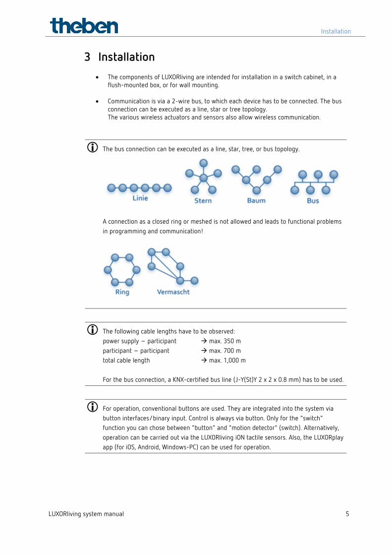
The bus connection can be executed as a line, star, tree, or bus topology.
A connection as a closed ring or meshed is not allowed and leads to functional problems in programming and communication!
The following cable lengths have to be observed: power supply – participant max. 350 m participant – participant max. 700 m total cable length max. 1,000 m For the bus connection, a KNX-certified bus line (J-Y(St)Y 2 x 2 x 0.8 mm) has to be used.
For operation, conventional buttons are used. They are integrated into the system via button interfaces/binary input. Control is always via button. Only for the "switch" function you can chose between "button" and "motion detector" (switch). Alternatively, operation can be carried out via the LUXORliving iON tactile sensors. Also, the LUXORplay app (for iOS, Android, Windows-PC) can be used for operation.
Installation
LUXORliving system manual 6
Please note that outdoors, a bus line can pose an increased safety risk. As an alternative in the outdoor area, normal motion detectors with relay contact can for instance be integrated into the system via the LUXORliving B6 binary input. When using the LUXORliving M140 weather station, installation location and cable routing should be chosen in a way, so access to the bus line is difficult. When using the modular LUXORliving M130/M100 weather sensors, the system's bus line is not routed to the outside, which ensures increased safety.
Simple start-up in 6 steps
LUXORliving system manual 7
4 Simple start-up in 6 steps
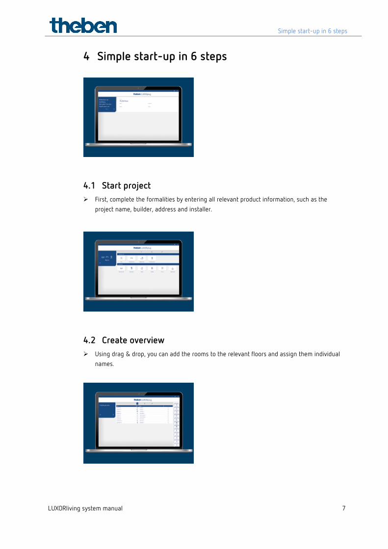
4.1 Start project First, complete the formalities by entering all relevant product information, such as the
project name, builder, address and installer.
4.2 Create overview Using drag & drop, you can add the rooms to the relevant floors and assign them individual
names.
Simple start-up in 6 steps
LUXORliving system manual 8
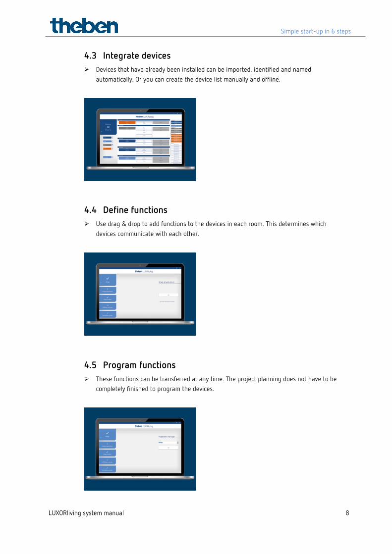
4.3 Integrate devices Devices that have already been installed can be imported, identified and named
automatically. Or you can create the device list manually and offline.
4.4 Define functions Use drag & drop to add functions to the devices in each room. This determines which
devices communicate with each other.
4.5 Program functions These functions can be transferred at any time. The project planning does not have to be
completely finished to program the devices.
Simple start-up in 6 steps
LUXORliving system manual 9
4.6 Prepare visualisation The project file is transmitted to the system control centre. The functions are then
extremely easy to operate and configure using the LUXORplay app.
Start-up with LUXORplug
LUXORliving system manual 10
5 Start-up with LUXORplug
5.1 Establish a connection LUXORliving is always put into operation by using the LUXORliving IP1 system control centre and the LUXORplug software. The LUXORplug software can be downloaded for free at https://www.theben.de/ (https://luxorliving.de/luxorplug/). For operation, the LUXORplay app is used, which is also available as a free download for your smartphone/tablet.
https://luxorliving.de/luxorplug/ System requirements for LUXORplug: - Windows 7 to Windows 10 - 32 bit and 64 bit
https://itunes.apple.com/de/app/luxorplay/id1319899246?mt=8 https://play.google.com/store/apps/details?id=de.theben.LUXORplay&hl=de https://luxorliving.de/luxorplay/ System requirements for LUXORplay: - Windows 7 to Windows 10 - 32 bit and 64 bit - Android from version 4.4, - iOS from version 9.x
The connection between PC and LUXORliving IP1 system control centre can be established in various ways. We recommend the connection via a router.
We recommend the connection via a router.
5.1.1 Option 1 – Connection via a router
Connect PC (WLAN or LAN) and LUXORliving IP1 system control centre (LAN) with the router and switch on the power supply of the LUXORliving IP1 system control centre.
The LUXORliving IP1 system control centre is delivered with activated DHCP service and receives its IP address automatically from the router. After start-up, the IP address is displayed in the LUXORliving IP1 display. If the router does not support DHCP, the IP address of LUXORliving IP1 has to be assigned manually. Please find further information on this in the manual of the router. In LUXORliving IP1, the IP address can be configured as follows:
Press the " " button and open the "IP Config" menu with the " " button.
Select the "DHCP" setting with the " " button.
Start-up with LUXORplug
LUXORliving system manual 11
Set it to "Manual" with " ", and confirm with " ". Now, you can set the IP address, subnet mask and gateway by using the arrow keys.
e.g. IP address 192.168.0.100/subnet mask 255.255.255.0/gateway 192.168.0.1
5.1.2 Option 2 – Connection without router using the DHCP service of LUXORplug
Via an integrated DHCP service in LUXORplug, an IP address can be assigned to the LUXORliving IP1 system control centre and the PC. This changes the network settings, which requires the appropriate access rights. When exiting LUXORplug, these settings will be undone.
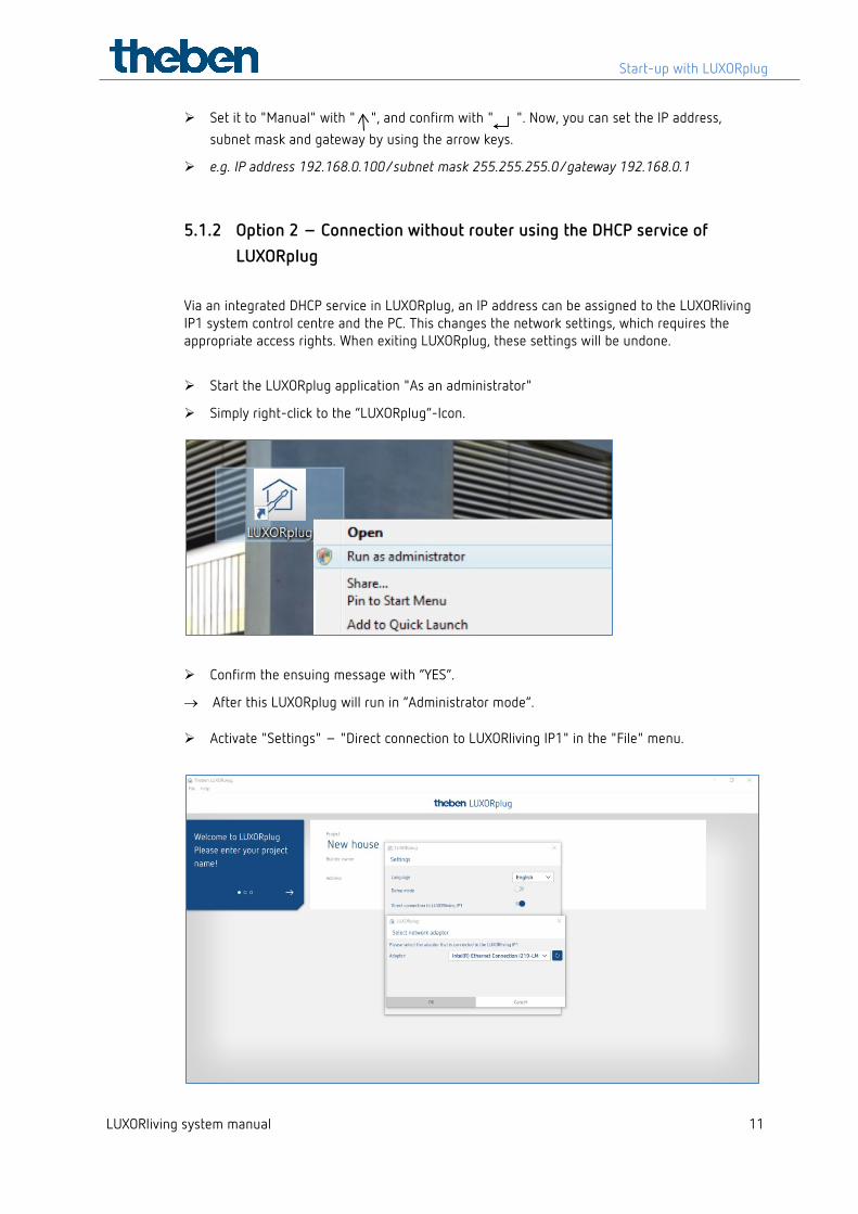
Start the LUXORplug application "As an administrator"
Simply right-click to the “LUXORplug”-Icon.
Confirm the ensuing message with “YES”.
→ After this LUXORplug will run in “Administrator mode”.
Activate "Settings" – "Direct connection to LUXORliving IP1" in the "File" menu.
Start-up with LUXORplug
LUXORliving system manual 12
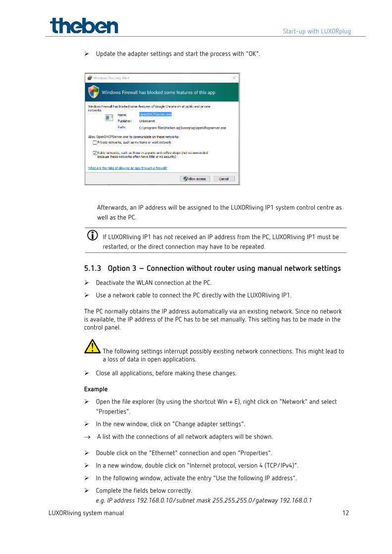
Update the adapter settings and start the process with "OK".
Afterwards, an IP address will be assigned to the LUXORliving IP1 system control centre as well as the PC.
If LUXORliving IP1 has not received an IP address from the PC, LUXORliving IP1 must be restarted, or the direct connection may have to be repeated.
5.1.3 Option 3 – Connection without router using manual network settings
Deactivate the WLAN connection at the PC.
Use a network cable to connect the PC directly with the LUXORliving IP1. The PC normally obtains the IP address automatically via an existing network. Since no network is available, the IP address of the PC has to be set manually. This setting has to be made in the control panel.
The following settings interrupt possibly existing network connections. This might lead to a loss of data in open applications.
Close all applications, before making these changes. Example
Open the file explorer (by using the shortcut Win + E), right click on "Network" and select "Properties".
In the new window, click on "Change adapter settings".
→ A list with the connections of all network adapters will be shown.
Double click on the "Ethernet" connection and open "Properties".
In a new window, double click on "Internet protocol, version 4 (TCP/IPv4)".
In the following window, activate the entry "Use the following IP address".
Complete the fields below correctly. e.g. IP address 192.168.0.10/subnet mask 255.255.255.0/gateway 192.168.0.1
Start-up with LUXORplug
LUXORliving system manual 13
Undo these settings after finishing your activities in the LUXORliving system and activate DHCP.
At LUXORliving IP1, the IP address has to be set manually as well:
Press the " " button and open the "IP Config" menu with the " " button.
Select the "DHCP" setting with the " " button, set it to "Manual" with " " and confirm with " ".
Set the IP address, subnet mask and gateway by using the arrow keys. e.g. IP address 192.168.0.100/subnet mask 255.255.255.0/gateway 192.168.0.1
→ The connection between PC and LUXORliving IP1 is now established.
Start the LUXORplug application and start configuration.
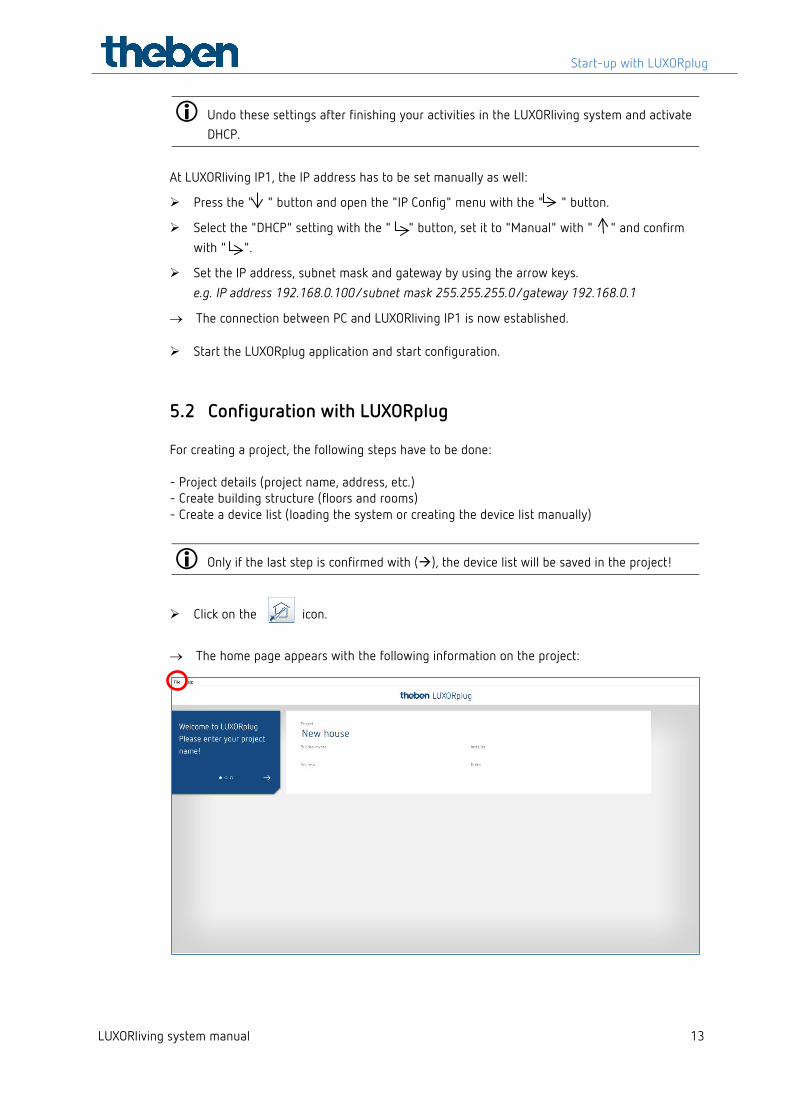
5.2 Configuration with LUXORplug For creating a project, the following steps have to be done: - Project details (project name, address, etc.) - Create building structure (floors and rooms) - Create a device list (loading the system or creating the device list manually)
Only if the last step is confirmed with (), the device list will be saved in the project!
Click on the icon.
→ The home page appears with the following information on the project:
Start-up with LUXORplug
LUXORliving system manual 14
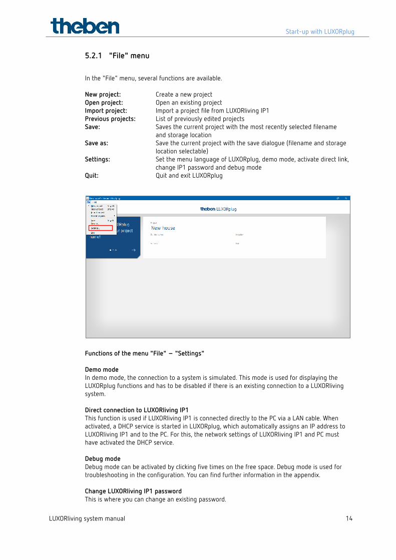
5.2.1 "File" menu
In the "File" menu, several functions are available. New project: Create a new project Open project: Open an existing project Import project: Import a project file from LUXORliving IP1 Previous projects: List of previously edited projects Save: Saves the current project with the most recently selected filename
and storage location Save as: Save the current project with the save dialogue (filename and storage
location selectable) Settings: Set the menu language of LUXORplug, demo mode, activate direct link,
change IP1 password and debug mode Quit: Quit and exit LUXORplug
Functions of the menu "File" – "Settings" Demo mode In demo mode, the connection to a system is simulated. This mode is used for displaying the LUXORplug functions and has to be disabled if there is an existing connection to a LUXORliving system. Direct connection to LUXORliving IP1 This function is used if LUXORliving IP1 is connected directly to the PC via a LAN cable. When activated, a DHCP service is started in LUXORplug, which automatically assigns an IP address to LUXORliving IP1 and to the PC. For this, the network settings of LUXORliving IP1 and PC must have activated the DHCP service. Debug mode Debug mode can be activated by clicking five times on the free space. Debug mode is used for troubleshooting in the configuration. You can find further information in the appendix. Change LUXORliving IP1 password This is where you can change an existing password.
Start-up with LUXORplug
LUXORliving system manual 15
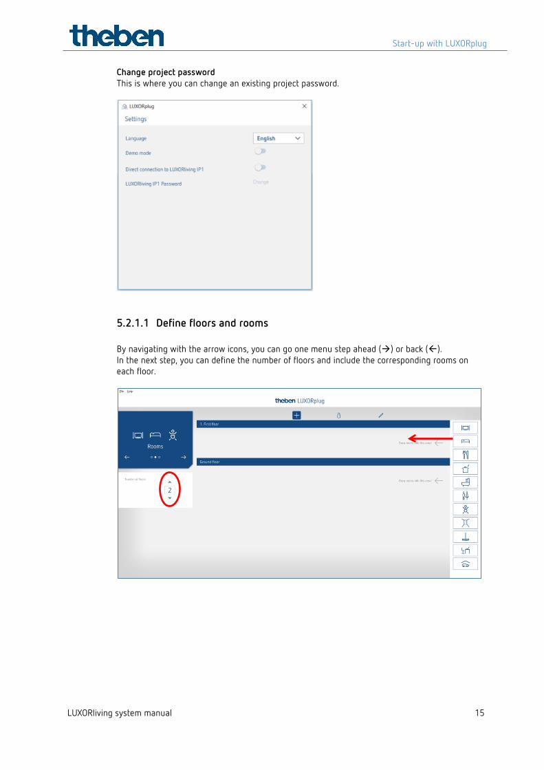
Change project password This is where you can change an existing project password.
5.2.1.1 Define floors and rooms By navigating with the arrow icons, you can go one menu step ahead () or back (). In the next step, you can define the number of floors and include the corresponding rooms on each floor.
Start-up with LUXORplug
LUXORliving system manual 16
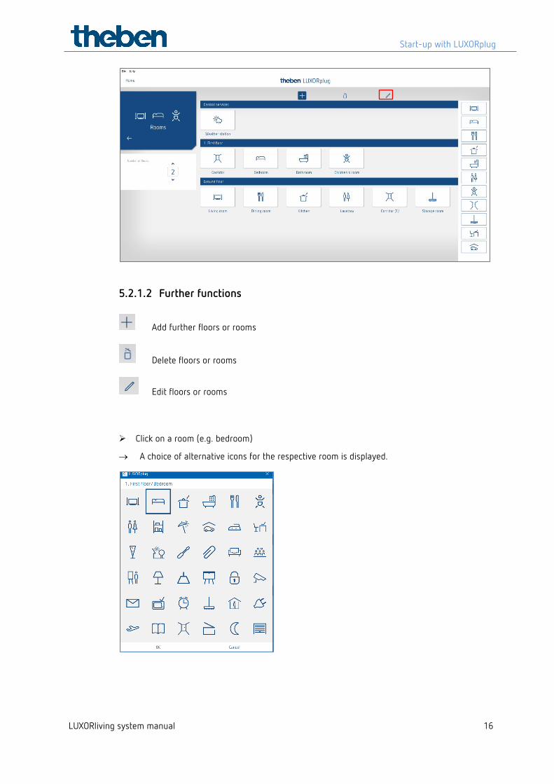
5.2.1.2 Further functions
Add further floors or rooms
Delete floors or rooms
Edit floors or rooms
Click on a room (e.g. bedroom)
→ A choice of alternative icons for the respective room is displayed.
Start-up with LUXORplug
LUXORliving system manual 17
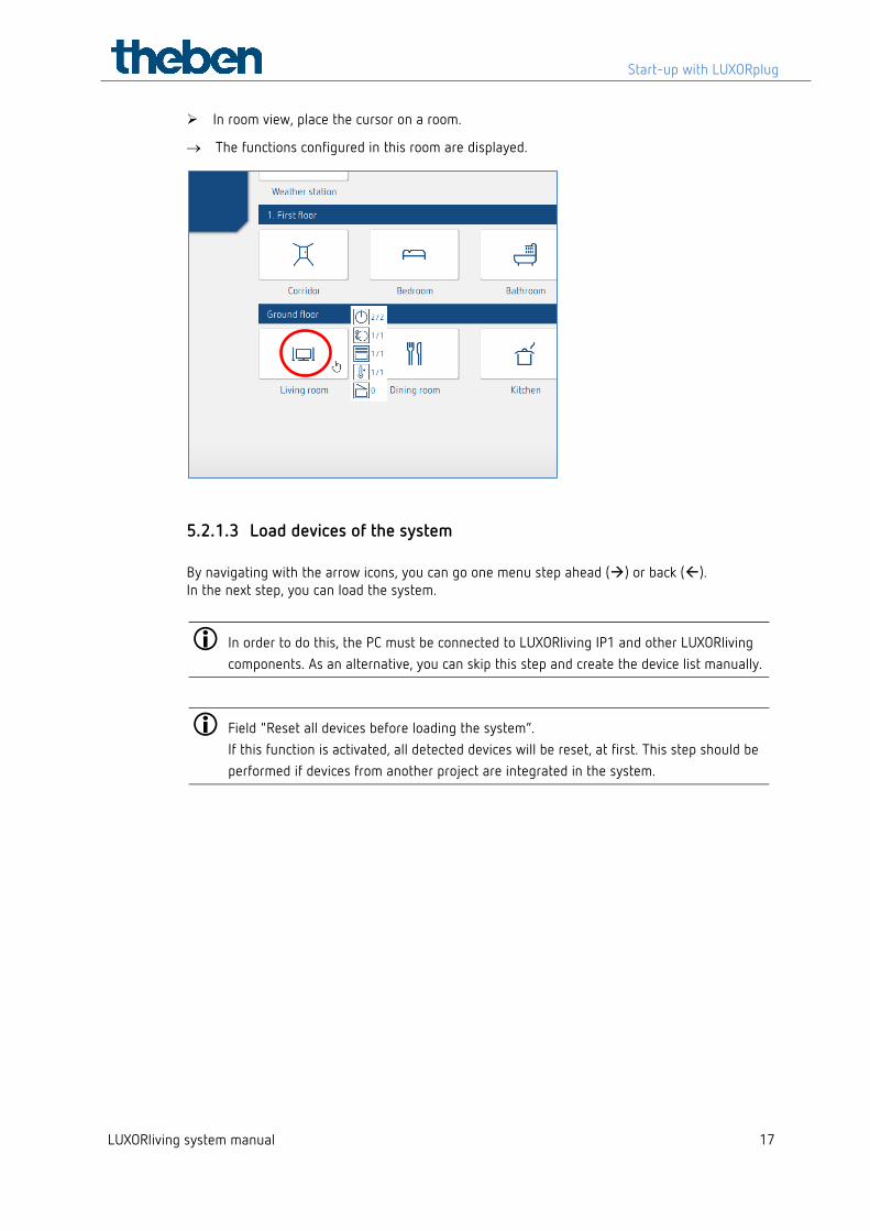
In room view, place the cursor on a room.
→ The functions configured in this room are displayed.
5.2.1.3 Load devices of the system By navigating with the arrow icons, you can go one menu step ahead () or back (). In the next step, you can load the system.
In order to do this, the PC must be connected to LUXORliving IP1 and other LUXORliving components. As an alternative, you can skip this step and create the device list manually.
Field "Reset all devices before loading the system“. If this function is activated, all detected devices will be reset, at first. This step should be performed if devices from another project are integrated in the system.
Start-up with LUXORplug
LUXORliving system manual 18
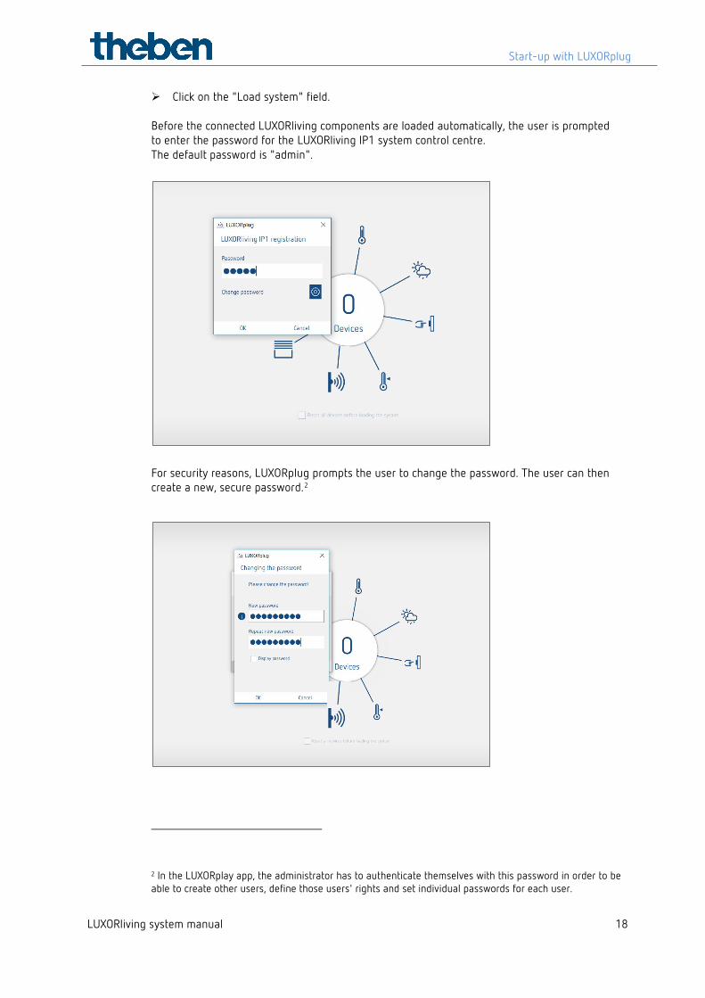
Click on the "Load system" field. Before the connected LUXORliving components are loaded automatically, the user is prompted to enter the password for the LUXORliving IP1 system control centre. The default password is "admin".
For security reasons, LUXORplug prompts the user to change the password. The user can then create a new, secure password.2
2 In the LUXORplay app, the administrator has to authenticate themselves with this password in order to be able to create other users, define those users' rights and set individual passwords for each user.
Start-up with LUXORplug
LUXORliving system manual 19
If the password is forgotten, the LUXORliving IP1 system control centre will need to be reset with a master reset. This can be done directly at the device ("Reset" menu – "Master Reset"). Afterwards, the password can be created again via LUXORplug. The default password after a master reset is always "admin".
For security reasons, the new administrator password must be entered before the system is loaded each time and whenever the system is being programmed.
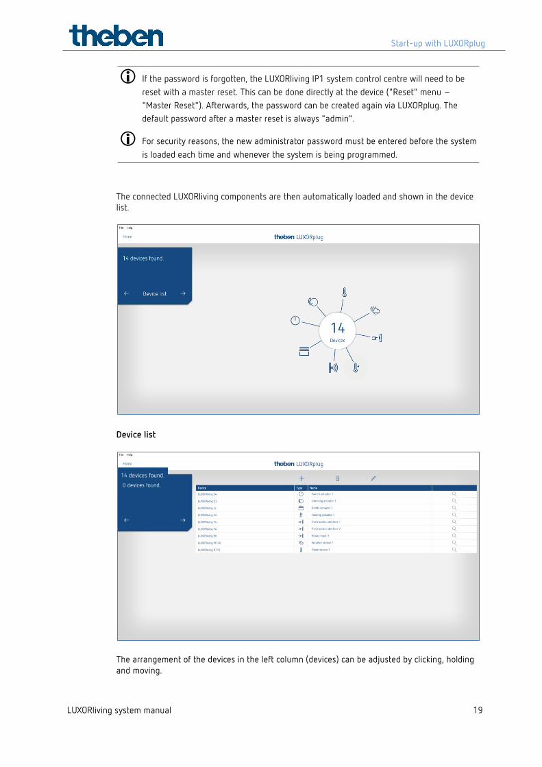
The connected LUXORliving components are then automatically loaded and shown in the device list.
Device list
The arrangement of the devices in the left column (devices) can be adjusted by clicking, holding and moving.
Start-up with LUXORplug
LUXORliving system manual 20
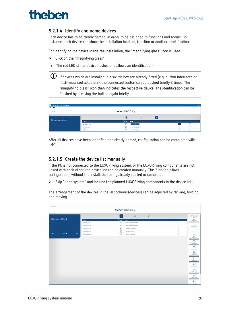
5.2.1.4 Identify and name devices Each device has to be clearly named, in order to be assigned to functions and rooms. For instance, each device can show the installation location, function or another identification. For identifying the device inside the installation, the "magnifying glass" icon is used.
Click on the "magnifying glass".
→ The red LED of the device flashes and allows an identification.
If devices which are installed in a switch box are already fitted (e.g. button interfaces or flush-mounted actuators), the connected button can be pushed briefly 3 times. The "magnifying glass" icon then indicates the respective device. The identification can be finished by pressing the button again briefly.
After all devices have been identified and clearly named, configuration can be completed with "".
5.2.1.5 Create the device list manually If the PC is not connected to the LUXORliving system, or the LUXORliving components are not linked with each other, the device list can be created manually. This function allows configuration, without the installation being already started or completed.
Skip "Load system" and include the planned LUXORliving components in the device list. The arrangement of the devices in the left column (devices) can be adjusted by clicking, holding and moving.
Start-up with LUXORplug
LUXORliving system manual 21
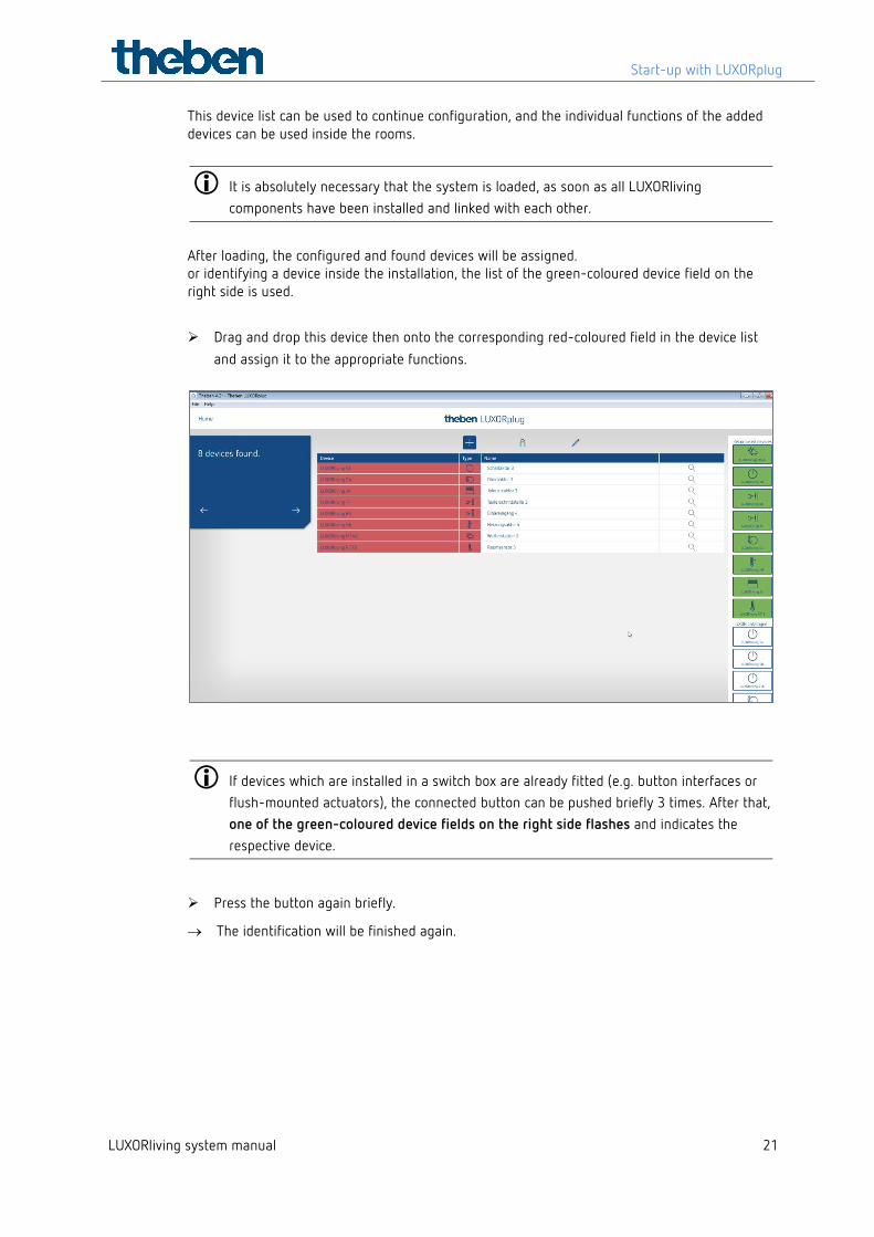
This device list can be used to continue configuration, and the individual functions of the added devices can be used inside the rooms.
It is absolutely necessary that the system is loaded, as soon as all LUXORliving components have been installed and linked with each other.
After loading, the configured and found devices will be assigned. or identifying a device inside the installation, the list of the green-coloured device field on the right side is used.
Drag and drop this device then onto the corresponding red-coloured field in the device list and assign it to the appropriate functions.
If devices which are installed in a switch box are already fitted (e.g. button interfaces or flush-mounted actuators), the connected button can be pushed briefly 3 times. After that, one of the green-coloured device fields on the right side flashes and indicates the respective device.
Press the button again briefly.
→ The identification will be finished again.
Start-up with LUXORplug
LUXORliving system manual 22
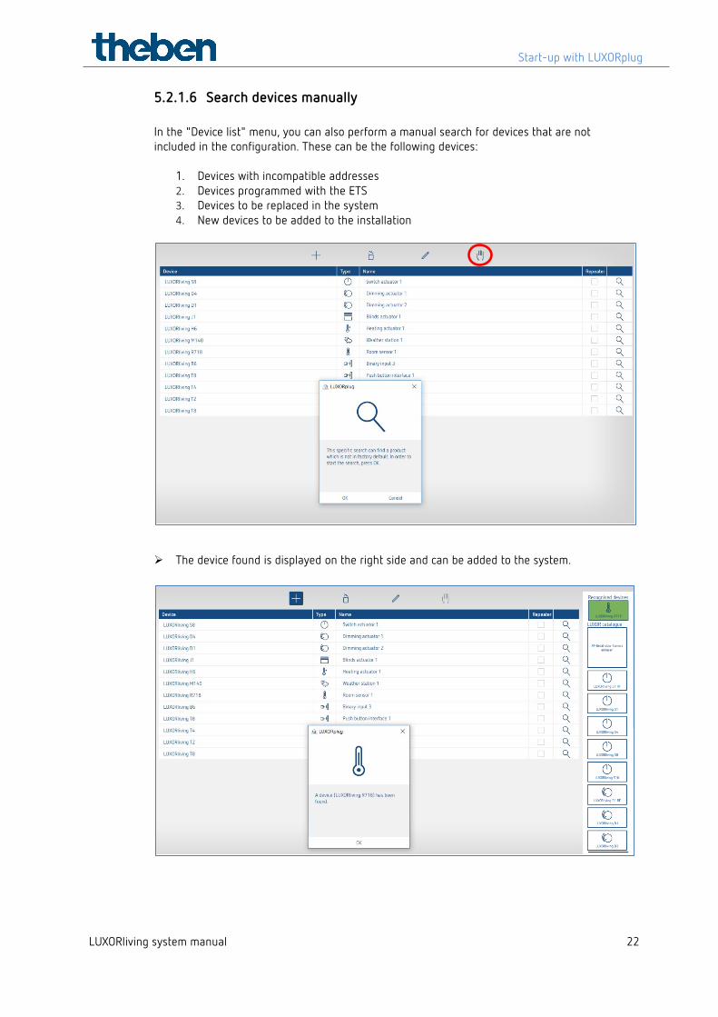
5.2.1.6 Search devices manually In the "Device list" menu, you can also perform a manual search for devices that are not included in the configuration. These can be the following devices:
1. Devices with incompatible addresses 2. Devices programmed with the ETS 3. Devices to be replaced in the system 4. New devices to be added to the installation
The device found is displayed on the right side and can be added to the system.
Start-up with LUXORplug
LUXORliving system manual 23
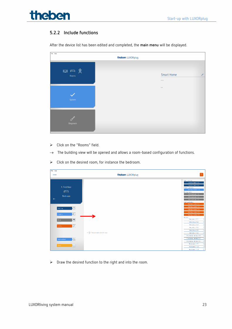
5.2.2 Include functions After the device list has been edited and completed, the main menu will be displayed.
Click on the "Rooms" field.
→ The building view will be opened and allows a room-based configuration of functions.
Click on the desired room, for instance the bedroom.
Draw the desired function to the right and into the room.
Start-up with LUXORplug
LUXORliving system manual 24
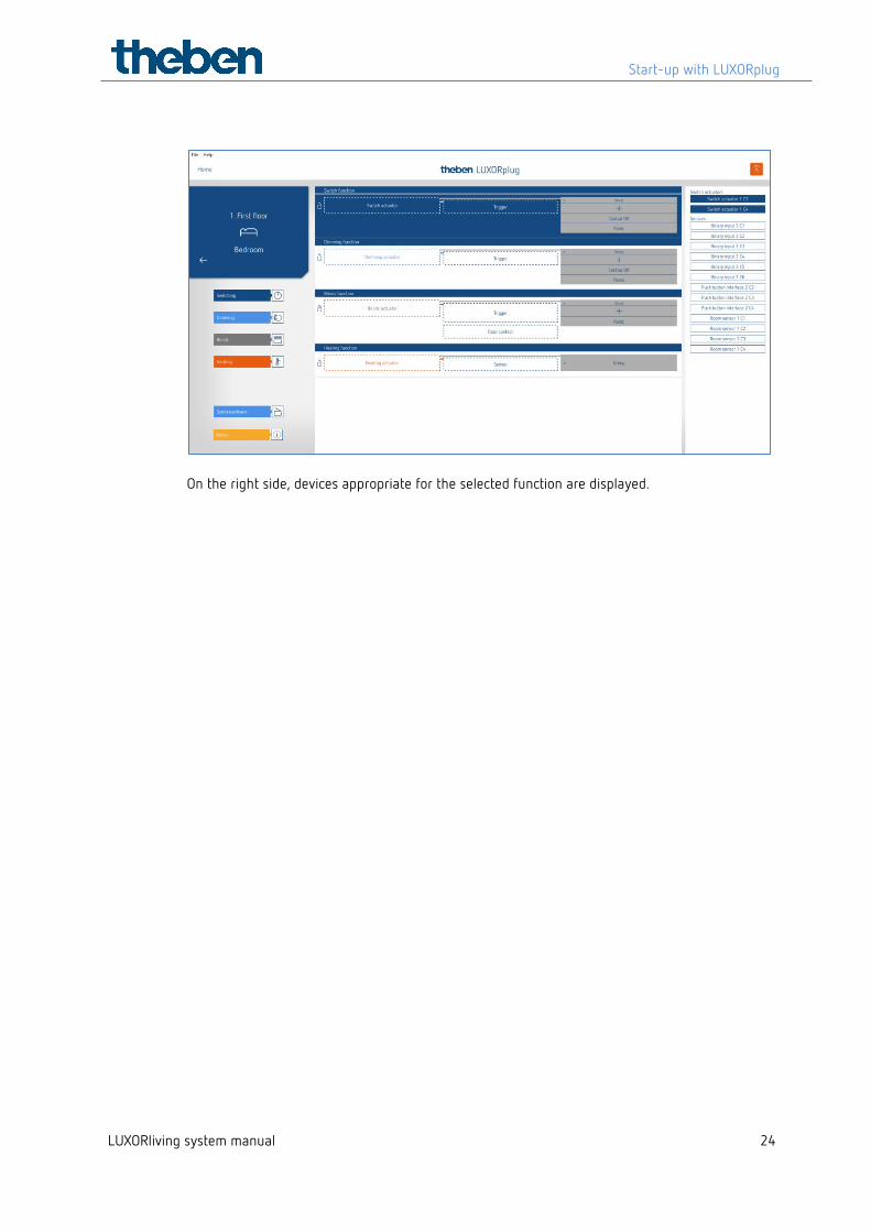
On the right side, devices appropriate for the selected function are displayed.
Start-up with LUXORplug
LUXORliving system manual 25
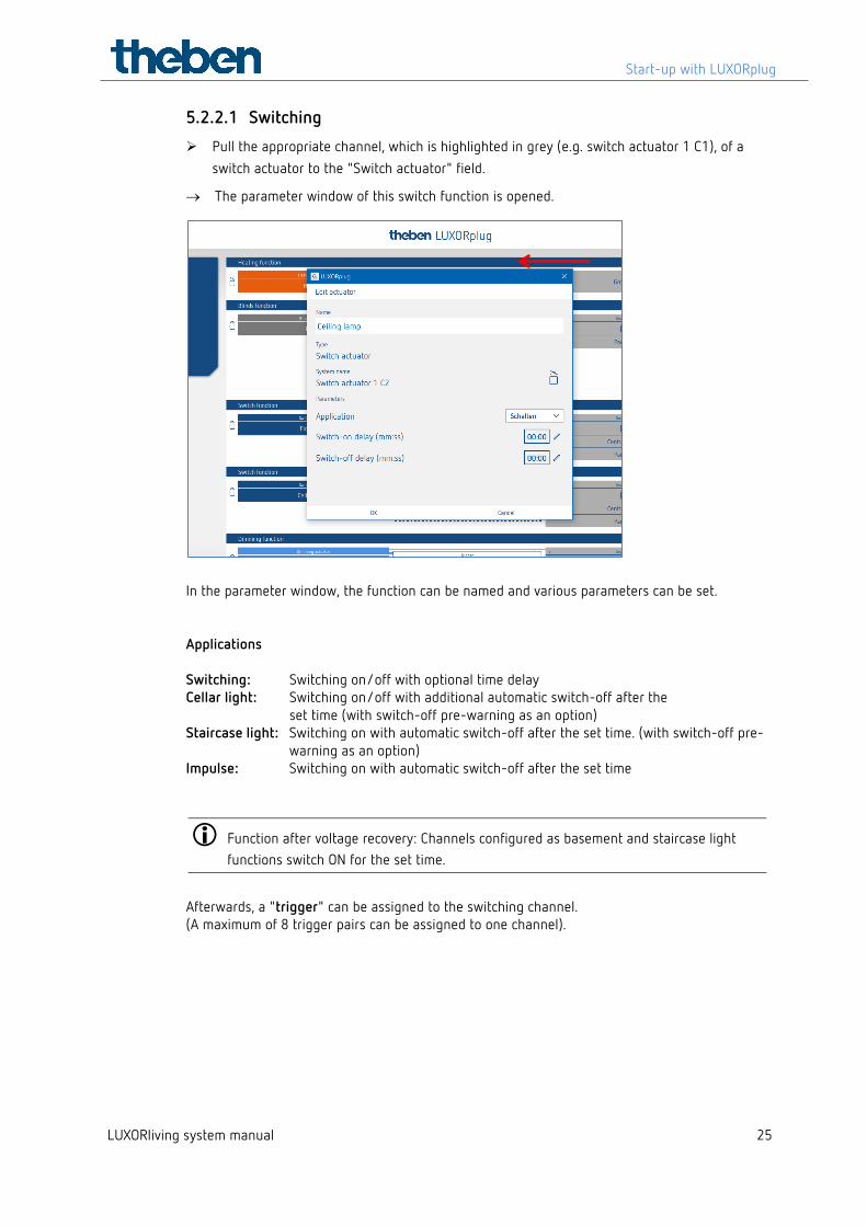
5.2.2.1 Switching
Pull the appropriate channel, which is highlighted in grey (e.g. switch actuator 1 C1), of a switch actuator to the "Switch actuator" field.
→ The parameter window of this switch function is opened.
In the parameter window, the function can be named and various parameters can be set. Applications Switching: Switching on/off with optional time delay Cellar light: Switching on/off with additional automatic switch-off after the
set time (with switch-off pre-warning as an option) Staircase light: Switching on with automatic switch-off after the set time. (with switch-off pre-
warning as an option) Impulse: Switching on with automatic switch-off after the set time
Function after voltage recovery: Channels configured as basement and staircase light functions switch ON for the set time.
Afterwards, a "trigger" can be assigned to the switching channel. (A maximum of 8 trigger pairs can be assigned to one channel).
Start-up with LUXORplug
LUXORliving system manual 26
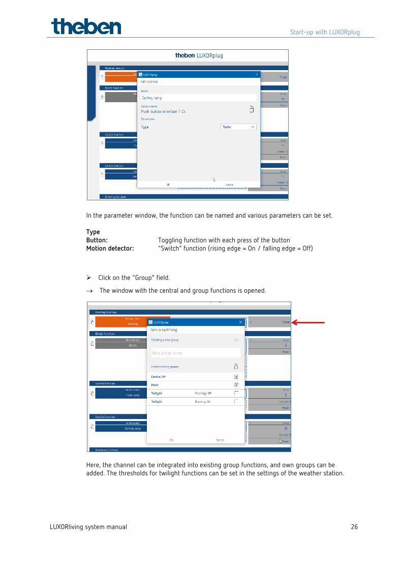
In the parameter window, the function can be named and various parameters can be set. Type Button: Toggling function with each press of the button Motion detector: "Switch“ function (rising edge = On / falling edge = Off)
Click on the "Group" field.
→ The window with the central and group functions is opened.
Here, the channel can be integrated into existing group functions, and own groups can be added. The thresholds for twilight functions can be set in the settings of the weather station.
Start-up with LUXORplug
LUXORliving system manual 27
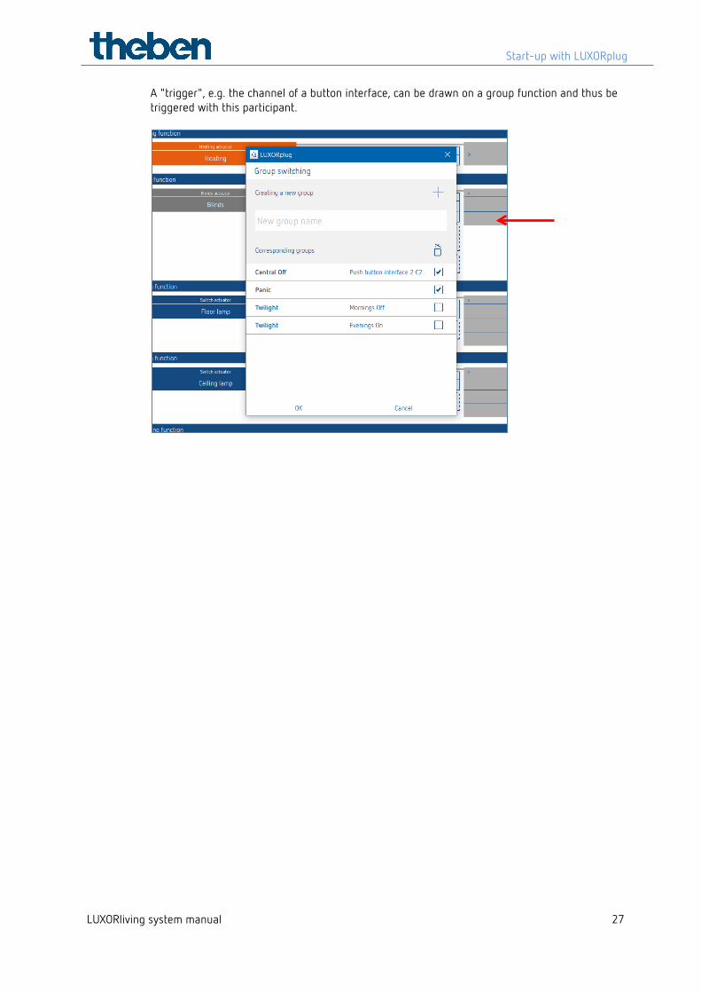
A "trigger", e.g. the channel of a button interface, can be drawn on a group function and thus be triggered with this participant.
Start-up with LUXORplug
LUXORliving system manual 28
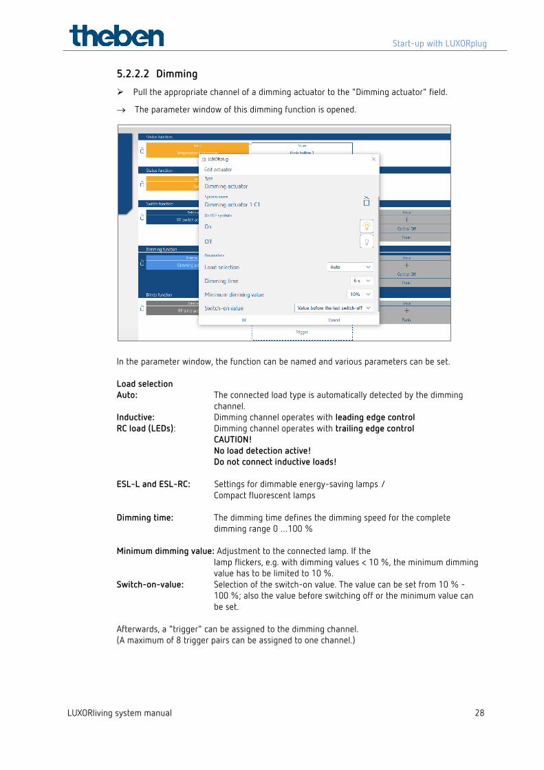
5.2.2.2 Dimming
Pull the appropriate channel of a dimming actuator to the "Dimming actuator" field.
→ The parameter window of this dimming function is opened.
In the parameter window, the function can be named and various parameters can be set. Load selection Auto: The connected load type is automatically detected by the dimming channel. Inductive: Dimming channel operates with leading edge control RC load (LEDs): Dimming channel operates with trailing edge control CAUTION! No load detection active! Do not connect inductive loads! ESL-L and ESL-RC: Settings for dimmable energy-saving lamps /
Compact fluorescent lamps
Dimming time: The dimming time defines the dimming speed for the complete dimming range 0 …100 %
Minimum dimming value: Adjustment to the connected lamp. If the lamp flickers, e.g. with dimming values < 10 %, the minimum dimming value has to be limited to 10 %.
Switch-on-value: Selection of the switch-on value. The value can be set from 10 % - 100 %; also the value before switching off or the minimum value can be set.
Afterwards, a "trigger" can be assigned to the dimming channel. (A maximum of 8 trigger pairs can be assigned to one channel.)
Start-up with LUXORplug
LUXORliving system manual 29
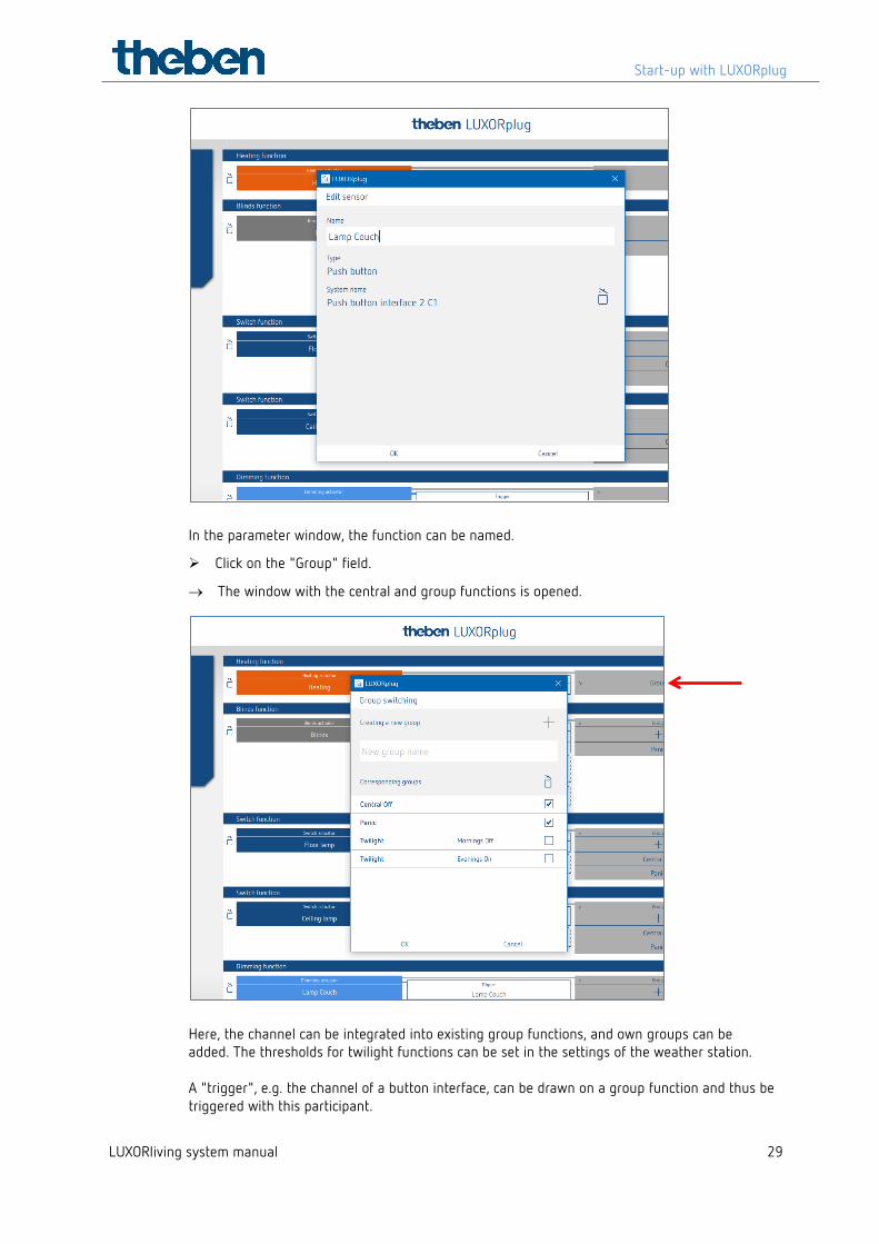
In the parameter window, the function can be named.
Click on the "Group" field.
→ The window with the central and group functions is opened.
Here, the channel can be integrated into existing group functions, and own groups can be added. The thresholds for twilight functions can be set in the settings of the weather station. A "trigger", e.g. the channel of a button interface, can be drawn on a group function and thus be triggered with this participant.
Start-up with LUXORplug
LUXORliving system manual 30
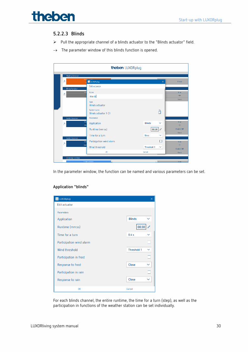
5.2.2.3 Blinds
Pull the appropriate channel of a blinds actuator to the "Blinds actuator" field.
→ The parameter window of this blinds function is opened.
In the parameter window, the function can be named and various parameters can be set. Application "blinds"
For each blinds channel, the entire runtime, the time for a turn (step), as well as the participation in functions of the weather station can be set individually.
Start-up with LUXORplug
LUXORliving system manual 31
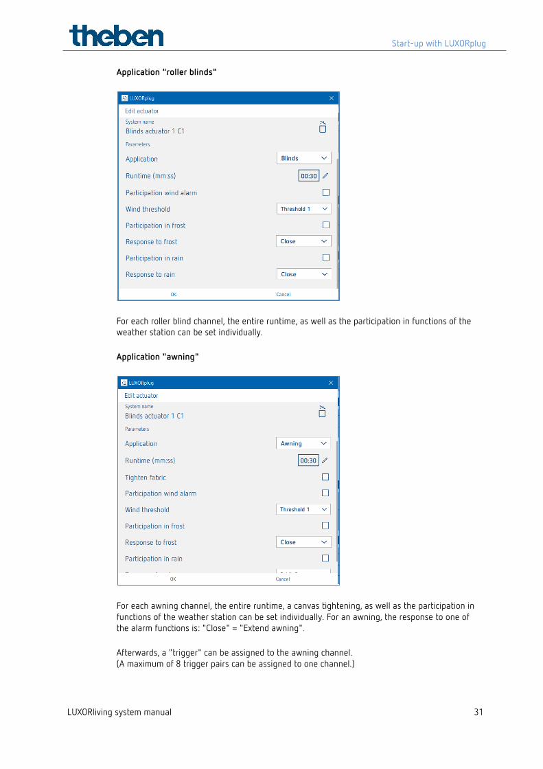
Application "roller blinds"
For each roller blind channel, the entire runtime, as well as the participation in functions of the weather station can be set individually. Application "awning"
For each awning channel, the entire runtime, a canvas tightening, as well as the participation in functions of the weather station can be set individually. For an awning, the response to one of the alarm functions is: "Close" = "Extend awning". Afterwards, a "trigger" can be assigned to the awning channel. (A maximum of 8 trigger pairs can be assigned to one channel.)
Start-up with LUXORplug
LUXORliving system manual 32
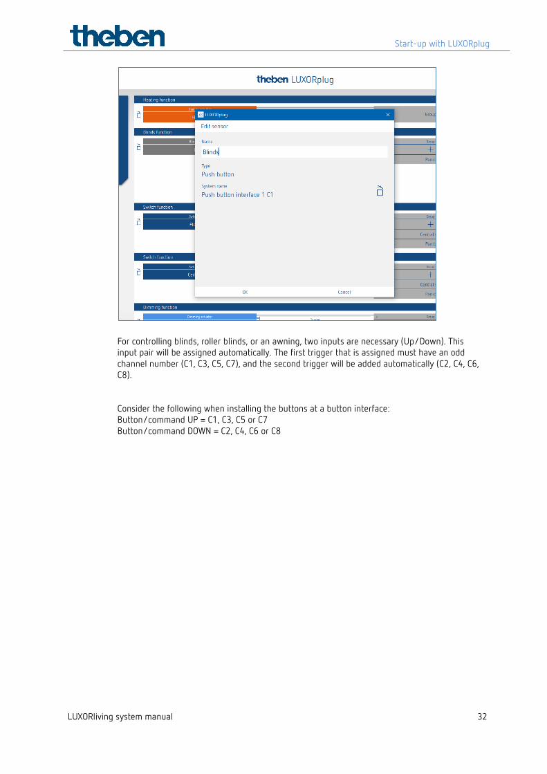
For controlling blinds, roller blinds, or an awning, two inputs are necessary (Up/Down). This input pair will be assigned automatically. The first trigger that is assigned must have an odd channel number (C1, C3, C5, C7), and the second trigger will be added automatically (C2, C4, C6, C8). Consider the following when installing the buttons at a button interface: Button/command UP = C1, C3, C5 or C7 Button/command DOWN = C2, C4, C6 or C8
Start-up with LUXORplug
LUXORliving system manual 33
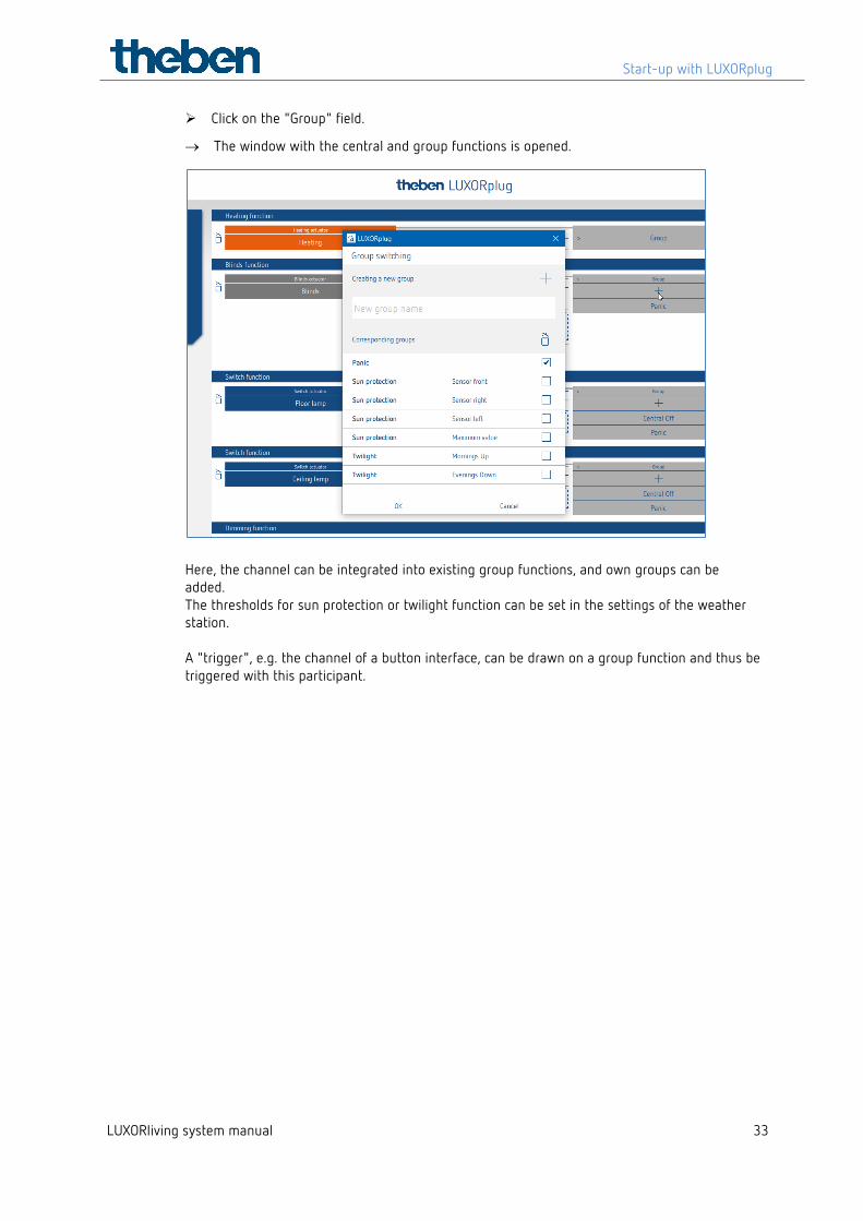
Click on the "Group" field.
→ The window with the central and group functions is opened.
Here, the channel can be integrated into existing group functions, and own groups can be added. The thresholds for sun protection or twilight function can be set in the settings of the weather station. A "trigger", e.g. the channel of a button interface, can be drawn on a group function and thus be triggered with this participant.
Start-up with LUXORplug
LUXORliving system manual 34
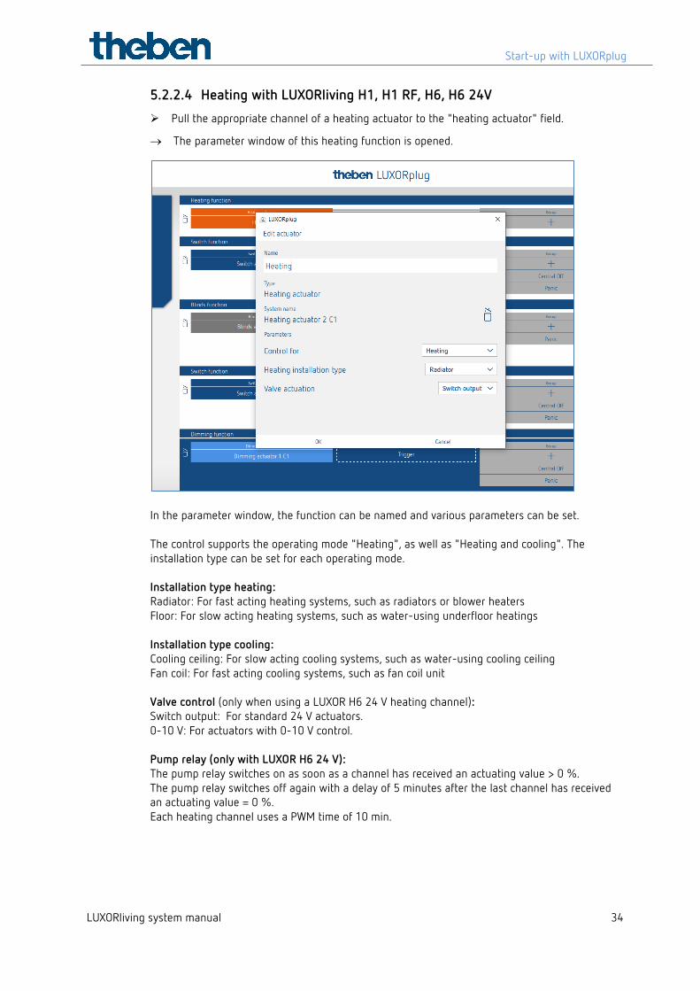
5.2.2.4 Heating with LUXORliving H1, H1 RF, H6, H6 24V
Pull the appropriate channel of a heating actuator to the "heating actuator" field.
→ The parameter window of this heating function is opened.
In the parameter window, the function can be named and various parameters can be set. The control supports the operating mode "Heating", as well as "Heating and cooling". The installation type can be set for each operating mode. Installation type heating: Radiator: For fast acting heating systems, such as radiators or blower heaters Floor: For slow acting heating systems, such as water-using underfloor heatings Installation type cooling: Cooling ceiling: For slow acting cooling systems, such as water-using cooling ceiling Fan coil: For fast acting cooling systems, such as fan coil unit Valve control (only when using a LUXOR H6 24 V heating channel): Switch output: For standard 24 V actuators. 0-10 V: For actuators with 0-10 V control. Pump relay (only with LUXOR H6 24 V): The pump relay switches on as soon as a channel has received an actuating value > 0 %. The pump relay switches off again with a delay of 5 minutes after the last channel has received an actuating value = 0 %. Each heating channel uses a PWM time of 10 min.
Start-up with LUXORplug
LUXORliving system manual 35
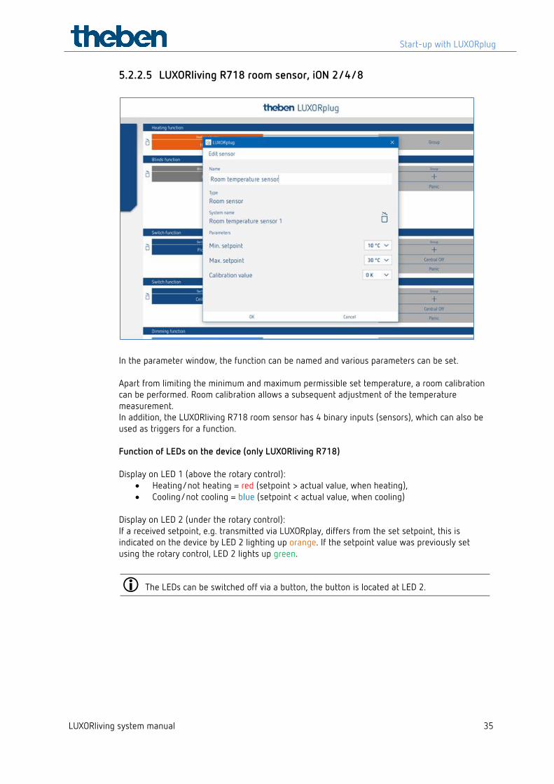
5.2.2.5 LUXORliving R718 room sensor, iON 2/4/8
In the parameter window, the function can be named and various parameters can be set. Apart from limiting the minimum and maximum permissible set temperature, a room calibration can be performed. Room calibration allows a subsequent adjustment of the temperature measurement. In addition, the LUXORliving R718 room sensor has 4 binary inputs (sensors), which can also be used as triggers for a function. Function of LEDs on the device (only LUXORliving R718) Display on LED 1 (above the rotary control):
• Heating/not heating = red (setpoint > actual value, when heating), • Cooling/not cooling = blue (setpoint < actual value, when cooling)
Display on LED 2 (under the rotary control): If a received setpoint, e.g. transmitted via LUXORplay, differs from the set setpoint, this is indicated on the device by LED 2 lighting up orange. If the setpoint value was previously set using the rotary control, LED 2 lights up green.
The LEDs can be switched off via a button, the button is located at LED 2.
Start-up with LUXORplug
LUXORliving system manual 36
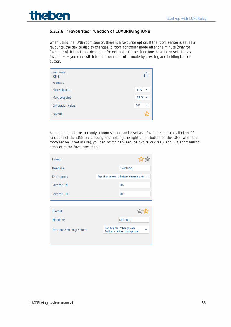
5.2.2.6 "Favourites" function of LUXORliving iON8 When using the iON8 room sensor, there is a favourite option. If the room sensor is set as a favourite, the device display changes to room controller mode after one minute (only for favourite A). If this is not desired – for example, if other functions have been selected as favourites – you can switch to the room controller mode by pressing and holding the left button.
As mentioned above, not only a room sensor can be set as a favourite, but also all other 10 functions of the iON8. By pressing and holding the right or left button on the iON8 (when the room sensor is not in use), you can switch between the two favourites A and B. A short button press exits the favourites menu.
Start-up with LUXORplug
LUXORliving system manual 37
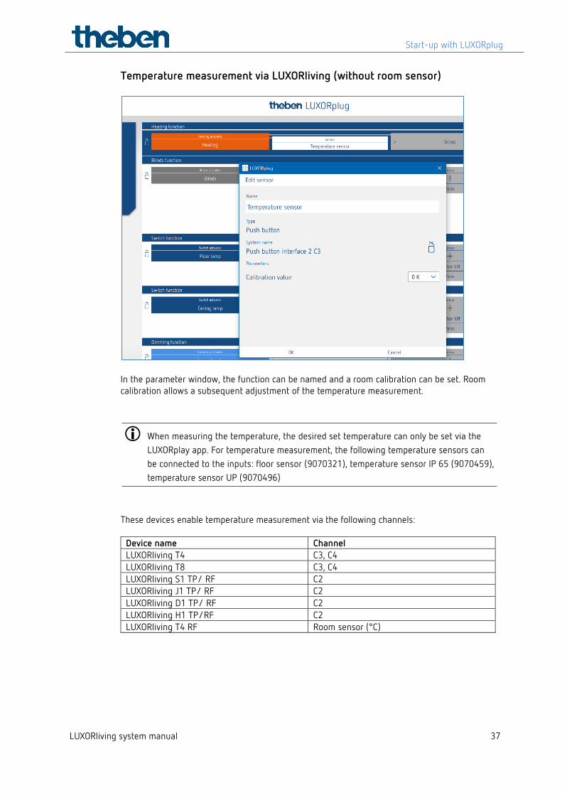
Temperature measurement via LUXORliving (without room sensor)
In the parameter window, the function can be named and a room calibration can be set. Room calibration allows a subsequent adjustment of the temperature measurement.
When measuring the temperature, the desired set temperature can only be set via the LUXORplay app. For temperature measurement, the following temperature sensors can be connected to the inputs: floor sensor (9070321), temperature sensor IP 65 (9070459), temperature sensor UP (9070496)
These devices enable temperature measurement via the following channels:
Device name Channel LUXORliving T4 C3, C4 LUXORliving T8 C3, C4 LUXORliving S1 TP/ RF C2 LUXORliving J1 TP/ RF C2 LUXORliving D1 TP/ RF C2 LUXORliving H1 TP/RF C2 LUXORliving T4 RF Room sensor (°C)
Start-up with LUXORplug
LUXORliving system manual 38
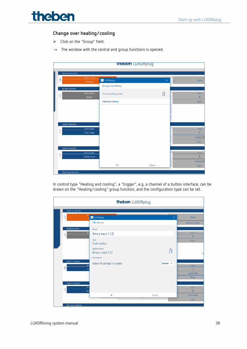
Change over heating/cooling
Click on the "Group" field.
→ The window with the central and group functions is opened.
In control type "Heating and cooling", a "trigger", e.g. a channel of a button interface, can be drawn on the "Heating/cooling" group function, and the configuration type can be set.
Start-up with LUXORplug
LUXORliving system manual 39
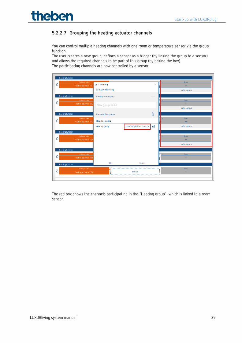
5.2.2.7 Grouping the heating actuator channels
You can control multiple heating channels with one room or temperature sensor via the group function. The user creates a new group, defines a sensor as a trigger (by linking the group to a sensor) and allows the required channels to be part of this group (by ticking the box). The participating channels are now controlled by a sensor.
The red box shows the channels participating in the "Heating group", which is linked to a room sensor.
Start-up with LUXORplug
LUXORliving system manual 40
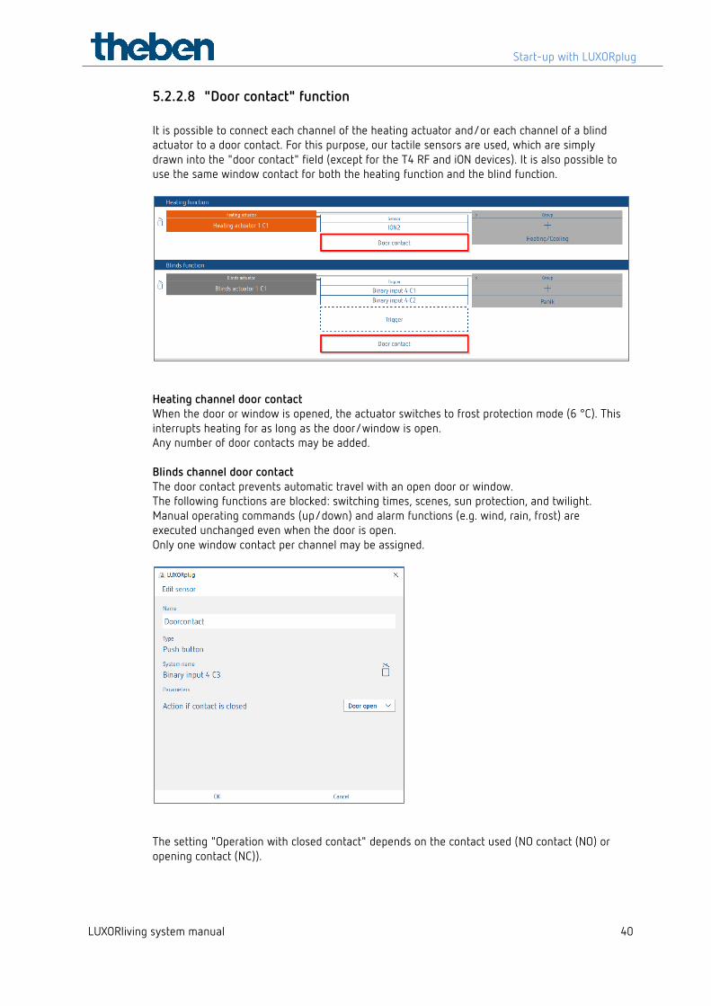
5.2.2.8 "Door contact" function It is possible to connect each channel of the heating actuator and/or each channel of a blind actuator to a door contact. For this purpose, our tactile sensors are used, which are simply drawn into the "door contact" field (except for the T4 RF and iON devices). It is also possible to use the same window contact for both the heating function and the blind function.
Heating channel door contact When the door or window is opened, the actuator switches to frost protection mode (6 °C). This interrupts heating for as long as the door/window is open. Any number of door contacts may be added. Blinds channel door contact The door contact prevents automatic travel with an open door or window. The following functions are blocked: switching times, scenes, sun protection, and twilight. Manual operating commands (up/down) and alarm functions (e.g. wind, rain, frost) are executed unchanged even when the door is open. Only one window contact per channel may be assigned.
The setting "Operation with closed contact" depends on the contact used (NO contact (NO) or opening contact (NC)).
Start-up with LUXORplug
LUXORliving system manual 41
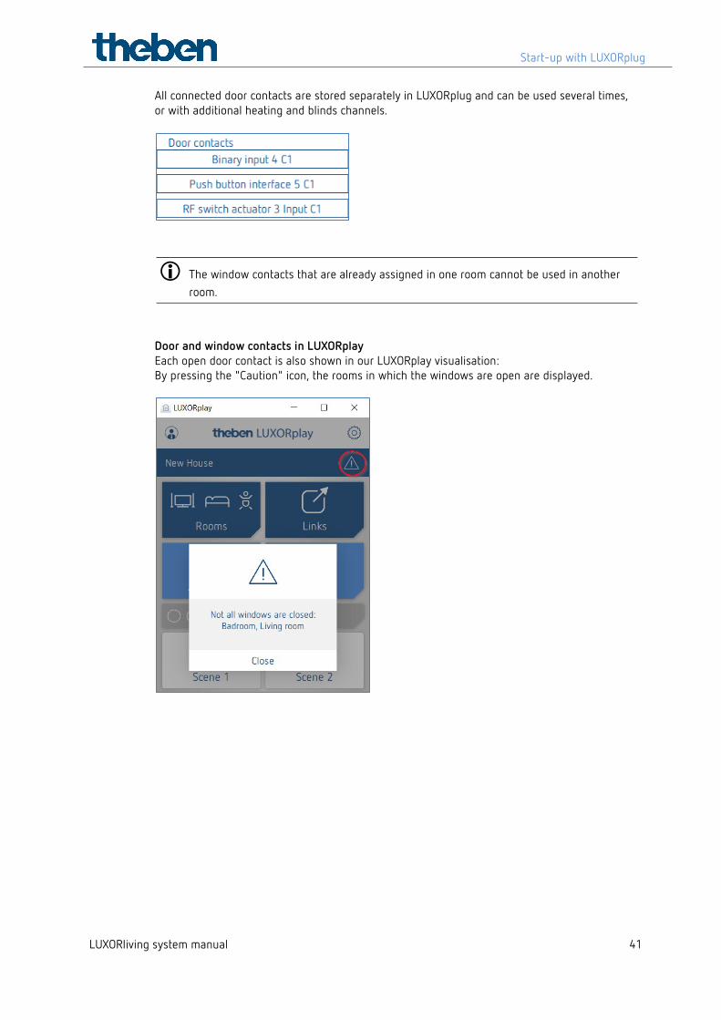
All connected door contacts are stored separately in LUXORplug and can be used several times, or with additional heating and blinds channels.
The window contacts that are already assigned in one room cannot be used in another room.
Door and window contacts in LUXORplay Each open door contact is also shown in our LUXORplay visualisation: By pressing the "Caution" icon, the rooms in which the windows are open are displayed.
Start-up with LUXORplug
LUXORliving system manual 42
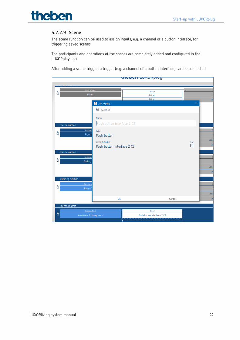
5.2.2.9 Scene The scene function can be used to assign inputs, e.g. a channel of a button interface, for triggering saved scenes. The participants and operations of the scenes are completely added and configured in the LUXORplay app. After adding a scene trigger, a trigger (e.g. a channel of a button interface) can be connected.
Start-up with LUXORplug
LUXORliving system manual 43
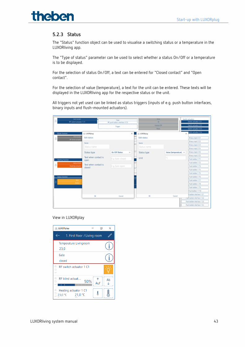
5.2.3 Status The "Status" function object can be used to visualise a switching status or a temperature in the LUXORliving app. The "Type of status" parameter can be used to select whether a status On/Off or a temperature is to be displayed. For the selection of status On/Off, a text can be entered for "Closed contact" and "Open contact". For the selection of value (temperature), a text for the unit can be entered. These texts will be displayed in the LUXORliving app for the respective status or the unit. All triggers not yet used can be linked as status triggers (inputs of e.g. push button interfaces, binary inputs and flush-mounted actuators).
View in LUXORplay
Start-up with LUXORplug
LUXORliving system manual 44
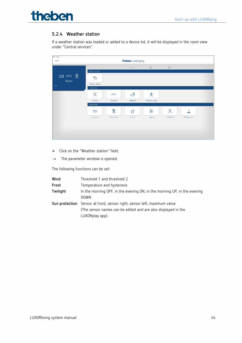
5.2.4 Weather station If a weather station was loaded or added to a device list, it will be displayed in the room view under "Central services".
Click on the "Weather station" field.
→ The parameter window is opened.
The following functions can be set:
Wind Threshold 1 and threshold 2 Frost Temperature and hysteresis Twilight In the morning OFF, in the evening ON, in the morning UP, in the evening DOWN Sun protection Sensor at front, sensor right, sensor left, maximum value (The sensor names can be edited and are also displayed in the LUXORplay app).
Start-up with LUXORplug
LUXORliving system manual 45
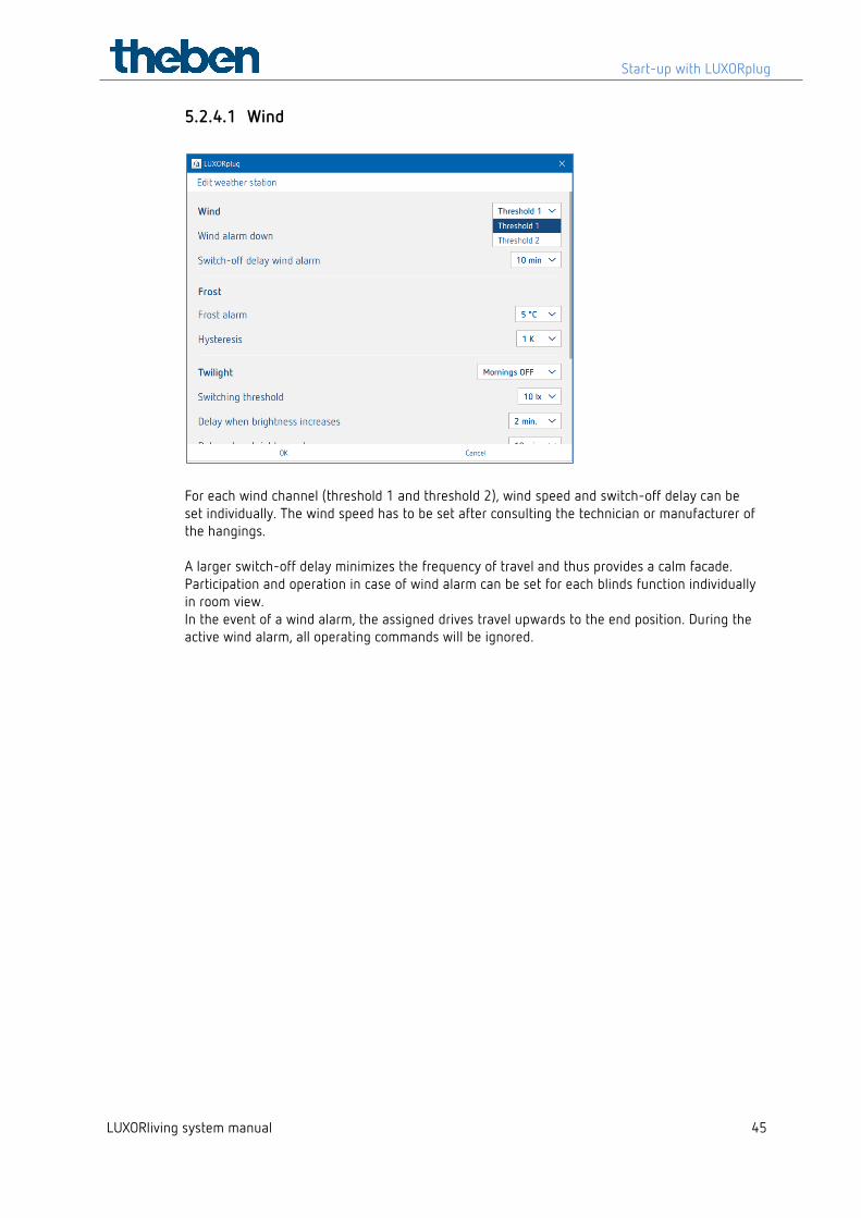
5.2.4.1 Wind
For each wind channel (threshold 1 and threshold 2), wind speed and switch-off delay can be set individually. The wind speed has to be set after consulting the technician or manufacturer of the hangings. A larger switch-off delay minimizes the frequency of travel and thus provides a calm facade. Participation and operation in case of wind alarm can be set for each blinds function individually in room view. In the event of a wind alarm, the assigned drives travel upwards to the end position. During the active wind alarm, all operating commands will be ignored.
Start-up with LUXORplug
LUXORliving system manual 46
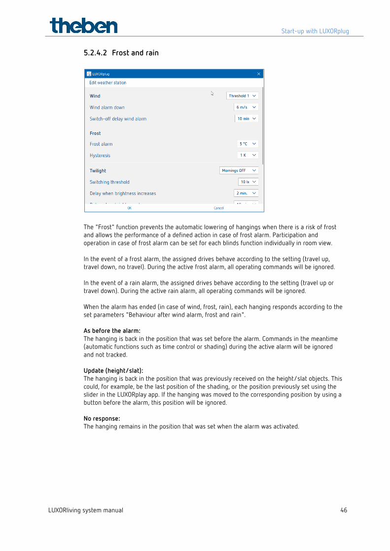
5.2.4.2 Frost and rain
The "Frost" function prevents the automatic lowering of hangings when there is a risk of frost and allows the performance of a defined action in case of frost alarm. Participation and operation in case of frost alarm can be set for each blinds function individually in room view. In the event of a frost alarm, the assigned drives behave according to the setting (travel up, travel down, no travel). During the active frost alarm, all operating commands will be ignored. In the event of a rain alarm, the assigned drives behave according to the setting (travel up or travel down). During the active rain alarm, all operating commands will be ignored. When the alarm has ended (in case of wind, frost, rain), each hanging responds according to the set parameters "Behaviour after wind alarm, frost and rain". As before the alarm: The hanging is back in the position that was set before the alarm. Commands in the meantime (automatic functions such as time control or shading) during the active alarm will be ignored and not tracked. Update (height/slat): The hanging is back in the position that was previously received on the height/slat objects. This could, for example, be the last position of the shading, or the position previously set using the slider in the LUXORplay app. If the hanging was moved to the corresponding position by using a button before the alarm, this position will be ignored. No response: The hanging remains in the position that was set when the alarm was activated.
Start-up with LUXORplug
LUXORliving system manual 47
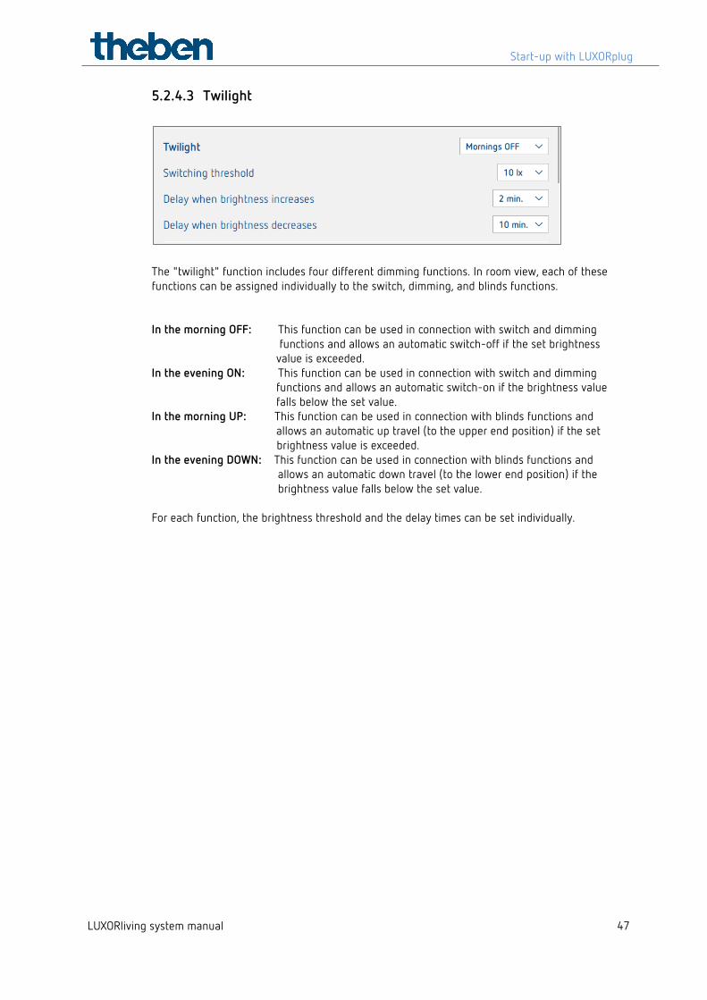
5.2.4.3 Twilight
The "twilight" function includes four different dimming functions. In room view, each of these functions can be assigned individually to the switch, dimming, and blinds functions. In the morning OFF: This function can be used in connection with switch and dimming functions and allows an automatic switch-off if the set brightness value is exceeded. In the evening ON: This function can be used in connection with switch and dimming functions and allows an automatic switch-on if the brightness value falls below the set value. In the morning UP: This function can be used in connection with blinds functions and allows an automatic up travel (to the upper end position) if the set
brightness value is exceeded. In the evening DOWN: This function can be used in connection with blinds functions and
allows an automatic down travel (to the lower end position) if the brightness value falls below the set value.
For each function, the brightness threshold and the delay times can be set individually.
Start-up with LUXORplug
LUXORliving system manual 48
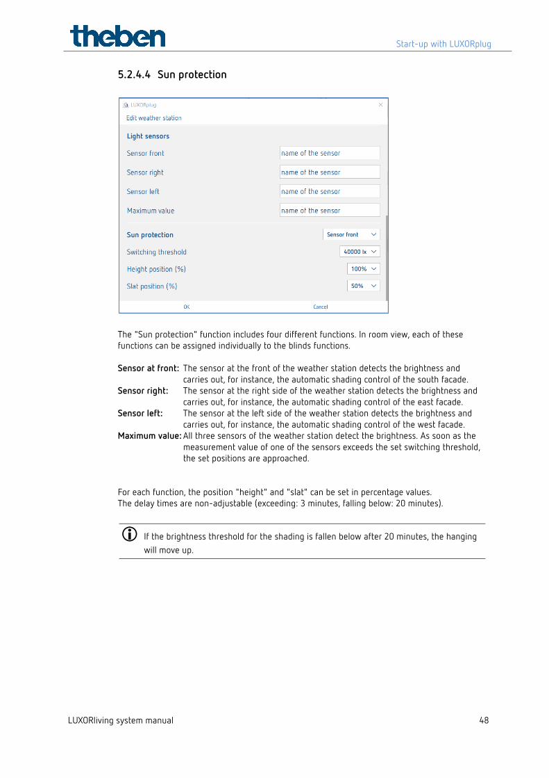
5.2.4.4 Sun protection
The "Sun protection" function includes four different functions. In room view, each of these functions can be assigned individually to the blinds functions. Sensor at front: The sensor at the front of the weather station detects the brightness and
carries out, for instance, the automatic shading control of the south facade. Sensor right: The sensor at the right side of the weather station detects the brightness and
carries out, for instance, the automatic shading control of the east facade. Sensor left: The sensor at the left side of the weather station detects the brightness and
carries out, for instance, the automatic shading control of the west facade. Maximum value: All three sensors of the weather station detect the brightness. As soon as the
measurement value of one of the sensors exceeds the set switching threshold, the set positions are approached.
For each function, the position "height" and "slat" can be set in percentage values. The delay times are non-adjustable (exceeding: 3 minutes, falling below: 20 minutes).
If the brightness threshold for the shading is fallen below after 20 minutes, the hanging will move up.
Start-up with LUXORplug
LUXORliving system manual 49
5.3 LUXORliving RF
5.3.1 General notes and installation The LUXORliving RF1 media coupler serves as the basic wireless device; it connects wireless devices with devices in the wired TP system. The power supply of the media coupler is provided by the bus voltage. The installation of the media coupler is a flush-mounted installation, for example in a standard flush-mounted box. When selecting the installation location, the range of the wireless devices must be taken into account. Ranges of approx. 30 m are possible within the building when conditions are favourable. All LUXORliving RF devices feature a configurable repeater function, i.e. received telegrams can be retransmitted if required, in order to increase the range. In systems with several LUXORliving RF devices, we recommend using as few LUXORliving RF media couplers as possible. If possible, only one LUXORliving RF media coupler should be present in the system and installed centrally so that all LUXORliving RF devices are within reception range. To optimise the range, individual RF devices can be used as "repeaters", so even more distant RF devices can be reached. If still two or more media couplers are used in a system, the media couplers must be within range of each other. This is absolutely necessary for collision-free communication (LBT = Listen Before Talk). If this is not the case, proper and error-free wireless communication is not guaranteed.
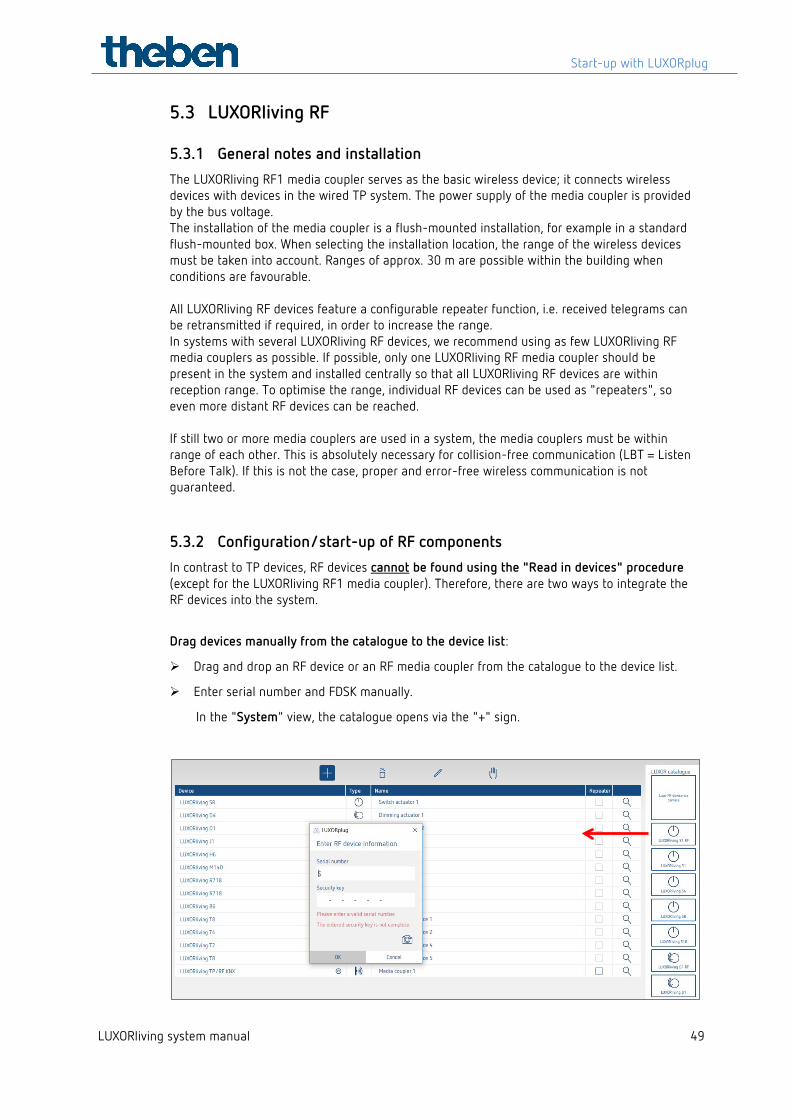
5.3.2 Configuration/start-up of RF components In contrast to TP devices, RF devices cannot be found using the "Read in devices" procedure (except for the LUXORliving RF1 media coupler). Therefore, there are two ways to integrate the RF devices into the system.
Drag devices manually from the catalogue to the device list:
Drag and drop an RF device or an RF media coupler from the catalogue to the device list.
Enter serial number and FDSK manually.
In the "System" view, the catalogue opens via the "+" sign.
Start-up with LUXORplug
LUXORliving system manual 50
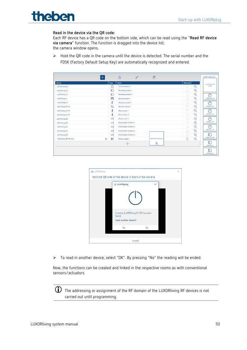
Read in the device via the QR code: Each RF device has a QR code on the bottom side, which can be read using the "Read RF device via camera" function. The function is dragged into the device list; the camera window opens.
Hold the QR code in the camera until the device is detected. The serial number and the FDSK (Factory Default Setup Key) are automatically recognized and entered.
To read in another device, select "OK". By pressing "No" the reading will be ended. Now, the functions can be created and linked in the respective rooms as with conventional sensors/actuators.
The addressing or assignment of the RF domain of the LUXORliving RF devices is not carried out until programming.
Start-up with LUXORplug
LUXORliving system manual 51
Info KNX/RF coupler
A coupler can only be integrated into the system via the "Read in system" option or via the manual search (hand symbol). Thereby, a domain address will be assigned to it. Via this, the RF devices assigned to the coupler can communicate with each other.
Devices which have already been programmed with a project cannot be used in a new project. During programming, the FDSK is replaced by a toolkey. Thus, the FDSK becomes invalid. The device receives its FDSK again via a master reset. The device can then be transferred to a new project.
Performing a master reset - De-energise the device. - Press and hold the Ph. address key on the device. - While the key is held, switch on the power again. After approx. 2 s the button can be released. The LED goes out.
If a Master reset must be performed on the coupler, the button is not released until the reception LED lights up.
Start-up with LUXORplug
LUXORliving system manual 52
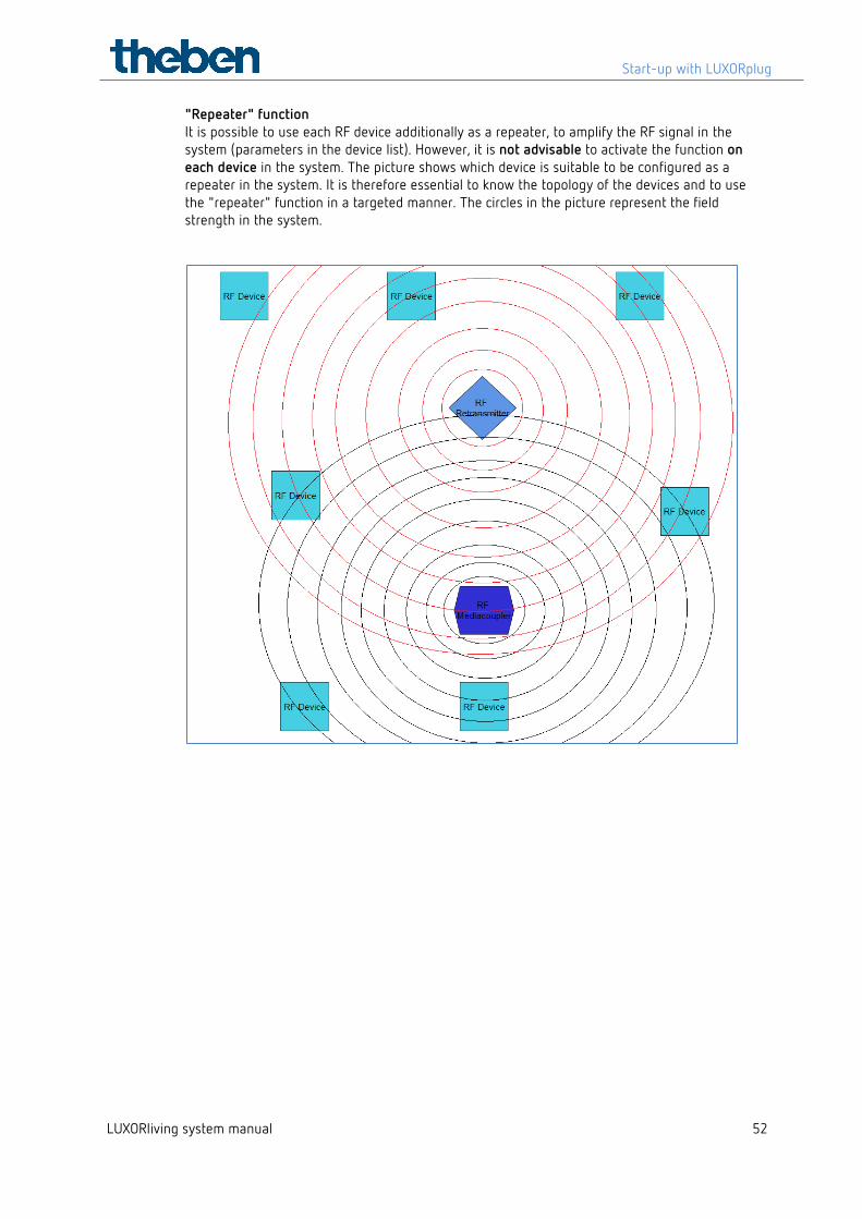
"Repeater" function It is possible to use each RF device additionally as a repeater, to amplify the RF signal in the system (parameters in the device list). However, it is not advisable to activate the function on each device in the system. The picture shows which device is suitable to be configured as a repeater in the system. It is therefore essential to know the topology of the devices and to use the "repeater" function in a targeted manner. The circles in the picture represent the field strength in the system.
Start-up with LUXORplug
LUXORliving system manual 53
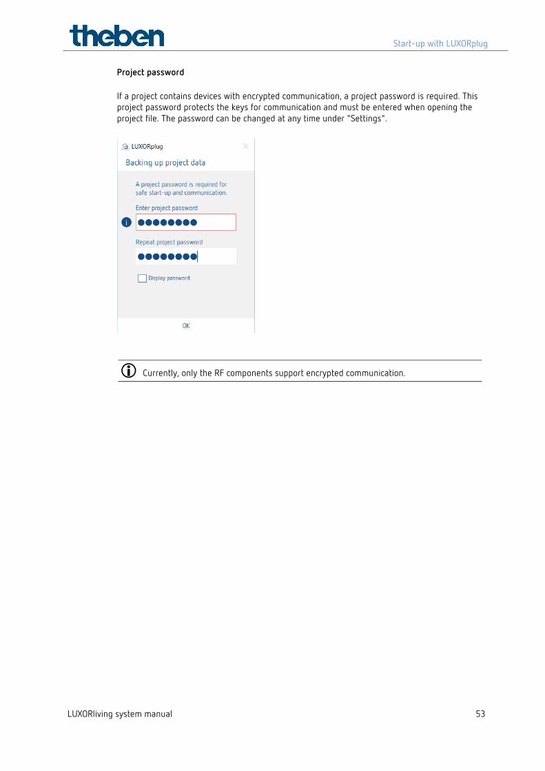
Project password If a project contains devices with encrypted communication, a project password is required. This project password protects the keys for communication and must be entered when opening the project file. The password can be changed at any time under "Settings".
Currently, only the RF components support encrypted communication.
Start-up with LUXORplug
LUXORliving system manual 54
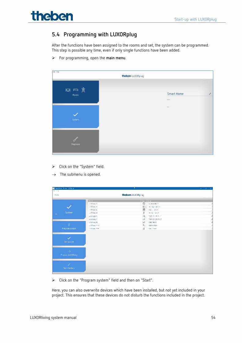
5.4 Programming with LUXORplug After the functions have been assigned to the rooms and set, the system can be programmed. This step is possible any time, even if only single functions have been added.
For programming, open the main menu.
Click on the "System" field.
→ The submenu is opened.
Click on the "Program system" field and then on "Start". Here, you can also overwrite devices which have been installed, but not yet included in your project. This ensures that these devices do not disturb the functions included in the project.
Start-up with LUXORplug
LUXORliving system manual 55
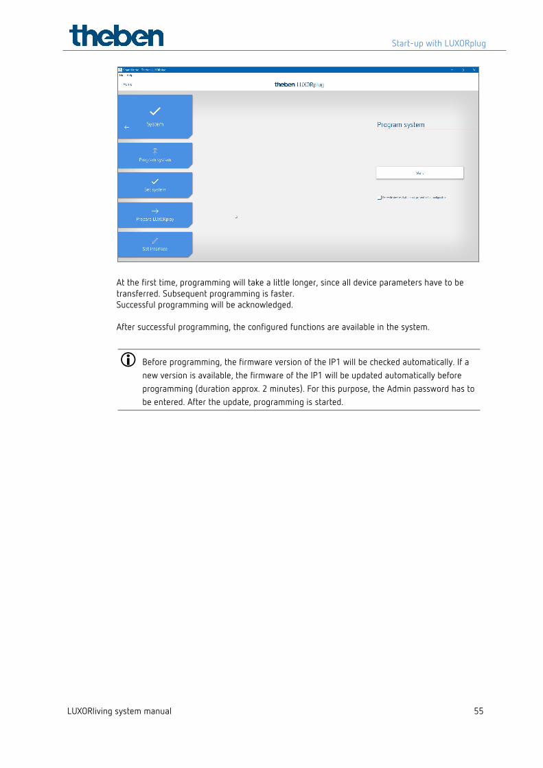
At the first time, programming will take a little longer, since all device parameters have to be transferred. Subsequent programming is faster. Successful programming will be acknowledged. After successful programming, the configured functions are available in the system.
Before programming, the firmware version of the IP1 will be checked automatically. If a new version is available, the firmware of the IP1 will be updated automatically before programming (duration approx. 2 minutes). For this purpose, the Admin password has to be entered. After the update, programming is started.
Start-up with LUXORplug
LUXORliving system manual 56
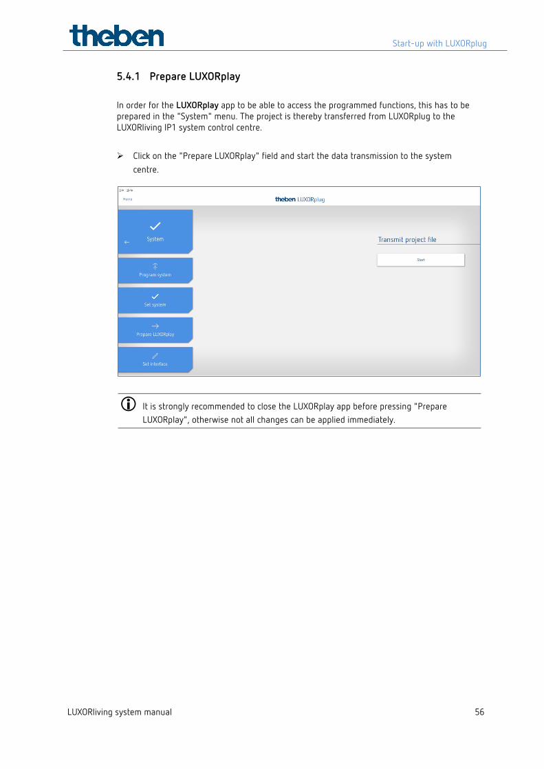
5.4.1 Prepare LUXORplay In order for the LUXORplay app to be able to access the programmed functions, this has to be prepared in the "System" menu. The project is thereby transferred from LUXORplug to the LUXORliving IP1 system control centre.
Click on the "Prepare LUXORplay" field and start the data transmission to the system centre.
It is strongly recommended to close the LUXORplay app before pressing "Prepare LUXORplay", otherwise not all changes can be applied immediately.
Start-up with LUXORplug
LUXORliving system manual 57
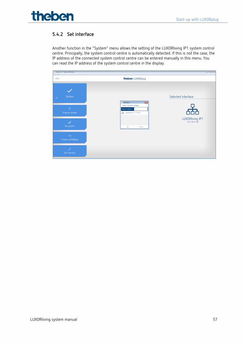
5.4.2 Set interface
Another function in the "System" menu allows the setting of the LUXORliving IP1 system control centre. Principally, the system control centre is automatically detected. If this is not the case, the IP address of the connected system control centre can be entered manually in this menu. You can read the IP address of the system control centre in the display.
Start-up with LUXORplug
LUXORliving system manual 58
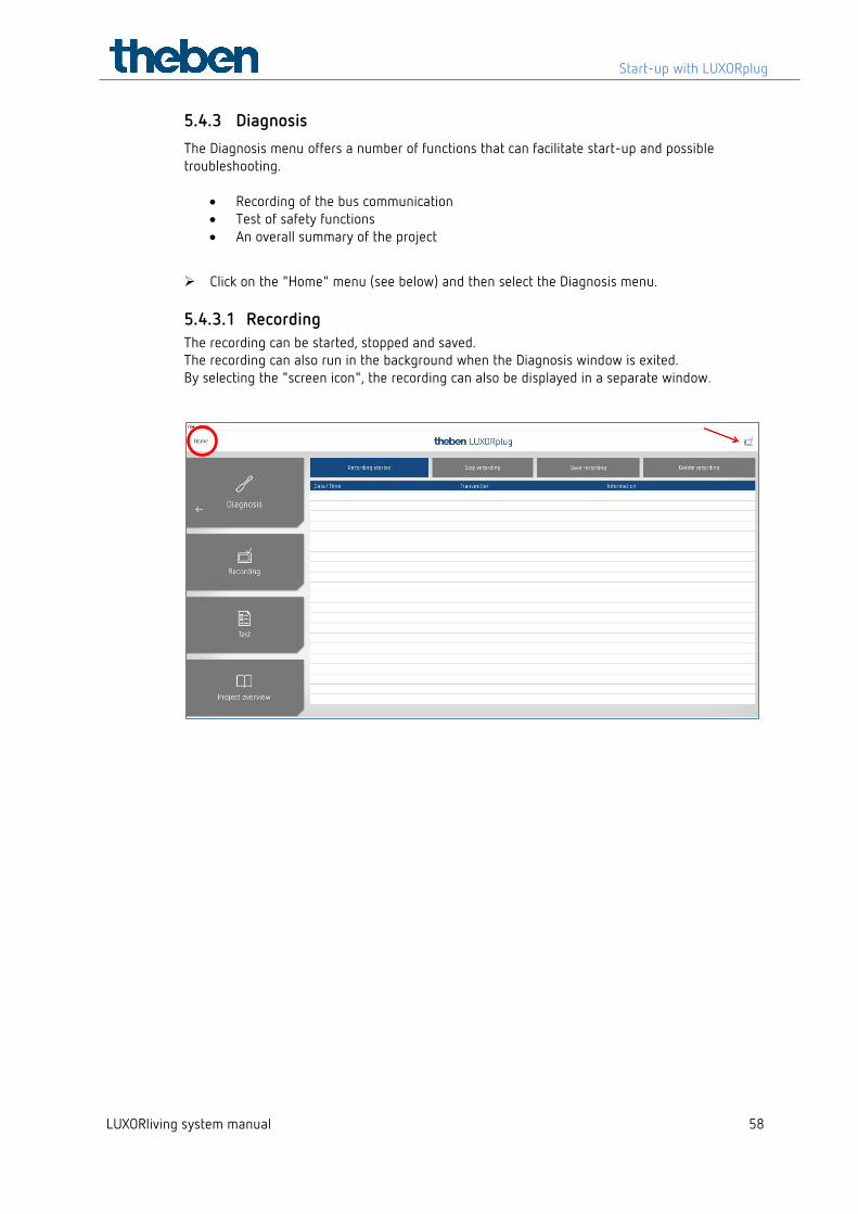
5.4.3 Diagnosis The Diagnosis menu offers a number of functions that can facilitate start-up and possible troubleshooting.
• Recording of the bus communication • Test of safety functions • An overall summary of the project
Click on the "Home" menu (see below) and then select the Diagnosis menu.
5.4.3.1 Recording The recording can be started, stopped and saved. The recording can also run in the background when the Diagnosis window is exited. By selecting the "screen icon", the recording can also be displayed in a separate window.
Start-up with LUXORplug
LUXORliving system manual 59
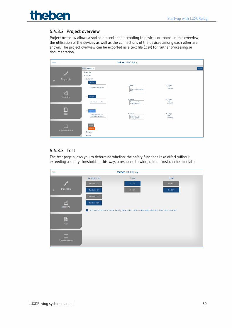
5.4.3.2 Project overview Project overview allows a sorted presentation according to devices or rooms. In this overview, the utilisation of the devices as well as the connections of the devices among each other are shown. The project overview can be exported as a text file (.csv) for further processing or documentation.
5.4.3.3 Test The test page allows you to determine whether the safety functions take effect without exceeding a safety threshold. In this way, a response to wind, rain or frost can be simulated.
Operation with LUXORplay
LUXORliving system manual 60
6 Operation with LUXORplay With the free LUXORplay app, the LUXORliving smart home system can be operated simply and conveniently. There are also various additional functions.
6.1 Users and authorisations
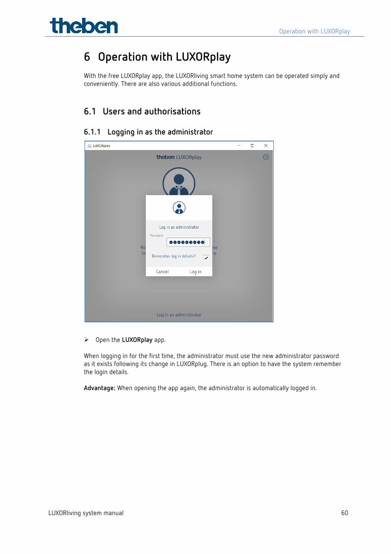
6.1.1 Logging in as the administrator
Open the LUXORplay app. When logging in for the first time, the administrator must use the new administrator password as it exists following its change in LUXORplug. There is an option to have the system remember the login details. Advantage: When opening the app again, the administrator is automatically logged in.
Operation with LUXORplay
LUXORliving system manual 61
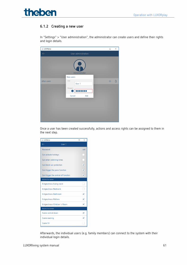
6.1.2 Creating a new user
In "Settings" > "User administration", the administrator can create users and define their rights and login details.
Once a user has been created successfully, actions and access rights can be assigned to them in the next step.
Afterwards, the individual users (e.g. family members) can connect to the system with their individual login details.
Operation with LUXORplay
LUXORliving system manual 62
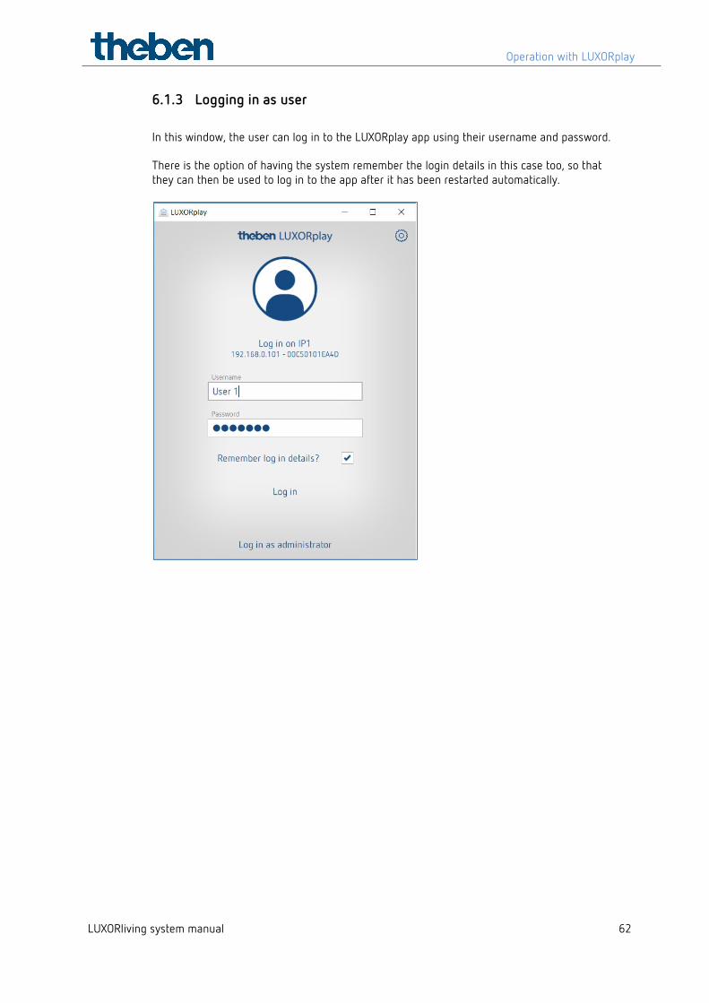
6.1.3 Logging in as user In this window, the user can log in to the LUXORplay app using their username and password. There is the option of having the system remember the login details in this case too, so that they can then be used to log in to the app after it has been restarted automatically.
Operation with LUXORplay
LUXORliving system manual 63
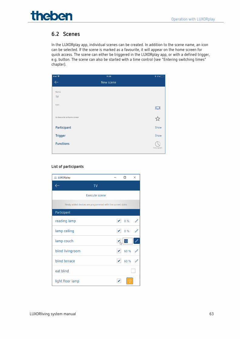
6.2 Scenes In the LUXORplay app, individual scenes can be created. In addition to the scene name, an icon can be selected. If the scene is marked as a favourite, it will appear on the home screen for quick access. The scene can either be triggered in the LUXORplay app, or with a defined trigger, e.g. button. The scene can also be started with a time control (see "Entering switching times" chapter).
List of participants
Operation with LUXORplay
LUXORliving system manual 64
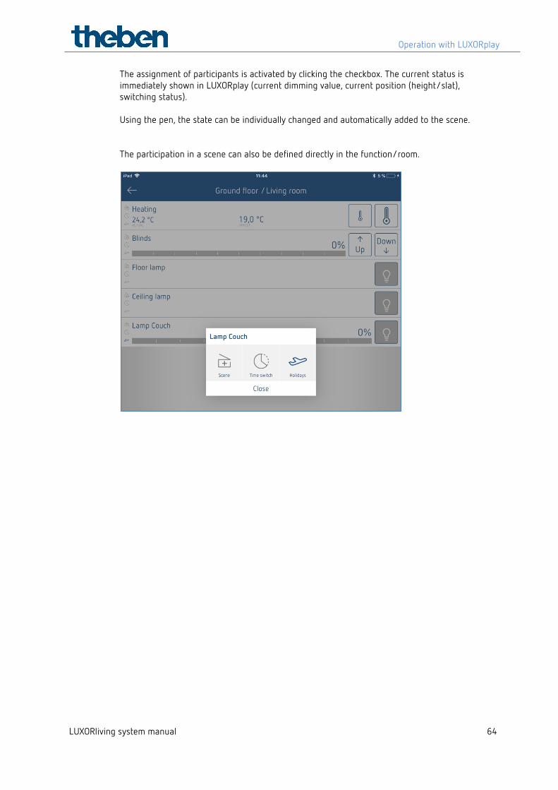
The assignment of participants is activated by clicking the checkbox. The current status is immediately shown in LUXORplay (current dimming value, current position (height/slat), switching status). Using the pen, the state can be individually changed and automatically added to the scene. The participation in a scene can also be defined directly in the function/room.
Operation with LUXORplay
LUXORliving system manual 65
6.3 "Time switch" function
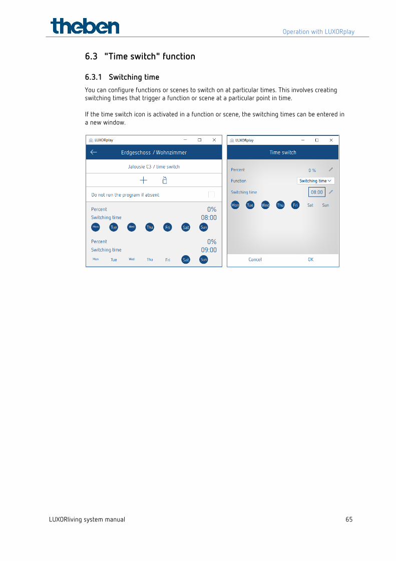
6.3.1 Switching time You can configure functions or scenes to switch on at particular times. This involves creating switching times that trigger a function or scene at a particular point in time. If the time switch icon is activated in a function or scene, the switching times can be entered in a new window.
Operation with LUXORplay
LUXORliving system manual 66
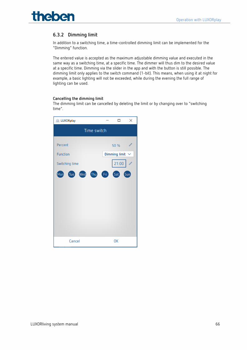
6.3.2 Dimming limit In addition to a switching time, a time-controlled dimming limit can be implemented for the "Dimming" function. The entered value is accepted as the maximum adjustable dimming value and executed in the same way as a switching time, at a specific time. The dimmer will thus dim to the desired value at a specific time. Dimming via the slider in the app and with the button is still possible. The dimming limit only applies to the switch command (1-bit). This means, when using it at night for example, a basic lighting will not be exceeded, while during the evening the full range of lighting can be used. Cancelling the dimming limit The dimming limit can be cancelled by deleting the limit or by changing over to "switching time".
Operation with LUXORplay
LUXORliving system manual 67
6.3.3 "Sun protection" and "Twilight" functions
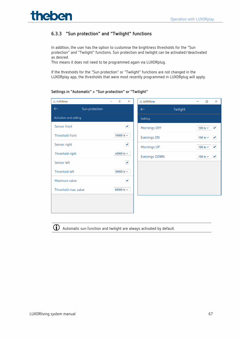
In addition, the user has the option to customise the brightness thresholds for the "Sun protection" and "Twilight" functions. Sun protection and twilight can be activated/deactivated as desired. This means it does not need to be programmed again via LUXORplug. If the thresholds for the "Sun protection" or "Twilight" functions are not changed in the LUXORplay app, the thresholds that were most recently programmed in LUXORplug will apply. Settings in "Automatic" > "Sun protection" or "Twilight"
Automatic sun function and twilight are always activated by default.
Operation with LUXORplay
LUXORliving system manual 68
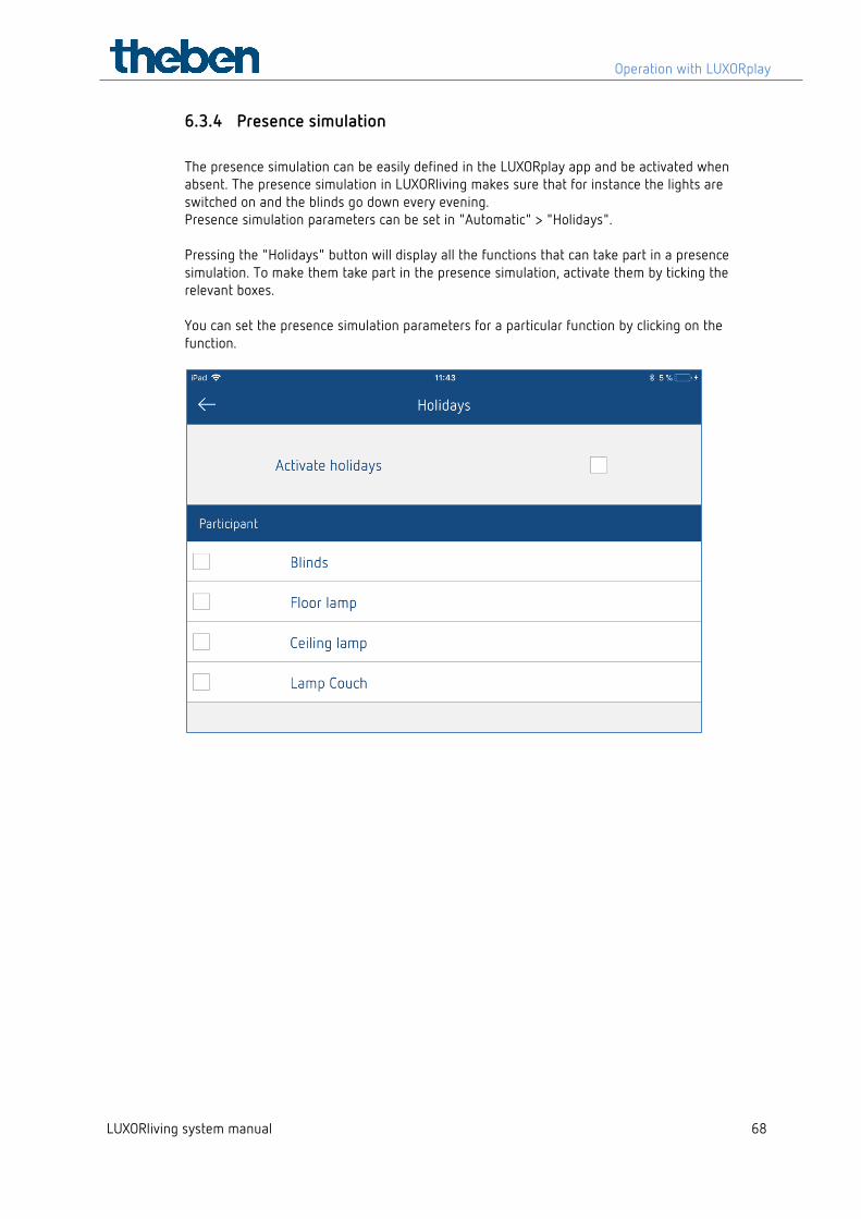
6.3.4 Presence simulation The presence simulation can be easily defined in the LUXORplay app and be activated when absent. The presence simulation in LUXORliving makes sure that for instance the lights are switched on and the blinds go down every evening. Presence simulation parameters can be set in "Automatic" > "Holidays". Pressing the "Holidays" button will display all the functions that can take part in a presence simulation. To make them take part in the presence simulation, activate them by ticking the relevant boxes. You can set the presence simulation parameters for a particular function by clicking on the function.
Operation with LUXORplay
LUXORliving system manual 69
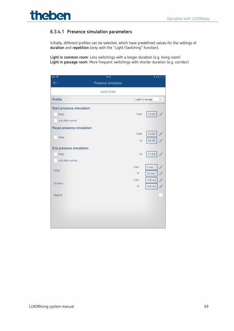
6.3.4.1 Presence simulation parameters Initially, different profiles can be selected, which have predefined values for the settings of duration and repetition (only with the "Light/Switching" function). Light in common room: Less switchings with a longer duration (e.g. living room) Light in passage room: More frequent switchings with shorter duration (e.g. corridor)
Operation with LUXORplay
LUXORliving system manual 70
6.3.4.2 Starting the presence simulation Case 1: Activation only once a day, starts the simulation always at the same time. Case 2: With additional activation and after sunset, the simulation starts with the latest event. The condition sunset is only available if a LUXORliving M140 weather station is present in the system. Example 1 (e.g. summer months) Start time: daily at 6:00 PM Sunset is at 9:30 PM
→ The presence simulation starts at 9:30 PM
Example 2 (e.g. winter months) Start time: daily at 6:00 PM Sunset is at 4:30 PM
→ The presence simulation starts at 6:00 PM
The starting condition is an AND operation, i.e. both conditions have to be fulfilled for the presence simulation to be started. Case 3: Only the condition "and after sunset" is selected. The presence simulation starts at the time of sunset.
6.3.4.3 Pausing the presence simulation If the presence simulation is to be paused for a certain time, a pause time from -- until can be defined. At the start of the pause time, all states will switch to OFF, and be reactivated after the end of the pause time.
6.3.4.4 End of presence simulation Case 1: If activation takes place only once a day, the simulation always ends at this time. Case 2: With additional activation and (or) after sunset, the simulation ends with the first event. Example 1 (e.g. summer months) Ending time: daily at 8:00 AM Sunrise is at 6:00 AM
→ The presence simulation ends at 6:00 AM
Example 2 Ending time: daily at 8:00 AM Sunrise is at 9:00 AM
→ The presence simulation ends at 8:00 AM
The condition for ending the presence simulation is an OR operation, i.e. one of the two conditions must be fulfilled for the presence simulation to be ended.
Operation with LUXORplay
LUXORliving system manual 71
Case 3: Only the condition and after sunset is selected. The presence simulation ends at the time of sunrise.
6.3.4.5 Delay When starting, the delay will be added to the starting time. The delay varies in the selected range from – until. The same applies for ending the presence simulation, i.e. the simulation ends accordingly later.
6.3.4.6 Duration and repetition If repetition is activated, the status will be activated for the set duration. The action will be repeated after the set delay. The duration and the delay vary in the selected range from – until. If repetition is deactivated, the job will be executed once for the set duration. If no time is entered for the duration (00:00), it will be switched on immediately after switching off..
6.3.4.7 Function with blinds At the start of the presence simulation, it will be moved to 100 % (DOWN). At the end of the presence simulation, it will be moved to 0 % (UP). If a delay is entered, it will be added to the start time, i.e. the hanging moves DOWN without a delay. At the end, the hanging will move UP with the delay. The delay time varies in the selected range from – until. Example 1 (summer months) Start time: daily at 6:00 PM Sunset is at 8:30 PM
→ The presence simulation starts at 8:30 PM
Example 2 (winter months) Start time: daily at 6:00 PM Sunset is at 4:30 PM
→ The presence simulation starts at 6:00 PM
Once you have set all the parameters as you want them, click "Activate holidays" on the previous screen to start the presence simulation. Each setting taking part in the simulation is identified with a small aeroplane icon in the room view.
Operation with LUXORplay
LUXORliving system manual 72
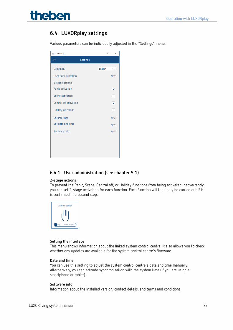
6.4 LUXORplay settings Various parameters can be individually adjusted in the "Settings" menu.
6.4.1 User administration (see chapter 5.1) 2-stage actions To prevent the Panic, Scene, Central off, or Holiday functions from being activated inadvertently, you can set 2-stage activation for each function. Each function will then only be carried out if it is confirmed in a second step.
Setting the interface This menu shows information about the linked system control centre. It also allows you to check whether any updates are available for the system control centre's firmware. Date and time You can use this setting to adjust the system control centre's date and time manually. Alternatively, you can activate synchronisation with the system time (if you are using a smartphone or tablet). Software info Information about the installed version, contact details, and terms and conditions.
Operation with LUXORplay
LUXORliving system manual 73
6.4.2 Export logs In the event of a malfunction in LUXORplay, so-called "logs" can be exported for diagnosis. In iOS and Android, the e-mail app opens, and you can send these logs directly to our hotline. In Windows, LUXORplay creates a folder C:\Documents\export_logs, where the encrypted diagnostic file is stored.
LUXORliving – the Theben Cloud
LUXORliving system manual 74
7 LUXORliving – the Theben Cloud
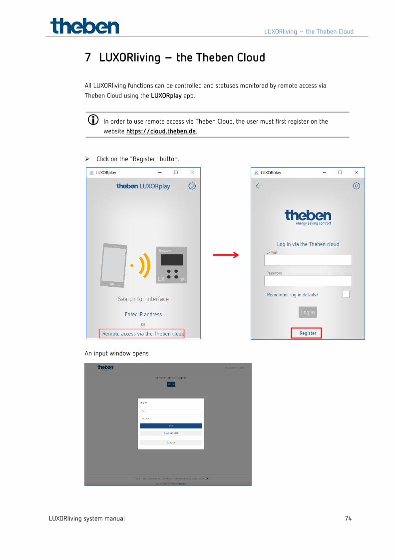
All LUXORliving functions can be controlled and statuses monitored by remote access via Theben Cloud using the LUXORplay app.
In order to use remote access via Theben Cloud, the user must first register on the website https://cloud.theben.de.
Click on the "Register" button.
An input window opens
LUXORliving – the Theben Cloud
LUXORliving system manual 75
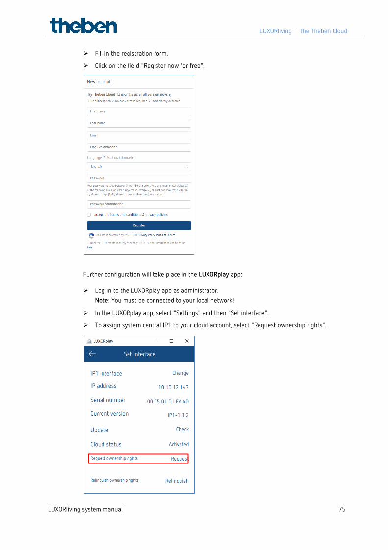
Fill in the registration form.
Click on the field "Register now for free".
Further configuration will take place in the LUXORplay app:
Log in to the LUXORplay app as administrator. Note: You must be connected to your local network!
In the LUXORplay app, select "Settings" and then "Set interface".
To assign system central IP1 to your cloud account, select "Request ownership rights".
LUXORliving – the Theben Cloud
LUXORliving system manual 76
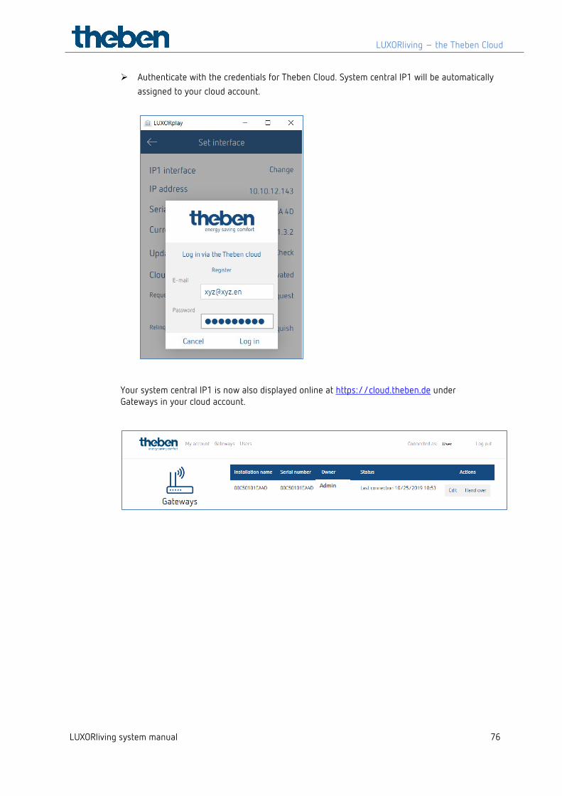
Authenticate with the credentials for Theben Cloud. System central IP1 will be automatically assigned to your cloud account.
Your system central IP1 is now also displayed online at https://cloud.theben.de under Gateways in your cloud account.
LUXORliving – the Theben Cloud
LUXORliving system manual 77
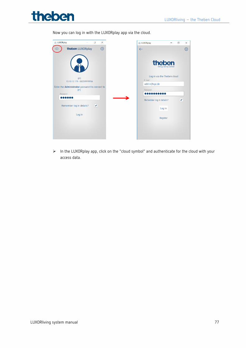
Now you can log in with the LUXORplay app via the cloud.
In the LUXORplay app, click on the "cloud symbol" and authenticate for the cloud with your access data.
LUXORliving – the Theben Cloud
LUXORliving system manual 78
7.1 Add other users
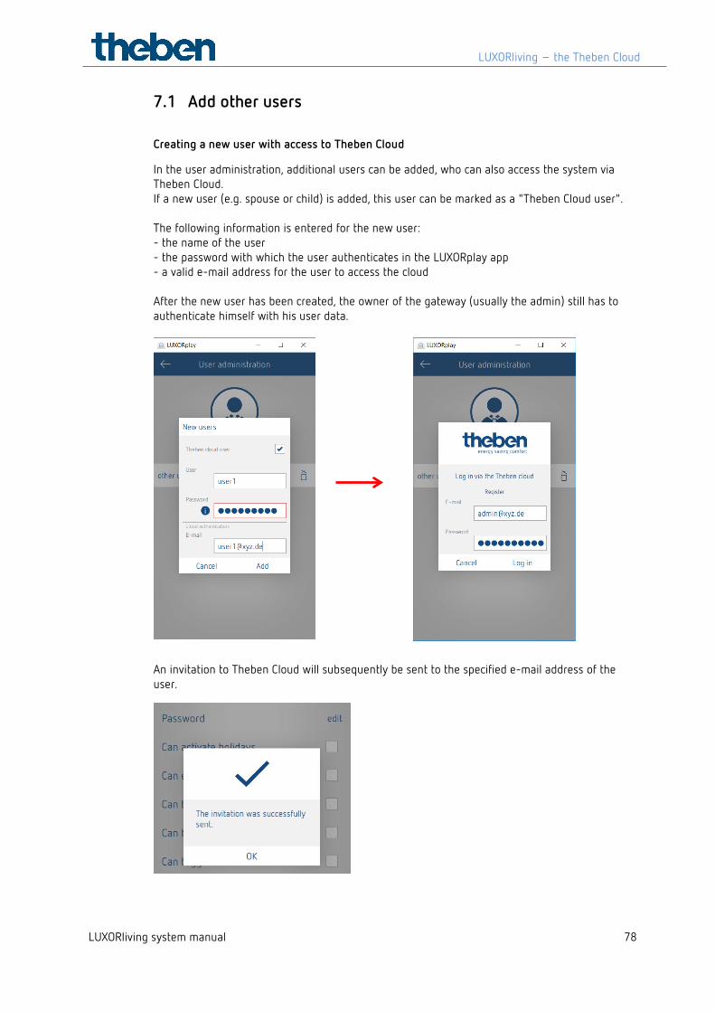
Creating a new user with access to Theben Cloud
In the user administration, additional users can be added, who can also access the system via Theben Cloud. If a new user (e.g. spouse or child) is added, this user can be marked as a "Theben Cloud user". The following information is entered for the new user: - the name of the user - the password with which the user authenticates in the LUXORplay app - a valid e-mail address for the user to access the cloud After the new user has been created, the owner of the gateway (usually the admin) still has to authenticate himself with his user data.
An invitation to Theben Cloud will subsequently be sent to the specified e-mail address of the user.
LUXORliving – the Theben Cloud
LUXORliving system manual 79
7.2 Cloud access for an existing user
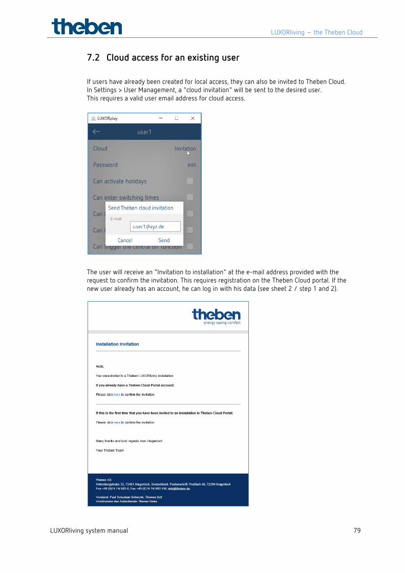
If users have already been created for local access, they can also be invited to Theben Cloud. In Settings > User Management, a "cloud invitation" will be sent to the desired user. This requires a valid user email address for cloud access.
The user will receive an "Invitation to installation" at the e-mail address provided with the request to confirm the invitation. This requires registration on the Theben Cloud portal. If the new user already has an account, he can log in with his data (see sheet 2 / step 1 and 2).
LUXORliving – the Theben Cloud
LUXORliving system manual 80
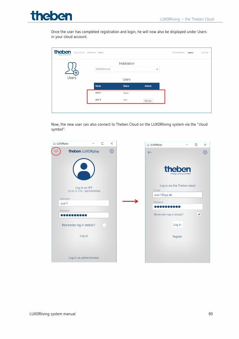
Once the user has completed registration and login, he will now also be displayed under Users in your cloud account.
Now, the new user can also connect to Theben Cloud on the LUXORliving system via the "cloud symbol".
Integration of personal assistants
LUXORliving system manual 81
8 Integration of personal assistants
8.1 LUXORliving and Amazon Alexa
8.1.1 Preconditions The following conditions must be met before your Amazon Alexa skills can be used with the LUXORliving smart home system:
1. Your LUXORliving system has been programmed.
2. LUXORplay has been prepared by using LUXORplug.
3. You can access your system locally via LUXORplay app.
4. You can access your system via LUXORplay over the Internet.
5. The "Theben Cloud with LUXORliving" has already been successfully implemented.
6. Your LUXORliving system control centre is connected to the Internet.
7. Your Amazon Echo (Alexa) is successfully connected to the network and has an active
Internet connection.
8. You have an Amazon user account.
8.1.2 Integration To use your LUXORliving smart home system with Amazon Alexa, follow these steps:
Open the Amazon Alexa app on your smartphone, tablet or in your web browser. To open Alexa via the web browser, go to https://alexa.amazon.de.
Go to "Skills & Games" in the menu.
Use the search function to find "Theben".
Select the "Theben LUXORliving skill".
Click "Enable for use".
Enter your login credentials (email and password) of the previously created Theben Cloud user account and click on "Login".
Select the Theben system control centre which you want to link to the skill from the list of gateways.
Enter the user name (admin) and password of your Theben system control centre and click on "Login".
Tip: The user name is always "admin". The login is the same login you use when you, as an administrator, wish to connect locally to your LUXORliving smart home system via the LUXORplay app.
Integration of personal assistants
LUXORliving system manual 82
The skill is now successfully linked to your Theben Cloud account and your Theben system control centre.
Click on "Finished" in the upper left corner.
Go to "Detect devices". This process may take some time. All new devices are now displayed. Already added devices are not displayed anymore.
Now add the detected devices. To do this, select the respective device and go to "Add".
Done! You can now control your LUXORliving system by voice using our Theben LUXORliving skill.
8.1.3 Examples The {device name} always refers to the name of the function you set in the LUXORplug configurator, or the one you have already customised in the Amazon Alexa app. Switch light: "Alexa, switch off ceiling light." Dim light: "Alexa, dim ceiling light to 50%." Dim light: "Alexa, set ceiling light to 50%." Control blinds/roller blinds: "Alexa, move blinds to 0%." (Note: The blinds move completely up.) Control blinds/roller blinds: "Alexa, move blinds to 80%." (Note: The blinds move to the indicated position.) Control blinds/roller blinds: "Alexa, move blinds to 100%." (Note: The blinds move completely down.)
The commands "up" and "down" or "increase" and "decrease" are used by Amazon Alexa for dimming the lighting and are predefined by Amazon. These commands are therefore not suitable for controlling blinds or roller blinds, as the movement goes in the opposite direction. Example: „Alexa, move the blinds up“ means up = brighter light/increased percentage, but the blinds actually move down.
Control scene: "Alexa, switch on scene TV." Control scene: "Alexa, activate scene TV."
Only those scenes can be operated by voice which are also assigned to a scene trigger in the LUXORliving system, e.g. a push button. As an alternative to the scenes in LUXORliving, you can also individually set so-called routines in the Alexa app, which are then activated via a voice command.
Set temperature: "Alexa, set living room to 22 degrees." Query temperature: "Alexa, what is the temperature in the living room."
Integration of personal assistants
LUXORliving system manual 83
If you would like to control devices by room name (e.g. "Alexa, turn off the lights in the living room."), you must set this via the device groups in the Amazon Alexa app.
8.2 LUXORliving and Google Home
8.2.1 Preconditions The following conditions must be met before your Google Home action can be used with the LUXORliving smart home system:
1. Your LUXORliving system has been programmed.
2. LUXORplay has been prepared by using LUXORplug.
3. You can access your system locally via LUXORplay app.
4. You can access your system via LUXORplay over the Internet.
5. "Theben Cloud with LUXORliving" has already been successfully implemented.
6. Your LUXORliving system control centre is connected to the Internet.
7. Your Google Home devices (e.g. Google Home Mini) is successfully connected to the
network and has an active Internet connection.
8. You have an Amazon user account.
8.2.2 Integration To use your LUXORliving smart home system with Google Home, follow these steps:
Open the Google Home app on the smartphone, tablet, etc.
Go to "Add" or click on the "+" in the top left corner of the app.
Click on "Set up device".
Click on "Have something already set up?".
Use the search function to find "Theben".
Select the "Theben LUXORliving action".
Enter your login credentials (email and password) of the previously created Theben Cloud user account and click on "Login".
Select the Theben system control centre which you want to link to the "action" from the list of gateways.
Enter the user name (admin) and password of the Theben system control centre and click on "Login".
Tip: The user name is always "admin". The login is the same login you use when you, as an administrator, wish to connect locally to your LUXORliving smart home system via the LUXORplay app.
Integration of personal assistants
LUXORliving system manual 84
The "action" is now successfully linked to your Theben Cloud account and your Theben system control centre. All new devices are now displayed. Already added devices are not displayed anymore.
Now, you have to add the detected devices. To do this, select the respective device and go to "Add".
Select the room to which the device should be added. Done! You can now control your LUXORliving system by voice using our Theben LUXORliving action.
8.2.3 Examples
The {device name} always refers to the name of the function you set in the LUXORplug configurator, or the one you have already customised in the Amazon Alexa app. Switch light: "Hey Google, switch off ceiling light." Dim light: "Hey Google, dim ceiling light to 50 %." Dim light: "Hey Google, set ceiling light to 50 %." Control blinds/roller blinds: "Hey Google, move blinds to 0 %." (Note: The blinds move completely down.) Control blinds/roller blinds: "Hey Google, move blinds to 80%." (Note: The blinds move to position 100 minus the indicated position, i.e. to 20 %.) Control blinds/roller blinds: "Hey Google, move blinds to 100 %." (Note: The blinds move completely up.)
Google Home uses the inverted percentage values. These commands are therefore not suitable for controlling blinds or roller blinds, as the running direction is inverted. Example: "Hey Google, move blinds to 80%." means that the blinds do not move down 80 %, but 20 % (100 % - 80 %). This can be avoided by using routines. In a routine, the desired blinds can be controlled together and the routine can be activated via an individual voice command, e.g. "Hey Google, activate shading.“
Control scene: "Hey Google, switch on scene TV." Control scene: "Hey Google, activate scene TV."
Only those scenes can be operated by voice which are also assigned to a scene trigger in the LUXORliving system, e.g. a push button. As an alternative to the scenes in LUXORliving, you can also individually set so-called routines in the Google Home app, which can then be activated via a voice command.

Integration of personal assistants
LUXORliving system manual 85
Set temperature: "Hey Google, set living room to 22 degrees." Query temperature: "Hey Google, what is the temperature in the living room." If you want to control devices by room name (e.g. "Hey Google, turn off the lights in the living room."), you must set this via the device groups in the Google Home app.
Appendix
LUXORliving system manual 86
9 Appendix
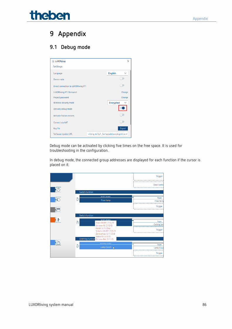
9.1 Debug mode
Debug mode can be activated by clicking five times on the free space. It is used for troubleshooting in the configuration. In debug mode, the connected group addresses are displayed for each function if the cursor is placed on it.
Appendix
LUXORliving system manual 87
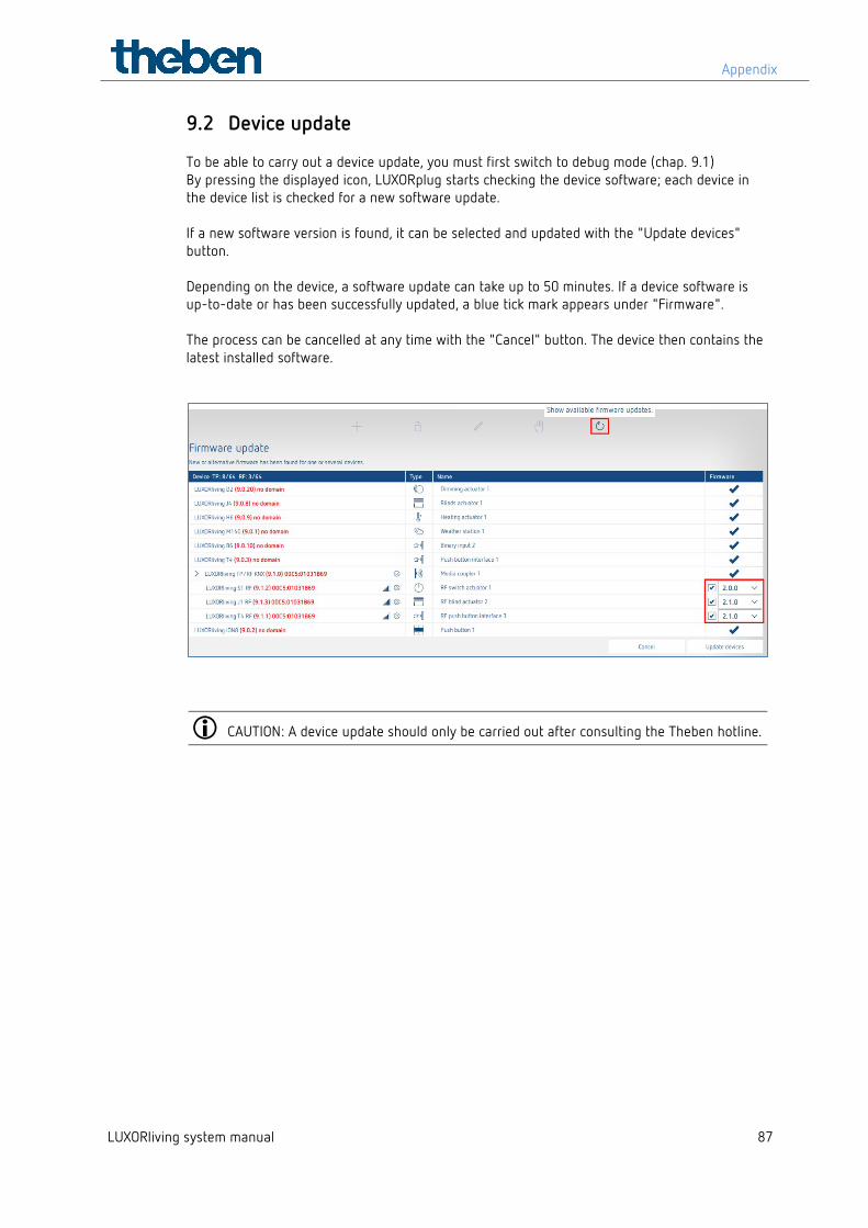
9.2 Device update To be able to carry out a device update, you must first switch to debug mode (chap. 9.1) By pressing the displayed icon, LUXORplug starts checking the device software; each device in the device list is checked for a new software update. If a new software version is found, it can be selected and updated with the "Update devices" button. Depending on the device, a software update can take up to 50 minutes. If a device software is up-to-date or has been successfully updated, a blue tick mark appears under "Firmware". The process can be cancelled at any time with the "Cancel" button. The device then contains the latest installed software.
CAUTION: A device update should only be carried out after consulting the Theben hotline.
FAQs concerning the LUXORliving webpage
LUXORliving system manual 88
10 FAQs concerning the LUXORliving webpage
10.1 General information
10.1.1 Which functions does LUXORliving currently offer? 1. Manual operation of lighting and drives
2. Control individually, in groups, centrally, or integrated in scenes
3. Panic function and central OFF
4. Presence simulation
5. Time control of the individual functions via weekly program
6. Control of the lighting depending on twilight
7. Automatic control of the drives depending on brightness, temperature, wind or rain
8. Individual scene function
9. Individual room control of heating and cooling systems
10. Operation via conventional buttons on site and via LUXORplay app
11. LUXORplay app for iOS, Android and Windows
12. Integration of further applications via app link
13. User administration in LUXORplay with rights assignment
14. Project import from system centre in LUXORplug
15. Function extensions via updates possible
16. Manual control directly at the actuators
17. Decentralised intelligence distributed over the system components
18. Remote access via Theben cloud or VPN connection
19. Voice control with Amazon Alexa or Google Assistant (only in connection with active Theben Cloud account)
10.1.2 How many devices can be integrated in one system? The system can be equipped with a maximum of 64 LUXORliving TP devices and a maximum of 64 LUXORliving RF devices, i.e. it includes system devices, sensors and actuators. A total of 15 media couplers can be used in the system.
10.1.3 How are the individual functions operated on site? For operation, conventional buttons are used. They are integrated into the system via button interfaces/binary inputs. Control is always via button. Only for the "switch" function you can chose between "button" and "motion detector" (switch).
FAQs concerning the LUXORliving webpage
LUXORliving system manual 89
10.1.4 What type of communication is used at how must the connection be executed?
Communication is via a 2-wire bus, to which each device has to be connected. KNX S mode is used as a protocol. The bus connection can be executed as a line, star or tree topology. The following cable lengths have to be observed: power supply – participant max. 350 m participant – participant max. 700 m total cable length max. 1,000 m. For the bus connection, a KNX-certified bus line (J-Y(St)Y 2 x 2 x 0.8 mm) has to be used.
10.1.5 How are the individual components configured and programmed? Configuration is done with the free LUXORplug software. For project planning, the already installed system and the connected components can be loaded. Alternatively, project planning can be done completely manually. A connection to the system centre is not necessary for project planning.
10.1.6 What types of switches can be used with LUXORliving? You are free to choose any type of switches and buttons. Via the LUXORliving T2, T4 and T8 button interfaces, any switches and buttons can be integrated into the LUXORliving system. Of course, this also applies to other consumers with floating contact, such as smoke detectors. Via the LUXORliving B6 binary input module, also non-floating contacts, of e.g. motion detectors, can be integrated in LUXORliving.
10.1.7 What type of lamps can be controlled with the LUXORliving dimming actuator?
The LUXORliving D4, D2 and D1 dimming actuators are designed for incandescent and halogen lamps, as well as dimmable LED lamps. Special attention was given to the dimming of LED lamps, which can be dimmed in a flicker-free and stepless manner in the LUXORliving system.
10.1.8 Can the dimming output of the LUXORliving dimming actuators be increased?
Basically, the LUXORliving D2 dimming actuator can dim 400 W per channel, the LUXORliving D4 200 W per channel and the LUXORliving D1, 250 W (in RC mode, this also applies to LED load!). Generally, these output limits are sufficient. If an increase of the load is still required, the LUXORliving D2 can be extended with the DMB 1 T dimming booster (max. 2 x DMB 1 T per channel).
10.1.9 How reliably do the switch actuators of the LUXORliving series switch even high inrush currents?
The LUXORliving S4, S8 and S16 switch actuators are optimised for capacitive switching loads and are equipped with corresponding relay contacts - inrush currents of 800 A / 200 µs are no problem.
FAQs concerning the LUXORliving webpage
LUXORliving system manual 90
10.1.10 How is room temperature control accomplished in the LUXORliving system?
The room temperature is detected and set via room sensor LUXORliving R718 or the iON8. The current room temperature is also displayed in the LUXORplay app, where the setpoint can always be defined. Alternatively, the room temperature can also be measured via various other devices (see chapter "Temperature measurement via LUXORliving (without room sensor))". In this case, a temperature sensor (9070459, 9070321 or 9070496) is connected to the respective device. The setpoint is then only set in the LUXORplay app.
10.1.11 How many scenes can be saved and controlled? 32 individual scenes can be saved and retrieved.
10.1.12 How many users can access the system simultaneously via the LUXORplay app?
A maximum of 5 users can simultaneously access the system. A higher number of simultaneous connections extends the loading times. The users are created and saved in the LUXORliving IP1 system control centre.
10.1.13 Is start-up possible even without an Internet router? Yes, by means of LUXORplug the computer can also connect directly with the system centre. The only thing that is needed is a LAN connection between PC and system centre. However, for the subsequent operation with the LUXORplay app, an Internet router is absolutely necessary.
10.1.14 What happens if the IP1 system control centre is disconnected? Thanks to decentralised intelligence inside the LUXORliving system, all basic functions will be preserved via the operating controls. However, additional functions, such as time and scene controls, as well as the operation via LUXORplay app, are dependent on the system control centre.
FAQs concerning the LUXORliving webpage
LUXORliving system manual 91
10.2 Problem solving
10.2.1 What is the reason that LUXORplug cannot establish a connection to the IP1 system centre?
After applying the bus voltage, the system centre needs approx. 1 minute for start-up, then it should be ready for operation. If access is not possible afterwards, check the following: If "No LAN" appears on the display of the IP1:
Check the cable connection to the router.
Check the router settings (DHCP must be activated).
If "No BUS" appears on the permanent display of the IP1:
Check the cable connection to the LUXORliving power unit.
10.2.2 What is the default password of the IP1 on delivery? The password is always "admin".
10.2.3 Why are devices not found when the system is scanned?
Perhaps the device has already been used in another system or KNX system. The device should be reset to the factory setting. To do this, disconnect the bus voltage, press and hold the Ph. address button on the device. While the button is held, switch the bus back on. After approx. 2 seconds, the button can be released. The LED will go out and the device is reset to factory settings.
10.2.4 Does the system have to be scanned when it is first commissioned or when it is extended, or is it sufficient to drag the (new) devices from the catalogue into the project?
The system can be configured in advance offline by manually adding the devices from the catalogue (drag & drop). However, it is always necessary to scan the system to ensure that the devices in LUXORplug are assigned to the relevant hardware.
10.2.5 How do the buttons have to be connected to the binary inputs for a blinds function?
2 consecutive inputs must always be used, starting with the odd channel number. The odd channel number must always be the "Up" button.
FAQs concerning the LUXORliving webpage
LUXORliving system manual 92
10.2.6 How do you reset the IP1 system control centre to factory settings (master reset) or restart it?
CAUTION: If a master reset is performed, all settings will be deleted, including e.g. the project, scenes and switching times.
A master reset or restart is performed directly on the LUXORliving IP1:
Press the " " button on the device.
Then press the " " button until the "Reset" menu appears on the display. The " " button is used to open the menu.
Select whether to perform a "Restart device" or a "Master reset".
A long press of the " " button causes a safety bar to run down. When it has expired, the IP1 restarts and the device is reset to factory settings in case of a master reset. The password after a master reset is again "admin".
10.2.7 LUXORplay cannot find the IP1 system control centre In rare cases, the LUXORplay app may not be able to find the IP1. This could have two reasons:
1. The router does not support UDP protocols, and therefore the IP1 is not automatically found.
2. It may be because the IP1 is located outside your own network in the so-called "subnetwork".
There is a parameter for this, which is hidden in the "Settings". It allows searching for IP addresses that are located in such a network. By default, this parameter is enabled, so the search in a subnetwork is blocked. In this case, the parameter must be deactivated.
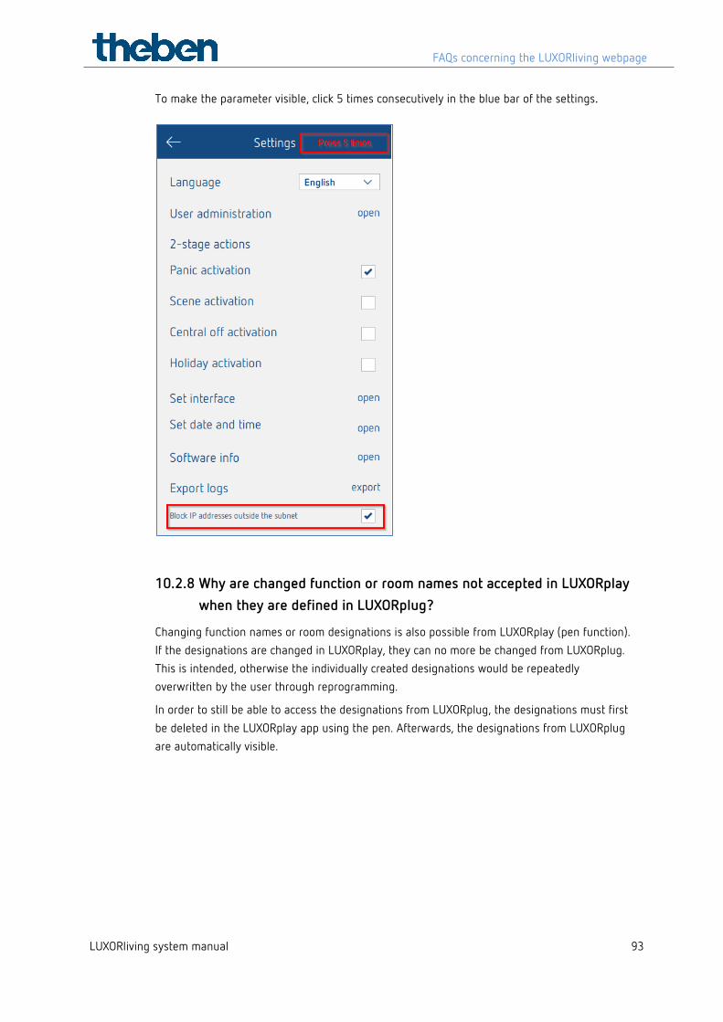
FAQs concerning the LUXORliving webpage
LUXORliving system manual 93
To make the parameter visible, click 5 times consecutively in the blue bar of the settings.
10.2.8 Why are changed function or room names not accepted in LUXORplay when they are defined in LUXORplug?
Changing function names or room designations is also possible from LUXORplay (pen function). If the designations are changed in LUXORplay, they can no more be changed from LUXORplug. This is intended, otherwise the individually created designations would be repeatedly overwritten by the user through reprogramming.
In order to still be able to access the designations from LUXORplug, the designations must first be deleted in the LUXORplay app using the pen. Afterwards, the designations from LUXORplug are automatically visible.
Contact
LUXORliving system manual 94
11 Contact Theben AG Hohenbergstr. 32 72401 Haigerloch GERMANY Tel. +49 7474 692-0 Fax +49 7474 692-150 Hotline Tel. +49 7474 692-369 [email protected] Addresses, telephone numbers etc. www.theben.de