halcon version 5.2 hdevelop user's manual - mvtec
TRANSCRIPT
HALCON Version 5.2
MVTec Software GmbH
HDevelopUser’s Manual
April 21, 1999
This manual explains the interactive tool HDevelop for HALCON version 5.2
All rights reserved. No part of this publication may be reproduced, stored in a retrieval system,or transmitted, in any form or by any means, electronic, mechanical, photocopying, recording,or otherwise, without prior written permission of the publisher.
1st Edition. July 19972nd Edition. November 19973rd Edition. March 19984th Edition. April 1999
Copyright c 1997-99 MVTec Software GmbH, Munich, GermanyMVTec Software GmbH
Information concerning HALCON:http://www.mvtec.com
Address: MVTec Software GmbHOrleansstr. 34D-81667 MunichGermany
E-mail: [email protected]
Contents
1 About this Manual 51.1 Readers . . . . . . . . . . . . . . . . . . . . . . . . . . . . . . . . . . . . . . 51.2 Organization of this Manual . . . . . . . . . . . . . . . . . . . . . . . . . . . 51.3 Additional Sources of Information . . . . . . . . . . . . . . . . . . . . . . . . 61.4 Release Notes . . . . . . . . . . . . . . . . . . . . . . . . . . . . . . . . . . . 7
2 Introduction 92.1 Concepts . . . . . . . . . . . . . . . . . . . . . . . . . . . . . . . . . . . . . 9
2.1.1 Working environment . .. . . . . . . . . . . . . . . . . . . . . . . . . 92.1.2 Data Structures . . . . .. . . . . . . . . . . . . . . . . . . . . . . . . 102.1.3 Module Structure . . . .. . . . . . . . . . . . . . . . . . . . . . . . . 11
2.2 Configuration . . . . . . . . . . . . . . . . . . . . . . . . . . . . . . . . . . . 122.3 Online Help . . . . . . . . . . . . . . . . . . . . . . . . . . . . . . . . . . . . 14
3 Example Session 15
4 Graphical User Interface 214.1 Interacting with HDevelop . . . . . . . . . . . . . . . . . . . . . . . . . . . . 214.2 Mouse Handling . . . . . . . . . . . . . . . . . . . . . . . . . . . . . . . . . . 224.3 Main Window . . . . . . . . . . . . . . . . . . . . . . . . . . . . . . . . . . . 22
4.3.1 Title Bar . . . . . . . . . . . . . . . . . . . . . . . . . . . . . . . . . 234.3.2 Menu Bar .. . . . . . . . . . . . . . . . . . . . . . . . . . . . . . . . 244.3.3 Tool Bar .. . . . . . . . . . . . . . . . . . . . . . . . . . . . . . . . 594.3.4 Window Area . . . . . .. . . . . . . . . . . . . . . . . . . . . . . . . 594.3.5 Status Bar .. . . . . . . . . . . . . . . . . . . . . . . . . . . . . . . . 60
4.4 Program Window . . . . . . . . . . . . . . . . . . . . . . . . . . . . . . . . . 604.5 Operator Window . . . . . . . . . . . . . . . . . . . . . . . . . . . . . . . . . 614.6 Variable Window . . . . . . . . . . . . . . . . . . . . . . . . . . . . . . . . . 65
4.6.1 Area for Iconic Data . .. . . . . . . . . . . . . . . . . . . . . . . . . 664.6.2 Area for Control Data .. . . . . . . . . . . . . . . . . . . . . . . . . 67
4.7 Graphics Window . . . . . . . . . . . . . . . . . . . . . . . . . . . . . . . . . 68
5 Language 715.1 Basic Types of Parameters . . . . . . . . . . . . . . . . . . . . . . . . . . . . 715.2 Control Types and Constants . . . . . . . . . . . . . . . . . . . . . . . . . . . 725.3 Variables . . . . . . . . . . . . . . . . . . . . . . . . . . . . . . . . . . . . . 745.4 Operations on Iconic Objects . . . . . . . . . . . . . . . . . . . . . . . . . . . 75
1
2 CONTENTS
5.5 Expressions for Input Control Parameters . .. . . . . . . . . . . . . . . . . . 755.5.1 General Features of Tuple Operations. . . . . . . . . . . . . . . . . . 755.5.2 Assignment. . . . . . . . . . . . . . . . . . . . . . . . . . . . . . . . 765.5.3 Basic Tuple Operations .. . . . . . . . . . . . . . . . . . . . . . . . . 785.5.4 Tuple Creation . . . . .. . . . . . . . . . . . . . . . . . . . . . . . . 795.5.5 Simple Arithmetic Operations . . . .. . . . . . . . . . . . . . . . . . 805.5.6 Bit Operations . . . . .. . . . . . . . . . . . . . . . . . . . . . . . . 815.5.7 String Operations . . . .. . . . . . . . . . . . . . . . . . . . . . . . . 815.5.8 Comparison Operators .. . . . . . . . . . . . . . . . . . . . . . . . . 845.5.9 Boolean Operators . . .. . . . . . . . . . . . . . . . . . . . . . . . . 845.5.10 Trigonometric Functions. . . . . . . . . . . . . . . . . . . . . . . . . 855.5.11 Exponential Functions .. . . . . . . . . . . . . . . . . . . . . . . . . 855.5.12 Numerical Functions . .. . . . . . . . . . . . . . . . . . . . . . . . . 855.5.13 Miscellaneous Functions. . . . . . . . . . . . . . . . . . . . . . . . . 875.5.14 Operator Precedence . .. . . . . . . . . . . . . . . . . . . . . . . . . 88
5.6 Reserved Words . . . . . . . . . . . . . . . . . . . . . . . . . . . . . . . . . . 885.7 Control Structures . . . . . . . . . . . . . . . . . . . . . . . . . . . . . . . . . 885.8 Limitations . . . .. . . . . . . . . . . . . . . . . . . . . . . . . . . . . . . . 90
6 Code Generation 916.1 Code Generation for C++ . . . . . . . . . . . . . . . . . . . . . . . . . . . . . 91
6.1.1 Basic Steps. . . . . . . . . . . . . . . . . . . . . . . . . . . . . . . . 916.1.2 Optimization . . . . . .. . . . . . . . . . . . . . . . . . . . . . . . . 926.1.3 Used Classes . . . . . .. . . . . . . . . . . . . . . . . . . . . . . . . 926.1.4 Limitations and Troubleshooting . . .. . . . . . . . . . . . . . . . . . 93
6.2 Code Generation for Visual Basic . . . . . . . . . . . . . . . . . . . . . . . . 976.2.1 Basic Steps. . . . . . . . . . . . . . . . . . . . . . . . . . . . . . . . 976.2.2 Program Structure . . .. . . . . . . . . . . . . . . . . . . . . . . . . 976.2.3 Limitations and Troubleshooting . . .. . . . . . . . . . . . . . . . . . 98
7 Program Examples 1037.1 Stamp Segmentation . . . . . . . . . . . . . . . . . . . . . . . . . . . . . . . 1037.2 Capillary Vessel . .. . . . . . . . . . . . . . . . . . . . . . . . . . . . . . . . 1067.3 Particles . . . . . . . . . . . . . . . . . . . . . . . . . . . . . . . . . . . . . . 1087.4 Annual Rings . . .. . . . . . . . . . . . . . . . . . . . . . . . . . . . . . . . 1117.5 Bonding . . . . . .. . . . . . . . . . . . . . . . . . . . . . . . . . . . . . . . 1127.6 Calibration Board . . . . . . . . . . . . . . . . . . . . . . . . . . . . . . . . . 1137.7 Devices . . . . . . . . . . . . . . . . . . . . . . . . . . . . . . . . . . . . . . 1157.8 Cell Walls . . . . . . . . . . . . . . . . . . . . . . . . . . . . . . . . . . . . . 1187.9 Region Selection . . . . . . . . . . . . . . . . . . . . . . . . . . . . . . . . . 1207.10 Exception Handling. . . . . . . . . . . . . . . . . . . . . . . . . . . . . . . . 1217.11 Road Scene . . . .. . . . . . . . . . . . . . . . . . . . . . . . . . . . . . . . 122
8 Miscellaneous 1258.1 Starting of HDevelop . . . . . . . . . . . . . . . . . . . . . . . . . . . . . . . 1258.2 Keycodes . . . . . . . . . . . . . . . . . . . . . . . . . . . . . . . . . . . . . 1258.3 Interactions during Program Execution . . . . . . . . . . . . . . . . . . . . . . 125
CONTENTS 3
8.4 Warning- and Error-Windows . . . . . . . . . . . . . . . . . . . . . . . . . . . 1268.5 Restrictions . . . . . . . . . . . . . . . . . . . . . . . . . . . . . . . . . . . . 126
A Control 129assign . . . . . . . . . . . . . . . . . . . . . . . . . . . . . . . . . . . . . . . 129comment . . . . . . . . . . . . . . . . . . . . . . . . . . . . . . . . . . . . . 130exit . . . . . . . . . . . . . . . . . . . . . . . . . . . . . . . . . . . . . . . . 130for . . . . . . . . . . . . . . . . . . . . . . . . . . . . . . . . . . . . . . . . . 131if . . . . . . . . . . . . . . . . . . . . . . . . . . . . . . . . . . . . . . . . . . 133ifelse. . . . . . . . . . . . . . . . . . . . . . . . . . . . . . . . . . . . . . . . 134insert . . . . . . . . . . . . . . . . . . . . . . . . . . . . . . . . . . . . . . . 134stop . . . . . . . . . . . . . . . . . . . . . . . . . . . . . . . . . . . . . . . . 135while . . . . . . . . . . . . . . . . . . . . . . . . . . . . . . . . . . . . . . . 136
B Develop 139dev clearobj . . . . . . . . . . . . . . . . . . . . . . . . . . . . . . . . . . . 139dev clearwindow . . . . . . . . . . . . . . . . . . . . . . . . . . . . . . . . . 139dev closeinspectctrl . . . . . . . . . . . . . . . . . . . . . . . . . . . . . . . 140dev closewindow . . . . . . . . . . . . . . . . . . . . . . . . . . . . . . . . . 141dev display . . . . . . . . . . . . . . . . . . . . . . . . . . . . . . . . . . . . 142dev error var . . . . . . . . . . . . . . . . . . . . . . . . . . . . . . . . . . . 142dev inspectctrl . . . . . . . . . . . . . . . . . . . . . . . . . . . . . . . . . . 143dev mappar . . . . . . . . . . . . . . . . . . . . . . . . . . . . . . . . . . . . 144dev mapprog . . . . . . . . . . . . . . . . . . . . . . . . . . . . . . . . . . . 145dev mapvar . . . . . . . . . . . . . . . . . . . . . . . . . . . . . . . . . . . . 145dev openwindow . . . . . . . . . . . . . . . . . . . . . . . . . . . . . . . . . 146dev setcheck . . . . . . . . . . . . . . . . . . . . . . . . . . . . . . . . . . . 148dev setcolor . . . . . . . . . . . . . . . . . . . . . . . . . . . . . . . . . . . 149dev setcolored . . . . . . . . . . . . . . . . . . . . . . . . . . . . . . . . . . 150dev setdraw . . . . . . . . . . . . . . . . . . . . . . . . . . . . . . . . . . . 151dev set line width . . . . . . . . . . . . . . . . . . . . . . . . . . . . . . . . . 152dev set lut . . . . . . . . . . . . . . . . . . . . . . . . . . . . . . . . . . . . . 153dev setpaint . . . . . . . . . . . . . . . . . . . . . . . . . . . . . . . . . . . 154dev setpart . . . . . . . . . . . . . . . . . . . . . . . . . . . . . . . . . . . . 155dev setshape . . . . . . . . . . . . . . . . . . . . . . . . . . . . . . . . . . . 156dev setwindow . . . . . . . . . . . . . . . . . . . . . . . . . . . . . . . . . . 157dev setwindow extents. . . . . . . . . . . . . . . . . . . . . . . . . . . . . . 158dev unmappar . . . . . . . . . . . . . . . . . . . . . . . . . . . . . . . . . . 159dev unmapprog. . . . . . . . . . . . . . . . . . . . . . . . . . . . . . . . . . 160dev unmapvar . . . . . . . . . . . . . . . . . . . . . . . . . . . . . . . . . . 160dev updatepc . . . . . . . . . . . . . . . . . . . . . . . . . . . . . . . . . . . 161dev updatetime . . . . . . . . . . . . . . . . . . . . . . . . . . . . . . . . . . 161dev updatevar . . . . . . . . . . . . . . . . . . . . . . . . . . . . . . . . . . 162dev updatewindow . . . . . . . . . . . . . . . . . . . . . . . . . . . . . . . . 162
C Glossary 165

4 CONTENTS
Index 167
Literature 172
Figures 174
Tables 177
Chapter 1
About this Manual
This manual is a guide to HDevelop — the graphical user interface for HALCON. HDevelopfacilitates rapid prototyping using the concept ofComputer Aided Vision Engineering (CAVE),which offers a highly interactive programming environment for designing image analysis pro-grams. Together with the HALCON library, it is a sophisticated image analysis package suit-able for product development, research, and education. HALCON provides operators coveringa wide range of applications: Factory automation, quality control, remote sensing, aerial imageinterpretation, medical image analysis, and surveillance tasks.This manual provides all necessary information to understand HDevelop’s basic philosophy andto use HDevelop.
1.1 Readers
This manual is intended for all new users of HALCON. It does not assume that you are anexpert in image processing. Regardless of your skills, it is quite easy to work with HDevelop.Anybody should be able to understand the basic HALCON principles to solve his or her imageanalysis problems quickly. Nevertheless, it is helpful to have an idea about the functionalityof graphical user interfaces (GUI)1, and about some basic image processing aspects (see, e.g.,[Bal82][Jai89][Rus92]).
1.2 Organization of this Manual
Each part of the manual concerns different areas of application and shows different levels ofdifficulty.The HDevelop user’s manual is structured as follows:
Chapter 2 Introduction Section 2.1 explains the basic concepts of HDevelop (data structures,configuration, etc.).
Chapter 3 Example SessionChapter 3 contains a first example that illustrates working withHDevelop.
Chapter 4 Graphical User Interface Chapter 4 explains the graphical user interface of HDe-velop. Sections 4.1 to 4.7 describe the interactive elements of the graphical user interface.
1Consult your platform’s documentation for general information.
5
6 CHAPTER 1. ABOUT THIS MANUAL
Chapter 5 Language Chapter 5 explains syntax and semantics of the language used in HDe-velop programs.
Chapter 6.1 Code Generation for C++This chapter explains the export of a HDevelop pro-gram to C++. Further information about using HALCON operators within conventionallanguages (C and C++) can be obtained in the user manuals HALCON/C and HAL-CON/C++.
Chapter 6.2 Code Generation for Visual BasicThis chapter explains the export of a HDe-velop program to Visual Basic. Further information about using HALCON operators withthe COM interface can be obtained in the user manuals HALCON/COM.
Chapter 7 Program Examples Programming in HDevelop is explained by examples in Chap-ter 7.
Chapter 8 MiscellaneousChapter 8 explains how to start HDevelop and describes keycodes,warning- and error windows, and restrictions.
Further information and hints can be found in:
Settings: The following sections explain how to set up the system:
� 2.2: General settings
� 2.3: Help files for HTML-browser
� 8.1: Starting HDevelop
� 8.2: Keyboard settings of HDevelop
Debugging: Hints for debugging can be found in:
� Sections 2.2 and 8.1: Starting the program
� Section 5: Programming HDevelop
1.3 Additional Sources of Information
For further information, you may consult the following manuals:
� Getting Started User’s Manual.
� HALCON/HDevelop: The reference manual for all HALCON operators (HDevelop ver-sion).
� HALCON/C++ User’s Manual: How to use the HALCON library in your C++ programs.
� HALCON/C++: The reference manual for all HALCON operators (C++ version).
� HALCON/C User’s Manual: How to use the HALCON library in your C programs.
� HALCON/C: The reference manual for all HALCON operators (C version).
� HALCON/COM User’s Manual: How to use the HALCON library in your COM pro-grams, e.g., in Visual Basic.
1.4. RELEASE NOTES 7
� HALCON C-Interface Programmer’s Guide: How to extend the HALCON system withyour own operators.
� Framegrabber Integration Programmer’s Manual: How to integrate a new framegrabberinto the HALCON system.
The reference manuals are available as HTML documents as well.
1.4 Release Notes
Please note the latest updates of this manual:
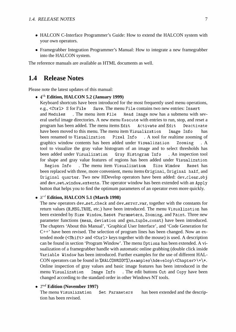
� 4th Edition, HALCON 5.2 (January 1999)Keyboard shortcuts have been introduced for the most frequently used menu operations,e.g.,<Ctrl> S for File . Save. The menuFile contains two new entries:Insert...andModules.... The menu itemFile . Read Image now has a submenu with sev-eral useful image directories. A new menuExecute with entries to run, stop, and reset aprogram has been added. The menu itemsEdit . Activate andEdit . Deactivate
have been moved to this menu. The menu itemVisualization . Image Info... hasbeen renamed toVisualization . Pixel Info.... A tool for realtime zooming ofgraphics window contents has been added underVisualization . Zooming.... Atool to visualize the gray value histogram of an image and to select thresholds hasbeen added underVisualization . Gray Histogram Info.... An inspection toolfor shape and gray value features of regions has been added underVisualization
. Region Info.... The menu itemVisualization . Size Window . Reset hasbeen replaced with three, more convenient, menu itemsOriginal, Original half, andOriginal quarter. Two new HDevelop operators have been added:dev clear obj
anddev set window extents. The operator window has been extended with anApply
button that helps you to find the optimum parameters of an operator even more quickly.
� 3rd Edition, HALCON 5.1 (March 1998)The new operatorsdev set check anddev error var, together with the constants forreturn values (H MSG TRUE, etc.) have been introduced. The menuVisualization hasbeen extended bySize Window, Reset Parameters, Zooming, andPaint. Three newparameter functions (mean, deviation andgen tuple const) have been introduced.The chapters ‘About this Manual’, ‘Graphical User Interface’, and ‘Code Generation forC++’ have been revised. The selection of program lines has been changed. Now an ex-tended mode (<Shift> and<Ctrl> keys together with the mouse) is used. A descriptioncan be found in section ‘Program Window’. The menuOptions has been extended. A vi-sualization of a framegrabber handle with automatic online grabbing (double click insideVariable Window has been introduced. Further examples for the use of different HAL-CON operators can be found in%HALCONROOT%\examples\hdevelop\<Chapter>\*\*.Online inspection of gray values and basic image features has been introduced in themenuVisualization . Image Info.... The edit buttonsCut andCopy have beenchanged according to the standard order in other Windows NT tools.
� 2nd Edition (November 1997)The menuVisualization . Set Parameters... has been extended and the descrip-tion has been revised.

8 CHAPTER 1. ABOUT THIS MANUAL
Chapter 2
Introduction
2.1 Concepts
The following sections explain the basic ideas and concepts of HALCON.
2.1.1 Working environment
Basically, HALCON supports two methods of programming:
� Interactive development of programs via HDevelop (as described in this manual) and
� using the programming languages C, and C++. HALCON provides an interface to theselanguages.
While developing programs according to the second method is done using standard program-ming tools, HDevelop actively supports the user in different ways:
� With the graphical user interface of HDevelop operators and iconic objects can be directlyanalyzed, selected, and changed within one environment.
� HDevelop suggests operators for specific tasks. In addition, a thematically structured op-erator list helps you finding an appropriate operator.
� An integrated online help contains information about each HALCON operator, such asa detailed description of the functionality, typical successor- or predecessor-operators,complexity of the operator, costs of computation time, error handling, examples of ap-plication. The online help is based on an internet browser such as Netscape Navigator orMicrosoft Internet Explorer.
� HDevelop comprises a program interpreter with edit and debug functions. It supportsprogramming features, such as loops and conditions.
� HDevelop immediately displays the results of operations. You can try different operatorsand/or parameters, and directly see the effect on the screen.
� Several graphical tools allow the examination of iconic and control data.
� Variables with an automatic garbage collection are used to manage iconic objects or con-trol values.
9
10 CHAPTER 2. INTRODUCTION
There are three basic ways to process and develop image analysis programs with HDevelop:
� Rapid prototyping in the interactive environment HDevelop.
� Development of an application that runs within HDevelop.
� Use HDevelop to develop an application that can be exported as C++ source code. Thisprogram can then be compiled and linked with the HALCON library so it runs as a standalone (console) application.
2.1.2 Data Structures
HALCON distinguishes between two types of data:iconicandcontroldata.
� Iconic data are all kinds of imageobjects(images, regions, or XLD objects describingareas and contours), whereas
� control data are all kinds of “numerical” values, such as integer, floating point numbersand also strings.
Control data defines input values for operator control parameters and is used to build complexstructures like bar charts or arrays of control values. Both —iconicandcontroldata — are pro-cessed according to the “tuple scheme” within HALCON, i.e., they may be a tuple (a number ofitems) consisting of several elements. HALCON always processes all elements of a tuple simul-taneously. You can handle tuples just in the same way as single objects/values. For example, tofilter several images you may call the filter operator several times on the different images or youcan put them into one tuple iconic object and pass it as input to the filter operator. HALCONprocesses the filter operation simultaneously on all tuple elements and returns another tuplecontaining the resulting images.We will now describe iconic data in detail to give you a better understanding how to handleimage data. Basic types areimages, regionsandXLD objects(eXtendedL ineDescription).Imagesare defined as a (sub-)set of pixels of a rectangular index range. An image consists ofone domain deftermining the image’s area of definition and one or more “channels” containingthe gray values of the pixels. Pixel data can be stored by the following types:byte, integer(1,2, and 4 byte),real, andcomplex. While processing an image, an operator exclusively workson the pixels inside the domain of the image. All pixels outside are ignored and may even haveinvalid (undefined) values. The domain (i.e., region of interest) can be ofanyshape and is notrestricted to rectangles like in many other systems. The region of interest concept allows you tofocusthe image processing. The amount of data to work on becomes smaller and the processingis much faster.Regionsare arbitrary subsets ofZZ � ZZ . They are used to define image areas of any size andshape at pixel precision. To reduce memory costs and to speed up the region processing theyare stored by a runlength encoding. Regions may define the domain of an image but can alsobe used — a basic feature of HALCON — as a flexible data structure of its own. The size ofregions isnot limited to the size of images. This strongly influences the effect of operations,e.g., in morphology, since it prevents image border artefacts. Moreover, regions may overlapwithout an implicit merging that would happen when storing them as images. This results in aflexible usage, e.g., for describing segmentation results or regions of interest.
2.1. CONCEPTS 11
XLD is the abbreviation for eXtendedL ine Description. This is a data structure used for de-scribing contours of areas (e.g., arbitrarily sized regions or polygons) and lines. An XLD objectis built up by setting base points along the contour/lines and connecting them with lines. Theycan represent a contour (or set of lines) at any precision by varying the number and position ofthe base points at subpixel precision. Additional information, such as gradient, filter response, orangle is stored with the points and lines. Typically, XLD objects describe the result of operatorsfor edge/line detection (e.g.,edges sub pix, lines gauss). In particular, they are used forimage processing at subpixel precision and offer a wide range of features and transformations.
2.1.3 Module Structure
Online DocuCOM (NT only)
VisualBasic
MSJava
Delphi
C
etc.
Applications
C++ HDevelop
Image Processing LibraryFrame-grabber
Extension
Interface
Iconic Data Management Operator Knowledge Base
Language Independent Operator Interface
Package
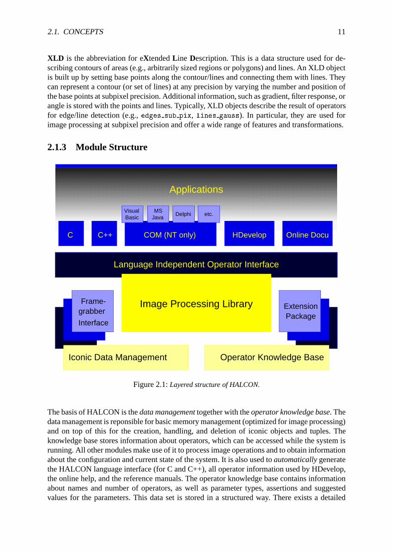
Figure 2.1:Layered structure of HALCON.
The basis of HALCON is thedata managementtogether with theoperator knowledge base. Thedata management is reponsible for basic memory management (optimized for image processing)and on top of this for the creation, handling, and deletion of iconic objects and tuples. Theknowledge base stores information about operators, which can be accessed while the system isrunning. All other modules make use of it to process image operations and to obtain informationabout the configuration and current state of the system. It is also used toautomaticallygeneratethe HALCON language interface (for C and C++), all operator information used by HDevelop,the online help, and the reference manuals. The operator knowledge base contains informationabout names and number of operators, as well as parameter types, assertions and suggestedvalues for the parameters. This data set is stored in a structured way. There exists a detailed
12 CHAPTER 2. INTRODUCTION
description for each operator which handles the effects of the operator and which indicates thecomplexity, the operator class, as well as cross references and alternatives.On top of these two modules the operators are implemented. Most of them are contained in theHALCON image processing library, which is decribed in the Operator Reference Manual. Thislibrary can dynamically be extended using so-calledpackages. The operators of these packagesbehave like normal HALCON operators, but they contain extensions to the standard libraryeither generated by MVTec (for easy update) or by the user. This concept permits the user toextend the system in a very flexible way. For more information see the C-Interface Manual.Using a similar mechanism, framegrabbers are integrated using dynamic libraries. This allowsthe user to integrate his/her own framegrabber or to download new releases of framegrabberinterfaces via the internet for fast and easy update without further changes of the rest of thesystem.The next module is thelanguage-independent operator interface. It contains modules for callingoperators, handling the input/output and passing data objects to the host language. An operatorcall is performed by thelanguage interfacewhich is generatedautomaticallyby a compilerusing the information in the operator data base. It allows to access HALCON operators withinthe programming languages C, C++, and COM (Windows NT only). The interface to C++allows the development of object oriented tools.HDevelop is implemented on top of the language interface using HALCONC and the GUItoolkit wxWindows developed by the Artificial Intelligence Applications Institute at The Uni-versity of Edinburgh to get a portable user interface for Windows and UNIX.
2.2 Configuration
The following section describes the environment variables that are used by the HALCON li-brary and HDevelop. A detailed description can be found the the Getting Started Manual. Thedescription here is given for the UNIX environment.
� HALCONROOT
This is the most important environment variable. It designates the directory inwhich HALCON is installed. Typical paths might be, e.g.,/usr/local/halcon or/usr/halcon on Unix systems, orC:\Program Files\MVTec\Halcon on Windows NTsystems. According to this variable the system can access subdirectories that are impor-tant for running HALCON. Some of them are:
– $HALCONROOT/help
Here the operator data base is situated. It is accessible by all HALCON programs toobtain information about HALCON operators.
– $HALCONROOT/doc/html/reference/hdevelop
HDevelop uses this directory for online help, which can be displayed by a suitableHTML browser like Netscape Navigator.
– $HALCONROOT/lut
User defined look-up tables are situated in this directory.
– $HALCONROOT/ocr
This directory includes trained fonts.
2.2. CONFIGURATION 13
– $HALCONROOT/license
This directory contains the license keys necessary for using HALCON.
– $HALCONROOT/images
If the variableHALCONIMAGES (see below) is not set the system looks for image filesin this directory.
� HALCONIMAGES
To search for image files specified by a relative path, the system uses this environmentvariable. Usually it contains several directory names, which are separated by colons onUnix systems and semicolons on Windows NT systems.
� ARCHITECTURE
Executable HALCON programs reside in$HALCONROOT/bin/$ARCHITECTURE.To indicate shared libraries the directory$HALCONROOT/lib/$ARCHITECTUREis used. ARCHITECTURE designates the used platform by an abbreviation (e.g.,hppa1.1-hp-hpux9 or sparc-sun-solaris2.5; syntax:processor-hardwarevendor-operatingsystem) or does not have any content (i.e., it is empty or undefined), ifthe installation for HALCON was made for one architecture only. It is useful to in-clude the path$HALCONROOT/bin/$ARCHITECTURE or $HALCONROOT/bin in the path(environment variablePATH) of a shell script.
� LD LIBRARY PATH andSHLIB PATH
Using anHP-UX architecture, the HALCON library path should be included in the envi-ronment variableSHLIB PATH to access shared libraries. For all other Unix architecturesthe environment variableLD LIBRARY PATH is used.
� HALCONSPY
If this environment variable is defined (regardless of the value) before you start a HAL-CON program, the HALCON spy tool is activated. This corresponds to executing theHALCON operatorset_spy("mode","on") in a HALCON program. With this, it ispossible to monitor an already linked HALCON program during runtime without modifi-cations.
Additionally, you may specify any monitoring mode for the HALCON debuggingtool. For this you choose a parameter value (e.g. ’operator’, ’ input control’,’output control’, etc.) and activate it. This is done by adding these parameters to theenvitonment variableHALCONSPY:
setenv HALCONSPY operator=on:input_control=on
Please note that the default output of spy is “standard out”, which might lead to problemsin a Windows NT environment. For further information concerningset_spy, please referto the HALCON reference manual.
� HALCONEXTENSIONS
This is a list of directories in which user-defined extension operators (so-called packages)are kept. Each package consists of a number of operators linked into a shared library, plusthe additional operator documentation in help-files and HTML files. See the C-InterfaceProgrammer’s Manual for details on user packages.
14 CHAPTER 2. INTRODUCTION
� DISPLAY
On Unix systems, HALCON uses this environment variable to determine the display onwhich to open windows. It is used in the same way as for other X11 applications.
� HOME
If you start HDevelop the system searches for a startup file in the home directory (seepage 125). The corresponding directory is designated by the variableHOME.
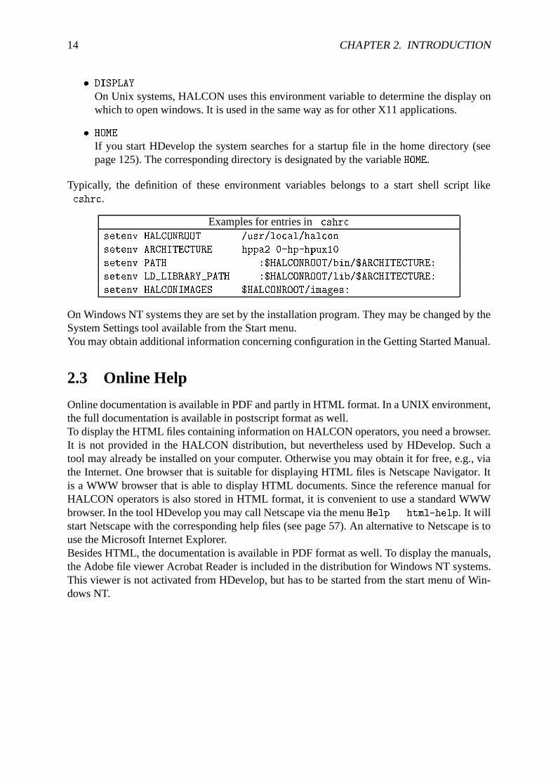
Typically, the definition of these environment variables belongs to a start shell script like.cshrc.
Examples for entries in.cshrcsetenv HALCONROOT /usr/local/halcon
setenv ARCHITECTURE hppa2.0-hp-hpux10
setenv PATH ...:$HALCONROOT/bin/$ARCHITECTURE:...
setenv LD_LIBRARY_PATH ...:$HALCONROOT/lib/$ARCHITECTURE:...
setenv HALCONIMAGES $HALCONROOT/images:.
On Windows NT systems they are set by the installation program. They may be changed by theSystem Settings tool available from the Start menu.You may obtain additional information concerning configuration in the Getting Started Manual.
2.3 Online Help
Online documentation is available in PDF and partly in HTML format. In a UNIX environment,the full documentation is available in postscript format as well.To display the HTML files containing information on HALCON operators, you need a browser.It is not provided in the HALCON distribution, but nevertheless used by HDevelop. Such atool may already be installed on your computer. Otherwise you may obtain it for free, e.g., viathe Internet. One browser that is suitable for displaying HTML files is Netscape Navigator. Itis a WWW browser that is able to display HTML documents. Since the reference manual forHALCON operators is also stored in HTML format, it is convenient to use a standard WWWbrowser. In the tool HDevelop you may call Netscape via the menuHelp . html-help. It willstart Netscape with the corresponding help files (see page 57). An alternative to Netscape is touse the Microsoft Internet Explorer.Besides HTML, the documentation is available in PDF format as well. To display the manuals,the Adobe file viewer Acrobat Reader is included in the distribution for Windows NT systems.This viewer is not activated from HDevelop, but has to be started from the start menu of Win-dows NT.
Chapter 3
Example Session
To get a first impression how to use HDevelop, you may have a look at the following examplesession. Every important step during the image processing session is explained in detail. Thus,having read this chapter thoroughly, you will understand the main HALCON ideas and concepts.Furthermore, you will learn the main aspects of HDevelop’s graphical user interface (for moredetails see chapter 4). A simple introduction can be found the in Getting Started Manual as well.In this example, the task is to detect circular marks attached to a person’s body in a gray valueimage. The program can be found in the file
%HALCONROOT%\examples\hdevelop\Manuals\HDevelop\marks.dev
After starting HDevelop (see pages 12 and 125), your first step is the loading of the imagemarks.tif from the directory%HALCONROOT%\images. You may perform this step in threedifferent ways:
� First, you may specify the operator nameread image in the operator window’s input textfield.
� Second, you may select this operator inOperators . File . Images . read image.
� The most often used and most convenient way is the third one. Here, you open the imageselection box pressing menu itemFile . Read Image . ... The menuFile . Read
Image contains several predefined directories, one of which is%HALCONROOT%\images.Usually, this directory will beC:\Program Files\MVTec\Halcon\images. Select thisdirectory by pressing the appropriate menu button. Now you can browse to your targetdirectory and choose a file name. By clicking the buttonOpen, a dialog window appears,in which you may specify a (new) name for the iconic variable which contains the imageyou are about to load. The variable will be used later in the program to access this image.
To facilitate the specification process, HDevelop offers you a default variable name, whichis derived from the image’s file name. Pressing the buttonOk transfers the operator intothe program window and inserts a first program line, similar to the following line, intoyour program:
read_image (Marks, 'C:\\Program Files\\MVTec\\Halcon\\images\\marks.tif')
This new program line is executed immediately and the loaded image is displayed in theactive graphics window. Please note the double backslashes, which are necessary since
15
16 CHAPTER 3. EXAMPLE SESSION
a single backslash is used to quote special characters (see page 73). In our example wechange the default for the name fromMarks to Christof.
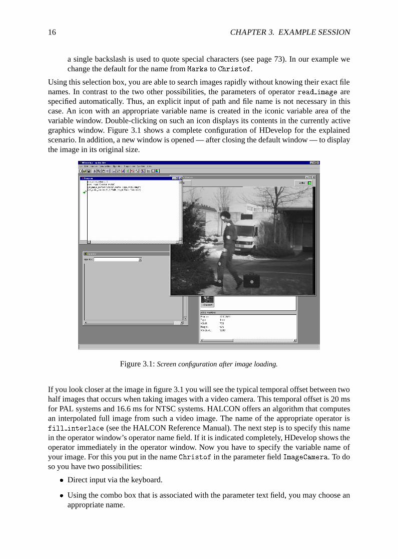
Using this selection box, you are able to search images rapidly without knowing their exact filenames. In contrast to the two other possibilities, the parameters of operatorread image arespecified automatically. Thus, an explicit input of path and file name is not necessary in thiscase. An icon with an appropriate variable name is created in the iconic variable area of thevariable window. Double-clicking on such an icon displays its contents in the currently activegraphics window. Figure 3.1 shows a complete configuration of HDevelop for the explainedscenario. In addition, a new window is opened — after closing the default window — to displaythe image in its original size.
Figure 3.1:Screen configuration after image loading.
If you look closer at the image in figure 3.1 you will see the typical temporal offset between twohalf images that occurs when taking images with a video camera. This temporal offset is 20 msfor PAL systems and 16.6 ms for NTSC systems. HALCON offers an algorithm that computesan interpolated full image from such a video image. The name of the appropriate operator isfill interlace (see the HALCON Reference Manual). The next step is to specify this namein the operator window’s operator name field. If it is indicated completely, HDevelop shows theoperator immediately in the operator window. Now you have to specify the variable name ofyour image. For this you put in the nameChristof in the parameter fieldImageCamera. To doso you have two possibilities:
� Direct input via the keyboard.
� Using the combo box that is associated with the parameter text field, you may choose anappropriate name.
17
The system’s suggestion for the interpolated image isImageFilled. By clicking buttonOKyou insert this operator into the program and execute it immediately. The computed image isdisplayed automatically in the active graphics window.In the next step you try to separate bright from dark pixels in the image using a threshold-ing operation. In this case, a segmentation using the simple thresholding operatorthreshold
does not result in a satisfying output. Hence you have to use the dynamic thresholding op-eratordyn threshold. For execution you need the original image (i.e., the interpolated fullimage) and an image to compare (containing the thresholds). You obtain this image by us-ing the smoothing filter, e.g.,mean image. As input image you choose your original imageImageFilled. After estimating the marks’ size in pixels, you specify a filter size which isapproximately twice the marks’ size (compare the HALCON Reference Manual entry fordyn threshold).
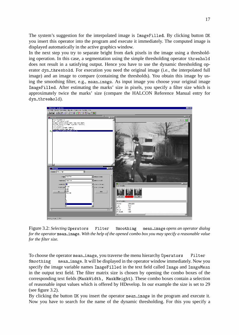
Figure 3.2:SelectingOperators . Filter . Smoothing . mean image opens an operator dialogfor the operatormean image. With the help of the opened combo box you may specify a reasonable valuefor the filter size.
To choose the operatormean image, you traverse the menu hierarchyOperators . Filter .
Smoothing . mean image. It will be displayed in the operator window immediately. Now youspecify the image variable namesImageFilled in the text field calledImage andImageMeanin the output text field. The filter matrix size is chosen by opening the combo boxes of thecorresponding text fields (MaskWidth, MaskHeight). These combo boxes contain a selectionof reasonable input values which is offered by HDevelop. In our example the size is set to 29(see figure 3.2).By clicking the buttonOK you insert the operatormean image in the program and execute it.Now you have to search for the name of the dynamic thresholding. For this you specify a
18 CHAPTER 3. EXAMPLE SESSION
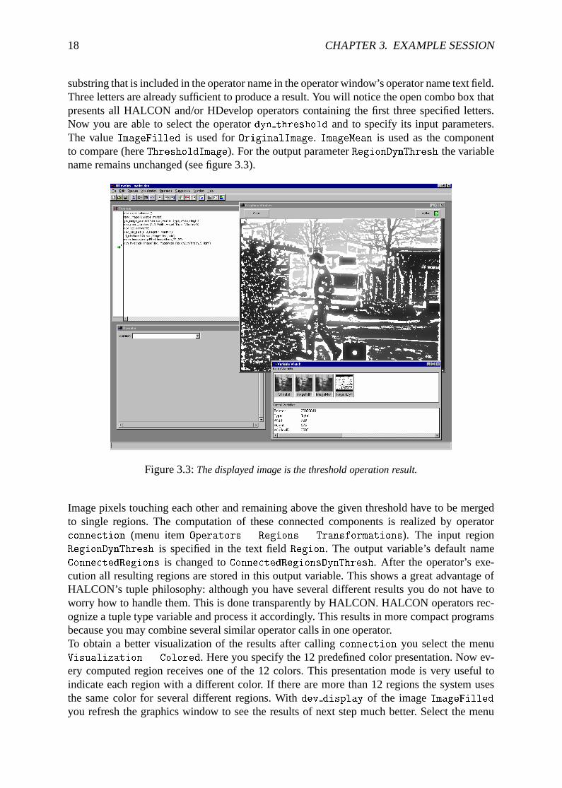
substring that is included in the operator name in the operator window’s operator name text field.Three letters are already sufficient to produce a result. You will notice the open combo box thatpresents all HALCON and/or HDevelop operators containing the first three specified letters.Now you are able to select the operatordyn threshold and to specify its input parameters.The valueImageFilled is used forOriginalImage. ImageMean is used as the componentto compare (hereThresholdImage). For the output parameterRegionDynThresh the variablename remains unchanged (see figure 3.3).
Figure 3.3:The displayed image is the threshold operation result.
Image pixels touching each other and remaining above the given threshold have to be mergedto single regions. The computation of these connected components is realized by operatorconnection (menu itemOperators . Regions . Transformations). The input regionRegionDynThresh is specified in the text fieldRegion. The output variable’s default nameConnectedRegions is changed toConnectedRegionsDynThresh. After the operator’s exe-cution all resulting regions are stored in this output variable. This shows a great advantage ofHALCON’s tuple philosophy: although you have several different results you do not have toworry how to handle them. This is done transparently by HALCON. HALCON operators rec-ognize a tuple type variable and process it accordingly. This results in more compact programsbecause you may combine several similar operator calls in one operator.To obtain a better visualization of the results after callingconnection you select the menuVisualization . Colored. Here you specify the 12 predefined color presentation. Now ev-ery computed region receives one of the 12 colors. This presentation mode is very useful toindicate each region with a different color. If there are more than 12 regions the system usesthe same color for several different regions. Withdev display of the imageImageFilledyou refresh the graphics window to see the results of next step much better. Select the menu
19
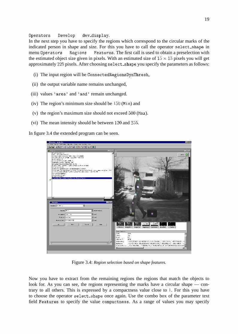
Operators . Develop . dev display.In the next step you have to specify the regions which correspond to the circular marks of theindicated person in shape and size. For this you have to call the operatorselect shape inmenuOperators . Regions . Features. The first call is used to obtain a preselection withthe estimated object size given in pixels. With an estimated size of15� 15 pixels you will getapproximately225 pixels. After choosingselect shape you specify the parameters as follows:
(i) The input region will beConnectedRegionsDynThresh,
(ii) the output variable name remains unchanged,
(iii) values'area' and'and' remain unchanged.
(iv) The region’s minimum size should be150 (Min) and
(v) the region’s maximum size should not exceed500 (Max).
(vi) The mean intensity should be between120 and255.
In figure 3.4 the extended program can be seen.
Figure 3.4:Region selection based on shape features.
Now you have to extract from the remaining regions the regions that match the objects tolook for. As you can see, the regions representing the marks have a circular shape — con-trary to all others. This is expressed by a compactness value close to1. For this you haveto choose the operatorselect shape once again. Use the combo box of the parameter textfield Features to specify the valuecompactness. As a range of values you may specify
20 CHAPTER 3. EXAMPLE SESSION
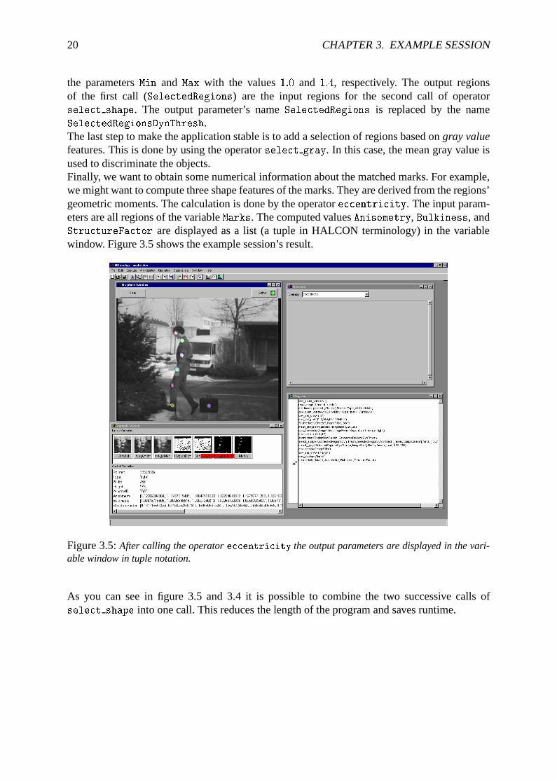
the parametersMin and Max with the values1:0 and 1:4, respectively. The output regionsof the first call (SelectedRegions) are the input regions for the second call of operatorselect shape. The output parameter’s nameSelectedRegions is replaced by the nameSelectedRegionsDynThresh.The last step to make the application stable is to add a selection of regions based ongray valuefeatures. This is done by using the operatorselect gray. In this case, the mean gray value isused to discriminate the objects.Finally, we want to obtain some numerical information about the matched marks. For example,we might want to compute three shape features of the marks. They are derived from the regions’geometric moments. The calculation is done by the operatoreccentricity. The input param-eters are all regions of the variableMarks. The computed valuesAnisometry, Bulkiness, andStructureFactor are displayed as a list (a tuple in HALCON terminology) in the variablewindow. Figure 3.5 shows the example session’s result.
Figure 3.5:After calling the operatoreccentricity the output parameters are displayed in the vari-able window in tuple notation.
As you can see in figure 3.5 and 3.4 it is possible to combine the two successive calls ofselect shape into one call. This reduces the length of the program and saves runtime.
Chapter 4
Graphical User Interface
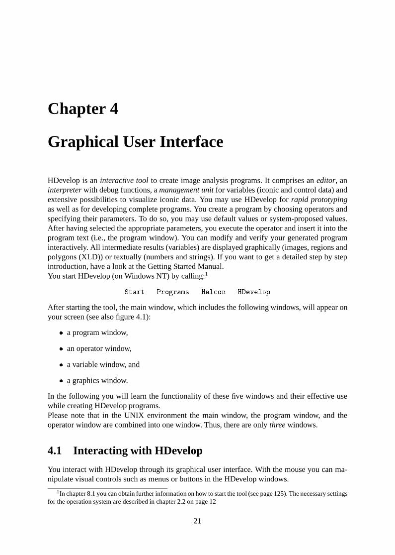
HDevelop is aninteractive toolto create image analysis programs. It comprises aneditor, aninterpreterwith debug functions, amanagement unitfor variables (iconic and control data) andextensive possibilities to visualize iconic data. You may use HDevelop forrapid prototypingas well as for developing complete programs. You create a program by choosing operators andspecifying their parameters. To do so, you may use default values or system-proposed values.After having selected the appropriate parameters, you execute the operator and insert it into theprogram text (i.e., the program window). You can modify and verify your generated programinteractively. All intermediate results (variables) are displayed graphically (images, regions andpolygons (XLD)) or textually (numbers and strings). If you want to get a detailed step by stepintroduction, have a look at the Getting Started Manual.You start HDevelop (on Windows NT) by calling:1
Start . Programs . Halcon . HDevelop
After starting the tool, the main window, which includes the following windows, will appear onyour screen (see also figure 4.1):
� a program window,
� an operator window,
� a variable window, and
� a graphics window.
In the following you will learn the functionality of these five windows and their effective usewhile creating HDevelop programs.Please note that in the UNIX environment the main window, the program window, and theoperator window are combined into one window. Thus, there are onlythreewindows.
4.1 Interacting with HDevelop
You interact with HDevelop through its graphical user interface. With the mouse you can ma-nipulate visual controls such as menus or buttons in the HDevelop windows.
1In chapter 8.1 you can obtain further information on how to start the tool (see page 125). The necessary settingsfor the operation system are described in chapter 2.2 on page 12
21
22 CHAPTER 4. GRAPHICAL USER INTERFACE
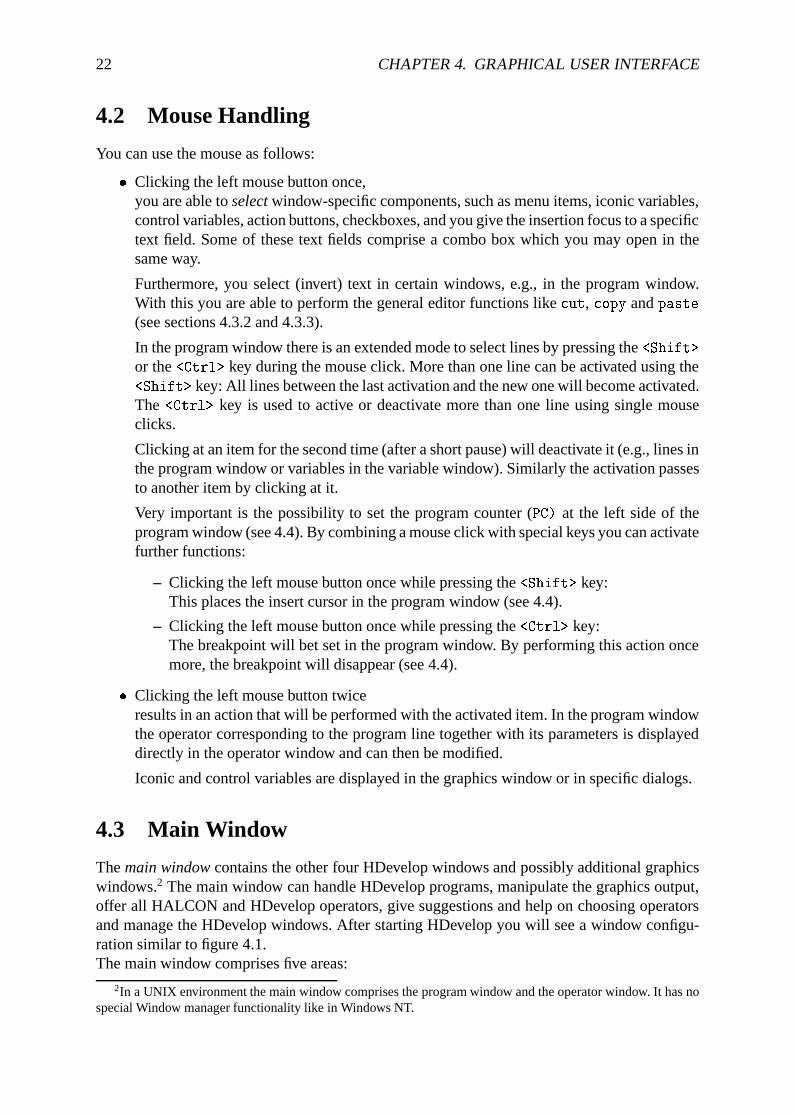
4.2 Mouse Handling
You can use the mouse as follows:
� Clicking the left mouse button once,you are able toselectwindow-specific components, such as menu items, iconic variables,control variables, action buttons, checkboxes, and you give the insertion focus to a specifictext field. Some of these text fields comprise a combo box which you may open in thesame way.
Furthermore, you select (invert) text in certain windows, e.g., in the program window.With this you are able to perform the general editor functions likecut, copy andpaste(see sections 4.3.2 and 4.3.3).
In the program window there is an extended mode to select lines by pressing the<Shift>
or the<Ctrl> key during the mouse click. More than one line can be activated using the<Shift> key: All lines between the last activation and the new one will become activated.The <Ctrl> key is used to active or deactivate more than one line using single mouseclicks.
Clicking at an item for the second time (after a short pause) will deactivate it (e.g., lines inthe program window or variables in the variable window). Similarly the activation passesto another item by clicking at it.
Very important is the possibility to set the program counter (PC) at the left side of theprogram window (see 4.4). By combining a mouse click with special keys you can activatefurther functions:
– Clicking the left mouse button once while pressing the<Shift> key:This places the insert cursor in the program window (see 4.4).
– Clicking the left mouse button once while pressing the<Ctrl> key:The breakpoint will bet set in the program window. By performing this action oncemore, the breakpoint will disappear (see 4.4).
� Clicking the left mouse button twiceresults in an action that will be performed with the activated item. In the program windowthe operator corresponding to the program line together with its parameters is displayeddirectly in the operator window and can then be modified.
Iconic and control variables are displayed in the graphics window or in specific dialogs.
4.3 Main Window
Themain windowcontains the other four HDevelop windows and possibly additional graphicswindows.2 The main window can handle HDevelop programs, manipulate the graphics output,offer all HALCON and HDevelop operators, give suggestions and help on choosing operatorsand manage the HDevelop windows. After starting HDevelop you will see a window configu-ration similar to figure 4.1.The main window comprises five areas:
2In a UNIX environment the main window comprises the program window and the operator window. It has nospecial Window manager functionality like in Windows NT.
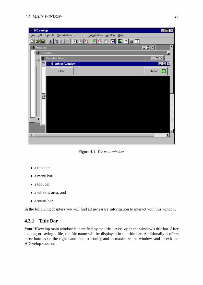
4.3. MAIN WINDOW 23
Figure 4.1:The main window.
� a title bar,
� a menu bar,
� a tool bar,
� a window area, and
� a status bar.
In the following chapters you will find all necessary information to interact with this window.
4.3.1 Title Bar
Your HDevelop main window is identified by the titleHDevelop in the window’s title bar. Afterloading or saving a file, the file name will be displayed in the title bar. Additionally it offersthree buttons on the right hand side to iconify and to maximize the window, and to exit theHDevelop session.
24 CHAPTER 4. GRAPHICAL USER INTERFACE
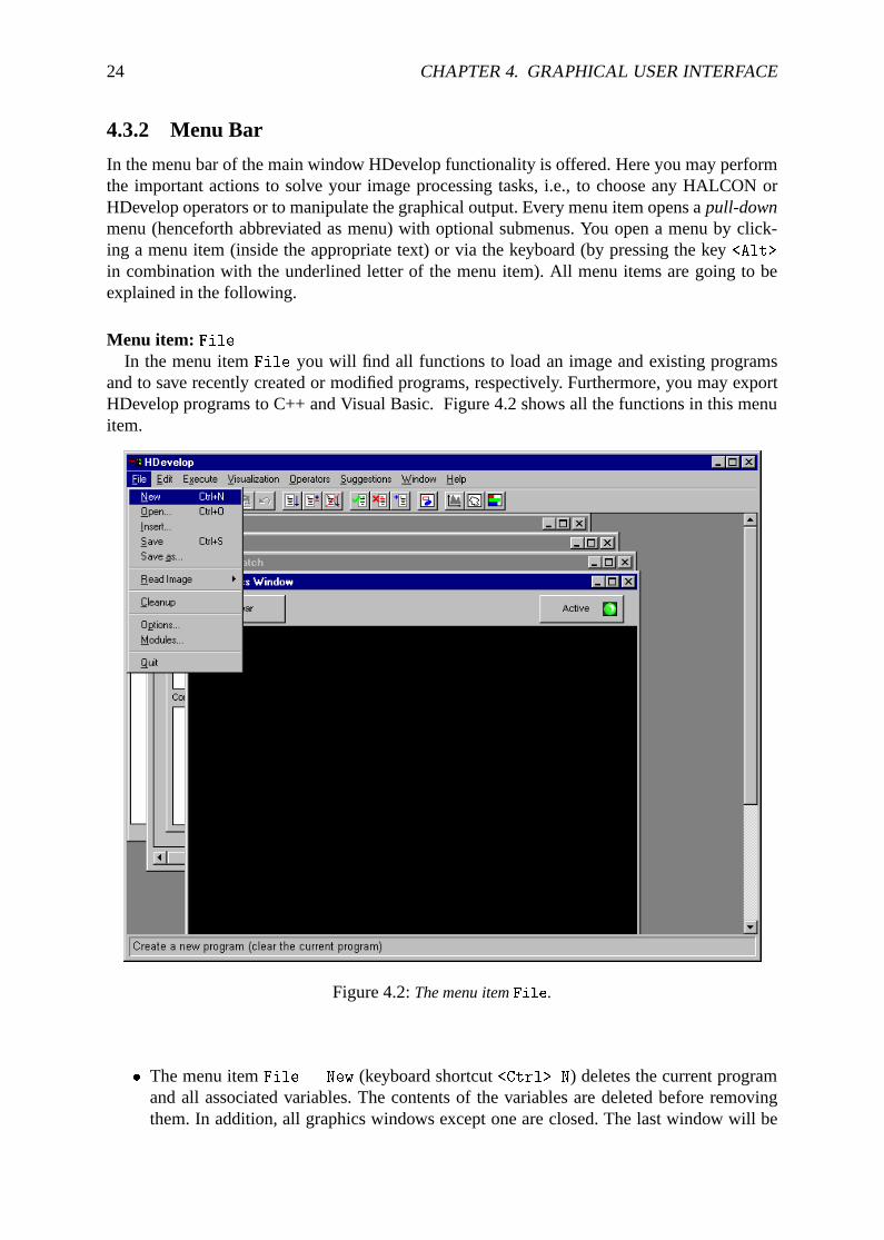
4.3.2 Menu Bar
In the menu bar of the main window HDevelop functionality is offered. Here you may performthe important actions to solve your image processing tasks, i.e., to choose any HALCON orHDevelop operators or to manipulate the graphical output. Every menu item opens apull-downmenu (henceforth abbreviated as menu) with optional submenus. You open a menu by click-ing a menu item (inside the appropriate text) or via the keyboard (by pressing the key<Alt>
in combination with the underlined letter of the menu item). All menu items are going to beexplained in the following.
Menu item: FileIn the menu itemFile you will find all functions to load an image and existing programs
and to save recently created or modified programs, respectively. Furthermore, you may exportHDevelop programs to C++ and Visual Basic. Figure 4.2 shows all the functions in this menuitem.
Figure 4.2:The menu itemFile.
� The menu itemFile . New (keyboard shortcut<Ctrl> N) deletes the current programand all associated variables. The contents of the variables are deleted before removingthem. In addition, all graphics windows except one are closed. The last window will be
4.3. MAIN WINDOW 25
cleared. The display parameters for the remaining graphics window are identical to thosewhen starting HDevelop. The first four parameters of the menuFile . Options arereset to their initial state: The update of windows, variables,PC, and time is on.
A security check prevents you from deleting the current program accidentally if the pro-gram has not been saved. A dialog box appears and waits for your response, whether youreally want to delete the HDevelop program. Your confirmation only deletes the HDe-velop program you are working on and not the file associated with it. Now you are readyto input a new HDevelop program. If you give a negative response, nothing will happen.You have to press one of the two buttons before you are able to continue interacting withHDevelop.
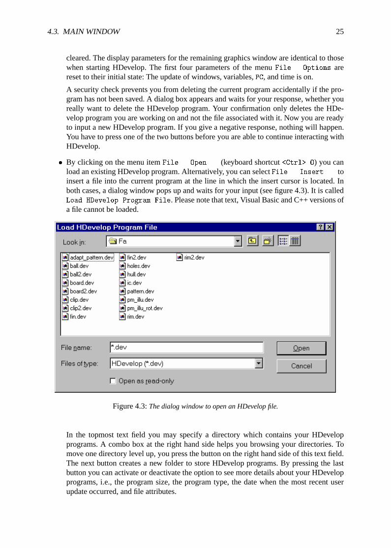
� By clicking on the menu itemFile . Open... (keyboard shortcut<Ctrl> O) you canload an existing HDevelop program. Alternatively, you can selectFile . Insert... toinsert a file into the current program at the line in which the insert cursor is located. Inboth cases, a dialog window pops up and waits for your input (see figure 4.3). It is calledLoad HDevelop Program File. Please note that text, Visual Basic and C++ versions ofa file cannot be loaded.
Figure 4.3:The dialog window to open an HDevelop file.
In the topmost text field you may specify a directory which contains your HDevelopprograms. A combo box at the right hand side helps you browsing your directories. Tomove one directory level up, you press the button on the right hand side of this text field.The next button creates a new folder to store HDevelop programs. By pressing the lastbutton you can activate or deactivate the option to see more details about your HDevelopprograms, i.e., the program size, the program type, the date when the most recent userupdate occurred, and file attributes.
26 CHAPTER 4. GRAPHICAL USER INTERFACE
The middle text area displays all available HDevelop files to choose from. By clicking theleft mouse button on a file name you select it. Double-clicking a file name opens the fileimmediately and displays it in the program window (see chapter 4.4).
Furthermore, you may specify the file name in the text field below. The combo box forfile type has no effect because only HDevelop programs with the extension.dev can beloaded. If you want to open your file with a write protection choose the checkbox at thebottom of this dialog window. To open your specified file, you press theOpen button. Thisaction deletes an already loaded HDevelop program and all created variables. The sameactions as withFile . New are performed. Now you can see your new program in theprogram window. The file name is displayed in the title bar of the main window. All its(uninstantiated) variables are shown in the variable window. To indicate that they do nothave any computed values, the system provides the iconic and control variables with aquestion mark. The program counter is placed on top of your program and you are readyto execute it. The visualization and options will be reset after loading (same asFile .
New).
If you want to cancel this task you have to press the corresponding button. By using oneof these two buttons (Open or Cancel) the dialog window disappears.
After you have loaded a program the corresponding file name will be appended at the endof the menuFile (after the menu itemQuit). This allows you to switch between recentlyloaded files quickly. The most recently loaded file is always listed first.
� The menu itemFile . Save (keyboard shortcut<Ctrl> S) saves the current programto a file. If no file name has been specified so far, the dialog corresponding toFile .
Save As... will be activated.
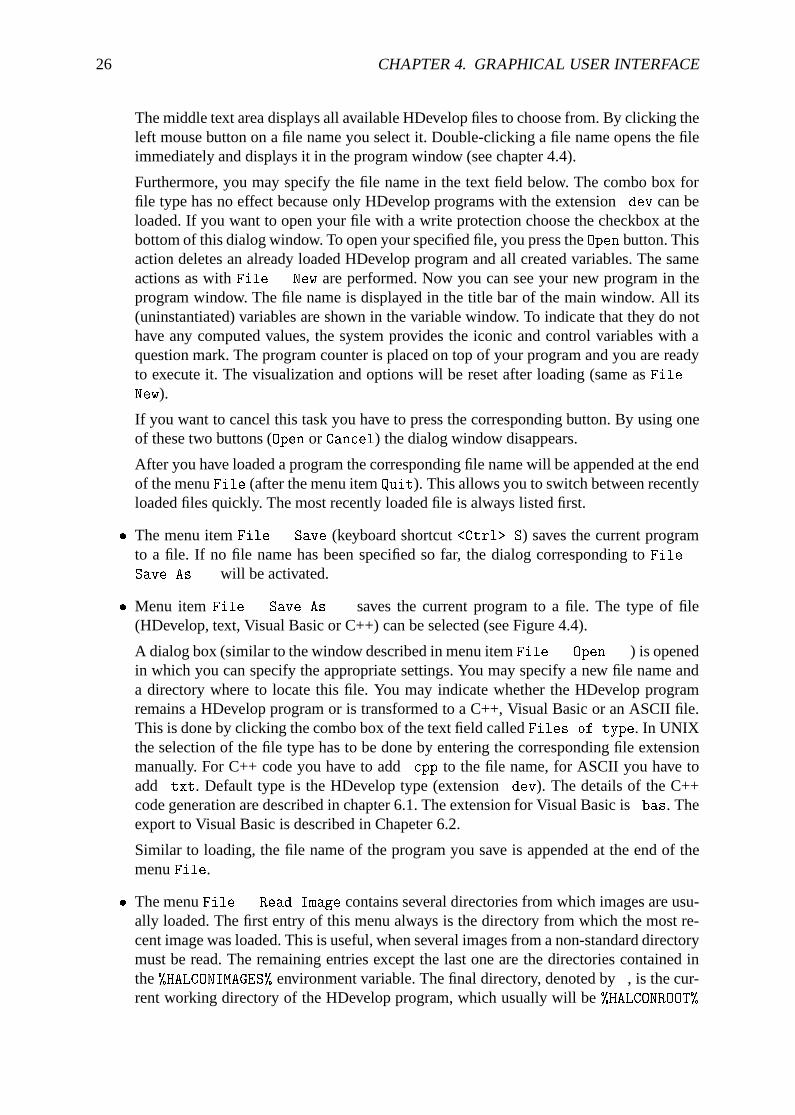
� Menu itemFile . Save As... saves the current program to a file. The type of file(HDevelop, text, Visual Basic or C++) can be selected (see Figure 4.4).
A dialog box (similar to the window described in menu itemFile . Open...) is openedin which you can specify the appropriate settings. You may specify a new file name anda directory where to locate this file. You may indicate whether the HDevelop programremains a HDevelop program or is transformed to a C++, Visual Basic or an ASCII file.This is done by clicking the combo box of the text field calledFiles of type. In UNIXthe selection of the file type has to be done by entering the corresponding file extensionmanually. For C++ code you have to add.cpp to the file name, for ASCII you have toadd.txt. Default type is the HDevelop type (extension.dev). The details of the C++code generation are described in chapter 6.1. The extension for Visual Basic is.bas. Theexport to Visual Basic is described in Chapeter 6.2.
Similar to loading, the file name of the program you save is appended at the end of themenuFile.
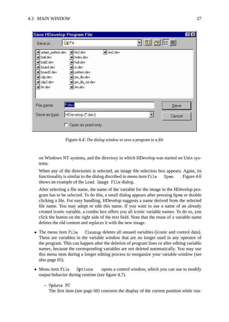
� The menuFile . Read Image contains several directories from which images are usu-ally loaded. The first entry of this menu always is the directory from which the most re-cent image was loaded. This is useful, when several images from a non-standard directorymust be read. The remaining entries except the last one are the directories contained inthe%HALCONIMAGES% environment variable. The final directory, denoted by., is the cur-rent working directory of the HDevelop program, which usually will be%HALCONROOT%
4.3. MAIN WINDOW 27
Figure 4.4:The dialog window to save a program to a file
on Windows NT systems, and the directory in which HDevelop was started on Unix sys-tems.
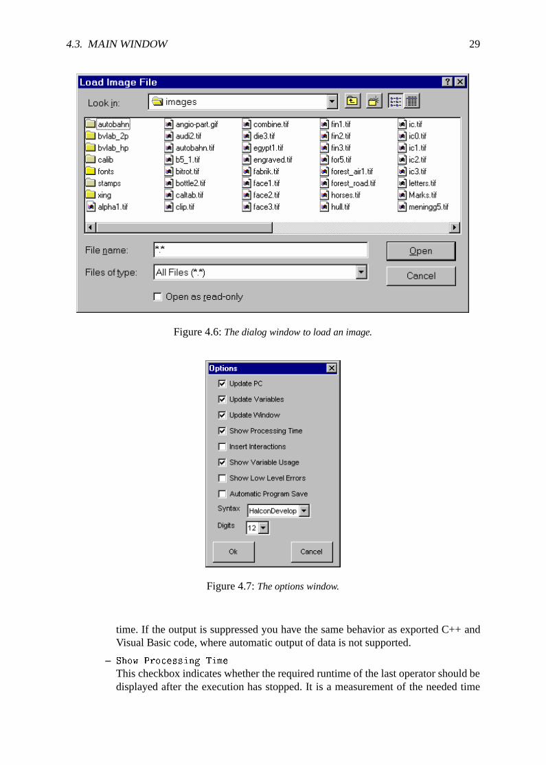
When any of the directories is selected, an image file selection box appears. Again, itsfunctionality is similar to the dialog discribed in menu itemFile . Open.... Figure 4.6shows an example of theLoad Image File dialog.
After selecting a file name, the name of the variable for the image in the HDevelop pro-gram has to be selected. To do this, a small dialog appears after pressingOpen or doubleclicking a file. For easy handling, HDevelop suggests a name derived from the selectedfile name. You may adopt or edit this name. If you want to use a name of an alreadycreated iconic variable, a combo box offers you all iconic variable names. To do so, youclick the button on the right side of the text field. Note that the reuse of a variable namedeletes the old content and replaces it with the new image.
� The menu itemFile . Cleanup deletes all unused variables (iconic and control data).These are variables in the variable window that are no longer used in any operator ofthe program. This can happen after the deletion of program lines or after editing variablenames, because the corresponding variables are not deleted automatically. You may usethis menu item during a longer editing process to reorganize your variable window (seealso page 65).
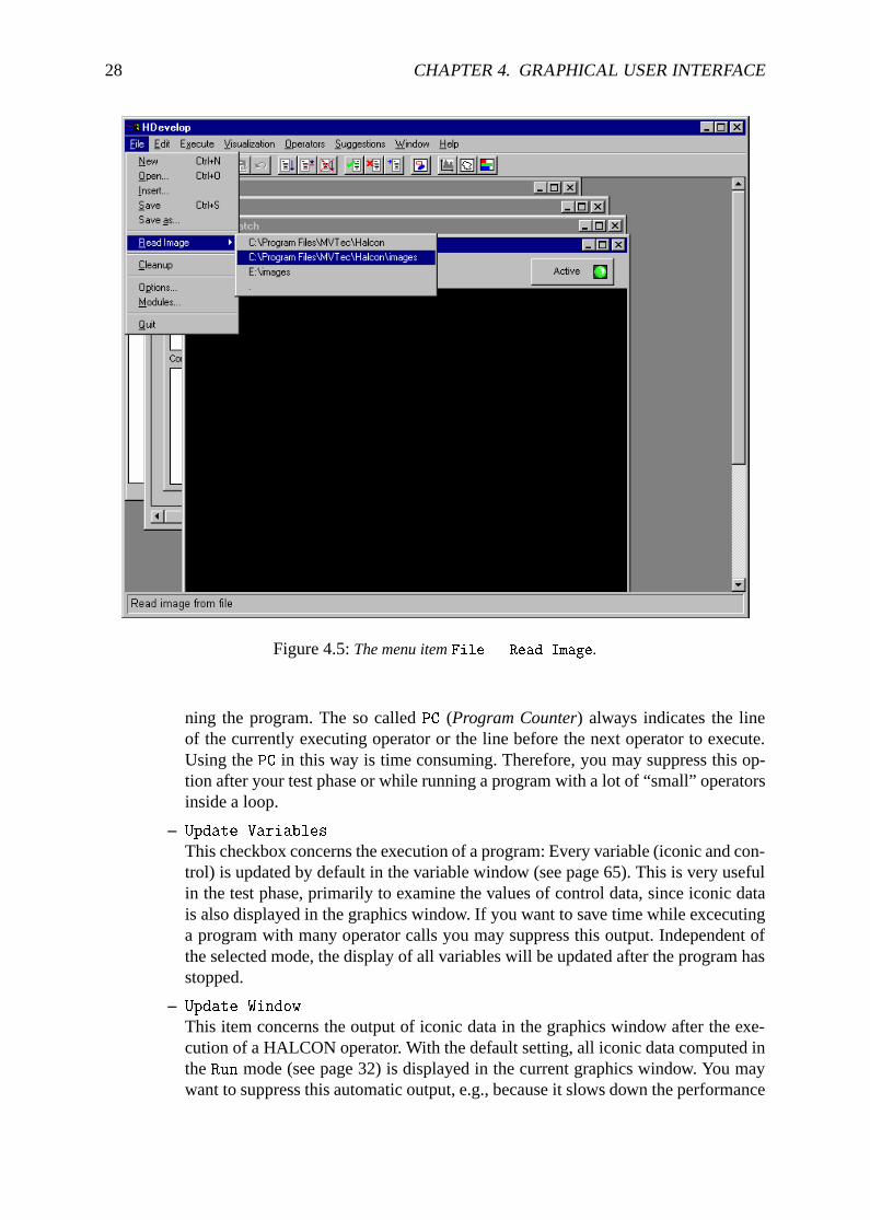
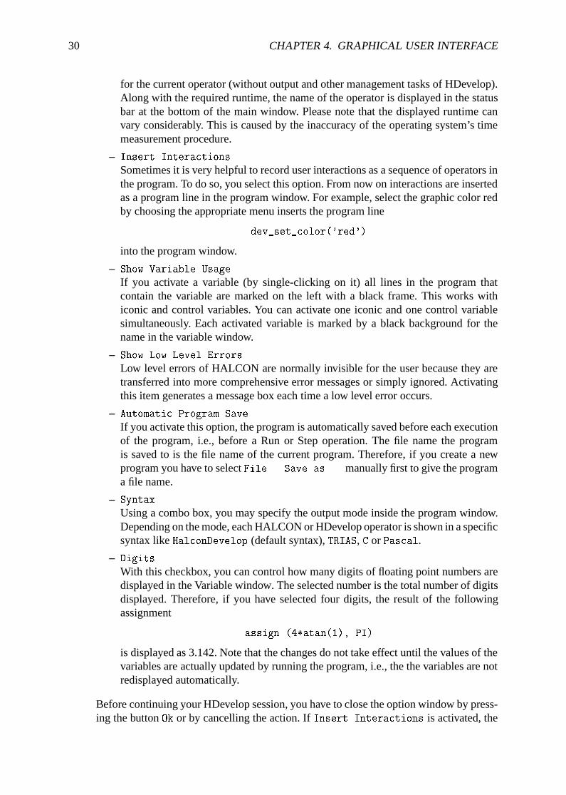
� Menu itemFile . Options... opens a control window, which you can use to modifyoutput behavior during runtime (see figure 4.7).
– Update PC
The first item (see page 60) concerns the display of the current position while run-
28 CHAPTER 4. GRAPHICAL USER INTERFACE
Figure 4.5:The menu itemFile . Read Image.
ning the program. The so calledPC (Program Counter) always indicates the lineof the currently executing operator or the line before the next operator to execute.Using thePC in this way is time consuming. Therefore, you may suppress this op-tion after your test phase or while running a program with a lot of “small” operatorsinside a loop.
– Update Variables
This checkbox concerns the execution of a program: Every variable (iconic and con-trol) is updated by default in the variable window (see page 65). This is very usefulin the test phase, primarily to examine the values of control data, since iconic datais also displayed in the graphics window. If you want to save time while excecutinga program with many operator calls you may suppress this output. Independent ofthe selected mode, the display of all variables will be updated after the program hasstopped.
– Update Window
This item concerns the output of iconic data in the graphics window after the exe-cution of a HALCON operator. With the default setting, all iconic data computed intheRun mode (see page 32) is displayed in the current graphics window. You maywant to suppress this automatic output, e.g., because it slows down the performance
4.3. MAIN WINDOW 29
Figure 4.6:The dialog window to load an image.
Figure 4.7:The options window.
time. If the output is suppressed you have the same behavior as exported C++ andVisual Basic code, where automatic output of data is not supported.
– Show Processing Time
This checkbox indicates whether the required runtime of the last operator should bedisplayed after the execution has stopped. It is a measurement of the needed time
30 CHAPTER 4. GRAPHICAL USER INTERFACE
for the current operator (without output and other management tasks of HDevelop).Along with the required runtime, the name of the operator is displayed in the statusbar at the bottom of the main window. Please note that the displayed runtime canvary considerably. This is caused by the inaccuracy of the operating system’s timemeasurement procedure.
– Insert Interactions
Sometimes it is very helpful to record user interactions as a sequence of operators inthe program. To do so, you select this option. From now on interactions are insertedas a program line in the program window. For example, select the graphic color redby choosing the appropriate menu inserts the program line
dev_set_color('red')
into the program window.
– Show Variable Usage
If you activate a variable (by single-clicking on it) all lines in the program thatcontain the variable are marked on the left with a black frame. This works withiconic and control variables. You can activate one iconic and one control variablesimultaneously. Each activated variable is marked by a black background for thename in the variable window.
– Show Low Level Errors
Low level errors of HALCON are normally invisible for the user because they aretransferred into more comprehensive error messages or simply ignored. Activatingthis item generates a message box each time a low level error occurs.
– Automatic Program Save
If you activate this option, the program is automatically saved before each executionof the program, i.e., before a Run or Step operation. The file name the programis saved to is the file name of the current program. Therefore, if you create a newprogram you have to selectFile . Save as... manually first to give the programa file name.
– Syntax
Using a combo box, you may specify the output mode inside the program window.Depending on the mode, each HALCON or HDevelop operator is shown in a specificsyntax likeHalconDevelop (default syntax),TRIAS, C or Pascal.
– Digits
With this checkbox, you can control how many digits of floating point numbers aredisplayed in the Variable window. The selected number is the total number of digitsdisplayed. Therefore, if you have selected four digits, the result of the followingassignment
assign (4*atan(1), PI)
is displayed as 3.142. Note that the changes do not take effect until the values of thevariables are actually updated by running the program, i.e., the the variables are notredisplayed automatically.
Before continuing your HDevelop session, you have to close the option window by press-ing the buttonOk or by cancelling the action. IfInsert Interactions is activated, the
4.3. MAIN WINDOW 31
changes applied inside the dialog will result in automatic operator insertionafterpressingOK.
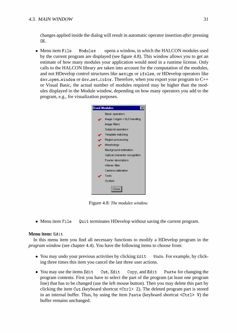
� Menu itemFile . Modules... opens a window, in which the HALCON modules usedby the current program are displayed (see figure 4.8). This window allows you to get anestimate of how many modules your application would need in a runtime license. Onlycalls to the HALCON library are taken into account for the computation of the modules,and not HDevelop control structures likeassign or ifelse, or HDevelop operators likedev open window or dev set color. Therefore, when you export your program to C++or Visual Basic, the actual number of modules required may be higher than the mod-ules displayed in the Module window, depending on how many operators you add to theprogram, e.g., for visualization purposes.
Figure 4.8:The modules window.
� Menu itemFile . Quit terminates HDevelop without saving the current program.
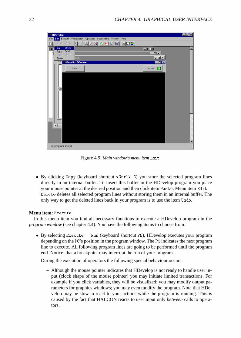
Menu item: EditIn this menu item you find all necessary functions to modify a HDevelop program in the
program window(see chapter 4.4). You have the following items to choose from:
� You may undo your previous activities by clickingEdit . Undo. For example, by click-ing three times this item you cancel the last three user actions.
� You may use the itemsEdit . Cut, Edit . Copy, andEdit . Paste for changing theprogram contents. First you have to select the part of the program (at least one programline) that has to be changed (use the left mouse button). Then you may delete this part byclicking the itemCut (keyboard shortcut<Ctrl> Z). The deleted program part is storedin an internal buffer. Thus, by using the itemPaste (keyboard shortcut<Ctrl> V) thebuffer remains unchanged.
32 CHAPTER 4. GRAPHICAL USER INTERFACE
Figure 4.9:Main window’s menu itemEdit.
� By clicking Copy (keyboard shortcut<Ctrl> C) you store the selected program linesdirectly in an internal buffer. To insert this buffer in the HDevelop program you placeyour mouse pointer at the desired position and then click itemPaste. Menu itemEdit .
Delete deletes all selected program lines without storing them in an internal buffer. Theonly way to get the deleted lines back in your program is to use the itemUndo.
Menu item: ExecuteIn this menu item you find all necessary functions to execute a HDevelop program in the
program window(see chapter 4.4). You have the following items to choose from:
� By selectingExecute . Run (keyboard shortcutF5), HDevelop executes your programdepending on thePC’s position in the program window. ThePC indicates the next programline to execute. All following program lines are going to be performed until the programend. Notice, that a breakpoint may interrupt the run of your program.
During the execution of operators the following special behaviour occurs:
– Although the mouse pointer indicates that HDevelop is not ready to handle user in-put (clock shape of the mouse pointer) you may initiate limited transactions. Forexample if you click variables, they will be visualized; you may modify output pa-rameters for graphics windows; you may even modify the program. Note that HDe-velop may be slow to react to your actions while the program is running. This iscaused by the fact that HALCON reacts to user input onlybetweencalls to opera-tors.
4.3. MAIN WINDOW 33
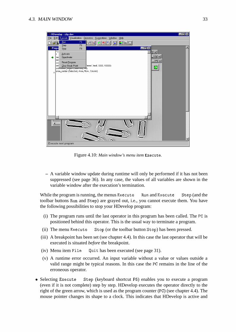
Figure 4.10:Main window’s menu itemExecute.
– A variable window update during runtime will only be performed if it has not beensuppressed (see page 36). In any case, the values of all variables are shown in thevariable window after the execution’s termination.
While the program is running, the menusExecute . Run andExecute . Step (and thetoolbar buttonsRun andStep) are grayed out, i.e., you cannot execute them. You havethe following possibilities to stop your HDevelop program:
(i) The program runs until the last operator in this program has been called. ThePC ispositioned behind this operator. This is the usual way to terminate a program.
(ii) The menuExecute . Stop (or the toolbar buttonStop) has been pressed.
(iii) A breakpoint has been set (see chapter 4.4). In this case the last operator that will beexecuted is situatedbeforethe breakpoint.
(iv) Menu itemFile . Quit has been executed (see page 31).
(v) A runtime error occurred. An input variable without a value or values outside avalid range might be typical reasons. In this case thePC remains in the line of theerroneous operator.
� SelectingExecute . Step (keyboard shortcutF6) enables you to execute a program(even if it is not complete) step by step. HDevelop executes the operator directly to theright of the green arrow, which is used as the program counter (PC) (see chapter 4.4). Themouse pointer changes its shape to a clock. This indicates that HDevelop is active and
34 CHAPTER 4. GRAPHICAL USER INTERFACE
not available for any user input. After the operator has terminated, all computed valuesare assigned to their respective variables that are named in the ouput parameter positions.Their graphical or textual representation in the variable window is also replaced. If iconicdata has been computed, you will see its presentation in the current graphics window.In the status bar of the program window the operator runtime is indicated (if the timemeasurement has not been deactivated).
ThePC is set before the next operator to execute. If the operators are specified in a sequen-tial order, this is the textual successor. In case of control statements (e.g.,if ... endif
or for ... endfor), thePC is seton the end marker (e.g.,endif or endfor) after theexecution of the last operator inside the statement’s body. Afterendfor andendwhilethePC is always set on the beginning of the loop. If a condition (asif or while) evaluatesto FALSE, thePC is setbehindthe end marker.
Suggestions in the menuSuggestions are determined for the recently executed operator.Finally the mouse pointer’s shape switches to the arrow shape and HDevelop is availablefor further transactions. Any user input which has been made during execution is handlednow.
� You may terminate the execution of a program (modeRun) by selectingExecute . Stop
(keyboard shortcutF9). If you do so, HDevelop continues processing until the currentoperator has completed its computations. This may take a long time if the operator istaking a lot of time to execute. There is no way of interrupting a HALCON operator. Afterinterrupting a program you may continue it by selectingExecute . Run andExecute .
Step. You may even edit the program before restarting it (e.g., by parameter modification,by exchanging operators with alternatives, or by inserting additional operators).
� It is often useful for testing purposes to prevent some lines of the program from beingexecuted. This can be done by selecting the appropriate lines in the program window andcalling Execute . Deactivate from the menu. With this, an asterisk is placed on thebeginning of the selected lines, and hence appear as comments in the program window.They have no influence on the program during runtime. The deactivated lines are stillpart of the program, i.e., they are stored like all other lines in a file and their variablesare still needed like all other variables. To reverse this action you may press itemEdit .
Activate.
Note that you can insert a comment into your program by using the operatorcomment.
� With the menu itemExecute . Reset Program you can reset the variables of the cur-rent program to their initial states, i.e., all variables have undefined values. Furthermore,the break point is cleared and the program counter is set to the first executable line of theprogram. This menu item is useful for testing and debbuging of programs.
� The menu itemExecute . Clear Break Point is used to clear the break point. Thisis often useful when the current program is long and you want to avoid having to scrollthe program window to locate the break point.
Menu item: VisualizationAll items which can be selected are shown in figure 4.11:
4.3. MAIN WINDOW 35
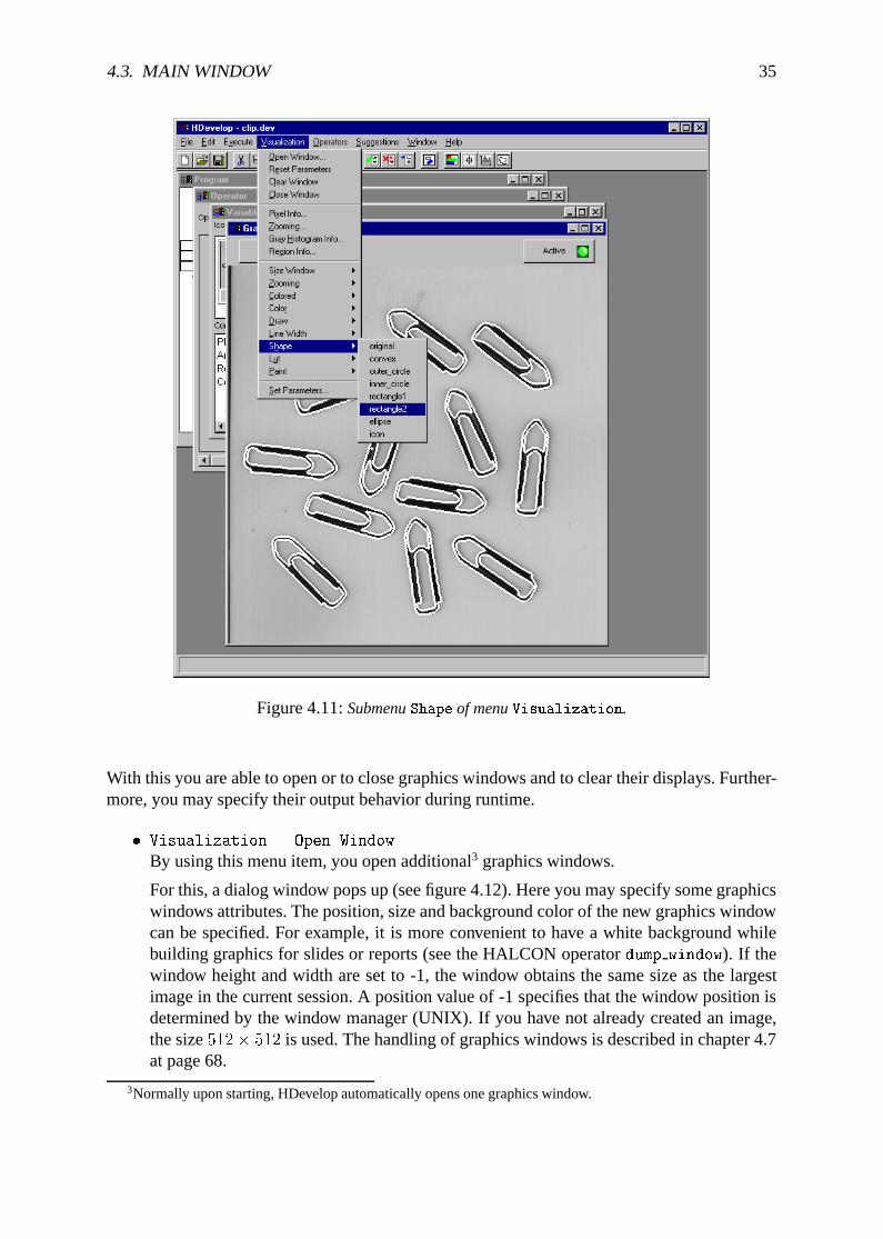
Figure 4.11:SubmenuShape of menuVisualization.
With this you are able to open or to close graphics windows and to clear their displays. Further-more, you may specify their output behavior during runtime.
� Visualization . Open Window...
By using this menu item, you open additional3 graphics windows.
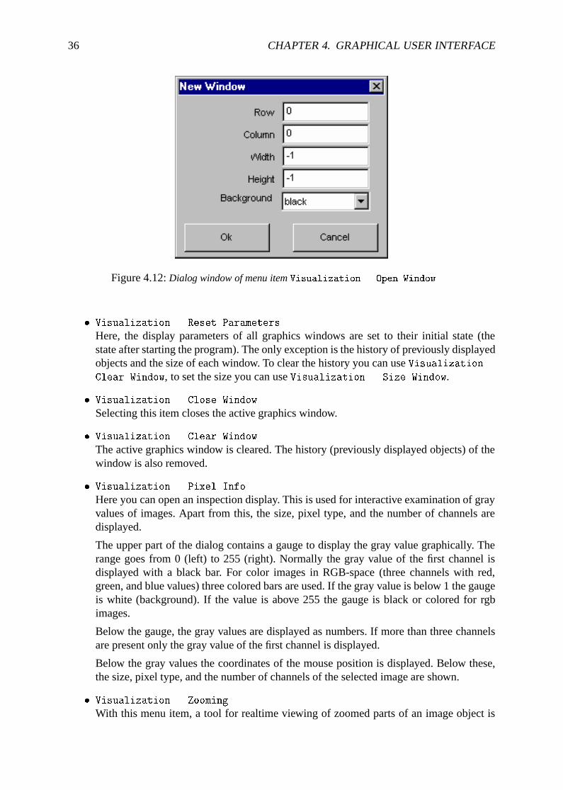
For this, a dialog window pops up (see figure 4.12). Here you may specify some graphicswindows attributes. The position, size and background color of the new graphics windowcan be specified. For example, it is more convenient to have a white background whilebuilding graphics for slides or reports (see the HALCON operatordump window). If thewindow height and width are set to -1, the window obtains the same size as the largestimage in the current session. A position value of -1 specifies that the window position isdetermined by the window manager (UNIX). If you have not already created an image,the size512� 512 is used. The handling of graphics windows is described in chapter 4.7at page 68.
3Normally upon starting, HDevelop automatically opens one graphics window.
36 CHAPTER 4. GRAPHICAL USER INTERFACE
Figure 4.12:Dialog window of menu itemVisualization . Open Window...
� Visualization . Reset Parameters
Here, the display parameters of all graphics windows are set to their initial state (thestate after starting the program). The only exception is the history of previously displayedobjects and the size of each window. To clear the history you can useVisualization .
Clear Window, to set the size you can useVisualization . Size Window.
� Visualization . Close Window
Selecting this item closes the active graphics window.
� Visualization . Clear Window
The active graphics window is cleared. The history (previously displayed objects) of thewindow is also removed.
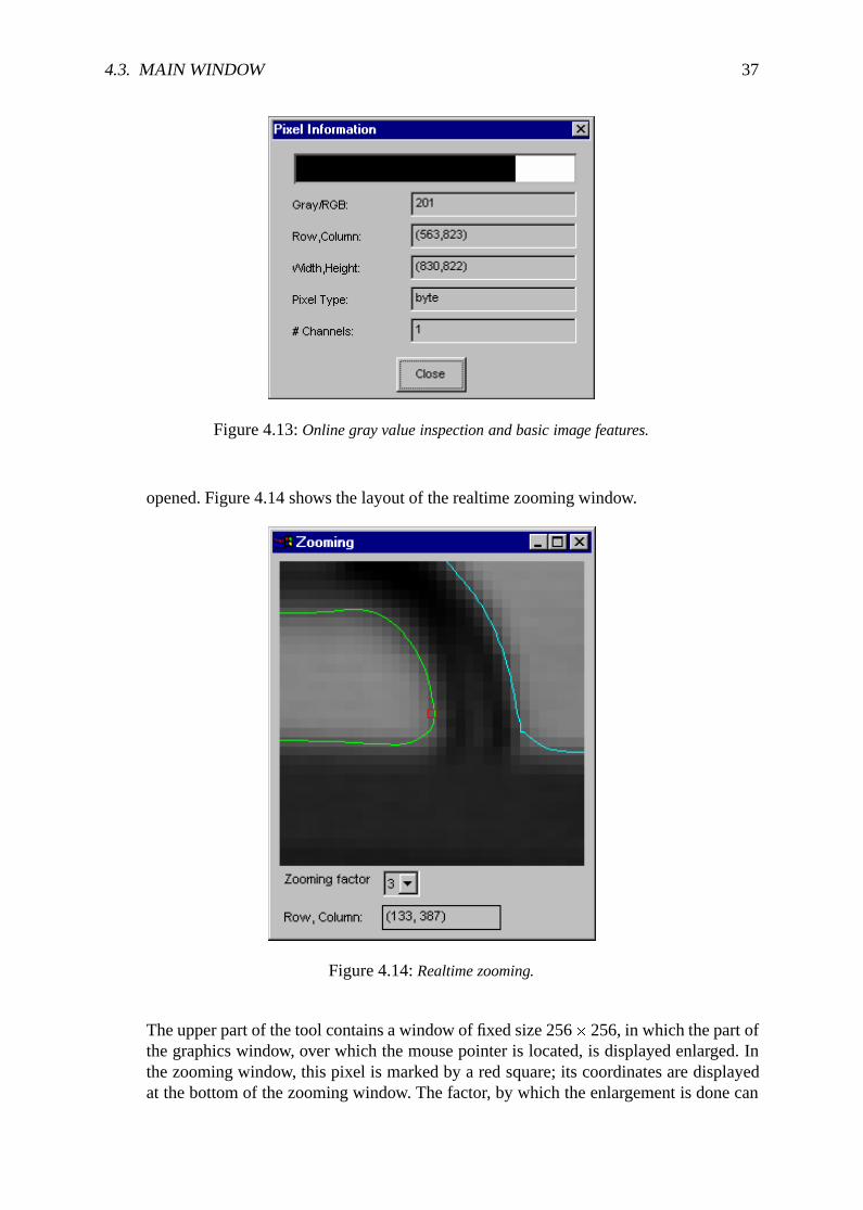
� Visualization . Pixel Info...
Here you can open an inspection display. This is used for interactive examination of grayvalues of images. Apart from this, the size, pixel type, and the number of channels aredisplayed.
The upper part of the dialog contains a gauge to display the gray value graphically. Therange goes from 0 (left) to 255 (right). Normally the gray value of the first channel isdisplayed with a black bar. For color images in RGB-space (three channels with red,green, and blue values) three colored bars are used. If the gray value is below 1 the gaugeis white (background). If the value is above 255 the gauge is black or colored for rgbimages.
Below the gauge, the gray values are displayed as numbers. If more than three channelsare present only the gray value of the first channel is displayed.
Below the gray values the coordinates of the mouse position is displayed. Below these,the size, pixel type, and the number of channels of the selected image are shown.
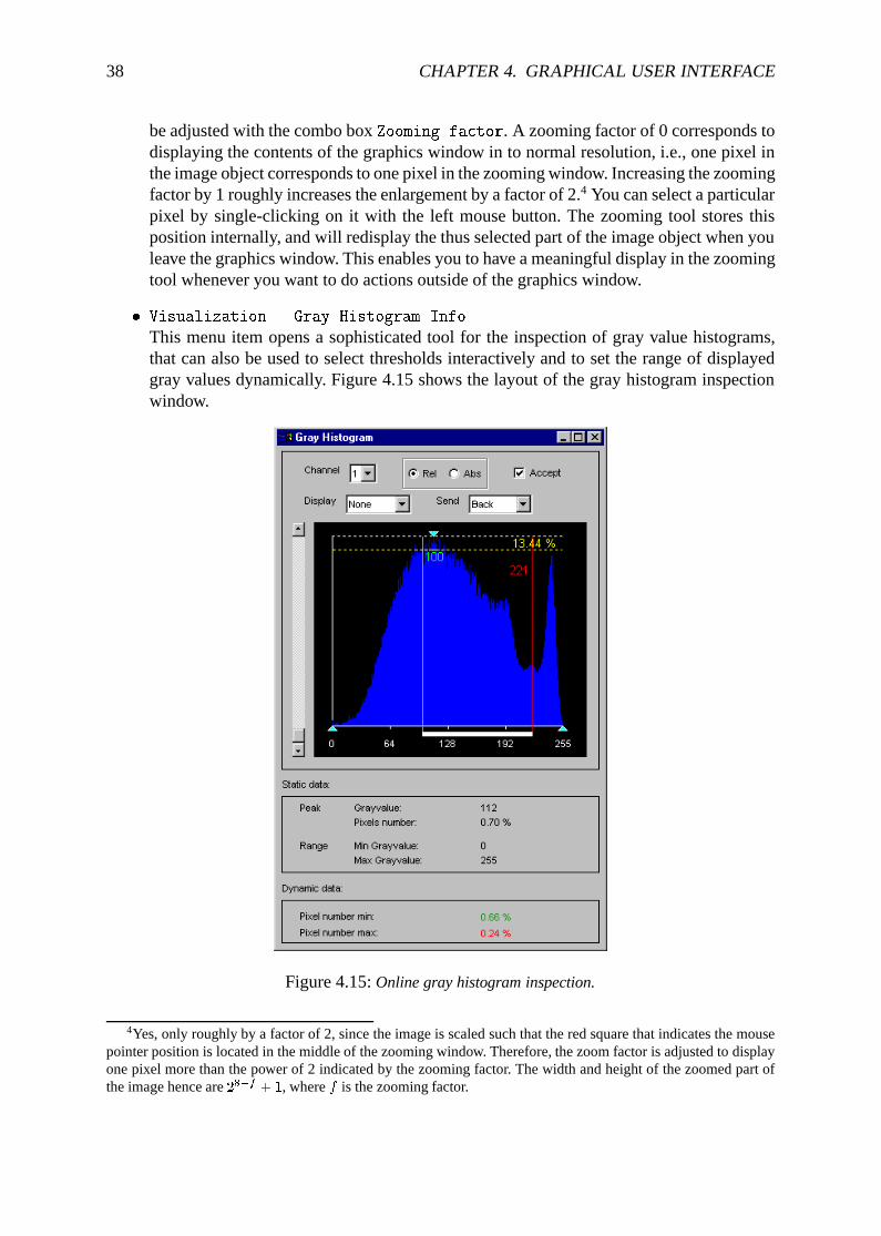
� Visualization . Zooming...
With this menu item, a tool for realtime viewing of zoomed parts of an image object is
4.3. MAIN WINDOW 37
Figure 4.13:Online gray value inspection and basic image features.
opened. Figure 4.14 shows the layout of the realtime zooming window.
Figure 4.14:Realtime zooming.
The upper part of the tool contains a window of fixed size 256�256, in which the part ofthe graphics window, over which the mouse pointer is located, is displayed enlarged. Inthe zooming window, this pixel is marked by a red square; its coordinates are displayedat the bottom of the zooming window. The factor, by which the enlargement is done can
38 CHAPTER 4. GRAPHICAL USER INTERFACE
be adjusted with the combo boxZooming factor. A zooming factor of 0 corresponds todisplaying the contents of the graphics window in to normal resolution, i.e., one pixel inthe image object corresponds to one pixel in the zooming window. Increasing the zoomingfactor by 1 roughly increases the enlargement by a factor of 2.4 You can select a particularpixel by single-clicking on it with the left mouse button. The zooming tool stores thisposition internally, and will redisplay the thus selected part of the image object when youleave the graphics window. This enables you to have a meaningful display in the zoomingtool whenever you want to do actions outside of the graphics window.
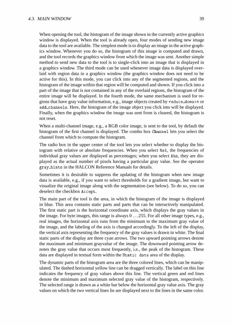
� Visualization . Gray Histogram Info...
This menu item opens a sophisticated tool for the inspection of gray value histograms,that can also be used to select thresholds interactively and to set the range of displayedgray values dynamically. Figure 4.15 shows the layout of the gray histogram inspectionwindow.
Figure 4.15:Online gray histogram inspection.
4Yes, only roughly by a factor of 2, since the image is scaled such that the red square that indicates the mousepointer position is located in the middle of the zooming window. Therefore, the zoom factor is adjusted to displayone pixel more than the power of 2 indicated by the zooming factor. The width and height of the zoomed part ofthe image hence are28�f + 1, wheref is the zooming factor.
4.3. MAIN WINDOW 39
When opening the tool, the histogram of the image shown in the currently active graphicswindow is displayed. When the tool is already open, four modes of sending new imagedata to the tool are available. The simplest mode is to display an image in the active graph-ics window. Whenever you do so, the histogram of this image is computed and drawn,and the tool records the graphics window from which the image was sent. Another simplemethod to send new data to the tool is to single-click into an image that is displayed ina graphics window. The third mode can be used whenever image data is displayed over-laid with region data in a graphics window (the graphics window does not need to beactive for this). In this mode, you can click into any of the segmented regions, and thehistogram of the image within that region will be computed and shown. If you click into apart of the image that is not contained in any of the overlaid regions, the histogram of theentire image will be displayed. In the fourth mode, the same mechanism is used for re-gions that have gray value information, e.g., image objects created byreduce domain oradd channels. Here, the histogram of the image object you click into will be displayed.Finally, when the graphics window the image was sent from is cleared, the histogram isnot reset.
When a multi-channel image, e.g., a RGB color image, is sent to the tool, by default thehistogram of the first channel is displayed. The combo boxChannel lets you select thechannel from which to compute the histogram.
The radio box in the upper center of the tool lets you select whether to display the his-togram with relative or absolute frequencies. When you selectRel, the frequencies ofindividual gray values are displayed as percentages; when you selectAbs, they are dis-played as the actual number of pixels having a particular gray value. See the operatorgray histo in the HALCON Reference Manuals for details.
Sometimes it is desirable to suppress the updating of the histogram when new imagedata is available, e.g., if you want to select thresholds for a gradient image, but want tovisualize the original image along with the segmentation (see below). To do so, you candeselect the checkboxAccept.
The main part of the tool is the area, in which the histogram of the image is displayedin blue. This area contains static parts and parts that can be interactively manipulated.The first static part is the horizontal coordinate axis, which displays the gray values inthe image. For byte images, this range is always 0 . . . 255. For all other image types, e.g.,real images, the horizontal axis runs from the minimum to the maximum gray value ofthe image, and the labeling of the axis is changed accordingly. To the left of the display,the vertical axis representing the frequency of the gray values is drawn in white. The finalstatic parts of the display are three cyan arrows. The two upward pointing arrows denotethe maximum and minimum grayvalue of the image. The downward pointing arrow de-notes the gray value that occurs most frequently, i.e., the peak of the histogram. Thesedata are displayed in textual form within theStatic data area of the display.
The dynamic parts of the histogram area are the three colored lines, which can be manip-ulated. The dashed horizontal yellow line can be dragged vertically. The label on this lineindicates the frequency of gray values above this line. The vertical green and red linesdenote the minimum and maximum selected gray value of the histogram, respectively.The selected range is drawn as a white bar below the horizontal gray value axis. The grayvalues on which the two vertical lines lie are displayed next to the lines in the same color.
40 CHAPTER 4. GRAPHICAL USER INTERFACE
The frequency of the respective gray values is displayed within theDynamic data areaof the display.
The selected range of gray values can be used for two major purposes. First, when thecombo boxDisplay is set toThreshold, the image, from which the histogram wascomputed, is segmented with athreshold operation with the selected minimum andmaximum gray value. Depending in the setting of the combo boxSend, the segmentationresult is either displayed in the graphics window, from which the image was originallysent (Send = Back), or to the active graphics window (Send = To Active). Second, ifDisplay is set toScale, the gray values of the image are scaled such that the gray value0 of the scaled image corresponds to the minimum selected gray value and the gray value255 to the maximum selected gray value. Again, the combo boxSend determines thegraphics window, in which the result is displayed. This mode is useful to interactively seta “window” of gray values that should be displayed with a large dynamic range.
If you want to select threshold parameters for a single image, display the image in theactive graphics window and open the histogram tool. For optimum visualization of thesegmentation results, it is best to set the visualization color to a color different from blackor white (seeVisualization . Color below). Now setDisplay to Threshold andinteractively drag the two vertical bars until you achieve the desired segmentation result.The parameters of the threshold operation can now be read off the two vertical lines.
If you want to select threshold parameters for an image, which is derived from another im-age, but want to display the segmentation on the original image, e.g., if you want to selectthresholds for a gradient image, two different possibilities exist. First, you can display thederived image, open the histogram tool, deselectAccept, display the original image, andthen select the appropriate thresholds. This way, only one window is needed for the vi-sualization. For the second possibility you can display the derived image in one window,make another window active or open a new window, display the original image there,make the first window active again, open the histogram tool, make the second windowactive again, setSend to To Active, and select your thresholds. Although in this case itis not necessary to deselectAccept, it is advantageous to do so, because this prevents thehistogram from being updated if you click into a graphics window accidentaly.
� Visualization . Region Info...
This menu item opens a tool for the convenient inspection of shape and gray value fea-tures of individual regions. It can, for instance, be used to determine thresholds for op-erators that select regions based on these features, e.g.,select shape or select gray.Figure 4.16 shows the layout of the region feature inspection window.
The strategy to determine the data from which to compute the features is very similarto that of the gray histogram inspection window. You can display an image or region bydouble-clicking on it in the variable window or you can select a region or an image whichis already displayed, by single-clicking it. If you display or click into an image, only thegray value features of the entire image will be calculated. If you click into a region thatis not underlaid with an image, only the shape features of this region will be displayed.If you click into a region that is underlaid with an image or into a region that has grayvalue information (e.g., fromreduce domain oradd channels), both the shape and grayvalue features of that region will be displayed. Finally, if you have overlaid an image witha region, but click into a part of the image that is outside the region, only the gray value
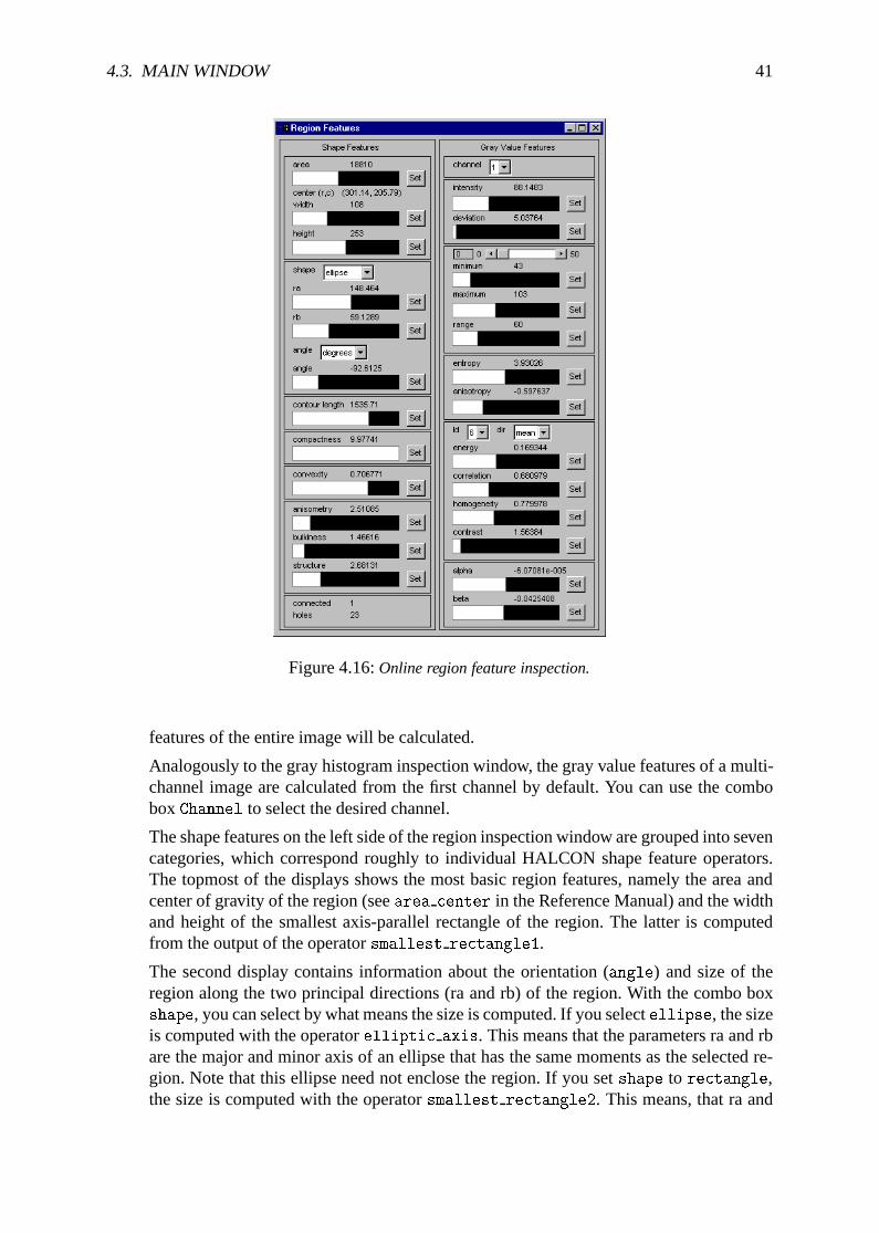
4.3. MAIN WINDOW 41
Figure 4.16:Online region feature inspection.
features of the entire image will be calculated.
Analogously to the gray histogram inspection window, the gray value features of a multi-channel image are calculated from the first channel by default. You can use the comboboxChannel to select the desired channel.
The shape features on the left side of the region inspection window are grouped into sevencategories, which correspond roughly to individual HALCON shape feature operators.The topmost of the displays shows the most basic region features, namely the area andcenter of gravity of the region (seearea center in the Reference Manual) and the widthand height of the smallest axis-parallel rectangle of the region. The latter is computedfrom the output of the operatorsmallest rectangle1.
The second display contains information about the orientation (angle) and size of theregion along the two principal directions (ra and rb) of the region. With the combo boxshape, you can select by what means the size is computed. If you selectellipse, the sizeis computed with the operatorelliptic axis. This means that the parameters ra and rbare the major and minor axis of an ellipse that has the same moments as the selected re-gion. Note that this ellipse need not enclose the region. If you setshape to rectangle,the size is computed with the operatorsmallest rectangle2. This means, that ra and
42 CHAPTER 4. GRAPHICAL USER INTERFACE
rb are half the width and height of the smallest rectangle with arbitrary orientation thatcompletely contains the selected region. The orientation of the region is computed in bothcases with the operatororientation region to get the full range of 360� for the angle.You can select whether to display the angle indegrees or radians with the correspond-ing combo box.
The next three displays show simpler shape features of the selected region. The first ofthese displays shows the contour lenght of the region, i.e., the euclidean length of itsboundary (seecontlength). The second one shows the compactness of the region, i.e.,the ratio of the contour length of the region and the circumference of a circle with thesame area as the region (seecompactness). The compactness of a region is always largerthan 1. The compacter the region, the closer the value of the compactness is to 1. Thethird display shows the convexity of the selected region, i.e., the ratio of the area of theregion and the area of the convex hull of the region (seeconvexity). The convexity of aregion is always smaller than 1. Only convex regions will reach the optimum convexityof 1.
The last but one display shows shape features derived from the ellipse parameters of theselected region, which are calculated witheccentricity. The anisometry of the regionis the ratio of the major and minor axis of the ellipse (i.e., the ratio of ra and rb in thesecond display if you setshape to ellipse). This feature measures how elongated theregion is. Its value is always larger than 1, with isometric regions having a value of 1.The definition of the more complex features bulkiness and structure factor (abbreviatedas structure in the display) can be obtained from the HALCON Reference Manual.
The final shape feature display shows the connected components and number of holes ofthe selected region, as computed byconnect and holes.
The gray value features are grouped into five displays on the right side of the regioninspection window. Again, they correspond roughly to individual HALCONoperators.The first display shows the mean gray value intensity and the corresponding standarddeviation of the selected region. These are computed with the operatorintensity.
The second display shows the output of the operatormin max gray. This operator com-putes the distribution (hestogram) of gray values in the image and returns the gray valuescorresponding to an upper and lower percentile of the distribution. This percentile canbe selected with the slider at the to of the display. For a percentile of 0 (the default), theminimum and maximum gray values of the region are returned. The display also showsthe range of gray values in the region, i.e., the difference between the maximum andminimum gray values.
In the third display, the gray value entropy of the selected region is displayed (seeentropy gray. Again, this is a feature derived from the histogram of gray values inthe region. The feature entropy measures whether the gray values are distributed equallywithin the region. This measure is always smaller than 8 (for byte images — the onlysuppurted image type for this operator). Only images with equally distributed gray valuesreach this maximum value. The feature anisotropy measures the symmetry of the distri-bution. Perfectly symmetric histograms will have an anisometry of -0.5.
The fourth display contains gray value features derived from the coocurrence matrix of theselected region are displayed (seecooc feature image. The combo boxld can be usedto select the number of gray values to be distinguished (2ld). The combo boxdir selects
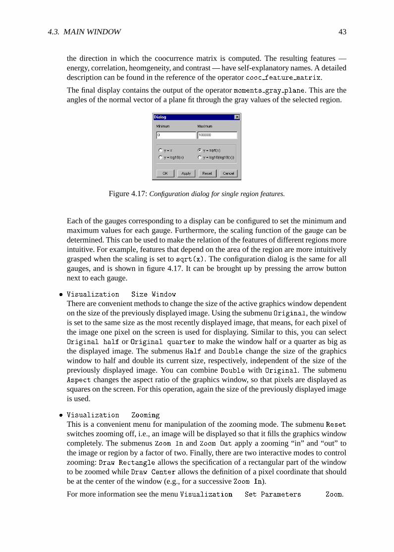
4.3. MAIN WINDOW 43
the direction in which the coocurrence matrix is computed. The resulting features —energy, correlation, heomgeneity, and contrast — have self-explanatory names. A detaileddescription can be found in the reference of the operatorcooc feature matrix.
The final display contains the output of the operatormoments gray plane. This are theangles of the normal vector of a plane fit through the gray values of the selected region.
Figure 4.17:Configuration dialog for single region features.
Each of the gauges corresponding to a display can be configured to set the minimum andmaximum values for each gauge. Furthermore, the scaling function of the gauge can bedetermined. This can be used to make the relation of the features of different regions moreintuitive. For example, features that depend on the area of the region are more intuitivelygrasped when the scaling is set tosqrt(x). The configuration dialog is the same for allgauges, and is shown in figure 4.17. It can be brought up by pressing the arrow buttonnext to each gauge.
� Visualization . Size Window
There are convenient methods to change the size of the active graphics window dependenton the size of the previously displayed image. Using the submenuOriginal, the windowis set to the same size as the most recently displayed image, that means, for each pixel ofthe image one pixel on the screen is used for displaying. Similar to this, you can selectOriginal half or Original quarter to make the window half or a quarter as big asthe displayed image. The submenusHalf andDouble change the size of the graphicswindow to half and double its current size, respectively, independent of the size of thepreviously displayed image. You can combineDouble with Original. The submenuAspect changes the aspect ratio of the graphics window, so that pixels are displayed assquares on the screen. For this operation, again the size of the previously displayed imageis used.
� Visualization . Zooming
This is a convenient menu for manipulation of the zooming mode. The submenuReset
switches zooming off, i.e., an image will be displayed so that it fills the graphics windowcompletely. The submenusZoom In andZoom Out apply a zooming “in” and “out” tothe image or region by a factor of two. Finally, there are two interactive modes to controlzooming:Draw Rectangle allows the specification of a rectangular part of the windowto be zoomed whileDraw Center allows the definition of a pixel coordinate that shouldbe at the center of the window (e.g., for a successiveZoom In).
For more information see the menuVisualization . Set Parameters... . Zoom.
44 CHAPTER 4. GRAPHICAL USER INTERFACE
� Visualization . Colored
This is an easy way to display multiple regions or XLDs. Each region is displayed in adifferent color, where the number of different colors is specified in the submenu. You canchoose between 3, 6 and 12 colors. If all regions are displayed with one color, you haveto use the operatorconnection beforehand. You can check this also with the operatorcount obj.
� Visualization . Color
This item enables color specification to display segmentation results (regions and XLD),text (write string) and general line drawings (e.g., 3D plots, contour lines, and barcharts). The number of colors which are available in the submenu depends on the graphicsdisplay (i.e., the number of bits used for displaying). After selecting a color, the previouslydisplayed region or XLD object will be redisplayed with this color. The default color iswhite.
� Visualization . Draw
Here you can select a visualization mode to display region data. It can either befilled(item fill) or thebordersare displayed only (itemmargin). The border line thicknessof the displayed regions is specified using the menu itemLine Width (see figure 4.19).
� Visualization . Line Width
Here you determine the line width for painting XLDs, borders of regions or other types oflines. You can select between a wide range of widths using the submenu. This parameteris effective ifdev set draw is set to modemargin only.
� Visualization . Shape
Here you specify the representation shape forregions. Thus you are able to display notonly the region’s original shape but also its enclosing rectangle or its enclosing circle.
� Visualization . Lut
This menu activates different look up tables, which can used to display gray images andcolor images in different intensities and colors. In the case of a true color display theimage has to be redisplayed due to the missing support of a look-up-table in the graphicshardware. For color images only the gray look-up-tables can be used, which change eachchannel (separately) with the same table.
� Visualization . Paint
This menu defines the mode to display gray images. For more information see the menuitemVisualization . Set Parameters....
� Visualization . Set Parameters...
By using this menu item, a dialog calledVisualization Parameters is opened, whichhandles more complex parameter settings. Select one setting with your left mouse but-ton and the window brings up the according parameter box. Each box contains differentbuttons, text fields, or check boxes to modify parameters.
Each box has anUpdate button. If this button is pressed, every change of a parameterwill immediately lead to a redisplay of the image, regions, or XLD in the graphicswindow. If the button is “off” the parameters become active for the next display of anobject (double click on an icon or excecution of an operator). By default the update is
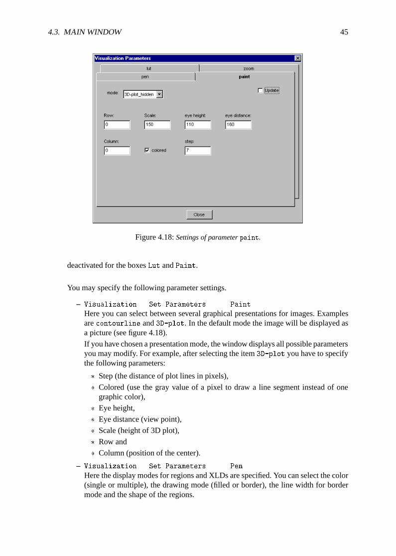
4.3. MAIN WINDOW 45
Figure 4.18:Settings of parameterpaint.
deactivated for the boxesLut andPaint.
You may specify the following parameter settings.
– Visualization . Set Parameters... . Paint
Here you can select between several graphical presentations for images. Examplesarecontourline and3D-plot. In the default mode the image will be displayed asa picture (see figure 4.18).
If you have chosen a presentation mode, the window displays all possible parametersyou may modify. For example, after selecting the item3D-plot you have to specifythe following parameters:
� Step (the distance of plot lines in pixels),
� Colored (use the gray value of a pixel to draw a line segment instead of onegraphic color),
� Eye height,
� Eye distance (view point),
� Scale (height of 3D plot),
� Row and
� Column (position of the center).
– Visualization . Set Parameters... . Pen
Here the display modes for regions and XLDs are specified. You can select the color(single or multiple), the drawing mode (filled or border), the line width for bordermode and the shape of the regions.
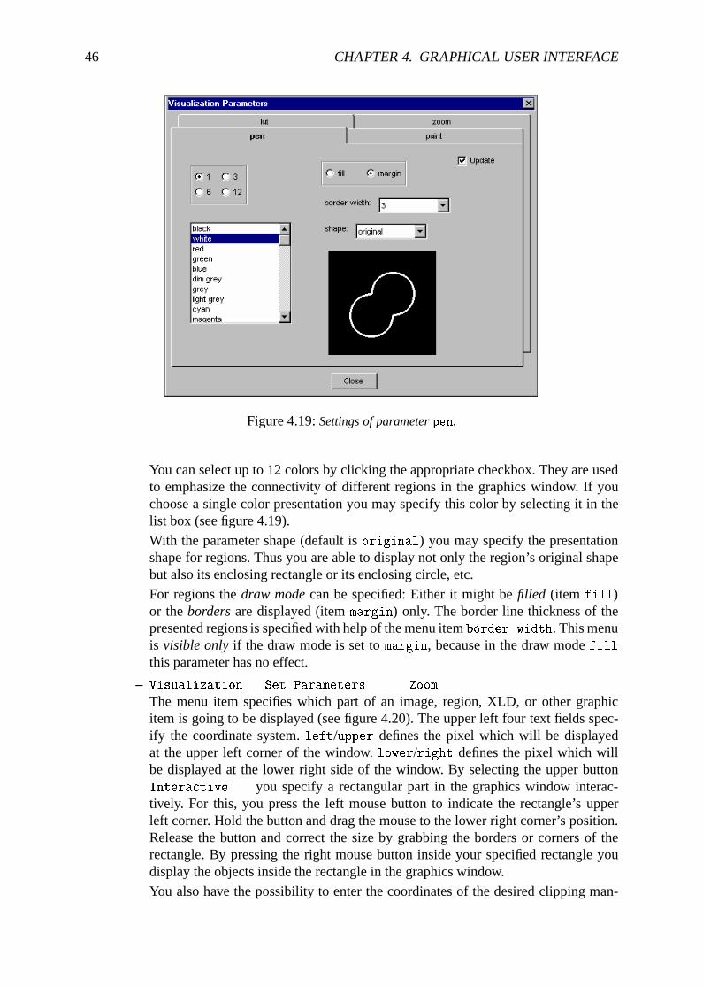
46 CHAPTER 4. GRAPHICAL USER INTERFACE
Figure 4.19:Settings of parameterpen.
You can select up to 12 colors by clicking the appropriate checkbox. They are usedto emphasize the connectivity of different regions in the graphics window. If youchoose a single color presentation you may specify this color by selecting it in thelist box (see figure 4.19).With the parameter shape (default isoriginal) you may specify the presentationshape for regions. Thus you are able to display not only the region’s original shapebut also its enclosing rectangle or its enclosing circle, etc.For regions thedraw modecan be specified: Either it might befilled (item fill)or thebordersare displayed (itemmargin) only. The border line thickness of thepresented regions is specified with help of the menu itemborder width. This menuis visible onlyif the draw mode is set tomargin, because in the draw modefillthis parameter has no effect.
– Visualization . Set Parameters... . Zoom
The menu item specifies which part of an image, region, XLD, or other graphicitem is going to be displayed (see figure 4.20). The upper left four text fields spec-ify the coordinate system.left/upper defines the pixel which will be displayedat the upper left corner of the window.lower/right defines the pixel which willbe displayed at the lower right side of the window. By selecting the upper buttonInteractive... you specify a rectangular part in the graphics window interac-tively. For this, you press the left mouse button to indicate the rectangle’s upperleft corner. Hold the button and drag the mouse to the lower right corner’s position.Release the button and correct the size by grabbing the borders or corners of therectangle. By pressing the right mouse button inside your specified rectangle youdisplay the objects inside the rectangle in the graphics window.You also have the possibility to enter the coordinates of the desired clipping man-
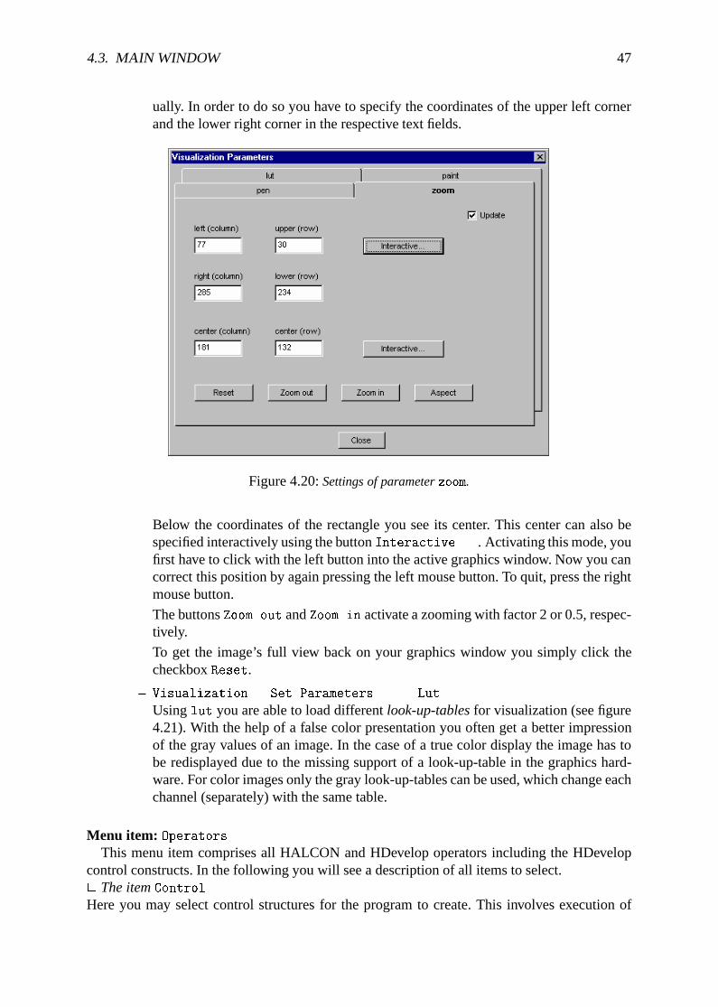
4.3. MAIN WINDOW 47
ually. In order to do so you have to specify the coordinates of the upper left cornerand the lower right corner in the respective text fields.
Figure 4.20:Settings of parameterzoom.
Below the coordinates of the rectangle you see its center. This center can also bespecified interactively using the buttonInteractive.... Activating this mode, youfirst have to click with the left button into the active graphics window. Now you cancorrect this position by again pressing the left mouse button. To quit, press the rightmouse button.
The buttonsZoom out andZoom in activate a zooming with factor 2 or 0.5, respec-tively.
To get the image’s full view back on your graphics window you simply click thecheckboxReset.
– Visualization . Set Parameters... . Lut
Usinglut you are able to load differentlook-up-tablesfor visualization (see figure4.21). With the help of a false color presentation you often get a better impressionof the gray values of an image. In the case of a true color display the image has tobe redisplayed due to the missing support of a look-up-table in the graphics hard-ware. For color images only the gray look-up-tables can be used, which change eachchannel (separately) with the same table.
Menu item: OperatorsThis menu item comprises all HALCON and HDevelop operators including the HDevelop
control constructs. In the following you will see a description of all items to select.2 The itemControlHere you may select control structures for the program to create. This involves execution of
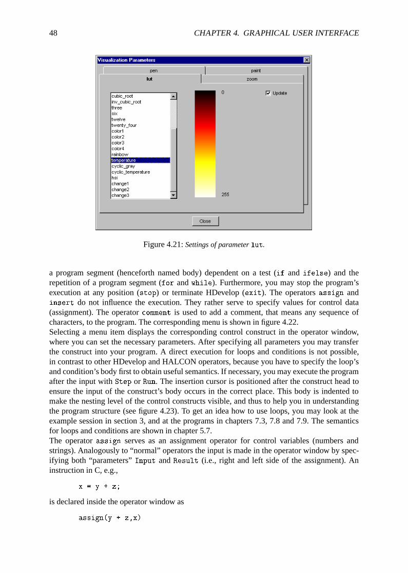
48 CHAPTER 4. GRAPHICAL USER INTERFACE
Figure 4.21:Settings of parameterlut.
a program segment (henceforth named body) dependent on a test (if and ifelse) and therepetition of a program segment (for andwhile). Furthermore, you may stop the program’sexecution at any position (stop) or terminate HDevelop (exit). The operatorsassign andinsert do not influence the execution. They rather serve to specify values for control data(assignment). The operatorcomment is used to add a comment, that means any sequence ofcharacters, to the program. The corresponding menu is shown in figure 4.22.Selecting a menu item displays the corresponding control construct in the operator window,where you can set the necessary parameters. After specifying all parameters you may transferthe construct into your program. A direct execution for loops and conditions is not possible,in contrast to other HDevelop and HALCON operators, because you have to specify the loop’sand condition’s body first to obtain useful semantics. If necessary, you may execute the programafter the input withStep or Run. The insertion cursor is positioned after the construct head toensure the input of the construct’s body occurs in the correct place. This body is indented tomake the nesting level of the control constructs visible, and thus to help you in understandingthe program structure (see figure 4.23). To get an idea how to use loops, you may look at theexample session in section 3, and at the programs in chapters 7.3, 7.8 and 7.9. The semanticsfor loops and conditions are shown in chapter 5.7.The operatorassign serves as an assignment operator for control variables (numbers andstrings). Analogously to “normal” operators the input is made in the operator window by spec-ifying both “parameters”Input andResult (i.e., right and left side of the assignment). Aninstruction in C, e.g.,
x = y + z;
is declared inside the operator window as
assign(y + z,x)
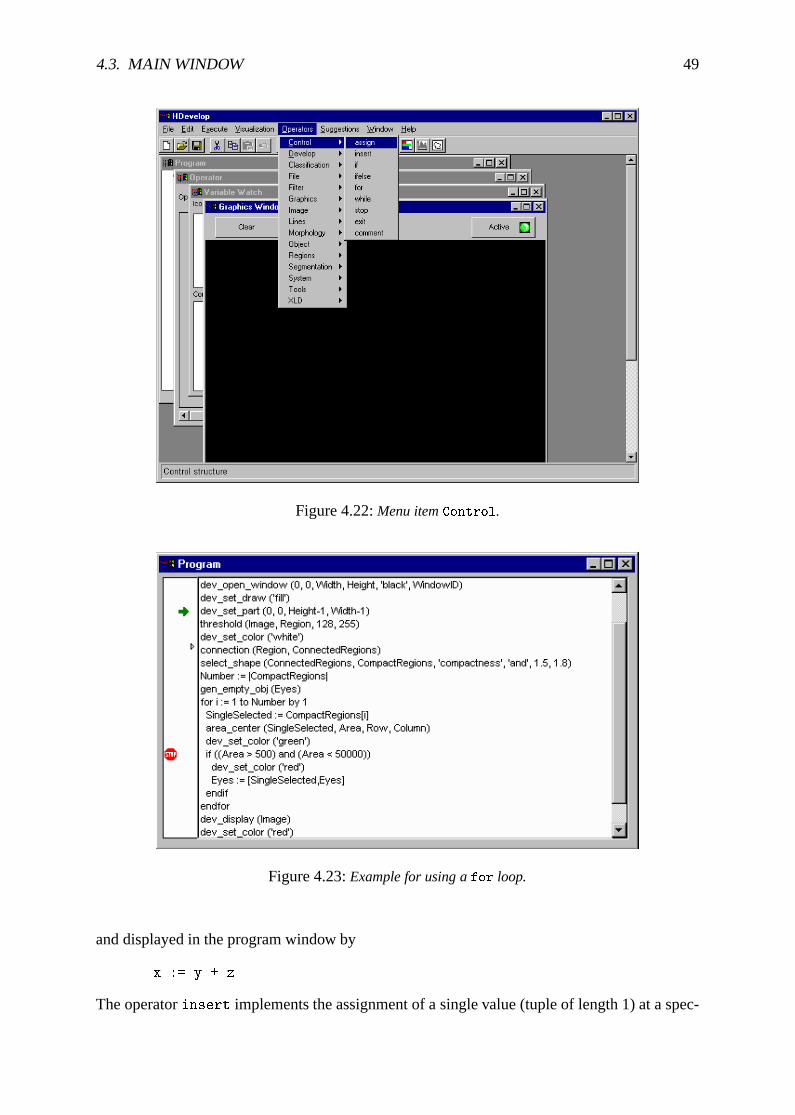
4.3. MAIN WINDOW 49
Figure 4.22:Menu itemControl.
Figure 4.23:Example for using afor loop.
and displayed in the program window by
x := y + z
The operatorinsert implements the assignment of a single value (tuple of length 1) at a spec-
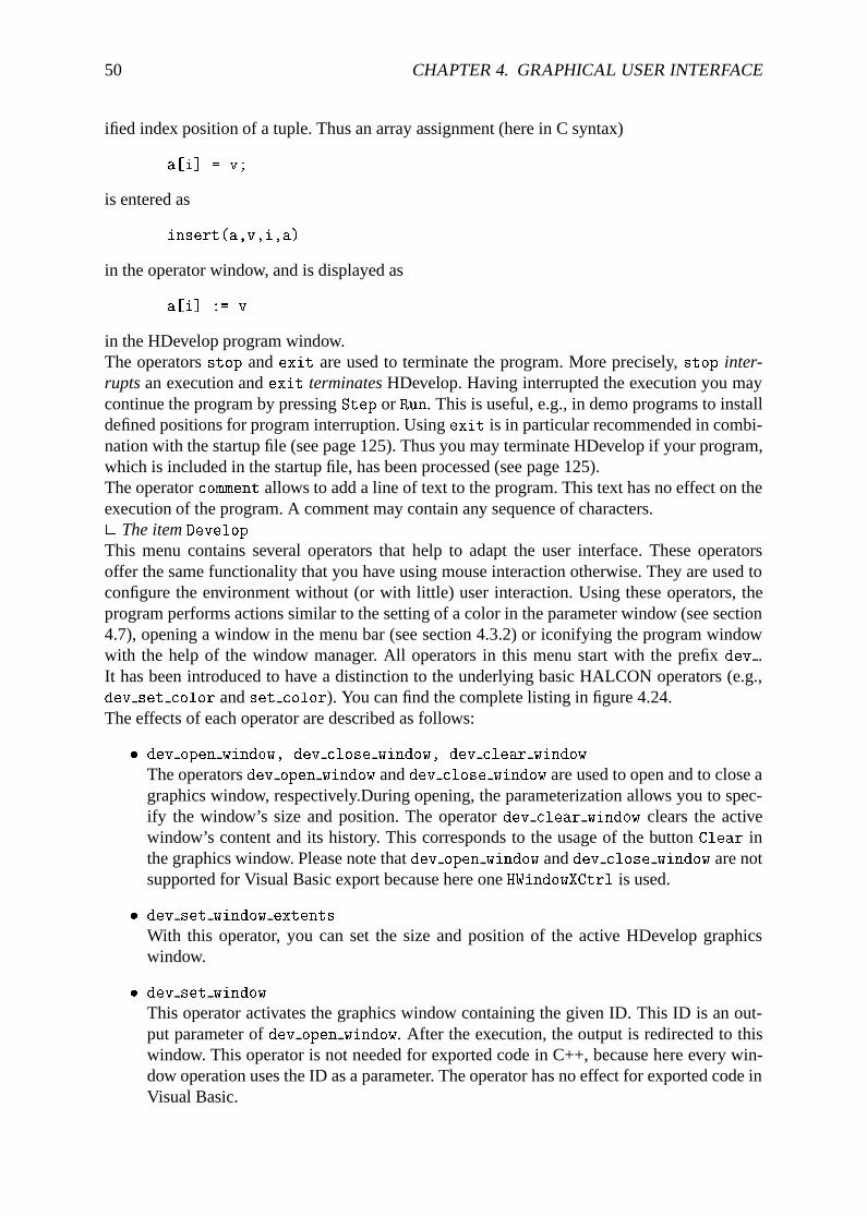
50 CHAPTER 4. GRAPHICAL USER INTERFACE
ified index position of a tuple. Thus an array assignment (here in C syntax)
a[i] = v;
is entered as
insert(a,v,i,a)
in the operator window, and is displayed as
a[i] := v
in the HDevelop program window.The operatorsstop andexit are used to terminate the program. More precisely,stop inter-ruptsan execution andexit terminatesHDevelop. Having interrupted the execution you maycontinue the program by pressingStep or Run. This is useful, e.g., in demo programs to installdefined positions for program interruption. Usingexit is in particular recommended in combi-nation with the startup file (see page 125). Thus you may terminate HDevelop if your program,which is included in the startup file, has been processed (see page 125).The operatorcomment allows to add a line of text to the program. This text has no effect on theexecution of the program. A comment may contain any sequence of characters.2 The itemDevelopThis menu contains several operators that help to adapt the user interface. These operatorsoffer the same functionality that you have using mouse interaction otherwise. They are used toconfigure the environment without (or with little) user interaction. Using these operators, theprogram performs actions similar to the setting of a color in the parameter window (see section4.7), opening a window in the menu bar (see section 4.3.2) or iconifying the program windowwith the help of the window manager. All operators in this menu start with the prefixdev .It has been introduced to have a distinction to the underlying basic HALCON operators (e.g.,dev set color andset color). You can find the complete listing in figure 4.24.The effects of each operator are described as follows:
� dev open window, dev close window, dev clear window
The operatorsdev open window anddev close window are used to open and to close agraphics window, respectively.During opening, the parameterization allows you to spec-ify the window’s size and position. The operatordev clear window clears the activewindow’s content and its history. This corresponds to the usage of the buttonClear inthe graphics window. Please note thatdev open window anddev close window are notsupported for Visual Basic export because here oneHWindowXCtrl is used.
� dev set window extents
With this operator, you can set the size and position of the active HDevelop graphicswindow.
� dev set window
This operator activates the graphics window containing the given ID. This ID is an out-put parameter ofdev open window. After the execution, the output is redirected to thiswindow. This operator is not needed for exported code in C++, because here every win-dow operation uses the ID as a parameter. The operator has no effect for exported code inVisual Basic.
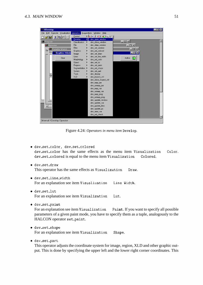
4.3. MAIN WINDOW 51
Figure 4.24:Operators in menu itemDevelop.
� dev set color, dev set colored
dev set color has the same effects as the menu itemVisualization . Color.dev set colored is equal to the menu itemVisualization . Colored.
� dev set draw
This operator has the same effects asVisualization . Draw.
� dev set line width
For an explanation see itemVisualization . Line Width.
� dev set lut
For an explanation see itemVisualization . Lut.
� dev set paint
For an explanation see itemVisualization . Paint. If you want to specify all possibleparameters of a given paint mode, you have to specify them as a tuple, analogously to theHALCON operatorset paint.
� dev set shape
For an explanation see itemVisualization . Shape.
� dev set part
This operator adjusts the coordinate system for image, region, XLD and other graphic out-put. This is done by specifying the upper left and the lower right corner coordinates. This
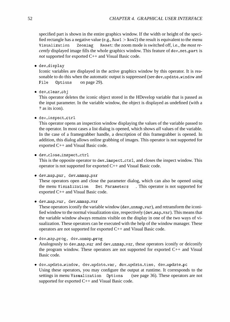
52 CHAPTER 4. GRAPHICAL USER INTERFACE
specified part is shown in the entire graphics window. If the width or height of the speci-fied rectangle has a negative value (e.g.,Row1> Row2) the result is equivalent to the menuVisualization . Zooming . Reset: the zoom mode is switched off, i.e., themost re-centlydisplayed image fills the whole graphics window. This feature ofdev set part isnotsupported for exported C++ and Visual Basic code.
� dev display
Iconic variables are displayed in the active graphics window by this operator. It is rea-sonable to do this when the automatic output is suppressed (seedev update window andFile . Options... on page 29).
� dev clear obj
This operator deletes the iconic object stored in the HDevelop variable that is passed asthe input parameter. In the variable window, the object is displayed as undefined (with a? as its icon).
� dev inspect ctrl
This operator opens an inspection window displaying the values of the variable passed tothe operator. In most cases a list dialog is opened, which showsall values of the variable.In the case of a framegrabber handle, a description of this framegrabber is opened. Inaddition, this dialog allows online grabbing of images. This operator is not supported forexported C++ and Visual Basic code.
� dev close inspect ctrl
This is the opposite operator todev inspect ctrl, and closes the inspect window. Thisoperator is not supported for exported C++ and Visual Basic code.
� dev map par, dev unmap par
These operators open and close the parameter dialog, which can also be opened usingthe menuVisualization . Set Parameters.... This operator is not supported forexported C++ and Visual Basic code.
� dev map var, dev unmap var
These operators iconify the variable window (dev unmap var), and retransform the iconi-fied window to the normal visualization size, respectively (dev map var). This means thatthe variable window always remains visible on the display in one of the two ways of vi-sualization. These operators can be executed with the help of the window manager. Theseoperators are not supported for exported C++ and Visual Basic code.
� dev map prog, dev unmap prog
Analogously todev map var anddev unmap var, these operators iconify or deiconifythe program window. These operators are not supported for exported C++ and VisualBasic code.
� dev update window, dev update var, dev update time, dev update pc
Using these operators, you may configure the output at runtime. It corresponds to thesettings in menuVisualization . Options... (see page 36). These operators are notsupported for exported C++ and Visual Basic code.
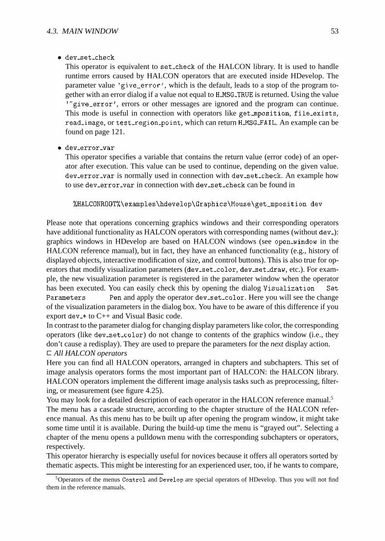
4.3. MAIN WINDOW 53
� dev set check
This operator is equivalent toset check of the HALCON library. It is used to handleruntime errors caused by HALCON operators that are executed inside HDevelop. Theparameter value'give_error', which is the default, leads to a stop of the program to-gether with an error dialog if a value not equal toH MSG TRUE is returned. Using the value'~give_error', errors or other messages are ignored and the program can continue.This mode is useful in connection with operators likeget mposition, file exists,read image, or test region point, which can returnH MSG FAIL. An example can befound on page 121.
� dev error var
This operator specifies a variable that contains the return value (error code) of an oper-ator after execution. This value can be used to continue, depending on the given value.dev error var is normally used in connection withdev set check. An example howto usedev error var in connection withdev set check can be found in
%HALCONROOT%\examples\hdevelop\Graphics\Mouse\get_mposition.dev .
Please note that operations concerning graphics windows and their corresponding operatorshave additional functionality as HALCON operators with corresponding names (withoutdev ):graphics windows in HDevelop are based on HALCON windows (seeopen window in theHALCON reference manual), but in fact, they have an enhanced functionality (e.g., history ofdisplayed objects, interactive modification of size, and control buttons). This is also true for op-erators that modify visualization parameters (dev set color, dev set draw, etc.). For exam-ple, the new visualization parameter is registered in the parameter window when the operatorhas been executed. You can easily check this by opening the dialogVisualization . Set
Parameters... . Pen and apply the operatordev set color. Here you will see the changeof the visualization parameters in the dialog box. You have to be aware of this difference if youexportdev * to C++ and Visual Basic code.In contrast to the parameter dialog for changing display parameters like color, the correspondingoperators (likedev set color) do not change to contents of the graphics window (i.e., theydon’t cause a redisplay). They are used to prepare the parameters for thenextdisplay action.2 All HALCON operatorsHere you can find all HALCON operators, arranged in chapters and subchapters. This set ofimage analysis operators forms the most important part of HALCON: the HALCON library.HALCON operators implement the different image analysis tasks such as preprocessing, filter-ing, or measurement (see figure 4.25).You may look for a detailed description of each operator in the HALCON reference manual.5
The menu has a cascade structure, according to the chapter structure of the HALCON refer-ence manual. As this menu has to be built up after opening the program window, it might takesome time until it is available. During the build-up time the menu is “grayed out”. Selecting achapter of the menu opens a pulldown menu with the corresponding subchapters or operators,respectively.This operator hierarchy is especially useful for novices because it offers all operators sorted bythematic aspects. This might be interesting for an experienced user, too, if he wants to compare,
5Operators of the menusControl andDevelop are special operators of HDevelop. Thus you will not findthem in the reference manuals.
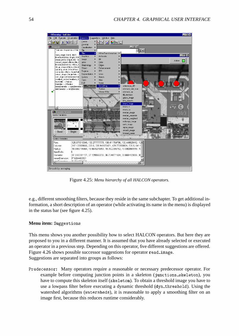
54 CHAPTER 4. GRAPHICAL USER INTERFACE
Figure 4.25:Menu hierarchy of all HALCON operators.
e.g., different smoothing filters, because they reside in the same subchapter. To get additional in-formation, a short description of an operator (while activating its name in the menu) is displayedin the status bar (see figure 4.25).
Menu item: Suggestions
This menu shows you another possibility how to select HALCON operators. But here they areproposed to you in a different manner. It is assumed that you have already selected or executedan operator in a previous step. Depending on this operator, five different suggestions are offered.Figure 4.26 shows possible successor suggestions for operatorread image.Suggestions are separated into groups as follows:
Predecessor: Many operators require a reasonable or necessary predecessor operator. Forexample before computing junction points in a skeleton (junctions skeleton), youhave to compute this skeleton itself (skeleton). To obtain a threshold image you have touse a lowpass filter before executing a dynamic threshold (dyn threshold). Using thewatershed algorithms (watersheds), it is reasonable to apply a smoothing filter on animage first, because this reduces runtime considerably.
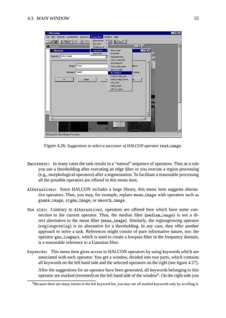
4.3. MAIN WINDOW 55
Figure 4.26:Suggestions to select a successor of HALCON operatorread image.
Successor: In many cases the task results in a “natural” sequence of operators. Thus as a ruleyou use a thresholding after executing an edge filter or you execute a region processing(e.g., morphological operators) after a segmentation. To facilitate a reasonable processingall the possible operators are offered in this menu item.
Alternatives: Since HALCON includes a large library, this menu item suggests alterna-tive operators. Thus, you may, for example, replacemean image with operators such asgauss image, sigma image, or smooth image.
See also: Contrary toAlternatives, operators are offered here which have somecon-nection to the current operator. Thus, the median filter (median image) is not a di-rect alternative to the mean filter (mean image). Similarly, the regiongrowing operator(regiongrowing) is no alternative for a thresholding. In any case, they offer anotherapproach to solve a task. References might consist of pure informative nature, too: theoperatorgen lowpass, which is used to create a lowpass filter in the frequency domain,is a reasonable reference to a Gaussian filter.
Keywords: This menu item gives access to HALCON operators by using keywords which areassociated with each operator. You get a window, divided into two parts, which containsall keywords on the left hand side and the selected operators on the right (see figure 4.27).
After the suggestions for an operator have been generated, all keywords belonging to thisoperator are marked (reversed) on the left hand side of the window6. On the right side you
6Because there are many entries in the left keyword list, you may see all marked keywords only by scrolling it.
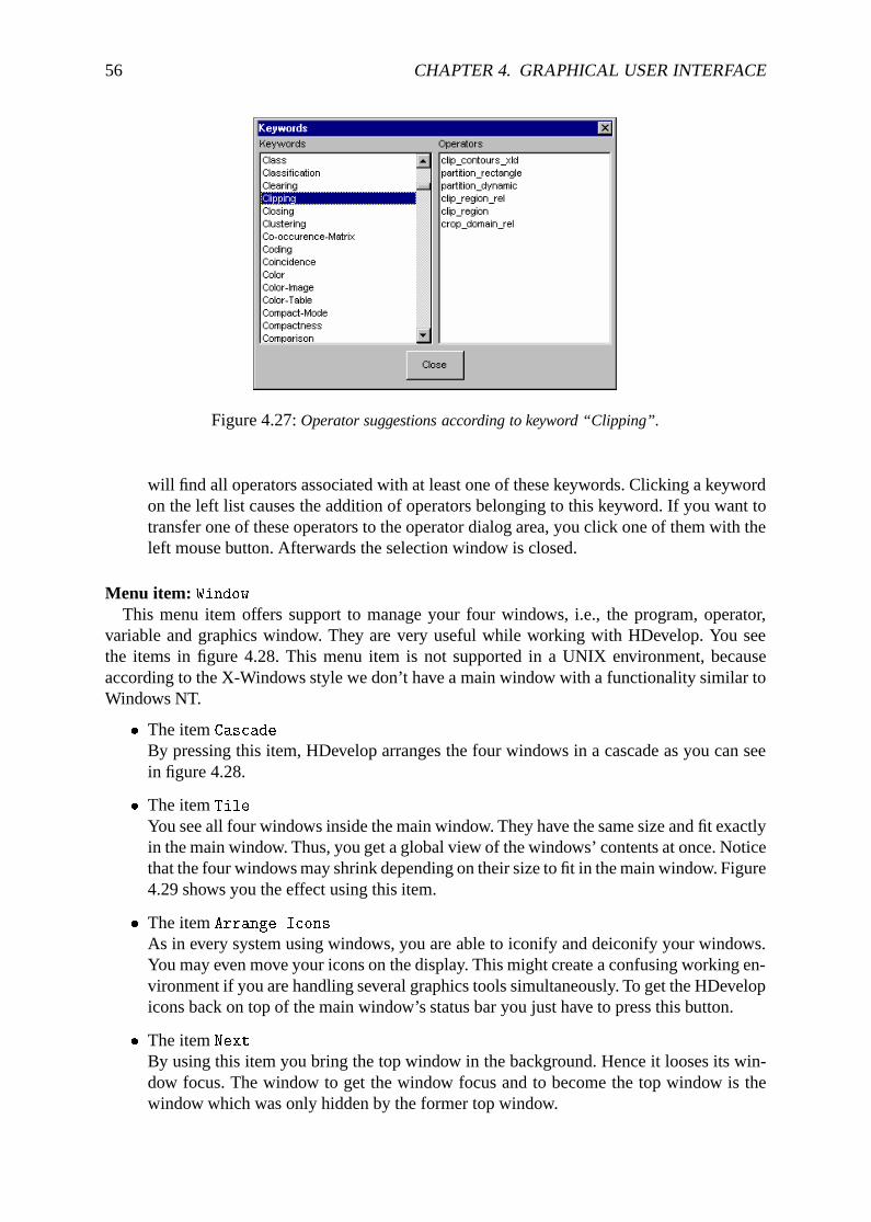
56 CHAPTER 4. GRAPHICAL USER INTERFACE
Figure 4.27:Operator suggestions according to keyword “Clipping”.
will find all operators associated with at least one of these keywords. Clicking a keywordon the left list causes the addition of operators belonging to this keyword. If you want totransfer one of these operators to the operator dialog area, you click one of them with theleft mouse button. Afterwards the selection window is closed.
Menu item: WindowThis menu item offers support to manage your four windows, i.e., the program, operator,
variable and graphics window. They are very useful while working with HDevelop. You seethe items in figure 4.28. This menu item is not supported in a UNIX environment, becauseaccording to the X-Windows style we don’t have a main window with a functionality similar toWindows NT.
� The itemCascade
By pressing this item, HDevelop arranges the four windows in a cascade as you can seein figure 4.28.
� The itemTile
You see all four windows inside the main window. They have the same size and fit exactlyin the main window. Thus, you get a global view of the windows’ contents at once. Noticethat the four windows may shrink depending on their size to fit in the main window. Figure4.29 shows you the effect using this item.
� The itemArrange Icons
As in every system using windows, you are able to iconify and deiconify your windows.You may even move your icons on the display. This might create a confusing working en-vironment if you are handling several graphics tools simultaneously. To get the HDevelopicons back on top of the main window’s status bar you just have to press this button.
� The itemNext
By using this item you bring the top window in the background. Hence it looses its win-dow focus. The window to get the window focus and to become the top window is thewindow which was only hidden by the former top window.
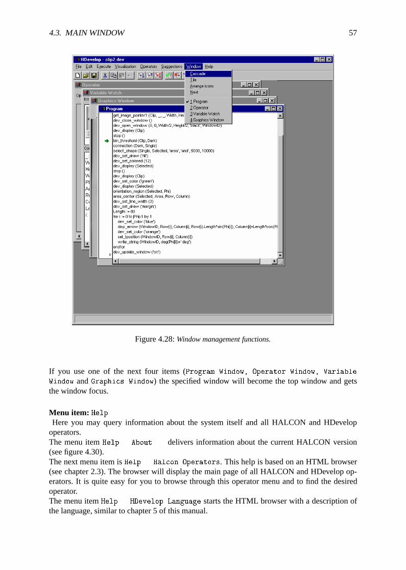
4.3. MAIN WINDOW 57
Figure 4.28:Window management functions.
If you use one of the next four items (Program Window, Operator Window, Variable
Window andGraphics Window) the specified window will become the top window and getsthe window focus.
Menu item: HelpHere you may query information about the system itself and all HALCON and HDevelop
operators.The menu itemHelp . About... delivers information about the current HALCON version(see figure 4.30).The next menu item isHelp . Halcon Operators. This help is based on an HTML browser(see chapter 2.3). The browser will display the main page of all HALCON and HDevelop op-erators. It is quite easy for you to browse through this operator menu and to find the desiredoperator.The menu itemHelp . HDevelop Language starts the HTML browser with a description ofthe language, similar to chapter 5 of this manual.
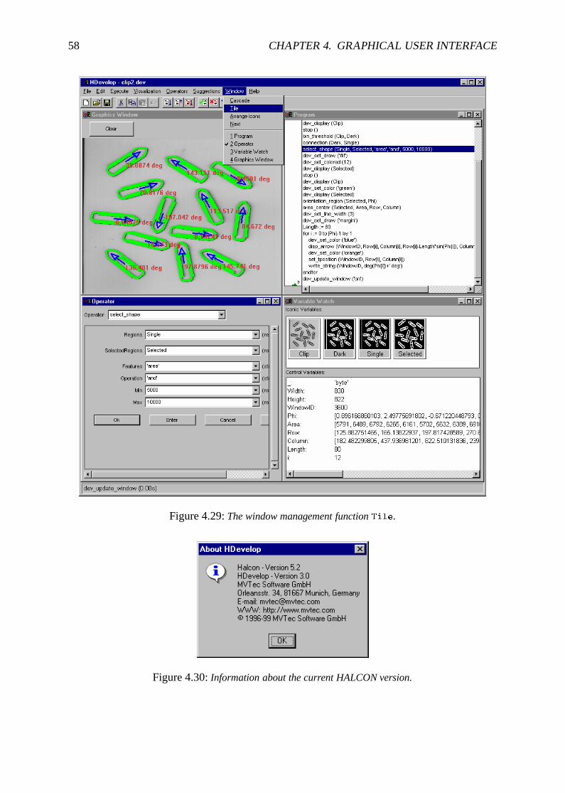
58 CHAPTER 4. GRAPHICAL USER INTERFACE
Figure 4.29:The window management functionTile.
Figure 4.30:Information about the current HALCON version.
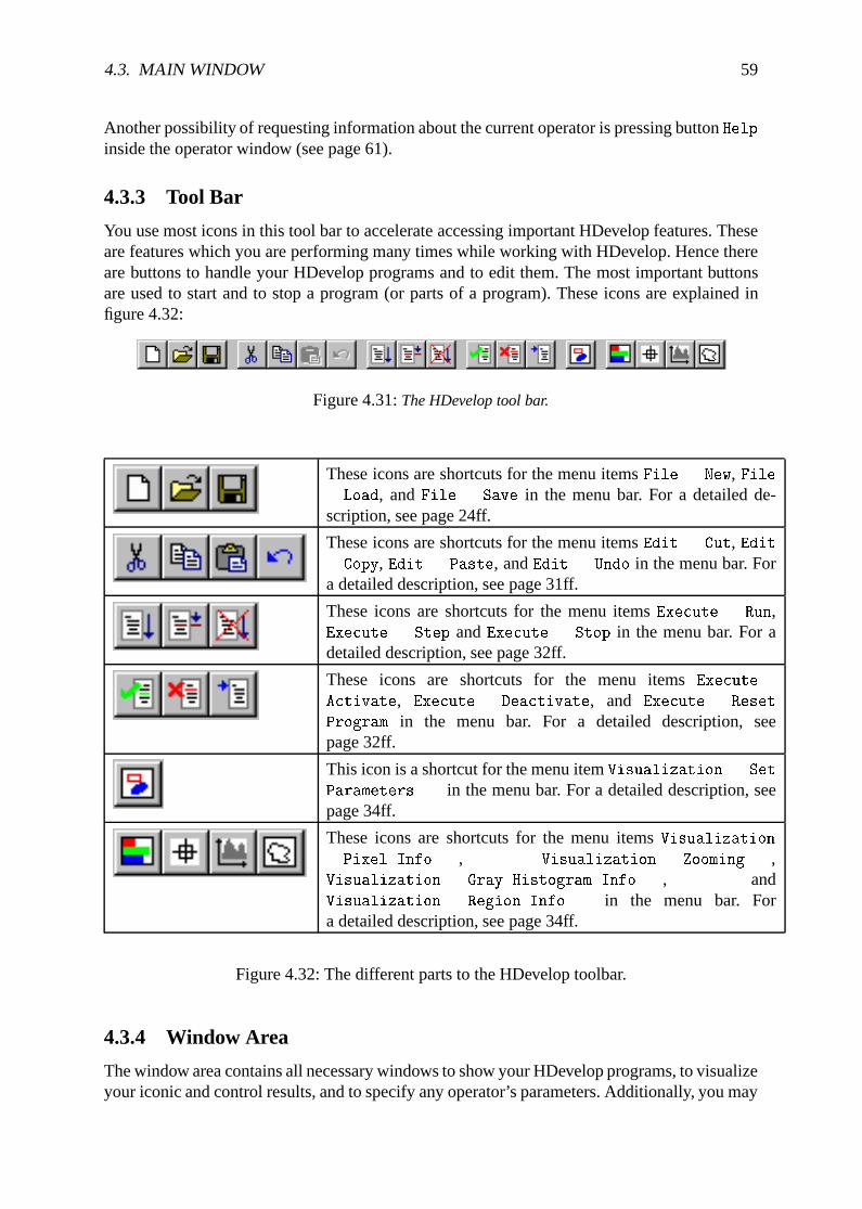
4.3. MAIN WINDOW 59
Another possibility of requesting information about the current operator is pressing buttonHelp
inside the operator window (see page 61).
4.3.3 Tool Bar
You use most icons in this tool bar to accelerate accessing important HDevelop features. Theseare features which you are performing many times while working with HDevelop. Hence thereare buttons to handle your HDevelop programs and to edit them. The most important buttonsare used to start and to stop a program (or parts of a program). These icons are explained infigure 4.32:
Figure 4.31:The HDevelop tool bar.
These icons are shortcuts for the menu itemsFile . New, File. Load, andFile . Save in the menu bar. For a detailed de-scription, see page 24ff.
These icons are shortcuts for the menu itemsEdit . Cut, Edit. Copy, Edit . Paste, andEdit . Undo in the menu bar. Fora detailed description, see page 31ff.
These icons are shortcuts for the menu itemsExecute . Run,Execute . Step andExecute . Stop in the menu bar. For adetailed description, see page 32ff.
These icons are shortcuts for the menu itemsExecute .
Activate, Execute . Deactivate, and Execute . Reset
Program in the menu bar. For a detailed description, seepage 32ff.
This icon is a shortcut for the menu itemVisualization . Set
Parameters... in the menu bar. For a detailed description, seepage 34ff.
These icons are shortcuts for the menu itemsVisualization
. Pixel Info..., Visualization . Zooming...,Visualization . Gray Histogram Info..., andVisualization . Region Info... in the menu bar. Fora detailed description, see page 34ff.
Figure 4.32: The different parts to the HDevelop toolbar.
4.3.4 Window Area
The window area contains all necessary windows to show your HDevelop programs, to visualizeyour iconic and control results, and to specify any operator’s parameters. Additionally, you may
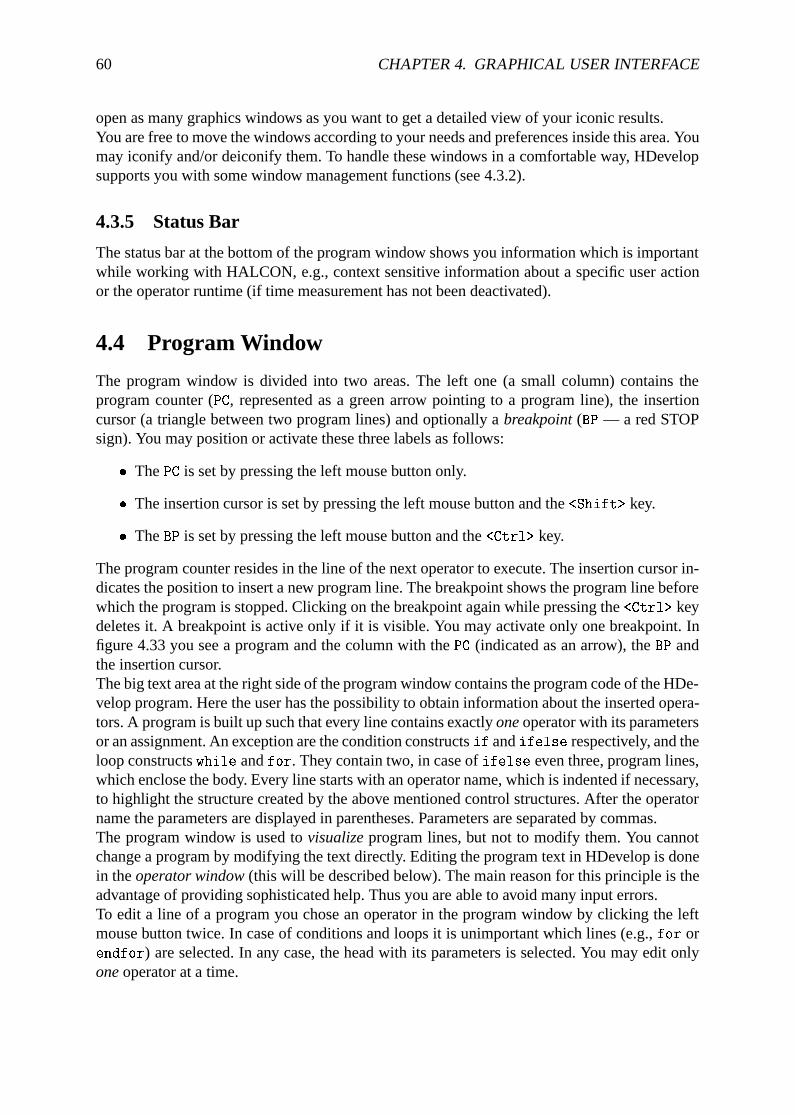
60 CHAPTER 4. GRAPHICAL USER INTERFACE
open as many graphics windows as you want to get a detailed view of your iconic results.You are free to move the windows according to your needs and preferences inside this area. Youmay iconify and/or deiconify them. To handle these windows in a comfortable way, HDevelopsupports you with some window management functions (see 4.3.2).
4.3.5 Status Bar
The status bar at the bottom of the program window shows you information which is importantwhile working with HALCON, e.g., context sensitive information about a specific user actionor the operator runtime (if time measurement has not been deactivated).
4.4 Program Window
The program window is divided into two areas. The left one (a small column) contains theprogram counter (PC, represented as a green arrow pointing to a program line), the insertioncursor (a triangle between two program lines) and optionally abreakpoint(BP — a red STOPsign). You may position or activate these three labels as follows:
� ThePC is set by pressing the left mouse button only.
� The insertion cursor is set by pressing the left mouse button and the<Shift> key.
� TheBP is set by pressing the left mouse button and the<Ctrl> key.
The program counter resides in the line of the next operator to execute. The insertion cursor in-dicates the position to insert a new program line. The breakpoint shows the program line beforewhich the program is stopped. Clicking on the breakpoint again while pressing the<Ctrl> keydeletes it. A breakpoint is active only if it is visible. You may activate only one breakpoint. Infigure 4.33 you see a program and the column with thePC (indicated as an arrow), theBP andthe insertion cursor.The big text area at the right side of the program window contains the program code of the HDe-velop program. Here the user has the possibility to obtain information about the inserted opera-tors. A program is built up such that every line contains exactlyoneoperator with its parametersor an assignment. An exception are the condition constructsif andifelse respectively, and theloop constructswhile andfor. They contain two, in case ofifelse even three, program lines,which enclose the body. Every line starts with an operator name, which is indented if necessary,to highlight the structure created by the above mentioned control structures. After the operatorname the parameters are displayed in parentheses. Parameters are separated by commas.The program window is used tovisualizeprogram lines, but not to modify them. You cannotchange a program by modifying the text directly. Editing the program text in HDevelop is donein theoperator window(this will be described below). The main reason for this principle is theadvantage of providing sophisticated help. Thus you are able to avoid many input errors.To edit a line of a program you chose an operator in the program window by clicking the leftmouse button twice. In case of conditions and loops it is unimportant which lines (e.g.,for orendfor) are selected. In any case, the head with its parameters is selected. You may edit onlyoneoperator at a time.
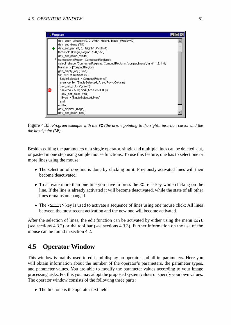
4.5. OPERATOR WINDOW 61
Figure 4.33:Program example with thePC (the arrow pointing to the right), insertion cursor and thethe breakpoint (BP).
Besides editing the parameters of a single operator, single and multiple lines can be deleted, cut,or pasted in one step using simple mouse functions. To use this feature, one has to select one ormore lines using the mouse:
� The selection ofone line is done by clicking on it. Previously activated lines will thenbecome deactivated.
� To activate more than one line you have to press the<Ctrl> key while clicking on theline. If the line is already activated it will become deactivated, while the state of all otherlines remains unchanged.
� The<Shift> key is used to activate a sequence of lines using one mouse click: All linesbetween the most recent activation and the new one will become activated.
After the selection of lines, the edit function can be activated by either using the menuEdit
(see sections 4.3.2) or the tool bar (see sections 4.3.3). Further information on the use of themouse can be found in section 4.2.
4.5 Operator Window
This window is mainly used to edit and display an operator and all its parameters. Here youwill obtain information about the number of the operator’s parameters, the parameter types,and parameter values. You are able to modify the parameter values according to your imageprocessing tasks. For this you may adopt the proposed system values or specify your own values.The operator window consists of the following three parts:
� The first one is the operator text field.
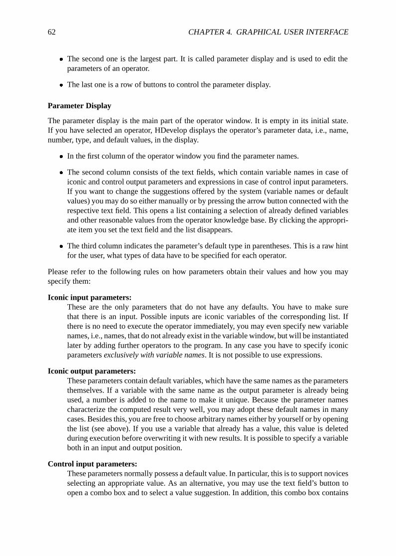
62 CHAPTER 4. GRAPHICAL USER INTERFACE
� The second one is the largest part. It is called parameter display and is used to edit theparameters of an operator.
� The last one is a row of buttons to control the parameter display.
Parameter Display
The parameter display is the main part of the operator window. It is empty in its initial state.If you have selected an operator, HDevelop displays the operator’s parameter data, i.e., name,number, type, and default values, in the display.
� In the first column of the operator window you find the parameter names.
� The second column consists of the text fields, which contain variable names in case oficonic and control output parameters and expressions in case of control input parameters.If you want to change the suggestions offered by the system (variable names or defaultvalues) you may do so either manually or by pressing the arrow button connected with therespective text field. This opens a list containing a selection of already defined variablesand other reasonable values from the operator knowledge base. By clicking the appropri-ate item you set the text field and the list disappears.
� The third column indicates the parameter’s default type in parentheses. This is a raw hintfor the user, what types of data have to be specified for each operator.
Please refer to the following rules on how parameters obtain their values and how you mayspecify them:
Iconic input parameters:These are the only parameters that do not have any defaults. You have to make surethat there is an input. Possible inputs are iconic variables of the corresponding list. Ifthere is no need to execute the operator immediately, you may even specify new variablenames, i.e., names, that do not already exist in the variable window, but will be instantiatedlater by adding further operators to the program. In any case you have to specify iconicparametersexclusively with variable names. It is not possible to use expressions.
Iconic output parameters:These parameters contain default variables, which have the same names as the parametersthemselves. If a variable with the same name as the output parameter is already beingused, a number is added to the name to make it unique. Because the parameter namescharacterize the computed result very well, you may adopt these default names in manycases. Besides this, you are free to choose arbitrary names either by yourself or by openingthe list (see above). If you use a variable that already has a value, this value is deletedduring execution before overwriting it with new results. It is possible to specify a variableboth in an input and output position.
Control input parameters:These parameters normally possess a default value. In particular, this is to support novicesselecting an appropriate value. As an alternative, you may use the text field’s button toopen a combo box and to select a value suggestion. In addition, this combo box contains
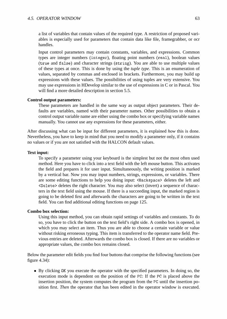
4.5. OPERATOR WINDOW 63
a list of variables that contain values of the required type. A restriction of proposed vari-ables is especially used for parameters that contain data like file, framegrabber, or ocrhandles.
Input control parameters may contain constants, variables, and expressions. Commontypes are integer numbers (integer), floating point numbers (real), boolean values(true andfalse) and character strings (string). You are able to use multiple valuesof these types at once. This is done by using thetuple type. This is an enumeration ofvalues, separated by commas and enclosed in brackets. Furthermore, you may build upexpressions with these values. The possibilities of using tuples are very extensive. Youmay use expressions in HDevelop similar to the use of expressions in C or in Pascal. Youwill find a more detailed description in section 5.5.
Control output parameters:These parameters are handled in the same way as output object parameters. Their de-faults are variables, named with their parameter names. Other possibilities to obtain acontrol output variable name are either using the combo box or specifying variable namesmanually. You cannot use any expressions for these parameters, either.
After discussing what can be input for different parameters, it is explainedhow this is done.Nevertheless, you have to keep in mind that you need to modify a parameter only, if it containsno values or if you are not satisfied with the HALCON default values.
Text input:To specify a parameter using your keyboard is the simplest but not the most often usedmethod. Here you have to click into a text field with the left mouse button. This activatesthe field and prepares it for user input. Simultaneously, the writing position is markedby a vertical bar. Now you may input numbers, strings, expressions, or variables. Thereare some editing functions to help you doing input:<Backspace> deletes the left and<Delete> deletes the right character. You may also select (invert) a sequence of charac-ters in the text field using the mouse. If there is a succeeding input, the marked region isgoing to be deleted first and afterwards the characters are going to be written in the textfield. You can find additional editing functions on page 125.
Combo box selection:Using this input method, you can obtain rapid settings of variables and constants. To doso, you have to click the button on the text field’s right side. A combo box is opened, inwhich you may select an item. Thus you are able to choose a certain variable or valuewithout risking erroneous typing. This item is transferred to the operator name field. Pre-vious entries are deleted. Afterwards the combo box is closed. If there are no variables orappropriate values, the combo box remains closed.
Below the parameter edit fields you find four buttons that comprise the following functions (seefigure 4.34):
� By clicking OK you execute the operator with the specified parameters. In doing so, theexecution mode is dependent on the position of thePC: If the PC is placed above theinsertion position, the system computes the program from thePC until the insertion po-sition first. Thenthe operator that has been edited in the operator window is executed.
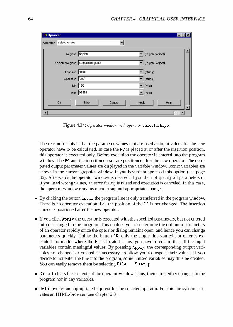
64 CHAPTER 4. GRAPHICAL USER INTERFACE
Figure 4.34:Operator window with operatorselect shape.
The reason for this is that the parameter values that are used as input values for the newoperator have to be calculated. In case thePC is placed at or after the insertion position,this operator is executed only. Before execution the operator is entered into the programwindow. ThePC and the insertion cursor are positioned after the new operator. The com-puted output parameter values are displayed in the variable window. Iconic variables areshown in the current graphics window, if you haven’t suppressed this option (see page36). Afterwards the operator window is cleared. If you did not specify all parameters orif you used wrong values, an error dialog is raised and execution is canceled. In this case,the operator window remains open to support appropriate changes.
� By clicking the buttonEnter the program line is only transferred in the program window.There is no operator execution, i.e., the position of thePC is not changed. The insertioncursor is positioned after the new operator.
� If you click Apply the operator is executed with the specified parameters, but not enteredinto or changed in the program. This enables you to determine the optimum parametersof an operator rapidly since the operator dialog remains open, and hence you can changeparameters quickly. Unlike the buttonOK, only the single line you edit or enter is ex-ecuted, no matter where thePC is located. Thus, you have to ensure that all the inputvariables contain maningful values. By pressingApply, the corresponding output vari-ables are changed or created, if necessary, to allow you to inspect their values. If youdecide to not enter the line into the program, some unused variables may thus be created.You can easily remove them by selectingFile . Cleanup.
� Cancel clears the contents of the operator window. Thus, there are neither changes in theprogram nor in any variables.
� Help invokes an appropriate help text for the selected operator. For this the system acti-vates an HTML-browser (see chapter 2.3).
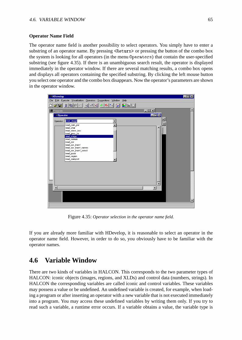
4.6. VARIABLE WINDOW 65
Operator Name Field
The operator name field is another possibility to select operators. You simply have to enter asubstring of an operator name. By pressing<Return> or pressing the button of the combo boxthe system is looking for all operators (in the menuOperators) that contain the user-specifiedsubstring (see figure 4.35). If there is an unambiguous search result, the operator is displayedimmediately in the operator window. If there are several matching results, a combo box opensand displays all operators containing the specified substring. By clicking the left mouse buttonyou select one operator and the combo box disappears. Now the operator’s parameters are shownin the operator window.
Figure 4.35:Operator selection in the operator name field.
If you are already more familiar with HDevelop, it is reasonable to select an operator in theoperator name field. However, in order to do so, you obviously have to be familiar with theoperator names.
4.6 Variable Window
There are two kinds of variables in HALCON. This corresponds to the two parameter types ofHALCON: iconic objects (images, regions, and XLDs) and control data (numbers, strings). InHALCON the corresponding variables are called iconic and control variables. These variablesmay possess a value or be undefined. An undefined variable is created, for example, when load-ing a program or after inserting an operator with a new variable that is not executed immediatelyinto a program. You may access these undefined variables by writing them only. If you try toread such a variable, a runtime error occurs. If a variable obtains a value, the variable type is
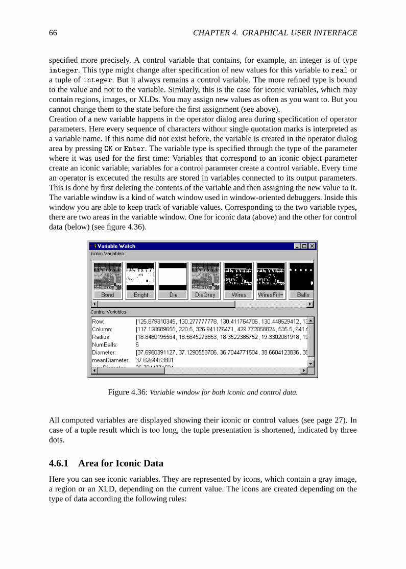
66 CHAPTER 4. GRAPHICAL USER INTERFACE
specified more precisely. A control variable that contains, for example, an integer is of typeinteger. This type might change after specification of new values for this variable toreal ora tuple ofinteger. But it always remains a control variable. The more refined type is boundto the value and not to the variable. Similarly, this is the case for iconic variables, which maycontain regions, images, or XLDs. You may assign new values as often as you want to. But youcannot change them to the state before the first assignment (see above).Creation of a new variable happens in the operator dialog area during specification of operatorparameters. Here every sequence of characters without single quotation marks is interpreted asa variable name. If this name did not exist before, the variable is created in the operator dialogarea by pressingOK or Enter. The variable type is specified through the type of the parameterwhere it was used for the first time: Variables that correspond to an iconic object parametercreate an iconic variable; variables for a control parameter create a control variable. Every timean operator is excecuted the results are stored in variables connected to its output parameters.This is done by first deleting the contents of the variable and then assigning the new value to it.The variable window is a kind of watch window used in window-oriented debuggers. Inside thiswindow you are able to keep track of variable values. Corresponding to the two variable types,there are two areas in the variable window. One for iconic data (above) and the other for controldata (below) (see figure 4.36).
Figure 4.36:Variable window for both iconic and control data.
All computed variables are displayed showing their iconic or control values (see page 27). Incase of a tuple result which is too long, the tuple presentation is shortened, indicated by threedots.
4.6.1 Area for Iconic Data
Here you can see iconic variables. They are represented by icons, which contain a gray image,a region or an XLD, depending on the current value. The icons are created depending on thetype of data according the following rules:
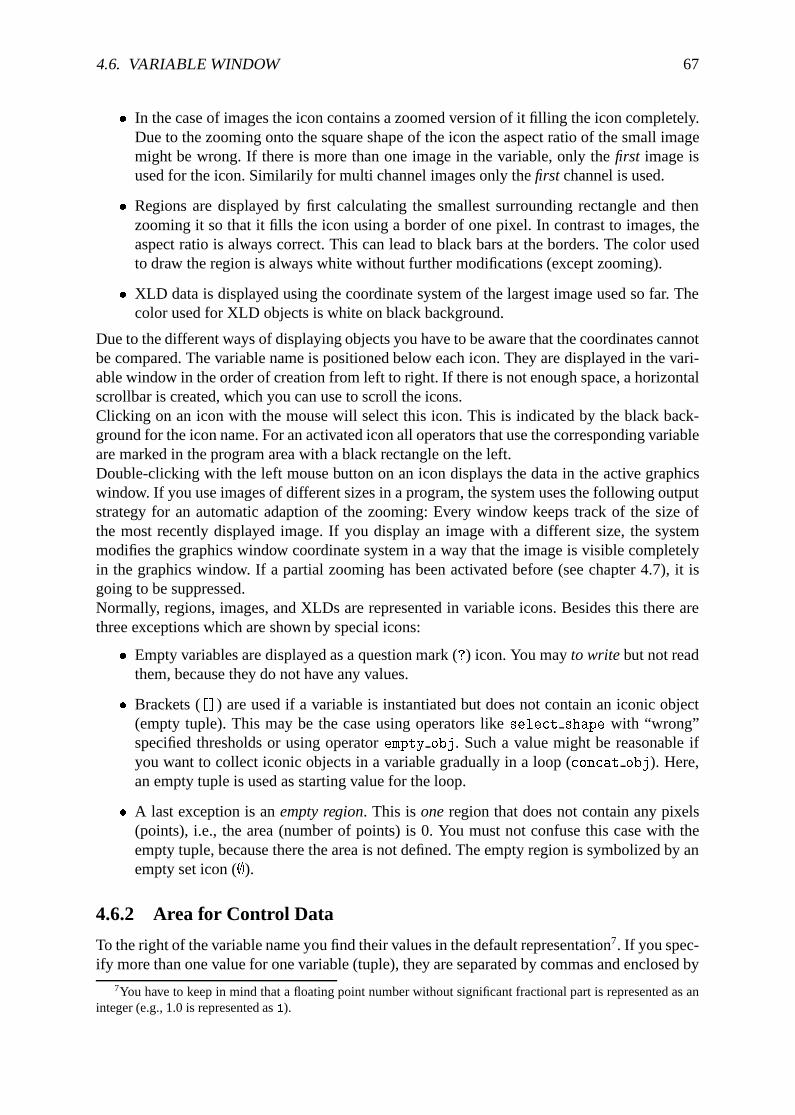
4.6. VARIABLE WINDOW 67
� In the case of images the icon contains a zoomed version of it filling the icon completely.Due to the zooming onto the square shape of the icon the aspect ratio of the small imagemight be wrong. If there is more than one image in the variable, only thefirst image isused for the icon. Similarily for multi channel images only thefirst channel is used.
� Regions are displayed by first calculating the smallest surrounding rectangle and thenzooming it so that it fills the icon using a border of one pixel. In contrast to images, theaspect ratio is always correct. This can lead to black bars at the borders. The color usedto draw the region is always white without further modifications (except zooming).
� XLD data is displayed using the coordinate system of the largest image used so far. Thecolor used for XLD objects is white on black background.
Due to the different ways of displaying objects you have to be aware that the coordinates cannotbe compared. The variable name is positioned below each icon. They are displayed in the vari-able window in the order of creation from left to right. If there is not enough space, a horizontalscrollbar is created, which you can use to scroll the icons.Clicking on an icon with the mouse will select this icon. This is indicated by the black back-ground for the icon name. For an activated icon all operators that use the corresponding variableare marked in the program area with a black rectangle on the left.Double-clicking with the left mouse button on an icon displays the data in the active graphicswindow. If you use images of different sizes in a program, the system uses the following outputstrategy for an automatic adaption of the zooming: Every window keeps track of the size ofthe most recently displayed image. If you display an image with a different size, the systemmodifies the graphics window coordinate system in a way that the image is visible completelyin the graphics window. If a partial zooming has been activated before (see chapter 4.7), it isgoing to be suppressed.Normally, regions, images, and XLDs are represented in variable icons. Besides this there arethree exceptions which are shown by special icons:
� Empty variables are displayed as a question mark (?) icon. You mayto writebut not readthem, because they do not have any values.
� Brackets ([]) are used if a variable is instantiated but does not contain an iconic object(empty tuple). This may be the case using operators likeselect shape with “wrong”specified thresholds or using operatorempty obj. Such a value might be reasonable ifyou want to collect iconic objects in a variable gradually in a loop (concat obj). Here,an empty tuple is used as starting value for the loop.
� A last exception is anempty region. This isoneregion that does not contain any pixels(points), i.e., the area (number of points) is 0. You must not confuse this case with theempty tuple, because there the area is not defined. The empty region is symbolized by anempty set icon (;).
4.6.2 Area for Control Data
To the right of the variable name you find their values in the default representation7. If you spec-ify more than one value for one variable (tuple), they are separated by commas and enclosed by
7You have to keep in mind that a floating point number without significant fractional part is represented as aninteger (e.g., 1.0 is represented as1).
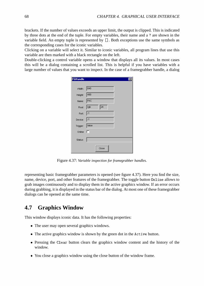
68 CHAPTER 4. GRAPHICAL USER INTERFACE
brackets. If the number of values exceeds an upper limit, the output is clipped. This is indicatedby three dots at the end of the tuple. For empty variables, their name and a? are shown in thevariable field. An empty tuple is represented by[]. Both exceptions use the same symbols asthe corresponding cases for the iconic variables.Clicking on a variable will select it. Similar to iconic variables, all program lines that use thisvariable are then marked with a black rectangle on the left.Double-clicking a control variable opens a window that displays all its values. In most casesthis will be a dialog containing a scrolled list. This is helpful if you have variables with alarge number of values that you want to inspect. In the case of a framegrabber handle, a dialog
Figure 4.37:Variable inspection for framegrabber handles.
representing basic framegrabber parameters is opened (see figure 4.37). Here you find the size,name, device, port, and other features of the framegrabber. The toggle buttonOnline allows tograb images continuously and to display them in the active graphics window. If an error occursduring grabbing, it is displayed in the status bar of the dialog. At most one of these framegrabberdialogs can be opened at the same time.
4.7 Graphics Window
This window displays iconic data. It has the following properties:
� The user may open several graphics windows.
� The active graphics window is shown by the green dot in theActive button.
� Pressing theClear button clears the graphics window content and the history of thewindow.
� You close a graphics window using the close button of the window frame.
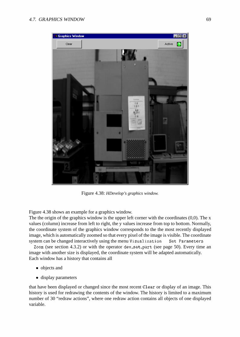
4.7. GRAPHICS WINDOW 69
Figure 4.38:HDevelop’s graphics window.
Figure 4.38 shows an example for a graphics window.The the origin of the graphics window is the upper left corner with the coordinates (0,0). The xvalues (column) increase from left to right, the y values increase from top to bottom. Normally,the coordinate system of the graphics window corresponds to the the most recently displayedimage, which is automatically zoomed so that every pixel of the image is visible. The coordinatesystem can be changed interactively using the menuVisualization . Set Parameters...
. Zoom (see section 4.3.2) or with the operatordev set part (see page 50). Every time animage with another size is displayed, the coordinate system will be adapted automatically.Each window has a history that contains all
� objects and
� display parameters
that have been displayed or changed since the most recentClear or display of an image. Thishistory is used for redrawing the contents of the window. The history is limited to a maximumnumber of 30 “redraw actions”, where one redraw action contains all objects of one displayedvariable.
70 CHAPTER 4. GRAPHICAL USER INTERFACE
Other output like text or general graphics likedisp line or disp circle or iconic data thatdisplayed using HALCON operators likedisp image or disp region arenot part of the his-tory, and arenot redrawn. Only the object classes image, region, and XLD that are displayedwith the HDevelop operatordev display or by double clicking on an icon are part of thehistory.You may change the size of the graphics window interactively by “gripping” the window borderwith the mouse. Then you can resize the window by dragging the mouse pointer. After this sizemodification the window content is redisplayed. Now you see the same part of the window withchanged zoom.The menu area of the graphics window has an additional function: If the mouse cursor is in thisarea the look up table of the window is reactivated. This is necessary if other programs use theirown look up table. Thus if there is a “strange” graphics window presentation, you may load theproper look up table by placing the mouse near the buttons.If you want to specify display parameters for a window you may select the menu itemVisualization in the menu bar. Here you can set the appropriate parameters by clicking thedesired item (see section 4.3.2). The parameters you have set in this way are used forall win-dows. The effects of the new parameters will be applied direcly to thelastobject of the windowhistory and alter its parameters only.For further information on parameter effects please refer to the appropriate HALCON operatorsin the reference manual.
Chapter 5
Language
The following chapter introduces the syntax and the semantics of the HDevelop language. Inother words, it illustrates what you can enter into a parameter slot of an operator. In the simplestcase this is the name of a variable, but it might also be an expression likesqrt(A). Besides,control structures (like loops) and the semantics of parameter passing are described.Chapter 7 explains the application of this language in image analysis. However, the HAL-CON operators are not described in this chapter. For this purpose refer to the HALCON ref-erence manual. All program examples used in this chapter can also be found in the directory$HALCONROOT/examples/hdevelop/Manuals/HDevelop.
5.1 Basic Types of Parameters
HALCON distinguishes two kinds of data: control data (numerical/string) and iconic data (im-ages, regions, etc.).By further distinguishinginput from output parameters, we get four different kinds of parame-ters. These four kinds always appear in the same order in the HDevelop parameter list. Table 5.1shows their order of appearance.
iconic inputiconic outputcontrol inputcontrol output
Table 5.1:Order of appearance of the four basic parameter types
As you see, iconic input objects are always passed as the first parameter(s), followed by theiconic output objects. The iconic data is followed by the control data, and again, the inputparameters succeed the output parameters. Each parameter is separated from its neighbours bya comma:
read_image (Image, 'Name')
area_center (Region, Area, Row, Column)
mean_image (Image, Mean, 11, 11)
71
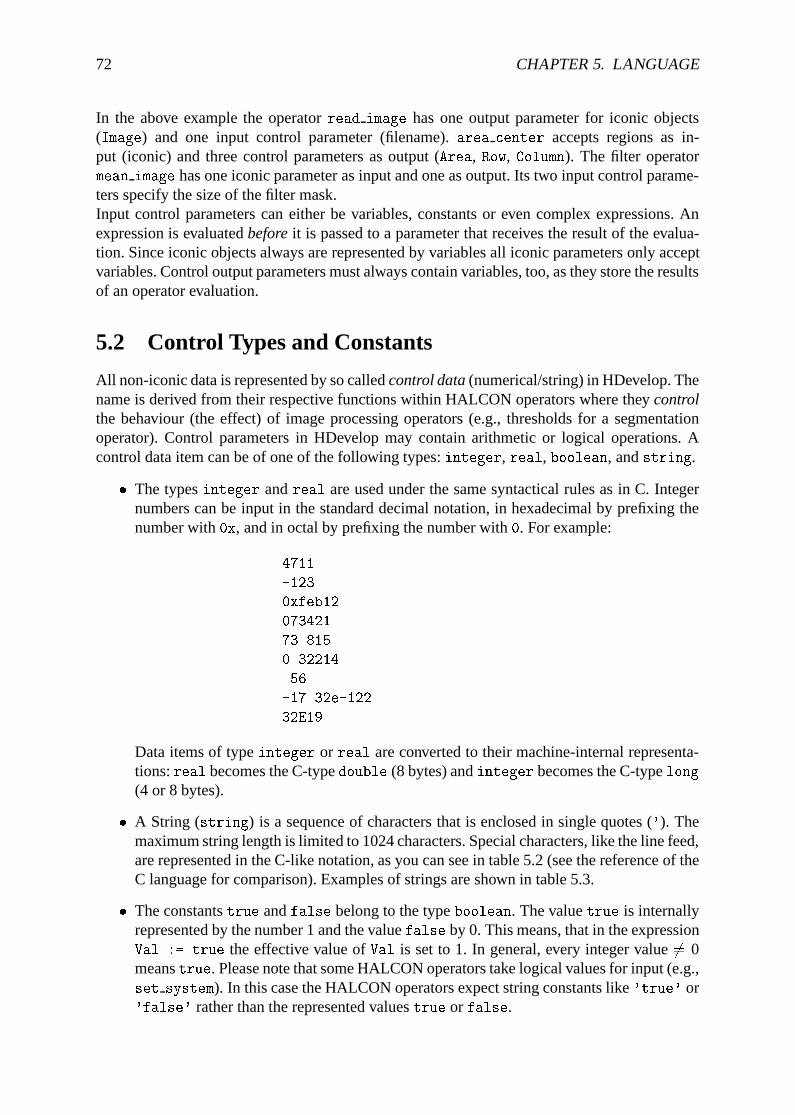
72 CHAPTER 5. LANGUAGE
In the above example the operatorread image has one output parameter for iconic objects(Image) and one input control parameter (filename).area center accepts regions as in-put (iconic) and three control parameters as output (Area, Row, Column). The filter operatormean image has one iconic parameter as input and one as output. Its two input control parame-ters specify the size of the filter mask.Input control parameters can either be variables, constants or even complex expressions. Anexpression is evaluatedbeforeit is passed to a parameter that receives the result of the evalua-tion. Since iconic objects always are represented by variables all iconic parameters only acceptvariables. Control output parameters must always contain variables, too, as they store the resultsof an operator evaluation.
5.2 Control Types and Constants
All non-iconic data is represented by so calledcontrol data(numerical/string) in HDevelop. Thename is derived from their respective functions within HALCON operators where theycontrolthe behaviour (the effect) of image processing operators (e.g., thresholds for a segmentationoperator). Control parameters in HDevelop may contain arithmetic or logical operations. Acontrol data item can be of one of the following types:integer, real, boolean, andstring.
� The typesinteger andreal are used under the same syntactical rules as in C. Integernumbers can be input in the standard decimal notation, in hexadecimal by prefixing thenumber with0x, and in octal by prefixing the number with0. For example:
4711
-123
0xfeb12
073421
73.815
0.32214
.56
-17.32e-122
32E19
Data items of typeinteger or real are converted to their machine-internal representa-tions:real becomes the C-typedouble (8 bytes) andinteger becomes the C-typelong(4 or 8 bytes).
� A String (string) is a sequence of characters that is enclosed in single quotes ('). Themaximum string length is limited to 1024 characters. Special characters, like the line feed,are represented in the C-like notation, as you can see in table 5.2 (see the reference of theC language for comparison). Examples of strings are shown in table 5.3.
� The constantstrue andfalse belong to the typeboolean. The valuetrue is internallyrepresented by the number 1 and the valuefalse by 0. This means, that in the expressionVal := true the effective value ofVal is set to 1. In general, every integer value6= 0meanstrue. Please note that some HALCON operators take logical values for input (e.g.,set system). In this case the HALCON operators expect string constants like'true' or'false' rather than the represented valuestrue or false.
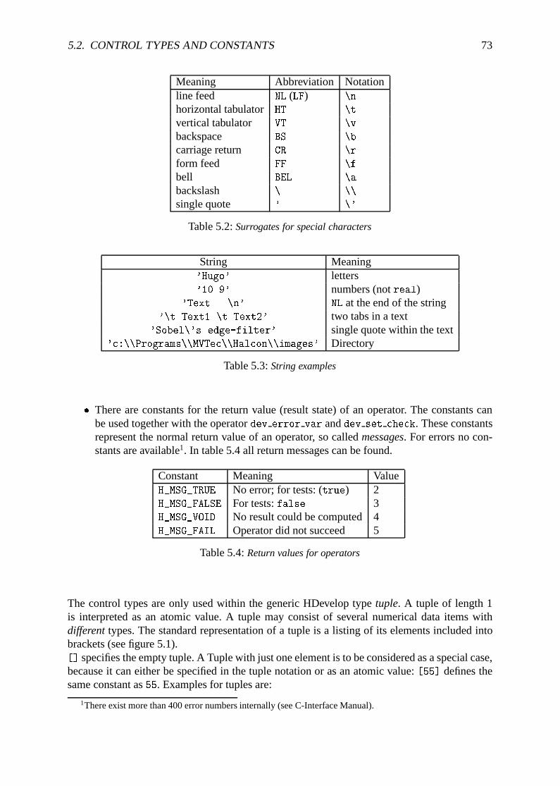
5.2. CONTROL TYPES AND CONSTANTS 73
Meaning Abbreviation Notationline feed NL (LF) \n
horizontal tabulator HT \t
vertical tabulator VT \v
backspace BS \b
carriage return CR \r
form feed FF \f
bell BEL \a
backslash \ \\
single quote ' \'
Table 5.2:Surrogates for special characters
String Meaning'Hugo' letters'10.9' numbers (notreal)
'Text...\n' NL at the end of the string'\t Text1 \t Text2' two tabs in a text
'Sobel\'s edge-filter' single quote within the text'c:\\Programs\\MVTec\\Halcon\\images' Directory
Table 5.3:String examples
� There are constants for the return value (result state) of an operator. The constants canbe used together with the operatordev error var anddev set check. These constantsrepresent the normal return value of an operator, so calledmessages. For errors no con-stants are available1. In table 5.4 all return messages can be found.
Constant Meaning ValueH_MSG_TRUE No error; for tests: (true) 2H_MSG_FALSE For tests:false 3H_MSG_VOID No result could be computed4H_MSG_FAIL Operator did not succeed 5
Table 5.4:Return values for operators
The control types are only used within the generic HDevelop typetuple. A tuple of length 1is interpreted as an atomic value. A tuple may consist of several numerical data items withdifferenttypes. The standard representation of a tuple is a listing of its elements included intobrackets (see figure 5.1).[] specifies the empty tuple. A Tuple with just one element is to be considered as a special case,because it can either be specified in the tuple notation or as an atomic value:[55] defines thesame constant as55. Examples for tuples are:
1There exist more than 400 error numbers internally (see C-Interface Manual).
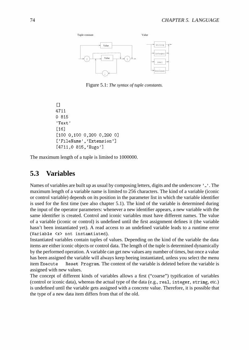
74 CHAPTER 5. LANGUAGE
,boolean
[ ]
Tuple constant
string
integer
real
Value
Value
Value
Figure 5.1:The syntax of tuple constants.
[]
4711
0.815
'Text'
[16]
[100.0,100.0,200.0,200.0]
['FileName','Extension']
[4711,0.815,'Hugo']
The maximum length of a tuple is limited to 1000000.
5.3 Variables
Names of variables are built up as usual by composing letters, digits and the underscore' '. Themaximum length of a variable name is limited to 256 characters. The kind of a variable (iconicor control variable) depends on its position in the parameter list in which the variable identifieris used for the first time (see also chapter 5.1). The kind of the variable is determined duringthe input of the operator parameters: whenever a new identifier appears, a new variable with thesame identifier is created. Control and iconic variables must have different names. The valueof a variable (iconic or control) is undefined until the first assignment defines it (the variablehasn’t been instantiated yet). A read access to an undefined variable leads to a runtime error(Variable <x> not instantiated).Instantiated variables contain tuples of values. Depending on the kind of the variable the dataitems are either iconic objects or control data. The length of the tuple is determined dynamicallyby the performed operation. A variable can get new values any number of times, but once a valuehas been assigned the variable will always keep beeing instantiated, unless you select the menuitemExecute . Reset Program. The content of the variable is deleted before the variable isassigned with new values.The concept of different kinds of variables allows a first (“coarse”) typification of variables(control or iconic data), whereas the actual type of the data (e.g.,real, integer, string, etc.)is undefined until the variable gets assigned with a concrete value. Therefore, it is possible thatthe type of a new data item differs from that of the old.
5.4. OPERATIONS ON ICONIC OBJECTS 75
5.4 Operations on Iconic Objects
Iconic objects are exclusively processed by HALCON operators. HALCON operators workon tuples of iconic objects, which are represented by their surrogates in the HALCON datamanagement. The results of those operators are again tuples of iconic objects or control dataelements. For a detailed description of the HALCON operators refer to the HALCON referencemanual and the remarks in chapter 5.5.3.
5.5 Expressions for Input Control Parameters
In HDevelop, the use of expressions is limited to control input parameters; all other kinds ofparameters must be assigned by variables.
5.5.1 General Features of Tuple Operations
This chapter is intended to give you a short overview over the features of tuples and their op-erations. A more detailed description of each operator mentioned here is given in the followingsections.Please note that in all following tables variables and constants have been substituted by letters.These letters give information about possible limitations of the areas of definition. A single letter(inside these tables) represents a data type. Operations on these symbols can only be applied toparameters of the indicated type or to expressions that return a result of the indicated type. Tobegin with, table 5.5 specifies the names and types of the symbolic names.
Symbol Typesi integer
a arithmetic, that is:integer or reall boolean
s string
v all types (atomic)t all types (tuple)
Table 5.5:Symbolic variables for the operation-description
Operators are normally described for atomic tuples (tuples of length 1). If the tuple containsmore than one element, most operators work as follows:
� If one of the tuples is of length one, all elements of the other tuples are combined withthat single value for the chosen operation.
� If both tuples have a length greater than one, both tuples must have the same length(otherwise a runtime error occurs). In this case, the selected operation is applied to allelements with the same index. The length of the resulting tuples is identical to the lengthof the input tuples.
� If one of the tuples is of length 0 ([]), a runtime error occurs.
In table 5.6 you can find some examples for arithmetic operations with tuples. In this exampleyou should pay special attention to the order in which the string concatenations are performed.
76 CHAPTER 5. LANGUAGE
Input Result5 * 5 25
[5] * [5] 25
[1,2,3] * 2 [2,4,6]
[1,2,3] * 2.1 + 10 [12.1,14.2,16.3]
[1,2,3] * [1,2,3] [1,4,9]
[1,2,3] * [1,2] runtime error'Text1' + 'Text2' 'Text1Text2'
17.23 + ' Text' '17.23 Text'
'Text1 ' + 99 + ' Text2' 'Text1 99 Text2'
'Text ' + 3.1 * 2 'Text 6.2'
3.1 * (2 + ' Text') runtime error3.1 + 2 + ' Text' '5.1 Text'
3.1 + (2 + ' Text') ) '3.12 Text'
'Text ' + 2.1 + 3 'Text 2.13'
Table 5.6:Examples for arithmetic operations with tuples and strings
5.5.2 Assignment
In HDevelop, an assignment is treated like an operator. To use an assignment you have to selectthe operatorassign (Input, Result). This operator has the following semantics: It evalu-atesInput (right side of assignment) and stores it inResult (left side of assignment). However,in the program text the assignment is represented by the usual syntax of the assignment opera-tor: ’:=’. The following example outlines the difference between an assignment in C syntax andits transformed version in HDevelop:The assignment in C syntax
u = sin(x) + cos(y);
is defined in HDevelop using the assignment operator as
assign(sin(x) + cos(y), u)
which is displayed in the program window as:
u := sin(x) + cos(y)
If the result of the expression doesn’t need to be stored into a variable, the expression candirectly be used as input value for any operator. Therefore, an assignment is necessary only ifthe value has to be used several times or if the variable has to be initialized (e.g., for a loop).A second assignment operator is available: (insert(Input,Value,Index,Result)). It isused to assign tuple elements. If the first input parameter and the first output parameter areidentical, the call:
insert (Areas, Area, Radius-1, Areas)
is not presented in the program text as an operator call, but in the more intuitive form as:
Areas[Radius-1] := Area.
5.5. EXPRESSIONS FOR INPUT CONTROL PARAMETERS 77
To construct a tuple withinsert, normally an empty tuple is used as initial value and theelements are inserted in a loop:
Tuple = []
for i := 0 to 5 by 1
Tuple[i] = sqrt(real(i))
endfor
As you can see from this example, the indices of a tuple start at 0.An insertion into a tuple can generally be performed in one of the following ways:
(i) In case of appending the value at the ’back’ or at the ’front’, the concatenation can beused. Here theassign operator is used with the following parameters:
assign([Tuple,NewVal],Tuple)
which is displayed as
Tuple := [Tuple,NewVal]
(ii) If the index position is somewhere in between, the operatorinsert has to be used. Ittakes the following arguments as input: first the tuple in which the new value should beinserted; then the new value and after that the index position as the third input parameter.The result (the fourth parameter) is almost identical with the input tuple, except of thenew value at the defined index position.
In the following example regions are dilated with a circle mask and afterwards the areas arestored into the tupleAreas. In this case the operatorinsert is used.
read_image (Mreut, 'mreut')
threshold (Mreut, Region, 190, 255)
Areas := []
for Radius := 1 to 50 by 1
dilation_circle (Region, RegionDilation, Radius)
area_center (RegionDilation, Area, Row, Column)
Areas[Radius-1] := Area
endfor
Please note that first the variableAreas has to be initialized in order to avoid a runtime error.In the exampleAreas is initialized with the empty tuple ([]). Instead ofinsert the operatorassign with tuple concatenation
Areas := [Areas,Area]
could be used, because the element is appended at the back of the tuple.More examples can be found in the programassign.dev.
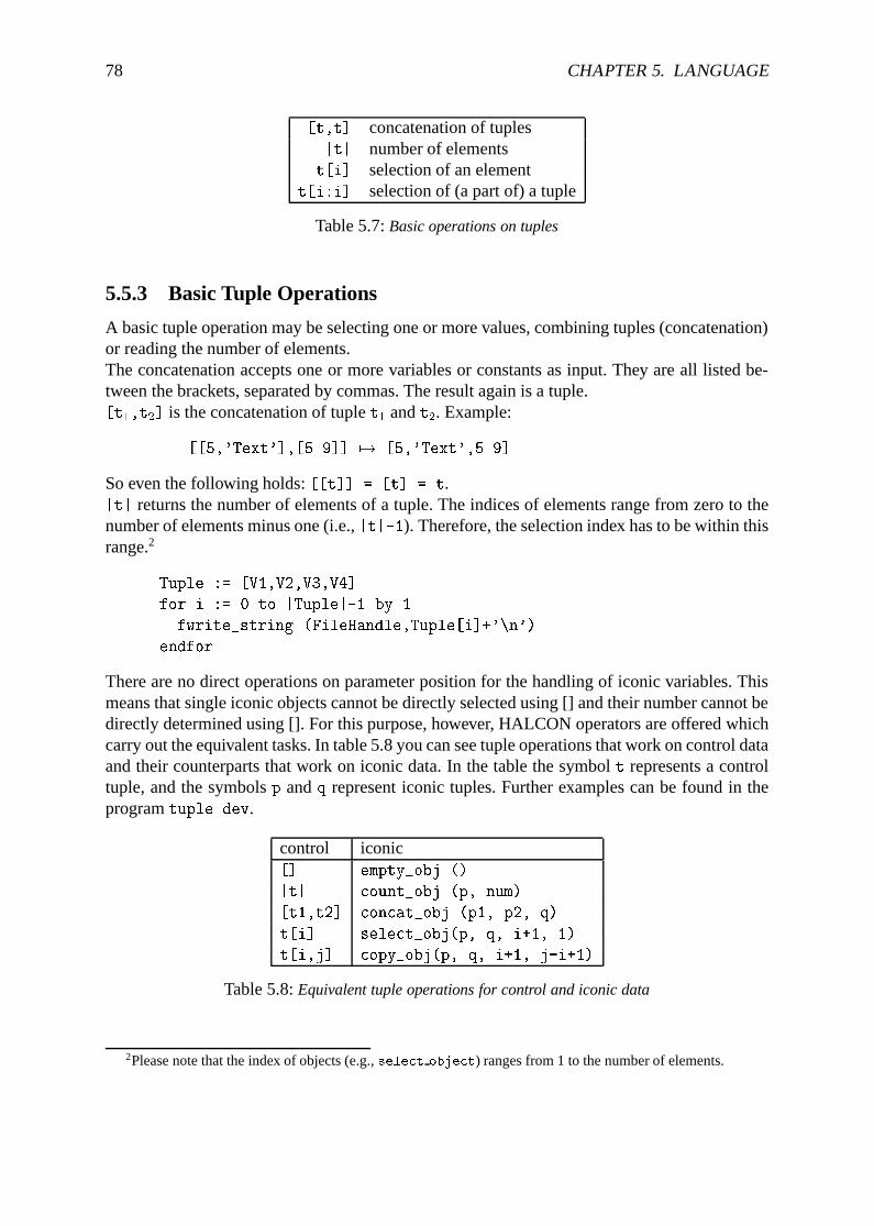
78 CHAPTER 5. LANGUAGE
[t,t] concatenation of tuples|t| number of elements
t[i] selection of an elementt[i:i] selection of (a part of) a tuple
Table 5.7:Basic operations on tuples
5.5.3 Basic Tuple Operations
A basic tuple operation may be selecting one or more values, combining tuples (concatenation)or reading the number of elements.The concatenation accepts one or more variables or constants as input. They are all listed be-tween the brackets, separated by commas. The result again is a tuple.[t1,t2] is the concatenation of tuplet1 andt2. Example:
[[5,'Text'],[5.9]] 7! [5,'Text',5.9]
So even the following holds:[[t]] = [t] = t.|t| returns the number of elements of a tuple. The indices of elements range from zero to thenumber of elements minus one (i.e.,|t|-1). Therefore, the selection index has to be within thisrange.2
Tuple := [V1,V2,V3,V4]
for i := 0 to |Tuple|-1 by 1
fwrite_string (FileHandle,Tuple[i]+'\n')
endfor
There are no direct operations on parameter position for the handling of iconic variables. Thismeans that single iconic objects cannot be directly selected using [] and their number cannot bedirectly determined using []. For this purpose, however, HALCON operators are offered whichcarry out the equivalent tasks. In table 5.8 you can see tuple operations that work on control dataand their counterparts that work on iconic data. In the table the symbolt represents a controltuple, and the symbolsp andq represent iconic tuples. Further examples can be found in theprogramtuple.dev.
control iconic[] empty_obj ()
|t| count_obj (p, num)
[t1,t2] concat_obj (p1, p2, q)
t[i] select_obj(p, q, i+1, 1)
t[i,j] copy_obj(p, q, i+1, j-i+1)
Table 5.8:Equivalent tuple operations for control and iconic data
2Please note that the index of objects (e.g.,select object) ranges from 1 to the number of elements.
5.5. EXPRESSIONS FOR INPUT CONTROL PARAMETERS 79
5.5.4 Tuple Creation
The simplest way to create a tuple, as mentioned in section 5.2, is the use of constants togetherwith theassign operator:
assign([],empty_tuple)
assign(4711,one_integer)
assign([4711,0.815],two_numbers)
This code is displayed as
empty_tuple := []
one_integer := 4711
two_numbers := [4711,0.815]
This is useful for constant tuples with a fixed (small) length. More general tuples can be createdby successive application of the concatenation or theinsert function together with variables,expressions or constants. If we want to generate a tuple of length 100, where each element hasthe value 4711, it might be done like this:
assign([],tuple)
for i := 1 to 100 by 1
assign([tuple,4711],tuple)
which is transformed to
tuple := []
for i := 1 to 100 by 1
tuple := [tuple,4711]
Because this is not very convenient a special function calledgen tuple const is available toconstruct a tuple of a given length, where each element has the same value. Using this function,the program from above is reduced to:
assign(gen_tuple_const(100,4711),tuple)
which is displaed as
tuple := gen_tuple_const(100,4711)
If we want to construct a tuple with the same length as a given tuple there are two ways to getan easy solution, The first one is based ongen tuple const:
assign(gen_tuple_const(|tuple_old|,4711),tuple_new)
which is displayed as
tuple_new := gen_tuple_const(|tuple_old|,4711)
The second one is a bit tricky and uses arithmetic functions:
assign((tuple_old * 0) + 4711,tuple_new)
which is displaed as
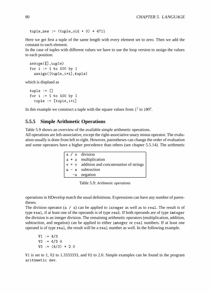
80 CHAPTER 5. LANGUAGE
tuple_new := (tuple_old * 0) + 4711
Here we get first a tuple of the same length with every element set to zero. Then we add theconstant to each element.In the case of tuples with different values we have to use the loop version to assign the valuesto each position:
assign([],tuple)
for i := 1 to 100 by 1
assign([tuple,i*i],tuple)
which is displaed as
tuple := []
for i := 1 to 100 by 1
tuple := [tuple,i*i]
In this example we construct a tuple with the square values from12 to 1002.
5.5.5 Simple Arithmetic Operations
Table 5.9 shows an overview of the available simple arithmetic operations.All operations are left-associative, except the right-associative unary minus operator. The evalu-ation usually is done from left to right. However, parentheses can change the order of evaluationand some operators have a higher precedence than others (see chapter 5.5.14). The arithmetic
a / a divisiona * a multiplicationv + v addition andconcatenationof stringsa - a subtraction
-a negation
Table 5.9:Arithmetic operations
operations in HDevelop match the usual definitions. Expressions can have any number of paren-theses.The division operator (a / a) can be applied tointeger as well as toreal. The result is oftypereal, if at least one of the operands is of typereal. If both operands are of typeintegerthe division is an integer division. The remaining arithmetic operators (multiplication, addition,subtraction, and negation) can be applied to eitherinteger or real numbers. If at least oneoperand is of typereal, the result will be areal number as well. In the following example.
V1 := 4/3
V2 := 4/3.0
V3 := (4/3) * 2.0
V1 is set to 1,V2 to 1.3333333, andV3 to 2.0. Simple examples can be found in the programarithmetic.dev.
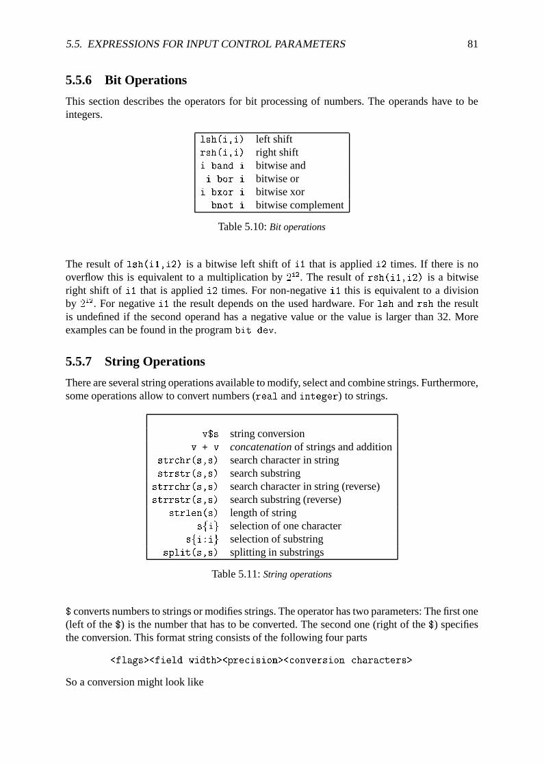
5.5. EXPRESSIONS FOR INPUT CONTROL PARAMETERS 81
5.5.6 Bit Operations
This section describes the operators for bit processing of numbers. The operands have to beintegers.
lsh(i,i) left shiftrsh(i,i) right shifti band i bitwise andi bor i bitwise or
i bxor i bitwise xorbnot i bitwise complement
Table 5.10:Bit operations
The result oflsh(i1,i2) is a bitwise left shift ofi1 that is appliedi2 times. If there is nooverflow this is equivalent to a multiplication by2i2. The result ofrsh(i1,i2) is a bitwiseright shift of i1 that is appliedi2 times. For non-negativei1 this is equivalent to a divisionby 2i2. For negativei1 the result depends on the used hardware. Forlsh andrsh the resultis undefined if the second operand has a negative value or the value is larger than 32. Moreexamples can be found in the programbit.dev.
5.5.7 String Operations
There are several string operations available to modify, select and combine strings. Furthermore,some operations allow to convert numbers (real andinteger) to strings.
v$s string conversionv + v concatenationof strings and addition
strchr(s,s) search character in stringstrstr(s,s) search substring
strrchr(s,s) search character in string (reverse)strrstr(s,s) search substring (reverse)
strlen(s) length of stringsfig selection of one character
sfi:ig selection of substringsplit(s,s) splitting in substrings
Table 5.11:String operations
$ converts numbers to strings or modifies strings. The operator has two parameters: The first one(left of the$) is the number that has to be converted. The second one (right of the$) specifiesthe conversion. This format string consists of the following four parts
<flags><field width><precision><conversion characters>
So a conversion might look like
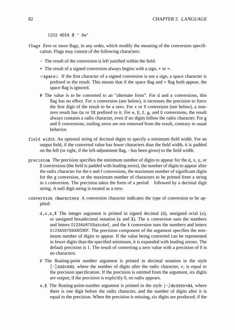
82 CHAPTER 5. LANGUAGE
1332.4554 $ '.6e'
flags Zero or more flags, in any order, which modify the meaning of the conversion specifi-cation. Flags may consist of the following characters:
- The result of the conversion is left justified within the field.
+ The result of a signed conversion always begins with a sign,+ or -.
<space> If the first character of a signed conversion is not a sign, a space character isprefixed to the result. This means that if the space flag and+ flag both appear, thespace flag is ignored.
# The value is to be converted to an “alternate form”. Ford and s conversions, thisflag has no effect. Foro conversion (see below), it increases the precision to forcethe first digit of the result to be a zero. Forx or X conversion (see below), a non-zero result has0x or 0X prefixed to it. Fore, E, f, g, andG conversions, the resultalways contains a radix character, even if no digits follow the radix character. Forg
andG conversions, trailing zeros are not removed from the result, contrary to usualbehavior.
field width An optional string of decimal digits to specify a minimum field width. For anoutput field, if the converted value has fewer characters than the field width, it is paddedon the left (or right, if the left-adjustment flag, - has been given) to the field width.
precision The precision specifies the minimum number of digits to appear for thed, o, x, orX conversions (the field is padded with leading zeros), the number of digits to appear afterthe radix character for the e and f conversions, the maximum number of significant digitsfor theg conversion, or the maximum number of characters to be printed from a stringin s conversion. The precision takes the form of a period. followed by a decimal digitstring. A null digit string is treated as a zero.
conversion characters A conversion character indicates the type of conversion to be ap-plied:
d,o,x,X The integer argument is printed in signed decimal (d), unsigned octal (o),or unsigned hexadecimal notation (x andX). The x conversion uses the numbersand letters0123456789abcdef, and theX conversion uses the numbers and letters0123456789ABCDEF. The precision component of the argument specifies the min-imum number of digits to appear. If the value being converted can be representedin fewer digits than the specified minimum, it is expanded with leading zeroes. Thedefault precision is 1. The result of converting a zero value with a precision of 0 isno characters.
f The floating-point number argument is printed in decimal notation in the style[-]dddrddd, where the number of digits after the radix character,r, is equal tothe precision specification. If the precision is omitted from the argument, six digitsare output; if the precision is explicitly 0, no radix appears.
e,E The floating-point-number argument is printed in the style[-]drddde+dd, wherethere is one digit before the radix character, and the number of digits after it isequal to the precision. When the precision is missing, six digits are produced; if the
5.5. EXPRESSIONS FOR INPUT CONTROL PARAMETERS 83
precision is 0, no radix character appears. TheE conversion character produces anumber withE introducing the exponent instead ofe. The exponent always containsat least two digits. However, if the value to be printed requires an exponent greaterthan two digits, additional exponent digits are printed as necessary.
g,G The floating-point-number argument is printed in stylef ore (or in styleE in the caseof aG conversion character), with the precision specifying the number of significantdigits. The style used depends on the value converted; stylee is used only if theexponent resulting from the conversion is less than -h or greater than or equal tothe precision. Trailing zeros are removed from the result. A radix character appearsonly if it is followed by a digit.
s The argument is taken to be a string, and characters from the string are printed untilthe end of the string or the number of characters indicated by the precision specifi-cation of the argument is reached. If the precision is omitted from the argument, itis interpreted as infinite and all characters up to the end of the string are printed.
b Similar to the s conversion specifier, except that the string can contain backslash-escapesequences which are then converted to the characters they represent.
In no case does a nonexistent or insufficient field width cause truncation of a field; if theresult of a conversion is wider than the field width, the field is simply expanded to containthe conversion result.
Examples for the string conversion can be found in the programstring.dev.The string concatenation (+) can be applied in combination with strings or all numerical types;if necessary, the operands are first transformed into strings (according to their standard repre-sentation). At least one of the operands has to be already a string so that the operator can act as astring concatenator. In the following example a filename (e.g.,'Name5.tiff') is generated. Forthis purpose two string constants ('Name' and'.tiff') and an integer value (the loop-indexi) are concatenated:
for i := 1 to 5 by 1
read_image (Bild, 'Name'+i+'.tiff')
endfor
str(r)chr(s1,s2) returns the index of the first (last) as a tuple occurrence of one character ins2 in strings1, or -1 if none of the characters occurs in the string.str(r)str(s1,s2) returns the index of the first (last) occurrence of string s2 in string s1, or-1 if s2 does not occur in the string.strlen(s) returns the number of characters ins.sfig returns the character at index positioni in s. The index ranges from zero to the length ofthe string minus 1. The result of the operator is a string of length one.sfi1:i2g returns all characters from index positioni1 up to positioni2 in s as a string. Theindex ranges from zero to the length of the string minus 1.split(s1,s2) devides the strings1 into single substrings. The string is split at those positionswhere it contains a character froms2. As an example the result of
split('/usr/image:/usr/proj/image',':')
consists of the two strings
['/usr/image','/usr/proj/image']
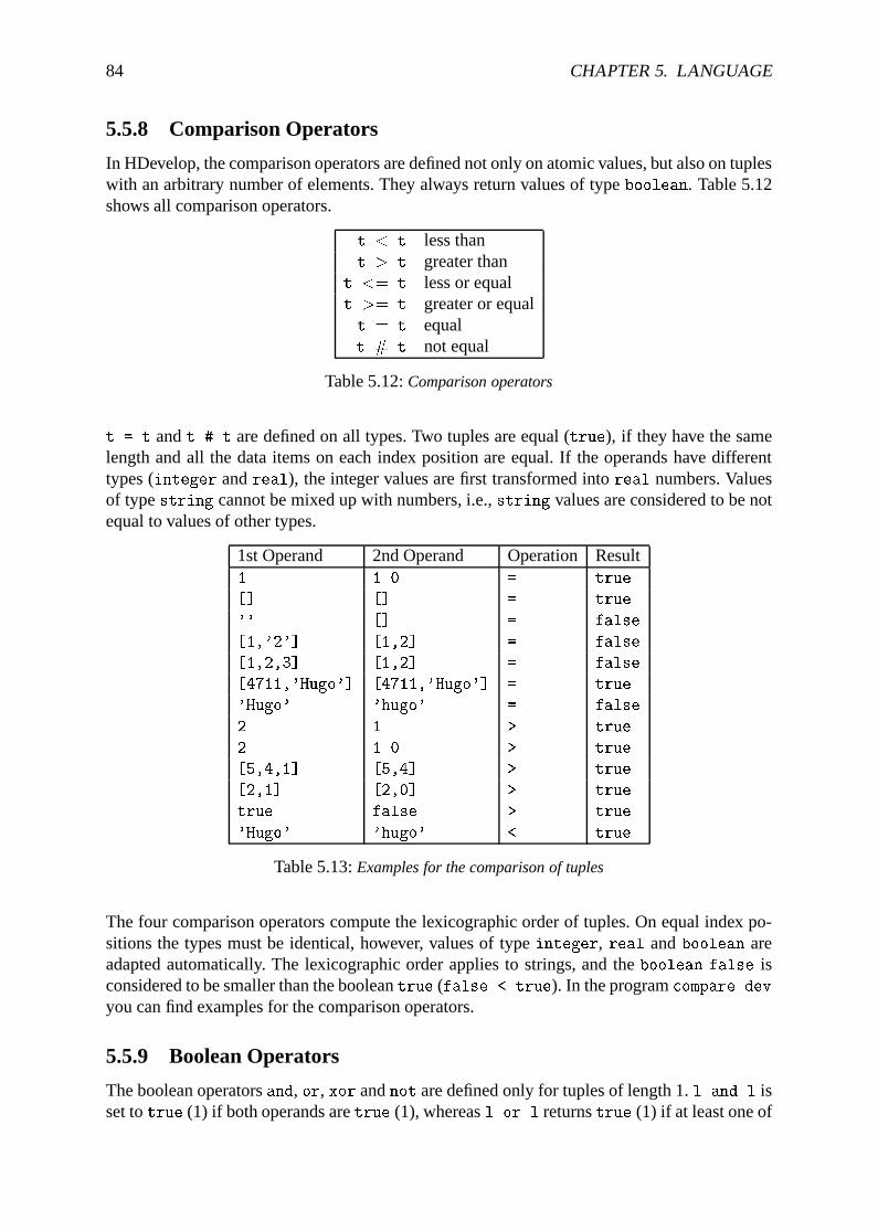
84 CHAPTER 5. LANGUAGE
5.5.8 Comparison Operators
In HDevelop, the comparison operators are defined not only on atomic values, but also on tupleswith an arbitrary number of elements. They always return values of typeboolean. Table 5.12shows all comparison operators.
t < t less thant > t greater than
t <= t less or equalt >= t greater or equalt = t equalt # t not equal
Table 5.12:Comparison operators
t = t andt # t are defined on all types. Two tuples are equal (true), if they have the samelength and all the data items on each index position are equal. If the operands have differenttypes (integer andreal), the integer values are first transformed intoreal numbers. Valuesof typestring cannot be mixed up with numbers, i.e.,string values are considered to be notequal to values of other types.
1st Operand 2nd Operand Operation Result1 1.0 = true
[] [] = true
'' [] = false
[1,'2'] [1,2] = false
[1,2,3] [1,2] = false
[4711,'Hugo'] [4711,'Hugo'] = true
'Hugo' 'hugo' = false
2 1 > true
2 1.0 > true
[5,4,1] [5,4] > true
[2,1] [2,0] > true
true false > true
'Hugo' 'hugo' < true
Table 5.13:Examples for the comparison of tuples
The four comparison operators compute the lexicographic order of tuples. On equal index po-sitions the types must be identical, however, values of typeinteger, real andboolean areadapted automatically. The lexicographic order applies to strings, and theboolean false isconsidered to be smaller than the booleantrue (false < true). In the programcompare.devyou can find examples for the comparison operators.
5.5.9 Boolean Operators
The boolean operatorsand, or, xor andnot are defined only for tuples of length 1.l and l isset totrue (1) if both operands aretrue (1), whereasl or l returnstrue (1) if at least one of
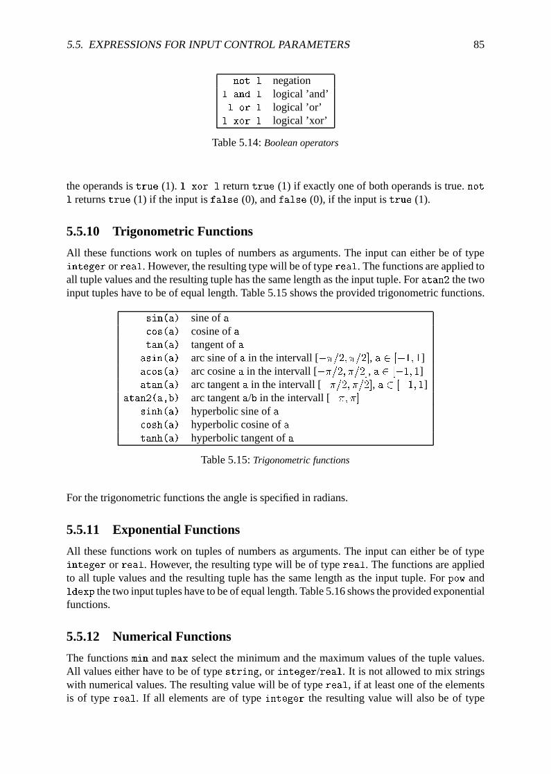
5.5. EXPRESSIONS FOR INPUT CONTROL PARAMETERS 85
not l negationl and l logical ’and’l or l logical ’or’
l xor l logical ’xor’
Table 5.14:Boolean operators
the operands istrue (1). l xor l returntrue (1) if exactly one of both operands is true.not
l returnstrue (1) if the input isfalse (0), andfalse (0), if the input istrue (1).
5.5.10 Trigonometric Functions
All these functions work on tuples of numbers as arguments. The input can either be of typeinteger orreal. However, the resulting type will be of typereal. The functions are applied toall tuple values and the resulting tuple has the same length as the input tuple. Foratan2 the twoinput tuples have to be of equal length. Table 5.15 shows the provided trigonometric functions.
sin(a) sine ofacos(a) cosine ofatan(a) tangent ofa
asin(a) arc sine ofa in the intervall [��=2; �=2], a 2 [�1; 1]acos(a) arc cosinea in the intervall [��=2; �=2], a 2 [�1; 1]atan(a) arc tangenta in the intervall [��=2; �=2], a 2 [�1; 1]
atan2(a,b) arc tangenta/b in the intervall [��; �]sinh(a) hyperbolic sine ofacosh(a) hyperbolic cosine ofatanh(a) hyperbolic tangent ofa
Table 5.15:Trigonometric functions
For the trigonometric functions the angle is specified in radians.
5.5.11 Exponential Functions
All these functions work on tuples of numbers as arguments. The input can either be of typeinteger or real. However, the resulting type will be of typereal. The functions are appliedto all tuple values and the resulting tuple has the same length as the input tuple. Forpow andldexp the two input tuples have to be of equal length. Table 5.16 shows the provided exponentialfunctions.
5.5.12 Numerical Functions
The functionsmin andmax select the minimum and the maximum values of the tuple values.All values either have to be of typestring, or integer/real. It is not allowed to mix stringswith numerical values. The resulting value will be of typereal, if at least one of the elementsis of typereal. If all elements are of typeinteger the resulting value will also be of type
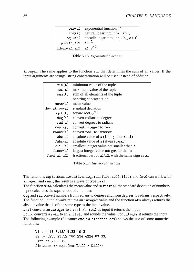
86 CHAPTER 5. LANGUAGE
exp(a) exponential functionea
log(a) natural logarithmln(a), a> 0
log10(a) decadic logarithm,log10(a), a> 0
pow(a1,a2) a1a2
ldexp(a1,a2) a1 �2a2
Table 5.16:Exponential functions
integer. The same applies to the functionsum that determines the sum of all values. If theinput arguments are strings, string concatenation will be used instead of addition.
min(t) minimum value of the tuplemax(t) maximum value of the tuplesum(t) sum of all elements of the tuple
or string concatenationmean(a) mean value
deviation(a) standard deviationsqrt(a) square root
pa
deg(a) convert radians to degreesrad(a) convert degrees to radians
real(a) convertinteger to real
round(a) convertreal to integer
abs(a) absolute value ofa (integer or real)fabs(a) absolute value ofa (alwaysreal)ceil(a) smallest integer value not smaller thana
floor(a) largest integer value not greater thana
fmod(a1,a2) fractional part ofa1/a2, with the same sign asa1
Table 5.17:Numerical functions
The functionssqrt, mean, deviation, deg, rad, fabs, ceil, floor andfmod can work withinteger andreal; the result is always of typereal.The functionmean calculates the mean value anddeviation the standard deviation of numbers.sqrt calculates the square root of a number.deg andrad convert numbers from radians to degrees and from degrees to radians, respectively.The functionround always returns aninteger value and the functionabs always returns theabsolut value that is of the same type as the input value.real converts aninteger to areal. Forreal as input it returns the input.round converts areal to aninteger and rounds the value. Forinteger it returns the input.The following example (filename:euclid distance.dev) shows the use of some numericalfunctions:
V1 := [18.8,132.4,33,19.3]
V2 := [233.23,32.786,234.4224,63.33]
Diff := V1 - V2
Distance := sqrt(sum(Diff * Diff))
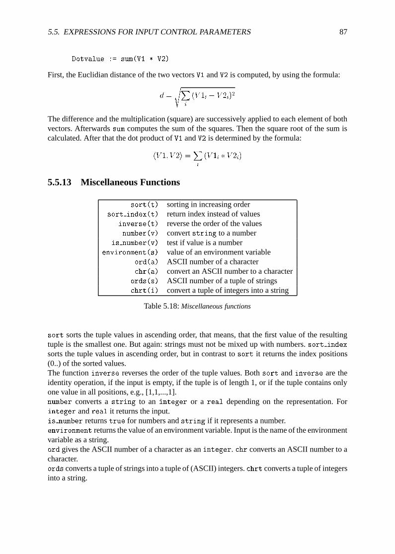
5.5. EXPRESSIONS FOR INPUT CONTROL PARAMETERS 87
Dotvalue := sum(V1 * V2)
First, the Euclidian distance of the two vectorsV1 andV2 is computed, by using the formula:
d =
sXi
(V 1i � V 2i)2
The difference and the multiplication (square) are successively applied to each element of bothvectors. Afterwardssum computes the sum of the squares. Then the square root of the sum iscalculated. After that the dot product ofV1 andV2 is determined by the formula:
hV 1; V 2i =Xi
(V 1i � V 2i)
5.5.13 Miscellaneous Functions
sort(t) sorting in increasing ordersort index(t) return index instead of values
inverse(t) reverse the order of the valuesnumber(v) convertstring to a number
is number(v) test if value is a numberenvironment(s) value of an environment variable
ord(a) ASCII number of a characterchr(a) convert an ASCII number to a characterords(s) ASCII number of a tuple of stringschrt(i) convert a tuple of integers into a string
Table 5.18:Miscellaneous functions
sort sorts the tuple values in ascending order, that means, that the first value of the resultingtuple is the smallest one. But again: strings must not be mixed up with numbers.sort index
sorts the tuple values in ascending order, but in contrast tosort it returns the index positions(0..) of the sorted values.The functioninverse reverses the order of the tuple values. Bothsort andinverse are theidentity operation, if the input is empty, if the tuple is of length 1, or if the tuple contains onlyone value in all positions, e.g., [1,1,...,1].number converts astring to an integer or a real depending on the representation. Forinteger andreal it returns the input.is number returnstrue for numbers andstring if it represents a number.environment returns the value of an environment variable. Input is the name of the environmentvariable as a string.ord gives the ASCII number of a character as aninteger. chr converts an ASCII number to acharacter.ords converts a tuple of strings into a tuple of (ASCII) integers.chrt converts a tuple of integersinto a string.
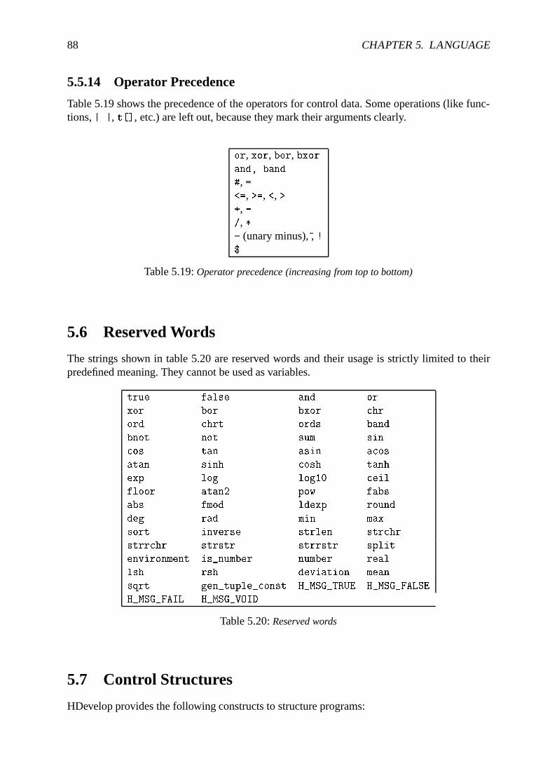
88 CHAPTER 5. LANGUAGE
5.5.14 Operator Precedence
Table 5.19 shows the precedence of the operators for control data. Some operations (like func-tions,| |, t[], etc.) are left out, because they mark their arguments clearly.
or, xor, bor, bxorand, band
#, =<=, >=, <, >+, -/, *- (unary minus),~, !$
Table 5.19:Operator precedence (increasing from top to bottom)
5.6 Reserved Words
The strings shown in table 5.20 are reserved words and their usage is strictly limited to theirpredefined meaning. They cannot be used as variables.
true false and or
xor bor bxor chr
ord chrt ords band
bnot not sum sin
cos tan asin acos
atan sinh cosh tanh
exp log log10 ceil
floor atan2 pow fabs
abs fmod ldexp round
deg rad min max
sort inverse strlen strchr
strrchr strstr strrstr split
environment is_number number real
lsh rsh deviation mean
sqrt gen_tuple_const H_MSG_TRUE H_MSG_FALSE
H_MSG_FAIL H_MSG_VOID
Table 5.20:Reserved words
5.7 Control Structures
HDevelop provides the following constructs to structure programs:
5.7. CONTROL STRUCTURES 89
� The simplest control structure isif. The condition contains a boolean expression. If thecondition is true, the body is executed. Otherwise the execution is continued at the firstexpression or operator call that follows the wordendif.
if (<Condition>)
...
endif
� Another simple control structure is the condition with alternative. If the condition is true,all expressions and calls between the head and the wordendif are performed. If thecondition is false the part betweenelse andendif is executed. Note that the operator iscalledifelse and it is displayed asif in the program text area.
if (<Condition>)
...
else
...
endif
� Thewhile loop has a boolean expression as the conditional part. As long as it istrue,the body of the loop is performed. In order to enter the loop, the condition has to be truein the first place.
while (<Condition>)
...
endwhile
In chapter 7.3 you can find an example for using thewhile loop.
� Thefor loop is controlled by a start and termination value and an incrementation valuethat determines the number of loop steps. These values may also be expressions whichare evaluated immediately before the loop is entered. The expressions may be of typeinteger or of typereal. If all input values are of typeinteger the loop variable willalso be of typeinteger. In all other cases the loop variable will be of typereal. If thestart value is less or equal to the termination value, the loop index is assigned with thestarting value and the body of the loop is entered. If the increment is less than zero theloop is entered if the start value is larger or equal to the end value. Each time the body isexecuted, the loop index is incremented by the incrementation value. If the loop index isequal to the termination value, the body of the loop is performed for the last time. If theloop index is larger than the termination value the body will not be excecuted any longer.3
Please note that it is not necessary, that the loop index has to be equal to the terminationvalue before terminating the loop. The loop index is set to the termination value whenthe loop is being left. Please note, that the expressions for start and termination valueare evaluated only once whenentering the loop. A modification of a variable that appearswithin these expressions has no influence on the termination of the loop. The same appliesto the modifications of the loop index. It also has no influence on the termination. The loop
3For negative increment values the loop is terminated if the loop index is less than the termination value.
90 CHAPTER 5. LANGUAGE
value is assigned to the correct value each time thefor operator is executed. For moredetails, see section 6.1.4 on the code generation offor loops.
If the for loop is left too early (e.g., if you pressStop and set thePC) and the loop isentered again, the expressions will be evaluated, as if the loop were entered for the firsttime.
for <loop value> := <Start> to <End> by <Increment>
...
endfor
In the following example the sine from 0 up to 6� is computed and printed in to thegraphical window (filename:sine.dev):
old_x := 0
old_y := 0
dev_set_color ('red')
dev_set_part(0, 0, 511, 511)
for x := 1 to 511 by 1
y := sin(x / 511.0 * 2 * 3.1416 * 3) * 255
disp_line (WindowID, -old_y+256, old_x, -y+256, x)
old_x := x
old_y := y
endfor
In this example the assumption is made that the window is of size 512�512. The drawingis always done from the most recently evaluated point to the current point.
Further examples on how to use thefor loop can be found in chapter 7.8 and 7.9.
� stop stops the program after the operator is executed. The program can be continued bypressing theStep or Run button.
� exit terminatesthe session of HDevelop.
5.8 Limitations
This section summarizes the restritions of the HDevelop language:
� Maximum number of objects per parameter : 100000
� Maximum length of strings : 1024 characters
� Maximum length of a variable name : 256 characters
� Maximum length of a tuple : 1000000
The general restrictions of the HALCON operators can be found in the “Getting Started” Man-ual.
Chapter 6
Code Generation
The idea of code generation is as follows: After developing a program according to the givenrequirements it has to be transferred to its final environment. Here, you often don’t want touse HDevelop to save memory or disk space. In addition the program should execute as fast aspossible, especially without the overhead of an interpreter. Therefore the program is transferredinto another language that can be compiled and allows a faster execution. In addition to thisfeatures of the new environment like special libraries or graphical user interface builder can beused.The aim of this chapter is to describe the general steps of program development using thisfeature. Later on some details of the code generation and optimization aspects are discussed.
6.1 Code Generation for C++
In this section the use of HALCON in C++ is describes.
6.1.1 Basic Steps
Interactive Development
The first step is the well known process of program development in HDevelop as it is describedin the rest of this manual.
Program Export
The next step is to export the program using the menuFile . Save As. Here you have toselect the language (C++) and save it to file. In UNIX you specify the file by giving it thecorresponding extension, which is “.cpp”. A file will be created that contains the HDevelopprogram as C++ source code in a procedureaction(). This procedure is called in functionmain(). Besides the program code, the file contains all necessary#include instructions. Allvariables (iconic as well as control) are declared locally in the procedureaction(). Iconicvariables belong to the classHobject and all other variables belong toHTuple.
Compiling and Linking
The last step is now to compile and link this new program. In the case of UNIXthis can be done using the predefinedmakefile which can be found in the directory
91
92 CHAPTER 6. CODE GENERATION
$HALCONROOT/examples/C++. To compile and link a program calledtest.cpp, you call themakefile like
make PROG_NAME=test
or set the variablePROG NAME in makefile to test and then just typemake. In the WindowsNT environment, Visual C++ is used for the compiling and linking. For details see the User’sManual of HALCON/C++.
6.1.2 Optimization
Optimization might be necessary for variables of classHTuple. This kind of optimization caneither be done in HDevelop or in the generated C++ code. In most cases optimization is notnecessary if you program according to the following rules.
(i) Using the tuple concatenation, it is more efficient to extend a tuple at the “right” side,like:
T := [T,New]
because this can the transformed to
T.Append(New);
in C++ and requires no creation of a new tuple, whereas
T := [New,T]
which is transferred to
T = New.Append(T);
would need the creation of a new tuple.
(ii) Another good way to modify a tuple is the operatorinsert (see section 5.5.2). In thiscase HDevelop code like
T[i] := New
can directly be transferred to the efficient and similar looking code
T[i] = New;
6.1.3 Used Classes
There are only two classes that are used:HTuple for control parameters andHobject for iconicdata. There is no need for other classes as long as the program has the same functionalityas in HDevelop. When editing a generated program you are free to use any of the classes ofHALCON/C++ to extend the functionality.
6.1. CODE GENERATION FOR C++ 93
6.1.4 Limitations and Troubleshooting
Besides the restrictions mentioned in the next section, please check also the description of theHDevelop operators on page 50.
Assignment
In HDevelop each time a new value is assigned to a variable its old contents are removed. Thisis also the case for iconic objects (Hobject). The classHTuple also has a destructor whichremoves the data stored inside a tuple. But problems arise if a tuple contains a handle (forexample file, windows, ocr, etc.). In this case, the memory of the handle, but not the data whichit points at, is automatically removed. Using C++, this data has to be removed explicitly bycalling the corresponding operators calledclose * like close ocr or close ocv. That meansthat theclose * operators for all handles in use have to be called
� before a new value is assigned to a handle and
� at the end of the program.
for - Loops
HDevelop and C++ have different semantics for loops, which can cause confusion. Becausethe problems are so seldom and the generated code would become very difficult to understandotherwise, the code generation ignores the different semantics. Now, what are these differences:
(i) In C++ you can modify the loop variable (e.g., by setting it to the end value of the con-dition) to terminate the loop. This can’t be done in HDevelop, because here the currentvalue is stored “inside” thefor-operator and is automatically updated when it is executedagain.
(ii) In C++ you can modify the step range if you use a variable for the increment. This is alsonot possible with HDevelop because the increment is stored “inside” thefor-operatorwhen the loop is entered.
(iii) The last difference concerns the value of the loop variable after exiting the loop. In C++it has the value with which the condition becomes false for the first time. In HDevelop itcontains the end value, which was calculated when the loop was entered.
Looking at the mentioned points we recommend to do the programming according to the fol-lowing rules:
(i) Don’t modify the loop variable or the step value inside the loop. If you need this behaviouruse thewhile-loop.
(ii) Don’t use the loop variable after the loop.
94 CHAPTER 6. CODE GENERATION
Automatic Display
Normally, the result of every operator is displayed in the graphics window of HDevelop. Thisis not the case when using an exported C++ program. It behaves like the HDevelop programrunning with the options: “update window = off”. That means, whenever you want to have datato be displayed you must explicitly call the operatordev display. This will be converted tothe appropriate C++ call in the exported code. Of course, you have to open a window (e.g. viadev open window) before displaying any data.
Exception Handling
In HDevelop, every exception normally causes the program to stop and report an error messagein a dialog window. This might not be useful in C++. In addition there are different defaultbehaviours concerning the result state of operators.
Messages In the case of C++ only severe errors cause an exception handling which terminatesthe program and prints an error message. This might cause problems with minor errors, so calledmessagesin HALCON. These messages are handled as return values of the operators and canhave the following values, which are also available in HDevelop as constants:
H_MSG_TRUE
H_MSG_FALSE
H_MSG_FAIL
H_MSG_VOID
One of these messages is always returned indicating the status of the operator. Normally, theresult isH MSG TRUE. Some operators returnH MSG FAIL like read image or read region
to indicate that they could not open a file or there was no permission to read it. In this casethe programmer has to check the return value and apply some adequate action. If the messageH MSG FALSE is ignored, errors like
Halcon Error #4056: Image data management: object-ID is NULL
will happen in successive operators, because the predecessor operator did not calculate an ap-propriate value.
Errors In the case of hard errors (i.e., no message as described above) the program stopswith an error message. To prevent this behaviour the HDevelop operatorsdev error var
and dev set check can be used to control the exception handling in the application. Thisworks similarly in HDevelop and C++. One difference is caused by the dynamic evaluationof dev error var in HDevelop. That means that each time the operator is executed (e.g., in aloop) the use of the error variable might change. In contrast to this, in C++ special code is addedto store the return values of operators. This code will therefore be static and cannot change dur-ing program excecution. To understand how the code generation works let us have a look at ashort example. Here at first the HDevelop program:
dev_set_check('~give_error')
dev_error_var(error,true)
threshold(image,region,100,255)
6.1. CODE GENERATION FOR C++ 95
dev_error_var(error,false)
if (error # H_MSG_TRUE)
write_string(WindowId,'error number = ' + error)
exit()
endif
dev_set_check('give_error')
This program will be translated to
HTuple error;
::set_check("~give_error");
error = ::threshold(image,®ion,100,255);
if (error != 2)
{
::write_string(WindowId,HTuple("error number = ") + HTuple(error));
exit(1);
}
::set_check("give_error");
As can be seen, the operatordev error var is eliminated and replaced by the use of the errorvariable later on.The points mentioned above might cause these two problems:
� If the second parameter ofdev error var cannot be derived from the program (becauseno constantfalse ortrue are used but expressions, the value will be interpreted astrue,that means: “start to use the variable”. To avoid confusion use only the constantsfalse
or true as values for the second parameter.
� The usage of a variable starts after the first call ofdev error var(ErrVariable,true).In C++ this means that all successive lines (i.e., lines “below”), until the firstdev error var(ErrVariable,false) will have the assignment toErrVariable. Thismight lead to a different behaviour compared with HDevelop, ifdev error var is calledinside a loop, because here the operators inside the loop beforedev error var mightalso useErrVariable after the second excecution of the loop body. Therefore: Try notto usedev error var inside a loop. Use it right at the beginning of the program.
Wrong Window-ID
In HDevelop, no window identifiers for most graphic operators are used, because windowsare simply inspection tools during program development and the concept of “active” windowsis used. But the window operators of the HALCON/C++ library require a window identifier.Therefore it is added automatically to each operator call. But in the case of multiple HDevelopwindows the mechanism might fail, especially if theActivate-button was used during programexecution.
Compiler errors
Sometimes it happens that messages like
CC: "./example.cpp", line 17: bad operands for *: int * HTuple
96 CHAPTER 6. CODE GENERATION
or
CC: "./example.cpp", line 17: error ambiguous call
CC: "./example.cpp", line 17: choices of HTuple::operator *():
CC: "./example.cpp", line 17: HTuple::operator *(const HTuple&) const;
CC: "./example.cpp", line 17: HTuple::operator *(double) const;
CC: "./example.cpp", line 17: HTuple::operator *(int) const;
are reported by the compiler. Both errors are caused by conflicting operators. In this case oneeither has to change the HDevelop or the C++ program. To understand how, let us look at thecode which caused the errors above.1 For the first error the C++ program would look like this:
HTuple T1,T2;
T1 = 2 * T2;
Because there is no operatorint * HTuple a compiler error is given. This error can be handledin two ways:
(i) Do appropriate type casting in C++:T1 = HTuple(2) * T2;
(ii) Change the order of the Operands in HDevelop and export the program again:T1 = T2 * 2;
Both changes will do. The first one would be used by the code generation anyway.The second error mentioned above is caused by a similar reason. The program might look likethis:
HTuple T1,T2;
long val;
T1 = T2 * val;
In this caseval is along variable and there is no multiplication available for the typelong inthe classHTuple. So again we have to change the program slightly by adding the cast Operator:
HTuple T1,T2;
long val;
T1 = T2 * HTuple(val);
System Parameters
You should know that HDevelop performs some changes of system parameters of HALCONby calling the operatorset system (see reference manual). This might cause the C++ programnot to produce identical output. If such a problem arises, you may query the system parametersby means ofget system in HDevelop after or while running the original HDevelop version ofthe program. Depending to the problem, you can now modify relevant parameters by explicitlycalling the operatorset system in your own C++ program.
1Both concrete errors shown above are hypothetical, as they would be avoided by the automatic code generationin this special case. But they are good examples for similar errors that might be caused by conflicting operators.
6.2. CODE GENERATION FOR VISUAL BASIC 97
Graphics Windows
The graphics windows of HDevelop and the basic window of the HALCON/C++ library havedifferent functionality. Because the HDevelop windows are not available in C++, one is re-stricted to the basic windows. To get more information about both types of windows look atsection 4.7 in this manual and read the description ofopen window in the HALCON/C++ ref-erence manual.
6.2 Code Generation for Visual Basic
This section describes the export of an HDevelop program to Visual Basic. HALCON can beused together with Visual Basic based on the COM interface of HALCON. The description ofthe interface can be found in the HALCON/COM interface User’s Manual.
6.2.1 Basic Steps
Interactive Development
The first step is the well known process of program development in HDevelop as it is describedin the rest of this manual.
Export
The next step is to export the program using the menuFile . Save As. Here you have to selectthe language (Visual Basic) and save it to file. In UNIX you specify the file by giving it thecorresponding extension, which is “.bas”. The result is a new file with the given name and theextension “.bas”.
Visual Basic Template
The exported file is intended to be used together with the predefined Visual Basic project thatcan be found in
%HALCONROOT%\examples\vb\HDevelopTemplate
This template has to be loaded by Visual Basic. The project contains a form with a displaywindow (HWindowXCtrl) and aRun-button. The file generated by HDevelop has to be addedto this project. This is done by using the menuProject . Add Module . Existing andselecting the file. Now the project is ready for execution: Run the project and then press theRun-button of the form which will call the exported code.
6.2.2 Program Structure
The file created by HDevelop consists of the subroutineRunHalcon() which corresponds to theoriginal program. In addition to this another subroutine is created with the nameInitHalcon().This subroutine applies the same initializations which HDevelop does.Most of the variables (iconic as well as control) are declared locally in the subroutineRunHalcon(). Iconic variables insideRunHalcon() belong to the classHUntypedObjectX
98 CHAPTER 6. CODE GENERATION
and control variables belong toVariant. The subroutineRunHalcon() has a parameterWindowwhich is of typeHWindowX. This is the link to the window in the panel where all output opera-tions are passed to.In addition to this, depending on the program, additional subroutines and variables are declared.
Array Assignment
If a single value is assigned to a variant array, a special subroutine is called to ensure that theindex is valid. If the array is to small the variable is resized.
Expressions
All parameter expression inside HDevelop are transferred to expressions based on the HALCONtuple operators. Therefore an expression might look somewhat complex. In many cases theseexpressions can be exchanged by simple Visual Basic expressions, liketuple sub becomes asimple subtraction. To ensure that the exported program has the same effect in Visual Basic thisexchange is not applied automatically, because the semantic is not always identical.
Stop
The HDevelop operatorstop is transferred into a subroutine in Visual Basic which creates amessage box. This message box causes the program to halt until the button is pressed.
Exit
The HDevelop operatorexit is transformed into the Visual Basic routineEnd. Because thisroutine has no parameter the parameters ofexit are suppressed.
Used Classes
There are only six classes/types that are used:Variant for control parameters andHUntypedObjectX for iconic data. In addition to this there is the container classHTupleX whichcomprises all operators of HALCON processing tuples, in this case the data typeVariant. Thenthere are the classesHWindowXCtrl and its low level contentHWindowX. HWindowXCtrl is usedinside the project for the output window and a variable of classHWindowX directs the output tothis window. Finally the classHOperatorSetX is used as a container for all HALCON op-erators. There is no need for other classes as long as the program has the same functionalityas in HDevelop. When editing a generated program you are free to use any of the classes ofHALCON/COM to extend the functionality.
6.2.3 Limitations and Troubleshooting
Besides the restrictions mentioned in the next section, please check also the description of theHDevelop operators on page 50.
6.2. CODE GENERATION FOR VISUAL BASIC 99
Duplicate Parameters
Due to the parameter handling of Visual Basic / COM it is not possible to use the same variablemore than once in one call. Thus for input and output parameters different variables have to beused. Also it is not possible to use the same variable twice for input or output. Examples forcode which isnotallowed are:
mean_image(Image,Image,3,3)
add_image(Image,Image,Add,1,0)
You have to introduce additional variables.
Reserved Words
In contrast to C++ and HDevelop Visual Basic has many reserved words. Thus the export addsthe prefixHXP to all variables to avoid collisions with these reserved words.
Graphics Windows
The graphics windows of HDevelop and the basic window of the HALCON/COM library havedifferent functionality.
� Instead of the HDevelop windowsonewindow of the classHWindowXCtrl is used. Thusif you want to use more than one window you have to modify the code accordingly.
� The size of the window in the panel is predefined (512�512) thus it will normally not fit toyour image size. Therefore you have to adapt this interactively or by using the propertiesof the window.
� The graphics windows in HDevelop automatically adapts to new image sizes. This isnot the case in Visual Basic. Thus you have to specify the zooming using the operator(dev )set part.
To get more information about both types of windows look at section 4.7 in this manual andread the description ofopen window in the HALCON Reference Manual.
Assignment
In HDevelop each time a new value is assigned to a variable its old contents is removed. Thisis also the case for iconic objects (HUntypedObjectX). The typeVariant also has a destructorwhich removes the data stored inside a tuple. But problems arise if a tuple contains a handle (forexample file, ocr, etc.). In this case, the memory of the handle, but not the data which it pointsat, is automatically removed. Using the exported code, this data has to be removed explicitlyby calling the corresponding operators calledclose * like close ocr or close file. Thatmeans that theclose * operators for all handles in use have to be called
� before a new value is assigned to a handle and
� at the end of the subroutine.
The ideal way would be to use the specific COM classes for this kind of data in combinationwith the member function. This exchange has to be done “by hand” because the export is notable to generate appropriate code.
100 CHAPTER 6. CODE GENERATION
for - Loops
HDevelop and Basic have different semantics for loops, which can cause confusion. Becausethe problems are so seldom and the generated code would become very difficult to understandotherwise, the code generation ignores the different semantics. Now, what are these differences:
(i) In Visual Basic you can modify the loop variable (e.g., by setting it to the end value ofthe condition) to terminate the loop. This can’t be done in HDevelop, because here thecurrent value is stored “inside” thefor-operator and is automatically updated when it isexecuted again.
(ii) In Visual Basic you can modify the step range if you use a variable for the increment.This is also not possible with HDevelop because the increment is stored “inside” thefor-operator when the loop is entered.
(iii) The last difference concerns the value of the loop variable after exiting the loop. In Vi-sual Basic it has the value with which the condition becomes false for the first time. InHDevelop it contains the end value, which was calculated when the loop was entered.
Looking at the mentioned points we recommend to do the programming according to the fol-lowing rules:
(i) Don’t modify the loop variable or the step value inside the loop. If you need this behaviouruse thewhile-loop.
(ii) Don’t use the loop variable after the loop.
Automatic Display
Normally, the result of every operator is displayed in the graphics window of HDevelop. Thisis not the case when using an exported Basic program. It behaves like the HDevelop programrunning with the options: “update window = off”. That means, whenever you want to have datato be displayed you must explicitly call the operatordev display. This will be converted to theappropriate Basic call in the exported code. Because the template project already has a window,there is no need to explicitly open a window inside HDevelop.
Exception Handling
In HDevelop, every exception normally causes the program to stop and report an error messagein a dialog window. This might not be useful in Visual Basic. The standard way to handle this inVisual Basic is by using theOn Error Goto command. This allows to access the reason for theexception and to continue accordingly. Thus for HDevelop programs containing error handling(dev set error var) the corresponding code is automatically included.Please note that a call of(dev )set check("give error") has no influence on the operatorcall. The exception willalwaysbe raised. This is also true for messages likeH MESS FAIL whichare not handled as exceptions in C++ e.g..
6.2. CODE GENERATION FOR VISUAL BASIC 101
Special Comments
HDevelop comments containing the# symbol as the first character are exported as Visual Basicstatement. Thus the line
* #Call MsgBox("Press button to continue",vbYes,"Program stop","",1000)
in HDevelop will result in
Call MsgBox("Press button to continue",vbYes,"Program stop","",1000)
in Visual Basic. This feature can be used to integrate Visual Basic code into an HDevelopprogram.
System Parameters
You should know that HDevelop performs some changes of system parameters of HALCONby calling the operatorset system (see reference manual). This might cause the Visual Basicprogram not to produce identical output. If such a problem arises, you may query the systemparameters by means ofget system in HDevelop after or while running the original HDevelopversion of the program. Depending to the problem, you can now modify relevant parameters byexplicitly calling the operatorset system in your own Visual Basic program.
Multiple Windows
The exported code is intended to work together with the Visual Basic template. Thus onlyone window is available. All window operations likeopen window, close window andset window extents are therefore suppressed. If you want to use more than one window youhave to modify the Basic code and project accordingly.

102 CHAPTER 6. CODE GENERATION
Chapter 7
Program Examples
This chapter contains examples that illustrate how to program with HDevelop. To understandthe examples you should have a basic knowledge of image analysis.The user interface is described in chapters 3 and 4. Language details are explained in chapter 5.The examples of this chapter are also available as program code in the directory
$HALCONROOT/examples/hdevelop/Manuals/HDevelop
for UNIX or
%HALCONROOT%\examples\hdevelop\Manuals\HDevelop
on WindowsNT. More detailed information on HALCON operators is available in the referencemanuals.
7.1 Stamp Segmentation
File name:stamps.devThe first example performs a document analysis task.Figure 7.1 shows a part of a stamp catalogpage. It contains two types of information about stamps: a graphical presentation and a textualdescription of the stamp.In this example you have to transform the textual information into a representation that can beprocessed by a computer with little effort. You might use an OCR program for this task, but youwill soon recognize that most of the available products create many errors due to the graphi-cal presentation of the stamps. Thus another task has to be preprocessed: the elimination of allstamps (i.e., changing stamps to the gray value of the paper). After this preprocessing it is pos-sible to process the remaining text using an OCR program. Figure 7.2 shows the segmentationresult.When creating an application to solve this kind of problem, it is helpful to describe characteristicattributes of the objects to be searched (here: stamps). This task can be solved by a novice withsome experience, too. In this case, a characterization might look as follows:
� Stamps are darker than paper.
� Stamps are connected image areas that do not overlap.
� Stamps have a minimum and maximum size.
103
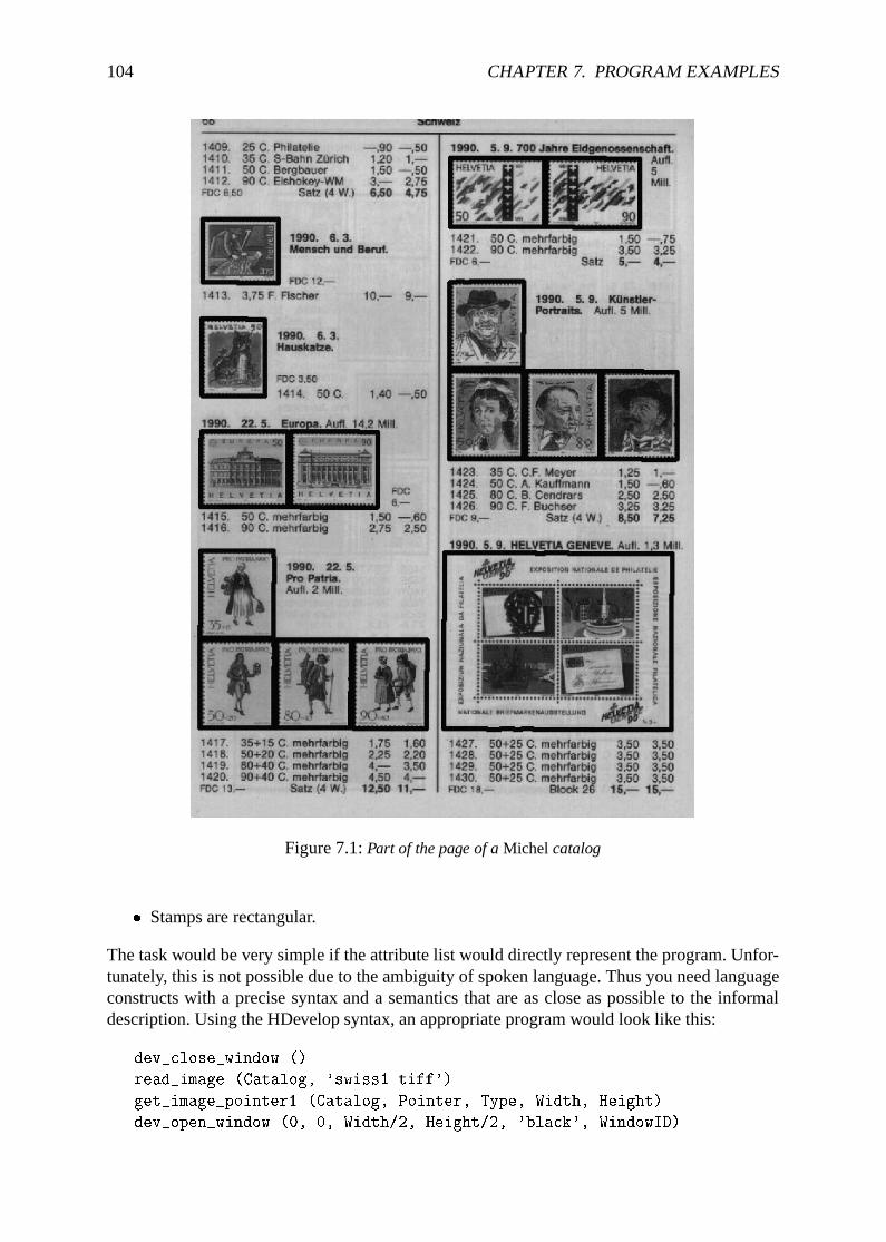
104 CHAPTER 7. PROGRAM EXAMPLES
Figure 7.1:Part of the page of aMichel catalog
� Stamps are rectangular.
The task would be very simple if the attribute list would directly represent the program. Unfor-tunately, this is not possible due to the ambiguity of spoken language. Thus you need languageconstructs with a precise syntax and a semantics that are as close as possible to the informaldescription. Using the HDevelop syntax, an appropriate program would look like this:
dev_close_window ()
read_image (Catalog, 'swiss1.tiff')
get_image_pointer1 (Catalog, Pointer, Type, Width, Height)
dev_open_window (0, 0, Width/2, Height/2, 'black', WindowID)
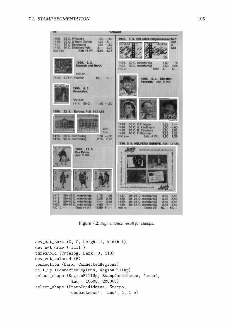
7.1. STAMP SEGMENTATION 105
Figure 7.2:Segmentation result for stamps.
dev_set_part (0, 0, Height-1, Width-1)
dev_set_draw ('fill')
threshold (Catalog, Dark, 0, 110)
dev_set_colored (6)
connection (Dark, ConnectedRegions)
fill_up (ConnectedRegions, RegionFillUp)
select_shape (RegionFillUp, StampCandidates, 'area',
'and', 10000, 200000)
select_shape (StampCandidates, Stamps,
'compactness', 'and', 1, 1.5)
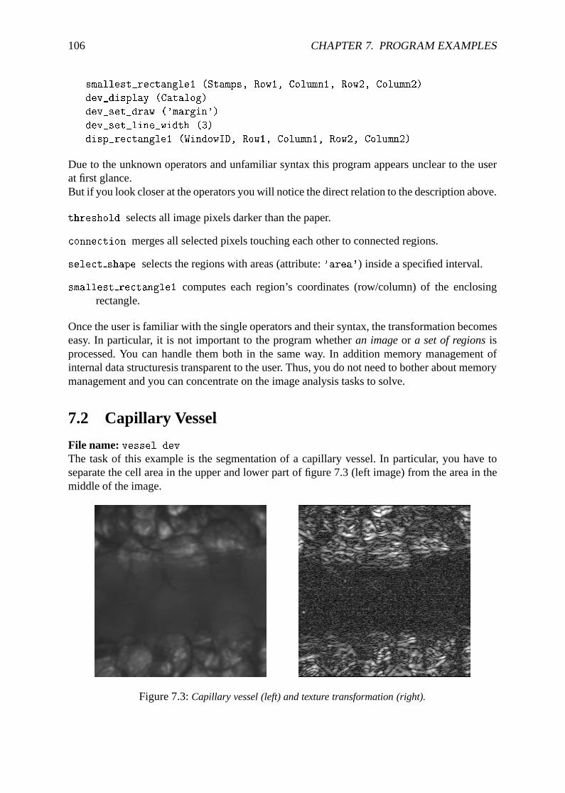
106 CHAPTER 7. PROGRAM EXAMPLES
smallest_rectangle1 (Stamps, Row1, Column1, Row2, Column2)
dev_display (Catalog)
dev_set_draw ('margin')
dev_set_line_width (3)
disp_rectangle1 (WindowID, Row1, Column1, Row2, Column2)
Due to the unknown operators and unfamiliar syntax this program appears unclear to the userat first glance.But if you look closer at the operators you will notice the direct relation to the description above.
threshold selects all image pixels darker than the paper.
connection merges all selected pixels touching each other to connected regions.
select shape selects the regions with areas (attribute:'area') inside a specified interval.
smallest rectangle1 computes each region’s coordinates (row/column) of the enclosingrectangle.
Once the user is familiar with the single operators and their syntax, the transformation becomeseasy. In particular, it is not important to the program whetheran imageor a set of regionsisprocessed. You can handle them both in the same way. In addition memory management ofinternal data structuresis transparent to the user. Thus, you do not need to bother about memorymanagement and you can concentrate on the image analysis tasks to solve.
7.2 Capillary Vessel
File name:vessel.devThe task of this example is the segmentation of a capillary vessel. In particular, you have toseparate the cell area in the upper and lower part of figure 7.3 (left image) from the area in themiddle of the image.
Figure 7.3:Capillary vessel (left) and texture transformation (right).
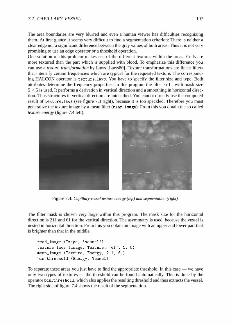
7.2. CAPILLARY VESSEL 107
The area boundaries are very blurred and even a human viewer has difficulties recognizingthem. At first glance it seems very difficult to find a segmentation criterion: There is neither aclear edge nor a significant difference between the gray values of both areas. Thus it is not verypromising to use an edge operator or a threshold operation.One solution of this problem makes use of the different textures within the areas: Cells aremore textured than the part which is supplied with blood. To emphasize this difference youcan use atexture transformationby Laws [Laws80]. Texture transformations are linear filtersthat intensify certain frequencies which are typical for the requested texture. The correspond-ing HALCON operator istexture laws. You have to specify the filter size and type. Bothattributes determine the frequency properties. In this program the filter'el' with mask size5� 5 is used. It performs a derivation in vertical direction and a smoothing in horizontal direc-tion. Thus structures in vertical direction are intensified. You cannot directly use the computedresult oftexture laws (see figure 7.3 right), because it is too speckled. Therefore you mustgeneralize the texture image by a mean filter (mean image). From this you obtain the so calledtexture energy(figure 7.4 left).
Figure 7.4:Capillary vessel texture energy (left) and segmentation (right).
The filter mask is chosen very large within this program. The mask size for the horizontaldirection is 211 and 61 for the vertical direction. The asymmetry is used, because the vessel isnested in horizontal direction. From this you obtain an image with an upper and lower part thatis brighter than that in the middle.
read_image (Image, 'vessel')
texture_laws (Image, Texture, 'el', 5, 5)
mean_image (Texture, Energy, 211, 61)
bin_threshold (Energy, Vessel)
To separate these areas you just have to find the appropriate threshold. In this case — we haveonly two types of textures — the threshold can be found automatically. This is done by theoperatorbin threshold, which also applies the resulting threshold and thus extracts the vessel.The right side of figure 7.4 shows the result of the segmentation.
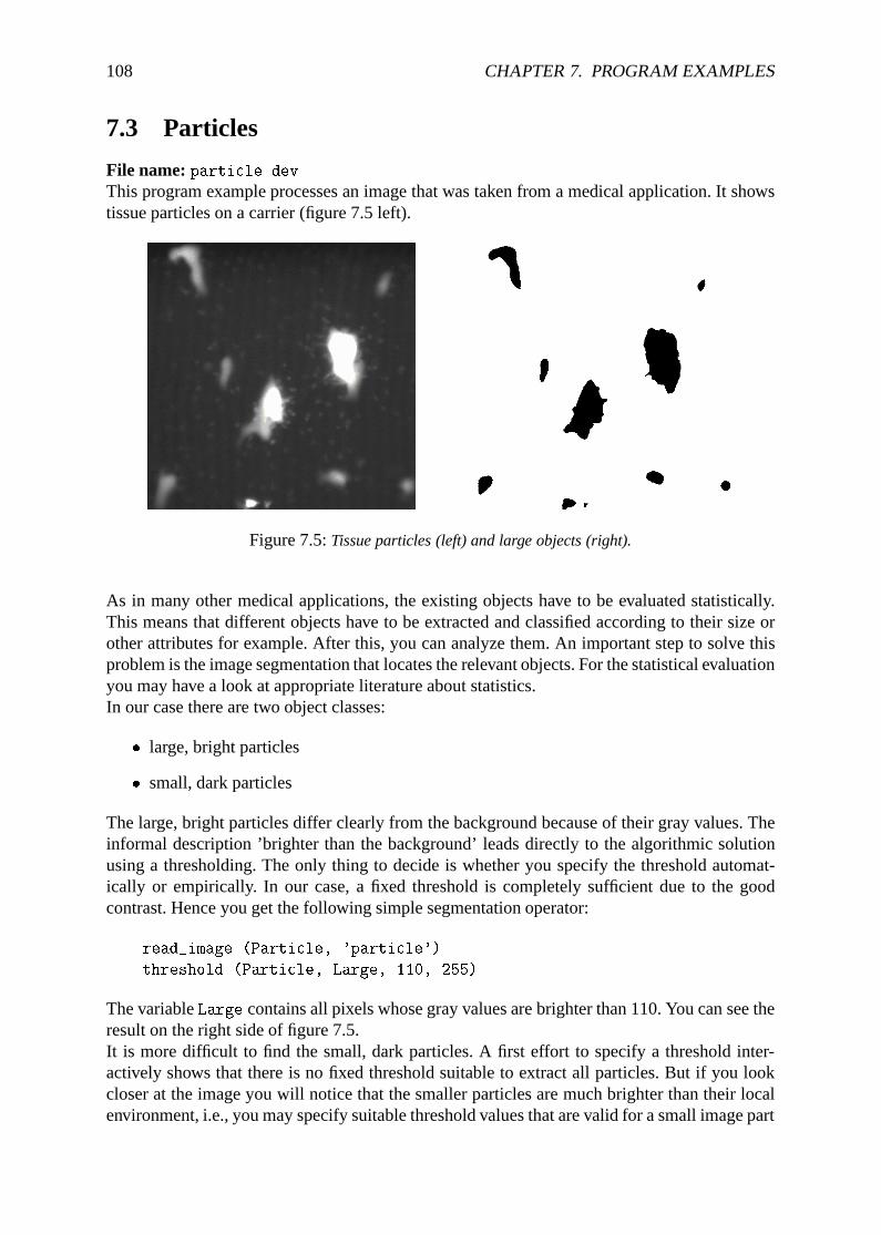
108 CHAPTER 7. PROGRAM EXAMPLES
7.3 Particles
File name:particle.devThis program example processes an image that was taken from a medical application. It showstissue particles on a carrier (figure 7.5 left).
Figure 7.5:Tissue particles (left) and large objects (right).
As in many other medical applications, the existing objects have to be evaluated statistically.This means that different objects have to be extracted and classified according to their size orother attributes for example. After this, you can analyze them. An important step to solve thisproblem is the image segmentation that locates the relevant objects. For the statistical evaluationyou may have a look at appropriate literature about statistics.In our case there are two object classes:
� large, bright particles
� small, dark particles
The large, bright particles differ clearly from the background because of their gray values. Theinformal description ’brighter than the background’ leads directly to the algorithmic solutionusing a thresholding. The only thing to decide is whether you specify the threshold automat-ically or empirically. In our case, a fixed threshold is completely sufficient due to the goodcontrast. Hence you get the following simple segmentation operator:
read_image (Particle, 'particle')
threshold (Particle, Large, 110, 255)
The variableLarge contains all pixels whose gray values are brighter than 110. You can see theresult on the right side of figure 7.5.It is more difficult to find the small, dark particles. A first effort to specify a threshold inter-actively shows that there is no fixed threshold suitable to extract all particles. But if you lookcloser at the image you will notice that the smaller particles are much brighter than their localenvironment, i.e., you may specify suitable threshold values that are valid for a small image part
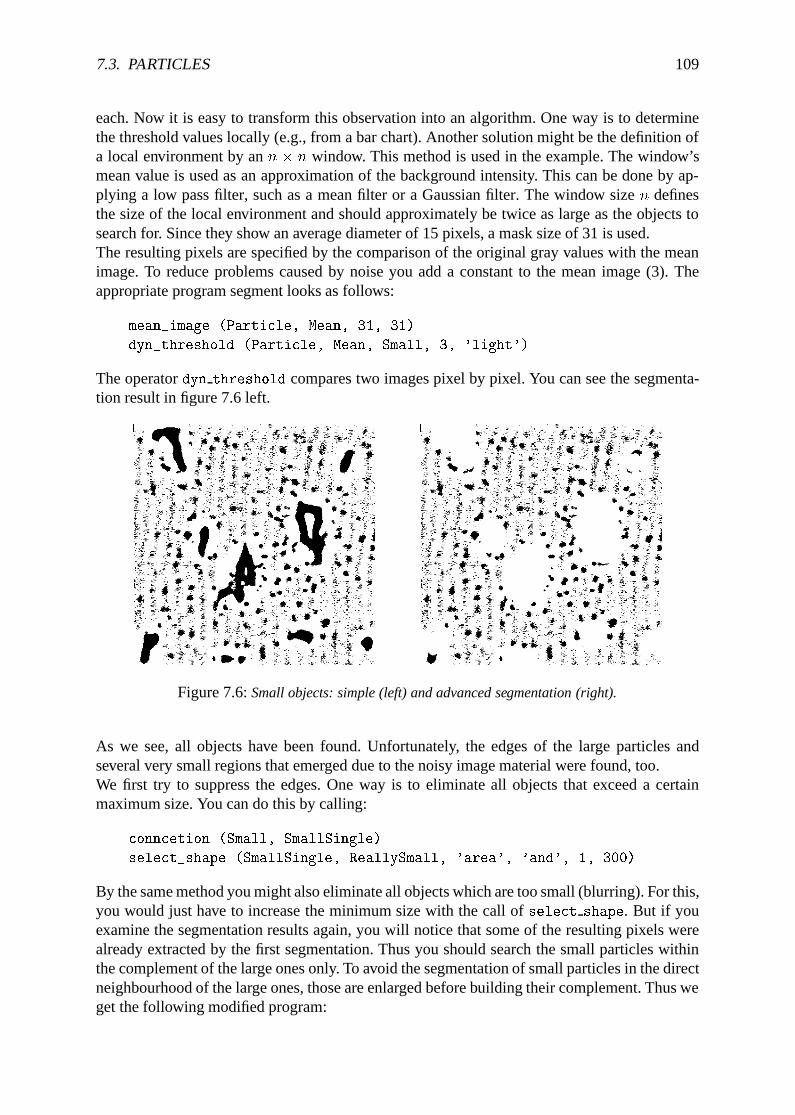
7.3. PARTICLES 109
each. Now it is easy to transform this observation into an algorithm. One way is to determinethe threshold values locally (e.g., from a bar chart). Another solution might be the definition ofa local environment by ann � n window. This method is used in the example. The window’smean value is used as an approximation of the background intensity. This can be done by ap-plying a low pass filter, such as a mean filter or a Gaussian filter. The window sizen definesthe size of the local environment and should approximately be twice as large as the objects tosearch for. Since they show an average diameter of 15 pixels, a mask size of 31 is used.The resulting pixels are specified by the comparison of the original gray values with the meanimage. To reduce problems caused by noise you add a constant to the mean image (3). Theappropriate program segment looks as follows:
mean_image (Particle, Mean, 31, 31)
dyn_threshold (Particle, Mean, Small, 3, 'light')
The operatordyn threshold compares two images pixel by pixel. You can see the segmenta-tion result in figure 7.6 left.
Figure 7.6:Small objects: simple (left) and advanced segmentation (right).
As we see, all objects have been found. Unfortunately, the edges of the large particles andseveral very small regions that emerged due to the noisy image material were found, too.We first try to suppress the edges. One way is to eliminate all objects that exceed a certainmaximum size. You can do this by calling:
conncetion (Small, SmallSingle)
select_shape (SmallSingle, ReallySmall, 'area', 'and', 1, 300)
By the same method you might also eliminate all objects which are too small (blurring). For this,you would just have to increase the minimum size with the call ofselect shape. But if youexamine the segmentation results again, you will notice that some of the resulting pixels werealready extracted by the first segmentation. Thus you should search the small particles withinthe complement of the large ones only. To avoid the segmentation of small particles in the directneighbourhood of the large ones, those are enlarged before building their complement. Thus weget the following modified program:
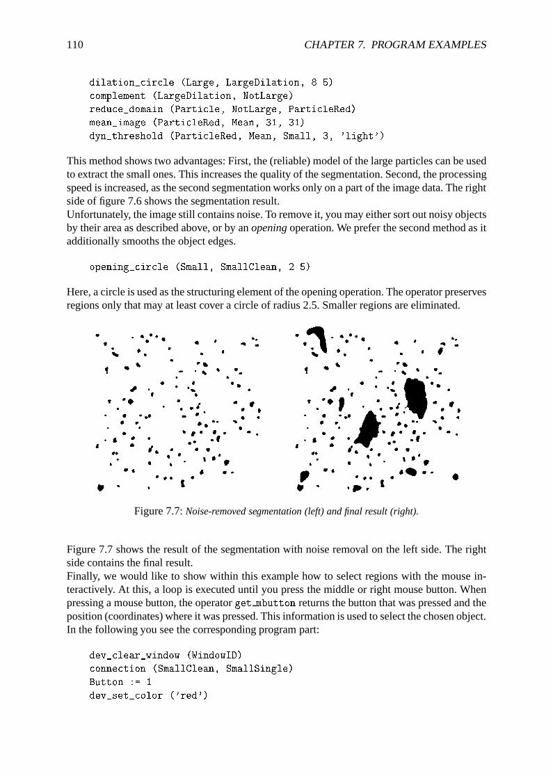
110 CHAPTER 7. PROGRAM EXAMPLES
dilation_circle (Large, LargeDilation, 8.5)
complement (LargeDilation, NotLarge)
reduce_domain (Particle, NotLarge, ParticleRed)
mean_image (ParticleRed, Mean, 31, 31)
dyn_threshold (ParticleRed, Mean, Small, 3, 'light')
This method shows two advantages: First, the (reliable) model of the large particles can be usedto extract the small ones. This increases the quality of the segmentation. Second, the processingspeed is increased, as the second segmentation works only on a part of the image data. The rightside of figure 7.6 shows the segmentation result.Unfortunately, the image still contains noise. To remove it, you may either sort out noisy objectsby their area as described above, or by anopeningoperation. We prefer the second method as itadditionally smooths the object edges.
opening_circle (Small, SmallClean, 2.5)
Here, a circle is used as the structuring element of the opening operation. The operator preservesregions only that may at least cover a circle of radius 2.5. Smaller regions are eliminated.
Figure 7.7:Noise-removed segmentation (left) and final result (right).
Figure 7.7 shows the result of the segmentation with noise removal on the left side. The rightside contains the final result.Finally, we would like to show within this example how to select regions with the mouse in-teractively. At this, a loop is executed until you press the middle or right mouse button. Whenpressing a mouse button, the operatorget mbutton returns the button that was pressed and theposition (coordinates) where it was pressed. This information is used to select the chosen object.In the following you see the corresponding program part:
dev_clear_window (WindowID)
connection (SmallClean, SmallSingle)
Button := 1
dev_set_color ('red')
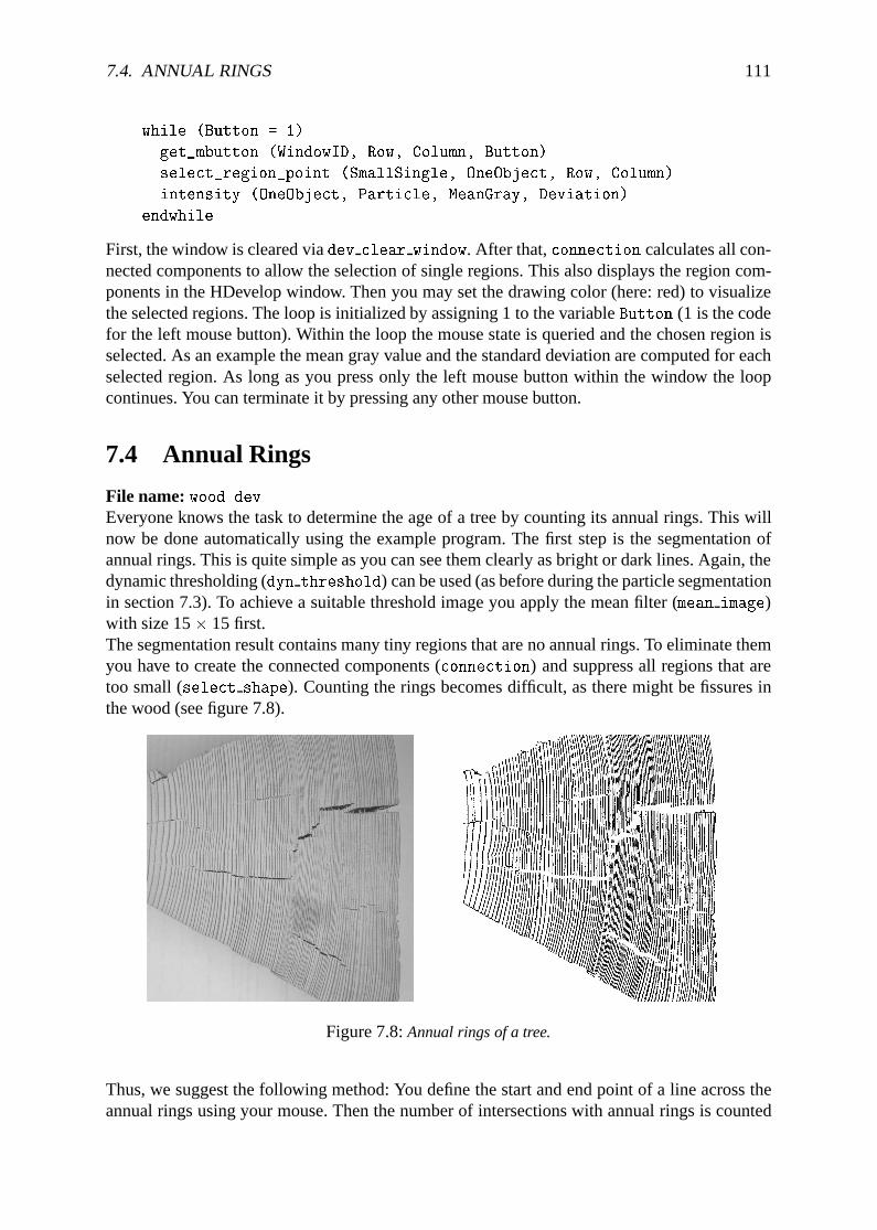
7.4. ANNUAL RINGS 111
while (Button = 1)
get_mbutton (WindowID, Row, Column, Button)
select_region_point (SmallSingle, OneObject, Row, Column)
intensity (OneObject, Particle, MeanGray, Deviation)
endwhile
First, the window is cleared viadev clear window. After that,connection calculates all con-nected components to allow the selection of single regions. This also displays the region com-ponents in the HDevelop window. Then you may set the drawing color (here: red) to visualizethe selected regions. The loop is initialized by assigning 1 to the variableButton (1 is the codefor the left mouse button). Within the loop the mouse state is queried and the chosen region isselected. As an example the mean gray value and the standard deviation are computed for eachselected region. As long as you press only the left mouse button within the window the loopcontinues. You can terminate it by pressing any other mouse button.
7.4 Annual Rings
File name:wood.devEveryone knows the task to determine the age of a tree by counting its annual rings. This willnow be done automatically using the example program. The first step is the segmentation ofannual rings. This is quite simple as you can see them clearly as bright or dark lines. Again, thedynamic thresholding (dyn threshold) can be used (as before during the particle segmentationin section 7.3). To achieve a suitable threshold image you apply the mean filter (mean image)with size 15� 15 first.The segmentation result contains many tiny regions that are no annual rings. To eliminate themyou have to create the connected components (connection) and suppress all regions that aretoo small (select shape). Counting the rings becomes difficult, as there might be fissures inthe wood (see figure 7.8).
Figure 7.8:Annual rings of a tree.
Thus, we suggest the following method: You define the start and end point of a line across theannual rings using your mouse. Then the number of intersections with annual rings is counted
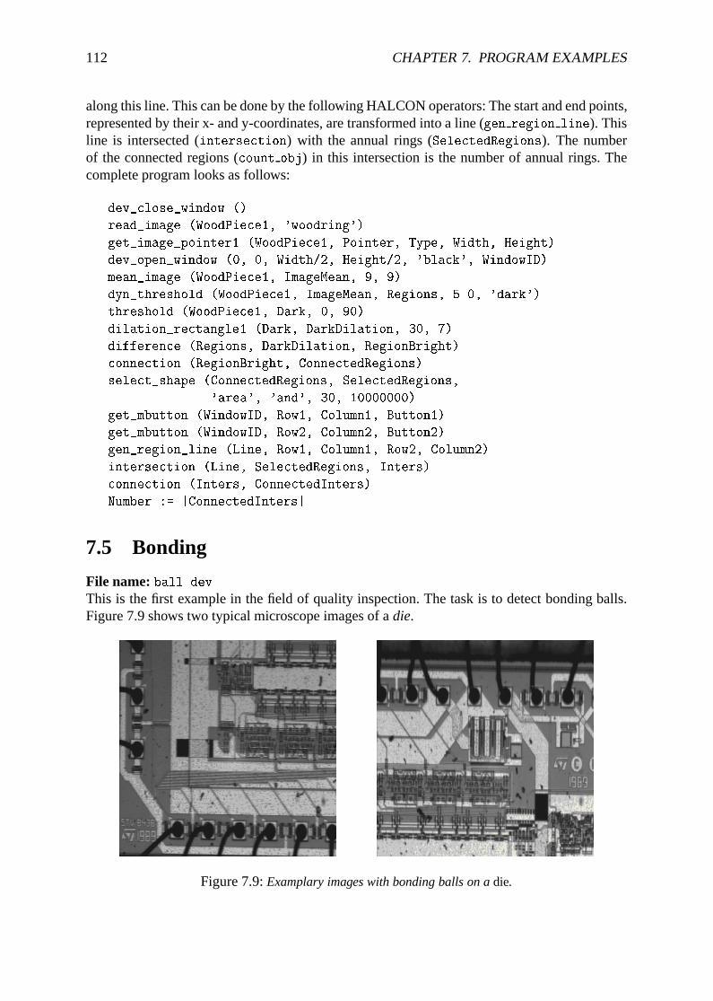
112 CHAPTER 7. PROGRAM EXAMPLES
along this line. This can be done by the following HALCON operators: The start and end points,represented by their x- and y-coordinates, are transformed into a line (gen region line). Thisline is intersected (intersection) with the annual rings (SelectedRegions). The numberof the connected regions (count obj) in this intersection is the number of annual rings. Thecomplete program looks as follows:
dev_close_window ()
read_image (WoodPiece1, 'woodring')
get_image_pointer1 (WoodPiece1, Pointer, Type, Width, Height)
dev_open_window (0, 0, Width/2, Height/2, 'black', WindowID)
mean_image (WoodPiece1, ImageMean, 9, 9)
dyn_threshold (WoodPiece1, ImageMean, Regions, 5.0, 'dark')
threshold (WoodPiece1, Dark, 0, 90)
dilation_rectangle1 (Dark, DarkDilation, 30, 7)
difference (Regions, DarkDilation, RegionBright)
connection (RegionBright, ConnectedRegions)
select_shape (ConnectedRegions, SelectedRegions,
'area', 'and', 30, 10000000)
get_mbutton (WindowID, Row1, Column1, Button1)
get_mbutton (WindowID, Row2, Column2, Button2)
gen_region_line (Line, Row1, Column1, Row2, Column2)
intersection (Line, SelectedRegions, Inters)
connection (Inters, ConnectedInters)
Number := |ConnectedInters|
7.5 Bonding
File name:ball.devThis is the first example in the field of quality inspection. The task is to detect bonding balls.Figure 7.9 shows two typical microscope images of adie.
Figure 7.9:Examplary images with bonding balls on adie.
7.6. CALIBRATION BOARD 113
Thedie border and the bonding wires appear dark. Thus you may apply a thresholding. Sincethe background is also dark we have to extract thedie before doing the segmentation. Thedieis rather bright. Thus we can select the pixels by their gray values.
read_image (Bond, 'die3')
threshold (Bond, Bright, 120, 255)
shape_trans (Bright, Die, 'rectangle2')
All pixels of thedie that got lost by the thresholding can be recoverd by using a hull compu-tation. Since thedie is rectangular and may be slightly turned during the assembly we use thesmallest enclosing rectangle as a hull.Now you can start the segmentation of wires and bonding balls. Since only those parts of wiresand balls are of interest that lie within thedie area, you may restrict the segmentation to thisregion. All dark pixels within thediearea belong to wires. Unfortunately, there are some brightreflections on the wires that are not found by the segmentation. You may fill these gaps by usingfill up shape. In our case, the gaps with a certain size (1 up to 100 pixels) are filled.
reduce_domain (Bond, Die, DieGray)
threshold (DieGray, Wires, 0, 100)
fill_up_shape (Wires, WiresFilled, 'area', 1, 100)
opening_circle (WiresFilled, Balls, 15.5)
connection (Balls, SingleBalls)
select_shape (SingleBalls, IntermediateBalls, 'circularity',and,0.85, 1.0)
sort_region (IntermediateBalls, FinalBalls, 'FirstPoint', 'True', 'column')
smallest_circle (FinalBalls, Row, Column, Radius)
Since the balls are wider than the wires, you may clean this region using a simple opening.The radius (here 15.5) should correspond to the minimum size of one ball. In both imagesyou see an erroneous segmentation that was created by a rectangular dark region. This can besuppressed by a shape segmentation. Since in practice a bonding detection would be performedonly close to the anticipated positions of bonding balls. Figure 7.10 shows the results of thewhole segmentation.Balls are shown in white color. Every radius of a ball you can find in the tuple variable Radius.The number of balls within the example you can get with the absolute value of Radius.
NumBalls := |Radius|
Diameter := 2*Radius
MeanDiameter := sum(Diameter)/NumBalls
MinDiameter := min(Diameter)
Diameter, MeanDiameter and MinDiameter are some examples for calculations possible withHDevelop.
7.6 Calibration Board
File name:calib.devThis example works with the image of a calibration board. It is used to specify the internal
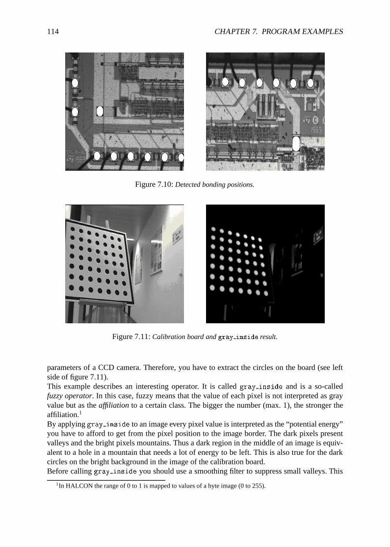
114 CHAPTER 7. PROGRAM EXAMPLES
Figure 7.10:Detected bonding positions.
Figure 7.11:Calibration board andgray inside result.
parameters of a CCD camera. Therefore, you have to extract the circles on the board (see leftside of figure 7.11).This example describes an interesting operator. It is calledgray inside and is a so-calledfuzzy operator. In this case, fuzzy means that the value of each pixel is not interpreted as grayvalue but as theaffiliation to a certain class. The bigger the number (max. 1), the stronger theaffiliation.1
By applyinggray inside to an image every pixel value is interpreted as the “potential energy”you have to afford to get from the pixel position to the image border. The dark pixels presentvalleys and the bright pixels mountains. Thus a dark region in the middle of an image is equiv-alent to a hole in a mountain that needs a lot of energy to be left. This is also true for the darkcircles on the bright background in the image of the calibration board.Before callinggray inside you should use a smoothing filter to suppress small valleys. This
1In HALCON the range of 0 to 1 is mapped to values of a byte image (0 to 255).
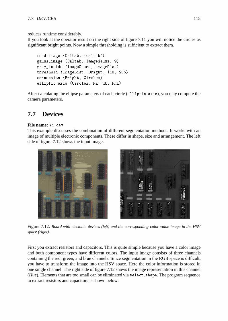
7.7. DEVICES 115
reduces runtime considerably.If you look at the operator result on the right side of figure 7.11 you will notice the circles assignificant bright points. Now a simple thresholding is sufficient to extract them.
read_image (Caltab, 'caltab')
gauss_image (Caltab, ImageGauss, 9)
gray_inside (ImageGauss, ImageDist)
threshold (ImageDist, Bright, 110, 255)
connection (Bright, Circles)
elliptic_axis (Circles, Ra, Rb, Phi)
After calculating the ellipse parameters of each circle (elliptic axis), you may compute thecamera parameters.
7.7 Devices
File name:ic.devThis example discusses the combination of different segmentation methods. It works with animage of multiple electronic components. These differ in shape, size and arrangement. The leftside of figure 7.12 shows the input image.
Figure 7.12:Board with electonic devices (left) and the corresponding color value image in the HSVspace (right).
First you extract resistors and capacitors. This is quite simple because you have a color imageand both component types have different colors. The input image consists of three channelscontaining the red, green, and blue channels. Since segmentation in the RGB space is difficult,you have to transform the image into the HSV space. Here the color information is stored inone single channel. The right side of figure 7.12 shows the image representation in this channel(Hue). Elements that are too small can be eliminated viaselect shape. The program sequenceto extract resistors and capacitors is shown below:
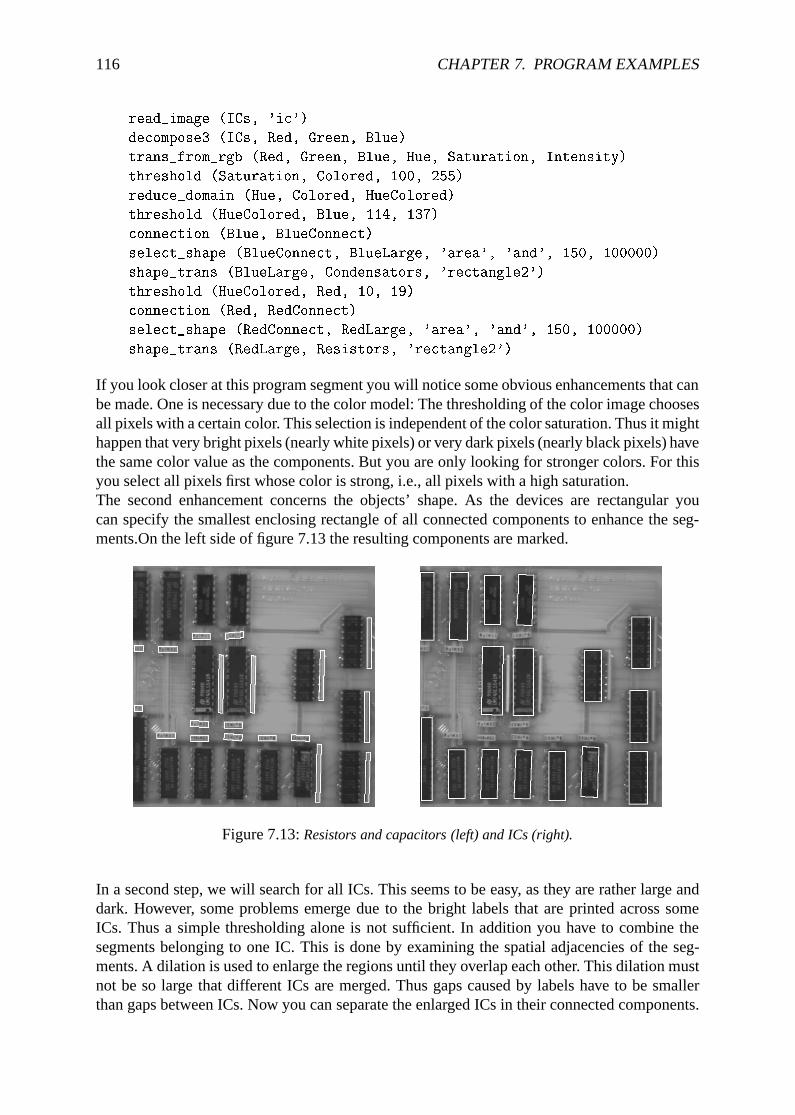
116 CHAPTER 7. PROGRAM EXAMPLES
read_image (ICs, 'ic')
decompose3 (ICs, Red, Green, Blue)
trans_from_rgb (Red, Green, Blue, Hue, Saturation, Intensity)
threshold (Saturation, Colored, 100, 255)
reduce_domain (Hue, Colored, HueColored)
threshold (HueColored, Blue, 114, 137)
connection (Blue, BlueConnect)
select_shape (BlueConnect, BlueLarge, 'area', 'and', 150, 100000)
shape_trans (BlueLarge, Condensators, 'rectangle2')
threshold (HueColored, Red, 10, 19)
connection (Red, RedConnect)
select_shape (RedConnect, RedLarge, 'area', 'and', 150, 100000)
shape_trans (RedLarge, Resistors, 'rectangle2')
If you look closer at this program segment you will notice some obvious enhancements that canbe made. One is necessary due to the color model: The thresholding of the color image choosesall pixels with a certain color. This selection is independent of the color saturation. Thus it mighthappen that very bright pixels (nearly white pixels) or very dark pixels (nearly black pixels) havethe same color value as the components. But you are only looking for stronger colors. For thisyou select all pixels first whose color is strong, i.e., all pixels with a high saturation.The second enhancement concerns the objects’ shape. As the devices are rectangular youcan specify the smallest enclosing rectangle of all connected components to enhance the seg-ments.On the left side of figure 7.13 the resulting components are marked.
Figure 7.13:Resistors and capacitors (left) and ICs (right).
In a second step, we will search for all ICs. This seems to be easy, as they are rather large anddark. However, some problems emerge due to the bright labels that are printed across someICs. Thus a simple thresholding alone is not sufficient. In addition you have to combine thesegments belonging to one IC. This is done by examining the spatial adjacencies of the seg-ments. A dilation is used to enlarge the regions until they overlap each other. This dilation mustnot be so large that different ICs are merged. Thus gaps caused by labels have to be smallerthan gaps between ICs. Now you can separate the enlarged ICs in their connected components.
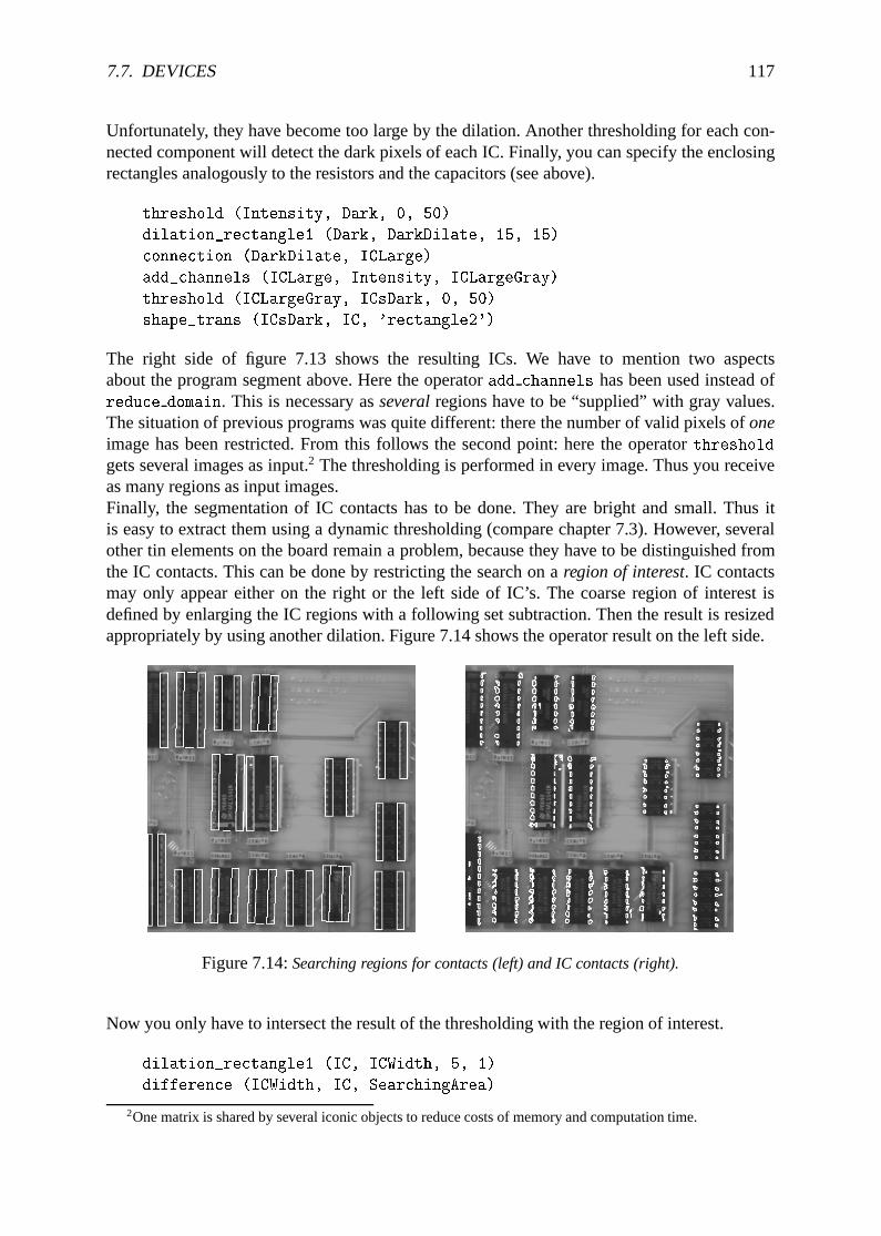
7.7. DEVICES 117
Unfortunately, they have become too large by the dilation. Another thresholding for each con-nected component will detect the dark pixels of each IC. Finally, you can specify the enclosingrectangles analogously to the resistors and the capacitors (see above).
threshold (Intensity, Dark, 0, 50)
dilation_rectangle1 (Dark, DarkDilate, 15, 15)
connection (DarkDilate, ICLarge)
add_channels (ICLarge, Intensity, ICLargeGray)
threshold (ICLargeGray, ICsDark, 0, 50)
shape_trans (ICsDark, IC, 'rectangle2')
The right side of figure 7.13 shows the resulting ICs. We have to mention two aspectsabout the program segment above. Here the operatoradd channels has been used instead ofreduce domain. This is necessary asseveralregions have to be “supplied” with gray values.The situation of previous programs was quite different: there the number of valid pixels ofoneimage has been restricted. From this follows the second point: here the operatorthreshold
gets several images as input.2 The thresholding is performed in every image. Thus you receiveas many regions as input images.Finally, the segmentation of IC contacts has to be done. They are bright and small. Thus itis easy to extract them using a dynamic thresholding (compare chapter 7.3). However, severalother tin elements on the board remain a problem, because they have to be distinguished fromthe IC contacts. This can be done by restricting the search on aregion of interest. IC contactsmay only appear either on the right or the left side of IC’s. The coarse region of interest isdefined by enlarging the IC regions with a following set subtraction. Then the result is resizedappropriately by using another dilation. Figure 7.14 shows the operator result on the left side.
Figure 7.14:Searching regions for contacts (left) and IC contacts (right).
Now you only have to intersect the result of the thresholding with the region of interest.
dilation_rectangle1 (IC, ICWidth, 5, 1)
difference (ICWidth, IC, SearchingArea)
2One matrix is shared by several iconic objects to reduce costs of memory and computation time.
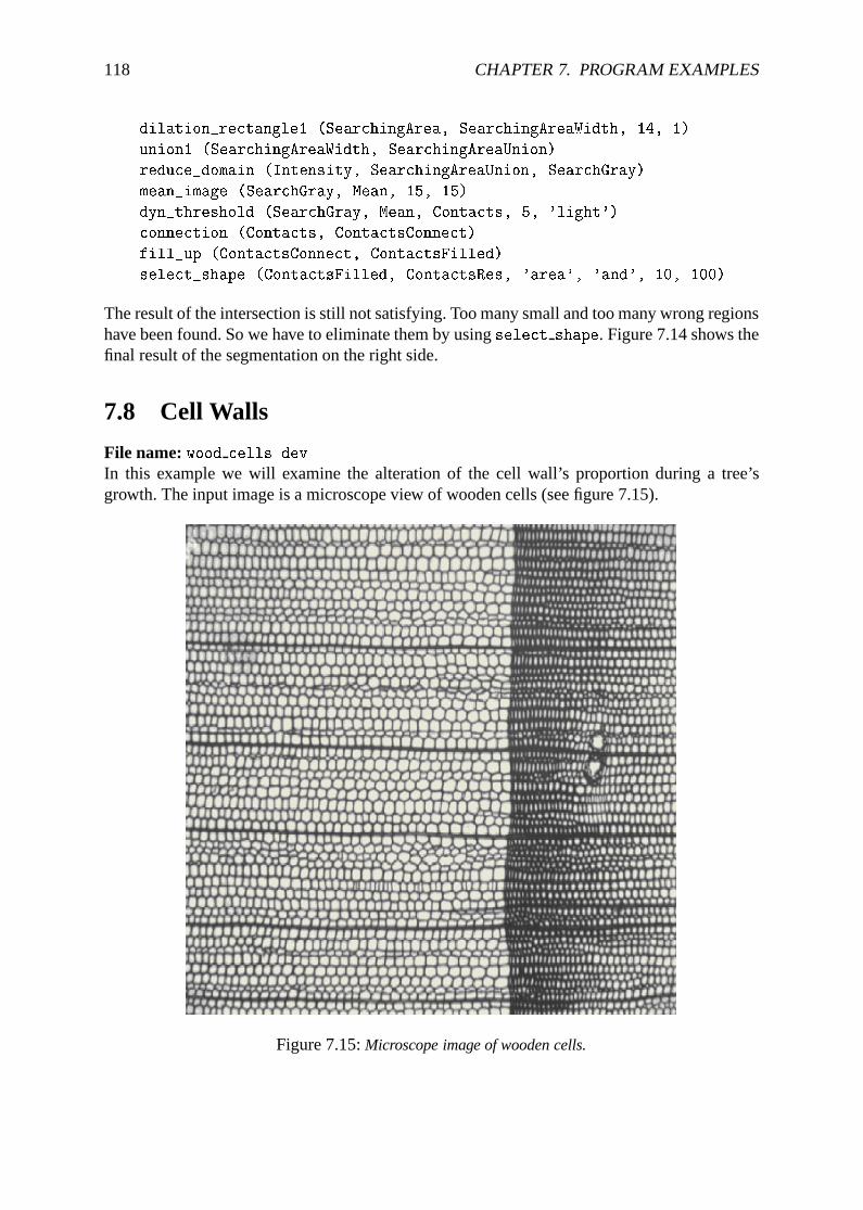
118 CHAPTER 7. PROGRAM EXAMPLES
dilation_rectangle1 (SearchingArea, SearchingAreaWidth, 14, 1)
union1 (SearchingAreaWidth, SearchingAreaUnion)
reduce_domain (Intensity, SearchingAreaUnion, SearchGray)
mean_image (SearchGray, Mean, 15, 15)
dyn_threshold (SearchGray, Mean, Contacts, 5, 'light')
connection (Contacts, ContactsConnect)
fill_up (ContactsConnect, ContactsFilled)
select_shape (ContactsFilled, ContactsRes, 'area', 'and', 10, 100)
The result of the intersection is still not satisfying. Too many small and too many wrong regionshave been found. So we have to eliminate them by usingselect shape. Figure 7.14 shows thefinal result of the segmentation on the right side.
7.8 Cell Walls
File name:wood cells.dev
In this example we will examine the alteration of the cell wall’s proportion during a tree’sgrowth. The input image is a microscope view of wooden cells (see figure 7.15).
Figure 7.15:Microscope image of wooden cells.
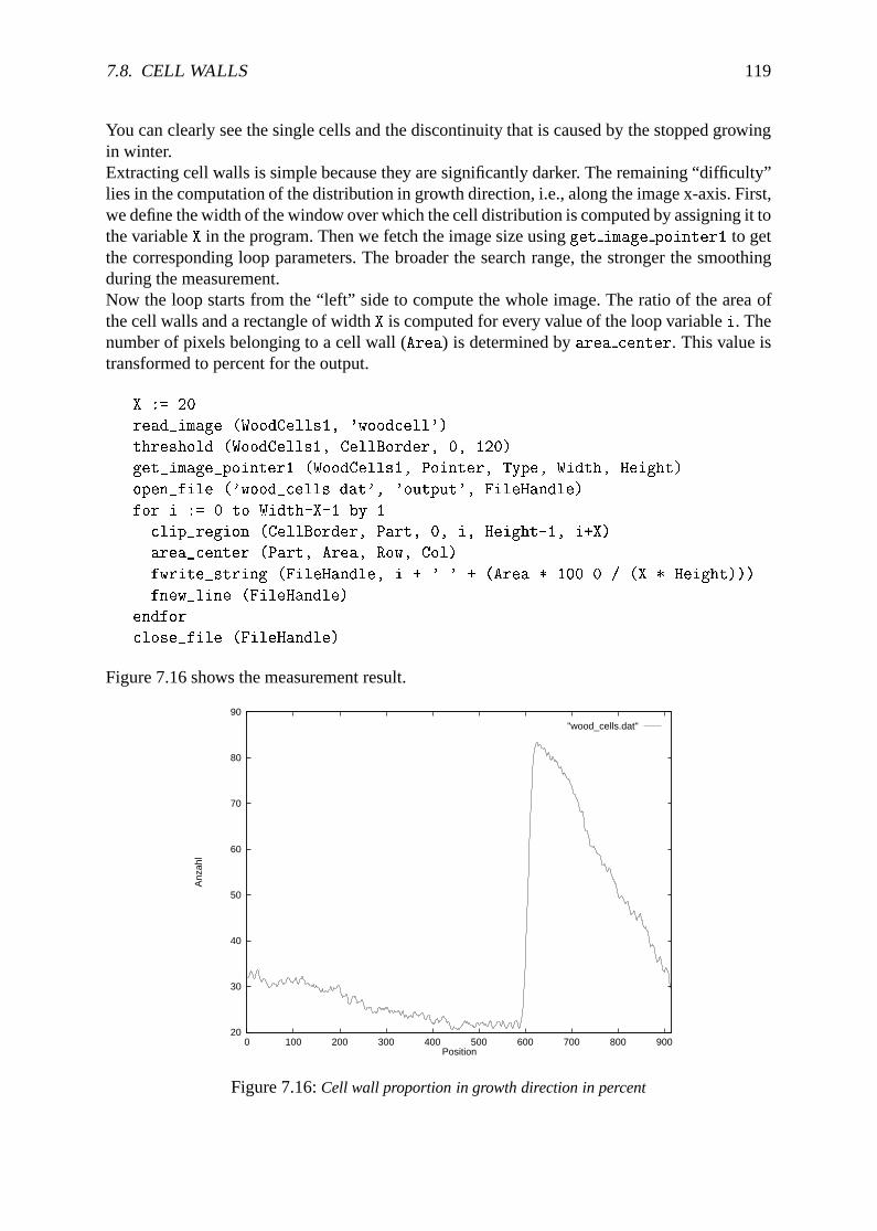
7.8. CELL WALLS 119
You can clearly see the single cells and the discontinuity that is caused by the stopped growingin winter.Extracting cell walls is simple because they are significantly darker. The remaining “difficulty”lies in the computation of the distribution in growth direction, i.e., along the image x-axis. First,we define the width of the window over which the cell distribution is computed by assigning it tothe variableX in the program. Then we fetch the image size usingget image pointer1 to getthe corresponding loop parameters. The broader the search range, the stronger the smoothingduring the measurement.Now the loop starts from the “left” side to compute the whole image. The ratio of the area ofthe cell walls and a rectangle of widthX is computed for every value of the loop variablei. Thenumber of pixels belonging to a cell wall (Area) is determined byarea center. This value istransformed to percent for the output.
X := 20
read_image (WoodCells1, 'woodcell')
threshold (WoodCells1, CellBorder, 0, 120)
get_image_pointer1 (WoodCells1, Pointer, Type, Width, Height)
open_file ('wood_cells.dat', 'output', FileHandle)
for i := 0 to Width-X-1 by 1
clip_region (CellBorder, Part, 0, i, Height-1, i+X)
area_center (Part, Area, Row, Col)
fwrite_string (FileHandle, i + ' ' + (Area * 100.0 / (X * Height)))
fnew_line (FileHandle)
endfor
close_file (FileHandle)
Figure 7.16 shows the measurement result.
20
30
40
50
60
70
80
90
0 100 200 300 400 500 600 700 800 900
Anz
ahl
Position
"wood_cells.dat"
Figure 7.16:Cell wall proportion in growth direction in percent
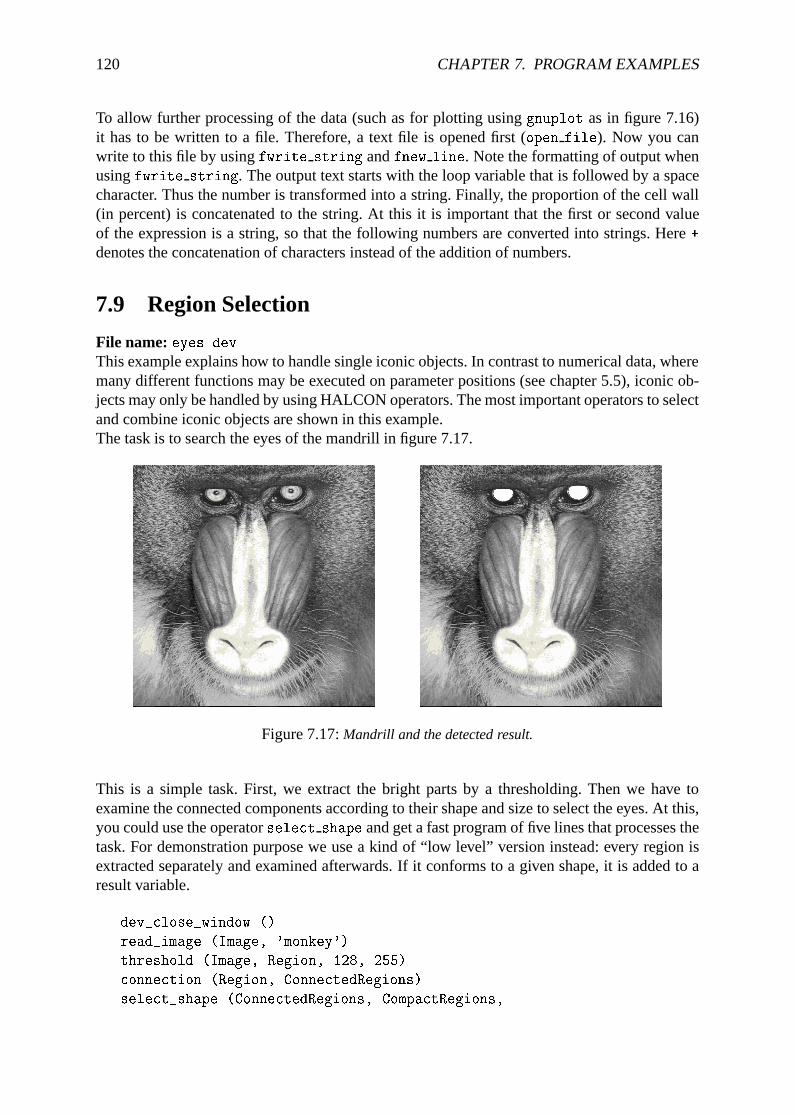
120 CHAPTER 7. PROGRAM EXAMPLES
To allow further processing of the data (such as for plotting usinggnuplot as in figure 7.16)it has to be written to a file. Therefore, a text file is opened first (open file). Now you canwrite to this file by usingfwrite string andfnew line. Note the formatting of output whenusingfwrite string. The output text starts with the loop variable that is followed by a spacecharacter. Thus the number is transformed into a string. Finally, the proportion of the cell wall(in percent) is concatenated to the string. At this it is important that the first or second valueof the expression is a string, so that the following numbers are converted into strings. Here+
denotes the concatenation of characters instead of the addition of numbers.
7.9 Region Selection
File name:eyes.devThis example explains how to handle single iconic objects. In contrast to numerical data, wheremany different functions may be executed on parameter positions (see chapter 5.5), iconic ob-jects may only be handled by using HALCON operators. The most important operators to selectand combine iconic objects are shown in this example.The task is to search the eyes of the mandrill in figure 7.17.
Figure 7.17:Mandrill and the detected result.
This is a simple task. First, we extract the bright parts by a thresholding. Then we have toexamine the connected components according to their shape and size to select the eyes. At this,you could use the operatorselect shape and get a fast program of five lines that processes thetask. For demonstration purpose we use a kind of “low level” version instead: every region isextracted separately and examined afterwards. If it conforms to a given shape, it is added to aresult variable.
dev_close_window ()
read_image (Image, 'monkey')
threshold (Image, Region, 128, 255)
connection (Region, ConnectedRegions)
select_shape (ConnectedRegions, CompactRegions,
7.10. EXCEPTION HANDLING 121
'compactness', 'and', 1.5, 1.8)
Number := |CompactRegions|
Eyes := []
for i := 1 to Number by 1
SingleSelected := CompactRegions[i]
area_center (SingleSelected, Area, Row, Column)
dev_set_color ('green')
if ((Area > 500) and (Area < 50000))
dev_set_color ('red')
Eyes := [SingleSelected,Eyes]
endif
endfor
Note that you have to specify the number of regions (count obj) in order to run afor loopfrom 1 to Number. Within this loop a region is selected (select obj) according to the loopvariablei in order to evaluate its attributes. If its area is within certain bounds the region isadded to variableEyes (concat obj). You have to specify the variableEyes properly, as it isalso used as input forconcat obj. This can be done by usingempty object that assigns noiconic object in a defined way to the variable, i.e.,count obj returns zero for it.During the run time of the program you can see how the individual regions are selected andexamined. To speed up the processing you can use the menuFile . Options to suppress theautomatic output.
7.10 Exception Handling
File name:exception.devIn some applications it is necessary to have explicit control over the result state of an operator.By default HDevelop stops if an operator returns a different state thanH MSG TRUE and givesan error message. To have explicit control over the result state, two HDevelop operators areavailable:dev error var anddev set check. The following example shows how to use theseoperators.The task is to get online information about the position of the mouse inside a graphics windowand to display the gray value at this position. This can be achieved using the two operatorsget mposition andget grayval. The problem withget mposition in HDevelop is, that itreturnsH MSG FAIL if the mouse is outside of the window to indicate that the mouse coordi-nates are invalid. This would lead to an interruption of the program. Therefore an explicit errorhandling is needed. The complete program is given below:
read_image (Image, 'mreut')
dev_close_window ()
dev_open_window (0, 0, -1, -1, 'black', WindowID)
dev_display (Image)
Button := 1
while (Button # 4)
dev_error_var (Error, 1)
dev_set_check ('~give_error')
get_mposition (WindowID, Row, Column, Button)
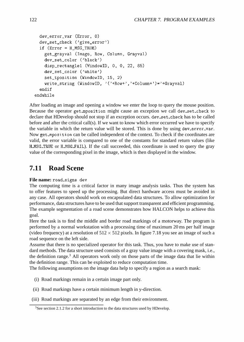
122 CHAPTER 7. PROGRAM EXAMPLES
dev_error_var (Error, 0)
dev_set_check ('give_error')
if (Error = H_MSG_TRUE)
get_grayval (Image, Row, Column, Grayval)
dev_set_color ('black')
disp_rectangle1 (WindowID, 0, 0, 22, 85)
dev_set_color ('white')
set_tposition (WindowID, 15, 2)
write_string (WindowID, '('+Row+','+Column+')='+Grayval)
endif
endwhile
After loading an image and opening a window we enter the loop to query the mouse position.Because the operatorget mposition might cause an exception we calldev set check todeclare that HDevelop should not stop if an exception occurs.dev set check has to be calledbefore and after the critical call(s). If we want to know which error occurred we have to specifythe variable in which the return value will be stored. This is done by usingdev error var.Now get mposition can be called independent of the context. To check if the coordinates arevalid, the error variable is compared to one of the constants for standard return values (likeH MSG TRUE or H MSG FAIL). If the call succeeded, this coordinate is used to query the grayvalue of the corresponding pixel in the image, which is then displayed in the window.
7.11 Road Scene
File name:road signs.dev
The computing time is a critical factor in many image analysis tasks. Thus the system hasto offer features to speed up the processing. But direct hardware access must be avoided inany case. All operators should work on encapsulated data structures. To allow optimization forperformance, data structures have to be used that support transparent and efficient programming.The example segmentation of a road scene demonstrates how HALCON helps to achieve thisgoal.Here the task is to find the middle and border road markings of a motorway. The program isperformed by a normal workstation with a processing time of maximum 20 ms per half image(video frequency) at a resolution of 512� 512 pixels. In figure 7.18 you see an image of such aroad sequence on the left side.Assume that there is no specialized operator for this task. Thus, you have to make use of stan-dard methods. The data structure used consists of a gray value image with a covering mask, i.e.,the definition range.3 All operators work only on those parts of the image data that lie withinthe definition range. This can be exploited to reduce computation time.The following assumptions on the image data help to specify a region as a search mask:
(i) Road markings remain in a certain image part only.
(ii) Road markings have a certain minimum length in y-direction.
(iii) Road markings are separated by an edge from their environment.
3See section 2.1.2 for a short introduction to the data structures used by HDevelop.
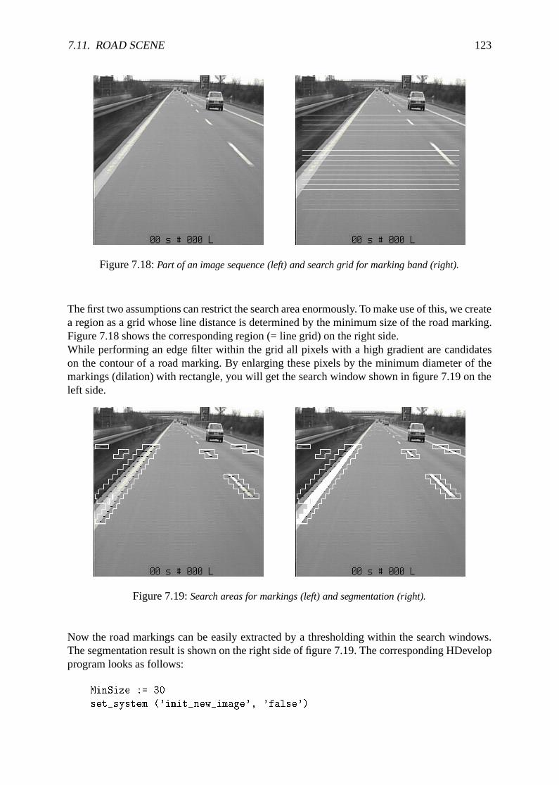
7.11. ROAD SCENE 123
Figure 7.18:Part of an image sequence (left) and search grid for marking band (right).
The first two assumptions can restrict the search area enormously. To make use of this, we createa region as a grid whose line distance is determined by the minimum size of the road marking.Figure 7.18 shows the corresponding region (= line grid) on the right side.While performing an edge filter within the grid all pixels with a high gradient are candidateson the contour of a road marking. By enlarging these pixels by the minimum diameter of themarkings (dilation) with rectangle, you will get the search window shown in figure 7.19 on theleft side.
Figure 7.19:Search areas for markings (left) and segmentation (right).
Now the road markings can be easily extracted by a thresholding within the search windows.The segmentation result is shown on the right side of figure 7.19. The corresponding HDevelopprogram looks as follows:
MinSize := 30
set_system ('init_new_image', 'false')
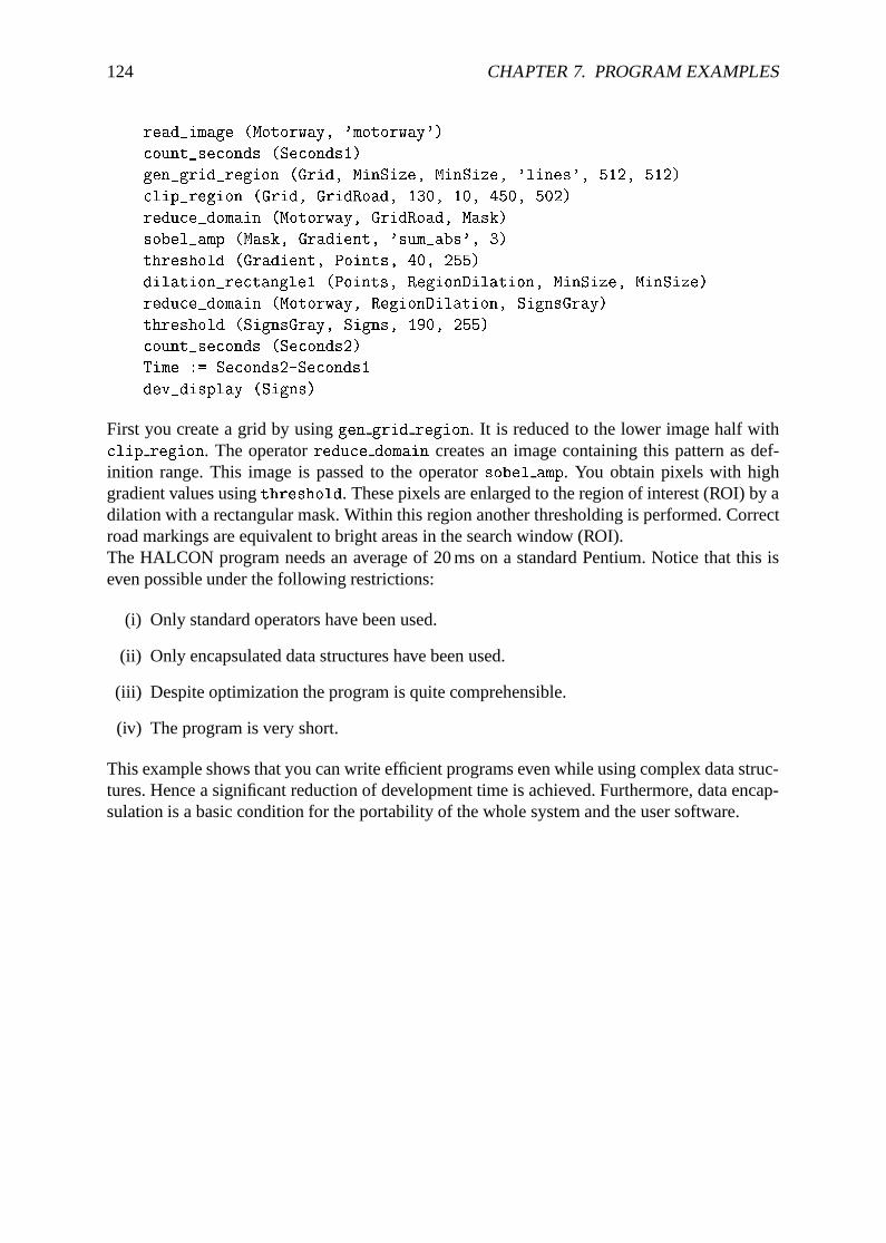
124 CHAPTER 7. PROGRAM EXAMPLES
read_image (Motorway, 'motorway')
count_seconds (Seconds1)
gen_grid_region (Grid, MinSize, MinSize, 'lines', 512, 512)
clip_region (Grid, GridRoad, 130, 10, 450, 502)
reduce_domain (Motorway, GridRoad, Mask)
sobel_amp (Mask, Gradient, 'sum_abs', 3)
threshold (Gradient, Points, 40, 255)
dilation_rectangle1 (Points, RegionDilation, MinSize, MinSize)
reduce_domain (Motorway, RegionDilation, SignsGray)
threshold (SignsGray, Signs, 190, 255)
count_seconds (Seconds2)
Time := Seconds2-Seconds1
dev_display (Signs)
First you create a grid by usinggen grid region. It is reduced to the lower image half withclip region. The operatorreduce domain creates an image containing this pattern as def-inition range. This image is passed to the operatorsobel amp. You obtain pixels with highgradient values usingthreshold. These pixels are enlarged to the region of interest (ROI) by adilation with a rectangular mask. Within this region another thresholding is performed. Correctroad markings are equivalent to bright areas in the search window (ROI).The HALCON program needs an average of 20 ms on a standard Pentium. Notice that this iseven possible under the following restrictions:
(i) Only standard operators have been used.
(ii) Only encapsulated data structures have been used.
(iii) Despite optimization the program is quite comprehensible.
(iv) The program is very short.
This example shows that you can write efficient programs even while using complex data struc-tures. Hence a significant reduction of development time is achieved. Furthermore, data encap-sulation is a basic condition for the portability of the whole system and the user software.
Chapter 8
Miscellaneous
In this chapter different aspects of working with HDevelop are discussed in detail.
8.1 Starting of HDevelop
In UNIX HDevelop is started from the shell like any other program. Optionally, an applicationname can be given as a parameter to HDevelop:
hdevelop <File>.dev
This application is then loaded. This is identical to a normal invocation of HDevelop (withoutany parameter) and a subsequent loading of the application. If you want to run the applicationimmediately after it has been loaded, you can invoke HDevelop as follows:
hdevelop -run <File>.dev
This is identical to a normal invocation of HDevelop (without any parameters) with a loadingof the application and pressing theRun-button in HDevelop. After the application has beenexecuted, HDevelop waits for input from the user. The program can be interrupted or stoppedby pressing theStop-button. To stop or halt the complete program without user interaction thestop or exit operator can be used.
8.2 Keycodes
In order to speed up the entering of values in the input fields of HDevelop (e.g., operator pa-rameters), several keycodes are defined, which have special functions. They conform to thestandards of theemacs editor. This feature is only available for UNIX systems. Some of themare shown in table 8.1.
8.3 Interactions during Program Execution
The interpreter of HDevelop allows some user interactions during the execution of a program.First, the stop button has to be mentioned, which is responsible for interrupting the executionof a program. When the stop button is pressed, the execution is stopped at the active HALCONoperator.
125
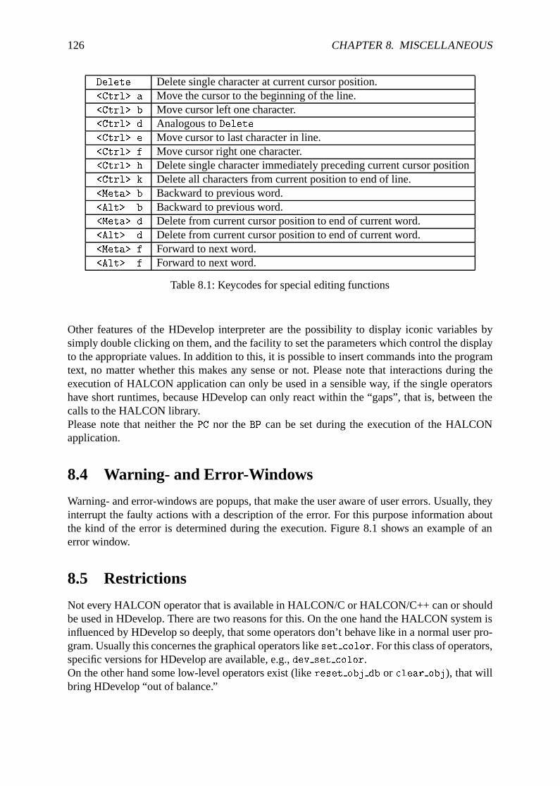
126 CHAPTER 8. MISCELLANEOUS
Delete Delete single character at current cursor position.<Ctrl> a Move the cursor to the beginning of the line.<Ctrl> b Move cursor left one character.<Ctrl> d Analogous toDelete<Ctrl> e Move cursor to last character in line.<Ctrl> f Move cursor right one character.<Ctrl> h Delete single character immediately preceding current cursor position<Ctrl> k Delete all characters from current position to end of line.<Meta> b Backward to previous word.<Alt> b Backward to previous word.<Meta> d Delete from current cursor position to end of current word.<Alt> d Delete from current cursor position to end of current word.<Meta> f Forward to next word.<Alt> f Forward to next word.
Table 8.1: Keycodes for special editing functions
Other features of the HDevelop interpreter are the possibility to display iconic variables bysimply double clicking on them, and the facility to set the parameters which control the displayto the appropriate values. In addition to this, it is possible to insert commands into the programtext, no matter whether this makes any sense or not. Please note that interactions during theexecution of HALCON application can only be used in a sensible way, if the single operatorshave short runtimes, because HDevelop can only react within the “gaps”, that is, between thecalls to the HALCON library.Please note that neither thePC nor theBP can be set during the execution of the HALCONapplication.
8.4 Warning- and Error-Windows
Warning- and error-windows are popups, that make the user aware of user errors. Usually, theyinterrupt the faulty actions with a description of the error. For this purpose information aboutthe kind of the error is determined during the execution. Figure 8.1 shows an example of anerror window.
8.5 Restrictions
Not every HALCON operator that is available in HALCON/C or HALCON/C++ can or shouldbe used in HDevelop. There are two reasons for this. On the one hand the HALCON system isinfluenced by HDevelop so deeply, that some operators don’t behave like in a normal user pro-gram. Usually this concernes the graphical operators likeset color. For this class of operators,specific versions for HDevelop are available, e.g.,dev set color.On the other hand some low-level operators exist (likereset obj db or clear obj), that willbring HDevelop “out of balance.”
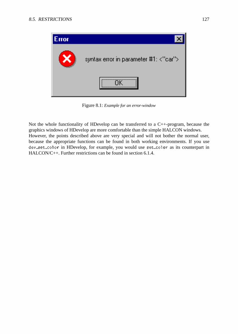
8.5. RESTRICTIONS 127
Figure 8.1:Example for an error-window
Not the whole functionality of HDevelop can be transferred to a C++-program, because thegraphics windows of HDevelop are more comfortable than the simple HALCON windows.However, the points described above are very special and will not bother the normal user,because the appropriate functions can be found in both working environments. If you usedev set color in HDevelop, for example, you would useset color as its counterpart inHALCON/C++. Further restrictions can be found in section 6.1.4.

128 CHAPTER 8. MISCELLANEOUS
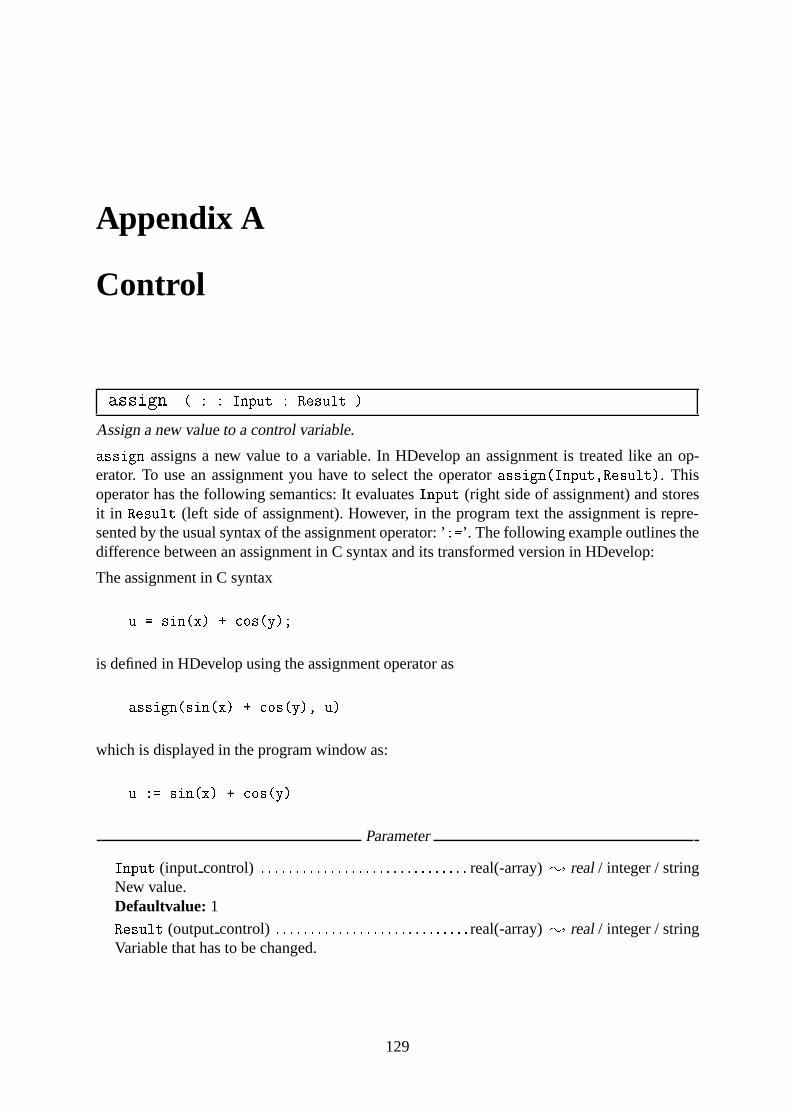
Appendix A
Control
assign ( : : Input : Result )
Assign a new value to a control variable.
assign assigns a new value to a variable. In HDevelop an assignment is treated like an op-erator. To use an assignment you have to select the operatorassign(Input,Result). Thisoperator has the following semantics: It evaluatesInput (right side of assignment) and storesit in Result (left side of assignment). However, in the program text the assignment is repre-sented by the usual syntax of the assignment operator: ’:=’. The following example outlines thedifference between an assignment in C syntax and its transformed version in HDevelop:
The assignment in C syntax
u = sin(x) + cos(y);
is defined in HDevelop using the assignment operator as
assign(sin(x) + cos(y), u)
which is displayed in the program window as:
u := sin(x) + cos(y)
Parameter
. Input (input control) : : : : : : : : : : : : : : : : : : : : : : : : : : : : : : real(-array); real/ integer / stringNew value.Defaultvalue: 1
. Result (outputcontrol) : : : : : : : : : : : : : : : : : : : : : : : : : : : : real(-array); real/ integer / stringVariable that has to be changed.
129
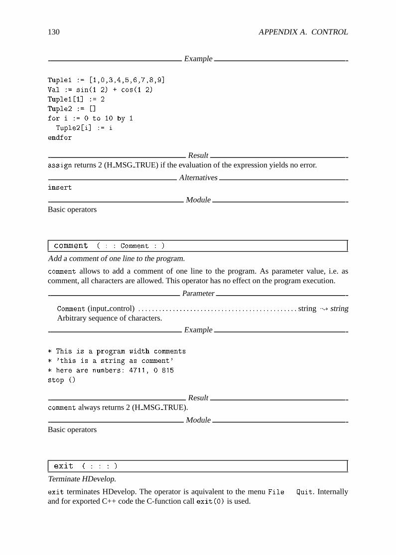
130 APPENDIX A. CONTROL
Example
Tuple1 := [1,0,3,4,5,6,7,8,9]
Val := sin(1.2) + cos(1.2)
Tuple1[1] := 2
Tuple2 := []
for i := 0 to 10 by 1
Tuple2[i] := i
endfor
Resultassign returns 2 (HMSG TRUE) if the evaluation of the expression yields no error.
Alternativesinsert
ModuleBasic operators
comment ( : : Comment : )
Add a comment of one line to the program.
comment allows to add a comment of one line to the program. As parameter value, i.e. ascomment, all characters are allowed. This operator has no effect on the program execution.
Parameter
. Comment (input control) : : : : : : : : : : : : : : : : : : : : : : : : : : : : : : : : : : : : : : : : : : : : : : string ; stringArbitrary sequence of characters.
Example
* This is a program width comments
* 'this is a string as comment'
* here are numbers: 4711, 0.815
stop ()
Resultcomment always returns 2 (HMSG TRUE).
ModuleBasic operators
exit ( : : : )
Terminate HDevelop.
exit terminates HDevelop. The operator is aquivalent to the menuFile . Quit. Internallyand for exported C++ code the C-function callexit(0) is used.
131
Example
read_image (Image, 'fabrik')
intensity (Image, Image, Mean, Deviation)
open_file ('intensity.txt', 'output', FileHandle)
fwrite_string (FileHandle, Mean + ' ' + Deviation)
close_file (FileHandle)
exit ()
Resultexit returns 0 (o.k.) to the calling environment of HDevelop = operating system.
See Alsostop
ModuleBasic operators
for ( : : Start, End, Step : Variable )
Execute the body for a fixed number.
The for loop is controlled by a start and termination value and an incrementation value thatdetermines the number of loop steps. These values may also be expressions which are evaluatedimmediately before the loop is entered. The expressions may be of typeinteger or of typereal. If all input values are of typeinteger the loop variable will also be of typeinteger.In all other cases the loop variable will be of typereal. If the start value is less or equal to thetermination value, the loop index is assigned with the starting value and the body of the loopis entered. If the increment is less than zero the loop is entered if the start value is larger orequal to the end value. Each time the body is executed, the loop index is incremented by theincrementation value. If the loop index is equal to the termination value, the body of the loop isperformed for the last time. If the loop index is larger than the termination value the body willnot be excecuted any longer. For negative increment values the loop is terminated if the loopindex is less than the termination value.
Please note that it is not necessary, that the loop index has to be equal to the termination valuebefore terminating the loop. The loop index is set to the termination value when the loop isbeing left. Please note, that the expressions for start and termination value are evaluated onlyonce when entering the loop. A modification of a variable that appears within these expressionshas no influence on the termination of the loop. The same applies to the modifications of theloop index. It also has no influence on the termination. The loop value is assigned to the correctvalue each time thefor operator is executed.
If the for loop is left too early (e.g. if you pressStop and set thePC) and the loop is enteredagain, the expressions will be evaluated, as if the loop were entered for the first time.
AttentionFor exported C++ please note the different semantics of the for loop.
132 APPENDIX A. CONTROL
Parameter
. Start (input control) : : : : : : : : : : : : : : : : : : : : : : : : : : : : : : : : : : : : : : : : number; integer/ realStart value for the loop variable.Defaultvalue: 1
. End (input control) : : : : : : : : : : : : : : : : : : : : : : : : : : : : : : : : : : : : : : : : : : :number; integer/ realEnd value for the loop variable.Defaultvalue: 5
. Step (input control) : : : : : : : : : : : : : : : : : : : : : : : : : : : : : : : : : : : : : : : : : :number; integer/ realIncrement value for the loop variable.Defaultvalue: 1
. Variable (outputcontrol) : : : : : : : : : : : : : : : : : : : : : : : : : : : : : : : : : : : :number; integer/ realLoop variable.
Example
dev_update_window ('off')
dev_close_window ()
dev_open_window (0, 0, 728, 512, 'black', WindowID)
read_image (Bond, 'die3')
dev_display (Bond)
stop ()
threshold (Bond, Bright, 100, 255)
shape_trans (Bright, Die, 'rectangle2')
dev_set_color ('green')
dev_set_line_width (3)
dev_set_draw ('margin')
dev_display (Die)
stop ()
reduce_domain (Bond, Die, DieGrey)
threshold (DieGrey, Wires, 0, 50)
fill_up_shape (Wires, WiresFilled, 'area', 1, 100)
dev_display (Bond)
dev_set_draw ('fill')
dev_set_color ('red')
dev_display (WiresFilled)
stop ()
opening_circle (WiresFilled, Balls, 15.5)
dev_set_color ('green')
dev_display (Balls)
stop ()
connection (Balls, SingleBalls)
select_shape (SingleBalls, IntermediateBalls, 'circularity', 'and', 0.85, 1.0)
sort_region (IntermediateBalls, FinalBalls, 'first_point', 'true', 'column')
dev_display (Bond)
dev_set_colored (12)
dev_display (FinalBalls)
stop ()
133
smallest_circle (FinalBalls, Row, Column, Radius)
NumBalls := |Radius|
Diameter := 2*Radius
meanDiameter := sum(Diameter)/NumBalls
mimDiameter := min(Diameter)
dev_display (Bond)
disp_circle (WindowID, Row, Column, Radius)
dev_set_color ('white')
set_font (WindowID, 'system26')
for i := 1 to NumBalls by 1
if (fmod(i,2)=1)
set_tposition (WindowID, Row[i-1]-1.5*Radius[i-1], Column[i-1]-60)
else
set_tposition (WindowID, Row[i-1]+2.5*Radius[i-1], Column[i-1]-60)
endif
write_string (WindowID, 'Diam: '+Diameter[i-1])
endfor
dev_set_color ('green')
dev_update_window ('on')
Resultfor returns 2 (HMSG TRUE) if the evaluation of the expression yields no error.endfor (asoperator) always returns 2 (HMSG TRUE)
Alternativeswhile
See Alsoif, ifelse
ModuleBasic operators
if ( : : Condition : )
Conditional statement.
if is a conditional statement. The condition contains a boolean expression. If the conditionis true, the body is executed. Otherwise the execution is continued at the first expression oroperator call that follows the correspondingendif.
Parameter
. Condition (input control) : : : : : : : : : : : : : : : : : : : : : : : : : : : : : : : : : : : : : : : : : : integer; integerCondition for the if statement.Defaultvalue: 1
Resultif returns 2 (HMSG TRUE) if the evaluation of the expression yields no error.endif (asoperators) always returns 2 (HMSG TRUE)
134 APPENDIX A. CONTROL
Alternativesifelse
See Alsofor, while
ModuleBasic operators
ifelse ( : : Condition : )
Condition with alternative.
ifelse is a condition with an alternative. If the condition is true (i.e. not 0), all expressions andcalls between the head and operatorendif are performed. If the condition is false (i.e. 0) thepart betweenelse andendif is executed. Note that the operator is calledilfelse and it isdisplayed asif in the program text area.
Parameter
. Condition (input control) : : : : : : : : : : : : : : : : : : : : : : : : : : : : : : : : : : : : : : : : : : integer; integerCondition for the if statement.Defaultvalue: 1
Resultifelse returns 2 (HMSG TRUE) if the evaluation of the expression yields no error.else andendif (as operators) always return 2 (HMSG TRUE)
Alternativesif
See Alsofor, while
ModuleBasic operators
insert ( : : Input, Value, Index : Result )
Assignment of a value into a tuple.
insert assigns a single value into an tuple. If the first input parameter and the first outputparameter are identical, the call:
insert (Areas, Area, Radius-1, Areas)
is not presented in the program text as an operator call, but in the more intuitive form as:
Areas[Radius-1] := Area
.
135
Parameter
. Input (input control) : : : : : : : : : : : : : : : : : : : : : : : : : : : : : : real(-array); real/ integer / stringTuple, where the new value has to be inserted.Defaultvalue: ’[]’
. Value (input control) : : : : : : : : : : : : : : : : : : : : : : : : : : : : : : : : : : : : : real ; real/ integer / stringValue that has to be inserted.Defaultvalue: 1Value Range:0� Value � 1000000
. Index (input control) : : : : : : : : : : : : : : : : : : : : : : : : : : : : : : : : : : : : : : : : : : : : : : integer; integerIndex position for new value.Defaultvalue: 0Value Suggestions:Index 2 f0, 1, 2, 3, 4, 5, 6gMinimal Value Step: 1
. Result (outputcontrol) : : : : : : : : : : : : : : : : : : : : : : : : : : : : real(-array); real/ integer / stringResult tuple with inserted values.
Resultinsert returns 2 (HMSG TRUE) if the evaluation of the expression yields no error.
Alternativesassign
ModuleBasic operators
stop ( : : : )
Stop program execution.
stop stops the program execution of HDevelopThePC is then placed at the program line behindstop. The operator is equivalent the presing thestop button in the menu bar.
Attentionstop is not available in C++.
Example
read_image (Image, 'fabrik')
regiongrowing (Image, Regions, 3, 3, 6, 100)
Number := |Regions|
dev_update_window ('off')
for i := 1 to Number by 1
RegionSelected := Regions[i]
dev_clear_window ()
dev_display (RegionSelected)
stop ()
endfor
136 APPENDIX A. CONTROL
Resultstop always returns 2 (HMSG TRUE)
See Alsoexit
ModuleBasic operators
while ( : : Condition : )
Continue to execute the body as long as the condition is true.
while executes the body as long as the condition is true. Thewhile loop has a boolean ex-pression as the conditional part. As long as it istrue (i.e. not equal 0), the body of the loop isperformed. In order to enter the loop, the condition has to be true in the first place.
Parameter
. Condition (input control) : : : : : : : : : : : : : : : : : : : : : : : : : : : : : : : : : : : : : : : : : : integer; integerCondition for loop.
Example
dev_update_window ('off')
dev_close_window ()
dev_open_window (0, 0, 512, 512, 'black', WindowID)
read_image (Image, 'particle')
dev_display (Image)
stop ()
threshold (Image, Large, 110, 255)
dilation_circle (Large, LargeDilation, 7.5)
dev_display (Image)
dev_set_draw ('margin')
dev_set_line_width (3)
dev_set_color ('green')
dev_display (LargeDilation)
dev_set_draw ('fill')
stop ()
complement (LargeDilation, NotLarge)
reduce_domain (Image, NotLarge, ParticlesRed)
mean_image (ParticlesRed, Mean, 31, 31)
dyn_threshold (ParticlesRed, Mean, SmallRaw, 3, 'light')
opening_circle (SmallRaw, Small, 2.5)
connection (Small, SmallConnection)
dev_display (Image)
dev_set_colored (12)
dev_display (SmallConnection)
stop ()
137
dev_set_color ('green')
dev_display (Image)
dev_display (SmallConnection)
Button := 1
while (Button = 1)
dev_set_color ('green')
get_mbutton (WindowID, Row, Column, Button)
dev_display (Image)
dev_display (SmallConnection)
dev_set_color ('red')
select_region_point (SmallConnection, SmallSingle, Row, Column)
dev_display (SmallSingle)
NumSingle := |SmallSingle|
if (NumSingle=1)
intensity (SmallSingle, Image, MeanGray, DeviationGray)
area_center (SmallSingle, Area, Row, Column)
dev_set_color ('yellow')
set_tposition (WindowID, Row, Column)
write_string (WindowID, 'Area='+Area+', Int='+MeanGray)
endif
endwhile
dev_set_line_width (1)
dev_update_window ('on')
Resultwhile returns 2 (HMSG TRUE) if the evaluation of the expression yields no error.endwhile
(as operator) always returns 2 (HMSG TRUE)
Alternativesfor
See Alsoif, ifelse
ModuleBasic operators

138 APPENDIX A. CONTROL
Appendix B
Develop
dev clear obj ( Objects : : : )
Delete an iconic object from the HALCON database.
dev clear obj deletes iconic objects, which are no longer needed, from the HALCONdatabase. It should be noted thatdev clear obj cannot be exported to C++ due to the au-tomatic memory management in C++.
AttentionNever useclear obj to clear objects in HDevelop. The operatordev clear obj has to be usedinstead.
Parameter
. Objects (input object) : : : : : : : : : : : : : : : : : : : : : : : : : : : : : : : : : : : : : :object(-array); HobjectObjects to be deleted.
Resultdev clear obj returns 2 (HMSG TRUE) if the variable is instantiated. If necessary, an ex-ception is raised.
See Alsoclear obj, test obj def, dev set check, reset obj db
ModuleBasic operators
dev clear window ( : : : )
Clear the active graphics window.
dev clear window clears the graphics window content and the history of the active window.Parameters assigned to this window (e.g. withdev set color, dev set draw, etc.) remain un-modified. The operator is equivalent to pressing theClear button of the active graphics window.A graphics window can be activated by callingdev set window.
Attention
139
140 APPENDIX B. DEVELOP
If dev clear window should be used for exported Code (C++), please note the description ofclear window due to the different semantics in C++.
Example
read_image (Image, 'fabrik')
regiongrowing (Image, Regions, 3, 3, 6, 100)
Number := |Regions|
dev_update_window ('off')
for i := 1 to Number by 1
RegionSelected := Regions[i]
dev_clear_window ()
dev_display (RegionSelected)
* stop ()
endfor
Resultdev clear window always returns 2 (HMSG TRUE).
Possible Predecessor Functionsdev set window, dev open window, dev display
Possible Successor Functionsdev display
See Alsoclear window
ModuleSystem operators
dev close inspect ctrl ( : : Variable : )
Close an inspect window of a control variable.
dev close inspect ctrl is the opposite operator todev inspect ctrl, and closes the in-spect window corresponding toVariable. The window can also be closed by pressing theClose-button of the dialog.
AttentionThis operator is not supported for exported C++ code.
Parameter
. Variable (input control) : : : : : : : : : : : : : : : : : : : : : : : : : : real(-array); real/ integer / stringName of the variable which inspect window has to be closed.
Example
Var := 1
dev_inspect_ctrl (Var)
141
Var := [1,2,3,9,5,6,7,8]
Var[3] := 4
stop
dev_close_inspect_ctrl (Var)
ResultIf an inspect window associated withVariable is opendev close inspect ctrl returns 2(H MSG TRUE).
Possible Predecessor Functionsdev inspect ctrl
ModuleBasic operators
dev close window ( : : : )
Close the active graphics window.
dev close window closes the active graphics window which have been opened bydev open window or by HDevelop (default window). The operator is equivalent to press-ing theClose button of the active window. A graphics window can be activated by callingdev set window.
AttentionIf dev close window should be used for exported Code (C++), please note the description ofclose window due to the different semantics in C++.
Example
* close all windows
for i := 1 to 10 by 1
dev_close_window ()
endfor
read_image (For5, 'for5')
get_image_pointer1 (For5, Pointer, Type, Width, Height)
dev_open_window (0, 0, Width, Height, 'black', WindowHandle)
dev_display (For5)
Resultdev close window always returns 2 (HMSG TRUE).
Possible Predecessor Functionsdev set window, dev open window
Possible Successor Functionsdev open window
See Alsoclose window
ModuleSystem operators
142 APPENDIX B. DEVELOP
dev display ( Object : : : )
Displays image objects in the current graphics window.
dev display displays an image object (image, region, or XLD) in the active graphics window.This is equivalent to a double click on an icon variable inside the variable window.
AttentionIf dev display should be used for exported Code (C++), please note the description ofdisp obj due to the different semantics in C++.
Parameter
. Object (input object) : : : : : : : : : : : : : : : : : : : : : : : : : : : : : : : : : : : : : : :object(-array); HobjectImage objects to be displayed.
Example
read_image (Image, 'fabrik')
regiongrowing (Image, Regions, 3, 3, 6, 100)
dev_clear_window ()
dev_display (Image)
dev_set_colored (12)
dev_set_draw ('margin')
dev_display (Regions)
Resultdev display always returns 2 (HMSG TRUE)
Alternativesdisp object, disp image, disp region, disp xld
See Alsodev set color, dev set colored, dev set draw, dev set line width
ModuleSystem operators
dev error var ( : : ErrorVar, Mode : )
Define or undefine an error variable.
dev error var defines an error variable, i.e. a variable which contains the status of the last callof an operator.ErrorVar will be H MSG TRUE (2) if no error had occured. The parameterMode specifies if the error variable should be used (1) or not (0). If an error variable is active itwill be updated each an operator excetion is finished. Thus a value is only valid until the nextcall of an operator. The value can be saved by assigning it to another variable (see example) orby callingdev error var(ErrorVar,0).
143
AttentionIf dev error var should be used for exported Code (C++), please note the different handlingof return values in C++.
Parameter
. ErrorVar (input control) : : : : : : : : : : : : : : : : : : : : : : : : : : : : : : : : : : : : integer(-array); integerName of the variable which shall contain the error status.
. Mode (input control) : : : : : : : : : : : : : : : : : : : : : : : : : : : : : : : : : : : : : : : : : : : : : : : integer; integerSwitch the error variable on or off.Defaultvalue: 1Value List: Mode 2 f0, 1g
Example
dev_close_window ()
dev_open_window (0, 0, 512, 512, 'black', WindowHandle)
dev_error_var (Error, 1)
dev_set_check ('~give_error')
FileName := 'wrong_name'
read_image (Image, FileName)
ReadError := Error
if (ReadError # H_MSG_TRUE)
write_string (WindowHandle, 'wrong file name: '+FileName)
endif
Resultdev error var always returns 2 (HMSG TRUE)
Possible Predecessor Functionsdev set check
Possible Successor Functionsdev set check, if, ifelse, assign
See Alsoset check
ModuleBasic operators
dev inspect ctrl ( : : Variable : )
Open a window to inspect a control variable.
dev inspect ctrl opens a dialog to check the contents of a control variable. This dialog hasa scrolled list with all the values of the variable. In the case of an framegrabber handle a spe-cific dialog is opened which displays the most important framegrabber parameters and canbe used to switch the framegrabber only interactively. The contents of the dilaog will be up-dated whenever the value(s) of variable changes. The update mode can influenced by the op-eratordev update ctrl. The dialog can be closed by pressing theClose-button or by callingdev close inspect ctrl.
144 APPENDIX B. DEVELOP
AttentionThis operator is not supported for exported C++ code.
Parameter
. Variable (input control) : : : : : : : : : : : : : : : : : : : : : : : : integer(-array); integer/ real / stringName of the variable to be checked.
Example
read_image (Image, 'fabrik')
regiongrowing (Image, Regions, 3, 3, 6, 100)
area_center (Regions, Area, Row, Column)
dev_inspect_ctrl (Area)
Resultdev inspect ctrl always returns 2 (HMSG TRUE)
See Alsodev update var
ModuleBasic operators
dev map par ( : : : )
Open the dialog to specify the display parameters.
dev map par opens the dialog which can also be accessed from the menuVisualization .
Set Parameters.... The dialog is used to configure the modes to display data like images,regions, or polygons.
AttentionThis operator is not supported for exported C++ code.
Example
read_image (Image, 'fabrik')
threshold (Image, Region, 128, 255)
dev_map_par ()
Resultdev map par always returns 2 (HMSG TRUE)
Possible Successor Functionsdev unmap par
ModuleBasic operators
145
dev map prog ( : : : )
Make the main window of HDevelop visible.
dev map prog is used to map the main window of HDevelop after it has been unmapped bydev unmap prog.
AttentionThis operator is not supported for exported C++ code.
Depending on the operating system or the window manager the execution ofdev map prog
will result only in a visible icon of the window. In this case it has to be opened by the user withmouse interaction.
Resultdev map prog always returns 2 (HMSG TRUE)
Possible Predecessor Functionsdev unmap prog
Possible Successor Functionsdev unmap prog
See Alsodev map par, dev map var
ModuleBasic operators
dev map var ( : : : )
Map the variable window on the screen.
dev map var maps the variable window on the screen (i.e. makes it visible) that has been un-mapped usingdev unmap var.
AttentionThis operator is not supported for exported C++ code.
Resultdev map var always returns 2 (HMSG TRUE)
Possible Predecessor Functionsdev unmap var
Possible Successor Functionsdev unmap var
See Alsodev map par, dev map prog
ModuleBasic operators
146 APPENDIX B. DEVELOP
dev open window ( : : Row, Column, Width, Height, Background :
WindowHandle )
Open a graphics window.
dev open window opens a new graphics window, which can be used to perform output of grayvalue data, regions, and graphics as well as to perform textual output. This new window auto-matically becomes active, which means that all output (dev display and automatical displayof operator results) is redirected to this window. This is shown by the green dot in theActive
button.
In the case of the standard display operators (likedisp image, disp region, disp line, etc.)instead ofdev display the logical window numberWindowHandle has to be used.
The background of the created window is set to the color specified inBackground.
Pressing theClear button clears the graphics window contents and the history of the window.This can also be achived by using the operatordev clear window. You close a graphics win-dow using theClose button of the window frame or by callingdev close window.
The the origin of the graphics window is the upper left corner with the coordinates (0,0). The xvalues (column) increase from left to right, the y values increase from top to bottom. Normally,the coordinate system of the graphics window corresponds to the the most recently displayedimage, which is automatically zoomed so that every pixel of the image is visible. The coordinatesystem can be changed interactively using the menuVisualization . Set Parameters .
Zoom or with the operatordev set part. Every time an image with a different size is displayed,the coordinate system will be adapted automatically.
Each window has a history which contains all
� objects and
� display parameters
which have been displayed or changed since the most recent clear action or display of a fullimage. This history is used for redrawing the contents of the window. Other output like text orgeneral graphics likedisp line or disp circle or iconic data that is displayed using HAL-CON operators likedisp image or disp region arenot part of the history, and arenot re-drawn. Only the object classes image, region, and XLD that are displayed with the HDevelopoperatordev display or by double clicking on an icon are part of the history.
You may change the size of the graphics window interactively by “gripping” the window borderwith the mouse. Then you can resize the window by dragging the mouse pointer. After this sizemodification the window content is redisplayed. Now you see the same part of the window withchanged zoom.
If the mouse cursor is inside the window its look-up-table is reactivated. This is necessaryif other programs use their own look-up table. Thus if there is a “strange” graphics windowpresentation, you may load the proper look-up table by placing the mouse inside the window.
Opening a window causes the assignment of a default font. It is used in connection with pro-cedures likewrite string and you may overwrite it by performingset font after calling
147
dev open window. On the other hand you have the possibility to specify a default font by call-ing set system('default font',<Fontname>) before opening a window (and all followingwindows; see alsoquery font).
If you want to specify display parameters for a window you may select the menu itemVisualization in the menu bar. Here you can set the appropriate parameters by clicking thedesired item. Parameters which you have set in this way are used forall windows (in contrastto standard windows opened withopen window). The effects of the new parameters will beapplied direcly to thelast object of the window history and alter its parameters only.
AttentionNever use close window to close an HDevelop graphics window. The operatordev close window has to be used instead.
If dev open window should be used for exported Code (C++), please note the description ofopen window due to the different semantics in C++.
Parameter
. Row (input control) : : : : : : : : : : : : : : : : : : : : : : : : : : : : : : : : : : : : : : : rectangle.origin.y; integerRow index of upper left corner.Defaultvalue: 0Value Range:0� Row
Minimal Value Step: 1Recommended Value Step:1Restriction: Row � 0
. Column (input control) : : : : : : : : : : : : : : : : : : : : : : : : : : : : : : : : : : : rectangle.origin.x; integerColumn index of upper left corner.Defaultvalue: 0Value Range:0� Column
Minimal Value Step: 1Recommended Value Step:1Restriction: Column � 0
. Width (input control) : : : : : : : : : : : : : : : : : : : : : : : : : : : : : : : : : : : : rectangle.extent.x; integerWidth of the window.Defaultvalue: 256Value Range:0� Width
Minimal Value Step: 1Recommended Value Step:1Restriction: (Width > 0) _ (Width = -1)
. Height (input control) : : : : : : : : : : : : : : : : : : : : : : : : : : : : : : : : : : : rectangle.extent.y; integerHeight of the window.Defaultvalue: 256Value Range:0� Height
Minimal Value Step: 1Recommended Value Step:1Restriction: (Height > 0) _ (Height = -1)
. Background (input control) : : : : : : : : : : : : : : : : : : : : : : : : : : : : : : : : : integer; integer/ stringColor of the background of the new window.Defaultvalue: ”black”
148 APPENDIX B. DEVELOP
. WindowHandle (outputcontrol) : : : : : : : : : : : : : : : : : : : : : : : : : : : : : : : : : : : :window ; integerWindow identifier.
Example
dev_close_window ()
read_image (For5, 'for5')
get_image_pointer1 (For5, Pointer, Type, Width, Height)
dev_open_window (0, 0, Width, Height, 'black', WindowHandle)
dev_display (For5)
dev_set_lut ('rainbow')
dev_display (For5)
stop ()
dev_set_lut ('default')
dev_display (For5)
stop ()
dev_set_part (100, 100, 300, 300)
dev_display (For5)
ResultIf the values of the specified parameters are correctdev open window returns 2(H MSG TRUE). If necessary an exception handling is raised.
Possible Successor Functionsdev display, dev set lut, dev set color, dev set draw, dev set part
Alternativesopen window
See Alsoquery color
ModuleSystem operators
dev set check ( : : Mode : )
Specify the error handling.
dev set check sepcifies how HDevelop should react if an error occures. IfMode has the value’give error’ – which is the system default – HDevelop stops the program execution if an ex-ception occures and displays an error message. If you use’˜give error’ the exception will beignored and the program continues.dev set check is intended to used in connection withdev error var, which allows to check for the result state of an operator.
AttentionIf dev set check should be used for exported Code (C++), please note the description ofset check due to the different semantics in C++.
149
Parameter
. Mode (input control) : : : : : : : : : : : : : : : : : : : : : : : : : : : : : : : : : : : : : : : : : : : : : : : : : :string ; stringMode of error handling.Defaultvalue: ’give error’
Example
dev_close_window ()
dev_open_window (0, 0, 512, 512, 'black', WindowHandle)
dev_error_var (Error, 1)
dev_set_check ('~give_error')
FileName := 'wrong_name'
read_image (Image, FileName)
dev_set_check ('give_error')
ReadError := Error
if (ReadError # H_MSG_TRUE)
write_string (WindowHandle, 'wrong file name: '+FileName)
endif
* Now the program will stop with an exception
read_image (Image, FileName)
Resultdev set check always returns 2 (HMSG TRUE)
Possible Successor Functionsdev error var
See Alsoset ckeck
ModuleSystem operators
dev set color ( : : ColorName : )
Set output color.
dev set color defines the color for region and line oriented output in the graphics win-dows. The available colors can be queried with the operatorquery color. The “colors”’black’ and ’white’ are available for all screens. If colors are used that are not displayableon the screen, HALCON can choose a similar, displayable color of the output. For this,set check('~color') must be called.
The defined color is used untildev set color or dev set colored is called.
Colors are defined for all graphics windows in contrast to the operatorset color.
AttentionIf dev set color should be used for exported Code (C++), please note the description ofset color due to the different semantics in C++.
150 APPENDIX B. DEVELOP
Parameter
. ColorName (input control) : : : : : : : : : : : : : : : : : : : : : : : : : : : : : : : : : : : : :string(-array); stringOutput color names.Defaultvalue: ’white’Value Suggestions:ColorName 2 f’white’, ’black’, ’grey’, ’red’, ’green’, ’blue’g
Example
read_image(Image,'mreut')
dev_set_draw('fill')
dev_set_color('red')
threshold(Image,Region,180,255)
dev_set_color('green')
threshold(Image,Region,0,179)
Resultdev set color always returns 2 (HMSG TRUE)
Possible Predecessor Functionsdev open window, query color, query all colors
Possible Successor Functionsdev display
Alternativesdev set colored
See Alsodev set draw, dev set line width, set color
ModuleSystem operators
dev set colored ( : : NumColors : )
Set multiple output colors.
dev set colored allows the user to display a tuple of regions in different colors.NumColors
defines the number of colors that are used. Valid values forNumColors can be queried withquery colored.
AttentionIf dev set colored should be used for exported Code (C++), please note the description ofset colored due to the different semantics in C++.
Parameter
. NumColors (input control) : : : : : : : : : : : : : : : : : : : : : : : : : : : : : : : : : : : : : : : : : : integer; integerNumber of output colors.Defaultvalue: 6Value List: NumColors 2 f3, 6, 12g
151
Example
read_image(Image,'monkey')
threshold(Image,Region,128,255)
dev_set_colored(6)
connection(Region,Regions)
Resultdev set colored always returns 2 (HMSG TRUE)
Possible Predecessor Functionsdev open window
Possible Successor Functionsdev display
Alternativesdev set color
See Alsodev set draw, dev set line width, set colored
ModuleSystem operators
dev set draw ( : : DrawMode : )
Define the region fill mode.
dev set draw defines the region fill mode. IfDrawMode is set to ’fill’, output regions are filled,if set to ’margin’, only contours are displayed. It is used by region output likedev display,disp region, disp circle, disp rectangle1, disp rectangle2, disp arrow, etc. If themode is ’margin’, the contour can be affected bydev set line width, set line approx andset line style.
AttentionIf dev set draw should be used for exported Code (C++), please note the description ofset draw due to the different semantics in C++.
Parameter
. DrawMode (input control) : : : : : : : : : : : : : : : : : : : : : : : : : : : : : : : : : : : : : : : : : : : : : string ; stringFill mode for region output.Defaultvalue: ’fill’Value List: DrawMode 2 f’fill’, ’margin’ g
Example
read_image(Image,'monkey')
threshold(Image,Region,128,255)
dev_clear_window
dev_set_color('red')
152 APPENDIX B. DEVELOP
dev_set_draw('fill')
dev_display(Region)
dev_set_color('white')
dev_set_draw('margin')
dev_display(Region)
Resultdev set draw always returns 2 (HMSG TRUE)
Possible Successor Functionsdev set line width, dev display
See Alsoset draw
ModuleSystem operators
dev set line width ( : : LineWidth : )
Define the line width for region contour output.
dev set line width defines the line width (in pixel) in which a region contour or lines aredisplayed (e.g. withdev display, disp region, disp line, disp polygon, etc.).
AttentionIf dev set line width should be used for exported Code (C++), please note the descriptionof set line width due to the different semantics in C++.
Parameter
. LineWidth (input control) : : : : : : : : : : : : : : : : : : : : : : : : : : : : : : : : : : : : : : : : : : integer; integerLine width for region output in contour mode.Defaultvalue: 1Restriction: LineWidth � 1
Example
read_image(Image,'monkey')
threshold(Image,Region,128,255)
dev_set_draw('margin')
dev_set_line_width(5)
dev_clear_window
dev_display(Region)
Resultdev set line width always returns 2 (HMSG TRUE)
Possible Successor Functionsdev display
See Alsoset line with, query line width
153
ModuleSystem operators
dev set lut ( : : LutName : )
Set “look-up-table” (lut).
dev set lut sets look-up-table of the the output window. A look-up-table defines the transfor-mation of a “gray value” within an image into a gray value or color on the screen. It describesthe screen gray value/color as a combination of red, green and blue for any image gray value(0..255) (so it is a ’table’ to ’look up’ the screen gray value/color for each image gray value:look-up-table). Transformation into screen-colors is performed in real-time at every time thescreen is displayed new (typically this happens about 60 - 70 times per second). So it is possibleto change the look-up-table to get a new look of images or regions. Please remind that not allmachines support changing the look-up-table (e.g. monochrome resp. truecolor).
For common monitors only one look-up-table can be loaded per screen. Whereasdev set lut
can be activated separately for each window. There is the following solution for this problem:It will always be activated the look-up-table that is assigned to the “active window” (a windowis set into the state “active” by placing the mouse inside the window).
look-up-tables can also be used with truecolor displays. In this case the look-up-table will besimulated in software. This means, that the look-up-table will be used each time an image isdisplayed.
query lut lists the names of all look-up-tables.
AttentionIf dev set lut should be used for exported Code (C++), please note the description ofset lut
due to the different semantics in C++.
Parameter
. LutName (input control) : : : : : : : : : : : : : : : : : : : : : : : : : : : : : : : : : : : : : : : : : : : : : : string ; stringName of look-up-table, values of look-up-table (RGB) or file name.Defaultvalue: ’default’Value Suggestions:LutName 2 f’default’, ’linear’, ’inverse’, ’sqr’, ’inv sqr’, ’cube’,’inv cube’, ’sqrt’, ’inv sqrt’, ’cubic root’, ’inv cubic root’, ’color1’, ’color2’, ’color3’,’color4’, ’three’, ’six’, ’twelfe’, ’twenty four’, ’rainbow’, ’temperature’, ’cyclicgray’,’cyclic temperature’, ’hsi’, ’change1’, ’change2’, ’change3’g
Example
read_image(Image,'mreut')
dev_set_lut('inverse')
* For true color only:
dev_display(Image)
Resultdev set lut always returns 2 (HMSG TRUE)
154 APPENDIX B. DEVELOP
Possible Successor Functionsdev display
See Alsoset lut
ModuleSystem operators
dev set paint ( : : Mode : )
Define the grayvalue output mode.
dev set paint defines the output mode for grayvalue display in the graphics window. Themode is used bydev display.
This page describes the different modes, that can be used for grayvalue output. It should benoted, that the mode ’default’ is the most suitable.
A different way to display grayvalues is the histogram (mode: ’histogram’). This mode has threeadditional parameter values: Row (second value) and column (third value). They denote row andcolumn of the histogram center for positioning on the screen. The scale factor (fourth value)determines the histogram size: a scale factor of 1 distinguishes 256 grayvalues, 2 distinguishes128 grevalues, and so on. The four values are passed as a tuple, e.g. [’histogram’, 256,256,1]. Ifonly the first value is passed (’histogram’), the other values are set to defaults or the last values,respectively. For histogram computation seegray histo.
The modes ’line’ and ’column’ allow to display gray values along lines or columns, respecively.The position (line- and columnindex) is passed with the second paramter value. The third pa-rameter value is the scale factor in percent (100 means 1 pixel per grayvalue, 50 means onepixel per two grayvalues).
Gray images can also be interpreted as 3d data, depending on the grayvalue. To view these 3dplots, select the modes ’contourline’, ’3D-plot’ or ’3D-plothidden’.
Paramters for modes that need more than one parameter can be passed the following ways:
� Only the name of the mode is passed: the defaults or the last values are used, respectively.Example:dev set paint('contourline')
� All values are passed: all output characteristics can be set. Example:dev set paint(['contourline',10,1])
� Only the first n values are passed: only the passed values are changed. Example:dev set paint(['contourline',10])
AttentionIf dev set paint should be used for exported Code (C++), please note the description ofset paint due to the different semantics in C++.
155
Parameter
. Mode (input control) : : : : : : : : : : : : : : : : : : : : : : : : : : : : : : : : : : : : string-array; string/ integerGrevalue output name. Additional parameters possible.Defaultvalue: ’default’Value List: Mode 2 f’default’, ’histogram’, ’line’, ’column’, ’contourline’, ’3D-plot’,’3D-plot hidden’, ’3D-plot point’g
Example
read_image(Image,'fabrik')
dev_set_paint('3D-plot')
dev_display(Image)
Possible Predecessor Functionsdev open window
Possible Successor Functionsdev set color, dev display
See Alsoset paint
ModuleSystem operators
dev set part ( : : Row1, Column1, Row2, Column2 : )
Modify the displayed image part.
dev set part modifies the image part that is displayed in the graphics window.(Row1,Column1) denotes the upper left corner and (Row2,Column2) the lower right corner ofthe image part to display.
If Row1 is larger thanRow2 the zooming will be reset. That means that the last displayed imagewill be completetly visible. Please note that this is not possible with the operatorset part
outside HDevelop.
AttentionIf dev set part should be used for exported Code (C++), please note the description ofset part due to the different semantics in C++.
Parameter
. Row1 (input control) : : : : : : : : : : : : : : : : : : : : : : : : : : : : : : : : : : : : : : rectangle.origin.y; integerRow of the upper left corner of the chosen image part.Defaultvalue: 0
. Column1 (input control) : : : : : : : : : : : : : : : : : : : : : : : : : : : : : : : : : : rectangle.origin.x; integerColumn of the upper left corner of the chosen image part.Defaultvalue: 0
. Row2 (input control) : : : : : : : : : : : : : : : : : : : : : : : : : : : : : : : : : : : : : rectangle.corner.y; integerRow of the lower right corner of the chosen image part.Defaultvalue: 128
156 APPENDIX B. DEVELOP
. Column2 (input control) : : : : : : : : : : : : : : : : : : : : : : : : : : : : : : : : : : rectangle.corner.x; integerColumn of the lower right corner of the chosen image part.Defaultvalue: 128
Example
read_image (Image, 'fabrik')
for i := 1 to 240 by 10
dev_set_part (i, i, 511-i, 511-i)
dev_display (Image)
endfor
dev_set_part (1, 1, -1, -1)
dev_display (Image)
Resultdev set part always returns 2 (HMSG TRUE)
Possible Successor Functionsdev display
See Alsoset part
ModuleSystem operators
dev set shape ( : : Shape : )
Define the region output shape.
dev set shape defines the shape for region output. The output shape is used bydev display
for regions. The available shapes can be queried withquery shape.
Available modes:
’original’: The shape is displayed unchanged. Nevertheless modifications via parameters likedev set line width can take place. This is also true for all other modes.
’outer circle’: Each region is displayed by the smallest surrounding circle. (Seesmallest circle.)
’inner circle’: Each region is displayed by the largest included circle. (Seeinner circle.)
’ellipse’: Each region is displayed by an ellipse with the same moments and orientation (Seeelliptic axis.)
’rectangle1’: Each region is displayed by the smallest surrounding rectangle parallel to thecoordinate axes. (Seesmallest rectangle1.)
’rectangle2’: Each region is displayed by the smallest surrounding rectangle. (Seesmallest rectangle2.)
’convex’: Each region is displayed by its convex hull (Seeshape trans.)
157
’icon’ Each region is displayed by the icon set withset icon in the center of gravity.
AttentionIf dev set shape should be used for exported Code (C++), please note the description ofset shape due to the different semantics in C++.
Parameter
. Shape (input control) : : : : : : : : : : : : : : : : : : : : : : : : : : : : : : : : : : : : : : : : : : : : : : : : string ; stringRegion output mode.Defaultvalue: ’original’Value List: Shape 2 f’original’, ’convex’, ’outer circle’, ’inner circle’, ’rectangle1’,’rectangle2’, ’ellipse’, ’icon’g
Example
read_image(Image,'monkey')
threshold(Image,Region,128,255)
connection(Region,Regions)
dev_set_shape('rectangle1')
dev_set_draw('margin')
dev_display(Regions)
Possible Successor Functionsdev display, dev set color
See Alsoset shape, dev set line with
ModuleSystem operators
dev set window ( : : WindowID : )
Activate a graphics window.
dev set window activates a graphics window. This is equivalent to pressing theActive buttonof the graphics window.
AttentionIf dev set window should be used for exported Code (C++), please note the different handlingof windows in C++.
dev set window is not supported for C++.
Parameter
. WindowID (input control) : : : : : : : : : : : : : : : : : : : : : : : : : : : : : : : : : : : : : : : : : :window ; integerWindow id.
Example
158 APPENDIX B. DEVELOP
dev_open_window (1, 1, 200, 200, 'black', WindowID1)
dev_open_window (1, 220, 200, 200, 'black', WindowID2)
read_image(Image,'monkey')
dev_set_window(WindowID1)
dev_display(Image)
dev_set_window(WindowID2)
dev_display(Image)
Possible Predecessor Functionsdev open window
Possible Successor Functionsdev display
ModuleBasic operators
dev set window extents ( : : Row, Column, Width, Height : )
Change position and size of a graphics window.
dev set window extents changes the position and/or the size of the currently active graphicswindow.
The parametersRow andColumn specify the new position (upper left corner) of the window.If one of both values is negative, the position will remain unchanged. The parametersWidth
andHeight specify the new size of the window. This is the size of the inner part that actuallydisplayes the data. If one of the two values is negative, the size will remain unchanged.
AttentionNever useset window extents to change the size and position of an HDevelop graphics win-dow. The operatordev set window extents has to be used instead.
Parameter
. Row (input control) : : : : : : : : : : : : : : : : : : : : : : : : : : : : : : : : : : : : : : : rectangle.origin.y; integerRow index of upper left corner.Defaultvalue: 0Value Range:0� Row
Minimal Value Step: 1Recommended Value Step:1Restriction: (Row � 0) _ (Row = -1)
. Column (input control) : : : : : : : : : : : : : : : : : : : : : : : : : : : : : : : : : : : rectangle.origin.x; integerColumn index of upper left corner.Defaultvalue: 0Value Range:0� Column
Minimal Value Step: 1Recommended Value Step:1Restriction: (Column � 0) _ (Column = -1)
159
. Width (input control) : : : : : : : : : : : : : : : : : : : : : : : : : : : : : : : : : : : : rectangle.extent.x; integerWidth of the window.Defaultvalue: 256Value Range:0� Width
Minimal Value Step: 1Recommended Value Step:1Restriction: (Width > 0) _ (Width = -1)
. Height (input control) : : : : : : : : : : : : : : : : : : : : : : : : : : : : : : : : : : : rectangle.extent.y; integerHeight of the window.Defaultvalue: 256Value Range:0� Height
Minimal Value Step: 1Recommended Value Step:1Restriction: (Height > 0) _ (Height = -1)
Example
dev_close_window ()
read_image (For5, 'for5')
get_image_pointer1 (For5, Pointer, Type, Width, Height)
dev_open_window (0, 0, Width, Height, 'black', WindowHandle)
dev_display (For5)
stop ()
dev_set_window_extents (-1,-1,Width/2,Height/2)
dev_display (For5)
stop ()
dev_set_window_extents (200,200,-1,-1)
ResultIf the values of the specified parameters are correctdev set window extents returns 2(H MSG TRUE). If necessary an exception handling is raised.
Possible Successor Functionsdev display, dev set lut, dev set color, dev set draw, dev set part
See Alsoset window extents
ModuleSystem operators
dev unmap par ( : : : )
Hide the window for the graphic parameters.
dev unmap par hides the window for the graphic parameters so that it is no longer visible. Itcan be mapped again using the operatordev map par.
AttentionThis operator is not supported for exported C++ code.
160 APPENDIX B. DEVELOP
Resultdev unmap par always returns 2 (HMSG TRUE)
Possible Successor Functionsdev map prog
See Alsodev map par, dev map prog, dev map var
ModuleBasic operators
dev unmap prog ( : : : )
Hide the main window.
dev unmap prog hides the main window so that it is no longer visible. It can be mapped againusing the operatordev map prog.
AttentionThis operator is not supported for exported C++ code.
Resultdev unmap prog always returns 2 (HMSG TRUE)
Possible Successor Functionsdev map prog, stop
See Alsodev map par, dev map prog, dev map var
ModuleBasic operators
dev unmap var ( : : : )
Hide the variable window.
dev unmap var hides the variable window so that it is no longer visible. It can be mapped againusing the operatordev map var.
AttentionThis operator is not supported for exported C++ code.
Resultdev unmap var always returns 2 (HMSG TRUE)
Possible Successor Functionsdev map var
See Alsodev map par, dev map prog
ModuleBasic operators
161
dev update pc ( : : DisplayMode : )
Specify the behaviour of the PC during program execution.
dev update pc specifies the behaviour of the PC during program execution. In the mode ’on’(default) the PC is always displayed in front of the current operator. In addition the programtext is scrolled – if necessary – so that the current operator is visible. In the mode ’off’ the PCis not visible during program execution and the program text will not be scrolled automatically.
This option can also be controled by the dialog
File . Options . Update PC.
AttentionThis operator is not supported for exported C++ code.
Parameter
. DisplayMode (input control) : : : : : : : : : : : : : : : : : : : : : : : : : : : : : : : : : : : : : : : : : string ; stringMode for runtime behaviour.Defaultvalue: ’off’Value List: DisplayMode 2 f’on’, ’off’ g
Resultdev update pc always returns 2 (HMSG TRUE)
See Alsodev update time, dev update window, dev update var
ModuleBasic operators
dev update time ( : : DisplayMode : )
Switch time measurement for operators on or off.
dev update time controls if the execution time of an operator has to be measured.
This option can also be controled by the dialog
File . Options . Show Processing Time.
AttentionThis operator is not supported for exported C++ code.
Parameter
. DisplayMode (input control) : : : : : : : : : : : : : : : : : : : : : : : : : : : : : : : : : : : : : : : : : string ; stringMode for graphic output.Defaultvalue: ’off’Value List: DisplayMode 2 f’on’, ’off’ g
Resultdev update time always returns 2 (HMSG TRUE)
162 APPENDIX B. DEVELOP
See Alsodev update pc, dev update window, dev update var
ModuleBasic operators
dev update var ( : : DisplayMode : )
Specify the behaviour of the variable window during program execution.
dev update var specifies the behaviour of the variable window during program execution.Using the mode ’on’ (default) the contents of the variable window (iconic and control variables)is updated each time a variable is modified by the program. In the mode ’off’ the variables areupdated only when the execution is finished. Please not that update in this contents only meansthe graphical representation of the internal values in the variable window.
This option can also be controled by the dialog
File . Options . Update Variables.
AttentionThis operator is not supported for exported C++ code.
Parameter
. DisplayMode (input control) : : : : : : : : : : : : : : : : : : : : : : : : : : : : : : : : : : : : : : : : : string ; stringMode for graphic output.Defaultvalue: ’off’Value List: DisplayMode 2 f’on’, ’off’ g
Resultdev update var always returns 2 (HMSG TRUE)
See Alsodev update pc, dev update window, dev update time
ModuleBasic operators
dev update window ( : : DisplayMode : )
Specify the output behaviour during program execution.
dev update window specifies the output behaviour during program execution. By default everyobject (image, region, or XLD) is displayed in the active graphics window. This can be changedby using the value ’off’ forDisplayMode. In this case objects are only displayed in single stepmode. Here one would use the operatordev display to output objects.
This option can also be controled by the dialog
File . Options . Update Window.
AttentionThis operator is not supported for exported C++ code.
163
Parameter
. DisplayMode (input control) : : : : : : : : : : : : : : : : : : : : : : : : : : : : : : : : : : : : : : : : : string ; stringMode for graphic output.Defaultvalue: ’off’Value List: DisplayMode 2 f’on’, ’off’ g
Resultdev update window always returns 2 (HMSG TRUE)
Possible Successor Functionsdev display
See Alsodev update pc, dev update var, dev update time
ModuleBasic operators

164 APPENDIX B. DEVELOP
Appendix C
Glossary
Boolean is the type name for the truth valuestrue andfalse as well as for the related booleanexpressions.
Body A body is part of a conditional instruction (if) or a loop (while or for) and consists ofa sequence of operator calls. If you consider thefor-loop, for instance, all operator calls,that are located betweenfor andendfor form the body.
Button A button is part of a graphical user interface. With the mouse the user can press a buttonto cause an action to be performed.
Control data Control data can be either numbers ("integer and "real), character strings("string) and truth values (boolean). This data can be used as atomic values (i.e., singlevalues) or as"tuples (i.e., arrays of values).
Empty region An empty"region contains no points at all, i.e., its area is zero.
Graphics window A graphics window is used in"HDevelop for displaying"images,"regions,or "XLD.
HDevelop is an interactive program for the creation of HALCON applications.
Iconic data are image data, i.e., image arrays and data, which are described by coordinates andare derived from image arrays, e.g.,"regions,"image and"XLD.
Image An image consists of one or more (multichannel image) image arrays and a"regionas the definition domain. All image arrays have the same dimension, but they can be ofdifferent pixel types. The size of the"region is smaller or equal than the size of the imagearrays. The"region determines all image points that should be processed.
Iconic object Generic implementation of"iconic data in HALCON.
integer is the type name for integer numbers. Integers are implemented using the C-typelong
(4 or 8 byte).
Operator data base The operator data base contains information about the HALCON opera-tors. They are loaded at runtime from the binary files in%HALCONROOT%\help.
Program window In HDevelop the program window contains the program. It is used to edit(copy, delete, and paste lines) and to run or debug the program.
165
166 APPENDIX C. GLOSSARY
Operator window In the operator window of HDevelop the parameters of the selected opera-tors can be entered or modified.
Real is the type name for floating point numbers. They are implemented using the C-typedouble (8 bytes).
Region A region is a set of image points without gray values. A region can be imagined as a bi-nary image (mask). Regions are implemented using runlength encoding. The region size isnot limited to the image size (see alsoset system('clip region','true'/'false')
in the HALCON reference manual.
String is the type name for character strings. A string starts and ends with a single quote; inbetween any character can be used except single quote. The empty string consists of twoconsecutive single quotes. The maximum length of a character string is limited to 1024characters.
Tuple A tuple is an ordered multivalue set. In case of"control data a tuple can consist of a largenumber of items with different data types. The term tuple is also used in conjunction with"iconic objects, if it is to be emphasized that several"iconic objects will be used.
Type "iconic variables can be assigned with data items of type"image,"region, and"XLD.The types of"control data items can be one of"integer, "real, "boolean, or"string.
Variable window In HDevelop the variable window manages the"control and"iconic data.
XLD is the short term for eXtendedLine Description. It is used as a superclass for contours,polygons, and lines (see also the HALCON Reference Manual).
Index
add channels, 39, 40, 117Aerial image interpretation, 5Application areas, 5Applications, 103area center, 41, 119Assertions, 11assign, 48, 76, 77, 79, 129Attributes, 103
bin threshold, 107Boolean, 165Breakpoint, 33, 60Buffer, 146Button, 165
C, 6, 9, 11C++, 6, 9–11, 24, 91
Compile, 91Export, 10, 91Link, 91
CAVE, 5Cleanup, 27, 64Clear, 139clear obj, 126Clearing, 139clip region, 124Closing, 141Code generation, 91, 97Color, 116COM, 97Comment, 130comment, 34, 48, 50, 130compactness, 42Computer Aided Vision Engineering, 5concat obj, 121Condition, 134Configuration, 12, 14connect and holes, 42Connected components, 111, 116connection, 106, 111
contlength, 42Control data, 10, 65, 165Control parameter, 71Control structures, 47, 48, 88
exit, 90for, 89if, 89ifelse, 89stop, 90while, 89
Control-Variable, 143convexity, 42cooc feature image, 42cooc feature matrix, 43Coordinate system, 51Coordinate-System, 146count obj, 112, 121
Data structures, 10, 71, 72, 75Database, 139Debugging, 6dev clear obj, 52, 139dev clear window, 50, 111, 139dev close inspect ctrl, 52, 140dev close window, 50, 141dev display, 52, 94, 100, 142dev error var, 53, 73, 94, 121, 142dev inspect ctrl, 52, 143dev map par, 52, 144dev map prog, 52, 145dev map var, 52, 145dev open window, 50, 94, 146dev set check, 53, 73, 94, 121, 148dev set color, 51, 149dev set colored, 51, 150dev set draw, 51, 151dev set line width, 51, 152dev set lut, 51, 153dev set paint, 51, 154dev set part, 51, 155
167
168 INDEX
dev set shape, 51, 156dev set window, 50, 157dev set window extents, 50, 158dev unmap par, 52, 159dev unmap prog, 52, 160dev unmap var, 52, 160dev update pc, 52, 161dev update time, 52, 161dev update var, 52, 162dev update window, 52, 162Dilation, 116, 123Document analysis, 103Domain, 10dyn threshold, 54dyn threshold, 109, 111
eccentricity, 42edges sub pix, 11Edit
Copy, 31, 32Cut, 31Paste, 31Undo, 31
Editor, 21elliptic axis, 41, 115empty obj, 121Encapsulation, 122entropy gray, 42Environment Variable, 12–14
ARCHITECTURE, 13DISPLAY, 14HALCONEXTENSIONS, 13HALCONIMAGES, 13, 26HALCONROOT, 12, 26HALCONSPY, 13HOME, 14LD LIBRARY PATH, 13SHLIB PATH, 13
Error message, 126Error-code, 142Example, 71
Annual Rings, 111Board, 115Bonding, 112Calibration board, 113Capillary vessel, 106Cell walls, 118
Devices, 115Exception, 121IC, 116Medical, 108Region selection, 120Road scene, 122Stamps, 103Tissue particles, 108
Example session, 15Exception, 142Exception handling, 94, 100Execute
Activate, 34Clear break point, 34Deactivate, 34Reset program, 34, 74Run, 32–34Step, 33, 34Stop, 33, 34
Execution time, 29Exit, 130exit, 48, 50, 90, 125, 130Extended line description, 10, 11
FA, 5Factory automation, 5false, 72, 165File, 120
Cleanup, 27, 64Insert, 25Modules, 31New, 24, 26Open, 25, 26Options, 25, 27Quit, 33Read image, 26Save, 26Save as, 26, 30
fill up shape, 113Filter
Gaussian, 109Linear, 107Low pass, 109Mean, 109Smoothing, 114
fnew line, 120for, 48, 89, 93, 100, 121, 131, 165
INDEX 169
Framegrabber, 52fwrite string, 120
gen grid region, 124gen region line, 112gen tuple const, 79get mbutton, 110get grayval, 121get image pointer1, 119get mposition, 121get system, 96, 101Gnuplot, 120Graphics, 146, 158Graphics window, 21, 68, 97, 99, 165
Activate, 50Clear, 36Close, 36, 50Color, 44Draw, 44History, 70Line width, 44Look up table, 44, 47Open, 35, 50Paint, 44, 45Parameter, 50Pen, 45Position, 50Reset, 36Size, 43, 50Zoom, 43, 46
Gray value, 10gray histo, 39gray inside, 114
H MSG FAIL, 73, 94, 121H MSG FALSE, 73, 94H MSG TRUE, 73, 94, 121H MSG VOID, 73, 94Help, 57History, 70, 139, 146Host language, 12HP-UX, 13
Iconic data, 10, 165Iconic object, 65, 71, 120, 165Iconic-Object, 139if, 48, 89, 133, 165ifelse, 48, 89, 134
Image, 10, 65, 165Image analysis, 53insert, 48, 49, 76, 79, 92, 134Insertion cursor, 60Inspection, 143intensity, 42Interaction, 125Internet Explorer, 14Interpreter, 21Intersection, 118intersection, 112
junctions skeleton, 54
Keyboard shortcuts<Ctrl> C, 32<Ctrl> N, 24<Ctrl> O, 25<Ctrl> S, 26<Ctrl> V, 31<Ctrl> Z, 31F5, 32F6, 33F9, 34
Keycodes, 125
Language definition, 71Language interface, 9, 11Language-independent operator interface,
12Laws filter, 107lines gauss, 11Loop, 48, 131, 136
Body, 165Lut, 47
Main window, 21, 22Menu bar, 24Title bar, 23Tool bar, 59
Manuals, 5mean image, 107, 111Medical image analysis, 5Memory management, 106Menu bar, 50min max gray, 42Miscellaneous, 125moments gray plane, 43
170 INDEX
Morphology, 10Mouse handling, 22
Netscape Navigator, 14Noise removal, 110Notation
Decimal, 72Hexadecimal, 72Octal, 72
open file, 120Opening, 110Operation
Arithmetics, 80Boolean, 84Comparison, 84String, 81Trigonometric, 85Tuple, 78
OperatorData base, 165Description, 12Name field, 65Sequence, 55Suggestions, 54
Operator text field, 61Operator window, 21, 59, 61, 63, 166
Apply, 64Cancel, 64Enter, 64, 66Help, 64Input parameter, 62OK, 63, 66Output parameter, 62, 63
Optimization, 92orientation region, 42Output, 27, 51
Package, 12, 13Paint mode, 45Parameter display, 62Parameter expressions, 75Parameter types, 71Pixel, 10Preprocessing, 53Program, 25, 60
Counter, 28, 33, 60Execution, 32–34, 48
Termination, 50Program window, 21, 60, 165Programming, 103
Quality control, 5
Rapid prototyping, 21read image, 54reduce domain, 39, 40, 117, 124Region, 10, 65, 166
Empty, 165Region of interest, 10, 117, 123Remote sensing, 5Reserved words, 88reset obj db, 126Restrictions, 90, 93, 98, 126ROI, 10, 124Run, 50, 125Run mode, 28Runtime error, 33, 94, 121
Segmentation, 103, 106, 122select gray, 40select obj, 121select shape, 40, 106, 109, 111, 115, 118,
120Semantics, 71set system, 96, 101Settings, 6Shell, 125skeleton, 54smallest rectangle1, 41, 106smallest rectangle2, 41sobel amp, 124Status bar, 60Step, 50Stop, 135Stop, 125stop, 48, 50, 90, 125, 135String, 81, 166
Concatenation, 75Operations, 81
Suggestion, 54Alternative, 55Keyword, 55Predecessor, 54See also, 55Successor, 54
INDEX 171
Surveillance tasks, 5Syntax, 71System parameters, 6
Termination, 130Texture, 107Texture energy, 107texture laws, 107Threshold, 106–108, 113, 115, 117, 120,
123threshold, 40, 106, 117, 124true, 72, 165Tuple, 63, 67, 166
Arithmetic, 75Concatenation, 77, 78
Type, 66, 166boolean, 72, 75, 84, 165Control parameter, 71, 72Iconic object, 71, 75integer, 10, 63, 72, 74, 75, 81, 165Numerical, 72real, 10, 63, 72, 74, 75, 81, 165, 166string, 10, 63, 72, 74, 75, 165, 166Tuple, 63
User extensions, 13
Variable, 74Control, 65, 67Iconic, 52, 65, 66Visualization, 28
Variable window, 21, 30, 52, 65, 66, 166Visual Basic, 24, 97
Export, 97Visualization
Line width, 51Region, 51Regions, 44Segmentation results, 44XLD, 44
watersheds, 54while, 48, 89, 93, 100, 136, 165Window, 139, 141, 146, 158
Halcon, 53ID, 50, 95
Window-size, 158Working environment, 9
XLD, 10, 11, 65, 166

172 INDEX
Bibliography
[Jai89] A.K. JainFundamentals of Digital Image Processing, Prentice–Hall International Edi-tions, Englewood Cliffs, New Jersey, 1989
[Bal82] D.H. Ballard, C.M. BrownComputer Vision, Prentice–Hall, Englewood Cliffs, NewJersey, 1982
[Rus92] J.C. RussThe Image Processing Handbook, CRC Press, Boca Raton, Florida, 1992
[Radig93] B. Radig (Hrsg.)Verarbeiten und Verstehen von Bildern, Oldenbourg, M¨unchen,1993
[Abmayr94] W. AbmayrEinfuhrung in die digitale Bildverarbeitung, B.G.Teubner, Stuttgart,1994
[Haralick92] R.M. Haralick, L.G. ShapiroComputer and Robot Vision, Addison-Wesley, Mas-sachusetts, 1992
[Eckstein91] W. Eckstein, W. Glock.Development and Implementation of Methods for Seg-mentation of bond-wedges, In R. Klette, editor, Proc. 4th Computer Analysis of Images andPatterns, volume 5 of Research in Informatics, pages 153–161, Dresden, 1991.
[Eckstein93] W. Eckstein, G. Lohmann, U. Meyer-Gruhl, R. Riemer, L. Altamirano Robles,J. WunderwaldBenutzerfreundliche Bildanalyse mit HORUS: Architektur und Konzepte, Pro-ceedings DAGM 1993, Springer Verlag, Berlin, 1993
[Jaehne89] B. J¨ahneDigitale Bildverarbeitung, Springer-Verlag, Berlin, 1989
[Laws80] K.I. LawsTexture image segmentation, Ph.D. dissertation, Dept. of Engineering, Uni-versity of Southern California, 1980
[Eck86] W. Eckstein, S.J. P¨oppl. PSIWAG - A Language for Logic Programming in ImageAnalysis, Proc. 8th ICPR, Paris, 1986
[Eck88] W. Eckstein.Das ganzheitliche Bildverarbeitungssystem HORUS, Proc. 10. DAGMSymposium, Z¨urich, 1988
[Eck93] W. Eckstein.Die Bildanalysesprache TRIAS, Dissertation. Infix-Verlag, St. Augustin,1993.
[Hae86] S. Haenel, W. Eckstein.Ein Arbeitplatz zur halbautomatischen Luftbildauswertung,Proc. 8. DAGM Symposium, Paderborn, 1986
173
174 BIBLIOGRAPHY
[Klo93] K. Klotz. Eine mehrschichtige Architektur zur Fehlerdiagnose und Fehlerbehebung beider Entwicklung von logischen Programmen, Dissertation, Infix-Verlag, St. Augustin, 1993.
[Kri92] H. Kristen, O. Munkelt. Markov-Feld-basierte Bildinterpretation mit automatischgenerierter Datenbasis, Proc. 14. DAGM Symposium, Dresden, 1992.
[Lan91] S. Lanser, W. Eckstein.Eine Modifikation des Deriche-Verfahrens zur Kantendetek-tion, Proc. 13. DAGM Symposium, M¨unchen, 1991
[Mes92] T. Messer.Wissensbasierte Synthese von Bildanalyseprogrammen, Dissertation, Infix-Verlag, St. Augustin, 1992.
[Rad92] B. Radig, W. Eckstein, K. Klotz, T. Messer, J. Pauli.Automatization in the Design ofImage Understanding Systems, Proc. 5th International Conference, IEA/AIE-92, Paderborn,Springer-Verlag 1992, LNAI 604, S. 35-45
List of Figures
2.1 Layered structure of HALCON . . . . . . . . . . . . . . . . . . . . . . . . . . 11
3.1 HDevelop loading an image . . . . . . . . . . . . . . . . . . . . . . . . . . . 163.2 HDevelop handlingmean . . . . . . . . . . . . . . . . . . . . . . . . . . . . . 173.3 HDevelop processingdyn threshold . . . . . . . . . . . . . . . . . . . . . . 183.4 select shape with attributesarea andcompactness . . . . . . . . . . . . . 193.5 HDevelop after segmentation termination . . . . . . . . . . . . . . . . . . . . 20
4.1 The main window of HDevelop . . . . . . . . . . . . . . . . . . . . . . . . . . 234.2 The menu itemFile . . . . . . . . . . . . . . . . . . . . . . . . . . . . . . . 244.3 The dialog window to open an HDevelop file. . . . . . . . . . . . . . . . . . . 254.4 The dialog window to save as . . . . . . . . . . . . . . . . . . . . . . . . . . . 274.5 The menu itemFile . Read Image . . . . . . . . . . . . . . . . . . . . . . 284.6 The dialog window to load an image. . . . . . . . . . . . . . . . . . . . . . . . 294.7 The options window. . . . . . . . . . . . . . . . . . . . . . . . . . . . . . . . 294.8 The modules window. . . . . . .. . . . . . . . . . . . . . . . . . . . . . . . . 314.9 Main window’s menu itemEdit. . . . . . . . . . . . . . . . . . . . . . . . . . 324.10 Main window’s menu itemExecute. . . . . . . . . . . . . . . . . . . . . . . . 334.11 MenuVisualization in the menu bar. . . . . . . . . . . . . . . . . . . . . . 354.12 Menu itemOpen window... in HDevelop. . . . . . . . . . . . . . . . . . . . 364.13 Online gray value checking. . .. . . . . . . . . . . . . . . . . . . . . . . . . 374.14 Realtime zooming.. . . . . . . . . . . . . . . . . . . . . . . . . . . . . . . . 374.15 Online gray histogram inspection. . . . . . .. . . . . . . . . . . . . . . . . . 384.16 Online region feature inspection.. . . . . . . . . . . . . . . . . . . . . . . . . 414.17 Configuration dialog for single region features. . . .. . . . . . . . . . . . . . 434.18 Settings of parameterpaint. . . . . . . . . . . . . . . . . . . . . . . . . . . . 454.19 Settings of parameterpen. . . . . . . . . . . . . . . . . . . . . . . . . . . . . 464.20 Settings of parameterzoom. . . . . . . . . . . . . . . . . . . . . . . . . . . . . 474.21 Settings of parameterlut. . . . . . . . . . . . . . . . . . . . . . . . . . . . . . 484.22 Menu itemControl. . . . . . . . . . . . . . . . . . . . . . . . . . . . . . . . 494.23 Examplefor loop . . . . . . . . . . . . . . . . . . . . . . . . . . . . . . . . . 494.24 MenuDevelop . . . . . . . . . . . . . . . . . . . . . . . . . . . . . . . . . . 514.25 Menu hierarchy of all HALCON operators. .. . . . . . . . . . . . . . . . . . 544.26 Suggestions to select a operator (successor) .. . . . . . . . . . . . . . . . . . 554.27 Operator suggestions according to keyword “Clipping”. . . . . . .. . . . . . . 564.28 Window management functions.. . . . . . . . . . . . . . . . . . . . . . . . . 574.29 The window management functionTile. . . . . . . . . . . . . . . . . . . . . 584.30 Information about the current HALCON version. . .. . . . . . . . . . . . . . 58
175
176 LIST OF FIGURES
4.31 Tool bar . . . . . .. . . . . . . . . . . . . . . . . . . . . . . . . . . . . . . . 594.32 The different parts to the HDevelop toolbar. .. . . . . . . . . . . . . . . . . . 594.33 Program example with thePC, theBP and the insertion cursor . . . . . . . . . . 614.34 Operator window with operatorselect shape. . . . . . . . . . . . . . . . . . 644.35 Operator selection in the operator name field .. . . . . . . . . . . . . . . . . . 654.36 Variable window .. . . . . . . . . . . . . . . . . . . . . . . . . . . . . . . . 664.37 Variable inspect (framegrabber). . . . . . . . . . . . . . . . . . . . . . . . . 684.38 Graphics window of HDevelop.. . . . . . . . . . . . . . . . . . . . . . . . . 69
5.1 The syntax of tuple constants . . . . . . . . . . . . . . . . . . . . . . . . . . . 74
7.1 Stamp catalog part . . . . . . . . . . . . . . . . . . . . . . . . . . . . . . . . 1047.2 Segmentation result for stamps . . . . . . . . . . . . . . . . . . . . . . . . . . 1057.3 Capillary vessel and texture transformation .. . . . . . . . . . . . . . . . . . 1067.4 Capillary vessel texture energy and segmentation . .. . . . . . . . . . . . . . 1077.5 Tissue particles and large objects . . . . . . . . . . . . . . . . . . . . . . . . . 1087.6 Tissue particles small objects . . . . . . . . . . . . . . . . . . . . . . . . . . . 1097.7 Tissue particles final result . . . . . . . . . . . . . . . . . . . . . . . . . . . . 1107.8 Number determination of annual rings . . . .. . . . . . . . . . . . . . . . . . 1117.9 Bonding position images . . . .. . . . . . . . . . . . . . . . . . . . . . . . . 1127.10 Detected bonding positions . . .. . . . . . . . . . . . . . . . . . . . . . . . . 1147.11 Calibration board .. . . . . . . . . . . . . . . . . . . . . . . . . . . . . . . . 1147.12 Board with devices. . . . . . . . . . . . . . . . . . . . . . . . . . . . . . . . 1157.13 Board devices . . .. . . . . . . . . . . . . . . . . . . . . . . . . . . . . . . . 1167.14 Searching regions and contacts .. . . . . . . . . . . . . . . . . . . . . . . . . 1177.15 Wooden cells . . .. . . . . . . . . . . . . . . . . . . . . . . . . . . . . . . . 1187.16 Distribution of cell wall proportion . . . . . .. . . . . . . . . . . . . . . . . . 1197.17 Mandrill’s eyes . .. . . . . . . . . . . . . . . . . . . . . . . . . . . . . . . . 1207.18 Segmentation of a road scene . .. . . . . . . . . . . . . . . . . . . . . . . . . 1237.19 Marking segmentation . . . . .. . . . . . . . . . . . . . . . . . . . . . . . . 123
8.1 An error-window . . . . . . . . . . . . . . . . . . . . . . . . . . . . . . . . . 127
List of Tables
5.1 Order of appearance of the four parameter kinds . . . . . . . . . . . . . . . . . 715.2 Surrogates for special characters . . . . . . . . . . . . . . . . . . . . . . . . . 735.3 String examples . . . . . . . . . . . . . . . . . . . . . . . . . . . . . . . . . . 735.4 Return values for operators . . . . . . . . . . . . . . . . . . . . . . . . . . . . 735.5 Symbolic variables for the operation-description . . . . . . . . . . . . . . . . . 755.6 Examples for arithmetic operations . . . . . . . . . . . . . . . . . . . . . . . . 765.7 Basic operations on tuples . . . . . . . . . . . . . . . . . . . . . . . . . . . . 785.8 Tuple operations for control and iconic data . . . . . . . . . . . . . . . . . . . 785.9 Arithmetic operations . . . . . . . . . . . . . . . . . . . . . . . . . . . . . . . 805.10 Bit operations . . .. . . . . . . . . . . . . . . . . . . . . . . . . . . . . . . . 815.11 Arithmetic operations . . . . . .. . . . . . . . . . . . . . . . . . . . . . . . . 815.12 Comparison operators . . . . . .. . . . . . . . . . . . . . . . . . . . . . . . . 845.13 Examples for relational operations . . . . . .. . . . . . . . . . . . . . . . . . 845.14 Boolean operators .. . . . . . . . . . . . . . . . . . . . . . . . . . . . . . . . 855.15 Trigonometric functions . . . .. . . . . . . . . . . . . . . . . . . . . . . . . 855.16 Exponential functions . . . . . .. . . . . . . . . . . . . . . . . . . . . . . . . 865.17 Numerical functions. . . . . . . . . . . . . . . . . . . . . . . . . . . . . . . . 865.18 Miscellaneous functions . . . .. . . . . . . . . . . . . . . . . . . . . . . . . 875.19 Operator precedence . . . . . .. . . . . . . . . . . . . . . . . . . . . . . . . 885.20 Reserved words . .. . . . . . . . . . . . . . . . . . . . . . . . . . . . . . . . 88
8.1 Keycodes for special editing functions . . . .. . . . . . . . . . . . . . . . . . 126
177