es3000 version n.4 - rev up cp
TRANSCRIPT
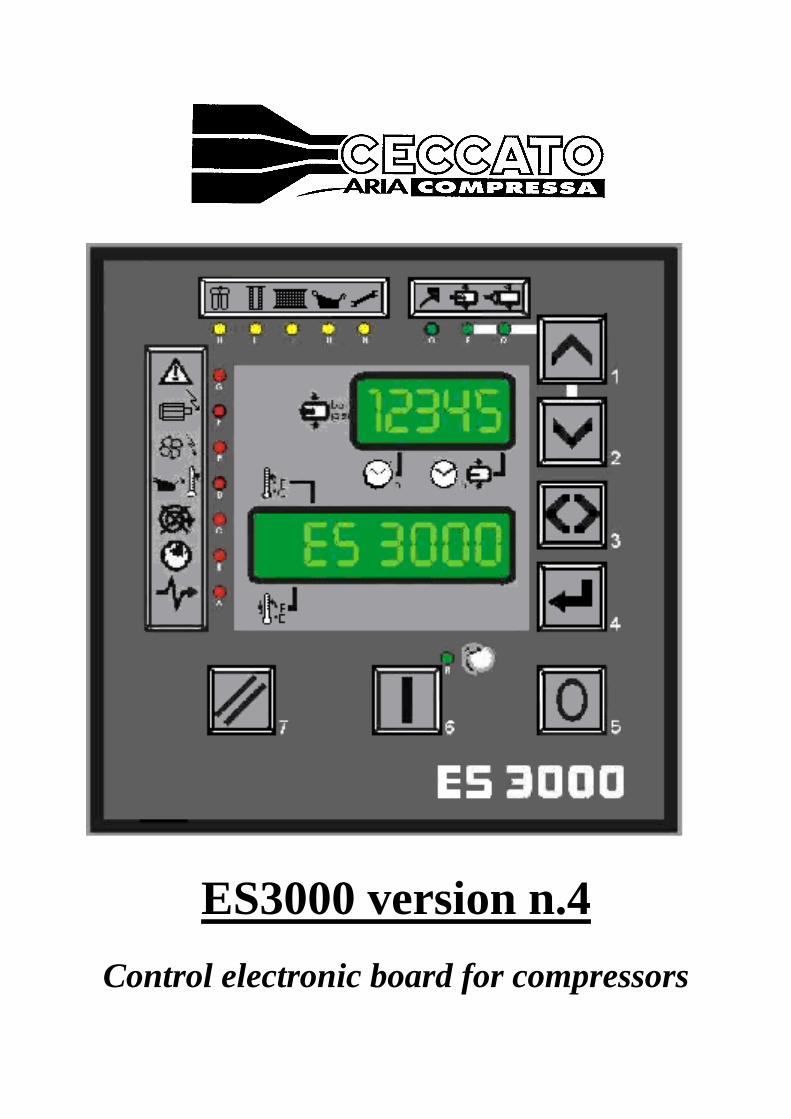
ES3000 version n.4
Control electronic board for compressors
Page 2
ES3000 Control electronic board for compressors
INDEX Pag.
1 GENERAL DESCRIPTION 3
1.1 TECHNICAL FEATURES 3
1.2 INPUT DEVICES 3
1.3 OUTPUT DEVICES 4
1.4 COMMUNICATION PORTS 5
1.5 DIP-SWITCH 5
1.6 PROGRAMMING AND WORKING PARAMETERS 5
1.7 FRONT AND REAR VIEWS 8
1.8 BUTTONS AND L.E.D.s 9
2 GENERAL FEATURES 15
2.1 START 15
2.2 STOP 15
2.3 STAND BY 15
2.4 REMOTE CONTROL 17
2.5 AUTOMATIC RESTARTING WHEN ENERGY IS CUT 17
2.6 ES99 EMULATION 17
2.7 NETWORK 17
2.8 INVERTER CONNECTION 20
2.9 WEEKLY/DAILY PLANNER ADJUSTEMENTS 21
2.10 WATCH ADJUSTMENT/ DAY OF THE WEEK 21
2.11 DATE ADJUSTMENTS 21
3 CONNECTIONS 21
3.1 TERMINAL BOARD 21
3.2 CIRCUIT DIAGRAM 23
3.3 CONNECTION DIAGRAM 24
Page 3
ES3000 Control electronic board for compressors
1. GENERAL DESCRIPTION
ES3000 is a control box for medium and big capacity compressors.
The board manages all the operations of the compressor like about starting, stopping, full load, no load
and so on.
The board itself carries out a test on the compressor and on the board to inform the status of the
compressor and in case also to stop it.
In order to read and to modify the settings, the board is provided with displays to verify the status of the
compressor and to check the operating condition. There are also push buttons to choose or modify the
settings.
ES3000 is capable to replace ES99 as the terminal connectors are exactly the same. The size of the
ES3000 is exactly double the previous ES99.
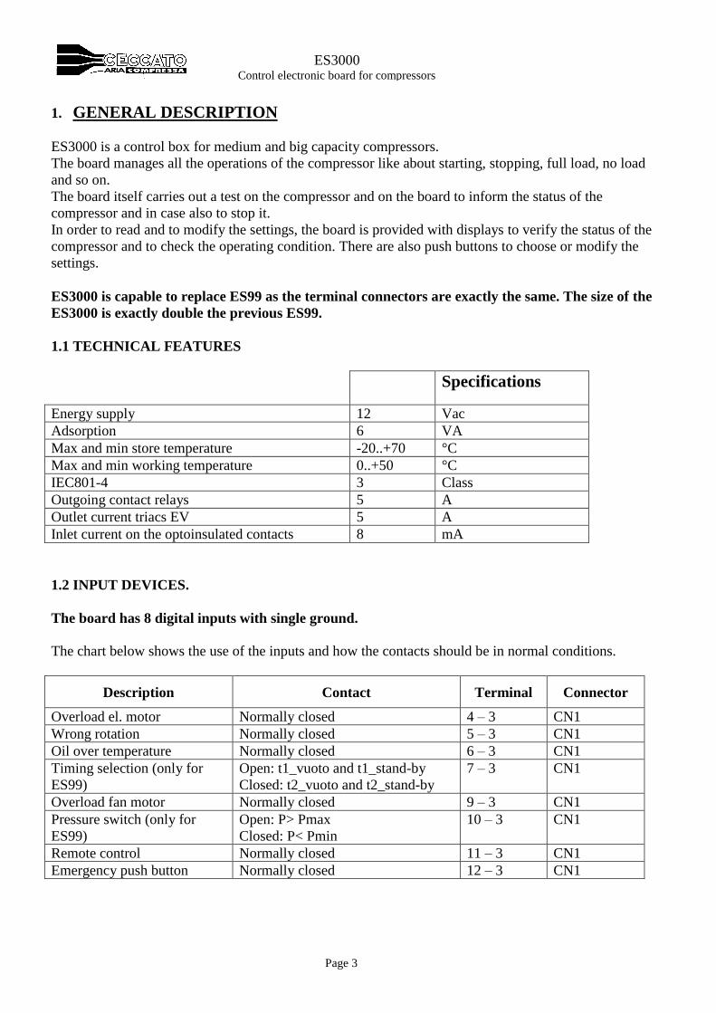
1.1 TECHNICAL FEATURES
Specifications
Energy supply 12 Vac
Adsorption 6 VA
Max and min store temperature -20..+70 °C
Max and min working temperature 0..+50 °C
IEC801-4 3 Class
Outgoing contact relays 5 A
Outlet current triacs EV 5 A
Inlet current on the optoinsulated contacts 8 mA
1.2 INPUT DEVICES.
The board has 8 digital inputs with single ground.
The chart below shows the use of the inputs and how the contacts should be in normal conditions.
Description Contact Terminal Connector
Overload el. motor Normally closed 4 – 3 CN1
Wrong rotation Normally closed 5 – 3 CN1
Oil over temperature Normally closed 6 – 3 CN1
Timing selection (only for
ES99)
Open: t1_vuoto and t1_stand-by
Closed: t2_vuoto and t2_stand-by
7 – 3 CN1
Overload fan motor Normally closed 9 – 3 CN1
Pressure switch (only for
ES99)
Open: P> Pmax
Closed: P< Pmin
10 – 3 CN1
Remote control Normally closed 11 – 3 CN1
Emergency push button Normally closed 12 – 3 CN1
Page 4
ES3000 Control electronic board for compressors
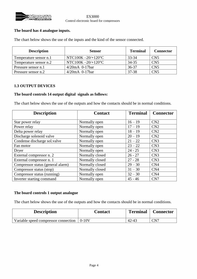
The board has 4 analogue inputs.
The chart below shows the use of the inputs and the kind of the sensor connected.
Description Sensor Terminal Connector
Temperature sensor n.1 NTC100K –20/+120°C 33-34 CN5
Temperature sensor n.2 NTC100K –20/+120°C 34-35 CN5
Pressure sensor n.1 4/20mA 0-17bar 36-37 CN5
Pressure sensor n.2 4/20mA 0-17bar 37-38 CN5
1.3 OUTPUT DEVICES
The board controls 14 output digital signals as follows:
The chart below shows the use of the outputs and how the contacts should be in normal conditions.
Description
Contact Terminal Connector
Star power relay Normally open 16 – 19 CN2
Power relay Normally open 17 – 19 CN2
Delta power relay Normally open 18 – 19 CN2
Discharge solenoid valve Normally open 20 – 19 CN2
Condense discharge sol.valve Normally open 21 – 22 CN3
Fan motor Normally open 23 – 22 CN3
Dryer Normally open 24 - 25 CN3
External compressor n. 2 Normally closed 26 - 27 CN3
External compressor n. 1 Normally closed 27 - 28 CN3
Compressor status (general alarm) Normally closed 29 – 30 CN4
Compressor status (stop) Normally closed 31 – 30 CN4
Compressor status (running) Normally open 32 – 30 CN4
Inverter starting command Normally open 45 - 46 CN7
The board controls 1 output analogue
The chart below shows the use of the outputs and how the contacts should be in normal conditions.
Description
Contact Terminal Connector
Variable speed compressor connection 0-10V 42-43 CN7

Page 5
ES3000 Control electronic board for compressors
1.4 COMMUNICATION PORTS
The board is provided with 2 communication ports.
A serial port RS485 for the communication between other ES3000 boards.
This can create a net up to 6 compressors using the same electronic board.
There is an interface port for communication with a personal computer via RS232 cable.
This is to modify the settings parameters of the board and to monitor the compressor from a remote
location, bringing the start, stop, alarms and status of the compressor signals.
1.5 DIP–SWITCH
Four dip–switches enable to activate the following features:
Dip
Switch
Position Features
1 ON Remote control activated
OFF
Remote control not activated
2 ON Automatic re-starting when power energy had been interrupted
OFF Waiting for re-set when power energy had been interrupted
3 ON ES99 software activated
OFF ES3000 software activated
4 ON Not applicable
OFF Not applicable
1.6 PROGRAMMING AND WORKING PARAMETERS
In order to make the use of the control box easier, it has been decided to store the setting values into the
static memory type Eeprom. The following cross reference chart shows the default parameters set from
the compressor manufacturer.
Symbol Parameter Unit Minimum Maximum Increment Settings Notes
NO PASSWORD
P0 Maximum pressure Bar/PSI 4 / 58 14 / 203 0,1 / 1 8 / 116 Only downwards
P1 Minimum pressure Bar/PSI 3,9 / 56 13,9 / 201 0,1 / 1 6,5 / 94 min 0,1bar/1psi lower
than P0
R2 Over temperature °C / F -10 / 14 105 / 221 1 / 1 100 / 212 Pre-alarm -5°C/-10F
T3 Delay time discharge
sol. valve
M 1 15 1 5
T4 Working time discharge
sol. valve
S 1 30 1 5
C5 Starting per hour - 0 25 1 10
C6 Temperature setting - 0 1 1 0 0=°C , 1=F
C7 Pressure setting - 0 1 1 0 0=bar , 1= PSI
F8 Weekly/daily schedule
activation
- 0 1 1 0 0=not activated
1=activated
Page 6
ES3000 Control electronic board for compressors
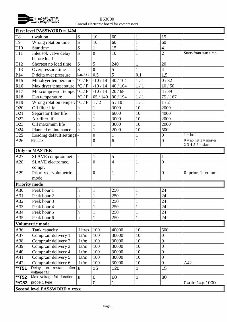
First level PASSWORD = 1404
T8 t wait on S 10 60 1 15
T9 Wrong rotation time S 10 60 1 60
T10 Star time S 1 15 1 4
T11 Inlet sol. valve delay
before load
S 0 10 1 2 Starts from start time
T12 Shortest no load time S 5 240 1 20
T13 Overpressure time S 0 5 1 4
P14 P delta over pressure bar/PSI 0,5 5 0,1 1,5
R15 Min.dryer temperature °C / F -10 / 14 40 / 104 1 / 1 0 / 32
R16 Max.dryer temperature °C / F -10 / 14 40 / 104 1 / 1 10 / 50
R17 Min.compressor temper. °C / F -10 / 14 20 / 68 1 / 1 4 / 39
R18 Fan temperature °C / F 65 / 149 90 / 194 1 / 1 75 / 167
R19 Wrong rotation temper. °C / F 1 / 2 5 / 10 1 / 1 1 / 2
O20 Oil filter life h 1 3000 10 2000
O21 Separator filter life h 1 6000 10 4000
O22 Air filter life h 1 3000 10 2000
O23 Oil maximum life h 1 3000 10 2000
O24 Planned maintenance h 1 2000 10 500
C25 Loading default settings - 0 1 1 0 1 = load
A26 Net link - 0 6 1 0 0 = no net 1 = master
2-3-4-5-6 = slave
Only on MASTER
A27 SLAVE compr.on net - 1 5 1 1
A28 SLAVE electromec.
compr.
- 0 4 1 0
A29 Priority or volumetric
mode
- 0 1 1 0 0=prior, 1=volum.
Priority mode
A30 Peak hour 1 h 1 250 1 24
A31 Peak hour 2 h 1 250 1 24
A32 Peak hour 3 h 1 250 1 24
A33 Peak hour 4 h 1 250 1 24
A34 Peak hour 5 h 1 250 1 24
A35 Peak hour 6 h 1 250 1 24
Volumetric mode
A36 Tank capacity Litres 100 40000 10 500
A37 Compr.air delivery 1 Lt/m 100 30000 10 0
A38 Compr.air delivery 2 Lt/m 100 30000 10 0
A39 Compr.air delivery 3 Lt/m 100 30000 10 0
A40 Compr.air delivery 4 Lt/m 100 30000 10 0
A41 Compr.air delivery 5 Lt/m 100 30000 10 0
A42 Compr.air delivery 6 Lt/m 100 30000 10 0 A42
**T51 Delay on restart after voltage fail
s 15 120 1 15
**T52 Max voltage fail duration s 0 60 1 30
**C53 probe 1 type . 0 1 0=ntc 1=pt1000
Second level PASSWORD = xxxx
Page 7
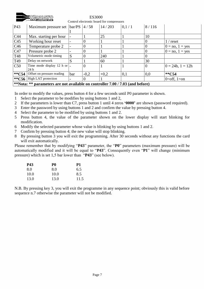
ES3000 Control electronic board for compressors
P43 Maximum pressure set bar/PS
I
4 / 58 14 / 203 0,1 / 1 8 / 116
C44 Max. starting per hour - 1 25 1 10
C45 Working hour reset - 0 1 1 0 1 / reset
C46 Temperature probe 2 - 0 1 1 0 0 = no, 1 = yes
C47 Pressure probe 2 - 0 1 1 0 0 = no, 1 = yes
T48 Volumetric mode timing S 0 240 1 0
T49 Delay on network S 1 60 1 30
C50 Time mode display 12 h or
24 h - 0 1 1 0 0 = 24h, 1 = 12h
**C54 Offset on pressure reading bar -0,2 +0,2 0,1 0,0 **C54
**C56 High LAT protection - 0 1 0=off, 1=on
**Nota: ** parameters are not available on controller 7.00 / 7.03 (and before)
In order to modify the values, press button 4 for a few seconds until P0 parameter is shown.
1 Select the parameter to be modifies by using buttons 1 and 2,
2 If the parameters is lower than C7, press button 1 until 4 zeros ‘0000’ are shown (password required).
3 Enter the password by using buttons 1 and 2 and confirm the value by pressing button 4.
4 Select the parameter to be modified by using buttons 1 and 2.
5 Press button 4, the value of the parameter shown on the lower display will start blinking for
modification.
6 Modify the selected parameter whose value is blinking by using buttons 1 and 2.
7 Confirm by pressing button 4; the new value will stop blinking.
8 By pressing button 3 you will exit the programming. After 30 seconds without any functions the card
will exit automatically.
Please remember that by modifying “P43” parameter, the “P0” parameters (maximum pressure) will be
automatically modified and it will be equal to “P43”. Consequently even “P1” will change (minimum
pressure) which is set 1,5 bar lower than “P43” (see below).
P43 P0 P1
8.0 8.0 6.5
10.0 10.0 8.5
13.0 13.0 11.5
N.B. By pressing key 3, you will exit the programme in any sequence point; obviously this is valid before
sequence n.7 otherwise the parameter will not be modified.
Page 8
ES3000 Control electronic board for compressors
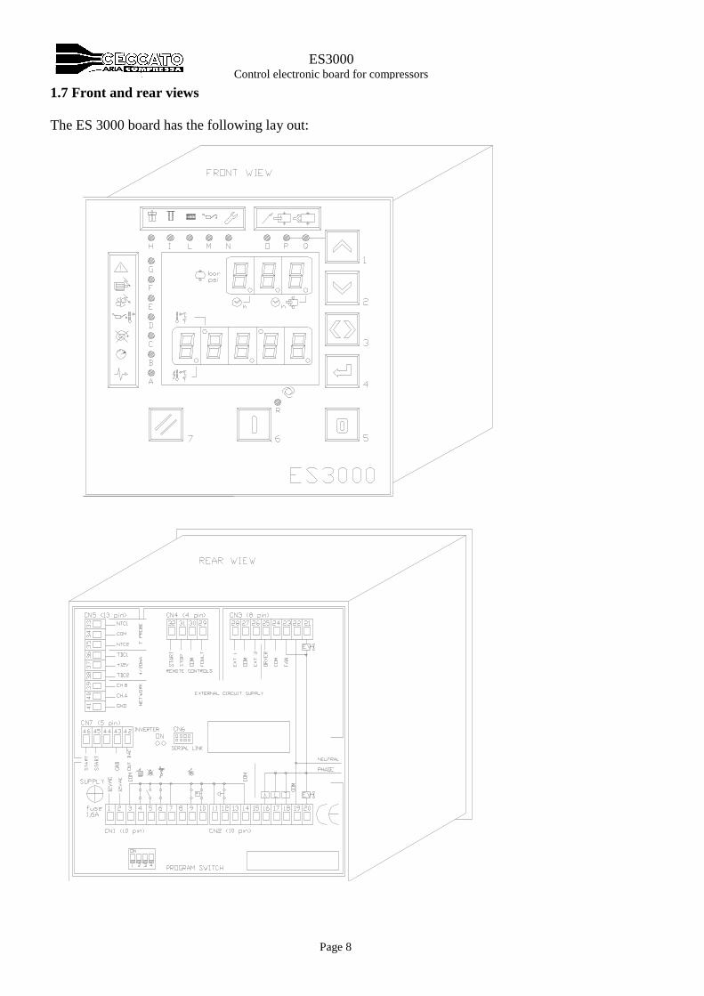
1.7 Front and rear views
The ES 3000 board has the following lay out:

Page 9
ES3000 Control electronic board for compressors
1.8 BUTTONS AND L.E.D.s
With the following 3 push buttons,
Button Symbol Description
7
TEST/RESET
By pushing this button the alarms already occurred are reset.
By pushing the button for more than 3 seconds, a control test is carry out on all the
board (all light have to be on) and shows the software version.
Pushing this button together with :
Button 3, the last 4 alarms are shown.
Button 4, you enter into the maintenance menu.
Button 5, enter into the daily/weekly schedule
6
RUNNING
By pushing this button the compressor starts.
5
STOPPING
By pushing this button the stop procedure starts.
Other 4 buttons to control the menus,
Button Symbol Description
4
PROGRAMMING
By pushing the button for more than 3 seconds you enter into the programming
menu.
3
TAB
By pushing the button you exit the programming and maintenance menus.
By pushing the button on the display appears the values of the optional probes (if
there are), the total working hours, the full load hours, the date and hours, the
connection with network and (if MASTER) the net address with the number and
status of the Slaves connected.
2
DOWN
By pushing the button you move throughout the parameters of the menus.
1
UP
By pushing the button the off load manually is activated or (in programming) you
move throughout the parameters of the menus.
Page 10
ES3000 Control electronic board for compressors
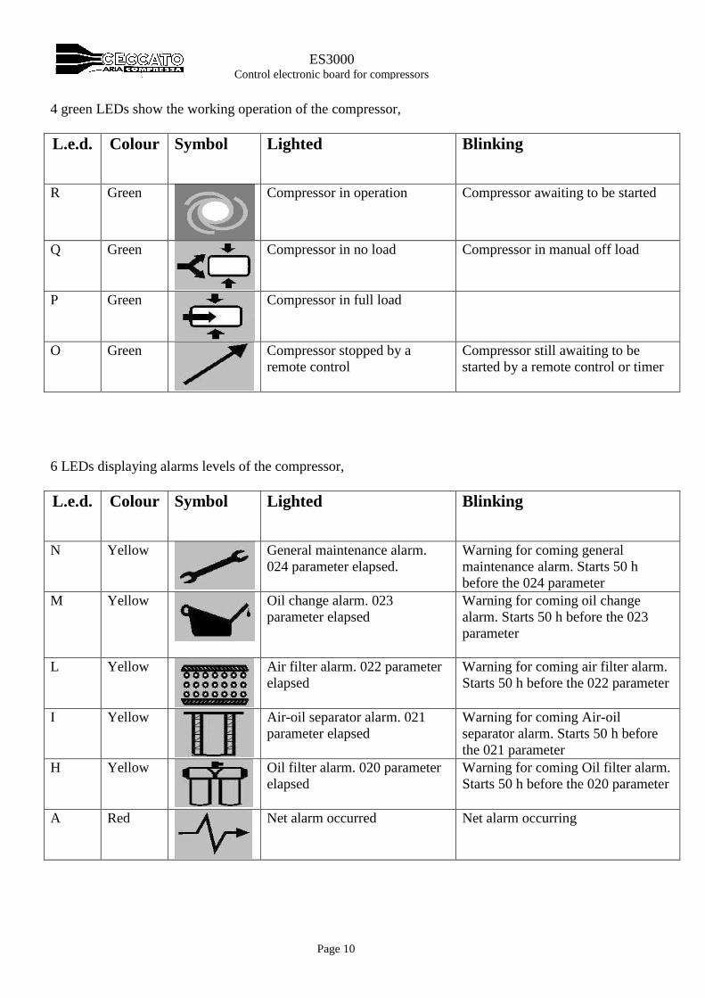
4 green LEDs show the working operation of the compressor,
L.e.d. Colour Symbol Lighted Blinking
R Green
Compressor in operation
Compressor awaiting to be started
Q Green
Compressor in no load
Compressor in manual off load
P Green
Compressor in full load
O Green
Compressor stopped by a
remote control
Compressor still awaiting to be
started by a remote control or timer
6 LEDs displaying alarms levels of the compressor,
L.e.d. Colour Symbol Lighted Blinking
N Yellow
General maintenance alarm.
024 parameter elapsed.
Warning for coming general
maintenance alarm. Starts 50 h
before the 024 parameter
M Yellow
Oil change alarm. 023
parameter elapsed
Warning for coming oil change
alarm. Starts 50 h before the 023
parameter
L Yellow
Air filter alarm. 022 parameter
elapsed
Warning for coming air filter alarm.
Starts 50 h before the 022 parameter
I Yellow
Air-oil separator alarm. 021
parameter elapsed
Warning for coming Air-oil
separator alarm. Starts 50 h before
the 021 parameter
H Yellow
Oil filter alarm. 020 parameter
elapsed
Warning for coming Oil filter alarm.
Starts 50 h before the 020 parameter
A Red
Net alarm occurred
Net alarm occurring
Page 11
ES3000 Control electronic board for compressors
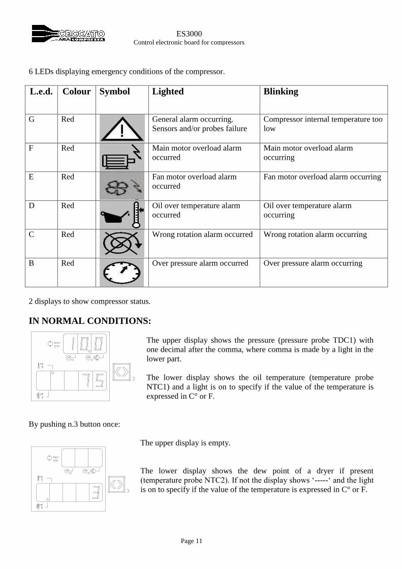
6 LEDs displaying emergency conditions of the compressor.
L.e.d. Colour Symbol Lighted Blinking
G Red
General alarm occurring.
Sensors and/or probes failure
Compressor internal temperature too
low
F Red
Main motor overload alarm
occurred
Main motor overload alarm
occurring
E Red
Fan motor overload alarm
occurred
Fan motor overload alarm occurring
D Red
Oil over temperature alarm
occurred
Oil over temperature alarm
occurring
C Red
Wrong rotation alarm occurred
Wrong rotation alarm occurring
B Red
Over pressure alarm occurred
Over pressure alarm occurring
2 displays to show compressor status.
IN NORMAL CONDITIONS:
The upper display shows the pressure (pressure probe TDC1) with
one decimal after the comma, where comma is made by a light in the
lower part.
The lower display shows the oil temperature (temperature probe
NTC1) and a light is on to specify if the value of the temperature is
expressed in C° or F.
By pushing n.3 button once:
The upper display is empty.
The lower display shows the dew point of a dryer if present
(temperature probe NTC2). If not the display shows ‘-----‘ and the light
is on to specify if the value of the temperature is expressed in C° or F.
Page 12
ES3000 Control electronic board for compressors
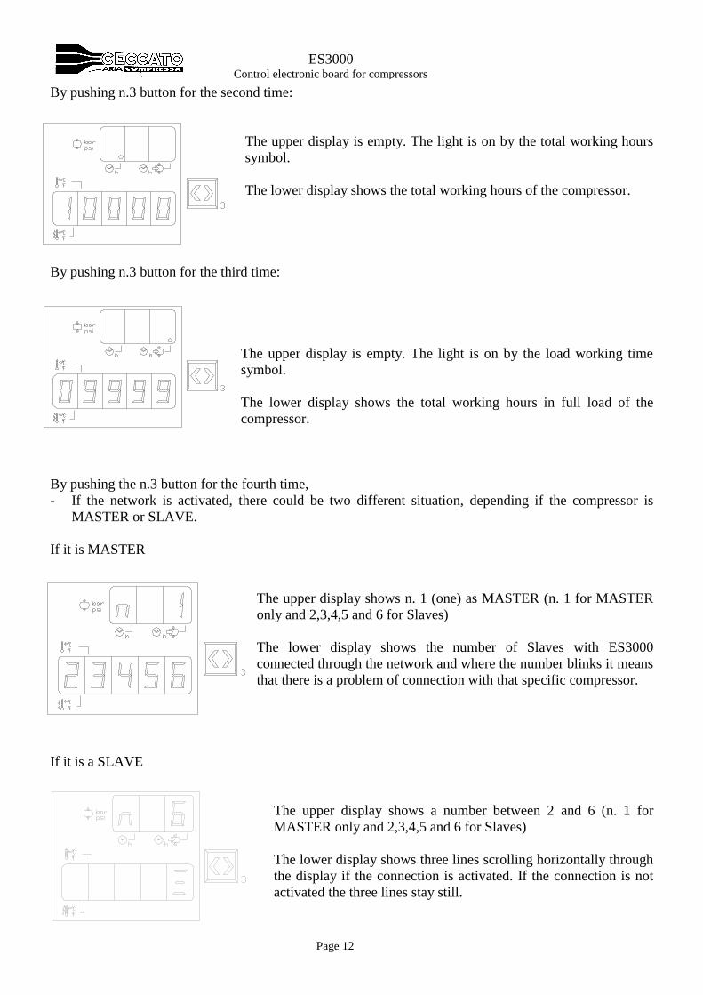
By pushing n.3 button for the second time:
The upper display is empty. The light is on by the total working hours
symbol.
The lower display shows the total working hours of the compressor.
By pushing n.3 button for the third time:
The upper display is empty. The light is on by the load working time
symbol.
The lower display shows the total working hours in full load of the
compressor.
By pushing the n.3 button for the fourth time,
- If the network is activated, there could be two different situation, depending if the compressor is
MASTER or SLAVE.
If it is MASTER
The upper display shows n. 1 (one) as MASTER (n. 1 for MASTER
only and 2,3,4,5 and 6 for Slaves)
The lower display shows the number of Slaves with ES3000
connected through the network and where the number blinks it means
that there is a problem of connection with that specific compressor.
If it is a SLAVE
The upper display shows a number between 2 and 6 (n. 1 for
MASTER only and 2,3,4,5 and 6 for Slaves)
The lower display shows three lines scrolling horizontally through
the display if the connection is activated. If the connection is not
activated the three lines stay still.
Page 13
ES3000 Control electronic board for compressors
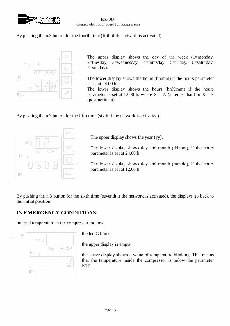
By pushing the n.3 button for the fourth time (fifth if the network is activated)
The upper display shows the day of the week (1=monday,
2=tuesday, 3=wednesday, 4=thursday, 5=friday, 6=saturday,
7=sunday).
The lower display shows the hours (hh:mm) if the hours parameter
is set at 24.00 h.
The lower display shows the hours (hhX:mm) if the hours
parameter is set at 12.00 h. where X = A (antemeridian) or X = P
(postmeridian).
By pushing the n.3 button for the fifth time (sixth if the network is activated)
The upper display shows the year (yy).
The lower display shows day and month (dd.mm), if the hours
parameter is set at 24.00 h
The lower display shows day and month (mm.dd), if the hours
parameter is set at 12.00 h
By pushing the n.3 button for the sixth time (seventh if the network is activated), the displays go back to
the initial position.
IN EMERGENCY CONDITIONS:
Internal temperature in the compressor too low:
the led G blinks
the upper display is empty
the lower display shows a value of temperature blinking. This means
that the temperature inside the compressor is below the parameter
R17.
Page 14
ES3000 Control electronic board for compressors
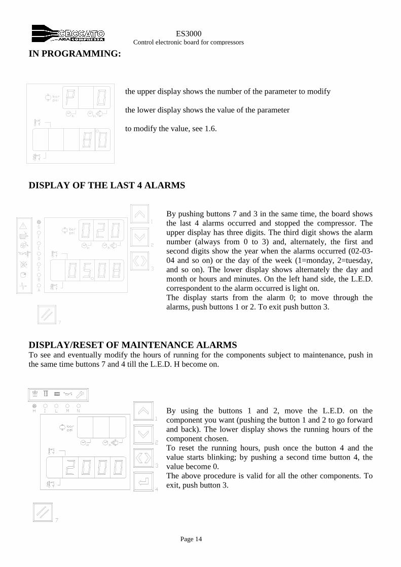
IN PROGRAMMING:
the upper display shows the number of the parameter to modify
the lower display shows the value of the parameter
to modify the value, see 1.6.
DISPLAY OF THE LAST 4 ALARMS
By pushing buttons 7 and 3 in the same time, the board shows
the last 4 alarms occurred and stopped the compressor. The
upper display has three digits. The third digit shows the alarm
number (always from 0 to 3) and, alternately, the first and
second digits show the year when the alarms occurred (02-03-
04 and so on) or the day of the week (1=monday, 2=tuesday,
and so on). The lower display shows alternately the day and
month or hours and minutes. On the left hand side, the L.E.D.
correspondent to the alarm occurred is light on.
The display starts from the alarm 0; to move through the
alarms, push buttons 1 or 2. To exit push button 3.
DISPLAY/RESET OF MAINTENANCE ALARMS To see and eventually modify the hours of running for the components subject to maintenance, push in
the same time buttons 7 and 4 till the L.E.D. H become on.
By using the buttons 1 and 2, move the L.E.D. on the
component you want (pushing the button 1 and 2 to go forward
and back). The lower display shows the running hours of the
component chosen.
To reset the running hours, push once the button 4 and the
value starts blinking; by pushing a second time button 4, the
value become 0.
The above procedure is valid for all the other components. To
exit, push button 3.
Page 15
ES3000 Control electronic board for compressors
2.GENERAL FUNCTION
2.1 Start
When button 6 is pushed, the board starts the sequence of starting and carries out the following steps:
1. The L.E.D. ‘R’ switch on
2. In the case the power relay has just been released, the board wait for the time as per the parameter
‘T8’, or the board wait for the pressure to be lower to the minimum pressure parameter ‘P1’.
3. The relays of line (‘L’) and star (‘Y’) are activated for the time set in the ‘T10’ parameter. From when
the line relay is activated and for the time set into the parameter T9, the ES3000 controls that the
temperature of the machines (temperature probe NTC1) increase at least of the value of ‘R19’ to
confirm that the rotation is correct or by stopping immediately the machine (note that this control is
deactivated if the temperature of the machine is over 30 C°).
4. When the time of T10 is elapsed, the star relay (‘Y’) is deactivated while the line relay remain
activated for a not adjustable time of 50 milliseconds. After that the triangle relay (‘T) is activated.
5. The solenoid valve of load/off load is delayed for the time value set in ‘T11’ (this is to delay the full
load operation). L.E.D. ‘P’ when is lighted on shows when the compressor is in full load.
6. When the maximum pressure is reached, the L.E.D. ‘Q’ lights on and the machine switch in off load.
2.2 Stop
By pushing the button 5 during the three phases of starting, cancels the procedure and stops the
compressor immediately. If the button 5 is pushed when the triangle relay (‘T’) is activated, the board
starts the stopping procedure that lasts for the value of ‘T12’, where the compressor runs off-load with the
solenoid valve deactivated. During all the stopping time, the L.E.D. ‘R’ blinks.
If the board is waiting for re-starting because the maximum pressure is reached, by pushing the button 5
cancel immediately all the functions running.
2.3 Stand By
In absence of compressed air from the system and with pressure over the Pmin (P1 parameter), the
compressor runs in off-load.
To reduce the energy consumption, the compressor stops as soon as a time is elapsed. The values of this
time is calculated as follows:
1) The machine cannot go over the number of starts value of C% parameter (where x=60/C5)
2) The time the machine remain still has to be over two times the T12 parameter ( > 2*F12 ), the
pressure must be over of the following formula [(P0-[1/3(P0-P1)].
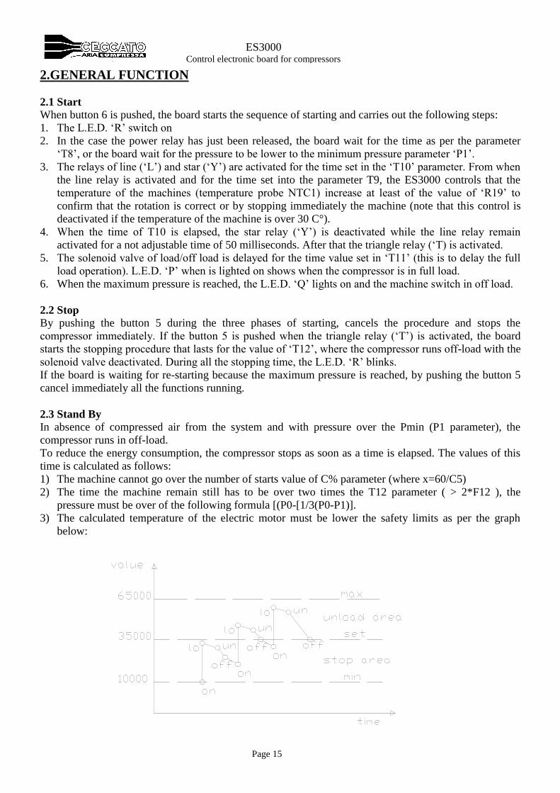
3) The calculated temperature of the electric motor must be lower the safety limits as per the graph
below:
Page 16
ES3000 Control electronic board for compressors
The solution adopted to define the idling time before to stop the compressor consists to calculate the
thermal trend of the electric motor in relation with the times and the different way of working of the
el.motor itself and to link this value to the parameter of number of starting (‘C5’).
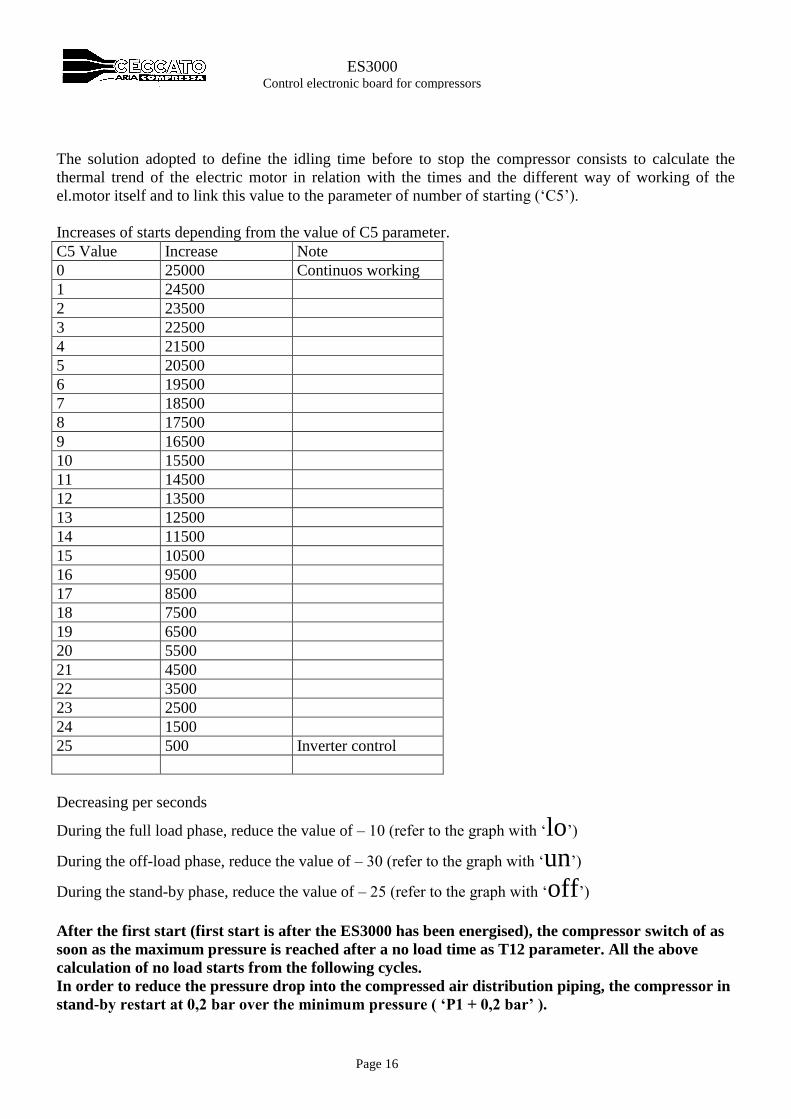
Increases of starts depending from the value of C5 parameter.
C5 Value Increase Note
0 25000 Continuos working
1 24500
2 23500
3 22500
4 21500
5 20500
6 19500
7 18500
8 17500
9 16500
10 15500
11 14500
12 13500
13 12500
14 11500
15 10500
16 9500
17 8500
18 7500
19 6500
20 5500
21 4500
22 3500
23 2500
24 1500
25 500 Inverter control
Decreasing per seconds
During the full load phase, reduce the value of – 10 (refer to the graph with ‘lo’)
During the off-load phase, reduce the value of – 30 (refer to the graph with ‘un’)
During the stand-by phase, reduce the value of – 25 (refer to the graph with ‘off’)
After the first start (first start is after the ES3000 has been energised), the compressor switch of as
soon as the maximum pressure is reached after a no load time as T12 parameter. All the above
calculation of no load starts from the following cycles.
In order to reduce the pressure drop into the compressed air distribution piping, the compressor in
stand-by restart at 0,2 bar over the minimum pressure ( ‘P1 + 0,2 bar’ ).

Page 17
ES3000 Control electronic board for compressors
2.4 Remote control
The remote control procedure enable stopping the compressor from a remote location by opening the
contacts in terminal board marked 11 and 3. Opening of the contact will start the stopping procedure and
the light 7 will be switched on. When the same contact will be closed, the compressor starts again
following the procedure described in 2.1.
The actions given by pushing the buttons on the ES3000 board are at the same level related to the
commands given from remote; it is possible to start the compressor both from remote location and also
from the machine itself.
N.B.: The function ‘Remote control’ is activated by the dip switch 1 located on the side of the
electronic board. If the position of this is OFF, the function is not activated and even opening the
contact 11 and 3 does not have any effect.
2.5 Automatic re-starting when energy is cut
The function ‘automatic restart’ is activated when the dip switch located on the back side of the ES3000
is ON. This function bring the compressor in the same condition it was when the energy was cut.
Status of the machine Missing of energy Energy return
While Running Machine stops Machine re-start
While still Machine still Machine still
N.B.: If the ‘Remote control’ function is activated and the remote contact between 11 and 3 is open,
when energy returns the machine will not re-start.
2.6 ES99 emulation.
The ES3000 can replace a ES99 if the dip switch n. 3 located on the back side of ES3000 is activated.
When this function is activated, the ES3000 works like an ES99 and it is possible to replace a fault ES99.
The connection sockets CN1 and CN2 are the same, the dimensions of ES3000 are not the same so the
hole where the old ES99 was has to be bigger.
Of course, we do not have on the displays the pressure and the temperature values and those information
will be replaced by ON and OFF.
2.7 Network
The ES3000 is capable to communicate with other ES3000 and also to manage other compressors
managed Electro-mechanically.
The net could be up to maximum of 6 units as follows:
n.1 MASTER
n.5 Slaves with ES3000 board
or
n.4 Slaves with Electro-mechanic control board.
Of course every slave Electro-mechanic replace a slave with ES3000 board; the possible combinations
are:
Page 18
ES3000 Control electronic board for compressors
MASTER SLAVE ES3000 SLAVE not ES3000 TOTAL
1 5 0 6
1 4 1 6
1 3 2 6
1 2 3* 6
1 1 4* 6
To activate the slaves not ES3000 n. 3 and 4 means to loose the digital outputs of the status of the
compressor because they are converted to manage external compressors.
The machines could be managed by the ES3000 in two different modes; PRIORITY and VOLUMETRIC.
2.8 INVERTER CONNECTION
The parameters C44 and C5, number of starts per hour, must be set at 25.
Digital output, contact K10 on terminals 45-46 on the connector CN8 for start or stop.
Analogic output, DAC (0-10 V) on terminals 43-44 on connector CN8 to modulate.
Start, when button n. 6 is pressed and then after the first start when P1 pressure +0,2 is reached.
Modulation of the rotation speed at pressure P0 – 0,5 bar
Idling when the pressure P0 is reached and for time set on parameter P12.
Load when pressure P1 is reached
Stop, when button 5 is pushed or when idling time parameter T12 is elapsed.
Emergency, K10 opens immediately on connector CN8.
Output DAC (0-10V), must give 10V (maximum tension), at the pressure of inverter (P0 – 0,5bar), must
give 0V at the minimum pressure (0bar).
N.B. pushing the button n. 1 (manual off load) make the contact DAC up to 10 Volt.
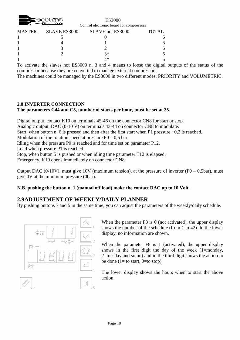
2.9 ADJUSTMENT OF WEEKLY/DAILY PLANNER By pushing buttons 7 and 5 in the same time, you can adjust the parameters of the weekly/daily schedule.
When the parameter F8 is 0 (not activated), the upper display
shows the number of the schedule (from 1 to 42). In the lower
display, no information are shown.
When the parameter F8 is 1 (activated), the upper display
shows in the first digit the day of the week (1=monday,
2=tuesday and so on) and in the third digit shows the action to
be done (1= to start, 0=to stop).
The lower display shows the hours when to start the above
action.
Page 19
ES3000 Control electronic board for compressors
ADJUSTMENT
To modify, push button 4 for more than 3 seconds while the value is visible, than modify the value that
blinks by pushing button 1 to increase and 2 to decrease and button 3 to move from hours and action to be
taken. To pass to the following day, you need to go over the 24:00 of the current day.
To confirm, push again button 4.To cancel push ‘0’ button for more than 3 seconds.
The minimum interval is 15 minutes with a maximum of 42 actions (start or stop). Automatically the
software does not accept impossible scheduling (a stop before a start and so on).
Entering the above parameters it is not enough; to activated the weekly/daily schedule, the parameter F8
has to be activated.
Please note that the schedule has to follow the sequence from 1 to 42 steps. The schedule has to start from
Monday to Sunday and to enter an action in the between, all the following actions have to be moved
downwards.
2.10 WATCH ADJUSTMENT / DAY OF THE WEEK To modify push button 4 for more than 3 seconds while is visible, than to modify the value that blinks by
using buttons 1 to increase ands 2 to decrease and button 3 to move from hours, minutes and day of the
week.
To confirm, push again button 4.
2.11 DATE ADJUSTMENT To modify, push button 4 for more than 3 seconds while the value is visible, than modify the value that
blinks by pushing button 1 to increase and 2 to decrease and button 3 to move from day to month to year.
To confirm, push again button 4.
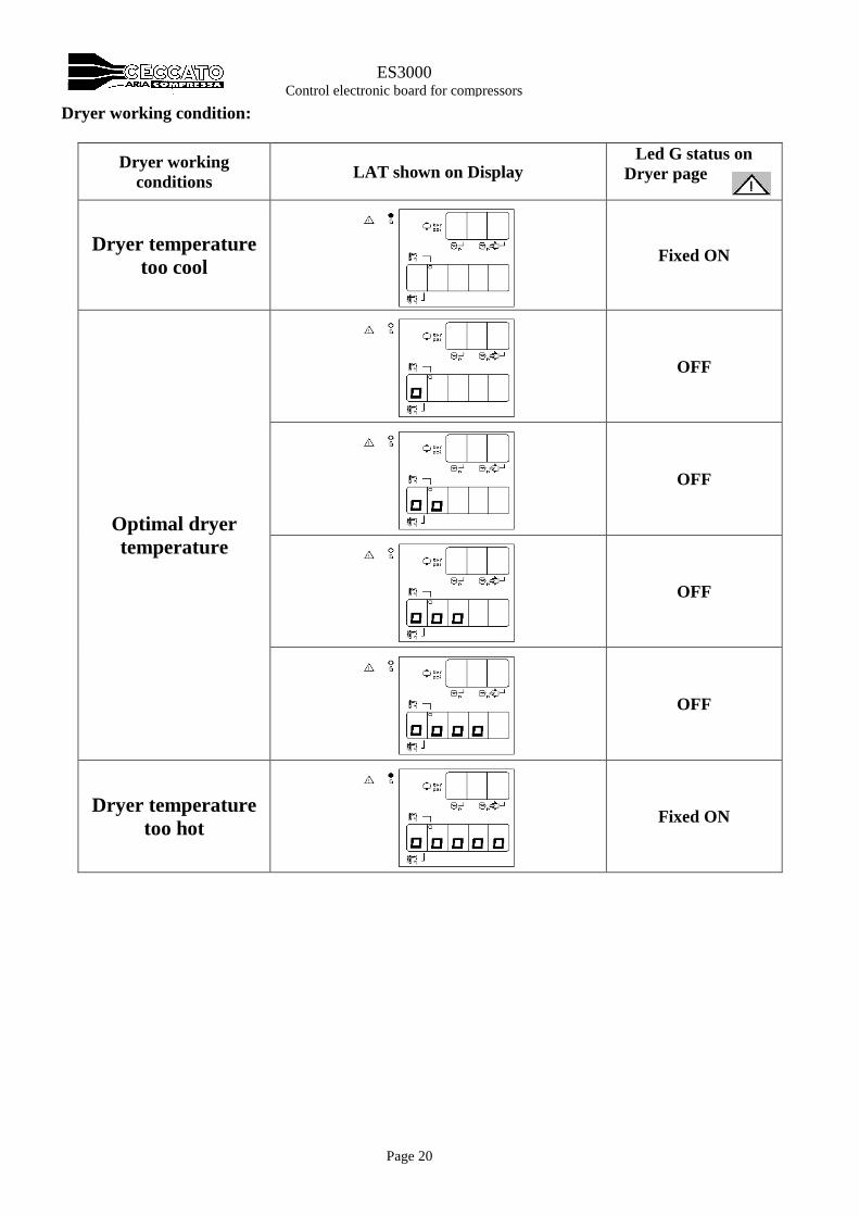
2.12 DRYER MANAGEMENT
Remark:
Function available only on controllers with sw V 7.00/7.03 or software A03.
To active dryer management it’s necessary to active the second temperature sensor NTC2 setting C46=1.
To see the LAT (lowest air temperature), push 3 times .
On second display the LAT is shown like an incremental bar.
Dryer Start Stop:
The Dryer is managed by output K06. This output is closed and open together the output K03 (Delta
contactor)
Compressor emergency/allarm: Ib this case also the Dryer is stopped.
Dryer Emergency:
In case of second NTC damage led G is fixed On.
Only dryer is stopped but compressor continue its working.
Page 20
ES3000 Control electronic board for compressors
Dryer working condition:
Dryer working
conditions LAT shown on Display
Led G status on
Dryer page
Dryer temperature
too cool
Fixed ON
Optimal dryer
temperature
OFF
OFF
OFF
OFF
Dryer temperature
too hot
Fixed ON
Page 21
ES3000 Control electronic board for compressors
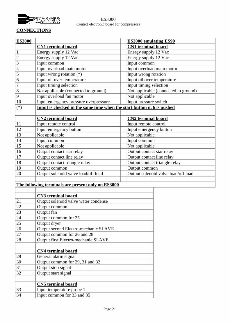
CONNECTIONS
ES3000 ES3000 emulating ES99
CN1 terminal board CN1 terminal board
1 Energy supply 12 Vac Energy supply 12 Vac
2 Energy supply 12 Vac Energy supply 12 Vac
3 Input common Input common
4 Input overload main motor Input overload main motor
5 Input wrong rotation (*) Input wrong rotation
6 Input oil over temperature Input oil over temperature
7 Input timing selection Input timing selection
8 Not applicable (connected to ground) Not applicable (connected to ground)
9 Input overload fan motor Not applicable
10 Input emergency pressure overpressure Input pressure switch
(*) Input is checked in the same time when the start button n. 6 is pushed
CN2 terminal board CN2 terminal board
11 Input remote control Input remote control
12 Input emergency button Input emergency button
13 Not applicable Not applicable
14 Input common Input common
15 Not applicable Not applicable
16 Output contact star relay Output contact star relay
17 Output contact line relay Output contact line relay
18 Output contact triangle relay Output contact triangle relay
19 Output common Output common
20 Output solenoid valve load/off load Output solenoid valve load/off load
The following terminals are present only on ES3000
CN3 terminal board
21 Output solenoid valve water condense
22 Output common
23 Output fan
24 Output common for 25
25 Output dryer
26 Output second Electro-mechanic SLAVE
27 Output common for 26 and 28
28 Output first Electro-mechanic SLAVE
CN4 terminal board
29 General alarm signal
30 Output common for 29, 31 and 32
31 Output stop signal
32 Output start signal
CN5 terminal board
33 Input temperature probe 1
34 Input common for 33 and 35
Page 22
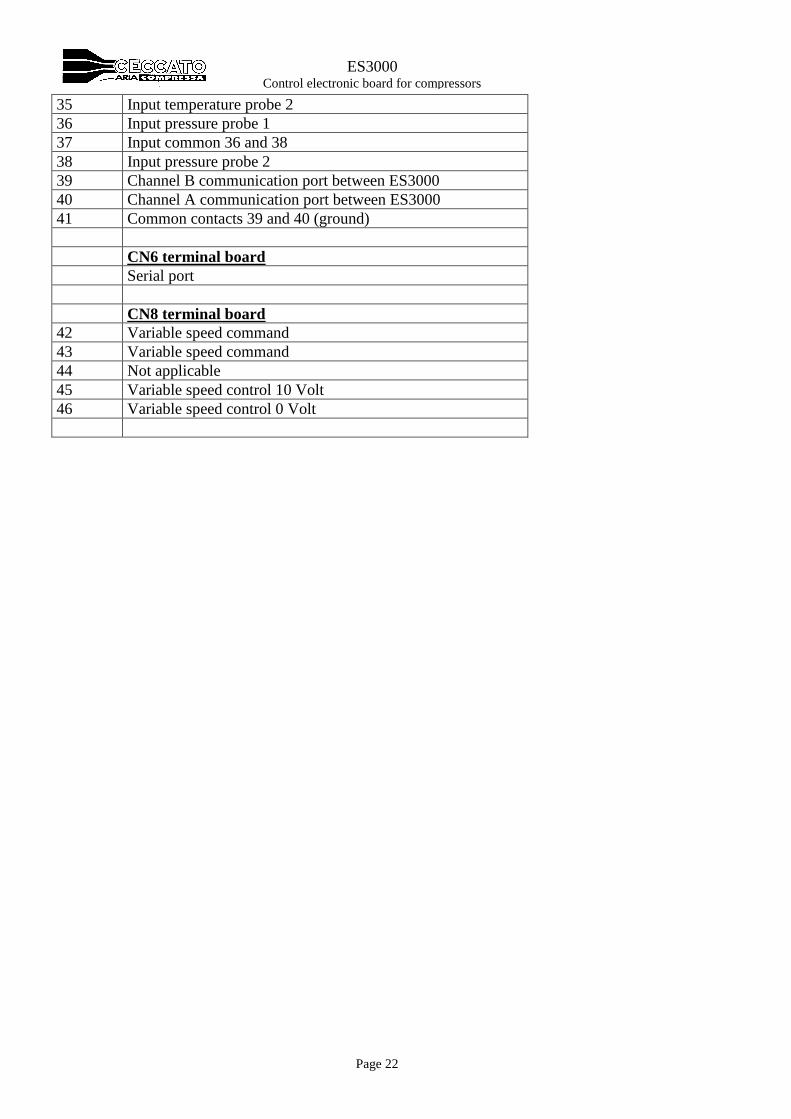
ES3000 Control electronic board for compressors
35 Input temperature probe 2
36 Input pressure probe 1
37 Input common 36 and 38
38 Input pressure probe 2
39 Channel B communication port between ES3000
40 Channel A communication port between ES3000
41 Common contacts 39 and 40 (ground)
CN6 terminal board
Serial port
CN8 terminal board
42 Variable speed command
43 Variable speed command
44 Not applicable
45 Variable speed control 10 Volt
46 Variable speed control 0 Volt
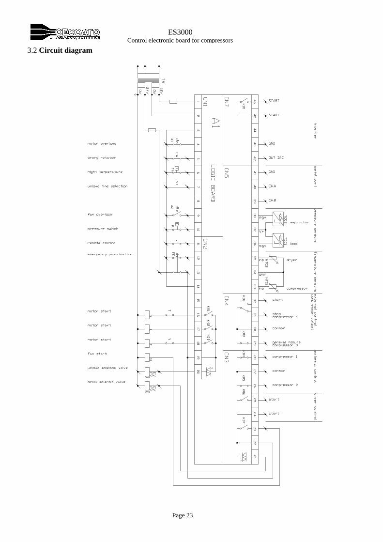
Page 23
ES3000 Control electronic board for compressors
3.2 Circuit diagram
Page 24
ES3000 Control electronic board for compressors
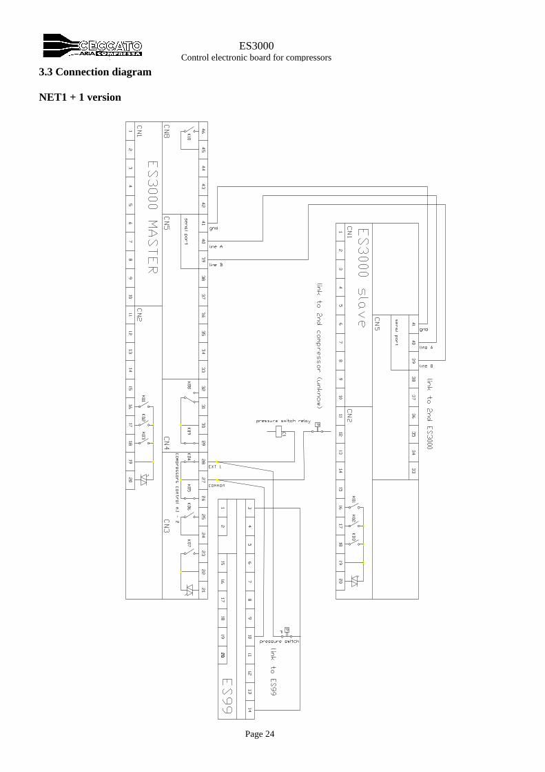
3.3 Connection diagram
NET1 + 1 version
Page 25
ES3000 Control electronic board for compressors
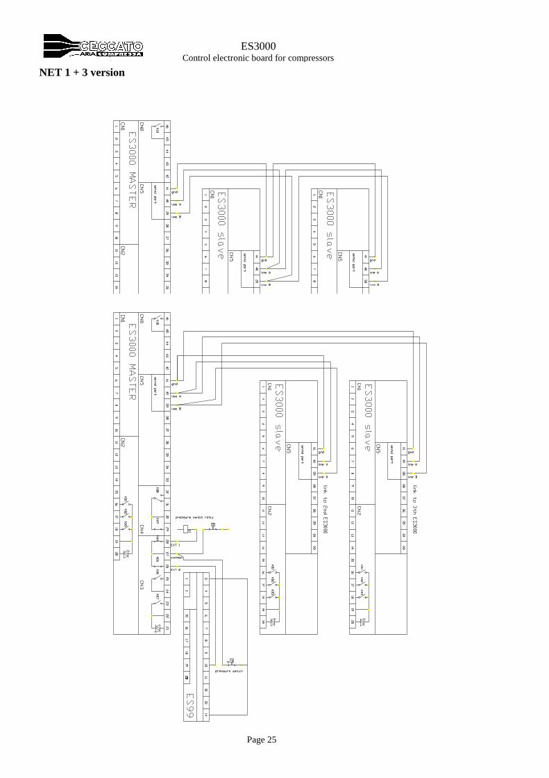
NET 1 + 3 version
Page 26
ES3000 Control electronic board for compressors
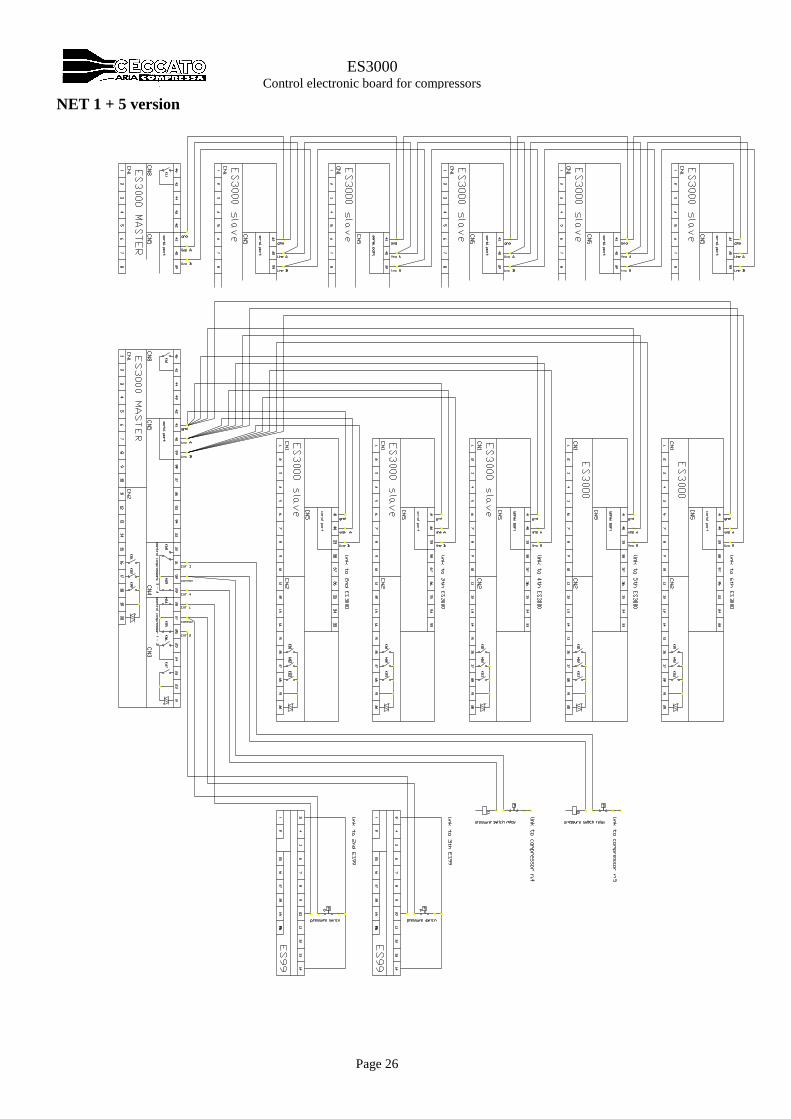
NET 1 + 5 version