synthesis of pt–co nanoparticles on multi-walled carbon nanotubes for methanol oxidation in h2so4...
TRANSCRIPT

So
Ra
b
c
d
a
ARRAA
KPMFME
1
ffppHfhbo
mtpPaotst
0d
Applied Catalysis A: General 407 (2011) 195– 203
Contents lists available at SciVerse ScienceDirect
Applied Catalysis A: General
j ourna l ho me page: www.elsev ier .com/ locate /apcata
ynthesis of Pt–Co nanoparticles on multi-walled carbon nanotubes for methanolxidation in H2SO4 solution
.S. Amina, K.M. El-Khatiba, R.M. Abdel Hameedb,∗, Eglal R. Souayac, Mohamed A. Etmand
Chem. Eng. & Pilot Plant Dept., Engineering Division, National Research Center, Dokki, Giza, EgyptChemistry Department, Faculty of Science, Cairo University, Giza, EgyptChemistry Department, Faculty of Science, Ain Shams University, Cairo, EgyptHousing and Building National Research Center (HBRC), El-Tahrir St., Dokki, Giza, Egypt
r t i c l e i n f o
rticle history:eceived 16 July 2011eceived in revised form 25 August 2011ccepted 26 August 2011vailable online 3 September 2011
a b s t r a c t
Pt and Pt–Co supported on MWCNTs were synthesized by the impregnation method using NaBH4 asthe reducing agent. The effect of varying NaBH4 concentration on particle size, morphology and chem-ical composition of Pt–Co/MWCNTs was studied. A homogeneous distribution of Pt–Co nanodepositswith particle size of 2–5 nm was attained in TEM images at Pt–Co/MWCNTs “×70” powder. EDX analysisconfirmed the reduction of higher amount of Co in Pt–Co/MWCNTs “×40” electrocatalyst. The electro-
eywords:latinum–cobaltethanol oxidation
uel cellsWCNTs
lectrocatalyst
chemical activity of Pt/MWCNTs and Pt–Co/MWCNTs electrocatalysts was examined towards methanoloxidation reaction in 0.5 M H2SO4 solution by employing the cyclic voltammetry and the chronoamper-ometry techniques. The lowest onset potential and the highest oxidation current density were gained atPt–Co/MWCNTs “×70” electrocatalyst. Its good stability over the long-term performance study elects itas a promising candidate for the DMFCs applications.
© 2011 Elsevier B.V. All rights reserved.
. Introduction
Nanotechnology has recently been applied to direct methanoluel cells (DMFCs); one of the most suitable and promising optionsor portable devices. With characteristics such as low working tem-erature, high energy-conversion efficiency and low emission ofollutants, DMFCs may help to solve the future energy crisis [1].owever, their commercial viability is still hindered by several
actors, including the low catalytic activity of the electrodes, theigh cost of the Pt-based electrocatalysts and their susceptibility toe poisoned by the CO-like intermediates formed in the methanolxidation reaction [2–6].
The development of bimetallic catalysts usually consists of a pri-ary metal that has a high catalytic activity and a secondary metal
hat can enhance the catalytic activity or prevent the poisoningroblems. Currently, the benchmark anode catalyst for DMFCs ist–Ru. It shows a significant activity for methanol oxidation as wells the dehydrogenation of water which is critical for the removalf adsorbed CO species [7–10]. However, it can’t be applied on
he commercial scale due to its prohibitively high cost and limitedupply. As a result, the preparation of non-precious alternativeso Pt–Ru catalysts became a must. Pt–Co alloys have been exam-∗ Corresponding author. Tel.: +20 2 35736877.E-mail address: [email protected] (R.M.A. Hameed).
926-860X/$ – see front matter © 2011 Elsevier B.V. All rights reserved.oi:10.1016/j.apcata.2011.08.045
ined as excellent CO-tolerant anode catalysts as well as Pt–Fe, Pt–Niand Pt–Mo [11–13]. Generally, it was found that the addition of Copromoted a more efficient initiation of methanol dehydrogenation,resulting in better performance for MOR in terms of the Faradic cur-rent compared to Pt/C [14]. Moreover, Pt withdraws electrons fromCo atoms to increase the amount of Pt0 species in Pt–Co/C [15].
In addition to the variety of the nanoparticles being synthe-sized, the choice of the suitable carbon support material is also animportant factor that can significantly affect the electrocatalyticactivity owing to its interaction with the metal catalyst [16]. Forthis purpose, conductive carbon black powders, such as Vulcans, arecommonly used. A new generation of catalyst supports, based oncarbon nanomaterials, has also been developed [17–22]. It involvescarbon nanotubes, carbon nanofibers, carbon nanocoils and car-bon nanohorns. They have distinctive characteristics, compared toconventional carbon black, such as more crystalline structure withhigh electrical conductivity, excellent corrosion resistance and highpurity with less catalyst poisons [23–26].
Because of the pristine structure of CNTs, it is difficult to attachmetal nanoparticles to their surface. This problem could be solvedby surface pre-treatment to introduce some anchoring sites to facil-itate the nanoparticles deposition [27–29]. Several methods have
been adopted to prepare highly dispersed metal/CNTs catalysts,e.g., electro-deposition [30] and supercritical fluid reaction [31].The conventional impregnation method is simple and it dependson the chemical reduction via a certain reducing agent [32–34]. The
1 ysis A:
utd
tidTeTrP
2
2
mMsri
2
upvtoinrigamvsab
2
dafpeNa
2
MrAd(cNw
96 R.S. Amin et al. / Applied Catal
se of different concentrations of this reducing agent would affecthe particle size, dispersion, morphology, surface composition andegree of alloying [35].
In this work, Pt–Co/MWCNTs catalysts were prepared usinghe impregnation method. Their surfaces were further character-zed employing transmission electron microscopy (TEM), X-rayiffraction (XRD) and energy dispersive X-ray spectroscopy (EDX).he electrocatalytic activity of these Pt–Co/MWCNTs catalysts wasxamined towards methanol oxidation reaction in H2SO4 solution.wo catalyst samples were synthesized using two different molaratios of NaBH4 and their performances are compared to that oft/MWCNTs.
. Experimental
.1. Materials
Hexachloroplatinic acid, cobalt chloride, sodium borohydride,ethanol and sulfuric acid were purchased from Sigma–Aldrich.ulti-walled carbon nanotubes were prepared on the laboratory
cale by the arc-discharge method. All chemicals were used aseceived without further purification. De-ionized water was usedn the solutions preparation.
.2. Preparation of MWCNTs
High quality carbon nanotubes were prepared in laboratory bysing submerged plasma DC arc-discharge method [36]. It is a sim-le way to get large quantities of CNTs in absence of the expensiveacuum system. CNTs can be easily separated from the soot andhe other impurities that are present in the crude product with-ut the need to use the costly post micro-filtration. Therefore, its economical, environmentally clean and produces uncontami-ated nanoparticles. The anode consists of two 99.9% pure graphiteods submerged in deionized water [37,38]. The highest CNTs yields obtained by applying 60 A and 24 V DC current through 1 mmap of graphite electrodes with diameter of 3 mm for the anodegainst 12 mm for the cathode. The plasma is formed by the ther-al evaporation of the anode material. Accordingly, the carbon
apor is produced by thermionic rather than thermo field emis-ion. The resulting CNTs have an external diameter of 2–8 nm andn average surface area of 1315 m2 g−1. Their length was found toe 400–800 nm.
.3. Purification and modification of MWCNTs
The as-prepared multi-walled carbon nanotubes were first oxi-ized in a solution composed of 8 M HNO3 + 8 M H2SO4 for 4 h inn ultrasonic bath to remove any impurities and generate surfaceunctional groups. Purification of MWCNTs surface prevents self-oisoning by foreign impurities, while functional group generationnhances the electrocatalyst deposition. After filtration, the MWC-Ts were rinsed with double distilled water for at least six timesnd dried at 80 ◦C for 6 h.
.4. Synthesis of Pt–Co/MWCNTs electrocatalysts
The Pt–Co nanoparticles with atomic ratio of 1:1 supported onWCNTs were synthesized using NaBH4 as a reducing agent at
oom temperature. The metal loading of the catalyst was 30 wt.%.ppropriate amount of MWCNTs was ultrasonically mixed withouble distilled water for 30 min, and then metal precursors
H2PtCl6 and CoCl2) were added to the mixture and mechani-ally stirred for 30 min, followed by sonication for another 30 min.aBH4 solutions of two different concentrations were prepared inhich the molar ratios of Pt and Co metals to NaBH4 were 1:40 andGeneral 407 (2011) 195– 203
1:70, namely “×40” and “×70”, respectively. The sodium borohy-dride solution was added dropwisely to the mixture, then the bathwas stirred for 3 h for complete reduction of metals. Finally, themixture was filtered, washed at least for 6 times and dried at 80 ◦Cfor 6 h. For comparison, Pt/MWCNTs catalyst was also prepared inthe same steps using the molar ratio of Pt precursor to NaBH4 as1:70.
2.5. Physical characterization of the electrocatalysts
The particle size and morphology of the prepared catalysts werecharacterized by transmission electron microscope (TEM) (JEOLJEM 2010). The used TEM instrument has the following qualifi-cations; it is made in JEOL company in Japan, with a maximummagnification power of 600 kx. Its maximum resolving power is0.2 nm/line with a maximum energy of 120 kV on steps startingfrom 40 kV. It has CCD-camera. It is computerized for minimumhuman errors with heating/cooling programs: up to +1000 ◦C downto −190 ◦C. The measuring mode of the sample in TEM instrumentdepends on its suspension in water followed by ultrasonicationfor 480 s in ultra 8050-H Clifton. It was then applied in the TEMinstrument on 100 mesh copper grid coated with carbon. Gatan pro-gram was used for data processing and particle size measurement.The particle size can be estimated automatically in a computer-ized way for a great number of particles and then it is recordedas a range in nm scale. The bulk composition of the nanocompos-ites was evaluated by energy dispersive X-ray analysis (EDX) in ascanning electron microscope (JEOL JAX-840) and a POEMS ICP-OESinstrument (Thermo Jarrell-Ash Corporation, Franklin, MA, USA).Their XRD patterns were obtained using a Rigaku-D/MAX-PC 2500X-ray diffractometer with the Cu K� (k = 1.5405 A) radiation sourceoperating at 40 kV and 200 mA.
2.6. Electrochemical measurements of the electrocatalysts
The electrocatalytic activity of Pt–Co/MWCNTs catalyst wasexamined towards methanol electrooxidation in 0.5 M H2SO4 solu-tion using cyclic voltammetry and chronoamperometry techniquesusing Voltalab6 potentiostat connected to a personal computer fordata recording and storage. A three electrode cell was constructedin which Pt is used as the counter electrode and Hg/HgSO4/1.0 MH2SO4 (MMS) as the reference electrode. The working electrodeconsists of Pt–Co/MWCNTs powder deposited on the surface ofcommercial carbon rod with active surface area of 0.5 cm2. Thesurface of the electrode for each experiment was mechanically pol-ished with emery papers in different grades. The polished surfacewas then rinsed with acetone followed by double distilled water.An activation step was carried out by cycling the carbon electrode in0.5 M H2SO4 solution in the potential range from −800 to +1600 mV(MMS) for 50 cycles at a scan rate of 50 mV s−1. 1.1 mg catalystsupported on MWCNTs was then deposited onto the carbon sur-face using 5 wt.% Nafion solution (dissolved in isopropyl alcohol). Auniform distribution of the Nafion solution was achieved by addingseveral doses using a microinjector. Several minutes were allowedto elapse after each dose to evaporate the isopropyl alcohol. Thismodified electrode was then dried at room temperature and storedin a desiccator. All electrochemical measurements were conductedin aerated electrolytes at room temperature of 30 ◦C ± 0.2.
3. Results and discussion
3.1. TEM analysis
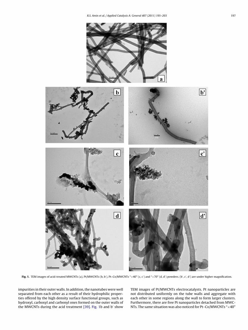
Fig. 1 shows the TEM images of the acid-treated MWCNTs,Pt/MWCNTs and Pt–Co/MWCNTs [“×40”, “×70”] electrocatalysts.It is observed from Fig. 1a that the acid-treated MWCNTs have no
R.S. Amin et al. / Applied Catalysis A: General 407 (2011) 195– 203 197
NTs “
istht
Fig. 1. TEM images of acid-treated MWCNTs (a), Pt/MWCNTs (b, b′), Pt–Co/MWC
mpurities in their outer walls. In addition, the nanotubes were well
eparated from each other as a result of their hydrophilic proper-ies offered by the high density surface functional groups, such asydroxyl, carboxyl and carbonyl ones formed on the outer walls ofhe MWCNTs during the acid treatment [39]. Fig. 1b and b′ show×40” (c, c′) and “×70” (d, d′) powders. (b′ , c′ , d′) are under higher magnification.
TEM images of Pt/MWCNTs electrocatalysts. Pt nanoparticles are
not distributed uniformly on the tube walls and aggregate witheach other in some regions along the wall to form larger clusters.Furthermore, there are free Pt nanoparticles detached from MWC-NTs. The same situation was also noticed for Pt–Co/MWCNTs “×40”
198 R.S. Amin et al. / Applied Catalysis A:
F[
eratsatfowb
3
PTptMoMpPgPdpibatdib[
3
“ct2(
ig. 2. XRD patterns of acid-treated MWCNTs, Pt/MWCNTs and Pt–Co/MWCNTs“×40”, “×70”] powders.
lectrocatalyst in Fig. 1c and c′ with metallic particle size in theange of 4–8 nm. However, a homogeneous distribution of smallnd dark dots of Pt–Co nanoparticles in Pt–Co/MWCNTs “×70” elec-rocatalyst is observed in Fig. 1d and d′. They are formed on theide walls of MWCNTs without any aggregation. No free particlesre detached from MWCNTs and a very narrow particle size dis-ribution is displayed with an average value of 2–5 nm. It is clearrom TEM analysis that NaBH4 concentration affects the morphol-gy, the size and the distribution of the metal nanoparticles. Thisas confirmed by Hyun et al. [35] who prepared PtRu/C electrodes
y the impregnation method using NaBH4.
.2. XRD analysis
Fig. 2 shows XRD patterns of the acid-treated MWCNTs,t/MWCNTs and Pt–Co/MWCNTs [“×40”, “×70”] electrocatalysts.he acid-treated MWCNTs exhibited characteristic diffractioneaks at 2� = 26.4◦, 44.4◦ and 54.6◦. These peaks can be attributedo the hexagonal graphite structures (0 0 2), (1 0 0) and (0 0 4) of the
WCNTs [40]. The formation of a sharp diffraction peak at 2� valuef 26.4◦ indicates the crystalline nature of graphitic structure of theWCNTs. After the reductive deposition process, these diffraction
eaks have substantially diminished indicating the formation oft and Pt–Co electrocatalysts on the MWCNTs surfaces. The newenerated diffraction peaks correspond to Pt(1 1 1), Pt(2 0 0) andt(2 2 0) with Pt-rich f.c.c. phases. The shift of Pt(1 1 1) and Pt(2 0 0)iffraction lines to higher 2� values in the Co-containing sam-les confirms the formation of bimetallic Pt–Co particles [41]. The
ncorporation of Co tends to contract the Pt lattice. Moreover, theroadening nature of their corresponding XRD patterns predictsn amorphous structure with relatively smaller sized Pt–Co par-icles compared to the Pt ones. This is in a good agreement withata obtained from TEM analysis. In fact, the peaks correspond-
ng to metallic Co or Co oxides were absent. However, they maye present in a very small amount or even in an amorphous form42].
.3. EDX analysis
The EDX spectra of Pt/MWCNTs and Pt–Co/MWCNTs [“×40”,×70”] electrocatalysts were represented in Fig. 3. Generally, it
an be seen that Pt and Co are the major elements. Table 1 showsheir atomic ratios with a total metal loading in the range of1–25 wt.% which approaches the theoretically calculated value30 wt.%). NaBH4 was used as a reducing agent; therefore, it isGeneral 407 (2011) 195– 203
predicted that as its amount increases, more metal nanoparticleswill be deposited on multi-walled carbon nanotubes to increasethe total metal loading. However, this is not definitely apparentin our study. Here, varying NaBH4 concentration mainly affectsthe weight ratio of Pt to Co. Lower amount of the reducing agentfavours the deposition of higher weight percentage of Co at theexpense of the loading of Pt as presented in Table 1. Hyun et al.[35] concluded that rich Ru samples in PtRu/C electrodes were pre-pared by adding lower NaBH4 concentrations as a result of thepriority reduction sequence of Ru to Pt. Moreover, Pt:Co atomicration in Pt–Co/MWCNTs “×70” sample was approximately 1:1.5that resembles the nominal ratio of 1:1.
3.4. Electrocatalytic activity of Pt/MWCNTs and Pt–Co/MWCNTselectrocatalysts
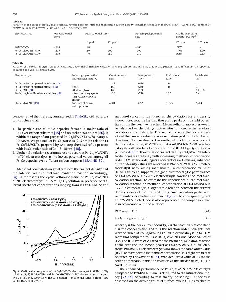
Fig. 4 shows the cyclic voltammograms of Pt/MWCNTs andPt–Co/MWCNTs “×70” electrodes in a solution of 0.5 M H2SO4containing 0.3 M methanol. They were recorded at a scan rate of10 mV s−1 in the potential range from −700 to +1300 mV (MMS).For comparison, the cyclic voltammogram of Pt/MWCNTs catalystis scanned in 0.5 M H2SO4 solution (see the dotted curve). A clearanodic scan of Pt/MWCNTs electrocatalyst was noticed in 0.5 MH2SO4 solution. On adding methanol, an oxidation peak appearsat a potential value of +80 mV. As a result of methanol oxidation,Pt–COads would be formed to poison the catalyst surface and reduceits activity in the subsequent cyclic voltammogram. The comingequations can summarize this reaction [43]:
Pt + CH3OH → Pt–COads + 4H+ + 4e− (1)
CH3OH + H2O → CO2 + 6H+ + 6e− (2)
Methanol is reoxidized in the reverse scan in a little peak at apotential value of −300 mV as a result of the removal of CO poisons[44] as follows:
Pt–COads + H2O → Pt + CO2 + 2H+ + 2e− (3)
At Pt–Co/MWCNTs “×70” electrocatalyst, the methanol oxida-tion peak current density records an increment by 4.5 times thatat Pt/MWCNTs one. This is accompanied by a potential shift in thenegative direction by 80 mV. An additional oxidation peak was alsoshown at Pt–Co/MWCNTs “×70” electrocatalyst at a potential valueof +550 mV (MMS). It corresponds to the oxidation of methanolintermediates. Moreover, the onset potential of the methanol oxi-dation reaction at Pt/MWCNTs electrode is −120 mV, compared toa value of −350 mV at Pt–Co/MWCNTs “×70” one. It is generallyrecognized that the onset potential can be an indicator in deter-mining the electrochemical activity of the electrocatalyst towardsthe methanol oxidation reaction [45,46]. This improvement atPt–Co/MWCNTs “×70” electrocatalyst may be explained by the factthat alloying cobalt together with Pt lowers the electronic bindingenergy to enhance the C–H cleavage reaction at a lower poten-tial value. Additionally, CO oxidation reaction is facilitated by thepresence of cobalt oxide [47].
The electrocatalytic activity of Pt–Co/MWCNTs “×40” electrodewas also examined. As listed in Table 2a, it shows much lower oxi-dation current density values [1.09 and 1.60 mA cm−2 at the firstand the second oxidation peaks, respectively]. Its activity is evenlower than that at Pt/MWCNTs electrode. Its oxidation peak poten-tial is also shifted in the positive direction by 110 and 50 mV atthe first and the second oxidation peaks, respectively, compared tothose at Pt–Co/MWCNTs “×70” electrocatalyst. However, methanol
oxidation reaction starts early at Pt–Co/MWCNTs “×40” electrode[−225 mV] relative to that at Pt/MWCNTs one [−120 mV]. Methanolis also reoxidized at the lowest potential value [−200 mV] amongthe prepared Pt/MWCNTs [−300 mV] and Pt–Co/MWCNTs “×70”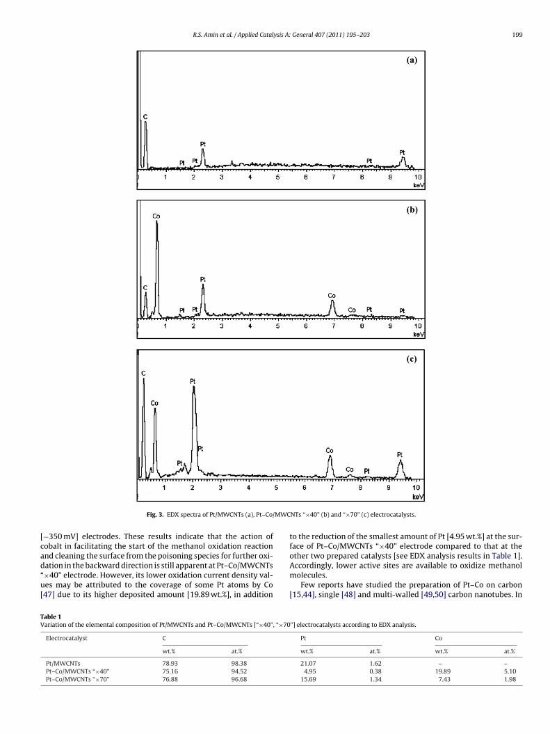
R.S. Amin et al. / Applied Catalysis A: General 407 (2011) 195– 203 199
MWC
[cad“u[
TV
Fig. 3. EDX spectra of Pt/MWCNTs (a), Pt–Co/
−350 mV] electrodes. These results indicate that the action ofobalt in facilitating the start of the methanol oxidation reactionnd cleaning the surface from the poisoning species for further oxi-
ation in the backward direction is still apparent at Pt–Co/MWCNTs×40” electrode. However, its lower oxidation current density val-es may be attributed to the coverage of some Pt atoms by Co47] due to its higher deposited amount [19.89 wt.%], in additionable 1ariation of the elemental composition of Pt/MWCNTs and Pt–Co/MWCNTs [“×40”, “×70
Electrocatalyst C
wt.% at.%
Pt/MWCNTs 78.93 98.38
Pt–Co/MWCNTs “×40” 75.16 94.52
Pt–Co/MWCNTs “×70” 76.88 96.68
NTs “×40” (b) and “×70” (c) electrocatalysts.
to the reduction of the smallest amount of Pt [4.95 wt.%] at the sur-face of Pt–Co/MWCNTs “×40” electrode compared to that at theother two prepared catalysts [see EDX analysis results in Table 1].
Accordingly, lower active sites are available to oxidize methanolmolecules.Few reports have studied the preparation of Pt–Co on carbon[15,44], single [48] and multi-walled [49,50] carbon nanotubes. In
”] electrocatalysts according to EDX analysis.
Pt Co
wt.% at.% wt.% at.%
21.07 1.62 – –4.95 0.38 19.89 5.10
15.69 1.34 7.43 1.98
200 R.S. Amin et al. / Applied Catalysis A: General 407 (2011) 195– 203
Table 2aVariation of the onset potential, peak potential, reverse peak potential and anodic peak current density of methanol oxidation in (0.3 M MeOH + 0.5 M H2SO4) solution atPt/MWCNTs and Pt–Co/MWCNTs [“×40”, “×70”] electrocatalysts.
Electrocatalyst Onset potential(mV)
Peak potential (mV) Reverse peak potential(mV)
Anodic peak currentdensity (mA cm−2)
1st peak 2nd peak 1st peak 2nd peak
Pt/MWCNTs −120 80 – −300 3.75 –Pt–Co/MWCNTs “×40” −225 110 600 −200 1.09 1.60Pt–Co/MWCNTs “×70” −350 0 550 −350 16.94 13.13
Table 2bVariation of the reducing agent, onset potential, peak potential of methanol oxidation in H2SO4 solution and Pt:Co molar ratio and particle size at different Pt–Co supportedon carbon and CNTs electrocatalysts.
Electrocatalyst Reducing agent in theimpregnation method
Onset potential(mV)
Peak potential(mV)
Pt:Co molarratio
Particle size(nm)
Pt–Co/carbon supported membrane [44] – −45 +460 1:1 –Pt–Co/carbon supported catalyst [15] NaBH4 −160 +260 1:1 3.7Pt–Co/CNTs [50] ethylene glycol −160 +100 – 3.2–3.6Pt–Co/single wall carbon nanotubes [48] mixed reducing agents
“NaBH4 and ethylene−30 +220 10:7 5.4
−301
cc
1
2
tF“f
Fstt
glycol”Pt–Co/MWCNTs [49] two-step chemical
reflux process
omparison of their results, summarized in Table 2b, with ours, wean conclude that:
. The particle size of Pt–Co deposits, formed in molar ratio of1:1 over carbon substrate [15] and on carbon nanotubes [50], iswithin the range of our prepared Pt–Co/MWCNTs “×70” sample.However, we got smaller Pt–Co particles [2–5 nm] in relation toPt–Co/MWCNTs, prepared by two-step chemical reflux processwith Pt:Co molar ratio of 3:1 [5–10 nm] [49].
. Methanol oxidation reaction starts and occurs at Pt–Co/MWCNTs“×70” electrocatalyst at the lowest potential values among allPt–Co deposits over different carbon supports [15,44,48–50].
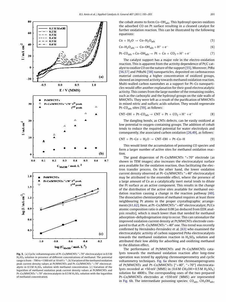
Methanol concentration greatly affects the current density and
he potential values of methanol oxidation reaction. Accordingly,ig. 5a represents the cyclic voltammograms of Pt–Co/MWCNTs×70” electrocatalyst in 0.5 M H2SO4 solution in presence of dif-erent methanol concentrations ranging from 0.1 to 0.6 M. As theig. 4. Cyclic voltammograms of (1) Pt/MWCNTs electrocatalyst in 0.5 M H2SO4
olution. (2, 3) Pt/MWCNTs and Pt–Co/MWCNTs “×70” electrocatalysts, respec-ively in (0.3 M MeOH + 0.5 M H2SO4) solution. The potential range is from −700o +1300 mV at 10 mV s−1.
+259 75:25 5–10
methanol concentration increases, the oxidation current densityvalues increase at the first and the second peaks with a slight poten-tial shift in the positive direction. More methanol molecules wouldbe adsorbed on the catalyst active sites to increase the resultingoxidation current density. This would increase the current den-sity of the corresponding reverse oxidation peak in the backwarddirection. The variation of the methanol oxidation peak currentdensity values at Pt/MWCNTs and Pt–Co/MWCNTs “×70” electro-catalysts with methanol concentration in 0.5 M H2SO4 solution isplotted in Fig. 5b. The oxidation current density at Pt/MWCNTs elec-trode increases gradually with increasing methanol concentrationup to 0.3 M, afterwards, it gets a constant value. However, enhancedcurrent density values are recorded at Pt–Co/MWCNTs “×70” elec-trocatalyst with adding methanol till a concentration value of0.6 M. This trend supports the good electrocatalytic performanceof Pt–Co/MWCNTs “×70” electrocatalyst towards the methanoloxidation reaction. To estimate the dependence of the methanoloxidation reaction on methanol concentration at Pt–Co/MWCNTs“×70” electrocatalyst, a logarithmic relation between the currentdensity values of the first and the second oxidation peaks withmethanol concentration is shown in Fig. 5c. The corresponding plotat Pt/MWCNTs electrode is also represented for comparison. Thisis in accordance with the relation:
Rate ≡ Ip = kCn (4a)
log Ip = log k + n log C (4b)
where Ip is the peak current density, k is the reaction rate constant,C is the concentration and n is the reaction order. Straight lineswere obtained at Pt–Co/MWCNTs “×70” electrocatalyst up to 0.6 Mmethanol compared to 0.3 M at Pt/MWCNTs one. Slope values of0.75 and 0.62 were calculated for the methanol oxidation reactionat the first and the second peaks at Pt–Co/MWCNTs “×70” elec-trode. Pt/MWCNTs electrocatalyst also shows the same order value[0.75] with respect to methanol concentration. It is higher than thatobtained by Tripkovic et al. [51] who deduced a value of 0.5 for theorder of methanol oxidation reaction at the surface of Pt(1 0 0) inNaOH solution.
The enhanced performance of Pt–Co/MWCNTs “×70” catalystcompared to Pt/MWCNTs one is attributed to the bifunctional the-ory [52–54]. According to that theory, poisoning CO species isadsorbed on the active sites of Pt surface, while OH is attached to
R.S. Amin et al. / Applied Catalysis A:
Fig. 5. (a) Cyclic voltammograms of Pt–Co/MWCNTs “×70” electrocatalyst in 0.5 MH2SO4 solution in presence of different concentrations of methanol. The potentialrange is from −700 to +1300 mV at 10 mV s−1. (b) Variation of the methanol oxidationpeak current density values at Pt/MWCNTs and Pt–Co/MWCNTs “×70” electrocat-alysts in 0.5 M H2SO4 solution with methanol concentration. (c) Variation of thelogarithm of methanol oxidation peak current density values at Pt/MWCNTs andPt–Co/MWCNTs “×70” electrocatalysts in 0.5 M H2SO4 solution with the logarithmof methanol concentration.
General 407 (2011) 195– 203 201
the cobalt atoms to form Co–OHads. This hydroxyl species oxidizesthe adsorbed CO on Pt surface resulting in a cleaned catalyst forfurther oxidation reaction. This can be illustrated by the followingequations:
Co + H2O → Co–H2Oads (5)
Co–H2Oads → Co–OHads + H+ + e− (6)
Pt–COads + Co–OHads → Pt + Co + CO2 + H+ + e− (7)
The catalyst support has a major role in the electro-oxidationreaction. This is apparent from the activity dependence of Pt/C cat-alyst to oxidize CO on the nature of the support [55]. Moreover, PtRu[56,57] and PtRuNi [58] nanoparticles, deposited on carbonaceousmaterial containing a higher concentration of oxidized groups,showed an improved activity towards methanol oxidation reaction.Multi-walled carbon nanotubes as a support for Pt–Co nanoparti-cles would offer another explanation for their good electrocatalyticactivity. This comes from the large number of the remaining oxides,such as the carboxylic and the hydroxyl groups on the side walls ofMWCNTs. They were left as a result of the purification of MWCNTsin mixed nitric and sulfuric acids solution. They would regeneratePt–COads sites [59], as follows:
CNT–OH + Pt–COads → CNT + Pt + CO2 + H+ + e− (8)
The dangling bonds, as CNTs defects, can be easily oxidized atlow potential to oxygen-containing groups. The addition of cobalttends to reduce the required potential for water electrolysis andconsequently, the associated carbon oxidation [26,49], as follows:
CNT + Pt–Co + H2O → CNT–OH + Pt–Co–H (9)
This would limit the accumulation of poisoning CO species andform a larger number of active sites for methanol oxidation reac-tion.
The good dispersion of Pt–Co/MWCNTs “×70” electrode (asshown in TEM images) also increases the electrocatalyst surfacearea available for the oxidation reaction, thus facilitating the elec-tron transfer process. On the other hand, the lower oxidationcurrent density observed at Pt–Co/MWCNTs “×40” electrocatalystmay be attributed to the ensemble effect, where the presence ofa large amount of Co as a catalytically inert metal tends to dilutethe Pt surface as an active component. This results in the changeof the distribution of the active sites available for methanol oxi-dation reaction causing a change in the reaction pathway [60].The dissociative chemisorption of methanol requires at least threeneighbouring Pt atoms in the proper crystallographic arrange-ments [61,62]. Here, at Pt–Co/MWCNTs “×40” electrocatalyst, Pt/Coatomic composition ratio is about 0.08 [as deduced from EDX anal-ysis results], which is much lower than that needed for methanoladsorption–dehydrogenation step to occur. This can rationalize theimproved oxidation current density at Pt/MWCNTs electrode com-pared to that at Pt–Co/MWCNTs “×40” one. This trend was recentlyconfirmed by Hernández-Fernández et al. [63] who examined theelectrocatalytic activity of carbon supported PtAu electrocatalyststowards the methanol oxidation reaction in H2SO4 solution andattributed their low ability for adsorbing and oxidizing methanolto the dilution effect.
The performance of Pt/MWCNTs and Pt–Co/MWCNTs cata-lysts towards the methanol oxidation reaction after long-timeoperation was tested by applying chronoamperometry and cyclicvoltammetry techniques. Fig. 6a shows the chronoamperogramsof Pt/MWCNTs and Pt–Co/MWCNTs [“×40”, “×70”] electrocata-
lysts recorded at +50 mV (MMS) in (0.6 M CH3OH + 0.5 M H2SO4)solution for 4800 s. The corresponding ones of the two preparedPt–Co/MWCNTs electrodes at +550 mV (MMS) are representedin Fig. 6b. The intermediate poisoning species: COads, CH3OHads,
202 R.S. Amin et al. / Applied Catalysis A: General 407 (2011) 195– 203
Fig. 6. Chronoamperograms of (a) Pt/MWCNTs and Pt–Co/MWCNTs [“×40”, “×70”]electrocatalysts at a potential value of +50 mV, (b) Pt–Co/MWCNTs ones at a poten-t
at[am“rP
so(oweoaaicroalig
[
[[
[[14] J. Zeng, J.Y. Lee, Int. J. Hydrogen Energy 32 (2007) 4389–4396.[15] J. Zeng, J.Y. Lee, J. Power Sources 140 (2005) 268–273.
ial value of +550 mV in (0.6 M MeOH + 0.5 M H2SO4) solution.
nd CHOads, formed during the methanol oxidation reaction tendso decrease the resulting current density at all electrocatalysts64]. After long-time operation, a steady state current density ischieved. It can be also observed that Pt/MWCNTs electrocatalystaintained a slightly higher current density than Pt–Co/MWCNTs
×40” one did, which is consistent with the cyclic voltammet-ic results. The highest steady state current density is gained att–Co/MWCNTs “×70” electrocatalyst.
The electrocatalyst stability over repeated cyclization repre-ents another factor to evaluate its performance after long-timeperation. Pt–Co/MWCNTs “×70” electrocatalyst was scanned in0.6 M methanol + 0.5 M H2SO4) solution for 10 cycles at a scan ratef 10 mV s−1. Its estimated oxidation peaks current density valuesere plotted as a function of the cycle number in Fig. 7. In gen-
ral, a decrease of the methanol oxidation peak current density wasbserved with continuous cyclization. This may be attributed to theccumulation of poisonous species (such as COads) on Pt surfaces a result of methanol consumption during successive scans [65]n addition to the change of the surface structure of Pt nanoparti-les. This current density decay is calculated as 86.7 and 75.5% withespect to its value in the first cycle for the first and the secondxidation peaks, respectively. These efficiency percentage valuesre still higher than that at Pt/MWCNTs electrode [64.24%]. Afterong operation, cobalt is leached from the catalyst surface due to
ts corrosion in acidic solutions as deduced from the Pourbaix dia-ram [66]. These long-term performance results of Pt–Co/MWCNTs[
[
Fig. 7. Variation of the methanol oxidation peak current density values atPt–Co/MWCNTs “×70” electrocatalyst with the number of repeated cycles in (0.6 MMeOH + 0.5 M H2SO4) solution.
“×70” electrode support its capability to oxidize methanol withbetter cleaning to the catalyst surface.
4. Conclusion
Pt–Co supported multi-walled carbon nanotubes were synthe-sized with two different NaBH4 molar ratios using the impregnationmethod. Different surface composition, particle size and level ofdispersion were observed. On the basis of the cyclic voltammetryand chronoamperometry results, Pt–Co/MWCNTs “×70” catalystexhibited the highest electrochemical activity for methanol oxi-dation reaction in H2SO4 solution compared to Pt/MWCNTs andPt–Co/MWCNTs “×40” catalysts. Here, methanol oxidation reac-tion occurs at the lowest potential value among all the previouslyprepared Pt–Co deposits over different carbon supports. 0.75 and0.62 were the calculated reaction order values at the first and thesecond oxidation peaks at Pt–Co/MWCNTs “×70” electrocatalyst.Its long-term cycleability and CO tolerance can be attributed tothe bifunctional mechanism of bimetallic catalysts. Moreover, theremaining oxides on MWCNTs walls would help in regeneratingPt–COads sites.
References
[1] S. Basri, S.K. Kamarudin, W.R.W. Daud, Z. Yaakub, Int. J. Hydrogen Energy 35(2010) 7957–7970.
[2] J.S. Ye, H.F. Cui, Y. Wen, W.D. Zhang, G.Q. Xu, F.S. Sheu, Microchim. Acta 152(2006) 267–275.
[3] T.R. Ralph, M.P. Hogarth, Platinum Met. Rev. 46 (2002) 3–14.[4] A.S. Aricò, S. Srinivasan, V. Antonucci, Fuel Cells 1 (2001) 133–161.[5] A. Freund, J. Lang, T. Lehmann, K.A. Starz, Catal. Today 27 (1996) 279–283.[6] S. Gottesfeld, I.D. Raistrick, S. Srinivasan, J. Electrochem. Soc. 134 (1987)
1455–1462.[7] X. Ren, P. Zelenay, S. Thomas, J. Davey, S. Gottesfeld, J. Power Sources 86 (2000)
111–116.[8] B.D. McNicol, D.A.J. Rand, K.R. Williams, J. Power Sources 83 (1999) 15–31.[9] S. Wasmus, A. Küver, J. Electroanal. Chem. 461 (1999) 14–31.10] K. Kordesch, G. Simander, Fuel Cells and Their Application, VCH Verlagsge-
sellschaft, Weinheim, 1996, p. 151.11] M. Watanabe, Y. Zhu, H. Uchida, J. Phys. Chem. B 104 (2000) 1762–1768.12] T. Toda, H. Igarashi, H. Uchida, M. Watanabe, J. Electrochem. Soc. 146 (1999)
3750–3756.13] M. Watanabe, H. Igarashi, T. Fujino, Electrochemistry 67 (1999) 1194–1196.
16] M. Uchida, Y. Aoyama, M. Tanabe, N. Yanagihara, N. Eda, A. Ohta, J. Electrochem.Soc. 142 (1995) 2572–2576.
17] V. Selvaraj, M. Alagar, K.S. Kumar, Appl. Catal. B: Environ. 75 (2007) 129–138.
ysis A:
[
[
[
[[
[
[
[[[
[
[[
[[[
[
[
[
[
[[[
[
[
[
[
[[[
[[[
[
[[[[
[
[
[
[
[[
[
[
R.S. Amin et al. / Applied Catal
18] J. Guo, G. Sun, Q. Wang, G. Wang, Z. Zhou, S. Tang, L. Jiang, B. Zhou, Q. Xin, Carbon44 (2006) 152–157.
19] R. Yang, X. Qiu, H. Zhang, J. Li, W. Zhu, Z. Wang, X. Huang, L. Chen, Carbon 43(2005) 11–16.
20] W. Li, C. Liang, W. Zhou, J. Qiu, H. Li, G. Sun, Q. Xin, Carbon 42 (2004)436–439.
21] K.W. Park, Y.E. Sung, J. Phys. Chem. B 108 (2004) 939–944.22] T. Yoshitake, Y. Shimakawa, S. Kuroshima, H. Kimura, T. Ichihashi, Y. Kubo,
D. Kasuya, K. Takahashi, F. Kokai, M. Yudasaka, S. Iijima, Physica B: Condens.Matter 323 (2002) 124–126.
23] T. Shuihua, S. Gongquan, Q. Jing, S. Shiguo, G. Junsong, X. Qin, G.M. Haarberg,Chin. J. Catal. 31 (2010) 12–17.
24] A.M. Zainoodin, S.K. Kamarudin, W.R.W. Daud, Int. J. Hydrogen Energy 35 (2010)4606–4621.
25] L. Li, Y. Xing, J. Electrochem. Soc. 153 (2006) A1823–A1828.26] Y. Shao, G. Yin, Y. Gao, P. Shi, J. Electrochem. Soc. 153 (2006) A1093–A1097.27] H. Liu, C. Song, L. Zhang, J. Zhang, H. Wang, D.P. Wilkinson, J. Power Sources 155
(2006) 95–110.28] K.I. Han, J.S. Lee, S.O. Park, S.W. Lee, Y.W. Park, H. Kim, Electrochim. Acta 50
(2004) 791–794.29] P. Serp, M. Corrias, P. Kalck, Appl. Catal. A: Gen. 253 (2003) 337–358.30] G. Girishkumar, K. Vinodgopal, D. Meisel, P.V. Kamat, J. Phys. Chem. B 108 (2004)
19960–19966.31] Y. Lin, X. Cui, C. Yen, C.M. Wai, J. Phys. Chem. B 109 (2005) 14410–14415.32] Z. Liu, J.Y. Lee, W. Chen, M. Han, L.M. Gan, Langmuir 20 (2004) 181–187.33] W. Li, C. Liang, J. Qiu, W. Zhou, H. Han, Z. Wei, G. Sun, Q. Xin, Carbon 40 (2002)
791–794.34] G. Che, B.B. Lakshmi, C.R. Martin, E.R. Fisher, Langmuir 15 (1999)
750–758.35] M.S. Hyun, S.K. Kim, B. Lee, D. Peck, Y. Shul, D. Jung, Catal. Today 132 (2008)
138–145.36] M.A. Etman, M.K. Bedewy, S.H.R. Ali, B.S. Azzam, Int. J. Nanopart. 2 (2009)
226–237.37] N. Sano, H. Wang, I. Alexandrou, M. Chhowalla, K.B.K. Teo, G.A.J. Amaratunga,
K. Iimura, J. Appl. Phys. 92 (2002) 2783–2788.38] J.-C. Charlier, J.-P. Michenaud, Phys. Rev. Lett. 70 (1993) 1858–1861.
39] H. Hu, B. Zhao, M.E. Itkis, R.C. Haddon, J. Phys. Chem. B 107 (2003) 13838–13842.40] W. Li, C. Liang, W. Zhou, J. Qiu, Z. Zhou, G. Sun, Q. Xin, J. Phys. Chem. B 107(2003) 6292–6299.41] J. Prabhuram, T.S. Zhao, Z.X. Liang, R. Chen, Electrochim. Acta 52 (2007)
2649–2656.
[
[[
General 407 (2011) 195– 203 203
42] E. Antolini, J.R.C. Salgado, R.M. da Silva, E.R. Gonzalez, Mater. Chem. Phys. 101(2007) 395–403.
43] C.H. Yen, K. Shimizu, Y.-Y. Lin, F. Bailey, I.F. Cheng, C.M. Wai, Energy Fuels 21(2007) 2268–2271.
44] T. Page, R. Johnson, J. Hormes, S. Noding, B. Rambabu, J. Electroanal. Chem. 485(2000) 34–41.
45] W. Chen, J. Kim, S. Sun, S. Chen, Langmuir 23 (2007) 11303–11310.46] Y. Lin, X. Cui, C.H. Yen, C.M. Wai, Langmuir 21 (2005) 11474–11479.47] E. Antolini, J.R.C. Salgado, E.R. Gonzalez, Appl. Catal. B: Environ. 63 (2006)
137–149.48] J. Shen, Y. Hu, C. Li, C. Qin, M. Ye, Electrochim. Acta 53 (2008) 7276–7280.49] C.-T. Hsieh, J.-Y. Lin, J. Power Sources 188 (2009) 347–352.50] P. Hernández-Fernández, M. Montiel, P. Ocón, J.L.G. Fierro, H. Wang, H.D.
Abruna, S. Rojas, J. Power Sources 195 (2010) 7959–7967.51] A.V. Tripkovic, K.Dj. Popovic, J.D. Momcilovic, D.M. Drazic, J. Electroanal. Chem.
448 (1998) 173–181.52] M. Krausa, W. Vielstich, J. Electroanal. Chem. 379 (1994) 307–314.53] G. Inzelt, J. Electroanal. Chem. 348 (1993) 465–471.54] M.W. Verbrugge, J. Electrochem. Soc. 136 (1989) 417–423.55] J.L. Gómez de la Fuente, S. Rojas, M.V. Martínez-Huerta, P. Terreros, M.A. Pena,
J.L.G. Fierro, Carbon 44 (2006) 1919–1929.56] J.L. Gómez de la Fuente, M.V. Martínez-Huerta, S. Rojas, P. Terreros, J.L.G. Fierro,
M.A. Pena, Catal. Today 116 (2006) 422–432.57] J.L. Gómez de la Fuente, M.V. Martínez-Huerta, S. Rojas, P. Terreros, J.L.G. Fierro,
M.A. Pena, Carbon 43 (2005) 3002–3005.58] M.V. Martínez-Huerta, S. Rojas, J.L. Gómez de la Fuente, P. Terreros, M.A. Pena,
J.L.G. Fierro, Appl. Catal. B: Environ. 69 (2006) 75–84.59] J. Chen, M. Wang, B. Liu, Z. Fan, K. Cui, Y. Kuang, J. Phys. Chem. B 110 (2006)
11775–11779.60] N.M. Markovic, P.N. Ross Jr., Surf. Sci. Rep. 45 (2002) 117–229.61] C. Lamy, A. Lima, V. LeRhun, F. Delime, C. Coutanceau, J.-M. Léger, J. Power
Sources 105 (2002) 283–296.62] H.A. Gasteiger, N. Markovic, P.N. Ross Jr., E.J. Cairns, Electrochim. Acta 39 (1994)
1825–1832.63] P. Hernández-Fernández, S. Rojas, P. Ocón, A. de Frutos, J.M. Figueroa, P. Ter-
reros, M.A. Pena, J.L.G. Fierro, J. Power Sources 177 (2008) 9–16.
64] A. Kabbabi, R. Faure, R. Durand, B. Beden, F. Hahn, J.-M. Léger, C. Lamy, J. Elec-troanal. Chem. 444 (1998) 41–53.65] M. Haruta, M. Daté, Appl. Catal. A: Gen. 222 (2001) 427–437.66] M. Pourbaix, Atlas of Electrochemical Equilibria in Aqueous Solutions, Perga-
mon Press, Brussels, 1963, p. 322.