prosimplus application example - methanol synthesis
TRANSCRIPT
Reader is reminded that this use case is only an example and should not be used for other purposes. Although this example is based on actual case it may not be considered as typical nor are the data used always the most accurate available. ProSim shall have no responsibility or liability for damages arising out of or related to the use of the results of calculations based on this example.
Copyright © 2018 ProSim, Labège, France – All rights reserved www.prosim.net
PROSIMPLUS APPLICATION EXAMPLE
METHANOL SYNTHESIS
EXAMPLE PURPOSE
This example illustrates the synthesis of methanol from a syngas. The syngas can be provided by a gasifier (e.g.
“PSPS_EX_EN - IGCC Plant”). The different steps are modeled: syngas compression reaction, flash purification
and then final distillation purification of the methanol produced. The synthesis reactor is modelled using Gibbs
energy minimization.
The particular points which are detailed in this example are the use of a Gibbs reactor, the modeling of the
distillation column condenser as an outside unit operation and the use of a “Calculator Switch” to change the
thermodynamic model in some part of the process.
ACCESS Free-Internet Restricted to ProSim clients Restricted Confidential
CORRESPONDING PROSIMPLUS FILE PSPS_EX_EN-Methanol-synthesis.pmp3
Methanol synthesis
Version: January 2018 Page: 2 / 15
Copyright © 2018 ProSim, Labège, France – All rights reserved www.prosim.net
TABLE OF CONTENTS
1. MODELING OF THE PROCESS 3
1.1. Process description 3
1.2. Process flowsheet 5
1.3. Components 6
1.4. Thermodynamic models 6
1.5. Operating conditions 7
1.5.1. Process feed 7
1.5.2. R101 reactor 7
1.5.3. Heat exchangers 8
1.5.4. Compressors 8
1.5.5. Flashs 8
1.5.6. Expansion valves 9
1.5.7. Calculator switch 9
1.5.8. C101 distillation column 9
1.5.9. Stream splitters 10
1.5.10. Mixers 10
1.6. Initializations 10
2. RESULTS 11
2.1. Mass and energy balances 11
2.2. Process performance 12
2.3. C101 column profiles 13
3. REFERENCES 15
Methanol synthesis
Version: January 2018 Page: 3 / 15
Copyright © 2018 ProSim, Labège, France – All rights reserved www.prosim.net
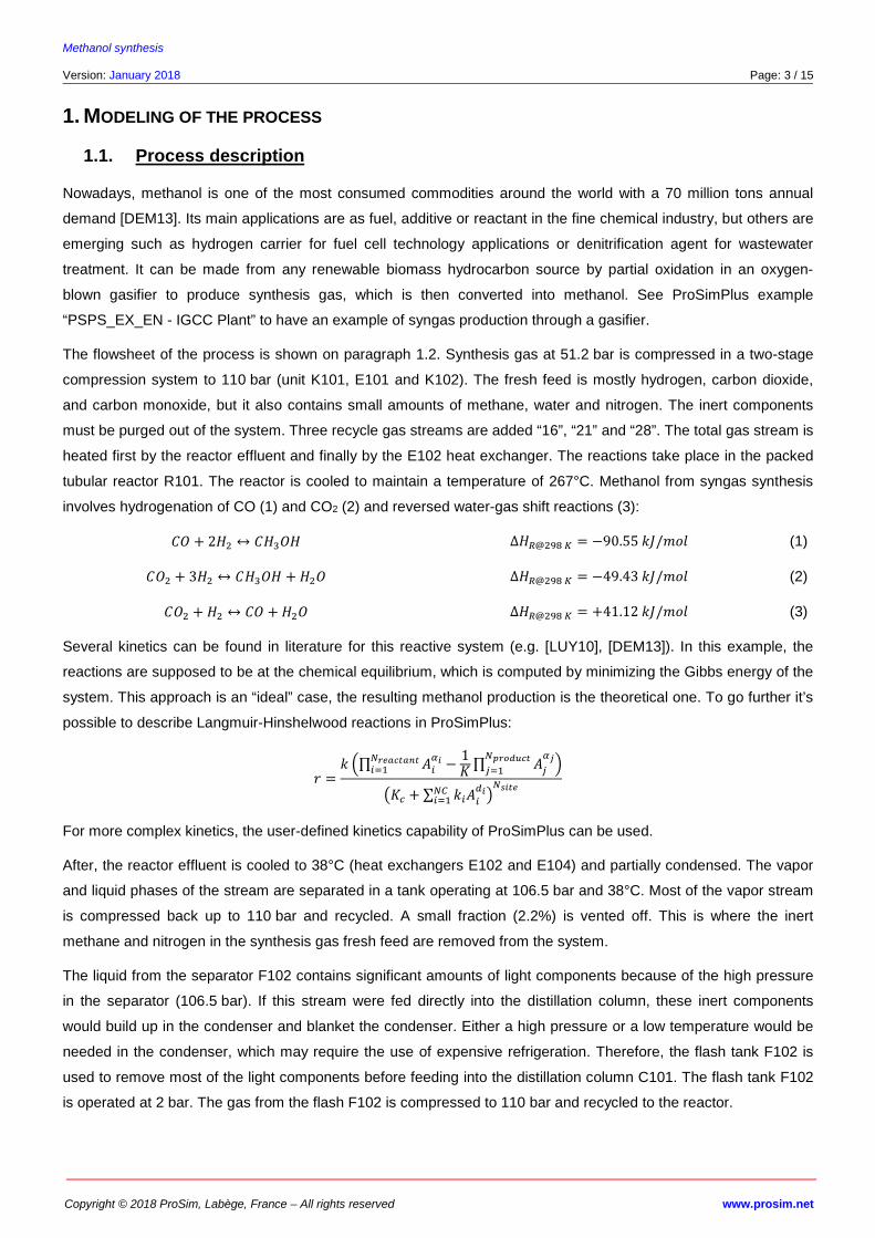
1. MODELING OF THE PROCESS
1.1. Process description
Nowadays, methanol is one of the most consumed commodities around the world with a 70 million tons annual
demand [DEM13]. Its main applications are as fuel, additive or reactant in the fine chemical industry, but others are
emerging such as hydrogen carrier for fuel cell technology applications or denitrification agent for wastewater
treatment. It can be made from any renewable biomass hydrocarbon source by partial oxidation in an oxygen-
blown gasifier to produce synthesis gas, which is then converted into methanol. See ProSimPlus example
“PSPS_EX_EN - IGCC Plant” to have an example of syngas production through a gasifier.
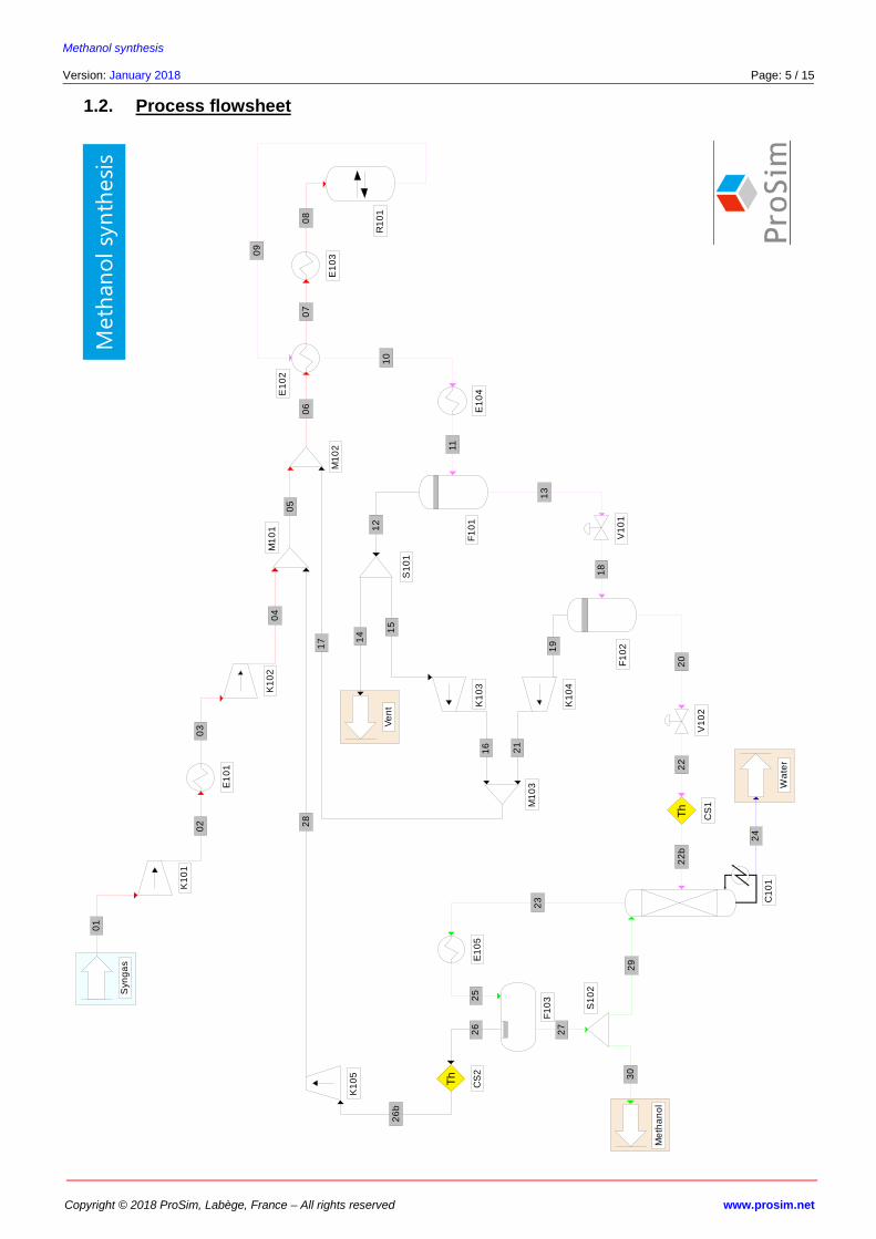
The flowsheet of the process is shown on paragraph 1.2. Synthesis gas at 51.2 bar is compressed in a two-stage
compression system to 110 bar (unit K101, E101 and K102). The fresh feed is mostly hydrogen, carbon dioxide,
and carbon monoxide, but it also contains small amounts of methane, water and nitrogen. The inert components
must be purged out of the system. Three recycle gas streams are added “16”, “21” and “28”. The total gas stream is
heated first by the reactor effluent and finally by the E102 heat exchanger. The reactions take place in the packed
tubular reactor R101. The reactor is cooled to maintain a temperature of 267°C. Methanol from syngas synthesis
involves hydrogenation of CO (1) and CO2 (2) and reversed water-gas shift reactions (3):
�� + 2�� ↔ ����� ∆��@��� � = −90.55 ��/��� (1)
��� + 3�� ↔ ����� + ��� ∆��@��� � = −49.43 ��/��� (2)
��� + �� ↔ �� + ��� ∆��@��� � = +41.12 ��/��� (3)
Several kinetics can be found in literature for this reactive system (e.g. [LUY10], [DEM13]). In this example, the
reactions are supposed to be at the chemical equilibrium, which is computed by minimizing the Gibbs energy of the
system. This approach is an “ideal” case, the resulting methanol production is the theoretical one. To go further it’s
possible to describe Langmuir-Hinshelwood reactions in ProSimPlus:
� =� �∏ ��
�� −1�
������������ ∏ �
�
�������������
�
��� + ∑ ��������
��� ������
For more complex kinetics, the user-defined kinetics capability of ProSimPlus can be used.
After, the reactor effluent is cooled to 38°C (heat exchangers E102 and E104) and partially condensed. The vapor
and liquid phases of the stream are separated in a tank operating at 106.5 bar and 38°C. Most of the vapor stream
is compressed back up to 110 bar and recycled. A small fraction (2.2%) is vented off. This is where the inert
methane and nitrogen in the synthesis gas fresh feed are removed from the system.
The liquid from the separator F102 contains significant amounts of light components because of the high pressure
in the separator (106.5 bar). If this stream were fed directly into the distillation column, these inert components
would build up in the condenser and blanket the condenser. Either a high pressure or a low temperature would be
needed in the condenser, which may require the use of expensive refrigeration. Therefore, the flash tank F102 is
used to remove most of the light components before feeding into the distillation column C101. The flash tank F102
is operated at 2 bar. The gas from the flash F102 is compressed to 110 bar and recycled to the reactor.
Methanol synthesis
Version: January 2018 Page: 4 / 15
Copyright © 2018 ProSim, Labège, France – All rights reserved www.prosim.net
The liquid from the flash tank F102 is pumped into the distillation column C101 (42-stages, feed on stage 27). This
column operates at 1 bar. Its objective is to obtain dehydrated methanol with few lights in it. There are three
specifications in this column:
0.01 mol % of methanol at the bottoms,
0.1 mol % of water at the liquid distillate,
Reflux-drum temperature at 50°C, which establishes the amount of vapor that must be removed from the
top of the reflux drum for compression and recycle.
The condenser of the column is modeled as a separated unit operation: heat exchanger E105, reflux drum F103
and splitter S102. By this way it’s easier to control the temperature of the condenser.
This example is adapted from [LUY10] and [DEM13].
Methanol synthesis
Version: January 2018 Page: 5 / 15
Copyright © 2018 ProSim, Labège, France – All rights reserved www.prosim.net
1.2. Process flowsheet S
yn
ga
s
K1
01
01
E1
01
02
K1
02
03
M1
01
04
M1
02
05
06
E1
03
07
R1
01
08
09
E1
04
10
F1
01
11
Ve
nt
12
13
F1
02
20
19
K1
04
K1
03
S1
01
14 1
5
16
M1
03
17
21
V1
01
18
V1
02
Wa
ter
Me
tha
no
l
E1
05
C1
01
F1
03
S1
02
22
24
23
25
27
29
30
Th
CS
1
Th
CS
2
K1
05
26
26
b
28
E1
02
22
b
Meth
ano
l sy
nth
esi
s
Methanol synthesis
Version: January 2018 Page: 6 / 15
Copyright © 2018 ProSim, Labège, France – All rights reserved www.prosim.net
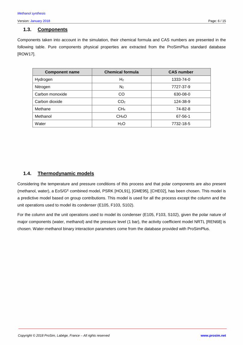
1.3. Components
Components taken into account in the simulation, their chemical formula and CAS numbers are presented in the
following table. Pure components physical properties are extracted from the ProSimPlus standard database
[ROW17].
Component name Chemical formula CAS number
Hydrogen H2 1333-74-0
Nitrogen N2 7727-37-9
Carbon monoxide CO 0630-08-0
Carbon dioxide CO2 0124-38-9
Methane CH4 0074-82-8
Methanol CH4O 0067-56-1
Water H2O 7732-18-5
1.4. Thermodynamic models
Considering the temperature and pressure conditions of this process and that polar components are also present
(methanol, water), a EoS/GE combined model, PSRK [HOL91], [GME95], [CHE02], has been chosen. This model is
a predictive model based on group contributions. This model is used for all the process except the column and the
unit operations used to model its condenser (E105, F103, S102).
For the column and the unit operations used to model its condenser (E105, F103, S102), given the polar nature of
major components (water, methanol) and the pressure level (1 bar), the activity coefficient model NRTL [REN68] is
chosen. Water-methanol binary interaction parameters come from the database provided with ProSimPlus.
Methanol synthesis
Version: January 2018 Page: 7 / 15
Copyright © 2018 ProSim, Labège, France – All rights reserved www.prosim.net
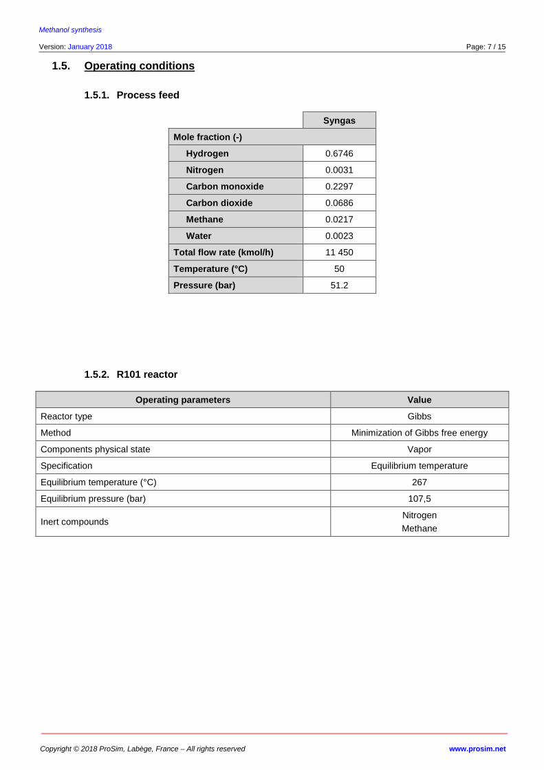
1.5. Operating conditions
1.5.1. Process feed
Syngas
Mole fraction (-)
Hydrogen 0.6746
Nitrogen 0.0031
Carbon monoxide 0.2297
Carbon dioxide 0.0686
Methane 0.0217
Water 0.0023
Total flow rate (kmol/h) 11 450
Temperature (°C) 50
Pressure (bar) 51.2
1.5.2. R101 reactor
Operating parameters Value
Reactor type Gibbs
Method Minimization of Gibbs free energy
Components physical state Vapor
Specification Equilibrium temperature
Equilibrium temperature (°C) 267
Equilibrium pressure (bar) 107,5
Inert compounds Nitrogen
Methane
Methanol synthesis
Version: January 2018 Page: 8 / 15
Copyright © 2018 ProSim, Labège, France – All rights reserved www.prosim.net
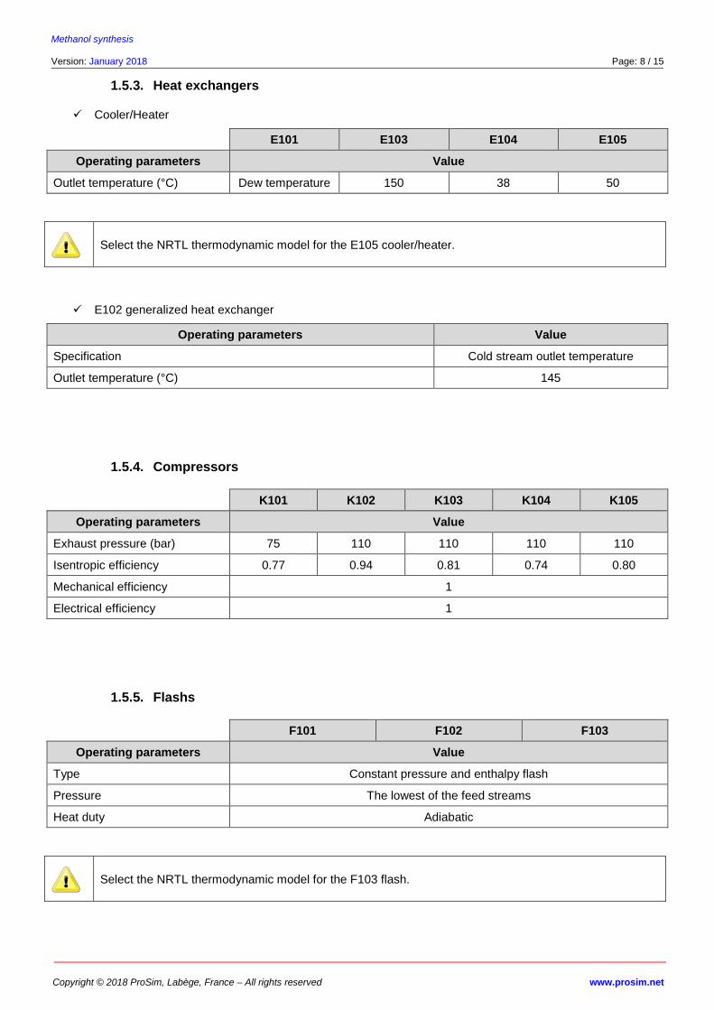
1.5.3. Heat exchangers
Cooler/Heater
E101 E103 E104 E105
Operating parameters Value
Outlet temperature (°C) Dew temperature 150 38 50
Select the NRTL thermodynamic model for the E105 cooler/heater.
E102 generalized heat exchanger
Operating parameters Value
Specification Cold stream outlet temperature
Outlet temperature (°C) 145
1.5.4. Compressors
K101 K102 K103 K104 K105
Operating parameters Value
Exhaust pressure (bar) 75 110 110 110 110
Isentropic efficiency 0.77 0.94 0.81 0.74 0.80
Mechanical efficiency 1
Electrical efficiency 1
1.5.5. Flashs
F101 F102 F103
Operating parameters Value
Type Constant pressure and enthalpy flash
Pressure The lowest of the feed streams
Heat duty Adiabatic
Select the NRTL thermodynamic model for the F103 flash.
Methanol synthesis
Version: January 2018 Page: 9 / 15
Copyright © 2018 ProSim, Labège, France – All rights reserved www.prosim.net
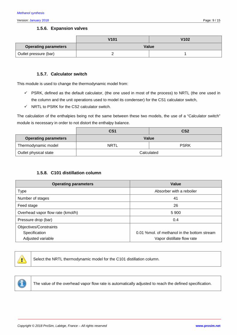
1.5.6. Expansion valves
V101 V102
Operating parameters Value
Outlet pressure (bar) 2 1
1.5.7. Calculator switch
This module is used to change the thermodynamic model from:
PSRK, defined as the default calculator, (the one used in most of the process) to NRTL (the one used in
the column and the unit operations used to model its condenser) for the CS1 calculator switch,
NRTL to PSRK for the CS2 calculator switch.
The calculation of the enthalpies being not the same between these two models, the use of a “Calculator switch”
module is necessary in order to not distort the enthalpy balance.
CS1 CS2
Operating parameters Value
Thermodynamic model NRTL PSRK
Outlet physical state Calculated
1.5.8. C101 distillation column
Operating parameters Value
Type Absorber with a reboiler
Number of stages 41
Feed stage 26
Overhead vapor flow rate (kmol/h) 5 900
Pressure drop (bar) 0.4
Objectives/Constraints
Specification
Adjusted variable
0.01 %mol. of methanol in the bottom stream
Vapor distillate flow rate
Select the NRTL thermodynamic model for the C101 distillation column.
The value of the overhead vapor flow rate is automatically adjusted to reach the defined specification.
Methanol synthesis
Version: January 2018 Page: 10 / 15
Copyright © 2018 ProSim, Labège, France – All rights reserved www.prosim.net
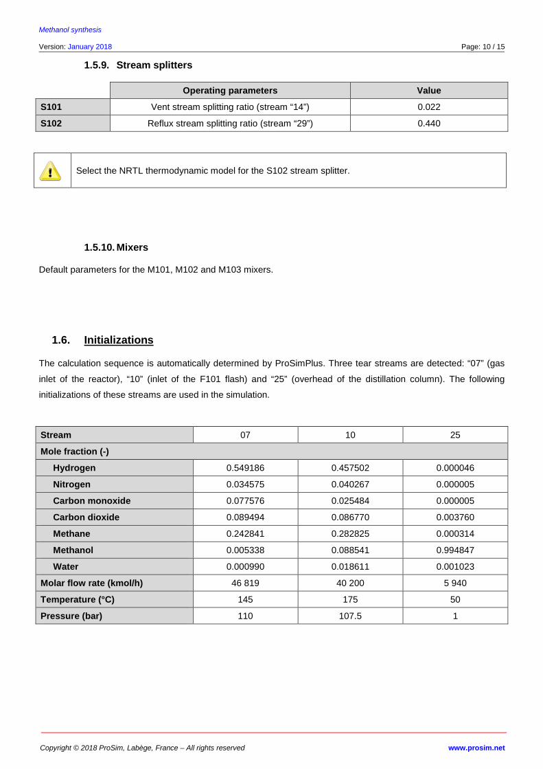
1.5.9. Stream splitters
Operating parameters Value
S101 Vent stream splitting ratio (stream “14”) 0.022
S102 Reflux stream splitting ratio (stream “29”) 0.440
Select the NRTL thermodynamic model for the S102 stream splitter.
1.5.10. Mixers
Default parameters for the M101, M102 and M103 mixers.
1.6. Initializations
The calculation sequence is automatically determined by ProSimPlus. Three tear streams are detected: “07” (gas
inlet of the reactor), “10” (inlet of the F101 flash) and “25” (overhead of the distillation column). The following
initializations of these streams are used in the simulation.
Stream 07 10 25
Mole fraction (-)
Hydrogen 0.549186 0.457502 0.000046
Nitrogen 0.034575 0.040267 0.000005
Carbon monoxide 0.077576 0.025484 0.000005
Carbon dioxide 0.089494 0.086770 0.003760
Methane 0.242841 0.282825 0.000314
Methanol 0.005338 0.088541 0.994847
Water 0.000990 0.018611 0.001023
Molar flow rate (kmol/h) 46 819 40 200 5 940
Temperature (°C) 145 175 50
Pressure (bar) 110 107.5 1
Methanol synthesis
Version: January 2018 Page: 11 / 15
Copyright © 2018 ProSim, Labège, France – All rights reserved www.prosim.net
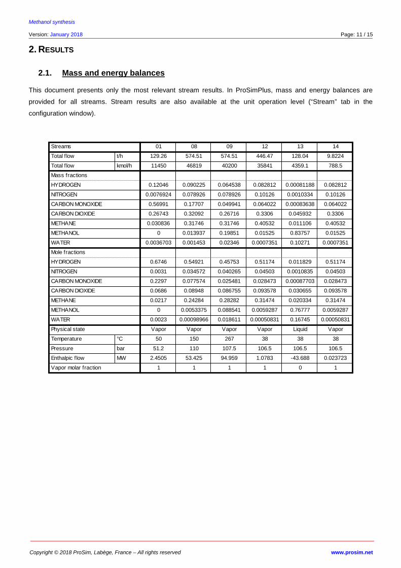
2. RESULTS
2.1. Mass and energy balances
This document presents only the most relevant stream results. In ProSimPlus, mass and energy balances are
provided for all streams. Stream results are also available at the unit operation level (“Stream” tab in the
configuration window).
Streams
Total f low t/h
Total f low kmol/h
Mass fractions
HYDROGEN
NITROGEN
CARBON MONOXIDE
CARBON DIOXIDE
METHANE
METHANOL
WATER
Mole fractions
HYDROGEN
NITROGEN
CARBON MONOXIDE
CARBON DIOXIDE
METHANE
METHANOL
WATER
Physical state
Temperature °C
Pressure bar
Enthalpic f low MW
Vapor molar fraction
01
129.26
11450
0.12046
0.0076924
0.56991
0.26743
0.030836
0
0.0036703
0.6746
0.0031
0.2297
0.0686
0.0217
0
0.0023
Vapor
50
51.2
2.4505
1
08
574.51
46819
0.090225
0.078926
0.17707
0.32092
0.31746
0.013937
0.001453
0.54921
0.034572
0.077574
0.08948
0.24284
0.0053375
0.00098966
Vapor
150
110
53.425
1
09
574.51
40200
0.064538
0.078926
0.049941
0.26716
0.31746
0.19851
0.02346
0.45753
0.040265
0.025481
0.086755
0.28282
0.088541
0.018611
Vapor
267
107.5
94.959
1
12
446.47
35841
0.082812
0.10126
0.064022
0.3306
0.40532
0.01525
0.0007351
0.51174
0.04503
0.028473
0.093578
0.31474
0.0059287
0.00050831
Vapor
38
106.5
1.0783
1
13
128.04
4359.1
0.00081188
0.0010334
0.00083638
0.045932
0.011106
0.83757
0.10271
0.011829
0.0010835
0.00087703
0.030655
0.020334
0.76777
0.16745
Liquid
38
106.5
-43.688
0
14
9.8224
788.5
0.082812
0.10126
0.064022
0.3306
0.40532
0.01525
0.0007351
0.51174
0.04503
0.028473
0.093578
0.31474
0.0059287
0.00050831
Vapor
38
106.5
0.023723
1
Methanol synthesis
Version: January 2018 Page: 12 / 15
Copyright © 2018 ProSim, Labège, France – All rights reserved www.prosim.net
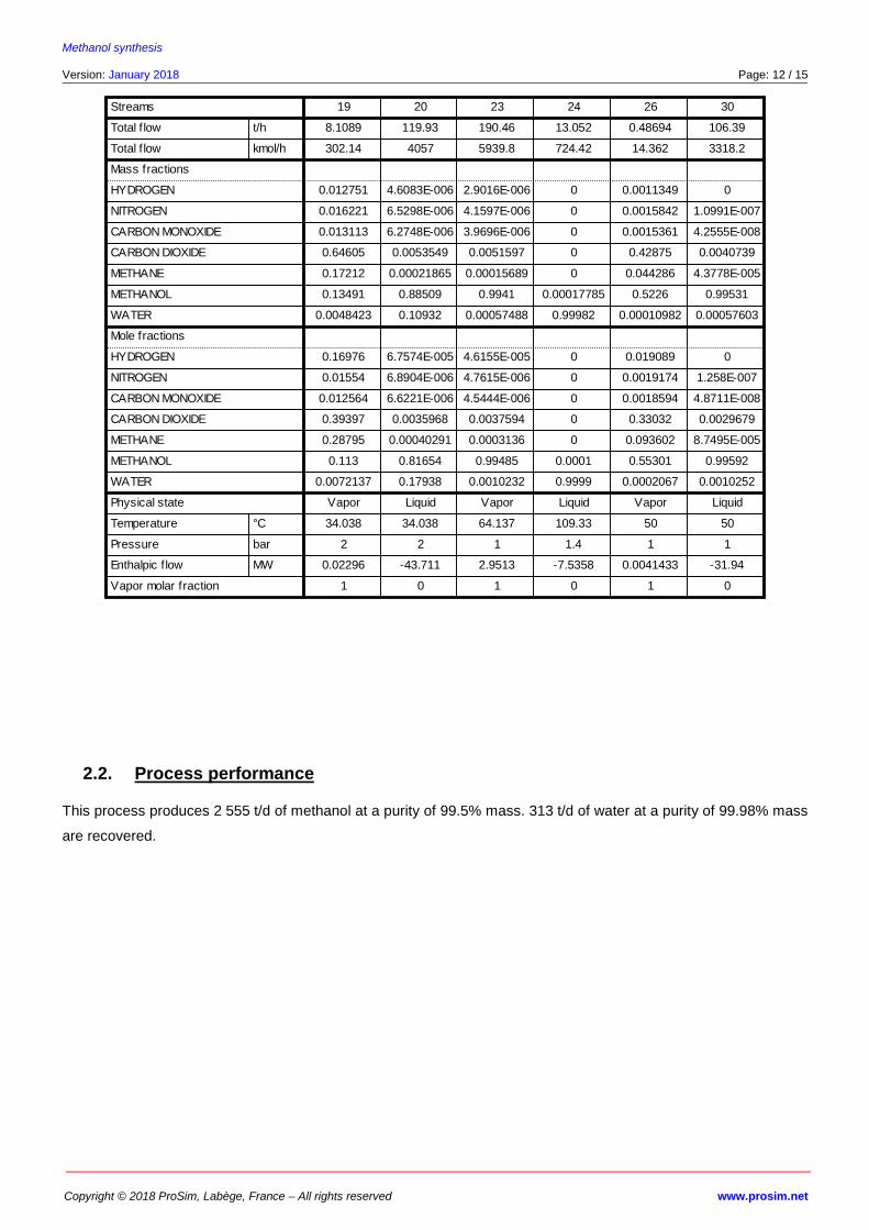
2.2. Process performance
This process produces 2 555 t/d of methanol at a purity of 99.5% mass. 313 t/d of water at a purity of 99.98% mass
are recovered.
Streams
Total f low t/h
Total f low kmol/h
Mass fractions
HYDROGEN
NITROGEN
CARBON MONOXIDE
CARBON DIOXIDE
METHANE
METHANOL
WATER
Mole fractions
HYDROGEN
NITROGEN
CARBON MONOXIDE
CARBON DIOXIDE
METHANE
METHANOL
WATER
Physical state
Temperature °C
Pressure bar
Enthalpic f low MW
Vapor molar fraction
19
8.1089
302.14
0.012751
0.016221
0.013113
0.64605
0.17212
0.13491
0.0048423
0.16976
0.01554
0.012564
0.39397
0.28795
0.113
0.0072137
Vapor
34.038
2
0.02296
1
20
119.93
4057
4.6083E-006
6.5298E-006
6.2748E-006
0.0053549
0.00021865
0.88509
0.10932
6.7574E-005
6.8904E-006
6.6221E-006
0.0035968
0.00040291
0.81654
0.17938
Liquid
34.038
2
-43.711
0
23
190.46
5939.8
2.9016E-006
4.1597E-006
3.9696E-006
0.0051597
0.00015689
0.9941
0.00057488
4.6155E-005
4.7615E-006
4.5444E-006
0.0037594
0.0003136
0.99485
0.0010232
Vapor
64.137
1
2.9513
1
24
13.052
724.42
0
0
0
0
0
0.00017785
0.99982
0
0
0
0
0
0.0001
0.9999
Liquid
109.33
1.4
-7.5358
0
26
0.48694
14.362
0.0011349
0.0015842
0.0015361
0.42875
0.044286
0.5226
0.00010982
0.019089
0.0019174
0.0018594
0.33032
0.093602
0.55301
0.0002067
Vapor
50
1
0.0041433
1
30
106.39
3318.2
0
1.0991E-007
4.2555E-008
0.0040739
4.3778E-005
0.99531
0.00057603
0
1.258E-007
4.8711E-008
0.0029679
8.7495E-005
0.99592
0.0010252
Liquid
50
1
-31.94
0
Methanol synthesis
Version: January 2018 Page: 13 / 15
Copyright © 2018 ProSim, Labège, France – All rights reserved www.prosim.net
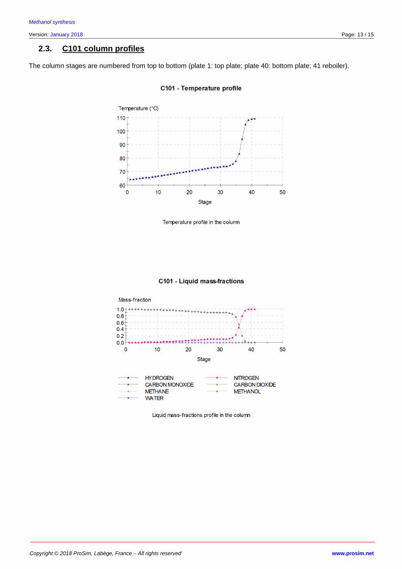
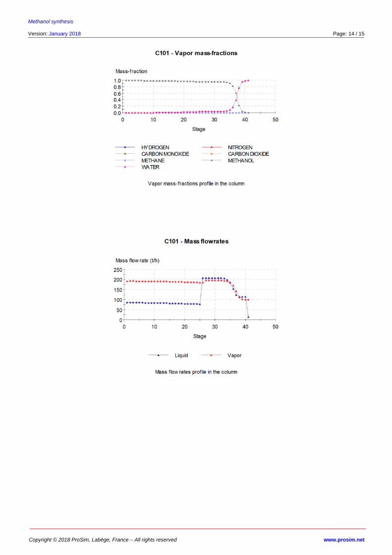
2.3. C101 column profiles
The column stages are numbered from top to bottom (plate 1: top plate; plate 40: bottom plate; 41 reboiler).
Methanol synthesis
Version: January 2018 Page: 14 / 15
Copyright © 2018 ProSim, Labège, France – All rights reserved www.prosim.net
Methanol synthesis
Version: January 2018 Page: 15 / 15
Copyright © 2018 ProSim, Labège, France – All rights reserved www.prosim.net
3. REFERENCES
[CHE02] CHEN J., FISCHER K., GMEHLING J., “Modification of PSRK Mixing Rules and Results for Vapor
– Liquid Equilibria, Enthalpy of Mixing and Activity Coefficients at Infinite Dilution”, Fluid Phase
Equilib., 200, 411-429 (2002)
[DEM13] DE MARIA R., DIAZ I., RODRIGUEZ M., SAIZ A., “Industrial Methanol Synthesis from Syngas:
Kinetic Study and Process Simulation”, Int. J. Chem. Reactor Eng., 11, 469-477 (2013)
[GME95] GMEHLING J., “From UNIFAC to Modified UNIFAC to PSRK with the Help of DDB”, Fluid Phase
Equilib., 107, 1-29 (1995)
[HOL91] HOLDERBAUM T., GMEHLING J., “PSRK: A Group Contribution Equation of State Based on
UNIFAC”, Fluid Phase Equilib., 70, 251-265 (1991)
[LUY10] LUYBEN W.L., “Design and Control of a Methanol Reactor/Column Process”, Ind. Eng. Chem.
Res., 49, 6150-6163 (2010)
[REN68] RENON H., PRAUSNITZ J.M., “Local Compositions in Thermodynamic Excess Functions for Liquid
Mixtures”, AIChE J., 14, 135-144 (1968)
[ROW17] ROWLEY R.L., WILDING W.V., OSCARSON J.L., GILES N.F., “DIPPR® Data Compilation of Pure
Chemical Properties”, Design Institute for Physical Properties, AIChE, New York, NY (2017)