synchronization of semiconductor laser on picosecond pulses
TRANSCRIPT

Synchronization of semiconductor laser on picosecond pulses
Pascal Besnarda, Olivier Vaudela and Jean-Franccois Hayaua
aFOTON-ENSSAT (CNRS - UMR6082) - Universite de Rennes 1,6 rue de Kerampont, B.P.8051822305 Lannion CEDEX, France
ABSTRACT
We show for the first time to our knowledge, synchronization between two bulk semiconductor lasers on anerratic train of pulses. They occurred erratically at different times, following a Poisson statistical law on thescale of the nanosecond. These pulses are due to excitability using an optically injected bulk semiconductorlaser. Synchronization between two lasers is shown and studied cascading two optical injection schemes. Thedegree of correlation between the two signal outputs is analyzed following the detuning and the injected powerand is related to the standard map of dynamics for optically injected laser, seeded by a continuous wave. Thesynchronization on a single pulse is studied as well as on a regular temporal train of pulses and we show that thebirth of synchronization is obtained for injected power related to a saturation process in the laser. A comparisonto quantum dash and quantum dot laser is discussed.
Keywords: synchronization, optical injection, semiconductor laser, bulk, quantum dots
1. INTRODUCTION
Seeding light from a laser into the cavity of a second one is a simple experiment.1,2 When the coupling isunidirectional, this scheme is called optical injection and is a basic tool for the study of synchronization processbetween oscillators. The dynamics has been extensively described theoretically and experimentally mainly whenthe seeded light is a continuous wave.3–7 It has been also suggested that chaotic signal may be synchronizedthrough optical injection8–12 following the proposal of Pecora and Carroll.13 The chaos is usually generatedthrough optical feedback.14,15 The general idea is to inject light from an extended cavity semiconductor laser(ECL) into the cavity of a second laser. When the injected signal has the same strength as that of the opticalfeedback in the ECL, the injected laser duplicates the first system. The injected laser completely synchronizesthen with anticipation (with a time lag corresponding to the round-trip EC time).16–18 However, more general-ized chaos synchronization can be accomplished through optical injection, which means that it is possible to reachsynchronization for a broad range of parameters such as injected-power level and with/without anticipation.19–22
Similar experiments have been realized with fiber lasers.23,24 It is moreover possible to reach synchronizationon other temporal dynamics.25
Generallized synchronization may be obtained without the help of optical feedback, using restrictively opticalinjection.25,26 This is based on a cascade of two successive optical injections (from master to receiver throughtransmitter). In this architecture, both transmitter and receiver may be set in different regimes7 such as re-laxation, multi-wave frequency, frequency doubling, chaotic regime. . . The synchronization can then be studiedby fixing the operating point of the transmitter and varying that of the receiver (as for example the detuningbetween the transmitter and the receiver or the injected power from the transmitter). One may choose theinverse case by setting the operating point of the receiver and going over that of the transmitter (by varying ofthe injected power from the master and its optical frequency). In this communication, we study synchronizationbetween two lasers when the seeded light is non continuous and characterized as a erractic spiking behaviour.This article is organized as follows: In section 2, the basics principle of optical injection and excitability aredescribed; In section 3, synchronization process is investigated. Finally, a brief conclusion is drawn.
Further author information: (Send correspondence to Pascal Besnard)Pascal Besnard: E-mail: [email protected], Telephone: +33-2-96-46-90-53, Fax : +33-2-96-37-01-99
Physics and Simulation of Optoelectronic Devices XVII, edited by Marek Osinski, Bernd Witzigmann, Fritz Henneberger, Yasuhiko Arakawa, Proc. of SPIE Vol. 7211,
72110T · © 2009 SPIE · CCC code: 0277-786X/09/$18 · doi: 10.1117/12.809949
Proc. of SPIE Vol. 7211 72110T-1

Figure 1. Optical injection principle.
2. OPTICAL INJECTION BY A CONTINUOUS-WAVE SIGNAL
2.1 Principle
The principle of an optical injection is sketched in Fig. 1. Laser, which is injected, is usually called the slavelaser (SL) while the other is called the master laser (ML).
In our experiments, the ML is a commercially available, single mode tunable external cavity semiconductorlaser, with a precision of 1 pm (125 MHz at 1.55μm), which gives out a power up to 3 mW . This power canbe increased thanks to a polarization maintaining (PM) optical amplifier (+23 dBm), with a high coefficientisolator (70 dB isolation) that ensures a unidirectional seeding from the master to the slave. The SL is a massiveInP/InGaAsP buried double heterostructure DFB laser chip emitting at 1.55 μm. Its temperature is regulated at25˚C thanks to a Peltier controller. Note that all the experiment is fiber-made with PM components, allowing aperfect reproducibility of the measurements. We don’t give more details about the experiment as the descriptioncan be found in former publications.7,25,27
2.2 Experimental results
Generally, the SL is feeded by a continuous wave. In this case, many phenomena have been classified3–7 followingthe control parameters which are essentially the injected power Pinj and the detuning Δν between the master(νm) and slave (νs) frequencies. Usual values for Δν and Pinj are in the respective intervals [−100;+100 GHz]and [−50; 0 dBm] ([100 nW ; 1 mW ]).Usually, results are presented in the “injected power-detuning” chart (Pinj − Δν), for which the different colorsshow at a glance the different regimes.
2.2.1 Dynamical behaviors
Injection by a continuous wave allows the SL to exhibit different kinds of dynamics:
• Frequency-locking28,29 (mark as “L” in Fig. 2-5): The amplification of the master line is made at theexpense of the slave line and is characterized by a linewidth transfer.27
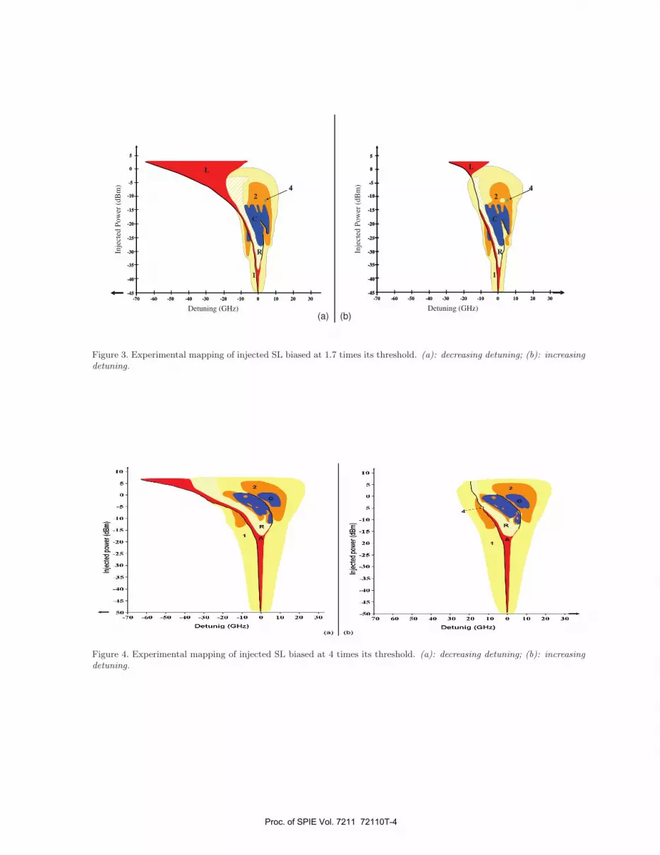
• Wave-mixing (mark as “1” in Fig. 3-5): Wave-mixing could create an image frequency νs − (νm − νs),symmetric of νm with respect to νs and multiple of them.
• Period doubling (mark as “2” in Fig. 3-5): New frequency lines appear between two lines observed in thewave-mixing regime.
• Period quadrupling (mark as “4” in Fig. 3-5): New frequency lines appear between two lines observed inthe period doubling regime.
• Chaos (mark as “C” in Fig. 3-5): The frequency spectra is characterized by a broad band that could beassimilated to noise.
• Undamped relaxation regime30 (mark as “R” in Fig. 3-5): Characteristics are very similar to wave-mixingbut for which mode spacing is equal to the relaxation oscillation frequency (ROF) of the slave laser. Thisspecific regime is more precisely detailed in Refs. 25 & 31.
Proc. of SPIE Vol. 7211 72110T-2

10
0
-5
-25-140 120 -100 80 -6 D -40 -20 0 20 0 60 80
Detuning (GHz)
Inje
cte
dp
ow
er
(dB
m)
L
Figure 2. Experimental mapping of injected SL biased at 1.2 times its threshold. Hatched area: frequency locking only fordecreasing detuning.
• Excitability. An excitable system is characterized by a large non-linear response to a small but sufficientlylarge perturbation from its stable equilibrium before settling back to the equilibrium. Historically, multi-pulses excitability had been observed in biology with neuronal transmission of information. In this domain,excitability is characterized by a spiking behaviour of the cell potential.32 In optics, excitability hasalready been observed in lasers with saturable absorber33,34 or lasers with optical feedback.35–37 In thisphysical field, excitability is also characterized by a spiking behaviour, by of the optical emitted power.Experimentally, Goulding et al38,39 have recently reported observation of multi-pulses excitability in a1.3μm quantum dot laser. This dynamics will be more precisely described in § 2.2.4.
2.2.2 Experimental mapping
Fig. 2, 3 and 4 present experimental mapping in the chart “injected power-detuning”, respectively for the slavelaser biased at 1.2, 1.7 and 4 times its threshold.
At low pumping rate (see Fig. 2), the injected laser mainly acts as an optical amplifier: We just observedfrequency-locking behavior or an amplification regime, for which two frequencies exist (that of the slave laserand the amplified one of the master).This figure shows moreover a bistability: In the hatched area, the slave laser is only frequency-locked for adecreasing detuning.
When the pumping rate is a little bit further increased (1.7), more regimes like wave-mixing, period dou-bling4,7. . . are observed as shown in Fig. 3.As explained in Ref. 28, the locking area divides in two branches when the injected power is increased from verylow values to about −35 dBm at this pumping rate. Above the intersection of these two areas, the undampedrelaxation regime takes place. This particular operating point is usually called the relaxation hole.As previously mentioned, the phenomenon is bistable as illustrated by Fig. 3(a) and 3(b), following here thevariation of the detuning.
Finally, for the slave laser biased at higher current, i.e. 4 times its threshold, the mapping is qualitativelysimilar to that at 1.7 times the threshold, as presented in Fig. 4.However relaxation hole is obtained for a larger injected power (∼ −16 dBm). At higher bias current, it is moredifficult to perturb the slave laser: More power have to be injected in order to obtain a similar regime.
2.2.3 Discussion
At low pumping rate, the behavior of the SL is closer to that of an amplifier. Increasing the pumping rate orthe gain leads to:
Proc. of SPIE Vol. 7211 72110T-3
E -15-' -20-
- -25 -
-30
-35-
-40 -
-45-50
70 60 50 40 30 20Detonig (GHz)
10 0 10 20 30
() (b)
10
5
0
-5
-10E
-15
-20
-25
-30
-35
-40
-45
-50
Detrig (GHz)-70 -60 -50 -40 -30 -20 -I (I 0 10 20 30
30
5
0
-5
-10
-15
-20
-25
-30
-35
-40
-45
10-10-20-30-40-50-60-70 0 20
A
1
2
C
R
4
30
5
0
-5
-10
-15
-20
-25
-30
-35
-40
-45
5
0
-5
-10
-15
-20
-25
-30
-35
-40
-45
10-10-20-30-40-50-60-70 0 20
L
1
2
C
R
4
Detuning (GHz)
Inje
cted
Pow
er (
dB
m)
30
5
0
-5
-10
-15
-20
-25
-30
-35
-40
-45
10-10-20-30-40-50-60-70 0 20
A
1
2
C
R
4
30
5
0
-5
-10
-15
-20
-25
-30
-35
-40
-45
10-10-20-30-40-50-60-70 0 20
L
1
2
C
R
4
Inje
cted
Pow
er (
dB
m)
Detuning (GHz)(a) (b)
Figure 3. Experimental mapping of injected SL biased at 1.7 times its threshold. (a): decreasing detuning; (b): increasingdetuning.
Figure 4. Experimental mapping of injected SL biased at 4 times its threshold. (a): decreasing detuning; (b): increasingdetuning.
Proc. of SPIE Vol. 7211 72110T-4

I0
Th
0
-10
-15
-20
-25
-30
-35
-40
-45
50-70
Strong injection
Moderate injection
VVeak injection
- Very weak injection
-60 -50 -40 -30 -20 -10 0 10 20 30
Detuning (GHz)
Figure 5. Injected power scale for the slave laser biased at 4 times its threshold.
• More complex maps, due to more regimes.
• A higher sensitivity to optical injection, which means that the locking area appears at lower injected power(−25 dBm at r = 1.2; −45 dBm at r = 1.7; −50 dBm at r = 4.)
• A translation of the different areas towards higher injected powers. This last property is a rule of thumb,which is basically illustrated by the translation of the relaxation hole (−35 dBm at r = 1.7; −15 dBm atr = 4.) Comparison of figures 3(a) and 4(a) shows obviously that area delimiting the different regimes arenot identically shaped and located at the same positions.
Different categories of optical injection can be defined as it is indicated in the experimental map of Fig. 5:
• Very weak optical injection, for which the master line is only amplified.7 It corresponds to power scale forwhich there is purity or impurity transfert,27 or as well for which the laser can be used as a very sensitivedetector.40
• Weak optical injection, for which the locking and wave-mixing occur.
• Moderate optical injection, for which complex dynamics occur like period doubling, chaos. This formerregime starts for an injected power corresponding to the relaxation hole.
• High injected power, for which bistability occurs.
• Very High injected power, for which the SL is always locked.
This last category is only seen numerically.25,31
These experimental mapping allow to highlight the existence of bistabilities29,41,42 for all bias current exploredin this work.
Proc. of SPIE Vol. 7211 72110T-5

1.3
C 1.2
o- 0.9
0.8
o
1,4
0.6
0.5
Time (1 ns/div)(a)
(c)
(b)
(d)1.4-
1.3-
1.2-
1.1-
o 1.0-
- 0.9-
0.8-
o 0.7-
0.6
0.5
Time (1 ns/div)
o 1.0
- 0.9
0.8
0 0.7
0.6
0.5
Time (1 ns/div)
1.4-
1.3
1.2-
1.1-
1.0-0
. 0.9-
0.8-
a 0.7-0
0.6-
0.5
Time (1 ns/div)
Figure 6. Examples of multi-pulses excitability.
2.2.4 Excitability behaviour
The experimental scheme allows us to observe multi-pulses excitability in the optically injected slave laser.Fig. 6 presents different exemples of the observed time series obtained for the SL biased at 1.2 times its threshold.Fig. 6(a) shows an exemple of a single pulse (order-1 excitability); Fig. 6(b), respectively (c), presents an exempleof two, respectively three, pulses following by an other one (order-2 and order-3 excitability). Finally, Fig. 6(d)presents an exemple of a multiple pulses behaviour (high order excitability). This results is the first observationof multi-pulses excitability for a 1.55μm DFB bulk laser.To complete these observations, we have mapped, in the “detuning-injected power” plane, the areas where wecan observe excitability spiking behaviour. This map is presented in Fig. 7.
To simplify, in this figure, we have only mapped the injection-locking area and multi-pulses excitability areas.These ones are pictured in grey in the figure. These areas are quite small: No more than 1GHz×2dB. This factexplains why we do not have indicated the parameter values of these observations in Fig. 6: Our measurementdevices are not enough accurate to fully distinguish the different injection points. Ones can also note that themulti-pulses areas’ location are in good agreement with theoretical studies already published.43
The probability density associated to the occurrence of spikes is seen to be close to a Poisson law (characterizedthrough the dispersion index of Fisher). Hence the delay between two pulses follows almost an exponential lawas shown in Fig. 8 and it is unlikely to have a separation higher than 50 ns.
3. SYNCHRONIZATION SCHEME
3.1 Principle
To study synchronization between two DFB semiconductor lasers, we use a cascade of two optical injections, aspresented in Ref. 26 and in Fig. 9.The first injection, between a ML and a transmitter laser (TL), fixes the operating point or dynamics of the TL.
Proc. of SPIE Vol. 7211 72110T-6

10
-40
Iniection lockhig area
Multi-pulses excitabi1i
-120 -100 -80 -60 -40 -20
Detuning (GIlz)
Figure 7. Mapping of multi-pulses excitability.
5 10 15 20
0
1000
2000
3000
4000
5000
Exp
eri
men
tal p
rob
ab
ilit
y d
en
sit
y
(arb
. u
., n
um
ber
or
co
un
ts)
Delay between spikes (ns)
Figure 8. Experimental probability density associated to the delay between two adjacent pulses.
Proc. of SPIE Vol. 7211 72110T-7
Time (lOns/div)
TransmitterReceiver
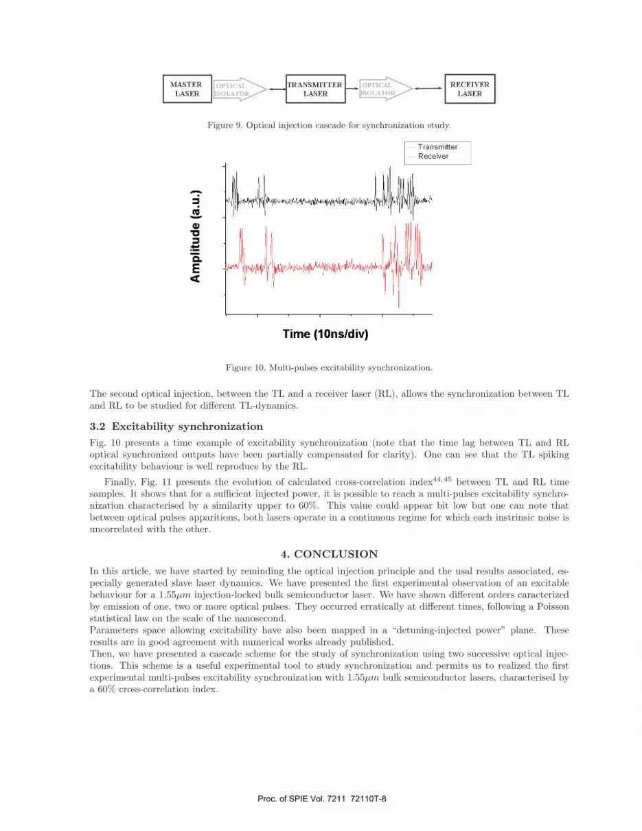
Figure 9. Optical injection cascade for synchronization study.
Figure 10. Multi-pulses excitability synchronization.
The second optical injection, between the TL and a receiver laser (RL), allows the synchronization between TLand RL to be studied for different TL-dynamics.
3.2 Excitability synchronizationFig. 10 presents a time example of excitability synchronization (note that the time lag between TL and RLoptical synchronized outputs have been partially compensated for clarity). One can see that the TL spikingexcitability behaviour is well reproduce by the RL.
Finally, Fig. 11 presents the evolution of calculated cross-correlation index44,45 between TL and RL timesamples. It shows that for a sufficient injected power, it is possible to reach a multi-pulses excitability synchro-nization characterised by a similarity upper to 60%. This value could appear bit low but one can note thatbetween optical pulses apparitions, both lasers operate in a continuous regime for which each instrinsic noise isuncorrelated with the other.
4. CONCLUSION
In this article, we have started by reminding the optical injection principle and the usal results associated, es-pecially generated slave laser dynamics. We have presented the first experimental observation of an excitablebehaviour for a 1.55μm injection-locked bulk semiconductor laser. We have shown different orders caracterizedby emission of one, two or more optical pulses. They occurred erratically at different times, following a Poissonstatistical law on the scale of the nanosecond.Parameters space allowing excitability have also been mapped in a “detuning-injected power” plane. Theseresults are in good agreement with numerical works already published.Then, we have presented a cascade scheme for the study of synchronization using two successive optical injec-tions. This scheme is a useful experimental tool to study synchronization and permits us to realized the firstexperimental multi-pulses excitability synchronization with 1.55μm bulk semiconductor lasers, characterised bya 60% cross-correlation index.
Proc. of SPIE Vol. 7211 72110T-8

1,0 -
0,9 -
0,8 -
0,7 -
0,6 -
0,5 -
0,4- ..
0,3 - .0,2 -
0,1- . .. .
0,0 , i,i,,,,,,,i,-50 -40 -30 -20 -10 0 10 20
Injected power (a.u. in dB)
Figure 11. Excitability synchronization cross-correlation index.
ACKNOWLEDGMENTS
Authors would like to thank N. Peraud for excitability behaviour characterization and “Laser Physic Group”colleagues for helpful discuss and comments.
REFERENCES[1] Stover, H. L. and Steier, W. H., “Locking of laser oscillators by light injection,” Applied Physics Letters 8,
91–93 (May 1966).[2] Lang, R., “Injection locking properties of a semi-conductor laser,” IEEE Journal of Quantum Electronics 18,
976–983 (Juin 1982).[3] Gavrielides, A., Kovanis, V., Varangis, A., Erneux, T., and C. Lythe, C., “Coexisting periodic attractors in
injection-locked diode lasers,” Quantum and Semiclassical Optics B 9, 785 (1997).[4] Simpson, T. B., Liu, J. M., Huang, K. F., and Tai, K., “Nonlinear Dynamics Induced by External Optical
Injection in Semiconductors Lasers,” Quantum Semiclassical Optics 9, 765–784 (October 1997).[5] Bondiou, M., Gabet, R., Besnard, P., and Stephan, G. M., “Optical bistabilities in injected semiconductor
lasers,” Proceedings of the international conference on LASERS’97 , 49–54 (1998).[6] Wieczorek, S., Krauskopf, B., and Lenstra, D., “A unifying view of bifurcations in a semiconductor laser
subject to optical injection,” Optics Communications 172, 279–295 (1999).[7] Blin, S., Guignard, C., Besnard, P., Gabet, R., Stephan, G., and Bondiou, M., “Phase and Spectral Proper-
ties of Optically Injected Semiconductor Lasers,” Comptes Rendus de la Physique 4, 687–699 (July - August2003).
[8] Mirasso, C., Colet, P., and Garcıa-Fernandez, P., “Synchronization of Chaotic Semiconductor Lasers: Ap-plication to Encoded Communications,” IEEE Photonics Technology Letters 8, 299–301 (February 1996).
[9] VanWiggeren, G. and Roy, R., “Optical Communication with Chaotic Waveforms,” Physical Review Let-ters 81, 3547–3550 (October 1998).
[10] Goedgebuer, J. P., Larger, L., and Porte, H., “Optical Cryptosystem Based on Synchronization of Hy-perchaos Generated by a Delayed Feedback Tunable Laser Diode,” Physical Review Letters 80, 2249–2252(March 1998).
Proc. of SPIE Vol. 7211 72110T-9

[11] Liu, Y., Chen, H., Liu, J., Davis, P., and Aida, T., “Communication Using Synchronization of Optical-Feedback-Induced Chaos in Semiconductor Lasers,” IEEE Transactions on Circuits and Systems - I: Fun-damental Theory and Applications 48, 1484–1490 (December 2001).
[12] Argyris, A., Syvridis, D., Larger, L., Annovazzi-Lodi, V., Colet, P., Fischer, I., Garca-Ojalvo, J., Mirasso,C. R., Pesquera, L., and Shore, K. A., “Chaos-based communications at high bit rates using commercialfibre-optic links,” Nature 438, 343–346 (Novembre 2005).
[13] Pecora, L. M. and Carroll, T. L., “Synchronization in Chaotic Systems,” Physical Review Letters 64, 821–824 (February 1990).
[14] Ohtsubo, J., “Chaos synchronization and chaotic signal masking in semiconductor lasers with optical feed-back,” IEEE Journal of Quantum Electronics 38(9), 1141–1154 (2002).
[15] Liu, Y., Chen, H. F., Liu, J. M., Davis, P., and Aida, T., “Synchronization of Optical-Feedback-InducedChaos in Semiconductor Lasers by Optical Injection,” Physical Review A 63, 031802(R) (March 2001).
[16] Masoller, C., “Anticipation in the Synchronization of Chaotic Semiconductor Lasers with Optical Feedback,”Physical Review Letters 86, 2782–2785 (Mars 2001).
[17] Sivaprakasam, S., Shahverdiev, E., Spencer, P., and Shore, K., “Experimental Demonstration of AnticipatingSynchronization in Chaotic Semiconductor Lasers with Optical Feedback,” Physical Review Letters 87,154101–154104 (2001).
[18] Kusumoto, K. and Ohtsubo, J., “Anticipating Synchronization Based on Optical Injection-Locking inChaotic Semiconductor Lasers,” IEEE Journal of Quantum Electronics 39, 1531–1536 (Dcembre 2003).
[19] Rulkov, N., Sushchik, L., and Abarbanel, H., “Generalized synchronization of chaos in directionally coupledchaotic systems,” Physical Review E 51, 980–994 (1995).
[20] Tang, D., Dykstra, R., Hamilton, M., and Heckenberg, N., “Observation of Generalized Synchronization ofChaos in a Driven Chaotic System,” Physical Review E 57, 5247–5251 (May 1998).
[21] Liu, Y., Davis, P., Takiguchi, Y., Aida, T., Saito, S., and Liu, J.-M., “Injection Locking and Synchronizationof Periodic and Chaotic Signals in Semiconductor Lasers,” IEEE Journal of Quantum Electronics 39, 269–278 (Fvrier 2003).
[22] Chen, H.-F. and Liu, J.-M., “Unidirectionally Coupled Synchronization of Optically Injected SemiconductorLasers,” Journal of Selected Topics in Quantum Electronics 10, 918–926 (September - October 2004).
[23] Annovazzi-Lodi, V., Merlo, S., Norgia, M., and Scir, A., “Characterization of a chaotic telecommunicationlaser for different fiber cavity lengths,” IEEE Journal of Quantum Electronics 38(9), 1171–1177 (2002).
[24] Imai, Y., Murukawa, H., and Imoto, T., “Chaos Synchronisation Characteristics in Erbium-Doped FiberLaser Systems,” Optics Communications 217, 415–420 (Mars 2003).
[25] Vaudel, O., Hayau, J.-F., and Besnard, P., “Synchronization between optically injected semiconductor laserson undamped relaxation oscillations,” Optical and Quantum Electronics 40, 109–118 (March 2007). Specialissue on Nonlinear Photonics - Contributions from the PHASE and IPSSO 2007 International Workshops.
[26] Guignard, C., Blin, S., and Besnard, P., “New Scheme for the Synchronization of Low Dimensional Chaos,”in [Conference on Lasers and Electro Optics - The Europeen Quantum Electronics Conference (CLEO-EQEC) ], (June 2003). EC1M.
[27] Bondiou, M., Gabet, R., Stephan, G., and Besnard, P., “Linewidth of an optically injected semiconductorlaser,” Journal of Optics B : Quantum and Semiclassical Optics 2, 41–46 (2000).
[28] Petitbon, I., Gallion, P., Debarge, G., and Chabran, C., “Locking bandwidth and relaxation oscillationsof an injected-locked semiconducteur laser,” IEEE Journal of Quantum Electronics 24, 148–154 (February1988).
[29] Lee, E.-K., Pang, H., Park, J.-D., and Lee, H., “Bistability and Chaos in an Injection Locked SemiconductorLaser,” Physical Review A 47, 736–739 (January 1993).
[30] Vaudel, O., Guignard, C., and Besnard, P., “Synchronization map of two uni-directionally coupled chaoticsemiconductor lasers,” in [EUROMECH Nonlinear Dynamics Conference (ENOC) ], (August 2005). paper18-427.
[31] Vaudel, O., Study of synchronization of chaos using optically injected semiconductor lasers, PhD thesis,University of Rennes I (January 2007).
[32] Murray, J., [Mathematical Biology ] (1990).
Proc. of SPIE Vol. 7211 72110T-10

[33] Dubbeldam, J. L. A., Krauskopf, B., and Lenstra, D., “Excitability and Coherence Resonance in Laserswith Saturable Absorber,” Physical Review E 60, 6580–6588 (Dec. 1999).
[34] Dubbeldam, J. and Krauskopf, B., “Self-Pulsations of Lasers with Saturable Absorber: Dynamics andBifurcations,” Optics Communications 159, 325–338 (Jan. 1999).
[35] Yacomotti, A., Eguia, M., Aliaga, J., Martinez, O., Mindlin, G., and Lipsich, A., “Interspike Time Distri-bution in Noise Driven Excitable Systems,” Physical Review Letters 83, 292–295 (July 1999).
[36] Krauskopf, B., Schneider, K., Sieber, J., Wieczorek, S., and Wolfrum, M., “Excitability and self-pulsationsnear homoclinic bifurcations in semiconductor laser systems,” Optics Communications 215, 367–379 (2003).
[37] Lindner, B., Garcıa-Ojalvo, J., Neiman, A., and Schimansky-Geier, L., “Effects of noise in excitable sys-tems,” Physics Reports 392, 321–424 (2004).
[38] Goulding, D., Hegarty, S., Melnik, S., Hartnett, M., McInerney, J., and Huyet, G., “Excitability in aquantum dot semiconductor laser with optical injection,” in [Photonics West ], (January 2007).
[39] Goulding, D., Hegarty, S., Rasskazov, O., Melnik, S., Hartnett, M., Greene, G., McInerney, J., Rachinskii,D., and Huyet, G. Physical review letters 98(153903) (2007).
[40] Stephan, G., Gabet, R., Besnard, P., Bondiou, M., and Kilper, D., “Ultrahigh Sensitivity Detector forCoherent Light: The Laser,” Congres SPIE (1999).
[41] Dutta, N., Agrawal, G., and Focht, M., “Bistability in coupled cavity semiconductor lasers,” Applied PhysicsLetters 44, 30–32 (January 1984).
[42] Kawaguchi, H., Inoue, K., Matsuoka, T., and Otsuka, K., “Bistable output characteristics in semiconductorlaser injection locking,” IEEE Journal of Quantum Electronics 21, 1314–1317 (September 1985).
[43] Wieczorek, S., Simpson, T., Krauskopf, B., and Lenstra, D., “Global Quantitative Predictions of ComplexLaser Dynamics,” Physical Review E 65, 045207(R) (April 2002).
[44] Hoel, P., [Introduction to Mathematical Statistics ], 4th ed. (1971).[45] Korn, G. and Korn, T., [Mathematical Handbook for Scientists and Engineers ], 2nd ed. (1968).
Proc. of SPIE Vol. 7211 72110T-11