symbol timing recovery for low-snr partial response recording channels
TRANSCRIPT
1
Symbol Timing Recovery for Low-SNR Partial Response Recording Channels
Jingfeng Liu, Hongwei Song and B. V. K. Vijaya Kumar
Data Storage Systems CenterCarnegie Mellon University
5000 Forbes AvePittsburgh, PA 15213, USA
2
Outline
� Timing recovery for data storage channels � Loss of lock� Piecewise linear phase drift approximation� Frequency estimation-based feedforward symbol
timing recovery (FOSTR)� Simulation results� Conclusions
3
Timing Recovery for Recording Channels
y(t)h[t-�(t)] ak
n(t)( ) [ ( )] ( )kk
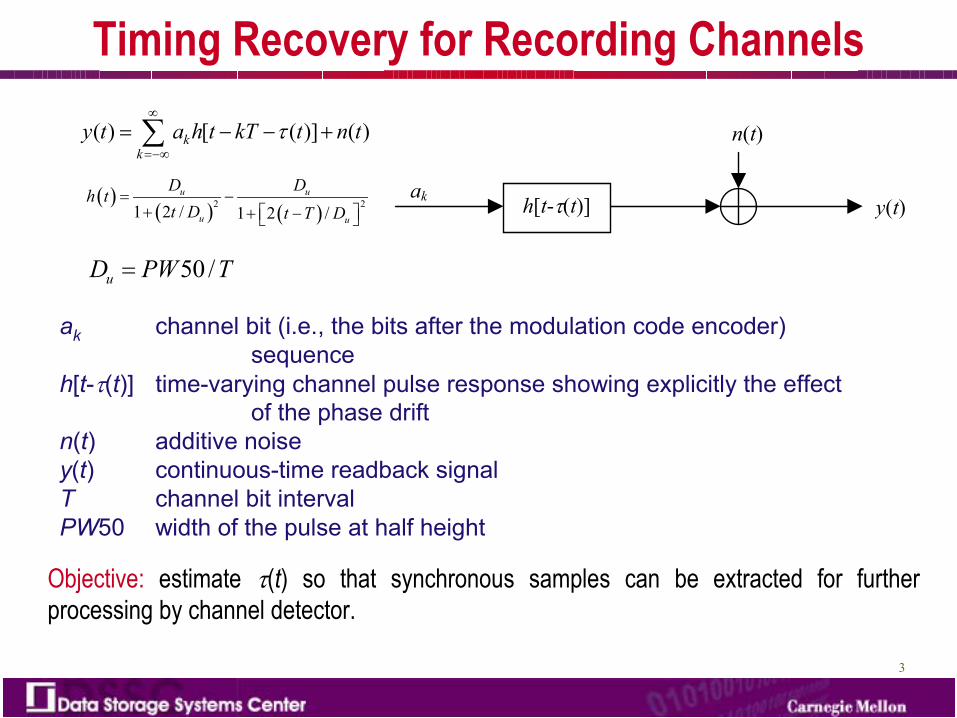
y t a h t kT t n t�
�
���
� � � ��
� �� � � �
2 21 2 / 1 2 /u u
u u
D Dh tt D t T D
� �� � �� �� �
50 /uD PW T�
ak channel bit (i.e., the bits after the modulation code encoder) sequence
h[t-�(t)] time-varying channel pulse response showing explicitly the effect of the phase drift
n(t) additive noisey(t) continuous-time readback signalT channel bit intervalPW50 width of the pulse at half height
Objective: estimate �(t) so that synchronous samples can be extracted for further processing by channel detector.
4
Current Timing Recovery Approach
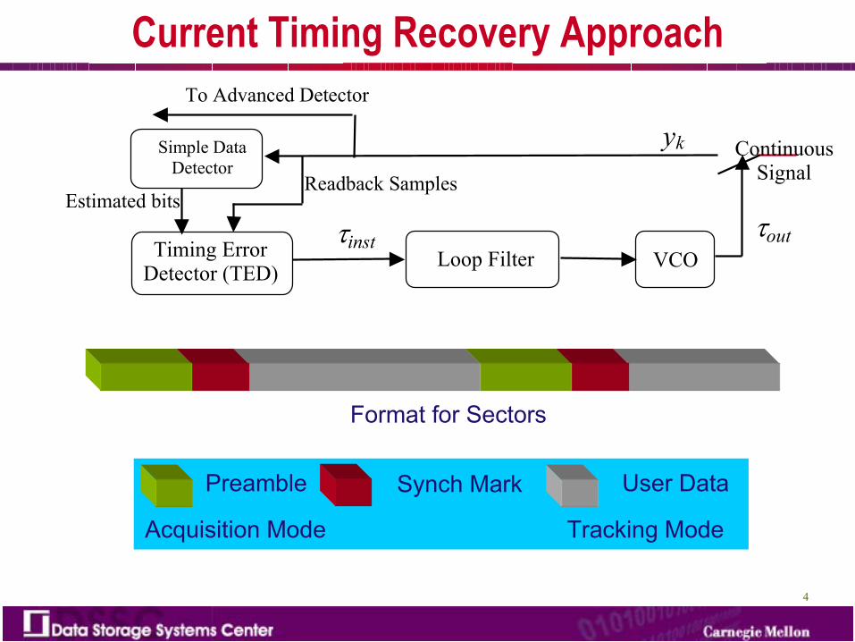
Simple Data Detector
Timing Error Detector (TED)
To Advanced Detector
Continuous Signal
yk
Loop Filter VCO�inst �out
Readback SamplesEstimated bits
Format for Sectors
Preamble Synch Mark User Data
Acquisition Mode Tracking Mode
5
6 7 8 9 10 11 1210-5
10-4
10-3
10-2
10-1
100
SNR (dB)
BE
R
6 7 8 9 10 11 1210-5
10-4
10-3
10-2
10-1
100
SNR (dB)
Loss
of L
ock
Rat
e
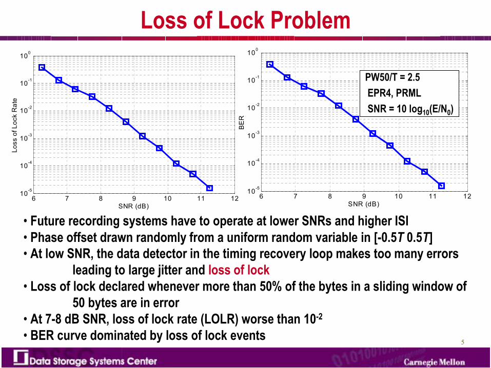
Loss of Lock Problem
• Future recording systems have to operate at lower SNRs and higher ISI• Phase offset drawn randomly from a uniform random variable in [-0.5T 0.5T]• At low SNR, the data detector in the timing recovery loop makes too many errors
leading to large jitter and loss of lock• Loss of lock declared whenever more than 50% of the bytes in a sliding window of
50 bytes are in error• At 7-8 dB SNR, loss of lock rate (LOLR) worse than 10-2
• BER curve dominated by loss of lock events
PW50/T = 2.5EPR4, PRMLSNR = 10 log10(E/N0)
6
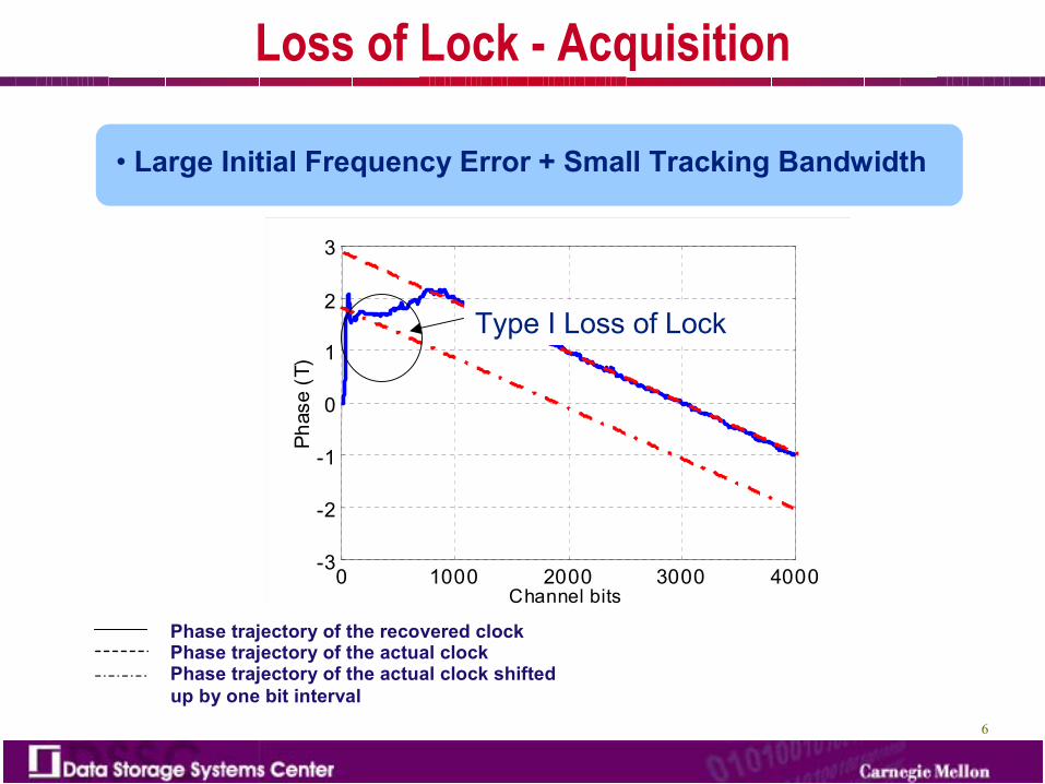
Loss of Lock - Acquisition
• Large Initial Frequency Error + Small Tracking Bandwidth
0 1000 2000 3000 4000-3
-2
-1
0
1
2
3
Channel bits
Phas
e (T
)
0 1000 2000 3000 4000-3
-2
-1
0
1
2
3
Channel bits
Phas
e (T
)Type I Loss of Lock
Phase trajectory of the recovered clockPhase trajectory of the actual clockPhase trajectory of the actual clock shiftedup by one bit interval
7
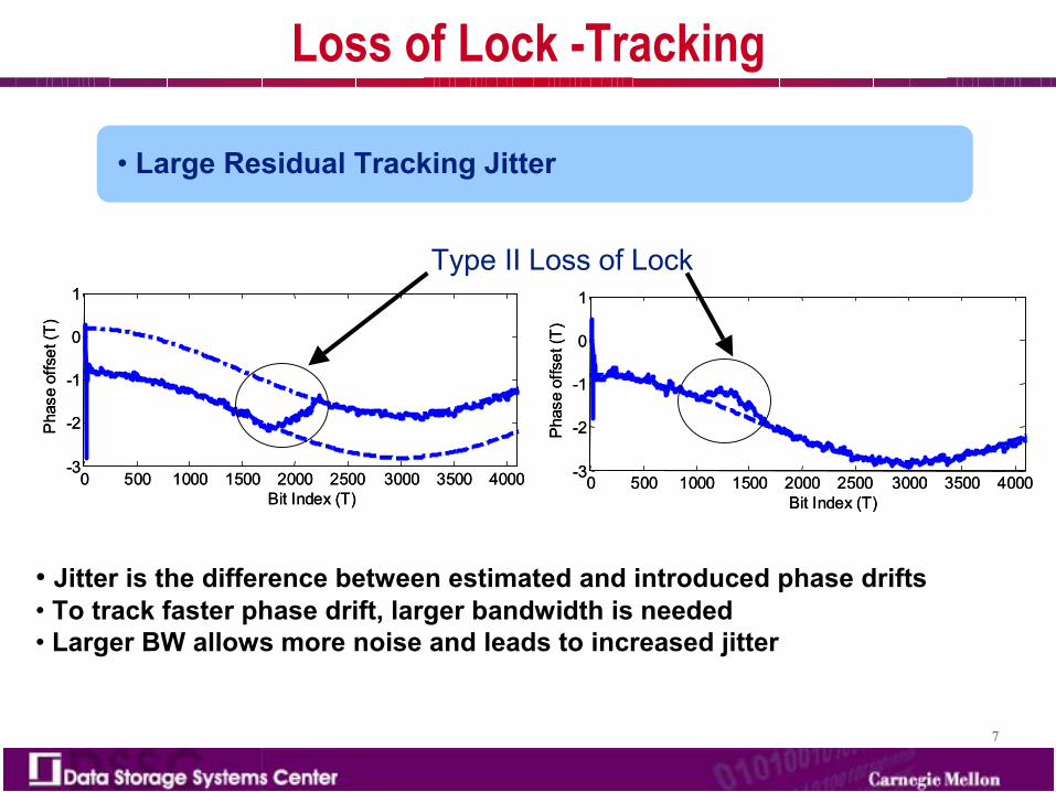
Loss of Lock -Tracking
Type II Loss of Lock
0 500 1000 1500 2000 2500 3000 3500 4000-3
-2
-1
0
1
Pha
se o
ffset
(T)
Bit Index (T)0 500 1000 1500 2000 2500 3000 3500 4000
-3
-2
-1
0
1
Pha
se o
ffset
(T)
Bit Index (T)0 500 1000 1500 2000 2500 3000 3500 4000
-3
-2
-1
0
1
Bit Index (T)
Phas
e of
fset
(T)
0 500 1000 1500 2000 2500 3000 3500 4000-3
-2
-1
0
1
Bit Index (T)
Phas
e of
fset
(T)
• Large Residual Tracking Jitter
• Jitter is the difference between estimated and introduced phase drifts• To track faster phase drift, larger bandwidth is needed• Larger BW allows more noise and leads to increased jitter
8
0.035 0.04 0.045 0.05 0.055 0.06 0.065 0.0710 -7
10 -6
10 -5
10 -4
10 -3
10 -2
10 -1
10 0
RMS Value of Residual Timing Jitter (T)
Loss
of L
ock
Rat
e
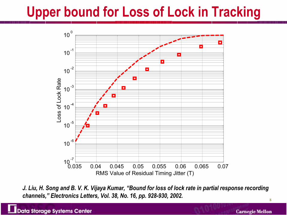
Upper bound for Loss of Lock in Tracking
J. Liu, H. Song and B. V. K. Vijaya Kumar, “Bound for loss of lock rate in partial response recording channels,” Electronics Letters, Vol. 38, No. 16, pp. 928-930, 2002.
9
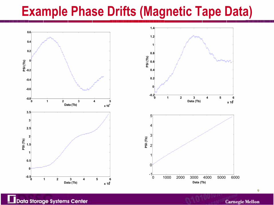
Example Phase Drifts (Magnetic Tape Data)
0 1 2 3 4 5x 10⁴
-0.8
-0.6
-0.4
-0.2
0
0.2
0.4
0.6
Data (Tb)
PSI (
Tb)
0 1000 2000 3000 4000 5000 6000-1
0
1
2
3
4
5
0 1 2 3 4 5 6x 10⁴
-0.5
0
0.5
1
1.5
2
2.5
3
3.5
Data (Tb)
PSI (
Tb)
0 1 2 3 4 5 6x 10⁴
-0.2
0
0.2
0.4
0.6
0.8
1
1.2
1.4
Data (Tb)
PSI (
Tb)
PSI (
Tb)
Data (Tb)
10
Phase Drift Models
Generally, phase drift �(t) in recording systems can be characterized by following three models:
• Linear phase drift model: This model represents a constant frequency offset between the actual bit rate and the bit rate used for sampling. It is a popular model used to model the phase drifts present in hard disk drives.
• Sinusoidal phase drift model: This is a good model for phase drift when the head arm is fluctuating because the servo control is not working properly, e.g., when the servo loop cannot damp out the excessive vibration in the head media in interface. To track this kind of phase drift, we need a PLL of a relatively large bandwidth, like tape drives.
• Autoregressive (AR) phase drift model: This model reflects the random nature of phase drift especially during the tracking mode when the frequency offset is small and there is no initial phase offset.
11
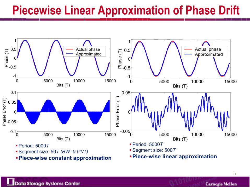
Piecewise Linear Approximation of Phase Drift
�Period: 5000T�Segment size: 500T�Piece-wise linear approximation
0 5000 10000 15000-1
-0.5
0
0.5
1
Bits (T)
Phas
e (T
) Actual phaseApproximated
0 5000 10000 15000-0.05
0
0.05
Bits (T)
Phas
e Er
ror (
T)
0 5000 10000 15000-1
-0.5
0
0.5
1
Bits (T)
Phas
e (T
) Actual phaseApproximated
0 5000 10000 15000-0.1
-0.05
0
0.05
0.1
Phas
e Er
ror (
T)
Bits (T)
�Period: 5000T�Segment size: 50T (BW=0.01/T)�Piece-wise constant approximation
12
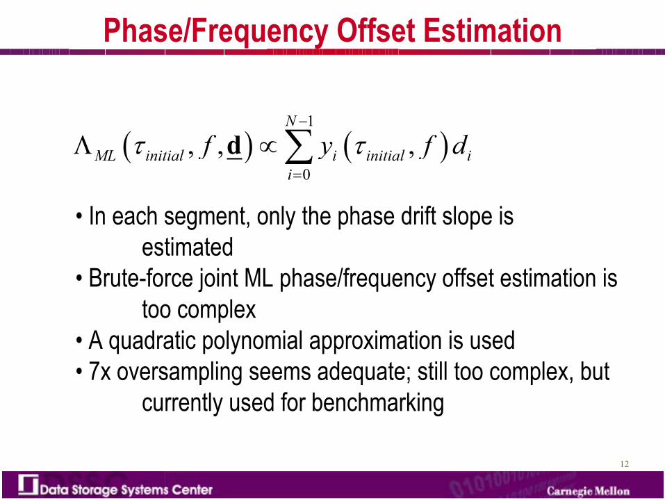
Phase/Frequency Offset Estimation
� � � �1
0, , ,
N
ML initial i initial ii
f y f d� �
�
�
� ��d
• In each segment, only the phase drift slope is estimated
• Brute-force joint ML phase/frequency offset estimation is too complex
• A quadratic polynomial approximation is used• 7x oversampling seems adequate; still too complex, but
currently used for benchmarking
13
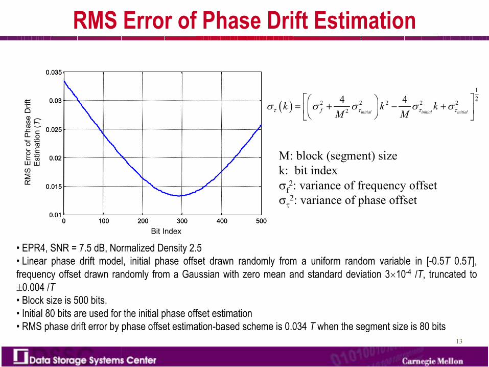
RMS Error of Phase Drift Estimation
0 100 200 300 400 5000.01
0.015
0.02
0.025
0.03
0.035
Bit Index0 100 200 300 400 500
0.01
0.015
0.02
0.025
0.03
0.035
RM
S Er
ror o
f Pha
se D
rift
Estim
atio
n (T
)
• EPR4, SNR = 7.5 dB, Normalized Density 2.5• Linear phase drift model, initial phase offset drawn randomly from a uniform random variable in [-0.5T 0.5T], frequency offset drawn randomly from a Gaussian with zero mean and standard deviation 3�10-4 /T, truncated to �0.004 /T• Block size is 500 bits. • Initial 80 bits are used for the initial phase offset estimation • RMS phase drift error by phase offset estimation-based scheme is 0.034 T when the segment size is 80 bits
� �
12
2 2 2 2 22
4 4initial initial initialfk k k
M M� � � �� � � � �
� �� �� � � �� �
� � �
M: block (segment) sizek: bit index�f
2: variance of frequency offset��
2: variance of phase offset
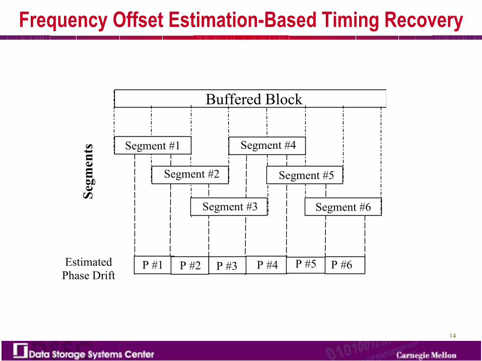
14
Buffered Block
Segment #1
Segment #2
Segment #3
Segment #4
Segment #5
Segment #6
P #1 P #2 P #3 P #4 P #5 P #6
Segm
ents
Estimated Phase Drift
Frequency Offset Estimation-Based Timing Recovery
15
5.5 6 6.5 7 7.5 8 8.50.02
0.03
0.04
0.05
0.06
0.07
SNR (dB)
RM
S Va
lue
of R
esid
ual T
imin
g Ji
tter (
T)
FOSTRConventional Decision-Directed
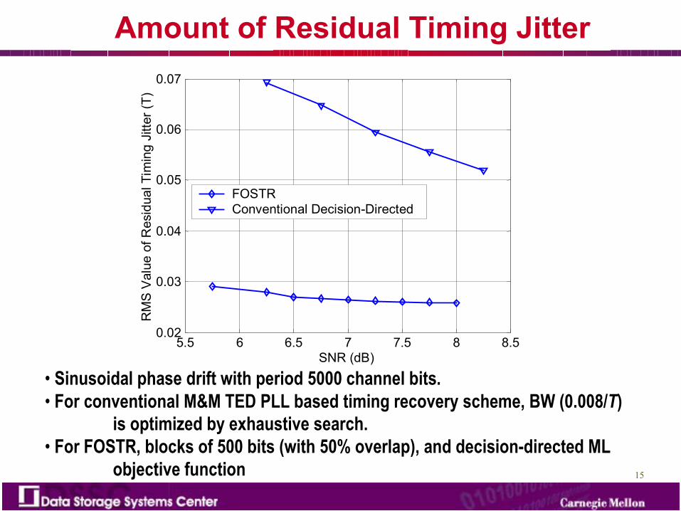
Amount of Residual Timing Jitter
• Sinusoidal phase drift with period 5000 channel bits. • For conventional M&M TED PLL based timing recovery scheme, BW (0.008/T)
is optimized by exhaustive search. • For FOSTR, blocks of 500 bits (with 50% overlap), and decision-directed ML
objective function
16
� Loss of lock is the more dominant timing recovery problem at low SNR
� Proposed a frequency-offset estimation based symbol timing recovery (FOSTR)
� Numerical simulations of FOSTR show improvement over conventional PLL-based timing recovery
Signal Processing for Storage (SPS) Technical Committee MeetingNoon-1.30 PM, Nov. 19 (TODAY)Peacock Room, 3rd Floor, Hyatt