surface enhancements accelerate bone bonding to cpc‐coated strain gauges
TRANSCRIPT

Surface enhancements accelerate bone bonding toCPC-coated strain gauges
Nicholas M. Cordaro,1 John A. Szivek,1 Don W. DeYoung2
1Orthopaedic Research Laboratory, Department of Orthopedic Surgery and Biomedical Engineering InterdisciplinaryProgram, University of Arizona, Tucson, Arizona 857242University Animal Care, University of Arizona, Tucson, Arizona 85721
Received 13 March 2000; revised 22 August 2000; accepted 18 January 2001
Abstract: Calcium phosphate ceramic (CPC)-coated straingauges have been used for in vivo bone strain measurementsfor up to 18 weeks, but they require 6 to 9 weeks for suffi-cient bonding. Osteogenic protein-1 (OP-1), PepTite™ (aproprietary ligand), calcium sulfate dihydrate (CSD), trans-forming growth factor b-1 (TGF-b1 ), and an endothelial celllayer with and without TGF-b1 were used as surface en-hancements to accelerate bone-to-CPC bonding. Young maleSprague–Dawley rats were implanted with unenhanced andenhanced CPC-coated gauges. Animals were allowed nor-mal activity for 3 weeks and then calcein labeled. Femurswere explanted following euthanasia. A gauge was attachedwith cyanoacrylate to the opposite femur in the same posi-tion as the CPC-coated gauge. Bones were cantilever-loadedto assess strain transfer. They were sectioned and stainedwith mineralized bone stain (MIBS) and examined with
transmitted and ultraviolet light. Mechanical testing indi-cated increased sensing accuracy for TGF-b1 and OP-1 en-hancements to 105 ± 14% and 92 ± 12% versus 52 ± 44% forthe unenhanced gauges. The PepTite™ and the endothelial-cell-layer-enhanced gauges showed lower sensing accuracy,and histology revealed a vascular layer near CPC particles.TGF-b1 increased bone formation when used prior to endo-thelial cell sodding. CSD prevented strain transfer to thefemur. TGF-b1 and OP-1 surface enhancements producedaccurate in vivo strain sensing on the rat femur after 3 weeks.© 2001 John Wiley & Sons, Inc. J Biomed Mater Res 56:109–119, 2001
Key words: strain gauge; calcium phosphate ceramics;transforming growth factor b-1; osteogenic protein-1; endo-thelial cells
INTRODUCTION
The loading imposed on bone influences bonechanges in shape and material properties.1,2 Improvedmethods of in vivo strain measurement will improveknowledge of this strain-mediated bone response. Invivo strain measurements previously have been re-corded by bonding strain gauges to bone with a cya-noacrylate adhesive.3–6 This method has been usedsuccessfully for up to 3 weeks.7 The strain readingshave been used to study bone adaptive behavior tovarious mechanical stimuli,2,8 the relationship be-tween bone structure and loading, and the effects ofimplants on this relationship.6,9,10 However, the adhe-
sive begins resorbing immediately in vivo, causingprogressively less accurate strain readings11,12 as timegoes on.
Calcium phosphate ceramic (CPC)-coated straingauges have been used for in vivo bone strain mea-surements in dogs and rats.13,14 This technique hasallowed gauges to remain bonded for up to 18weeks.13 However, the time required for sufficientbone bonding to produce an accurate strain reading isat least 6 weeks in rats and 9 weeks in dogs.15,16 Thegoal of this study was to develop a method that cre-ates a faster and longer-lasting bone bond to CPC-coated strain gauges.
Biochemical and biologic surface treatments wereplaced onto a blend of CPC particles. This particleblend had demonstrated secure bonding at 6 weeks inan earlier rat study.17 Transforming growth factor-b1,osteogenic protein-1t, extracted endothelial cells, Pep-Tite™, calcium sulfate dihydrate, and a combinationof transforming growth factor-b1and endothelial cellswere used as surface enhancements.
Transformation growth factor-b (TGF-b1) is a mul-tifunctional polypeptide synthesized from humanplatelets into a 25-kD homodimer.18 It affects many
This manuscript contains information collected and sub-mitted as part of a Master’s degree (N.M.C.) at the Univer-sity of Arizona.
Correspondence to: J.A. Szivek; [email protected] grant sponsor: National Science Foundation;
contract grant number: BES-9807623Contract grant sponsor: The Whitaker Foundation (Spe-
cial Opportunity Award)
© 2001 John Wiley & Sons, Inc.

aspects of cell growth, differentiation, and function,including the induction of osteoblast mitogenic activ-ity.18 Published evidence indicates that it has pro-duced a threefold increase of bone ingrowth into po-rous-coated canine implants after 4 weeks.19 It washypothesized that the TGF-b1 would increase boneformation on the CPC, leading to faster attachment.
Osteogenic protein-1 (OP-1) is a synthetic form ofnaturally occurring bone morphogenetic protein-7(BMP-7) derived from the dimetric protein TGF-b su-perfamily. BMPs have been noted for possessing os-teoinductive properties and for inducing ectopic boneformation.20 A tenfold increase in alkaline phospha-tase activity (leading to osteocalcin production) after48 h in vitro has been noted when BMP-2 and BMP-3were added to a murine bone-marrow stromal osteo-progenitor cell line.20 BMP-2 has been noted to in-crease alkaline phosphatase activity in a subpopula-tion of muscle-derived cells (leading to osteogenic dif-ferentiation).21 OP-1 is osteogenic in human patients.22
Therefore it was hypothesized that OP-1 would in-crease the amount of bone-to-CPC attachment at anearlier time.
Williams et al. 1992, developed a method of isolat-ing endothelial cells for re-implantation onto vasculargrafts to induce angiogenesis.23 It was hypothesizedthat the resulting increased vascularization from im-planted endothelial cells would increase bone forma-tion.24 A method of isolating endothelial cells from therat and sodding this onto the CPC particles has beendeveloped and that method was used.
PepTite™ was designed specifically to noncova-lently bond (carboxy-terminal) to an existing surfaceto leave the arginine–glycine–aspartic acid sequenceaccessible for cell attachment.25 The cell attachment tothe PepTite™ interface was hypothesized to produce avascular matrix that would promote bone growth andattachment to the surrounding CPC particles.
Calcium sulfate dihydrate (CSD) has been used inclinical practice to fill bone defects and deliver anti-bodies.26 CSD dissolves quickly in vivo, and this dis-solution is followed by bone formation in the defect.CSD releases calcium as it is digested by giant cells,leaving a reserve for osteointegration.27,28 It was hy-pothesized that this effect would aid in early boneconduction on the CPC.
These surface enhancements were chosen becauseof their osteogenic or osteoconductive effects. Previ-ously tested unenhanced gauges sensed strain accu-rately after 6 weeks.15,17 A 3-week study was con-ducted since unenhanced controls were expected toachieve less than 100% accurate strain sensing andenhanced coatings were expected to achieve a greateraccuracy of strain sensing. This study format allowedus to determine which enhancement accelerated the
process of bone formation onto the CPC particles, thusallowing more accurate strain sensing. Cantileverbending tests were used to assess the extent of strainsensing accuracy and histomorphometry was used toassess bone formation adjacent to the CPC-coatedstrain gauges. In combination these measurementsprovided an indication of the relative rates of boneformation and bonding to the CPC coatings, thus test-ing our overall hypothesis that relative to unenhancedCPC-coated gauges, enhanced gauges would increasestrain sensing accuracy at 3 weeks.
MATERIALS AND METHODS
Strain gauge preparation
Uniaxial type EA-06-015K-120 single element straingauges (Micro-Measurements Group Inc., Raleigh, NorthCarolina) were coated on their sensing surfaces with a CPCparticle blend of 15 wt % of a CPC previously designatedCPC 6 and 85 wt % of a CPC previously designated CPC 7.This blend has shown favorable bone-to-CPC bonding16
while providing excellent CPC/gauge interface strength.28
Particles were obtained from Biointerfaces (San Diego, Cali-fornia). Scanning electron micrographs have shown thatCPC 6 is a rounded particle with an average long axis of 9 ±7 mm and an average short axis of 6 ± 5 mm. EDAX (energydisperse X ray) indicated that it is a tricalcium phosphate(TCP). CPC 7 is an angular, rock-like microcrystalline hy-droxyapatite with a long-axis dimension of 561 ± 112 mmand a short-axis dimension of 115 ± 70 mm.28
CPC particles were attached to gauges using a publishedprocedure.17,29 The sensing sides of the gauges were sandedwith 600-grit carbide paper. A thin layer of 15 wt % solutionof medical-grade polysulfone (Amoco, Huntington Beach,California) dissolved in 1,1,2,2 tetrachloroethane (Kodak,Rochester, New York) was applied to the sensing surface ofeach gauge and they were baked for 1 h at 90°C. This layerthen was sanded with 1200-grit carbide paper. A secondlayer of the polysulfone was applied. The CPC blend wassprinkled onto the polysulfone. The polysulfone solutionwas used to bond the CPC particles to the sensing surface ofthe strain gauge. The gauges were baked for 5 h at 90°C todry the solvent and strengthen the interface. A weight on aglass slide was used to press the CPC particles into the poly-sulfone during heat treatment. The nonsensing surfaces ofthe gauges were coated using a published technique30 (Szi-vek et al., 1992) with three water proofing polymer coatings:nitrile rubber, acrylic, and a polyurethane (M coat B, M coatD, and M coat A, respectively). All gauges were doublepackaged and sterilized using ethylene oxide, and then theywere aerated before use. Dektac and scanning electron mi-croscopy of selected gauges showed a consistent coatingthickness.15
110 CORDARO, SZIVEK, AND DEYOUNG

Surface enhancements applied to CPC-coatedgauges
Transforming growth factor-b1
TGF-b1 (Collaborative Biomedical Products, Bedford,Massachusetts) was stored at −70°C in 1-mg sample sizesuntil used. Each mg of TGF-b1 was reconstituted with 12 mLof 4 mM HCl solution filtered through a 0.2-mm Acrodisktfilter. Sterilized CPC gauges were opened under a sterilelaminar flow hood and placed on a petri dish. Each gaugereceived 1⁄3 mg of reconstituted TGF-b1. They were stored ina controlled humidity chamber at 37°C for 18 h prior tobeing implanted during aseptic surgery. Care was taken notto touch the surfaces or to allow them to become desiccated.
Petri dishes containing gauges that had to be held longerthan 18 h were wrapped tightly in parafilm and refrigerated.Prior to surgery these gauges were brought to room tem-perature and held in a controlled humidity chamber.
Osteogenic protein-1 (bone morphogenetic protein-7)
During aseptic surgery, 0.5 mg of human recombinantOP-1 (Creative Biomolecules, Hopkinton, Massachusetts)was re-hydrated with 2 cc of sterile water. The OP-1 dis-solved completely into a solution that was drawn into asterile syringe. Two drops of the OP-1 solution were placeddirectly onto CPC surfaces and two directly onto the bonecontact zone for a total dose of 0.05 ± .01 mL or 12.5 ± 2.5 mgof OP-1
Endothelial cell sodding, with and without TGF-b1
Three gauges were coated with TGF-b1 before applyingan endothelial cell layer and three received only the endo-thelial cell layer. Endothelial cells were harvested and pre-pared according to a published technique.24 Two sections ofapproximately 2 × 1 × 0.5 cm3 of epididymal fat were re-moved following a midline abdominal incision. The fat wasplaced in a sterile container with harvest media, minced,washed to remove red blood cells, then digested and centri-fuged to separate the fat, collagenase, and cells. The vascularendothelial cells that formed a pellet were re-suspended andspun to create a concentrated solution of 0.7–4.3 × 10⁶ cellsper mL (established using a Coulter counter). The CPC-coated strain gauges were soaked in this cell-containing so-lution for 20 min at 37°C before implantation.
PepTite™
Six gauges were coated with PepTite™, a proprietary li-gand25,31 that was bonded to the CPC particles. FollowingPepTite™ attachment, gauges were sterilized in ethylene ox-ide and aerated prior to implantation. To confirm that thecarboxy-terminal of PepTite™ adequately attached to theCPC 6+7 gauges, selected gauges coated with the PepTite™were placed in cell culture, and cell populations on theirsurfaces were evaluated using fluorescence microscopy.
Calcium sulfate dihydrate
An OsteoSet™ bone void filler kit, which contains calciumsulfate hemihydrate (CSH; Wright Medical TechnologiesInc., Arlington, Tennessee), was mixed with 1 part (wt) CSHto 0.3 parts (wt) sterile water to form a slurry that was al-lowed to thicken for 5 min, forming calcium sulfate dihy-drate. The CPC particles were covered with a thin layer ofthe mixture and then implanted.
Surgical procedures
A group of six 120-day-old male Sprague–Dawley ratswere used to test each surface enhancement except cell sod-ding. The cell sodding procedure and cell sodding combinedwith TGF-b1 both seemed promising enhancements. As apreliminary experiment the cell-sodded gauges were testedwith and without TGF-b1 in two groups of three rats todetermine which offered a better solution. The total numberof rats used was 36. All surgical procedures followed theNational Institute of Health guidelines for the care and useof laboratory animals (NIH publication 85-23, rev.1985). Therats were anesthetized with an injectable anesthetic. One legwas shaved and scrubbed on the lateral and medial sidefrom below the knee to above the hip in preparation foraseptic surgery. An incision then was made on the lateralaspect of the leg, below the hip and extending to the knee.The intramuscular plane was separated to expose the femur.The periosteum on the anterior lateral surface was removedand dried with gauze. One gauge was placed on the mid-diaphysis with the CPC layer toward the bone and the sens-ing element oriented along the long axis of the bone. Gaugeswere secured with three equally spaced 00 Poly-Vicrylt re-sorbable sutures (Ethicon, New Jersey). The skin was closedwith subcuticular stitches after apposition of the muscle. Theanimals were ambulatory within 5 h and were returned totheir cages. They were allowed normal cage activity withfood and water ad libitum.
At 7 days and again at 3 days prior to sacrifice, the testanimals were injected subcutaneously with a 0.40-cc solu-tion containing 18 mg/mL of calcein. The calcein was usedto label the newly formed mineralized bone.
Mechanical testing and CPC/bone bonding analysis
The animals were euthanized using CO2 hypoxia 3 weeksafter gauge implantation. Both femora were explanted andall tissues were removed. Care was taken to assure thatgauges were not dislodged during these procedures. In ad-dition, bones were covered with saline-soaked gauze duringpreparation to prevent dehydration.
Left and right femora were potted in separate aluminumholders, embedding the femoral condyles in Cerrobendt, alow melting point alloy (Scottsdale Tool, Phoenix, Arizona).Anatomic landmarks (the femoral head, greater trochanter,and femoral condyles) were used to align and positionfemora at the same depth in the holders. A strain gauge wasattached using a cyanoacrylate adhesive to the anterior lat-
111SURFACE ENHANCEMENTS ACCELERATE BONE BONDING
eral aspect of the control femur in the same position as theimplanted CPC-coated gauge on the contralateral femur.Great care was taken during this process to achieve accurategauge placement.
Gauges were wired and connected to signal conditionersthat were interfaced with a NiDAQ data acquisition board,monitored with Lab View 5.0 on a Macintosh G3. The em-bedded femora were attached to an L-shaped support fix-ture and were loaded so that bones were tested in cantileverbending.32 Gauges were placed alternately in tension andcompression, using a servo-hydraulic series 810 MTS (Ma-terials Testing Systems Corporation, Minneapolis, Minne-sota) at a rate of 0.5 kg/s to a peak load of approximately0.55 kg. Selection of this load rate was based on published invivo strain measurements that reflect rat femur loading dur-ing normal gait.5 Measurements were collected and thestrain was interpolated at 0.50 kg. A percent sensing accu-racy was calculated from the strain recorded for the CPC-coated gauge divided by the glued gauge [sensing accuracy= (strain CPC-coated/strain glued) × 100]. Data outlierswere reduced for the tensile and compressive loading setsindependently, using Chauvenet’s criterion.33 This criterionrejects data points that have a probability of obtaining thevalue, based on the standard deviation and mean, of lessthan 1÷(two times the number of measurements). Tensileand compressive strain measurements were averaged andstandard deviations were calculated. The statistical signifi-cance of the measurements collected from gauges with vari-ous surface enhancement were calculated using the Mann–Whitney rank sum test unless the particular set passed therank sum test, in which case the unpaired t test was used(SigmaStat 2.0, Chicago, Illinois).
Histology and histomorphometry
Bone samples were prepared for embedding by drilling ahole proximal to the knee that allowed fluid infiltration dur-
ing dehydration and embedding. Ethanol solutions mixedwith distilled water were used to dehydrate the bones. Thedehydration steps consisted of placing the bones in 70%ethanol for 2 h (2 changes), then in 95% ethanol for 8 h (3changes), and then in 100% ethanol for 11 h (3 changes)(minimum time limits). The bones were imbedded in poly-methyl methacrylate (K-plast softener and initiator fromDelaware Diamond Knives, Inc.), following a publishedtechnique.34
Four to seven samples were cut through each gauge per-pendicular to the long axis of the bone using a diamondwafering saw. The sections were ground to 10 mm andstained using MIBS, a mineralized bone stain.35
Digital images of the stained samples were collected toassess bone formation due to surface enhancements. Histo-morphometry was carried out using transmitted and ultra-violet light. Total bone area and cortical areas were mea-sured. Bones were divided into four quadrants, the gaugebeing in quadrant 1 (Fig. 1). In quadrant 1 the new bonegrowth, the area of periosteal new bone growth, the erodedperimeter (total lengths of resorption), single- and double-label perimeter of calcein labels, and the calcein interlabelwidths were determined. Directly below the new bone inQuadrant 1 the number of osteoid seams, the number ofcalcein-labeled osteoid seams, osteoid widths, calcein inter-label widths, and inner- and outer-labeled perimeters ofbone structural units were determined. The mineral apposi-tion rate (MAR) was calculated in both the new bone growthand existing bone under the gauge by dividing the interlabelcalcein widths by the interlabel time.35,36 The statistical sig-nificance of the measurements was computed using a t test(SigmaStat 2.0, Chicago, Illinois).
RESULTS
Mechanical testing results
Unenhanced gauges had a mean sensing accuracyof 52 ± 44% (n = 5). PepTite™-coated gauges (49 ±15%; n = 4) displayed a lower sensing accuracy, butthese results were not statistically significantly differ-ent from the unenhanced gauges. The OP-1 (92 ± 12%;n = 6) and the TGF-b1 (105 ± 14%; n = 5) showed thehighest sensing accuracy, and both were statisticallysignificantly different from the unenhanced, with a95% confidence interval (Fig. 2). All six of the CSD-coated gauges were too loose to test or fell off duringnecropsy. The sensing accuracy of each of these speci-mens was assigned a value of zero. The CSD gaugeswere sutured back onto the femur for histology. Thegauges coated with the endothelial cells displayedpoor sensing accuracy (15 ±17%; n = 2). One of thethree gauges was too loose to test and was assigned avalue of zero. The gauges coated with TGF-b1 and
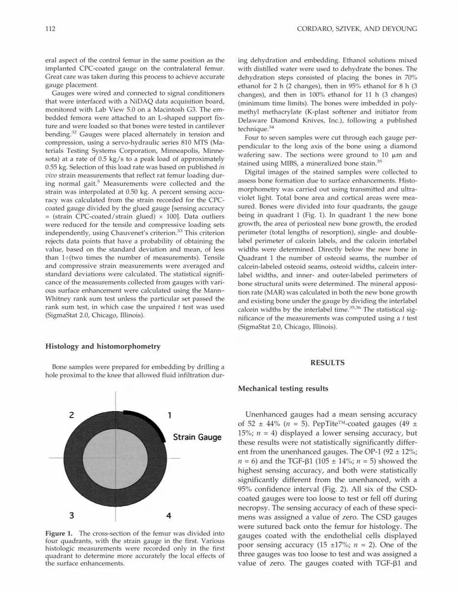
Figure 1. The cross-section of the femur was divided intofour quadrants, with the strain gauge in the first. Varioushistologic measurements were recorded only in the firstquadrant to determine more accurately the local effects ofthe surface enhancements.
112 CORDARO, SZIVEK, AND DEYOUNG

then endothelial cells produced a wide range of sens-ing accuracy’s (43 ± 50%; n = 2). A visual examinationof both groups of cell-sodded gauges just prior to im-plantation suggested that the CPC layer was thinneron TGF-b1-treated gauges. This may have been a re-sult of the solutions in which these gauges weresoaked in order to add cells and then TGF-b1 to theCPC surface.
Histomorphometric results
Although more new bone was formed, relative tounenhanced controls (Fig. 3), on PepTite™-coatedgauges (Fig. 4) this was not statistically significant(Table I).
OP-1- and TGF-b1-enhanced CPC-coated gaugesproduced more new bone and more bone-to-CPC con-tact than other enhancements (Figs. 5 and 6). Both pro-duced areas of woven bone; however TGF-b1 pro-duced tighter woven bone at the CPC–bone interface(Fig. 7). The gauges with the TGF-b1 enhancementalso appeared to cause a slight though not statisticallysignificant increase in total cortical area (9.2 ± 1.3 mm2
vs 8.8 ± .8 mm2) relative to the unenhanced. There wasvisual evidence of a thicker calcein label on the peri-osteal perimeter. The OP-1 produced sporadic areas ofnew woven bone that often extended outward tangen-tially to the bone surface. This resulted in a larger,though not statistically significantly different, totalbone area of 14.0 ±1.1 mm2 versus 13.3 ± .7 mm2 forthe unenhanced control sections. These patterns ofsporadic woven bone occasionally were present on themedial side of the bone, opposite the gauge.
A vascularized layer was noted between the boneand CPC coatings on the histologic sections of the Pep-Tite™ and cell-sodding-enhanced coatings (Fig. 8).Both produced large areas of erosion (0.6 ± .3 mm and
0.68 ± .39 mm in length, respectively, versus 0.11 ± 07mm for the unenhanced gauge) on the periosteal sur-face beneath the gauge (Table II). The PepTite™ en-hancement produced a layer of new bone, with a 0.29± .23 mm2 area adjacent to eroded areas that extendedtoward but did not contact the CPC particles. Vascu-larized areas with endothelial cells and fibrous tissuesurrounded the CPC particles. When TGF-b1 wasadded before the cell-sodding procedure, areas of newwoven bone were noted (Table II) that were similar tothose noted in TGF-b1-enhanced CPC coatings.
The CSD-enhanced gauges produced results similarto the unenhanced gauges (Tables I–III) in all mea-sured parameters except the single/double label pe-rimeter. The differences were not statistically signifi-cant. However, there was little to no bone growth nearthe CPC particles (Fig. 9). The CSD bone interface wasclearly identifiable in the optical microscope butlacked osteoconductive activity, as determined from alack of calcein labeling. There appeared to be cellswithin the CSD matrix. The calcein-labeled perimeterwas only 0.94 ± .64 mm (Table II). In some cases amicrofracture was observed at the CSD–bone inter-face, likely induced during bone removal or duringslide polishing. In regions along the gauge edges,where the CSD and CPC were exposed to soft vascu-larized tissues, there were areas of new woven bone.
The number of osteoid seams in the cortical bone ofall groups was in a similar range (Table III) except forboth the cell-sodded groups (Fig. 10). The cell-soddedgroup alone statistically was significantly lower, andthe group with cell sodding and TGF-b1 statisticallywas significantly higher than the unenhanced controlgroup. The number of labeled osteoid seams in thecortical bone was statistically significantly higher forthe PepTite™, the TGF-b1, and the endothelial cellswith TGF-b1. The calcein-labeled perimeters werelargest for the TGF-b1 group. All of the enhancedgroups had a larger outer perimeter compared to theunenhanced group while only the PepTite™-, OP-1-,TGF-b1-, and CSD-enhanced groups had a larger in-ner calcein perimeter (Table III).
Mineral appositional rates (MARs) were calculatedin both the new bone and the preexisting cortical bone(Fig. 11). The MAR for all gauges was higher in thenew bone versus the preexisting bone. None of theMARs in the preexisting bone was statistically signifi-cantly different. The MAR in the new bone was sta-tistically significantly different for the PepTite™ (p =.048) and the endothelial cell-sodded (p = .008) groupsversus the unenhanced CPC-coated gauges.
DISCUSSION
The blended CPC 6+7, composed of a tricalciumphosphate and a microcrystalline hydroxyapatite, was
Figure 2. Sensing accuracy of seven groups of CPC-coatedgauges relative to glued controls. The p values (Student’s t)are from comparisons made to the unenhanced CPC gauges.The error bars represent the standard deviation.
113SURFACE ENHANCEMENTS ACCELERATE BONE BONDING

TABLE IComparison of the Total Areas of Bone and New Bone for Enhanced and Unenhanced CPC-Coated Strain Gauges
Total Bone Area(square mm)
Total CorticalBone Area (square mm)
New Bone Growthin Quad 1 (square mm)
Unenhanced 13.3 ± 0.7 8.8 ± 0.8 0.16 ± 0.06PepTite™ 13.1 ± 1.3 (p = .669) 8.8 ± 0.9 (p = 1.0) 0.29 ± 0.23 (p = .101)OP-1 14.0 ± 1.1 (p = .099) 9.7 ± 1.1 (p = .048) 0.39 ± 0.20 (p = .002)TGF-b1 13.8 ± 1.3 (p = .286) 9.2 ± 1.3 (p = .410) 0.36 ± 0.26 (p = .028)CSD 13.3 ± 0.6 (p = 1.00) 9.1 ± 0.9 (p = .414) 0.17 ± 0.14 (p = .836)Cells 13.2 ± 0.6 (p = .772) 6.7 ± 2.7 (p = .033) 0.26 ± 0.20 (p = .115)Cells w/TGF 13.0 ± 1.0 (p = .496) 8.2 ± 0.5 (p = .122) 0.33 ± 0.16 (p = .008)
The OP-1 and TGF-b1 caused the most new bone to form adjacent to the gauge.
TABLE IIParameters Measured in New Bone under CPC Gauges in Quadrant 1
Single/Double LabelPerimeter (mm) Interlabel Distance (mm) Eroded Perimeter (mm)
Unenhanced 1.7 ± 0.6 16.4 ± 2.4 0.1 ± 0.1PepTite™ 2.4 ± 1.3 (p = .139) 22.4 ± 4.4 (See Figure 2) 0.6 ± 0.3 (p = .026)OP-1 3.7 ± 1.7 (p = .002) 15.8 ± 3.9 0.2 ± 0.1 (p = .220)TGF-b1 2.4 ± 2.0 (p = .303) 16.8 ± 3.9 0.1 ± 0.1 (p = 1.0)CSD 0.9 ± 0.7 (p = .013) 17.8 ± 5.1 0.1 ± 0.1 (p = 1.0)Cells 2.2 ± 0.9 (p = .201) 23.1 ± 5.3 0.5 ± 0.4 (p = .142)Cells w/TGF 2.5 ± 0.7 (p = .029) 25.2 ± 5.2 0.2 ± 0.2 (p = .451)
The single/double label perimeter is the length of the calcein labels, and the interlabel distance is the spacing between thecalcein labels. The eroded perimeter is the length of bone that was absorbed under the gauge.
TABLE IIIHistologic Measurements Made Below the Gauge and New Bone in the Cortical Section within Quadrant 1
# of Osteoids# of Osteoids
with LabelOsteoid Width
(mm)Interlabel Width
(mm)
Label Perimeter
Outer (mm) Inner (mm)
Unenhanced 32.0 ± 8.1 2.8 ± 2.3 6.7 ± 5.8 8.6 ± 3.2 0.15 ± 0.06 0.10 ± 0.05PepTite™ 33.0 ± 20.7 (p = .888) 13.3 ± 15.3 (p = .046) 7.4 ± 2.3 11.6 ± 3.6 0.17 ± 0.06 0.11 ± 0.04OP-1 26.5 ± 18.0 (p = .386) 3.6 ± 2.7 (p = .476) 6.3 ± 2.7 10.3 ± 6.0 0.19 ± 0.06 0.14 ± 0.05TGF-b1 25.1 ± 6.9 (p = .055) 8.5 ± 7.1 (p = .027) 8.2 ± 3.8 11.5 ± 3.2 0.22 ± 0.13 0.15 ± 0.07CSD 33.7 ± 17.0 (p = .775) 3.3 ± 3.8 (p = .720) 7.3 ± 2.3 14.2 ± 11.8 0.19 ± 0.06 0.11 ± 0.05Cells 21.0 ± 8.4 (p = .021) 14.3 ± 7.5 (p = .001) 7.0 ± 1.5 11.0 ± 3.1 0.16 ± 0.06 0.10 ± 0.04Cells w/TGF 35.5 ± 12.1 (p = .020) 11.5 ± 10.3 (p = .020) 8.9 ± 1.3 13.6 ± 10.4 0.26 ± 0.07 0.10 ± 0.03
The higher number of labeled osteoid seams with the PepTite™, TGF-b1, endothelial cells, and endothelial cells withTGF-b1 enhancements indicate a higher bone turnover rate during the labeling period.
Figure 3. The unenhanced CPC-coated gauge (G) is shown, using standard light photomicrography, attached to the poly-sulfone (PS) and then to the CPC particles (C1–C3). New bone (NB) is shown extending from the preexisting cortical bone(CB) to particles C1 and C2. No growth is observed adjacent to particles C3. [Color figure can be viewed in the online issue,which is available at www.interscience.wiley.com.]
114 CORDARO, SZIVEK, AND DEYOUNG

Figure 4. The PepTite™-enhanced CPC gauges (G) produced a vascularized tissue layer (V) between the CPC (C)/polysulfone (PS) and the new bone (NB) A large amount of new bone grew from the preexisting cortical bone (CB). [Colorfigure can be viewed in the online issue, which is available at www.interscience.wiley.com.]
Figure 5. Osteogenic protein-1-enhanced CPC-coated gauge (G) is secured to the new bone (NB) through CPC particles(C1–C3). This interface bonds the gauge to the preexisting cortical bone (CB). Bone spurs (S) existed on the section of the OP-1group. (A) areas of forming bone. [Color figure can be viewed in the online issue, which is available at www.interscience.wiley.com.]
Figure 6. Transforming growth factor b-1-enhanced CPC-coated gauge (G) is shown attached to the CPC particle (C1, C2)by the polysulfone layer (PS). New bone (NB) has extended from the preexisting cortical bone (CB) along the entire CPC–boneinterface. There is a small amount of erosion (E) of the cortical bone. Osteoclasts (OC) and osteoblasts (OB) are observed.[Color figure can be viewed in the online issue, which is available at www.interscience.wiley.com.]
115SURFACE ENHANCEMENTS ACCELERATE BONE BONDING

chosen as the strain-gauge coating to test the enhance-ments because it had a combination of favorable prop-erties relative to a series of CPCs tested in earlier stud-ies,15–17,29,37 such as a high CPC-to-bone interfaceshear strength after 6 weeks in vivo17 and a high CPC-to-gauge interface shear strength.29
The greater accuracy of comparative strain readingsfrom TGF-b1 and OP-1 surface-enhanced CPC-coatedgauges indicates that these enhancements acceleratedbone bonding to the CPC particles relative to unen-hanced CPC coatings. Gross histologic observationsrevealed extensive bone-to-CPC contact. However, theOP-1 enhancement produced bone spurs that ex-tended into the adjacent muscle tissue. These spursmay have resulted from the enhancement applicationtechnique. A technique similar to that used with theTGF-b1 may produce more consistent results withfewer areas of spur growth. Gross histologic observa-tions further revealed that both of these enhancementsproduced woven bone in most regions (more pro-nounced with OP-1), and numerous osteoclasts andosteoblasts were evident, indicating a high level ofbone activity.
The PepTite™ inhibited bone-to-CPC particle at-tachment relative to unenhanced samples by inducingthe formation of a vascular layer between the CPCparticles and the bone matrix. There was extensivebone growth up to the vascular layer from the existingcortical surface. The calcein labels indicated that rapidbone formation was occurring between 7 and 3 daysprior to sacrifice, and a statistically significantly
higher MAR was evident. This suggests that while alocal increase in vascularization increases bonegrowth, this two-step process causes slower bone at-tachment to CPC-coated strain gauges than did theprocess that formed bone when gauges were en-hanced with OP-1 or TGF-b1.
The cell-sodding technique produced similar vascu-larization and statistically a significantly higher MAR,as noted for the PepTite™. However, there were moreareas of bone precursor cells adjacent to the soddedCPC particles than there were to the PepTite™ group.Enhancing the CPC particles with TGF-b1 before thecell-sodding process established significant bone-to-CPC particle attachment (Fig. 12). This effect wasnoted by Winn et al. when BMP-2 was used alone andin combination with human osteoblast precursor cellsin a rat calvarial defect model.38 The sensing accuracyfor the cell-sodded gauges with TGF-b1 were lowerand the scatter wider than might be expected from theamount of bone seen during histology. It is possiblethat the harvest media used to digest the fat tissue andseparate the endothelial cells partially dissolved theCPC coating on the gauges.
The calcium sulfate dihydrate-enhanced gaugesshowed very little bone attachment to CPC particles.Although there were precursor cells found within theCSD, there was little bone formation, as noted fromthe lack of calcein labeling. Bone growth did occuralong the edges of the gauges, where the CSD and theCPC particles were exposed to the surrounding tis-sues. The growth could have been due to the increasedvascularization in those areas.
Two variables that could have affected the sensingaccuracy in this experiment were attachment of theCPC particles to the strain gauges and relative align-ment of the glued control gauges and the CPC-coated
Figure 7. A magnified view of a transforming growth fac-tor b-1-enhanced CPC-coated gauge shows the level of cel-lular activity forming new bone (NB) and attaching the pre-existing cortical cone (CB) to CPC particles (C). Osteoclastsforming an osteoid seam (OS) are visible. [Color figure canbe viewed in the online issue, which is available atwww.interscience.wiley.com.]
Figure 8. A magnified view of the endothelial cell-layerCPC-coated gauges shows capillary vessels (V1, V2) adja-cent to a CPC particle (C) and polysulfone (PS). V1 points toa single nucleus of an endothelial cell forming a capillary.Attached to the interior of the cell wall are four immunecells. [Color figure can be viewed in the online issue, whichis available at www.interscience.wiley.com.]
116 CORDARO, SZIVEK, AND DEYOUNG

experimental gauges on the femora for mechanicaltesting. The CPC particle attachment to the straingauges has been well studied and characterized byBattraw et al. (1998).29 They investigated variousgauge preparation techniques to produce a strongershear interface between the CPC particles and thegauge surface.29 These techniques were implementedin the current study. Battraw et al., in 1996, furtherstudied the mechanical symmetry of rat femora andshowed that less than 2.0% sensing accuracy differ-ence between contralateral femora can be achieved byaccurate gauge alignment.32
CONCLUSIONS
1. The unenhanced CPC 6+7 produced a variablesensing accuracy of 52 ± 44% at 3 weeks on therat femur.
2. The TGF-b1 and OP-1 surface enhancements ac-celerated bone-to-CPC particle bonding, produc-ing improved and less variable sensing accura-cies of 105 ± 14% and 92 ±12%, respectively, after3 weeks.
3. The PepTite™ and the endothelial layer enhance-ments induced vascularization near CPC par-ticles, resulting in relatively slower bone-to-CPCparticle attachment.
Figure 11. Mineral appositional rates (MARs) are shownfor each group in the preexisting cortical bone and for thenew bone directly below the gauge. As anticipated, the MARis higher in the new bone compared to the existing bone.With the PepTite™ and the endothelial cell layer enhance-ments, the MAR was increased further during the calcein-labeling period. Increased vascularization was noted inthese two groups. The error bars represent standard devia-tions.
Figure 9. The calcium sulfate dihydrate (CSD)-enhanced CPC-coated gauge (G) failed to bond the preexisting cortical bone(CB) to the CPC particles (C1, C2). CSD is visible between the bone and the CPC. [Color figure can be viewed in the onlineissue, which is available at www.interscience.wiley.com.]
Figure 10. The endothelial cell-layered CPC-coated gauges produced a structured tissue layer (T) between CPC particles (C)and the preexisting cortical bone (CB). New bone (NB) and areas of erosion (E) or absorption are visible on the cortical layer.(PS) polysulfone; (G) gauge; (OS) osteoid seam. [Color figure can be viewed in the online issue, which is available atwww.interscience.wiley.com.]
117SURFACE ENHANCEMENTS ACCELERATE BONE BONDING

4. The combination of TGF-b1 and endothelial cellsincreased bone-to-CPC particle bonding relativeto the use of endothelial cells alone.
5. CSD inhibited bone-to-CPC particle bonding at 3weeks.
The authors thank Dr. Stuart Williams for his assistancewith the cell sodding. They further thank BioInterfaces Inc.,Creative BioMolecules, Telios Pharmaceuticals, Inc., andWright Medical Technology, Inc. for providing (to J.A.S.) theCPC particles, the OP-1, the PepTite™, and the CSD, respec-tively.
References
1. Woo SL, Kuel SC, Amiel D, Gomez MA, Hayes WC, White FC,Akeson WH. The effect of prolonged physical training on theproperties of long bone: A study of Wolff’s law. J Bone JointSurg 1981;63:780–786.
2. Rubin CT, Lanyon LE. Regulation of bone formation by ap-plied dynamic loads. J Bone Joint Surg 1984;6:397–402.
3. Lanyon LE. Strain in sheep lumbar vertebrae recorded duringlife. Acta Orthop Scand 1971;42:102–112.
4. Lanyon LE, Smith RN. Bone strain in the tibia during normalquadrupedal locomotion. Acta Orthop Scand 1970;41:238–248.
5. Keller TS, Spengler DM. In vivo strain gauge implantation inrats. J Biomech 1982;15:911–917.
6. Szivek JA, Johnson EM, Magee FP, Emmanual J, Poser R, Koen-eman JB. Bone remodeling and in vivo strain analysis of intactand implanted greyhound proximal femora. J Invest Surg 1994;7:213–233.
7. Baggott DG, Lanyon LE. An independent “post-mortem” cali-bration of electrical resistance strain gauges bonded to bonesurfaces “in vivo.” J Biomech 1977;10:615–622.
8. Lanyon LE, Rubin CT. Static and dynamic loads as an influenceon bone remodeling. J Biomech 1984;17:897–905.
9. Lanyon LE, Paul IL, Rubin CT, Thrasher EL, DeLaura R, RoseRM, Radin EL. .In vivo strain measurements from bone andprosthesis following total hip replacement. J Bone Joint Surg1981;63:989–1001.
10. Szivek JA, Pilliar RM, Weatherly GC, Binnington AG. A quan-titative study of the effect of strain redistribution on bone re-modeling. Trans Orthop Res Soc 1985;10:373.
11. Leonard F, Kulkarri RK, Brandes G, Nelson J, Cameron JJ.Synthesis and degradation of poly(alkylalphacyanoacrylates). JAppl Biomater 1990;1:241–248.
12. Cameron JL, Woodard SC, Pulaski EJ, Sleeman HK, Bandes G,Kulkarni RK, Leonard F. The degradation of cyanoacrylate tis-sue adhesive. Surgery 1965;58:424–430.
13. Szivek JA, DeYoung DW. In vivo strain measurements col-lected using calcium phosphate ceramic-bonded strain gauges.J Invest Surg 1997;10:263–273.
14. Szivek JA, Halloran B, Rabkin B, Anderson P, Persselin SL. Invivo strain measurements from the lateral femur and anteriortibia of rats. Trans Sixth World Biomater Cong 2000:424
15. Szivek JA, Anderson PL, Wilson DL, DeYoung DW. Develop-ment of a model for study of in vivo bone strains in normal andmicrogravity environments. Technical Note. J Appl Biomater1995;6:203–208.
16. Szivek JA, Anderson PL, Dishongh TJ, DeYoung DW. Evalua-tion of factors affecting bonding rate of calcium phosphateceramic coatings for in vivo strain gauge attachment. J BiomedMater Res 1996;33:121–132.
17. Battraw GA, Szivek JA, Anderson PL. Bone bonding strengthof calcium phosphate ceramic coated strain gauges. J BiomedMater Res 1999;44:32–35.
18. Becton Dickinson Laboratory product specification sheet. Hu-man transforming growth factor-b1. Bedford, Massachusetts;1996.
19. Sumner DR, Turner TM, Gombotz WR, Urban RM, Galante JO.Enhancement of bone ingrowth by transforming growth fac-tor-b. J Bone Joint Surg 1995;77:1135–1147.
20. Daluiski A, Engstrand T, Thompson K, Wolfman N, NguyenDA, Stevenson S, Pederson R, Bahamande M, Rosen V, LyonsKM. BMP-3 is a negative regulator of osteogenesis in vitro andin vivo. Trans Orthop Res Soc 1999;24:590.
21. Bosch P, Musgrave DS, Shuler FS, Menetrey J, Lowenstein JE,Evans CH, Huard J. Osteoprogenitor cells in skeletal muscle.Trans Orthop Res Soc 1999;24:90.
22. Bulstra SK, Geesink RGT, Hoefnagels NHM. Osteogenic activ-
Figure 12. A combination of transforming growth factor b-1 and endothelial cells produced areas of new bone (NB) andvascularization (V) between the preexisting cortical bone (CB) and CPC (C)-coated strain gauge (G). (A) areas of calcifyingbone; (PS) polysulfone. [Color figure can be viewed in the online issue, which is available at www.interscience.wiley.com.]
118 CORDARO, SZIVEK, AND DEYOUNG

ity of OP-1 bone morphogenetic protein-7 (BMP-7) in a humanfibular defect model. Trans Orthop Res Soc 1999;24:62.
23. Villanueva JE, Nimni ME. Promotion of calvarial cell osteogen-esis by endothelial cells. J Bone Min Res 1990;5:733–739.
24. Williams SK, Carter T, Park PK, Rose DR, Schneider T, JarrellBE. Formation of multilayer cellular lining on a polyurethanevascular graft following endothelial cell lining. J Biomed MaterRes 1992;26:103–117.
25. Tschopp JF, Craig WS, Tolley J, Blevitt J, Mazur C, Piersch-bacher MD. Therapeutic application of matrix biology. MethEnzymol 1994;245:556–569.
26. Sidqui M, Collin P, Vitte C, Forest N. Osteoblast adherence andresorption activity of isolated osteoclasts on calcium sulfatehemihydrate. Biomaterials 1995;16:1327–1332.
27. Peltier LF. The use of plaster of Paris to fill defects in bone. ClinOrthop 1961;21:1–31.
28. Peltier LF. Treatment of unicameral bone cyst by curettage andpacking with plaster of Paris pellets. J Bone Joint Surg 1978;70:820–822.
29. Battraw GA, Szivek JA, Anderson PL. Interface strength stud-ies of calcium phosphate ceramic strain gauges. J BiomedMater Res 1998;43:462–468.
30. Szivek JA, Johnson EM, Magee FP. In vivo strain analysis of thegreyhound femoral diaphysis. J Invest Surg 1992;5:91–108.
31. Glass JR, Blevitt JM, Dickerson K, Pierschbacher MD, CraigWS. Cell attachment and motility on materials identified by
surface active RGD-containing peptides. Ann NY Acad Sci1994;523:177–186.
32. Battraw GA, Miera V, Anderson PL, Szivek JA. Bilateral sym-metry of biomechanical properties in rat femora. J BiomedMater Res 1996;32:285–288.
33. Holman JP. Experimental methods for engineers. New York:McGraw–Hill, Inc., 6th ed.; 1994. 640 p.
34. Emmanual J, Hornbeck C, Bloebaum RD. A polymethylmeth-acrylate embedding method for large specimens of mineral-ized bone with implants. Stain Technol 1987;62:401–410.
35. Villanueva AR. Histomorphometric quantitative analysis ofbone. In: Sheehan DC, Hrapchak B, editors. Theory and prac-tice of histotechnology. St. Louis: Mosby Company; 1980.480 p.
36. Garner SC, Sanford C, Anderson JB, Ambrose WW. Skeletaltissues and mineralization. In: Anderson JB, Garner SC, edi-tors. Calcium and phosphorus in health and disease. NewYork: CRC Press; 1995. p 97–118.
37. Maliniak MN, Szivek JA, DeYoung DW, Emmanual J. Hy-droxyapatite-coated strain gauges for long-term in vivo bonestrain measurements. J Appl Biomater 1993;4:143–152.
38. Winn SR, Schmitt JM, Buck D, Hu Y, Grainger D, Hollinger JO.Tissue-engineered bone biomimetic to regenerate calvarialcritical-sized defects in athymic rats. J Biomed Mater Res 1999;45:414–421.
119SURFACE ENHANCEMENTS ACCELERATE BONE BONDING