supersaturated dispersions of rodlike viruses with added attraction
TRANSCRIPT
arX
iv:0
908.
0676
v1 [
cond
-mat
.sof
t] 5
Aug
200
9
Supersaturated dispersions of rod-like viruses with added attraction
P. Holmqvist,1 M. Ratajczyk,1, 2 G. Meier,1 H. H. Wensink,3 and M. P. Lettinga1
1Institut fur Festkorperforschung, Forschungszentrum Julich, D-52425 Julich, Germany2Institute of Physics, A. Mickiewicz University, Umultowska 85, 61-614, Poznan, Poland
3Department of Chemical Engineering, Imperial College London,
South Kensington Campus, London SW7 2AZ, United Kingdom
(Dated: August 5, 2009)
The kinetics of isotropic-nematic (I-N) and nematic-isotropic (N-I) phase transitions in disper-sions of rod-like fd-viruses are studied. Concentration quenches were applied using pressure jumpsin combination with polarization microscopy, birefringence and turbidity measurements. The fullbiphasic region could be accessed, resulting in the construction of a first experimental analogue ofthe bifurcation diagram. The N-I spinodal points for dispersions of rods with varying concentrationsof depletion agents (dextran) were obtained from orientation quenches, using cessation of shear flowin combination with small angle light scattering. We found that the location of the N-I spinodalpoint is independent of the attraction, which was confirmed by theoretical calculations. Surprisingly,the experiments showed that also the absolute induction time, the critical nucleus and the growthrate are insensitive of the attraction, when the concentration is scaled to the distance to the phaseboundaries.
PACS numbers: 82.70.Dd, 64.70.Md, 82.60.Lf, 83.80.Xz
I. INTRODUCTION
A long standing issue in the physics of fluids is the be-havior of the homogeneous fluid close to the point whereit becomes unstable and phase separates, i.e. the spin-
odal point ϕs [1]. Before the spinodal point the fluid willbe meta-stable or supersaturated, which means that thefluid will only undergo a phase transition when fluctua-tions in the concentration are sufficiently high to over-come a certain nucleation barrier. Thus the meta-stableregion is characterized by the induction time τind forphase separation to set in. τind goes to infinity enter-ing the meta-stable region from the stable region at thebinodal point ϕb , i.e. 1/τind → 0 at ϕb, while τind → 0approaching ϕs. For molecular fluids it is very difficultdetermine the spinodal point, because the tiniest impu-rity will lower the nucleation barrier and the phase sep-aration is very fast. The binodal point is easier to ac-cess, since it is given by the final phase separated state.Colloidal systems have proven to be very suitable for thistype of fundamental studies. The main reason is that theinteractions between the colloids can be tailored, whilethe size of the colloids slows down the kinetics as com-pared to fluids permitting direct visualization [2]. Oneway of tailoring the interaction between colloids is to addnon-adsorbing polymers to the system. Polymers induceattractive interaction between the colloids, due to the de-pletion of the polymer between the colloids [3]. The rangeand the strength of the attractive potential is controlledby the polymer size and concentration, respectively. Dueto attractions colloid-polymer mixtures typically show agas-liquid-like phase transition [4]. Despite of the advan-tages of colloids, it is also for this class of systems difficultto access the meta-stable and unstable region in a con-trolled way. Firstly, the spinodal and binodal line arelocated very close to each other, while the energy barrier
for phase separation to take place is low. Secondly, sys-tems might be arrested in the metastable state[5]. Thechallenge is to bring the system in a meta-stable statewhile maintaining the system homogeneous.
Where concentration is the only order parameter ofinterest for gas-liquid phase separating colloidal spheres,dispersions of colloidal rods have two order parametersthat characterize the phase behavior which are stronglycoupled: particle concentration and orientational order.These systems exhibit an isotropic-nematic (I-N) phasetransition, where the system gains positional entropy atthe cost of the orientational entropy. The location ofthe transition can be derived from Onsager theory forslender hard rods [6]. The phase behavior around theI-N transition is characterized by two branches [7]: anisotropic branch with zero orientational order and a ne-matic branch with a finite orientational order, as depicted
in Fig. 1. The I-N binodal point ϕ(I)b will be first encoun-
tered when following the isotropic branch by increasing
the concentration. For ϕ > ϕ(I)b the system will be meta-
stable, or supercooled, with respect to fluctuations in theorientation towards an aligned state. After some typicalinduction time τind fluctuations will be sufficient to over-come the nucleation barrier and isolated nematic droplets(tactoids) will grow in a isotropic background. For even
higher concentrations, i.e. for ϕ > ϕ(I)s the system be-
comes unstable to fluctuations, such that each fluctuationin the orientation of the rods will result in a continuousgrowth of the nematic phase out of the isotropic phase.
Likewise, the system will have a N-I binodal ϕ(N)b and
spinodal ϕ(N)s point when following the nematic branch
by decreasing the concentration. In this case the systemis superheated because fluctuations towards a lower or-dering drive the phase separation. Beyond the binodal
point, i.e. for ϕ < ϕ(N)b isotropic nuclei (atactoids) will
2
form after some induction time τind, while beyond the
spinodal point, i.e. for ϕ < ϕ(N)s , each fluctuation in the
orientation of the rods initiates spinodal phase separationand an isotropic phase of disordered rods continuouslygrows out of the nematic phase.
The difference in concentration between the I-N andN-I binodal points of a hard rod liquid is only about10 % [8]. Hence the spinodal and binodal points are lo-cated very close to each other. The density differencebetween the binodal points increases when the rods aremade attractive: the I-N binodal shifts to lower concen-trations while the N-I binodal shifts to higher concen-trations. This has been shown experimentally for vari-ous rod-polymer mixtures [9, 10, 11, 12]. It is, however,not obvious that the location of the spinodal points areequally affected by adding polymer. As a consequenceit is not known to what extend the metastable and un-stable regions are affected by the addition of polymer.Even for hard rods the location of the spinodal points,i.e. the open symbols in Fig. 1, has never been experi-mentally confirmed. The goal of this paper is to locatethe spinodal points with respect to the binodal pointsover a range of attractions by probing the kinetics of thephase separation process. This goal requires a well de-fined time t = 0 at which the system is quenched from aninitially stable state into a meta-stable or unstable state,in order to determine the induction time τind. Takingadvantage of the two order parameters that characterizerod dispersions also two types of quenches can be made:a quench in the orientation and in concentration.
An orientation quench can be performed by first apply-ing an external field to a phase separated system some-where in the biphasic region, thus preparing a full ne-matic phase, as indicated by the dashed line in Fig. 1.The system is quenched when at t = 0 the external field isswitched off, which renders the system either unstable ormeta-stable depending on the concentration. Tang andFraden used the diamagnetic anisotropy of fd virus to in-duce I-N phase transitions with a high magnetic field [13]and demonstrated nicely the existence of an unstable re-gion. Here they quenched, however, always to some fi-nite field strength. Similarly, we used in an earlier papershear flow to prepare a stable nematic phase [14]. Ces-sation of flow at t = 0 renders the nematic phase meta-stable or unstable depending on the concentration, seeFig. 1. Small Angle Light Scattering (SALS) was thenused to probe the formed biphasic structures and deter-mine the spinodal as the concentration where structureformation sets in immediately after the quench. In thispaper we again rely on this technique on mixtures of fd
and dextran, but as compared to the earlier experimentsthe sensitivity is improved such that measurements couldbe performed also when density differences between thephases were small as is the case at low polymer concen-trations.
The disadvantage of the orientation quench is that onlythe nematic-isotropic transition is probed. In order toaccess also the I-N transition one needs to make a con-
centration quench. Such a quench can be made by rig-orous stirring a phase separated system and probe it im-mediately after stirring, as was done for dispersions ofboehmite rods [15].
Apart from the practical problems this imposes on theexperiment, the results could also be biased by resid-ual alignment in the sample after mixing [16]. Quencheswere also initiated by polymerizing short actin fila-ments [17]. Both methods could evidence the distinctionbetween nucleation-and-growth and spinodal decompo-sition by the morphology of the phase separated struc-tures, without pinpointing the actual location of the spin-odal points. Nucleation-growth mechanisms and spin-odal structures have also been observed in computer sim-ulations [18, 19, 20, 21]. In this paper we perform pres-sure quenches from 1 bar up to 1000 bar and vise versa.Given the compressibility of water, this corresponds withinstantaneous concentration quenches of up to 5 % [22],as indicated by the solid arrows in Fig. 1. We probechanges using polarization microscopy, birefringence andturbidity measurements. We could determine both theisotropic to nematic (I-N) and nematic to isotropic (N-I) spinodal, since full nematic phase could be induced,starting with a full isotropic phase. Thus we constructa first experimental analogue of the bifurcation diagramplotted in Fig. 1. Since with pressure quenches only asmall concentration range can be accessed, we relied oncessation of shear flow to study the attractive rods withadded dextran.
To supplement the experiments we have used ScaledParticle Theory (SPT) approach to predict the phase be-havior of colloidal rods for a range of polymer concen-trations, including the I-N and I-N spinodal lines. Theexperimental data are qualitatively compared with thistheory. In Sec. II we introduce the SPT and presentits results in the form of two phase diagrams. In Sec.III we introduce our experimental techniques and samplepreparation. The effect of the pressure and orientationquenches are given in Sec. III B and III C, respectively,resulting in the determination of the spinodal and bin-odal points in Sec. IVC and growth rates in Sec. IVD.
II. THEORY
The phase diagram of a rod-polymer mixture can bepredicted from free-volume theory, as elaborated in detailin Refs. 23, 24. The free energy per particle of a systemof N hard spherocylindrical rods with length L and di-ameter D in a volume V in osmotic equilibrium with areservoir of ideal, non-adsorbing polymer with a volumefraction ϕR
p takes the following form:
βF
N∼ log y+σ[f ]+P [f ]y+
1
2Q[f ]y2−
(3γ − 1)ϕRp
2q3
α([f ], ϕ)
ϕ(1)
in terms of the thermal energy β−1 = kBT , rod as-pect ratio γ = L/D ≫ 1 and polymer-colloid size ratio
3
meta-stableunstable
meta-stable
nematic
unstable
ϕs(N)
ϕb(I) ϕs
(I)
ϕb(N)
ϕ
isotropic
1.0
S
0.024 0.0400.0360.0320.028
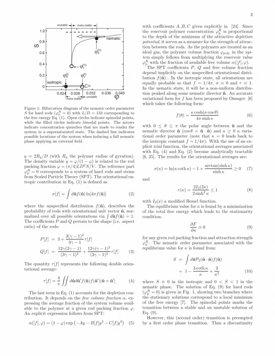
Figure 1: Bifurcation diagram of the nematic order parameterS for hard rods (ϕR
p = 0) with L/D = 133 corresponding tothe free energy Eq. (1). Open circles indicate spinodal points,while the filled circles indicate binodal points. The arrowsindicate concentration quenches that are made to render thesystem in a supersaturated state. The dashed line indicatespossible locations of the system when inducing a full nematicphase applying an external field.
q = 2Rg/D (with Rg the polymer radius of gyration).The density variable y = ϕ/(1 − ϕ) is related to the rodpacking fraction ϕ = (π/4)LD2N/V . The reference partϕR
p = 0 corresponds to a system of hard rods and stemsfrom Scaled Particle Theory (SPT). The orientational en-tropic contribution in Eq. (1) is defined as
σ[f ] =
∫duf(u) ln[4πf(u)] (2)
where the unspecified distribution f(u), describes theprobability of rods with orientational unit vector u, nor-malized over all possible orientations via
∫duf(u) = 1.
The coefficients P and Q pertain to the shape (i.e. aspectratio) of the rods:
P [f ] = 3 +3(γ − 1)2
3γ − 1τ [f ]
Q[f ] =12γ(2γ − 1)
(3γ − 1)2+
12γ(γ − 1)2
(3γ − 1)2τ [f ] (3)
The quantity τ [f ] represents the following double orien-tational average:
τ [f ] =4
π
∫∫dudu′f(u)f(u′)|u × u
′| (4)
The last term in Eq. (1) accounts for the depletion con-tribution. It depends on the free volume fraction α, ex-pressing the average fraction of the system volume avail-able to the polymer at a given rod packing fraction ϕ.An explicit expression follows from SPT:
α([f ], ϕ) = (1 − ϕ) exp(−Ay − B[f ]y2 − C[f ]y3
)(5)
with coefficients A, B, C given explicitly in [24]. Sincethe reservoir polymer concentration ϕR
p is proportionalto the depth of the minimum of the attractive depletion
potential, it serves as a measure for the strength of attrac-tion between the rods. As the polymers are treated as anideal gas, the polymer volume fraction ϕpoly in the sys-
tem simply follows from multiplying the reservoir valueϕR
p with the fraction of available free volume α([f ], ϕ).The SPT coefficients P , Q and free volume fraction
depend implicitly on the unspecified orientational distri-bution f(u) . In the isotropic state, all orientations areequally probable so that f = 1/4π, σ ≡ 0 and τ ≡ 1.In the nematic state, it will be a non-uniform distribu-tion peaked along some nematic director n. An accuratevariational form for f has been proposed by Onsager [6]which takes the following form:
f(θ) =κ cosh(κ cos θ)
4π sinhκ(6)
with 0 ≤ θ ≤ π the polar angle between u and thenematic director n (cos θ = u · n) and κ ≥ 0 a varia-tional order parameter (note that κ = 0 leads back tothe isotropic constant f = 1/4π). With the use of an ex-plicit trial function, the orientational averages associatedwith Eq. (4) and Eq. (2) become analytically tractable[6, 25]. The results for the orientational averages are:
σ(κ) = ln(κ coth κ) − 1 +arctan(sinhκ)
sinhκ≥ 0 (7)
and
τ(κ) =2I2(2κ)
2 sinh2 κ≤ 1 (8)
with I2(x) a modified Bessel function.The equilibrium value for κ is found by a minimization
of the total free energy which leads to the stationaritycondition:
∂F
∂κ≡ 0 (9)
for any given rod packing fraction and attraction strengthϕR
p . The nematic order parameter associated with theequilibrium value for κ is found from:
S =
∫duP2(u · n)f(u)
= 1 −3 cothκ
κ+
3
κ2(10)
where S ≡ 0 in the isotropic and 0 < S < 1 in thenematic phase. The solution of Eq. (9) for hard rods(ϕR
p = 0) is given in Fig. 1, showing two branches wherethe stationary solutions correspond to a local minimumof the free energy [7]. The spinodal points marks thetransition between a stable and an unstable solution ofEq. (9).
However, this (second order) transition is preemptedby a first order phase transition. Thus a discontinuity

4
both in concentration and in the ordering of the systemwill occur. The co-existence of two phases requires thatthe osmotic pressure Π and chemical potential µ of the
isotropic phase, with volume fraction ϕ(I)b , and the ne-
matic phase, with volume fraction ϕ(N)b , are equal:
Π(ϕ(I)b ) = Π(ϕ
(N)b ) (11)
µ(ϕ(I)b ) = µ(ϕ
(N)b ) (12)
The binodal points can thus be found using the ther-modynamic relations µ = ∂F
∂N V,Tand Π = − ∂F
∂V N,Tin
combination with Eq. 1.The phase diagram for a rod-polymer mixture is given
in Fig. 2a and shows the characteristic widening of thebiphasic gap as the amount of polymer is increased. Thelocation of the spinodal points, however, appears muchless affected by the depletion attraction. This is reflectedmore clearly if we plot the spinodal curves in terms of thefraction 0 ≤ ϕnem ≤ 1 of nematic phase formed, ratherthan the overall rod packing fraction ϕ. Applying thelever rule, we may relate ϕnem to ϕ via:
ϕnem =ϕ − ϕ
(I)b
ϕ(N)b − ϕ
(I)b
(13)
with ϕ(I/N)b the binodal rod packing fractions corre-
sponding to the coexisting isotropic and nematic phases.Fig. 2b shows that the NI spinodal instability occurs ifthe overall rod concentration corresponds to the nematicphase occupying about 20 % of the system volume. Thisresult is virtually independent of the strength of the de-pletion attraction as long as the amount of added poly-mer is not too large.
III. EXPERIMENTAL
A. Sample
Fd-virus suspensions were used in a 20 mM Tris bufferwith 100 mM NaCl at a pH of 8.2. The virus is a longand thin rod like particle (length 880 nm long, width6.6 nm, persistence length 2.2µm). Attractions betweenthe rods are varied through depletion by addition of dex-tran (480 kd, Pharmacosmos). A small amount of FITC-labeled dextran was added to be able to determine thedextran concentration spectroscopically. See Ref. [26]for the labeling procedure of dextran. The samples wereprepared as follows: First, a homogeneous fd-virus sus-pension of 21.1 mg/ml fd virus with dextran is allowedto macroscopically phase separate into an isotropic andnematic phase. The two phases were then separated intotwo different vials and the dextran and fd-virus concen-trations were determined spectroscopically. Three differ-ent dextran concentration were used in this study given
Figure 2: (a) Phase diagram for a rod-polymer mixture withL/D = 133 and colloid-polymer size ratio q = 2Rg/D = 5.4.Plotted in terms of the rod packing fraction ϕrod and polymervolume fraction ϕpoly in the system. Coexisting isotropic andnematic phases are connected by tie lines, with the nematicphase having a higher ϕrod. (b) Location of the isotropic-nematic spinodals in terms of the fraction of nematic phaseϕnem [Eq. (13)] plotted versus the system polymer concentra-tion ϕpoly on the vertical axis.
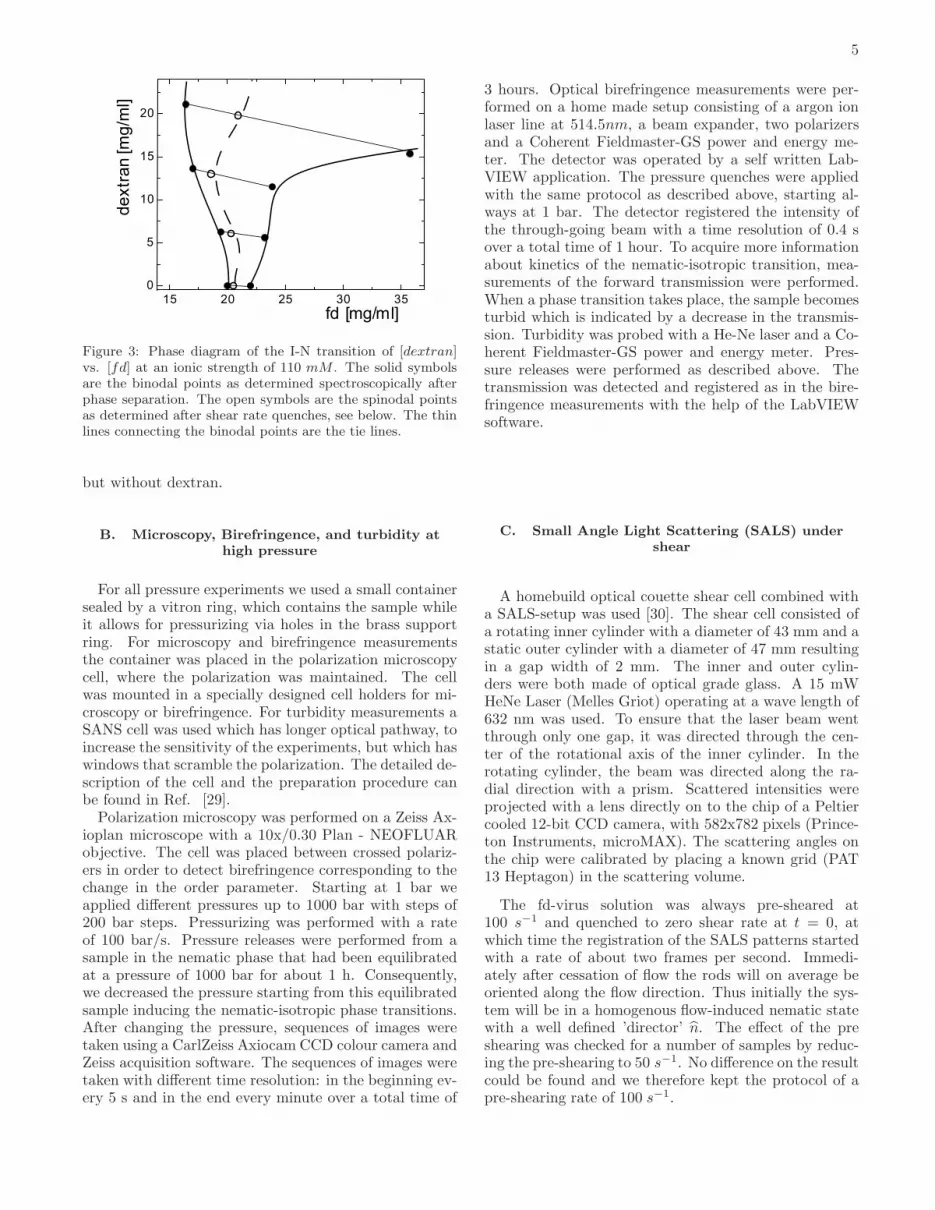
an initial virus concentration of 21.1 mg/ml: 6 mg/ml(low), 13 mg/ml (middle) and 20 mg/ml (high). The re-sulting phase diagram is shown in Fig. 3. This phasebehavior differs somewhat from previous published re-sults for the same system [9, 14]. The deviation mightbe due to different polydispersity of the dextran whichcan drastically change the interaction [27] and thus thephase behaviour[28]. By combining different volumes of
the isotropic, ϕ(I)b , and the nematic, ϕ
(N)b , phase from the
initially phase separated sample we can prepare any con-centration along one tie-line, with a concentration ϕnem
relative to the phase boundaries as expressed in Eq. 13.The concentration of dextran and fd-virus for each sam-ple was checked after every new mixing. For pressureexperiments a sample very close to the isotropic-nematicspinodal has been prepared at the same ionic strength,
5
15 20 25 30 350
5
10
15
20de
xtr
an
[m
g/m
l]
fd [mg/ml]
Figure 3: Phase diagram of the I-N transition of [dextran]vs. [fd] at an ionic strength of 110 mM . The solid symbolsare the binodal points as determined spectroscopically afterphase separation. The open symbols are the spinodal pointsas determined after shear rate quenches, see below. The thinlines connecting the binodal points are the tie lines.
but without dextran.
B. Microscopy, Birefringence, and turbidity athigh pressure
For all pressure experiments we used a small containersealed by a vitron ring, which contains the sample whileit allows for pressurizing via holes in the brass supportring. For microscopy and birefringence measurementsthe container was placed in the polarization microscopycell, where the polarization was maintained. The cellwas mounted in a specially designed cell holders for mi-croscopy or birefringence. For turbidity measurements aSANS cell was used which has longer optical pathway, toincrease the sensitivity of the experiments, but which haswindows that scramble the polarization. The detailed de-scription of the cell and the preparation procedure canbe found in Ref. [29].
Polarization microscopy was performed on a Zeiss Ax-ioplan microscope with a 10x/0.30 Plan - NEOFLUARobjective. The cell was placed between crossed polariz-ers in order to detect birefringence corresponding to thechange in the order parameter. Starting at 1 bar weapplied different pressures up to 1000 bar with steps of200 bar steps. Pressurizing was performed with a rateof 100 bar/s. Pressure releases were performed from asample in the nematic phase that had been equilibratedat a pressure of 1000 bar for about 1 h. Consequently,we decreased the pressure starting from this equilibratedsample inducing the nematic-isotropic phase transitions.After changing the pressure, sequences of images weretaken using a CarlZeiss Axiocam CCD colour camera andZeiss acquisition software. The sequences of images weretaken with different time resolution: in the beginning ev-ery 5 s and in the end every minute over a total time of
3 hours. Optical birefringence measurements were per-formed on a home made setup consisting of a argon ionlaser line at 514.5nm, a beam expander, two polarizersand a Coherent Fieldmaster-GS power and energy me-ter. The detector was operated by a self written Lab-VIEW application. The pressure quenches were appliedwith the same protocol as described above, starting al-ways at 1 bar. The detector registered the intensity ofthe through-going beam with a time resolution of 0.4 sover a total time of 1 hour. To acquire more informationabout kinetics of the nematic-isotropic transition, mea-surements of the forward transmission were performed.When a phase transition takes place, the sample becomesturbid which is indicated by a decrease in the transmis-sion. Turbidity was probed with a He-Ne laser and a Co-herent Fieldmaster-GS power and energy meter. Pres-sure releases were performed as described above. Thetransmission was detected and registered as in the bire-fringence measurements with the help of the LabVIEWsoftware.
C. Small Angle Light Scattering (SALS) undershear
A homebuild optical couette shear cell combined witha SALS-setup was used [30]. The shear cell consisted ofa rotating inner cylinder with a diameter of 43 mm and astatic outer cylinder with a diameter of 47 mm resultingin a gap width of 2 mm. The inner and outer cylin-ders were both made of optical grade glass. A 15 mWHeNe Laser (Melles Griot) operating at a wave length of632 nm was used. To ensure that the laser beam wentthrough only one gap, it was directed through the cen-ter of the rotational axis of the inner cylinder. In therotating cylinder, the beam was directed along the ra-dial direction with a prism. Scattered intensities wereprojected with a lens directly on to the chip of a Peltiercooled 12-bit CCD camera, with 582x782 pixels (Prince-ton Instruments, microMAX). The scattering angles onthe chip were calibrated by placing a known grid (PAT13 Heptagon) in the scattering volume.
The fd-virus solution was always pre-sheared at100 s−1 and quenched to zero shear rate at t = 0, atwhich time the registration of the SALS patterns startedwith a rate of about two frames per second. Immedi-ately after cessation of flow the rods will on average beoriented along the flow direction. Thus initially the sys-tem will be in a homogenous flow-induced nematic statewith a well defined ’director’ n. The effect of the preshearing was checked for a number of samples by reduc-ing the pre-shearing to 50 s−1. No difference on the resultcould be found and we therefore kept the protocol of apre-shearing rate of 100 s−1.

6
Figure 4: Sequence of polarization microscopy image afteran increase in pressure, starting at 1 bar. The final pres-sure is a measure of the concentration. Bright regions witha higher orientational order parameter appear at about 15minutes after a quench to 400 bar indicative of a nucleation-growth mechanism (middle left). For a final pressure of 1000bar phase separation sets in immediately (top right), indica-tive of spinodal decomposition, while after 40 minutes a fullnematic phase is formed (bottom right).
IV. RESULTS
A. Concentration quenches using pressure
Sequences of micrographs taken after pressurequenches for different time delays are gathered in Fig.4 and 5. The starting pressure for Fig. 4 was 1 barso that initially the system was in the isotropic phase.The varied depth of the quenches allowed for explorationof different regions on the phase diagram. For the 200bar pressure quench the images stay dark throughoutthe whole experiment (data not shown). For a quenchto400 bar the total intensity only starts to increase af-ter about 5 minutes. At longer times brighter regions,indicative of a finite order parameter, are visible due tonucleation-and-growth. The possible presence of tactoidscould not be observed, because a 10x objective was used.An induction time τind for phase separation to set in ischaracteristic for the meta-stable states. For a quench
Figure 5: As Fig. 4 but now starting at 1000 bar. Nucleation-and-growth events can be seen for a final pressure of 600 barafter 15 minutes (middle left). For a final pressure of 200 barphase separation sets in immediately (top right), indicative ofspinodal decomposition, but also the total intensity is muchreduced, indicative of a lower ordering. After 1 hour a fullisotropic phase is formed (bottom right).
to 800 bar an almost instant change in the intensity isobserved along with homogeneous structure formation.This observation suggests that the I-N spinodal is locatedin the immediate vicinity of this applied pressure. Inthe last sequence corresponding to the deepest quench of1000 bar one can see the full transition from isotropic tonematic phase through spinodal decomposition. First,the increase in intensity started immediately after thequench, i.e. τind = 0. Second, the initial early stagesof the transition exhibited morphology characteristic forspinodal decomposition - interconnected, labyrinth-likestructures spanning through the whole sample. Figure6 shows a thresholded picture taken at 50 seconds afterthis quench. Typical spinodal decomposition morphol-ogy is evident. The last two micrographs of the 1000bar quench show that the system develops into a fullynematic phase indicated by large homogenous regions ofthe same colour that only reorient with time. Thus the
I-N spinodal ϕ(I)s is located in the very proximity of the
N-I binodal ϕ(N)b .
Fig. 5 depicts the nematic-isotropic phase transition
7
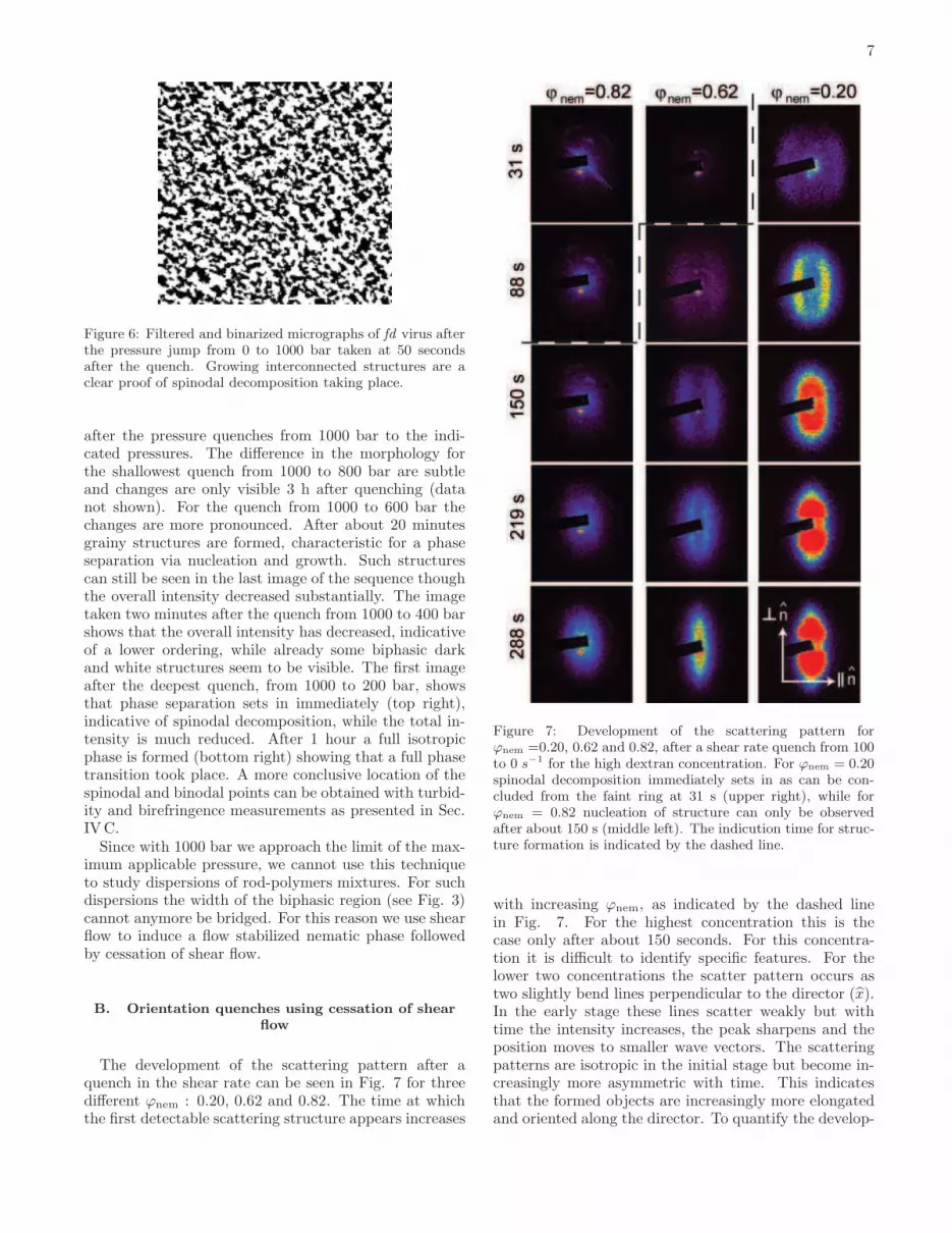
Figure 6: Filtered and binarized micrographs of fd virus afterthe pressure jump from 0 to 1000 bar taken at 50 secondsafter the quench. Growing interconnected structures are aclear proof of spinodal decomposition taking place.
after the pressure quenches from 1000 bar to the indi-cated pressures. The difference in the morphology forthe shallowest quench from 1000 to 800 bar are subtleand changes are only visible 3 h after quenching (datanot shown). For the quench from 1000 to 600 bar thechanges are more pronounced. After about 20 minutesgrainy structures are formed, characteristic for a phaseseparation via nucleation and growth. Such structurescan still be seen in the last image of the sequence thoughthe overall intensity decreased substantially. The imagetaken two minutes after the quench from 1000 to 400 barshows that the overall intensity has decreased, indicativeof a lower ordering, while already some biphasic darkand white structures seem to be visible. The first imageafter the deepest quench, from 1000 to 200 bar, showsthat phase separation sets in immediately (top right),indicative of spinodal decomposition, while the total in-tensity is much reduced. After 1 hour a full isotropicphase is formed (bottom right) showing that a full phasetransition took place. A more conclusive location of thespinodal and binodal points can be obtained with turbid-ity and birefringence measurements as presented in Sec.IVC.
Since with 1000 bar we approach the limit of the max-imum applicable pressure, we cannot use this techniqueto study dispersions of rod-polymers mixtures. For suchdispersions the width of the biphasic region (see Fig. 3)cannot anymore be bridged. For this reason we use shearflow to induce a flow stabilized nematic phase followedby cessation of shear flow.
B. Orientation quenches using cessation of shearflow
The development of the scattering pattern after aquench in the shear rate can be seen in Fig. 7 for threedifferent ϕnem : 0.20, 0.62 and 0.82. The time at whichthe first detectable scattering structure appears increases
Figure 7: Development of the scattering pattern forϕnem =0.20, 0.62 and 0.82, after a shear rate quench from 100to 0 s−1 for the high dextran concentration. For ϕnem = 0.20spinodal decomposition immediately sets in as can be con-cluded from the faint ring at 31 s (upper right), while forϕnem = 0.82 nucleation of structure can only be observedafter about 150 s (middle left). The indicution time for struc-ture formation is indicated by the dashed line.
with increasing ϕnem, as indicated by the dashed linein Fig. 7. For the highest concentration this is thecase only after about 150 seconds. For this concentra-tion it is difficult to identify specific features. For thelower two concentrations the scatter pattern occurs astwo slightly bend lines perpendicular to the director (x).In the early stage these lines scatter weakly but withtime the intensity increases, the peak sharpens and theposition moves to smaller wave vectors. The scatteringpatterns are isotropic in the initial stage but become in-creasingly more asymmetric with time. This indicatesthat the formed objects are increasingly more elongatedand oriented along the director. To quantify the develop-

8
q [nm-1]
a
b
0.0000 0.0005 0.0010
0.0000 0.0005 0.0010
time
timeI [a
rb. u
nits]
I [a
rb. u
nits]
Figure 8: Development of the scattering along the flow direc-tion for ϕnem = 0.20 (a) and ϕnem = 0.62 (b) as deduced fromthe scattering patterns in Fig. 7. The total time is three anda half minutes in (a) and six minutes in (b).
ment of the formed biphasic structure we extract inten-sity profiles along and perpendicular to the director. Thetime development of the scattering along the director isshown in Fig. 8. Here the formation of the structure peakand both the movement to lower q-values and the inten-sity increase of this peak are clearly seen for the two low-est concentrations, ϕnem, where it should be mentionedthat for the lowest ϕnem the peak develops immediatelyafter cessation of flow, indicative of spinodal decompo-sition. At the highest concentration the structure peakcan only be distinguished at longer times, characteristicfor nucleation-and-growth. Fig. 8 and similar plots takenfor other concentrations will be used in the following sec-tions as a base to deduce the induction time for structureformation.
C. Spinodal and binodal points
Figures 4,5 and 7 all show that after the quench phaseseparation sets in immediately or after some inductiontime τind, depending on the depth of the quench. As ex-plained in the introduction, in order to locate the spin-odal and binodal points we have to find at what con-centration τind for the formation of nematic (for the I-Ntransition) or isotropic structures (for the N-I transition)goes either to zero or to infinity.
To determine τind for quenches in the orientation weplot the intensity of the peak in the scattering pattern,
(a)
(c)
(b)
0 500 1000
0.2
0.4
1 to 900 bar
1 to 700 bar
1 to 200 bar
1 to 400 bar
1 to 800 bar
1000 2000 3000
0.6
0.8
1.0
0.00
0.05
0.10
τind
τind
Tu
rbd
itity [a
rb. u
nits
]
I to
tal [
arb
. u
nits]
I bire [a
rb. u
nits]
I(q
ma
x)
[arb
. u
nits]
I total branch
Figure 9: (a) The intensity at the peak of the scattering pat-tern, I(qmax), after cessation of shear flow for ϕnem = 0.30(�), ϕnem = 0.62 (◦) and ϕnem = 0.82 (△) at the high dex-tran concentration to study the N-I transition. (b) Turbidity(solid symbols)and total intensity of the polarization micro-graphs (open symbols) after a pressure drop (cubes: 400 bar,bullets : 200 bar) to study the N-I transition. The total in-tensity of the polarization micrographs after the initial decay,Ibranchtotal , is also indicated. (c) Birefringence intensity after an
increase in pressure to study the I-N transition. The lines inthe plots indicate the extrapolation to determine the induc-tion time after a shear rate or pressure quench.
see Fig. 8, as a function of time. Fig. 9a shows this timedevelopment for three different ϕnem. The induction τind
is now obtained by extrapolating the linear intensity in-crease to zero intensity. This procedure was repeatedfor different attraction strength, i.e. different dextranconcentrations. The result is shown in Fig. 10a, whererespectively τind and 1/τind are plotted vs. ϕnem for the
9
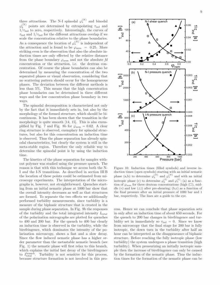
three attractions. The N-I spinodal ϕ(N)s and binodal
ϕ(N)b points are determined by extrapolating τind and
1/τind to zero, respectively. Interestingly, the curves ofτind and 1/τind for the different attractions overlap if wescale the concentration relative to the phase boundaries.
As a consequence the location of ϕ(N)s is independent of
the attraction and is found to be ϕnem = 0.25. Morestriking even is the observation that also the absolute in-duction times are only effected by the relative distancefrom the phase boundary ϕnem and not the absolute fd
concentration or the attraction, i.e. the dextran con-centration. Of course the phase boundaries can also bedetermined by measuring the concentration of the twoseparated phases or visual observation, considering thatno scattering pattern should occur for the homogeneousphases. The deviation between the different methods isless than 5%. This means that the high concentrationphase boundaries can be determined in three differentways and the low concentration phase boundary in twoways.
The spinodal decomposition is characterized not onlyby the fact that it immediately sets in, but also by themorphology of the formed structure, which should be bi-continuous. It has been shown that the transition in themorphology is quite smooth [14, 15]. This is also exem-plified by Fig. 7 and Fig. 8b for ϕnem = 0.62. A clearring structure is observed, exemplary for spinodal struc-tures, but also for this concentration an induction timeis observed. Thus the phase separation has already spin-odal characteristics, but clearly the system is still in themeta-stable region. Therefore the only reliable way todetermine the spinodal point is by using the inductiontime.
The kinetics of the phase separation for samples with-out polymer was studied using the pressure quench. Thereason is that with this technique we access both the N-I and the I-N transitions. As described in section III Bthe location of these points could be estimated from mi-croscopy experiments. The interpretation of the micro-graphs is, however, not straightforward. Quenches start-ing from an initial nematic phase at 1000 bar show thatthe overall intensity decreases as well as that structuresare formed. To separate the two effects we additionallyperformed turbidity measurements, since turbidity is ameasure of the biphasic structure that is created in thesample during phase separation. In Fig. 9b the responsesof the turbidity and the total integrated intensity Itotal
of the polarization micrographs are plotted for quenchesto 400 and 200 bar. For the quench to 400 bar clearlyan induction time is observed in the turbidity, while thebirefringence, which dominates the intensity of the po-larization microscopy, shows a fast and a slow decay.Since the flow induced nematic phase has a higher or-der parameter than the metastable nematic branch (seeFig. 1) the nematic phase will first relax to this branch,which explains the initial fast decay of the birefringenceto Ibranch
total . Turbidity is not sensitive for this process,because structure formation is not involved in this pro-
(a)
(b)
(c)
ϕnem
I-N pressure quench
0.0 0.2 0.4 0.6 0.80
40
80
120
0.00
0.02
0.04
0.06
N-I pressure quench
N-I shear quench
0
1000
2000
3000
0.000
0.001
0.002
0.003
200 400 600 800 10000.000
0.002
0.004
0.006
0.008
0
200
400
600
Pressure [bar]
τin
d [s
]τ
ind [s
]τ
ind [s
] 1\τ
ind [s
]1
\τin
d [s]
1\τ
ind [s
]
Figure 10: Induction times (filled symbols) and inverse in-duction times (open symbols) starting with an initial nematic
phase (a,b) to determine ϕ(N)b and ϕ
(N)s and with an initial
isotropic phase (c) to determine ϕ(I)b and ϕ
(I)s ; (a) as a func-
tion of ϕnem for three dextran concentrations (high (�), mid-dle (◦) and low (△)) after pre-shearing; (b,c) as a function ofthe final pressure after an initial pressure of 1000 bar and 1bar, respectively. The lines are a guide to the eye.
cess. Hence we can conclude that phase separation setsin only after an induction time of about 650 seconds. Forthe quench to 200 bar changes in birefringence and tur-bidity set in immediately so τind = 0. Since we knowfrom microscopy that the final stage for 200 bar is fullyisotropic, the down turn in the turbidity after half anhour can be interpreted as the disappearance of biphasicstructure. Before reaching the fully isotropic phase (lowturbidity) the system undergoes a phase transition (highturbidity). When pressurizing an initially isotropic sam-ple then the increase of birefringence can only be causedby the formation of the nematic phase. Thus the induc-tion times for the formation of the nematic phase can be
10
I to
tal [a
rb.u
nits]
Pressure [bar]
0 200 400 600 800 1000
0.0
0.2
0.4
0.6
0.8
1.0
bra
nch
Figure 11: The experimental equivalent of the bifurcation di-
agram. The pressures corresponding to ϕ(N)s and ϕ
(I)s are de-
termined from Fig. 9b and c as the pressures where τind → 0
(solid symbols). The pressures corresponding to ϕ(N)b and ϕ
(I)b
are given by the pressures where 1/τind → 0 (open symbols).The total intensity of the polarization micrographs after theinitial decay, Ibranch
total , (see Fig 9b) is taken as a measure of theorientational order parameter (stars). The line is a guide tothe eye.
obtained from the birefringence responses as plotted inFig. 9 c.
The induction times and the reverse induction timesare plotted in Fig. 10 b and c for the turbidity and bire-fringence, respectively. The pressures corresponding to
ϕ(N)s and ϕ
(I)s are determined from these two figures as
the pressures where τind → 0, while the pressures cor-
responding to ϕ(N)b and ϕ
(I)b are given by the pressures
where 1/τind → 0. We can now construct the experi-mental equivalent, Fig. 11, of the theoretical bifurcationdiagram, Fig. 1, using pressure as a measure of concen-tration and the total intensity of the micrographs afterthe initial decay as a measure of the orientational orderparameter (Fig. 9b). Note that the error bar in thepressure is determined from the uncertainty in the ex-trapolation to τind → 0 and 1/τind → 0. Another sourceof error could also be the exact concentration of the rods,since the data were taken on different batches. This er-ror would show up as a shift of the entire curve that isobtained from the used batch. This could explain why
ϕ(N)s is somewhat smaller than ϕ
(I)b , which is in principle
not possible.
D. Growth rates
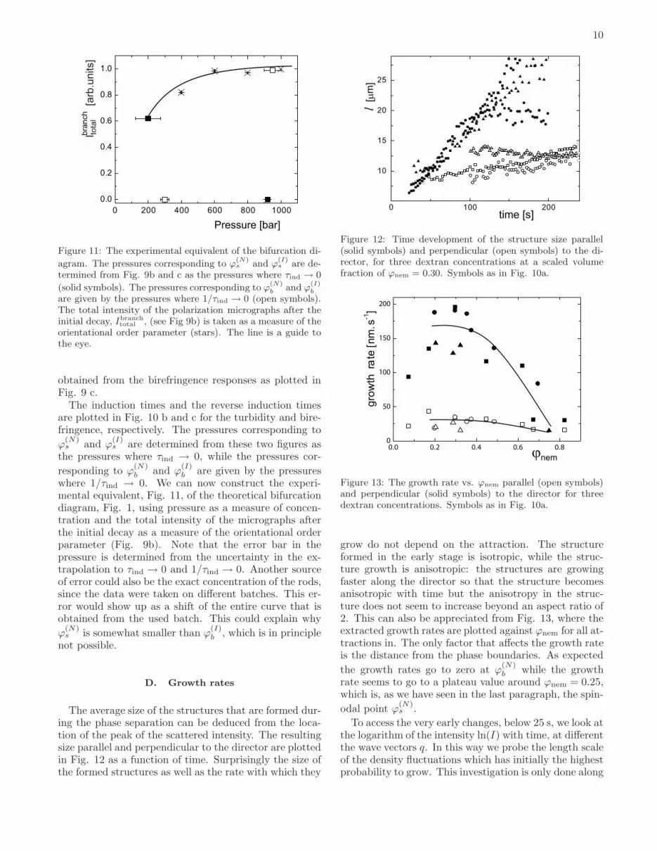
The average size of the structures that are formed dur-ing the phase separation can be deduced from the loca-tion of the peak of the scattered intensity. The resultingsize parallel and perpendicular to the director are plottedin Fig. 12 as a function of time. Surprisingly the size ofthe formed structures as well as the rate with which they
l [µ
m]
10
15
20
25
0 100 200
Figure 12: Time development of the structure size parallel(solid symbols) and perpendicular (open symbols) to the di-rector, for three dextran concentrations at a scaled volumefraction of ϕnem = 0.30. Symbols as in Fig. 10a.
ϕnem
gro
wth
ra
te [
nm
.s ]
-1
0.0 0.2 0.4 0.6 0.80
50
100
150
200
Figure 13: The growth rate vs. ϕnem parallel (open symbols)and perpendicular (solid symbols) to the director for threedextran concentrations. Symbols as in Fig. 10a.
grow do not depend on the attraction. The structureformed in the early stage is isotropic, while the struc-ture growth is anisotropic: the structures are growingfaster along the director so that the structure becomesanisotropic with time but the anisotropy in the struc-ture does not seem to increase beyond an aspect ratio of2. This can also be appreciated from Fig. 13, where theextracted growth rates are plotted against ϕnem for all at-tractions in. The only factor that affects the growth rateis the distance from the phase boundaries. As expected
the growth rates go to zero at ϕ(N)b while the growth
rate seems to go to a plateau value around ϕnem = 0.25,which is, as we have seen in the last paragraph, the spin-
odal point ϕ(N)s .
To access the very early changes, below 25 s, we look atthe logarithm of the intensity ln(I) with time, at differentthe wave vectors q. In this way we probe the length scaleof the density fluctuations which has initially the highestprobability to grow. This investigation is only done along
11
0.000 0.001 0.002
0.00
0.05
0.10
0.15
(b)
dln
(In
t)/d
t
q [nm]-1
0.00
0.02
0.04
0.06
0.08
dln
(In
t)/d
t
(a)
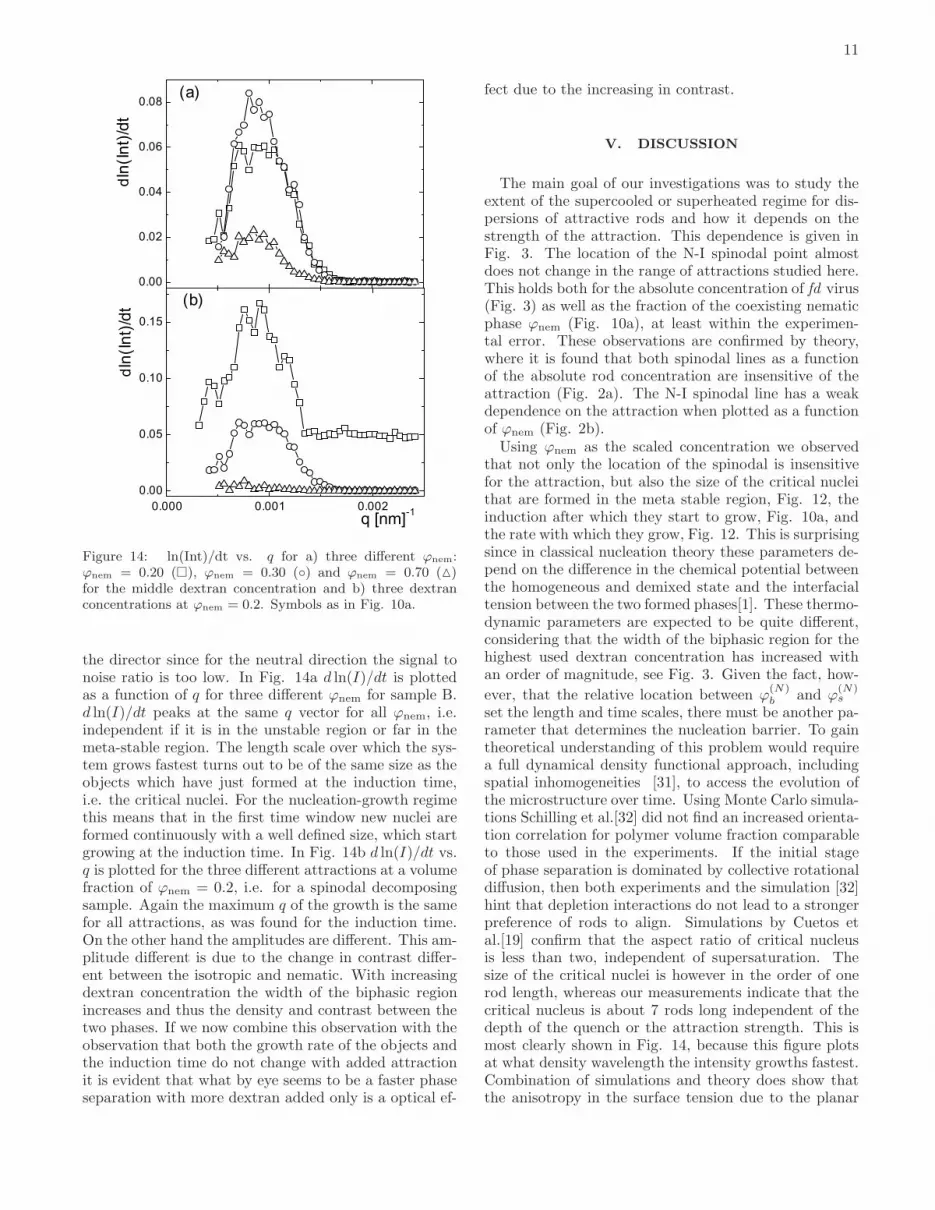
Figure 14: ln(Int)/dt vs. q for a) three different ϕnem:ϕnem = 0.20 (�), ϕnem = 0.30 (◦) and ϕnem = 0.70 (△)for the middle dextran concentration and b) three dextranconcentrations at ϕnem = 0.2. Symbols as in Fig. 10a.
the director since for the neutral direction the signal tonoise ratio is too low. In Fig. 14a d ln(I)/dt is plottedas a function of q for three different ϕnem for sample B.d ln(I)/dt peaks at the same q vector for all ϕnem, i.e.independent if it is in the unstable region or far in themeta-stable region. The length scale over which the sys-tem grows fastest turns out to be of the same size as theobjects which have just formed at the induction time,i.e. the critical nuclei. For the nucleation-growth regimethis means that in the first time window new nuclei areformed continuously with a well defined size, which startgrowing at the induction time. In Fig. 14b d ln(I)/dt vs.q is plotted for the three different attractions at a volumefraction of ϕnem = 0.2, i.e. for a spinodal decomposingsample. Again the maximum q of the growth is the samefor all attractions, as was found for the induction time.On the other hand the amplitudes are different. This am-plitude different is due to the change in contrast differ-ent between the isotropic and nematic. With increasingdextran concentration the width of the biphasic regionincreases and thus the density and contrast between thetwo phases. If we now combine this observation with theobservation that both the growth rate of the objects andthe induction time do not change with added attractionit is evident that what by eye seems to be a faster phaseseparation with more dextran added only is a optical ef-
fect due to the increasing in contrast.
V. DISCUSSION
The main goal of our investigations was to study theextent of the supercooled or superheated regime for dis-persions of attractive rods and how it depends on thestrength of the attraction. This dependence is given inFig. 3. The location of the N-I spinodal point almostdoes not change in the range of attractions studied here.This holds both for the absolute concentration of fd virus(Fig. 3) as well as the fraction of the coexisting nematicphase ϕnem (Fig. 10a), at least within the experimen-tal error. These observations are confirmed by theory,where it is found that both spinodal lines as a functionof the absolute rod concentration are insensitive of theattraction (Fig. 2a). The N-I spinodal line has a weakdependence on the attraction when plotted as a functionof ϕnem (Fig. 2b).
Using ϕnem as the scaled concentration we observedthat not only the location of the spinodal is insensitivefor the attraction, but also the size of the critical nucleithat are formed in the meta stable region, Fig. 12, theinduction after which they start to grow, Fig. 10a, andthe rate with which they grow, Fig. 12. This is surprisingsince in classical nucleation theory these parameters de-pend on the difference in the chemical potential betweenthe homogeneous and demixed state and the interfacialtension between the two formed phases[1]. These thermo-dynamic parameters are expected to be quite different,considering that the width of the biphasic region for thehighest used dextran concentration has increased withan order of magnitude, see Fig. 3. Given the fact, how-
ever, that the relative location between ϕ(N)b and ϕ
(N)s
set the length and time scales, there must be another pa-rameter that determines the nucleation barrier. To gaintheoretical understanding of this problem would requirea full dynamical density functional approach, includingspatial inhomogeneities [31], to access the evolution ofthe microstructure over time. Using Monte Carlo simula-tions Schilling et al.[32] did not find an increased orienta-tion correlation for polymer volume fraction comparableto those used in the experiments. If the initial stageof phase separation is dominated by collective rotationaldiffusion, then both experiments and the simulation [32]hint that depletion interactions do not lead to a strongerpreference of rods to align. Simulations by Cuetos etal.[19] confirm that the aspect ratio of critical nucleusis less than two, independent of supersaturation. Thesize of the critical nuclei is however in the order of onerod length, whereas our measurements indicate that thecritical nucleus is about 7 rods long independent of thedepth of the quench or the attraction strength. This ismost clearly shown in Fig. 14, because this figure plotsat what density wavelength the intensity growths fastest.Combination of simulations and theory does show thatthe anisotropy in the surface tension due to the planar
12
anchoring of rods at the interface plays an important rolein the formation of a critical nucleus [20]. If this effectdominates the kinetics, it is understandable that attrac-tion between the rods is less important than for examplethe aspect ratio of the rod. Comparing experiments andsimulations one should realize that not only the aspectratio of the viruses is an order of magnitude bigger thanthose used in simulations, but also that we consider inFig. 14 the N-I and not the I-N transition.
The only parameter that is influenced by the attractionis the rate at which the gradient in the density grows,as plotted in Fig. 14b, which is due to the increasingwidth of the biphasic region. All samples in this plot arequenched into the unstable region and therefore undergospinodal decomposition. The curve for the highest at-traction, i.e. the highest polymer concentration, showsa clear peak. This is typical for spinodal decompositionthat is dominated by translational diffusion [33, 34]. Atthe middle concentration there is still a clear peak, butit is not obvious wether the demixing rate goes to zerofor q → 0 or not. For the lowest concentration of dex-tran the data are too noisy to draw any conclusions. Ourresults are somewhat different from earlier experimentsperformed at 13 mg/ml of dextran, which hinted thatthe growth rate does not go to zero for q → 0 [14].Also the binodal lines found in this paper have sharperfeatures as compared to those published in Ref. [9]. Dif-ferences in the poly-dispersity of the dextran that is usedcould explain these discrepancies. In the latter paperalso a significantly large part of the phase diagram wascovered. The reason for the somewhat limited range ofattraction studied here is that higher concentrations ofdextran would lead to a too high turbidity of the sampleand multiple scattering, corrupting the reliability of themeasurements. This effect could explain the fact thatfor the high polymer concentrations in Fig. 14b a fi-nite growth rate is found at high q values. Concerningthe time dependence of the structure growth we foundwithin experimental error a power law of around one,see the linear dependence in Fig. 12a, whereas theorypredicts a lower power dependence[31]. Possibly we arerestricted to the very initial stage of the phase separationprocess. The sizes of the coalescing structure formed atlater times are too big, so that the scattered light hitsthe beam stop. This problem does not occur when usingmicroscopy as in Ref. [17, 35].
With the pressure quench we accessed both the N-Iand the I-N transition. As for the N-I transition we ob-served that also ϕ
(I)s is located in the proximity of ϕ
(N)b .
With this we confirm for the first time the theoreticalprediction done in Ref. [7]. What these experimentsalso show is that for the deepest quenches the initiallyhomogeneous single phase (I or N) undergoes a localphase separation before it completely turns in to the newsingle phase. This mechanism confirms similar observa-tions in computer simulations[20] on initially isotropichard spherocylinder-polymer mixtures. The fact that wecan reach the full nematic state from the isotropic state
with the pressure quench is striking, since it is knownthat the concentration difference between the two bin-odal points is 10 %, whereas with a pressure quench to1000 bar the water is compressed only 5 %. Here it isimportant to note that we are comparing the isotropicphase at 1 bar with the nematic phase at 1000 bar. As-suming that the width of the biphasic region does notchange with pressure, it would mean that at high pres-sure the I-N transition sets in at lower concentrations. Itis known that the location of the I-N transition is tem-perature dependent. This dependency could be linkedto the temperature dependence of the flexibility of the fd
virus [36]. Similarly, the features of fd virus could changesat high pressures. This change cannot be an irreversibleprocess like denaturation, since the phase transitions arecompletely reversible. Further experiments are needed toshow if is a specific feature like the flexibility of rod-likeviruses that changes with pressure. Alternatively, moregeneral features like the Debye double layer of chargedcolloids could be pressure dependent.
VI. CONCLUSIONS
We have studied the behavior of supersaturated dis-persions of rod-like viruses. Superheated nematic disper-sions were prepared by first applying a strong shear flow.Cessation of the shear flow at t = 0 renders the nematicphase meta-stable or unstable depending on the concen-tration, see Fig. 1. We probed the structure formationusing Small Angle Light Scattering. With the analysisof the scattering patterns we could access the inductiontime for structure formation τind, the size of the criti-cal nucleus and the growth rate. These parameters weremeasured over a broad range of attractions as inducedby the addition of dextran as a depletion agent. Wefound that the N-I spinodal point, i.e. the concentrationwhere τind → 0, is independent of the attraction, whichwas confirmed by theoretical calculations. Interestingly,also the absolute induction time, the critical nucleus andthe growth rate are insensitive of the attraction, whenthe concentration is scaled to the distance to the phaseboundaries as given by ϕnem. This observation hintsthat concepts of classical nucleation theory are insuffi-cient to understand nucleation processes in anisotropicfluids. We also applied pressure quenches on dispersionsof rods without added polymer, thus supercooling or su-perheating the system. The pressure quenches were deepenough to induce a complete phase transition from theisotropic to the nematic phase and vice versa, which takesplace initially via phase separation. As a consequenceboth the N-I and I-N spinodal could be accessed. Bya combination of polarization microscopy, birefringenceand turbidity measurements we were able to construct afirst experimental analogue of the bifurcation diagram ofKayser and Raveche [7].
13
VII. ACKNOWLEDGMENTS
This work was performed within the framework ofthe Transregio SFB TR6, ’Physics of colloidal disper-sions in external fields’. The authors thank R. Tuinier,
A. Patkowski and J. Dhont for stimulating discussions.D. Kleshchanok is thanked for critical reading of themanuscript. R. Vavrin is thanked for technical assistancewith the turbidity measurements.
[1] P. G. Debenedetti, Metastable Liquids. (Princeton uni-versity Press, Princeton, New Jersey, 1996), 2nd ed.
[2] V. J. Anderson and H. N. W. Lekkerkerker, Nature 416,811 (2002).
[3] S. Asakura and F. Oosawa, J. Chem. Phys. 22, 1255(1954).
[4] H. N. W. Lekkerkerker, W. C.-K. Poon, P. N. Pusey,A. Stroobants, and P. B. Warren, Europhys. Lett. 20,559 (1992).
[5] H. Verduin and J. K. G. Dhont, J. Colloid Int. Sci. 172,425 (1995).
[6] L. Onsager, Ann. N.Y. Acad. Sci. 51, 62 (1949).[7] R. F. Kayser and H. J. Raveche, Phys. Rev. A 17, 2067
(1978).[8] G. J. Vroege and H. N. W. Lekkerkerker, Rep. Prog.
Phys. 55, 1241 (1992).[9] Z. Dogic, K. R. Purdy, E. Grelet, M. Adams, and
S. Fraden, Phys. Rev. E 69, 051702 (2004).[10] M. P. B. van Bruggen and H. N. W. Lekkerkerker, Macro-
molecules 33, 5532 (2000).[11] J. Buitenhuis, L. N. Donselaar, P. A. Buining,
A. Stroobants, and H. N. W. Lekkerkerker, J. ColloidInt. Sci. 175, 46 (1995).
[12] C. D. Edgar and D. G. Gray, Macromolecules 35, 7400(2002).
[13] J. Tang and S. Fraden, Phys. Rev. Lett. 71, 3509 (1993).[14] M. P. Lettinga, K. Kang, A. Imhof, D. Derks, and
J. K. G. Dhont, J. Phys.: Condens. Matter 17, S3609(2005).
[15] M. P. B. van Bruggen, J. K. G. Dhont, and H. N. W.Lekkerkerker, Macromolecules 32, 2256 (1999).
[16] M. Ripoll, P. Holmqvist, R. G. Winkler, G. Gompper,J. K. G. Dhont, and M. P. Lettinga, Phys. Rev. Lett.101, 168302 (2008).
[17] P. W. Oakes, J. Viamontes, and J. X. Tang, Phys. Rev.E75, 061902 (2007).
[18] T. Schilling and D. Frenkel, Phys. Rev. Lett. 92, 085505
(2004).[19] A. Cuetos and M. Dijkstra, Phys. Rev. Lett. 98, 095701
(2007).[20] A. Cuetos, R. van Roij, and M. Dijkstra, Soft Matter 4,
757 (2008).[21] R. Berardi, A. Costantini, L. Muccioli, S. Orlandi, and
C. Zannoni, J. Chem. Phys. 126, 044905 (2007).[22] R. A. Fine and F. J. Millero, J. Chem. Phys. (1973).[23] H. N. W. Lekkerkerker and A. Stroobants, Nuovo Ci-
mento 16, 949 (1994).[24] R. Tuinier, T. Taniguchi, and H. H. Wensink, Eur. Phys.
J. E 23, 355 (2007).[25] M. Franco-Melgar, A. J. Haslam, and G. Jackson, Mol.
Phys. 106, 649 (2008).[26] R. H. Tromp, F. van de Velde, J. Riel, and M. Paques,
Food Res. Int. 34, 931 (2001).[27] D. Kleshchanok, R. Tuinier, and P. R. Lang, Langmuir
22, 9121 (2006).[28] R. Tuinier, J. Rieger, and C. G. de Kruif, Adv. Col. Int.
Sci. 103, 1 (2003).[29] J. Kohlbrecher, A. Bollhalder, R. Vavrin, and G. Meier,
Rev. Sci. Instrum. 78, 1251011 (2007).[30] P. Holmqvist, M. P. Lettinga, J. Buitenhuis, and J. K. G.
Dhont, Langmuir 21, 10976 (2005).[31] J. K. G. Dhont and W. J. Briels, Phys. Rev. E 72, 031404
(2005).[32] T. Schilling, S. Jungblut, and M. A. Miller, Phys. Rev.
Lett. 98, 108303 (2007).[33] A. Matsuyama, R. M. L. Evans, and M. E. Cates, Phys.
Rev. E 61, 2977 (2000).[34] J. W. Winters, T. Odijk, and P. van der Schoot, Phys.
Rev. E 63, 011501 (2000).[35] A. H. Chowdhury, and P. S. Russo, J. Chem. Phys. 92,
5744 (1990).[36] J. Tang, and S. Fraden, Biopolymers 39, 13 (1996).