super series - in worm gear units - benzlers
TRANSCRIPT
SIZE: 4” to 10.5”
ELECONSUPER SERIESIN WORM GEAR UNITS
ww
w.
el
ec
on
.c
om
Cata
logue N
o.: 2
02/G
/02/2
011
Super SeriesNU
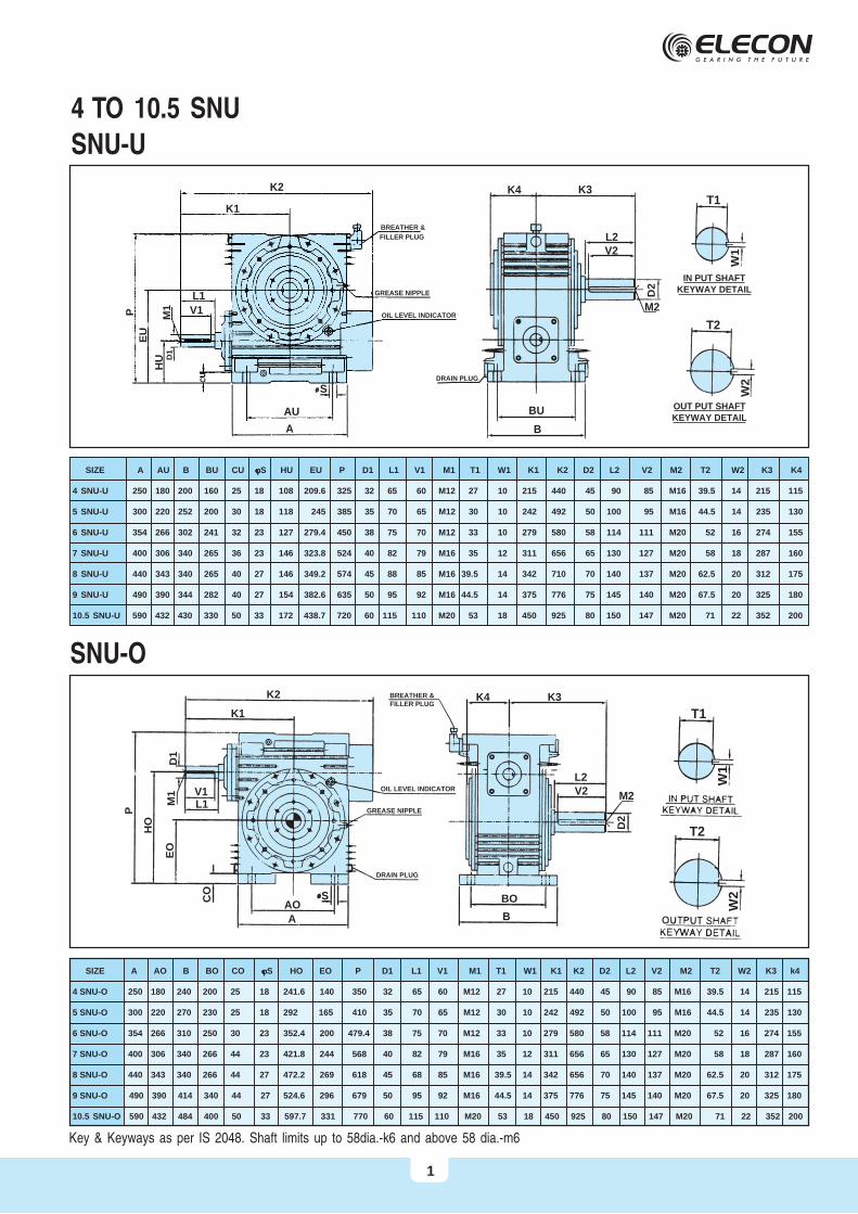
4 TO 10.5 SNU
SNU-U
SNU-O
SIZE A AU B BU CU jjjjjS HU EU P D1 L1 V1 M1 T1 W1 K1 K2 D2 L2 V2 M2 T2 W2 K3 K4
4 SNU-U 250 180 200 160 25 18 108 209.6 325 32 65 60 M12 27 10 215 440 45 90 85 M16 39.5 14 215 115
5 SNU-U 300 220 252 200 30 18 118 245 385 35 70 65 M12 30 10 242 492 50 100 95 M16 44.5 14 235 130
6 SNU-U 354 266 302 241 32 23 127 279.4 450 38 75 70 M12 33 10 279 580 58 114 111 M20 52 16 274 155
7 SNU-U 400 306 340 265 36 23 146 323.8 524 40 82 79 M16 35 12 311 656 65 130 127 M20 58 18 287 160
8 SNU-U 440 343 340 265 40 27 146 349.2 574 45 88 85 M16 39.5 14 342 710 70 140 137 M20 62.5 20 312 175
9 SNU-U 490 390 344 282 40 27 154 382.6 635 50 95 92 M16 44.5 14 375 776 75 145 140 M20 67.5 20 325 180
10.5 SNU-U 590 432 430 330 50 33 172 438.7 720 60 115 110 M20 53 18 450 925 80 150 147 M20 71 22 352 200
SIZE A AO B BO CO jjjjjS HO EO P D1 L1 V1 M1 T1 W1 K1 K2 D2 L2 V2 M2 T2 W2 K3 k4
4 SNU-O 250 180 240 200 25 18 241.6 140 350 32 65 60 M12 27 10 215 440 45 90 85 M16 39.5 14 215 115
5 SNU-O 300 220 270 230 25 18 292 165 410 35 70 65 M12 30 10 242 492 50 100 95 M16 44.5 14 235 130
6 SNU-O 354 266 310 250 30 23 352.4 200 479.4 38 75 70 M12 33 10 279 580 58 114 111 M20 52 16 274 155
7 SNU-O 400 306 340 266 44 23 421.8 244 568 40 82 79 M16 35 12 311 656 65 130 127 M20 58 18 287 160
8 SNU-O 440 343 340 266 44 27 472.2 269 618 45 68 85 M16 39.5 14 342 656 70 140 137 M20 62.5 20 312 175
9 SNU-O 490 390 414 340 44 27 524.6 296 679 50 95 92 M16 44.5 14 375 776 75 145 140 M20 67.5 20 325 180
10.5 SNU-O 590 432 484 400 50 33 597.7 331 770 60 115 110 M20 53 18 450 925 80 150 147 M20 71 22 352 200
Key & Keyways as per IS 2048. Shaft limits up to 58dia.-k6 and above 58 dia.-m6
K2 K4 K3
L2V2
M2
BU
T1
T2
W1
W2
B
D2
K1
L1
AU
OIL LEVEL INDICATOR
IN PUT SHAFTKEYWAY DETAIL
DRAIN PLUG
GREASE NIPPLE
BREATHER &
FILLER PLUG
A
S
V1
M1
HU
EU
P
D1
OUT PUT SHAFTKEYWAY DETAIL
K2 K4 K3
L2V2
BO
T1
T2
W1
W2
B
M2
D2
K1
D1
P
HO
EO
M1 V1
L1
CO
AO
A
S
GREASE NIPPLE
DRAIN PLUG
OIL LEVEL INDICATOR
BREATHER &FILLER PLUG
1
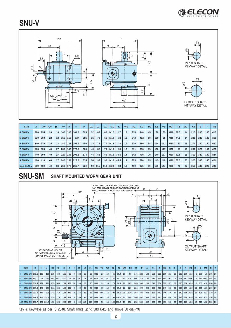
SNU-V
Size A AV CV fffffS HV H K P D1 L1 V1 M1 T1 W1 K1 K2 D2 L2 V2 M2 T2 W2 K3 E F M3
4 SNU-V 280 235 20 18 140 108 101.6 325 32 65 60 M12 27 10 215 440 45 90 85 M16 39.5 14 215 200 100 M16
5 SNU-V 320 260 22 18 165 118 127 385 35 70 65 M12 30 10 242 492 50 100 95 M16 44.5 14 235 240 130 M16
6 SNU-V 340 270 25 23 180 127 152.4 450 38 75 70 M12 33 10 279 580 58 114 111 M20 52 16 274 280 150 M20
7 SNU-V 400 320 40 27 200 146 177.8 524 40 82 79 M16 35 12 311 656 65 130 127 M20 58 18 287 320 150 M20
8 SNU-V 440 360 40 27 220 146 203.2 574 45 88 85 M16 39.5 14 342 710 70 140 137 M20 62.5 18 312 340 180 M24
9 SNU-V 490 410 40 27 240 154 228.6 635 50 95 92 M16 44.5 14 375 776 75 145 140 M20 67.5 20 325 386 180 M24
10.5 SNU-V 560 460 40 33 260 172 266.7 720 60 115 110 M20 53 18 450 925 80 150 147 M20 71 22 352 440 220 M30
SNU-SM
SIZE K H U K1 K2 G J N D1 L1 V1 M1 T1 W1 D2 T2 W2 D3 D4 P A A1 B B1 C S E F M2 O Q M3 R T
4 SNU-SM 101.6 108 115 215 440 115 95 6 32 65 60 M12 27 10 65 69.4 18 95 146 222 180 160 250 200 25 18 200 100 M16 8 200 M8 165 20
5 SNU-SM 127 118 140 242 492 145 115 15 35 70 65 M12 30 10 70 75.1 20 105 195 272 220 200 300 252 30 18 240 130 M16 8 250 M10 210 20
6 SNU-SM 152.4 127 170 279 580 165 132 20 38 75 70 M12 33 10 75 80.1 20 105 205 330 266 241 354 302 32 23 280 150 M20 8 305 M10 250 20
7 SNU-SM 177.8 146 200 311 656 160 132 8 40 82 79 M16 35 12 80 85.6 22 120 224 390 306 266 400 340 36 23 320 150 M20 12 355 M10 280 20
8 SNU-SM 203.2 146 225 342 710 180 148 8 45 88 85 M16 39.5 14 90 95.6 25 130 263 445 343 266 440 340 40 27 340 160 M24 12 405 M12 318 20
9 SNU-SM 228.6 154 252.4 375 776 190 157 8 50 95 92 M16 44.5 14 95 100.6 25 140 266 492 390 282 490 344 40 27 386 180 M24 12 460 M12 330 20
10.5 SNU-SM 266.7 172 281.3 450 925 205 180 8 60 115 110 M20 53 18 100 106.6 28 152 292 540 432 330 590 430 50 33 440 220 M30 12 510 M12 380 20
Key & Keyways as per IS 2048. Shaft limits up to 58dia.-k6 and above 58 dia.-m6
SHAFT MOUNTED WORM GEAR UNIT
2
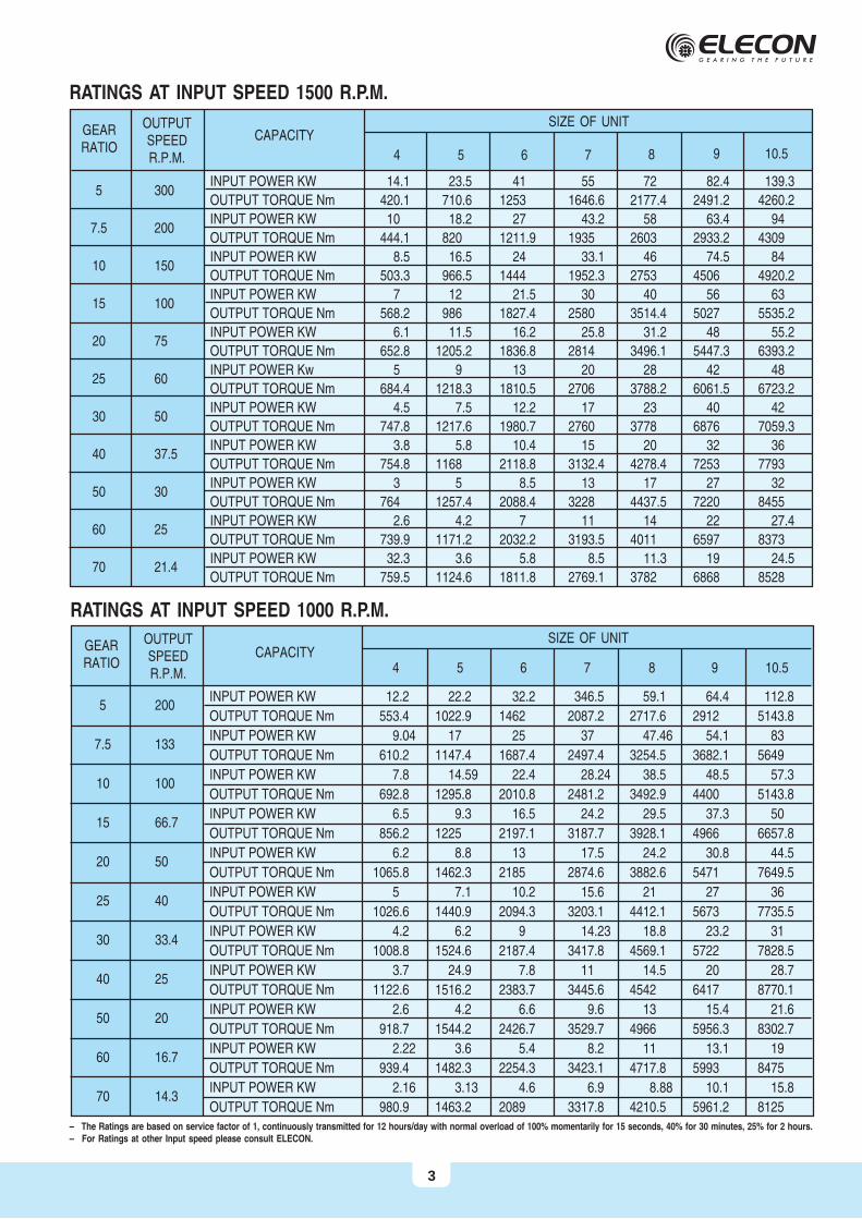
RATINGS AT INPUT SPEED 1500 R.P.M.
– The Ratings are based on service factor of 1, continuously transmitted for 12 hours/day with normal overload of 100% momentarily for 15 seconds, 40% for 30 minutes, 25% for 2 hours.– For Ratings at other Input speed please consult ELECON.
GEARRATIO
OUTPUTSPEEDR.P.M.
CAPACITYSIZE OF UNIT
4 5 6 7
5 300
7.5 200
10 150
15 100
20 75
25 60
30 50
40 37.5
50 30
60 25
70 21.4
8 9
RATINGS AT INPUT SPEED 1000 R.P.M.
GEARRATIO
OUTPUTSPEEDR.P.M.
CAPACITYSIZE OF UNIT
4 5 6 7
INPUT POWER KW 12.2 22.2 32.2 346.5 59.1 64.4 112.8
OUTPUT TORQUE Nm 553.4 1022.9 1462 2087.2 2717.6 2912 5143.8
INPUT POWER KW 9.04 17 25 37 47.46 54.1 83
OUTPUT TORQUE Nm 610.2 1147.4 1687.4 2497.4 3254.5 3682.1 5649
INPUT POWER KW 7.8 14.59 22.4 28.24 38.5 48.5 57.3
OUTPUT TORQUE Nm 692.8 1295.8 2010.8 2481.2 3492.9 4400 5143.8
INPUT POWER KW 6.5 9.3 16.5 24.2 29.5 37.3 50
OUTPUT TORQUE Nm 856.2 1225 2197.1 3187.7 3928.1 4966 6657.8
INPUT POWER KW 6.2 8.8 13 17.5 24.2 30.8 44.5
OUTPUT TORQUE Nm 1065.8 1462.3 2185 2874.6 3882.6 5471 7649.5
INPUT POWER KW 5 7.1 10.2 15.6 21 27 36
OUTPUT TORQUE Nm 1026.6 1440.9 2094.3 3203.1 4412.1 5673 7735.5
INPUT POWER KW 4.2 6.2 9 14.23 18.8 23.2 31
OUTPUT TORQUE Nm 1008.8 1524.6 2187.4 3417.8 4569.1 5722 7828.5
INPUT POWER KW 3.7 24.9 7.8 11 14.5 20 28.7
OUTPUT TORQUE Nm 1122.6 1516.2 2383.7 3445.6 4542 6417 8770.1
INPUT POWER KW 2.6 4.2 6.6 9.6 13 15.4 21.6
OUTPUT TORQUE Nm 918.7 1544.2 2426.7 3529.7 4966 5956.3 8302.7
INPUT POWER KW 2.22 3.6 5.4 8.2 11 13.1 19
OUTPUT TORQUE Nm 939.4 1482.3 2254.3 3423.1 4717.8 5993 8475
INPUT POWER KW 2.16 3.13 4.6 6.9 8.88 10.1 15.8
OUTPUT TORQUE Nm 980.9 1463.2 2089 3317.8 4210.5 5961.2 8125
5 200
7.5 133
10 100
15 66.7
20 50
25 40
30 33.4
40 25
50 20
60 16.7
70 14.3
8 9 10.5
10.5
INPUT POWER KW 14.1 23.5 41 55 72 82.4 139.3
OUTPUT TORQUE Nm 420.1 710.6 1253 1646.6 2177.4 2491.2 4260.2
INPUT POWER KW 10 18.2 27 43.2 58 63.4 94
OUTPUT TORQUE Nm 444.1 820 1211.9 1935 2603 2933.2 4309
INPUT POWER KW 8.5 16.5 24 33.1 46 74.5 84
OUTPUT TORQUE Nm 503.3 966.5 1444 1952.3 2753 4506 4920.2
INPUT POWER KW 7 12 21.5 30 40 56 63
OUTPUT TORQUE Nm 568.2 986 1827.4 2580 3514.4 5027 5535.2
INPUT POWER KW 6.1 11.5 16.2 25.8 31.2 48 55.2
OUTPUT TORQUE Nm 652.8 1205.2 1836.8 2814 3496.1 5447.3 6393.2
INPUT POWER Kw 5 9 13 20 28 42 48
OUTPUT TORQUE Nm 684.4 1218.3 1810.5 2706 3788.2 6061.5 6723.2
INPUT POWER KW 4.5 7.5 12.2 17 23 40 42
OUTPUT TORQUE Nm 747.8 1217.6 1980.7 2760 3778 6876 7059.3
INPUT POWER KW 3.8 5.8 10.4 15 20 32 36
OUTPUT TORQUE Nm 754.8 1168 2118.8 3132.4 4278.4 7253 7793
INPUT POWER KW 3 5 8.5 13 17 27 32
OUTPUT TORQUE Nm 764 1257.4 2088.4 3228 4437.5 7220 8455
INPUT POWER KW 2.6 4.2 7 11 14 22 27.4
OUTPUT TORQUE Nm 739.9 1171.2 2032.2 3193.5 4011 6597 8373
INPUT POWER KW 32.3 3.6 5.8 8.5 11.3 19 24.5
OUTPUT TORQUE Nm 759.5 1124.6 1811.8 2769.1 3782 6868 8528
3
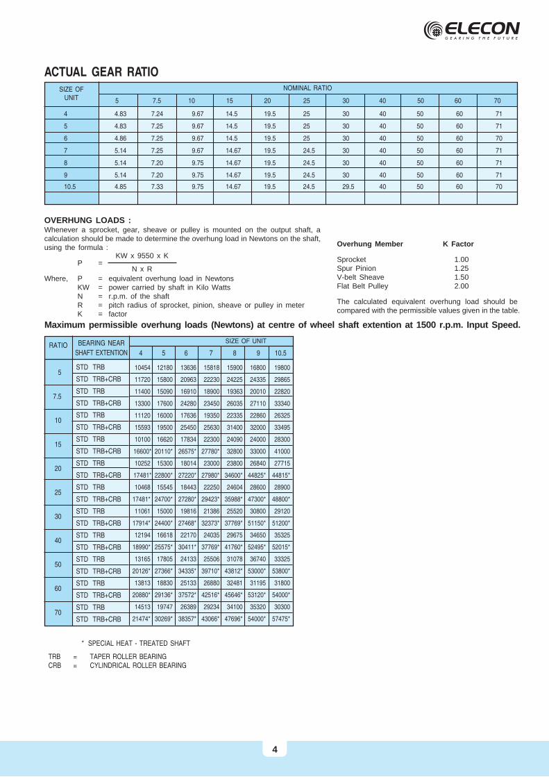
ACTUAL GEAR RATIO
Overhung Member K Factor
Sprocket 1.00Spur Pinion 1.25V-belt Sheave 1.50Flat Belt Pulley 2.00
The calculated equivalent overhung load should becompared with the permissible values given in the table.
OVERHUNG LOADS :Whenever a sprocket, gear, sheave or pulley is mounted on the output shaft, acalculation should be made to determine the overhung load in Newtons on the shaft,using the formula :
P =
Where, P = equivalent overhung load in NewtonsKW = power carried by shaft in Kilo WattsN = r.p.m. of the shaftR = pitch radius of sprocket, pinion, sheave or pulley in meterK = factor
KW x 9550 x K
N x R
Maximum permissible overhung loads (Newtons) at centre of wheel shaft extention at 1500 r.p.m. Input Speed.
* SPECIAL HEAT - TREATED SHAFT
TRB = TAPER ROLLER BEARINGCRB = CYLINDRICAL ROLLER BEARING
NOMINAL RATIO
5 7.5 10 15 20 25 30 40 50 60 70
SIZE OFUNIT
4 4.83 7.24 9.67 14.5 19.5 25 30 40 50 60 71
5 4.83 7.25 9.67 14.5 19.5 25 30 40 50 60 71
6 4.86 7.25 9.67 14.5 19.5 25 30 40 50 60 70
7 5.14 7.25 9.67 14.67 19.5 24.5 30 40 50 60 71
8 5.14 7.20 9.75 14.67 19.5 24.5 30 40 50 60 71
9 5.14 7.20 9.75 14.67 19.5 24.5 30 40 50 60 71
10.5 4.85 7.33 9.75 14.67 19.5 24.5 29.5 40 50 60 70
5
7.5
10
15
20
25
30
40
50
60
70
RATIO BEARING NEAR
SHAFT EXTENTION
STD TRB
STD TRB+CRB
STD TRB
STD TRB+CRB
STD TRB
STD TRB+CRB
STD TRB
STD TRB+CRB
STD TRB
STD TRB+CRB
STD TRB
STD TRB+CRB
STD TRB
STD TRB+CRB
STD TRB
STD TRB+CRB
STD TRB
STD TRB+CRB
STD TRB
STD TRB+CRB
STD TRB
STD TRB+CRB
10454 12180 13636 15818 15900 16800 19800
11720 15800 20963 22230 24225 24335 29865
11400 15090 16910 18900 19363 20010 22820
13300 17600 24280 23450 26035 27110 33340
11120 16000 17636 19350 22335 22860 26325
15593 19500 25450 25630 31400 32000 33495
10100 16620 17834 22300 24090 24000 28300
16600* 20110* 26575* 27780* 32800 33000 41000
10252 15300 18014 23000 23800 26840 27715
17481* 22800* 27220* 27980* 34600* 44825* 44815*
10468 15545 18443 22250 24604 28600 28900
17481* 24700* 27280* 29423* 35988* 47300* 48800*
11061 15000 19816 21386 25520 30800 29120
17914* 24400* 27468* 32373* 37769* 51150* 51200*
12194 16618 22170 24035 29675 34650 35325
18990* 25575* 30411* 37769* 41760* 52495* 52015*
13165 17805 24133 25506 31078 36740 33325
20126* 27366* 34335* 39710* 43812* 53000* 53800*
13813 18830 25133 26880 32481 31195 31800
20880* 29136* 37572* 42516* 45646* 53120* 54000*
14513 19747 26389 29234 34100 35320 30300
21474* 30269* 38357* 43066* 47696* 54000* 57475*
SIZE OF UNIT
4 5 6 7 8 9 10.5
4
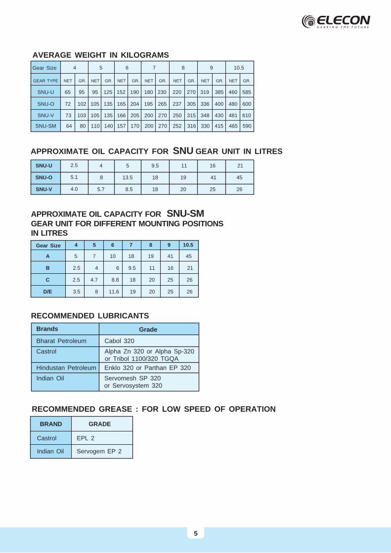
AVERAGE WEIGHT IN KILOGRAMS
Gear Size 4 5 6 7 8 9 10.5
GEAR TYPE NET GR. NET GR. NET GR. NET GR. NET GR. NET GR. NET GR.
SNU-U 65 95 95 125 152 190 180 230 220 270 319 385 460 585
SNU-O 72 102 105 135 165 204 195 265 237 305 336 400 480 600
SNU-V 73 103 105 135 166 205 200 270 250 315 348 430 481 610
SNU-SM 64 80 110 140 157 170 200 270 252 316 330 415 465 590
5
RECOMMENDED GREASE : FOR LOW SPEED OF OPERATION
BRAND
Castrol
Indian Oil
EPL 2
Servogem EP 2
GRADE
APPROXIMATE OIL CAPACITY FOR SNU GEAR UNIT IN LITRES
4 5 9.5 11 16 21
8 13.5 18 19 41 45
5.7 8.5 18 20 25 26
2.5
5.1
4.0
SNU-U
SNU-O
SNU-V
APPROXIMATE OIL CAPACITY FOR SNU-SMGEAR UNIT FOR DIFFERENT MOUNTING POSITIONS IN LITRES
5 7 10 18 19 41 45
2.5 4 6 9.5 11 16 21
2.5 4.7 8.8 18 20 25 26
3.5 8 11.6 19 20 25 26
A
B
C
D/E
Gear Size 4 5 6 7 8 9 10.5
Brands
Bharat Petroleum Cabol 320
Castrol Alpha Zn 320 or Alpha Sp-320 or Tribol 1100/320 TGQA
Hindustan Petroleum Enklo 320 or Parthan EP 320
Indian Oil Servomesh SP 320 or Servosystem 320
RECOMMENDED LUBRICANTS
Grade
PRODUCT SAFETY INFORMATION
General ELECON gear units will operate safety provided that they are selected, installed, used
and maintained property. As with any equipment consists of rotating swhafts andtransmitting power, adequate guarding is necessary to elimiate the possibility of physi-cal contact with rotating shafts or coupling.
Potential Hazards The following points should be noted and brought to attention to the persons involved
in the installation, use and maintenance of equipment.
1. For lifting of gearunit eye-bolts or lifting points (on larger units) should be used.
2. Check the grade and quantity of lubrication before commissioning. Read and carry out all instructions onlubricant plate and in the installation and maintenance manual literature.
3. Installation must be performed in accordance with the manufacturer’s instruction and be undertaken bysuitably qualified personnel.
4. Ensure the proper maintenance of gearboxes in operation. USE ONLY ELECON SPARES FOR GEAR-BOXES.
5. The oil level should be examined periodically, if required the oil should be filled again.
6. The operating speeds, transmitting powers, generated torques or the external loads must not exceed thedesign values.
7. The driving and the driven equipment must be correctly selected to ensure that the complete installation ofthe machinery will perform satisfactorily e.g. avoiding system critical speeds, system torsional vibration etc.
As improvement in designing are continuously being made, the details and dimensions are subject to alterationwithout notice.
ELECON ENGINEERING CO. LTD.POST BOX # 6, VALLABH VIDYANAGAR 388 120, GUJARAT, INDIATEL.: +91-2692-236513, 236520, 232890 FAX : +91-2692-236527
E-MAIL : [email protected] Site : http://www.elecon.com
Any other required information or clarification can be obtained by writing to :
6