strona 1 z 71 1. purpose providing trouble-free work of technical
TRANSCRIPT

Strona 1 z 71
1. PURPOSE
Providing trouble-free work of technical installations and their respective devices and
optimization of maintenance and operation costs by defining basic technical requirements in
the electrical engineering field.
2. SCOPE OF THE STUDY
This instruction applies to the companies of PCC group: PCC Rokita SA, PCC Exol SA, PCC
PU Sp. z o.o., PCC MCAA Sp. z o.o., PCC Prodex Sp. z o.o., LabMatic Sp. z o.o., PCC Apakor
Sp. z o.o., PCC Therm Sp z o.o.
No. Position Responsibility and authorisations
1 Technical Director Instruction implementation supervision
3. RULES OF CONDUCT
3.1 DEFINITIONS AND ABBREVIATIONS
No. Name Definition
1 I&C Instrumentation and Control (equipment)
2 EX Explosion-proof (equipment for explosive atmospheres)
3 LED Light-Emitting Diode
4 RM Risk Matrix
5 TES Technical Equipment Standard
6 IMS Integrated Management System
7 ATEX (Fr. Atmosphères Explosibles) The European Union directive
(legal act), where the basic requirements, required to be met by
all devices intended to be used within an explosive atmosphere
area, are defined.
8 CPU Central Processing Unit - digital, sequential device carrying out
commands based on interpreted data retrieved from the
memory.
9 DCS Distributed Control System – control and visualisation system of
an industrial process, that has a common database for control
and visualisation, unlike SCADA systems or PLC.
10 HMI Human-Machine Interface – control (operator) panel – electrical
device allowing control of other devices, carrying out specific
processes, e.g. technological or production.
11 LV Low voltage, not higher than 1 kV.
Strona 2 z 71
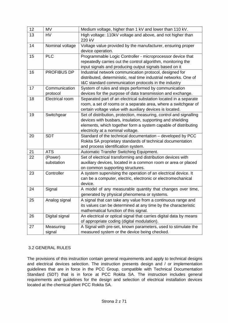
12 MV Medium voltage, higher than 1 kV and lower than 110 kV.
13 HV High voltage: 110kV voltage and above, and not higher than
220 kV
14 Nominal voltage Voltage value provided by the manufacturer, ensuring proper
device operation.
15 PLC Programmable Logic Controller - microprocessor device that
repeatedly carries out the control algorithm, monitoring the
input signals and producing output signals based on it
16 PROFIBUS DP Industrial network communication protocol, designed for
distributed, deterministic, real time industrial networks. One of
I&C standard communication protocols in the industry
17 Communication
protocol
System of rules and steps performed by communication
devices for the purpose of data transmission and exchange.
18 Electrical room Separated part of an electrical substation located in a separate
room, a set of rooms or a separate area, where a switchgear of
certain voltage value with auxiliary devices is located.
19 Switchgear Set of distribution, protection, measuring, control and signalling
devices with busbars, insulation, supporting and shielding
elements, which together form a system capable of distributing
electricity at a nominal voltage.
20 SDT Standard of the technical documentation – developed by PCC
Rokita SA proprietary standards of technical documentation
and process identification system.
21 ATS Automatic Transfer Switching Equipment.
22 (Power)
substation
Set of electrical transforming and distribution devices with
auxiliary devices, located in a common room or area or placed
on common supporting structures.
23 Controller A system supervising the operation of an electrical device. It
can be a computer, electric, electronic or electromechanical
device.
24 Signal A model of any measurable quantity that changes over time,
generated by physical phenomena or systems.
25 Analog signal A signal that can take any value from a continuous range and
its values can be determined at any time by the characteristic
mathematical function of this signal.
26 Digital signal An electrical or optical signal that carries digital data by means
of appropriate coding (digital modulation).
27 Measuring
signal
A Signal with pre-set, known parameters, used to stimulate the
measured system or the device being checked.
3.2 GENERAL RULES
The provisions of this instruction contain general requirements and apply to technical designs
and electrical devices selection. The instruction presents design and / or implementation
guidelines that are in force in the PCC Group, compatible with Technical Documentation
Standard (SDT) that is in force at PCC Rokita SA. The instruction includes general
requirements and guidelines for the design and selection of electrical installation devices
located at the chemical plant PCC Rokita SA.
Strona 3 z 71
3.3 PROCEDURE DESCRIPTION
3.3.1 Basic project requirements
Devices, electrical and power installations should be designed to meet requirements of current
standards, legal acts and guidelines included in this document.
Electric devices should be designed, selected and installed so as to provide required technical
safety level of production installation.
Electrical devices selection should be compatible with the „List of devices covered by
standardization ESUT01”. Technical specifications of a devices made by the Designer should
be approved by the Contracting Authority.
A production plant should be adapted for auto-starting as much as possible.
In case of modernization, extension or at the time of planning to build a new production plant,
analysis of technical potentials to supply power to a receiving plant shall be each time required.
In case of planning to increase power of the installation connexion or if construction of new
supply connections is required, suitable administrator of a unit or a distribution network should
be appropriately requested to issue relevant technical conditions related to connecting those
elements.
Technical conditions of connection are issued appropriately by:
- an expert authorised by the Power Grid Department (GTS) – in case of connection to
the power distribution network.
- an expert authorised by the Planning Department (GTP) – in case of connection to
the unit power distribution network.
1. During engineering works, it is necessary to adopt rules related to equipment technical
standardisation and rules related to technical solutions should be met in order to ensure:
- provision of power supply that meets requirements specified in item XI of the Instruction of
the power distribution network operation and handling applicable at PCC Rokita SA.)
- high reliability level,
- operational safety,
- high quality of equipment/solutions,
- transparency of network and standardisation of solutions to facilitate operations in the future,
- optimal use of electricity,
- low operational costs and self-operation.
2. Design temperature. During engineering stage related to motors, devices and electrical
equipment, outside temperature range -25oC to 40oC shall be assumed.
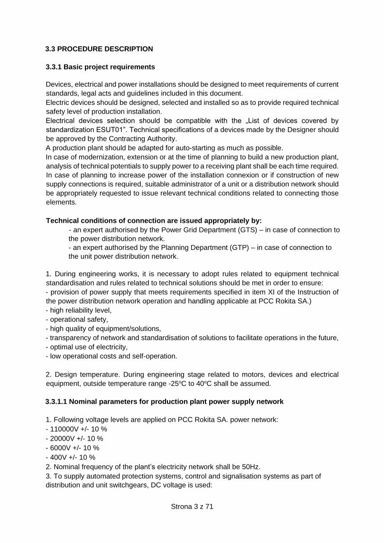
3.3.1.1 Nominal parameters for production plant power supply network
1. Following voltage levels are applied on PCC Rokita SA. power network:
- 110000V +/- 10 %
- 20000V +/- 10 %
- 6000V +/- 10 %
- 400V +/- 10 %
2. Nominal frequency of the plant’s electricity network shall be 50Hz.
3. To supply automated protection systems, control and signalisation systems as part of
distribution and unit switchgears, DC voltage is used:

Strona 4 z 71
- 24 VDC +10 / -15 %
- 110 VDC +10 / -15 %
- 220 VDC +10 / -15 %
4. Basic illumination, plug-in sockets, etc. as part of building internal systems are supplied
with 230/400 VAC.
5. Standby or emergency illumination systems as part of building internal systems are
supplied with 110 VDC or 220 VDC, depending on the DC system that has been applied in
the auxiliaries switchgear.
3.3.2 General safety rules
1. Equipment and devices containing PCB compounds are not allowed.
2. For the technical equipment passing through fire barriers, following compounds shall be
used respectively:
- sealing compounds of required EI resistance class - in case of cable and pipe arrangement
- fire barriers of required EI resistance class - in case of busbars arrangement.
3. For the technical equipment passing through building walls, water-proof and gas-tight (at
least 2 bar leakproof) containment cable penetrations shall be used.
4. Every power shutdown to critical devices should be indicated in a continuous-supervision
location.
5. Manual switching of UPS devices into bypass mode, should be indicated in a continuous-
supervision location.
6. Immediate reset emergency lighting should be used to show exits and illuminate escape
routes. Such lighting should meet requirements of current standards and regulations.
7. Flammable liquid and gas tanks should be grounded in at least two locations.
8. Flexible earthing devices, equipped with electronic controls shall be used at
loading/unloading areas for trucks, trailers, railway tank cars, etc.
9. If necessary, non-insulated wired shunts should be installed to get electrical continuity and
avoid electrostatic charges formation.
10. Rails should be grounded.
11. Battery rooms, in which lead acid batteries are stored, should be equipped with eyewash
stations.
3.3.3 Explosive areas classification
RESPONSIBILITY FOR DEVELOPMENT OF THE DOCUMENT:
The design office which is to engineer a conceptual, construction, or process design - subject
to range of design works and changes to be implemented - shall be responsible for assessing
the risk of explosion, in accordance with the requirements of the Regulation of the Minister of
Interior and Administration on fire protection of buildings, other civil structures and lands.
On behalf of PCC, a technologist or any other authorised person responsible for technological
operations as well as a Fire Protection Expert (BRP Team) should participate in the process
of explosion risk assessment.
The explosion risk assessment should contain a declaration of the transfer of copyright to PCC
and should be given in paper and electronic editable (e.g. .doc, .dwg, .xls) form.
Every risk of explosion assessment document should be approved by the Fire Protection
Expert (BRP Team). In case of impossibility to obtain such acceptance (e.g. divergence in
Strona 5 z 71
opinions related to range of zones), BRP Team decides of the zone range and type. In such a
case, the design office representatives do not have to sign the document that have been
developed.
DOCUMENT’S DEVELOPMENT AND UPDATE DEADLINES:
Assessment of risk explosion should be developed at the stage of conceptual or construction
design, if a conceptual design is not developed.
Assessment of risk explosion should be verified and updated before development of detailed
design, and before operation of the installation within which emission can occur.
SCOPE OF THE DOCUMENT
Assessment of risk explosion should contain at least:
- Information related to range of area to be analysed,
- Technology description,
- Danger analysis,
- Determination of type and range of the explosive zones,
- Guidelines for selection of devices to be operated in the explosive zones.
- Classification tables, complying with PN-EN standards, which contain list and
specification of flammable substances.
- Classification tables, complying with PN-EN standards, which contain list and
specification of emission areas and ventilation assessment.
- Calculations of pressure increase that can be generated as a result of explosion.
- Graphic part showing type and range of explosive zones.
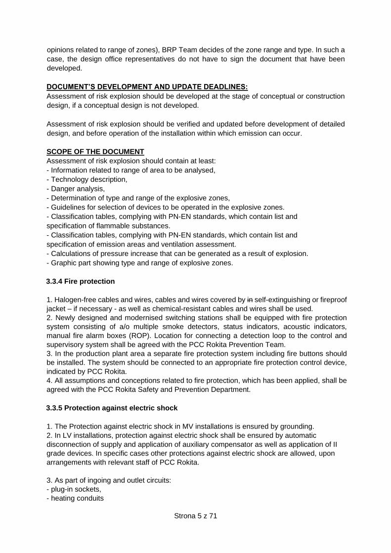
3.3.4 Fire protection
1. Halogen-free cables and wires, cables and wires covered by in self-extinguishing or fireproof
jacket – if necessary - as well as chemical-resistant cables and wires shall be used.
2. Newly designed and modernised switching stations shall be equipped with fire protection
system consisting of a/o multiple smoke detectors, status indicators, acoustic indicators,
manual fire alarm boxes (ROP). Location for connecting a detection loop to the control and
supervisory system shall be agreed with the PCC Rokita Prevention Team.
3. In the production plant area a separate fire protection system including fire buttons should
be installed. The system should be connected to an appropriate fire protection control device,
indicated by PCC Rokita.
4. All assumptions and conceptions related to fire protection, which has been applied, shall be
agreed with the PCC Rokita Safety and Prevention Department.
3.3.5 Protection against electric shock
1. The Protection against electric shock in MV installations is ensured by grounding.
2. In LV installations, protection against electric shock shall be ensured by automatic
disconnection of supply and application of auxiliary compensator as well as application of II
grade devices. In specific cases other protections against electric shock are allowed, upon
arrangements with relevant staff of PCC Rokita.
3. As part of ingoing and outlet circuits:
- plug-in sockets,
- heating conduits
Strona 6 z 71
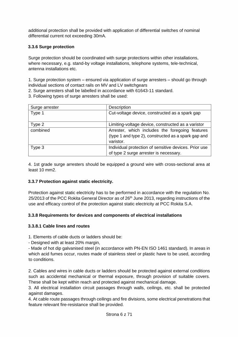
additional protection shall be provided with application of differential switches of nominal
differential current not exceeding 30mA.
3.3.6 Surge protection
Surge protection should be coordinated with surge protections within other installations,
where necessary, e.g. stand-by voltage installations, telephone systems, tele-technical,
antenna installations etc.
1. Surge protection system – ensured via application of surge arresters – should go through
individual sections of contact rails on MV and LV switchgears
2. Surge arresters shall be labelled in accordance with 61643-11 standard.
3. Following types of surge arresters shall be used:
Surge arrester Description
Type 1
Cut-voltage device, constructed as a spark gap
Type 2 Limiting-voltage device, constructed as a varistor
combined Arrester, which includes the foregoing features
(type 1 and type 2), constructed as a spark gap and
varistor.
Type 3 Individual protection of sensitive devices. Prior use
of type 2 surge arrester is necessary.
4. 1st grade surge arresters should be equipped a ground wire with cross-sectional area at
least 10 mm2.
3.3.7 Protection against static electricity.
Protection against static electricity has to be performed in accordance with the regulation No.
25/2013 of the PCC Rokita General Director as of 26th June 2013, regarding instructions of the
use and efficacy control of the protection against static electricity at PCC Rokita S.A.
3.3.8 Requirements for devices and components of electrical installations
3.3.8.1 Cable lines and routes
1. Elements of cable ducts or ladders should be:
- Designed with at least 20% margin,
- Made of hot dip galvanised steel (in accordance with PN-EN ISO 1461 standard). In areas in
which acid fumes occur, routes made of stainless steel or plastic have to be used, according
to conditions.
2. Cables and wires in cable ducts or ladders should be protected against external conditions
such as accidental mechanical or thermal exposure, through provision of suitable covers.
These shall be kept within reach and protected against mechanical damage.
3. All electrical installation circuit passages through walls, ceilings, etc. shall be protected
against damages.
4. At cable route passages through ceilings and fire divisions, some electrical penetrations that
feature relevant fire-resistance shall be provided.
Strona 7 z 71
5. In case of corrugated pipes used as a form of protection of wire terminals at devices,
appropriate Adaptalok ends shall be used.
6. Cable route system solutions shall be used.
7. Separate cable routes shall be used for arrangement of control, signal and
telecommunication cables.
8. Electrical continuity for cable routes and accessories shall be ensured; cable routes shall be
grounded every 15 to 20 meters. Electrical continuity shall be ensured by connection of all
elements of cable routes by a copper wire featuring at least 6mm2 cross section with crimped-
on ring terminals. Alternatively, for routes intended for cables of voltage up to 1kV, system
connections are allowed, if these have appropriate declarations of cable route manufacturer.
9. Cables in the ground should be laid on sand subcrust. These shall be marked every 10
meters at all specific points such as crossings, manholes and covers. For further details
see 3.3.8.3 chapter of this instruction.
10. Routes of underground cables shall be marked along their entire length and width with foil
colour corresponding to its nominal voltage.
- blue for cables of nominal voltage up to 1kV,
- red for cables of nominal voltage over 1kV,
- green for control cables,
- yellow for telecommunication cables.
11. In absolute terms, cable arrangement conditions – as per the manufacturer’s guidelines
and N SEP E-004 standard - shall be complied with.
3.3.8.2 Selection of the cables, wires and equipment.
1. Electrical plants that power up MV receivers should be ensured with application of single-
or triple-core cables:
- of copper or aluminium conductors,
- with XLPE insulation,
- common copper return core,
- with the outer sheath made of PE or self-extinguishing or fire-retardant, resistant to corrosion
caused by chemical exposure (hydrocarbons) PVC.
2. Electrical plants that power up LV receivers should be ensured with application of electrical
power multi-conductor copper cables, with PVC insulation and outer sheath.
Flammability IEC 60332 – 1 – 2, self-extinguishing. For receivers of nominal power at least
110kW application of the following cables is allowed:
- single-core cables with copper conductors,
- XLPE-insulated,
- service and protective wires featuring identical cross-section.
- covered externally by PE or self-extinguishing or fire-retardant PVC, resistant to corrosion
caused by chemical exposure.
3. Electrical power cables supplying electrical motors, arranged in explosion-risk zones should
additionally feature long-term load rating at least 125% of nominal motor current.
4. 230V AC or 24V DC electrical control, signalling, and measuring installations shall be
provided with multi-core wires:
- service and protective wires featuring identical cross-section ,
- self-extinguishing in accordance with IEC 60332 -1 – 2 standards,
- resistant to chemical exposure (depending on location),
- with numbered cores, or with colour-code,
Strona 8 z 71
- for industrial use; additionally, as part of external installations these shall be UV radiation and
weather resistant.
5. Cables completely or partly located within explosion-risk zones shall have following minimal
cross-section areas of cores:
- electrical power cables – 2.5mm2,
- signal and control cables – 1.5mm2,
- telecommunication cables – 1.0mm2,
If using cables of cross-section area less than above is necessary, please contact the
Contracting Authority for permit for deviation.
6. Cables should have increased insulation parameters in accordance with table No. 1.
Table No. 1. – Rated voltage of insulation.
MV power cables I Rated voltage 6/10kV
II Rated voltage 12/20kV
LV power, control, signalling cables Rated voltage 0.6/1kV
Telecommunication cables, Rated voltage 0.3/0.5 kV
Electrical, control, signal wires Rated voltage 0.4/0.7 kV
7. Signalling cables should have additional at least 10% core couples. Recommended
maximum quantity of conductors as part of a wire is 24.
8. Type, quantity of cable couples and routes shall be agreed with Telecommunication
Department of PCC IT S.A.
9. Cables for drives supplied by frequency converters should be equipped with a screen that
meets electromagnetic compatibility requirements.
10. Selection of wire and cable cross-sections should be carried out on the basis of calculations
specified in the project. These calculations confirm acceptable voltage drop, allowable long-
term load rating, short-circuit-, overload-protection efficiency and electric shock protection
efficiency.
3.3.8.3 Cables, wires and cable lines marking
Cables and wires arranged in buildings shall be permanently marked within a distance not
exceeding 10m.
All cable lines should be marked by properly attached stainless or plastic boards containing
the following information:
- Symbol of cable line,
- Registration number of cable line,
- Cable type,
- Cable rated voltage,
- Symbol of phase in case of single-core cables),
- Year of cable arrangement.
Strona 9 z 71
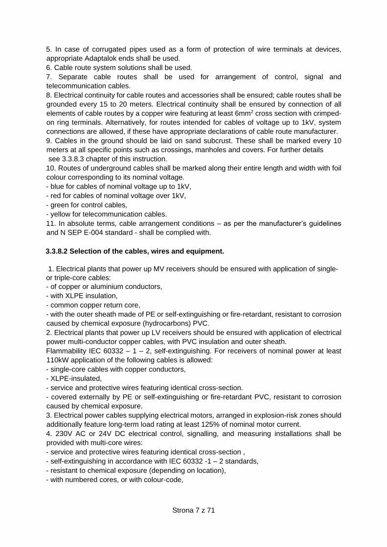
Table 2. Cable line labels. Description of columns can be found in table No. 3.
1 2 3 4 5 6 7
High voltage cable line
K 2
3x1XRUHKXS
240mm2
115/125
kV L1 2010
Medium voltage cable line
L 240
3x1xYHKXS
240mm2 12/20 kV L1 2010
Low voltage cable line
LN 12 YAKY 4x240mm2 0,6/1kV - 2010
Control cable line
LS 26 YKSY 12x2,5mm2 0,6/1kV - 2010
Fibre-optic cable line
LO 15 FO A-DQ(ZN)2Y 24J - - 2010
Table No. 3. Column description
Column Description
1 Symbol of cable line
2 Registration number of cable line
3 Cable type
4 Cable rated voltage
5 Symbol of phase for single core cables
6 Year of cable arrangement
7 Label colour
Markings shall be legible, clear and permanent. Descriptions of cabinets and switchboards
shall be compatible with the technical documentation and guidelines:
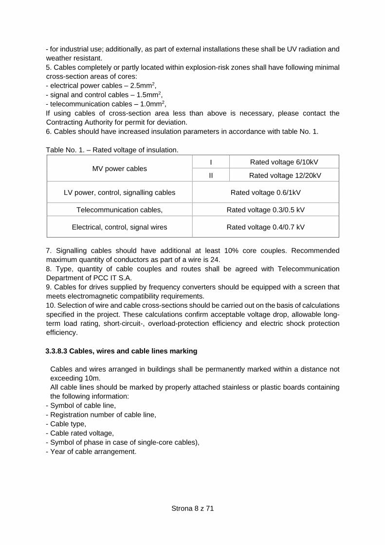
Example of cable band:
Figure 1. Model cable band
- Tags (cable bands) on lines supplying switchgears should include at least line registration
number, cable type, rated voltage, year of cable arrangement.
- Tags on outflow conduits that supply service devices should include building and switchgear
designation, switchgear name, circuit and technological number and in case of missing
technological number – name of device should be included.
Strona 10 z 71
Example:
U-28/R1a/5/UPS
U-28 – building name
R1a – switchgear name
5 – circuit number
UPS – device name
- Wire and cable descriptions and designations shall be made both inside and outside
distribution devices.
3.3.8.4 Labelling wire, cores, terminals and loads
1. Guidelines for wire and terminal designations
• Alphanumeric symbols and colours are used for marking wires and terminals.
Designations of wires and terminals along with of wire terminal colours are listed in
table No. 2.
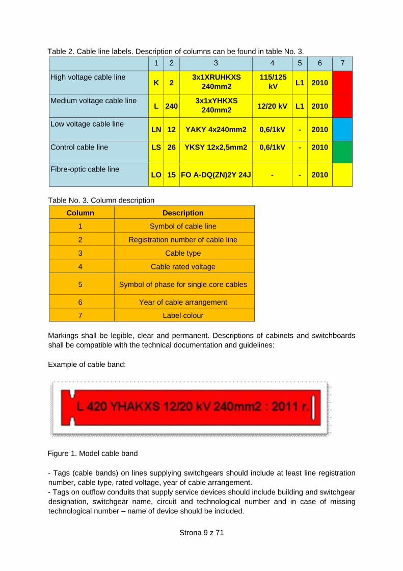
• All terminal strip sets shall be indicated with a tag consisting of an alphanumeric
symbol; all individual terminal shall have a numerical tag. Fig. 2 shows the example of
correctly labelled block.
Fig. 2. Example of a terminal block mark.
-Every wire core shall be marked at both ends,
-Tags on all cores at terminal blocks inputs or equipment terminals should be labelled in two
directions i.e. DESTINATION/SOURCE in a following manner:
- Block or apparatus mark from the destination side: terminal number on the terminal block or
equipment from the destination side.
- Block or apparatus mark from the source side: terminal number on the terminal block or
equipment from the source side; example of such a tag is shown in Fig. 3.
Strona 11 z 71
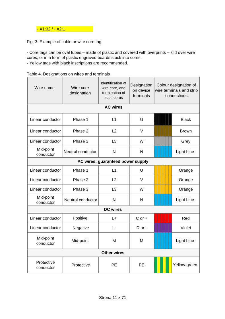
- X1:32 / - A2:1
Fig. 3. Example of cable or wire core tag
- Core tags can be oval tubes – made of plastic and covered with overprints – slid over wire
cores, or in a form of plastic engraved boards stuck into cores.
- Yellow tags with black inscriptions are recommended.
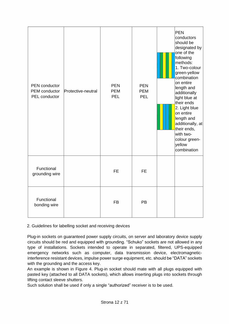
Table 4. Designations on wires and terminals
Wire name
Wire core
designation
Identification of
wire core, and
termination of
such cores
Designation
on device
terminals
Colour designation of
wire terminals and strip
connections
AC wires
Linear conductor Phase 1 L1 U Black
Linear conductor Phase 2 L2 V Brown
Linear conductor Phase 3 L3 W Grey
Mid-point
conductor Neutral conductor N N Light blue
AC wires; guaranteed power supply
Linear conductor Phase 1 L1 U Orange
Linear conductor Phase 2 L2 V Orange
Linear conductor Phase 3 L3 W Orange
Mid-point
conductor Neutral conductor N N Light blue
DC wires
Linear conductor Positive L+ C or + Red
Linear conductor Negative L- D or - Violet
Mid-point
conductor Mid-point M M Light blue
Other wires
Protective
conductor Protective PE PE Yellow-green
Strona 12 z 71
PEN conductor
PEM conductor
PEL conductor
Protective-neutral
PEN
PEM
PEL
PEN
PEM
PEL
PEN
conductors
should be
designated by
one of the
following
methods:
1. Two-colour
green-yellow
combination
on entire
length and
additionally
light blue at
their ends
2. Light blue
on entire
length and
additionally, at
their ends,
with two-
colour green-
yellow
combination
Functional
grounding wire FE FE
Functional
bonding wire FB PB
2. Guidelines for labelling socket and receiving devices
Plug-in sockets on guaranteed power supply circuits, on server and laboratory device supply
circuits should be red and equipped with grounding. “Schuko” sockets are not allowed in any
type of installations. Sockets intended to operate in separated, filtered, UPS-equipped
emergency networks such as computer, data transmission device, electromagnetic-
interference resistant devices, impulse power surge equipment, etc. should be “DATA” sockets
with the grounding and the access key.
An example is shown in Figure 4. Plug-in socket should mate with all plugs equipped with
pasted key (attached to all DATA sockets), which allows inserting plugs into sockets through
lifting contact sleeve shutters.
Such solution shall be used if only a single “authorized” receiver is to be used.
Strona 13 z 71
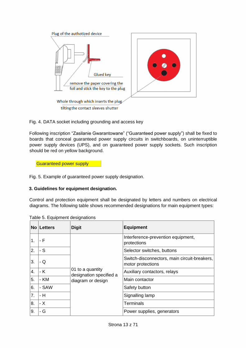
Fig. 4. DATA socket including grounding and access key
Following inscription “Zasilanie Gwarantowane” (“Guaranteed power supply”) shall be fixed to
boards that conceal guaranteed power supply circuits in switchboards, on uninterruptible
power supply devices (UPS), and on guaranteed power supply sockets. Such inscription
should be red on yellow background.
Guaranteed power supply
Fig. 5. Example of guaranteed power supply designation.
3. Guidelines for equipment designation.
Control and protection equipment shall be designated by letters and numbers on electrical
diagrams. The following table shows recommended designations for main equipment types:
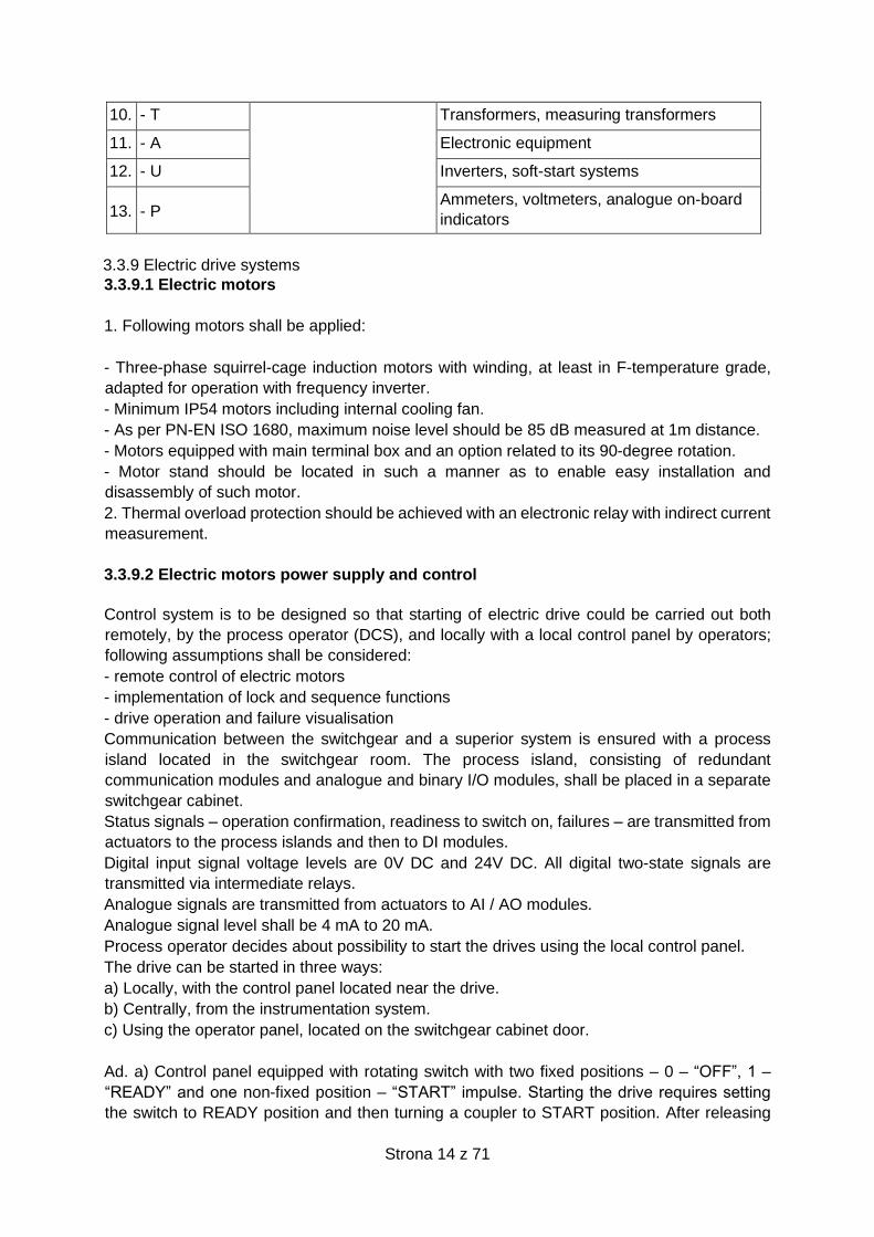
Table 5. Equipment designations
No Letters Digit Equipment
1. - F
01 to a quantity
designation specified a
diagram or design
Interference-prevention equipment,
protections
2. - S Selector switches, buttons
3. - Q Switch-disconnectors, main circuit-breakers,
motor protections
4. - K Auxiliary contactors, relays
5. - KM Main contactor
6. - SAW Safety button
7. - H Signalling lamp
8. - X Terminals
9. - G Power supplies, generators
Strona 14 z 71
10. - T Transformers, measuring transformers
11. - A Electronic equipment
12. - U Inverters, soft-start systems
13. - P Ammeters, voltmeters, analogue on-board
indicators
3.3.9 Electric drive systems
3.3.9.1 Electric motors
1. Following motors shall be applied:
- Three-phase squirrel-cage induction motors with winding, at least in F-temperature grade,
adapted for operation with frequency inverter.
- Minimum IP54 motors including internal cooling fan.
- As per PN-EN ISO 1680, maximum noise level should be 85 dB measured at 1m distance.
- Motors equipped with main terminal box and an option related to its 90-degree rotation.
- Motor stand should be located in such a manner as to enable easy installation and
disassembly of such motor.
2. Thermal overload protection should be achieved with an electronic relay with indirect current
measurement.
3.3.9.2 Electric motors power supply and control
Control system is to be designed so that starting of electric drive could be carried out both
remotely, by the process operator (DCS), and locally with a local control panel by operators;
following assumptions shall be considered:
- remote control of electric motors
- implementation of lock and sequence functions
- drive operation and failure visualisation
Communication between the switchgear and a superior system is ensured with a process
island located in the switchgear room. The process island, consisting of redundant
communication modules and analogue and binary I/O modules, shall be placed in a separate
switchgear cabinet.
Status signals – operation confirmation, readiness to switch on, failures – are transmitted from
actuators to the process islands and then to DI modules.
Digital input signal voltage levels are 0V DC and 24V DC. All digital two-state signals are
transmitted via intermediate relays.
Analogue signals are transmitted from actuators to AI / AO modules.
Analogue signal level shall be 4 mA to 20 mA.
Process operator decides about possibility to start the drives using the local control panel.
The drive can be started in three ways:
a) Locally, with the control panel located near the drive.
b) Centrally, from the instrumentation system.
c) Using the operator panel, located on the switchgear cabinet door.
Ad. a) Control panel equipped with rotating switch with two fixed positions – 0 – “OFF”, 1 –
“READY” and one non-fixed position – “START” impulse. Starting the drive requires setting
the switch to READY position and then turning a coupler to START position. After releasing
Strona 15 z 71
the switch, it returns to READY position automatically. The drive is stopped by setting the knob
to OFF position.
Ad. b) Remote drive start is carried out through control commands from the superior system
to the switchboard process island. Control signals are transmitted via executive relays from
DO / AO modules.
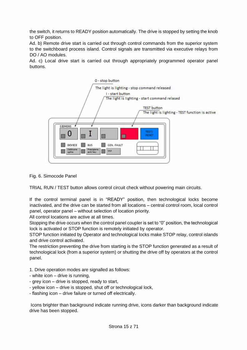
Ad. c) Local drive start is carried out through appropriately programmed operator panel
buttons.
Fig. 6. Simocode Panel
TRIAL RUN / TEST button allows control circuit check without powering main circuits.
If the control terminal panel is in “READY” position, then technological locks become
inactivated, and the drive can be started from all locations – central control room, local control
panel, operator panel – without selection of location priority.
All control locations are active at all times.
Stopping the drive occurs when the control panel coupler is set to “0” position, the technological
lock is activated or STOP function is remotely initiated by operator.
STOP function initiated by Operator and technological locks make STOP relay, control islands
and drive control activated.
The restriction preventing the drive from starting is the STOP function generated as a result of
technological lock (from a superior system) or shutting the drive off by operators at the control
panel.
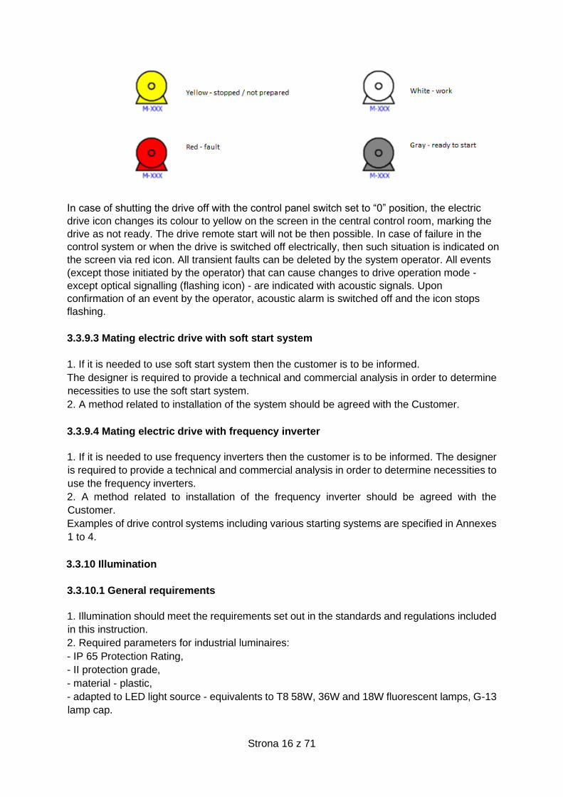
1. Drive operation modes are signalled as follows:
- white icon – drive is running,
- grey icon – drive is stopped, ready to start,
- yellow icon – drive is stopped, shut off or technological lock,
- flashing icon – drive failure or turned off electrically.
Icons brighter than background indicate running drive, icons darker than background indicate
drive has been stopped.
Strona 16 z 71
In case of shutting the drive off with the control panel switch set to “0” position, the electric
drive icon changes its colour to yellow on the screen in the central control room, marking the
drive as not ready. The drive remote start will not be then possible. In case of failure in the
control system or when the drive is switched off electrically, then such situation is indicated on
the screen via red icon. All transient faults can be deleted by the system operator. All events
(except those initiated by the operator) that can cause changes to drive operation mode -
except optical signalling (flashing icon) - are indicated with acoustic signals. Upon
confirmation of an event by the operator, acoustic alarm is switched off and the icon stops
flashing.
3.3.9.3 Mating electric drive with soft start system
1. If it is needed to use soft start system then the customer is to be informed.
The designer is required to provide a technical and commercial analysis in order to determine
necessities to use the soft start system.
2. A method related to installation of the system should be agreed with the Customer.
3.3.9.4 Mating electric drive with frequency inverter
1. If it is needed to use frequency inverters then the customer is to be informed. The designer
is required to provide a technical and commercial analysis in order to determine necessities to
use the frequency inverters.
2. A method related to installation of the frequency inverter should be agreed with the
Customer.
Examples of drive control systems including various starting systems are specified in Annexes
1 to 4.
3.3.10 Illumination
3.3.10.1 General requirements
1. Illumination should meet the requirements set out in the standards and regulations included
in this instruction.
2. Required parameters for industrial luminaires:
- IP 65 Protection Rating,
- II protection grade,
- material - plastic,
- adapted to LED light source - equivalents to T8 58W, 36W and 18W fluorescent lamps, G-13
lamp cap.

Strona 17 z 71
3. Additional parameters related to industrial luminaires to be used within potentially explosive
areas:
- housing material - fiberglass-reinforced polyester; lampshade - polycarbonate,
- I protection grade,
- IP66 Protection Rating,
- LED light source,
- appropriate certificates that allow application of industrial illumination in specific zones.
3.3.10.2 Basic illumination
1. Illumination on technological plants, pump stations, as well as main roads, internal roads,
access roads, manoeuvring yards, personnel rooms, control rooms, as well as storage and
handling tanks, etc. should be provided with standard luminaires equipped with LED light
source.
2. The entire illumination within a plant should be independently switched on or off from the
control room. Internal illumination on facilities within the battery limit, e.g. pump stations or
other poorly illuminated locations, should be activated locally.
3. Illumination circuit load as part of explosive zones should not exceed 80% of the rated load.
4. In control rooms, control stations and similar rooms - as part of buildings equipped with
HMI (human-machine interface) - the following items shall be applied:
- Illuminance of 500 lx,
- Walls and other background elements for HMI-equipped devices should be bright and
softened.
5. For external lighting - if illumination colour makes no difference, it is necessary to apply low-
pressure sodium discharge lamps as a light source.
6. In electrical power station rooms, illumination shall be installed on structures made of
reinforced C-profiles, suspended to the ceiling on threaded rods. The height of suspension of
the structure above the floor should directly result from calculations related to illuminance.
7. In battery rooms, Ex type luminaries shall be used. Switching on shall be carried out via
switching device located outside a room.
8. In container-type electrical power stations it is allowed to provide illumination along
commercial tubes.
9. LED light source luminaires, twilight sensor and motion detector shall be used above the
entrance door to transformer chambers.
3.3.10.3 Emergency lighting
1. Emergency lighting support time in the control room should be at least 90 minutes.
Extension of the emergency lighting support time may be carried out as per the analysis of
activities necessary for safe shutdown of a technological plant. This time should be agreed
between the Customer and the Designer.
2. A solution that allows using emergency lighting as general lighting is recommended.
3. Emergency lighting should be powered by a cumulative battery bank.
4. In electrical power stations within the emergency lighting circuit, an automatic / manual
selection switch shall be used.
5. Emergency lighting luminaires shall be marked with yellow 2 cm wide strip glued across the
lampshade.
Strona 18 z 71
3.3.11 Heating installation
3.3.11.1 General guidelines
1. Power supply for the electric heating system on devices and equipment should be
provided as part of TN-S system.
2. The heating circuits must be protected with overcurrent circuit breakers with a 30 mA
differential switch module.
3. The scope, method and data related to electric heating should be agreed with technological
staff and included in the design. Table 3.6.1. shows model data for selection of heating cables.
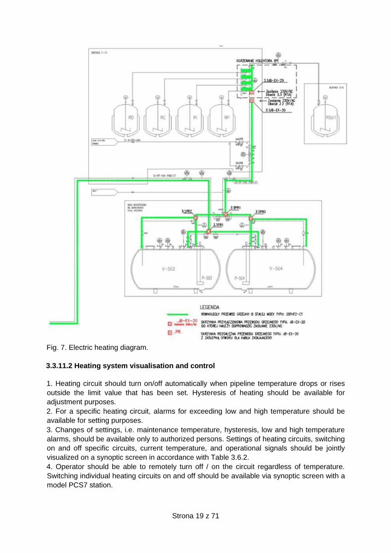
4. Design of electric heating should include a/o a diagram including heating circuits on a plant,
locations of junction boxes, locations of temperature sensors, etc. A model diagram of electric
heating is shown in addendum to this document.
5. Monitoring and control of heating should be provided via application of redundant, distributed
ET 200M / LINK IM153-2 6ES7153-2BA02-0XB0 stations. These should be equipped with the
following modules:
- digital input module SM 321, 32 DI DC24V (6ES7321-1BL00-0AA0),
- digital output module SM 322, 32 DO DC24V/0,5A (6ES7322-1BL00-0AA0),
- analogue input module SM 331, 8AI, 9/12/14 BITS (6ES7331-7KF02-0AB0),
- analogue output module SM 332, 8AO, U/I, 11/12 BITS (6ES7332-5HF00-0AB0).
The connection between a distributed station and a controller must be provided via a redundant
PROFIBUS DP network.
6. In case of heating individual circuits, heating circuits may be controlled by means of digital
thermostats equipped with local temperature display.
In such a case, power supply and control of heating circuits shall be carried out in accordance
with diagram 1, shown in addendum to this document .
7. Heating system shall be designed and constructed (hardware and software) with a 30%
reserve.
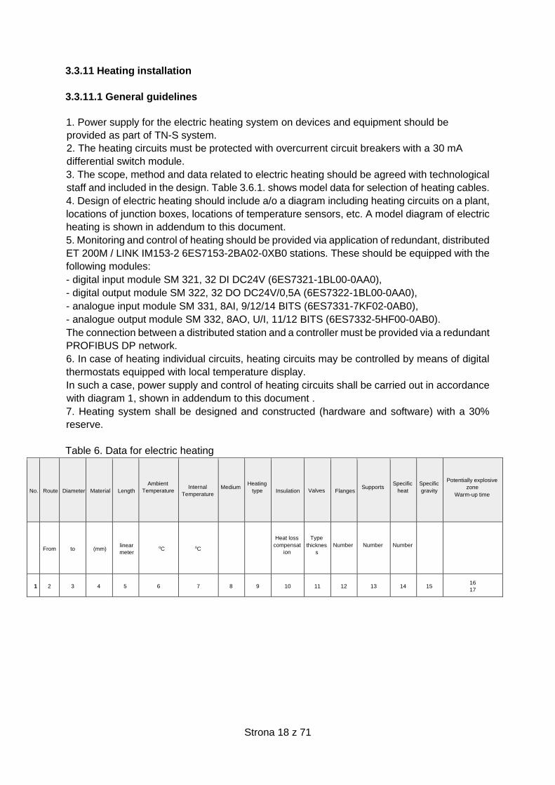
Table 6. Data for electric heating
No. Route Diameter Material Length
Ambient
Temperature
Internal
Temperature
Medium
Heating
type
Insulation Valves Flanges Supports
Specific
heat
Specific
gravity
Potentially explosive
zone
Warm-up time
From to (mm) linear
meter oC oC
Heat loss
compensat
ion
Type
thicknes
s
Number
Number
Number
1 2 3 4 5 6 7 8 9 10 11 12 13 14 15 16
17
Strona 19 z 71
Fig. 7. Electric heating diagram.
3.3.11.2 Heating system visualisation and control
1. Heating circuit should turn on/off automatically when pipeline temperature drops or rises
outside the limit value that has been set. Hysteresis of heating should be available for
adjustment purposes.
2. For a specific heating circuit, alarms for exceeding low and high temperature should be
available for setting purposes.
3. Changes of settings, i.e. maintenance temperature, hysteresis, low and high temperature
alarms, should be available only to authorized persons. Settings of heating circuits, switching
on and off specific circuits, current temperature, and operational signals should be jointly
visualized on a synoptic screen in accordance with Table 3.6.2.
4. Operator should be able to remotely turn off / on the circuit regardless of temperature.
Switching individual heating circuits on and off should be available via synoptic screen with a
model PCS7 station.
Strona 20 z 71
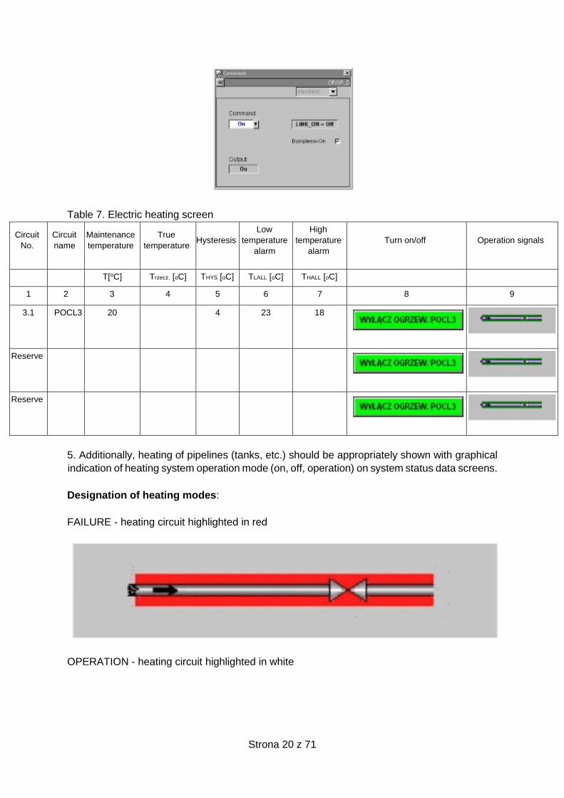
Table 7. Electric heating screen
Circuit
No.
Circuit
name
Maintenance
temperature
True
temperature
Hysteresis
Low
temperature
alarm
High
temperature
alarm
Turn on/off
Operation signals
T[oC] Trzecz. [oC] THYS [oC] TLALL [oC] THALL [oC]
1 2 3 4 5 6 7 8 9
3.1 POCL3 20 4 23 18
Reserve
Reserve
5. Additionally, heating of pipelines (tanks, etc.) should be appropriately shown with graphical
indication of heating system operation mode (on, off, operation) on system status data screens.
Designation of heating modes:
FAILURE - heating circuit highlighted in red
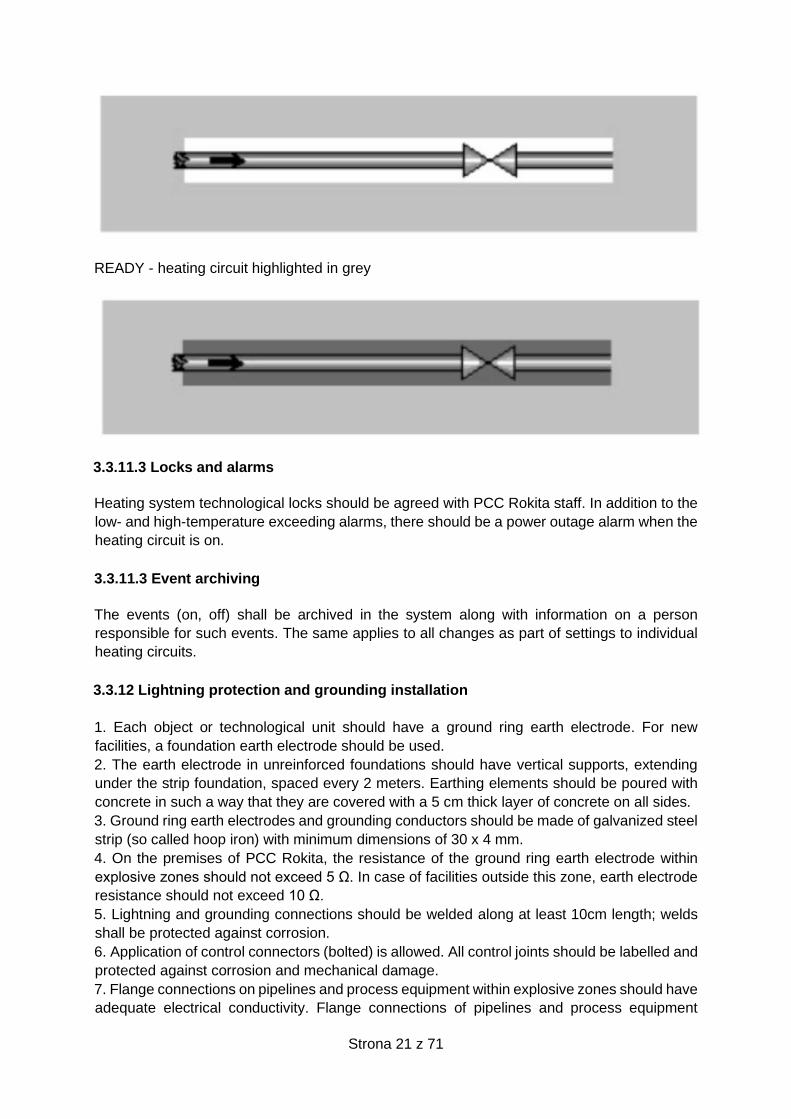
OPERATION - heating circuit highlighted in white
Strona 21 z 71
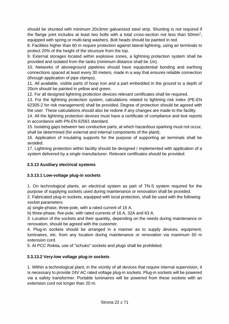
READY - heating circuit highlighted in grey
3.3.11.3 Locks and alarms
Heating system technological locks should be agreed with PCC Rokita staff. In addition to the
low- and high-temperature exceeding alarms, there should be a power outage alarm when the
heating circuit is on.
3.3.11.3 Event archiving
The events (on, off) shall be archived in the system along with information on a person
responsible for such events. The same applies to all changes as part of settings to individual
heating circuits.
3.3.12 Lightning protection and grounding installation
1. Each object or technological unit should have a ground ring earth electrode. For new
facilities, a foundation earth electrode should be used.
2. The earth electrode in unreinforced foundations should have vertical supports, extending
under the strip foundation, spaced every 2 meters. Earthing elements should be poured with
concrete in such a way that they are covered with a 5 cm thick layer of concrete on all sides.
3. Ground ring earth electrodes and grounding conductors should be made of galvanized steel
strip (so called hoop iron) with minimum dimensions of 30 x 4 mm.
4. On the premises of PCC Rokita, the resistance of the ground ring earth electrode within
explosive zones should not exceed 5 Ω. In case of facilities outside this zone, earth electrode
resistance should not exceed 10 Ω.
5. Lightning and grounding connections should be welded along at least 10cm length; welds
shall be protected against corrosion.
6. Application of control connectors (bolted) is allowed. All control joints should be labelled and
protected against corrosion and mechanical damage.
7. Flange connections on pipelines and process equipment within explosive zones should have
adequate electrical conductivity. Flange connections of pipelines and process equipment
Strona 22 z 71
should be shunted with minimum 20x3mm galvanized steel strip. Shunting is not required if
the flange joint includes at least two bolts with a total cross-section not less than 50mm2,
equipped with spring or multi-tang washers. Bolt heads should be painted in red.
8. Facilities higher than 60 m require protection against lateral lightning, using air terminals to
protect 20% of the height of the structure from the top.
9. External storages located within explosive zones, a lightning protection system shall be
provided and isolated from the tanks (minimum distance shall be 1m).
10. Networks of aboveground pipelines should have equipotential bonding and earthing
connections spaced at least every 30 meters, made in a way that ensures reliable connection
(through application of pipe clamps).
11. All available, visible parts of hoop iron and a part embedded in the ground to a depth of
20cm should be painted in yellow and green.
12. For all designed lightning protection devices relevant certificates shall be required.
13. For the lightning protection system, calculations related to lightning risk index (PE-EN
62305-2 for risk management) shall be provided. Degree of protection should be agreed with
the user. These calculations should also be redone if any changes are made to the facility.
14. All the lightning protection devices must have a certificate of compliance and test reports
in accordance with PN-EN 62561 standard.
15. Isolating gaps between two conductive parts, at which hazardous sparking must not occur,
shall be determined (for external and internal components of the plant).
16. Application of insulating supports for the purpose of supporting air terminals shall be
avoided.
17. Lightning protection within facility should be designed / implemented with application of a
system delivered by a single manufacturer. Relevant certificates should be provided.
3.3.13 Auxiliary electrical systems
3.3.13.1 Low-voltage plug-in sockets
1. On technological plants, an electrical system as part of TN-S system required for the
purpose of supplying sockets used during maintenance or renovation shall be provided.
2. Fabricated plug-in sockets, equipped with local protection, shall be used with the following
socket parameters:
a) single-phase, three-pole, with a rated current of 16 A,
b) three-phase, five-pole, with rated currents of 16 A, 32A and 63 A.
3. Location of the sockets and their quantity, depending on the needs during maintenance or
renovation, should be agreed with the customer.
4. Plug-in sockets should be arranged in a manner as to supply devices, equipment,
luminaires, etc. from any location during maintenance or renovation via maximum 50 m
extension cord.
5. At PCC Rokita, use of "schuko" sockets and plugs shall be prohibited.
3.3.13.2 Very-low voltage plug-in sockets
1. Within a technological plant, in the vicinity of all devices that require internal supervision, it
is necessary to provide 24V AC rated voltage plug-in sockets. Plug-in sockets will be powered
via a safety transformer. Portable luminaires will be powered from these sockets with an
extension cord not longer than 20 m.
Strona 23 z 71
2. Location of sockets and their quantity depend on the needs during maintenance or
renovation works and should be agreed with the customer.
3. 24V sockets should be min. IP44 protection rated and marked in purple.
3.3.14 Telecommunication system
1. Technological system should be equipped with a paging (intercom) loudspeaker
communication system – to be agreed with the Customer, future User and PCC IT
Telecommunications Department.
2. The quantity and arrangement of paging devices and the location of devices are to be agreed
between the Designer, the Contracting Authority, and future User during the project
arrangements.
3. Intercom installation cables will be laid along pipe racks or supporting structures, in cable
ducts or on cable ladders, in channels or in the ground.
4. Cable trays or ladders shall be protected against external factors such as rainfall, insolation,
mechanical, electrical or chemical exposure by providing appropriate covers.
5. It is necessary to use cables with flame retardant, hydrocarbon resistant sheaths.
6. The following telecommunication systems shall be agreed with the Customer, future User
and PCC IT Telecommunications Department:
- telephone communication
- computer network
- CCTV system
7. In case of buildings with office rooms, additional consideration should be given to providing
those rooms with access control system and alarm system. We suggest designing an
additional, dedicated room in which ICT cables will be arranged.
8. Equipment standard (manufacturer, type, model, etc.) shall be agreed with PCC IT
Telecommunications Department.
9. At the stage of developing a map for design purposes, ICT points of connection to the
existing telecommunication systems at the plant should be agreed with PCC IT
Telecommunications Department.
10. ICT system design shall be agreed with the PCC IT Telecommunications Department.
11. In office rooms, laboratory rooms, etc. for the purpose of operation of computer and
telephone networks and power supply for laboratory computer equipment, the systems should
be made as surface-mounted using Legrand POLAM SUWAŁKI strips - KIO series with 80mm
wide covers or KIO 45 strips with K45 modules.
3.3.15 Electrical power stations and substations
Electrical power stations and substations should meet the requirements specified in Polish
regulations and standards, including internal requirements applicable at the Contracting
Authority.
3.3.15.1 Electrical power stations and substations supplying system
1. Electrical power substations shall be supplied from two independent electrical power
sources.
2. Each power unit should be able to provide full power for the entire switchgear. Elements of
supplying systems in every section should be selected in such a manner as to take over full
load of the switchgear.

Strona 24 z 71
3. Distributing substations shall be equipped with automatic systems:
- Automatic Transfer Switching (ATS) equipment
- Planned Power Supply Switching Automatics (PSS)
4. ATS systems should be provided basing on a dedicated microprocessor automatic device
compliant with technical equipment standard.
3.3.15.2 Medium- and low-voltage switchgears
1. Medium- and low-voltage switchgears and devices installed inside these should meet
requirements specified in Polish regulations and standards, including internal requirements at
the Contracting Authority.
2. Switchgear supplying system should be based on a single switchable busbar system
(divided into two sections). Every section of the switchboard should be evenly loaded.
3. Switchgears inside the main power units should be made as double switchable system
including longitudinal and lateral coupling.
3.3.15.3 Medium-voltage switchgear
1. Medium-voltage switchgears should be made on the basis of the metal-clad, interior, metal-
enclosed, free-standing bays.
2. Main, outlet and protective busbars shall be made of cooper.
3. Every bay has to be equipped with decompression duct/ducts for exhaust gases made by
short circuit with electric arc inside the switchgear.
4. Decompression ducts have to be equipped with suitable exhaust flaps, opening under the
pressure which is generated by electric arc inside the switchgear.
5. Switchgears should be designed to ensure minimum 30% load increase without necessity
to reconstruct bays and change cross-sections of busbars.
6. Switchgears have to be adapted to local and remote control from a superior control system.
8. Required parameters:
a) Rated voltage: not less than 12kV, 50/60Hz,
b) Rated short-time withstand current: according to contemporary conditions, considering
increase in electrical power system parameters in the future, but no less than 16kA/1sec.
c) Rated peak withstand current: according to contemporary conditions, considering increase
in electrical power system parameters in the future, but no less than 40kA/1sec.
d) Protection Rating – not less than IP4X
e) orientation: free-standing or wall units (only in container stations).
f) Minimal graduation of free-standing bay:
- power supply bay 750mm,
- outlet bay 750mm,
- measuring bay 600mm,
- coupler bay 750mm.
g) insulation: air or SF6 (only in container stations),
h) working temperature range: -25oC to 40oC,
i) circuit breakers:
- arc box – vacuum,
- driving mechanism – spring, self-tensioning motor mechanism,
- mechanical endurance – not less than 30 000 operations,
- control voltage – 220V DC or 110V DC,
- equipped with at least one closing coil and two shunt-trip opening coils.

Strona 25 z 71
- adapted for control by a superior system.
- equipped with internal anti-pumping system
- equipped with motor mechanism for moving a slide-out module.
j) control voltage – 220V DC or 110V DC,
k) A certificate to confirm nominal parameters and compliance with Polish standards issued by
a body accredited by the Polish Centre for Accreditation is required for switchgears including
entire equipment.
8. Medium-voltage switchgears should be equipped with:
a) Withdrawable circuit breaker with manual and electrical drive (it does not apply to container
stations),
b) Selector switch disconnectors with manual and electrical drive (it applies to double busbar
stations),
c) System of mechanical, electromechanical, and electrical interlocks, which prevent against
erroneous operations,
d) Fixed earthing switch installed inside every bay, equipped with suitable interlocks that
prevent against short-circuit made by the switch, and auxiliary contacts signalling position of
the switch, separate for “grounded” and “opened” position,
e) Voltage-presence indicators on each bay connection mating with capacitive insulators,
f) Voltage-presence indicators on busbars in each measuring bay mating with the capacitive
insulators,
g) Analogue ammeter,
h) Arc protection,
i) Emergency (mechanical) terminal at every bay with a circuit breaker to disconnect a breaker.
j) Emergency button to disconnect a circuit breaker at every bay.
k) Automatic systems: Automatic Transfer Switching, Planned Power Supply Switching (PSS),
Automatic return switching, Auto supply switching. PSS automatics has to ensure controlled,
synchronous, uninterruptible power supply switching.
l) Measuring system for basic electrical quantities of every bay (i.e. current and voltage as part
of each phase and voltage frequency).
m) Recording system for remote read of events and faults, as well as basic electrical quantities
of every bay (i.e. current and voltage as part of each phase and voltage frequency), and
additionally, status of every switch in the switchgear.
n) Automation, control, protections, signal and measuring systems implemented on the basis
of bay controller (including protection relay function) providing additionally remote supervision
and control of switches from SCADA system in every bay.
o) Systems for measuring electric active & passive energy consumption, adjusted for remote
reading.
p) System of door emergency opening on all compartments which ensures opening the door
in case of bay damage without bay damage.
9. MV switchgears should have a synoptic diagram on the doors of each bay auxiliary circuits
compartment; such a diagram should reproduce electric connections of the bay main circuits
and status of the switches.
Strona 26 z 71
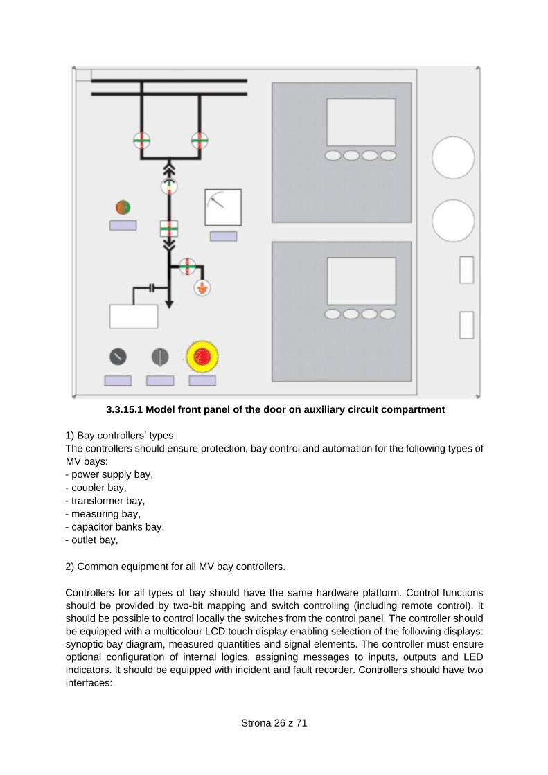
3.3.15.1 Model front panel of the door on auxiliary circuit compartment
1) Bay controllers’ types:
The controllers should ensure protection, bay control and automation for the following types of
MV bays:
- power supply bay,
- coupler bay,
- transformer bay,
- measuring bay,
- capacitor banks bay,
- outlet bay,
2) Common equipment for all MV bay controllers.
Controllers for all types of bay should have the same hardware platform. Control functions
should be provided by two-bit mapping and switch controlling (including remote control). It
should be possible to control locally the switches from the control panel. The controller should
be equipped with a multicolour LCD touch display enabling selection of the following displays:
synoptic bay diagram, measured quantities and signal elements. The controller must ensure
optional configuration of internal logics, assigning messages to inputs, outputs and LED
indicators. It should be equipped with incident and fault recorder. Controllers should have two
interfaces:
Strona 27 z 71
- Fibre interface RS to connect with the telemechanic concentrator. Following communication
protocols are allowed: IEC 60870-5-103, DNP 3,0.
- Fibre interface or RS for maintenance channel with dial-up connection.
3) Coupler bay controller:
As a standard, the controller should have following automatics:
- Two-stage time-delay overcurrent protection,
- Earth-fault, directional protection,
- Disconnection system, for short-circuit connecting.
4) Capacitor banks bay controller:
As a standard, the controller should have the following automatics:
- Two-stage time-delay overcurrent protection,
- Protection against short-circuits inside capacitor banks,
- Overvoltage protection (for line-to-line voltage),
- Earth-fault protection,
- Automatics for connecting capacitor banks.
5) Outlet bay controller:
As a standard, the controller should have the following automatics:
- Two-stage time-delay overcurrent protection,
- Earth-fault protection operated as per the criterion related to reactive power, admittance,
conductance,
- Automatic load shedding,
- Disconnection system, for short-circuit connecting .
6) ATS controller:
As a standard, the controller should meet the following requirements:
- Provision of instruments as part of open and hidden reserve:
- Selection of operational mode on the basis of switches status in the MV switchgear,
- Control of three circuit breakers as part of hidden reserve or two circuit breakers as part of
open reserve,
- Selection of return or non-return ATS cycle,
- Permanent or temporary local instrument interlocking and as part of telemechanic.
3.3.15.4 Structure of 0.4kV distributive switchgear
All 0,4kV distribution switchgears, in the range of construction, testing and protection must
meet requirements specified in the following standards: PN-EN-61439-1:2011, PN-EN-61439-
2:2011 and PN-EN 50274:2004.
The switchgear must consist of cabinets divided into following compartments:
- apparatus compartment,
- ring circuits compartment,
- main busbar compartment,
- distribution busbar compartment,
- cable compartment,
Strona 28 z 71
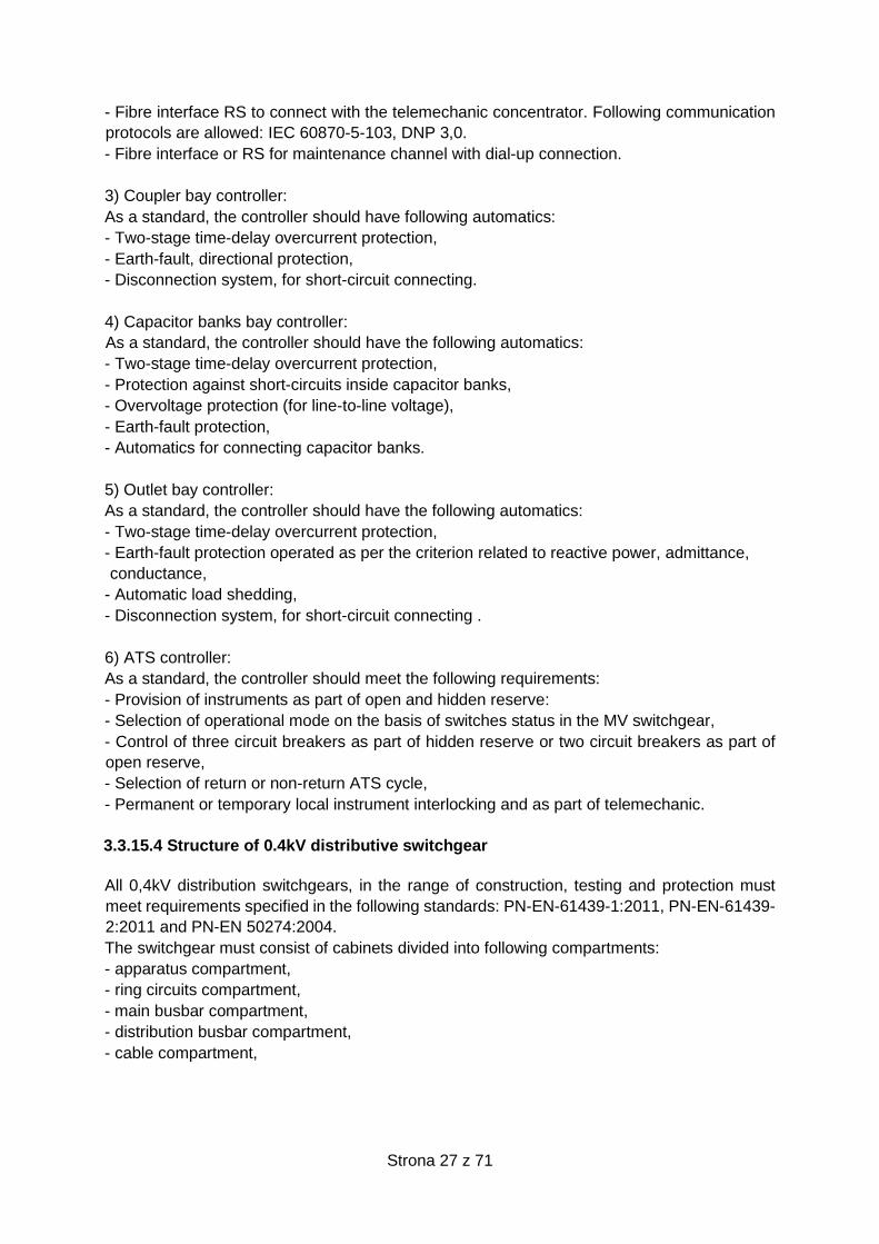
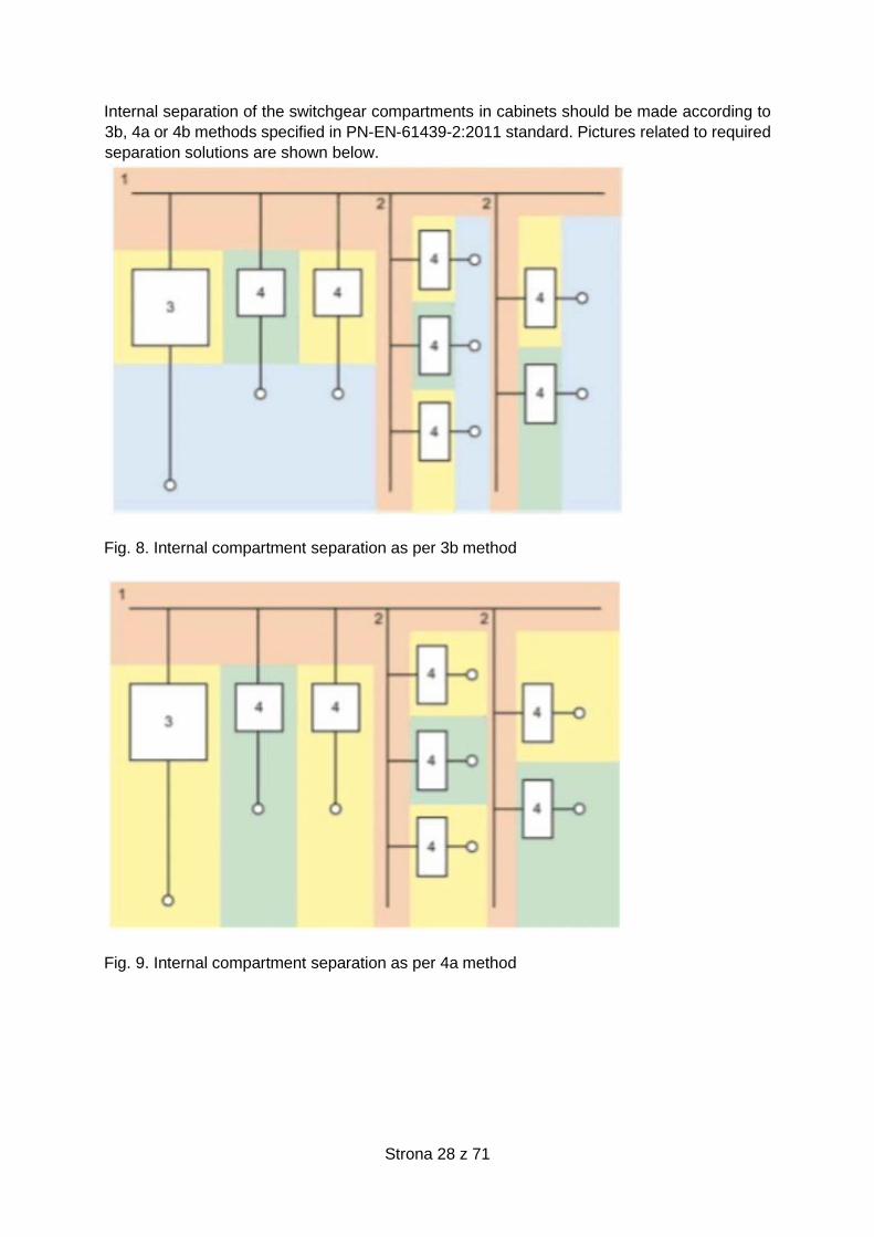
Internal separation of the switchgear compartments in cabinets should be made according to
3b, 4a or 4b methods specified in PN-EN-61439-2:2011 standard. Pictures related to required
separation solutions are shown below.
Fig. 8. Internal compartment separation as per 3b method
Fig. 9. Internal compartment separation as per 4a method
Strona 29 z 71
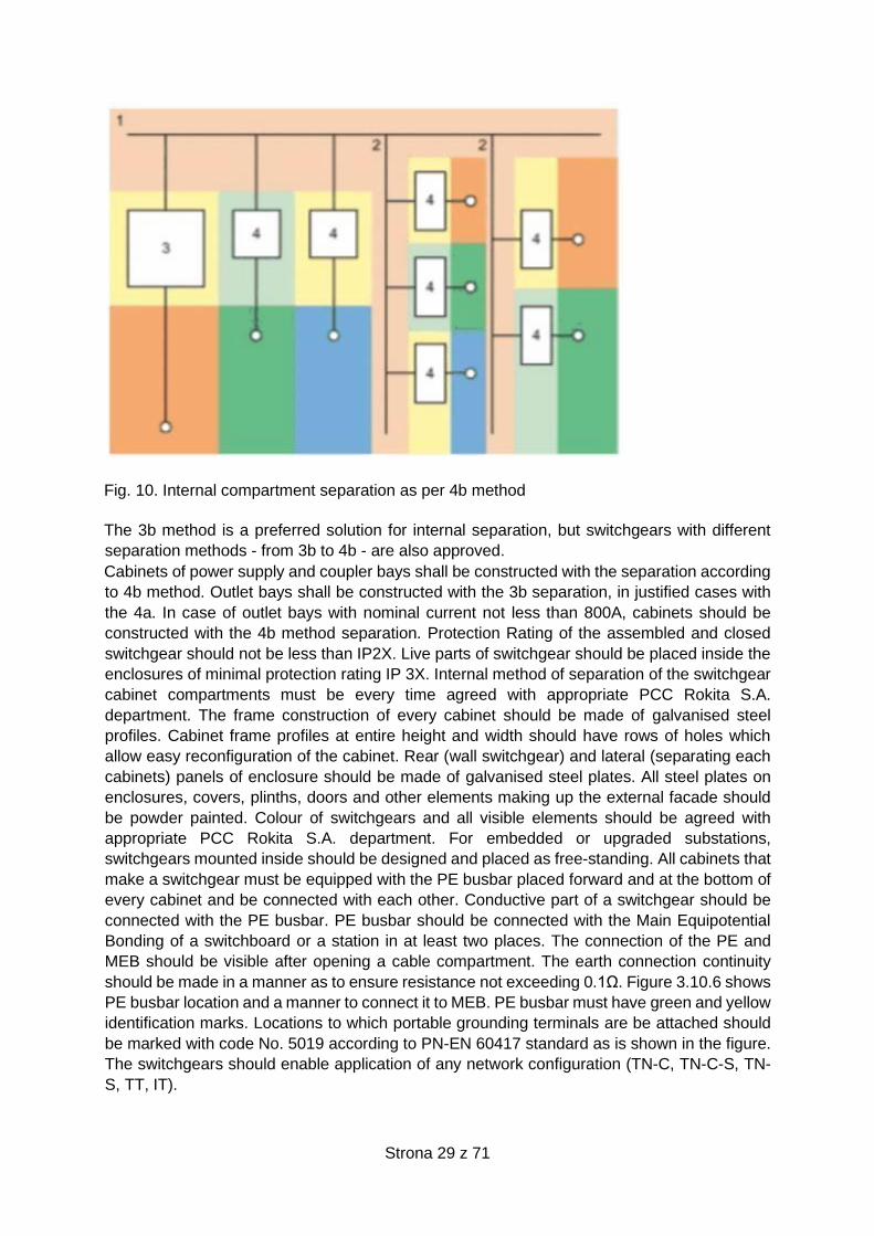
Fig. 10. Internal compartment separation as per 4b method
The 3b method is a preferred solution for internal separation, but switchgears with different
separation methods - from 3b to 4b - are also approved.
Cabinets of power supply and coupler bays shall be constructed with the separation according
to 4b method. Outlet bays shall be constructed with the 3b separation, in justified cases with
the 4a. In case of outlet bays with nominal current not less than 800A, cabinets should be
constructed with the 4b method separation. Protection Rating of the assembled and closed
switchgear should not be less than IP2X. Live parts of switchgear should be placed inside the
enclosures of minimal protection rating IP 3X. Internal method of separation of the switchgear
cabinet compartments must be every time agreed with appropriate PCC Rokita S.A.
department. The frame construction of every cabinet should be made of galvanised steel
profiles. Cabinet frame profiles at entire height and width should have rows of holes which
allow easy reconfiguration of the cabinet. Rear (wall switchgear) and lateral (separating each
cabinets) panels of enclosure should be made of galvanised steel plates. All steel plates on
enclosures, covers, plinths, doors and other elements making up the external facade should
be powder painted. Colour of switchgears and all visible elements should be agreed with
appropriate PCC Rokita S.A. department. For embedded or upgraded substations,
switchgears mounted inside should be designed and placed as free-standing. All cabinets that
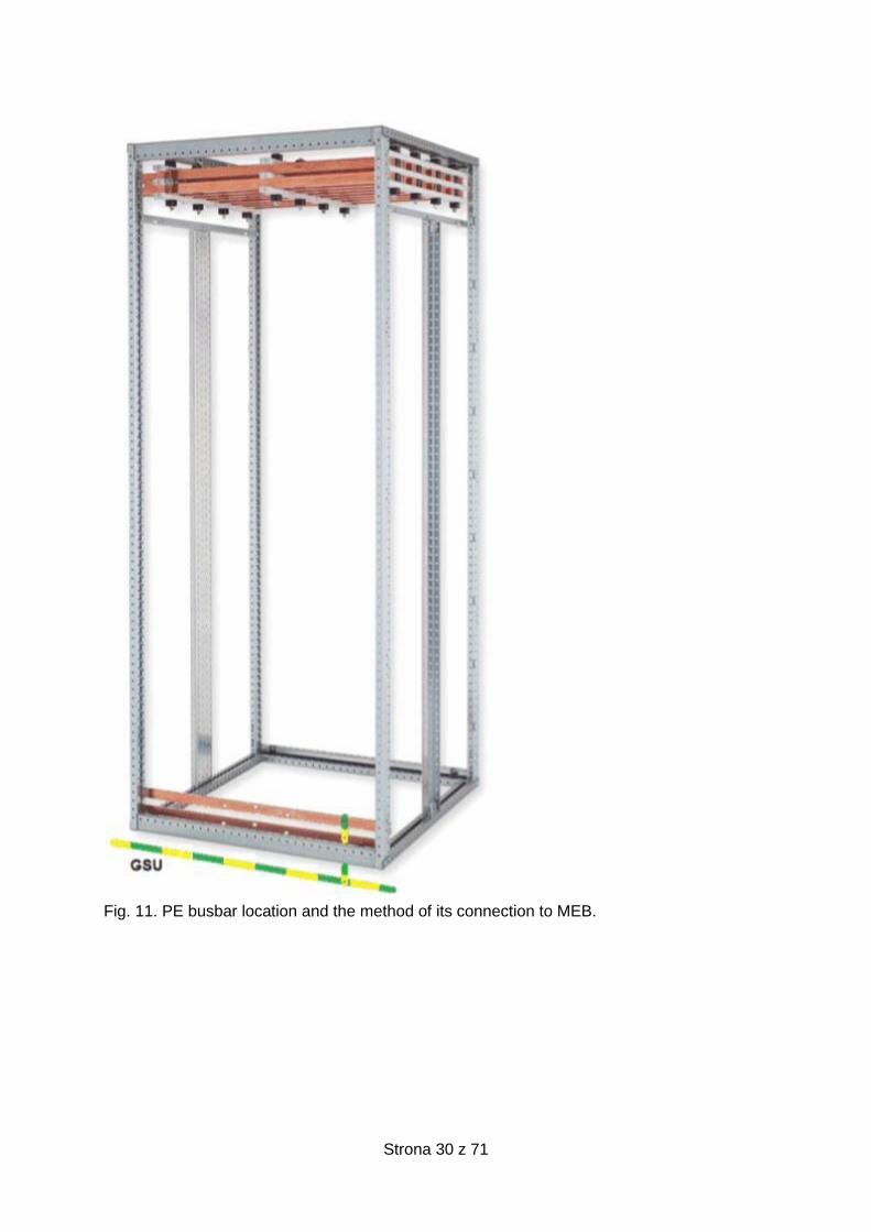
make a switchgear must be equipped with the PE busbar placed forward and at the bottom of
every cabinet and be connected with each other. Conductive part of a switchgear should be
connected with the PE busbar. PE busbar should be connected with the Main Equipotential
Bonding of a switchboard or a station in at least two places. The connection of the PE and
MEB should be visible after opening a cable compartment. The earth connection continuity
should be made in a manner as to ensure resistance not exceeding 0.1Ω. Figure 3.10.6 shows
PE busbar location and a manner to connect it to MEB. PE busbar must have green and yellow
identification marks. Locations to which portable grounding terminals are be attached should
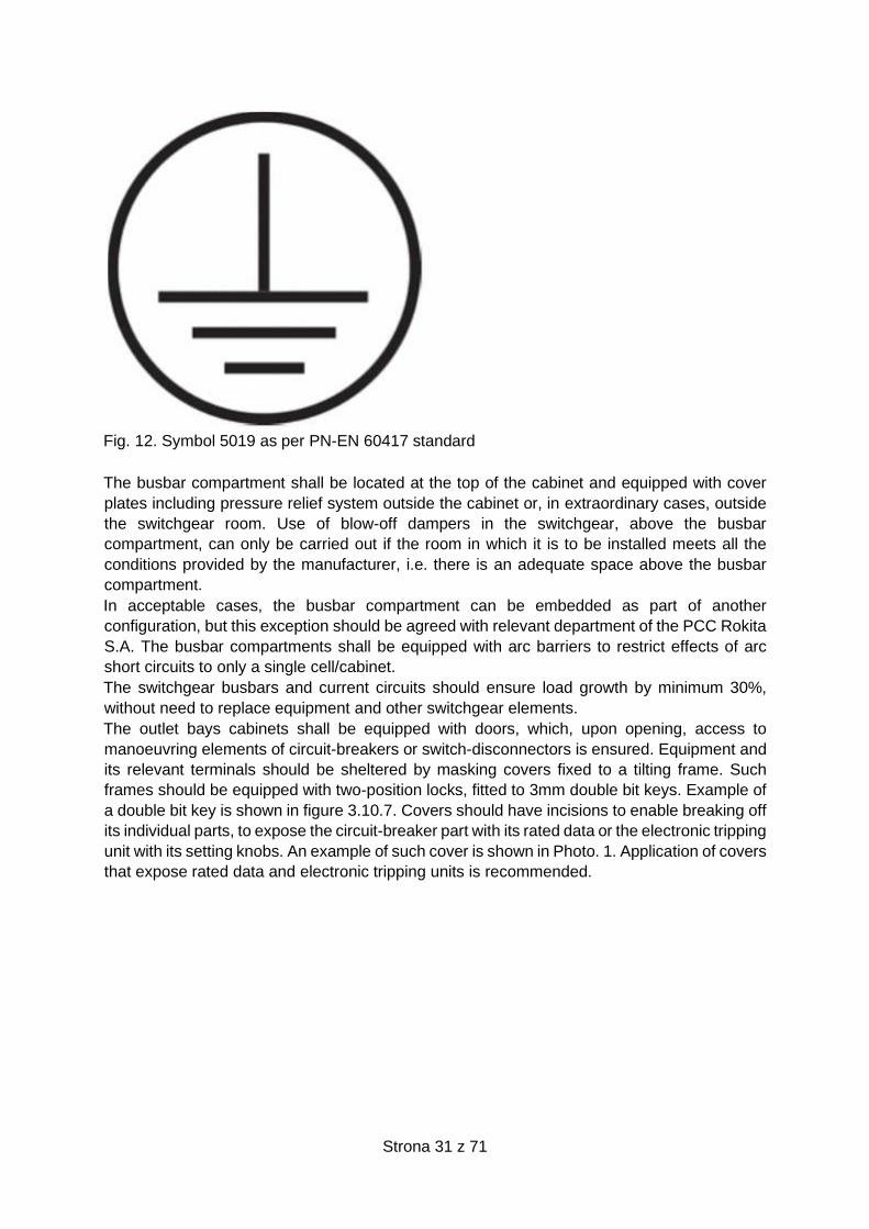
be marked with code No. 5019 according to PN-EN 60417 standard as is shown in the figure.
The switchgears should enable application of any network configuration (TN-C, TN-C-S, TN-
S, TT, IT).
Strona 30 z 71
Fig. 11. PE busbar location and the method of its connection to MEB.
Strona 31 z 71
Fig. 12. Symbol 5019 as per PN-EN 60417 standard
The busbar compartment shall be located at the top of the cabinet and equipped with cover
plates including pressure relief system outside the cabinet or, in extraordinary cases, outside
the switchgear room. Use of blow-off dampers in the switchgear, above the busbar
compartment, can only be carried out if the room in which it is to be installed meets all the
conditions provided by the manufacturer, i.e. there is an adequate space above the busbar
compartment.
In acceptable cases, the busbar compartment can be embedded as part of another
configuration, but this exception should be agreed with relevant department of the PCC Rokita
S.A. The busbar compartments shall be equipped with arc barriers to restrict effects of arc
short circuits to only a single cell/cabinet.
The switchgear busbars and current circuits should ensure load growth by minimum 30%,
without need to replace equipment and other switchgear elements.
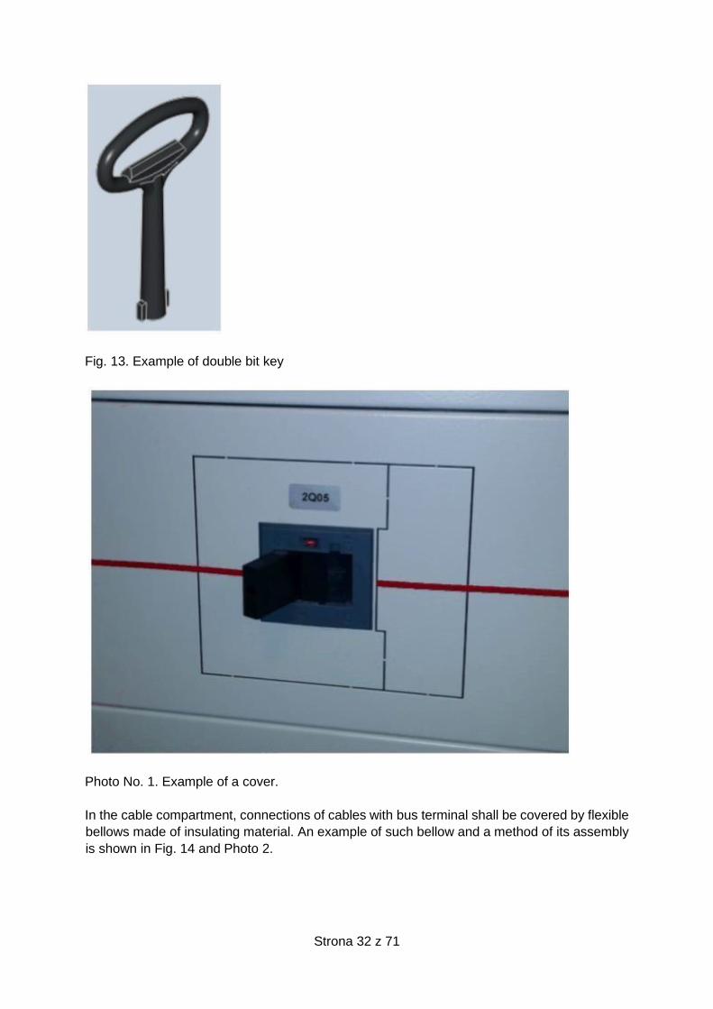
The outlet bays cabinets shall be equipped with doors, which, upon opening, access to
manoeuvring elements of circuit-breakers or switch-disconnectors is ensured. Equipment and
its relevant terminals should be sheltered by masking covers fixed to a tilting frame. Such
frames should be equipped with two-position locks, fitted to 3mm double bit keys. Example of
a double bit key is shown in figure 3.10.7. Covers should have incisions to enable breaking off
its individual parts, to expose the circuit-breaker part with its rated data or the electronic tripping
unit with its setting knobs. An example of such cover is shown in Photo. 1. Application of covers
that expose rated data and electronic tripping units is recommended.
Strona 32 z 71
Fig. 13. Example of double bit key
Photo No. 1. Example of a cover.
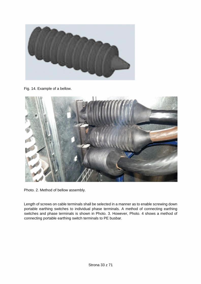
In the cable compartment, connections of cables with bus terminal shall be covered by flexible
bellows made of insulating material. An example of such bellow and a method of its assembly
is shown in Fig. 14 and Photo 2.
Strona 33 z 71
Fig. 14. Example of a bellow.
Photo. 2. Method of bellow assembly.
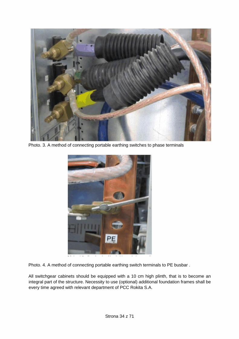
Length of screws on cable terminals shall be selected in a manner as to enable screwing down
portable earthing switches to individual phase terminals. A method of connecting earthing
switches and phase terminals is shown in Photo. 3. However, Photo. 4 shows a method of
connecting portable earthing switch terminals to PE busbar.
Strona 34 z 71
Photo. 3. A method of connecting portable earthing switches to phase terminals
Photo. 4. A method of connecting portable earthing switch terminals to PE busbar .
All switchgear cabinets should be equipped with a 10 cm high plinth, that is to become an
integral part of the structure. Necessity to use (optional) additional foundation frames shall be
every time agreed with relevant department of PCC Rokita S.A.

Strona 35 z 71
3.3.15.5 Switchgear configuration and equipment
1) Distributive switchgears 0,4kV should be configured as single-system longitudinal coupling-
sequenced and equipped with copper system and outlet busbars. Each switchgear should
have following cabinets:
a) Bus coupler bay,
b) Power feeders,
c) Outlet bays (with 30%-margin per a section),
d) Individual energy meter bays (for all sections)
2) Power feeders - primarily equipped with the following equipment:
a) Withdrawable air circuit-breakers, with 110V DC or 220V DC drive,
b) Network parameter monitoring device with RS485 interface, and Modbus communication
protocol,
c) Current transformers for the network monitoring device,
d) LED indicator for bay operation status. Red signal – breaker switched on, green signal –
breaker switched off, orange(yellow) signal - triggered protections.
3) Bus coupler bays – primarily equipped with the following equipment:
a) Withdrawable air circuit-breakers, with 110V or 220V DC drive,
b) Network parameter monitoring device with RS485 interface, and Modbus communication
protocol,
c) Current transformers for the network monitoring device,
d) LED indicator of bay operation status. Red signal – breaker switched on, green signal –
breaker switched off, orange(yellow) signal - triggered protections.
e) Power Supply Switching Unit with the PSS control panel.
4) Outlet bays - primarily equipped with the following equipment:
a) Fixed compact or air cut-outs,
b) Network monitoring device with RS485 interface, and Modbus communication protocol,
c) At least 0.5 grade current transformers for measuring electric power consumption.
d) Current transformers for network monitoring device,
e) LED indicator of bay operation status. Red signal – breaker switched on, green signal –
breaker switched off, orange(yellow) signal - triggered protections.
5) Power-meters shall be placed at opposite ends of the switchgear or free-standing. These
shall be equipped with:
a) Power meters with RS485 interface (its type should be agreed at designing or
implementation stage).
b) WAGO-type connection board/strip - equipped with protections as part of voltage circuits
and voltage control, transparent cover adapted to sealing (its type should be agreed at
designing or implementation stage).
c) All meters shall be connected to serial device server RS485 via 8-pin RJ45 connectors and
communicated with the Syndis Energia system.
6) In acceptable cases fuse-switches can be used; these are to be equipped with contacts to
enable sending messages related to opening/closing switches and burnout of fuse-link to
Syndis RV. Use of fuse-switches shall be every time agreed with the Contracting Authority.
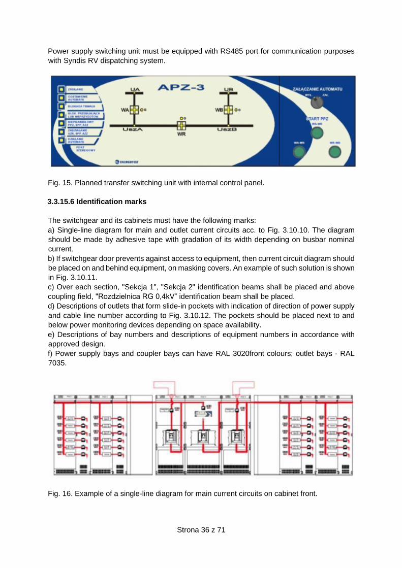
7) Power switching units should enable automatic transfer switching as well as planned transfer
switching. The unit should be equipped with a switch for shutdown purposes, and a control
panel to provide planned transfer switching. The unit with internal control panel is
recommended. In relevant cases, the control panel may be a separate unit but it must be
delivered by the same manufacturer as the unit itself. Example of planned transfer switching
unit with internal control panel is shown in Fig. 3.10.9.
Strona 36 z 71
Power supply switching unit must be equipped with RS485 port for communication purposes
with Syndis RV dispatching system.
Fig. 15. Planned transfer switching unit with internal control panel.
3.3.15.6 Identification marks
The switchgear and its cabinets must have the following marks:
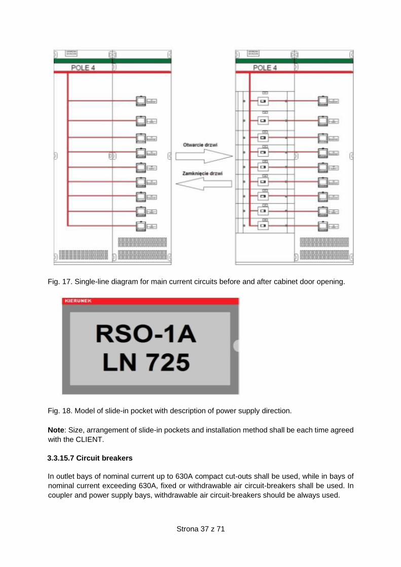
a) Single-line diagram for main and outlet current circuits acc. to Fig. 3.10.10. The diagram
should be made by adhesive tape with gradation of its width depending on busbar nominal
current.
b) If switchgear door prevents against access to equipment, then current circuit diagram should
be placed on and behind equipment, on masking covers. An example of such solution is shown
in Fig. 3.10.11.
c) Over each section, "Sekcja 1", "Sekcja 2" identification beams shall be placed and above
coupling field, "Rozdzielnica RG 0,4kV” identification beam shall be placed.
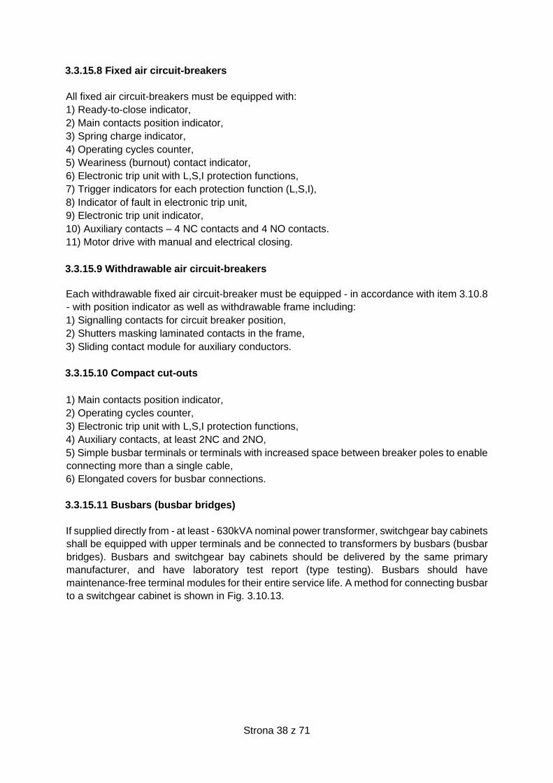
d) Descriptions of outlets that form slide-in pockets with indication of direction of power supply
and cable line number according to Fig. 3.10.12. The pockets should be placed next to and
below power monitoring devices depending on space availability.
e) Descriptions of bay numbers and descriptions of equipment numbers in accordance with
approved design.
f) Power supply bays and coupler bays can have RAL 3020front colours; outlet bays - RAL
7035.
Fig. 16. Example of a single-line diagram for main current circuits on cabinet front.
Strona 37 z 71
Fig. 17. Single-line diagram for main current circuits before and after cabinet door opening.
Fig. 18. Model of slide-in pocket with description of power supply direction.
Note: Size, arrangement of slide-in pockets and installation method shall be each time agreed
with the CLIENT.
3.3.15.7 Circuit breakers
In outlet bays of nominal current up to 630A compact cut-outs shall be used, while in bays of
nominal current exceeding 630A, fixed or withdrawable air circuit-breakers shall be used. In
coupler and power supply bays, withdrawable air circuit-breakers should be always used.
Strona 38 z 71
3.3.15.8 Fixed air circuit-breakers
All fixed air circuit-breakers must be equipped with:
1) Ready-to-close indicator,
2) Main contacts position indicator,
3) Spring charge indicator,
4) Operating cycles counter,
5) Weariness (burnout) contact indicator,
6) Electronic trip unit with L,S,I protection functions,
7) Trigger indicators for each protection function (L,S,I),
8) Indicator of fault in electronic trip unit,
9) Electronic trip unit indicator,
10) Auxiliary contacts – 4 NC contacts and 4 NO contacts.
11) Motor drive with manual and electrical closing.
3.3.15.9 Withdrawable air circuit-breakers
Each withdrawable fixed air circuit-breaker must be equipped - in accordance with item 3.10.8
- with position indicator as well as withdrawable frame including:
1) Signalling contacts for circuit breaker position,
2) Shutters masking laminated contacts in the frame,
3) Sliding contact module for auxiliary conductors.
3.3.15.10 Compact cut-outs
1) Main contacts position indicator,
2) Operating cycles counter,
3) Electronic trip unit with L,S,I protection functions,
4) Auxiliary contacts, at least 2NC and 2NO,
5) Simple busbar terminals or terminals with increased space between breaker poles to enable
connecting more than a single cable,
6) Elongated covers for busbar connections.
3.3.15.11 Busbars (busbar bridges)
If supplied directly from - at least - 630kVA nominal power transformer, switchgear bay cabinets
shall be equipped with upper terminals and be connected to transformers by busbars (busbar
bridges). Busbars and switchgear bay cabinets should be delivered by the same primary
manufacturer, and have laboratory test report (type testing). Busbars should have
maintenance-free terminal modules for their entire service life. A method for connecting busbar
to a switchgear cabinet is shown in Fig. 3.10.13.
Strona 39 z 71
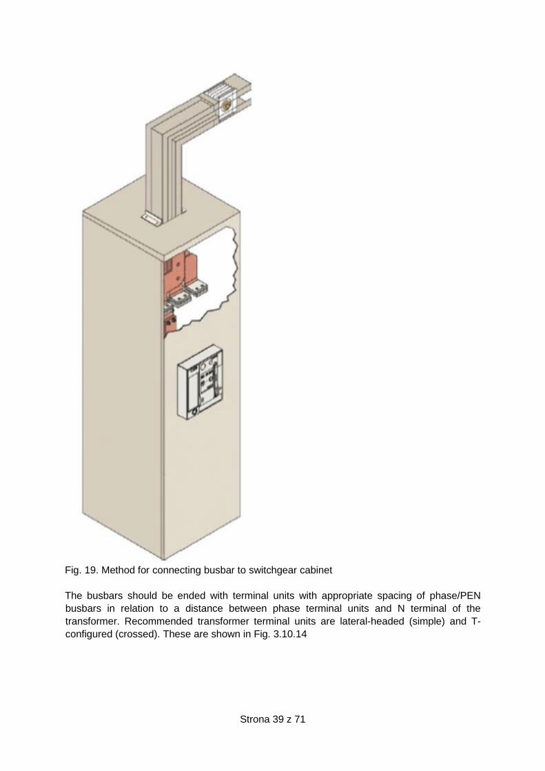
Fig. 19. Method for connecting busbar to switchgear cabinet
The busbars should be ended with terminal units with appropriate spacing of phase/PEN
busbars in relation to a distance between phase terminal units and N terminal of the
transformer. Recommended transformer terminal units are lateral-headed (simple) and T-
configured (crossed). These are shown in Fig. 3.10.14
Strona 40 z 71
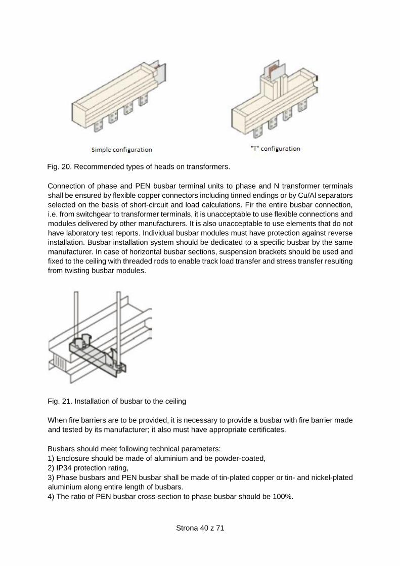
Fig. 20. Recommended types of heads on transformers.
Connection of phase and PEN busbar terminal units to phase and N transformer terminals
shall be ensured by flexible copper connectors including tinned endings or by Cu/Al separators
selected on the basis of short-circuit and load calculations. Fir the entire busbar connection,
i.e. from switchgear to transformer terminals, it is unacceptable to use flexible connections and
modules delivered by other manufacturers. It is also unacceptable to use elements that do not
have laboratory test reports. Individual busbar modules must have protection against reverse
installation. Busbar installation system should be dedicated to a specific busbar by the same
manufacturer. In case of horizontal busbar sections, suspension brackets should be used and
fixed to the ceiling with threaded rods to enable track load transfer and stress transfer resulting
from twisting busbar modules.
Fig. 21. Installation of busbar to the ceiling
When fire barriers are to be provided, it is necessary to provide a busbar with fire barrier made
and tested by its manufacturer; it also must have appropriate certificates.
Busbars should meet following technical parameters:
1) Enclosure should be made of aluminium and be powder-coated,
2) IP34 protection rating,
3) Phase busbars and PEN busbar shall be made of tin-plated copper or tin- and nickel-plated
aluminium along entire length of busbars.
4) The ratio of PEN busbar cross-section to phase busbar should be 100%.
Strona 41 z 71
5) Connecting busbar modules shall be ensured via coupling units with a torque screw (blind-
rivet screw).
6) Each busbar modules must be able to operate at temperatures from - 5oC to + 40oC inside
buildings and from - 25oC to + 40oC outside buildings.
3.3.15.12 Terminal blocks and wires
All terminal blocks should meet requirements of PN-EN 60947-7 standard. Terminal blocks
should be screw adapters - attached to TS rail – which enable multiple connecting and
disconnecting circuits during the service life. Screw adapters should feature at least the
following parameters:
1) Insulation rated voltage 750V,
2) Surge rated voltage 6kV,
3) Nominal current 24A,
4) Ambient temperature operational range: -25 to 120°C,
5) Service life at least 40 years.
Configuration and organisation of terminal blocks should include circuit grouping as per the
following functions:
a) Current circuits,
b) Voltage circuits,
c) Control circuits,
d) Signal circuits,
e) Telemechanic circuits
i) Other circuits, if required.
Terminal blocks, terminals and wires connected to them must be respectively marked.
The terminal blocks on individual circuits should have following designations:
1. General circuits – block designation X0….9,
2. Current circuits – block designation XP1….9,
3. Voltage circuits – block designation XU1….9,
4. Control circuits – block designation XST0….9,
5. Signal circuits – block designation XSY0….9,
6. Telemechanic circuits – block designation XSY0….9,
Designation (symbol) of a block must be placed on so-called “holders” and should be made
legibly and permanently. Prior to block marking, a digit or a numeral that mean switchgear bay
number to which a terminal block is assigned, e.g. 1XP2, which means current circuits block
no. 2 in bay no. 1.
Voltage terminal blocks - if include more than a single voltage value, should have separation
barriers including terminal block designation and voltage value, e.g. 1XU2 – 24VDC. An
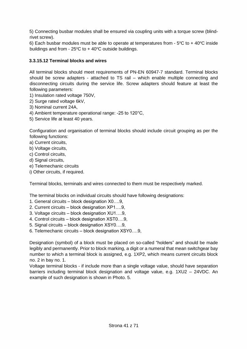
example of such designation is shown in Photo. 5.
Strona 42 z 71
Photo. 5. Example marking of terminal block 2 within bay circuit 1.
Terminal block connectors should have terminal designation in a form of Arabic numerals in
two or three locations, that is, at both terminals of a connector (wire location) and if necessary,
in the central part of a connector (triple marking). Arrangement of enumeration on a connector
should allow easy and unambiguous reading of terminal connector number in case of
horizontal or vertical installation of terminal strip. Each block terminal should, in its central part,
have two rows for sockets used in case of linking terminal connectors with “jumpers”.
Required method of marking terminals, and linking terminal connectors by the “jumpers” is
shown in Photo. 6.
Photo. 6. A method of marking terminal connectors.
Each wire, at its both endings, shall be equipped with address markers including description
(address) provided in a legible and durable manner. Manual descriptions or designations
including groups of individual markers shall not be allowed.
Address marker, at terminal block or equipment or device side, shall be marked in the following
order:
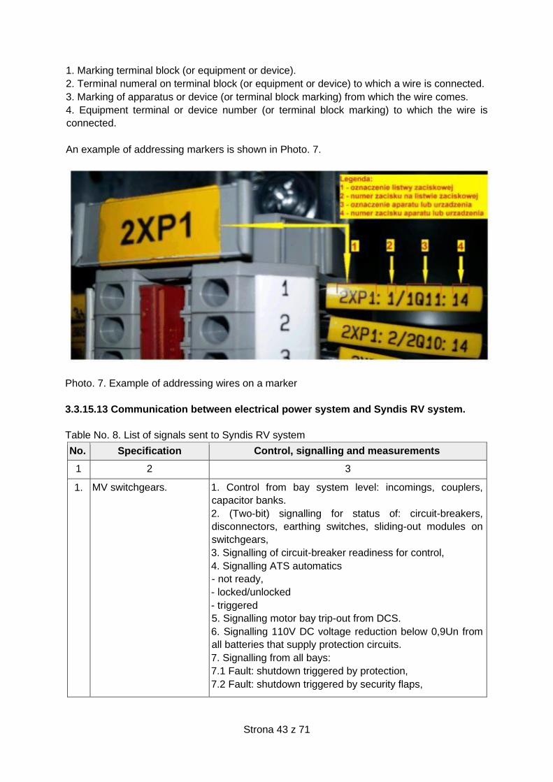
Strona 43 z 71
1. Marking terminal block (or equipment or device).
2. Terminal numeral on terminal block (or equipment or device) to which a wire is connected.
3. Marking of apparatus or device (or terminal block marking) from which the wire comes.
4. Equipment terminal or device number (or terminal block marking) to which the wire is
connected.
An example of addressing markers is shown in Photo. 7.
Photo. 7. Example of addressing wires on a marker
3.3.15.13 Communication between electrical power system and Syndis RV system.
Table No. 8. List of signals sent to Syndis RV system
No. Specification Control, signalling and measurements
1 2 3
1. MV switchgears.
1. Control from bay system level: incomings, couplers,
capacitor banks.
2. (Two-bit) signalling for status of: circuit-breakers,
disconnectors, earthing switches, sliding-out modules on
switchgears,
3. Signalling of circuit-breaker readiness for control,
4. Signalling ATS automatics
- not ready,
- locked/unlocked
- triggered
5. Signalling motor bay trip-out from DCS.
6. Signalling 110V DC voltage reduction below 0,9Un from
all batteries that supply protection circuits.
7. Signalling from all bays:
7.1 Fault: shutdown triggered by protection,
7.2 Fault: shutdown triggered by security flaps,
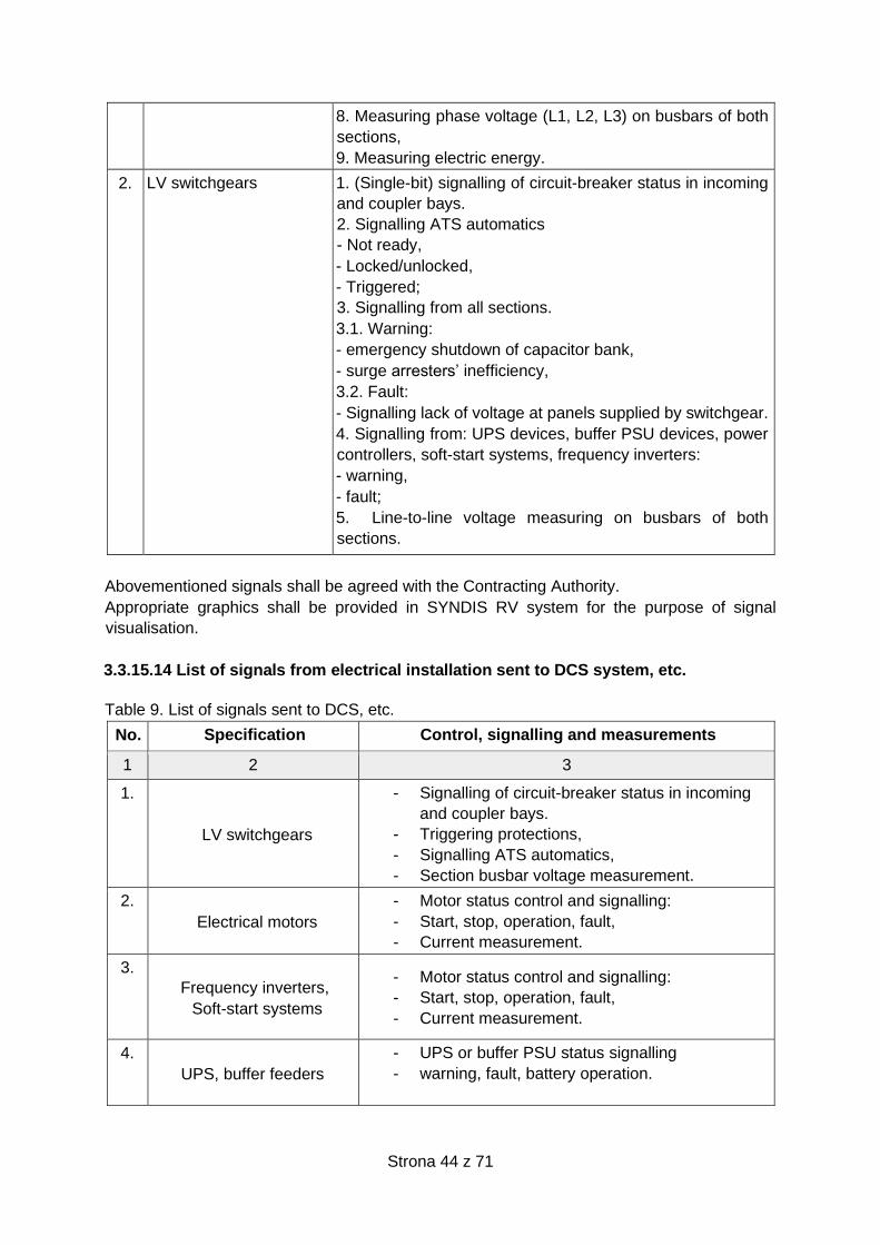
Strona 44 z 71
8. Measuring phase voltage (L1, L2, L3) on busbars of both
sections,
9. Measuring electric energy.
2. LV switchgears
1. (Single-bit) signalling of circuit-breaker status in incoming
and coupler bays.
2. Signalling ATS automatics
- Not ready,
- Locked/unlocked,
- Triggered;
3. Signalling from all sections.
3.1. Warning:
- emergency shutdown of capacitor bank,
- surge arresters’ inefficiency,
3.2. Fault:
- Signalling lack of voltage at panels supplied by switchgear.
4. Signalling from: UPS devices, buffer PSU devices, power
controllers, soft-start systems, frequency inverters:
- warning,
- fault;
5. Line-to-line voltage measuring on busbars of both
sections.
Abovementioned signals shall be agreed with the Contracting Authority.
Appropriate graphics shall be provided in SYNDIS RV system for the purpose of signal
visualisation.
3.3.15.14 List of signals from electrical installation sent to DCS system, etc.
Table 9. List of signals sent to DCS, etc.
No. Specification Control, signalling and measurements
1 2 3
1.
LV switchgears
- Signalling of circuit-breaker status in incoming
and coupler bays.
- Triggering protections,
- Signalling ATS automatics,
- Section busbar voltage measurement.
2.
Electrical motors
- Motor status control and signalling:
- Start, stop, operation, fault,
- Current measurement.
3.
Frequency inverters,
Soft-start systems
- Motor status control and signalling:
- Start, stop, operation, fault,
- Current measurement.
4.
UPS, buffer feeders
- UPS or buffer PSU status signalling
- warning, fault, battery operation.

Strona 45 z 71
5. DC network - Network status signalling: warning, fault
Abovementioned signals should be agreed with the Contracting Authority. Appropriate graphic
symbols should be provided in DCS for the purpose of signal visualisation.
3.3.16 6/0,4kV distributive transformers
3.3.16.1 General requirements
1) 1. It is allowed to use the following transformers:
a) of dry (resin) type,
b) F-grade insulated double-winding transformers which are impregnated by epoxy resin under
vacuum. Windings insulated by resin imposed with roving method are not allowed,
c) of F-grade insulation featuring average winding temperature increase equal 100ºC. The
following parameters for transformer isolation must be guaranteed:
- Average winding temperatures - 140ºC,
- Maximum winding temperatures - 155ºC,
d) With voltage adjuster at non-voltage mode,
e) AN- or AF-cooled (in relevant cases).
2. New transformers should be equipped with no-load running compensation. Capacitors
should be selected on the basis of parameters - declared by the manufacturer - and
calculations. Capacitors should be installed on LT side of transformer as shown in Photo 8.
Photo. 8. Fastening of capacitor to non-load running compensator
3) When selecting new units, the values of no-load and load losses should be taken into
account. The values of load and non-load losses should be as low as possible; these shall not
exceed values given in tables 10 and 11 (in accordance with the EU Directive No. 548/2014).
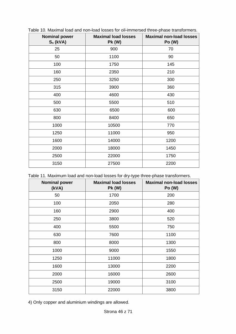
Strona 46 z 71
Table 10. Maximal load and non-load losses for oil-immersed three-phase transformers.
Nominal power
Sn (kVA)
Maximal load losses
Pk (W)
Maximal non-load losses
Po (W)
25 900 70
50 1100 90
100 1750 145
160 2350 210
250 3250 300
315 3900 360
400 4600 430
500 5500 510
630 6500 600
800 8400 650
1000 10500 770
1250 11000 950
1600 14000 1200
2000 18000 1450
2500 22000 1750
3150 27500 2200
Table 11. Maximum load and non-load losses for dry-type three-phase transformers.
Nominal power
(kVA)
Maximal load losses
Pk (W)
Maximal non-load losses
Po (W)
50 1700 200
100 2050 280
160 2900 400
250 3800 520
400 5500 750
630 7600 1100
800 8000 1300
1000 9000 1550
1250 11000 1800
1600 13000 2200
2000 16000 2600
2500 19000 3100
3150 22000 3800
4) Only copper and aluminium windings are allowed.
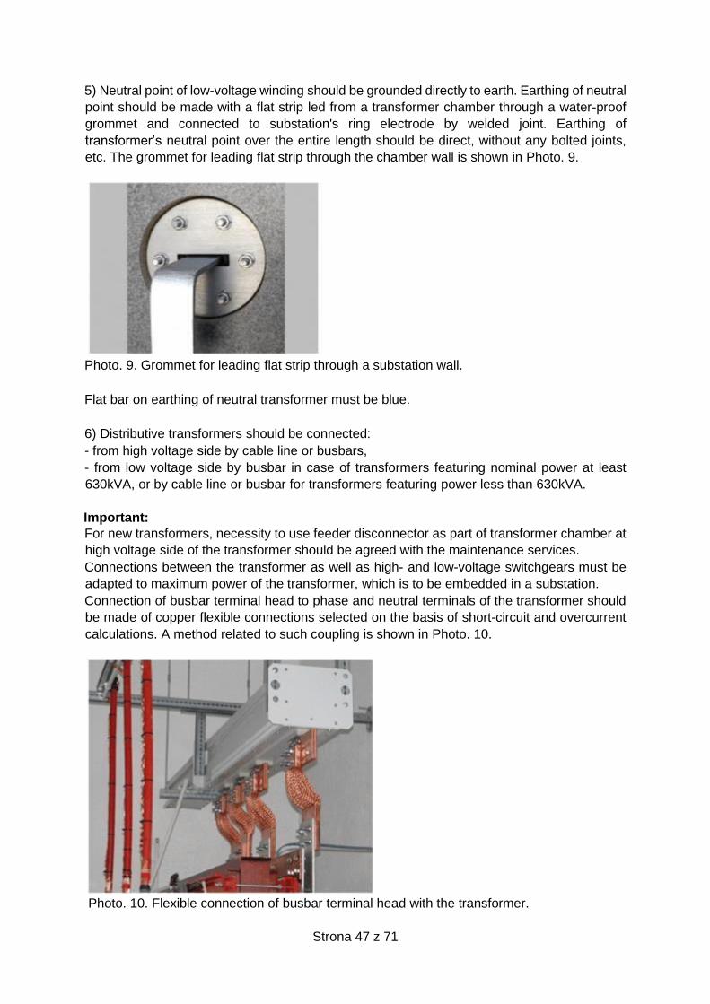
Strona 47 z 71
5) Neutral point of low-voltage winding should be grounded directly to earth. Earthing of neutral
point should be made with a flat strip led from a transformer chamber through a water-proof
grommet and connected to substation's ring electrode by welded joint. Earthing of
transformer’s neutral point over the entire length should be direct, without any bolted joints,
etc. The grommet for leading flat strip through the chamber wall is shown in Photo. 9.
Photo. 9. Grommet for leading flat strip through a substation wall.
Flat bar on earthing of neutral transformer must be blue.
6) Distributive transformers should be connected:
- from high voltage side by cable line or busbars,
- from low voltage side by busbar in case of transformers featuring nominal power at least
630kVA, or by cable line or busbar for transformers featuring power less than 630kVA.
Important:
For new transformers, necessity to use feeder disconnector as part of transformer chamber at
high voltage side of the transformer should be agreed with the maintenance services.
Connections between the transformer as well as high- and low-voltage switchgears must be
adapted to maximum power of the transformer, which is to be embedded in a substation.
Connection of busbar terminal head to phase and neutral terminals of the transformer should
be made of copper flexible connections selected on the basis of short-circuit and overcurrent
calculations. A method related to such coupling is shown in Photo. 10.
Photo. 10. Flexible connection of busbar terminal head with the transformer.
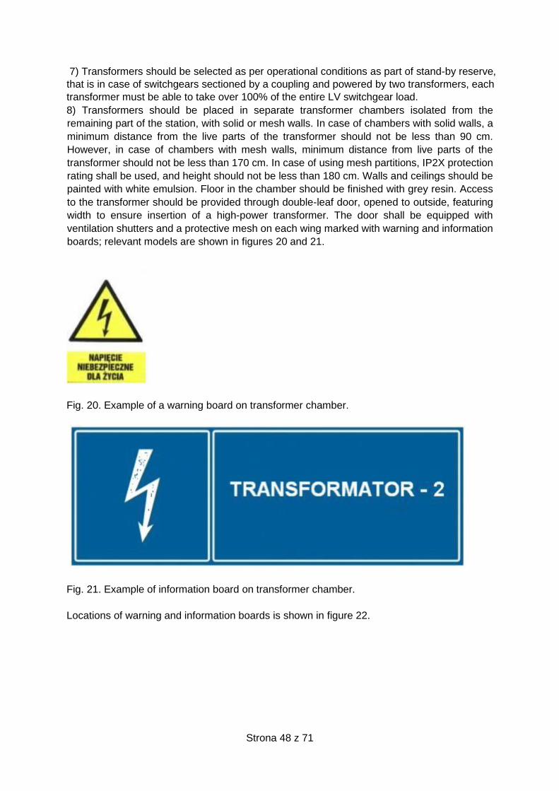
Strona 48 z 71
7) Transformers should be selected as per operational conditions as part of stand-by reserve,
that is in case of switchgears sectioned by a coupling and powered by two transformers, each
transformer must be able to take over 100% of the entire LV switchgear load.
8) Transformers should be placed in separate transformer chambers isolated from the
remaining part of the station, with solid or mesh walls. In case of chambers with solid walls, a
minimum distance from the live parts of the transformer should not be less than 90 cm.
However, in case of chambers with mesh walls, minimum distance from live parts of the
transformer should not be less than 170 cm. In case of using mesh partitions, IP2X protection
rating shall be used, and height should not be less than 180 cm. Walls and ceilings should be
painted with white emulsion. Floor in the chamber should be finished with grey resin. Access
to the transformer should be provided through double-leaf door, opened to outside, featuring
width to ensure insertion of a high-power transformer. The door shall be equipped with
ventilation shutters and a protective mesh on each wing marked with warning and information
boards; relevant models are shown in figures 20 and 21.
Fig. 20. Example of a warning board on transformer chamber.
Fig. 21. Example of information board on transformer chamber.
Locations of warning and information boards is shown in figure 22.
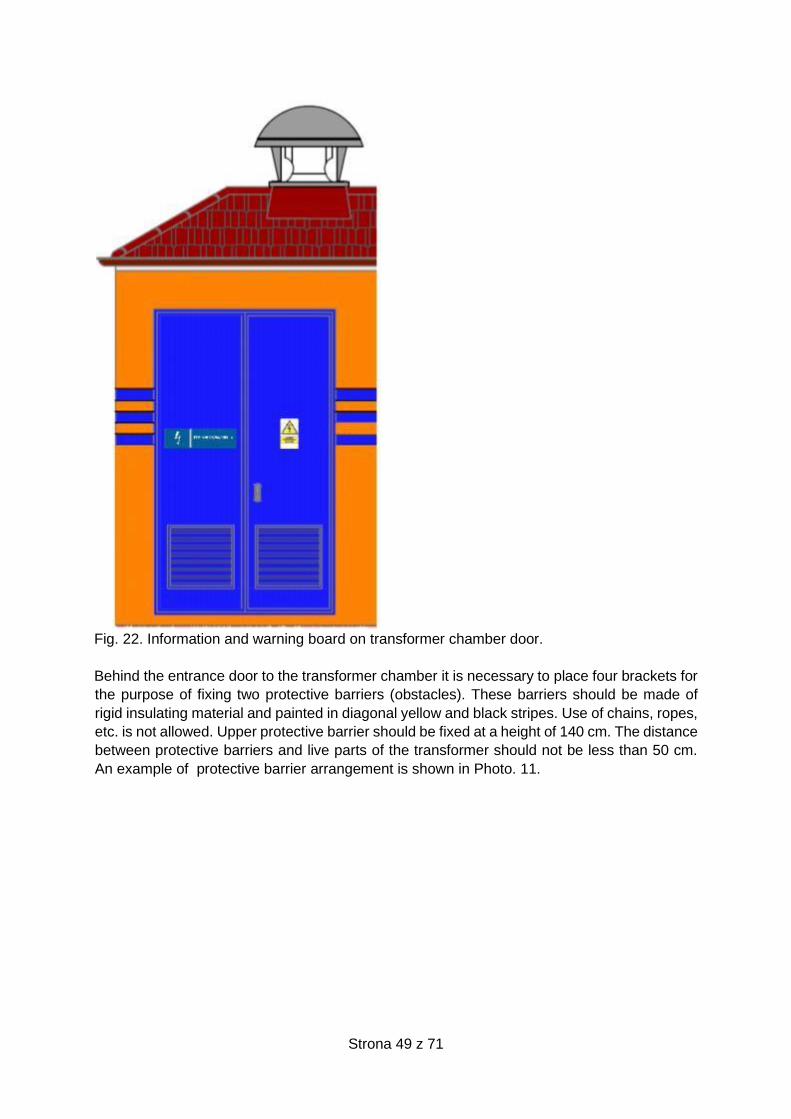
Strona 49 z 71
Fig. 22. Information and warning board on transformer chamber door.
Behind the entrance door to the transformer chamber it is necessary to place four brackets for
the purpose of fixing two protective barriers (obstacles). These barriers should be made of
rigid insulating material and painted in diagonal yellow and black stripes. Use of chains, ropes,
etc. is not allowed. Upper protective barrier should be fixed at a height of 140 cm. The distance
between protective barriers and live parts of the transformer should not be less than 50 cm.
An example of protective barrier arrangement is shown in Photo. 11.
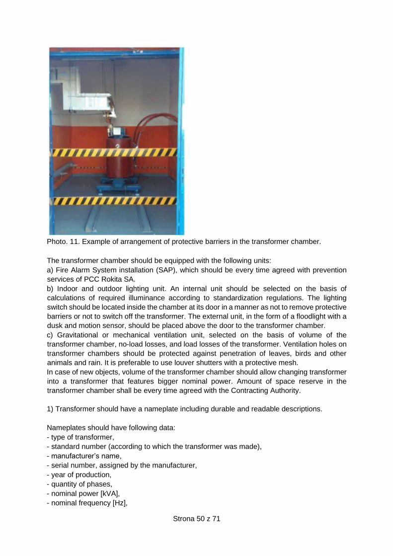
Strona 50 z 71
Photo. 11. Example of arrangement of protective barriers in the transformer chamber.
The transformer chamber should be equipped with the following units:
a) Fire Alarm System installation (SAP), which should be every time agreed with prevention
services of PCC Rokita SA.
b) Indoor and outdoor lighting unit. An internal unit should be selected on the basis of
calculations of required illuminance according to standardization regulations. The lighting
switch should be located inside the chamber at its door in a manner as not to remove protective
barriers or not to switch off the transformer. The external unit, in the form of a floodlight with a
dusk and motion sensor, should be placed above the door to the transformer chamber.
c) Gravitational or mechanical ventilation unit, selected on the basis of volume of the
transformer chamber, no-load losses, and load losses of the transformer. Ventilation holes on
transformer chambers should be protected against penetration of leaves, birds and other
animals and rain. It is preferable to use louver shutters with a protective mesh.
In case of new objects, volume of the transformer chamber should allow changing transformer
into a transformer that features bigger nominal power. Amount of space reserve in the
transformer chamber shall be every time agreed with the Contracting Authority.
1) Transformer should have a nameplate including durable and readable descriptions.
Nameplates should have following data:
- type of transformer,
- standard number (according to which the transformer was made),
- manufacturer’s name,
- serial number, assigned by the manufacturer,
- year of production,
- quantity of phases,
- nominal power [kVA],
- nominal frequency [Hz],

Strona 51 z 71
- HV and LV [kV] nominal voltages, including range of settings,
- HV and LV [A] nominal currents,
- connection group,
- short-circuit voltage: measured value expressed in per cents,
- type of cooling (ONAN),
- total mass,
- no-load losses, measured value [W],
- load losses, measured value [W],
- class of winding insulation.
2) Transformers must be made of brand-new materials and come from current production (in
case of new transformers).
3) Marking HV, LV, N and earthing terminals should be made in a readable and durable
manner; these shall be attached to transformer structure.
4) Transformers should have a visible and readable description of each taps for voltage
regulation.
5) Transformer’s undercarriage must be equipped with smooth wheels for longitudinal and
lateral travel. Transformer’s undercarriage structure should have two earthing terminals, to be
connected with a flat strip, to the Main Equipotential Bonding (MEB) in the transformer
chamber coupled with MEB station. MEB in the transformer chamber should have a flat strip
grip to bolt earthing terminal on portable earthing devices. Photo. 12 presents a method related
to this solution.
Photo. 12. A method for leading flat strip to the earthing terminal on portable earthing devices.
MEB should be connected to a station grounding with a flat strip led through station wall or
foundation by tight bolted grommet. Use of such grommet is shown in Photo. 13.
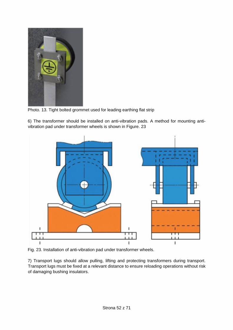
Strona 52 z 71
Photo. 13. Tight bolted grommet used for leading earthing flat strip
6) The transformer should be installed on anti-vibration pads. A method for mounting anti-
vibration pad under transformer wheels is shown in Figure. 23
Fig. 23. Installation of anti-vibration pad under transformer wheels.
7) Transport lugs should allow pulling, lifting and protecting transformers during transport.
Transport lugs must be fixed at a relevant distance to ensure reloading operations without risk
of damaging bushing insulators.
Strona 53 z 71
3.3.16.2 Specific requirements
1) Nominal voltage:
- HV windings: 6.3kV or 21kV,
- LV windings: 0.42kV.
2) Voltage setting:
- for dry transformers: ± 2 x 2.5%,
- adjustment as part of non-voltage mode,
- changing the taps at HV side.
3) Nominal power
In case of selection of transformer power output, following criteria shall be meet:
a) Value of calculated peak power.
b) Configuration of loads.
c) Required power margin.
d) Expected increase of load power.
e) Minimizing losses in the transformer.
f) Possibility of transformer overloading.
g) In justified cases, degree of THD in current.
Transformer nominal power shall be selected from the following values (25; 50; 100; 160; 250;
315 ; 400; 630; 800; 1000; 1250; 1600; 2000; 2500; 3150 ) kVA on the basis of design
calculations, as per active and reactive power balance for a given facility; reserve ratio should
be also considered.
Transformer apparent power must not be less than peak apparent power required by receivers
powered by this transformer.
where:
- kr – reserve ratio
- SnT – transformer nominal apparent power [kVA]
- SS –apparent power of receivers powered by a transformer featuring SnT apparent power
[kVA]
Following reserve ratios shall be used:
a) kr = 1.1 ÷ 1.3 for transformers featuring power exceeding 1.6 MVA.
b) kr = 1.3 ÷ 1.6 for transformers featuring power not exceeding 1.6MVA.
4) Short-circuit voltage
Short-circuit voltages for principal tapping should not exceed:
- 4.5% for transformer power not exceeding 400kVA,
- 6% for transformer power exceeding 630kVA.
5) Rated frequency
Rated frequency – 50Hz
6) Temperature protection.
Two-stage temperature protection on windings should be provided.
- first stage – warning signal at temperatures between 130°C and 140°C,
- second stage – signal to disconnect transformer at temperatures between 150°C and 155°C.
Signals related to exceeding first and second temperature stage shall be sent to SYNDIS RV
system.
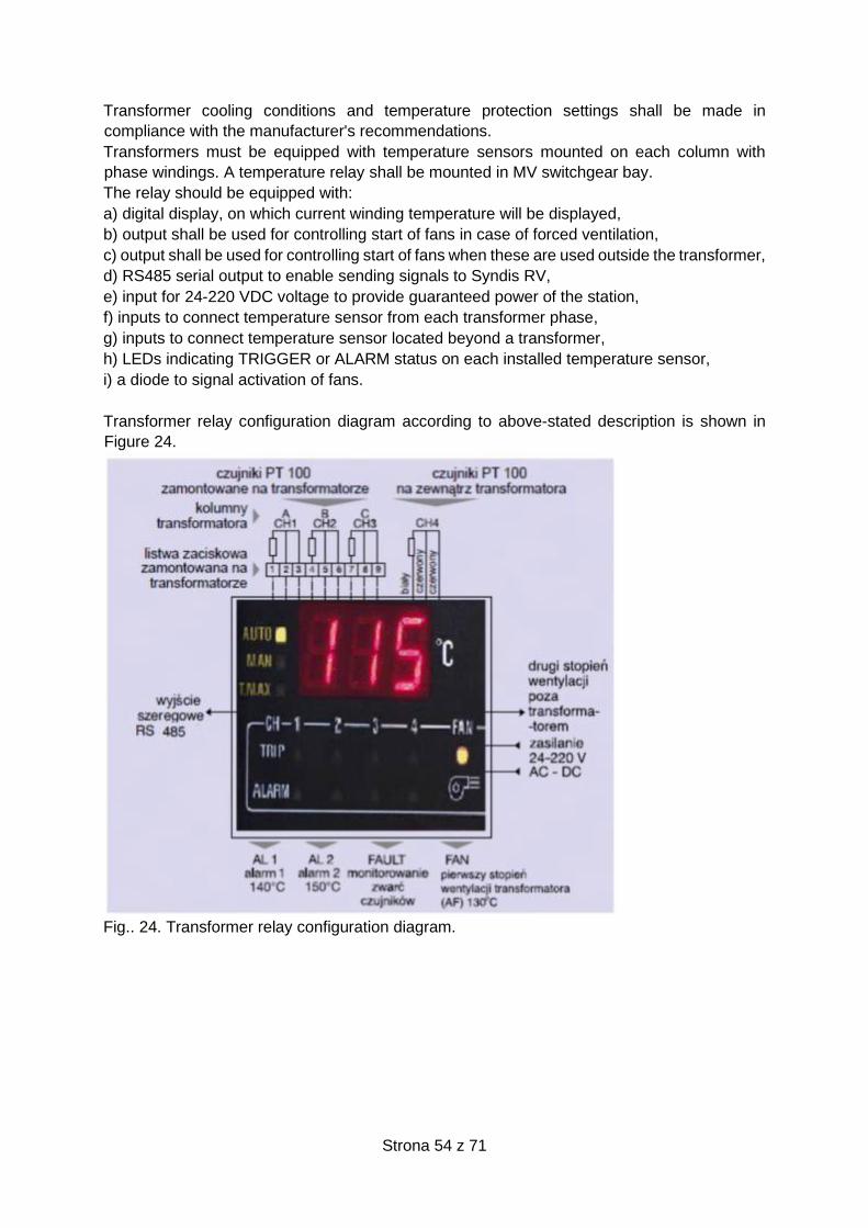
Strona 54 z 71
Transformer cooling conditions and temperature protection settings shall be made in
compliance with the manufacturer's recommendations.
Transformers must be equipped with temperature sensors mounted on each column with
phase windings. A temperature relay shall be mounted in MV switchgear bay.
The relay should be equipped with:
a) digital display, on which current winding temperature will be displayed,
b) output shall be used for controlling start of fans in case of forced ventilation,
c) output shall be used for controlling start of fans when these are used outside the transformer,
d) RS485 serial output to enable sending signals to Syndis RV,
e) input for 24-220 VDC voltage to provide guaranteed power of the station,
f) inputs to connect temperature sensor from each transformer phase,
g) inputs to connect temperature sensor located beyond a transformer,
h) LEDs indicating TRIGGER or ALARM status on each installed temperature sensor,
i) a diode to signal activation of fans.
Transformer relay configuration diagram according to above-stated description is shown in
Figure 24.
Fig.. 24. Transformer relay configuration diagram.
Strona 55 z 71
3.3.17 Special power supply systems
3.3.17.1 Special low-voltage power supply systems
1. Special power supply systems are required for the following loads:
a) 3x400 / 230V AC guaranteed supply system for electric motors required by technological
process,
b) 24V DC guaranteed supply system for DCS control system, protection and control as well
as I&C systems;
c) 220V DC and 110V DC guaranteed supply system for security system and control of
electrical switchboards;
d) guaranteed power supply system for emergency lighting,
e) 230V AC guaranteed supply system.
2. Special power supply systems as part of normal operating mode are supplied from low-
voltage network.
3. In case of requirements resulting from technological needs related to manufacturing plants,
at least one power generator shall be provided as part of the system. Such generator should
provide power to special supply systems operating in emergency mode, i.e. in absence of low-
voltage power supply.
4. The following items must be always agreed with the customer:
a) conditions for cooperation between power generators and separate power system fed
from the generator,
b) design of the power generator application system,
c) request for proposal related to provision of power generators,
d) selection of the power generator deliverer.
5. Special power supply systems should be designed basing on buffer power supply from
accumulator batteries via uninterrupted switching systems.
6. Basic emergency power supply system for loads:
a) AC - is an inverter cooperating with a separate accumulator battery,
b) DC - is a buffer power supply (rectifier) connected to the DC switchboard in parallel with
accumulator battery.
3.3.17.2 Buffer power supplies
1. Buffer feeder should be selected for supplying DC loads and for charging buffer
accumulator battery.
2. Buffer feeder should have following features and parameters:
a) High stability of voltage (changes less than 1%) and low ripples (less than 0.5%) of the
rectifier output voltage, in the range of load changes from 0 to 100% as well as voltage
fluctuations in the supply network +/- 15%.
b) Possibility of setting output voltage and setting battery current limit.
c) Galvanic separation of DC and AC circuits.
d) Integrated electronic protection against short circuits and overloads.
e) Clear and easy-to-use display informing about all output parameters and alarm operation
states on power supply unit, as well as signals related to exceeding pre-set alarm
parameters.
f) Temperature correction of buffer voltage.
g) High reliability.
3. Buffer feeder should be equipped with the following systems:
a) RS 485 communication interface with software enabling full remote control of power
supply unit operation from a PC computer.
Strona 56 z 71
b) Thermal probe (-10°C to +40°C) including temperature correction system related to
voltage during battery charging.
c) Automatic check of battery circuit continuity.
d) Continuous measurement of electric charge delivered to and taken from battery.
e) Fast battery charging system.
f) Continuous earth fault monitoring.
g) Contacts for mating with DCS system.
4. Buffer feeder should enable easy extension of the powered network.
5. Buffer feeders should meet requirements for electromagnetic compatibility specified in
European directives and standards.
6. Distortion from higher harmonics should comply with directives and standards.
7. Buffer feeders shall work properly when mating accumulator batteries attached to a
common switchboard.
3.3.17.3 UPS (Uninterruptible Power Supplies)
1. UPSs may be used in exceptional cases, upon arrangements with the user, for guaranteed
AC power supply of:
a) DCS operator stations,
b) emergency lighting circuits or local computer networks,
c) electric motors required by technological process.
2. All UPSs should meet the following requirements:
2.1 UPSs should meet requirements for electromagnetic compatibility specified in the EU
directives related to resistance to external interferences and reduction of level of interference
emission to environment.
2.2 Each UPS should have the following parameters:
a) continuous operation mode, double conversion (True on line),
b) Efficiency exceeding 85% at 100% load
c) input voltage 1x 230 V or 3 x 400/230 V
d) input voltage tolerance -15% to + 10% of rated voltage,
e) rated frequency of input voltage 50 Hz
f) input voltage frequency tolerance from 0.5% to 8.0% of the input voltage rated frequency
g) output voltage 230 V or 400/230 V
h) output voltage stability +/- 1% statically, +/- 2% dynamically
i) output voltage frequency 50 Hz
j) output voltage frequency stability at least ±0.1% when operating with accumulator batteries
k) THDi of input current less than 10%
l) THDu of output voltage less than 3%,
m) permissible loudness, from a distance of 1 m, less than 60dB
n) IP rating at least IP 20
o) minimum 30 minutes autonomous operation time,
p) maximum 10ms time of potential-free status at UPS output.
2.4 Only UPSs operating in parallel, redundant systems should be designed for parallel
operation.
2.5 UPS units should be equipped with internal protection against external short circuits and
overloads.
2.6 Inputs and outputs of UPSs should be protected against overvoltage by surge arresters
selected as per parameters of UPSs, the UPSs supplying network and devices powered from
UPSs.
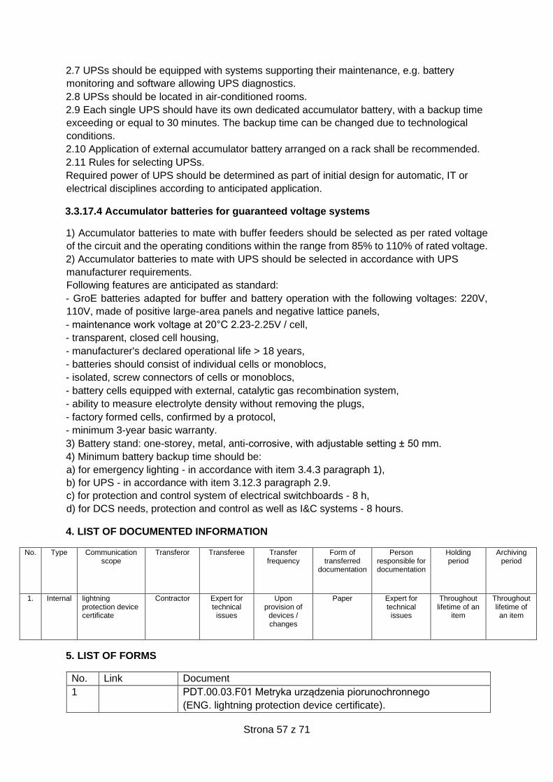
Strona 57 z 71
2.7 UPSs should be equipped with systems supporting their maintenance, e.g. battery
monitoring and software allowing UPS diagnostics.
2.8 UPSs should be located in air-conditioned rooms.
2.9 Each single UPS should have its own dedicated accumulator battery, with a backup time
exceeding or equal to 30 minutes. The backup time can be changed due to technological
conditions.
2.10 Application of external accumulator battery arranged on a rack shall be recommended.
2.11 Rules for selecting UPSs.
Required power of UPS should be determined as part of initial design for automatic, IT or
electrical disciplines according to anticipated application.
3.3.17.4 Accumulator batteries for guaranteed voltage systems
1) Accumulator batteries to mate with buffer feeders should be selected as per rated voltage
of the circuit and the operating conditions within the range from 85% to 110% of rated voltage.
2) Accumulator batteries to mate with UPS should be selected in accordance with UPS
manufacturer requirements.
Following features are anticipated as standard:
- GroE batteries adapted for buffer and battery operation with the following voltages: 220V,
110V, made of positive large-area panels and negative lattice panels,
- maintenance work voltage at 20°C 2.23-2.25V / cell,
- transparent, closed cell housing,
- manufacturer's declared operational life > 18 years,
- batteries should consist of individual cells or monoblocs,
- isolated, screw connectors of cells or monoblocs,
- battery cells equipped with external, catalytic gas recombination system,
- ability to measure electrolyte density without removing the plugs,
- factory formed cells, confirmed by a protocol,
- minimum 3-year basic warranty.
3) Battery stand: one-storey, metal, anti-corrosive, with adjustable setting ± 50 mm.
4) Minimum battery backup time should be:
a) for emergency lighting - in accordance with item 3.4.3 paragraph 1),
b) for UPS - in accordance with item 3.12.3 paragraph 2.9.
c) for protection and control system of electrical switchboards - 8 h,
d) for DCS needs, protection and control as well as I&C systems - 8 hours.
4. LIST OF DOCUMENTED INFORMATION
No. Type Communication scope
Transferor Transferee Transfer frequency
Form of transferred
documentation
Person responsible for documentation
Holding period
Archiving period
1. Internal lightning protection device certificate
Contractor Expert for technical issues
Upon provision of
devices / changes
Paper Expert for technical issues
Throughout lifetime of an
item
Throughout lifetime of an item
5. LIST OF FORMS
No. Link Document
1 PDT.00.03.F01 Metryka urządzenia piorunochronnego
(ENG. lightning protection device certificate).
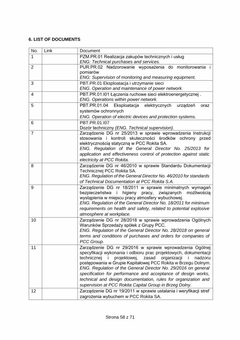
Strona 58 z 71
6. LIST OF DOCUMENTS
No. Link Document
1 PZM.PR.01 Realizacja zakupów technicznych i usług ENG: Technical purchases and services.
2 PUR.PR.02 Nadzorowanie wyposażenia do monitorowania i pomiarów ENG: Supervision of monitoring and measuring equipment.
3 PBT.PR.01 Eksploatacja i utrzymanie sieci ENG. Operation and maintenance of power network.
4 PBT.PR.01.I01 Łączenia ruchowe sieci elektroenergetycznej . ENG. Operations within power network.
5 PBT.PR.01.04 Eksploatacja elektrycznych urządzeń oraz
systemów ochronnych
ENG. Operation of electric devices and protection systems.
6 PBT.PR.01.I07 Dozór techniczny (ENG. Technical supervision).
7 Zarządzenie DG nr 25/2013 w sprawie wprowadzenia Instrukcji stosowania i kontroli skuteczności środków ochrony przed elektrycznością statyczną w PCC Rokita SA. ENG. Regulation of the General Director No. 25/2013 for
application and effectiveness control of protection against static
electricity at PCC Rokita.
8 Zarządzenie DG nr 46/2010 w sprawie Standardu Dokumentacji Technicznej PCC Rokita SA. ENG. Regulation of the General Director No. 46/2010 for standards
of Technical Documentation at PCC Rokita S.A.
9 Zarządzenie DG nr 18/2011 w sprawie minimalnych wymagań bezpieczeństwa i higieny pracy, związanych możliwością wystąpienia w miejscu pracy atmosfery wybuchowej. ENG. Regulation of the General Director No. 18/2011 for minimum
requirements on health and safety, related to potential explosive
atmosphere at workplace.
10 Zarządzenie DG nr 28/2018 w sprawie wprowadzenia Ogólnych Warunków Sprzedaży spółek z Grupy PCC. ENG. Regulation of the General Director No. 28/2018 on general
terms and conditions of purchases and orders for companies of
PCC Group.
11 Zarządzenie DG nr 29/2016 w sprawie wprowadzenia Ogólnej specyfikacji wykonania i odbioru prac projektowych, dokumentacji technicznej i projektowej, zasad organizacji i nadzoru postępowania w Grupie Kapitałowej PCC Rokita w Brzegu Dolnym. ENG. Regulation of the General Director No. 29/2016 on general
specification for performance and acceptance of design works,
technical and design documentation, rules for organization and
supervision at PCC Rokita Capital Group in Brzeg Dolny.
12 Zarządzenie DG nr 19/2011 w sprawie ustalania i weryfikacji stref
zagrożenia wybuchem w PCC Rokita SA.
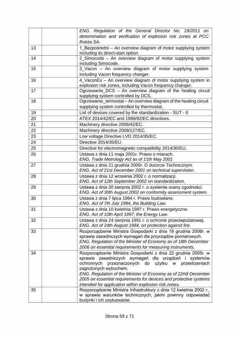
Strona 59 z 71
ENG. Regulation of the General Director No. 19/2011 on
determination and verification of explosion risk zones at PCC
Rokita SA.
13 1_Bezpośredni – An overview diagram of motor supplying system including its direct-start option.
14 2_Simocode – An overview diagram of motor supplying system including Simocode.
15 3_Vacon – An overview diagram of motor supplying system
including Vacon frequency changer.
16 4_VaconEx – An overview diagram of motor supplying system in explosion risk zones, including Vacon frequency changer.
17 Ogrzewanie_DCS – An overview diagram of the heating circuit supplying system controlled by DCS.
18 Ogrzewanie_termostat – An overview diagram of the heating circuit
supplying system controlled by thermostat.
19 List of devices covered by the standardization - SUT - E
20 ATEX 2014/42/EC and 1999/92/EC directives.
21 Machinery directive 2006/42/EC.
22 Machinery directive 2009/127/EC.
23 Low voltage Directive LVD 2014/35/EC.
24 Directive 2014/35/EU.
25 Directive for electromagnetic compatibility 2014/30/EU.
26 Ustawa z dnia 11 maja 2001r. Prawo o miarach. ENG. Trade Metrology Act as of 11th May 2001
27 Ustawa z dnia 21 grudnia 2000r. O dozorze Technicznym. ENG. Act of 21st December 2001 on technical supervision.
28 Ustawa z dnia 12 września 2002 r. o normalizacji. ENG. Act of 12th September 2002 on standardization.
29 Ustawa z dnia 30 sierpnia 2002 r. o systemie oceny zgodności. ENG. Act of 30th August 2002 on conformity assessment system.
30 Ustawa z dnia 7 lipca 1994 r. Prawo budowlane. ENG. Act of 7th July 1994, the Building Law.
31 Ustawa z dnia 10 kwietnia 1997 r. Prawo energetyczne. ENG. Act of 10th April 1997, the Energy Law.
32 Ustawa z dnia 24 sierpnia 1991 r. o ochronie przeciwpożarowej. ENG. Act of 24th August 1994, on protection against fire.
33 Rozporządzenie Ministra Gospodarki z dnia 18 grudnia 2006r. w sprawie zasadniczych wymagań dla przyrządów pomiarowych. ENG. Regulation of the Minister of Economy as of 18th December
2006 on essential requirements for measuring instruments.
34 Rozporządzenie Ministra Gospodarki z dnia 22 grudnia 2005r. w sprawie zasadniczych wymagań dla urządzeń i systemów ochronnych przeznaczonych do użytku w przestrzeniach zagrożonych wybuchem.
ENG. Regulation of the Minister of Economy as of 22nd December 2005 on essential requirements for devices and protective systems
intended for application within explosion risk zones. 35 Rozporządzenie Ministra Infrastruktury z dnia 12 kwietnia 2002 r.,
w sprawie warunków technicznych, jakim powinny odpowiadać budynki i ich usytuowanie.
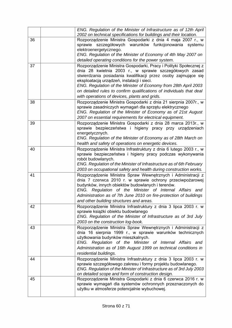
Strona 60 z 71
ENG. Regulation of the Minister of Infrastructure as of 12th April 2002 on technical specifications for buildings and their location.
36 Rozporządzenie Ministra Gospodarki z dnia 4 maja 2007 r., w sprawie szczegółowych warunków funkcjonowania systemu elektroenergetycznego. ENG. Regulation of the Minister of Economy of 4th May 2007 on
detailed operating conditions for the power system.
37 Rozporządzenie Ministra Gospodarki, Pracy i Polityki Społecznej z dnia 28 kwietnia 2003 r., w sprawie szczegółowych zasad stwierdzania posiadania kwalifikacji przez osoby zajmujące się eksploatacją urządzeń, instalacji i sieci. ENG. Regulation of the Minister of Economy from 28th April 2003
on detailed rules to confirm qualifications of individuals that deal
with operations of devices, plants and grids.
38 Rozporządzenie Ministra Gospodarki z dnia 21 sierpnia 2007r., w sprawie zasadniczych wymagań dla sprzętu elektrycznego ENG. Regulation of the Minister of Economy as of 21st August
2007 on essential requirements for electrical equipment.
39 Rozporządzenie Ministra Gospodarki z dnia 28 marca 2013r., w sprawie bezpieczeństwa i higieny pracy przy urządzeniach energetycznych. ENG. Regulation of the Minister of Economy as of 28th March on
health and safety of operations on energetic devices.
40 Rozporządzenie Ministra Infrastruktury z dnia 6 lutego 2003 r., w sprawie bezpieczeństwa i higieny pracy podczas wykonywania robót budowlanych. ENG. Regulation of the Minister of Infrastructure as of 6th February
2003 on occupational safety and health during construction works.
41 Rozporządzenie Ministra Spraw Wewnętrznych i Administracji z dnia 7 czerwca 2010 r. w sprawie ochrony przeciwpożarowej budynków, innych obiektów budowlanych i terenów. ENG. Regulation of the Minister of Internal Affairs and
Administration as of 7th June 2010 on fire-protection of buildings
and other building structures and areas.
42 Rozporządzenie Ministra Infrastruktury z dnia 3 lipca 2003 r. w sprawie książki obiektu budowlanego ENG. Regulation of the Minister of Infrastructure as of 3rd July
2003 on the construction log-book.
43 Rozporządzenie Ministra Spraw Wewnętrznych i Administracji z dnia 16 sierpnia 1999 r., w sprawie warunków technicznych użytkowania budynków mieszkalnych. ENG. Regulation of the Minister of Internal Affairs and
Administration as of 16th August 1999 on technical conditions in
residential buildings.
44 Rozporządzenie Ministra Infrastruktury z dnia 3 lipca 2003 r. w sprawie szczegółowego zakresu i formy projektu budowlanego. ENG. Regulation of the Minister of Infrastructure as of 3rd July 2003 on detailed scope and form of construction design.
45 Rozporządzenie Ministra Gospodarki z dnia 6 czerwca 2016 r. w sprawie wymagań dla systemów ochronnych przeznaczonych do użytku w atmosferze potencjalnie wybuchowej.
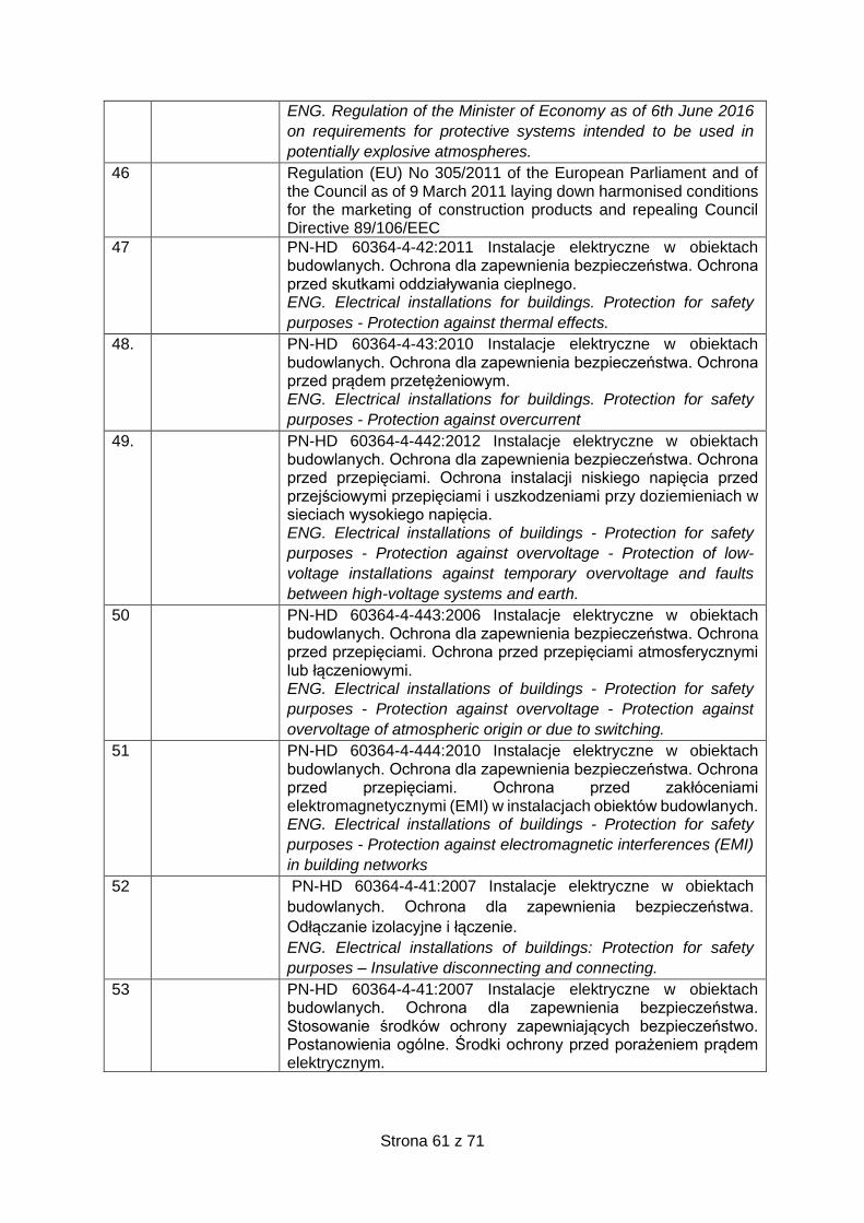
Strona 61 z 71
ENG. Regulation of the Minister of Economy as of 6th June 2016
on requirements for protective systems intended to be used in
potentially explosive atmospheres.
46 Regulation (EU) No 305/2011 of the European Parliament and of the Council as of 9 March 2011 laying down harmonised conditions for the marketing of construction products and repealing Council Directive 89/106/EEC
47 PN-HD 60364-4-42:2011 Instalacje elektryczne w obiektach budowlanych. Ochrona dla zapewnienia bezpieczeństwa. Ochrona przed skutkami oddziaływania cieplnego. ENG. Electrical installations for buildings. Protection for safety
purposes - Protection against thermal effects.
48. PN-HD 60364-4-43:2010 Instalacje elektryczne w obiektach budowlanych. Ochrona dla zapewnienia bezpieczeństwa. Ochrona przed prądem przetężeniowym. ENG. Electrical installations for buildings. Protection for safety
purposes - Protection against overcurrent
49. PN-HD 60364-4-442:2012 Instalacje elektryczne w obiektach budowlanych. Ochrona dla zapewnienia bezpieczeństwa. Ochrona przed przepięciami. Ochrona instalacji niskiego napięcia przed przejściowymi przepięciami i uszkodzeniami przy doziemieniach w sieciach wysokiego napięcia. ENG. Electrical installations of buildings - Protection for safety
purposes - Protection against overvoltage - Protection of low-
voltage installations against temporary overvoltage and faults
between high-voltage systems and earth.
50 PN-HD 60364-4-443:2006 Instalacje elektryczne w obiektach budowlanych. Ochrona dla zapewnienia bezpieczeństwa. Ochrona przed przepięciami. Ochrona przed przepięciami atmosferycznymi lub łączeniowymi. ENG. Electrical installations of buildings - Protection for safety
purposes - Protection against overvoltage - Protection against
overvoltage of atmospheric origin or due to switching.
51 PN-HD 60364-4-444:2010 Instalacje elektryczne w obiektach budowlanych. Ochrona dla zapewnienia bezpieczeństwa. Ochrona przed przepięciami. Ochrona przed zakłóceniami elektromagnetycznymi (EMI) w instalacjach obiektów budowlanych. ENG. Electrical installations of buildings - Protection for safety
purposes - Protection against electromagnetic interferences (EMI)
in building networks
52 PN-HD 60364-4-41:2007 Instalacje elektryczne w obiektach
budowlanych. Ochrona dla zapewnienia bezpieczeństwa.
Odłączanie izolacyjne i łączenie.
ENG. Electrical installations of buildings: Protection for safety
purposes – Insulative disconnecting and connecting.
53 PN-HD 60364-4-41:2007 Instalacje elektryczne w obiektach budowlanych. Ochrona dla zapewnienia bezpieczeństwa. Stosowanie środków ochrony zapewniających bezpieczeństwo. Postanowienia ogólne. Środki ochrony przed porażeniem prądem elektrycznym.
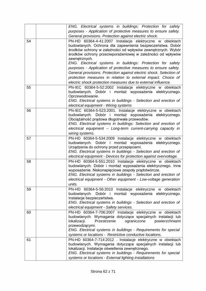
Strona 62 z 71
ENG. Electrical systems in buildings: Protection for safety
purposes - Application of protective measures to ensure safety.
General provisions. Protection against electric shock.
54 PN-HD 60364-4-41:2007 Instalacje elektryczne w obiektach budowlanych. Ochrona dla zapewnienia bezpieczeństwa. Dobór środków ochrony w zależności od wpływów zewnętrznych. Wybór środków ochrony przeciwporażeniowej w zależności od wpływów zewnętrznych. ENG. Electrical systems in buildings: Protection for safety
purposes - Application of protective measures to ensure safety.
General provisions. Protection against electric shock. Selection of
protection measures in relation to external impact. Choice of
electric shock protection measures due to external influence.
55 PN-IEC 60364-5-52:2002 Instalacje elektryczne w obiektach budowlanych. Dobór i montaż wyposażenia elektrycznego. Oprzewodowanie. ENG. Electrical systems in buildings - Selection and erection of
electrical equipment - Wiring systems
56 PN-IEC 60364-5-523:2001. Instalacje elektryczne w obiektach budowlanych. Dobór i montaż wyposażenia elektrycznego. Obciążalność prądowa długotrwała przewodów. ENG. Electrical systems in buildings: Selection and erection of
electrical equipment – Long-term current-carrying capacity in
wiring systems.
57 PN-HD 60364-5-534:2009 Instalacje elektryczne w obiektach budowlanych. Dobór i montaż wyposażenia elektrycznego. Urządzenia do ochrony przed przepięciami. ENG. Electrical systems in buildings - Selection and erection of
electrical equipment - Devices for protection against overvoltage.
58 PN-HD 60364-5-551:2010 Instalacje elektryczne w obiektach budowlanych. Dobór i montaż wyposażenia elektrycznego. Inne wyposażenie. Niskonapięciowe zespoły prądotwórcze. ENG. Electrical systems in buildings - Selection and erection of
electrical equipment - Other equipment - Low-voltage generation
units.
59 PN-HD 60364-5-56:2010 Instalacje elektryczne w obiektach budowlanych. Dobór i montaż wyposażenia elektrycznego. Instalacje bezpieczeństwa. ENG. Electrical systems in buildings - Selection and erection of
electrical equipment - Safety services.
60 PN-HD 60364-7-706:2007 Instalacje elektryczne w obiektach budowlanych. Wymagania dotyczące specjalnych instalacji lub lokalizacji. Przestrzenie ograniczone powierzchniami przewodzącymi. ENG. Electrical systems in buildings - Requirements for special
systems or locations - Restrictive conductive locations.
61 PN-HD 60364-7-714:2012 . Instalacje elektryczne w obiektach budowlanych. Wymagania dotyczące specjalnych instalacji lub lokalizacji. Instalacje oświetlenia zewnętrznego. ENG. Electrical systems in buildings - Requirements for special
systems or locations - External lighting installations

Strona 63 z 71
62 PN-HD 60364-7-717:2006 Instalacje elektryczne w obiektach budowlanych. Wymagania dotyczące specjalnych instalacji lub lokalizacji. Zespoły ruchome lub przewoźne. ENG. Electrical systems in buildings - Requirements for special
installations or locations - Mobile or transportable units.
63 PN-IEC 60050-826:2007 Międzynarodowy słownik terminologiczny elektryki. Część 826 Instalacje elektryczne. ENG. International Electrotechnical Vocabulary (IEV) - Part 826:
Electrical systems in buildings.
64 PN-IEC 60050-195:2001 Międzynarodowy słownik terminologiczny elektryki. Uziemienia i ochrona przeciwporażeniowa ENG. International Electrotechnical Vocabulary (IEV) - Part 195:
Earthing and protection against electric shock.
65 PN-EN 60445:2011 Zasady podstawowe i bezpieczeństwa przy współdziałaniu człowieka z maszyną, oznaczanie i identyfikacja. Oznaczenia identyfikacyjne zacisków urządzeń i zakończeń żył przewodów oraz ogólne zasady systemu alfanumerycznego. ENG. Basic and safety principles for man-machine interface,
marking and identification - Identification of equipment terminals,
conductor terminations and conductors and basic alphanumeric
system rules.
66 PN-EN 60445:2011 Zasady podstawowe i bezpieczeństwa przy współdziałaniu człowieka z maszyną, oznaczanie i identyfikacja. Oznaczenia identyfikacyjne zacisków urządzeń i zakończeń żył przewodów oraz ogólne zasady systemu alfanumerycznego. ENG. Basic and safety principles for man-machine interface,
marking and identification – Identification marks on terminals and
conductors ends and general rules for alphanumeric system.
67 PN-HD 308 S2:2007 Identyfikacja żył w kablach i przewodach oraz w przewodach sznurowych. ENG. Identification of conductors in cables and wires and cord wires.
68 PN-EN 61140:2016-07 Ochrona przed porażeniem prądem elektrycznym. Wspólne aspekty instalacji i urządzeń. ENG. Protection against electric shock - Common aspects for
systems and equipment.
69 PN-EN 50310:2011 Stosowanie połączeń wyrównawczych i uziemiających w budynkach z zainstalowanym sprzętem informatycznym. ENG. Application of compensation and bonding networks in
buildings and other structures equipped with IT devices.
70 PN-EN 60529:2003 Stopnie ochrony zapewnianej przez obudowy (Kod IP). ENG. Degrees of protection provided by enclosures (IP Code).
71 PN-EN 60664-1:2005. Koordynacja izolacji urządzeń elektrycznych w układach niskiego napięcia. Część 1 Zasady, wymagania i badania.
ENG. Insulation coordination for equipment within low-voltage
systems - Part 1: Principles, requirements and tests.
72 PN-EN 50341-1:2013-03 Elektroenergetyczne linie napowietrzne prądu przemiennego powyżej 45 kV. Część 1 Wymagania ogólne. Specyfikacje wspólne.
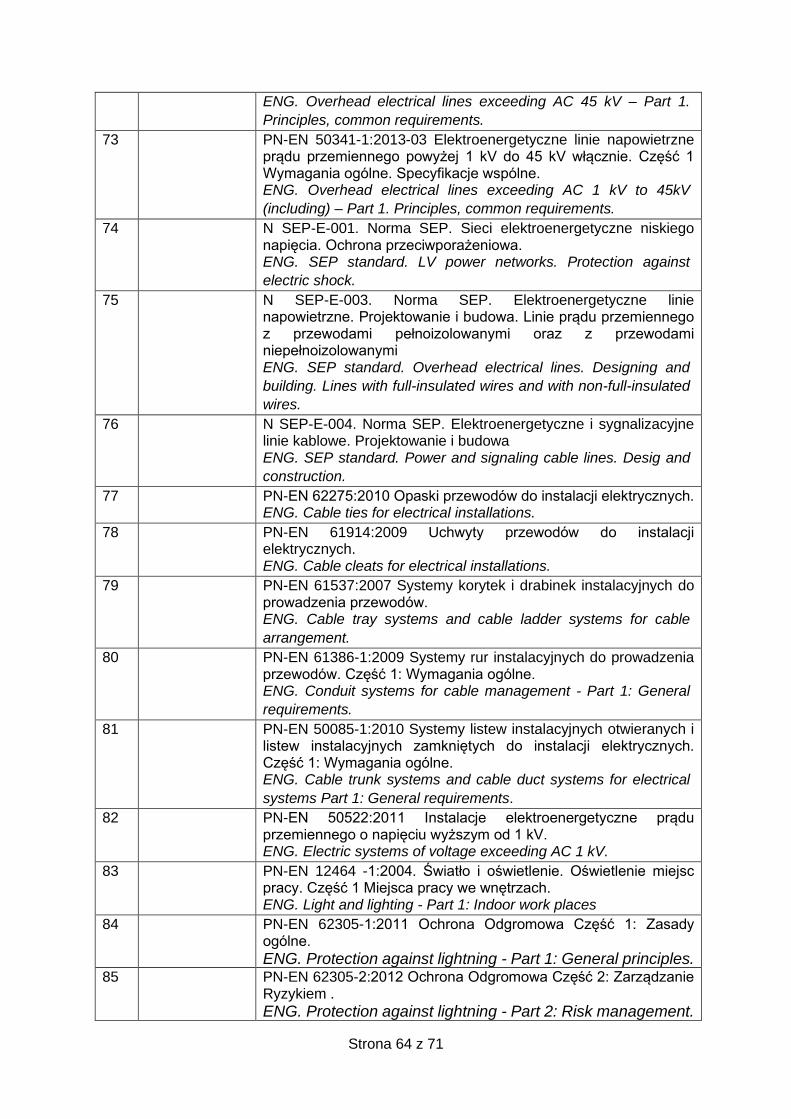
Strona 64 z 71
ENG. Overhead electrical lines exceeding AC 45 kV – Part 1.
Principles, common requirements.
73 PN-EN 50341-1:2013-03 Elektroenergetyczne linie napowietrzne prądu przemiennego powyżej 1 kV do 45 kV włącznie. Część 1 Wymagania ogólne. Specyfikacje wspólne. ENG. Overhead electrical lines exceeding AC 1 kV to 45kV
(including) – Part 1. Principles, common requirements.
74 N SEP-E-001. Norma SEP. Sieci elektroenergetyczne niskiego napięcia. Ochrona przeciwporażeniowa. ENG. SEP standard. LV power networks. Protection against
electric shock.
75 N SEP-E-003. Norma SEP. Elektroenergetyczne linie napowietrzne. Projektowanie i budowa. Linie prądu przemiennego z przewodami pełnoizolowanymi oraz z przewodami niepełnoizolowanymi ENG. SEP standard. Overhead electrical lines. Designing and
building. Lines with full-insulated wires and with non-full-insulated
wires.
76 N SEP-E-004. Norma SEP. Elektroenergetyczne i sygnalizacyjne linie kablowe. Projektowanie i budowa ENG. SEP standard. Power and signaling cable lines. Desig and
construction.
77 PN-EN 62275:2010 Opaski przewodów do instalacji elektrycznych. ENG. Cable ties for electrical installations.
78 PN-EN 61914:2009 Uchwyty przewodów do instalacji elektrycznych. ENG. Cable cleats for electrical installations.
79 PN-EN 61537:2007 Systemy korytek i drabinek instalacyjnych do prowadzenia przewodów. ENG. Cable tray systems and cable ladder systems for cable
arrangement.
80 PN-EN 61386-1:2009 Systemy rur instalacyjnych do prowadzenia przewodów. Część 1: Wymagania ogólne. ENG. Conduit systems for cable management - Part 1: General
requirements.
81 PN-EN 50085-1:2010 Systemy listew instalacyjnych otwieranych i listew instalacyjnych zamkniętych do instalacji elektrycznych. Część 1: Wymagania ogólne. ENG. Cable trunk systems and cable duct systems for electrical
systems Part 1: General requirements.
82 PN-EN 50522:2011 Instalacje elektroenergetyczne prądu przemiennego o napięciu wyższym od 1 kV. ENG. Electric systems of voltage exceeding AC 1 kV.
83 PN-EN 12464 -1:2004. Światło i oświetlenie. Oświetlenie miejsc pracy. Część 1 Miejsca pracy we wnętrzach. ENG. Light and lighting - Part 1: Indoor work places
84 PN-EN 62305-1:2011 Ochrona Odgromowa Część 1: Zasady ogólne.
ENG. Protection against lightning - Part 1: General principles. 85 PN-EN 62305-2:2012 Ochrona Odgromowa Część 2: Zarządzanie
Ryzykiem .
ENG. Protection against lightning - Part 2: Risk management.
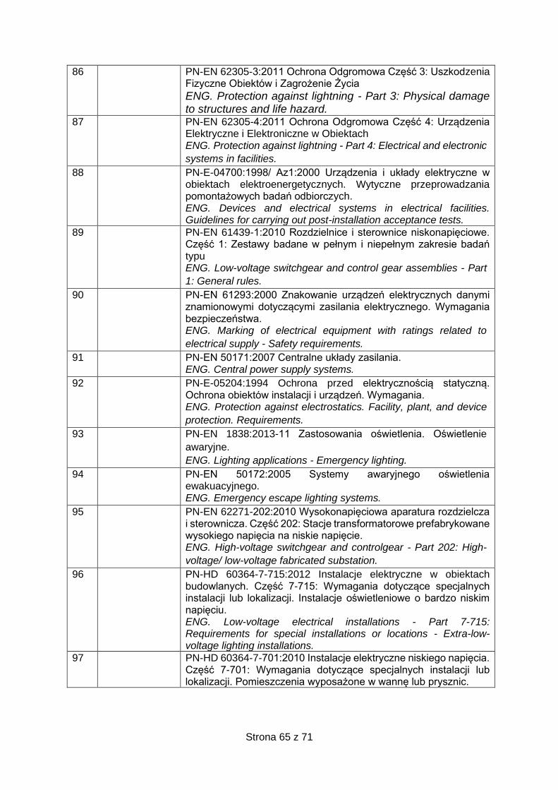
Strona 65 z 71
86 PN-EN 62305-3:2011 Ochrona Odgromowa Część 3: Uszkodzenia Fizyczne Obiektów i Zagrożenie Życia
ENG. Protection against lightning - Part 3: Physical damage to structures and life hazard.
87 PN-EN 62305-4:2011 Ochrona Odgromowa Część 4: Urządzenia Elektryczne i Elektroniczne w Obiektach ENG. Protection against lightning - Part 4: Electrical and electronic
systems in facilities.
88 PN-E-04700:1998/ Az1:2000 Urządzenia i układy elektryczne w obiektach elektroenergetycznych. Wytyczne przeprowadzania pomontażowych badań odbiorczych. ENG. Devices and electrical systems in electrical facilities. Guidelines for carrying out post-installation acceptance tests.
89 PN-EN 61439-1:2010 Rozdzielnice i sterownice niskonapięciowe. Część 1: Zestawy badane w pełnym i niepełnym zakresie badań typu ENG. Low-voltage switchgear and control gear assemblies - Part
1: General rules.
90 PN-EN 61293:2000 Znakowanie urządzeń elektrycznych danymi znamionowymi dotyczącymi zasilania elektrycznego. Wymagania bezpieczeństwa. ENG. Marking of electrical equipment with ratings related to
electrical supply - Safety requirements.
91 PN-EN 50171:2007 Centralne układy zasilania. ENG. Central power supply systems.
92 PN-E-05204:1994 Ochrona przed elektrycznością statyczną. Ochrona obiektów instalacji i urządzeń. Wymagania. ENG. Protection against electrostatics. Facility, plant, and device
protection. Requirements.
93 PN-EN 1838:2013-11 Zastosowania oświetlenia. Oświetlenie
awaryjne.
ENG. Lighting applications - Emergency lighting.
94 PN-EN 50172:2005 Systemy awaryjnego oświetlenia ewakuacyjnego. ENG. Emergency escape lighting systems.
95 PN-EN 62271-202:2010 Wysokonapięciowa aparatura rozdzielcza i sterownicza. Część 202: Stacje transformatorowe prefabrykowane wysokiego napięcia na niskie napięcie. ENG. High-voltage switchgear and controlgear - Part 202: High-
voltage/ low-voltage fabricated substation.
96 PN-HD 60364-7-715:2012 Instalacje elektryczne w obiektach budowlanych. Część 7-715: Wymagania dotyczące specjalnych instalacji lub lokalizacji. Instalacje oświetleniowe o bardzo niskim napięciu. ENG. Low-voltage electrical installations - Part 7-715: Requirements for special installations or locations - Extra-low-voltage lighting installations.
97 PN-HD 60364-7-701:2010 Instalacje elektryczne niskiego napięcia. Część 7-701: Wymagania dotyczące specjalnych instalacji lub lokalizacji. Pomieszczenia wyposażone w wannę lub prysznic.
Strona 66 z 71
Low-voltage electrical installations - Part 7-701: Requirements for
special systems or locations - Locations equipped with a bath or
shower.
98 PN-HD 60364-7-704:2010 Instalacje elektryczne niskiego napięcia. Część 7-704: Wymagania dotyczące specjalnych instalacji lub lokalizacji. Instalacje na terenie budowy i rozbiórki. ENG. Low-voltage electrical systems - Part 7-704: Requirements
for special systems or locations - Construction and demolition site
installations.
99 PN-HD 60364-5-559:2012 Instalacje elektryczne w obiektach budowlanych. Część 5-559: Dobór i montaż wyposażenia elektrycznego. Oprawy oświetleniowe i instalacje oświetleniowe. ENG. Electrical systems in buildings - Part 5-559: Selection and
erection of electrical equipment - Luminaires and lighting
installations.
100 PN-HD 60364-7-712:2016-05 Instalacje elektryczne w obiektach budowlanych. Część 7-712: Wymagania dotyczące specjalnych instalacji lub lokalizacji. Fotowoltaiczne (PV) układy zasilania. ENG. Low voltage electrical installations - Part 7-712:
Requirements for special installations or locations - Solar
photovoltaic (PV) power supply systems.
101 PN-EN 1363-1:2012 Badania odporności ogniowej. Część1: Wymagania ogólne. ENG. Fire resistance tests. Part 1: General requirements.
102 PN-EN 50200:2006 Metoda badania palności cienkich przewodów i kabli bez ochrony specjalnej stosowanych w obwodach zabezpieczających. ENG. Method of test for resistance to fire of unprotected small
cables in emergency circuits.
103 PN-HD 60364-4-41:2017-09 Instalacje elektryczne niskiego napięcia. Część 4-41: Ochrona dla zapewnienia bezpieczeństwa. Ochrona przed porażeniem elektrycznym ENG. Low voltage electrical installations - Part 4-41: Protection for
safety purposes - Protection against electric shock.
104 PN-HD 60364-5-54:2011 . Instalacje elektryczne niskiego
napiecia. Część 5-54: Dobór i montaż wyposażenia elektrycznego.
Uziemienia, przewody ochronne i przewody połączeń ochronnych
ENG. Low-voltage electrical installations - Part 5-54: Selection and
erection of electrical equipment - Earthing arrangements and
protective conductors.
105 PN-HD 60364-6:2016-07 Instalacje elektryczne niskiego napięcia. Część 6: Sprawdzanie ENG. Low voltage electrical installations - Part 6: Verification.
106 PN-HD 60364-1:2010 Instalacje elektryczne niskiego napięcia. Część 1: Wymagania podstawowe, ustalanie ogólnych charakterystyk, definicje. ENG. Low-voltage electrical installations - Part 1: Fundamental
principles, assessment of general characteristics, definitions.
107 PN-HD 60364-5-51:2011. Instalacje elektryczne w obiektach budowlanych. Część 5-51: Dobór i montaż wyposażenia elektrycznego. Postanowienia ogólne.
Strona 67 z 71
ENG. Electrical systems in buildings - Part 5-51: Selection and
erection of electrical equipment - Common rules.
108 PN-EN 60079-14:2014-06 Urządzenia elektryczne w przestrzeniach zagrożonych wybuchem. Część 14: Instalacje elektryczne w przestrzeniach zagrożonych wybuchem innych niż w kopalniach. ENG. Explosive atmosphere electrical equipment - Part 14:
Electrical installations in explosive zones other than in mines.
109 PN-EN 60034-18-34:2012 Maszyny elektryczne wirujące. ENG. Rotating electrical machines.
110 PN-EN 61439-1:2010 Rozdzielnice i sterownice niskonapięciowe. Część 1: Zestawy badane w pełnym i niepełnym zakresie badań typu ENG. Low-voltage switchgear and controlgear assemblies - Part 1:
Sets tested with full and incomplete scope of type-testing.
111 PN-EN 61660-1:2002 Prądy zwarciowe w obwodach pomocniczych prądu stałego w elektrowniach i stacjach elektroenergetycznych. Część 1: Obliczanie prądów zwarciowych ENG. Short-circuit currents in DC auxiliary installations in power
plants and substations - Part 1: Calculation of short-circuit currents.
112 PN-EN 61660-2:2002 Prądy zwarciowe w obwodach pomocniczych prądu stałego w elektrowniach i stacjach elektroenergetycznych. Część 2: Obliczanie skutków. ENG. Short-circuit currents in D.C. auxiliary installations in power
plants and substations - Part 2: Calculation of effects
113 PN-EN 60664-1:2006 Koordynacja izolacji urządzeń elektrycznych w układach niskiego napięcia. Część 1: Zasady, wymagania i badania. ENG. Insulation coordination for equipment within low-voltage
systems - Part 1: Principles, requirements and tests.
114 PN-EN 61439-3:2012 Rozdzielnice i sterownice niskonapięciowe. Część 3: wymagania dotyczące niskonapięciowych rozdzielnic i sterownic przeznaczonych do instalowania w miejscach dostępnych do użytkowania przez osoby niewykwalifikowane. Rozdzielnice tablicowe ENG. Low-voltage switchgear and controlgear assemblies - Part 3:
Requirements for low-voltage switchgears and controlgears
intended to be used in locations available for non-qualified persons
(DBO). Distribution boards
115 PN-EN 60099-5:2014-01 Ograniczniki przepięć. Zalecenia wyboru
i sterowania.
ENG. Surge arresters - Selection and control recommendations.
116 PN-EN 50575:2015-03 Kable i przewody elektroenergetyczne,
sterownicze i telekomunikacyjne. Kable i przewody do zastosowań
ogólnych w obiektach budowlanych o określonej klasie odporności
pożarowej.
ENG. Power, control and communication cables - Cables for
general applications in buildings featuring specific fire resistance.
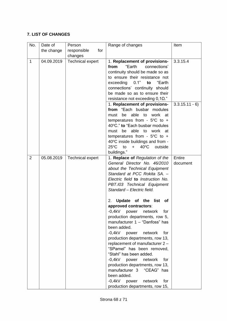
Strona 68 z 71
7. LIST OF CHANGES
No. Date of
the change
Person
responsible for
changes
Range of changes Item
1 04.09.2019 Technical expert 1. Replacement of provisions-
from “Earth connections’
continuity should be made so as
to ensure their resistance not
exceeding 0.1” to “Earth
connections’ continuity should
be made so as to ensure their
resistance not exceeding 0,1Ω.”
3.3.15.4
1. Replacement of provisions-
from “Each busbar modules
must be able to work at
temperatures from - 5oC to +
40oC.” to “Each busbar modules
must be able to work at
temperatures from - 5oC to +
40oC inside buildings and from -
25oC to + 40oC outside
buildings.”
3.3.15.11 - 6)
2 05.08.2019 Technical expert 1. Replace of Regulation of the
General Director No. 46/2010
about the Technical Equipment
Standard at PCC Rokita SA. –
Electric field to Instruction No.
PBT.I03 Technical Equipment
Standard – Electric field.
2. Update of the list of
approved contractors:
-0,4kV power network for
production departments, row 5,
manufacturer 1 – “Danfoss” has
been added.
-0,4kV power network for
production departments, row 13,
replacement of manufacturer 2 –
“SPamel” has been removed,
“Stahl” has been added.
-0,4kV power network for
production departments, row 13,
manufacturer 3 “CEAG” has
been added.
-0,4kV power network for
production departments, row 15,
Entire
document
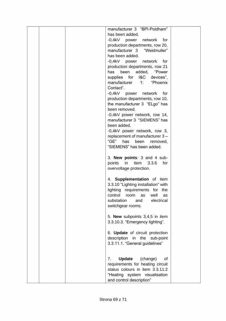
Strona 69 z 71
manufacturer 3 “BPI-Poldham”
has been added.
-0,4kV power network for
production departments, row 20,
manufacturer 3 “Weidmuller”
has been added.
-0,4kV power network for
production departments, row 21
has been added, “Power
supplies for I&C devices”,
manufacturer 1: “Phoenix
Contact”.
-0,4kV power network for
production departments, row 10,
the manufacturer 3 “ELgo” has
been removed.
-0,4kV power network, row 14,
manufacturer 3 “SIEMENS” has
been added.
-0,4kV power network, row 3,
replacement of manufacturer 3 –
“GE” has been removed,
“SIEMENS” has been added.
3. New points: 3 and 4 sub-
points in item 3.3.6 for
overvoltage protection.
4. Supplementation of item
3.3.10 "Lighting installation" with
lighting requirements for the
control room as well as
substation and electrical
switchgear rooms.
5. New subpoints 3,4,5 in item
3.3.10.3. “Emergency lighting”.
6. Update of circuit protection
description in the sub-point
3.3.11.1. “General guidelines”
7. Update (change) of
requirements for heating circuit
status colours in item 3.3.11.2
“Heating system visualisation
and control description”
Strona 70 z 71
8. New subpoint 11 in item
3.3.14 „Telecommunication
systems”
9. Update of records in item
3.3.15.2 “Medium and low
voltage switchgears”
10. Replace of the title of item
3.3.16 “Power transformers” to
“Distributive transformers
6/0,4kV”
11. Update of records in item
3.3.16.2. “Specific
requirements”.
12. Update of proper names
“PCT” to “PCC IT”
13. Modification of control
diagrams for heating
installations.
14. Modification of control
diagrams for electric motors.
15. Update of standards and
regulations.
16. Update of provisions in item
3.3.12 “Lightning protection and
grounding installation”.
- Provisions related to foundation earth electrode has been added. - Provisions related to “For objects outside this [explosive] zone, this resistance should not be greater than 10 Ω” in item 3.3.12.4. has been added. - 8-16 items have been added. 17. Update (change) of subpoint 1 in item 3.3.9.2. “Motors power supply and control” 18. Removal of the diagram with a control system including LG frequency changer. 19. Lightning protection device certificate has been added.

Strona 71 z 71