stabilaire liquid lpg pump packaged bs1 - vapor gas
TRANSCRIPT

Operations & MaintenanceOperations & MaintenanceOperations & MaintenanceOperations & MaintenanceManualManualManualManual
...Innovative liquid vaporizing and gas mixing solutions
1140 NW 46 Street, Seattle, Washington, USA 98107Tel: 206-789-5410 Fax: 206-789-5414 Web: www.algas-sdi.com
FILE: MANUAL PN 52631 REV 04-04-02 STABILAIRE.DOC

WARNING
Read the OPERATION MANUAL before operating this equipment.
� NOTE: Algas-SDI reserves the right to use alternate manufacturers’components as vendor delivery applicability dictates. Literaturecontained in the Operation Manual has been supplied byvendors. Please check to be sure supplied data matches yourconfiguration. Contact Algas-SDI if any questions exist.
� This equipment uses LPG-a flammable fuel, or NH3-a toxic gas,(depending on the model), handled under pressure. Inherent hazardsexist and a thorough understanding of the equipment is required toallow safe operation and maintenance.
� Allow only a TRAINED and FULLY QUALIFIED PERSON to service thisequipment.
� Any time a component must be replaced, use the same type, model,etc. DO NOT SUBSTITUTE! The consequence from such actions areunpredictable and may lead to dire consequences. When componentsare replaced with components not approved for use in our FM/ULlisted equipment, the FM/UL listing becomes void for that unit.

Liquid LPG Pump Data Sheet
Job Number: _____________ Serial Number: ______________ Year Built: ___________
Electrical Specifications:
Electrical Drawing: _______________________ Rev.: ______
Input Electrical Power: __________Volts, ______Amps, ______Phase, ______Hz.
Starter Type:! Switch, Not Fused! Manual Starter, Overload Heater Size: ______! Magnetic Starter, Overload Heater Size: ______
Specifications:Pump Type: Positive Displacement Sliding VanePump Manufacturer: Blackmer
Pump Model Number: Internal Relief Setting: Pump Model Number: Internal Relief Setting:! LGF1 105 psi ! LGL2 150 psi! LGL1 ¼ 150 psi ! LGL3 150 psi! LGL1 ½ 150 psi
Operating Pressure Range:BS1 – BS2 BS3! 25-75 psig ! 20-65 psig ! Other: ________psig! 70-140 psig ! 50-100 psig! 130-200 psig ! 80-170 psig
Economy Pressure Switch Settings:! No Switch Installed! Close @ ______psig, re-opens at 10 psig Above Close Pressure.
Pump Speed:! 1750 rpm ! 520 rpm! 1450 rpm ! 470 rpm! 980 rpm ! 420 rpm! 780 rpm ! 350 rpm! 640 rpm

This page intentionally left blank.

Warranty, Copyrights and ApprovalsWarranty, Copyrights and ApprovalsWarranty, Copyrights and ApprovalsWarranty, Copyrights and Approvals
WARRANTYWARRANTYWARRANTYWARRANTY
Algas-SDI International, LLC (ASDI) warrants that the equipment is free ofdefects in materials and workmanship under normal use and service. ASDIagrees to repair or replace, at our option, without charge f.o.b. factory, any partwhich has proven defective to the satisfaction of Algas-SDI International, LLCwithin one (1) year from the date of the original installation or within 18 monthsfrom the date of shipment, whichever is earlier. Equipment, which in the opinionof ASDI, has been damaged by improper installation or operation, or has beenabused or tampered with in any way, will not be accepted for return underwarranty.
Algas-SDI International, LLC will not accept back charges for work performed byothers upon or in conjunction with ASDI equipment, unless prior authorization isgiven by means of an Algas-SDI International, LLC purchase order. Algas-SDIInternational, LLC will not be liable by reason of shutdown, non-operation orincreased expense of operation of other equipment, or any other loss or damageof any nature, whether direct or consequential, arising from any causewhatsoever.
Algas-SDI International, LLC makes NO other warranty of any kind, whatsoeverexpressed or implied; and all warranties of merchantability and fitness for aparticular purpose are hereby disclaimed by Algas-SDI International, LLC andexcluded from these terms of sale. No person has any authority to bind Algas-SDI International, LLC to any representation or warranty other than this warranty.
COPYRIGHTCOPYRIGHTCOPYRIGHTCOPYRIGHT
Copyright 2000 by Algas-SDI International, LLC, Seattle, Washington 98107. Allrights reserved. No part of this manual may be reproduced or copied in any formor by any means, photographic, electronic, or mechanical, without the priorexpress written consent from Algas-SDI International, LLC, Seattle, Washington,USA.

Symbols and ConventionsSymbols and ConventionsSymbols and ConventionsSymbols and Conventions
Special symbols are used to denote hazardous or important information. Youshould familiarize yourself with their meaning and take special notice of theindicated information.
Please read the following explanations thoroughly.
GENERAL WARNING OR CAUTIONGENERAL WARNING OR CAUTIONGENERAL WARNING OR CAUTIONGENERAL WARNING OR CAUTION
Indicates hazards or unsafe practices which can result in damage tothe equipment or cause personal injury. Use care and follow theinstructions given.
FLAMMABLE GAS HAZARDFLAMMABLE GAS HAZARDFLAMMABLE GAS HAZARDFLAMMABLE GAS HAZARD
Indicates a potential hazard which can result in severe personalinjury or death. Use extreme care and follow the instructions given.
ELECTRICAL DISCONNECT REQUIREDELECTRICAL DISCONNECT REQUIREDELECTRICAL DISCONNECT REQUIREDELECTRICAL DISCONNECT REQUIRED
Indicates a potentially dangerous situation which can result insevere personal injury or death or damage to equipment. Use greatcare and follow the instruction given.
ASDI CONTACT NUMBERSASDI CONTACT NUMBERSASDI CONTACT NUMBERSASDI CONTACT NUMBERS
If you have questions, need help with your equipment, or want information onother products, contact Algas-SDI at:
Telephone: 206.789.5410
Facsimile: 206.789.5414
Email: [email protected]
Internet: http://www.algas-sdi.com

Table of ContentsTable of ContentsTable of ContentsTable of Contents
1.1.1.1. IntroductionIntroductionIntroductionIntroduction
Special Problems of Pumping Liquid Petroleum Gas 1-1
Algas-SDI Pumping Systems 1-1
Figure 1 – Component Drawing – BS1 and BS1½ 1-2
Figure 2 – Component Drawing – BS2 and BS3 1-3
Basic Components of Stabilaire Pump Systems 1-4
Valves 1-4
Back Pressure Control Valve 1-4
Relief/Bypass Valve 1-4
Hydrostatic Relief Valve 1-4
Isolation Valve 1-4
Outlet Isolation Valve 1-4
Check Valves 1-4
Inlet Strainer 1-4
Pump – Positive Displacement Sliding Vane Type 1-5
Explosion Proof Electric Motor 1-5
Start/Stop Switch 1-5
Three Position Switch 1-5
Bypass Flow Option – Economy Setting 1-5
2.2.2.2. InstallationInstallationInstallationInstallation
General Installation of Stabilaire Systems 2-7
Figure 3 – Typical Installation Drawing 2-7
Pump Base 2-8
Types of Valves and Fittings to Use 2-8
Location and Piping – General Information 2-8
Determining Correct Pump Capacity 2-9
Pump Motors 2-9
V-Belt Drive Pumps 2-10
Figure 4 – Pulley Alignment 2-10
Figure 5 – Proper Belt Tension 2-11
Direct Coupled Pumps 2-11
Alignment Verification Guidelines for Direct Coupled Pumps 2-12
Figure 6 – Alignment 2-12

3.3.3.3. StartupStartupStartupStartup
Operation Check 3-13
Take All Safety Precautions! 3-13
Verify That the Pump System Has Been Installed Correctly 3-13
Pump Setting and Adjustment Procedures 3-14
Adjusting Output Setpoint 3-14
Internal Pump Relief Valve Adjustment 3-14
4.4.4.4. OperationOperationOperationOperation
Startup 4-15
Normal Operation 4-16
Operating Precautions 4-16
Inlet Pressure 4-16
Outlet Pressure 4-16
Back Pressure Relief Valve 4-16
5.5.5.5. MaintenanceMaintenanceMaintenanceMaintenance
Strainer 5-17
Lubrication 5-17
Pump Overhaul and Repair 5-18
Tool Required 5-18
Disassembly 5-18
Assembly 5-19
6.6.6.6. TroubleshootingTroubleshootingTroubleshootingTroubleshooting
Table 1 – Pump Troubleshooting 6-21
Appendix A: Component InformationAppendix A: Component InformationAppendix A: Component InformationAppendix A: Component Information
Appendix B: Technical InformationAppendix B: Technical InformationAppendix B: Technical InformationAppendix B: Technical Information
Figure 7 - Electrical schematic for pump with on/off switch. B-65
Figure 8 - Electrical schematic for pump with manual starter. B-65
Figure 9 - Electrical schematic for pumps with magnetic starters. B-66

Algas-SDI Operations and Maintenance Manual – P/N - 52631 1-1
IntroductionIntroductionIntroductionIntroduction 1111SPECIAL PROBLEMS OF PUMPING LIQUID PETROLEUM GAS
Pump systems manufactured by Algas-SDI are designed to pump LiquidPetroleum Gas, both butane and propane, in their liquid state. Because propaneand butane are pumped in an unnatural state, they are difficult to handle. Theslightest drop in pressure or the smallest addition of heat will cause the LPG toboil, especially when it is going through a pipe. All necessary safety measureswith LPG pump systems should be taken.
ALGAS-SDI PUMPING SYSTEMS
Algas-SDI STABILAIRE Liquid Pump Systems are fully packaged pumpingsystems designed to pump liquid petroleum gas in its liquid state. The systemsare pressure stabilized and include a positive displacement sliding vane pumpwith an internal relief valve, explosion proof motor, bypass line, pressure reliefvalve, shut-off valve, check valves, and pressure gauges. The pressure reliefvalve provides a stable delivery pressure by returning excess pump capacityto the storage tank. The STABILAIRE systems are designed for continuous useand meet all Class 1, Division 1, Group D requirements. All of the electrical wiringis explosion-proof. An inlet strainer is provided for field installation. Each systemis leak tested at the factory.
The smaller capacity pump systems, models BS1 through BS1½ are direct driveunits; the pumps are either mounted directly on the face of the motor by flange orare connected to electric motors by a flexible coupling. The larger capacity pumpsystems, models BS2 through BS3, are driven by V-drive belts. The smallerpump systems, BS1, provide 10 to 15 gpm (38 to 57 lpm) at a differentialpressure of 125 psi. (862kPa). The BS1½ have capacities from 9 to 35 gpm(34 to 132 lpm) at a differential pressure of 150 psi. Models BS2 and BS3 providefrom 30 to 300 gpm (114 to 1135 lpm) at a differential pressure of 150 psi. Thepumps used in the larger systems have a special cavitation liner that “cushions”the effects of collapsing vapor bubbles within the pump, reducing noise, vibration,and wear.
The pumps themselves are designed for easy maintenance and featurereplaceable end disks, vanes, casing liners and seals which can be easilyreplaced with basic tools. The sliding vanes are self-adjusting and maintain theirefficiency throughout their life.
Both direct coupled and belt driven pumps have heavy duty bolted-down safetycovers surrounding their drives. All systems are supplied with industrial dutyexplosion-proof motors.
The pump systems feature a manual starter located near the motor. Magneticstarters featuring a Hand-Off-Auto switch are available as an option for thesystems. Another option includes a pressure switch system and magnetic starterto turn on the pump when the LPG storage tank pressure is below a pre-set level.

IntroductionIntroductionIntroductionIntroduction
1-2 Algas-SDI Operation & Maintenance Manual – P/N - 52631
Figure 1 – Component Drawing – BS1 and BS1½
BS1 and BS1½.dxf
1. LPG Inlet strainer. 10. Pump – positive displacementsliding vane type.
2. Internal relief/bypass valve. 11. LPG inlet.
3. LPG inlet pressure gauge. 12. LPG outlet.
4. Back pressure control valve. 13. LPG excess return.
5. LPG outlet pressure gauge. 14. Coupling guard.
6. Hydrostatic relief valve. 15. Coupling between motor and pump.
7. Outlet isolation valve. 16. Explosion-proof electric motor.
8. Check valves. 17. LPG bypass line.
9. Starter or on/off control switch.
NOTENOTENOTENOTE
These systems are designed for above ground LPG tanks. A specialpumping system is required for use with underground tanks.

IntroductionIntroductionIntroductionIntroduction
Algas-SDI Operation & Maintenance Manual – P/N – 52631 1-3
Figure 2 – Component Drawing – BS2 and BS3
BS2 and BS3
1. LPG inlet strainer. 11. LPG inlet.
2. Internal relief/bypass valve. 12. LPG outlet.
3. LPG inlet pressure gauge. 13. LPG excess return.
4. Back pressure control valve. 14. V-belt guard.
5. LPG outlet pressure gauge. 15. V-belt drive.
6. Hydrostatic relief valve. 16. Explosion-proof electric motor.
7. Outlet isolation valve. 17. LPG bypass line.
8. Check valves. 18. Motor mounting bolts.
9. Starter with on/off control switch. 19. Motor position adjustment screw.
10. Pump – positive displacementsliding vane type.

IntroductionIntroductionIntroductionIntroduction
1-4 Algas-SDI Operation & Maintenance Manual – P/N - 52631
Basic Components of Stabilaire Pump SystemsBasic Components of Stabilaire Pump SystemsBasic Components of Stabilaire Pump SystemsBasic Components of Stabilaire Pump Systems
VALVES
Back Pressure Control Valve (Item 4)
This valve adjusts downstream discharge pressure. When discharge pressureexceeds the relief valve setpoint, the LPG returns to the storage tank.
Relief/By-pass Valve (Item 2)
This valve is set to relieve excessive differential pressure if the back pressurecontrol valve malfunctions.
Hydrostatic Relief Valve
The hydrostatic relieve valve protects the pipe from trapped LPG liquid. If liquidis trapped and builds up pressure higher than the factory setting it automaticallydischarges. It automatically reseats after discharge.
Isolation Valve
Isolation valves allow the gauges to be removed without shutting down thesystem and can also be used to bleed the system by removing the gauge first.Isolation valves also allow air to be bled out of the system when it is firstinstalled.
Outlet Isolation Valve
The Outlet Isolation valve is used to close the pump discharge when setting theback pressure control valve and also to facilitate pump repair and maintenance.
Check Valves
Check valves prevent the LPG liquid from flowing backward to the pump whileallowing a bypass for the LPG when the pump is not used.
INLET STRAINER
Traps dirt and foreign material in the system.

IntroductionIntroductionIntroductionIntroduction
Algas-SDI Operation & Maintenance Manual – P/N – 52631 1-5
PUMP – POSITIVE DISPLACMENT SLIDING VANE TYPE
For maximum efficiency, the pumps use a rotor with sliding vanes. The LPG isdrawn behind each vane through the inlet port and into the pumping chamber.As the rotor turns, the LPG is transferred between the vanes to the port where it isdischarged as the pumping chamber narrows. Each vane pushes the LPG before it.
The Pump vanes maintain contact with the chamber by three forces: (1)centrifugal force from the rotor’s rotation, (2) push rods moving betweenopposing vanes, and (3) liquid pressure entering through the vane grooves andacting on the rear of the vanes.
Pump efficiency is maintained as the vanes wear out. New vanes and the pumpvane liner can be replaced quickly and easily without removing the pump fromthe system.
Rotation of the pump is always counter-clockwise when viewing the unit from thepump end. Standard assembly is with the intake to the left and discharge to theright.
EXPLOSION PROOF ELECTRIC MOTOR
The motors are sealed and the bearings do not require lubrication ormaintenance of any kind.
The motors are designed for 20% overload for short periods of time. The pumpmotors have an overload protector and will shut off if they become overheated.Low voltage at the motor will also cause the motor to shut off.
NOTENOTENOTENOTE
Explosion Proof Electric Motors are subject to moisturecondensation inside when not used regularly. Moisture inside themotors can cause electrical problems and may short out the motor.To eliminate this problem, operate the motor at least once a weeklong enough for it to get hot.
START/STOP SWITCHThe start/stop switch is either manual or magnetic. Pumps with magnetic controlsystems can be operated remotely, by a computer control system or by hand. Ifpumps with magnetic switches are overloaded, the pump will automatically shutoff.
THREE POSITION SWITCHPumping systems supplied with the optional magnetic starter use a 3 positionswitch known as a “Hand-Off-Auto” switch.
The HAND Position allows the pump to be started manually. The OFF positionwill stop the unit under any condition. The AUTO position allows the unit to beoperated from a remote control source.
BY-PASS FLOW OPTION - ECONOMY SETTING
The optional by-pass feature of STABILAIRE Pump Systems saves energy byshutting off the pump automatically and letting incoming LPG bypass it if the tankand inlet pressure are adequate. Algas-SDI terms this “Economy Setting.”

IntroductionIntroductionIntroductionIntroduction
1-6 Algas-SDI Operation & Maintenance Manual – P/N - 52631
This page intentionally left blank.

Algas-SDI Operations and Maintenance Manual – P/N - 52631 2-7
InstallationInstallationInstallationInstallation 2222GENERAL INSTALLTION OFSTABILAIRE PUMP SYSTEMS
See Figure 3. All local codes and regulations must be determined so theinstallation conforms to local requirements.
CAUTIONCAUTIONCAUTIONCAUTION
LPG is explosive and extremely flammable. Appropriate safetyprocedures must be observed when installing and operating thesystem.
Figure 3 – Typical Installation Drawing
Installation.wmf

InstallationInstallationInstallationInstallation
2-8 Algas-SDI Operation & Maintenance Manual – P/N - 52631
PUMP BASE
The steel base of the pump unit must be installed on concrete. Pumps bolted toa concrete foundation will operate better with less vibration. The steel base mustbe level on the concrete. If necessary, drive metal shims under the steel basenear the concrete anchor bolts to make the base level. Refer to drawing # 1701-8001 for mounting suggestions.
TYPES OF VALVES ANDFITTINGS TO USE
Use gate or ball type valves, not globe valves for installation. The flow of theLPG should be as straight through as possible. See Figure 3.
Do not use fittings that reduce the LPG pressure. Vaporization may occur andcause cavitation.
LOCATION AND PIPING -GENERAL INFORMATION
If the LPG liquid boils in the intake line the system may fail. Boiling may becaused by heat from sunshine, heat from the earth on underground piping, heatfrom the atmosphere when the air is warmer than the liquid in the pipes, frictionfrom the liquid in the pipe and restrictions in the pipe. Vapor in the pipe mayreduce the flow of LPG liquid to the pump, causing damage to the pump.
Locate the pump within five feet (1.5 meters) of the LPG storage tanks to reducethe friction of the LPG through the pipe.
Whenever possible, locate the pump directly under the supply tank so the pipingwill be short to keep friction loss minimal and where vapors will rise into the tank.
Never locate the pump more than 50 piping feet (15 meters) from the LPG tanks.
Where the pipes are connected horizontally to the pump, slope the pipingdownward to the pump at least one inch per 10 feet (2.5 centimeters per 3meters) so vapors will go back to the tanks. Whenever possible, the pipe shoulddrop straight down from the manifold at least 12 inches (30 centimeters) to thepump.
The inlet pipe should have a length ten times that of its diameter between thepump inlet and the strainer.
Do not bury the intake lines underground. Do not route the intake piping upwardat any point because vapor will accumulate. In cold weather when vaporizers areneeded most, pump cavitation from vapors is much worse because bubbles fromboiling are much larger because vapor pressure is low.
Flexible connectors are recommended for the intake and discharge pipingbecause they will result in much quieter pump operation and help eliminatevaporization problems. The recommended flexible connectors should be rated atleast 350 psi (24.5 KG/CM2) see NFPA 58.
When installing the system, check to make sure that the pipes are properlysupported so there is no pipe strain on the pump. Always flush the piping beforeinstalling the pump to remove all debris and welding slag.

InstallationInstallationInstallationInstallation
Algas-SDI Operation & Maintenance Manual – P/N – 52631 2-9
DETERMINING CORRECTPUMP CAPACITY
The delivery rate of LPG at the system operating pressure should be 2 to 3 timesthe maximum system consumption. For example, a 1,000 GPH system requiresa pump with a capacity of 2,000 to 3,000 GPH at the desired pressure.
All vaporizers have a cycling type of operation and have changes in load duringoperation. In the cycling process, the flow rate of LPG liquid from the pump to thevaporizer is much larger than a calculated steady flow rate. For example, in thecase of a vaporizer supplying LPG vapor to a blender that has only one venturi,the off period is zero flow and the on period is maximum flow.
When the system starts and the vaporizer begins operating, the liquid chamber isempty of LPG and must be filled rapidly to avoid a low pressure condition. Thisrequires extra pump capacity.
Maximum flow rates are always used in determining the sizing of propaneequipment. The piping from the pump to the vaporizer should be sized for themaximum capacity of the vaporizer. In determining the pump capacity, thepressure drop through the vaporizer output pressure must be determined bycalculating the total pressure drop in the system.
The built-in relief valve on the pump is factory set to prevent re-circulation whichwould cause vapor binding. Never connect the back pressure control valvedischarge pipe into the pump intake piping.
PUMP MOTORSThe lead wires to the motor starter should be run through rigid threaded metalconduit, explosion-proof joints and explosion proof condulets. Adequate sizewire must be used from the power source to the motor starter.
Motor rotation should always be the same as the direction arrow on the pumpbody. If the motor rotation is incorrect, check the wiring with the wiring diagramon the motor.
NOTENOTENOTENOTE
3 phase motors may be reversed in direction by changing theposition of any two of the three lead wires.
CAUTIONCAUTIONCAUTIONCAUTION
Do not reverse the pump rotation to reverse the direction of theflow. This will not work! Reverse rotation would make the pumpunsafe and work poorly.
An overload protector will cut off power to the motor if it overheats. The motortemperature depends on the load and the air temperature. Shading the motorfrom direct sunlight will help reduce its operating temperature.

InstallationInstallationInstallationInstallation
2-10 Algas-SDI Operation & Maintenance Manual – P/N - 52631
V-BELT DRIVE PUMPS
See Figure 2. Loose belts will cause noise and excessive wear. Follow thesedirections for installation or replacement of V-belts.
V-Belt Installation Guide
1. Remove V-Belt guard, Fig.2 Item 14, unscrew the bolts holding it down andlift it up and out of the way.
2. Check for proper rotation, by applying power to motor. Check pump rotationdirection indicated on pump. Motor rotation MUST match that of pump.
3. After proper rotation has been verified, disconnect power to motor.
4. Loosen, but do not remove, the four mounting bolts, Fig. 2, Item 18.
5. Loosen motor position adjustment bolt(s), Fig. 2. Item 19, until approximately1” to 1 ½” of the motor position bolt(s) are visible. This will allow the motor tobe moved towards the pump for easier installation of the V-Belt(s) ontopulleys.
6. Install V-Belt(s) over both pulleys.
7. Check for proper installation of pulleys with a straight edge. Place the straightedge against the outside face of both pulleys. The straight edge MUST beable to lay up against both edges of both pulleys at the same time. Thepulleys are aligned when the straight edge is flush at points A through D.See Figure 4.
Figure 4 – Pulley Alignment
Pulley Alignment.dxf

InstallationInstallationInstallationInstallation
Algas-SDI Operation & Maintenance Manual – P/N – 52631 2-11
8. Tighten motor position adjustment bolt(s) until proper belt tension isachieved. Proper belt tension is the lowest tension at which the belt(s) willnot slip under peak load conditions. A general rule for ASDI’s applicationof V-Belts: a 10 to 15 (4 to 7 kg) lb. pressure applied at the center point onthe belt between the pump and motor pulleys should deflect the belt ½” to ¾”(1 cm to 2 cm). See Figure 5.
Figure 5 – Proper Belt Tension
Belt Tension.dxf
9. After proper tension has been achieved, re-check for proper pulley alignmentwith a straight edge. Place the straight edge against the outside face of bothpulleys. The straight edge MUST be able to lay up against both edges ofboth pulleys, at the same time. The pulleys are aligned when the straightedge is flush at points A through D. See figure 4. If belt tension adjustmenthas mis-aligned the pulleys, the motor adjustment bolts must be loosenedand the procedure repeated.
10. Tighten the four (4) motor mounting bolts (item 18) securely.
11. Before replacing the V-Belt guard (14), momentarily apply power to motor todouble-check tension, alignment and rotation.
12. Replace the V-Belt guard and tighten all bolts securely.
DIRECT COUPLED PUMPS (REFER TO FIGURE 1)
The coupling alignment must be near perfect to give quiet, long-life to the pumpand driver. The pump and driver shafts are carefully aligned at the factory, butthe alignment should always be checked after the pump is installed and beforeinitial operation.
After the power to the pump motor is disconnected and the coupling guard isremoved, use either of the methods on the following pages to align the pumpcoupling.

InstallationInstallationInstallationInstallation
2-12 Algas-SDI Operation & Maintenance Manual – P/N - 52631
ALIGNMENT VERIFICATION GUIDELINES FOR DIRECT COUPLED PUMPS
1. Disconnect power to pump motor.
2. Remove coupling guard.
3. Inspect flexible coupling insert for wear.
4. Two methods can be used to check alignment of couplings. One requires theuse of a small straight edge. The other requires the use of a feeler gauge.
Figure 6 – Direct Coupled Pump Alignment
Direct Coupled Pump Alignment.dxf

Algas-SDI Operations and Maintenance Manual – P/N - 52631 3-13
StartupStartupStartupStartup 3333OPERATION CHECK
Thoroughly check the entire LPG facility for safe operation and function beforestarting up the process. The check must include the condition and operation ofthe storage tanks, pipes, electrical wiring, and appropriate valves all the way tothe outlet and transfer pipes.
TAKE ALL SAFTEY PRECAUTIONS!
CAUTIONCAUTIONCAUTIONCAUTION
LPG is explosive and extremely dangerous. Take all necessarysafety precautions in operation of the system. No open flames orsources of electrical sparks should be in the operating facility.
NOTENOTENOTENOTE
All piping of the system, both incoming and outgoing, should bethoroughly cleaned and tested before starting.
WARNINGWARNINGWARNINGWARNING
No smoking throughout the entire facility! Even smoking in anadjacent room next to the facility or close by outdoors isdangerous.
VERIFY THAT THE PUMP SYSTEM HAS BEEN INSTALLED CORRECTLY
1. Check the pump system for correct installation of all components. All boltsshould be tight, secure, and the V-belts should be correctly adjusted. See themaintenance section for correct tightening of belts if necessary.
2. Check the wiring, make sure there are no broken or frayed wires and that allwiring is properly installed. Check all electrical conduit for correct installationand ensure that all fittings are tight.
3. Measure the incoming voltage with a voltmeter to check if it is the correctvoltage for the system.
4. All piping should be clean, free of moisture and have no leaks. Even a smallleak anywhere in the entire facility is unacceptable!

StartupStartupStartupStartup
3-14 Algas-SDI Operation & Maintenance Manual – P/N - 52631
PUMP SETTINGS AND ADJUSTMENT PROCEDURES (REFER TO FIGURES 1 OR 2)
Perform these procedures on initial startup of the system, if the pump is restartedafter being idle, or if the delivery pressure or tank pressure changes.
CAUTIONCAUTIONCAUTIONCAUTION
Before performing this procedure, follow all safety procedures forLPG. Make sure there are no open flames or electrical sparks, weargloves and appropriate clothing.
ADJUSTING OUTPUT SETPOINT
1. Determine the required pump discharge pressure.
2. Slowly open shut-off valves in the storage tank for pump section line andreturn lines. Open all shut-off valves between storage tank and pump.
3. Verify tank pressure reading and gauge reading on LPG pump inlet. Bothshould correspond with each other. If not, refer to step #2.
4. Close shut-off valve at pump outlet.
5. Loosen lock nut on adjustment bolt for the control valve, Fig. 2, Item 4.Turn adjustment bolt out until it is loose. DO NOT remove completely.
6. Turn pump on. You may notice a slight pressure increase at the outletpressure gauge.
7. Slowly start to turn adjustment bolt “in” on the control relief valve, Fig. 2,Item 4, until the desired outlet pressure is attained. Stop the adjustmentwhen the pressure is obtained.
8. Tighten lock nut, making sure adjustment bolt does not turn while tightening.
INTERNAL PUMP RELIEF VALVE ADJUSTMENT
CAUTIONCAUTIONCAUTIONCAUTION
Only try this test briefly. If the relief valve doesn’t open during thetest, open the outlet valve. The internal bypass valve of the pump isdesigned for emergency protection only. It may be damaged if thisprocedure is done for any length of time.
1. To test pump bypass valve (Fig. 2, Item 2) for proper operation, with pumpoutlet closed and pump on, momentarily close manual shut-off valve in thecontrol relief valve return line to the tank. The pressure increase should beslightly higher than the normal discharge pressure.
For example: if the outlet pressure is normally 80 psi, the outlet pressureshould now be 90 to 100 psi.
2. Adjust the valve as required using a hex wrench and an open end wrench.
3. Open manual shut-off valve in the control relief valve return line to the tank.
4. Open pump outlet shut-off valve (Fig.2, Item 7). Pump is now ready foroperation.

Algas-SDI Operations and Maintenance Manual – P/N - 52631 4-15
OperationOperationOperationOperation 4444StartupStartupStartupStartup
1. Check the system thoroughly before putting it into operation. Any problemwith the system: leak, faulty valve, loose bolt or connection is unacceptable!Repairs must be made immediately.
The wiring should be examined for correct connections, voltage and properrotation.
2. Open all valves in the lines to the pump.
3. Turn on the power to the pump
4. Turn on the pump.
If it is in correct operating order, the motor should start quickly, the pressure willcome up immediately, the pump will run at normal operating speed and thepressure gauge on the discharge side of the pump will indicate the correctoperating pressure. Refer to the troubleshooting guides if there is pump noise,vibration, leakage, overheating, or low pressure.
To check pump operation separately, start it manually. (In systems withmagnetic starters, put the Hand-Off-Auto Switch in the HAND position).

OperationOperationOperationOperation
Algas-SDI Operation & Maintenance Manual – P/N - 52631 4-16
Normal OperationNormal OperationNormal OperationNormal Operation
OPERATING PRECAUTIONS
! Do not run the pump dry.
! Do not allow LPG liquid to cavitate in the pump as this will also damage it.
! Correct piping minimizes vaporization of the LPG liquid into the pump.Excessive vaporization in the intake line causes pump noise and excessivewear. Restrictive intake piping, globe valves, or some types of tank outletvalves can cause cavitation. Circulation of LPG liquid through the built-inrelief valve causes cavitation inside the pump. The relief valve is anemergency protection device only.
! Check the inlet and outlet pressure at regular intervals.
! Check the bearing seal at the shaft end of the pump for leaks.
! Pump drives should operate satisfactorily with a minimum of vibration.
! If direct coupled pumps vibrate excessively they should be checked foralignment as noted in the maintenance section.
INLET PRESSURE
If the inlet pressure differs or fluctuates from the setpoint the system should beshut down, lines bled to zero pressure, purged and source of difficultydetermined. (Changes in climate will also cause changes in inlet pressure.)
OUTLET PRESSURE
If the outlet pressure and all other parts of the pump system are functioningnormally, the control valve must be reset. See Adjusting the Output Setpointprocedure in the initial startup section.
BACK PRESSURE RELIEF VALVE
The back pressure relief valve may need to be adjusted as climatic conditions change causing a change in the storage tank pressure.
To adjust the back pressure relief valve perform the following:
1. Turn off the pump.
2. Loosen the adjusting nut on the relief valve and screw out the pusher post allof the way.
3. Start the pump, make sure the pump is operating normally.
4. Slowly screw in the pusher post until the output pressure is the desiredsetting.
5. Tighten the adjusting nut.

Algas-SDI Operations and Maintenance Manual – P/N - 52631 5-17
MaintenanceMaintenanceMaintenanceMaintenance 5555STRAINER
Inspect and clean the strainer periodically. A dirty strainer screen can causevaporization, cavitation, lower the pump capacity and increase pump wear.
On new installations, inspect the strainer frequently until the initial accumulationof dirt and other material is flushed from the system.
To clean the strainer, shut down the system, remove the cap and remove thescreen.
A plugged strainer basket or a very fine strainer may also cause cavitation andnoise.
CAUTIONCAUTIONCAUTIONCAUTION
System pressure must be zero before the strainer basket can beremoved and cleaned.
CAUTIONCAUTIONCAUTIONCAUTION
Strainer contents may be flammable. Observe all safety rules inhandling flammable material.
LUBRICATION
The pump bearings should be lubricated every six months with number 2 lithium-base type of grease. Apply the grease slowly with a grease gun to the greasefittings on each bearing cover until excess grease begins to come from the relieffitting. It is normal for some grease to escape from the tell-tale holes under thebearing covers for a short period after lubrication.
For operation in very low temperatures, lubricate the pump with a lowtemperature grease.
NOTENOTENOTENOTE
If excessive grease leaks from the holes under the bearing coversthe mechanical seal may be damaged or liquified gas may beleaking past the seal and gradually washing grease out of thebearing chamber. Remove the bearing head and examine themechanical seal for wear or damage. If gas is escaping from thetell-tale holes, the entire mechanical seal must be replaced.

MaintenanceMaintenanceMaintenanceMaintenance
5-18 Algas-SDI Operation & Maintenance Manual – P/N - 52631
Pump overhaul and repairPump overhaul and repairPump overhaul and repairPump overhaul and repair
CAUTIONCAUTIONCAUTIONCAUTION
Before performing any work on the pump, follow all safetyprocedures for LPG gas. Make sure there are no open flames orelectrical sparks, and wear appropriate clothing.
CAUTIONCAUTIONCAUTIONCAUTION
Do not open the pump until the pressure is bled off. On systemswith meters, the differential valve will keep LPG under pressure inthe pump, meter, and piping even when the hose is emptied.
TOOLS REQUIRED
Worn or defective parts can be replaced using the following tools:
1. small blade screwdriver
2. small hammer
3. two pairs of vise-grip pliers
4. long handle wrenches
5. one half of the drive coupling and key
DISASSEMBLY
Lock nuts are secured by a lock washer tang. This tang must be pried out of oneslot, in the lock nut, with a small blade screwdriver. After removing both lock nutsand lock washers, remove the four (4) head cap screws. While holding thecylinder, tap the drive end of the rotor shaft and the pump will pop apart. Usecaution to avoid getting dirt into the bearing grease and to not damage themechanical seals. Remove the combination bypass and relief valve.
Observe all parts and check them for wear and physical damage. Replace alldefective parts. A groove around the cylinder bore or back wall makes that partunusable. These same conditions apply to the head wall. Parts with suchgrooves should be replaced.

MaintenanceMaintenanceMaintenanceMaintenance
Algas-SDI Operation & Maintenance Manual – P/N – 52631 5-19
ASSEMBLY
NOTENOTENOTENOTE
The rotor and shaft is used as an assembly pilot guide to getalignment between the cylinder and the head.
1. Apply a light coating of grease or oil to the “O” rings and insert themechanical seal assembly into the cylinder. Insert ball bearings (shield sideinboard).
2. Insert the drive end of the rotor shaft through the mechanical seal andbearing. Push the rotor into the cylinder and rotate to engage the seal drivetangs.
3. Install the tang lock washer and lock nut. Using vice-grip pliers, tighten thelock nut to pull the rotor down tight against the cylinder back wall.
4. Cover the shaft with cloth to protect it, then tighten the drive end of the rotorshaft in a vise. Insert the four (4) vanes.
5. Insert the head “O” ring, mechanical seal assembly, and bearing (shield sideinboard) in the head. Place this assembly over the outboard end of the rotorshaft.
6. Press down and rotate the head to engage the seal drive tangs, then juststart the four (4) head cap screws.
7. Install the tanged lock washer and start the lock nut. Grasp and clamp thelock nut in the vise-grip pliers. With the vice-grip pliers clamped on to the locknut, pull the head down very tight. Wiggle the head while tightening the locknut.
8. Tighten the four (4) head cap screws before loosening the outboard lock hut,then loosen both lock nuts three more turns.
9. Using a keyed coupling half, check that the rotor turns free, only the sealshould cause any drag. It should turn easily by hand. If the rotor does not runfree, tear down the pump and correct the problem.
10. Tighten the drive end lock nut with vise-grip pliers until a moderate rotor dragis felt when turning the rotor shaft with the coupling half.
11. Locate the closest lock washer tang and lock nut slot. Align that slot and tangand stake the tang into the slot.
12. Clamp the coupling half and the outboard lock nut firmly in vise-grip pliers.Tighten the outboard lock nut approximately one-eighth (�) of a turn past thepoint where rotor drag disappears.
13. Remove both vise-grips, turn the rotor shaft with the coupling half and checkfor free turning (no metal-to-metal rotor drag). Align the closest slot and tangand stake the tang into the slot.
14. Install the bearing cover and bracket, then lubricate both inboard andoutboard bearings.

MaintenanceMaintenanceMaintenanceMaintenance
5-20 Algas-SDI Operation & Maintenance Manual – P/N - 52631
15. Install the bypass/relief valve, making certain the valve slides freely and thedisc is properly located in the valve. Insert the valve spring and install thevalve cover.
NOTENOTENOTENOTE
Vanes installed backwards will cause vibration and low pumppressure.
Improper adjustment of the bearing lock nuts will cause worn orscored disks and rotor ends. If the lock nuts are not drawn upevenly, the rotor and disk will wear.

Algas-SDI Operations and Maintenance Manual – P/N - 52631 6-21
TroubleshootingTroubleshootingTroubleshootingTroubleshooting 6666Table 1 - Pump Troubleshooting
PROBLEM CAUSE SOLUTION
Power is not connected. Connect power.
Blown fuse. Replace fuse.
Switch on starter is not in correctposition.
Reset switch.
Switch in panel is not in correctposition.
Reset switch.
Pump switch not reset.To restart pump, first turn off the pumpswitch, press the reset button, then turnon the pump switch.
Burnt or defective electric motor. Replace motor.
Electric motor will not run.
Loose wires. Reconnect wires.
Restricted excess flow valve in tank. Replace excess flow valve 1.
Restricted valve in inlet pie line. Open shut-off valves.
Low tank pressure. Check tank pressure.
Worn pumps or vanes sticking. Rebuild pump.
Pump speed too low.On pumps with V-belts,check the belt tension.
Low voltage supply. Supply correct voltage to motors.
Bypass valve stuck or set too low.Check capacity with bypass line closedwith manual valve. Readjust, repair,or replace valve.
Clogged strainer. Clean strainer.
Pump will run –low output pressure.
Poor suction. Increase intake and vapor pipe sizes.
Restricted valve in pump return lines. Check all valves.
Relief control valve set to high. Check setting.
High tank pressure. Check tank pressure.Pump will run –high output pressure.
Failed control valve. Repair or replace.
Load too high for motor. Check pump and drive mechanism.
Improper inlet power. Check and restore incoming voltage.Pump runs for short time,then stops.
Overload heaters too small. Check overload size.
Loose mounting bolts. Tighten all mounting bolts.
Relief control valve line too small. Check data sheet.
Pump and motor out of alignment. Re-align pump and motor.
Worn belts. Check V-belt installation guidelines.
Restricted valve in pump piping. Open all valves in pump piping.
Cavitation from poor suction. Increase size of intake and vapor pipes.
Excessive vibration and/ornoise when pump is running.
Very high differential pressure. Check for restriction in discharge line.

TroubleshootingTroubleshootingTroubleshootingTroubleshooting
6-22 Algas-SDI Operation & Maintenance Manual – P/N – 52631
PROBLEM CAUSE SOLUTION
Closed valve in line. Open proper valve.
Closed excess flow valve at tank outlet. Open excess flow valve.
Vapor binding or boiling LPGat intake line.
Check inlet pipes and valvesfor proper installation.
Wrong type of valves installed. Install correct valves.
Restriction in suction line L.Locate pump as close as possibleto supply tank.
Pump runsbut no LPG delivered.
Broken pump shaft. Disassemble pump and repair.
Leakage at drain holes on the bottomof the pump cylinder and the head.
Replace mechanical seals.Pump leaks.
Leakage between pump cylinder andhead.
Replace the head “O” ring(head must be removed).
Foreign matter in pump.Clean out the pump – check thestrainer and clean it.
Broken pump blades. Disassemble pump and replace blades.Pump will not turn.
Bearing seized. Clean or replace pump bearings.
Damaged back pressure control valve.Repair or replace back pressurecontrol valve.
Cavitation at pump. Open all valves to pump.
Poor installation – correct pipingto pump.
Clean strainer.
Unstable outlet pressure.
Worn pump. Rebuilt pump.

APPENDIX A
COMPONENT INFORMATION

This page intentionally left blank.

BLACKMER LLIQUEFIED GGAS PPUMPSFFOORR LLPP-GGAASS AANNDD NNHH33 SSEERRVVIICCEE
INSTALLATION, OPERATION, AND MAINTENANCE INSTRUCTIONS
MODELS: LGF1D, LGB1D, LGF1PD, LGB1PD, LGF1C, LGB1C, LGF1PC, LGB1PC
960400INSTRUCTIONS NO. 501-A00Page 1 of 8Section 500Effective December 2000Replaces 585/A April 80
TABLE OF CONTENTS Page
SAFETY DATA ..........................................................1-2
PUMP DATA.................................................................2Technical Data.......................................................2Initial Start Up Information .....................................2
INSTALLATION............................................................2Pre-Installation Cleaning .......................................3Location and Piping...............................................3Pump Mounting .....................................................3Coupling Alignment ...............................................3Pump Rotation.......................................................3Combination Pump Relief Valve &
Back-to-tank Bypass Valve.................................3
OPERATION ................................................................4Pre-Start Up Check List.........................................4Start Up Procedures ..............................................4Relief Valve Setting and Adjustment .....................4
MAINTENANCE ...........................................................4Scheduled Maintenance........................................5
Strainers ..........................................................5Pump Lubrication.............................................5
Vane Replacement ................................................5Pump Disassembly................................................5Pump Assembly ....................................................5
PUMP TROUBLESHOOTING ...................................7-8
NOTICE:Blackmer liquefied gas pumps MUST only be installedin systems which have been designed by qualifiedengineering personnel. The system MUST conform toall applicable local and national regulations and safetystandards.
This manual is intended to assist in the installationand operation of the Blackmer liquefied gas pumps,and MUST be kept with the pump.
Blackmer liquefied gas pump service shall beperformed by qualified technicians ONLY. Serviceshall conform to all applicable local and nationalregulations and safety standards.
Thoroughly review this manual, all instructions andhazard warnings, BEFORE performing any work onthe Blackmer liquefied gas pumps.
Maintain ALL system and Blackmer liquefied gaspump operation and hazard warning decals.
SAFETY DATA
This is a SAFETY ALERT SYMBOL.When you see this symbol on the product, or in the manual, look for
one of the following signal words and be alert to the potential forpersonal injury, death or major proper ty damage.
Warns of hazards that WILL cause serious personal injury, death or major proper ty damage.
Warns of hazards that CAN cause serious personal injury, death or major proper ty damage.
Warns of hazards that CAN cause personal injuryor proper ty damage.
NOTICE:Indicates special instructions which are very
impor tant and must be followed.
NOTE: Numbers in parentheses following individual partsindicate reference numbers on the corresponding BlackmerPump Parts List 501-A01.

INSTALLATION
PUMP DATA
SAFETY DATA
2
TECHNICAL DATA INITIAL START UP INFORMATION
Model No.Serial No.Date of Installation:Pressure Gauge Reading:Vacuum Gauge Reading:
Flow Rate:
Maximum Pump Speed 1750 RPM
Maximum Temperature 240oF (115oC)
Maximum Differential Pressure 125 psi (8.6 bar)
Maximum Working Pressure 350 psi (24.1 bar)(Inlet Pressure + Differential Pressure)
FAILURE TO RELIEVE SYSTEMPRESSURE PRIOR TO PERFORMINGPUMP SERVICE OR MAINTENANCECAN CAUSE PERSONAL INJURY ORPROPERTY DAMAGE.Hazardous pressure
can cause personal injury orproperty damage.
IF PUMPING HAZARDOUS OR TOXICFLUIDS, SYSTEM MUST BE FLUSHEDAND DECONTAMINATED, INSIDE ANDOUT, PRIOR TO PERFORMINGMAINTENANCE.Hazardous or toxic
fluids can causeserious injury.
Hazardous voltage.Can shock, burn or cause death.
Install, ground and wire to local andNational Electrical Code requirements.
Install an all-leg disconnect switch nearthe unit motor.
Disconnect and lockout electrical powerbefore installation or service.
Electrical supply MUST match motor nameplatespecifications.
Motors equipped with thermal protection automaticallydisconnect motor electrical circuit when overload exists.Motor can start unexpectedly and without warning.
Hazardousmachinery cancause seriouspersonal injury.
FAILURE TO DISCONNECT ANDLOCKOUT ELECTRICAL POWERBEFORE ATTEMPTING MAINTENANCECAN CAUSE SERIOUS PERSONALINJURY OR DEATH.
FAILURE TO DISCONNECT ANDLOCKOUT ELECTRICAL POWERBEFORE ATTEMPTING MAINTENANCECAN CAUSE SHOCK, BURNS ORDEATH.Hazardous voltage.
Can shock, burn or cause death.
DO NOT ATTEMPT TO OPEN THE PUMPUNTIL YOU HAVE BLED OFF THEPRESSURE. ON SYSTEMS WITHMETERS, THE DIFFERENTIAL VALVEWILL KEEP LIQUID UNDER PRESSUREIN THE PUMP, METER AND PIPINGEVEN WHEN THE HOSE IS EMPTIED.
Hazardous pressurecan cause personalinjury or propertydamage.
DISCONNECTING FLUID ORPRESSURE CONTAINMENTCOMPONENTS DURING PUMPOPERATION CAN CAUSE SERIOUSPERSONAL INJURY, DEATH OR MAJORPROPERTY DAMAGE.
Hazardous pressurecan cause personal injury orproperty damage.
NOTE: These pumps are listed by Underwriters’Laboratories for liquefied petroleum gas and NH3 service.
NOTICE:THIS PUMP SHALL BE INSTALLED IN ACCORDANCEWITH THE REQUIREMENTS OF NFPA 58 AND ALLAPPLICABLE LOCAL, STATE AND NATIONALREGULATIONS.
NOTICE:BLACKMER LP-GAS PUMPS MUST ONLY BEINSTALLED IN SYSTEMS DESIGNED BY QUALIFIEDENGINEERING PERSONNEL. SYSTEM DESIGN MUSTCONFORM WITH ALL APPLICABLE REGULATIONSAND CODES AND PROVIDE WARNING OF ALLSYSTEM HAZARDS.

INSTALLATION
3
1. To check for parallel alignment, the use of a dial indicator ispreferred. If a dial indicator is not available use a straightedge. Turn both shafts by hand, checking the readingthrough one complete revolution. Maximum offset shouldbe less than .005" (125 microns).
2. To check for angular alignment, insert a feeler gaugebetween the coupling halves. Check the spacing in 90degree increments around the coupling (four check points).Maximum variation should not exceed .005" (125 microns).
PRE-INSTALLATION CLEANINGForeign matter entering the pump WILL cause extensivedamage. The supply tank and intake piping MUST be cleanedand flushed prior to pump installation and operation.
LOCATION AND PIPINGAn improperly designed piping system or improper unitinstallation WILL significantly reduce pump performance andlife. Blackmer recommends the following piping system layoutand unit installation.
1. To minimize intake losses, locate the pump as close aspossible to the source of supply.
2. Intake piping and fittings MUST be at least as large indiameter as the pump intake connection.
3. Minimize the number of intake line fittings (valves, elbows,etc.) and piping turns or bends. The nearest fitting on theintake line must be 6" from the pump to permit access tothe pump relief valve (see Figure 2).
4. An intake strainer must be installed 5 - 10 pipe diametersfrom the pump intake. The strainer should have a net openarea of at least four times the area of the intake pipe.Strainers must be cleaned regularly to avoid pumpstarvation aand cavitation.
5. Intake and discharge piping MUST be free of all leaks.6. To facilitate piping expansion and contraction, expansion
joints should be placed 3 feet (0.9m) from the pump intakeand discharge.
7. ALL piping and fittings MUST be properly supported toprevent any piping loads from being placed on the pump.
8. Install pressure gauges in the NPT ports provided in thepump cylinder to check pump at start up.
9. The external bypass line should be 1/2" (12.7 mm) diameterpipe and can be piped back to either the liquid or vaporsection of the tank. See Figure 2.
10.Whenever possible, keep liquefied gas systems full ofliquid, even when idle. This will keep the O-rings fromchanging shape, shrinking or super cooling. Evaporationof liquefied gas leaves an abrasive powder on the surfacewhich can cause wear to the pump, meter, and seals.
PUMP MOUNTINGPermanently mounted the unit by securing the base plate withadequately sized anchor bolts to a level concrete floorfollowing recommended industry standards. A solidfoundation will reduce system noise and vibration, and willimprove pump performance. Refer to ANSI/HI standards or asuitable pump handbook for information on typical pumpmounting and foundations. Check coupling alignment afterpump and base assembly is secured to the foundation.
COUPLING ALIGNMENTThe pump must be directly coupled to a gear and/or driver witha flexible coupling.
Both angular and parallel coupling alignment MUST bemaintained between the pump, gear, motor, etc. in accordancewith manufacturer’s instructions. See Figure 1.
Figure 1 - Alignment Check
PUMP ROTATIONLG1 pump models are designed as LEFT HAND pumps ONLY,with COUNTERCLOCKWISE rotation. When viewing thepump from the non-drive end (pump end), the pump intakeport and relief valve must always be on the left, and thedischarge port on the right. See Figure 2.
NOTICE:CONFIRM CORRECT PUMP ROTATION BY CHECKING THEPUMP ROTATION ARROWS RESPECTIVE TO PUMP DRIVERROTATION. DO NOT OPERATE THE PUMP IN REVERSEROTATION TO REVERSE THE DIRECTION OF FLOW.
COMBINATION PUMP RELIEF VALVE AND BACK-TO-TANK BYPASS VALVEThe built-in spring loaded pump relief valve on the LG1 pumpmodels has a dual purpose. The valve provides an externalbypass back to the tank to provide relief of excess pressure.The valve also will act as an internal safety relief valverecirculating fluid within the pump to provide relief of excesspressure if the separate back-to-tank line is closed. SeeFigure 2. Refer to “Relief Valve Setting and Adjustment” forproper valve setting and adjustment procedure.
Figure 2 - Piping Configuration
Ball or GateValves
Storage Tank
Bypass to Tank - Liquid or Vapor Section
DischargeGauge Plug
InletGauge Plug
Direction ofRotation
Unions6"Min.
Strainer

OPERATION
MAINTENANCE
4
RELIEF VALVE SETTING AND ADJUSTMENTThe pump relief valve factory pressure setting is marked on ametal tag attached to the valve cover. The relief valve must beset at least 10 - 20 psi (0.7 - 1.4 bar) higher than the operatingpressure or the system pressure control valve setting.
Relief Valve Adjustment Procedure:1. To INCREASE the pressure setting, Loosen the locknut
(3), and turn the adjusting screw (2) inward, orCLOCKWISE.
2. To DECREASE the pressure setting, Loosen the locknut(3), and turn the adjusting screw (2) outward, orCOUNTERCLOCKWISE.
Hazardous or toxicfluids can causeserious injury.
IF PUMPING HAZARDOUS FLUIDS,SYSTEM MUST BE FLUSHED ANDDECONTAMINATED, INSIDE AND OUT,PRIOR TO PERFORMING SERVICE.
4. Check the flow rate to ensure the pump is operating withinthe expected parameters. Record flow rate in the “InitialStart Up Information” section.
5. With the manual valve in the bypass line OPEN, check thepressure setting of the relief valve by slowly closing a valvein the discharge line and reading the pressure gauge. Asthe valve in the discharge line is closed, the pumpdischarge pressure will rise to a maximum value, then dropback slightly. Use the maximum pressure to determine thevalve setting. This pressure should be 10 - 20 psi (0.7 -1.4 bar) higher than the maximum system operatingpressure. If adjustments need to be made, refer to the"Relief Valve Setting and Adjustment" section of thismanual.
NOTE: If the pump is operated with both the dischargeline and bypass line closed, the pump will recirculate fluidthrough the internal relief valve, causing cavitation andexcessive wear on the pump. The pressure gauge mayalso read lower than with normal operation.
Hazardousmachinery cancause seriouspersonal injury.
FAILURE TO DISCONNECT ANDLOCKOUT ELECTRICAL POWERBEFORE ATTEMPTING MAINTENANCECAN CAUSE SERIOUS PERSONALINJURY OR DEATH.
DISCONNECTING FLUID ORPRESSURE CONTAINMENTCOMPONENTS DURING PUMPOPERATION CAN CAUSE SERIOUSPERSONAL INJURY, DEATH OR MAJORPROPERTY DAMAGE.
Hazardous pressurecan cause personal injury orproperty damage.
Hazardousmachinery cancause seriouspersonal injury.
OPERATION WITHOUT GUARDS INPLACE CAN CAUSE SERIOUSPERSONAL INJURY, MAJORPROPERTY DAMAGE OR DEATH.
PUMP OPERATING AGAINST ACLOSED VALVE CAN CAUSESYSTEM COMPONENT FAILURE,PERSONAL INJURY AND PROPERTYDAMAGE.Hazardous pressure
can cause personal injury orproperty damage.
PRE-START UP CHECK LIST1. Inspect complete piping system and supports to ensure
that no piping loads are being placed on the pump.
2. Ensure all valves and fittings in piping system are in thestart-up or operating positions.
3. Check the wiring of the pump motor and jog the motor toverify proper pump rotation.
START UP PROCEDURESNOTICE:
CONSULT THE "PUMP TROUBLESHOOTING" SECTION OF THIS MANUAL IF DIFFICULTIES DURING START UP AREEXPERIENCED.
1. Start the motor. Priming should occur within one minute.
2. Check the pressure gauges to ensure the system isoperating within expected parameters. Record the gaugereadings in the "Initial Start Up Information" section of thismanual for future reference.
3. Inspect piping, fittings, and associated system equipmentfor leaks, noise, vibration and overheating.
HazardousPressure
INCORRECT SETTINGS OF THE PRESSURERELIEF VALVE CAN CAUSE SYSTEMCOMPONENT FAILURE, PERSONAL INJURYAND PROPERTY DAMAGE.
DO NOT ATTEMPT TO OPEN THE PUMPUNTIL YOU HAVE BLED OFF THEPRESSURE. ON SYSTEMS WITHMETERS, THE DIFFERENTIAL VALVEWILL KEEP LIQUID UNDER PRESSUREIN THE PUMP, METER AND PIPINGEVEN WHEN THE HOSE IS EMPTIED.
Hazardous pressurecan cause personalinjury or propertydamage.

MAINTENANCE
5
SCHEDULED MAINTENANCE
StrainersStrainers must be cleaned regularly to avoid pump starvation.Schedule will depend upon the application and operatingconditions.
Pump LubricationBall bearings must be lubricated every three months atminimum. More frequent lubrication may be required,depending on the application and the operating conditions.
Recommended Grease:Exxon® - RONNEX MP Grease; Mobil® MOBILITH AW-2 (64353-6) Grease, or equivalent.
Greasing Procedure:1. Remove the grease relief fittings (76A) from the bearing
cover (27) and mounting bracket (108 or 108A).
2. SLOWLY apply grease with a hand gun until grease beginsto escape from the grease relief fitting port. Discard excessgrease in accordance with the proper codes and regulations.
3. Replace the grease relief fittings (76A).
DO NOT overgrease pump bearings. While it is normal forsome grease to escape from the grease tell-tale hole afterlubrication, excessive grease on pumps equipped withmechanical seals can cause seal failure. The tell-tale hole islocated in the head between the bearing and the seal.
VANE REPLACEMENT
NOTICE:FOLLOW ALL HAZARD WARNINGS AND INSTRUCTIONSPROVIDED IN THE "MAINTENANCE" SECTION OF THIS MANUAL.
1. Drain and relieve pressure from the pump and system asrequired.
2. Remove the bearing cover (27), locknut (24A) andlockwasher (24B) from the outboard (non-driven) side ofthe pump.
2. Remove the head assembly according to steps 6 - 8 in the"Pump Disassembly" section of this manual.
3. Turn the shaft by hand until a vane (14) comes to the top(12 o'clock) position of the rotor. Remove the vane andinstall a new one.
4. Repeat step 3 until all vanes have been replaced.
5. Reassemble the pump according to steps 10 - 17 of the"Pump Assembly" section of this manual.
NOTICE:MAINTENANCE SHALL BE PERFORMED BY QUALIFIEDTECHNICIANS ONLY, FOLLOWING THE APPROPRIATEPROCEDURES AND WARNINGS AS PRESENTED IN THISMANUAL.
PUMP DISASSEMBLYNOTICE:
FOLLOW ALL HAZARD WARNINGS AND INSTRUCTIONSPROVIDED IN THE "MAINTENANCE" SECTION OF THISMANUAL.
1. Drain and relieve pressure from the pump and system asrequired.
2. Loosen the coupling (34) and remove the shaft key (35).
3. Remove the four mounting screws (28A) and remove theentire pump assembly from the bracket mount (108 or108A).
4. Remove the bearing cover capscrews (28), the bearingcover (27) and gasket (26) from the outboard pump end.Discard the bearing cover gasket.
5. Remove the locknuts and lockwashers (24A & 24B) fromBOTH shaft ends:
a. Bend up the engaged lockwasher tang and rotate thelocknut counterclockwise to remove it from the shaft
b. Slide the lockwasher off the shaft. Inspect thelockwasher for damage and replace as required.
c. Repeat on opposite shaft end.
6. Clean the outboard pump shaft thoroughly, making surethe shaft is free of nicks and burrs. This will preventdamage to the mechanical seal when the outboard headassembly is removed.
7. Remove the head capscrews (21) and carefully pry thehead (20) away from the cylinder.
8. Slide the head off the shaft. The head O-ring (72), bearing(24), and mechanical seal (153) will come off with the headassembly. Remove and discard the head O-ring.
a. Pull the bearing (24) from the housing in the head.b. Place a cloth under the seal to prevent damage, and
using a blunt instrument, gently push the backside ofthe seal assembly to remove it from the head. Becareful not to contact the seal faces during removal.Remove and discard the mechanical seal O-rings/sealrings.
9. Clean the inboard pump shaft thoroughly, making sure theshaft is free of nicks and burrs.
10.Gently pull the rotor and shaft (13) from the cylinder. Whileone hand is pulling the shaft, the other hand should becupped underneath the rotor to prevent the vanes (14)from falling out. Carefully set the rotor and shaft aside forfuture vane replacement and reassembly.
11. Pull the bearing and mechanical seal from the pumpcylinder. Be careful not to damage the seal componentsduring removal. Remove and discard the mechanical sealO-rings/seal rings.
PUMP ASSEMBLYBefore reassembling the pump, inspect all componentparts for wear or damage, and replace as required. Washout the bearing/seal recess of the head and cylinder, and

MAINTENANCE
6
Figure 4 - Locknut Adjustment
Figure 3 - Head O-Ring Installation
remove any burrs or nicks from the rotor and shaft. 1. Reassemble the INBOARD side of the pump first, by
positioning the pump cylinder (12) with the INTAKE portand relief valve to the right.
2. Apply a small amount of quality O-ring lubricant in the sealand bearing recess of the cylinder to facilitate mechanicalseal installation (153).
a. Insert the seal jacket assembly (153A) into the sealrecess of the cylinder with the drive tangs of the jacketinward.
b. With the polished face outward, align the notches of therotating seal face with the jacket, and install the sealface and ring assembly (153F, 153G) into the jacketassembly. After installation, clean the seal face with aclean tissue and alcohol.
c. Install the seal backup ring (153N) into the seal recess.
d. Clean the polished face of the stationary seat (153B)with a clean tissue and alcohol. Align the stationaryseat and O-ring assembly (153B, 153D,) and insert itinto the seal recess with the polished face inward tomate with the rotating face.
3. Hand pack the ball bearing (24) with grease. Refer to"Lubrication" in the Pump Maintenance Section for therecommended grease.
4. Install the bearing (24) into the cylinder recess. Thebearing balls should face outward, with the grease shieldinward. Ensure that the bearing (24) is fully and squarelyseated against the mechanical seal (153).
5. Turn the pump cylinder (12) around and begin assembly onthe opposite, outboard end.
6. Remove the vanes (14) from the rotor and shaft assembly(13). Inspect for wear and damage, and replace asfollows:
a. Apply a light coating of quality O-ring lubricant on theinboard shaft (driven end) to facilitate installation.
b. Insert the inboard shaft end into the pump cylinder.Carefully sl ide the shaft through the installedmechanical seal (153) and bearing (24).
c. Rotate the shaft to engage the drive tangs of themechanical seal (153) in the rotor.
d. Insert the four vanes (14) into the slots in the rotor.
7. Install the lockwasher with the tangs outward, and thelocknut with the tapered end inward, on the inboard shaftend. Ensure the inner tang “A” of the lockwasher isengaged in the slot in shaft threads. Bend it slightly, ifnecessary. (See Figure 4.)
8. Using a spanner wrench, tighten the locknut (24A) to pullthe rotor flat against the back wall of the cylinder. DO NOTovertighten the locknut and bend or shear the innertang. Adjustment to the locknuts will be made after thehead is installed.
9. Follow the procedures in steps 2 - 4 above to install themechanical seal (153) and bearing (24) into the head.Apply a small amount of quality O-ring lubricant in the headrecess to facilitate installation.
10.Apply a small amount of quality O-ring lubricant to the O-ring groove on the inside face of the head and install a newhead O-ring (72) in the groove by laying the O-ring flat andstarting in on one side of the groove, stretching ahead withthe fingers, as shown in Figure 3.
11. Apply a light coating of quality O-ring lubricant on theoutboard shaft to facilitate head installation.
12.With the tell-tale hole towards the bottom of the pump,carefully install the head assembly (20) over the shaft andagainst the cylinder (12). Use care not to damage themechanical seal components.
13.Rotate the head (20) to engage the drive tangs of the sealjacket with the slots in the rotor.
14. Install and snug up the head capscrews (21). The headcapscrews will be fully tightened after the second locknut isinstalled.
15. Install the locknut (24A) and lockwasher (24B) on theoutboard shaft end as instructed in step 7.
16.Using a keyed coupling half, hold the inboard shaft end andtighten the outboard locknut with a spanner wrench to pullthe head against the cylinder. DO NOT overtighten andshear the inner tang of the lockwasher.
17.Rotate the shaft to test for binding or tight spots. If the rotordoes not turn freely, tap the rim of the head with a softfaced mallet until the correct position is found. Uniformlytighten the head capscrews, torquing to 25 lbs ft (34 Nm).
18.LOCKNUT ADJUSTMENTIt is important the bearing locknuts (24A) and lockwashers(24B) be adjusted properly. Overtightening locknuts cancause bearing failure or a broken lockwasher tang. Looselocknuts will allow the rotor to shift against the head orcylinder wall, causing wear. See Figure 4.

MAINTENANCE
7
a. Using a spanner wrench, tighten both locknuts (24A) toensure that the bearings (24) are bottomed in the head(20) or cylinder recess. DO NOT overtighten andbend or shear the lockwasher inner tang.
b. Loosen both locknuts (24A) one complete turn.c. Turn the shaft by hand to verify free movement. If it
binds, readjust the head (20).d. Tighten one locknut (24A) until a slight rotor drag is felt
when turning the shaft by hand.e. Back off the nut the width of one lockwasher tang "B".
Secure the locknut (24A) by bending the closest alignedlockwasher tang into the slot in the locknut (24A). Thepump should turn freely when rotated by hand.
f. Tighten the opposite locknut (24A) the width of onelockwasher tang. Tighten just past the desired tang,then back off the nut to align the tang with the slot in thenut. Secure the nut by bending the aligned lockwashertang into the slot in the locknut. The pump shouldcontinue to turn freely when rotated by hand.
SYMPTOM PROBABLE CAUSE
Pump Not Priming 1. Pump not wetted.2. Worn vanes3. Suction valve closed.4. Leaks in the suction line.5. Strainer clogged.6. Suction line or valves clogged or too restrictive.7. Pump vapor-locked.8. Pump speed too low for priming.9. Relief valve partially open, worn or not seating properly.
Reduced Capacity 1. Pump speed too low.2. Suction valves not fully open.3. Leaks in the suction line.4. Excessive restriction in the suction line (i.e.: undersized piping,
too many elbows & fittings, clogged strainer, etc.).5. Damaged or worn parts.6. Excessive restriction in discharge line causing partial flow
through the relief valve.7. Relief Valve worn, set too low, or not seating properly.
g. To check adjustment, grasp the nut and washer withfingers and rotate back and forth. If this cannot bedone, one or both locknuts are too tight and should bealternately loosened one stop at a time (.001") (25microns). Begin by loosening the locknut adjusted last.
19.Attach the new bearing cover gasket (26) and the bearingcover (27) to the head with the grease fitting (76) upward.Install and tighten the bearing cover capscrews (28),torquing to 15 lbs ft (20 Nm).
20. Inspect the grease seal (104) in the foot bracket for wear ordamage and replace as required. Grease the outsidediameter of the grease seal (104) and push it into thebracket (108 or 108A) with the lip inward.
21.Mount the assembled pump on the foot bracket (108 or108A) with the four mounting screws (28A).
22. Reinstall coupling, shaft key, and coupling guards.
23.Refer to “Pre-Start Up Check List” and “Start UpProcedures” sections of this manual prior to restartingpump operation.
NOTICE:MAINTENANCE SHALL BE PERFORMED BY QUALIFIED TECHNICIANS ONLY, FOLLOWINGTHE APPROPRIATE PROCEDURES AND WARNINGS AS PRESENTED IN THIS MANUAL.
continued on following page
PUMP TROUBLESHOOTING

SYMPTOM PROBABLE CAUSE
Noise 1. Excessive pressure drop in pump inlet pipe due to:
a. Undersized or restricted fittings in the suction line.b. Pump speed too fast.c. Pump too far from fluid source.
2. Running the pump with a closed discharge line and closed bypass return line.
3. Pump not securely mounted.4. Bearings worn or damaged.5. Vibration from improperly anchored piping.6. Bent shaft, or drive coupling misaligned.7. Excessively worn rotor.8. Malfunctioning valve in the system.9. Relief valve setting too low.
10. Damaged vanes (see following category).
Damaged Vanes 1. Foreign objects entering the pump.2. Running the pump dry for extended periods of time.3. Cavitation.4. Incompatibility with the liquids pumped.5. Excessive heat.6. Settled or solidified material in the pump at start-up.7. Hydraulic hammer - pressure spikes.
Broken Shaft 1. Foreign objects entering the pump.2. Relief valve not opening.3. Hydraulic hammer - pressure spikes.4. Pump/driver misalignment.5. Excessively worn vanes or vane slots.
Mechanical Seal Leakage 1. O-rings not compatible with the liquids pumped.2. O-rings nicked, cut or twisted3. Shaft at seal area damaged, worn or dirty.4. Ball bearings overgreased.5. Excessive cavitation.6. Mechanical seal faces cracked, scratched, pitted or dirty.
Overload on Motor 1. Horsepower of motor not sufficient for application.2. Improper wiring and/or low voltage to motor.3. Misalignment.4. Excessive pressure or speed.5. Bearing locknuts adjusted improperly.6. Faulty or worn bearings.7. Rotor rubbing against head or cylinder.8. Dirty mechanical seal faces.
PUMP TROUBLESHOOTING
1809 Century Avenue, Grand Rapids, Michigan 49509-1595, U.S.A.Telephone: (616) 241-1611 • Fax: (616) 241-3752
E-mail: [email protected] • Internet Address: www.blackmer.com Litho in U.S.A • © Copyright 2000

BLACKMER PARTS LIST 960401
Page 1 of 2 PARTS LIST 501-A01
PUMP MODELS: LGF1D, LGB1D, LGF1PD, LGB1PD
and discontinued models LGF1C, LGB1C, LGF1PC, LGB1PC
(See Instructions 501-A00 or 585/A for Installation, Operation and Maintenance)
Section
Effective
Replaces
500
Feb. 2001
Oct. 2000 &
585/A1 Aug. 00
Ref. No.
Description Parts per
Pump Part No.
Ref. No.
Description Parts per
Pump Part No.
2 Adjusting Screw – Relief Valve (R/V) 1 432901 28 2 Capscrews – Bearing Cover 4 920080
3 Locknut – Adjusting Screw 1 922811 28A 2 Bracket Mounting Screws 4 920090
4 Cover – R/V 1 412901 28B 2 Bracket Mounting Screws 4 920101
4A 1 O-Ring – Spring Guide 1 711940 28C Guard Screw 1 920026
7 Spring Guide – R/V 1 422901 Coupling Half – Pump 906150
8 1 Spring – R/V 1 472901 Coupling Half – Motor (56C) 906151
9 1 Valve – R/V 1 452901 Couplng. Half – Motor (143-145TC/184C) 906147
9A1 Disc – R/V 1 442901
34
Coupling Spider
1
906155
10 1 O-Ring – R/V Cover 1 701965 35 1 Key – Shaft 1 909126
Cylinder – LGF1, LGB1 022914 72 1 O-Ring – Head 1 711941 12 2
Cylinder – LGF1P, LGB1P 1
022915 73 Gage Plug (1/4”) 2 908198
Rotor & Shaft Assembly 1 262901 73A 2 Gage Plug (3/4”) 1 908225 13
(Includes Ref. Nos. 24A & 24B) 092912 76 Grease Fitting 2 317815
14 1 Vane – Duravane (Std.) 4 092909 76A Grease Relief Fitting 2 701992
20 2 Head 1 032905 104 1 Grease Seal 1 331934
21 Capscrews – Head 4 920178 Bracket – (base mount) - LGB1(P)D 832913
24 1 Ball Bearing 2 903405 108
Bracket (C-faced footless) – LGF1(P)D 1
832912
24A Locknut – Bearing 2 903531 108A Capscrews – Bracket 4 920331
24B 1 Lockwasher – Bearing 2 903532 108B Bracket (C-faced footed) - see page 2 - -
26 1,2 Gasket – Bearing Cover 1 383075 186 Guard 1 804120
27 2 Bearing Cover 1 043071 Pump Repair Kit (not shown) 1 892950
1 = Parts included in Pump Repair Kit. 2 = To fit the LGB1 (P) C, LGF1 (P) C use: Ref. No. 12-022902/022911 respectively, Ref. No. 20-032902, Ref. No. 26-382901, Ref. No. 27-042901, Ref. No. 28-920203, Ref. No. 28A & B-920230, Ref. No. 73A-908198, and Ref. No.108-832901/832905 respectively. Keep this parts list with Installation, Operation and Maintenance Instructions 501-A00 or 585/A.

1809 Century Avenue, Grand Rapids, Michigan 49509-1595, U.S.A.
Telephone: (616) 241-1611 / Fax: (616) 241-3752 E-Mail: [email protected] / Internet: www.blackmer.com
Parts List 501-A01page 2 of 2
MECHANICAL SEAL
Ref. No. Part Name
Parts Per
Pump Part No.
153* Mechanical Seal Assembly 2 332920
153A Jacket Assembly – Seal 2 **332922
153B Stationary Seat (Steel) 2 **332901
153D O-Ring – Stationary Seat (Buna-N) 2 711916
153F Seal Face (Carbon) 2 **332902
153G O-ring – Rotating (Buna-N) 2 711939
* Included in Pump Repair Kit.
** Ref. Nos. 153A, 153B & 153F are not available as separate repair parts.
MOUNTING BRACKET
Ref. No. Part Name
Parts Per
Pump Part No.
108B Bracket (C-faced footed) – LGF1(P)D 1 833000


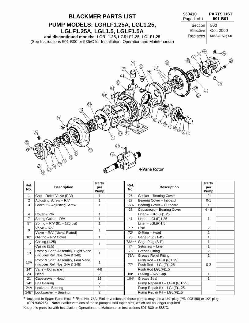
BLACKMER PARTS LIST 960410 Page 1 of 1
PARTS LIST 501-B01
PUMP MODELS: LGRLF1.25A, LGL1.25, LGLF1.25A, LGL1.5, LGLF1.5A
and discontinued models: LGRL1.25, LGRLF1.25, LGLF1.25 (See Instructions 501-B00 or 585/C for Installation, Operation and Maintenance)
Section Effective Replaces
500 Oct. 2000 585/C1 Aug 00
Ref. No.
Description Parts per
Pump Part No.
Ref. No.
Description Parts per
Pump Part No.
1 Cap – Relief Valve (R/V) 1 413200 26 Gasket – Bearing Cover 2 383075 2 Adjusting Screw – R/V 1 433909 27 Bearing Cover – Inboard 0-1 043070 3 Locknut – Adjusting Screw 1 922923 27A Bearing Cover – Outboard 1 043071 28 Capscrews – Bearing Cover 4 - 8 920080 4 Cover – R/V 1 413076 Liner – LGRL(F)1.25 183003 7 Spring Guide – R/V 1 423955 Liner – LGL(F)1.25 183004 8* Spring – R/V (81 – 125 psi) 1 471428
41 Liner – LGL(F)1.5
1 183301
Valve – R/V 453077 71* Disc 2 063075 9
Valve – R/V (Nickel Plated) 1
452300 72* O-Ring – Head 2 701918 10* O-Ring – R/V Cover 1 711924 73 Gage Plug (1/4”) 1 908195
Casing (1.25) 013075 73A** Gage Plug (3/4”) 1 908225 12
Casing (1.5) 1
013376 74 Setscrew – Liner 1 922088 76 Grease Fitting 2 317815
13 Rotor & Shaft Assembly, Eight Vane (Includes Ref. Nos. 24A & 24B)
1 262300
76A Grease Relief Fitting 2 701992 Push Rod – LGRL(F)1.25 123004
13A Rotor & Shaft Assembly, Four Vane (Includes Ref. Nos. 24A & 24B)
1 263076
Push Rod – LGL(F)1.25 123076 14* Vane – Duravane 4-8 093088
77* Push Rod LGL(F)1.5
0-2 123401
20 Head 2 033073 88* O-Ring – R/V Cap 1 701949 21 Capscrews – Head 16 920276 104* Grease Seal 1 331927 24* Ball Bearing 2 903114 Pump Repair Kit – LGRL(F)1.25 892302 24A Locknut – Bearing 2 903534 Pump Repair Kit – LGL(F)1.25 892301 24B* Lockwasher – Bearing 2 903533
Pump Repair Kit – LGL(F)1.5
892600
* Included in Spare Parts Kits, ** Ref. No. 73A: Earlier versions of these pumps may use a 1/4” plug (P/N 908198) or 1/2” plug (P/N 908215). Note: earlier versions of these pumps used taper pins, which are no longer required.
Keep this parts list with Installation, Operation and Maintenance Instructions 501-B00 or 585/C.

1809 Century Avenue, Grand Rapids, Michigan 49509-1595, U.S.A. Telephone: (616) 241-1611 Fax: (616) 241-3752
E-Mail: [email protected] Internet: www.blackmer.com Parts List 501-B01, Page 2 of 2
Mechanical Seal
Ref. No. Part Name Parts Per
Pump Part No.
153* Mechanical Seal Assembly 2 333045
153A** Stationary Seat
( Hardened Steel )
2 333061
153B** Seal Face ( Carbon ) 2 333053
153C** Jacket Assembly 2 333057
153D O-Ring – Stationary (Buna-N) 2 711916
153E O-Ring – Rotating (Buna-N) 2 711915
* Included in Spare Parts Kits ** Ref. Nos. 153A, 153B, 153C are not available as separate replacement parts.
FLANGE ‘F’ MOUNTING
Ref. No.
Description Parts per
Pump Part No.
12A Casing w/o Feet – LG(R)LF1.25 1 013077
Casing w/o Feet – LGLF1.5 1 013377
28A Bracket Mounting Screws 4 920101
28C Guard Screw 1 920026
Coupling Half – Pump 906147
Coupling Spider (56C/143TC-184C) 906155
Coupling Half – Motor (56C) 906151 34
Coupling Half – Motor (143TC-184C)
1
906147
Cplg. Half – Motor (182TC-184TC/215C) 906146
56 Capscrews – Adapter Ring Mounting 4 920480
86 Motor Adapter Ring (182TC Frame) 1 832914
108 1 Mounting Bracket 1 832912
108B Capscrews - Bracket 4 920331
186 Guard 1 804120
1 = Use (P/N 833000 – Mounting Bracket w/ feet) on discontinued models LG(R)LF1.25 and LGLF1.5


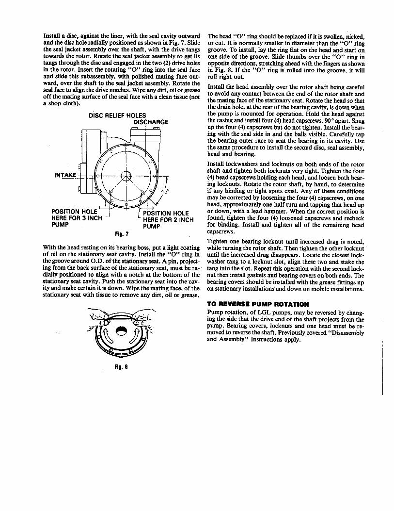
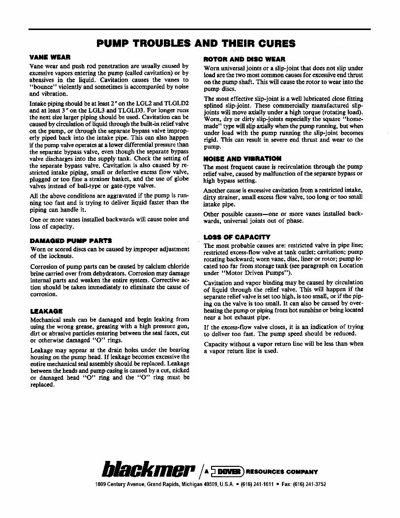

BLACKMER PARTS LIST 960418Page 1 of 2
PARTS LIST501-C01
PUMP MODELS: Section 500LGLD2E, LGLD3E Effective Dec 1999
(See Instructions 501-C00 for Installation, Operation and Maintenance) Replaces 585/E1 Apr 90
DISCONTINUED MODELS: LGL2E, TLGLD2E, LGL3E, TLGLD3E
Ref.No. Description
PartsPer
PumpSize 2
Part No.Size 3
Part No.Ref.No. Description
PartsPer
PumpSize 2
Part No.Size 3
Part No.4 Cover - Relief Valve (R/V) 1 414401 415113 Cascrews - Bearing Cover (Size 2) 8 920285 N/A5 Capscrews - R/V Cover 6 920331 920331 28 Capscrews - Bearing Cover (Size 3) 12 N/A 9202858 Spring - R/V 1 *471423 *475135 35 Key - Shaft 1 *909130 *909130
Valve - R/V (Std.) *454405 *455129 41 Liner 1 184405 1851119 Valve - R/V (Nickel Plated) 1 454406 455100 Flange - NPT 654401 65511210 O-RIng - R/V Cover 1 *701919 *701925 42 Flange - Weld 2 654405 65510212 Casing 1 014405 015127 42A O-Ring - Flange 2 *702004 *702002
Rotor & Shaft Asy. - LGL Capscrew - NPT Flange 920384 92054713 (Includes Ref. Nos. 24A & 24B) 1 264443 265149 42B Capscrew - Weld Flange 8 920351 920510Rotor & Shaft Asy. – LGLD &TLGLD** 71 Disc 2 *064412 *06511213A (Includes Ref. Nos. 24A & 24B)
1 264445 26514872 O-Ring - Head 2 *702022 *702041
14 Vane - Duravane (Std.) 6 *091419 *095131 73 Gage Plug 2 908198 90819820 Head 2 034416 035128 74 ++++ Key - Liner 1 183991 185191
Capscrews - Head (Size 2) 32 920351 N/A 76 Grease Fitting 2 317815 31781521 Capscrews - Head (Size 3) 40 N/A 920369 76A Grease Relief Fitting 2 701992 70199224 Ball Bearing 2 *903156 *903166 77 Push Rod 3 123905 *12510524A Locknut - Bearing 2 903521 903523 104 Grease Seal 1 (2) *331918 *33190824B Lockwasher - Bearing 2 *903522 *903524, 123A Dirt Shield 1 (2) *701480 N/A26 Gasket - Bearing Cover 2 *383940 *385125 Shaft Protector27 Bearing Cover (Inboard) 1 (2) 041431 041815 186 (TLGLD Models Only) 1 341601 341801
27A Bearing Cover (Outboard) 1 (3) 041433 041817 Pump Repair Kit 894420 895127* Parts Included in Pump Repair Kits.** Double-Ended Rotor & Shaft.The Following applies to double end shaft pump models LGLD2E, TLGLD2E, LGLD3E & TLGLD3E: (1) Use One (2) Use Two (3) Use NoneKeep this parts list with Installation, Operation and Maintenance Instructions 501-C00.+ Pump Models Before 1995 Require Key 184407.

1809 Century Avenue, Grand Rapids, Michigan 49509-1595, U.S.A.Telephone: (616) 241-1611 / Fax: (616) 241-3752 Parts List 501-C01
E-Mail: [email protected] / Internet: www.blackmer.com Page 2 of 2
MECHANICAL SEAL - STANDARDRef.No. Part Name
PartsPer
PumpSize 2 Part
No.Size 3
Part No.
153 Mechanical Seal Assembly 2 **331652 **335125 153A Stationary Seat (Steel) 2 331828 335126 153B Seal Face (Carbon) 2 331609 331867 153C Jacket Assembly 2 331651 335128 153D O-Ring - Stationary (Buna-N) 2 711924 702025 153E O-Ring Rotating (Buna-N) 2 711918 711912
* Included in Pump Repair Kit.** NOTE: Mechanical Seal Ref. No. 153 is only sold as a complete assembly.Ref. Nos. 153A, 153B & 153C are not available as separate replacement parts.

WARNING
Fisher relief valves must be installed, oper-ated and maintained in accordance with fed-eral, state, and local codes, rules and regula-tions, and Fisher instructions.
If the spring case develops a leak or if theoutlet continually vents gas, service to theunit may be required. Failure to correcttrouble could result in a hazardous condi-tion. Only a qualified person must install orservice the unit.
eFisher Controls International, Inc. 1965, 1993; All Rights Reserved
Figure 1. Type 98L & 98H Back
IntroductionType 98L and Type 98H (see figure 1) are self-operated,spring-loaded back pressure or relief valves. Typical ap-plications include use in wash tanks, small heaters, fuel andoil lines, air supply systems, test fixtures, and sterilizers.Relief pressure ranges are 2 to 38 psig (0.14 to 2.6 bar), infour ranges, for the Type 98L and 15 to 200 psig (1.03 to13.8 bar), in eight ranges, for the Type 98H. Type 98L bodysizes are 1/4, 1/2, 3/4 and 1-inch. Type 98H body sizes are1/4, 1/2, 3/4, 1, 1-1/2 and 2-inch.
SpecificationsSpecifications for the Type 98L and 98H backpressure andrelief valves are given in table 1.
TYPE 98HW6155
TYPE 98LW6156
Fisher Controls Instruction Manual
Type 98L and Type 98H BackPressure and Relief Valves
August 1993 Form 1570R
Pressure and R
Type 98L and 98H
D10
0258
X01
2
elief Valves

Types 98L and 98HR
Table 1. Specifications
Available ConstructionsType 98L: Self-operated with standard adjustingscrew. Relief pressure ranges are 2 to 38 psig (0.14to 2.6 bar).Type 98H: Self-operated with standard adjustingscrew. Relief pressure ranges are 15 to 200 psig(1.03 to 13.8 bar).
End Connection StyleNPT screwed, socket weld, or ANSI flanged-14inches face to face (DIN flanged-356mm face toface)
Body SizesJ 1/4,J 1/2,J 3/4,J 1,J 1-1/2,J 2
Maximum Inlet Pressures, Psig(1,5) (Set PressurePlus Buildup)
STEEL (WCB)OR STAINLESS
CAST IRON BODY
TYPENUMBER
STEEL (WCB)OR STAINLESSSTEEL BODY/ All Trims to
Metal Trims (4)TYPENUMBER
STEEL BODY/ALL TRIMS TO150_F(2) (66_C)
All Trims to150_F(3) (66_C) To 315_F
(66_C)To 406_F(208_C)
98L 125 (52) 60 (16) 60 (16) 60 (16)
98H 300 (149) 300 (149) 300 (149) 250 (121)
Relief Pressure RangesSee table 2
1. Relief pressure setting plus maximum allowable buildup over setting.2. Or fluoroelastomer trims to 300_F (149_C) or metal trims to 450_F (232_C).3. Or fluoroelastomer trims to 300_F (149_C).
2
Table 2. Relief Pre
Allowable Temperature Ranges(5)
Nitrile Parts: -20 to 200_F (-29 to 93_C)Neoprene Parts: -40 to 150_F (-40 to 66_C)Fluoroelastomer Parts: 0 to 300_F (-18 to 149_C)Metal Diaphragm and SeatCast Iron Body and Spring Case:-40 to 406_F (-40 to 208_C)Steel Body and Spring Case:-20 to 450_F (-29 to 232_C)Stainless Steel Body and Spring Case:-40 to 450_F (-40 to 232_C)
Approximate Weight, lb (kg)
Type 98H1/4-inch Body: 7 (3.18)1/2-inch Body: 7 (3.18)3/4-inch Body: 16 (7.26)1-inch Body: 16 (7.26)1-1/2-inch Body: 55 (25)2-inch Body: 55 (25)Type 98L1/4-inch Body: 6 (2.80)1/2-inch Body: 13 (5.90)3/4-inch Body: 30 (13.6)1-inch Body: 30 (13.6)
4. Interpolate for intermediate pressure ratings.5. The pressure/temperature limits in this bulletin and any applicable standard
limitation should not be exceeded.
ssure Ranges
BODY SIZE, 98L RANGE 98H RABODY SIZE,INCHES Psi Bar Psi
1/4
2 to 176 to 14
12 to 2529 to 38
0.1 to 1.20.4 to 1.00.8 to 1.71.4 to 2.6
15 to 3525 to 7570 to 140
130 to 200
1/2
2 to 176 to 14
12 to 2529 to 38
0.1 to 1.20.4 to 1.00.8 to 1.71.4 to 2.6
15 to 3525 to 7570 to 140
130 to 200
3/4 & 1
2 to 176 to 14
12 to 2529 to 38
0.1 to 1.20.4 to 1.00.8 to 1.71.4 to 2.6
15 to 3525 to 7570 to 140
130 to 200
1-1/2 & 2
- - -- - -- - -- - -
- - -- - -- - -- - -
5 to 3520 to 6550 to 10080 to 170
1. All springs may be backed off to 0 psig (bar). However, highest capacities and bestperformances are obtained by using these springs in their recommended ranges. Psi(bar) rather than psig (bar) are used for differential relief constructions.
NGE COLOR| PARTBar
COLOR|CODE
PARTNUMBER
1.0 to 2.41.7 to 5.24.8 to 9.79.0 to 13.8
YellowGreenRedBlue
1E3925270221E3926270121E3927271421L346127142
1.0 to 2.41.7 to 5.24.8 to 9.79.0 to 13.8
YellowGreenRedBlue
1E3956270221D7455271421D3957271921L380027142
1.0 to 2.41.7 to 5.24.8 to 9.79.0 to 13.8
YellowGreenRedBlue
1E3989270221E3990271421D3991271621L380127232
0.3 to 2.41.4 to 4.53.4 to 6.95.6 to 11.7
Dark GrayLight BlueLight GrayBlack
1E7923270921E7953270821E7954270821P788827082

Types 98L and 98H
InstallationUnbox and inspect the valve. Remove pipe scale and otherforeign material from the connecting pipeline. Apply a suit-able pipe compound to the male threads. The relief valvecan be installed in any position as long as the flow is in thedirection indicated by the arrow cast on the body.
Maximum operating temperatures for the Type 98L and 98Hrelief valves are as follows:
Elastomer diaphragm or seat: 150_F (66_C)
Metal diaphragm and seat: 406_F (208_C) with cast ironbody and spring case or 450_F (232_C) with steel or stain-less steel body and spring case
CL3383-AA1756-1
Figure 2. Type 98L Relief Valve Operational Schematic
Vents
WARNING
If the process fluid is hazardous, install re-mote vent lines to carry fluid to a safe area.
If remote venting is necessary, an optional tapped vent inthe spring case is available. Install remote vent lines in thespring case and outlet openings. The vent lines must havethe largest practical diameter and be as short as possiblewith a minimum number of bends or elbows.
Overpressure
WARNING
Overpressuring any portion of this equip-ment may result in equipment damage,leaks in the relief valve, or personal injurydue to bursting of pressure-containingparts. The system should be inspected afterany overpressure condition.
Relief or back pressure ranges are from 2 to 200 psig (0.14to 13.8 bar). The individual spring range of your relief valveis stamped on the nameplate.
Maximum inlet pressures depend upon body materials andtemperatures. See table 1 for the maximum inlet pressureof the valve. The valve should be inspected for damage af-ter any overpressure condition.
AdjustmentEach unit is factory set for the pressure specified on your or-der. The allowable spring range is stamped on the name-plate. If a pressure setting beyond the indicated range is re-quired, substitute the appropriate spring. Be sure to labelthe valve to indicate the new pressure range.
Always use a pressure gauge to monitor pressure whenmaking adjustments.
Loosen the locknut (key 17). To increase the setting, turnthe adjusting screw (key 15) clockwise. Turn the adjustingscrew counterclockwise to decrease the setting. Tightenthe locknut.
Principle Of OperationRelief or back pressure valves respond to changes in up-stream pressure. Pressure changes register under the dia-phragm (see figure 2) through a registration hole in thevalve body. When the pressure increases beyond the springsetting, the diaphragm pressure overcomes the spring com-pression. This causes the valve plug to move away from theorifice. The flow line through the valve is open and excesspressure is vented. When upstream pressure drops back tonormal, the valve resumes its closed position.
3

Types 98L and 98HR
Table 3. Torque SpecificationsBody Size, Spring Case Orifice
Maintenance
WARNING
To avoid personal injury and equipmentdamage, isolate the valve from all pressure.Cautiously release pressure from the valvebefore attempting disassembly.
Due to normal wear and damage that may occur from exter-nal sources, relief valve parts such as the O-rings, gaskets,diaphragm, orifice, and valve plug should be inspected peri-odically and replaced as necessary. The frequency of in-spection and replacement depends upon the severity ofservice conditions or the requirements of state and federallaws.
Instructions are given below for disassembly of the Type98L and 98H back pressure relief valves. These valves donot have to be removed from the pipeline to inspect internalparts. Suitable lubricants are indicated on the assemblydrawings. Apply the lubricants as the relief valve is beingreassembled. Refer to figures 3 and 4 while servicing the re-lief valve.
1. Relieve the spring tension by loosening the locknut (key17) and turning the adjusting screw (key 15) counterclock-wise. Remove the cap screws (key 16). Lift off the springcase (key 2), spring (key 11), and upper spring seat (key 9).
2. Lift out the diaphragm unit which includes the pusher post(key 6), lower spring seat (key 8), diaphragm head (key 25,Type 98L), diaphragm (key 12), washer (key 7), and valveplug (key 4). (There will be two diaphragms if the diaphragmmaterial is metal or fluoroelastomer.)
3. Check the orifice (key 3). If it needs replacing or repairing,unscrew the valve plug guide (key 5) and then the orifice.The valve plug can be removed by sliding it off of the pusherpost.
Note
If damage to elastomer or metal seating surfaces issevere, replace the orifice and valve plug O-ring with newparts. However, by following the lapping procedurebelow, it is possible to repair metal seating surfaces ifthey are only slightly worn or scratched.
4. Lapping procedure:
a. Place a small amount of 500-grit silicon carbide oraluminum oxide lapping compound on a flat surface such asa piece of heavy plate glass.
4
8 motion on the lapping compound. Do not allow the part totip or rock since this would round the corners.
c. Repeat step b for each part, using an 800-grit or1000-grit silicon carbide or aluminum oxide lapping com-pound.
d. Wash away all traces of the lapping compound. Tohelp prevent scratching the seating surfaces, a light coat ofoil may be applied before returning the valve plug and orificeto the body. See table 3 for torque specifications.
5. Return the orifice and valve plug guide to the body.
6. To replace the valve plug O-ring (key 22), remove thescrew (key 24) and O-ring retainer (key 21) from the plug.Remove and replace the O-ring.
7. Separate the remainder of the diaphragm unit parts. Takethe locknut (key 26) off of the pusher post. Slide off thewasher (key 23), lower spring seat, diaphragm head (Type98L), diaphragm, washer (key 7), and gasket (key 10).
8. Slip the plug onto the pusher post.
Note
If a metal diaphragm is to be replaced by a elastomer dia-phragm or a elastomer diaphragm by a metal diaphragm,a new pusher post is required. Each diaphragm materialrequires a different length pusher post.
9. Replace the diaphragm gasket (key 19) if necessary.
10. Slip gasket, washer, diaphragm, diaphragm head, lowerspring seat, and washer back onto the pusher post. Screwon the locknut and return the unit to the body.
11. Set the spring in the lower spring seat and place the up-per spring seat on the spring.
12. Put the spring case over the spring and onto the body.Tighten the cap screws finger tight only.
Inches Ft-Lbs Ft-Lbs
1/41/2
3/4 - 11-1/2 - 2
4.5 - 5.010 - 1324 - 3040 - 50
8 - 1229 - 3533 - 42
140 - 170
b. Take the valve plug or orifice and move it in a figure

Types 98L and 98H
13. To ensure proper slack in the diaphragm, apply somespring compression by turning the adjusting screw clock-wise. Finish tightening the cap screws.
Parts OrderingWhen corresponding with your Fisher sales office or salesrepresentative about this equipment, be sure to include thetype number and other information stamped on the name-plate.
When ordering replacement parts, reference the key num-ber of each needed part and specify the eleven-characterpart number as found in the following parts list.
Parts ListKey Description Part Number
Note
In this parts list, parts marked NACE are intended forcorrosion-resistant service as detailed in the NationalAssociation of Corrosion Engineers (NACE) standardMR0175-92.
Parts kit (included are keys 3, 4, 10, 12,19, 21, 22 and 24). Also included for 98Honly is key 14.
Elastomer Trim1/4-inch body R98H X0000121/2-inch body R98H X0000223/4 and 1-inch body R98H X0000321-1/2 and 2-inch bodyType 98H only R98H X000072
Metal Trim1/4-inch body R98H X0000421/2-inch body R98H X0000523/4 and 1-inch body R98H X0000621-1/2 and 2-inch bodyType 98H only R98H X000082
1 Body See following table2 Spring Case
Type 98HCast iron1/4-inch body 2E3912 190121/2-inch-body 2J4962 190123/4 and 1�inch bodies 3E3978 190121-1/2 and 2-inch bodies 4P7840 19012
Steel1/4-inch body 2J1275 220121/2-inch body 2L4163 220123/4 and 1-inch bodies 3E4087 220121-1/2 and 2-inch bodies 3P7904 22012
*Recommended spare part.
Key Description Part Number
2 Spring Case (Continued)Type 98LCast iron1/4-inch body 2E3913 190121/2-inch body 3J4963 190123/4 and 1-inch bodies 4E3979 19012
Steel1/4-inch body 2J1279 220121/2-inch body 3L4161 220123/4 and 1-inch bodies 4E5929 22012
3* Orifice See following table4* Valve Plug See following table
5 Valve Plug Guide416 stainless steel1/4-inch body 1L3458 351321/2-inch bodies 1L3416 351323/4 and 1-inch bodies 1L3429 351321-1/2 and 2-inch bodies 1P7885 35132
316 stainless steel1/4-inch body (NACE) 1L3458 350721/2-inch body (NACE) 1L3416 350723/4 and 1-inch bodies (NACE) 1L3429 350721-1/2 and 2-inch bodies (NACE)Type 98H only 1P7885 35072
6 Pusher Post See following table7 Washer (elastomer diaphragm only)
416 stainless steel trim1/4-inch body 1L3447 360121/2-inch body 1L3398 360123/4 and 1-inch bodies 1L3428 36012
316 stainless steel trim1/4-inch body, std 1L3447 36142(NACE) 1L3447 X0012
1/2-inch body, std 1L3398 35072(NACE) 1L3398 40032
3/4 and 1-inch bodies, std 1L3428 36142(NACE) 1L3428 X0022
8 Lower Spring Seat1/4-inch body, aluminum 1L3446 090121/2-inch body, aluminum 1L3397 080123/4 and 1-inch bodies, aluminum 1L3427 080121-1/2 and 2-inch bodiesType 98H only, steel zinc plated 1P7877 24152
9 Upper Spring Seat, steel pl1/4-inch body 1B7985 250621/2-inch body 1D6671 250723/4 and 1-inch bodies 1E3987 250721-1/2 and 2-inch bodiesType 98H only 1P7876 24092
10* Gasket, composition(2 req’d for metal diaphragm)1/4-inch body 1L3448 040221/2-inch body 1L3411 040223/4 and 1-inch bodies 1L3434 040221-1/2 and 2-inch bodies (metaldiaphragm only) (2 req’d)Type 98H only 1P7880 04022
11 Relief Valve Spring See following table12* Diaphragm See following table13 Nameplate, aluminum
(not shown) 11A5494 X0A214* O-Ring, Type 98H only
1-1/2 and 2-inch bodies,elastomer seat onlyNitrile 1C7822 06992Fluoroelastomer 1K7561 06382Fluoroelastomer (NACE) 1K7561 35072
5

Types 98L and 98HR
30A7028A1757-1
Key Description Part Number
15 Adjusting Screw, steel pl1/4-inch bodyStandard 1E6399 28992
1/2-inch bodyStandard 1D9954 48702For handwheel 1J4964 28982
3/4 and 1-inch bodiesStandard 1A3308 28982
1-1/2 and 2-inch bodiesStandard, Type 98H only 1A6801 28992
16 Cap Screw, steel plType 98L1/4-inch body (10 req’d) 1A4078 240521/2-inch body (10 req’d) 1A3816 240523/4 and 1-inch bodies (12 req’d) 1A3369 24052
Type 98H1/4-inch body (6 req’d) 1A3917 240521/2-inch body (8 req’d) 1A3526 240523/4 and 1-inch bodies (8 req’d) 1A3418 240521-1/2 and 2-inch bodies (8 req’d) 1K5684 28982
6
Key Description Part Number
17 Jam Nut, steel zinc plated1/4-inch body 1A3522 241221/2-inch body 1A3537 241223/4 and 1-inch bodies 1A3192 241221-1/2 and 2-inch bodiesType 98H only 1A3681 24112
18 Drive Screw (not shown)Stainless steel (2 req’d) 1A3682 28982
19* Diaphragm Gasket, elastomerUse w/302 stainless steel diaphragmType 98H1/4-inch body 1E3931 040221/2-inch body 1E3961 040223/4 and 1-inch bodies 1E3993 040221-1/2 and 2-inch bodies 1P7879 04022
Type 98L1/4-inch body 1E3940 040221/2-inch body 1E3970 040223/4 and 1-inch bodies 1E3904 04022
Figure 3. Type 98L Relief Valve Assembly Drawing
*Recommended spare part.

Types 98L and 98H
Figure 4. Type 98H Relief Valve Assembly Drawing
Key Description Part Number
21 O-Ring Retainer (elastomer seat only)1/4-inch body416 stainless steel 1L3460 35132316 stainless steel (NACE) 1L3460 35072
1/2-inch body416 stainless steel 1L3415 35232316 stainless steel (NACE) 1L3415 35072
3/4 and 1-inch bodies416 stainless steel 1L3430 35132316 stainless steel (NACE) 1L3430 35072
1-1/2 and 2-inch bodies, Type 98H only416 stainless steel 1P7875 35132316 stainless steel (NACE) 1P7875 35072
22* O-Ring (elastomer seat only)1/4-inch bodyNitrile 1C8538 06992Fluoroelastomer 1C8538 X0052
1/2-inch bodyNitrile 1D2888 06992Fluoroelastomer 1N5301 06382
3/4 and 1-inch bodiesNitrile 1C7821 06992Fluoroelastomer 1N1632 06382
*Recommended spare part.
Key Description Part Number
22 L-Ring, Type 98H onlyElastomer seat only1-1/2 and 2-inch bodiesNitrile 1P7874 03202Fluoroelastomer 1P7874 06382
23 Lockwasher, steel1/4 and 1/2-inch bodies 1C2256 289823/4 and 1-inch bodies 1H6243 289921-1/2 and 2-inch bodies, Type 98H only 1A4878 28992
24 Machine Screw, stainless steelElastomer seat only1/4-inch body (NACE) 1L3462 389921/2-inch body (NACE) 1L3444 389923/4 and 1-inch bodies (NACE) 1L3435 389921-1/2 and 2-inch bodies (NACE)Type 98H only 1P7886 38992
30a7041 a
7

Types 98L and 98HR
Key Description Part Number
25 Diaphragm HeadType 98L, steel zinc plated1/4-inch body 1L3455 250721/2-inch body 1L3396 250723/4 and 1-inch bodies 1L3421 25072
Type 98H, steel1-1/2 and 2-inch bodies (2 req’d)Standard 1P7882 25012(NACE) 1P7882 35072
26 Locknut, steel zinc plated1/4 and 1/2-inch bodies 1L8723 241223/4 and 1-inch bodies 1L8722 241221-1/2 and 2-inch bodies, Type 98H only 1P7887 24122
8
Key Description Part Number
28 Handwheel, zinc1/2-inch body only 1J4961 44012
29 Machine Screw, steel pl1/2-inch bodyWith handwheel only 1A8517 28982
30 Lockwasher, steel1/2-inch bodyWith handwheel only 1A3523 32992
51 NACE Tag, not shown 19A6034 X01252 Tag Wire, not shown (NACE) 1U7581 X0022
Key 1 Regulator Body, NPTTYPE 98H
BODY SIZE,INCHES NACE
For Other Than Sour GasCorrosion Resistance ApplicationsINCHES NACE
Cast Iron Steel 316 SST
1/41/23/4
1L3721X00522L3687X00222L3734X0062
1L3464190122L3395190122L342519012
1L3721220122L3687220122L373422012
1L3721330922L3687330922L373433092
11-1/2
2
2L3735X00323P7868X00223P7867X0042
2L3426190123P7868190123P786719012
2L3735220123P7868220123P786722012
2L13735330923P7868330923P786733092
98L
NACEFor Other Than Sour Gas
Corrosion Resistance ApplicationsNACECast Iron Steel 316 SST
1L3723X00222L3689X00322L3182X0022
1L3465190122L3392190122L341919012
1L3723220122L3689220122L318222012
1L3723330922L3689330922L318233092
2L3183X0042- - -- - -
2L342019012- - -- - -
2L318322012- - -- - -
2L318333092- - -- - -
Key 1 Regulator Body, ANSI Class 150 & 300 Flanges
BODYSIZE,
TYPE 98HBODY MATERIALBODY
SIZE,INCHES
Steel Stainless SteelSIZE,INCHES ANSI Class
150 300 150 300
1/2 1V5178X0012 - - - 1V5178X0022 - - -
3/4 - - - - - - - - - - - -
1 2V3805X0012 2U8048X0012 2V3805X00B2 2U8048X0022
1-1/2 21B0804X012 1V4541X0012 21B0804X0022 1V4541X0022
2 10A0192X012 10A4986X012 10A0192X022 1V4541X0022
TYPE 98LBODY MATERIAL
Steel Stainless Steel
ANSI Class
150 300 150 300
- - - - - - - - - - - -
2V4264X0022 - - - - - - - - -
2V3641X0022 2U8047X0012 2V3641X0012 - - -
- - - - - - - - - - - -
- - - - - - - - - - - -
Key 1 Regulator Body, Socket Weld
BODY SIZE, TYPE 98H BODY MATERIALBODY SIZE,INCHES Steel Stainless Steel
1/2 2L9673X0022 2L9673X0012
3/4 - - - - - -
1 2N414422012 2N4144X0012
1-1/2 3V4542X0012 3V4542X0022
2 30A0191X012 30A0191X032
TYPE 98L BODY MATERIAL
Steel Stainless Steel
- - - - - -
2N4463X0012 - - -
2N445222012 2N4452X0012
- - - - - -
- - - - - -
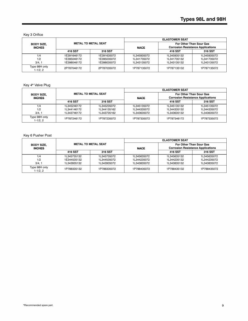
Types 98L and 98H
Key 3 Orifice
METAL TO METAL SEATBODY SIZE,INCHES
METAL TO METAL SEATINCHES
416 SST 316 SST
1/41/2
3/4, 1
1E3916461721E3950461721E398046172
1E3916350721E3950350721E398035072
Type 98H only1-1/2, 2
2P787046172 2P787035072
*Recommended spare part.
ELASTOMER SEAT
NACEFor Other Than Sour Gas
Corrosion Resistance ApplicationsNACE416 SST 316 SST
1L3459350721L3417350721L343135072
1L3459351321L3417351321L343135132
1L3459350721L3417350721L343135072
1P787135072 1P787135132 1P787135072
Key 4* Valve Plug
METAL TO METAL SEATBODY SIZE,INCHES
METAL TO METAL SEATINCHES
416 SST 316 SST
1/41/2
3/4, 1
1L3452461721L3441461721L343746172
1L3452350721L3441351621L343735162
Type 98H only1-1/2, 2
1P787246172 1P787235072
ELASTOMER SEAT
NACEFor Other Than Sour Gas
Corrosion Resistance ApplicationsNACE416 SST 316 SST
1L3451350721L3443350721L343635072
1L3451351321L3443351321L343635132
1L3451350721L3443350721L343635072
1P787335072 1P787346172 1P787335072
Key 6 Pusher Post
METAL TO METAL SEATBODY SIZE,INCHES
METAL TO METAL SEATINCHES
416 SST 316 SST
1/41/2
3/4, 1
1L3457351321E3445351321L343935132
1L3457350721L3445350721L343935072
Type 98H only1-1/2, 2
1P788335132 1P788335072
ELASTOMER SEAT
NACEFor Other Than Sour Gas
Corrosion Resistance ApplicationsNACE416 SST 316 SST
1L3456350721L3442350721L343835072
1L3456351321L3442351321L343835132
1L3456350721L3442350721L343835072
1P788435072 1P788435132 1P788435072
9
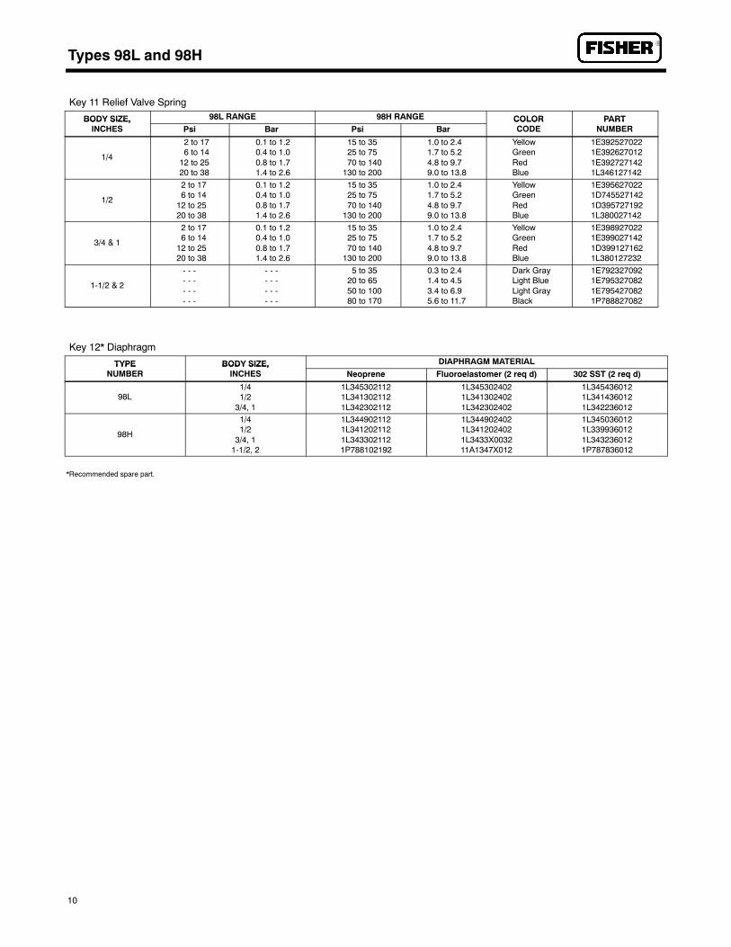
Types 98L and 98HR
Key 11 Relief Valve Spring
BODY SIZE, 98L RANGE 98H RANGEBODY SIZE,INCHES Psi Bar Psi Bar
1/4
2 to 176 to 14
12 to 2520 to 38
0.1 to 1.20.4 to 1.00.8 to 1.71.4 to 2.6
15 to 3525 to 7570 to 140
130 to 200
1.0 to 2.41.7 to 5.24.8 to 9.79.0 to 13.8
1/2
2 to 176 to 14
12 to 2520 to 38
0.1 to 1.20.4 to 1.00.8 to 1.71.4 to 2.6
15 to 3525 to 7570 to 140
130 to 200
1.0 to 2.41.7 to 5.24.8 to 9.79.0 to 13.8
3/4 & 1
2 to 176 to 14
12 to 2520 to 38
0.1 to 1.20.4 to 1.00.8 to 1.71.4 to 2.6
15 to 3525 to 7570 to 140
130 to 200
1.0 to 2.41.7 to 5.24.8 to 9.79.0 to 13.8
1-1/2 & 2
- - -- - -- - -- - -
- - -- - -- - -- - -
5 to 3520 to 6550 to 10080 to 170
0.3 to 2.41.4 to 4.53.4 to 6.95.6 to 11.7
10
*Recommended spare part.
COLOR PARTCOLORCODE
PARTNUMBER
YellowGreenRedBlue
1E3925270221E3926270121E3927271421L346127142
YellowGreenRedBlue
1E3956270221D7455271421D3957271921L380027142
YellowGreenRedBlue
1E3989270221E3990271421D3991271621L380127232
Dark GrayLight BlueLight GrayBlack
1E7923270921E7953270821E7954270821P788827082
Key 12* Diaphragm
TYPE BODY SIZE,TYPENUMBER
BODY SIZE,INCHES
98L1/41/2
3/4, 1
98H
1/41/2
3/4, 11-1/2, 2
DIAPHRAGM MATERIAL
Neoprene Fluoroelastomer (2 req’d) 302 SST (2 req’d)
1L3453021121L3413021121L342302112
1L3453024021L3413024021L342302402
1L3454360121L3414360121L342236012
1L3449021121L3412021121L3433021121P788102192
1L3449024021L3412024021L3433X003211A1347X012
1L3450360121L3399360121L3432360121P787836012

Types 98L and 98H

Types 98L and 98HR
Fisher ControlsFor information, contact Fisher Controls:Marshalltown, Iowa 50158 USA Sao Paulo 05424 BrazilCernay 68700 France Singapore 0512
While this information is presented in good faith and believed to be accurate,Fisher Controls does not guarantee satisfactory results from reliance upon suchinformation. Nothing contained herein is to be construed as a warranty or guar-antee, express or implied, regarding the performance, merchantability, fitness
or any other matter with respect to the products, nor as a recommendation touse any product or process in conflict with any patent. Fisher Controls reservesthe right, without notice, to alter or improve the designs or specifications of theproducts described herein.
Printed in U.S.A.
R

APPENDIX B
TECHNICAL INFORMATION

This page intentionally left blank.

Technical InformationTechnical InformationTechnical InformationTechnical Information
Algas-SDI Operations and Maintenance Manual – P/N - 52631 B-65
Figure 7 – Electrical schematic for pump with on/off switch
Figure 8 – Electrical schematic for pump with manual starter.
NOTENOTENOTENOTE
For all Pumps see Data Sheet for voltage and wire per diagram onmotor.

Technical InformationTechnical InformationTechnical InformationTechnical Information
B-66 Algas-SDI Operations and Maintenance Manual – P/N - 52631
Figure 9 – Electrical schematic for pumps with magnetic starters.

Technical InformationTechnical InformationTechnical InformationTechnical Information
Algas-SDI Operations and Maintenance Manual – P/N - 52631 B-67
This page intentionally left blank.