ge zoneline® packaged terminal air conditioners
TRANSCRIPT

GE Zoneline® packaged terminal air conditionersAZ41/61 2011 contract sales architects and engineers data manual
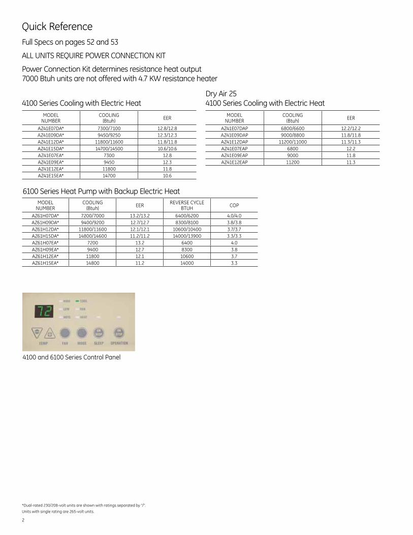
Quick Reference
4100 Series Cooling with Electric Heat
4100 and 6100 Series Control Panel
Full Specs on pages 52 and 53
ALL UNITS REQUIRE POWER CONNECTION KIT
Power Connection Kit determines resistance heat output 7000 Btuh units are not offered with 4.7 KW resistance heater
MODEL NUMBER
COOLING (Btuh) EER
AZ41E07DA* 7300/7100 12.8/12.8AZ41E09DA* 9450/9250 12.3/12.3AZ41E12DA* 11800/11600 11.8/11.8AZ41E15DA* 14700/14500 10.6/10.6AZ41E07EA* 7300 12.8AZ41E09EA* 9450 12.3AZ41E12EA* 11800 11.8AZ41E15EA* 14700 10.6
Dry Air 25 4100 Series Cooling with Electric Heat
MODEL NUMBER
COOLING (Btuh) EER
AZ41E07DAP 6800/6600 12.2/12.2AZ41E09DAP 9000/8800 11.8/11.8AZ41E12DAP 11200/11000 11.3/11.3AZ41E07EAP 6800 12.2AZ41E09EAP 9000 11.8AZ41E12EAP 11200 11.3
6100 Series Heat Pump with Backup Electric Heat MODEL
NUMBERCOOLING
(Btuh) EER REvERSE CyCLE BTUH COP
AZ61H07DA* 7200/7000 13.2/13.2 6400/6200 4.0/4.0AZ61H09DA* 9400/9200 12.7/12.7 8300/8100 3.8/3.8AZ61H12DA* 11800/11600 12.1/12.1 10600/10400 3.7/3.7AZ61H15DA* 14800/14600 11.2/11.2 14000/13900 3.3/3.3AZ61H07EA* 7200 13.2 6400 4.0AZ61H09EA* 9400 12.7 8300 3.8AZ61H12EA* 11800 12.1 10600 3.7AZ61H15EA* 14800 11.2 14000 3.3
*Dual-rated 230/208-volt units are shown with ratings separated by “/”.
Units with single rating are 265-volt units.
2
3
geappliances.com
Electric Heat Amps include electric heater and fan motor current draw. 265-volt units are to be permanently connected in compliance with National Electrical Code and local codes and have a factory-installed junction box on the chassis. Each 265-volt sub-base kit consists of sub-base with appropriate receptacle for minimum circuit amperage, chaseway to route power connector from sub-base to chassis and wiring to connect sub-base to building wiring. 265-Volt Power Connection Kit must be ordered separately.
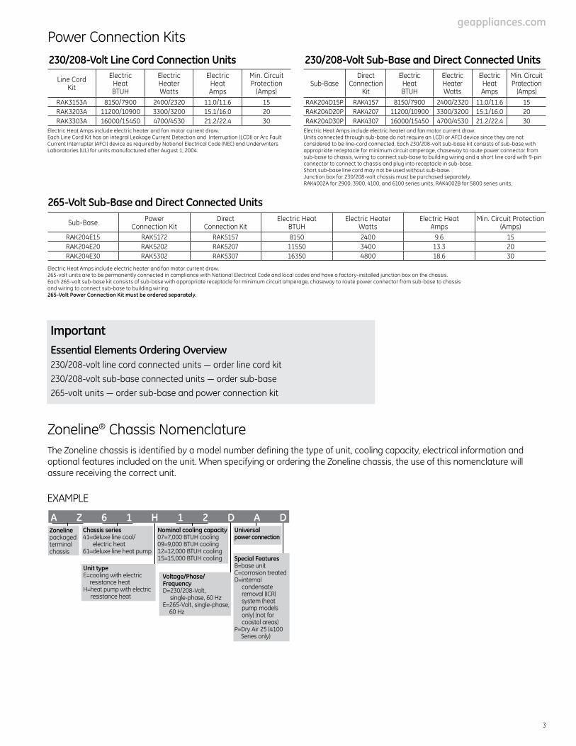
Power Connection Kits
Zoneline® Chassis NomenclatureThe Zoneline chassis is identified by a model number defining the type of unit, cooling capacity, electrical information and optional features included on the unit. When specifying or ordering the Zoneline chassis, the use of this nomenclature will assure receiving the correct unit.
230/208-Volt Line Cord Connection Units
Line Cord Kit
Electric Heat BTUH
Electric Heater Watts
Electric Heat Amps
Min. Circuit Protection
(Amps)RAK3153A 8150/7900 2400/2320 11.0/11.6 15RAK3203A 11200/10900 3300/3200 15.1/16.0 20RAK3303A 16000/15450 4700/4530 21.2/22.4 30
Electric Heat Amps include electric heater and fan motor current draw.Each Line Cord Kit has an integral Leakage Current Detection and Interruption (LCDI) or Arc Fault Current Interrupter (AFCI) device as required by National Electrical Code (NEC) and Underwriters Laboratories (UL) for units manufactured after August 1, 2004.
230/208-Volt Sub-Base and Direct Connected Units
Sub-BaseDirect
Connection Kit
Electric Heat BTUH
Electric Heater Watts
Electric Heat Amps
Min. Circuit Protection
(Amps)RAK204D15P RAK4157 8150/7900 2400/2320 11.0/11.6 15RAK204D20P RAK4207 11200/10900 3300/3200 15.1/16.0 20RAK204D30P RAK4307 16000/15450 4700/4530 21.2/22.4 30
Electric Heat Amps include electric heater and fan motor current draw. Units connected through sub-base do not require an LCDI or AFCI device since they are not considered to be line-cord connected. Each 230/208-volt sub-base kit consists of sub-base with appropriate receptacle for minimum circuit amperage, chaseway to route power connector from sub-base to chassis, wiring to connect sub-base to building wiring and a short line cord with 9-pin connector to connect to chassis and plug into receptacle in sub-base. Short sub-base line cord may not be used without sub-base. Junction box for 230/208-volt chassis must be purchased separately. RAK4002A for 2900, 3900, 4100, and 6100 series units, RAK4002B for 5800 series units.
265-Volt Sub-Base and Direct Connected Units
Sub-Base Power Connection Kit
Direct Connection Kit
Electric Heat BTUH
Electric Heater Watts
Electric Heat Amps
Min. Circuit Protection (Amps)
RAK204E15 RAK5172 RAK5157 8150 2400 9.6 15RAK204E20 RAK5202 RAK5207 11550 3400 13.3 20RAK204E30 RAK5302 RAK5307 16350 4800 18.6 30
ImportantEssential Elements Ordering Overview230/208-volt line cord connected units — order line cord kit
230/208-volt sub-base connected units — order sub-base
265-volt units — order sub-base and power connection kit
EXAMPLE
A Z 6 1 H 1 2 D A DChassis series41= deluxe line cool/
electric heat61=deluxe line heat pump
Unit typeE= cooling with electric
resistance heatH= heat pump with electric
resistance heat
Zonelinepackaged terminal chassis
Nominal cooling capacity07=7,000 BTUH cooling 09=9,000 BTUH cooling 12=12,000 BTUH cooling 15=15,000 BTUH cooling Special Features
B=base unitC=corrosion treatedD= internal
condensate removal (ICR) system (heat pump models only) (not for coastal areas)
P= Dry Air 25 (4100 Series only)
Voltage/Phase/FrequencyD= 230/208-Volt,
single-phase, 60 HzE= 265-Volt, single-phase,
60 Hz
Universal power connection
4
The Zoneline® 4100 and 6100 Series have incorporated changes suggested by customers, along with enhancements by GE’s Technology Team and changes necessary to meet new UL and NEC requirements. “L” shaped condenser coil.
Cross flow blower across the product line for quieter operation.
The “Partial Open Vent Air” feature was a specific request by a customer.
“Heat Sentinel” is an enhancement developed by GE’s Technology Team to help lodging professionals welcome their guests with a moderate-temperature room and to help lower cooling costs.
Devices have been added on cord-connected units to protect against injury from unsafe power cords.
See the “Features and Benefits” section for in-depth explanation of these changes and the industry-leading features of GE Zoneline retained from the previous series.
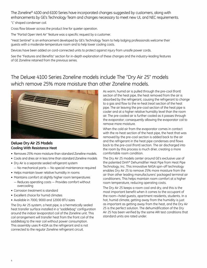
The Deluxe 4100 Series Zoneline models include The “Dry Air 25” models which remove 25% more moisture than other Zoneline models.
Deluxe Dry Air 25 Models Cooling With Resistance Heat• Removes25%moremoisturethanstandardZonelinemodels.• CoolsanddriesairinlesstimethanstandardZonelinemodels• DryAirisaseparatesealedrefrigerantsystem — No mechanical parts — No special maintenance required• Helpsmaintainlowerrelativehumidityinrooms•Maintainscomfortatslightlyhigherroomtemperatures — Reduces operating costs — Provides comfort without
overcooling • Corrosiontreatmentisstandard• Excellentchoiceforhumidclimates• Availablein7000,9000and12000BTUsizes
The Dry Air 25 system, a heat pipe, is a hermetically sealed heat transfer surface installed in a “saddlebag” configuration around the indoor (evaporator) coil of the Zoneline unit. This coil arrangement will transfer heat from the front coil of the saddlebag to the rear coil without power consumption. This assembly uses R-410A as the refrigerant and is not connected to the regular Zoneline refrigerant circuit.
As warm, humid air is pulled through the pre-cool (front) section of the heat pipe, the heat removed from the air is absorbed by the refrigerant, causing the refrigerant to change to a gas and flow to the re-heat (rear) section of the heat pipe. The air leaving the pre-cool section of the heat pipe is cooler and at a higher relative humidity level than the room air. The pre-cooled air is further cooled as it passes through the evaporator; consequently allowing the evaporator coil to remove more moisture.
When the cold air from the evaporator comes in contact with the re-heat section of the heat pipe, the heat that was removed by the pre-cool section is added back to the air and the refrigerant in the heat pipe condenses and flows back to the pre-cool (front) section. The air discharged into the room by this process is much drier, creating a more comfortable room condition.
The Dry Air 25 models center around GE’s exclusive use of the patented Dinh® Dehumidifier Heat Pipe from Heat Pipe Technology, Inc. This innovative NASA spin-off technology enables Dry Air 25 to remove 25% more moisture from the air than other leading manufacturers’ packaged terminal air conditioners. This helps maintain room comfort at a higher room temperature, reducing operating costs.
The Dry Air 25 keeps a room cool and dry, and this is the most important benefit when it comes to the occupant of the room—hotel guests, apartment residents, students. In a hot, humid climate, getting away from the humidity is just as important as getting away from the heat, and the Dry Air 25 is the perfect solution. The dehumidification of the Dry Air 25 has been verified by the same ARI test conditions that standard units are rated under.

5
geappliances.comTable of Contents
Front Cover 1
Mini Specs 4100 and 6100 Series 2
Mini Specs Power Connection Kits and Nomenclature 3
The 4100/6100 and Dry 25 4
Table of Contents 5
Introduction 6
The Zoneline System 7
Features and Benefits
Features Table 8
Features and Benefits 9–11
Auxiliary Control Settings 12–13
Central Desk Control 14
Remote Thermostat Control 15–17
Heat Pumps and Energy Savings 18–19
Installation and Dimensions
Application Comments 20
Case Dimensions 21
Wall Case/Sub-Base Installation 22–33
Condensate Disposal Systems 34–36
Ducted Installations 37–39
Exterior Grilles 40–41
Product Data
Electrical Connection 42
Essential Elements Ordering Overview 43
Maximum Connected Load 44
Latent System Capacity 44
Normal Yearly Operating Data 45
Schematics 46–49
Product Specifications
Suggested Bid Form Specifications 50–51
Zoneline Chassis Nomenclature/Receptacles/Sub-Bases 52
Installation Specifications 53
Complete Accessory List 54
General Installation Suggestions 55–56
Warranty 56
Notes 57-58
Alphabetical Index 59
Back Cover 60
Important NoticeEquipment used as a primary source for heating or cooling is an integral part of the building in which it is installed. Proper application is essential for satisfactory performance over a wide range of operating conditions. It is strongly recommended that a professional engineer determine proper application.
If the unit is a replacement unit, its specifications and performance may differ from those of the unit it is replacing. For that reason, we again strongly recommend that a professional engineer determine proper application.

6
IntroductionThis manual is designed to provide product, performance and application information to our customers and their architects and engineers for use in selection and design of a zonal comfort control system utilizing GE Zoneline® Packaged Terminal Air Conditioners (PTAC) and Packaged Terminal Heat Pumps (PTHP). GE Zoneline PTACs and PTHPs are self-contained units designed for through-the-wall installations in hotels, motels, apartments, hospitals, nursing homes, add-on rooms and many other installations.
Zoneline units provide individual room or zone control in both cooling and heating operation. There is a model for practically every application, ranging in cooling capacity from 7,200 to 14,800 BTUH and heating capacity from 6,400 to 14,000 BTUH in heat pump operation. See pages 42 and 54 for resistance heaters available.
The Deluxe Line consists of the 4100 Series with electric resistance heat, the 4100 Series Dry Air 25 Models with enhanced dehumidification for hot and humid climates and the 6100 Series heat pump. The 6100 Series heat pump features reverse cycle defrost and simultaneous supplemental resistance heat, when needed, to maintain room comfort. Both offer tactile touch controls with digital display and optional corrosion protection.
Deluxe Line Standard Features:• Two-fan-motorsystemwithIndoorCross-Flow
Blower for quieter operation• DigitalControls —LED Temperature Display —Easy Temperature Selection —Tactile Touch Pad• UniversalHeaters • HeatSentinel• “L”CoilDesignCondenser• 3-PositionVentDoor• FreezeSentinel™ • IndoorCoilFrostControl• CentralDeskControlInterface• RemoteThermostatControlInterface• RandomRestart • ElectronicTemperatureLimiting• “SmartFan”FanCycle/ContinuousControl• TransferFanInterface• ReverseCycleDefrostandSimultaneous
Supplemental Resistance Heat on Heat Pumps• QuickHeatRecovery
Deluxe Line Optional Features:• CorrosionProtection• InternalCondensateRemoval(on6100Series
Heat Pump without Corrosion Protection)NOTE: Dry Air 25 models include all the standard features of the
4100 Series plus standard corrosion protection.
Advantages of the GE Zoneline System:• FlexibleApplication — May be installed from flush to finished floor to
3" from the ceiling — 7,200 to 14,800 BTUH units in same physical size — Deluxe 4100 and 6100 Series may be ducted to
condition more than one room — Compatible with Class 2 remote thermostat control — Compatible with 2-wire CDC or many Energy
Management Systems• EconomicalInstallation — No ductwork necessary — No mechanical equipment rooms or pipes required
for heating/cooling units — Replacement units fit existing 42"-wide by 16"-high
wall cases • QuietOperation — Indoor cross-flow blower• Energy-SavingOperation — Units in unoccupied areas may be turned off — Designed for efficient cooling operation — EERs from
10.6 to 13.2 — Efficient heat pump units — COPs from 3.3 to 4.0 — Extended heat pump operation without sacrificing
room comfort• EaseofMaintenance — Permanently lubricated fan motors — Upfront lift-out interchangeable filters — Slide-out chassis for easy access for cleaning or if
service is required• ReverseCycleHeatPumpOperation
The 6100 Series heat pumps utilize the unique GE PTAC heat pump operation to ensure a comfortable room. The logic used by the units is the same logic used by central system heat pumps to provide greater savings.
7
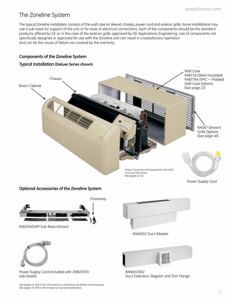
geappliances.comThe Zoneline SystemThe typical Zoneline installation consists of the wall case (or sleeve), chassis, power cord and exterior grille. Some installations may use a sub-base for support of the unit or for ease of electrical connections. Each of the components should be the standard products offered by GE or, in the case of the exterior grille, approved by GE Applications Engineering. Use of components not specifically designed or approved for use with the Zoneline unit can result in unsatisfactory operation and can be the cause of failure not covered by the warranty.
Components of the Zoneline System
Typical Installation (Deluxe Series shown)
See pages 22 and 32 for information on electrical sub-bases and chaseway.See pages 37-39 for information on ducted installations.
RAK601/602 Duct Extension, Register and Trim Flange
RAK6052 Duct Adapter
Wall CaseRAB71A (Steel-Insulated)RAB77A4 (SMC — Molded)Wall Case Options (See page 22)
RAG67 (shown)Grille Options(See page 40)
Room Cabinet
Chassis
Power Connection Kit (required on all units)Line Cord Kit shownSee pages 42-43
Optional Accessories of the Zoneline System
RAK204D20P Sub-Base (shown)
Chaseway
Power Supply Cord (included with 208V/230V sub-bases)
Power Supply Cord
8
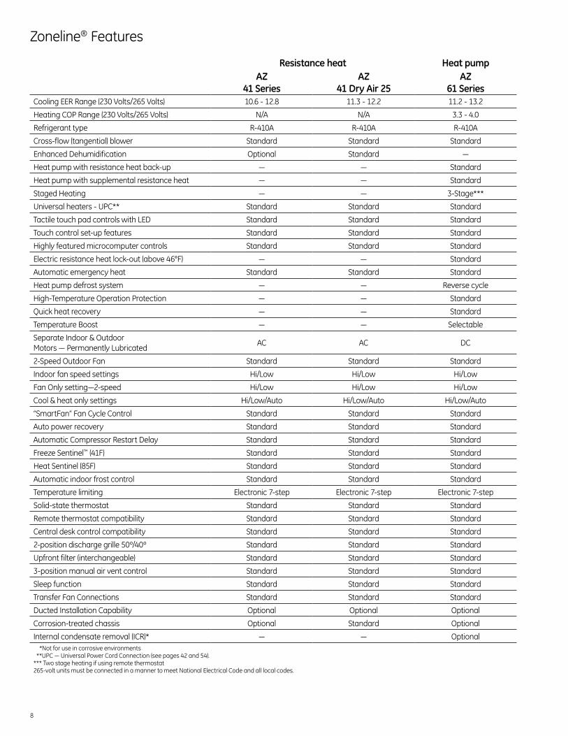
Zoneline® Features
Resistance heat Heat pumpAZ
41 Series AZ
41 Dry Air 25AZ
61 SeriesCooling EER Range (230 Volts/265 Volts) 10.6 - 12.8 11.3 - 12.2 11.2 - 13.2
Heating COP Range (230 Volts/265 Volts) N/A N/A 3.3 - 4.0
Refrigerant type R-410A R-410A R-410A
Cross-flow (tangential) blower Standard Standard Standard
Enhanced Dehumidification Optional Standard —
Heat pump with resistance heat back-up — — Standard
Heat pump with supplemental resistance heat — — Standard
Staged Heating — — 3-Stage***
Universal heaters - UPC** Standard Standard Standard
Tactile touch pad controls with LED Standard Standard Standard
Touch control set-up features Standard Standard Standard
Highly featured microcomputer controls Standard Standard Standard
Electric resistance heat lock-out (above 46°F) — — Standard
Automatic emergency heat Standard Standard Standard
Heat pump defrost system — — Reverse cycle
High-Temperature Operation Protection — — Standard
Quickheatrecovery — — Standard
Temperature Boost — — Selectable
Separate Indoor & Outdoor Motors — Permanently Lubricated
AC AC DC
2-Speed Outdoor Fan Standard Standard Standard
Indoor fan speed settings Hi/Low Hi/Low Hi/Low
Fan Only setting—2-speed Hi/Low Hi/Low Hi/Low
Cool & heat only settings Hi/Low/Auto Hi/Low/Auto Hi/Low/Auto
“SmartFan” Fan Cycle Control Standard Standard Standard
Auto power recovery Standard Standard Standard
Automatic Compressor Restart Delay Standard Standard Standard
Freeze Sentinel™ (41F) Standard Standard Standard
Heat Sentinel (85F) Standard Standard Standard
Automatic indoor frost control Standard Standard Standard
Temperature limiting Electronic 7-step Electronic 7-step Electronic 7-step
Solid-state thermostat Standard Standard Standard
Remote thermostat compatibility Standard Standard Standard
Central desk control compatibility Standard Standard Standard
2-position discharge grille 50º/40º Standard Standard Standard
Upfront filter (interchangeable) Standard Standard Standard
3-position manual air vent control Standard Standard Standard
Sleep function Standard Standard Standard
Transfer Fan Connections Standard Standard Standard
Ducted Installation Capability Optional Optional Optional
Corrosion-treated chassis Optional Standard Optional
Internal condensate removal (ICR)* — — Optional *Not for use in corrosive environments **UPC — Universal Power Cord Connection (see pages 42 and 54). *** Two stage heating if using remote thermostat 265-volt units must be connected in a manner to meet National Electrical Code and all local codes.

9
geappliances.comFeatures and Benefits
Standard Physical DimensionsGE has maintained the same dimensions since 1961 — 42" wide x 16" high x 13-3/4" deep
Replacement of older units is made easy.
Weather-Protected Electrical ComponentsVital electrical components are protected from the weather by locating them on the indoor side of the weather barrier.
Weather-Resistant “Superseal”Properly installed unit in undistorted case keeps air leakage to a minimum.
7 CFM air infiltration with 25 MPH wind on ICR units — even less on units without ICR.
Industry specification is 19 CFM of air infiltration.
Heater Sizes to Meet Room RequirementsAll units are equipped with a universal heater — the resistance heat output is determined by power connection kit.
230/208-volt — Line-Cord Connected Units — 2.4/2.32 KW with RAK3153A — 15-amp circuit; 3.3/3.20 KW with RAK3203A — 20-amp circuit; 4.7/4.53 KW with RAK3303A — 30-amp circuit.
230/208-volt - Sub-Base Connected Units — 2.4/2.32 KW with RAK204D15P — 15-amp circuit; 3.3/3.20 KW with RAK204D20P — 20-amp circuit; 4.7/4.53 KW with RAK204D30P — 30-amp circuit.
265-volt — 2.4 KW with RAK5172 — 15-amp circuit; 3.4 KW with RAK5202 — 20-amp circuit; 4.8 KW with RAK5302 — 30-amp circuit.
Unit Controls 4100 and 6100 Series — touch pad controls with digital readout of temperature set point.
Highly Featured Microprocessor Controls Microprocessor controls are programmed to interface with the temperature sensors to maximize comfort conditions for the room occupant and provide outstanding features.
Thermistors are used to sense small changes in temperature to give excellent room control and allow the microprocessor to monitor and react to changing conditions.
Electric Resistance Heat Lock-OutTo maximize the savings of the heat pump operation, the Zoneline heat pumps do not utilize the resistance heater when the outdoor temperature is above 46°F during normal operation.TheresistanceheatisusedintheQuickHeatRecovery feature.
Automatic Emergency HeatAutomatically uses electric resistance heat if the heat pump output is not sufficient to maintain selected room temperature.
Reverse Cycle Heat Pump Defrost SystemStandard on all Zoneline 6100 Series heat pumps.
Enables heat pump to operate at lower temperatures when other systems switch to more expensive electric resistance heat.
See pages 18 and 19 for discussion of heat pump operation and defrost systems.
High-Temperature Heat Pump Operation Protection Automatically protects the compressor if heat pump is operated with high outdoor temperatures.
Power to the outdoor fan is turned off if the indoor coil gets too hot during heat pump operation to prevent damage to the compressor.
Quick Heat Recovery – Heat Pump Units When the unit operation is changed from STOP or COOL to HEAT, the electric resistance heaters are used to warm the room to the thermostat set point. This provides faster room temperature increase for greater guest comfort.
Fan Motors – Permanently LubricatedAll units have two fan motors for quiet operation and maximum operating efficiency.
Motors are permanently lubricated to reduce maintenance and totally enclosed to keep dirt and water out of the motor windings.
Outdoor Fan The unit automatically selects the most efficient speed for the outdoor fan. The operating sound level is lower when the outdoor fan can operate in low speed yet there are situations where it must operate in high speed. The unit changes the fan speed automatically.
Indoor Fan Speed Selections – HIGH/LOWUnit may be operated in HIGH HEAT or LOW HEAT or HIGH COOL or LOW COOL.
10
Features and Benefits
Fan-Only Setting – HIGH/LOWThe unit provides the option of selecting either HIGH or LOW speed for Fan-Only operation.
Fan-Cycle Switch – “SmartFan”Unique “SmartFan” allows unit to operate fan continuously in cooling operation and fan cycle in heating to provide better guest comfort. Eliminates complaint of cold air draft during heating operation.
Eliminates need of changing fan-cycle switch seasonally.
“SmartFan” settings are controlled via the auxiliary control setting push button.
Compressor Random Restart In the event of a power failure, all compressors attempting to restart immediately when power is restored can result in a power surge that can cause another power interruption.
The microprocessors in the Zoneline® units have a random restart logic system that prevents all units from starting at the same time.
Rotary Compressor Smoother operation for quiet, dependable service. GE has used rotary compressors since 1961.
Compressor Restart Delay Zoneline units are designed to provide a minimum of three minutes of compressor off time to allow refrigerant pressures to equalize before restarting to prevent compressor damage.
Zoneline units are also designed to provide a minimum of three minutes of compressor run time to prevent room occupant disturbance due to short-cycling of the air conditioner.
Freeze Sentinel™
Detects low room temperature and turns on heater to help protect against damage caused by freezing room temperature.
Heater turns on at 41°F and warms indoor thermistor temperature to 46°F and shuts off.
Freeze Sentinel may be turned off by dip switch on auxiliary control.
Heat SentinelThe property owner may choose to activate the Heat Sentinel feature on the Zoneline unit. If the Heat Sentinel is activated and room temperature reaches 85°F while the unit is in the “STOP” setting, the unit will automatically start in air conditioning operation and will shut off when the room temperature reaches 80°F. This will help dehumidify the air and lower high temperatures so the guest will not be entering an extremely hot room.
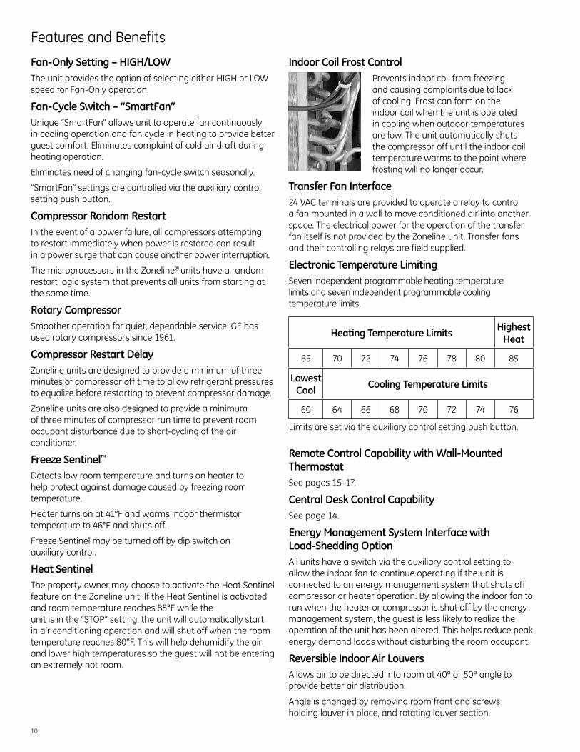
Indoor Coil Frost ControlPrevents indoor coil from freezing and causing complaints due to lack of cooling. Frost can form on the indoor coil when the unit is operated in cooling when outdoor temperatures are low. The unit automatically shuts the compressor off until the indoor coil temperature warms to the point where frosting will no longer occur.
Transfer Fan Interface24 VAC terminals are provided to operate a relay to control a fan mounted in a wall to move conditioned air into another space. The electrical power for the operation of the transfer fan itself is not provided by the Zoneline unit. Transfer fans and their controlling relays are field supplied.
Electronic Temperature LimitingSeven independent programmable heating temperature limits and seven independent programmable cooling temperature limits.
Remote Control Capability with Wall-Mounted ThermostatSee pages 15–17.
Central Desk Control Capability See page 14.
Energy Management System Interface with Load-Shedding Option All units have a switch via the auxiliary control setting to allow the indoor fan to continue operating if the unit is connected to an energy management system that shuts off compressor or heater operation. By allowing the indoor fan to run when the heater or compressor is shut off by the energy management system, the guest is less likely to realize the operation of the unit has been altered. This helps reduce peak energy demand loads without disturbing the room occupant.
Reversible Indoor Air Louvers Allows air to be directed into room at 40º or 50º angle to provide better air distribution.
Angle is changed by removing room front and screws holding louver in place, and rotating louver section.
Heating Temperature Limits Highest Heat
65 70 72 74 76 78 80 85
Lowest Cool Cooling Temperature Limits
60 64 66 68 70 72 74 76
Limits are set via the auxiliary control setting push button.
11
geappliances.comFeatures and Benefits
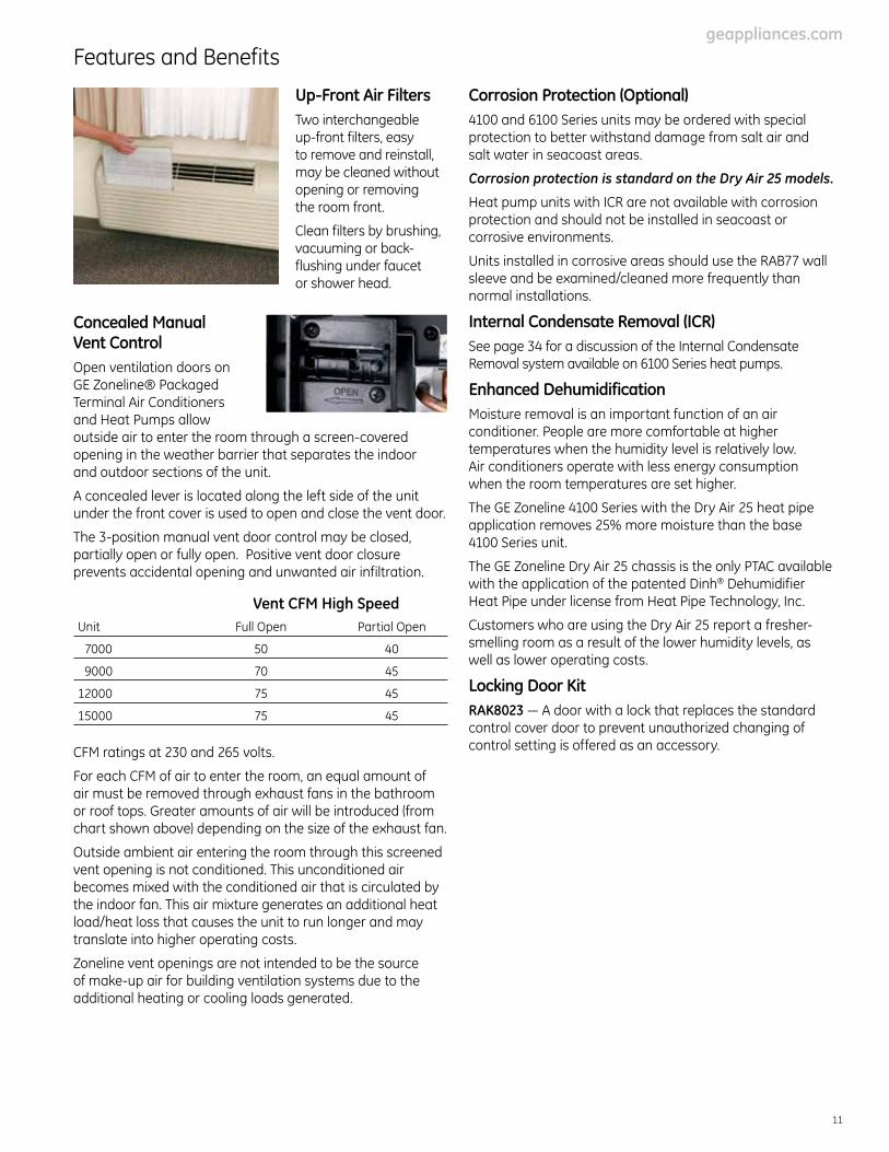
Up-Front Air Filters Two interchangeable up-front filters, easy to remove and reinstall, may be cleaned without opening or removing the room front.
Clean filters by brushing, vacuuming or back-flushing under faucet or shower head.
Concealed Manual Vent Control Open ventilation doors on GE Zoneline® Packaged Terminal Air Conditioners and Heat Pumps allow outside air to enter the room through a screen-covered opening in the weather barrier that separates the indoor and outdoor sections of the unit.
A concealed lever is located along the left side of the unit under the front cover is used to open and close the vent door.
The 3-position manual vent door control may be closed, partially open or fully open. Positive vent door closure prevents accidental opening and unwanted air infiltration.
Vent CFM High Speed Unit Full Open Partial Open
7000 50 40
9000 70 45
12000 75 45
15000 75 45
CFM ratings at 230 and 265 volts.
For each CFM of air to enter the room, an equal amount of air must be removed through exhaust fans in the bathroom or roof tops. Greater amounts of air will be introduced (from chart shown above) depending on the size of the exhaust fan.
Outside ambient air entering the room through this screened vent opening is not conditioned. This unconditioned air becomes mixed with the conditioned air that is circulated by the indoor fan. This air mixture generates an additional heat load/heat loss that causes the unit to run longer and may translate into higher operating costs.
Zoneline vent openings are not intended to be the source of make-up air for building ventilation systems due to the additional heating or cooling loads generated.
Corrosion Protection (Optional) 4100 and 6100 Series units may be ordered with special protection to better withstand damage from salt air and salt water in seacoast areas.
Corrosion protection is standard on the Dry Air 25 models.
Heat pump units with ICR are not available with corrosion protection and should not be installed in seacoast or corrosive environments.
Units installed in corrosive areas should use the RAB77 wall sleeve and be examined/cleaned more frequently than normal installations.
Internal Condensate Removal (ICR)See page 34 for a discussion of the Internal Condensate Removal system available on 6100 Series heat pumps.
Enhanced Dehumidification Moisture removal is an important function of an air conditioner. People are more comfortable at higher temperatures when the humidity level is relatively low. Air conditioners operate with less energy consumption when the room temperatures are set higher.
The GE Zoneline 4100 Series with the Dry Air 25 heat pipe application removes 25% more moisture than the base 4100 Series unit.
The GE Zoneline Dry Air 25 chassis is the only PTAC available with the application of the patented Dinh® Dehumidifier Heat Pipe under license from Heat Pipe Technology, Inc.
Customers who are using the Dry Air 25 report a fresher-smelling room as a result of the lower humidity levels, as well as lower operating costs.
Locking Door KitRAK8023 — A door with a lock that replaces the standard control cover door to prevent unauthorized changing of control setting is offered as an accessory.
12
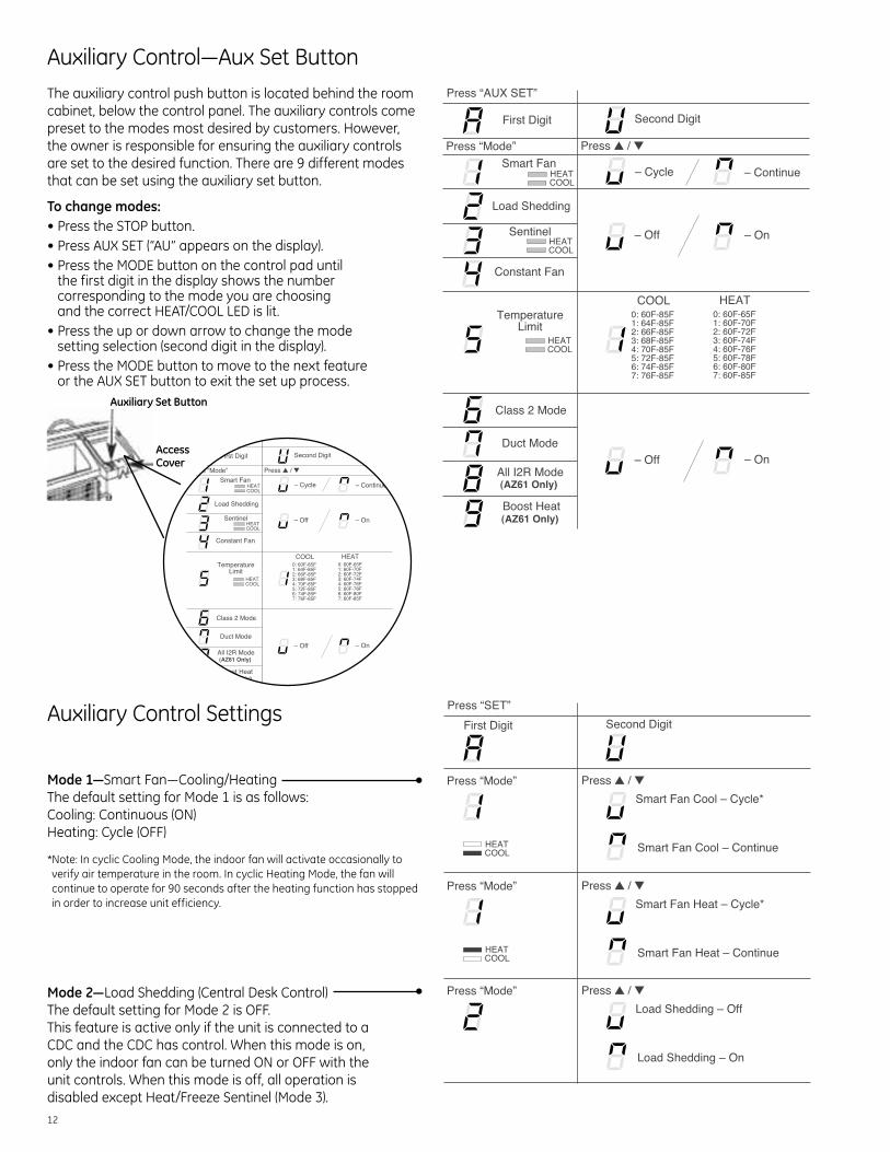
Auxiliary Control—Aux Set Button
Auxiliary Control Settings
The auxiliary control push button is located behind the room cabinet, below the control panel. The auxiliary controls come preset to the modes most desired by customers. However, the owner is responsible for ensuring the auxiliary controls are set to the desired function. There are 9 different modes that can be set using the auxiliary set button.
To change modes:•PresstheSTOPbutton.•PressAUXSET(“AU”appearsonthedisplay).•PresstheMODEbuttononthecontrolpaduntil
the first digit in the display shows the number corresponding to the mode you are choosing and the correct HEAT/COOL LED is lit.
•Presstheupordownarrowtochangethemode setting selection (second digit in the display).
•PresstheMODEbuttontomovetothenextfeature or the AUX SET button to exit the set up process.
Press “SET”First Digit Second Digit
Press “Mode” Press /
HEATCOOL
Smart Fan Cool – Cycle*
Smart Fan Cool – Continue
Press “Mode” Press /
HEATCOOL
Smart Fan Heat – Cycle*
Smart Fan Heat – Continue
Press “Mode” Press / Load Shedding – Off
Load Shedding – On
Press “AUX SET”
First Digit Second Digit
Press “Mode” Press / Smart Fan
HEATCOOL
Load Shedding
SentinelHEATCOOL
Constant Fan
Temperature Limit
HEATCOOL
Class 2 Mode
Duct Mode
All I2R Mode
Boost Heat
0: 60F-85F1: 64F-85F2: 66F-85F3: 68F-85F4: 70F-85F5: 72F-85F6: 74F-85F7: 76F-85F
0: 60F-65F1: 60F-70F2: 60F-72F3: 60F-74F4: 60F-76F5: 60F-78F6: 60F-80F7: 60F-85F
HEATCOOL
– Off – On
– Off – On
– Cycle – Continue
(AZ61 Only)
(AZ61 Only)
Mode 2—Load Shedding (Central Desk Control) The default setting for Mode 2 is OFF. This feature is active only if the unit is connected to a CDC and the CDC has control. When this mode is on, only the indoor fan can be turned ON or OFF with the unit controls. When this mode is off, all operation is disabled except Heat/Freeze Sentinel (Mode 3).
Mode 1—Smart Fan—Cooling/Heating The default setting for Mode 1 is as follows: Cooling: Continuous (ON) Heating: Cycle (OFF)
Press “AUX SET”
First Digit Second Digit
Press “Mode” Press / Smart Fan
HEATCOOL
Load Shedding
SentinelHEATCOOL
Constant Fan
Temperature Limit
HEATCOOL
Class 2 Mode
Duct Mode
All I2R Mode
Boost Heat
0: 60F-85F1: 64F-85F2: 66F-85F3: 68F-85F4: 70F-85F5: 72F-85F6: 74F-85F7: 76F-85F
0: 60F-65F1: 60F-70F2: 60F-72F3: 60F-74F4: 60F-76F5: 60F-78F6: 60F-80F7: 60F-85F
HEATCOOL
– Off – On
– Off – On
– Cycle – Continue
(AZ61 Only)
(AZ61 Only)
Auxiliary Set Button
Access Cover
* Note: In cyclic Cooling Mode, the indoor fan will activate occasionally to verify air temperature in the room. In cyclic Heating Mode, the fan will continue to operate for 90 seconds after the heating function has stopped in order to increase unit efficiency.
13
geappliances.com
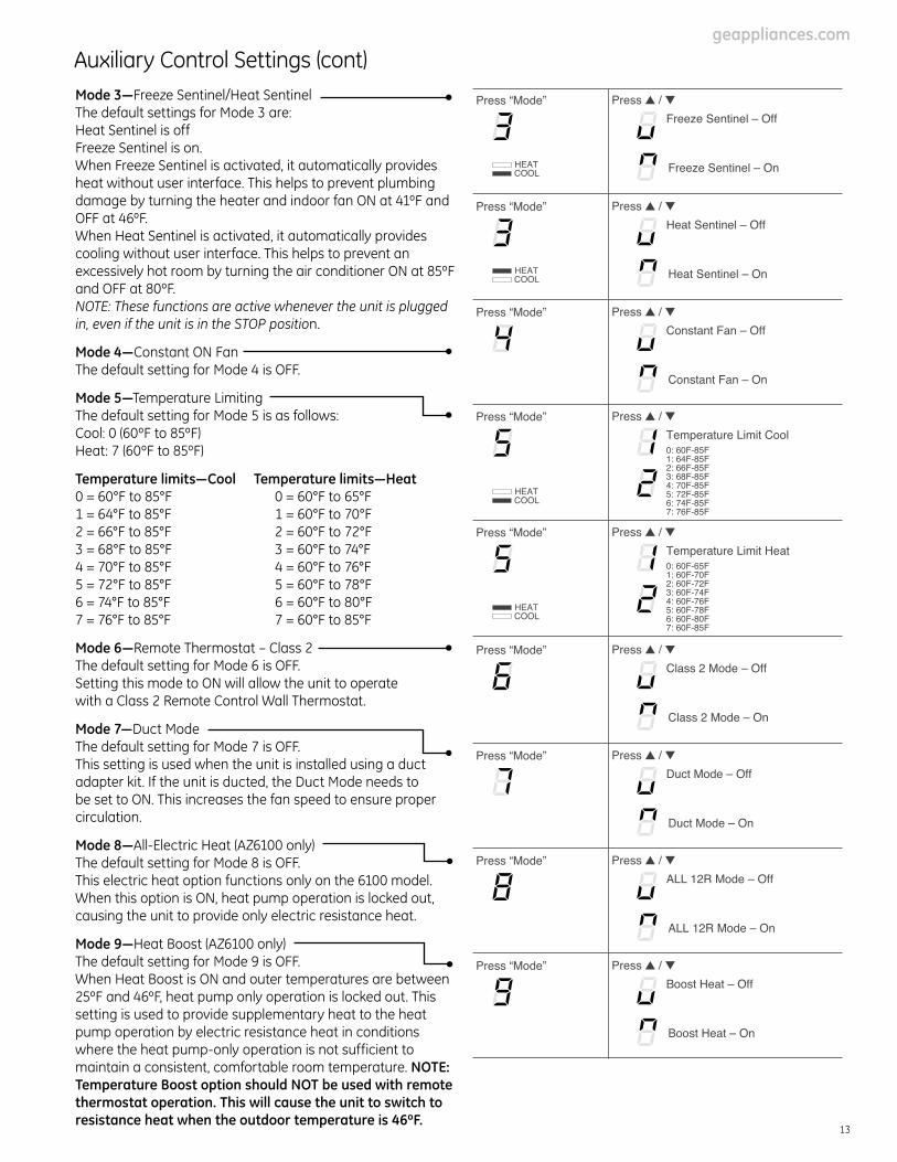
Auxiliary Control Settings (cont)Mode 3—Freeze Sentinel/Heat Sentinel The default settings for Mode 3 are: Heat Sentinel is off Freeze Sentinel is on. When Freeze Sentinel is activated, it automatically provides heat without user interface. This helps to prevent plumbing damage by turning the heater and indoor fan ON at 41ºF and OFF at 46ºF. When Heat Sentinel is activated, it automatically provides cooling without user interface. This helps to prevent an excessively hot room by turning the air conditioner ON at 85ºF and OFF at 80ºF. NOTE: These functions are active whenever the unit is plugged in, even if the unit is in the STOP position.
Mode 4—Constant ON Fan The default setting for Mode 4 is OFF.
Mode 5—Temperature Limiting The default setting for Mode 5 is as follows: Cool: 0 (60ºF to 85ºF) Heat: 7 (60ºF to 85ºF)
Temperature limits—Cool Temperature limits—Heat 0 = 60°F to 85°F 0 = 60°F to 65°F 1 = 64°F to 85°F 1 = 60°F to 70°F 2 = 66°F to 85°F 2 = 60°F to 72°F 3 = 68°F to 85°F 3 = 60°F to 74°F 4 = 70°F to 85°F 4 = 60°F to 76°F 5 = 72°F to 85°F 5 = 60°F to 78°F 6 = 74°F to 85°F 6 = 60°F to 80°F 7 = 76°F to 85°F 7 = 60°F to 85°F
Mode 6—Remote Thermostat – Class 2 The default setting for Mode 6 is OFF. Setting this mode to ON will allow the unit to operate with a Class 2 Remote Control Wall Thermostat.
Mode 7—Duct Mode The default setting for Mode 7 is OFF. This setting is used when the unit is installed using a duct adapter kit. If the unit is ducted, the Duct Mode needs to be set to ON. This increases the fan speed to ensure proper circulation.
Mode 8—All-Electric Heat (AZ6100 only) The default setting for Mode 8 is OFF. This electric heat option functions only on the 6100 model. When this option is ON, heat pump operation is locked out, causing the unit to provide only electric resistance heat.
Mode 9—Heat Boost (AZ6100 only) The default setting for Mode 9 is OFF. When Heat Boost is ON and outer temperatures are between 25ºF and 46ºF, heat pump only operation is locked out. This setting is used to provide supplementary heat to the heat pump operation by electric resistance heat in conditions where the heat pump-only operation is not sufficient to maintain a consistent, comfortable room temperature. NOTE: Temperature Boost option should NOT be used with remote thermostat operation. This will cause the unit to switch to resistance heat when the outdoor temperature is 46ºF.
Press “Mode” Press /
HEATCOOL
Freeze Sentinel – Off
Freeze Sentinel – On
Press “Mode” Press /
HEATCOOL
Heat Sentinel – Off
Heat Sentinel – On
Press “Mode” Press / Constant Fan – Off
Constant Fan – On
Press “Mode” Press / Duct Mode – Off
Duct Mode – On
Press “Mode” Press / ALL 12R Mode – Off
ALL 12R Mode – On
Press “Mode” Press / Boost Heat – Off
Boost Heat – On
Press “Mode” Press /
HEATCOOL
Temperature Limit Cool
Press “Mode” Press / Class 2 Mode – Off
Class 2 Mode – On
0: 60F-85F1: 64F-85F2: 66F-85F3: 68F-85F4: 70F-85F5: 72F-85F6: 74F-85F7: 76F-85F
Press “Mode” Press /
HEATCOOL
Temperature Limit Heat0: 60F-65F1: 60F-70F2: 60F-72F3: 60F-74F4: 60F-76F5: 60F-78F6: 60F-80F7: 60F-85F

14
Central Desk Control Some installations may want to govern the ability of the unit to operate from a control device remote to the unit or even remote to the room in which the unit is located. The general term given to systems such as this is Central Desk Control. The most common installation of this type of system is a switch mounted at the registration desk and, upon guest check-in, a button is pushed or a switch is moved to allow the air conditioner to operate. Likewise, when the guest checks out the device is put into the “OFF” position so the unit will not operate while the room is vacant.
It is not necessary that the controlling device be located at a central desk to employ a device that will control the unit operation. For instance, in some resort areas devices are connected to sliding glass doors and opening the door causes a contact to close, turning the air conditioner off. This prevents energy being wasted by operating the air conditioner when warm, humid air is entering the room. Some systems operate by motion sensors or heat-sensing detectors mounted in the room. These types of systems determine occupant presence in the room and allow the unit to operate; if no one is in the room the device signals the air conditioner to turn off.
Zoneline® models offer load-shedding capabilities on units connected to Central Desk Control systems. For more information on the models’ load-shedding feature, see page 10.
There is a wide variety of devices available, each with its own benefits and constraints. While GE does not offer components that are external to the unit for a Central Desk Control (CDC) system, GE Zoneline units are compatible with most CDC and energy management systems. Zoneline units provide a 24 VAC circuit that powers the Central Desk Control system and no external power is needed. All Zoneline 4100 and 6100 Series units are compatible with simple on/off 2-wire Central Desk Control systems. Consult with the provider of the energy management system to be sure it is compatible with GE Zoneline units. Zoneline units have standard connectors factory-installed to provide a CDC interface that permits the unit to be connected to most of the energy management systems. The devices connected to the Zoneline units require no power supply or transformers external to the unit.
Important CDC Comments (all series applicable)
1. When the switching device closes the circuit of the CDC conductors, the unit operation stops.
2. Do not use a common bus (at the unit or at the switch panel) in the wiring. Both wires comprising the circuit must connect to the unit connectors and to the controlling switch. Running one wire from one unit to another unit is common busing and may damage internal components or cause erratic operation of the system.
3. A 24-volt transformer is contained within the Zoneline unit. No external voltage may be applied to the unit through the CDC terminals. (Voltage on the CDC conductors is 24 volts AC.)
4. Recommended wire size must be followed as a minimum requirement.
Wire Size #AWG Maximum Allowable Length #22 600 Ft.
#20 900 Ft.
#18 1500 Ft.
#16 2000 Ft.
Freeze Sentinel™ and Heat Sentinel remains operational when the unit is connected to a CDC system. Even if the unit is turned “OFF” at the central location, if the sensor at the unit detects the low or high limit temperature, the unit will automatically turn on until it reaches the preset shutdown temperature (46°F heating, 80°F cooling).
Connecting the Zoneline unit to a CDC system does not eliminate the ability to connect the unit to a remote thermostat. Once the circuit is “opened,” and control of the unit removed from the CDC system, the selected controls—either the unit— mounted control or the remote thermostat—govern the operation of the unit.
Please see page 55 for installation recommendations for the Central Desk Control wiring.
CDC Terminal Location and Typical WiringSee page 15 for location of CDC terminals on unit.
Unit #2Unit #1 Unit #3
Example of Common BusingNOT PERMITTED
CDC Terminalson Zoneline unit
INCORRECT Common Busing
Normally OpenSwitch -
Unit Operational
Typical Wiring(All Wiring Shown Is Field Supplied)
15
geappliances.com
The remote thermostat-Class 2 option (Mode 6 in the auxiliary control setting) must be turned ON to enable remote thermostat control. Refer to installation instructions packaged with the chassis.
Please see page 55 for installation recommendations for the remote thermostat wiring.Compatibility of other thermostats considered for use with GE Zoneline units is the responsibility of the customer. The control voltage on the remote control conductors is 24 volts AC. The AC voltage may not be compatible with some solid-state thermostats.
The fan speed for the 4100 Series in remote thermostat operation is selected by the connection of the fan wire from the thermostat to either the HIGH or LOW terminal on the unit. See the sketch of the unit terminals below for the location of the HIGH and LOW fan-speed terminals. Operating the unit in low fan speed reduces the operating sound level of the unit.
Freeze Sentinel™ and Heat Sentinel remain operational if the unit is connected to a remote thermostat. The unit may be connected to a Central Desk Control (CDC) system and controlled with a remote thermostat when the CDC system has the unit in operation. See page 14 for additional information on the CDC system.
Unit temperature limiting settings are not functional when unit is connected to a remote thermostat.
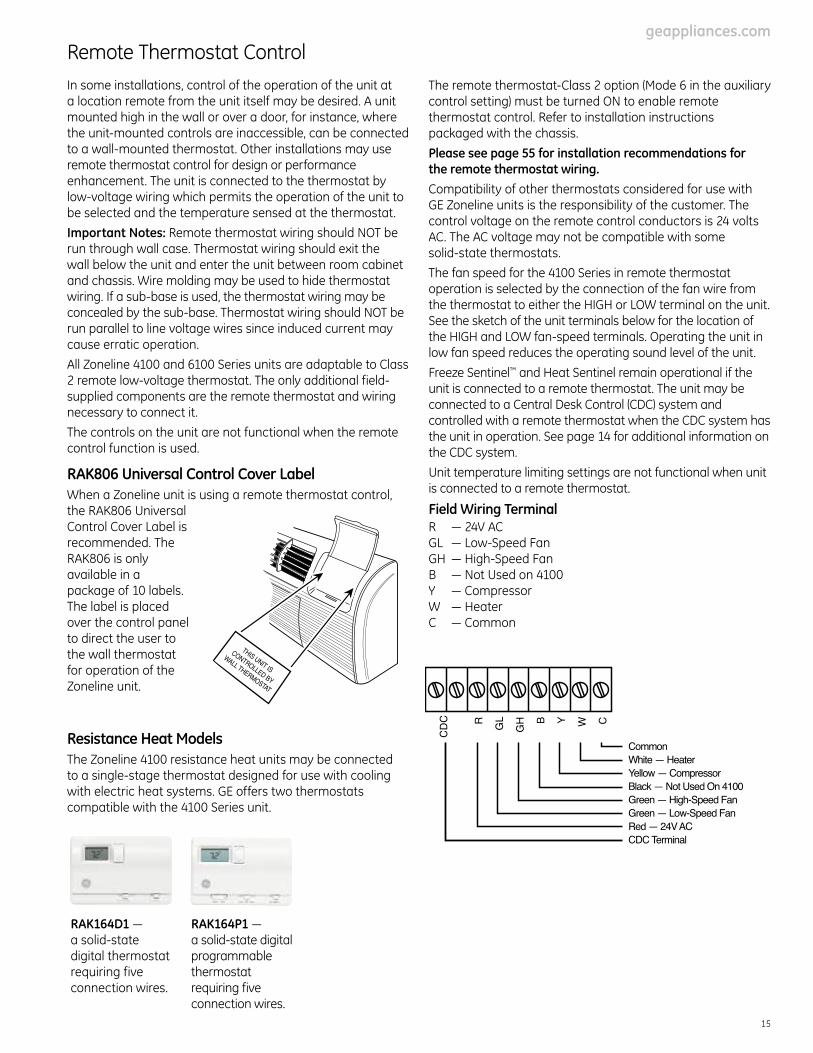
Field Wiring Terminal R — 24V AC GL — Low-Speed Fan GH — High-Speed Fan B — Not Used on 4100 Y — Compressor W — Heater C — Common
Remote Thermostat ControlIn some installations, control of the operation of the unit at a location remote from the unit itself may be desired. A unit mounted high in the wall or over a door, for instance, where the unit-mounted controls are inaccessible, can be connected to a wall-mounted thermostat. Other installations may use remote thermostat control for design or performance enhancement. The unit is connected to the thermostat by low-voltage wiring which permits the operation of the unit to be selected and the temperature sensed at the thermostat.
Important Notes: Remote thermostat wiring should NOT be run through wall case. Thermostat wiring should exit the wall below the unit and enter the unit between room cabinet and chassis. Wire molding may be used to hide thermostat wiring. If a sub-base is used, the thermostat wiring may be concealed by the sub-base. Thermostat wiring should NOT be run parallel to line voltage wires since induced current may cause erratic operation.
All Zoneline 4100 and 6100 Series units are adaptable to Class 2 remote low-voltage thermostat. The only additional field-supplied components are the remote thermostat and wiring necessary to connect it.
The controls on the unit are not functional when the remote control function is used.
RAK806 Universal Control Cover Label When a Zoneline unit is using a remote thermostat control, the RAK806 Universal Control Cover Label is recommended. The RAK806 is only available in a package of 10 labels. The label is placed over the control panel to direct the user to the wall thermostat for operation of the Zoneline unit.
Resistance Heat ModelsThe Zoneline 4100 resistance heat units may be connected to a single-stage thermostat designed for use with cooling with electric heat systems. GE offers two thermostats compatible with the 4100 Series unit.
R GL
GH B Y W C
Common White — HeaterYellow — CompressorBlack — Not Used On 4100Green — High-Speed FanGreen — Low-Speed FanRed — 24V ACCDC Terminal
R GL
GH B Y W C
Common — GroundWhite — HeaterYellow — CompressorBlack — Reversing ValveGreen — High-Speed FanGreen — Low-Speed FanRed — 24V AC
Resistance Heat Models
Heat Pump Models
CD
C
RAK164D1 — a solid-state digital thermostat requiring five connection wires.
RAK164P1 — a solid-state digital programmable thermostat requiring five connection wires.
16
Remote Thermostat Control
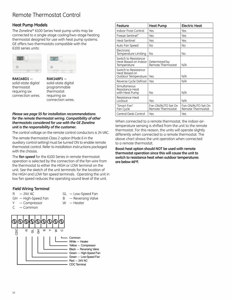
Heat Pump ModelsThe Zoneline® 6100 Series heat pump units may be connected to a single-stage cooling/two-stage heating thermostat designed for use with heat pump systems. GE offers two thermostats compatible with the 6100 series units:
RAK148D1 — solid-state digital thermostat requiring six connection wires.
RAK148P1 — solid-state digital programmable thermostat requiring six connection wires.
Please see page 55 for installation recommendations for the remote thermostat wiring. Compatibility of other thermostats considered for use with the GE Zoneline unit is the responsibility of the customer. The control voltage on the remote control conductors is 24 VAC.
The remote thermostat-Class 2 option (Mode 6 in the auxiliary control setting) must be turned ON to enable remote thermostat control. Refer to installation instructions packaged with the chassis.
The fan speed for the 6100 Series in remote thermostat operation is selected by the connection of the fan wire from the thermostat to either the HIGH or LOW terminal on the unit. See the sketch of the unit terminals for the location of the HIGH and LOW fan speed terminals. Operating the unit in low fan speed reduces the operating sound level of the unit.
Field Wiring Terminal R — 24V AC GL — Low-Speed Fan GH — High-Speed Fan B — Reversing Valve Y — Compressor W — Heater C — Common
Feature Heat Pump Electric HeatIndoor Frost Control Yes YesFreeze Sentinel™ Yes YesHeat Sentinel Yes YesAuto Fan Speed No NoElectronic Temperature Limiting No NoSwitch to Resistance Heat Based on Indoor Temperature
Determined by Remote Thermostat N/A
Switch to Resistance Heat Based on Outdoor Temperature Yes N/AReverse Cycle Defrost Yes N/ASimultaneous Resistance Heat with Heat Pump No N/AResistance Heat Lockout Yes N/A“Smart Fan” Fan Cycle
Fan ON/AUTO Set On Remote Thermostat
Fan ON/AUTO Set On Remote Thermostat
Central Desk Control Yes Yes
R GL
GH B Y W C
Common White — HeaterYellow — CompressorBlack — Reversing ValveGreen — High-Speed FanGreen — Low-Speed FanRed — 24V ACCDC Terminal
R GL
GH B Y W C
Common — GroundWhite — HeaterYellow — CompressorBlack — Reversing ValveGreen — High-Speed FanGreen — Low-Speed FanRed — 24V AC
Resistance Heat Models
Heat Pump Models
CD
C
When connected to a remote thermostat, the indoor-air- temperature sensing is shifted from the unit to the remote thermostat. For this reason, the units will operate slightly differently when connected to a remote thermostat. The above chart shows the unit operation when connected to a remote thermostat.
Boost heat option should NOT be used with remote thermostat operation since this will cause the unit to switch to resistance heat when outdoor temperatures are below 46ºF.

17
geappliances.com
Zoneline Series Thermostat Model Type Function Low-Voltage Conductors
4100 RAK164D1 DigitalCooling and Heating
5
RAK164P1 Digital Programmable 5
6100 RAK148D1 Digital Single-Stage Cooling – 2-Stage Heating
6
RAK148P1 Digital Programmable 6
Thermostat wire size – up to 60 feet AWG20 – up to 66 feet AWG18
Remote Thermostat Control Selection Chart For Zoneline Packaged Terminal Units
For remote thermostat operation follow the steps below:1. Turn on the unit and ensure it is working properly
BEFORE proceeding.
2. Unplug the unit or disconnect power and remove the room cover.
3. Connect the thermostat wiring per the appropriate diagram/colors for your model.
4. Plug the unit back in or reconnect power.
5. Press the Aux Set button once. The letters AU will appear in the display.
6. Press the mode button until the number “6” appears in the left hand digit.
7. Press the up arrow once so the top half of the right hand digit is lit.
8. Press the Aux Set button to exit the setup function.
9. Replace the room cover.
See pages 12 and 13 for full instructions on using the Auxiliary Controls Feature.
18
Heat Pumps and Energy Savings• GEZoneline® heat pumps are designed to provide
cost-efficient heat pump operation while monitoring room conditions to maintain comfort.
The units employ a logic system monitoring both outdoor and indoor temperatures to determine the heat source, thus increasing energy savings by operating longer in the heat pump mode.
Heat pumps save energy and cost less to operate than units with electric resistance heaters as the only heat source. Just as the EER of an air conditioner is an indication of the efficiency of the unit, COP (Coefficient of Performance) is the indication of the efficiency of the heat pump. This relative efficiency of a heat pump compares the unit to electric resistance heat. If a unit has a COP of 3.0, it means the unit will produce three times as much heat at rating conditions for the same electrical input wattage used for electric resistance heat.
The compressor is used in heat pump operation just as in air conditioning operation. In heat pump operation, the hot refrigerant gas is directed to the indoor coil rather than to the outdoor coil. Room air that circulates over the indoor coil gains heat from the coil rather than losing heat to the coil as during cooling operation.
As the outdoor temperature falls, the heat pump is able to extract less heat from the outdoor air to raise the temperature of the indoor air. For this reason, all packaged terminal heat pumps also have electric resistance heaters as backup to heat pump operation. At some point, the heat pump is unable to provide sufficient heat to adequately warm the room. Many Packaged Terminal Heat Pumps cease heat pump operation and change to more expensive resistance heat at some pre-determined outdoor temperature to compensate for the inability of the heat pump to maintain room temperature. This point, called the “switchover point,” is usually at an outdoor temperature where savings from heat pump operation may still be realized if the unit is designed to maintain room comfort at the lower outdoor temperatures.
Balance PointAn important consideration in the selection of a heat pump unit is the “balance point” of the installation. Virtually every room is unique—with different insulation, different sizes and types of windows, different types of construction, different directional exposures. All these variables, as well as geographical location, must be considered in order to determine the balance point, the point at which the heat pump is unable to produce enough heat to compensate for the heat loss of the room or area being heated. For these reasons a consulting engineer should be engaged to calculate the heat loss and specify the heat pump unit required.
GE offers the 6100 series of Zoneline heat pump units—with highly featured microprocessor controls—react to the indoor temperature as well as the outdoor temperature in determining the heat source to provide comfortable room conditions and energy savings. This determination of the heat source based on the indoor temperature helps provide a more comfortable room.

19
geappliances.comHeat Pumps and Energy Savings
Heat Pump Operation — Zoneline 6100 SeriesHeat sources: Heat pump, heat pump and simultaneous electric resistance heat or electric resistance heat.
Zoneline heat pumps employ a highly featured microprocessor control system interfaced with thermistors to accurately measure indoor air temperature, outdoor air temperature, indoor coil temperature and outdoor coil temperature. This system allows the microprocessor to precisely and predictably react to changing conditions in order to provide a very advanced packaged terminal heat pump operating system.
The Zoneline heat pumps are designed to help ensure a comfortable room. When “HEAT” is selected, the unit will determine if the room air is warm enough to satisfy the thermostat setting. If the temperature at the unit sensor is below the desired temperature, the electric resistance heater will be utilized to warm the room to the point where the thermostat is satisfied. This feature is designed to allow the temperature of an unoccupied room to be maintained at an energy-saving level without inconveniencing the room occupant. Once the thermostat has been satisfied, the resistance heater will turn off and the heat pump will operate as shown in the Heat Source Logic chart until the thermostat calls for heat again. The unit will operate in this manner even if connected to a Central Desk Control.
ROOM
TEMPERATURE VS. THERMOSTAT
SET POINT
Above 46°F
Between 46°F and 25°F
Below 25°F
Less Than 1.8°F Below
Heat Pump Heat Pump*Full Resistance
Heat
1.8°F to 2.7°F Below
Heat PumpHeat Pump + Supplemental
Heater
Full Resistance Heat
More than 2.7°F Below
Heat PumpFull Resistance
HeatFull Resistance
Heat
Zoneline Heat Pump Heat Source Logic
The Boost Heat option utilizes the supplemental simultaneous heater at the same time as heat pump operation when the outdoor temperature is below 46°F regardless of the indoor air temperature**. The chart above indicates the heat source of the heat pump under various indoor and outdoor conditions. The unit is designed to provide heat pump savings without sacrificing room comfort.
TheQuickHeatRecoveryfeatureisnotaffectedbytheHeatSource Logic shown in the chart below. For more information abouttheQuickHeatRecoveryFeature,seepage9.Thefull heat output of the resistance heater is dependent upon circuit amperage and the power connection kit used. See pages 3 and 42–43 for information on power connection kits and available heater capacities.
An option is provided in the auxiliary controls (Mode 8) to allow the unit to operate only in resistance heat. The use of this option significantly increases the cost for heating.
Heat pump defrost — Zoneline 6100 SeriesZoneline heat pumps utilize a reverse-cycle demand defrost system to extend heat pump operation and increase savings from extended operation. The microprocessor determines the need for defrosting by criteria based on continuous compressor running time, outdoor air temperature, outdoor coil temperature and the rate of temperature change of the outdoor coil. When defrosting is required, the unit reverses the flow of refrigerant to direct the hot gas into the outdoor coil to melt the frost buildup. Before and after the reverse-cycle defrosting, the unit shuts off the compressor to allow the refrigerant pressures to equalize throughout the system. This eliminates the possibility of a loud reversing noise. During these periods of pressure equalization, the full resistance heat capacity of the unit is activated to help ensure room comfort conditions during the defrost cycle. The unit remains in the defrost cycle for a minimum of two minutes up to a maximum of nine minutes. The defrost cycle terminates when the outdoor coil reaches a temperature of 68°F or the maximum time has been reached.
Heat pump condensateSee page 34 for information on heat pump condensate. The Zoneline 6100 Series heat pumps may be ordered with a factory-installed Internal Condensate Removal (ICR) system to minimize the amount of condensate water draining from the unit during heat pump operation. The ICR system has proven to be an effective means of minimizing the amount of heat pump condensate dripping from the unit. However, if the requirements of a particular installation will allow no dripping of condensate water from the wall case, the installation of an internal or external drain system is recommended.
Units with ICR may not be installed in seacoast or corrosive environment applications.
* If the Boost Heat switch (auxiliary setting #9) is “ON”, the supplemental simultaneous heater will be used with heat pump operation. Simultaneous supplemental heater: 1.0 KW @ 230 V; 0.8 KW @ 208V; 1.0 KW @ 265V.
** Boost Heat option only applies to systems controlled at the unit. Boost Heat option should NOT be used with remote thermostat operation since this will cause the unit to switch to resistance heat when outdoor temperatures are below 46°F.
20
OVER 40 FT.
CORRECT
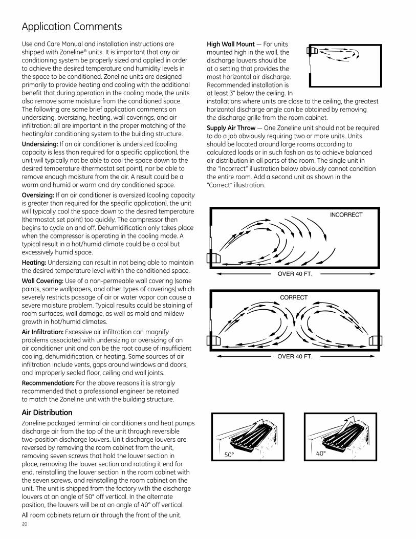
High Wall Mount — For units mounted high in the wall, the discharge louvers should be at a setting that provides the most horizontal air discharge. Recommended installation is at least 3" below the ceiling. In installations where units are close to the ceiling, the greatest horizontal discharge angle can be obtained by removing the discharge grille from the room cabinet.
Supply Air Throw — One Zoneline unit should not be required to do a job obviously requiring two or more units. Units should be located around large rooms according to calculated loads or in such fashion as to achieve balanced air distribution in all parts of the room. The single unit in the “Incorrect” illustration below obviously cannot condition the entire room. Add a second unit as shown in the “Correct” illustration.
Application Comments
Use and Care Manual and installation instructions are shipped with Zoneline® units. It is important that any air conditioning system be properly sized and applied in order to achieve the desired temperature and humidity levels in the space to be conditioned. Zoneline units are designed primarily to provide heating and cooling with the additional benefit that during operation in the cooling mode, the units also remove some moisture from the conditioned space. The following are some brief application comments on undersizing, oversizing, heating, wall coverings, and air infiltration: all are important in the proper matching of the heating/air conditioning system to the building structure.
Undersizing: If an air conditioner is undersized (cooling capacity is less than required for a specific application), the unit will typically not be able to cool the space down to the desired temperature (thermostat set point), nor be able to remove enough moisture from the air. A result could be a warm and humid or warm and dry conditioned space.
Oversizing: If an air conditioner is oversized (cooling capacity is greater than required for the specific application), the unit will typically cool the space down to the desired temperature (thermostat set point) too quickly. The compressor then begins to cycle on and off. Dehumidification only takes place when the compressor is operating in the cooling mode. A typical result in a hot/humid climate could be a cool but excessively humid space.
Heating: Undersizing can result in not being able to maintain the desired temperature level within the conditioned space.
Wall Covering: Use of a non-permeable wall covering (some paints, some wallpapers, and other types of coverings) which severely restricts passage of air or water vapor can cause a severe moisture problem. Typical results could be staining of room surfaces, wall damage, as well as mold and mildew growth in hot/humid climates.
Air Infiltration: Excessive air infiltration can magnify problems associated with undersizing or oversizing of an air conditioner unit and can be the root cause of insufficient cooling, dehumidification, or heating. Some sources of air infiltration include vents, gaps around windows and doors, and improperly sealed floor, ceiling and wall joints.
Recommendation: For the above reasons it is strongly recommended that a professional engineer be retained to match the Zoneline unit with the building structure.
Air DistributionZoneline packaged terminal air conditioners and heat pumps discharge air from the top of the unit through reversible two-position discharge louvers. Unit discharge louvers are reversed by removing the room cabinet from the unit, removing seven screws that hold the louver section in place, removing the louver section and rotating it end for end, reinstalling the louver section in the room cabinet with the seven screws, and reinstalling the room cabinet on the unit. The unit is shipped from the factory with the discharge louvers at an angle of 50° off vertical. In the alternate position, the louvers will be at an angle of 40° off vertical.
All room cabinets return air through the front of the unit.
50° 40°
OVER 40 FT.
INCORRECT
21
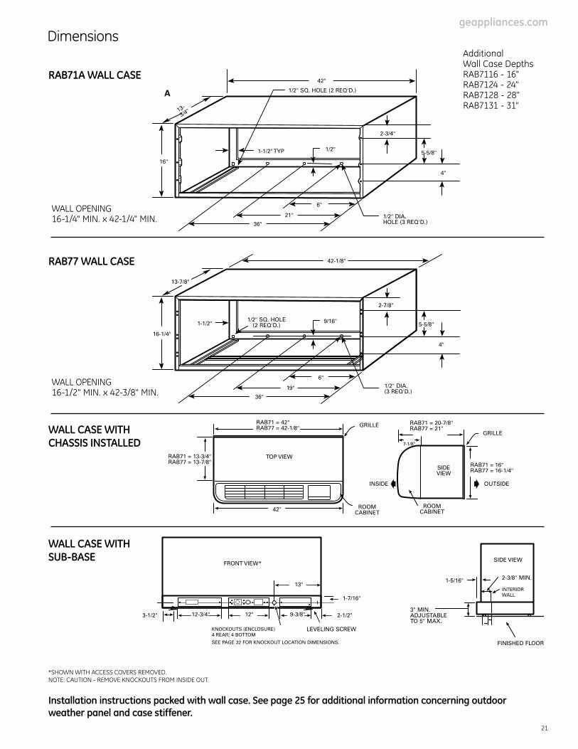
geappliances.comDimensions
RAB71A WALL CASE
WALL OPENING16-1/4" MIN. x 42-1/4" MIN.
RAB77 WALL CASE
WALL OPENING16-1/2" MIN. x 42-3/8" MIN.
WALL CASE WITH CHASSIS INSTALLED
WALL CASE WITH SUB-BASE
*SHOWN WITH ACCESS COVERS REMOVED.NOTE: CAUTION - REMOVE KNOCKOUTS FROM INSIDE OUT.
Installation instructions packed with wall case. See page 25 for additional information concerning outdoor weather panel and case stiffener.
Additional Wall Case DepthsRAB7116 - 16"RAB7124 - 24"RAB7128 - 28"RAB7131 - 31"
42"
13-3/4"
16"
1-1/2" TYP 1/2"
6"
21"
36"
A 1/2" SQ. HOLE (2 REQ'D.)
1/2" DIA.HOLE (3 REQ'D.)
2-3/4"
5-5/8"
4"
6"
19"
36"
16-1/4"
13-7/8"
1-1/2"
42-1/8"
1/2" SQ. HOLE (2 REQ'D.)
9/16"
2-7/8"
5-5/8"
4"
1/2" DIA.(3 REQ'D.)
RAB71 = 42"RAB77 = 42-1/8"
RAB71 = 13-3/4"RAB77 = 13-7/8"
42"
TOP VIEW
GRILLE
ROOMCABINET
INSIDE
ROOMCABINET
SIDEVIEW
RAB71 = 20-7/8"RAB77 = 21"
OUTSIDE
RAB71 = 16"RAB77 = 16-1/4"
GRILLE
7-1/8"
FRONT VIEW*
3-1/2" 12-3/4" 12" 9-3/8" 2-1/2"
1-7/16"
LEVELING SCREWKNOCKOUTS (ENCLOSURE)4 REAR; 4 BOTTOM
SEE PAGE 32 FOR KNOCKOUT LOCATION DIMENSIONS.
1-5/16" 2-3/8" MIN.
INTERIORWALL
3" MIN.ADJUSTABLETO 5" MAX.
FINISHED FLOOR
SIDE VIEW
13"
22
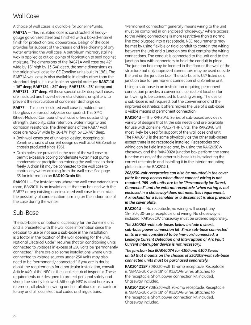
Wall Case
A choice of wall cases is available for Zoneline® units.
RAB71A — This insulated case is constructed of heavy-gauge galvanized steel and finished with a baked-enamel finish for protection and appearance. Design of the case provides for support of the chassis and free draining of any water entering the wall case. A petroleum microcrystalline wax is applied at critical points of fabrication to seal against moisture. The dimensions of the RAB71A wall case are 42" wide by 16" high by 13-3/4" deep, the same dimensions as the original wall case for GE Zoneline units built in 1961. The RAB71A wall case is also available in depths other than the standard depth. It is available on special order as: RAB7116 – 16" deep; RAB7124 – 24" deep; RAB7128 – 28" deep; and RAB7131 – 31" deep. All these special-order deep wall cases are insulated and have sheet-metal dividers, or splitters, to prevent the recirculation of condenser discharge air.
RAB77 — This non-insulated wall case is molded from fiberglass-reinforced polyester compound. This SMC (Sheet-Molded Compound) wall case offers outstanding strength, durability, color retention, water integrity and corrosion resistance. The dimensions of the RAB77 wall case are 42-1/8" wide by 16-1/4" high by 13-7/8" deep. • Bothwallcasesareofuniversaldesign,acceptingall
Zoneline chassis of current design as well as all GE Zoneline chassis produced since 1961.
• Drainholesareprovidedintherearofthewallcasetopermit excessive cooling condensate water, heat pump condensate or precipitation entering the wall case to drain freely. A drain kit may be connected to the wall case to control any water draining from the wall case. See page 35 for information on RAD10 Drain Kit.
RAK901L — For installations where the wall case extends into room, RAK901L is an insulation kit that can be used with the RAB77 or any existing non-insulated wall case to minimize the possibility of condensation forming on the indoor side of the case during the winter.
Sub-BaseThe sub-base is an optional accessory for the Zoneline unit and is presented with the wall case information since the decision to use or not use a sub-base in the installation is a factor in the location of the wall opening for the unit. National Electrical Code® requires that air conditioning units connected to voltages in excess of 250 volts be “permanently connected.” There are also some installations where units connected to voltage sources under 250 volts may also need to be “permanently connected.” If you are in doubt about the requirements for a particular installation, consult Article 440 of the NEC or the local electrical inspector. These requirements are designed to protect personal safety and should be strictly followed. Although NEC is cited here as a reference, all electrical wiring and installations must conform to any and all local electrical codes and regulations.
“Permanent connection” generally means wiring to the unit must be contained in an enclosed “chaseway,” where access to the wiring connections is more restrictive than a normal line cord plugged into a receptacle. NEC requirements may be met by using flexible or rigid conduit to contain the wiring between the unit and a junction box that contains the wiring connections. The conduit is connected to the unit and to the junction box with connectors to hold the conduit in place. The junction box may be located in the floor or the wall of the structure but only approved connectors may be used outside the unit or the junction box. The sub-base is UL® listed as a junction box for permanent connection of a Zoneline unit.
Using a sub-base in an installation requiring permanent connection provides a convenient, consistent location for unit wiring to be connected to building wiring. The use of a sub-base is not required, but the convenience and the improved aesthetics it offers makes the use of a sub-base a viable means of permanent connection.
RAK204U — The RAK204U Series of sub-bases provides a variety of designs that fit the site needs and are available for use with Zoneline PTAC/PTHP units. The RAK204U will most likely be used for support of the wall case and unit. The RAK204U is the same physically as the other sub-bases except there is no receptacle installed. Receptacles and wiring can be field installed and, by using the RAK205CW chaseway and the RAK4002A junction box perform the same function as any of the other sub-base kits by selecting the correct receptacle and installing it in the interior mounting plate inside the RAK204U.
208/230-volt receptacles can also be mounted in the cover plate for easy access when direct connect wiring is not required. 265-volt units are to be “Permanently (or Direct) Connected” and the external receptacle (when wiring is not enclosed in a chaseway) does not meet this requirement. A knockout for a fuseholder or a disconnect is also provided in the cover plate. RAK204U — No receptacle, no wiring; will accept any 15-, 20-, 30-amp receptacle and wiring. No chaseway is included. RAK205CW chaseway must be ordered separately.
The 230/208-volt sub-bases below include a short, sub-base power connection kit. Since sub-base connected units are not considered to be line-cord connected, a Leakage Current Detection and Interruption or Arc Fault Current Interrupter device is not necessary.The junction box (RAK4002A for 4100 and 6100 Series units) that mounts on the chassis of 230/208-volt sub-base connected units must be purchased separately. RAK204D15P 208/230-volt 15-amp receptacle. Receptacle is NEMA6-20R with 18" of #12AWG wires attached to the receptacle. Short power connection kit included. Chaseway included.
RAK204D20P 208/230-volt 20-amp receptacle. Receptacle is NEMA6-20R with 18" of #12AWG wires attached to the receptacle. Short power connection kit included. Chaseway included.
23
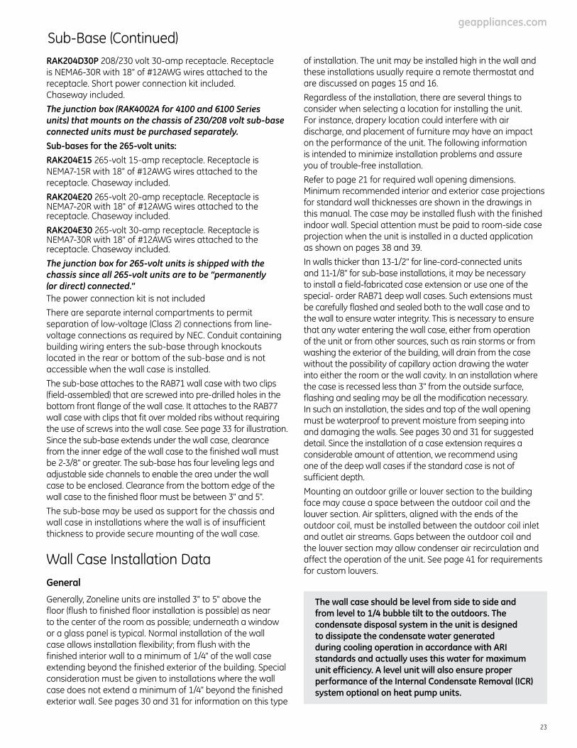
geappliances.comSub-Base (Continued)RAK204D30P 208/230 volt 30-amp receptacle. Receptacle is NEMA6-30R with 18" of #12AWG wires attached to the receptacle. Short power connection kit included. Chaseway included.
The junction box (RAK4002A for 4100 and 6100 Series units) that mounts on the chassis of 230/208 volt sub-base connected units must be purchased separately. Sub-bases for the 265-volt units: RAK204E15 265-volt 15-amp receptacle. Receptacle is NEMA7-15R with 18" of #12AWG wires attached to the receptacle. Chaseway included.
RAK204E20 265-volt 20-amp receptacle. Receptacle is NEMA7-20R with 18" of #12AWG wires attached to the receptacle. Chaseway included.
RAK204E30 265-volt 30-amp receptacle. Receptacle is NEMA7-30R with 18" of #12AWG wires attached to the receptacle. Chaseway included.
The junction box for 265-volt units is shipped with the chassis since all 265-volt units are to be “permanently (or direct) connected.”The power connection kit is not included
There are separate internal compartments to permit separation of low-voltage (Class 2) connections from line-voltage connections as required by NEC. Conduit containing building wiring enters the sub-base through knockouts located in the rear or bottom of the sub-base and is not accessible when the wall case is installed.
The sub-base attaches to the RAB71 wall case with two clips (field-assembled) that are screwed into pre-drilled holes in the bottom front flange of the wall case. It attaches to the RAB77 wall case with clips that fit over molded ribs without requiring the use of screws into the wall case. See page 33 for illustration. Since the sub-base extends under the wall case, clearance from the inner edge of the wall case to the finished wall must be 2-3/8" or greater. The sub-base has four leveling legs and adjustable side channels to enable the area under the wall case to be enclosed. Clearance from the bottom edge of the wall case to the finished floor must be between 3" and 5".
The sub-base may be used as support for the chassis and wall case in installations where the wall is of insufficient thickness to provide secure mounting of the wall case.
Wall Case Installation DataGeneral
Generally, Zoneline units are installed 3" to 5" above the floor (flush to finished floor installation is possible) as near to the center of the room as possible; underneath a window or a glass panel is typical. Normal installation of the wall case allows installation flexibility; from flush with the finished interior wall to a minimum of 1/4" of the wall case extending beyond the finished exterior of the building. Special consideration must be given to installations where the wall case does not extend a minimum of 1/4" beyond the finished exterior wall. See pages 30 and 31 for information on this type
of installation. The unit may be installed high in the wall and these installations usually require a remote thermostat and are discussed on pages 15 and 16.
Regardless of the installation, there are several things to consider when selecting a location for installing the unit. For instance, drapery location could interfere with air discharge, and placement of furniture may have an impact on the performance of the unit. The following information is intended to minimize installation problems and assure you of trouble-free installation.
Refer to page 21 for required wall opening dimensions. Minimum recommended interior and exterior case projections for standard wall thicknesses are shown in the drawings in this manual. The case may be installed flush with the finished indoor wall. Special attention must be paid to room-side case projection when the unit is installed in a ducted application as shown on pages 38 and 39.
In walls thicker than 13-1/2" for line-cord-connected units and 11-1/8" for sub-base installations, it may be necessary to install a field-fabricated case extension or use one of the special- order RAB71 deep wall cases. Such extensions must be carefully flashed and sealed both to the wall case and to the wall to ensure water integrity. This is necessary to ensure that any water entering the wall case, either from operation of the unit or from other sources, such as rain storms or from washing the exterior of the building, will drain from the case without the possibility of capillary action drawing the water into either the room or the wall cavity. In an installation where the case is recessed less than 3" from the outside surface, flashing and sealing may be all the modification necessary. In such an installation, the sides and top of the wall opening must be waterproof to prevent moisture from seeping into and damaging the walls. See pages 30 and 31 for suggested detail. Since the installation of a case extension requires a considerable amount of attention, we recommend using one of the deep wall cases if the standard case is not of sufficient depth.
Mounting an outdoor grille or louver section to the building face may cause a space between the outdoor coil and the louver section. Air splitters, aligned with the ends of the outdoor coil, must be installed between the outdoor coil inlet and outlet air streams. Gaps between the outdoor coil and the louver section may allow condenser air recirculation and affect the operation of the unit. See page 41 for requirements for custom louvers.
The wall case should be level from side to side and from level to 1/4 bubble tilt to the outdoors. The condensate disposal system in the unit is designed to dissipate the condensate water generated during cooling operation in accordance with ARI standards and actually uses this water for maximum unit efficiency. A level unit will also ensure proper performance of the Internal Condensate Removal (ICR) system optional on heat pump units.
24
Wall Case Installation Data (Continued)
For new construction, early planning with the architect is necessary. Unit location, electrical connection locations and wall openings of the proper dimensions are essential to avoid the necessity of rework, fillers, framing, moving electrical outlets and other expensive modifications.
For existing construction it is important that carpentry, masonry and electrical work be performed by competent, qualified personnel. Since installations in existing construction may involve removal of building material from the structure, locating the wall case must be done correctly.
Architectural Window/ Louver InstallationMany installations utilize an architectural window/louver combination to enhance the exterior appearance of the building. The exterior grille for the air conditioner is built as an integral part of the window frame. An internal drain system is highly recommended for these installations (see page 36). When this type of installation is made, there must be provision in the grille work for condensate water to drain to the exterior (including the overflow relief drain holes) and not be routed back into the interior of the building or into the wall cavity. Failure to allow for the drainage of condensate water can cause extensive damage to structural components. The problems associated with the lack of condensate drain consideration often show up shortly after the air conditioners are turned on in a new building. New buildings that have been virtually wide-open during construction have a significant amount of moisture in the air and in the building components that the air conditioners start removing as they operate. The free area in the louver section must also comply with the requirements shown on page 41.
The wall case should be anchored to the architectural window/louver section to reduce air infiltration and excessive vibration of the chassis and wall case during unit operation. Field-fabricated and installed case angles are the recommended method of securing the wall case to the window/louver framework.
Window, Curtain and Panel Wall ConstructionWith this type of construction, provision for support of the unit, other than by the wall itself, is often required. Such support may be in the form of wood or metallic material of the proper thickness to maintain a level case. This additional support should be located both near the wall and at the front of the wall case. Sub-base (RAK204 Series) with four leveling legs provides an excellent support for the unit in this type of installation. See page 28 for details of this type of installation.
In existing construction, common practice is to remove a pane of glass, metal, wood, or other construction material and build a frame around the wall case. Similar filler panel material may be installed around the case for appearance and weather seal.
Masonry Wall ConstructionThe wall case should be installed during construction and lintels should be used to support the blocks above the wall case. The wall case will not support the concrete block. The installation instructions show how the wall case must be secured to the masonry and caulked. Do not remove the cardboard stiffener supplied with the wall case until ready to install the chassis. See page 29 for details of installation in masonry wall.
For existing masonry construction, wall openings must be made by removing concrete blocks to achieve the proper- size opening. Consult the builder, architect or owner to determine the necessity for lintels to support the block above the wall case.
Anchor bolts are normally required to secure the case to the wall and shims may be required to prevent distortion of the wall case when securing the wall case to the wall. Field- supplied case angles can be used to position and secure the wall case to the wall and to cover oversized wall openings.
Brick, Frame, Stucco and Shingle ConstructionFor new construction, the opening for the wall case should be framed and the wall case inserted into the opening during construction. Lintels should be used when the building material is heavy and is not self-supporting (such as brick). The wall case will fit an opening of six courses of standard brick or five courses of jumbo brick. Wall framing in this type construction is normally on 16" centers and the wall case will fit a framed opening spanning three 16" O.C. 2" x 4" stud spaces.
For existing construction, the indoor and outdoor wall will need to be cut out, allowing for clearances of 1/8" on all sides of the wall case. Work should begin on the inside wall. Cut the correct dimensions and mark (using drill holes) the outside wall from each corner of the inside cutout. Studding that interferes with the opening must be removed and a suitable frame constructed to secure the wall case and provide adequate support for case and chassis.
As shipped, the RAB71A Series or RAB77 is ready for installation.

25
geappliances.com
Do not remove the stiffener from inside the wall case or the weather closure panel from the outside face of the wall case until the outdoor grille and chassis are ready to be installed.
Installation of Wall Case in Wall Opening
1. Position the wall case into the wall. The room-side edge of the RAB71A or RAB77 wall case should be at least flush with the finished wall for line-cord installations and permanent- connection installations when no sub-base is used, and should project into the room at least 2-3/8" when a sub-base is used. The outside edge of the wall case should extend at least 1/4" beyond the outside wall. This is necessary for proper caulking, to prevent sealing the drain holes in the rear flange of the wall case, and to facilitate the installation of an accessory drain, if used. If the minimum exterior dimensions are not met, refer to pages 30 and 31.
The wall case should be level from side to side and from level to 1/4 bubble tilt to the outdoors. The condensate disposal system in the unit is designed to dissipate the condensate water generated during cooling operation in accordance with ARI standards and actually uses this water for maximum unit efficiency. A level unit will also ensure proper performance of the Internal Condensate Removal (ICR) system optional on heat pump units.
2. The wall case should be secured to the wall at both sides. Use a minimum of two screws or other fastening device on each side. See Figure 2 on page 26. Mark the wall case on each side 2" from the bottom and 2" from the top at a point where basic wall structure is located. Drill wall case and use fasteners appropriate for wall construction. All holes for fasteners in the side of the wall case must be at least 2" up from the bottom of the wall case. Never locate screws or put other holes in the bottom of the wall case. The ONLY exception is when an RAD10 drain kit is installed to connect to an internal drain system. See page 36 for RAD10 drain kit information.
If the wall opening is greater than the case dimensions, spacers must be used on the sides between the wall case and the wall support structure to prevent distorting the wall case.
3. Caulk or gasket the entire opening on the outside between the wall case and exterior wall surface (four sides) to provide total water and air seal.
4. Caulk or gasket room-side opening between wall case and interior wall surface (four sides). Opening beneath or around the wall case can allow outdoor air to leak into the room, resulting in increased operating costs and improper room temperature control.
Care should be taken in location of electrical supply entry in relationship to wall sleeve to assure access to receptacle or junction box once unit is installed. • Refertopage43formaximumpowercordlength.• Permanentlyconnectedunitsclosetofinishedfloormust
allow for conduit clearance.
Case AnglesIn some installations, such as curtain walls, window walls, or where the structural material of the wall is insufficient to support or fasten wall case, case angles may be used. Case angles are pieces of steel or other material of similar structural strength that are formed to a 90° angle, with holes to fasten the case angle to the wall case and to the structural component of the wall surrounding the wall case.
The following describes the procedure when field-fabricated and -installed case angles are applied.
1. Position case angles around top and sides of wall case at the desired location. Position case angles vertically on each side of wall case to provide a level installation.
2. Mark wall case through holes in case angles. The lowest hole on the sides of the wall case must be a minimum of 2" above the bottom of the case.
3. For RAB71A wall case, drill 5/32" diameter holes at locations marked on wall case in Step 2, and assemble angles to wall case using #10 x 1/2" self-tapping screws. For RAB77 wall case, follow the same procedure except use a #10 x 1/2" bolt, washer and nut to attach case angles to case. Install screws or bolts from inside wall case.
4. Do not drill any holes in bottom of wall case. Do not distort wall case.
5. Do not use case angles for a lintel.
Preparation of the Wall Case for All Types of Construction
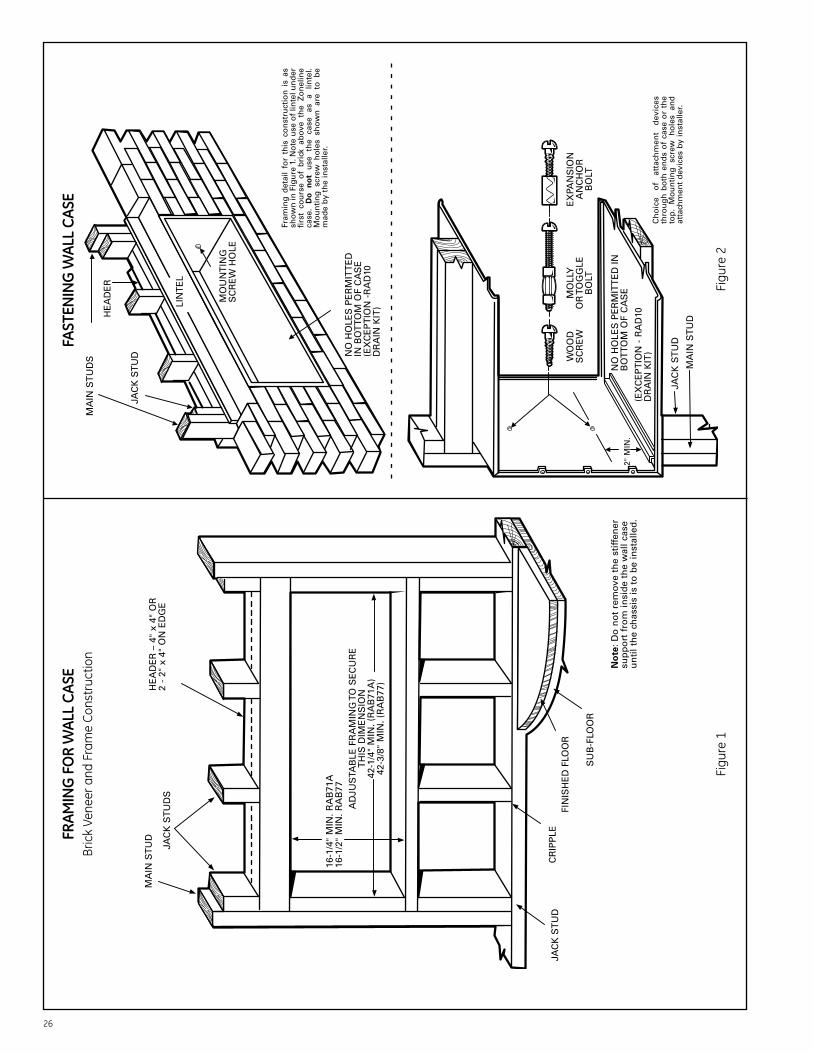
26
FRAM
ING
FO
R W
ALL
CASE
Bric
k Ve
neer
and
Fra
me
Cons
truc
tion
FAST
ENIN
G W
ALL
CASE
Figu
re 1
Figu
re 2
MA
IN S
TU
D
JAC
K S
TU
DS
HE
AD
ER
– 4
" x
4" O
R2
- 2"
x 4
" O
N E
DG
E
16-1
/4"
MIN
. RA
B71
A16
-1/2
" M
IN. R
AB
77A
DJU
STA
BLE
FR
AM
ING
TO
SE
CU
RE
TH
IS D
IME
NS
ION
42-1
/4"
MIN
. (R
AB
71A
)42
-3/8
" M
IN. (
RA
B77
)
JAC
K S
TU
DC
RIP
PLE
FIN
ISH
ED
FLO
OR
SU
B-F
LOO
R
No
te: D
o n
ot
rem
ove
the
stiff
ener
su
pp
ort
fro
m in
sid
e th
e w
all c
ase
un
til t
he
chas
sis
is t
o b
e in
stal
led
.
MA
IN S
TU
DS
JAC
K S
TU
D
HE
AD
ER
MO
UN
TIN
GS
CR
EW
HO
LE
LIN
TE
L
Fram
ing
det
ail
for
this
co
nst
ruct
ion
is
as
sho
wn
in F
igu
re 1
. No
te u
se o
f lin
tel u
nd
er
firs
t co
urs
e o
f b
rick
ab
ove
the
Zo
nel
ine
case
. D
o
no
t u
se
the
case
as
a
linte
l. M
ou
nti
ng
scr
ew h
ole
s sh
ow
n a
re t
o b
e m
ade
by
the
inst
alle
r.
NO
HO
LES
PE
RM
ITT
ED
IN B
OT
TOM
OF
CA
SE
(EX
CE
PT
ION
-R
AD
10D
RA
IN K
IT)
Ch
oic
e o
f at
tach
men
t d
evic
es
thro
ug
h b
oth
en
ds
of
case
or
the
top
. M
ou
nti
ng
sc
rew
h
ole
s an
d
atta
chm
ent
dev
ices
by
inst
alle
r.M
AIN
ST
UD
JAC
K S
TU
D
2" M
IN.
WO
OD
SC
RE
WM
OLL
YO
R T
OG
GLE
BO
LT
EX
PAN
SIO
NA
NC
HO
RB
OLT
NO
HO
LES
PE
RM
ITT
ED
INB
OT
TOM
OF
CA
SE
(EX
CE
PT
ION
- R
AD
10D
RA
IN K
IT)

27
geappliances.com
WAL
L SE
CTIO
N –
DET
AILE
D S
IDE
VIEW
Fram
e an
d Br
ick
Vene
er In
stal
latio
nCo
rd s
et c
onne
cted
CA
ULK
*
Sub-
Base
Con
nect
ed
CA
ULK
*
ST
EE
L LI
NT
EL
RA
B71
A
13-
3/4"
RA
B77
13-
7/8"
20-7
/8"
(R
AB
71A
)21
"
(R
AB
77)
RO
OM
CA
BIN
ET
2" M
IN.
MO
UN
TIN
G S
CR
EW
SB
Y IN
STA
LLE
R
RA
B71
A
16"
RA
B77
16-
1/4"
WA
LL C
AS
E
OU
TD
OO
RG
RIL
LE
CA
ULK
*
CA
ULK
*
1/4"
MIN
. RA
G60
1/
4"R
AG
61, 6
2, 6
3 1-
3/8"
RA
G67
1-
1/4"
PO
WE
R S
UP
PLY
CO
ND
UIT
WA
LL R
EC
EP
TAC
LE(B
Y O
TH
ER
S)
FIN
ISH
ED
FLO
OR
OR
TO
P O
FC
AR
PE
T
*Cau
lk a
rou
nd
per
imet
er o
f w
all c
ase
all f
ou
r si
des
wh
ere
it jo
ins
the
bu
ildin
g -
Inte
rio
r an
d E
xter
ior.
CA
ULK
*
1/4"
CA
ULK
*
LIN
TE
L
RA
B71
A
13-
3/4"
RA
B77
13-
7/8"
20-7
/8"
(R
AB
71A
)21
"
(R
AB
77)
RO
OM
CA
BIN
ET
2" M
IN.
MO
UN
TIN
G S
CR
EW
SB
Y IN
STA
LLE
R RA
B71
A
16"
RA
B77
16-
1/4"
WA
LL C
AS
E
OU
TD
OO
RG
RIL
LE
SID
E C
HA
NN
EL
3" M
IN.
5" M
AX
.
1-5/
16"
FIN
ISH
ED
FLO
OR
OR
TO
P O
FC
AR
PE
T
SU
B-B
AS
E(R
AK
204)
CA
ULK
*
PO
WE
R S
UP
PLY
CO
ND
UIT
(ALT
ER
NA
TE
EN
TR
Y)
3-11
/16"
*Cau
lk a
rou
nd
p
erim
eter
of
wal
l ca
se a
ll fo
ur
sid
es
wh
ere
it jo
ins
the
bu
ildin
g -
Inte
rio
r an
d E
xter
ior.
2-3/
8"

28
WAL
L SE
CTIO
N –
DET
AILE
D S
IDE
VIEW
Win
dow
, 2" c
urta
in o
r pan
el w
all i
nsta
llatio
n w
ith ra
g re
ar g
rille
ext
ende
d be
yond
out
er w
all s
urfa
ce
RO
OM
CA
BIN
ET
Gas
ket
and
ca
ulk
aro
un
d
per
imet
er o
f w
all c
ase
all
fou
r si
des
w
her
e it
join
s th
e b
uild
ing
WA
LL C
AS
E
OU
TD
OO
RG
RIL
LE
Gas
ket
and
ca
ulk
aro
un
d
per
imet
er o
f w
all c
ase
all
fou
r si
des
w
her
e it
join
s th
e b
uild
ing
CA
SE
AN
GLE
(FI
ELD
SU
PP
LIE
D)
RA
B71
A
22-1
/4"
RA
B77
22
-3/8
"W
ITH
RA
G61
-63
RA
B71
A
21-1
/8"
RA
B77
21
-1/4
"W
ITH
RA
G60
RA
B71
A
16"
RA
B77
16-1
/4"
RE
CE
PTA
CLE
(BY
OT
HE
RS
)
MIN
. 2 S
UP
PO
RT
SFI
ELD
SU
PP
LIE
DFL
OO
R
US
E N
OS
CR
EW
S IN
BO
TTO
M O
FC
AS
E
16"
RO
OM
CA
BIN
ET
WA
LL C
AS
E
OU
TD
OO
RG
RIL
LE
CA
SE
AN
GLE
(FI
ELD
SU
PP
LIE
D)
RA
B71
A
22-1
/4"
RA
B77
22
-3/8
"W
ITH
RA
G61
-63
RA
B71
A
21-1
/8"
RA
B77
21
-1/4
"W
ITH
RA
G60
RA
B71
A
16"
RA
B77
A
16-1
/4"
16"
WA
LL O
RW
IND
OW
GA
SK
ET
(FIE
LDS
UP
PLI
ED
)
SID
EC
HA
NN
EL
(RA
K20
4)S
UB
-BA
SE
PO
WE
R S
UP
PLY
CO
ND
UIT
(ALT
ER
NA
TE
EN
TR
Y)LE
VE
LIN
G L
EG
3" M
IN.
5" M
AX
.
FLO
OR
Sub-
Base
Con
nect
edCo
rd S
et C
onne
cted
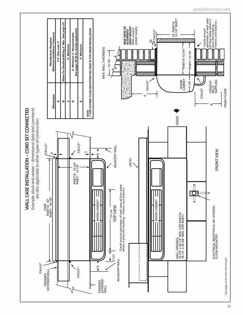
29
geappliances.com
WAL
L CA
SE IN
STAL
LATI
ON
– C
ORD
SET
CO
NN
ECTE
DEx
ampl
e: b
lock
and
ven
eer –
dim
ensi
onal
dat
a an
d co
mm
ents
are
also
app
licab
le to
oth
er ty
pes
of c
onst
ruct
ion
Man
ufa
ctu
rer
Req
uir
edM
inim
um
Inst
alla
tio
n C
lear
ance
1/4"
(S
ee n
ote
1)
Allo
w F
or
Ele
ctri
cal W
irin
g 0
" M
in. (
See
pag
e 27
)
0" M
inim
um
0" M
inim
um
2"
Rec
om
men
ded
See
pag
es 3
8-39
fo
r d
uct
ed a
pp
licat
ion
.
3" M
inim
um
FIN
ISH
ED
EX
TE
RIO
R W
ALL
Dim
ensi
on
A B C D E
NO
TE
:1.
FO
R O
UT
SID
E F
LUS
H M
OU
NT
ING
SE
E P
AG
E 3
5 FO
R D
RA
IN IN
STA
LLA
TIO
N.
CA
ULK
*
CA
ULK
*
CA
ULK
*
CA
ULK
*
CA
ULK
*
CA
ULK
*
CA
SE
RA
B71
A
42"
RA
B77
4
2-1/
8"
FIN
ISH
ED
EX
TE
RIO
R
WA
LL
RO
OM
CA
BIN
ET
RA
B71
A
13-
3/4"
RA
B77
1
3-7/
8" AD
JAC
EN
T W
ALL
AD
JAC
EN
T W
ALL
D
A C
D
27-1
/4"
TOP
VIE
W2-
1/2"
*Cau
lk a
rou
nd
per
imet
er o
f w
all c
ase
all f
ou
r si
des
wh
ere
it jo
ins
the
bu
ildin
g -
Inte
rio
r an
d E
xter
ior.
RO
OM
CA
BIN
ET
LIN
TE
L
FRO
NT
VIE
WE
LEC
TR
ICA
L R
EC
EP
TAC
LE (
BY
OT
HE
RS
).FL
US
H M
OU
NT
ED
.
WA
LL O
PE
NIN
G16
-1/4
" x
42-1
/4"
MIN
. FO
R R
AB
71A
16-1
/2"
x 42
-3/8
" M
IN. F
OR
RA
B77
See
page
43
for l
ine
cord
leng
th.
INS
IDE
MA
X. W
ALL
TH
ICK
NE
SS
13-1
/8"
E
B
A CA
ULK
*
FIN
ISH
FLO
OR
*Cau
lk a
rou
nd
per
imet
er o
f w
all c
ase
all f
ou
r si
des
wh
ere
itjo
ins
the
bu
ildin
g -
Inte
rio
r an
d E
xter
ior.
RO
OM
CA
BIN
ET
7-1/
8"
RA
B71
A 1
3-3/
4"
RA
B77
13-
7/8"
16"
RA
B71
A16
-1/8
" R
AB
77
SID
E V
IEW
OF
ALT
ER
NA
TE
HIG
H M
OU
NT
Wit
h c
on
du
itp
ow
er s
up
ply
.
CO
ND
UIT
FI
ELD
S
UP
PLI
ED
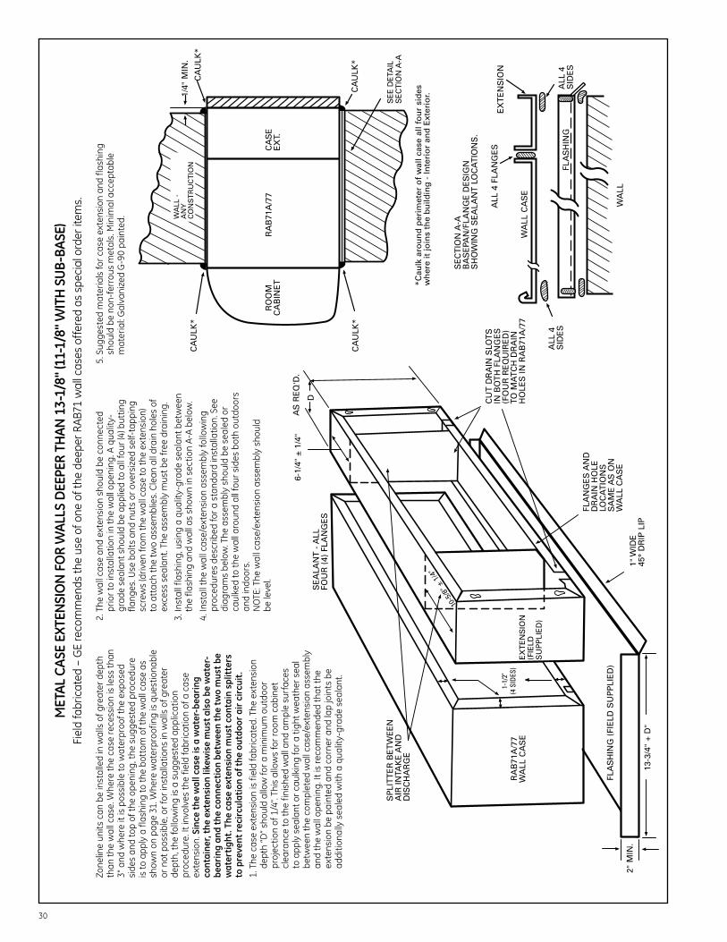
30
MET
AL C
ASE
EXTE
NSI
ON
FO
R W
ALLS
DEE
PER
THAN
13-
1/8"
(11-
1/8"
WIT
H S
UB-B
ASE)
Fiel
d fa
bric
ated
– G
E re
com
men
ds th
e us
e of
one
of t
he d
eepe
r RAB
71 w
all c
ases
off
ered
as
spec
ial o
rder
item
s.
CA
ULK
*
SP
LIT
TE
R B
ET
WE
EN
A
IR IN
TAK
E A
ND
D
ISC
HA
RG
E
Zone
line
units
can
be
inst
alle
d in
wal
ls o
f gre
ater
dep
th
than
the
wal
l cas
e. W
here
the
case
rec
essi
on is
less
than
3"
and
whe
re it
is p
ossi
ble
to w
ater
proo
f the
exp
osed
si
des
and
top
of th
e op
enin
g, th
e su
gges
ted
proc
edur
e is
to a
pply
a fl
ashi
ng to
the
bott
om o
f the
wal
l cas
e as
sh
own
on p
age
31. W
here
wat
erpr
oofin
g is
que
stio
nabl
e or
not
pos
sibl
e, o
r fo
r ins
talla
tions
in w
alls
of g
reat
er
dept
h, th
e fo
llow
ing
is a
sug
gest
ed a
pplic
atio
n pr
oced
ure.
It in
volv
es th
e fie
ld fa
bric
atio
n of
a c
ase
exte
nsio
n. S
ince
the
wal
l cas
e is
a w
ater
-bea
ring
co
ntai
ner,
the
exte
nsio
n lik
ewis
e m
ust a
lso
be w
ater
- be
arin
g an
d th
e co
nnec
tion
betw
een
the
two
mus
t be
wat
ertig
ht. T
he c
ase
exte
nsio
n m
ust c
onta
in s
plit
ters
to
pre
vent
rec
ircu
latio
n of
the
outd
oor
air
circ
uit.
1. T
he c
ase
exte
nsio
n is
fiel
d fa
bric
ated
. The
ext
ensi
on
dept
h “D
” sho
uld
allo
w fo
r a
min
imum
out
door
pr
ojec
tion
of 1
/4".
This
allo
ws
for
room
cab
inet
cl
eara
nce
to th
e fin
ishe
d w
all a
nd a
mpl
e su
rfac
es
to a
pply
sea
lant
or
caul
king
for
a tig
ht w
eath
er s
eal
betw
een
the
com
plet
ed w
all c
ase/
exte
nsio
n as
sem
bly
and
the
wal
l ope
ning
. It i
s re
com
men
ded
that
the
exte
nsio
n be
pai
nted
and
cor
ner a
nd la
p jo
ints
be
addi
tiona
lly s
eale
d w
ith a
qua
lity-
grad
e se
alan
t.
2. T
he w
all c
ase
and
exte
nsio
n sh
ould
be
conn
ecte
d pr
ior t
o in
stal
latio
n in
the
wal
l ope
ning
. A q
ualit
y-
grad
e se
alan
t sho
uld
be a
pplie
d to
all
four
(4) b
uttin
g fla
nges
. Use
bol
ts a
nd n
uts
or o
vers
ized
sel
f-ta
ppin
g sc
rew
s (d
riven
from
the
wal
l cas
e to
the
exte
nsio
n)
to a
ttac
h th
e tw
o as
sem
blie
s. C
lean
all
drai
n ho
les
of
exce
ss s
eala
nt. T
he a
ssem
bly
mus
t be
free
dra
inin
g.
3. In
stal
l fla
shin
g, u
sing
a q
ualit
y-gr
ade
seal
ant b
etw
een
the
flash
ing
and
wal
l as
show
n in
sec
tion
A-A
belo
w.
4. In
stal
l the
wal
l cas
e/ex
tens
ion
asse
mbl
y fo
llow
ing
proc
edur
es d
escr
ibed
for a
sta
ndar
d in
stal
latio
n. S
ee
diag
ram
s be
low
. The
ass
embl
y sh
ould
be
seal
ed o
r ca
ulke
d to
the
wal
l aro
und
all f
our s
ides
bot
h ou
tdoo
rs
and
indo
ors.
N
OTE
: The
wal
l cas
e/ex
tens
ion
asse
mbl
y sh
ould
be
leve
l.
5. S
ugge
sted
mat
eria
ls fo
r ca
se e
xten
sion
and
flas
hing
sh
ould
be
non-
ferr
ous
met
als.
Min
imal
acc
epta
ble
mat
eria
l: G
alva
nize
d G
-90
pain
ted.
SE
ALA
NT
- A
LLFO
UR
(4)
FLA
NG
ES
6-1/
4" ±
1/4
"A
S R
EQ
'D.
CU
T D
RA
IN S
LOT
SIN
BO
TH
FLA
NG
ES
(FO
UR
RE
QU
IRE
D)
TO M
AT
CH
DR
AIN
HO
LES
IN R
AB
71A
/77
FLA
NG
ES
AN
DD
RA
IN H
OLE
LOC
AT
ION
SS
AM
E A
S O
NW
ALL
CA
SE
1" W
IDE
45°
DR
IP L
IP
FLA
SH
ING
(FI
ELD
SU
PP
LIE
D)
13-3
/4"
+ D
"
2" M
IN.
D
10-5
/8" ±
1/4
"
CA
ULK
*
CA
ULK
*
CA
ULK
*
WA
LL -
AN
YC
ON
ST
RU
CT
ION
RA
B71
A/7
7R
OO
MC
AB
INE
TC
AS
EE
XT.
SE
E D
ETA
ILS
EC
TIO
N A
-A
*Cau
lk a
rou
nd
per
imet
er o
f w
all c
ase
all f
ou
r si
des
wh
ere
it jo
ins
the
bu
ildin
g -
Inte
rio
r an
d E
xter
ior.
EX
TE
NS
ION
ALL
4 F
LAN
GE
S
WA
LL C
AS
E
ALL
4
SID
ES
WA
LL
FLA
SH
ING
ALL
4
SID
ES
SE
CT
ION
A-A
BA
SE
PAN
/FLA
NG
E D
ES
IGN
SH
OW
ING
SE
ALA
NT
LO
CA
TIO
NS
.
1/4"
MIN
.
RA
B71
A/7
7W
ALL
CA
SE
1-1/
2"(4
SID
ES)
EX
TE
NS
ION
(FIE
LDS
UP
PLI
ED
)
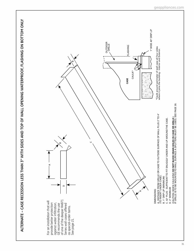
31
geappliances.com
CA
ULK
*
A
DIM
EN
SIO
NS
:A
. DIS
TAN
CE
FR
OM
GR
ILLE
OR
CA
SE
TO
OU
TS
IDE
SU
RFA
CE
OF
WA
LL P
LUS
2" T
O 4
" (T
O IN
SE
RT
UN
DE
R C
AS
E).
B. 1
" D
RIP
LIP
(M
INIM
UM
)C
. 42"
PLU
S -
SU
FFIC
IEN
T T
O F
IT S
NU
GG
LY U
ND
ER
AN
D U
P A
RO
UN
D T
HE
CA
SE
.D
. 2"
MIN
IMU
M(C
AU
TIO
N: W
HE
N C
AU
LKIN
G D
O N
OT
BLO
CK
DR
AIN
HO
LES
IN C
AS
E O
R G
RIL
LE.)
IF G
RIL
LE IS
TO
BE
MO
UN
TE
D T
O W
ALL
SU
RFA
CE
A S
PLI
TT
ER
S M
US
T B
E U
SE
D, S
EE
PA
GE
30.
B
D
C
A
B
*Cau
lk a
rou
nd
per
imet
er o
f w
all c
ase
all f
ou
r si
des
wh
ere
it jo
ins
the
bu
ildin
g -
Inte
rio
r an
d E
xter
ior.
1" W
IDE
45°
DR
IP L
IP
FLA
SH
ING
OU
TD
OO
RG
RIL
LE
CA
SE
For a
n in
stal
latio
n th
at w
ill
prov
ide
bett
er p
rote
ctio
n ag
ains
t wat
er in
filtr
atio
n,
GE
reco
mm
ends
the
use
of
one
of t
he d
eepe
r RAB
71
Serie
s w
all c
ases
off
ered
as
spe
cial
-ord
er it
ems.
Se
e pa
ge 2
1.
ALTE
RNAT
E –
CASE
REC
ESSI
ON
LES
S TH
AN 3
" W
ITH
SID
ES A
ND
TO
P O
F W
ALL
OPE
NIN
G W
ATER
PRO
OF,
FLA
SHIN
G O
N B
OTT
OM
ON
LY
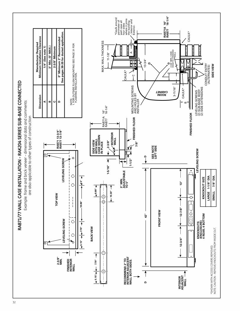
32
RAB7
1/77
WAL
L CA
SE IN
STAL
LATI
ON
- RA
K204
SER
IES
SUB-
BASE
CO
NN
ECTE
DEx
ampl
e: fr
ame
and
bric
k ve
neer
- d
imen
sion
al d
ata
and
com
men
tsar
e al
so a
pplic
able
to o
ther
type
s of
con
stru
ctio
n
TOP
VIE
W
Man
ufa
ctu
rer
Req
uir
edM
inim
um
Inst
alla
tio
n C
lear
ance
1/4"
(S
ee n
ote
1)
3" M
in. (
5" M
AX
.)
2-3/
8" M
inim
um
0" M
inim
um
2"
Rec
om
men
ded
See
pag
es 3
8-39
fo
r d
uct
ed a
pp
licat
ion
.
Dim
ensi
on
A B C D
NO
TE
:1.
FO
R O
UT
SID
E F
LUS
H M
OU
NT
ING
SE
E P
AG
E 3
1 FO
R
FLA
SH
ING
INS
TALL
AT
ION
.
2-3/
8"M
IN.
FIN
ISH
ED
INT
ER
IOR
WA
LL
LEV
ELI
NG
SC
RE
WLE
VE
LIN
G S
CR
EW
RA
B71
13-
3/4"
RA
B77
13-
7/8"
5.15
"7.
70"
18.8
6"1.
5"
5.15
"7.
70"
10.3
0"8.80
"
BA
CK
VIE
W
FRO
NT
VIE
W
42"
DD SE
E N
OT
ELE
FT S
IDE
INT
ER
IOR
AD
JAC
EN
TW
ALL
12-3
/4"
12-7
/8"
13"
LEV
ELI
NG
SC
RE
W
KN
OC
KO
UT
SIZ
E
LAR
GE
1
-1/8
" D
IA.
SM
ALL
7/8
" D
IA.
KN
OC
KO
UT
S(E
NC
LOS
UR
E)
4 R
EA
R; 4
BO
TTO
M
*SH
OW
N W
ITH
ACC
ESS
COVE
RS R
EMO
VED
.N
OTE
: CAU
TIO
N -
REM
OVE
KN
OCK
OU
TS F
ROM
INSI
DE
OU
T.
SID
E V
IEW
WIT
H W
ALL
CA
SE
SH
OW
NIN
PLA
CE
FIN
ISH
ED
FLO
OR
3" M
IN.
AD
JUS
TAB
LETO
5"
1-5/
16"
2-3/
8"IN
TE
RIO
RW
ALL
RA
B71
A
16"
RA
B77
16-
1/4"
7/8"
1-1/
2"
FIN
ISH
ED
FLO
OR
RA
B71
A
16"
RA
B77
16-1
/4"
SID
E V
IEW
MA
X. W
ALL
TH
ICK
NE
SS
11-1
/8"
MO
UN
TIN
G S
CR
EW
SA
ND
HO
LES
BY
INS
TALL
ER
LEV
ELI
NG
SC
RE
WS
(2)
SU
B-B
AS
E B
OD
Y(2
) S
IDE
EX
TE
NS
ION
S
CO
ND
UIT
EN
TR
Y(A
LTE
RN
AT
ES
)
CA
ULK
*
ROOMCABINET
CA
BC
AU
LK*
3-11
/16"
2-3/
8" M
IN. C
AS
EE
DG
E T
O F
INIS
HE
D
W
ALL
13-3
/4"
CA
ULK
*
*Cau
lk a
rou
nd
p
erim
eter
of
wal
l cas
e al
l fo
ur
sid
es
wh
ere
it jo
ins
the
bu
ildin
g
- In
teri
or
and
E
xter
ior.
RE
CO
MM
EN
D 2
" TO
INT
ER
IOR
AD
JAC
EN
TW
ALL
BO
TH
SID
ES
.

33
geappliances.com
RAK2
04 S
ERIE
S SU
B-BA
SE IN
STAL
LATI
ON
AN
D E
LECT
RICA
L D
ATA
RAB7
1A/7
7 W
all C
ase
RA
K40
02B
CH
AS
EW
AY O
PT
ION
(Sh
ow
n W
ith
ou
t C
has
sis
and
Wal
l Cas
e fo
r In
stal
lati
on
Lo
cati
on
On
ly.)
NO
TE
: TY
PE
“E
”M
OU
NT
ING
CLI
P M
US
TB
E U
SE
D W
ITH
MO
LDE
DC
AS
E.
MO
LDE
DC
AS
E
SU
B-B
AS
EM
OU
NT
ING
CLI
PTY
PE
“E
”
TYP
E“D
”U
SE
WIT
HR
AB
71A
TYP
E“E
”U
SE
WIT
HR
AB
77
TY
PE
“A
”
T
YP
E “
B”
T
YP
E “
C”
6
RE
Q’D
.
2
RE
Q’D
.
8
RE
Q’D
.
GR
EE
N
GR
OU
ND
SC
RE
W(T
YP
E “
C”)
ME
TAL
CA
SE
SC
RE
W C
LIP
TYP
E “
D”
TYP
E “
A”
SC
RE
W
TO S
EC
UR
ES
IDE
CH
AN
NE
LS
6"
5/
32"
DIA
. HO
LE (
SE
E N
OT
E)
F
OR
SE
CU
RIN
G T
YP
E “
D”
CLI
PS
TO
SLE
EV
E U
SIN
G
TYP
E “
A”
SC
RE
WS
6"
TYP
E “
A”
SC
RE
W
TYP
E “
C”
SC
RE
WA
CC
ES
S P
LAT
ES
TYP
E “
C”
SC
RE
W
TYP
E “
B”
SC
RE
W
SID
E C
HA
NN
ELS
AR
E A
DJU
STA
BLE
FRO
M 1
3-3/
4" T
O 2
-3/8
" IN
LE
NG
TH
BY
BR
EA
KIN
G O
FF S
EC
TIO
NS
OF
SID
EC
HA
NN
ELS
.N
OT
E: I
F M
ETA
L C
AS
E D
OE
S N
OT
HA
VE
SC
RE
W H
OLE
S, 5
/32"
DIA
. HO
LES
MU
ST
B
E D
RIL
LED
6"
FRO
M E
AC
H S
IDE
IN F
RO
NT
FLA
NG
E. (
SE
E IN
SE
RT
).
Elec
tric
al w
iring
may
ent
er th
e su
b-ba
se th
roug
h an
y of
the
knoc
kout
hol
es p
rovi
ded
in th
e su
b-ba
se.
Knoc
kout
hol
es in
the
sub-
base
acc
ess
plat
e m
ay a
ccom
mod
ate
a re
cept
acle
, whi
ch a
llow
s th
e us
e of
a p
ower
cor
d (if
per
mitt
ed b
y co
de fo
r the
par
ticul
ar in
stal
latio
n).
A kn
ocko
ut fo
r a c
ircui
t bre
aker
, fus
ehol
der o
r a d
isco
nnec
t is
also
pro
vide
d. S
ee p
ages
22
and
23 fo
r des
crip
tion
of e
lect
rical
con
tent
s of
thes
e su
b-ba
ses.
34
Condensate Disposal Systems
Cooling CondensateAir conditioners produce condensate water as a result of lowering the humidity of the area being conditioned. When the indoor coil temperature is below the dew point, moisture in the air condenses into water droplets on the coil. This water drains to a pan located under the indoor coil and is routed through the barrier (the partition separating the indoor and outdoor sides of the unit) to the base pan on the outdoor side. It is then picked up and dispersed against the outdoor coil, which is hot when the unit is in the air conditioning mode. The water is evaporated into the atmosphere by contact with the hot outdoor coil. This evaporation process also helps lower the temperature of the outdoor coil and improves the operating efficiency of the unit.
Slinger Ring SystemsPackaged terminal units employ various means of dispersing the condensate water. One of the most popular, and most effective, means is by the use of a “slinger ring.” A slinger ring is a ring around the circumference of the outdoor fan. The design of the unit positions the slinger ring very close to the bottom of the base pan so water in the base pan is lifted by the rotating ring. Water picked up by the slinger ring will be dispersed into the air stream and deposited on the hot outdoor coil where it evaporates.
All Zoneline® Series packaged terminal air conditioners and packaged terminal heat pumps utilize a slinger ring for cooling condensate disposal.
Certification Test RequirementsARI (Air Conditioning & Refrigerating Institute) requires that all certified packaged terminal air conditioners and packaged terminal heat pumps pass a cooling condensate disposal test. One stipulation of the ARI test is that “the test start with condensate collection pan brimful.” In order to pass the ARI Condensate Disposal Test the unit must operate continuously for four hours without condensed water blowing, dripping, or running off the unit casing during the test or after the unit has been turned off. Under extremely high outdoor humidity conditions or extreme operating conditions, such as exceptionally high air infiltration (a door or window left open while the unit is running, for instance) it is possible for any air conditioner to be unable to dissipate all the cooling condensate generated.
All Zoneline Series packaged terminal air conditioners and packaged terminal heat pumps meet the condensate disposal requirements of ARI standards 310 and 380.
Heat Pump CondensateDuring the operation of a unit in the heat pump, or “reverse cycle,” mode the outdoor coil becomes the cold coil and the indoor coil becomes the hot coil due to reversing the flow of the refrigerant. When the temperature of the outdoor coil is below the dew point, condensation will form on the outdoor coil just as it does on the indoor coil during cooling operation. Since the dew point is humidity- as well as temperature- related, there may be more condensate on days when the relative humidity is high.
Heat Pump Condensate DisposalSince the outdoor coil is cold during heat pump operation, the condensate water cannot be deposited on the outdoor coil as the water would cause frost to form on the coil. This frost would block the airflow through the coil and greatly reduce the outdoor air. Rather than allow this problem to occur, heat pump units must dispose of the condensate in another manner.
Temperature-Activated Drain ValveThe most widely used method of disposing of heat pump condensate is with a temperature-activated drain valve. This is a device mounted in the base pan of a heat pump unit with a bellows that expands on temperature rise and contracts with temperature drop. A shaft with a rubber plug on the end is connected to the bellows. When the outdoor
temperature remains above a certain temperature, the bellows is expanded and the plug fits tightly into a hole in the bottom, or base pan, of the unit. When the plug is blocking the hole, as it should be during cooling operation, the condensate water is contained in the base pan. At temperatures when heating is required, the bellows contracts, the rubber plug is retracted from the hole and the heat pump condensate water is allowed to drain into the wall case. The valve is fully open at approximately 45°F.
Drain KitsAlthough the Zoneline units are designed to dissipate most of the condensate generated during normal cooling operation, there may be times when abnormal operating conditions cause more condensate than the unit can dissipate. Heat pumps also generate condensate that the unit may not be designed to dissipate. For these reasons, if condensate dripping from the wall case is objectionable, an internal or external drain system should be installed. See pages 35 and 36 for information covering the drain systems and the RAD10 kit available to connect to the wall case.
Internal Condensate Removal (ICR) SystemGE has developed an Internal Condensate Removal (ICR) system for packaged terminal heat pumps. This system has been offered as an option on Zoneline packaged terminal Heat Pumps since 1982, and thousands of them are in use. During heat pump operation the ICR system utilizes a small pump to lift the water from the base pan and pump it into a collector tray positioned above the indoor coil. The water drains from the collector tray and drips onto the warm indoor coil where it is evaporated into the room atmosphere. If an excess amount of water is pumped to the indoor side, it is routed back to the outdoor portion of the base pan.
The ICR system has proven to be an effective means of minimizing the amount of heat pump condensate dripping from the unit. However, if the restrictions of a particular installation will allow absolutely no drippage of condensate water from the wall case, the installation of an internal or external drain system is recommended.
Units with ICR may not be installed in seacoast or corrosive environment applications.
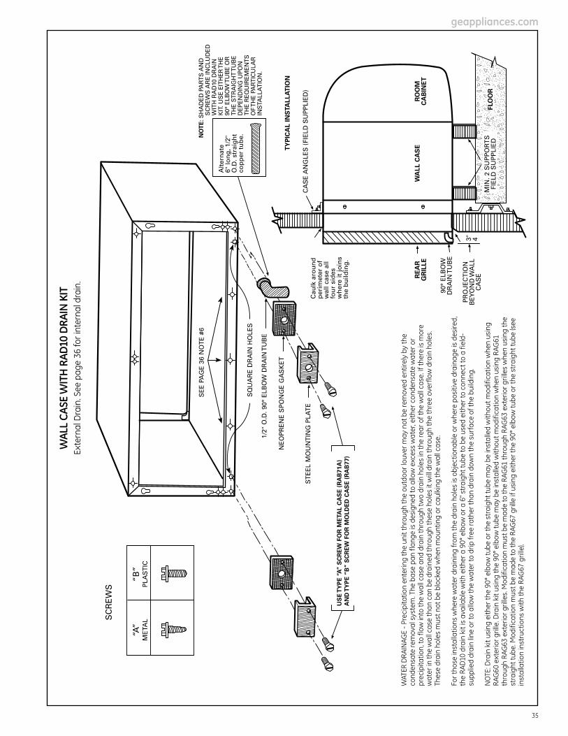
35
geappliances.com
WAL
L CA
SE W
ITH
RAD
10 D
RAIN
KIT
Exte
rnal
Dra
in. S
ee p
age
36 fo
r int
erna
l dra
in.
SE
E P
AG
E 3
6 N
OT
E #
6
SC
RE
WS
RE
AR
GR
ILLE
“A”
ME
TAL
“B”
PLA
ST
IC
NE
OP
RE
NE
SP
ON
GE
GA
SK
ET
1/2"
O.D
. 90°
ELB
OW
DR
AIN
TU
BE
ST
EE
L M
OU
NT
ING
PLA
TE
US
E T
YP
E “
A”
SC
RE
W F
OR
ME
TAL
CA
SE
(R
AB
71A
)A
ND
TY
PE
“B
” S
CR
EW
FO
R M
OLD
ED
CA
SE
(R
AB
77)
Alt
ern
ate
6" lo
ng
, 1/2
"O
.D. s
trai
gh
tco
pp
er t
ub
e.NO
TE
: SH
AD
ED
PA
RT
S A
ND
S
CR
EW
S A
RE
INC
LUD
ED
W
ITH
RA
D10
DR
AIN
K
IT. U
SE
EIT
HE
R T
HE
90
° E
LBO
W T
UB
E O
R
TH
E S
TR
AIG
HT
TU
BE
D
EP
EN
DIN
G U
PO
N
TH
E R
EQ
UIR
EM
EN
TS
O
F T
HE
PA
RT
ICU
LAR
IN
STA
LLA
TIO
N.
WA
LL C
AS
ER
OO
MC
AB
INE
T
PR
OJE
CT
ION
BEY
ON
D W
ALL
CA
SE
90°
ELB
OW
DR
AIN
TU
BE
MIN
. 2 S
UP
PO
RT
SFI
ELD
SU
PP
LIE
DFL
OO
R
CA
SE
AN
GLE
S (
FIE
LD S
UP
PLI
ED
)
TYP
ICA
L IN
STA
LLA
TIO
N
Cau
lk a
rou
nd
p
erim
eter
of
wal
l cas
e al
l fo
ur
sid
es
wh
ere
it jo
ins
the
bu
ildin
g.
3" 4"
WAT
ER D
RAIN
AGE
- Pr
ecip
itatio
n en
terin
g th
e un
it th
roug
h th
e ou
tdoo
r lou
ver m
ay n
ot b
e re
mov
ed e
ntire
ly b
y th
e
cond
ensa
te re
mov
al s
yste
m. T
he b
ase
pan
flang
e is
des
igne
d to
allo
w e
xces
s w
ater
, eith
er c
onde
nsat
e w
ater
or
prec
ipita
tion,
to fl
ow in
to th
e w
all c
ase
and
drai
n th
roug
h tw
o dr
ain
hole
s in
the
rear
of t
he w
all c
ase.
If th
ere
is m
ore
wat
er in
the
wal
l cas
e th
an c
an b
e dr
aine
d th
roug
h th
ese
hole
s it
will
dra
in th
roug
h th
e th
ree
over
flow
dra
in h
oles
. Th
ese
drai
n ho
les
mus
t not
be
bloc
ked
whe
n m
ount
ing
or c
aulk
ing
the
wal
l cas
e.
For t
hose
inst
alla
tions
whe
re w
ater
dra
inin
g fr
om th
e dr
ain
hole
s is
obj
ectio
nabl
e or
whe
re p
ositi
ve d
rain
age
is d
esire
d,
the
RAD
10 d
rain
kit
is a
vaila
ble
with
eith
er a
90°
elb
ow o
r a 6
" str
aigh
t tub
e to
be
used
eith
er to
con
nect
to a
fiel
d-
supp
lied
drai
n lin
e or
to a
llow
the
wat
er to
drip
free
rath
er th
an d
rain
dow
n th
e su
rfac
e of
the
build
ing.
NO
TE: D
rain
kit
usin
g ei
ther
the
90°
elbo
w tu
be o
r the
str
aigh
t tub
e m
ay b
e in
stal
led
with
out m
odifi
catio
n w
hen
usin
g RA
G60
ext
erio
r gril
le. D
rain
kit
usin
g th
e 90
° el
bow
tube
may
be
inst
alle
d w
ithou
t mod
ifica
tion
whe
n us
ing
RAG
61
thro
ugh
RAG
63 e
xter
ior g
rille
s. M
odifi
catio
n m
ust b
e m
ade
to th
e RA
G61
thro
ugh
RAG
63 e
xter
ior g
rille
s w
hen
usin
g th
e st
raig
ht tu
be. M
odifi
catio
n m
ust b
e m
ade
to th
e RA
G67
gril
le if
usi
ng e
ither
the
90°
elbo
w tu
be o
r the
str
aigh
t tub
e (s
ee
inst
alla
tion
inst
ruct
ions
with
the
RAG
67 g
rille
).
SQ
UA
RE
DR
AIN
HO
LES

36
WAL
L CA
SE W
ITH
RAD
10 D
RAIN
KIT
Inte
rnal
Dra
in. S
ee p
age
35 fo
r ext
erna
l dra
in.
SC
RE
WS
“A”
ME
TAL
“B”
PLA
ST
IC
NE
OP
RE
NE
SP
ON
GE
GA
SK
ET
ST
EE
L M
OU
NT
ING
PLA
TE
US
E T
YP
E “
A”
SC
RE
W F
OR
ME
TAL
CA
SE
(R
AB
71)
AN
D T
YP
E “
B”
SC
RE
W F
OR
MO
LDE
D C
AS
E (
RA
B77
)
NO
TE
: SH
AD
ED
PA
RT
S A
ND
SC
RE
WS
IN
CLU
DE
D W
ITH
RA
D10
DR
AIN
K
IT. T
HE
90°
ELB
OW
TU
BE
IS
RE
CO
MM
EN
DE
D F
OR
INT
ER
NA
L D
RA
IN IN
STA
LLA
TIO
N.
OV
ER
FLO
W R
ELI
EF
DR
AIN
SE
E N
OT
E 6
SE
E D
ETA
ILB
ELO
W
US
E T
YP
E “
A”
SC
RE
WS
FO
R B
OT
H R
AB
71A
AN
D R
AB
77
NU
T(M
OLD
ED
CA
SE
(R
AB
77)
ON
LY)
DE
TAIL
GA
SK
ET
CA
BIN
ET
BO
TTO
M
TU
BE
1/2"
OD
CO
VE
RP
LAT
E
1. T
he R
AD10
dra
in k
it is
inst
alle
d in
the
bott
om o
f the
wal
l cas
e w
hen
it is
des
ired
to d
rain
co
nden
sate
to a
n in
tern
al d
rain
sys
tem
in th
e bu
ildin
g.2.
The
dra
in k
it is
mou
nted
on
the
bott
om o
f the
wal
l cas
e pr
ior t
o in
stal
latio
n of
the
case
in th
e w
all.
It m
ay b
e lo
cate
d an
ywhe
re o
n th
e ro
om-s
ide
port
ion
exce
pt fo
r sub
-bas
e in
stal
latio
ns.
For t
hese
the
drai
n sh
ould
be
at le
ast 3
" fro
m th
e in
door
edg
e of
the
case
so
as to
ade
quat
ely
clea
r the
sub
-bas
e.3.
A te
mpl
ate
is fu
rnis
hed
with
the
kit f
or lo
catin
g th
e ne
cess
ary
thre
e ho
les
in th
e ca
se b
otto
m
—tw
o to
pro
vide
a s
ecur
ing
mea
ns a
nd o
ne to
pro
vide
a d
rain
hol
e fo
r the
1/2
" OD
tubi
ng
(see
det
ails
at l
eft).
4. A
tube
or h
ose
1/2"
I.D
. (ob
tain
ed lo
cally
) mus
t be
inst
alle
d on
the
drai
n tu
be a
nd c
onne
cted
to
the
inte
rnal
dra
in s
yste
m in
the
build
ing.
5. W
ith th
e RA
D10
the
two
squa
re d
rain
hol
es in
the
bott
om o
uter
flan
ge o
f the
wal
l cas
e ar
e se
aled
by
the
gask
ets
and
mou
ntin
g pl
ates
sho
wn
abov
e.6.
Thr
ee (3
) 1/2
" dia
met
er h
oles
loca
ted
1/4"
abo
ve th
e ca
se b
otto
m in
the
bott
om o
uter
flan
ge
prov
ide
over
flow
dra
inag
e to
the
outd
oors
whe
n w
ind-
driv
en ra
in e
nter
s th
e ch
assi
s.
SQ
UA
RE
DR
AIN
HO
LES

37
geappliances.comDucted Installations
4100 and 6100 Series Zoneline® units may be used in ducted installations. With a ducted installation it is possible to condition the air in two areas that have a common wall separating them. A special adapter mounts on the wall case and a transition piece directs the air from the unit into the adapter. Instructions for mounting the adapter to the wall case are included with the duct adapter. The adapter contains a grille that allows air from the unit to be discharged into the primary room and the adapter connects to a duct extension that allows the air to flow to the adjoining room. Ducting a unit may allow a single unit to be used rather than a separate unit in each room, providing a means of reducing initial equipment cost. The duct may extend a total of 15 feet (with a field-fabricated insulated duct extension) in one direction, either to the right or to the left of the unit. A baffle in the adapter allows up to 50% of the discharge air to be delivered to the secondary room.The installation of the wall case and sub-base, if used, is the same for units being ducted as for free-standing units. The duct adapter support bracket overlaps the wall case by 1" and the bracket and mounting screws add approximately 3/8" (3/16" on each side) to the width of the wall case. If less than 1" of the wall case projects into the room it will be necessary to allow for the additional width in the opening for the wall case. The duct adapter mounting brackets should be mounted prior to installing the case in the wall.Refer to pages 38 and 39 for drawings of ducted installations. Prior to the installation of the transition from the room cabinet to the adapter, it will be necessary to remove the discharge grille from the room cabinet. Instructions for this modification are included with the duct adapter.
New Ducted Installations
Components
Duct Adapter RAK6052 — The duct adapter is secured to each side of the wall case and requires the drilling of mounting holes in the wall case during installation. A template for the hole location is in the installation instructions. By securing the duct adapter to the wall case, the chassis retains the slide-out feature for servicing after the transition piece is removed. Duct Extension RAK601 — This kit contains a 44"-long insulated duct, a register mounting collar, and an air supply register. It can be secured to the duct adapter at either end of the adapter. This duct may be cut at any dimension and used in two applications providing the sum of the two duct lengths necessary does not exceed the 44" length. Even in single applications the mounting flange must be cut off one end of the duct to accept the collar and supply register.
Mounting Collar and Supply Register RAK602 —These components are included in the Duct Extension Kit RAK601. They may be ordered separately for installations where two duct extensions are made from one RAK601.
Ducted Application ConsiderationsWhen designing a ducted application, some application considerations to be made include:1. Do not exceed the 15-foot-length maximum for the
duct extension. Field-supplied duct extension must be completely insulated with minimum of 1/2" insulation
2. The duct must be a straight run. Turns or bends in the duct extension create air pressure drops that the unit is not designed to overcome.
3. Turn the “Duct Mode” on in the auxiliary control settings (Mode 7). This increases the fan speed to ensure proper circulation.
4. Minimum recommended clearance between the unit and the adjacent wall is 2”.
5. Provisions for return air must be made to allow air circulation from secondary room. Doors in both secondary and primary rooms may be undercut or a return grille may be installed through a common wall.
6. When calculating the heat gain/heat loss take both areas into consideration.
Replacements of Existing Ducted UnitsSince the design of the Zoneline chassis has changed over the years to provide better performance and appearance, some of the components used in ducted applications have changed. Select the proper components from the information below. The best procedure in determining the correct kit is to measure duct extension cross section.
Flat-Top Discharge Units (Zoneline Units Built Prior to 1988)Existing Duct Extension Cross Section Measurements: 8-3/8" height x 6-1/2" widthDuct Adapter RAK7012 — This duct adapter will allow the replacement of a new chassis (4100 or 6100 Series unit) into an existing ducted application. This adapter will align properly with the duct extension and will eliminate the need to modify the wall opening. In order to minimize replacement costs, some of the components of the old duct adapter must be removed and used in the new installation. Consult the Installation Instructions of the RAK7012 before removing and discarding the old duct adapter. See additional notes page 56.
Slope-Front Discharge Units (Models With AZC, AZR, AZW, or AZ21 or AZ31 Prefix)Existing Duct Extension Cross Section Measurements: 7-3/32" height x 6-1/2" widthDuct Transition RAK7022 — This duct transition will allow the replacement of a new slope-front discharge Zoneline chassis (4100 or 6100 Series unit) into a previous-design slope-front ducted installation. See additional notes page 56.
Duct Adapter RAK6052
RAK601 Duct Extension,Mounting Collar and Register
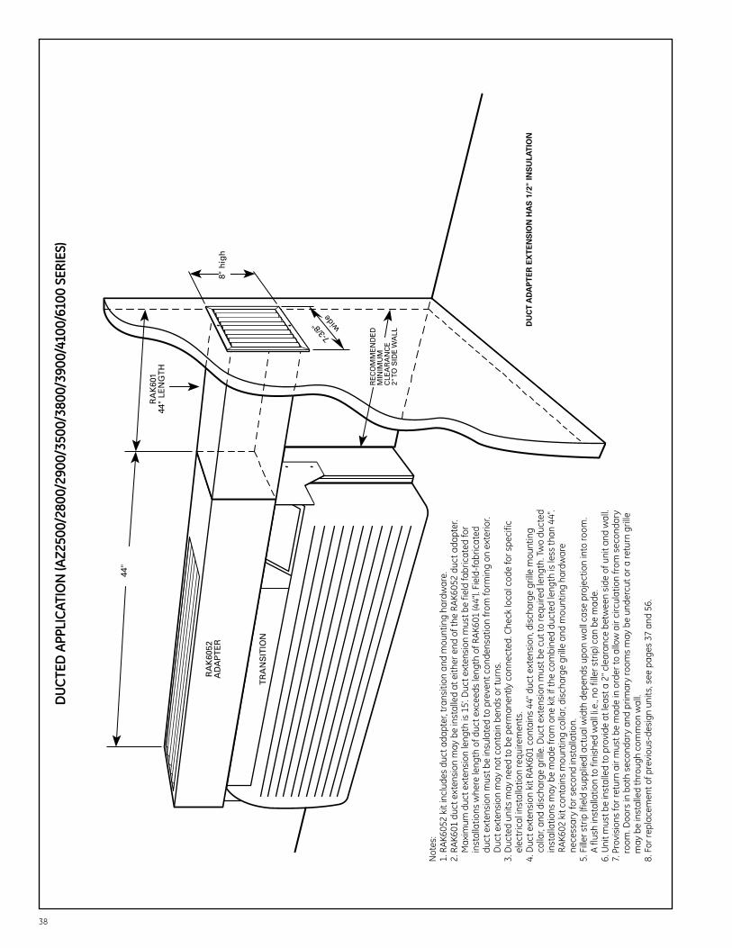
38
DUC
TED
APP
LICA
TIO
N (A
Z250
0/28
00/2
900/
3500
/380
0/39
00/4
100/
6100
SER
IES)
44"
DU
CT
AD
AP
TE
R E
XT
EN
SIO
N H
AS
1/2
" IN
SU
LAT
ION
Not
es:
1. R
AK60
52 k
it in
clud
es d
uct a
dapt
er, t
rans
ition
and
mou
ntin
g ha
rdw
are.
2. R
AK60
1 du
ct e
xten
sion
may
be
inst
alle
d at
eith
er e
nd o
f the
RAK
6052
duc
t ada
pter
. M
axim
um d
uct e
xten
sion
leng
th is
15'
. Duc
t ext
ensi
on m
ust b
e fie
ld fa
bric
ated
for
inst
alla
tions
whe
re le
ngth
of d
uct e
xcee
ds le
ngth
of R
AK60
1 (4
4").
Fiel
d-fa
bric
ated
du
ct e
xten
sion
mus
t be
insu
late
d to
pre
vent
con
dens
atio
n fr
om fo
rmin
g on
ext
erio
r. D
uct e
xten
sion
may
not
con
tain
ben
ds o
r tur
ns.
3. D
ucte
d un
its m
ay n
eed
to b
e pe
rman
ently
con
nect
ed. C
heck
loca
l cod
e fo
r spe
cific
el
ectr
ical
inst
alla
tion
requ
irem
ents
.4.
Duc
t ext
ensi
on k
it RA
K601
con
tain
s 44
" duc
t ext
ensi
on, d
isch
arge
gril
le m
ount
ing
co
llar,
and
disc
harg
e gr
ille.
Duc
t ext
ensi
on m
ust b
e cu
t to
requ
ired
leng
th. T
wo
duct
ed
inst
alla
tions
may
be
mad
e fr
om o
ne k
it if
the
com
bine
d du
cted
leng
th is
less
than
44"
. RA
K602
kit
cont
ains
mou
ntin
g co
llar,
disc
harg
e gr
ille
and
mou
ntin
g ha
rdw
are
ne
cess
ary
for s
econ
d in
stal
latio
n.5.
Fill
er s
trip
(fie
ld s
uppl
ied)
act
ual w
idth
dep
ends
upo
n w
all c
ase
proj
ectio
n in
to ro
om.
A flu
sh in
stal
latio
n to
fini
shed
wal
l (i.e
., no
fille
r str
ip) c
an b
e m
ade.
6. U
nit m
ust b
e in
stal
led
to p
rovi
de a
t lea
st a
2" c
lear
ance
bet
wee
n si
de o
f uni
t and
wal
l.7.
Pro
visi
ons
for r
etur
n ai
r mus
t be
mad
e in
ord
er to
allo
w a
ir ci
rcul
atio
n fr
om s
econ
dary
ro
om. D
oors
in b
oth
seco
ndar
y an
d pr
imar
y ro
oms
may
be
unde
rcut
or a
retu
rn g
rille
m
ay b
e in
stal
led
thro
ugh
com
mon
wal
l.8.
For
repl
acem
ent o
f pre
viou
s-de
sign
uni
ts, s
ee p
ages
37
and
56.
RA
K60
144
" LE
NG
TH
RA
K60
52A
DA
PT
ER
TR
AN
SIT
ION
8" h
igh
RE
CO
MM
EN
DE
DM
INIM
UM
CLE
AR
AN
CE
2" T
O S
IDE
WA
LL7-3/
8" wid
e
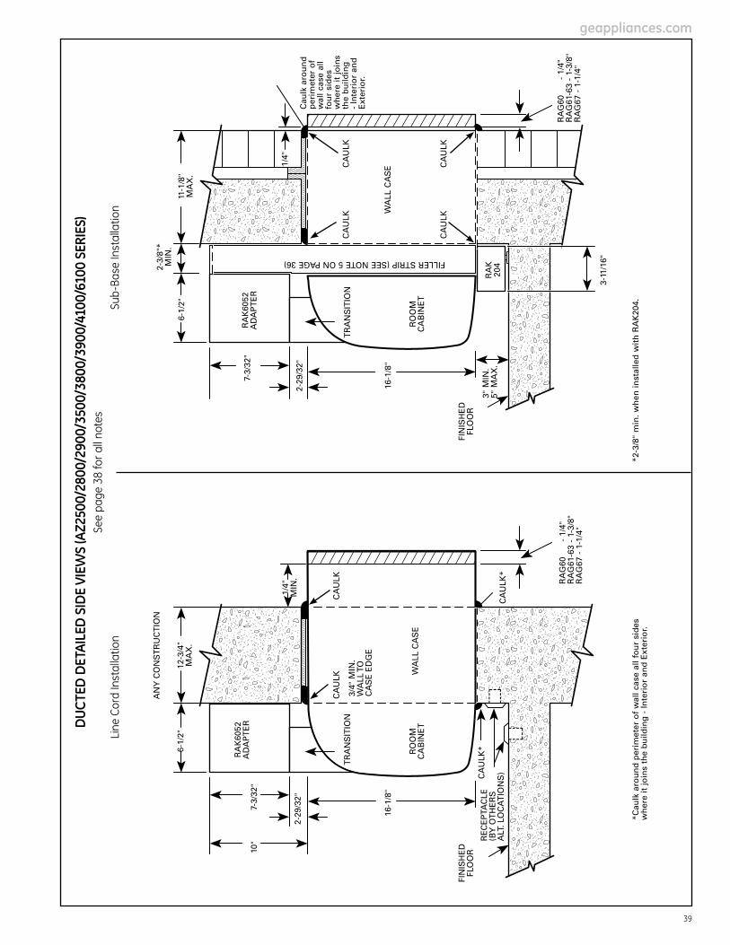
39
geappliances.com
DUC
TED
DET
AILE
D S
IDE
VIEW
S (A
Z250
0/28
00/2
900/
3500
/380
0/39
00/4
100/
6100
SER
IES)
See
page
38
for a
ll no
tes
Line
Cor
d In
stal
latio
n
CA
ULK
*
Sub-
Base
Inst
alla
tion
AN
Y C
ON
ST
RU
CT
ION
12-3
/4"
MA
X.
6-1/
2"
10"
7-3/
32"
RA
K60
52A
DA
PT
ER
16-1
/8"
TR
AN
SIT
ION
RO
OM
CA
BIN
ET
3/4"
MIN
.W
ALL
TO
CA
SE
ED
GE
WA
LL C
AS
E
FIN
ISH
ED
FLO
OR
RE
CE
PTA
CLE
(BY
OT
HE
RS
ALT
. LO
CA
TIO
NS
)C
AU
LK*
RA
G60
-
1/4"
RA
G61
-63
- 1-
3/8"
RA
G67
- 1
-1/4
"
*Cau
lk a
rou
nd
per
imet
er o
f w
all c
ase
all f
ou
r si
des
wh
ere
it jo
ins
the
bu
ildin
g -
Inte
rio
r an
d E
xter
ior.
1/4"
MIN
.2-
29/3
2"
*2-3
/8"
min
. wh
en in
stal
led
wit
h R
AK
204.
RA
G60
-
1/4"
RA
G61
-63
- 1-
3/8"
RA
G67
- 1
-1/4
"
3-11
/16"
RA
K20
43"
MIN
.5"
MA
X.
FIN
ISH
ED
FLO
OR
16-1
/8"
TR
AN
SIT
ION
RO
OM
CA
BIN
ET
WA
LL C
AS
ECA
ULK
CA
ULK
CA
ULK
CA
ULK
CA
ULK
CA
ULK
Cau
lk a
rou
nd
p
erim
eter
of
wal
l cas
e al
l fo
ur
sid
es
wh
ere
it jo
ins
the
bu
ildin
g
- In
teri
or
and
E
xter
ior.
2-29
/32"
7-3/
32"
RA
K60
52A
DA
PT
ER
FILLER STRIP (SEE NOTE 5 ON PAGE 36)
6-1/
2"11
-1/8
"M
AX
.
2-3/
8"*
MIN
.
1/4"
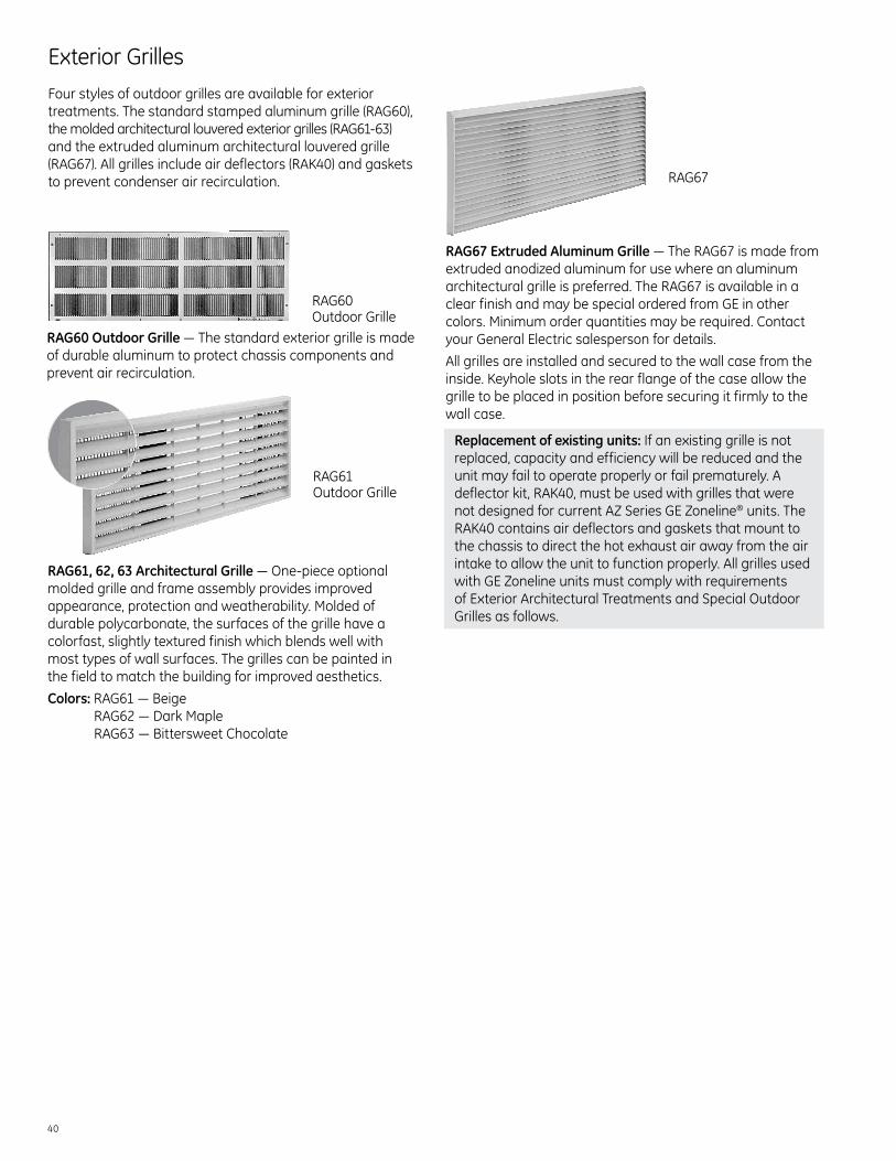
40
Exterior Grilles
Four styles of outdoor grilles are available for exterior treatments. The standard stamped aluminum grille (RAG60), the molded architectural louvered exterior grilles (RAG61-63) and the extruded aluminum architectural louvered grille (RAG67). All grilles include air deflectors (RAK40) and gaskets to prevent condenser air recirculation. RAG67
RAG60 Outdoor Grille
RAG60 Outdoor Grille — The standard exterior grille is made of durable aluminum to protect chassis components and prevent air recirculation.
RAG61, 62, 63 Architectural Grille — One-piece optional molded grille and frame assembly provides improved appearance, protection and weatherability. Molded of durable polycarbonate, the surfaces of the grille have a colorfast, slightly textured finish which blends well with most types of wall surfaces. The grilles can be painted in the field to match the building for improved aesthetics.
Colors: RAG61 — Beige RAG62 — Dark Maple RAG63 — Bittersweet Chocolate
RAG67 Extruded Aluminum Grille — The RAG67 is made from extruded anodized aluminum for use where an aluminum architectural grille is preferred. The RAG67 is available in a clear finish and may be special ordered from GE in other colors. Minimum order quantities may be required. Contact your General Electric salesperson for details.
All grilles are installed and secured to the wall case from the inside. Keyhole slots in the rear flange of the case allow the grille to be placed in position before securing it firmly to the wall case.
Replacement of existing units: If an existing grille is not replaced, capacity and efficiency will be reduced and the unit may fail to operate properly or fail prematurely. A deflector kit, RAK40, must be used with grilles that were not designed for current AZ Series GE Zoneline® units. The RAK40 contains air deflectors and gaskets that mount to the chassis to direct the hot exhaust air away from the air intake to allow the unit to function properly. All grilles used with GE Zoneline units must comply with requirements of Exterior Architectural Treatments and Special Outdoor Grilles as follows.
RAG61 Outdoor Grille

41
geappliances.com
The architectural design of a building may dictate the use of special or oversized louvers for aesthetic reasons. Louvers other than standard Zoneline exterior grilles may be used on the Zoneline unit, however, these special louvers, or any special exterior architectural treatments of the building facade that may restrict the free circulation of condenser airflow, should be referred to GE Application Engineering for evaluation and approval. The following guidelines should be followed in selecting a louver:
1. The louver must have a minimum of 65% free area. ASHRAE defines free area as the minimum area of the opening in an air inlet or outlet through which air can pass. Percent (%) free area equals the X dimension divided by the Y dimension.
2. The louver should be attached to the wall case in a manner that will prevent recirculation of condenser discharge air into the air inlet. If the louver is not attached directly to the wall case, a field-supplied splitter or gasket is required between the chassis and the louver to prevent recirculation.
It is important that the above criteria be followed since a louver that is too restrictive or allows recirculation will reduce the unit’s capacity and efficiency, increase the electrical current draw, cause intermittent operation due to the compressor overload protector shutting the compressor off, and cause failure of the compressor overload and shorten compressor life. Using the unit with a grille that is too restrictive or allows recirculation may constitute improper installation and will void the unit's warranty. A scale drawing of the louver section should be sent to GE Application Engineering. To assure the proper performance of the Zoneline unit and comply with Underwriters Laboratories requirements, it may be necessary to send a sample louver section (at least 16" x 42") to an independent lab to be tested with the Zoneline unit.
Sample Calculations
Free Area (%) = xy x 100 x = 1" y = 1.5"
F.A. % = 1
1.5 x 100 = 66.7%
Exterior Architectural Treatments and Special Outdoor Grilles
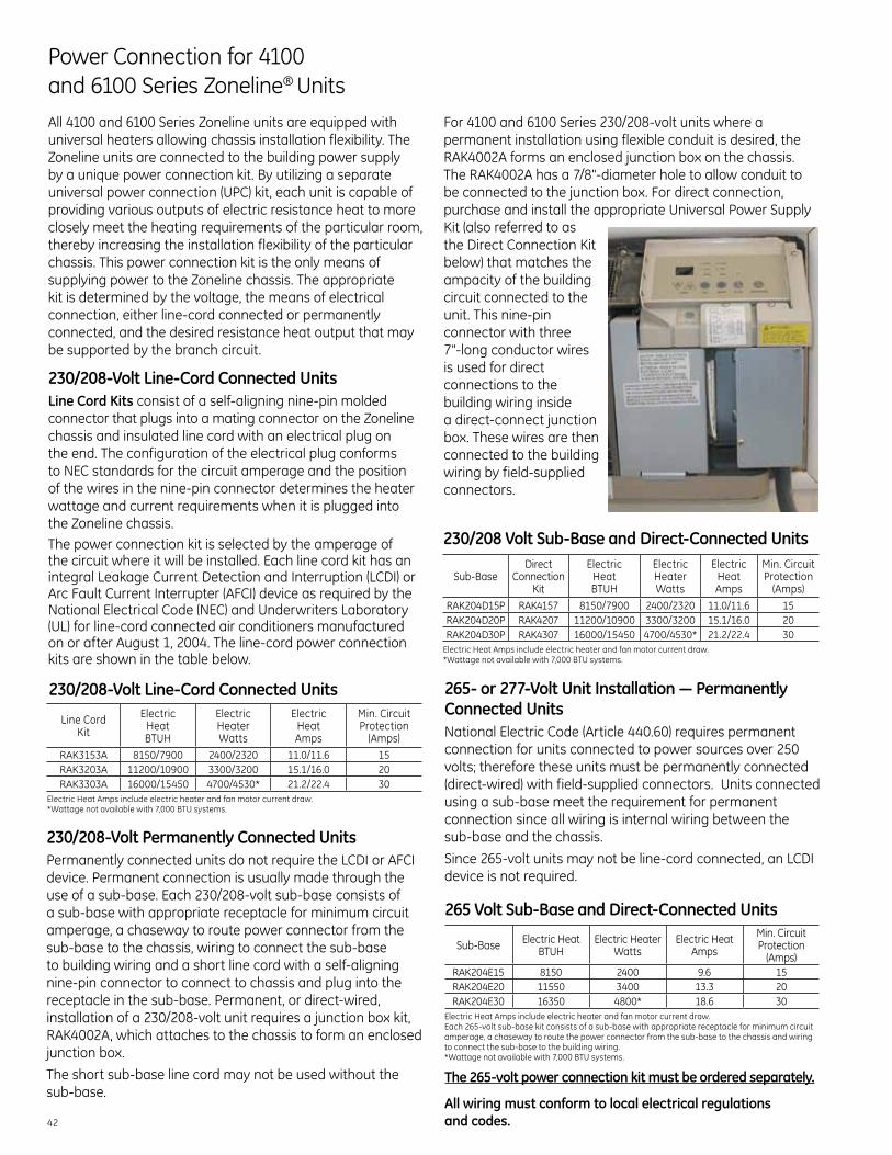
42
Power Connection for 4100 and 6100 Series Zoneline® Units
All 4100 and 6100 Series Zoneline units are equipped with universal heaters allowing chassis installation flexibility. The Zoneline units are connected to the building power supply by a unique power connection kit. By utilizing a separate universal power connection (UPC) kit, each unit is capable of providing various outputs of electric resistance heat to more closely meet the heating requirements of the particular room, thereby increasing the installation flexibility of the particular chassis. This power connection kit is the only means of supplying power to the Zoneline chassis. The appropriate kit is determined by the voltage, the means of electrical connection, either line-cord connected or permanently connected, and the desired resistance heat output that may be supported by the branch circuit.
230/208-Volt Line-Cord Connected UnitsLine Cord Kits consist of a self-aligning nine-pin molded connector that plugs into a mating connector on the Zoneline chassis and insulated line cord with an electrical plug on the end. The configuration of the electrical plug conforms to NEC standards for the circuit amperage and the position of the wires in the nine-pin connector determines the heater wattage and current requirements when it is plugged into the Zoneline chassis.The power connection kit is selected by the amperage of the circuit where it will be installed. Each line cord kit has an integral Leakage Current Detection and Interruption (LCDI) or Arc Fault Current Interrupter (AFCI) device as required by the National Electrical Code (NEC) and Underwriters Laboratory (UL) for line-cord connected air conditioners manufactured on or after August 1, 2004. The line-cord power connection kits are shown in the table below.
230/208-Volt Line-Cord Connected Units
Line Cord Kit
Electric Heat BTUH
Electric Heater Watts
Electric Heat Amps
Min. Circuit Protection
(Amps)RAK3153A 8150/7900 2400/2320 11.0/11.6 15RAK3203A 11200/10900 3300/3200 15.1/16.0 20RAK3303A 16000/15450 4700/4530* 21.2/22.4 30
Electric Heat Amps include electric heater and fan motor current draw.*Wattage not available with 7,000 BTU systems.
230/208-Volt Permanently Connected UnitsPermanently connected units do not require the LCDI or AFCI device. Permanent connection is usually made through the use of a sub-base. Each 230/208-volt sub-base consists of a sub-base with appropriate receptacle for minimum circuit amperage, a chaseway to route power connector from the sub-base to the chassis, wiring to connect the sub-base to building wiring and a short line cord with a self-aligning nine-pin connector to connect to chassis and plug into the receptacle in the sub-base. Permanent, or direct-wired, installation of a 230/208-volt unit requires a junction box kit, RAK4002A, which attaches to the chassis to form an enclosed junction box.
The short sub-base line cord may not be used without the sub-base.
Electric Heat Amps include electric heater and fan motor current draw.Each 265-volt sub-base kit consists of a sub-base with appropriate receptacle for minimum circuit amperage, a chaseway to route the power connector from the sub-base to the chassis and wiring to connect the sub-base to the building wiring. *Wattage not available with 7,000 BTU systems.
The 265-volt power connection kit must be ordered separately.
All wiring must conform to local electrical regulations and codes.
265 Volt Sub-Base and Direct-Connected Units
Sub-Base Electric Heat BTUH
Electric Heater Watts
Electric Heat Amps
Min. Circuit Protection
(Amps)RAK204E15 8150 2400 9.6 15RAK204E20 11550 3400 13.3 20RAK204E30 16350 4800* 18.6 30
230/208 Volt Sub-Base and Direct-Connected Units
Sub-BaseDirect
Connection Kit
Electric Heat BTUH
Electric Heater Watts
Electric Heat Amps
Min. Circuit Protection
(Amps)RAK204D15P RAK4157 8150/7900 2400/2320 11.0/11.6 15RAK204D20P RAK4207 11200/10900 3300/3200 15.1/16.0 20RAK204D30P RAK4307 16000/15450 4700/4530* 21.2/22.4 30
Electric Heat Amps include electric heater and fan motor current draw.*Wattage not available with 7,000 BTU systems.
265- or 277-Volt Unit Installation — Permanently Connected UnitsNational Electric Code (Article 440.60) requires permanent connection for units connected to power sources over 250 volts; therefore these units must be permanently connected (direct-wired) with field-supplied connectors. Units connected using a sub-base meet the requirement for permanent connection since all wiring is internal wiring between the sub-base and the chassis.
Since 265-volt units may not be line-cord connected, an LCDI device is not required.
For 4100 and 6100 Series 230/208-volt units where a permanent installation using flexible conduit is desired, the RAK4002A forms an enclosed junction box on the chassis. The RAK4002A has a 7/8"-diameter hole to allow conduit to be connected to the junction box. For direct connection, purchase and install the appropriate Universal Power Supply Kit (also referred to as the Direct Connection Kit below) that matches the ampacity of the building circuit connected to the unit. This nine-pin connector with three 7"-long conductor wires is used for direct connections to the building wiring inside a direct-connect junction box. These wires are then connected to the building wiring by field-supplied connectors.
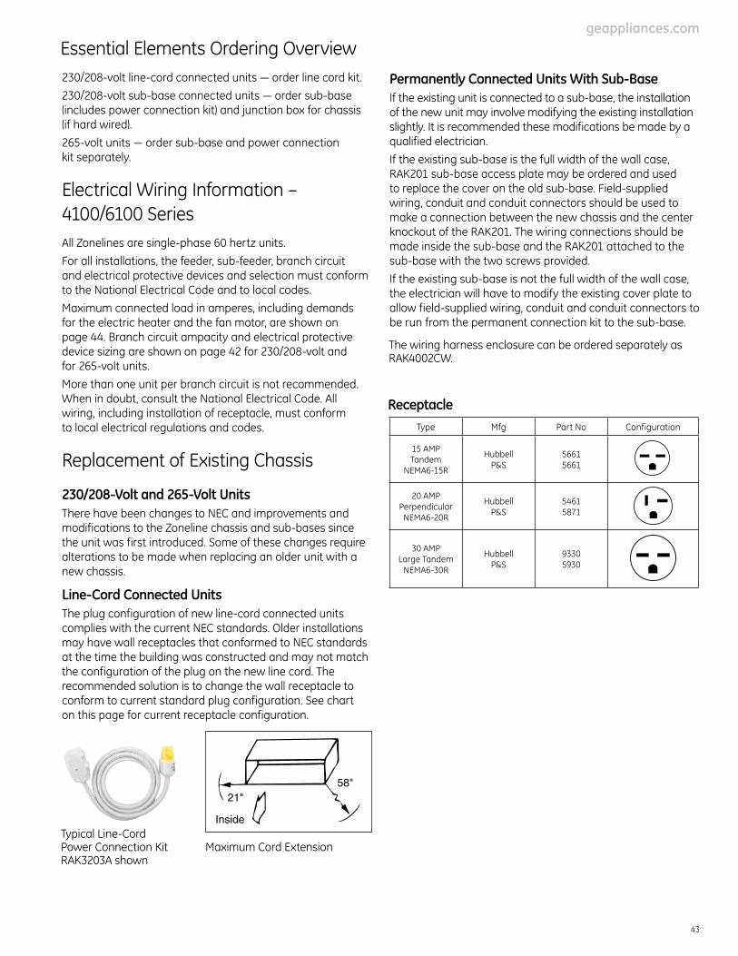
43
geappliances.comEssential Elements Ordering Overview
The wiring harness enclosure can be ordered separately as RAK4002CW.
230/208-volt line-cord connected units — order line cord kit.
230/208-volt sub-base connected units — order sub-base (includes power connection kit) and junction box for chassis (if hard wired).
265-volt units — order sub-base and power connection kit separately.
Electrical Wiring Information – 4100/6100 Series All Zonelines are single-phase 60 hertz units.
For all installations, the feeder, sub-feeder, branch circuit and electrical protective devices and selection must conform to the National Electrical Code and to local codes.
Maximum connected load in amperes, including demands for the electric heater and the fan motor, are shown on page 44. Branch circuit ampacity and electrical protective device sizing are shown on page 42 for 230/208-volt and for 265-volt units.
More than one unit per branch circuit is not recommended. When in doubt, consult the National Electrical Code. All wiring, including installation of receptacle, must conform to local electrical regulations and codes.
Replacement of Existing Chassis
230/208-Volt and 265-Volt UnitsThere have been changes to NEC and improvements and modifications to the Zoneline chassis and sub-bases since the unit was first introduced. Some of these changes require alterations to be made when replacing an older unit with a new chassis.
Line-Cord Connected UnitsThe plug configuration of new line-cord connected units complies with the current NEC standards. Older installations may have wall receptacles that conformed to NEC standards at the time the building was constructed and may not match the configuration of the plug on the new line cord. The recommended solution is to change the wall receptacle to conform to current standard plug configuration. See chart on this page for current receptacle configuration.
Permanently Connected Units With Sub-BaseIf the existing unit is connected to a sub-base, the installation of the new unit may involve modifying the existing installation slightly. It is recommended these modifications be made by a qualified electrician.
If the existing sub-base is the full width of the wall case, RAK201 sub-base access plate may be ordered and used to replace the cover on the old sub-base. Field-supplied wiring, conduit and conduit connectors should be used to make a connection between the new chassis and the center knockout of the RAK201. The wiring connections should be made inside the sub-base and the RAK201 attached to the sub-base with the two screws provided.
If the existing sub-base is not the full width of the wall case, the electrician will have to modify the existing cover plate to allow field-supplied wiring, conduit and conduit connectors to be run from the permanent connection kit to the sub-base.
Typical Line-CordPower Connection KitRAK3203A shown
58"21"
Inside
Maximum Cord Extension
Type Mfg Part No Configuration
15 AMP Tandem
NEMA6-15R
Hubbell P&S
5661 5661
20 AMP Perpendicular
NEMA6-20R
Hubbell P&S
5461 5871
30 AMP Large Tandem
NEMA6-30R
Hubbell P&S
9330 5930
Receptacle
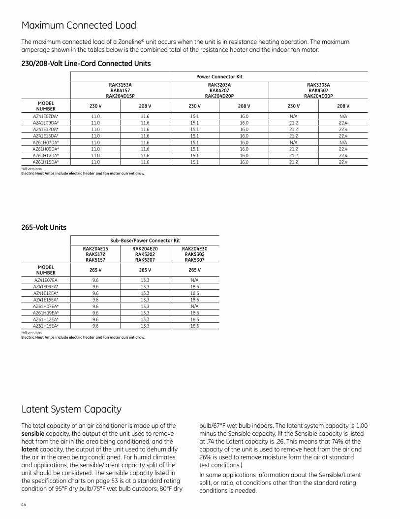
44
Maximum Connected Load
The maximum connected load of a Zoneline® unit occurs when the unit is in resistance heating operation. The maximum amperage shown in the tables below is the combined total of the resistance heater and the indoor fan motor.
230/208-Volt Line-Cord Connected Units
Power Connector Kit
RAK3153A RAK4157
RAK204D15P
RAK3203A RAK4207
RAK204D20P
RAK3303A RAK4307
RAK204D30PMODEL
NUMBER 230 V 208 V 230 V 208 V 230 V 208 V
AZ41E07DA* 11.0 11.6 15.1 16.0 N/A N/AAZ41E09DA* 11.0 11.6 15.1 16.0 21.2 22.4AZ41E12DA* 11.0 11.6 15.1 16.0 21.2 22.4AZ41E15DA* 11.0 11.6 15.1 16.0 21.2 22.4AZ61H07DA* 11.0 11.6 15.1 16.0 N/A N/AAZ61H09DA* 11.0 11.6 15.1 16.0 21.2 22.4AZ61H12DA* 11.0 11.6 15.1 16.0 21.2 22.4AZ61H15DA* 11.0 11.6 15.1 16.0 21.2 22.4
*All versionsElectric Heat Amps include electric heater and fan motor current draw.
265-Volt Units
Sub-Base/Power Connector Kit
RAK204E15 RAK5172 RAK5157
RAK204E20 RAK5202 RAK5207
RAK204E30 RAK5302 RAK5307
MODEL NUMBER 265 V 265 V 265 V
AZ41E07EA 9.6 13.3 N/AAZ41E09EA* 9.6 13.3 18.6AZ41E12EA* 9.6 13.3 18.6AZ41E15EA* 9.6 13.3 18.6AZ61H07EA* 9.6 13.3 N/AAZ61H09EA* 9.6 13.3 18.6AZ61H12EA* 9.6 13.3 18.6AZ61H15EA* 9.6 13.3 18.6
*All versionsElectric Heat Amps include electric heater and fan motor current draw.
Latent System Capacity
The total capacity of an air conditioner is made up of the sensible capacity, the output of the unit used to remove heat from the air in the area being conditioned, and the latent capacity, the output of the unit used to dehumidify the air in the area being conditioned. For humid climates and applications, the sensible/latent capacity split of the unit should be considered. The sensible capacity listed in the specification charts on page 53 is at a standard rating condition of 95°F dry bulb/75°F wet bulb outdoors; 80°F dry
bulb/67°F wet bulb indoors. The latent system capacity is 1.00 minus the Sensible capacity. (If the Sensible capacity is listed at .74 the Latent capacity is .26. This means that 74% of the capacity of the unit is used to remove heat from the air and 26% is used to remove moisture form the air at standard test conditions.)
In some applications information about the Sensible/Latent split, or ratio, at conditions other than the standard rating conditions is needed.

45
geappliances.com
Formula for Calculating Operating Costs Using Above Data:
Normal Yearly Operating Data
(Cooling Hours based on 75°F indoor temperature with air conditioner sized to meet the design conditions.)
ASHRAE Heating Estimated Degree Cooling Location Days Hours
ALABAMA Birmingham 2,551 1,390 Huntsville 3,070 1,340 Mobile 1,560 1,640 Montgomery 2,291 1,580 ARIZONA Flagstaff 7,152 310 Phoenix 1,765 2,280 Tucson 1,800 1,920 Yuma 974 2,520 ARKANSAS Fort Smith 3,292 1,410 Little Rock 3,219 1,330 CALIFORNIA Bakersfield 2,122 1,530 Fresno 2,611 1,210 Los Angeles 2,061 310 Sacramento 2,502 1,030 San Diego 1,458 390 San Francisco 3,015 110 COLORADO Colorado Springs 6,423 520 Denver 6,283 550 Grand Junction 5,641 910 CONNECTICUT Hartford 6,235 480 DISTRICT of COLUMBIA Washington 4,224 1,010 DELAWARE Wilmington 4,930 770 FLORIDA Jacksonville 1,239 1,690 Miami 214 2,850 Orlando 766 1,930 Tallahassee 1,485 1,500 Tampa 683 2,350 GEORGIA Atlanta 2,961 1,130 Augusta 2,397 1,400 Macon 2,136 1,440 Savannah 1,819 1,510 IDAHO Boise 5,809 670 Lewiston 5,542 600 Pocatello 7,033 570 ILLINOIS Chicago 6,155 780 Moline 6,408 760 Springfield 5,429 890 INDIANA Evansville 4,435 1,090 Fort Wayne 6,205 710 Indianapolis 5,699 820 South Bend 6,439 600 IOWA Burlington 6,114 730 Des Moines 6,588 710 Sioux City 6,951 770 KANSAS Dodge City 4,986 1,020 Goodland 6,141 800 Topeka 5,182 880 Wichita 4,620 1,070
ASHRAE Heating Estimated Degree Cooling Location Days Hours
ASHRAE Heating Estimated Degree Cooling Location Days Hours
KENTUCKY Lexington 4,683 830 Louisville 4,660 1,130 LOUISIANA Alexandria 1,921 1,670 Baton Rouge 1,560 1,860 New Orleans 1,385 1,790 Shreveport 2,184 1,470 MAINE Portland 7,511 290 MARYLAND Baltimore 4,654 850 MASSACHUSETTS Boston 5,634 500 MICHIGAN Detroit 6,293 590 Flint 7,377 440 Grand Rapids 6,894 530 MINNESOTA Duluth 10,000 200 Minneapolis 8,382 550 MISSISSIPPI Jackson 2,239 1,560 MISSOURI Columbia 5,046 960 Kansas City 4,711 1,210 Springfield 4,900 970 St. Louis 4,900 1,080 MONTANA Billings 7,049 520 Glasgow 8,996 410 Great Falls 7,750 420 Missoula 8,125 350 NEBRASKA Grand Island 6,530 770 Omaha 6,612 750 NEVADA Ely 7,733 500 Las Vegas 2,709 1,980 Reno 6,332 520 NEW JERSEY Newark 4,589 710 NEW MEXICO Albuquerque 4,348 1,040 Clayton 5,158 720 Silver City 3,705 1,260 NEW YORK Albany 6,875 480 Binghamton 7,286 310 Buffalo 7,062 450 New York 4,811 790 Rochester 6,748 470 Syracuse 6,756 500 NORTH CAROLINA Asheville 4,042 690 Charlotte 3,191 1,230 Raleigh 3,393 1,070 Winston-Salem 3,595 960 NORTH DAKOTA Bismarck 8,851 510 Fargo 9,226 490 Williston 9,243 580
OHIO Cincinnati 5,265 840 Cleveland 6,351 610 Columbus 5,660 810 Dayton 5,622 740 Toledo 6,494 590 OKLAHOMA Oklahoma City 3,725 1,200 Tulsa 3,860 1,410 OREGON Medford 5,008 620 Pendleton 5,127 590 Portland 4,635 270 PENNSYLVANIA Harrisburg 5,251 730 Philadelphia 5,144 810 Pittsburgh 5,987 590 Scranton 6,254 440 Williamsport 5,934 600 RHODE ISLAND Providence 5,954 470 SOUTH CAROLINA Charleston 2,033 1,390 Columbia 2,484 1,440 Greenville 2,980 1,120 SOUTH DAKOTA Rapid City 7,345 580 Sioux Falls 7,839 610 TENNESSEE Chattanooga 3,254 1,180 Knoxville 3,494 1,070 Memphis 3,232 1,320 Nashville 3,578 1,220 TEXAS Corpus Christi 914 2,380 Dallas 2,363 1,900 El Paso 2,700 1,580 Houston 1,396 1,850 Lubbock 3,578 1,310 San Antonio 1,546 1,920 UTAH Milford 6,497 910 Salt Lake City 6,052 830 VERMONT Burlington 8,269 130 VIRGINIA Norfolk 3,421 1,010 Richmond 3,865 1,020 Roanoke 4,150 870 WASHINGTON Seattle 5,145 180 Spokane 6,655 430 Yakima 5,941 530 WEST VIRGINIA Charleston 4,476 860 Huntington 4,446 820 WISCONSIN Madison 7,863 530 Milwaukee 7,635 450 WYOMING Casper 7,410 600 Cheyenne 7,381 420 Sheridan 7,680 530
Heating* — Heat Loss KW x Heating Degree Days x “C” x Cost Per KWH
= Operating CostOutdoor Design Temperature Difference* The above formula is for electric resistance heating only. Power consumption using the Zoneline heat pumps should be adjusted by Seasonal Performance Factor (SPF).
The local power supplier should be consulted for recommended value of “C.” This factor will vary between 17 and 24.
Cooling — Calculated Heat Gain (BTUH) x = Unit Cooling Watts x Cooling Hours x Cost per KWH = Operating CostInstalled unit capacity (BTUH) 1000 Watts/KW
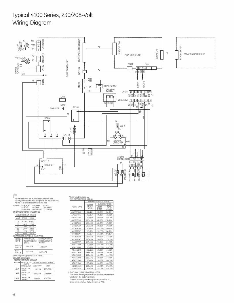
Typical 4100 Series, 230/208-Volt Wiring Diagram
46
TEST TEMPERATURE IS 68degF.7.Motor winding resistance
TEST TEMPERATURE IS 68degF.6.HEATER RESISTANCE:5.This diagram applied to AZ41E series.
109701793029960493305194094900
73201195019970328603462063260
I.D COILROOM
907050323010
degF
SENSOR RESISTANCE(ohm)
3.THERMISTOR SENSOR RESISTANCE:OR:ORANGE
RE:REDWH:WHITEYL:YELLOW
BK:BLACKBL:BLUEBR:BROWN
GR:GREENGY:GRAY
2.COLOR:
*1:The lead wires are multicolured with black tube.*2:The jointwires are white except that the first one is red.*3:The 7k BTU models don't have this wire.
1.NOTE:
4.TRANSFORMER WINDING RESISTANCE:
2.4kW
1.4kW
1.0kW
PIN NO.3-6WH-BL
PIN NO.2-5RD-YL
PIN NO.1-4BK-BR
265V208V/230V
HEATER RESISTANCE(ohm)CHECK POINTHEATER
CONNECTOR
HEATER
195±35% 200±35%
200±35% 205±35%
75±35% 85±35%
208/230VPA052JB
265VPA053JB
PRIMARY COILRESISTANCE(ohm)BK-BK
SECONDARY COILRESISTANCE(ohm)WH-WH
100±10% 1.31±10%
127±10% 1.27±10%
MODELNAME
8.FAULT ANALYSIS OF INDOOR FAN MOTORIf the motor winding resistance is out of spec,please check whether it's the motor's problem;If there is no voltage between pin1 and pin2 of CN102,please check whether it's the problem of PWB.
CN1
TERMINALBOARD
*1 OPEATION BOARD UNITMAIN BOARD UNIT
BCN
301.
BCN
302
BCN
7.BC
N9
I.D.C
OIL
ROO
M
CN11
CN3.
CN5.
CN6
TRANSFORMER
OR
OR
YLYL
4321*2
*2
DRIV
E BO
ARD
UN
IT BCN
107.
BCN
108.
BCN
109
BCN
106
CN10
4
BK
BK
WHWH
7
12
5
BRORYL(208/230V)
(265V)*3O
RBLWH
GRRDGYBRBK
98456321
*3WH
RD
BK BR GY
RDG
RW
HBL
OR
1 2 3 4 5 6 7 9
CBK
O.L.P
BK
CT10
1
T1
RY101NR101
CN8
HEATERCONNECTOR
BLYLBR
PRO
TECT
OR
FUSE
BK
BLRD
BLWH
YLRDBRBK
HEA
TER(
2.4k
W)
HEA
TER(
1.4k
W)
HEA
TER(
1.0k
W)
1 2 34 5 6654 321
BLYLBR
CN110
41
123 3
21
COMP.
BL
RUNNINGCAPACITOR WHRD
SR
TRIAC UNITBL YLBT2 BT1
BCN112
EDC
RY102
VARISTOR
RD
WH
BK
BL
GY
O.DFM
O.D
FAN
CAPA
CITO
R
CN10
1(W
H)
5
3
1
RD
BKI.DFM
OR
ORI.D F
ANCA
PACI
TOR
PROTECTOR
A
*2
CN11
2
1
3
CN10
5CN
102(
YH)
MODEL NAME
WINDING RESISTANCE(ohm)
INDOOR
RD-BK
OUTDOOR MOTORHIGH
SPEEDRD-BK WH-BK
AZ41E07DAB 183±15% 390±15% 284±15%183±15%
183±15%399±15%399±15%
148±15%148±15%
AZ41E07DACAZ41E07DAP
AZ41E07EAB
AZ41E07EAC
AZ41E07EAP
AZ41E09DABAZ41E09DAC
AZ41E09DAP
AZ41E09EAB
AZ41E09EACA441E09EAPAZ41E12DAB
AZ41E12DAC
AZ41E12DAPAZ41E12EABAZ41E12EACAZ41E12EAPAZ41E15DAB
AZ41E15DAC
AZ41E15EABAZ41E15EAC
265±15%
265±15%
265±15%
183±15%183±15%183±15%
265±15%265±15%
265±15%183±15%183±15%
183±15%265±15%
265±15%265±15%183±15%
183±15%
265±15%265±15%
400±15%
400±15%
400±15%
193±15%193±15%
193±15%
294±15%294±15%294±15%126±15%
126±15%126±15%148±15%148±15%
148±15%126±15%
126±15%
148±15%148±15%
234±15%
139±15%
139±15%
204±15%204±15%
204±15%
125±15%125±15%125±15%146±15%
146±15%146±15%124±15%
124±15%124±15%146±15%
146±15%
124±15%124±15%
MOTORSPEED
LOW
*1
CN1
INTERFACE
(NR101)Varistor CN8
CIRCUITCONTROL
TRAN
SFOR
MER
UNIVERSAL CONNECTOR
CN5
MAIN BOARD UNIT
Capacitor(C101, C101A, C102)
PROTECTOR
FUSE
DIP SW
ROOM
CDC
REMOTE T'STAT
CN2
BCN7
.BCN
9
FU10
4
FU10
5
FU10
6
HEATER
HEATER
HEATER
HEAT
ER P
OWER
CHEC
K CI
RCUI
T
O.L.P
.
C
R S
RUNN
ING
CAPA
CITO
R
T1
TRIAC CONTROLCIRCUIT
*1: C101 is used for 230V models and both C101A and C102 are used for 265V models.
AC CLOCK
*2
RY104
TRIAC
CT MONITORCIRCUIT
UNIT
*1
RY105
RY101
RY102BCN1
08
CN11
CN10
4
POWER SUPPLY 12VSWITCHING
BCN1
07
CN3
BOARDDRIVE
(for setting)
ID.COIL
EXTERNAL FAN
THER
MO
SLEEPSLEEP
FAN SPEED
OPER
ATIO
N BO
ARD
MODE
DECODER
AUTOLOWHIGH
HEATFANCOOLOPEOPE
DOWNUP
RY10
1
RY10
2
BCN1
09
CN6
*3
*2: 4A 250V is used for 230V models;3.15A 500V is used for 265Vmodels.*3: 61H models have this leadwire except for 7000btu models.
CT101
SSR1
Capacitor
Indoor
Fan MotorCapacitor
SSR1
HALLIC
OutdoorFanMotor
RY10
4
RY10
5
CN105
COMPMOTOR
Fan Motor
FanMotor
CN102CN101
FU10
3
BCN
106
CN110
TERMINALBOARD
FU101
A

47
geappliances.comTypical 4100 Series, 230/208-Volt Schematic Diagram
TEST TEMPERATURE IS 68degF.7.Motor winding resistance
TEST TEMPERATURE IS 68degF.6.HEATER RESISTANCE:5.This diagram applied to AZ41E series.
109701793029960493305194094900
73201195019970328603462063260
I.D COILROOM
907050323010
degF
SENSOR RESISTANCE(ohm)
3.THERMISTOR SENSOR RESISTANCE:OR:ORANGE
RE:REDWH:WHITEYL:YELLOW
BK:BLACKBL:BLUEBR:BROWN
GR:GREENGY:GRAY
2.COLOR:
*1:The lead wires are multicolured with black tube.*2:The jointwires are white except that the first one is red.*3:The 7k BTU models don't have this wire.
1.NOTE:
4.TRANSFORMER WINDING RESISTANCE:
2.4kW
1.4kW
1.0kW
PIN NO.3-6WH-BL
PIN NO.2-5RD-YL
PIN NO.1-4BK-BR
265V208V/230V
HEATER RESISTANCE(ohm)CHECK POINTHEATER
CONNECTOR
HEATER
195±35% 200±35%
200±35% 205±35%
75±35% 85±35%
208/230VPA052JB
265VPA053JB
PRIMARY COILRESISTANCE(ohm)BK-BK
SECONDARY COILRESISTANCE(ohm)WH-WH
100±10% 1.31±10%
127±10% 1.27±10%
MODELNAME
8.FAULT ANALYSIS OF INDOOR FAN MOTORIf the motor winding resistance is out of spec,please check whether it's the motor's problem;If there is no voltage between pin1 and pin2 of CN102,please check whether it's the problem of PWB.
CN1
TERMINALBOARD
*1 OPEATION BOARD UNITMAIN BOARD UNIT
BCN
301.
BCN
302
BCN
7.BC
N9
I.D.C
OIL
ROO
M
CN11
CN3.
CN5.
CN6
TRANSFORMER
OR
OR
YLYL
4321*2
*2
DRI
VE B
OAR
D U
NIT BC
N10
7.BC
N10
8.BC
N10
9BC
N10
6CN
104
BK
BK
WHWH
7
12
5
BRORYL(208/230V)
(265V)*3O
RBLWH
GRRDGYBRBK
98456321
*3WH
RD
BK BR GY
RDG
RW
HBL
OR
1 2 3 4 5 6 7 9
CBK
O.L.P
BK
CT10
1
T1
RY101NR101
CN8
HEATERCONNECTOR
BLYLBR
PRO
TECT
OR
FUSE
BK
BLRD
BLWH
YLRDBRBK
HEA
TER(
2.4k
W)
HEA
TER(
1.4k
W)
HEA
TER(
1.0k
W)
1 2 34 5 6654 321
BLYLBR
CN110
41
123 3
21
COMP.
BL
RUNNINGCAPACITOR WHRD
SR
TRIAC UNITBL YLBT2 BT1
BCN112
EDC
RY102
VARISTOR
RD
WH
BK
BL
GY
O.DFM
O.D
FAN
CAPA
CITO
R
CN10
1(W
H)
5
3
1
RD
BKI.DFM
OR
ORI.D F
ANCA
PACI
TOR
PROTECTOR
A
*2
CN11
2
1
3
CN10
5CN
102(
YH)
MODEL NAME
WINDING RESISTANCE(ohm)
INDOOR
RD-BK
OUTDOOR MOTORHIGH
SPEEDRD-BK WH-BK
AZ41E07DAB 183±15% 390±15% 284±15%183±15%
183±15%399±15%399±15%
148±15%148±15%
AZ41E07DACAZ41E07DAP
AZ41E07EAB
AZ41E07EAC
AZ41E07EAP
AZ41E09DABAZ41E09DAC
AZ41E09DAP
AZ41E09EAB
AZ41E09EACA441E09EAPAZ41E12DAB
AZ41E12DAC
AZ41E12DAPAZ41E12EABAZ41E12EACAZ41E12EAPAZ41E15DAB
AZ41E15DAC
AZ41E15EABAZ41E15EAC
265±15%
265±15%
265±15%
183±15%183±15%183±15%
265±15%265±15%
265±15%183±15%183±15%
183±15%265±15%
265±15%265±15%183±15%
183±15%
265±15%265±15%
400±15%
400±15%
400±15%
193±15%193±15%
193±15%
294±15%294±15%294±15%126±15%
126±15%126±15%148±15%148±15%
148±15%126±15%
126±15%
148±15%148±15%
234±15%
139±15%
139±15%
204±15%204±15%
204±15%
125±15%125±15%125±15%146±15%
146±15%146±15%124±15%
124±15%124±15%146±15%
146±15%
124±15%124±15%
MOTORSPEED
LOW
*1
CN1
INTERFACE
(NR101)Varistor CN8
CIRCUITCONTROL
TRAN
SFOR
MER
UNIVERSAL CONNECTOR
CN5
MAIN BOARD UNIT
Capacitor(C101, C101A, C102)
PROTECTOR
FUSE
DIP SW
ROOM
CDC
REMOTE T'STAT
CN2
BCN7
.BCN
9
FU10
4
FU10
5
FU10
6
HEATER
HEATER
HEATER
HEAT
ER P
OWER
CHEC
K CI
RCUI
T
O.L.P
.
C
R S
RUNN
ING
CAPA
CITO
R
T1
TRIAC CONTROLCIRCUIT
*1: C101 is used for 230V models and both C101A and C102 are used for 265V models.
AC CLOCK
*2
RY104
TRIAC
CT MONITORCIRCUIT
UNIT
*1
RY105
RY101
RY102BCN1
08
CN11
CN10
4
POWER SUPPLY 12VSWITCHING
BCN1
07
CN3
BOARDDRIVE
(for setting)
ID.COIL
EXTERNAL FAN
THER
MO
SLEEPSLEEP
FAN SPEED
OPER
ATIO
N BO
ARD
MODE
DECODER
AUTOLOWHIGH
HEATFANCOOLOPEOPE
DOWNUP
RY10
1
RY10
2
BCN1
09
CN6
*3
*2: 4A 250V is used for 230V models;3.15A 500V is used for 265Vmodels.*3: 61H models have this leadwire except for 7000btu models.
CT101
SSR1
Capacitor
Indoor
Fan MotorCapacitor
SSR1
HALLIC
OutdoorFanMotor
RY10
4
RY10
5
CN105
COMPMOTOR
Fan Motor
FanMotor
CN102CN101
FU10
3
BCN
106
CN110
TERMINALBOARD
FU101
A
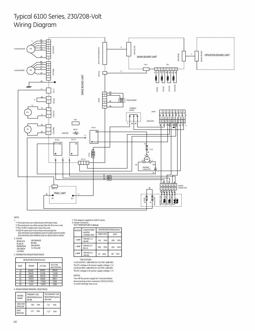
48
Typical 6100 Series, 230/208-Volt Wiring Diagram
TION BOARD UNIT
HEATER CONNECTOR
CN10
2(W
H)
CN10
3(BL
)CN
112
BCN
202
CN20
1(YL
)CN
105(
BK)
CT10
1
CN10
4BC
N10
6BC
N10
1.BC
N10
8.BC
N10
9
CN4.
CN5.
CN6
YL YL OR
OR
BK BK BL BL
ROO
M
I.D.C
OIL
O.D
.CO
IL
OU
TDO
OR
BK BR GY
RD GR WH
BL OR
BCN
7.BC
N9
BCN
301.
BCN
302
OR
BLWHGR
RDGY
BRBK RD WH
TERMINALBOARD
RUNNINGCAPACITOR
HEA
TER(
1.0k
W)
HEA
TER(
1.4k
W)
HEA
TER(
2.4k
W)
BK BR RD YL WH
BL
FUSE
PRO
TECT
OR
BR YL BL
DRI
VE B
OAR
D U
NIT
3
3
CN1
12345
8
FMO.D.FAN MOTOR
BKWHYLBLRD
OR
RD
BLYLWHBK
I.D.FAN MOTOR FM 4321
6
GR
*2
BR
*41
2
1
ICR
YL
YL
*4
RD
RD
RV
1
CN8
NR101
VARISTOR
RY102 RY110
RY101
T1
C D E
1 4
CN110
5
21
7
WHWH
BK
BK
TRANSFORMER
*2
CN11
*21 2 3 4 5 6 7 8
1 2 3 6 5 4 8 9
97654321
*3
(265V)
(208/230V)
BCN112
BT1 BT2
YL
MAIN BOARD UNITOPEA*1
*3YL OR BR
BK
O.L.P
BK
C
R S
RD WH
BL
COMP.
1 2 34 5 6
654 321
RD BL
BK
BL TRIAC UNIT
*1
123 3
21BR
YLBL
FU101
TERMINALBOARD
THER
MO
SLEEP
SLEEP
FAN SPEED
MODE
DECODER
AUTO
LOW
HIGH
HEAT
FAN
COOL
OPE
OPE
DOWN
OPER
ATIO
N BO
ARD
UP
DIP SW
ROOM
CDC
REMOTE T'STAT
EXTERNAL FAN CN2
INTERFACE
MAIN BOARD UNIT
(for setting)
OD.COIL
ID.COIL
Outdoor
BCN7
.BCN9
CN5
TRIACCONTROLCIRCUIT
RY201
CT MONITORCIRCUIT
ISOLATOR
CIRCUITCONTROL
RY108
RY101
RY102
RY110
BCN1
08BC
N101
CN4
BCN1
09
CN6
UNITBOARDDRIVE
CN201
CN8
CN103CN102T1
FU102
15VPOWER SUPPLYSWITCHING
RY10
8
RY20
1
POWER SUPPLY12V
SWITCHING
CN105
*1(NR101)Varistor
TRAN
SFOR
MER
Capacitor
FU10
4
FU10
5
FU10
6
BCN1
06
CN110
FU10
3
AC CLOCK
*2
CN11
CN10
4
(C101, C101A,C102)
RY10
1
RY10
2
RY11
0
HEAT
ER PO
WER
CHEC
K CI
RCUI
T
PUMPSol.
ValveReverse
MotorFan
Indoor
MotorFan
Outdoor ICR
PROTECTOR
FUSE
HEATER
HEATER
HEATER
*3
UNIVERSAL CONNECTOR
O.L.P
.
C
R S
RUNN
ING
CAPA
CITO
R
TRIACCT101
*1: C101 is used for 230V models and both C101A and C102 are used for 265V models*2:4A 250V is used for 230V models;3.15A 500V is used for 265Vmodels.*3:61H models have this leadwire except for 7000btu models.
CN1
COMPMOTOR
7. DC MO
208/230VPA052JB
265VPA053JB
PRIMARY COILRESISTANCE(ohm)BK-BK
SECONDARY COILRESISTANCE(ohm)WH-WH
100 ` 10%
127 ` 10%
1.31 ` 10%
1.27 ` 10%
MODELNAME
4. TRANSFORMER WINDING RESISTANCE:
(1)CN103:PIN 1-2(BK-WH) DC15V; PIN1-6(BK-RD):The DC voltage is AC power supply voltage x 1.4(2)CN102:PIN1-2(BK-WH) DC15V; PIN1-5(BK-RD):The DC voltage is AC power supply voltage x 1.4
*1:The lead wires are multicolured with black tube.*2:The jointwires are white ex*3:The 7k BTU models don't have this wire.*4:AZ61H series don't have these wires,except for
AZ61H07DAD.AZ61H09DAD.AZ61H12DAD.AZ61H15DAD.AZ61H07EAD.AZ61H09EAD.AZ61H12EAD.AZ61H15EAD.
BK:BLACKBL:BLUEBR:BROWNGR:GREENGY:GRAY
OR:ORANGERE:REDWH:WHITEYL:YELLOW
Tu wer supply for 2 minutes beforedisconnecting motor connector (CN102.CN103).or motor damage may occur.
NOTE:1.
2. COLOR:
3. THERMISTOR SENSOR RESISTANCE:
O.D COIL&OUTDOOR
SENSOR RESISTANCE(ohm)
degF
103032507090
ROOM I.D COIL
63260346203286019970119507320
949005194049330299601793010970
280301534014570885053003280
5. This diagram applied to AZ61H series.6. Heater resistance:
TEST TEMPERATURE IS 68degF.
195 ` 35% 200 ` 35%
200 ` 35% 205 ` 35%
75 ` 35% 85 ` 35%
CHECK POINTHEATERCONNECTOR
PIN NO.1-4BK-BR
PIN NO.2-5RD-YL
PIN NO.3-6WH-BL
HEATER HEATER RESISTANCE(ohm)
208V/230V 265V
1.0kW
1.4kW
2.4kW
TOR VOLTAGE:
NOTICE:
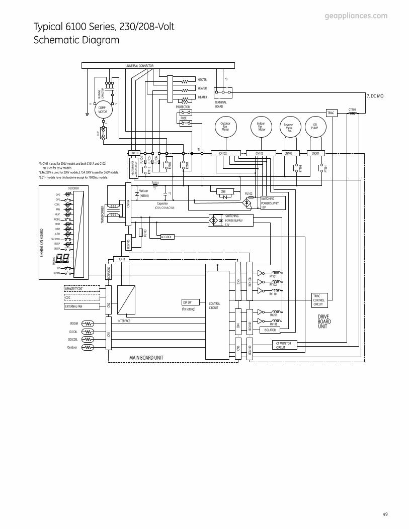
49
geappliances.comTypical 6100 Series, 230/208-Volt Schematic Diagram
TION BOARD UNIT
HEATER CONNECTOR
CN10
2(W
H)
CN10
3(BL
)CN
112
BCN
202
CN20
1(YL
)CN
105(
BK)
CT10
1
CN10
4BC
N10
6BC
N10
1.BC
N10
8.BC
N10
9
CN4.
CN5.
CN6
YL YL OR
OR
BK BK BL BL
ROO
M
I.D.C
OIL
O.D
.CO
IL
OU
TDO
OR
BK BR GY
RD GR WH
BL OR
BCN
7.BC
N9
BCN
301.
BCN
302
OR
BLWHGR
RDGY
BRBK RD WH
TERMINALBOARD
RUNNINGCAPACITOR
HEA
TER(
1.0k
W)
HEA
TER(
1.4k
W)
HEA
TER(
2.4k
W)
BK BR RD YL WH
BL
FUSE
PRO
TECT
OR
BR YL BL
DRI
VE B
OAR
D U
NIT
3
3
CN1
12345
8
FMO.D.FAN MOTOR
BKWHYLBLRD
OR
RD
BLYLWHBK
I.D.FAN MOTOR FM 4321
6
GR
*2
BR
*41
2
1
ICR
YL
YL
*4
RD
RD
RV
1
CN8
NR101
VARISTOR
RY102 RY110
RY101
T1
C D E
1 4
CN110
5
21
7
WHWH
BK
BK
TRANSFORMER
*2
CN11
*21 2 3 4 5 6 7 8
1 2 3 6 5 4 8 9
97654321
*3
(265V)
(208/230V)
BCN112
BT1 BT2
YL
MAIN BOARD UNITOPEA*1
*3YL OR BR
BK
O.L.P
BK
C
R S
RD WH
BL
COMP.
1 2 34 5 6
654 321
RD BL
BK
BL TRIAC UNIT
*1
123 3
21BR
YLBL
FU101
TERMINALBOARD
THER
MO
SLEEP
SLEEP
FAN SPEED
MODE
DECODER
AUTO
LOW
HIGH
HEAT
FAN
COOL
OPE
OPE
DOWN
OPER
ATIO
N BO
ARD
UP
DIP SW
ROOM
CDC
REMOTE T'STAT
EXTERNAL FAN CN2
INTERFACE
MAIN BOARD UNIT
(for setting)
OD.COIL
ID.COIL
Outdoor
BCN7
.BCN9
CN5
TRIACCONTROLCIRCUIT
RY201
CT MONITORCIRCUIT
ISOLATOR
CIRCUITCONTROL
RY108
RY101
RY102
RY110
BCN1
08BC
N101
CN4
BCN1
09
CN6
UNITBOARDDRIVE
CN201
CN8
CN103CN102T1
FU102
15VPOWER SUPPLYSWITCHING
RY10
8
RY20
1
POWER SUPPLY12V
SWITCHING
CN105
*1(NR101)Varistor
TRAN
SFOR
MER
Capacitor
FU10
4
FU10
5
FU10
6
BCN1
06
CN110
FU10
3
AC CLOCK
*2
CN11
CN10
4
(C101, C101A,C102)
RY10
1
RY10
2
RY11
0
HEAT
ER PO
WER
CHEC
K CI
RCUI
T
PUMPSol.
ValveReverse
MotorFan
Indoor
MotorFan
Outdoor ICR
PROTECTOR
FUSE
HEATER
HEATER
HEATER
*3
UNIVERSAL CONNECTOR
O.L.P
.
C
R S
RUNN
ING
CAPA
CITO
R
TRIACCT101
*1: C101 is used for 230V models and both C101A and C102 are used for 265V models*2:4A 250V is used for 230V models;3.15A 500V is used for 265Vmodels.*3:61H models have this leadwire except for 7000btu models.
CN1
COMPMOTOR
7. DC MO
208/230VPA052JB
265VPA053JB
PRIMARY COILRESISTANCE(ohm)BK-BK
SECONDARY COILRESISTANCE(ohm)WH-WH
100 ` 10%
127 ` 10%
1.31 ` 10%
1.27 ` 10%
MODELNAME
4. TRANSFORMER WINDING RESISTANCE:
(1)CN103:PIN 1-2(BK-WH) DC15V; PIN1-6(BK-RD):The DC voltage is AC power supply voltage x 1.4(2)CN102:PIN1-2(BK-WH) DC15V; PIN1-5(BK-RD):The DC voltage is AC power supply voltage x 1.4
*1:The lead wires are multicolured with black tube.*2:The jointwires are white ex*3:The 7k BTU models don't have this wire.*4:AZ61H series don't have these wires,except for
AZ61H07DAD.AZ61H09DAD.AZ61H12DAD.AZ61H15DAD.AZ61H07EAD.AZ61H09EAD.AZ61H12EAD.AZ61H15EAD.
BK:BLACKBL:BLUEBR:BROWNGR:GREENGY:GRAY
OR:ORANGERE:REDWH:WHITEYL:YELLOW
Tu wer supply for 2 minutes beforedisconnecting motor connector (CN102.CN103).or motor damage may occur.
NOTE:1.
2. COLOR:
3. THERMISTOR SENSOR RESISTANCE:
O.D COIL&OUTDOOR
SENSOR RESISTANCE(ohm)
degF
103032507090
ROOM I.D COIL
63260346203286019970119507320
949005194049330299601793010970
280301534014570885053003280
5. This diagram applied to AZ61H series.6. Heater resistance:
TEST TEMPERATURE IS 68degF.
195 ` 35% 200 ` 35%
200 ` 35% 205 ` 35%
75 ` 35% 85 ` 35%
CHECK POINTHEATERCONNECTOR
PIN NO.1-4BK-BR
PIN NO.2-5RD-YL
PIN NO.3-6WH-BL
HEATER HEATER RESISTANCE(ohm)
208V/230V 265V
1.0kW
1.4kW
2.4kW
TOR VOLTAGE:
NOTICE:

50
The following are suggested specifications for the Zoneline® 4100 Series Packaged Terminal Air Conditioner and the 6100 Series Packaged Terminal Heat Pump.The contractor will furnish Packaged Terminal Air Conditioners of the sizes and capacities shown on the schedule and in the specifications. The units shall be located as shown on the drawings and each shall consist of a chassis, room cabinet, wall case, sub-base if specified, and outdoor grille.Units shall be listed by UL, and ARI and cUL certified as to capacity and efficiency and shall be GE Zoneline models or equal. Unit dimensions shall not exceed 42-1/8" wide and 16-1/4" high with room cabinet in place. Units shall be designed to operate on (208) (230) (265) volts, 60 Hz., single-phase power. Chassis. The air conditioner chassis shall be the standard product of the manufacturer and shall be shipped in protective cartons to prevent damage. Cartons shall be appropriately marked at the factory with wording sufficient to warn handlers against improper stacking, up-ending, rolling or dropping. The chassis shall be the slide-in type, ready to operate after installation. Each shall consist of the following sections and components:• Eachunitshallhaveamatching,easilyremovable,
textured finish, wrap-around room cabinet molded of high- temperature styrene to resist corrosion and damage. The room cabinet shall have slide-out washable filters accessible without requiring removal of room cabinet from chassis;
• Hermeticallysealedrefrigerantsystemwithexternalvibration isolated rotary-type compressor, condenser and evaporator coils and capillary refrigerant control. Airflow system consisting of one permanently lubricated two-speed fan motor for the outdoor fan and a separate permanently lubricated two-speed fan motor for the indoor fan. Outdoor fan shall be multi-blade axial-flow design made of non-corrosive material. Indoor fan shall be of a design to optimize airflow and operating sound. All motors on the exterior side of the weather barrier shall be of an enclosed design to reduce the effects of moisture and corrosion;
• Line-cordconnectedunitsshallrequirealine-cordpowerconnection kit with integral Leakage Current Detection and Interruption device or Arc Fault Current Interrupter as required by National Electrical Code® (NEC) and Underwriters Laboratories. The unit shall have a universal resistance heater with output determined by connection to the power source with the appropriate power connection kit to provide specified heat output;
• Afan-cycleoptiontopermitcontinuousfanoperationor fan cycle operation, independently selectable for heating and cooling operation;
• Fan-onlyoperationineitherhighorlowfanspeedselectableby room occupant;
• Apositivecoolingcondensatedisposalsystemwhich meets the test requirements of applicable A.R.I. Standard 310 (for Packaged Terminal Air Conditioners) and 380 (for Packaged Terminal Heat Pumps) (80°F dry bulb, 75°F wet bulb, 80% relative humidity);
Suggested Bid Form Specifications
• Condenserandevaporatorcoilstobeconstructedofcoppertubing and aluminum plate fins designed to achieve EER and COP rating of the unit;
• Indoorandoutdoorairflowsthatmatchthecapacityofthecoils for efficient heat transfer. Water blow-off shall not occur on the indoor coil;
• Adjustableindoordischargeairlouversthatprovidea50°offvertical air pattern with an alternate position to provide a 40° off vertical air pattern;
• Easilyaccessiblecontrolsforselectionofunitoperation and thermostat setting. Controls shall be covered by a hinged door;
• Positive-closing,manuallycontrolled,three-positionfresh-airvent capable of providing selection of fully open, partially open or closed setting. Vent door is to be secured for shipping;
• Solid-statethermostatcontroltosenseroomtemperature;• Electronictemperaturelimitingwithsevenindependent
heating and cooling settings to limit maximum and minimum temperatures without restricting movement of thermostat control knob;
• FreezeSentinel™ to automatically activate the electric resistance heater and fan motor to warm and circulate indoor air to help prevent damage due to freezing temperatures. Freeze Sentinel shall operate as long as unit is connected to powered electrical circuit and unit shall provide ability for owner to defeat the Freeze Sentinel operation;
• HeatSentineltoautomaticallyactivateairconditioneroperation when the unit is in the STOP setting when the room temperature warms to 85ºF and turns air conditioner operation off when the room temperature cools to 80°F, if selected by owner;
• Compatiblewithtwo-wireCentralDeskControlsystems;• RemoteThermostatcompatibilitywithClass2remote
thermostat;• Connectionstointerfacewithatransferfantomoveairinto
another room;Unit shall have means of electrical connection listed by Underwriters Laboratories and compatible with the unit’s required voltage and ampacity in conformance with National Electrical Code and local codes.Additional specifications for GE Zoneline 6100 Series Packaged Terminal Heat Pumps Heat pump units shall provide operation that will either: A) automatically phase in electric resistance heat, if outdoor temperature is below 46°F, if heat pump alone is unable to maintain room temperature; or B) use partial electric resistance heat simultaneous with heat pump operation any time the outdoor temperature is below 46;°F. Selection of A or B operation is made by means of a selector switch concealed from room occupant. In either A or B operation, the unit will switch to full resistance heat if room temperature continues to decline or the outdoor temperature falls below 25°F. If the outdoor temperature is above 46°F, unit will lock out electric resistance heat and operate on heat pump only.
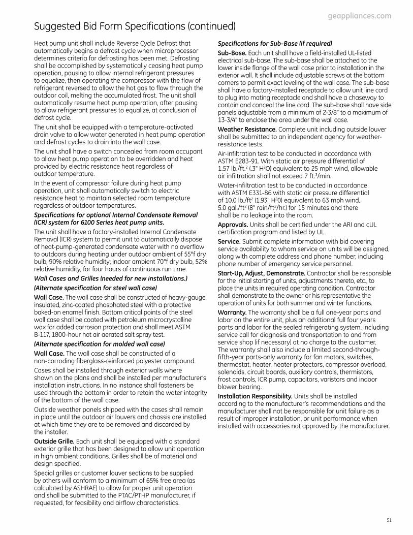
51
geappliances.comSuggested Bid Form Specifications (continued)
Heat pump unit shall include Reverse Cycle Defrost that automatically begins a defrost cycle when microprocessor determines criteria for defrosting has been met. Defrosting shall be accomplished by systematically ceasing heat pump operation, pausing to allow internal refrigerant pressures to equalize, then operating the compressor with the flow of refrigerant reversed to allow the hot gas to flow through the outdoor coil, melting the accumulated frost. The unit shall automatically resume heat pump operation, after pausing to allow refrigerant pressures to equalize, at conclusion of defrost cycle. The unit shall be equipped with a temperature-activated drain valve to allow water generated in heat pump operation and defrost cycles to drain into the wall case.The unit shall have a switch concealed from room occupant to allow heat pump operation to be overridden and heat provided by electric resistance heat regardless of outdoor temperature.In the event of compressor failure during heat pump operation, unit shall automatically switch to electric resistance heat to maintain selected room temperature regardless of outdoor temperatures.Specifications for optional Internal Condensate Removal (ICR) system for 6100 Series heat pump units.The unit shall have a factory-installed Internal Condensate Removal (ICR) system to permit unit to automatically dispose of heat-pump-generated condensate water with no overflow to outdoors during heating under outdoor ambient of 55°f dry bulb, 90% relative humidity; indoor ambient 70°f dry bulb, 52% relative humidity, for four hours of continuous run time. Wall Cases and Grilles (needed for new installations.) (Alternate specification for steel wall case)Wall Case. The wall case shall be constructed of heavy-gauge, insulated, zinc-coated phosphated steel with a protective baked-on enamel finish. Bottom critical points of the steel wall case shall be coated with petroleum microcrystalline wax for added corrosion protection and shall meet ASTM B-117, 1800-hour hot air aerated salt spray test. (Alternate specification for molded wall case)Wall Case. The wall case shall be constructed of a non-corroding fiberglass-reinforced polyester compound.Cases shall be installed through exterior walls where shown on the plans and shall be installed per manufacturer’s installation instructions. In no instance shall fasteners be used through the bottom in order to retain the water integrity of the bottom of the wall case. Outside weather panels shipped with the cases shall remain in place until the outdoor air louvers and chassis are installed, at which time they are to be removed and discarded by the installer. Outside Grille. Each unit shall be equipped with a standard exterior grille that has been designed to allow unit operation in high ambient conditions. Grilles shall be of material and design specified. Special grilles or customer louver sections to be supplied by others will conform to a minimum of 65% free area (as calculated by ASHRAE) to allow for proper unit operation and shall be submitted to the PTAC/PTHP manufacturer, if requested, for feasibility and airflow characteristics.
Specifications for Sub-Base (if required)Sub-Base. Each unit shall have a field-installed UL-listed electrical sub-base. The sub-base shall be attached to the lower inside flange of the wall case prior to installation in the exterior wall. It shall include adjustable screws at the bottom corners to permit exact leveling of the wall case. The sub-base shall have a factory-installed receptacle to allow unit line cord to plug into mating receptacle and shall have a chaseway to contain and conceal the line cord. The sub-base shall have side panels adjustable from a minimum of 2-3/8" to a maximum of 13-3/4" to enclose the area under the wall case.Weather Resistance. Complete unit including outside louver shall be submitted to an independent agency for weather-resistance tests.Air-infiltration test to be conducted in accordance with ASTM E283-91. With static air pressure differential of 1.57 lb./ft.2 (.3" H2O) equivalent to 25 mph wind, allowable air infiltration shall not exceed 7 ft.3/min. Water-infiltration test to be conducted in accordance with ASTM E331-86 with static air pressure differential of 10.0 lb./ft2 (1.93" H20) equivalent to 63 mph wind, 5.0 gal./ft2 (8" rain/ft2/hr.) for 15 minutes and there shall be no leakage into the room.Approvals. Units shall be certified under the ARI and cUL certification program and listed by UL. Service. Submit complete information with bid covering service availability to whom service on units will be assigned, along with complete address and phone number, including phone number of emergency service personnel. Start-Up, Adjust, Demonstrate. Contractor shall be responsible for the initial starting of units, adjustments thereto, etc., to place the units in required operating condition. Contractor shall demonstrate to the owner or his representative the operation of units for both summer and winter functions. Warranty. The warranty shall be a full one-year parts and labor on the entire unit, plus an additional full four years parts and labor for the sealed refrigerating system, including service call for diagnosis and transportation to and from service shop (if necessary) at no charge to the customer. The warranty shall also include a limited second-through- fifth-year parts-only warranty for fan motors, switches, thermostat, heater, heater protectors, compressor overload, solenoids, circuit boards, auxiliary controls, thermistors, frost controls, ICR pump, capacitors, varistors and indoor blower bearing. Installation Responsibility. Units shall be installed according to the manufacturer’s recommendations and the manufacturer shall not be responsible for unit failure as a result of improper installation, or unit performance when installed with accessories not approved by the manufacturer.

52
Zoneline® Chassis Nomenclature
EXAMPLE
Receptacles/Sub-Bases
The Zoneline chassis is identified by a model number defining the type of unit, cooling capacity, electrical information and optional features included on the unit. When specifying or ordering the Zoneline chassis use of this nomenclature will assure receiving the correct unit.
A Z 6 1 H 1 2 D A DChassis series41= deluxe line cool/
electric heat61= deluxe line
heat pump
Unit typeE= cooling with electric
resistance heatH= heat pump with electric
resistance heat
Zonelinepackaged terminal chassis
Nominal cooling capacity07=7,000 BTUH cooling 09=9,000 BTUH cooling 12=12,000 BTUH cooling 15=15,000 BTUH cooling
Special FeaturesB=base unitC=corrosion treatedD= internal
condensate removal (ICR) system (heat pump models only) (not for coastal areas)
P=Dry Air 25
Voltage/Phase/FrequencyD= 230/208 Volt, single
phase, 60 HzE= 265 Volt, single phase,
60 Hz
Universal power connection
RAK204U RAK204D15P RAK204D20P RAK204D30P RAK204E15 RAK204E20 RAK204E30
Voltage N/A 230/208 230/208 230/208 265 265 265
Amps N/A 15 20 30 15 20 30
Receptacle N/A NEMA6-20R NEMA6-20R NEMA6-30R NEMA7-15R NEMA7-20R NEMA7-30R
230/208 Volt sub-bases include appropriate power cord kit.265 Volt units are to be direct connected. Cordset through enclosed chaseway into interior sub-base receptacle meets the NEC requirements.
Sub-bases
Tandem 230/208V 15 AmpNEMA6-15R
Perpendicular230/208V 20 AmpNEMA6-20R
Large tandem 230/208V 30 AmpNEMA6-30R
265V 15 AmpNEMA7-15R
265V 20 AmpNEMA7-20R;
265V 30 AmpNEMA7-30R;
Power connection kits are required on all Zoneline® chassis (see chart below).The correct kit for the installation is determined by the voltage and amperage of the electrical circuit and the means of connecting the unit to the building wiring. If the unit is to be plugged into a receptacle, a line cord kit would be used; if the unit is to be permanently connected, a permanent connection kit would be used. 265 volt cord set units must be installed in compliance with National Electrical Code®.
Power connection kitsRequired on all models. See specification sheet for heater KW and branch circuit ampacity.
RAK3153A/3203A/3303A230/208 volt line cord connection kit
RAK4157/4207/4307230/208 volt universal power supply kit
RAK5157/5207/5307265 volt universal power supply kit
230/208 volt Line cord connected units
LCDI Power Connection Kit RAK3153A RAK3203A RAK3303AHeater KW 2.4/2.32 3.3/3.2 4.7/4.53
Watts 2,400/2,320 3,300/3,200 4,700/4,530*
BTUH 8,150/7,900 11,200/10,900 16,000/15,450
Amps 11.0/11.6 15.1/16.0 21.2/22.4
Min. circuit amps 15 20 30
Recommended protective
device
15 amp time delay
fuse or breaker
20 amp time delay
fuse or breaker
30 amp time delay
fuse or breaker
265 volt Permanent connected units** (Cord set)
RAK5172 RAK5202 RAK53022.4 3.4 4.8
2,400 3,400 4,800*
8,150 11,550 16,350
9.6 13.3 18.6
15 20 30
15 amp time delay fuse
20 amp time delay fuse
30 amp time delay fuse
230/208 volt Direct connection kit†
RAK4157 RAK4207 RAK4307Heater KW 2.4/2.32 3.3/3.2 4.7/4.53
Watts 2,400/2,320 3,300/3,200 4,700/4,530*
BTUH 8,150/7,900 11,200/10,900 16,000/15,450
Amps 11.0/11.6 15.1/16.0 21.2/22.4
Min. circuit amps 15 20 30
Recommended protective
device
15 amp time delay
fuse or breaker
20 amp time delay
fuse or breaker
30 amp time delay
fuse or breaker
265 volt Direct connection kit†
RAK5157 RAK5207 RAK53072.4 3.4 4.8
2,400 3,400 4,800*
8,150 11,550 16,350
9.6 13.3 18.6
15 20 30
15 amp time delay fuse
20 amp time delay fuse
30 amp time delay fuse
*Wattage not available with 7,000 BTU systems.**To be used with sub-base †To be used with sub-base or connection to building wiringSpecifications subject to change.
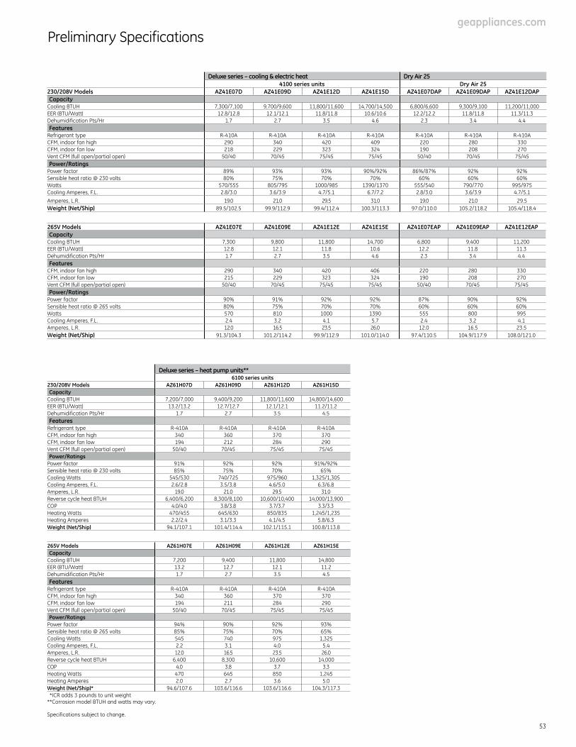
53
geappliances.comPreliminary Specifications
Deluxe series – cooling & electric heat Dry Air 254100 series units Dry Air 25
230/208V Models AZ41E07D AZ41E09D AZ41E12D AZ41E15D AZ41E07DAP AZ41E09DAP AZ41E12DAPCapacity
Cooling BTUH 7,300/7,100 9,700/9,600 11,800/11,600 14,700/14,500 6,800/6,600 9,300/9,100 11,200/11,000EER (BTU/Watt) 12.8/12.8 12.1/12.1 11.8/11.8 10.6/10.6 12.2/12.2 11.8/11.8 11.3/11.3Dehumidification Pts/Hr 1.7 2.7 3.5 4.6 2.3 3.4 4.4Features
Refrigerant type R-410A R-410A R-410A R-410A R-410A R-410A R-410ACFM, indoor fan high 290 340 420 409 220 280 330CFM, indoor fan low 218 229 323 324 190 208 270Vent CFM (full open/partial open) 50/40 70/45 75/45 75/45 50/40 70/45 75/45Power/Ratings
Power factor 89% 93% 93% 90%/92% 86%/87% 92% 92%Sensible heat ratio @ 230 volts 80% 75% 70% 70% 60% 60% 60%Watts 570/555 805/795 1000/985 1390/1370 555/540 790/770 995/975Cooling Amperes, F.L. 2.8/3.0 3.6/3.9 4.7/5.1 6.7/7.2 2.8/3.0 3.6/3.9 4.7/5.1
Amperes, L.R. 19.0 21.0 29.5 31.0 19.0 21.0 29.5Weight (Net/Ship) 89.5/102.5 99.9/112.9 99.4/112.4 100.3/113.3 97.0/110.0 105.2/118.2 105.4/118.4
Deluxe series – heat pump units**6100 series units
230/208V Models AZ61H07D AZ61H09D AZ61H12D AZ61H15DCapacity
Cooling BTUH 7,200/7,000 9,400/9,200 11,800/11,600 14,800/14,600EER (BTU/Watt) 13.2/13.2 12.7/12.7 12.1/12.1 11.2/11.2Dehumidification Pts/Hr 1.7 2.7 3.5 4.5Features
Refrigerant type R-410A R-410A R-410A R-410ACFM, indoor fan high 340 360 370 370CFM, indoor fan low 194 212 284 290Vent CFM (full open/partial open) 50/40 70/45 75/45 75/45Power/Ratings
Power factor 91% 92% 92% 91%/92%Sensible heat ratio @ 230 volts 85% 75% 70% 65%Cooling Watts 545/530 740/725 975/960 1,325/1,305Cooling Amperes, F.L. 2.6/2.8 3.5/3.8 4.6/5.0 6.3/6.8Amperes, L.R. 19.0 21.0 29.5 31.0Reverse cycle heat BTUH 6,400/6,200 8,300/8,100 10,600/10,400 14,000/13,900COP 4.0/4.0 3.8/3.8 3.7/3.7 3.3/3.3Heating Watts 470/455 645/630 850/835 1,245/1,235Heating Amperes 2.2/2.4 3.1/3.3 4.1/4.5 5.8/6.3Weight (Net/Ship) 94.1/107.1 101.4/114.4 102.1/115.1 100.8/113.8
265V Models AZ41E07E AZ41E09E AZ41E12E AZ41E15E AZ41E07EAP AZ41E09EAP AZ41E12EAPCapacity
Cooling BTUH 7,300 9,800 11,800 14,700 6,800 9,400 11,200EER (BTU/Watt) 12.8 12.1 11.8 10.6 12.2 11.8 11.3Dehumidification Pts/Hr 1.7 2.7 3.5 4.6 2.3 3.4 4.4Features
CFM, indoor fan high 290 340 420 406 220 280 330CFM, indoor fan low 215 229 323 324 190 208 270Vent CFM (full open/partial open) 50/40 70/45 75/45 75/45 50/40 70/45 75/45Power/Ratings
Power factor 90% 91% 92% 92% 87% 90% 92%Sensible heat ratio @ 265 volts 80% 75% 70% 70% 60% 60% 60%Watts 570 810 1000 1390 555 800 995Cooling Amperes, F.L. 2.4 3.2 4.1 5.7 2.4 3.2 4.1Amperes, L.R. 12.0 16.5 23.5 26.0 12.0 16.5 23.5Weight (Net/Ship) 91.3/104.3 101.2/114.2 99.9/112.9 101.0/114.0 97.4/110.5 104.9/117.9 108.0/121.0
265V Models AZ61H07E AZ61H09E AZ61H12E AZ61H15ECapacity
Cooling BTUH 7,200 9,400 11,800 14,800EER (BTU/Watt) 13.2 12.7 12.1 11.2Dehumidification Pts/Hr 1.7 2.7 3.5 4.5Features
Refrigerant type R-410A R-410A R-410A R-410ACFM, indoor fan high 340 360 370 370CFM, indoor fan low 194 211 284 290Vent CFM (full open/partial open) 50/40 70/45 75/45 75/45Power/Ratings
Power factor 94% 90% 92% 93%Sensible heat ratio @ 265 volts 85% 75% 70% 65%Cooling Watts 545 740 975 1,325Cooling Amperes, F.L. 2.2 3.1 4.0 5.4Amperes, L.R. 12.0 16.5 23.5 26.0Reverse cycle heat BTUH 6,400 8,300 10,600 14,000COP 4.0 3.8 3.7 3.3Heating Watts 470 645 850 1,245Heating Amperes 2.0 2.7 3.6 5.0Weight (Net/Ship)* 94.6/107.6 103.6/116.6 103.6/116.6 104.3/117.3**ICR adds 3 pounds to unit weight **Corrosion model BTUH and watts may vary.
Specifications subject to change.
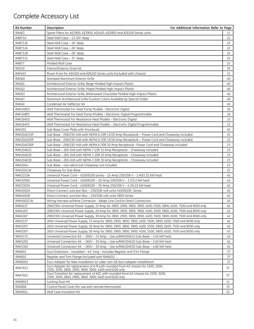
54
Complete Accessory List
Kit Number Description For Additional Information Refer to PageRAA63 Spare Filters for AZ2900, AZ3900, AZ4100, AZ5800 and AZ6100 Series units 11
RAB71A Steel Wall Case – 13-3/4" deep 22
RAB7116 Steel Wall Case – 16" deep 22
RAB7124 Steel Wall Case – 24" deep 22
RAB7128 Steel Wall Case – 28" deep 22
RAB7131 Steel Wall Case – 31" deep 22
RAB77 Molded Wall Case 22
RAD10 Interior/Exterior Drain kit 35
RAF453 Room Front for AZ4100 and AZ6100 Series units (included with chassis) 11
RAG60 Stamped Aluminum Exterior Grille 40
RAG61 Architectural Exterior Grille, Beige Molded High-Impact Plastic 40
RAG62 Architectural Exterior Grille, Maple Molded High-Impact Plastic 40
RAG63 Architectural Exterior Grille, Bittersweet Chocolate Molded High-Impact Plastic 40
RAG67 Aluminum Architectural Grille (Custom Colors Available by Special Order) 40
RAK40 Condenser Air Deflector Kit 40
RAK148D1 Wall Thermostat For Heat Pump Models - Electronic Digital 16
RAK148P1 Wall Thermostat For Heat Pump Models – Electronic Digital Programmable 16
RAK164D1 Wall Thermostat For Resistance Heat Models – Electronic Digital 15
RAK164P1 Wall Thermostat For Resistance Heat Models – Electronic Digital Programmable 15
RAK201 Sub-Base Cover Plate with Knockouts 43
RAK204D15P Sub-Base - 208/230-Volt with NEMA 6-20R 15/20 Amp Receptacle – Power Cord and Chaseway included 22
RAK204D20P Sub-Base - 208/230-Volt with NEMA 6-20R 15/20 Amp Receptacle – Power Cord and Chaseway included 22
RAK204D30P Sub-Base - 208/230-Volt with NEMA 6-30R 30 Amp Receptacle –Power Cord and Chaseway included 23
RAK204E15 Sub-Base – 265-Volt with NEMA 7-15R 15 Amp Receptacle – Chaseway included 23
RAK204E20 Sub-Base – 265-Volt with NEMA 7-20R 20 Amp Receptacle – Chaseway included 23
RAK204E30 Sub-Base – 265-Volt with NEMA 7-30R 30 Amp Receptacle – Chaseway included 23
RAK204U Sub-Base – non-electrical Chaseway not included 22
RAK205CW Chaseway for Sub-Base 22
RAK3153A Universal Power Cord – 4100/6100 series – 15-Amp 230/208 V – 2.40/2.32 kW heat 42
RAK3203A Universal Power Cord – 4100/6100 – 20-Amp 230/208 V – 3.3/3.2 kW heat 42
RAK3303A Universal Power Cord – 4100/6100 – 30-Amp 230/208 V – 4.7/4.53 kW heat 42
RAK4002A Direct-Connect Junction Box – 230/208-volt units 4100/6100 Series 42
RAK4002B Direct-Connect Junction Box – 230/208-volt units 5800 Series 42
RAK4002CW Wiring Harness w/Inline Connector - Adapt Line Cord to Direct Connection 43
RAK4157 208/230V Universal Power Supply, 15 Amp for 2800, 2900, 3800, 3900, 4100, 5500, 5800, 6100, 7500 and 8500 only 42
RAK4207 208/230V Universal Power Supply, 20 Amp for 2800, 2900, 3800, 3900, 4100, 5500, 5800, 6100, 7500 and 8500 only 42
RAK4307 208/230V Universal Power Supply, 30 Amp for 2800, 2900, 3800, 3900, 4100, 5500, 5800, 6100, 7500 and 8500 only 42
RAK5157 265V Universal Power Supply, 15 Amp for 2800, 2900, 3800, 3900, 4100, 5500, 5800, 6100, 7500 and 8500 only 42
RAK5207 265V Universal Power Supply, 20 Amp for 2800, 2900, 3800, 3900, 4100, 5500, 5800, 6100, 7500 and 8500 only 42
RAK5307 265V Universal Power Supply, 30 Amp for 2800, 2900, 3800, 3900, 4100, 5500, 5800, 6100, 7500 and 8500 only 42
RAK5172 Universal Connection Kit – 265V – 15 Amp – Use w/RAK204E15 Sub-Base – 2.40 kW heat 42
RAK5202 Universal Connection Kit – 265V – 20 Amp – Use w/RAK204E20 Sub-Base – 3.40 kW heat 42
RAK5302 Universal Connection Kit – 265V – 30 Amp – Use w/RAK204E30 Sub-Base – 4.80 kW heat 42
RAK601 Duct Extension – Insulated – 44" long – includes Register and Trim Flange 37
RAK602 Register and Trim Flange (Included with RAK601) 37
RAK6052 Duct Adapter for New Installation (or older non-GE duct adapter installation) 37
RAK7012 Duct Adapter for replacement of A-B with rounded-front AZ chassis for 2200, 3200, 2500, 3500, 2800, 2900, 3800, 3900, 4100 and 6100 only 37
RAK7022 Duct Transition for replacement of AZC with rounded-front AZ chassis for 2200, 3200, 2500, 3500, 2800, 2900, 3800, 3900, 4100 and 6100 only 37
RAK8023 Locking Door Kit 11
RAK806 Control Panel Cover (for use with remote thermostat) 15
RAK901L Wall Case Insulation Kit 22
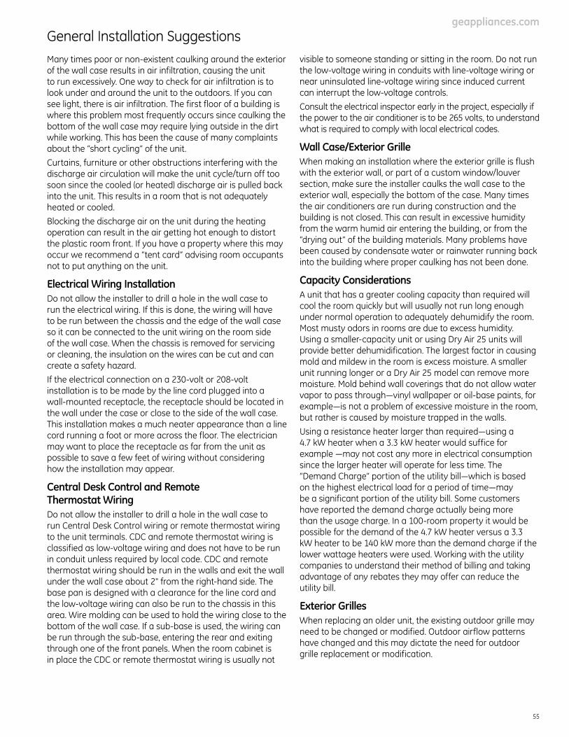
55
geappliances.comGeneral Installation SuggestionsMany times poor or non-existent caulking around the exterior of the wall case results in air infiltration, causing the unit to run excessively. One way to check for air infiltration is to look under and around the unit to the outdoors. If you can see light, there is air infiltration. The first floor of a building is where this problem most frequently occurs since caulking the bottom of the wall case may require lying outside in the dirt while working. This has been the cause of many complaints about the “short cycling” of the unit.
Curtains, furniture or other obstructions interfering with the discharge air circulation will make the unit cycle/turn off too soon since the cooled (or heated) discharge air is pulled back into the unit. This results in a room that is not adequately heated or cooled.
Blocking the discharge air on the unit during the heating operation can result in the air getting hot enough to distort the plastic room front. If you have a property where this may occur we recommend a “tent card” advising room occupants not to put anything on the unit.
Electrical Wiring InstallationDo not allow the installer to drill a hole in the wall case to run the electrical wiring. If this is done, the wiring will have to be run between the chassis and the edge of the wall case so it can be connected to the unit wiring on the room side of the wall case. When the chassis is removed for servicing or cleaning, the insulation on the wires can be cut and can create a safety hazard.
If the electrical connection on a 230-volt or 208-volt installation is to be made by the line cord plugged into a wall-mounted receptacle, the receptacle should be located in the wall under the case or close to the side of the wall case. This installation makes a much neater appearance than a line cord running a foot or more across the floor. The electrician may want to place the receptacle as far from the unit as possible to save a few feet of wiring without considering how the installation may appear.
Central Desk Control and Remote Thermostat WiringDo not allow the installer to drill a hole in the wall case to run Central Desk Control wiring or remote thermostat wiring to the unit terminals. CDC and remote thermostat wiring is classified as low-voltage wiring and does not have to be run in conduit unless required by local code. CDC and remote thermostat wiring should be run in the walls and exit the wall under the wall case about 2" from the right-hand side. The base pan is designed with a clearance for the line cord and the low-voltage wiring can also be run to the chassis in this area. Wire molding can be used to hold the wiring close to the bottom of the wall case. If a sub-base is used, the wiring can be run through the sub-base, entering the rear and exiting through one of the front panels. When the room cabinet is in place the CDC or remote thermostat wiring is usually not
visible to someone standing or sitting in the room. Do not run the low-voltage wiring in conduits with line-voltage wiring or near uninsulated line-voltage wiring since induced current can interrupt the low-voltage controls.
Consult the electrical inspector early in the project, especially if the power to the air conditioner is to be 265 volts, to understand what is required to comply with local electrical codes.
Wall Case/Exterior GrilleWhen making an installation where the exterior grille is flush with the exterior wall, or part of a custom window/louver section, make sure the installer caulks the wall case to the exterior wall, especially the bottom of the case. Many times the air conditioners are run during construction and the building is not closed. This can result in excessive humidity from the warm humid air entering the building, or from the “drying out” of the building materials. Many problems have been caused by condensate water or rainwater running back into the building where proper caulking has not been done.
Capacity ConsiderationsA unit that has a greater cooling capacity than required will cool the room quickly but will usually not run long enough under normal operation to adequately dehumidify the room. Most musty odors in rooms are due to excess humidity. Using a smaller-capacity unit or using Dry Air 25 units will provide better dehumidification. The largest factor in causing mold and mildew in the room is excess moisture. A smaller unit running longer or a Dry Air 25 model can remove more moisture. Mold behind wall coverings that do not allow water vapor to pass through—vinyl wallpaper or oil-base paints, for example—is not a problem of excessive moisture in the room, but rather is caused by moisture trapped in the walls.
Using a resistance heater larger than required—using a 4.7 kW heater when a 3.3 kW heater would suffice for example —may not cost any more in electrical consumption since the larger heater will operate for less time. The “Demand Charge” portion of the utility bill—which is based on the highest electrical load for a period of time—may be a significant portion of the utility bill. Some customers have reported the demand charge actually being more than the usage charge. In a 100-room property it would be possible for the demand of the 4.7 kW heater versus a 3.3 kW heater to be 140 kW more than the demand charge if the lower wattage heaters were used. Working with the utility companies to understand their method of billing and taking advantage of any rebates they may offer can reduce the utility bill.
Exterior GrillesWhen replacing an older unit, the existing outdoor grille may need to be changed or modified. Outdoor airflow patterns have changed and this may dictate the need for outdoor grille replacement or modification.

56
General Installation Suggestions
Ducted Installation CommentsNew Installations
The GE Zoneline® 4100 and 6100 Series are approved for ducted installation using the GE Duct Adapter model RAK6052 and the GE Duct Extension RAK601. A field-fabricated duct extension with the same interior measurements as the RAK601 may be used with the RAK6052 duct adapter. GE does not recommend ducting in more than one direction.
The use of a duct adapter other than the RAK6052 is not approved by GE and may cause problems such as inadequate airflow to the secondary room or the unit shutting off on one of the overload devices.
Failure to allow for adequate air return from the secondary room is often the cause of less than satisfactory performance of a ducted installation.
Replacement InstallationsGE offers duct adapters to allow for easy replacements of previous-design chassis in ducted installations where a GE duct adapter was used in the original installation. A duct adapter is available that will align with the duct extension when GE-built components were used in the original installation.
The duct adaptor/extension used from the early 1960s until late 1987 was 8-3/8" high by 6-1/2" wide. If the chassis to be replaced is the flat-top discharge (design until late 1987) the duct adapter model RAK7012 will align with the existing duct extension. This means the duct extension will not have to be changed. However, to keep the cost of the replacement to a minimum there are components that will need to be taken off the existing installation and used on the RAK7012 duct adapter. The wall case mounting brackets, screws, discharge grille, damper and end cap will need to be retained.
If the chassis is a slope-front discharge and the duct dimensions are 8-3/8" high by 6-1/2" wide, then the chassis has already been replaced and the purchase of a new duct adapter is not required. The only piece that needs to be replaced in this installation is the transition piece, model RAK7022, which fits between the chassis and the duct adapter.
If the chassis being replaced has a model number that begins with AZ22, AZ25, AZ28, AZ29, AZ32, AZ35, AZ38 or AZ39, the new 4100 or 6100 Series unit can be installed using the same duct components.
If the existing chassis is a slope-front discharge and the duct dimensions are 7-3/32" high by 6-1/2" wide, only the RAK7022 transition piece is required to install a 4100 or 6100 Series unit in the ducted installation.
There were a number of Zoneline units installed in ducted installations that did not use a GE duct adapter. The easiest way to determine if the existing duct adapter is a GE duct adapter is if compare the duct adapter dimensions to the dimensions above. If the dimensions are different from the dimensions above or if the duct adapter is not made of sheet metal, it is not a GE duct adapter. In such installations GE recommends the removal of the old duct adapter and duct extension and the installation of a RAK6052 duct adapter and a RAK601 duct extension. Zoneline units installed in installations not using GE duct adapters and an extension with the same cross-section dimensions as the duct adapter may not be covered by the warranty.
What is coveredLimited one-year warrantyFor one year from the date of the original purchase, GE will repair or replace any part of the air conditioner which fails due to a defect in materials or workmanship. During this limited one-year warranty, GE will provide, free of charge, all labor and related service costs to repair or replace the defective part.
Limited five-year warrantyFor five years from the date of the original purchase, GE will repair or replace the Sealed Refrigerating System if any part of the Sealed Refrigerating System (the compressor, condenser, evaporator, and
all connecting tubing) should fail due to a defect in materials or workmanship. During this limited five-year warranty, GE will provide, free of charge, all labor and related service costs to repair or replace the defective part.
Limited second-through-fifth-year parts warrantyFrom the second through the fifth year from the date of the original purchase, GE will replace the Fan Motors, Switches, Thermostat, Heater, Heater Protectors, Compressor Overload, Solenoids, Circuit Boards, Auxiliary Controls, Thermistors, Freeze Sentinel™, Frost Controls, ICR Pump, Capacitors, Varistors and Indoor Blower Bearing, if any of these parts should fail due to a defect in materials or workmanship. During this additional four-year limited warranty, you will be responsible for any labor and related service costs.
*See written warranty for details
Zoneline Warranty*
57
geappliances.comNotes

58
Notes
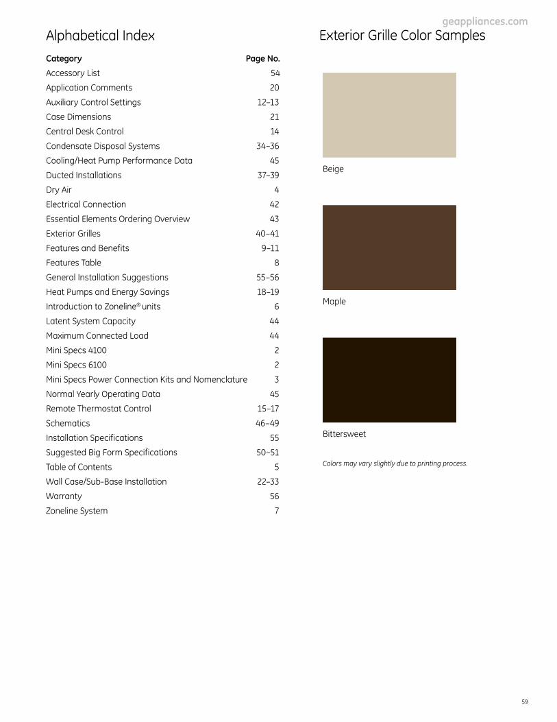
Alphabetical Index
Category Page No.
Accessory List 54
Application Comments 20
Auxiliary Control Settings 12–13
Case Dimensions 21
Central Desk Control 14
Condensate Disposal Systems 34–36
Cooling/Heat Pump Performance Data 45
Ducted Installations 37–39
Dry Air 4
Electrical Connection 42
Essential Elements Ordering Overview 43
Exterior Grilles 40–41
Features and Benefits 9–11
Features Table 8
General Installation Suggestions 55–56
Heat Pumps and Energy Savings 18–19
Introduction to Zoneline® units 6
Latent System Capacity 44
Maximum Connected Load 44
Mini Specs 4100 2
Mini Specs 6100 2
Mini Specs Power Connection Kits and Nomenclature 3
Normal yearly Operating Data 45
Remote Thermostat Control 15–17
Schematics 46–49
Installation Specifications 55
Suggested Big Form Specifications 50–51
Table of Contents 5
Wall Case/Sub-Base Installation 22–33
Warranty 56
Zoneline System 7
59
geappliances.comExterior Grille Color Samples
Bittersweet
Maple
Beige
Colors may vary slightly due to printing process.

100 years of innovation and we’re just getting startedFor more than a century, GE has been committed to producing innovative products that change the way people live. The result of thorough research and rigorous testing, GE appliances are designed for years of dependable performance. Today, the GE tradition of quality and innovation continues.
GE has a policy of continuous improvement of its products and reserves the right to change materials and specifications without notice.
© 2011 General Electric CompanyPub. No. 20-S081 PC66466
Before purchasing an appliance, read important information about its estimated annual energy consumption or energy efficiency rating that is available from your retailer or geappliances.com.
GEAppliancesAppliance ParkLouisville, KY 40225
geappliances.com
zoneline.com