ge digital energy multilin
TRANSCRIPT
2
Transformers
3
• Who was the better actor in a transformer movie:
• A – Marky Mark
• B- Shia Labuff.
Pole Question
4
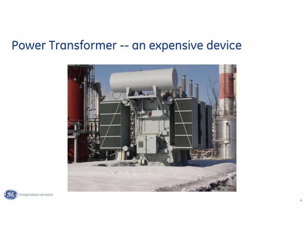
Power Transformer -- an expensive device
5
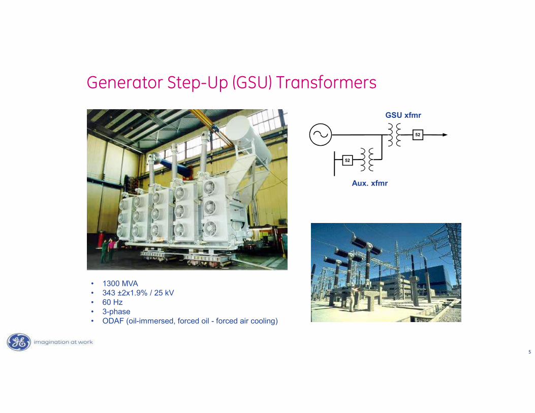
Generator Step-Up (GSU) Transformers
52
52
• 1300 MVA • 343 ±2x1.9% / 25 kV • 60 Hz • 3-phase • ODAF (oil-immersed, forced oil - forced air cooling)
GSU xfmr
Aux. xfmr
6
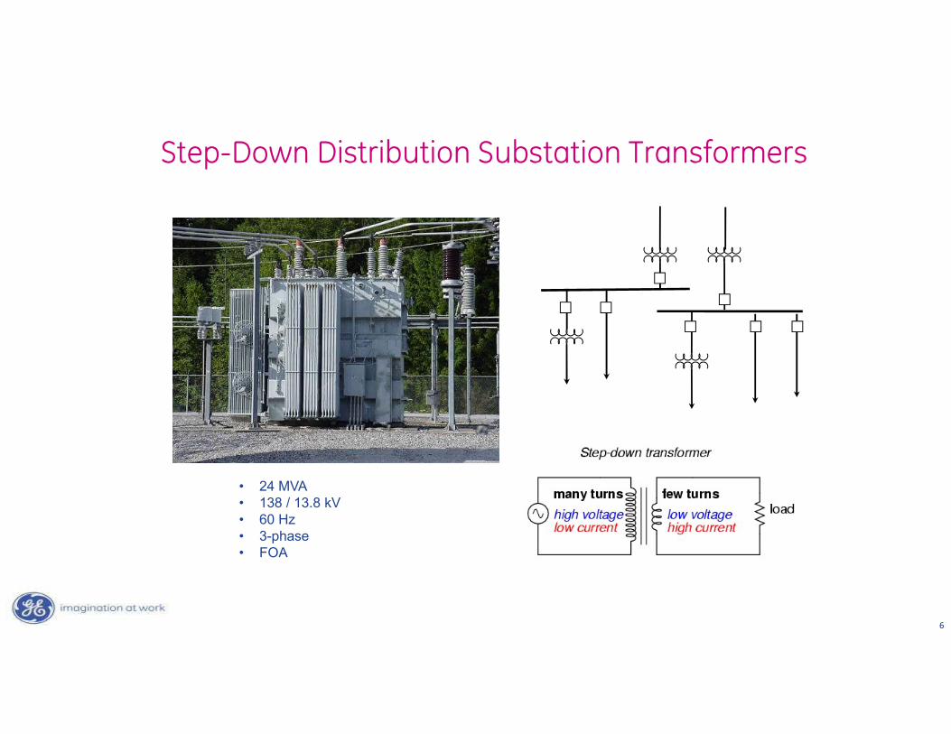
Step-Down Distribution Substation Transformers
• 24 MVA • 138 / 13.8 kV • 60 Hz • 3-phase • FOA
7
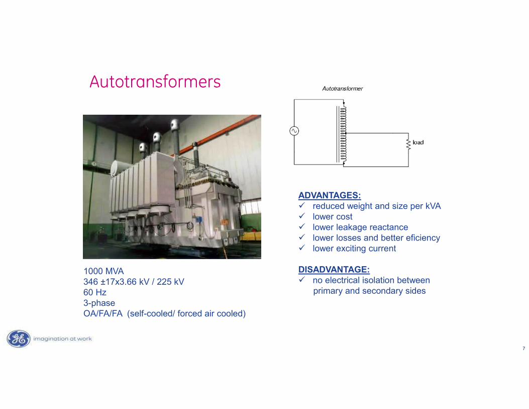
1000 MVA346 ±17x3.66 kV / 225 kV60 Hz3-phaseOA/FA/FA (self-cooled/ forced air cooled)
Autotransformers
ADVANTAGES: reduced weight and size per kVA lower cost lower leakage reactance lower losses and better eficiency lower exciting current
DISADVANTAGE: no electrical isolation between
primary and secondary sides
8
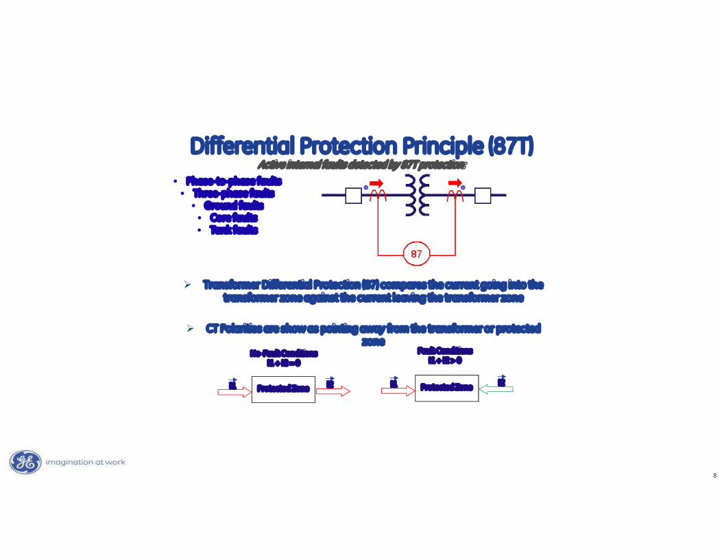
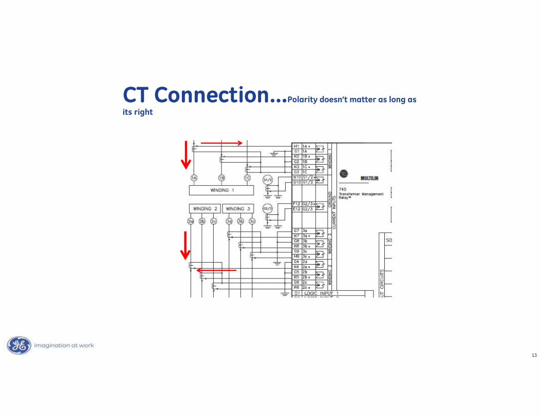
Transformer Differential Protection (87) compares the current going into the transformer zone against the current leaving the transformer zone
CT Polarities are show as pointing away from the transformer or protected zone
Protected Zone Protected Zone
No-Fault ConditionsI1 + I2 = 0
I1 I2 I1 I2
Fault ConditionsI1 + I2 > 0
• Phase-to-phase faults• Three-phase faults
• Ground faults• Core faults• Tank faults
Differential Protection Principle (87T)Active internal faults detected by 87T protection:
9
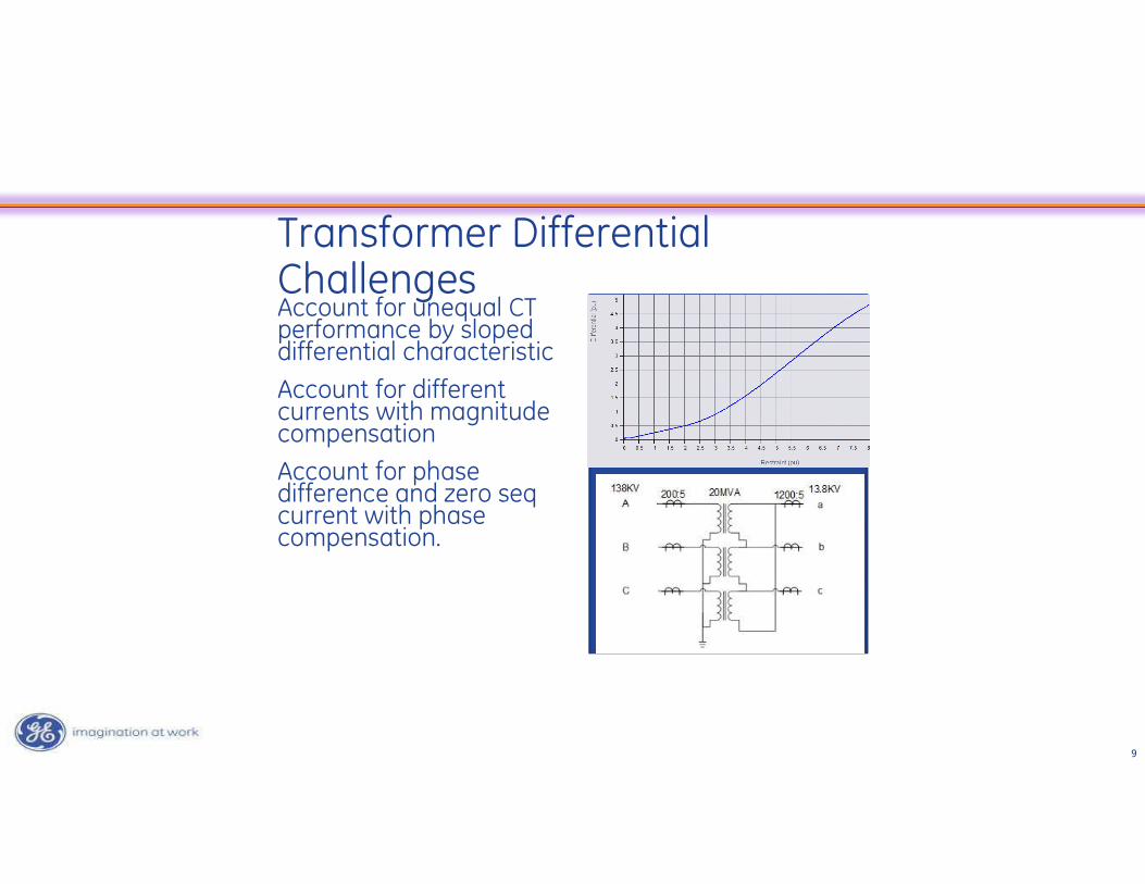
Transformer Differential ChallengesAccount for unequal CT performance by sloped differential characteristicAccount for different currents with magnitude compensationAccount for phase difference and zero seq current with phase compensation.
10
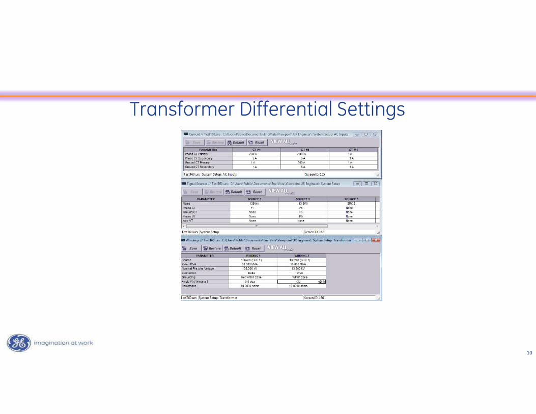
Transformer Differential Settings
11
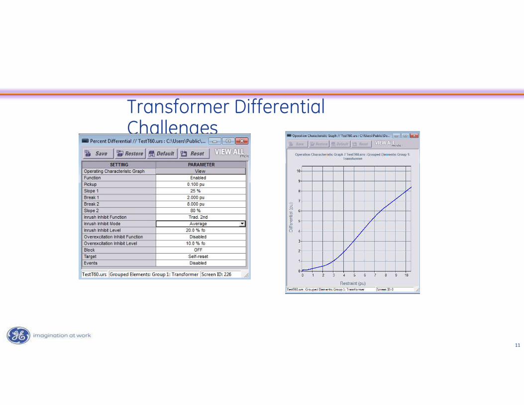
Transformer Differential Challenges
12
• Why does polarity matter:
• A – it properly determines direction relative to another quantity
• B- You always have to have the dot awayfrom the equipment
• C – It doesn’t really matter.
Pole Question
13
CT Connection…Polarity doesn’t matter as long as
its right
14
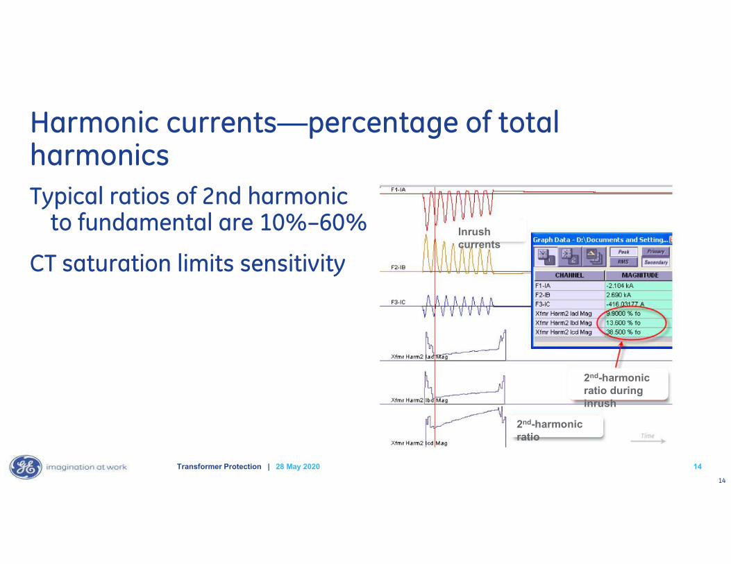
Harmonic currents—percentage of total harmonicsTypical ratios of 2nd harmonic
to fundamental are 10%–60%
CT saturation limits sensitivity
1428 May 2020Transformer Protection |
Inrush currents
2nd-harmonic ratio during inrush
2nd-harmonic ratio
15
Harmonic Restraint Mode should be set to:
• A – per phase
• B- two out of three
• C – average
Pole Question

16
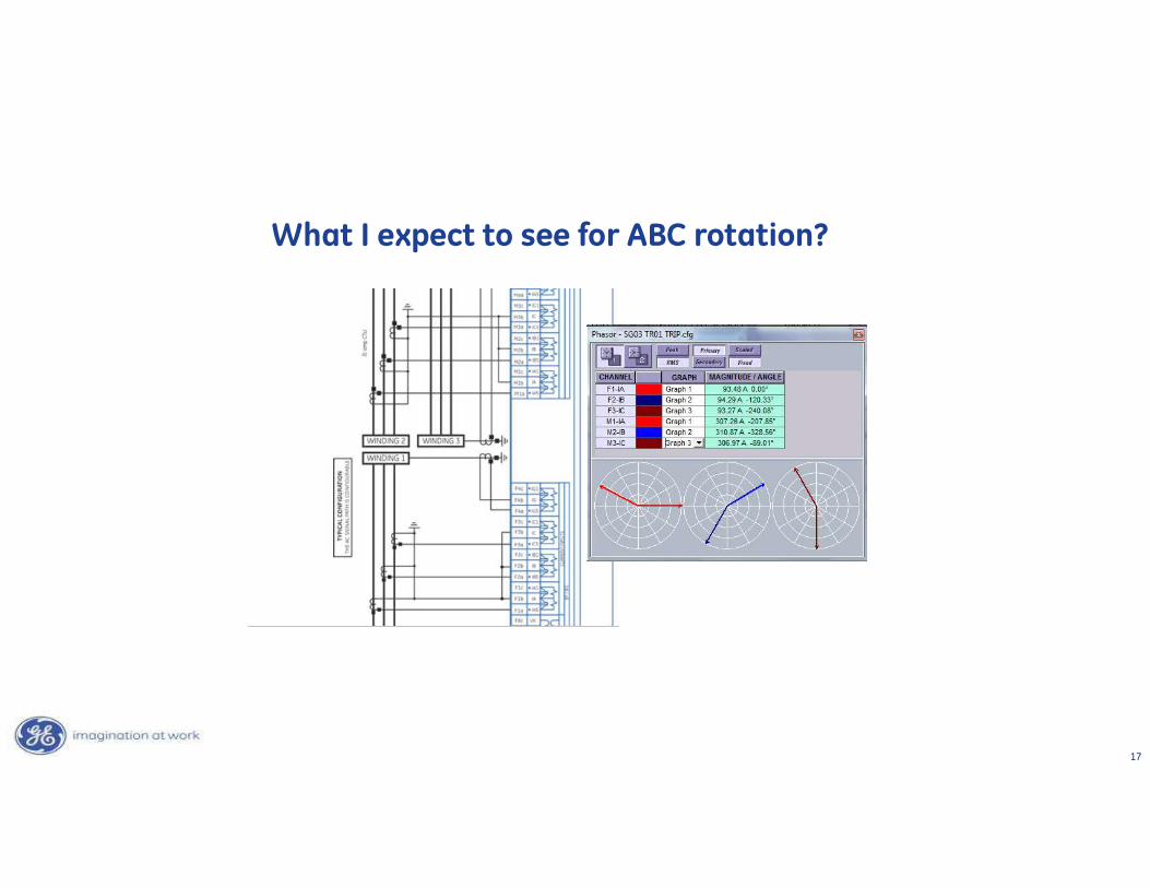
Typically H Winding leads X winding by 30 degrees
What I expect to see for ABC rotation?
A
C
B
a
b
c
17
What I expect to see for ABC rotation?
18
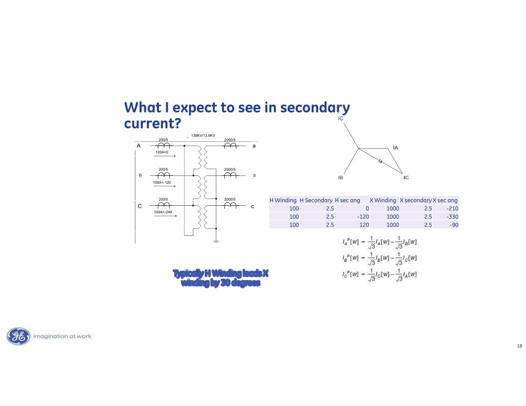
Typically H Winding leads X winding by 30 degrees
What I expect to see in secondary current?
H Winding H Secondary H sec ang X Winding X secondary X sec ang100 2.5 0 1000 2.5 -210100 2.5 -120 1000 2.5 -330100 2.5 120 1000 2.5 -90
200/5
200/5
200/5
2000/5
2000/5
2000/5138KV/13.8KV
100A<0
100A<-120
100A<-240
A
C c
a
19
Transformer phase compensation in the relay is performed by:
• A – magically shifting the current by the correct angle
• B- using the angle with respect to setting to mathematically determine how the shift is occurring a combination of current to get the shift.
• C – it depends
Pole Question
20
28 May 2020Transformer Protection | 20
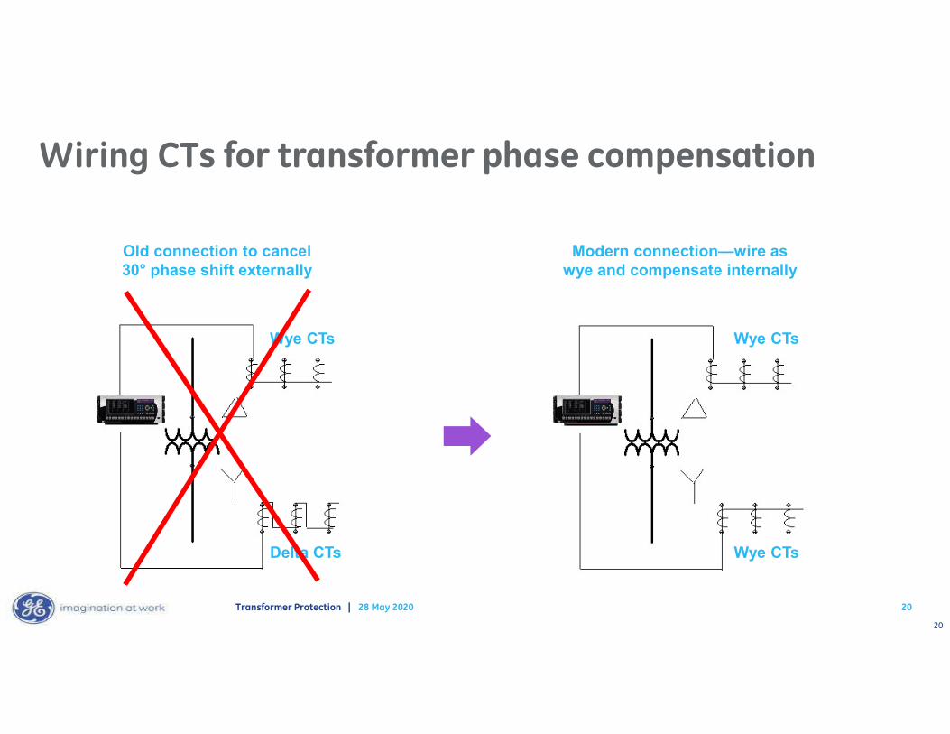
Delta CTs
Wye CTs
Wye CTs
Wye CTs
Wiring CTs for transformer phase compensation
Old connection to cancel 30° phase shift externally
Modern connection—wire as wye and compensate internally
21
28 May 2020Transformer Protection | 21
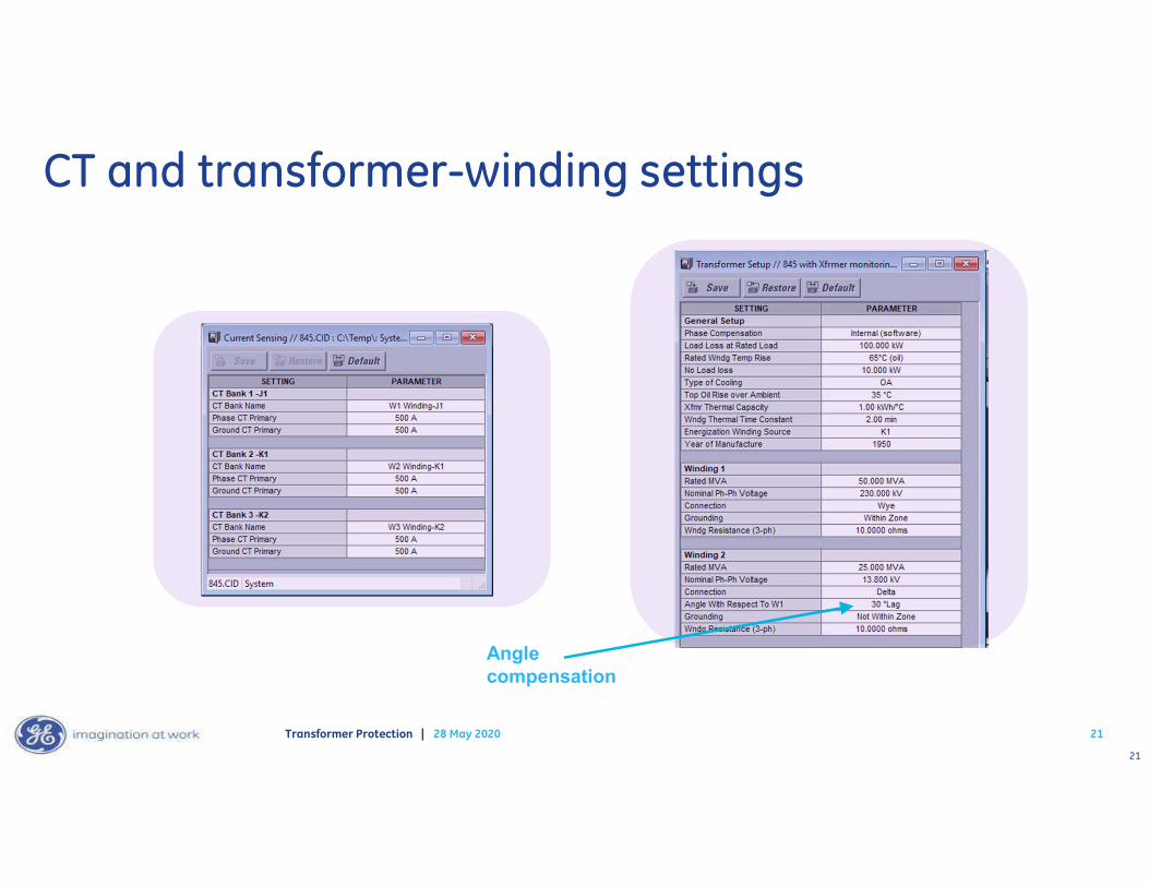
CT and transformer-winding settings
Angle compensation
22
28 May 2020Transformer Protection | 22
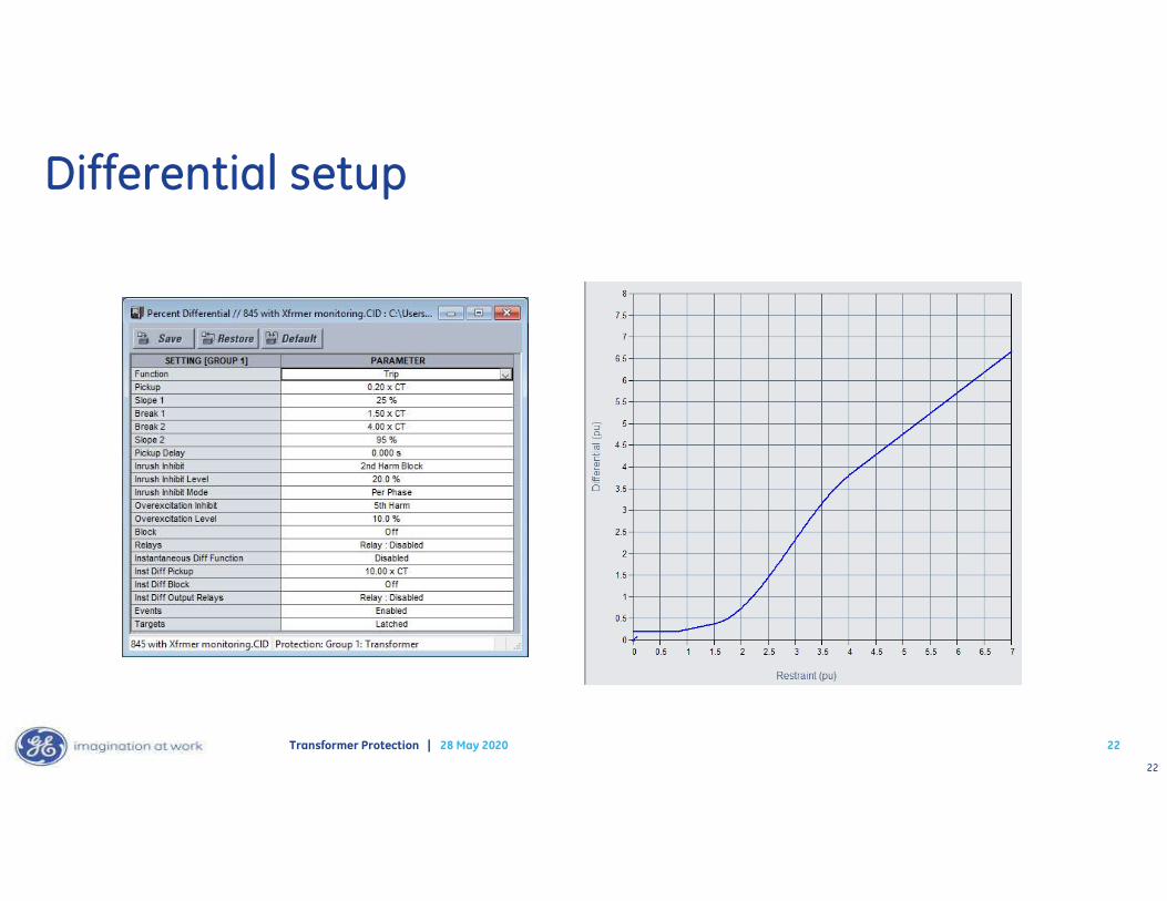
Differential setup
23
28 May 2020Transformer Protection | 23
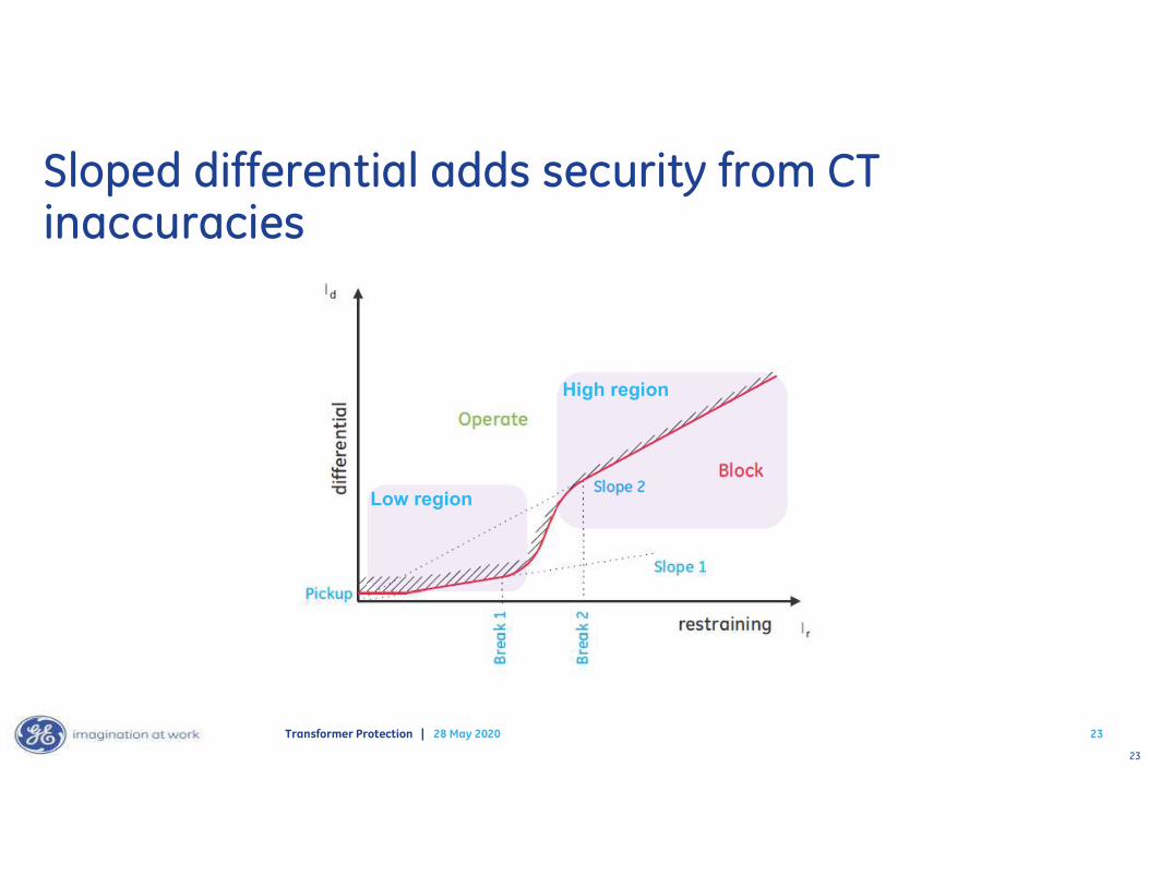
Sloped differential adds security from CT inaccuracies
Low region
High region
24
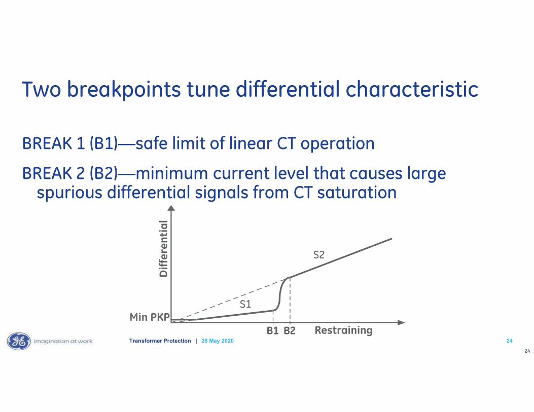
Two breakpoints tune differential characteristic
BREAK 1 (B1)—safe limit of linear CT operation
BREAK 2 (B2)—minimum current level that causes large spurious differential signals from CT saturation
2428 May 2020Transformer Protection |
S1
S2
Diff
eren
tial
RestrainingMin PKP
B1 B2
25
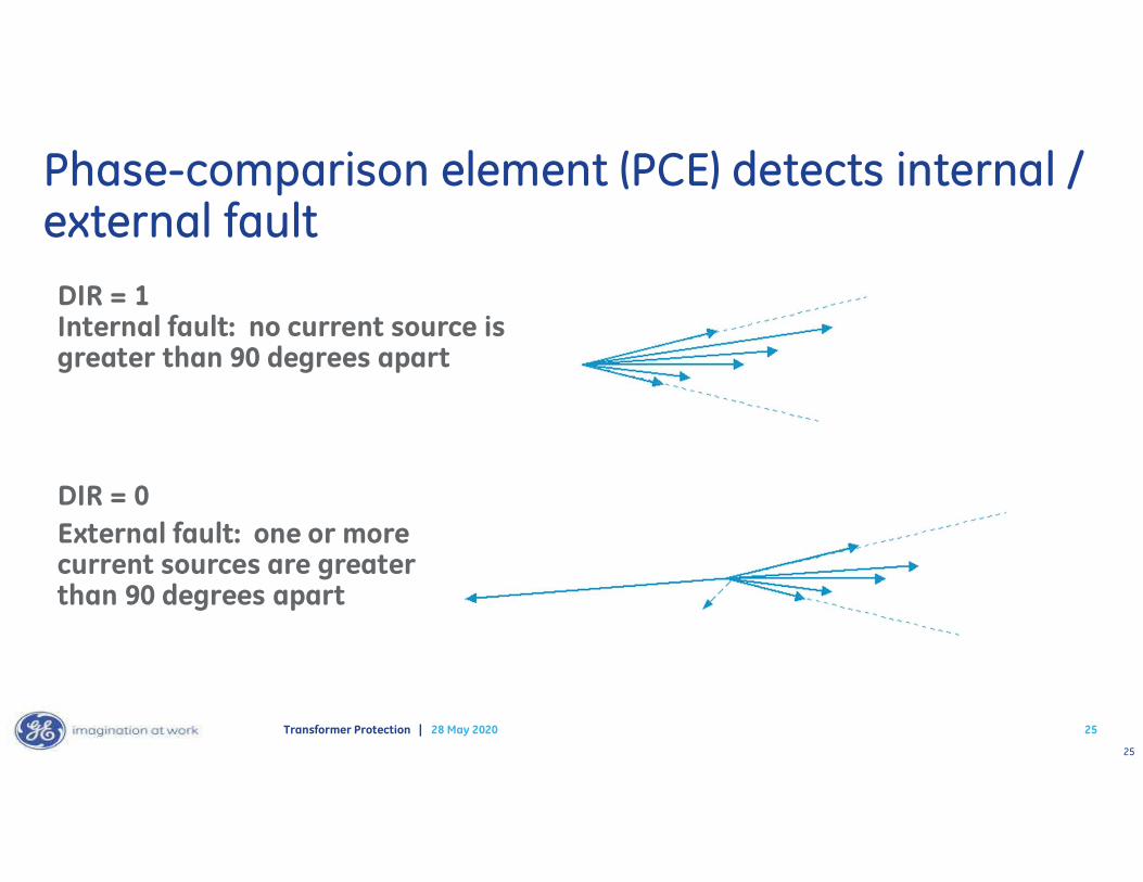
DIR = 1 Internal fault: no current source is greater than 90 degrees apart
DIR = 0External fault: one or more current sources are greater than 90 degrees apart
28 May 2020Transformer Protection |
Phase-comparison element (PCE) detects internal / external fault
25
26
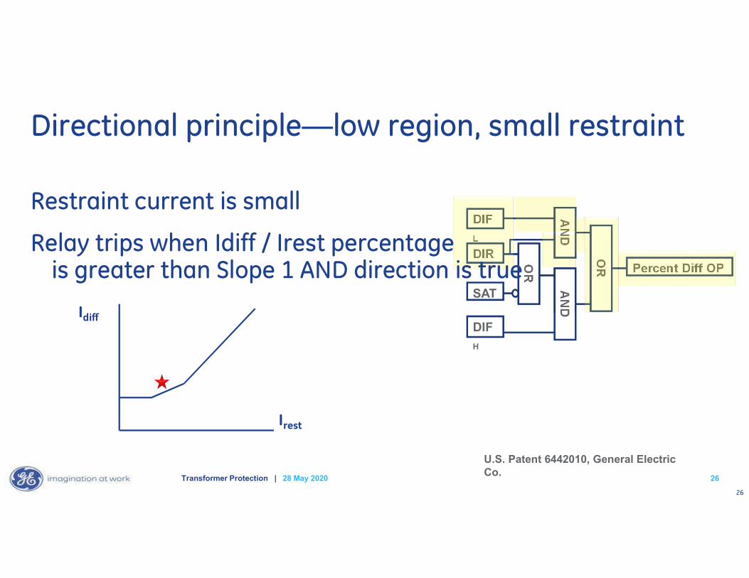
DIF
L
DIR
SAT
DIF
H
OR
AN
D
OR Percent Diff OP
AN
D
Irest
Idiff
U.S. Patent 6442010, General Electric Co.
Directional principle—low region, small restraint
Restraint current is small
Relay trips when Idiff / Irest percentageis greater than Slope 1 AND direction is true
2628 May 2020Transformer Protection |
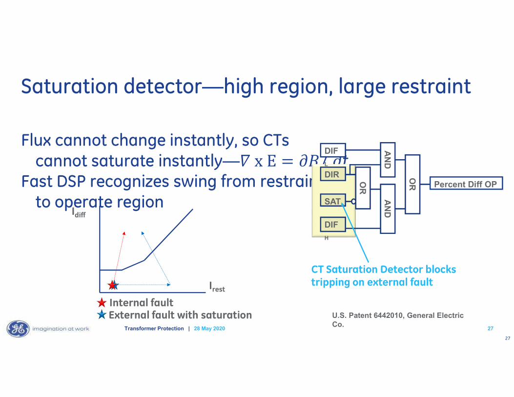
27
Flux cannot change instantly, so CTs cannot saturate instantly— t
Fast DSP recognizes swing from restraint to operate region
CT Saturation Detector blocks tripping on external faultIrest
Idiff
External fault with saturationInternal fault
Saturation detector—high region, large restraint
2728 May 2020Transformer Protection |
DIF
L
DIR
SAT
DIF
H
OR
AN
D
OR Percent Diff OP
AN
D
U.S. Patent 6442010, General Electric Co.
28
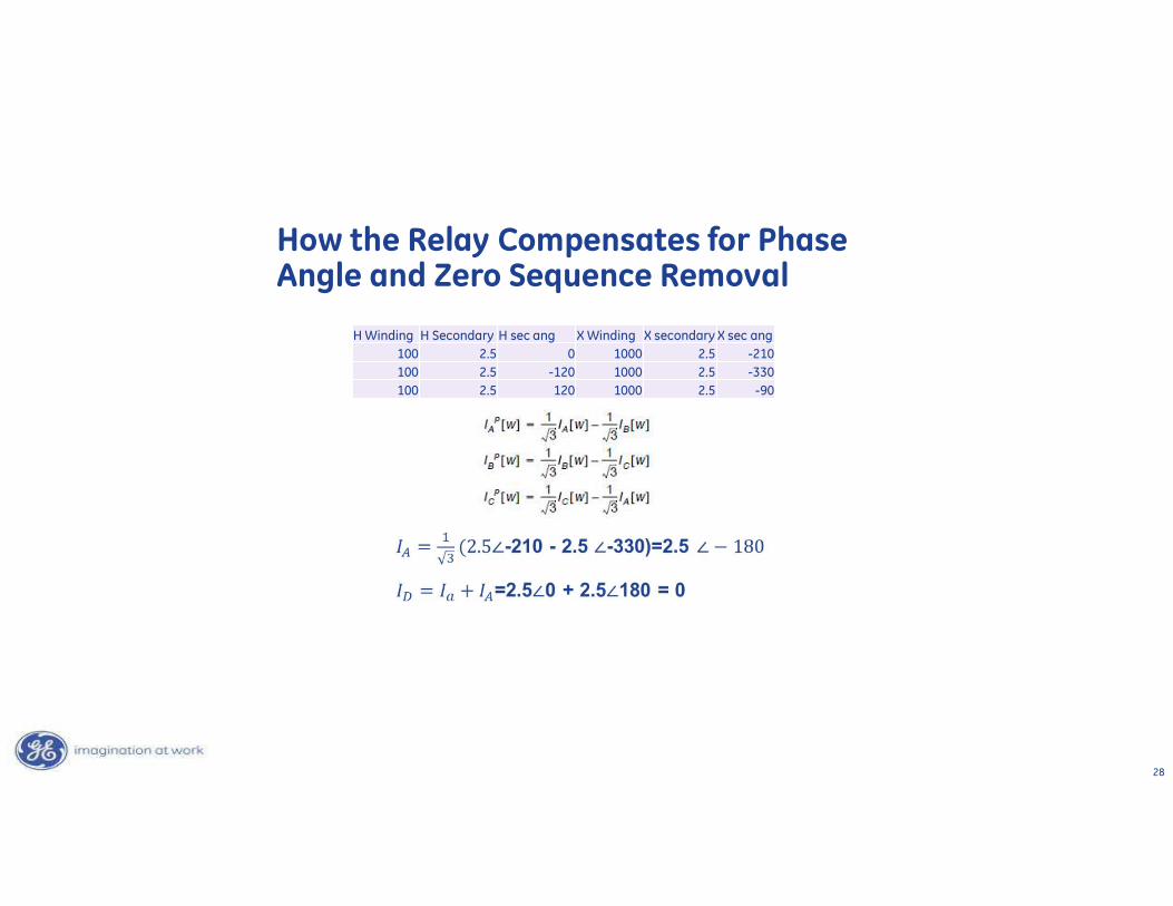
How the Relay Compensates for Phase Angle and Zero Sequence Removal
H Winding H Secondary H sec ang X Winding X secondary X sec ang100 2.5 0 1000 2.5 -210100 2.5 -120 1000 2.5 -330100 2.5 120 1000 2.5 -90
29
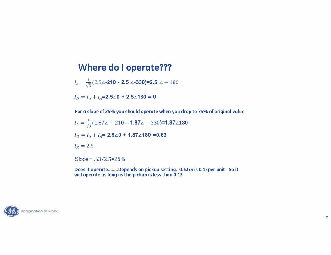
Where do I operate???
For a slope of 25% you should operate when you drop to 75% of original value
Does it operate……..Depends on pickup setting. 0.63/5 is 0.13per unit. So it will operate as long as the pickup is less than 0.13
30
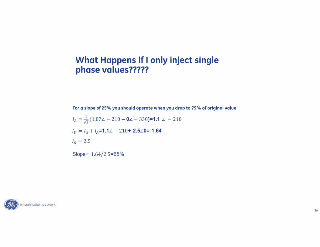
What Happens if I only inject single phase values?????
For a slope of 25% you should operate when you drop to 75% of original value
31
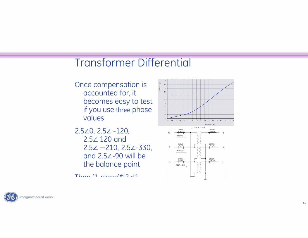
Transformer Differential
200/5
200/5
200/5
2000/5
2000/5
2000/5138KV/13.8KV
100A<0
100A<-120
100A<-240
A
C c
a