ge fanuc automation
TRANSCRIPT
GE Fanuc Automation
Computer Numerical Control Products
Series 0 / 00 / 0-Matefor Lathe
Parameter Manual
GFZ-61400E/03 November 1996
GFL-001
Warnings, Cautions, and Notesas Used in this Publication
Warning
Warning notices are used in this publication to emphasize that hazardous voltages, currents,temperatures, or other conditions that could cause personal injury exist in this equipment ormay be associated with its use.
In situations where inattention could cause either personal injury or damage to equipment, aWarning notice is used.
Caution
Caution notices are used where equipment might be damaged if care is not taken.
NoteNotes merely call attention to information that is especially significant to understanding andoperating the equipment.
This document is based on information available at the time of its publication. While effortshave been made to be accurate, the information contained herein does not purport to cover alldetails or variations in hardware or software, nor to provide for every possible contingency inconnection with installation, operation, or maintenance. Features may be described hereinwhich are not present in all hardware and software systems. GE Fanuc Automation assumesno obligation of notice to holders of this document with respect to changes subsequently made.
GE Fanuc Automation makes no representation or warranty, expressed, implied, or statutorywith respect to, and assumes no responsibility for the accuracy, completeness, sufficiency, orusefulness of the information contained herein. No warranties of merchantability or fitness forpurpose shall apply.
©Copyright 1996 GE Fanuc Automation North America, Inc.
All Rights Reserved.
Preface
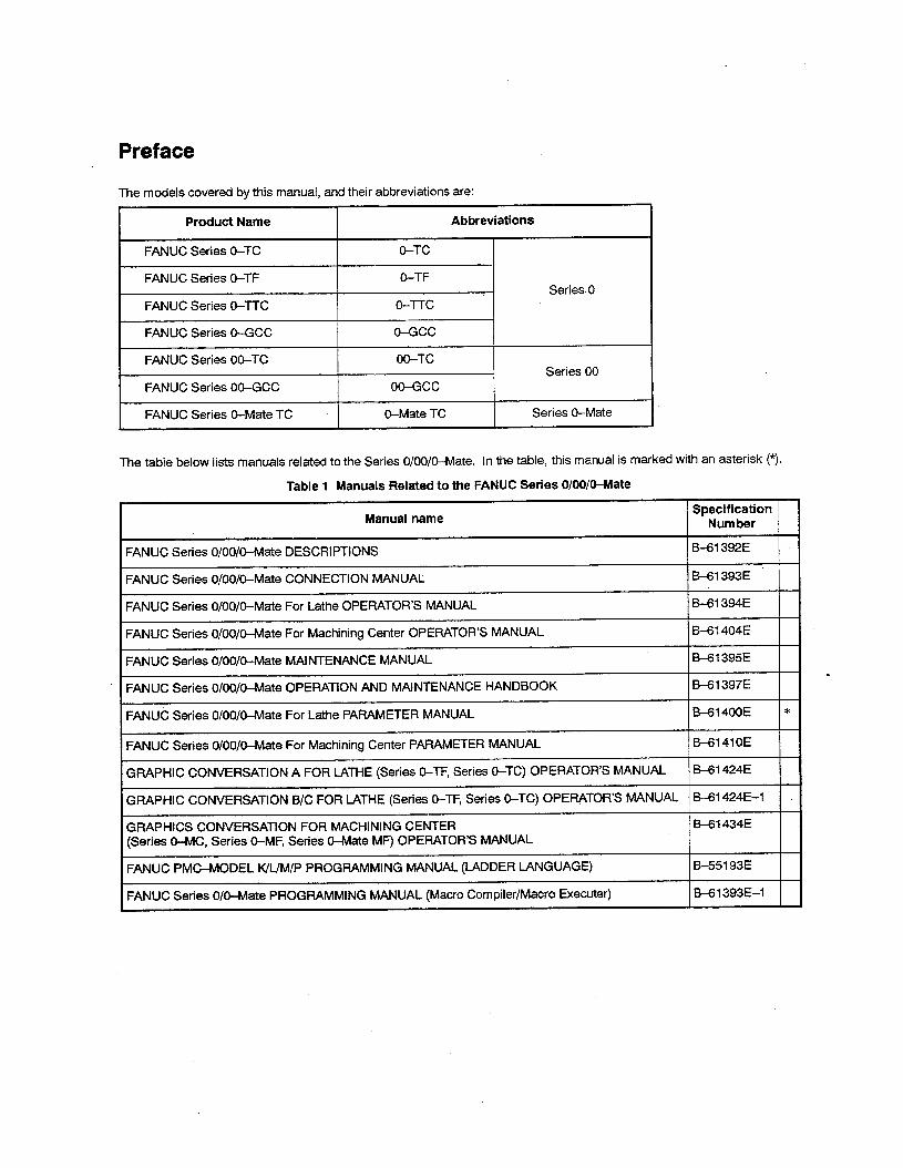
The models covered by this manual, and their abbreviations are: .
Product Name Abbreviations
FANUC Series 0-TC 0-TC
FANUC Series 0-TF 0-TF I Series. 0
FANUC Series O-TX O-IX
FANUC Series 0-GCC 0-GCC
FANUC Series 00-TC 00-TC Series 00
FANUC Series OO-GCC OO-GCC
FANUC Series O-Mate TC O-Mate TC Series O-Mate
The table below lists manuals related to the Series O/00/0-Mate. In the table, this manual is marked with an asterisk (*).
Table 1 Manuals Related to the FANUC Series 0/00/O-Mate
Manual name Specification
Number
FANUC Series O/00/0-Mate DESCRIPTIONS B-61 392E
FANUC Series O/OO/&Mate CONNECTION MANUAL B-61393E
FANUC Series 0/00/O-Mate For Lathe OPERATOR’S MANUAL &I 394E
FANUC Series O/OO/O-Mate For Machining Center OPERATOR’S MANUAL B61404E
FANUC Series O/00/0-Mate MAINTENANCE MANUAL B-61 395E
FANUC Series O/00/0-Mate OPERATION AND MAINTENANCE HANDBOOK B-61 397E
FAN& Series O/OO/O-Mate For Lathe PARAMETER MANUAL Bal400E *
FANUC Series O/OO/O-Mate For Machining Center PARAMETER MANUAL B-61 41 OE
GRAPHIC CONVERSATION A FOR LATHE (Series 0-TF, Series 0-TC) OPERATOR’S MANUAL B-61 424E
GRAPHIC CONVERSATION B/C FOR LATHE (Series 0-TF, Series 0-TC) OPERATOR’S MANUAL B--61424E-1
GRAPHICS CONVERSATION FOR MACHINING CENTER B-61 434E (Series O-MC, Series O-MF, Series O-Mate MF) OPERATOR’S MANUAL
FANUC PMC-MODEL K/L/M/P PROGRAMMING MANUAL (LADDER LANGUAGE) , B-551 93E
FANUC Series O/O-Mate PROGRAMMING MANUAL (Macro Compiler/Macro Executer) B-61 393E-I
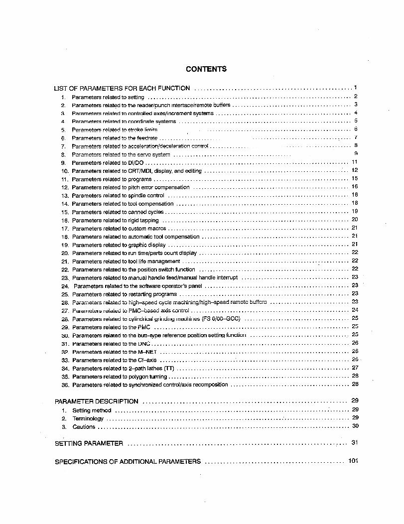
CONTENTS
LIST OF PARAMETERS FOR EACH FUNCTION ................................................... 1
1. Parameters related to setting ........................................................................ 2
2. Parameters related to the reader/punch interface/remote buffers .......................................... 3
3. Parameters related to controlled axes/increment systems ................................................ 4
4. Parameters related to coordinate systems ............................................................. 5
5. Parameters related to stroke limits .................................................................... 6
6. Parameters related to the feedrate ............................................................... 1 .... 7
7. Parameters related to acceleration/deceleration control .................................................. 8
8. Parameters related to the servo system ............................................................... 9
9. Parameters related to Dl/DO ........................................................................ 11
10. Parameters related to CRT/MDI, display, and editing ................................................ i .. 12
11. Parameters related to programs ..................................................................... 15
12. Parameters related to pitch error compensation ....................................................... 16
13. Parameters related to spindle control ................................................................ I6
14. Parameters related to tool compensation ............................................................. 18
15. Parameters related to canned cycles ................................................................. 19
16. Parameters related to rigid tapping .................................................................. 20
17. Parameters related to custom macros ................................................................ 21
18. Parameters related to automatic tool compensation .................................................... 21
;i 9. Parameters related to graphic display ................................................................ 21
20. Parameters related to run time/parts count display ....................................................... 22
21. Parameters related to tool life management ........................................................... 22
22. Parameters related to the position switch function ......................................... .: .......... 22
23 . . Parameters related to manual handle feed/manual handle interrupt ...................................... 23
24. Parameters related to the software operator’s panel ................................................... 23
25. Parameters related to restarting programs ............................................................ 23
26. Parameters related to high-speed cycle machining/high-speed remote buffers ............................ 23
27. Parameters related to PMGbased axis control ........................................................ 24
28. Parameters related to cylindrical grinding machines (FS O/OO-GCC) ..................................... 25
29. Parameters related to the PMC ..................................................................... 25
30. Parameters related to the butt-type reference position setting function ................................... 25
31. Parameters related to the DNC ...................................................................... 26
32. Parameters related to the M-NET ................................................................... 26
33. Parameters related to theCf-axis .................................................................... 26 .
34. Parameters related to 2-path lathes (TT) ............................................................. 27
35. Parameters related to polygon turning ................................................................ 28
36. Parameters related to synchronized control/axis recomposition .......................................... 28
PARAMETER DESCRIPTION ................................................................... 29
I. Setting method ................................................................................... 29
2. Terminology ....................................................................................... 29
3. Cautions.. ....................................................................................... 30
SE-l-l-ING PARAMETER ........................................................................ 31
SPECIFICATIONS OF ADDITIONAL PARAMtERS ............................................. 101
List of Parameters for each Function
The Parameters for each function is the following. For details, see “Parameter Explanation”.
Parameters related to setting
Parameters related to the reader/punch interface/remote buffers
Parameters related to controlled axes/increment systems
Parameters related to coordinate systems
Parameters related to stroke limits
Parameters related to the feedrate
Parameters related to acceleration/deceleration control
Parameters related to the servo system
Parameters related to Dl/DO
Parameters related to CRT/MDI, display, and editing
Parameters related to programs
Parameters related to pitch error compensation
Parameters related to spindle control
Parameters related to tool compensation
Parameters related to canned cycles
Parameters related to rigid tapping
Parameters related to custom macros
Parameters related to automatic tool compensation
Parameters related to graphic display
Parameters related to run time/parts count display
Parameters related to tool life management
Parameters related to the position switch function
Parameters related to manual handle feed/manual handle interrupt
Parameters related to the software operator’s panel
Parameters related to restarting programs
Parameters related to high-speed cycle machining/high+peed remote buffers
Parameters related to PMC-based axis control
Parameters related to cylindrical grinding machines (FSO/O&GCC)
Parameters related to the PMC
Parameters related to the butt-type reference position setting function
Parameters related to the DNC
Parameters related to the M-NW
Parameters related to the Cf-axis
Parameters related to 2-path lathes (IT)
Parameters related to polygon turning
Parameters related to synchronized control/axis recomposition
In the explanation of each bit parameter, the left-hand side of a slash (I) indicates the state when the bit is set to 0, and the right-hand side of a slash indicates the state when the bit is set to 1.
Example: The current setting is O/l. .
1
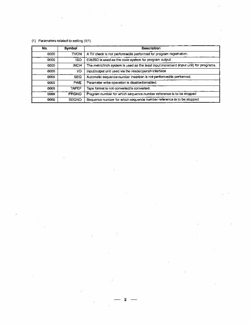
(1) Parameters related to setting (l/l )
No. 1 Symbol 1 Description
0000 1 TVON 1 A TV check is not performed/is performed for program registration-.
0000 IS0 EIA/ISO is used as the code system for program output,
0000 INCH The metric/inch system is used as the least input increment (input unit) for programs.
0000 1 I/O 1 Input/output unit used via the reader/punch interface
I 0000 1 SEQ 1 Automatic sequence number insertion is not performed/is performed.
I 0000 1 PWE 1 Parameter write operation is disabled/enabled.
I 0000 1 TAPEF I Tape format is not converted/is converted.
r 00001 PRGNOlogram number for which sequence number reference is to be stopped
I 0000 1 SEQNOI Sequence number for which sequence number reference is to be. stopped
2
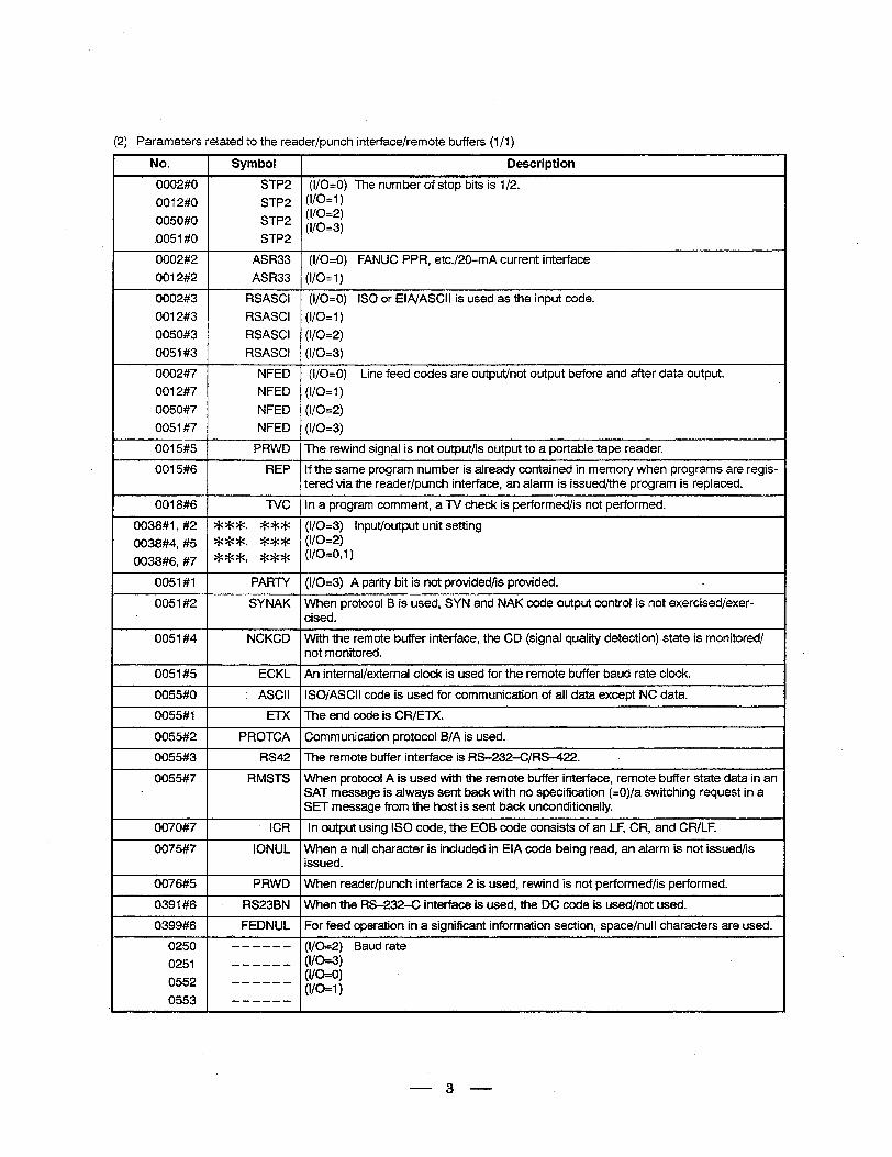
(2) Parameters related to the reader/punch interface/remote buffers (l/l)
No. Symbol Description
0002#0 STP2 (I/0=0) The number of stop bits is l/2.
0012#0 STP2 (l/0=1 )
0050#0 STP2 (l/o=2)
.0051 #O STP2 (l/0=3)
0002#2 ASR33 (I/0=0) FANUC PPR, etcJ2O-mA current interface
0012#2 ASR33 (I/0=1)
0002#3 RSASCI (I/0=0) IS0 or EIA/ASCII is used as the input code.
0012#3 RSASCI (l/0=1)
0050#3 RSASCI (l/0=2)
0051#3 RSASCI (l/0=3)
0002#7 NFED (I/0=0) Line feed codes are output/not output before and after data output.
0012#7 NFED (I/0=1)
0050#7 NFED (l/0=2)
0051#7 NFED (l/0=3)
0015#5 PRWD The rewind signal is not output/is output to a portable tape reader.
0015#6 REP If the same program number is already contained in memory when programs are regis- tered via the reader/punch interface, an alarm is issued/the program is replaced.
0018#6 TVC In a program comment, a TV check is performed/is not performed.
0038#1, #2 *Wk, *W (l/0=3) Input/output unit setting
OO38#4, #5 ‘k’k*, *** (l/0=2)
0038#6, #7 ***, *** WO=o,l)
0051#1 PARTY (l/0=3) A parity bit is not provided/is provided. L
0051#2 SYNAK When protocol B is used, SYN and NAK code output control is not exercised/exer- cised.
0051#4 NCKCD With the remote buffer interface, the CD (signal quality detection) state is monitored/ not monitored.
0051#5 ECKL An internal/external clock is used for the remote buffer baud rate clock.
0055#0 :. ASCII ISO/ASCII code is used for communication of all data except NC data.
0055#1 ETX The end code is CR/ETX.
0055#2 PROTCA Communication protocol B/A is used.
0055#3 RS42 The remote buffer interface is RS-232-C/RS-422. .
0055#7 RMSTS When protocol A is used with the remote buffer interface, remote buffer state data in an SAT message is always sent back with no specification (=0)/a switching request in a SET message from the host is sent back unconditionally.
0070#7 ICR In output using IS0 code, the EOB code consists of an LF, CR, and CR/LF.
0075#7 IONUL When a null character is included in EIA code being read, an alarm is not issued/is issued.
0076#5 PRWD When reader/punch interface 2 is used, rewind is not performed/is performed.
0391#6 RS23BN When the RS-232-C interface is used, the DC code is used/not used.
0399#6 FEDNUL For feed operation in a significant information section, space/null characters are used.
0250 - - - - - - (l/0=2) Baud rate
0251 ------ (l/0=3)
0552 (l/0=0)
0553 ------ (I/0=1) ------
3
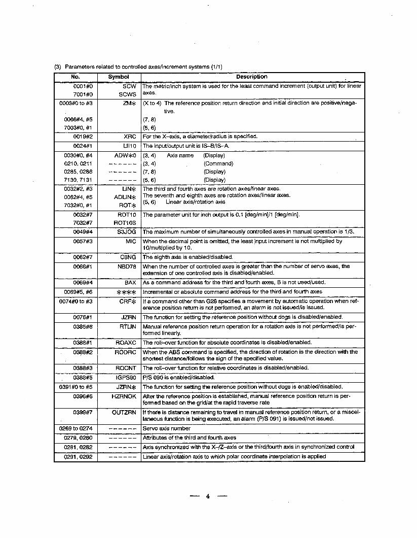
(3) Parameters related to controlled axes/increment systems (l/l)
No. Symbol Description
0001 #O SCW The metric/inch system is used for the least command increment (output unit) fo;linear
7001 #O sews axeS*
0003#0 to #3 ZM* (X to 4) The reference position return direction and initial direction are positive/nega-
tive.
0066#4, #5 (7, 8) 7003#0, #l (596)
0019#2 XRC For the X-axis, a dikmeter/radius is specified.
0024#1 LIIlO The input/output unit is IS-B/IS-A.
0030#0, #4 ADW*O (3, 4) Axis name (Display)
0210,0211 ------ (3,4) (Command)
0285,0286 ------ (7, 8) (Display)
7130,7131 ------ (5, 6) (Display)
0032#2, #3 LIN* The third and fourth axes are rotation axes/linear axes.
0062#4, #5 ADLlN.+ The seventh and eighth axes are rotation axes/linear axes.
7032#0, #I ROT* (5’ 6, Linear axis/rotation axis
0032#7 ROT1 0 The parameter unit for inch output is 0.1 [deg/min]/l [deg/min].
7032#7 ROT1 OS
0049#4 SSJOG The maximum number of simultaneously controlled axes in manual operation is l/3.
0057#3 MIC When the decimal point is omitted, the least @put increment is not multiplied by 1 O/multiplied by 10.
0062#7 C8NG The eighth axis is enabled/disabled.
0066#1 NBD78 When the number of controlled axes is greater than the number of servo axes, the extension of one controlled axis is disabled/enabled.
0069#4 BAX As a command address for the third and fourth axes, B is not used/used.
0069#5, #6 **** Incremental or absolute command address for the third and fourth axes
0074#0 to #3 CRF* If a command other than G28 specifies a movement by automatic operation when ref- erence position return is not performed, an alarm is not issued/is issued.
0076#1 JZRN ‘The function for setting the reference position without dogs is disabled/enabled.
0385#6 RTUN Manual reference position return operation for a rotation axis is not performed/is per- formed linearly.
0388#1 ROAXC The roll-over function for absolute coordinates is disabled/enabled.
0388#2 RODRC When the ABS command is specified, the direction of rotation is the direction with the shortest distance/follows the sign of the specified value.
0388#3 ROCNT The roll-over function for relative coordinates is disabled/enabled.
0388#5 IGPS90 P/S 090 is enabled/disabled. .
0391 #O to #5 JZRN* The function for setting the reference position without dogs is enabled/disabled.
0396#6 HZRNOK After the reference position is established, manual reference position return is per- formed based on the grid/at the rapid traverse rate
0399#7 OUTZRN If thet’e is distance remaining to travel in manual reference position return, or a miscel- laneous function is being executed, an alarm (P/S 091) is issued/not issued.
3269 to 0274 ------ Servo axis number
0279,028O - - - - - - Attributes of the third and fourth axes
0281,0282 - - - - - - Axis synchronized with the X-/Z-axis or the third/fourth axis in synchronized control
9291,0292 - - - - - - Linear axis/rotation axis to which polar coordinate interpolation is applied
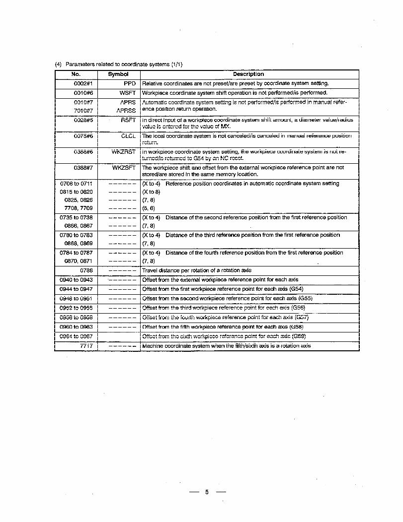
(4) Parameters related to coordinate systems (l/l)
No. Symbol Description
0002#1 PPD Relative coordinates are not preset/are preset by coordinate system setting.
0010#6 WSFT Workpiece coordinate system shift operation is not performed/is performed.
0010#7 APRS Automatic coordinate system setting is not performed/is performed in manual refer-
7010#7 APRSS ence position return operation.
0028#5 RSFT In direct input of a workpiece coordinate system shift amount, a diameter value/radius value is entered for the value of MX. I
0075#6 CLCL The local coordinate system is not canceled/is canceled in manual reference position return.
0388#6 WKZRST In workpiece coordinate system setting, the workpiece coordinate system is not re- turned/is returned to G54 by an NC reset.
0388#7 WKZSFT The workpiece shift and offset from the external workpiece reference point are not. stored/are stored in the same memory location.
0708 to 0711 - - - - - - (X to 4) Reference position coordinates in automatic coordinate system setting
0815 to 0820 ------ (Xto8)
0825,0826 ------ (7, 8)
7708,7709 ------ (5, 6)
0735 to 0738 - - - - - - (X to 4) Distance of the second reference position from the first reference position
0866,0867 ------ (7, 8)
0780 to 0783 - - - - - - (X to 4) Distance of the third reference position from the first reference position
0868,0869 ------ (7, 8)
0784 to 0787 - - - - - - (X to 4) Distance of the fourth reference position from the first reference position
0870,087l ------ (7, 8) L.
0788 - - - - - - Travel distance per rotation of a rotation axis
0940 to 0943 .- - - - - - Offset from the external workpiece reference point for each axis
0944 to 0947 - - - - - - Cffset from the first workpiece reference point for each axis (G54)
0948 to 0951 - - - - - - Cffset from the second workpiece reference point for each axis (G55)
0952 to 0955 - - - - - - Offset from the third workpiece reference point for each axis (G56)
0956 to 0959 - - - - - - Offset from the fourth workpiece reference po.int for each axis (G57)
0960 to 0963 - - - - - - Cffset from the fifth workpiece reference point for each axis (G58)
0964 to 0967 - - - - - - Cffset from the sixth workpiece reference point for each axis (G59)
7717 - - - - - - Machine coordinate system when the fifth/sixth axis is a rotation axis
-5-
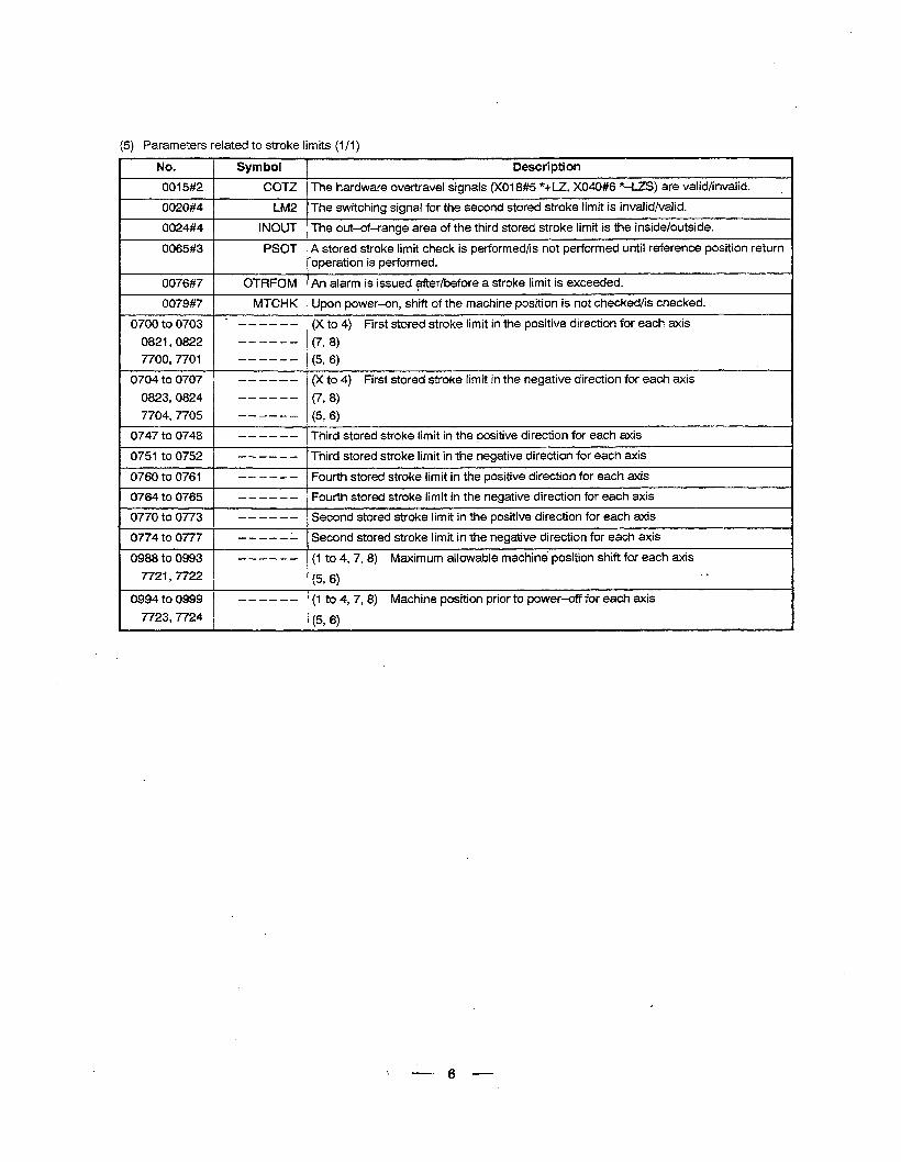
(5) Parameters related to stroke limits (1 /I )
No.
0015#2
0020#4
0024#4
0065#3
0076#7
0079#7
0700 to 0703
0821,0822
7700,770l
0704 to 0707
0823,0824
7704,7705
0747 to 0748
.0751 to 0752
0760 to 0761
0764 to 0765
0770 to 0773
0774 to 0777
0988 to 0993
7721,7722
0994 to 0999
7723,7724
Symbol Description
COT2 The hardware overtravel signals (XOl8#5 *+Lz, XO40#6 *-lZS) are valid/invalid.
LM2 The switching signal for the second stored stroke limit is invalid/valid.
INOUT The out-of-range area of the third stored stroke limit is the inside/outside.
PSOT A stored stroke limit check is performed/is not performed until reference position return I operation is performed.
OTRFOM An alarm is issued after/before a stroke limit is exceeded.
MTCHK Upon power-on, shift of the machine position is not checked/is checked.
’ ------ (X to 4) First stored stroke limit in the positive direction for each axis ------ (798) ------ (5, 6)
- - - - - - (X to 4) First stored stroke limit in the negative direction for each axis
------ (7, 8)
------ (5, 6)
- - - - - - Third stored stroke limit in the positive direction for each axis
- - - - - - Third stored stroke limit in the negative direction for each axis
- - - - - - Fourth stored stroke iimit in the positive direction for each axis
- - - - - - Fourth stored stroke limit in the negative direction for each axis
- - - - - - Second stored stroke limit in the positive direction for each axis
- - - - - - Second stored stroke limit in the negative direction for each axis
- - - - - - (1 to 4, 7,8) Maximum allowable machine position shift for each axis
(596) *
------ (1 to 4, 7, 8) Machine position prior to power-off for each axis
(596)
\ -(j--
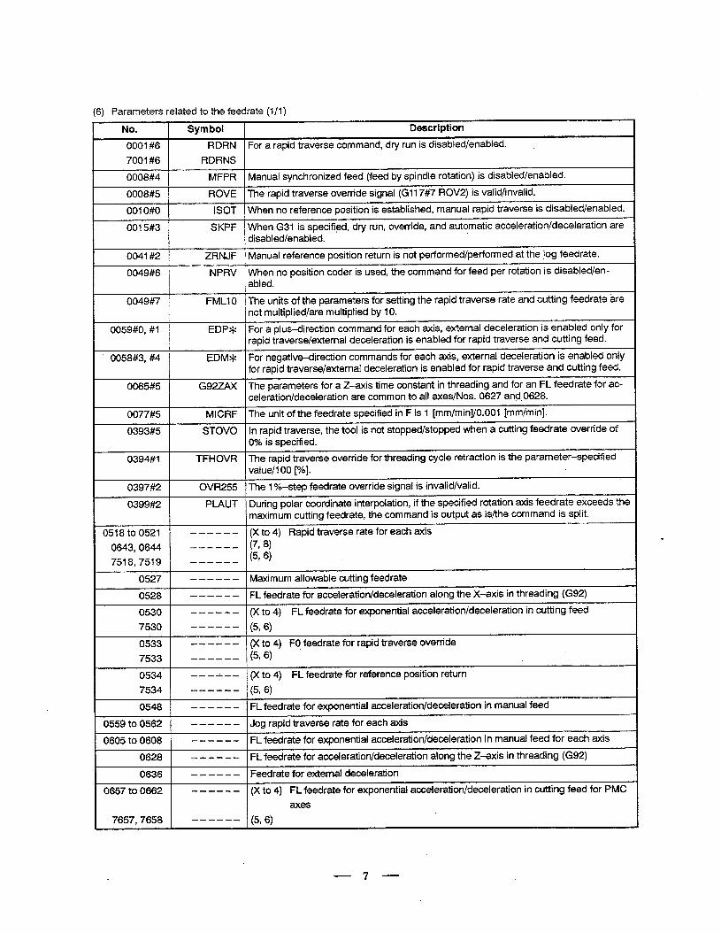
(6) Parameters related to the feedrate (l/l)
No.
0001#6
7001#6
0008#4
0008#5
001 O#O
0015#3
0041#2
0049#6
0049#7
0059#0, #I
0058#3, #4
0065#5
0077#5
0393#5
0394#1
0397#2
0399#2
0518 to 0521
0643,0644
7518,7519
0527
0528
0530
7530
0533
7533
0534
7534
0548
0559 to 0562
0605 to 0608
0628
0636
0657 to 0662
7657,7658
Symbol
RDRN
RDRNS
MFPR
ROVE
ISOT
SKPF
ZRNJF
NPRV
FMLI 0
EDP*
EDM*
G92zAX
. MICRF
STOVO
TFHOVR
OVR255
PLAUT
---c-m
------
------
--B-B-
------
_--___
------
------
------
-,-A--
------
------
c-----
c-----
------
------
------
-----a
Description
For a rapid traverse command, dry run is disabled/enabled. ,
Manual synchronized feed (feed by spindle rotation) is disabled/enabled.
The rapid traverse override signal (G117#7 ROV2) is valid/invalid.
When no reference position is established, manual rapid traverse is disabled/enabled.
When G31 is specified, dry run, override, and automatic acceleration/deceleration are disabled/enabled.
Manual reference position return is not performed/performed at the jog feedrate.
When no position coder is used, the command for feed per rotation is disabled/en- abled.
The units of the parameters for setting the rapid traverse rate and cutting feedrate are not multiplied/are multiplied by 10.
For a plus-direction command for each axis, external deceleration is enabled only for rapid traverse/external deceleration is enabled for rapid traverse and cutting feed.
For negative-direction commands for each axis, external deceleration is enabled only for rapid traverse/external deceleration is enabled for rapid traverse and cutting feed.
The parameters for a Z-axis time constant in threading and for an FL feedrate for ac- celeration/deceleration are common to all axes/Nos. 0627 and 0628. .
The unit of the feedrate specified in F is 1 [mm/min]/O.OOl [mm/min].
In rapid traverse, the tool is not stopped/stopped when a cutting feedrate override of 0% is specified.
The rapid traverse override for threading cycle retraction is the parameter-specified value/l 00 p?]. L
The I %-step feedrate override signal is invalid/valid.
During polar coordinate interpolation, if the specified rotation axis feedrate exceeds the maximum cutting feedrate, the command is output as is/the command is split.
(X to 4) Rapid traverse rate for each axis
(718) (516)
Maximum allowable cutting feedrate .
FL feedrate for acceleration/deceleration along the X-axis in threading (G92)
(X to 4) FL feedrate for exponential acceleration/deceleration in cutting feed
(596)
(X to 4) FO feedrate for rapid traverse override (596) -
(X to 4) FL feedrate for reference position return
(5#6)
FL feedrate for exponential acceleration/deceleration in manual feed
Jog rapid traverse rate for each axis
FL feedrate for exponential acceleration/deceleration in manual feed for each axis
FL feedrate for acceleration/deceleration along the Z-axis in threading (G92)
Feedrate for external deceleration
(X to 4) FL feedrate for exponential acceleration/deceleration in cutting feed for PMC
axes
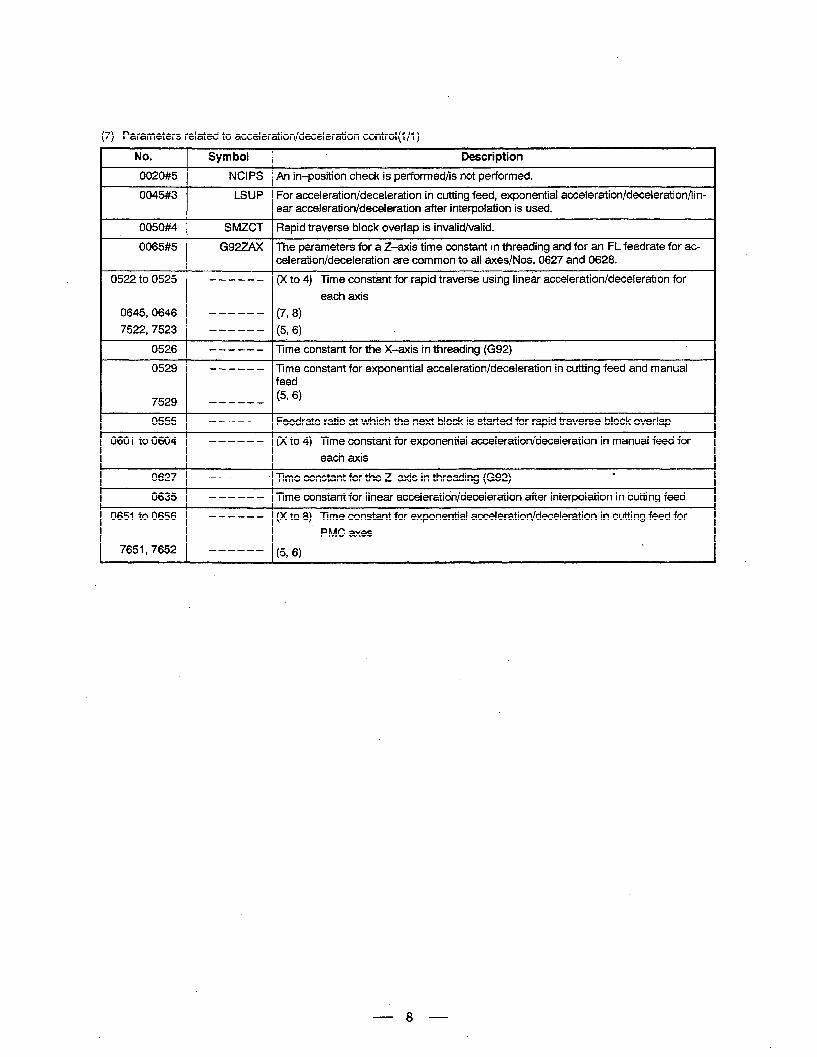
(7) Parameters related to acceleration/deceleration control(lj1)
No. 1 Symbol
NCIPS
0522 to 0525 ------
0645,0646 ------
7522,7523 ------
0526 ------
0529 W--.--W
7529 -W-W--
0555 1 -----a
0601 to 0604 ------
0627 1 ----we ’ Time constant for the Z-axis in threading (G92)
0635 1 -a----
0651 to 0656 ----a-
7651,7652 ------
Description
An in-position check is performed/is not performed.
For acceleration/deceleration in cutting feed, exponential acceleration/deceleration/lin- ear acceleration/deceleration after interpolation is used.
Rapid traverse block overlap is invalid/valid.
The parameters for a Z-axis time constant in threading and for an FL feedrate for ac- celeration/deceleration are common to all axes/Nos. 0627 and 0628.
(X to 4) Time constant for rapid traverse using linear acceleration/deceleration for
each axis
(7,8)
(596)
Time constant for the X-axis in threading (G92)
Time constant for exponential acceleration/deceleration in cutting feed and manual feed
(596)
Feedrate ratio at which the next block is started for rapid traverse block overlap
(X to 4) Time constant for exponential acceleration/deceleration in manual feed for
each axis .
Time constant for linear acceleration/deceleration after interpolation in cutting feed.
(X to 8) Time constant for exponential acceleration/deceleration in cutting feed for
PMC axes
66)
8
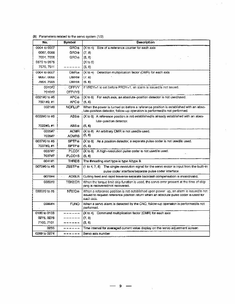
(8) Parameters related to the servo system (l/2)
No. Symbol Description
0004 to 0007 GRD* (X to 4) Size of a reference counter for each axis
0067,0068 GRD* (7,8)
7004,7005 GRD* (5, 6) .
. 0570 to 0575 ------ (X to 8)
7570,7511 ------ (5, 6)
0004 to 0007 DMR* (X to 4) Detection multiplication factor (DMR) for each axis
0067,0068 DMR* (798) ,
7004,7005 DMR* (5,6)
0010#2 . OFFW If VRDY=l is set before PRDY=l, an alarm is issued/is not issued.
7010#2 OFFVYS
0021 #O to #5 APC* (X to 8) For each axis, an absolute-position detector is not used/used.
7021#0, #I APC* (5,6)
0021#6 NOFLUP When the power is turned on before a reference position is established with an abso- lute-position detector, follow-up operation is performed/is not performed.
0022#0 to #5 ABS* (X to 8) A reference position is not established/is already established with an abso-
lute-position detector.
7022#0, #I ABS* (5, 6)
0035#7 ACMR (X to 8) An arbitrary CMR is not used/is used.
7035#7 ACMRS (5, 6,
0,037#0 to #5 SPTP* (X to 8) As a position detector, a separate pulse coder is not used/is used. 7037#0, #I SPTP* (5, 6)
0037#7 PLCOI (X to 8) A high-resolution pulse coder is not used/is used. L 7037#7 PLCOIS (5,6)
0041 #I THRDB The threading start type is type A/type 8.
0072#0 to #5 ZSSTP* (1 to 4, 7,8) The single-revolution signal for the servo motor is input from the built-in
pulse coder interface/separate pulse coder interface.
0076#4 . . ADBLS Cutting feed and rapid traverse separate backlash compensation is invalid/valid.
0389#3 TSKECR When the torque limit skip function is used, the servo error present at the time of skip- ping is recovered/not recovered.
0390#0 to #5 NREQ* When a reference position is not established upon power-up, an alarm is issued/is not issued to request reference position return when an absolute pulse coder is used for each axis.
0399#4 FUN0 When a sewo alarm is detected by the CNC, follow-up operation is performed/is not performed.
0100 to 0103 - - - - - - (X to 4) Command multiplication factor (CMR) for each axis
0275,0276 ------ (7,8)
7100,7101 ------ (5, 6)
0255 - - - - - - Time interval for averaged current value display on the servo adjustment screen
0269 to 0274 ------ Servo axis number
9
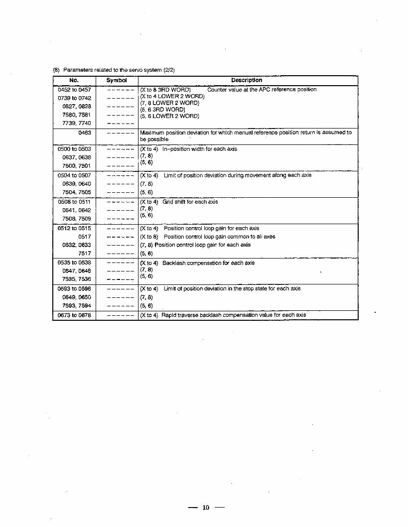
(8) Parameters related to the servo system (2/2)
No.
0452 to 0457
0739 to 0742
0827,0828
7580,758l
7739,774o
0463
Symbol Description
------ (Xto83RDWORD) Counter value at the APC reference position ------ (X to 4 LOWER 2 WORD)
(7,8 LOWER 2 WORD) ------ (5, 6 3RD WORD)
------ (5,6 LOWER2 WORD) ------
- - - - - - Maximum position deviation for which manual reference position return is assumed to be possible
,
0500 to 0503
0637,0638
7500,750l
0504 to 0507
0639,064O
7504,7505
0508 to 0511
0641,0642
7508,7509
051 2 to 0515
0517
0632,0633
7517
0535 to 0538
0647,0648
7535,7536
- - - - - - (X to 4) in-position width for each axis ------ (7, 8)
(5T6) ------
- - - - - - (X to 4) Limit of position deviation during movement along each axis
------ (7, 8)
------ (5, 6)
- - - - - - (X to 4) Grid shift for each axis ------ (7, 8)
(5, ‘6) ------
- - - - - - (X to 4) Position control loop gain for each axis
- - - - - - (X to 8) Position control loop gain common to all axes
- - - - - - (7, 8) Position control loop gain for each axis
------ (5, 6)
- - - - - - (X to 4) Backlash compensation for each axis ------ (7, 8) c ------ (5S6) .
0593 to 0596 - - - - - - (X to 4) Limit of position deviation in the stop state for eadh axis
0649,065O ------ (7, 8)
7593,7594 ------ (5, 6)
0673 to 0678 - - - - - - (X to 4) Rapid traverse backlash compensation value for each axis .
- 10 -
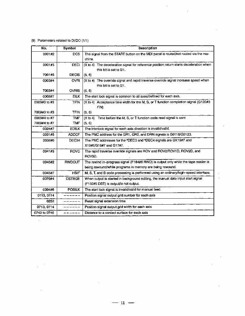
(9) Parameters related to DI/DO (I/I )
NO.
0001#2
0001#5
7001#5
0003#4
7003#4
0008#7
0009#0 to #3
7009#0 to #3
0009#4 to #7
7009#4 to #7
0024##7
0031#5
0038#0
0041#3
0045#2
0045#7
0070#4
0394#6
0113,0114
0252
0713,0714
0743 to 0746
Symbol Description
DCS The signal from the START button on the MDI panel is routed/not routed via the ma-
chine.
DECI (X to 4) The deceleration signal for reference position return starts deceleration when
this bit is set to O/I.
DECIS (5, 6)
OVRI (X to 4) The override signal and rapid traverse ove.rride signal increase speed when
this bit is set to.O/I .
OVRIS (5, 6)
EILK The start lock signal is common to all axes/defined for each axis.
TFIN (X to 4) Acceptance time width for the M, S, or T function completion signal (GI2Q#3
FIN)
TFIN (5, 6)
TMF (X to 4) 7Ime before the M, S, or T function code read signal is sent
TMF (5, 6)
EDILK The interlock signal for each axis direction is invalid/valid.
ADDCF The PMC address for the GRl , GR2, and DRN signals is GO11 8/G0123.
DEC34 The PMC addresses for the *DEC3 and *DEC4 signals are GXI 9#7 and
XI 9#5/GI 6#7 and GI 7#7. .
ROVC The rapid traverse override signals are ROV and ROV2/ROVl D, ROV2D, and
ROV3D.
RWDOUT The rewind in-progress signal’ (F164##6 RWD) is output only while the tape reader is
being rewound/while programs in memory are being rewound.
I-lSIF M, S, T, and B code processing is performed using an ordinary/high-speed interface.
DSTBGE When output is started in background editing, the manual data input start signal
(F150#5 DST) is output/is not output.
POSILK The start lock signal is invalid/valid for manual feed.
- - - - - - Position signal output grid pumber for each axis
- - - - - - Reset signal extension time
- - - - - - Position signal output grid width for each axis
- - - - - - Distance to a contact surface for each axis
- 11 -
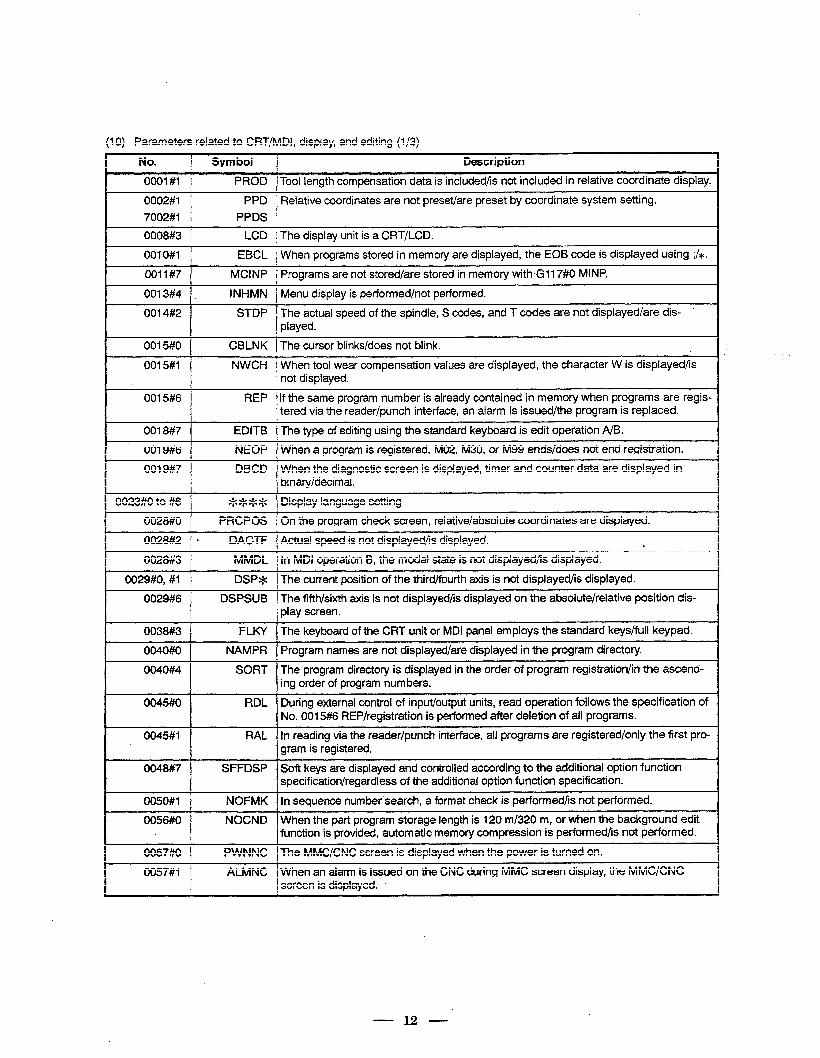
(10) Parameters related to CRT/MDl, display, and editing (i/3)
No. Symbol Description
0001 #I PROD Tool length compensation data is included/is not included in relative coordinate display.
0002#1 PPD Relative coordinates are not preset/are preset by coordinate system setting.
7002#1 PPDS
0008#3 LCD The display unit is a CRT/LCD.
001 O#l EBCL When programs stored in memory are displayed, the EOB code is displayed using ;I’*.
0011#7 MCI NP Programs are not stored/are stored in memory with G117#0 MINP.
0013#4 . INHMN Menu display is performed/not performed.
0014#2 STDP The actual speed of the spindle, S codes, and T codes are not displayed/are dis- played.
0015#0 CBLNK The cursor blinks/does not blink.
0015#1 NWCH When tool wear compensation values are displayed, the character W is displayed/is not displayed.
0015#6 REP If the same program number is already contained in memory when programs are regis- tered via the reader/punch interface, an alarm is issued/the program is replaced.
0018#7 EDITB The type of editing using the standard keyboard is edit operation A/B.
0019#6 NEOP When a program is registered, M02, M30, or M99 ends/does not end registration.
0019#7 DBCD When the diagnostic screen is displayed, timer and counter data are displayed in binary/decimal.
0023#0 to #6 **** Display language setting
0028#0 PRCPOS On the program check screen, relative/absolute coordinates are displayed.
0028#2 . DACTF Actual speed is not displayed/is displayed. h
0028#3 MMDL In MDI operation B, the modal state is not displayed/is displayed.
0029#0, #1 DSP* The current position of the third/fourth axis is not displayed/is displayed.
0029#6 DSPSUB The fifth/sixth axis is not displayed/is displayed on the absolute/relative position dis- play screen.
0038#3 FLKY The keyboard of the CRT unit or MDI panel employs the standard keys/full keypad.
0040#0 NAMPR Program names are not displayed/are displayed in the program directory.
0040#4 SORT The program directory is displayed in the order of program registration/in the ascend- ing order of program numbers.
0045#0 RDL During external control of input/output units, read operation follows the specification of No. 0015#6 REP/registration is performed after deletion of all programs.
0045#1 RAL In reading via the reader/punch interface, all programs are registered/only the first pro- gram is registered.
0048#7 SFFDSP Soft keys are displayed and controlled according to the additional option function specification/regardless of the additional option function specification.
0050#1 NOFMK In sequence number search, a format check is performed/is not performed.
0056#0 NOCND When the part program storage length is 120 m/320 m, or when the background edit function is provided, automatic memory compression is performed/is not performed.
0057#0 PWNNC The MMC/CNC screen is displayed when the power is turned on.
0057#1 ALMNC When an alarm is issued on the CNC during MMC screen display, the MMC/CNC screen is displayed.
- 12 -
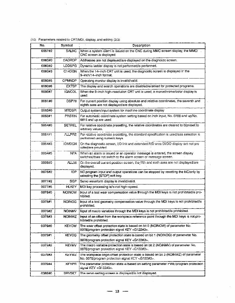
(10) Parameters related to CRT/MD& display, and editing (2/3)
No.
0057#2
Symbol * Description
SALNC When a system alarm is issued on the CNC during MMC screen display, the MMCl CNC screen is displayed.
I 0060#0 1 DADRDP 1 Addresses are not displayed/are displayed on the diagnostic screen.
I 0060#2 1 LDDSPG 1 Dynamic ladder display is not performed/is performed.
0060#3 Cl 4DGN When the 14-inch CRT unit is used, the diagnostic screen is displayed in the Q-inch/l 4-inch format.
0060#5 OPMNDP Operating monitor display is invalid/valid.
I 0060#6 1 EXTSP 1 The display and search operations are disabled/enabled for protected programs. I 0060#7
~~ ~~ When the g-inch high-resolution CRT unit is used, a monochrome/color display is
0061#6 DSP78 For current position display using absolute and relative coordinates, the seventh arid eighth axes are not displayed/are displayed.
0063#0 1
0063#1
0064#0
MTDSPI 1 Output system/input system for machine coordinate display
PRSTIN For automatic coordinate system setting based on inch input, No. 0708 and up/No. 0815 and up are used.
SETREL For relative coordinate presetting, the relative coordinates are cleared to O/preset to arbitrary values.
0064##1 ALLPRE For relative coordinate presetting, the standard specification is used/axis selection is performed using numeric keys. I
0064#3 IOMDGN On the diagnostic screen, I/O link and extended R/D area DI/DO display are not pro- vided/are provided. I
0064#5 NPA When an alarm is issued or an operator message is entered, the screen display switches/does not switch to the alarm screen or message screen. L. I
0066#0 ALL56 On the overall current position screen, the fifth and sixth axes are not displayed/are c displayed. I
0076#2 IOP NC program input and output operations can be stopped by resetting the NC/only by selecting the [STOP] soft key. I
0077#2
0077#6
SGP Servo waveform display is invalid/valid.
HLKEY MDI key processing is/is not high-speed.
0078#0 NOINOW Input of a tool wear compensation value through the MDI keys is not prohibited/is pro- hibited. I
0078#1 NOINOG Input of a tool geometry compensation value through the MDI keys is not prohibited/is prohibited. I
- 0078#2 ]
0078#3
NOINMV 1 Input of macro variables through the MDI keys is not prohibited/is prohibited.
NOINWZ input of an offset from the workpiece referende point through the MDI keys is not pro- hibited/is prohibited.
0079#0 KEYOW The wear offset protection state is based on bit 0 (NOINOW) of parameter No. 0078/program protection signal KEY cG122#3>. I
0079#1 KEYOG The geometry offset protection state is based on bit 1 (NOINOG) of parameter No.
0078lprogram protection signal KEY <G122#3>. I KEYMV The macro variable protection state is based on bit 2 (NOINMV) of parameter No.
0078/program protection signal KEY cG122#3>. I KEYWZ The workpiece origin offset protection state is based on bit 3 (NOINWZ) of parameter
No. 0078/program protection signal KEY <Gl22#3>.
0079#4 KEYPR The parameter protection state is based on setting parameter PWE/program protection signal KEY <G122#3>.
0389#0 1 SRVSET 1 The servo setting screen is displayed/is not displayed.
13
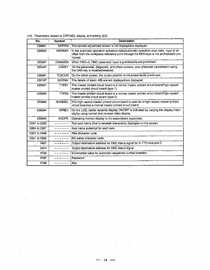
110) Parameters related to CRT/MDl, display, and editing (3/3)
No. ( Symbol 1 Description ’
0389#1 SPPRM The spindle adjustment screen is not displayed/is displayed.
0393#2
1
WKNMDI In the automatic operation activation state/automatic operation stop state, input of an
1 hibited. offset from the workpiece reference point through the MDI keys is not prohibited/is pro-
- 0393#7 1 DGNWEB-1 When PWE=O, PMC parameter input is prohibited/is not prohibited.
0394#7 On the parameter,-diagnostic, and offset screens, one-character cancellation using the CAN key is disabled/enabled.
0395#1 1 TLSCUR 1 On the offset screen, the cursor position is not preserved/is preserved.
0397#7
0398#1
SERNAI The details of alarm 409 are not displayed/are displayed.
TYPE1 The master printed circuit board is a normal master printed circuit board/high-speed master printed circuit board (type 1).
. 0398#2 TYPE2 The master printed circuit board is a normal master printed circuit board/high-speed master printed circuit board (type 2).
0398#3 NORMAL The high-speed master printed circuit board is used as a high-speed master printed circuit board/as a normal master printed circuit board.
0398#4 ATREV On the LCD, ladder dynamic display ON/OFF is indicated by varying the display inten- sity/by using normal and reverse video display.
0398#5 1 EXOPE 1 Operating monitor display is not expanded/is expanded.
0257 to 0263 1
0264 to 0267 1
- - - - - - 1 Tool post name (first to seventh characters) displayed on the screen
- - - - - - f Axis name subscript for each axis
0337 to 0346
0351 to 0355
0457
0474
0550
0797
0798 1
- - - - - - Title character code
- - - - - - NC name character code a.
- - - - - - Output destination address for CNC status signal for O-TX tool post 2
- - - - - - Output destination address for CNC status signal
- - - - - - Incremental value for automatic sequence number insertion
- - - - - - Password
_-_-_- ,Key
- 14 -
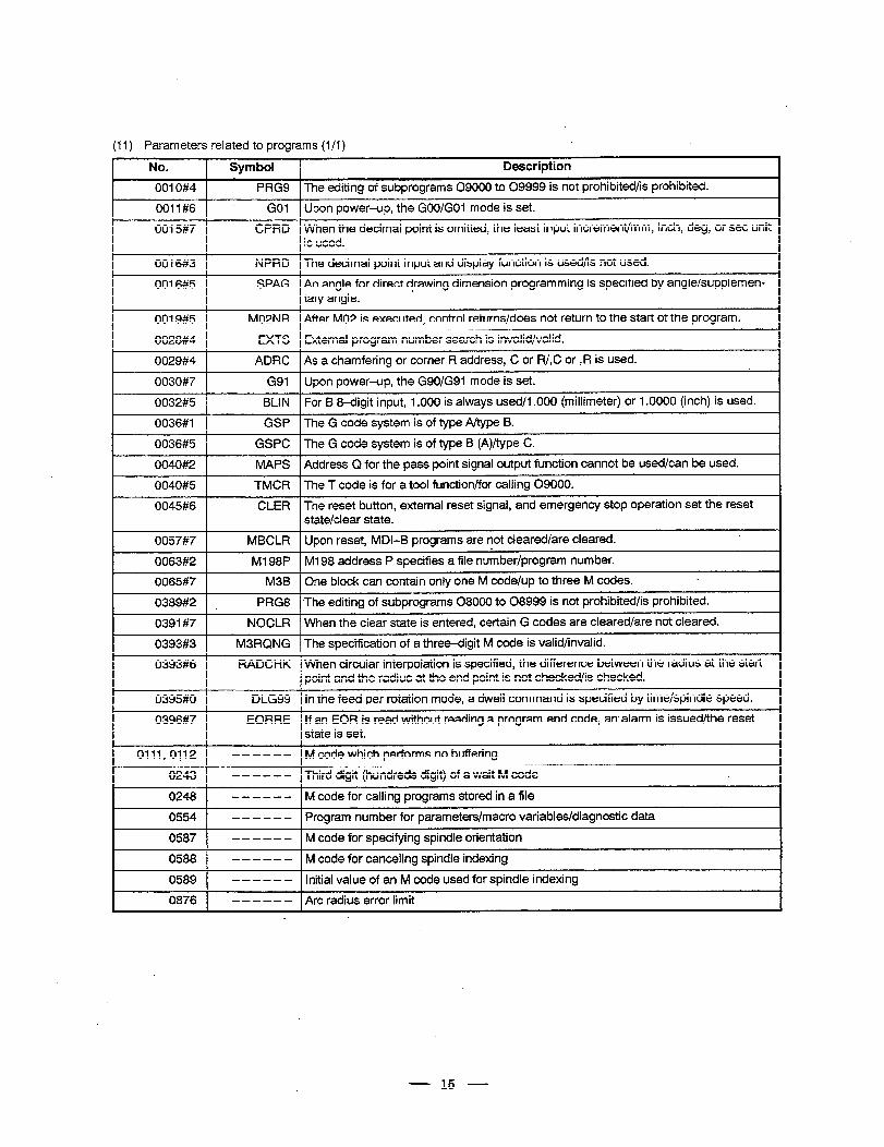
(11) Parameters related to programs (l/l)
No.
0010#4
0011#6
Symbol Description 1
PRG9 The editing of subprograms 09000 to 09999 is not prohibited/is prohibited.
GO1 Upon power-up, the GOO/GOl mode is set.
0015#7
0016#3
CPRD When the decimal point is omitted, the least input increment/mm, inch, deg, or set unit is used. I
4 NPRD The decimal point input and display function is used/is not used.
0016#5 SPAG An angle for direct drawing dimension programmin,g is specified by angle/supplemen- , tary angle.
0019#5 M02NR After MO2 is executed, control returns/does not return to the start of the program.
0028#4
0029#4
0030#7
EXTS External program number search is invalid/valid.
ADRC As a chamfering or corner R address, C or R/,C or ,R is used.
G91 Upon power-up, the G90/G91 mode is set.
0032#5 ( BLIN 1 For B 8-digit input, 1 .OOO is always used/l .OOO (millimeter) or 1 .OOOO (inch) is used.
0036#1 GSP The G code system is of type A/type B.
0036#5 1 GSPC 1 The G code system is of type B (A)/type C. I
0040#2
0040#5
0045#6
MAPS Address Q for the pass point signal output function cannot be used/can be used.
TMCR The T code is for a tool function/for calling 09000.
CLER The reset button, external reset signal, and emergency stop operation set the reset state/clear state.
I 0057#7 1 MBCLR f Upon reset, MDI-E! programs are not cleared/are cleared.
0063#2
0065#7
0389#2
0391#7
0393#3
Ml 98P Ml 98 address P specifies a file number/program number. m M3B One block can contain only one M code/up to three M codes. L
PRG8 *The editing of subprograms 08000 to 08999 is not prohibited/is prohibited.
NOCLR When the clear state is entered, certain G codes are cleared/are not cleared.
M3RQNG The specification of a three-digit M code is valid/invalid.
. I 0393#6 RADCHK When circular interpolation is specified, the difference between the radius at the start point and the radius at the end point is not checked/is checked. I
0395#0
0396#7
DLG99 In the feed per rotation mode, a dwell command is specified by time/spindle speed.
EORRE If an EOR is read without reading a program end code, an’alarm is issued/the reset state is set.
0111,0112 1 - - - - - - . 1 M code which performs no buffering
0243 - - - - - - , Third digit (hundreds digit) of a wait M code
0248 - - - - - - M code for calling programs stored in a file
0554 1 - - - - - - 1 Program number for parameters/macro variables/diagnostic data
0587 1 - - - - - - 1 M code for specifying spindle orientation
0588 1 - - - - - - 1 M code for canceling spindle indexing
0589 1 - - - - - - 1 Initial value of an M code used for spindle. indexing
0876 1 - - - - - - 1 Arc radius error limit
15
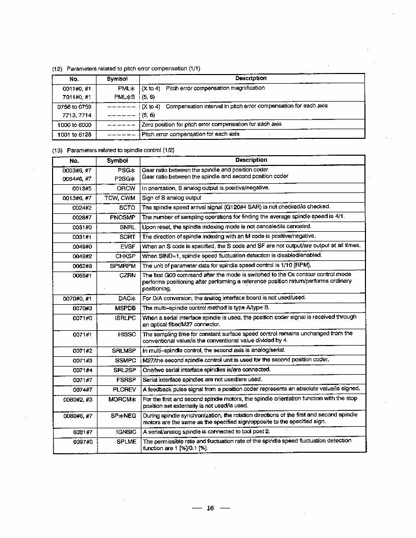
112) Parameters related to pitch error compensation (i/l)
No. 1 Symbol 1 Description
0011 #O, #I PML* (X to 4) Pitch error compensation magnification
7011##0, #I PML*S (5, 6)
0756 to 0759 - - - - - - (X to 4) Compensation interval in pitch error compensation for each axis
7713,7714 . ------ (5, 6)
1000 to 6000 1
1001 to 6128 1
- - - - - - 1 Zero position for pitch error compensation for each axis
- - - - - - 1 Pitch error compensation for each axis
(13) Parameters related to spindle control (l/2)
No. Symbol Description
0003#6, #7 PSG* Gear ratio between the spindle and position coder
0064#6, #7 P2SG* Gear ratio between the spindle and second position coder
0013#5 ORCW In orientation, S analog output is positive/negative.
0013#6, #7 TCW, CWM Sign of S analog output
0024#2 SCTO The spindle speed arrival signal (G120##4 SAR) is not checked/is checked.
0028#7 PNOSMP The number of sampling operations for finding the average spindle speed is 4/l.
0031 #O SNRL Upon reset, the spindle indexing mode is not canceled/is canceled.
0031 #l SDRT The direction of spindle indexing with an M code is positive/negative.
0049#0 EVSF When an S code is specified, the S code and SF are not output/are output at all times.
0049#2 CHKSP When SIND=l, spindle speed fluctuation detection is disabled/enabled.
I 0062#3 SPMRPM The unit of parameter data for spindle speed control is l/l 0 [RPM].
0065#1 CZRN The first GO0 command after the mode is switched to the Cs contour control mode performs positioning after performing a reference position return/performs ordinary positioning.
0070#0, #I DAC* For D/A conversion, the analog interface board is not used/used.
0070#3 MSPDB The multi-spindle control method is type A/type B.
0071 #O ISRLPC When a serial interface spindle is used, the position coder signal is received through an optical fiber/M27 connector.
0071#1 . HISSC The sampling time for constant surface speed control remains unchanged from the conventional value/is the conventional value divided by 4.
0071#2 SRLMSP In multi-spindle control, the second axis is analog/serial.
. 0071#3 SSMPC M27/the second spindle control unit is used for the second position coder.
. 0071#4 SRL2SP ‘One/two serial interface spindles is/are connected.
0071#7 FSRSP Serial interface spindles are not used/are used.
0074#7 PLCREV A feedback pulse signal from a position coder represents an absolute value/is signed.
0080#2, #3 MORCM* For the first and second spindle motors, the spindle orientation function with the stop position set externally is not usedhs used.
0080#6,’ #7 SP*NEG During spindle synchronization, the rotation directions of the first and second spindle motors are the same as the specified sign/opposite to the specified sign.
0381#7 IGNSIC A serial/analog spindle is connected to tool post 2. *
0397#0 SPLME The permissible rate and fluctuation rate of the spindle speed fluctuation detection function are 1 p%JO.l [%].
I
- 16 -
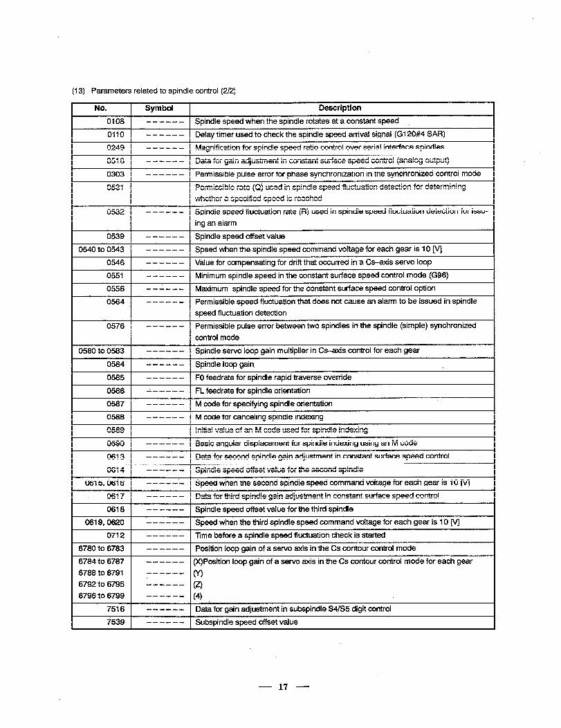
(13) Parameters related to spindle control (2/2)
No.
0108
0110
0249
0516
0303
0531
Symbol Description
- - - - - - Spindle speed when the spindle rotates at a constant speed
- - - - - - Delay timer used to check the spindle speed arrival signal (G120#4 SAR)
- - - - - - Magnification for spindle speed ratio control over serial interface spindles
- - - - - - Data for gain adjustment in constant surface speed control (analog output)
------ Permissible pulse error for phase synchronization in the synchronized control mode
------ Permissible rate (Q) used in spindle speed fluctuation detection for determining
whether a specified speed is reached
0532 - - - - - - Spindle speed fluctuation rate (R) used in spindle speed fluctuation detection for issu-
ing an alarm
0539
0540 to 0543
0546
0551
0556
0564
- - - - - - Spindle speed offset value
- - - - - - Speed when the spindle speed command voltage for each gear is 10 M
- - - - - - Value for compensating for drift that occurred in a Cs-axis servo loop
- - - - - - Minimum spindle speed in the constant surface speed control mode (G96)
- - - - - - Maximum spindle speed for the constant surface speed control option
------ Permissible speed fluctuation that does not cause an alarm to be issued in spindle
speed fluctuation detection
0576 ------ Permissible pulse error between two spindles in the spindle (simple) synchronized
control mode
0580 to 0583 - - - - - - Spindle servo loop gain multiplier in Cs-axis control for each gear
0584 ------ Spindle loop gain. c
0585 - - - - - - FO feedrate for spindle rapid traverse override
0586 A - - - - - FL feedrate for spindle orientation
0587 ------ M code for specifying spindle orientation
0588 - - - - - - M code for canceling spindle indexing
0589 - - - - - - Initial value of an M code used for spindle indexing
0590 -- --- - Basic angular displacement for spindle indexing using an M code
0613 ------ Data for second spindle gain adjustment in constant surface speed control .
0614 - - - - - - Spindle speed offset value for the second spindle
0615,0616 -----.- Speed when the second spindle speed commandvoltage for each gear is 10 M
_ 0617 - - - - - - Data for third spindle gain adjustment in constant surface speed control
0618 - - - - - - Spindle speed offset value for the third spindle
0619,062O - - - - - - Speed when the third spindle speed command voltage for each gear is 10 M
0712 - - - - - - Time before a spindle speed fluctuation check is started
6780 to 6783 - - - - - - Position loop gain of a servo axis in the .Cs contour control mode
6784 to 6787 - - - - - - (X)Position loop gain of a sewo axis in the Cs contour control mode for each gear
6788 to 6791 ------ 03 6792 to 6795 L----- (2)
6796 to 6799 ------ (4) .
7516 - - - - - - Data for gain adjustment in subspindle S4/S5 digit control
7539 - - - - - - Subspindle speed offset value
- 17 -
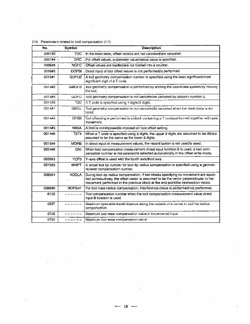
(14) Parameters related to tool compensation (1 /I)
No.
0001#3
0001#4
0008#6
0010#5
0013#1
0013#2
Symbol Description
TOC In the reset state, offset vectors are not canceled/are canceled.
ORC For offset values, a diameter value/radius value is specified.
NOFC Offset values are loaded/are not loaded into a counter.
DOFSI Direct input of tool offset values is not performed/is performed.
GOFU2 A tool geometry compensation number is specified using the least significant/most significant digit of a T code.
GMOFS Tool geometry compensation is performed by shifting the coordinate system/by moving the tool.
0013#3
0014#0
0014#1
GOFC Tool geometry compensation is not canceled/is canceled by position number 0.
T2D A T code is specified using 4 digits/2 digits.
GMCL Tool geometry compensation is not canceled/is canceled when the’reset state is en- tered.
0014#4 OFSB Tool offsetting is performed in a block containing a T code/performed together with axis movement.
0014#5
0014#6
0015#4
0024#6
0036#3
0075#3
0395#4
0399#0
0122
WIGA A iimit is not imposed/is imposed on tool offset setting.
T2T4 When a T code is specified using 2 digits, the upper 2 digits are assumed to be OO/are assumed to be the same as the lower 2 digits.
MORB In direct input of measurement values, the record button is not used/is used.
QNI When tool compensation measurement direct input function B is used, a tool com- pensation number is not selected/is selected automatically in the offset write mode.
YOF3 Y-axis offset is used with the fourth axis/third axis.
WNPT A virtual tool tip number for tool-tip radius compensation is specified using a geomet- ric/wear compensation number.
ADDLA During tool-tip radius compensation, if two blocks specifying no movement are speci- e fied consecutively, the offset vector is assumed to be the vector perpendicular to the
movement performed in the previous block at the end point/the intersection vector.
NOPS4l For tool nose radius compensation, interference check is performed/not performed.
- - - - - - Tool compensation number when the tool compensation measurement value direct input B function is used
0557 - - - - - - Maximum ignorabte travel distance along the outside of a corner in tool-tip radius compensation
0728 - - - - - - Maximum tool wear compensation value in incremental input
0729 - - - - - - Maximum tool wear compensation value
- 18 -
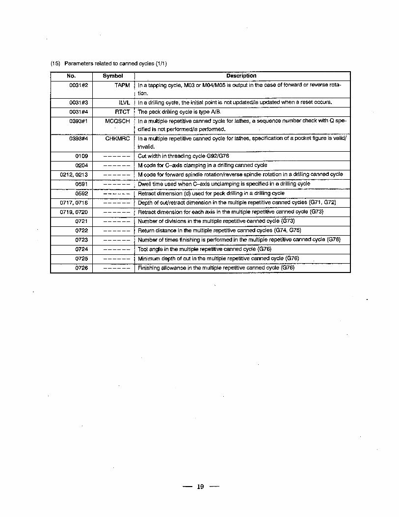
(15) Parameters related to canned cycles (1 /I )
I No. 1 Symbol 1 Description I
0031#2 TAPM In a tapping cycle, MO3 or M04/M05 is output in the case of forward or reverse rota-
tion.
0031#3 I
ILVL In a drilling cycle, the initial point is not updated/is updated when a reset occurs.
0031#4 RTCT The peck drilling cycle is type A/B.
0393#1
0393#4
MCQSCH In a multiple repetitive canned cycle for lathes, a sequence number check with Q spe-
cified is not performed/is performed.
CHKMRC In a multiple repetitive canned cycle for lathes, specification of a pocket figure is valid/
invalid.
0109
0204
1 0212,0213 1
- - - - - - Cut width in threading cycle G92/G76
- - - - - - M code for C-axis clamping in a drilling canned cycle h
-a---- I M code for forward spindle rotation/reverse spindle rotation in a drilling canned cycle 1
0591 - - - - - - Dwell time used when C-axis unclamping is specified in a drilling cycle
0592 1 lL=- - -Retract dimension (d) used for peck drilling in a drilling cycle I 0717,0718 1 -------I phfut/t De t o c re ract dimension in the multiple repetitive canned cycles (G71, G72) 1
0719,072O 1 - - - - - - 1 Retract dimension for each axis in the multiple repetitive canned cycle (G73) I 0721 1 - - - - - - 1 Number of divisions in the multiple repetitive canned cycle (G73) I
0722 1 - - - - - - 1 Return distance in the multiple repetitive canned cycles (G74, G75) I
0723 1 ---m-e 1 Number of times finishing is performed in the multiple repetitive canned cycle (G76) 1
0724 1 - - - - - - I Tool angle in the multiple repetitive canned cycle (G76) . I
0725 - - - - - - Minimum depth of cut in the multiple repetitive canned cycle (G76) L
0726 - - - - - - Finishing allowance in the multiple repetitive canned cycle (G76)
- 19 -
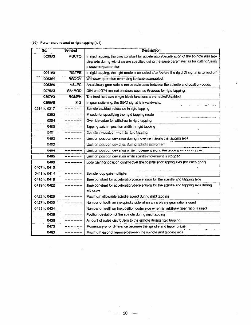
:I 6) Parameters related to rigid tapping (l/l)
No. 1 Symbol 1 Description
0029#3 RGCTO In rigid tapping, the time constant for acceleration/deceleration of the spindle and tap-
ping axis during withdraw are specified using the same parameter as for cutting/using
a separate parameter.
0041#0 1 RGTPE 1 In rigid tapping, the rigid mode is canceled after/before the rigid DI signal is turned off.
0063#4 1 RGDOV 1 Withdraw operation overriding is disabled/enabled.
0063#6 1
0076#3 [
VSLPC 1 An arbitrary gear ratio is not used/is used betweenthe spindle and position coder.
G84m G84 and G74 are not used/are used as G codes for rigid tapping.
0397#3 1 RGMFH 1 The feed hold and single block functions are enabled/disabled.
0399#5 1 SIG 1 In gear switching, the SIND signal is invalid/valid.
0214 to 0217 1 -- - - - - 1 Spindle backlash distance in rigid tapping
0253 1 - - - - - - 1 M code for specifying the rigid tapping mode
0254 1 --B-m- 10~ em ‘d e value for withdraw in rigid tapping
0400 1 - - - - - - I Tapping axis in-position width in rigid tapping
0401 I - - - - - - I Spindle in-position width in rigid tapping
0402 - __----_ Limit on position deviation during movement along the tapping axis
0403 - - - - - - Limit on position deviation during spindle movement
0404 ---- -- Limit on position deviation while movement along the tapping axis is stopped
0405 - - - - - - Limit on position deviation whife spindle movement is stopped
0406 - - - - - - Loop gain for position control over the spindle and tapping axis (for each gear)
0407 to 0410 L
0411 to 0414 - - - - - - Spindle loop gain multiplier
0415 to 0418 - - - - - - Time constant for acceleration/deceleration for the spindle and tapping axis
0419 to 0422 - - - - - - Time constant for acceleration/deceleration for the spindle and tapping axis during
withdraw
0423 to 0426 - - - - - - Maximum allowable spindle speed during rigid tapping
0427 to 0430 - - - - - - Number cf teeth on the spindle side when an arbitrary gear ratio is used
0431 to 0434 Number of teeth on the position coder side when an arbitrary gear ratio is used
0435 - - - - - - Position deviation of the spindle during rigid tapping
0436 - - - - - - Amount of pulse distribution to the spindle during rigid tapping
0473 - - - - 7 - Momentary error difference between the spindle and tapping axis
0483 - - - - - - Maximum error d’ifference between the spindle and tapping axis
20
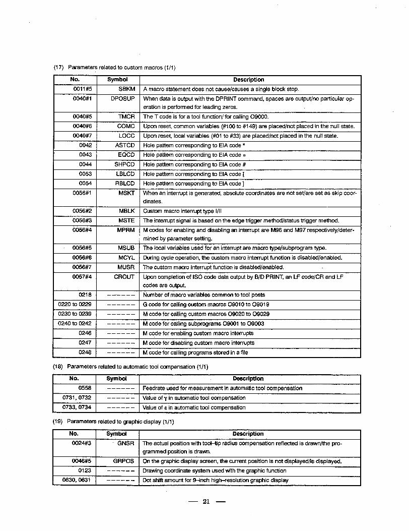
(17) Parameters related to custom macros (1 /I )
No. 1 Symbol 1 Description
0011#5 1 SBKM 1 A macro statement does not cause/causes a single block stop.
0040#1 DPOSUP
I
When data is output with the DPRINT command, spaces are output/no particular op-
eration is performed for leading zeros.
0040#5 1 TMCR 1 The T code is for a tool function/ for calling 09000.
0040#6 1 COMC 1 Upon reset, common variables (#IO0 to #149) are placed/not placed in the null state.
0040#7 I LOCC I Upon reset, local variables (##Ol to #33) are placed/not placed in the null state.
0042 1 ASTCD 1 Hole pattern corresponding to EIA code *
0043 I EQCD 1 Hole pattern corresponding to EIA code =
0044’ I SHPCD I Hole pattern corresponding to EIA code #
0053 I LBLCD I Hole pattern corresponding to EIA code [
0054 1 RBLCD I Hole pattern corresponding to EIA code ]
0056#1 MSKT When an interrupt is generated, absolute coordinates are not set/are set as skip coor-
dinates.
0056#2 1 MBLK I Custom macro interrupt type l/II
0056#3 1
0056#4
MSTE I The interrupt signal is based on the edge trigger method/status trigger method.
MPRM M codes for enabling and disabling an interrupt are M96 and M97 respectively/deter-
mined by parameter setting.
c 0056#5
0056#6
0056#7
0057#4
0218
0220 to 0229
0230 to 0239
0240 to 0242
0246
0247
0248
MSUB The local variables used for an interrupt are macro type/subprogram type.
MCYL During cycle operation, the custom macro interrupt function is disabled/enabled.
MUSR The custom macro interrupt function is disabled/enabled. c
CROUT Upon completion of IS0 code data output by B/D PRINT, an LF code/CR and LF
codes are output.
---- - - Number of macro variables common to tool posts
- - -- - - G code for calling custom macros 09010 to 09019
------ M code for calling custom macros 09020 to 09029
- - - - - - M code for calling subprograms 09001 to 09003
- - - - - - M code for enabling custom macro interrupts
- - - - - - M code for disabling custom macro interrupts
- - - - - - M code for calling programs stored in a file
(18) Parameters related to automatic tool compensation (l/l) .
No. 1 Symbol I Description
I 0558 1 - - - - - - I Feedrate used for measurement in automatic tool compensation
0731,0732 1 - - - - - - I Value of y in automatic tool compensation
0733,0734 I - - - - - - I Value of E in automatic tool compensation
(19) Parameters related to graphic display (l/l)
No. I Symbol 1 Description
0024#3 GNSR The actual position with tool-tip radius compensation reflected is drawn/the pro-
grammed position is drawn.
0046#5 I GRPOS I On the graphic display screen, the current position is not displayed/is displayed.
0123 1 - - - - - - I Drawing coordinate system used with the graphic function
0630,063l 1 - - - - - - Dot shift amount for 9-inch high-resolution graphic display
21
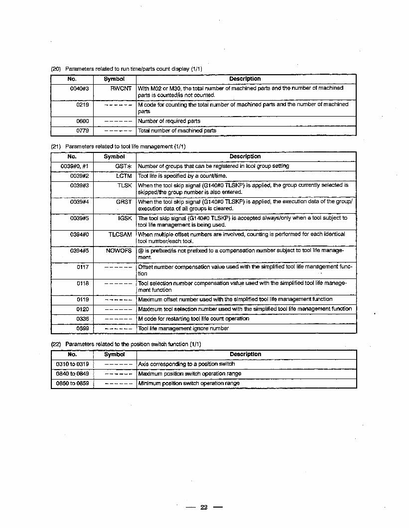
(20) Parameters related to run time/parts count display (l/l) &
No. Symbol Description
0040#3 RWCNT With MO2 or M30, the total number of machined parts and the number of machined parts is counted/is not counted.
0219 ------ M code for counting the total number of machined parts and the number of machined parts
I
0600 - - - - - - Number of required parts
0779 1 - - - - - - 1 Total number of machined parts
(21) Parameters related to tool life management (l/l)
No. Symbol Description
0039#0, #I GST* Number of groups that can be registered in tool group setting
0039#2 LCTM Tool life is specified by a count/time.
0039#3 TLSK When the tool skip signal (Gl40#0 TLSKP) is applied, the group currently selected is skipped/the group number is also entered.
0039#4 GRST When the tool skip signal (Gl40#0 TLSKP) is applied, the execution data of the group/ execution data of all groups is cleared.
0039#5 IGSK The tool skip signal (Gl40#0 TLSKP) is accepted always/only when a tool subject to tool life management is being used.
0394#0 TLCSAM When multiple offset numbers are involved, counting is performed for each identical tool num her/each tool.
0394##5 NOWOFS @ is prefixed/is not prefixed to a compensation number subject to tool life manage- ment.
0117
0118
- - - - - - Cffset number compensation value used with the simplified tool life management func- tion c
- - - - - - Tool selection number compensation value used with the simplified tool life manage- . ment function
0119 - - - - - - Maximum offset number used with the simplified tool life management function
0120 - - - - - - Maximum tool selection number used with the simplified tool life management function
0336 . - - - - - - M code for restarting tool life count operation
0599 - - - - - - Tool life management ignore number
(22) Parameters related to the position switch function (l/l) .
No. Symbol Description
‘0310 to0319 - - - - - - Axis corresponding to a position switch
0840 to, 0849 - - - - - - Maximum position switch operation range
0850 to 0859 - - - - - - Minimum position switch operation range I
.
22
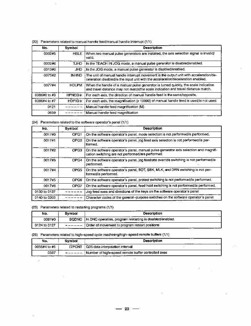
123) Parameters related to manual handle feed/manual handle interrupt (l/l)
No. Symbol Description
0002#5 HSLE When two manual pulse generators are installed, the axis selection signal is invalid/ valid.
0002#6
0013#0
0075#2
0077#4
0386#0 to #3
0386#4 to #7
0121
0699
TJHD In the TEACH IN JOG mode, a manual pulse generator is disabled/enabled.
JHD In the JOG mode, a manual pulse generator is disabled/enabled.
INHND The unit of manual handle interrupt movement is the output unit with acceleration/de- celeration disabled/is the input unit with the acceleration/deceleration enabled.
HDLPM When the handle of a manual pulse generator is turned quickly, the scale indication and travel distance may not match/the scale indication and travel distance match.
HPNEG* For each axis, the direction of manual handle feed is the same/opposite.
HDPIG* For each axis, the magnification (x 10000) of manual ,handle feed is used/is not used.
- - - - - - Manual handle feed magnification (M)
- - - - - - Manual handle feed magnification
(24) Parameters related to the software operator’s panel (l/l)
No. 1 Symbol 1 Description
0017#0 1 OPGI 1 On the software operator’s panel, mode selection is not performed/is performed,
0017#1
~~~~ On the software operator’s panel, jog feed axis selection is not performed/is per- formed.
0017#2 OPG3 On the software operator’s panel, manual pulse generator axis selection and magnifi- cation switching are not performed/are performed.
0017#3 0PG4 On the software operator’s panel, jog feedrate override switching is not performed/is performed. L
0017#4 0PG5 On the software operator’s panel, BDT, SBK, MLK, and DRN switching is not per- formed/is performed.
0017#5
0017#6
OPG6 On the software operator’s panel, protect switching is not performed/is performed.
0PG7 On the software operator’s panel, feed hold switching is not performed/is performed.
0130 to 0137 1 ___--- 1 gf d Jo ee axes and directions of the keys on the software operator’s panel
0140 to 0203 - - - - - - Character codes of the general-purpose switches on the software operator’s panel
[25) Parameters related to restarting programs (l/l)
I No. 1 Symbol 1 Description
I 0387#0 1 SQDNC 1 In DNC operation, program restarting is disabled/enabled.
1 0124to0127 1 -a,--, l()cj f r er 0 movement to program restart positions
(26) Parameters related to high-speed cycle machining/high-speed remote buffers (l/l)
I No. 1 Symbol 1 Description
1 0055#4 to #6 1 ITPCNT 1 GO5 data interpolation interval
0597 1 - - - - - - ] Number of high-speed remote buffer controlled axes
23
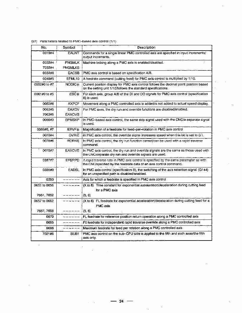
:27) Parameters related to PMC-based axis control (l/l)
No. Symbol Description
0019#4 EAUNT Commands for a single linear PMC controlled axis are specified in input increments/ output increments.
0032#4 PNGMLK Machine locking along a PMC axis is enabled/disabled.
7032#4 PNGMLKS
0032#6 EACSB PMC axis control is based on specification A/B.
0049#5 EFMLlO A feedrate command (cutting feed) for PMC axis control is multiplied by 1 /I 0.
0052#0 to #7 NODIC* Current position display for PMC axis control follows the decimal point position based on the setting unit 1 /I O/follows the standard specifications.
0063 #0 to #5 EBC* For each axis, group A/B of the DI and DO signals for PMC axis control (specification 8) is used.
0062#6 AXPCF Movement along a PMC controlled axis is added/is not added to actual speed display.
0063#5 EAXOV For PMC axes, the dry run and override functions are disabled/enabled.
7063#5 EAXOVS
0066#3 EPMSKP In PMC-based axis control, the same skip signal used with the CNC/a separate signal is used.
0066#6, #7
0078#4
0078#6
ERVF* Magnification of a feedrate for feed-per-rotation in PMC axis control
OVRIE In PMC axis control, the override signal increases speed when this bit is set to O/l.
RDRNE In PMC axis control, the dry run function cannot/can be used with a rapid traverse command.
’ 0078#7
0387#7
0398#0
0350
0651 to 0656
7651,7652
0657 to 0662
7657,7658
0672
0685
0698
7021#6
EAXOVE In PMC axis control, the dry run and override signals are the same as those used with the CNC/separate dry run and override signals are used.
EFERPD A rapid traverse rate in PMC axis control is specified by the same paramgter as with the CNC/specified by the feedrate data of an axis control command.
EADSL In PMC axis control (specification B), the switching of the axis selection signal (G144) for an unspecified path is disabled/enabled.
- - - - - - Axis for which a feedrate is specified in PMC axis control
- - - - - - (X to 8) Time constant for exponential acceleration/deceleration during cutting feed
for a PMC axis
------ (5, 6)
- - - - - - (X to 8) FL feedrate for exponential acceleration/deceleration during cutting feed for a
PMC axis
------ (5, 6)
-- -- - - FL feedrate for reference position return operation along a PMC controlled axis
-- -- - - FO feedrate for independent rapid traverse override along a PMC controlled axis
- - - - - - Maximum feedrate for feed per rotation along a PMC controlled axis
SUB1 PMC axis control on the sub-CPU side is applied to the fifth and sixth axes/the fifth axis only.
24
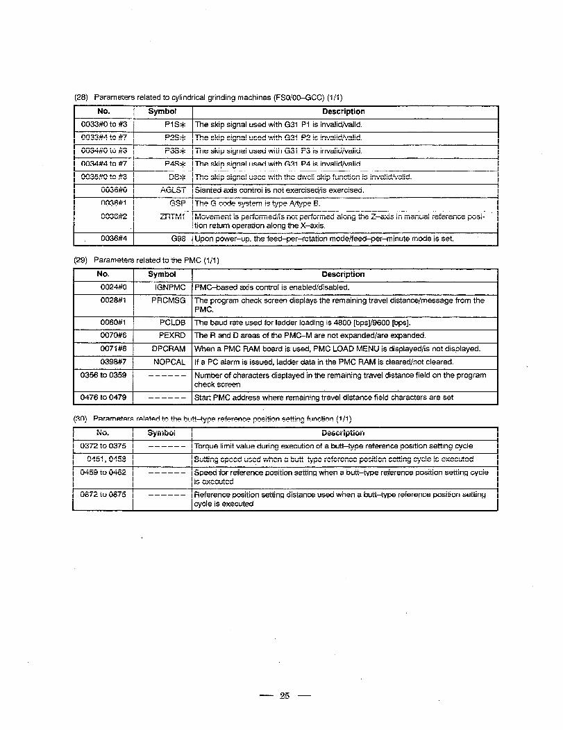
(28) Parameters related to cylindrical grinding machines (FSO/OO-CCC) (1 /I)
I No. 1 Symbol 1 Description
1 0033#0 to#3 / Pl S* 1 The skip signal used with G31 PI is invalid/valid.
1 0033#4to #7 1 P2S* f The skip signal used with G31 P2 is invalid/valid.
1 0034#0 to #3 I P3S* I The skip signal used with G31 P3 is invalid/valid.
1 0034#4tO #7 I P4S* 1 The skip signal used with G31 P4 is invalid/valid.
I 0035#0 to#3 I DS* I The skip signal used with the dwell skip function is invalid/valid.
I 0036#0 ( AGLST I Slanted axis control is not exercised/is exercised.
I 0036#1 1 GSP 1 The G code system is type A/type B.
0036#2 ZRTMI Movement is performed/is not performed along the Z-axis in manual reference posi- tion return operation along the X-axis.
1 _ 0036#4 1 G98 1 Upon power-up, the feed-per-rotation mode/feed-per-minute mode is set. .
(29) Parameters related to the PMC (l/l)
No. ] Symbol 1 Description
I 0024#0 1 IGNPMC ] PMC-based axis control is enabled/disabled.
0028#1 PRCMSG The program check screen displays the remaining travel distance/message from the PMC.
I 0060#1 1 PCLDB 1 The baud rate used for ladder loading is 4800 [bps]/9600 [bps].
0070#6 ] PEXRD 1 The R and D areas of the PMC-M are not expanded/are expanded.
0071#6 1
0398#7 1
DPCRAM 1 When a PMC RAM board is used, PMC LOAD MENU is displayed/is not displayed.
NOPCAL f If a PC alarm is issued, ladder data in the PMC RAM is cleared/not cleared.
0356 to 0359 - - - - - - Number of characters displayed in the remaining travel distance field on the program check screen
0476 to 0479 1 -w-e-- Start PMC address where remaining travel distance field characters are set
130) Parameters related to the butt-type reference position setting function (I/l)
No. ] Symbol I Description
0372 to 0375 1
0451,0458 1
- - - - - - 1 Torque limit value during execution of a butt-type reference position setting cycle
- - - - - - I Butting speed used when a butt-type reference position setting cycle is executed
0459 to 0462 - - - - - - Speed for reference position setting when a butt-type reference position setting cycle is executed
0872 to 0875 - - - - - - Reference position setting distance used when a butt-type reference position setting cycle is executed
- 25 -
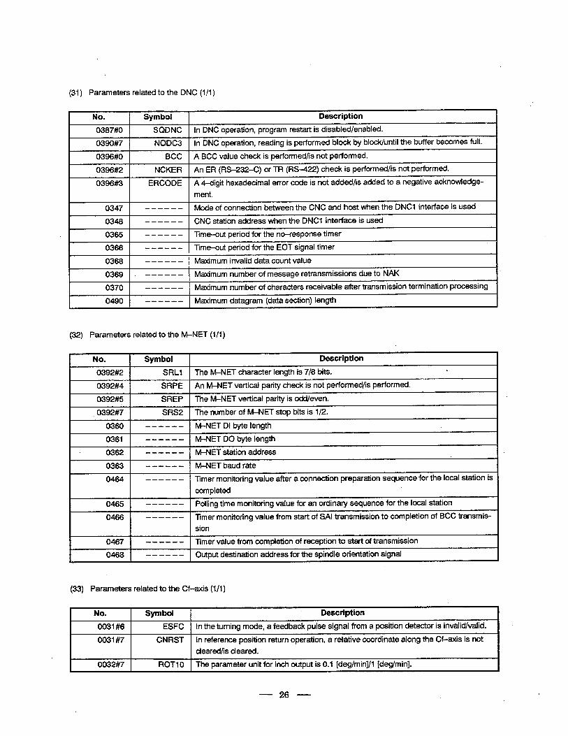
(31) Parameters related to the DNC (l/l)
I No. 1 Symbol 1 Description
I 0387#0 1 SQDNC 1 In DNC operation, program restart is disabled/enabled.
0390#7 NODC3 In DNC.operation, reading is performed block by block/until the buffer becomes full.
I 0396#0 1 . BCC 1 A BCC value check is performed/is not performed.
0396#2
0396#3
~ ~~ NCKER An ER (RS-232-C) or TR (RS-422) check is performed/is not performed.
ERCODE A 4-digit hexadecimal error code’is not added/is added to a negative acknowledge-
ment.
I 0347 1 ------ I Mode of connection between the CNC and host when the DNCI interface is used
I 0348 ( - - - - - - 1 CNC station address when the DNCI interface is used
0365 - - - - - - mme-out period for the no-response timer
0366 - - - - - - Time-out period for the EOT signal timer
0368 - - - - - - Maximum invalid data count value I
0369 f --e-w- Maximum number of message retransmissions due to NAK
0370 I ------ 1 Maximum number of characters receivable after transmission termination processing
0490 - - - - - - Maximum datagram (data section) length
(32) Parameters related to the M-NET (l/l)
I No. I Symbol I Description
0392#2 1 SRLI 1 The M-NET character length is 7/8 bits. *
0392#4
0392#5
~~~ SRPE An M-NET vertical parity check is not performed/is performed.
SREP The M-NET vertical parity is odd/even.
I _ 0392#7 1 SRS2 f The number of M-NET stop bits is l/2.
I 0360 1 ------ 1 M-NETDI bytelength
r--- 0361 1 ------ I M-NETDO byte length
0362 - - - - - - M-NET station address
0363 -- -- - - M-NET baud rate
0464 ------ Timer monitoring value ager a connection preparation sequence for the local station is
completed ,
0465 ------ Polling time monitoring value for an ordinary sequence for the local station
0466 ------ Timer monitoring value from start of SAI transmission to completion of BCC transmis-
I sion
I 0467 1 - - - - - - 1 Timer value from completion of reception to start of transmission
I 0468 1 - - - - - - 1 Output destination address for the spindle orientation signal
(33) Parameters related to the Cf-axis (l/l)
No. I Symbol 1 Description
0031#6 1
0031#7
0032#7
ESFC 1 In the turning mode, a feedback pulse signal from a position detector is invalid/valid.
CNRST In reference position return operation, a relative coordinate along the Cf-axis is not
cleared/is cleared.
ROT1 0 The parameter unit for inch output is 0.1 [deg/min]/l [deglmin].
- 26 -
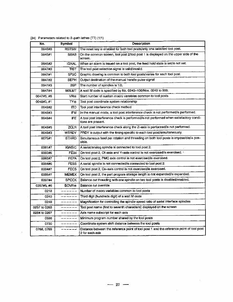
(34) Parameters related to 2-path lathes (TT) (1 /I )
No. Symbol Description
0046#0 RSTSW The reset key is enabled for both tool posts/only one selected tool post.
0046#1 SBAB On the common screen, tool post 2/tool post 1 is displayed on the upper side of the screen.
0046#2 IGNAL When an alarm is issued on a tool post, the feed hold state is set/is not set.
0047#0 TIST The tool post selection signal is valid/invalid.
0047#1 SP2C I Graphic drawing is common to both tool posts/varies for each tool post.
0047#2 SEPH Output destination of the manual handle pulse signal
0047#3 2SP The number of spindles is l/2.
0047#4 M3LMT A wait M code is specified by No. 0243+1 OO/Nos. 0243 to 999.
0047#5, #6 VR* Start number of custom macro variables common to tool posts
0048#0, #I TY* Tool post coordinate system relationship
0048#2 IT0 Tool post interference check method
0048#3 IFM In the manual mode, a tool post interference check is not performed/is performed.
0048#4 l,FE A tool post interference check is performed/is not performed when satisfactory condi- tions are present.
0048#5 ZCLR A tool post interference check along the Z-axis is performed/is not performed.
0049#3 VVTRDY PRDY is output with the timing specific to each tool post/simultaneously.
0075#1 STHRD Simultaneous feed per rotation and threading on both tool posts is impossible/is pos- si ble.
0381#7 IGNSIC A serial/analog spindle is connected to tool post 2.
0383#6 FE34 On tool post 2, Cf-axis and Y-axis control is not exercised/is exercised. L
0383#7 FEPA On tool post 2, PMC axis control is not exercised/is exercised.
0384#6 FESS A serial spindle is not connected/is connected to tool post 2.
0384#7 FECS On tool post 2, Cs-axis control is not exercised/is exercised.
0385#7 MEMEX On tool post 2, the part program storage length is not expanded/is expanded.
0397#4 SPCCK Balance cut threading with one spindle on two tool posts is disabled/enabled.
0397#5, #6 BOVR* Balance cut override
0218 - - -- - - Number of macro.variables common to tool posts
0243 - - - - - - Third digit (hundreds digit) of a wait M code
0249 ------ Magnification for controlling the spindle speed ratio of serial interface spindles
0257 to 0263 -Z---L Tool post name (first to seventh characters) displayed on the screen
0264 to 0267 - - - - - - Axis name subscript for each axis
0598 B----L Minimum program number shared by the tool posts
0730 - - - - - - Coordinate system shift distance between the tool posts
0768,0769 . -----1 Distance between the reference point of tool post 1 and the reference point of tool post 2 for each axis
27
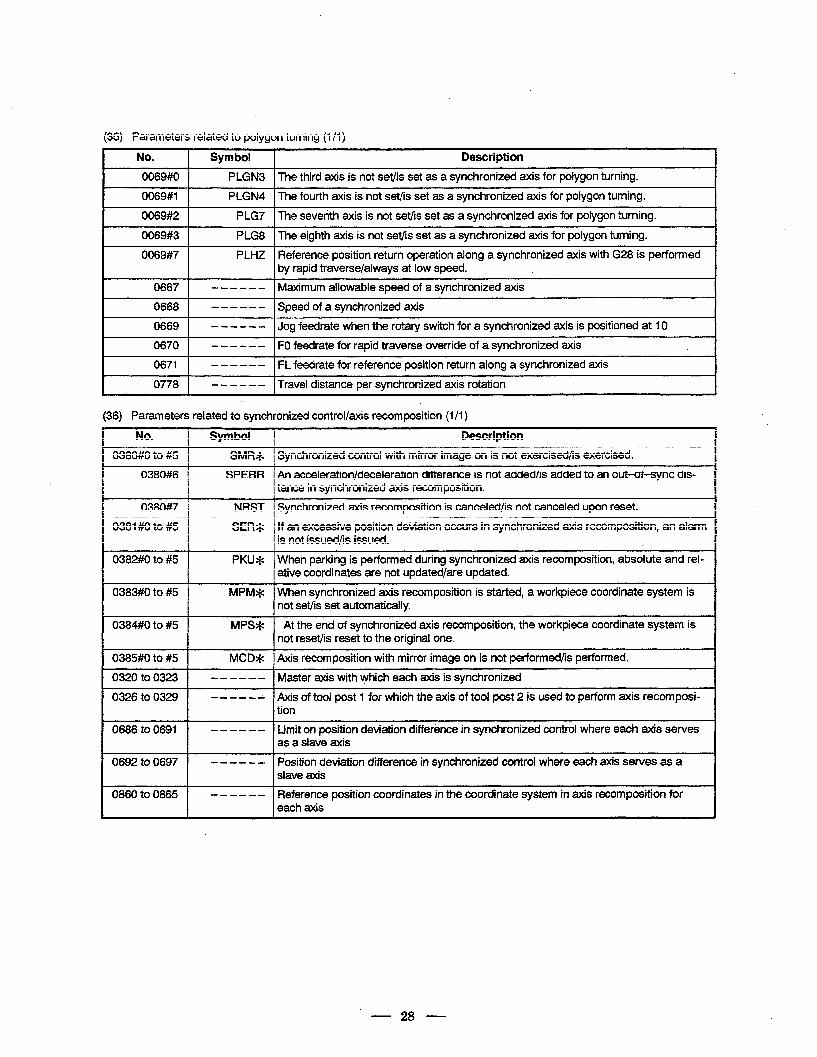
(35) Parameters related to polygon turning (l/l) v
No. Symbol Description
0069#0 PLGN3 The third axis is not set/is set as a synchronized axis for polygon turning.
0069#1 PLGN4 The fourth axis is not set/is set as a synchronized axis for polygon turning.
0069#2 PLG7 The seventh axis is not set/is set as a synchronized axis for polygon turning.
I 0069#3 1 PLG8 1 The eighth axis is not set/is set as a synchronized axis for polygon turning. I 0069#7 PLHZ Reference position return operation along a synchronized axis with G28 is performed
by rapid traverse/always at low speed.
0667 1 - - - - - - 1 Maximum allowable speed of a synchronized axis
I 0668 1 ------ )Speedofasynchronizedaxis I 0669 - - - - - - Jog feedrate when the rotary switch for a synchronized axis is positioned at 10
0670 - - - - - - FO feedrate for rapid traverse override of a synchronized axis
0671 - - - - - - FL feedrate for reference position return along a synchronized axis
I 0778 1 - - - - - - 1 Travel distance per synchronized axis rotation I
(36) Parameters related to synchronized control/axis recomposition (1 /I)
No. 1 Symbol Description
0380#0 to #5 1 SMR* Synchronized control with mirror image .on is not exercised/is exercised.
An acceleration/deceleration difference is not added/is added to an out-of-sync dis- tance in synchronized axis recomposition.
Synchronized axis recomposition is canceled/is not canceled upon reset.
, If an excessive position deviation occurs in synchronized axis recomposition, an alarm is not issued/is issued. L
SPERR 0380#6
0380#7 f NRST
0381#0 to #5 I
SER*
, When parking is performed during synchronized axis recomposition, absolute and rel- ative coordinates are not updated/are updated.
~ When synchronized axis recomposition is started, a workpiece coordinate system is not set/is set automatically.
0382#0 to #5
0383#0 to #5
PKU*
MPM*
0384#0 to #5 1 MPS* At the end of synchronized axis recomposition, the workpiece coordinate system is ’ not reset/is reset to the original one.
Axis recomposition with mirror image on is not performed/is performed.
Master axis with which each axis is synchronized
Axis of tool post 1 for which the axis of tool post 2 is used to perform axis recomposi- tion
0385#0 to #5 1 MCD*
0320 to 0323 1 ------ ~_~ ~
0326 to 0329 ------
0686 to 0691
I
-II.---- Limit on position deviation difference in synchronized control where each axis serves as a slave axis
I _ _~_~
0692 to 0697 ------ Position deviation difference in synchronized control where each axis serves as a slave axis
Reference position coordinates in the coordinate system in axis recomposition for each axis
0860 to 0865 ------
- 28 -
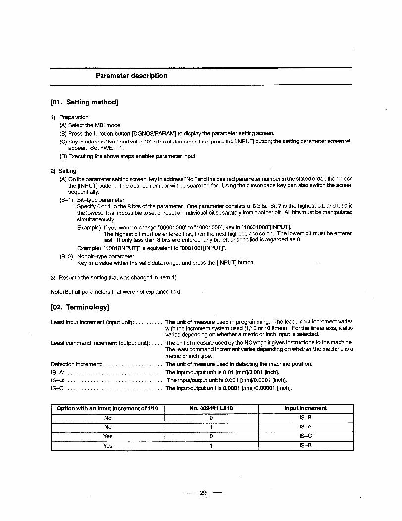
Parameter description
[Ol. Setting method]
1) Preparation
(A) Select the MDI mode.
(B) Press the function button [DGNOS/PARAM] to display the parameter setting screen.
(C) Key in address “No.” and value “0” in the stated order, then press the [INPUT] button; the setting parameter screen will appear. Set PWE = I.
(D) Executing the above steps enables parameter input.
2) Setting
(A) On the parameter setting screen, key in address “No.” and the desired parameter number in the stated order, then press the [INPUT] button. The desired number will be searched for. Using the cursor/page key can also switch the screen sequentially.
(B-l ) Bit-type parameter Specify 0 or 1 in the 8 bits of the parameter. One parameter consists of 8 bits. Bit 7 is the highest bit, and bit 0 is the lowest. It is impossible to set or reset an individual bit separately from another bit. All bits must be manipulated simultaneously.
Example) If you want to change “00001000” to “10001000”, key in “10001 OOO”[INPUT]. The highest bit must be entered first, then the next highest, and so on. The lowest bit must be entered last. If only less than 8 bits are entered, any bit left unspecified is regarded as 0.
Example) “1001 [INPUTJ” is equivalent to “0001001 [INPUTJ”.
(B-2) Nonbit-type parameter Key in a value within the valid data range, and press the [INPUT] button.
3) Resume the settingthat was changed in item I).
Note)Set all parameters that were not explained to 0.
[02. Terminology]
Least input increment (input unit): . . . . . . . . . .
Least command increment (output unit): . . . .
Detection increment: ..................... IS-A: ..................................
IS-B: ..................................
IS-C: ..................................
The unit of measure used in programming. The least input increment varies with the increment system used (l/l 0 or IO times). For the linear axis, it also varies depending on whether a metric or inch input is selected.
The unit of measure used by the NC when it gives instructions to the machine. The least command increment varies depending on whether the machine is a metric or inch type.
The unit of measure used in detecting the machine position.
The input/output unit is 0.01 [mm]/O.OOl [inch].
The input/output unit is 0.001 [mm]/O.OOOl [inch].
The input/output unit is 0.0001 [mm]/O.00001 Dnch].
Option with an input increment of l/IO 1 No. 0024#1 LIIIO I Input increment I I
No I 0 IS-B
No I 1 I IS-A I Yes I 0 I IS-C’ I Yes I 1 I IS-B I
- 29 -
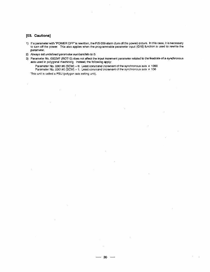
[03. Cautions]
1) If a parameter with “POWER OFF” is rewritten, the P/S 000 alarm (turn off the power) occurs. In this case, it is necessary to turn off the power. This also applies when the programmable parameter input (GIO) function is used to rewrite the parameter.
2) Always set undefined parameter numbers/bits to 0.
3) Parameter No. 0032#7 (ROT1 0) does not affect the input increment parameter related to the feedrate of a synchronous axis used in polygonal machining. Instead, the following apply:
Parameter No. OOOl#O (SCW) = 0: Least command increment of the synchronous axis x 1000 Parameter No. OOOl#O (SCW) = I : Least command increment of the synchronous axis x 100
This unit is called a PSU (polygon axis setting unit).
30
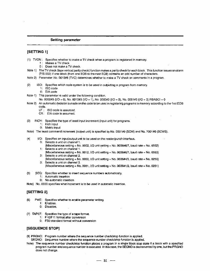
Setting parameter
. [SETTING
(1) TVON : 1 : 0:
11
Specifies whether to make a TV check when a program is registered in memory. Makes a TV check. Does not make a TV check.
Note 1) The TV check (tape vertical parity check) function makes a parity check for each block. This function issues an alarm (P/S 002) if one block (from one EOB to the next EOB) contains an odd number of characters.
Note 2) Parameter No. OOl8#6 (TVC) determines whether to make a TV check on comments in a program.
Note 1)
Note 2)
iso: Specifies which code system is to be used in outputting a program from memory. I : IS0 code 0: EIA code
This parameter is valid under the following condition.
No. 0002#3 (l/O = 0), No. 0012#3 (l/O = I), No. 0050#3 (i/O = 2), No. 0051#3 (i/O = 3) RSASCI = 0
An automatic decision is made on the code to be used in registering programs in memory according to the first EOB code. LF : IS0 code is assumed. CR : EIA code is assumed.
(3) INCH: Specifies the type of least input increment (input unit) for programs. 1: Inch input 0: Metric input
Note) The least command increment (output unit) is specified by No. 0001 #O (SCW) and No. 7001 #O (SCWS).
(4) l/O: Specifies an input/output unit to be used on the reader/punch interface. I.
0: Selects a unit on channel 1. (Miscellaneous setting = No. 0002, l/O unit setting = No. 0038#6/7, baud rate = No. 0552)
1: Selects a unit on channel I. (Miscellaneous setting = No. 0012, I/O unit setting = No. 0038#6/7, baud rate = No. 0553)
2: Selects a unit on channel 2. (Miscellaneous setting = No. 0050, I/O unit setting = No. 0038#4/5, baud rate = No. 0250)
3: Selects a unit on channel 3. (Miscellaneous setting = No. O&1, I/O unit setting = No. 0038#1/2, baud rate = No. 0251)
(5) SEQ: Specifies whether to insert sequence numbers automatically. 1: Automatic insertion 0: No automatic insertion
Note) No. 0550 specifies what increment is to be used in automatic insertion.
[SETTING 21
(6) PWE: Specifies whether to enable parameter writing. 1: Enables. 0: Disables.
(7) TAPEF: Specifies the type of a tape format. 1: Fl O/F11 format after conversion 0: FSO standard format without conversion
[SEQUENCE STOP]
(8) PRGNO: Program number where the sequence number check/stop function is applied. SEQNO: Sequence number where the sequence number check/stop function is applied.
Note) The sequence number check/stop function places a program in a single block stop state if a block with a specified program number and sequence number is executed. In this case, the SEQNO is decremented by one, but the PRGNO does not change.
31
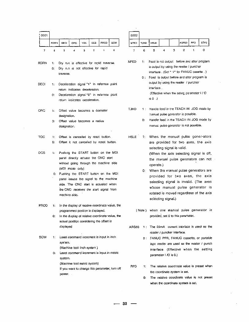
0001
Y
RDRN DECI ORC TOC DCS PROD sew
7
RDRN
DECI
ORC
TOC
DCS
PROD
sew
6
1:
0:
1:
0:
1:
0:
7:
0:
1:
0:
5 4 3 2 1 0
Dry run is effective for rapid traverse.
Dry run is not effective for rapid
traverse.
Decelaration signal “1” in refernce point
return indicates deceleration.
Decelaration signal “0” in refernce point
return indicates deceleration.
Offset value becomes
designation.
Offset value becomes
designation.
a diameter
a radius
Offset is canceiled by reset button.
Offset it not canceiled by reset button.
Pushing the START button on the MDI
panel directly actuate the CNC start
without going through the machine side
(MDI mode only)
Pushing the START button on the MDI
panel issues the signal to the machine
side. The CNC start is actuated when
the CNC receives the start signal from
machine side.
In the display of relative coordinate vaiue, the
programmed position is displayed.
in the display of relative coordinate value, the
actual position considering the offset is
displayed
Least command increment is input in inch
system.
(Machine tool: inch system )
Least command increment is input in metric
system-
(Machine tookmetric system)
if you want to change this parameter, turn off
power.
1 0002 1
NFED TJHD HSLE ASR33 PPD STP2 4
7 6 5 4 3 2 1 0
NFED 1:
0:
Feed is not output before and after progtam
is output by using the reader / puncher
interface . (Set u 1“ for FANUC casette . )
Feed is output before and after program is
output by using the reader / puncher
interface .
(Effective when the seting parameter I / 0
is 0 .)
TJHD feed in the TEACH IN JOG mode by
pulse generator is possible.
feed in the TEACH IN JOG mode by
puise generator is not possible.
HSLE
1 :
0:
1:
Handle
manual
Handle
manual
When the manual pulse gener-ators
are provided for two axes, the axis
selecting signal is valid.
(When the axis selecting signal is off,
the manual pulse generators can not
operate.).
0: When the manual pulse generators are
provided for two axes, the axis
selecting signal is invalid. (The axes
whose manual pulse generator is
rotated is moved regardless of the axis
selecting signal.)
( Note ) when one manual pulse generator is
provided, set 0 to this parameter.
ARS33 1 :
0:
The 20mA current interface is used as the
reader / puncher interface.
FANUC PPR, FANUC ca.ssette, or portable
tape reader are used as the reader / punch
interface. (Effective when the setting
parameter I /O is 0.)
PPD 1:
0:
The relative coordinate value is preset when
the coordinate system is set.
The relative coordinate value is not preset
when the coordinate system is set.
32
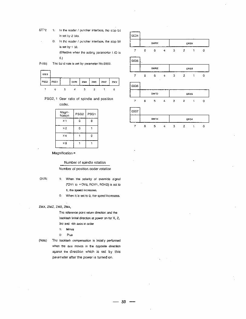
STP2 1: In the reader / puncher interface, the stop bit
is set by 2 bits.
0: in the reader / puncher interface, the stop bit
is set by 1 bit.
(Effective when the setting paramerter 1 /O is
0.)
(Note) The band rate is set by parameter No.0552.
r-l 0003
, PSG2 PSGl OVRI ZM4 ZM3 ZMZ ZMX
*
7 6 5 4 3 2 I 0
PSG2, 1 Gear ratio of spindie and position
coder.
Magni- fication PSG2 PSG-I
Xl 0 0
x2 0 1
x4 1 0
x8 1 1 ,
e
Magnification =
Number of spindle rotat :ion
Number of position coder rotation
OVRI 1: When the polarity of override signal
(*OVI to + OV8, ROVl, ROV2) is set to
1, the speed increases.
0: When it is set to 0, the speed increases.
ZMX, ZMZ, ZM3, ZM4,
The reference point return direction and the
backlash initial direction at power on for X, 2,
3rd and 4th axes in order
1: Minus
0: Pius
(Note) The backlash compensation is initially performed
r-l 0004 I
DMRX GRDX .
7 6 5 4 3 2 1 0
DMRZ I GRDZ I
7 6 5 4 3 2 1 0
I I 0006 r
DMR3 GRD3
7 6 5 4 3 2 1 0
0007
DM R4 GRD4
7 6 5 4 3 2 1 0
when the axis moves in the opposite direction
against the direction which is set by this
parameter after the power is turned on.
.- 33
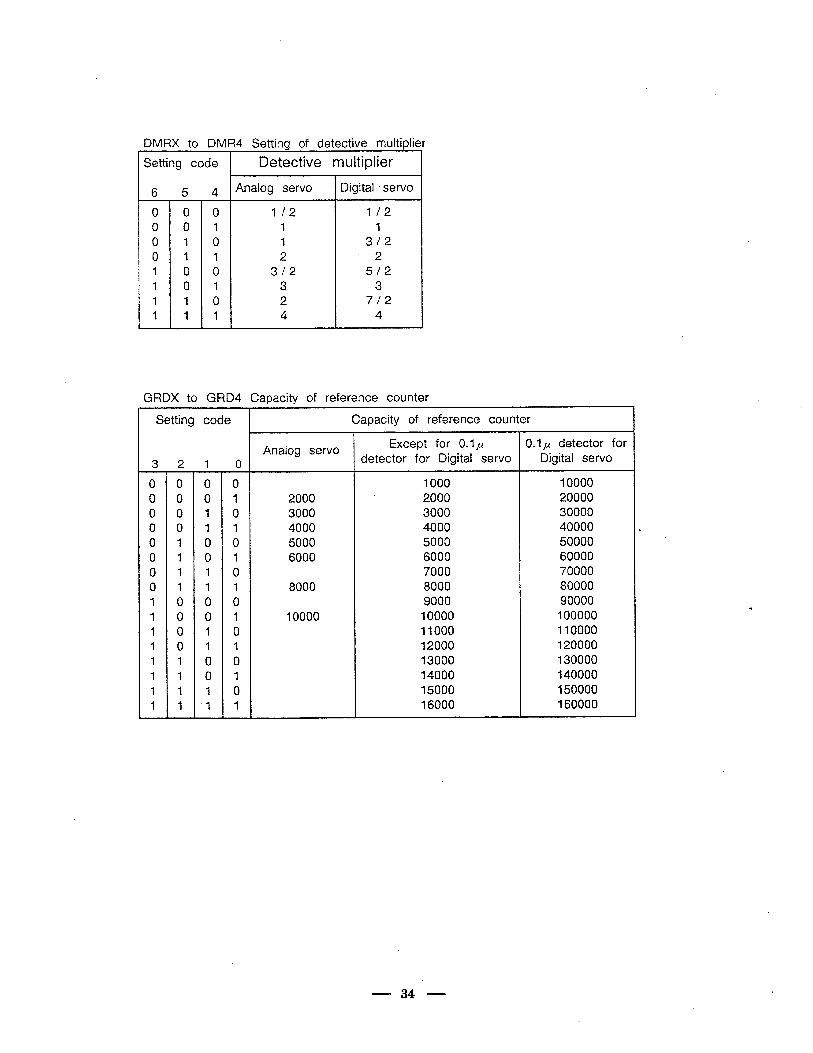
DMRX to DMR4 Setting of detective multiplier -l Setting code Detective multiplier
6 5 4 lAnalog=z&Lz- Digital ’ servo i
0 0 0 1 f2 l/2 0 0 1 1 1 0 1 0 I 312 0 1 1 2 2 1 0 0 312 512 1 .o 1 3 3 I 1 0 2 7/2 1 1 1 4 4
, V
GRDX tb GRD4 Capacity of reference counter
Setting code Capacity of reference counter
Analog servo Except for 0.1~ 0.1~ detector for
321 0 detector for Digital servo Digital servo
0 0 0 0 1000 10000 0 0 0 1 2000 2000 20000 0 0 1 0 3000 3000 30000 0 0 1 1 4000 4000 40000 0 1 0 0 5000 5000 50000 0 1 0 1 6000 6000 60000 0 1 I 0 7000 70000 0 1 1 1 8000 8000 80000 1 0 0 0 9000 90000 1 0 0 1 10000 10000 100000 1 0 1 0 11000 110000 1 0 1 1 12000 120000 1 1 0 0 13000 130000 1 1 0 1 14000 140000 I 1 1 0 15000 150000
16000 160000 . I 1 ‘1 I
34
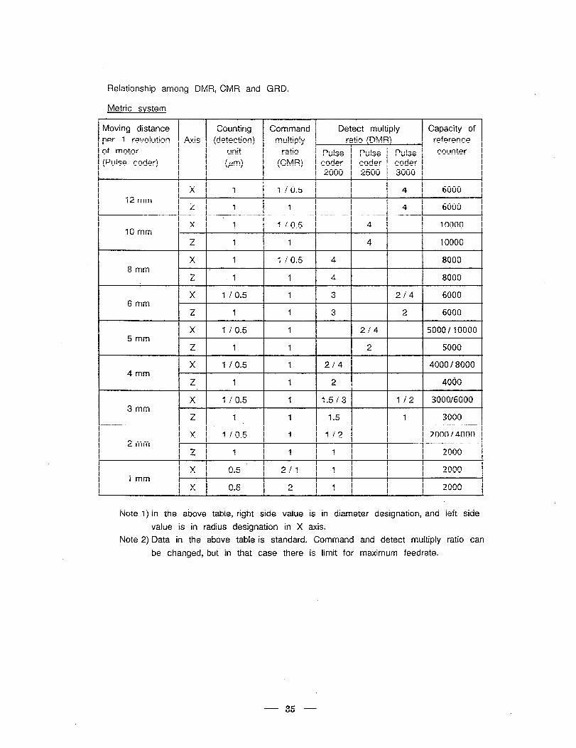
Relationship among DMR, CMR and GRD.
Metric system
Moving distance Counting Command Detect multiply Capacity of
per 1 revolution Axis (detection) multiply ratio (DMR) reference
of motor unit ratio Pulse Pulse Pulse counter
(Pulse coder) (pm> (CMV coder coder coder 2000 2500 3000
X 1 1 / 0.5 4 6000 12 mm
Z 1 1 4 6000
x *1 1 / 0.5 4 10000 10 mm
Z 1 1 4 10000
X 1 I IO.5 4 8000 8mm
Z I I 4 8000
- x 1 IO.5 1 3 2/4 6000 6 mm
Z 1 1 3 2 6000
X I / 0.5 1 2/4 5000/10000 5mm
Z 1 1 2 5000
X 1 ! 0.5 1 214 4000 / 8000 4mm
Z .l 1 2 4000
X 1 ! 0.5 I 1.5 / 3 I /2 3000/6000 3 mm
z 1 1 1.5 1 3000
X 1 / 0.5 1 I /2 2000 / 4000 2mm
z 1 1 1 2000
’ X 0.5 2/l I 2000 1 mm
X 0.5 2 I 2000
Note 1) In the above table, right side value is in diameter designation, and left side
value is in radius designation in X axis.
Note 2) Data in the above table is standard. Command and detect multiply ratio can
be changed, but i.n that case there is limit for maximum feedrate.
- 35 -
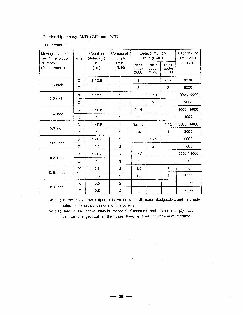
Relationship among DMR, CMR and GRD.
Inch system
Moving distance Counting Command Detect multiply Capacity of per 1 revolution Axis (detection) multiply ratio (DMR) reference
of motor unit ratio Pulse Pulse Pulse
counter
(Pulse coder) km) (CMR) coder coder coder 2000 2500 3000
X I / 0.5 1 3 2/4 6000 0.6 inch
Z 1 1 3 2 6000
0.5 inch X 1 / 0.5 1 2/4 5000 /lOOOO
. 2 1 1 2 5000
X 1 / 0.5 I 2/4 4000 / 8000 0.4 inch
z 1 1 2 4000
X 1 / 0.5 I 1.5/3 l/2 3000 / 6000 0.3 inch
Z 1 1 1.5 1 3000
X 1 / 0.5 1 I /2 5000 0.25 inch
e z 0.5 2 2 5000
X 1 / 0.5 1 I /2 2000 / 4000 0.2 inch
z 1 1 I I 2060
X 0.5 2 1.5 1 3000 0.15 inch
Z 0.5 2 1.5 1 3000 \
X 0.5 I 2 1 2000 0.1 inch
I z 0.5 2 1 2000 c
Note 1) In the above table, right side value is in diameter designation, and left side .
value is in radius designation in X axis.
Note 2) Data in the above table is standard. Command and detect multiply ’ ratio
can be changed, but in that case there is limit for maximum feedrate.
36
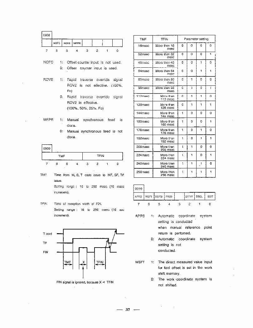
0008
NOFC ROVE MFPR
4
7 6 5 4 3 2 1 0
NOFC 1: Offset counter input is not used.
0: Offset counter input is used.
ROVE I: Rapid traverse override signal
ROV2 is not effective. (lOO%,
Fo)
0: Rapid traverse override signal
ROV2 is effective.
(lOO%, 50%, 25%, Fo)
MFPR 1: Manual synchronous feed is
done.
0: Manual synchronous feed is not
done.
TMF I TFIN I
7 6 5 4 3 2 1 0
TMF Time from M, S, T code issue to MF, SF, TF
issue.
Setting range : 16 to 256 msec. (16 msec
increment).
TFIN Time of reception width of FIN.
Setting range : 16 to 256 msec. (16 set
increment).
T cord
TF
FiN
TM&.& TFIN (.)
1
FIN signal is ignored, because X-g TFIN
I TMF TFIN Parameter setting 1
I I 1
I 4
1 Gmsec More then 16 0 0 0 0 msec
32msec More then 32 0 0 0 1 msec
48msec More then 48 0 0 1 0 msec
64msec More then 64 0 0 1 1 msec
80msec 0 1 0 0
96msec
msec
More then 96 0 1 0 1
11 Zmsec
msec
More then 112 msec
0 1 1 0
128msec More then 128 msec
0 1 1 1
144msec More then 1 0 0 0 144 msec
160msec More then 1 0 0 1 160 msec
176msec More then 1 0 1 0 176 msec
192msec More then 1 0 1 1 192 msec
208msec More then 1 1 0 0 1 . 208 msec
224msec More then 1 1 0 1 224 msec
240msec More then 1 1 1 240 msec L
256msec More then 1 1 1 1 256 msec
0010
APRS WSFT DOFSI PRG9
1
OFWY EBCL ISOT
7 6
APRS
WSFT
5 4 3 2 1 0
Automatic coordinate system
setting is conducted
when manual reference point
return is perfomed.
Automatic coordinate system
setting is not
conducted.
The direct measured value input
for tool offset is set in the work
shift memory.
The work coordinate system is
not shifted.
37
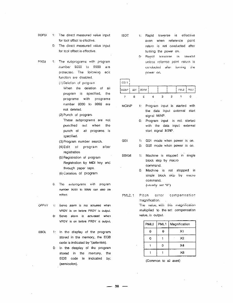
DOFSI 1:
0:
PRG9 1:
0:
OFFVY 1:
0:
EBCL 1:
0:
The direct measured value input
for tool offset is efective.
The direct measured value input
for tool offset is effective.
The subprograms with program
number 9000 to 9999 are
protected. The foliowing edit
function are disabled.
( I) Deletion of program
When the deletion of ail
program is specified, the
programs with programs
number 9000 to 9999 are
not deleted.
(2) Punch of program
These subprograms are not
punched out when the
punch of ail programs is
specified.
(3) Program number search.
(4)Edit of program after
registration
(5) Registration of program
Registration by MDI key and
through paper tape.
(6) Collation of program
Th.e subprograms with program
number 9000 to 9999 can also be
edited.
Servo alarm is not actuated when
VRDY is on before PRDY is output.
Servo alarm is acturated when
VRDY is on before PRDY is output.
in the display of the program
stored in the memory, the EOB
code is indicated by *(asterrisk).
in the despiay of the program
stored in the memory, the
EOB code is indicated by;
(semicolon).
ISOT 1: Rapid traverse is effective
even when reference point
return is not conducted after
turning the power on.
0: Rapid traverse is invalid
unless refernce point return is
conducted after turning the
power on.
1 0011 I
MCtNP GO1 SBKM PML2 PMLl
7 6 5 4 3 2 1 0 .
MCINP 1: Program input is started with
the data input external start
signal MINP.
0: Program input is not started
with the data input external
start signal MINP.
GO1 I: GO1 mode when power is on.
0: GO0 mode when power is on.
SBKM 1: Machine is stopped in; single
block skip by macro
command.
0: Machine is not stopped in
single block skip by macro
command.
(usually set “0”)
PML2, 1 Pitch error compensation
magnification. ,
The value, with this magnification
multiplied to the set compensation
value, is output.
1 PML2 ( PMLI 1 Magnification
(Common to all axes)
- 38 -
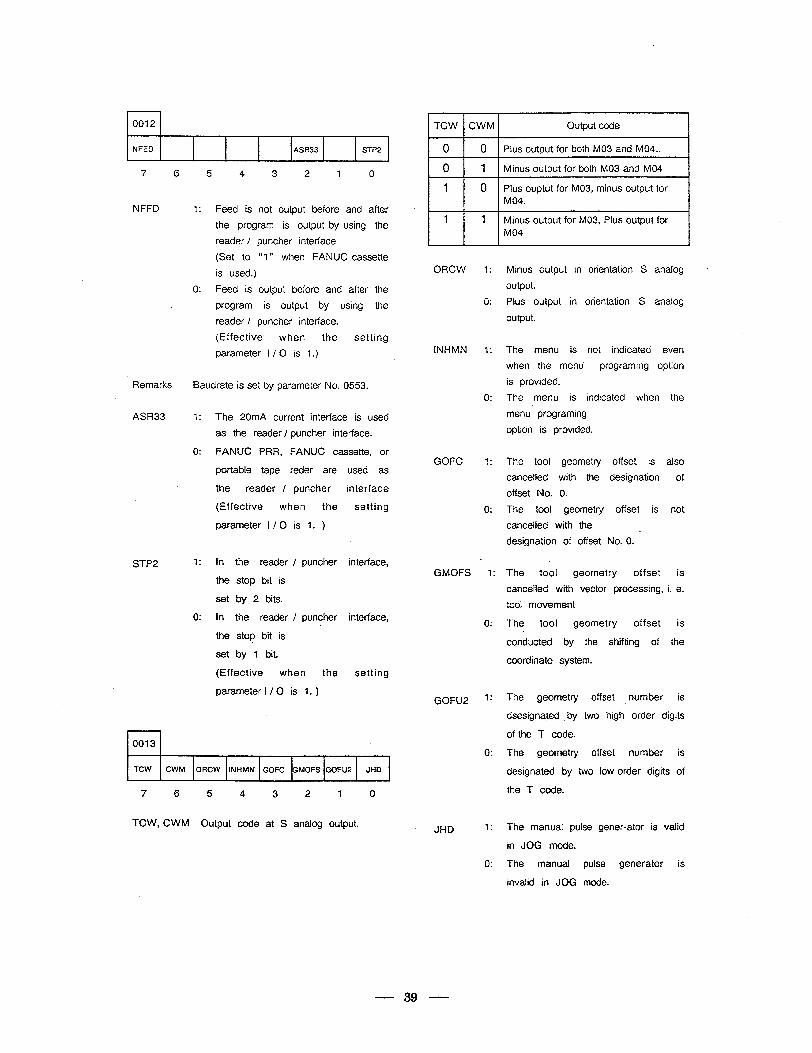
0012
NFED ASR33 STP2 6 \
7 6 5 4 3 2 1 0
NFFD 1:
0:
Feed is not output before and after
the program is output by using the
reader / puncher interface
(Set to ‘Y " when FAN UC cassette
is used.)
Feed is output before and after the
program is output by using the
reader / puncher interface.
(Effective when the setting
parameter I / 0 is 1.)
Remarks Baudrate is set by parameter No. 0553.
ASR33 1: The 20mA current interface is used
as the reader / puncher interface.
0: FANUC PRR, FANUC cassette, or
portable tape reder are used as
the reader / puncher interface
(Effective when the setting
parameter I / Cl is 1. )
STP2 1: In the reader / puncher interface,
the stop bit is
set by 2 bits.
0: In the reader / puncher interface,
the stop bit is
set by 1 bit.
(Effective when the setting
parameter I / 0 is 1. )
rl 0013
TCW CWM ORCW INHMN GOFC GMOFS GOFU2 JHD
7 6 5 4 .3 2 1 0
TCW, CWM Output code at S analog output.
ITCWICWMI Output code
1 0 1 0 1 Pius output for both MO3 and M04.. ,_~~,~ 1~ ,~I Minus output for both MO3 and MO4
Plus ouptut for M03, minus output for
Minus output for M03, Plus output for j ’ 1. ’ lMO4
ORCW 1:
0:
INHMN 1:
0:
GOFC 1:
0:
c GMOFS 1:
0:
GOFU2 ?
0:
. JHD 1:
0:
Minus output in orientation S analog
output.
.
Pius output in orientation S analog
output.
The menu is not indicated even
when the menu programing option
is provided.
The menu is indicated when the
menu programing
option is provided.
The tool geometry offset is also
cancelled with the designation of
offset No. 0.
The tool geometry offset is not
cancelled with the
designation of offset No. 0. i
The tooi geometry offset is
canceiled with vector processing, i. e.
tool movement
The tool geometry offset is
conducted by the shifting of the
coordinate system.
The geometry offset number is
dsesignated _ by two high order digits
of the T code.
The geometry offset number is
designated by two low order digits of
the T code.
The manual pulse gener-ator is valid
in JOG mode.
The manual pulse generator is
invalid in JOG mode.
39
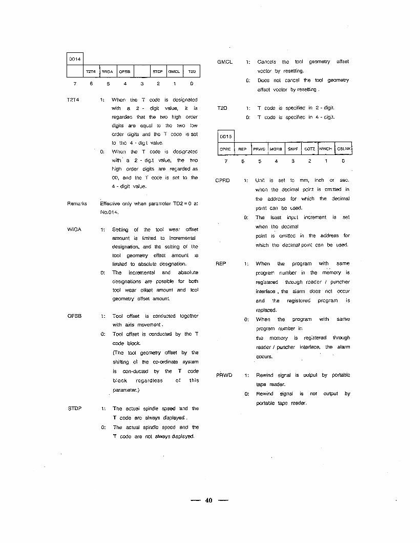
Y
0014
T2T4 WIGA OFSEi STOP GMCL T2D
7 6 5 4 3 2 1 0
T2T4 1: When the T code is designated
with a 2 - digit value, it is
regarded that the two high order
digits are equal to the two low
Remarks Effective only when parameter TD2 = 0 at
WIGA
OFSB
order digits and the T code is set
to !ile 4 - cligit value.
0: When the T code is designated
with a 2 - digit value, the two
high order digits are regarded as
00, and the T code is set to the
4 - digit value.
1: of the tool wear offset
amount is limited to incremental
designation, and the setting of the
tool geometry offset amount is
limited to absolute designation.
0: The incremental and absolute
designations are possible for both
tool wear offset amount and tool
geometry offset amount.
1: Tool offset is conducted together
with &is movement .
0: Too! offset is conducted by the T
code block.
(The tool geometry offset by the
shifting of the co-ordinate system
is con-ducted by the T code
block regardless of this
parameter.)
GMCL -I: Cancels the tool geometry offset
vector by resetting.
0: Does not cancel the tool geometry
offset vector by resetting .
T2D 1: T code is specified in 2 - digit_
0: T code is specified in 4 - digit.
, 0015
CPRD REP PRWD MORB SKPF COT2 NWCH CBLNK ,
7 6
CPRD 1:
I
0:
REP 1:
0:
PRWD I:
0:
5 4 2 , 0
Unit is set to mm, inch or sec.
when the decimal point is omitted in
the address for which the decimal
point can be used.
The least input increment is set
when the decimal
point is omitted in the address for
which the decimal point can be used.
the program same
program number in the memory is
registered through reader / puncher
interface , the alarm does not occur
and the registered program is
replaced.
When the program with same
program number in
the memory is registered through
reader / puncher interface, the alarm
occurs.
Rewind signal is output by portable
tape reader.
Rewind signal is not output by
portable tape reader. STDP 1: The actual spindle speed aand the
T code are always displayed .
0: The actual spindle speed and the
T code are not always displayed.
40..
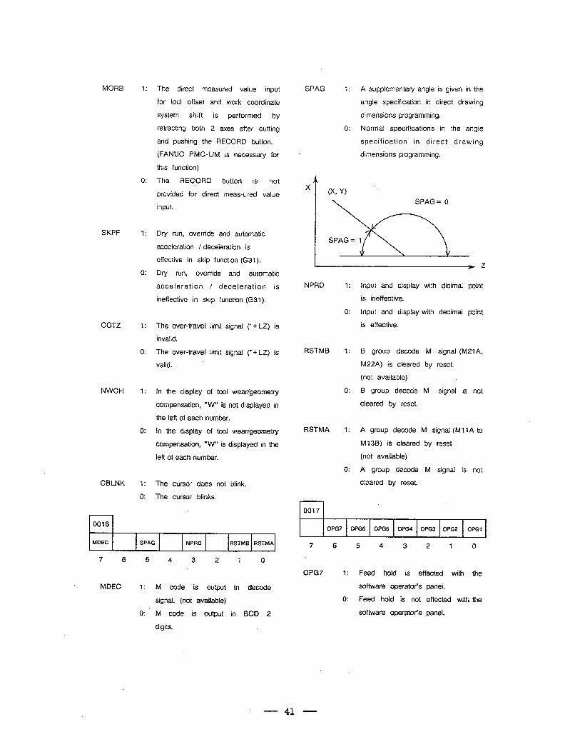
1: The direct measured value input
for tool offset and work coordinate
system shift is performed by
retracting both 2 axes after cutting
and pushing the RECORD button.
(FANUC PMC-L/M is necessary for
this function)
The RECORD button is not
provided for direct meas-ured value
input.
Dry run, override and automatic
acceleration / deceleration is
effective in skip function (G31).
Dry run, override and automatic
acceleration / deceleration is
ineffective in skip function (G31).
The over-travel limit signal r + LZ) is
invalid.
The over-travel limit signal (* + LZ) is
valid.
In the display of tool wear/geometry
compensation, “W” is not displayed in
the left of each number.
In the display of tool wear/geometry
compensation, ‘@W” is displayed in the
left of each number.
The cursor does not blink.
The cursor blinks.
SPAG 1: A supplementary angle is given in the
angle specification in direct drawing
dimensions programming.
0: Normal specifications in the angle
specification in direct. drawing
dimensions programming. a
X 0:
1:
0:
1:
0:
1:
0:
1:
0:
SKPF
NPRD 1: Input and display
is ineffective.
0: Input and display with decimal point
is effective.
RSTMB 1: B group decode M signal (M21A,
M22A) is cleared by reset.
(not available) c
0: B group decode M signal is not
cleared by reset.
RSTMA 1: A group decode M signal (Ml 1 A to
Ml 3s) is cleared by reset
(not available)
0: A group decode M signal is not
cleared by reset.
rl 0017
dicimal point
COTZ
NWCH
CBLNK
0016 I 0PG7 0PG6 OPGS 0PG4 0PG3 OPG2 OPGl c
7 6 5 4 3 2 1 0 MDEC SPAG NPRD RSTMB RSTMA
7 6 5 4 3 2 1 0
0PG7 1: hold with
1: output decode software operator’s panel.
0: Feed hold is not effected with the
software operator’s panel.
signal. (not available)
0: M code
digits.
in BCD 2
41
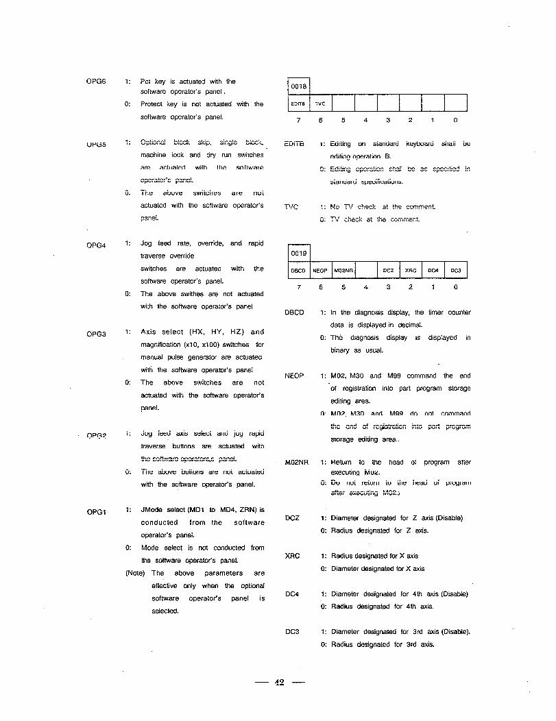
0PG6
0PG5
OPG4
OPG3
OPG2
OPGI
1:
0:
1:
0:
1:
0:
1:
0:
1:
0:
1:
0:
Pet key is actuated with the
software operator’s panel .
Protect key is not actuated with the
software operator’s panel.
Optional block skip, single block,
machine lock and dry run switches
are actuated with the software
operator’s panel.
The above switches are not
actuated with the software operator’s
panel.
t
Jog feed rate, override, and rapid
traverse override
switches are actuated with the
software operator’s panel.
The above swithes are not actuated
with the software operator’s panel
Axis select (HX, HY, HZ) and
magnification (xl 0, x100) switches for
manual pulse generator are actuated
with the software operator’s panel
The above switches are not
actuated with the software operator’s
panel.
Jog feed axis select and jog rapid
traverse buttons are actuated with
the software operators,s panel.
The above buttons are not actuated
with the software operator’s panel.
JMode select (MD1 to MD4, ZRN) is
conducted from the software
operator’s panel.
Mode select is not conducted from
the softvvare operator’s panel.
(Note) The above parameters are
effective only when the optional
software operator’s panel is
selected.
rl 0018
EDITB TVC ,
7 6
EDITB 1:
0:
TVC 1:
0:
rl 0019
5 4 3
Editing on standard
editing operation B.
Editing operation shall
standard specifications.
No TV check at the comment.
2 1 0
keyboard shall
be as specified in
TV check at the comment.
DBCD NEOP M02NR DC2 XRC DC4 DC3 l
7 6 3 2 0
DBCD 1: In the diagnosis display, the timer counter
data is displayed in decimal.
0: The diagnosis display is displayed in
binary as usual.
NEOP 1: M02, M30 and M99 command the end
of registration into part program storage
editing area.
0: M02, M30 and M99 do not command
the end of registration into part program
storage editing area..
M02NR Return to the head of program after
executing M02.
Do not return to the head of program
after executing M02.1
DCZ Diameter designated for Z axis (Disable)
Radius designated for Z axis.
XRC
1:
0:
1:
0:
1:
0:
1:
.o:
1:
0:
Radius designated for X
Diameter designated for
DC4 Diameter designated for 4th axis (Disable)
Radius designated for 4th axis.
DC3 Diameter designated for 3rd axis (Disable).
Radius designated for 3rd axis.
42
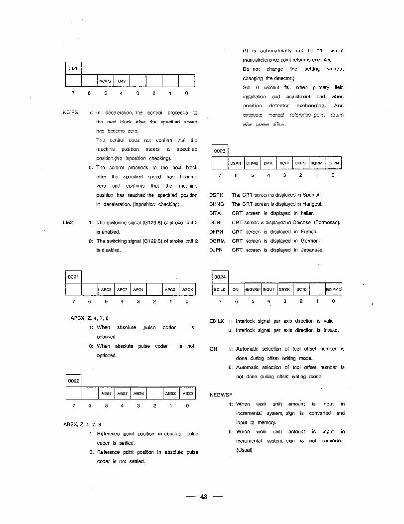
0020
NCIPS LM2 4
7 6 5 4 3 2 1 0
NCIPS I: In deceleration, the control proceeds to
0:
LM2 1:
0:
the next block after the specified speed
has become zero.
The control does not confirm that the
machine position meets a specified
position.(No inposition checking).
The control proceeds to the next block
after the specified speed has become
Zt3-0 and confirms that the machine
position has reached the specified position
in deceleration. (Inposition checking).
The switching signal (G129.6) of stroke limit 2
is enabled.
The switching signal (G129.6) of stroke limit 2
is disabled.
r-l 0021
APC8 APC7 APC4
i APCZ APCX
.
7 6 5 4 3 2 1 0 7 6 5 4 3 2 1 0
APCX, Z, 4, 7, 8
1:
* 0:
When absolute
optioned.
When absolute
optioned.
pulse coder is
pulse coder is not
0022
ABS8 ABS7 ABS4 ABSZ ABSX
7 6 5 4 3 2 1 0
ABSX, Z, 4, 7, 8
1: Reference point position in absolute pulse
coder is settled.
0: Reference point position in absolute pulse
coder is not settled.
(It is automatically set to “1” when
manualreference point return is executed.
Do not change the setting without
. changing the detector.)
Set 0 without fail when primary field
installation and adjustment and when
position detector exchanging. And
exexcute manual reference point return
after power off/on.
, 0023
DSPN DHNG DITA DCHI DFRN DGRM DJPN
7 6 5 4 3 2 1 0
DSPN The CRT screen is displayed in Spanish.
DHNG The CRT screen is displayed in Hangeul.
DITA CRT screen is displayed in Italian
DCHI CRT screen is displayed in Chinese (Formosan).
DFRN CRT screen is displayed in French.
DGRM CRT screen is displayed in German.
DJPN CRT screen is displayed in Japanese.
. , b024
EDILK QNI dEGWSF INOUT GNSR SCTO IGNPMC
EDILK 1: Interlock signal per axis direction is valid.
0: Interlock signal per axis direction is invalid.
QNI 1:
0:
Automatic selection of tool offset number is
done during offset writing mode.
Automatic selection of tool offset number is
not done during offset writing mode.
NEGWSF
1:
0:
When work shift amount is input in
incremental system, sign is converted and
input to memory.
When work shift amount is input in
incremental system, sign is not converted.
(Usual)
43
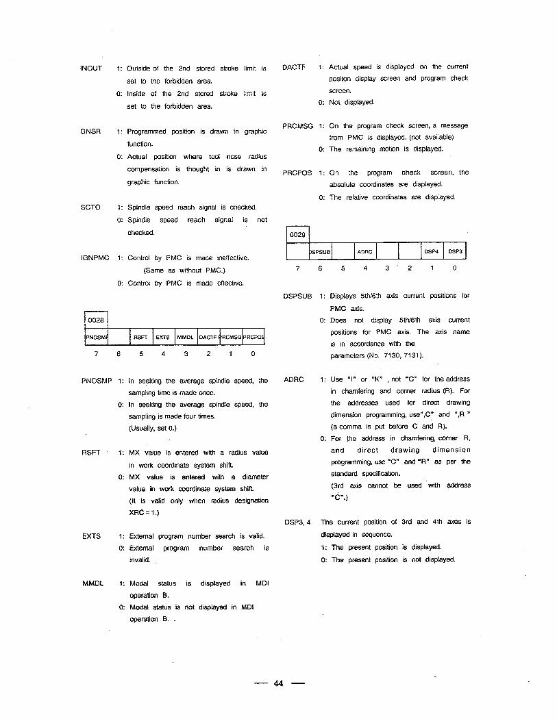
INOUT Outside of the 2nd stored stroke limit is
set to the forbidden area.
Inside of the 2nd stored stroke limit is
set to the forbidden area.
DACTF 1:
0:
GNSR Programmed position is drawn in graphic
function.
PRCMSG 1: On the program check screen, a message
0: Actual position where tool nose radius
compensation is thought in is drawn in
graphic function. PRCPOS 1:
SCTO Spindle speed reach signal is checked.
Spindle speed reach signal is not
checked.
0:
l-l 0029
IGNPMC Control by PMC is made ineffective.
(Same as without PMC.)
Control by PMC is made effective.
0 ISPSUB ADRC
7 6 5 4 3 2 1 0
DSPSUB 1:
rl 0028 0:
PNOSM RSFT EXTS MMDL DACTF ‘RCMSG PRCPOS
RSFT
EXTS
MMDL
.5 4 3 2 1 0
In seeking the average spindle speed, the
sampling time is m&de once.
In seeking the average spindle speed, the
sampling is made four times.
(Usually, set 0.)
MX value is entered with a radius value
in work coordinate system shift
MX value is entered with a diameter
value in work coordinate system shift-
(It is valid only when radius designation
XRC=l.)
External program number search is valid.
External program number search is
invalid.
Modal status is displayed in MDI
operation B.
Modal status is not displayed in MDI
operation B. .
Actual speed is displayed on the current
positon display screen and program check
screen.
Not displayed.
from PMC is displayed. (not available)
The remaining motion is displayed.
On the program check screen,
absolute coordinates are displayed.
The relative coordinates are displayed.
the
. DSP4 DSP3
ADRC 1:
0:
Displays 5thI6th axis current positions for
PMC axis.
Does not display 5th/6th axis current
positions for PMC axis. The axis name
is in accordance with the
parameters (No. 7130, 7131).
Use “I” or “K” , not “C” for the address
in chamfering and corner radius (R). For
the addresses used for direct drawing
dimension programming, use“,C” and “,R ”
(a comma is put before C and R).
For the address in chamfering, corner R,
and direct drawing dimension
programming, use “C” and “R” as per the
standard specification.
(3rd axis cannot be used ‘with address
“CY)
DSP3, 4 The current position of
displayed in sequence.
1: The present position
0: The present position
.
3rd and 4th axes is
is displayed.
is not displayed.
44
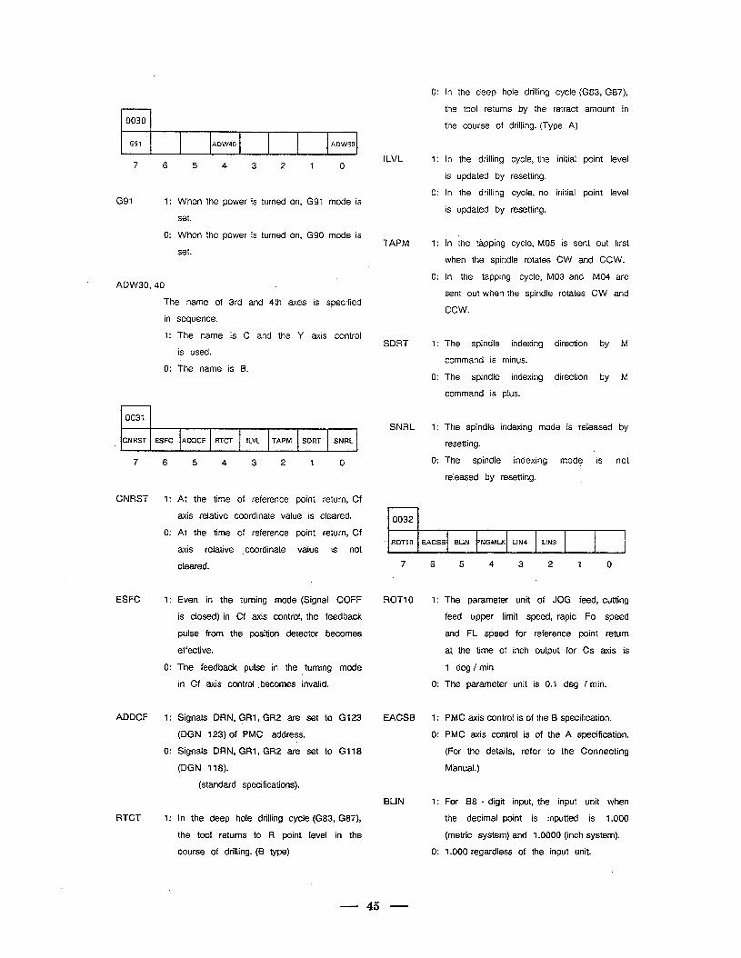
r-l 0030
c91 ADW40 ADW30 L
7 6 5 4 3 2 -I 0
G91 1: When the power is turned on, G91 mode is
set.
0: When the power is turned on, G90 mode is
set.
ADW30,40
The name of 3rd and 4th axes is specified
in sequence.
1: The name is C and the Y axis control
is used.
0: The name is B.
0031
CNRST ESFC AODCF RTCT ILVL TAPM SDRT SNRL e
‘
7 6 5 4 3 2 1 0
CNRST
ESFC
ADDCF
RTCT
1:
0:
1:
0:
1:
0:
1:
At the time of reference point return, Cf
axis relative coordinate value is cleared.
At the time of reference point return, Cf
axis relative . coordinate value is not
cleared.
Even in the turning mode (Signal COFF
is closed) in Cf axis control, the feedback
pulse from the position detector becomes
effective.
The feedback pulse in the turning mode
in Cf axis control .becomes invalid.
Signals DRN, GRl, GR2 are set to G123
(DGN 123) of PMC address.
Signals DRN, GRl, GR2 are set to Gt 18
(DGN 118).
(standard specifications).
In the deep hole drilling cycle (G83, G87),
the tool returns to R point level in the
course of drilling. (B type)
ILVL
TAPM
SDRT
SNRL
0:
1:
0:
1:
0:
1:
0:
1:
0:
In the deep hole drilling cycle (G83, G87),
the tool returns by the retract amount in
the course of drilling. (Type A)
In the drilling cycle, the initial point level
is updated by resetting.
In the drilling cycle, no initial point level
is updated by resetting.
In the tapping cycle, MO5 is sent out first
when the spindle rotates CW and CCW.
In the tapping cycle, MO3 and MO4 are
sent out when the spindle rotates CW and
ccw.
The spindle indexing direction by M
command is minus.
The spindle indexing direction by M
command is plus.
The spindle indexing mode is released by
resetting.
The spindle indexing mode is not
released by resetting. c
rl 0032
ROT10 EACSB BLIN ‘NGMLK LIN4 LIN3
7
ROT1 0
EACSB
BLIN
6
1:
0:
1:
0:
1:
0:
5 4 3 2 1 0
The parameter unit of JOG feed, cutting
feed upper limit speed, rapid Fo speed
and FL speed for reference point return
at, the time of inch output for Cs axis is
1 deg / min
The parameter unit is 0.1 deg / min.
PMC axis control is of the B specification.
PMC axis control is of the A specification.
(For the details, refer to the Connecting
Manual.)
For 88 - digit input, the input unit when
the decimal point is inputted is 1.000
(metric system) and 1.0000 (inch system).
1.000 regardless of the input unit.
45
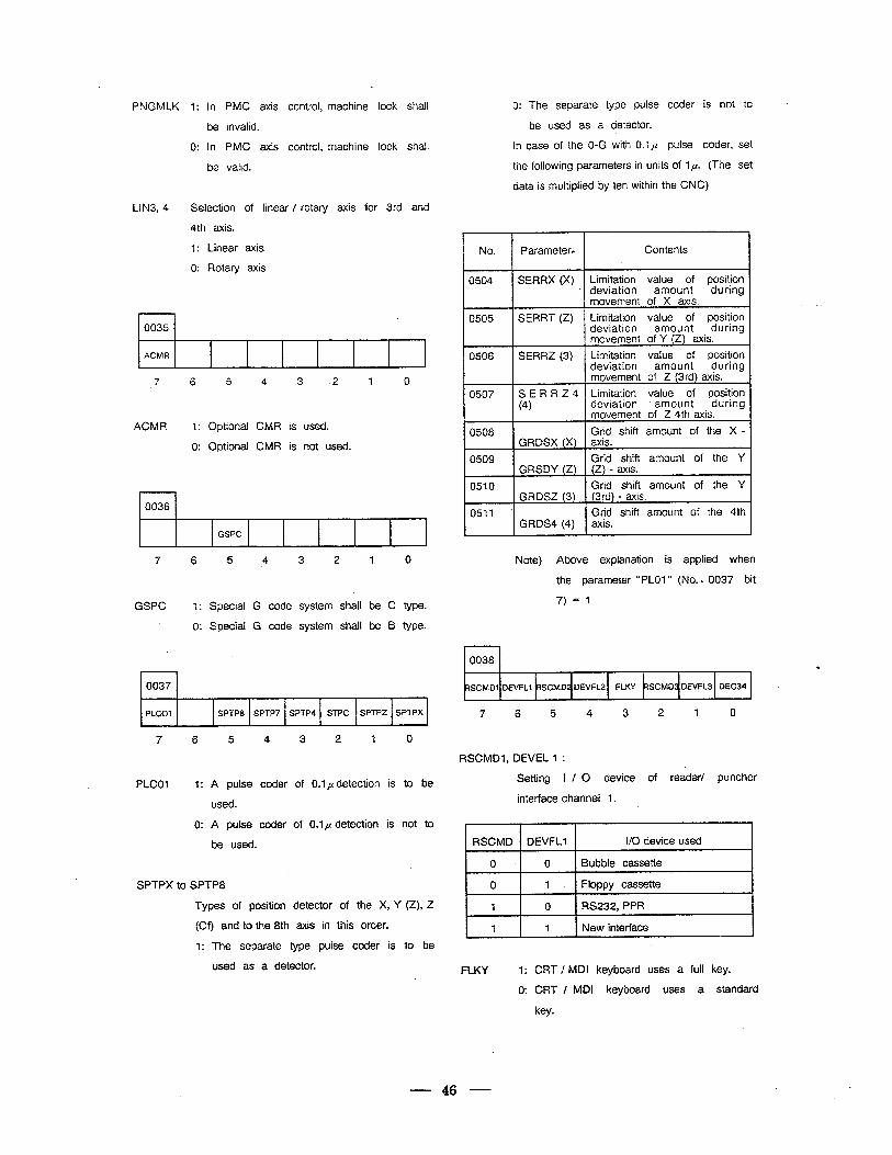
PNGMLK 1: In PMC axis control, machine lock shall 0: The separate type pulse coder is not to
be invalid. be used as a detector.
0: In PMC axis control, machine iock shall
be valid.
In case of the O-G with 0.1,~ pulse coder, set
the following parameters in units of 1,~. (The set
data is multiplied by ten within the CNC)
LlN3, 4 Selection of linear / rotary axis for 3rd and
4th axis.
1: Linear axis
0: Rotary axis
0035 *
ACMR
.7 6 5 4 3 2 1 0
ACMR 1: Optional CMR is used.
0: Optional CMR is not used.
, 0036
GSPC
7 6 5 4 3 2 1 0
GSPC 1: Special G code system shall be C type.
0: Special G code system shall be B type.
0037
PLCOl SPTP8 SPTP7 SPTP4 STPC SPTPZ SPTPX 4
.
7
No. Parameter* Contents
0504 SERRX (X) Limitation value of position deviation amount during movement of X axis.
0505
0506
0507
SERRT (2) Limitation value of position deviation amount during movement of Y (Z) axis.
SERRZ (3) Limitation value of position deviation amount during . movement of Z (3rd) axis.
S E R R Z 4 Limitation value of position (4) deviation . amount during
movement of Z 4th axis.
0508 Grid shift amount of the X - GRDSX (X) axis.
0509 Grid shift amount of the Y GRSDY (Z) (Z) - axis.
0510 Grid shift amount of the Y GRDSZ (3) (3rd) - axis.
0511 ’ Grid shift amount of, the 4th GRDS4 (4) axis.
4
Note) Above explanation is applied when
the parameter “PLO1 ” (No. L 0037 bit
7)=1
1
0038 .
7 6 5 4 3 2 1 0
7 6 5 4 3 2 1 0
RSCMDI, DEVEL 1 :
PLCOl 1: A pulse coder. of 0.1 p detection is to be
used.
0: A pulse coder of 0.1 p detection is not to
be used.
Setting I / 0 device of reader/ puncher
interface channei 1.
RSCMD DEVFLl I/O device used
SPTPX to SPTP8 I 0 I 1 1 Floppy cassette I Types of position detector of the X, Y (Z), Z
(Cf) and to the 8th axis in this order.
1: The separate type pulse coder is to be
used as a detector.
1 0 RS232, PPR
1 1 New interface
FLKY 1: CRT / MDI keyboard uses a
0: CRT / MDI keyboard uses
key.
full key.
a standard
rdIp 0 1 Bubble cassette I
46
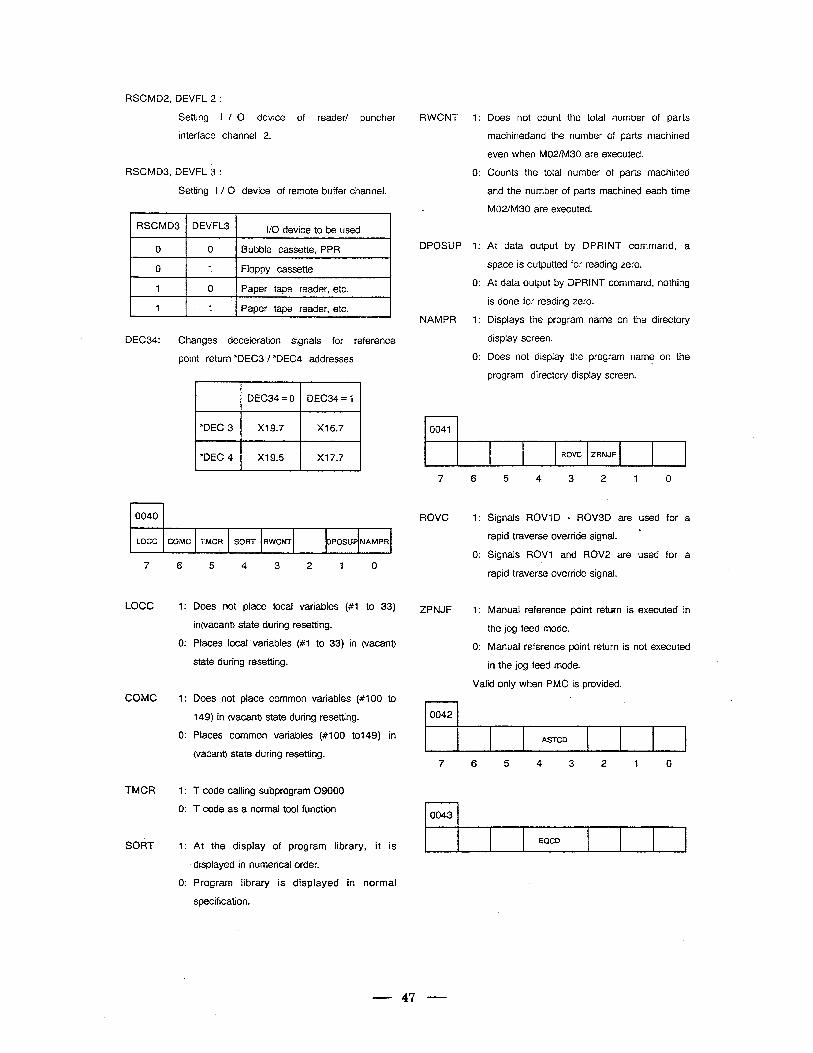
RSCMDi, DEVFL 2 :
Setting I / 0 device of reader/ puncher
interface channel 2.
RWCNT I:
RSCMD3, DEVFL 3 : 0:
Setting I / 0 device of remote buffer channel.
RSCMD3 DEVFL3 I I I/O device to be used I
0 I 0 I Bubble cassette, PPR I
0 I 1 I Floppy cassette I 1 I 0 I Paper tape reader, etc. I 1 -1 Paper tape reader, etc.
DEC34: Changes deceleration signals for reference
point return “DEC3 / *DEC4 addresses
L
t I DEC34 = 0 I
DEC34 = 1 I
I*DEC 3 1 X19.7 1 X16.7
I *DEC 4 I
Xl 9.5 I
Xl 7.7 I
LOCC COMC TMCR SORT RWCNT DPOSlJP NAMPR
7 6 5 4 3 2 1 0
LOCC Does not place local variables (#l to 33)
in(vacant) state during resetting.
Places local’variables (#l to 33) in (vacant)
state during resetting.
COMC Does not place common variables (HO0 to
149) in (vacant) ‘state during resetting.
Places common variables (#IO0 to149) in
(vacant) state during resetting.
TMCR T code calling subprogram 09000
T code as a normal tool function
SORT
1:
0:
1:
0:
1:
0:
1:
0:
At the display of program library, it is
displayed in numerical order.
Program library is displayed in normal
specification.
0040
DPOSUP 1:
0:
NAMPR 1:
0:
rl 0041
Does not count the total number of parts
machinedand the number of parts machined
even when M02/M30 are executed.
Counts the total number of parts machined
and the number of parts machined each time
M 02/M 30 are executed.
At data output by DPRINT command, a
space is outputted for reading zero.
At data output by DPRINT command, nothing
is done for reading zero.
Displays the program name on the directory
display screen.
Does not display the program name
program directory display screen.
on the
c I
ROVC ZRNJF
7 6 5 4 3 2 1 0
ROVC 1: Signals ROWD - ROV3D are used for a
L rapid traverse override signal.
0: Signals ROVl and ROV2 are used for a
rapid traverse override signal.
ZPNJF 1:
0:
Manual reference point return is executed in
the jog feed mode.
Manual reference point return is not executed
in the jog feed mode.
Valid only when PMC is provided.
0042
ASTCD b
7 6 5 4 3 2 1 0
0043
EQCD
- 47 -
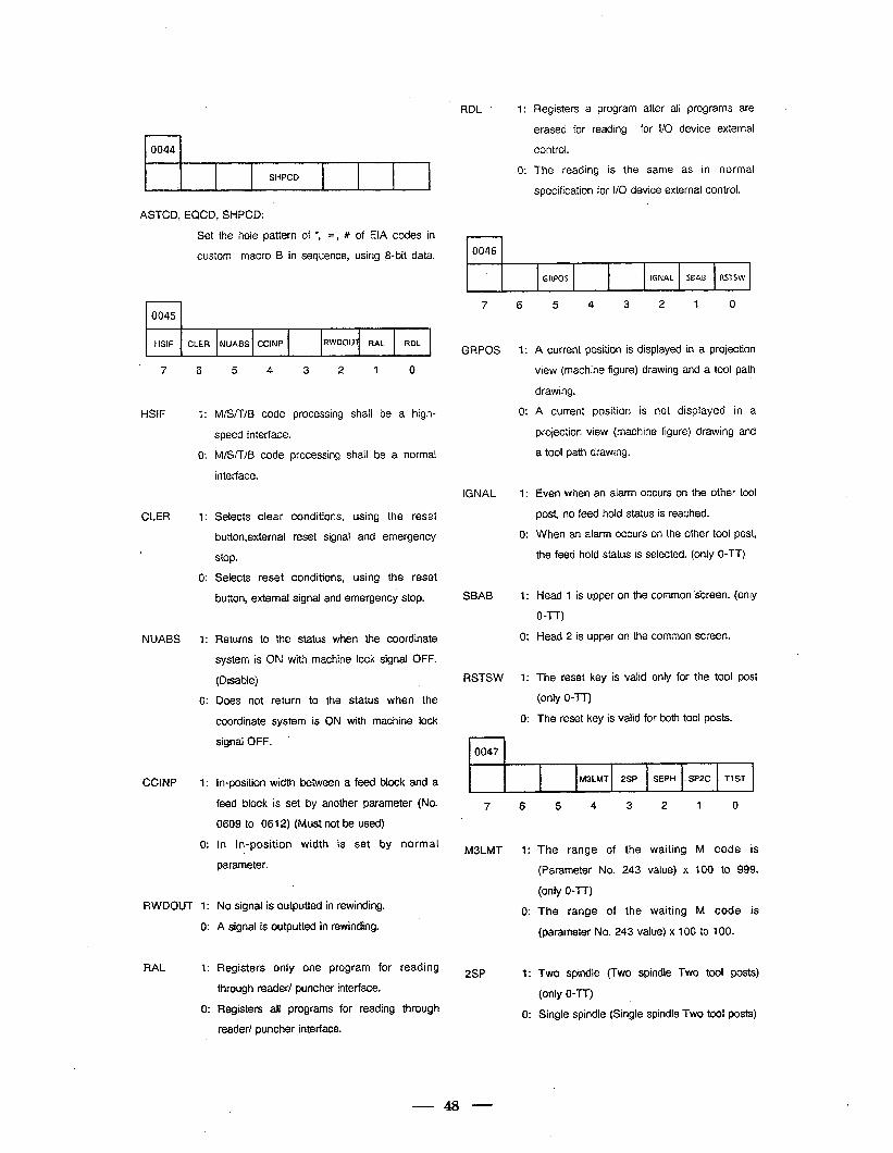
r-l 0044
+ SHPCD
ASTCD, EQCD, SHPCD:
Set the hole pattern of *, =, # of EIA codes in
custom macro B in sequence, using 8-bit data.
4
0045
HSIF CLER NUABS CCINP RWDOUl RAL RDL ,
7 6 5 4 3 2 1 0
HSIF 1:
0:
1:
0:
1:
0:
1:
0:
M/SK/B code processing shall be a high-
speed interface.
M/STT/B code processing shall be a normal
interface.
CLER Selects clear conditions, using the reset
button,external reset signai and emergency
stop.
Selects reset conditions, using the reset
button, external signal and emergency stop.
NUABS Returns to the status when the coordinate
system is ON with machine lock signal OFF.
(Disable)
Does not return to the status when the
coordinate -system is ON with machine lock
signal OFF. ’
CCINP In-position width between a feed block and a
feed block is set by another parameter (No.
0609 to 0612) (Must not be used)
in In-position width is set by normal
parameter.
RWDOUT 1: No signal is outputted in rewinding.
0: A signal is outputted in rewinding.
RAL 1:
0:
Registers only one program for reading
through reader/ puncher interface.
Registers all programs for reading through
reader/ puncher interface.
RDL 1:
0:
i 1
Registers a program after all programs are
erased for reading for l/O device external
control.
The reading is the same as in normal
specification for I/O device external control.
0046
GRPOS IGNAL SBAB RSTSW
7 6
GRPOS
IGNAL
SBAB
RSTSW
1:
0:
1:
0:
1:
0:
5 4 3 2 1 0
A current position is displayed in a projection
view (machine figure) drawing and a toot path
drawing.
A current position is not displayed in a
projection view (machine figure) drawing and
a tool path drawing.
Even when an alarm occurs on the other tool
post, no feed hold status is reached.
When an alarm occurs on the other tool post,
the feed hold status is selected. (only OTT)
Head 1 is upper on the common s’creen. (only
OTT)
Head 2 is upper on the common screen.
The reset key is valid only for the tool post
(only O-IT)
The reset key is valid for both tool posts.
0047
M3LMT 2SP SEPH . SP2C 7-l ST
7 6
M3LMT
2SP
48
5 4 3 2 1 0
The range of the waiting M code is
(Parameter No. 243 value) x 100 to 999.
(only OTT)
The range of the waiting M code is
(parameter No. 243 value) x 100 to 100.
Two spindle (Two spindle Two tool posts)
(only 0-n)
Single spindle (Single spindle Two tool posts)
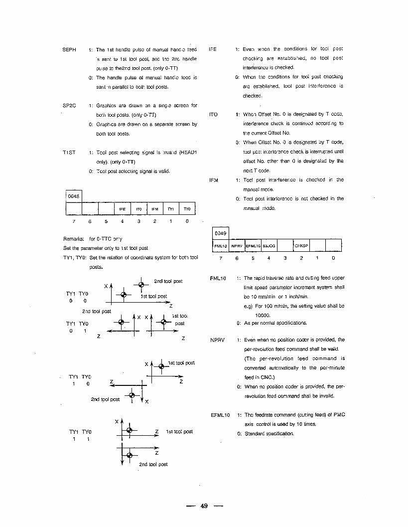
SEPH
SP2C
TI ST
r-l 0048
1:
0:
1:
0:
1:
0:
The 1st handle pulse of manual handle feed
is sent to 1 st tool post, and the 2nd handle
pulse to the2nd tool post. (only OTT)
The handle pulse of manual handle feed is
sent in parallel to both tool posts.
Graphics are drawn on a single screen for
both tool posts. (only 0-T-T)
Graphics are drawn on a separate screen by
both tool posts.
Tool post selecting signal is invalid (HEAD1
only). (only 0-TT)
Tool post selecting signal is valid.
-T
IFE n-0 IFM N7 l-f0 .
7 6 5 4 3 2 1 0
Remarks: for 0-TTC only
Set the parameter only to 1 st tool post
TYI , TYO: Set the relation of coordinate system for both tool
posts.
TYl TYO
. TY1 TYO
i 0
X
TY? TYO
&
z 1 St tool post
1 1
2nd tool post
IFE
IT0
IFM
7:
0:
1:
0:
1:
0:
Even when the conditions for tool post
checking are established, no tool post
interference is checked.
When the conditions for tool post checking
are established, tool post interference is
checked.
When Offset No. 0 is designated by T code,
interference check is continued according to
the current Offset No.
When Offset No. 0 is designated by T code,
tool post interference check is interrupted until
offset No. other than 0 is designated by the
next T code.
Tool post interference is checked in the
manual mode.
Tool post interference is not checked in the
mnaual mode.
rl 0049 ,
FMLIO NPRV EFMLlO S3JOG CHKSP
7 6
FMLlO 1:
0: As per normal specifications.
NPRV 1:
0:
EFMLIO 1:
0:
5 4 3 2 1 0
The rapid traverse rate and cutting feed upper
limit speed parameter increment system shall
be 10 mm/min or 1 inch/min.
e.g) For 100 m/min, the setting value shall be
7 0000.
Even when no position coder is provided, the
per-revolution feed command shall be valid.
(The per-revolution feed command is
converted automatically to the per-minute
feed in CNC.)
When no position coder is provided, the per-
revolution feed command shall be invalid.
The feedrate command (cutting feed) of PMC
axis control is used by 70 times.
Standard specification.
49
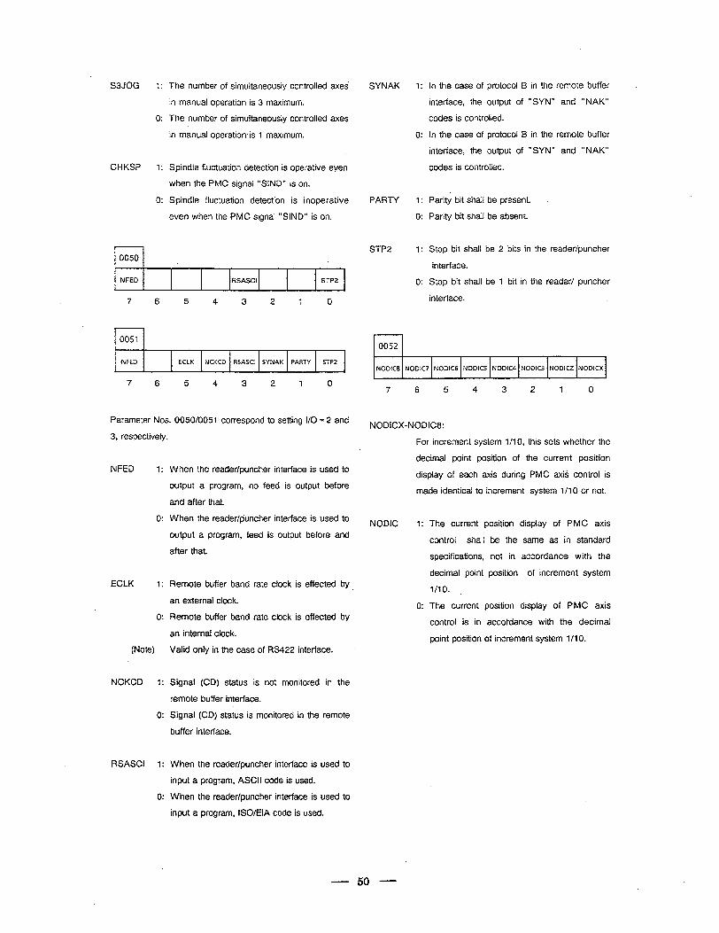
S3JOG
CHKSP
r-l 0050
The number of simultaneously controlled axes
in manual operation is 3 maximum.
The number of simultaneously controlled axes
in manual operation, is 1 maximum.
Spindle fluctuation detection is operative even
when the PMC signal “SIND” is on.
Spindle fluctuation detection is inoperative
even when the PMC signal “SIND” is on.
NFED RSASCI ’ STP2
7 6 5 4 3 2 1 0
I I 10051 1 #
,NFED ECLK NCKCD RSASCI SYNAK PARTY STP2 1 ,
7 6 5 4 3 2 1 0
Parameter Nos. 0050/0051 correspond to setting i/O = 2 and
3, respectively.
NFED 1:
0:
ECLK I:
0: Remote buffer band rate clock is effected by
an internal clock.
(Note) Valid only in the case of RS422 interface.
NCKCD 1:
0:
RSASCI 1:
0:
When the reader/puncher interface is used to
output a program, no feed is output before
and after that.
When the reader/puncher interface is used to
output a program, feed is output before and
after that.
Remote buffer band rate clock is effected by
an external clock.
Signal (CD) status is not monitored in the
remote buffer interface.
Signal (CD) status is monitored in the remote
buffer interface.
When the reader/puncher interface is used to
input a program, ASCII code is used.
When the reader/puncher interface is used to
input a program, ISO/EIA code is used.
SYNAK 1: in the case of protocol B in the remote buffer .
interface, the output of “SYN” and ” NAK"
codes is controlled.
0: in the case of protocol B in the remote buffer
interface, the output of “SYN” and ” NAK"
codes is controlled.
PARTY 1: Parity bit shall be present.
0: Parity bit shall be absent.
STP2 1: Stop bit shall be 2 bits in the reader/puncher
interface.
0: Stop bit shall be 1
interface.
bit in the reader/ puncher
rl 0052
NODIC8 NODIC7 NODIC6 NODICS NODICQ NODiC3 NODICZ NODICX
7 6 5 4 3 2 1 0
NODICX-NODiC8:
For increment system l/l 0, this sets whether the
decimal point position of the current position
display of each axis during PMC axis control is
made identical to increment system l/l 0 or not.
NODIC 1:
0:
The current position display of PMC axis
control shall be the same as in standard
specifications, not in accordance with the
decimal point position of increment system
l/10. ,
The current position display of PMC axis
control is in accordance with the decimal
point position of increment system 1 /l 0.
- 50 -
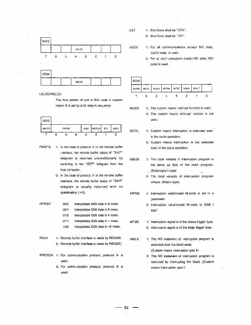
0053
LBLCD c
7 6 5 4 3 2 1 0
0054
RBLCD 4
LBLCDIRBLCD:
The hole pattern of and in EIA code in custom
macro B is set by 8-bit data in sequence.
10055 1 .
RMSTS ITPCNT RS42 PROTCA ETX ASCII
7 6 5 4 3 2 -I 0
RMSTS in the case of protocol A in the remote buffer
interface, the remote buffer status of “SAT”
telegram is returned unconditionally by
switching to the “SET” telegram from the
host computer.
In the case of protocol A in the remote buffer
interface, the remote buffer status of “SAT”
telegram is usually returned with no
specification ( = 0).
ITPCNT 000: Interpolates GO5 data in 8 msec.
001: Interpolates GO5 data in 2 msec.
010: Interpolates GO5 data in 4 msec.
011: interpolates GO5 data in 1 msec.
RS42
100: Interpolates GO5 data in 16 msec.
Remote buffer interface is made by RES422.
Remote buffer interface is made by RS232C.
PROTCA For communication
used.
For communication
used.
protocol; protocol A is
protocol, protocol B is
EXT 1: End Code shall be ” ETX”.
0: End Code shall be “CR”.
ASCII 1: For all communications except NC data,
0:
ASCII code is used.
For all communications except NC data, IS0
code is used.
rl 0056
MUSR MCYL MSUB MPRM MTSE MBLK MSKT 1
7 6
MUSR
MCYL
MSUB
MPRM
MTSE
MBLK
1:
0:
1:
0:
1:
c
0:
1:
0:
7:
0:
1:
0:
5 4 3 2 1 0
The custom macro interrupt function is used.
The custom macro interrupt function is not
used.
Custom macro interruption is executed even
in the cycle operation.
Custom macro interruption is not executed
even in the cycle operation.
The local variable of interruption program is
the same as that of the main program.
(Subprogram type) .
The local variable of interruption program
unique. (Macro type)
Interruption valid/invalid M-code is set in a
parameter.
Interruption valid/invalid M-code is M96 /
M97.
Interruption signal is of the status trigger type.
Interruption signal is of the edge trigger type.
The NC statement of interruption program is
executed after the block ends.
(Custom macro interruption type II)
The NC .statement of interruption program is
executed by interrupting the block. (Custom
macro interruption type I)
51
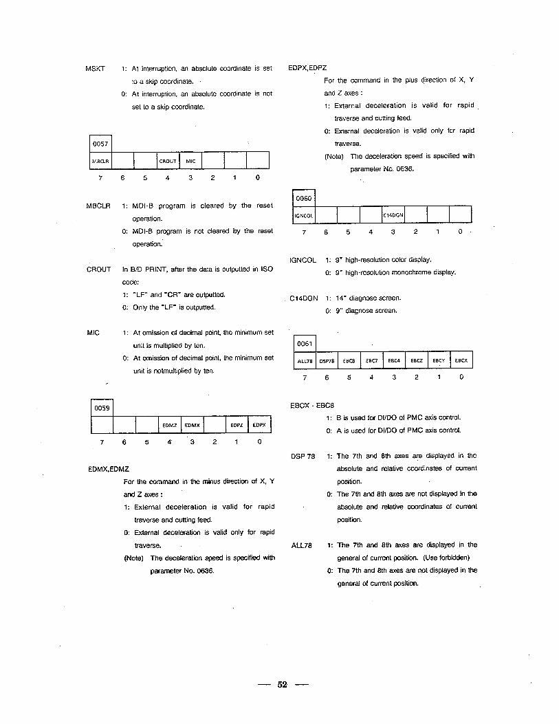
MSKT 1: At interruption, an absolute coordinate is set EDPX;EDPZ
to a skip coordinate.
0: At interruption, an absolute coordinate is not
set to a skip coordinate.
0057
MBCLR CROUT MIC
7 6 5 4 3 2 1 0
MBCLR
CROUT
MIC
1: MDI-B program is cleared by the reset
operation.
0: MDI-B program is not cleared by the reset
operation.’
In B/D PRINT, after the data is outputted in IS0
code:
” LF” and %R” are outputted.
Only the “LF” is outputted.
At omission of decimal point, the minimum set
unit is multiplied by ten.
At omission of decimal point, the minimum set
unit is notmultiplied by ten.
1
0059
.
EDMZ EDMX EDPZ EDPX i
7 6 5 4’ 3 2 1 0
EDMX,EDMZ
For the command in the minus direction of X, Y
DSP78 1: The 7th and 8th axes are displayed in the
absolute and relative coordinates of current
position.
The 7th and 8th axes are not displayed in the
absolute and relative coordinates of current
position.
andzaxes: ’ 0:
1: External deceleration is valid for rapi
traverse and cutting feed.
d
0: External deceleration is valid only for rapid
traverse. -
(Note) The deceieration speed is specified with
parameter No. 0636.
For the command in the plus girection of X, Y
and Z axes :
1: External deceleration is valid for rapid
traverse and cutting feed.
0: External deceleration is valid only for rapid
traverse.
(Note) The deceleration speed is specified with
parameter No. 0636.
0060
IGNCOL C14DGN
7 '6 5 4 3 2 1 0.
IGNCOL 1: 9” high-resolution color display.
0: 9” high-resolution monochrome display.
C14DGN 1: 14" diagnose screen.
0: 9” diagnose screen.
l-l 0061
ALL78 DSP78
7 6 5 4 3 2 1 0
EBCX - EBC8
1: B is used for DI/DO of PMC axis control.
0: A is used for DVDO of PMC axis control.
ALL78 1:
0:
The 7th and 8th axes are displayed in the
general of current position. (Use forbidden)
The 7th and 8th axes are not displayed in the
general of current position.
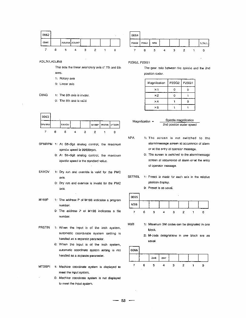
t 0062
CSNG ADLINS ADLIN7 L
7 6 5 4 3 2 I 0
ADLIN-/,ADLIN8
This sets the linear axis/rotary axis of 7th and 8th
axes.
I : Rotary axis
0: Linear axis
C8NG I: The 8th axis is invalid.
0: The 8th axis is valid.
I0063 1 I
SPMRPM 1
EAXOV M 198P PRSTIN MTDSPI
7 6
SPMRPM 1:
0:
EAXOV I:
0:
MI98P 1:
0:
PRSTIN 1: When the input is of the inch system,
0:
MTDSPI I:
. 0:
5 4 3 2 I 0
At %-digit analog control, the maximum
spindle speed is 99999rpm.
At %-digit analog control, the maximum
spindle speed is the standard value.
Dry run and override is valid for the PMC
axis.
Dry run and override is invalid for the PMC
axis.
The address P of Ml 98 indicates a program
number.
The address P of Ml 98 indicates a file
number. .
automatic coordinate system setting is
handied as a separate parameter.
When the input is of the inch system,
automatic coordinate system setting is not
handted as a separate parameter.
Machine coordinate system is displayed to
meet the input system.
Machine coordinate system is not displayed
to meet the input system.
0064
P2SG2 PZSG 1 NPA SETREL
7 6 5 4 3 2 I 0
P2SG2, P2SG1
The gear ratio between the spindle and the 2nd
position coder.
Magnification P2SG2 P2SGI
XI 0 0
x2 0 1
x4 I 0
x8 I I 1
Magnification = Spindle magnification
2nd position coder speed
NPA I:
0:
SETREL I:
0:
The screen is not switched to the
alarm/message screen at occurrence of alarm
or at the entry of operator message.
The screen is switched to the afarm/message
screen at occurrence of alarm or&at the entry
of operator message.
Preset is made for each axis in the relative
position display.
Preset is as usual.
a
M3B
7 6 5 4 3 2-I 0
M3B 1: Maximum 3M codes can be disignated in one
block.
2: M-code designations in .one block are as
usual.
rl 0066
ZM8 ZM7
7 6 5 4 3 2 1 0
- 53 -
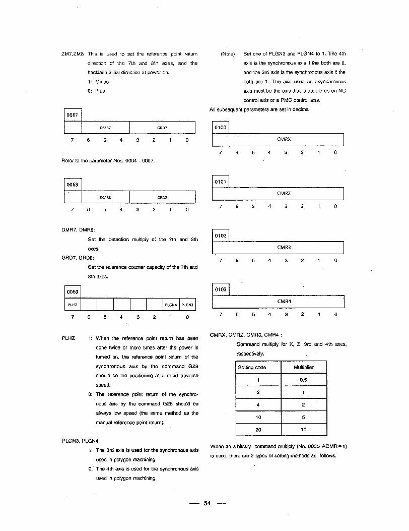
ZM7,ZM8
1 0067
This is used to set the reference point return
direction of the 7th and 8th axes, and the
backlash initial direction at power on.
1: Minus
0: Pius
(Note) Set one of PLGN3 and PLGN4 to 7. The 4th
axis is the synchronous axis if the both are 0,
and the 3rd axis is the synchronous axis if the
both are 1. The axis used as asynchronous
axis must be the axis that is usable as an NC
control axis or a PMC control axis.
All subsequent parameters are set in decimal
I DMR7 I GRD7
7 6 5 4 3 2 1 0 CMRX I
7 6 5 4 3 2 1 0
Refer to the parameter Nos. 0004 - 0007.
r-l 0068
I DMR8 I
CRD8 I
7 6 5 4 3 2 1 0
DMR7, DMR8:
Set the detection multiply of the 7th and 8th
axes.
GRD7, GRD8:
Set the reference counter capacity of the 7th and
8th axes.
I I 0069
PLHZ PLGN4 PLGN3 ‘
7 6 5 4 3 2 1 0
PLHZ 1: When the reference point return has been
done twice or more times after the power is
turned on, the reference point return of the
synchronous axis by the command G28
should be the positioning at a rapid traverse
speed.
0: The reference point return of the synchro-
nous axis by the command G28 should be
always low speed (the same method as the
manual reference point return).
PLGNS, PLGN4
1:
0:’
The 3rd axis is used for the synchronous axis
used in polygon machining.
The 4th axis is used for the synchronous axis
used in polygon machining.
rl 0101
I CMRZ I
7 6 5 4 3 2 1 0
I CMR3 I
7 6 5 4 3 2 1 0
c
rl 0103
I CMR4 I
7 6 5 4 3 2 1 0
CMRX, CMRZ, CMR3, CMR4 :
Command multiply for X, Z, 3rd and 4th axes,
respectively.
Setting code ’ Multiplier
1 0.5
2 1
* 4 2
10 5
20 10
When an arbitrary command multiply (No. 0035 ACMR =l)
is used, there are 2 types of setting methods as follows.
54
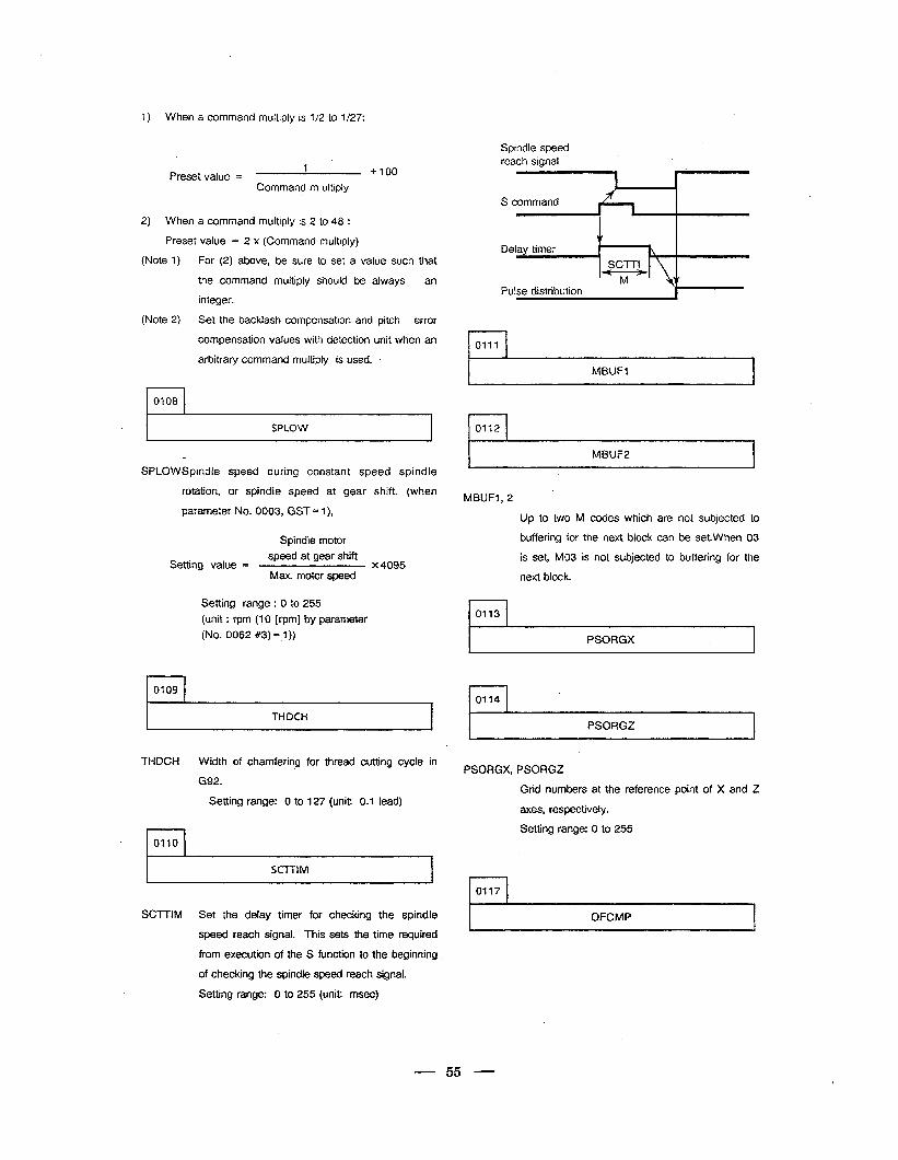
Spindle speed reach signal
1) When a command multiply is l/2 to l/27:
1 Preset value = +100
Command m ultiply
S command
Pulse distribution -
2) When a command multiply is 2 to 48 :
Preset value = 2 x (Command multiply)
(Note 1) For (2) above, be sure to set a value such that
the command multiply should be always an
integer.
(Note 2) Set the backlash compensation and pitch error
compensation values with detection unit when an
arbitrary command multiply is used. . l-l 0111
r- MBUF1 I
r-l 0108
. I SPLOW ~~ I
r MBUF2 I
SPLOWSpindJe speed during constant speed spindle
rotation, or spindle speed at gear shift. (when
parameter No. 0003, GST = I),
MBUFl, 2
Up to two M codes which are not subjected to
Setting value = speed at gear shift
x 4095 Max. motor speed
Spindle motor buffering for the next block can be set.When 03
is set, MO3 is not subjected to buffering for the c
next block.
Setting. range : 0 to 255
(unit : rpm (10 [rpm] by parameter
(No. 0062 #3) = ,I ))
r-l 0113
r PSORGX
r-l 0109
I THDCH PSORGZ
THDCH Width of chamfering for thread cutting cycle in
G92.
Setting range: 0 to 127 (unit: 0.1 lead)
PSORGX; PSORGZ
Grid numbers at the reference point of X and Z
axes, respectively.
Setting range: 0 to 255
r-l 0110
I SCTTIM I
l-l 0117
r OFCMP SCllIM Set the delay timer for checking the spindle
speed reach signal. This sets the time required
from execution of the S function to the beginning
of checking the spindle speed reach signal.
Setting range: 0 to 255 (unit: msec)
55
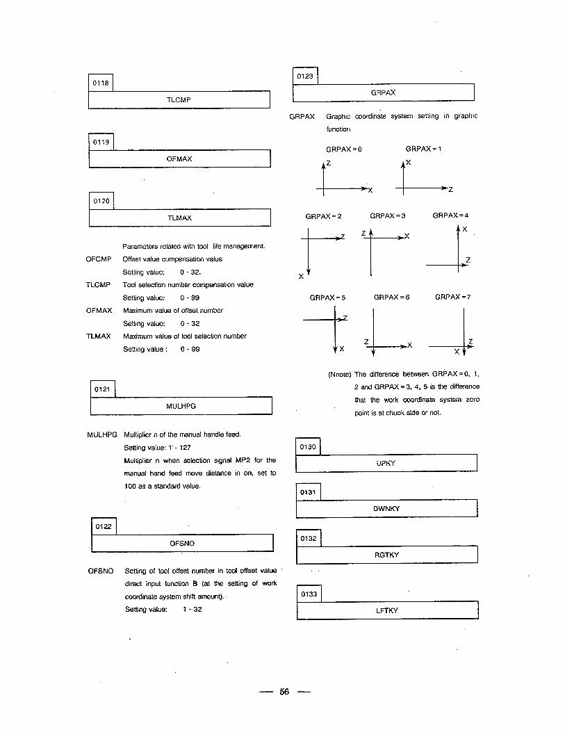
r-l 0123 l-l 0118
TLCMP
l-l 0119
I OFMAX I
l-l 0120
I TLMAX I
Parameters related with tool life management.
OFCMP Off set value compensation value
Setting value; 0 - 32.
TLCMP Tool selection number compensation value
Setting value: 0 - 99
OFMAX Maximum value of offset number
Setting value: 0 - 32
TLMAX Maximum value of tool selection number
Setting value : 0 - 99
l--l 0121
I MULHPG
MULHPG
n 0122
Multiplier n of the manual handle feed.
Setting value: 1’ - 127
Multiplier n when selection signal MP2 for the
manual hand feed move distance in on, set to
100 as a standard value.
.I OFSNO I
OFSNO Setting of tool offset number in tool offset value
direct input function B (at the setting of work
coordinate system shift amount).
Setting value: l-32
r-- GRPAX
GRPAX Graphic coordinate system setting in graphic
function
GRPAX = 0 GRPAX = 1
GRPAX = 2
X +
GRPAX =5
i--
i X
GRPAX = 3
Z
+”
GRPAX = 6
GRPAX = 4
X
-1. Z
GRPAX = 7
--L Z X
(Nnote) The difference between GRPAX = 0, 1,
2 and GRPAX = 3, 4, 5 is the difference
that the work coordinate system zero
point is at chuck side or not.
l-l 0130
UPKY
f 0131
I 9
DWNKY
0132
RGTKY
r-l 0133
I LFTKY I .
56
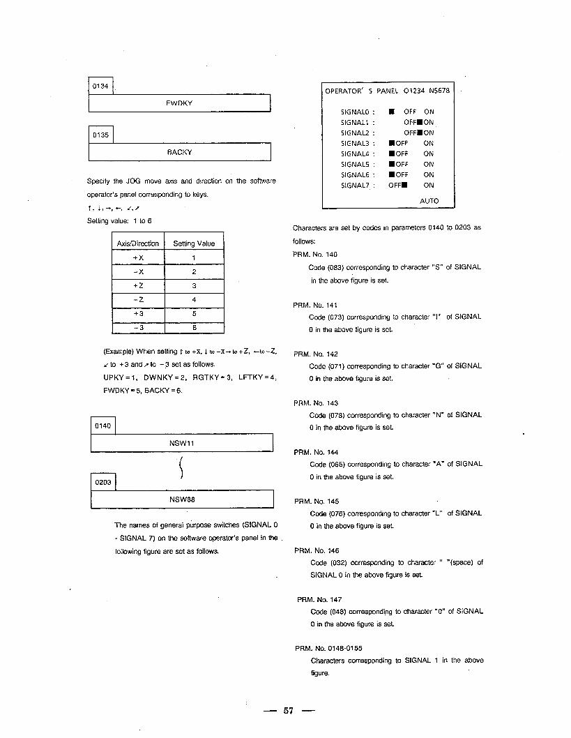
r-l 0134
I FWDKY I
I BACKY I
. Specify the JOG move axis and direction on the software
operator’s panel corresponding to keys.
f, 193, +, *(,f
Setting value: 1 to 6
Axis/Direction Setting Value
+3 5
-3 6
(Example) When setting T to +x, 1 to -x+to +Z, +to -Z,
/to +3andrto - 3 set as follows.
UPKY = 1, DWNKY = 2, RGTKY = 3, LFTKY =4,
FWDKY = 5, BACKY = 6.
0140 .
NSWt1
r-l 0203
I NSW88 I
The names of general purpose switches (SIGNAL 0
- SIGNAL 7) on the software operator’s panel in the
following figure are set as follows.
OPERATOR’ S PANEL 01234 N5678
SIGNAL0 : H OFF ON
SIGNAL? : OFFmON
SIGNAL2 : OFFBON
SIGNAL3 : DOFF ON
SIGNAL4 : aOFF ON
SIGNALS : MOFF ON
SIGNAL6 : HOFF ON
SIGNAL7 : OFFm ON
AUTO
Characters are set by codes in parameters 0140 to 0203 as
follows:
PRM. No. 140
Code (083) corresponding to character “S” of SIGNAL
in the above figure is set.
PRM. No. 141
Code (073) corresponding to character “I” of SIGNAL
0 in the above figure is set.
PRM. No. 142
Code (071) corresponding to character “G” of SIGNAL
0 in the above figure is set. 2.
PRM. No. 143
Code (078) corresponding to character “N” of SIGNAL
0 in the above figure is set.
PRM. No. 144
Code (065) corresponding to character “A” of SIGNAL
0 in the above figure is set.
PRM. No. 145
Code (076) corresponding to character “L” of SIGNAL
0 in the above figure is set.
PRM. No. 146
Code (032) corresponding to character ” “(space) of
SIGNAL 0 in the above figure is set.
PRM. No. 147
Code (048) corresponding to character “0” of SIGNAL
0 in the above figure is set.
PRM. No. 0148-0155
Characters corresponding to SIGNAL 1 in the above
figure.
- 57 -
PRM.No.0156-0163 PRM.No.0188-0195
Characters corresponding to SIGNAL 2 in the above Characters corresponding to SIGNAL 6 in the above
figure. figure.
PRM. No.0164-0171
Characters corresponding to SIGNAL 3 in the above
figure.
PRM.No.0196-0203
Characters corre-sponding to SIGNAL 7 in the
above figure.
PRM. No.Olz-0179
Characters corresponding to SIGNAL 4 in the above
figure.
For character codes, refer to the characters-to-codes
table in the next page.
Setting value 0 is a space.
PRM.No.0180-0187
Characters corre-sponding to SIGNAL 5 in the above
figure.
- 58 -
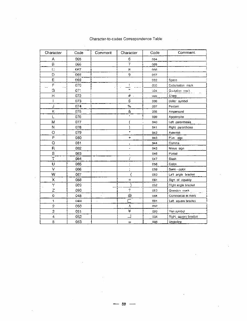
Character-to-codes Correspondence Table
, Character Code Comment Character Code Comment
A 065 ’ 6 054
B 066 7 055
C 067 8 056
D 068 9 057 I
E 069 032 Space
F 070 ! 033 Exclamation mark
G 071 II 034 Quotation mark
H 072 # 035 Sharp
I 073 $ 036 Dollar symbol
J 074 % 037 Percent
K 075 & 038 Ampersand
L 076 3 039 Apostrophe
M 077 ( 040 Left parenthesis
N 078 ) 041 Right parenthesis
0 079 * 042 Asterrisk
P 080 + 043 Pius sign
Q 081 ? 044 Comma
R 082 045 Minus sign
S 083 . Period . 046
T 084 / 047 Slash A
U 085 . . 058 Colon
V 086 . 1 059 Semi - colon
w 087 ! ( 060 Left angle bracket
X I 088 061 Sign of equality
Y 089 1 062 Right angle bracket
z 090 ? 063 Question mark
0 048 @ 064 Commercial at mark
1 049 L 091 Left square bracket
2 050 A 092
3 051 Y 093 Ye? symbol
4 052 z 094 Right square dracket
5 053 095 Underline ,
- 59 -
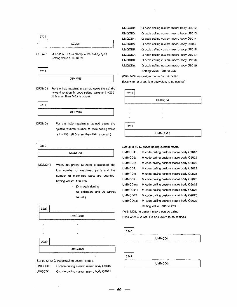
r-l 0204
CCLMP
CCLMP M-code of C-axis clamp in the drilling cycle
Setting value : 00 to 99
l-l 0212
I DFXM03 I
DFXM03 For the hole machining canned cycle the spindle
forward rotation M code setting value is 1 - 255.
(If 0 is set then MO3 is output.)
rl 0213
I DFXM04 I
DFXM04 For the hole machining canned cycle the
spindle reverse rotation M code setting value
is l-255. (If 0 is set then MO4 is output.)
( 0219 . I I MCDCNT
MCDCNT
I I 0220
When the preset M code is executed, the
total number of machined parts and the
number of machined parts are counted.
Setting value: 7 to 255
. (0 is equivalent to
no setting.98 and 99 cannot
be set.)
I UMGCDO I
UMGCD2:
UMGCD3:
UMGCD4:
UMGCDS:
UMGCDG:
UMGCD7:
UMGCD8:
UMGCDS:
G code calling custom macro body 09012 .
G code calling custom macro body 09013
G code calling custom macro body 09014
G code calling custom macro body 09015
G code calling custom macro body 09016
G code calling custom macro body 09017
G code calling custom macro body 09018
G code calling custom macro body 09019
Setting value: 001 to 225
(With MOO, no custom macro can be called.
Even when 0 is set, it is equivalent to no setting.)
rl 0230
UMMCD4
. .
. .
. .
rl 0239
I UMMCD13 I
Set up to 10 M codes calling custom macro.
UMMCD4: M code calling custom macro body 09020
UMMCDS: M code calling custom macro body 09021
UMMCDG: M code calling custom macro body 09022
UMMCD7: M code calling custom macro body 09023
UMMCD8: M code calling custom macro body 09024
UMMCDS: M code calling custom macro body 09625
UMMCDlO: M code calling custom macro body 09026
UMMCDll: M code calling custom macro body 09027
UMMCDl2: M code calling custom macro body 09028
UMMCD13: M code calling custom macro body 09029
Setting value: 006 to 255 .
(With MOO, no custom macro can be called.
Even when 0 is set, it is equivalent to no setting.)
.
rl 0240
I UMMCDl I
I UMGCDS I rl 0241
Set up to 10 G codes calling custom macro.
UMGCDO: G code calling custom macro body 09010
UMGCDl: G code calling custom macro body 09011
UMMCD2 c
60 -
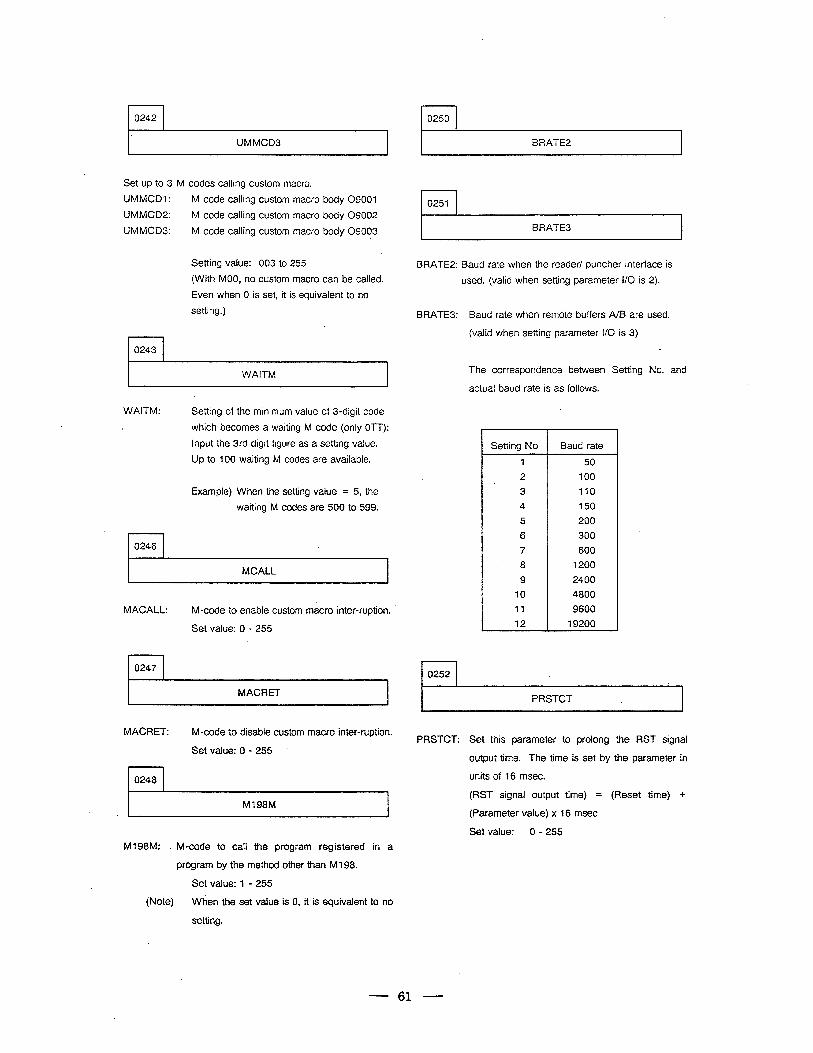
rl 0242 0250
I’ UMMCD3 I
Set up to 3 M codes calling custom macro.
UMMCDI:
UMMCD2:
UMMCD3:
M code calling custom macro body 09001
M code calling custom macro body 09002
M code calling custom macro body 09003
r-l 0243
Setting value: 003 to 255
(With MOO, no custom macro can be called.
Even when 0 is set, it is equivalent to no
setting.)
I WAITM I
WAITM: Setting of the minimum value of 3-digit code
which becomes a waiting M code (only OTT):
Input the 3rd digit figure as a setting value.
Up to 100 waiting M codes are available.
Example) When the setting value = 5, the
waiting M codes are 500 to 599.
l-l 0246
MCALL I
MACALL: M-code to enable custom macro inter-ruption.
Set value: 0 - 255
rl 0247
I MACRET I
MACRET: M-code to disable custom macro inter-ruption.
Set value: 0 - 255
I I 0248
M798M 1 A
M198M: . M-code to call the program registered in a
program by the method other than M 198.
Set value: 1 - 255
(Note) When the set value is 0, it is equivalent to no
setting.
BRATE2
0251
BRATE3 .
BRATE2: Baud rate when the reader/ puncher interface is
used. (valid when setting parameter l/O is 2).
BRATE3: Baud rate when remote buffers A/B are used.
(valid when setting parameter l/O is 3)
1 1 1 0252 1
The correspondence between Setting No. and
actual baud rate is as follows.
Setting No Baud rate
1 50
2 100
3 110
4 150
5 200
6 300
7 600
8 1200
9 2400
10 4800
11 9600
12 19200
PRSTCT .
PRSTCT: Set this parameter to prolong the RST signal
output time. The time is set by the parameter in
units of 16 msec.
(RST signal output time) = (Reset time) +
(Parameter value) x 16 msec.
Set value: 0 - 255
61
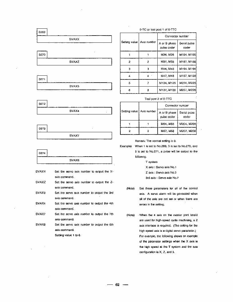
? 0269
SVAXX
. 0270
SVAXZ A
. 1 0271
SVAX3 .
t 0272
SVAX4 4
I
0273
7 SVAX7
0274 4
SVAX8
SVAXX
SVAXZ
SVAX3
SVAX4
SVAX7
SVAX8
Set the servo axis number to output the X-
axis command.
Set the servo axis number to output the Z-
axis command.
Set the servo axis number to output the 3rd
axis command.
Set the. sewo axis number to output Jhe 4th
axis command.
Set the servo axis number to output the 7th
axis command.
Set the servo axis number to output the 8th
axis command.
Setting value 1 to 6.
Setting value Axis number >I
1
2
1 I M34, M35 I M184, Ml85 I
2 1 M37, M38 1 Ml87, MN381
3
4 k 5
I 6
0-TC or tool post 1 of 0-TTC
3 I M44, M45 I
M194, Ml95 I
4 I M47, M48 I Ml 97, MI 98 I I
7 M134, Ml35 M224., M225
8 M137, Ml38 M227, M228
Tool post 2 of 0-TTC
I Connector number I Setting value
1 1 M64, M65 M204, M205 ’
2 2 M67, M68 M207, M208
Remark: The normal setting is 0.
Example) When 1 is set to No.269, 3 is set to No.270, and
5 is set to No.271, a pulse will be output to the
following.
(Note)
(Note)
T system
X axis : Servo axis No.1
Z axis : Servo axis No.3
3rd axis : Servo axis No.7
Set these parameters for all of the control
axis. A servo alarm will be generated when
all of the axis are not set or when there are
errors in the setting.
When the 4 axis on the master print botid
are used for high-speed cycle machining, a 2
axis interface is required. (The setting for the
high-speed axis is a digital servo parameter.)
For example, the following shows an example
of the parameter settings when the X axis is
the high speed at the T system and the axis
confiauration is X. Z, and 3.
--62 -
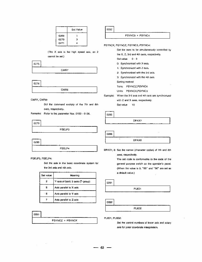
Set Value
0269 1
~
0270 3
0271 4
(The X axis is the high speed axis, so 2
cannot be set.)
0275
CMR7
0276
CMR8
CMR7, CMR8:
Set the command multiply of the 7th and 8th
axes, respectively.
Remarks: Refer to the parameter Nos. 0100 - 0130.
0279
‘ PSELP3
.
0280
PSELP4
PSELP3, PSELP4: .
Set the axis in the basic coordinate system for
the 3rd axis and 4th axis.
\ 4 Set value Meaning
2 Y-axis of basic 3 axes (T-group)
5 Axis parallel to X-axis
6 Axis parallel to Y-axis
7 Axis paraiiel to Z-axis
0281
PSYNCZ + PSYNCX
0282
PSYNC3 + PSYNC4
PSYNCX, PSYNCZ, PSYNC3, PSYNC4:
Example)
r-l 0285
Set the axes to be simultaneously controlled by
the X, Z, 3rd and 4th axes, respectively.
Set value 0 - 3
0: Synchronized with X-axis.
1: Synchronized with Z-axis.
2: Synchronized with the 3rd axis.
3: Synchronized with the 4th axis.
Setting method
Tens: PSYNCZ,PSYNC4
Units: PSYNCX,PSYNC3
When the 3rd axis and 4th axis are synchronized
with 2 and X axes, respectively:
Set value 10
0286
DPAX8
a.
,
DPAX7, 8: Set the names (character codes) of 7th and 8th
axes, respectively.
The set code is conformable to the code of the
general purpose switch on the operator’s panel.
(When the value is 0, “55” and “56” are set as
a default value.)
rl 0291
I 0292
PLIID2
PLliDl, PLIID2:
Set the control numbers of linear axis and rotary
axis for polar coordinate interpolation.
63
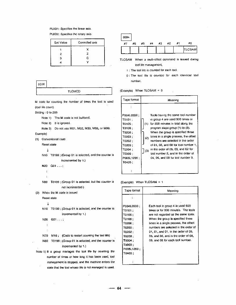
l-l 0336
PLllDl: Specifies the linear axis.
PLIID2: Specifies the rotary axis.
I Set Value I Controlled axis
X
Z
C Y
I TLCMCD I
M code for counting the number of times the tool is used
(tool life count)
Setting : 0 to 255
Note 1) The M code is not buffered.
Note 2) 0 is ignored.
Note 3) Do not use MOl, M02, M30, M98, or M99.
Example)
(1) Conventional case
Reset state
Nl 0 TO1 99 ; (Group 01 is selected, and the counter is
incremented by 1.)
N20 GOI . . . .
N80 TO199 ; (Group 01 is selected, but the counter is
not incremented.)
(2) When the M code is issued
Reset state
, J NlO TO199 ; (Group 01 is selected, and the counter is
incremented by 1.)
N20 Go1 . . . ;
N70 M16; (Code to restart counting the tool life)
N80 TO199 ; (Group 01 is selected, and the counter is
incremented by 1.)
Note 1) If a group manages the tool life by counting the
number of times or how long it has been used, tool
management is stopped, and the machine enters the
state that the tool whose life is not managed is used.
#7 #6 #5 #4 #3 #2 #1 #O
TLCSAM
TLCSAM When a muiti-offset command is issued during
tool life management,
1 : The tool life is counted for each tool.
0 : The tool life is counted for each identical tool
number.
(Example) When TLCSAM = 0
Tape format
P004L0500 ;
TO101 ;
TO105 ;
TO108 ;
TO206 ;
TO203 ;
TO202 ;
TO209 ;
TO304 ;
TO309 ;
P005L1200 ;
TO405 ;
1 (1)
I (2)
3 (3)
Tools having the same tool number
in group 4 are used 500 times or
for 500 minutes in total along the
program steps group (1) to (3).
When the group is specified three
times in a single process, the offset
numbers are selected in the order
of 01, 05, and 08 for tool number 1,
in the order of 06, 03, and 02 for
tool number 2, and in the order of
04, 09, and 09 for tool number 3.
(Example) When TLCSAM = 1
Tape format
P004L0500 ;
TO101 ; TO105 ; TO108 ; TO206 ; TO203 ; TO202 ; TO209 ; TO304 ; TO309 ; P005L1200 ;
TO405 ;
.
Meaning
Meaning
Each tool in group 4 is used 500
times or for 500 minutk. The tools
are not regarded as the same tools.
When the group is specified three
times in a single process, the offset
numbers are selected in the order of
01, 01, and 01, in the order of 05,
05, and 05, and in the order of 08,
08, and 08 for each tool number.
64
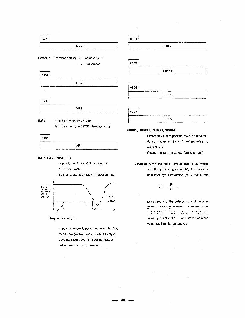
rl 0500 l-l 0504
INPX I SERRX I
Remarks: Standard setting 20 (metric output)
12 (inch output)
0501
INPZ
l-l 0502
INP3 I
SERRZ
rl 0506
I SERR3 I
l-l 0507 .
lNP3 In-position width for 3rd axis.
Setting range : 0 to 32767 (detection unit)
SERR4
SERRX, SERRZ, SERR3, SERR4
0503 Limitation value of position deviation amount
during ‘movement for X, 2, 3rd and 4th axis,
INP4 4 respectively.
Setting range: 0 to 32767 (detection unit)
INPX, INPZ, INP3, fNP4
in-position width for X, Z, 3rd and 4th (Example) When the rapid traverse rate is 10 m/min.
axis,respectively. and the position gain is 30, the erior is
Setting range: 0 to 32767 (detection unit) calculated by: Conversion of 10 m/min. into
Position deflec- tion value
In-position width
In position check is performed when the feed
mode changes from rapid traverse to rapid
traverse, rapid traverse to cutting feed, or
cutting feed to rapid traverse.
F E= - G
pulses/set. with the detection unit of Q/pulse
gives 166,666 pulses/set. Therefore, E =
166,666/30 = 5,555 pulses: Multiply this
value by a factor of 1.5, and set the obtained
value 8333 as the parameter.
65
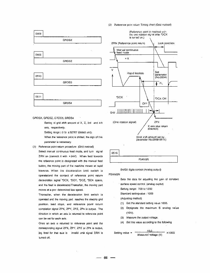
(2) Reference point return Timing chart (Grid method)
(Reference point is reached with the one rotation signal after *DCX is turned on.)
ZRN (Reference point return) Lock ,condition
I I 0508
I GRDSX I
0509
Manual continuous
GRDSZ 4
r-l 0510
I GRDS3 I
“DCX . *DCX ON r-l 0511
I GRDS4 I 1 1
I
Grid
GRDSX, GRDSZ, GRDS3, GRDS4
(One rotation signal) /
ZPX Setting of grid shift amount of X, Z, 3rd and 4th
/
X axis plus return direction)
(Grid shift amount set by L parameter No.0508-05 11)
axis, respectively-
Setting range : 0 to 2 32767 (detect unit).
When the reference point is shifted, the sign of this
parameter is necessary.
(1) Reference point return procedure (Grid method)
Select manual continuous feed mode, and turn signal
ZRN on (connect it with + 24V). When feed towards
.
t PSANGN the reference point is designated with the manual feed
button, the moving part of the machine moves at rapid
S4/S5 digits control (Analog output)
PSANGN
Sets the data for adjusting the gain of constant
traverse. When the deceleration limit switch is
operatedand the contact of reference point return
deceleration signal * *pCX, *DCY, *DCZ, *DC4 opens,
and the feed is decelerated.Thereafter, the moving part
moves at a pre- determined low speed.
Thereafter, when the deceleration limit switch is
operated and the moving part reaches the electric grid
position, feed stops, and reference point return
completion signal ZPX, ZPY, ZPZ, ZP4 is output. The
direction in which an axis is returned to reference point
surface speed control. (analog ouptut)
Setting range: 700 to 1250
Standard settingvalue : 1000
(Adjusting method)
(1) Set the standard setting value 1000.
(2) Designate the maximum S analog value
(1 OV).
(3) Measure the output voltage. .
(4) Set this value according to the following
can be set for each axis.
Once .an axis is returned
corresponding signal ZPX,
jog feed for that axis is
turned off.
to reference point and the
ZPY, ZPZ or ZP4 is output,
invalid until signal ZRN is Setting value = 10.0
Measured voltage (V) x1000
66
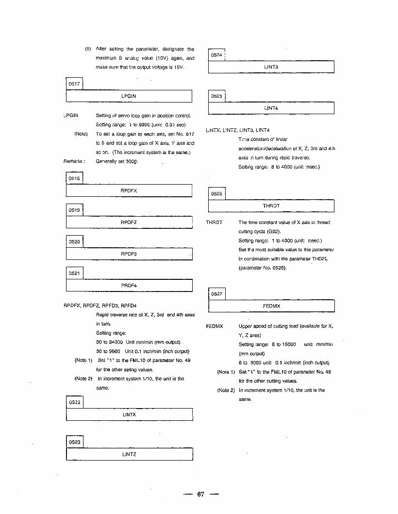
(5)
r-l 0517
After setting the parameter, designate the
maximum S analog value (1 OV) again, and
make sure that the output voltage is WV.
LPGIN r-l 0525
LPGJN Setting of servo loop gain in position control.
Setting range: l to 9999 (unit: 0.01 set)
(Note) To set a loop gain to each axis, set No. 517
to 0 and set a loop gain of X axis, Y axis and
so on. (The increment system is the same.)
Remarks : Generally set 3009. .
rl 0518
RPDFX
r-l 0519
RPDFZ
r-l 0520
RPDF3
rl 0521
PRDF4
RPDFX, RPDFZ, RPFD3, RPFD4
(Note 1)
(Note 2)
r-l 0522
Rapid traverse rate-of X, 2, 3rd and 4th axes
in turn.
Setting range:
30 to 24000 Unit mm/min (mm output)
30 to 9600 Unit 0.1 inch/min (inch output)
Set ” 1” to the FMLl 0 of parameter No. 49
for the other seting values.
In increment system l/l 0, the unit is the
same.
I LINTX I
rl 0524
I LINT3 I
I LINT4 I
LINTX, LINTi!, LINT3, LINT4
Time constant of linear
acceleration/deceleration of X, 2, 3rd and 4th
axes in turn during rapid traverse.
Setting range: 8 to 4000 (unit: msec.)
l-l 0526
I THRDT I
THRDT The time constant value of X axis in thread
cutting cycle (G92).
Setting range: 1 to 4000 (unit: msec.)
Set the most suitable value to this parameter
in combination with the parameter THDFL
(parameter No. 0528).
r-l 0527
I FEDMX I FEDMX
(Note 1)
(Note 2)
Upper speed of cutting feed (available for X,
Y, 2 axes)
Setting range: 6 to 15000 unit: mm/min ’ . (mm output)
6 to 6000 unit: 0.1 inch/min (inch output)
Set “1” to the FMLI 0 of parameter No. 49
for the other cutting values.
In increment system l/l 0, the unit is the
same.
rl 0523
I LINTZ I
67
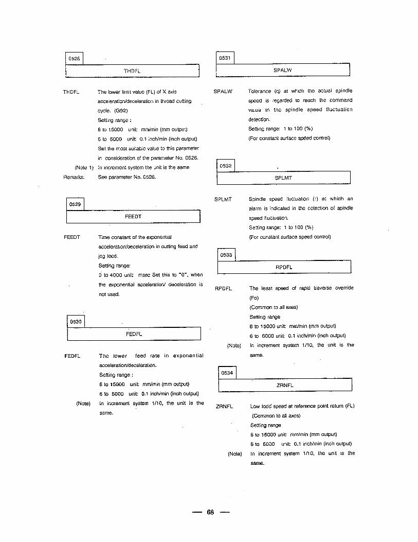
0528 (
THDFL I SPALW
THDFL
(Note 1)
Remarks:
The lower limit value (FL) of X axis
acceleration/deceleration in thread cutting
cycle. (G92)
Setting range :
6 to 15000 unit: mm/min (mm output)
6 to 6000 unit: 0.1 inch/min (inch output)
Set the most suitable value to this parameter
in consideration of the parameter No. 0526.
In increment system the unit is the same
See parameter No. 0526.
FEEDT 1
FEEDT Time constant of the exponential
acceleration/deceleration in cutting feed and
jog feed.
Setting range:
d to 4000 unit: msec Set this to “O”, when
the exponential acceleration/ deceleration is
not used.
rl 0530
I FEDFL -1
FEDFL The lower feed rate in exponential
acceleration/deceleration.
Setting range :
6 to 15000 unit: mm/min (mm output)
6 to 6000 unit: 0.1 inch/min (inch output)
(Note) In increment system l/IO, the unit is the
same.
0531
SPALW Tolerance (q) at which the actual spindle
speed is regarded to reach the command
value in the spindle speed fluctuation
detection.
Setting range: 1 to 100 (%)
(For constant surface speed control)
.
SPLMT
SPLMT Spindle speed fluctuation (r) at which an
alarm is indicated in the detection of spindle
speed fluctuation.
Setting range: 1 to 100 (%)
(For constant surface speed control)
0533
RPDFL
RPDFL
(Note)
I 1
The least speed of rapid traverse override
(Fo)
(Common to all axes)
Setting range
6 to 15000 unit: mrn/min (mm output)
6 to 6000 unit: 0.1 incWmin (inch output)
In increment system l/l 0, the unit is the
same.
0534
ZRNFL
ZRNFL Low feed speed at reference point return (FL)
(Common to all axes)
Setting range
6 to 15000 unit: mm/min (mm output)
6 to 6000 unit: 0.1 inchlmin .(inch output)
(Note) In increment system l/l 0, the unit is the
same.
- 68 -
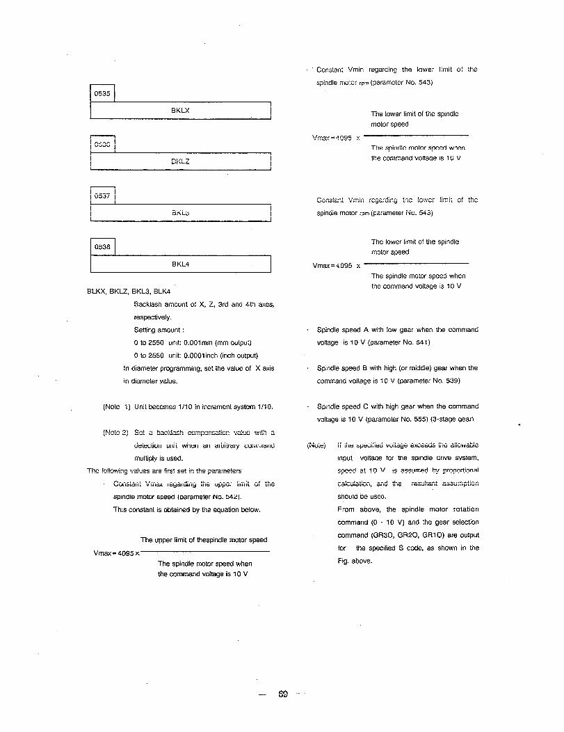
r-l 0535
s Constant Vmin regarding the lower limit of the
spindle motor rpm (parameter No. 543)
I BKLX I
1 0536 1
I BKLZ I
r-l 0537
I BKL3 I
l-l 0538
BLKX, BKLZ, BKL3, BLK4
Backlash amount of X, Z, 3rd and 4th axes,
respectively.
Setting amount :
0 to 2550 unit: O..OOl mm (mm output)
0 to 2550 unit: O.OOOlinch (inch output)
In diameter programming, set the value of X
in diameter value.
axis
(Note 1) Unit becomes l/l 0 in increment system l/l 0.
(Note 2) Set a backlash compensation value with a
detection unit when an arbitrary command
multiply is used.
The following values are first set in the parameters
- Constant Vmax regarding the upper limit of the
spindle motor speed (parameter No. 542).
This constant is obtained by the equation below.
The upper limit of thespindle motor speed
Vmax = 4095 x
The spindle mot& speed when
the command voltage is 10 V
The lower limit of the spindle
motor speed
Vmax=4095 x
The spindle motor speed when
the command voltage is 10 V
. Constant Vmin regarding the lower limit of the
spindle motor rpm (parameter NO. 543)
The lower limit of the spindle
motor speed .
Vmax=4095 x
The spindle motor speed when
the command voltage is 10 V
l Spindle speed A with low gear when the command
voltage is 10 V (parameter No. 541)
l Spindle speed B with high (or middle) gear when the
command voltage is 10 V (parameter No. 539)
= Spindle speed C with high gear when the command
voltage is 10 V (parameter No. 555) (3-stage gear)
(Note) If the specified voltage exceeds the allowable
input voltage for the spindle drive system,
speed at 10 V is assumed by proportional
calculation, and the resultant assumption
should be used.
From above, the spindle motor rotation
command (0 - 10 V) and the gear selection
command (GR30, GR20, GRlO) are output
for the specified S code, as shown in the
Fig. above.
69
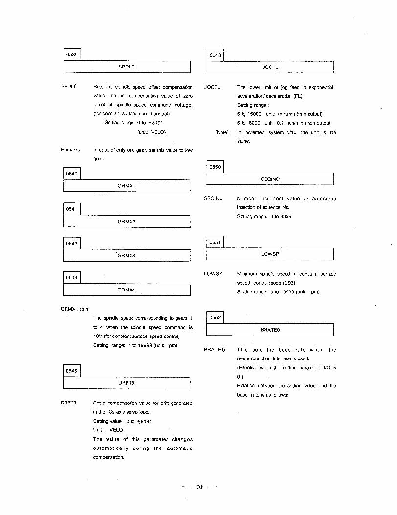
l-l 0548
SPDLC
SPDLC Sets the spindle speed offset compensation
value, that is, compensation value of zero
offset of spindle speed command voltage.
(for constant surface speed control)
Setting range: 0 to + 8191
(unit: VELO)
Remarks: In case of only one gear, set this value to low
gear.
0540
GRMXl
I JOGFi
JOGFL The lower limit of jog feed in exponential
acceleration/ deceleration (FL)
Setting range :
6 tq 15000 unit: mm/min (mm output)
6 to 6000 unit: 0.1 inch/min (inch output)
(Note) In increment system l/l 0, the unit is the
same.
r-l 0550
I SEQJNC I
0541
GRMX2 A
SEQJNC Number increment value in automatic
insertion of equence No.
Setting range: 0 to 9999
r-l 0551
'GRMX3
rl 0543
I GRMX4 -1
GRMXl to4
rl 0546
The spindle speed corresponding to gears 1
to 4 when the spindle speed command is
1 OV.(for constant surface speed control)
Setting range: 1 to 19999 (unit: rpm)
I DRFT3 I
LOWSP
LOWSP Minimum spindle speed in constant surface
speed control mode (G96)
Setting range: 0 to 19999 (unit: rpm)
0552
BRATEO
BRATE 0 This sets the baud rate when the
reader/puncher interface is used.
(Effective when the setting parameter I/O is
0.1
Relation between the setting value and the
baud rate is as follows:
DRFT3 Set a compensation value for drift generated
in the Cs-axis servo loop.
Setting value 0 to t 8191
Unit : VELO
The value of this parameter changes
automatically during the automatic
compensation.
70
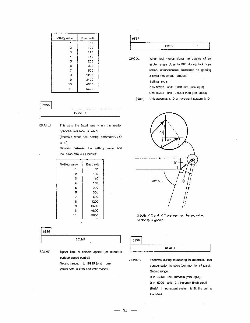
r-l 0553
Setting value Baud rate
1 50
2 100
3 110
4 150
5 200
6 300
7 600
8 1200
9 2400
10 4800
11 9600
BRATEI
BRATEl This sets the baud rate when the reader
/ puncher interface is used.
(Effective when the setting parameter I / 0
is 1.)
Relation between the setting value and
t the baud rate is as follows:
r-l 0556
Setting value I Baud rate
I
2
3
4
5
6
7
8'
9
10
11
50
100
110
150
200
300
600
1200
2400
4800
9660
SCLMP
SCLMP Upper limit of spindle speed (for constant
surface speed control)
Setting range: 1 to 19999 (unit: rpm)
(Valid both in G96 and G97 modes.)
0557 9
CRCDL ,
CRCDL When tool moves along the outside of an
acute angle close to 90” during tool nose
radius compensation, limitations on ignoring
a small movement amount.
Setting range:
0 to 16383 unit: 0.001 mm (mm input)
0 to 16383 unit: 0.0001 inch (inch input)
(Note) Unit becomes l/l 0 in increment system l/l 0.
If both AX and AY are less than the set value,
vector 0 is ignored.
0558
ACALFL
ACALFL Feedrate during measuring in automatic tool
compensation function (common fof all axes).
Setting range:
0 to 15000 unit: mm/min (mm input)
0 to 6000 unit: 0.1 inch/min (inch input)
(Note) In increment system l/l 0, the unit is
the same.
71
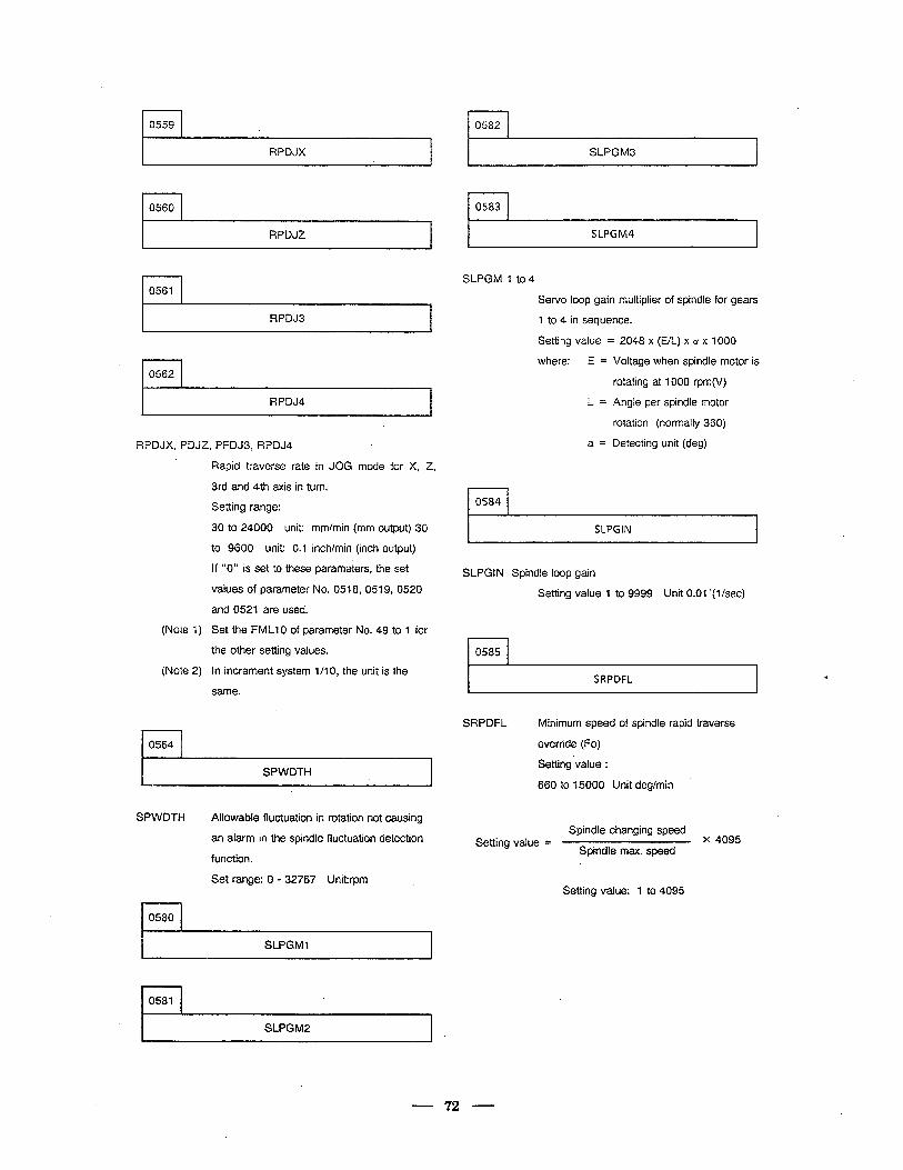
I I 0559
I RPDJX
l-l 0560
RPDJZ
rl 0561
RPDJ3
. r-l 0562
RPDJ4
RPDJX, PDJZ, PFDJ3, RPDJ4
(Note 1)
(Note 2)
rl 0564
Rapid traverse rate in JOG mode for X, Z,
3rd and 4th axis in turn.
Setting range:
30 to 24000 unit: mm/min (mm output) 30
to 9600 unit: 0.1 inch/min (inch output)
If “0” is set to these parameters, the set
values of parameter No. 0518, 0519, 0520
and 0521 are used.
Set the FMLlO of parameter No. 49 to 1 for
the other setting values.
In increment system l/l 0, the unit is the
same.
SPWDTH
SPWDTH Allowable fluctuation in rotation not causing
an alarm in the spindle fluctuation detection
function.
Set range: 0 - 32767 Unit:rpm .
l-l 0580
SLPGMl
rl 0581
SLPGM2 .
0582
SLPGM3
I I 0583
SLPGM4
SLPGM 1 to 4
Servo loop gain multiplier of spindle for gears
1 to 4 in sequence.
Setting value = 2048 x (E/L) x a x 1000
where: E =
L=
a =
Voltage when spindle motor is
rotating at 1000 rpm(V)
Angle per spindle motor
rotation (normally 360)
Detecting unit (deg)
rl 0584 c
SLPGIN
SLPGIN Spindle loop gain
Setting value 1 to 9999 Unit 0.01 ‘(lkec)
0585
. SRPDFL
SRPDFL Minimum speed of spindle rapid traverse
override (Fo)
Setting value :
660 to 15000 Unit deg/min
Spindle changing speed Setting value = x 4095
Spindle max. speed
Setting value: 1 to 4095
- 72 -
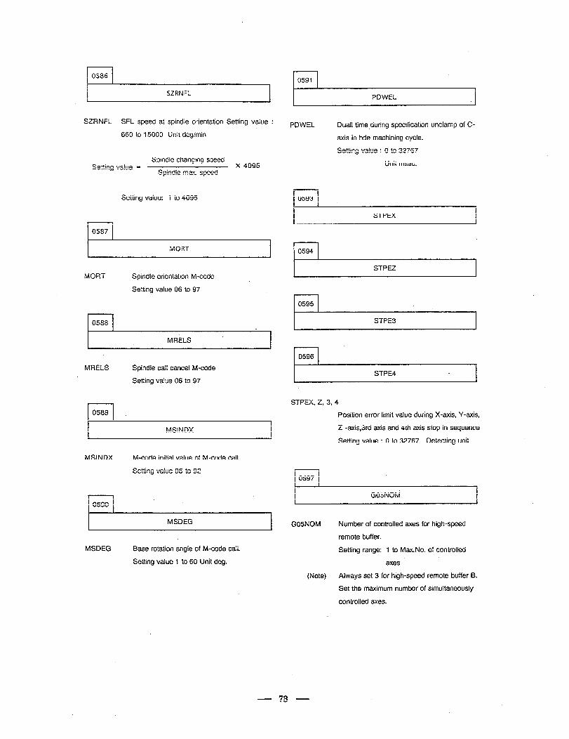
r-l 0586 r 0591
I SZRNFL I PDWEL .I
SZRNFL SFL speed at spindle orientation Setting value : PDWEL Dual1 time during specification unclamp of C-
axis in hde machining cycle.
Setting value : 0 to 32767
Unit msec.
660 to 15000 Unit deg/min
Spindle changing speed Setting value = x 4095
Spindle max. speed
I I 0593 Setting value: 1 to 4095
l-l 0587
STPEX
f-l 0594 I MORT I
STPEZ MORT Spindle orientation M-code
Setting value 06 to 97
I I 0595
l-l 0588 STPE3
rl 0596
MRELS
MRELS Spindle tail cancel M-code
Setting value 06 to 97 STPE4 L
STPEX, Z, 3, 4
Position error limit value during X-axis, Y-axis,
2 -axis,3rd axis and 4th axis stop in sequence
Setting value : 0 to 32767 Detecting unit
I 0589
I MSINDX I
MSINDX M-code initial value of M-code call.
Setting value 06 to 92 rl 0597
I G05NOti . I l-l 0590
I MSDEG I GOSNOM
(Note)
Number of controlled axes for high-speed
remote buffer.
Setting range: 1 to Max.No. of controlled
axes
Always set 3 for high-speed remote buffer B.
Set the maximum number of simultaneously
controlled axes.
MSDEG Base rotation angle of M-code call.
Setting value 1 to 60 Unit deg.
73
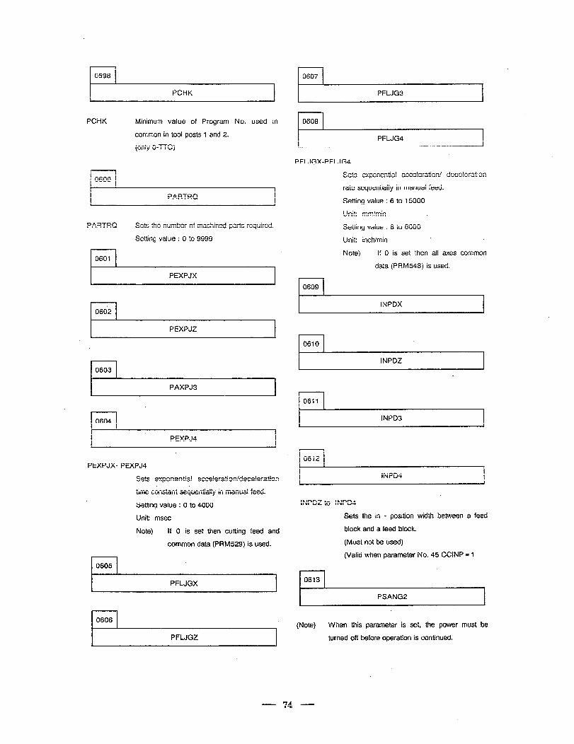
r-l 0607
PFLJG3
rl 0608 PCHK Minimum value of Program No. used in
common in too! posts 1 and 2. .
(only 0-TTC) PFLJG4
PFLJGX-PFLJG4
Sets exponential acceleration/ deceleration
fate ‘sequentially in manual feed.
Setting value : 6 to 15000
Unit: mm/min
l-l 0609
Setting value : 6 to 6000
Unit: inch/min
Note) If 0 is set then a!! axes common
data (PRM548) is used.
1 0600 1
PARTRQ
PARTRQ
l-l 0601
Sets the number of machined parts required.
Setting value : 0 to 9999
PEXPJX
r- - INPDX I l-l 0662
PEXPJZ
c I I 0610
I 0603
INPDZ
PAXPJ3
l-l 0611
rl 0604 INPD3
PEXPJ4
r-l 0612 PEXPJX- PEXPJ4
. INPD4 Sets exponential acceleration/deceleration
time constant sequentially in manual feed.
Setting value : 0 to 4000
Unit: msec
Note) If 0 is set then cutting feecJ and
common data (PRM529) is used.
rl 0605
INPDZ to INPD4
Sets the in - position width between a feed
block and a feed block.
(Must not be used)
(Valid when parameter No. 45 CCINP = 1
r-l 0613 PFLJGX
PSANG2
(Note) When this parameter is set, the power must be
turned off before operation is continued. PFLJGZ
74
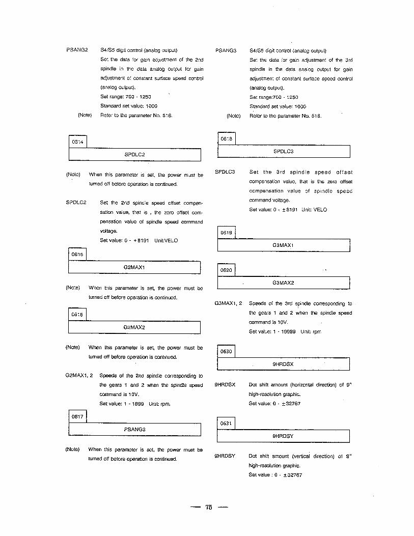
PSANG2 WS5 digit control (analog output) PSANG3
Set the data for gain adjustment of the 2nd
spindle in the data analog output for gain
adjustment of constant surface speed control
(analog output).
Set range: 700 - 1250
Standard set value: 1000
(Note) Refer to the parameter No. 516. (Note)
r-l 0614
0618
SPDLC2
(Note) When this parameter is set, the power must be
turned off before operation is continued.
SPDLC2 Set the 2nd spindle speed offset compen-
sation value, that is , the zero offset com-
pensation value of spindle speed
voltage.
rl 0615
Set value: 0 - + 8191 Unit:VELO
command
I GZMAXl I
(Note) When this parameter is set, the power must be
turned off before operation is continued.
0616 4
G2MAX2
(Note) When this parameter is set, the power must be
turned off before operation is continued.
G2MAX1, 2 Speeds of the 2nd spindle corresponding to
the gears 1 and 2 when the spindle speed
command is 1OV.
Set value: 1 - 1999 Unit: rpm.
0617
PSANG3
(Note) When this parameter is set, the power must be
turned off before operation is continued.
S4/S5 digit control (analog output)
Set the data for gain adjustment of the 3rd
spindle in the data analog output for gain
adjustment of constant surface speed control
(analog output).
Set range:700 - 1250
Standard set value: 1000
Refer to the parameter No. 516. ’
.
SPDLC3
SPDLC3 .
Set the 3rd spindle speed offset
compensation value, that is the zero offset
compensation value of spindle speed
command voltage.
Set value: 0 - k 8191 Unit: VELO
.
0619 *
G3MAXl
.
0620 l. 1
_ G3MAX2 4
G3MAX1, 2 Speeds of the 3rd spindle corresponding to
the gears 1 and 2 when the spindle speed
command is 1OV.
Set value: 1 - 19999 Unit: rpm
0630
SHRDSX 4
SHRDSX Dot shift amount (horizontal direction) of 9”
high-resolution graphic.
Set value: 0 - t 32767
, 0631
SHRDSY
SHRDSY Dot shift amount (vertical direction) of 9”
high-resolution graphic.
Set value : 0 - + 32767
- 75 -
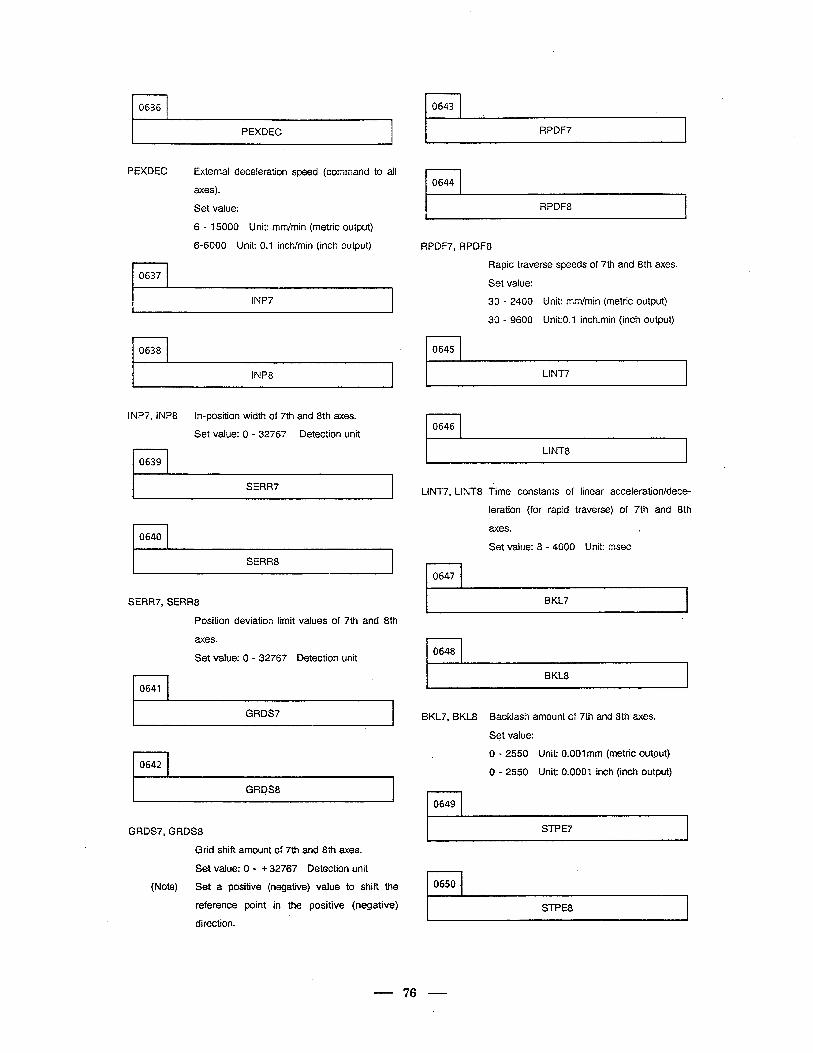
l-l 0636
. 0643
I PEXDEC RPDF7
PEXDEC External deceleration speed (command to all
axes).
Set value:
rl 0644
r RPDF8 I
rl 0637
6 - 15000 Unit: mm/min (metric output)
6-6000 Unit: 0.1 inch/min (inch output) RPDF7, RPDF8
Rapid traverse speeds of 7th and 8th axes.
Set value:
30 - 2400 Unit: mm/min (metric output)
30 - 9600 UnitO.1 inch.min (inch output)
0645
Li NT7
lNP7
l-l 0638
I INP8
INP7, INP8 In-position width of 7th and 8th axes.
Set value: 0 - 32767 Detection unit 0646
f
LINT8
-I I 0639
I SERR7 I LINT7 LINT8 Time constants of linear acceleration/dece-
leration (for rapid traverse) of 7th and 8th
axes. c l-l 0640 Set value: 8 - 4000 Unit: msec
I SERR8 I n 0647
I BKL7 I SERRT, SERR8
Position deviation limit values of 7th and 8th
axes. . n 0648 Set value: 0 - 32767 Detection unit
BKL8 I l-l 0641
I GRDS7 I BKL7, BKL8 Backlash amount of 7th and 8th axes.
Set value:
0 - 2550 Unit: 0.001 mm (metric output)
rl 0642 0 - 2550 Unit: 0.0001 inch (inch output)
I GRt@8 I r-l 0649
I STPE7 GRDS7, GRDS8
Grid shift amount of 7th and 8th axes. .
Set value: 0 - + 32767 Detection unit
(Note) Set a positive (negative) value to shift the
reference point in the positive (negative)
direction.
n 0650
STPE8
- 76 -
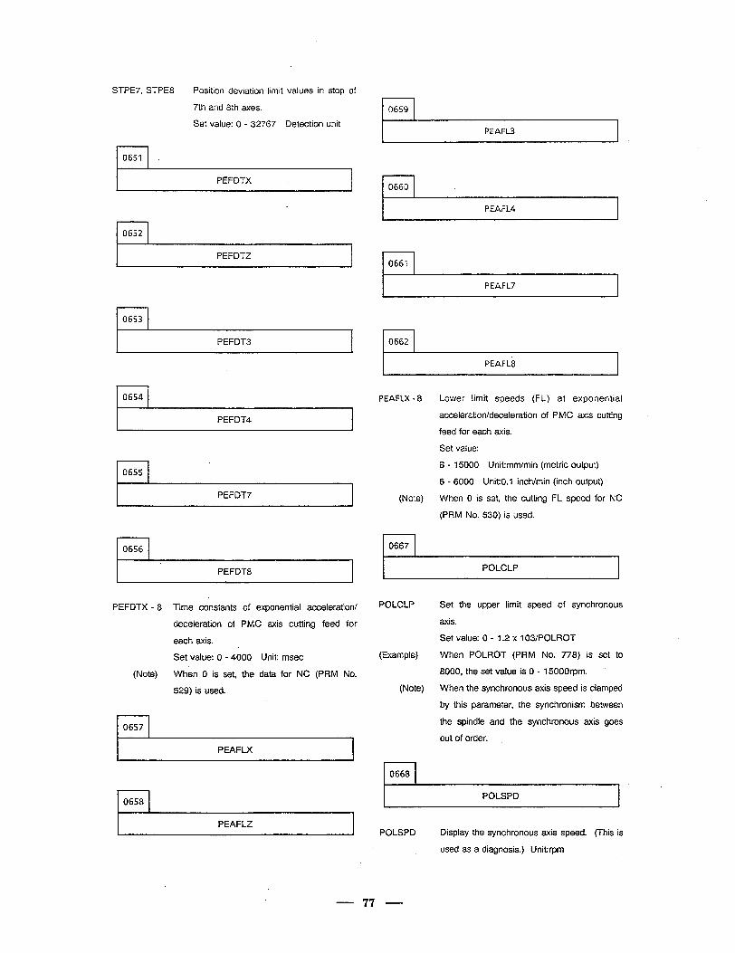
STPE7, STPE8 Position deviation limit values in stop of
7th and 8th axes.
Set value: 0 - 32767 Detection unit r-l 0659
PEAFL3
I I 0651
PEFDTX r-l 0660
I PEAFL4
l-l 0652
l-l 0661 PEFDTZ
PEAFL7
l-l 0653
l-l 0662 PEFDT3
PEAFL8
r-l 0654 PEAFLX - 8
(Note)
rl 0667
Lower limit speeds (FL) at exponential
acceleration/deceleration of PMC axis cutting
feed for each axis.
Set value:
6 - 15000 Unit:mm/min (metric output)
6 - 6000 Unit:O.l inch/min (inch output)
When 0 is set, the cutting FL speed for NC
(PRM No. 530) is used.
PEFDT4
rl 0655
PEFDT7
I I 0656
POLCLP PEFDT8
POLCLP Set the upper limit speed of synchronous
axis.
Set value: 0 - 1.2 x 10³IPOLROT
(Example) When POLROT (PRM No. 778) is set to
8000, the set value is 0 - 15000rpm.
(Note) When the synchronous axis speed is clamped
by this parameter, the synchronism between
the spindle and the synchronous axis goes
out of order.
PEFDTX - 8 Time constants of exponential acceleration/
deceleration of PMC axis cutting feed for
each axis.
Set value: 0 - 4000 Unit: msec
(Note) When 0 is set, the data for NC (PRM No.
529) is used.
l-l 0657
PEAFLX .
0668
POLSPD r-l 0658
PEAFLZ POLSPD Display the synchronous axis speed. (This is
used as a diagnosis.) Unit:rpm
- 77 -
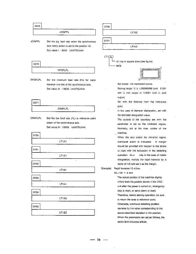
0669
JOGFPL
JOGFPL Set the jog feed rate when the synchronous
axis rotary switch is set to the position 10.
Set value:1 - 2000 Unit:PSU/min
r-l 0670
RPDFLPL
RPDFLPL Set the minimum feed rate (Fo) for rapid
traverse override of the synchronous axis.
Set value: 6 - 15000 Unit:PSU/min
1
0671
ZRNFLPL
ZRNFLPL Set the low feed rate (FL) at reference point
return of the synchronous axis.
Set value: 6 - 15000 Unit-.PSU/min
0700
LT1 X1
\
0701
iTlZ1
rl 0702
I LT131 I
r-l 0703
I IT141 I
LT1 X2
I LTlZ2 I
l-l 0706
I LT132 I
L-i-142 I
L-l-1 DO l- nth top in square zone (see figure).
- axis
2
Set stroke limit mentioned above.
Setting range : 0 to It 99999999 (unit: 0.001
mm in mm output or 0.0001 inch in inch
output)
Set with the distance from the reference
point.
In the case of diameter designation, set with
the diameter designation value.
The outside of the boundary set with the
parameter is set as the inhibited region.
Normally, set at the max. stroke of the
machine. c When the axis enters the inhibited region,
over-travel alarm is indicated. A margin
should be provided with respect to the stroke
to cope with the fluctuation in the detecting
operation. As a rule, in the case of metric
designation, multiply the rapid traverse by a
factor of l/5 and set it as the margin.
Example) Rapid traverse 10 m/min. .
10 x l/5 = 2 mm
The actual position of the machine slightly
differs from the position stored in the CNC
unit after the power is turned on, emergency
stop is reset, or servo alarm is reset.
Therefore, before starting operation, be sure
to return the axes to reference point.
Otherwise, overtravel detecting position
deviates by the value corresponding to the
above-described deviation in the position.
When the parameters are set as follows, the
stroke limit becomes infinite.
78
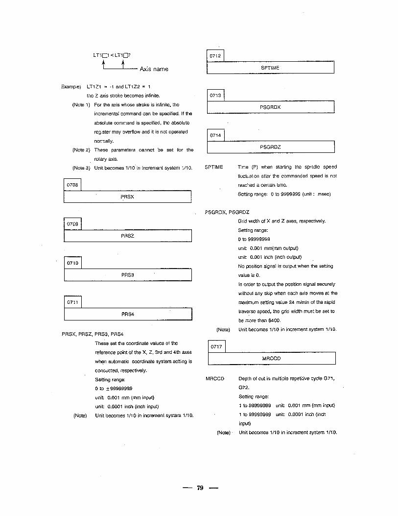
LTlnl c LTln2
u Axis name
l-l 0712
Example) LT? 21 = -1 and LTlZ2 = 1 4
the Z axis stroke becomes infinite. 0713
(Note 1)
(Note 2)
(Note 3)
rl 0708
For the axis whose stroke is infinite, the
incremental command can be specified. If the
absolute command is specified, the absolute
register may overflow and it is not operated
normally.
These parameters cannot be set for the
rotary axis.
Unit becomes l/l 0’ in increment system 1 /l 0.
~- SPTIME
PSGRDX
0714
PSGRDZ
,
SPTIME Time (P) when starting the spindle speed
fluctuation after the commanded speed is not
reached a certain time.
PRSX Setting range: 0 to 9999999 (unit : msec)
0709
PRSZ
I I 0710
PRS3 *
l-l 0711
PRS4
PRSX, PRSZ, PRS3, PRS4
These set the coordinate values of the
reference point of the X, Z, 3rd and 4th axes
when automatic coordinate system setting is
conducted, respectively.
Setting range:
0 to k9999999.9
unit: 0.001 mm (mm input)
unit: 0.0001 inch (inch input)
(Note) Unit becomes l/l 0 in increment system l/l 0.
PSGRDX, PSGRDZ
Grid width of X and Z axes, respectively.
Setting range:
0 to 99999999
unit: 0.001 mm(mm output)
unit: 0.001 inch (inch output) i
No position signal is output when the setting
value is 0.
In order to output the position signal securely
without any skip when each axis moves at the
maximum setting value 24 m/min of the rapid
traverse speed, the grid width must be set to
be more than 6400.
(Note) Unit becomes l/l 0 in increment system 7 /l 0.
. 0717
MRCCD
MRCCD Depth of cut in multiple repetitive cycle G71,
G72.
Setting range:
1 to 99999999 unit: 0.001 mm (mm input)
1 to 99999999 unit: 0.0001 inch (inch
input)
(Note) Unit becomes l/l 0 in increment system l/l 0.
79
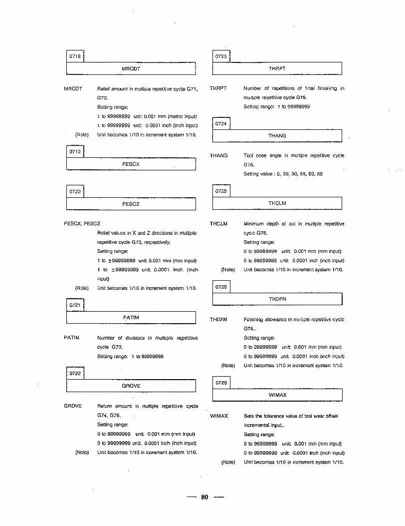
1
0718
MRCDT
MRCDT Relief amount in multiple repetitive cycle G71,
G72.
Setting range:
I to 99999999 unit: 0.001 mm (metric input)
1 to 99999999 unit: 0.0001 inch (inch input)
.(Note) Unit becomes 1 /l 0 in increment system l/l 0.
rl 0719
PESCX
rl 0720 I I 0725
r-l 0723
THRPT
THRPT Number of repetitions of final finishing in
multiple repetitive cycle G76.
Setting range: 1 to 99999999
r-l 0724
THANG I .
THANG Tool nose angle in multiple repetitive cycle
G76.
. Setting value : 0, 29, 30, 55, 60, 80
I PESCZ I I THCLM I
PESCX, PESCZ
Relief values in X and Z directions in m’ultiple
repetitive cycle G73, respectively.
Setting range:
1 to k99999999 unit: 0.001 mm (mm input)
1 to k99999999 unit: 0.0001 inch (inch
input)
(Note) Unit becomes l/l 0 in increment system 1 /l 0.
I I 0721
PAT/M
PATI M Number of divisions in multiple repetitive
cycle G73.
Setting range: 1 to 99999999
l-l 0722
I GROVE I
THCLM Minimum depth of cut in multiple repetitive
cycle G76.
Setting range:
0 to 99999999 unit: 0.001 mm (mm input)
0 to 99999999 unit: 0.0001 inch (inch input)
(Note) Unit becomes l/l 0 in increment system l/l 0.
I I 0726
I THDFN I THDFN Finishing allowance in multiple repetitive cycle
G76..
Setting range:
0 to 99999999 unit: 0.001 mm (mm input)
0 to 99999999 unit: 0.0001 inch (inch input)
(Note) Unit becomes l/l 0 in increment system l/l 0.
0728.
GROVE Return amount in multiple repetitive cycle
G74, G75.
Setting range:
0 to 99999999 unit: 0.001 mm (mm input)
0 to 99999999 unit: 0.0001 inch (inch input)
(Note) Unit becomes l/l 0 in increment system 1 /l 0.
WIMAX
(Note)
Sets the tolerance value of tool wear offset
incremental input.
Setting range:
0 to 99999999 unit: 0.001 mm (mm input)
0 to 99999999 unit: 0.0001 inch (inch input)
Unit becomes l/l 0 in increment system 1 /l 0.
80
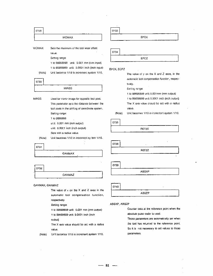
l-l 0729 . I WOMAX I
WOMAX Sets the maximum of the tool wear offset
value.
Setting range:
1 to 99999999 unit: 0.001 mm (mm input)
1 to 99999999 unit: 0.0001 inch (inch input)
(Note) Unit becomes l/l 0 in increment system 1 /l 0.
r-l 0730
I MIRSS I
MiRSS
(Note)
- l-l 0731
Used for mirror image for opposite tool post.
This parameter sets the distance between the
tool posts in the shifting of coordinate system.
Setting range:
1 to 9999999 _
unit: 0.001 mm (mm output)
unit: 0.0001 inch (inch output)
Sets with a radius value.
Unit becomes l/l 0 in increment sy tern 1 /l 0.
GANtiAX .
r-l 0732
*I GANMAZ I
GANMAX, GANMAZ
The. value of e on the X and Z axes in the
automatic tool compensation function,
respectively
Setting range:
1 to 99999999 unit: 0.001 mm (mm output)
7 to 99999999 unit: 0.0001 inch (inch
output)
The X axis value should be set with a radius
value.
(Note) Unit becomes l/l 0 in increment system l/l 0.
0733 4
EPCX
EPCX, ECPZ
The value of y on the X and Z axes, in the
automatic tool compensation function, respec-
tively.
Setting range:
1 to 99999999 unit: 0.001 mm (mm output)
1 to 99999999 unit: 0.0001 inch (inch output)
The X axis value should be set with a radius
value.
(Note) Unit becomes l/10 in increment system l/l 0.
r-l 0735
REF2X I
L
0736
1 REF2Z
l-l 0739
ABSXP
1 ABSZP
ABSXP, ABSZP
Counter data at the reference point when the
absolute pulse coder is used.
These parameters are automatically set when
the tool has returned to the reference point.
So it is not necessary to set values to these
parameters.
81
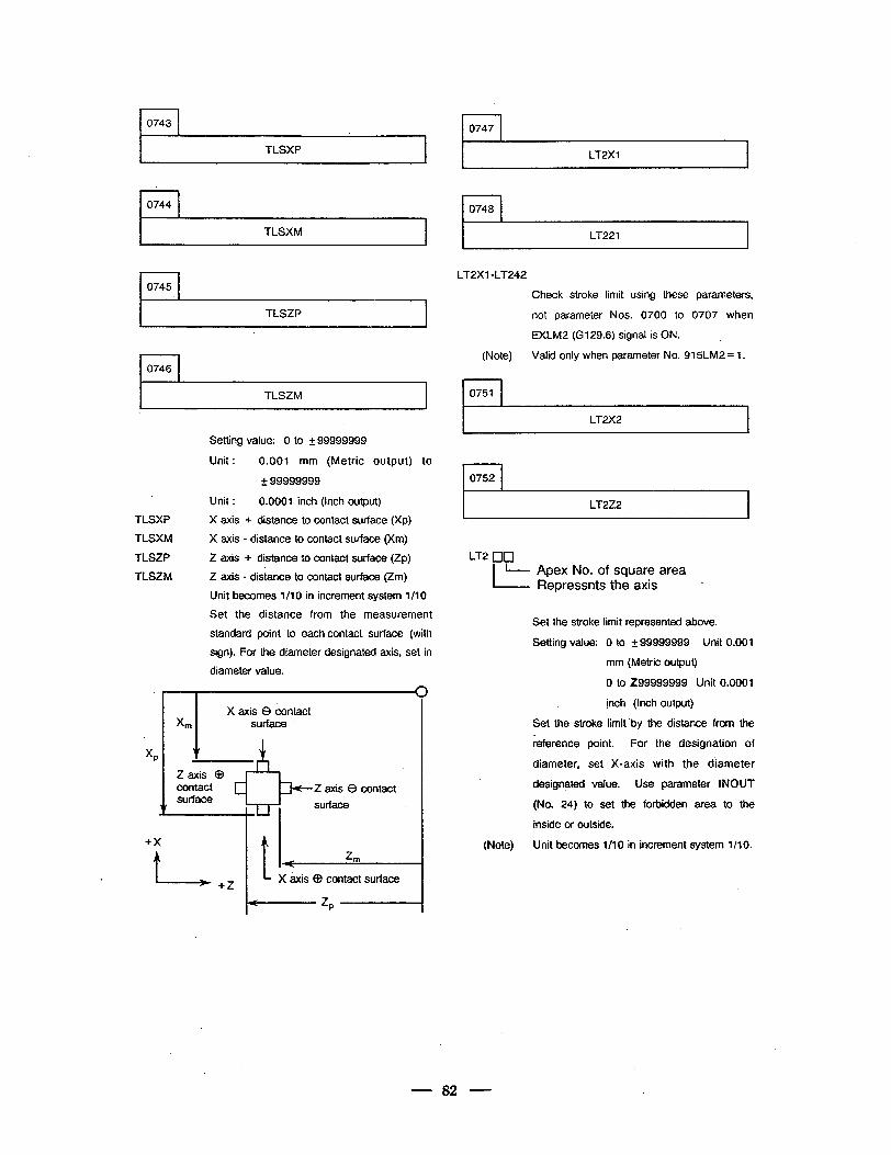
* 0743
TLSXP
.
0744
TLSXM
0745 l
TLSZP ,
0746
TLSZM. I
Setting value: 0 to f 99999999
Unit : 0.001 mm (Metric output) to
* 99999999
Unit : 0.0001 inch (Inch output)
TLSXP X axis + distance to contact surface (Xp)
TLSXM X axis - distance to contact surface (Xm)
TLSZP Z axis + distance to contact surface (Zp)
TLSZM Z axis - distance to contact surface (Zm)
Unit becomes l/l 0 in increment system l/l 0
Set ihe distance from the measurement
standard point to each contact surface (with
sign). For the diameter designated axis, set in
diameter value.
3
. I \
X axis 8 contact X, surface
xP
v &
Z axis CD contact 2 axis 0 contact surface
I surface
I- ZIn
+x
. f +Z L X &is @ contact surface
- zP 1
0747 I
LT2X-I
i-l 0748
LT221 I
LT2X1 d-l-242
Check stroke limit using these parameters,
not parameter Nos. 0700 to 0707 when
EXLM2 (G129.6) signal is ON.
(Note) Valid only when parameter No. 915LM2 = 1.
0751
LT2X2
l-l 0752
I LT2Z2 I
LT2 [lr]
I- - Apex No. of square area
Repressnts the axis i
Set the stroke limit represented above.
Setting value: 0 to k 99999999 Unit 0.001
mm (Metric output)
0 to 299999999 Unit 0.0001
inch (Inch output)
Set the stroke limit ‘by the distance from the
reference point. For the designation of
diameter, set X-axis with the d’iameter
designated value. Use parameter INOUT
(No. 24) to set the forbidden area to the
inside or outside.
(Note) Unit becomes l/l 0 in increment system l/l 0.
82
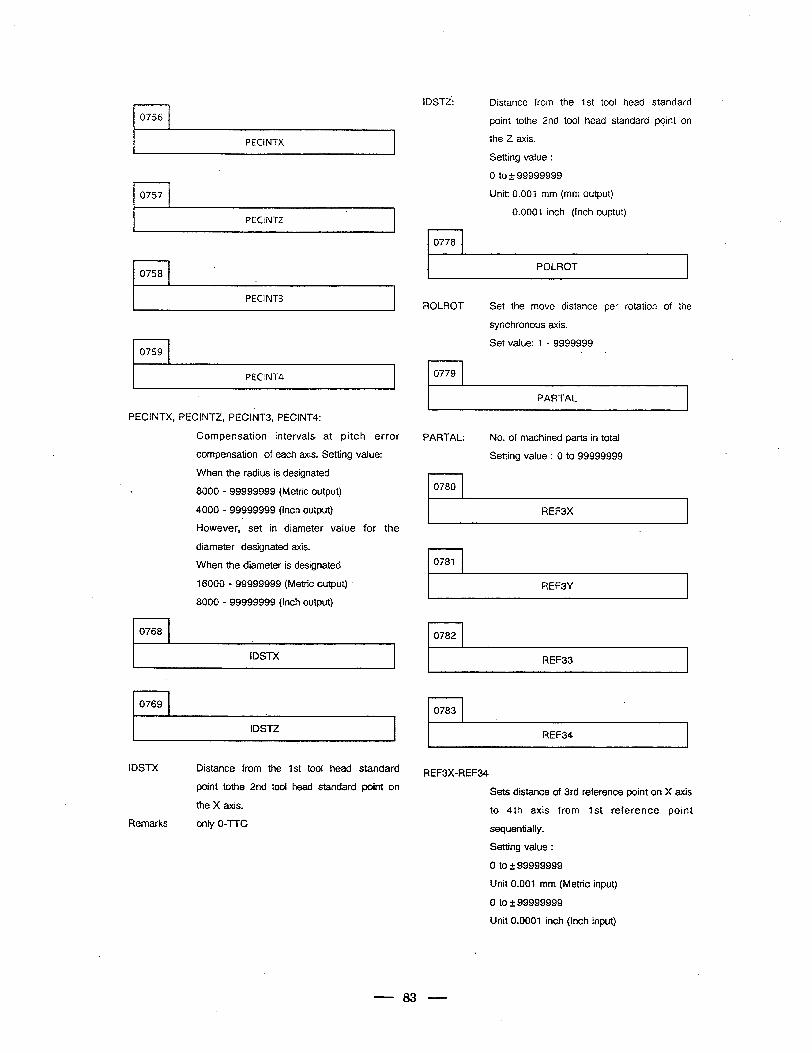
r-l 0756
PECINTX
rl 0757:
PECINTZ I
rl 0758
PECINT3
I 0759
PECINT4
PECINTX, PEClNTZ, PECINT3, PEClNT4:
Compensation intervals. at pitch error
compensation of each axis. Setting value:
When the radius is designated
8000 - 99999999 (Metric output)
4000 - 99999999 (Inch output)
However, set in diameter value for the
diameter designated axis.
When the diameter is designated
16000 - 99999999 (Metric output)
8000 - 99999999 (Inch output)
I-l 0768
I IDSTX I
r-l 0769
I IDSTZ I
IDSTZ: Distance from the 1st tool head standard
point tothe 2nd tool head standard point on
the Z axis.
Setting value :
rl 0778
0 to + 99999999
Unit: 0.001 mm (mm output)
0.0001 inch (Inch ouptut)
POLROT
ROLROT Set the move distance per rotation of the
synchronous axis.
Set value: 1 - 9999999
r-l 0779
PARTAL
PARTAL: No. of machined parts in total
Setting value : 0 to 99999999
I I 0780
I REF3X I
l-l 0781
I REF3Y I
rl 0782
REF33 I
l-l 0783
I REF34 I IDSTX
Remarks
Distance from the 1st tool head standard
point tothe 2nd tool head standard point on
the X axis.
only 0-TTC
REF3X-REF34
Sets distance of 3rd reference point on X axis
to 4th axis from 1st reference point
sequentially.
Setting value :
0 to k 99999999
Unit 0.001 mm (Metric input)
0 to z!z 99999999
Unit 0.0001 inch (Inch input)
83
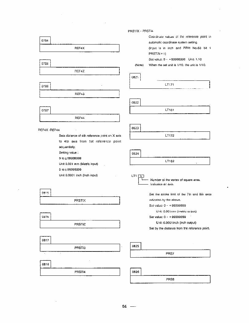
PRSTIX - PRSTI4
rl 0784
I REF4X I
r-l 0785
I REF4Z I
l-l 0786
rl 0787
Coordinate values of the reference point in
automatic coordinate system setting.
(input is in inch and PRM No.63 bit 1
PRSTIN = 1)
Set value: 0 - + 99999999 Unit: 1.10
(Note) When the set unit is l/l 0, the unit is 1 110.
rl 0821
LT171
REF43 I
I REF44
REFdX -REF44
Sets distance of 4th reference point on
to ‘4th axis from 1st reference
sequentially.
Setting value :
0 to 2 99999999
Unit 0.001 mm (Metric input)
0 to 2 99999999
Unit 0.0001 inch (Inch input)
X axis
point
r
0815
c PRSTIX
, 0816
PRSTIZ
0817
PRSTI3
rl 0818
PRST14
i-l 0823
I LTl72
l-l 0824
LT182 c
L-n clcl
I- - Number of the vertex of square area.
Indicates an axis.
Set the stroke limit of the 7th and 8th axes
indicated by the above.
Set value: 0 - + 99999999
Unit: 0.001 mm (metric output)
Set value: 0 - + 99999999 *
Unit: O.OOOlinch (inch output)
’ Set by the distance from the reference point.
1 0825
PRS7
0826
PRS8
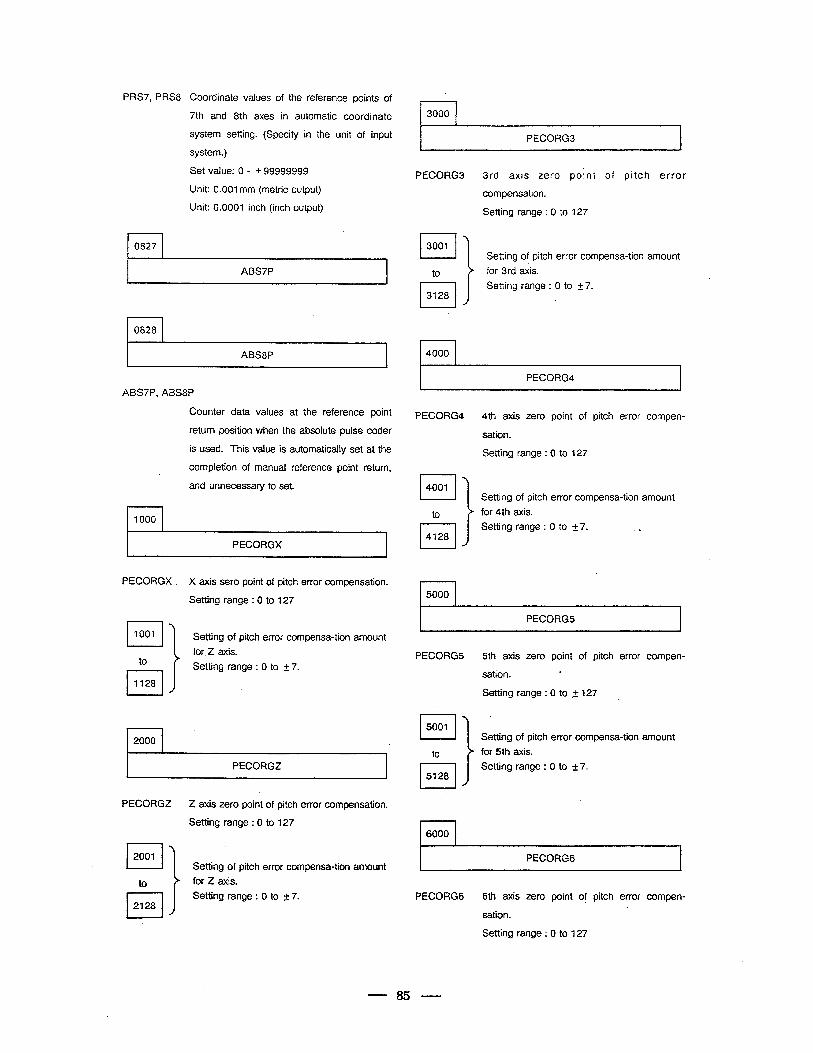
PRS7, PRS8
rl 0827
Coordinate values of the reference points of
7th and 8th axes in automatic coordinate
system setting. (Specify in the unit of input
system.)
Set value: 0 - + 99999999
Unit: 0.001 mm (metric output)
Unit: 0.0001 inch (inch output)
PECORG3
PECORG3 3rd axis zero point of pitch error
compensation.
Setting range : 0 to 127
Setting of pitch error compensa-tion amount
for 3rd axis. ABSP
Setting range : 0 to + 7.
l-l 0828
l-l 4000 ABS8P
PECORG4
ABS7P, ABS8P
Counter data values at the reference point
return position when the absolute pulse coder
is used. This value is automaticaily set at the
completion of manual reference point return,
and unnecessary to set.
PECORG4 4th axis zero point of pitch error compen-
sation.
Setting range : 0 to 127
Setting of pitch error compensa-tion amount
for 4th axis.
Setting range : 0 to 2 7. 1000
PECORGX
PECORGX . X axis sero point of pitch error compensation.
Setting range : 0 to 127
Setting of pitch error compensa-tion amount
for.2 axis.
I I 5000
PECORGS
l-l 1001
to PECORG5 5th axis zero point of pitch error compen-
Setting range : 0 to 2 7.
0-J 1128 sation. .
Setting range : 0 to ,+ 127 .
Setting of pitch error compensa-tion amount
Setting range : 0 to k 7.
2000
PECORGZ
PECORGZ Z axis zero point of pitch error compensation.
Setting range : 0 to 127 r-l 6000
PECORGG Setting of pitch error compensa-tion amount
for 2 axis.
Setting range : 0 to 2 7. PECORGG 6th axis zero point of pitch error compen-
sation.
Setting range : 0 to 127
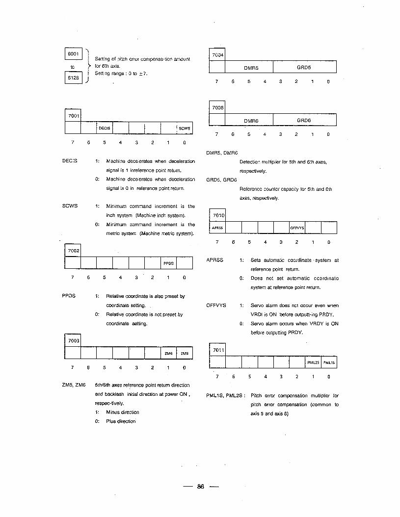
LJ 6001
to
Setting of pitch error compensa-tion amount
for 6th axis.
Setting range : 0 to 2 7.
r-l 7001
DEW3 . sews 4
7 6
DECIS I:
0:
sews 1:
0:
5 4 3 2 1 0
Machine decelerates when deceleration
signal is 1 inreference point return.
Machine decelerates when deceleration
signal is 0 in reference point return.
Minimum command increment is the
inch system (Machine inch system).
Minimum command increment is the
metric system (Machine metric system).
rl 7002
PPDS
7 6 5 4 3 2 1 0
7004
DMRS GRDs
7 6 5 4 3 -2 7 0
4
7005
DMR6 GRD6
7 6
DMRS, DMR6
GRDS, GRD6
l-l 7010
5 4 3 2 1 0
APRSS OFFVYS
Detection multiplier for 5th and 6th axes,
respectively.
Reference counter capacity for 5th and 6th
axes, respectively.
7 6
APRSS 1:
0:
5 4 3 2 1 0
Sets automatic coordinate &system at
reference point return.
Does not set automatic coordinate
system at reference point return.
PPDS 1: Relative coordinate is also preset by
I
coordinate setting. OFFVYS 1: Sewo alarm does not occur even when
0: Relative coordinate is not preset by VRDI is ON before output-king PRDY.
coordinate setting. 0: Servo alarm occurs when VRDY is ON
before outputting PRDY.
7003 r
7011 ZM6 ZM5 1
4 PMLZS PMLlS
7 6 5 4 3 2 1 0 t
ZM5,ZM6 5th/6th axes reference point return direction
and backlash initial direction at power ON ,
respec-tively. .
1: Minus direction
0: Plus direction
7 6 5 4 3 2 1 0
PMLlS, PMLZS : Pitch error compensation
pitch error compensation
axis 5 and axis 6)
multiplier for
(common to
86
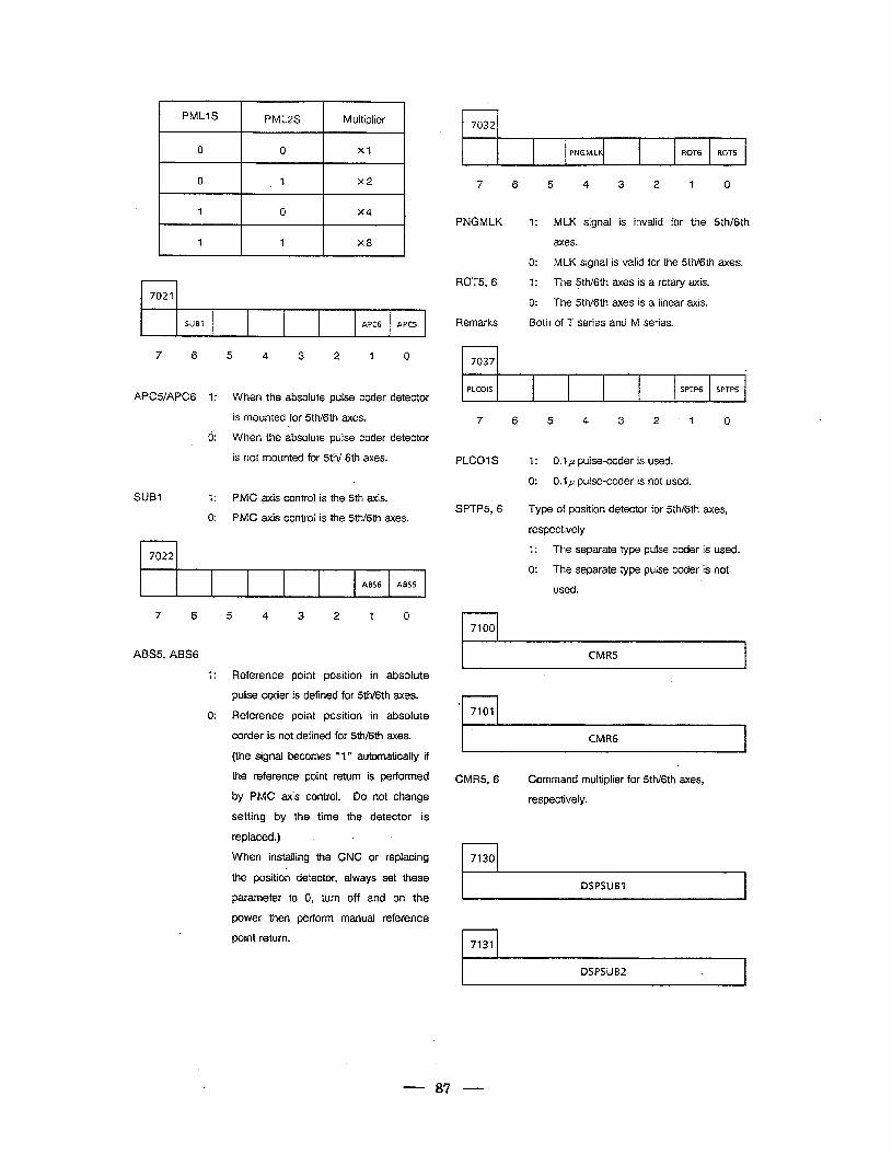
PMLlS PML2S
0 0
0 1
1 0
Multiplier
Xl
x2
x4
1
I
1 xa
7021
SUB1 APC6 APCS
7 6 5 4 3 2 1
APCSfAPC6 1: When the absolute pulse coder
is mounted for 5th/6th axes.
0: When the absolute pulse coder
is not mounted for 5th/ 6th axes .
SUB1 1: PMC axis control is the 5th axis.
0
detector
detector
0: PMC axis control is the 5th/6th axes.
I 1
7022 ,
ABS6 ABSS & -4
7 6 5 4 3 2 1 0
r 1 7032
,
PNCMLK ROT6 ROTS
7 6 5 4 3 2 1 0
PNGMLK 1: MLK signal is invalid for the 5th/6th
axes.
0: MLK signal is valid for the 5th/6th axes.
ROT56
Remarks
1: The 5tlV6th axes is a rotary axis.
0: The 5th/6th axes is a linear axis.
Both of T series and M series.
7037
PLCOIS SPTP6 SPTPS ,
7 6 5 4 3 2 1 0
PLCOlS 1: 0.1~ pulse-coder is used.
0: 0.1 p pulse-coder is not used.
SPTP5,6 Type of position detector for 5th/6th axes,
respectively
1: The separate type pulse coder is used.
0: The separate type pulse coder is not 2.
used.
r-l 7100
ABS5, ABS6 I CMR5 I
1: Reference point position in absolute
pulse coder is defined for 5th/6th axes.
0: Reference point position in absolute
corder is not defined for 5th/6th axes.
(the signal becomes “ 1” automatically if
the reference point return is performed
by PMC axis control. Do not change
setting by the time the detector is
replaced.)
When installing the CNC or replacing
the position detector, always set these
parameter to 0, turn off and on the
power then perform manual reference
point return.
I CMR6 I
CMRS, 6 - Ccmmand multiplier for 5th/6th axes,
respectively.
r-l 7130
DSPSUBI
l-l 7131
DSPSUB2
87
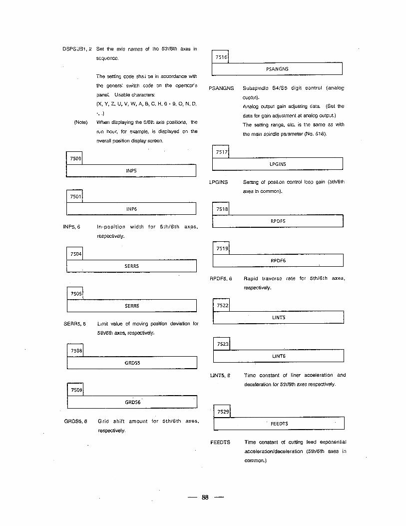
DSPSUBl, 2 Set the axis names of the 5thBh axes in
sequence.
(Note)
I 1
r-l 7516
PSANGNS
The setting code shall be in accordance with
the general switch code on the operator’s
panel. Usable characters:
(X Y, Z U, V, W A, B, C, R, 6 - 9, 0, N D,
PSANGNS Subspindle S4/S5 digit control (analog
ouptut).
Analog output gain adjusting data. (Set the
data for gain adjustment at analog output.)
The setting range, etc. is the same as with
the main spindle parameter (No. 516).
When displaying the 5/6th axis positions, the
run hour, for example, is displayed on the
overall position display screen.
1 75171
7500
INP5
LPGINS
LPGINS Setting of position control loop gain (5th/6th
axes in common).
INP6 7518
RPDFS INP5,6 in-position width for 5th/6th ax,es,
respectively.
rl 7504 7519
RPDFG
I SERR5 I
RPDFS, 6 Rapid traverse rate for 5th/6th axes,
respectively.
I I 7505
SERRG I
7522
Ll NT5 SERR5,6 Limit value of moving position deviation for
‘5th/6th axes, respectively.
rl 7523
rl 7508
I LINT6
GRDS5 I
LINT5, 6 Time constant of liner acceleration and
deceleration for 5th/6th axes respectively.
GRDS6
r-l 7529
FEEDTS GRDS5,6 Grid shift amount for 5th/6th axes,
respectively.
FEEDTS Time constant of cutting feed exponential
acceleration/deceleration (5th/6th axes in
common.)
88
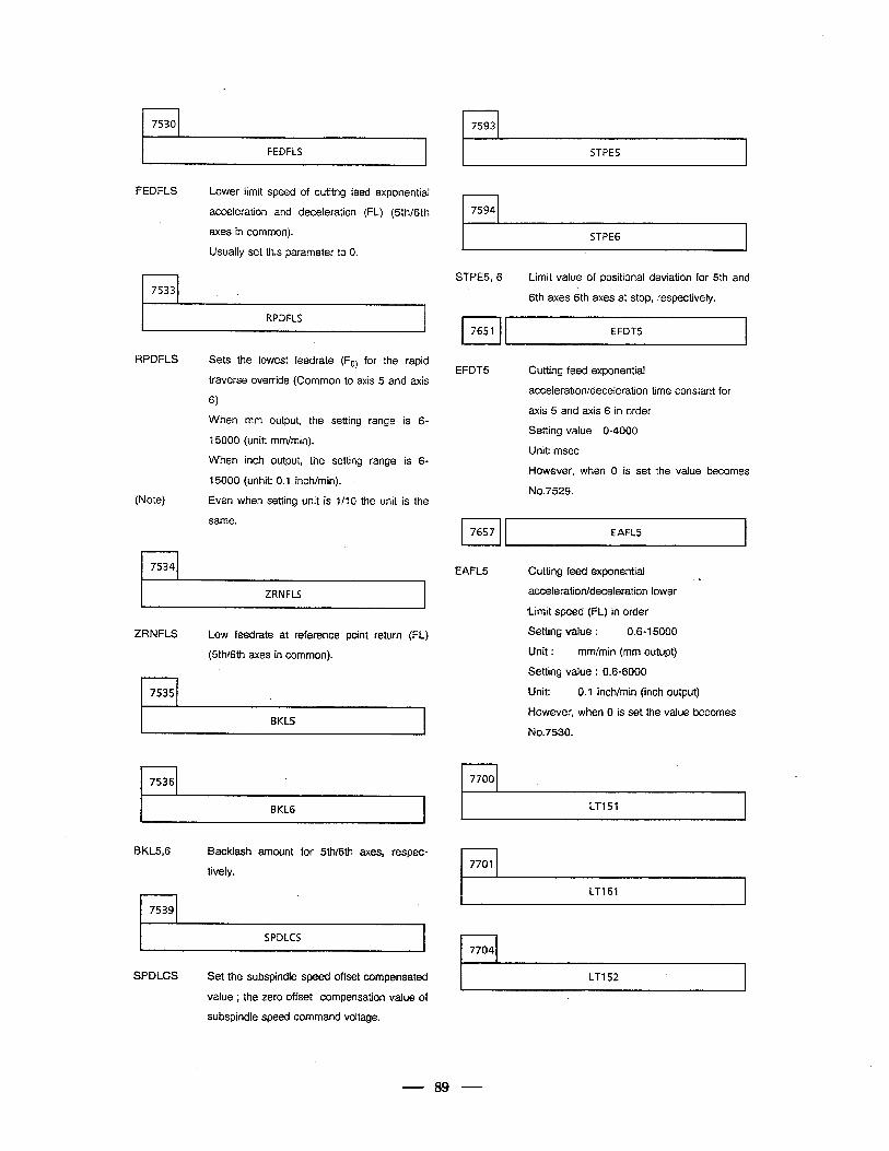
a
r I r-l 7593 7530 ,
FEDFLS r STPES -
r-l 7594
FEDFLS Lower limit speed of cutitng feed exponential
acceleration and deceleration (FL) (5th/6th
r STPE6 axes in common).
Usually set this parameter to 0.
STPE5,6 Limit value of positional deviation for 5th and
r-l 7533 6th axes 6th axes at stop, respectively.
RPDFLS 1 EFDTS
RPDFLS Sets the lowest feedrate (F,) for the rapid
traverse override (Common to axis 5 and axis
6)
(Note)
When mm output, the setting range is 6-
t 5000 (unit: mm/min).
When inch output, the setting range is 6-
15000 (unhit: 0.1 inch/min).
Even when setting unit is l/l 0 the unit is the
same.
EFDTS Cutting feed exponential
acceleration/deceleration time constant for
axis 5 and axis 6 in order
Setting value O-4000
Unit: msec
However, when 0 is set the value becomes
No.7529.
I. 7657 EAFLS 1
r-l 7534 EAFLS Cutting feed exponential c acceleration/deceleration lower
Limit speed (FL) in order
Setting value : 0.6-I 5000
I ZRNFLS I
ZRNFLS Low fee&ate at reference point return (FL)
(5th/6th axes in common). Unit : mm/min (mm outupt)
Setting value : 0.6-6000
Unit:
However,
N0.7530.
0.1 inch/min (inch output)
when 0 is set the value becomes
7535
I
I BKLS
r-l 7536 rl 7700
I- LTl51 I I BKL6
BKL5,6 Backlash amount for 5th/6th axes, respec-
tively.
r LT161 I
SPDLCS l-l 7704
r LTI 52 I SPDLCS Set the subspindle speed offset compensated
value ; the zero offset compensation value of
su bspindle speed command voitage.
89
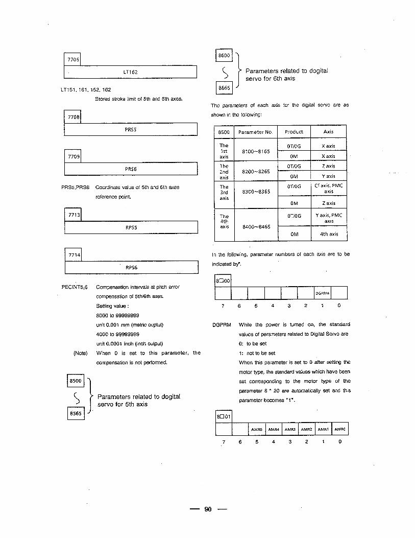
r-l 7705
I ’ LTI 62
LT151, 161, 152, 162 cl
8665
Stored stroke limit of 5th and 6th axes.
PRS5
7709
PRS6
PRSS,PRSG Coordinate value of 5th and 6th axes
reference point.
l-l 7713
RPS5
. 7714
RPS6
PECINT5,6 Compensation intervals at pitch error
compensation of 5th/6th axes.
Setting value :
8000 to 99999999
unit 0.001 mfn (metric ouptut)
4000 to 99999999
unit 0.0001 inch (inch output)
(Note) When 0 is set to this parameter, the 1: not to be set
compensation is. not performed.
i?l 8500
(A t Parameters related to dogital servo for 5th axis
.
Parameters related to dogital servo for 6th axis
The parameters of each axis for the digital servo are as
shown in the following:
8500 Parameter No. Product Axis
The 2nd axis
The 3rd axis
The 4th axis
OT/OG Z axis 8200-8265 ..<. , _
OM Y axis ’ 1 OT/OG Cf axis, PMC
8300-8365 - axis
OM Z axis
OT/OG Y axis, PMC axis
8400-8465
OM 4th axis
In the following, parameter numbers of each axis are to be
indicated by”. c
1 8100
DGPRM
7 6 5 4 3 2 1 0
DGPRM While the power is turned on, the standard
values of parameters related to Digital Servo are
0: to be set
When this parameter is set to 0 after setting the
motor type, the standard values which have been
set corresponding to the motor type of the
parameter 8 * 20 are automatically set and this
parameter becomes @’ 1”.
1 7
8c101
AMRS AMR4 AMR3 AMR2 AMRl AMRO
,
7 6 5 4 3 2 1 0
90
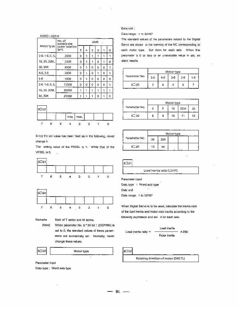
AMRO-AMR5
No. of pulse/pulse AMR
Motortype coder rotation (P/r) 543210
2-0, I-O, 0,5, 2000 0 1 1 1 1 1
10,20,20M, 2500 0 1 1 0 1 0
30,30R 3000 010001
4-0,3-o 2000 0 1 0 1 0 1
80021
VFSEL PSSEL
7 6 5 4 3 2 1 0
Since the set value has been fixed as in the following, never
change it.
The setting value of the PSSEL is 1. While that of the
VFSEL is 0. .
rl 8003 \
1
4
Data unit :
Data range: 1 to 32767
The standard values of the parameters related to the Digital
Servo are stored in the memory of the NC corresponding to
each motor type. Set them for each axis. When this
parameter is 0 or less or an unavailable value is set, an
alarm results.
Motor type
Parameter No- 5-O 4-O 3-O 2-O 1-O
8020 3 4 5 6 7 I
r I 1 I Motor tvpe I , I
Parameter No. o 5 IO 20M 20
8020 8 9 IO 11 12
f Motor type
Parameter No. 3o 30R
8020 13 14
r-l 8021
I Load inertia ratio (LDINT) I
7 6 5 4 3 2 1 0 Parameter input
I 1 8004
4
7 6 5 4.3 2 1 0
Remarks Both of T series and M series.
(Note) When parameter No. 8 * 00 bit 1 (DGPRM) is
set to 0, the standard values of these param-
eters are autmatically set. Normally, never
change these values.
Motor type 8022
Parameter input
Data type : Word axis type
Data type : Word axis type
Data unit
Data range: 1 to 32767
When Digital Servo is to’be used, calculate the inertia ratio
of the load inertid and motor rotor inertia according to the
following expression and set it for each axis.
Load inertia Load inertia ratio = x 256
Rotor inertia
Rotating direction of motor (DIRCTL)
91
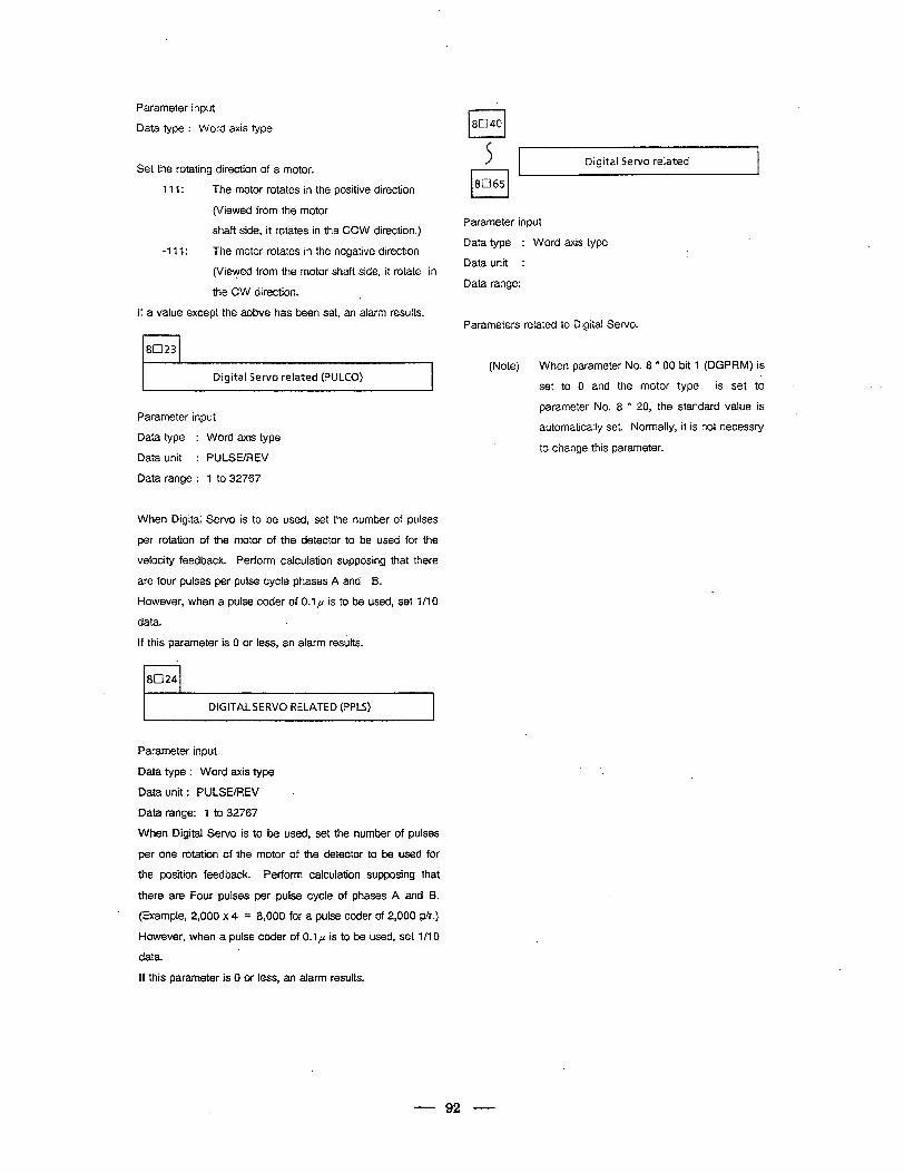
Parameter input
Data type : Word axis type
Set the rotating direction of a motor.
111: The motor rotates in the positive direction
(Viewed from the motor
shaft side, it rotates in the CCW direction.)
-111: The motor rotates in the negative direction
(Viewed from the motor shaft side, it rotate in
the CW direction. ‘1.
If a value except the aobve has been set, an alarm results.
8023
, Digital Servo related (PULCO)
Parameter input
Data type : Word axis type
Data unit : PULSE/REV
Data range : 1 to 32767
When Digital Servo is to be used, set the number of pulses
per rotation of the motor of the detector to be used for the
velocity feedback. Perform calculation supposing that there
are four pulses per pulse cycle phases A and B.
However, when a pulse coder of 0.1~ is to be used, set l/l 0
data.
If this parameter is 0 or less, an alarm results.
.
8024
DIGITAL SERVO RELATED (PPLS)
Parameter input
Data type : Word axis type
Data unit : PULSE/REV .
Data range: 7 to 32767
When Digital Servo is to be used, set the number of pulses
per one rotation of the motor of the detector to be used for
the position feedback. Perform calculation supposing that
there are Four pulses per pulse cycle of phases A and B.
. (Example, 2,000 x 4 = 8,000 for a pulse coder of 2,000 p/r.)
However, when a pulse coder of 0.1 p is to be used, set l/l 0
data.
If this parameter is 0 or less, an alarm results.
0 8040
Digital Servo related
Parameter input
Data type : Word axis type
Data unit :
Data range:
Parameters related to Digital Servo.
(Note) When parameter No. 8 * 00 bit 1 (DGPRM) is
set to 0 and the motor type is set to
parameter No. 8 * 20, the standard value is
automatically set. Normally, it is not necessry
to change this parameter.
92
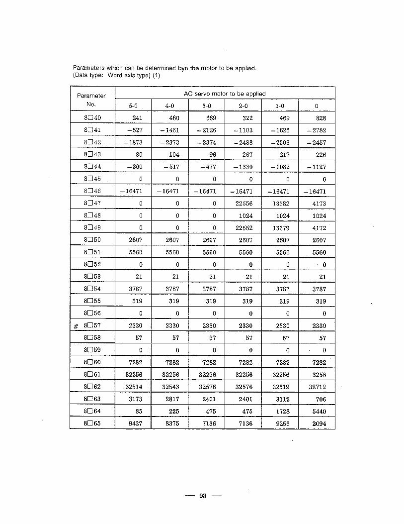
Parameters which can be determined byn the motor to be applied.
(Data type: Word axis type) (I)
Parameter , AC servo motor to be applied
NO. 5-o 4-o 3-o 2-o 1-O 0
8040 241 460 669 322 469 828
8041 -527 -1461 -2126 -1103 -1625 -2782
8042 -1873 -2373 -2374 -2488 -2503 -2457
8043 80 104 96 267 217 226
8044 -300 -517 -477 -1330 -1082 -1127
8045 0 *o 0 0 0 0
8046 -16471 -16471 -16471 -16471 -16471 -16471
8047 0 0 0 22556 13682 4173
8048 0 0 0 1024 1024 1024
8049 0 0 0 22552 13679 4172
8fl50 2607 2607 2607 2607 2607 2607
8051 5560 5560 5560 5560 5560 5560 I
8052 0 0 0 0 0 L 0
8053 21 21 21 21 21 -21
8054 3787 3787 3787 3787 3787 3787
8055 319 319 319 319 319 319
8056 0 0 0 0 0 0
8057 # 2330 2330 2330 2330 2330 2330
8058 57 57 57 57 57 57
8059 0 0 0 0 0 -0
8060 7282 7282 7282 7282 7282 7282
8061 32256 32256 32256 32256 32256 3256
8062 .32514 32543 32576 32576 32519 32712
8063 3173 2817 2401 2401 3112 706
8064 85 225 475 475 1728 5440
8065 9437 8375 7136 7136 9256 2094 1
- 93 -
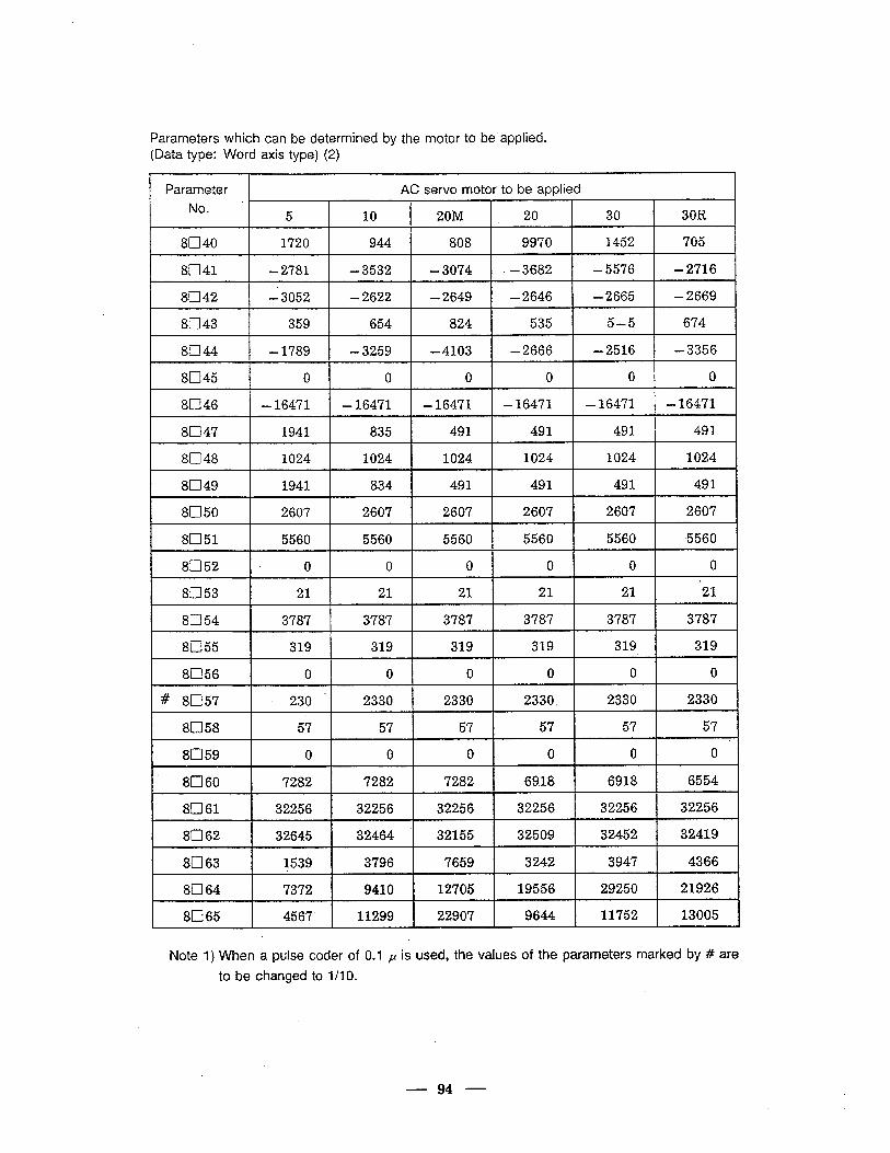
Parameters which can be determined by the motor to be’applied. (Data type: Word axis type) (2)
Parameter AC servo motor to be applied
- No. 5 10 20M 20 30 30R
8040 1720 944 808 9970 1452 705
8041 -2'781 -3532 -3074 . -3682 -5576 -2716
8042 -3052 -2622 -2649 -2646 -2665 -2669
8043 359 654 824 535 5-5 674 I
SC344 -1789 -3259 -4103 -2666 -2516 -3356
8045 0 0 0 0 0 0
8046 -16471 -16471 -16471 -16471 -16471 -16471
8047 1941 835 491 491 491 491
8048 1024 1024 1024 1024 1024 1024
8D49 1941 834 491 491 491 491
sz350 2607 2607 2607 2607 2607 2607
8051 5560 5560 5560 5560 5560 5560
8052 0 '0 0 0 0 0
8053 21 21 21 21 21 &l
81354 . 3787 3787 3787 3787 3787 3787 f
8055 319 319 319 319 319 319 1
8056 0 0 0 0 0 0
# - SD57 . 230 2330 2330 2330. 2330 2330
8058 57 57 57 57 57 57
SD59 0 -0 0 0 0 0
8a60 7282 7282 7282 6918 6918 6554
8061 32256 32256 32256 32256 32256 32256
. 8062 32645 32464 32155 32509 32452 32419
8063 1539 3796 7659 3242 3947 4366
8064 7372 9410 12705 19556 29250 21926
8065 4567 11299 22907 9644 11752 13005 4
Note 1) When a pulse coder of 0.1 p is used, the values of the parameters marked by # are
to be changed to l/l 0.
94

Common parameters for each motor model
(Data type: bit axis type)
I Parameter I Data I L J
No. #7 #6 #5 #4 #3 #2 #l #0
8003 0 0 0 0 0 0 0 1
1 8004 IO IO IO II 11 IO II IO I
95
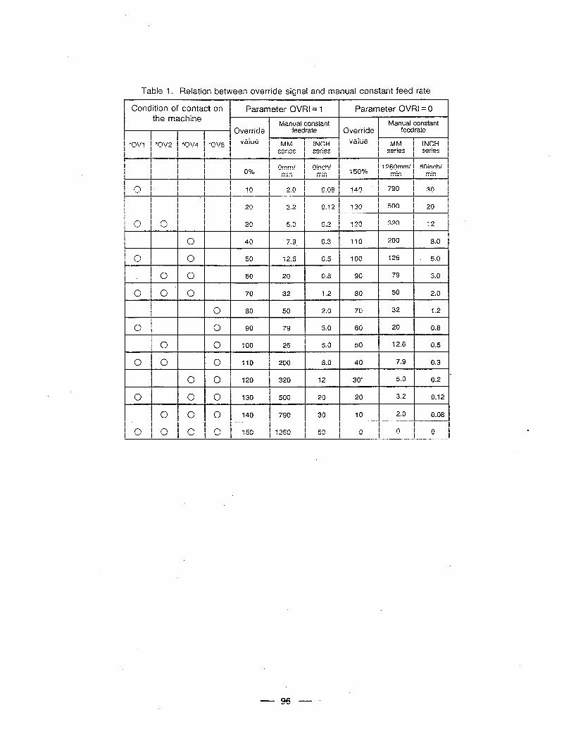
Table 1. Relation between override signal and manual constant feed rate
Condition of contact on Parameter OVRI = I Parameter OVRI = 0 the machine
- Overrid’e Manual constant Manual constant
feedrate Override feedrate
“OVI *ov2 “0V4 *OV8 value MM INCH value MM INCH series series series series
0% Omm/ Oinch/ 1260mm/ 50inch/ min min 150% min min
0 10 2.0 0.08 140 790 30
. 20 3.2 0.12 130 500 20
0 0 30 5.0 0.2 120 320 12
0 40 7.9. 0.3 110 200 8.0
0 0 50 12.6 0.5 100 126 . 5.0
0 0 60 20 0.8 90 79 3.0
0 0 0 70 32 1.2 80 50 2.0
0 80 50 2.0 70 32 1.2
0 0 90 79 3.0 60 20 0.8
0 0 100 26 5.0 50 12.6 0.5
0 0 0 110 200 8.0 40 7.9 0.3
L 0 0 120 320 12 30‘ 5.0 0.2
0 0 0 130 500 20 20 3.2 0.12
0 0 0 140 790 30 10 2.0 0.08
0 0 0 0 150 1260 50 0 0 0 1 I I
.
96
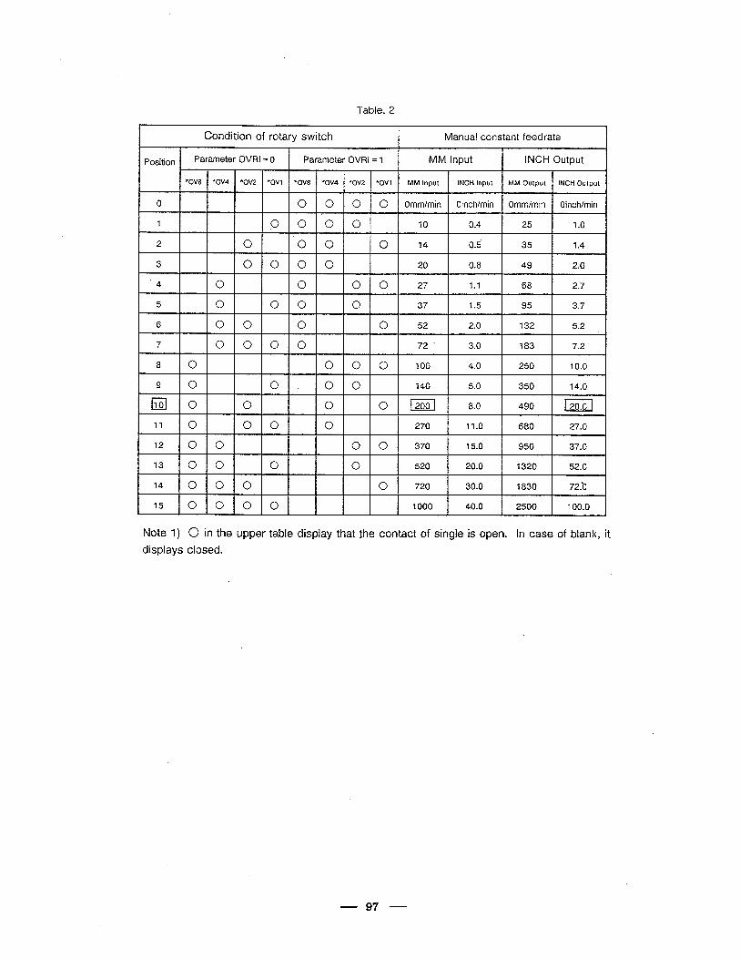
Table. 2
Condition of rotary switch Manual constant feedrate
Position Parameter OVRI = 0 Parameter OVRI = 1 MM Input INCH Output
“OV8 *ov4 *0V2 *ov1 “OV8 “Owl *ov2 *ov1 MM Input INCH Input MM Output 1NCH Out put I
0 0 0 0 0 Omm/min Oinch/min Omm/min Oinch/min
1 0 0 0 0 10 0.4 25 1.0
2 0 ‘00 0 14 0.5 35 1.4
3 0 0 0 0 20 0.8 49 2.0
4 0 0 0 0 27 1.1 68 2.7 I
5 0 0 0 0 37 1.5 95 3.7
6 0 0 0 0 52 2.0 132 5.2
7 0 0 0 0 72 - 3.0 183 7.2
8 0 0 0 0 100 4.0 250 10.0
9 0 0. 00 140 5.0 350 14.0
11010 0 0 0 12001 8.0 490 l2o.01 I
11 0 0 0 0 270 11.0 680 27.0
12 0 0 0 0 370 15.0 950 37.0
13 0 0 0 0 520 20.0 1320 52.0
14 0 0 0 0 720 30.0 1830 72.b I
15 ,o 0 0 0 1000 40.0 2500 100.0 .
Note 1) 0 in the upper table display that the contact of single is open. in case of blank, it
displays closed.
97
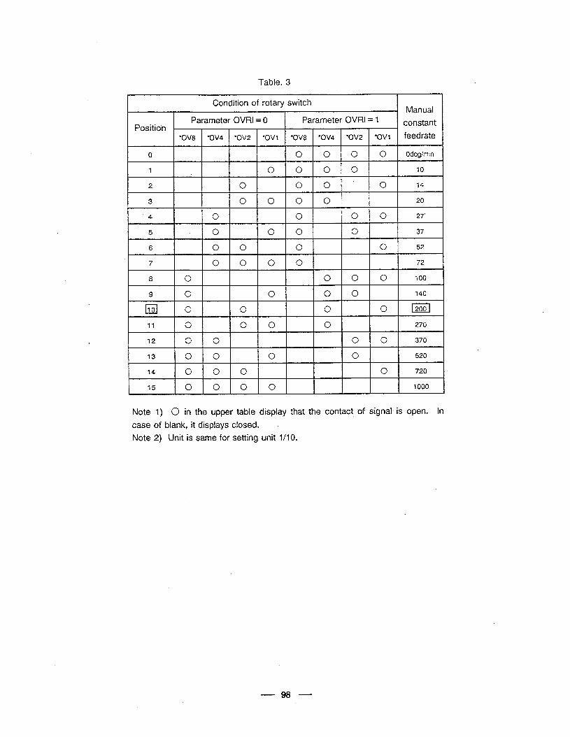
Table. 3
Condition of rotary switch . Manual
Parameter OVRl = 0 Parameter OVRI = 1 Position constant
*0V8 *ov4 *ov2 *ov1 *0V8 “OV4 *ov2 *ov1 feedrate
0 0 0 0 0 Odeg/min
1 0 0 0 0 10
2 0. 0 0 0 14
3 0 0 0 0 20
* ‘4 0 0 0 0 27’
5 0 0 0 0 37
6 0 0 0 0 52
7 0'0 0 0 72
8 0 0 0 0 100
9 0 0 0 0 140
cl 10 0 0 0 0 12001
11 0 0 0 0 270 r
12 0 0 0 0 370
73 0 0 0 0 520
14 0 0 0 0 720
I 75 lololoro-I I I I I 1000
Note 1) 0 in the upper table display that the contact of signal is open. In
case of blank, it displays closed. I
Note 2) Unit is same for setting unit l/l 0.
98
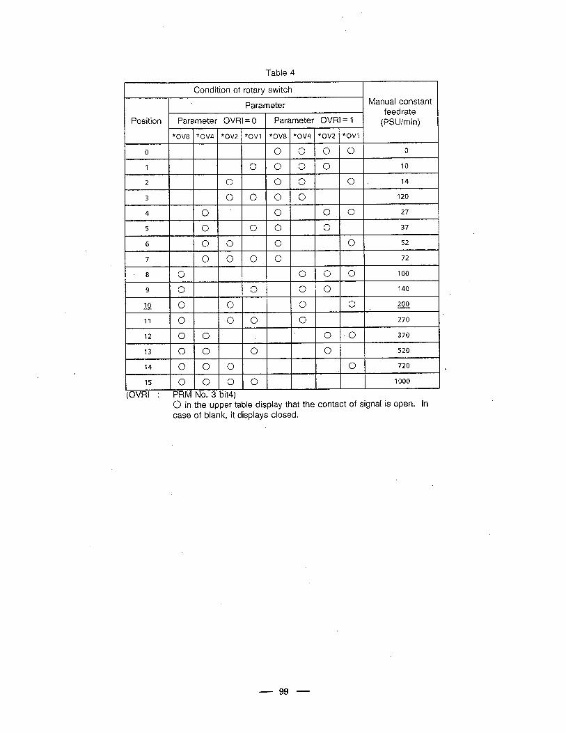
Table 4 r
Condition of rotary switch
Parameter Manual constant / feedrate
Position Parameter OVRI = 0 Parameter OVRI = 1 (PSU/min) T
*OV8 “OV4 “OV2 *OVl “OV8 *OV4 *OV2 *OVl
0 0 0 0 0 0
1 0 0 0 0 10
2 0. 0 0 0 14
3 0 0 0 0 120
4 0 0 0, 0 27
5 0 0 0 0 37
6 0 0 0 0 52
7 0 0 0 0 72
8 0 0 0 0 100
9 0 0 0 0 140 s
fi 0 0 0 0 200
‘11 0 0 0 0 270
12 0 0 0 -0 370
13 0 0 0 0 520
14 0 0 0 0 720 a.
15 0 0 0 0 1000 I 4 (OVRI : PRM No. 3 bit4)
0 in the upper table display that the contact of signal is open. in case of blank, it displays closed.
- 99 -
Specifications of ,Additional Parameters
l This document is a description of the additional parameter applied in FANUC Series
0-TC 0666-l 8/04X 0680-l 6, 0681-l 6, 0682-l 6 or later. Therefore, some
parameters might not be applied in other series/edition.
l Because the specification might be limited, please refer to each specifications when
applying these parameters.
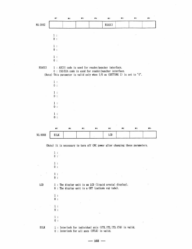
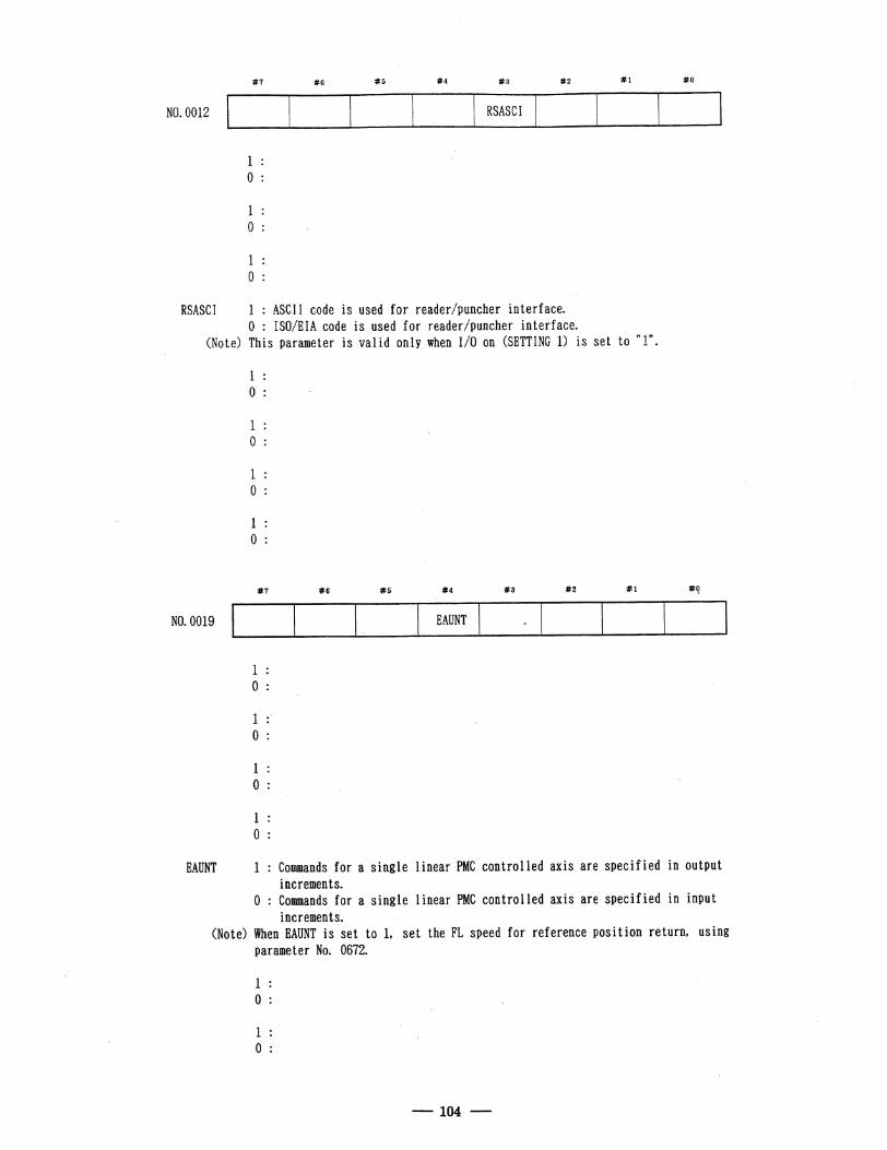
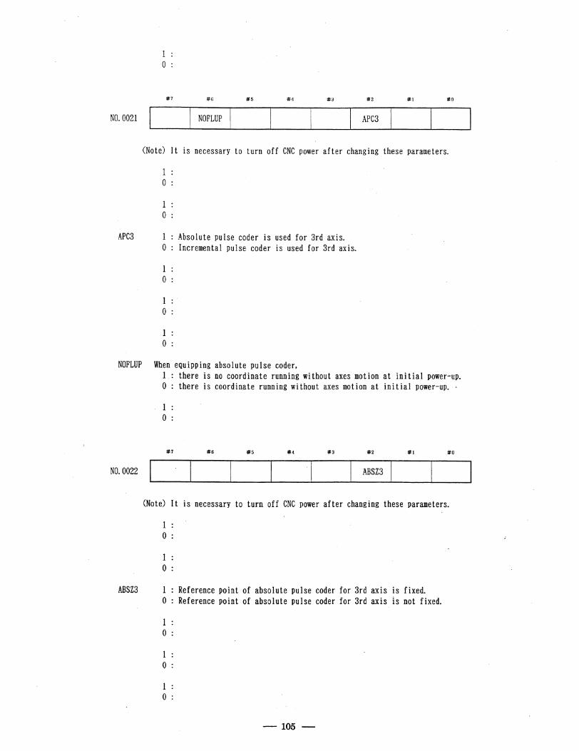
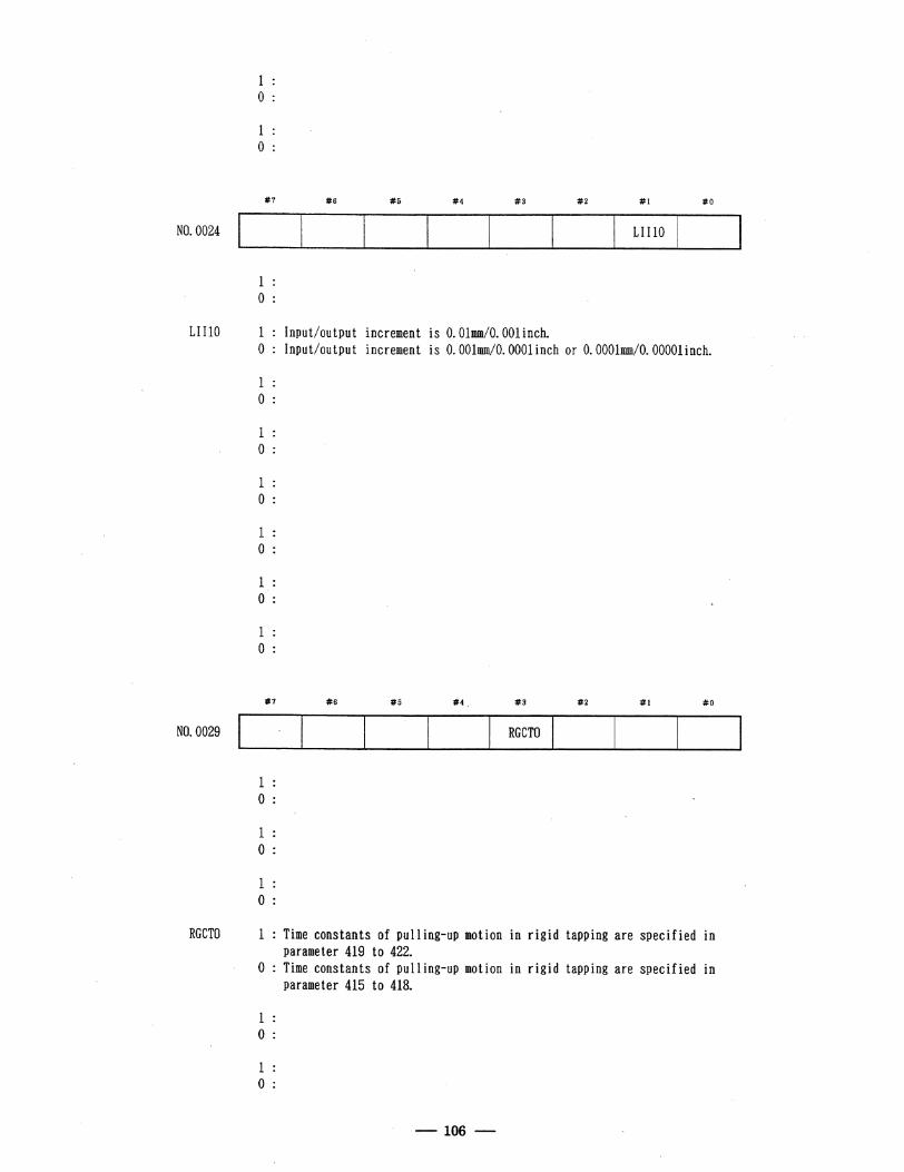
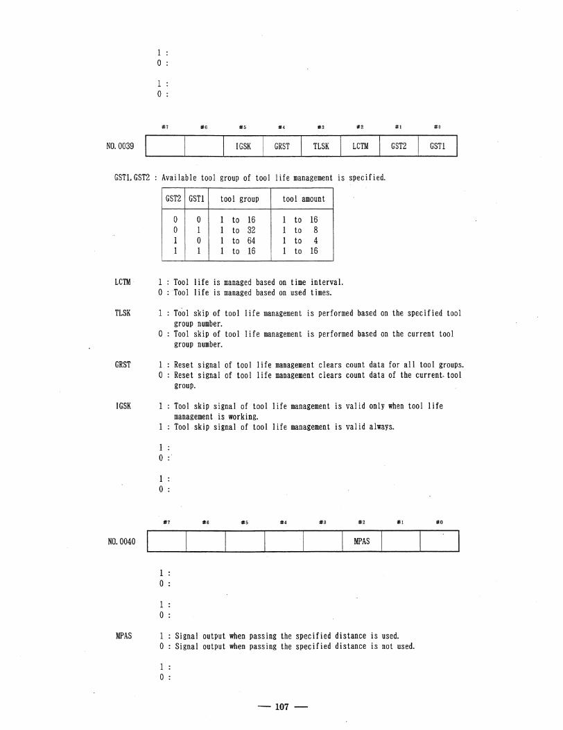
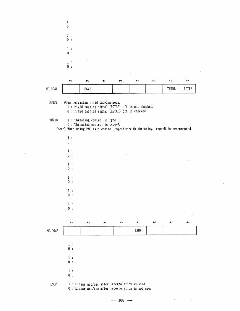
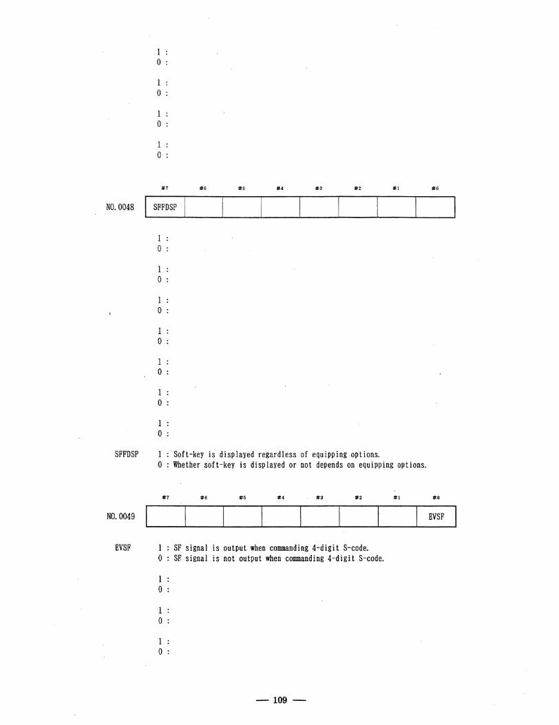
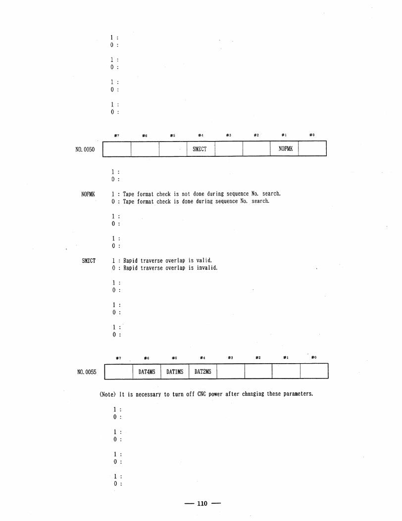
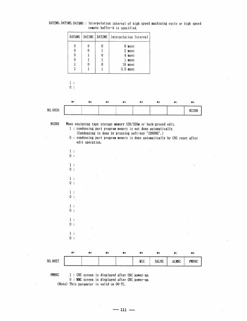
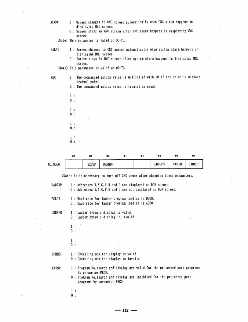
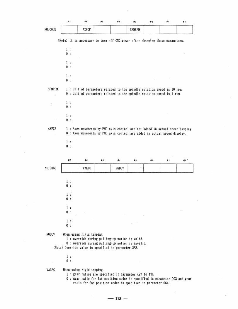
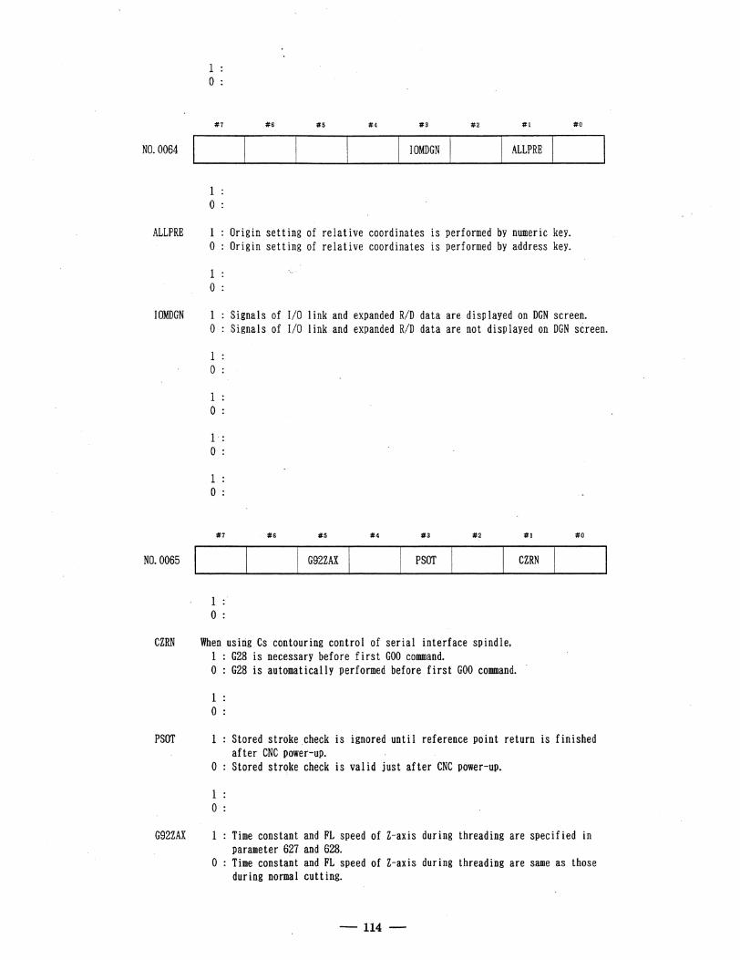
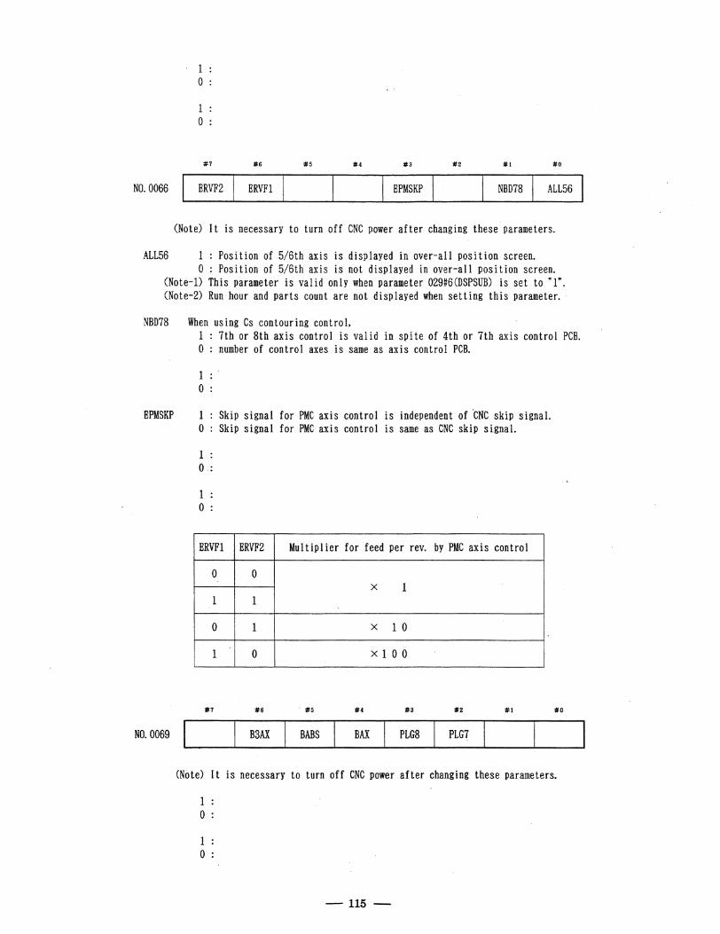
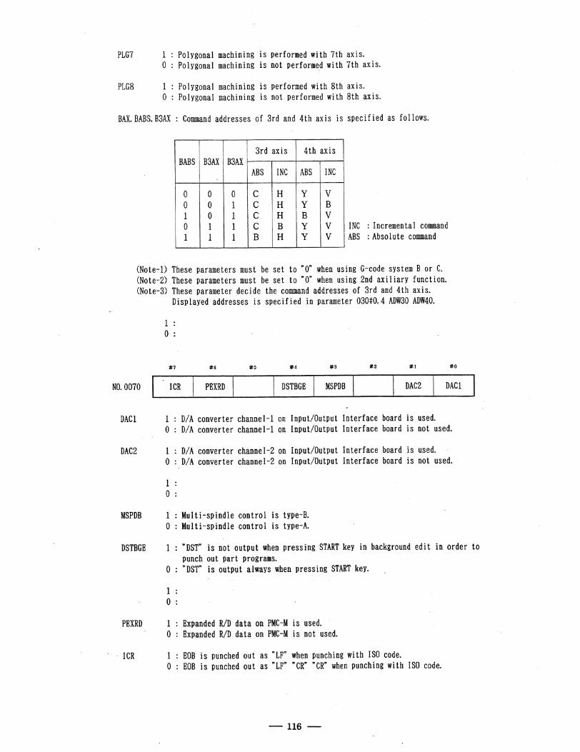
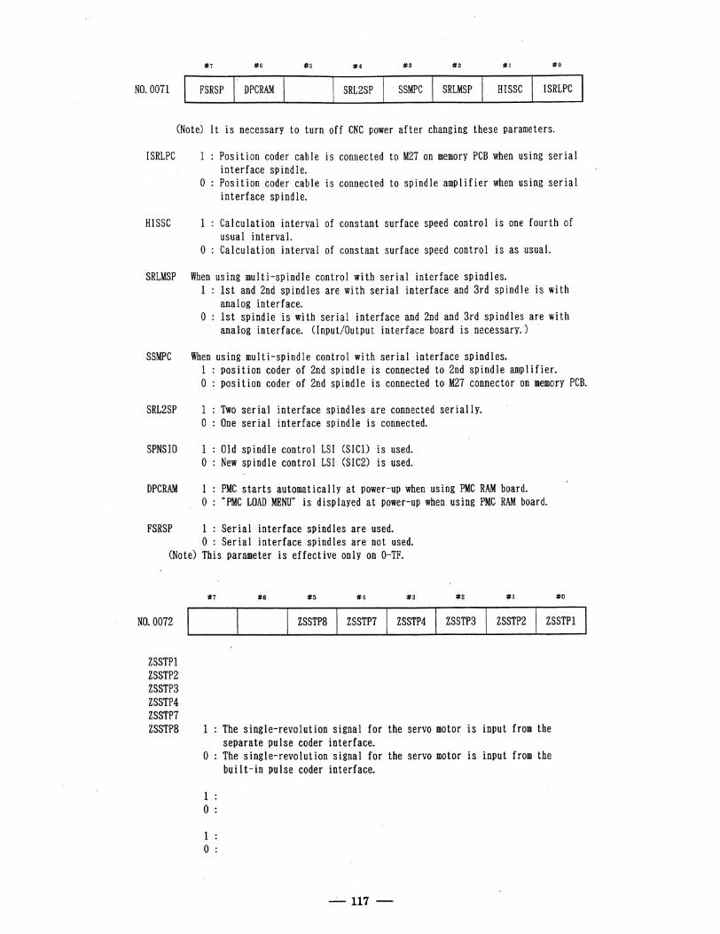
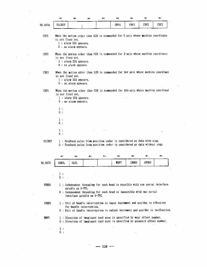
NO. 0074
CRFX
CRFZ
CRF3
CRF4
PLCREV
#7 #6 #5 #4 #3 #2 #l #O
,
PLCREV . CRF4 CRF3 s CRFZ CRFX
When the motion other than G28 is commanded for X-axis whose machine coordinate is not fixed yet,
1 : alarm 224 appears. 0 : no alarm appears.
When the motion other than G28 is commanded for Z-axis whose machine coordinate is not fixed yet,
1 : alarm 224 appears. 0 : no alarm appears.
When the motion other than .G28 is commanded. for 3rd-axis whose machine coordinat is not fixed yet,
1 : alarm 224 appears. 0 : no alarm appears.
When the motion other than G28 is commanded for 4th-axis whose machine coordinat is not fixed yet,
1 : alarm 224 appears. 0 : no alarm appears.
1 .
Ol
1 : 0 :
1’: . i. 0 :
1 : Feedback pulse from position coder is considered as data with sign. 0 : Feedback pulse from position coder is considered as data without sign.
#7 #6 x5 #4 #3 #2 Xl #O
NO. 0075 IONUL CLCL WNPT I NHND STHRD .
1 . . 0 . . .
STHRD 1 : Independent threading for each head is possible with one serial interface spindle on 0-TTC.
0 : Independent threading for each head is impossible with one serial interface spindle on 0-TTC.
INHND 1 : Unit of handle interruption is input increment and acc/dec is effective for handle interrupt ion.
1 0 : Unit of handle interruption is output increment and acc/dec is ineffective.
WNPT 1 : Direction of imaginary tool nose is specified by wear offset number. 0 : Direction of imaginary tool nose is specified by geometry offset number.
1 : .
0 :
- 118 -
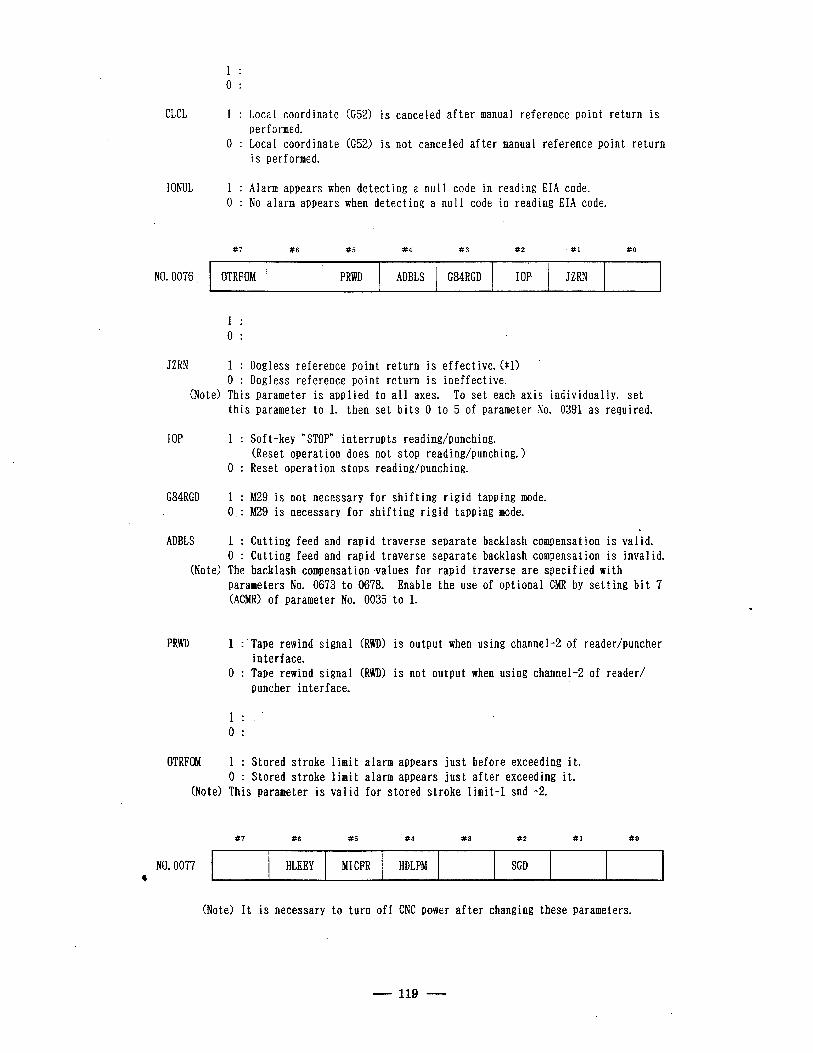
1 : 0 :
CLCL 1 : Local coordinate (G52) is canceled after manual reference point return is performed.
0 : Local coordinate (G52) is not canceled after manual reference point return is performed.
I ONUL 1 : Alarm appears when detecting a null code in reading EIA code. 0 : No alarm appears when detecting a null code in reading EIA code.
117 #6 #5 #4 #3 X2 #I a0
\
NO. 0076 OTRFOM PRWD ADBLS G84RGD IOP JZRN
1 : 0 :
JZRN 1 : Dogless reference point return is effective. ($1) 0 : Dogless reference point return is ineffective.
(Note) This parameter is applied to all axes. To set each axis individually, set this parameter to 1, then set bits 0 to 5 of parameter No. 0391 as required.
IOP 1 :
0 :
G84RGD 1 : M29 is not necessary for shifting rigid tapping mode. 0 : M29 is necessary for shifting rigid tapping mode.
ADBLS 1 : Cutting feed and rapid traverse separate backlash compensation is valid. 0 : Cutting feed and rapid traverseseparate backlash compensation is invalid.
(Note) The backlash compensation values for rapid traverse are specified with
Soft-key “STOP” interrupts reading/punching. (Reset operation does not stop reading/punching. > Reset operation stops reading/punching.
parameters No. 0673 to 0678. Enable the use of optional CMR by setting bit 7 (ACMR) of parameter No. 0035 to 1.
PRWD 1 :‘Tape rewind signal (RWD) is output when using channel-2 of reader/puncher interface.
0 : Tape rewind signal (RWD) is not output when using channel-2 of reader/ puncher interface.
1 .
OI
OTRFOM 1 : Stored stroke limit alarm appears just before exceeding it. 0 : Stored stroke limit alarm appears just after exceeding it.
(Note) This parameter is valid for stored stroke limit-l snd -2.
#? #6 #5 ‘#4 #3 #2 Xl #o
NO. 0077 HLKEY MI CFR HDLPM SGD *
(Note) It is necessary to turn off CNC power after changing these parameters.
- 119 -
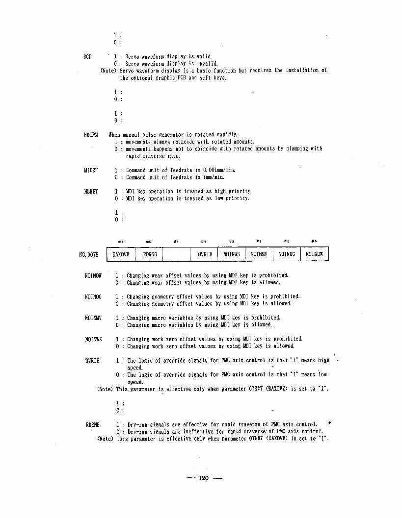
1 : 0 :
SGD * 1 : Servo waveform display is valid. 0 : Servo waveform display is invalid.
(Note> Servo waveform display is a basic function but requires the installation of
HDLPM
MICRF
HLKEY
NO. 0078
the optional graphic PCB and soft keys.
1 : 0: .
1 : 0 :
When manual pulse generator is rotated rapidly, 1 : movements always coincide with rotated amounts. 0 : movements happens not to coincide with rotated amounts by clamping with
rapid traverse rate.
1 : Command unit of feedrate is O.OOlmm/min. 0 : Command unit of feedrate is lmm/min.
1 : MD1 key operation is treated as high priority. 0 : ‘MD1 key operation is treated as low priority.
1 : 0 :
#? #6 #5 #4 #3 #2 #1 #O
EAXOVE RDRNE OVRIE NOINWS NOINMV NOINOG NOINOW +
NOINOW 1 : Changing wear offset values by using MD1 key is prohibited. 0 : Changing wear offset values by using MDI. key is allowed.
NOINOG 1 : Changing geometry offset values by using MD1 key is prohibited. 0 : Changing geometry offset values by using MD1 key is allowed.
NOINMV 1 : Changing macro variables by using MD1 key is prohibited. 0 : Changing macro variables by using MD1 key is allowed.
NOINWZ 1 : Changing work zero offset values by using MD1 key is prohibited. ' 0 : Changing work zero offset values by using MD1 key is allowed.
OVRIE 1 : The logic of override signals for PMC axis control is that “1” means high - speed.
0 : The logic of override signals for PMC axis control is that Yn means low speed.
(Note) This parameter is effective only when parameter 078#? (EAXOVE) is set to *I”.
1 . . 0 . .
RDRNE 1 : Dry-run signals are effective for rapid traverse of PMC axis control. @ 0 : Dry-run signals are ineffective for rapid traverse.of PMC axis control.
(Note) This parameter is effective only. when parameter 078#7 (EAXOVE) is set to “1”.
- 120 -
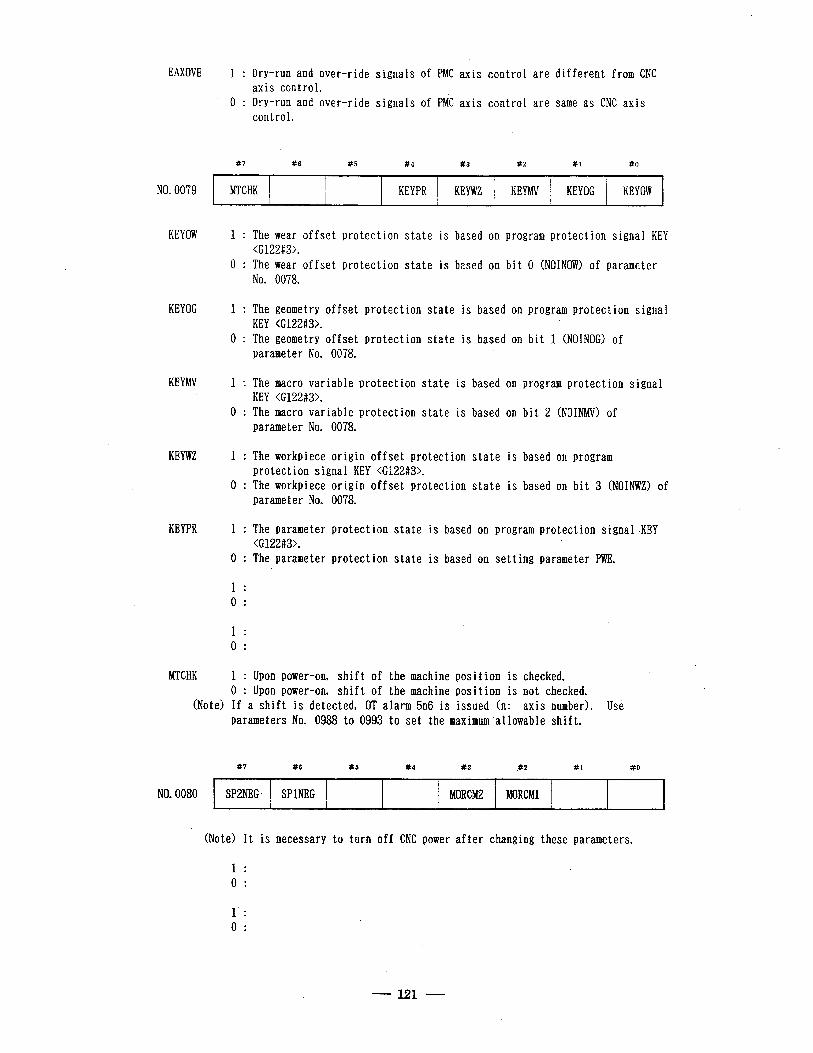
EAXOVE 1 : Dry-run and over-ride signals of PMC axis control are different from CNC axis control.
0 : Dry-run and over-ride signals of PMC axis control are same as CNC axis control.
NO. 0079
#7
MTCHK
#6 #5 #4
KEYPR
#3 #2 #l #O
.
KEYWZ KEYMV KEYOG KEY OW ,
KEYOW 1 : The wear offset protection state is based on program protection signal KEY <G122#3>.
0 : The wear offset protection state is based on bit 0 (NOINOW) of parameter No. 0078.
KEYOG 1 : The geometry offset protection state is based on program protection signal KEY <G122#3>.
0 : The geometry offset protection state is based on bit 1 (NOINOG) of parameter No. 0078.
KEYMV 1 : The macro variable protection state is based on program protection signal KEY -<G122#3>.
0 : The macro variable protection state is based on bit 2 (NOINMV) of parameter No. 0078.
KEYWZ 1 : The workpiece origin offset protection state is based on program protection signal KEY <G122#3>.
0 : The workpiece origin offset protection state is based on bit 3 (NOINWZ) of parameter No. 0078.
KEYPR 1 : The parameter protection state is based on program protection signal &KEY <G122#3>.
0 : The parameter protection state is based on setting parameter PWE.
1 : 0 :
1 : 0 . .
MTCHK 1 : Upon power-on, shift of the machine position is checked. 0 : Upon power-on, shift of the machine position is not checked.
(Note) If a shift is detected, OT alarm 5n6 is issued (n: axis number). Use parameters No. 0988 to 0993 to set the maximum’allowable shift.
#7 #6 x5 #4 #3 P2 #1 #O
NO. 0080 SP2NEG. SPlNEG MORCM2 MORCMl
(Note) It is necessary to turn off CNC power after changing these parameters.
1 : 0 :
1’ : 0 :
121
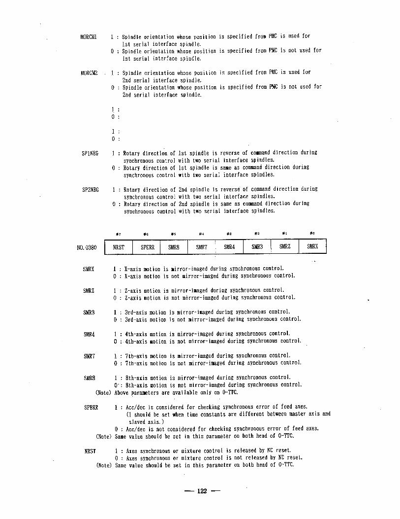
MORCMl 1 : Spindle orientation whose position is specified from PMC is used for 1st serial interface spindle.
0 : Spindle orientation whose position is specified from PMC is not used for 1st serial interface spindle.
MORCM2 1 : Spindle orientation whose position is specified from PMC is used for 2nd serial interface spindle.
0 : Spindle orientation whose position is specified from PMC is not used for 2nd serial interface spindle.
1 : 0 . .
1 : 0 :
SPlNEG 1 : Rotary direction of 1st spindle is reverse of command direction during synchronous control with two serial interface spindles.
0 : Rotary direction of 1st spindle is same as command direction during synchronous control with two serial interface spindles.
SP2NEG 1 : Rotary direction of 2nd spindle is reverse of command direction during synchronous control with two serial interface spindles.
0 : .Rotary direction of 2nd spindle is same as command direction during synchronous control with two serial interface spindles.
#7 #6 #5 #4 83 #2 #l 110
. *
NO. 0380 NRST SPERR SMR8 sMR7 sMR4 sMR3 SMRZ SMRX
SMRX 1 : X-axis motion is mirror -imaged dur ing synchronous con trol. 0 : X-axis motion is not mi rror-imaged during synchronous control.
SMRZ 1 : Z-axis motion is mirror- imaged dur 0 : Z-axis motion is not mir ror-imaged
i ng synchronou s control. during synchr onous control.
sMR3 1 : 3rd-axis motion is mirror-imaged during synchronous control. 0 :‘3rd-axis motion is not mirror-imaged during synchronous control.
sMR4 1 : 4th-ax is motion is mirror-imaged during sync hronous control. 0 :. 4.t h-ax is motion is not mirror-imaged during synchron .ous control.
sMR7 1 : 7th-axis motion is mirror-imaged during synchronous control. 0 : 7th-axis motion is not mirror-imaged during synchronous control.
SMR8 1 : 8th-axis motion is mirror-imaged during synchronous control. 0, : 8th-axis motion is not mirror-imaged during synchronous control.
(Note) Above *parameters’ are available only on 0-TTC.
SPERR 1 : Acc/dec is considered for checking synchronous error of feed axes. (1 should be set when time constants are different between master axis and slaved axis. >
0 : Acc/dec is not considered for checking synchronous error of feed axes. (Note) Same value should be set in this parameter on both head of 0-TTC.
NRST 1 : Axes synchronous or mixture control is released by NC reset. 0 : Axes synchronous or mixture control is not released by NC reset.
(Note) Same value should be set in this parameter on both head of O-TTC.
122
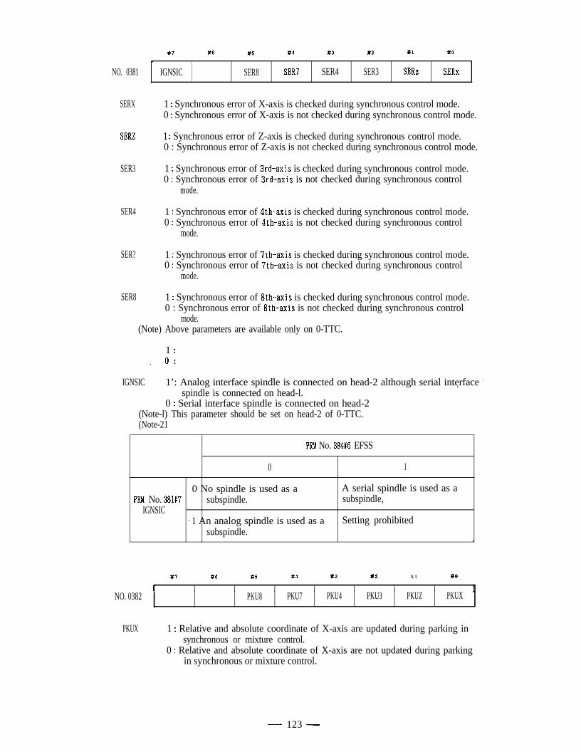
NO. 0381
SERX
SERZ
SER3
SER4
SER?
SER8
#7 #6 #5 #4 #3 #2 #l #O
c ,
IGNSIC SER8 SER? . SER4 SER3 SERz SERx
1 : Synchronous error of X-axis is checked during synchronous control mode.0 : Synchronous error of X-axis is not checked during synchronous control mode.
1 : Synchronous error of Z-axis is checked during synchronous control mode.0 : Synchronous error of Z-axis is not checked during synchronous control mode.
1 : Synchronous error of 3rd-axis is checked during synchronous control mode.0 : Synchronous error of 3rd-axis is not checked during synchronous control
mode.
1 : Synchronous error of $th-axis is checked during synchronous control mode.0 : Synchronous error of 4th-axis is not checked during synchronous control
mode.
1 : Synchronous error of ‘?th-axis is checked during synchronous control mode.0 : Synchronous error of 7th-axis is not checked during synchronous control
mode.
1 : Synchronous error of 8th-axis is checked during synchronous control mode.0 : Synchronous error of 8th-axis is not checked during synchronous control
mode.(Note) Above parameters are available only on 0-TTC.
1 :_ 0:
IGNSIC 1’: Analog interface spindle is connected on head-2 although serial interface .ispindle is connected on head-l.
0 : Serial interface spindle is connected on head-2(Note-l) This parameter should be set on head-2 of 0-TTC.(Note-21
PRM No. 384#6 EFSS
0 1
0 No spindle is used as a A serial spindle is used as aPM. No. 381#7 subspindle. subspindle,
IGNSIC9 An analog spindle is used as a Setting prohibited
subspindle.J
#? #6 #5 #4 #3 #2 X l #O
I I I I I I I I 1NO. 0382 PKU8 PKU7 PKU4 PKU3 PKUZ PKUX
PKUX 1 : Relative and absolute coordinate of X-axis are updated during parking insynchronous or mixture control.
0 : Relative and absolute coordinate of X-axis are not updated during parkingin synchronous or mixture control.
-. 123 -
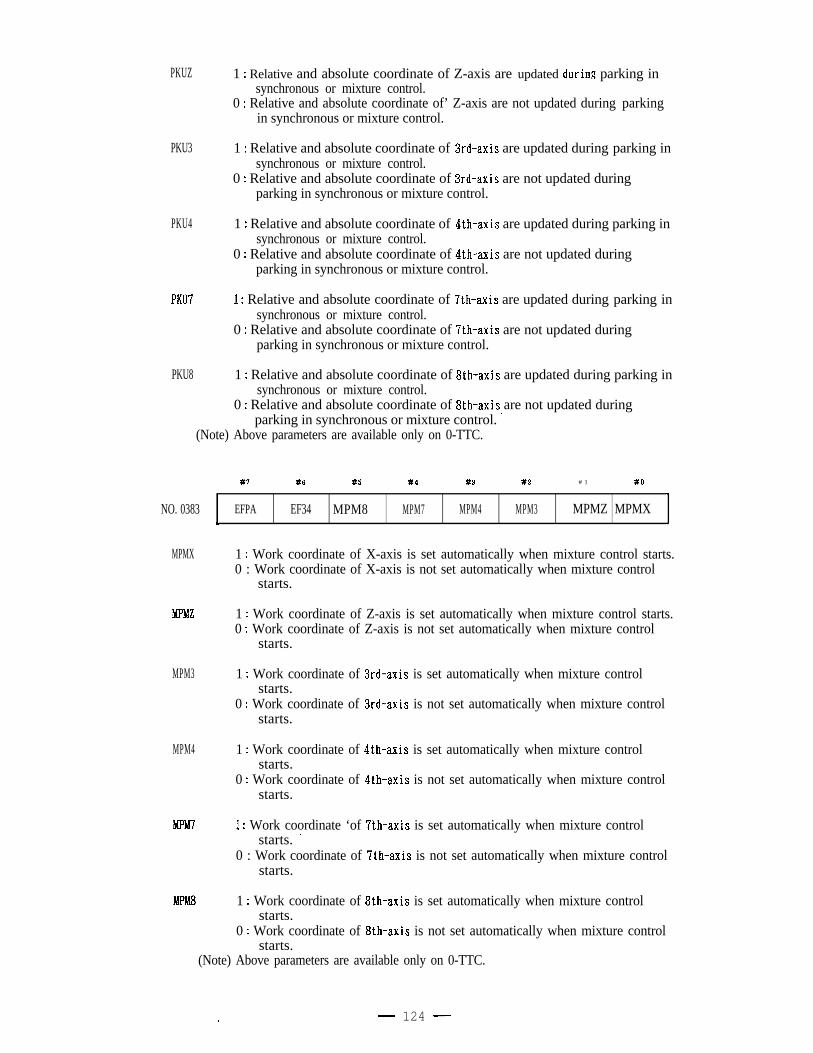
PKUZ
PKU3
PKU4
PKU7
PKU8
1 : Relative and absolute coordinate of Z-axis are updated dtiring parking insynchronous or mixture control.
0 : Relative and absolute coordinate of’ Z-axis are not updated during parkingin synchronous or mixture control.
1 : Relative and absolute coordinate of 3rd-axis are updated during parking insynchronous or mixture control.
0 : Relative and absolute coordinate of 3rd-axis are not updated duringparking in synchronous or mixture control.
1 : Relative and absolute coordinate of 4th-axis are updated during parking insynchronous or mixture control.
0 : Relative and absolute coordinate of 4th-axis are not updated duringparking in synchronous or mixture control.
1 : Relative and absolute coordinate of 7th-axis are updated during parking insynchronous or mixture control.
0 : Relative and absolute coordinate of 7th-axis are not updated duringparking in synchronous or mixture control.
1 : Relative and absolute coordinate of 8th-axis are updated during parking insynchronous or mixture control.
0 : Relative and absolute coordinate of 8th-axis are not updated duringparking in synchronous or mixture control. ’
(Note) Above parameters are available only on 0-TTC.
NO. 0383
MPMX
MPMZ
MPM3
MPM4
Mm7
MPM8
#7 #6 #5 #4 #3 #2 # 1 #O
. I
EFPA EF34 MPM8 MPM7 MPM4 MPM3 MPMZ MPMXk
1 : Work coordinate of X-axis is set automatically when mixture control starts.0 : Work coordinate of X-axis is not set automatically when mixture control
starts.
1 : Work coordinate of Z-axis is set automatically when mixture control starts.0 : Work coordinate of Z-axis is not set automatically when mixture control
starts.
1 : Work coordinate of 3rd-axis is set automatically when mixture controlstarts.
0 : Work coordinate of 3rd-axis is not set automatically when mixture controlIstarts.
1 : Work coordinate of 4th-axis is set automatically when mixture controlstarts.
0 : Work coordinate of 4th-axis is not set automatically when mixture controlstarts.
1 : Work coordinate ‘of 7th-axis is set automatically when mixture controlstarts. ’
0 : Work coordinate of 7th-axis is not set automatically when mixture controlstarts.
1 : Work coordinate of 8th-axis is set automatically when mixture controlstarts.
0 : Work coordinate of 8th-axis is not set automatically when mixture controlstarts.
(Note) Above parameters are available only on 0-TTC.
. - 124 -
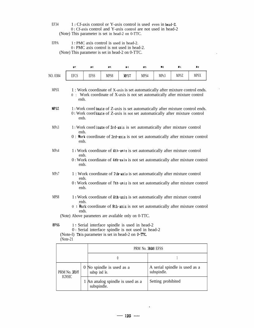
EF34 1 : Cf-axis control or Y-axis control is used even in head-Z.0 : Cf-axis control and Y-axis control are not used in head-2
(Note) This parameter is set in head-2 on 0-TTC.
EFPA 1 : PMC axis control is used in head-2.0 : PMC axis control is not used in head-2.
(Note) This parameter is set in head-2 on 0-TTC. ,
NO. 0384
MPSX
MPSZ
MPs3
MPs4
MPs7
MPS8
#? #6 #5 #4 #3 #2 #l #O
EFCS EFSS MPS8 MPS7 MPS4 MPs3 MPSZ MPSX
1 : Work coordinate of X-axis is set automatically after mixture control ends.0 : Work coordinate of X-axis is not set automatically after mixture control
ends.
1 : Work coord0 : Work coord
ends.
1 : Work coordends.
inate of Z-axis is set automatically after mixture control ends.inate of Z-axis is not set automatically after mixture control
inate of 3rd-axis is set automatically after mixture control
0 : .Work coordinate of 3rd-axis is not set automatically after mixture controlends.
1 : Work coordinate of $th-axis is set automatically after mixture controlends.
0 : Work coordinate of 4th-axis is not set automatically after mixture controlends.
1 : Work coordinate of 7th-axis is set automatically after mixture controlends.
0 : Work coordinate of ?th-axis is not set automatically after mixture controlends.
1 : Work coordinate of 8th-axis is set automatically after mixture controlends.
0 :‘Work coordinate of 8th-axis is not set automatically after mixture controlends.
(Note) Above parameters are available only on 0-TTC.
EFSS 1 : Serial interface spindle is used in head-20 : Serial interface spindle is not used in head-2
(Note-l) ,This parameter is set in head-2 on 0-TTC.(Note-21
PRM No. 384#6 EFSS
0 1
0 No spindle is used as a A serial spindle is used as aPRM No. 381#7 subsp ind le. subspindle.
IGNSIC1 An analog spindle is used as a Setting prohibited
subspindle.
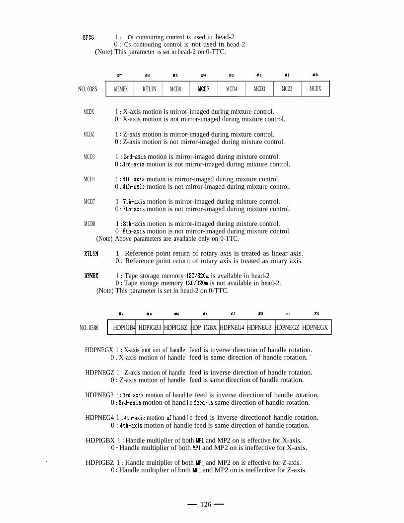
WCS 1 : CS contouring control is used in head-20 : Cs contouring control is not used in head-2
(Note) This parameter is set in head-2 on 0-TTC.
NO. 0385
MCDX
MCDZ
MCD3
MCD4
MCD7
MCD8
#7 #6 #5 #4 #3 #2 #I #O
MEMEX RTLIN MCD8 MCD7 MCD4 MCD3 MCDZ MCDX
1 : X-axis motion is mirror-imaged during mixture control.0 : X-axis motion is not mirror-imaged during mixture control.
1 : Z-axis motion is mirror-imaged during mixture control.0 : Z-axis motion is not mirror-imaged during mixture control.
1 : 3rd-axis motion is mirror-imaged during mixture control.0 : 3rd-axis motion is not mirror-imaged during mixture control.
1 : 4th-axis motion is mirror-imaged during mixture control.0 : 4th-axis motion is not mirror-imaged during mixture control.
1 : ‘Ith-axis motion is mirror-imaged during mixture control.0 : 7th-axis motion is not mirror-imaged during mixture control.
1 : 8th-axis motion is mirror-imaged during mixture control.0 : 8th-axis motion is not mirror-imaged during mixture control.
(Note) Above parameters are available only on 0-TTC.
RTLIN 1 : Reference point return of rotary axis is treated as linear axis.0.: Reference point return of rotary axis is treated as rotary axis.
MEMEX 1 : Tape storage memory 120/320m is available in head-20 : Tape storage memory 120/320m is not available in head-2.
(Note) This parameter is set in head-2 on 0-TTC.
NO. 0386
#7 #:s #5 #4 #3 #2 # 1 80
HDPIGB4 HDPIGB3 HDPIGBZ HDP IGBX HDPNEG4 HDPNEG3 HDPNEGZ HDPNEGX4
HDPNEGX 1 : X-axis mot ion of handle feed is inverse direction of handle rotation.0 : X-axis motion of handle feed is same direction of handle rotation. ’
HDPNEGZ 1 : Z-axis motion of handle feed is inverse direction of handle rotation.0 .: Z-axis motion of handle feed is same direction of handle rotation.
HDPNEG3 1 : 3rd-axis motion of hand0 : 3rd-axis motion of hand
e feed is inverse direction of handle rotation.e feed.is same direction of handle rotation.
HDPNEG4 1 : 4th-axis motion .of hand 1 e feed is inverse directionof handle rotation.0 : 4th-axis motion of handle feed is same direction of handle rotation.
HDPIGBX 1 : Handle multiplier of both MP1 and MP2 on is effective for X-axis.0 : Handle multiplier of both MPl and MP2 on is ineffective for X-axis.
. HDPIGBZ 1 : Handle multiplier of both MPl and MP2 on is effective for Z-axis.0 : Handle multiplier of both MPl and MP2 on is ineffective for Z-axis.
- 126 -
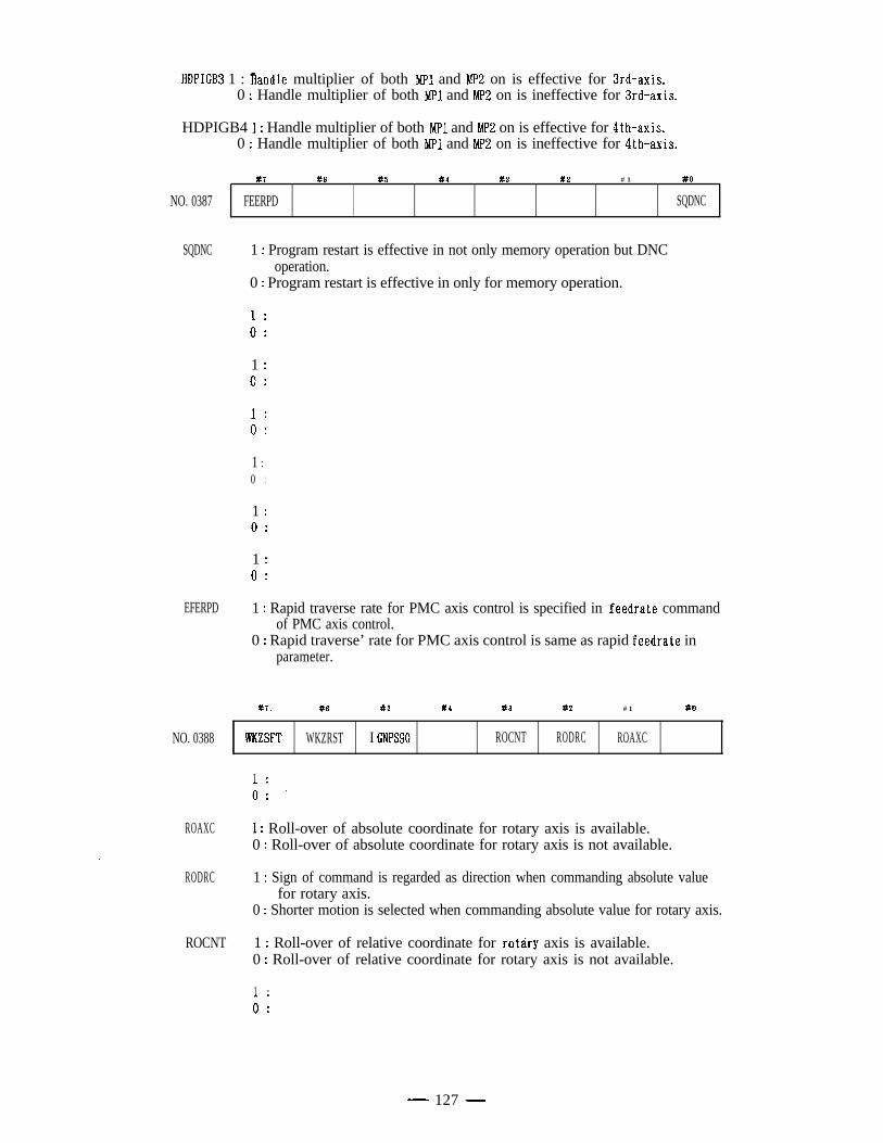
HDPIGB3 1 : handle multiplier of both MPl and MP2 on is effective for 3rd-axis.0 : Handle multiplier of both MPl and MP2 on is ineffective for 3rd-axis.
HDPIGB4 1 : Handle multiplier of both MPl and MP2 on is effective for 4th-axis.0 : Handle multiplier of both MPl and MP2 on is ineffective for 4th-axis.
NO. 0387
#7
FEERPD
#6 #5 #4 #3 #2 # 1 #O
SQDNC.
SQDNC 1 : Program restart is effective in not only memory operation but DNCoperation.
0 : Program restart is effective in only for memory operation.
1 .
OI
1 :0 :
1 :0 :
1 :0 ..
1 :0 :
1 :0 :
EFERPD 1 : Rapid traverse rate for PMC axis control is specified in feedrate commandof PMC axis control.
0 : Rapid traverse’ rate for PMC axis control is same as rapid feedrate inparameter.
#7. #6 #S #4 #3 #2 # 1 a0
NO. 0388 WKZSFT WKZRST I GNPSSO ROCNT RODRC ROAXC
1 .
OI .
ROAXC 1 : Roll-over of absolute coordinate for rotary axis is available.0 : Roll-over of absolute coordinate for rotary axis is not available.
RODRC 1 : Sign of command is regarded as direction when commanding absolute valuefor rotary axis.
0 : Shorter motion is selected when commanding absolute value for rotary axis.
ROCNT ’ 1 : Roll-over of relative coordinate for rotary axis is available.0 : Roll-over of relative coordinate for rotary axis is not available.
1 .0;
- 127 -
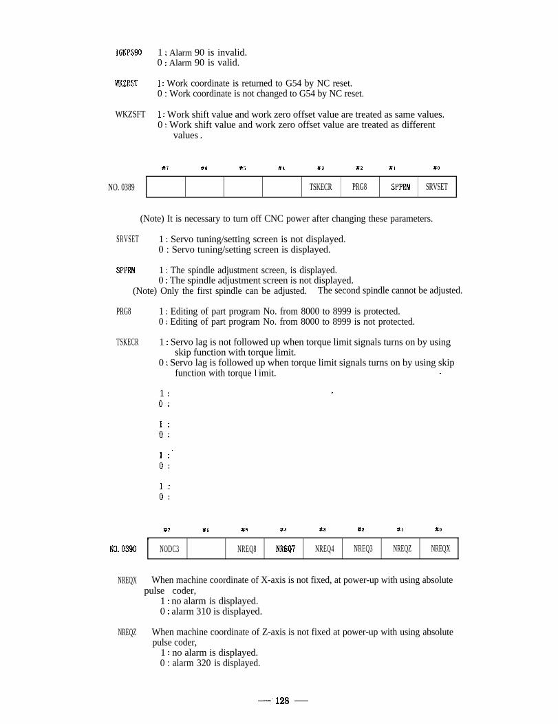
IGNPSSO 1 : Alarm 90 is invalid.0 : Alarm 90 is valid.
WKZRST 1 : Work coordinate is returned to G54 by NC reset.0 : Work coordinate is not changed to G54 by NC reset.
WKZSFT .1 : Work shift value and work zero offset value are treated as same values.0 : Work shift value and work zero offset value are treated as different
values .
NO. 0389
#7 #6 #5 #4 #3
TSKECR
#2
PRG8
#I
SPPRh!
#O
SRVSET
(Note) It is necessary to turn off CNC power after changing these parameters.
SRVSET 1 : Servo tuning/setting screen is not displayed.0 : Servo tuning/setting screen is displayed.
SPPRM 1 : The spindle adjustment screen, is displayed.0 : The spindle adjustment screen is not displayed.
(Note) Only the first spindle can be adjusted. The second spindle cannot be adjusted.
PRG8 1 : Editing of part program No. from 8000 to 8999 is protected.0 : Editing of part program No. from 8000 to 8999 is not protected.
TSKECR 1 : Servo lag is not followed up when torque limit signals turns on by usingskip function with torque limit.
0 : Servo lag is followed up when torque limit signals turns on by using skipfunction with torque 1 imit. 2.
1 : _
0 :
1 :0 :
1 :.0 ..
1 :0 :
X? #6 #5 #4 #3 #2 Xl #O
. I
NO. 0390 NODC3 NREQ8 NREQ7 NREQ4 NREQ3 NREQZ NREQX
NREQX When machine coordinate of X-axis is not fixed, at power-up with using absolute’ pulse coder,
1 : no alarm is displayed.0 : alarm 310 is displayed.
NREQZ When machine coordinate of Z-axis is not fixed at power-up with using absolutepulse coder,
1 : no alarm is displayed.0 : alarm 320 is displayed.
-‘128 -
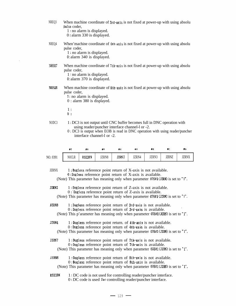
NREQ3
NREQ4
NREQ7
NREQ8
NODC3
NO. 0391
JZRNX
When machine coordinate of 3rd~axis is not fixed at power-up with using absolu.pulse coder,
1 : no alarm is displayed.0 : alarm 330 is displayed.
When’machine coordinate of $th-axis is not fixed at power-up with using absolupulse coder,
1 : no alarm is displayed.0 : alarm 340 is displayed.
When machine coordinate of 7th-axis is not fixed at power-up with using absolupulse coder,
1 : no alarm is displayed.0 : alarm 370 is displayed.
When machine coordinate of 8th-axis is not fixed at power-up with using absolupulse coder,
1 : no alarm is displayed.0 : alarm 380 is displayed.
1 :0 :
1 : DC3 is not output until CNC buffer becomes full in DNC operation withusing reader/puncher interface channel-l or -2.
0 : DC3 is output when EOB is read in DNC operation with using reader/puncherinterface channel-l or -2.
#7 #6 #5 #4 #3 #2 #I #O
\
NOCLR RS23BN JZRN8 JZRN? JZRN4 JZRN3 JZRNZ JZRNX
1 : Dogless reference point return of X-axis is not available.0 : Dogless reference point return of X-axis is available.
(Note) This parameter has meaning only when parameter 076#1 (JZRN) is set to Yn.
JZRNZ 1 : Dogless reference point return of Z-axis is not available.0 : ‘Dogless reference point return of Z-axis is available.
(Note) This parameter has meaning only when parameter 076#1 (JZRN) is set to nln.
JZRN3 1 : Dogless reference point return of 3rd-axis is not available.0 : Dogless reference point return of 3rd-axis is available. -
(Note) This p’arameter has meaning only when parameter 076#1 (JZRN) is set to Yn.
JZRN4 1 : Dogless reference point return. of $th-axis is not available.0 : Dogless reference point return of 4th-axis is available.
(Note) This parameter has meaning only when parameter 076#1 (JZRN) is set to Y”.
JZRN7 1 : Dogless reference point return of 7th-axis is not available.0 : Dogless reference point return of 7th-axis is available.
(Note) This parameter has meaning only when parameter 076#1 (JZRN) is set to “In.
JZRN8 1 : Dogless reference point return of 8th-axis is not available.0 : Dogless reference point return of 8th-axis is available.
(Note) This parameter has meaning only when parameter 076#1 (JZRN) is set to *ln.
RS23BN 1 : DC code is not used for controlling reader/puncher interface.0 : DC code is used .for controlling reader/puncher interface.
129
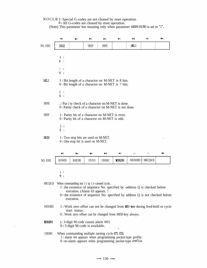
N O C L R 1 : Special G-codes are not cleared by reset operation.0 : All G-codes are cleared by reset operation.
(Note) This parameter has meaning only when parameter 045#6 (CLER) is set to 7”.
#7 #6 #5 #4 #3 #2 #I #O
NO. 0392 SRS2 SREP SRPE SRLlL
1 :0 :
1 .
0 I
SRLl 1 : Bit length of a charactor on M-NET is 8 bits.0 : Bit length of a charactor on M-NET is 7 bits.
1 :0 :
SRPE . 1 : Par i ty check of a charactor on M-NET is done.0 : Parity check of a charactor on M-NET is not done.
SREP 1 : Parity bit of a charactor on M-NET is even.0 : Parity bit of a charactor on M-NET is odd.
1 :0 :
SRS2 1 : Two stop bits are used on M-NET.0 : One stop bit is used on M-NET.
#7 #6 #5 #4 #3 x2 #1 #O
NO. 0393 DGNWEB RADCHK STOVO CHKMRC M3RQNG WKNOMD I MRCQSCH
1 .
0:
MRCQSCH When commanding mu 1 t ip 1 e canned cycle,1 : the existence of sequence No. specified by -address Q is checked before
execution. (Alarm 63 appears. >0 : the existence of sequence No. specified by address Q is not checked before
execution.
WKNOMDI 1 : Work zero offset can not be changed from MDI-key during feed-hold or cyclestart status.
0 : Work zero offset can be changed from MDI-key always.
M3RQNG ’ 1 : 3-digit M-code causes alarm 003.0 : 3-digit M-code is available.
l
CHKMRC When commanding multiple turning cycle G‘71, G72,1 : alarm 64 appears when programming pocket-type profile.0 : no alarm appears when programming pocket-type prof de.
- 130 -
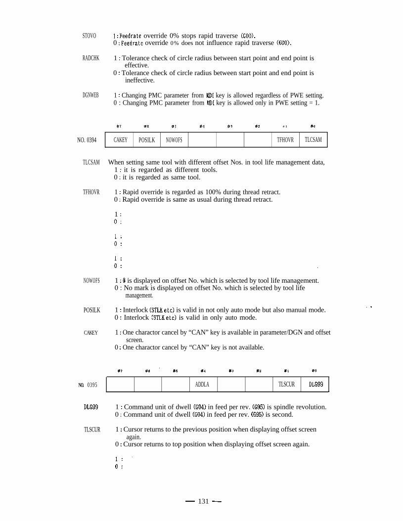
STOVO 1 : Feedrate override 0% stops rapid traverse (GOOX0 : Feedrate override 0% does not influence rapid traverse (GOOX
RADCHK 1 : Tolerance check of circle radius between start point and end point iseffective.
0 : Tolerance check of circle radius between start point and end point isineffective.
DGNWEB 1 : Changing PMC parameter from MD1 key is allowed regardless of PWE setting.0 : Changing PMC parameter from MD1 key is allowed only in PWE setting = 1.
NO. 0394
117 X6
CAKEY POSILK
#S #4 #3 82 # 1 #O
NOWOFS TFHOVR TLCSAM
TLCSAM When setting same tool with different offset Nos. in tool life management data,1 : it is regarded as different tools.0 : it is regarded as same tool.
TFHOVR 1 : Rapid override is regarded as 100% during thread retract.0 : Rapid override is same as usual during thread retract.
1 :0 :
1 .OI
1 .:0 : *
NOWOFS 1 : 8 is displayed on offset No. which is selected by tool life management.0 : No mark is displayed on offset No. which is selected by tool life
management.
POSILK 1 : Interlock (STLK etc) is valid in not only auto mode but also manual mode.0 : Interlock (STLK etc) is valid in only auto mode.
CAKEY 1 : One charactor cancel by “CAN” key is available in parameter/DGN and offsetscreen.
0 : One charactor cancel by “CAN” key is not available.
#7 #6 - #5 #4 #3 82 #l #O
NO. 0395 ADDLA TLSCUR DLG99.
DLG99 1 : Command unit of dwell (GO41 in feed per rev. (G95) is spindle revolution.0 : Command unit of dwell (GO41 in feed per rev. (G95) is second.
. .
TLSCUR 1 : Cursor returns to the previous position when displaying offset screenagain.
0 : Cursor returns to top position when displaying offset screen again.
1: .0 :
- 131 -
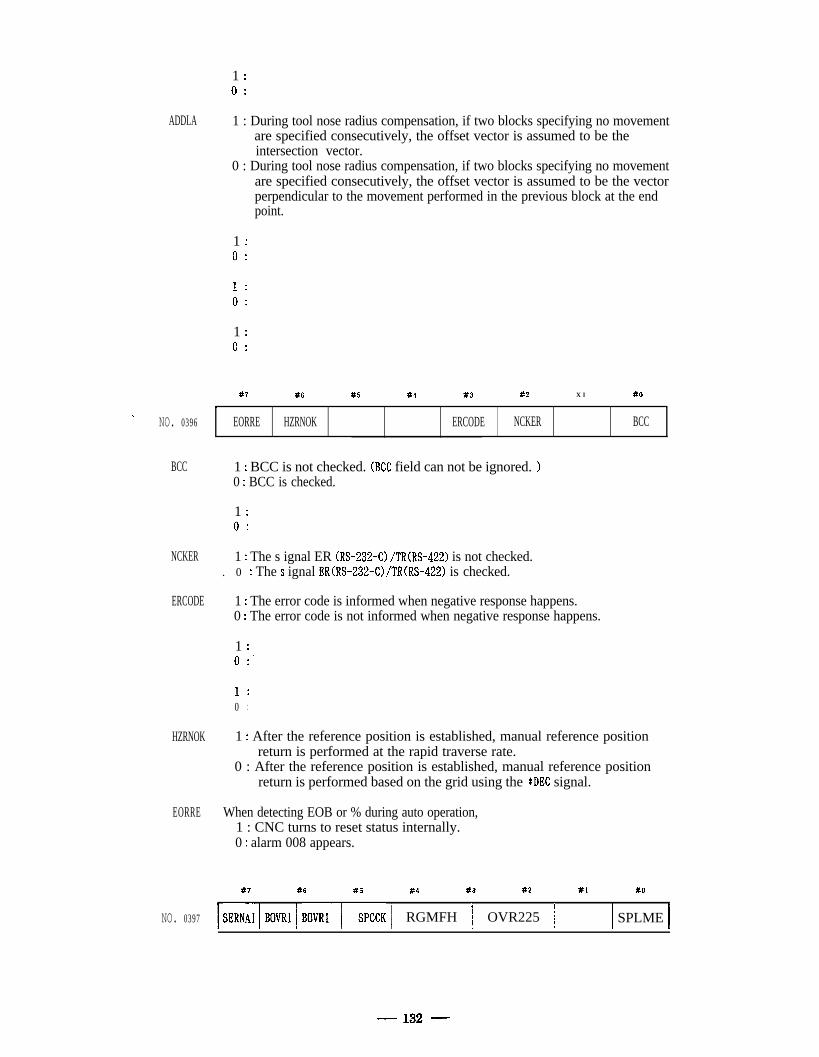
1 :0 :
ADDLA
\NO. 0396
BCC
NCKER
ERCODE
HZRNOK
EORRE
1 : During tool nose radius compensation, if two blocks specifying no movementare specified consecutively, the offset vector is assumed to be theintersection vector.
0 : During tool nose radius compensation, if two blocks specifying no movementare specified consecutively, the offset vector is assumed to be the vectorperpendicular to the movement performed in the previous block at the endpoint.
1 :0 :
1Oi
1 :0 :
#7 #S #5 ’ #4 #3 #2 X l #O
c ,
EORRE HZRNOK ERCODE NCKER BCC
1 : BCC is not checked. (BCC field can not be ignored. )0 : BCC is checked.
1 :0 :
1 : The s ignal ER (RS-232-C) /TR(RS-422) is not checked.. 0 : The s ignal ER(RS-232~C>/TR(RS-422) is checked.
1 : The error code is informed when negative response happens.0 : The error code is not informed when negative response happens.
1 :0 :’
1 ..0 ..
1 : After the reference position is established, manual reference positionreturn is performed at the rapid traverse rate.
0 : After the reference position is established, manual reference positionreturn is performed based on the grid using the *DEC signal.
When detecting EOB or % during auto operation,1 : CNC turns to reset status internally.0 : alarm 008 appears.
87 #6 #5 84 #3 #2 #L #O
NO. 0397 1 sERN;i 1 BOVRl 1 BOVRi-/-SPCCK 1 RGMFH / OVR225 / / SPLME 1
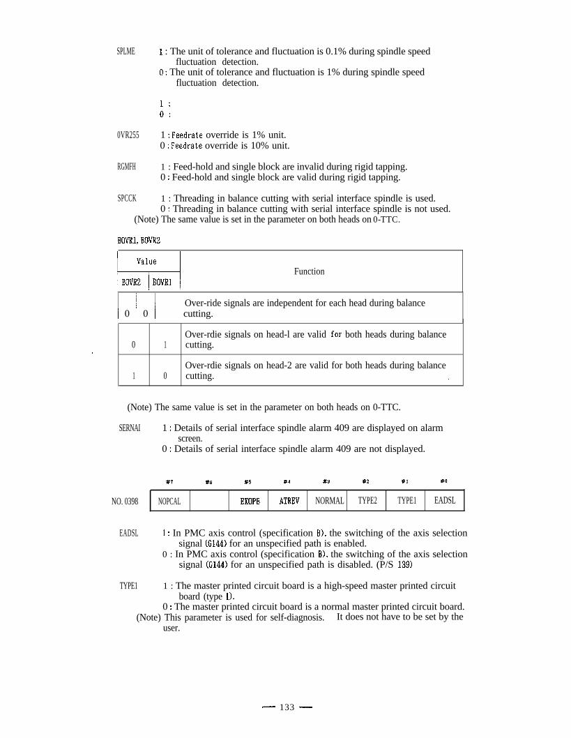
SPLME
0VR255
RGMFH
SPCCK
1 : The unit of tolerance and fluctuation is 0.1% during spindle speedfluctuation detection.
0 : The unit of tolerance and fluctuation is 1% during spindle speedfluctuation detection.
1 : Peedrate override is 1% unit.0 : Feedrate override is 10% unit.
1 : Feed-hold and single block are invalid during rigid tapping.0 : Feed-hold and single block are valid during rigid tapping.
1 : Threading in balance cutting with serial interface spindle is used.0 : Threading in balance cutting with serial interface spindle is not used.
(Note) The same value is set in the parameter on both heads on 0-TTC.
BOW, BOVR2
Valuel-l-4BOVRZ BOVRlFunction
1 0 / 0 / cutting.Over-ride signals are independent for each head during balance
0Over-rdie signals on head-l are valid .for both heads during balance
1 cutting.
1Over-rdie signals on head-2 are valid for both heads during balance
0 cutting. 2.
(Note) The same value is set in the parameter on both heads on 0-TTC.
SERNAI 1 : Details of serial interface spindle alarm 409 are displayed on alarmscreen.
0 : Details of serial interface spindle alarm 409 are not displayed.
NO. 0398
#7
NOPCAL
#6 #5
EXOPE
#4 #3 #2 #l x0
ATREV NORMAL TYPE2 TYPE1 EADSL
EADSL 1 : In PMC axis control (specification B), the switching of the axis selectionsignal (G144) for an unspecified path is enabled.
0 : In PMC axis control (specification B), the switching of the axis selectionsignal (G144) for an unspecified path is disabled. (P/S 139)
TYPE1 1 : The master printed circuit board is a high-speed master printed circuitboard (type 1).
0 : The master printed circuit board is a normal master printed circuit board.(Note) This parameter is used for self-diagnosis. It does not have to be set by the
user.
- 133 -
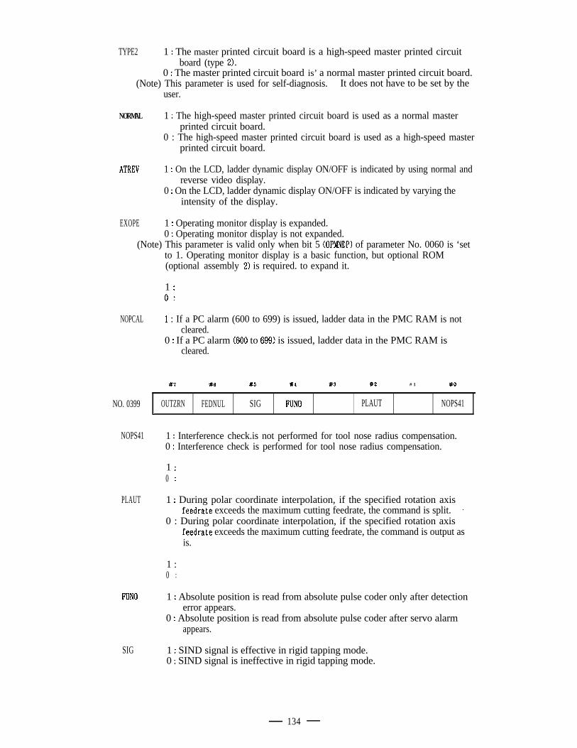
TYPE2 1 : The master printed circuit board is a high-speed master printed circuitboard (type 2).
0 : The master printed circuit board is’ a normal master printed circuit board.(Note) This parameter is used for self-diagnosis. It does not have to be set by the
user.
NORMAL 1 : The high-speed master printed circuit board is used as a normal masterprinted circuit board.
0 : The high-speed master printed circuit board is used as a high-speed masterprinted circuit board.
ATREV 1 : On the LCD, ladder dynamic display ON/OFF is indicated by using normal andreverse video display.
0 : On the LCD, ladder dynamic display ON/OFF is indicated by varying theintensity of the display.
EXOPE 1 : Operating monitor display is expanded.0 : Operating monitor display is not expanded.
(Note) This parameter is valid only when bit 5 (OPMNDP) of parameter No. 0060 is ‘setto 1. Operating monitor display is a basic function, but optional ROM(optional assembly 2) is required. to expand it.
NOPCAL
NO. 0399
NOPS41
PLAUT
FUN0
SIG
1 :0 :’
1 : If a PC alarm (600 to 699) is issued, ladder data in the PMC RAM is notcleared.
0 : If a PC alarm (600 to 699) is issued, ladder data in the PMC RAM iscleared.
#7 X6 #5 #4 83 #Z # 1 #Q
OUTZRN FEDNUL SIG FUN0 PLAUT NOPS41,
1 : Interference check.is not performed for tool nose radius compensation.0 : Interference check is performed for tool nose radius compensation.
1 :’0 ..
1 : During polar coordinate interpolation, if the specified rotation axisfeedrate exceeds the maximum cutting feedrate, the command is split. *
0 : During polar coordinate interpolation, if the specified rotation axisfeedrate exceeds the maximum cutting feedrate, the command is output asis.
1 :0 ..
1 : Absolute position is read from absolute pulse coder only after detectionerror appears.
0 : Absolute position is read from absolute pulse coder after servo alarmappears.
1 : SIND signal is effective in rigid tapping mode.0 : SIND signal is ineffective in rigid tapping mode.
134

FEDNUL 1 : “NULL” code is output as feed data during meaning information.*o : “SPACE” code is output as feed data during meaning information.
OUTZRN When reference point return is operated during feed-hold stab1 : no alarm appears.0 : alarm 91 appears.
- 135 -
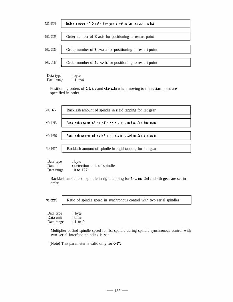
NO. 0124
NO. 0125 Order number of Z-axis for positioning to restart point
NO. 0126 Order number of 3rd-axis for positioning to. restart point
NO. 0127 Order number of 4th-axis for positioning to restart point
Data type : byteData ‘range : 1 to4
Positioning orders of XL3rd and 4th-axis when moving to the restart point arespecified in order.
NO. 0214hi I
Backlash amount of spindle in rigid tapping for 1st gear
NO. 0215
NO. 0216
NO. 0217 Backlash amount of spindle in rigid tapping for 4th gear
Data typeData unitData range
: byte: detection unit of spindle: 0 to 127
Backlash amounts of spindle in rigid tapping for lst,2nd,3rd and 4th gear are set inorder.
NO. 0249 Ratio of spindle speed in synchronous control with two serial spindlesI
Data type : byteData unit : timeData range : 1 to 9
Multiplier of 2nd spindle speed for 1st spindle during spindle synchronous control withtwo serial interface spindles is set.
(Note) This parameter is valid only for 0-TTL
- 136 -
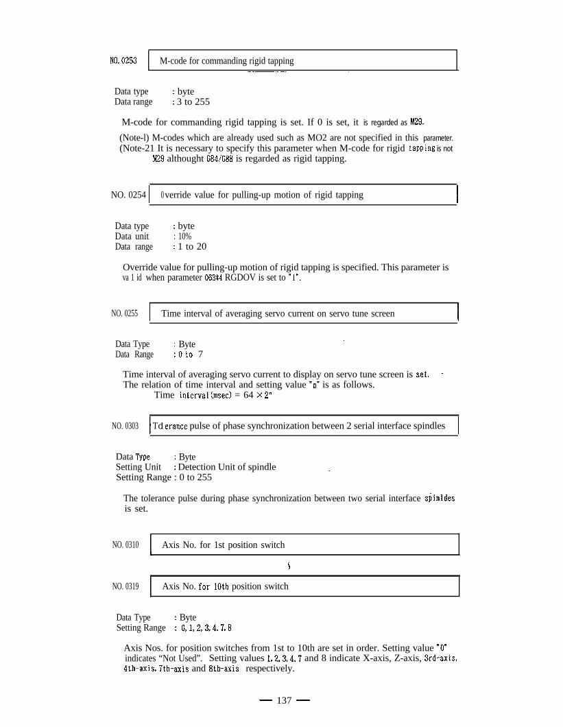
NO. 0253 M-code for commanding rigid tapping
Data typeData range
: byte: 3 to 255
M-code for commanding rigid tapping is set. If 0 is set, it is regarded as bQ9.
(Note-l) M-codes which are already used such as MO2 are not specified in this parameter.(Note-21 It is necessary to specify this parameter when M-code for rigid tapping is not
M29 althought G84/G88 is regarded as rigid tapping.
NO. 0254 1 0verride value for pulling-up motion of rigid tapping I
Data typeData unitData range
: byte: 10%: 1 to 20
Override value for pulling-up motion of rigid tapping is specified. This parameter isva 1 id when parameter 063#4 RGDOV is set to Y”.
NO. 0255 I Time interval of averaging servo current on servo tune screen I
Data Type : Byte1
Data Range : 0 to 7
Time interval of averaging servo current to display on servo tune screen is set. iThe relation of time interval and setting value “nn is as follows.
Time interval(msec) = 64 X 2”
NO. 0303 1 T 1o erance pulse of phase synchronization between 2 serial interface spindles I
Data Type : ByteSetting Unit : Detection Unit of spindleSetting Range : 0 to 255
.
The tolerance pulse during phase synchronization between two serial interface sdinldesis set.
NO. 0310 Axis No. for 1st position switch
NO. 0319 Axis No. for*lOth position switch.
Data Type : ByteSetting Range : 0,1,2,3,4,7,8
Axis Nos. for position switches from 1st to 10th are set in order. Setting value “0”indicates “Not Used”. Setting values 1,2,3,4,7 and 8 indicate X-axis, Z-axis, 3rd-axis,4th-axis, 7th-axis and 8th-axis respectively.
- 137 -
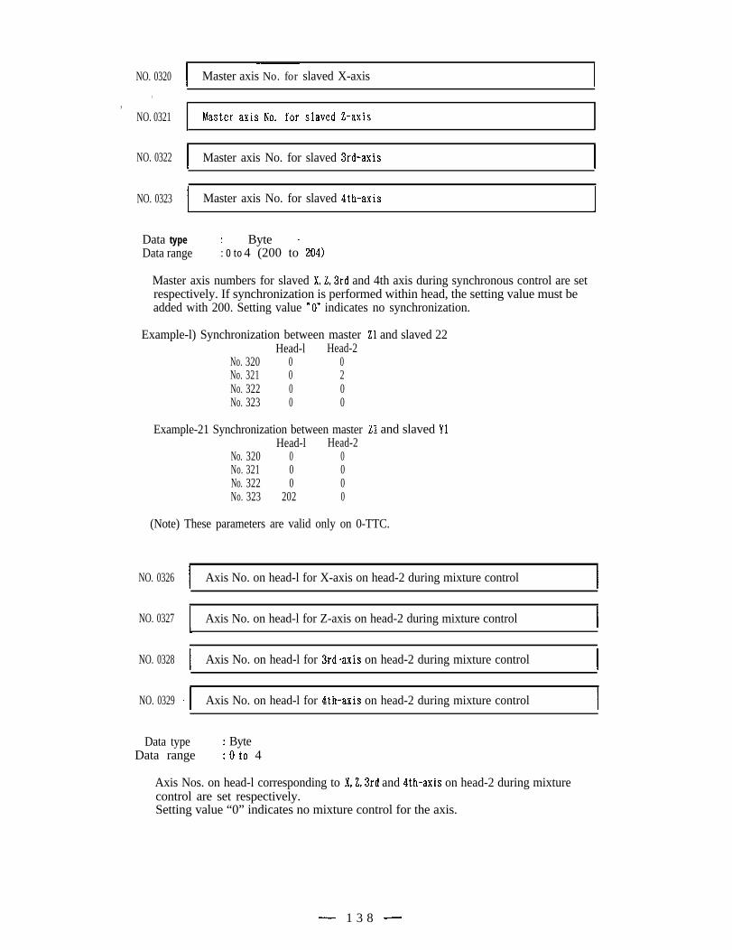
NO. 0320,
,NO. 0321
NO. 0322
NO. 0323
I-~
Master axis No. for slaved X-axis I
I Master axis No. for slaved 3rd-axis
I Master axis No. for slaved 4th-axis I
Data type : Byte -Data range : 0 to 4 (200 to 204)
Master axis numbers for slaved XL3rd and 4th axis during synchronous control are setrespectively. If synchronization is performed within head, the setting value must beadded with 200. Setting value “On indicates no synchronization.
a Example-l) Synchronization between masterHead-l Head-2
No. 320 0 0No. 321 0 2No. 322 0 0No. 323 0 0
Example-21 Synchronization between masterHead-l Head-2
No. 320 0 0No. 321 0 0No. 322 0 0No. 323 202 0
21 and slaved 22
21 and slaved Yl
(Note) These parameters are valid only on 0-TTC.
NO. 0326
NO. 0327
NO. 0328
NO. 0329
I Axis No. on head-l for X-axis on head-2 during mixture control I
I Axis No. on head-l for Z-axis on head-2 during mixture control I
I Axis No. on head-l for 3rd-axis on head-2 during mixture control I
-I Axis No. on head-l for 4th.axis on head-2 during mixture control I
Data type : ByteData range : 0 to 4
Axis Nos. on head-l corresponding to X,Z,3rd and 4th-axis on head-2 during mixturecontrol are set respectively.Setting value “0” indicates no mixture control for the axis.
- 1 3 8 -
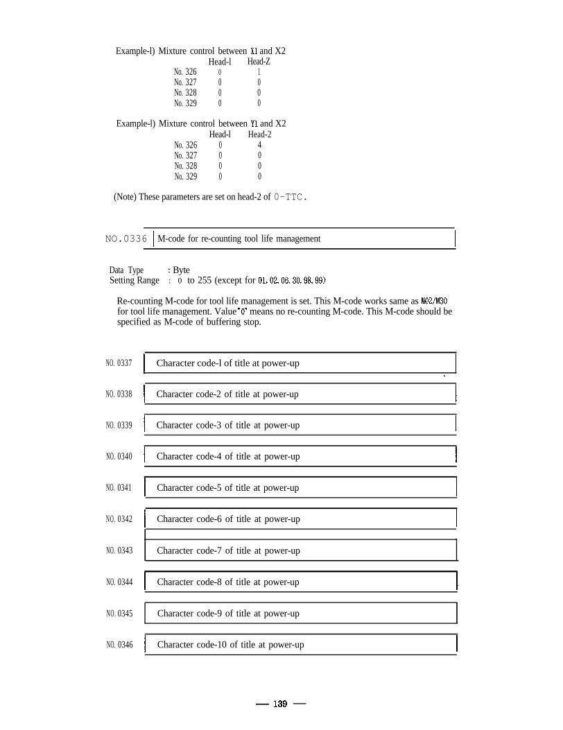
Example-l) Mixture control between Xl and X2Head-l Head-Z
No. 326 0 1No. 327 0 0No. 328 0 0No. 329 0 0
Example-l) Mixture control between Yl and X2Head-l Head-2
No. 326 0 4No. 327 0 0No. 328 0 0No. 329 0 0
(Note) These parameters are set on head-2 of 0-TTC.
NO.0336 1 M-code for re-counting tool life management
Data Type : ByteSetting Range : 0 to 255 (except for 01,02,06,30,98,99)
Re-counting M-code for tool life management is set. This M-code works same as M02/M30for tool life management. Value nO” means no re-counting M-code. This M-code should bespecified as M-code of buffering stop.
NO. 0337
NO. 0338
NO. 0339
NO. 0340
NO. 0341
NO. 0342
NO. 0343
NO. 0344
NO. 0345
NO. 0346
I Character code-l of title at power-upI
II
l.
I Character code-2 of title at power-up I
I Character code-3 of title at power-up I
I Character code-4 of title at power-up I
I Character code-5 of title at power-up I
I Character code-6 of title at power-up I
I
Character code-7 of title at power-up
I Character code-8 of title at power-up
Character code-9 of title at power-up
I Character code-10 of title at power-up I
139
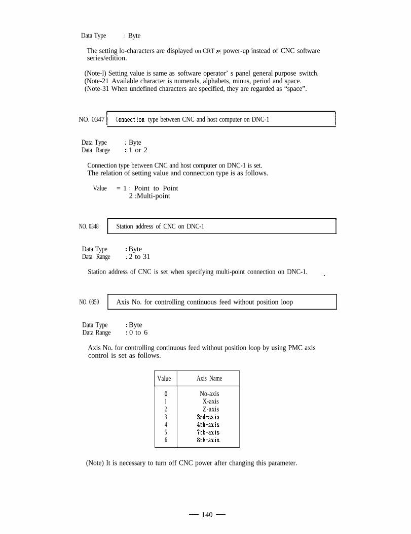
Data Type : Byte
The setting lo-characters are displayed on CRT at power-up instead of CNC softwareseries/edition.
(Note-l) Setting value is same as software operator’ s panel general purpose switch.(Note-21 Available character is numerals, alphabets, minus, period and space.(Note-31 When undefined characters are specified, they are regarded as “space”.
NO. 0347 1 C onnection type between CNC and host computer on DNC-1 I
Data Type : ByteData Range : 1 or 2
Connection type between CNC and host computer on DNC-1 is set.The relation of setting value and connection type is as follows.
Value = 1 : Point to Point2 :Multi-point
NO. 0348 Station address of CNC on DNC-1
Data Type : ByteData Range : 2 to 31
Station address of CNC is set when specifying multi-point connection on DNC-1.
NO. 0350 Axis No. for controlling continuous feed without position loop
Data TypeData Range
: Byte-: 0 to 6
Axis No. for controlling continuous feed without position loop by using PMC axiscontrol is set as follows.
Value Axis Name
0123456
1
No-axisX-axisZ-axis
3rd-axis4th-axis7th-axis8th-axis
(Note) It is necessary to turn off CNC power after changing this parameter.
- 140 -
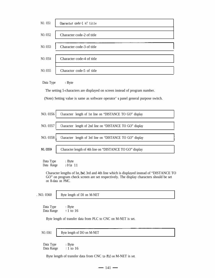
NO. 0351
NO. 0352 Character code-2 of title
NO. 0353 Character code-3 of title
Character code-4 of title,
NO. 0354
NO. 0355
Data Type
I Charactor code-5 of titleI
: Byte
The setting 5-characters are displayed on screen instead of program number.
(Note) Setting value is same as software operator’ s panel general purpose switch.
NO. 0356 ( Character length of 1st line on “DISTANCE TO GO” display I
NO. 0357 ) Character length of 2nd line on “DISTANCE TO GO” display I
NO. 0358 1 Character length of 3rd line on “DISTANCE TO GO” display I
NO. 0359 Character length of 4th line on “DISTANCE TO GO” display
Data TypeData Range
: Byte: 0 to 11
Character lengths of lst, 2nd, 3rd and 4th line which is displayed instead of “DISTANCE TOGO” on program check screen are set respectively. The display characters should be seton R-data on PMC.
.. NO. 0360 Byte length of DI on M-NET
Data TypeData Range
: Byte: 1 to 16
Byte length of transfer data from PLC to CNC on M-NET is set.
NO. 0361 Byte length of DO on M-NET
Data TypeData Range
: Byte: 1 to 16
Byte length of transfer data from CNC to.PLC on M-NET is set.
- 141 -
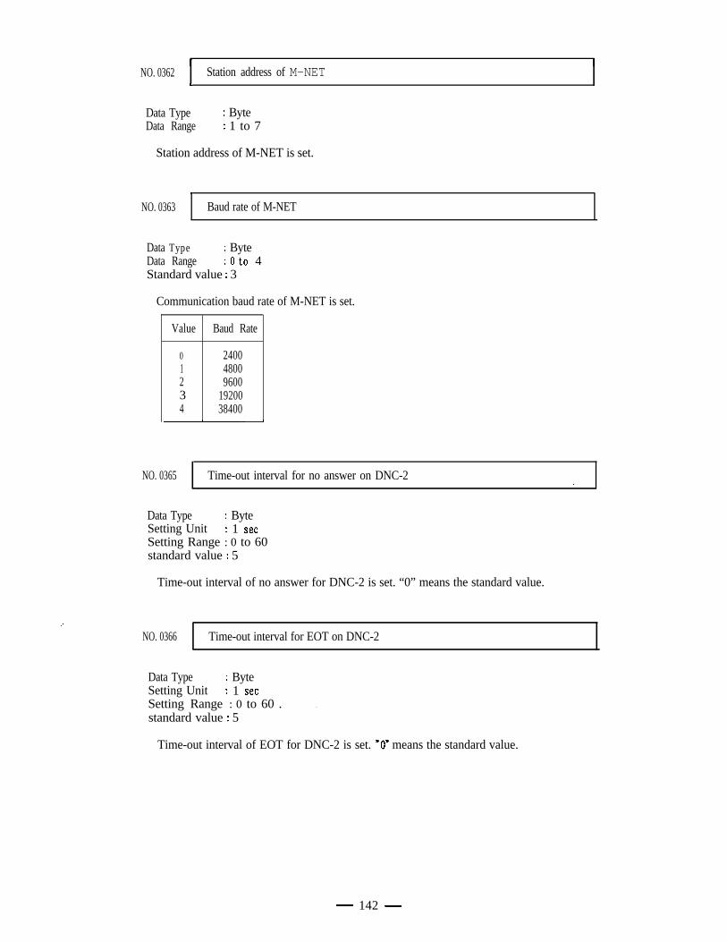
NO. 0362 Station address of M-NET4
Data Type : ByteData Range : 1 to 7
Station address of M-NET is set.
1 _
NO. 0363 Baud rate of M-NET
Data Type : ByteData Range : 0 to 4Standard value : 3
Communication baud rate of M-NET is set.
Value Baud Rate
01234
240048009600
1920038400
NO. 0365 Time-out interval for no answer on DNC-2
Data Type : ByteSetting Unit : 1 setSetting Range : 0 to 60standard value : 5
Time-out interval of no answer for DNC-2 is set. “0” means the standard value.
NO. 0366 Time-out interval for EOT on DNC-2
Data Type : ByteSetting Unit : 1 setSetting Range : 0 to 60 .standard value : 5
.
Time-out interval of EOT for DNC-2 is set. .“O” means the standard value.
- 142 -
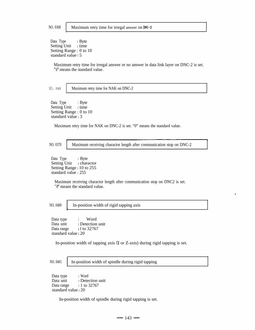
NO. 0368 Maximum retry time for irregal answer on DNC-2t 4
Data Type : ByteSetting Unit : timeSetting Range : 0 to 10standard value : 5
Maximum retry time for irregal answer or no answer in data link layer on DNC-2 is set.nO” means the standard value.
NO. 0369 Maximum retry time for NAK on DNC-2
Data Type : ByteSetting Unit : timeSetting Range : 0 to 10standard value : 3
Maximum retry time for NAK on DNC-2 is set. “0” means the standard value.
NO. 0370 Maximum receiving charactor length after communication stop on DNC-2
Data Type : ByteSetting Unit : charactorSetting Range : 10 to 255standard value : 255
Maximum receiving charactor length after communication stop on DNC2 is set.*On means the standard value.
.
NO. 0400 In-position width of rigid tapping axis,
Data type : Word .Data unit : Detection unitData range : f to 32767standard value : 20
In-position width of tapping axis (X or Z-axis) during rigid tapping is set.
NO. 0401 In-position width of spindle during rigid tappingI
Data type : WordData unit : Detection unitData range : 1 to 32767standard value : 20
In-position width of spindle during rigid tapping is set.
- 143 -
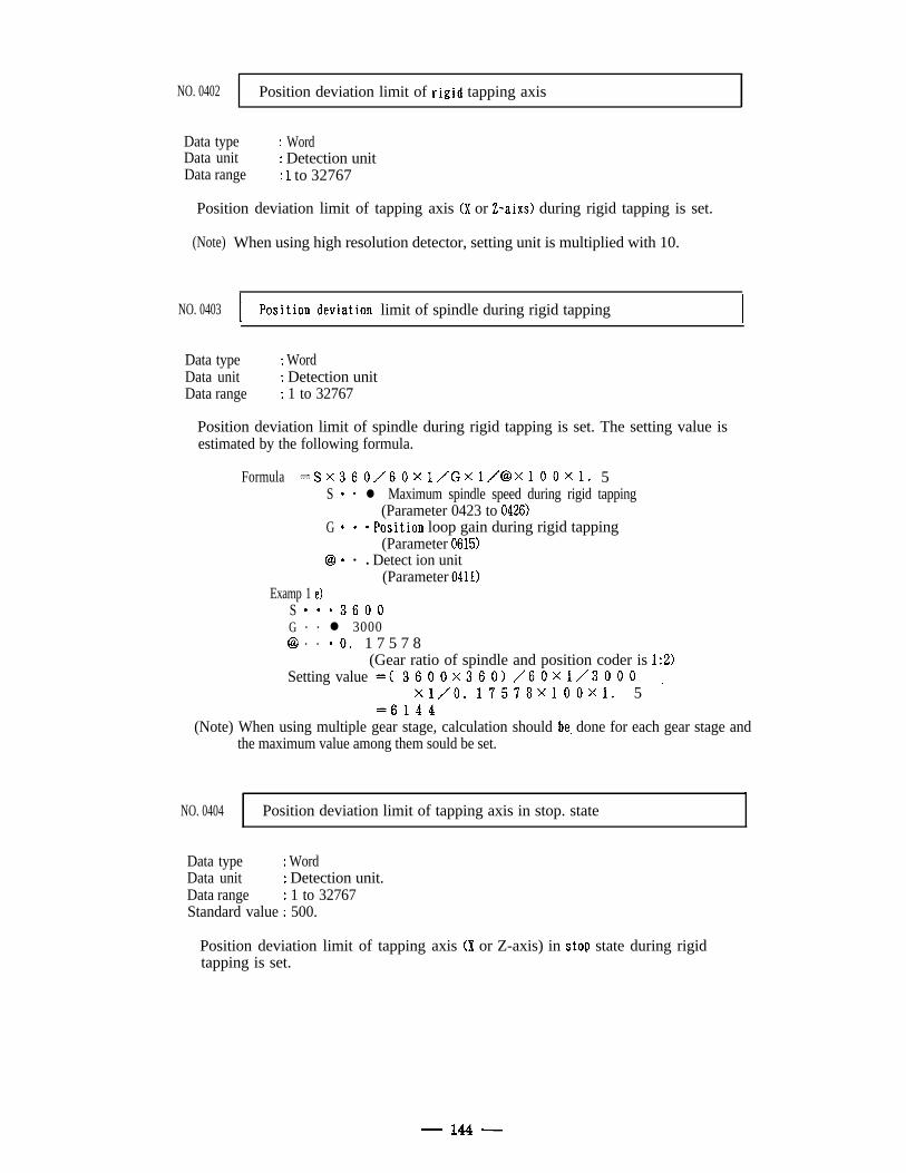
NO. 0402 Position deviation limit of rigid tapping axis
Data typeData unitData range
: Word: Detection unit: 1 to 32767
Position deviation limit of tapping axis (X or Z-aixs) during rigid tapping is set.
(Note) When using high resolution detector, setting unit is multiplied with 10.
NO. 0403 limit of spindle during rigid tapping I
Data typeData unitData range
: Word: Detection unit: 1 to 32767
Position deviation limit of spindle during rigid tapping is set. The setting value isestimated by the following formula.
Formula =Sx360/60x1/Gx1/@x100x1. 5S 0 l l Maximum spindle speed during rigid tapping
(Parameter 0423 to 0426)G b . *Position loop gain during rigid tapping
(Parameter 0615)C9 0 l
l Detect ion unit(Parameter 0411)
Examp 1 e)S 0 0 03600G . . l 3000@I . . @O. 1 7 5 7 8
(Gear ratio of spindle and position coder is 19)Setting value =( 3600x360)/60x1/3000
xl/O. 17578x100x1. 5 -=6144
(Note) When using multiple gear stage, calculation should be. done for each gear stage andthe maximum value among them sould be set.
NO. 0404 Position deviation limit of tapping axis in stop. stateI
Data type : WordData unit : Detection unit.Data range : 1 to 32767Standard value : 500.
Position deviation limit of tapping axis (X or Z-axis) in stop state during rigidtapping is set.
- 144 -
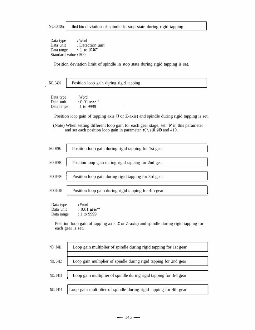
NO.0405 1 P -tOSI ion deviation of spindle in stop state during rigid tapping I
Data type : WordData unit : Detection unitData range : 1 to 32767Standard value : 500
Position deviation limit of spindle in stop state during rigid tapping is set.
NO. 0406_.. . Position loop gain during rigid tapping.
Data typeData unitData range
: Word: 0.01 msec-’: 1 to 9999 .
Position loop gain of tapping axis (X or Z-axis) and spindle during rigid tapping is set.
(Note) When setting different loop gain for each gear stage, set “0” in this parameterand set each position loop gain in parameter 407,408,409 and 410.
NO. 0407 I Position loop gain during rigid tapping for 1st gear I
NO. 0408
NO. 0409
NO. 0410
I Position loop gain during rigid tapping for 2nd gear I
I Position loop gain during rigid tapping for 3rd gear I
I Position loop gain during rigid tapping for 4th gear I
Data typeData unitData range
I Word: 0.01 msec-1: 1 to 9999
Position loop gain of tapping axis (X or Z-axis) and spindle during rigid tapping foreach gear is set.
NO. 0411 Loop gain multiplier of spindle during rigid tapping for 1st gear
NO. 0412 Loop gain multiplier of spindle during rigid tapping for 2nd gear
NO. 0413 I Loop gain multiplier of spindle during rigid tapping for 3rd gear INO. 0414 Loop gain multiplier of spindle during rigid tapping for 4th gear
- 145 -
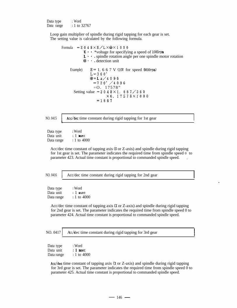
Data type : WordData range : 1 to 32767
Loop gain multiplier of spindle during rigid tapping for each gear is set.The setting value is calculated by the following formula.
Formula =2048xE/Lx@xlOOOIS** *voltage for specifying a speed of 1OOOrpmLa* l spindle rotation angle per one spindle motor rotation@ l l
l detection unit
Example) E = 1. 6 6 7 V (1OV for speed 6000rpm)L=360°@=La/4096
=720° /4096= O . 1 7 5 7 8 ”
Setting value =2048x1. 667/360x0. 17578x1‘000
=1667
NO. 0415 I Acc/dec time constant during rigid tapping for 1st gear I
Data typeData unit
: Word: 1 msec
Data range : 1 to 4000
Acc/dec time constant of tapping axis (X or Z-axis) and spindle during rigid tappingfor 1st gear is set. The parameter indicates the required time from spindle speed 0 toparameter 423. Actual time constant is proportional to commanded spindle speed. L
NO. 0416 I Acc/dec time constant during rigid tapping for 2nd gear I. .
Data type : WordData unitData range
i 1 msec: 1 to 4000
Acc/dec time constant of tapping axis (X or Z-axis) and spindle during rigid tappingfor 2nd gear is set. The parameter indicates the required time from spindle speed 0 toparameter 424. Actual time constant is proportional to commanded spindle speed.
NO. 0417 1 A /dcc ec time constant during rigid tapping for 3rd gearI
Data typeData unitData range
: Word: 1 msec: 1 to 4000
Acc/dec time constant of tapping axis (X or Z-axis) and spindle during rigid tappingfor 3rd gear is set. The parameter indicates the required time from spindle speed 0 toparameter 425. Actual time constant is proportional to commanded spindle speed.
146
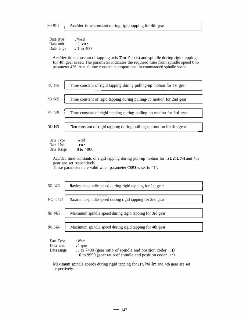
NO. 0418 I Acc/dec time constant during rigid tapping for 4th gear I
Data type : WordData unit : 1 msecData range : 1 to 4000
Acc/dec time constant of tapping axis (X or Z-axis) and spindle during rigid tappingfor 4th gear is set. The parameter indicates the required time from spindle speed 0 toparameter 426. Actual time constant is proportional to commanded spindle speed.
NO. 0419 I Time constant of rigid tapping during pulling-up motion for 1st gear .4 I
NO. 0420I
Time constant of rigid tapping during pulling-up motion for 2nd gearI
NO. 0421I
Time constant of rigid tapping during pulling-up motion for 3rd gear
NO. 0422 T’rme constant of rigid tapping during pulling-up motion for 4th gear
Data TypeData UnitData Range
: Word: msec: 0 to 4000
Acc/dec time constants of rigid tapping during pull-up motion for lstJnd,3rd and 4thgear are set respectively. iThese parameters are valid when parameter 029#3 is set to “1”.
NO. 0423 Maximum spindle speed during rigid tapping for 1st gear I
NO. 0424 1-~
Maximum spindle speed during rigid tapping for 2nd gear I
Nil. 0425 Maximum spindle speed during rigid tapping for 3rd gear
NO. 0426 Maximum spindle speed during rigid tapping for 4th gear
Data TypeData unitData range
: Word: 1 rpm: d to 7400 (gear ratio of spindle and position coder 1:l)
0 to 9999 (gear ratio of spindle and position coder 1:n)
Maximum spindle speeds during rigid tapping for lst,2ndS3rd and 4th gear are setrespectively. .
147
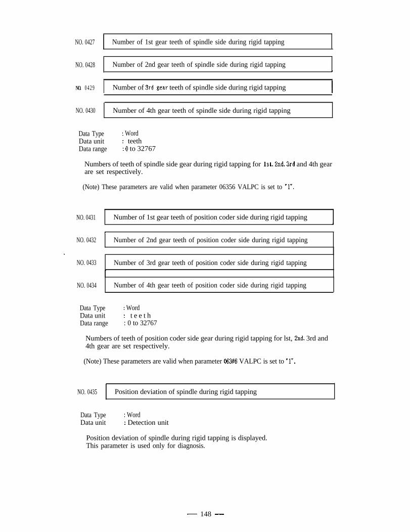
NO. 0427 Number of 1st gear teeth of spindle side during rigid tapping
NO. 0428 Number of 2nd gear teeth of spindle side during rigid tapping
NO. 0429 I Number of 3rd.gear teeth of spindle side during rigid tapping I
NO. 0430 Number of 4th gear teeth of spindle side during rigid tapping
Data TypeData unitData range
: Word: teeth: 0 to 32767
Numbers of teeth of spindle side gear during rigid tapping for lst,2nd,3rd and 4th gearare set respectively.
(Note) These parameters are valid when parameter 06356 VALPC is set to *In.
NO. 0431 Number of 1st gear teeth of position coder side during rigid tapping
v
NO. 0432 Number of 2nd gear teeth of position coder side during rigid tapping
e /
NO. 0433 Number of 3rd gear teeth of position coder side during rigid tapping*
NO. 0434 Number of 4th gear teeth of position coder side during rigid tapping
Data TypeData unitData range
: Word: t e e t h: 0 to 32767
Numbers of teeth of position coder side gear during rigid tapping for lst, 2nd, 3rd and4th gear are set respectively.
(Note) These parameters are valid when parameter 063#6 VALPC is set to “l? .
NO. 0435 Position deviation of spindle during rigid tapping
Data TypeData unit
: Word: Detection unit
Position deviation of spindle during rigid tapping is displayed.This parameter is used only for diagnosis.
- 148 -
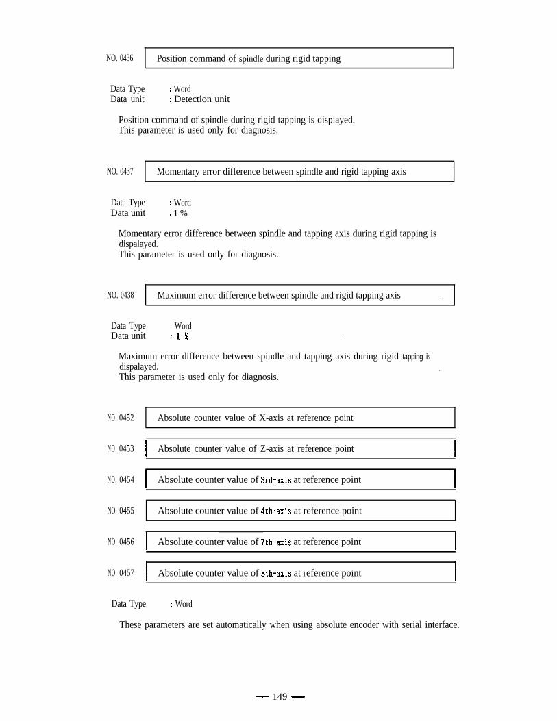
NO. 0436 Position command of spindle during rigid tapping
Data Type : WordData unit : Detection unit
Position command of spindle during rigid tapping is displayed.This parameter is used only for diagnosis.
NO. 0437 Momentary error difference between spindle and rigid tapping axis
Data TypeData unit
: Word: 1 %
Momentary error difference between spindle and tapping axis during rigid tapping isdispalayed.This parameter is used only for diagnosis.
NO. 0438 Maximum error difference between spindle and rigid tapping axis _
Data TypeData unit
: Word: 1 % .
Maximum error difference between spindle and tapping axis during rigid tapping isdispalayed.
l
This parameter is used only for diagnosis.
NO. 0452
NO. 0453
NO. 0454
NO. 0455
NO. 0456
NO. 0457
Absolute counter value of X-axis at reference point
I Absolute counter value of Z-axis at reference point I
I Absolute counter value of 3rd-axis at reference point I
Absolute counter value of 4th-axis at reference point
I Absolute counter value of 7th-axis at reference point I
I Absolute counter value of 8th-axis at reference point I
Data Type : Word
These parameters are set automatically when using absolute encoder with serial interface.
- 149 -
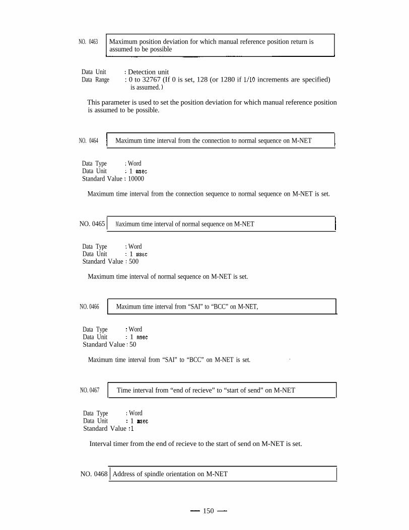
NO. 0463 Maximum position deviation for which manual reference position return isassumed to be possible
Data UnitData Range
: Detection unit: 0 to 32767 (If 0 is set, 128 (or 1280 if l/10 increments are specified)
is assumed. >
This parameter is used to set the position deviation for which manual reference positionis assumed to be possible.
NO. 0464 I Maximum time interval from the connection to normal sequence on M-NET I
Data Type : WordData Unit : 1 msecStandard Value : 10000
Maximum time interval from the connection sequence to normal sequence on M-NET is set.
NO. 0465 ) Maximum time interval of normal sequence on M-NET I
Data Type : WordData Unit : 1 msecStandard Value : 500
Maximum time interval of normal sequence on M-NET is set.
NO. 0466 Maximum time interval from “SAI” to “BCC” on M-NET,
Data Type : WordData Unit : 1 msecStandard Value : 50
Maximum time interval from “SAI” to “BCC” on M-NET is set. ,
NO. 0467 Time interval from “end of recieve” to “start of send” on M-NET
Data Type : WordData Unit : 1 msecStandard Value : 1
Interval timer from the end of recieve to the start of send on M-NET is set.
NO. 0468 1 Address of spindle orientation on M-NET
- 150 -
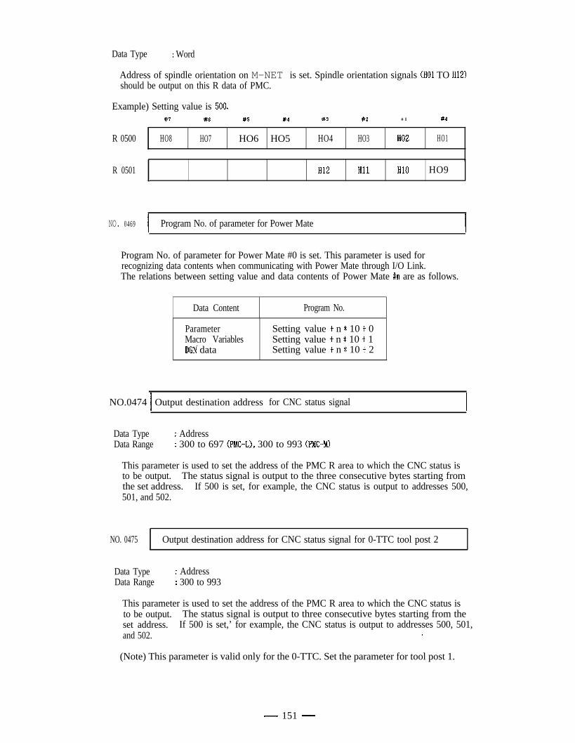
Data Type : Word
Address of spindle orientation on M-NET is set. Spindle orientation signals (HO1 TO H12)should be output on this R data of PMC.
Example) Setting value is 500,#7 #6 #5 #4 #3 #2 # I #O
R 0500 HO8 HO7 HO6 HO5 HO4 HO3 HO2 HO1
1
R 0501 HI2 HI1 HI0 HO9I
NO. 0469 I Program No. of parameter for Power MateI
Program No. of parameter for Power Mate #0 is set. This parameter is used forrecognizing data contents when communicating with Power Mate through I/O Link.The relations between setting value and data contents of Power Mate #n are as follows.
Data Content Program No.
ParameterMacro VariablesDGN data
Setting value t n * 10 + 0Setting value + n * 10 + 1Setting value f n * 10 + 2
NO.0474 1 Output destination address for CNC status signalI
Data TypeData Range
: Address: 300 to 697 (PMC-L), 300 to 993 (PMC-M)
This parameter is used to set the address of the PMC R area to which the CNC status isto be output. The status signal is output to the three consecutive bytes starting fromthe set address. If 500 is set, for example, the CNC status is output to addresses 500,501, and 502.
NO. 0475 Output destination address for CNC status signal for 0-TTC tool post 2
Data TypeData Range
: Address: 300 to 993
This parameter is used to set the address of the PMC R area to which the CNC status isto be output. The status signal is output to three consecutive bytes starting from theset address. If 500 is set,’ for example, the CNC status is output to addresses 500, 501,and 502. .
(Note) This parameter is valid only for the 0-TTC. Set the parameter for tool post 1.
- 151 -
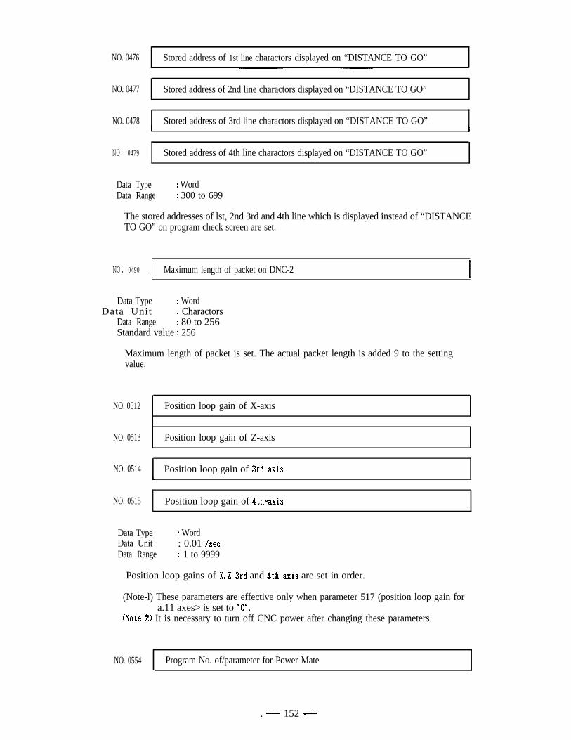
NO. 0476 Stored address of 1st line charactors displayed on “DISTANCE TO GO”,
NO. 0477 Stored address of 2nd line charactors displayed on “DISTANCE TO GO”I
NO. 0478 Stored address of 3rd line charactors displayed on “DISTANCE TO GO”
NO. 0479 Stored address of 4th line charactors displayed on “DISTANCE TO GO”
Data Type : WordData Range : 300 to 699
The stored addresses of lst, 2nd 3rd and 4th line which is displayed instead of “DISTANCETO GO” on program check screen are set.
NO. 0490 - I Maximum length of packet on DNC-2 I
Data Type : WordData Unit : Charactors
Data Range : 80 to 256Standard value : 256
Maximum length of packet is set. The actual packet length is added 9 to the settingvalue.
NO. 0512 Position loop gain of X-axis
NO. 0513 Position loop gain of Z-axis
NO. 0514 Position loop gain of 3rd-axis
NO. 0515 Position loop gain of $th-axis
Data TypeData UnitData Range
: Word: 0.01 /set:’ 1 to 9999
Position loop gains of X,Z,3rd and 4th-axis are set in order.
(Note-l) These parameters are effective only when parameter 517 (position loop gain fora.11 axes> is set to nOn.
(Note-2) It is necessary to turn off CNC power after changing these parameters.
NO. 0554 Program No. of/parameter for Power Mate
. - 152 -
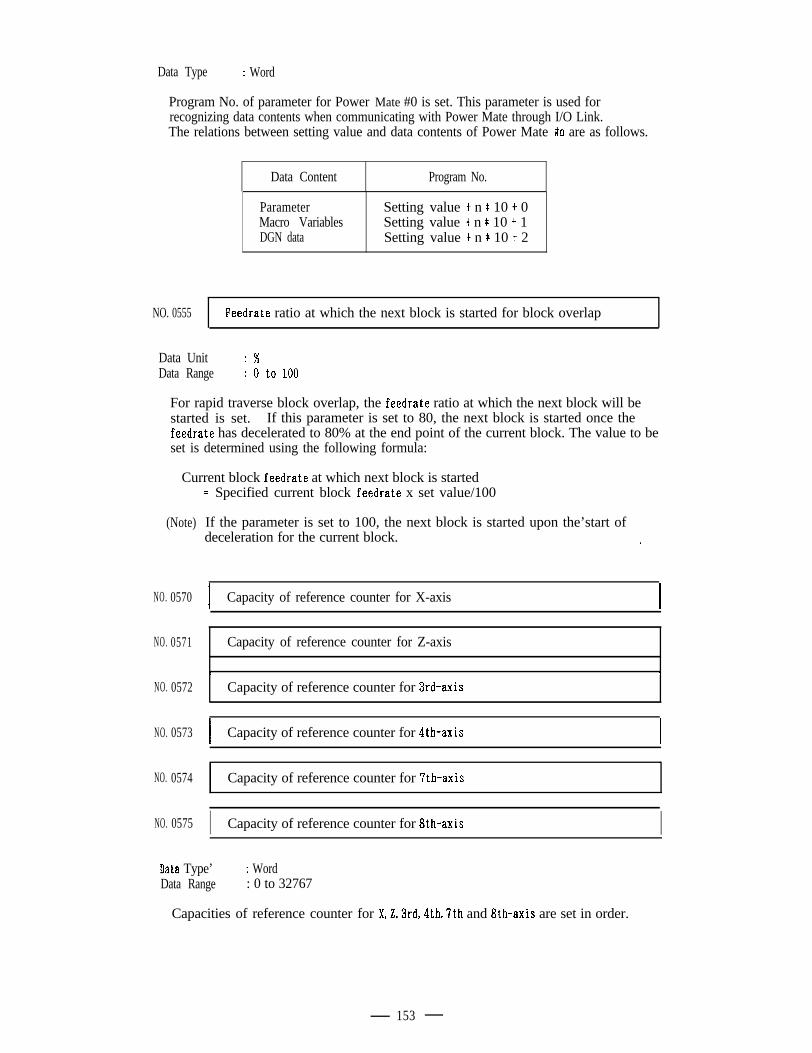
Data Type : Word
Program No. of parameter for Power Mate #0 is set. This parameter is used forrecognizing data contents when communicating with Power Mate through I/O Link.The relations between setting value and data contents of Power Mate #n are as follows.
Data Content Program No.
ParameterMacro VariablesDGN data
Setting value t n * 10 f 0Setting value + n * 10 -I- 1Setting value + n * 10 + 2
NO. 0555 Feedrate ratio at which the next block is started for block overlap
Data UnitData Range
: %: 0 to 100
For rapid traverse block overlap, the feedrate ratio at which the next block will bestarted is set. If this parameter is set to 80, the next block is started once thefeedrate has decelerated to 80% at the end point of the current block. The value to beset is determined using the following formula:
Current block feedrate at which next block is started
(Note)
NO. 0570
NO. 0571
NO. 0572
NO. 0573
NO. 0574
NO. 0575
= Specified current block feedrate x set value/100
If the parameter is set to 100, the next block is started upon the’start of Gdeceleration for the current block. i
I Capacity of reference counter for X-axis I
Capacity of reference counter for Z-axis
t ?Capacity of reference counter for 3rd-axis
I Capacity of reference counter for 4th-axis I
I
Capacity of reference counter for ‘Ith-axis
I Capacity of reference counter for &h-axis I.Data Type’Data Range
: Word: 0 to 32767
Capacities of reference counter for X,Z,3rd,4th97th and 8th-axis are set in order.
153
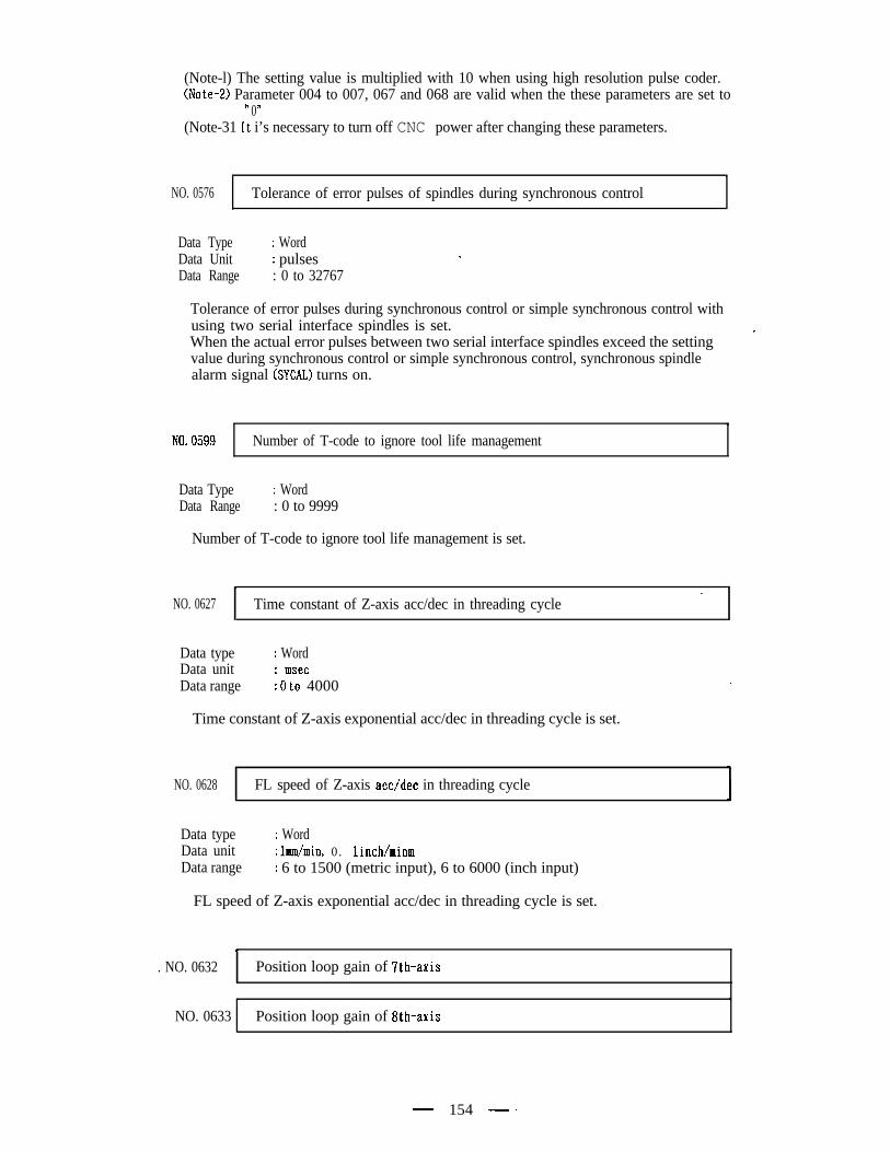
(Note-l) The setting value is multiplied with 10 when using high resolution pulse coder.(Note-2) Parameter 004 to 007, 067 and 068 are valid when the these parameters are set ton n0(Note-31 It i’s necessary to turn off CNC power after changing these parameters.
NO. 0576 Tolerance of error pulses of spindles during synchronous control.
Data TypeData UnitData Range
: Word: pulses: 0 to 32767
.
Tolerance of error pulses during synchronous control or simple synchronous control withusing two serial interface spindles is set.
’When the actual error pulses between two serial interface spindles exceed the settingvalue during synchronous control or simple synchronous control, synchronous spindlealarm signal (SYCAL) turns on.
NO. 0599 Number of T-code to ignore tool life management
Data TypeData Range
: Word: 0 to 9999
Number of T-code to ignore tool life management is set.
. ,LNO. 0627 Time constant of Z-axis acc/dec in threading cycle
Data typeData unitData range
: Word: msec: 0 to 4000 .
Time constant of Z-axis exponential acc/dec in threading cycle is set.
NO. 0628 FL speed of Z-axis acc/dec in threading cycle
Data typeData unitData range
: Word: lmm/min, 0. linch/minm: 6 to 1500 (metric input), 6 to 6000 (inch input)
FL speed of Z-axis exponential acc/dec in threading cycle is set. .
.. NO. 0632 Position loop gain of 7th-axis
t ,NO. 0633 Position loop gain of 8th-axis
- 154 - .
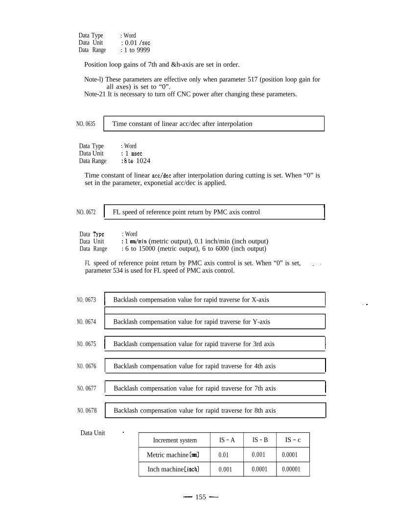
Data Type : WordData Unit : 0.01 /setData Range : 1 to 9999
Position loop gains of 7th and &h-axis are set in order.
Note-l) These parameters are effective only when parameter 517 (position loop gain forall axes) is set to “0”.
Note-21 It is necessary to turn off CNC power after changing these parameters.
NO. 0635 Time constant of linear acc/dec after interpolation
Data TypeData UnitData Range
: Word: 1 msec: 8 to 1024
Time constant of linear acc/dec after interpolation during cutting is set. When “0” isset in the parameter, exponetial acc/dec is applied.
NO. 0672 I FL speed of reference point return by PMC axis control 1DataDataData
FL
Type : WordUnit : 1 mm/min (metric output), 0.1 inch/min (inch output)Range : 6 to 15000 (metric output), 6 to 6000 (inch output)
speed of reference point return by PMC axis control is set. When “0” is set, L .parameter 534 is used for FL speed of PMC axis control.
NO. 0673
NO. 0674
NO. 0675
NO. 0676
NO. 0677
NO. 0678
Backlash compensation value for rapid traverse for X-axis . .
,Backlash compensation value for rapid traverse for Y-axis
I Backlash compensation value for rapid traverse for 3rd axis I
I Backlash compensation value for rapid traverse for 4th axisI
I Backlash compensation value for rapid traverse for 7th axis I
L
Backlash compensation value for rapid traverse for 8th axis
Data Unit .
Increment system
Metric machine hml
IS - A IS - B IS - c
0.01 0.001 0.0001
Inch machine Cinch] 0.001 0.0001 0.00001
- 155 -
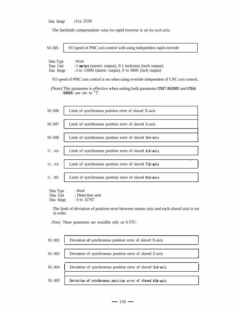
Data Range : 0 to 2550
The backlash compensation value for rapid traverse is set for each axis.
NO. 0685 FO speed of PMC axis control with using independent rapid override
Data Type : WordData Unit : 1 mm/min (metric output), 0.1 inch/min (inch output)Data Range : 0 to 15000 (metric output), 0 to 6000 (inch output)
FO speed of PMC axis control is set when using override independent of CNC axis control..
(Note) This parameter is effective when setting both parameter 078#‘7 (EAXOVE) and 078#6(RDRNE) are set to *ln.
NO. 0686 Limit of synchronous position error of slaved X-axis
NO. 0687 Limit of synchronous position error of slaved Z-axis
NO. 0688 Limit of synchronous position error of slaved 3rd-axis
NO. 0689 Limit of synchronous position error of slaved 4th-axis
NO. 0690 Ia.
Limit of synchronous position error of slaved ‘7th-axis I
NO. 0691 Limit of synchronous position error of slaved 8th-axis
Data TypeData UnitData Range
: Word: Detection unit: 0 to 32767
The limit of deviation of position error between master axis and each slaved axis is setin order.
(Note) These parameters are avaialble only on 0-TTC.
NO. 0692 I Deviation of synchronous position error of slaved X-axis I
NO. 0693 Deviation of synchronous position error of slaved Z-axis
NO. 0694 I Deviation of synchronous position error of slaved 3rd-axis I
NO. 0695
.
- 156 -
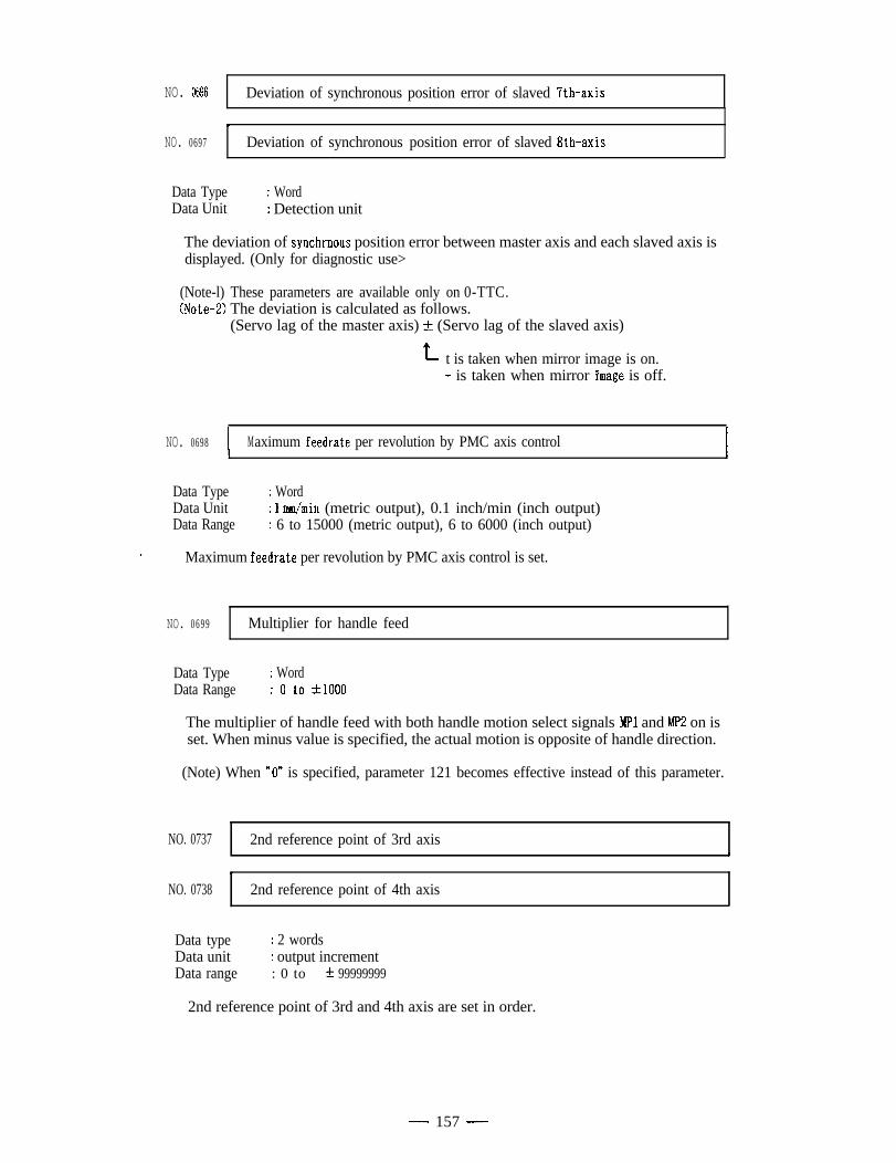
NO. 0696 Deviation of synchronous position error of slaved 7th-axis
.NO. 0697 Deviation of synchronous position error of slaved 8th-axis
Data TypeData Unit
: Word: Detection unit
The deviation of synchrnous position error between master axis and each slaved axis isdisplayed. (Only for diagnostic use>
(Note-l) These parameters are available only on 0-TTC.(Note-Z) The deviation is calculated as follows.
(Servo lag of the master axis) & (Servo lag of the slaved axis)
t t is taken when mirror image is on.- is taken when mirror i’mage is off.
NO. 0698 1 . Maximum feedrate per revolution by PMC axis control I
Data TypeData UnitData Range
: Word: 1 mm/min (metric output), 0.1 inch/min (inch output): 6 to 15000 (metric output), 6 to 6000 (inch output)
Maximum feedrate per revolution by PMC axis control is set.
NO. 0699 Multiplier for handle feed
Data TypeData Range
: Word: 0 to t1000
The multiplier of handle feed with both handle motion select signals Mpl and MP2 on isset. When minus value is specified, the actual motion is opposite of handle direction.
(Note) When “0” is specified, parameter 121 becomes effective instead of this parameter.
NO. 0737 2nd reference point of 3rd axis
.NO. 0738 2nd reference point of 4th axis
Data typeData unitData range
: 2 words: output increment: 0 to t 99999999
2nd reference point of 3rd and 4th axis are set in order.
- 157 -
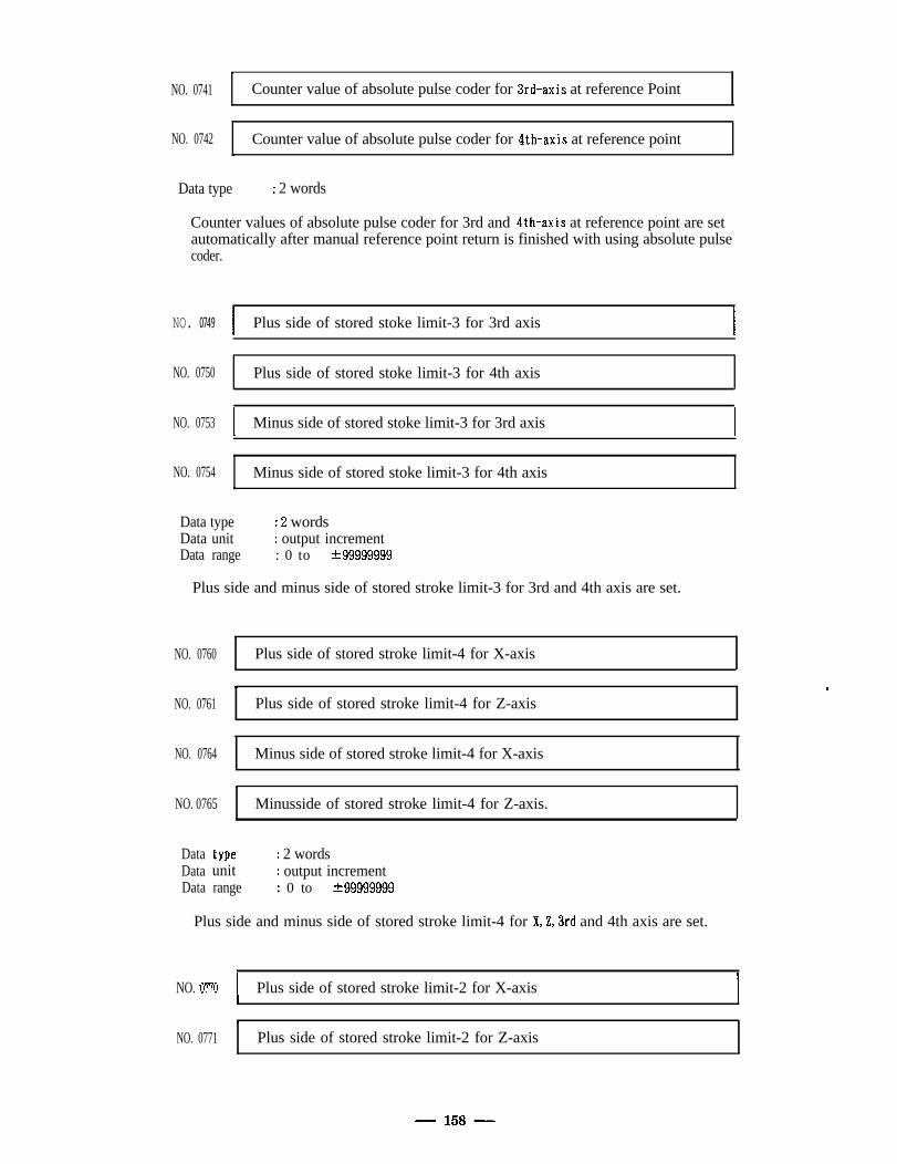
tNO. 0741 Counter value of absolute pulse coder for 3rd-axis at reference Point
NO. 0742 Counter value of absolute pulse coder for 4th-axis at reference point,
Data type : 2 words
Counter values of absolute pulse coder for 3rd and 4th-axis at reference point are setautomatically after manual reference point return is finished with using absolute pulsecoder.
NO. 0749 I Plus side of stored stoke limit-3 for 3rd axis I
NO. 0750 Plus side of stored stoke limit-3 for 4th axis
NO. 0753 I Minus side of stored stoke limit-3 for 3rd axis I
NO. 0754 Minus side of stored stoke limit-3 for 4th axis,
Data typeData unitData range
: 2 words: output increment: 0 to t99999999
Plus side and minus side of stored stroke limit-3 for 3rd and 4th axis are set.
NO. 0760 Plus side of stored stroke limit-4 for X-axis
.NO. 0761 Plus side of stored stroke limit-4 for Z-axis
.
NO. 0764 Minus side of stored stroke limit-4 for X-axis.
l .NO. 0765 Minusside of stored stroke limit-4 for Z-axis.
Data typeData unitData range
: 2 words: output increment: 0 to t99999999
Plus side and minus side of stored stroke limit-4 for X,Z,3rd and 4th axis are set.
NO. ‘0770 I Plus side of stored stroke limit-2 for X-axis I
T
NO. 0771 Plus side of stored stroke limit-2 for Z-axis
- 158 -
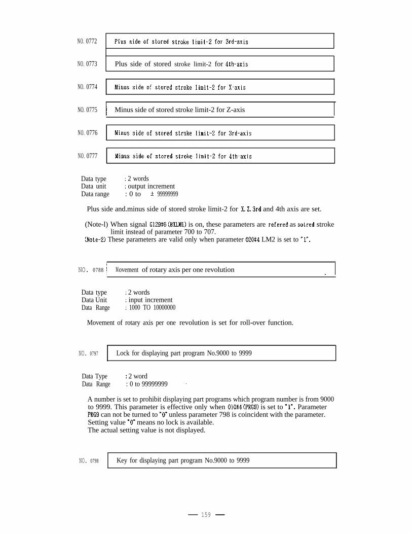
NO. 0772
NO. 0773
NO. 0774
NO. 0775
NO. 0776
NO. 0777
Plus side of stored stroke limit-2 for 4th-axis
I Minus side of stored stroke limit-2 for Z-axis I
Data type : 2 wordsData unit : output incrementData range : 0 to t 99999999
Plus side and.minus side of stored stroke limit-2 for X,Z,3rd and 4th axis are set.
(Note-l) When signal G129#6 (EXLMl) is on, these parameters are refered as sotred strokelimit instead of parameter 700 to 707.
(Note-2) These parameters are valid only when parameter 020#4 LM2 is set to Yn.
NO. 0788 1 Movement of rotary axis per one revolution L I
Data type : 2 wordsData Unit : input incrementData Range : 1000 TO 10000000
Movement of rotary axis per one revolution is set for roll-over function.
NO. 0797 Lock for displaying part program No.9000 to 9999
Data TypeData Range
: 2 word: 0 to 99999999
A number is set to prohibit displaying part programs which program number is from 9000to 9999. This parameter is effective only when 010#4 (PRGS) is set to “Y. ParameterPRG9 can not be turned to nOn unless parameter 798 is coincident with the parameter.Setting value nO” means no lock is available.The actual setting value is not displayed.
NO. 0798 Key for displaying part program No.9000 to 9999
159
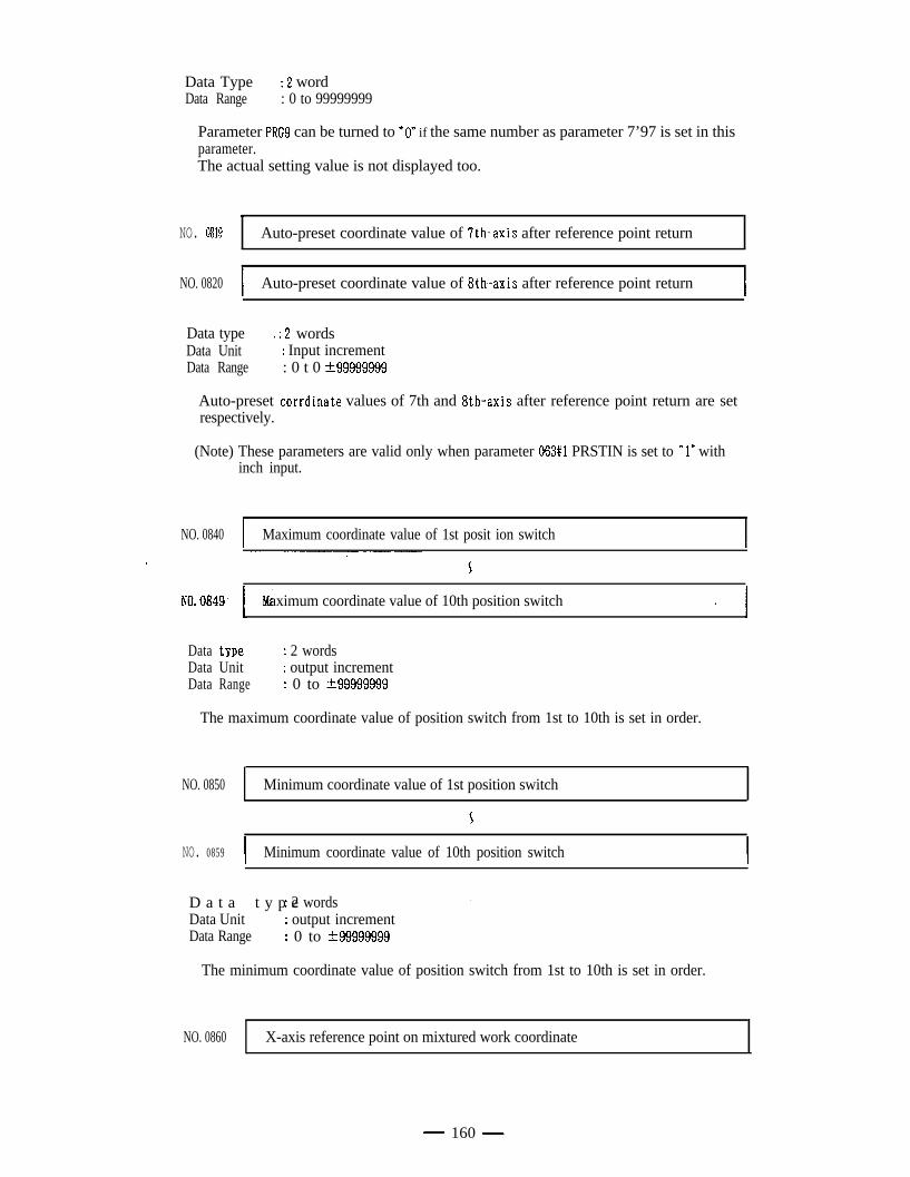
Data Type e : 2 wordData Range : 0 to 99999999
Parameter PRG9 can be turned to “0” if the same number as parameter 7’97 is set in thisparameter.The actual setting value is not displayed too.
,NO. 0819 Auto-preset coordinate value of 7th-axis after reference point return
NO. 0820 I Auto-preset coordinate value of 8th-axis after reference point return I
Data type ’ . : 2 wordsData Unit : Input incrementData Range : 0 t 0 t99999999
Auto-preset corrdinate values of 7th and 8th-axis after reference point return are setrespectively.
(Note) These parameters are valid only when parameter 063#1 PRSTIN is set to Y” withinch input.
NO. 0840 I Maximum coordinate value of 1st posit ion switch I
Data
NO.0849. 1 M’aximum coordinate value of 10th position switch * I
type : 2 wordsData Unit : output incrementData Range : 0 to -+99999999
The maximum coordinate value of position switch from 1st to 10th is set in order.
NO. 0850 Minimum coordinate value of 1st position switch
NO. 0859 I Minimum coordinate value of 10th position switch I
D a t a t y p e: 2 wordsData Unit : output incrementData Range : 0 to &99999999
.
The minimum coordinate value of position switch from 1st to 10th is set in order.
NO. 0860 X-axis reference point on mixtured work coordinate
- 160 -
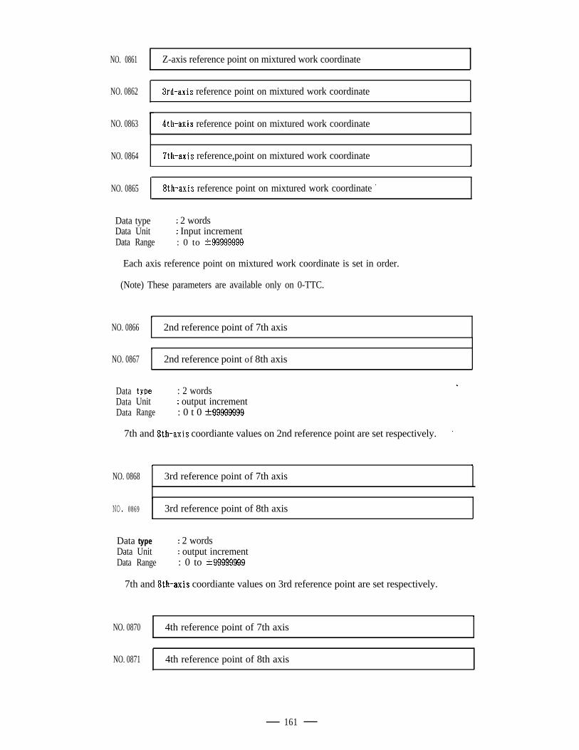
NO. 0861 Z-axis reference point on mixtured work coordinate
NO. 0862 3rd-axis reference point on mixtured work coordinate
NO. 0863 4th-axis reference point on mixtured work coordinate
NO. 0864 7th-axis reference,point on mixtured work coordinate
NO. 0865 8th-axis reference point on mixtured work coordinate *
,
I
.
Data typeData UnitData Range
: 2 words: Input increment: 0 to t99999999
Each axis reference point on mixtured work coordinate is set in order.
(Note) These parameters are available only on 0-TTC.
.NO. 0866 2nd reference point of 7th axis
\NO. 0867 2nd reference point of 8th axis
Data typeData UnitData Range
: 2 words: output increment: 0 t 0 rt99999999
L
7th and 8th-axis coordiante values on 2nd reference point are set respectively. ’
\ a
NO. 0868 3rd reference point of 7th axis
.
NO. 0869 3rd reference point of 8th axis
Data typeData UnitData Range
: 2 words: output increment: 0 to t99999999
7th and 8th-axis coordiante values on 3rd reference point are set respectively.
NO. 0870 4th reference point of 7th axisI
NO. 0871 4th reference point of 8th axis
161
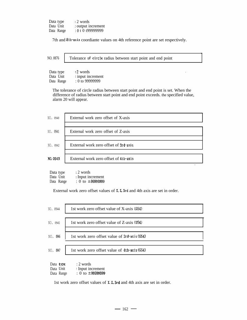
Data type : 2 wordsData Unit : output incrementData Range : 0 t 0 t99999999
7th and 8th-axis coordiante values on 4th reference point are set respectively.
NO. 0876 Tolerance ofoircle radius between start point and end point
Data typeData UnitData Range
: 2 words: input increment: 0 to 99999999
.
The tolerance of circle radius between start point and end point is set. When thedifference of radius between start point and end point exceeds. the specified value,alarm 20 will appear.
NO. 0940 External work zero offset of X-axis
NO. 0941 External work zero offset of Z-axis
NO. 0942 External work zero offset of 3rd-axis
NO. 0943
I
External work zero offset of 4th-axisl
Data typeData UnitData Range
: 2 words: Input increment: 0 to t99999999
External work zero offset values of XL3rd and 4th axis are set in order.
NO. 0944 1st work zero offset value of X-axis (G54).
NO. 0945 1st work zero offset value of Z-axis (G54),
NO. 0946 I 1st work zero offset value of 3rd-axis (G54) I
NO. 0947 1st work zero offset value of 4th-axis CC541
Data typeData UnitData Range
: 2 words: Input increment: 0 to t99999999
1st work zero offset values of X,2,3rd and 4th axis are set in order.
162
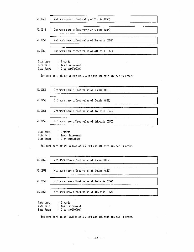
NO. 0948
NO. 0949
NO. 0950
NO. 0951
I 2nd work zero offset value of X-axis (G55) I
I 2nd work zero offset value of Z-axis CC551 I
I _~
2nd work zero offset value of 3rd-axis (G55) I
I 2nd work zero offset value of 4th-axis (G55)
Data type Data Unit Data Range
: 2 words : Input increment : 0 to t99999999
2nd work zero offset values of X,Z,3rd and 4th axis are set in order.
NO. 0952 3rd work zero offset value of X-axis (G56)
NO. 0953
NO. 0954
NO. 0955 3rd work zero offset value of 4th-axis (G56)
Data type Data Unit Data Range
: 2 words : Input increment : 0 to t99999999
c
3rd work zero offset values of X,Z,3rd and 4th axis are set in order.
NO. 0956 4th work zero offset value of X-axis CC571
NO. 0957 4th work zero offset value of Z-axis (657)
NO. 0958 4th work zero offset value of Srd-axis (G57)
NO.0959 1 4th work zero offset value of 4th-axis (G57)
Data type Data Unit Data Range
: 2 words : Input increment : 0 to t 99999999
.
4th work zero offset values of X,2,3rd and 4th axis are set in order.
163
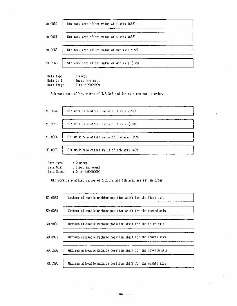
NO. 0960 5th work zero offset value of X-axis (G58)
NO. 0961 5th work zero offset value of Z-axis CC581 I .
NO.0962 1 5th work zero offset value of 3rd-axis (G58)
NO. 0963 1 5th work zero offset value of 4th-axis (G58). I
Data type : Data Unit : Data Range :
2 words Input increment 0 to -+99999999
5th work zero offset values of X, 2,3rd and 4th axis are set in order.
NO. 0964 I- 6th work zero offset value of X-axis (G59) I
NO. 0965 1 6th work zero offset value of Z-axis (G59) I
NO.0966 1 6th work zero offset value of 3rd-axis (G59)
NO. 0967 1 6th work zero offset value of 4th-axis (G59) . I
Data type : 2 words Data Unit : Input increment Data Range : 0 to t99999999
6th work zero offset values of X,Z,3rd and 4th axis are set in order.
NO. 0988
NO, 0989
NO. 0990
NO. 0991
NO. 0992
NO. 0993
I Maximum allowable machine position shift for the first axis I
I Maximum allowable machine position shift for the second axis I
I Maximum allowable machine position shift for the third axis I
Maximum allowable machine position shift for the fourth axis
I. Maximum allowable machine position shift for the seventh axis
f
Maximum allowable machine position shift for the eighth axis
- 164 -
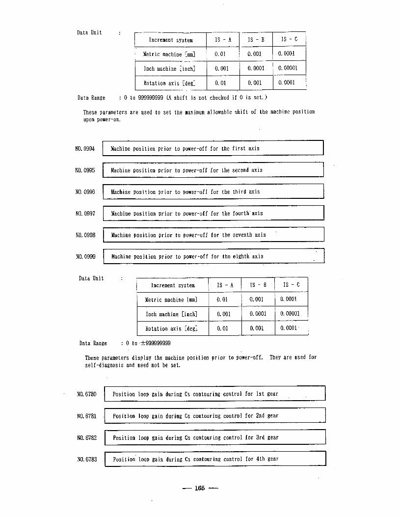
Data Unit : f
Increment system IS - A IS - B IS - c
Metric machine [mm] 0.01 0.001 0.0001
Inch machine [inch] 0.001 0.0001 0.00001
Rotat ion axis [deg] 0.01 0.001 0.0001
Data Range : 0 to 999999999 (A shift is not checked if 0 is set. >
These parameters are used to set the maximum allowable shift of the machine position upon power-on.
NO. 0994 Machine position prior to power-off for the first axis
NO. 0995 Machine position prior to power-off for the second axis
.
NO. 0996 Machine position prior to power-off for the third axis
NO. 0997 Machine position prior to power-off for the fourth’axis
NO. 0998 .
’ Machine position prior to power-off for the seventh axis ~~
NO. 0999 Machine position prior to power-off for the eighth axis
Data Unit : Increment system IS - A IS - B
Metric machine [mm] 0.01 0.001
Inch machine [inch] 0.001 0.0001
Rotat ion axis [degl 0.01 0.001
.
J.
IS - c
0.0001
0.00001
0.0001
Data Range : 0 to +999999999
These parameters display the machine position prior to power-off. They are used for self-diagnosis and need not be set.
NO. 6780 ) P OSI ion loop gain during Cs contouring control for 1st gear ’ t I
NO. 6781 ’ Position loop gain during Cs contouring control for 2nd gear
NO. 6782 1 P OSI ion loop gain during Cs contouring control for 3rd gear l t I
NO. 6783 Position- loop gain during Cs contouring control for 4th gear
165
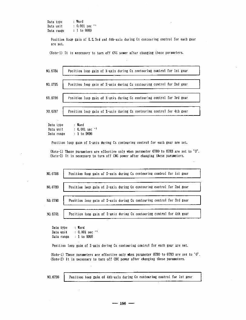
Data type Data unit Data range
: Word : 0.001 set -+ : 1 to 9999
Position loop gain of X,Z,3rd and 4th~axis during Cs contouring control for each gear are set.
(Note-11 It is necessary to turn off CNC power after changing these parameters.
l
NO. 6784 Position loop gain of X-axis during Cs contouring control for 1st gear
NO.6785 Position loop gain of X-axis during Cs contouring control for 2nd gear
NO. 6786 Position loop gain of X-axis during Cs contouring control for 3rd gear , .
b
NO. 6787 Position loop gain of X-axis during Cs contouring control for 4th gear
Data type Data unit Data range
: Word : 0.001 set -l : 1 to 9999
Position loop gain of X-axis during Cs contouring control for each gear are set.
(Note-11 These parameters are effective only when parameter 6780 to 6783 are set to nO”. (Note-21 It is necessary to turn off CNC power after changing these parameters.
NO. 6788 c
Position loop gain of Z-axis during Cs contouring control for 1st gear
NO. 6789 Position loop gain of Z-axis during Cs contouring control for 2nd gear
NO. 6790 Position loop gain of Z-axis during Cs contouring control for 3rd gear
NO. 6791 I Position loop gain of Z-axis during Cs contouring control for 4th gear I
Data type : Word Data unit : 0.001 set -l Data range : I to 9999
Position loop gain of Z-axis during Cs contouring control for each gear are set.
(Note-l) These parameters are effective’only when parameter 6780 to 6783 are set to “0”. (Note-21 It is necessary to turn off CNC power after changing these parameters.
NO.6796 1 P ‘t= ’ OSI ran loop gain of 4th-axis during Cs contouring control for 1st gear I
- 166 -
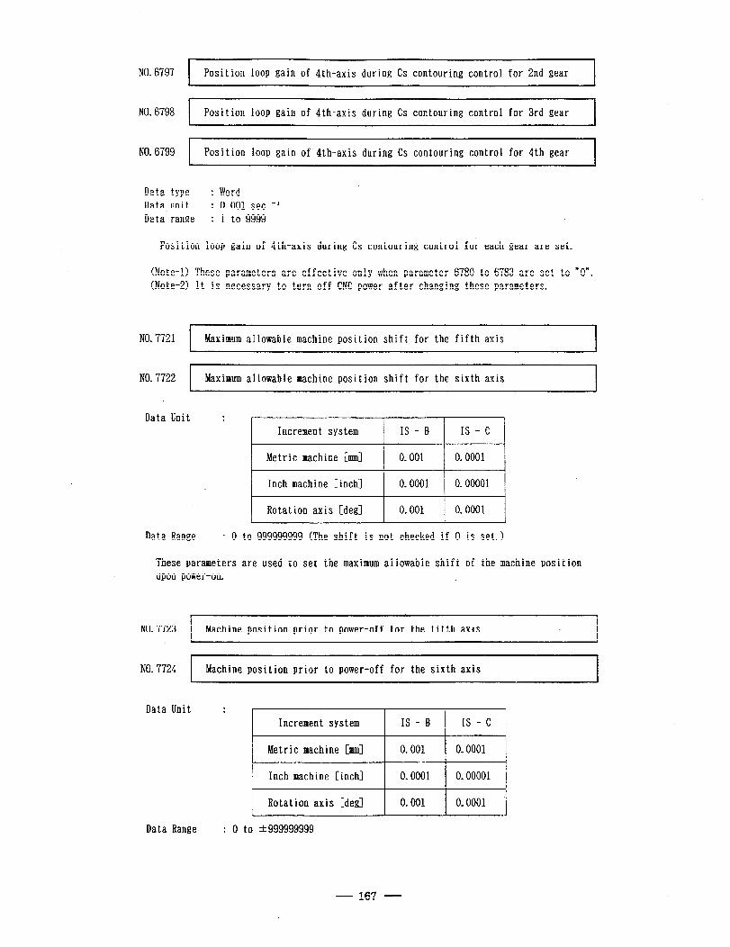
NO. 6797 ( P osi ion loop gain of 4th-axis during Cs contouring control for 2nd gear l t‘ I
NO, 6798 1
Position loop gain of 4th-axis during Cs contouring control for 3rd gear
NO. 6799 I Position loop gain of 4th-axis during Cs contouring control for 4th gear I
Data type : Word Data unit : 0.001 set -l Data range : 1 to 9999
. Position loop gain of $th-axis during Cs contouring control for each gear are set.
(Note-0 These parameters are effective only when parameter 6780 to 6783 are set to “0”. (Note-21 It is necessary to turn off CNC power after changing these parameters.
NO. 7721 Maximum allowable machine position shift for the fifth axis
NO. 7722 I
Maximum allowable machine position shift for the sixth axis I
Data Unit : Increment system IS - B IS - c
Metric machine [mm] 0.001 0.0001
Inch machine [inch] j 0.0001 j 0.00001
Rotat ion axis [deg] 0.001 0.0001
Data Range : 0 to 999999999 (The shift is not checked if 0 is set.)
These parameters are used to set the maximum allowable shift of the machine position upon power-on.
NO.7723 M h’ ac me position prior to power-off for the fifth axis
NO. 7724 I
Machine position prior to power-off for the sixth axis I
Data Unit : r
Increment system IS - B IS - c
Metric machine [mm] 0.001 0.0001
Inch machine [inch] 0.0001 0.00001
Rotation axis [deg] 0.001 0.0001
Data Range : 0 to t999999999
- 167 -

These parame ters d isplay the machine position prior to power-off. self-diagnos is and need not be set.
They are used for
168
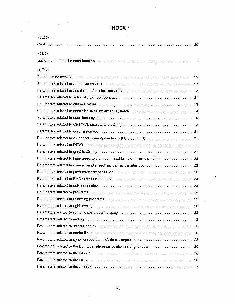
<c> Cautions . . . . . . . . . . . . . . . . . . . . . . . . .
<L>
INDEX .
. . . . . . . . . . . . . . . . . . . . . . . . . . . . . . . . . . . . 30
List of parameters for each function . . . . . . . . . . . . . . . . . . . . . . . . . . . . . . . . . . . . . . . . . . . 1
<P>
Parameter description . . . . . . . . . . . . . . . . . . . . . . . . . . . . . . . . . . . . . . . . . . . . . . . . . . . 29
Parameters related to
Parameters related to
Parameters related to
Parameters related to
Parameters related to
Parameters related to
Parameters related to
Parameters related to
Parameters related to
Parameters related to
Parameters related .to
Parameters related to
Parameters related to
Parameters related to
Parameters related to
Parameters related to
Parameters related to
Parameters related to
Parameters related to
Parameters related to
Parameters related to
Parameters related to
Parameters related to
Parameters related to
Parameters related to
Parameters rei,ated to
Parameters related to
Parameters related to
2-path lathes (TT) ...................................... 27
acceleration/deceleration control ............................ 8
automatic tool compensation ............................... 21
canned cycles ......................................... 19
controlled axes/increment systems .......................... 4
ooordinate systems ..................................... 5
CRTIMDI, display, and editing . . . . . . . . . . . . . . . . . . . . . . . . . . . . . . 12
custom macros ........................................ 21
cylindrical grinding machines (FS O/00-CCC) ................... 25
Di/DO ......................... .A ................... 11
graphic display ........................................ 21 i
high-speed cycle machining/high-speed remote buffers ............ 23
manual handle feed/manual handle interrupt .................... 23
pitch error compensation ................................. 16
PMC-based axis control .................................. 24
polygon turning ........................................ 28
programs ............................................ 15
restarting programs . . . . . . . . . . . . . . . . . . . . . . . . . . . . . . . . . . . . . 23
rigid tapping .......................................... 20
run time/parts count display ............................... 22
setting .............................................. 2
spindle control ......................................... 16
stroke limits . . . . . . . . . . . . . . . . . . . . . . . . . . . . . . . . . . . . . . . . . . . 6
synchronized control/axis recomposition . . . . . . . . . . . . . . . . . . . . . . . 28
the butt-type reference position setting function . . . . . . . . . . . . . . . . . 25
the Cf-axis . . . . . . . . . . . . . . . . . . . . . . . . . . . . . . . . . . . . . . . . . . . 26
the DNC . . . . . . . . . . . . . . . . . . . . . . . . . . . . . . . . . . . . . . . . . . . . . 26
the feedrate . . . . . . . . . . . . . . . . . . . . . . . . . . . . . . . . . . . . . . . . . . . 7
Parameters related to the
Parameters related to the
Parameters related to the
Parameters related to the
Parameters related to the
Parameters related to the
M-NET ............... . ............................ 26
PMC ............................................. 25
position switch function ................................ 22
reader/punch interface/remote buffers ..................... 3
servo system ....................................... 9
software operator’s panel .............................. 23
Parameters related to tool compensation ...................................... 18
Parameters related to tool life management .................................... 22
<s> * Setting method ...... . ................................................. 29
Setting parameter ...................................................... 31
Specifications of additional parameters ....................................... 101
<T>
Terminology . . . . . . . . . . . . . . . . . . . . . . . . . . . . . . . . . . . . . . . . . . . . . . . . . . . . . . . . . . 29
i-2
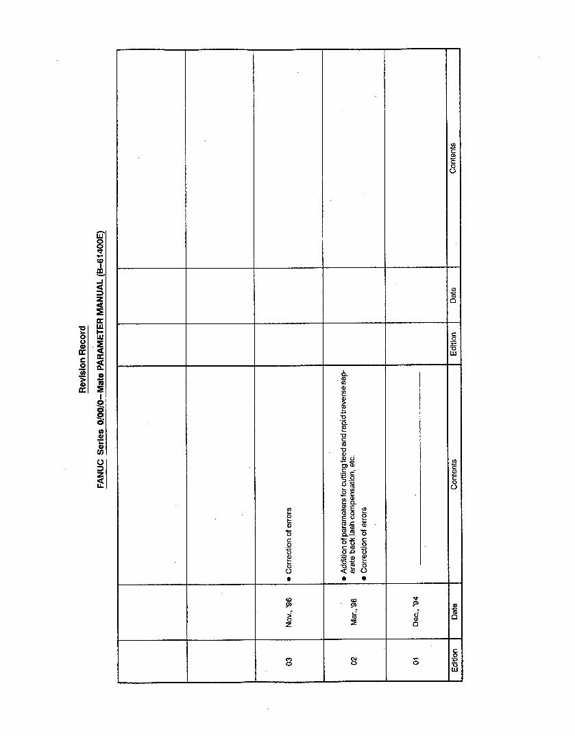
Rev
isio
n R
eco
rd
FA
NU
C S
erie
s O
/00/
0-M
ate
PA
RA
ME
TE
R
MA
NU
AL
(B
-61
4OO
E)
03
Nov
., ‘9
6 l C
orre
ctio
n of
err
ors
02
Mar
.,‘96
l A
dditi
on o
f par
amet
ers
for
cutti
ng f
eed
and
rapi
d tra
vers
e se
p-
arat
e ba
ck l
ash
com
pens
atio
n,
etc.
l C
orre
ctio
n of
err
ors
01
Dec
., ‘9
4
Edi
tion
Dat
e C
onte
nts
Edi
tion
Dat
e C
onte
nts

· No part of this manual may bereproduced in any form.
· All specifications and designsare subject to change withoutnotice.