fanuc 35ib - peter lehmann ag
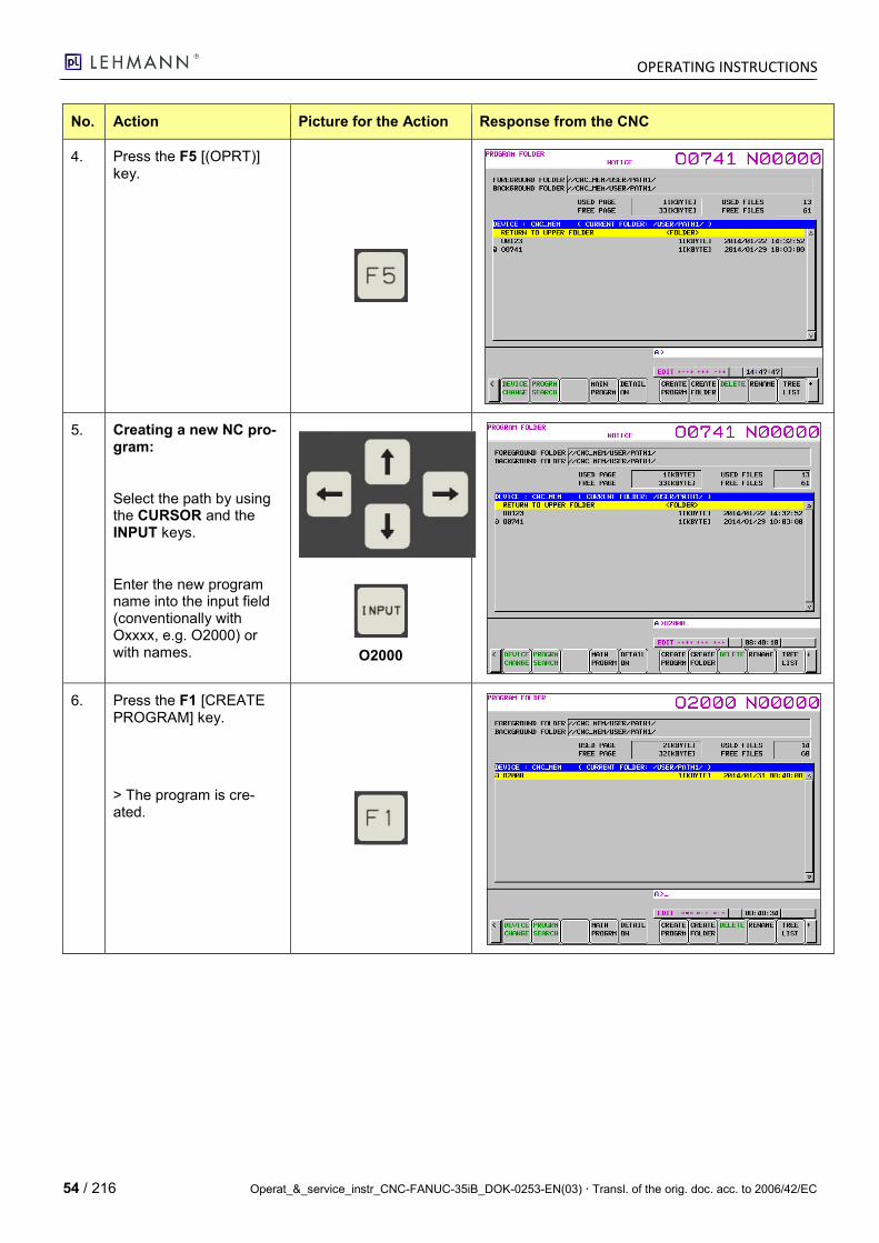
TRANSCRIPT
Operat_&_service_instr_CNC-FANUC-35iB_DOK-0253-EN(03) Transl. of the orig. doc. acc. to 2006/42/EC 1 / 216
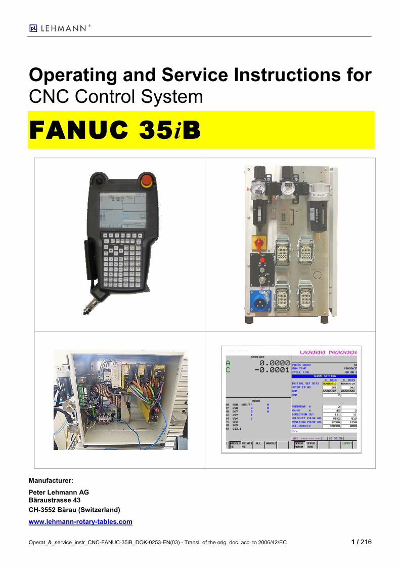
Operating and Service Instructions for CNC Control System
FANUC 35iB
Manufacturer:
Peter Lehmann AG Bäraustrasse 43
CH-3552 Bärau (Switzerland)
www.lehmann-rotary-tables.com
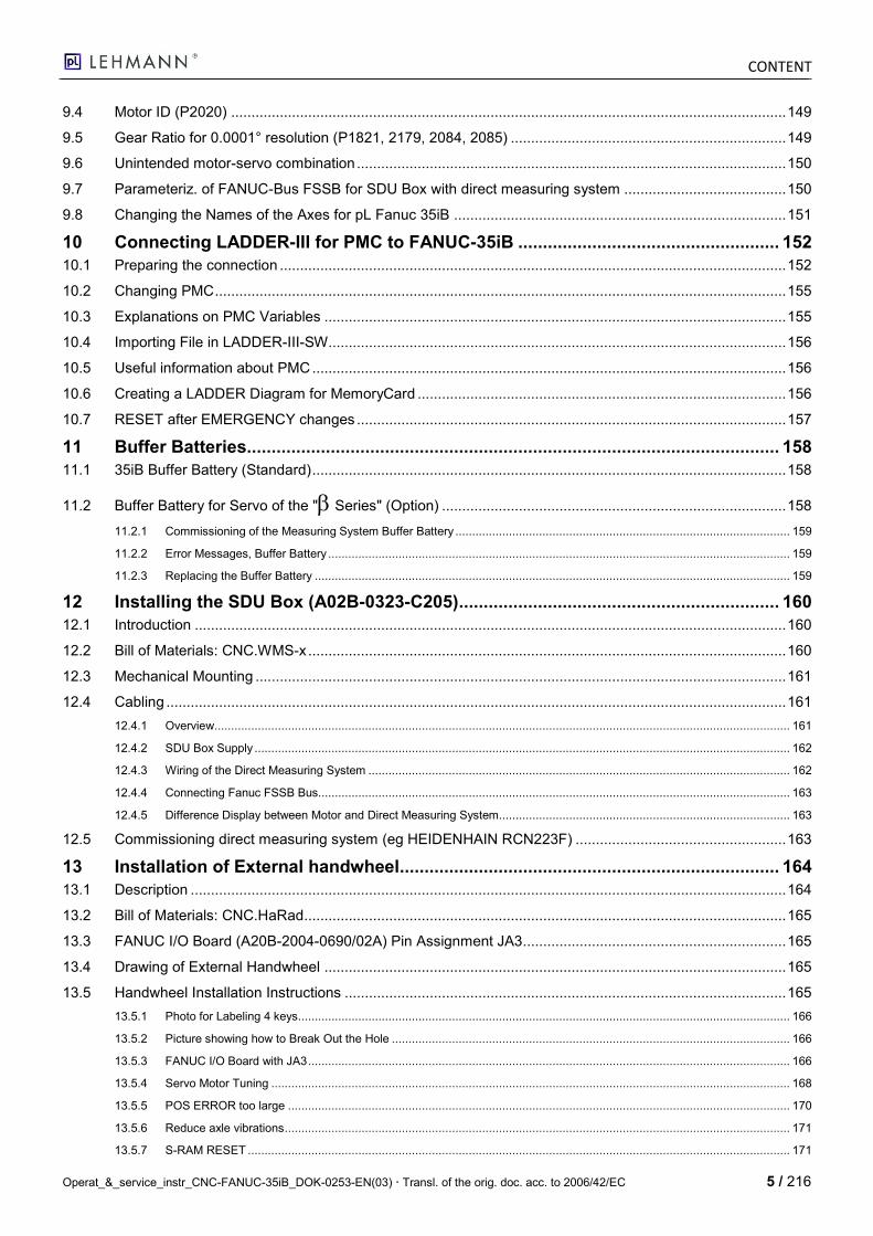
CONTENT
2 / 216 Operat_&_service_instr_CNC-FANUC-35iB_DOK-0253-EN(03) Transl. of the orig. doc. acc. to 2006/42/EC
Table of Contents
A. Operating Instructions .................................................................................................... 7
1 GENERAL INFORMATION ............................................................................................... 7
1.1 History .............................................................................................................................................................. 7
1.2 Product Documentation - Validity of this Document ........................................................................................ 8
1.3 Instructions on Safety and Personal Protection ............................................................................................... 8
2 Functional Overview ....................................................................................................... 9
2.1 Technical data ................................................................................................................................................ 11
3 FANUC "i Pendant" Handheld Controller Panel.......................................................... 13
3.1 Designations .................................................................................................................................................. 13
3.2 Key Functions ................................................................................................................................................ 14
3.2.1 Explanation of the Keys ....................................................................................................................................................... 14
3.2.2 Function Keys and Switching Keyboard Assignment ............................................................................................................ 17
4 Operating the CNC FANUC 35iB .................................................................................. 18
4.1 NC Program Structure ................................................................................................................................... 18
4.2 Starting Up CNC FANUC 35iB ....................................................................................................................... 19
4.2.1 Starting Up in Standard Situation ......................................................................................................................................... 19
4.3 REF Mode (Approaching Reference Points) ................................................................................................. 20
4.4 JOG Mode (Moving Axes Manually) .............................................................................................................. 21
4.5 STEP or Handwheel Mode via Machine Operator's Panel ............................................................................ 22
4.5.1 Function STEP since PMC-Version „PMC1_V01E08beta“ (new Sept. 2014)........................................................................ 22
4.5.2 STEP- and HANDWHEEL-Function at PMC-Version „PMC1_V01E07“ (old) ........................................................................ 23
4.6 MDI Mode (Creating / Moving Temporary Program) ..................................................................................... 26
4.6.1 Example of working with the MDI Mode ............................................................................................................................... 26
4.7 EDIT Mode (Creating a Workpiece Program) ................................................................................................ 28
4.7.1 Fanuc Standard File Structure for File Storage .................................................................................................................... 28
4.7.2 Starting the EDIT Mode ....................................................................................................................................................... 28
4.7.3 Selecting a NC Program from the List for Editing or Processing ........................................................................................... 30
4.7.4 Creating a New Program...................................................................................................................................................... 33
4.7.5 Inserting a New Sequence or Value ..................................................................................................................................... 35
4.7.6 Changing a Sequence or Value ........................................................................................................................................... 36
4.7.7 Deleting a Sequence or Value.............................................................................................................................................. 37
4.7.8 Deleting a Program .............................................................................................................................................................. 38
4.8 AUTO Mode (Program Selection) .................................................................................................................. 40
4.8.1 Introduction .......................................................................................................................................................................... 40
4.8.2 Selecting an NC Program (Main Program) ........................................................................................................................... 40
4.8.3 Starting the Current NC Program ......................................................................................................................................... 40
4.8.4 Accessing the PG at a Sequence Number ........................................................................................................................... 43
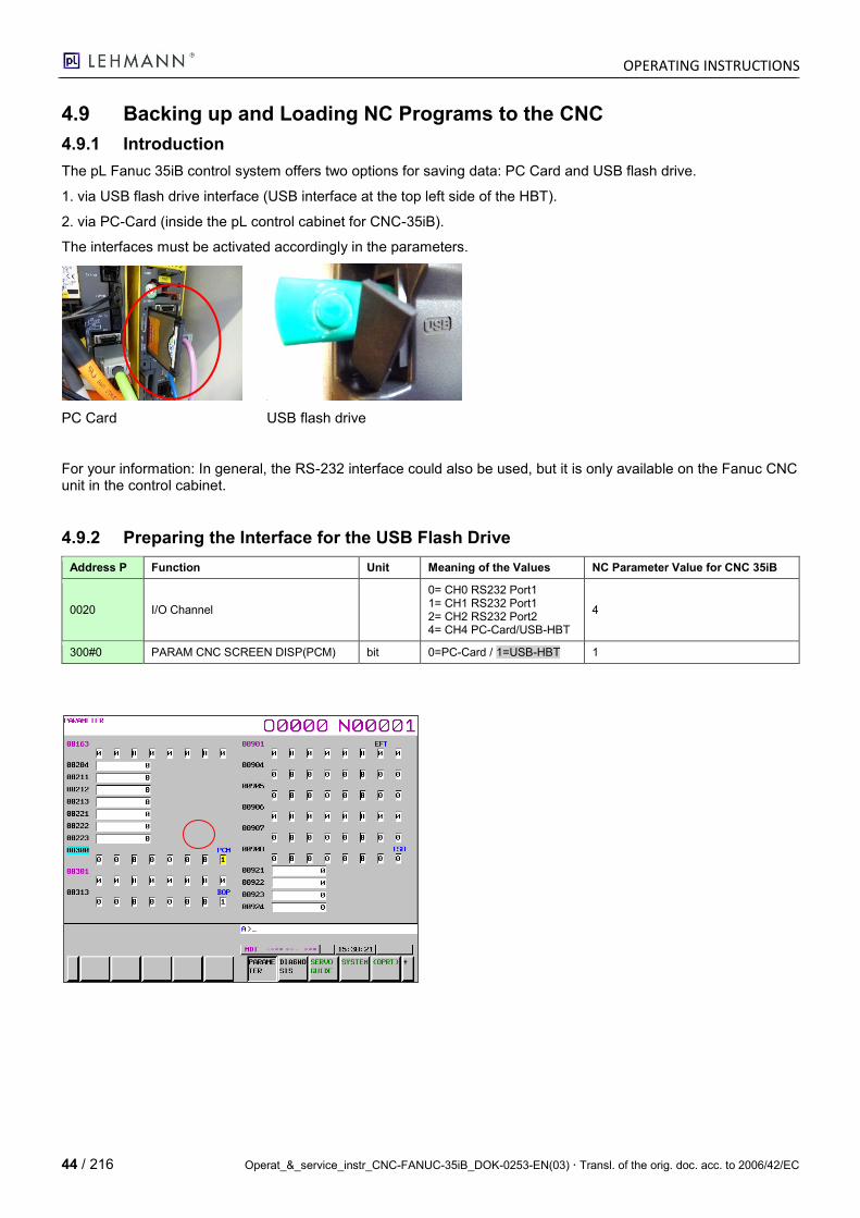
4.9 Backing up and Loading NC Programs to the CNC ...................................................................................... 44
4.9.1 Introduction .......................................................................................................................................................................... 44
4.9.2 Preparing the Interface for the USB Flash Drive ................................................................................................................... 44
4.9.3 Reading the NC Program out to the USB Flash Drive or PC Card ........................................................................................ 45
4.9.4 Reading the NC Program out from the USB Flash Drive or PC Card .................................................................................... 48
4.9.5 Deleting a NC Program or Creating a New NC Program ...................................................................................................... 53
CONTENT
Operat_&_service_instr_CNC-FANUC-35iB_DOK-0253-EN(03) Transl. of the orig. doc. acc. to 2006/42/EC 3 / 216
5 Programming and Function Examples ........................................................................ 56
5.1 Program commands according to DIN 66025 ................................................................................................ 56
5.2 Programming Example for 1-axis Model ........................................................................................................ 60
5.3 Programming Example for 2-axis Model ........................................................................................................ 60
5.4 Description of Individual Programming Functions ......................................................................................... 61
5.5 Reference Point and Workpiece Zero Point Shift .......................................................................................... 63
5.6 directPOS (Position Specification via M-Func 1…5) ..................................................................................... 64
5.6.1 Introduction .......................................................................................................................................................................... 64
5.6.2 NC Prog Selection Assignment: ........................................................................................................................................... 64
5.6.3 Example NC Prog for directPOS Function ............................................................................................................................ 64
5.7 Customer Macro Programming ...................................................................................................................... 64
5.7.1 Introduction .......................................................................................................................................................................... 64
5.7.2 Variables.............................................................................................................................................................................. 65
5.7.3 Variable Types ..................................................................................................................................................................... 66
5.7.4 Call by Reference ................................................................................................................................................................ 66
5.7.5 Checking or changing macro variables ................................................................................................................................ 67
5.7.6 Arithmetic and Logic Operations .......................................................................................................................................... 69
5.7.7 Assignment of Letters to Variable Numbers ......................................................................................................................... 69
5.7.8 Program Example ................................................................................................................................................................ 70
5.8 pL Division Computer Macro .......................................................................................................................... 71
5.8.1 Macro Description ................................................................................................................................................................ 71
5.8.2 Transferring Parameters for the Macro:................................................................................................................................ 72
5.8.3 Division Computer Macro Code ........................................................................................................................................... 72
5.9 Macro Call ...................................................................................................................................................... 73
5.9.1 Subprogram Call G65 .......................................................................................................................................................... 73
5.9.2 G Function Call G300 .......................................................................................................................................................... 73
5.10 Program Examples ........................................................................................................................................ 73
5.10.1 Example 1 (Division computer combined with other positions) ............................................................................................. 73
5.10.2 Example 2 (Continuous Turning in the Same Direction) ....................................................................................................... 74
6 PMC Parameter Setting ................................................................................................. 75
6.1 Displaying the PMC Version Number ............................................................................................................ 75
6.2 Preparing PMC Data to be Changed ............................................................................................................. 76
6.3 Language switching of the PMC reporting system ........................................................................................ 76
6.4 Keep relay ...................................................................................................................................................... 77
6.5 Timer .............................................................................................................................................................. 82
6.5.1 Signal Time Diagram ........................................................................................................................................................... 83
6.6 DATA .............................................................................................................................................................. 84
6.6.1 Access ................................................................................................................................................................................. 84
6.6.2 Configuration of the speed for endless turning M03 / M04 .................................................................................................... 85
6.7 Turning a 2-axis CNC into a 1-axis CNC ....................................................................................................... 85
6.7.1 Removing Axis 2 SERVO completely: .................................................................................................................................. 85
6.7.2 Deselecting Axis 2 SERVO only: .......................................................................................................................................... 85
6.8 Saving PrintScreen from Current Monitor Content to Card ........................................................................... 85
7 Connection to the Higher-Level Machine .................................................................... 87
CONTENT
4 / 216 Operat_&_service_instr_CNC-FANUC-35iB_DOK-0253-EN(03) Transl. of the orig. doc. acc. to 2006/42/EC
7.1 Plug Connections at the Control Cabinet ....................................................................................................... 87
7.2 X17 Connector for the Connection to the Machine ........................................................................................ 88
7.2.1 CNC.MFK - M-Function Cable for the Connection to the Machine ........................................................................................ 88
7.3 Standard Connection for 1- and 2-axis Model ............................................................................................... 90
7.3.1 Acknowledgeable M-Function at the CNC Machine.............................................................................................................. 91
7.3.2 Program Example ................................................................................................................................................................ 91
7.4 Time Signal Diagram for CNC FANUC 35iB ................................................................................................. 91
7.5 Further Functions on the X17a Connector and their Connection .................................................................. 92
7.6 Operation of the machine tool without CNC-FANUC-35iB ............................................................................ 93
B. Service Instructions ............................................................................................................ 94
8 Commissioning.............................................................................................................. 94
8.1 Introduction .................................................................................................................................................... 94
8.2 Initial Commissioning, Step by Step .............................................................................................................. 95
8.2.1 Introduction .......................................................................................................................................................................... 95
8.2.2 IP Addresses ....................................................................................................................................................................... 95
8.2.3 Commissioning Procedure ................................................................................................................................................... 95
8.3 Basics: i-Pendant (Handheld Controller) ....................................................................................................... 96
8.3.1 Screen ................................................................................................................................................................................. 96
8.3.2 Touches sans volant intégrée .............................................................................................................................................. 96
8.3.3 Touches avec volant intégrée .............................................................................................................................................. 97
8.3.4 Switching from "CNC Control Panel" to "i-Pendant OS" ....................................................................................................... 98
8.3.5 EMERGENCY STOP and USB ............................................................................................................................................ 98
8.3.6 Dimensions .......................................................................................................................................................................... 98
8.3.7 Configuring 35iB for "i Pendant" Handheld Controller Panel ................................................................................................. 99
8.3.8 PMC Configuration............................................................................................................................................................. 100
8.3.9 Loading NC Parameters..................................................................................................................................................... 102
8.3.10 Loading PMC (LADDER), PMC Parameters ...................................................................................................................... 105
8.3.10.1 Preparing Loading ...................................................................................................................................................................... 105
8.3.10.2 Loading PMC .............................................................................................................................................................................. 107
8.3.10.3 Loading PMC Parameters........................................................................................................................................................... 108
8.3.10.4 Loading PMC IOCONF ............................................................................................................................................................... 109
8.3.10.5 Loading PMC Message .............................................................................................................................................................. 110
8.3.10.6 Saving Files Read in from RAM in F-ROM .................................................................................................................................. 111
8.3.11 Checking the PMC (LADDER) SW Version ........................................................................................................................ 114
8.3.12 Adjusting System-Specific Parameters .............................................................................................................................. 115
8.3.13 Loading Macros (Division Computer and directPos) ........................................................................................................... 116
8.3.14 Setting date and time ......................................................................................................................................................... 126
8.4 Complete Data Backup prior to Delivery ...................................................................................................... 128
8.4.1 Resetting WriteEnable NC and PMC Parameters .............................................................................................................. 132
8.5 Checklist for Initial Commissioning (Check-Your-Work) .............................................................................. 136
9 NC Parameter Setting .................................................................................................. 138
9.1 Preparing Data to be Changed .................................................................................................................... 138
9.2 NC Parameters ............................................................................................................................................ 138
9.2.1 Fanuc Graphic for the Assignment of Axes ........................................................................................................................ 148
9.3 Parametrization of Handy with and without integrated hand-wheel............................................................. 148
CONTENT
Operat_&_service_instr_CNC-FANUC-35iB_DOK-0253-EN(03) Transl. of the orig. doc. acc. to 2006/42/EC 5 / 216
9.4 Motor ID (P2020) ......................................................................................................................................... 149
9.5 Gear Ratio for 0.0001° resolution (P1821, 2179, 2084, 2085) .................................................................... 149
9.6 Unintended motor-servo combination .......................................................................................................... 150
9.7 Parameteriz. of FANUC-Bus FSSB for SDU Box with direct measuring system ........................................ 150
9.8 Changing the Names of the Axes for pL Fanuc 35iB .................................................................................. 151
10 Connecting LADDER-III for PMC to FANUC-35iB ..................................................... 152
10.1 Preparing the connection ............................................................................................................................. 152
10.2 Changing PMC ............................................................................................................................................. 155
10.3 Explanations on PMC Variables .................................................................................................................. 155
10.4 Importing File in LADDER-III-SW................................................................................................................. 156
10.5 Useful information about PMC ..................................................................................................................... 156
10.6 Creating a LADDER Diagram for MemoryCard ........................................................................................... 156
10.7 RESET after EMERGENCY changes .......................................................................................................... 157
11 Buffer Batteries............................................................................................................ 158
11.1 35iB Buffer Battery (Standard) ..................................................................................................................... 158
11.2 Buffer Battery for Servo of the " Series" (Option) ..................................................................................... 158
11.2.1 Commissioning of the Measuring System Buffer Battery .................................................................................................... 159
11.2.2 Error Messages, Buffer Battery .......................................................................................................................................... 159
11.2.3 Replacing the Buffer Battery .............................................................................................................................................. 159
12 Installing the SDU Box (A02B-0323-C205) ................................................................. 160
12.1 Introduction .................................................................................................................................................. 160
12.2 Bill of Materials: CNC.WMS-x ...................................................................................................................... 160
12.3 Mechanical Mounting ................................................................................................................................... 161
12.4 Cabling ......................................................................................................................................................... 161
12.4.1 Overview............................................................................................................................................................................ 161
12.4.2 SDU Box Supply ................................................................................................................................................................ 162
12.4.3 Wiring of the Direct Measuring System .............................................................................................................................. 162
12.4.4 Connecting Fanuc FSSB Bus............................................................................................................................................. 163
12.4.5 Difference Display between Motor and Direct Measuring System....................................................................................... 163
12.5 Commissioning direct measuring system (eg HEIDENHAIN RCN223F) .................................................... 163
13 Installation of External handwheel ............................................................................. 164
13.1 Description ................................................................................................................................................... 164
13.2 Bill of Materials: CNC.HaRad....................................................................................................................... 165
13.3 FANUC I/O Board (A20B-2004-0690/02A) Pin Assignment JA3 ................................................................. 165
13.4 Drawing of External Handwheel .................................................................................................................. 165
13.5 Handwheel Installation Instructions ............................................................................................................. 165
13.5.1 Photo for Labeling 4 keys ................................................................................................................................................... 166
13.5.2 Picture showing how to Break Out the Hole ....................................................................................................................... 166
13.5.3 FANUC I/O Board with JA3 ................................................................................................................................................ 166
13.5.4 Servo Motor Tuning ........................................................................................................................................................... 168
13.5.5 POS ERROR too large ...................................................................................................................................................... 170
13.5.6 Reduce axle vibrations ....................................................................................................................................................... 171
13.5.7 S-RAM RESET .................................................................................................................................................................. 171
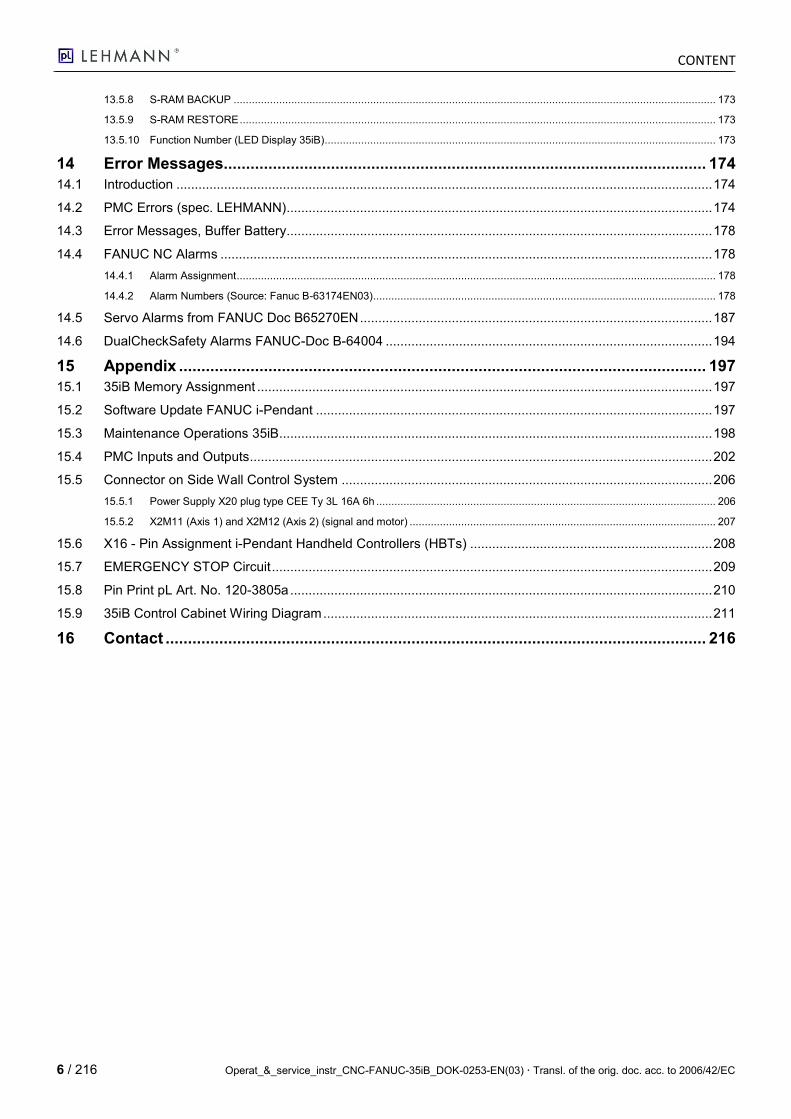
CONTENT
6 / 216 Operat_&_service_instr_CNC-FANUC-35iB_DOK-0253-EN(03) Transl. of the orig. doc. acc. to 2006/42/EC
13.5.8 S-RAM BACKUP ............................................................................................................................................................... 173
13.5.9 S-RAM RESTORE ............................................................................................................................................................. 173
13.5.10 Function Number (LED Display 35iB) ................................................................................................................................. 173
14 Error Messages............................................................................................................ 174
14.1 Introduction .................................................................................................................................................. 174
14.2 PMC Errors (spec. LEHMANN).................................................................................................................... 174
14.3 Error Messages, Buffer Battery.................................................................................................................... 178
14.4 FANUC NC Alarms ...................................................................................................................................... 178
14.4.1 Alarm Assignment .............................................................................................................................................................. 178
14.4.2 Alarm Numbers (Source: Fanuc B-63174EN03) ................................................................................................................. 178
14.5 Servo Alarms from FANUC Doc B65270EN ................................................................................................ 187
14.6 DualCheckSafety Alarms FANUC-Doc B-64004 ......................................................................................... 194
15 Appendix ...................................................................................................................... 197
15.1 35iB Memory Assignment ............................................................................................................................ 197
15.2 Software Update FANUC i-Pendant ............................................................................................................ 197
15.3 Maintenance Operations 35iB...................................................................................................................... 198
15.4 PMC Inputs and Outputs .............................................................................................................................. 202
15.5 Connector on Side Wall Control System ..................................................................................................... 206
15.5.1 Power Supply X20 plug type CEE Ty 3L 16A 6h ................................................................................................................ 206
15.5.2 X2M11 (Axis 1) and X2M12 (Axis 2) (signal and motor) ..................................................................................................... 207
15.6 X16 - Pin Assignment i-Pendant Handheld Controllers (HBTs) .................................................................. 208
15.7 EMERGENCY STOP Circuit ........................................................................................................................ 209
15.8 Pin Print pL Art. No. 120-3805a ................................................................................................................... 210
15.9 35iB Control Cabinet Wiring Diagram .......................................................................................................... 211
16 Contact ......................................................................................................................... 216

OPERATING INSTRUCTIONS
Operat_&_service_instr_CNC-FANUC-35iB_DOK-0253-EN(03) Transl. of the orig. doc. acc. to 2006/42/EC 7 / 216
A. Operating Instructions
1 GENERAL INFORMATION
Dear Customer
We wish you much success with the LEHMANN FANUC 35iB CNC control system.
The LEHMANN FANUC 35iB Type D CNC control system is perfectly aligned to our rotary tables of the 500 series. It is available either as a 1-axis or 2-axis model. For more information, please refer to the BR500 catalog on our website.
By means of the FANUC 35iB CNC control system, LEHMANN rotary tables can be connected to the machine so that they work like additional integrated axes. The FANUC 35iB processes the control signals of the machine tool, moves the rotary tables, controls the clamping etc. and monitors its functions at the same time.
The FANUC 35iB is programmed by using the supplied FANUC handheld controller. Thus, it is extremely simple to operate the control system.
This manual only describes the current LEHMANN application of the FANUC 35iB Type D control. Among others, the extensive manuals «FANUC 35iB Nos. B-64523, B-64524, B-64525, B-65270 and B-64530» by FANUC served as a source. These are also available in different languages on the web.
1.1 History
Ix(1) Datum(2) Seite Text Von
02 2014-12-04 div Handrad intern/extern eingearbeitet. Eg
02 2015-02-06 158 Messsystemkabel 0.7m neu 0.9m, 1.4m neu 1.8m Bm
02 2016-03-03 202 Power supply Stecker eingefügt. Eg
03 2018-03-07 div P.8040; M-Verknüpfung besser beschrieben, nebst vielen an-dern Erweiterungen, Ergänzungen, Korrekturen.
eg
Änd.-Index u. Dat. sind in jeder Fusszeile. …__DOK-xxxx-xx.00 (1)_...._YYYY-MM-DD (2).docx
OPERATING INSTRUCTIONS
8 / 216 Operat_&_service_instr_CNC-FANUC-35iB_DOK-0253-EN(03) Transl. of the orig. doc. acc. to 2006/42/EC
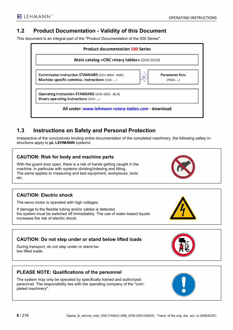
1.2 Product Documentation - Validity of this Document
This document is an integral part of the "Product Documentation of the 500 Series".
1.3 Instructions on Safety and Personal Protection
Irrespective of the conclusively binding entire documentation of the completed machinery, the following safety in-structions apply to pL LEHMANN systems.
CAUTION: Risk for body and machine parts
With the guard door open, there is a risk of hands getting caught in the machine, in particular with systems dividing/indexing and tilting. The same applies to measuring and test equipment, workpieces, tools etc.
CAUTION: Electric shock
The servo motor is operated with high voltages.
If damage to the flexible tubing and/or cables is detected, the system must be switched off immediately. The use of water-based liquids increases the risk of electric shock.
CAUTION: Do not step under or stand below lifted loads
During transport, do not step under or stand be-low lifted loads.
PLEASE NOTE: Qualifications of the personnel
The system may only be operated by specifically trained and authorized personnel. The responsibility lies with the operating company of the "com-pleted machinery".
OPERATING INSTRUCTIONS
Operat_&_service_instr_CNC-FANUC-35iB_DOK-0253-EN(03) Transl. of the orig. doc. acc. to 2006/42/EC 9 / 216
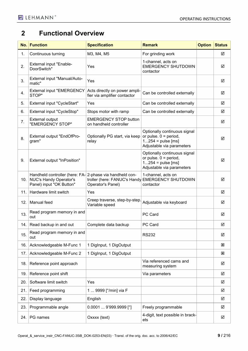
2 Functional Overview
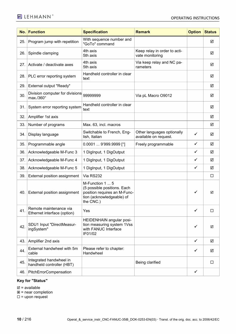
No. Function Specification Remark Option Status
1. Continuous turning M3, M4, M5 For grinding work
2. External input "Enable-DoorSwitch"
Yes 1-channel, acts on EMERGENCY SHUTDOWN contactor
3. External input "Manual/Auto-matic"
Yes
4. External input "EMERGENCY STOP"
Acts directly on power ampli-fier via amplifier contactor
Can be controlled externally
5. External input "CycleStart" Yes Can be controlled externally
6. External input "CycleStop" Stops motor with ramp Can be controlled externally
7. External output "EMERGENCY STOP"
EMERGENCY STOP button on handheld controller
8. External output "EndOfPro-gram"
Optionally PG start, via keep relay
Optionally continuous signal or pulse. 0 = period, 1...254 = pulse [ms] Adjustable via parameters
9. External output "InPosition"
Optionally continuous signal or pulse. 0 = period, 1...254 = pulse [ms] Adjustable via parameters
10. Handheld controller (here: FA-NUC's Handy Operator's Panel) input "OK Button"
2-phase via handheld con-troller (here: FANUC's Handy Operator's Panel)
1-channel, acts on EMERGENCY SHUTDOWN contactor
11. Hardware limit switch Yes
12. Manual feed Creep traverse, step-by-step. Variable speed
Adjustable via keyboard
13. Read program memory in and out
PC Card
14. Read backup in and out Complete data backup PC Card
15. Read program memory in and out
RS232
16. Acknowledgeable M-Func 1 1 DigInput, 1 DigOutput
17. Acknowledgeable M-Func 2 1 DigInput, 1 DigOutput
18. Reference point approach Via referenced cams and measuring system
19. Reference point shift Via parameters
20. Software limit switch Yes
21. Feed programming 1 ... 9999 [°/min] via F
22. Display language English
23. Programmable angle 0.0001 ... 9’999.9999 [°] Freely programmable
24. PG names Oxxxx (text) 4-digit, text possible in brack-ets
OPERATING INSTRUCTIONS
10 / 216 Operat_&_service_instr_CNC-FANUC-35iB_DOK-0253-EN(03) Transl. of the orig. doc. acc. to 2006/42/EC
No. Function Specification Remark Option Status
25. Program jump with repetition With sequence number and "GoTo" command
26. Spindle clamping 4th axis 5th axis
Keep relay in order to acti-vate monitoring
27. Activate / deactivate axes 4th axis 5th axis
Via keep relay and NC pa-rameters
28. PLC error reporting system Handheld controller in clear text
29. External output "Ready"
30. Division computer for divisions max./360°
99999999 Via pL Macro O9012
31. System error reporting system Handheld controller in clear text
32. Amplifier 1st axis
33. Number of programs Max. 63, incl. macros
34. Display language Switchable to French, Eng-lish, Italian
Other languages optionally available on request.
35. Programmable angle 0.0001 ... 9’999.9999 [°] Freely programmable
36. Acknowledgeable M-Func 3 1 DigInput, 1 DigOutput
37. Acknowledgeable M-Func 4 1 DigInput, 1 DigOutput
38. Acknowledgeable M-Func 5 1 DigInput, 1 DigOutput
39. External position assignment Via RS232
40. External position assignment
M-Function 1 ... 5 (5 possible positions. Each position requires an M-Func-tion (acknowledgeable) of the CNC.)
41. Remote maintenance via Ethernet interface (option)
Yes
42. SDU1 Input "DirectMeasur-ingSystem"
HEIDENHAIN angular posi-tion measuring system 1Vss with FANUC Interface IF01/02
43. Amplifier 2nd axis
44. External handwheel with 5m cable
Please refer to chapter: Handwheel
45. Integrated handwheel in handheld controller (HBT)
Being clarified
46. PitchErrorCompensation
Key for "Status"
= available = near completion = upon request
OPERATING INSTRUCTIONS
Operat_&_service_instr_CNC-FANUC-35iB_DOK-0253-EN(03) Transl. of the orig. doc. acc. to 2006/42/EC 11 / 216
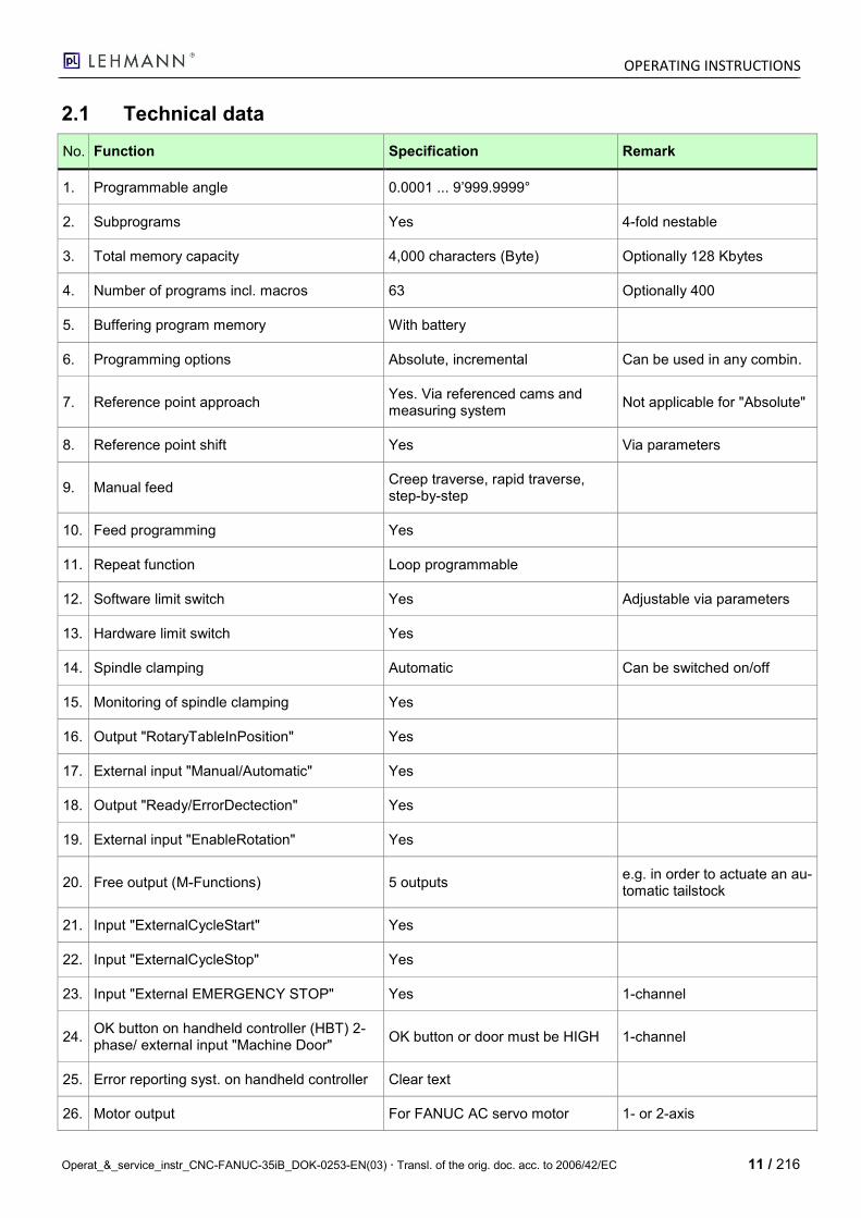
2.1 Technical data
No. Function Specification Remark
1. Programmable angle 0.0001 ... 9’999.9999°
2. Subprograms Yes 4-fold nestable
3. Total memory capacity 4,000 characters (Byte) Optionally 128 Kbytes
4. Number of programs incl. macros 63 Optionally 400
5. Buffering program memory With battery
6. Programming options Absolute, incremental Can be used in any combin.
7. Reference point approach Yes. Via referenced cams and measuring system
Not applicable for "Absolute"
8. Reference point shift Yes Via parameters
9. Manual feed Creep traverse, rapid traverse, step-by-step
10. Feed programming Yes
11. Repeat function Loop programmable
12. Software limit switch Yes Adjustable via parameters
13. Hardware limit switch Yes
14. Spindle clamping Automatic Can be switched on/off
15. Monitoring of spindle clamping Yes
16. Output "RotaryTableInPosition" Yes
17. External input "Manual/Automatic" Yes
18. Output "Ready/ErrorDectection" Yes
19. External input "EnableRotation" Yes
20. Free output (M-Functions) 5 outputs e.g. in order to actuate an au-tomatic tailstock
21. Input "ExternalCycleStart" Yes
22. Input "ExternalCycleStop" Yes
23. Input "External EMERGENCY STOP" Yes 1-channel
24. OK button on handheld controller (HBT) 2-phase/ external input "Machine Door"
OK button or door must be HIGH 1-channel
25. Error reporting syst. on handheld controller Clear text
26. Motor output For FANUC AC servo motor 1- or 2-axis
OPERATING INSTRUCTIONS
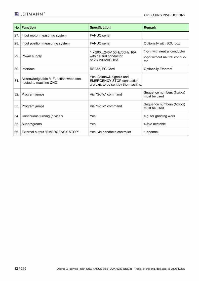
12 / 216 Operat_&_service_instr_CNC-FANUC-35iB_DOK-0253-EN(03) Transl. of the orig. doc. acc. to 2006/42/EC
No. Function Specification Remark
27. Input motor measuring system FANUC serial
28. Input position measuring system FANUC serial Optionally with SDU box
29. Power supply 1 x 200…240V 50Hz/60Hz 16A with neutral conductor or 2 x 200VAC 16A
1-ph. with neutral conductor
2-ph without neutral conduc-tor
30. Interface RS232, PC Card Optionally Ethernet
31. Acknowledgeable M-Function when con-nected to machine CNC
Yes. Acknowl. signals and EMERGENCY STOP connection are exp. to be sent by the machine.
32. Program jumps Via "GoTo" command Sequence numbers (Nxxxx) must be used
33. Program jumps Via "GoTo" command Sequence numbers (Nxxxx) must be used
34. Continuous turning (divider) Yes e.g. for grinding work
35. Subprograms Yes 4-fold nestable
36. External output "EMERGENCY STOP" Yes, via handheld controller 1-channel
OPERATING INSTRUCTIONS
Operat_&_service_instr_CNC-FANUC-35iB_DOK-0253-EN(03) Transl. of the orig. doc. acc. to 2006/42/EC 13 / 216
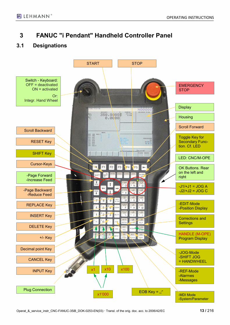
3 FANUC "i Pendant" Handheld Controller Panel
3.1 Designations
-MDI Mode -System/Parameter
LED: CNC/M-OPE
Switch - Keyboard: OFF = deactivated
ON = activated
Or: Integr. Hand Wheel
SHIFT Key
Cursor-Keys
RESET Key
-Page Forward -Increase Feed
INSERT Key
DELETE Key
+/- Key
CANCEL Key
Decimal point Key
INPUT Key
Corrections and Settings
EOB Key = „;“
-REF-Mode -Alarmes -Messages
-J1/+J1 = JOG A -J2/+J2 = JOG C
Scroll Forward
STOP START
Scroll Backward
EMERGENCY STOP
Housing
Display
OK Buttons. Rear on the left and right
Toggle Key for Secondary Func-tion. Cf. LED
-EDIT-Mode -Position Display
REPLACE Key
-Page Backward -Reduce Feed
HANDLE (M-OPE) Program Display
-JOG-Mode -SHIFT JOG = HANDWHEEL
x1 x10 x100
x1‘000
Plug Connection
OPERATING INSTRUCTIONS
14 / 216 Operat_&_service_instr_CNC-FANUC-35iB_DOK-0253-EN(03) Transl. of the orig. doc. acc. to 2006/42/EC
3.2 Key Functions
3.2.1 Explanation of the Keys
No. Designation Explanation
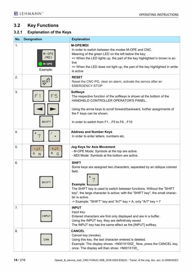
1.
Example:
M-OPE/MDI
In order to switch between the modes M-OPE and CNC.
Meaning of the green LED on the left below the key:
=> When the LED lights up, the part of the key highlighted in brown is ac-
tive
=> When the LED does not light up, the part of the key highlighted in white
is active
2.
RESET
Reset the CNC-PG, clear an alarm, activate the servos after an
EMERGENCY-STOP
3.
…
Softkeys
The respective function of the softkeys is shown at the bottom of the
HANDHELD CONTROLLER OPERATOR'S PANEL.
Using the arrow keys to scroll forward/backward, further assignments of
the F keys can be shown.
In order to switch from F1…F5 to F6…F10
4.
…
Address and Number Keys
In order to enter letters, numbers etc.
5.
…
Jog Keys for Axis Movement
- M-OPE Mode: Symbols at the top are active.
- MDI Mode: Symbols at the bottom are active.
6.
SHIFT
Some keys are assigned two characters, separated by an oblique colored
field.
Example:
The SHIFT key is used to switch between functions. Without the "SHIFT
key", the large character is active; with the "SHIFT key", the small charac-
ter is active.
-> Example: "SHIFT" key and "A/7" key = A, only "A/7" key = 7
7.
INPUT
Input key.
Entered characters are first only displayed and are in a buffer.
Using the INPUT key, they are definitively saved.
The INPUT key has the same effect as the [INPUT] softkey.
8.
CANCEL
Cancel key (revoke).
Using this key, the last character entered is deleted.
Example: The display shows: >N001X100Z_ Now, press the CANCEL key
once. The display will then show: >N001X100_
OPERATING INSTRUCTIONS
Operat_&_service_instr_CNC-FANUC-35iB_DOK-0253-EN(03) Transl. of the orig. doc. acc. to 2006/42/EC 15 / 216
No. Designation Explanation
9.
EOB: Each NC sequence must be completed by "EndOfBlock"; a semico-
lon " ; " is generated.
10.
Operating Mode Switching Keys:
- AUTO: NC program sequence
- EDIT: Edit NC program
- MDI: MDI Mode
- REF: Approach reference points
- JOG: Moving the axes using the JOG keys
- SHIFT-JOG: Handwheel or step-by-step operation
11.
These keys are only available in the M-OPE Mode:
- START: cycle start.
- SINGLE: Activate an individual program sequence.
- STOP: cycle stop.
12.
Program editing keys
ALTER: Text: REPLACE
INSERT: Text: INSERT
DELETE: Text: DELETE
13.
PROGRAM: Activate NC program display
14.
MESSAGE: Show display for message and alarm details
15.
POS: Activate position display
OPERATING INSTRUCTIONS
16 / 216 Operat_&_service_instr_CNC-FANUC-35iB_DOK-0253-EN(03) Transl. of the orig. doc. acc. to 2006/42/EC
No. Designation Explanation
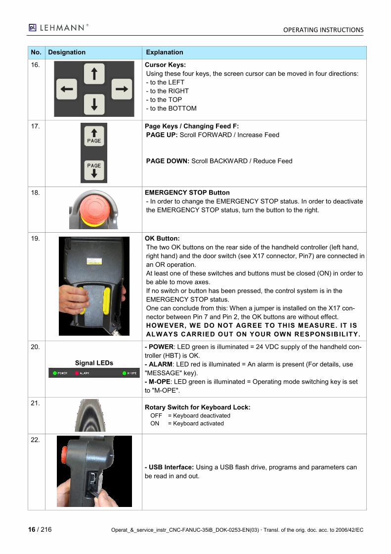
16.
Cursor Keys:
Using these four keys, the screen cursor can be moved in four directions:
- to the LEFT
- to the RIGHT
- to the TOP
- to the BOTTOM
17.
Page Keys / Changing Feed F:
PAGE UP: Scroll FORWARD / Increase Feed
PAGE DOWN: Scroll BACKWARD / Reduce Feed
18.
EMERGENCY STOP Button
- In order to change the EMERGENCY STOP status. In order to deactivate
the EMERGENCY STOP status, turn the button to the right.
19.
OK Button:
The two OK buttons on the rear side of the handheld controller (left hand,
right hand) and the door switch (see X17 connector, Pin7) are connected in
an OR operation.
At least one of these switches and buttons must be closed (ON) in order to
be able to move axes.
If no switch or button has been pressed, the control system is in the
EMERGENCY STOP status.
One can conclude from this: When a jumper is installed on the X17 con-
nector between Pin 7 and Pin 2, the OK buttons are without effect.
HOWEVER, WE DO NOT AGREE TO THIS MEASURE. IT IS
ALWAYS CARRIED OUT ON YOUR OWN RESPONSIBILITY.
20.
Signal LEDs
- POWER: LED green is illuminated = 24 VDC supply of the handheld con-
troller (HBT) is OK.
- ALARM: LED red is illuminated = An alarm is present (For details, use
"MESSAGE" key).
- M-OPE: LED green is illuminated = Operating mode switching key is set
to "M-OPE".
21.
Rotary Switch for Keyboard Lock:
OFF = Keyboard deactivated
ON = Keyboard activated
22.
- USB Interface: Using a USB flash drive, programs and parameters can
be read in and out.
OPERATING INSTRUCTIONS
Operat_&_service_instr_CNC-FANUC-35iB_DOK-0253-EN(03) Transl. of the orig. doc. acc. to 2006/42/EC 17 / 216
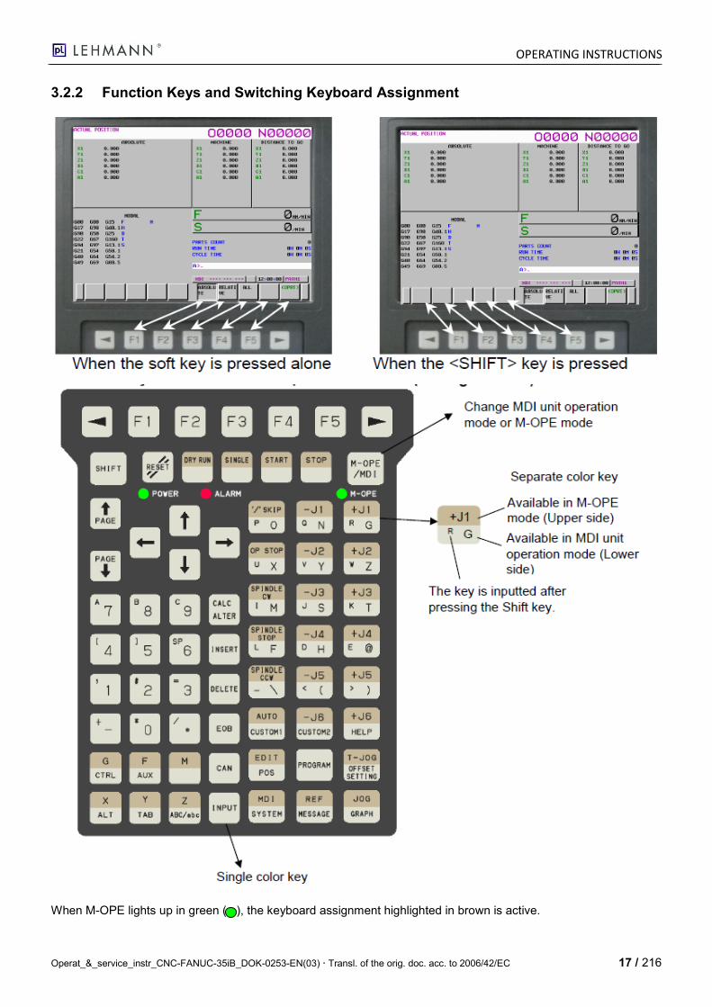
3.2.2 Function Keys and Switching Keyboard Assignment
When M-OPE lights up in green ( ), the keyboard assignment highlighted in brown is active.
OPERATING INSTRUCTIONS
18 / 216 Operat_&_service_instr_CNC-FANUC-35iB_DOK-0253-EN(03) Transl. of the orig. doc. acc. to 2006/42/EC
4 Operating the CNC FANUC 35iB
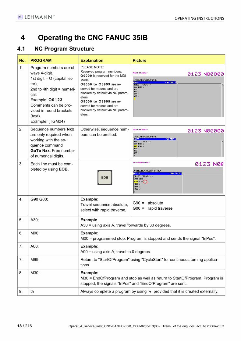
4.1 NC Program Structure
No. PROGRAM Explanation Picture
1. Program numbers are al-
ways 4-digit.
1st digit = O (capital let-
ter),
2nd to 4th digit = numeri-
cal.
Example: O0123
Comments can be pro-
vided in round brackets
(text).
Example: (TGM24)
PLEASE NOTE:
Reserved program numbers:
O0000 is reserved for the MDI
Mode.
O8000 to O8999 are re-
served for macros and are
blocked by default via NC param-
eters.
O9000 to O9999 are re-
served for macros and are
blocked by default via NC param-
eters.
2. Sequence numbers Nxx
are only required when
working with the se-
quence command
GoTo Nxx. Free number
of numerical digits.
Otherwise, sequence num-
bers can be omitted.
3. Each line must be com-
pleted by using EOB.
4. G90 G00; Example:
Travel sequence absolute,
select with rapid traverse,
G90 = absolute
G00 = rapid traverse
5. A30; Example
A30 = using axis A, travel forwards by 30 degrees.
6. M00; Example:
M00 = programmed stop. Program is stopped and sends the signal "InPos".
7. A00; Example:
A00 = using axis A, travel to 0 degrees.
7. M99; Return to "StartOfProgram" using "CycleStart" for continuous turning applica-
tions
8. M30; Example:
M30 = EndOfProgram and stop as well as return to StartOfProgram. Program is
stopped, the signals "InPos" and "EndOfProgram" are sent.
9. % Always complete a program by using %, provided that it is created externally.
OPERATING INSTRUCTIONS
Operat_&_service_instr_CNC-FANUC-35iB_DOK-0253-EN(03) Transl. of the orig. doc. acc. to 2006/42/EC 19 / 216
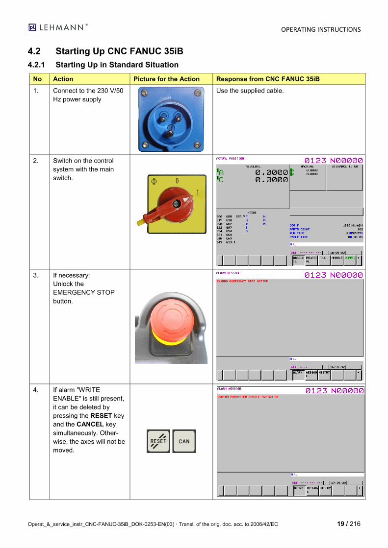
4.2 Starting Up CNC FANUC 35iB
4.2.1 Starting Up in Standard Situation
No Action Picture for the Action Response from CNC FANUC 35iB
1. Connect to the 230 V/50
Hz power supply
Use the supplied cable.
2. Switch on the control
system with the main
switch.
3. If necessary:
Unlock the
EMERGENCY STOP
button.
4. If alarm "WRITE
ENABLE" is still present,
it can be deleted by
pressing the RESET key
and the CANCEL key
simultaneously. Other-
wise, the axes will not be
moved.

OPERATING INSTRUCTIONS
20 / 216 Operat_&_service_instr_CNC-FANUC-35iB_DOK-0253-EN(03) Transl. of the orig. doc. acc. to 2006/42/EC
No Action Picture for the Action Response from CNC FANUC 35iB
5. Using the POS key, the
screen mask with the
current axis positions
can be activated again.
4.3 REF Mode (Approaching Reference Points)
No. Action Picture for the Action Response from the CNC
1. After starting up, the CNC
automatically enters the
REF Mode.
If an alarm message is
present, it must be de-
leted first by pressing the
RESET key.
Afterwards, the position
display can be activated
by pressing the POS key.
Only if an alarm is present:
2. Switch keyboard function
by pressing the M-OPE
key (LED must light up in
green).
3. If available:
Start reference point ap-
proach for the 2nd axis
by pressing -J2 or +J2.
2nd axis approaches the reference point.
4. By pressing the CYCLE
START key, both axes
are referenced.
Both axes approach the reference points.
OPERATING INSTRUCTIONS
Operat_&_service_instr_CNC-FANUC-35iB_DOK-0253-EN(03) Transl. of the orig. doc. acc. to 2006/42/EC 21 / 216
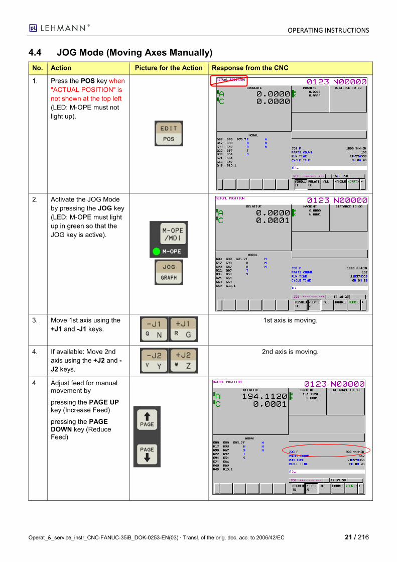
4.4 JOG Mode (Moving Axes Manually)
No. Action Picture for the Action Response from the CNC
1. Press the POS key when
"ACTUAL POSITION" is
not shown at the top left
(LED: M-OPE must not
light up).
2. 1 Activate the JOG Mode
by pressing the JOG key
(LED: M-OPE must light
up in green so that the
JOG key is active).
3. 2 Move 1st axis using the
+J1 and -J1 keys.
1st axis is moving.
4. 3 If available: Move 2nd
axis using the +J2 and -
J2 keys.
2nd axis is moving.
4 Adjust feed for manual movement by
pressing the PAGE UP key (Increase Feed)
pressing the PAGE DOWN key (Reduce Feed)
OPERATING INSTRUCTIONS
22 / 216 Operat_&_service_instr_CNC-FANUC-35iB_DOK-0253-EN(03) Transl. of the orig. doc. acc. to 2006/42/EC
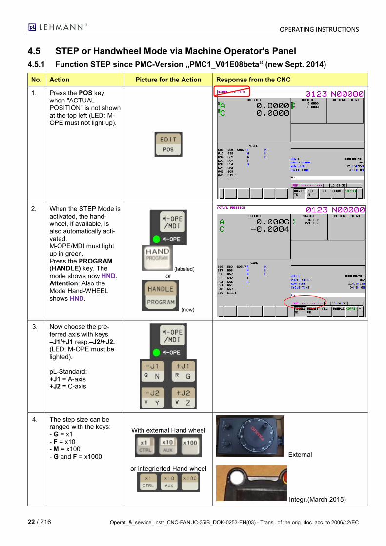
4.5 STEP or Handwheel Mode via Machine Operator's Panel
4.5.1 Function STEP since PMC-Version „PMC1_V01E08beta“ (new Sept. 2014)
No. Action Picture for the Action Response from the CNC
1. Press the POS key when "ACTUAL POSITION" is not shown at the top left (LED: M-OPE must not light up).
2. When the STEP Mode is activated, the hand-wheel, if available, is also automatically acti-vated. M-OPE/MDI must light up in green. Press the PROGRAM (HANDLE) key. The mode shows now HND. Attention: Also the Mode Hand-WHEEL shows HND.
(labeled) or
(new)
3. Now choose the pre-ferred axis with keys –J1/+J1 resp.–J2/+J2. (LED: M-OPE must be lighted). pL-Standard: +J1 = A-axis +J2 = C-axis
4. The step size can be ranged with the keys: - G = x1 - F = x10 - M = x100 - G and F = x1000
With external Hand wheel
or integrierted Hand wheel
External
Integr.(March 2015)
OPERATING INSTRUCTIONS
Operat_&_service_instr_CNC-FANUC-35iB_DOK-0253-EN(03) Transl. of the orig. doc. acc. to 2006/42/EC 23 / 216
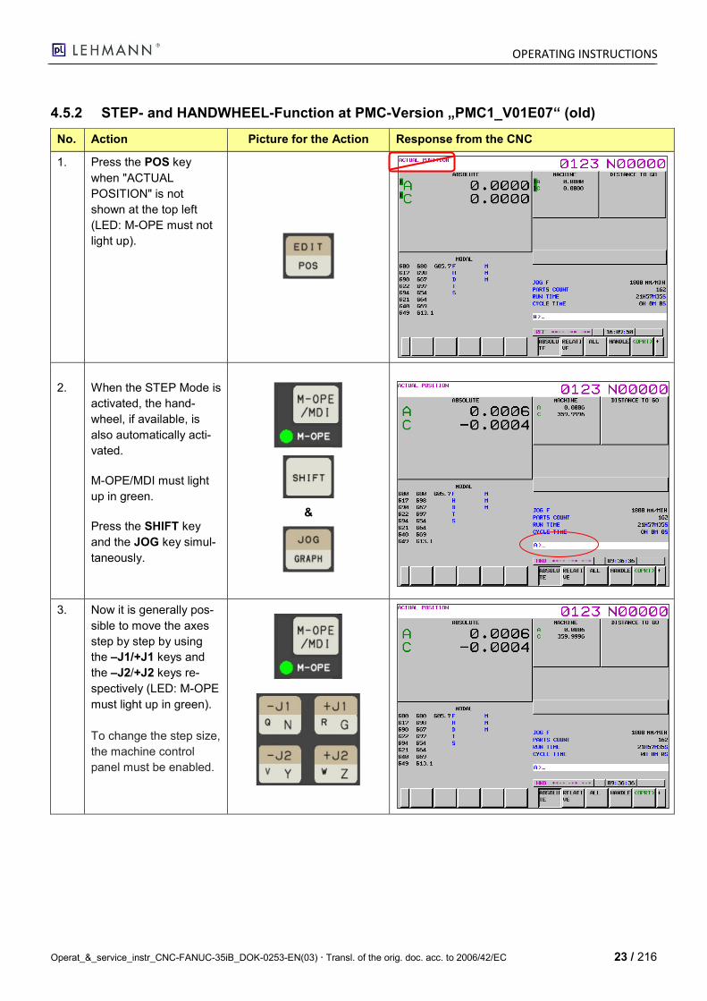
4.5.2 STEP- and HANDWHEEL-Function at PMC-Version „PMC1_V01E07“ (old)
No. Action Picture for the Action Response from the CNC
1. Press the POS key
when "ACTUAL
POSITION" is not
shown at the top left
(LED: M-OPE must not
light up).
2. When the STEP Mode is
activated, the hand-
wheel, if available, is
also automatically acti-
vated.
M-OPE/MDI must light
up in green.
Press the SHIFT key
and the JOG key simul-
taneously.
&
3. Now it is generally pos-
sible to move the axes
step by step by using
the –J1/+J1 keys and
the –J2/+J2 keys re-
spectively (LED: M-OPE
must light up in green).
To change the step size,
the machine control
panel must be enabled.
OPERATING INSTRUCTIONS
24 / 216 Operat_&_service_instr_CNC-FANUC-35iB_DOK-0253-EN(03) Transl. of the orig. doc. acc. to 2006/42/EC
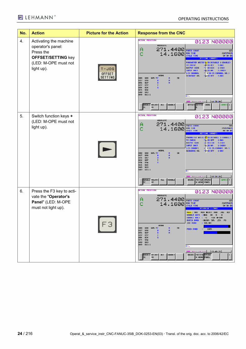
No. Action Picture for the Action Response from the CNC
4. Activating the machine
operator's panel:
Press the
OFFSET/SETTING key
(LED: M-OPE must not
light up).
5. Switch function keys +
(LED: M-OPE must not
light up).
6. Press the F3 key to acti-
vate the "Operator's
Panel" (LED: M-OPE
must not light up).
OPERATING INSTRUCTIONS
Operat_&_service_instr_CNC-FANUC-35iB_DOK-0253-EN(03) Transl. of the orig. doc. acc. to 2006/42/EC 25 / 216
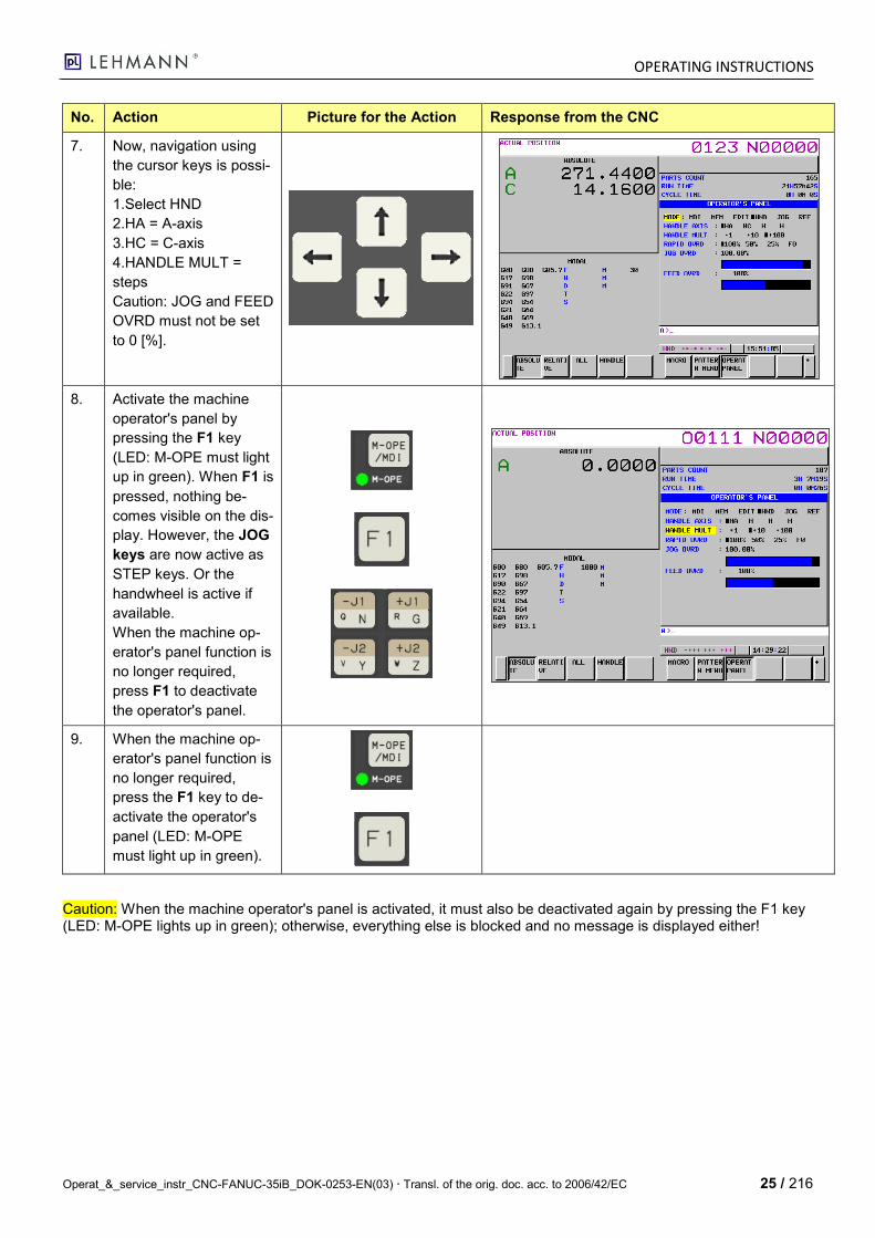
No. Action Picture for the Action Response from the CNC
7. Now, navigation using
the cursor keys is possi-
ble:
1.Select HND
2.HA = A-axis
3.HC = C-axis
4.HANDLE MULT =
steps
Caution: JOG and FEED
OVRD must not be set
to 0 [%].
8. Activate the machine
operator's panel by
pressing the F1 key
(LED: M-OPE must light
up in green). When F1 is
pressed, nothing be-
comes visible on the dis-
play. However, the JOG
keys are now active as
STEP keys. Or the
handwheel is active if
available.
When the machine op-
erator's panel function is
no longer required,
press F1 to deactivate
the operator's panel.
9. When the machine op-
erator's panel function is
no longer required,
press the F1 key to de-
activate the operator's
panel (LED: M-OPE
must light up in green).
Caution: When the machine operator's panel is activated, it must also be deactivated again by pressing the F1 key (LED: M-OPE lights up in green); otherwise, everything else is blocked and no message is displayed either!

OPERATING INSTRUCTIONS
26 / 216 Operat_&_service_instr_CNC-FANUC-35iB_DOK-0253-EN(03) Transl. of the orig. doc. acc. to 2006/42/EC
4.6 MDI Mode (Creating / Moving Temporary Program)
The MDI Mode is the operating mode by means of which an operator is able to enter and process program data without saving these in the program memory.
4.6.1 Example of working with the MDI Mode
No. Action Picture for the Action Response from the CNC
1. Press the POS key
when "ACTUAL
POSITION" is not shown
at the top left (LED: M-
OPE must not light up).
2. Activate the MDI Mode
by pressing the MDI key
(LED: M-OPE must light
up in green so that the
MDE key is active).
3. Activate the program display by press-
ing the PROGRAM key.
Explanations:
a) The MDI program always starts with
the letter O, followed by 4 numerical
digits xxxx.
b) The MDI program cannot be saved.
c) Upon command M30, the MDI pro-
gram will be automatically deleted.
d) If a program repeat is required, the
ReturnTo command M99 must there-
fore always be used.
For an example, please see further be-
low.
4. Enter the workpiece pro-
gram by using G and M
commands and axis
names.
OPERATING INSTRUCTIONS
Operat_&_service_instr_CNC-FANUC-35iB_DOK-0253-EN(03) Transl. of the orig. doc. acc. to 2006/42/EC 27 / 216
No. Action Picture for the Action Response from the CNC
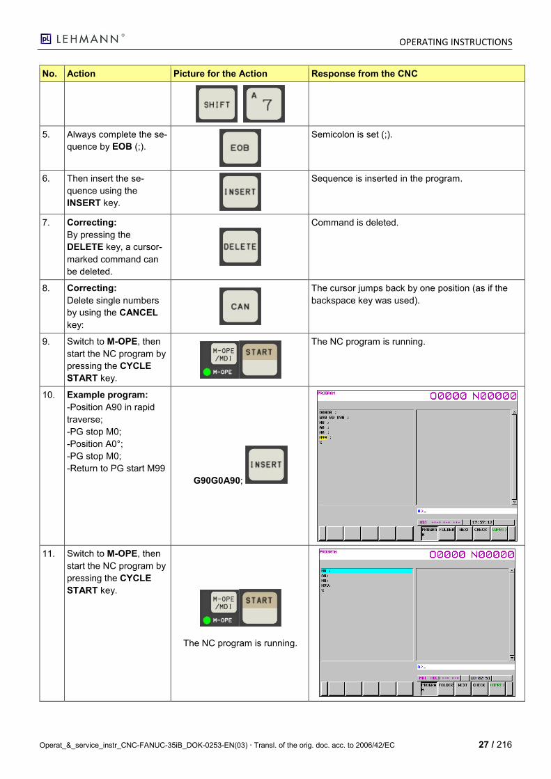
5. Always complete the se-
quence by EOB (;).
Semicolon is set (;).
6. Then insert the se-
quence using the
INSERT key.
Sequence is inserted in the program.
7. Correcting:
By pressing the
DELETE key, a cursor-
marked command can
be deleted.
Command is deleted.
8. Correcting:
Delete single numbers
by using the CANCEL
key:
The cursor jumps back by one position (as if the
backspace key was used).
9. Switch to M-OPE, then
start the NC program by
pressing the CYCLE
START key.
The NC program is running.
10. Example program:
-Position A90 in rapid
traverse;
-PG stop M0;
-Position A0°;
-PG stop M0;
-Return to PG start M99
G90G0A90;
11. Switch to M-OPE, then
start the NC program by
pressing the CYCLE
START key.
The NC program is running.
OPERATING INSTRUCTIONS
28 / 216 Operat_&_service_instr_CNC-FANUC-35iB_DOK-0253-EN(03) Transl. of the orig. doc. acc. to 2006/42/EC
4.7 EDIT Mode (Creating a Workpiece Program)
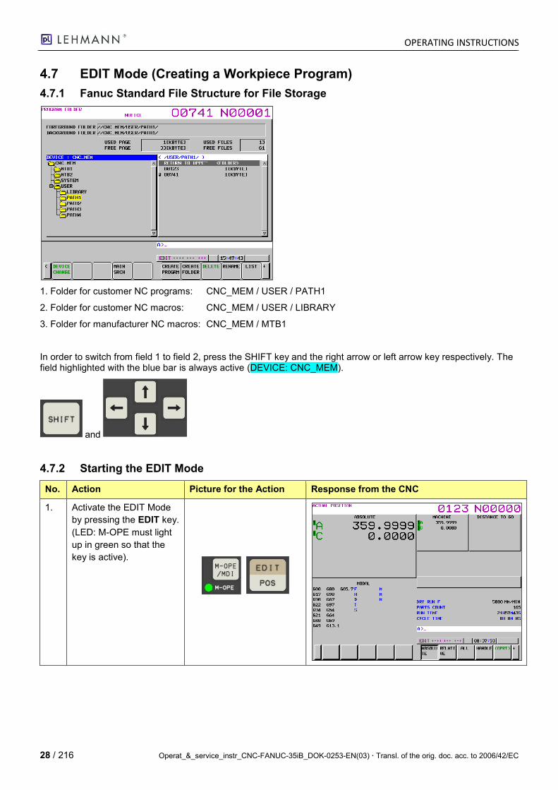
4.7.1 Fanuc Standard File Structure for File Storage
1. Folder for customer NC programs: CNC_MEM / USER / PATH1
2. Folder for customer NC macros: CNC_MEM / USER / LIBRARY
3. Folder for manufacturer NC macros: CNC_MEM / MTB1
In order to switch from field 1 to field 2, press the SHIFT key and the right arrow or left arrow key respectively. The field highlighted with the blue bar is always active (DEVICE: CNC_MEM).
and
4.7.2 Starting the EDIT Mode
No. Action Picture for the Action Response from the CNC
1. Activate the EDIT Mode
by pressing the EDIT key.
(LED: M-OPE must light
up in green so that the
key is active).
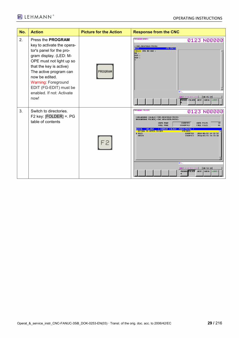
OPERATING INSTRUCTIONS
Operat_&_service_instr_CNC-FANUC-35iB_DOK-0253-EN(03) Transl. of the orig. doc. acc. to 2006/42/EC 29 / 216
No. Action Picture for the Action Response from the CNC
2. Press the PROGRAM
key to activate the opera-
tor's panel for the pro-
gram display. (LED: M-
OPE must not light up so
that the key is active)
The active program can
now be edited.
Warning: Foreground
EDIT (FG-EDIT) must be
enabled. If not: Activate
now!
3. Switch to directories.
F2 key: [FOLDER] =. PG
table of contents

OPERATING INSTRUCTIONS
30 / 216 Operat_&_service_instr_CNC-FANUC-35iB_DOK-0253-EN(03) Transl. of the orig. doc. acc. to 2006/42/EC
4.7.3 Selecting a NC Program from the List for Editing or Processing
No. Action Picture for the Action Response from the CNC
1. Prerequisite:
PROGRAM FOLDER is
active.
- Use the cursor keys to
navigate the bar high-
lighted in yellow to the
required program (LED:
M-OPE must not light
up).
- Afterwards, press the
INPUT key to selected
the required program.
Caution: The program is
only active for editing; in
order to activate it in the
Automatic Mode, it must
also be selected as main
program. The active
main program is marked
by the CNC with an а.
The action can be car-
ried out in the EDIT or in
the MEM Mode.
2. By pressing the F5
[OPRT] key, switch the
screen mask.
3. Press the F [TREELIST]
key.
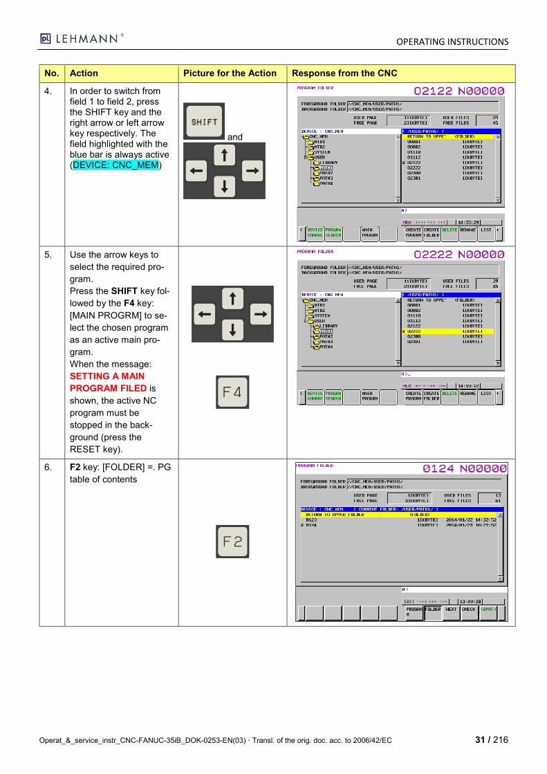
OPERATING INSTRUCTIONS
Operat_&_service_instr_CNC-FANUC-35iB_DOK-0253-EN(03) Transl. of the orig. doc. acc. to 2006/42/EC 31 / 216
No. Action Picture for the Action Response from the CNC
4. In order to switch from field 1 to field 2, press the SHIFT key and the right arrow or left arrow key respectively. The field highlighted with the blue bar is always active (DEVICE: CNC_MEM)
and
5. Use the arrow keys to
select the required pro-
gram.
Press the SHIFT key fol-
lowed by the F4 key:
[MAIN PROGRM] to se-
lect the chosen program
as an active main pro-
gram.
When the message:
SETTING A MAIN
PROGRAM FILED is
shown, the active NC
program must be
stopped in the back-
ground (press the
RESET key).
6. F2 key: [FOLDER] =. PG
table of contents
OPERATING INSTRUCTIONS
32 / 216 Operat_&_service_instr_CNC-FANUC-35iB_DOK-0253-EN(03) Transl. of the orig. doc. acc. to 2006/42/EC
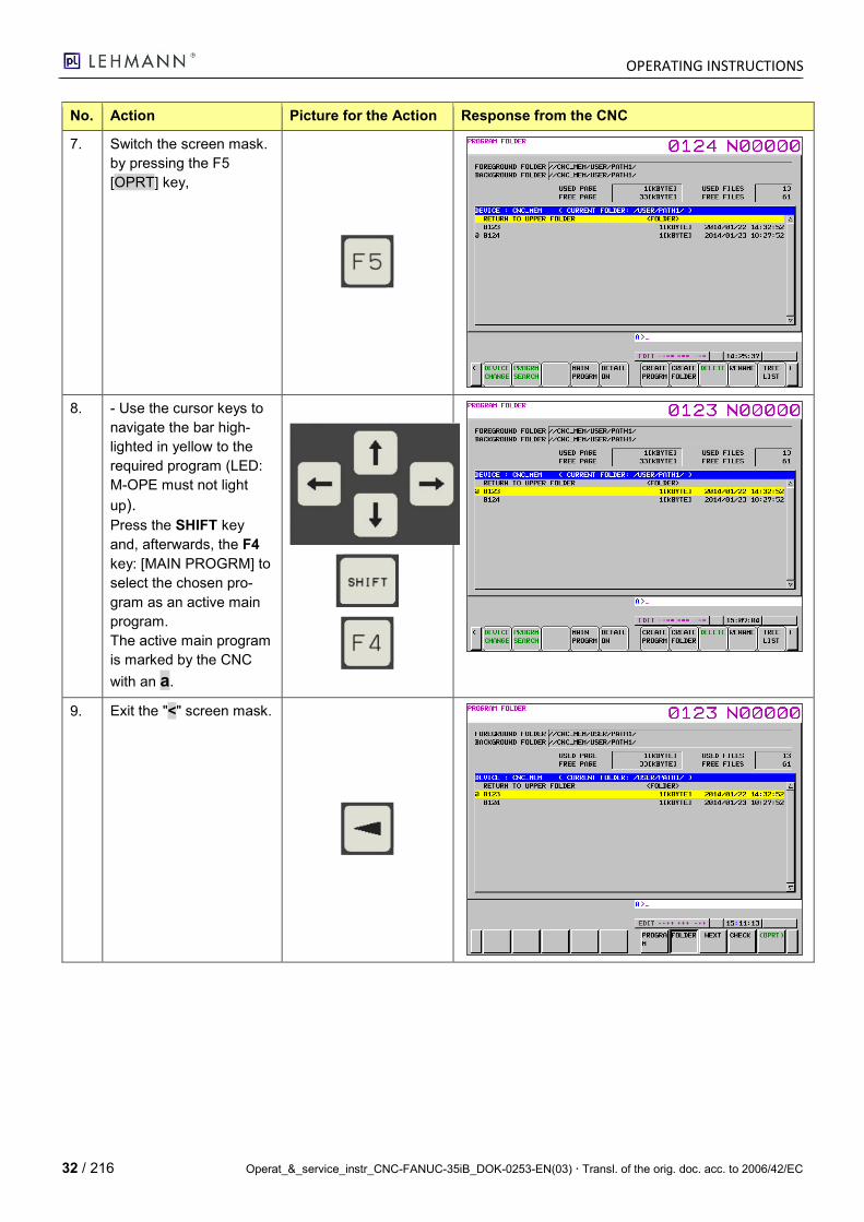
No. Action Picture for the Action Response from the CNC
7. Switch the screen mask.
by pressing the F5
[OPRT] key,
8. - Use the cursor keys to
navigate the bar high-
lighted in yellow to the
required program (LED:
M-OPE must not light
up).
Press the SHIFT key
and, afterwards, the F4
key: [MAIN PROGRM] to
select the chosen pro-
gram as an active main
program.
The active main program
is marked by the CNC
with an а.
9. Exit the "<" screen mask.
OPERATING INSTRUCTIONS
Operat_&_service_instr_CNC-FANUC-35iB_DOK-0253-EN(03) Transl. of the orig. doc. acc. to 2006/42/EC 33 / 216
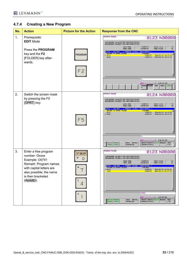
4.7.4 Creating a New Program
No. Action Picture for the Action Response from the CNC
1. Prerequisite:
EDIT Mode
Press the PROGRAM
key and the F2
[FOLDER] key after-
wards.
2. Switch the screen mask
by pressing the F5
[OPRT] key.
3. Enter a free program
number: Oxxxx
Example: O0741
Remark: Program names
with capital letters are
also possible; the name
is then bracketed
<NAME>.
OPERATING INSTRUCTIONS
34 / 216 Operat_&_service_instr_CNC-FANUC-35iB_DOK-0253-EN(03) Transl. of the orig. doc. acc. to 2006/42/EC
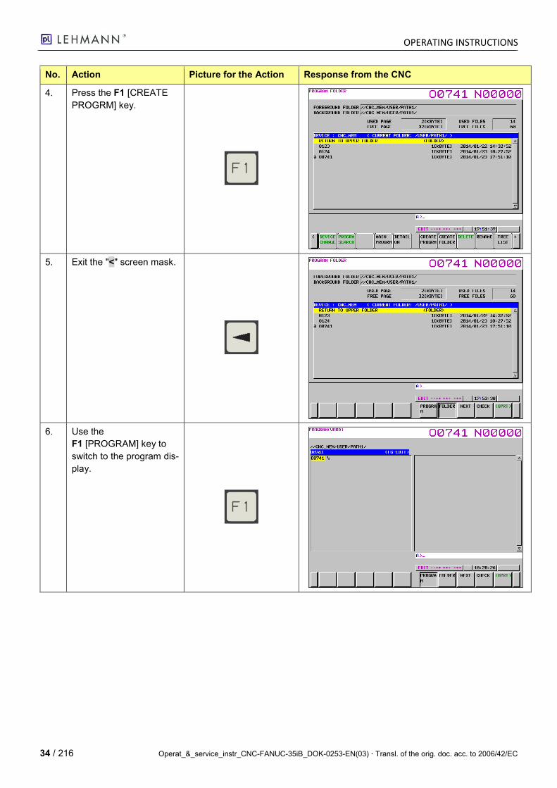
No. Action Picture for the Action Response from the CNC
4. Press the F1 [CREATE
PROGRM] key.
5. Exit the "<" screen mask.
6. Use the
F1 [PROGRAM] key to
switch to the program dis-
play.

OPERATING INSTRUCTIONS
Operat_&_service_instr_CNC-FANUC-35iB_DOK-0253-EN(03) Transl. of the orig. doc. acc. to 2006/42/EC 35 / 216
4.7.5 Inserting a New Sequence or Value
No. Action Picture for the Action Response from the CNC
1. Prerequisite:- EDIT Mode
-PROGRAM(WORD) screen mask
2. -Move the cursor behind the position where the se-quence is to be inserted.
-Enter sequence: M0;
(; = EOB key)
Remark:
Incorrect input can be de-leted step by step using the CANCEL key (func-tions as the backspace key).
= BackSpace
3. Insert the sequence in the input field into the program by pressing the INSERT key.
OPERATING INSTRUCTIONS
36 / 216 Operat_&_service_instr_CNC-FANUC-35iB_DOK-0253-EN(03) Transl. of the orig. doc. acc. to 2006/42/EC
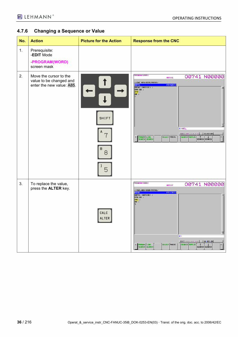
4.7.6 Changing a Sequence or Value
No. Action Picture for the Action Response from the CNC
1. Prerequisite: -EDIT Mode
-PROGRAM(WORD) screen mask
2. Move the cursor to the value to be changed and enter the new value: A85.
3. To replace the value, press the ALTER key.
OPERATING INSTRUCTIONS
Operat_&_service_instr_CNC-FANUC-35iB_DOK-0253-EN(03) Transl. of the orig. doc. acc. to 2006/42/EC 37 / 216
4.7.7 Deleting a Sequence or Value
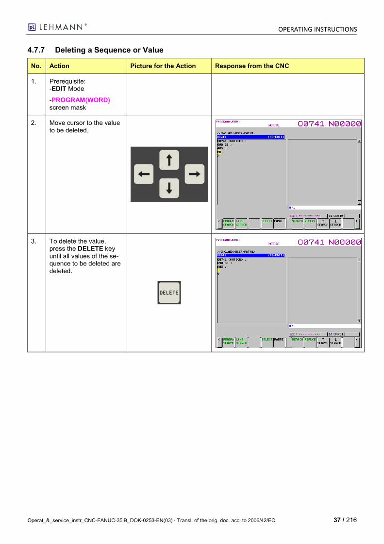
No. Action Picture for the Action Response from the CNC
1. Prerequisite: -EDIT Mode
-PROGRAM(WORD) screen mask
2. Move cursor to the value to be deleted.
3. To delete the value, press the DELETE key until all values of the se-quence to be deleted are deleted.
OPERATING INSTRUCTIONS
38 / 216 Operat_&_service_instr_CNC-FANUC-35iB_DOK-0253-EN(03) Transl. of the orig. doc. acc. to 2006/42/EC
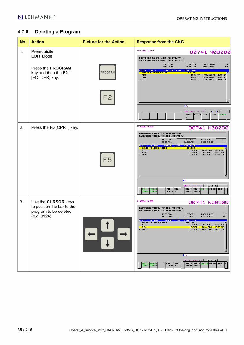
4.7.8 Deleting a Program
No. Action Picture for the Action Response from the CNC
1. Prerequisite: EDIT Mode
Press the PROGRAM key and then the F2 [FOLDER] key.
2. Press the F5 [OPRT] key.
3. Use the CURSOR keys to position the bar to the program to be deleted (e.g. 0124).
OPERATING INSTRUCTIONS
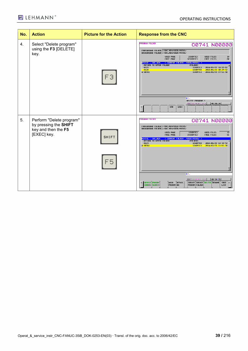
Operat_&_service_instr_CNC-FANUC-35iB_DOK-0253-EN(03) Transl. of the orig. doc. acc. to 2006/42/EC 39 / 216
No. Action Picture for the Action Response from the CNC
4. Select "Delete program" using the F3 [DELETE] key.
5. Perform "Delete program" by pressing the SHIFT key and then the F5 [EXEC] key.
OPERATING INSTRUCTIONS
40 / 216 Operat_&_service_instr_CNC-FANUC-35iB_DOK-0253-EN(03) Transl. of the orig. doc. acc. to 2006/42/EC
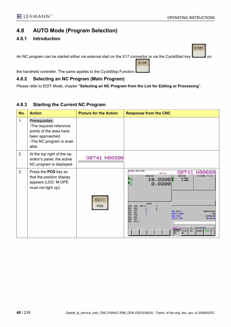
4.8 AUTO Mode (Program Selection)
4.8.1 Introduction
An NC program can be started either via external start on the X17 connector or via the CycleStart key on
the handheld controller. The same applies to the CycleStop Function .
4.8.2 Selecting an NC Program (Main Program)
Please refer to EDIT Mode, chapter "Selecting an NC Program from the List for Editing or Processing".
4.8.3 Starting the Current NC Program
No. Action Picture for the Action Response from the CNC
1. Prerequisites:
-The required reference
points of the axes have
been approached.
-The NC program is avail-
able.
2. At the top right of the op-
erator’s panel, the active
NC program is displayed.
3. Press the POS key so
that the position display
appears (LED: M-OPE
must not light up).

OPERATING INSTRUCTIONS
Operat_&_service_instr_CNC-FANUC-35iB_DOK-0253-EN(03) Transl. of the orig. doc. acc. to 2006/42/EC 41 / 216
No. Action Picture for the Action Response from the CNC
4. Press the AUTO Mode
key (MEM).
5. When the program num-
ber corresponds to the
required program, the NC
program can then be pro-
cessed via the external
start input of the X17
connector or the CYCLE
START key.
(LED: M-OPE must light
up in green).
6. Adjust feed by
pressing the PAGE UP
key (Increase Feed)
pressing the PAGE
DOWN key (Reduce
Feed)
(LED: M-OPE must light
up in green).

OPERATING INSTRUCTIONS
42 / 216 Operat_&_service_instr_CNC-FANUC-35iB_DOK-0253-EN(03) Transl. of the orig. doc. acc. to 2006/42/EC
No. Action Picture for the Action Response from the CNC
7. Switch the POS display
to the NC program dis-
play by pressing the
PROGRAM key (LED: M-
OPE must not light up).
8. Stop the currently running
program by using the
"CycleStop" key or via
the stop signal on the
X17 connector. (LED: M-
OPE must light up in
green).
9. By pressing the RESET
key, it is possible to force
a restart of the program.
The cursor jumps to
StartOfProgram.
OPERATING INSTRUCTIONS
Operat_&_service_instr_CNC-FANUC-35iB_DOK-0253-EN(03) Transl. of the orig. doc. acc. to 2006/42/EC 43 / 216
No. Action Picture for the Action Response from the CNC
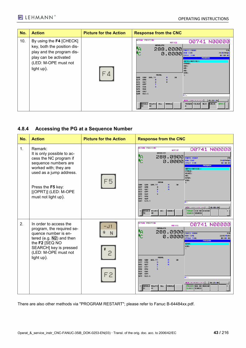
10. By using the F4 [CHECK]
key, both the position dis-
play and the program dis-
play can be activated
(LED: M-OPE must not
light up).
4.8.4 Accessing the PG at a Sequence Number
No. Action Picture for the Action Response from the CNC
1. Remark: It is only possible to ac-cess the NC program if sequence numbers are worked with; they are used as a jump address.
Press the F5 key: [(OPRT)] (LED: M-OPE
must not light up).
2. In order to access the program, the required se-quence number is en-tered (e.g. N2) and then the F2 [SEQ NO SEARCH] key is pressed (LED: M-OPE must not
light up).
There are also other methods via "PROGRAM RESTART"; please refer to Fanuc B-64484xx.pdf.
OPERATING INSTRUCTIONS
44 / 216 Operat_&_service_instr_CNC-FANUC-35iB_DOK-0253-EN(03) Transl. of the orig. doc. acc. to 2006/42/EC
4.9 Backing up and Loading NC Programs to the CNC
4.9.1 Introduction
The pL Fanuc 35iB control system offers two options for saving data: PC Card and USB flash drive.
1. via USB flash drive interface (USB interface at the top left side of the HBT).
2. via PC-Card (inside the pL control cabinet for CNC-35iB).
The interfaces must be activated accordingly in the parameters.
PC Card USB flash drive
For your information: In general, the RS-232 interface could also be used, but it is only available on the Fanuc CNC unit in the control cabinet.
4.9.2 Preparing the Interface for the USB Flash Drive
Address P Function Unit Meaning of the Values NC Parameter Value for CNC 35iB
0020 I/O Channel
0= CH0 RS232 Port1 1= CH1 RS232 Port1 2= CH2 RS232 Port2 4= CH4 PC-Card/USB-HBT
4
300#0 PARAM CNC SCREEN DISP(PCM) bit 0=PC-Card / 1=USB-HBT 1
OPERATING INSTRUCTIONS
Operat_&_service_instr_CNC-FANUC-35iB_DOK-0253-EN(03) Transl. of the orig. doc. acc. to 2006/42/EC 45 / 216
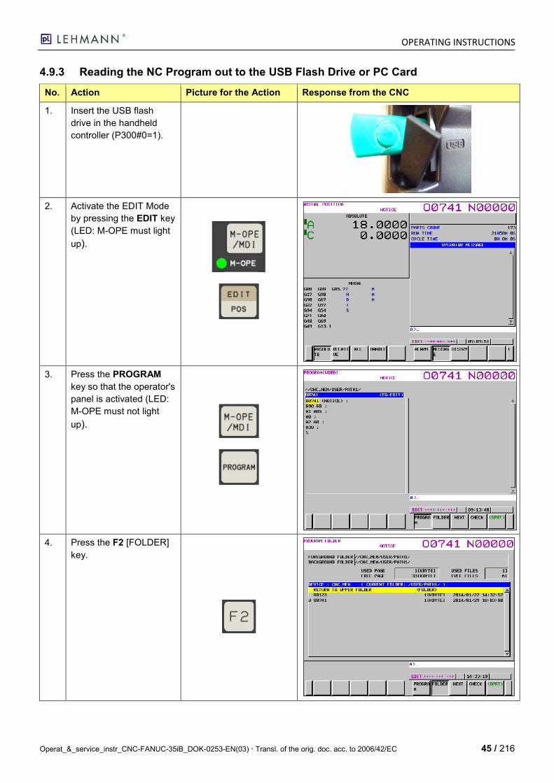
4.9.3 Reading the NC Program out to the USB Flash Drive or PC Card
No. Action Picture for the Action Response from the CNC
1. Insert the USB flash
drive in the handheld
controller (P300#0=1).
2. Activate the EDIT Mode
by pressing the EDIT key
(LED: M-OPE must light
up).
3. Press the PROGRAM
key so that the operator's
panel is activated (LED:
M-OPE must not light
up).
4. Press the F2 [FOLDER]
key.
OPERATING INSTRUCTIONS
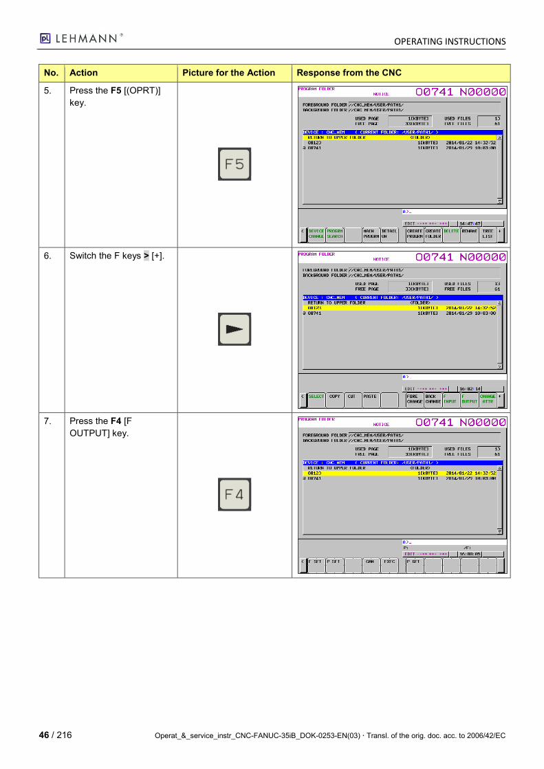
46 / 216 Operat_&_service_instr_CNC-FANUC-35iB_DOK-0253-EN(03) Transl. of the orig. doc. acc. to 2006/42/EC
No. Action Picture for the Action Response from the CNC
5. Press the F5 [(OPRT)]
key.
6. Switch the F keys > [+].
7. Press the F4 [F
OUTPUT] key.
OPERATING INSTRUCTIONS
Operat_&_service_instr_CNC-FANUC-35iB_DOK-0253-EN(03) Transl. of the orig. doc. acc. to 2006/42/EC 47 / 216
No. Action Picture for the Action Response from the CNC
8. Use the Cursor keys to
position the bar high-
lighted in yellow to the
required program.
Press the F1 [P GET]
key; the required pro-
gram is shown in the in-
put line.
9.
Press the SHIFT button
and then the F2 [P SET]
button.
10. Press the SHIFT key and
the F5 [EXEC] key after-
wards. At the bottom
right, OUTPUT appears
and flashes until the data
has been read out.
11. Use the PC to check if
the file is available on the
flash drive: Example file
name = O0741
Reading out the program
completed
For info:
With "F SET" the file name can be defined independently of the PG no. If you work without "F SET", the file name is the same as the PG no.
OUTPUT
OPERATING INSTRUCTIONS
48 / 216 Operat_&_service_instr_CNC-FANUC-35iB_DOK-0253-EN(03) Transl. of the orig. doc. acc. to 2006/42/EC
4.9.4 Reading the NC Program out from the USB Flash Drive or PC Card
No. Action Picture for the Action Response from the CNC
1. Insert the USB flash drive in the handheld controller (P300#0=1).
2. Activate the EDIT Mode by pressing the EDIT key (LED: M-OPE must light
up).
3. Press the PROGRAM key so that the operator's panel is activated (LED: M-OPE must not light
up).
4. Press the F2 [FOLDER] key.
OPERATING INSTRUCTIONS
Operat_&_service_instr_CNC-FANUC-35iB_DOK-0253-EN(03) Transl. of the orig. doc. acc. to 2006/42/EC 49 / 216
No. Action Picture for the Action Response from the CNC
5. Press the F5 [(OPRT)] key.
6. Is only required in order to adjust the FOREGROUND FOLDER.
Using this path, the pro-grams read in are saved. The path is usually as fol-lows: //CNC_MEM/USER/PATH1
Switch the function keys [+].
7. Is only required in order to adjust the FOREGROUND FOLDER.
It is then possible to se-lect the required folder using the CURSOR and the INPUT keys.
By pressing the F1 [FORE CHANGE] key, the folder is activated for data storage.
It is already specified cor-rectly in the example.
OPERATING INSTRUCTIONS
50 / 216 Operat_&_service_instr_CNC-FANUC-35iB_DOK-0253-EN(03) Transl. of the orig. doc. acc. to 2006/42/EC
No. Action Picture for the Action Response from the CNC
8. Is only required in order to adjust the FOREGROUND FOLDER.
Switch the function keys [+].
9. Press the SHIFT key and then the F1 [DEVICE CHANGE] key in order to change the drive (USB flash drive or PC Card).
10. Press the F1 [MEMORY CARD] key so that the data on the USB flash drive or PC Card are dis-played.
OPERATING INSTRUCTIONS
Operat_&_service_instr_CNC-FANUC-35iB_DOK-0253-EN(03) Transl. of the orig. doc. acc. to 2006/42/EC 51 / 216
No. Action Picture for the Action Response from the CNC
11. Press the F2 [F INPUT] key.
12. Use the Cursor keys to position the bar high-lighted in yellow to the re-quired program.
Press the F1 [P GET] key; the required program is shown in the input line.
13. Press the SHIFT F1 [F SET] key in order to se-lect the macro.
For info:
With "P SET", the PG no. Can be set independently of the file name.
OPERATING INSTRUCTIONS
52 / 216 Operat_&_service_instr_CNC-FANUC-35iB_DOK-0253-EN(03) Transl. of the orig. doc. acc. to 2006/42/EC
No. Action Picture for the Action Response from the CNC
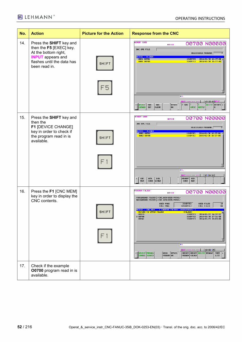
14. Press the SHIFT key and then the F5 [EXEC] key. At the bottom right, INPUT appears and flashes until the data has been read in.
15. Press the SHIFT key and then the F1 [DEVICE CHANGE] key in order to check if the program read in is available.
16. Press the F1 [CNC MEM] key in order to display the CNC contents.
17. Check if the example O0700 program read in is available.
INPUT
OPERATING INSTRUCTIONS
Operat_&_service_instr_CNC-FANUC-35iB_DOK-0253-EN(03) Transl. of the orig. doc. acc. to 2006/42/EC 53 / 216
4.9.5 Deleting a NC Program or Creating a New NC Program
No. Action Picture for the Action Response from the CNC
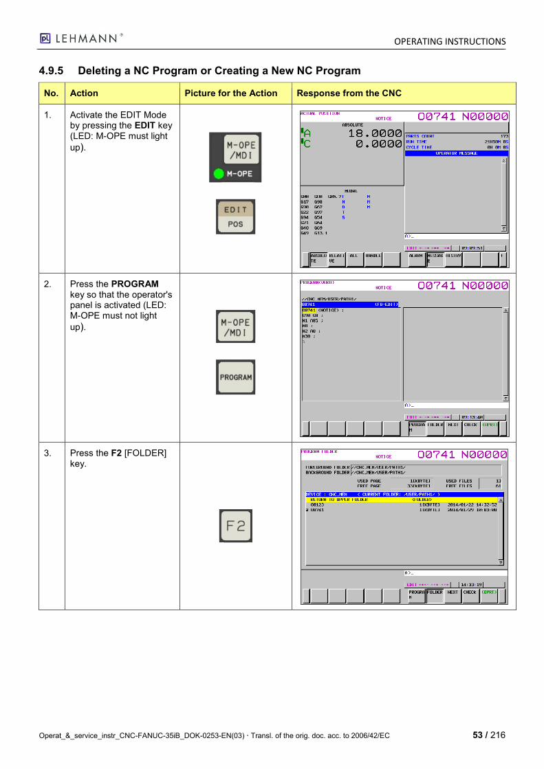
1. Activate the EDIT Mode by pressing the EDIT key (LED: M-OPE must light
up).
2. Press the PROGRAM key so that the operator's panel is activated (LED: M-OPE must not light
up).
3. Press the F2 [FOLDER] key.
OPERATING INSTRUCTIONS
54 / 216 Operat_&_service_instr_CNC-FANUC-35iB_DOK-0253-EN(03) Transl. of the orig. doc. acc. to 2006/42/EC
No. Action Picture for the Action Response from the CNC
4. Press the F5 [(OPRT)] key.
5. Creating a new NC pro-gram:
Select the path by using the CURSOR and the INPUT keys.
Enter the new program name into the input field (conventionally with Oxxxx, e.g. O2000) or with names.
O2000
6. Press the F1 [CREATE PROGRAM] key.
> The program is cre-ated.
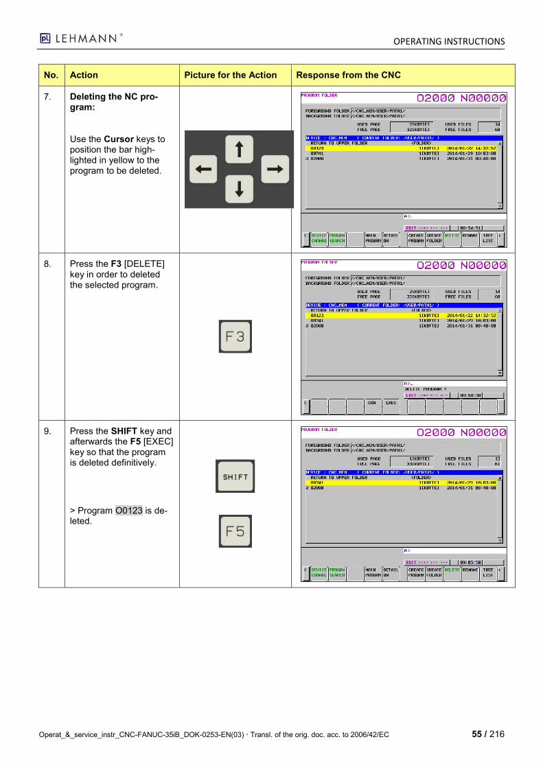
OPERATING INSTRUCTIONS
Operat_&_service_instr_CNC-FANUC-35iB_DOK-0253-EN(03) Transl. of the orig. doc. acc. to 2006/42/EC 55 / 216
No. Action Picture for the Action Response from the CNC
7. Deleting the NC pro-gram:
Use the Cursor keys to position the bar high-lighted in yellow to the program to be deleted.
8. Press the F3 [DELETE] key in order to deleted the selected program.
9. Press the SHIFT key and afterwards the F5 [EXEC] key so that the program is deleted definitively.
> Program O0123 is de-leted.
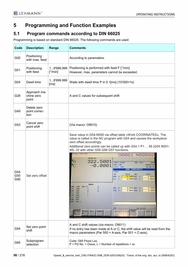
OPERATING INSTRUCTIONS
56 / 216 Operat_&_service_instr_CNC-FANUC-35iB_DOK-0253-EN(03) Transl. of the orig. doc. acc. to 2006/42/EC
5 Programming and Function Examples
5.1 Program commands according to DIN 66025
Programming is based on standard DIN 66025. The following commands are used:
Code Description Range Comments
G00 Positioning with max. feed
According to parameters.
G01 Positioning with feed
1...9'999.999 [°/min]
Positioning is performed with feed F [°/min]
However, max. parameters cannot be exceeded.
G04 Dwell time 1...9'999.999 [ms]
Waits with dwell time P in 0.1[ms] (10’000=1s)
G28 Approach ma-chine zero point
A and C values for subsequent shift
G49 Delete zero point correc-tion
G53 Cancel zero point shift
(Via macro: O9010)
G54 G55 G56
Set zero offset
Save value in G54-N000 via offset table «Work COORINATES». The value is called in the NC program with G54 and causes the workpiece zero offset accordingly.
Additional zero points can be called up with G54.1 P1 ... 48 (G54 N001-48). Or with other G55 G56 G57 functions.
G54 Set zero point shift
A and C shift values (via macro: O9011)
If no entry has been made at A or C, the shift value will be read from the macro parameters (Par 500 = A-axis, Par 501 = C-axis).
G65 Subprogram selection
Code: G65 Pxxxx Lxx; P = PG No. = Oxxxx, L = Number of repetitions = xx
OPERATING INSTRUCTIONS
Operat_&_service_instr_CNC-FANUC-35iB_DOK-0253-EN(03) Transl. of the orig. doc. acc. to 2006/42/EC 57 / 216
Code Description Range Comments
Subprogram is completed by using M99 instead of M30.
G90 Absolute Type of dimensioning
G91 Incremental Type of dimensioning
G94 Feed shift For G01 in [°/min]
G300 Division com-puter A-axis
Via pL macro
M3 Continuous turning CW (clockwise)
Only for di-vider
Enter spindle speed via "S" in [1/min]
M4
Continuous turning CCW (counterclock-wise)
Only for di-vider
Enter spindle speed via "S" in [1/min]
M5 Stop continu-ous turning
M10 Clamp 1st axis
M11 Unclamp 1st axis
M20 Clamp 2nd axis
M21 Unclamp 2nd axis
M00 CycleStop Results in a CycleStop. Sends the "InPosition" signal.
M30
EndOfPro-gram with re-turn to StartOfPro-gram
Return to StartOfProgram
M98 Subprogram selection
Pxxxx Max.4-fold nested (M98 Pxxxx) (only processed once per selection)
M99 Return to StartOfPro-gram
Contrary to M30, PG sequence is not stopped.
Shortest travel range for ro-tary axes
Positions rotary axes (Modulo with shortest travel range) Only adjustable via parameters
-Param 1006 RABX: 0 = Shortest travel range 1 = "+ / - "sign
-Param 1008 RollOn for Modulo
OPERATING INSTRUCTIONS
58 / 216 Operat_&_service_instr_CNC-FANUC-35iB_DOK-0253-EN(03) Transl. of the orig. doc. acc. to 2006/42/EC
Code Description Range Comments
M100 Reset M-Func 1 Resets the dig. output of M-Func 1 to 0.
M101 Set M-Func 1 in pulse form
48…10'000 [ms]
Sets the dig. output of M-Func 1 in pulse form to 1 until timer no. 001 (PMC timer in msec) has run down. The NC program is not stopped.
M102 Set M-Func 1 Sets the dig. output of M-Func 1 to 1. The NC program is not stopped. The output is reset by M02, M30, "Reset //", M100 and M101.
M103
Set M-Func 1 and wait for acknowledg-ment
Acknowledgeable M-Function: Sets the dig. output of M-Func 1 to 1. The NC program is stopped until the acknowledgment input of M-Function 1 has been actuated.
The output is reset "Reset //".
M104 M-Func 1 No function
M105 Reset M-Func 2 Resets the dig. output of M-Func 2 to 0.
M106 Set M-Func 2 in pulse form
48…10'000 [ms]
Sets the dig. output of M-Func 2 in pulse form to 1 until timer no. 001 (PMC timer in msec) has run down. The NC program is not stopped.
M107 Set M-Func 2 Sets the dig. output of M-Func 2 to 1. The NC program is not stopped. The output is reset by M02, M30, "Reset //", M105 and M106.
M108
Set M-Func 2 and wait for acknowledg-ment
Acknowledgeable M-Function: Sets the dig. output of M-Func 2 to 1. The NC program is stopped until the acknowledgment input of M-Function 2 has been actuated.
The output is reset "Reset //".
M109 M-Func 2 No function
M110 Reset M-Func 3 Resets the dig. output of M-Func 3 to 0.
M111 Set M-Func 3 in pulse form
48…10'000 [ms]
Sets the dig. output of M-Func 3 in pulse form to 1 until timer no. 002 (PMC timer in msec) has run down. The NC program is not stopped.
M112 Set M-Func 3 Sets the dig. output of M-Func 3 to 1. The NC program is not stopped. The output is reset by M02, M30, "Reset //", M110 and M111.
M113
Set M-Func 3 and wait for acknowledg-ment
Acknowledgeable M-Function: Sets the dig. output of M-Func 3 to 1. The NC program is stopped until the acknowledgment input of M-Function 3 has been actuated.
The output is reset "Reset //".
M114 M-Func 3 No function
M115 Reset M-Func 4 Resets the dig. output of M-Func 4 to 0.
OPERATING INSTRUCTIONS
Operat_&_service_instr_CNC-FANUC-35iB_DOK-0253-EN(03) Transl. of the orig. doc. acc. to 2006/42/EC 59 / 216
Code Description Range Comments
M116 Set M-Func 4 in pulse form
48…10'000 [ms]
Sets the dig. output of M-Func 4 in pulse form to 1 until timer no. 003 (PMC timer in msec) has run down. The NC program is not stopped.
M117 Set M-Func 4 Sets the dig. output of M-Func 4 to 1. The NC program is not stopped. The output is reset by M02, M30, "Reset //", M115 and M116.
M118
Set M-Func 4 and wait for acknowledg-ment
Acknowledgeable M-Function: Sets the dig. output of M-Func 4 to 1. The NC program is stopped until the acknowledgment input of M-Function 4 has been actuated.
The output is reset "Reset //".
M119 M-Func 4 No function
M120 Reset M-Func 5 Resets the dig. output of M-Func 5 to 0.
M121 Set M-Func 5 in pulse form
48…10'000 [ms]
Sets the dig. output of M-Func 5 in pulse form to 1 until timer no. 004 (PMC timer in msec) has run down. The NC program is not stopped.
M122 Set M-Func 5 Sets the dig. output of M-Func 5 to 1. The NC program is not stopped. The output is reset by M02, M30, "Reset //", M120 and M121.
M123
Set M-Func 5 and wait for acknowledg-ment
Acknowledgeable M-Function: Sets the dig. output of M-Func 5 to 1. The NC program is stopped until the acknowledgment input of M-Function 1 has been actuated.
The output is reset "Reset //".
M124 M-Func 5 No function
GOTO Goes to sequence Nxxxx; only possible if sequence numbers are used.
N Sequence number
Default setting: 10 steps (sequence number is only required if GOTO com-mands are worked with)
Oxxxx (text)
Program num-ber 4-digit
A, B, C
Dimensioning command Names of the axes
F Feed rate for G01 Feed in [°/min]
S Speed at M03/M04 Speed [1/min] of the dividing / indexing axis
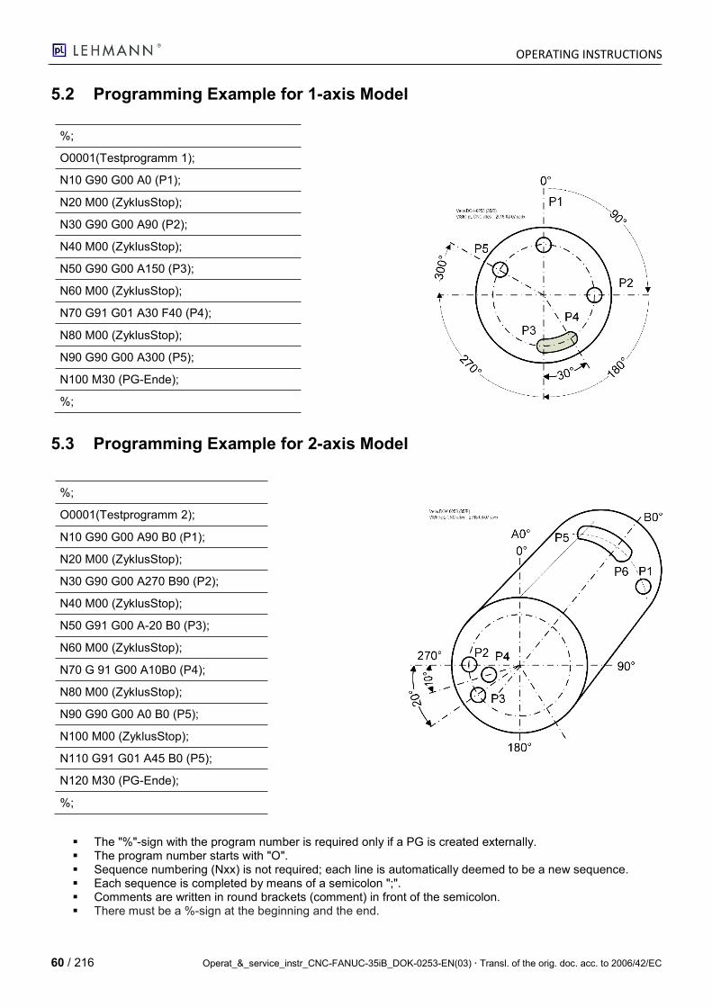
OPERATING INSTRUCTIONS
60 / 216 Operat_&_service_instr_CNC-FANUC-35iB_DOK-0253-EN(03) Transl. of the orig. doc. acc. to 2006/42/EC
5.2 Programming Example for 1-axis Model
%;
O0001(Testprogramm 1);
N10 G90 G00 A0 (P1);
N20 M00 (ZyklusStop);
N30 G90 G00 A90 (P2);
N40 M00 (ZyklusStop);
N50 G90 G00 A150 (P3);
N60 M00 (ZyklusStop);
N70 G91 G01 A30 F40 (P4);
N80 M00 (ZyklusStop);
N90 G90 G00 A300 (P5);
N100 M30 (PG-Ende);
%;
5.3 Programming Example for 2-axis Model
%;
O0001(Testprogramm 2);
N10 G90 G00 A90 B0 (P1);
N20 M00 (ZyklusStop);
N30 G90 G00 A270 B90 (P2);
N40 M00 (ZyklusStop);
N50 G91 G00 A-20 B0 (P3);
N60 M00 (ZyklusStop);
N70 G 91 G00 A10B0 (P4);
N80 M00 (ZyklusStop);
N90 G90 G00 A0 B0 (P5);
N100 M00 (ZyklusStop);
N110 G91 G01 A45 B0 (P5);
N120 M30 (PG-Ende);
%;
The "%"-sign with the program number is required only if a PG is created externally. The program number starts with "O". Sequence numbering (Nxx) is not required; each line is automatically deemed to be a new sequence. Each sequence is completed by means of a semicolon ";". Comments are written in round brackets (comment) in front of the semicolon. There must be a %-sign at the beginning and the end.
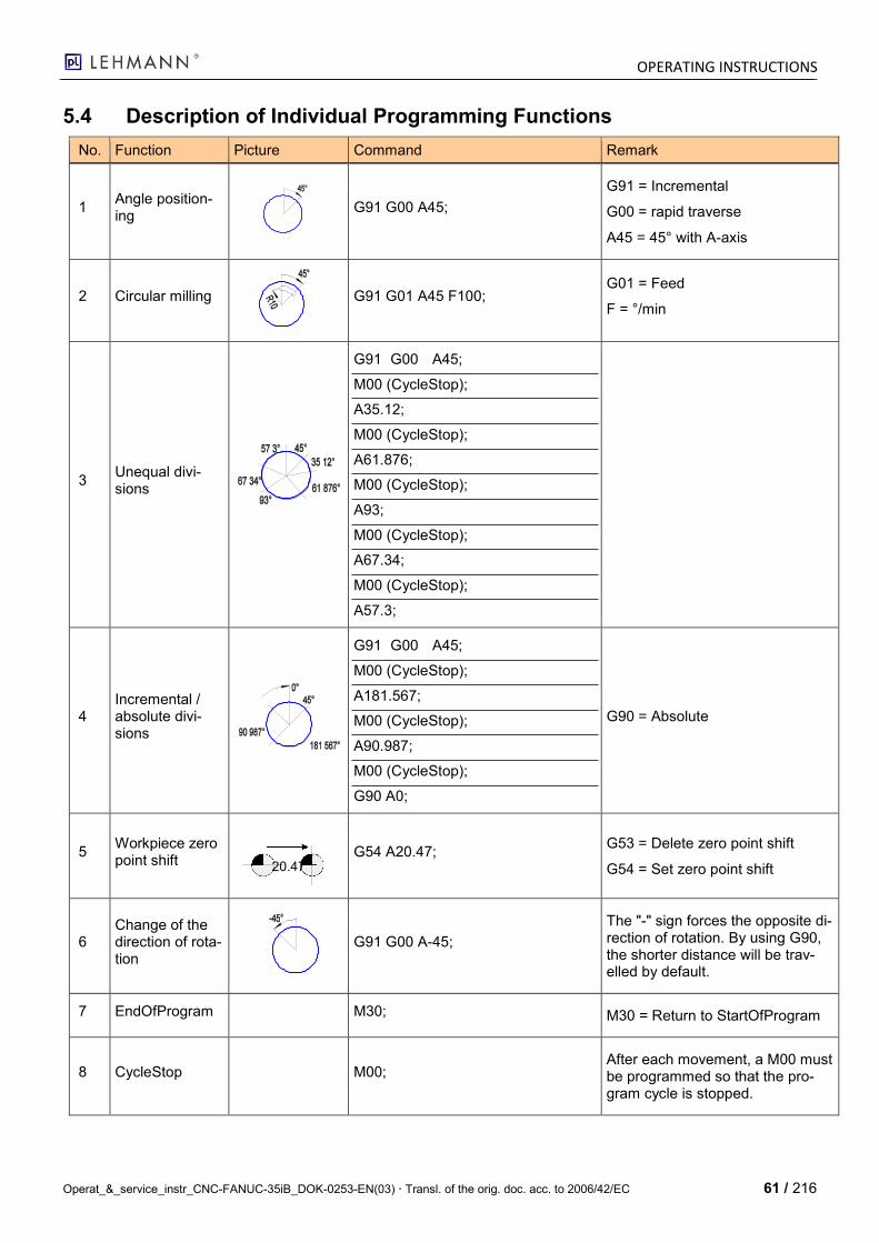
OPERATING INSTRUCTIONS
Operat_&_service_instr_CNC-FANUC-35iB_DOK-0253-EN(03) Transl. of the orig. doc. acc. to 2006/42/EC 61 / 216
5.4 Description of Individual Programming Functions
No. Function Picture Command Remark
1 Angle position-ing
G91 G00 A45;
G91 = Incremental
G00 = rapid traverse
A45 = 45° with A-axis
2 Circular milling
G91 G01 A45 F100; G01 = Feed
F = °/min
3 Unequal divi-sions
G91 G00 A45;
M00 (CycleStop);
A35.12;
M00 (CycleStop);
A61.876;
M00 (CycleStop);
A93;
M00 (CycleStop);
A67.34;
M00 (CycleStop);
A57.3;
4 Incremental / absolute divi-sions
G91 G00 A45;
M00 (CycleStop);
A181.567;
M00 (CycleStop);
A90.987;
M00 (CycleStop);
G90 A0;
G90 = Absolute
5 Workpiece zero point shift
G54 A20.47; G53 = Delete zero point shift
G54 = Set zero point shift
6 Change of the direction of rota-tion
G91 G00 A-45;
The "-" sign forces the opposite di-rection of rotation. By using G90, the shorter distance will be trav-elled by default.
7 EndOfProgram M30; M30 = Return to StartOfProgram
8 CycleStop M00; After each movement, a M00 must be programmed so that the pro-gram cycle is stopped.
20.47°
OPERATING INSTRUCTIONS
62 / 216 Operat_&_service_instr_CNC-FANUC-35iB_DOK-0253-EN(03) Transl. of the orig. doc. acc. to 2006/42/EC
No. Function Picture Command Remark
9 M98: Subpro-gram selection
-
M98P1001
-
-
M98P1002
-
-
M98P1001
-
-
O1001
M99
Hauptprogramm
Unterprogramm #1
Verknüpf_FANUC_PMi_alleSpr.vsd
O1002
M99
Unterprogramm #2
Programm für
Bohrung #1
Programm für
Bohrung #2
M98 Pxxxx;
10 G65: Subpro-gram selection
G65 P_ L_;
P = PG No.
L = Number of repetitions
11 Continuous turning
0.5min-1
30sec
M04 S0.5;
G04 P300000;
M05;
30 seconds continuous turning in CCW (counterclockwise) direction with 0.5[1/min]
Value P in 0.0001 seconds
12 M-Functions
M110
M111
M112
M113
M114
Acknowledgeable M-Functions, parameterizable
13 Reference point run
G28 A0.0 Moves to the reference position
14 Dwell time
G04 P10000
Dwell time = 1 second Value P in 0.0001 seconds
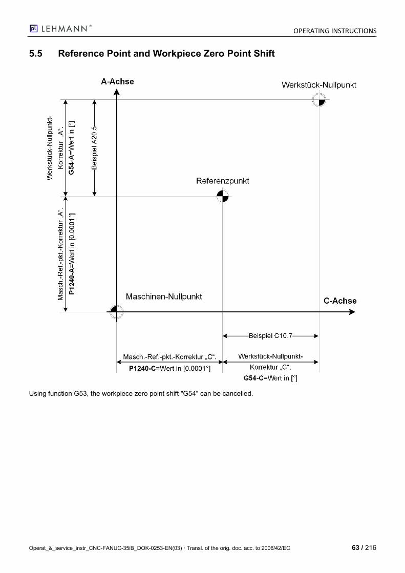
OPERATING INSTRUCTIONS
Operat_&_service_instr_CNC-FANUC-35iB_DOK-0253-EN(03) Transl. of the orig. doc. acc. to 2006/42/EC 63 / 216
5.5 Reference Point and Workpiece Zero Point Shift
Using function G53, the workpiece zero point shift "G54" can be cancelled.
OPERATING INSTRUCTIONS
64 / 216 Operat_&_service_instr_CNC-FANUC-35iB_DOK-0253-EN(03) Transl. of the orig. doc. acc. to 2006/42/EC
5.6 directPOS (Position Specification via M-Func 1…5)
5.6.1 Introduction
The M-Functions M1…M5 can be activated by means of PMC keep relay K5.0=1. They are then used to select / call up a saved program( Position).
These NC programs must be saved in the "CNC_MEM: USER/LIBRARY" directory when NC Par 3467 has the value 7 by default. The path could also be changed using this parameter.
5.6.2 NC Prog Selection Assignment:
M-Func 1 = NC Prog O8881
M-Func 2 = NC Prog O8882
M-Func 3 = NC Prog O8883
M-Func 4 = NC Prog O8884
M-Func 5 = NC Prog O8885
5.6.3 Example NC Prog for directPOS Function
O8881 (POSITION 1);
G90 G0 A0;
M30;
5.7 Customer Macro Programming
5.7.1 Introduction
Subprograms are suited for repetitions of identical processes.
Thanks to the "Customer Macro" function, it is also possible to use variables, arithmetic and logic operations such as conditional branches. It generally facilitates the development of programs.
A customer macro can, like an editing program, be selected via a simple command.
O0001;
:
:
:
G85 P9010 R50.0 L2;
:
:
M30;
O9010;
#1=#18/2;
G01 X#1 A#1 F300;
X#1 Y-#1;
:
:
:
M99;
Programm Kundenmakro
Verknüpf_FANUC_PMi_alleSpr.vsd
OPERATING INSTRUCTIONS
Operat_&_service_instr_CNC-FANUC-35iB_DOK-0253-EN(03) Transl. of the orig. doc. acc. to 2006/42/EC 65 / 216
5.7.2 Variables
Introduction
In a normal operating program, the G code and the travel range are directly specified by means of a numerical value, for instance: G100 and X100.0.
In customer macros, numerical values can be entered either directly or in the form of variable numbers. The associ-ated variable values are edited via the NC program of the 35iB or its manual keyboard input.
#1=#2+100;
G01 X#1 F300;
Display of Variables
When defining a variable, the "#" number sign followed by the respective variable number is displayed. When per-sonal computers are used, the assignment of names to the variables is possible; this option is not available for cus-tomer macros.
Example, created by means of the CNC 35iB: #1
The variable number can be specified in more detail by means of an expression. The expression must be provided in square brackets.
Example: #[#1+#2--12]
Variable Value Range
Local and global variables can either have the value 0 or a value within the following ranges:
-1047 to -10-29
0
+10-29 to +1047
If the calculation result proves to be invalid, alarm no. 111 will be sent.
Omitting the Decimal Point
When defining variables in programs, the decimal point within the value of the variable can be omitted.
Example:
If #1=123; is defined, the actual value of the variable is #1 123.000.
#1=123; is the same as #1=123.000;
Non-Defined Variable
If the value of a variable has not been defined, this is referred to as zero variable.
Variable #0 is always a zero variable. This variable can only be read but not written.
OPERATING INSTRUCTIONS
66 / 216 Operat_&_service_instr_CNC-FANUC-35iB_DOK-0253-EN(03) Transl. of the orig. doc. acc. to 2006/42/EC
5.7.3 Variable Types
Depending on the variable number, variables can be divided into four types.
Variable Number
Variable Type
Function
#0 Zero Always has the value zero.
#1 - #33 Local
Local variables can only be used within a macro for buffering data, e.g. the results of a process.
When the control system is switched off, local variables are set to zero.
When a macro is selected, local variables are assigned arguments.
#100 - #199
#500 - #699 Global
Common variables can be used by several macro programs. When the control system is switched off,
-- data is deleted in the variables #100 to #199.
-- data is saved in the variables #500 to #699.
#1000 - System System variables are used for reading and writing various CNC data such as the current position and tool compensation values.
5.7.4 Call by Reference
The word address has been entered with the variable number. If an expression is used, this expression must be provided in square brackets.
Example:
G01X[#1+#2]F#3;
A called variable will be rounded according to the smallest input increment for the respective address.
Example:
If G00X#1; is carried out in a 1/1000mm CNC and variable #1 is assigned the value 12.3456, the actual command will be interpreted as G00X12.346; .
In order to reverse the plus sign of the called variable values, a minus sign (-) must precede the number sign (#).
Example:
G00X-#1;
If a non-defined variable is called, this variable will be skipped until the next address word has been reached.
Example:
If the value of variable #1 is 0 and the value of variable #2 is also zero, performing G00X#1Y#2; will result in G00X0; .
Restrictions
Program numbers, sequence numbers and numbers for the optional skipping of sequences cannot be called by reference.
Example:
Variables cannot be used like this:
O#1; /#2G00X100.0; N#3Y200.0;
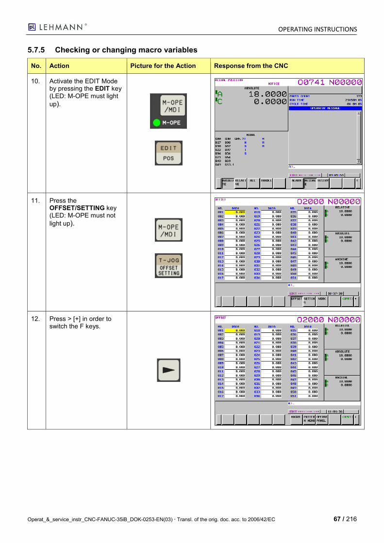
OPERATING INSTRUCTIONS
Operat_&_service_instr_CNC-FANUC-35iB_DOK-0253-EN(03) Transl. of the orig. doc. acc. to 2006/42/EC 67 / 216
5.7.5 Checking or changing macro variables
No. Action Picture for the Action Response from the CNC
10. Activate the EDIT Mode by pressing the EDIT key (LED: M-OPE must light
up).
11. Press the OFFSET/SETTING key (LED: M-OPE must not
light up).
12. Press > [+] in order to switch the F keys.
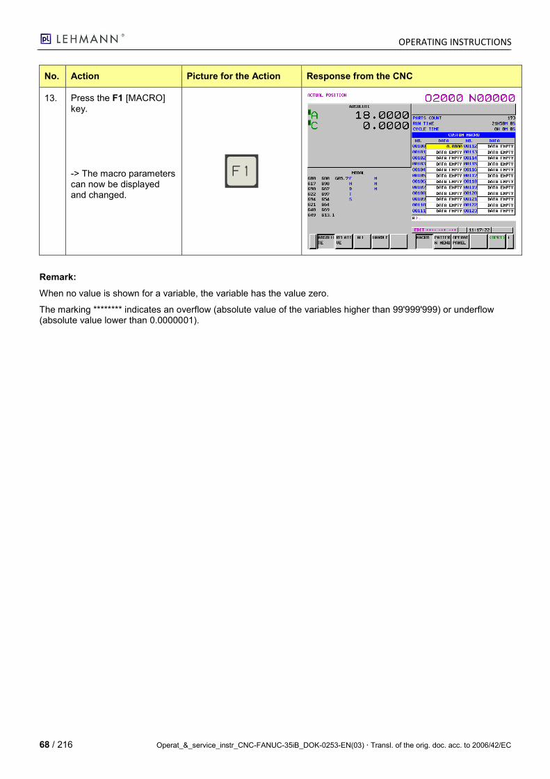
OPERATING INSTRUCTIONS
68 / 216 Operat_&_service_instr_CNC-FANUC-35iB_DOK-0253-EN(03) Transl. of the orig. doc. acc. to 2006/42/EC
No. Action Picture for the Action Response from the CNC
13. Press the F1 [MACRO] key.
-> The macro parameters can now be displayed and changed.
Remark:
When no value is shown for a variable, the variable has the value zero.
The marking ******** indicates an overflow (absolute value of the variables higher than 99'999'999) or underflow (absolute value lower than 0.0000001).
OPERATING INSTRUCTIONS
Operat_&_service_instr_CNC-FANUC-35iB_DOK-0253-EN(03) Transl. of the orig. doc. acc. to 2006/42/EC 69 / 216
5.7.6 Arithmetic and Logic Operations
The operations described below can be carried out on the variables.
The expression to the right of the operator can contain constants and/or variables, combined by functions or opera-tors.
The variables #j and #K can be respectively replaced with constants in expressions. Variables to the left can also be replaced with expressions.
Function Format Remark
Definition #i=#j
Sum
Difference
Product
Quotient
#i=#j+#k;
#i=#j--#k;
#i=#j*#k;
#i=#j/#k;
Sine
Arc sine
Cosine
Arc cosine
Tangent
Arc tangent
#i=SIN[#j];
#i=ASIN[#j];
#i=COS[#j];
#i=ACOS[#j];
#i=TAN[#j];
#i=ATAN[#j]/[#k];
Angles are displayed in degrees. 90 de-
grees 30 minutes is written as 90.5 de-
grees.
Square root
Absolute value
Rounding
Rounding down
Rounding up
Natural logarithm
Exponential function
#i=SQRT[#j];
#i=ABS[#j];
#i=ROUND[#j];
#i=FIX[#j];
#i=FUP[#j];
#i=LN[#j];
#i=EXP[#j];
OR
XOR
AND
#i=#j OR #k;
#i=#j XOR #k;
#i=#j AND #k;
Logic operations for binary numbers are
carried out on a bit-by-bit basis.
Conversion from BCD to BIN
Conversion from BIN to BCD
#i=BIN[#j];
#i=BCD[#j]; Signal exchange from and to the PLC
Equal EQ == (C-Code)
Not equal to NE != (C-Code)
Greater than GT > (C-Code)
Less than LT < (C-Code)
Greater than or equal GE >= (C-Code)
Less than or equal LE <= (C-Code)
5.7.7 Assignment of Letters to Variable Numbers
Address Variable No. Address Variable No. Address Variable No.
A #1 I #4 T #20
B #2 J #5 U #21
C #3 K #6 V #22
D #7 M #13 W #23
E #8 Q #17 X #24
F #9 R #18 Y #25
H #11 S #19 Z #26
The addresses G, L, N, O and P cannot be used in arguments. Addresses which are not required can be omitted. Their local variables are set to zero.
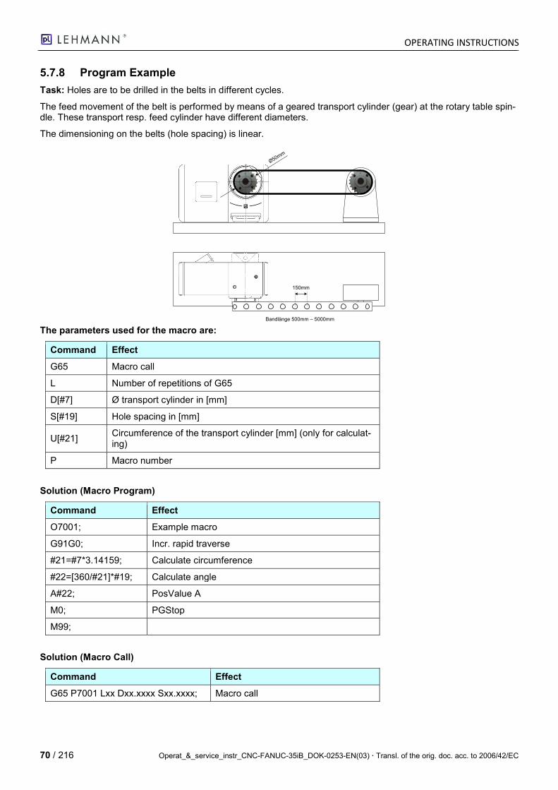
OPERATING INSTRUCTIONS
70 / 216 Operat_&_service_instr_CNC-FANUC-35iB_DOK-0253-EN(03) Transl. of the orig. doc. acc. to 2006/42/EC
5.7.8 Program Example
Task: Holes are to be drilled in the belts in different cycles.
The feed movement of the belt is performed by means of a geared transport cylinder (gear) at the rotary table spin-dle. These transport resp. feed cylinder have different diameters.
The dimensioning on the belts (hole spacing) is linear.
Bandlänge 500mm – 5000mm
150mm
Ø50mm
The parameters used for the macro are:
Command Effect
G65 Macro call
L Number of repetitions of G65
D[#7] Ø transport cylinder in [mm]
S[#19] Hole spacing in [mm]
U[#21] Circumference of the transport cylinder [mm] (only for calculat-ing)
P Macro number
Solution (Macro Program)
Command Effect
O7001; Example macro
G91G0; Incr. rapid traverse
#21=#7*3.14159; Calculate circumference
#22=[360/#21]*#19; Calculate angle
A#22; PosValue A
M0; PGStop
M99;
Solution (Macro Call)
Command Effect
G65 P7001 Lxx Dxx.xxxx Sxx.xxxx; Macro call
OPERATING INSTRUCTIONS
Operat_&_service_instr_CNC-FANUC-35iB_DOK-0253-EN(03) Transl. of the orig. doc. acc. to 2006/42/EC 71 / 216
5.8 pL Division Computer Macro
5.8.1 Macro Description
The FANUC-35iB does not have a division computer. By means of macro programming, however, you can com-
pose this division computer yourself using the required variables.
The division computer Macro "O9012" from pL LEHMANN is a simple division computer. It divides any segment "S"
into any number of division sections "D"; these sections can be repeated (R) as often as required.
The division computer works with absolute values and has the advantage that the "remainder" of the division is also
involved. In order to ensure that involving this "remainder" also works, factor "D" must always be greater than or
equal to the number of repetitions "R".
Note: D >= R.
The division computer is designed for rotary axes; the Modulo 360° is thus included. The division computer is not
suitable for linear axes; however, it could be easily changed or modified.
Macro 9012 has been programmed for the "1st Fanuc axis" with the designation "A". For other use, the macro can
be easily adjusted (please refer to "Notes").
By default, the division computer works with input G00; if, however, a G01 with Fxxxx was programmed in advance,
it can also be operated in the feed with variable speed.
The division computer can be called either as subprogram "G65" or as G function "G300". In order to link the G
function "G300", the NC parameter P6052 must be set from 0 to 300. In addition, the macro must be copied to
path: "/USER/LIBRARY/" for "Fanuc 35iB"and simply to the main directory for "Fanuc PMi" (there is only one).
The movement's direction of rotation can be inverted by using a minus sign (-) in front of the segment value (e.g. S-
360).
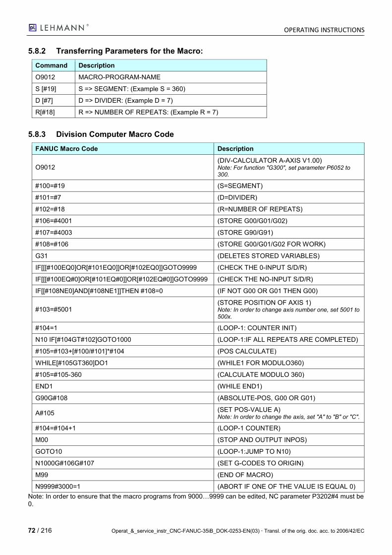
OPERATING INSTRUCTIONS
72 / 216 Operat_&_service_instr_CNC-FANUC-35iB_DOK-0253-EN(03) Transl. of the orig. doc. acc. to 2006/42/EC
5.8.2 Transferring Parameters for the Macro:
Command Description
O9012 MACRO-PROGRAM-NAME
S [#19] S => SEGMENT: (Example S = 360)
D [#7] D => DIVIDER: (Example D = 7)
R[#18] R => NUMBER OF REPEATS: (Example R = 7)
5.8.3 Division Computer Macro Code
FANUC Macro Code Description
O9012 (DIV-CALCULATOR A-AXIS V1.00) Note: For function "G300", set parameter P6052 to 300.
#100=#19 (S=SEGMENT)
#101=#7 (D=DIVIDER)
#102=#18 (R=NUMBER OF REPEATS)
#106=#4001 (STORE G00/G01/G02)
#107=#4003 (STORE G90/G91)
#108=#106 (STORE G00/G01/G02 FOR WORK)
G31 (DELETES STORED VARIABLES)
IF[[[#100EQ0]OR[#101EQ0]]OR[#102EQ0]]GOTO9999 (CHECK THE 0-INPUT S/D/R)
IF[[[#100EQ#0]OR[#101EQ#0]]OR[#102EQ#0]]GOTO9999 (CHECK THE NO-INPUT S/D/R)
IF[[#108NE0]AND[#108NE1]]THEN #108=0 (IF NOT G00 OR G01 THEN G00)
#103=#5001 (STORE POSITION OF AXIS 1) Note: In order to change axis number one, set 5001 to 500x.
#104=1 (LOOP-1: COUNTER INIT)
N10 IF[#104GT#102]GOTO1000 (LOOP-1:IF ALL REPEATS ARE COMPLETED)
#105=#103+[#100/#101]*#104 (POS CALCULATE)
WHILE[#105GT360]DO1 (WHILE1 FOR MODULO360)
#105=#105-360 (CALCULATE MODULO 360)
END1 (WHILE END1)
G90G#108 (ABSOLUTE-POS, G00 OR G01)
A#105 (SET POS-VALUE A) Note: In order to change the axis, set "A" to "B" or "C".
#104=#104+1 (LOOP-1 COUNTER)
M00 (STOP AND OUTPUT INPOS)
GOTO10 (LOOP-1:JUMP TO N10)
N1000G#106G#107 (SET G-CODES TO ORIGIN)
M99 (END OF MACRO)
N9999#3000=1 (ABORT IF ONE OF THE VALUE IS EQUAL 0)
Note: In order to ensure that the macro programs from 9000…9999 can be edited, NC parameter P3202#4 must be 0.
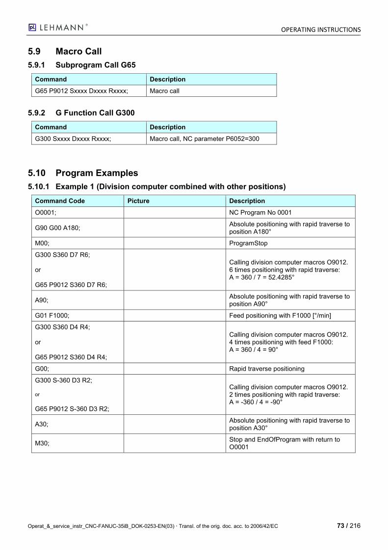
OPERATING INSTRUCTIONS
Operat_&_service_instr_CNC-FANUC-35iB_DOK-0253-EN(03) Transl. of the orig. doc. acc. to 2006/42/EC 73 / 216
5.9 Macro Call
5.9.1 Subprogram Call G65
Command Description
G65 P9012 Sxxxx Dxxxx Rxxxx; Macro call
5.9.2 G Function Call G300
Command Description
G300 Sxxxx Dxxxx Rxxxx; Macro call, NC parameter P6052=300
5.10 Program Examples
5.10.1 Example 1 (Division computer combined with other positions)
Command Code Picture Description
O0001; NC Program No 0001
G90 G00 A180; Absolute positioning with rapid traverse to position A180°
M00; ProgramStop
G300 S360 D7 R6; or G65 P9012 S360 D7 R6;
Calling division computer macros O9012. 6 times positioning with rapid traverse: A = 360 / 7 = 52.4285°
A90; Absolute positioning with rapid traverse to position A90°
G01 F1000; Feed positioning with F1000 [°/min]
G300 S360 D4 R4; or G65 P9012 S360 D4 R4;
Calling division computer macros O9012. 4 times positioning with feed F1000: A = 360 / 4 = 90°
G00; Rapid traverse positioning
G300 S-360 D3 R2; or
G65 P9012 S-360 D3 R2;
Calling division computer macros O9012. 2 times positioning with rapid traverse: A = -360 / 4 = -90°
A30; Absolute positioning with rapid traverse to position A30°
M30; Stop and EndOfProgram with return to O0001

OPERATING INSTRUCTIONS
74 / 216 Operat_&_service_instr_CNC-FANUC-35iB_DOK-0253-EN(03) Transl. of the orig. doc. acc. to 2006/42/EC
5.10.2 Example 2 (Continuous Turning in the Same Direction)
Command Code Picture Description
O0002; NC Program No 0002
G300 S360 D11 R11; or
G65 P9012 S360 D11 R11;
Calling division computer mac-ros O9012. Step-by-step continuous turning positioning: A = 360 / 11 = 32.7272° This division is carried out con-tinuously; despite the irregular "remainder", the axis will always return to 0.0000°.
M99; EndOfProgram with return to O0002
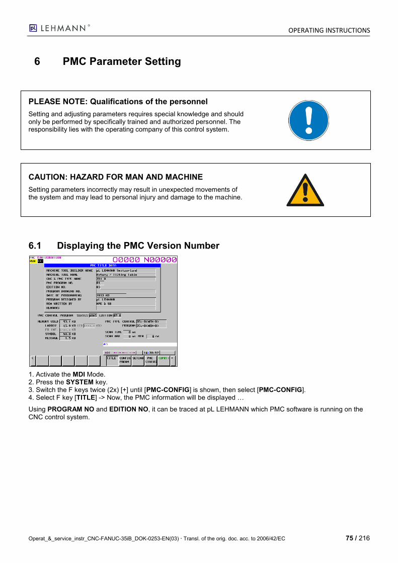
OPERATING INSTRUCTIONS
Operat_&_service_instr_CNC-FANUC-35iB_DOK-0253-EN(03) Transl. of the orig. doc. acc. to 2006/42/EC 75 / 216
6 PMC Parameter Setting
PLEASE NOTE: Qualifications of the personnel
Setting and adjusting parameters requires special knowledge and should only be performed by specifically trained and authorized personnel. The responsibility lies with the operating company of this control system.
CAUTION: HAZARD FOR MAN AND MACHINE
Setting parameters incorrectly may result in unexpected movements of the system and may lead to personal injury and damage to the machine.
6.1 Displaying the PMC Version Number
1. Activate the MDI Mode. 2. Press the SYSTEM key. 3. Switch the F keys twice (2x) [+] until [PMC-CONFIG] is shown, then select [PMC-CONFIG]. 4. Select F key [TITLE] -> Now, the PMC information will be displayed …
Using PROGRAM NO and EDITION NO, it can be traced at pL LEHMANN which PMC software is running on the CNC control system.
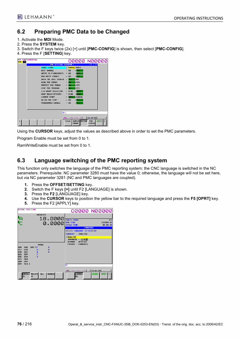
OPERATING INSTRUCTIONS
76 / 216 Operat_&_service_instr_CNC-FANUC-35iB_DOK-0253-EN(03) Transl. of the orig. doc. acc. to 2006/42/EC
6.2 Preparing PMC Data to be Changed
1. Activate the MDI Mode. 2. Press the SYSTEM key. 3. Switch the F keys twice (2x) [+] until [PMC-CONFIG] is shown, then select [PMC-CONFIG]. 4. Press the F [SETTING] key.
Using the CURSOR keys, adjust the values as described above in order to set the PMC parameters.
Program Enable must be set from 0 to 1.
RamWriteEnable must be set from 0 to 1.
6.3 Language switching of the PMC reporting system
This function only switches the language of the PMC reporting system; the CNC language is switched in the NC parameters. Prerequisite: NC parameter 3280 must have the value 0; otherwise, the language will not be set here, but via NC parameter 3281 (NC and PMC languages are coupled).
1. Press the OFFSET/SETTING key. 2. Switch the F keys [+] until F2 [LANGUAGE] is shown. 3. Press the F2 [LANGUAGE] key. 4. Use the CURSOR keys to position the yellow bar to the required language and press the F5 [OPRT] key. 5. Press the F2 [APPLY] key.
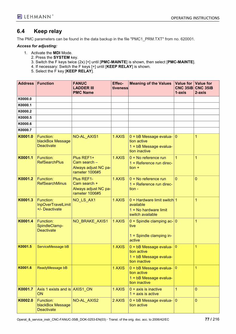
OPERATING INSTRUCTIONS
Operat_&_service_instr_CNC-FANUC-35iB_DOK-0253-EN(03) Transl. of the orig. doc. acc. to 2006/42/EC 77 / 216
6.4 Keep relay
The PMC parameters can be found in the data backup in the file "PMC1_PRM.TXT" from no. 620001.
Access for adjusting:
1. Activate the MDI Mode. 2. Press the SYSTEM key. 3. Switch the F keys twice (2x) [+] until [PMC-MAINTE] is shown, then select [PMC-MAINTE]. 4. If necessary: Switch the F keys [+] until [KEEP RELAY] is shown. 5. Select the F key [KEEP RELAY].
Address Function FANUC LADDER III PMC Name
Effec-tiveness
Meaning of the Values Value for CNC 35iB 1-axis
Value for CNC 35iB 2-axis
K0000.0
K0000.1
K0000.2
K0000.5
K0000.6
K0000.7
K0001.0 Function: blackBox Message Deactivate
NO-AL_AXIS1 1 AXIS 0 = bB Message evalua-tion active
1 = bB Message evalua-tion inactive
0 1
K0001.1 Function: RefSearchPlus
Plus REF1+ Cam search –
Always adjust NC pa-rameter 1006#5
1 AXIS 0 = No reference run
1 = Reference run direc-tion +
1 1
K0001.2 Function: RefSearchMinus
Plus REF1- Cam search +
Always adjust NC pa-rameter 1006#5
1 AXIS 0 = No reference run
1 = Reference run direc-tion -
0 0
K0001.3 Function: InpOverTravelLimit +/- Deactivate
NO_LS_AX1 1 AXIS 0 = Hardware limit switch available
1 = No hardware limit switch available
1 1
K0001.4 Function: SpindleClamp-Deactivate
NO_BRAKE_AXIS1 1 AXIS 0 = Spindle clamping ac-tive
1 = Spindle clamping in-active
0 1
K0001.5 ServiceMessage bB 1 AXIS 0 = bB Message evalua-tion active
1 = bB Message evalua-tion inactive
0 1
K0001.6 ReadyMessage bB 1 AXIS 0 = bB Message evalua-tion active
1 = bB Message evalua-tion inactive
0 1
K0001.7 Axis 1 exists and is ON
AXIS1_ON 1 AXIS 0 = axis is inactive 1 = axis is active
1 0
K0002.0 Function: blackBox Message Deactivate
NO-AL_AXIS2 2 AXIS 0 = bB Message evalua-tion active
0 0
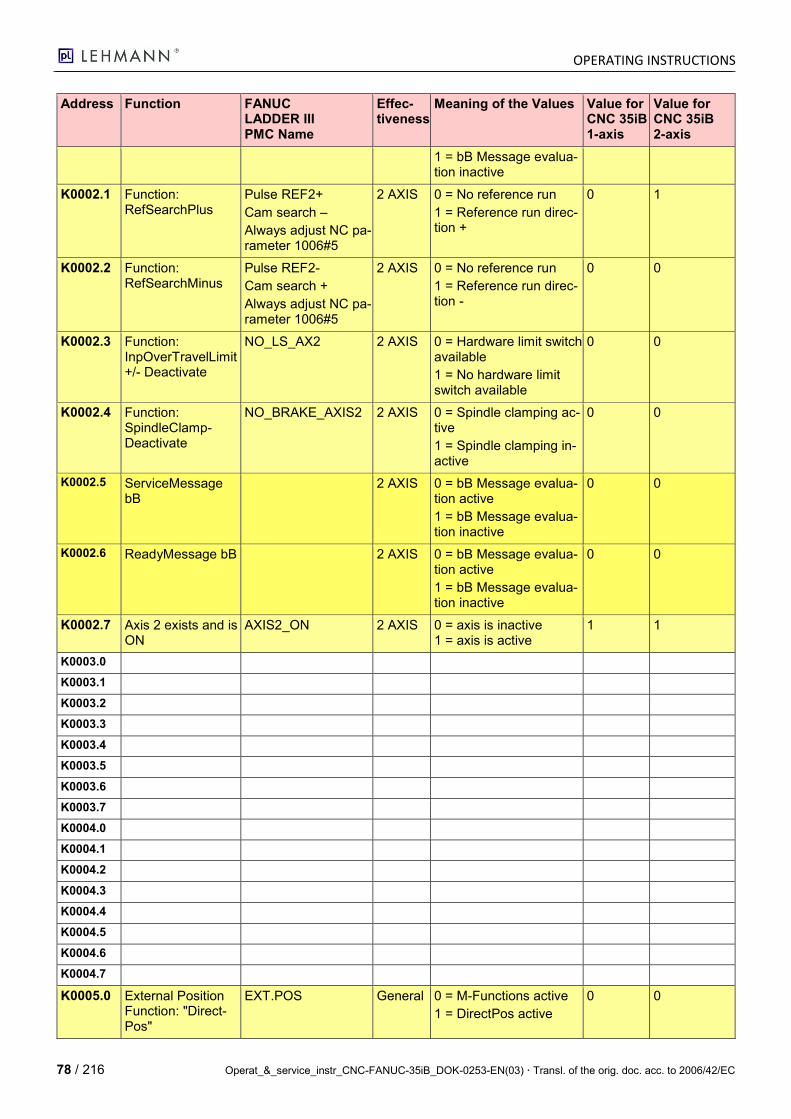
OPERATING INSTRUCTIONS
78 / 216 Operat_&_service_instr_CNC-FANUC-35iB_DOK-0253-EN(03) Transl. of the orig. doc. acc. to 2006/42/EC
Address Function FANUC LADDER III PMC Name
Effec-tiveness
Meaning of the Values Value for CNC 35iB 1-axis
Value for CNC 35iB 2-axis
1 = bB Message evalua-tion inactive
K0002.1 Function: RefSearchPlus
Pulse REF2+
Cam search –
Always adjust NC pa-rameter 1006#5
2 AXIS 0 = No reference run
1 = Reference run direc-tion +
0 1
K0002.2 Function: RefSearchMinus
Pulse REF2-
Cam search +
Always adjust NC pa-rameter 1006#5
2 AXIS 0 = No reference run
1 = Reference run direc-tion -
0 0
K0002.3 Function: InpOverTravelLimit +/- Deactivate
NO_LS_AX2 2 AXIS 0 = Hardware limit switch available
1 = No hardware limit switch available
0 0
K0002.4 Function: SpindleClamp-Deactivate
NO_BRAKE_AXIS2 2 AXIS 0 = Spindle clamping ac-tive
1 = Spindle clamping in-active
0 0
K0002.5 ServiceMessage bB
2 AXIS 0 = bB Message evalua-tion active
1 = bB Message evalua-tion inactive
0 0
K0002.6 ReadyMessage bB 2 AXIS 0 = bB Message evalua-tion active
1 = bB Message evalua-tion inactive
0 0
K0002.7 Axis 2 exists and is ON
AXIS2_ON 2 AXIS 0 = axis is inactive 1 = axis is active
1 1
K0003.0
K0003.1
K0003.2
K0003.3
K0003.4
K0003.5
K0003.6
K0003.7
K0004.0
K0004.1
K0004.2
K0004.3
K0004.4
K0004.5
K0004.6
K0004.7
K0005.0 External Position Function: "Direct-Pos"
EXT.POS General 0 = M-Functions active
1 = DirectPos active
0 0
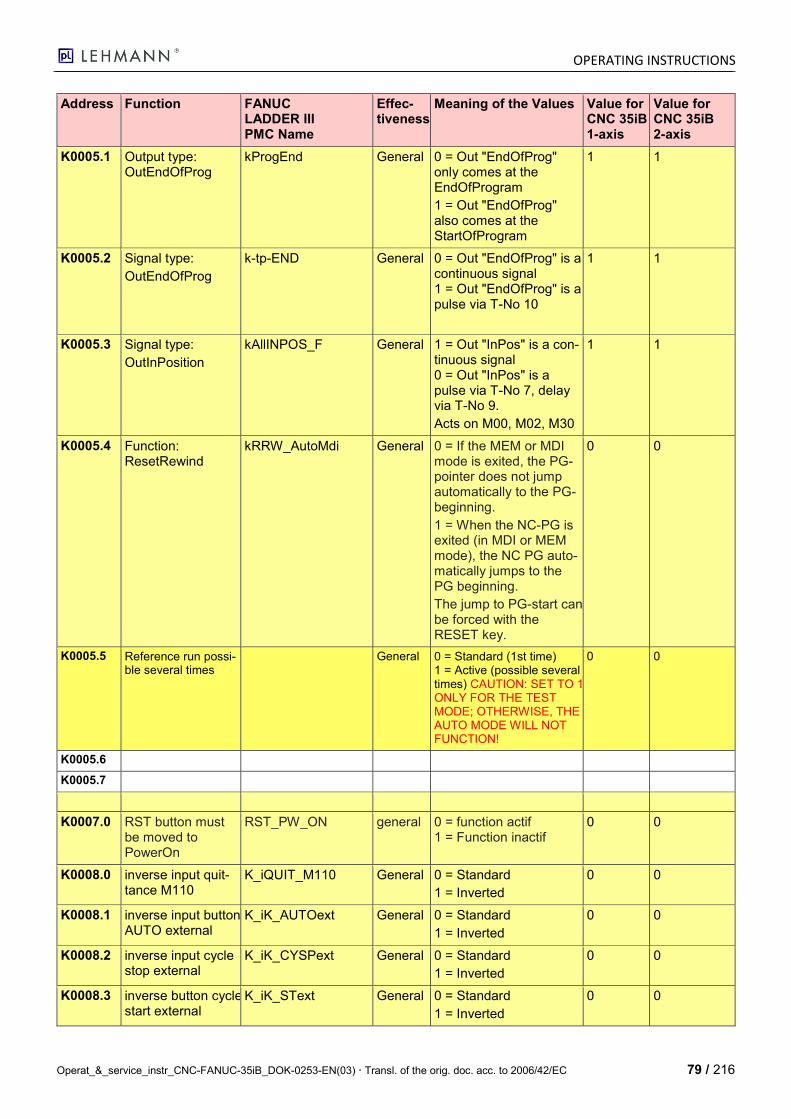
OPERATING INSTRUCTIONS
Operat_&_service_instr_CNC-FANUC-35iB_DOK-0253-EN(03) Transl. of the orig. doc. acc. to 2006/42/EC 79 / 216
Address Function FANUC LADDER III PMC Name
Effec-tiveness
Meaning of the Values Value for CNC 35iB 1-axis
Value for CNC 35iB 2-axis
K0005.1 Output type: OutEndOfProg
kProgEnd General 0 = Out "EndOfProg" only comes at the EndOfProgram
1 = Out "EndOfProg" also comes at the StartOfProgram
1 1
K0005.2 Signal type:
OutEndOfProg
k-tp-END General 0 = Out "EndOfProg" is a continuous signal 1 = Out "EndOfProg" is a pulse via T-No 10
1 1
K0005.3 Signal type:
OutInPosition
kAllINPOS_F General 1 = Out "InPos" is a con-tinuous signal 0 = Out "InPos" is a pulse via T-No 7, delay via T-No 9.
Acts on M00, M02, M30
1 1
K0005.4 Function: ResetRewind
kRRW_AutoMdi General 0 = If the MEM or MDI mode is exited, the PG-pointer does not jump automatically to the PG-beginning.
1 = When the NC-PG is exited (in MDI or MEM mode), the NC PG auto-matically jumps to the PG beginning.
The jump to PG-start can be forced with the RESET key.
0 0
K0005.5 Reference run possi-ble several times
General 0 = Standard (1st time) 1 = Active (possible several times) CAUTION: SET TO 1 ONLY FOR THE TEST MODE; OTHERWISE, THE AUTO MODE WILL NOT FUNCTION!
0 0
K0005.6
K0005.7
K0007.0 RST button must be moved to PowerOn
RST_PW_ON general 0 = function actif 1 = Function inactif
0 0
K0008.0 inverse input quit-tance M110
K_iQUIT_M110 General 0 = Standard
1 = Inverted
0 0
K0008.1 inverse input button AUTO external
K_iK_AUTOext General 0 = Standard
1 = Inverted
0 0
K0008.2 inverse input cycle stop external
K_iK_CYSPext General 0 = Standard
1 = Inverted
0 0
K0008.3 inverse button cycle start external
K_iK_SText General 0 = Standard
1 = Inverted
0 0
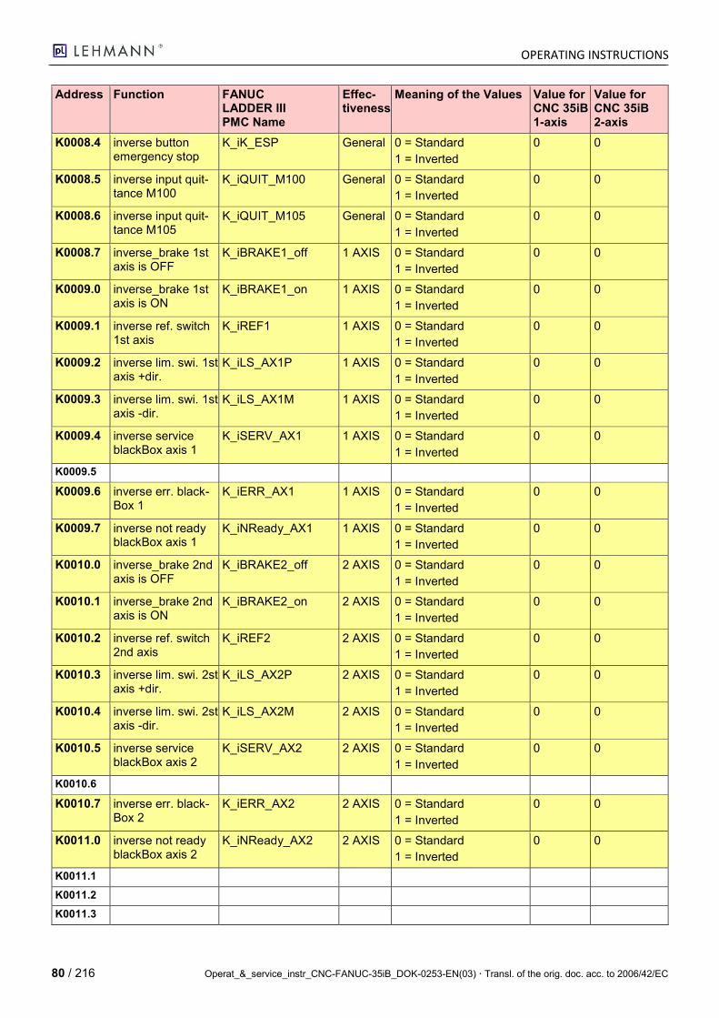
OPERATING INSTRUCTIONS
80 / 216 Operat_&_service_instr_CNC-FANUC-35iB_DOK-0253-EN(03) Transl. of the orig. doc. acc. to 2006/42/EC
Address Function FANUC LADDER III PMC Name
Effec-tiveness
Meaning of the Values Value for CNC 35iB 1-axis
Value for CNC 35iB 2-axis
K0008.4 inverse button emergency stop
K_iK_ESP General 0 = Standard
1 = Inverted
0 0
K0008.5 inverse input quit-tance M100
K_iQUIT_M100 General 0 = Standard
1 = Inverted
0 0
K0008.6 inverse input quit-tance M105
K_iQUIT_M105 General 0 = Standard
1 = Inverted
0 0
K0008.7 inverse_brake 1st axis is OFF
K_iBRAKE1_off 1 AXIS 0 = Standard
1 = Inverted
0 0
K0009.0 inverse_brake 1st axis is ON
K_iBRAKE1_on 1 AXIS 0 = Standard
1 = Inverted
0 0
K0009.1 inverse ref. switch 1st axis
K_iREF1 1 AXIS 0 = Standard
1 = Inverted
0 0
K0009.2 inverse lim. swi. 1st axis +dir.
K_iLS_AX1P 1 AXIS 0 = Standard
1 = Inverted
0 0
K0009.3 inverse lim. swi. 1st axis -dir.
K_iLS_AX1M 1 AXIS 0 = Standard
1 = Inverted
0 0
K0009.4 inverse service blackBox axis 1
K_iSERV_AX1 1 AXIS 0 = Standard
1 = Inverted
0 0
K0009.5
K0009.6 inverse err. black-Box 1
K_iERR_AX1 1 AXIS 0 = Standard
1 = Inverted
0 0
K0009.7 inverse not ready blackBox axis 1
K_iNReady_AX1 1 AXIS 0 = Standard
1 = Inverted
0 0
K0010.0 inverse_brake 2nd axis is OFF
K_iBRAKE2_off 2 AXIS 0 = Standard
1 = Inverted
0 0
K0010.1 inverse_brake 2nd axis is ON
K_iBRAKE2_on 2 AXIS 0 = Standard
1 = Inverted
0 0
K0010.2 inverse ref. switch 2nd axis
K_iREF2 2 AXIS 0 = Standard
1 = Inverted
0 0
K0010.3 inverse lim. swi. 2st axis +dir.
K_iLS_AX2P 2 AXIS 0 = Standard
1 = Inverted
0 0
K0010.4 inverse lim. swi. 2st axis -dir.
K_iLS_AX2M 2 AXIS 0 = Standard
1 = Inverted
0 0
K0010.5 inverse service blackBox axis 2
K_iSERV_AX2 2 AXIS 0 = Standard
1 = Inverted
0 0
K0010.6
K0010.7 inverse err. black-Box 2
K_iERR_AX2 2 AXIS 0 = Standard
1 = Inverted
0 0
K0011.0 inverse not ready blackBox axis 2
K_iNReady_AX2 2 AXIS 0 = Standard
1 = Inverted
0 0
K0011.1
K0011.2
K0011.3
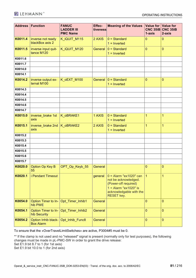
OPERATING INSTRUCTIONS
Operat_&_service_instr_CNC-FANUC-35iB_DOK-0253-EN(03) Transl. of the orig. doc. acc. to 2006/42/EC 81 / 216
Address Function FANUC LADDER III PMC Name
Effec-tiveness
Meaning of the Values Value for CNC 35iB 1-axis
Value for CNC 35iB 2-axis
K0011.4 inverse not ready blackBox axis 2
K_iQUIT_M115 2 AXIS 0 = Standard
1 = Inverted
0 0
K0011.5 inverse input quit-tance M120
K_iQUIT_M120 General 0 = Standard
1 = Inverted
0 0
K0011.6
K0011.7
K0014.0
K0014.1
K0014.2 inverse output ex-ternal M100
K_oEXT_M100 General 0 = Standard
1 = Inverted
0 0
K0014.3
K0014.4
K0014.5
K0014.6
K0014.7
K0015.0 inverse_brake 1st axis
K_oBRAKE1 1 AXIS 0 = Standard
1 = Inverted
1 1
K0015.1 inverse_brake 2nd axis
K_oBRAKE2 2 AXIS 0 = Standard
1 = Inverted
1 1
K0015.2
K0015.3
K0015.4
K0015.5
K0015.6
K0015.7
K0020.0 Option Op Key B 55
OPT_Op_Keyb_55 General 0 0
K0020.1 i Pendant Timeout general 0 = Alarm "ex1020" can not be acknowledged. (Power-off required)
1 = Alarm "ex1020" is acknowledgable with the RESET key.
1 1
K0054.0 Option Timer to In-hib PWE
Opt_Timer_Inhib1 General 0 0
K0054.1 Option Timer to In-hib Security
Opt_Timer_Inhib2 General 0 0
K0054.2 Option Inhib black-Box Alarm
Opt_Inhib_Func8 General 0 0
To ensure that the «OverTravelLimitSwitches» are active, P3004#5 must be 0.
** If the clamp is not used and no "released" signal is present (normally only for test purposes), the following changes must be made in pL-PMC-SW in order to grant the drive release: Set E1.9 bit 8.7 to 1 (for 1st axis) Set E1.9 bit 10.0 to 1 (for 2nd axis)

OPERATING INSTRUCTIONS
82 / 216 Operat_&_service_instr_CNC-FANUC-35iB_DOK-0253-EN(03) Transl. of the orig. doc. acc. to 2006/42/EC
6.5 Timer
The PMC parameters can be found in the data backup in the file "PMC1_PRM.TXT" from no. 60000. The value must still be multiplied by the corresponding timer time constant (Example: 4 x 48ms = 192ms).
Access via SYSTEM -> PMC-MAINTENANCE -> TIMER (Caution: Please do not confuse number and address.)
Picture: Timer Screen Mask
Timer Ad-dress
Timer No.
Function Effective-ness
Meaning of the Values Value for 35iB CNC 1-axis
Value for 35iB CNC 2-axis
T0000 1 Pulse duration M101 General Value x 1ms Min. value 48 Max. value 255
200 200
T0002 2 Pulse duration M106 General Value x 1ms Min. value 48 Max. value 255
200 200
T0004 3 Pulse duration M111 General Value x 1ms Min. value 48 Max. value 255
200 200
T0006 4 Pulse duration M116 General Value x 1ms Min. value 48 Max. value 255
200 200
T0008 5 Pulse duration M121 General Value x 1ms Min. value 48 Max. value 255
200 200
T0010 6
T0012 7 Pulse duration: OutInPosition
General Value x 1ms Min. value 48 Max. value 255
200 200
T0014 8
T0016 9 Pulse delay:
OutInPosition
General Value x 1ms Min. value 48 Max. value 255
0 200
T0018 10 Pulse duration: OutEndOfProg
General Value x 1ms – Timer Min. value 48 Max. value 255
200 200
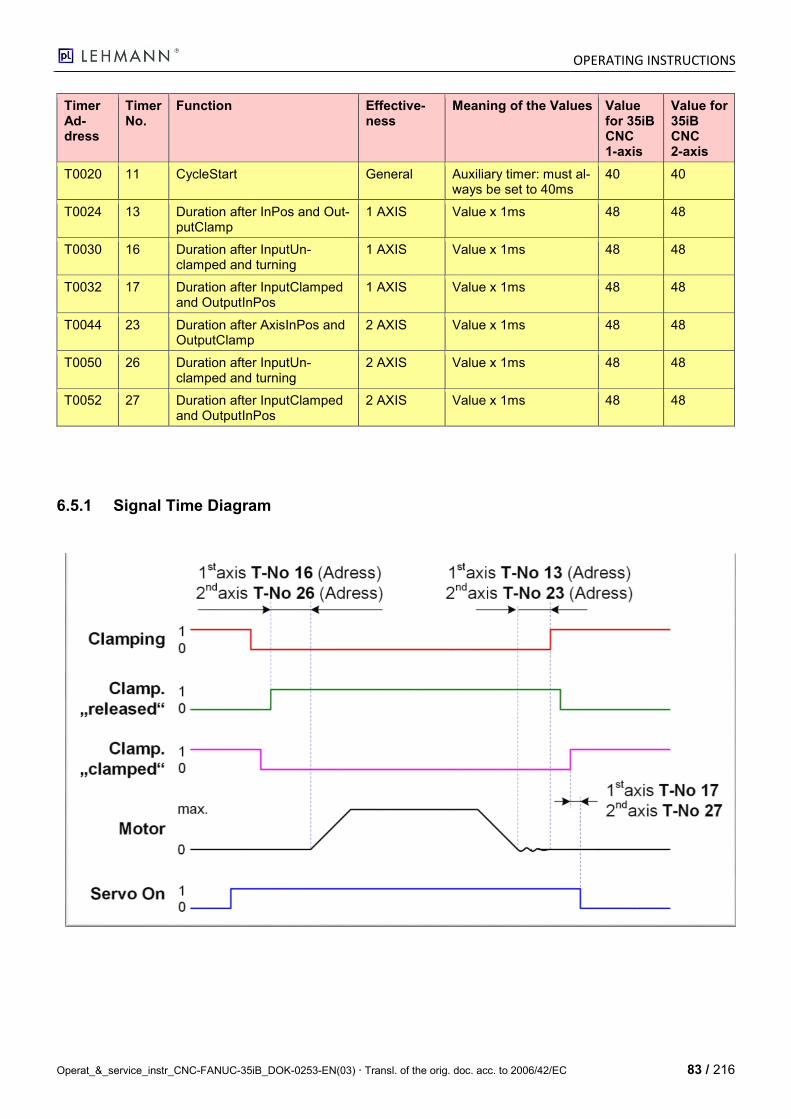
OPERATING INSTRUCTIONS
Operat_&_service_instr_CNC-FANUC-35iB_DOK-0253-EN(03) Transl. of the orig. doc. acc. to 2006/42/EC 83 / 216
Timer Ad-dress
Timer No.
Function Effective-ness
Meaning of the Values Value for 35iB CNC 1-axis
Value for 35iB CNC 2-axis
T0020 11 CycleStart General Auxiliary timer: must al-ways be set to 40ms
40 40
T0024 13 Duration after InPos and Out-putClamp
1 AXIS Value x 1ms 48 48
T0030 16 Duration after InputUn-clamped and turning
1 AXIS Value x 1ms 48 48
T0032 17 Duration after InputClamped and OutputInPos
1 AXIS Value x 1ms 48 48
T0044 23 Duration after AxisInPos and OutputClamp
2 AXIS Value x 1ms 48 48
T0050 26 Duration after InputUn-clamped and turning
2 AXIS Value x 1ms 48 48
T0052 27 Duration after InputClamped and OutputInPos
2 AXIS Value x 1ms 48 48
6.5.1 Signal Time Diagram
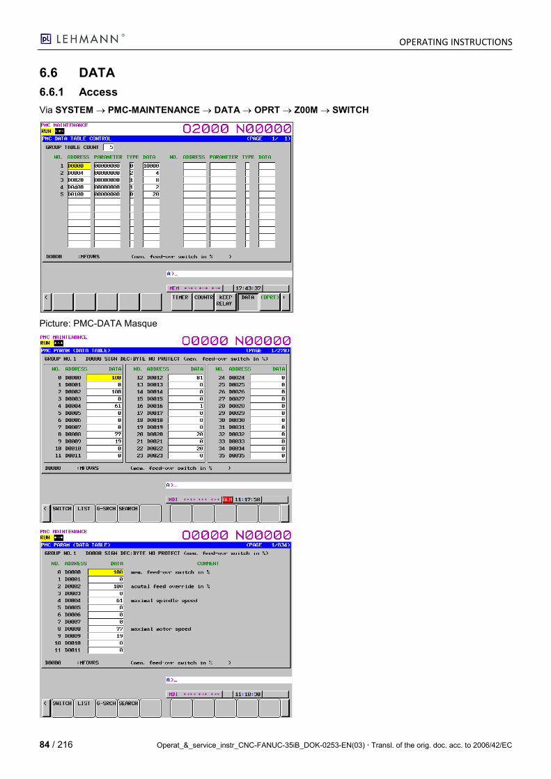
OPERATING INSTRUCTIONS
84 / 216 Operat_&_service_instr_CNC-FANUC-35iB_DOK-0253-EN(03) Transl. of the orig. doc. acc. to 2006/42/EC
6.6 DATA
6.6.1 Access
Via SYSTEM PMC-MAINTENANCE DATA OPRT Z00M SWITCH
Picture: PMC-DATA Masque
OPERATING INSTRUCTIONS
Operat_&_service_instr_CNC-FANUC-35iB_DOK-0253-EN(03) Transl. of the orig. doc. acc. to 2006/42/EC 85 / 216
6.6.2 Configuration of the speed for endless turning M03 / M04
Extract: List according to instructions, Basic PMC Instructions from FANUC-CH
Address Function Effective-ness
Meaning of the Values Value for CNC 35iB 1-axis
D0000 MEM Mode FeedOverride Switch in [%]
1 AXIS Max. continuous turning speed M03/M04
10
D0004 MaximumSpindleSpeed 1 AXIS Maximum spindle speed M03/M04
4
D0008 MotorSpeed 1 AXIS Maximum motor speed M03/M04
3000
D0012 GearRatio 1 AXIS Gear ratio 90
Important: For endless turning with M03 / M04, the NC parameter P8040 must be P1821. Otherwise the pro-grammed RPM (revolutions per minute) will not match the ACTUAL speed. With "D0000", only 10% should be programmed by default at the beginning with regard to gearbox damage.
6.7 Turning a 2-axis CNC into a 1-axis CNC
6.7.1 Removing Axis 2 SERVO completely:
1. Load NC and PMC parameters from 1st axis CNC and disconnect the CNC from the power supply system (NC parameter 11802#4 and NC parameter 24000 = 1000 are relevant => FSSB deselect 1st axis resp. NC-Par 24001 = 1000 => FSSB deselect 2nd axis)
2. Insert Servo-2 CXA19 cable at Servo-1 CXA19 (ServoReady).
3. Remove Servo-1 COP10A connector (FSSB).
4. Servo can be removed.
5. Switch on the CNC and test.
6.7.2 Deselecting Axis 2 SERVO only:
1. Load NC and PMC parameters from 1-axis CNC. 2. Reboot CNC and test.
6.8 Saving PrintScreen from Current Monitor Content to Card
A PrintScreen can be made of almost all monitor contents.
1. Insert memory card (USB flash drive at i-Pendant P300#0=1 or PC Card at CNC P300#0=0).
2. Green LED "M-OPE" must light up (switch by pressing the M-OPE/MDI key).
3. Press the SHIFT key until the time display on the monitor stops (approx. 5 sec) at the bottom right.
4. 4. Release the SHIFT key and wait until the OUTPUT message flashes at the bottom right.
5. Wait until the flashing has stopped; the PrintScreen data is then stored on the storage medium.
6. The data medium can now be read by using the PC Filename.BMP.
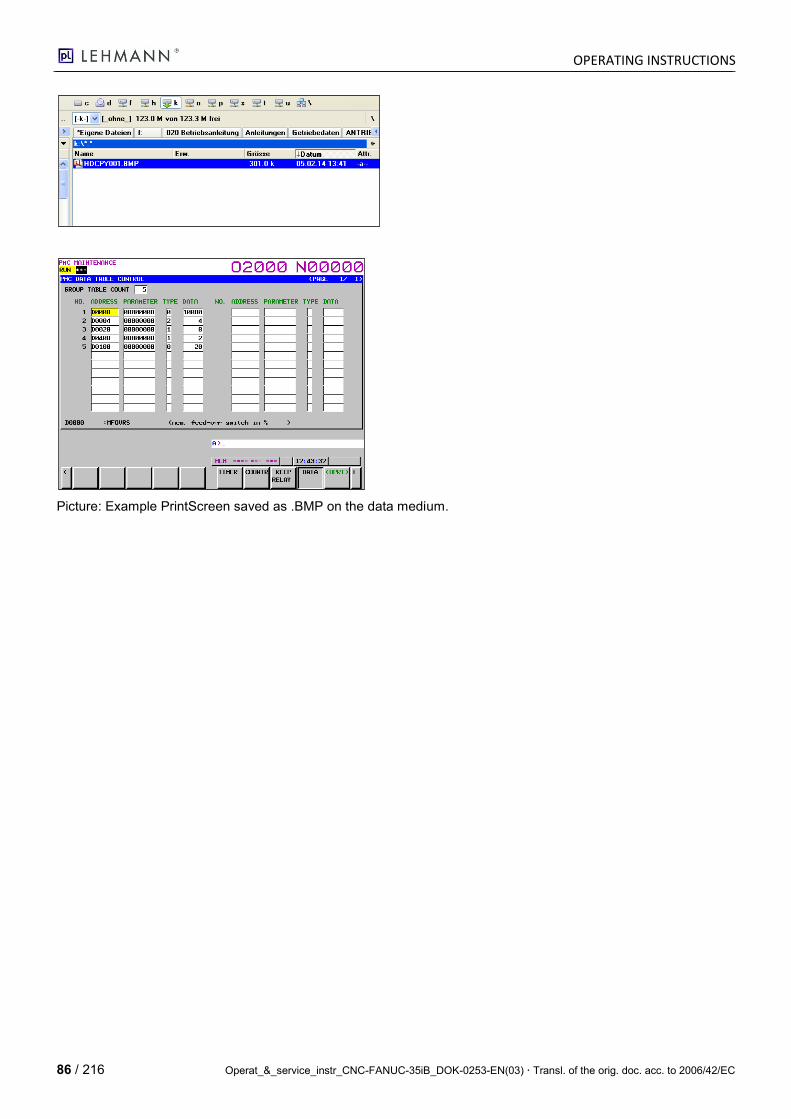
OPERATING INSTRUCTIONS
86 / 216 Operat_&_service_instr_CNC-FANUC-35iB_DOK-0253-EN(03) Transl. of the orig. doc. acc. to 2006/42/EC
Picture: Example PrintScreen saved as .BMP on the data medium.
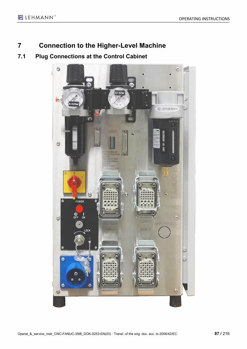
OPERATING INSTRUCTIONS
Operat_&_service_instr_CNC-FANUC-35iB_DOK-0253-EN(03) Transl. of the orig. doc. acc. to 2006/42/EC 87 / 216
7 Connection to the Higher-Level Machine
7.1 Plug Connections at the Control Cabinet
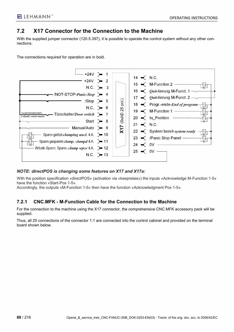
OPERATING INSTRUCTIONS
88 / 216 Operat_&_service_instr_CNC-FANUC-35iB_DOK-0253-EN(03) Transl. of the orig. doc. acc. to 2006/42/EC
7.2 X17 Connector for the Connection to the Machine
With the supplied jumper connector (120.5.397), it is possible to operate the control system without any other con-nections.
The connections required for operation are in bold.
NOTE: directPOS is changing some features on X17 and X17a:
With the position specification «directPOS» (activation via «keeprelais») the inputs «Acknowledge M-Function 1-5» have the function «Start-Pos 1-5». Accordingly, the outputs «M-Function 1-5» then have the function «Acknowledgment Pos 1-5».
7.2.1 CNC.MFK - M-Function Cable for the Connection to the Machine
For the connection to the machine using the X17 connector, the comprehensive CNC.MFK accessory pack will be supplied.
Thus, all 25 connections of the connector 1:1 are connected into the control cabinet and provided on the terminal board shown below.
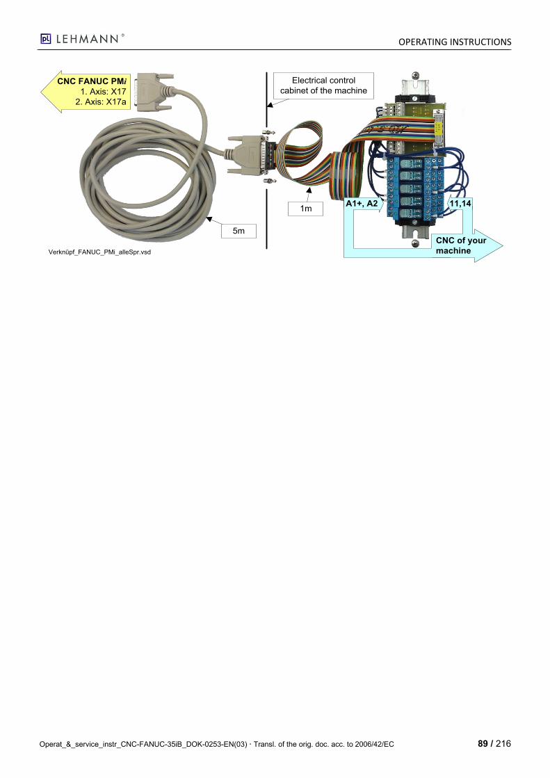
OPERATING INSTRUCTIONS
Operat_&_service_instr_CNC-FANUC-35iB_DOK-0253-EN(03) Transl. of the orig. doc. acc. to 2006/42/EC 89 / 216
1m
5m
Electrical control
cabinet of the machineCNC FANUC PMi
1. Axis: X17
2. Axis: X17a
A1+, A2
CNC of your
machine
11,14
Verknüpf_FANUC_PMi_alleSpr.vsd
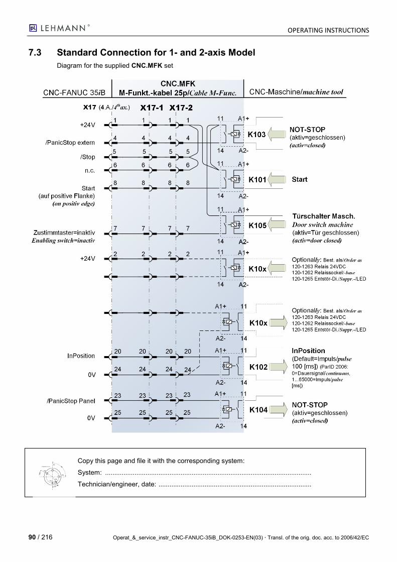
OPERATING INSTRUCTIONS
90 / 216 Operat_&_service_instr_CNC-FANUC-35iB_DOK-0253-EN(03) Transl. of the orig. doc. acc. to 2006/42/EC
7.3 Standard Connection for 1- and 2-axis Model
Diagram for the supplied CNC.MFK set
Copy this page and file it with the corresponding system:
System: ................................................................................................................
Technician/engineer, date: ...................................................................................
30°
0°
90°
300°
Progbeispiel_1b.vsd
P1
P2
P3P4
P5
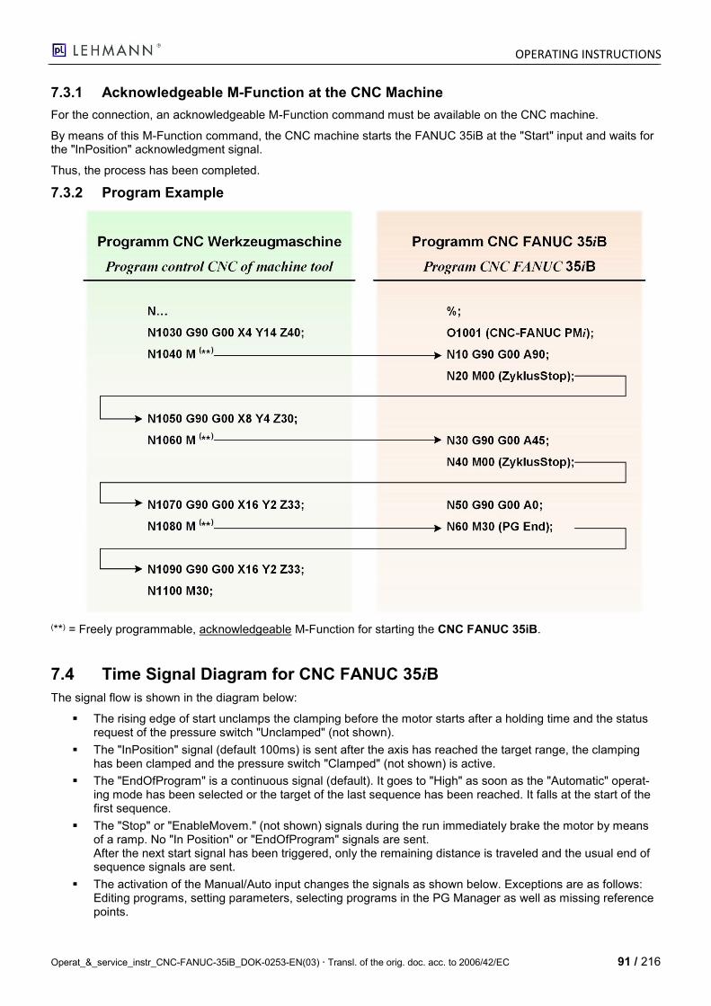
OPERATING INSTRUCTIONS
Operat_&_service_instr_CNC-FANUC-35iB_DOK-0253-EN(03) Transl. of the orig. doc. acc. to 2006/42/EC 91 / 216
7.3.1 Acknowledgeable M-Function at the CNC Machine
For the connection, an acknowledgeable M-Function command must be available on the CNC machine.
By means of this M-Function command, the CNC machine starts the FANUC 35iB at the "Start" input and waits for the "InPosition" acknowledgment signal.
Thus, the process has been completed.
7.3.2 Program Example
(**) = Freely programmable, acknowledgeable M-Function for starting the CNC FANUC 35iB.
7.4 Time Signal Diagram for CNC FANUC 35iB
The signal flow is shown in the diagram below:
The rising edge of start unclamps the clamping before the motor starts after a holding time and the status request of the pressure switch "Unclamped" (not shown).
The "InPosition" signal (default 100ms) is sent after the axis has reached the target range, the clamping has been clamped and the pressure switch "Clamped" (not shown) is active.
The "EndOfProgram" is a continuous signal (default). It goes to "High" as soon as the "Automatic" operat-ing mode has been selected or the target of the last sequence has been reached. It falls at the start of the first sequence.
The "Stop" or "EnableMovem." (not shown) signals during the run immediately brake the motor by means of a ramp. No "In Position" or "EndOfProgram" signals are sent. After the next start signal has been triggered, only the remaining distance is traveled and the usual end of sequence signals are sent.
The activation of the Manual/Auto input changes the signals as shown below. Exceptions are as follows: Editing programs, setting parameters, selecting programs in the PG Manager as well as missing reference points.
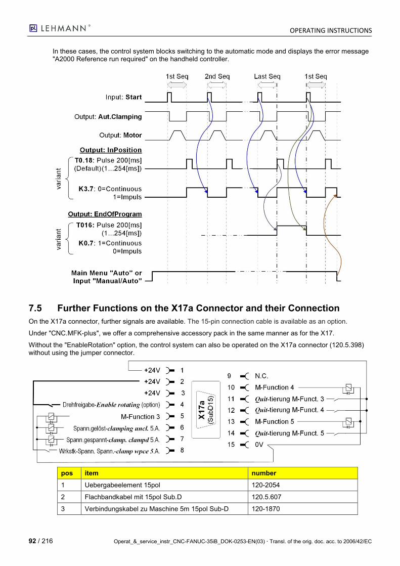
OPERATING INSTRUCTIONS
92 / 216 Operat_&_service_instr_CNC-FANUC-35iB_DOK-0253-EN(03) Transl. of the orig. doc. acc. to 2006/42/EC
In these cases, the control system blocks switching to the automatic mode and displays the error message "A2000 Reference run required" on the handheld controller.
7.5 Further Functions on the X17a Connector and their Connection
On the X17a connector, further signals are available. The 15-pin connection cable is available as an option.
Under "CNC.MFK-plus", we offer a comprehensive accessory pack in the same manner as for the X17.
Without the "EnableRotation" option, the control system can also be operated on the X17a connector (120.5.398) without using the jumper connector.
pos item number
1 Uebergabeelement 15pol 120-2054
2 Flachbandkabel mit 15pol Sub.D 120.5.607
3 Verbindungskabel zu Maschine 5m 15pol Sub-D 120-1870
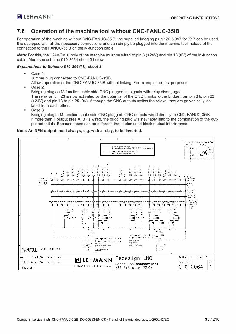
OPERATING INSTRUCTIONS
Operat_&_service_instr_CNC-FANUC-35iB_DOK-0253-EN(03) Transl. of the orig. doc. acc. to 2006/42/EC 93 / 216
7.6 Operation of the machine tool without CNC-FANUC-35iB
For operation of the machine without CNC-FANUC-35iB, the supplied bridging plug 120.5.397 for X17 can be used. It is equipped with all the necessary connections and can simply be plugged into the machine tool instead of the connection to the FANUC-35iB on the M-function cable.
Note: For this, the +24V/0V supply of the machine must be wired to pin 3 (+24V) and pin 13 (0V) of the M-function cable. More see scheme 010-2064 sheet 3 below.
Explanations to Scheme 010-2064(1), sheet 3
Case 1: Jumper plug connected to CNC-FANUC-35iB. Allows operation of the CNC-FANUC-35iB without linking. For example, for test purposes.
Case 2: Bridging plug on M-function cable side CNC plugged in, signals with relay disengaged. The relay on pin 23 is now activated by the potential of the CNC thanks to the bridge from pin 3 to pin 23 (+24V) and pin 13 to pin 25 (0V). Although the CNC outputs switch the relays, they are galvanically iso-lated from each other.
Case 3: Bridging plug to M-function cable side CNC plugged, CNC outputs wired directly to CNC-FANUC-35iB. If more than 1 output (see A, B) is wired, the bridging plug will inevitably lead to the combination of the out-put potentials. Because these can be different, the diodes used block mutual interference.
Note: An NPN output must always, e.g. with a relay, to be inverted.
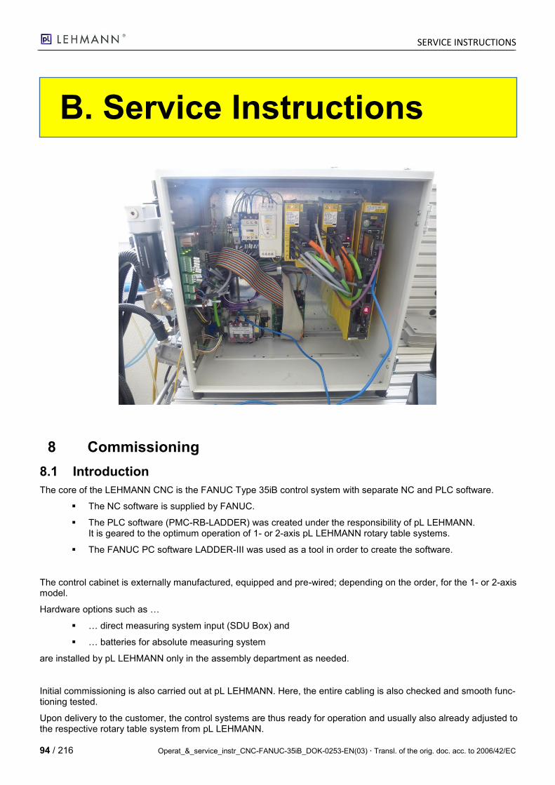
SERVICE INSTRUCTIONS
94 / 216 Operat_&_service_instr_CNC-FANUC-35iB_DOK-0253-EN(03) Transl. of the orig. doc. acc. to 2006/42/EC
B. Service Instructions
8 Commissioning
8.1 Introduction
The core of the LEHMANN CNC is the FANUC Type 35iB control system with separate NC and PLC software.
The NC software is supplied by FANUC.
The PLC software (PMC-RB-LADDER) was created under the responsibility of pL LEHMANN. It is geared to the optimum operation of 1- or 2-axis pL LEHMANN rotary table systems.
The FANUC PC software LADDER-III was used as a tool in order to create the software.
The control cabinet is externally manufactured, equipped and pre-wired; depending on the order, for the 1- or 2-axis model.
Hardware options such as …
… direct measuring system input (SDU Box) and
… batteries for absolute measuring system
are installed by pL LEHMANN only in the assembly department as needed.
Initial commissioning is also carried out at pL LEHMANN. Here, the entire cabling is also checked and smooth func-tioning tested.
Upon delivery to the customer, the control systems are thus ready for operation and usually also already adjusted to the respective rotary table system from pL LEHMANN.

SERVICE INSTRUCTIONS
Operat_&_service_instr_CNC-FANUC-35iB_DOK-0253-EN(03) Transl. of the orig. doc. acc. to 2006/42/EC 95 / 216
8.2 Initial Commissioning, Step by Step
8.2.1 Introduction
The Fanuc CNC control system must be configured, parameterized and provided with data before it can be used. There is no possibility to send all data at once to the control system; it must be imported and transferred file by file.
8.2.2 IP Addresses
By default, the permanently assigned IP addresses are saved as follows; they must not be changed or modified.
Control System Compo-nent
Permanently As-signed IP Address
Remark
CNC 35iB 192.168.1.10 : 8193 Communication with LADDERIII programming system or with i-Pendant
i-Pendant (handheld con-troller)
192.168.1.200 Communication with CNC-35iB
Optional ETH card for CNC 35iB
Permanently assigned IP -> address freely selectable
Communication with PC network for NC program trans-fer or remote maintenance. Attention: This option is not currently offered by pL LEHMANN.
8.2.3 Commissioning Procedure
The procedure followed in order to import and transfer the data, which is described in detail below, should be as follows:
No. What How OK
1. Activate the handheld controller -> adjust manually
2. PMC configuration -> adjust manually
3. NC parameters -> File transfer via PC Card (CNC-PARA.TXT)
4. PMC-LADDER -> File transfer via PC Card (PMC1.000)
5. PMC parameters -> File transfer via PC Card (PMC1_PRM.TXT)
6. I/O configuration -> File transfer via PC Card (IOCONFIG.000)
7. Messages -> File transfer via PC Card (M1PMCMSG.TXT)
8. Macros and test programs -> File transfer via PC Card (Oxxxx…)
9. Connect and test axes -> manually
10. Complete data backup -> File transfer via PC Card (save everything)
Card Adapter A02B-0236-K150 Compact Flash Card 256MB A02B-0213-K211
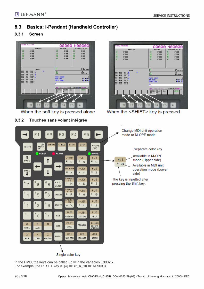
SERVICE INSTRUCTIONS
96 / 216 Operat_&_service_instr_CNC-FANUC-35iB_DOK-0253-EN(03) Transl. of the orig. doc. acc. to 2006/42/EC
8.3 Basics: i-Pendant (Handheld Controller)
8.3.1 Screen
8.3.2 Touches sans volant intégrée
In the PMC, the keys can be called up with the variables E9902.x. For example, the RESET key is: [//] => iP_K_10 => R0903.3
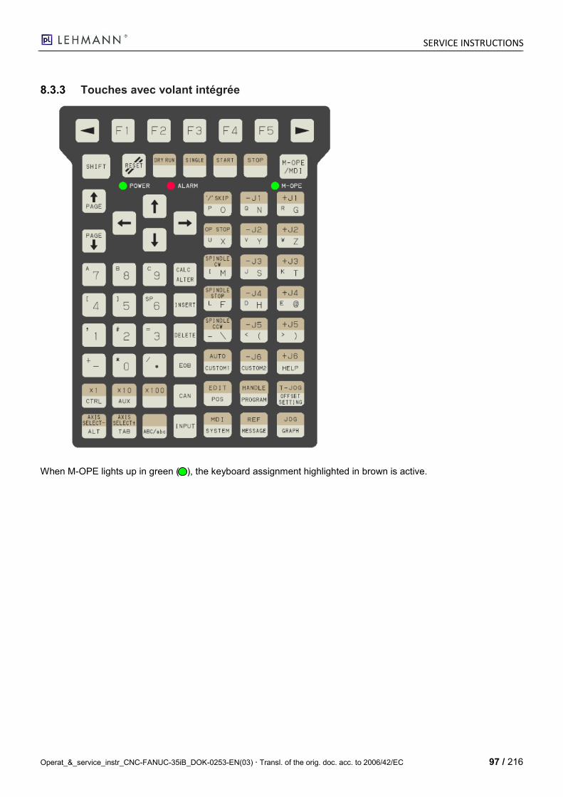
SERVICE INSTRUCTIONS
Operat_&_service_instr_CNC-FANUC-35iB_DOK-0253-EN(03) Transl. of the orig. doc. acc. to 2006/42/EC 97 / 216
8.3.3 Touches avec volant intégrée
When M-OPE lights up in green ( ), the keyboard assignment highlighted in brown is active.
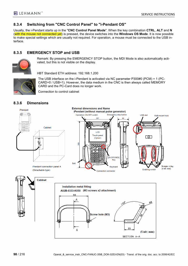
SERVICE INSTRUCTIONS
98 / 216 Operat_&_service_instr_CNC-FANUC-35iB_DOK-0253-EN(03) Transl. of the orig. doc. acc. to 2006/42/EC
8.3.4 Switching from "CNC Control Panel" to "i-Pendant OS"
Usually, the i-Pendant starts up in the "CNC Control Panel Mode". When the key combination CTRL, ALT and N (with the mouse not connected yet) is pressed, the device switches into the Windows OS Mode. It is now possible to make special settings which are usually not required. For operation, a mouse must be connected to the USB in-terface.
8.3.5 EMERGENCY STOP and USB
Remark: By pressing the EMERGENCY STOP button, the MDI Mode is also automatically acti-vated, but this is not visible on the display.
HBT Standard ETH address: 192.168.1.200
The USB interface on the i-Pendant is activated via NC parameter P300#0 (PCM) = 1 (PC-CARD=0 / USB=1). However, the data medium in the CNC is then always called MEMORY CARD and the PC-Card does no longer work.
Connection to control cabinet
8.3.6 Dimensions
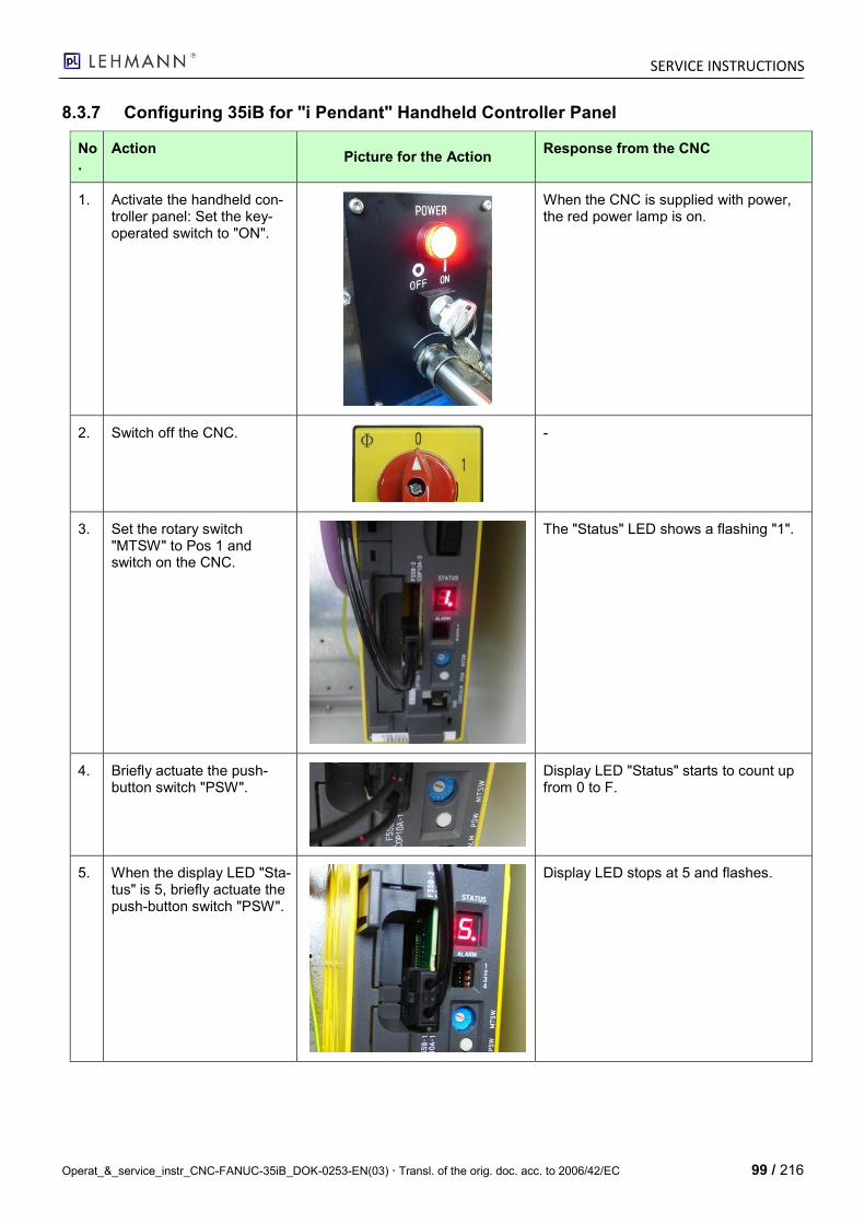
SERVICE INSTRUCTIONS
Operat_&_service_instr_CNC-FANUC-35iB_DOK-0253-EN(03) Transl. of the orig. doc. acc. to 2006/42/EC 99 / 216
8.3.7 Configuring 35iB for "i Pendant" Handheld Controller Panel
No.
Action Picture for the Action
Response from the CNC
1. Activate the handheld con-troller panel: Set the key-operated switch to "ON".
When the CNC is supplied with power, the red power lamp is on.
2. Switch off the CNC.
-
3. Set the rotary switch "MTSW" to Pos 1 and switch on the CNC.
The "Status" LED shows a flashing "1".
4. Briefly actuate the push-button switch "PSW".
Display LED "Status" starts to count up from 0 to F.
5. When the display LED "Sta-tus" is 5, briefly actuate the push-button switch "PSW".
Display LED stops at 5 and flashes.
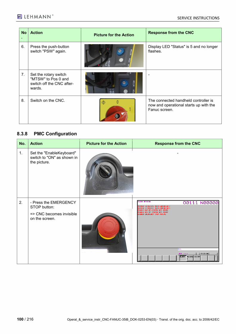
SERVICE INSTRUCTIONS
100 / 216 Operat_&_service_instr_CNC-FANUC-35iB_DOK-0253-EN(03) Transl. of the orig. doc. acc. to 2006/42/EC
No.
Action Picture for the Action
Response from the CNC
6. Press the push-button switch "PSW" again.
Display LED "Status" is 5 and no longer flashes.
7. Set the rotary switch "MTSW" to Pos 0 and switch off the CNC after-wards.
-
8. Switch on the CNC.
The connected handheld controller is now and operational starts up with the Fanuc screen.
8.3.8 PMC Configuration
No. Action Picture for the Action Response from the CNC
1. Set the "EnableKeyboard" switch to "ON" as shown in the picture.
-
2. - Press the EMERGENCY STOP button:
=> CNC becomes invisible on the screen.
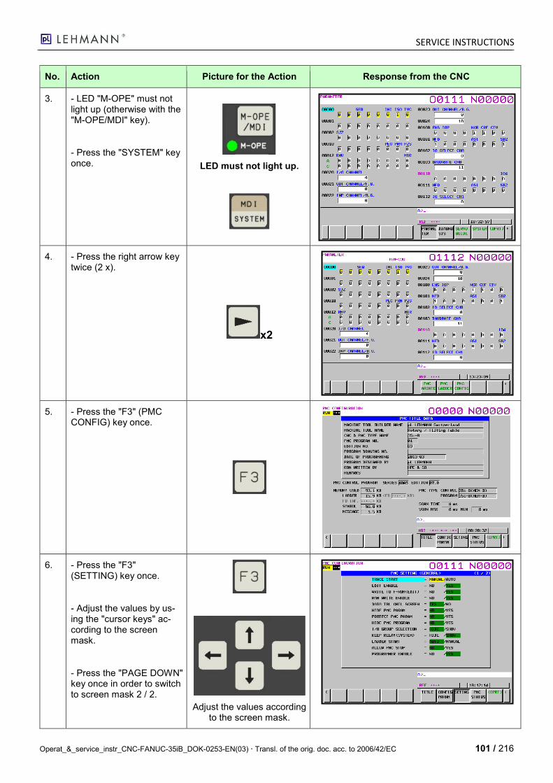
SERVICE INSTRUCTIONS
Operat_&_service_instr_CNC-FANUC-35iB_DOK-0253-EN(03) Transl. of the orig. doc. acc. to 2006/42/EC 101 / 216
No. Action Picture for the Action Response from the CNC
3. - LED "M-OPE" must not light up (otherwise with the "M-OPE/MDI" key).
- Press the "SYSTEM" key once.
LED must not light up.
4. - Press the right arrow key twice (2 x).
x2
5. - Press the "F3" (PMC CONFIG) key once.
6. - Press the "F3" (SETTING) key once.
- Adjust the values by us-ing the "cursor keys" ac-cording to the screen mask.
- Press the "PAGE DOWN" key once in order to switch to screen mask 2 / 2.
Adjust the values according to the screen mask.
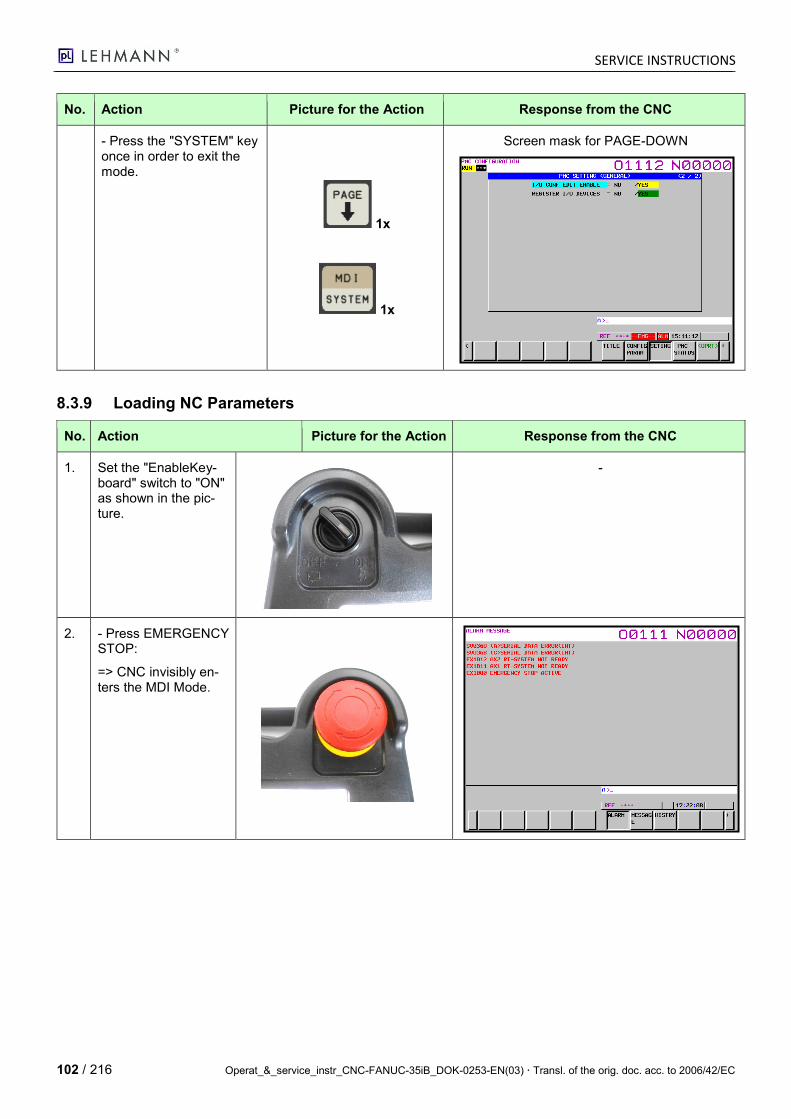
SERVICE INSTRUCTIONS
102 / 216 Operat_&_service_instr_CNC-FANUC-35iB_DOK-0253-EN(03) Transl. of the orig. doc. acc. to 2006/42/EC
No. Action Picture for the Action Response from the CNC
- Press the "SYSTEM" key once in order to exit the mode.
1x
1x
Screen mask for PAGE-DOWN
8.3.9 Loading NC Parameters
No. Action Picture for the Action Response from the CNC
1. Set the "EnableKey-board" switch to "ON" as shown in the pic-ture.
-
2. - Press EMERGENCY STOP:
=> CNC invisibly en-ters the MDI Mode.
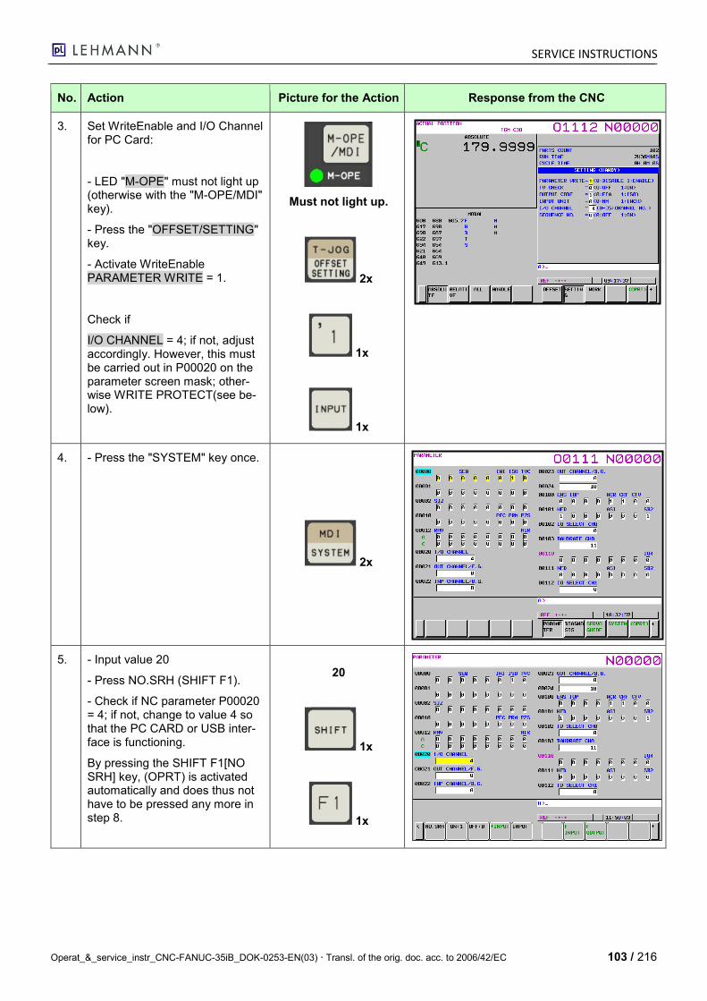
SERVICE INSTRUCTIONS
Operat_&_service_instr_CNC-FANUC-35iB_DOK-0253-EN(03) Transl. of the orig. doc. acc. to 2006/42/EC 103 / 216
No. Action Picture for the Action Response from the CNC
3. Set WriteEnable and I/O Channel for PC Card:
- LED "M-OPE" must not light up (otherwise with the "M-OPE/MDI" key).
- Press the "OFFSET/SETTING" key.
- Activate WriteEnable PARAMETER WRITE = 1.
Check if
I/O CHANNEL = 4; if not, adjust accordingly. However, this must be carried out in P00020 on the parameter screen mask; other-wise WRITE PROTECT(see be-low).
Must not light up.
2x
1x
1x
4. - Press the "SYSTEM" key once.
2x
5. - Input value 20
- Press NO.SRH (SHIFT F1).
- Check if NC parameter P00020 = 4; if not, change to value 4 so that the PC CARD or USB inter-face is functioning.
By pressing the SHIFT F1[NO SRH] key, (OPRT) is activated automatically and does thus not have to be pressed any more in step 8.
20
1x
1x
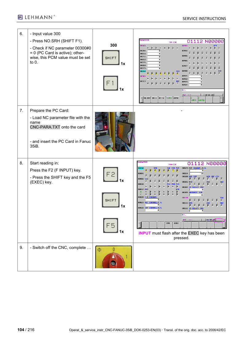
SERVICE INSTRUCTIONS
104 / 216 Operat_&_service_instr_CNC-FANUC-35iB_DOK-0253-EN(03) Transl. of the orig. doc. acc. to 2006/42/EC
6. - Input value 300
- Press NO.SRH (SHIFT F1).
- Check if NC parameter 00300#0 = 0 (PC Card is active); other-wise, this PCM value must be set to 0.
300
1x
1x
7. Prepare the PC Card:
- Load NC parameter file with the name CNC-PARA.TXT onto the card
- and insert the PC Card in Fanuc 35iB.
-
8. Start reading in:
Press the F2 (F INPUT) key.
- Press the SHIFT key and the F5 (EXEC) key. 1x
1x
1x
INPUT must flash after the EXEC key has been pressed.
9. - Switch off the CNC, complete …
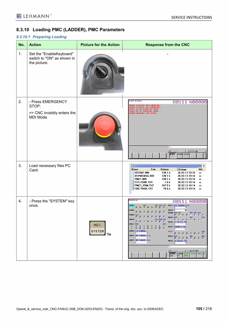
SERVICE INSTRUCTIONS
Operat_&_service_instr_CNC-FANUC-35iB_DOK-0253-EN(03) Transl. of the orig. doc. acc. to 2006/42/EC 105 / 216
8.3.10 Loading PMC (LADDER), PMC Parameters
8.3.10.1 Preparing Loading
No. Action Picture for the Action Response from the CNC
1. Set the "EnableKeyboard" switch to "ON" as shown in the picture.
-
2. - Press EMERGENCY STOP:
=> CNC invisibly enters the MDI Mode.
3. Load necessary files PC Card:
4. - Press the "SYSTEM" key once.
1x
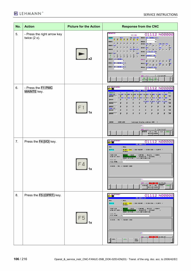
SERVICE INSTRUCTIONS
106 / 216 Operat_&_service_instr_CNC-FANUC-35iB_DOK-0253-EN(03) Transl. of the orig. doc. acc. to 2006/42/EC
No. Action Picture for the Action Response from the CNC
5. - Press the right arrow key twice (2 x).
x2
6. - Press the F1 PMC MAINTE key.
1x
7. Press the F4 [I/O] key.
1x
8. Press the F5 (OPRT) key.
1x
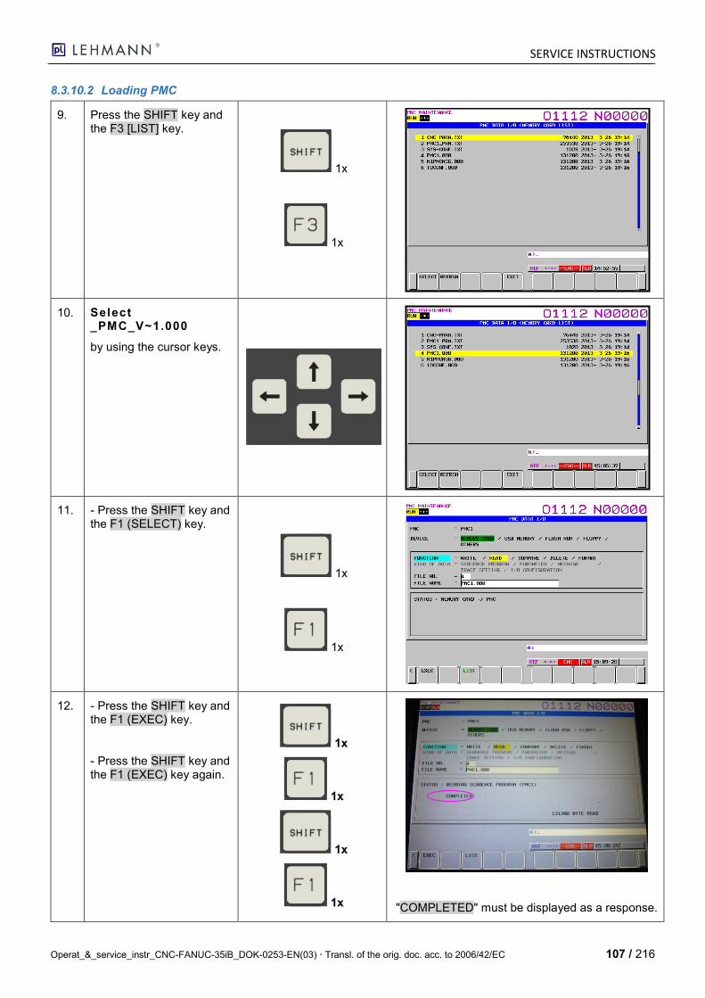
SERVICE INSTRUCTIONS
Operat_&_service_instr_CNC-FANUC-35iB_DOK-0253-EN(03) Transl. of the orig. doc. acc. to 2006/42/EC 107 / 216
8.3.10.2 Loading PMC
9. Press the SHIFT key and the F3 [LIST] key.
1x
1x
10. Select _PMC_V~1.000
by using the cursor keys.
11. - Press the SHIFT key and the F1 (SELECT) key.
1x
1x
12. - Press the SHIFT key and the F1 (EXEC) key.
- Press the SHIFT key and the F1 (EXEC) key again.
1x
1x
1x
1x
"COMPLETED" must be displayed as a response.
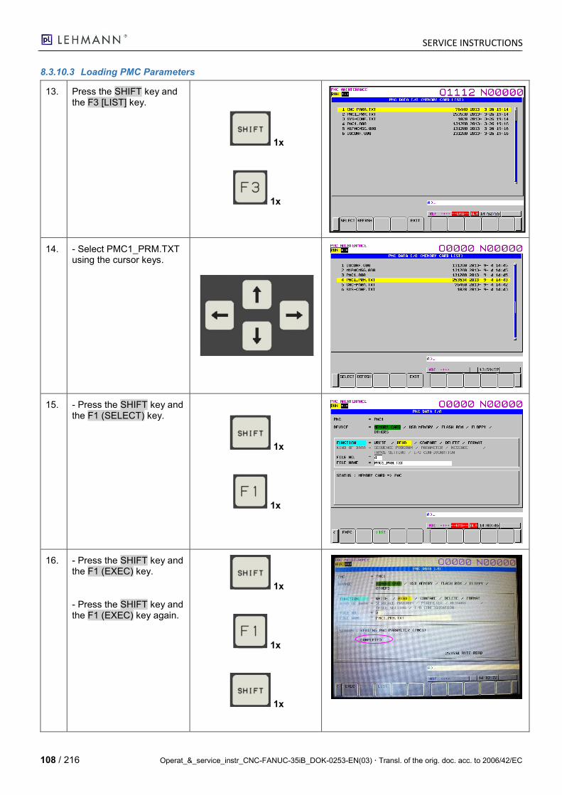
SERVICE INSTRUCTIONS
108 / 216 Operat_&_service_instr_CNC-FANUC-35iB_DOK-0253-EN(03) Transl. of the orig. doc. acc. to 2006/42/EC
8.3.10.3 Loading PMC Parameters
13. Press the SHIFT key and the F3 [LIST] key.
1x
1x
14. - Select PMC1_PRM.TXT using the cursor keys.
15. - Press the SHIFT key and the F1 (SELECT) key.
1x
1x
16. - Press the SHIFT key and the F1 (EXEC) key.
- Press the SHIFT key and the F1 (EXEC) key again.
1x
1x
1x

SERVICE INSTRUCTIONS
Operat_&_service_instr_CNC-FANUC-35iB_DOK-0253-EN(03) Transl. of the orig. doc. acc. to 2006/42/EC 109 / 216
1x
17. Successful copying is con-firmed with "COMPLETE".
8.3.10.4 Loading PMC IOCONF
18. Press the SHIFT key and the F3 [LIST] key.
1x
1x
19. - Select IOCONF.000 with the cursor keys.
20. - Press the SHIFT key and the F1 (SELECT) key.
1x
1x
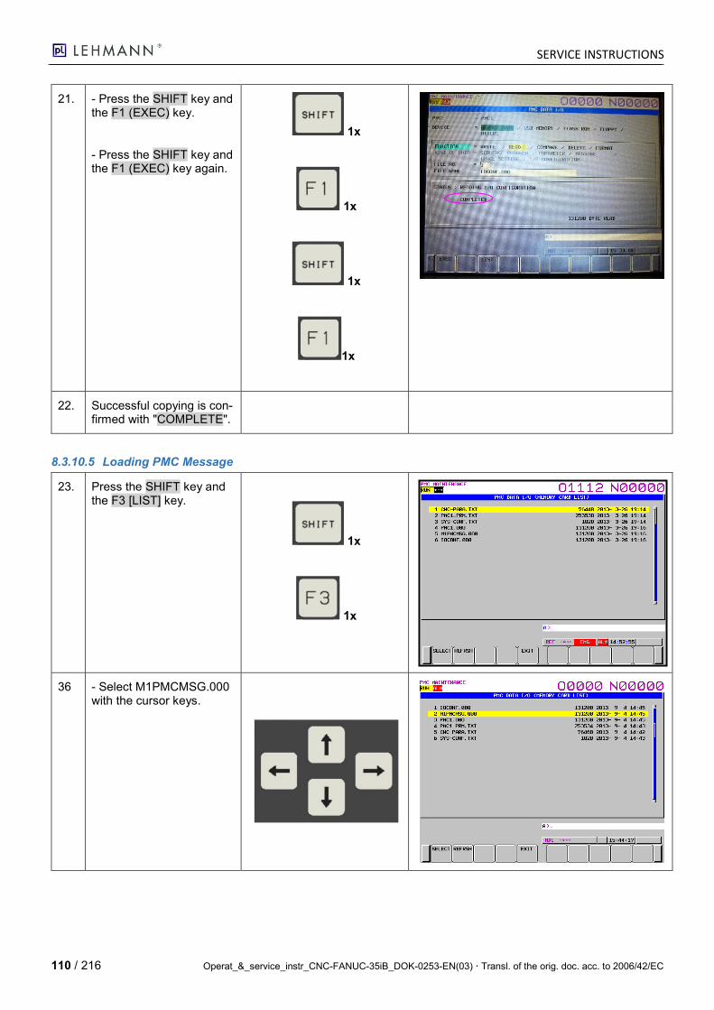
SERVICE INSTRUCTIONS
110 / 216 Operat_&_service_instr_CNC-FANUC-35iB_DOK-0253-EN(03) Transl. of the orig. doc. acc. to 2006/42/EC
21. - Press the SHIFT key and the F1 (EXEC) key.
- Press the SHIFT key and the F1 (EXEC) key again.
1x
1x
1x
1x
22. Successful copying is con-firmed with "COMPLETE".
8.3.10.5 Loading PMC Message
23. Press the SHIFT key and the F3 [LIST] key.
1x
1x
36 - Select M1PMCMSG.000 with the cursor keys.
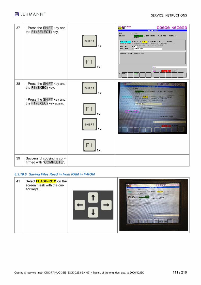
SERVICE INSTRUCTIONS
Operat_&_service_instr_CNC-FANUC-35iB_DOK-0253-EN(03) Transl. of the orig. doc. acc. to 2006/42/EC 111 / 216
37 - Press the SHIFT key and the F1 (SELECT) key.
1x
1x
38 - Press the SHIFT key and the F1 (EXEC) key.
- Press the SHIFT key and the F1 (EXEC) key again.
1x
1x
1x
1x
39 Successful copying is con-firmed with "COMPLETE".
8.3.10.6 Saving Files Read in from RAM in F-ROM
41 Select FLASH-ROM on the screen mask with the cur-sor keys.
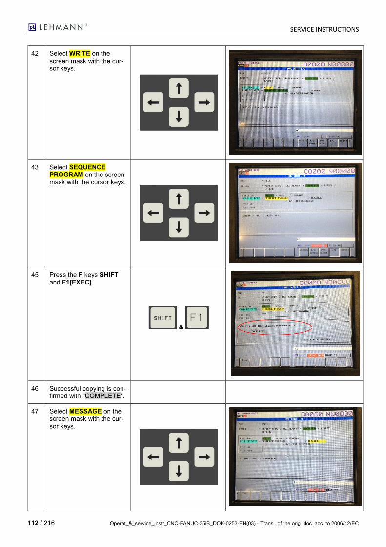
SERVICE INSTRUCTIONS
112 / 216 Operat_&_service_instr_CNC-FANUC-35iB_DOK-0253-EN(03) Transl. of the orig. doc. acc. to 2006/42/EC
42 Select WRITE on the screen mask with the cur-sor keys.
43 Select SEQUENCE PROGRAM on the screen mask with the cursor keys.
45 Press the F keys SHIFT and F1[EXEC].
&
46 Successful copying is con-firmed with "COMPLETE".
47 Select MESSAGE on the screen mask with the cur-sor keys.
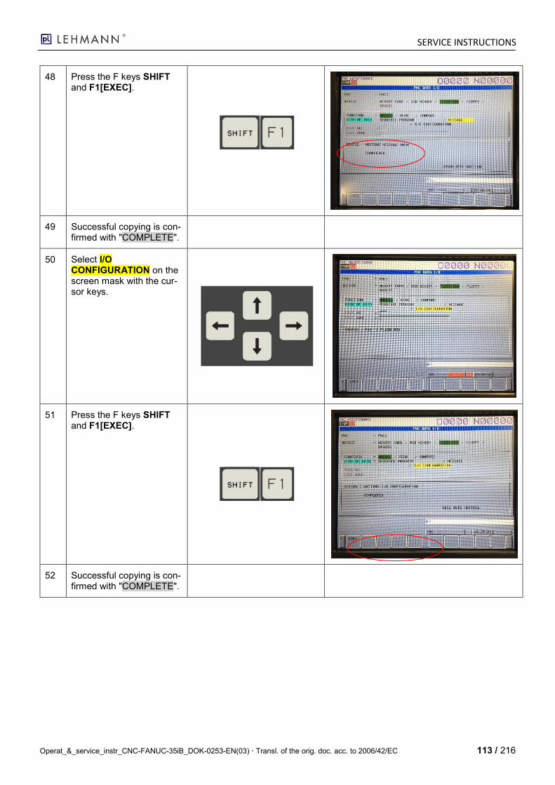
SERVICE INSTRUCTIONS
Operat_&_service_instr_CNC-FANUC-35iB_DOK-0253-EN(03) Transl. of the orig. doc. acc. to 2006/42/EC 113 / 216
48 Press the F keys SHIFT and F1[EXEC].
49 Successful copying is con-firmed with "COMPLETE".
50 Select I/O CONFIGURATION on the screen mask with the cur-sor keys.
51 Press the F keys SHIFT and F1[EXEC].
52 Successful copying is con-firmed with "COMPLETE".
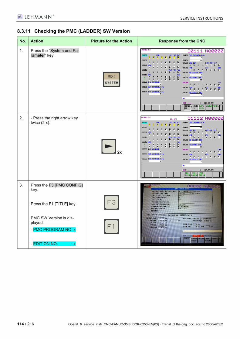
SERVICE INSTRUCTIONS
114 / 216 Operat_&_service_instr_CNC-FANUC-35iB_DOK-0253-EN(03) Transl. of the orig. doc. acc. to 2006/42/EC
8.3.11 Checking the PMC (LADDER) SW Version
No. Action Picture for the Action Response from the CNC
1. Press the "System and Pa-rameter" key.
2. - Press the right arrow key twice (2 x).
2x
3. Press the F3 [PMC CONFIG] key.
Press the F1 [TITLE] key.
PMC SW Version is dis-played:
- PMC PROGRAM NO: x
- EDITION NO. : x
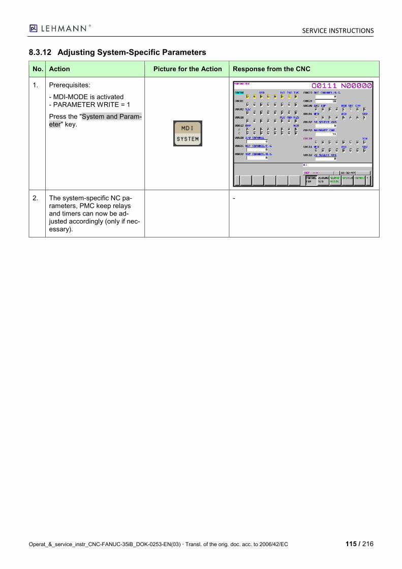
SERVICE INSTRUCTIONS
Operat_&_service_instr_CNC-FANUC-35iB_DOK-0253-EN(03) Transl. of the orig. doc. acc. to 2006/42/EC 115 / 216
8.3.12 Adjusting System-Specific Parameters
No. Action Picture for the Action Response from the CNC
1. Prerequisites:
- MDI-MODE is activated - PARAMETER WRITE = 1
Press the "System and Param-eter" key.
2. The system-specific NC pa-rameters, PMC keep relays and timers can now be ad-justed accordingly (only if nec-essary).
-
SERVICE INSTRUCTIONS
116 / 216 Operat_&_service_instr_CNC-FANUC-35iB_DOK-0253-EN(03) Transl. of the orig. doc. acc. to 2006/42/EC
8.3.13 Loading Macros (Division Computer and directPos)
No. Action Picture for the Action Response from the CNC
1.
1. Switch off the CNC.
2. Trigger the EMERGENCY STOP.
3. Switch on the CNC.
- The X17 jumper connector must be inserted.
2. Prerequisites:
- LED "M-OPE“ must light up (otherwise with the "M-OPE/MDI" key).
- Press the "MDI Mode" key.
- LED "M-OPE" must not light up (otherwise with the "M-OPE/MDI" key).
- Press the "OFFSET/SETTING" key twice (2x).
Must light up.
Must not light up.
2x
3. - Activate WriteEnable PARAMETER WRITE = 1.
SERVICE INSTRUCTIONS
Operat_&_service_instr_CNC-FANUC-35iB_DOK-0253-EN(03) Transl. of the orig. doc. acc. to 2006/42/EC 117 / 216
No. Action Picture for the Action Response from the CNC
4. Press the "System and Pa-rameter" key.
5. A>_ Enter "3202", press the F1 key (NO.SRH).
1x
1x
6. Adjust:
- P3202#0=0 (NE8)
(Thus, the macros O8000 … O8999 can be edited.)
- P3202#4 = 0 (NE9)
(Thus, the macros O9000 … O9999 can be edited.)
Set Bit 0 (NE8) and Bit 4 (NE9)
to 0.
7. Operating mode: Select the Edit Mode.
Must light up.

SERVICE INSTRUCTIONS
118 / 216 Operat_&_service_instr_CNC-FANUC-35iB_DOK-0253-EN(03) Transl. of the orig. doc. acc. to 2006/42/EC
No. Action Picture for the Action Response from the CNC
8. Prerequisites:
- Operating mode: Edit Mode
Press the Program key.
Must not light up.
9. - Press the F2 [FOLDER] key.
10. Prepare the PC Card:
- Load division computer and directPos macros from the pL network onto the PC Card.
- O8881 (directPos1)
- O8882 (directPos2)
- O8883 (directPos3)
- O8884 (directPos4)
- O8885 (directPos5)
- O9012 (division computer)
CAUTION: O8881…O8885 differ for the 1-axis and 2-axis model.
- Insert the PC Card in 35iB.
11. Setting FOREGROUND FOLDER
SERVICE INSTRUCTIONS
Operat_&_service_instr_CNC-FANUC-35iB_DOK-0253-EN(03) Transl. of the orig. doc. acc. to 2006/42/EC 119 / 216
No. Action Picture for the Action Response from the CNC
Setting is required in order to ensure that the data is saved in the "//CNC_MEM/USER/LIBRARY" directory:
12. Press the F key F5 [OPRT].
13. Press the F key F5 [TREELIST].
14. Use the cursor keys to navi-gate the yellow bar to LIBRARY.
SERVICE INSTRUCTIONS
120 / 216 Operat_&_service_instr_CNC-FANUC-35iB_DOK-0253-EN(03) Transl. of the orig. doc. acc. to 2006/42/EC
No. Action Picture for the Action Response from the CNC
15. Switch the function keys and press the right arrow key.
16. Press the F1 [FORE CHANGE] key.
The files read in by the PC Card are then saved in the //CNC_MEM/USER/LIBRARY/ folder (FOREGROUND FOLDER).
17. Switch the function keys and press the right arrow key.
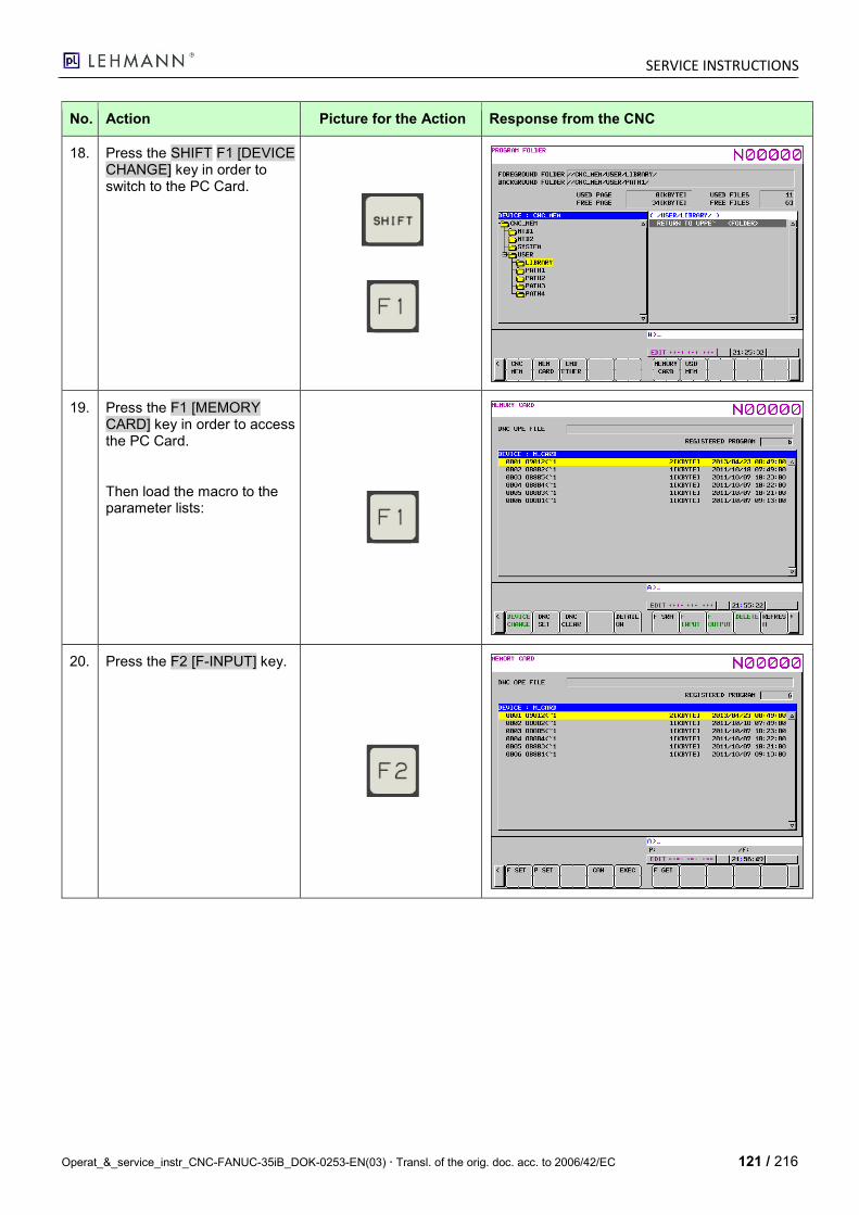
SERVICE INSTRUCTIONS
Operat_&_service_instr_CNC-FANUC-35iB_DOK-0253-EN(03) Transl. of the orig. doc. acc. to 2006/42/EC 121 / 216
No. Action Picture for the Action Response from the CNC
18. Press the SHIFT F1 [DEVICE CHANGE] key in order to switch to the PC Card.
19. Press the F1 [MEMORY CARD] key in order to access the PC Card.
Then load the macro to the parameter lists:
20. Press the F2 [F-INPUT] key.

SERVICE INSTRUCTIONS
122 / 216 Operat_&_service_instr_CNC-FANUC-35iB_DOK-0253-EN(03) Transl. of the orig. doc. acc. to 2006/42/EC
No. Action Picture for the Action Response from the CNC
21. Press the F1 [F GET] key.
22. Press the SHIFT F1 [F SET] key to select the macro.
23. Press the SHIFT F5 [EXEC] key to perform the copy com-mand.
INPUT message at the bot-tom right flashes briefly; if OK, the number of the macro read in is shown at the top right.
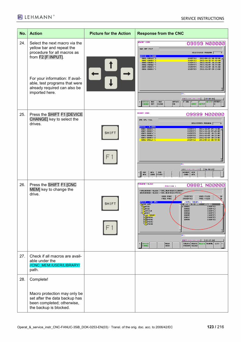
SERVICE INSTRUCTIONS
Operat_&_service_instr_CNC-FANUC-35iB_DOK-0253-EN(03) Transl. of the orig. doc. acc. to 2006/42/EC 123 / 216
No. Action Picture for the Action Response from the CNC
24. Select the next macro via the yellow bar and repeat the procedure for all macros as from F2 [F INPUT].
For your information: If avail-able, test programs that were already required can also be imported here.
25. Press the SHIFT F1 [DEVICE CHANGE] key to select the drives.
26. Press the SHIFT F1 [CNC MEM] key to change the drive.
27. Check if all macros are avail-able under the //CNC_MEM:/USER/LIBRARY/
path.
28. Complete!
Macro protection may only be set after the data backup has been completed; otherwise, the backup is blocked.
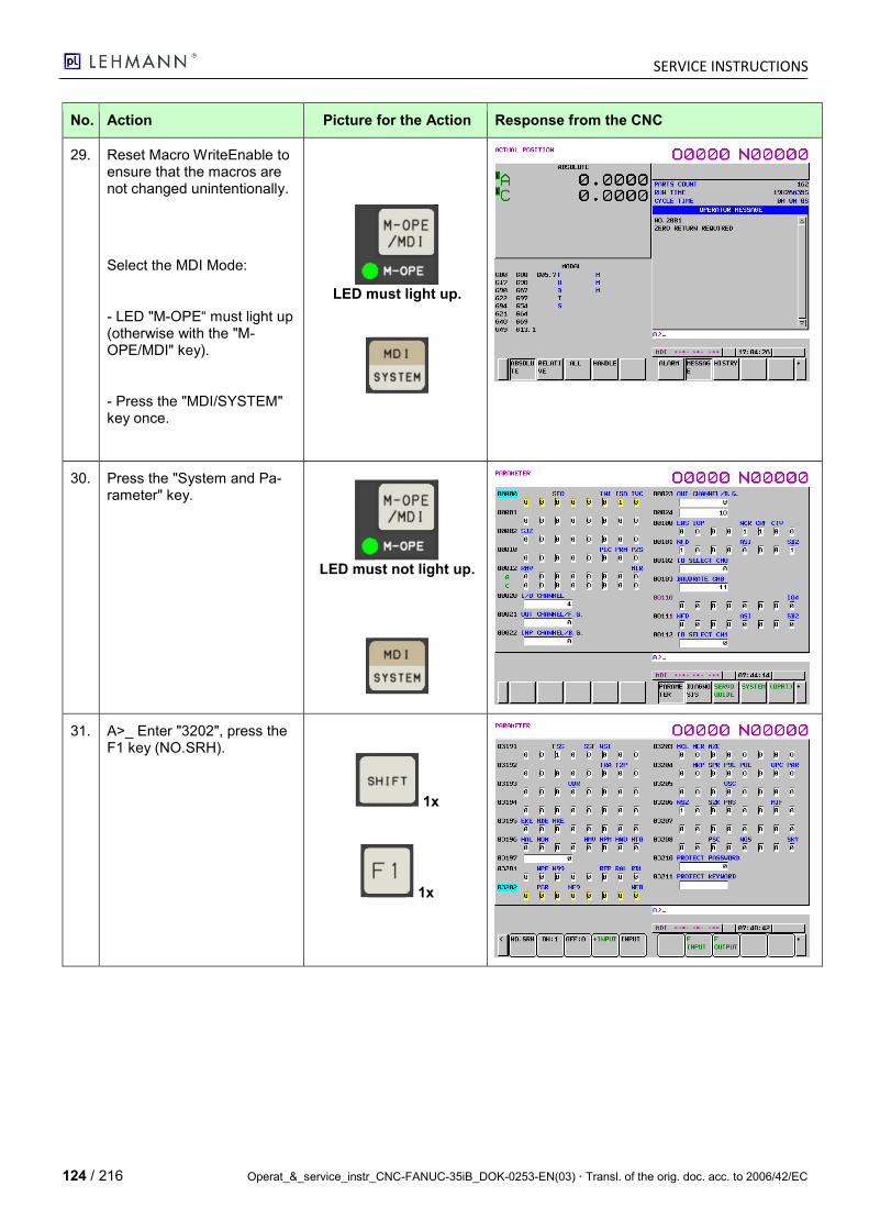
SERVICE INSTRUCTIONS
124 / 216 Operat_&_service_instr_CNC-FANUC-35iB_DOK-0253-EN(03) Transl. of the orig. doc. acc. to 2006/42/EC
No. Action Picture for the Action Response from the CNC
29. Reset Macro WriteEnable to ensure that the macros are not changed unintentionally.
Select the MDI Mode:
- LED "M-OPE“ must light up (otherwise with the "M-OPE/MDI" key).
- Press the "MDI/SYSTEM" key once.
LED must light up.
30. Press the "System and Pa-rameter" key.
LED must not light up.
31. A>_ Enter "3202", press the F1 key (NO.SRH).
1x
1x
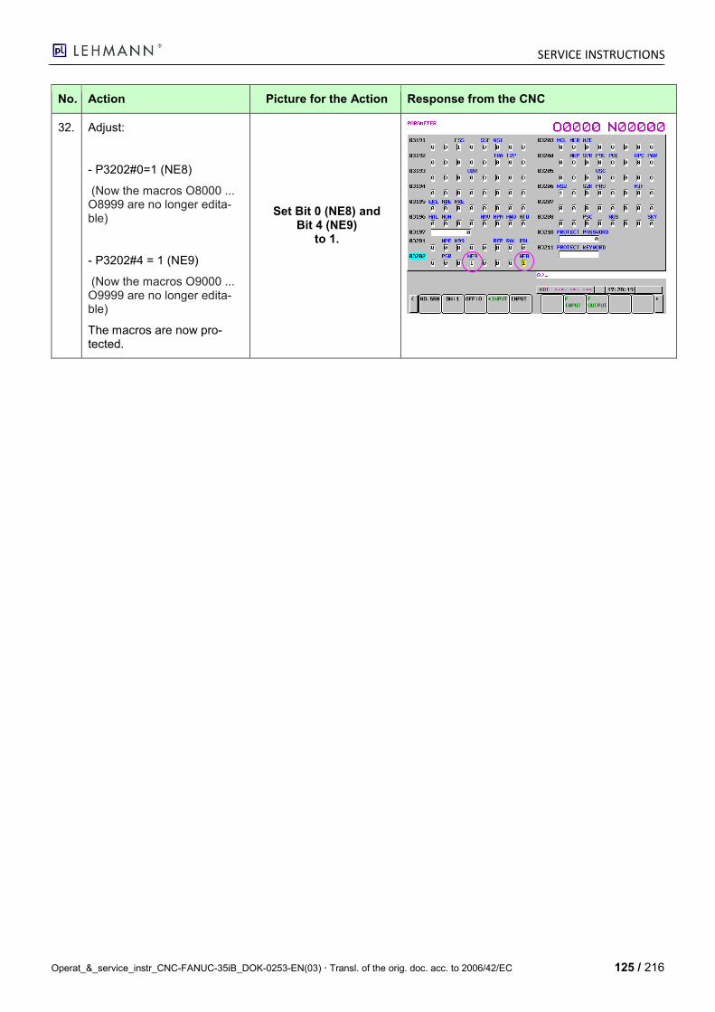
SERVICE INSTRUCTIONS
Operat_&_service_instr_CNC-FANUC-35iB_DOK-0253-EN(03) Transl. of the orig. doc. acc. to 2006/42/EC 125 / 216
No. Action Picture for the Action Response from the CNC
32. Adjust:
- P3202#0=1 (NE8)
(Now the macros O8000 ... O8999 are no longer edita-ble)
- P3202#4 = 1 (NE9)
(Now the macros O9000 ... O9999 are no longer edita-ble)
The macros are now pro-tected.
Set Bit 0 (NE8) and Bit 4 (NE9)
to 1.
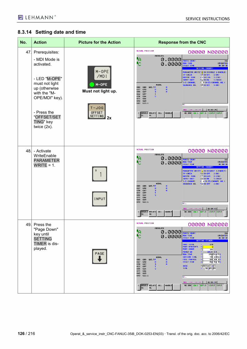
SERVICE INSTRUCTIONS
126 / 216 Operat_&_service_instr_CNC-FANUC-35iB_DOK-0253-EN(03) Transl. of the orig. doc. acc. to 2006/42/EC
8.3.14 Setting date and time
No. Action Picture for the Action Response from the CNC
47. 1 Prerequisites:
- MDI Mode is activated.
- LED "M-OPE" must not light up (otherwise with the "M-OPE/MDI" key).
- Press the "OFFSET/SETTING" key twice (2x).
Must not light up.
2x
48. - Activate WriteEnable PARAMETER WRITE = 1.
49. 2 Press the "Page Down" key until SETTING TIMER is dis-played.
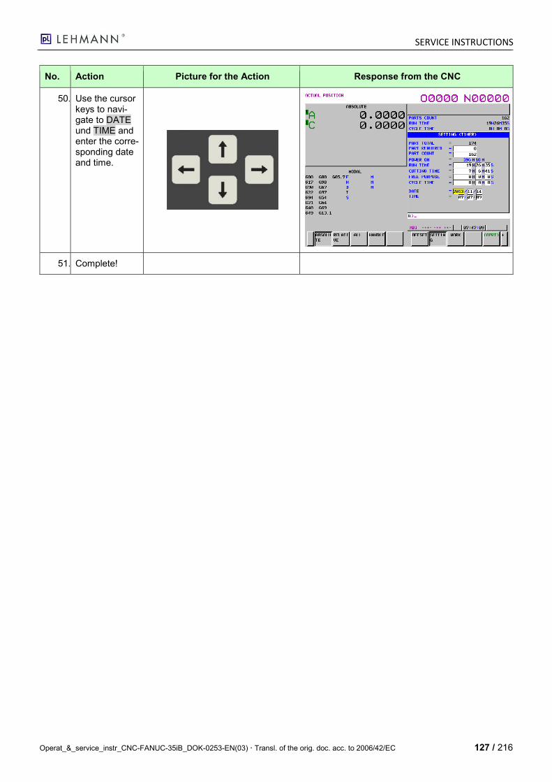
SERVICE INSTRUCTIONS
Operat_&_service_instr_CNC-FANUC-35iB_DOK-0253-EN(03) Transl. of the orig. doc. acc. to 2006/42/EC 127 / 216
No. Action Picture for the Action Response from the CNC
50. 3 Use the cursor keys to navi-gate to DATE und TIME and enter the corre-sponding date and time.
51. 2 Complete!

SERVICE INSTRUCTIONS
128 / 216 Operat_&_service_instr_CNC-FANUC-35iB_DOK-0253-EN(03) Transl. of the orig. doc. acc. to 2006/42/EC
8.4 Complete Data Backup prior to Delivery
No. Action Picture for the Ac-tion
Response from the CNC
1. Prepare:
Select the MDI Mode:
- Acknowledge all ALARM mes-sages.
- PARAMETER WRITE = 1
- P20 (I/O Channel) = 4
- P300#0 (PCM) = 0
- P138#0 (MDP) = 1
- P313#0 (BOP) = 1
- P3202#0 (NE8) = 0
- P3202#4 (NE9) = 0
Select the EDIT Mode:
- Insert empty PC Card at CNC.
- Caution: ALL DATA backup only works with the PC Card.
2. Parameter Mode:
Press the "System and Parame-ter" key.
3. Switch the function keys:
Press the arrow the right key until F3 = ALL IO is shown.
3x
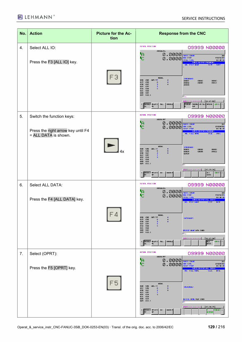
SERVICE INSTRUCTIONS
Operat_&_service_instr_CNC-FANUC-35iB_DOK-0253-EN(03) Transl. of the orig. doc. acc. to 2006/42/EC 129 / 216
No. Action Picture for the Ac-tion
Response from the CNC
4. Select ALL IO:
Press the F3 [ALL IO] key.
5. Switch the function keys:
Press the right arrow key until F4 = ALL DATA is shown.
4x
6. Select ALL DATA:
Press the F4 [ALL DATA] key.
7. Select (OPRT):
Press the F5 [OPRT] key.
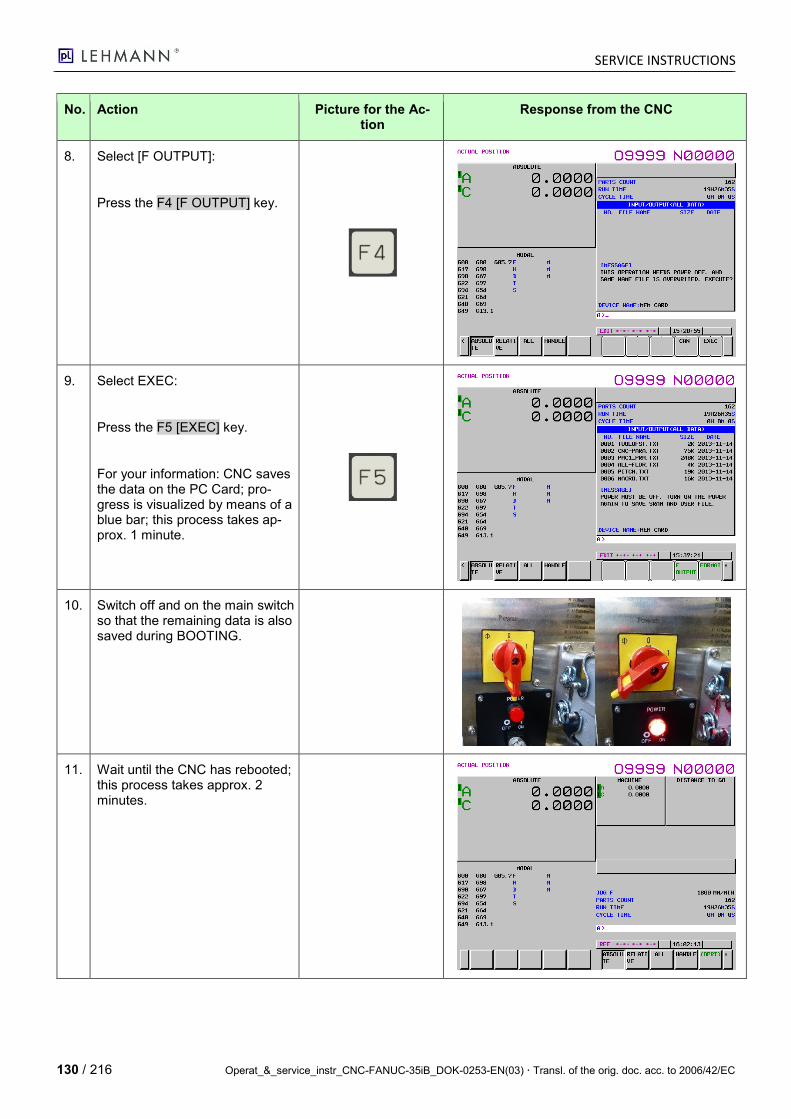
SERVICE INSTRUCTIONS
130 / 216 Operat_&_service_instr_CNC-FANUC-35iB_DOK-0253-EN(03) Transl. of the orig. doc. acc. to 2006/42/EC
No. Action Picture for the Ac-tion
Response from the CNC
8. Select [F OUTPUT]:
Press the F4 [F OUTPUT] key.
9. Select EXEC:
Press the F5 [EXEC] key.
For your information: CNC saves the data on the PC Card; pro-gress is visualized by means of a blue bar; this process takes ap-prox. 1 minute.
10. Switch off and on the main switch so that the remaining data is also saved during BOOTING.
11. Wait until the CNC has rebooted; this process takes approx. 2 minutes.
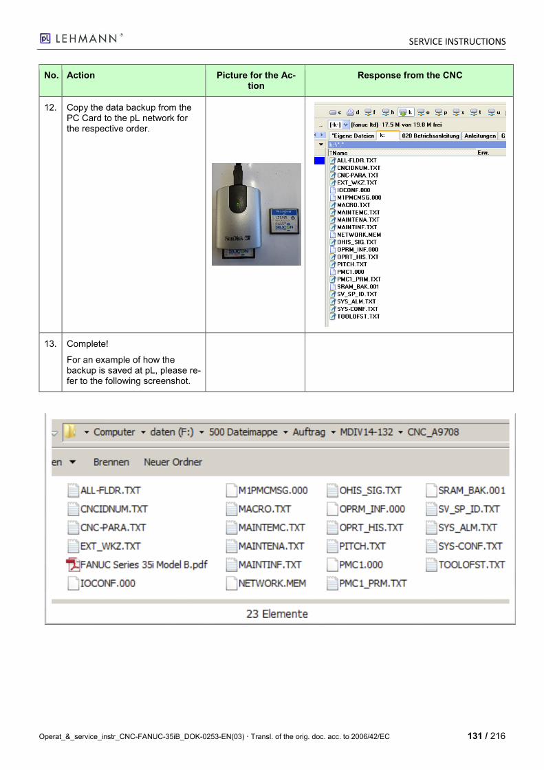
SERVICE INSTRUCTIONS
Operat_&_service_instr_CNC-FANUC-35iB_DOK-0253-EN(03) Transl. of the orig. doc. acc. to 2006/42/EC 131 / 216
No. Action Picture for the Ac-tion
Response from the CNC
12. Copy the data backup from the PC Card to the pL network for the respective order.
13. Complete!
For an example of how the backup is saved at pL, please re-fer to the following screenshot.

SERVICE INSTRUCTIONS
132 / 216 Operat_&_service_instr_CNC-FANUC-35iB_DOK-0253-EN(03) Transl. of the orig. doc. acc. to 2006/42/EC
8.4.1 Resetting WriteEnable NC and PMC Parameters
No. Action Picture for the Action Response from the CNC
1. NC Parameters: Activating Macro Write Protect
2. Reset Macro WriteEnable to ensure that the macros are not changed unintentionally.
Select the MDI Mode:
- LED "M-OPE“ must light up (otherwise with the "M-OPE/MDI" key).
- Press the "MDI/SYSTEM" key once.
LED must light up.
3. Set Parameter WriteEnable:
- LED "M-OPE" must not light up (otherwise with the "M-OPE/MDI" key).
- Press the "OFFSET/SETTING" key.
- Activate WriteEnable PARAMETER WRITE = 1.
Must not light up.
2x
1x
1x
4. Press the "System and Pa-rameter" key.
LED must not light
up.

SERVICE INSTRUCTIONS
Operat_&_service_instr_CNC-FANUC-35iB_DOK-0253-EN(03) Transl. of the orig. doc. acc. to 2006/42/EC 133 / 216
No. Action Picture for the Action Response from the CNC
5. A>_ Enter "3202", press the F1 key (NO.SRH).
1x
1x
6. Adjust:
- P3202#0=1 (NE8)
(Thus, the macros O8000 … O8999 can be edited.)
- P3202#4 = 1 (NE9)
(Thus, the macros O9000 … O9999 can be edited.)
Now, the macros are pro-tected.
Set Bit 0 (NE8) and Bit 4 (NE9)
to 1.
7. Activating PMC Write Protect
8. - LED "M-OPE" must not light up (otherwise with the "M-OPE/MDI" key).
- Press the "SYSTEM" key once.
LED must not light
up.
3x
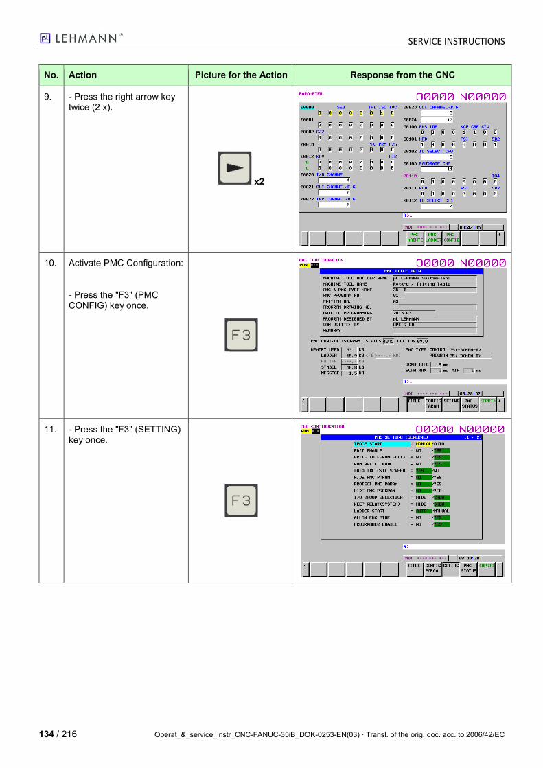
SERVICE INSTRUCTIONS
134 / 216 Operat_&_service_instr_CNC-FANUC-35iB_DOK-0253-EN(03) Transl. of the orig. doc. acc. to 2006/42/EC
No. Action Picture for the Action Response from the CNC
9. - Press the right arrow key twice (2 x).
x2
10. Activate PMC Configuration:
- Press the "F3" (PMC CONFIG) key once.
11. - Press the "F3" (SETTING) key once.

SERVICE INSTRUCTIONS
Operat_&_service_instr_CNC-FANUC-35iB_DOK-0253-EN(03) Transl. of the orig. doc. acc. to 2006/42/EC 135 / 216
No. Action Picture for the Action Response from the CNC
12. - Adjust the values with the "cursor keys" according to the screen mask.
Adjust the values ac-cording to the screen
mask.
13. Activate screen mask 2 of 2:
- Press the "PAGE DOWN" key once to switch to screen mask 2 / 2.
Adjust the values ac-cording to the screen
mask.
14. Reset Parameter WriteEna-ble:
- LED "M-OPE" must not light up (otherwise with the "M-OPE/MDI" key).
- Press the "OFFSET/SETTING" key.
- Activate WriteEnable PARAMETER WRITE = 0.
Must not light up.
2x
1x
1x
15. - Pres the "SYSTEM" key once (1x) to exit the mode.
- Parameter WriteEnable will be automatically reset during the next BOOTING.
SERVICE INSTRUCTIONS
136 / 216 Operat_&_service_instr_CNC-FANUC-35iB_DOK-0253-EN(03) Transl. of the orig. doc. acc. to 2006/42/EC
8.5 Checklist for Initial Commissioning (Check-Your-Work)
No. Procedure and Checklist Auxiliary means Action Checked, OK
1.
2. Connect the power cable to the control cabinet. (1-phase 230 VAC)
Power cable None
3. Switch on the main switch at the control cabinet.
The fan noise of the CNC becomes audible.
4. Check whether LED "F12 and "F2" light up on the print (fuses).
Control cabinet
5. Activate the handheld con-troller via PMi.
According to Operating Instructions (OI)
6. Read in the NC parameters. According to Operating Instructions (OI)
7. Read in the PMC-LADDER. According to Operating Instructions (OI)
8. Read in the PMC parame-ters.
According to Operating Instructions (OI)
9. Read in I/O configuration According to Operating Instructions (OI)
10. Read in messages According to Operating Instructions (OI)
11. Loading macros O8000 to O9999
According to Operating Instructions (OI)
12. Set time and date According to Operating Instructions (OI)
13. Connect the test cable har-ness to the motor and measuring system as well as to the blackBOX simula-tor.
Test cable harness None
14. EMERGENCY STOP exter-nal
Test box modulaNC4001 Print LED "ESP EXT" switches
15. EMERGENCY STOP inter-nal (handheld controller)
Handheld controller EMERGENCY STOP switch
Print LED "ESP INT" switches
16. OK BUTTON / Door switch. These are connected in an OR operation.
Test box modulaNC4001 OK button L/R (handheld controller)
Print LED "DOOR/EnSwitch" switches
17. - Activate the JOG Mode and move the axes. - The spindle clamping must be activated in order to en-sure that it is also checked. - Test direction of travel +/-. - Test resolution i-Total.
Test cable harness
- Clamping is unclamped. - Motor rotates. - If ES do not react, set K2.0 … K2.3 correctly.
18. Activate the ZRN Mode and carry out a reference run us-ing the axes.
Test cable harness - Clamping is unclamped. - Motor rotates until the reference cam is found.
SERVICE INSTRUCTIONS
Operat_&_service_instr_CNC-FANUC-35iB_DOK-0253-EN(03) Transl. of the orig. doc. acc. to 2006/42/EC 137 / 216
No. Procedure and Checklist Auxiliary means Action Checked, OK
19. ExternalStart (Input) Test box modulaNC4001 NC PG sequence must start.
20. /ExternalStop (Input) Test box modulaNC4001 NC PG sequence must stop.
21. InPos Signal (Output) Test box modulaNC4001 After M00 or M30, the InPos signal (LED) must be sent and displayed.
22. EndOfProgram Signal (Out-put)
Test box modulaNC4001 After M30, the EndOfProgram sig-nal (LED) must be sent and dis-played.
23. Automatic Mode (Input) Test box modulaNC4001 AUTO Mode is activated
24. SystemReady Signal (Out-put)
Test box modulaNC4001 The SystemReady signal (LED) must be sent and displayed if there is no error present.
25. M-Function 1 (Output) Ackn. M-Function 1 (Input)
NC-PG Code: M103 (Acknowledgeable M-Function)
M-Func 1 is set; it is reset with Acknowledgeable M-Function 1.
26. M-Function 2 (Output) Ackn. M-Function 2 (Input)
NC-PG Code: M108 (Acknowledgeable M-Function)
M-Func 2 is set (LED); it is reset with Acknowledgeable M-Function 2.
27. M-Function 3 (Output) Ackn. M-Function 3 (Input)
NC-PG Code: M113 (Acknowledgeable M-Function)
M-Func 3 is set (LED); it is reset with Acknowledgeable M-Function 3.
28. M-Function 4 (Output) Ackn. M-Function 4 (Input)
NC-PG Code: M118 (Acknowledgeable M-Function)
M-Func 4 is set (LED); it is reset with Acknowledgeable M-Function 4.
29. M-Function 5 (Output) Ackn. M-Function 5 (Input)
NC-PG Code: M123 (Acknowledgeable M-Function)
M-Func 5 is set (LED); it is reset with Acknowledgeable M-Function 5.
30. Test HW limit switch for tilt-ing systems.
Switch at scale disk
31. Test SW limit switch for tilt-ing systems.
Adjust via NC parame-ters.
32. Delete test programs O0001 to O7999.
According to Operating Instructions (OI): 4.7.8 Deleting Program
33. Perform a complete data backup.
According to Operating Instructions: Chapter 8.4 Complete data backup
34. WriteEnable NE8 and NE9 reset in NC-P3202
According to Operating Instructions: Chapter 8.4.1 Resetting WriteEn-able NC and PMC
35. NC WriteEnables reset (Pa-rameter Write)
Revient automatiquement au Power-off.
36. PMC WriteEnables reset According to Operating Instructions: 8.4.1
37. Check complete, OK.

SERVICE INSTRUCTIONS
138 / 216 Operat_&_service_instr_CNC-FANUC-35iB_DOK-0253-EN(03) Transl. of the orig. doc. acc. to 2006/42/EC
9 NC Parameter Setting
9.1 Preparing Data to be Changed
- "PARAMETER WRITE =" must be set from 0 to 1.
- The MDI mode or the EMERGENCY STOP must be actuated. - In addition, the following NC parameters are responsible for password protection, according to FANUC
manual B-64483EN: Parameters P3201, P3210, P3211, P3226 and P3222 - For the machine tool type FANUC-Robodrill the parameter K0000 # 6 must also be set to 1 (applies to
"PMC-Keeprelais").
9.2 NC Parameters
Based on the FANUC Manuals: B-64530EN-01 and 65270EN-07
Address P Function Unit
Effective-ness -1- or 2-Axis -General
Meaning of the Values
Value for CNC 35iB 1-axis EA-507 90:1. Motor FANUC b1.0/6000is
Value for CNC 35iB 2-axis TF-(507)510 90:1. Motor FANCU a2/5000is
0000 Parameter of Setting bits
#0=TVC: TV check 0=not perfor. / 1=perfor. #1=ISO: Code Data Outp. 0=EIA / 1=ISO #2=INI: Unit of Input 0=in mm / 1= in inches #5=SEQ: Sequence No 0=not perfor. / 1=perfor.
00100010 00100010
0012#7 RMV-Table Axis bits Axis Attach=0 / De-tach=1
0xxxxxxx 0xxxxxxx
0020 I/O Channel
0= CH0 RS232 Port1 1= CH1 RS232 Port1 2= CH2 RS232 Port2 4= CH4 PC-Card / USBi- Pendant (pL) 17= Standard-USB (not pL))
4 4
0101#0 SB2 (CH0) 1 1
0101#3 ASI (CH0) 0 0
0101#7 NFD (CH0) 1 1
0102 DEVICE No (CH0) 0 = für PC 0 0
0103 BAUDRATE (CH0) 11 = 9600Baud 11 11
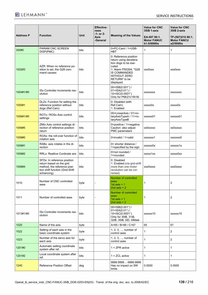
SERVICE INSTRUCTIONS
Operat_&_service_instr_CNC-FANUC-35iB_DOK-0253-EN(03) Transl. of the orig. doc. acc. to 2006/42/EC 139 / 216
Address P Function Unit
Effective-ness -1- or 2-Axis -General
Meaning of the Values
Value for CNC 35iB 1-axis EA-507 90:1. Motor FANUC b1.0/6000is
Value for CNC 35iB 2-axis TF-(507)510 90:1. Motor FANCU a2/5000is
300#0 PARAM CNC SCREEN DISP(PMC)
bits 0=PC-Card / 1=USB-HBT
1 1
1002#3 AZR: When no reference po-sition is set, the G28 com-mand causes:
bits
0: Reference position return using decelera-tion dogs to be exe-cuted. 1: Alarm PS0304, "G28 IS COMMANDED WITHOUT ZERO RETURN" to be displayed.
xxx0xxx xxx0xxx
1004#1/#0 ISx Controller increments res-olution
bits
00=ISB(0.001°) / 01=ISA(0.01°) / 10=ISC(0.0001°) Only for PMi/21i/18i16i
xxxxxxxx xxxxxxxx
1005#1 DLZx: Function for setting the reference position without dogs (Ref.Cam)
bits 0: Disabled (with Ref.Cam) 1: Enabled
xxxxx0x xxxxx0x
1006#1/#0 ROTx / ROSx Axis control settings
bits 00=LinearAxis / 01=ro-taryAxisTypeA / 11=ro-taryAxisTypeB
xxxxxx01 xxxxxx01
1006#5 ZMIx Axis control settings di-rection of reference position return
bits 0=positive / 1=negative Caution: also adjust PMC parameters
xx0xxxxx xx0xxxxx
1008#0 ROAx: the roll-over function of rotation axis
bits 0=invalid / 1=valid xxxxxxx1 xxxxxxx0
1008#1 RABx: axis rotates in the di-rection
bits 0= shorter distance / 1=specified by the sign
xxxxxx0x xxxxxx1x
1008#2 RRLx: Realtive Cordinate are: bits 0=not rounded / 1=rounded
xxxxx1xx xxxxx0xx
1008#4
SFDx: In reference position return based on the grid method, the reference posi-tion shift function (Grid-Shift enhancing).
bits
0: Disabled 1: Enabled (via grid-shift more than one motor revolution can be cor-rected)
xxx0xxxx xxx0xxxx
1010 Number of CNC controlled axes
byte -
Number of controlled axes: 1st axis = 1 2nd axis = 2
1 2
1011 Number of controlled axes byte -
Number of controlled axes: 1st axis = 1 2nd axis = 2
1 2
1013#1/#0 ISx Controller increments res-olution
bits
00=ISB(0.001°) / 01=ISA(0.01°) / 10=ISC(0.0001°) Only for 30iB, 31iB, 32iB, 35iB, 0iD, 0iMate
xxxxxx10 xxxxxx10
1020 Name of the axis byte A=65 / B=66 / C=67 65 67
1022 Setting of each axis in the basic coordinate system
byte 1, 2, 3, ..., number of control axes
1 2
1023 Number of the servo axis for each axis
byte 1, 2, 3, ..., number of control axes
1 2
1201#0 Automatic setting coordinate system after ref.
bits 1 = ZPR active 1 1
1201#2 Local coordinate system after ref.
bits 1 = ZCL active 1 1
1240 Reference Position Offset deg 9999.9999…-9999.9999 Has no impact on SW limits
0.0000 0.0000
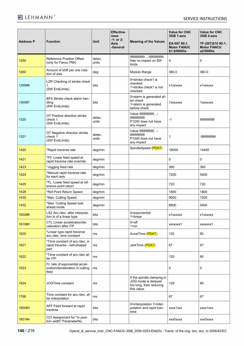
SERVICE INSTRUCTIONS
140 / 216 Operat_&_service_instr_CNC-FANUC-35iB_DOK-0253-EN(03) Transl. of the orig. doc. acc. to 2006/42/EC
Address P Function Unit
Effective-ness -1- or 2-Axis -General
Meaning of the Values
Value for CNC 35iB 1-axis EA-507 90:1. Motor FANUC b1.0/6000is
Value for CNC 35iB 2-axis TF-(507)510 90:1. Motor FANCU a2/5000is
1250 Reference Position Offset (only for Fanuc PMi)
detec. units
99999999…-99999999 Has no impact on SW limits
0 0
1260 Amount of shift per one rota-tion of axis
deg Modulo Range 360.0 360.0
1300#6 LZR Checking of stroke check 1 (SW EndLimits)
bits
0=stroke check1 is checked 1=stroke check1 is not checked
x1xxxxxx x1xxxxxx
1300#7 BFA Stroke check alarm han-dling (SW EndLimits)
bits
0=alarm is generated af-ter check 1=alarm is generated before check
1xxxxxxx 1xxxxxxx
1320 OT Positive direction stroke check 1 (SW EndLimits)
detec. units
Value 99999999…-99999999 P1240 does not have any impact
-1 99999998
1321 OT Negative direction stroke check 1 (SW EndLimits)
detec. units
Value 99999999…-99999999 P1240 does not have any impact
1 -99999999
1420 *Rapid traverse rate deg/min SpindleSpeed (PDAT)
18000 14400
1421 *F0: Lower feed speed at rapid traverse rate override
deg/min 0 0
1423 *Jogging feed rate deg/min 360 360
1424 *Manual rapid traverse rate for each axis
deg/min 7200 5400
1425 *FL: Lower feed speed at ref-erence point return
deg/min 720 720
1428 *Ref.Point Return Speed deg/min 1800 1800
1430 *Max. Cutting Speed deg/min 9000 7200
1432 *Max. Cutting Speed look ahead mode
deg/min 6800 5400
1602#6 LS2 Acc./dec. after interpola-tion is of a linear type
bits 0=exponential 1=linear
x1xxxxxx x1xxxxxx
1610#0 CTL Linear acceleration/de-celeration after ITP
bits 0=off 1=on
xxxxxxx1 xxxxxxx1
1620 *Linear type rapid traverse acc./dec. time constant
ms AccelTime (PDAT) 120 80
1621 *Time constant of acc./dec. in rapid traverse - bell-shaped part
ms JerkTime (PDAT) 67 67
1622 *Time constant of acc./dec af-ter ITP
ms 120 80
1623 FL rate of exponential accel-eration/deceleration in cutting feed
ms 0 0
1624 JOGTime constant ms
If the spindle clamping in JOG mode is delayed too long, then reducing this value.
120 80
1768 Time constant for acc./dec. af-ter interpolation
ms 67 67
1800#3 AFF Feed forward at rapid traverse
bits 0=interpolation 1=inter-polation and rapid trav-erse
xxxx1xxx xxxx1xxx
1801#4 CCI Assignment for "In posi-tion width" ParameterNo.
bits xxx0xxxx xxx0xxxx
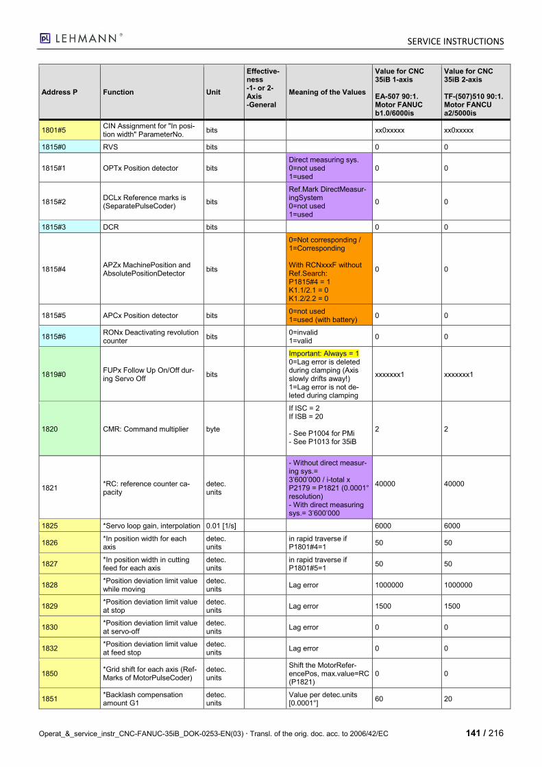
SERVICE INSTRUCTIONS
Operat_&_service_instr_CNC-FANUC-35iB_DOK-0253-EN(03) Transl. of the orig. doc. acc. to 2006/42/EC 141 / 216
Address P Function Unit
Effective-ness -1- or 2-Axis -General
Meaning of the Values
Value for CNC 35iB 1-axis EA-507 90:1. Motor FANUC b1.0/6000is
Value for CNC 35iB 2-axis TF-(507)510 90:1. Motor FANCU a2/5000is
1801#5 CIN Assignment for "In posi-tion width" ParameterNo.
bits xx0xxxxx xx0xxxxx
1815#0 RVS bits 0 0
1815#1 OPTx Position detector bits Direct measuring sys. 0=not used 1=used
0 0
1815#2 DCLx Reference marks is (SeparatePulseCoder)
bits
Ref.Mark DirectMeasur-ingSystem 0=not used 1=used
0 0
1815#3 DCR bits 0 0
1815#4 APZx MachinePosition and AbsolutePositionDetector
bits
0=Not corresponding / 1=Corresponding With RCNxxxF without Ref.Search: P1815#4 = 1 K1.1/2.1 = 0 K1.2/2.2 = 0
0 0
1815#5 APCx Position detector bits 0=not used 1=used (with battery)
0 0
1815#6 RONx Deactivating revolution counter
bits 0=invalid 1=valid
0 0
1819#0 FUPx Follow Up On/Off dur-ing Servo Off
bits
Important: Always = 1 0=Lag error is deleted during clamping (Axis slowly drifts away!) 1=Lag error is not de-leted during clamping
xxxxxxx1 xxxxxxx1
1820 CMR: Command multiplier byte
If ISC = 2 If ISB = 20 - See P1004 for PMi - See P1013 for 35iB
2 2
1821 *RC: reference counter ca-pacity
detec. units
- Without direct measur-ing sys.= 3’600’000 / i-total x P2179 = P1821 (0.0001° resolution) - With direct measuring sys.= 3’600’000
40000
40000
1825 *Servo loop gain, interpolation 0.01 [1/s] 6000 6000
1826 *In position width for each axis
detec. units
in rapid traverse if P1801#4=1
50 50
1827 *In position width in cutting feed for each axis
detec. units
in rapid traverse if P1801#5=1
50 50
1828 *Position deviation limit value while moving
detec. units
Lag error 1000000 1000000
1829 *Position deviation limit value at stop
detec. units
Lag error 1500 1500
1830 *Position deviation limit value at servo-off
detec. units
Lag error 0 0
1832 *Position deviation limit value at feed stop
detec. units
Lag error 0 0
1850 *Grid shift for each axis (Ref-Marks of MotorPulseCoder)
detec. units
Shift the MotorRefer-encePos, max.value=RC (P1821)
0 0
1851 *Backlash compensation amount G1
detec. units
Value per detec.units [0.0001°]
60 20
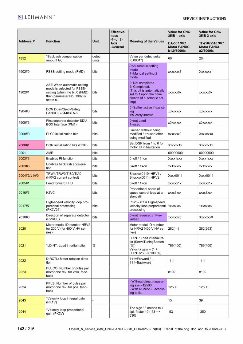
SERVICE INSTRUCTIONS
142 / 216 Operat_&_service_instr_CNC-FANUC-35iB_DOK-0253-EN(03) Transl. of the orig. doc. acc. to 2006/42/EC
Address P Function Unit
Effective-ness -1- or 2-Axis -General
Meaning of the Values
Value for CNC 35iB 1-axis EA-507 90:1. Motor FANUC b1.0/6000is
Value for CNC 35iB 2-axis TF-(507)510 90:1. Motor FANCU a2/5000is
1852 *Backlash compensation amount G0
detec. units
Value per detec.units [0.0001°]
60 20
1902#0 FSSB setting mode (FMD) bits
0=Automatic setting mode 1=Manual setting 2 mode
xxxxxxx1 Xxxxxxx1
1902#1
ASE When automatic setting mode is selected for FSSB-setting (when the bit 0 (FMD) then parameter No. 1902 is set to 0.
bits
0: Not completed. 1: Completed. (This bit is automatically set to 1 upon the com-pletion of automatic set-ting)
xxxxxx0x xxxxxx0x
1904#6 DCN DuasCheckSafety FANUC B-64483EN-2
bits 0=Saftey active if exsist-ing 1=Safety inactiv
x0xxxxxx x0xxxxxx
1905#6 First separate detector SDU BOX Interface (PM1)
bits 0=not used 1=used
x0xxxxxx x0xxxxxx
2000#0 PLC0 initialization bits bits 0=used without being modified / 1=used after being modified
xxxxxxx0 Xxxxxxx0
2000#1 DGR initialization bits (DGP) bits Set DGP from 1 to 0 for motor ID initialization
Xxxxxx1x Xxxxxx1x
2001 AMR bits 00000000 00000000
2003#3 Enables PI function bits 0=off / 1=on Xxxx1xxx Xxxx1xxx
2003#5 Enables backlash accelera-tion
bits 0=off / 1=on xx1xxxxx xx1xxxxx
2004#2/#1/#0 TRW1/TRW0/TIB0/TIA0 (HRV2 current control)
bits Bitsxxxx0110=HRV1 / Bitsxxxx0011=HRV2
Xxxx0011 Xxxx0011
2005#1 Feed forward FFD bits 0=off / 1=on xxxxxx1x xxxxxx1x
2016#3 K2VC bits Proportional share of speed control loop at a standstill
xxxx1xxx xxxx1xxx
2017#7 High-speed velocity loop pro-portional processing (PK2V25)
bits PK25-Bit7 = High-speed velocity loop proportional processing
1xxxxxxx 1xxxxxxx
2018#0 Direction of separate detector (RVRSE)
bits 0=not reversed / 1=re-versed
xxxxxxx0 Xxxxxxx0
2020 Motor model ID number HRV2 for 200 V (for 400 V HV se-ries)
- Motor model ID number for HRV2 (400 V HV se-ries)
282(---) 262(263)
2021 *LDINT: Load intertial ratio %
LDINT: Load intertial ra-tio (ServoTuningScreen [%]) Velocity gain = (1 + LDINT/256) × 100 [%]
769(400) 769(400)
2022 DIRCTL: Motor rotation direc-tion
- 111=Forward / -111=Backward
-111 -111
2023 PULCO: Number of pulse par motor one rev. for velo. feed-back
8192 8192
2024 PPLS: Number of pulse par motor one rev. for pos. feed-back
- Without direct measur-ing sys.=12500 - With RCN223F accord-ing to list
12500 12500
2043 *Velocity loop integral gain (PK1V)
- 15 39
2044 *Velocity loop proportional gain (PK2V)
- The sign "-" means mul-tipl.-factor 10 (-53 => 530)
-53 -350
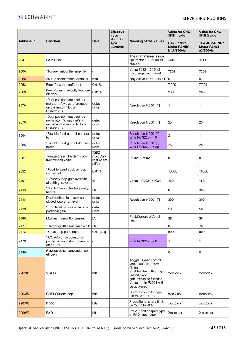
SERVICE INSTRUCTIONS
Operat_&_service_instr_CNC-FANUC-35iB_DOK-0253-EN(03) Transl. of the orig. doc. acc. to 2006/42/EC 143 / 216
Address P Function Unit
Effective-ness -1- or 2-Axis -General
Meaning of the Values
Value for CNC 35iB 1-axis EA-507 90:1. Motor FANUC b1.0/6000is
Value for CNC 35iB 2-axis TF-(507)510 90:1. Motor FANCU a2/5000is
2047 Gain POA1 The sign "-" means mul-tipl.-factor 10 (-5000 => 50000)
-5000 -5000
2060 *Torque limit of the amplifier - Value 7282=100% of max. amplifier current
7282 7282
2066 250 μs acceleration feedback mm only active if P2017#7=1 0 0
2068 Feed-forward coefficient 0.01% 7’000 7’000
2069 Feed-forward velocity loop co-efficient
0.01% 200 200
2078
*Dual position feedback nu-merator. (Always referenced on the motor. Not on RCN223F.)
detec. units
Resolution 0.0001 [°] 1 1
2079
*Dual position feedback de-nominator. (Always refer-enced on the motor. Not on RCN223F.)
detec. units
Resolution 0.0001 [°] 25 25
2084 *Flexible feed gear of numera-tor
detec. units
Resolution 0.0001[°] With RCN223F = 9
2 1
2085 *Flexible feed gear of denomi-nator
detec. units
Resolution 0.0001[°] With RCN223F = 20
25 25
2087 Torque offset, Tandem con-trol/Preload value
7282 => max Cur-rent of am-plifier
-7282 to 7282 0 0
2092 *Feed-forward position loop coefficient
0.01% 10000 10000
2107 * Velocity loop gain override at cutting traverse
% Value x P2021 at G01 150 150
2113 *Notch filter center frequency, filter 1
Hz 0 300
2118 Dual position feedback semi-closed loop error level
detec. units
Resolution 0.0001 [°] 300 300
2119 *Stop level with variable pro-portional gain
detec. units
50 50
2165 Maximum amplifier current [A] PeakCurrent of Ampli-fier.
25 25
2177 *Damping filter limit bandwidth Hz 0 70
2178 *Servo loop gain, rapid 0.01 [1/s] 6000 6000
2179 *RC: reference counter ca-pacity denominator of param-eter 1821
- With RCN232F = 0 1 1
2185 Position pulse conversion co-efficient
- 0 0
2202#1 VGCG bits
Toggle: speed control loop G00/G01, 0=off /1=on Enables the cutting/rapid velocity loop gain switching function. Value = 1 in P2021 will be activated
xxxxxx1x xxxxxx1x
2203#2 CRPI Current loop bits Current controller type 0.5 PI, 0=off / 1=on
xxxxx1xx xxxxx1xx
2207#3 PD50 bits Proportional share limit, 0=75% / 1=50%
xxxx0xxx xxxx0xxx
2209#2 FADL bits 0=FAD bell-shaped type, 1=FAD linear type
Xxxxx1xx Xxxxx1xx
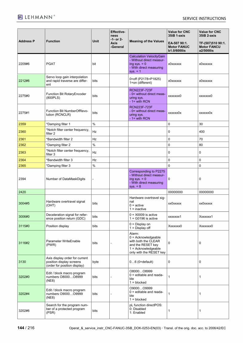
SERVICE INSTRUCTIONS
144 / 216 Operat_&_service_instr_CNC-FANUC-35iB_DOK-0253-EN(03) Transl. of the orig. doc. acc. to 2006/42/EC
Address P Function Unit
Effective-ness -1- or 2-Axis -General
Meaning of the Values
Value for CNC 35iB 1-axis EA-507 90:1. Motor FANUC b1.0/6000is
Value for CNC 35iB 2-axis TF-(507)510 90:1. Motor FANCU a2/5000is
2209#6 PGAT bit
Calculation VelocityGain - Without direct measur-ing sys. = 0 - With direct measuring sys. = 1
x0xxxxxx x0xxxxxx
2212#6 Servo loop gain interpolation and rapid traverse are differ-ent
bits 0=off (P2178=P1825) 1=on (different)
x0xxxxxx x0xxxxxx
2275#0 Function Bit RotaryEncoder (800PLS)
bits
RCN223F-723F - 0= without direct meas-uring sys. - 1= with RCN
xxxxxxx0 xxxxxxx0
2275#1 Function Bit NumberOfRevo-lution (RCNCLR)
bits
RCN223F-723F - 0= without direct meas-uring sys. - 1= with RCN
xxxxxx0x xxxxxx0x
2359 *Damping filter 1 % 0 30
2360 *Notch filter center frequency, filter 2
Hz 0 400
2361 *Bandwidth filter 2 Hz 0 70
2362 *Damping filter 2 % 0 80
2363 *Notch filter center frequency, filter 3
Hz 0 0
2364 *Bandwidth filter 3 Hz 0 0
2365 *Damping filter 3 % 0 0
2394 Number of DataMaskDigits -
Corresponding to P2275 - Without direct measur-ing sys. = 0 - With direct measuring sys. = 8
0 0
2420 00000000 00000000
3004#5 Hardware overtravel signal (OHT)
bits
Hardware overtravel sig-nal 0 = active 1 = inactive
xx0xxxxx xx0xxxxx
3006#0 Deceleration signal for refer-ence position return (GDC)
bits 0 = X0009 is active 1 = G0196 is active
xxxxxxx1 Xxxxxxx1
3115#0 Position display bits 0 = Display on 1 = Display off
Xxxxxxx0 Xxxxxxx0
3116#2 Parameter WriteEnable (PWR)
bits -
Alarm: 0 = Acknowledgeable with both the CLEAR and the RESET key 1 = Acknowledgeable only with the RESET key
0 0
3130 Axis display order for current position display screens (order for position display)
byte 0…6 (0=default) 0 0
3202#0 Edit / block macro program numbers O8000…O8999 (NE8)
bits -
O8000…O8999 0 = editable and reada-ble 1 = blocked
1 1
3202#4 Edit / block macro program numbers O9000…O9999 (NE8)
bits -
O9000…O9999 0 = editable and reada-ble 1 = blocked
1 1
3202#6
Search for the program num-ber of a protected program (PSR)
bits
pL function directPOS: 0: Disabled 1: Enabled
1 1
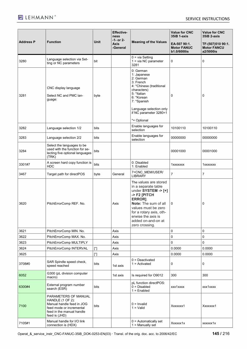
SERVICE INSTRUCTIONS
Operat_&_service_instr_CNC-FANUC-35iB_DOK-0253-EN(03) Transl. of the orig. doc. acc. to 2006/42/EC 145 / 216
Address P Function Unit
Effective-ness -1- or 2-Axis -General
Meaning of the Values
Value for CNC 35iB 1-axis EA-507 90:1. Motor FANUC b1.0/6000is
Value for CNC 35iB 2-axis TF-(507)510 90:1. Motor FANCU a2/5000is
3280 Language selection via Set-ting or NC parameters
bit 0 = via Setting 1 = via NC parameter 3281
0 0
3281
CNC display language Select NC and PMC lan-guage:
byte
0: German 1: Japanese 2: German 3: French 4: *Chinese (traditional characters) 5: *Italian 6: *Korean 7: *Spanish Language selection only if NC parameter 3280=1 *= Optional
0 0
3282 Language selection 1/2 bits Enable languages for selection
10100110 10100110
3283 Language selection 2/2 bits Enable languages for selection
00000000 00000000
3284
Select the languages to be used with the function for se-lecting five optional languages (TRK)
bits 00001000 00001000
3301#7 A screen hard copy function is HDC
bits 0: Disabled 1: Enabled
1xxxxxxx 1xxxxxxx
3467 Target path for directPOS byte General 7=CNC_MEM/USER/ LIBRARY
7 7
3620 PitchErrorComp REF. No. Axis
The values are stored in a separate table under SYSTEM -> [+] -> F2 [PITCH ERROR]. Note: The sum of all
values must be zero for a rotary axis, oth-erwise the axis is added on-and-on at zero crossing.
0 0
3621 PitchErrorComp MIN. No. Axis 0 0
3622 PitchErrorComp MAX. No. Axis 0 0
3623 PitchErrorComp MULTIPLY Axis 0 0
3624 PitchErrorComp INTERVAL [°] Axis 0.0000 0.0000
3625 [°] Axis 0.0000 0.0000
3708#0 SAR Spindle speed check, speed reached
bits 1st axis
0 = Deactivated 1 = Activated
0 0
6052 G300 (pL division computer macro)
1st axis Is required for O9012 300 300
6300#4 External program number search (ESR)
bits pL function directPOS: 0 = Disabled 1 = Enabled
xxx1xxxx xxx1xxxx
7100
PARAMETERS OF MANUAL HANDLE (1 OF 2): Manual handle feed in JOG feed mode or incremental feed in the manual handle feed is (JHD)
bits 0 = Invalid 1 = Valid
Xxxxxxx1 Xxxxxxx1
7105#1 Manual handle for I/O link connection is (HDX)
0 = Automatically set 1 = Manually set
Xxxxxx1x xxxxxx1x
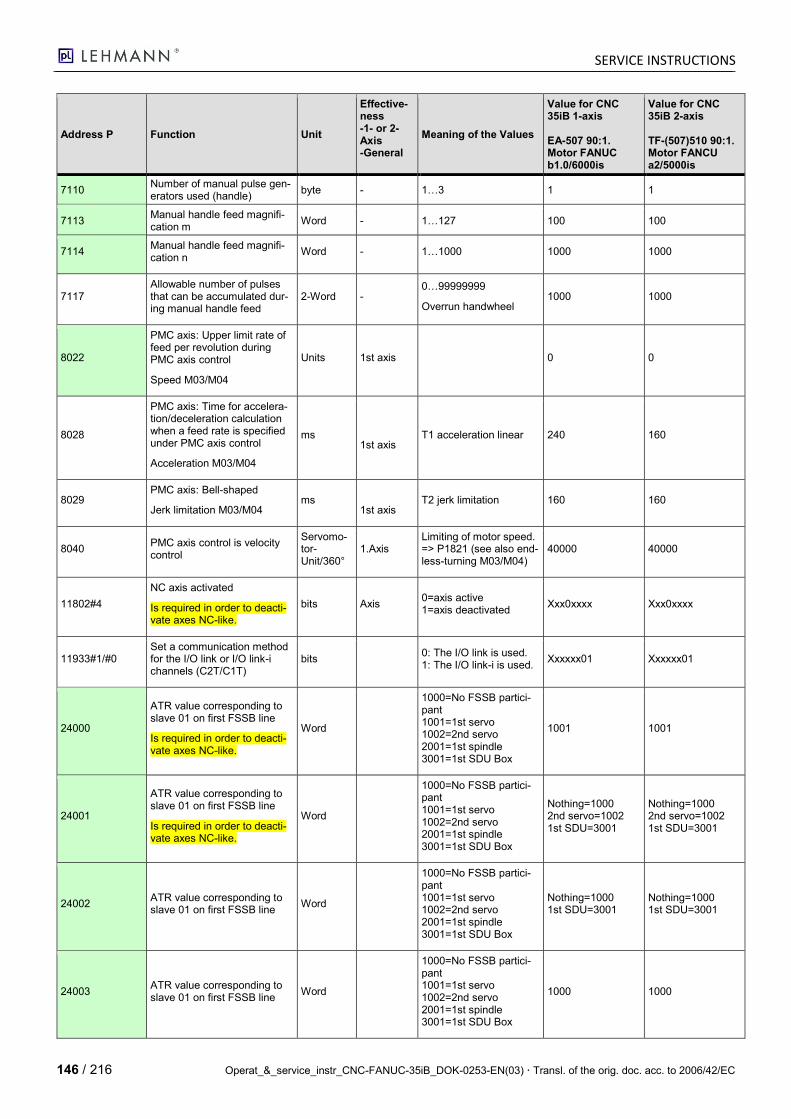
SERVICE INSTRUCTIONS
146 / 216 Operat_&_service_instr_CNC-FANUC-35iB_DOK-0253-EN(03) Transl. of the orig. doc. acc. to 2006/42/EC
Address P Function Unit
Effective-ness -1- or 2-Axis -General
Meaning of the Values
Value for CNC 35iB 1-axis EA-507 90:1. Motor FANUC b1.0/6000is
Value for CNC 35iB 2-axis TF-(507)510 90:1. Motor FANCU a2/5000is
7110 Number of manual pulse gen-erators used (handle)
byte - 1…3 1 1
7113 Manual handle feed magnifi-cation m
Word - 1…127 100 100
7114 Manual handle feed magnifi-cation n
Word - 1…1000 1000 1000
7117 Allowable number of pulses that can be accumulated dur-ing manual handle feed
2-Word - 0…99999999
Overrun handwheel 1000 1000
8022
PMC axis: Upper limit rate of feed per revolution during PMC axis control
Speed M03/M04
Units 1st axis 0 0
8028
PMC axis: Time for accelera-tion/deceleration calculation when a feed rate is specified under PMC axis control
Acceleration M03/M04
ms
1st axis T1 acceleration linear 240 160
8029 PMC axis: Bell-shaped
Jerk limitation M03/M04 ms
1st axis T2 jerk limitation 160 160
8040 PMC axis control is velocity control
Servomo-tor-Unit/360°
1.Axis Limiting of motor speed. => P1821 (see also end-less-turning M03/M04)
40000 40000
11802#4
NC axis activated
Is required in order to deacti-vate axes NC-like.
bits Axis 0=axis active 1=axis deactivated
Xxx0xxxx Xxx0xxxx
11933#1/#0 Set a communication method for the I/O link or I/O link-i channels (C2T/C1T)
bits 0: The I/O link is used. 1: The I/O link-i is used.
Xxxxxx01 Xxxxxx01
24000
ATR value corresponding to slave 01 on first FSSB line
Is required in order to deacti-vate axes NC-like.
Word
1000=No FSSB partici-pant 1001=1st servo 1002=2nd servo 2001=1st spindle 3001=1st SDU Box
1001 1001
24001
ATR value corresponding to slave 01 on first FSSB line
Is required in order to deacti-vate axes NC-like.
Word
1000=No FSSB partici-pant 1001=1st servo 1002=2nd servo 2001=1st spindle 3001=1st SDU Box
Nothing=1000 2nd servo=1002 1st SDU=3001
Nothing=1000 2nd servo=1002 1st SDU=3001
24002 ATR value corresponding to slave 01 on first FSSB line
Word
1000=No FSSB partici-pant 1001=1st servo 1002=2nd servo 2001=1st spindle 3001=1st SDU Box
Nothing=1000 1st SDU=3001
Nothing=1000 1st SDU=3001
24003 ATR value corresponding to slave 01 on first FSSB line
Word
1000=No FSSB partici-pant 1001=1st servo 1002=2nd servo 2001=1st spindle 3001=1st SDU Box
1000 1000
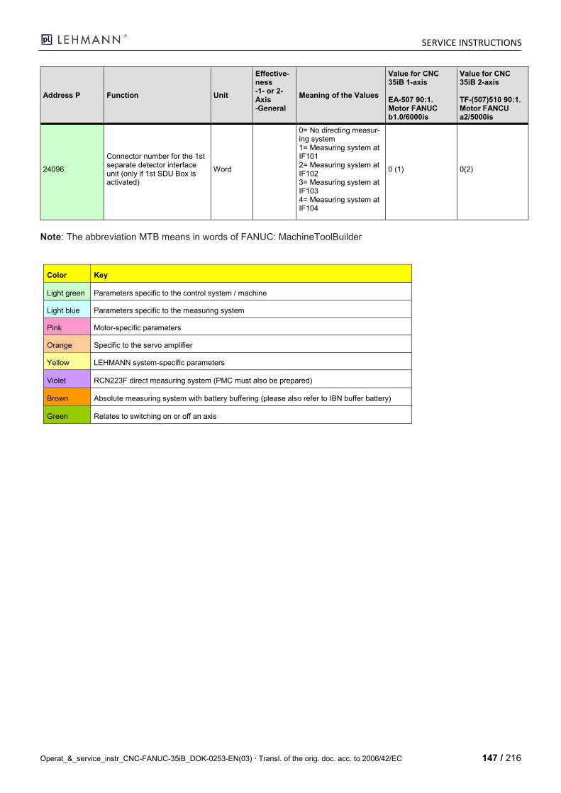
SERVICE INSTRUCTIONS
Operat_&_service_instr_CNC-FANUC-35iB_DOK-0253-EN(03) Transl. of the orig. doc. acc. to 2006/42/EC 147 / 216
Address P Function Unit
Effective-ness -1- or 2-Axis -General
Meaning of the Values
Value for CNC 35iB 1-axis EA-507 90:1. Motor FANUC b1.0/6000is
Value for CNC 35iB 2-axis TF-(507)510 90:1. Motor FANCU a2/5000is
24096
Connector number for the 1st separate detector interface unit (only if 1st SDU Box is activated)
Word
0= No directing measur-ing system 1= Measuring system at IF101 2= Measuring system at IF102 3= Measuring system at IF103 4= Measuring system at IF104
0 (1) 0(2)
Note: The abbreviation MTB means in words of FANUC: MachineToolBuilder
Color Key
Light green Parameters specific to the control system / machine
Light blue Parameters specific to the measuring system
Pink Motor-specific parameters
Orange Specific to the servo amplifier
Yellow LEHMANN system-specific parameters
Violet RCN223F direct measuring system (PMC must also be prepared)
Brown Absolute measuring system with battery buffering (please also refer to IBN buffer battery)
Green Relates to switching on or off an axis
SERVICE INSTRUCTIONS
148 / 216 Operat_&_service_instr_CNC-FANUC-35iB_DOK-0253-EN(03) Transl. of the orig. doc. acc. to 2006/42/EC
9.2.1 Fanuc Graphic for the Assignment of Axes
9.3 Parametrization of Handy with and without integrated hand-wheel
NC-parameter adress P
function code unit description
Handheld Con-troller Panel without inte-grated hand-wheel
Handheld Con-troller Panel with integrated hand-wheel
3206#7 NS2 Bits CNC screen dual display function is: 0 = disabled 1 = enabled
0 0
11539#4 OEN bits
iPendant operation ON/OFF switch ENBC is: 0 = disabled 1 = enabled
0 1
11539#6 MCD bits
iPendant operation mode control signal MOPEC is: 0 = disabled 1 = enabled
0 1
11540 Address type of the operation mode con-trol signal
0 3
11541 Address number of the operation mode control signal
0 9928
11542 Address type of the key signal area (E area)
3 3
11543 Address number of the key signal area 9900 9900
11544 Refresh interval time of the key signal data
64 64
11546 Deactivate parameter P12300 / P12340 for the 1st manual pulse coder
0 1
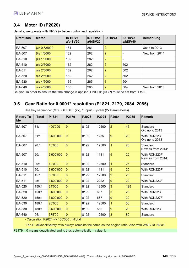
SERVICE INSTRUCTIONS
Operat_&_service_instr_CNC-FANUC-35iB_DOK-0253-EN(03) Transl. of the orig. doc. acc. to 2006/42/EC 149 / 216
9.4 Motor ID (P2020)
Usually, we operate with HRV2 (= better control and regulation)
Drehtisch Motor ID HRV1 a/biSV20
ID HRV2 a/biSV20
ID HRV3 ID HRV2 a/biSV40
Bemerkung
EA-507 βis 0.5/6000 181 281 ? - Used to 2013
EA-507 βis 1/6000 182 282 ? - New from 2014
EA-510 βis 1/6000 182 282 ? -
EA-510 αis 2/5000 162 262 ? 502
EA-511 αis 2/5000 162 262 ? 502
EA-520 αis 2/5000 162 262 ? 502
EA-530 αis 4/5000 165 265 ? 504
EA-640 αis 4/5000 165 265 ? 504 New from 2018
Caution: In order to ensure that the change is applied, P2000#1(DGP) must be set from 1 to 0.
9.5 Gear Ratio for 0.0001° resolution (P1821, 2179, 2084, 2085)
Use key sequence: (MDI, OFFSET (2x), 1 Input, System (2x Parameters))
Rotary Ta-ble
i Total P1821 P2179 P2023 P2024 P2084 P2085 Remark
EA-507 81:1 400’000 9 8192 12500 2 45 Standard Old up to 2013
EA-507 81:1 3'600’000 0 8192 1235 9 20 With RCN223F Old up to 2013
EA-507 90:1 40’000 0 8192 12500 1 25 Standard New as from 2014:
EA-507 90:1 3'600’000 0 8192 1111 9 20 With RCN223F New as from 2014:
EA-510 90:1 40’000 0 8192 12500 1 25 Standard
EA-510 90:1 3'600’000 0 8192 1111 9 20 With RCN223F
EA-511 45:1 80’000 0 8192 12500 2 25 Standard
EA-511 45:1 3'600’000 0 8192 2222 9 20 With RCN223F
EA-520 150:1 24’000 0 8192 12500 3 125 Standard
EA-520 150:1 3'600’000 0 8192 667 3 20 With RCN223F
EA-520 150:1 3'600’000 0 8192 667 9 20 With RCN227F
EA-530 180:1 20’000 0 8192 12500 1 50 Standard
EA-530 180:1 3'600’000 0 8192 555 9 20 With RCN223F
EA-640 96:1 375'00 0 8192 12500 3 80 Standard
- Calculation P2024 => 100'000 : i-Total
-The DualCheckSafety ratio always remains the same as the engine ratio. Also with WMS-RCN2xxF.
P2179 = 0 means deactivated and is thus automatically = value 1.

SERVICE INSTRUCTIONS
150 / 216 Operat_&_service_instr_CNC-FANUC-35iB_DOK-0253-EN(03) Transl. of the orig. doc. acc. to 2006/42/EC
9.6 Unintended motor-servo combination
For FANUC servo-systems, the motor and servo must match each other according to FANUC specifications. Otherwise, the CNC will give an error when entering the motor number. The error can be turned off for testing purposes, but FANUC does not guarantee.
So that the mentioned error does not appear, for example with too large servo, the following attitudes are neces-sary:
a) Increase NC parameter "P2165" from 20 (= standard value SV20) to 45 (= servo size SV40). b) The maximum servo current "P2060" must then be reduced accordingly, for example from P2060 = 7282
(100%) to 3641 (50%) due to the oversize.
9.7 Parameteriz. of FANUC-Bus FSSB for SDU Box with direct measuring system
Parameter Number
1 axis with-out SDU Box
2 axes with-out SDU Box
1 axis with SDU Box
2 axes with SDU Box
Function
1020-A1 65 65 65 65 Name of the axis (65=A)
1020-A2 - 67 - 67 Name of the axis (67=C)
1022-A1 0 0 0 0
Setting of each axis in the basic coor-dinate system - 0 = Rotary axis - 1 = X-Axis - 2 = Y-Axis - 3 = Z-Axis
1022-A2 0 0 0 0 Setting of each axis in the basic coor-dinate system
1023-A1 1 1 1 1 Number of the servo axis for each axis
1023-A2 - 2 - 2 Number of the servo axis for each axis
1902#0 xxxxxxx1 xxxxxxx1 xxxxxxx1 xxxxxxx1 FSSB setting mode
1905#6 X0xxxxxx x0xxxxxx X1xxxxxx x1xxxxxx 1. SDU-BOX Interface active
24000 1001 1001 1001 1001 ATR value corresponding to slave 01 on first FSSB line
24001 1000 1002 3001 1002 ATR value corresponding to slave 01 on first FSSB line
24002 1000 1000 1000 3001 ATR value corresponding to slave 01 on first FSSB line
24003 1000 1000 1000 1000 ATR value corresponding to slave 01 on first FSSB line
24096-A1 0 0 1 1(0) Connector number for the 1st sep-arate detector interface unit (only if 1st SDU Box is activated) 1=IF101
24096-A2 0 0 0 2 Connector number for the 1st sep-arate detector interface unit (only if 1st SDU Box is activated) 2=IF102
Remark: - These parameters apply only to the series 30. The Series 0i-MD has different parameters. The Series 0i-MF pa-rameters are quite similar to the 30. - Value 1,000 means that the participant is deactivated. - If the servo numbers 1001 and 1002 are swapped with P24000 and P24001, the 1st servo becomes the 2nd axis and vice versa! - With an absolute direct measuring system (e.g. Heidenhain RCN223F), the reference point need no longer be ap-proached. The CNC can then be immediately parameterized as with a measuring system buffer battery; please re-fer to FANUC Operating Instructions (OI) under "14.2.1 Commissioning the Measuring System Buffer Battery".
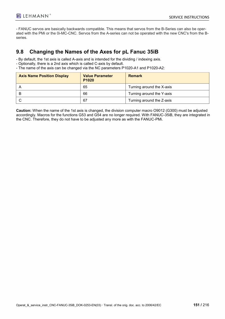
SERVICE INSTRUCTIONS
Operat_&_service_instr_CNC-FANUC-35iB_DOK-0253-EN(03) Transl. of the orig. doc. acc. to 2006/42/EC 151 / 216
- FANUC servos are basically backwards compatible. This means that servos from the B-Series can also be oper-ated with the PMi or the 0i-MC-CNC. Servos from the A-series can not be operated with the new CNC's from the B-series.
9.8 Changing the Names of the Axes for pL Fanuc 35iB
- By default, the 1st axis is called A-axis and is intended for the dividing / indexing axis. - Optionally, there is a 2nd axis which is called C-axis by default. - The name of the axis can be changed via the NC parameters P1020-A1 and P1020-A2:
Axis Name Position Display Value Parameter P1020
Remark
A 65 Turning around the X-axis
B 66 Turning around the Y-axis
C 67 Turning around the Z-axis
Caution: When the name of the 1st axis is changed, the division computer macro O9012 (G300) must be adjusted accordingly. Macros for the functions G53 and G54 are no longer required. With FANUC-35iB, they are integrated in the CNC. Therefore, they do not have to be adjusted any more as with the FANUC-PMi.
SERVICE INSTRUCTIONS
152 / 216 Operat_&_service_instr_CNC-FANUC-35iB_DOK-0253-EN(03) Transl. of the orig. doc. acc. to 2006/42/EC
10 Connecting LADDER-III for PMC to FANUC-35iB
10.1 Preparing the connection
No. What Picture
1. - Parameter Write must be set from 0 to 1.
2. - Programmer Enable must be set from NO to YES.
- RamWriteEnable must be set from NO to YES.
3. Picture: Switch for access with LADDER-III
Remarks:
Standard ETH address of FANUC-35iB: 192.168.1.10 (port 8193). In principle, it must not be changed for communication with the i-Pendent hand-held unit. To connect the PC with FANUC-LADDER III software, a switch is switched between i-Pendant and 35iB.
For a data transfer to a public ETH network, an additional, optional ETH card should be inserted.
Programming is via ETH interface Range: 192.168.1.xxx In the virtual Windows 7, the "USB to ETH-BOX" parameters must be adjusted as described above.

SERVICE INSTRUCTIONS
Operat_&_service_instr_CNC-FANUC-35iB_DOK-0253-EN(03) Transl. of the orig. doc. acc. to 2006/42/EC 153 / 216
Connect to Z Button.
Switch online for monitoring
SERVICE INSTRUCTIONS
154 / 216 Operat_&_service_instr_CNC-FANUC-35iB_DOK-0253-EN(03) Transl. of the orig. doc. acc. to 2006/42/EC
As soon as Interlock 1st Axis = 1, the axes can be moved.
SVF1 ServoOff 1st Axis = 1 means that the servo is switched off, 0 = the servo controls and regulates.
G126.0 = ServoOff 1.axis
G130.0 = Interlook 1.axis
SERVICE INSTRUCTIONS
Operat_&_service_instr_CNC-FANUC-35iB_DOK-0253-EN(03) Transl. of the orig. doc. acc. to 2006/42/EC 155 / 216
10.2 Changing PMC
If changes have been made, a backup (backup from RAM to F-ROM) must always be carried out at the end; other-wise, the changes made are lost after a restart of the control system.
By pressing "F" and the "CTRL key" at the same time, the search function can be started in the LADDER software.
Our PMC was created using SB6 programming (Fanuc B61863E).
10.3 Explanations on PMC Variables
R = Register => Keep relay
F = Software connection from CNC to PMC
G = Software connection from PMC to CNC
X = Hardware connection from Machine to PMC (Input)
Y = Hardware connection from PMC to Machine (Output)
CNC
(Standard Fanuc soft-ware)
PMC
(Specific LEHMANN software created with LADDER 3)
Machine
(Input/Outputs for rotary table)
F Y
G X

SERVICE INSTRUCTIONS
156 / 216 Operat_&_service_instr_CNC-FANUC-35iB_DOK-0253-EN(03) Transl. of the orig. doc. acc. to 2006/42/EC
10.4 Importing File in LADDER-III-SW
In order to import a TXT file in LADDER-III-SW, the texts must start with a % and also end with a %. The mnemonic file also needs a "@4" (4 for messages) after the % sign.
%@0 -> SYSTEM PARAMETER
%@1 -> TITLE
%@2 -> SYMBOL & COMMENT
%@3 -> LADDER
%@4 -> LADDER
%@5 -> I/O MODULE
10.5 Useful information about PMC
- For Ethernet connections, always use Port 8193; ETH address is shown under SETTING -> PRM -> Right arrow until ETHPRM is displayed -> Setting screen mask and address, e.g. ADR 192.168.1.100 SUB 255.255.255.0. In order to ensure that ETH communication is functioning, "HIGH SPEED I/F" = USE must be selected under PMC -> MONIT.
- The Fanuc PC software LADDER3-V5.90 is used.
- PMC type "PMC SB6/RB6"
- The MacroB functions are standard with the PMiD and thus free of charge.
10.6 Creating a LADDER Diagram for MemoryCard
File -> Export -> Memorycard Format File; a file is created with 128kB for loading onto the CNC via PC Card.
SERVICE INSTRUCTIONS
Operat_&_service_instr_CNC-FANUC-35iB_DOK-0253-EN(03) Transl. of the orig. doc. acc. to 2006/42/EC 157 / 216
10.7 RESET after EMERGENCY changes
PMC-LEVEL 1: Now the RESET key must always be pressed after EMERGENCY STOP (R0903.3)
PL-FUNC: InPOS signal has previously output the InPOS signal when the NOAUS button is pressed. G0008.4 suppresses this now.
iPendant_In: Switches E9900.1, R0899.0, K7.1: When K7.1 is set to ON, the keyboard enable switch is always "key-enabled". Unfortunately, the function has no effect at the moment.
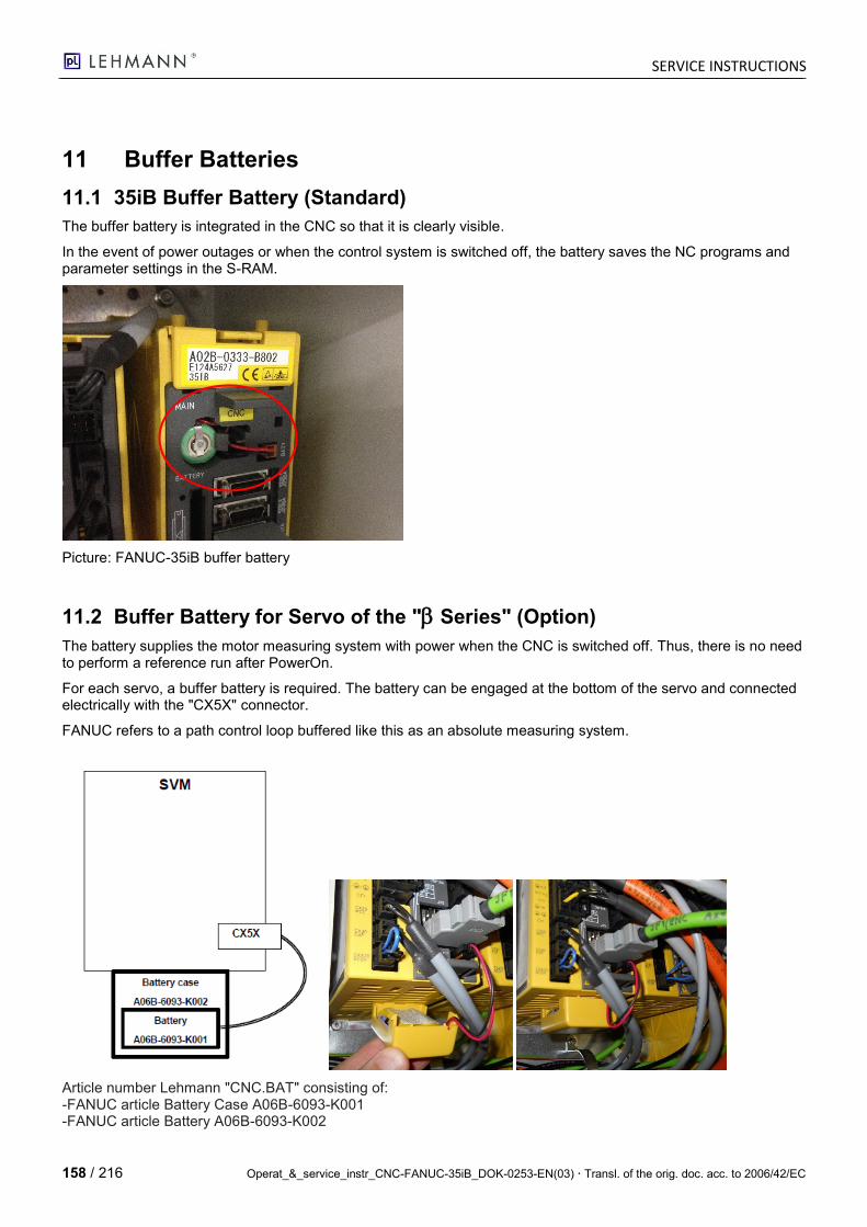
SERVICE INSTRUCTIONS
158 / 216 Operat_&_service_instr_CNC-FANUC-35iB_DOK-0253-EN(03) Transl. of the orig. doc. acc. to 2006/42/EC
11 Buffer Batteries
11.1 35iB Buffer Battery (Standard)
The buffer battery is integrated in the CNC so that it is clearly visible.
In the event of power outages or when the control system is switched off, the battery saves the NC programs and parameter settings in the S-RAM.
Picture: FANUC-35iB buffer battery
11.2 Buffer Battery for Servo of the " Series" (Option)
The battery supplies the motor measuring system with power when the CNC is switched off. Thus, there is no need to perform a reference run after PowerOn.
For each servo, a buffer battery is required. The battery can be engaged at the bottom of the servo and connected electrically with the "CX5X" connector.
FANUC refers to a path control loop buffered like this as an absolute measuring system.
Article number Lehmann "CNC.BAT" consisting of: -FANUC article Battery Case A06B-6093-K001 -FANUC article Battery A06B-6093-K002
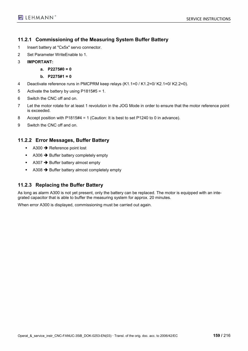
SERVICE INSTRUCTIONS
Operat_&_service_instr_CNC-FANUC-35iB_DOK-0253-EN(03) Transl. of the orig. doc. acc. to 2006/42/EC 159 / 216
11.2.1 Commissioning of the Measuring System Buffer Battery
1 Insert battery at "Cx5x" servo connector.
2 Set Parameter WriteEnable to 1.
3 IMPORTANT:
a. P2275#0 = 0
b. P2275#1 = 0
4 Deactivate reference runs in PMCPRM keep relays (K1.1=0 / K1.2=0/ K2.1=0/ K2.2=0).
5 Activate the battery by using P1815#5 = 1.
6 Switch the CNC off and on.
7 Let the motor rotate for at least 1 revolution in the JOG Mode in order to ensure that the motor reference point is exceeded.
8 Accept position with P1815#4 = 1 (Caution: It is best to set P1240 to 0 in advance).
9 Switch the CNC off and on.
11.2.2 Error Messages, Buffer Battery
A300 Reference point lost
A306 Buffer battery completely empty
A307 Buffer battery almost empty
A308 Buffer battery almost completely empty
11.2.3 Replacing the Buffer Battery
As long as alarm A300 is not yet present, only the battery can be replaced. The motor is equipped with an inte-grated capacitor that is able to buffer the measuring system for approx. 20 minutes.
When error A300 is displayed, commissioning must be carried out again.
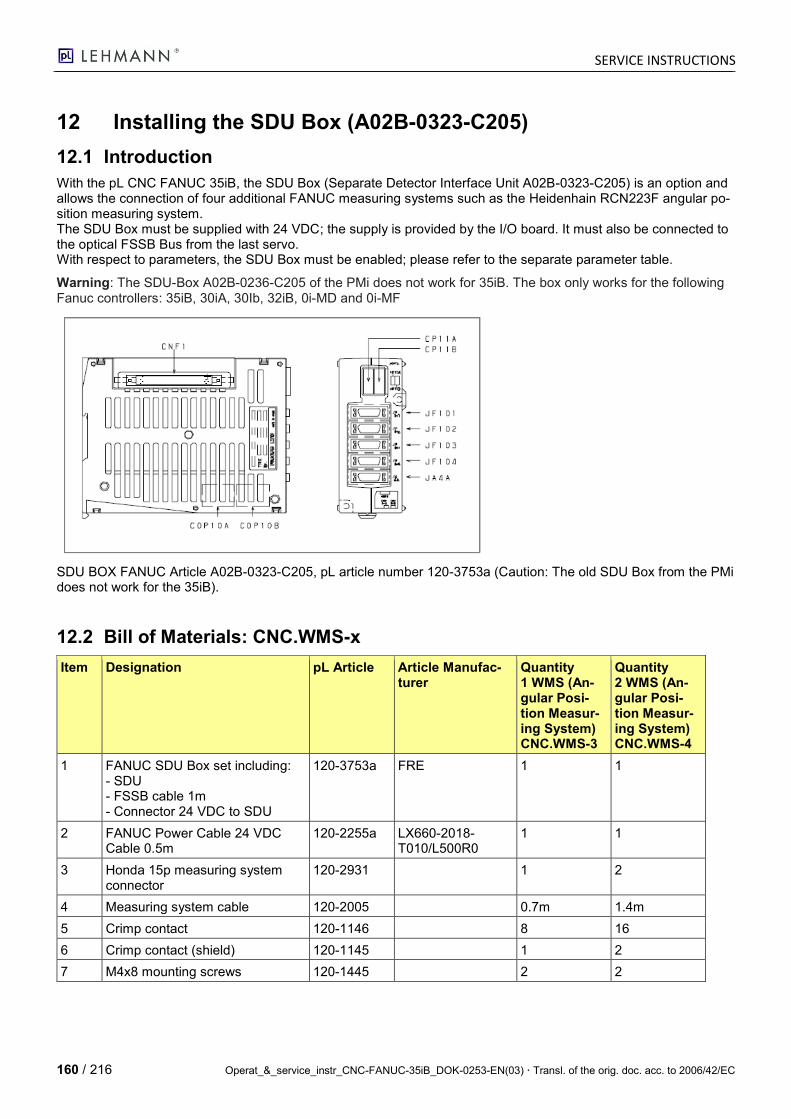
SERVICE INSTRUCTIONS
160 / 216 Operat_&_service_instr_CNC-FANUC-35iB_DOK-0253-EN(03) Transl. of the orig. doc. acc. to 2006/42/EC
12 Installing the SDU Box (A02B-0323-C205)
12.1 Introduction
With the pL CNC FANUC 35iB, the SDU Box (Separate Detector Interface Unit A02B-0323-C205) is an option and allows the connection of four additional FANUC measuring systems such as the Heidenhain RCN223F angular po-sition measuring system. The SDU Box must be supplied with 24 VDC; the supply is provided by the I/O board. It must also be connected to the optical FSSB Bus from the last servo. With respect to parameters, the SDU Box must be enabled; please refer to the separate parameter table.
Warning: The SDU-Box A02B-0236-C205 of the PMi does not work for 35iB. The box only works for the following Fanuc controllers: 35iB, 30iA, 30Ib, 32iB, 0i-MD and 0i-MF
SDU BOX FANUC Article A02B-0323-C205, pL article number 120-3753a (Caution: The old SDU Box from the PMi does not work for the 35iB).
12.2 Bill of Materials: CNC.WMS-x
Item Designation pL Article Article Manufac-turer
Quantity 1 WMS (An-gular Posi-tion Measur-ing System) CNC.WMS-3
Quantity 2 WMS (An-gular Posi-tion Measur-ing System) CNC.WMS-4
1 FANUC SDU Box set including: - SDU - FSSB cable 1m - Connector 24 VDC to SDU
120-3753a FRE 1 1
2 FANUC Power Cable 24 VDC Cable 0.5m
120-2255a LX660-2018-T010/L500R0
1 1
3 Honda 15p measuring system connector
120-2931 1 2
4 Measuring system cable 120-2005 0.7m 1.4m
5 Crimp contact 120-1146 8 16
6 Crimp contact (shield) 120-1145 1 2
7 M4x8 mounting screws 120-1445 2 2
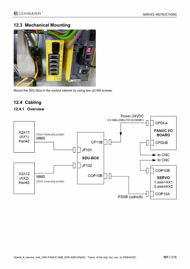
SERVICE INSTRUCTIONS
Operat_&_service_instr_CNC-FANUC-35iB_DOK-0253-EN(03) Transl. of the orig. doc. acc. to 2006/42/EC 161 / 216
12.3 Mechanical Mounting
Mount the SDU Box in the control cabinet by using two (2) M4 screws.
12.4 Cabling
12.4.1 Overview
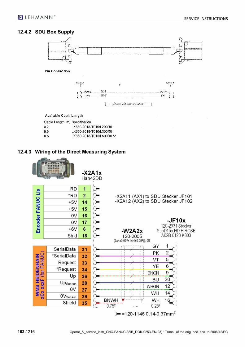
SERVICE INSTRUCTIONS
162 / 216 Operat_&_service_instr_CNC-FANUC-35iB_DOK-0253-EN(03) Transl. of the orig. doc. acc. to 2006/42/EC
12.4.2 SDU Box Supply
12.4.3 Wiring of the Direct Measuring System
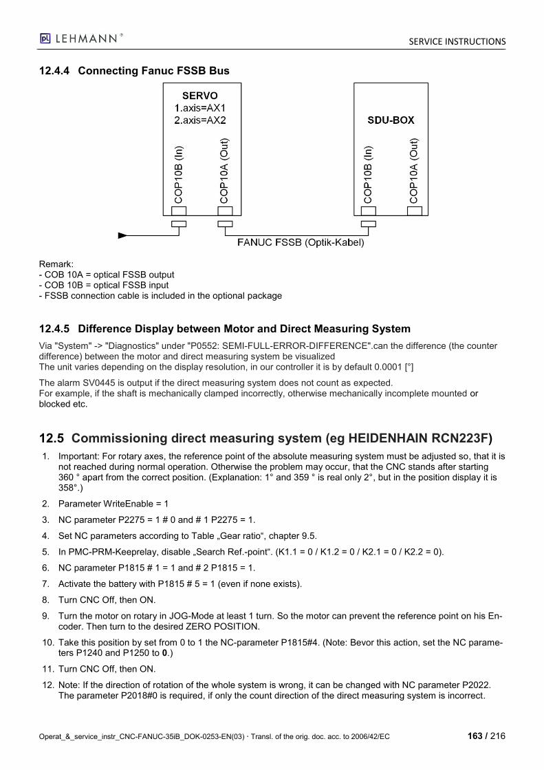
SERVICE INSTRUCTIONS
Operat_&_service_instr_CNC-FANUC-35iB_DOK-0253-EN(03) Transl. of the orig. doc. acc. to 2006/42/EC 163 / 216
12.4.4 Connecting Fanuc FSSB Bus
Remark: - COB 10A = optical FSSB output - COB 10B = optical FSSB input - FSSB connection cable is included in the optional package
12.4.5 Difference Display between Motor and Direct Measuring System
Via "System" -> "Diagnostics" under "P0552: SEMI-FULL-ERROR-DIFFERENCE".can the difference (the counter difference) between the motor and direct measuring system be visualized The unit varies depending on the display resolution, in our controller it is by default 0.0001 [°]
The alarm SV0445 is output if the direct measuring system does not count as expected. For example, if the shaft is mechanically clamped incorrectly, otherwise mechanically incomplete mounted or blocked etc.
12.5 Commissioning direct measuring system (eg HEIDENHAIN RCN223F)
1. Important: For rotary axes, the reference point of the absolute measuring system must be adjusted so, that it is not reached during normal operation. Otherwise the problem may occur, that the CNC stands after starting 360 ° apart from the correct position. (Explanation: 1° and 359 ° is real only 2°, but in the position display it is 358°.)
2. Parameter WriteEnable = 1
3. NC parameter P2275 = 1 # 0 and # 1 P2275 = 1.
4. Set NC parameters according to Table „Gear ratio“, chapter 9.5.
5. In PMC-PRM-Keeprelay, disable „Search Ref.-point“. (K1.1 = 0 / K1.2 = 0 / K2.1 = 0 / K2.2 = 0).
6. NC parameter P1815 # 1 = 1 and # 2 P1815 = 1.
7. Activate the battery with P1815 # 5 = 1 (even if none exists).
8. Turn CNC Off, then ON.
9. Turn the motor on rotary in JOG-Mode at least 1 turn. So the motor can prevent the reference point on his En-coder. Then turn to the desired ZERO POSITION.
10. Take this position by set from 0 to 1 the NC-parameter P1815#4. (Note: Bevor this action, set the NC parame-ters P1240 and P1250 to 0.)
11. Turn CNC Off, then ON.
12. Note: If the direction of rotation of the whole system is wrong, it can be changed with NC parameter P2022. The parameter P2018#0 is required, if only the count direction of the direct measuring system is incorrect.
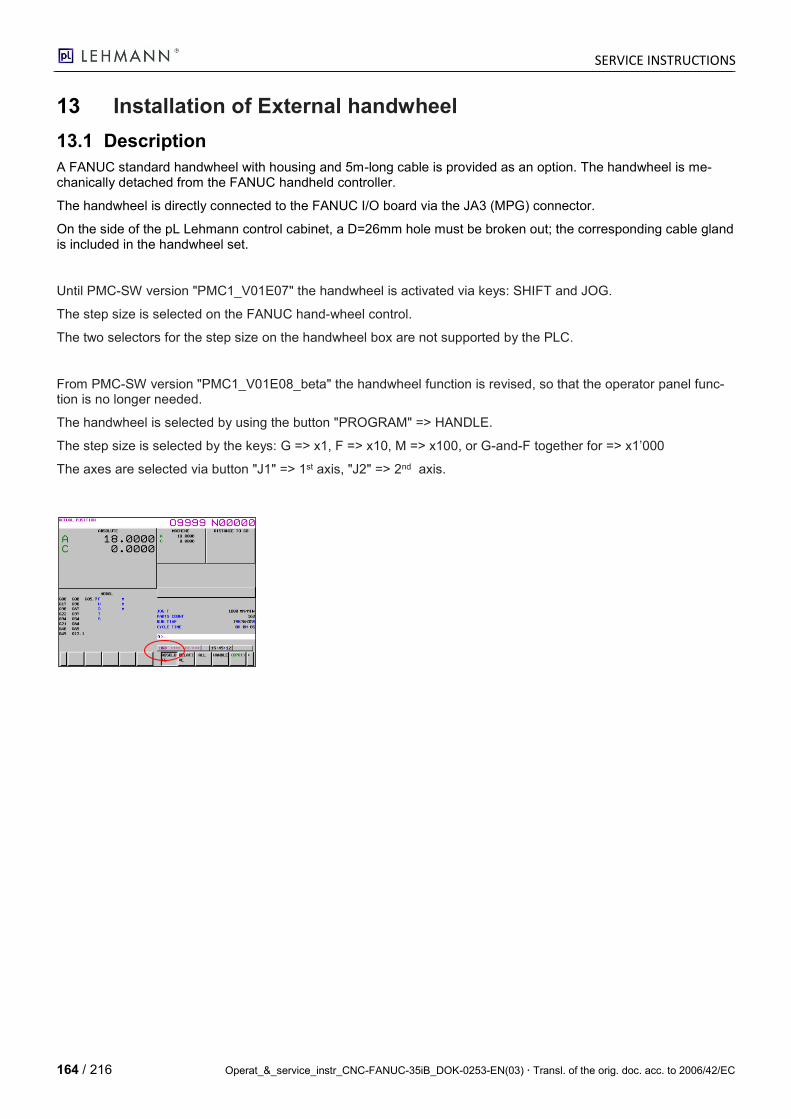
SERVICE INSTRUCTIONS
164 / 216 Operat_&_service_instr_CNC-FANUC-35iB_DOK-0253-EN(03) Transl. of the orig. doc. acc. to 2006/42/EC
13 Installation of External handwheel
13.1 Description
A FANUC standard handwheel with housing and 5m-long cable is provided as an option. The handwheel is me-chanically detached from the FANUC handheld controller.
The handwheel is directly connected to the FANUC I/O board via the JA3 (MPG) connector.
On the side of the pL Lehmann control cabinet, a D=26mm hole must be broken out; the corresponding cable gland is included in the handwheel set.
Until PMC-SW version "PMC1_V01E07" the handwheel is activated via keys: SHIFT and JOG.
The step size is selected on the FANUC hand-wheel control.
The two selectors for the step size on the handwheel box are not supported by the PLC.
From PMC-SW version "PMC1_V01E08_beta" the handwheel function is revised, so that the operator panel func-tion is no longer needed.
The handwheel is selected by using the button "PROGRAM" => HANDLE.
The step size is selected by the keys: G => x1, F => x10, M => x100, or G-and-F together for => x1’000
The axes are selected via button "J1" => 1st axis, "J2" => 2nd axis.

SERVICE INSTRUCTIONS
Operat_&_service_instr_CNC-FANUC-35iB_DOK-0253-EN(03) Transl. of the orig. doc. acc. to 2006/42/EC 165 / 216
13.2 Bill of Materials: CNC.HaRad
Item Designation pL Article Article Manufac-turer
Quantity
1 FANUC handwheel set including: - Handwheel in housing - Handwheel cable 5m - Connector to I/O board
120-3757 FRE201N0701 1
2 D=7mm cable sleeve 120-3754 1
3 M25x1.5 cable gland 120-3755 1
4 M25x1.5 nut 120-3756 1
13.3 FANUC I/O Board (A20B-2004-0690/02A) Pin Assignment JA3
Honda connector
- Pin 12 = 0 V - Pin 1 = A - Pin 2 = B - Pin 9 = +5 V
13.4 Drawing of External Handwheel
13.5 Handwheel Installation Instructions
1. Break out the hole (D=26mm) for the cable gland with the designation "HANDWHEEL".
2. Remove the connector housing and pass the connector through the hole.
3. Tighten the nut of the cable gland at the control cabinet wall.
4. Reassemble the connector housing and insert the JA3 connector in the FANUC I/O board.
5. Label the keys with Label printer, according to photo.
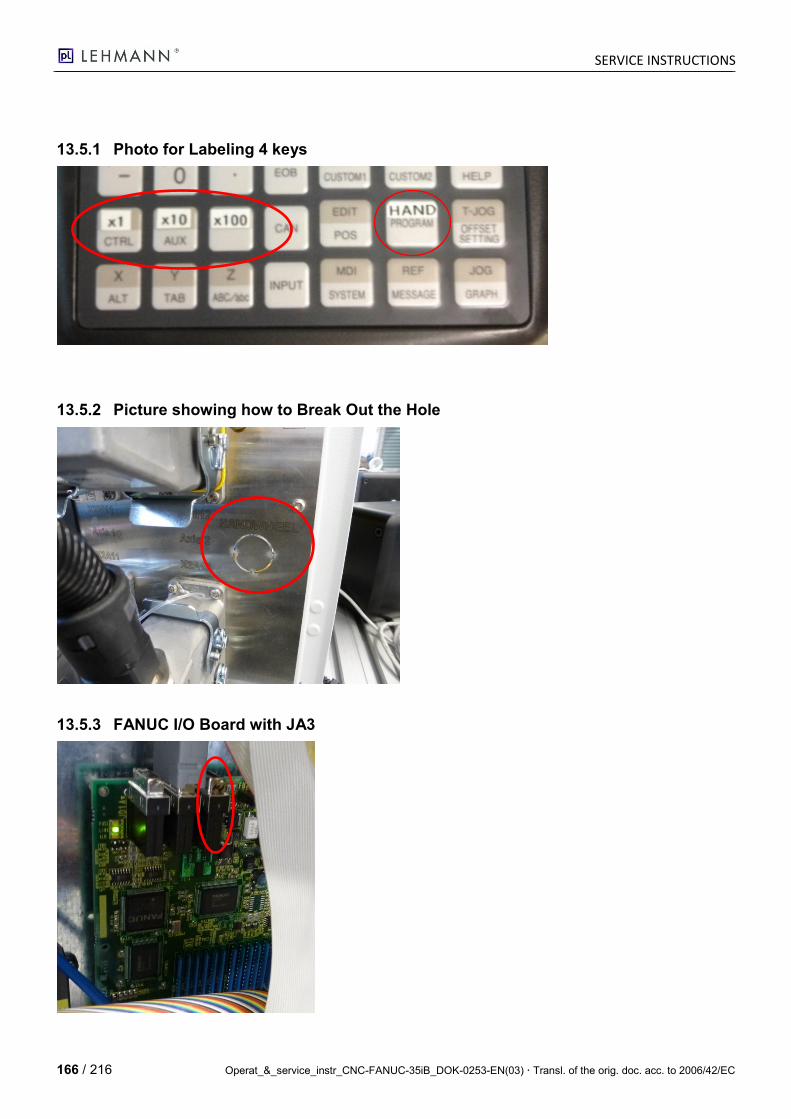
SERVICE INSTRUCTIONS
166 / 216 Operat_&_service_instr_CNC-FANUC-35iB_DOK-0253-EN(03) Transl. of the orig. doc. acc. to 2006/42/EC
13.5.1 Photo for Labeling 4 keys
13.5.2 Picture showing how to Break Out the Hole
13.5.3 FANUC I/O Board with JA3
SERVICE INSTRUCTIONS
Operat_&_service_instr_CNC-FANUC-35iB_DOK-0253-EN(03) Transl. of the orig. doc. acc. to 2006/42/EC 167 / 216
Green "Link" LED must always flash
SERVICE INSTRUCTIONS
168 / 216 Operat_&_service_instr_CNC-FANUC-35iB_DOK-0253-EN(03) Transl. of the orig. doc. acc. to 2006/42/EC
13.5.4 Servo Motor Tuning
PLEASE NOTE: Qualifications of the personnel
This chapter should only be used and applied by specialized personnel and experts who have a good knowledge of control circuits and can handle this control system safely and reliably.
No. Action Picture for the Action Response from the CNC
1. Prerequisites:
- In order to change NC pa-rameters, the MDI Mode must be activated.
- In order to move the axes by using the JOG keys, the JOG Mode must be acti-vated.
- LED "M-OPE" must not light up (otherwise with the "M-OPE/MDI" key).
- Press the "OFFSET/SETTING" key twice (2x).
Must not light up.
2x
2. - Activate WriteEnable PARAMETER WRITE = 1.
(Only required in order to change parameters)
3. Press the SYSTEM key.
SERVICE INSTRUCTIONS
Operat_&_service_instr_CNC-FANUC-35iB_DOK-0253-EN(03) Transl. of the orig. doc. acc. to 2006/42/EC 169 / 216
No. Action Picture for the Action Response from the CNC
4. Press the Switch F keys key.
5. Press the F3: [SERVO PARAM] key.
6. Press the F2 [SERVO TUNE] key.
SERVICE INSTRUCTIONS
170 / 216 Operat_&_service_instr_CNC-FANUC-35iB_DOK-0253-EN(03) Transl. of the orig. doc. acc. to 2006/42/EC
No. Action Picture for the Action Response from the CNC
7. With the CURSOR keys, the required field can be marked and the value changed.
8. With the PAGE UP/DOWN keys, the corresponding axis can be selected.
The VELOC.GAIN parameter (P2021) is very effective to change the controller properties.
This lag error analysis is part of the commissioning process. The positioning should be carried out with and without spindle clamping.
The lag error is shown under POS ERROR. First of all, the assessment of the value shown in an angular degree of 0.0001 is important. An angular degree of 0.0001 corresponds to 0.36 arc seconds.
13.5.5 POS ERROR too large
Please only take the recommended measures if you have corresponding knowledge.
a) Increase VELOC.GAIN in increments of 10 (more intense speed gain) until the drive system starts to vibrate when moving; then reduce by 20%.
b) Increase INT.GAIN. in single increments (more intense integral gain) until the drive system starts to vibrate when moving; then reduce by 20%.
In case of doubt, always contact our TCS and ask for a specialist.
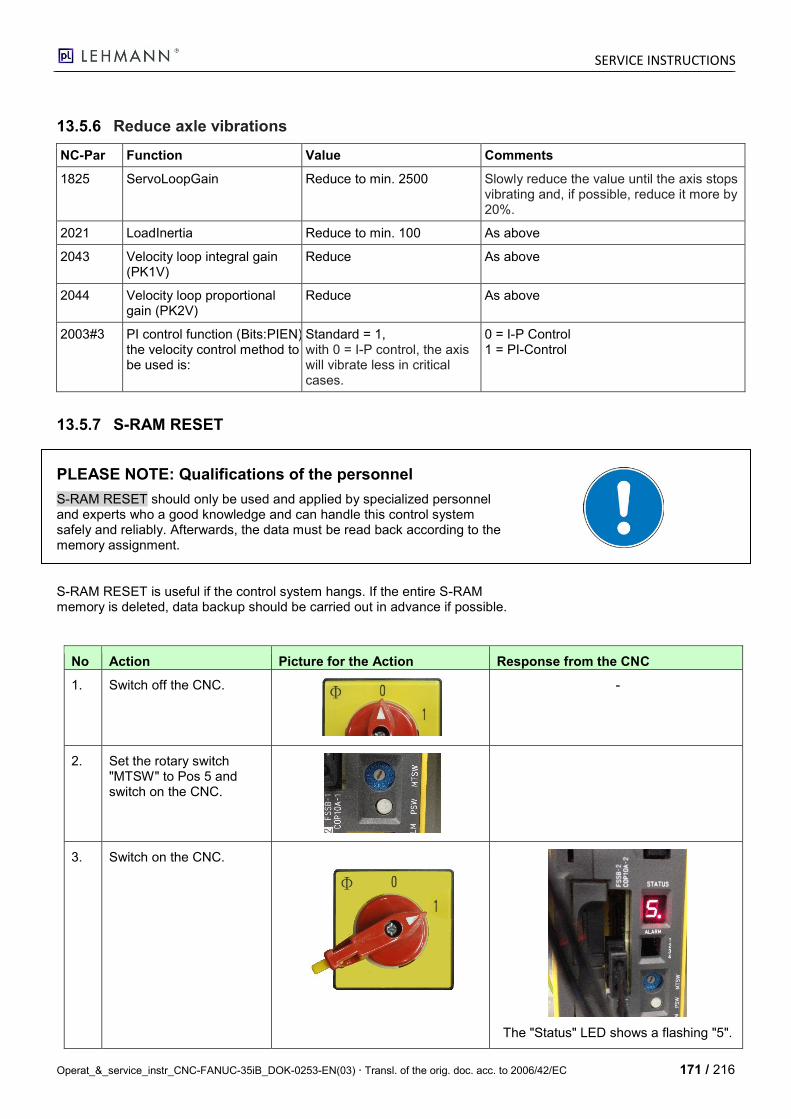
SERVICE INSTRUCTIONS
Operat_&_service_instr_CNC-FANUC-35iB_DOK-0253-EN(03) Transl. of the orig. doc. acc. to 2006/42/EC 171 / 216
13.5.6 Reduce axle vibrations
NC-Par Function Value Comments
1825 ServoLoopGain Reduce to min. 2500 Slowly reduce the value until the axis stops vibrating and, if possible, reduce it more by 20%.
2021 LoadInertia Reduce to min. 100 As above
2043 Velocity loop integral gain (PK1V)
Reduce As above
2044 Velocity loop proportional gain (PK2V)
Reduce As above
2003#3 PI control function (Bits:PIEN) the velocity control method to be used is:
Standard = 1, with 0 = I-P control, the axis will vibrate less in critical cases.
0 = I-P Control 1 = PI-Control
13.5.7 S-RAM RESET
PLEASE NOTE: Qualifications of the personnel
S-RAM RESET should only be used and applied by specialized personnel and experts who a good knowledge and can handle this control system safely and reliably. Afterwards, the data must be read back according to the memory assignment.
S-RAM RESET is useful if the control system hangs. If the entire S-RAM memory is deleted, data backup should be carried out in advance if possible.
No Action Picture for the Action Response from the CNC
1. Switch off the CNC.
-
2. Set the rotary switch "MTSW" to Pos 5 and switch on the CNC.
3. Switch on the CNC.
The "Status" LED shows a flashing "5".
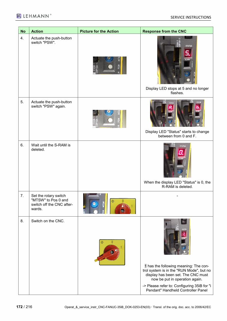
SERVICE INSTRUCTIONS
172 / 216 Operat_&_service_instr_CNC-FANUC-35iB_DOK-0253-EN(03) Transl. of the orig. doc. acc. to 2006/42/EC
No Action Picture for the Action Response from the CNC
4. Actuate the push-button switch "PSW".
Display LED stops at 5 and no longer flashes.
5. Actuate the push-button switch "PSW" again.
Display LED "Status" starts to change between from 0 and F.
6. Wait until the S-RAM is deleted.
When the display LED "Status" is 0, the R-RAM is deleted.
7. Set the rotary switch "MTSW" to Pos 0 and switch off the CNC after-wards.
-
8. Switch on the CNC.
1 has the following meaning: The con-trol system is in the "RUN Mode", but no
display has been set. The CNC must now be put in operation again.
-> Please refer to: Configuring 35iB for "i Pendant" Handheld Controller Panel
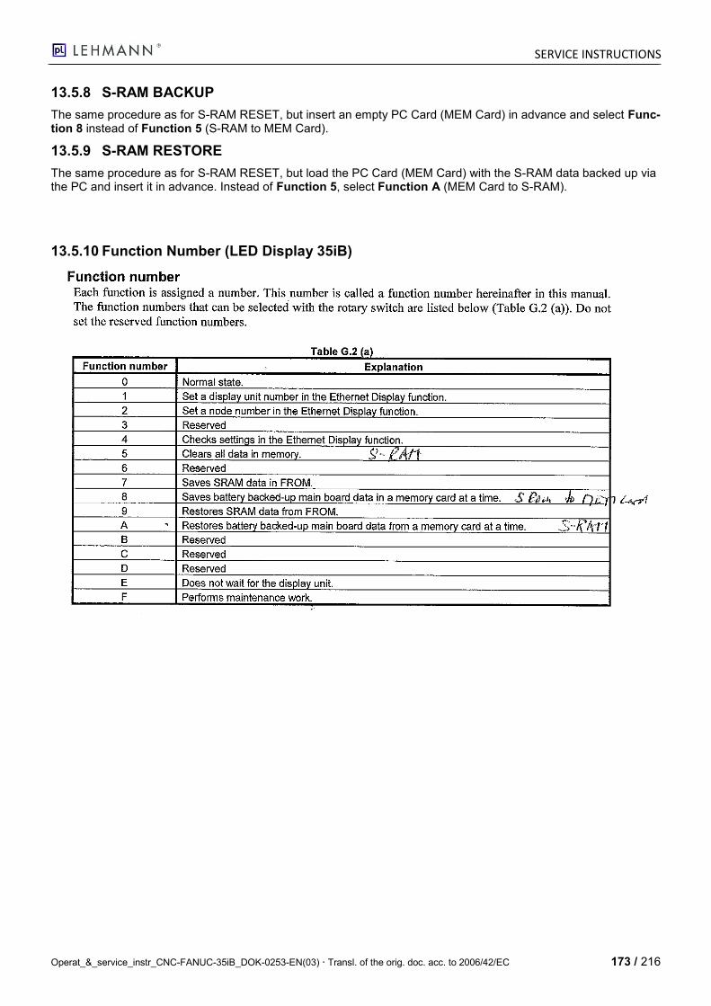
SERVICE INSTRUCTIONS
Operat_&_service_instr_CNC-FANUC-35iB_DOK-0253-EN(03) Transl. of the orig. doc. acc. to 2006/42/EC 173 / 216
13.5.8 S-RAM BACKUP
The same procedure as for S-RAM RESET, but insert an empty PC Card (MEM Card) in advance and select Func-tion 8 instead of Function 5 (S-RAM to MEM Card).
13.5.9 S-RAM RESTORE
The same procedure as for S-RAM RESET, but load the PC Card (MEM Card) with the S-RAM data backed up via the PC and insert it in advance. Instead of Function 5, select Function A (MEM Card to S-RAM).
13.5.10 Function Number (LED Display 35iB)

SERVICE INSTRUCTIONS
174 / 216 Operat_&_service_instr_CNC-FANUC-35iB_DOK-0253-EN(03) Transl. of the orig. doc. acc. to 2006/42/EC
14 Error Messages
14.1 Introduction
Message Function Remark
0 to 999 System alarms PG cycle is stopped
1000 to 2000 General alarms PG cycle is stopped
2000 to Messages PG cycle is not stopped, only message
14.2 PMC Errors (spec. LEHMANN)
Remark: As long as the errors are active, they are shown in clear text on the ALARM screen mask.
A history entry including date and time is also created in each case. Here, only the ALARM numbers + "external alarm" without clear text are shown.
Address Message Meaning Corrective Action
A020.0 1000 EMERGENCY STOP ACTIVE Emergency stop handheld controller or external
Unlock emergency stop
A020.1 1001 GUARD DOOR / OK BUTTON
A020.2 1002 FEED 0% Feed too low Increase feed
A020.3 1003 LIMIT SWITCH +A A+ end position reached Leave end position
A020.4 1004 LIMIT SWITCH -A A- end position reached Leave end position
A020.5 1005 LIMIT SWITCH +C C+ end position reached Leave end position
A020.6 1006 LIMIT SWITCH -C C- end position reached Leave end position
A020.7 1007 BRAKE A IS NOT ON Spindle clamping A is not clamped Check compressed air, vent
A021.0 1008 BRAKE A IS NOT OFF Spindle clamping A is not unclamped Compressed air is missing, BRAKY def.
A021.1 1009 BRAKE C IS NOT ON Spindle clamping C is not clamped Check compressed air, vent
A021.2 1010 BRAKE C IS NOT OFF Spindle clamping C is not unclamped Compressed air is missing, BRAKY def.
A021.3 1011 DT-SYSTEM NOT READY A Rotary table A not ready e.g. compressed air is missing
A021.4 1012 DT-SYSTEM NOT READY C Rotary table C not ready e.g. compressed air is missing
A021.5 1013 DT-ALARM A Rotary table A alarm according to error codes
A021.6 1014 DT-ALARM C Rotary table C alarm according to error codes
A021.7
A022.0
A022.1
A022.2
A022.3
A022.4
A022.5
SERVICE INSTRUCTIONS
Operat_&_service_instr_CNC-FANUC-35iB_DOK-0253-EN(03) Transl. of the orig. doc. acc. to 2006/42/EC 175 / 216
Address Message Meaning Corrective Action
A022.6
A022.7
A023.0
A023.1
A023.2
A023.3
A023.4
A023.5
A023.6
A023.7
A024.0 2000 REFERENCE RUN REQUIRED For this mode, a reference run is re-quired
Approach reference point
A024.1 2001 PROG.SPINDLE SPEED TOO HIGH "Continuous turning" mode active Reduce speed
A024.2
A024.3
A024.4
A024.5
A024.6
A024.7
A025.0
A025.1
A025.2
A025.3
A025.4
A025.5
A025.6
A025.7
A026.0
A026.1
A026.2
A026.3
A026.4
A026.5
A026.6
A026.7
A027.0 2100 BATTERY ALARM S-RAM batt. empty (param. + progr.) Replace
A027.1 2101 DT-SERVICE MESSAGE A A axis requires service Call TCS LEHMANN
A027.2 2101 DT-SERVICE MESSAGE C C axis requires service Call TCS LEHMANN
A027.3
A027.4
SERVICE INSTRUCTIONS
176 / 216 Operat_&_service_instr_CNC-FANUC-35iB_DOK-0253-EN(03) Transl. of the orig. doc. acc. to 2006/42/EC
Address Message Meaning Corrective Action
A027.5
A027.6
A027.7
A028.0
A028.1
A028.2
A028.3
A028.4
A028.5
A028.6
A028.7
A029.0
A029.1
A029.2
A029.3
A029.4
A029.5
A029.6
A029.7
A030.0 1021 AX1 TEMP. INTERNAL blackBOX Alarm No. 01
A030.1 1022 AX1 RELATIVE HUMIDITY blackBOX Alarm No. 02
A030.2 1023 AX1 EXCESS PRESSURE HOUSING blackBOX Alarm No. 03
A030.3 1024 AX1 VACUUM HOUSING blackBOX Alarm No. 04
A030.4 1025 AX1 EXCESS CURRENT PROP.VALVE PRESSURE
blackBOX Alarm No. 05
A030.5 1026 AX1 MINIMUM CURRENT PROP.VALVE PRESSURE
blackBOX Alarm No. 06
A030.6 1027 AX1 EXCESS PRESSURE SYSTEM PRESSURE 6BAR
blackBOX Alarm No. 07
A030.7 1028 AX1 VACUUM SYSTEM PRESSURE 6BAR blackBOX Alarm No. 08
A031.0 1029 AX1 MOTOR EXCESS CURRENT blackBOX Alarm No. 09
A031.1 1030 AX1 STROKE/ACCELERATION blackBOX Alarm No. 10
A031.2 1031 AX1 MAX. SPEED blackBOX Alarm No. 11
A031.3 1032 AX1 SPINDLE CL. TIME CLAMP blackBOX Alarm No. 12
A031.4 1033 AX1 SPINDLE CL. TIME UNCLAMP blackBOX Alarm No. 13
A031.5 1034 AX1 VALVE SPINDLE CLAMPING DISCONN. blackBOX Alarm No. 14
A031.6 1035 AX1 VALVE SPINDLE CLAMPING CURRENT blackBOX Alarm No. 15
A031.7 1036 AX1 EXTERNAL BOOSTY ERROR blackBOX Alarm No. 16
A032.0 1037 AX1 LICENSE EXPIRED blackBOX Alarm No. 17
A032.1 1038 AX1 LICENSE KEY INCORRECT blackBOX Alarm No. 18
A032.2 1039 AX1 SYSTEMZEIT FEHLERHAFT blackBOX Alarm No. 19
SERVICE INSTRUCTIONS
Operat_&_service_instr_CNC-FANUC-35iB_DOK-0253-EN(03) Transl. of the orig. doc. acc. to 2006/42/EC 177 / 216
Address Message Meaning Corrective Action
A032.3 1040 AX1 Max.Revolution Speed blackBOX Alarm No. 20
A032.4 1041 AX1 Acceleration IRQ blackBOX Alarm No. 21
A032.5 1042 AX1 Revolution On Time max. blackBOX Alarm No. 22
A032.6 1043 AX1 First Time Limit blackBOX Alarm No. 23
A032.7 1044 AX1 Second Time Limit blackBOX Alarm No. 24
A033.0 1045 AX1 NO SERIAL NUMBER PARAMETERIZED blackBOX Alarm No. 25
A033.1 1046 AX1 INIT SPINDLE CLAMPING SENSOR blackBOX Alarm No. 26
A033.2 1047 AX1 INIT SYSTEM PRESSURE SENSOR blackBOX Alarm No. 27
A033.3 1048 AX1 INIT INTERNAL PRESSURE SENSOR DEFECTIVE
blackBOX Alarm No. 28
A033.4 1049 AX1 INIT ACCEL.SENSORS DEFECTIVE blackBOX Alarm No. 29
A033.5
A033.6
A033.7
A034.0 1121 AX2 TEMP. INTERNAL blackBOX Alarm No. 01
A034.1 1122 AX2 RELATIVE HUMIDITY blackBOX Alarm No. 02
A034.2 1123 AX2 EXCESS PRESSURE HOUSING blackBOX Alarm No. 03
A034.3 1124 AX2 VACUUM HOUSING blackBOX Alarm No. 04
A034.4 1125 AX2 EXCESS CURRENT PROP.VALVE PRESSURE
blackBOX Alarm No. 05
A034.5 1126 AX2 MINIMUM CURRENT PROP.VALVE PRESSURE
blackBOX Alarm No. 06
A034.6 1127 AX2 EXCESS PRESSURE SYSTEM PRESSURE 6BAR
blackBOX Alarm No. 07
A034.7 1128 AX2 VACUUM SYSTEM PRESSURE 6BAR blackBOX Alarm No. 08
A035.0 1129 AX2 MOTOR EXCESS CURRENT blackBOX Alarm No. 09
A035.1 1130 AX2 STROKE/ACCELERATION blackBOX Alarm No. 10
A035.2 1131 AX2 MAX. SPEED blackBOX Alarm No. 11
A035.3 1132 AX2 SPINDLE CL. TIME CLAMP blackBOX Alarm No. 12
A035.4 1133 AX2 SPINDLE CL. TIME UNCLAMP blackBOX Alarm No. 13
A035.5 1134 AX2 VALVE SPINDLE CLAMPING DISCONN. blackBOX Alarm No. 14
A035.6 1135 AX2 VALVE SPINDLE CLAMPING CURRENT blackBOX Alarm No. 15
A035.7 1136 AX2 EXTERNAL BOOSTY ERROR blackBOX Alarm No. 16
A036.0 1137 AX2 LICENSE EXPIRED blackBOX Alarm No. 17
A036.1 1138 AX2 LICENSE KEY INCORRECT blackBOX Alarm No. 18
A036.2 1139 AX2 SYSTEM TIME INCORRECT blackBOX Alarm No. 19
A036.3 1140 AX2 Max.Revolution Speed blackBOX Alarm No. 20
A036.4 1141 AX2 Acceleration IRQ blackBOX Alarm No. 21
A036.5 1142 AX2 Revolution On Time max. blackBOX Alarm No. 22
A036.6 1143 AX2 First Time Limit blackBOX Alarm No. 23
A036.7 1144 AX2 Second Time Limit blackBOX Alarm No. 24
SERVICE INSTRUCTIONS
178 / 216 Operat_&_service_instr_CNC-FANUC-35iB_DOK-0253-EN(03) Transl. of the orig. doc. acc. to 2006/42/EC
Address Message Meaning Corrective Action
A037.0 1145 AX2 NO SERIAL NUMBER PARAMETERIZED blackBOX Alarm No. 25
A037.1 1146 AX2 INIT SPINDLE CLAMPING SENSOR blackBOX Alarm No. 26
A037.2 1147 AX2 INIT SYSTEM PRESSURE SENSOR blackBOX Alarm No. 27
A037.3 1148 AX2 INIT INTERNAL PRESSURE SENSOR DEFECTIVE
blackBOX Alarm No. 28
A037.4 1149 AX2 INIT ACCEL.SENSORS DEFECTIVE blackBOX Alarm No. 29
A037.5
A037.6
A037.7
14.3 Error Messages, Buffer Battery
No. Meaning Action
A300 Reference point lost Order a replacement battery.
A306 Buffer battery completely empty Under no circumstances switch off the CNC FANUC PMi.
A307 Buffer battery almost empty Only switch off the CNC FANUC PMi for a short time.
A308 Buffer battery almost completely empty Do not switch off the CNC FANUC PMi.
14.4 FANUC NC Alarms
14.4.1 Alarm Assignment
The error codes are classified as follows:
No. Alarm
000 - 255 P/S (Program errors)
300 - 349 Absolute pulse coder (APC) alarms
350 - 399 Serial pulse coder (SPC) alarms
400 - 499 Servo alarms
500 - 599 Overtravel alarms
700 - 749 Overheat alarms
750 - 799 Spindle alarms (For the Power Mate i-D/D2)
900 - 999 System alarms
5000 and higher P/S alarm (Program error)
14.4.2 Alarm Numbers (Source: Fanuc B-63174EN03)
Type D Control System
1) P/S (Program errors)
No. Message Contents
000 PLEASE TURN OFF POWER
A parameter which requires the power off was input, turn off power.
001 TH PARITY ALARM TH alarm (A character with incorrect parity was input). Correct the tape.
002 TV PARITY ALARM TV alarm (The number of characters in a block is odd.) This alarm will be generated only when the TV check is effective.
SERVICE INSTRUCTIONS
Operat_&_service_instr_CNC-FANUC-35iB_DOK-0253-EN(03) Transl. of the orig. doc. acc. to 2006/42/EC 179 / 216
No. Message Contents
003 TOO MANY DIGITS Data exceeding the maximum allowable number of digits was input. (See Appendix C in the Oper-ator’s Manual.)
004 ADDRESS NOT FOUND A numeral or the sign “ – ” was input without an address at the beginning of a block. Modify the program.
005 NO DATA AFTER ADDRESS
The address was not followed by the appropriate data but was followed by another address or EOB code. Modify the program.
006 ILLEGAL USE OF NEGATIVE SIGN
Sign “ – ” input error (Sign “ – ” was input after an address with which it cannot be used. Or two or more “ – ” signs were input.) Modify the program.
007 ILLEGAL USE OF DECIMAL POINT
Decimal point “.” input error (A decimal point was input after an address with which it can not be used. Or two decimal points were input.) Modify the program.
009 ILLEGAL ADDRESS INPUT Unusable character was input in significant area. Modify the program.
010 IMPROPER G–CODE An unusable G code or G code corresponding to the function not provided is specified. Modify the program.
011 NO FEED RATE COMMANDED
Feed rate was not commanded to a cutting feed or the feed rate was inadequate. Modify the pro-gram.
014 CAN NOT COMMAND G95 A synchronous feed is specified without the option for threading / synchronous feed.
015 TOO MANY AXES COMMANDED
The number of the commanded axes exceeded that of simultaneously controlled axes.
020 OVER TOLERANCE OF RADIUS
In circular interpolation (G02 or G03), difference of the distance between the start point and the center of an arc and that between the end point and the center of the arc exceeded the value specified in parameter no. 3410.
021 ILLEGAL PLANE AXIS COMMANDED
An axis not included in the selected plane (by using G17, G18, G19) was commanded in circular interpolation. Modify the program.
022 NO CIRCULAR RADIUS When circular interpolation is specified, neither R (specifying an arc radius), nor I, J, and K (speci-fying the distance from a start point to the center) is specified.
027 NO AXES COMMANDED IN G43/G44
No axis is specified in G43 and G44 blocks for the tool length offset. Offset is not canceled but an-other axis is offset for the tool length offset. Modify the program.
028 ILLEGAL PLANE SELECT In the plane selection command, two or more axes in the same direction are commanded. Modify the program.
029 ILLEGAL OFFSET VALUE The offset values specified by H code is too large. Modify the program.
030 ILLEGAL OFFSET NUMBER The offset number specified by H code for tool length offset is too large. Modify the program.
031 ILLEGAL P COMMAND IN G10
In setting an offset amount by G10, the offset number following address P was excessive or it was not specified. Modify the program.
032 ILLEGAL OFFSET VALUE IN G10
In setting an offset amount by G10 or in writing an offset amount by system variables, the offset amount was excessive.
044 G27–G30 NOT ALLOWED IN FIXED CYC
One of G27 to G30 is commanded in canned cycle mode. Modify the program.
046 ILLEGAL REFERENCE RETURN COMMAND
Other than P2 and P3 are commanded for 2nd and 3rd reference position return command.
059 PROGRAM NUMBER NOT FOUND
In an external program number search, a specified program number was not found. Otherwise, a program specified for searching is being edited in background processing. Check the program number and external signal, or discontinue the background editing.
060 SEQUENCE NUMBER NOT FOUND
Commanded sequence number was not found in the sequence number search. Check the se-quence number.
070 NO PROGRAM SPACE IN MEMORY
The memory space is insufficient. Delete any unnecessary programs, then retry.
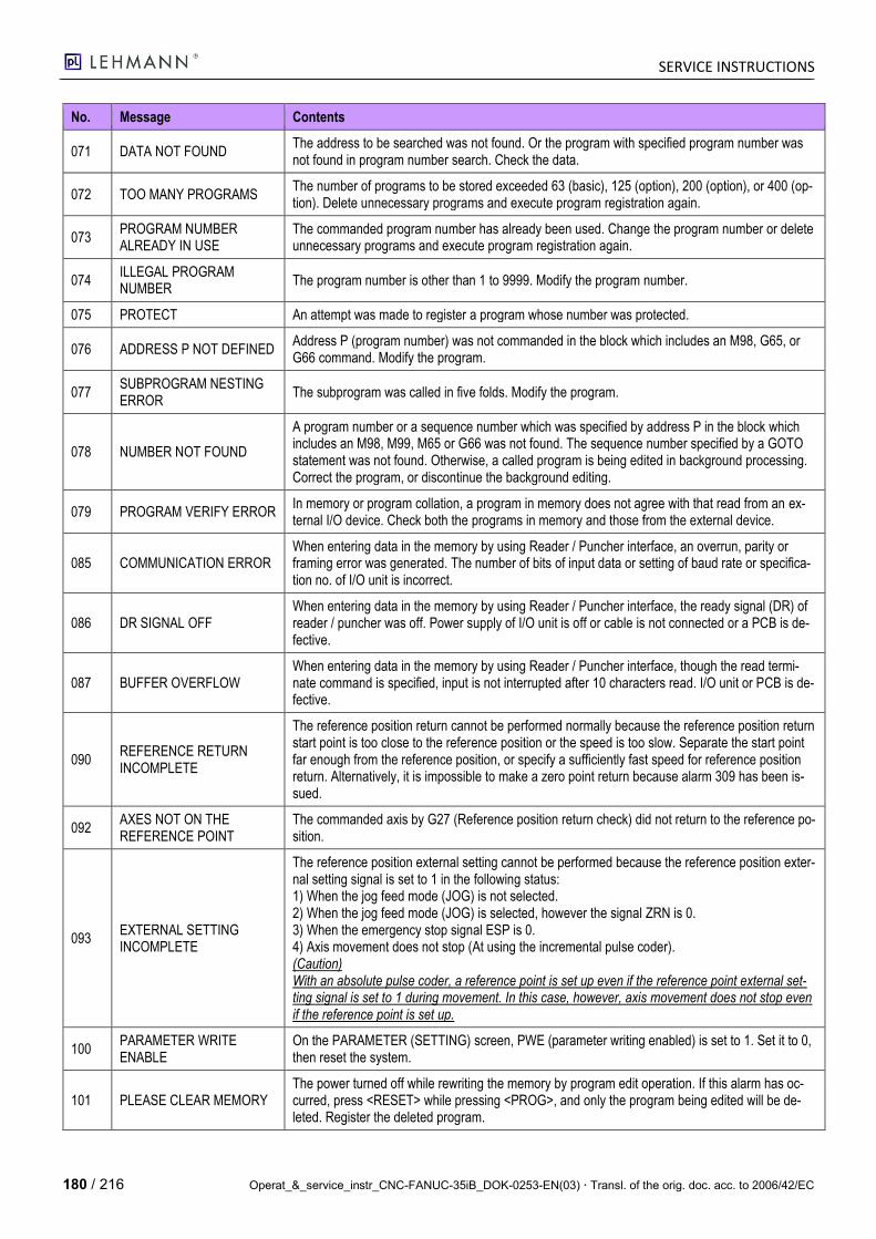
SERVICE INSTRUCTIONS
180 / 216 Operat_&_service_instr_CNC-FANUC-35iB_DOK-0253-EN(03) Transl. of the orig. doc. acc. to 2006/42/EC
No. Message Contents
071 DATA NOT FOUND The address to be searched was not found. Or the program with specified program number was not found in program number search. Check the data.
072 TOO MANY PROGRAMS The number of programs to be stored exceeded 63 (basic), 125 (option), 200 (option), or 400 (op-tion). Delete unnecessary programs and execute program registration again.
073 PROGRAM NUMBER ALREADY IN USE
The commanded program number has already been used. Change the program number or delete unnecessary programs and execute program registration again.
074 ILLEGAL PROGRAM NUMBER
The program number is other than 1 to 9999. Modify the program number.
075 PROTECT An attempt was made to register a program whose number was protected.
076 ADDRESS P NOT DEFINED Address P (program number) was not commanded in the block which includes an M98, G65, or G66 command. Modify the program.
077 SUBPROGRAM NESTING ERROR
The subprogram was called in five folds. Modify the program.
078 NUMBER NOT FOUND
A program number or a sequence number which was specified by address P in the block which includes an M98, M99, M65 or G66 was not found. The sequence number specified by a GOTO statement was not found. Otherwise, a called program is being edited in background processing. Correct the program, or discontinue the background editing.
079 PROGRAM VERIFY ERROR In memory or program collation, a program in memory does not agree with that read from an ex-ternal I/O device. Check both the programs in memory and those from the external device.
085 COMMUNICATION ERROR When entering data in the memory by using Reader / Puncher interface, an overrun, parity or framing error was generated. The number of bits of input data or setting of baud rate or specifica-tion no. of I/O unit is incorrect.
086 DR SIGNAL OFF When entering data in the memory by using Reader / Puncher interface, the ready signal (DR) of reader / puncher was off. Power supply of I/O unit is off or cable is not connected or a PCB is de-fective.
087 BUFFER OVERFLOW When entering data in the memory by using Reader / Puncher interface, though the read termi-nate command is specified, input is not interrupted after 10 characters read. I/O unit or PCB is de-fective.
090 REFERENCE RETURN INCOMPLETE
The reference position return cannot be performed normally because the reference position return start point is too close to the reference position or the speed is too slow. Separate the start point far enough from the reference position, or specify a sufficiently fast speed for reference position return. Alternatively, it is impossible to make a zero point return because alarm 309 has been is-sued.
092 AXES NOT ON THE REFERENCE POINT
The commanded axis by G27 (Reference position return check) did not return to the reference po-sition.
093 EXTERNAL SETTING INCOMPLETE
The reference position external setting cannot be performed because the reference position exter-nal setting signal is set to 1 in the following status: 1) When the jog feed mode (JOG) is not selected. 2) When the jog feed mode (JOG) is selected, however the signal ZRN is 0. 3) When the emergency stop signal ESP is 0. 4) Axis movement does not stop (At using the incremental pulse coder). (Caution) With an absolute pulse coder, a reference point is set up even if the reference point external set-ting signal is set to 1 during movement. In this case, however, axis movement does not stop even if the reference point is set up.
100 PARAMETER WRITE ENABLE
On the PARAMETER (SETTING) screen, PWE (parameter writing enabled) is set to 1. Set it to 0, then reset the system.
101 PLEASE CLEAR MEMORY The power turned off while rewriting the memory by program edit operation. If this alarm has oc-curred, press <RESET> while pressing <PROG>, and only the program being edited will be de-leted. Register the deleted program.
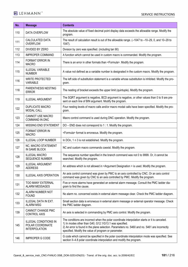
SERVICE INSTRUCTIONS
Operat_&_service_instr_CNC-FANUC-35iB_DOK-0253-EN(03) Transl. of the orig. doc. acc. to 2006/42/EC 181 / 216
No. Message Contents
110 DATA OVERFLOW The absolute value of fixed decimal point display data exceeds the allowable range. Modify the program.
111 CALCULATED DATA OVERFLOW
The result of calculation result is out of the allowable range. (–1047 to –10–29, 0, and 10–29 to 1047).
112 DIVIDED BY ZERO Division by zero was specified. (including tan 90)
113 IMPROPER COMMAND A function which cannot be used in custom macro is commanded. Modify the program.
114 FORMAT ERROR IN MACRO
There is an error in other formats than <Formula>. Modify the program.
115 ILLEGAL VARIABLE NUMBER
A value not defined as a variable number is designated in the custom macro. Modify the program.
116 WRITE PROTECTED VARIABLE
The left side of substitution statement is a variable whose substitution is inhibited. Modify the pro-gram.
118 PARENTHESIS NESTING ERROR
The nesting of bracket exceeds the upper limit (quintuple). Modify the program.
119 ILLEGAL ARGUMENT The SQRT argument is negative, BCD argument is negative, or other values than 0 to 9 are pre-sent on each line of BIN argument. Modify the program.
122 DUPLICATE MACRO MODAL CALL
Four nesting levels of macro calls and/or macro modal calls have been specified. Modify the pro-gram.
123 CANNOT USE MACRO COMMAND IN DNC
Macro control command is used during DNC operation. Modify the program.
124 MISSING END STATEMENT DO – END does not correspond to 1 : 1. Modify the program.
125 FORMAT ERROR IN MACRO
<Formula> format is erroneous. Modify the program.
126 ILLEGAL LOOP NUMBER In DOn, 1 n 3 is not established. Modify the program.
127 NC, MACRO STATEMENT IN SAME BLOCK
NC and custom macro commands coexist. Modify the program.
128 ILLEGAL MACRO SEQUENCE NUMBER
The sequence number specified in the branch command was not 0 to 9999. Or, it cannot be searched. Modify the program.
129 ILLEGAL ARGUMENT ADDRESS
An address which is not allowed in <Argument Designation > is used. Modify the program.
130 ILLEGAL AXIS OPERATION An axis control command was given by PMC to an axis controlled by CNC. Or an axis control command was given by CNC to an axis controlled by PMC. Modify the program.
131 TOO MANY EXTERNAL ALARM MESSAGES
Five or more alarms have generated an external alarm message. Consult the PMC ladder dia-gram to find the cause.
132 ALARM NUMBER NOT FOUND
No alarm no. concerned exists in external alarm message clear. Check the PMC ladder diagram.
133 ILLEGAL DATA IN EXT. ALARM MSG
Small section data is erroneous in external alarm message or external operator message. Check the PMC ladder diagram.
139 CANNOT CHANGE PMC CONTROL AXIS
An axis is selected in commanding by PMC axis control. Modify the program.
145 ILLEGAL CONDITIONS IN POLAR COORDINATE INTERPOLATION
The conditions are incorrect when the polar coordinate interpolation starts or it is canceled. 1) In modes other than G40, G12.1/G13.1 was specified. 2) An error is found in the plane selection. Parameters no. 5460 and no. 5461 are incorrectly specified. Modify the value of program or parameter.
146 IMPROPER G CODE G code which cannot be specified in the polar coordinate interpolation mode was specified. See section II–4.8 polar coordinate interpolation and modify the program.
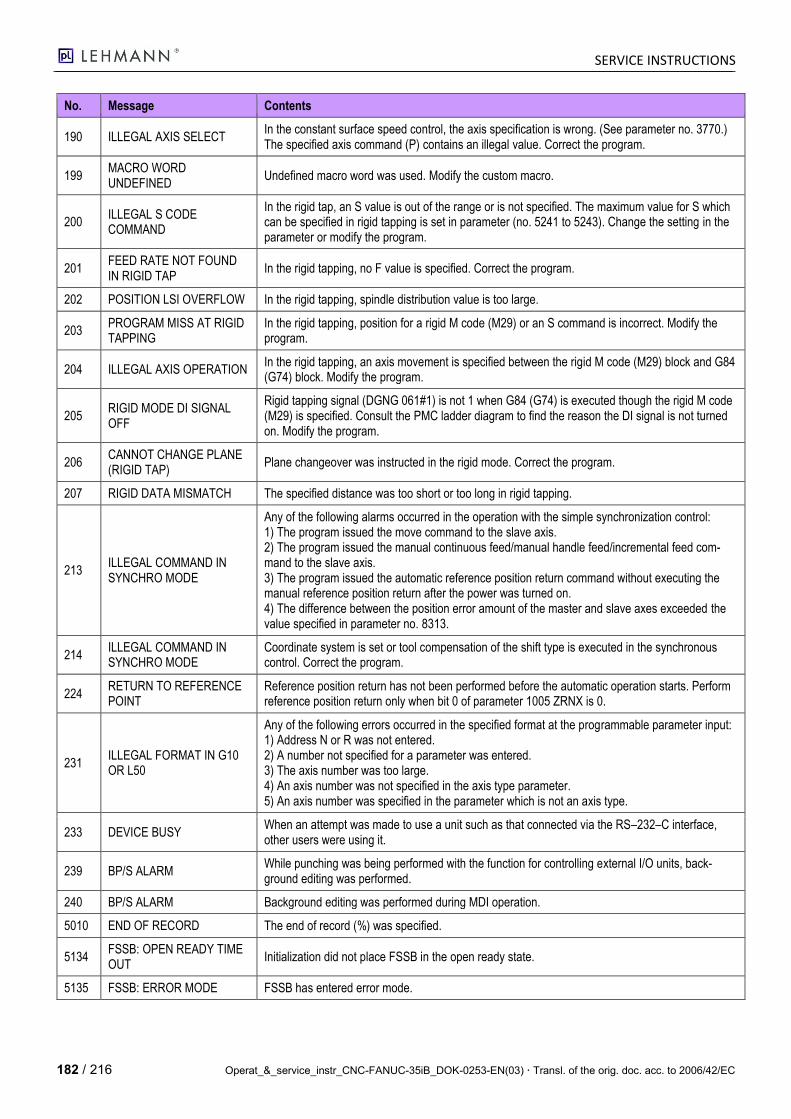
SERVICE INSTRUCTIONS
182 / 216 Operat_&_service_instr_CNC-FANUC-35iB_DOK-0253-EN(03) Transl. of the orig. doc. acc. to 2006/42/EC
No. Message Contents
190 ILLEGAL AXIS SELECT In the constant surface speed control, the axis specification is wrong. (See parameter no. 3770.) The specified axis command (P) contains an illegal value. Correct the program.
199 MACRO WORD UNDEFINED
Undefined macro word was used. Modify the custom macro.
200 ILLEGAL S CODE COMMAND
In the rigid tap, an S value is out of the range or is not specified. The maximum value for S which can be specified in rigid tapping is set in parameter (no. 5241 to 5243). Change the setting in the parameter or modify the program.
201 FEED RATE NOT FOUND IN RIGID TAP
In the rigid tapping, no F value is specified. Correct the program.
202 POSITION LSI OVERFLOW In the rigid tapping, spindle distribution value is too large.
203 PROGRAM MISS AT RIGID TAPPING
In the rigid tapping, position for a rigid M code (M29) or an S command is incorrect. Modify the program.
204 ILLEGAL AXIS OPERATION In the rigid tapping, an axis movement is specified between the rigid M code (M29) block and G84 (G74) block. Modify the program.
205 RIGID MODE DI SIGNAL OFF
Rigid tapping signal (DGNG 061#1) is not 1 when G84 (G74) is executed though the rigid M code (M29) is specified. Consult the PMC ladder diagram to find the reason the DI signal is not turned on. Modify the program.
206 CANNOT CHANGE PLANE (RIGID TAP)
Plane changeover was instructed in the rigid mode. Correct the program.
207 RIGID DATA MISMATCH The specified distance was too short or too long in rigid tapping.
213 ILLEGAL COMMAND IN SYNCHRO MODE
Any of the following alarms occurred in the operation with the simple synchronization control: 1) The program issued the move command to the slave axis. 2) The program issued the manual continuous feed/manual handle feed/incremental feed com-mand to the slave axis. 3) The program issued the automatic reference position return command without executing the manual reference position return after the power was turned on. 4) The difference between the position error amount of the master and slave axes exceeded the value specified in parameter no. 8313.
214 ILLEGAL COMMAND IN SYNCHRO MODE
Coordinate system is set or tool compensation of the shift type is executed in the synchronous control. Correct the program.
224 RETURN TO REFERENCE POINT
Reference position return has not been performed before the automatic operation starts. Perform reference position return only when bit 0 of parameter 1005 ZRNX is 0.
231 ILLEGAL FORMAT IN G10 OR L50
Any of the following errors occurred in the specified format at the programmable parameter input: 1) Address N or R was not entered. 2) A number not specified for a parameter was entered. 3) The axis number was too large. 4) An axis number was not specified in the axis type parameter. 5) An axis number was specified in the parameter which is not an axis type.
233 DEVICE BUSY When an attempt was made to use a unit such as that connected via the RS–232–C interface, other users were using it.
239 BP/S ALARM While punching was being performed with the function for controlling external I/O units, back-ground editing was performed.
240 BP/S ALARM Background editing was performed during MDI operation.
5010 END OF RECORD The end of record (%) was specified.
5134 FSSB: OPEN READY TIME OUT
Initialization did not place FSSB in the open ready state.
5135 FSSB: ERROR MODE FSSB has entered error mode.
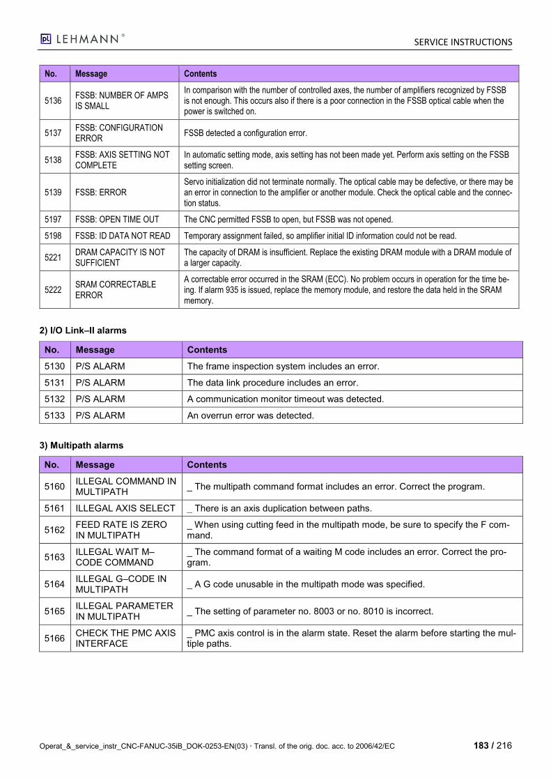
SERVICE INSTRUCTIONS
Operat_&_service_instr_CNC-FANUC-35iB_DOK-0253-EN(03) Transl. of the orig. doc. acc. to 2006/42/EC 183 / 216
No. Message Contents
5136 FSSB: NUMBER OF AMPS IS SMALL
In comparison with the number of controlled axes, the number of amplifiers recognized by FSSB is not enough. This occurs also if there is a poor connection in the FSSB optical cable when the power is switched on.
5137 FSSB: CONFIGURATION ERROR
FSSB detected a configuration error.
5138 FSSB: AXIS SETTING NOT COMPLETE
In automatic setting mode, axis setting has not been made yet. Perform axis setting on the FSSB setting screen.
5139 FSSB: ERROR Servo initialization did not terminate normally. The optical cable may be defective, or there may be an error in connection to the amplifier or another module. Check the optical cable and the connec-tion status.
5197 FSSB: OPEN TIME OUT The CNC permitted FSSB to open, but FSSB was not opened.
5198 FSSB: ID DATA NOT READ Temporary assignment failed, so amplifier initial ID information could not be read.
5221 DRAM CAPACITY IS NOT SUFFICIENT
The capacity of DRAM is insufficient. Replace the existing DRAM module with a DRAM module of a larger capacity.
5222 SRAM CORRECTABLE ERROR
A correctable error occurred in the SRAM (ECC). No problem occurs in operation for the time be-ing. If alarm 935 is issued, replace the memory module, and restore the data held in the SRAM memory.
2) I/O Link–II alarms
No. Message Contents
5130 P/S ALARM The frame inspection system includes an error.
5131 P/S ALARM The data link procedure includes an error.
5132 P/S ALARM A communication monitor timeout was detected.
5133 P/S ALARM An overrun error was detected.
3) Multipath alarms
No. Message Contents
5160 ILLEGAL COMMAND IN MULTIPATH
_ The multipath command format includes an error. Correct the program.
5161 ILLEGAL AXIS SELECT _ There is an axis duplication between paths.
5162 FEED RATE IS ZERO IN MULTIPATH
_ When using cutting feed in the multipath mode, be sure to specify the F com-mand.
5163 ILLEGAL WAIT M–CODE COMMAND
_ The command format of a waiting M code includes an error. Correct the pro-gram.
5164 ILLEGAL G–CODE IN MULTIPATH
_ A G code unusable in the multipath mode was specified.
5165 ILLEGAL PARAMETER IN MULTIPATH
_ The setting of parameter no. 8003 or no. 8010 is incorrect.
5166 CHECK THE PMC AXIS INTERFACE
_ PMC axis control is in the alarm state. Reset the alarm before starting the mul-tiple paths.

SERVICE INSTRUCTIONS
184 / 216 Operat_&_service_instr_CNC-FANUC-35iB_DOK-0253-EN(03) Transl. of the orig. doc. acc. to 2006/42/EC
4) Electronic cam alarms
No. Message Contents
5246 ELECTRONIC CAM PARAMETER ILLEGAL
The settings of the parameters related to the electronic cam below include an error. Correct the settings. No. 8086 (cam shaft axis number) No. 8087 (tracing axis selection) No. 8088 (cam figure data point count) Bit 0 of no. 1006 (rotation axis setting) Bit 0 of no. 1008 (rollover setting) No. 1260 (travel distance per revolution of a rotation axis)
5247 CAM DATA ILLEGAL _ The check sum of cam data is incorrect. _ The cam shaft phase number of cam data is incorrect. _ Cam data could not be transferred.
5248 CAM DATA AREA INSUFFICIENT
_ The option for a part program storage length of 160 m or 320 m is unavailable so that the allocation of a cam data storage area failed. _ Cam data is excessively large so that the storage area is insufficient.
5249 ELECTRONIC CAM CANNOT EXECUTE
Phase matching or electronic cam operation could not be performed for any of the following reasons: _ Phase matching was executed without storing cam data. _ Electronic cam operation was executed before completion of phase matching. _ The electronic cam function was executed while an axis movement was being made with another function.
5) Multi axes synchronous alarms
No. Message Contents
5261 PMC INDIRECT COMMAND IS ILLEGAL
Data specified in an indirect specification command includes an error. Set cor-rect data.
5262 NO SYNCHRO MODE Turn on the synchronization mode signal. Check if the synchronization-related parameters are set correctly.
5263 ILLEGAL SYNCHRO COMMAND FORMAT
An invalid value is entered as the specified parent axis travel distance.
5264 AXIS MOVES TO THE OPPOSITE
Too many rotations were made in the direction opposite to the specified syn-chronization direction. This alarm is issued when an excessive movement is made in the opposite direction. This alarm is not issued the instant a movement is made in the opposite direction.
5265 REFERENCE RETURN IN SYNCHRO MODE
Before performing a reference position return operation, turn off the synchroni-zation mode signal.
5266 PARENT AXIS IS NOT ROTATION ONE
When specifying start point synchronization, specify a rotation axis as the parent axis.
5267 ILLEGAL SYNCHRO AXIS SETTING
Set the parent axis parameter (parameter no. 8380) and the parent axis cate-gory parameter (parameter no. 8381) for synchronization correctly.
5268 NON–SYNCHRO AXIS IS COMMANDED
Synchronization was specified for an axis not related to synchronization or for an axis with no parent (namely, top-parent axis). Check the execution program, the parent axis parameter (parameter no. 8380) and the parent axis category parameter (parameter no. 8381).
5269 ILLEGAL APC AXIS INFORMATION
APC information is being used by another function (such as the electronic cam function). In this case, turn off the synchronization mode and check that these settings are invalid, then turn on the synchronization mode again. Alternatively, cancel.
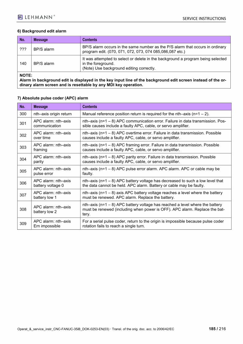
SERVICE INSTRUCTIONS
Operat_&_service_instr_CNC-FANUC-35iB_DOK-0253-EN(03) Transl. of the orig. doc. acc. to 2006/42/EC 185 / 216
6) Background edit alarm
No. Message Contents
??? BP/S alarm BP/S alarm occurs in the same number as the P/S alarm that occurs in ordinary program edit. (070, 071, 072, 073, 074 085,086,087 etc.)
140 BP/S alarm It was attempted to select or delete in the background a program being selected in the foreground. (Note) Use background editing correctly.
NOTE: Alarm in background edit is displayed in the key input line of the background edit screen instead of the or-dinary alarm screen and is resettable by any MDI key operation.
7) Absolute pulse coder (APC) alarm
No. Message Contents
300 nth–axis origin return Manual reference position return is required for the nth–axis (n=1 – 2).
301 APC alarm: nth–axis communication
nth–axis (n=1 – 8) APC communication error. Failure in data transmission. Pos-sible causes include a faulty APC, cable, or servo amplifier.
302 APC alarm: nth–axis over time
nth–axis (n=1 – 8) APC overtime error. Failure in data transmission. Possible causes include a faulty APC, cable, or servo amplifier.
303 APC alarm: nth–axis framing
nth–axis (n=1 – 8) APC framing error. Failure in data transmission. Possible causes include a faulty APC, cable, or servo amplifier.
304 APC alarm: nth–axis parity
nth–axis (n=1 – 8) APC parity error. Failure in data transmission. Possible causes include a faulty APC, cable, or servo amplifier.
305 APC alarm: nth–axis pulse error
nth–axis (n=1 – 8) APC pulse error alarm. APC alarm. APC or cable may be faulty.
306 APC alarm: nth–axis battery voltage 0
nth–axis (n=1 – 8) APC battery voltage has decreased to such a low level that the data cannot be held. APC alarm. Battery or cable may be faulty.
307 APC alarm: nth–axis battery low 1
nth–axis (n=1 – 8) axis APC battery voltage reaches a level where the battery must be renewed. APC alarm. Replace the battery.
308 APC alarm: nth–axis battery low 2
nth–axis (n=1 – 8) APC battery voltage has reached a level where the battery must be renewed (including when power is OFF). APC alarm. Replace the bat-tery.
309 APC alarm: nth–axis Ern impossible
For a serial pulse coder, return to the origin is impossible because pulse coder rotation fails to reach a single turn.

SERVICE INSTRUCTIONS
186 / 216 Operat_&_service_instr_CNC-FANUC-35iB_DOK-0253-EN(03) Transl. of the orig. doc. acc. to 2006/42/EC
8) Serial pulse coder (SPC) alarms
When either of the following alarms is issued, a possible cause is a faulty serial pulse coder or cable.
No. Message Contents
360 n AXIS: ABNORMAL CHECKSUM (INT)
A checksum error occurred in the built-in pulse coder.
361 n AXIS: ABNORMAL PHASE DATA (INT)
A phase data error occurred in the built-in pulse coder.
362 n AXIS: ABNORMAL REV.DATA (INT)
A rotation speed count error occurred in the built-in pulse coder.
363 n AXIS: ABNORMAL CLOCK (INT) A clock error occurred in the built-in pulse coder.
364 n AXIS: SOFT PHASE ALARM (INT)
The digital servo software detected invalid data in the built-in pulse coder.
365 n AXIS: BROKEN LED (INT) An LED error occurred in the built-in pulse coder.
366 n AXIS: PULSE MISS (INT) A feedback error occurred in the built-in pulse coder.
367 n AXIS: COUNT MISS (INT) A count error occurred in the built-in pulse coder.
368 n AXIS: SERIAL DATA ERROR (INT)
Communication data from the built-in pulse coder cannot be received.
369 n AXIS: DATA TRANS. ERROR (INT)
A CRC or stop bit error occurred in the communication data being re-ceived from the built-in pulse coder.
380 n AXIS: BROKEN LED (EXT) The separate detector is erroneous.
381 n AXIS: ABNORMAL PHASE (EXT LIN)
A phase data error occurred in the separate linear scale.
382 n AXIS: COUNT MISS (EXT) A pulse error occurred in the separate detector.
383 n AXIS: PULSE MISS (EXT) A count error occurred in the separate detector.
384 n AXIS: SOFT PHASE ALARM (EXT)
The digital servo software detected invalid data in the separate detec-tor.
385 n AXIS: SERIAL DATA ERROR (EXT)
Communication data from the separate detector cannot be received.
386 n AXIS: DATA TRANS. ERROR (EXT).
A CRC or stop bit error occurred in the communication data being re-ceived from the separate detector.
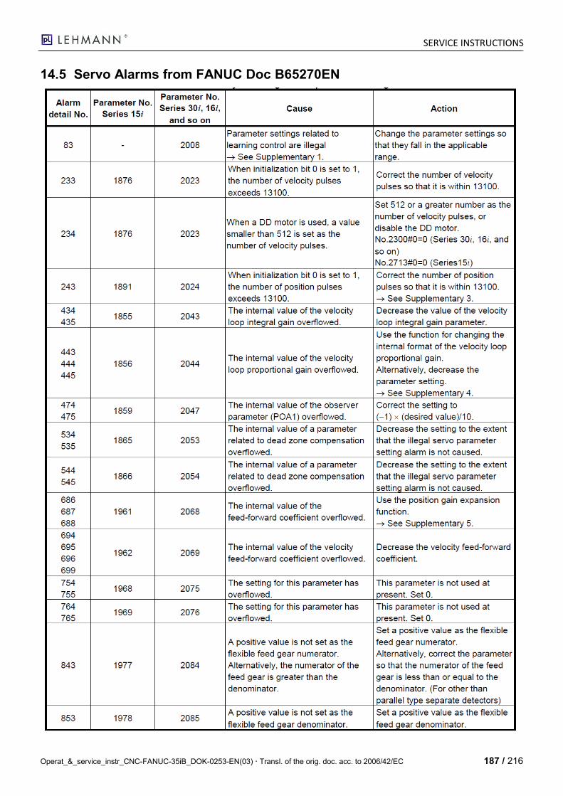
SERVICE INSTRUCTIONS
Operat_&_service_instr_CNC-FANUC-35iB_DOK-0253-EN(03) Transl. of the orig. doc. acc. to 2006/42/EC 187 / 216
14.5 Servo Alarms from FANUC Doc B65270EN

SERVICE INSTRUCTIONS
188 / 216 Operat_&_service_instr_CNC-FANUC-35iB_DOK-0253-EN(03) Transl. of the orig. doc. acc. to 2006/42/EC

SERVICE INSTRUCTIONS
Operat_&_service_instr_CNC-FANUC-35iB_DOK-0253-EN(03) Transl. of the orig. doc. acc. to 2006/42/EC 189 / 216
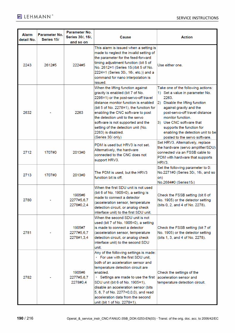
SERVICE INSTRUCTIONS
190 / 216 Operat_&_service_instr_CNC-FANUC-35iB_DOK-0253-EN(03) Transl. of the orig. doc. acc. to 2006/42/EC
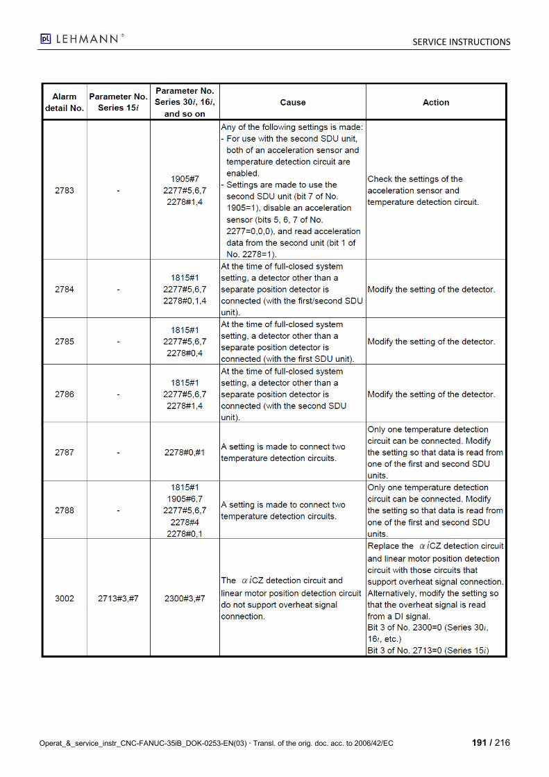
SERVICE INSTRUCTIONS
Operat_&_service_instr_CNC-FANUC-35iB_DOK-0253-EN(03) Transl. of the orig. doc. acc. to 2006/42/EC 191 / 216
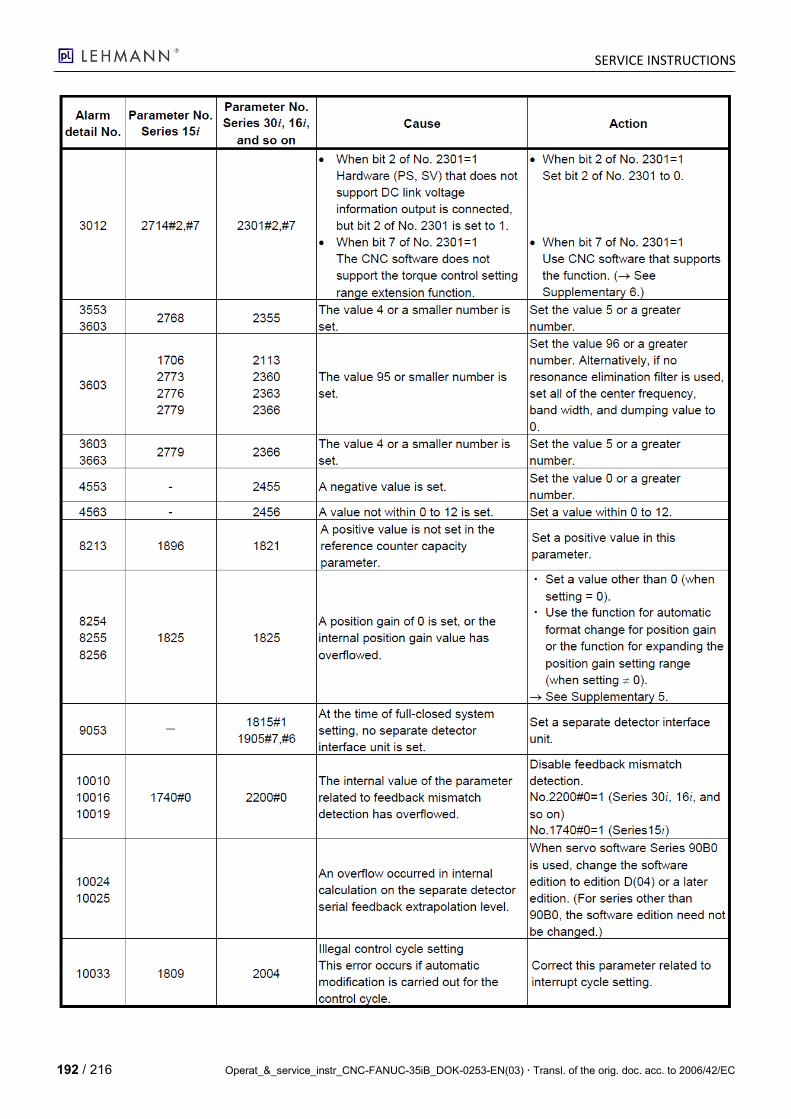
SERVICE INSTRUCTIONS
192 / 216 Operat_&_service_instr_CNC-FANUC-35iB_DOK-0253-EN(03) Transl. of the orig. doc. acc. to 2006/42/EC
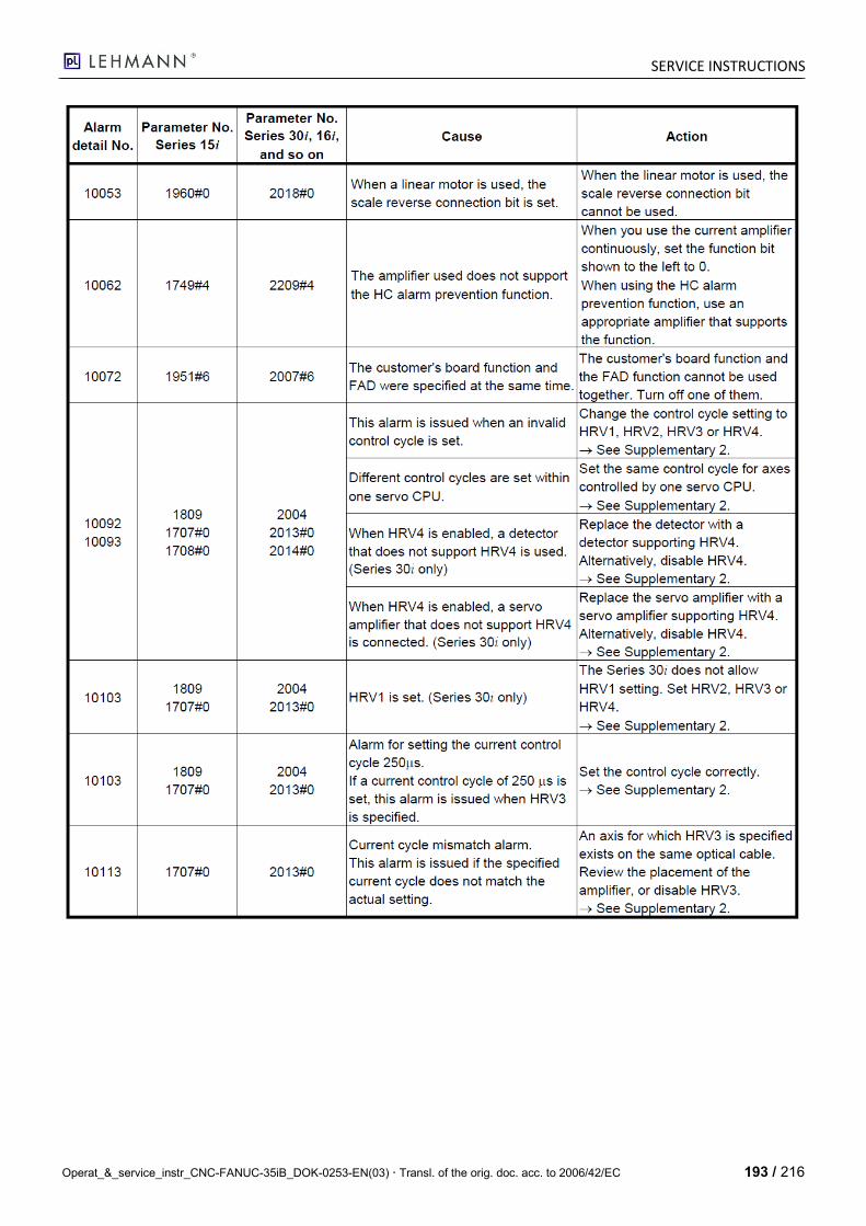
SERVICE INSTRUCTIONS
Operat_&_service_instr_CNC-FANUC-35iB_DOK-0253-EN(03) Transl. of the orig. doc. acc. to 2006/42/EC 193 / 216
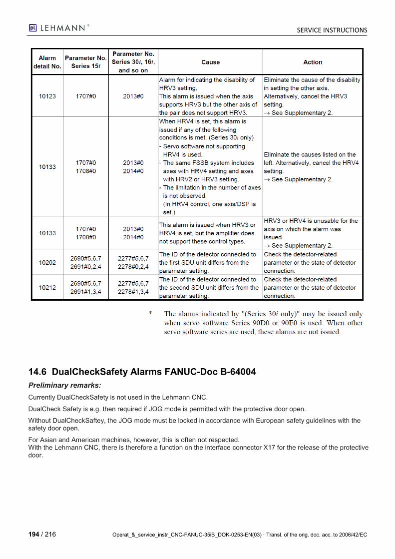
SERVICE INSTRUCTIONS
194 / 216 Operat_&_service_instr_CNC-FANUC-35iB_DOK-0253-EN(03) Transl. of the orig. doc. acc. to 2006/42/EC
14.6 DualCheckSafety Alarms FANUC-Doc B-64004
Preliminary remarks:
Currently DualCheckSafety is not used in the Lehmann CNC.
DualCheck Safety is e.g. then required if JOG mode is permitted with the protective door open.
Without DualCheckSaftey, the JOG mode must be locked in accordance with European safety guidelines with the safety door open.
For Asian and American machines, however, this is often not respected. With the Lehmann CNC, there is therefore a function on the interface connector X17 for the release of the protective door.

SERVICE INSTRUCTIONS
Operat_&_service_instr_CNC-FANUC-35iB_DOK-0253-EN(03) Transl. of the orig. doc. acc. to 2006/42/EC 195 / 216
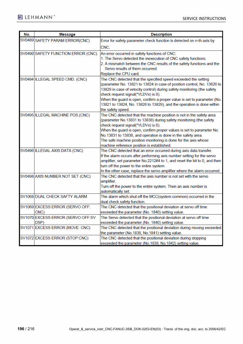
SERVICE INSTRUCTIONS
196 / 216 Operat_&_service_instr_CNC-FANUC-35iB_DOK-0253-EN(03) Transl. of the orig. doc. acc. to 2006/42/EC

SERVICE INSTRUCTIONS
Operat_&_service_instr_CNC-FANUC-35iB_DOK-0253-EN(03) Transl. of the orig. doc. acc. to 2006/42/EC 197 / 216
15 Appendix
15.1 35iB Memory Assignment
S-RAM (Battery-Buffered) F-ROM (EEROM)
NC parameters NC Basic (FANUC NC firmware)
PMC parameters PG Servo (FANUC servo firmware)
Workpiece programs and macros PMC-RB-LADDER (LEHMANN-spec. PLC program)
Tool memory MESSAGE
Pitch Error Compensation I/O CONFIGURATION
Ethernet data (default address 192.168.1.10)
Macro B
Key: - Green: already installed by FANUC upon delivery - Yellow: must always be installed by pL Lehmann - Blue: must be installed by pL Lehmann only if required
15.2 Software Update FANUC i-Pendant
Initial situation: SW V01.0/7.0
1. Load USB flash drive with the current FANUC SW via PC.
2. Insert USB flash drive in the i-Pendant.
3. Boot the i-Pendant and press the F3 key while the handheld controller boots.
4. Wait until "Setup is" is shown on the display.
5. Press the INPUT key.
6. Wait until "Setup complete" is shown on the display.
7. Switch off the i-Pendant and remove the USB flash drive.
8. Reboot i-Pendant, wait until the "SW Version 01.1/7.0" is shown.
9. Choose "Continuous" in the selection field on the display.
10. Switch off and reboot the i-Pendant.
11. Update is complete -> The i-Pendant should start again with the usual FANUC screen mask.
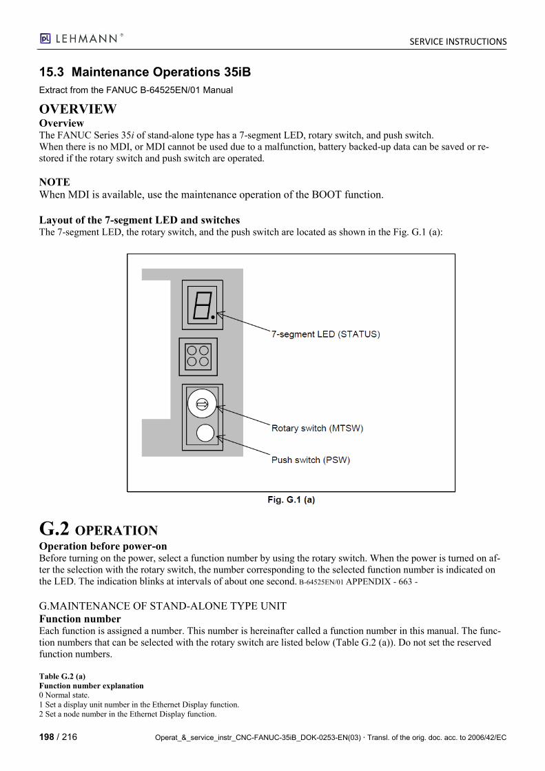
SERVICE INSTRUCTIONS
198 / 216 Operat_&_service_instr_CNC-FANUC-35iB_DOK-0253-EN(03) Transl. of the orig. doc. acc. to 2006/42/EC
15.3 Maintenance Operations 35iB
Extract from the FANUC B-64525EN/01 Manual
OVERVIEW Overview The FANUC Series 35i of stand-alone type has a 7-segment LED, rotary switch, and push switch.
When there is no MDI, or MDI cannot be used due to a malfunction, battery backed-up data can be saved or re-
stored if the rotary switch and push switch are operated.
NOTE
When MDI is available, use the maintenance operation of the BOOT function.
Layout of the 7-segment LED and switches The 7-segment LED, the rotary switch, and the push switch are located as shown in the Fig. G.1 (a):
G.2 OPERATION Operation before power-on Before turning on the power, select a function number by using the rotary switch. When the power is turned on af-
ter the selection with the rotary switch, the number corresponding to the selected function number is indicated on
the LED. The indication blinks at intervals of about one second. B-64525EN/01 APPENDIX - 663 -
G.MAINTENANCE OF STAND-ALONE TYPE UNIT
Function number Each function is assigned a number. This number is hereinafter called a function number in this manual. The func-
tion numbers that can be selected with the rotary switch are listed below (Table G.2 (a)). Do not set the reserved
function numbers.
Table G.2 (a)
Function number explanation
0 Normal state.
1 Set a display unit number in the Ethernet Display function.
2 Set a node number in the Ethernet Display function.
SERVICE INSTRUCTIONS
Operat_&_service_instr_CNC-FANUC-35iB_DOK-0253-EN(03) Transl. of the orig. doc. acc. to 2006/42/EC 199 / 216
3 Reserved
4 Checks settings in the Ethernet Display function.
5 Clears all data in memory.
6 Reserved
7 Saves SRAM data in FROM.
8 Saves battery backed-up main board data in a memory card at a time.
9 Restores SRAM data from FROM.
A Restores battery backed-up main board data from a memory card at a time.
B Reserved
C Reserved
D Reserved
E Does not wait for the display unit.
F Performs maintenance work.
G.3 OPERATION OF EACH FUNCTION Function number 1 This function sets a display unit number in the Ethernet Display function.
(1) Check that number 1 blinks on the LED, and press the push switch.
(2) If the push switch is pressed, the 16 numbers from 0 to F are displayed on the LED in sequence at one-second
intervals. When the display unit number to be set is displayed on the LED, press the push switch.
0: Not used.
1: The HSSB connection display unit or CNC-specific display unit is set.
2 to 4: Not used.
5: The Ethernet connection display unit is set.
6 to F: Not used.
(3) The selected display unit number blinks on the LED. Press the push switch again.
(4) The selected display unit number is displayed on the LED and saved in the CNC.
Function number 2 This function sets a node number in the Ethernet Display function.
(1) Check that number 2 blinks on the LED, and press the push switch.
(2) If the push switch is pressed, the 16 numbers from 0 to F are displayed on the LED in sequence at one second
intervals. When the node number to be set is displayed on the LED, press the push switch.
The node number ranges from 0 to 7.
(3) The selected node number blinks on the LED. Press the push switch again.
(4) The node number is displayed on the LED and the display unit number is saved in the CNC.
Function number 4 This function checks settings in the Ethernet Display function.
(1) Check that number 4 blinks on the LED, and press the push switch.
APPENDIX B-64525EN/01
- 664 –
G. MAINTENANCE OF
STAND-ALONE TYPE UNIT (2) When the push switch is pressed, 0 and 1 are displayed on the LED alternately at one second intervals.
When 0 is displayed, press the push switch.
(3) The selected number 0 blinks on the LED. Press the push switch to stop blinking.
(4) The three numbers from 0 to 2 are displayed in sequence at one second intervals again. When the number to be
checked is displayed on the LED, press the push switch.
0: Not used.
1: A display unit number is checked.
2: A node number is checked.
(5) The selected number blinks. Press the push switch to stop blinking.
Function number 5 This function clears all the battery backed-up SRAM data.
SERVICE INSTRUCTIONS
200 / 216 Operat_&_service_instr_CNC-FANUC-35iB_DOK-0253-EN(03) Transl. of the orig. doc. acc. to 2006/42/EC
The settings of the Ethernet Display function are also cleared and the display unit number and node number are set
to 1 and 0, respectively.
(1) Check that number 5 blinks on the LED, and press the push switch.
(2) Number 5 is displayed on the LED. Press the push switch.
(3) Display of the LED changes in the order: "-", "F", and "0".
(4) After all-clear operation terminates normally, the LED display stops changing at number 0.
(5) Turn off the power, return the rotary switch to the original position, and turn on the power again.
WARNING
1 This operation enables the CNC system to start up solely (initial state). Accordingly, to recover
various functional operations, the cleared data needs to be set again.
2 This operation can be performed by those personnel who have received maintenance and safety
training.
Function number 7 This function saves the following data to the backup data 1 area, which is present in FROM. The data saved by this
function can be restored using the operation indicated by function number 9 or using the SRAM DATA UTILITY
function of the BOOT function.
• Parameters and various data items such as offset data stored in SRAM, which is battery-powered.
• NC programs stored in FROM, which is not battery-powered.
(1) Check that number 7 blinks on the LED, and press the push switch.
(2) When the push switch is pressed, 0 and 1 are displayed on the LED alternately at one second intervals. When 0
is displayed, press the push switch.
0: Saving SRAM data to FROM
1: Not used
(3) The LED display changes in the order from "-" to "F".
(4) The LED indicates clockwise rotation while the data is being saved.
(5) When the data is successfully saved, the LED indicates 0. When the data is not successfully saved, the LED in-
dicates 1 if an error occurs or the LED indicates 3 if the capacity is exceeded.
When bit 1 (ABI) of parameter no. 10340 is 1, an error occurs because the data cannot be saved and
the LED indicates 1.
Function number 8 This function saves battery backed-up mainboard data in one memory card at a time. The data saved using this
function can be restored at a time by performing the operation for function number A or by using the SRAM
DATA UTILITY function of the boot function.
(1) Insert a memory card with enough free space into the memory card slot (MEMORY CARD CNM1B)
of the main body.
(2) Check that number 8 blinks on the LED, and press the push switch.
(3) Number 8 is displayed on the LED. Press the push switch.
APPENDIX B-64525EN/01
- 665 -
G.MAINTENANCE OF STAND-ALONE TYPE UNIT (4) While data is being saved in the memory card, display of the LED rotates clockwise.
(5) If the data cannot fit in one memory card, number 3 blinks. Replace the memory card with another one, and
press the push switch.
(6) If the data cannot be written to the memory card, number 2 blinks on the LED. Replace the memory card with
another one, and press the push switch.
(7) When the data has been saved normally, number 0 is displayed on the LED. If the data cannot be saved nor-
mally, number 1 is displayed on the LED.
(8) If the data cannot be backed up because it is illegal, number 1 blinks on the LED. In this case, it is impossible to
save all the data at a time. Back up individual data items one by one, then perform all-clear operation.
SERVICE INSTRUCTIONS
Operat_&_service_instr_CNC-FANUC-35iB_DOK-0253-EN(03) Transl. of the orig. doc. acc. to 2006/42/EC 201 / 216
Function number 9 This function restores the following data from the backup data 1 area, which is present in FROM. The data restored
by this function is the data saved by the operation of function number 7.
• Parameters and various data items such as offset data stored in SRAM, which is battery-powered.
• NC programs stored in FROM, which is not battery-powered.
(1) Check that number 9 blinks on the LED, and press the push switch.
(2) When the push switch is pressed, 0 and 1 are displayed on the LED alternately at one-second intervals. When 0
is displayed, press the push switch.
0: Restoring SRAM data from FROM
1: Not used
(3) The LED indicates counterclockwise rotation while the data is being restored.
(4) When the data is successfully restored, the LED indicates 0. When the data is not successfully restored, the
LED indicates 1.
Function number A This function restores battery backed-up mainboard data from a memory card at a time.
(1) Insert the memory card in the memory card slot (MEMORY CARD CNM1B) of the control unit.
(2) Check that A blinks on the LED, and press the push switch.
(3) When letter A is displayed on the LED, press the push switch.
(4) While data is being restored from the memory card, the LED indication turns counterclockwise.
(5) If the entire data cannot be restored from the single memory card, number 3 blinks. Replace the memory card
with the next memory card, and press the push switch.
(6) If the memory card cannot be recognized correctly, number 2 blinks on the LED. Check the memory card sta-
tus, and press the push switch.
(7) When the data has been restored normally, number 0 is displayed on the LED. If the data cannot be restored
normally, number 1 is displayed on the LED.
Function number E This setting does not wait for the display unit. Use this setting for a configuration without a display unit.
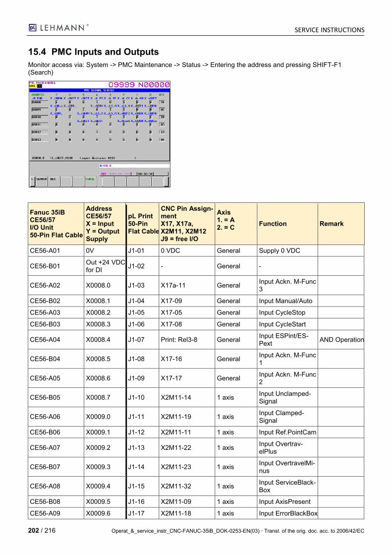
SERVICE INSTRUCTIONS
202 / 216 Operat_&_service_instr_CNC-FANUC-35iB_DOK-0253-EN(03) Transl. of the orig. doc. acc. to 2006/42/EC
15.4 PMC Inputs and Outputs
Monitor access via: System -> PMC Maintenance -> Status -> Entering the address and pressing SHIFT-F1 (Search)
Fanuc 35iB CE56/57 I/O Unit 50-Pin Flat Cable
Address CE56/57 X = Input Y = Output Supply
pL Print 50-Pin Flat Cable
CNC Pin Assign-ment X17, X17a, X2M11, X2M12 J9 = free I/O
Axis 1. = A 2. = C
Function Remark
CE56-A01 0V J1-01 0 VDC General Supply 0 VDC
CE56-B01 Out +24 VDC for DI
J1-02 - General -
CE56-A02 X0008.0 J1-03 X17a-11 General Input Ackn. M-Func 3
CE56-B02 X0008.1 J1-04 X17-09 General Input Manual/Auto
CE56-A03 X0008.2 J1-05 X17-05 General Input CycleStop
CE56-B03 X0008.3 J1-06 X17-08 General Input CycleStart
CE56-A04 X0008.4 J1-07 Print: Rel3-8 General Input ESPint/ES-Pext
AND Operation
CE56-B04 X0008.5 J1-08 X17-16 General Input Ackn. M-Func 1
CE56-A05 X0008.6 J1-09 X17-17 General Input Ackn. M-Func 2
CE56-B05 X0008.7 J1-10 X2M11-14 1 axis Input Unclamped-Signal
CE56-A06 X0009.0 J1-11 X2M11-19 1 axis Input Clamped-Signal
CE56-B06 X0009.1 J1-12 X2M11-11 1 axis Input Ref.PointCam
CE56-A07 X0009.2 J1-13 X2M11-22 1 axis Input Overtrav-elPlus
CE56-B07 X0009.3 J1-14 X2M11-23 1 axis Input OvertravelMi-nus
CE56-A08 X0009.4 J1-15 X2M11-32 1 axis Input ServiceBlack-Box
CE56-B08 X0009.5 J1-16 X2M11-09 1 axis Input AxisPresent
CE56-A09 X0009.6 J1-17 X2M11-18 1 axis Input ErrorBlackBox

SERVICE INSTRUCTIONS
Operat_&_service_instr_CNC-FANUC-35iB_DOK-0253-EN(03) Transl. of the orig. doc. acc. to 2006/42/EC 203 / 216
Fanuc 35iB CE56/57 I/O Unit 50-Pin Flat Cable
Address CE56/57 X = Input Y = Output Supply
pL Print 50-Pin Flat Cable
CNC Pin Assign-ment X17, X17a, X2M11, X2M12 J9 = free I/O
Axis 1. = A 2. = C
Function Remark
CE56-B09 X0009.7 J1-18 X2M11-26 1 axis Input ReadyBlack-Box
CE56-A10 X0010.0 J1-19 X2M12-14 2 axes Input Unclamped-Signal
CE56-B10 X0010.1 J1-20 X2M12-19 2 axes Input Clamped-Signal
CE56-A11 X0010.2 J1-21 X2M12-11 2 axes Input Ref.PointCam
CE56-B11 X0010.3 J1-22 X2M12-22 2 axes Input Overtrav-elPlus
CE56-A12 X0010.4 J1-23 X2M12-23 2 axes Input OvertravelMi-nus
CE56-B12 X0010.5 J1-24 X2M12-32 2 axes Input ServiceBlack-Box
CE56-A13 X0010.6 J1-25 X2M12-09 2 axes Input AxisPresent
CE56-B13 X0010.7 J1-26 X2M12-18 2 axes Input ErrorBlackBox
CE56-A14 DICOM0 J1-27 0 VDC General Supply 0 VDC = PNP Logic
CE56-B14 - J1-28 -
CE56-A15 - J1-29 -
CE56-B15 - J1-30 -
CE56-A16 Y0014.0 J1-31 X17a-05 General Output M-Func 3
CE56-B16 Y0014.1 J1-32 Not connected - -
CE56-A17 Y0014.2 J1-33 X17-19 General Output M-Func 1
CE56-B17 Y0014.3 J1-34 X17-15 General Output M-Func 2
CE56-A18 Y0014.4 J1-35 X17-18 General Output EndOfPro-gram
CE56-B18 Y0014.5 J1-36 X17-20 General Output InPosition
CE56-A19 Y0014.6 J1-37 X17-22 General Output Sys-temReady
CE56-B19 Y0014.7 J1-38 X17a-10 General Output M-Func 4
CE56-A20 Y0015.0 J1-39 X2M11-21 1 axis Output ClampSpin-dle
CE56-B20 Y0015.1 J1-40 X2M12-21 2 axes Output ClampSpin-dle
CE56-A21 Y0015.2 J1-41 X17a-13 General Output M-Func 5
CE56-B21 Y0015.3 J1-42 Not connected -
CE56-A22 Y0015.4 J1-43 J9-11 General Output free
CE56-B22 Y0015.5 J1-44 J9-12 General Output free
CE56-A23 Y0015.6 J1-45 Not connected
CE56-B23 Y0015.7 J1-46 Not connected

SERVICE INSTRUCTIONS
204 / 216 Operat_&_service_instr_CNC-FANUC-35iB_DOK-0253-EN(03) Transl. of the orig. doc. acc. to 2006/42/EC
Fanuc 35iB CE56/57 I/O Unit 50-Pin Flat Cable
Address CE56/57 X = Input Y = Output Supply
pL Print 50-Pin Flat Cable
CNC Pin Assign-ment X17, X17a, X2M11, X2M12 J9 = free I/O
Axis 1. = A 2. = C
Function Remark
CE56-A24 DOCOM J1-47 F2: Supply 24 VDC
General Supply 24 VDC +24 V = PNP Logic
CE56-B24 DOCOM J1-48 F2: Supply 24 VDC
General Supply 24 VDC +24 V = PNP Logic
CE56-A25 DOCOM J1-49 F2: Supply 24 VDC
General Supply 24 VDC +24V = PNP Logic
CE56-B25 DOCOM J1-50 F2: Supply 24 VDC
General Supply 24 VDC +24 V = PNP Logic
CE57-A01 0V J2-01 0 VDC General Supply 0 VDC
CE57-B01 Out +24 VDC for DI
J2-02 - General -
CE57-A02 X0011.0 J2-03 X2M12-26 2 axes Input ReadyBlack-Box
CE57-B02 X0011.1 J2-04 Rel1-8 General Inp. Enable EN3 (A6) or DoorSwitch
OR Operation
CE57-A03 X0011.2 J2-05 EN2 General Enable EN2 (B5)
CE57-B03 X0011.3 J2-06 X17a-04 2 axes Input EnableRo-tation 2nd Axis
CE57-A04 X0011.4 J2-07 X17a-12 General Input Ackn. M-Func 4
CE57-B04 X0011.5 J2-08 X17a-14 General Input Ackn. M-Func 5
CE57-A05 X0011.6 J2-09 J9-01 General Input free
CE57-B05 X0011.7 J2-10 J9-02 General Input free
CE57-A06 X0012.0 J2-11 J9-03 General Input free
CE57-B06 X0012.1 J2-12 J15-01 General HW-STEP1
CE57-A07 X0012.2 J2-13 J9-05 General Input free
CE57-B07 X0012.3 J2-14 J15-02 General HW-STEP2
CE57-A08 X0012.4 J2-15 J8-11 General Handy Con. Check
CE57-B08 X0012.5 J2-16 J15-03 General HW-STEP3
CE57-A09 X0012.6 J2-17 J8-12 General Input free
CE57-B09 X0012.7 J2-18 J15-04 General HW-AXE1
CE57-A10 X0013.0 J2-19 J9-06 General Input free
CE57-B10 X0013.1 J2-20 J15-05 General HW-AXE2
CE57-A11 X0013.2 J2-21 X17-7 General DOOR Switch New as from V1.02
CE57-B11 X0013.3 J2-22 J15-06 General Input free
CE57-A12 X0013.4 J2-23 -
CE57-B12 X0013.5 J2-24 J15-07 General Input free
CE57-A13 X0013.6 J2-25 -
SERVICE INSTRUCTIONS
Operat_&_service_instr_CNC-FANUC-35iB_DOK-0253-EN(03) Transl. of the orig. doc. acc. to 2006/42/EC 205 / 216
Fanuc 35iB CE56/57 I/O Unit 50-Pin Flat Cable
Address CE56/57 X = Input Y = Output Supply
pL Print 50-Pin Flat Cable
CNC Pin Assign-ment X17, X17a, X2M11, X2M12 J9 = free I/O
Axis 1. = A 2. = C
Function Remark
CE57-B13 X0013.7 J2-26 J9-04 General Input free
CE57-A14 - J2-27 -
CE57-B14 DICOM5 J2-28 Supply 0 V General Supply 0 V = PNP Logic
CE57-A15 - J2-29 -
CE57-B15 - J2-30 -
CE57-A16 Y0016.0 J2-31 -
CE57-B16 Y0016.1 J2-32 -
CE57-A17 Y0016.2 J2-33 -
CE57-B17 Y0016.3 J2-34 -
CE57-A18 Y0016.4 J2-35 J9-07 General Output free
CE57-B18 Y0016.5 J2-36 J9-08 General Output free
CE57-A19 Y0016.6 J2-37 J9-09 General Output free
CE57-B19 Y0016.7 J2-38 J9-10 General Output free
CE57-A20 Y0017.0 J2-39 -
CE57-B20 Y0017.1 J2-40 J15-08 General Output free
CE57-A21 Y0017.2 J2-41 -
CE57-B21 Y0017.3 J2-42 -
CE57-A22 Y0017.4 J2-43 -
CE57-B22 Y0017.5 J2-44 -
CE57-A23 Y0017.6 J2-45 -
CE57-B23 Y0017.7 J2-46 -
CE57-A24 DOCOM J2-47 F2: Supply 24 VDC
General Supply 24 VDC +24 V = PNP Logic
CE57-B24 DOCOM J2-48 F2: Supply 24 VDC
General Supply 24 VDC +24 V = PNP Logic
CE57-A25 DOCOM J2-49 F2: Supply 24 VDC
General Supply 24 VDC +24V = PNP Logic
CE57-B25 DOCOM J2-50 F2: Supply 24 VDC
General Supply 24 VDC +24V = PNP Logic
PMC intern R0903.5 Handy-Schal-ter
0 = Off / 1 = On
Caution: Address name and symbol name must not be identical. Key:
- CE56 => Print-J1
- CE57 => Print-J2
- X2M11 => Print AX1
- X2M12 => Print AX2

SERVICE INSTRUCTIONS
206 / 216 Operat_&_service_instr_CNC-FANUC-35iB_DOK-0253-EN(03) Transl. of the orig. doc. acc. to 2006/42/EC
15.5 Connector on Side Wall Control System
15.5.1 Power Supply X20 plug type CEE Ty 3L 16A 6h
The included cable has 3 flex with different colors and a plug type CEE Typ 3L 16A 6h on both ends:
Brown => 1.phase
Blue => neutral or 2.phase
Green/yellow => earth
Plug type CEE Typ 3L 16A 6h
Input current 16A
For the 1-axis and for the 2-axis CNC control is the same input-fuse inside (16A).
For each axis the control needs a current of 8[A] (that means min. 8A, max 16A)
automatic fuse 16A
Input voltage 200…240VAC
There are 2 possibilities:
1-phase (L1 / N) 220…240[VAC]
2-phases (L1 / L2) 200…240[VAC]
FANUC-Servo amplifier Bi SV20
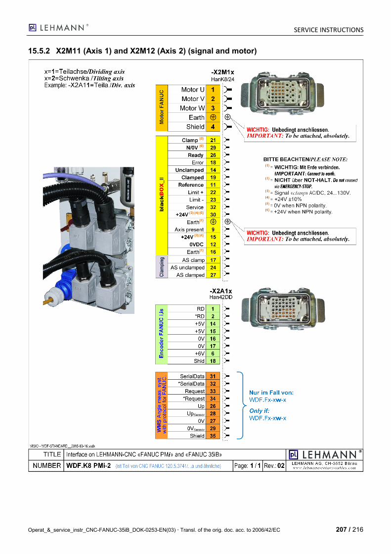
SERVICE INSTRUCTIONS
Operat_&_service_instr_CNC-FANUC-35iB_DOK-0253-EN(03) Transl. of the orig. doc. acc. to 2006/42/EC 207 / 216
15.5.2 X2M11 (Axis 1) and X2M12 (Axis 2) (signal and motor)
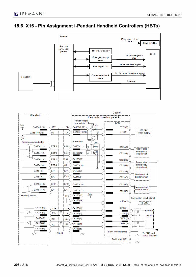
SERVICE INSTRUCTIONS
208 / 216 Operat_&_service_instr_CNC-FANUC-35iB_DOK-0253-EN(03) Transl. of the orig. doc. acc. to 2006/42/EC
15.6 X16 - Pin Assignment i-Pendant Handheld Controllers (HBTs)

SERVICE INSTRUCTIONS
Operat_&_service_instr_CNC-FANUC-35iB_DOK-0253-EN(03) Transl. of the orig. doc. acc. to 2006/42/EC 209 / 216
15.7 EMERGENCY STOP Circuit
This EMERGENCY STOP circuit is realized on the Lehmann print art. no. 120-3805a with safety print relays (Rel1, Rel2 and Rel3). J- designations are pins on the print.
For your information: - EMERGENCY STOP button from the handheld controller to the pL CNC has a two-channel design. - OK buttons from the handheld controller to the pL CNC have a one-channel design. - EMERGENCY STOP from the higher-level machine to the pL CNC has a one-channel design. - EMERGENCY STOP from the pL CNC to the higher-level machine has a one-channel design. - Guard door enable from the higher-level machine to the pL CNC has a one-channel design. - The entire pL print diagram is stored in a separate file.
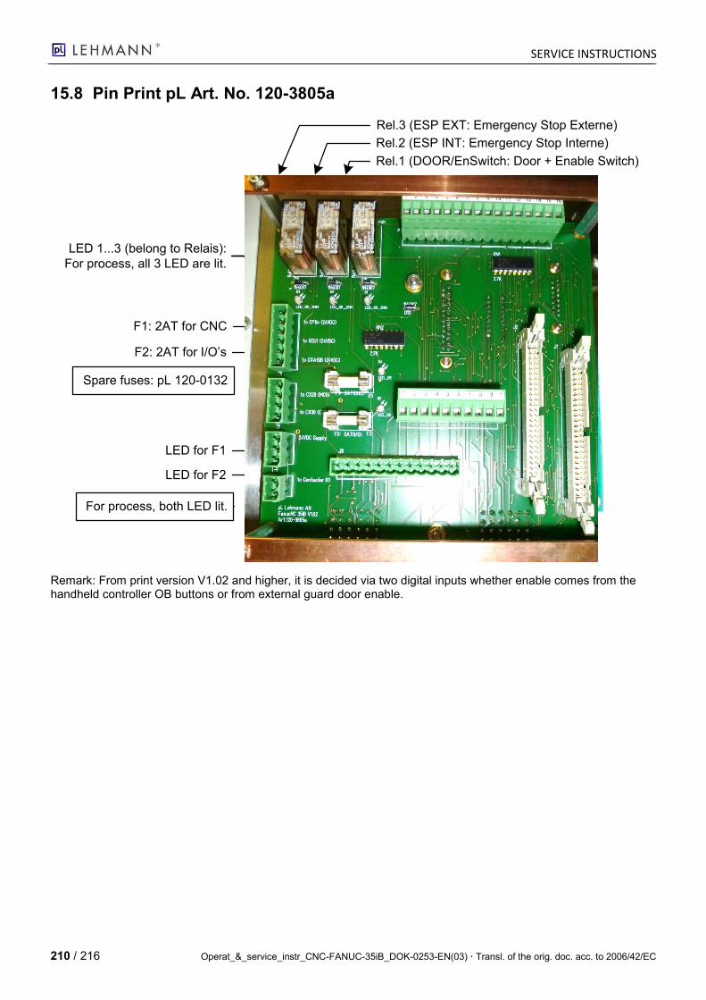
SERVICE INSTRUCTIONS
210 / 216 Operat_&_service_instr_CNC-FANUC-35iB_DOK-0253-EN(03) Transl. of the orig. doc. acc. to 2006/42/EC
15.8 Pin Print pL Art. No. 120-3805a
Rel.3 (ESP EXT: Emergency Stop Externe)
Rel.2 (ESP INT: Emergency Stop Interne)
Rel.1 (DOOR/EnSwitch: Door + Enable Switch)
LED 1...3 (belong to Relais):
For process, all 3 LED are lit.
F1: 2AT for CNC
F2: 2AT for I/O’s
Spare fuses: pL 120-0132
LED for F1
LED for F2
For process, both LED lit.
Remark: From print version V1.02 and higher, it is decided via two digital inputs whether enable comes from the handheld controller OB buttons or from external guard door enable.
SERVICE INSTRUCTIONS
Operat_&_service_instr_CNC-FANUC-35iB_DOK-0253-EN(03) Transl. of the orig. doc. acc. to 2006/42/EC 211 / 216
15.9 35iB Control Cabinet Wiring Diagram
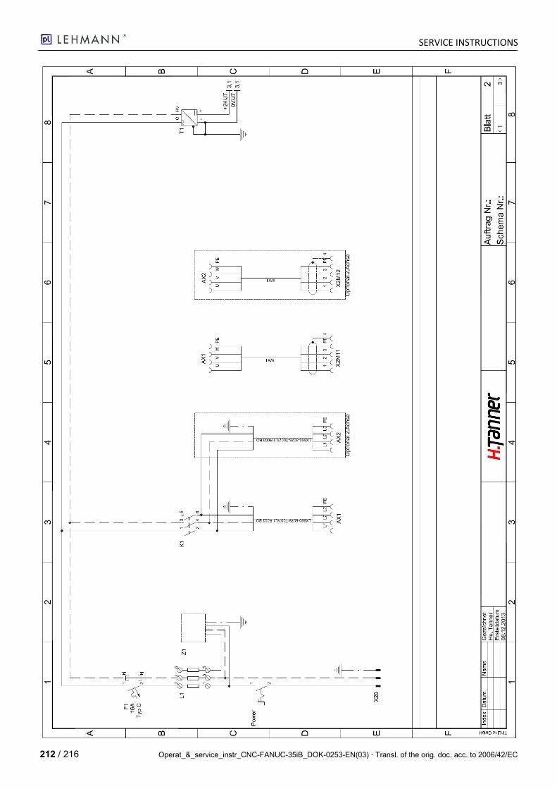
SERVICE INSTRUCTIONS
212 / 216 Operat_&_service_instr_CNC-FANUC-35iB_DOK-0253-EN(03) Transl. of the orig. doc. acc. to 2006/42/EC

SERVICE INSTRUCTIONS
Operat_&_service_instr_CNC-FANUC-35iB_DOK-0253-EN(03) Transl. of the orig. doc. acc. to 2006/42/EC 213 / 216
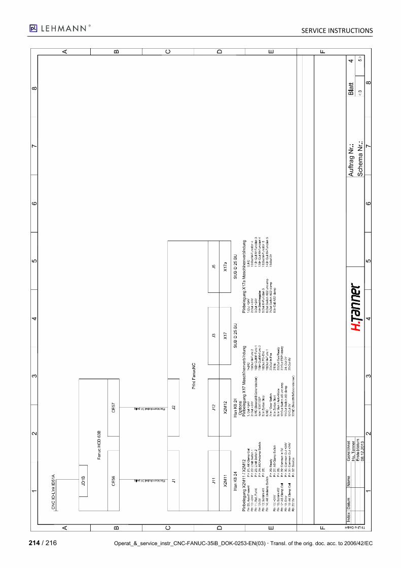
SERVICE INSTRUCTIONS
214 / 216 Operat_&_service_instr_CNC-FANUC-35iB_DOK-0253-EN(03) Transl. of the orig. doc. acc. to 2006/42/EC

SERVICE INSTRUCTIONS
Operat_&_service_instr_CNC-FANUC-35iB_DOK-0253-EN(03) Transl. of the orig. doc. acc. to 2006/42/EC 215 / 216
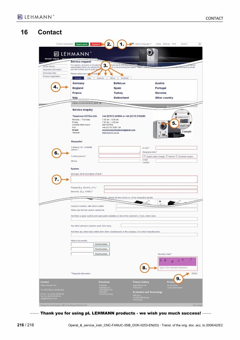
CONTACT
216 / 216 Operat_&_service_instr_CNC-FANUC-35iB_DOK-0253-EN(03) Transl. of the orig. doc. acc. to 2006/42/EC
16 Contact
Thank you for using pL LEHMANN products - we wish you much success!