sserc bulletin
TRANSCRIPT

SSERC Bulletin 205 Summer 2002 205 - 1
�������������
�������������� ����������������������� �����������
CONTENTS
1 Editorial
2 News & comment
3 Gas cylinders andregulators
4 Van de Graaff shocks
6 Brady’s reagent
7 Texas datalogger
9 Graphical Analysis
10 Anodising aluminium
11 Microbiologyresources
12 Microscopeillumination
13 Constant springmotor
14 Laser diode modules
15 UV LEDs
16 Trade news, Contact lens retraction
ISSUE 205
The Bulletin ispublished by
SSERC, St Mary’sBuilding,23 Holyrood Road,Edinburgh, EH8 8AE
Tel: 0131 558 8180
Fax: 0131 558 8191
E-mail: [email protected]
Managing Editor:John RichardsonCopyright is held to bewaived only for bona-fideeducational uses withincurrent Scottish memberEAs, schools and colleges.
���������������������� �������������������
ISSN 0267-7474
��������������A lot has happened since the Scottish Executivepublished its Science Strategy in August 2001.
We have a new Minister for Enterprise and LifelongLearning (and nearly a’thing else). One of the previousincumbent’s parting shots was an article in BusinessA.M. reiterating her belief in the importance of scienceand skills in the economic and cultural lives of Scots.The Royal Society of Edinburgh has followed up a keyelement in the Strategy and accepted the Executive’sinvitation to convene a Science Advisory Committee.That group now has a practising teacher as one of itsmembers. The Royal Society of London has continuedto be active also, not only south of the border butacross the UK. The Westminster Parliament’s SelectCommittee on Science and Technology is part waythrough its investigation into science education 14 to18. Sir Gareth Roberts’ report to HM Treasury onScience, Engineering, Technology and Mathematicsskills was published in April. Science Year is half-waythrough.
This is perhaps a good time to review and reflect onwhat progress has been made in improving Scottishscience education. When the Executive published thescience strategy it made some key commitments toScotland’s science base. Stating a political will is, ofcourse, relatively easy. Keeping to one’s commitmentsby following through and delivering was aye thetricky bit. It is for the science and technology com-munity to encourage and assist with the next phaseof implementation. We need to ensure, before anymore high-profile initiatives or debates divert thecollective political and educational attention, that wesee a number of elements of the Science Strategycarried through in practice.
Much of the activity already announced has beenwelcome. It has probably contributed to partialachievement of some of the declared objectives.Our own major interests lie generally in school andcollege science education. More specifically our corebusiness, to use the jargon, is to assist with - andsupport - the provision of adequate facilities andresources for learning and teaching in science andtechnology. Over the years we’ve also been sucked
into related activities, such as health and safetyadvice, training and ICT applications. It may beuseful then, in this and subsequent bulletins, toreview progress - or any lack of it - in these areas.
Firstly, what about our own key concern, kit? Whathas been done about funding for equipment andapparatus?
A number of reports, pre-dating the Science Strategy,stressed the need to replace obsolete and worn-outscience education equipment. The Executive hasbegun to tackle this problem but it got off to asomewhat bumpy start. The first announcement wasof a figure of £10 million or so for new equipment.In practice school science seems to have seen little, ifany, of that money. It is best left to readers to spec-ulate as to where it went. The next slice of fundingwas £5 million - which was nice. Most, if not all, ofthis has probably gone to support educationalelements of the Science Strategy (not just kit). It wasa bit of a scramble though. The entitlements wereannounced late in the financial year. The notice toeach Council on their share of the latest tranche, £3million or so, has been much better. That letter wasdated 1st May (see over). Discounting the original,ghostly, £10 million, a total of £8 million has beendisbursed thus far. This was the figure spat out ofthe rumour mill a while ago. So, is that it then?
If so, it isn’t enough. Scottish science education willhave been let down. Informed estimates suggestthat, after twenty years or more of neglect, schoolscience needs £15 million a year for five years if weare to make a real difference. That’s equivalent, intotal, to the initial capital costs of just one majorScience Centre. Meantime, the number of youngpeople taking up the physical sciences continues todecline. The uptake of biological sciences is slowing.
A clichéd schools’ verdict on the Science Strategy,thus far, seems unavoidable:
“An encouraging start, but a sustainedeffort is needed to make further progress.”
* * *

205 - 2 SSERC Bulletin 205 Summer 2002
����� ������� �
More money for scienceIn support of its national priorities forthe development of science education inschools, as set out in the Science Strategyfor Scotland, the Scottish Executive hasannounced further funding for scienceactivities and resources totalling £3million for the financial year ending 31stMarch 2003. This is new money and isadditional to the £5 million announcedearly in 2002 (see Bulletin 204). As before,these funds are ring fenced for scienceprojects so as to assist schools in linewith the objectives of the ScienceStrategy.
Distribution of funds has again beenbased on pupil numbers. Councils’allocations are tabulated below.
COUNCIL ALLOCATION
Aberdeen City £97,640
Aberdeenshire £175,980
Angus £72,500
Argyll & Bute £64,210
Clackmannanshire £28,560
Dumf. & Galloway £108,040
Dundee City £76,140
East Ayrshire £73,050
East Dunbartonshire £69,750
East Lothian £54,310
East Renfrewshire £58,440
Edinburgh City of £185,440
Eilean Siar (W.Isles) £24,440
Falkirk £79,750
Fife £203,760
Glasgow City £282,570
Highland £161,050
Inverclyde £47,920
Midlothian £50,290
Moray £58,910
North Ayrshire £82,630
North Lanarkshire £191,580
Orkney Islands £17,670
Perth & Kinross £84,560
Renfrewshire £99,980
Scottish Borders £74,290
Shetland Islands £21,630
South Ayrshire £66,680
South Lanarkshire £180,450
Stirling £54,480
West Dunbartonshire £55,930
West Lothian £97,370
TOTAL £3,000,000
������� Additional science funding by EA.See the equivalent table on page 2of Bulletin 204 for the 2001-02allocations.
Institute for Science EducationPlans for an Institute for ScienceEducation in Scotland (ISES) are at anadvanced stage. Nine of the ScottishUniversities and a number of otherpartner organisations have signalledtheir support for this proposal which hasbeen put forward by an Advisory Boardto the Faculty of Science and Engineeringat the University of Edinburgh.
The University is assigning some of itsKnowledge Transfer grant monies to thedevelopment of the Institute and hastaken the lead role in its foundation andpromotion. Although the Institute willprobably be housed in Edinburgh’sScience and Engineering Faculty, the firmintention is for national coverage forISES through its various members orpartners and their activities. A coreactivity will be the provision of highquality professional development forteachers and technicians.
The ISES implementation group has awide and varied membership whichincludes representatives from otheruniversities, a headteacher and othersfrom the school sector, ADES, the ScottishEarth Science Education Forum (SESEF),the Scottish Centre for BiotechnologyEducation, SAPS, SEED and SSERC. At thetime of writing the group was in theprocess of appointing a DevelopmentDirector for the Institute.
SCBE appoints staffThe Scottish Centre for BiotechnologyEducation (SCBE), see above, is basedalongside staff of the SAPS Scotlandproject within the Institute of Cellularand Molecular Biology in Edinburgh.SCBE also works with other members ofthe SAPS team at the Quest Laboratory inDollar. The Centre has now appointed aProject Manager to take forward thistype of collaborative work. A Post-doctoral development officer withexperience of appropriate gene technol-ogies is also to be appointed. Initiallythey will adapt a number of protocolsfrom the USA to make them moreappropriate for use in Scottish courses.
And, finally - SAPS, SCBE, the Faculty ofEducation in Edinburgh, SSERC and SCBC(the Scottish Colleges BiotechnologyConsortium) have jointly submitted atender for a Pilot Option Module for theChartered Teacher Programme. The bidwas developed under the auspices of theInstitute for Science Education Scotland.
Science 5-14 newsAfter a somewhat faltering start, the paceof the Improving Science Education 5-14national project has now picked upsignificantly. A Project Manager has beenappointed and will be in post by earlyJune. Three Development Officers eachfrom different authorities should also bein post by late July or early August. Theywill work closely with both LT Scotlandstaff and with the SSERC team which isdeveloping the next phase of the SOLSN(Science Online Support Network) project.
A SOLSN development site is alreadyavailable for inspection and comment -see www.solsn.org.uk. User names andpasswords are available, on request, toany Scottish teachers, technicians or EAofficers.
RSE/SEELLD FellowshipsThe Royal Society of Edinburgh, with thesupport of the Scottish Executive Enter-prise and Lifelong Learning Department,is inviting applications for a number ofScience Fellowships for Teachers, startinglate 2002/early 2003.
Applicants must be members of teachingstaff in a Scottish secondary school.Science Fellowships will fund theappointment of a temporary replace-ment to enable a Teaching Fellow to takeleave from his or her own institution,while still continuously employed withhis/her present employer.
Applicants may choose a company forthe placement or one of the organis-ations provided on the RSE list (see p.16).Fellowships will normally be tenable forup to three months or one academicterm. Once appointed, Fellows will berequired to devote their full time to theplacement project.
These fellowhips will be of interest toteachers in chemistry, biology, physics,electronics, engineering, computing andcareers. The Scottish Executive hopesthat the scheme will enhance the transferof ideas from commercial or industrialorganisations to the education system,benefiting both the schools and individ-ual teachers.
The closing date for applications is the30th of August 2002. For more detailscontact the RSE’s Research AwardsManager (see the text box on the backpage).
* * *

SSERC Bulletin 205 Summer 2002 205 - 3
Cylinders
Usually the cylinders are on hire from a supplier, eg BOC, whoalso fills them with the appropriate gas. Being the owner thesupplier has the responsibility for pressure testing thecylinder.
However users should carry out a visual check on eachoccasion of use. If there are obvious problems such as:
- damage to the threads
- if the regulator doesn’t seat properly or
- if the spindle valve requires great force to turn off thesupply,
return the cylinder to the gas supplier.
Regulators
These are usually owned by schools, who will then have theresponsibility for testing them. In discussion with the HSEon this subject, their opinion was that gas cylinder regulatorsare most unlikely to cause problems, but should be profess-ionally checked at “appropriate intervals”. There is no actualfigure stated in legislation for the length of the interval as thisdepends on the amount of use and abuse which theregulator might receive.
A specialist HSE inspector who had worked for many years inthe compressed gases industry considered that an inspectionat intervals of 5 or 6 years was adequate for regulators whichmight be used between six and ten times in a year -especially when compared with the heavy use of regulatorsin industry. He also added that:
- the design of gas regulators is such that they shouldalways ‘fail to minimum danger’ and shut off;
- he only knew of one instance where a regulator failedcatastrophically and that was on an old device whichwas being constantly turned on and off several timesevery day;
- modern diaphragms last a long time.
Replacement
If the regulators are older than 20 years they should bereplaced. Such regulators may be marked BS 5741, or haveno BS marking at all. Some a bit younger would be stamp-ed with BS EN 585 or BS 7650. They will probably be morethan 5 years old and will need testing soon. Regulatorspurchased since around 1998 carry the marking BS EN ISO2503.
The rotary pressure adjusting control knob can be screwedcompletely out of some older regulators; such regulatorsshould also be replaced. Modern ones have captive controlknobs.
������
Gas cylinders and regulatorsBoth of these components must, by law, be examined regularly.
Also, in the case of nitrogen, check that the regulator isdesigned to withstand the higher pressure of 230 bar nowsupplied in cylinders instead of 137 bar. It is vital that you donot use a new cylinder of nitrogen with an old regulatorwhich may not have been designed to cope with higherpressures. BOC state that most regulators sold in the UKsince 1987 should be suitable. The maximum inlet pressurefor which the regulator is designed is usually marked on theregulator. If you are uncertain on this point, check with thegas supplier before you use it.
Suppliers of regulators include Freshford, Northern Technical& Chemical Services and Wescol (Scottish agent: ExpressFuels).
RECOMMENDED CHECKS AND TESTS
On each occasion of use make a visual inspectionfor obvious signs of physical damage to the valves,casing, couplings and threads.
Check also that the regulator is suitable for use withthe gas in the cylinder; the colour codes for thecontained gas have changed (see entry for GasCylinders in the Hazardous Chemicals Manual CD2 forfuller details). The correct means of identification isby reading the name stamped on the cylinder.
Annually, or if there is reason to suspect a leak,carry out a simple leak test
Wear goggles for this test. With the regulator fittedto the cylinder attach a short length of rubber tubingto the outlet and close the open end with alaboratory screw clip. Apply a dilute solution ofdetergent over the joints and the outside of theregulator, adjust the output pressure to a very lowvalue, say 0.5 bar. Afterwards remove detergentsolution with a damp cloth and dry the regulator. Ifany leaks are indicated by the appearance of smallbubbles, then the regulator should be returned tothe supplier or other firm for fuller testing.
Every five years have a test made by a competentengineer
For example Freshford Ltd currently quote £10 pluscarriage. If a repair is also needed, this will cost anextra £40. If you purchase a new regulator, have ittested at five year intervals, ie at 5 years and 10 yearsafter purchase and consider replacement after 15years of age. If an EA can collect all its regulatorstogether the cost of transport can be greatlyreduced. Freshford make regular visits to universitiesin Scotland.
BOC sell regulators with a 5 year expiry date stampedon them and strenuously recommend that they arereplaced every 5 years. Note that this is arecommendation and not a legal requirement.
205 - 4 SSERC Bulletin 205 Summer 2002
������
Van de Graaff generator hazardsExcepting to persons with certain medical conditions, there is little risk of harm from electric shock from a Van de Graaff generator whose domedoes not exceed 25 cm. Two cases of shock are analysed - a direct spark to the body from a charged dome, and an unintended discharge of acharged person. The first of these leads to a limit for maximum dome size. The article finishes with guidance on how to run the machine safely.
We discuss firstly the risk of harm to pupils with unusualmedical conditions1. Listed below are cardiac conditionswhich may place someone at increased risk of ventricularfibrillation2. Subjects with any of these conditions should notreceive electrical discharges from this equipment:
� coronary heart disease (e.g. angina, history of heartattack)
� cardiac rhythm disorders
� intra-cardiac conduction pathway anomalies
� presence of an implanted cardiac pacemaker
� hypertension (high blood pressure)
Regarding epileptic subjects, the risk of seizure is unlikely, butepileptic subjects should not be allowed to take that chance.
There is no evidence to suggest that persons without anysuch medical condition are at risk of ventricular fibrillation ongetting electric shocks from a small Van de Graaff generator.This is underpinned by a theoretical understanding, whichindicates no significant risk of harm3.1 Based on correspondence with a medical inspector of the Health and
Safety Executive2 An uncoordinated, rapid, electrical activity of the heart; there is no
effective pulse and death ensues rapidly.3 In the absence of an electrical fault condition in the apparatus itself.
Physiological effects
The physiological effects of electrostatic discharges [1]depend on the spark energy (Table 1). This, in turn, is depen-dent on the capacitance of the system and the stored charge,or potential with respect to earth.
The capacitance of the human body lies between 100 and300 pF.
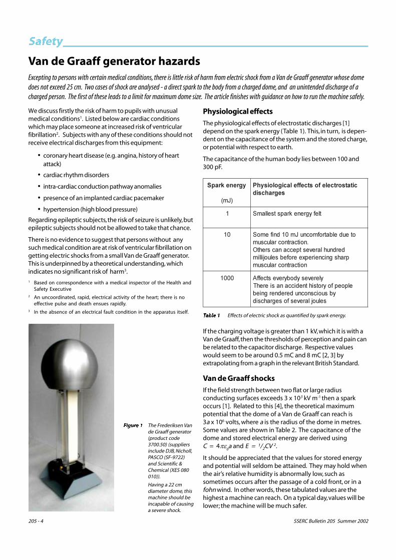
������ The Frederiksen Vande Graaff generator(product code3700.50) (suppliersinclude DJB, Nicholl,PASCO (SF-9722)and Scientific &Chemical (XES 080010)).
Having a 22 cmdiameter dome, thismachine should beincapable of causinga severe shock.
����������
����
���� �������� ������������� ��� ����� ��
� ������ ��������������
�� ��������������� ������ ������ ������� ����������
���� ��������������� �������������� �� �����������������������
������� ����������
���� ������������������ �������������� ������ �������!
������� �� ������ ��� ���������������������������
If the charging voltage is greater than 1 kV, which it is with aVan de Graaff, then the thresholds of perception and pain canbe related to the capacitor discharge. Respective valueswould seem to be around 0.5 mC and 8 mC [2, 3] byextrapolating from a graph in the relevant British Standard.
Van de Graaff shocks
If the field strength between two flat or large radiusconducting surfaces exceeds 3 x 10³ kV m-1 then a sparkoccurs [1]. Related to this [4], the theoretical maximumpotential that the dome of a Van de Graaff can reach is3a x 106 volts, where a is the radius of the dome in metres.Some values are shown in Table 2. The capacitance of thedome and stored electrical energy are derived usingC = 4��
0a and E = 1/2CV 2.
It should be appreciated that the values for stored energyand potential will seldom be attained. They may hold whenthe air’s relative humidity is abnormally low, such assometimes occurs after the passage of a cold front, or in afohn wind. In other words, these tabulated values are thehighest a machine can reach. On a typical day, values will belower; the machine will be much safer.
����� � Effects of electric shock as quantified by spark energy.
SSERC Bulletin 205 Summer 2002 205 - 5
������
There are two ways whereby the user can get a shock – fromcoming too near to a charged dome, or from an unintendeddischarge while being charged deliberately.
A person will get an unintended shock by carelessly comingtoo close to the charged dome. Most of the stored energyon the dome may then discharge to earth through theperson’s body giving the unintended shock. If we set a limiton the stored energy that should reside on the dome to be1 J, then the maximum dome diameter is 25 cm. There is, sofar as we are aware, just one product on the educationalmarket that breaks this limit. It is the newly designed STEmodel with a dome diameter of 28 cm. (We have raised thiswith STE.)
Another means of shock occurs when a person - usually apupil – is deliberately charged up and gets unintentionallydischarged. In such a system, the electrical properties ofthe human body play a significant part. The highestpotential reached is governed by the minimum radius ofexternal body parts. The value might be 5 mm with a pinkie.The system voltage comprising dome and body might thenreach V = 3a x 106 V = 15 kV. With the body’s capacitance of300 pF, the energy to be discharged = 1/
2CV 2 = 34 mJ and
the charge stored on the person = CV = 4.5 mC. A suddendischarge of this amount of energy and charge wouldcertainly be noticed. It would probably be disagreeable. Itmight even verge on being painful, but is unlikely to haveany other direct effect.
Do bear in mind that any person getting a shock is at risk ofharm from jerking or falling over in fright. There is then anindirect risk of a blow to the head, or damage to muscles,bones, or other parts.
Operational rules
In consideration of the above, the following rules should beapplied:
1. Beforehand the teacher should check the appropriaterecords held at school for any relevant heart condition.
2. Before using the equipment, the teacher should warn theclass that it should not be used by anyone with such aheart condition.
������������
����
���������
�"��
����������������
�#��
������������ ������
����
�$ �� ��% ��&
&$ '� &(% �)*
)$ +� �$' �(%�
������� Electrical properties related to dome diameter.
3. Charge only one person at a time to limit the chargedcapacitance of the system. The severity of the electricshock increases with capacitance. The shock canincrease with the number of persons being chargedsimultaneously.
4. Persons being charged should be limited to volunteers. Itis generally inadvisable to attempt to charge everyone ina class, whether singly, or together in a chain (asexplained above).
5. Because a human body has capacitance, do not letsomeone touch a charged dome, then walk away. Inthese circumstances such a person may carry quite a lotof charge and experience a disagreeable and possiblyunexpected electric shock on touching earth. Any otherperson touching such a charged person is also at risk ofgetting a shock.
6. The dome may be safely discharged by touching it withan earthed, metal conductor mounted on an insulatedstand or handle. If this is operated properly, the experi-menter should not receive a shock.
7. The dome should be discharged immediately after everyoperation ensuring that it never stands idle in a chargedcondition.
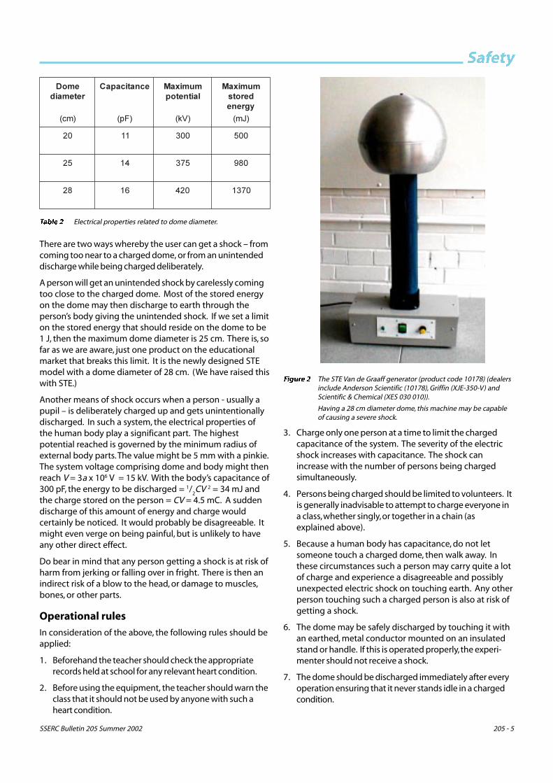
������ The STE Van de Graaff generator (product code 10178) (dealersinclude Anderson Scientific (10178), Griffin (XJE-350-V) andScientific & Chemical (XES 030 010)).
Having a 28 cm diameter dome, this machine may be capableof causing a severe shock.
205 - 6 SSERC Bulletin 205 Summer 2002
������8. The dome may be safely discharged through the human
body by arranging that the person getting thedischarge is in poor contact with an earthed conductor.Instruct him to place one hand, palm down, firmly incontact with the benchtop, which is presumed to bewooden, or of similar, low conductivity. The dome maythen be discharged by bringing the other hand up to it,either by direct skin contact with the dome, or througha hand held metal wand or sphere. Break contact withthe dome before breaking contact with the bench.These directions assume that the benchtop insulationresistance is at least one megohm to earth, which isusually the case. By following these instructions thedome should be safely and completely discharged withthe person experiencing only a slight physiologicaleffect.
9. The demonstration with hair standing on end may bedone safely by adapting the above procedure. Beginwith the generator off and dome uncharged. Instructthe pupil to stand on an insulated platform (such as aplastic basin) and place one hand on the dome whileensuring that no part of the body or clothing is incontact with the bench, or another pupil. Start thegenerator and run until hairs stand on end. Stop thegenerator and instruct the pupil to place his free hand onthe wooden benchtop while still keeping his other handfirmly on the dome. Wait several seconds untilcompletely discharged. Remove hand from dome, step
off the platform and walk away from the apparatus. Thedome at this stage will not be carrying a charge and willbe safe for another person to touch.
10. The demonstration of lighting a Bunsen flame bydischarging through a human body to the Bunsenfunnel would seem also to be fairly harmless providedthat the Bunsen funnel does not have a low resistancepath to earth, which is usually the case. Test lighting theBunsen with an insulated lead. If the air discharge pathis small and the accompanying sound is slight, it shouldbe safe to use a human body for the discharge path.
11. If the capacitance of the system were to be greatlyincreased, for instance by connecting the dome to aLeyden jar, the stored electric energy can increase to adangerous extent.
All science staff should be trained in how to work with theVan de Graaff generator, being made aware to avoid adirect path through the human body to a good earth (anearthed conductor of low resistance).
References1 BS 5958: Part 1 : 1991 Code of practice for control of undesirable static
electricity Part 1 General considerations BSI.
2. PD 6519 : Part 2 : 1995 Guide to effects of current on human beingsand livestock Part 2 Special aspects relating to human beings BSI.
3. Preventing electric shock Bulletin 173 SSERC 1992.
4. Berg R.E. The Physics Teacher 28 5 (May 1990) pp 281-5.
Brady’s reagentThis Advanced Higher Chemistry prescribed practical activity (PPA) includes a recipe and safety information for Brady’s reagent.
Whilst working our way through this practical we noticedthat, in the Teacher/Lecturer/Technician Guide [1], Brady’sreagent is described as containing concentrated sulphuricacid, which is correctly identified as a corrosive solution.Unfortunately, in the ‘Student Instructions’, it states – “Brady’sreagent also contains sulphuric acid, which is irritating (ouremphasis) to the eyes and skin” . Brady’s reagent is in fact acorrosive solution. Students need to be made aware of thisand that sulphuric acid is classified as:
IRRITANT at concentrations � 0.5 M to < 1.5 M
CORROSIVE at concentrations � 1.5 M
In addition, we noticed that the recipe for Brady’s reagentdetailed in the PPA support material is different from thatgiven in the SSERC Hazardous Chemicals CD2. Both aregiven below for comparison.
HSDU: Unit 3 PPA2: Preparation of Brady’s Reagent (Tor TECH): Dissolve 2.5 g 2,4 dinitrophenylhydrazine in5 cm3 concentrated sulphuric acid. To this mixture add50 cm3 methanol carefully and with cooling. Warm theresulting solution to dissolve any remaining solid andadd 10 cm3 water.
SSERC (Hazardous Chemicals CD2): Preparation ofBrady’s reagent (T or TECH): Wear rubber or plasticgloves and eye protection. Suspend 1 g of 2,4-dinitrophenylhydrazine (DNPH) in 50 cm3 of methanol(HIGHLY FLAMMABLE & TOXIC) and add 2 cm3 ofconcentrated sulphuric acid (CORROSIVE) and stir well.Filter if cloudy. It is easy to avoid raising dust as thehydrazine is stored moist. The mixture is CORROSIVE,HIGHLY FLAMMABLE & TOXIC and should be labelledaccordingly.
The most notable differences between these recipes are thatthe SSERC version requires a smaller volume of concentratedsulphuric acid, less 2,4 dinitrophenylhydrazine and does notrequire heating (the heat generated during the addition ofthe concentrated sulphuric acid helps to dissolve the 2,4DNPH). These are all plus points in terms of safety and cost.But does the SSERC version produce similar results to thatobtained when using the PPA recipe? Well, yes it does. Wetested both versions of the reagent and found the results tobe comparable.
Reference1. HSDU, Advanced Higher Chemistry, Unit 3, PPA 2, Identification by
Derivative Formation.

SSERC Bulletin 205 Summer 2002 205 - 7
�����������
Texas dataloggerThis is an outline review of the Texas Instruments calculator-based datalogger CBL 2 wherein its ease of use, functionality and speed arecompared with computer-based instruments.
The CBL 2 is used in conjunction with aTexas Instruments (TI) graphicscalculator, the TI-83 Plus being thepreferred model1, and electronicsensors made by the US companyVernier. With around 40 good qualitysensors to choose from, the scope ofthe measurement system is extensive.It covers the 3 school sciences, biology,chemistry and physics. It can be run inany of the standard modes: variableversus time, A against B, a dependentvariable against a keyboard entry, etc.It can log very fast or slow. Loggingcan be begun with a keyboard press,or triggered automatically. Itsfunctionality is fairly complete.
Where it really scores is on price. Thecost of the 2 essential components, a CBL2 and TI-83 Plus, is £171. This priceincludes sensors for temperature, lightand voltage. Compare that with areasonably priced computer-baseddatalogger, say the Alba, and aninexpensive laptop, and the bill comes to£978. That is nearly 6 times greater! Ifyou want a class set of dataloggers, thenthe CBL 2 may be an affordable option2.
The hardware is simple and quick to setup. Taking up minimal bench space, itcan be set up alongside other equip-ment with little inconvenience. It’sportable and may be used in almost anysituation – in a lift, on a bicycle, in theplayground, or on a field trip. It wouldbe a convenient instrument for manystudies – human physiology, sportsscience, fairground physics, rocketryand environmental monitoring, to thinkof a few.
What’s the rub? Relative to computer-based instruments, it is slow and
����������� �����������
�� ������,���� ���� ���������-��������� ��������� ���� �
�������������������.���� ���/�������������0������
�����.�������������� ������1���� ��
������������2
�� �����0�������������������
��0���32����� ���� ���������-� ���������� �������� �0�����
� �0������������0���0 ������� ����
���������������������0� �����4������������ ����������������
5����6����������0��������������� 0���� ���� �
�������0 ������������������ �1�����.�������� ���� 5 0��,��0��
���������� ������� ������7�8��� ��#������ ������,��������
���� ��������� �
������������� ������� ������7�� �������� ���� ��#
������ ��� �0���
��������������������������� ������ ����������������0
� ����������� ��� ���� ��� �9,�������� ��� ����������������
����������������
�����������0�� ������������:����������������0����������
����������
;����������� ������������ �6 �������� <�����������������
����� ������ �6
���5 ���� ����������������� :���������0���������������������
� ��� ��������� �� ������������������������������� ��.����5��-7!=7��5����������5�����
5! !��������� ���� �������������5�!�5!�13! !�
���5������������������������<��5� ������������������������
�������������� ���
������ �� �����������!
0������������������ ������>��)*�����������������, ���������
��������
����� � Comparative review of the CBL 2 relative to computer-based interfaces and dataloggers.
ponderous to operate. The calculatorkeyboard has 50 keys. Since most ofthe keys have 3 functions, the totalnumber of keyed functions is anamazing 135. The keyboard can take along time to learn and understand.Unless used continually, the keys, theirpositions in the keyboard, and their
purposes may be quite readily for-gotten. For this review, the TI-83 wasused for three extended periods each amonth or two apart. On the twooccasions when the reviewer had soreturned to work with the calculator,he had to spend several hours relearn-ing how to operate it.
������� ���������� �������� ������� ��
������������
������� ������������
!������
������������
������� ��
���
�������� ����! ���� '� &�� &��
��� 4�/ ��� �� &' &%
���������� �9� 3 ��� $� &' &%
����� � Speed trials on 3 dataloggers. Each was set to carry out the same task.
1 Other Texas calculators, such as the TI-82,run reduced versions only of thedatalogging software DataMate. Theyshould be avoided, but consult your dealer.
2 But this price scoring may well be un-sound.It overlooks the government’s national planto put one computer for every four pupils ineach secondary school, the cost being borneby central funding.
205 - 8 SSERC Bulletin 205 Summer 2002
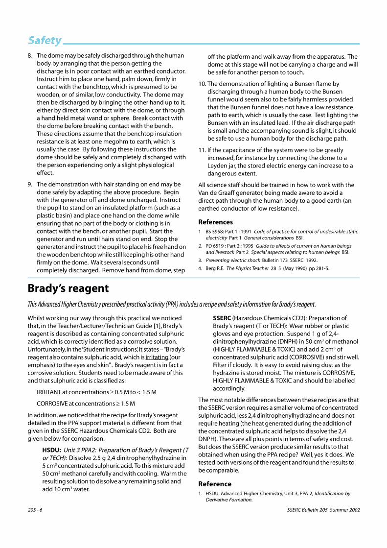
�����������A comparative test was set up with theCBL 2 and two computer-based data-loggers (Table 2). In each system onechange was made in the defaultlogging settings, a physical quantity waslogged for a period of 10 s and theresulting graphical display was opti-mised. One result shows that thenumber of instructions required didnot differ significantly between eitherthe calculator or computer-baseddataloggers. (The calculator has manyspecial function keys which a standardcomputer lacks. This should give it anadvantage. In fact, the CBL 2 requireda few more keypresses.) The otherresult showed that the CBL 2 is 200%slower than computer-based data-loggers doing comparable tasks. It is asluggish instrument to run.
The other grave disappointment is thedisplay, which resembles one on a1980s computer.
The CBL 2 can be used in demonstra-tions with the Silver Edition of theTI-83 Plus graphics calculator and a TIViewScreen projection screen sittingon an underlit overhead projector.Data can also be transferred from thegraphics calculator to a computer (PCor MAC) for class display with acomputer projector. There is anexcellent software package fromVernier, called Graphical Analysis,which facilitates this data transferfrom the calculator (see followingreview).
Summary
Summarizing this review, the 3 bigplusses are the wide scope of appli-cation, simplicity of hardware set-upand, relatively speaking, very low cost,allowing high quality data-capture on abudget. But the 3 big negatives arethat it is not simple to use, its operationis slow, and its display is primitive.
In our opinion this is an instrument forthe committed enthusiast rather thanthe normal science teacher, for whom acomputer-based datalogger would bethe preferred choice. It needs to beused continually and often so as tolearn, but not forget, how to operate it.
There is a significant risk that, in somedepartments, once bought, it will eitherbe underused, or sit in a cupboardunused.
�"����������������#�
$��� �� ����������%�� ������ ��$��������
����
������ ��$��������
&'� ���� (�)�
������3 ���� !"# �������>���������9
&*�'&?��������$�&?
������!������1��$%������������ �
&*(?
������!������1��$%������������ �
&*(?
������� ���/�������
��&������� !"#���������9�������>
&*�*(?
������� ���/��0���
<! ����������&*�*��?
����������������36%� "�%$'�� �
*�+�?
����������������36%� "�%$'�� �
*�+�?
���������/ <! ���� ������ ���������5�����������
����� �������� �&*�&��?
��� ������ <�������,��
%)�?
��� ������ <**$?
��� ��������# %�&+,<9'�?
��� ������������! �������,�9�&�*�?
4&�&+,<9+&?
��� ������1 �����$�,�@$%?
'�&+,<9%(?
������� ������:��� ��
<! (��&*�'(?
������$,�4&��?
$'(+,<9&��?
��� ������" !4,�"/&%�%��?
('(+,<9('�?
����������������7��� ��
!4,-72&*?
����+��,%2$%?
����+��,%2� ��&�+%?
4%'&+,<9&)?
���0��� ���0�������� ��� ������������
������������� ���9�()+,<9
$$�?����������9�()+,<9*$'?��� ����
���0����� ������ � ���� ��� ����
�������� �����
���� ������������ ���������
&*�*+?
����������� �����A <! ��)*�������������+
&*�(�?
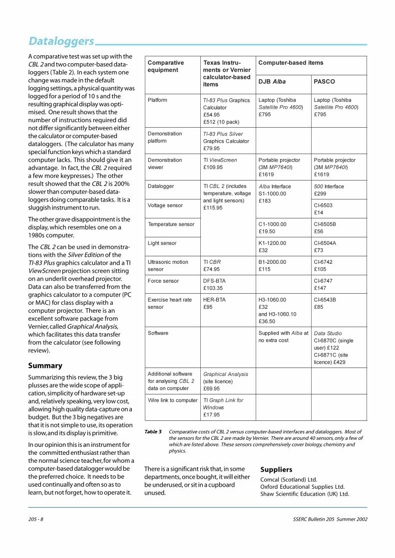
������� Comparative costs of CBL 2 versus computer-based interfaces and dataloggers. Most ofthe sensors for the CBL 2 are made by Vernier. There are around 40 sensors, only a few ofwhich are listed above. These sensors comprehensively cover biology, chemistry andphysics.
SuppliersComcal (Scotland) Ltd.Oxford Educational Supplies Ltd.Shaw Scientific Education (UK) Ltd.

SSERC Bulletin 205 Summer 2002 205 - 9
������ ���������
����������� ������
The new version of Vernier’s software offers powerful computer graphing facilities. Even so, it is simple to use and is very reasonably priced.We recommend it, strongly.
ReviewGraphical Analysis is a program for MACor Windows produced by Vernier, a UScompany specializing in scientificcomputer products. The original versionfirst appeared in 1982. That and Version2 have been deservedly popular inAmerica. Version 3 has just been releasedand is stocked by several UK suppliers. Itis extraordinarily good and ought to bea standard utility package in everyscience department.
On starting up the program, 3 windowsappear. At top left is an empty table and,below it, a text box. Occupying the righthand side of the screen, is an emptygraph. There is a cursor sitting in the topcell of the table. On typing in a data pair,a corresponding point appears on thegraph. If more data is entered from the
keyboard, so more points appear on thegraph. It is as simple and elementary asthat!
In all, there are several ways of enteringdata:
• Keyboard entry.
• Importing a text file (e.g. consisting ofa table in Microsoft Word, or text filecreated by Alba).
• Copying data from a spreadsheet (e.g.Microsoft Excel), or text (e.g. table inMicrosoft Word) and pasting intoGraphical Analysis.
• Transferring data from a TexasInstruments graphing calculator (withdatalogger).
Proceeding from an initial graph,commands for editing the graph and tableand analysing the data appear by
������ Example of the default screen display on Graphical Analysis (Version 3), with added data and statistical analysis.
positioning the mouse in the relevant partof the screen and clicking, or by clickingon a toolbar icon, or selecting from apulldown menu. No operation is obscureor complicated. It really is all as easy as pie.Yet there is considerable depth of analysisand the display can be refined in almostany way the user wants.
For the purchase price of just under £70,the school gets a site licence. This allowsstudents to run the program on theirhome computers.
Each window can be copied and pastedinto a Word document. Thus it is verysimple to copy tables and graphs out ofGraphical Analysis and paste them into labreports. It is equally simple transferringdata the other way – copying data in texttables or spreadsheets and pasting intoGraphical Analysis.
205 - 10 SSERC Bulletin 205 Summer 2002
���������
Anodising aluminiumAdvice is given on how to carry out this chemistry practical.
We recently received an enquiry from a school following uppoor results obtained when trying to dye anodisedaluminium. Demonstrating this process is a suggestedactivity within the Chemistry Intermediate 1 syllabus (seeUnit 2: Everyday Chemistry, (a) Metals – Corrosion). Below aredetails of a method that we have thoroughly tested andwhich has consistently given us good results. We suggest theuse of aluminium sheet (Griffin & George A/1690/50 £9.70 orPhilip Harris B5A40964 £9.57) or aluminium takeaway foodcontainers as both of these produced good results. Alumin-ium drinks cans, although plentiful and ‘free’ are not recom-mended since they have internal and external coatings.These are very difficult to remove and they inhibit theanodising process.
Apparatus/Reagents������������������� �� � �� �������� ������ ��� ����� ��������������������� ��� !"�#�$�����������������%����&�#'�(��������)������� ��� �������
$ ���� ������������*������*�������������+���������������&,--,.�/.),��������+�������0������&1,21�3�4��++�5�6)!�� ���� � ����������&�� ��������������� ��������
���)7�����������4 ������ �����8���
Preparing the Aluminium Strip
1. Cut out 2 strips, 2 cm x 6 cm, from an aluminium sheetor food container. Attach a crocodile clip to each ofthese.
2. Clean and de-grease the aluminium strips by immersingin a beaker of Industrial Methylated Spirits (IMS)(HIGHLY FLAMMABLE) for about 1 minute. (MineralisedIMS is fine.)
3. Remove the aluminium strip from the IMS, handling thecrocodile clips only. Once the aluminium has been socleaned do not touch it. Rinse it with distilled water anduse immediately.
Anodising the Aluminium Strip
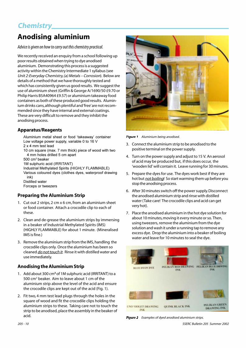
1. Add about 300 cm3 of 1M sulphuric acid (IRRITANT) to a500 cm3 beaker. Aim to leave about 1 cm of thealuminium strip above the level of the acid and ensurethe crocodile clips are kept out of the acid (Fig. 1).
2. Fit two, 4 mm test lead plugs through the holes in thesquare of wood and fit the crocodile clips holding thealuminium strips to these. Taking care not to touch thestrip to be anodised, place the assembly in the beaker ofacid.
3. Connect the aluminium strip to be anodised to thepositive terminal on the power supply.
4. Turn on the power supply and adjust to 15 V. An aerosolof acid may be produced but, if this does occur, the‘wooden lid’ will contain it. Leave running for 30 minutes.
5. Prepare the dyes for use. The dyes work best if they arehot but not boiling! So start warming them up before youstop the anodising process.
6. After 30 minutes switch off the power supply. Disconnectthe anodised aluminium strip and rinse with distilledwater (Take care! The crocodile clips and acid can getvery hot).
7. Place the anodised aluminium in the hot dye solution forabout 10 minutes, moving it every minute or so. Then,using tweezers, remove the aluminium from the dyesolution and wash it under a running tap to remove anyexcess dye. Drop the aluminium into a beaker of boilingwater and leave for 10 minutes to seal the dye.
������ Aluminium being anodised.
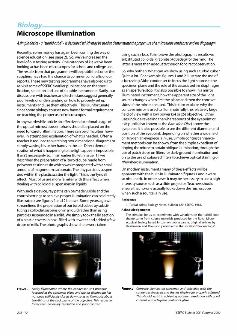
������ Examples of dyed anodised aluminium strips.

SSERC Bulletin 205 Summer 2002 205 - 11
���������
To obtain the best results use fresh sulphuric acid for eachstrip of aluminium to be anodised.
Dyes
We found that Dylon clothes dyes (one tin in 250 cm3 ofwater) and Pelikan and Uno waterproof drawing inks (slightlydiluted) worked well. The best colours were blue, purple andred. We also managed to produce a navy blue effect usingblack Quink ink.
Safety
Hazards with the substances used in this practical aretabulated opposite.
Wear eye protection and work in a well-ventilatedlaboratory. Ensure any acid aerosol produced during theanodising process is contained or work in a fume cupboard.
When making up dye solutions other than the water solubletypes named herein: Wear appropriate gloves, eye protectionand a PVC apron. Avoid inhaling any dust and, preferably, usea fume cupboard.
���� �� ���*�+
�������� <��������6��6<��������
�������������,714 66 1"B12><2������������0�����;��� ���������
� �0����0�5 ������� ��9<C�!� ���� ������� �� ���� � ���������� ����.����!
������������������������� ���� �� ���� �����
���������6�����
,!= !<--< ����������������������/����� ������ ����������� � ���� �
�����������
��/ 1:"6- 2� ��!= !<--<������ �6 �0��� ��,�=7>�=<9- 9�������� �� ���������������������5� ����
�����!�����������������������������������D��0�������������������
�������� ����������������������������������/�����������6������ ���������������������8�/�6�
��������� ����!�'����4�����/���� �����/5+���4�����/5&* 0��4�����/5����4
�+%����4 ����������#<� �<<<5<<5< ������ ������ �����������05� ��� �����
#< ���� � ��� �������������
�������
New microbiology resources
In the last issue, we carried a short piece on disinfectantsand, in passing, we mentioned an updating exercise on theold Strathclyde Code of Practice on Safety in Microbiology.A new edition of the code is now at the final draft stage andis out for proofing. This has been due largely to the efforts ofJim Stafford, one time at the Higher Still Development Unit(HSDU), now back with East Ayrshire Council, and KathCrawford of the SAPS Scotland Biotechnology Project. Also atthat asymptotic stage, loathed by any editor, are electronicversions of the Microbiological Techniques Cards originallypublished in print form by SSERC and HSDU (see Figure 1below).
������ Main menu page for electronic version of the MicrobiologyTechniques publication.
These have been largely the work of Ian Birrell at SSERC withadvice and help from Kath Crawford and Kirsty Menzies ofthe SAPS project. The electronic version of the techniquescards uses web pages to allow rapid retrieval of informationon any particular technique. This is the same approach weadopted for our well-regarded Hazardous Chemicals CD.
With this new resource we’ve taken things one stage furtherand added a large number of original photographic images(see Figure 2 for an example). These photographs supple-ment the excellent line drawings based on Jim Shield’s (ofBalfron High School) original graphics. For conveniencewe’ve included a copy of the Code of Practice (as a Word filemeantime) and there is a link to a web page version of thefuller list of micro-organisms from SSERC Bulletin 194. Weshall be making arrangements soon for the distribution of thisnew resource on CD-ROM.
������ Part page for asub-culturingsequencewith originalphotographs.
205 - 12 SSERC Bulletin 205 Summer 2002
�������Microscope illuminationA simple device - a “turbid cube” - is described which may be used to demonstrate the proper use of a microscope condenser and iris diaphragm.
Recently, some money has again been coming the way ofscience education (see page 2). So, we’ve increased thelevel of our testing activity. One category of kit we’ve beenlooking at has been microscopes for school and college use.The results from that programme will be published, once thesuppliers have had the chance to comment on drafts of ourreports. These new testing programmes have also led us tore-visit some of SSERC’s earlier publications on the speci-fication, selection and use of suitable instruments. Sadly, ourdiscussions with teachers and technicians suggest generallypoor levels of understanding on how to properly set upinstruments and use them effectively. This is unfortunatesince some biology courses now have a formal requirementon teaching the proper use of microscopes.
In any worthwhile article on effective educational usage ofthe optical microscope, emphasis should be placed on theneed for careful illumination. There can be difficulties, how-ever, in attempting explanation of what is needed. Often ateacher is reduced to sketching two-dimensional diagrams orsimply waving his or her hands in the air. Direct demon-stration of what is happening to the light appears impossible.It ain’t necessarily so. In an earlier Bulletin issue [1], wedescribed the preparation of a ‘turbid cube’ made frompolyester casting resin which was impregnated with a smallamount of magnesium carbonate. The tiny particles suspen-ded within the plastic scatter the light. This is the Tyndalleffect. Most of us are more familiar with this effect whendealing with colloidal suspensions in liquids.
With such a device, ray paths can be made visible and thecontrol settings to achieve proper illumination can be directlyillustrated (see figures 1 and 2 below). Some years ago westreamlined the preparation of our turbid cubes by substi-tuting a colloidal suspension in a liquid rather than usingparticles suspended in a solid. We simply took the lid sectionof a plastic coverslip box, filled with it water and added a fewdrops of milk. The photographs shown here were taken
using such a box. To improve the photographic results wesubstituted colloidal graphite (Aquadag) for the milk. Thelatter is more than adequate though for direct observation.
So, why bother? What can we show using such a turbid cube?Quite a lot. For example, figures 1 and 2 illustrate the use ofa focussing Abbe condenser to focus the light source at thespecimen plane and the role of the associated iris diaphragmas an aperture stop. It is also possible to show, in a mirrorilluminated instrument, how the apparent size of the lightsource changes when first the plane and then the concavesides of the mirror are used. This in turn explains why theconcave mirror is used to illuminate fully the relatively largefield of view with a low power (x4 or x5) objective. Otheruses include revealing the whereabouts of the eyepoint orexit pupil (also known as the Ramsden Disc) above theeyepiece. It is also possible to see the different diameter andposition of the eyepoint, depending on whether a widefieldor Huygenian eyepiece is in use. Simple contrast enhance-ment methods can be shown, from the simple expedient oftipping the mirror to obtain oblique illumination, through theuse of patch stops on filters for dark-ground illumination andon to the use of coloured filters to achieve optical staining orRheinberg illumination.
On modern instruments many of these effects will beapparent with the built-in illuminator (figures 1 and 2 wereso obtained). In other cases it may be necessary to use a highintensity source such as a slide projector. Teachers shouldensure that no-one actually looks down the microscopewhen such a source is in use.
Reference
1. Turbid cubes, Biology Notes, Bulletin 129, SSERC, 1981.
Acknowledgements
The stimulus for us to experiment with variations on the turbid cubetheme came from course materials produced by the Royal Micro-scopical Society based in turn on two separate, original articles byHaselmann and Thomson published in the society’s “Proceedings”.
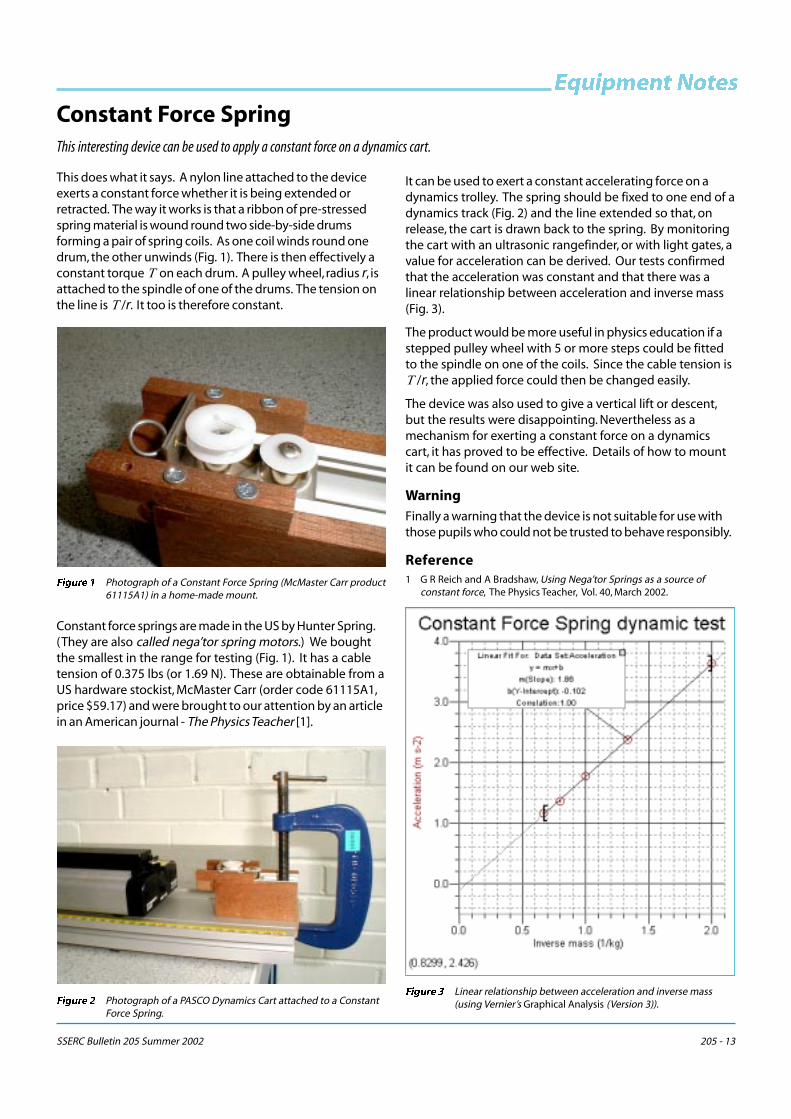
������ Faulty illumination where the condenser isn’t properlyfocussed at the specimen plane and the iris diaphragm hasnot been sufficiently closed down so as to illuminate abouttwo-thirds of the back plane of the objective. This results inlower than necessary resolution and poor contrast.
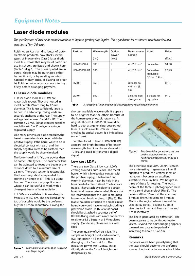
������ Correctly illuminated specimen and objective with thecondenser focussed and the iris diaphragm properly adjusted.This should assist in achieving optimum resolution with goodcontrast and adequate control of glare.
SSERC Bulletin 205 Summer 2002 205 - 13
������� �������
This does what it says. A nylon line attached to the deviceexerts a constant force whether it is being extended orretracted. The way it works is that a ribbon of pre-stressedspring material is wound round two side-by-side drumsforming a pair of spring coils. As one coil winds round onedrum, the other unwinds (Fig. 1). There is then effectively aconstant torque � on each drum. A pulley wheel, radius �, isattached to the spindle of one of the drums. The tension onthe line is ��/�. It too is therefore constant.
Constant force springs are made in the US by Hunter Spring.(They are also called nega’tor spring motors.) We boughtthe smallest in the range for testing (Fig. 1). It has a cabletension of 0.375 lbs (or 1.69 N). These are obtainable from aUS hardware stockist, McMaster Carr (order code 61115A1,price $59.17) and were brought to our attention by an articlein an American journal - The Physics Teacher [1].
It can be used to exert a constant accelerating force on adynamics trolley. The spring should be fixed to one end of adynamics track (Fig. 2) and the line extended so that, onrelease, the cart is drawn back to the spring. By monitoringthe cart with an ultrasonic rangefinder, or with light gates, avalue for acceleration can be derived. Our tests confirmedthat the acceleration was constant and that there was alinear relationship between acceleration and inverse mass(Fig. 3).
The product would be more useful in physics education if astepped pulley wheel with 5 or more steps could be fittedto the spindle on one of the coils. Since the cable tension is��/�, the applied force could then be changed easily.
The device was also used to give a vertical lift or descent,but the results were disappointing. Nevertheless as amechanism for exerting a constant force on a dynamicscart, it has proved to be effective. Details of how to mountit can be found on our web site.
Warning
Finally a warning that the device is not suitable for use withthose pupils who could not be trusted to behave responsibly.
Reference1 G R Reich and A Bradshaw, Using Nega’tor Springs as a source of
constant force, The Physics Teacher, Vol. 40, March 2002.���� � Photograph of a Constant Force Spring (McMaster Carr product
61115A1) in a home-made mount.
���� � Photograph of a PASCO Dynamics Cart attached to a ConstantForce Spring.
���� � Linear relationship between acceleration and inverse mass(using Vernier’s Graphical Analysis (Version 3)).
Constant Force SpringThis interesting device can be used to apply a constant force on a dynamics cart.
205 - 14 SSERC Bulletin 205 Summer 2002
������� �������
Laser diode modulesThe specifications of laser diode modules continue to improve, yet they drop in price. This is good news for customers. Here is a review of aselection of Class 2 devices.
Roithner, an Austrian distributor of opto-electronic products, now stocks severaltypes of inexpensive Class 2 laser diodemodules. Those that may be of particularuse in schools are listed and shown here(Table 1) (Fig. 1). The prices quoted are ineuros. Goods may be purchased eitherby credit card, or by sending an inter-national money order. If placing an orderlet Roithner know what you want to buyfirstly before arranging payment.
LJ laser diode modulesLJ laser diode modules (LDM) arereasonably robust. They are housed inmetal barrels 29 mm long by 12 mmdiameter. This is just sufficiently large tobe held in a lab clamp. Flying leads aresecurely anchored at the rear. The supplyvoltage lies between 3 and 6 V DC. Thecurrent is 25 mA. Suitable power supplieswould be AA, C or D cells, or a voltageregulated supply.
Like many other laser diode modules, thebarrel makes electrical contact with thepositive supply. If the barrel were to be inelectrical contact with earth and thesupply negative were to be earthed, thenthe supply would be short-circuited.
The beam quality is fair, but poorer thanon some HeNe types. The collimator lenscan be adjusted to focus the beam at anydistance down to a minimum size of2.5 mm. The cross-section is rectangular.The beam may also be expanded tosubtend an angle of 6°. This is a usefulfeature. There are many applicationswhere it can be useful to work with adivergent beam of laser radiation.
LJ LDMs are available in 8 wavelengthsfrom 635 to 850 nm. The one listed at thetop of our table would be the preferredbuy for a school laboratory. Having the
,������ �������"�-
�� �
�����(������A��
$ �����&�����
���� ����
����7�
�1�E&%+6/1 &%+ � ��&�$�' $ ��������" �&�'%
6�1�E�&+6/1 �&+ � ��&�$�' $ ��������"5��������6D2�����9/
&'�+$
%�,61 �&+ � ����������9F��+,'
�&
���*
'�,61 �&+ � ����&&5� �1�� �������
������������������
���*
����� A selection of laser diode modules presently available from Roithner.
shortest available wavelength, it appearsto be brighter than the others because ofthe human eye’s photopic response. Atonly 34.50 euros, LDM635/1LJ would behard to beat as a general purpose schoollaser. It is sold as a Class 2 laser. I havechecked its optical power. It is indeed justunder 1 mW.
The other listed LJ laser (LDM650/1LJM)appears less bright because of its longerwavelength, but it can be modulated to10 kHz and used to transmit a digitalsignal.
Low cost LDMsThere are two Class 2 low cost LDMscosting around 9 euros each. The metalbarrel, which is in electrical contact withthe positive supply, is between 8 and9 mm in diameter. It can be held in theboss head of a clamp stand. The leads arefragile. They attach by solder to a circuitboard and have no strain relief. Before usewe recommend that the LDM is mountedin a wooden block to clamp it (Fig. 2). Theleads should be attached to a small circuitboard you would have to make, including aprotection diode. To this circuit boardshould be attached a stronger pair offlexible, flying leads with 4 mm connectorsto either a 4.5 V battery, or 5 V regulatedsupply. (For details, please see our website.)
The beam quality of LM-03 is fair. Thesample we bought produced a uniform,oval light patch 4 x 3 mm at 30 cm,diverging to 7 x 5 mm at 3 m. Themeasured power was 1.2 mW. This isslightly above the Class 2 limit, but notdangerously so.
������ Laser diode modules LM-04 (left) andan LJ type (right).
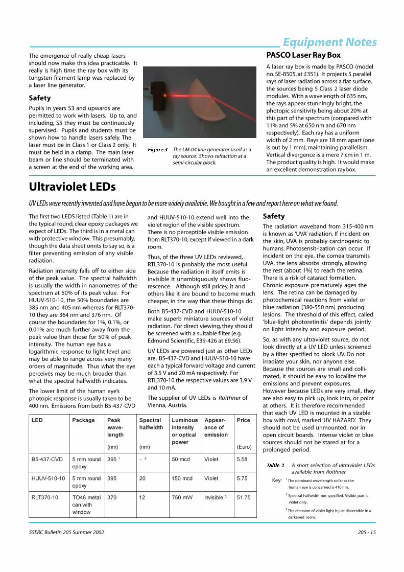
The other low cost LDM, LM-04, is muchmore interesting. It generates a line. Iforiented to produce a vertical sheet ofradiation, it becomes an excellentsubstitute for a ray box. We bought inthree of these for testing. The worstbeam of the three is photographed herewith a semi-circular block (Fig. 3). Thebeam width is 3.5 mm at the aperture,3 mm at 10 cm, reducing to 1 mm at50 cm – the region where it would beused in ray optics. Beyond 50 cm itdiverges to 3 mm and 8 mm at 1 m and2 m respectively.
The line is generated by diffraction. Thebeam appears to be continuous up to50 cm. Beyond this point, fringing appears,the mark to space ratio graduallyincreasing to about 1:1 at 2 m.
RemarksFor years we’ve been proselytizing thatthe laser should become the preferredsource of optical radiation in school labs.
Figure 2 Two LM-04 line generators, the oneon the right being fitted to ahardwook block, which serves as aclamp.
SSERC Bulletin 205 Summer 2002 205 - 15
������� �������The emergence of really cheap lasersshould now make this idea practicable. Itreally is high time the ray box with itstungsten filament lamp was replaced bya laser line generator.
SafetyPupils in years S3 and upwards arepermitted to work with lasers. Up to, andincluding, S5 they must be continuouslysupervised. Pupils and students must beshown how to handle lasers safely. Thelaser must be in Class 1 or Class 2 only. Itmust be held in a clamp. The main laserbeam or line should be terminated witha screen at the end of the working area.
������ The LM-04 line generator used as aray source. Shows refraction at asemi-circular block.
Ultraviolet LEDsUV LEDs were recently invented and have begun to be more widely available. We bought in a few and report here on what we found.
The first two LEDS listed (Table 1) are inthe typical round, clear epoxy packages weexpect of LEDs. The third is in a metal canwith protective window. This presumably,though the data sheet omits to say so, is afilter preventing emission of any visibleradiation.
Radiation intensity falls off to either sideof the peak value. The spectral halfwidthis usually the width in nanometres of thespectrum at 50% of its peak value. ForHUUV-510-10, the 50% boundaries are385 nm and 405 nm whereas for RLT370-10 they are 364 nm and 376 nm. Ofcourse the boundaries for 1%, 0.1%, or0.01% are much further away from thepeak value than those for 50% of peakintensity. The human eye has alogarithmic response to light level andmay be able to range across very manyorders of magnitude. Thus what the eyeperceives may be much broader thanwhat the spectral halfwidth indicates.
The lower limit of the human eye’sphotopic response is usually taken to be400 nm. Emissions from both B5-437-CVD
and HUUV-510-10 extend well into theviolet region of the visible spectrum.There is no perceptible visible emissionfrom RLT370-10, except if viewed in a darkroom.
Thus, of the three UV LEDs reviewed,RTL370-10 is probably the most useful.Because the radiation it itself emits isinvisible It unambiguously shows fluo-rescence. Although still pricey, it andothers like it are bound to become muchcheaper, in the way that these things do.
Both B5-437-CVD and HUUV-510-10make superb miniature sources of violetradiation. For direct viewing, they shouldbe screened with a suitable filter (e.g.Edmund Scientific, E39-426 at £9.56).
UV LEDs are powered just as other LEDsare. B5-437-CVD and HUUV-510-10 haveeach a typical forward voltage and currentof 3.5 V and 20 mA respectively. ForRTL370-10 the respective values are 3.9 Vand 10 mA.
The supplier of UV LEDs is Roithner ofVienna, Austria.
SafetyThe radiation waveband from 315-400 nmis known as ‘UVA’ radiation. If incident onthe skin, UVA is probably carcinogenic tohumans. Photosensit-ization can occur. Ifincident on the eye, the cornea transmitsUVA, the lens absorbs strongly, allowingthe rest (about 1%) to reach the retina.There is a risk of cataract formation.Chronic exposure prematurely ages thelens. The retina can be damaged byphotochemical reactions from violet orblue radiation (380-550 nm) producinglesions. The threshold of this effect, called‘blue-light photoretinitis’ depends jointlyon light intensity and exposure period.
So, as with any ultraviolet source, do notlook directly at a UV LED unless screenedby a filter specified to block UV. Do notirradiate your skin, nor anyone else.Because the sources are small and colli-mated, it should be easy to locallize theemissions and prevent exposures.However because LEDs are very small, theyare also easy to pick up, look into, or pointat others. It is therefore recommendedthat each UV LED is mounted in a sizablebox with cowl, marked ‘UV HAZARD’. Theyshould not be used unmounted, nor inopen circuit boards. Intense violet or bluesources should not be stared at for aprolonged period.
�./ ������ �����"�� $������
���������������
������/��� �������������
�����
�����) $�������� ���
����
�� � �� � � ����7
/#9,(%',&4 � �����&����
&*% � , $ ����& �����# )&�&
��,��&,#::2 � �����&����
&*% �$ ����&� �����# &(�&
��,�(%!1- �����+'�!���0 ��0�� �0
�(% $� A��&( ������� < % &(��&
������� A short selection of ultraviolet LEDsavailable from Roithner.
Key: 1 The dominant wavelength so far as the
human eye is concerned is 410 nm.
2 Spectral halfwidth not specified. Visible part is
violet only.
3 The emission of violet light is just discernible in a
darkened room.
PASCO Laser Ray BoxA laser ray box is made by PASCO (modelno. SE-8505, at £351). It projects 5 parallelrays of laser radiation across a flat surface,the sources being 5 Class 2 laser diodemodules. With a wavelength of 635 nm,the rays appear stunningly bright, thephotopic sensitivity being about 20% atthis part of the spectrum (compared with11% and 5% at 650 nm and 670 nmrespectively). Each ray has a uniformwidth of 2 mm. Rays are 18 mm apart (oneis out by 1 mm), maintaining parallelism.Vertical divergence is a mere 7 cm in 1 m.The product quality is high. It would makean excellent demonstration raybox.

205 - 16 SSERC Bulletin 205 Summer 2002
���AddressesAnderson Scientific, Luzon House, Main Road,Cardross, Dunbartonshire, G82 5PX.T: 01389 841220, F: 01389 849180,W: www.andersonscientific-tech.com
Benetec Ltd., Microvision Department,Grosvenor House, 1 High Street, Edgware,Middlesex, HA8 7TA. T: 020 8381 1122F: 020 8381 1133, E: [email protected]: www.drbtech.com
British Standards Institution (BSI), ChiswickHigh Road, London, W4 4AL. T: 020 8996 9001,F: 020 8996 7001, W: www.bsi.org.uk
Comcal (Scotland) Ltd., 11 Bath Street, Glasgow,G2 1HY. T: 0141 332 5147, F: 0141 332 8527,W: www.comcal.net
djb microtech, Delfie House, 1 Delfie Drive,Greenock, PA16 9EN. T/F: 01475 786540,W: www.djb.co.uk
Economatics (Education) Ltd., Epic House,Darnall Road, Sheffield, S9 5AA.T: 0114 281 3311, F: 0114 243 9306,W: www.econmatics.co.uk/education
Edmund Scientific Ltd., 1 Tudor House,Lysander Close, Clifto Moor, York, YO30 4XB.T: 01904 691 469, F: 01904 691 569,W: www.edsci.com
Frederiksen - suppliers include DJB, Nicholl,PASCO and Scientific & Chemical.
Freshford Limited, 15 Turner Lane, Ashton-under-Lyne, Lancs., OL6 8LT. T: 0161 343 2091
Griffin & George, Bishop Meadow Road,Loughborough, Leicestershire, LE11 5RG.T: 01509 233344, F: 01509 231893,E: [email protected]
Philip Harris Education, Findel House,Excelsior Road, Ashby Business Park, Ashby-de-la-Zouch, Leicestershire, LE65 1NG.T: 0845 120 4520, F: 01530 419 492,W: www.philipharris.co.uk
Instruments Direct Limited, Unit 14,Worton Road, Isleworth, Middlesex, TW7 6ER.Tel: 0208 560 5678, Fax: 0208 232 8669,Website: www.InstrumentsDirect.co.uk/pasco
McMaster-Carr Supply Co., 473 Ridge Road,Dayton, NJ 08810, USA. T: +1 732 329 3200,F: +1 732 329 3772, W: www.mcmaster.com
Nicholl Education Limited, 4 Westleigh Hall,Wakefield Road, Denby Dale, Huddersfield,HD8 8QJ. T: 01484 865994, F: 01484 860008,E: [email protected]
Northern Technical & Chemical Services,Unit D44, Brunswick Business Centre, Liverpool,L3 4BD. T: 0151 707 8550
PASCO - see Instruments Direct
Oxford Educational Supplies Ltd., Unit 19,Weston Business Park, Weston on the Green,Bicestor, Oxon, OX25 3SX. T: 01869 344500,F: 01869 343654, W: oxford-educational.co.uk
Revolution Education Limited, 4 Old DiaryBusiness Centre, Melcombe Road, Bath,BA2 3LR.
T: 01225 340563 F: 01225 340564
E: [email protected] W: www.rev-ed.co.uk
Trade news
Oscilloscope offerThe Physics Department at the Universityof Glasgow have let us know that theyhave a number of ‘quite good’ 2-channeloscilloscopes they would like to place ingood homes (schools). If you would liketo take them up on this kind offer, pleasecontact Matthew Trainer at:
��������������� �
RevolutionThe manufacturer of technologyproducts, Revolution Education, movedfrom London to Bath at the end of lastyear. Please note their new address inthe list opposite.
EuromicrovisionEuromicrovision, supplier of educationalmicroscopes, recently ceased trading. Thebusiness activity has transferred toanother company - Benetec Ltd (seeaddress list opposite).
����������
We have received for testing a Frenchdatalogging system Jeulin VTT, which isavailable in the UK from Economatics. Thismultipurpose instrument can connect toabout 25 sensors. The core of the systemconsists of the VTT Console. This has 17keys for controlling its use, a 128 x 128pixel LCD screen to display results orgraphs, and inputs for 4 sensors. It has thefollowing modes of use:
• Datalogger, remote from computer.• Direct reading instrument.
• Storage oscilloscope.
Files can be transferred to a computer foranalysis. The console can be operateddirectly from the computer. The VTTConsole Starter Pack, which includes 5sensors, costs £569.
Contact lenses - retractionIn the last issue we published a reportsaying that the fluids between the eyeand a contact lens can be dried up withmicrowave radiation from electricalsparking or welding. We now under-stand that this story is a myth andapologize for any alarm it may havecaused. The article had been published inhaste and had not been checked out.
We are reassured that the warning didnot fool many of you, judging by theresponse it elicited. We are particularygrateful to Karl Grice, PT Physics atHazelhead Academy, who uncovered thestory behind the warning. To see hisaccount, look at our website.
Roithner Lasertechnik, 1040, Vienna, Austria,Schonbrunner Strasse 7 / B. T: +43 1 586 52 43,F: +43 1 586 41 43, W: www.roithner-laser.com
SAPS Biotechnology Scotland Project, Instituteof Cell& Mollecular Biology, Univ. of Edinburgh,Darwin Building, King’s Buildings, Mayfield Rd.,Edinburgh, EH9 3JR. T: 0131 650 7124,W: www.saps.plantsci.cam.ac.uk
AND AT: Quest Biotech Laboratory, Dollar Acad.,Dollar, FK14 7DU. T: 01259 743753.
Scientific & Chemical Supplies Ltd.,Carlton House, Livingstone Road, Bilston,West Midlands, WV14 0QZ. T: 01902 402402,F: 01902 402343, W: www.scichem.co.uk
Shaw Scientific Education (UK) Ltd.,PO Box 404, Aylesbury, HP19 9WD.T: 0870 241 6938, F: 0870 241 6939,E: [email protected]
STE - see dealers (Anderson Scientific, Griffin,Scientific & Chemical)
Vernier, 13979 S. W. Millikan Way, Beaverton,OR 97005-2886, USA. T: +1 503 277 2299,F: +1 503 277 2440, W: www.vernier.com
Wescol Limited, PO Box 41, Unit 2,Brickheath Road, Wolverhampton, WV1 2RZ.T: 01902 351283
Scottish Agent: Express Fuels (Scotland) Ltd.,789 South Street, Scotstoun, Glasgow,G14 0BX. T: 0141 357 1111.
RSE/SEELLD Teacher FellowshipsThis is a new scheme and is being runinitially as a pilot. Other Universities andInstitutions may be involved at a later stage.
Further details and an application form canbe obtained from:
Ms Anne Ferguson, Research AwardsManager, The Royal Society of Edinburgh,22-26 George Street, Edinburgh, EH2 2PQTel: 0131 240 5013 Fax: 0131 240 5024E: [email protected]: www.royalsoced.org.uk
Placements can be at a site of the Fellow’sown choice but are also available at -
University of Edinburgh
University of Glasgow
Royal Observatory Edinburgh
Scottish Earth Science Education Forum
and at the Scottish Science Centres:
� Our Dynamic Earth, Edinburgh
� Sensation, Dundee
� Satrosphere Aberdeen

SSERC Bulletin 205 Summer 2002 205 - 17