special specification for fabrication of steel
TRANSCRIPT

SPECIAL SPECIFICATION FOR FABRICATION OF STEEL GIRDERS
164

SCHEDULE OF TECHNICAL REQUIREMENTS (STR) FOR FABRICATION OF STEEL GIREDERS 1 General and Infrastructural Requirements for Steel Girders.
1.1 The fabricator must have adequate organization including supervisors, skilled workers and adequate manpower to execute the fabrication work in competent manner. 1.1.1 A proper organization must exist to perform the functions of purchasing of various raw materials and consumables etc. and maintaining related inspection certificates, test certificates etc.
1 Previous experience of fabricating steel structures capable of with-standing dynamic loads such as bridge girders, microwave towers, pressure vessels, heavy industrial steel structures etc. is essential. 2 A proper procedure for maintenance of records for receipt and consumption of raw material should be in vogue or developed so as to permit verification by railway’s representative. 3 Adequate power supply should be available through distribution agencies and adequate backup shall be available through captive generation. 4 Covered bay area served by EOT cranes or by mechanically operated machines should be provided to handle day today fabrication of girder components. 5 Enough area to store raw material, sub-assemblies and finished product should be available. The area provided should be enough to store raw materials to execute the work order for requirement of steel. Suitable material handling facilities in form of EOT/ mobile cranes should be available. 6 A separate line for inspection and testing of girders should be provided for final inspection and testing of bridge girders by railway’s Inspecting engineers. 7 Covered shed area protected from rain, dust etc. should be provided for surface preparation/painting/ metalising of steel girders. As no part of the work shall be painted unless it has been finally passed and cleared by inspecting officer, adequate space for storing fabricated component awaiting painting shall be available. 8 For full scale layout of drawing to which girders are to be manufactured, template shop with steel/ concrete floor should be available. For symmetrical girders, central half of the layout may be done and for non-symmetrical girders full-length layout shall be required. Further, for development of jigs and fixtures this shop should have in-house jigs manufacturing facilities. 9 Sufficient space for trial erection of the girder after manufacture shall be available. For this purpose, proper handling equipment, stacking space and other facility shall be available. 10 An adequately equipped and staffed drawing office is required for preparation of fabrication drawings.
1.2 Machinery & Plants 1.2.1 Following machinery and plants shall be available with the fabricator :
1.2.2 EOT/Portal/mobile crane of min. 10t capacity or suitable material handling facility to serve the handling of material for fabrication of girders, unloading of raw material and loading of finished product. 1.2.3 Compressors of adequate capacity suitable for riveting and for other simultaneous applications. 1.2.4 Oxy-Acetylene gas cutting equipment 1.2.5 Profile cutting equipment of adequate size.
FINAL
165

1.2.6 Self-propelled straight cutting equipment preferably consisting of multiple torches. 1.2.7 Radial drilling machines of adequate capacity to drill holes of 12 to 50mm diameter. 1.2.8 End milling machine. 1.2.9 Plate & structural sections straightening machine. 1.2.10 Pneumatic/ hydraulic yoke riveting machine. 1.2.11 Adequate number of portable pneumatic tools such as grinders, drilling machines, chipping machines, wrenches etc. 1.2.12 Dumpy level or theodolite instrument for recording of camber/deflection of trial erected girder. 1.2.13 Facilities for surface preparation/ painting/ metallising as per IRS B-1 specification. 1.2.14 A) To test the raw material and girders to conform it for relevant specification, testing facilities for the following must be provided :-
a) Elcometer for measuring thickness of paint. b) Steel measuring tape duly calibrated
1.2.15 B) Following facilities for testing of material can be in house or may be arranged from external agencies : a) Equipment required for testing of mechanical properties, chemical composition and microstructure etc. b) Ultrasonic flaw detention testing facilities for checking internal flaws and thickness of section
1.2.16 System of periodical maintenance of M&P must be in vogue and proper records maintained. 3.0 Quality Infrastructure 3.1 Fabricator shall have proper quality infrastructure to ensure the quality product as required under latest issue of IRS B1 Specification and IRS Welded Bridge Code as applicable. ISO certified firms would be preferred. 3.2 A system should be in force for analysis of defects noticed during internal and external inspections of the final product and sub-assemblies. A dynamic arrangement for a feed back to the source of defects and for rectification should be in vogue. 3.3 The fabricator should have adequate infrastructure and facilities like checking gauges, templates etc. during fabrication required from time to time so as to ensure that the finished product is as per requirement of IRS: B1 and Welded Bridge Code. 3.4 Following specifications/ codes commonly referred in connection with fabrication of riveted steel girders must be available with fabricator.
IRS B-1 Fabrication and erection of steel Girder Bridges IRS Steel Bridge Code IS: 1148 Hot rolled steel rivet bars (upto 40mm dia) for structural purpose IS :1149 High tensile steel rivet bars for structural purpose IS : 1852 Rolling and cutting tolerance for Hot Rolled Steel Products IS : 2062 Hot rolled low, medium and high tensile structural steel. The latest version of BIS Code/ Specifications referred herein including their amendments issued from time to time are to be followed : 3.5 All equipment must meet the requirements of corresponding BIS or other international Specifications. 4.0 Additional general and infrastructural requirements for fabrication of welded girders.
FINAL
166

4.1 The following facilities should be available for fabrication of welded girders. 1 Welding transformers/rectifier for Manual Metal Arc Welding (MMAW) 2 Inert gas (Carbon Dioxide) welding equipment sets. 3 Automatic sub-merged arc welding equipment 4 Suitable welding manipulators 5 Macroetching/ Dye Penetrant or Magnetic Particle testing facilities 6 Arrangement for radiographic test either in house or from external agency 7 Tongue tester for measuring current and voltage 8 Gauges for checking weld size, throat thickness and edge preparation etc. 4.2 Machine for edge preparation before welding. 4.3 Fabricators must ensure that welding and gas cutting equipment/ accessories meet BIS or other international standard requirements. It will be fabricators responsibility to satisfy the inspecting engineer that all the welding equipment/ accessories conform to the BIS standard or any other standard in the absence of proper making on such equipment/ accessories. 4.4 Only trained and qualified Welders shall be deployed for welding. The welders must be trained in accordance with the provisions of IS: 817. They must be trained either from recognized welding institutes or by in-house training, if proper facilities exist. The welders must be tested as per requirements of IS: 7310 and proper records maintained. 4.5 All welding shall be carried out under the overall supervision of a qualified welding supervisor who has been trained in Welding Technology from any recognized welding institute. 4.6 Welding instructions shall be prominently displayed on the shop floor. Requirement of the job in hand must be clearly explained to the welder before he is permitted to work. 4.7 Following specifications/ codes commonly referred in connection with fabrication of welded steel girders must be available with fabricator. IRS WBC IRS Welded Bridge Code IS: 817 Code of practice for training and testing of metal arc welders IS: 818 Code of Practice for Safety and health requirements in electric and gas welding operations IS: 822 Code of Procedure for inspection of welds IS: 4353 Recommendations for sub-merged arch welding of mild steel and low alloy steels IS:7307(Pt. 1) Approval tests for welding procedure IS: 7310(Pt.1) Approval tests for welders working to approved welding procedure-fusion welding of steel IS: 9595 Recommendations for metal arc welding of carbon and carbon manganese steel. 4.8 The latest version of BIS Code/Specifications referred herein including their amendments issued from time to time are to be followed. Wherever to the standards mentioned above appears in the specification it shall be taken as a reference to the latest version of the standard.
FINAL
167

SPECIAL SPECIFICATION FOR STEEL WORKS & BEARINGS
168

SPECIAL SPECIFICATIONS FOR STEEL WORKS & BEARINGS 1.0 GENERAL 1.1 These specifications shall apply to all such works as are required to be executed under the contract or otherwise directed by the Engineer. In every case the work shall be carried out to the satisfaction of the Engineer and shall conform to the location lines, grades and cross sections shown on the drawings or as indicated by the Engineer. The quality of the work and the materials shall comply with the requirement set forth in the succeeding sections. Where the drawings and specifications described a portion of the work in only general term and not in complete details, it shall be understood that only the best quality are to be employed and the instruction of the Engineer are to be fully complied with and shall be binding on the contractor. The contractor shall be fully responsible to ensure that the finished works are free from any defects, weakness, cracks etc. 1.2 All matters and specifications not expressly provided for as specified in the tender documents for this work shall be in accordance with N. F Railway, General conditions of Contract-1998 and Standard Specifications -1993 edition corrected upto date and the contractor shall be bound by them for the due performance of the contract. 1.3 Whenever the terms ‘Engineer-in-charge’ appears in the specifications shall be read as “Engineer” and shall have the meaning as defined in the General Condition of Contract (G.C.C.). Similarly the work department shall mean “Railway” as defined in the G.C.C. 1.4 In the event of any provision not being covered by Indian Railway standard specification (IRS) and N F Railway Specifications, reference may be made to the relevant IS (Indian Standard of the Bureau of Indian Standards (BIS)), BS and ASTM specifications in that order. Wherever these are silent, the fabrication shall conform to sound engineering practices and in case of any dispute arising out of the interpretation of the above, decision of the Engineer shall be final and binding on the contractor. 1.5 Wherever a reference made to any of the standard specification and code of practice under clause shall be taken as a reference to the latest version/revision of the same and shall include all the errata/corrections made in the same from time to time. 1.6 In case of any contradiction between provision in the specification laid down here and in the IRS specification and codes which have been referred to, the former shall prevail and that in all cases the decision of the Engineer shall be final and binding on the contractor. 2.0 FABRICATION 2.1 General 2.1.1 The contractor, if not covered in RDSO’s approved list for Fabrication of steel girders for bridges, should have fulfill the “SCHEDULE OF TECHNICAL REQUIREMENTS FOR FABRICATION OF STEEL GIRDERS (STR) furnished in 2.1.2 Annexure-A. As per RDSO’s letter No. CBS/G/ Reg dated 8/14-07-2008. 2.1.2 The fabrication of the girders and its accessories shall be carried out by the contractor in his factory premises or in a well-established fabrication workshop to be set up by the contractor at the bridge site. 2.2.2 The workshop staff shall have requisite experience, proven skill and experience in the technique of fabricating large components. Accuracy of fabrication shall be realized and ensured through controlled high precision jigs, fixtures and templates, which shall be inspected and passed by R.D.S.O/ Engineer/ Any other inspection agency/officer (herein after called I.O) as nominated by the Railway. 2.2.3 The fabrication shall be preceded by following : 2.2.4 Process Document Verification
FINAL
169

S. N. Process Document Details 1 Approval of Quality Assurance Plans(QAP)
Stage-wise manufacturing process from raw material indicating various steps, tests, checks& their frequency, test equipment used, their calibration status, sampling plan, authority for grant of clearance 2 Scrutiny & Approval of welding procedure specification sheet(WPSS)
Process sheet indicating plate/section used, welding process, type of joint, welding consumables quality, welding parameters to be employed, acceptance standards and tests applicable etc. 3 Welders’ certification and Qualification records(WPQR)
Name of the welder, qualification, experience, qualification tests and records for each welding process and joint, welding parameter etc. 2.2.4.1 Abovementioned Quality Assurance Plans etc. are to be submitted by the contractor. The officials responsible for monitoring these identified quality parameters shall also be specified in these Quality Assurance Plans etc. The contractor shall get above Documents, quality assurance plans etc. approved from RDSO/Engineer/I.O before start of fabrication work. 2.2.5 Raw Material and Gauge Certification S. N. ITEM Details 1 Inspection of Raw Materials Source of purchase, Material TCs Quantity, Size, Visual examination, mechanical properties, chemical composition, ultrasonic examination, Charpy Impact Test, Lab test reports etc. 2 Certification of raw materials Verification of mill test certificates with test results obtained, cast wise identification of raw materials and ensuring their traceability clearance etc. 3 Inspection of Layout on template floor
Layout plan for manufacture of girders, detailed planning of components, sequence of fabrication etc. 4 Inspection of Jigs, Fixtures and Master Plates.
Dimensional inspection of Jigs, fixtures, master plates used in manufacture of girder to ensure accuracy 5 Certification of Jigs, Fixtures and Master Plates
Stamping of Jigs, fixtures, master plates to certify their use during fabrication by the inspection officials. 2.2.5.1 Abovementioned Inspections, tests and certifications etc. shall be done by RDSO/Engineer/I.O before start of and/or during fabrication works. a) The RDSO/Engineer/I.O shall be empowered to check the manufacturing process from time to time to ensure that the work is being executed as per approved quality assurance plans etc. The quality records shall be submitted to Engineer for record, after completion of fabrication work. b) The work of fabrication in contractor’s fabrication shop will, at all times, be open for inspection by RDSO/Engineer/I.O. Before dispatch of fabricated steel work from the shops, the same will be inspected in the contractor’s fabrication workshop by RDSO/Engineer/I.O who will thereafter issue inspection certificate. c) The details of inspection items during and after fabrication are as
FINAL
170
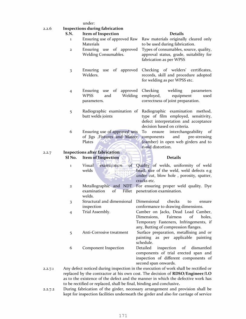
under: 2.2.6 Inspections during fabrication S.N. Item of Inspection Details 1 Ensuring use of approved Raw Materials Raw materials originally cleared only to be used during fabrication. 2 Ensuring use of approved Welding Consumables. Types of consumables, source, quality, approval status, grade, suitability for fabrication as per WPSS 3 Ensuring use of approved Welders. Checking of welders’ certificates, records, skill and procedure adopted for welding as per WPSS etc. 4 Ensuring use of approved WPSS and Welding parameters.
Checking welding parameters employed, equipment used correctness of joint preparation. 5 Radiographic examination of butt welds joints Radiographic examination method, type of film employed, sensitivity, defect interpretation and acceptance decision based on criteria. 6 Ensuring use of approved sets of Jigs ,Fixtures and Master Plates
To ensure interchangeability of components and pre-stressing (camber) in open web girders and to avoid distortion. 2.2.7 Inspections after fabrication Sl No. Item of Inspection Details 1 Visual examination of welds Quality of welds, uniformity of weld bead, size of the weld, weld defects e.g under cut, blow hole , porosity, spatter, cracks etc. 2 Metallographic and NDT examination of Fillet welds.
For ensuring proper weld quality. Dye penetration examination. 3 Structural and dimensional inspection Dimensional checks to ensure conformance to drawing dimensions. 4 Trial Assembly. Camber on Jacks, Dead Load Camber, Dimensions, Fairness of holes, Temporary Fasteners, Infringements, if any, Butting of compression flanges. 5 Anti-Corrosive treatment Surface preparation, metallising and or painting as per applicable painting schedule. 6 Component Inspection Detailed inspection of dismantled components of trial erected span and inspection of different components of second span onwards. 2.2.7.1 Any defect noticed during inspection in the execution of work shall be rectified or replaced by the contractor at his own cost. The decision of RDSO/Engineer/I.O as to the existence of the defect and the manner in which the defective work has to be rectified or replaced, shall be final, binding and conclusive. 2.2.7.2 During fabrication of the girder, necessary arrangement and provision shall be kept for inspection facilities underneath the girder and also for carriage of service
FINAL
171

cables, pipe lines etc. as per approved plans. 2.2.8 Fabrication Drawings 2.2.8.1 The contractor shall prepare detailed shop drawings including Drawing Office Dispatch Lists (DODL’s) on the basis of design drawings supplied by Engineer, in such size and in such details as may be specified/ approved by Engineer. The shop drawings shall be submitted to Engineer in triplicate, one copy of which will be returned after scrutiny and approval. The fabrication drawings shall indicate member sizes prior to and after flame cutting and or machining to obtain correct length and shape, tolerance provisions, welding sequence, type and size of welding. This drawing should be checked and approved by the Engineer before starting of the fabrication but no claim for any delay for approval by the Engineer shall be entertained by the engineer. Contractor can arrange the proof checking of the working fabrication drawings from any reputed consultant and the cost of proof checking of the working fabrication drawings will be borne by the contractor. 2.3 Maintenance of records by Fabricators 2.3.1 The records of fabrication shall be maintained in the registers as per the formats given in Appendix I of IRS B1 – 2001. 2.4 Tolerances in Fabrication 2.4.1 Fabrication tolerance for girders shall be as stipulated in Appendix II of IRS-B1-2001. 2.4.2 Permissible deviation for driven rivets shall be as stipulated in Appendix-IV of IRS-B1-2001. 3.0 BRIEF DESIGN DATA (i) The through type steel girders have been designed for single track Modified Broad Gauge Loading (MBG) as per Indian Railway Bridge Rules and Standard Specifications and three lane road loading as per IRC class “A” or one lane of IRC class “A” & one lane of IRC class 70R as per IRC-06-2000. All panel joints are designed for vertical and transverse forces including secondary moments. (ii) The structure shall be fabricated to camber as per IRS steel bridge code and or as provided in the approved drawings. The deflection of the girder is expected not to exceed the values as given in the approved drawings. (iii) All members of the girder and joints are to be either riveted or welded as shown in the approved structural drawings. No welding, except where approved by the Engineer is to be carried out at site. All welding and riveting are to be carried out as per relevant IRS Specifications and as approved by the Railway. 4.0 MATERIALS 4.1 STRUCTURAL STEEL, RIVETS AND WELDING MATERIALS ETC. i) Structural steel shall conform to specifications contained in this document. ii) The steel shall comply in all respects with the requirements of approved drawings and relevant codes and specifications and shall be procured from approved manufacturers only. It may be noted that quality of steel used for fabrication shall be the essence of the contract & shall be rigidly followed. Entire Steel sections (100%) to be supplied by the manufacturers shall be ultrasonically tested as per codal provisions at the manufacturer’s premises before dispatch. Only tested steel shall be used for fabrication. In rare cases, that too only for case of sections other than plates, ultrasonic testing may be dispensed with after prior approval of Chief Engineer/Con. This approval may be given only on production of certificate to the effect of non-requirement of testing of such sections by producers like SAIL/TISCO/RINL.
FINAL
172

iii) Further the contractor has to arrange Charpy V-notch Impact test of the structural steel supplied by the Contractor in terms of relevant IS code stipulations.
iv) All rolled sections shall bear cast mark and shall be of such length as to avoid butt welded joints in components of truss. Such rolled sections shall be within rolling tolerances stipulated as per IS: 1852 and shall be defects free.
v) The tenderer(s) shall supply information in the tender regarding source/manufacturers from where procurement of steel is proposed by him/them. However, the usage of type and grade of steel may vary during the execution of the work depending upon the design requirement and market availability. No claim shall be entertained from the contractor on this account and payment shall be as per relevant items in the schedule of items, quantities and rates. vi) Steel for rivets shall conform to IS: 1148 for M.S and IS: 1149 for H.T.S. All field rivets shall conform to IS: 1149 or as approved by Engineer. vii) Welding consumables for Manual Metal Arc Welding (MMAW) shall conform to IRS-M-28. viii) Wire and flux combination for submerged arc welding shall conform to IRS M-39.(or as stipulated/approved by Engineer) ix) Filler wires for CO2 welding shall conform to RDSO/M&C/Specification issued vide letter No. M&C/W/111/24 dated 1.1.1994/7.2.1994.(or as stipulated/approved by Engineer) x) All welding consumables (electrodes, wire, flux etc.) shall be procured only from the manufacturers approved by RDSO subject to final approval by Engineer. xi) In an extreme eventuality of steel of particular section not being made available locally by Indian Steel manufactures, the tenderer(s) may have to import steel. The imported steel shall be of equivalent specification. Use of built-up sections in place of rolled sections can be permitted. Working out the weight of steel for payment in such cases will be based on the actual sections used. Engineer will not take any responsibility of delays in importing the steel and no cognizance of the same will be given in the completion period. 4.2 Test Certificates (i) All materials for the work shall pass tests and/or analysis prescribed by the relevant IS specifications or such other equivalent specifications. (ii) For all materials including rivets and bolts, the contractor shall furnish copies of test certificates from the manufacturers including proof sheets, mill sheets etc. showing that the materials have been tested in accordance with the requirements of various specifications and codal provisions. (iii) If any further testing of materials is required by the Engineer in respect of these and other items, the same shall be arranged by the contractor at a reputed laboratory/National test house/workshop Laboratory as directed/approved by Engineer. For this, nothing extra shall be payable and accepted rates in the schedule of items, quantities and rates shall be deemed to include this. (iv) Even satisfactory outcome of such tests or analysis shall in no way limit, dilute or interfere with the absolute right of the Engineer to reject the whole or part of such materials supplied, which in the judgment of the inspecting authority/ Engineer does not comply with the conditions of the contract. The decision of the Engineer in this regard shall be final, binding and conclusive for all purposes.
FINAL
173

4.3 Steel Tape 4.3.1 Contractor shall use steel tape conforming to IS: 1270 duly tested and issued with certificate of accuracy by an accredited National testing house for templating, fabrication of drilling jig etc. The tape shall be calibrated under a tension of 1.8 kg at 16.7 degree C. 4.3.2 All marking and checking of master gussets, camber layout, etc shall preferably be at the mean temperature of the fabrication zone. 4.4 Straightening 4.4.1 All rolled sections and plates shall be straight and free from defects like twists and bends before they are used for marking and cutting. 4.4.2 If any rolled section of plate has minor defects, it shall with the approval of the Engineer, be cold straightened by pressure with the help of plate and section straightening machine. Pressure applied for straightening shall be such as not to damage the surface or microstructure of grains in the steel member. 4.4.3 Flattening, straightening and bending in hot condition shall not be carried out unless specified on drawings and or approved by Engineer. 4.5 Cutting of Material (a) All edges shall be machined mechanically (by a saw) or controlled torch oxy-acetylene flame cut. All flame cut edges shall be ground to secure clean and square edges. No shearing of section or plates is permitted. (b) When flame cutting is deployed on a plate of long length, flame cutting shall be done by multi-torch mechanically controlled equipment to ensure a straight clean cut and prevent lateral distortion due to heat application. All flame cut edges shall be ground or machined to obtain reasonably clean square and true edges. Drag lines formed during flame cutting shall be removed. (c) While chalk marking for flame cutting, following cutting allowance shall be added to the prescribed dimensions: (i) Thickness Cutting allowance (ii) Up to 12 mm +3mm (iii) Above 12 and up to 25 mm +5mm (iv) Above 25mm +7mm (d) Templates made from 3 to 4 mm thick steel plate shall be used for cutting Gussets. Long length cutting by marking with white chalk and string may be followed. (e) Minimum edge distance while preparing profile for gussets, cleats and edges of components from center of rivet hole to a flame cut edge shall be 1.75 times the diameter of hole, and for machined edge or rolled edge shall be 1.5 times the diameter of rivet holes, (machined edge means first edge distance kept 1.75 times diameter of hole for flame cutting and reduced to 1.5 times diameter of hole by removal of material by machining). 4.6 METHOD OF FABRICATION 4.6.1 Considering the length and height of span, jigs and fixtures shall be used to guide and support drilling of holes and fixtures during entire fabrication work, assembly of components, before riveting / welding of components. 4.6.2 Drilling jigs shall be fabricated with the help of Master gussets
FINAL
174

fabricated as templates for all panel joints of truss. Jigs after manufacture shall be checked and approved by Engineer or any other Inspecting agency as nominated by Chief Engineer/ Con. Only approved and stamped jigs shall be used for fabrication. First component after drilling of holes through approved jig for each specific component of truss, shall be checked with the help of Master gusset by the Inspecting Officer before further fabrication. 4.6.3 Tack Assembly a) For fabrication of riveted construction, top and bottom chords of members shall be tack assembled for drilling of holes through jig. Tack assembly of members shall be done by stitch rivets after positioning the drilling jig in true position. b) Drilling jig and tacked members shall be clamped to a fixture to avoid shifting of jig during handling and drilling. c) Tack welding may be permitted only at the ends and the locations which will eventually be cut and removed. No active part of the component shall be tack welded as this would initiate crack formation in service. 4.7 Template The contractor shall supply and provide required templates at his own cost. No separate payment shall be made for this and accepted rates shall be deemed to include this aspect. The templates used for the work shall be of steel of similar category as the member and shall be of tested quality. 4.8 Template Shop a) Fully covered template shop consisting of uninterrupted steel or concrete floor as approved having true and correct level covering adequate area shall be provided by the contractor. b) Camber layout shall be drawn to full scale from end of girder to half span. This camber layout once approved shall be used for fabrication of master gusset profiles and end profile of each member. It shall be used for working out the actual lengths of each member and checked to conform to the calculated length. c) Master gussets at every panel joint of top chord, bottom chord and middle web panel shall be marked accurately on camber layout drawn on template floor. d) All precautions shall be taken while drawing camber layout for correct setting of angle of intersection of chord and web member and great accuracy shall be ensured while transferring the same on master gusset. While marking centre point of field rivet holes on master gusset, if there is symmetry of holes on vertical axis, marking shall be made only on half the master gusset across vertical axis, and holes drilled by inscribing each hole. Subsequently remaining half portion shall be drilled through gusset using the same half portion master gusset. This will help realize symmetry of holes in gusset and fairing of field rivet hole during girder assembly.
FINAL
175

e) Camber layout and fabrication of Master gusset at every panel joint requires highly skilled and trained staff experienced in accurate fabrication of large girders, drilling jigs and fixtures. At least one jig shall be required for each component. Each jig shall be numbered and a record kept in register for identification. 4.9 Drilling of Holes a) Holes for riveting in members shall be carried out by drilling through jig only. No punching or hand drilling of holes is permitted. Sub-punching to a diameter 6mm less than that of finished holes may be permitted by Inspecting Officer/Engineer except in the main truss members of open web girders. b) When the holes are to be sub-punched they shall be marked off with a centre punch and made with a nipple punch or preferably, shall be punched in a machine in which the position of the hole is automatically regulated. The punching shall be so accurate that when the work has been put together before drilling, a gauge 1.5 mm less in diameter than the size of the punched holes can be passed easily through all the holes. c) Drilling jig should be provided with an internal turned and case hardened bush at all holes in jig, for retaining accuracy of all similar units fabricated. Bushes will have a tolerance of –0.0/+0.1 mm for shop riveting. The tolerance shall be periodically checked & replaced when the tolerance exceeds –0.00/+0.4 mm (for hardening). Before fixing to jig, bushes shall be checked with an approved plug gauge to ensure these tolerances. d) Drilling of all holes through jig by radial drilling machine for fabrication of top and bottom chords of all members will be allowed. Web members and floor system having welded construction, field holes for riveting shall be drilled through jig. e) Holes for countersunk heads of rivets, bolts or screws shall be drilled to the correct profile so as to keep the heads flush with the surface. f) Holes for rivets shall be 1.5 mm greater than the diameter of rivet bars used. Holes for turned bolts, for field connection, where specified on drawing shall be drilled in the shop 1 mm less than diameter of holes shown on the drawing and should be reamed at site to suit diameter of turned bolt. g) Drilling to enlarge unfaired holes is prohibited. The holes required to be enlarged shall be reamed provided the Engineer permits such reaming after satisfying himself about the extent of inaccuracy and the effect of reaming on the soundness of the structure. The Engineer reserves the right to reject all steel work if the holes are not properly matched. 5.0 Rivets & Riveting of Components a) The work shall include supply of all rivets, bolts, nuts, washers etc. required for complete erection at site with allowance for wastage. The contractor shall be responsible for supplying site rivets of correct length. The length of such rivets shall be verified in the presence of Engineer’s representative by snapping a few rivets of each length to check whether the holes have been completely filled in by rivet material. Particularly in case of rivets with long grips (with grip exceeding 6 times the diameter), specimen rivets shall be cut to see if the holes are totally filled even though the rivets are tight under the usual hammer tests. b) All rivets to be used shall be checked with profile gauge for its true shape, contours of head, concentricity of head, diameter as well as correct length to match the thickness of joint. Calibrated gauges for rivet dimensions and contours shall be provided by the contractor for use of the Inspecting Officer and the Engineer.
FINAL
176
c) Service bolts and nuts, ordinary plates, washers and drifts for use in the erection of the work shall also be supplied by the contractor at his own cost. On completion of the work these materials may be taken back by the contractor. d) The dimensions on the drawings refer to the diameters of the rivet holes as finished rivets. The rivets shall be made to relevant IS specification. The clearance i.e. the difference in diameter of rivet measured under head (before heating) and rivet hole shall not be less than 0.75 mm. The shanks shall be made of length sufficient to fill the holes thoroughly and to form the head. e) Riveting shall not be started until such time as Engineer or his authorized representative has personally satisfied himself that the alignment of the girders is correct, the vertical members plumb correctly, the camber is according to that shown on the camber diagram with camber jacks screwed tight, all the mating surfaces are secure and in full contact with service bolts and field rivet holes in alignment. f) All rivets shall be properly heated to straw heat for the full length of the shank, firmly backed and closed. The head of the rivet, particularly in long rivets, shall be heated more than the point and in no case shall the point be heated more than the head. Before placing the rivet in drilled holes the rivets shall be smartly jerked to shake off oxide scale. Where it is impossible to back up by normal method of holding up, double gunning may be resorted to. Alternatively pneumatic holding device may be used. g) Unless permitted by Engineer, all riveting shall be done by machine riveting using hydraulic riveters for sound & perfect riveting. Fabrication workshop should have Hydraulic Riveting facilities for fabrication of heavy duty bridge girders as per IRS specifications. Pneumatic riveters may be used subject to approval of Inspecting Officer/Engineer. The working pressure to be employed when using pneumatic or hydraulic tools shall be as per manufacturer’s specifications and approved by the Engineer. Hand riveting shall only be done when specifically allowed by the Engineer. In such cases means shall be adopted to ensure the rivets are used for their entire length and fill rivet holes completely, the snap being used only to give the correct form of head. h) All rivets when driven shall completely fill the holes, have the heads concentric with the shanks and shall be in full contact with the surface. Driven rivets when struck sharply on the dolly side head with a 110 gm rivet-testing hammer shall be free from movement and vibration. While riveting built up members, great care shall be exercised to ensure that the set of holes for field rivets in each flange of the built up member is aligned, dead square in relation to that in the other flange and not aborted. Use of special jigs shall be made to ensure this fit. i) All sparking, loose and burnt rivets, and rivets with cracks, badly formed eccentric or deficient heads shall be cut out/ taken out and replaced by others. Permissible deviation of driven rivets shall be as per IRS B1-2001. Rivets shall also be cut out when required for the examination of the work. The Engineer shall approve actual method of cutting out. Recupping and caulking shall in no circumstances be resorted to.
FINAL
177

j) Service bolts shall be frequently retightened as the riveting proceeds, the number and position of the drifts used in the joints permitting this. All field rivets shall be tested as directed by the Engineer. k) Care must be taken to use rivets of correct dimensions but burrs or lips around the rivet heads shall not be removed. l) Rivets less than 10 mm diameter may be driven cold subject to approval of Engineer. Flattened rivet head may be used in certain places where clearance demands so. m) When all the rivets at a joint have been finally passed they shall be painted as per specification. 5.1 Welding of Components/parts a) All welding work shall be as per IRS Standard and by such process that the workmanship is flawless. All welding shall be by automatic and semi-automatic submerged arc welding process, except where inaccessible. Site welding shall be avoided, but if necessary, shall be carried out only on secondary members having low stresses to transmit across the joint for which approval of the Engineer shall be required. b) Welded construction shall be carried out generally in accordance with provisions of the IRS Welded Bridge Code and IS:9595 (Metal Arc Welding) and further subject to specifications as under: c) Welding shall be done only by qualified and approved welding operators, whose competency has been verified and certified by RDSO/Engineer/I.O. Routine re-testing of welding operators may be required every six months if deemed necessary by the Engineer who also reserves the right to retest any welding operator at any time during the contract. d) All long and continuous welds shall be carried out by automatic Submerged Arc Welding (SAW) process only, in order to obtain sound and uniform shape and cross section. CO2 or manual metal arc welding (MMAW) may be done for short lengths or for secondary connections where access to the location of the weld does not permit Submerged Arc Welding (SAW), subject to approval of Engineer. e) Except for special types of edge preparation, such as single & double U and single & double J, the fusion edges of all the plates which are to be joined by welding may be prepared by using mechanically controlled automatic flame cutting equipment and then ground to smooth finish. Special edge preparation should be made by machining or gauging. f) The contractor shall appoint welding supervisors whose competence and qualification shall be subject to approval of RDSO/Engineer/I.O. All welds shall be carried out satirically under their direction & supervision. g) Welding position for fabrication of components shall be Flat or Horizontal position for SAW (flat position preferred) and Flat or Horizontal position for CO2 or manual metal arc welding. h) To ensure above position for welding, component shall be placed in a manipulator, tack assembled and rotated in the manipulator to assist welding sequence and prevent distortion of member. In absence of manipulator, special jig and fixtures shall be provided for positioning and careful handling by crane, subject to approval of Engineer. 5.2 Welding Procedure 5.2.1 The welding procedure shall be such as to avoid distortion and minimize residual shrinkage stresses. Properly designed jigs should be used for assembly. The welding techniques and sequences, quality, size of electrodes, voltage and current required shall be as prescribed by manufacturers of the material and welding equipment. The contractor should submit full details of welding procedure in pro-forma given at
FINAL
178

Appendix-V of IRS B1 – 2001. 5.3 Sequence of welding and welding pass 5.3.1 The sequence of welding and welding pass shall be done as per IRS B1 – 2001. 5.4 Weld Quality Tests 5.4.1 A. Procedure Trials 5.4.1.1 Welding and flame cutting trials as per following shall be carried out and completed before fabrication on representative samples of materials to be used in the work; a) The samples of material shall be selected and marked by the Engineer when the materials for the work are inspected in contractor’s fabrication / storage. b) The trials of flame cutting shall be carried out in material representative of all thicknesses to be used in the work. c) Trials on material 19mm thick may be taken to include all material under 19mm thick and on material 38mm thick to include material between 19mm and 38mm thick. Over 38mm thickness material shall be tested for every thickness increment of 6mm. The trials of flame cutting shall be carried out in material representative of all thicknesses to be used in the work. d) The welding & flame cutting trials shall be commensurate to the satisfaction of Engineer/Inspecting Officer and the procedures to be adopted in the fabrication of work which shall include: i) Welding procedure in accordance with relevant specification. ii) Heat control techniques required to ensure that the flame cut surface of steel are suitable for inclusion in welds. e) The trials shall include specimen weld details from the actual construction which shall be welded in a manner simulating the most unfavorable instances of fit-up and preparation. After welding the specimens shall be held as long as possible at room temperature but in any case not less than 72 hours, and then shall be sectioned and examined for cracking. Six representative samples of each weld joint similar to joint used in fabrication of all components shall be prepared by qualified and certified welding operators. f) Following groups of tests shall be carried out: i) Butt welds: Transverse tensile test, transverse & longitudinal bend test with the root of weld in tension and compression respectively, Charpy V-notch impact test. ii) Fillet welds: Fillet weld fracture test.
Tack welds: Inspection for cracking iii) All welds: Macro examination. 5.4.2 B. Additional tests as under shall also be carried out for approval and during contract executions stage, as per requirement and instructions of RDSO/ Engineer/ I.O., the cost of which shall be borne by the contractor. Following tests are normally performed on welds; 5.4.2.1 (a) Non Destructive Tests (NDT):
- Visual inspection/profile gauge for dimensional check of size and throat thickness of weld. - Etching test for penetration of joint. - Magnetic particle or Ultra Sonic Pulse Velocity (USPV) - Gamma Radiography & X-ray (only for butt welds) - Dye penetration of all weld joints.
5.4.2.2 (b) Destructive Test: - Tensile test - Bend test - Impact test - Load test.
5.4.2.2.1 Once samples representing the weld joint used in fabrication of all components are
FINAL
179

tested and test results are found satisfactory, then approval shall be taken from the Engineer/Inspecting Officer for the welding of built up components by approved welding operators. Welding Procedure Qualification Records (WPQR’s) shall be prepared which shall include joint details, welding consumables (i.e. electrode/wire & flux combination), weld parameters (i.e. welding current, wire feed speed), welding position, welding equipment carriage speed (for SAW process), arc Length, arc voltage etc. 5.4.4 C. Qualification and Testing of welders: i) No welding operator shall be employed on the work until he has, in the presence of the RDSO/Engineer/I.O, passed the appropriate tests laid down in relevant specification. ii) Where plates of 12mm thick and over are to be butt welded the tests set out in relevant specification is to be followed. iii) Routine re-testing of welding operators may be required every six months if deemed necessary by the RDSO/Engineer/I.O iv) The RDSO/Engineer/I.O reserves the right to require any welding operator to be re-tested at any time during the contract. 5.5 Precautions during welding I. The Contractor shall submit list of weld joints of different combined thickness for approval of welding procedure for all members. II. The welding of built up component shall be carried out only by approved welding operators and in accordance with Welding Procedure Qualification Records. WPQR’s shall be prepared in advance and approved by the Engineer. Proper welding sequence shall be followed to avoid distortion and minimize residual shrinkage stress, and surface defects, within acceptable tolerance limits. III. To ensure sound and defect free welding of built up members, record of welding adopted as per approved qualifying procedure shall be maintained in Performa prescribed in guidelines for welded fabrication issued by RDSO or as stipulated in IRS-B1-2001. IV. Any change during welding for fabrication of built up member, such as welding sequence, welding process, positioning, wire and flux combination, joint details, increase or decrease in combined thickness of joint by 5 mm etc. shall be carried out only after representative samples test and procedure qualification, is accepted. In no case any deviation from WPQR’s without approval of Engineer shall be permitted. 5.6 Preparation of Faces I. Preparation of joint face: Except for special types of edge preparation such as single or double ‘U’ & ‘J’ joints, the fusion edges of all plates which are to be joined by welding shall be prepared by using mechanically controlled automatic flame cutting equipment with the cutting allowance as per clause 4.6 and the extra length machined to obtain correct length. II. It shall be ensured by Non-destructive tests that the fusion face and adjacent surface are free from cracks, notches or other irregularities that are likely to cause defects during service or interfere with deposition of the weld. III. Fusion faces and the surrounding surface upto 50 mm shall be free from mill scale, moisture, oil, paint dirt or any other substance which may affect the quality of the weld, and same shall be removed by grinding or flame cleaning/grit blasting. IV. Details of joint, fusion faces, root face and gap shall be as per details given in fabrication drawing or as stipulated in IS: 9595.
FINAL
180

5.7 Welding Operation I. Parts to be welded shall be assembled such that the joints to be welded are accessible and visible to the operator. Assembly jig and fixture shall be used for accuracy. II. Manipulators should preferably be used to execute the sequence of welding without disturbance, in the most suitable position. Fixtures shall maintain the alignment with minimum restraint in order to reduce the possibility of locked up stresses. III. Run in and run out plates shall be provided for fabrication of built up members or truss to ensure that weld will start on run in plate and weld will stop on run out plate and thus avoid crater defects on the components. IV. The size and length of weld shall not be less than those specified in the drawing nor shall they be in excess of the requirement without prior approval of the Inspecting Officer. The location of weld shall not be changed without prior approval of the Engineer. V. During design and detailing of component lengths, care is to be taken to avoid butt weld in built up members of truss. Therefore it is essential to use only nearest size and length of rolled sections that have been procured to scheduled sizes and lengths by proper planning. No butt weld shall be carried out without approval of Engineer. VI. Fabrication of components subject to dynamic loading in the structure need careful inspection during fabrication by qualified, experienced and certified Engineer from contractor’s side and final approval by RDSO/Engineer/I.O. This inspection shall be carried out as stipulated in Indian Railway Welded Bridge Code before, during and after welding. 5.8 Additional Precautions during Welding I. Following precautions shall further be observed during fabrication. II. All equipment shall be provided with calibrated gauges to observe limits of variation for parameters prescribed in WPQR’s for welding current, arc voltage, speed of travel of equipment etc. III. Covered shed for environmental control (particularly against dust, moisture and water) shall be provided to avoid entrapment of hydrogen, which is likely to cause crack initiation in weld or under bed of weld (i.e. Heat Affected Zone HAZ). Also baking of flux used for submerged arc welding in oven for an hour at 200 degree C shall be carried out to ensure that no moisture is contained in flux during welding. IV. All tack welds shall be carried out by qualified and approved welder only. As tack weld will become part of the final weld, it shall be free from all cracks and other welding defects. V. If multiple runs are used for fabrication of built up member, inter run cleaning shall be carried out and subsequent weld bed made only after approval of inspecting officer or his authorized representative. This is to check free defects in the weld. Also visible defects such as cracks, cavities, if any, shall be removed by grinding. It shall be ensured during welding that craters are avoided. VI. Stray arcing of components, which cause local hard spots or cracking of parent metal, shall be avoided. VII. Flux of approved quality will be permitted for use. VIII. The Auto melt grade wire spools of wires for Submerged Arc Welding and Carbon Dioxide (CO2) consumables of only the approved quality will be permitted. IX. Pre Heat Treatment will be given to the consumables to remove the moisture if any X. No violation of welding procedure will be permitted on any account. 5.9 General : Riveting & Welding 5.9.1 Qualified, trained, and experienced supervision is essential at all times during fabrication/erection and for maintenance of records.
FINAL
181

5.9.2 After riveting of riveted components or welding of welded components, they shall be finished finally by grinding or matching with the help of a profile template. All the butting ends of components shall be faced in milling machine after members have been completely fabricated. 5.9.3 In the case of compression members, the face shall be machined so that the faces are of proper angle as shown in drawing and the joint when made will be in close contact throughout within a gap tolerance of less than 0.15 mm. The Inspecting officer may permit a tolerance of (-) 0.4 mm at isolated points in butting line. 5.10 Full penetration butt welding with radiography testing: 5.10.1 Above is not permitted in this work. 6.0 PAINTING Specifications for metallising and painting of bridge girders shall be as per IRS: B1-2001. 6.1 SURFACE PREPARATION ( FOR ALL TYPES OF PAINTING AND METALLISING) 6.1.1 Surface of all components /members of the superstructure shall be prepared as per following provisions before application of first coat of paint/primer or before Metallising. I. The surface should be clean, dry and free from contaminants and it should be rough enough to ensure adhesion of the paint film. However it should not be so rough that the film cannot cover the surface peaks. II. The cleaning of the surface shall be done initially with the use of emery paper, wire brushes, scrapers etc. for spot cleaning to remove rust, scale etc. Subsequently, sand blasting of the surface shall be done to remove rust, mill scale along with some of the base metal. This will be achieved by high velocity impact of abrasive material against the surface in accordance with the provisions of IS: 6586, which will also create a base for good adhesion. The abrasive material once used for cleaning heavily contaminated surface should not be reused even though re-screened. Washed salt free angular silica sand of mesh size 12 to 30 with a minimum of 40% retained on a 20 mesh screen shall be used for blasting. The material specifications and other requirements shall be as provided in Indian Railways Bridge Manual, 1998. III. All site rivets, bolts, nuts and washers shall be thoroughly cleaned and dipped in boiled linseed oil. All machined surfaces are to be well coated with a mixture of white lead conforming to IS: 34 and Mutton tallow conforming to IS: 887 as per specifications before dispatch to site. Nothing extra shall be payable to contractor on this account. IV. Surface preparation shall not be carried out in the following conditions:
- In rainy season from June to September and from December to January. - In extremely windy/misty/dust blowing conditions. - At night - In winter before 8 A.M. - In summer between 11 and 15 hrs, in areas, which are likely to be exposed to direct sunlight. - Engineer reserves the right to change the above timings.
6.2 Metallising and Painting of steel structure of the Bridge :- I. All the components in the floor in open web girders shall be metalized as per IRS specifications. Components to be metalized in rail deck are cross girders, stringers and connecting gussets. II. The sprayed coating shall be applied as soon as possible after surface preparation. The wire method shall be used for the purpose of metallising, the diameter of the wire being 3mm or 5mm as per approved by Engineer. III. The composition of the aluminum to be sprayed shall be in accordance with
FINAL
182

BS: 1475, material 1-B (99.5%) aluminum otherwise as per IS: 739 and IS: 2590. However, the selection of metal for spraying, i.e. Zinc or Aluminum shall be subject to final approval by the Engineer. IV. Specified thickness of coating shall be applied in multiple layers and in no case less than 2 passes of the metal spraying unit shall be made over every part of the surface. The surface after spraying shall be free from uncoated parts of lumps of loosely spattered metal V. At least one layer of the coating must be applied within four hours of blasting and the surface must be completely coated to the specified thickness within 8 hours of blasting. VI. Minimum thickness of metal coating applied shall be 115 microns and average thickness shall be 150 microns. The metal coating shall be checked for thickness by approved magnetic thickness measuring gauge. At least one reading for each sqm of area painted shall be taken. The calibration of the gauge shall be checked against a standard of similar thickness within an accuracy of 10%. VII. For measurement of dry film thickness, following instruments may be used by the contractor. Dry film thickness is to be measured as described in Appendix-VII of IRS BI-2001.
(a) Electronic coating thickness gauge. (b) Elcometer (magnetic thickness gauge) Dial type. (c) Surface profile gauge.
VIII. Any oil, grease or other contamination should be removed by thorough washing with a suitable thinner until no visible traces exist and the surfaces should be allowed to dry thoroughly before application of paint. The coatings may be applied by brush or spray. If sprayed, pressure type spray guns must be used. One coat of wash primer to IS: 5666 shall be applied first. After 4 to 6 hours or the application of the wash primer, one coat of Zinc chrome primer to IS: 104 with the additional provision that zinc chrome to be used in the manufacture of primer shall conform to type 2 of IS: 51 shall be applied. IX. The third coat shall be by Aluminum paint conforming to IS: 2339. The girder parts shall be dispatched to site after the third coat (i.e. first finishing coat or cover coat).
6.2.1 After assembling and launching at site, second finishing coat of Aluminum paint conforming to IS: 2339 shall be applied after touching up the primer and first finishing coat. 6.3 Painting of other components/parts of Girders. 6.3.1 Protective coatings by paintings as per following painting schedule may be applied with the approval of the Engineer: (a) Primer coat: One coat of ready mixed zinc chromate priming to IS:104 followed by one coat of ready mixed paint red oxide zinc chrome priming paint to IS:2074. (b) Finishing Coat: Two coats of aluminum paint to IS: 2339 shall be applied over the primer coats. In the workshop, One coat of primer shall be applied. Before dispatching the girder parts to the site, the finishing coat (cover coat) shall be applied. After assembling and erection at site, the second finishing coat shall be applied, after touching up the primer and finishing coat, if damaged in transit. 6.4 Inspection 6.4.1 Adhesion: The sprayed metal coating shall be subjected to an adhesion test using the method described in IRS BI-2001. If any part of the coating between the lines breaks away from the base metal, it shall be deemed to have failed the test.
FINAL
183

6.5 Paints for painting of steel works: Source, Quality & testing i. Paint and other accessories including those for metallising work will be supplied by the contractor. Paints manufactured only by the following firms may be used subject to their being in the approved list of RDSO and final approval by the Engineer. (a) M/s. Jenson Nicholson paints. (b) M/s British / Burger paints. (c) M/s Shalimar Paint (d) M/s I.C.I. paints. (e) M/s Nerolac. Paints. ii. In case above brands are not on approved list of RDSO, the contractor shall submit proposal of alternate brands borne on approved list of RDSO. iii. The contractor shall furnish to the Engineer, the date of manufacture of paint as certified by the manufacturers with the necessary container marking and test certificate for paint conforming to relevant IS code. In addition to this, he shall also submit the necessary vouchers in respect of paint purchased by him. iv. The Engineer reserves the right to get the paint tested at contractor’s expenses as considered necessary by the Engineer. If the test results do not conform to relevant IS specifications fully, then the lot of paint shall be rejected and got removed from the contractor(s) storage. If the paint has already been applied it shall be removed.
In addition to above, the following tests are required to be carried out in the field. a) Weight per litre. b) Consistency test c) Scratch test. d) Flexibility and adhesive test. v. The Engineer reserves the right to reject the lot of paint even on the basis of field results. vi. Shelf-life of the paints shall be as per provisions in the IRS-B1-2001/Indian Railway Bridge Manual 1998 or as approved/directed by the Engineer. 6.6 Painting - General Instructions a) Painting shall not be commenced till the surface preparation has been approved by the Engineer or his representative or inspecting officer. b) Sealed containers of paint of approved brand shall be used. The paint drums must be rolled, turned upside down and shaken before opening. The paint must be stirred well before use. Over stirring which results in invisible air bubbles etc., shall be avoided. c) Where brush painting is accepted, the paint must be applied by means of flat brushes not more than 75mm in width having soft flexible bristles conforming to IS: 384. d) Round and oval brushes of approved quality conforming to IS: 487 may also be used as per the instructions of the Engineer or his representative or inspecting officer. e) All new brushes should be soaked in raw linseed oil conforming to IS: 77 for at least 24 hours before use. f) A little blue paint shall be added, in the first coat of aluminum paint to distinguish it from second coat. For paints of other colours for final and finishing two coats, suitable pigment shall be used as per instruction of the Engineer, to distinguish the first coat from the second coat.
FINAL
184

g) The date of painting shall be marked with paint on the member. h) Each coat of paint shall be left dry till it sufficiently hardens before the subsequent coat is applied. Each coat of paint shall be inspected by the Engineer or inspecting officer and certified as satisfactory before applying subsequent coat. 7.0 ASSEMBLY & ERECTION 7.1 General a) The contractor shall provide at his own cost all tools, machinery, equipment and erection material, including all temporary works and shall assemble all components in every respect as stipulated in the contract and in accordance with approved scheme, drawings and specifications. b) Before starting the work the contractor shall seek the Engineer’s approval as to the method he proposes to follow and the type and suitability of equipment he proposes to use for assembly of girder components and launching of girder. The approval of the Engineer shall however not in any way relieve the contractor of his responsibility for the adequacy and safety of methods and/or equipment he proposes to use for carrying out the work in accordance with drawings and specifications. c) All temporary works shall be properly designed and fabricated & erected with great care for the loads, which they will be called upon to support. Adequate allowance and provision for the effect of lateral forces and wind loads shall be made to meet unforeseen conditions. d) When chains are used for lashing, care must be taken to protect the edges of members from twisting and distortion, damage to paint and similar effects. e) Temporary bracing shall be provided to take care of stresses caused by erection equipment or other incidental loads during erection. f) The method used for lifting and slinging flexible members shall be brought to the notice of the Engineer and shall be subject to his approval. g) The contractor shall observe sufficient accuracy in the assembly of every part of the work to ensure that all parts fit accurately together. h) Contractor shall take all necessary precautions for safety of the substructure of this Bridge and substructure and superstructure of approach viaducts, during assembling, erection & launching works of the girders and nothing extra will be paid, on account of this. In addition, the contractor shall adopt all precautionary measures for safe plying of inland vessels, boats, crafts etc. and nothing extra will be paid, owing to this. 7.2 Procedure for Assembly in Workshop & Site 7.2.1 The contractor is required to undertake test assembly of one girder of each type of span in his fabrication workshop to prove accuracy of templates and jigs. This assembly can be done in horizontal position. In case the fabrication workshop is set up by the contractor at bridge site itself the test assembly may be done at assembly platform and after testing of accuracy of jigs, fixtures& templates and the camber, the same assembly can be launched after riveting. 7.2.2 The test assembly shall be certified by RDSO/Engineer/I.O. 7.2.3 Following procedure may be used by contractor subject to checking of design by contractor’s consultant and final approval by the RDSO/Engineer/I.O. a) The joints at the end of each top & bottom chord shall be drifted, bolted and preferably stitch riveted to their Geometrical outline. b) The procedure during assembly shall consist of placing camber jacks in position to support the structure. The camber jacks shall be set such that they provide sufficient height to allow for lowering of panel points to obtain and maintain the required camber. Throughout the process of
FINAL
185

assembly, tilt, shift, twisting etc. shall be repeatedly checked. The jacks shall be spaced so that they will support the ends of the main girders and the panel points. c) The bottom chord members shall then be placed on the camber jacks, carefully leveled and checked for straightness and the joints completed by riveting. d) The vertical and diagonal web members, except the end verticals shall then be erected with gusset connection outward from centre in their proper position on the bottom chords. Temporary gussets with correct hole position as on master gusset shall be fixed to connect the top end of diagonals. Strainers shall be used to realize matching of holes in the gussets at top & bottom of the diagonals & verticals, to ensure that the angles between the members at the bottom joints are as given by the nominal outline of the girders. The verticals and diagonals shall then be riveted to the lower chord. e) All panel points, except the central one shall now be lowered by an amount sufficient to produce the correct camber on the main girders as shown on the camber diagram. f) The top chord shall thereafter be erected piece by piece, working symmetrically outwards from the centre without loss of camber profile. g) Temporary top gussets, if used, shall be replaced by permanent gussets outwards from the centre. h) The ends posts shall be erected last. The upper end connection should preferably be made first and if there is no splicing in the end vertical, the final closure be made at the bottom connection. If there is splicing, it shall be made at the splicing. i) Frequent checks shall be made of the camber of girders during erection and care taken that the correct camber is obtained when the girder is completely assembled. 7.3 Inspection, Testing & Marking (i) All components shall be offered for inspection prior to painting. All approved components shall be stamped defect free, painted as per specifications prior to dispatch to bridge site. (ii) On final finishing of each component, it shall be marked distinctly with paint with shipping mark for guidance, during assembly of component. All other aspects not stated above shall comply with IRS-BI-2001 and Welded Bridge Code. 7.4 Transports from Workshop & Stacking at Site
7.4.1 All items fabricated in the workshop shall be marked and packaged with accompanying package list. The items after fabrication shall be transported by contractor to site by Road in a manner as to cause no damage to the components. Contractor shall be liable for all losses and damages in transit for the materials consigned by him till materials are erected and work completed and taken over by the Engineer. Insurance against loss or damage in transit, if any, shall be the responsibility of the contractor. 7.4.2 After identification & correct marking, all components of each girder shall be dismantled & similar components shall be grouped together & labeled; rivets bolts and plates of each size shall be packed separately in the manner described elsewhere in this tender document, after approval by the inspecting authority. 7.4.3 The packages shall be of such size by length & weight that they are safely transportable by Road. The components shall be provided with necessary packing to avoid damage to painting & members in transit. 7.4.4 Dimensions for transport shall be as per standard schedules.
FINAL
186

7.5 Assembly at Site 7.5.1 Holes 7.5.1.1 After drilling holes in temporary tack assembled components, the components shall be taken apart after match marking and all burrs left by drill and sharp edges of all holes shall be removed by spot grinding to ensure full contact when assembled. 7.5.1.2 Assembly fixture shall be used to build components for turned bolt connection. These connections will help realize correct position of member and matching of coaxial holes in opposite members besides true alignment and level. 7.5.1.3 After assembly, all blank holes shall be checked with plug gauge of diameter 0.8mm less than hole diameter, to check fair matching of holes before riveting. 7.5.2 Drifts 7.5.2.1 Drifts as per IRS specifications may be used for drawing light members into position, but their use on heavy members should be restricted. In no case shall the drifting be allowed to such an extent that holes are distorted. Drifting to enlarge the unfaired holes is prohibited. 7.5.3 Reaming 7.5.3.1 The holes that will have to be enlarged to admit rivets should be reamed subject to approval of Engineer/Inspecting Officer who will satisfy himself about the extent of inaccuracy and the effect of reaming on the soundness of the structure. The Contractor shall supply special rivets to fill reamed holes, where reaming is approved. Record of all such variations shall be maintained. However, these provisions should not apply for under drilled holes meant for turned bolts. Copies of all correspondence pertaining to the recourse of reaming and the use of oversize rivets shall be sent by the contractor for information to Engineer. 7.5.4 Making of joints 7.5.4.1 Care shall be taken to see that all burrs are removed and no surface defects exist before the parts are assembled. The mating surfaces shall establish full contact when assembled. In cases where the joints have to withstand stresses arising from special methods of erection, provision is to be made to take the whole stress that will or may occur. Cylindrical drifts and turned bolts shall be used to withstand such stresses and no reliance is to be placed on service bolts for this purpose. Up to a maximum of 40 percent of the holes of each member of the joint are to be filled with drifts and balance of strength required is to be attained with turned bolts. The position and number of the drifts and bolts will be decided/approved by Engineer. 7.5.5 Painting of Joints 7.5.5.1 All surfaces, which are in permanent contact, shall be thoroughly cleaned down to the bare metal, to remove mill scale and grease etc. They shall be painted immediately before assembly with one coat of ready mixed paint zinc chromate priming to IS : 104 and raw linseed oil freshly ground and the surface prepared for painting as per painting specification at Clause 6.0. 7.6 Assembly and Launching (i) The assembling of components at site to required camber and grade along bridge axis, preceding additional temporary structures and accessories for launching of girders and all related matters shall be full responsibility of the contractor. (ii) The launching of girders shall be done as per approved drawings. For this purpose, the contractor shall submit in triplicate, detailed launching schemes of all the girders including design calculations, safety procedures and method statement with such plans, sketches and other details as may be necessary to determine the suitability and adequacy of the schemes proposed. The methods adopted shall not, under any circumstances, cause the stresses in various members of girder spans to exceed permissible and safe limits at any stage of launching. One copy duly approved by the Engineer shall be returned to the contractor.
FINAL
187

(iii) For the Engineer’s use and record, the contractor shall supply free of charge, four sets of prints on strong paper and one set of neatly executed tracings on linen of approved detailed drawings for assembly and launching schemes for use at site. (iv) The contractor shall provide full structural details of the temporary members and their connections to the girder, along with necessary design calculations not only justifying members’ sizes but also of the entire launching system adopted. Contractor shall provide full structural details of the temporary member and their connections to the girder, along with necessary design calculations not only justifying members’ sizes but also of the entire launching system adopted. Contractor will be responsible for getting approval of launching scheme submitted by him from the Engineer. (v) In order to ensure perfect fit of the temporary components, holes may be carefully drilled for the connecting members in between the girders in situ and T & F High tension grip bolts used. (vi) The launching system shall be test tried if directed by the Engineer and no separate payment for this shall be made. (vii) Nothing extra will be paid to the contractor for adopting any scheme for launching and the costs are to be covered in the relevant item in the schedule of items, quantities and rates. All temporary members shall be removed after launching and may be taken back by the contractor. Erection gussets provided for connecting the members may be cut and edges ground as directed /approved by the Engineer. 7.7 Permanent/Temporary Strengthening (viii) The launching arrangement may include fabrication of launching nose or restraining girders, sway restraining devices such as sway ropes, restraining cables etc., the supply and fixing of members for temporary strengthening of girder members to take care of erection stresses and strains and other relevant components for satisfactory and successful completion of the defined scope of work. Erection stresses must be kept within safe and permissible limits at every stage of erection. (ix) The contractor has to make arrangements at his own cost for the steel for temporary arrangements including sway restraining devices for launching and temporary strengthening of girder, as may be required for the launching operations. The rate quoted should take into account these factors as nothing extra shall be paid. (x) Launching scheme may also require permanent strengthening of some members. In such case, all additional steel (over and above approved payable weight /DODL as per approved structural drawings) required for permanent/temporary strengthening for proper launching/erection of the girders shall be arranged by contractor at his own cost. Railway shall be responsible for issue/payment of steel only to the extent of approved payable weight. 7.8 Inspection and Rectification (xi) During erection of girders, the contractor shall provide all facilities and permit the Engineer to inspect the field assembly, site riveting and erection of spans to the satisfaction of engineer. (xii) After inspection by the Engineer/ Inspecting agency, the contractor shall identify cause of any defect, imperfection and/or fault noticed during such inspection and initiate corrective action as per the direction of the Engineer. All defects, imperfections or faults, shall be made good by the contractor to the Engineer’s satisfaction and the cost of identifying and rectifying such defects, imperfection or faults shall be borne by the contractor.
FINAL
188
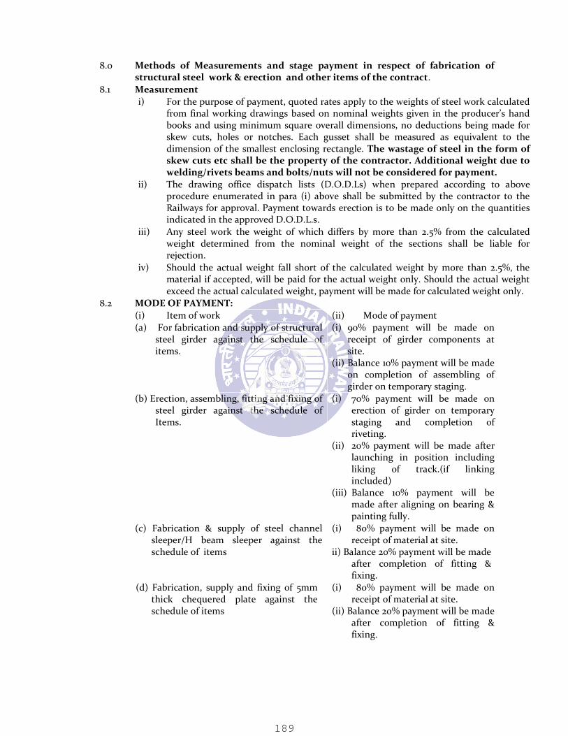
8.0 Methods of Measurements and stage payment in respect of fabrication of structural steel work & erection and other items of the contract. 8.1 Measurement i) For the purpose of payment, quoted rates apply to the weights of steel work calculated from final working drawings based on nominal weights given in the producer’s hand books and using minimum square overall dimensions, no deductions being made for skew cuts, holes or notches. Each gusset shall be measured as equivalent to the dimension of the smallest enclosing rectangle. The wastage of steel in the form of skew cuts etc shall be the property of the contractor. Additional weight due to welding/rivets beams and bolts/nuts will not be considered for payment. ii) The drawing office dispatch lists (D.O.D.Ls) when prepared according to above procedure enumerated in para (i) above shall be submitted by the contractor to the Railways for approval. Payment towards erection is to be made only on the quantities indicated in the approved D.O.D.L.s. iii) Any steel work the weight of which differs by more than 2.5% from the calculated weight determined from the nominal weight of the sections shall be liable for rejection. iv) Should the actual weight fall short of the calculated weight by more than 2.5%, the material if accepted, will be paid for the actual weight only. Should the actual weight exceed the actual calculated weight, payment will be made for calculated weight only. 8.2 MODE OF PAYMENT: (i) Item of work (ii) Mode of payment (a) For fabrication and supply of structural steel girder against the schedule of items.
(i) 90% payment will be made on receipt of girder components at site. (ii) Balance 10% payment will be made on completion of assembling of girder on temporary staging. (b) Erection, assembling, fitting and fixing of steel girder against the schedule of Items.
(i) 70% payment will be made on erection of girder on temporary staging and completion of riveting. (ii) 20% payment will be made after launching in position including liking of track.(if linking included) (iii) Balance 10% payment will be made after aligning on bearing & painting fully. (c) Fabrication & supply of steel channel sleeper/H beam sleeper against the schedule of items
(i) 80% payment will be made on receipt of material at site. ii) Balance 20% payment will be made after completion of fitting & fixing. (d) Fabrication, supply and fixing of 5mm thick chequered plate against the schedule of items
(i) 80% payment will be made on receipt of material at site. (ii) Balance 20% payment will be made after completion of fitting & fixing.
FINAL
189

9.0 DEVIATION FROM SPECIFICATIONS 9.1 The contractor may extend suggestions for member substitution, fabrication method, launching procedure and the like; provided the fundamental character such as area & stiffness of the member and the connections are not adversely affected and preferably remain unchanged. The decision of Engineer shall be final and binding on all such proposals made by the contractor. Nothing extra will be paid to the contractor for such deviations. The contractor shall document all such deviations for the Engineer’s record. Entire cost of structural analysis shall be borne by the contractor. 10.0 CONTRACTOR’(S) LIABILITY 10.1 Any fitting, accessory or apparatus which may not have been mentioned in this specification or the drawings, but which are usual or necessary in the execution of such work, are to be provided by the Contractor without extra payment. The whole work must be completed in all details, whether mentioned in this specification or not, with the exception of such work as has been specified in the schedule of items to be separately provided for in the Contract. 10.2 Notwithstanding the specifications and conditions stated in the contract, the contractor shall keep the Engineer/Employer authority fully indemnified and free from all liabilities and risks consequential to any lapse on his part in respect of material quality, standard of workmanship, accuracy of fabrication and the like. He shall provide all labour and material required for execution of the work as per listed standards and in absence of any IRS & IS specifications, to the relevant British standards. 11.0 ADDITIONAL REQUIREMENTS FOR SUPERSTRUCTURE 11.1 The suitable ladders, inspection galleries, inspection platforms etc. shall be provided as per approved drawing. 11.2 The bearing shall be provided as per specifications and requirements. Anti-seismic arrangements shall be provided as per approved drawings. 11.3 Steel Chequered plates 620mm wide and 5mm thick, conforming to IS 2062/ IS 3502 shall be used for pathway, man refuge floor etc. for entire length of the bridge. The payment for this shall be made as per relevant item in the schedule of items, quantities and rates. The cost of fixing (including fasteners) to girder component/sleepers shall be deemed to be included in relevant item rate and shall not be paid extra. 12.0 BEARINGS 12.1 General: Pot type PTFE Bearings 12.1.1 Pot type bearings shall consist of a metal piston supported by a disc or un-reinforced elastomer confined within a metal cylinder to take care of rotation. Horizontal movement, if required shall with a system of sealing rings be provided by sliding surfaces of PTFE pads sliding against stainless steel mating surfaces. The pot bearings shall consist of cast steel assemblies or fabricated structural steel assemblies. 12.1.2 Provisions of IRC –83 (Part I) shall be applicable for all metallic elements. Provisions of IRC-83 (Part II) shall be applicable for all elastomer elements. Provisions of IRC-83 (Part III) shall be applicable for POT/POT-PTFE bearing. When any items are not covered by IRC: 83 (Part I, Part II and Part III), the same shall be as per guidelines given hereunder and BS: 5400 (Sections 9.1 and 9.2), except that the same shall be permitted. If there is any conflict between BS on the one hand and IRC on the other, the provisions of IRC will be guiding. 12.2 Fabrication 12.1.1 The surface mating with the PTFE in the sliding pair shall be corrosion resistant stainless steel. Normally, the stainless steel shall form the upper component. The stainless steel shall overlap the PTFE after full movement on all sides. If stainless
FINAL
190

steel sheet is used, it should be bonded by continuous welding along the edges. Adhesive or any other bonding can be approved by the Engineer. The surface shall be prepared by thorough cleaning to remove grease, dust or any other foreign substance. 12.2.2 PTFE modular sheets of the sliding pair shall be located by confinement assisted by bonding. Confined PTFE shall be recessed into the metal backing plate. The shoulders of the recess shall be sharp and square to restrict the flow of PTFE. 12.2.3 The thickness of the PTFE shall not be less than 4.5 mm with projection above the recess not exceeding 2.0mm. When the piston is subjected to tilting, the seal must slide along the wall and alter its shape according to the angle of tilt. At the same time, it must be sufficiently rigid to bridge the gap between the piston and the wall of the pot. However, the percentage of plan area of the lubrication cavities to the gross area shall not exceed 25%. The depth of the cavity shall not exceed 2.0 mm. 12.2.4 The diameter of thickness ratio of the confined elastomer shall not exceed 15. The surface of the confined elastomer shall be smooth. 12.2.5 A seal shall be provided to prevent extrusion of the confined elastomer between the piston and the pot wall. The seal should stay functional under the loads and rotations acting on it. Additional seal shall be provided to prevent entry of dust into the pot wall. Sealing rings for pot bearings shall be fabricated from stainless steel. 12.2.6 The hardness of the piston and the wall at their contact region shall be minimum 350 BHN to reduce wear. The surface finish of the pot base in contact with the confined elastomer shall be very smooth. 12.2.7 All bearings shall be installed with anchor and anchor screws or some similar device such that while replacing, the bearings can be removed with minimum lifting of the superstructure. 12.2.8 The external surface of the assemblies shall be completely cleaned by sand blasting. After sand blasting, dust shall be removed from the surface using clean and dry compressed air or a clean brush after which suitable coating shall be applied. 12.2.9 POT bearings including all parts as shown on the drawings shall be fully shop assembled at the manufacturer’s works to ensure proper fitting of all parts. 12.3 Materials 12.3.1 a) Steel i) Structural steel shall conform to IS: 2062-2006. ii) Cast steel shall conform to Gr. 280-520W of IS: 1030. 0.3 to 0.5 % copper may be added to increase the corrosion resistance properties. iii) Stainless steel shall conform to AISI: 304 or X04Cr18Ni10 of IS: 6911 for ordinary application. For applications with adverse/ corrosive environment, the stainless steel shall conform to AISI: 316L or 02Cr17Ni12Mo2 of IS: 6911. iv) Reinforcement shall conform to IS-1786-1985(Fe415/Fe500) 12.3.2 b) PTFE PTFE (poly tetra fluoro ethylene) shall be of unfilled pure virgin quality. It shall be free sintered. The mechanical properties of unfilled PTFE shall comply with Grade A of BS: 3784. 12.3.3 c) Elastomer The confined elastomer inside pot will have the following properties:
FINAL
191
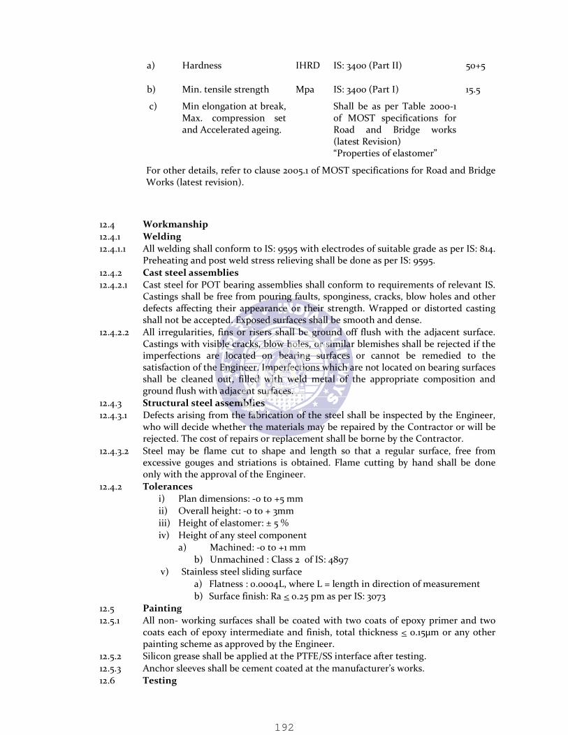
a) Hardness IHRD IS: 3400 (Part II) 50+5 b) Min. tensile strength Mpa IS: 3400 (Part I) 15.5 c) Min elongation at break, Max. compression set and Accelerated ageing.
Shall be as per Table 2000-1 of MOST specifications for Road and Bridge works (latest Revision) “Properties of elastomer”
For other details, refer to clause 2005.1 of MOST specifications for Road and Bridge Works (latest revision). 12.4 Workmanship 12.4.1 Welding 12.4.1.1 All welding shall conform to IS: 9595 with electrodes of suitable grade as per IS: 814. Preheating and post weld stress relieving shall be done as per IS: 9595. 12.4.2 Cast steel assemblies 12.4.2.1 Cast steel for POT bearing assemblies shall conform to requirements of relevant IS. Castings shall be free from pouring faults, sponginess, cracks, blow holes and other defects affecting their appearance or their strength. Wrapped or distorted casting shall not be accepted. Exposed surfaces shall be smooth and dense. 12.4.2.2 All irregularities, fins or risers shall be ground off flush with the adjacent surface. Castings with visible cracks, blow holes, or similar blemishes shall be rejected if the imperfections are located on bearing surfaces or cannot be remedied to the satisfaction of the Engineer. Imperfections which are not located on bearing surfaces shall be cleaned out, filled with weld metal of the appropriate composition and ground flush with adjacent surfaces. 12.4.3 Structural steel assemblies 12.4.3.1 Defects arising from the fabrication of the steel shall be inspected by the Engineer, who will decide whether the materials may be repaired by the Contractor or will be rejected. The cost of repairs or replacement shall be borne by the Contractor. 12.4.3.2 Steel may be flame cut to shape and length so that a regular surface, free from excessive gouges and striations is obtained. Flame cutting by hand shall be done only with the approval of the Engineer. 12.4.2 Tolerances i) Plan dimensions: -0 to +5 mm ii) Overall height: -0 to + 3mm iii) Height of elastomer: ± 5 % iv) Height of any steel component a) Machined: -0 to +1 mm b) Unmachined : Class 2 of IS: 4897 v) Stainless steel sliding surface a) Flatness : 0.0004L, where L = length in direction of measurement b) Surface finish: Ra < 0.25 pm as per IS: 3073 12.5 Painting 12.5.1 All non- working surfaces shall be coated with two coats of epoxy primer and two coats each of epoxy intermediate and finish, total thickness < 0.15µm or any other painting scheme as approved by the Engineer. 12.5.2 Silicon grease shall be applied at the PTFE/SS interface after testing. 12.5.3 Anchor sleeves shall be cement coated at the manufacturer’s works. 12.6 Testing
FINAL
192
12.6.1 Raw materials 12.6.1.1 Necessary test certificates for all raw materials shall be furnished by manufacturers. Reference may also be made to Clause 2005.1 of MOST specifications for Road and Bridge Works (latest revision) for tests on elastomers. 12.6.2 Test on casting 12.6.3 Test on welding 12.6.3.1 All welding shall be tested by dye Penetration method. Butt welding shall be tested by Ultrasonic method/Radiography. Soundness of welding shall be certified by the manufacturer. 12.6.4 Test on Mild Steel 12.6.4.1 Mild Steel to be tested for physical and chemical properties as per IS:226 and IS:2062. 12.6.5 Test on stainless steel 12.6.5.1 Stainless steel to be tested for chemical analysis as per AISI: 316. 12.6.6 Test on PTFE 12.6.6.1 PTFE to be tested for mechanical properties as per BS: 5400. 12.6.7 Test on Elastomer 12.6.7.1 Elastomer to be tested for physical and chemical properties as per IRC: 83 (part-II). 12.6.8 Acceptance test on bearing (i) All bearings shall be checked for overall dimensions. (ii) All bearings shall be load tested to 1.1 times maximum design capacity including seismic force. Bearing tested at higher loads cannot be used. Manufacture’s certificate with test proof to be submitted along with the design to the Engineer for approval before their use in work. If the Engineer desires the bearings to be got tested by RDSO, Lucknow/ any other Inspecting agency, the same shall be got done by the contractor at its own cost. (iii) A pair of bearings selected at random will undergo testing in order to determine the coefficient of friction “µ”. The coefficient of friction shall < 0.05 at the design load. (iv) Two bearings selected at random shall be tested for permissible rotation. 12.7 Installation of POT-Cum-PTFE Bearings 12.7.1 General (i) Care shall be taken during installation of the bearings to permit their correct functioning in accordance with the design scheme. (ii) To prevent contaminations, dismantling of the bearings at the site shall not be done. (iii) The load shall be transferred onto the bearings only when the bedding material has developed sufficient strength. The props for the framework shall only be removed after lapse of appropriate time. In special cases, this can be ensured by suitable devices like jacks, etc. (iv) Temporary clamps and shims (introduced to maintain working clearance) shall be removed at an appropriate time, before the bearing is required to permit movement. (v) Permitted installation tolerance of the bearing from plane of sliding shall be maintained. (vi) Cement based non-shrinking grout with air releasing additive and epoxy based grout, whichever is specified shall be first tried at the site. For the proprietary grout mixes, appropriate instructions from the manufacture shall be followed especially with regard to the following: (a) Preparation->concrete cleaning, roughening, presoaking, etc.
FINAL
193

(b) Forms ->sturdiness, leak proofing shape, header funnel vents, etc. (c) Bearing Base->cleaning, etc. (d) Placement->mixing, consistency, time period, finishing, etc. (e) Protection->curing, ambient temperature, etc. 13.1 Name Plate: 13.1.1 A neat casting bearing the name of the contractor, the place and year of manufacture, the standard of loading to be specified by the Engineer shall be bolted conspicuously on all girders. The drawing of the name plate shall be approved by the Engineer. 13.2 Erection Mark : 13.2.2 Every portion of the work shall be distinctly stenciled with paint with letter size not less than 10mm for guidance in the erection in the field, and stamped with the letters specified in the drawings. In the case of non-interchangeable work, the system of marking shall be in accordance with the drawings prepared by the tenderer and approved by the Purchaser. 13.3 Rivets and Bolts Lists. : 13.3.3 The contractor shall also supply, without charge, six complete lists of the rivets, bolts, service bolts, washers and drifts required for erecting the work at site, showing the parts of the work to which the various rivets and bolts belong and having each item marked so as to indicate the particular case in which it will be found. 13.4 Photographs : 13.4.1 The contractor shall also supply without charge, two sets of large well-executed, unmounted photographs of the first span of each description of truss bridge when erected, taken from two points of view and showing th ,.e erection marking as clearly as possible. 13.5 Attestation of Tracings etc. 13.5.1 The tracings, photographs and lists shall be examined and signed by the Inspecting Officer/Engineer. They shall be supplied with the first installment of the work delivered. 14.0 Inspection (General): 14.1 The Inspection Officer/Engineer shall have free access to the works of the Contractor at all reasonable times and shall be at liberty to inspect the process of manufacture at any such time and to reject in whole or part, any work or material that does not conform to the provisions of this specification and may order the same to be removed, replaced or altered at the expense of the contractor. All gauges and templates necessary to satisfy the Inspecting Officer of the complete interchangeability of parts must be supplied by the contractor free of cost. 15.0 SCHEME OF LAUNCHING 15.1 Detailed launching/erection drawings/ schemes based on the approved structural and fabrication (shop) drawings shall be developed by the contractor at their own cost and the same will be submitted after proof checking from the reputed Institutions/Consultants. The detailed launching scheme after proof checking from reputed institutions / consultant shall be submitted to Engineer for approval. Entire cost of proof checking, alteration/ modification/ strengthening of members/joints etc. shall be borne by contractor. Rate quoted by Contractor for different items should include this aspect. Contractor will have to check the design of the members of the girders/truss and if any modification/alteration/strengthening of any member is required for any additional stresses, the same shall be done by the contractor at his own cost. 16.0 LINKING OF TRACK OVER GIRDER TYPE BRIDGES 16.1 Fabrication of steel channel sleepers
FINAL
194

16.1.1 Fabrication of BG steel channel sleepers shall be done at contractor’s own workshop with his tools, plants and consumables as per RDSO’s Drg. No. B-1636/R-2 and B-1636/1/R-2 & New drg. No. B-1636/2 and other drawings mentioned therein and as per RDSO’s specification May/2004 (Report No BS-45). 16.1.2 The finished sleeper shall be manufactured to the following dimensional tolerance: Length 0.00mm to + 5.0mm Width and height 0.00mm to + 1.0mm 16.1.2.1 The contractor shall provide necessary gauges to facilitate the measurements of all dimensions, hole diameters etc. 16.1.3 Testing: Completed product will be subjected testing as a part and whole. Test will be done to make sure that there are no bends, kinks, cracks or any kind of distortion in the channel sleeper. Before taking fabrication work in large scale, contractor will arrange to fabricate few numbers of sleepers (to be specified by the Engineer) at his own cost. These sleepers shall be subjected to necessary testes including destructive test, too. Further fabrication shall be taken up only when results of these tests are found satisfactory by the Engineers. All sleepers shall be subjected to tests given below. 16.1.4 Completed Sleepers: Contractor will arrange to conduct bend test on at least of 0.5% of completed sleepers with sleepers being subjected to highest MBG axel load. 16.1.5 Elastomeric pads shall be joined with MS plate using polychloroprene based self-curing adhesive. Surface of the elastomeric pad to be bonded shall be cleared by gently rubbing with fine emery cloth for the purpose of removing any superficial layers or extraneous matters such as wax. Care shall be exercised during rubbing so that the surface of the rubber pad is not damaged. The surface of the MS plate to which the elastomeric pad is to be bonded shall be cleared free from dirt, oil, grease, rust, mild scale or any other extraneous matters. The adhesive shall be applied in thin layers uniformly spread both on surface of the elastomeric pad and MS plate to be bonded. After application of adhesive 10 to 15 minutes shall be allowed before joining the two surface so as to allow solvent to evaporate. The elastomeric pad shall be joined in position with the MS plate and wherever practicable roller pressure shall be applied from one end so as to avoid air entrapment/gap. 16.1.6 Galvanising- Hot dip Galvanising of iron and steel articles is to be done as per IS: 2629 “Recommended Practice for Hot Dip Galvanising of iron and steel” and as per RDSO’s Specifications May/2004 (BS-45). 16.2 Fabrication of H-Beam sleepers. 16.2.1 Fabrication of H-Beam sleepers shall be done at contractor’s own workshop with his own tools, plants, machineries and consumable as per RDSO’s Drg. No. B-1363/ 4, 5, 6 & RH-1122 and other drawings mentioned therein and as per RDSO’s specification no. BS: 45. H-Beam sleeper should be made of standard rolled section IS HB-200 @37.3 kg/m conforming to IS: 2062 Gr. A. Beams and MS plates to IS: 2062 Gr. B fully killed and normalized steel. The H-beam sleepers and all the required MS fittings shall be galvanized as per IS: 4759. 16.2.2 The test on sleepers should be done as per RDSO’s guidelines. The contractor will arrange to conduct test as per RDSO’s guidelines on completed H-Beam sleepers. 16.2.3 The fittings of H-Beam sleepers shall be inspected by RDSO/RITES and used only after RDSO/RITES certification. The charges for this inspection will be borne by the contractor. The required fittings like elastomeric pads of steel sleepers shall be procured from RDSO approved sources and their inspection shall be conducted by RDSO. 16.2.4 The testing and test on the sleepers should be done as per those with Channel sleepers as mentioned above. 16.3 TRACK LINKING WITH CHANNEL SLEEPERS 16.3.1 For linking of track on girders the provisions in the IRPWM-2004, IRICEN Pune’s
FINAL
195

publications on quality control in the track linking, track circulars issued by PCE/CE/N F railway shall be followed. 16.3.2 Design and provision of Guard rail shall be as per para 275(2) of IRPWM, 2004. The end of the guard rails should be bent vertically and buried and a piece of timber fixed on the end to prevent entanglement of hanging loose couplings. 16.3.3 Linking of track on girders shall be on steel channel sleepers as per RDSO’s Drg.No. B-1636 and the instructions/ notes laid therein. Steel channel sleepers shall be laid at a maximum spacing of 740mm centre to centre for BG and 530mm centre to centre for MG. 16.3.4 The steel channel sleepers shall be fastened to the girders with the hook bolts and nuts duly connected with ISA: 75X75X8mm angle runners through the hook bolts for the entire length of the girders as per RDSO’s Drg. No. B-1636/A for seating arrangement for riveted plate girder/ stringers. 16.3.5 Rails and guard rails shall be fastened to sleeper as per RDSO’s Drg. No. RDSO/T-5454 and T/5455 – 5462 for rail fastening arrangement on girder bridges with steel channel sleepers. 16.3.6 For snap head rivet girders MS groove pad plate of appropriate thickness shall be used between channel sleepers and the top flange of girder for clearing the rivet heads, curtailment of flange plate and adjustment of cross level. 16.4 TRACK LINKING WITH H-BEAM SLEEPERS 16.4.1 For linking of track on girders the provisions in the IRPWM-2004, IRICEN Pune’s publications on quality control in the track linking, track circulars issued by PCE/CE/NF railway shall be followed. 16.4.2 Design and provision of Guard rail shall be as per para 275(2) of IRPWM, 2004. The end of the guard rails should be bent vertically and buried and a piece of timber fixed on the end to prevent entanglement of hanging loose couplings. 16.4.3 The linking of track on girders with H-Beam sleeper shall be done as per RDSO’s drg No. B-1636/4, 5& 6 and instruction/notes laid therein. Track fitting for H-Beam sleeper should as per drawing No RH-983 & RH-1122 developed by M/s Rahee Industries Ltd. Kolkatta or as per guidelines issued by RDSO and or as directed by the Engineer. H-Beam sleeper shall be laid at a maximum spacing of 740mm centre to centre for BG. 16.4.4 The rails and guard rails shall be fastened to sleeper as per RDSO’s Drawing No B-1636/5 and as per Drg No T-5155 to 5164. The gangway shall be provided as per RDSO’s Drg no B-1635/5. 17.0 TEST CERTIFICATES i. All materials for the work shall pass tests and/or analysis prescribed by the relevant IS specifications or such other equivalent specifications. ii. All raw materials shall be obtained from recognized producers or their authorized representatives and the contractor shall furnish copies of test certificates from the manufacturers including proof sheets, mill sheets etc. showing that the materials have been tested in accordance with the requirements of various specifications and codal provisions and to the satisfaction of the Railway. iii. Any approval given by the Railway in consequence of such tests or analysis shall in no way limit or interfere with the absolute right of the Railway to reject the whole or part of such materials supplied, which in the judgment of the inspecting authority/ Engineer does not comply with the conditions of the contract. The decision of the Engineer in this regard shall be final, binding and conclusive for all purposes.
FINAL
196

ANNEXURE-A SCHEDULE OF TECHNICAL REQUIREMENTS (STR) FOR FABRICATION OF STEEL GIREDERS 1 General and Infrastructural Requirements for Steel Girders. 1.1 The fabricator must have adequate organization including supervisors, skilled workers and adequate manpower to execute the fabrication work in competent manner. 1.2 A proper organization must exist to perform the functions of purchasing of various raw materials and consumables etc. and maintaining related inspection certificates, test certificates etc. 1.3 Previous experience of fabricating steel structures capable of with-standing dynamic loads such as bridge girders, microwave towers, pressure vessels, heavy industrial steel structures etc. is essential. 1.4 A proper procedure for maintenance of records for receipt and consumption of raw material should be in vogue or developed so as to permit verification by railway’s representative. 1.5 Adequate power supply should be available through distribution agencies and adequate backup shall be available through captive generation. 1.6 Covered bay area served by EOT cranes or by mechanically operated machines should be provided to handle day today fabrication of girder components. 1.7 Enough area to store raw material, sub-assemblies and finished product should be available. The area provided should be enough to store raw materials to execute the work order for requirement of steel. Suitable material handling facilities in form of EOT/ mobile cranes should be available. 1.8 A separate line for inspection and testing of girders should be provided for final inspection and testing of bridge girders by railway’s inspecting engineers. 1.9 Covered shed area protected from rain, dust etc. should be provided for surface preparation/painting/ metalising of steel girders. As no part of the work shall be painted unless it has been finally passed and cleared by inspecting officer, adequate space for storing fabricated component awaiting painting shall be available. 1.10 For full scale layout of drawing to which girders are to be manufactured, template shop with steel/ concrete floor should be available. For symmetrical girders, central half of the layout may be done and for non-symmetrical girders full-length layout shall be required. Further, for development of jigs and fixtures this shop should have in-house jigs manufacturing facilities. 1.11 Sufficient space for trial erection of the girder after manufacture shall be available. For this purpose, proper handling equipment, stacking space and other facility shall be available. 1.12 An adequately equipped and staffed drawing office is required for preparation of fabrication drawings. 2.0 Machinery & Plants 2.1 Following machinery and plants shall be available with the fabricator: 2.1.1 EOT/Portal/mobile crane of min. 10t capacity or suitable material handling facility to serve the handling of material for fabrication of girders, unloading of raw material and loading of finished product. 2.1.2 Compressors of adequate capacity suitable for riveting and for other simultaneous applications. 2.1.3 Oxy-Acetylene gas cutting equipment 2.2 a) Profile cutting equipment of adequate size. 2.3 b) Self-propelled straight cutting equipment preferably consisting of multiple torches.
FINAL
197

2.4 Radial drilling machines of adequate capacity to drill holes of 12 to 50mm diameter. 2.5 End milling machine. 2.6 Plate & structural sections straightening machine. 2.7 Pneumatic/ hydraulic yoke riveting machine. 2.8 Adequate number of portable pneumatic tools such as grinders, drilling machines, chipping machines, wrenches etc. 2.9 Dumpy level or theodolite instrument for recording of camber/deflection of trial erected girder. 2.10 Facilities for surface preparation/ painting/ metallising as per IRS B-1 specification. 2.11 A) To test the raw material and girders to conform it for relevant specification, testing facilities for the following must be provided :- a) Elcometer for measuring thickness of paint. b) Steel measuring tape duly calibrated. B) Following facilities for testing of material can be in house or may be arranged from external agencies: a) Equipment required for testing of mechanical properties, chemical composition and microstructure etc. b) Ultrasonic flaw detention testing facilities for checking internal flaws and thickness of section. 2.12 System of periodical maintenance of M&P must be in vogue and proper records maintained. 3.0 Quality Infrastructure 3.1 Fabricator shall have proper quality infrastructure to ensure the quality product as required under latest issue of IRS B1 Specification and IRS Welded Bridge Code as applicable. ISO certified firms would be preferred. 3.2 A system should be in force for analysis of defects noticed during internal and external inspections of the final product and sub-assemblies. A dynamic arrangement for a feed back to the source of defects and for rectification should be in vogue. 3.3 The fabricator should have adequate infrastructure and facilities like checking gauges, templates etc. during fabrication required from time to time so as to ensure that the finished product is as per requirement of IRS: B1 and Welded Bridge Code. 3.4 Following specifications/ codes commonly referred in connection with fabrication of riveted steel girders must be available with fabricator. IRS B-1 Fabrication and erection of steel Girder Bridges IRS Steel Bridge Code IS: 1148 Hot rolled steel rivet bars (upto 40mm dia) for structural purpose IS :1149 High tensile steel rivet bars for structural purpose IS : 1852 Rolling and cutting tolerance for Hot Rolled Steel Products IS : 2062 Hot rolled low, medium and high tensile structural steel. The latest version of BIS Code/ Specifications referred herein including their amendments issued from time to time are to be followed: 3.5 All equipment must meet the requirements of corresponding BIS or other international Specifications. 4.0 Additional general and infrastructural requirements for fabrication of welded girders. 4.1 The following facilities should be available for fabrication of welded girders. a) Welding transformers/rectifier for Manual Metal Arc Welding (MMAW) b) Inert gas (Carbon Dioxide) welding equipment sets. c) Automatic sub-merged arc welding equipment d) Suitable welding manipulators e) Macroetching/ Dye Penetrant or Magnetic Particle testing facilities
FINAL
198
f) Arrangement for radiographic test either in house or from external agency g) Tongue tester for measuring current and voltage h) Gauges for checking weld size, throat thickness and edge preparation etc. 4.2 Machine for edge preparation before welding. 4.3 Fabricators must ensure that welding and gas cutting equipment/ accessories meet BIS or other international standard requirements. It will be fabricators responsibility to satisfy the inspecting engineer that all the welding equipment/ accessories conform to the BIS standard or any other standard in the absence of proper making on such equipment/ accessories. 4.4 Only trained and qualified Welders shall be deployed for welding. The welders must be trained in accordance with the provisions of IS: 817. They must be trained either from recognized welding institutes or by in-house training, if proper facilities exist. The welders must be tested as per requirements of IS: 7310 and proper records maintained. 4.5 All welding shall be carried out under the overall supervision of a qualified welding supervisor who has been trained in Welding Technology from any recognized welding institute. 4.6 Welding instructions shall be prominently displayed on the shop floor. Requirement of the job in hand must be clearly explained to the welder before he is permitted to work. 4.7 Following specifications/ codes commonly referred in connection with fabrication of welded steel girders must be available with fabricator. IRS WBC IRS Welded Bridge Code IS: 817 Code of practice for training and testing of metal arc welders IS: 818 Code of Practice for Safety and health requirements in electric and gas welding operations IS: 822 Code of Procedure for inspection of welds IS: 4353 Recommendations for sub-merged arch welding of mild steel and low alloy steels IS:7307(Pt. 1) Approval tests for welding procedure IS: 7310(Pt.1) Approval tests for welders working to approved welding procedure-fusion welding of steel IS: 9595 Recommendations for metal arc welding of carbon and carbon manganese steel. 4.7.1 The latest version of BIS Code/Specifications referred herein including their amendments issued from time to time are to be followed. Wherever to the standards mentioned above appears in the specification it shall be taken as a reference to the latest version of the standard.
FINAL
199