specification for carbon steel electrodes for shielded metal arc
TRANSCRIPT

Specification forCarbon SteelElectrodes forShielded MetalArc Welding
AWS A5.1/A5.1M:2012An American National Standard

AWS A5.1/A5.1M:2012An American National Standard
Approved by theAmerican National Standards Institute
April 10, 2012
Specification for Carbon Steel
Electrodes for Shielded Metal Arc Welding
14th Edition
Supersedes AWS A5.1/A5.1M:2004
Prepared by theAmerican Welding Society (AWS) A5 Committee on Filler Metals and Allied Materials
Under the Direction of theAWS Technical Activities Committee
Approved by theAWS Board of Directors
AbstractThis specification establishes the requirements for classification of carbon steel electrodes for shielded metal arc weld-ing. The requirements include mechanical properties of weld metal, weld metal soundness, and usability of electrode.Requirements for composition of the weld metal, moisture content of low-hydrogen electrode coverings, standard sizesand lengths, marking, manufacturing, and packaging are also included. A guide to the use of the standard is included inan annex.
Optional supplemental requirements include improved toughness and ductility, lower moisture contents, and diffusiblehydrogen limits.
This specification makes use of both U.S. Customary Units and the International System of Units (SI). Since these arenot equivalent, each system must be used independently of the other.

ii
AWS A5.1/A5.1M:2012
International Standard Book Number: 978-0-87171-810-5American Welding Society
8669 Doral Blvd., Doral, FL 33166© 2012 by American Welding Society
All rights reservedPrinted in the United States of America
Photocopy Rights. No portion of this standard may be reproduced, stored in a retrieval system, or transmitted in anyform, including mechanical, photocopying, recording, or otherwise, without the prior written permission of the copyrightowner.
Authorization to photocopy items for internal, personal, or educational classroom use only or the internal, personal, oreducational classroom use only of specific clients is granted by the American Welding Society provided that the appropriatefee is paid to the Copyright Clearance Center, 222 Rosewood Drive, Danvers, MA 01923, tel: (978) 750-8400; Internet:<www.copyright.com>.

iii
AWS A5.1/A5.1M:2012
Statement on the Use of American Welding Society Standards
All standards (codes, specifications, recommended practices, methods, classifications, and guides) of the AmericanWelding Society (AWS) are voluntary consensus standards that have been developed in accordance with the rules of theAmerican National Standards Institute (ANSI). When AWS American National Standards are either incorporated in, ormade part of, documents that are included in federal or state laws and regulations, or the regulations of other govern-mental bodies, their provisions carry the full legal authority of the statute. In such cases, any changes in those AWSstandards must be approved by the governmental body having statutory jurisdiction before they can become a part ofthose laws and regulations. In all cases, these standards carry the full legal authority of the contract or other documentthat invokes the AWS standards. Where this contractual relationship exists, changes in or deviations from requirementsof an AWS standard must be by agreement between the contracting parties.
AWS American National Standards are developed through a consensus standards development process that bringstogether volunteers representing varied viewpoints and interests to achieve consensus. While AWS administers theprocess and establishes rules to promote fairness in the development of consensus, it does not independently test, evalu-ate, or verify the accuracy of any information or the soundness of any judgments contained in its standards.
AWS disclaims liability for any injury to persons or to property, or other damages of any nature whatsoever, whetherspecial, indirect, consequential, or compensatory, directly or indirectly resulting from the publication, use of, or relianceon this standard. AWS also makes no guarantee or warranty as to the accuracy or completeness of any informationpublished herein.
In issuing and making this standard available, AWS is neither undertaking to render professional or other services for oron behalf of any person or entity, nor is AWS undertaking to perform any duty owed by any person or entity to someoneelse. Anyone using these documents should rely on his or her own independent judgment or, as appropriate, seek theadvice of a competent professional in determining the exercise of reasonable care in any given circumstances. It isassumed that the use of this standard and its provisions is entrusted to appropriately qualified and competent personnel.
This standard may be superseded by new editions. This standard may also be corrected through publication of amendmentsor errata, or supplemented by publication of addenda. Information on the latest editions of AWS standards includingamendments, errata, and addenda is posted on the AWS web page (www.aws.org). Users should ensure that they have thelatest edition, amendments, errata, and addenda.
Publication of this standard does not authorize infringement of any patent or trade name. Users of this standard acceptany and all liabilities for infringement of any patent or trade name items. AWS disclaims liability for the infringement ofany patent or product trade name resulting from the use of this standard.
AWS does not monitor, police, or enforce compliance with this standard, nor does it have the power to do so.
Official interpretations of any of the technical requirements of this standard may only be obtained by sending a request,in writing, to the appropriate technical committee. Such requests should be addressed to the American Welding Society,Attention: Managing Director, Technical Services Division, 8669 Doral Blvd., Doral, FL 33166 (see Annex B). Withregard to technical inquiries made concerning AWS standards, oral opinions on AWS standards may be rendered. Theseopinions are offered solely as a convenience to users of this standard, and they do not constitute professional advice.Such opinions represent only the personal opinions of the particular individuals giving them. These individuals do notspeak on behalf of AWS, nor do these oral opinions constitute official or unofficial opinions or interpretations of AWS.In addition, oral opinions are informal and should not be used as a substitute for an official interpretation.
This standard is subject to revision at any time by the AWS A5 Committee on Filler Metals and Allied Materials. It mustbe reviewed every five years, and if not revised, it must be either reaffirmed or withdrawn. Comments (recommendations,additions, or deletions) and any pertinent data that may be of use in improving this standard are required and should beaddressed to AWS Headquarters. Such comments will receive careful consideration by the AWS A5 Committee on FillerMetals and Allied Materials and the author of the comments will be informed of the Committee’s response to thecomments. Guests are invited to attend all meetings of the AWS A5 Committee on Filler Metals and Allied Materials toexpress their comments verbally. Procedures for appeal of an adverse decision concerning all such comments are providedin the Rules of Operation of the Technical Activities Committee. A copy of these Rules can be obtained from the AmericanWelding Society, 8669 Doral Blvd., Doral, FL 33166.

This page is intentionally blank.
iv
AWS A5.1/A5.1M:2012
iv
v
AWS A5.1/A5.1M:2012
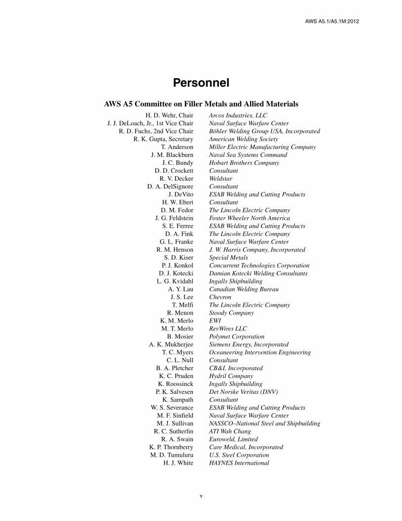
Personnel
AWS A5 Committee on Filler Metals and Allied MaterialsH. D. Wehr, Chair Arcos Industries, LLC
J. J. DeLoach, Jr., 1st Vice Chair Naval Surface Warfare CenterR. D. Fuchs, 2nd Vice Chair Böhler Welding Group USA, Incorporated
R. K. Gupta, Secretary American Welding SocietyT. Anderson Miller Electric Manufacturing Company
J. M. Blackburn Naval Sea Systems CommandJ. C. Bundy Hobart Brothers Company
D. D. Crockett ConsultantR. V. Decker Weldstar
D. A. DelSignore ConsultantJ. DeVito ESAB Welding and Cutting Products
H. W. Ebert ConsultantD. M. Fedor The Lincoln Electric Company
J. G. Feldstein Foster Wheeler North AmericaS. E. Ferree ESAB Welding and Cutting ProductsD. A. Fink The Lincoln Electric Company
G. L. Franke Naval Surface Warfare CenterR. M. Henson J. W. Harris Company, Incorporated
S. D. Kiser Special MetalsP. J. Konkol Concurrent Technologies Corporation
D. J. Kotecki Damian Kotecki Welding ConsultantsL. G. Kvidahl Ingalls Shipbuilding
A. Y. Lau Canadian Welding BureauJ. S. Lee ChevronT. Melfi The Lincoln Electric Company
R. Menon Stoody CompanyK. M. Merlo EWIM. T. Merlo RevWires LLC
B. Mosier Polymet CorporationA. K. Mukherjee Siemens Energy, Incorporated
T. C. Myers Oceaneering Intervention EngineeringC. L. Null Consultant
B. A. Pletcher CB&I, IncorporatedK. C. Pruden Hydril CompanyK. Roossinck Ingalls Shipbuilding
P. K. Salvesen Det Norske Veritas (DNV)K. Sampath Consultant
W. S. Severance ESAB Welding and Cutting ProductsM. F. Sinfield Naval Surface Warfare CenterM. J. Sullivan NASSCO–National Steel and Shipbuilding
R. C. Sutherlin ATI Wah ChangR. A. Swain Euroweld, Limited
K. P. Thornberry Care Medical, IncorporatedM. D. Tumuluru U.S. Steel Corporation
H. J. White HAYNES International

vi
AWS A5.1/A5.1M:2012
Advisors to the AWS A5 Committee on Filler Metal and Allied Material
R. L. Bateman Soldaduras West Arco LimitadaJ. E. Beckham Chrysler LLCR. A. Daemen Consultant
C. E. Fuerstenau Lucas-Milhaupt, IncorporatedJ. P. Hunt Special MetalsS. Imaoka Kobe Steel, Limited
W. A. Marttila WAMcom Consulting LLCD. R. Miller ABS Americas Materials DepartmentM. P. Parekh Consultant
M. A. Quintana The Lincoln Electric CompanyE. S. Surian National University of Lomas de Zamora
AWS A5A Subcommittee on Carbon and Low Alloy Steel ElectrodesG. L. Franke, Chair Naval Surface Warfare Center
R. A. Swain, Vice Chair Euroweld, LimitedR. K. Gupta, Secretary American Welding Society
R. V. Decker Weldstar CompanyJ. J. DeLoach, Jr. Naval Surface Warfare Center
H. W. Ebert ConsultantK. K. Gupta Westinghouse Electric Corporation
M. James The Lincoln Electric CompanyS. J. Knostman Hobart Brothers
A. Y. Lau Canadian Welding BureauT. C. Myers Oceaneering Intervention Engineering
M. P. Parekh ConsultantM. A. Quintana The Lincoln Electric Company
P. K. Salvesen Det Norske Veritas (DNV)K. Sampath Consultant
M. S. Sierdzinski ESAB Welding & Cutting Products
Advisors to the AWS A5A Subcommittee on Carbon and Low Alloy Steel Electrodes
S. Imaoka Kobe Steel, LimitedD. J. Kotecki Damian Kotecki Welding ConsultantsD. R. Miller ABS Americas Materials Department
M. D. Tumuluru U.S. Steel Corporation

vii
AWS A5.1/A5.1M:2012
Foreword
This foreword is not part of AWS A5.1/A5.1M:2012, Specification for Carbon Steel Electrodesfor Shielded Metal Arc Welding, but is included for informational purposes only.
This specification is the latest revision of the first filler metal specification issued over 70 years ago. The initial 1940document and the three revisions within the next five years were prepared by a joint committee of the American Societyfor Testing and Materials and the American Welding Society. However, they were issued with only an ASTM specifica-tion designation. The 1948 revision was the first specification issued with the AWS designation appearing on the docu-ment. The 1969 revision was the first time that the document was issued without the ASTM designation.
This document is the second of the A5.1 specifications which makes use of both U.S. Customary Units and the Inter-national System of Units (SI). The dimensions are not exact equivalents in the two systems. Previous A5.1 specificationsshowed an approximate conversion to SI units for informational purposes only. This practice is discontinued. Instead SIunits used are hard conversions to rational units. In selecting rational metric units, AWS A1.1, Metric Practice Guide forthe Welding Industry, and International Standard ISO 544, Welding consumables — Technical delivery conditions forwelding filler materials — Type of product, dimensions, tolerances and markings, are used where suitable. Tables andfigures make use of both U.S. Customary and SI Units, which, with the application of the specified tolerances, providesfor interchangeability of products in both the U.S. Customary and SI Units.
Substantive changes in this revision include adding of boron reporting requirement in Table 7, and updating Clause 6,Rounding-Off Procedure. These changes are shown in italic font.
Document Development:
ASTM A 233-40T Tentative Specifications for Iron and Steel Arc-Welding Electrodes
ASTM A 233-42T Tentative Specifications for Iron and Steel Arc-Welding Electrodes
ASTM A 233-43T Tentative Specifications for Iron and Steel Arc-Welding Electrodes
ASTM A 233-45T Tentative Specifications for Iron and Steel Arc-Welding Electrodes
ASTM A 233-48T Tentative Specifications for Mild Steel Arc Welding ElectrodesAWS A5.1-48T
ASTM A 233-55T Tentative Specifications for Mild Steel Arc Welding ElectrodesAWS A5.1-55T
ASTM A 233-58T Tentative Specification for Mild Steel Arc Welding ElectrodesAWS A5.1-58T
AWS A5.1-64T Tentative Specification for Mild Steel Covered Arc Welding ElectrodesASTM A 233-64T
AWS A5.1-69 Specification for Mild Steel Covered Arc Welding ElectrodesANSI W3.1-1973
ANSI/AWS A5.1-78 Specification for Carbon Steel Covered Arc-Welding Electrodes
ANSI/AWS A5.1-81 Specification for Carbon Steel Covered Arc-Welding Electrodes
ANSI/AWS A5.1-91 Specification for Carbon Steel Electrodes for Shielded Metal Arc Welding
AWS A5.1/A5.1M:2004 Specification for Carbon Steel Electrodes for Shielded Metal Arc Welding
Comments and suggestions for the improvement of this standard are welcomed. They should be sent to the Secretary, AWSA5 Committee on Filler Metals and Allied Materials, American Welding Society, 8669 Doral Blvd., Doral, FL 33166.

This page is intentionally blank.
viii
AWS A5.1/A5.1M:2012
viii

ix
AWS A5.1/A5.1M:2012
Table of ContentsPage No.
Personnel ......................................................................................................................................................................vForeword .....................................................................................................................................................................viiList of Tables.................................................................................................................................................................xList of Figures ...............................................................................................................................................................x
1. Scope .....................................................................................................................................................................1
Part A—General Requirements ....................................................................................................................................1
2. Normative References .........................................................................................................................................1
3. Classification ........................................................................................................................................................2
4. Acceptance ...........................................................................................................................................................2
5. Certification .........................................................................................................................................................2
6. Rounding-Off Procedure ....................................................................................................................................3
Part B—Tests, Procedures, and Requirements .............................................................................................................4
7. Summary of Tests ................................................................................................................................................4
8. Retest ....................................................................................................................................................................4
9. Weld Test Assemblies ..........................................................................................................................................5
10. Chemical Analysis .............................................................................................................................................13
11. Radiographic Test..............................................................................................................................................13
12. Tension Test........................................................................................................................................................19
13. Bend Test ............................................................................................................................................................20
14. Impact Test.........................................................................................................................................................20
15. Fillet Weld Test ..................................................................................................................................................20
16. Moisture Test .....................................................................................................................................................22
17. Absorbed Moisture Test....................................................................................................................................22
18. Diffusible Hydrogen Test ..................................................................................................................................24
Part C—Manufacture, Identification, and Packaging.................................................................................................25
19. Method of Manufacture ....................................................................................................................................25
20. Standard Sizes and Lengths .............................................................................................................................25
21. Core Wire and Covering ...................................................................................................................................26
22. Exposed Core .....................................................................................................................................................26
23. Electrode Identification.....................................................................................................................................26
24. Packaging ...........................................................................................................................................................26
25. Marking of Packages.........................................................................................................................................27
Annex A (Informative)—Guide to AWS Specification for Carbon Steel Electrodes for Shielded MetalAnnex A (Informative)—Arc Welding.......................................................................................................................29Annex B (Informative)—Guidelines for the Preparation of Technical Inquiries .......................................................45
AWS Filler Metal Specifications by Material and Welding Process ..........................................................................47AWS Filler Metal Specifications and Related Documents.........................................................................................49

x
AWS A5.1/A5.1M:2012
List of Tables
Table Page No.
1 Electrode Classification .................................................................................................................................32 Tension Test Requirements ............................................................................................................................43 Charpy V-Notch Impact Requirements ..........................................................................................................54 Required Tests................................................................................................................................................65 Base Metal for Test Assemblies...................................................................................................................146 Requirements for Preparation of Fillet Weld Test Assemblies ....................................................................147 Chemical Composition Requirements for Weld Metal ................................................................................168 Radiographic Soundness Requirements.......................................................................................................199 Dimensional Requirements for Fillet Weld Usability Test Specimens ........................................................21
10 Moisture Content Limits for Electrode Coverings.......................................................................................2311 Diffusible Hydrogen Limits for Weld Metal................................................................................................2412 Standard Sizes and Lengths .........................................................................................................................25A.1 Canadian Electrode Classifications Similar to AWS Classifications...........................................................30A.2 Comparison of Equivalent Classifications ...................................................................................................32A.3 Typical Storage and Drying Conditions for Covered Arc Welding Electrodes ...........................................35A.4 Typical Amperage Ranges ...........................................................................................................................37A.5 Discontinued Electrode Classifications........................................................................................................43
List of Figures
Figure Page No.
1 Pad for Chemical Analysis of Undiluted Weld Metal....................................................................................82 Groove Weld Test Assembly for Mechanical Properties and Soundness of Weld Metal Produced by
Using All Electrode Classifications Except E6022 [E4322] and E7018M [E4918M] Electrodes ................93 Fillet Weld Test Assembly ...........................................................................................................................104 Test Assembly for Transverse Tension and Longitudinal Guided Bend Tests for Welds Made
with E6022 [E4322] Electrodes ...................................................................................................................115 Groove Weld Test Assembly for Mechanical Properties and Soundness of Weld Metal Produced by
Using E7018M [E4918M] Electrodes..........................................................................................................126 Welding Positions for Fillet Weld Test Assemblies .....................................................................................157 Radiographic Acceptance Standards for Rounded Indications (Grades 1 and 2) ........................................178 Dimensions of Fillet Welds..........................................................................................................................219 Alternative Methods for Facilitating Fracture of the Fillet Weld.................................................................22
10 Order of Mandatory and Optional Supplemental Designators.....................................................................27

AWS A5.1/A5.1M:2012
1
1. Scope1.1 This specification prescribes requirements for the classification of carbon steel electrodes for shielded metal arcwelding.
1.2 Safety and health issues and concerns are beyond the scope of this standard and, therefore, are not fully addressedherein. Some safety and health information can be found in Informative Annex Clauses A5 and A10. Safety and healthinformation is available from other sources, including, but not limited to, ANSI Z49.1, Safety in Welding, Cutting, andAllied Processes,1 and applicable federal and state regulations.
1.3 This specification makes use of both U.S. Customary Units and the International System of Units (SI).
The measurements are not exact equivalents; therefore, each system must be used independently of the other withoutcombining in any way when referring to material properties. The specification with the designation A5.1 uses U.S.Customary Units. The specification A5.1M uses SI Units. The latter are shown within brackets ([ ]) or in appropriatecolumns in tables and figures. Standard dimensions based on either system may be used for sizing of filler metal orpackaging or both under A5.1 or A5.1M specifications.
Part AGeneral Requirements
2. Normative ReferencesThe following standards contain provisions which, through reference in this text, constitute provisions of this AWS stan-dard. For dated references, subsequent amendments to, or revisions of, any of these publications do not apply. Howeverparties to agreement based on this AWS standard are encouraged to investigate the possibility of applying the mostrecent editions of the documents shown below. For undated references, the latest edition of the standard referenced applies.
The following documents are referenced in the mandatory sections of this document:
(1) ASTM E29, Standard Practice for Using Significant Digits in Test Data to Determine Conformance withSpecifications2
(2) ASTM E350, Standard Test Methods for Chemical Analysis of Carbon Steel, Low-Alloy Steel, Silicon ElectricalSteel, Ingot Iron, and Wrought Iron
(3) ASTM E1032, Standard Test Method for Radiographic Examination of Weldments
1 ANSI Z49.1 is published by the American Welding Society, 8669 Doral Blvd., Doral, FL 33166.2 ASTM standards are published by ASTM International, 100 Barr Harbor Drive, West Conshohocken, PA 19428-2959.
Specification for Carbon Steel Electrodesfor Shielded Metal Arc Welding

AWS A5.1/A5.1M:2012
2
(4) AWS A1.1, Metric Practice Guide for the Welding Industry3
(5) AWS A4.3, Standard Methods for Determination of the Diffusible Hydrogen Content of Martensitic, Bainitic, andFerritic Steel Weld Metal Produced by Arc Welding
(6) AWS A4.4M, Standard Procedure for Determination of Moisture Content of Welding Fluxes and Welding ElectrodeFlux Coverings
(7) AWS A5.01M/A5.01 (ISO 14344 MOD), Procurement Guidelines for Consumables—Welding and Allied Pro-cesses—Flux and Gas Shielded Electrical Welding Processes
(8) AWS B4.0 or B4.0M, Standard Methods for Mechanical Testing of Welds
(9) ANSI Z49.1 Safety in Welding, Cutting, and Allied Processes
(10) ISO 544, Welding consumables — Technical delivery conditions for welding filler materials — Type of product,dimensions, tolerances and markings.4
3. Classification3.1 The welding electrodes covered by the A5.1 specification utilize a system based on U.S. Customary Units to classifythe welding electrodes covered according to:
(1) Type of current (see Table 1)
(2) Type of covering (see Table 1)
(3) Welding position (see Table 1)
(4) Mechanical properties of the weld metal in the as-welded or aged condition (see Tables 2 and 3).
3.1M The welding electrodes covered by the A5.1M specification utilize a system based on International System ofUnits to classify the welding electrodes covered according to:
(1) Type of current (see Table1)
(2) Type of covering (see Table 1)
(3) Welding position (see Table 1)
(4) Mechanical properties of the weld metal in the as-welded or aged condition (see Tables 2 and 3).
3.2 Material classified under one classification shall not be classified under any other classification in one specification,although it may be classified under both specifications, except that E7018M [E4918M] may also be classified as E7018[E4918] provided the electrode meets all of the requirements of both classifications.
4. AcceptanceAcceptance of the welding electrodes shall be in accordance with the provisions of AWS A5.01M/A5.01 (ISO 14344MOD).
5. CertificationBy affixing the AWS specification and classification designations to the packaging, or the classification to the product,the manufacturer certifies that the product meets the requirements of this specification.5
3 AWS standards are published by the American Welding Society, 8669 Doral Blvd., Doral, FL 33166.4 ISO standards are published by the American National Standards Institute, 11 West 42nd Street, New York, NY 10036-8002.5 See Clause A4 for further information concerning certification and the testing called for to meet this requirement.

3
AWS A5.1/A5.1M:2012
6. Rounding-Off Procedure
For purposes of determining compliance with the requirements of this standard, the actual test values obtained shall besubjected to the rounding-off rules of ASTM E29 or ISO 80000-1, Annex B, Rule A (the results are the same). If the mea-sured values are obtained by equipment calibrated in units other than those of the specified limit, the measured valuesshall be converted to the units of the specified limit before rounding off. If an average value is to be compared to thespecified limit, rounding off shall be done only after calculating the average. An observed or calculated value shall berounded to the nearest 1000 psi (1 ksi) for tensile and yield strength for A5.1, or to the nearest 10 MPa for tensile andyield strength for A5.1M, and to the nearest unit in the last right-hand place of figures used in expressing the limitingvalues for other quantities. The rounded-off results shall fulfill the requirements for the classification under test.
Table 1Electrode Classification
AWS Classification
Type of Covering Welding Positiona Type of CurrentbA5.1 A5.1M
E6010E6011E6012E6013
E4310E4311E4312E4313
High cellulose sodiumHigh cellulose potassiumHigh titania sodiumHigh titania potassium
F, V, OH, HF, V, OH, HF, V, OH, HF, V, OH, H
dcepac or dcepac or dcenac, dcep, or dcen
E6018c E4318c Low-hydrogen potassium, iron powder F, V, OH, H ac or dcep
E6019 E4319 Iron oxide titania potassium F, V, OH, H ac, dcep, or dcen
E6020 E4320 High iron oxide H-filletF
ac or dcenac, dcep, or dcen
E6022d E4322d High iron oxide F, H-fillet ac or dcen
E6027 E4327 High iron oxide, iron powder H-filletF
ac or dcenac, dcep, or dcen
E7014 E4914 Iron powder, titania F, V, OH, H ac, dcep, or dcen
E7015 E4915 Low-hydrogen sodium F, V, OH, H dcep
E7016c E4916c Low-hydrogen potassium F, V, OH, H ac or dcep
E7018c E4918c Low-hydrogen potassium, iron powder F, V, OH, H ac or dcep
E7018M E4918M Low-hydrogen iron powder F, V, OH, H dcep
E7024c E4924c Iron power, titania H-fillet, F ac, dcep, or dcen
E7027 E4927 High iron oxide, iron powder H-filletF
ac or dcenac, dcep, or dcen
E7028c E4928c Low-hydrogen potassium, iron powder H-fillet, F ac or dcep
E7048 E4948 Low-hydrogen potassium, iron powder F, OH, H, V-down ac or dcep
a The abbreviations, F, H, H-fillet, V, V-down, and OH indicate the welding positions as follows: F = Flat, H = Horizontal, H-fillet = Horizontal fillet,V = Vertical, progression upwards (for electrodes 3/16 in [5.0 mm] and under, except 5/32 in [4.0 mm] and under for classifications E6018 [E4318],E7014 [E4914], E7015 [E4915], E7016 [E4916], E7018 [E4918], E7018M [E4918M], E7048 [E4948]). V-down = Vertical, progression downwards(for electrodes 3/16 in [5.0 mm] and under, except 5/32 in [4.0 mm] and under for classifications E6018 [E4318], E7014 [E4914], E7015 [E4915],E7016 [E4916], E7018 [E4918], E7018M [E4918M], E7048 [E4948]), OH = Overhead (for electrodes 3/16 in [5.0 mm] and under, except 5/32 in[4.0 mm] and under for classifications E6018 [E4318], E7014 [E4914], E7015 [E4915], E7016 [E4916], E7018 [E4918], E7018M [E4918M], E7048[E4948]).
b The term “dcep” refers to direct current electrode positive (dc, reverse polarity). The term “dcen” refers to direct current electrode negative (dc,straight polarity).
c Electrodes with supplemental elongation, notch toughness, absorbed moisture, and diffusible hydrogen requirements may be further identified as shownin Tables 2, 3, 10, and 11.
d Electrodes of the E6022 [E4322] classification are intended for single-pass welds only.

4
AWS A5.1/A5.1M:2012
Part BTests, Procedures, and Requirements
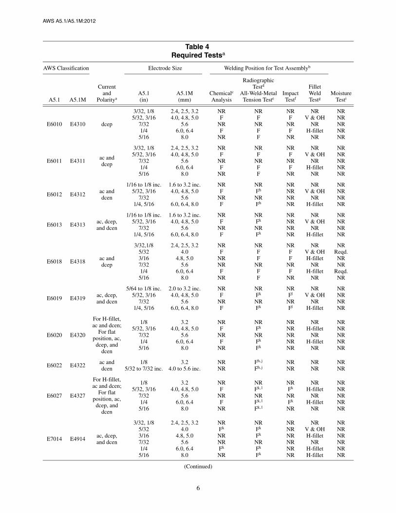
7. Summary of TestsThe tests required for each classification are specified in Table 4. The purpose of these tests is to determine the chemicalcomposition, mechanical properties, and soundness of the weld metal, moisture content of the low-hydrogen electrodecovering, and the usability of the electrode. The base metal for the weld test assemblies, the welding and testing proce-dures to be employed, and the results required are given in Clauses 9 through 18. The supplemental tests for absorbedmoisture, in Clause 17, and diffusible hydrogen, in Clause 18, are not required for classification of the low-hydrogenelectrodes, except for E7018M [E4918M], where these are required (see notes i and m of Table 4).
8. RetestIf the results of any test fail to meet the requirement, that test shall be repeated twice. The results of both retests shallmeet the requirement. Specimens for retest may be taken from the original test assembly or from a new test assembly.For chemical analysis, retest need be only for those specific elements that failed to meet the test requirement. If theresults of one or both retests fail to meet the requirement, the material under test shall be considered as not meeting therequirements of this specification for that classification.
Table 2Tension Test Requirementsa, b, c
AWS Classification Tensile Strength Yield Strength at 0.2% Offset ElongationPercentage in 4xDiameter LengthA5.1 A5.1M A5.1 (ksi) A5.1M (MPa) A5.1 (ksi) A5.1M (MPa)
E6010E6011E6012E6013E6018E6019E6020E6022d
E6027
E4310E4311E4312E4313E4318E4319E4320E4322d
E4327
606060606060606060
430430430430430430430430430
48484848484848
Not Sp48
330330330330330330330
ecified330
22221717222222
Not Specified22
E7014E7015E7016E7018E7024E7027E7028E7048E7018M
E4914E4915E4916E4918E4924E4927E4928E4948E4918M
7070707070707070
Note f
490490490490490490490490
Note f
5858585858585858
g53–72g
400400400400400400400400
g370–500g
1722222217e
22222224
a See Table 4 for sizes to be tested.b Requirements are in the as-welded condition with aging as specified in 12.2.c Single values are minimum.d A transverse tension test, as specified in 12.5 and a longitudinal guided bend test, as specified in Clause 13 are required.e Weld metal from electrodes identified as E7024-1 [E4924-1] shall have elongation of 22% minimum.f Tensile strength of this weld metal is a nominal 70 ksi [490 MPa].g For 3/32 in [2.4 mm] electrodes, the maximum yield strength shall be 77 ksi [530 MPa].

5
AWS A5.1/A5.1M:2012
In the event that, during preparation or after completion of any test, it is clearly determined that prescribed or proper pro-cedures were not followed in preparing the weld test assembly or test specimen(s) or in conducting the test, the test shallbe considered invalid, without regard to whether the test was actually completed or whether test results met, or failed tomeet, the requirement. That test shall be repeated, following proper prescribed procedures. In this case, the requirementfor doubling the number of test specimens does not apply.
9. Weld Test Assemblies9.1 One or more of the following five weld test assemblies are required:
(1) The weld pad in Figure 1 for chemical analysis of the weld metal
(2) The groove weld in Figure 2 for mechanical properties and soundness of weld metal made with all electrode clas-sifications except E6022 [E4322] and E7018M [E4918M]
(3) The fillet weld in Figure 3 for the usability of the electrode
Table 3Charpy V-Notch Impact Requirements
AWS Classification Limits for 3 out of 5 Specimensa
A5.1 A5.1M Average, Min. Single Value, Min.
E6010, E6011, E6018E6027, E7015,E7016b, E7018b,E7027, E7048
E4310, E4311, E4318E4327, E4915,E4916b, E4918b,E4927, E4948
20 ft·lbf at –20°F[27 J at –30°C]
15 ft·lbf at –20°F[20 J at –30°C]
E6019E7028
E4319E4928
20 ft·lbf at 0°F[27 J at –20°C]
15 ft·lbf at 0°F[20 J at –20°C]
E6012, E6013,E6020, E6022,E7014, E7024b
E4312, E4313E4320, E4322E4914, E4924b
Not Specified Not Specified
AWS Classification Limits for 5 out of 5 Specimensc
A5.1 A5.1M Average, Min. Single Value, Min.
E7018M E4918M 50 ft·lbf at –20°F[67 J at –30°C]
40 ft·lbf at –20°F[54 J at –30°C]
a Both the highest and lowest test values obtained shall be disregarded in computing the average. Two of these remaining three values shall equal orexceed 20 ft·lbf [27 J].
b Electrodes with the following optional supplemental designations shall meet the lower temperature impact requirements specified below:
AWS Classification Electrode DesignationCharpy V-Notch Impact Requirements,
Limits for 3 out of 5 specimens (Refer to Note a above)
A5.1 A5.1M A5.1 A5.1M Average, Min. Single Value, Min.
E7016E7018
E4916E4918
E7016-1E7018-1
E4916-1E4918-1
20 ft·lbf at –50°F[27 J at –45°C]
15 ft·lbf at –50°F[20 J at –45°C]
E7024 E4924 E7024-1 E4924-120 ft·lbf at 0°F[27 J at –20°C]
15 ft·lbf at 0°F[20 J at –20°C]
c All five values obtained shall be used in computing the average. Four of the five values shall equal, or exceed, 50 ft·lbf [67 J].
6
AWS A5.1/A5.1M:2012
Table 4Required Testsa
AWS Classification
Currentand
Polaritya
Electrode Size Welding Position for Test Assemblyb
MoistureTestiA5.1 A5.1M
A5.1(in)
A5.1M(mm)
Chemicalc
Analysis
RadiographicTestd
All-Weld-Metal Tension Teste
ImpactTestf
FilletWeldTestg
E6010 E4310 dcep
3/32, 1/85/32, 3/16
7/321/45/16
2.4, 2.5, 3.24.0, 4.8, 5.0
5.66.0, 6.4
8.0
NRF
NRF
NR
NRF
NRFF
NRF
NRF
NR
NRV & OH
NRH-fillet
NR
NRNRNRNRNR
E6011 E4311ac anddcep
3/32, 1/85/32, 3/16
7/321/45/16
2.4, 2.5, 3.24.0, 4.8, 5.0
5.66.0, 6.4
8.0
NRF
NRF
NR
NRF
NRFF
NRF
NRF
NR
NRV & OH
NRH-fillet
NR
NRNRNRNRNR
E6012 E4312 ac anddcen
1/16 to 1/8 inc.5/32, 3/16
7/321/4, 5/16
1.6 to 3.2 inc.4.0, 4.8, 5.0
5.66.0, 6.4, 8.0
NRF
NRF
NRFh
NRFh
NRNRNRNR
NRV & OH
NRH-fillet
NRNRNRNR
E6013 E4313ac, dcep,and dcen
1/16 to 1/8 inc.5/32, 3/16
7/321/4, 5/16
1.6 to 3.2 inc.4.0, 4.8, 5.0
5.66.0, 6.4, 8.0
NRF
NRF
NRFk
NRFk
NRNRNRNR
NRV & OH
NRH-fillet
NRNRNRNR
E6018 E4318 ac anddcep
3/32,1/85/323/167/321/45/16
2.4, 2.5, 3.24.0
4.8, 5.05.6
6.0, 6.48.0
NRF
NRNRF
NR
NRFF
NRFF
NRFF
NRF
NR
NRV & OHH-fillet
NRH-fillet
NR
NRReqd.NRNR
Reqd.NR
E6019 E4319 ac, dcep,and dcen
5/64 to 1/8 inc.5/32, 3/16
7/321/4, 5/16
2.0 to 3.2 inc.4.0, 4.8, 5.0
5.66.0, 6.4, 8.0
NRF
NRF
NRFk
NRFk
NRFl
NRFl
NRV & OH
NRH-fillet
NRNRNRNR
E6020 E4320
For H-fillet,ac and dcen;
For flatposition, ac,
dcep, anddcen
1/85/32, 3/16
7/321/45/16
3.24.0, 4.8, 5.0
5.66.0, 6.4
8.0
NRF
NRF
NR
NRFk
NRFk
Fk
NRNRNRNRNR
NRH-fillet
NRH-fillet
NR
NRNRNRNRNR
E6022 E4322 ac anddcen
1/85/32 to 7/32 inc.
3.24.0 to 5.6 inc.
NRNR
Fh, j
Fh, jNRNR
NRNR
NRNR
E6027 E4327
For H-fillet,ac and dcen;
For flatposition, ac,
dcep, anddcen
1/85/32, 3/16
7/321/45/16
3.24.0, 4.8, 5.0
5.66.0, 6.4
8.0
NRF
NRF
NR
NRFk, l
NRFk, l
Fk, l
NRFk
NRFk
NR
NRH-fillet
NRH-fillet
NR
NRNRNRNRNR
E7014 E4914 ac, dcep,and dcen
3/32, 1/85/323/167/321/45/16
2.4, 2.5, 3.24.0
4.8, 5.05.6
6.0, 6.48.0
NRFk
NRNRFk
NR
NRFk
Fk
NRFk
Fk
NRNRNRNRNRNR
NRV & OHH-fillet
NRH-filletH-fillet
NRNRNRNRNRNR
(Continued)

7
AWS A5.1/A5.1M:2012
Table 4 (Continued)Required Testsa
AWS Classification
Currentand
Polaritya
Electrode Size Welding Position for Test Assemblyb
MoistureTestiA5.1 A5.1M
A5.1(in)
A5.1M(mm)
Chemicalc
Analysis
RadiographicTestd
All-Weld-Metal Tension Teste
ImpactTestf
FilletWeldTestg
E7015 E4915 dcep
3/32, 1/85/323/167/321/45/16
2.4, 2.5, 3.24.0
4.8, 5.05.6
6.0, 6.48.0
NRF
NRNRF
NR
NRFF
NRFF
NRFF
NRF
NR
NRV & OHH-fillet
NRH-fillet
NR
NRReqd.NRNR
Reqd.NR
E7016 E4916 ac anddcep
3/32, 1/85/323/167/321/45/16
2.4, 2.5, 3.24.0
4.8, 5.05.6
6.0, 6.48.0
NRF
NRNRF
NR
NRFF
NRFF
NRFF
NRF
NR
NRV & OHH-fillet
NRH-fillet
NR
NRReqd.NRNR
Reqd.NR
E7018 E4918ac anddcep
3/32, 1/85/323/167/321/45/16
2.4, 2.5, 3.24.0
4.8, 5.05.6
6.0, 6.48.0
NRF
NRNRF
NR
NRFF
NRFF
NRFF
NRF
NR
NRV & OHH-fillet
NRH-fillet
NR
NRReqd.NRNR
Reqd.NR
E7018Mm E4918Mm dcep3/32 to 5/32 inc.3/16 to 5/16 inc.
2.4 to 4.0 inc.4.8 to 8.0 inc.
FF
VF
VF
NRNR
Reqd.Reqd.
E7024 E4924ac, dcep,and dcen
3/32, 1/85/323/167/321 / 45/16
2.4, 2.5, 3.24.0
4.8, 5.05.6
6.0, 6.48.0
NRFl
NRNRFl
NR
NRFk, l
Fk, l
NRFk, l
Fk, l
NRn
Fn
Fn
NRn
Fn
NRn
NRH-filletH-fillet
NRH-fillet
NR
NRNRNRNRNRNR
E7027 E4927
For H-fillet,ac and dcen
For flatposition, ac,
dcep, anddcen
1/85/323/167/321/45/16
3.24.0
4.8, 5.05.6
6.0, 6.48.0
NRFl
NRNRFl
NR
NRFk, l
Fk, l
NRFk, l
Fk, l
NRFl
Fl
NRFl
NR
NRH-filletH-fillet
NRH-fillet
NR
NRNRNRNRNRNR
E7028 E4928 ac anddcep
1/85/323/167/321/45/16
3.24.0
4.8, 5.05.6
6.0, 6.48.0
NRF
NRNRF
NR
NRFl
Fl
NRFl
Fl
NRFF
NRF
NR
NRH-filletH-fillet
NRH-fillet
NR
NRReqd.NRNR
Reqd.NR
E7048 E4948 ac anddcep
1/85/32
3/16
3.24.0
4.8, 5.0
NRF
NR
NRF
F
NRF
F
NRV-down& OH
V-down& H-fillet
NRReqd.
NR
(Continued)

8
AWS A5.1/A5.1M:2012
Table 4 (Continued)Required Testsa
a The minimum completed pad size shall be at least four layers in height (H) with length (L) and width (W) sufficient to perform analysis.The sample for analysis shall be taken at least 1/4 in [6.0 mm] above the original base metal surface.
Notes:1. Base metal of any convenient size, of any type specified in Table 5, shall be used as the base for the weld pad.2. The surface of the base metal on which the filler metal is to be deposited shall be clean.3. The pad shall be welded in the flat position with successive layers to obtain undiluted weld metal.4. One pad shall be welded for each type of current shown in Table 4 except for those classifications identified by note k in Table 4.5. The number and size of the beads will vary according to the size of the electrode and the width of the weave, as well as the amperage
employed. The width of each weld pass in each weld layer shall be no more than 2-1/2 times the diameter of the core wire.6. The preheat temperature shall not be less than 60°F [15°C] and the interpass temperature shall not exceed 300°F [150°C].7. The slag shall be removed after each pass.8. The test assembly may be quenched in water between passes to control interpass temperature.
Figure 1—Pad for Chemical Analysis of Undiluted Weld Metal
a NR means “not required.” The abbreviations, F, H-fillet, V-down, V, and OH are defined in Note a of Table 1. The terms “dcep” and “dcen,” aredefined in Note b of Table 1.
b Standard electrode sizes not requiring this specific test can be classified provided at least two other sizes of that classification have passed the testsrequired for them, or the size to be classified meets specification requirements by having been tested in accordance with Figures 1, 2, and 3 and Table 6.
c See Clause 10.d See Clause 11.e See Clause 12.f See Clause 14.g See Clause 15.h A radiographic test is not required for this classification.i The moisture test given in Clause 16 is the required test for moisture content of the covering. In Clauses 17 and 18 are supplemental tests required
only when their corresponding optional supplemental designators are to be used with the classification designators.j An all-weld-metal tension test is not required for E6022 [E4322] electrodes. Instead, a transverse tension test (see 12.5) and a longitudinal guided
bend test (see Clause 13) are required for classification of 5/32 in, 3/16 in, and 7/32 in [4.0 mm, 5.0 mm, and 6.0 mm] E6022 [E4322] electrodes.k When dcep and dcen are shown, only dcen need be tested.l Electrodes longer than 18 in [450 mm] will require a double length test assembly in accordance with Note 1 of Figure 2, to ensure uniformity of the
entire electrode.mTests in Clause 17, and in Clause 18, are required for all sizes of E7018M [E4918M].n Electrodes identified as E7024-1 [E4924-1] shall be impact tested (see Note b of Table 3).

9
AWS A5.1/A5.1M:2012
Notes:1. For electrodes longer than 18 in [450 mm], a 20 in [500 mm] long test assembly shall be welded.2. Base metal shall be as specified in Table 5.3. The surfaces to be welded shall be clean.4. Prior to welding, the assembly may be preset to yield a welded joint sufficiently flat to facilitate removal of the test specimens. As an
alternative, restraint or a combination of restraint and presetting may be used to keep the welded joint within 5° of plane. A weldedtest assembly that is more than 5° out of plane shall be discarded. Straightening of the test assembly is prohibited.
5. Welding shall be in the flat position, using each type of current specified in Table 4 except for classifications identified by Note k inTable 4.
6. The preheat temperature shall be 225°F [105°C] minimum. The interpass temperature shall not be less than 225°F [105°C] nor morethan 350°F [175°C].
7. The joint root may be seal welded with 3/32 in or 1/8 in [2.5 mm or 3.2 mm] electrodes using stringer beads.8. In addition to the stops and starts at the ends, each pass shall contain a stop and start in between the ends.9. The completed weld shall be at least flush with the surface of the test plate.
Figure 2—Groove Weld Test Assembly for Mechanical Properties andSoundness of Weld Metal Produced by Using All Electrode Classifications
Except E6022 [E4322] and E7018M [E4918M] Electrodes
ElectrodeSize
PlateThickness (T)
Root Opening(R)
Passesper
LayerTotal
LayersDimension DescriptionA5.1(in)
A5.1M(mm)
A5.1(in)
A5.1M(mm)
A5.1(in)
A5.1M(mm)
A5.1(in)
A5.1M(mm)
G Offset from Groove Edge 1/4–1/2 6–15 3/32 2.5 1/2 12 3/8 10 2 Not SpecifiedL Length, min. (See Note 1) 10 2500 1/8 3.2 1/2 12 1/2 13 2 5–7S Strip Overlap, min. 1/4 6 5/32 4.0 3/4 20 5/8 16 2 7–9V Strip Thickness, min. 1/4 6 3/16 5.0 3/4 20 3/4 19 2 6–8W Width, min. 5 1250 7/32 6.0 3/4 20 7/8 22 2 6–8Z Discard, min. 1 25 1/4 6.0 1 25 1 25 2 9–11
5/16 8.0 1-1/4 30 1-1/8 28 2 10-–12

10
AWS A5.1/A5.1M:2012
Notes:1. Base metal shall be as specified in Table 5.2. The surfaces to be welded shall be clean.3. An assembly shall be welded in each position specified in Table 6 and shown in Figure 6 using each type of current specified in Table 4.4. The preheat shall be 60°F [15°C] minimum.5. A single pass fillet weld shall be made on one side of the joint. The first electrode shall be consumed to a stub length no greater than
2 in [50 mm].6. Welding in the vertical position shall be upward progression, except the E7048 [E4948] classification where progression shall be
downward.7. Weld cleaning shall be limited to slag chipping, brushing, and needle scaling. Grinding or filing of the weld is prohibited.
Figure 3—Fillet Weld Test Assembly
DIMENSIONS in mm
C, approx. 1 25H, min. 3 75W, min. 3 75T See Table 6L See Table 6

11
AWS A5.1/A5.1M:2012
(4) The groove weld in Figure 4 for transverse tensile and longitudinal bend tests for welds made with the E6022[E4322] single-pass electrode
(5) The groove weld in Figure 5 for mechanical properties and soundness of weld metal made with the E7018M[E4918M] electrode.
The sample for chemical analysis may be taken from the reduced section of the fractured tension test specimen or from acorresponding location (or any location above it) in the weld metal in the groove weld in Figures 2 or 5, thereby avoidingthe need to make the weld pad. In case of dispute, the weld pad shall be the referee method.
Notes:1. Base metal shall be as specified in Table 5.2. The surfaces to be welded shall be clean.3. Prior to welding, the assembly may be preset to yield a welded joint sufficiently flat to facilitate removal of the test specimens. As an
alternative, restraint or a combination of restraint and presetting may be used to keep the welded joint within 5° of plane. A weldedtest assembly that is more than 5° out of plane shall be discarded. Straightening of the test assembly is prohibited.
4. The assembly shall be welded in the flat position, using the type of current specified in Table 4.5. The preheat temperature shall be 60°F [15°C] min. The interpass temperature shall not exceed 350°F [180°C].6. In addition to the stops and starts at the ends, each pass shall contain a stop and start in between the ends.7. Back gouging may be done to ensure sound weld metal through the entire thickness of test assembly.8. The completed weld shall be at least flush with the surface of the test plate.
Figure 4—Test Assembly for Transverse Tension and Longitudinal GuidedBend Tests for Welds Made With E6022 [E4322] Electrodes
DIMENSIONS
A5.1 A5.1M
in mm
L Length, min. 10 250W Width, min 4 100R Root Opening, max. 1/16 1.6ST Transverse Specimen 2 50SL Longitudinal Specimen 6 150T Thickness 1/4 6Z Discard, min. 1 25

12
AWS A5.1/A5.1M:2012
Notes:1. Base metal shall be as specified in Table 5.2. The surfaces to be welded shall be clean.3. Prior to welding, the assembly may be preset to yield a welded joint sufficiently flat to facilitate removal of the test specimens. As an
alternative, restraint or a combination of restraint and presetting may be used to keep the welded joint within 5° of plane. A weldedtest assembly that is more than 5° out of plane shall be discarded. Straightening of the test assembly is prohibited.
4. The assembly shall be welded in the vertical position with progression upward for electrodes 5/32 in [4.0 mm] and less in size, and inthe flat position for electrodes 3/16 in [5.0 mm] and greater in size, using the type of current specified in Table 4 for the electrode andwelding technique recommended by the electrode manufacturer.
5. The preheat temperature and the interpass temperature shall be 200°F to 250°F [90°C to 120°C].6. The welding heat input shall be 30 kJ/in to 40 kJ/in [1.2 kJ/mm to 1.6 kJ/mm] for the 3/32 in [2.5 mm] size electrodes and 50 kJ/in to
60 kJ/in [2.0 kJ/mm to 2.4 kJ/mm] for the 1/8 in [3.2 mm] size and larger electrodes.7. In addition to the stops and starts at the ends, each pass shall contain a stop and start in between the ends.8. The completed weld shall be at least flush with the surface of the test plate. Maximum weld reinforcement shall be 3/16 in [5.0 mm].
Peening of weld beads is not permitted.
Figure 5—Groove Weld Test Assembly for Mechanical Properties andSoundness of Weld Metal Produced by Using E7018M [E4918M] Electrodes
Dimension DescriptionA5.1(in)
A5.1M(mm)
G Offset from Groove Edge 1/4–1/2 6–15L Length, min. 10 250R Root Opening, min. 1/4 6S Strip Overlap, min. 1/4 6T Plate Thickness 3/4 20V Strip Thickness, min. 1/4 6W Width, min. 5 125Z Discard, min. 1 25

AWS A5.1/A5.1M:2012
13
9.2 Preparation of each weld test assembly shall be as prescribed in 9.3 through 9.5. The base metal for each assemblyshall be as required in Table 5 and shall meet the requirements of the ASTM specification shown there or an equivalentspecification. Electrodes other than low-hydrogen electrodes shall be tested without conditioning.6 Low-hydrogenelectrodes, if they have not been protected against moisture pickup in storage, shall be held at a temperature within therange 500°F to 800°F [260°C to 430°C] for a minimum of one hour prior to testing. Testing of the assemblies shall be asprescribed in Clauses 10 through 15.
9.3 Weld Pad. A weld pad shall be prepared as specified in Figure 1, except when one of the alternatives in 9.1 (tak-ing the sample from the broken tension test specimen or from a corresponding location—or any location above it—in theweld metal in the groove weld in Figure 2 or 5) is selected. Base metal of any convenient size of the type specified inTable 5 shall be used as the base for the weld pad. The surface of the base metal on which the filler metal is depositedshall be clean. The pad shall be welded in the flat position with multiple layers to obtain undiluted weld metal.
The preheat temperature shall be not less than 60°F [15°C] and the interpass temperature shall not exceed 300°F[150°C]. The slag shall be removed after each pass. The pad may be quenched in water between passes. The dimensionsof the completed pad shall be as shown in Figure 1. Testing of this assembly shall be as specified in Clause 10.
9.4 Groove Weld
9.4.1 Mechanical Properties and Soundness. A test assembly shall be prepared and welded as specified in Figure 2or 5 using base metal of the appropriate type specified in Table 5. Testing of this assembly shall be as specified inClauses 11, 12, and 14. The assembly shall be tested in the as-welded condition.
9.4.2 Transverse Tension and Longitudinal Bend Tests. A test assembly shall be prepared and welded as specifiedin Figure 4 using base metal of the appropriate type specified in Table 5. Testing of this assembly shall be as specified in12.5 through 12.7 and Clause13. The assembly shall be tested in the as-welded condition.
9.5 Fillet Weld. A test assembly shall be prepared and welded as specified in Table 4 and Figure 3 using base metal ofthe appropriate type specified in Table 5. The welding positions shall be as specified in Table 6 and Figures 3 and 6according to the size and classification of electrode. Testing of the assembly shall be as specified in Clause 15.
10. Chemical Analysis10.1 The sample for analysis shall be taken from weld metal produced with the electrode. The sample shall be takenfrom a weld pad or the reduced section of the fractured all-weld-metal tension test specimen or from a correspondinglocation in the groove weld in Figure 2 or 5. Areas where arc starts or craters exist shall be avoided.
The top surface of the pad described in 9.3 and shown in Figure 1 shall be removed and discarded, and a sample foranalysis shall be obtained from the underlying metal by any appropriate mechanical means. The sample shall be free ofslag and shall be taken at least 1/4 in [6 mm] from the nearest surface of the base metal.
The sample from the reduced section of the fractured tension test specimen or from a corresponding location (or anylocation above it) in the groove weld in Figure 2 or 5 shall be prepared for analysis by any suitable mechanical means.
10.2 The sample shall be analyzed by accepted analytical methods. The referee method shall be ASTM E350, StandardTest Methods for Chemical Analysis of Carbon Steel, Low Alloy Steel, Silicon Electrical Steel, Ingot Iron and Wrought Iron.
10.3 The results of the analysis shall meet the requirements of Table 7 for the classification of the electrode under test.
11. Radiographic Test11.1 When required in Table 4, the groove weld described in 9.4.1 and shown in Figure 2 or 5 shall be radiographed toevaluate the soundness of the weld metal. In preparation for radiography, the backing shall be removed, and both sur-faces of the weld shall be machined or ground smooth. The finished surface of the weld may be flush with the plate orhave a reasonably uniform reinforcement not exceeding 3/32 in [2.5 mm]. Both surfaces of the test assembly, in the areaof the weld, shall be smooth enough to avoid difficulty in interpreting the radiograph.
6 Conditioning can be considered to be any preparation or procedure, such as baking the electrode, which the user would not normallypractice.

14
AWS A5.1/A5.1M:2012
Table 5Base Metal for Test Assemblies
AWS Classification
Base Metal
Type ASTM Specificationa UNS Numberb
All Carbon SteelA131 Grade BA285 Grade AA285 Grade B
K02102K01700K02200
All except E7018M [E4918M] Carbon Steel
A285 Grade CA283 Grade DA36A29 Grade 1015A29 Grade 1020
K02801K02702K02600G10150G10200
a Equivalent steel may be used.b SAE/ASTM Unified Numbering System for Metals and Alloys.
Table 6Requirements for Preparation of Fillet Weld Test Assemblies
AWS Classification Electrode Size Thickness (T)a Length (L), Min.b Welding Fillet Weld Size
A5.1 A5.1M in mm in mm in mm Position in mm
E6010and
E6011
E4310and
E4311
3/321/85/323/167/321/45/16
2.4, 2.53.24.0
4.8, 5.05.6
6.0, 6.48.0
1/83/163/83/81/21/21/2
35
1010121212
10121212
12 or 16c
1616
250300300300
300 or 400c
400400
V & OHV & OHV & OHV & OHH-filletH-filletH-fillet
5/32 max.3/16 max.1/4 max.
5/16 max.1/4 min.1/4 min.1/4 min.
4.0 max.5.0 max.6.0 max.8.0 max.6.0 min.6.0 min.6.0 min.
E6012,E6013,
andE6019
E4312,E4313,
andE4319
1/16–5/643/321/85/323/167/321/45/16
1.6-2.02.4, 2.5
3.24.0
4.8, 5.05.6
6.0, 6.48.0
1/81/83/163/81/21/21/21/2
335
1012121212
610121212
12 or 16c
1616
150250300300300
300 or 400c
400400
V & OHV & OHV & OHV & OHV & OHH-filletH-filletH-fillet
1/8 max.1/8 max.
3/16 max.1/4 max.3/8 max.1/4 min.
5/16 min.5/16 min.
3.0 max.3.0 max.5.0 max.6.0 max.
10.0 max.6.0 min.8.0 min.8.0 min.
E7014 E4914
3/321/85/323/167/321/45/16
2.4, 2.53.24.0
4.8, 5.05.6
6.0, 6.48.0
1/83/163/83/83/81/21/2
35
1010101212
12121212
12 or 16c
1616
300300300300
300 or 400c
400400
V & OHV & OHV & OHH-filletH-filletH-filletH-fillet
5/32 max.3/16 max.5/16 max.1/4 min.1/4 min.
5/16 min.5/16 min.
4.0 max.5.0 max.8.0 max.6.0 min.6.0 min.8.0 min.8.0 min.
E7015and
E7016
E4915and
E4916
3/321/85/323/167/321/45/16
2.4, 2.53.24.0
4.8, 5.05.6
6.0, 6.48.0
1/81/43/83/81/21/21/2
36
1010121212
10121212
12 or 16c
1616
250300300300
300 or 400c
400400
V & OHV & OHV & OHH-filletH-filletH-filletH-fillet
5/32 max.3/16 max.5/16 max.3/16 min.1/4 min.
5/16 min.5/16 min.
4.0 max.5.0 max.8.0 max.5.0 min.6.0 min.8.0 min.8.0 min.
(Continued)

15
AWS A5.1/A5.1M:2012
Figure 6—Welding Positions for Fillet Weld Test Assemblies
E6018and
E7018
E4318and
E4918
3/321/85/323/167/321/45/16
2.4, 2.53.24.0
4.8, 5.05.6
6.0, 6.48.0
1/81/43/83/81/21/21/2
36
1010121212
10 or 12d
121212
12 or 16c
1616
250 or 300d
300300300
300 or 400c
400400
V & OHV & OHV & OHH-filletH-filletH-filletH-fillet
3/16 max.1/4 max.
5/16 max.1/4 min.1/4 min.
5/16 min.5/16 min.
5.0 max.6.0 max.8.0 max.6.0 min.6.0 min.8.0 min.8.0 min.
E6020 E4320
1/85/323/167/321/45/16
3.24.0
4.8, 5.05.6
6.0, 6.48.0
1/43/83/81/21/21/2
61010121212
1212
12 or 16c
161616
300300
300 or 400c
400400400
H-filletH-filletH-filletH-filletH-filletH-fillet
1/8 min.5/32 min.3/16 min.1/4 min.
5/16 min.5/16 min.
3.0 min.4.0 min.5.0 min.6.0 min.8.0 min.8.0 min.
E6027,E7024,E7027,
andE7028
E4327,E4924,E4927,
andE4928
3/32e
1/85/323/167/321/45/16
2.4, 2.5e
3.24.0
4.8, 5.05.6
6.0, 6.48.0
1/41/43/83/81/21/21/2
66
1010121212
101212
12 or 16c
16 or 26f
16 or 26f
16 or 26f
250300300
300 or 400c
400 or 650f
400 or 650f
400 or 650f
H-filletH-filletH-filletH-filletH-filletH-filletH-fillet
5/32 min.5/32 min.3/16 min.1/4 min.1/4 min.
5/16 min.5/16 min.
4.0 min.4.0 min.5.0 min.6.0 min.6.0 min.8.0 min.8.0 min.
E7048 E49481/85/323/16
3.24.0
4.8, 5.0
1/43/83/8
61010
1212
12 or 16
300300
300 or 400
V-down & OHV-down & OH
H-fillet & V-down
1/4 max.5/16 max.1/4 min.
6.0 max.8.0 max.6.0 max.
a See Figure 3. Any classification test can be conducted with either USC or SI thickness plate.b When the end of the bead with the first electrode will be less than 4 in [100 mm] from the end of the test assembly, a starting tab or a longer test
assembly shall be used.c For 14 in [350 mm] electrodes, the minimum length of the test assembly shall be 12 in [300 mm]; for 18 in [450 mm] electrodes, the minimum length
of the test assembly shall be 16 in [400 mm].d For 12 in [300 mm] electrodes, the minimum length of the test assembly shall be 10 in [250 mm]; for 14 in [350 mm] electrodes, the minimum length
of the test assembly shall be 12 in [300 mm].e E7024 only.f For 18 in [450 mm] electrodes, the minimum length of the test assembly shall be 16 in [400 mm]; for 28 in [700 mm] electrodes, the minimum length
of the test assembly shall be 26 in [650 mm].
Table 6 (Continued)Requirements for Preparation of Fillet Weld Test Assemblies
AWS Classification Electrode Size Thickness (T)a Length (L), Min.b Welding Fillet Weld Size
A5.1 A5.1M in mm in mm in mm Position in mm

16
AWS A5.1/A5.1M:2012
11.2 The weld shall be radiographed in accordance with ASTM E1032. The quality level of inspection shall be 2-2T.
11.3 The soundness of the weld metal meets the requirements of this specification if the radiograph shows:
(1) No cracks, no incomplete fusion or incomplete joint penetration
(2) No slag inclusions longer than 1/4 in [6.0 mm] or 1/3 of the thickness of the weld, whichever is greater, or nogroups of slag inclusions in line that have an aggregate length greater than the thickness of the weld in a length 12 timesthe thickness of the weld, except when the distance between the successive inclusions exceeds 6 times the length of thelongest inclusions in the group
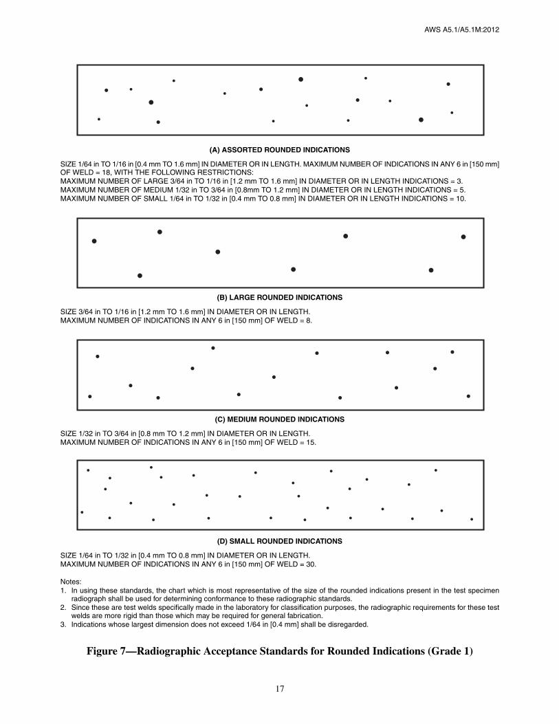
(3) No rounded indications in excess of those permitted by the radiographic standards in Figure 7 according to thegrade specified in Table 8.
In evaluating the radiograph, 1 in [25 mm] of the weld measured from each end of the assembly shall be disregarded.
11.4 A rounded indication is an indication (on the radiograph) whose length is no more than three times its width.Rounded indications may be circular, elliptical, conical, or irregular in shape, and they may have tails. The size of arounded indication is the largest dimension of the indication, including any tail that may be present. The indication maybe porosity or slag. Indications whose largest dimension does not exceed 1/64 in [0.4 mm] shall be disregarded. Testassemblies with porosity indications larger than the largest rounded indications permitted in the radiographic standardsdo not meet the requirements of this specification.
Table 7Chemical Composition Requirements for Weld Metal
AWS Classification
UNSa
Number
Weight Percentb
A5.1 A5.1M C Mn Si P S Ni Cr Mo V
Combined Limit forMn + Ni + Cr
+ Mo + V
E6010E6011E6012E6013E6019E6020E6027
E4310E4311E4312E4313E4319E4320E4327
W06010W06011W06012W06013W06019W06020W06027
0.20 1.20 1.00 N.S. N.S. 0.30 0.20 0.30 0.08 N.S.
E6018E7015E7016E7018
E4318E4915E4916E4918
W06018W07015W07016W07018
0.030.150.150.15
0.601.251.601.60
0.400.900.750.75
0.0250.0350.0350.035
0.0150.0350.0350.035
0.300.300.300.30
0.200.200.200.20
0.300.300.300.30
0.080.080.080.08
N.S.1.501.751.75
E7014E7024E7027
E4914E4924E4927
W07014W07024W07027
0.150.150.15
1.251.251.60
0.900.900.75
0.0350.0350.035
0.0350.0350.035
0.300.300.30
0.200.200.20
0.300.300.30
0.080.080.08
1.501.501.75
E7028E7048
E4928E4948
W07028W07048 0.15 1.60 0.90 0.035 0.035 0.30 0.20 0.30 0.08 1.75
E7018M E4918M W07018 0.120.40to
1.600.80 0.030 0.020 0.25 0.15 0.35 0.05 N. S.
a SAE/ASTM Unified Numbering System for Metals and Alloys.b Single values are maximum. N. S. means Not Specified.c Analysis for boron is required to be reported if intentionally added, or if it is known to be present at levels greater than 0.0010%.
17
AWS A5.1/A5.1M:2012
(A) ASSORTED ROUNDED INDICATIONS
SIZE 1/64 in TO 1/16 in [0.4 mm TO 1.6 mm] IN DIAMETER OR IN LENGTH. MAXIMUM NUMBER OF INDICATIONS IN ANY 6 in [150 mm]OF WELD = 18, WITH THE FOLLOWING RESTRICTIONS:MAXIMUM NUMBER OF LARGE 3/64 in TO 1/16 in [1.2 mm TO 1.6 mm] IN DIAMETER OR IN LENGTH INDICATIONS = 3.MAXIMUM NUMBER OF MEDIUM 1/32 in TO 3/64 in [0.8mm TO 1.2 mm] IN DIAMETER OR IN LENGTH INDICATIONS = 5.MAXIMUM NUMBER OF SMALL 1/64 in TO 1/32 in [0.4 mm TO 0.8 mm] IN DIAMETER OR IN LENGTH INDICATIONS = 10.
(B) LARGE ROUNDED INDICATIONS
SIZE 3/64 in TO 1/16 in [1.2 mm TO 1.6 mm] IN DIAMETER OR IN LENGTH.MAXIMUM NUMBER OF INDICATIONS IN ANY 6 in [150 mm] OF WELD = 8.
(C) MEDIUM ROUNDED INDICATIONS
SIZE 1/32 in TO 3/64 in [0.8 mm TO 1.2 mm] IN DIAMETER OR IN LENGTH.MAXIMUM NUMBER OF INDICATIONS IN ANY 6 in [150 mm] OF WELD = 15.
(D) SMALL ROUNDED INDICATIONS
SIZE 1/64 in TO 1/32 in [0.4 mm TO 0.8 mm] IN DIAMETER OR IN LENGTH.MAXIMUM NUMBER OF INDICATIONS IN ANY 6 in [150 mm] OF WELD = 30.
Notes:1. In using these standards, the chart which is most representative of the size of the rounded indications present in the test specimen
radiograph shall be used for determining conformance to these radiographic standards.2. Since these are test welds specifically made in the laboratory for classification purposes, the radiographic requirements for these test
welds are more rigid than those which may be required for general fabrication.3. Indications whose largest dimension does not exceed 1/64 in [0.4 mm] shall be disregarded.
Figure 7—Radiographic Acceptance Standards for Rounded Indications (Grade 1)

18
AWS A5.1/A5.1M:2012
(E) ASSORTED ROUNDED INDICATIONS
SIZE 1/64 in TO 5/64 in [0.4 mm TO 2.0 mm] IN DIAMETER OR IN LENGTH.MAXIMUM NUMBER OF INDICATIONS IN ANY 6 in [150 mm] OF WELD = 27, WITH THE FOLLOWING RESTRICTIONS:MAXIMUM NUMBER OF LARGE 1/16 in TO 5/64 in [1.6 mm TO 2.0 mm] IN DIAMETER OR IN LENGTH INDICATIONS = 3.MAXIMUM NUMBER OF MEDIUM 3/64 in TO 1/16 in [1.2 mm TO 1.6 mm] IN DIAMETER OR IN LENGTH INDICATIONS = 8.MAXIMUM NUMBER OF SMALL 1/64 in TO 3/64 in [0.4 mm TO 1.2 mm] IN DIAMETER OR IN LENGTH INDICATIONS = 16.
(F) LARGE ROUNDED INDICATIONS
SIZE 1/16 in TO 5/64 in [1.6 mm TO 2.0 mm] IN DIAMETER OR IN LENGTH.MAXIMUM NUMBER OF INDICATIONS IN ANY 6 in [150 mm] OF WELD = 14.
(G) MEDIUM ROUNDED INDICATIONS
SIZE 3/64 in TO 1/16 in [1.2 mm TO 1.6 mm] IN DIAMETER OR IN LENGTH.MAXIMUM NUMBER OF INDICATIONS IN ANY 6 in [150 mm] OF WELD = 22.
(H) SMALL ROUNDED INDICATIONS
SIZE 1/64 in TO 3/64 in [0.4 mm TO 1.2 mm] IN DIAMETER OR IN LENGTH.MAXIMUM NUMBER OF INDICATIONS IN ANY 6 in [150 mm] OF WELD = 44.
Notes:1. In using these standards, the chart which is most representative of the size of the rounded indications present in the test specimen
radiograph shall be used for determining conformance to these radiographic standards.2. Since these are test welds specifically made in the laboratory for classification purposes, the radiographic requirements for these test
welds are more rigid than those which may be required for general fabrication.3. Indications whose largest dimension does not exceed 1/64 in [0.4 mm] shall be disregarded.
Figure 7 (Continued)—Radiographic Acceptance Standards for Rounded Indications (Grade 2)

19
AWS A5.1/A5.1M:2012
12. Tension Test
12.1 For all electrodes except E6022 [E4322], one all-weld-metal round tension test specimen as specified in the TensionTest section of AWS B4.0 [AWS B4.0M], Standard Methods for Mechanical Testing of Welds, shall be machined fromthe groove weld described in 9.4.1 and Figure 2 or 5. For a test plate thickness of 1/2 in [12 mm], the all-weld-metal ten-sion test specimen shall have a nominal diameter of 0.250 in [6.5 mm]. For a test plate thickness of 3/4 in [20 mm] ormore, the all-weld-metal tension test specimen shall have a nominal diameter of 0.500 in [12.5 mm]. For all plate thick-nesses, the gauge length-to-diameter ratio shall be 4:1.
12.2 After machining, but before testing, the specimen for all electrodes except the low hydrogen classifications may beaged at 200°F to 220°F [90°C to 105°C] for up to 48 hours, then allowed to cool to room temperature. Refer to Annex A,A6.3 for a discussion on the purpose of aging.
12.3 The aged and unaged specimens shall be tested in the manner described in the Tension Test section of AWS B4.0[AWS B4.0M], Standard Methods for Mechanical Testing of Welds.
12.4 The results of the tension test shall meet the requirements specified in Table 2.
12.5 For E6022 [E4322], one transverse rectangular tension test specimen as specified in the Tension Test section ofAWS B4.0 [AWS B4.0M], Standard Methods for Mechanical Testing of Welds, shall be machined from the groove welddescribed in 9.4.2 and shown in Figure 4. The transverse rectangular tensile specimen shall be a full-thickness specimenmachined transverse to the weld with a nominal reduced section width of 1.50 in [38 mm].
Table 8Radiographic Soundness Requirements
AWS Classification
Radiographic Standarda, bA5.1 A5.1M
E6018E6019E6020E7015E7016E7018
ME7018ME7048
E4318E4319E4320E4915E4916E4918
ME4918ME4948
Grade 1
E6010E6011E6013E6027E7014E7024E7027E7028
E4310E4311E4313E4327E4914E4924E4927E4928
Grade 2
E6012E6022
E4312E4322 Not Specified
a See Figure 7.b The radiographic soundness obtainable under industrial conditions employed for the various electrode classifications is discussed in A6.10.1 in
Annex A.

AWS A5.1/A5.1M:2012
20
13. Bend Test13.1 One longitudinal face bend specimen, as required in Table 4, shall be machined from the groove weld test assemblydescribed in 9.4.2 and shown in Figure 4. The nominal length of the specimen shall be 6 in [150 mm], the nominal widthof the specimen shall be 1.50 in [38 mm], and the nominal thickness shall be 0.25 in [6 mm]. Other dimensions shallbe as specified in the Bend Test section of AWS B4.0 [AWS B4.0M], Standard Methods for Mechanical Testing of Welds.
13.2 After machining, but before testing, the specimen may be aged at 200°F to 220°F [90°C to 105°C] for up to48 hours, then allowed to cool to room temperature. Refer to Annex A, A6.3 for a discussion on the purpose of aging.
13.3 The specimen shall be tested in the manner described in the Bend Test section of AWS B4.0 [AWS B4.0M], Stan-dard Methods for Mechanical Testing of Welds, by bending it uniformly through 180° over a 3/4 in [19 mm] radius inany suitable jig, as specified in AWS B4.0 [AWS B4.0M]. Positioning of the face bend specimen shall be such that theweld face of the last side welded shall be in tension.
13.4 Each specimen, after bending, shall conform to the 3/4 in [19 mm] radius, with an appropriate allowance for spring-back, and the weld metal shall not contain openings in excess of 1/8 in [3 mm] on the convex surface.
14. Impact Test14.1 Five full-size Charpy V-notch impact test specimens, as specified in the Fracture Toughness Test section of AWSB4.0 [AWS B4.0M], Standard Methods for Mechanical Testing of Welds, shall be machined from the test assemblyshown in Figure 2 or 5, for those classifications for which impact testing is required in Table 4. The Charpy V-notchspecimens shall have the notched surface and the struck surface parallel with each other within 0.002 in [0.05 mm]. Theother two surfaces shall be square with the notched or struck surfaces within ±10 minutes of a degree. The notch shallbe smoothly cut by mechanical means and shall be square with the longitudinal edge within 1°.
The geometry of the notch shall be measured on at least one specimen in a set of five specimens. Measurement shall bedone at a minimum 50X magnification on either a shadowgraph or a metallograph. The correct location of the notchshall be verified by etching before or after machining.
14.2 The five specimens shall be tested in accordance with the Fracture Toughness Test section of AWS B4.0 [AWSB4.0M]. The test temperature shall be at or below that specified in Table 3 for the classification under test. The actualtemperature used shall be listed on the certification documentation when issued.
14.3 In evaluating the test results for all the classifications that require impact testing, except E7018M [E4918M], thelowest and highest values obtained shall be disregarded. Two of the three remaining values shall equal, or exceed, thespecified 20 ft·lbf [27 J] energy level. One of the three may be lower, but not lower than 15 ft·lbf [20 J], and the averageof the three shall be not less than the required 20 ft·lbf [27 J] energy level.
14.4 In evaluating the results for E7018M [E4918M], all five impact values shall be included. At least four of the fiveshall equal, or exceed, the specified 50 ft·lbf [67 J] energy level. One of the five may be lower than that, but not lowerthan 40 ft·lbf [54 J]. The average of the 5 results shall be not less than the required 50 ft·lbf [67 J] energy level.
15. Fillet Weld Test15.1 The fillet weld test, when required in Table 4, shall be made in accordance with 9.5 and Figure 3. The entire face ofthe completed fillet weld shall be examined visually. It shall be free of cracks, overlap, slag, and porosity, and shall besubstantially free of undercut. An infrequent short undercut up to 1/32 in [0.8 mm] in depth shall be allowed. After thevisual examination, a macro examination specimen, approximately 1 in [25 mm] in length, shall be removed as shown inFigure 3. One cross-sectional surface of the specimen shall be polished, etched, and then examined as required in 15.2.
15.2 Scribe lines shall be placed on the prepared surface, as shown in Figure 8, and the fillet weld size, fillet weld leg,and convexity shall be determined to the nearest 1/64 in [0.5 mm] by actual measurement—see Figure 8. These mea-surements shall meet the requirements of Table 6 with respect to minimum or maximum fillet weld size and the require-ments of Table 9 with respect to maximum convexity and maximum difference between fillet weld legs according to thefillet weld size measured.

21
AWS A5.1/A5.1M:2012
Notes:1. Fillet weld size is the leg lengths of the largest isosceles right triangle which can be inscribed within the fillet weld cross section.2. Convexity is the maximum distance from the face of a convex fillet weld perpendicular to a line joining the weld toes.3. Fillet weld leg is the distance from the joint root to the toe of the fillet weld.
Figure 8—Dimensions of Fillet Welds
Table 9Dimensional Requirements for
Fillet Weld Usability Test Specimensa
Measured Fillet Weld Size Maximum ConvexityMaximum Difference
Between Fillet Weld Legs
in mm in mm in mm
1/89/645/32
11/643/16
13/647/32
15/641/4
17/649/32
19/645/16
21/6411/3223/643/8
or more
3.0—4.04.5—5.05.56.06.5—7.07.58.08.59.0—9.5
or more
5/645/645/645/645/645/645/645/645/643/323/323/323/323/323/323/323/32
2.0—2.02.0—2.02.02.02.0—2.52.52.52.52.5—2.5
1/323/643/641/161/165/645/643/323/327/647/641/81/89/649/645/325/32
1.0—1.01.5—2.02.02.52.5—3.03.03.03.54.0—4.0
a All measurements shall be rounded to the nearest 1/64 in [0.5 mm].

22
AWS A5.1/A5.1M:2012
15.3 The remaining two sections of the test assembly shall be broken through the fillet weld by a force exerted as shownin Figure 9. When necessary to facilitate fracture through the fillet, one or more of the following procedures may beused:
(1) A reinforcing bead, as shown in Figure 9A, may be added to each leg of the weld.
(2) The position of the web on the flange may be changed, as shown in Figure 9B.
(3) The face of the fillet may be notched, as shown in Figure 9C.
Tests in which the weld metal pulls out of the base metal during bending are invalid tests. Specimens in which thisoccurs shall be replaced, specimen for specimen, and the test completed. In this case, the doubling of specimens asrequired for retest in Clause 8, Retest, does not apply.
15.4 The fractured surfaces shall be visually examined without magnification. The fracture surface shall be free ofcracks. Incomplete fusion at the weld root shall not be greater than 20% of the total length of the weld. There shall be nocontinuous length of incomplete fusion greater than 1 in [25 mm] as measured along the weld axis except for electrodesof the E6012 [E4312], E6013 [E4313], and E7014 [E4914] classifications. Fillet welds made with electrodes of theseclassifications may exhibit incomplete penetration through the entire length. They may also exhibit incomplete fusionwhich shall at no point exceed 25% of the smaller leg length of the fillet weld.
16. Moisture Test16.1 The moisture content of the covering of the electrode, when required by Table 4, shall be determined by any suit-able method. In case of dispute, the method described in AWS A4.4M, Standard Procedure for Determination of Mois-ture Content of Welding Fluxes and Welding Electrode Flux Coverings, shall be the referee method.
16.2 The electrodes shall be tested without conditioning, unless the manufacturer recommends otherwise. If the elec-trodes are conditioned, that fact, along with the method used for conditioning, and the time and temperature involved inthe conditioning, shall be noted on the test record. The moisture content shall not exceed the limit specified in Table 10,for the classification under test.
17. Absorbed Moisture Test17.1 In order for a low-hydrogen electrode to be designated as low-moisture-absorbing with the optional supplemental“R” suffix designator or classified as E7018M [E4918M], sufficient electrodes shall be exposed to an environment of80°F [27°C]/80% relative humidity (RH) for a period of not less than nine hours by any suitable method. In case ofdispute, the exposure method described in 17.2 through 17.6 shall be the referee method. The moisture content of the
Figure 9—Alternative Methods for Facilitating Fracture of the Fillet Weld

23
AWS A5.1/A5.1M:2012
electrode covering on the low-moisture-absorbing, low-hydrogen electrodes (for example E7015R [E4915R], E7016R[E4916R], E7016-1R [E4916-1R], E7018R [E4918R], E7018-1R [E4918-1R], E7018M [E4918M], E7028R [E4928R],E7048R [E4948R]) shall be determined by any suitable method. In case of dispute, the method described in AWS Spec-ification A4.4M, Standard Procedure for Determination of Moisture Content of Welding Fluxes and Welding ElectrodeFlux Coverings, shall be the referee method. The moisture content of the exposed covering shall not exceed the maxi-mum specified moisture content for the designated electrode and classification in Table 10.
17.2 An electrode sample of each size of E7018M [E4918M] or the smallest and the largest sizes of “R” designated elec-trode shall be exposed. If the electrodes are conditioned prior to exposure, that fact, along with the method used forconditioning, and the time and temperature involved in conditioning, shall be noted on the test record. Conditioning ofelectrodes after exposure is not permitted.
17.3 The electrode sample shall be exposed in a suitably calibrated and controlled environmental chamber for nine hoursminimum at 80°F to 85°F [27°C to 30°C] and 80% to 85% relative humidity.
17.4 The environmental chamber shall meet the following design requirements:
(1) The apparatus shall be an insulated humidifier which produces the temperature of adiabatic saturation throughregenerative evaporation or vaporization of water.
(2) The apparatus shall have an average air speed within the envelope of air surrounding the covered electrode of100 fpm to 325 fpm [0.5 m/s to 1.7 m/s].
(3) The apparatus shall have a drip-free area where the covered electrode up to 18 in [450 mm] in length can be posi-tioned with length as perpendicular as practical to the general air flow.
(4) The apparatus shall have a calibrated means of continuously measuring and recording the dry bulb temperatureand either the wet bulb temperature or the differential between the dry bulb and wet bulb temperature over the period oftime required.
Table 10Moisture Content Limits for Electrode Coverings
AWS Classification Electrode Designation Limit of Moisture Content, % by Wt, Max.
A5.1 A5.1M A5.1 A5.1M As-Received or Conditioneda As-Exposedb
E6018E7015E7016
E7018
E7028E7048
E4318E4915E4916
E4918
E4928E4948
E6018E7015E7016E7016-1E7018E7018-1E7028E7048
E4318E4915E4916E4916-1E4918E4918-1E4928E4948
0.6 Not Specified
E6018E7015E7016
E7018
E7028E7048
E4318E4915E4916
E4918
E4928E4948
E6018RE7015RE7016RE7016-1RE7018RE7018-1RE7028RE7048R
E4318RE4915RE4916RE4916-1RE4918RE4918-1RE4928RE4948R
0.3 0.4
E7018M E4918M E7018M E4918M 0.1 0.4
a As-received or conditioned electrode coverings shall be tested as specified in Clause 16, Moisture Test.b As-exposed electrode coverings shall have been exposed to a moist environment as specified in Clause 17 before being tested as specified in Clause 16.

24
AWS A5.1/A5.1M:2012
(5) The apparatus shall have an air speed of at least 900 fpm [4.5 m/s] over the wet bulb sensor unless the wet bulbsensor can be shown to be insensitive to air speed or has a known correction factor that will provide for an adjusted wetbulb reading equal to the temperature of adiabatic saturation.
(6) The apparatus shall have the wet bulb sensor located on the suction side of the fan so that there is an absence ofheat radiation on the sensor.
17.5 The exposure procedure shall be as follows:
(1) The electrode sample taken from previously unopened packages, or from a reconditioned lot, shall be heated to atemperature –0°, +10°F [6°C] above the dew point.
(2) The electrode sample shall be loaded into the chamber without delay after the packages are opened.
(3) The electrodes shall be placed in the chamber in a vertical or horizontal position on at least 1 in [25 mm] centers,with the length of the electrode as perpendicular as practical to the general air flow.
(4) Time, temperature, and humidity shall be continuously recorded for the period that the electrodes are in thechamber.
(5) Counting of the exposure time shall start when the required temperature and humidity in the chamber areestablished.
(6) At the end of the exposure time, the electrodes shall be removed from the chamber and a sample of the electrodecovering taken for moisture determination, as specified in Clause 16.
17.6 All of the critical variables which could affect test results have not been identified here. Consequently, the manufac-turer shall control such other variables deemed relevant to ensure greater consistency of results.
18. Diffusible Hydrogen Test18.1 The smallest and largest size of the electrode of each classification to be identified by an optional supplementaldiffusible hydrogen designator, and all sizes of E7018M [E4918M], shall be tested according to one of the methodsgiven in AWS A4.3, Standard Methods for Determination of the Diffusible Hydrogen Content of Martensitic, Bainitic,and Ferritic Steel Weld Metal Produced by Arc Welding. Based upon the average value of test results which satisfy therequirements of Table 11, the appropriate diffusible hydrogen designator may be added at the end of the classification.
Table 11Diffusible Hydrogen Limits for Weld Metala
AWS Classification
Diffusible Hydrogen DesignatorDiffusible Hydrogen Content,
Average mL/100g Deposited Metal, Max.bA5.1 A5.1M
E7018M E4918M None 4
E6018ME7015ME7016ME7018ME7028ME7048M
E4318ME4915ME4916ME4918ME4928ME4948M
H16
H8
H4
16
8
4
a Diffusible hydrogen testing in Clause 18, Diffusible Hydrogen Test, is required for E7018M [E4918M]. Diffusible hydrogen testing of other lowhydrogen electrodes is only required when the optional diffusible hydrogen designator is added.
b Some low hydrogen classifications may not meet the H4 and H8 requirements.

25
AWS A5.1/A5.1M:2012
18.2 Testing shall be done without conditioning of the electrode, unless the manufacturer recommends otherwise. If theelectrodes are conditioned, that fact, along with the method used for conditioning, and the time and temperature involvedin the conditioning, shall be noted on the test record.
18.3 For purposes of certifying compliance with diffusible hydrogen requirements, the reference atmospheric conditionshall be an absolute humidity of ten (10) grains of moisture/lb [1.43g/kg] of dry air at the time of welding.7 The actualatmospheric conditions shall be reported along with the average value for the tests according to AWS A4.3.
18.4 When the absolute humidity equals or exceeds the reference condition at the time of preparation of the test assem-bly, the test shall be acceptable as demonstrating compliance with the requirements of this specification, provided theactual test results satisfy the diffusible hydrogen requirements for the applicable designator. Likewise, if the actual testresults for an electrode meet the requirements for the lower, or lowest hydrogen designator, as specified in Table 11, theelectrode also meets the requirements for all higher hydrogen designators in Table 11 without need to retest.
Part CManufacture, Identification, and Packaging
19. Method of ManufactureThe electrodes classified according to this specification may be manufactured by any method that will produce elec-trodes that meet the requirements of this specification.
20. Standard Sizes and Lengths20.1 Standard sizes (diameter of the core wire) and lengths of electrodes are shown in Table 12.
20.2 The diameter of the core wire shall not vary more than ±0.002 in [0.05 mm] from the diameter specified. The lengthshall not vary more than ±1/4 in [10 mm] from that specified.
7 See A8.2 in Annex A.
Table 12Standard Sizes and Lengths
Core Wire Diametera Lengthsa, b
A5.1 (in) A5.1Mc (mm) A5.1 (in) A5.1M (mm)
1/165/643/32—1/85/323/16—
7/32—1/45/16
1.62.0—2.53.24.0—5.0—6.0—8.0
99 or 12
12 or 14—14
14 or 1814 or 18
—14 or 18 or 28
—18 or 2818 or 28
225225 or 300
—300 or 350
350350 or 450
—350 or 450
—350 or 450 or 700
—450 or 700
a Lengths and sizes other than these shall be as agreed between purchaser and supplier.b In all cases, end-gripped electrodes are standard.c ISO 544 Welding consumables — Technical delivery conditions for welding filler materials — Type of product, dimensions, tolerances and markings.
See 20.2 for tolerances on diameter and length.

AWS A5.1/A5.1M:2012
26
21. Core Wire and Covering21.1 The core wire and covering shall be free of defects that would interfere with uniform deposition of the electrode.
21.2 The core wire and the covering shall be concentric to the extent that the maximum core-plus-one-covering dimen-sion shall not exceed the minimum core-plus-one-covering dimension by more than:
(1) 7% of the mean dimension in sizes 3/32 in [2.5 mm] and smaller;
(2) 5% of the mean dimension in sizes 1/8 in [3.2 mm] and 5/32 in [4.0 mm];
(3) 4% of the mean dimension in sizes 3/16 in [5.0 mm] and larger.
Concentricity may be measured by any suitable means.
22. Exposed Core22.1 The grip end of each electrode shall be bare (free of covering) for a distance of not less than 1/2 in [12 mm],nor more than 1-1/4 in [30 mm] for 5/32 in [4.0 mm] and smaller sizes, and not less than 3/4 in [20 mm] nor more than1-1/2 in [40 mm] for 3/16 in [5.0 mm] and larger sizes, to provide for electrical contact with the electrode holder.
22.2 The arc end of each electrode shall be sufficiently conductive and the covering sufficiently tapered to permit easystriking of the arc. The length of the conductive portion (measured from the end of the core wire to the location wherethe full cross-section of the covering is obtained) shall not exceed 1/8 in [3.2 mm] or the diameter of the core wire, which-ever is less. Electrodes with chipped coverings near the arc end, baring the core wire no more than the lesser of 1/4 in[6.0 mm] or twice the diameter of the core wire, meet the requirements of this specification, provided no chip uncoversmore than 50% of the circumference of the core.
23. Electrode IdentificationAll electrodes shall be identified as follows:
23.1 At least one imprint of the electrode designation (classification plus any optional designators) shall be applied to theelectrode covering in the order specified in Figure 10, starting within 2-1/2 in [65 mm] of the grip end of the electrode.The prefix letter “E” in the classification may be omitted from the imprint.
23.2 The numbers and letters of the imprint shall be of bold block type of a size large enough to be legible.
23.3 The ink used for imprinting shall provide sufficient contrast with the electrode covering so that, in normal use, thenumbers and letters are legible both before and after welding.
23.4 When an electrode is classified as meeting the requirements of A5.1 and A5.1M, both electrode designations shallbe applied.
24. Packaging24.1 Electrodes shall be suitably packaged to protect them from damage during shipment and storage under normalconditions. In addition, E7018M [E4918M] electrodes shall be packaged in hermetically sealed containers. These her-metically sealed containers shall be capable of passing the test specified in 24.3.
24.2 Standard package weights shall be as agreed between purchaser and supplier.
24.3 Hermetically sealed containers may be tested by selecting a representative sample container and immersing in waterthat is at a temperature of at least 50°F [30°C] above that of the packaged material (room temperature). The containershall be immersed so that the surface under observation is one inch [25 mm] below the water level and the greatest basicdimension of the container is parallel to the surface of the water. A “leaker” is indicated by a steady stream of air bubblesemanating from the container. A container with a stream that lasts for 30 seconds or more does not meet the require-ments of this specification.

27
AWS A5.1/A5.1M:2012
25. Marking of Packages25.1 The following product information (as a minimum) shall be legibly marked on the outside of each unit package:
(1) AWS specification and classification designations along with applicable optional designators (year of issue maybe excluded)
(2) Supplier’s name and trade designation
(3) Size and net weight
(4) Lot, control, or heat number.
25.2 The appropriate precautionary information8 as given in ANSI Z49.1, latest edition, (as a minimum) or its equiva-lent, shall be prominently displayed in legible print on all packages of electrodes, including individual unit packagesenclosed within a larger package.
8 Typical examples of “warning labels” are shown in figures in ANSI Z49.1 for some common or specific consumables used withcertain processes.
Mandatory Classification Designators*
Designates an electrode. This designator may be deleted from the product imprint requiredfor identification of the electrode.
Designates the tensile strength (minimum), in ksi [MPa ÷ 10], of the weld metal when pro-duced in accordance with the test assembly preparation procedure of this specification (seeTable 2).
Designates the welding position in which electrodes are usable, the type of covering, andthe kind of welding current for which the electrodes are suitable (see Table 1).
Designates an electrode (E7018M [E4918M]) intended to meet most military require-ments (greater toughness, lower moisture content—both as-received and after exposure—and mandatory diffusible hydrogen limits for weld metal) (see Tables 3, 10, and 11).
EXXYYEXXYYMEXXYY–1 HZ R Optional Supplemental Designators*
Designates that the electrode meets the requirements of the absorbed moisture test (anoptional supplemental test for all low hydrogen electrodes except the E7018M [E4918M]classification, for which the test is required) (see Table 10).
Designates that the electrode meets the requirements of the diffusible hydrogen test (anoptional supplemental test of the weld metal from low hydrogen electrodes—as-receivedor conditioned—with an average value not exceeding “Z” mL of H2 per 100 g of depositedmetal, where “Z” is 4, 8, or 16) (see Table 11).
Designates that the electrode (E7016, E7018, or E7024) [E4916, E4918, or E4924] meetsthe requirements for improved toughness—and ductility in the case of E7024 [E4924]—(optional supplemental test requirements shown in Tables 2 and 3) (see notes to Tables 2and 3).
*The combination of these designators constitutes the electrode classification.
Figure 10—Order of Mandatory and Optional Supplemental Designators

This page is intentionally blank.
28
AWS A5.1/A5.1M:2012

AWS A5.1/A5.1M:2012
29
Annex A (Informative)
Guide to AWS Specification for Carbon SteelElectrodes for Shielded Metal Arc Welding
This annex is not part of AWS A5.1/A5.1M:2012, Specification for Carbon Steel Electrodesfor Shielded Metal Arc Welding, but is included for informational purposes only.
A1. IntroductionThe purpose of this guide is to correlate the electrode classifications with their intended applications so the specificationcan be used effectively. Appropriate base metal specifications are referred to whenever that can be done and when itwould be most helpful. Such references are intended only as examples rather than complete listings of the base metalsfor which each electrode classification is suitable.
A2. Classification SystemA2.1 The system for identifying the electrode classifications in this specification follows the standard pattern used inother AWS filler metal specifications. The prefix letter “E” at the beginning of each classification designation stands forelectrode. The first two digits, 60 [43], for example, designate tensile strength of at least 60 ksi [430 MPa] of the weldmetal, produced in accordance with the test assembly preparation section of the specification. In this document, theclassification in U.S. Customary Units is followed by the SI Unit classification in brackets. The third digit designatesposition usability that will allow satisfactory welds to be produced with the electrode.
Thus, the “1,” as in E6010 [E4310], means that the electrode is usable in all positions (flat, horizontal, vertical, and over-head). The “2,” as in E6020 [E4320] designates that the electrode is suitable for use in the flat position and for makingfillet welds in the horizontal position. The “4,” as in E7048 [E4948], designates that the electrode is suitable for use invertical welding with downward progression and for other positions (see Table 1). The last two digits taken together des-ignate the type of current with which the electrode can be used and the type of covering on the electrode, as listed inTable 1.
A2.2 Optional designators are also used in this specification in order to identify electrodes that have met the mandatoryclassification requirements and certain supplementary requirements as agreed to between the supplier and the purchaser.A “-1” designator following classification identifies an electrode which meets optional supplemental impact require-ments at a lower temperature than required for the classification (see Note b to Table 3). An example of this is theE7024-1 [E4924-1] electrode which meets the classification requirements of E7024 [E4924] and also meets the optionalsupplemental requirements for toughness and improved elongation of the weld metal (see Note e to Table 2).
Certain low-hydrogen electrodes also may have optional designators. An optional supplemental designator “HZ” follow-ing the four digit classification designators or following the “-1” optional supplemental designator, if used, indicates anaverage diffusible hydrogen content of not more than “Z” mL/100g of deposited metal when tested in the “as-received”or conditioned state in accordance with AWS A4.3, Standard Methods for Determination of the Diffusible HydrogenContent of Martensitic, Bainitic, and Ferritic Steel Weld Metal Produced by Arc Welding. Electrodes that are designatedas meeting the lower or lowest hydrogen limits, as specified in Table 11, are also understood to be able to meet any

AWS A5.1/A5.1M:2012
30
higher hydrogen limits even though these are not necessarily designated along with the electrode classification. There-fore, as an example, an electrode designated as “H4” also meets “H8” and “H16” requirements without being designatedas such. See Clause 18, Diffusible Hydrogen Test, and Table 11.
A letter “R” is a designator used with the low-hydrogen electrode classifications. It is used to identify electrodes thathave been exposed to a humid environment for a given length of time and tested for moisture absorption in addition tothe standard moisture test required for classification of low-hydrogen electrodes (see Clause 17, Absorbed MoistureTest, and Table 10).
A2.3 Table A.1 shows the classification for similar electrodes from Canadian Standards Association standard W48-01,Filler Metals and Allied Materials for Metal Arc Welding.
A2.4 Request for Filler Metal Classification
A2.4.1 When a welding electrode cannot be classified according to some classification given in this specification, themanufacturer may request that a classification be established for that welding electrode. The manufacturer may do thisby following the procedure given in A2.4.3, below.
A2.4.2 A request to establish a new electrode classification must be a written request, and it needs to provide suffi-cient detail to permit the Committee on Filler Metals and Allied Materials, or the Subcommittee, to determine whether anew classification or the modification of an existing classification is more appropriate, and whether either is necessary tosatisfy the need.
A2.4.3 In particular, the request needs to include:
(1) All classification requirements as given for existing classifications, such as, chemical composition ranges,mechanical property requirements, and usability test requirements.
Table A.1Canadian Electrode Classifications
Similar to AWS Classifications
Canadian Electrode Classificationa A5.1 A5.1M
E4310E4311E4312E4313E4322E4327E4910E4911E4912E4913E4914E4915E4916
bE4918b
E4922cE4924c
E4927E4928E4948
E6010E6011E6012E6013E6022E6027
————
E7014E7015E7016E7018
—E7024E7027E7028E7048
E4310E4311E4312E4313E4322E4327
————
E4914E4915E4916E4918
—E4924E4927E4928E4948
a From CSA Standard W48-01, Filler Metals and Allied Materials for Metal Arc Welding, published by Canadian Standards Association, 178 RexdaleBoulevard, Rexdale, Ontario, Canada M9W 1R3.
b Also includes E4918-1 designated electrode.c Also includes E4924-1 designated electrodes.

31
AWS A5.1/A5.1M:2012
(2) Any testing conditions for conducting the tests used to demonstrate that the product meets the classificationrequirements. (It would be sufficient, for example, to state that the welding conditions are the same as for the otherclassifications.)
(3) Information on Descriptions and Intended Use, which parallels that for existing classifications, for that section ofthe annex.
(4) Proposed ASME “F” number, if appropriate.
A request for a new classification without the above information will be considered incomplete. The Secretary willreturn the request to the requestor for further information.
A2.4.4 The request should be sent to the Secretary of the Committee on Filler Metals and Allied Materials at AWSHeadquarters. Upon receipt of the request, the Secretary will:
(1) Assign an identifying number to the request. The number shall include the date the request was received.
(2) Confirm receipt of the request, and give the identification number to the person making the request.
(3) Send a copy of the request to the Chair of the Committee on Filler Metals and Allied Materials, and the Chair ofthe particular Subcommittee involved.
(4) File the original request.
(5) Add the request to the log of outstanding requests.
A2.4.5 All necessary action on each request shall be completed as soon as possible. If more than 12 months elapse,the Secretary shall inform the requestor of the status of the request, with copies to the Chairs of the Committee and Sub-committee. Requests still outstanding after 18 months shall be considered not to have been answered in a timely mannerand the Secretary shall report these to the Chair of the Committee on Filler Metals and Allied Materials, for action.
A2.4.6 The Secretary shall include a copy of the log of all requests pending and those completed during the precedingyear with the agenda for each Committee on Filler Metals and Allied Materials meeting. Any other publication ofrequests that have been completed will be at the option of the American Welding Society, as deemed appropriate.
A2.5 An international system for designating welding filler metals developed by the International Institute of Welding(IIW) is being adopted in many ISO specifications. Table A.2 shows those used in ISO 2560 for comparison with theclassifications in this specification. To understand the proposed international designation system, one is referred to Table1 and the annex of AWS document IFS:2002, entitled International Index of Welding Filler Metal Classifications.National specifications from many industrial countries having comparable filler metals are also found in Table 1 ofIFS:2002.
A3. AcceptanceAcceptance of all welding materials classified under this specification is in accordance with AWS A5.01M/A5.01 (ISO14344 MOD), as the specification states. Any testing a purchaser requires of the supplier, for material shipped in accor-dance with this specification, needs to be clearly stated in the purchase order, according to the provisions of AWS A5.01.In the absence of any such statement in the purchase order, the supplier may ship the material with whatever testing thesupplier normally conducts on material of that classification, as specified in Schedule F, Table 1, of the AWS A5.01.Testing in accordance with any other schedule in that table must be properly required by the purchase order. In suchcases, acceptance of the material shipped shall be in accordance with those requirements.
A4. CertificationThe act of placing the AWS Specification and Classification designations and optional supplemental designators, ifapplicable, on the packaging enclosing the product or the classification on the product itself, constitutes the supplier’s(manufacturer’s) certification that the product meets all of the requirements of the specification.

32
AWS A5.1/A5.1M:2012
The only testing requirement implicit in this certification is that the manufacturer has actually conducted the testsrequired by the specification on material that is representative of that being shipped and that the material met the require-ments of the specification. Representative material, in this case, is any production run of that classification using thesame formulation. “Certification” is not to be construed to mean that tests of any kind were necessarily conducted onsamples of the specific material shipped. Tests on such material may or may not have been made. The basis for the certi-fication required by the specification is the classification test of “representative material” cited above, and the “Manufac-turer’s Quality Assurance Program” in AWS A5.01M/A5.01 (ISO 14344 MOD).
A5. Ventilation During WeldingA5.1 The following five major factors govern the quantity of fumes in the atmosphere to which welders and weldingoperators are exposed during welding:
(1) Dimensions of the space in which welding is done (with special regard to the height of the ceiling)
(2) Number of welders and welding operators working in that space
(3) Rate of evolution of fumes, gases, or dust, according to the materials and processes used
(4) The proximity of welders and welding operators to the fumes as they issue from the welding zone, and to thegases and dust in the space in which they are working
(5) The ventilation provided to the space in which the welding is done.
Table A.2Comparison of Equivalent Classificationsa
ISO2560b
USAAWS
A B A5.1 A5.1M
E35xC21E35xC11E35xR12E35xR12
—E35xRA12E35xA13E35xA33E35xRA54E38xR32E38xB22E38xB12
—E38xB32
——
E38xRR4E38xRR4E38xRA54E38xB53E38xB35
E4310E4311E4312E4313E4318E4319E4320
—E4327E4914E4915E4916E4916-1E4918E4918-1
—E4924E4924-1E4927E4928E4948
E6010E6011E6012E6013E6018E6019E6020E6022E6027E7014E7015E7016E7016-1E7018E7018-1E7018ME7024E7024-1E7027E7028E7048
E4310E4311E4312E4313E4318E4319E4320E4322E4327E4914E4915E4916E4916-1E4918E4918-1E4918ME4924E4924-1E4927E4928E4948
a The requirements for the equivalent classifications are not necessarily identical in every respect.b ISO 2560, Welding consumables — Covered electrodes for manual metal arc welding of nonalloy fine grain steels — Classification.

AWS A5.1/A5.1M:2012
33
A5.2 American National Standard ANSI Z49.1, Safety in Welding, Cutting, and Allied Processes (published by theAmerican Welding Society), discusses the ventilation that is required during welding and should be referred to fordetails. Attention is drawn particularly to the section of that document entitled, “Health Protection and Ventilation.”
A6. Welding Considerations
A6.1 Weld metal properties may vary widely, according to size of the electrode and amperage used, size of the weldbeads, base metal thickness, joint geometry, preheat and interpass temperatures, surface condition, base metal composi-tion, dilution, etc. Because of the profound effect of these variables, a test procedure was chosen for this specificationwhich would represent good welding practice and minimize variation of the most potent of these variables.
A6.2 It should be recognized, however, that production practices may be different. The differences encountered mayalter the properties of the weld metal. For instance, interpass temperatures may range from subfreezing to severalhundred degrees. No single temperature or reasonable range of temperatures can be chosen for classification tests whichwill be representative of all of the conditions encountered in production work.
Properties of production welds may vary accordingly, depending on the particular welding conditions. Weld metal prop-erties may not duplicate, or even closely approach, the values listed and prescribed for test welds. For example, ductilityin single pass welds in thick base metal made outdoors in cold weather without adequate preheating may drop to littlemore than half that required herein and normally obtained. This does not indicate that either the electrodes or the weldsare below standard. It indicates only that the particular production conditions are more severe than the test conditionsprescribed by this specification.
A6.3 Hydrogen is another factor to be considered in welding. Weld metals, other than those from low-hydrogen elec-trodes (E7015 [E4915], E7016 [E4916], E7018 [E4918], E7018M [E4918M], E7028 [E4928], and E7048 [E4948])contain significant quantities of hydrogen for some period of time after they have been made. Most of this hydrogengradually escapes. After two to four weeks at room temperature or 24 hours to 48 hours at 200°F to 220°F [90°C to105°C], most of it has escaped. As a result of this change in hydrogen content, ductility of the weld metal increasestowards its inherent value, while yield, tensile and impact strengths remain relatively unchanged.
This specification permits aging of the test specimens at 200°F to 220°F [90°C to 105°C] for up to 48 hours before sub-jecting them to the all-weld-metal tension or transverse bend test. This is done to minimize discrepancies in testing (seealso A8.2, Diffusible Hydrogen Test).
A6.4 When weldments are given a postweld heat treatment, the temperature and time at temperature are very important.The tensile and yield strengths generally are decreased as postweld heat treatment temperature and time at temperatureare increased.
A6.5 Welds made with electrodes of the same classification and the same welding procedure will have significantly dif-ferent tensile and yield strengths in the as-welded and postweld heat-treated conditions. Comparison of the values for as-welded and postweld heat-treated (1150°F [620°C] for one hour) weld metal will show the following:
A6.5.1 The tensile strength of the postweld heat-treated weld metal will be approximately 5 ksi [35 MPa] lower thanthat of the weld metal in the as-welded condition.
A6.5.2 The yield strength of the postweld heat-treated weld metal will be approximately 10 ksi [70 MPa] lower thanthat of the weld metal in the as-welded condition.
A6.6 Conversely, postweld heat-treated welds made with the same electrodes and using the same welding procedureexcept for variation in interpass temperature and postweld heat treatment time, can have almost identical tensile andyield strengths. As an example, almost identical tensile and yield strengths may be obtained in two welds, one using aninterpass temperature of 300°F [150°C] and postweld heat-treated for 1 hour at 1150°F [620°C], and the other using aninterpass temperature of 212°F [100°C] and postweld heat-treated for 10 hours at 1150°F [620°C].

AWS A5.1/A5.1M:2012
34
A6.7 Electrodes which meet all the requirements of any given classification may be expected to have similar characteris-tics. Certain minor differences continue to exist from one brand to another due to differences in preferences that existregarding specific operating characteristics. Furthermore, the only differences between the present E60XX and E70XX[E43XX and E49XX] classifications are the differences in chemical composition and mechanical properties of the weldmetal, as shown in Tables 2, 3, and 7. In many applications, electrodes of either E60XX or E70XX [E43XX or E49XX]classifications may be used.
A6.8 Since the electrodes within a given classification have similar operating characteristics and mechanical properties,the user can limit the study of available electrodes to those within a single classification after determining which classifi-cation best suits the particular requirements.
A6.9 This specification does not establish values for all characteristics of the electrodes falling within a given classifica-tion, but it does establish values to measure those of major importance. In some instances, a particular characteristic iscommon to a number of classifications and testing for it is not necessary. In other instances, the characteristics are sointangible that no adequate tests are available. This specification does not necessarily provide all the information neededto determine which classification will best fulfill a particular need. The information included in Annex Clause A7regarding typical applications for each classification supplements information given elsewhere in the specification and isintended to provide assistance in making electrode selections. However, it must be noted that it is the fabricator’s respon-sibility to ensure that the electrode selected will satisfy all of the performance requirements for the intended applicationsunder the specific fabrication conditions in use.
A6.10 Some important tests for measuring major electrode characteristics are as follows:
A6.10.1 Radiographic Test. Nearly all of the carbon steel electrodes covered by this specification are capable of pro-ducing welds that meet most radiographic soundness requirements. However, if incorrectly applied, unsound welds maybe produced by any of the electrodes. For electrodes of some classifications, the radiographic requirements in Table 8 arenot necessarily indicative of the average radiographic soundness to be expected in production use. Electrodes of theE6010 [E4310], E6011 [E4311], E6019 [E4319], and E6020 [E4320] classifications can be expected to produce accept-able radiographic results.
Under certain conditions, notably in welding long, continuous joints in relatively thick base metal, low-hydrogen elec-trodes of the E7015 [E4915], E7016 [E4916], E7018 [E4918], and E7018M [E4918M] classifications will often produceeven better results. On the other hand, in joints open to the atmosphere on the root side, at the ends of joints, in jointswith many stops and starts, and in welds on small diameter pipe or in small, thin, irregularly shaped joints, the low-hydrogen electrodes tend to produce welds of poor radiographic soundness. For the shielded metal arc process, E6013[E4313] electrodes usually produce the best radiographic soundness in welding small, thin parts.
E6027 [E4327], E7024 [E4924], and E7028 [E4928] electrodes produce welds which may be either quite good or ratherinferior in radiographic soundness. The tendency seems to be in the latter direction. Of all types, the E6022 [E4322] andE6012 [E4312] electrodes generally produce welds with the least favorable radiographic soundness.
A6.10.2 Fillet Weld Test. This test is included as a means of demonstrating the usability of an electrode. This test isconcerned with the appearance of the weld (i.e., weld face contour and smoothness, undercut, overlap, size, and resis-tance to cracking). It also provides an excellent and inexpensive method of determining the adequacy of fusion at theweld root (one of the important considerations for an electrode).
A6.10.3 Toughness. Charpy V-notch impact requirements are included in the specification. All classes of electrodesin the specification can produce weld metal of sufficient toughness for many applications. The inclusion of impactrequirements for certain electrode classifications allows the specification to be used as a guide in selecting electrodeswhere low-temperature toughness is required. There can be considerable variation in the weld metal toughness unlessparticular attention is given to the welding procedure and the preparation and testing of the specimens. The impactenergy values are for Charpy V-notch specimens and should not be confused with values obtained with other toughnesstests.
A6.11 Electrode Covering Moisture Content and Conditioning
A6.11.1 Hydrogen can have adverse effects on welds in some steels under certain conditions. One source of thishydrogen is moisture in the electrode coverings. For this reason, the proper storage, treatment, and handling of elec-trodes are necessary.

35
AWS A5.1/A5.1M:2012
A6.11.2 Electrodes are manufactured to be within acceptable moisture limits, consistent with the type of covering andstrength of the weld metal. They are then normally packaged in a container which has been designed to provide thedegree of moisture protection considered necessary for the type of covering involved.
A6.11.3 If there is a possibility that the noncellulosic electrodes may have absorbed excessive moisture, they maybe restored by rebaking. Some electrodes require rebaking at a temperature as high as 800°F [425°C] for approximately1 hour to 2 hours. The manner in which the electrodes have been produced and the relative humidity and temperatureconditions under which the electrodes are stored determine the proper length of time and temperature used for condition-ing. Some typical storage and drying conditions are included in Table A.3.
A6.11.4 Cellulosic coverings for E6010 [E4310] and E6011 [E4311] electrodes need moisture levels of approxi-mately 3% to 7% for proper operation; therefore, storage or conditioning above ambient temperature may dry them toomuch and adversely affect their operation (see Table A.3).
A6.12 Core Wire. The core wire for all the electrodes classified in the specification is usually a mild steel having a typ-ical composition which may differ significantly from that of the weld metal produced by the covered electrodes.
A6.13 Coverings
A6.13.1 Electrodes of some classifications have substantial quantities of iron powder added to their coverings. Theiron powder fuses with the core wire and the other metals in the covering, as the electrode melts, and is deposited as partof the weld metal, just as is the core wire. Relatively high currents can be used since a considerable portion of the electri-cal energy passing through the electrode is used to melt the thicker covering containing iron powder. The result is thatmore weld metal may be obtained from a single electrode with iron powder in its covering than from a single electrodeof the same diameter without iron powder.
A6.13.2 Due to the thick covering and deep cup produced at the arcing end of the electrode, iron powder electrodescan be used very effectively with a “drag” technique. This technique consists of keeping the electrode covering in con-tact with the workpiece at all times, which makes for easy handling. However, a technique using a short arc length ispreferable if the 3/32 in or 1/8 in [2.5 mm or 3.2 mm] electrodes are to be used in other than flat or horizontal fillet weld-ing positions or for making groove welds.
A6.13.3 The E70XX [E49XX] electrodes were included in this specification to acknowledge the higher strength lev-els obtained with many of the iron powder and low-hydrogen electrodes, as well as to recognize the industry demand for
Table A.3Typical Storage and Drying Conditions for Covered Arc Welding Electrodes
AWS Classification Storage Conditionsa, b
Drying ConditionscA5.1 A5.1M Ambient Air Holding Ovens
E6010, E6011 E4310, E4311 Ambient Temperature Not recommended Not recommended
E6012, E6013, E6019, E6020, E6022, E6027, E7014, E7024, E7027
E4312, E4313, E4319, E4320, E4322, E4327, E4914, E4924, E4927
80°F ± 20°F[30°C ± 10°C]
50% max.relative humidity
20°F to 40°F[10°C to 20°C]above ambient
temperature
275°F ± 25°F[135°C ± 15°C]
1 hour attemperature
E6018, E7015, E7016, E7018, E7028, E7018M, E7048
E4318, E4915 E4916, E4918, E4928, E4918M, E4948
Not recommended 50°F to 250°F[30°C to 140°C]above ambient
temperature
500°F to 800°F[260°C to 425°C]
1 to 2 hours attemperature
a After removal from manufacturer’s packaging.b Some of these electrode classifications may be designated as meeting low moisture absorbing requirements. This designation does not imply that
storage in ambient air is recommended.c Because of inherent differences in covering composition, the manufacturers should be consulted for the exact drying conditions.

AWS A5.1/A5.1M:2012
36
electrodes with 70 ksi [490 MPa] minimum tensile strength. Unlike the E70XX-X [E49XX-X] classification in AWSA5.5, Specification for Low-Alloy Steel Electrodes for Shielded Metal Arc Welding, these electrodes do not containdeliberate alloy additions, nor are they required to meet minimum tensile properties after postweld heat treatment.
A6.13.4 E70XX [E49XX] low-hydrogen electrodes have mineral coverings which are high in limestone and otheringredients that are low in moisture and hence produce weld deposits “low in hydrogen content.” Low-hydrogenelectrodes were developed for welding low-alloy high-strength steels, some of which were high in carbon content. Elec-trodes with other than low-hydrogen coverings may produce “hydrogen-induced cracking” in those steels. These under-bead cracks occur in the base metal, usually just below the weld bead. Weld metal cracks may also occur.
Low-hydrogen electrodes should be used when welding high-sulfur or enameling steels. Other electrodes are likely tocause porosity and/or cracks in high-sulfur steels. With enameling steels, the hydrogen that escapes after welding withother than low-hydrogen electrodes produces holes in the enamel.
A6.14 Amperage Ranges. Table A.4 gives amperage ranges which are satisfactory for most classifications. When weld-ing vertically upward, currents near the lower limit of the range are generally used.
A7. Description and Intended Use of Electrodes
A7.1 E6010 [E4310] Classification
A7.1.1 E6010 [E4310] electrodes are characterized by a deeply penetrating, forceful, spray type arc and readilyremovable, thin, friable slag which may not seem to completely cover the weld bead. Fillet welds usually have a rela-tively flat weld face and have a rather coarse, unevenly spaced ripple. The coverings are high in cellulose, usuallyexceeding 30% by weight. The other materials generally used in the covering include titanium dioxide, metallic deoxi-dizers such as ferromanganese, various types of magnesium or aluminum silicates, and liquid sodium silicate as a binder.Because of their covering composition, these electrodes are generally described as the high-cellulose sodium type.
A7.1.2 These electrodes are recommended for all welding positions, particularly on multiple pass applications in thevertical and overhead welding positions and where welds of good soundness are required. They frequently are selectedfor joining pipe and generally are capable of welding in the vertical position with either uphill or downhill progression.
A7.1.3 The majority of applications for these electrodes is in joining carbon steel. However, they have been used toadvantage on galvanized steel and on some low-alloy steels. Typical applications include shipbuilding, buildings,bridges, storage tanks, piping, and pressure vessel fittings. Since the applications are so widespread, a discussion of eachis impractical. Sizes larger than 3/16 in [5.0 mm] generally have limited use in other than flat or horizontal-fillet weldingpositions.
A7.1.4 These electrodes have been designed for use with dcep (electrode positive). The maximum amperage that cangenerally be used with the larger sizes of these electrodes is limited in comparison to that for other classifications due tothe high spatter loss that occurs with high amperage.
A7.2 E6011 [E4311] Classification
A7.2.1 E6011 [E4311] electrodes are designed to be used with ac current and to duplicate the usability characteristicsand mechanical properties of the E6010 [E4310] classification. Although also usable with dcep (electrode positive), adecrease in joint penetration will be noted when compared to the E6010 [E4310] electrodes. Arc action, slag, and filletweld appearance are similar to those of the E6010 [E4310] electrodes.
A7.2.2 The coverings are also high in cellulose and are described as the high-cellulose potassium type. In addition tothe other ingredients normally found in E6010 [E4310] coverings, small quantities of calcium and potassium compoundsusually are present.
A7.2.3 Sizes larger than 3/16 in [5.0 mm] generally have limited use in other than flat or horizontal-fillet weldingpositions.

AWS A5.1/A5.1M:2012
37
Tab
le A
.4Ty
pic
al A
mp
erag
e R
ang
es
Ele
ctro
deD
iam
eter
A5.
1,E
6010
, E
6011
E60
12E
6013
E60
19E
6020
E60
22,E
6027
, E
7027
E70
14,E
7015
, E
7016
,E60
18,
E70
18M
, E
7018
,E70
24,
E70
28E
7048
A5.
1(i
n)A
5.1M
(mm
)A
5.1M
,E43
10,
E43
11E
4312
E43
13E
4319
E43
20E
4322
,E43
27,
E49
27E
4914
,E49
15,
E49
16
,E43
18,
E49
18M
, E
4918
,E49
24,
E49
28E
4948
1/16
5/64
3/32
a
1/8
5/32
3/16
7/32
1/4
5/16
1.6
2.0
2.4a ,
2.5
a
3.2
4.0
5.0
5.6
6.0
8.0
— —40
to 8
075
to 1
2511
0 to
170
140
to 2
1517
0 to
250
210
to 3
2027
5 to
425
20 to
40
25 to
60
35 to
85
80 to
140
110
to 1
9014
0 to
240
200
to 3
2025
0 to
400
300
to 5
00
20 to
40
25 to
60
45 to
90
80 to
130
105
to 1
8015
0 to
230
210
to 3
0025
0 to
350
320
to 4
30
—35
to 5
550
to 9
080
to 1
4013
0 to
190
190
to 2
5024
0 to
310
310
to 3
6036
0 to
410
— — —10
0 to
150
130
to 1
9017
5 to
250
225
to 3
1027
5 to
375
340
to 4
50
— — —11
0 to
160
140
to 1
9017
0 to
400
370
to 5
20— —
— — —12
5 to
185
160
to 2
4021
0 to
300
250
to 3
5030
0 to
420
375
to 4
75
— —80
to 1
2511
0 to
160
150
to 2
1020
0 to
275
260
to 3
4033
0 to
415
390
to 5
00
— —65
to 1
1010
0 to
150
140
to 2
0018
0 to
255
240
to 3
2030
0 to
390
375
to 4
75
— —70
to 1
1010
5 to
155
130
to 2
0020
0 to
275
260
to 3
4031
5 to
400
375
to 4
70
— —10
0 to
145
140
to 1
9018
0 to
250
230
to 3
0527
5 to
365
335
to 4
3040
0 to
525
— — —80
to 1
4015
0 to
220
210
to 2
70— — —
aT
his
diam
eter
is n
ot m
anuf
actu
red
in th
e E
7028
[E
4828
] cl
assi
fica
tion
.

AWS A5.1/A5.1M:2012
38
A7.3 E6012 [E4312] Classification
A7.3.1 E6012 [E4312] electrodes are characterized by low penetrating arc and dense slag, which completely coversthe bead. This may result in incomplete root penetration in fillet welded joints. The coverings are high in titania, usuallyexceeding 35% by weight, and usually are referred to as the “titania” or “rutile” type. The coverings generally also con-tain small amounts of cellulose and ferromanganese, and various siliceous materials such as feldspar and clay withsodium silicate as a binder. Also, small amounts of certain calcium compounds may be used to produce satisfactory arccharacteristics on dcen (electrode negative).
A7.3.2 Fillet welds tend to have a convex weld face with smooth even ripples in the horizontal welding position, andwidely spaced rougher ripples in the vertical welding position which become smoother and more uniform as the size ofthe weld is increased. Ordinarily, a larger size fillet must be made in the vertical and overhead welding positions usingE6012 [E4312] electrodes compared to welds with E6010 [E4310] and E6011 [E4311] electrodes of the same diameter.
A7.3.3 The E6012 [E4312] electrodes are all-position electrodes and usually are suitable for welding in the verticalwelding position with either the upward or downward progression. However, more often the larger sizes are used in theflat and horizontal welding positions rather than in the vertical and overhead welding positions. The larger sizes are oftenused for single pass, high-speed, high current fillet welds in the horizontal welding position. Their ease of handling,good fillet weld face, and ability to bridge wide root openings under conditions of poor fit, and to withstand high amper-ages make them very well suited to this type of work. The electrode size used for vertical and overhead position weldingis frequently one size smaller than would be used with an E6010 [E4310] or E6011 [E4311] electrode.
A7.3.4 Weld metal from these electrodes is generally lower in ductility and may be higher in yield strength (1 ksi to2 ksi [7 MPa to 14 MPa]) than weld metal from the same size of either the E6010 [E4310] or E6011 [E4311] electrodes.
A7.4 E6013 [E4313] Classification
A7.4.1 E6013 [E4313] electrodes, although very similar to the E6012 [E4312] electrodes, have distinct differences.Their flux covering makes slag removal easier and gives a smoother arc transfer than E6012 [E4312] electrodes. This isparticularly the case for the small diameters 1/16 in, 5/64 in, and 3/32 in [1.6 mm, 2.0 mm, and 2.5 mm]. This permitssatisfactory operation with lower open-circuit ac voltage. E6013 [E4313] electrodes were designed specifically for lightsheet metal work. However, the larger diameters are used on many of the same applications as E6012 [E4312] electrodesand provide low penetrating arc. The smaller diameters provide a less penetrating arc than is obtained with E6012[E4312] electrodes. This may result in incomplete penetration in fillet welded joints.
A7.4.2 Coverings of E6013 [E4313] electrodes contain rutile, cellulose, ferromanganese, potassium silicate as abinder, and other siliceous materials. The potassium compounds permit the electrodes to operate with ac at low amper-ages and low open-circuit voltages.
A7.4.3 E6013 [E4313] electrodes are similar to the E6012 [E4312] electrodes in usability characteristics and beadappearance. The arc action tends to be quieter and the bead surface smoother with a finer ripple. The usability character-istics of E6013 [E4313] electrodes vary slightly from brand to brand. Some are recommended for sheet metal applicationswhere their ability to weld satisfactorily in the vertical welding position with downward progression is an advantage.
Others, with a more fluid slag, are used for horizontal fillet welds and other general purpose welding. These electrodesproduce a flat fillet weld face rather than the convex weld face characteristic of E6012 [E4312] electrodes. They are alsosuitable for making groove welds because of their concave weld face and easily removable slag. In addition, the weldmetal is definitely freer of slag and oxide inclusions than E6012 [E4312] weld metal and exhibits better soundness.Welds with the smaller diameter E6013 [E4313] electrodes often meet the Grade 1 radiographic requirements of thisspecification.
A7.4.4 E6013 [E4313] electrodes usually cannot withstand the high amperages that can be used with E6012 [E4312]electrodes in the flat and horizontal welding positions. Amperages in the vertical and overhead positions, however, aresimilar to those used with E6012 [E4312] electrodes.
A7.5 E7014 [E4914] Classification
A7.5.1 E7014 [E4914] electrode coverings are similar to those of E6012 [E4312] and E6013 [E4313] electrodes, butwith the addition of iron powder for obtaining higher deposition efficiency. The covering thickness and the amount ofiron powder in E7014 [E4914] are less than in E7024 [E4924] electrodes (see A7.10).

AWS A5.1/A5.1M:2012
39
A7.5.2 The iron powder also permits the use of higher amperages than are used for E6012 [E4312] and E6013[E4313] electrodes. The amount and character of the slag permit E7014 [E4914] electrodes to be used in all positions.
A7.5.3 The E7014 [E4914] electrodes are suitable for welding carbon and low alloy steels. Typical weld beads aresmooth with fine ripples. Joint penetration is approximately the same as that obtained with E6012 [E4312] electrodes(see A7.3.1), which is advantageous when welding over a wide root opening due to poor fit. The face of fillet weldstends to be flat to slightly convex. The slag is easy to remove. In many cases, it removes itself.
A7.6 Low-Hydrogen Electrodes
A7.6.1 Electrodes of the low-hydrogen classifications E6018 [E4318], E7015 [E4915], E7016 [E4916], E7018[E4918], E7018M [E4918M], E7028 [E4928], and E7048 [E4948]) are made with inorganic coverings that contain min-imal moisture. The covering moisture test such as specified in AWS A4.4M, Standard Procedure for Determination ofMoisture Content of Welding Fluxes and Welding Electrode Flux Coverings, converts hydrogen-bearing compounds inany form in the covering into water vapor that is collected and measured. The test thus assesses the potential hydrogenavailable from an electrode covering. All low-hydrogen electrodes, in the as-manufactured condition or after condition-ing, are expected to meet a maximum covering moisture limit of 0.6% or less, as required in Table 10.
A7.6.2 The relative potential of an electrode to contribute to diffusible hydrogen in the weld metal can be assessedmore directly, but less conveniently, by the diffusible hydrogen test, as specified in Clause 18. The results of this test,using electrodes in the as-manufactured condition or after conditioning, permit the addition of an optional supplementaldiffusible hydrogen designator to the classification designation according to Table 11 (see also A8.2 in this annex).
A7.6.3 In order to maintain low-hydrogen electrodes with minimal moisture in their coverings, these electrodesshould be stored and handled with considerable care. Electrodes which have been exposed to humidity may absorb con-siderable moisture and their low-hydrogen character may be lost. Then conditioning can restore their low-hydrogencharacter (see Table A.3).
A7.6.4 Low-hydrogen electrode coverings can be designed to resist moisture absorption for a considerable time in ahumid environment. The absorbed moisture test (see Clause 17) assesses this characteristic by determining the coveringmoisture after nine hours exposure to 80°F [27°C], 80% relative humidity air. If, after this exposure, the covering mois-ture does not exceed 0.4%, then the optional supplemental designator, “R,” may be added to the electrode classificationdesignation, as specified in Table 10 (see also A8.3 in this annex).
A7.6.5 E7015 [E4915] Classification
A7.6.5.1 E7015 [E4915] electrodes are low-hydrogen electrodes to be used with dcep (electrode positive). Theslag is chemically basic.
A7.6.5.2 E7015 [E4915] electrodes are commonly used for making small welds on thick base metal, since thewelds are less susceptible to cracking (see A6.13.4). They are also used for welding high-sulfur and enameling steels.Welds made with E7015 [E4915] electrodes on high-sulfur steels may produce a very tight slag and a very rough orirregular bead appearance in comparison to welds with the same electrodes in steels of normal sulfur content.
A7.6.5.3 The arc of E7015 [E4915] electrodes is moderately penetrating. The slag is heavy, friable, and easy toremove. The weld face is convex, although a fillet weld face may be flat.
A7.6.5.4 E7015 [E4915] electrodes up to and including the 5/32 in [4.0 mm] size are used in all welding positions.Larger electrodes are used for groove welds in the flat welding position and fillet welds in the horizontal and flat weldingpositions.
A7.6.5.5 Amperages for E7015 [E4915] electrodes are higher than those used with E6010 [E4310] electrodes ofthe same diameter. The shortest possible arc length should be maintained for best results with E7015 [E4915] electrodes.This reduces the risk of porosity. The necessity for preheating is reduced; therefore, better welding conditions are provided.
A7.6.6 E7016 [E4916] Classification
A7.6.6.1 E7016 [E4916] electrodes have all the characteristics of E7015 [E4915] electrodes, plus the ability tooperate on ac. The core wire and coverings are very similar to those of E7015 [E4915], except for the use of a potassiumsilicate binder or other potassium salts in the coverings to facilitate their use with ac. Most of the preceding discussion onE7015 [E4915] electrodes applies equally well to the E7016 [E4916] electrodes. The discussion in A6.13.4 also applies.

AWS A5.1/A5.1M:2012
40
A7.6.6.2 Electrodes designated as E7016-1 [E4916-1] have the same usability and weld metal composition asE7016 [E4916] electrodes except that the manganese content is set at the high end of the range. They are intended forwelds requiring a lower transition temperature than is normally available from E7016 [E4916] electrodes.
A7.6.7 E6018 [E4318] and E7018 [E4918] Classifications
A7.6.7.1 E7018 [E4918] electrode coverings are similar to E7015 [E4915] coverings, except for the addition of arelatively high percentage of iron powder. The coverings on these electrodes are slightly thicker than those of the E7016[E4916] electrodes.
A7.6.7.2 E7018 [E4918] low-hydrogen electrodes can be used with either ac or dcep. They are designed for thesame applications as the E7016 [E4916] electrodes. As is common with all low-hydrogen electrodes, a short arc lengthshould be maintained at all times.
A7.6.7.3 In addition to their use on carbon steel, the E7018 [E4918] electrodes are also used for joints involvinghigh-strength, high-carbon, or low-alloy steels (see also A6.13). The fillet welds made in the horizontal and flat weldingpositions have a slightly convex weld face, with a smooth and finely rippled surface. The electrodes are characterized bya smooth, quiet arc, very low spatter, and medium arc penetration. E7018 [E4918] electrodes can be used at high travelspeeds.
A7.6.7.4 Electrodes designated as E7018-1 [E4918-1] have the same usability and weld metal composition asE7018 [E4918] electrodes, except that the manganese content is set at the high end of the range. They are intended forwelds requiring a lower transition temperature than is normally available from E7018 [E4918] electrodes.
A7.6.7.5 E6018 [E4318] electrodes possess operating and mechanical property characteristics similar to E7018[E4918] except at a lower strength level. The electrode covering and low hydrogen characteristics are also similar. Thiselectrode is desirable where matching or undermatching weld deposit is required. Electrodes that meet this classificationmay also be suitable for buffer layer application in cladding operations.
A7.6.8 E7018M [E4918M] Classification
A7.6.8.1 E7018M [E4918M] electrodes are similar to E7018-1H4R [E4918-1H4R] electrodes, except that the test-ing for mechanical properties and for classification is done on a groove weld that has a 60° included angle and, for elec-trodes up to 5/32 in [4.0 mm], welded in the vertical position with upward progression. The impact test results areevaluated using all five test values and higher values are required at –20°F [–30°C]. The maximum allowable moisture-in-coating values in the “as-received” or reconditioned state are more restrictive than that required for E7018R[E4918R]. This classification closely corresponds to MIL-7018-M in the United States military standard MIL-E-22200/10 specification, with the exception that the absorbed moisture limits on the electrode covering and the diffusiblehydrogen limits on the weld metal are not as restrictive as those in MIL-E-22200/10.
A7.6.8.2 E7018M [E4918M] is intended to be used with dcep type current in order to produce the optimummechanical properties. However, if the manufacturer desires, the electrode may also be classified as E7018 [E4918] pro-vided all the requirements of E7018 [E4918] are met.
A7.6.8.3 In addition to their use on carbon steel, the E7018M [E4918M] electrodes are used for joining carbonsteel to high-strength low-alloy steels and higher carbon steels. Fillet welds made in the horizontal and flat welding posi-tions have a slightly convex weld face, with a smooth and finely rippled surface. The electrodes are characterized by asmooth, quiet arc, very low spatter, and medium arc penetration.
A7.6.9 E7028 [E4928] Classification
A7.6.9.1 E7028 [E4928] electrodes are very much like the E7018 [E4918] electrodes. However, E7028 [E4928]electrodes are suitable for fillet welds in the horizontal welding position and groove welds in the flat welding positiononly, whereas E7018 [E4918] electrodes are suitable for all positions.
A7.6.9.2 The E7028 [E4928] electrode coverings are much thicker. They make up approximately 50% of theweight of the electrodes. The iron content of E7028 [E4928] electrodes is higher (approximately 50% of the weight ofthe coverings). Consequently, on fillet welds in the horizontal position and groove welds in the flat welding position,E7028 [E4928] electrodes give a higher deposition rate than the E7018 [E4918] electrodes for a given size of electrode.

AWS A5.1/A5.1M:2012
41
A7.6.10 E7048 [E4948] Classification. Electrodes of the E7048 [E4948] classification have the same usability,composition, and design characteristics as E7018 [E4918] electrodes, except that E7048 [E4948] electrodes are specifi-cally designed for exceptionally good vertical welding with downward progression (see Table 1).
A7.7 E6019 [E4319] Classification
A7.7.1 E6019 [E4319] electrodes, although very similar to E6013 and E6020 [E4313 and E4320] electrodes in theircoverings, have distinct differences. E6019 [E4319] electrodes, with a rather fluid slag system, provide deeper arc pene-tration and produce weld metal that meets a 22% minimum elongation requirement, meets the Grade 1 radiographicstandards, and has an average impact strength of 20 ft·lbf [27J] when tested at 0°F [–20°C].
A7.7.2 E6019 [E4319] electrodes are suitable for multipass welding of up to 1 in [25 mm] thick steel. They aredesigned for use with ac, dcen, or dcep. While 3/16 in [5.0 mm] and smaller diameter electrodes can be used for allwelding positions (except vertical welding position with downward progression), the use of larger diameter electrodesshould be limited to the flat or horizontal fillet welding position. When welding in the vertical welding position withupward progression, weaving should be limited to minimize undercut.
A7.8 E6020 [E4320] Classification
A7.8.1 E6020 [E4320] electrodes have a high iron oxide covering. They are characterized by a spray type arc, pro-duce a smooth and flat or slightly concave weld face, and have an easily removable slag.
A7.8.2 A low viscosity slag limits their usability to horizontal fillets and flat welding positions. With arc penetrationranging from medium to deep (depending upon welding current), E6020 [E4320] electrodes are best suited for thickerbase metal.
A7.9 E6022 [E4322] Classification. Electrodes of the E6022 [E4322] classification are recommended for single-pass,high-speed, high-current welding of groove welds in the flat welding position, lap joints in the horizontal welding posi-tion, and fillet welds on sheet metal. The weld face tends to be more convex and less uniform, especially since the weld-ing speeds are higher.
A7.10 E7024 [E4924] Classification
A7.10.1 E7024 [E4924] electrode coverings contain large amounts of iron powder in combination with ingredientssimilar to those used in E6012 and E6013 [E4312 and E4313] electrodes. The coverings on E7024 [E4924] electrodesare very thick and usually amount to about 50% of the weight of the electrode, resulting in higher deposition efficiency.
A7.10.2 The E7024 [E4924] electrodes are well suited for making fillet welds in the flat or horizontal position. Theweld face is slightly convex to flat, with a very smooth surface and a very fine ripple. These electrodes are characterizedby a smooth, quiet arc, very low spatter, and low arc penetration. They can be used with high travel speeds. Electrodes ofthese classifications can be operated on ac, dcep, or dcen.
A7.10.3 Electrodes designated as E7024-1 [E4924-1] have the same general usability characteristics as E7024[E4924] electrodes. They are intended for use in situations requiring greater ductility and a lower transition temperaturethan normally is available from E7024 [E4924] electrodes.
A7.11 E6027 [E4327] Classification
A7.11.1 E6027 [E4327] electrode coverings contain large amounts of iron powder in combination with ingredientssimilar to those found in E6020 [E4320] electrodes. The coverings on E6027 [E4327] electrodes are also very thick andusually amount to about 50% of the weight of the electrode.
A7.11.2 The E6027 [E4327] electrodes are designed for fillet or groove welds in the flat welding position with ac,dcep, or dcen, and will produce a flat or slightly concave weld face on fillet welds in the horizontal position with eitherac or dcen.
A7.11.3 E6027 [E4327] electrodes have a spray-type arc. They will operate at high travel speeds. Arc penetration ismedium. Spatter loss is very low. E6027 [E4327] electrodes produce a heavy slag which is honeycombed on the under-side. The slag is friable and easily removed.

AWS A5.1/A5.1M:2012
42
A7.11.4 Welds produced with E6027 [E4327] electrodes have a flat to slightly concave weld face with a smooth, fine,even ripple, and good wetting along the sides of the joint. The weld metal may be slightly inferior in radiographic sound-ness to that from E6020 [E4320] electrodes. High amperages can be used, since a considerable portion of the electricalenergy passing through the electrode is used to melt the covering and the iron powder it contains. These electrodes arewell suited for thicker base metal.
A7.12 E7027 [E4927] Classification. E7027 [E4927] electrodes have the same usability and design characteristics asE6027 [E4327] electrodes, except they are intended for use in situations requiring slightly higher tensile and yieldstrengths than are obtained with E6027 [E4327] electrodes. They must also meet chemical composition requirements(see Table 7). In other respects, all previous discussions for E6027 [E4327] electrodes also apply to E7027 [E4927]electrodes.
A8. Special TestsA8.1 It is recognized that supplementary tests may be necessary to determine the suitability of these welding electrodesfor applications involving properties not considered in this specification. In such cases, additional tests to determinespecific properties, such as hardness, corrosion resistance, mechanical properties at higher or lower service tempera-tures, wear resistance, and suitability for welding combinations of different carbon and low alloy steels, may need to beconducted.
A8.2 Diffusible Hydrogen Test
A8.2.1 Hydrogen-induced cracking of weld metal or the heat-affected-zone generally is not a problem with carbonsteels containing 0.3% or less carbon, nor with lower strength alloy steels. However, the electrodes classified in thisspecification are sometimes used to join higher carbon steels or low-alloy high-strength steels where hydrogen-inducedcracking may be a serious problem.
A8.2.2 The coating moisture test has proven to be a satisfactory test over many years as a means of assessing thedegree of care needed to avoid hydrogen-induced cracking. This is, however, an indirect test. Moisture itself does notcause cracking, but the diffusible hydrogen that forms from the moisture in the arc can cause cracking. Nor is moisturethe only source of hydrogen.
A8.2.3 Since entry of diffusible hydrogen into the weld pool can be affected by the form of the moisture in the coat-ing (for example, chemically bonded versus surface adsorbed), there is a fundamental utility for considering diffusiblehydrogen for low-hydrogen electrodes. Accordingly, the use of optional designators for diffusible hydrogen is intro-duced to indicate the maximum average value obtained under a clearly defined test condition in AWS A4.3, StandardMethods for Determination of the Diffusible Hydrogen Content of Martensitic, Bainitic, and Ferritic Steel Weld MetalProduced by Arc Welding.
A8.2.4 The user of this information is cautioned that actual fabrication conditions may result in different diffusiblehydrogen values than those indicated by the designator.
A8.2.5 The use of a reference atmospheric condition during welding is necessitated because the arc is imperfectlyshielded. Moisture from the air, distinct from that in the covering, can enter the arc and subsequently the weld pool, con-tributing to the resulting observed diffusible hydrogen. This effect can be minimized by maintaining as short an arclength as possible consistent with a steady arc. Experience has shown that the effect of arc length is minor at H16 level,but can be very significant at the H4 level. An electrode meeting the H4 requirements under the reference atmosphericconditions may not do so under conditions of high humidity at the time of welding, especially if a long arc length ismaintained.
A8.2.6 The reference atmospheric condition during welding of the test assembly is 10 grains of water vapor perpound of dry air [1.43 g of water vapor per kg of dry air]. This corresponds to 70°F [21°C] and 10% RH on a standardpsychrometric chart at 29.92 in [760 mm] Hg barometric pressure. Actual conditions, measured using a sling psychrom-eter, that equal or exceed this reference condition provide assurance that the conditions during welding will not diminishthe final results of the test.
A8.3 Absorbed Moisture Test. The development of low-hydrogen electrode coverings that resist moisture absorptionduring exposure to humid air is a recent improvement in covered electrode technology. Not all commercial low-hydrogen

43
AWS A5.1/A5.1M:2012
electrodes possess this characteristic. To assess this characteristic, the absorbed moisture test described in Clause 17 wasdevised. The exposure conditions selected for the test are arbitrary. Other conditions may yield quite different results.
A task group of the AWS A5A Subcommittee evaluated this test and concluded that it can successfully differentiatemoisture resistant electrodes from those which are not. The task group also observed considerable variability of coveringmoisture results after exposure of electrodes in cooperative testing among several laboratories. The precision of the testis such that, with moisture resistant electrodes from a single lot, the participating laboratories could observe exposedcovering moisture values ranging, for example, from 0.15% or less to 0.35% or more. The task group concluded that thevariability was due to both variations in the exposure conditions and the variability inherent in the application of themoisture test procedure. Therefore, it is not realistic to set a limit for covering moisture of exposed moisture resistantelectrodes lower than 0.4% at this time.
A9. Discontinued ClassificationsA number of electrode classifications have been discontinued during the numerous revisions of this specification, reflectingeither changes in commercial practice, or changes in the scope of filler metals classified in the specification. These dis-continued electrode classifications are listed in Table A.5, along with the year they were last published in this specification.
A10. General Safety ConsiderationsNOTE: Safety and health issues and concerns are beyond the scope of this standard and, therefore, are not fullyaddressed herein. Some safety and health information can be found in Annex Clause A5. Safety and health informationis available from other sources, including, but not limited to, Safety and Health Fact Sheets listed in A10.2, ANSI Z49.1,Safety in Welding, Cutting, and Allied Processes,9 and applicable federal and state regulations.
9 ANSI Z49.1 is published by the American Welding Society, 8669 Doral Blvd., Doral, FL 33166.
Table A.5Discontinued Electrode Classificationsa
AWS ClassificationLast A5.1 (ASTM A-233)
Publication Date AWS ClassificationLast A5.1 (ASTM A-233)
Publication Date
E4511E4521
bE7010b
bE7011b
E7012bE7020b
E7030bE8010b
bE8011b
E8012bE8020b
E8030bE9010b
bE9011b
E9012E9020
1943194319451945194519451945194519451945194519451945194519451945
E90300bE10010b
bE10011b
E10012E10020E10030E45100E45200E60140E60150E60160
cE6018c0E60240E60280E60300
194519451945194519451945195819581958195819581958195819581958
a See Clause A9 for information on discontinued classifications.b These electrode classifications were transferred from the ASTM A233-45T to the new AWS A5.5-48T. They were later discontinued from that spec-
ification and replaced with the new “G” classifications in order to permit a single classification system with weld metal chemical compositionrequirements in AWS A5.5-58T.
c This classification was reintroduced in the 2004 revision of AWS A5.1/A5.1M with revised classification requirements.

AWS A5.1/A5.1M:2012
44
A10.1 Safety and Health Fact Sheets. The Safety and Health Fact Sheets listed below are published by the AmericanWelding Society (AWS). They may be downloaded and printed directly from the AWS website at http://www.aws.org.The Safety and Health Fact Sheets are revised and additional sheets added periodically.
A10.2 AWS Safety and Health Fact Sheets Index (SHF)10
No. Title1 Fumes and Gases2 Radiation3 Noise4 Chromium and Nickel in Welding Fume5 Electrical Hazards6 Fire and Explosion Prevention7 Burn Protection8 Mechanical Hazards9 Tripping and Falling
10 Falling Objects11 Confined Spaces12 Contact Lens Wear13 Ergonomics in the Welding Environment14 Graphic Symbols for Precautionary Labels15 Style Guidelines for Safety and Health Documents16 Pacemakers and Welding17 Electric and Magnetic Fields (EMF)18 Lockout/Tagout19 Laser Welding and Cutting Safety20 Thermal Spraying Safety21 Resistance Spot Welding22 Cadmium Exposure from Welding & Allied Processes23 California Proposition 6524 Fluxes for Arc Welding and Brazing: Safe Handling and Use25 Metal Fume Fever26 Arc Viewing Distance27 Thoriated Tungsten Electrodes28 Oxyfuel Safety: Check Valves and Flashback Arrestors29 Grounding of Portable and Vehicle Mounted Welding Generators30 Cylinders: Safe Storage, Handling, and Use31 Eye and Face Protection for Welding and Cutting Operations33 Personal Protective Equipment (PPE) for Welding & Cutting34 Coated Steels: Welding and Cutting Safety Concerns36 Ventilation for Welding & Cutting37 Selecting Gloves for Welding & Cutting
10 AWS standards are published by the American Welding Society, 8669 Doral Blvd., Doral, FL 33166.

AWS A5.1/A5.1M:2012
45
Annex B (Informative)
Guidelines for the Preparation of Technical InquiriesThis annex is not part of AWS A5.1/A5.1M:2012, Specification for Carbon Steel Electrodes
for Shielded Metal Arc Welding, but is included for informational purposes only.
B1. IntroductionThe American Welding Society (AWS) Board of Directors has adopted a policy whereby all official interpretations ofAWS standards are handled in a formal manner. Under this policy, all interpretations are made by the committee that isresponsible for the standard. Official communication concerning an interpretation is directed through the AWS staff mem-ber who works with that committee. The policy requires that all requests for an interpretation be submitted in writing.Such requests will be handled as expeditiously as possible, but due to the complexity of the work and the procedures thatmust be followed, some interpretations may require considerable time.
B2. ProcedureAll inquiries shall be directed to:
Managing DirectorTechnical Services DivisionAmerican Welding Society8669 Doral Blvd.Doral, FL 33166
All inquiries shall contain the name, address, and affiliation of the inquirer, and they shall provide enough informationfor the committee to understand the point of concern in the inquiry. When the point is not clearly defined, the inquirywill be returned for clarification. For efficient handling, all inquiries should be typewritten and in the format specifiedbelow.
B2.1 Scope. Each inquiry shall address one single provision of the standard unless the point of the inquiry involves twoor more interrelated provisions. The provision(s) shall be identified in the scope of the inquiry along with the edition ofthe standard that contains the provision(s) the inquirer is addressing.
B2.2 Purpose of the Inquiry. The purpose of the inquiry shall be stated in this portion of the inquiry. The purposecan be to obtain an interpretation of a standard’s requirement or to request the revision of a particular provision in thestandard.
B2.3 Content of the Inquiry. The inquiry should be concise, yet complete, to enable the committee to understand thepoint of the inquiry. Sketches should be used whenever appropriate, and all paragraphs, figures, and tables (or annex)that bear on the inquiry shall be cited. If the point of the inquiry is to obtain a revision of the standard, the inquiry shallprovide technical justification for that revision.
B2.4 Proposed Reply. The inquirer should, as a proposed reply, state an interpretation of the provision that is the pointof the inquiry or provide the wording for a proposed revision, if this is what the inquirer seeks.
AWS A5.1/A5.1M:2012
46
B3. Interpretation of Provisions of the StandardInterpretations of provisions of the standard are made by the relevant AWS technical committee. The secretary of thecommittee refers all inquiries to the chair of the particular subcommittee that has jurisdiction over the portion of thestandard addressed by the inquiry. The subcommittee reviews the inquiry and the proposed reply to determine what theresponse to the inquiry should be. Following the subcommittee’s development of the response, the inquiry and theresponse are presented to the entire committee for review and approval. Upon approval by the committee, the interpretationis an official interpretation of the Society, and the secretary transmits the response to the inquirer and to the WeldingJournal for publication.
B4. Publication of InterpretationsAll official interpretations will appear in the Welding Journal and will be posted on the AWS web site.
B5. Telephone InquiriesTelephone inquiries to AWS Headquarters concerning AWS standards should be limited to questions of a general natureor to matters directly related to the use of the standard. The AWS Board Policy Manual requires that all AWS staffmembers respond to a telephone request for an official interpretation of any AWS standard with the information thatsuch an interpretation can be obtained only through a written request. Headquarters staff cannot provide consulting ser-vices. However, the staff can refer a caller to any of those consultants whose names are on file at AWS Headquarters.
B6. AWS Technical CommitteesThe activities of AWS technical committees regarding interpretations are limited strictly to the interpretation of provisionsof standards prepared by the committees or to consideration of revisions to existing provisions on the basis of new dataor technology. Neither AWS staff nor the committees are in a position to offer interpretive or consulting services on (1)specific engineering problems, (2) requirements of standards applied to fabrications outside the scope of the document,or (3) points not specifically covered by the standard. In such cases, the inquirer should seek assistance from a competentengineer experienced in the particular field of interest.

47
AWS A5.1/A5.1M:2012
AWS Filler Metal Specifications by Material and Welding Process
OFW SMAW
GTAWGMAW
PAW FCAW SAW ESW EGW Brazing
CarbonSteel A5.20 A5.10 A5.18, A5.36 A5.36 A5.17 A5.25 A5.26 A5.8, A5.31
Low-AlloySteel A5.20 A5.50 A5.28, A5.36 A5.36 A5.23 A5.25 A5.26 A5.8, A5.31
StainlessSteel A5.40 A5.9, A5.220 A5.22 A5.90 A5.90 A5.90 A5.8, A5.31
CastIron
A5.15 A5.15 A5.15 A5.15 A5.8, A5.31
NickelAlloys A5.11 A5.14 A5.34 A5.14 A5.14 A5.8, A5.31
AluminumAlloys A5.30 A5.10 A5.8, A5.31
CopperAlloys
A5.60 A5.70 A5.8, A5.31
TitaniumAlloys A5.16 A5.8, A5.31
ZirconiumAlloys A5.24 A5.8, A5.31
MagnesiumAlloys
A5.19 A5.8, A5.31
TungstenElectrodes A5.12
Brazing Alloys and Fluxes A5.8, A5.31
SurfacingAlloys
A5.21 A5.13 A5.21 A5.21 A5.21
ConsumableInserts A5.30
ShieldingGases MA5.32 MA5.32 MA5.32

This page is intentionally blank.
48
AWS A5.1/A5.1M:2012

49
AWS A5.1/A5.1M:2012
AWS Filler Metal Specifications and Related DocumentsDesignation Title
FMC Filler Metal Comparison Charts
IFS International Index of Welding Filler Metal Classifications
UGFM User’s Guide to Filler Metals
A4.2M(ISO 8249 MOD)
Standard Procedures for Calibrating Magnetic Instruments to Measure the Delta Ferrite Content of Austeniticand Duplex Ferritic-Austenitic Stainless Steel Weld Metal
A4.3 Standard Methods for Determination of the Diffusible Hydrogen Content of Martensitic, Bainitic, and FerriticSteel Weld Metal Produced by Arc Welding
A4.4M Standard Procedures for Determination of Moisture Content of Welding Fluxes and Welding Electrode Flux Coverings
A4.5M/A4.5(ISO 15792-3 MOD)
Standard Methods for Classification Testing of Positional Capacity and Root Penetration of Welding Consumables in aFillet Weld
A5.01M/A5.01(ISO 14344 MOD)
Procurement Guidelines for Consumables—Welding and Allied Processes—Flux and Gas Shielded ElectricalWelding Processes
A5.02/A5.02M Specification for Filler Metal Standard Sizes, Packaging, and Physical Attributes
A5.1/A5.1M Specification for Carbon Steel Electrodes for Shielded Metal Arc Welding
A5.2/A5.2M Specification for Carbon and Low-Alloy Steel Rods for Oxyfuel Gas Welding
A5.3/A5.3M Specification for Aluminum and Aluminum-Alloy Electrodes for Shielded Metal Arc Welding
A5.4/A5.4M Specification for Stainless Steel Electrodes for Shielded Metal Arc Welding
A5.5/A5.5M Specification for Low-Alloy Steel Electrodes for Shielded Metal Arc Welding
A5.6/A5.6M Specification for Copper and Copper-Alloy Electrodes for Shielded Metal Arc Welding
A5.7/A5.7M Specification for Copper and Copper-Alloy Bare Welding Rods and Electrodes
A5.8/A5.8M Specification for Filler Metals for Brazing and Braze Welding
A5.9/A5.9M Specification for Bare Stainless Steel Welding Electrodes and Rods
A5.10/A5.10M(ISO 18273 MOD
Welding Consumables—Wire Electrodes, Wires and Rods for Welding of Aluminum and Aluminum-Alloys—Classification
A5.11/A5.11M Specification for Nickel and Nickel-Alloy Welding Electrodes for Shielded Metal Arc Welding
A5.12M/A5.12(ISO 6848 MOD)
Specification for Tungsten and Oxide Dispersed Tungsten Electrodes for Arc Welding and Cutting
A5.13/A5.13M Specification for Surfacing Electrodes for Shielded Metal Arc Welding
A5.14/A5.14M Specification for Nickel and Nickel-Alloy Bare Welding Electrodes and Rods
A5.15 Specification for Welding Electrodes and Rods for Cast Iron
A5.16/A5.16M Specification for Titanium and Titanium-Alloy Welding Electrodes and Rods
A5.17/A5.17M Specification for Carbon Steel Electrodes and Fluxes for Submerged Arc Welding
A5.18/A5.18M Specification for Carbon Steel Electrodes and Rods for Gas Shielded Arc Welding
A5.19 Specification for Magnesium Alloy Welding Electrodes and Rods
A5.21/A5.21M Specification for Bare Electrodes and Rods for Surfacing
A5.22/A5.22M Specification for Stainless Steel Flux Cored and Metal Cored Welding Electrodes and Rods
A5.23/A5.23M Specification for Low-Alloy Steel Electrodes and Fluxes for Submerged Arc Welding
A5.24/A5.24M Specification for Zirconium and Zirconium-Alloy Welding Electrodes and Rods
A5.25/A5.25M Specification for Carbon and Low-Alloy Steel Electrodes and Fluxes for Electroslag Welding
A5.26/A5.26M Specification for Carbon and Low-Alloy Steel Electrodes for Electrogas Welding
A5.28/A5.28M Specification for Low-Alloy Steel Electrodes and Rods for Gas Shielded Arc Welding
A5.30/A5.30M Specification for Consumable Inserts
A5.31M/A5.31 Specification for Fluxes for Brazing and Braze Welding
A5.32M/A5.32(ISO 14175 MOD)
Welding Consumables—Gases and Gas Mixtures for Fusion Welding and Allied Processes
A5.34/A5.34M Specification for Nickel-Alloy Electrodes for Flux Cored Arc Welding
A5.36/A5.36M Specification for Carbon and Low-Alloy Steel Flux Cored Electrodes for Flux Cored Arc Welding and MetalCored Electrodes for Gas Metal Arc Welding

This page is intentionally blank.
50
AWS A5.1/A5.1M:2012
