sound in biased piezoelectric materials of general anisotropy
TRANSCRIPT

Early View publication on www.interscience.wiley.com (issue and page numbers not yet assigned;citable using Digital Object Identifier – DOI)
Ann. Phys. (Leipzig), 1–18 (2005) / DOI 10.1002/andp.200510160
Sound in biased piezoelectric materials of general anisotropy
Nico F. Declercq∗, Joris Degrieck, and Oswald Leroy
Research Team on Physical Acoustics and Acousto-Optics, Soete Laboratory – Department of MechanicalConstruction and Production, Ghent University, Sint Pietersnieuwstraat 41, 9000 Ghent, Belgium
Received 10 March 2005, revised 4 July 2005, accepted 15 July 2005 2005 by U. EckernPublished online 20 September 2005
Key words Piezoelectricity, stress, lithium niobate.
PACS 43.20.Bi, 43.20.Hq, 43.25.Ba
A theoretical model is presented that describes the propagation of sound in biased piezoelectric crystals ofany kind of symmetry. The symmetry relations for the higher order material constants of trigonal 3m crystals,are calculated and listed in the appendix. The example of Lithium Niobate is highlighted, under influenceof a bias pressure. The change of slowness (inverse velocity), because of this pressure, is calculated forevery direction. Also the influence of stress on the acoustic polarization and the energy flow is outlined.Furthermore, the difference between the case where piezoelectricity is included and the case where it isomitted, is discussed. The description of changing slowness surfaces, because of a bias field, is not limitedto homogeneous plane waves, but also inhomogeneous plane waves are taken into account.
c© 2005 WILEY-VCH Verlag GmbH & Co. KGaA, Weinheim
1 Introduction
In ultrasonics, a lot of studies have been published the last few decades about the interaction of ultrasoundwith commonly used materials, with the aim of nondestructive testing of materials. Therefore, most papersreport results on isotropic media (stainless steel, brass, . . . ) or orthotropic media [1–4] (mostly fiber rein-forced composites). Modeling of materials of general (triclinic) anisotropy does not happen so frequently.Nevertheless, the basic principles of this modeling are given in standard books, such as the book by Nye [5],the book by Auld [6] or the book by Musgrave [7]. The reason is probably the difficulty to overcome theinitial problems, when studying the propagation of sound in anisotropic media. With the existence of actu-ators and transducers, the need to understand the propagation of sound in piezoelectric crystals, has foundentry in a number of research teams around the world. However, for the case of piezoelectric crystals, mostattention went to the study of the propagation of surface waves.
On the other hand, in the field of nondestructive testing of materials, the presence of initial or residualstress in different materials, including anisotropic materials, has been taken into account [8,9] with the aimof evaluating residual stress in fresh materials or with the aim of evaluating applied stress in materials incivil constructions.
Lately, possibly with the purpose of measuring stress or with the purpose of controlling actuators [10–12]by means of stress, the propagation of surface waves on piezoelectric materials, has been studied [13]. Thismotivated us to study the propagation of bulk waves in the presence of a bias field and to find out whetherthe presence of piezoelectricity makes a crystal more or less susceptible to stress and also to find out howinhomogeneous waves behave in biased piezoelectric crystals.
∗ Corresponding author E-mail: [email protected] or [email protected]
c© 2005 WILEY-VCH Verlag GmbH & Co. KGaA, Weinheim

2 N.F. Declercq et al.: Sound in biased piezoelectric materials of general anisotropy
This paper is organized as follows: First of all, the acoustic field and the electric field are described andcoupled to each other by means of the piezoelectric effect. This procedure is well known. The presenceof a bias field, which can be an initial stress field or an initial electric field, is considered here, contraryto earlier studies, and entered into the constitutive relations, taking into account the fact that the linearmaterial properties, characterizing the propagation of sound, are changed, compared to the unbiased state,because of the bias fields. Because of the possible large magnitudes of the bias fields, their influence onthe materials is essentially nonlinear. Therefore, we consider sound, described in a linear regime, that ispropagating in a crystal whose properties are affected in a nonlinear way by the presence of a bias field.Consideration of this effect has been done before for surface waves [13], though not for bulk waves in thesematerials. Expressions are obtained for the dependence of the material properties on the bias fields andthese expressions are used to obtain a generalized form of the Christoffel equation for general anisotropic(triclinic) media. Furthermore, an expression is obtained for the energy flow of sound, in a piezoelectriccrystal of any kind of anisotropy, in the presence of bias fields. The latter has not been considered in thecited earlier works on the propagation of surface waves.
Finally, the concept of inhomogeneous waves, a concept that has never been considered before in piezo-electric materials, is introduced by means of the idea of a complex direction. The purpose of consideringinhomogeneous waves is not to find exact values of the velocity for a given inhomogeneity, but to findout whether such wave are more susceptible to stress, or in a different manner susceptible to stress, thanhomogeneous plane waves. This knowledge is important in order to find out whether it could be productiveto apply inhomogeneous waves in the study of materials under stress. All calculations in this report areperformed for Lithium Niobate [14, 15]. In what follows, we take into account Einstein’s double suffixnotation convention.
2 Foundations of the model
For piezoelectric materials, the stress tensor is not only related to the mechanical strain through the stiffnessconstants, but also to the electric field through piezoelectric and dielectric properties [6,16]. Therefore, forpiezoelectric materials, in the absence of residual or applied stress (resulting in a linear regime), the stresstensor is given by
σij = σMij − ξkijEk (1)
with the pure mechanically originating stress given by σMij = cijklekl.
On the other hand, the electrical displacement is in its turn related not only to the electric field, but alsoto the mechanical strain, and is given by
Dk = εkiEi + ξkijeij . (2)
Furthermore, cijkl = βimβjnβkpβlqc′mnpq, ξkij = βkpβiqβjrξ
′pqr and εki = βkpβiqε
′pq in which βij are
the entries of the rotation matrix for a rotation from the intrinsic lattice coordinate system to the laboratorycoordinate system while cijkl is the stiffness tensor, ξkij is the piezoelectric stress tensor, εij is the dielectricalpermittivity tensor, E is the electric field vector, D is the dielectric displacement vector and ekl is the straintensor. The quantities cijkl, ξkij and εij are valid in the laboratory coordinate system, whereas c′
ijkl, ξ′kij
and ε′ij are valid in the intrinsic lattice coordinate system. In what follows, a superscript ‘0’ will denote
initial quantities.For biased piezoelectric materials, we consider a linear regime for the acoustic waves, but in a material
that is biased by the pre-stressed state, whence the material parameters become stress dependent, i.e.
σij − σ0ij = c∗
ijklekl − ξ∗kij
(Ek − E0
k
)(3)
and
Dk − D0k = ε∗
ki
(Ei − E0
i
)+ ξ∗
kijeij , (4)
c© 2005 WILEY-VCH Verlag GmbH & Co. KGaA, Weinheim

Ann. Phys. (Leipzig) (2005) / www.ann-phys.org 3
where an asterisk denotes a stress dependent parameter. It can be found in [17] that in the regime ofquasi-electrostatics, the potential energy W can be expanded in a Taylor series as follows:
W = W0 +12
cklmneklemn +13!
cklmnpqeklemnepq +14!
cklmnpqrseklemnepqers − ξmklEmekl
− 12
εklEkEl − 12
ξmklpqEmeklepq − 16
εklmEkElEm − 12
γmnklEmEnekl + h.o.t. (5)
with γkijl the electrostrictive tensor, εkij the higher order dielectric tensor and ξkijml the higher orderpiezoelectric tensor. The constants cijklmn, γknij and εkij describe the nonlinear behavior, which is causedby the initial stress and initial electric field. The expression ‘h.o.t.’ means ‘higher order terms’. Furthermoreγkijl = βkmβinβjpβlqγ
′mnpq. The quantity γkijl is valid in the laboratory coordinate system, while γ′
mnpq
is valid in the intrinsic lattice coordinate system.In addition, it is also known that, for the second symmetric fully contra-variant, material Piola-Kirchchoff
stress tensor [17]
σij =∂W
∂eij(6)
and
Dm = − ∂W
∂Em. (7)
Whence, for the total field parameters
σij = cijklekl + 12 cijklmneklemn − ξmijEm − ξmijkleklEm − 1
2 γmnijEmEn + h.o.t. , (8)
Dm = ξmijeij + 12 ξmijkleijekl + εmnEn + 1
2 εmnpEnEp + γmnijEneij + h.o.t. , (9)
whilst for the initial field parameters
σ0ij = cijkle
0kl + 1
2 cijklmne0kle
0mn − ξmijE
0m − ξmijkle
0klE
0m − 1
2 γmnijE0mE0
n + h.o.t. , (10)
D0m = ξmije
0ij + 1
2 ξmijkle0ije
0kl + εmnE0
n + 12 εmnpE
0nE0
p + γmnijE0ne0
ij + h.o.t. . (11)
The acoustic field variables are then found by subtracting the initial fields from the total fields, applyingthe identity ab − a0b0 = b0(a − a0) + a0(b − b0) + ∆, with ∆ = (a − a0)(b − b0) ≈ 0; ∆ is neglectedhenceforth. Then, after comparison with (3) and (4), (10) and (11) result in
c∗ijkl = cijkl + cijklmne0
mn − ξmijklE0m , (12)
ξ∗mij = ξmij + ξmijkle
0kl + γmnijE
0n , (13)
ε∗mn = εmn + εmnpE
0p + γmnije
0ij . (14)
In what follows, we denote entire tensors by means of a symbol in between square brackets and we keepon using the same symbols without the square brackets for tensor entries. The bias state is determined bythe initial stress tensor [σ0
ij ] and by the initial electric field vector E0. However, in expressions (12)–(14),we need information about [e0
kl] instead of [σ0ij ]. The values for [e0
kl] are found by first obtaining an initial(‘guess’) value
[einitialkl
]=[cijkl
]−1[σ0
ij
]. (15)
c© 2005 WILEY-VCH Verlag GmbH & Co. KGaA, Weinheim

4 N.F. Declercq et al.: Sound in biased piezoelectric materials of general anisotropy
Then, the values in [e0kl] are further optimized by a computer program until the values of [σ0
ij ] in (10) reacha value that differs less than δ from the exact bias stress. In the calculations described further on, we havechosen δ = 10−5, which is very small.
The difference ∆ is calculated as follows:
∆ =∑
i,j
∣∣∣σ0
ij − cijkle0kl − 1
2 cijklmne0kle
0mn + ξmijE
0m + ξmijkle
0klE
0m + 1
2 γmnijE0mE0
n
∣∣∣ . (16)
This optimization procedure is more accurate than the procedure of Liu et al. [13], where, for the case ofsurface waves on biased piezoelectric crystals, in (12)–(14), only the initial value
[einitialkl
]obtained from
(15) is used, instead of the exact result [e0kl].
Nevertheless, according to [18, 19] for stressed anisotropic materials (here extended to piezo-electricmaterials), one must add an extra term to (3), i.e.
σij − σ0ij = c∗
ijklekl − ξ∗kij
(Ek − E0
k
)+
∂ui
∂rkσ0
kj . (17)
In the paper of Liu et al [13], the second term on the right side of (17) is not explicitly taken into account,whilst according to Man and Lu [19] this term should be taken into account for generality (e.g for includingplasticity due to the bias stress). This extra term is always taken into account in the calculations reportedin the current paper. Nevertheless, it will only be important for very high initial stress. Consideration of (3)and (4) and (12)–(15) shows that there are two independent applied fields possible, i.e. a residual or appliedstress and also an electric field.
Furthermore, from [5] we know that the following general symmetry relations hold: ξkij = ξkji, εki =εik and also γkijl = γikjl = γkilj , εkij = εikj = εkji, ξkijml = ξkjiml = ξkijlm = ξkmlij , andcijklpn = cjiklpn = cijlkpn = cijknp = cklijpn = cpnijkl = cijpnkl
Moreover, for any symmetry operation [aij ], with ‘a’ a rotation or a reflection, on a crystal, the tensorsdescribing the crystal must remain unchanged. This results in relationships between different elements ofthe tensors under consideration. In the Appendix A, the calculated symmetry relations are shown for atrigonal 3m crystal.
Generally speaking, there are 5 different possible plane waves in a piezo-electric material, because theacoustic wave equation has three solutions and electromagnetism permits two more solutions. Howeverthese solutions are coupled in acousto-electromagnetic modes in piezo electric materials.
In addition, from [6] we know that any field E can be described in a rotational field Er with ∇×Er = 0and an irrotational field Eirr with ∇ × Eirr = 0. For ultrasonic waves, the accompanying electric field isquasistatic and can be described by E = Eirr, whence
E = −∇ϕ (18)
with ϕ a scalar potential. It is shown in [20] that in the quasistatic approach, there are only 4 waves possiblefor each propagation direction.
3 A generalization of Christoffel’s equation
The acoustic wave equation for visco-elastic materials is given by
∂σij
∂rj= ρ∗ ∂2ui
∂t2(19)
with ρ∗ = ρ0(1 − eii), whereas the electromagnetic field equations in the absence of electric currents andelectric loads are given by
∇ × E = µ0∂H∂t
(20)
c© 2005 WILEY-VCH Verlag GmbH & Co. KGaA, Weinheim

Ann. Phys. (Leipzig) (2005) / www.ann-phys.org 5
and
∇ × H =∂D∂t
. (21)
Taking into account (18), relations (20) and (21) can be replaced by
∇ · ∂2
∂t2
(−ε∗
ki
∂ϕ
∂ri+ ξ∗
kij
∂uj
∂rj
)= 0 . (22)
We demand plane wave solutions, whence
u = AP exp i(kxx + kyy + kzz − ωt
)(23)
and
ϕ = B exp i(kxx + kyy + kzz − ωt
). (24)
Then, relation (22) immediately implies
B =krksξ
∗rsqAPq
ε∗mnkmkn
. (25)
For the purpose of what follows, we now prove that
ε∗pskpks = 0 . (26)
Well, from [5] it is found that
ε∗psEpEs = 2Ξ (27)
with Ξ the electric energy (which is always positive) and it can be shown straightforwardly that
ε∗psEpEs = Q
|E||k| (28)
with
Q = ε∗pskpks . (29)
Therefore it is proved that condition (26) holds.Now, combining relations (19) and (22), we find
MipPp = 0 (30)
with
Mip = km
(ε∗
msks)(c∗ijpl + δipσ
0lj
)kjkl + ξ∗
lijkjklξ∗mnpkn − (ε∗
msks) ρω2δip
. (31)
It can be shown straightforwardly that Mip = Mpi. Eq. (30) is an extension of the Christoffel equation forthe case of stressed piezoelectric materials. Only nontrivial solutions P = 0 are possible whenever
det[M ] = 0 . (32)
Then, if (26) is taken into account several times, the polynomial equation (32) ultimately becomes
Xnpqrstvwknkpkqkrksktkvkw + Ynpqrstknkpkqkrkskt + Znpqrknkpkqkr + Ωnpknkp = 0 . (33)
c© 2005 WILEY-VCH Verlag GmbH & Co. KGaA, Weinheim

6 N.F. Declercq et al.: Sound in biased piezoelectric materials of general anisotropy
The expressions for Ωnp, Znpqr, Ynpqrst and Xnpqrstvw are given in the Appendix B. Eq. (33) is thegeneralized form of the Christoffel equation expressed in the wave vector components.
In the case of scattering at an interface, the wave vector components k1 and k2 along the interface areknown, because of Snell’s law. Then, the polynomial (33) can be transformed into an explicit polynomialin the unknown k3, i.e.
8∑
s=0
asks3 = 0 (34)
with
a8 = X33333333 , (35)
a7 =∑
P (1)
Xqrnpstxz , (36)
a6 = Y333333 +∑
P (2)
Xqrnpstxz , (37)
a5 =∑
P (1)
Ynpqrst +∑
P (3)
Xqrnpstxz , (38)
a4 = Z3333 +∑
P (2)
Ynpqrst +∑
P (4)
Xqrnpstxz , (39)
a3 =∑
P (1)
Znpqr +∑
P (3)
Ynpqrst +∑
P (5)
Xqrnpstxz , (40)
a2 = Ω33 +∑
P (2)
Znpqr +∑
P (4)
Ynpqrst +∑
P (6)
Xqrnpstxz , (41)
a1 =∑
P (1)
Ωpn +∑
P (3)
Znpqr +∑
P (5)
Ynpqrst +∑
P (7)
Xqrnpstxz , (42)
a0 =∑
P (2)
Ωpn +∑
P (4)
Znpqr +∑
P (6)
Ynpqrst +∑
P (8)
Xqrnpstxz , (43)
in which∑
P (m)Vγ means summation of Vγ over all the indices γ, e.g.γ ∈ n, p, q, r, s, t, that follow in the
given quantity V and multiplied by all corresponding kγ and all the possible permutations of the indices γgiven that always m of the indices γ are set different from ‘3’ and the others equal to ‘3’ and given the factthat kγ is replaced by ‘1’ whenever the corresponding γ is set equal to ‘3’.
Eq. (34) is an eight degree polynomial in the unknown k3. It means that there are 8 solutions possibleand therefore, for monoclinic materials, 4 modes are possible in the upward direction, accompanied by their4 twin solutions in the downward direction. However, one of those modes is always [21] evanescent, andis therefore only important along the interface and does not propagate into the bulk. This means that inthe bulk of the crystal, only 6 types of propagating modes exist. Furthermore, for triclinic materials, thesemodes are two by two symmetric, whence only 3 physically different types of propagation modes exist.This reduction from 8 to 6 modes is also mathematically accomplished by consideration of a propagationdirection m. Then, ki = kmi and the polynomial (33) becomes
0 = Xnpqrstvwmnmpmqmrmsmtmvmwk6 + Ynpqrstmnmpmqmrmsmtk4
+ Znpqrmnmpmqmrk2 + H (44)
c© 2005 WILEY-VCH Verlag GmbH & Co. KGaA, Weinheim

Ann. Phys. (Leipzig) (2005) / www.ann-phys.org 7
with H = Ωnpmnmp, H being a nonzero constant number for a given media and given direction. The6th degree polynomial (44) corresponds to an extended form of what is generally known as the stiffenedChristoffel equation, which is described by Auld [6] in the simpler case of unbiased crystals. Therefore, the3 types of solutions correspond to quasi acoustic bulk modes (one quasi longitudinal and 2 quasi shear).
Classically, the (real) wave vector k is replaced by k = lω(mgeg) and is entered into (44). The angularfrequency is ω. Then, for each (real) direction (mx, my, mz), the eigenvalue l can be determined. This l isthen the slowness (inverse velocity) value. At the same time, the polarization vector P is determined as theeigenvector. We have developed a program that is able to draw 3D slowness surfaces.
The modes are then labeled according to the sound polarization and are labeled as quasi longitudinal(QL), quasi shear horizontal (QSH) and quasi shear vertical (QSV). If it follows that the polarization ismainly directed along the propagation direction, the label QL is added. If the polarization is mainly shearand directed along the XY-plane, the label QSH is added. If the polarization is mainly shear and directedalong the z-axis, the label QSV is added.
4 The energy flux
From [6] and [22] we know that the instantaneous Poynting vector is given by
Fi = 12
[
−σij
∂u+j
∂t+ ϕ
∂D+
∂t
]
, (45)
in which the superscript ‘+’ means ‘complex conjugate’ . Without presuming the wave vector to be realor complex, it can be shown straightforwardly that (45), in the presence of a bias field, becomes, for anamplitude equal to unity,
Fi = 12 ω
(cilkj + σ0
kjδij
)kkP+
l Pj +(−iσ0
ij + B(ξkijkk − ξ+
ijkk+k
))P+
j + ε+ijk
+j |B|2
. (46)
The average power then corresponds to the real part of Fi, whereas the peak reactive power corresponds tothe imaginary part of Fi [6].
5 Inhomogeneous waves
An inhomogeneous wave is defined as a plane wave having a complex wave vector k. The notion ofinhomogeneous waves inside the bulk of a piezoelectric crystal, is introduced through the concept of acomplex direction. A real direction is then defined as a real vector d1, for which d1 · d1 = 1. This isgeneralized to a complex direction d = d1 + id2, for which d · d+ = 1. Then, it is possible to determinethe value l from the following definition:
k = lω (d1 + id2) , (47)
where ω is the angular frequency. For every possible complex direction, it is possible to determine l. Thenumber of combinations of d1 and d2 is reduced by introducing a complex direction that, for simplicity,contains no imaginary part along the z-axis.
d1 + id2 =(
d1,x − ib√
1 − d21,y
)ex +
(d1,y + ibd1,x
)ey +
(d1,z
)ez
/√
1 + b2(2d2
1,x + d21,z
). (48)
The parameter b is then a measure for the fraction of imaginariness of the complex direction.
c© 2005 WILEY-VCH Verlag GmbH & Co. KGaA, Weinheim

8 N.F. Declercq et al.: Sound in biased piezoelectric materials of general anisotropy
When the direction (48) is entered into the Christoffel equation, the complex scalar l = l1 + il2 can beresolved. This value then determines the entire complex wave vector k as
k =((
k1,x + ik2,x
)ex +
(k1,y + ik2,y
)ey +
(k1,z + ik2,z
)ez
) /N (49)
with
k1,x/ω = l1d1,x + l2b√
1 − d21,y , (50)
k2,x/ω = −l1b√
1 − d21,y + l2d1,x , (51)
k1,y/ω = l1d1,y − l2bd1,x , (52)
k2,y/ω = l1bd1,x + l2d1,y , (53)
k1,z/ω = l1d1,z , (54)
k2,z/ω = l2d1,z , (55)
N =√
1 + b2(2d2
1,x + d21,z
). (56)
6 Numerical results
In this report, we limit the discourse to Lithium Niobate, because this is the only crystal of which allthe necessary material constants are known to us. The material properties of Lithium Niobate are givenin Appendix A.
In general, the velocity of sound, propagating inside a crystal, is direction dependent. For many appli-cations, such as for implementation of Snell’s law in the description of the scattering of sound, one is moreinterested in the slowness, i.e. the inverse velocity, instead of the velocity itself. A slowness vector is avector in a certain chosen direction, having a length corresponding to the magnitude of the slowness in thatparticular direction. The surface that is formed by the slowness vectors if all propagation directions areconsidered consequently is called the slowness surface. Therefore the spots on a slowness surface representthe slowness in the direction formed by that spot and the origin of the diagram and having a magnituderepresented by the distance between the spot and the origin.
Calculation of the slowness vector for each direction is done by solving the extended Christoffel’sequation (32), taking into account all earlier formulas for entry formation. It results in three possible valuesfor the magnitude of the wave vector, for each considered direction and for a given frequency. The slownessvector is then found by dividing the found wave vector by the considered frequency. Therefore the slownessvector is a frequency independent quantity. As described earlier, the three solutions then correspond to thethree possible modes, i.e. quasi-longitudinal (QL), quasi-shear-horizontal (QSH) and quasi-shear-vertical(QSV).
The slowness of Lithium Niobate is of the order of magnitude of 1.8x10⁻⁴ sm−1. Lithium Niobate israther anisotropic, but not as extreme as for instance paratellurite [23,24]. The slowness surfaces of LithiumNiobate are well known [6]. As a result, in this report, only the changes are shown due to pressure (we donot consider an electric bias field). Consequently, the figures here show the difference between the slownesscurves ‘after pressure is applied’ and ‘before pressure is applied’ (i.e. ‘after’ minus ‘before’). The sameholds for the added arrows, whether they represent the polarization or the energy flow. Furthermore, weonly discuss real slowness surfaces, real energy flow and real polarization. The imaginary parts are mostlynil, and are only significant for inhomogeneous waves, as is known from other papers on inhomogeneouswaves in isotropic and anisotropic media [25–36]. Whenever arrows are shown, their length must be regardedas a relative length. The exact values are calculated by means of our computer program, however during
c© 2005 WILEY-VCH Verlag GmbH & Co. KGaA, Weinheim
Ann. Phys. (Leipzig) (2005) / www.ann-phys.org 9
the plot procedure, they are enlarged or contracted automatically until their length fits best into the plot.Nevertheless, this contraction or enlargement, is the same for all arrows on the same plot. This is thereason why the overall presence of tiny arrows, if this is the case, is due to only a few larger arrows, thatare sometimes hidden behind some of the lobes of the changed slowness curves. The computer programchanges the values in order to make the largest arrows of reasonable size, resulting in the other arrows beingvery small. Furthermore, we mainly focus on the direction dependence of the described effects and not asmuch on their exact values.
6.1 The influence of stress in crystals – comparison between the piezoelectric caseand the non-piezoelectric case
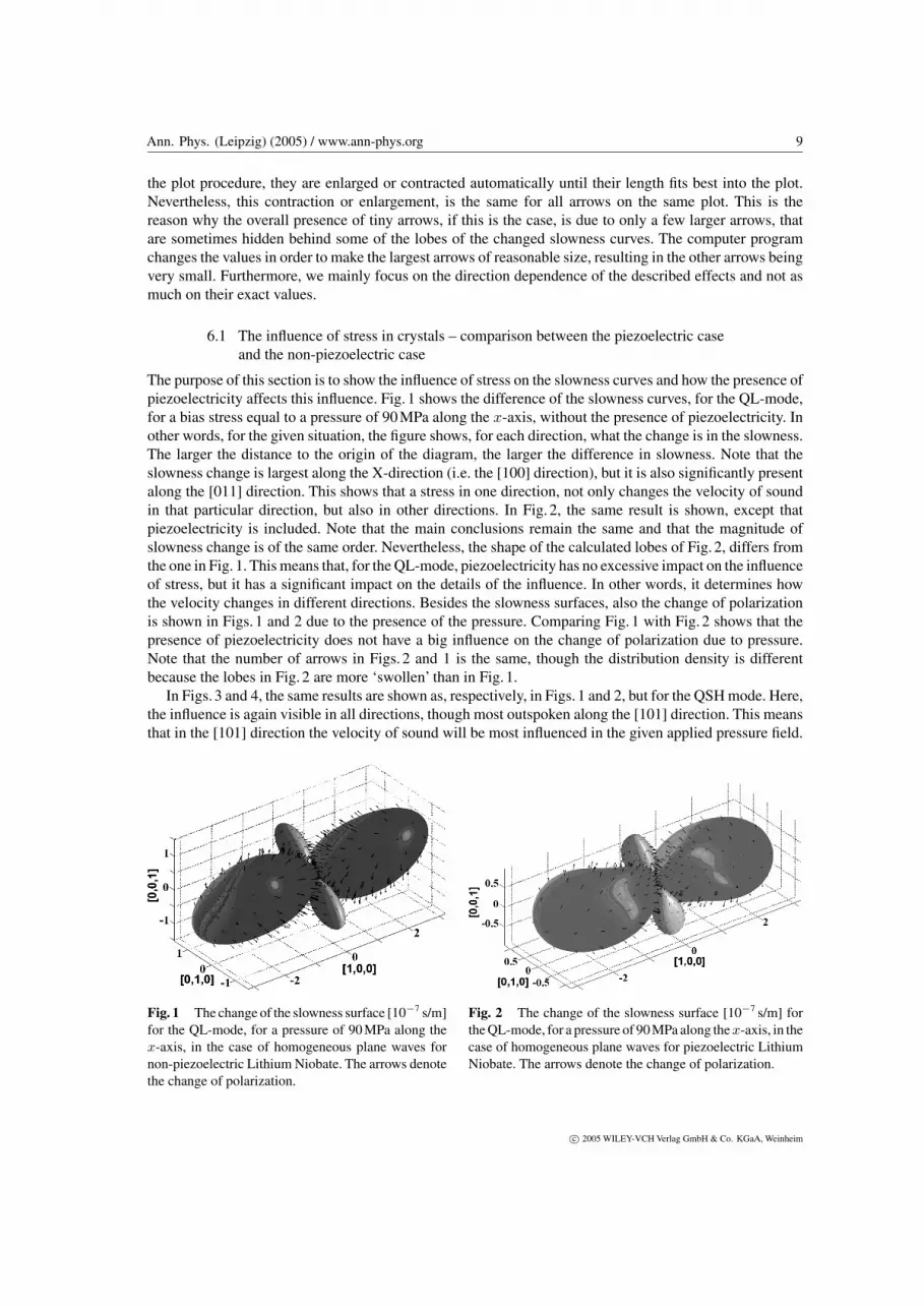
The purpose of this section is to show the influence of stress on the slowness curves and how the presence ofpiezoelectricity affects this influence. Fig. 1 shows the difference of the slowness curves, for the QL-mode,for a bias stress equal to a pressure of 90 MPa along the x-axis, without the presence of piezoelectricity. Inother words, for the given situation, the figure shows, for each direction, what the change is in the slowness.The larger the distance to the origin of the diagram, the larger the difference in slowness. Note that theslowness change is largest along the X-direction (i.e. the [100] direction), but it is also significantly presentalong the [011] direction. This shows that a stress in one direction, not only changes the velocity of soundin that particular direction, but also in other directions. In Fig. 2, the same result is shown, except thatpiezoelectricity is included. Note that the main conclusions remain the same and that the magnitude ofslowness change is of the same order. Nevertheless, the shape of the calculated lobes of Fig. 2, differs fromthe one in Fig. 1. This means that, for the QL-mode, piezoelectricity has no excessive impact on the influenceof stress, but it has a significant impact on the details of the influence. In other words, it determines howthe velocity changes in different directions. Besides the slowness surfaces, also the change of polarizationis shown in Figs. 1 and 2 due to the presence of the pressure. Comparing Fig. 1 with Fig. 2 shows that thepresence of piezoelectricity does not have a big influence on the change of polarization due to pressure.Note that the number of arrows in Figs. 2 and 1 is the same, though the distribution density is differentbecause the lobes in Fig. 2 are more ‘swollen’ than in Fig. 1.
In Figs. 3 and 4, the same results are shown as, respectively, in Figs. 1 and 2, but for the QSH mode. Here,the influence is again visible in all directions, though most outspoken along the [101] direction. This meansthat in the [101] direction the velocity of sound will be most influenced in the given applied pressure field.
Fig. 1 The change of the slowness surface [10−7 s/m]for the QL-mode, for a pressure of 90 MPa along thex-axis, in the case of homogeneous plane waves fornon-piezoelectric Lithium Niobate. The arrows denotethe change of polarization.
Fig. 2 The change of the slowness surface [10−7 s/m] forthe QL-mode, for a pressure of 90 MPa along the x-axis, in thecase of homogeneous plane waves for piezoelectric LithiumNiobate. The arrows denote the change of polarization.
c© 2005 WILEY-VCH Verlag GmbH & Co. KGaA, Weinheim

10 N.F. Declercq et al.: Sound in biased piezoelectric materials of general anisotropy
Fig. 3 The change of the slowness surface[10−7 s/m] for the QSH-mode, for a pressure of90 MPa along the x-axis, in the case of homogeneousplane waves for non-piezoelectric Lithium Niobate.The arrows denote the change of energy flux.
Fig. 4 The change of the slowness surface[10−7 s/m] for the QSH-mode, for a pressure of90 MPa along the x-axis, in the case of homogeneousplane waves for piezoelectric Lithium Niobate. Thearrows denote the change of energy flux.
The different behavior of the QSH-mode, compared to the QL-mode, is of course due to the difference inpolarization between the two modes. Inasmuch as piezoelectricity had only a minor impact on the behaviorof the QL-mode, Figs. 3 and 4 show that piezoelectricity has a major impact on the change of the slownesssurface of the QSH mode, not so much in the magnitude, but very much in the directional dependence ofthe effect.
Whereas the change of polarization was depicted as arrows in Figs. 1 and 2, the change of the real part ofthe Poynting vector is depicted as arrows in Figs. 3 and 4. Only in a few directions is the change of energyflow much larger than in the overall directions. This is the reason for the apparent very small arrows on thefigures.
Figs. 5 and 6 again correspond to, respectively, Figs. 1 and 2, but for the QSV-mode. The influence ofpressure is again very different for this mode. Furthermore, the effect of piezoelectricity is more outspokenin magnitude than for the other modes. The arrows denote the change of polarization, just as in Figs. 1 and 2.Note again that only in a very few directions, the change is significantly larger than in the overall directions,which is once more the reason for the apparent very small arrows on the figures.
In the next sections, no arrows are depicted anymore on the slowness surfaces and only the slownesssurfaces themselves are considered.
6.2 The influence of the inhomogeneity on the effect of stress in crystalsfor the piezoelectric case and the non-piezoelectric case
In this section, we are mainly interested in the cases of previous section, though in the presence of aninhomogeneity of the considered sound waves. For simplicity, we limit the discourse to a parameter ofimaginariness b = 60/140. Fig. 7 corresponds to Fig. 1, i.e. the QL-mode, in the absence of piezoelectricity,though for b = 60/140. It is seen that the change of the slowness surface is again largest along the Xdirection and along the [011] direction. But the effect is much stronger along the [011] direction than in thecase of homogeneous plane waves of Fig. 1. In Fig. 8, piezoelectricity is involved and the result is a verystrong direction dependence of the slowness change.
c© 2005 WILEY-VCH Verlag GmbH & Co. KGaA, Weinheim

Ann. Phys. (Leipzig) (2005) / www.ann-phys.org 11
Fig. 5 The change of the slowness surface[10−7 s/m] for the QSV-mode, for a pressure of90 MPa along the x-axis, in the case of homogeneousplane waves for non-piezoelectric Lithium Niobate.
Fig. 6 The change of the slowness surface[10−7 s/m] for the QSV-mode, for a pressure of90 MPa along the x-axis, in the case of homogeneousplane waves for piezoelectric Lithium Niobate.
Fig. 7 The change of the slowness surface [10−7 s/m] forthe QL-mode, for a pressure of 90 MPa along the x-axis,in the case of inhomogeneous plane waves (b=60/140) fornon-piezoelectric Lithium Niobate.
Fig. 8 The change of the slowness surface [10−7 s/m] forthe QL-mode, for a pressure of 90 MPa along the x-axis,in the case of inhomogeneous plane waves (b=60/140) forpiezoelectric Lithium Niobate.
In Figs. 9 and 10, again inhomogeneous waves are considered with b = 60/140, for the QSH-mode andmust be compared to Fig. 3, respectively Fig. 4. The overall effect is of the same order of magnitude asfor homogeneous plane waves in Figs. 3 and 4, though in some directions, a much larger effect is visible.Also the shape of the surfaces without (Fig. 9) or with (Fig. 10) piezoelectricity involved, is very different.A significant difference between the slowness curves without or with piezoelectricity, was visible for theQSV-mode in Fig. 5, respectively Fig. 6. Again a significant difference is visible for inhomogeneous wavesin Fig. 11, respectively Fig. 12.
c© 2005 WILEY-VCH Verlag GmbH & Co. KGaA, Weinheim

12 N.F. Declercq et al.: Sound in biased piezoelectric materials of general anisotropy
Fig. 9 The change of the slowness surface[10−7 s/m] for the QL-mode, for a pressure of90 MPa along the x-axis, in the case of inhomoge-neous plane waves (b=60/140) for non-piezoelectricLithium Niobate.
Fig. 10 The change of the slowness surface[10−7 s/m] for the QL-mode, for a pressure of90 MPa along the x-axis, in the case of inhomo-geneous plane waves (b=60/140) for piezoelectricLithium Niobate.
Fig. 11 The change of the slowness surface [10−7 s/m] forthe QL-mode, for a pressure of 90 MPa along the x-axis, inthe case of inhomogeneous plane waves (b=60/140) for non-piezoelectric Lithium Niobate.
Fig. 12 The change of the slowness surface[10−7 s/m] for the QL-mode, for a pressure of 90 MPaalong the x-axis, in the case of inhomogeneous planewaves (b=60/140) for piezoelectric Lithium Niobate.
6.3 The influence of the magnitude and the direction of stress in crystals
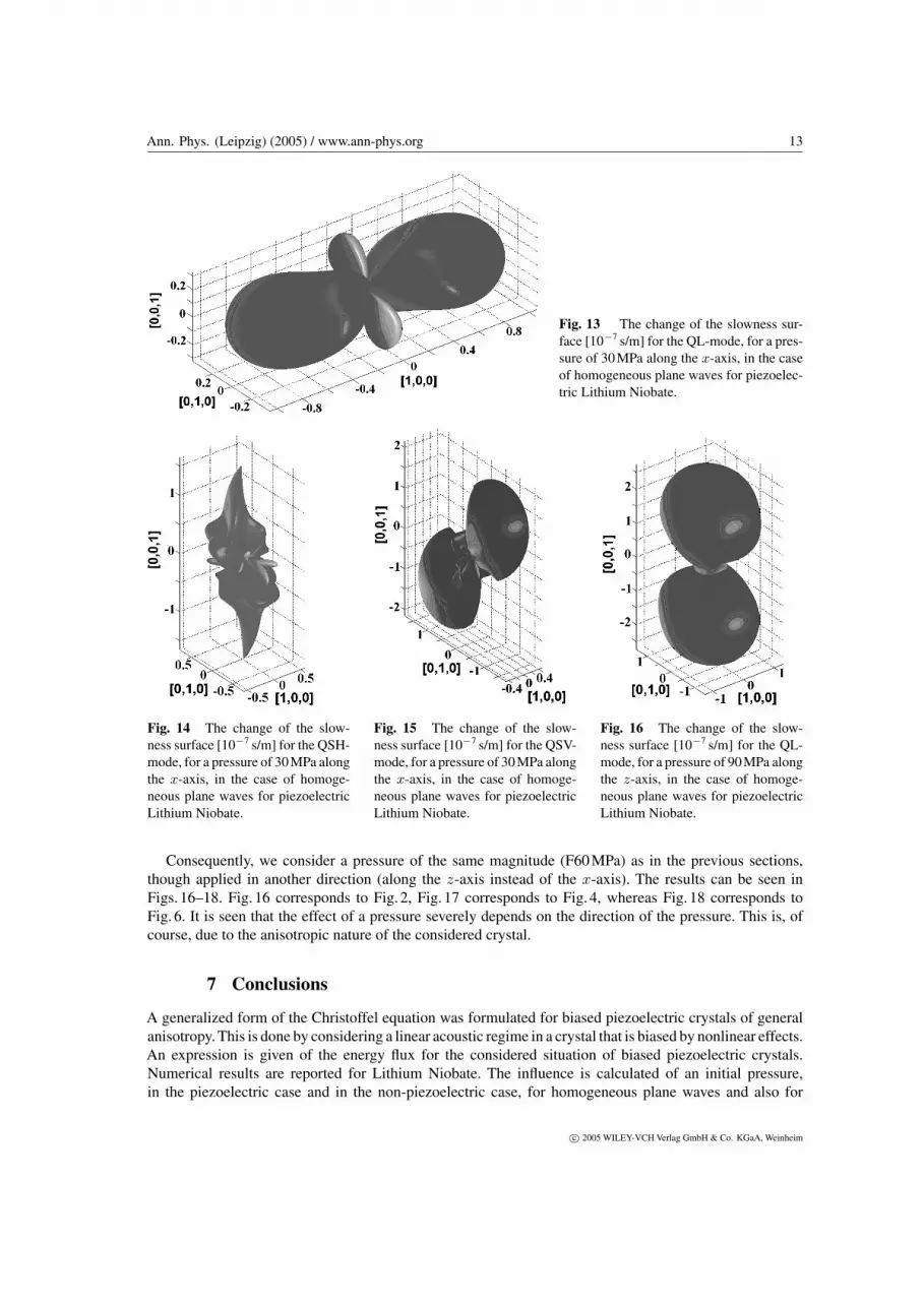
In this section, we limit the discourse to the case where piezoelectricity is involved. Contrary to the last twosections, here, different magnitudes of pressure are considered (instead of only 90 MPa), as well as differentdirections (instead of only the X-direction). In Figs. 13–15, a pressure is considered along the X-direction,of 30 MPa. Fig. 13 corresponds to Fig. 2, Fig. 14 corresponds to Fig. 4, whereas Fig. 15 corresponds to Fig. 6.Note that the shape of the alteration of the slowness curves is essentially equal for the different magnitudeof pressure, though the magnitude of the alteration is different. This means that the directional dependenceof the effect of an applied pressure, is not influenced by the magnitude of that pressure. Only the extent ofthe effect depends on the magnitude of the applied pressure.
c© 2005 WILEY-VCH Verlag GmbH & Co. KGaA, Weinheim
Ann. Phys. (Leipzig) (2005) / www.ann-phys.org 13
Fig. 13 The change of the slowness sur-face [10−7 s/m] for the QL-mode, for a pres-sure of 30 MPa along the x-axis, in the caseof homogeneous plane waves for piezoelec-tric Lithium Niobate.
Fig. 14 The change of the slow-ness surface [10−7 s/m] for the QSH-mode, for a pressure of 30 MPa alongthe x-axis, in the case of homoge-neous plane waves for piezoelectricLithium Niobate.
Fig. 15 The change of the slow-ness surface [10−7 s/m] for the QSV-mode, for a pressure of 30 MPa alongthe x-axis, in the case of homoge-neous plane waves for piezoelectricLithium Niobate.
Fig. 16 The change of the slow-ness surface [10−7 s/m] for the QL-mode, for a pressure of 90 MPa alongthe z-axis, in the case of homoge-neous plane waves for piezoelectricLithium Niobate.
Consequently, we consider a pressure of the same magnitude (F60 MPa) as in the previous sections,though applied in another direction (along the z-axis instead of the x-axis). The results can be seen inFigs. 16–18. Fig. 16 corresponds to Fig. 2, Fig. 17 corresponds to Fig. 4, whereas Fig. 18 corresponds toFig. 6. It is seen that the effect of a pressure severely depends on the direction of the pressure. This is, ofcourse, due to the anisotropic nature of the considered crystal.
7 Conclusions
A generalized form of the Christoffel equation was formulated for biased piezoelectric crystals of generalanisotropy. This is done by considering a linear acoustic regime in a crystal that is biased by nonlinear effects.An expression is given of the energy flux for the considered situation of biased piezoelectric crystals.Numerical results are reported for Lithium Niobate. The influence is calculated of an initial pressure,in the piezoelectric case and in the non-piezoelectric case, for homogeneous plane waves and also for
c© 2005 WILEY-VCH Verlag GmbH & Co. KGaA, Weinheim

14 N.F. Declercq et al.: Sound in biased piezoelectric materials of general anisotropy
Fig. 17 The change of the slowness surface [10−7 s/m] forthe QSH-mode, for a pressure of 90 MPa along the z-axis,in the case of homogeneous plane waves for piezoelectricLithium Niobate.
Fig. 18 The change of the slowness surface[10−7 s/m] for the QSV-mode, for a pressureof 90 MPa along the z-axis, in the case ofhomogeneous plane waves for piezoelectricLithium Niobate.
inhomogeneous plane waves. Furthermore, the influence of the magnitude and the direction of the consideredpressure, on the change in the acoustic wave velocity, was studied as well.
Acknowledgements Nico F. Declercq is a postdoctoral fellow of the Fund for Scientific Research – Flanders(FWO – Vlaanderen)
Appendix A
This appendix describes the symmetry relations between the different material property constants. Therelations are calculated by a newly developed semi-automatic computer program that is able to handle anykind of symmetry relations and the results differ from the ones of [37, 38], where a trigonal 3m crystalis considered, instead of the trigonal 3m crystal of the current report. The developed computer programuncovered one misprint in the material property tables in [13].
The different relationships for the trigonal 3m point group are determined by the generators of the group,these are:
a ∈
− 12
√3
2 0
−√
32 − 1
2 00 0 1
,
−1 0 00 1 00 0 1
. (A1)
Any crystal having the trigonal 3m symmetry (for example Lithium Niobate) cannot have properties thatalter when any of the generators (A1) operate on it. Hence, all tensors describing the material properties ofthe crystal must remain unaffected by (A1).
The transformations are performed as:
cijkl = aipajqakralscpqrs , (A2)
εij = aipajqεpq with εki = εik , (A3)
ξijk = aipajqakrξpqr with ξkij = ξkji , (A4)
c© 2005 WILEY-VCH Verlag GmbH & Co. KGaA, Weinheim

Ann. Phys. (Leipzig) (2005) / www.ann-phys.org 15
γijklEj = aipajqakralsγpqrsEq with γkijl = γikjl = γkilj , (A5)
εijk = aipajqakrεpqr with εkij = εikj = εkji , (A6)
ξijklm = aipajqakralsamtξpqrst with ξkijml = ξkjiml = ξkijlm = ξkmlij , (A7)
cijklmn = aipajqakralsamtanvcpqrstv (A8)
with cijklmn = cjiklmn = cijlkmn = cijknm = cklijmn = cmnijkl = cijmnkl .
On the one hand, if we demand that the transformations (A2)–(A8) for the operators (A1) do not change thematerial constants, then we ultimately obtain, for Lithium Niobate the symmetry relations for the dependentmaterials constants, as listed below. On the other hand, the numerical values for the independent constantswere obtained from [13].
The independent second order elastic constants [×1010 N/m2] are:
C33 = 24.5 , C14 = 0.9 , C44 = 6.0 ,
C11 = 20.3 , C12 = 5.3 , C13 = 7.5 .(A9)
The calculated symmetry relations between the dependent and independent second order elastic con-stants are:
C15 = C16 = C25 = C26 = C35 = C36 = C45 = C46 = C34 = 0;
C56 = C14 , C24 = −C14 , C55 = C44 ,
C23 = C13 , C22 = C11 , C66 = −C12/2 + C11/2 .
(A10)
The independent third order elastic constants [×1011 N/m2] are:
C333 = −29.6 , C111 = −21.2 , C222 = −23.3 , C112 = −5.3 ,
C113 = −5.7 , C114 = 2.0 , C123 = −2.5 , C124 = 0.4 ,
C133 = −7.8 , C134 = 1.5 , C144 = −3.00 , C155 = −6.7 ,
C344 = −6.8 , C444 = −0.3 .
(A11)
The calculated symmetry relations between the dependent and independent third order elastic constants are:
C236 = C336 = C334 = C115 = C116 = C566 = C666 = C346 = C345 = C445 = C446
= C226 = C335 = C145 = C135 = C245 = C136 = C246 = C225 = C146 = C235
= C125 = C126 = C556 = C555 = 0 ,
C233 = C133 , C255 = C144 , C356 = C134 , C234 = −C134 , C223 = C113 ,
C244 = C155 , C355 = C344 , C455 = −C444 , C466 = C124 ,
C266 = −C112/4 + C111/2 − C222/4 , C456 = C155/2 − C144/2 ,
C366 = −C123/2 + C113/2 , C224 = −2C124 − C114 ,
C156 = C114/2 + 3C124/2 , C256 = −C124/2 + C114/2 ,
C166 = −C111/2 − C112/4 + 3C222/4 , C122 = C111 + C112 − C222 ,
(A12)
The independent second order piezoelectric constants [C/m2] are:
ξ31 = 0.2 , ξ22 = 2.5 , ξ15 = 3.7 , ξ33 = 1.3 . (A13)
c© 2005 WILEY-VCH Verlag GmbH & Co. KGaA, Weinheim

16 N.F. Declercq et al.: Sound in biased piezoelectric materials of general anisotropy
The calculated symmetry relations between the dependent and independent second order piezoelectricconstants are:
ξ34 = ξ23 = ξ25 = ξ26 = ξ35 = ξ36 = ξ11 = ξ12 = ξ14 = ξ13 = 0 ,
ξ32 = ξ31 , ξ16 = −ξ22 , ξ21 = −ξ22 , ξ24 = ξ15 ,(A14)
The independent second order piezoelectric constants [C/m2] are:
ξ115 = 17.1 , ξ116 = −4.7 , ξ125 = 19.9 , ξ126 = 15.9 , ξ135 = 19.6 ,
ξ136 = −0.9 , ξ145 = 20.3 , ξ311 = 14.7 , ξ312 = 13.0 ,
ξ313 = −10.0 , ξ314 = 11.0 , ξ333 = −17.3 , ξ344 = −10.2 .
(A15)
The calculated symmetry relations between the dependent and independent third order piezoelectric con-stants are:
ξ346 = ξ245 = ξ246 = ξ334 = ξ122 = ξ233 = ξ134 = ξ235 = ξ144 = ξ316 = ξ315 = ξ133
= ξ124 = ξ111 = ξ112 = ξ113 = ξ114 = ξ326 = ξ216 = ξ215 = ξ345 = ξ155 = ξ336
= ξ123 = ξ325 = ξ226 = ξ225 = ξ236 = ξ166 = ξ156 = ξ335 = 0 ,
ξ255 = ξ145 , ξ214 = ξ125 , ξ244 = −ξ145 , ξ234 = ξ135 ,
ξ323 = ξ313 , ξ324 = −ξ314 , ξ356 = ξ314 , ξ213 = ξ136 ,
ξ223 = −ξ136 , ξ224 = ξ115 , ξ355 = ξ344 , ξ322 = ξ311 ,
(A16)
ξ146 = ξ115/2 − ξ125/2 , ξ366 = −ξ312/2 + ξ311/2 , ξ266 = −ξ126/2 + ξ116/2 ,
ξ222 = −3ξ116/2 − ξ126/2 , ξ211 = 3ξ126/2 + ξ116/2 , ξ256 = ξ115/2 − ξ125/2 ,
ξ212 = −ξ126/2 + ξ116/2 .
The second order independent dielectric constants [10−12 F/m] are:
ε1 = 389 , ε3 = 257 . , (A17)
The calculated symmetry relations between the dependent and independent second order independent di-electric constants are:
ε2 = ε1 , ε4 = ε5 = ε6 = 0 . (A18)
The third order independent dielectric constants [10−19 F/m]:
ε15 = −2.81 , ε22 = −2.40 , ε33 = −2.91 . (A19)
The calculated symmetry relations between the dependent and independent third order independent dielectricconstants :
ε11 = ε12 = ε13 = ε23 = ε14 = 0 , ε24 = ε15 , ε16 = −ε22 . (A20)
The electrostrictive constants [10−9 F/m] are:
γ11 = 1.11 , γ12 = 2.19 , γ13 = 2.32 , γ14 = 1.51 ,
γ31 = 0.19 , γ33 = −2.76 , γ41 = 1.85 , γ44 = −1.83 .(A21)
c© 2005 WILEY-VCH Verlag GmbH & Co. KGaA, Weinheim

Ann. Phys. (Leipzig) (2005) / www.ann-phys.org 17
The calculated symmetry relations between the dependent and independent electrostrictive constants:
γ35 = γ36 = γ52 = γ25 = γ61 = γ16 = γ26 = γ34 = γ15 = γ53 = γ54 = γ51 = γ63
= γ64 = γ62 = γ43 = γ45 = γ46 = 0 ,
γ32 = γ31 , γ65 = γ14 , γ42 = −γ41 , γ56 = γ41 , γ22 = γ11 ,
γ23 = γ13 , γ55 = γ44 , γ24 = −γ14 , γ21 = γ12 , γ66 = γ11/2 − γ12/2 .
(A22)
Appendix B
This appendix presents the expressions for Ωnp, Znpqr, Ynpqrst, and Xnpqrstvw as a function of the stressdependent material constants c∗
ijkl, ξ∗mij and ε∗
mn of (12)–(21).
In the formulas below, for notational simplicity, the superscript ‘*’ has been neglected in the materialconstants. Also the superscript ‘0’ has been neglected in the stress tensor components.
Xnpstvwxz = εvwσz,x
− c1n2pc1s2t − c1n3pc1s3t + c2s2tc3p3n + c1n1pc2s2t + c1n1pc3t3s − c2n3pc2s3t
+ σpn
(c3t3s + c2s2t + c1t1s
)
+εvw
σpnσtsσzx + 2c1n2pc1s3tc2x3z − c2n3pc2s3tc1x1z − c1n3pc1s3tc2x2z
+ c1n1pc2s2tc3x3z − c1n2pc1s2tc3x3z
+ 2c1n2pc1s3tξz2xξvw3 − c1n3pξt1sξvw3c2x2z + 2c1n2pξt1sξvw3c2x3z
− c2n3pξt2sξvw3c1x1z − c2n3pc2s3tξz1xξvw1 − c1n2pc1s2tξz3xξvw3 + c1n1pc2s2tξz3xξvw3
− c1n3pc1s3tξz2xξvw2 + c1n1pξt2sξvw2c3x3z − c1n2pξt1sξvw2c3x3z + 2ξp1nξvw2c1s3tc2x3z
− ξp1nξvw2c1s2tc3x3z + ξp1nξvw1c2s2tc3x3z − ξp1nξvw3c1s3tc2x2z − ξp2nξvw3c2s3tc1x1z
+ σpnσtsξz3xξvw3 + σpnξt2sξvw2σzx + ξp1nξvw1σtsσzx + σpnc2s2tξz3xξvw3
+ c1n1pσtsξz3xξvw3 + σpnξt2sξvw2c3x3z − c1n3pξt1sξvw3σzx + c1n1pξt2sξvw2σzx
− c1n2pξt1sξvw2σzx − c2n3pξt2sξvw3σzx − ξp1nξvw3c1s3tσzx − ξp1nξvw2c1s2tσzx
+ ξp1nξvw1c2s2tσzx − ξp2nξvw3c2s3tσzx + ξp1nξvw1σtsc3x3z , (B1)
Ynpstvw = −ρω2εvw
2σpnc3s3t + σpnc2s2t + c2n2pσts + 2c1n1pσt,s + c2n2pc3s3t
+ c1n1pc3s3t + c1n1pc2s2t − c1n3pc1s3t − c1n2pc1s2t − c2n3pc2s3t + 3σpnσts
−ρω22σpnξt3sξvw3 + σpnξt2sξvw2 + ξp2nξvw2σts + 2ξp1nξvw1σts
+ c1n1pξt3sξvw3 + c2n2pξt3sξvw3 − c1n3pξt1sξvw3 + c1n1pξt2sξvw2
− c1n2pξt1sξvw2 − c2n3pξt2sξvw3 + ξp2nξvw2c3s3t + ξp1nξvw1c3s3t
− ξp1nξvw3c1s3t − ξp1nξvw2c1s2t − ξp2nξvw3c2s3t + ξp1nξvw1c2s2t
, (B2)
Znpst = ρ2ω4εst
(c1n1p + 3σpn + c2n2p + c3n3p
)+ ρ2ω4(ξp1nξst1 + ξp2nξst2 + ξp3nξst3
), (B3)
Ωvw = −εvwρ3ω6 . (B4)
c© 2005 WILEY-VCH Verlag GmbH & Co. KGaA, Weinheim

18 N.F. Declercq et al.: Sound in biased piezoelectric materials of general anisotropy
References
[1] M. Pluta, A. G. Every, and W. Grill, Ultrasonics 42(F1–9), 243–248 (2004).[2] J. Degrieck, N. F. Declercq, and O. Leroy, Insight, Non-Destr. Test. Cond. Monit. (UK) 45(F3), 196–201 (2003).[3] N. F. Declercq, J. Degrieck, and O. Leroy, Ultrasonics 42, 173–177 (2004).[4] N. F. Declercq, J. Degrieck, and O. Leroy, to appear in NDT&E Int. (UK).[5] J. F. Nye, Physical Properties of Crystals – Their Representation by Tensors and Matrices (Oxford Science
Publications, New York, 1985).[6] B.A. Auld, Acoustic fields and waves in solids, volume I, second edition (Krieger, Florida, 1989).[7] M. J. P. Musgrave, Crystal Acoustics: Introduction to the Study of Elastic Waves and Vibrations in Crystals
(Holden-Day, California, 1970).[8] A. D. Degtyar, W. Huang, and S. I. Rokhlin, J. Acoust. Soc. Am. 104(F4), 2192–2003 (1998).[9] A. D. Degtyar and S. I. Rokhlin, J. Acoust. Soc. Am. 104(F4), 1992–2003 (1998).
[10] J. Friend and K. Nakamura, IEEE/ASME Trans. Mechatronics 9(F3), 467–473 (2004).[11] C. H. Yun, T. Hasegawa, K. Nakamura, and S. Ueha, Jpn. J. Appl. Phys. 1, Regul. Pap. Short Notes (Japan)
43(F5B), 2864–2868 (2004).[12] J. Friend, K. Nakamura, and S. Ueha, Jpn. J. Appl. Phys. 1, Regul. Pap. Short Notes (Japan) 43(F5B), 3040–3044
(2004).[13] H. Liu, Z. B. Kuang, and Z. M. Cai, Ultrasonics 41, 397–405 (2003).[14] M.A. Breazeale, I.V. Ostrovskii, and M. S. McPherson, J. Appl. Phys. 96(F5), 2990–2994 (2004).[15] M. S. McPherson, I. Ostrovskii, and M.A. Breazeale, Phys. Rev. Lett. 89(F11), art no 115506 (2002).[16] A. H. Nayfeh, Wave Propagation in Layered Anisotropic Media (North Holland, Elsevier, Amsterdam, 1995).[17] G. Maugin, Nonlinear Waves in Elastic Crystals (Oxford Science Publications, New York, 1999).[18] A. D. Degtyar and S. I. Rokhlin, J. Appl. Phys. 78(F3), 1547–1556 (1995).[19] A. S. Man and W.Y. Lu, J. Elast. 17, 159–182 (1987).[20] B.A. Auld, Acoustic Fields and Waves in Solids, Vol. II, 2nd ed. (Krieger, Florida, 1989).[21] A. Darinskii, Private communication, Institute of Crystallography, Russian Academy of Sciences, Leninsky
pr. 59, Moscow, 119333, Russia.[22] B. D. Zaitsev and I. E. Kuznetsova, IEEE Trans. Ultrason. Ferroelectr. Freq. Control (USA) 50(F12), 1762–1765
(2003).[23] V. B. Voloshinov, Ultrasonics 31(5), 333–338 (1993).[24] N.V. Polikarpova and V. B. Voloshinov, Acust., Acta Acust. (Germany) 89, 930–935 (2003).[25] N. F. Declercq, R. Briers, J. Degrieck, and O. Leroy, IEEE Trans. Ultrason. Ferroelectr. Freq. Control (USA)
52(F5), 776–791 (2005).[26] N. F. Declercq, J. Degrieck, and O. Leroy, J. Acoust. Soc. Am. 116(F1), 51–60 (2004).[27] M. Hayes, Arch. Ration. Mech. Anal. 85, 41–79 (1984).[28] S. I. Rokhlin, T. K. Bolland, and L. Adler, J. Acoust. Soc. Am. 79(F4), 906–918 (1986).[29] B. Hosten, M. Deschamps, and B. R. Tittmann, J. Acoust. Soc. Am. 82(F5), 1763–1770 (1987).[30] B. Hosten, Ultrasonics 29, 445–450 (1991).[31] M. Deschamps and B. Hosten, J. Acoust. Soc. Am. 91(F4), 2007–2015 (1992).[32] P. Lanceleur, H. Ribeiro, and J.-F. De Belleval, J. Acoust. Soc. Am. 93(F4), 1882–1892 (1993).[33] M. Deschamps and F. Assouline, Acust., Acta Acust. (Germany) 86, 295–302 (2000).[34] B. Roge, Reflexion/transmission d’une onde plane inhomogene incidente sur une interface plane separant deux
milieux anisotropes, Thesis, Universite de Technologie de Compiegne, France (1999).[35] P. Boulanger and M. Hayes, Z. Angew. Math. Phys. 51(F6), 1031–1038 (2000).[36] M. Deschamps and O. Poncelet, Ultrasonics 40, 293–296 (2002).[37] R. F. S. Hearmon, Acta Crystallogr. 6, 331–340 (1953).[38] R. F. S. Hearmon, Acta Crystallogr. 10, 121–124 (1957).
c© 2005 WILEY-VCH Verlag GmbH & Co. KGaA, Weinheim