sma features - comar fluid power
TRANSCRIPT

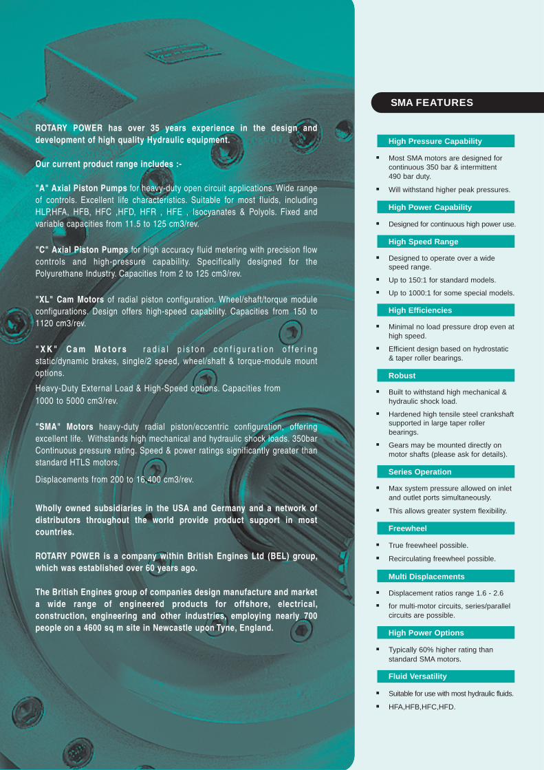
ROTARY POWER has over 35 years experience in the design anddevelopment of high quality Hydraulic equipment.
Our current product range includes :-
"A" Axial Piston Pumps for heavy-duty open circuit applications. Wide rangeof controls. Excellent life characteristics. Suitable for most fluids, includingHLP,HFA, HFB, HFC ,HFD, HFR , HFE , Isocyanates & Polyols. Fixed andvariable capacities from 11.5 to 125 cm3/rev.
"C" Axial Piston Pumps for high accuracy fluid metering with precision flowcontrols and high-pressure capability. Specifically designed for thePolyurethane Industry. Capacities from 2 to 125 cm3/rev.
"XL" Cam Motors of radial piston configuration. Wheel/shaft/torque moduleconfigurations. Design offers high-speed capability. Capacities from 150 to1120 cm3/rev.
" XK " C am Mo t o r s r a d i a l p i s t o n c o n f i g u r a t i o n o f f e r i n gstatic/dynamic brakes, single/2 speed, wheel/shaft & torque-module mountoptions.
Heavy-Duty External Load & High-Speed options. Capacities from1000 to 5000 cm3/rev.
"SMA" Motors heavy-duty radial piston/eccentric configuration, offeringexcellent life. Withstands high mechanical and hydraulic shock loads. 350barContinuous pressure rating. Speed & power ratings significantly greater thanstandard HTLS motors.
Displacements from 200 to 16,400 cm3/rev.
Wholly owned subsidiaries in the USA and Germany and a network ofdistributors throughout the world provide product support in mostcountries.
ROTARY POWER is a company within British Engines Ltd (BEL) group,which was established over 60 years ago.
The British Engines group of companies design manufacture and marketa wide range of engineered products for offshore, electrical,construction, engineering and other industries, employing nearly 700people on a 4600 sq m site in Newcastle upon Tyne, England.
SMA FEATURES
� Most SMA motors are designed forcontinuous 350 bar & intermittent490 bar duty.
� Will withstand higher peak pressures.
� Designed for continuous high power use.
� Designed to operate over a widespeed range.
� Up to 150:1 for standard models.
� Up to 1000:1 for some special models.
� Minimal no load pressure drop even athigh speed.
� Efficient design based on hydrostatic& taper roller bearings.
� Built to withstand high mechanical &hydraulic shock load.
� Hardened high tensile steel crankshaftsupported in large taper rollerbearings.
� Gears may be mounted directly onmotor shafts (please ask for details).
� Max system pressure allowed on inletand outlet ports simultaneously.
� This allows greater system flexibility.
� True freewheel possible.
� Recirculating freewheel possible.
� Displacement ratios range 1.6 - 2.6
� for multi-motor circuits, series/parallelcircuits are possible.
� Typically 60% higher rating thanstandard SMA motors.
� Suitable for use with most hydraulic fluids.
� HFA,HFB,HFC,HFD.
High Effic ienc ies
Fluid Versatil ity
High Power Opt ions
Mult i Displacements
Freewheel
Series Operation
Robust
High Power Capabil ity
High Speed Range
High Pressure Capabil ity
S M A R A D I A L P I S T O N M O T O R S
1
PAGE CONTENTS
2 DESCRIPTION OF OPERATION
3 CONFIGURATIONS
4 MOTOR SELECTION
5 SMA ORDER CODES
5 MOTOR OPTIONS
6 DIMENSIONAL DATA - ROTATING SHAFT C1 / T1
7 TECHNICAL DATA - ROTATING SHAFT C1 / T1
8 INSTALLATION DATA - TORQUE ARM MOUNT ROTATING SHAFT MOTOR V1
9 TECHNICAL DATA - TORQUE ARM MOUNT ROTATING SHAFT MOTOR V1
10 INSTALLATION DATA - ROTATING SHAFT, MULTI DISPLACEMENT MOTOR C2 / T2
11 TECHNICAL DATA - ROTATING SHAFT, MULTI DISPLACEMENT MOTOR C2
12 TECHNICAL DATA - ROTATING SHAFT, MULTI DISPLACEMENT MOTOR T2
13/16 INSTALLATION AND APPLICATION
17 COMMISSIONING AND SERVICE
INDEX
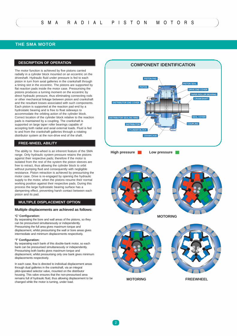
Multiple displacemen ts are achieved as follows:
‘C’ Configur ation:By separating the bore and wall areas of the pistons, so theycan be pressurised simultaneously or independently.Pressurising the full area gives maximum torque anddisplacement, whilst pressurising the wall or bore areas givesintermediate and minimum displacements respectively.
‘T’ Conf igur ation:By separating each bank of this double-bank motor, so eachbank can be pressurised simultaneously or independently.Pressurising both banks gives maximum torque anddisplacement, whilst pressurising only one bank gives minimumdisplacements respectively.
In each case, flow is directed to individual displacement areasthrough dual galleries in the crankshaft, via an integralpilot-operated selector valve, mounted on the distributorhousing. This valve ensures that the non-pressurised arearemains full of hydraulic fluid, thus allowing displacement to bechanged while the motor is turning, under load.
THE SMA MOTOR
S M A R A D I A L P I S T O N M O T O R S
2
DESCRIPTION OF OPERATION
The motor function is achieved by five pistons carriedradially in a cylinder block mounted on an eccentric on thedriveshaft. Hydraulic fluid under pressure is fed to eachpiston in turn from axial galleries in the crankshaft througha timing slot in the eccentric. The pistons are supported byflat reaction pads inside the motor case. Pressurising thepistons produces a turning moment on the eccentric bydirect hydraulic pressure, thus eliminating connecting rodsor other mechanical linkage between piston and crankshaftand the resultant losses associated with such components.Each piston is supported at the reaction pad end by ahydrostatic bearing and is free to float sideways toaccommodate the orbiting action of the cylinder block.Correct location of the cylinder block relative to the reactionpads is maintained by a coupling. The crankshaft issupported on large taper roller bearings capable ofaccepting both radial and axial external loads. Fluid is fedto and from the crankshaft galleries through a rotatingdistributor system at the non-drive end of the shaft.
FREE-WHEEL ABILIT Y
The ability to free-wheel is an inherent feature of the SMArange. Only hydraulic system pressure retains the pistonsagainst their respective pads; therefore if the motor isisolated from the rest of the system the piston sleeves arefree to retract, thus allowing the cylinder block to orbitwithout pumping fluid and consequently with negligibleresistance. Piston retraction is achieved by pressurising themotor case. Drive is re-engaged by opening the hydraulicsupply to the motor, when the pistons resume their normalworking position against their respective pads. During thisprocess the large hydrostatic bearing surface has adampening effect, preventing harsh contact between eachpiston and its pad.
MULTIPLE DISPLACEMENT OPTION
High pressu re Low pressure
MOTORING
MOTORING
FREEWHEEL
CRANKSHAFT
SEAL COVER
DRIVE END COVER
PISTON SEAL
COUPLING
CRANKCASE
CYLINDER BLOCK
DISTRIBUTOR
DISTRIBUTOR SEALING RING
DISTRIBUTOR END COVER
PISTON
PISTON PAD
TAPER ROLLER BEARING
COMPONENT IDENTIFICATION
CONFIGURATIONS
S M A R A D I A L P I S T O N M O T O R S
3
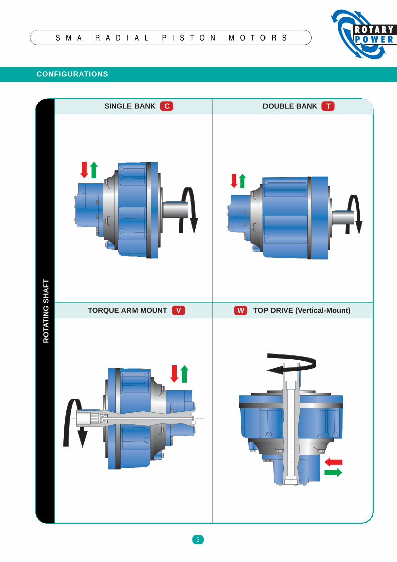
SINGLE BANK C DOUBLE BANK T
TORQUE ARM MOUNT V W TOP DRIVE (Vertical-Mount)
RO
TAT
ING
SH
AF
T
MOTOR SELECTION
S M A R A D I A L P I S T O N M O T O R S
4
CALCULA TIONS
00
100
125
120
115
110
105
130
95
90
85
80
75
70
65
60
55
50
45
40
35
30
25
20
15
10
5
100 200 300 400 500 600 700 800 900 1000 1100
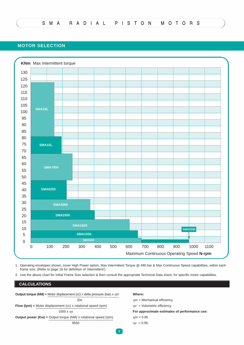
KNm Max Intermittent torque
Maximum Continuous Operating Speed N-rpm
SMA16L
SMA10L
SMA7000
SMA6250
SMA3500
SMA2500
SMA1600
SMA1000
SMA500
1. Operating envelopes shown, cover High Power option, Max Intermittent Torque @ 490 bar & Max Continuous Speed capabilities, within eachframe size. (Refer to page 16 for definition of ‘intermittent’)
2. Use the above chart for Initial Frame Size selection & then consult the appropriate Technical Data sheet, for specific motor capabilities.
Output torque (NM) = Motor displacement (cc) x delta pressure (bar) x ηm
20π
Flow (lpm) = Motor displacement (cc) x rotational speed (rpm)
1000 x ηv
Output power (Kw) = Output torque (NM) x rotational speed (rpm)
9550
Where:
ηm = Mechanical efficiency
ηv = Volumetric efficiency
For approximate estimates of performance use:
ηm = 0.95
ηv = 0.95.
SMA0350
SMA ORDER CODES
S M A R A D I A L P I S T O N M O T O R S
5
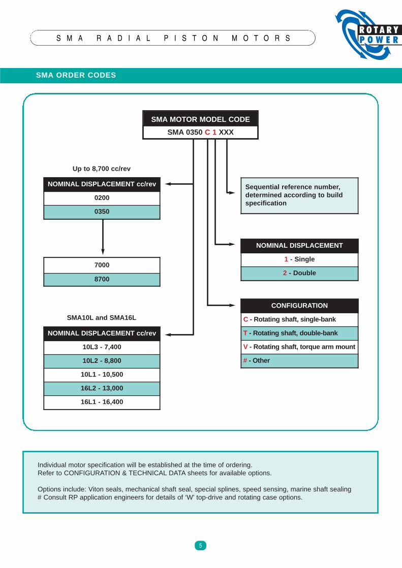
SMA MOTOR MODEL CODE
SMA 0350 C 1 XXX
NOMINAL DISPLACEMENT cc/re v
0200
0350
NOMINAL DISPLACEMENT
1 - Singl e
2 - Doubl e
Sequent ial reference number ,determined accordi ng to bui ldspeci fication
NOMINAL DISPLACEMENT cc/re v
10L3 - 7,400
10L2 - 8,800
10L1 - 10,500
16L2 - 13,000
16L1 - 16,400
CONFIGURATION
C - Rotating shaft, single-bank
T - Rotating shaft, double-bank
V - Rotating shaft, torque arm mount
# - Other
7000
8700
Individual motor specification will be established at the time of ordering.Refer to CONFIGURATION & TECHNICAL DATA sheets for available options.
Options include: Viton seals, mechanical shaft seal, special splines, speed sensing, marine shaft sealing# Consult RP application engineers for details of ‘W’ top-drive and rotating case options.
Up to 8,700 cc/ rev
SMA10L and SMA16L
DIMENSION DATA
S M A R A D I A L P I S T O N M O T O R S
6
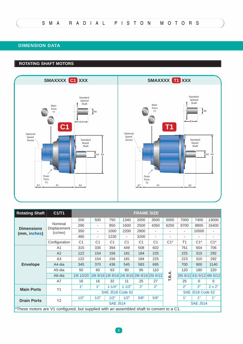
ROTATING SHAFT MOTORS
Rotat ing Shaft C1/T1 FRAME SIZE
Dimensi ons(mm, inches )
NominalDisplacement(cc/rev)
200 500 750 1340 2000 3500 5000 7000 7400 13000
290 - 850 1600 2500 4350 6250 8700 8800 16400
350 - 1000 2200 2800 - - - 10500 -
480 - 1230 - 3200 - - - - -
Configuration C1 C1 C1 C1 C1 C1 C1* T1 C1* C1*
Envelope
A1 315 335 394 449 508 602
T.B
.A.
761 604 706
A2 122 154 156 181 184 225 225 310 292
A3 122 154 156 181 184 225 223 310 292
A4-dia 345 370 436 545 583 695 700 900 1140
A5-dia 50 60 63 80 95 110 120 180 220
A6-dia 19t 10/20 18t 8/16 19t 8/16 24t 8/16 28t 8/16 25t 6/12 26t 6/12 41t 6/12 48t 6/12
A7 16 16 32 11 25 27 25 0 0
Main Ports Y11” 1” 1-1/4” 1 1/2” 2” 2” 2” 2” 2 x 2”
SAE J518 Code 62 SAE J518 Code 62
Drain Ports Y21/2” 1/2” 1/2” 1/2” 5/8” 5/8” 1” 1” 1”
SAE J514 SAE J514
*These motors are V1 configured, but supplied with an assembled shaft to convert to a C1.
SMAXXXX T1 XXXSMAXXXX C1 XXX
A4
A1 A2A7
A3
A6
A5
MainPorts
Y1
OptionalSpeedSensor
StandardSplined
Shaft
C1
DrainPorts
Y2
StandardKeyedShaft
C1
A4
A1 A2A7
A3
A6
A5
MainPorts
Y1
OptionalSpeedSensor
StandardSplined
Shaft
T1
DrainPorts
Y2
StandardKeyedShaft
T1
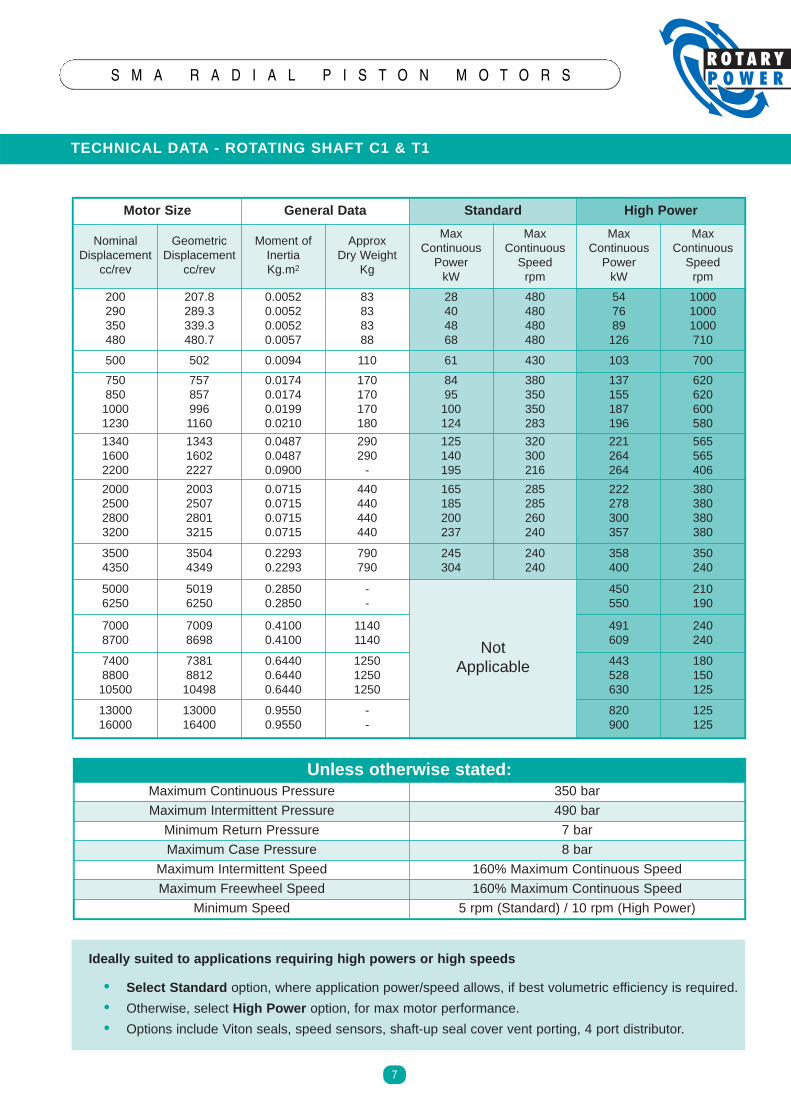
TECHNICAL DATA - ROTATING SHAFT C1 & T1
S M A R A D I A L P I S T O N M O T O R S
7
Motor Size General Data Standard High Power
NominalDisplacement
cc/rev
GeometricDisplacement
cc/rev
Moment ofInertiaKg.m2
ApproxDry Weight
Kg
MaxContinuousPowerkW
MaxContinuousSpeedrpm
MaxContinuousPowerkW
MaxContinuousSpeedrpm
200290350480
207.8289.3339.3480.7
0.00520.00520.00520.0057
83838388
28404868
480480480480
547689126
100010001000710
500 502 0.0094 110 61 430 103 700
75085010001230
7578579961160
0.01740.01740.01990.0210
170170170180
8495100124
380350350283
137155187196
620620600580
134016002200
134316022227
0.04870.04870.0900
290290-
125140195
320300216
221264264
565565406
2000250028003200
2003250728013215
0.07150.07150.07150.0715
440440440440
165185200237
285285260240
222278300357
380380380380
35004350
35044349
0.22930.2293
790790
245304
240240
358400
350240
50006250
50196250
0.28500.2850
--
NotApplicable
450550
210190
70008700
70098698
0.41000.4100
11401140
491609
240240
7400880010500
7381881210498
0.64400.64400.6440
125012501250
443528630
180150125
1300016000
1300016400
0.95500.9550
--
820900
125125
Unless otherwi se stated:Maximum Continuous Pressure 350 bar
Maximum Intermittent Pressure 490 bar
Minimum Return Pressure 7 bar
Maximum Case Pressure 8 bar
Maximum Intermittent Speed 160% Maximum Continuous Speed
Maximum Freewheel Speed 160% Maximum Continuous Speed
Minimum Speed 5 rpm (Standard) / 10 rpm (High Power)
Ideally sui ted to applicat ions requi ring high power s or high speeds
• Select Standar d option, where application power/speed allows, if best volumetric efficiency is required.
• Otherwise, select High Power option, for max motor performance.
• Options include Viton seals, speed sensors, shaft-up seal cover vent porting, 4 port distributor.
INSTALLA TION DATA
S M A R A D I A L P I S T O N M O T O R S
8
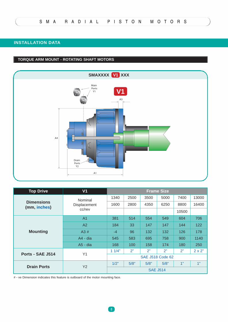
TORQUE ARM MOUNT - ROTATING SHAFT MOTORS
Top Drive V1 Frame Size
Dimensi ons(mm, inches)
NominalDisplacement
cc/rev
1340 2500 3500 5000 7400 13000
1600 2800 4350 6250 8800 16400
10500
Mounting
A1 381 514 554 549 604 706
A2 184 33 147 147 144 122
A3 # -4 96 132 132 126 178
A4 - dia 545 583 695 758 900 1140
A5 - dia 168 100 158 174 180 250
Ports - SAE J514 Y11 1/4” 2” 2” 2” 2” 2 x 2”
SAE J518 Code 62
Drain Ports Y21/2” 5/8” 5/8” 5/8” 1” 1”
SAE J514
SMAXXXX V1 XXX
# - ve Dimension indicates this feature is outboard of the motor mounting face.
V1MainPorts
Y1
DrainPorts
Y2
A4
A1
A3
V1
S M A R A D I A L P I S T O N M O T O R S
9
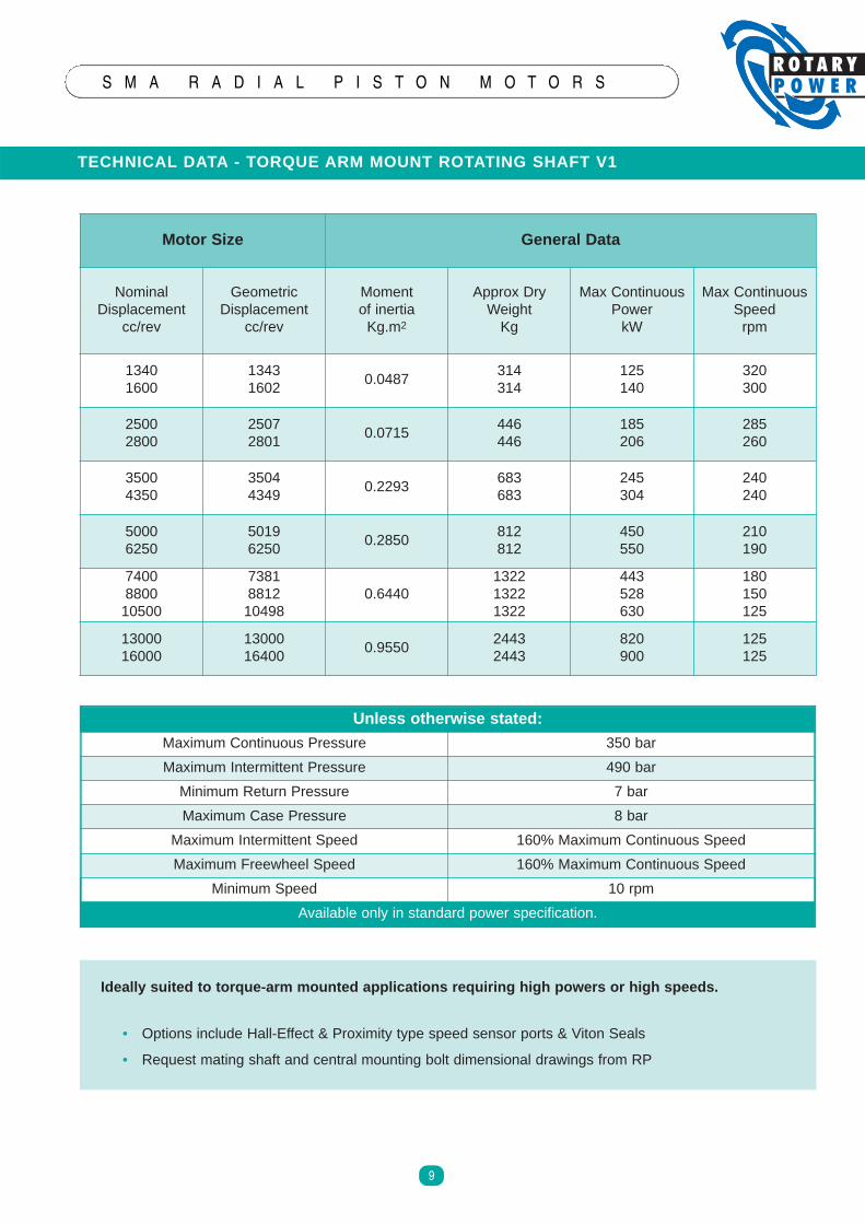
TECHNICAL DATA - TORQUE ARM MOUNT ROTATING SHAFT V1
Motor Size General Data
NominalDisplacement
cc/rev
GeometricDisplacement
cc/rev
Momentof inertiaKg.m2
Approx DryWeightKg
Max ContinuousPowerkW
Max ContinuousSpeedrpm
13401600
13431602
0.0487314314
125140
320300
25002800
25072801
0.0715446446
185206
285260
35004350
35044349
0.2293683683
245304
240240
50006250
50196250
0.2850812812
450550
210190
7400880010500
7381881210498
0.6440132213221322
443528630
180150125
1300016000
1300016400
0.955024432443
820900
125125
Ideally suite d to tor que-arm mount ed applica tions requiring high powers or high speeds.
• Options include Hall-Effect & Proximity type speed sensor ports & Viton Seals
• Request mating shaft and central mounting bolt dimensional drawings from RP
Unless other wise stated:
Maximum Continuous Pressure 350 bar
Maximum Intermittent Pressure 490 bar
Minimum Return Pressure 7 bar
Maximum Case Pressure 8 bar
Maximum Intermittent Speed 160% Maximum Continuous Speed
Maximum Freewheel Speed 160% Maximum Continuous Speed
Minimum Speed 10 rpm
Available only in standard power specification.
INSTALLA TION DATA
S M A R A D I A L P I S T O N M O T O R S
10
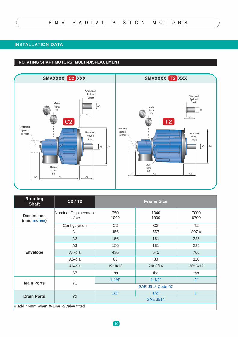
ROTATING SHAFT MOTORS: MULTI-DISPLACEMENT
SMAXXXX C2 XXX SMAXXXX T2 XXX
Rotatin gShaft
C2 / T2 Frame Size
Dimensi ons(mm, inches )
Nominal Displacementcc/rev
7501000
13401600
70008700
Configuration C2 C2 T2
Envelope
A1 456 557 807 #
A2 156 181 225
A3 156 181 225
A4-dia 436 545 700
A5-dia 63 80 110
A6-dia 19t 8/16 24t 8/16 26t 6/12
A7 tba tba tba
Main Ports Y11-1/4” 1-1/2” 2”
SAE J518 Code 62
Drain Ports Y21/2” 1/2” 1”
SAE J514
# add 46mm when X-Line R/Valve fitted
A1A7 A2
A4A5
A3
A6
C2
StandardSplined
Shaft
MainPorts
Y1
OptionalSpeedSensor
DrainPorts
Y2
StandardKeyedShaft
A1A7 A2
A4A5
A3
A6
T2
StandardSplined
Shaft
MainPorts
Y1
OptionalSpeedSensor
DrainPorts
Y2
StandardKeyedShaft
C2 T2
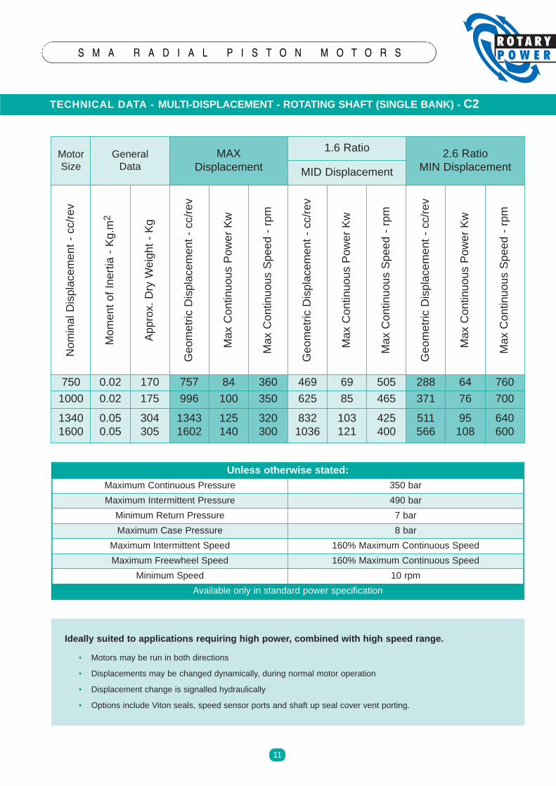
TECHNICAL DATA - MULTI-DISPLACEMENT - ROTATING SHAFT (SINGLE BANK) - C2
S M A R A D I A L P I S T O N M O T O R S
11
MotorSize
GeneralData
MAXDisplacement
1.6 Ratio 2.6 RatioMIN DisplacementMID Displacement
NominalDisplacement-cc/rev
MomentofInertia-Kg.m2
Approx.DryWeight-Kg
GeometricDisplacement-cc/rev
MaxContinuousPowerKw
MaxContinuousSpeed-rpm
GeometricDisplacement-cc/rev
MaxContinuousPowerKw
MaxContinuousSpeed-rpm
GeometricDisplacement-cc/rev
MaxContinuousPowerKw
MaxContinuousSpeed-rpm
750 0.02 170 757 84 360 469 69 505 288 64 760
1000 0.02 175 996 100 350 625 85 465 371 76 700
13401600
0.050.05
304305
13431602
125140
320300
8321036
103121
425400
511566
95108
640600
Ideally suite d to applica tions requiring high powe r, combined with high speed range .
• Motors may be run in both directions
• Displacements may be changed dynamically, during normal motor operation
• Displacement change is signalled hydraulically
• Options include Viton seals, speed sensor ports and shaft up seal cover vent porting.
Unless other wise stated:Maximum Continuous Pressure 350 bar
Maximum Intermittent Pressure 490 bar
Minimum Return Pressure 7 bar
Maximum Case Pressure 8 bar
Maximum Intermittent Speed 160% Maximum Continuous Speed
Maximum Freewheel Speed 160% Maximum Continuous Speed
Minimum Speed 10 rpm
Available only in standard power specification
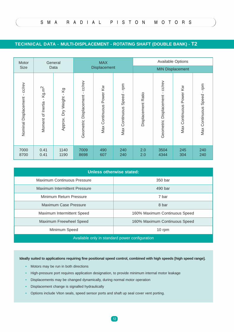
TECHNICAL DATA - MULTI-DISPLACEMENT - ROTATING SHAFT (DOUBLE BANK ) - T2
S M A R A D I A L P I S T O N M O T O R S
12
Ideally suited to applications requiri ng fine posi tional speed control, comb ined with high speeds [hi gh speed range].
• Motors may be run in both directions
• High-pressure port requires application designation, to provide minimum internal motor leakage
• Displacements may be changed dynamically, during normal motor operation
• Displacement change is signalled hydraulically
• Options include Viton seals, speed sensor ports and shaft up seal cover vent porting.
Unless oth erwise stated:
Maximum Continuous Pressure 350 bar
Maximum Intermittent Pressure 490 bar
Minimum Return Pressure 7 bar
Maximum Case Pressure 8 bar
Maximum Intermittent Speed 160% Maximum Continuous Speed
Maximum Freewheel Speed 160% Maximum Continuous Speed
Minimum Speed 10 rpm
Available only in standard power configuration
MotorSize
GeneralData
MAXDisplacement
Available Options
MIN Displacement
NominalDisplacement-cc/rev
MomentofInertia-Kg.m2
Approx.DryWeight-Kg
GeometricDisplacement-cc/rev
MaxContinuousPowerKw
MaxContinuousSpeed-rpm
DisplacementRatio
GeometricDisplacement-cc/rev
MaxContinuousPowerKw
MaxContinuousSpeed-rpm
70008700
0.410.41
11401190
70098698
490607
240240
2.02.0
35044344
245304
240240
S M A R A D I A L P I S T O N M O T O R S
13
MOTOR INSTALLATIO N AND APPLICATION
GENERAL
The following information is for general guidance only and it is recommended that individual applications arediscussed with Rotary Power.
Always examine the motor externally to check that damage has not occurred during transit. Ensure that the areasaround the protective plugs are clean and remove all protective coatings.
Do not remove protective plugs from the main ports and drain connections until system flushing is complete andimminent connection to the circuit is to be made.
MOUNTING
Install ation and motor specif icat ion available upon request
Case mountingProvision is made for locating the motor by means of a spigot diameter on the motor case. The motor should bemounted on a flat, machined face with a pilot diameter machined to the nominal spigot +0.025 to +0.075 mm.Clearance should be provided for the fillet radius between the motor spigot and mounting face. Fixing is by either 5or 10 mounting bolts, depending upon motor model. All fixing holes provided should be utilised. If heavy or frequenttorque reversals are anticipated, one or more of the attachment holes should be reamed in conjunction with themounting bracket and then bolts fitted.
Torque Arm MountingPlease consult Rotary Power for details.
Shaft detai ls C1/C2/T1/T2Two standard output shaft end options are available on the SMA motor range; cylindrical shaft with parallel key orBS involute side fit splined shaft.
Motor drive connections should be designed to eliminate unnecessary axial and radial loads and thus prolongbearing life. A cylindrical shaft is recommended for a flexible coupling output connection, and a splined shaft usedwhere the driven shaft is rigidly connected to the motor. Alignment of the two shafts should be maintained within 0.05mm TIR.
Splined shafts should be assembled using molybdenum grease, or preferably in an oil bath.
When using cylindrical shafts in applications where pressures are high or where reverse loadings or shock loads areexpected then the coupling should be shrunk onto the shaft to provide an interference fit. Note: hammering orpressing components onto the shaft may cause damage to the crankshaft bearings.
S M A R A D I A L P I S T O N M O T O R S
14
MOTOR INSTALLATI ON AND APPLICATION
CASE DRAINS
Rotating shaft motors are provided with 2 or more main drain ports located on the main crankcase.The drain port that is to be used should be installed in the highest possible position. The bore size of the drain lineshould be large enough to minimise case pressure under all operating conditions. Rotary Power can advise caseflow and flushing flow (if applicable) for each specific model so that drain lines can be sized correctly.
For shaft up applications, an optional top vent must be used and for shaft down an optional distributor end vent portmust be used. These are to be used in conjunction with the main case drain port, which itself must be looped up tothe level of the top or distributor vent, to prevent siphoning.
Motor case pressure should be kept to a minimum. Continuous high pressure will adversely affect the life of the shaftseal system, and also affect the minimum boost pressure requirements for correct motor operation. Motor drain linesshould be independently returned to the tank.
RADIAL/AX IAL LOADS
SMA motors will accept high radial and axial loads. For individual motor information, or to discuss your applicationrequirements, please contact Rotary Power.
FREEWHEELING
The ability to freewheel is an inherent feature of the SMA motor. True freewheel is achieved by isolating the mainports from the pressure supply and connecting them direct to tank.
The case pressure needs to be developed by adding flow to the motor case, and creating a back pressure in thedrain line (nominally 2 Bar above any remaining main port pressures).
This retracts and holds the pistons in their respective bores and provides internal lubrication to hydrostatic bearings.It is possible to engage and dis-engage freewheel whilst the motor is rotating. However, due to the potentially highflow rates that may be required, the high risk of pump cavitation damage and excessive motor case pressures, it ishighly recommended where possible to engage and dis-engage freewheel whilst the motor is stationary.
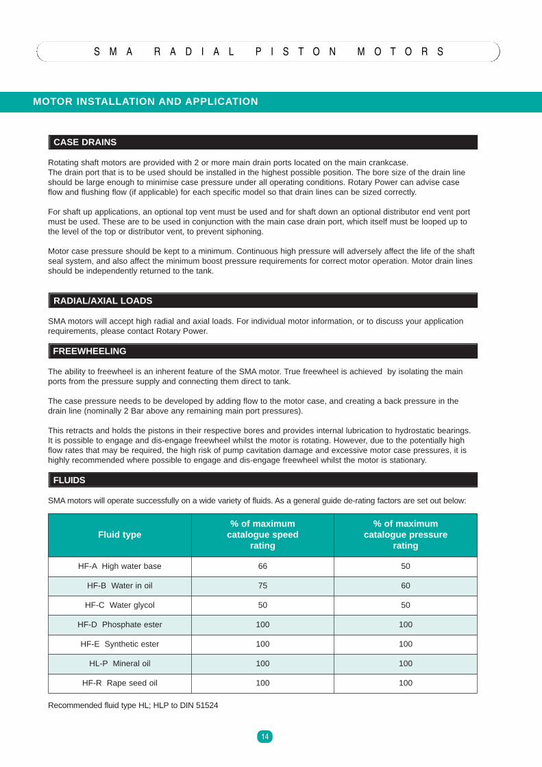
FLUIDS
SMAmotors will operate successfully on a wide variety of fluids. As a general guide de-rating factors are set out below:
Recommended fluid type HL; HLP to DIN 51524
Flu id type% of maximum
cata logue speedrating
% of maxi mumcatalogue press ure
rating
HF-A High water base 66 50
HF-B Water in oil 75 60
HF-C Water glycol 50 50
HF-D Phosphate ester 100 100
HF-E Synthetic ester 100 100
HL-P Mineral oil 100 100
HF-R Rape seed oil 100 100
MOTOR INSTALLATI ON AND APPLICATION
S M A R A D I A L P I S T O N M O T O R S
15
VISCOSITY
Optimum viscosity 20-200 cSt.Minimum / maximum viscosity 15-1000 cSt.
FILTRATION / CLEANLINESS
Fluid cleanliness to NAS 1638 Class 9 ISO code 18/13 or betterFiltration B25 ratio 75 or better for a simple closed loop system.
OUT OF BALA NCE FORCES
The orbiting motion of the cylinder block in rotating shaft motors creates an out of balance force as the motor rotates. Inmost low to medium speed applications this has no detectable effect. However, where speed is high or where themachine mass is very low, it may be beneficial to install a counterbalance weight.
SEALING
All standard SMAmotors are fitted with a nitrile sealing system that is compatible with mineral hydraulic fluids.
STARTING TORQUE
Many factors will influence starting efficiencies, such as differential pressure and the rate of rise of pressure. Typicalstarting torque efficiency is 92% .
LOW SPEED OPERATION
The minimum operating speed capable will depend upon the motor model and the operating conditions but can be aslow as 5 rpm for a standard motor and 10 rpm for the high power version. Special designs are available to provideoptimised low speed operation.
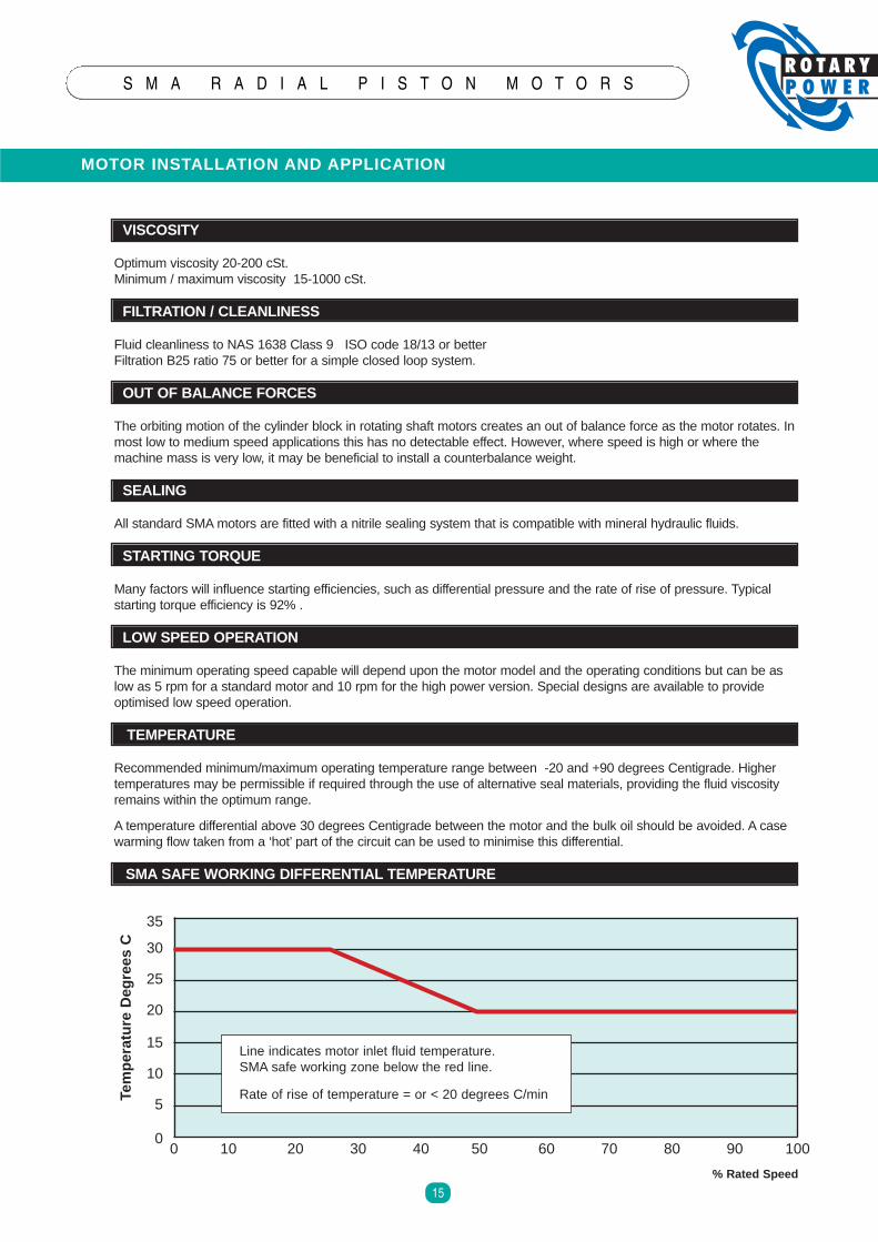
TEMPERATURE
Recommended minimum/maximum operating temperature range between -20 and +90 degrees Centigrade. Highertemperatures may be permissible if required through the use of alternative seal materials, providing the fluid viscosityremains within the optimum range.
A temperature differential above 30 degrees Centigrade between the motor and the bulk oil should be avoided. A casewarming flow taken from a ‘hot’ part of the circuit can be used to minimise this differential.
SMA SAFE WORKING DIFFERENTIAL TEMPERATURE
FLUSHING/WARMING FLOW0 10 20 30 40 50 60 70 80 90 100
35
30
25
20
15
10
5
0
Tem
per
atu
reD
egre
esC
% Rated Speed
Line indicates motor inlet fluid temperature.SMA safe working zone below the red line.
Rate of rise of temperature = or < 20 degrees C/min
MOTOR INSTALLATI ON AND APPLICATION
S M A R A D I A L P I S T O N M O T O R S
16
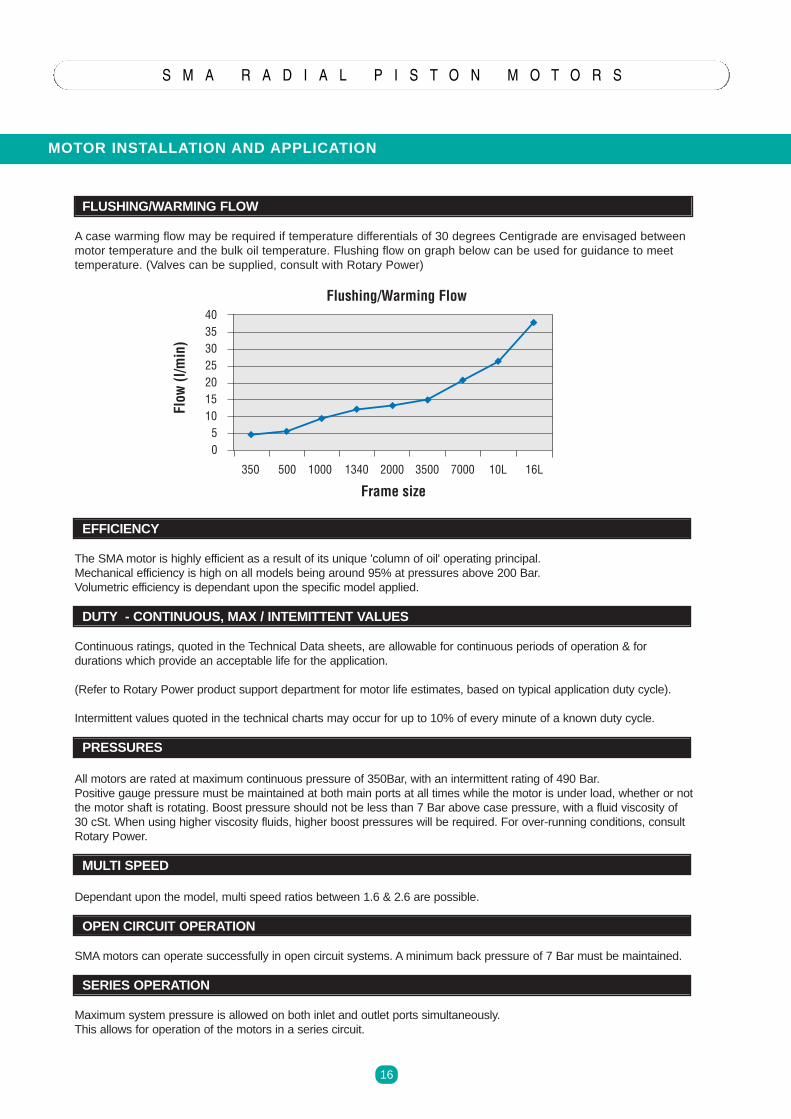
FLUSHING/WARMING FLOW
A case warming flow may be required if temperature differentials of 30 degrees Centigrade are envisaged betweenmotor temperature and the bulk oil temperature. Flushing flow on graph below can be used for guidance to meettemperature. (Valves can be supplied, consult with Rotary Power)
EFFICIENCY
The SMAmotor is highly efficient as a result of its unique 'column of oil' operating principal.Mechanical efficiency is high on all models being around 95% at pressures above 200 Bar.Volumetric efficiency is dependant upon the specific model applied.
DUTY - CONTINUOUS, MAX / INTEMITTENT VALUES
Continuous ratings, quoted in the Technical Data sheets, are allowable for continuous periods of operation & fordurations which provide an acceptable life for the application.
(Refer to Rotary Power product support department for motor life estimates, based on typical application duty cycle).
Intermittent values quoted in the technical charts may occur for up to 10% of every minute of a known duty cycle.
PRESSURES
All motors are rated at maximum continuous pressure of 350Bar, with an intermittent rating of 490 Bar.Positive gauge pressure must be maintained at both main ports at all times while the motor is under load, whether or notthe motor shaft is rotating. Boost pressure should not be less than 7 Bar above case pressure, with a fluid viscosity of30 cSt. When using higher viscosity fluids, higher boost pressures will be required. For over-running conditions, consultRotary Power.
MULTI SPEED
Dependant upon the model, multi speed ratios between 1.6 & 2.6 are possible.
OPEN CIRCUIT OPERATION
SMAmotors can operate successfully in open circuit systems. A minimum back pressure of 7 Bar must be maintained.
SERIES OPERATION
Maximum system pressure is allowed on both inlet and outlet ports simultaneously.This allows for operation of the motors in a series circuit.
40353025201510
50
350 500 1000 1340 2000 3500 7000 10L 16L
Flushing/Warming Flow
Frame size
Flow
(l/m
in)
COMMISSIONING / SERVICE
S M A R A D I A L P I S T O N M O T O R S
17
SMA SERVICE
Full factory service is available for general overhaul and test to new motor standard. Shaft seals may wear and need periodicreplacement. Seal kits are available and it is recommended that a suitable stock level is held.
Motors returned for factory overhaul should have been cleaned externally and drained of fluids. Transport plugs should befitted to all ports as soon as machine pipe work has been removed and before the motor is dismounted. All ancillaryequipment should be removed where possible and the unit should be clearly labelled, stating who has sent it, and wherefrom.
Please contact ROTARY POWER product support department for further information.
1. During system assembly thoroughly descale, clean andflush all pipework, fittings and the reservoir.Fill the system with new, filtered fluid that meets requiredspecifications regarding viscosity at envisaged operatingtemperature, type and cleanliness for all componentsfitted within the system. Motor requirements are given ineach technical data section. The motor case must befilled through the motor case drain port on rotating shaftmotors or, through one of the case vent ports located inthe crankcase on rotating case motors. Ensure the casedrain line is filled and all connections tightened.
2. Check the rotation-flow information given on theinstallation drawing.
3. Start the drive pump slowly- for engines, turn over on the starter motor for a fewseconds at a time.- for electric motors, by a series of rapid on /off cycles.This is to ensure the pump internal components are filledwith oil.Run the system at 25% max high flow and low pressure,actuate all systems in all modes until all entrained air inthe system has been released. This air could causesome pulsation but, the motor should run smoothly afterapproximately ten minutes operation.
4. After the motor rotation has been proved under no- loadconditions, it may be operated up to maximum pressure.
5. Check and top up fluid level if necessary.
6. The motor case pressure should be checked in alloperating modes to ensure that the maximum allowablevalue for the specific motor model is not exceeded.
7. Check and adjust all settings where necessary incompliance with all supplier’s instructions to systemrequirements.
8. Check steady state operating temperature is inaccordance with system and component requirements.
9. Check for and repair any leaks.
10. After the first few hours running, clean or renew ( asappropriate ) all filters.
11. The following points should be incorporated in themachine maintenance instructions:
After one hundr ed hours operation ;
A. Check the security of all mounting bolts and socket headscrews used in the assembly of the motor.
B. Check the security of the drive coupling and pipeconnections.
C. Clean or replace filter elements as recommended by themanufacturer.
READ THIS TOGETHER WITH INSTRUCTIONS SUPPLIED FOR OTHER COMPONENTS FITTED.

ROTARY POWER has over 35 years experience in the design anddevelopment of high quality Hydraulic equipment.
Our current product range includes :-
"A" Axial Piston Pumps for heavy-duty open circuit applications.Wide range of controls. Excellent life characteristics. Suitable formost fluids, including HLP,HFA, HFB, HFC ,HFD, HFR , HFE ,Isocyanates & Polyols. Fixed and variable capacities from 11.5 to 125cm3/rev.
"C" Axial Piston Pumps for high accuracy fluid metering withprecision flow controls and high-pressure capability. Specificallydesigned for the Polyurethane Industry. Capacities from 3 to 62cm3/rev.
"XL" Cam Motors of radial piston configuration.Wheel/shaft/torquemodule configurations. Design offers high-speed capability.Capacities from 150 to 1120 cm3/rev.
" XK " Cam Mo to r s r a d i a l p i s t o n con f i g u r a t i o n o f f e r i n gstatic/dynamic brakes, single/2 speed, wheel/shaft & torque-module mount options.
Heavy-Duty External Load & High-Speed options. Capacities from
1000 to 5000 cm3/rev.
"SMA" Motors heavy-duty radial piston/eccentric configuration,offering excellent life. Withstands high mechanical and hydraulicshock loads. 350bar Continuous pressure rating. Speed & powerratings significantly greater than standard HTLS motors.
Displacements from 150 to 10500 cm3/rev.
Wholly owned subsidiaries in the USA and Germany and anetwork of distributors throughout the world provide productsupport in most countries.
ROTARY POWER is a company within British Engines Ltd (BEL)group, which was established over 60 years ago.
The British Engines group of companies design manufactureand market a wide range of engineered products foroffshore, electrical, construction, engineering and otherindustries, employing nearly 700 people on a 4600 sq m site inNewcastle upon Tyne, England.
FEATURES
Modular Concept
n Common torque unitn 4 standard output optionsn Over 20 optional output options
Freewheel
n True freewheel possiblen Recirculating freewheel possible
High-Torque Start
n Efficient piston roller designn Pintle valving reduces mechanical losses
Total Reversibility
n Equal torque in both directions
Compact Installation
n Multi-stroking radial piston designn Minimum overall dimensionsn High power-to-weight ratio
High Pressure Capability
n Designed to operate at up to 420bar peak pressure
Low Inertia
Higher capacity lower speed drives :
n Reduced inertia enables rapidreversals and speed changes
n Reduced mechanical losses ingeared drives
n Reduced noise
Service
XL designed for easy service :
n Fully interchangeable componentsn Few special tools neededn Split mechanical and torque
functions
Reliability
XL developed from over 20 years’ experiencein industries such as :
n Construction n Miningn Defence n Steel Productionn Brewing n Offshoren Food Production n Municipal
X L R A D I A L P I S T O N M O T O R S
XL COMPACT PISTON MOTORS
1
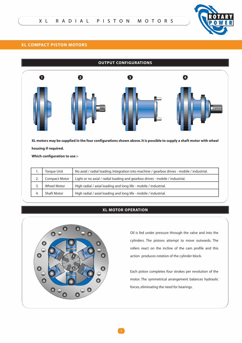
OUTPUT CONFIGURATIONS
XL MOTOR OPERATION
Oil is fed under pressure through the valve and into the
cylinders. The pistons attempt to move outwards. The
rollers react on the incline of the cam profile and this
action produces rotation of the cylinder block.
Each piston completes four strokes per revolution of the
motor. The symmetrical arrangement balances hydraulic
forces, eliminating the need for bearings.
XLmotors may be supplied in the four configurations shown above. It is possible to supply a shaft motor with wheel
housing if required.
Which configuration to use :-
1. Torque Unit No axial / radial loading. Integration into machine / gearbox drives - mobile / industrial.
2. Compact Motor Light or no axial / radial loading and gearbox drives - mobile / industrial.
3. Wheel Motor High radial / axial loading and long life - mobile / industrial.
4. Shaft Motor High radial / axial loading and long life - mobile / industrial.
1 2 3 4
2
X L R A D I A L P I S T O N M O T O R S
XL MOTOR TECHNICAL DATA
2
7000650060005500500045004000350030002500200015001000500
0
5000
4000
3000
2000
1000
lbft Nm XL150 XL200 XL280 XL390 XL490 XL560 XL780 XL880 XL980 XL1050 XL1120
XL150 XL200 XL280 XL390 XL490 XL560 XL780 XL880 XL980 XL1050 XL1120
1000900800700600500400300200100
0Rev/Min
XL150 XL200 XL280 XL390 XL490 XL560 XL780 XL880 XL980 XL1050 XL1120
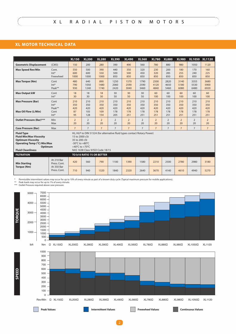
Geometric Displacement (CM3) 150 200 280 390 490 560 780 880 980 1050 1120
Max Speed Rev/Min Cont. 550 500 390 440 350 320 230 200 180 170 160Int* 600 600 550 500 500 450 320 285 255 240 225Freewheel 1000 1000 1000 850 850 850 850 850 850 850 850
Max Torque (Nm) Cont 480 640 890 1250 1570 1790 2500 2820 3140 3355 3680Int* 790 1050 1480 2060 2590 2590 4120 4650 5180 5530 5900Peak** 930 1240 1740 2420 3040 3460 4840 5460 6080 6480 6920
Max Output kW Cont 18 18 18 30 30 30 60 60 60 60 60Int* 30 30 30 50 50 50 100 100 100 100 100
Max Pressure (Bar) Cont 210 210 210 210 210 210 210 210 210 210 210Int* 350 350 350 350 350 350 350 350 350 350 350Peak** 420 420 420 420 420 420 420 420 420 420 420
Max Oil Flow (L/Min) Cont 87 105 109 178 178 178 178 178 178 178 178Int* 95 128 154 205 251 251 251 251 251 251 251
Outlet Pressure (Bar)*** Min 2 2 2 2 2 2 2 2 2 2 2Max 20 20 20 20 20 20 20 20 20 20 20
Case Pressure (Bar) Max 7 7 7 7 7 7 7 7 7 7 7
Fluid Type HL; HLP to DIN 51524 (for alternative fluid types contact Rotary Power)Fluid Min/Max Viscosity 15 to 2000 cStOptimumViscosity 35 to 200 cStOperating Temp (°C) Min/Max -30°C to +80°C
Optimum +40°C to +70°CFluid Cleanliness NAS 1638 Class 9/ISO Code 18/15
FILTRATION TO b10 RATIO 75 OR BETTER
At 210 BarMin Starting Press. Cont.
420 560 790 1100 1390 1580 2210 2500 2780 2980 3180
Torque (Nm) At 350 BarPress. Cont. 710 940 1320 1840 2320 2640 3670 4140 4610 4940 5270
TORQUE
SPEE
D
* Permissible intermittent values may occur for up to 10% of every minute as part of a known duty cycle (Typical maximum pressure for mobile applications).** Peak loads may occur for up to 1% of every minute.*** Outlet Pressure required above case pressure.
Peak Values Intermittent Values Freewheel Values Continuous Values
3
X L R A D I A L P I S T O N M O T O R S
PERFORMANCE DATA - POWER CHARTS
3
0 4 8 12 16 20
0 20 40 60 80 100
Flow gpm
Flow lpm6000
4000
2000
0
Pres
sure
psi
Pres
sure
bar
0 100 200 300 400 500 600Speed rpm
500
400
300
200
100
0
30 KW
10 KW
0 4 8 12 16 20
0 20 40 60 80 100
Flow gpm
Flow lpm6000
4000
2000
0
Pres
sure
psi
Pres
sure
bar
500
400
300
200
100
0
0 100 200 300 400 500 600Speed rpm
30 KW
10 KW
Flow lpm
0 5 10 15 20 25 30
0 20 40 60 80 100120140160
Flow gpm
0 100 200 300 400 500Speed rpm
6000
4000
2000
0
Pres
sure
psi
Pres
sure
bar
500
400
300
200
100
0
30 KW
10 KW
Flow lpm
0 5 10 15 20 25 30 35
0 25 50 75 100 125 150 175
Flow gpm
0 100 200 300 400 500Speed rpm
Flow lpm
0 10 20 30
0 50 100 150
Flow gpm
0 50 100 150 200 250 300Speed rpm
6000
4000
2000
0
Pres
sure
psi
Pres
sure
bar
500
400
300
200
100
0
50 KW30 KW
10 KW
Flow lpm
0 8 16 24 32 40
0 49 80 120 160 200
Flow gpm
0 100 200 300 400 500Speed rpm
6000
4000
2000
0
Pres
sure
psi
Pres
sure
bar
500
400
300
200
100
0
Flow lpm
0 10 20 30 40 50
0 50 100 150 200 250
Flow gpm
0 100 200 300 400Speed rpm
6000
4000
2000
0
Pres
sure
psi
Pres
sure
bar
500
400
300
200
100
0
6000
4000
2000
0Pr
essu
reps
i
Pres
sure
bar
500
400
300
200
100
0
6000
4000
2000
0
Pres
sure
psi
Pres
sure
bar
500
400
300
200
100
0
6000
4000
2000
0
Pres
sure
psi
Pres
sure
bar
500
400
300
200
100
0
0 50 100 150 200 250 300Speed rpm
Flow lpm
0 10 20 30
0 50 100 150
Flow gpm
0 50 100 150 200 250Speed rpm
Flow lpm
0 8 16 24 32 40
0 40 80 120 160 200
Flow gpm
6000
4000
2000
0Pr
essu
reps
i
Pres
sure
bar
500
400
300
200
100
0
0 50 100 150 200Speed rpm
Flow lpm
0 10 20 30 40 50
0 50 100 150 200 250
Flow gpm
6000
4000
2000
0
Pres
sure
psi
Pres
sure
bar
500
400
300
200
100
0
0 50 100 150 200Speed rpm
Flow lpm
0 10 20 30 40 50
0 50 100 150 200 250
Flow gpm
50 KW30 KW
10 KW
50 KW30 KW
10 KW
40 KW20 KW
80 KW60 KW
100 KW
40 KW
20 KW
80 KW60 KW
100 KW
40 KW20 KW
80 KW60 KW
100 KW
40 KW20 KW
80 KW60 KW
100 KW
40 KW20 KW
80 KW60 KW
100 KW
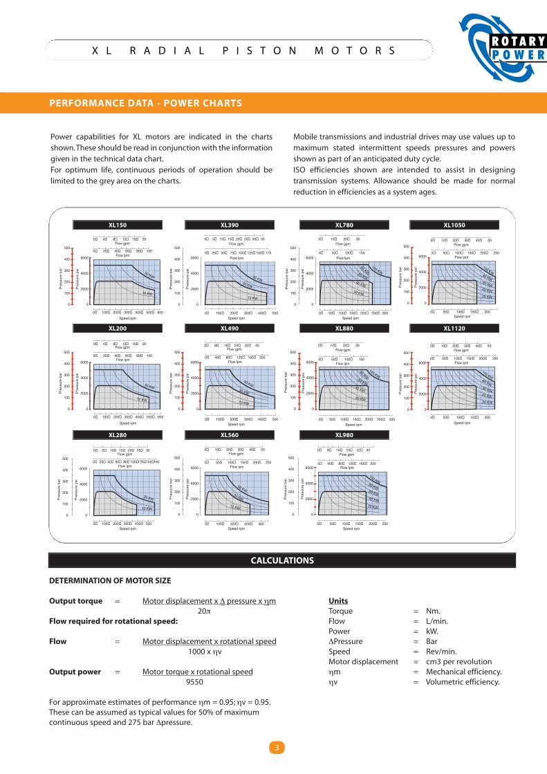
DETERMINATION OF MOTOR SIZE
Output torque = Motor displacement x ∆ pressure x ηm Units20π Torque = Nm.
Flow required for rotational speed: Flow = L/min.Power = kW.
Flow = Motor displacement x rotational speed ∆Pressure = Bar1000 x ηv Speed = Rev/min.
Motor displacement = cm3 per revolutionOutput power = Motor torque x rotational speed ηm = Mechanical efficiency.
9550 ηv = Volumetric efficiency.
For approximate estimates of performance ηm = 0.95;ηv = 0.95.These can be assumed as typical values for 50% of maximumcontinuous speed and 275 bar ∆pressure.
CALCULATIONS
Power capabilities for XL motors are indicated in the chartsshown.These should be read in conjunction with the informationgiven in the technical data chart.For optimum life, continuous periods of operation should belimited to the grey area on the charts.
Mobile transmissions and industrial drives may use values up tomaximum stated intermittent speeds pressures and powersshown as part of an anticipated duty cycle.ISO efficiencies shown are intended to assist in designingtransmission systems. Allowance should be made for normalreduction in efficiencies as a system ages.
XL150 XL390 XL780 XL1050
XL200 XL490 XL880 XL1120
XL280 XL560 XL980
4
X L R A D I A L P I S T O N M O T O R S
PERFORMANCE DATA
4
CASE DRAIN FLOW
0 100 200 300 400Presure (bar)
5.6
4.8
4.0
3.2
2.4
1.6
0.8
0
Flow
(I/m
)
XL 390 - 1120
XL 150 - 280
XL1120 XL560XL280
XL980 XL490
XL780 XL390 XL200
XL150
0 100 200 300 400 500SPEED rpm
PRES
SURE
bar
28
24
20
16
12
8
4
0
0 100 200 300 400 500
181614121086420
Speed rpm
Pres
sure
bar XL 880 - 1120
XL 150 - 780
XL 390 - 1120
XL 150 - 280
0 200 400 600 800 1000 1200
1.6
1.2
0.8
0.4
0
Speed min -1
Case
pres
sure
inba
r
NO LOAD PRESSURE DROP
BOOST PRESSURE FREEWHEELING
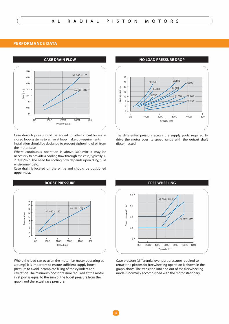
Case drain figures should be added to other circuit losses inclosed loop systems to arrive at loop make-up requirements.Installation should be designed to prevent siphoning of oil fromthe motor case.Where continuous operation is above 300 min-1 it may benecessary to provide a cooling flow through the case, typically 1-2 litres/min. The need for cooling flow depends upon duty, fluidenvironment etc.Case drain is located on the pintle and should be positioneduppermost.
The differential pressure across the supply ports required todrive the motor over its speed range with the output shaftdisconnected.
Where the load can overrun the motor (i.e.motor operating asa pump) it is important to ensure sufficient supply boostpressure to avoid incomplete filling of the cylinders andcavitation.The minimum boost pressure required at the motorinlet port is equal to the sum of the boost pressure from thegraph and the actual case pressure.
Case pressure (differential over port pressure) required toretract the pistons for freewheeling operation is shown in thegraph above.The transition into and out of the freewheelingmode is normally accomplished with the motor stationary.
5
X L R A D I A L P I S T O N M O T O R S
OUTPUT CONFIGURATIONS
5
RADI
ALLO
AD(K
g)
6000
0
300 Distance (mm) 0
Note : Right hand portion of above graph is based onfatigue limit for shaft in rotating bending.
XL 150 200 180
Shaft Motors (Consult Rotary Power)
0
0
RADI
ALLO
AD(K
g)
6000
350 Distance (mm)
XL 780 880 980 1050 1120
0
0
RADI
ALLO
AD(K
g)
6000
300 Distance (mm)
XL 390 490 560
0
0
RADI
ALLO
ADNE
WTO
N
6000
300 Distance (mm)
XL COMPACT
XL 150-280
XL 390-1120
625 Newton
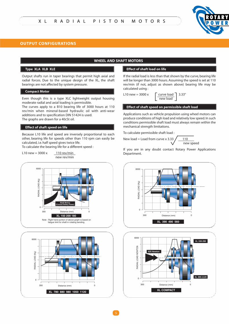
WHEEL AND SHAFT MOTORS
Type XLA XLB XLE
Output shafts run in taper bearings that permit high axial andradial forces. Due to the unique design of the XL, the shaftbearings are not affected by system pressure.
Compact Motor
Even though this is a type XLC lightweight output housingmoderate radial and axial loading is permissible.The curves apply to a B10 bearing life of 3000 hours at 110rev/min when mineral-based hydraulic oil with anti-wearadditions and to specification DIN 51424 is used.The graphs are drawn for a 40cSt oil.
Effect of shaft speed on life
Because L10 life and speed are inversely proportional to eachother, bearing life for speeds other than 110 rpm can easily becalculated, i.e. half speed gives twice life.To calculate the bearing life for a different speed :
L10 new = 3000 x 110 rev/minnew rev/min
Effect of shaft load on life
If the radial load is less than that shown by the curve, bearing lifewill be longer than 3000 hours. Assuming the speed is set at 110rev/min (if not, adjust as shown above) bearing life may becalculated using :
L10 new = 3000 x curve load 3.33°new load
Effect of shaft speed on permissible shaft load
Applications such as vehicle propulsion using wheel motors canproduce conditions of high load and relatively low speed. In suchconditions permissible shaft load must always remain within themechanical strength limitations.
To calculate permissible shaft load :
New load = Load from curve x 3.33 110new speed
If you are in any doubt contact Rotary Power ApplicationsDepartment.
6
X L R A D I A L P I S T O N M O T O R S
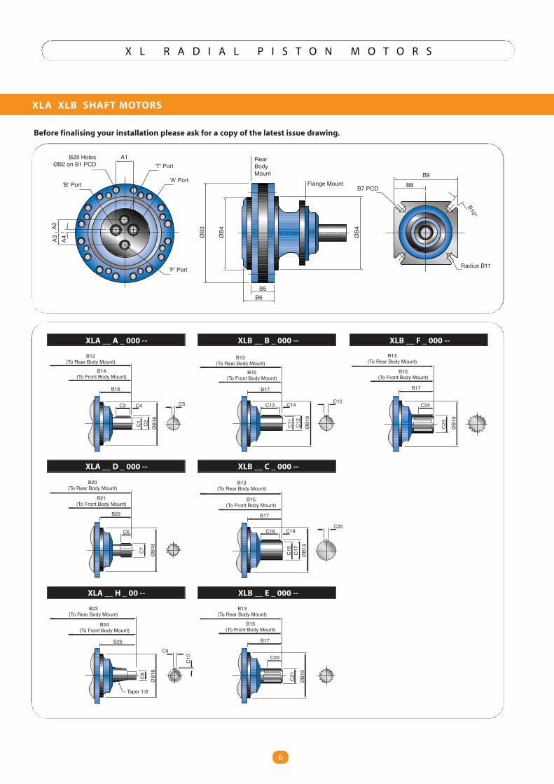
XLA XLB SHAFT MOTORS
6
B29 HolesØB2 on B1 PCD
'B' Port
A1
'F' Port
'A' Port
'T' Port
A4A2
A3 ØB3
ØB4
ØB4
B5B6
RearBodyMount
Flange MountB9
B8
Radius B11
B7 PCD
B10°
B12(To Rear Body Mount)
B14(To Front Body Mount)
B16
C3 C4
C1 C2 ØB1
8
C5
B20(To Rear Body Mount)
B21(To Front Body Mount)
B22
C6
C7 ØB1
8
B23(To Rear Body Mount)
B24(To Front Body Mount)
B25
C8
C10
ØB1
8
C9
Taper 1:8
B13(To Rear Body Mount)
B15(To Front Body Mount)
B17
C13 C14
C11
C12
ØB1
9
C15
B13(To Rear Body Mount)
B15(To Front Body Mount)
B17
C18 C19
C17
C16
ØB1
9
C20
B13(To Rear Body Mount)
B15(To Front Body Mount)
B17
C22
C21
ØB1
9
B13(To Rear Body Mount)
B15(To Front Body Mount)
B17
C24
C23
ØB1
9
XLA __ A _ 000 -- XLB __ B _ 000 --
XLA __ D _ 000 -- XLB __ C _ 000 --
XLA __ H _ 00 -- XLB __ E _ 000 --
XLB __ F _ 000 --
Before finalising your installation please ask for a copy of the latest issue drawing.
7
X L R A D I A L P I S T O N M O T O R S
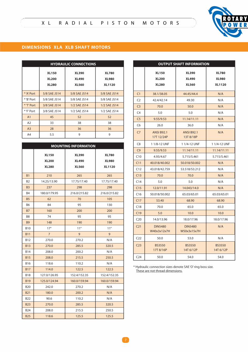
DIMENSIONS XLA XLB SHAFT MOTORS
HYDRAULIC CONNECTIONS
XL150 XL390 XL780
XL200 XL490 XL980
XL280 XL560 XL1120
* ‘A’ Port 5/8 SAE J514 5/8 SAE J514 5/8 SAE J514
* ‘B’ Port 5/8 SAE J514 5/8 SAE J514 5/8 SAE J514
* ‘T’ Port 3/8 SAE J514 1/2 SAE J514 1/2 SAE J514
* ‘F’ Port 3/8 SAE J514 1/2 SAE J514 1/2 SAE J514
A1 45 52 52
A2 33 38 38
A3 28 36 36
A4 5.5 9 9
MOUNTING INFORMATION
XL150 XL390 XL780
XL200 XL490 XL980
XL280 XL560 XL1120
B1 210 265 265
B2 14.25/13.90 17.75/17.40 17.75/17.40
B3 237 298 298
B4 180.0/179.95 216.0/215.82 216.0/215.82
B5 62 70 105
B6 84 95 130
B7 160 200 200
B8 74 95 95
B9 148 190 190
B10 17° 11° 11°
B11 7 9 9
B12 270.0 270.2 N/A
B13 270.0 285.5 320.5
B14 208.0 200.2 N/A
B15 208.0 215.5 250.5
B16 118.6 110.2 N/A
B17 114.0 122.5 122.5
B18 127.0/126.95 152.4/152.35 152.4/152.35
B19 125.0/124.94 160.0/159.94 160.0/159.94
B20 242.0 270.2 N/A
B21 180.0 200.2 N/A
B22 90.6 110.2 N/A
B23 270.0 285.5 320.5
B24 208.0 215.5 250.5
B25 118.6 125.5 125.5
OUTPUT SHAFT INFORMATION
XL150 XL390 XL780
XL200 XL490 XL980
XL280 XL560 XL1120
C1 38.1/38.05 44.45/44.4 N/A
C2 42.4/42.14 49.30 N/A
C3 70.0 50.0 N/A
C4 5.0 5.0 N/A
C5 9.55/9.53 11.14/11.11 N/A
C6 26.0 36.0 N/A
C7 ANSI B92.1 ANSI B92.1 N/A
17T 12/24P 13T 8/18P
C8 1 1/8-12 UNF 1 1/4-12 UNF 1 1/4-12 UNF
C9 9.55/9.53 11.14/11.11 11.14/11.11
C10 4.93/4.67 5.715/5.461 5.715/5.461
C11 40.018/40.002 50.018/50.002 N/A
C12 43.018/42.759 53.518/53.212 N/A
C13 70.0 70.0 N/A
C14 5.0 5.0 N/A
C15 12.0/11.91 14.043/14.0 N/A
C16 50.018/50.002 65.03/65.01 65.03/65.01
C17 53.40 68.90 68.90
C18 70.0 65.0 65.0
C19 5.0 10.0 10.0
C20 14.0/13.96 18.0/17.96 18.0/17.96
C21 DIN5480 DIN5480 N/A
W40x3x12x7H W50x3x15x7H
C22 50.0 53.0 N/A
C23 BS3550 BS3550 BS3550
17T 8/16P 14T 6/12P 14T 6/12P
C24 50.0 54.0 54.0
* Hydraulic connection sizes denote SAE ‘O’ ring boss size.These are not thread dimensions.
8
X L R A D I A L P I S T O N M O T O R S
A1
A2A3 A4
'A' Port
'T' Port
'B' Port
'F' Port
B3
B4
B5
B6
B1 B2
C1
C2
C3 C4
B7 HolesDiameter B8Equispaced onB9 PCD
C7 StudsThread C8on C9 PCD
B2
Rim ThicknessMin C5Max C6
Rear body mount
Front body mount
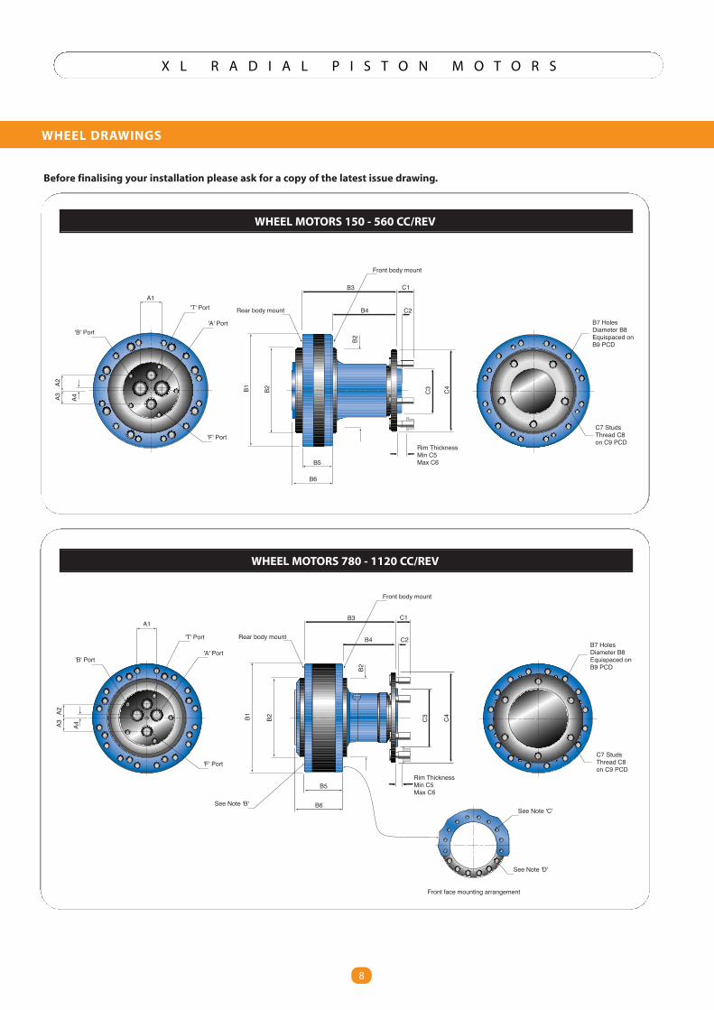
WHEEL DRAWINGS
8
A1
A2A3 A4
'A' Port
'T' Port
'B' Port
'F' Port
B3
B4
B5
B6
B1 B2
C1
C2
Rim ThicknessMin C5Max C6
C3 C4
B2
B7 HolesDiameter B8Equispaced onB9 PCD
C7 StudsThread C8on C9 PCD
See Note 'B'See Note 'C'
See Note 'D'
Front face mounting arrangement
Rear body mount
Front body mount
WHEEL MOTORS 150 - 560 CC/REV
WHEEL MOTORS 780 - 1120 CC/REV
Before finalising your installation please ask for a copy of the latest issue drawing.
9
X L R A D I A L P I S T O N M O T O R S
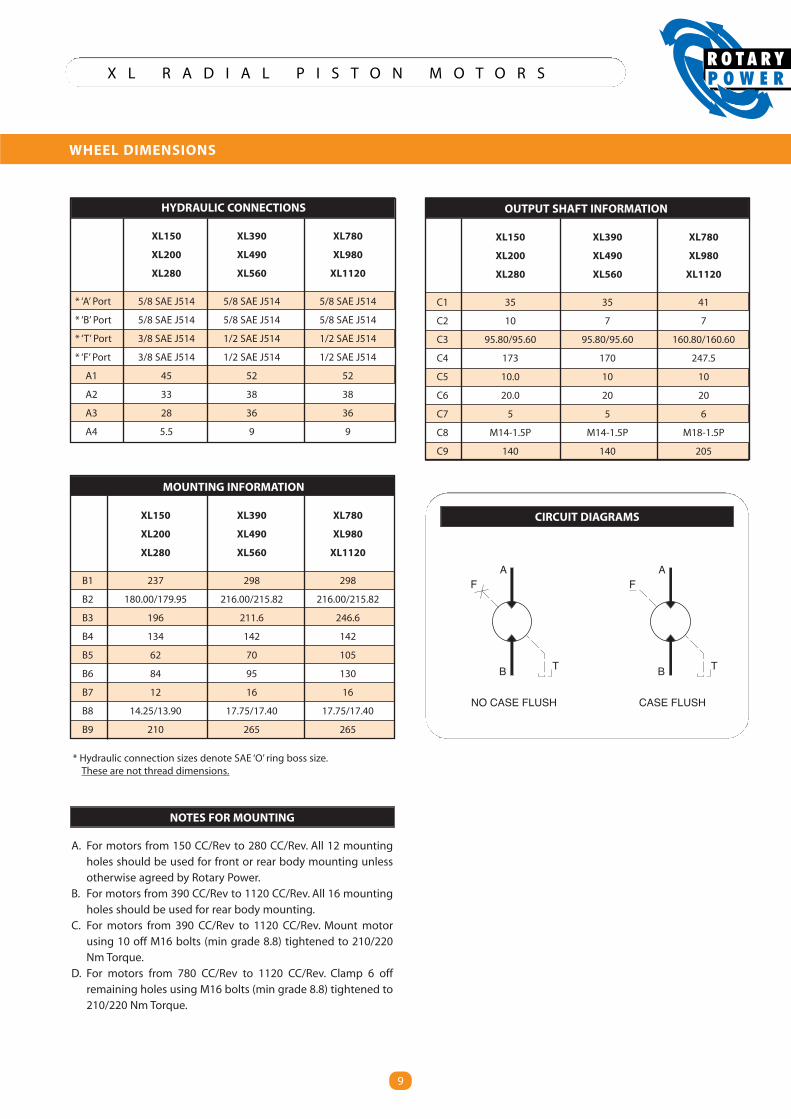
WHEEL DIMENSIONS
9
HYDRAULIC CONNECTIONS
XL150 XL390 XL780
XL200 XL490 XL980
XL280 XL560 XL1120
* ‘A’ Port 5/8 SAE J514 5/8 SAE J514 5/8 SAE J514
* ‘B’ Port 5/8 SAE J514 5/8 SAE J514 5/8 SAE J514
* ‘T’ Port 3/8 SAE J514 1/2 SAE J514 1/2 SAE J514
* ‘F’ Port 3/8 SAE J514 1/2 SAE J514 1/2 SAE J514
A1 45 52 52
A2 33 38 38
A3 28 36 36
A4 5.5 9 9
MOUNTING INFORMATION
XL150 XL390 XL780
XL200 XL490 XL980
XL280 XL560 XL1120
B1 237 298 298
B2 180.00/179.95 216.00/215.82 216.00/215.82
B3 196 211.6 246.6
B4 134 142 142
B5 62 70 105
B6 84 95 130
B7 12 16 16
B8 14.25/13.90 17.75/17.40 17.75/17.40
B9 210 265 265
OUTPUT SHAFT INFORMATION
XL150 XL390 XL780
XL200 XL490 XL980
XL280 XL560 XL1120
C1 35 35 41
C2 10 7 7
C3 95.80/95.60 95.80/95.60 160.80/160.60
C4 173 170 247.5
C5 10.0 10 10
C6 20.0 20 20
C7 5 5 6
C8 M14-1.5P M14-1.5P M18-1.5P
C9 140 140 205
NO CASE FLUSH CASE FLUSH
B T
AF
B T
AF
CIRCUIT DIAGRAMS
NOTES FOR MOUNTING
A. For motors from 150 CC/Rev to 280 CC/Rev. All 12 mountingholes should be used for front or rear body mounting unlessotherwise agreed by Rotary Power.
B. For motors from 390 CC/Rev to 1120 CC/Rev. All 16 mountingholes should be used for rear body mounting.
C. For motors from 390 CC/Rev to 1120 CC/Rev. Mount motorusing 10 off M16 bolts (min grade 8.8) tightened to 210/220Nm Torque.
D. For motors from 780 CC/Rev to 1120 CC/Rev. Clamp 6 offremaining holes using M16 bolts (min grade 8.8) tightened to210/220 Nm Torque.
* Hydraulic connection sizes denote SAE ‘O’ ring boss size.These are not thread dimensions.
10
X L R A D I A L P I S T O N M O T O R S
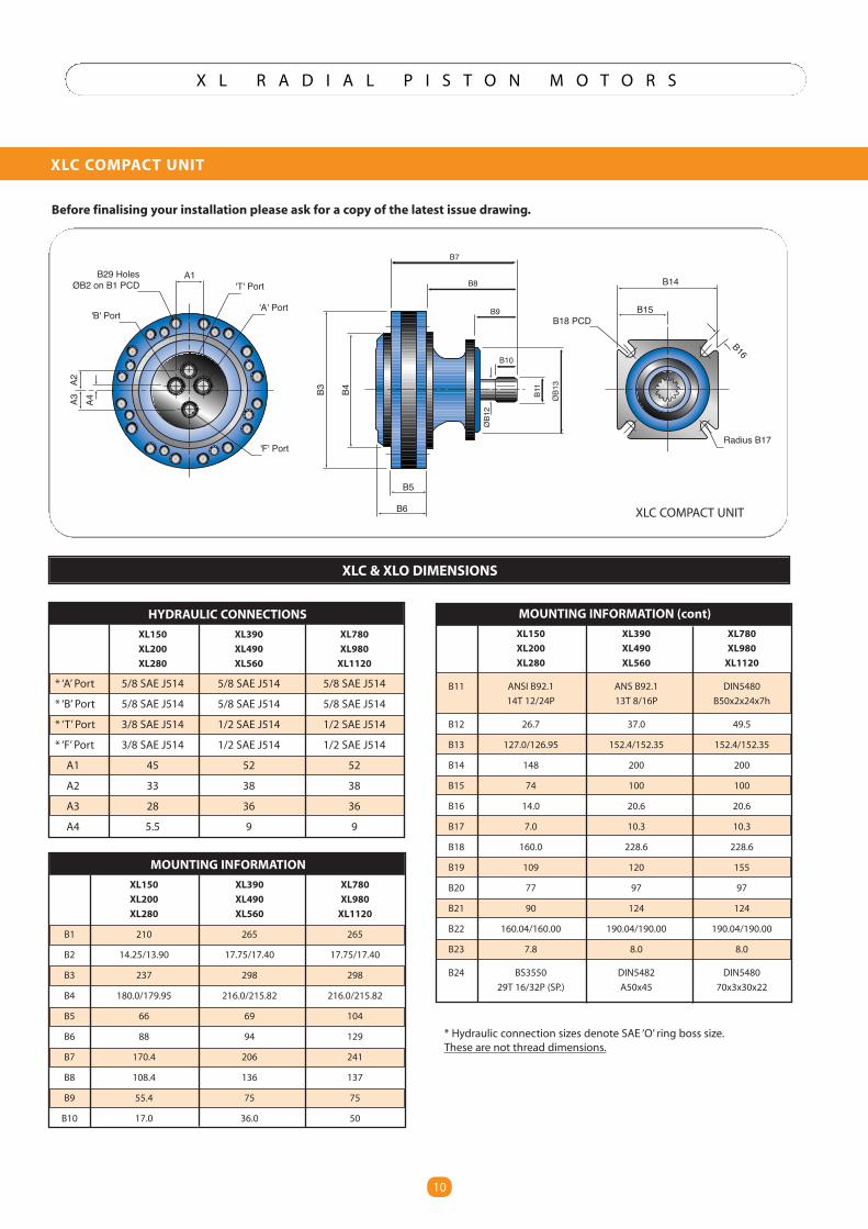
XLC COMPACT UNIT
10
B29 HolesØB2 on B1 PCD
A1'T' Port
'A' Port'B' Port
'F' Port
A4A2
A3
B3 B4
B5
B6
B14
B15
Radius B17
B18 PCD
B16
B7
B8
B9
B10
B11
ØB1
3
ØB1
2
HYDRAULIC CONNECTIONS
XL150 XL390 XL780
XL200 XL490 XL980
XL280 XL560 XL1120
* ‘A’ Port 5/8 SAE J514 5/8 SAE J514 5/8 SAE J514
* ‘B’ Port 5/8 SAE J514 5/8 SAE J514 5/8 SAE J514
* ‘T’ Port 3/8 SAE J514 1/2 SAE J514 1/2 SAE J514
* ‘F’ Port 3/8 SAE J514 1/2 SAE J514 1/2 SAE J514
A1 45 52 52
A2 33 38 38
A3 28 36 36
A4 5.5 9 9
MOUNTING INFORMATION (cont)
XL150 XL390 XL780
XL200 XL490 XL980
XL280 XL560 XL1120
B11 ANSI B92.1 ANS B92.1 DIN5480
14T 12/24P 13T 8/16P B50x2x24x7h
B12 26.7 37.0 49.5
B13 127.0/126.95 152.4/152.35 152.4/152.35
B14 148 200 200
B15 74 100 100
B16 14.0 20.6 20.6
B17 7.0 10.3 10.3
B18 160.0 228.6 228.6
B19 109 120 155
B20 77 97 97
B21 90 124 124
B22 160.04/160.00 190.04/190.00 190.04/190.00
B23 7.8 8.0 8.0
B24 BS3550 DIN5482 DIN5480
29T 16/32P (SP.) A50x45 70x3x30x22
MOUNTING INFORMATION
XL150 XL390 XL780
XL200 XL490 XL980
XL280 XL560 XL1120
B1 210 265 265
B2 14.25/13.90 17.75/17.40 17.75/17.40
B3 237 298 298
B4 180.0/179.95 216.0/215.82 216.0/215.82
B5 66 69 104
B6 88 94 129
B7 170.4 206 241
B8 108.4 136 137
B9 55.4 75 75
B10 17.0 36.0 50
XLC COMPACT UNIT
XLC & XLO DIMENSIONS
Before finalising your installation please ask for a copy of the latest issue drawing.
* Hydraulic connection sizes denote SAE ‘O’ ring boss size.These are not thread dimensions.
11
X L R A D I A L P I S T O N M O T O R S
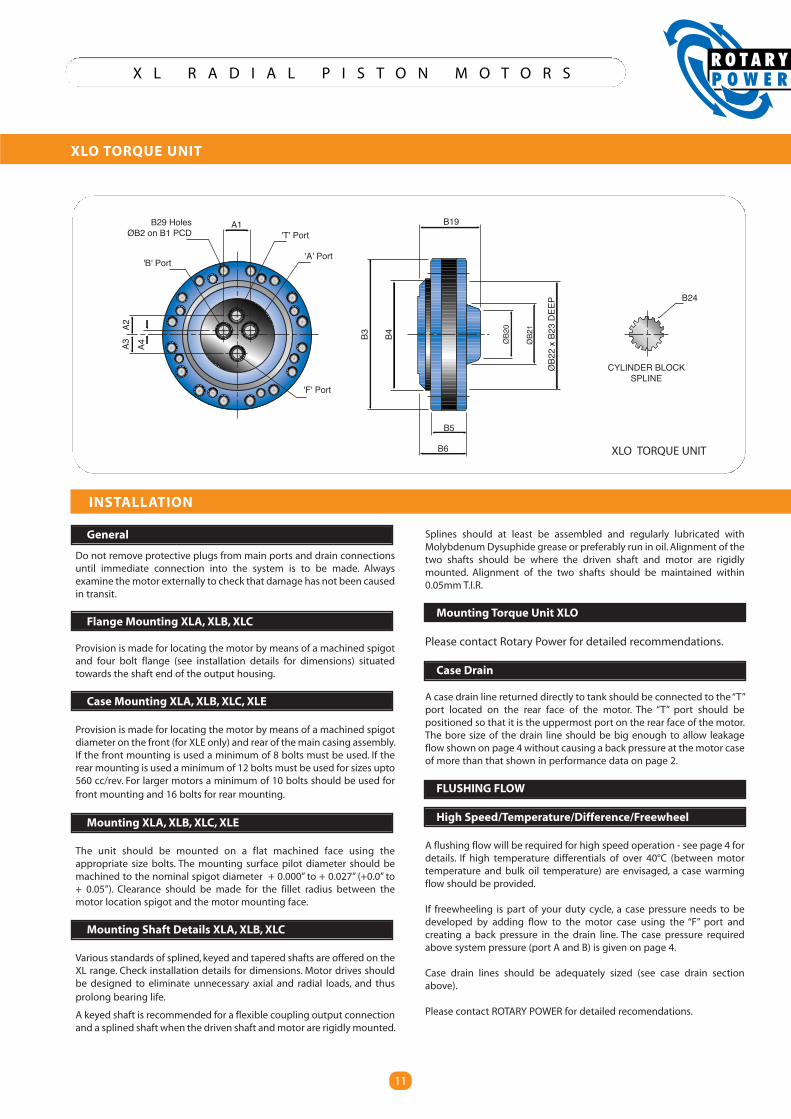
XLO TORQUE UNIT
11
B3 B4
B5
B6
B19
ØB2
2x
B23
DEEP
ØB2
0
ØB2
1
B24
B29 HolesØB2 on B1 PCD
A1'T' Port
'A' Port'B' Port
'F' Port
A4A2
A3
CYLINDER BLOCKSPLINE
General
Do not remove protective plugs from main ports and drain connectionsuntil immediate connection into the system is to be made. Alwaysexamine themotor externally to check that damage has not been causedin transit.
Flange Mounting XLA, XLB, XLC
Provision is made for locating the motor by means of a machined spigotand four bolt flange (see installation details for dimensions) situatedtowards the shaft end of the output housing.
Case Mounting XLA, XLB, XLC, XLE
Provision is made for locating the motor by means of a machined spigotdiameter on the front (for XLE only) and rear of themain casing assembly.If the front mounting is used a minimum of 8 bolts must be used. If therear mounting is used aminimum of 12 bolts must be used for sizes upto560 cc/rev. For larger motors a minimum of 10 bolts should be used forfront mounting and 16 bolts for rear mounting.
Mounting XLA, XLB, XLC, XLE
The unit should be mounted on a flat machined face using theappropriate size bolts. The mounting surface pilot diameter should bemachined to the nominal spigot diameter + 0.000” to + 0.027” (+0.0” to+ 0.05”). Clearance should be made for the fillet radius between themotor location spigot and the motor mounting face.
Mounting Shaft Details XLA, XLB, XLC
Various standards of splined, keyed and tapered shafts are offered on theXL range. Check installation details for dimensions. Motor drives shouldbe designed to eliminate unnecessary axial and radial loads, and thusprolong bearing life.
A keyed shaft is recommended for a flexible coupling output connectionand a splined shaft when the driven shaft andmotor are rigidly mounted.
Splines should at least be assembled and regularly lubricated withMolybdenumDysuphide grease or preferably run in oil.Alignment of thetwo shafts should be where the driven shaft and motor are rigidlymounted. Alignment of the two shafts should be maintained within0.05mm T.I.R.
Mounting Torque Unit XLO
Please contact Rotary Power for detailed recommendations.
Case Drain
A case drain line returned directly to tank should be connected to the“T”port located on the rear face of the motor. The “T” port should bepositioned so that it is the uppermost port on the rear face of the motor.The bore size of the drain line should be big enough to allow leakageflow shown on page 4 without causing a back pressure at the motor caseof more than that shown in performance data on page 2.
FLUSHING FLOW
High Speed/Temperature/Difference/Freewheel
A flushing flow will be required for high speed operation - see page 4 fordetails. If high temperature differentials of over 40°C (between motortemperature and bulk oil temperature) are envisaged, a case warmingflow should be provided.
If freewheeling is part of your duty cycle, a case pressure needs to bedeveloped by adding flow to the motor case using the “F” port andcreating a back pressure in the drain line. The case pressure requiredabove system pressure (port A and B) is given on page 4.
Case drain lines should be adequately sized (see case drain sectionabove).
Please contact ROTARY POWER for detailed recomendations.
INSTALLATION
XLO TORQUE UNIT
12
X L R A D I A L P I S T O N M O T O R S
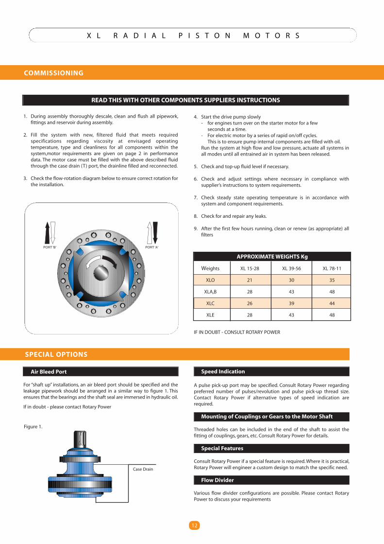
COMMISSIONING
12
PORT 'B' PORT 'A'
APPROXIMATEWEIGHTS Kg
Weights XL 15-28 XL 39-56 XL 78-11
XLO 21 30 35
XLA,B 28 43 48
XLC 26 39 44
XLE 28 43 48
1. During assembly thoroughly descale, clean and flush all pipework,fittings and reservoir during assembly.
2. Fill the system with new, filtered fluid that meets requiredspecifications regarding viscosity at envisaged operatingtemperature, type and cleanliness for all components within thesystem,motor requirements are given on page 2 in performancedata. The motor case must be filled with the above described fluidthrough the case drain (T) port, the drainline filled and reconnected.
3. Check the flow-rotation diagram below to ensure correct rotation forthe installation.
4. Start the drive pump slowly- for engines turn over on the starter motor for a fewseconds at a time.
- For electric motor by a series of rapid on/off cycles.This is to ensure pump internal components are filled with oil.
Run the system at high flow and low pressure, actuate all systems inall modes until all entrained air in system has been released.
5. Check and top-up fluid level if necessary.
6. Check and adjust settings where necessary in compliance withsupplier’s instructions to system requirements.
7. Check steady state operating temperature is in accordance withsystem and component requirements.
8. Check for and repair any leaks.
9. After the first few hours running, clean or renew (as appropriate) allfilters
Air Bleed Port
For “shaft up” installations, an air bleed port should be specified and theleakage pipework should be arranged in a similar way to figure 1. Thisensures that the bearings and the shaft seal are immersed in hydraulic oil.
If in doubt - please contact Rotary Power
Speed Indication
A pulse pick-up port may be specified. Consult Rotary Power regardingpreferred number of pulses/revolution and pulse pick-up thread size.Contact Rotary Power if alternative types of speed indication arerequired.
Mounting of Couplings or Gears to the Motor Shaft
Threaded holes can be included in the end of the shaft to assist thefitting of couplings, gears, etc. Consult Rotary Power for details.
Special Features
Consult Rotary Power if a special feature is required.Where it is practical,Rotary Power will engineer a custom design to match the specific need.
Flow Divider
Various flow divider configurations are possible. Please contact RotaryPower to discuss your requirements
IF IN DOUBT - CONSULT ROTARY POWER
READ THISWITH OTHER COMPONENTS SUPPLIERS INSTRUCTIONS
SPECIAL OPTIONS
Figure 1.
Case Drain
13
X L R A D I A L P I S T O N M O T O R S
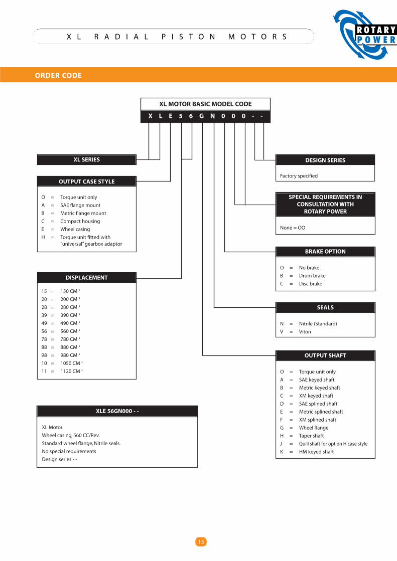
ORDER CODE
13
X L E 5 6 G N 0 0 0 - -
XL SERIES
OUTPUT CASE STYLE
O = Torque unit only
A = SAE flange mount
B = Metric flange mount
C = Compact housing
E = Wheel casing
H = Torque unit fitted with“universal”gearbox adaptor
DISPLACEMENT
15 = 150 CM 3
20 = 200 CM 3
28 = 280 CM 3
39 = 390 CM 3
49 = 490 CM 3
56 = 560 CM 3
78 = 780 CM 3
88 = 880 CM 3
98 = 980 CM 3
10 = 1050 CM 3
11 = 1120 CM 3
DESIGN SERIES
Factory specified
SPECIAL REQUIREMENTS INCONSULTATIONWITH
ROTARY POWER
None = OO
BRAKE OPTION
O = No brake
B = Drum brake
C = Disc brake
SEALS
N = Nitrile (Standard)
V = Viton
OUTPUT SHAFT
O = Torque unit only
A = SAE keyed shaft
B = Metric keyed shaft
C = XM keyed shaft
D = SAE splined shaft
E = Metric splined shaft
F = XM splined shaft
G = Wheel flange
H = Taper shaft
J = Quill shaft for option H case style
K = HM keyed shaft
XL MOTOR BASIC MODEL CODE
XLE 56GN000 - -
XL Motor
Wheel casing, 560 CC/Rev.
Standard wheel flange, Nitrile seals.
No special requirements
Design series - -
XF RANGE
XF05

XF FEATURES
Modular Concept
� Common torque unit with shaft or wheel motor housings
Pintle Design
� No axial bearing thrust support required
High Pressure Rating
� Designed to operate up to 420bar peak pressure
High Start Output Torque
� Pintle valve reduces mechanical losses
High Reliability
� Few moving parts
Low Maintenance
� Sealed/lubricated bearings in shaft and wheel motors
High Radial Load Capacity
� Heavy duty tapered roller bearings as standard
Freewheel
� True (zero displacement) available
Fully Reversible
� Equal torque in both rotation directions
Compact
� High power to weight ratio and minimum overall dimensions
� Speed sensor
� SAE or “G” ports
� Axial ports
� Viton seals
Customised solutions are available - Please consult Rotary Power
XF STANDARD OPTIONS
ROTARY POWER has over 40 years experience in the design and development of high quality Hydraulic equipment.
Our current product range includes :-
“A” Axial Piston Thruster Motors purpose designed for R.O.V applications. Fixed and variable capacities from 11.5 to 125 cm3/rev.
“C” Axial Piston Pumps�IRU�KLJK�DFFXUDF\�ÀXLG�PHWHULQJ�ZLWK�SUHFLVLRQ�ÀRZ�FRQWUROV�DQG�KLJK�SUHVVXUH�FDSDELOLW\��6SHFL¿FDOO\�GHVLJQHG�IRU�WKH�Polyurethane Industry. Capacities from 3 to 62 cm3/rev.
“XL” Cam Motors�RI� UDGLDO�SLVWRQ�FRQ¿JXUDWLRQ��:KHHO�VKDIW�WRUTXH�PRGXOH�FRQ¿JXUDWLRQV��'HVLJQ�RIIHUV�KLJK�VSHHG�FDSDELOLW\��&DSDFLWLHV�from 150 to 1120 cm3/rev.
“XF” Cam Motors� RI� UDGLDO� SLVWRQ� FRQ¿JXUDWLRQ�� 1(:� JHQHUDWLRQ�design, developed from the proven technology of the “XL” but with a smaller envelope, radial ports & more displacement.
“XK” Cam Motors��UDGLDO�SLVWRQ�FRQ¿JXUDWLRQ�RIIHULQJ�VWDWLF�G\QDPLF�brakes, single/2 speed, wheel/shaft & torque-module mount options. Heavy-Duty External Load & High-Speed options. Capacities from 1000 to 5000 cm3/rev.
“SMA” Motors� KHDY\�GXW\� UDGLDO� SLVWRQ�HFFHQWULF� FRQ¿JXUDWLRQ��offering excellent life. Withstands high mechanical and hydraulic shock loads. 350bar Continuous pressure rating. Speed & power UDWLQJV�VLJQL¿FDQWO\�JUHDWHU�WKDQ�VWDQGDUG�+7/6�PRWRUV�Displacements from 150 to 10500 cm3/rev.
Wholly owned subsidiaries in the USA and Germany and a network of distributors throughout the world provide product support in most countries.
ROTARY POWER is a company within British Engines (UK) Ltd group, which was established over 50 years ago.
The British Engines group of companies design manufacture and market a wide range of engineered products for offshore, electrical, construction, engineering and other industries, employing nearly 700 people on a 4600 sq m site in Newcastle upon Tyne, England.
X F 0 5 R A D I A L P I S T O N M O T O R S
1
XF COMPACT PISTON MOTORS
PAGE CONTENTS
2 TECHNICAL DATA
3 ORDER CODE
4 TORQUE UNIT DIMENSIONS
4 TORQUE UNIT CUSTOMER MOUNTING DIMENSIONS
5 TORQUE UNIT L10 LIFE
6 SHAFT MOTOR DIMENSIONS (Spline)
6 SHAFT MOTOR FRAME MOUNTING DIMENSIONS
7 SHAFT MOTOR DIMENSIONS (Key)
7 SHAFT MOTOR RADIAL LOAD LIMITS & L10 LIFE
8 WHEEL MOTOR DIMENSIONS
9 WHEEL MOTOR FRAME MOUNTING DIMENSIONS
9 WHEEL MOTOR RADIAL LOAD LIMITS & L10 LIFE
10 HYDRAULIC CONNECTIONS
11 OPTION (Shaft-up air vent port)
11 OPTION (Speed-sensor)
12 POWER ENVELOPES
12 DUTY CYCLE DATA
13 TORQUE OUTPUT
13 INPUT FLOW
14 NO LOAD PRESSURE DROP
14 CASE LEAKAGE
15 MINIMUM BOOST PRESSURE (Pumping)
15 FREEWHEELING
16 INSTALLATION & COMMISSIONING
17 RP MOTOR PRODUCT OVERVIEW
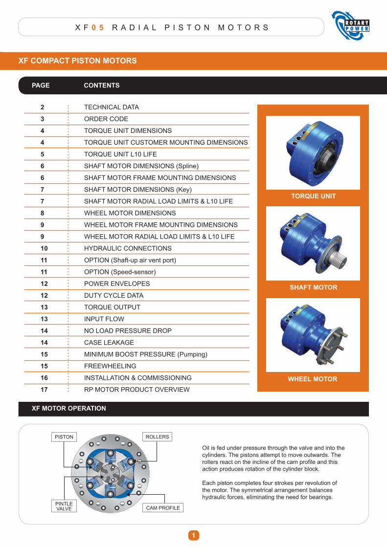
XF MOTOR OPERATION
PISTON ROLLERS
PINTLEVALVE CAM PROFILE
Oil is fed under pressure through the valve and into the cylinders. The pistons attempt to move outwards. The UROOHUV�UHDFW�RQ�WKH�LQFOLQH�RI�WKH�FDP�SUR¿OH�DQG�WKLV�action produces rotation of the cylinder block.
Each piston completes four strokes per revolution of the motor. The symmetrical arrangement balances hydraulic forces, eliminating the need for bearings.
TORQUE UNIT
SHAFT MOTOR
WHEEL MOTOR
X F 0 5 R A D I A L P I S T O N M O T O R S
2
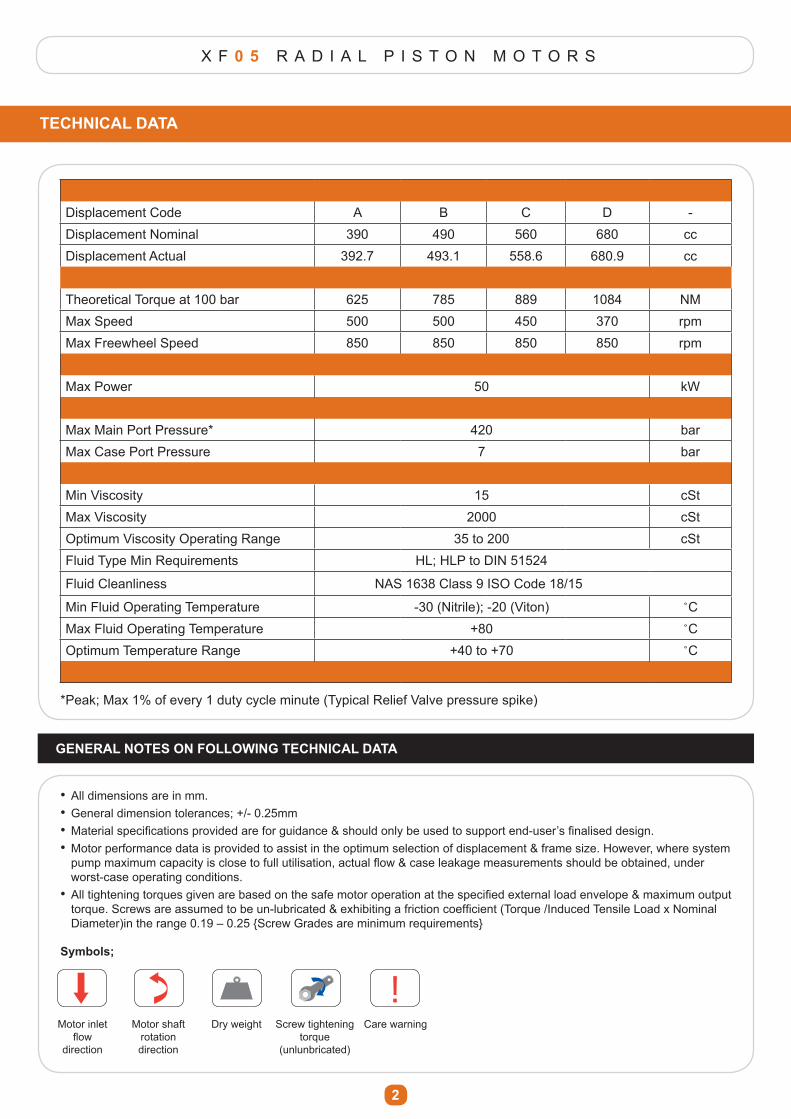
Displacement Code A B C D -Displacement Nominal 390 490 560 680 ccDisplacement Actual 392.7 493.1 558.6 680.9 cc
Theoretical Torque at 100 bar 625 785 889 1084 NMMax Speed 500 500 450 370 rpmMax Freewheel Speed 850 850 850 850 rpm
Max Power 50 kW
Max Main Port Pressure* 420 barMax Case Port Pressure 7 bar
Min Viscosity 15 cStMax Viscosity 2000 cStOptimum Viscosity Operating Range 35 to 200 cStFluid Type Min Requirements HL; HLP to DIN 51524
Fluid Cleanliness NAS 1638 Class 9 ISO Code 18/15
Min Fluid Operating Temperature -30 (Nitrile); -20 (Viton) ˚CMax Fluid Operating Temperature +80 ˚COptimum Temperature Range +40 to +70 ˚C
TECHNICAL DATA
*Peak; Max 1% of every 1 duty cycle minute (Typical Relief Valve pressure spike)
GENERAL NOTES ON FOLLOWING TECHNICAL DATA
� All dimensions are in mm.� General dimension tolerances; +/- 0.25mm�� 0DWHULDO�VSHFL¿FDWLRQV�SURYLGHG�DUH�IRU�JXLGDQFH��VKRXOG�RQO\�EH�XVHG�WR�VXSSRUW�HQG�XVHU¶V�¿QDOLVHG�GHVLJQ���Motor performance data is provided to assist in the optimum selection of displacement & frame size. However, where system � SXPS�PD[LPXP�FDSDFLW\�LV�FORVH�WR�IXOO�XWLOLVDWLRQ��DFWXDO�ÀRZ��FDVH�OHDNDJH�PHDVXUHPHQWV�VKRXOG�EH�REWDLQHG��XQGHU� worst-case operating conditions.�� $OO�WLJKWHQLQJ�WRUTXHV�JLYHQ�DUH�EDVHG�RQ�WKH�VDIH�PRWRU�RSHUDWLRQ�DW�WKH�VSHFL¿HG�H[WHUQDO�ORDG�HQYHORSH��PD[LPXP�RXWSXW�� WRUTXH��6FUHZV�DUH�DVVXPHG�WR�EH�XQ�OXEULFDWHG��H[KLELWLQJ�D�IULFWLRQ�FRHI¿FLHQW��7RUTXH��,QGXFHG�7HQVLOH�/RDG�[�1RPLQDO� Diameter)in the range 0.19 – 0.25 {Screw Grades are minimum requirements}
!Symbols;
! !
! !Motor inlet
ÀRZ�direction
Motor shaft rotation direction
Dry weight Screw tightening torque
(unlunbricated)
Care warning
X F 0 5 R A D I A L P I S T O N M O T O R S
3
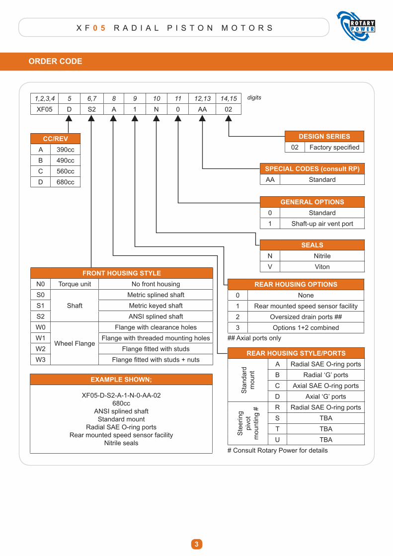
ORDER CODE
1,2,3,4 5 6,7 8 9 10 11 12,13 14,15
XF05 D S2 A 1 N 0 AA 02
digits
CC/REVA 390ccB 490ccC 560ccD 680cc
FRONT HOUSING STYLEN0 Torque unit No front housingS0
ShaftMetric splined shaft
S1 Metric keyed shaftS2 ANSI splined shaftW0
Wheel Flange
Flange with clearance holesW1 Flange with threaded mounting holesW2 )ODQJH�¿WWHG�ZLWK�VWXGVW3 )ODQJH�¿WWHG�ZLWK�VWXGV���QXWV
EXAMPLE SHOWN;
XF05-D-S2-A-1-N-0-AA-02680cc
ANSI splined shaftStandard mount
Radial SAE O-ring portsRear mounted speed sensor facility
Nitrile seals
DESIGN SERIES02 )DFWRU\�VSHFL¿HG
SPECIAL CODES (consult RP)AA Standard
GENERAL OPTIONS0 Standard1 Shaft-up air vent port
SEALSN NitrileV Viton
REAR HOUSING OPTIONS0 None1 Rear mounted speed sensor facility2 Oversized drain ports ##3 Options 1+2 combined
REAR HOUSING STYLE/PORTS
Sta
ndar
d m
ount
A Radial SAE O-ring portsB 5DGLDO�µ*¶�SRUWVC Axial SAE O-ring portsD $[LDO�µ*¶�SRUWV
Ste
erin
g pi
vot
mou
ntin
g # R Radial SAE O-ring ports
S TBAT TBAU TBA
# Consult Rotary Power for details
## Axial ports only
X F 0 5 R A D I A L P I S T O N M O T O R S
4
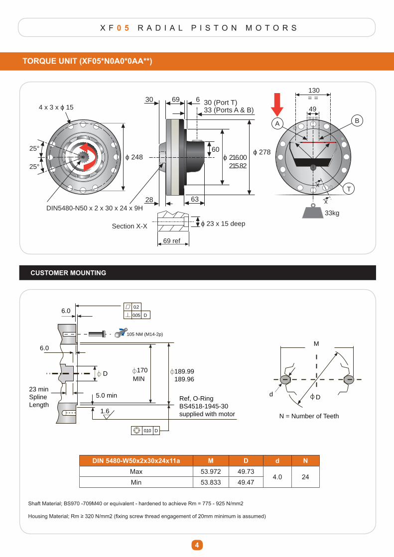
TORQUE UNIT (XF05*N0A0*0AA**)
CUSTOMER MOUNTING
4 x 3 x o 15
o 248
DIN5480-N50 x 2 x 30 x 24 x 9H
25°
25°
28
30 69 30 (Port T)33 (Ports A & B)
6
o 27860o 216.00 215.82
63
49
130
= =
= =
T
BA
33kg
69 ref
o 23 x 15 deepSection X-X
x
x
6.00.2
0.05
105 NM (M14-2p)
D
6.0
1.6
DMIN
170 189.99189.96
5.0 min Ref, O-RingBS4518-1945-30supplied with motor
23 minSplineLength
M
D
N = Number of Teeth
d
0.10 D
DIN 5480-W50x2x30x24x11a M D d NMax 53.972 49.73
4.0 24Min 53.833 49.47
Shaft Material; BS970 -709M40 or equivalent - hardened to achieve Rm = 775 - 925 N/mm2
+RXVLQJ�0DWHULDO��5P�������1�PP���¿[LQJ�VFUHZ�WKUHDG�HQJDJHPHQW�RI���PP�PLQLPXP�LV�DVVXPHG�
X F 0 5 R A D I A L P I S T O N M O T O R S
5
TORQUE UNIT
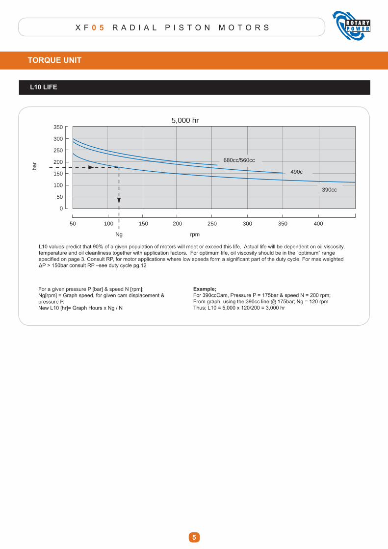
L10 LIFE
5,000 hr
680cc/560cc
490c
390cc
50 100 150 200 250 300 350 400
rpmNg
bar
350
300
250
200
150
100
50
0
L10 values predict that 90% of a given population of motors will meet or exceed this life. Actual life will be dependent on oil viscosity, temperature and oil cleanliness together with application factors. For optimum life, oil viscosity should be in the “optimum” range VSHFL¿HG�RQ�SDJH����&RQVXOW�53��IRU�PRWRU�DSSOLFDWLRQV�ZKHUH�ORZ�VSHHGV�IRUP�D�VLJQL¿FDQW�SDUW�RI�WKH�GXW\�F\FOH��)RU�PD[�ZHLJKWHG�ǻ3�!����EDU�FRQVXOW�53�±VHH�GXW\�F\FOH�SJ���
Example;For 390ccCam, Pressure P = 175bar & speed N = 200 rpm;From graph, using the 390cc line @ 175bar; Ng = 120 rpmThus; L10 = 5,000 x 120/200 = 3,000 hr
For a given pressure P [bar] & speed N [rpm];Ng[rpm] = Graph speed, for given cam displacement & pressure P.New L10 [hr]= Graph Hours x Ng / N
X F 0 5 R A D I A L P I S T O N M O T O R S
6
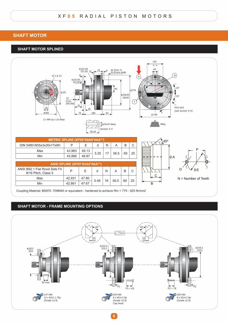
SHAFT MOTOR
SHAFT MOTOR SPLINED
12 x o 13
o 175
2 x M6-1p x 10 deep
49
130
= =
= =
T
BA
46kg
25°
25°
x
xo 248
4x2x o15(see section X-X)
38
o 150
o 115.00 114.95
8
o 222.00 221.82 12 678
o 278
o 216.00 215.82
30 (Port T)33 (Ports A&B)
60
6318979
70
47FULLSPLINE
10
78 refSection X-X
o23x15 deep
METRIC SPLINE (XF05*S0A0*0AA**)DIN 5480-N55x3x30x17x9H P E d N A B C
Max 43.963 49.135.25 17 56.5 69 25
Min 43.866 48.87
ANSI SPLINE (XF05*S2A0*0AA**)ANSI B92.1 Flat Rood Side Fit
8/16 Pitch, Class 5 P E d N A B C
Max 42.931 47.805.49 16 56.0 69 25
Min 42.861 47.67
Coupling Material; BS970 -709M40 or equivalent - hardened to achieve Rm = 775 - 925 N/mm2
45º
C
A
E
P
D
B
N = Number of Teeth
45º
C
A
E
P
D
B
N = Number of Teeth
SHAFT MOTOR - FRAME MOUNTING OPTIONS
o 115.2 115.1
o 222.2 222.1 o 216.2
216.1
50 max
P1 + 63 P2 + 78P1
147 NM12 x M12-1.75p(Grade 12.9)
250 NM8 x M14-2.0p(Grade 12.9)Cap head
250 NM8 x M14-2.0p(Grade 12.9)
P2
45° 45°
1.51.0
1.51.0
0.2
X F 0 5 R A D I A L P I S T O N M O T O R S
7
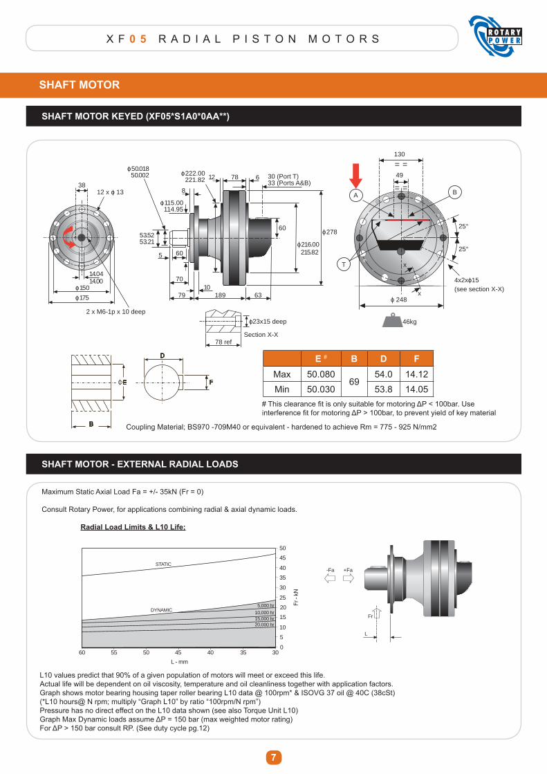
SHAFT MOTOR
SHAFT MOTOR KEYED (XF05*S1A0*0AA**)
12 x o 13
o 175
2 x M6-1p x 10 deep
49
130
= =
= =
T
BA
46kg
25°
25°
x
xo 248
4x2xo15(see section X-X)
38
o 150
o 115.00 114.95
8
o 222.00 221.82
o 50.018 50.002 12 678
o 278
o 216.00 215.82
30 (Port T)33 (Ports A&B)
60
6318979
70
5
10
14.0414.00
53.5253.21
60
78 refSection X-X
o23x15 deep
B
E
D
F
E # B D FMax 50.080
6954.0 14.12
Min 50.030 53.8 14.05
Coupling Material; BS970 -709M40 or equivalent - hardened to achieve Rm = 775 - 925 N/mm2
SHAFT MOTOR - EXTERNAL RADIAL LOADS
60 55 50 45 40
L - mm
20,000 hr15,000 hr10,000 hr
5,000 hrDYNAMIC
STATIC
35 300
5
10
15
20
25
30
35
40
45
50
Maximum Static Axial Load Fa = +/- 35kN (Fr = 0)
Consult Rotary Power, for applications combining radial & axial dynamic loads.
Radial Load Limits & L10 Life;
L10 values predict that 90% of a given population of motors will meet or exceed this life.Actual life will be dependent on oil viscosity, temperature and oil cleanliness together with application factors.Graph shows motor bearing housing taper roller bearing L10 data @ 100rpm* & ISOVG 37 oil @ 40C (38cSt)(*L10 hours@ N rpm; multiply “Graph L10” by ratio “100rpm/N rpm”)Pressure has no direct effect on the L10 data shown (see also Torque Unit L10)*UDSK�0D[�'\QDPLF�ORDGV�DVVXPH�ǻ3� �����EDU��PD[�ZHLJKWHG�PRWRU�UDWLQJ�)RU�ǻ3�!�����EDU�FRQVXOW�53���6HH�GXW\�F\FOH�SJ����
L
Fr
-Fa +Fa
��7KLV�FOHDUDQFH�¿W�LV�RQO\�VXLWDEOH�IRU�PRWRULQJ�ǻ3������EDU��8VH�LQWHUIHUHQFH�¿W�IRU�PRWRULQJ�ǻ3�!����EDU��WR�SUHYHQW�\LHOG�RI�NH\�PDWHULDO
X F 0 5 R A D I A L P I S T O N M O T O R S
8
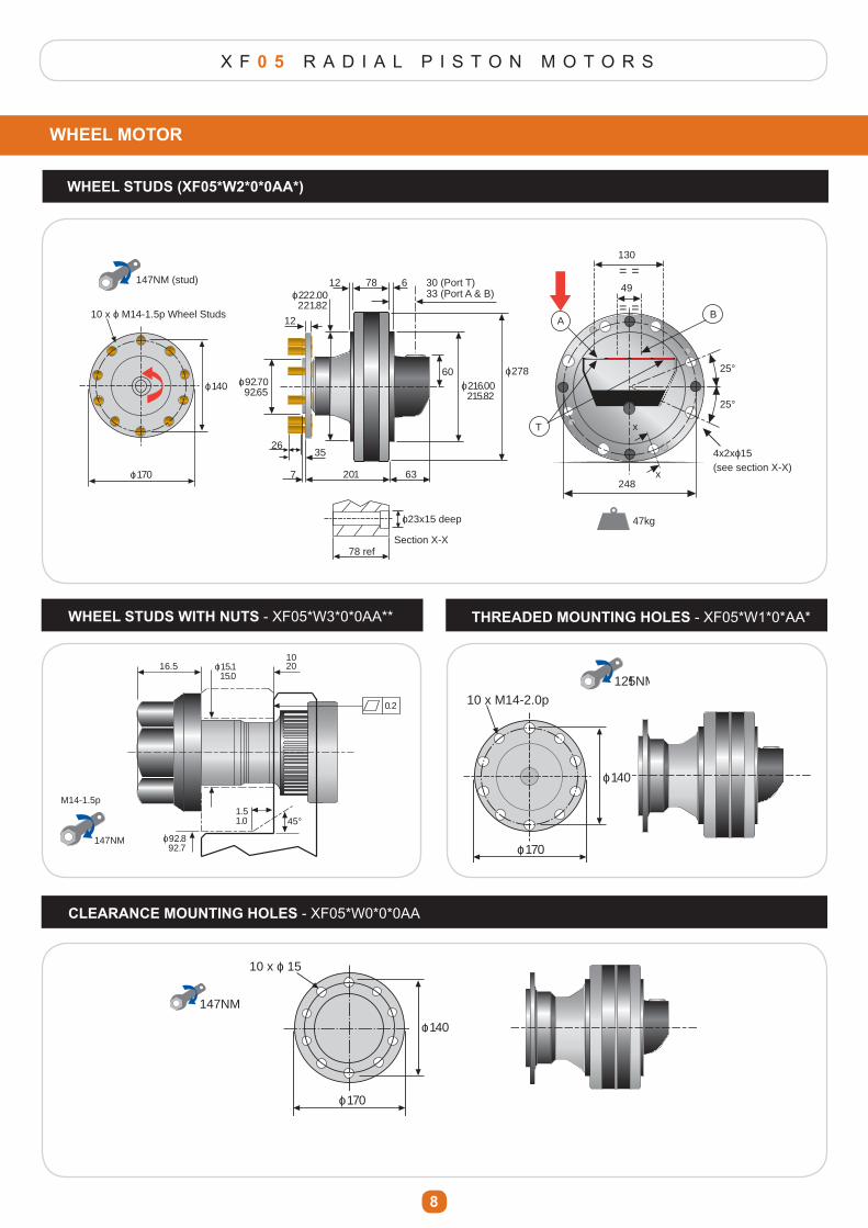
WHEEL MOTOR
WHEEL STUDS (XF05*W2*0*0AA*)
49
130
= =
= =
T
BA
47kg
25°
25°
x
x248
4x2xo15(see section X-X)
12
7812 6
7
35
201
o 92.70 92.65
63
60
26
o 216.00 215.82
o 278
30 (Port T)33 (Port A & B)o 222.00
221.82
78 refSection X-X
10 x o M14-1.5p Wheel Studs
o 140
o 170
147NM (stud)
o23x15 deep
WHEEL STUDS WITH NUTS - XF05*W3*0*0AA** THREADED MOUNTING HOLES - XF05*W1*0*AA*
0.2
16.51020o 15.1
15.0
45°
o 92.8 92.7
1.51.0
147NM
M14-1.5p
10 x M14-2.0p
o 140
o 170
125NM
CLEARANCE MOUNTING HOLES - XF05*W0*0*0AA
10 x o 15
o 140
o 170
147NM
10 x M14-2.0p
o 140
o 170
125NM
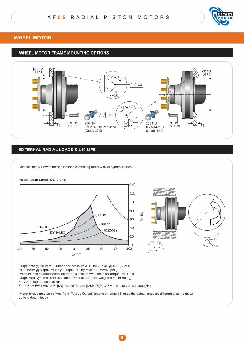
X F 0 5 R A D I A L P I S T O N M O T O R S
9
WHEEL MOTOR FRAME MOUNTING OPTIONS
45°
1.51.0
0.2
45°
1.51.0
0.2
o 222.2 222.1 o 216.2
216.1
P1 P2P1 + 63 P2 + 78250 NM8 x M14-2.0p cap head(Grade 12.9)
250 NM8 x M14-2.0p(Grade 12.9)
EXTERNAL RADIAL LOADS & L10 LIFE
Graph data @ 100rpm*, 20bar back pressure & ISOVG 37 oil @ 40C (38cSt)(*L10 hours@ N rpm; multiply “Graph L10” by ratio “100rpm/N rpm”)Pressure has no direct effect on the L10 data shown (see also Torque Unit L10)*UDSK�0D[�'\QDPLF�ORDGV�DVVXPH�ǻ3� �����EDU��PD[�ZHLJKWHG�PRWRU�UDWLQJ�)RU�ǻ3�!�����EDU�FRQVXOW�53)U �¥�)W2 + Fw2) where; Ft [kN]= Motor Torque [kN.M]/R[M] & Fw = Wheel Vertical Load[kN]
(Motor torque may be derived from “Torque Output” graphs on page 15, once the actual pressure differential at the motorports is determined)
Consult Rotary Power, for applications combining radial & axial dynamic loads.
-L+L
FrFr
R
Fr
Ft
Fw
0 -25 -50 -75
L- mm
0
20
-100255075100
40
60
80
100
120
140
1,000 hr
5,000 hr
50,000 hrSTATIC
DYNAMIC
WHEEL MOTOR
Radial Load Limits & L10 Life;
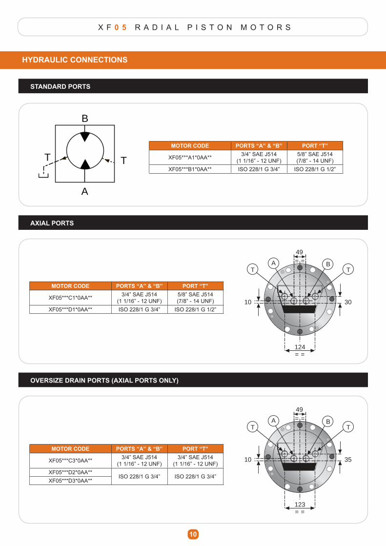
X F 0 5 R A D I A L P I S T O N M O T O R S
10
HYDRAULIC CONNECTIONS
B
A
TTMOTOR CODE PORTS “A” & “B” PORT “T”
XF05***A1*0AA** 3/4” SAE J514(1 1/16” - 12 UNF)
5/8” SAE J514(7/8” - 14 UNF)
XF05***B1*0AA** ISO 228/1 G 3/4” ISO 228/1 G 1/2”
AXIAL PORTS
49= =
= =
T TBA
124
10 30
49= =
= =
T TBA
123
10 35
OVERSIZE DRAIN PORTS (AXIAL PORTS ONLY)
MOTOR CODE PORTS “A” & “B” PORT “T”
XF05***C1*0AA** 3/4” SAE J514(1 1/16” - 12 UNF)
5/8” SAE J514(7/8” - 14 UNF)
XF05***D1*0AA** ISO 228/1 G 3/4” ISO 228/1 G 1/2”
MOTOR CODE PORTS “A” & “B” PORT “T”
XF05***C3*0AA** 3/4” SAE J514(1 1/16” - 12 UNF)
3/4” SAE J514(1 1/16” - 12 UNF)
XF05***D2*0AA**ISO 228/1 G 3/4” ISO 228/1 G 3/4”
XF05***D3*0AA**
STANDARD PORTS

X F 0 5 R A D I A L P I S T O N M O T O R S
11
OPTIONS
SHAFT-UP AIR VENT PORT (XF05******1AA**)
15°
3/8” SAEJ514 (9/16” -18 UNF0(1-1/16” -12 UNF)
Case Drain Line
T
Ensure drain line routingprevents air traps forming
SPEED SENSOR
NROTOR
X
X
67.5
(0.5 COUNTER-CLOCKWISE ROTATION FROM SENSOR CONTACT POSITION)
CUSTOMER-SUPPLIED SEALING WASHER IS REQUIRED HERE, TO PREVENT EXTERNAL LEAKAGE FROM SENSOR THREADS
CUSTOMER-SUPPLIED SENSOR
SECTION X-X
3
1
o 135
36 x o6
ROTOR
PRIOR TO ADJUSTING THE SPEED SENSOR ENSURE THE ROTOR IS POSITIONED TOWARDS THE PORTS. THIS CAN BE ACHIEVED BY STANDING THE MOTOR VERTICALLY, WITH THE PORTS ALONG THE BOTTOM.
MAINTAIN 0.5 GAP!
MOTOR CODE PORT “N”XF05****1*0AA**
M12-1.0pXF05****3*0AA**
!
!
!
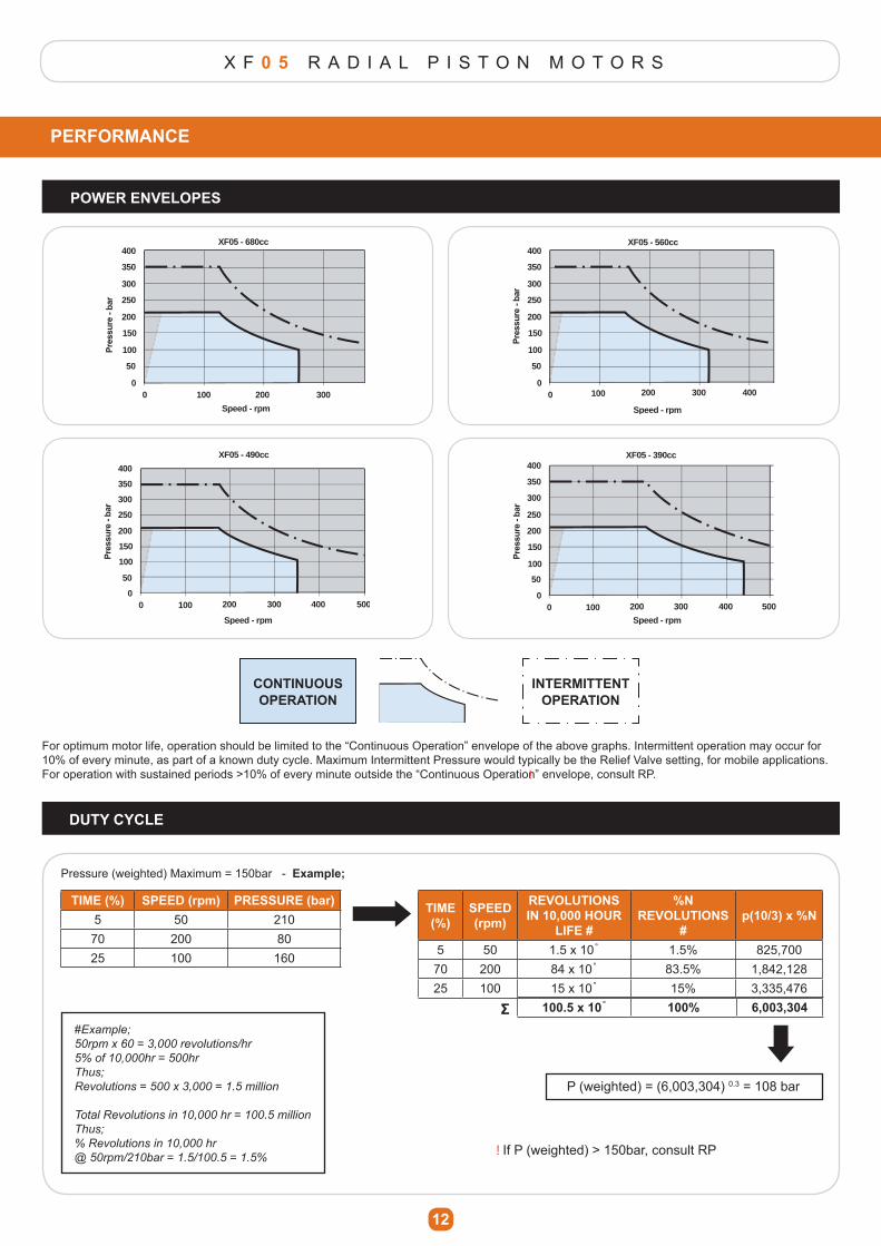
X F 0 5 R A D I A L P I S T O N M O T O R S
12
PERFORMANCE
0 100 200 300
Speed - rpm
XF05 - 680cc
0
50
100
150
200
250
300
350
400
0 100 200 300 400
Speed - rpm
XF05 - 560cc
0
50
100
150
200
250
300
350
400
0 100 200 300 400 500
Speed - rpm
XF05 - 490cc
0
50
100
150
200
250
300
350
400
0 100 200 300 400 500
Speed - rpm
XF05 - 390cc
0
50
100
150
200
250
300
350
400
For optimum motor life, operation should be limited to the “Continuous Operation” envelope of the above graphs. Intermittent operation may occur for 10% of every minute, as part of a known duty cycle. Maximum Intermittent Pressure would typically be the Relief Valve setting, for mobile applications. )RU�RSHUDWLRQ�ZLWK�VXVWDLQHG�SHULRGV�!����RI�HYHU\�PLQXWH�RXWVLGH�WKH�³&RQWLQXRXV�2SHUDWLRQ´�HQYHORSH��FRQVXOW�53��
DUTY CYCLE
TIME (%) SPEED (rpm) PRESSURE (bar)5 50 210
70 200 8025 100 160
Pressure (weighted) Maximum = 150bar - Example;
TIME (%)
SPEED (rpm)
REVOLUTIONS IN 10,000 HOUR
LIFE #
%N REVOLUTIONS
#p(10/3) x %N
5 50 1.5 x 10˚ 1.5% 825,70070 200 84 x 10˚ 83.5% 1,842,12825 100 15 x 10˚ 15% 3,335,476
100.5 x 10˚ 100% گ6,003,304
P (weighted) = (6,003,304) 0.3 = 108 bar
#Example;
50rpm x 60 = 3,000 revolutions/hr
5% of 10,000hr = 500hr
Thus;
Revolutions = 500 x 3,000 = 1.5 million
Total Revolutions in 10,000 hr = 100.5 million
Thus;
% Revolutions in 10,000 hr
@ 50rpm/210bar = 1.5/100.5 = 1.5%,I�3��ZHLJKWHG��!����EDU��FRQVXOW�53
POWER ENVELOPES
!
!
CONTINUOUS OPERATION
INTERMITTENT OPERATION
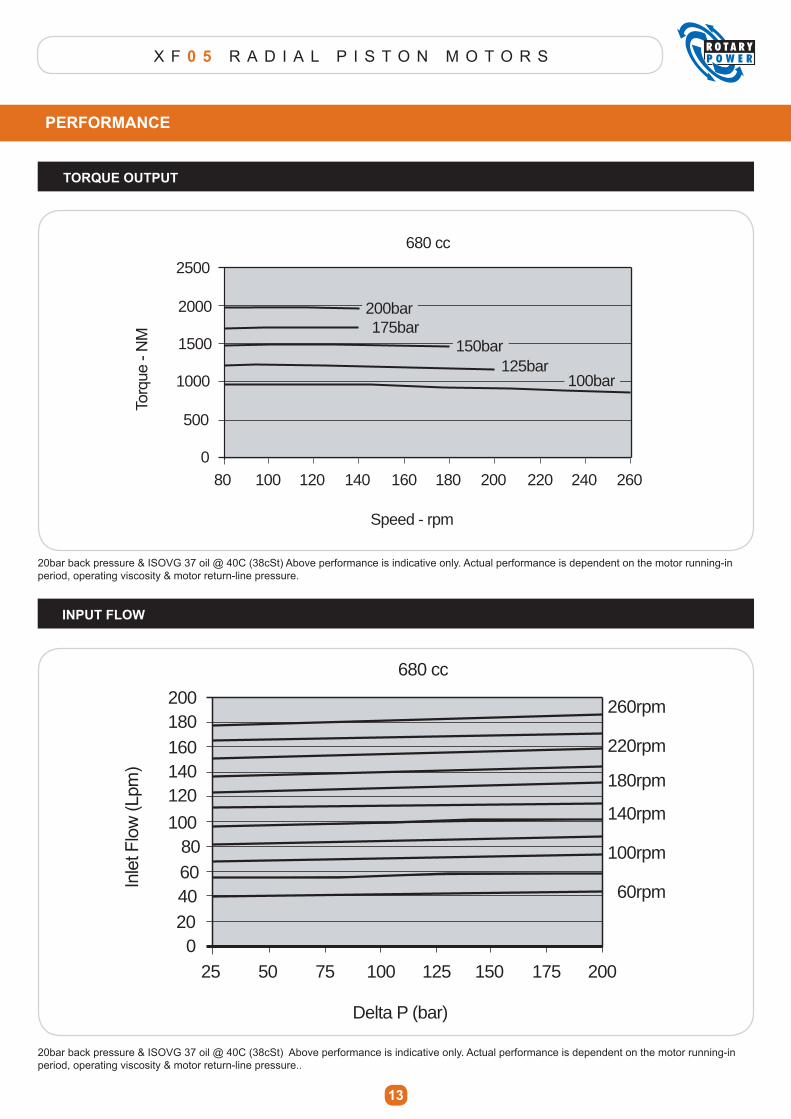
X F 0 5 R A D I A L P I S T O N M O T O R S
13
PERFORMANCE
INPUT FLOW
80 100 120 140 160 180 200 220 240 260
Speed - rpm
175bar
125bar
680 cc
0
500
1000
1500
2000
2500
200bar
150bar
100bar
25 50 75 100 125 150 175 200
Delta P (bar)
680 cc
020406080
100
120140160180200
60rpm
100rpm
140rpm
180rpm
220rpm
260rpm
20bar back pressure & ISOVG 37 oil @ 40C (38cSt) Above performance is indicative only. Actual performance is dependent on the motor running-in period, operating viscosity & motor return-line pressure.
20bar back pressure & ISOVG 37 oil @ 40C (38cSt) Above performance is indicative only. Actual performance is dependent on the motor running-in period, operating viscosity & motor return-line pressure..
TORQUE OUTPUT
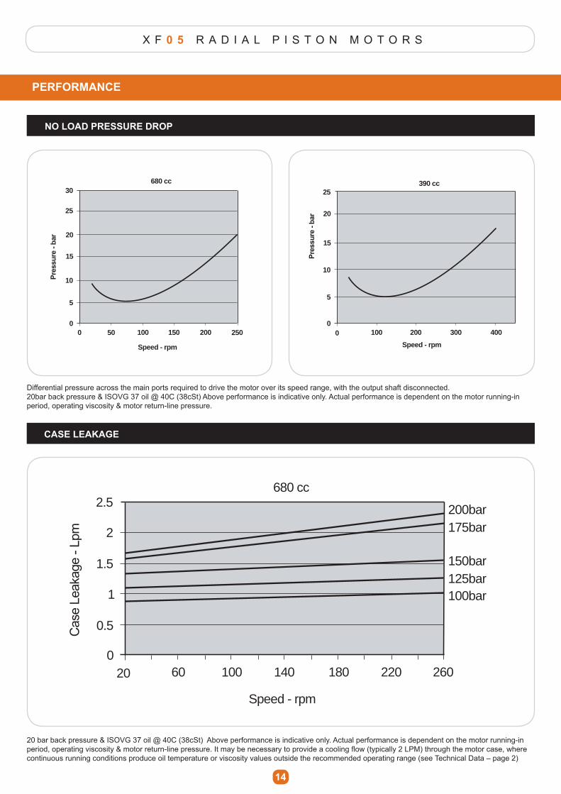
X F 0 5 R A D I A L P I S T O N M O T O R S
PERFORMANCE
NO LOAD PRESSURE DROP
14
CASE LEAKAGE
Differential pressure across the main ports required to drive the motor over its speed range, with the output shaft disconnected.20bar back pressure & ISOVG 37 oil @ 40C (38cSt) Above performance is indicative only. Actual performance is dependent on the motor running-in period, operating viscosity & motor return-line pressure.
20 bar back pressure & ISOVG 37 oil @ 40C (38cSt) Above performance is indicative only. Actual performance is dependent on the motor running-in SHULRG��RSHUDWLQJ�YLVFRVLW\��PRWRU�UHWXUQ�OLQH�SUHVVXUH��,W�PD\�EH�QHFHVVDU\�WR�SURYLGH�D�FRROLQJ�ÀRZ��W\SLFDOO\���/30��WKURXJK�WKH�PRWRU�FDVH��ZKHUH�continuous running conditions produce oil temperature or viscosity values outside the recommended operating range (see Technical Data – page 2)
0 100 200
Speed - rpm
680 cc
0
5
10
15
20
25
30
0 100 200 300 400
Speed - rpm
390 cc
0
5
10
15
20
25
50 150 2500 100 200
Speed - rpm
680 cc
0
5
10
15
20
25
30
0 100 200 300 400
Speed - rpm
390 cc
0
5
10
15
20
25
50 150 250
20 100 14060 180 220 260
100bar125bar150bar
175bar200bar
Speed - rpm
680 cc
0
0.5
1
1.5
2
2.5
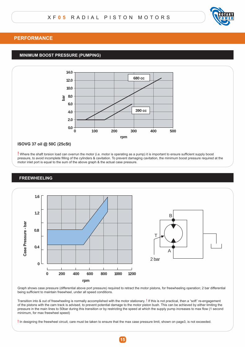
X F 0 5 R A D I A L P I S T O N M O T O R S
PERFORMANCE
MINIMUM BOOST PRESSURE (PUMPING)
15
FREEWHEELING
0 200 300100 400 500
rpm
0.0
2.0
4.0
6.0
8.0
10.0
12.0
14.0
680 cc
390 cc
ISOVG 37 oil @ 50C (25cSt)
!�:KHUH�WKH�VKDIW�WRUVLRQ�ORDG�FDQ�RYHUUXQ�WKH�PRWRU��L�H��PRWRU�LV�RSHUDWLQJ�DV�D�SXPS��LW�LV�LPSRUWDQW�WR�HQVXUH�VXI¿FLHQW�VXSSO\�ERRVW�SUHVVXUH��WR�DYRLG�LQFRPSOHWH�¿OOLQJ�RI�WKH�F\OLQGHUV��FDYLWDWLRQ��7R�SUHYHQW�GDPDJLQJ�FDYLWDWLRQ��WKH�PLQLPXP�ERRVW�SUHVVXUH�UHTXLUHG�DW�WKH�motor inlet port is equal to the sum of the above graph & the actual case pressure.
0 400 600200 800 1000 1200
rpm
0
0.4
0.8
1.2
1.6
T
B
A
2 bar
Graph shows case pressure (differential above port pressure) required to retract the motor pistons, for freewheeling operation; 2 bar differential EHLQJ�VXI¿FLHQW�WR�PDLQWDLQ�IUHHZKHHO��XQGHU�DOO�VSHHG�FRQGLWLRQV�
Transition into & out of freewheeling is normally accomplished with the motor stationary. ! If this is not practical, then a “soft” re-engagement of the pistons with the cam track is advised, to prevent potential damage to the motor piston bush. This can be achieved by either limiting the SUHVVXUH�LQ�WKH�PDLQ�OLQHV�WR���EDU�GXULQJ�WKLV�WUDQVLWLRQ�RU�E\�UHVWULFWLQJ�WKH�VSHHG�DW�ZKLFK�WKH�VXSSO\�SXPS�LQFUHDVHV�WR�PD[�ÀRZ����VHFRQG�minimum, for max freewheel speed)
! In designing the freewheel circuit, care must be taken to ensure that the max case pressure limit, shown on page3, is not exceeded.

X F 0 5 R A D I A L P I S T O N M O T O R S
16
INSTALLATION
COMMISSIONING
!
Detailed installation drawings are available on request.
Motor shaft drives should be designed to eliminate unnecessary axial & radial loads; thus prolonging outputhousing bearing life.
.H\HG�VKDIWV�DUH�UHFRPPHQGHG�IRU�D�ÀH[LEOH�FRXSOLQJ�RXWSXW�FRQQHFWLRQ�
Splined shafts are suited to installations where the driven shaft & motor are rigidly mounted.(Alignment between motor & driven shaft should be maintained within 0.05mm)
For maximum life, splines should be lubricated with Molybdenum Disulphide grease, on assembly, or preferablyrun in oil lubrication.
Do not remove protective plugs from hydraulic or speed sensor ports until immediate connection into the systempipe work is made.
Always examine the motor externally to ensure no damage has been caused in transit.
Case drain lines, connected to either of the “T” ports indicated, should be returned directly to tank.
The “T” port should be positioned as the uppermost port, to ensure air is properly vented from the pipe work.
Where the motor is mounted with shaft uppermost, an air vent port is necessary to ensure proper lubrication of the bearing housing shaft seal (General Option “1” in Product Code).
7KH�ERUH�VL]H�RI�WKH�FDVH�GUDLQ�OLQH�VKRXOG�EH�VXI¿FLHQW�WR�HQVXUH�WKDW�FDVH�SUHVVXUH�GRHV�QRW�H[FHHG�WKH�PD[LPXP�VSHFL¿HG�LQ�³7HFKQLFDO�'DWD´�RQ�SDJH����XQGHU�DOO�RSHUDWLQJ�FRQGLWLRQV (especially during cold-start)
�,I�WKH�GLIIHUHQFH�EHWZHHQ�PRWRU�FDVH�GUDLQ�WHPSHUDWXUH��WKH�WDQN�WHPSHUDWXUH�LV�!����&��WKHQ�D�FDVH�ZDUPLQJ�ÀRZ�PXVW�EH�SURYLGHG��WR�SUHYHQW�SRVVLEOH�WKHUPDO�VKRFN�GDPDJH�WR�WKH�PRWRU�
For series connection of motors consult ROTARY POWER
3ULRU�WR�PRWRU�DVVHPEO\��WKRURXJKO\�GH�VFDOH��FOHDQ��ÀXVK�DOO�SLSH�ZRUN��¿WWLQJV��RLO�WDQN�
)LOO�WKH�V\VWHP�ZLWK�QHZ��¿OWHUHG�RLO�(refer to “Technical Data” on page 3 for motor oil requirements)
Fill the motor case & drain line with oil through the case drain port “T” & re-connect case drain pipe work.
&KHFN�URWDWLRQ�GLUHFWLRQ�UHTXLUHG�LV�FRQVLVWHQW�ZLWK�WKH�GLUHFWLRQ�RI�LQOHW�ÀRZ�(see relevant motor dimensional data)
Start the drive pump at lowest practical speed to prime the system (for combustion engines turn over the starter motor
for a few seconds at a time. For electric motors use a series of rapid on/off cycles)
5XQ�WKH�V\VWHP�DW�KLJK�ÀRZ��ORZ�SUHVVXUH��DFWXDWH�DOO�V\VWHPV�LQ�DOO�PRGHV�XQWLO�DOO�HQWUDLQHG�DLU�LV�SXUJHG�
Check & top-up oil levels if necessary
Check & adjust settings where necessary, in compliance with all system & component supplier requirements.
Check steady state operating temperature is in compliance with all system & component supplier requirements.
Check for & repair any external leaks.
$IWHU�WKH�¿UVW�IHZ�KRXUV�RI�UXQQLQJ��FOHDQ�RU�UHQHZ�DOO�¿OWHUV��DV�DSSURSULDWH�
IF IN DOUBT CONSULT ROTARY POWER

X F 0 5 R A D I A L P I S T O N M O T O R S
17
APPLICATIONS
AUGER FEEDER DRIVE CUTTER-HEAD DRIVE
DRUM SCREENER ASPHALT PAVER
HARVESTER ROAD PLANER
XF RANGE
XF10
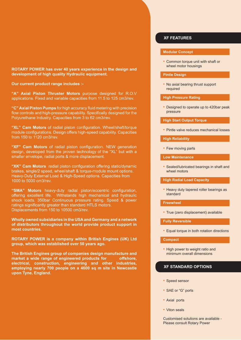
XF FEATURES
Modular Concept
� Common torque unit with shaft or wheel motor housings
Pintle Design
� No axial bearing thrust support required
High Pressure Rating
� Designed to operate up to 420bar peak pressure
High Start Output Torque
� Pintle valve reduces mechanical losses
High Reliability
� Few moving parts
Low Maintenance
� Sealed/lubricated bearings in shaft and wheel motors
High Radial Load Capacity
� Heavy duty tapered roller bearings as standard
Freewheel
� True (zero displacement) available
Fully Reversible
� Equal torque in both rotation directions
Compact
� High power to weight ratio and minimum overall dimensions
� Speed sensor
� SAE or “G” ports
� Axial ports
� Viton seals
Customised solutions are available - Please consult Rotary Power
XF STANDARD OPTIONS
ROTARY POWER has over 40 years experience in the design and development of high quality Hydraulic equipment.
Our current product range includes :-
“A” Axial Piston Thruster Motors purpose designed for R.O.V applications. Fixed and variable capacities from 11.5 to 125 cm3/rev.
“C” Axial Piston Pumps�IRU�KLJK�DFFXUDF\�ÀXLG�PHWHULQJ�ZLWK�SUHFLVLRQ�ÀRZ�FRQWUROV�DQG�KLJK�SUHVVXUH�FDSDELOLW\��6SHFL¿FDOO\�GHVLJQHG�IRU�WKH�Polyurethane Industry. Capacities from 3 to 62 cm3/rev.
“XL” Cam Motors�RI� UDGLDO�SLVWRQ�FRQ¿JXUDWLRQ��:KHHO�VKDIW�WRUTXH�PRGXOH�FRQ¿JXUDWLRQV��'HVLJQ�RIIHUV�KLJK�VSHHG�FDSDELOLW\��&DSDFLWLHV�from 150 to 1120 cm3/rev.
“XF” Cam Motors� RI� UDGLDO� SLVWRQ� FRQ¿JXUDWLRQ�� 1(:� JHQHUDWLRQ�design, developed from the proven technology of the “XL” but with a smaller envelope, radial ports & more displacement.
“XK” Cam Motors��UDGLDO�SLVWRQ�FRQ¿JXUDWLRQ�RIIHULQJ�VWDWLF�G\QDPLF�brakes, single/2 speed, wheel/shaft & torque-module mount options. Heavy-Duty External Load & High-Speed options. Capacities from 1000 to 5000 cm3/rev.
“SMA” Motors� KHDY\�GXW\� UDGLDO� SLVWRQ�HFFHQWULF� FRQ¿JXUDWLRQ��offering excellent life. Withstands high mechanical and hydraulic shock loads. 350bar Continuous pressure rating. Speed & power UDWLQJV�VLJQL¿FDQWO\�JUHDWHU�WKDQ�VWDQGDUG�+7/6�PRWRUV�Displacements from 150 to 10500 cm3/rev.
Wholly owned subsidiaries in the USA and Germany and a network of distributors throughout the world provide product support in most countries.
ROTARY POWER is a company within British Engines (UK) Ltd group, which was established over 50 years ago.
The British Engines group of companies design manufacture and market a wide range of engineered products for offshore, electrical, construction, engineering and other industries, employing nearly 700 people on a 4600 sq m site in Newcastle upon Tyne, England.

X F 1 0 R A D I A L P I S T O N M O T O R S
1
XF COMPACT PISTON MOTORS
PAGE CONTENTS
2 TECHNICAL DATA
3 ORDER CODE
4 TORQUE UNIT DIMENSIONS
4 TORQUE UNIT CUSTOMER MOUNTING DIMENSIONS
5 TORQUE UNIT L10 LIFE
6 SHAFT MOTOR DIMENSIONS (Spline)
6 SHAFT MOTOR FRAME MOUNTING DIMENSIONS
7 SHAFT MOTOR DIMENSIONS (Key)
7 SHAFT MOTOR RADIAL LOAD LIMITS & L10 LIFE
8 WHEEL MOTOR DIMENSIONS
9 WHEEL MOTOR FRAME MOUNTING DIMENSIONS
9 WHEEL MOTOR RADIAL LOAD LIMITS & L10 LIFE
10 HYDRAULIC CONNECTIONS
11 OPTION (Shaft-up air vent port)
11 OPTION (Speed-sensor)
12 POWER ENVELOPES
12 DUTY CYCLE DATA
13 TORQUE OUTPUT
13 INPUT FLOW
14 NO LOAD PRESSURE DROP
14 CASE LEAKAGE
15 MINIMUM BOOST PRESSURE (Pumping)
15 FREEWHEELING
16 INSTALLATION & COMMISSIONING
17 RP MOTOR PRODUCT OVERVIEW
XF MOTOR OPERATION
PISTON ROLLERS
PINTLEVALVE CAM PROFILE
Oil is fed under pressure through the valve and into the cylinders. The pistons attempt to move outwards. The UROOHUV�UHDFW�RQ�WKH�LQFOLQH�RI�WKH�FDP�SUR¿OH�DQG�WKLV�action produces rotation of the cylinder block.
Each piston completes four strokes per revolution of the motor. The symmetrical arrangement balances hydraulic forces, eliminating the need for bearings.
TORQUE UNIT
SHAFT MOTOR
WHEEL MOTOR
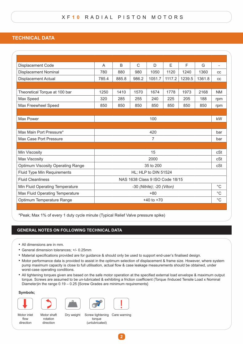
X F 1 0 R A D I A L P I S T O N M O T O R S
2
Displacement Code A B C D E F G -Displacement Nominal 780 880 980 1050 1120 1240 1360 ccDisplacement Actual 785.4 885.8 986.2 1051.7 1117.2 1239.5 1361.8 cc
Theoretical Torque at 100 bar 1250 1410 1570 1674 1778 1973 2168 NMMax Speed 320 285 255 240 225 205 188 rpmMax Freewheel Speed 850 850 850 850 850 850 850 rpm
Max Power 100 kW
Max Main Port Pressure* 420 barMax Case Port Pressure 7 bar
Min Viscosity 15 cStMax Viscosity 2000 cStOptimum Viscosity Operating Range 35 to 200 cStFluid Type Min Requirements HL; HLP to DIN 51524
Fluid Cleanliness NAS 1638 Class 9 ISO Code 18/15
Min Fluid Operating Temperature -30 (Nitrile); -20 (Viton) °CMax Fluid Operating Temperature +80 °COptimum Temperature Range +40 to +70 °C
TECHNICAL DATA
*Peak; Max 1% of every 1 duty cycle minute (Typical Relief Valve pressure spike)
GENERAL NOTES ON FOLLOWING TECHNICAL DATA
� All dimensions are in mm.� General dimension tolerances; +/- 0.25mm�� 0DWHULDO�VSHFL¿FDWLRQV�SURYLGHG�DUH�IRU�JXLGDQFH��VKRXOG�RQO\�EH�XVHG�WR�VXSSRUW�HQG�XVHU¶V�¿QDOLVHG�GHVLJQ���Motor performance data is provided to assist in the optimum selection of displacement & frame size. However, where system � SXPS�PD[LPXP�FDSDFLW\�LV�FORVH�WR�IXOO�XWLOLVDWLRQ��DFWXDO�ÀRZ��FDVH�OHDNDJH�PHDVXUHPHQWV�VKRXOG�EH�REWDLQHG��XQGHU� worst-case operating conditions.�� $OO�WLJKWHQLQJ�WRUTXHV�JLYHQ�DUH�EDVHG�RQ�WKH�VDIH�PRWRU�RSHUDWLRQ�DW�WKH�VSHFL¿HG�H[WHUQDO�ORDG�HQYHORSH��PD[LPXP�RXWSXW�� WRUTXH��6FUHZV�DUH�DVVXPHG�WR�EH�XQ�OXEULFDWHG��H[KLELWLQJ�D�IULFWLRQ�FRHI¿FLHQW��7RUTXH��,QGXFHG�7HQVLOH�/RDG�[�1RPLQDO� Diameter)in the range 0.19 – 0.25 {Screw Grades are minimum requirements}
!Symbols;
! !
! !Motor inlet
ÀRZ�direction
Motor shaft rotation direction
Dry weight Screw tightening torque
(unlubricated)
Care warning
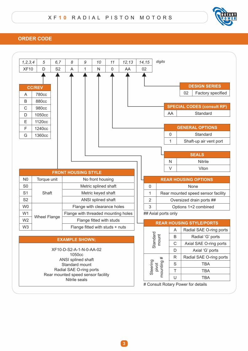
X F 1 0 R A D I A L P I S T O N M O T O R S
3
ORDER CODE
1,2,3,4 5 6,7 8 9 10 11 12,13 14,15
XF10 D S2 A 1 N 0 AA 02
digits
CC/REVA 780ccB 880ccC 980ccD 1050ccE 1120ccF 1240ccG 1360cc
FRONT HOUSING STYLEN0 Torque unit No front housingS0
ShaftMetric splined shaft
S1 Metric keyed shaftS2 ANSI splined shaftW0
Wheel Flange
Flange with clearance holesW1 Flange with threaded mounting holesW2 )ODQJH�¿WWHG�ZLWK�VWXGVW3 )ODQJH�¿WWHG�ZLWK�VWXGV���QXWV
EXAMPLE SHOWN;
XF10-D-S2-A-1-N-0-AA-021050cc
ANSI splined shaftStandard mount
Radial SAE O-ring portsRear mounted speed sensor facility
Nitrile seals
DESIGN SERIES02 )DFWRU\�VSHFL¿HG
SPECIAL CODES (consult RP)AA Standard
GENERAL OPTIONS0 Standard1 Shaft-up air vent port
SEALSN NitrileV Viton
REAR HOUSING OPTIONS0 None1 Rear mounted speed sensor facility2 Oversized drain ports ##3 Options 1+2 combined
REAR HOUSING STYLE/PORTS
Sta
ndar
d m
ount
A Radial SAE O-ring portsB 5DGLDO�µ*¶�SRUWVC Axial SAE O-ring portsD $[LDO�µ*¶�SRUWV
Ste
erin
g pi
vot
mou
ntin
g # R Radial SAE O-ring ports
S TBAT TBAU TBA
# Consult Rotary Power for details
## Axial ports only
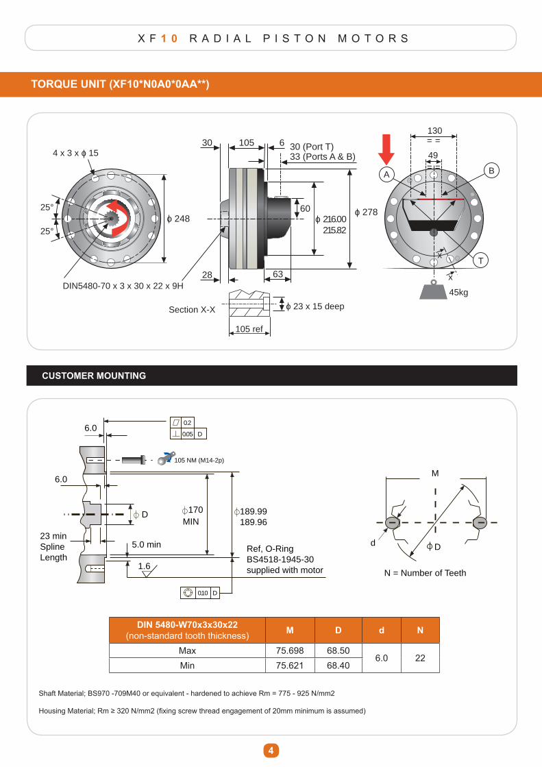
X F 1 0 R A D I A L P I S T O N M O T O R S
4
TORQUE UNIT (XF10*N0A0*0AA**)
CUSTOMER MOUNTING
4 x 3 x o 15
o 248
DIN5480-70 x 3 x 30 x 22 x 9H
25°
25°
28
30 105 30 (Port T)33 (Ports A & B)
6
o 27860o 216.00 215.82
63
49
130
= =
= =
T
BA
45kg
105 ref
o 23 x 15 deepSection X-X
x
x
6.00.2
0.05
105 NM (M14-2p)
D
6.0
1.6
DMIN
170 189.99189.96
5.0 min Ref, O-RingBS4518-1945-30supplied with motor
23 minSplineLength
M
D
N = Number of Teeth
d
0.10 D
DIN 5480-W70x3x30x22(non-standard tooth thickness) M D d N
Max 75.698 68.506.0 22
Min 75.621 68.40
Shaft Material; BS970 -709M40 or equivalent - hardened to achieve Rm = 775 - 925 N/mm2
+RXVLQJ�0DWHULDO��5P�������1�PP���¿[LQJ�VFUHZ�WKUHDG�HQJDJHPHQW�RI���PP�PLQLPXP�LV�DVVXPHG�
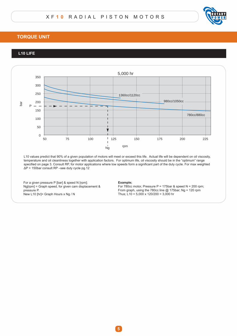
X F 1 0 R A D I A L P I S T O N M O T O R S
5
TORQUE UNIT
L10 LIFE
5,000 hr
1360cc/1120cc
980cc/1050cc
780cc/880cc
50 75 100 125 150 175 200 225
rpmNg
bar
350
300
250
200
150
100
50
0
P
L10 values predict that 90% of a given population of motors will meet or exceed this life. Actual life will be dependent on oil viscosity, temperature and oil cleanliness together with application factors. For optimum life, oil viscosity should be in the “optimum” range VSHFL¿HG�RQ�SDJH����&RQVXOW�53��IRU�PRWRU�DSSOLFDWLRQV�ZKHUH�ORZ�VSHHGV�IRUP�D�VLJQL¿FDQW�SDUW�RI�WKH�GXW\�F\FOH��)RU�PD[�ZHLJKWHG�ǻ3�!����EDU�FRQVXOW�53�±VHH�GXW\�F\FOH�SJ���
Example;For 780cc motor, Pressure P = 175bar & speed N = 200 rpm;From graph, using the 780cc line @ 175bar; Ng = 120 rpmThus; L10 = 5,000 x 120/200 = 3,000 hr
For a given pressure P [bar] & speed N [rpm];Ng[rpm] = Graph speed, for given cam displacement & pressure P.New L10 [hr]= Graph Hours x Ng / N
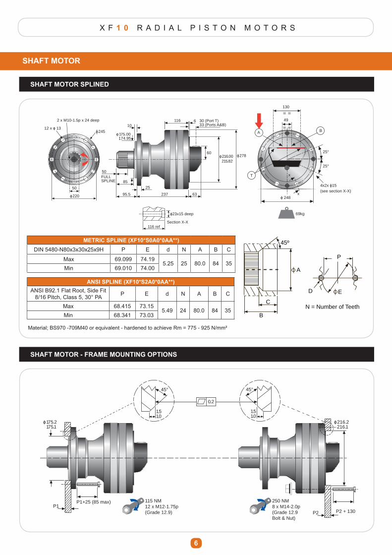
X F 1 0 R A D I A L P I S T O N M O T O R S
6
SHAFT MOTOR
SHAFT MOTOR SPLINED
12 x o 13o 245
2 x M10-1.5p x 24 deep 49
130
= =
= =
T
BA
69kg
25°
25°
x
xo 248
4x2x o15(see section X-X)
50
o 220
116 refSection X-X
o23x15 deep
10
o 175.00 174.95
116 6 30 (Port T)33 (Ports A&B)
o 278o 216.00 215.82
60
6323795.5
2585
50FULLSPLINE
METRIC SPLINE (XF10*S0A0*0AA**)DIN 5480-N80x3x30x25x9H P E d N A B C
Max 69.099 74.195.25 25 80.0 84 35
Min 69.010 74.00
ANSI SPLINE (XF10*S2A0*0AA**)ANSI B92.1 Flat Root, Side Fit
8/16 Pitch, Class 5, 30° PA P E d N A B C
Max 68.415 73.155.49 24 80.0 84 35
Min 68.341 73.03
Material; BS970 -709M40 or equivalent - hardened to achieve Rm = 775 - 925 N/mm²
45º
C
A
E
P
D
B
N = Number of Teeth
45º
C
A
E
P
D
B
N = Number of Teeth
SHAFT MOTOR - FRAME MOUNTING OPTIONS
45° 45°
1.51.0
1.51.0
0.2
115 NM12 x M12-1.75p(Grade 12.9)
250 NM8 x M14-2.0p(Grade 12.9 Bolt & Nut)
o 175.2 175.1
P1+25 (85 max)P1
P2 + 130P2
o 216.2 216.1
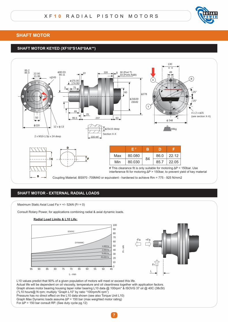
X F 1 0 R A D I A L P I S T O N M O T O R S
7
SHAFT MOTOR
SHAFT MOTOR KEYED (XF10*S1A0*0AA**)
o 245
2 x M10-1.5p x 24 deep
49
130
= =
= =
T
BA
69kg
25°
25°
x
xo 248
4 x 2 x o15(see section X-X)50
o 220
22.0021.95
116 refSection X-X
o23x15 deep
85.285.0
12 x o 13
116 6 30 (Port T)33 (Ports A&B)
60o 278
o 216.00 215.82
6323795.5
2585
o 80.03 80.11
755
o 175.00 174.95
10
B
E
D
F
E # B D FMax 80.080
8486.0 22.12
Min 80.030 85.7 22.05
Coupling Material; BS970 -709M40 or equivalent - hardened to achieve Rm = 775 - 925 N/mm2
SHAFT MOTOR - EXTERNAL RADIAL LOADS
7580859095 70 65 60 55
L - mm
20,000 hr
5,000 hr
2,000 hr
1,000 hr
DYNAMIC
STATIC
50 450
10
20
30
40
50
60
70
80
90
100
Maximum Static Axial Load Fa = +/- 52kN (Fr = 0)
Consult Rotary Power, for applications combining radial & axial dynamic loads.
Radial Load Limits & L10 Life;
L10 values predict that 90% of a given population of motors will meet or exceed this life.Actual life will be dependent on oil viscosity, temperature and oil cleanliness together with application factors.Graph shows motor bearing housing taper roller bearing L10 data @ 100rpm* & ISOVG 37 oil @ 40C (38cSt)(*L10 hours@ N rpm; multiply “Graph L10” by ratio “100rpm/N rpm”)Pressure has no direct effect on the L10 data shown (see also Torque Unit L10)*UDSK�0D[�'\QDPLF�ORDGV�DVVXPH�ǻ3� �����EDU��PD[�ZHLJKWHG�PRWRU�UDWLQJ�)RU�ǻ3�!�����EDU�FRQVXOW�53���6HH�GXW\�F\FOH�SJ����
L
Fr
-Fa +Fa
��7KLV�FOHDUDQFH�¿W�LV�RQO\�VXLWDEOH�IRU�PRWRULQJ�ǻ3������EDU��8VH�LQWHUIHUHQFH�¿W�IRU�PRWRULQJ�ǻ3�!����EDU��WR�SUHYHQW�\LHOG�RI�NH\�PDWHULDO
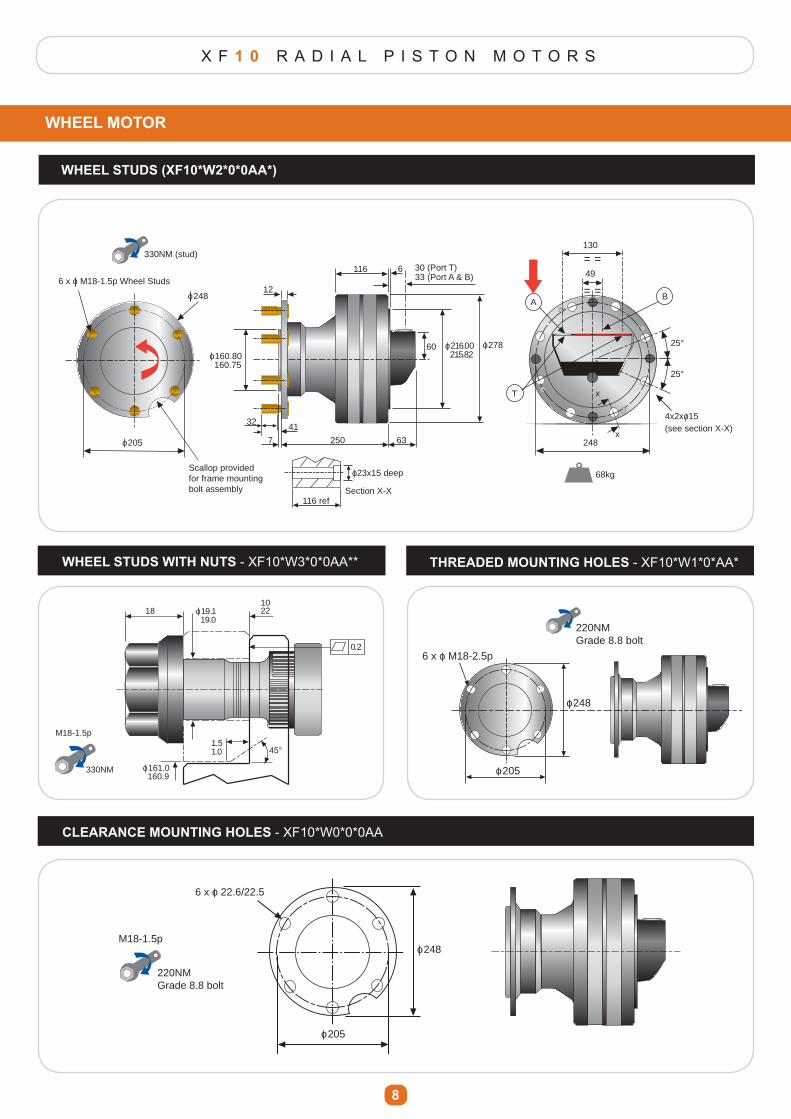
X F 1 0 R A D I A L P I S T O N M O T O R S
8
WHEEL MOTOR
WHEEL STUDS (XF10*W2*0*0AA*)
49
130
= =
= =
T
BA
68kg
25°
25°
x
x248
4x2xo15(see section X-X)
116 refSection X-X
6 x o M18-1.5p Wheel Studs
o 248
o 205
330NM (stud)
o23x15 deepScallop provided for frame mounting bolt assembly
12
116 6 30 (Port T)33 (Port A & B)
60 o 216.00 215.82
o 278
7 250 63
4132
o 160.80 160.75
WHEEL STUDS WITH NUTS - XF10*W3*0*0AA** THREADED MOUNTING HOLES - XF10*W1*0*AA*
0.2
181022o 19.1
19.0
45°
o 161.0 160.9
1.51.0
330NM
M18-1.5p
6 x o M18-2.5p
o 248
o 205
220NMGrade 8.8 bolt
CLEARANCE MOUNTING HOLES - XF10*W0*0*0AA
o 248
o 205
220NMGrade 8.8 bolt
M18-1.5p
6 x o 22.6/22.5
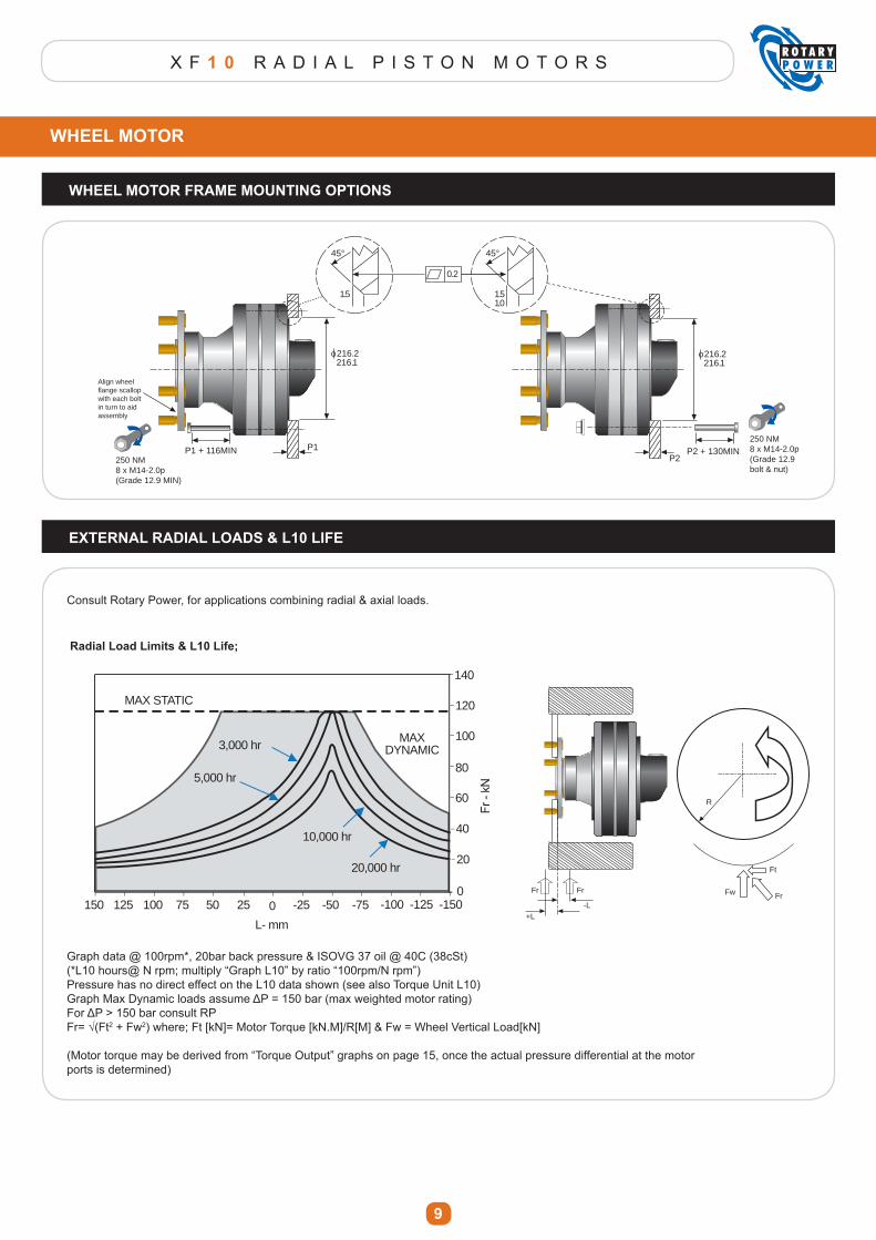
X F 1 0 R A D I A L P I S T O N M O T O R S
9
WHEEL MOTOR FRAME MOUNTING OPTIONS
P1 + 116MIN250 NM8 x M14-2.0p(Grade 12.9 bolt & nut)
45°
1.51.0
45°
1.5
0.2
o 216.2 216.1
P2P2 + 130MIN
o 216.2 216.1
P1
Align wheel flange scallop with each bolt in turn to aid assembly
250 NM8 x M14-2.0p(Grade 12.9 MIN)
EXTERNAL RADIAL LOADS & L10 LIFE
Graph data @ 100rpm*, 20bar back pressure & ISOVG 37 oil @ 40C (38cSt)(*L10 hours@ N rpm; multiply “Graph L10” by ratio “100rpm/N rpm”)Pressure has no direct effect on the L10 data shown (see also Torque Unit L10)*UDSK�0D[�'\QDPLF�ORDGV�DVVXPH�ǻ3� �����EDU��PD[�ZHLJKWHG�PRWRU�UDWLQJ�)RU�ǻ3�!�����EDU�FRQVXOW�53)U �¥�)W2 + Fw2) where; Ft [kN]= Motor Torque [kN.M]/R[M] & Fw = Wheel Vertical Load[kN]
(Motor torque may be derived from “Torque Output” graphs on page 15, once the actual pressure differential at the motorports is determined)
Consult Rotary Power, for applications combining radial & axial loads.
-L+L
FrFr
R
Fr
Ft
Fw
0 -25 -50 -75
L- mm
0
20
-100 -125 -150255075100125150
40
60
80
100
120
140
3,000 hr
5,000 hr
10,000 hr
MAX STATIC
MAX DYNAMIC
20,000 hr
WHEEL MOTOR
Radial Load Limits & L10 Life;
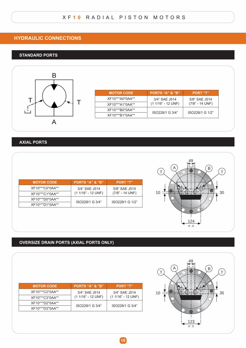
X F 1 0 R A D I A L P I S T O N M O T O R S
10
HYDRAULIC CONNECTIONS
B
A
TTMOTOR CODE PORTS “A” & “B” PORT “T”
XF10***A0*0AA** 3/4” SAE J514(1 1/16” - 12 UNF)
5/8” SAE J514(7/8” - 14 UNF)XF10***A1*0AA**
XF10***B0*0AA**ISO228/1 G 3/4” ISO228/1 G 1/2”
XF10***B1*0AA**
AXIAL PORTS
49= =
= =
T TBA
124
10 30
49= =
= =
T TBA
123
10 35
OVERSIZE DRAIN PORTS (AXIAL PORTS ONLY)
MOTOR CODE PORTS “A” & “B” PORT “T”XF10***C0*0AA** 3/4” SAE J514
(1 1/16” - 12 UNF)5/8” SAE J514(7/8” - 14 UNF)XF10***C1*0AA**
XF10***D0*0AA**ISO228/1 G 3/4” ISO228/1 G 1/2”
XF10***D1*0AA**
MOTOR CODE PORTS “A” & “B” PORT “T”XF10***C2*0AA** 3/4” SAE J514
(1 1/16” - 12 UNF)3/4” SAE J514
(1 1/16” - 12 UNF)XF10***C3*0AA**XF10***D2*0AA**
ISO228/1 G 3/4” ISO228/1 G 3/4”XF10***D3*0AA**
STANDARD PORTS
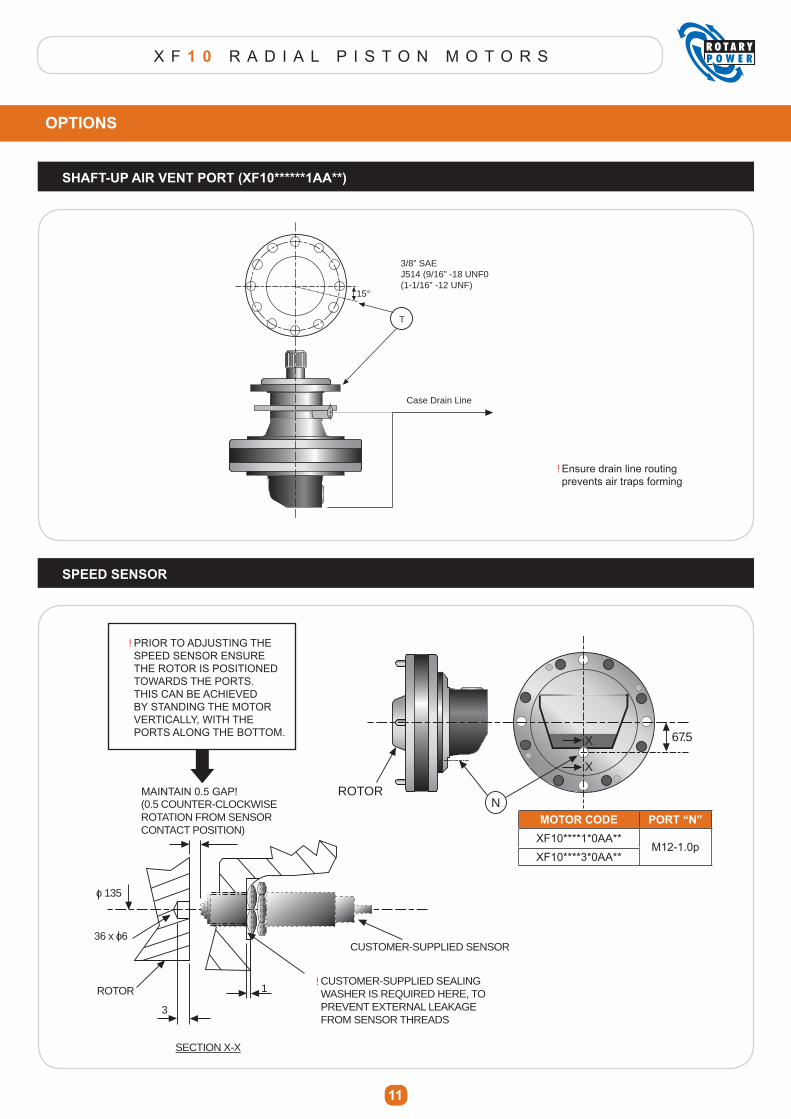
X F 1 0 R A D I A L P I S T O N M O T O R S
11
OPTIONS
SHAFT-UP AIR VENT PORT (XF10******1AA**)
15°
3/8” SAEJ514 (9/16” -18 UNF0(1-1/16” -12 UNF)
Case Drain Line
T
Ensure drain line routingprevents air traps forming
SPEED SENSOR
NROTOR
X
X
67.5
(0.5 COUNTER-CLOCKWISE ROTATION FROM SENSOR CONTACT POSITION)
CUSTOMER-SUPPLIED SEALING WASHER IS REQUIRED HERE, TO PREVENT EXTERNAL LEAKAGE FROM SENSOR THREADS
CUSTOMER-SUPPLIED SENSOR
SECTION X-X
3
1
o 135
36 x o6
ROTOR
PRIOR TO ADJUSTING THE SPEED SENSOR ENSURE THE ROTOR IS POSITIONED TOWARDS THE PORTS. THIS CAN BE ACHIEVED BY STANDING THE MOTOR VERTICALLY, WITH THE PORTS ALONG THE BOTTOM.
MAINTAIN 0.5 GAP!
MOTOR CODE PORT “N”XF10****1*0AA**
M12-1.0pXF10****3*0AA**
!
!
!
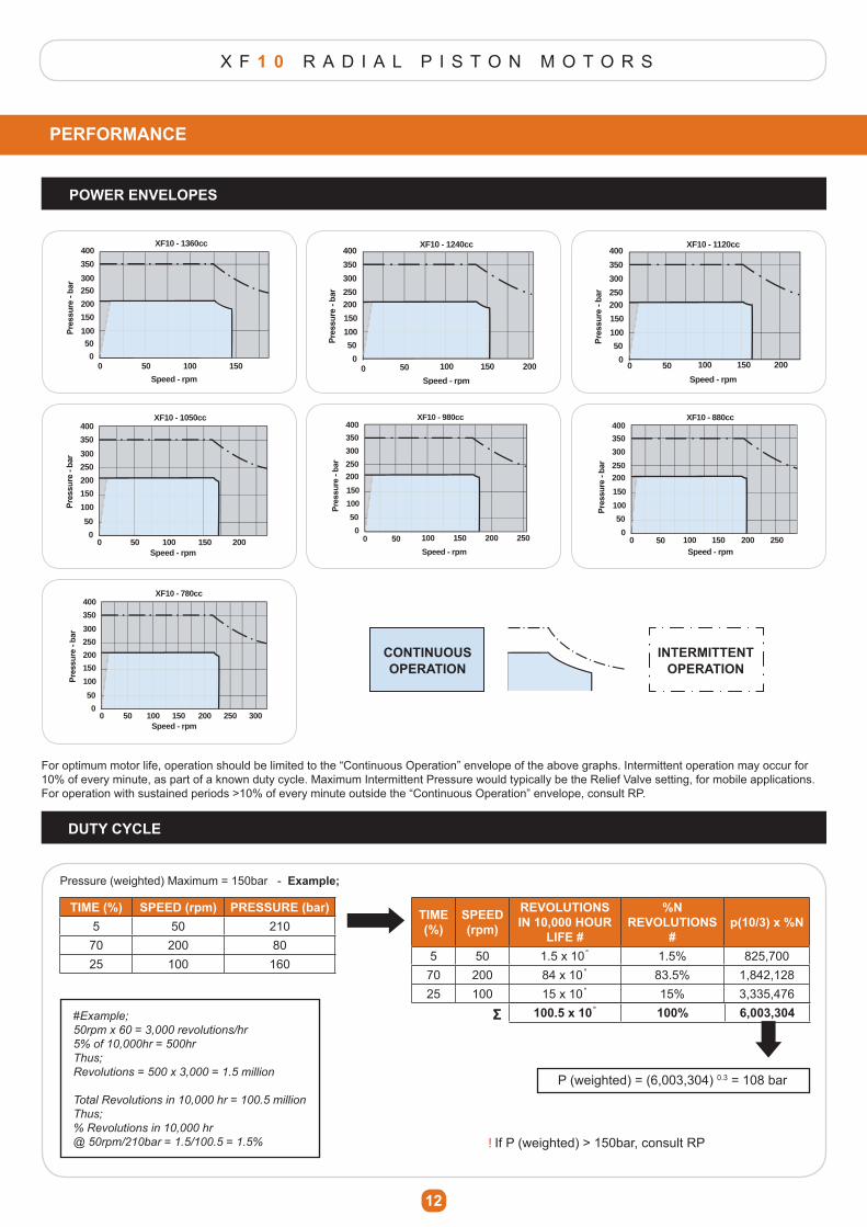
X F 1 0 R A D I A L P I S T O N M O T O R S
12
PERFORMANCE
Speed - rpm
XF10 - 1360cc
00
50 100 150
50100
150
200
250300
350
400
0 50 100 150 200
Speed - rpm
XF10 - 1120cc
0
50
100
150
200250
300
350
400
0 50 100 150 200
Speed - rpm
XF10 - 1240cc
0
50
100
150
200250
300
350
400
Speed - rpm
XF10 - 1050cc
00
50 100 200150
50
100
150
200
250
300
350
400
0 50 100 150 200 250
Speed - rpm
XF10 - 980cc
0
50
100
150
200
250
300
350
400
0 50 100 150 200 250Speed - rpm
XF10 - 880cc
0
50
100
150
200250
300
350
400
Speed - rpm
XF10 - 780cc
00
50 100 200 250 300150
50
100
150
200
250
300
350
400
Speed - rpm
XF10 - 1360cc
00
50 100 150
50100
150
200
250300
350
400
0 50 100 150 200
Speed - rpm
XF10 - 1120cc
0
50
100
150
200250
300
350
400
0 50 100 150 200
Speed - rpm
XF10 - 1240cc
0
50
100
150
200250
300
350
400
Speed - rpm
XF10 - 1050cc
00
50 100 200150
50
100
150
200
250
300
350
400
0 50 100 150 200 250
Speed - rpm
XF10 - 980cc
0
50
100
150
200
250
300
350
400
0 50 100 150 200 250Speed - rpm
XF10 - 880cc
0
50
100
150
200250
300
350
400
Speed - rpm
XF10 - 780cc
00
50 100 200 250 300150
50
100
150
200
250
300
350
400
For optimum motor life, operation should be limited to the “Continuous Operation” envelope of the above graphs. Intermittent operation may occur for 10% of every minute, as part of a known duty cycle. Maximum Intermittent Pressure would typically be the Relief Valve setting, for mobile applications. )RU�RSHUDWLRQ�ZLWK�VXVWDLQHG�SHULRGV�!����RI�HYHU\�PLQXWH�RXWVLGH�WKH�³&RQWLQXRXV�2SHUDWLRQ´�HQYHORSH��FRQVXOW�53��
DUTY CYCLE
TIME (%) SPEED (rpm) PRESSURE (bar)5 50 210
70 200 8025 100 160
Pressure (weighted) Maximum = 150bar - Example;
TIME (%)
SPEED (rpm)
REVOLUTIONS IN 10,000 HOUR
LIFE #
%N REVOLUTIONS
#p(10/3) x %N
5 50 1.5 x 10˚ 1.5% 825,70070 200 84 x 10˚ 83.5% 1,842,12825 100 15 x 10˚ 15% 3,335,476
100.5 x 10˚ 100% گ6,003,304
P (weighted) = (6,003,304) 0.3 = 108 bar
#Example;
50rpm x 60 = 3,000 revolutions/hr
5% of 10,000hr = 500hr
Thus;
Revolutions = 500 x 3,000 = 1.5 million
Total Revolutions in 10,000 hr = 100.5 million
Thus;
% Revolutions in 10,000 hr
@ 50rpm/210bar = 1.5/100.5 = 1.5% ,I�3��ZHLJKWHG��!����EDU��FRQVXOW�53
POWER ENVELOPES
!
CONTINUOUS OPERATION
INTERMITTENT OPERATION
Speed - rpm
XF10 - 1360cc
00
50 100 150
50100
150
200
250300
350
400
0 50 100 150 200
Speed - rpm
XF10 - 1120cc
0
50
100
150
200250
300
350
400
0 50 100 150 200
Speed - rpm
XF10 - 1240cc
0
50
100
150
200250
300
350
400
Speed - rpm
XF10 - 1050cc
00
50 100 200150
50
100
150
200
250
300
350
400
0 50 100 150 200 250
Speed - rpm
XF10 - 980cc
0
50
100
150
200
250
300
350
400
0 50 100 150 200 250Speed - rpm
XF10 - 880cc
0
50
100
150
200250
300
350
400
Speed - rpm
XF10 - 780cc
00
50 100 200 250 300150
50
100
150
200
250
300
350
400
Speed - rpm
XF10 - 1360cc
00
50 100 150
50100
150
200
250300
350
400
0 50 100 150 200
Speed - rpm
XF10 - 1120cc
0
50
100
150
200250
300
350
400
0 50 100 150 200
Speed - rpm
XF10 - 1240cc
0
50
100
150
200250
300
350
400
Speed - rpm
XF10 - 1050cc
00
50 100 200150
50
100
150
200
250
300
350
400
0 50 100 150 200 250
Speed - rpm
XF10 - 980cc
0
50
100
150
200
250
300
350
400
0 50 100 150 200 250Speed - rpm
XF10 - 880cc
0
50
100
150
200250
300
350
400
Speed - rpm
XF10 - 780cc
00
50 100 200 250 300150
50
100
150
200
250
300
350
400
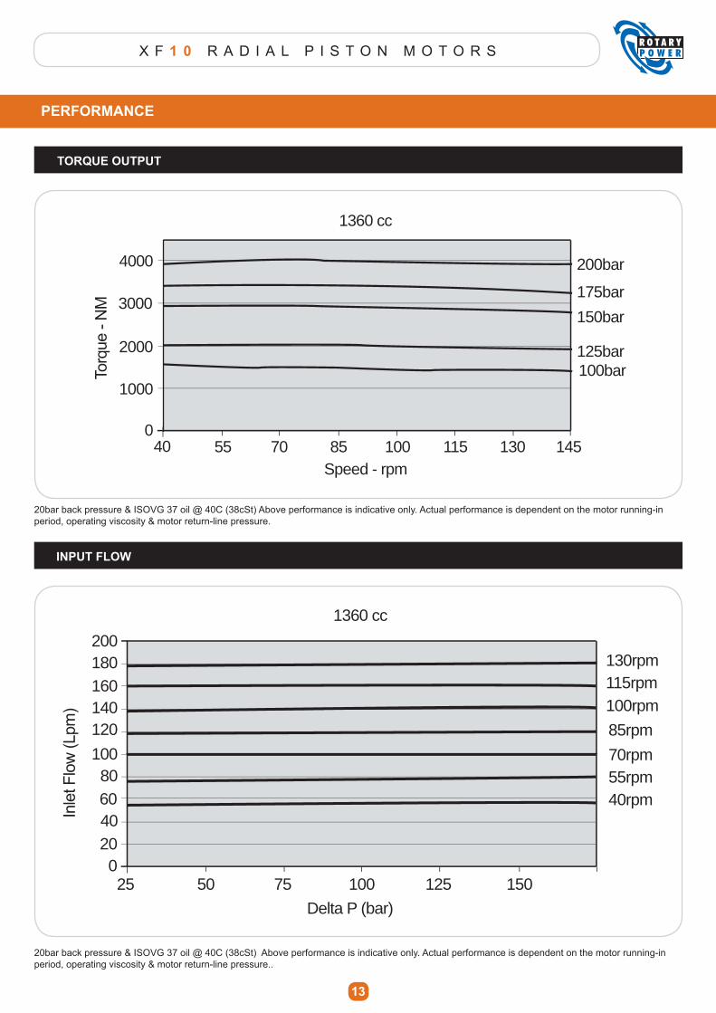
X F 1 0 R A D I A L P I S T O N M O T O R S
13
PERFORMANCE
INPUT FLOW
40 55 70 85 100 115 130 145Speed - rpm
175bar
125bar
1360 cc
0
1000
2000
3000
4000 200bar
150bar
100bar
25 50 75 100 125 150
Delta P (bar)
1360 cc
020406080
100
120140160180200
40rpm55rpm70rpm
85rpm
100rpm115rpm130rpm
20bar back pressure & ISOVG 37 oil @ 40C (38cSt) Above performance is indicative only. Actual performance is dependent on the motor running-in period, operating viscosity & motor return-line pressure.
20bar back pressure & ISOVG 37 oil @ 40C (38cSt) Above performance is indicative only. Actual performance is dependent on the motor running-in period, operating viscosity & motor return-line pressure..
TORQUE OUTPUT
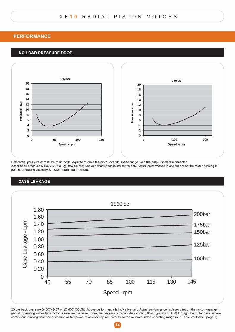
X F 1 0 R A D I A L P I S T O N M O T O R S
PERFORMANCE
NO LOAD PRESSURE DROP
14
CASE LEAKAGE
Differential pressure across the main ports required to drive the motor over its speed range, with the output shaft disconnected.20bar back pressure & ISOVG 37 oil @ 40C (38cSt) Above performance is indicative only. Actual performance is dependent on the motor running-in period, operating viscosity & motor return-line pressure.
20 bar back pressure & ISOVG 37 oil @ 40C (38cSt) Above performance is indicative only. Actual performance is dependent on the motor running-in SHULRG��RSHUDWLQJ�YLVFRVLW\��PRWRU�UHWXUQ�OLQH�SUHVVXUH��,W�PD\�EH�QHFHVVDU\�WR�SURYLGH�D�FRROLQJ�ÀRZ��W\SLFDOO\���/30��WKURXJK�WKH�PRWRU�FDVH��ZKHUH�continuous running conditions produce oil temperature or viscosity values outside the recommended operating range (see Technical Data – page 2)
0 100
Speed - rpm
1360 cc
0
2
4
6
8
10
12
14
16
18
20
0 100 200
Speed - rpm
780 cc
0
2
4
6
8
20
10
12
14
16
18
50 1500 100
Speed - rpm
1360 cc
0
2
4
6
8
10
12
14
16
18
20
0 100 200
Speed - rpm
780 cc
0
2
4
6
8
20
10
12
14
16
18
50 150
40 70 8555 100 115 145
100bar
125bar
150bar175bar
200bar
Speed - rpm
1360 cc
0
0.200.400.600.801.001.201.401.601.80
130
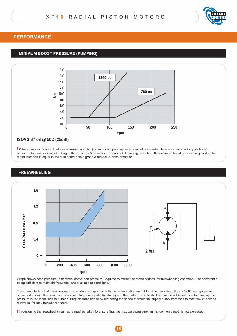
X F 1 0 R A D I A L P I S T O N M O T O R S
PERFORMANCE
MINIMUM BOOST PRESSURE (PUMPING)
15
FREEWHEELING
0 100 15050 200 250
rpm
0.0
2.0
4.0
6.08.0
10.0
12.0
14.0
16.0
18.0
1360 cc
780 cc
ISOVG 37 oil @ 50C (25cSt)
!�:KHUH�WKH�VKDIW�WRUVLRQ�ORDG�FDQ�RYHUUXQ�WKH�PRWRU��L�H��PRWRU�LV�RSHUDWLQJ�DV�D�SXPS��LW�LV�LPSRUWDQW�WR�HQVXUH�VXI¿FLHQW�VXSSO\�ERRVW�SUHVVXUH��WR�DYRLG�LQFRPSOHWH�¿OOLQJ�RI�WKH�F\OLQGHUV��FDYLWDWLRQ��7R�SUHYHQW�GDPDJLQJ�FDYLWDWLRQ��WKH�PLQLPXP�ERRVW�SUHVVXUH�UHTXLUHG�DW�WKH�motor inlet port is equal to the sum of the above graph & the actual case pressure.
0 400 600200 800 1000 1200
rpm
0
0.4
0.8
1.2
1.6
T
B
A
2 bar
Graph shows case pressure (differential above port pressure) required to retract the motor pistons, for freewheeling operation; 2 bar differential EHLQJ�VXI¿FLHQW�WR�PDLQWDLQ�IUHHZKHHO��XQGHU�DOO�VSHHG�FRQGLWLRQV�
Transition into & out of freewheeling is normally accomplished with the motor stationary. ! If this is not practical, then a “soft” re-engagement of the pistons with the cam track is advised, to prevent potential damage to the motor piston bush. This can be achieved by either limiting the SUHVVXUH�LQ�WKH�PDLQ�OLQHV�WR���EDU�GXULQJ�WKLV�WUDQVLWLRQ�RU�E\�UHVWULFWLQJ�WKH�VSHHG�DW�ZKLFK�WKH�VXSSO\�SXPS�LQFUHDVHV�WR�PD[�ÀRZ����VHFRQG�minimum, for max freewheel speed)
! In designing the freewheel circuit, care must be taken to ensure that the max case pressure limit, shown on page3, is not exceeded.
X F 1 0 R A D I A L P I S T O N M O T O R S
16
INSTALLATION
COMMISSIONING
!
Detailed installation drawings are available on request.
Motor shaft drives should be designed to eliminate unnecessary axial & radial loads; thus prolonging outputhousing bearing life.
.H\HG�VKDIWV�DUH�UHFRPPHQGHG�IRU�D�ÀH[LEOH�FRXSOLQJ�RXWSXW�FRQQHFWLRQ�
Splined shafts are suited to installations where the driven shaft & motor are rigidly mounted.(Alignment between motor & driven shaft should be maintained within 0.05mm)
For maximum life, splines should be lubricated with Molybdenum Disulphide grease, on assembly, or preferablyrun in oil lubrication.
Do not remove protective plugs from hydraulic or speed sensor ports until immediate connection into the systempipe work is made.
Always examine the motor externally to ensure no damage has been caused in transit.
Case drain lines, connected to either of the “T” ports indicated, should be returned directly to tank.
The “T” port should be positioned as the uppermost port, to ensure air is properly vented from the pipe work.
Where the motor is mounted with shaft uppermost, an air vent port is necessary to ensure proper lubrication of the bearing housing shaft seal (General Option “1” in Product Code).
7KH�ERUH�VL]H�RI�WKH�FDVH�GUDLQ�OLQH�VKRXOG�EH�VXI¿FLHQW�WR�HQVXUH�WKDW�FDVH�SUHVVXUH�GRHV�QRW�H[FHHG�WKH�PD[LPXP�VSHFL¿HG�LQ�³7HFKQLFDO�'DWD´�RQ�SDJH����XQGHU�DOO�RSHUDWLQJ�FRQGLWLRQV (especially during cold-start)
�,I�WKH�GLIIHUHQFH�EHWZHHQ�PRWRU�FDVH�GUDLQ�WHPSHUDWXUH��WKH�WDQN�WHPSHUDWXUH�LV�!����&��WKHQ�D�FDVH�ZDUPLQJ�ÀRZ�PXVW�EH�SURYLGHG��WR�SUHYHQW�SRVVLEOH�WKHUPDO�VKRFN�GDPDJH�WR�WKH�PRWRU�
For series connection of motors consult ROTARY POWER
3ULRU�WR�PRWRU�DVVHPEO\��WKRURXJKO\�GH�VFDOH��FOHDQ��ÀXVK�DOO�SLSH�ZRUN��¿WWLQJV��RLO�WDQN�
)LOO�WKH�V\VWHP�ZLWK�QHZ��¿OWHUHG�RLO�(refer to “Technical Data” on page 3 for motor oil requirements)
Fill the motor case & drain line with oil through the case drain port “T” & re-connect case drain pipe work.
&KHFN�URWDWLRQ�GLUHFWLRQ�UHTXLUHG�LV�FRQVLVWHQW�ZLWK�WKH�GLUHFWLRQ�RI�LQOHW�ÀRZ�(see relevant motor dimensional data)
Start the drive pump at lowest practical speed to prime the system (for combustion engines turn over the starter motor
for a few seconds at a time. For electric motors use a series of rapid on/off cycles)
5XQ�WKH�V\VWHP�DW�KLJK�ÀRZ��ORZ�SUHVVXUH��DFWXDWH�DOO�V\VWHPV�LQ�DOO�PRGHV�XQWLO�DOO�HQWUDLQHG�DLU�LV�SXUJHG�
Check & top-up oil levels if necessary
Check & adjust settings where necessary, in compliance with all system & component supplier requirements.
Check steady state operating temperature is in compliance with all system & component supplier requirements.
Check for & repair any external leaks.
$IWHU�WKH�¿UVW�IHZ�KRXUV�RI�UXQQLQJ��FOHDQ�RU�UHQHZ�DOO�¿OWHUV��DV�DSSURSULDWH�
IF IN DOUBT CONSULT ROTARY POWER
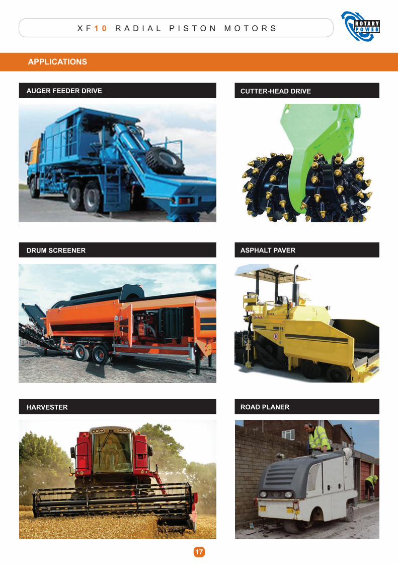
X F 1 0 R A D I A L P I S T O N M O T O R S
17
APPLICATIONS
AUGER FEEDER DRIVE CUTTER-HEAD DRIVE
DRUM SCREENER ASPHALT PAVER
HARVESTER ROAD PLANER
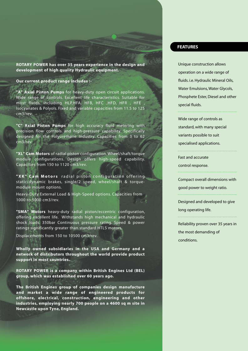
ROTARY POWER has over 35 years experience in the design anddevelopment of high quality Hydraulic equipment.
Our current product range includes :-
"A" Axial Piston Pumps for heavy-duty open circuit applications.Wide range of controls. Excellent life characteristics. Suitable formost fluids, including HLP,HFA, HFB, HFC ,HFD, HFR , HFE ,Isocyanates & Polyols. Fixed and variable capacities from 11.5 to 125cm3/rev.
"C" Axial Piston Pumps for high accuracy fluid metering withprecision flow controls and high-pressure capability. Specificallydesigned for the Polyurethane Industry. Capacities from 3 to 62cm3/rev.
"XL" Cam Motors of radial piston configuration. Wheel/shaft/torquemodule configurations. Design offers high-speed capability.Capacities from 150 to 1120 cm3/rev.
" XK " Cam Mo to r s r a d i a l p i s t o n c o n f i g u r a t i o n o f f e r i n gstatic/dynamic brakes, single/2 speed, wheel/shaft & torque-module mount options.
Heavy-Duty External Load & High-Speed options. Capacities from
1000 to 5000 cm3/rev.
"SMA" Motors heavy-duty radial piston/eccentric configuration,offering excellent life. Withstands high mechanical and hydraulicshock loads. 350bar Continuous pressure rating. Speed & powerratings significantly greater than standard HTLS motors.
Displacements from 150 to 10500 cm3/rev.
Wholly owned subsidiaries in the USA and Germany and anetwork of distributors throughout the world provide productsupport in most countries.
ROTARY POWER is a company within British Engines Ltd (BEL)group, which was established over 60 years ago.
The British Engines group of companies design manufactureand market a wide range of engineered products foroffshore, electrical, construction, engineering and otherindustries, employing nearly 700 people on a 4600 sq m site inNewcastle upon Tyne, England.
Unique construction allows
operation on a wide range of
fluids. i.e. Hydraulic Mineral Oils,
Water Emulsions, Water Glycols,
Phosphete Ester, Diesel and other
special fluids.
Wide range of controls as
standard, with many special
variants possible to suit
specialised applications.
Fast and accurate
control response.
Compact overall dimensions with
good power to weight ratio.
Designed and developed to give
long operating life.
Reliability proven over 35 years in
the most demanding of
conditions.
FEATURES
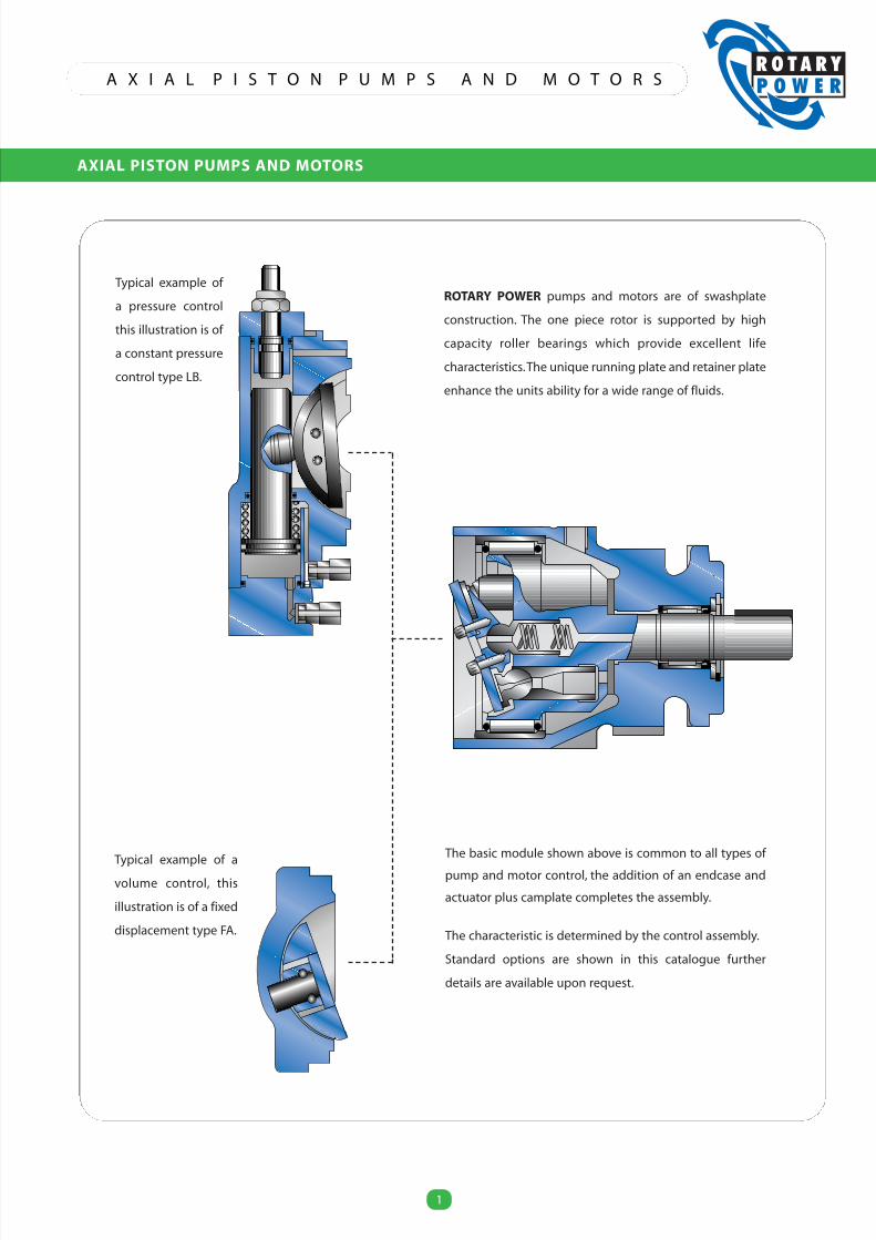
ROTARY POWER pumps and motors are of swashplate
construction. The one piece rotor is supported by high
capacity roller bearings which provide excellent life
characteristics.The unique running plate and retainer plate
enhance the units ability for a wide range of fluids.
Typical example of
a pressure control
this illustration is of
a constant pressure
control type LB.
The basic module shown above is common to all types of
pump and motor control, the addition of an endcase and
actuator plus camplate completes the assembly.
The characteristic is determined by the control assembly.
Standard options are shown in this catalogue further
details are available upon request.
Typical example of a
volume control, this
illustration is of a fixed
displacement type FA.
A X I A L P I S T O N P U M P S A N D M O T O R S
AXIAL PISTON PUMPS AND MOTORS
1
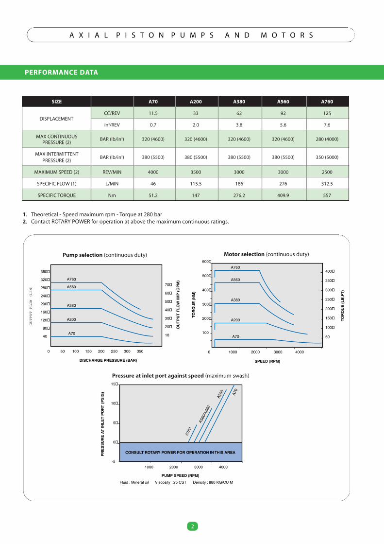
PERFORMANCE DATA
2
A X I A L P I S T O N P U M P S A N D M O T O R S
2
SIZE A70 A200 A380 A560 A760
CC/REV 11.5 33 62 92 125
in3/REV 0.7 2.0 3.8 5.6 7.6
MAX CONTINUOUS BAR (lb/in2) 320 (4600) 320 (4600) 320 (4600) 320 (4600) 280 (4000)PRESSURE (2)
MAX INTERMITTENTBAR (lb/in2) 380 (5500) 380 (5500) 380 (5500) 380 (5500) 350 (5000)
PRESSURE (2)
MAXIMUM SPEED (2) REV/MIN 4000 3500 3000 3000 2500
SPECIFIC FLOW (1) L/MIN 46 115.5 186 276 312.5
SPECIFIC TORQUE Nm 51.2 147 276.2 409.9 557
400
350
300
250
200
150
100
50
600
500
400
300
200
100
0 1000 2000 3000 4000
SPEED (RPM)
TORQ
UE(N
M)
TORQ
UE(L
B.FT
)
A760
A560
A380
A200
A70
360
320
280
240
200
160
120
80
40
0 50 100 150 200 250 300 350
70
60
50
40
30
20
10
DISCHARGE PRESSURE (BAR)
OUT
PUT
FLOW
IMP
(GPM
)
OUTPUT
FLOW
(LPM)
15
10
5
0
-51000 2000 3000 4000
CONSULT ROTARY POWER FOR OPERATION IN THIS AREA
A760
A560
/A38
0
A200 A7
0
Fluid : Mineral oil Viscosity : 25 CST Density : 880 KG/CU M
PRES
SURE
ATIN
LET
PORT
(PSI
G)
PUMP SPEED (RPM)
A760
A560
A380
A200
A70
1. Theoretical - Speed maximum rpm - Torque at 280 bar2. Contact ROTARY POWER for operation at above the maximum continuous ratings.
Motor selection (continuous duty)Pump selection (continuous duty)
Pressure at inlet port against speed (maximum swash)
DISPLACEMENT
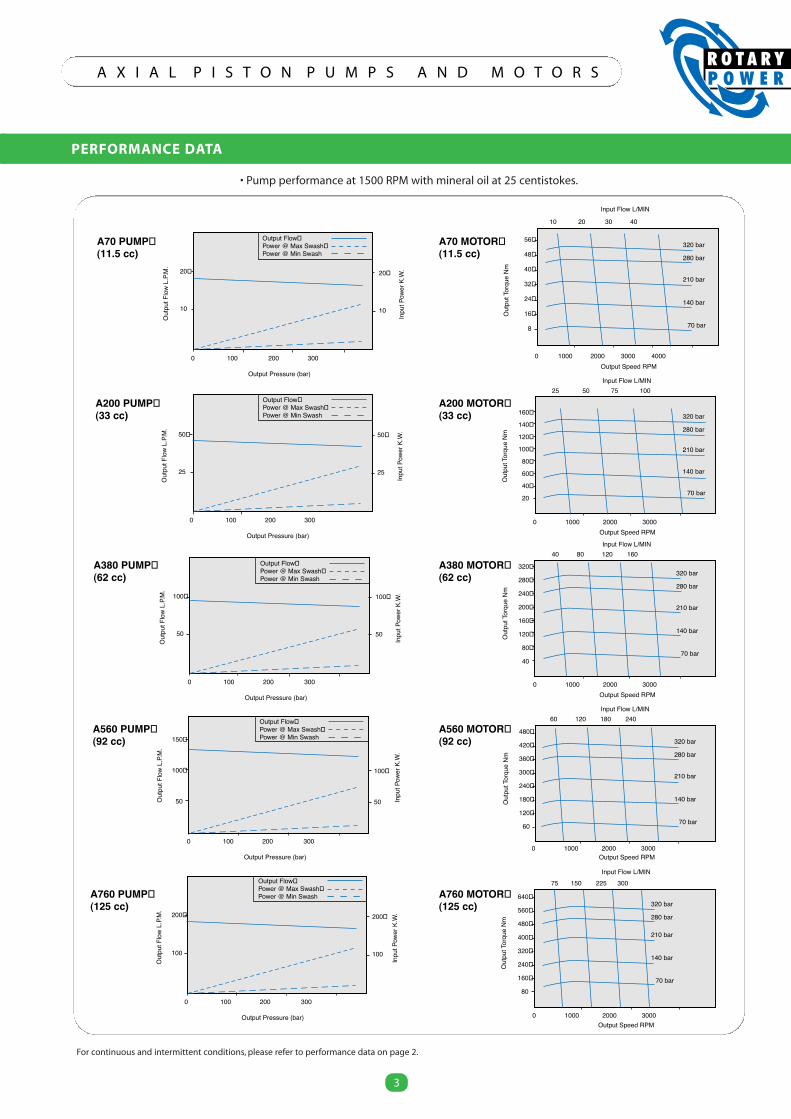
PERFORMANCE DATA
3
A X I A L P I S T O N P U M P S A N D M O T O R S
3
Output Flow Power @ Max Swash Power @ Min Swash
Output Flow Power @ Max Swash Power @ Min Swash
Output Flow Power @ Max Swash Power @ Min Swash
Output Flow Power @ Max Swash Power @ Min Swash
Output Flow Power @ Max Swash Power @ Min Swash
A70 PUMP (11.5 cc)
20
10
20
10
0 100 200 300
Output Pressure (bar)
Inpu
tPow
erK.
W.
Out
putF
low
L.P.
M.
A200 PUMP (33 cc)
50
25
50
25
0 100 200 300
Output Pressure (bar)
Inpu
tPow
erK.
W.
Out
putF
low
L.P.
M.
A380 PUMP (62 cc)
100
50
100
50
0 100 200 300
Output Pressure (bar)
Inpu
tPow
erK.
W.
Out
putF
low
L.P.
M.
A560 PUMP (92 cc)
100
50
150
100
50
0 100 200 300
Output Pressure (bar)
Inpu
tPow
erK.
W.
Out
putF
low
L.P.
M.
A760 PUMP (125 cc)
200�
100
200
100
0 100 200 300
Output Pressure (bar)
Inpu
tPow
erK.
W.
Out
putF
low
L.P.
M.
A70 MOTOR (11.5 cc)
Out
putT
orqu
eNm
0 1000 2000 3000 4000
56
48
40
32
24
16
8
Output Speed RPM
Input Flow L/MIN
10 20 30 40
Input Flow L/MIN25 50 75 100
0 1000 2000 3000
320 bar
280 bar
210 bar
140 bar
70 bar
160
140
120
100
80
60
40
20O
utpu
tTor
que
Nm
Output Speed RPM
320 bar
280 bar
210 bar
140 bar
70 bar
320 bar
280 bar
210 bar
140 bar
70 bar
320 bar
280 bar
210 bar
140 bar
70 bar
320 bar
280 bar
210 bar
140 bar
70 bar
Input Flow L/MIN40 80 120 160
320
280
240
200
160
120
80
40
Out
putT
orqu
eNm
0 1000 2000 3000Output Speed RPM
Input Flow L/MIN60 120 180 240
0 1000 2000 3000Output Speed RPM
480
420
360
300
240
180
120
60
Out
putT
orqu
eNm
Input Flow L/MIN75 150 225 300
640�
560�
480�
400�
320�
240�
160�
80
Out
putT
orqu
eNm
0 1000 2000 3000Output Speed RPM
A200 MOTOR (33 cc)
A380 MOTOR (62 cc)
A560 MOTOR (92 cc)
A760 MOTOR (125 cc)
For continuous and intermittent conditions, please refer to performance data on page 2.
• Pump performance at 1500 RPM with mineral oil at 25 centistokes.
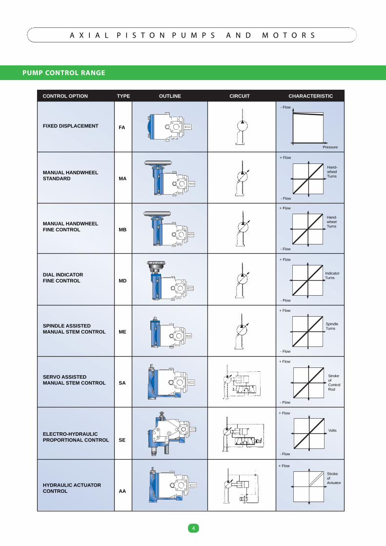
PUMP CONTROL RANGE
4
A X I A L P I S T O N P U M P S A N D M O T O R S
4
FIXED DISPLACEMENT
MANUAL HANDWHEELSTANDARD
MANUAL HANDWHEELFINE CONTROL
DIAL INDICATORFINE CONTROL
SPINDLE ASSISTEDMANUAL STEM CONTROL
SERVO ASSISTEDMANUAL STEM CONTROL
ELECTRO-HYDRAULICPROPORTIONAL CONTROL
HYDRAULIC ACTUATORCONTROL
FA
MA
MB
MD
ME
SA
SE
AA
CONTROL OPTION TYPE OUTLINE CIRCUIT CHARACTERISTIC
- Flow
Pressure
+ Flow
- Flow
+ Flow
- Flow
+ Flow
- Flow
+ Flow
- Flow
+ Flow
- Flow
+ Flow
- Flow
+ Flow
Hand-wheelTurns
Hand-wheelTurns
IndicatorTurns
SpindleTurns
StrokeofControlRod
Volts
StrokeofActuator
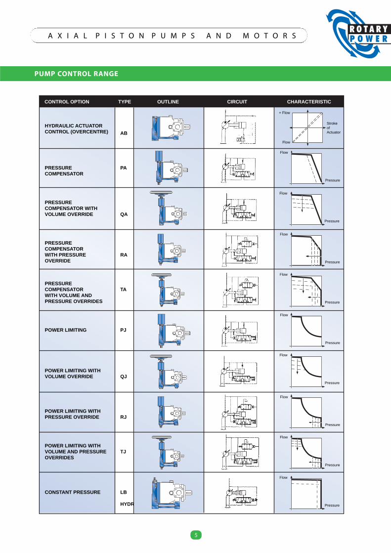
PUMP CONTROL RANGE
5
A X I A L P I S T O N P U M P S A N D M O T O R S
5
HYDRAULIC ACTUATORCONTROL (OVERCENTRE)
PRESSURE COMPENSATOR
PRESSURE COMPENSATOR WITH VOLUME OVERRIDE
PRESSURE COMPENSATORWITH PRESSURE OVERRIDE
PRESSURECOMPENSATORWITH VOLUME AND PRESSURE OVERRIDES
POWER LIMITING
POWER LIMITING WITH VOLUME OVERRIDE
POWER LIMITING WITH PRESSURE OVERRIDE
POWER LIMITING WITH VOLUME AND PRESSURE OVERRIDES
CONSTANT PRESSURE
AB
PA
QA
RA
TA
PJ
QJ
RJ
TJ
LB
HYDR
CONTROL OPTION TYPE OUTLINE CIRCUIT CHARACTERISTIC
Pressure
Flow
+ Flow
Flow
StrokeofActuator
Pressure
Flow
Pressure
Flow
Pressure
Flow
Pressure
Flow
Pressure
Flow
Pressure
Flow
Pressure
Flow
Pressure
Flow
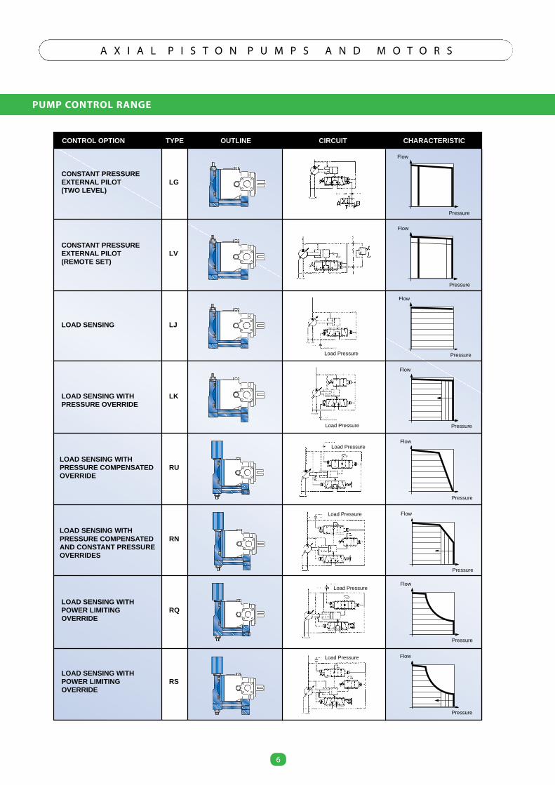
PUMP CONTROL RANGE
6
A X I A L P I S T O N P U M P S A N D M O T O R S
6
CONSTANT PRESSURE EXTERNAL PILOT (TWO LEVEL)
CONSTANT PRESSUREEXTERNAL PILOT(REMOTE SET)
LOAD SENSING
LOAD SENSING WITHPRESSURE OVERRIDE
LOAD SENSING WITHPRESSURE COMPENSATED OVERRIDE
LOAD SENSING WITH PRESSURE COMPENSATED AND CONSTANT PRESSURE OVERRIDES
LOAD SENSING WITH POWER LIMITING OVERRIDE
LOAD SENSING WITH POWER LIMITING OVERRIDE
LG
LV
LJ
LK
RU
RN
RQ
RS
CONTROL OPTION TYPE OUTLINE CIRCUIT CHARACTERISTIC
Pressure
Flow
Pressure
Flow
Pressure
Flow
Pressure
Flow
Pressure
Flow
Pressure
Flow
Pressure
Flow
Pressure
Flow
Load Pressure
Load Pressure
Load Pressure
Load Pressure
Load Pressure
Load Pressure
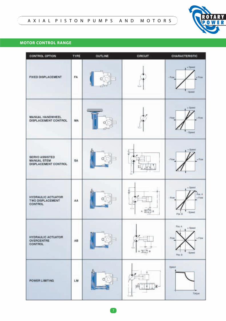
MOTOR CONTROL RANGE
7
A X I A L P I S T O N P U M P S A N D M O T O R S
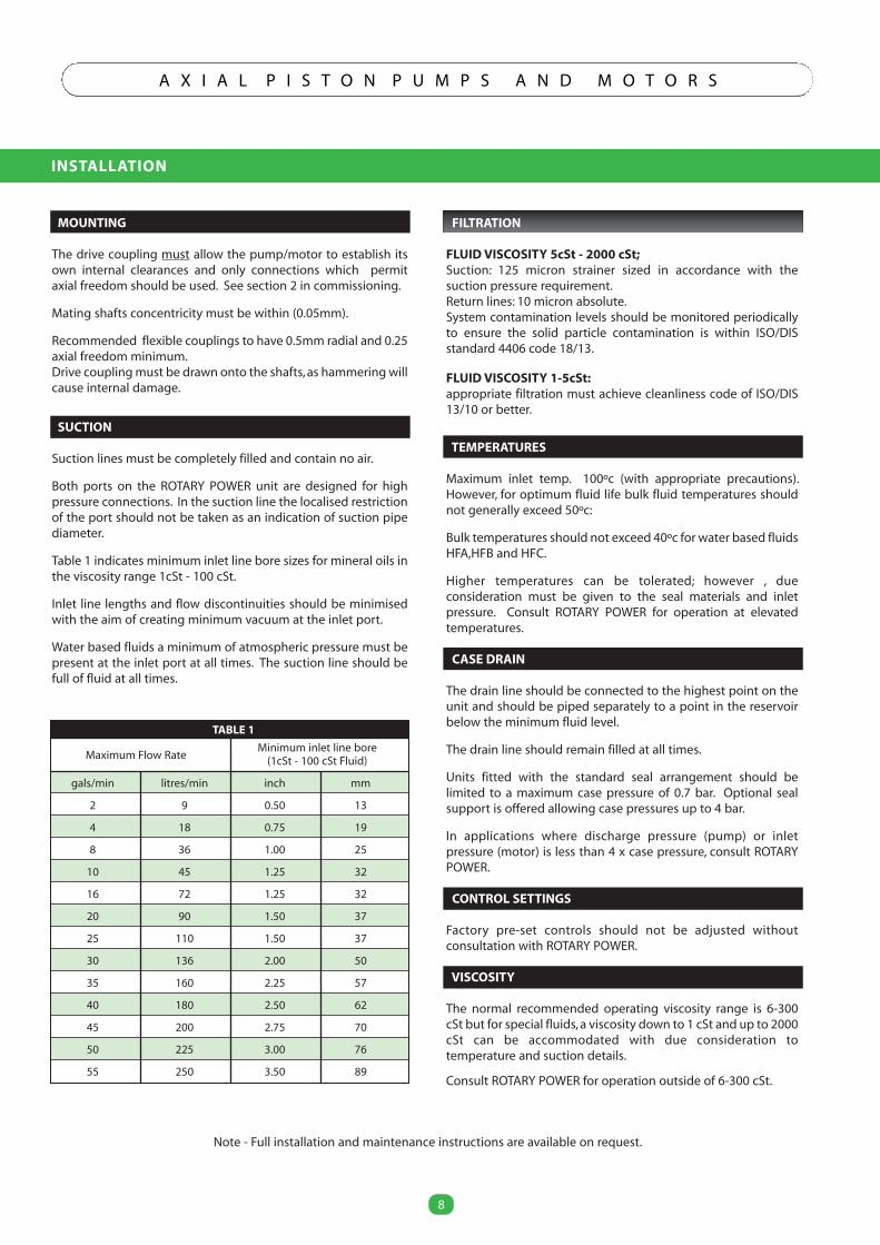
INSTALLATION
8
A X I A L P I S T O N P U M P S A N D M O T O R S
8
TABLE 1
Minimum inlet line boreMaximum Flow Rate (1cSt - 100 cSt Fluid)
gals/min litres/min inch mm
2 9 0.50 13
4 18 0.75 19
8 36 1.00 25
10 45 1.25 32
16 72 1.25 32
20 90 1.50 37
25 110 1.50 37
30 136 2.00 50
35 160 2.25 57
40 180 2.50 62
45 200 2.75 70
50 225 3.00 76
55 250 3.50 89
Note - Full installation and maintenance instructions are available on request.
MOUNTING
The drive coupling must allow the pump/motor to establish itsown internal clearances and only connections which permitaxial freedom should be used. See section 2 in commissioning.
Mating shafts concentricity must be within (0.05mm).
Recommended flexible couplings to have 0.5mm radial and 0.25axial freedom minimum.Drive coupling must be drawn onto the shafts,as hammering willcause internal damage.
SUCTION
Suction lines must be completely filled and contain no air.
Both ports on the ROTARY POWER unit are designed for highpressure connections. In the suction line the localised restrictionof the port should not be taken as an indication of suction pipediameter.
Table 1 indicates minimum inlet line bore sizes for mineral oils inthe viscosity range 1cSt - 100 cSt.
Inlet line lengths and flow discontinuities should be minimisedwith the aim of creating minimum vacuum at the inlet port.
Water based fluids a minimum of atmospheric pressure must bepresent at the inlet port at all times. The suction line should befull of fluid at all times.
FILTRATION
FLUID VISCOSITY 5cSt - 2000 cSt;Suction: 125 micron strainer sized in accordance with thesuction pressure requirement.Return lines: 10 micron absolute.System contamination levels should be monitored periodicallyto ensure the solid particle contamination is within ISO/DISstandard 4406 code 18/13.
FLUID VISCOSITY 1-5cSt:appropriate filtration must achieve cleanliness code of ISO/DIS13/10 or better.
TEMPERATURES
Maximum inlet temp. 100ºc (with appropriate precautions).However, for optimum fluid life bulk fluid temperatures shouldnot generally exceed 50ºc:
Bulk temperatures should not exceed 40ºc for water based fluidsHFA,HFB and HFC.
Higher temperatures can be tolerated; however , dueconsideration must be given to the seal materials and inletpressure. Consult ROTARY POWER for operation at elevatedtemperatures.
CASE DRAIN
The drain line should be connected to the highest point on theunit and should be piped separately to a point in the reservoirbelow the minimum fluid level.
The drain line should remain filled at all times.
Units fitted with the standard seal arrangement should belimited to a maximum case pressure of 0.7 bar. Optional sealsupport is offered allowing case pressures up to 4 bar.
In applications where discharge pressure (pump) or inletpressure (motor) is less than 4 x case pressure, consult ROTARYPOWER.
CONTROL SETTINGS
Factory pre-set controls should not be adjusted withoutconsultation with ROTARY POWER.
VISCOSITY
The normal recommended operating viscosity range is 6-300cSt but for special fluids,a viscosity down to 1 cSt and up to 2000cSt can be accommodated with due consideration totemperature and suction details.
Consult ROTARY POWER for operation outside of 6-300 cSt.
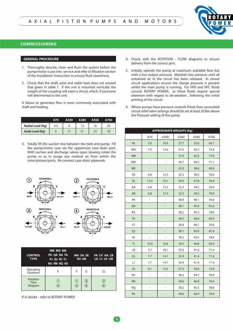
COMMISSIONING
9
A X I A L P I S T O N P U M P S A N D M O T O R S
9
CONTROL
MB MD ME
MA SA SE FA CV AA LBTYPE
PA QA RA TASH AB LG LJ LK LMPJ QJ RJ TJ
RU RN RQ RS
OperatingQuadrant P P Q Q
RotationFlow � � � �
Diagram � � � �
APPROXIMATEWEIGHTS (Kg)
A70 A200 A380 A560 A760
FA 5.0 10.9 27.7 35.0 64.1
MA 7.5 13.6 37.0 42.3 73.6
MB - - 37.0 42.3 73.6
MD - - 36.7 40.3 71.1
ME - - 35.0 38.6 69.4
SA 6.8 12.3 32.3 39.5 70.0
SE 13.3 19.1 39.9 47.8 79.4
AA 6.8 12.3 32.3 39.5 70.0
AB 6.8 12.3 32.3 39.5 70.0
PA - - 36.8 44.1 76.6
QA - - 38.1 45.4 81.6
RA - - 38.2 45.5 78.0
TA - - 39.5 46.8 83.0
PJ - - 36.8 44.1 76.6
QJ - - 38.1 45.4 81.6
RJ - - 38.2 45.5 78.0
TJ 10.0 16.8 39.5 46.8 83.0
LB 7.7 14.1 35.9 41.4 71.4
LG 7.7 14.1 35.9 41.4 71.4
LJ 7.7 14.1 35.9 41.4 71.4
LK 9.1 15.5 37.3 42.8 72.8
RU - - 38.2 45.5 78.0
RN - - 39.6 46.9 79.4
RQ - - 38.2 45.5 78.0
RS - - 39.6 46.9 79.4If in doubt - refer to ROTARY POWER
GENERAL PROCEDURE
1. Thoroughly descale, clean and flush the system before thepump/motor is put into service and refer to filtration sectionof the Installation Instruction to ensure fluid cleanliness.
2. Check that the shaft, axial and radial load does not exceedthat given in table 1. If the unit is mounted vertically theweight of the coupling will exert a thrust, which, if excessivewill detrimental to the unit.
A failure to generates flow is most commonly associated withshaft end loading.
3. Totally fill the suction line between the tank and pump. Fillthe pump/motor case via the uppermost case drain port.With suction and discharge valves open slowing rotate thepump so as to purge any residual air from within therotor/pistons/ports. Re-connect case drain pipework.
4. Check with the ROTATION - FLOW diagrams to ensuredelivery from the correct port.
5. Initially, operate the pump at maximum available flow butwith a low output pressure. Maintain low pressure until allentrained air in the circuit has been released. In closedcircuit applications ensure the charge pressure is presentwhilst the main pump is running. For HFB and HFC fluidsconsult ROTARY POWER, as these fluids require specialattention with regard to de-aeration , following the initialpriming of the circuit.
6. Where pumps have pressure controls fitted, then associatedcircuit relief valve settings should be set at least 20 Bar abovethe Pressure setting of the pump.
A70 A200 A380 A560 A760
Radial Load (Kg) 4.5 9 12 16 20
Axial Load (Kg) 6 11 21 23 30
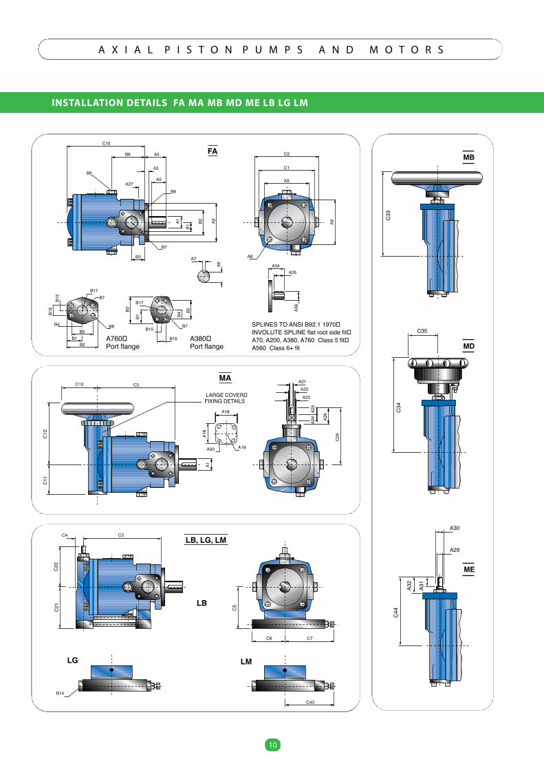
INSTALLATION DETAILS FA MA MB MD ME LB LG LM
10
A X I A L P I S T O N P U M P S A N D M O T O R S
10
C10
B6 A4
A3
A5A27
B3
B7
B8
A2B2
B1
A1B9
A7
A6
C2
C1
A9
A8
A9B8
B17B7
B4B5
B1B2
B16
B15
B2
B1 B4
B5
B15
B16
B7
B17
A35A34
A36
SPLINES TO ANSI B92.1 1970 INVOLUTE SPLINE flat root side fit A70, A200, A380, A760 Class 5 fit A560 Class 6+ fit
FA
A760 Port flange
A380 Port flange
C33
MB
C34
C35
MD
C44
A32
A31
A30
A29
ME
C12
C3
A1
MA
C11
C13
A26
C29
A24
A25
A23
A22A21
A18
A18
A20 A19
LARGE COVER FIXING DETAILS
C5
C6
LB, LG, LM
C22
C3
LB
C7
C21
C4
LMLG
C43
B14
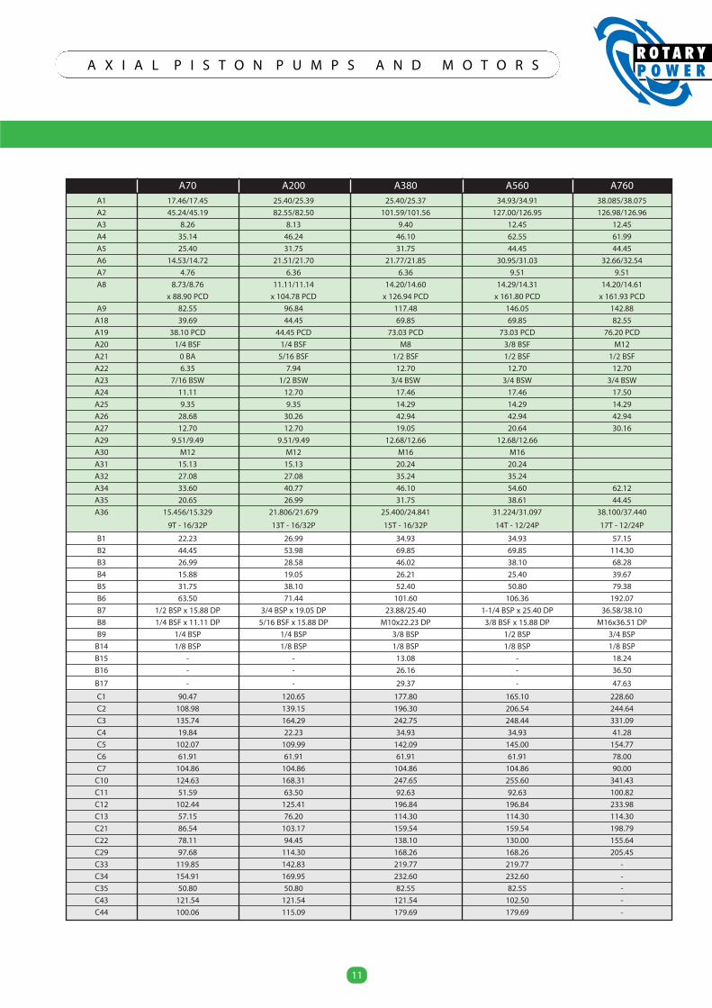
11
A X I A L P I S T O N P U M P S A N D M O T O R S
11
A70 A200 A380 A560 A760A1 17.46/17.45 25.40/25.39 25.40/25.37 34.93/34.91 38.085/38.075
A2 45.24/45.19 82.55/82.50 101.59/101.56 127.00/126.95 126.98/126.96
A3 8.26 8.13 9.40 12.45 12.45
A4 35.14 46.24 46.10 62.55 61.99
A5 25.40 31.75 31.75 44.45 44.45
A6 14.53/14.72 21.51/21.70 21.77/21.85 30.95/31.03 32.66/32.54
A7 4.76 6.36 6.36 9.51 9.51
A8 8.73/8.76 11.11/11.14 14.20/14.60 14.29/14.31 14.20/14.61
x 88.90 PCD x 104.78 PCD x 126.94 PCD x 161.80 PCD x 161.93 PCD
A9 82.55 96.84 117.48 146.05 142.88
A18 39.69 44.45 69.85 69.85 82.55
A19 38.10 PCD 44.45 PCD 73.03 PCD 73.03 PCD 76.20 PCD
A20 1/4 BSF 1/4 BSF M8 3/8 BSF M12
A21 0 BA 5/16 BSF 1/2 BSF 1/2 BSF 1/2 BSF
A22 6.35 7.94 12.70 12.70 12.70
A23 7/16 BSW 1/2 BSW 3/4 BSW 3/4 BSW 3/4 BSW
A24 11.11 12.70 17.46 17.46 17.50
A25 9.35 9.35 14.29 14.29 14.29
A26 28.68 30.26 42.94 42.94 42.94
A27 12.70 12.70 19.05 20.64 30.16
A29 9.51/9.49 9.51/9.49 12.68/12.66 12.68/12.66
A30 M12 M12 M16 M16
A31 15.13 15.13 20.24 20.24
A32 27.08 27.08 35.24 35.24
A34 33.60 40.77 46.10 54.60 62.12
A35 20.65 26.99 31.75 38.61 44.45
A36 15.456/15.329 21.806/21.679 25.400/24.841 31.224/31.097 38.100/37.440
9T - 16/32P 13T - 16/32P 15T - 16/32P 14T - 12/24P 17T - 12/24P
B1 22.23 26.99 34.93 34.93 57.15
B2 44.45 53.98 69.85 69.85 114.30
B3 26.99 28.58 46.02 38.10 68.28
B4 15.88 19.05 26.21 25.40 39.67
B5 31.75 38.10 52.40 50.80 79.38
B6 63.50 71.44 101.60 106.36 192.07
B7 1/2 BSP x 15.88 DP 3/4 BSP x 19.05 DP 23.88/25.40 1-1/4 BSP x 25.40 DP 36.58/38.10
B8 1/4 BSF x 11.11 DP 5/16 BSF x 15.88 DP M10x22.23 DP 3/8 BSF x 15.88 DP M16x36.51 DP
B9 1/4 BSP 1/4 BSP 3/8 BSP 1/2 BSP 3/4 BSP
B14 1/8 BSP 1/8 BSP 1/8 BSP 1/8 BSP 1/8 BSP
B15 - - 13.08 - 18.24
B16 - - 26.16 - 36.50
B17 - - 29.37 - 47.63
C1 90.47 120.65 177.80 165.10 228.60
C2 108.98 139.15 196.30 206.54 244.64
C3 135.74 164.29 242.75 248.44 331.09
C4 19.84 22.23 34.93 34.93 41.28
C5 102.07 109.99 142.09 145.00 154.77
C6 61.91 61.91 61.91 61.91 78.00
C7 104.86 104.86 104.86 104.86 90.00
C10 124.63 168.31 247.65 255.60 341.43
C11 51.59 63.50 92.63 92.63 100.82
C12 102.44 125.41 196.84 196.84 233.98
C13 57.15 76.20 114.30 114.30 114.30
C21 86.54 103.17 159.54 159.54 198.79
C22 78.11 94.45 138.10 130.00 155.64
C29 97.68 114.30 168.26 168.26 205.45
C33 119.85 142.83 219.77 219.77 -
C34 154.91 169.95 232.60 232.60 -
C35 50.80 50.80 82.55 82.55 -
C43 121.54 121.54 121.54 102.50 -
C44 100.06 115.09 179.69 179.69 -
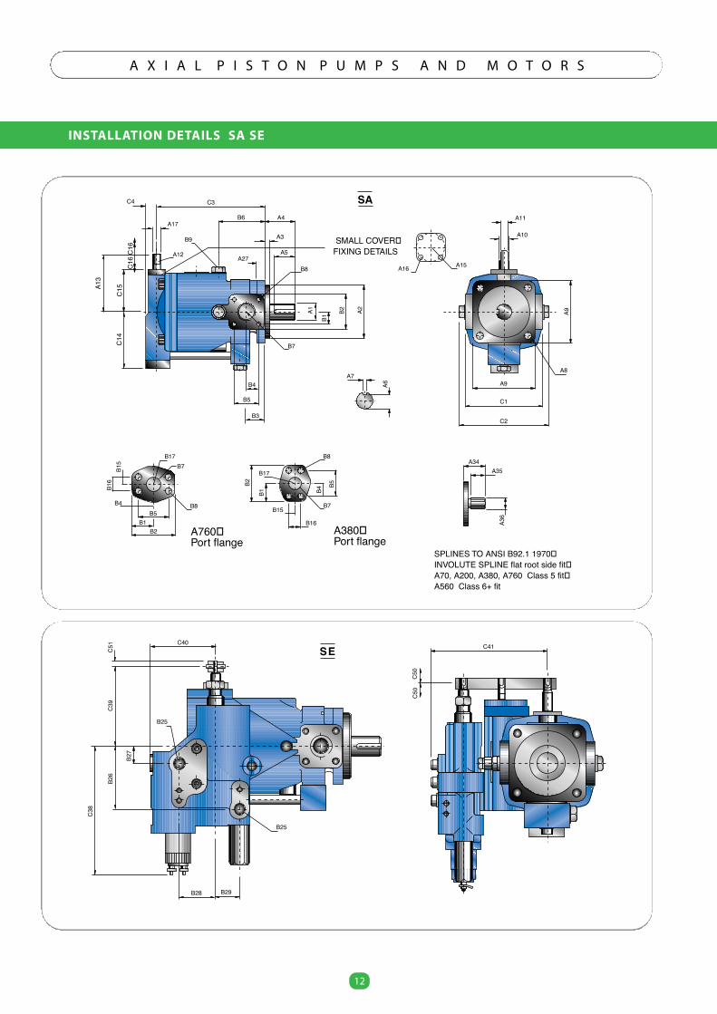
INSTALLATION DETAILS SA SE
12
A X I A L P I S T O N P U M P S A N D M O T O R S
12
B26
C50
C41C40
C50
B28 B29
C38
B27
C39
C51
B25
B25
SE
A13
C14
C4 C3
B6 A4
A3
A5A27
B4
B5
B3
B7
B8
A2B2
B1
A1
B9
A7A6 A9
C1
C2
A8
A9
B8
B17B7
B4B5
B1B2
B16
B15
B2
B1 B4
B5
B15
B16
B7
B17 A35A34
A36
SPLINES TO ANSI B92.1 1970 INVOLUTE SPLINE flat root side fit A70, A200, A380, A760 Class 5 fit A560 Class 6+ fit
SA
A16 A15
A11
A10
C15
A17
A12
C16
C16
B8
A760 Port flange
A380 Port flange
SMALL COVER FIXING DETAILS
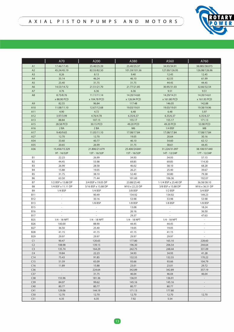
13
A X I A L P I S T O N P U M P S A N D M O T O R S
13
A70 A200 A380 A560 A760A1 17.46/17.45 25.40/25.39 25.40/25.37 34.93/34.91 38.085/38.075
A2 45.24/45.19 82.55/82.50 101.59/101.56 127.00/126.95 126.98/126.96
A3 8.26 8.13 9.40 12.45 12.45
A4 35.14 46.24 46.10 62.55 61.99
A5 25.40 31.75 31.75 44.45 44.45
A6 14.53/14.72 21.51/21.70 21.77/21.85 30.95/31.03 32.66/32.54
A7 4.76 6.36 6.36 9.51 9.51
A8 8.73/8.76 11.11/11.14 14.20/14.60 14.29/14.31 14.20/14.61
x 88.90 PCD x 104.78 PCD x 126.94 PCD x 161.80 PCD x 161.93 PCD
A9 82.55 96.84 117.48 146.05 142.88
A10 11.08/11.10 12.67/12.68 19.03/19.01 19.03/19.01 19.38/19.96
A11 4.90 4.72 6.48 6.48 5.97
A12 3.97/3.99 4.76/4.78 6.35/6.37 6.35/6.37 6.35/6.37
A13 88.84 107.15 155.17 155.17 171.13
A15 28.58 PCD 30.15 PCD 49.20 PCD 49.20 PCD 53.98 PCD
A16 2 BA 2 BA M6 1/4 BSF M8
A17 9.40/9.65 11.05/11.10 17.08/17.84 17.08/17.84 17.08/17.84
A27 12.70 12.70 19.05 20.64 30.16
A34 33.60 40.77 46.10 54.60 62.12
A35 20.65 26.99 31.75 38.61 44.45
A36 15.456/15.329 21.806/21.679 25.400/24.841 31.224/31.097 38.100/37.440
9T - 16/32P 13T - 16/32P 15T - 16/32P 14T - 12/24P 17T - 12/24P
B1 22.23 26.99 34.93 34.93 57.15
B2 44.45 53.98 69.85 69.85 114.30
B3 26.99 28.58 46.02 38.10 68.28
B4 15.88 19.05 26.21 25.40 39.67
B5 31.75 38.10 52.40 50.80 79.38
B6 63.50 71.44 101.60 106.36 192.07
B7 1/2 BSP x 15.88 DP 3/4 BSP x 19.05 DP 23.88/25.40 1-1/4 BSP x 25.40 DP 36.58/38.10
B8 1/4 BSF x 11.11 DP 5/16 BSF x 15.88 DP M10 x 22.23 DP 3/8 BSF x 15.88 DP M16 x 36.51 DP
B9 1/4 BSP 1/4 BSP 3/8 BSP 1/2 BSP 3/4 BSP
B11 - 90.49 134.92 134.92 149.23
B12 - 30.16 53.98 53.98 53.98
B13 - 1/8 BSP 1/8 BSP 1/8 BSP 1/8 BSP
B15 - - 13.08 - 18.24
B16 - - 26.16 - 36.50
B17 - - 29.37 - 47.63
B25 1/4 - 18 NPT 1/4 - 18 NPT 1/4 - 18 NPT 1/4 - 18 NPT -
B26 100.00 88.90 44.45 44.45 -
B27 36.50 25.40 19.05 19.05 -
B28 41.15 41.15 41.15 41.15 -
B29 29.97 29.97 29.97 29.97 -
C1 90.47 120.65 177.80 165.10 228.60
C2 108.98 139.15 196.30 206.54 244.64
C3 135.74 164.29 242.75 248.44 331.09
C4 19.84 22.23 34.93 34.93 41.28
C14 75.43 91.85 132.55 132.55 170.22
C15 51.59 65.09 93.66 93.66 104.79
C16 11.89 15.88 23.01 23.01 29.72
C36 - 224.64 342.89 342.89 357.19
C37 - 31.75 46.04 46.04 46.04
C38 155.96 181.36 136.91 136.91 -
C39 84.07 99.62 145.16 145.16 -
C40 80.77 80.77 80.77 80.77 -
C41 129.06 144.19 171.13 177.80 -
C50 12.70 12.70 12.70 12.70 12.70
C51 6.35 6.35 7.92 5.54 -
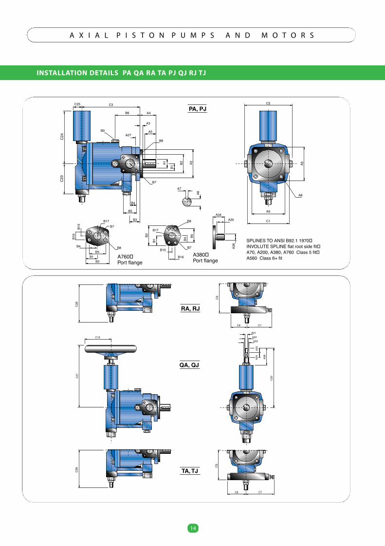
INSTALLATION DETAILS PA QA RA TA PJ QJ RJ TJ
14
A X I A L P I S T O N P U M P S A N D M O T O R S
14
C5
C7C6
C20
RA, RJ
C13
C5
C7C6
C26
QA, QJ
TA, TJ
C27
A28
A24
A25
A21A22A33
C26
C23
C3
B6 A4
A3
A5A27
B4
B5
B3
B7
B8
A2B2
B1
A1
B9
A7
A6
A9
C1
C2
A8
A9
B8
B17B7
B4B5
B1B2
B16
B15
B2
B1 B4
B5
B15
B16
B7
B17
A35A34
A36
SPLINES TO ANSI B92.1 1970 INVOLUTE SPLINE flat root side fit A70, A200, A380, A760 Class 5 fit A560 Class 6+ fit
PA, PJ
C24
B8
A760 Port flange
A380 Port flange
C25
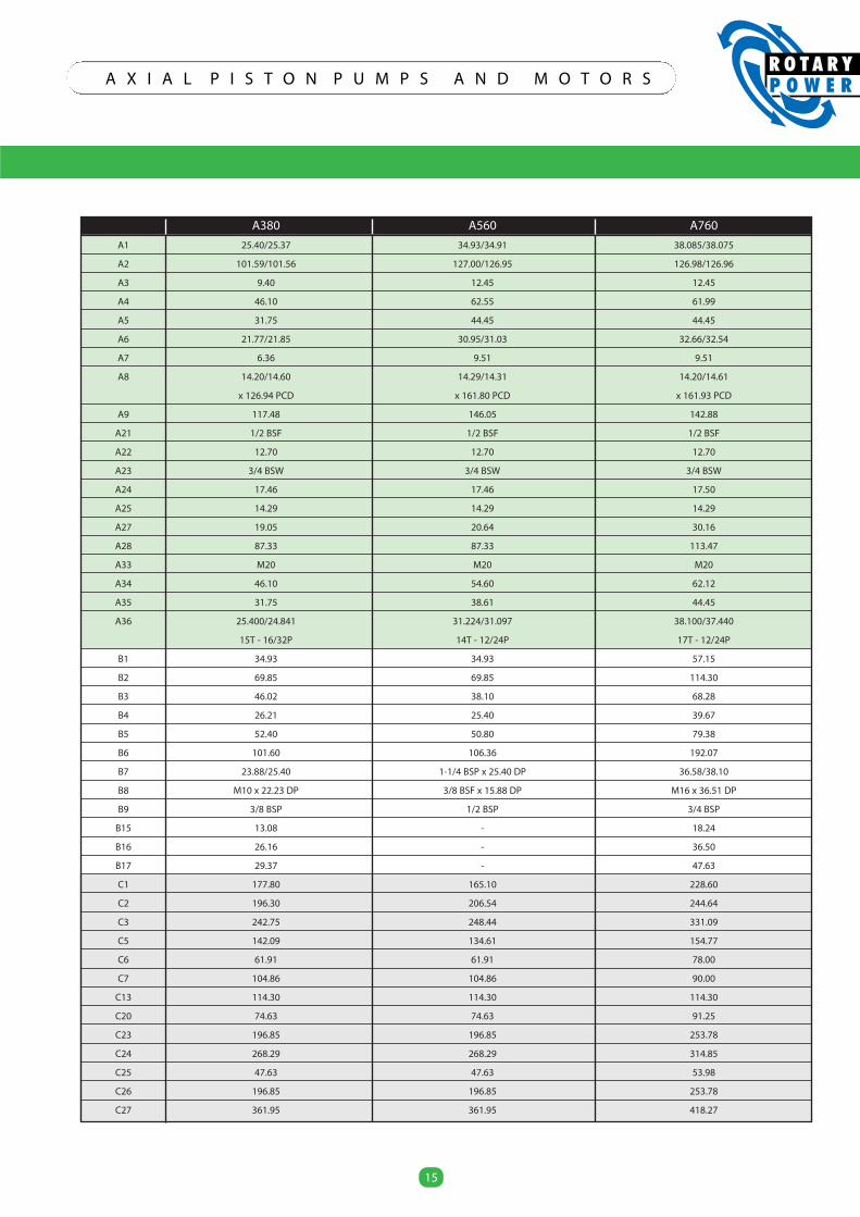
15
A X I A L P I S T O N P U M P S A N D M O T O R S
15
A380 A560 A760
A1 25.40/25.37 34.93/34.91 38.085/38.075
A2 101.59/101.56 127.00/126.95 126.98/126.96
A3 9.40 12.45 12.45
A4 46.10 62.55 61.99
A5 31.75 44.45 44.45
A6 21.77/21.85 30.95/31.03 32.66/32.54
A7 6.36 9.51 9.51
A8 14.20/14.60 14.29/14.31 14.20/14.61
x 126.94 PCD x 161.80 PCD x 161.93 PCD
A9 117.48 146.05 142.88
A21 1/2 BSF 1/2 BSF 1/2 BSF
A22 12.70 12.70 12.70
A23 3/4 BSW 3/4 BSW 3/4 BSW
A24 17.46 17.46 17.50
A25 14.29 14.29 14.29
A27 19.05 20.64 30.16
A28 87.33 87.33 113.47
A33 M20 M20 M20
A34 46.10 54.60 62.12
A35 31.75 38.61 44.45
A36 25.400/24.841 31.224/31.097 38.100/37.440
15T - 16/32P 14T - 12/24P 17T - 12/24P
B1 34.93 34.93 57.15
B2 69.85 69.85 114.30
B3 46.02 38.10 68.28
B4 26.21 25.40 39.67
B5 52.40 50.80 79.38
B6 101.60 106.36 192.07
B7 23.88/25.40 1-1/4 BSP x 25.40 DP 36.58/38.10
B8 M10 x 22.23 DP 3/8 BSF x 15.88 DP M16 x 36.51 DP
B9 3/8 BSP 1/2 BSP 3/4 BSP
B15 13.08 - 18.24
B16 26.16 - 36.50
B17 29.37 - 47.63
C1 177.80 165.10 228.60
C2 196.30 206.54 244.64
C3 242.75 248.44 331.09
C5 142.09 134.61 154.77
C6 61.91 61.91 78.00
C7 104.86 104.86 90.00
C13 114.30 114.30 114.30
C20 74.63 74.63 91.25
C23 196.85 196.85 253.78
C24 268.29 268.29 314.85
C25 47.63 47.63 53.98
C26 196.85 196.85 253.78
C27 361.95 361.95 418.27
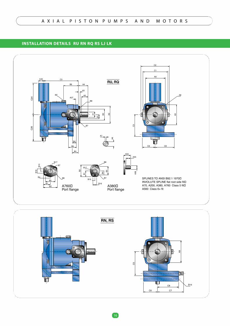
INSTALLATION DETAILS RU RN RQ RS LJ LK
16
A X I A L P I S T O N P U M P S A N D M O T O R S
16
C26
C3
B6 A4
A3
A5A27
B7
B8
A2B2
B1
A1B9
A7
A6
A9
C1
C2
A8
A9B8
B17B7
B4B5
B1B2
B16
B15
B2
B1 B4
B5
B15
B16
B7
B17
A35A34
A36
SPLINES TO ANSI B92.1 1970 INVOLUTE SPLINE flat root side fit A70, A200, A380, A760 Class 5 fit A560 Class 6+ fit
RU, RQ
C24
B8
A760 Port flange
A380 Port flange
C25
C8C6
C5
B4
B5
B3
B14
A9
RN, RS
C8
C6
C5
C7
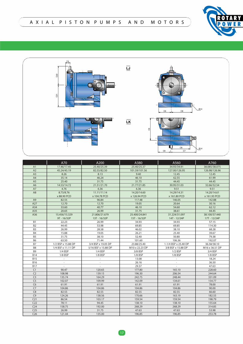
17
A X I A L P I S T O N P U M P S A N D M O T O R S
17
A70 A200 A380 A560 A760A1 17.46/17.45 25.40/25.39 25.40/25.37 34.93/34.91 38.085/38.075A2 45.24/45.19 82.55/82.50 101.59/101.56 127.00/126.95 126.98/126.96A3 8.26 8.13 9.40 12.45 12.45A4 35.14 46.24 46.10 62.55 61.99A5 25.40 31.75 31.75 44.45 44.45A6 14.53/14.72 21.51/21.70 21.77/21.85 30.95/31.03 32.66/32.54A7 4.76 6.36 6.36 9.51 9.51A8 8.73/8.76 11.11/11.14 14.20/14.60 14.29/14.31 14.20/14.61
x 88.90 PCD x 104.78 PCD x 126.94 PCD x 161.80 PCD x 161.93 PCDA9 82.55 96.84 117.48 146.05 142.88
A27 12.70 12.70 19.05 20.64 30.16A34 33.60 40.77 46.10 54.60 62.12A35 20.65 26.99 31.75 38.61 44.45A36 15.456/15.329 21.806/21.679 25.400/24.841 31.224/31.097 38.100/37.440
9T - 16/32P 13T - 16/32P 15T - 16/32P 14T - 12/24P 17T - 12/24PB1 22.23 26.99 34.93 34.93 57.15B2 44.45 53.98 69.85 69.85 114.30B3 26.99 28.58 46.02 38.10 68.28B4 15.88 19.05 26.21 25.40 39.67B5 31.75 38.10 52.40 50.80 79.38B6 63.50 71.44 101.60 106.36 192.07B7 1/2 BSP x 15.88 DP 3/4 BSP x 19.05 DP 23.88/25.40 1-1/4 BSP x 25.40 DP 36.58/38.10B8 1/4 BSF x 11.11 DP 5/16 BSF x 15.88 DP M10 x 22.23 DP 3/8 BSF x 15.88 DP M16 x 36.51 DPB9 1/4 BSP 1/4 BSP 3/8 BSP 1/2 BSP 3/4 BSP
B14 1/8 BSP 1/8 BSP 1/8 BSP 1/8 BSP 1/8 BSPB15 - - 13.08 - 18.24B16 - - 26.16 - 36.50B17 - - 29.37 - 47.63C1 90.47 120.65 177.80 165.10 228.60C2 108.98 139.15 196.30 206.54 244.64C3 135.74 164.29 242.75 248.44 331.09C5 102.07 109.99 142.09 134.61 154.77C6 61.91 61.91 61.91 61.91 78.00C7 104.86 104.86 104.86 104.86 90.00C8 82.55 82.55 82.55 82.55 66.60C9 124.26 138.56 170.66 163.19 182.55
C21 86.54 103.17 159.54 159.54 198.79C22 78.11 94.45 138.10 138.10 155.64C24 158.75 192.00 268.29 268.29 314.85C25 26.99 31.75 47.63 47.63 53.98C26 121.44 135.00 196.85 196.85 253.78
B14
LJ
C6 C8
B14C8C6
C9C7
C21
C22
C4
LK
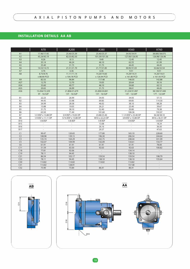
INSTALLATION DETAILS AA AB
18
A X I A L P I S T O N P U M P S A N D M O T O R S
18
A70 A200 A380 A560 A760A1 17.46/17.45 25.40/25.39 25.40/25.37 34.93/34.91 38.085/38.075A2 45.24/45.19 82.55/82.50 101.59/101.56 127.00/126.95 126.98/126.96A3 8.26 8.13 9.40 12.45 12.45A4 35.14 46.24 46.10 62.55 61.99A5 25.40 31.75 31.75 44.45 44.45A6 14.53/14.72 21.51/21.70 21.77/21.85 30.95/31.03 32.66/32.54A7 4.76 6.36 6.36 9.51 9.51A8 8.73/8.76 11.11/11.14 14.20/14.60 14.29/14.31 14.20/14.61
x 88.90 PCD x 104.78 PCD x 126.94 PCD x 161.80 PCD x 161.93 PCDA9 82.55 96.84 117.48 146.05 142.88
A27 12.70 12.70 19.05 20.64 30.16A34 33.60 40.77 46.10 54.60 62.12A35 20.65 26.99 31.75 38.61 44.45A36 15.456/15.329 21.806/21.679 25.400/24.841 31.224/31.097 38.100/37.440
9T - 16/32P 13T - 16/32P 15T - 16/32P 14T - 12/24P 17T - 12/24P
B1 22.23 26.99 34.93 34.93 57.15B2 44.45 53.98 69.85 69.85 114.30B3 26.99 28.58 46.02 38.10 68.28B4 15.88 19.05 26.21 25.40 39.67B5 31.75 38.10 52.40 50.80 79.38B6 63.50 71.44 101.60 106.36 192.07B7 1/2 BSP x 15.88 DP 3/4 BSP x 19.05 DP 23.88/25.40 1-1/4 BSP x 25.40 DP 36.58/38.10B8 1/4 BSF x 11.11 DP 5/16 BSP x 15.88 DP M10 x 22.23 DP 3/8 BSF x 15.88 DP M16 x 36.51 DP
B10 1/8 BSP 1/8 BSP 1/8 BSP 1/8 BSP 1/8 BSPB15 - - 13.08 - 18.24B16 - - 26.16 - 36.50B17 - - 29.37 - 47.63
C1 90.47 120.65 177.80 165.10 228.60C2 108.98 139.15 196.30 206.54 244.64C3 135.74 164.29 242.75 248.44 331.09C5 102.07 109.99 142.09 134.61 154.77C6 61.91 61.91 61.91 61.91 78.00
C11 51.59 63.50 92.63 92.63 100.82C18 77.81 92.06 - 134.14 -C19 78.11 94.45 - 138.10 -C21 86.54 103.17 159.54 159.54 198.79C22 78.11 94.45 138.10 138.10 155.64C30 114.82 114.82 114.82 114.82 -C31 113.82 128.91 - 157.48 -C32 73.90 73.84 86.41 86.41 -
AA
C18
C19
B10
AB
C11
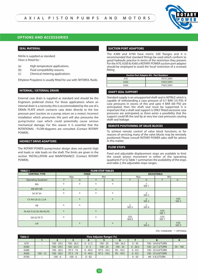
SEAL MATERIAL
Nitrile is supplied as standard.Viton is fitted for :
(a) High temperature applications.(b) Fluid compatibility reasons.(c) Chemical metering applications.
Ethylene Propylene is usually fitted for use with SKYDROL fluids.
INTERNAL / EXTERNAL DRAIN
External case drain is supplied as standard and should be theEngineers preferred choice. For those applications where aninternal drain is a necessity, this is accommodated by the use of aDRAIN PLATE which connects case drain directly to the lowpressure port (suction on a pump, return on a motor). Incorrectinstallation which pressurises this port will also pressurise thepump/motor case which could potentially cause seriousmechanical damage. For this reason it is essential that theROTATIONAL - FLOW diagrams are consulted. (Contact ROTARYPOWER).
INDIRECT DRIVE ADAPTORS
The ROTARY POWER pump/motor design does not permit highend loads or side loads on the shaft. The limits are given in thesection ‘INSTALLATION and MAINTENANCE’. (Contact ROTARYPOWER).
OPTIONS AND ACCESSORIES
19
A X I A L P I S T O N P U M P S A N D M O T O R S
Table 2 Flow Adjuster Ranges (%)1 2 3 4 5 6 7 8 9
A70 - 100 - 29.5 100 - 26.5 0 - 21.5 100 - 20 100 - 26.5 0 - 30 100 - 34 8.4/TURN -A200 - 100 - 29.5 100 - 23.5 0 - 5 100 - 23 100 - 24 0 - 26.5 100 - 22 7.3/TURN 50 - 100A380 - 100 - 28.5 97.5 - 19 0 - 49.5 97.5 - 18.5 95 - 18.5 0 - 8.5 100 - 35 6.9/TURN -A560 100 - 15 100 - 28.5 97.5 - 19 0 - 49.5 97.5 - 18.5 95 - 18.5 0 - 8.5 100 - 35 6.9/TURN -A760 - 100 - 0 100 - 0 0 - 82 - - 0 - 50 89 - 0 8.3/TURN -
TABLE 1 FLOW STOP TABLESCONTROL TYPE FIXED ADJUSTABLE
Max Min Max MinOperating Quadrant P Q P Q P Q P Q
MA * * * * *SEE 1
MB MD ME * *SA SE SH * * * * *SEE 2
CV AA LB LG LJ LK * * * STDSEE 3 SEE 4
AB * * * *SEE 5 SEE 6
PA RA PJ RJ RU RN RQ RS * * STDSEE 7
QA QJ TA TJ * * STD STDSEE 8 SEE 7
LM * * * STDSEE 6 SEE 9
STD : STANDARD * : OPTIONAL
SUCTION PORT ADAPTORS
The A380 and A760 have metric SAE flanges and it isrecommended that standard fittings be used which conform togood hydraulic practice in terms of the restriction they present.For the A70,A200 & A560 a ROTARY POWER suction port adaptorshould be employed to avoid the ‘local’ restriction of a screwedfitting .
SHAFT SEAL SUPPORT
Standard supply is an unsupported shaft seal in NITRILE which iscapable of withstanding a case pressure of 0.7 BAR (10 PSI). Ifcase pressures in excess of this and upto 4 BAR (60 PSI) areanticipated, then the shaft seal must be supported. It isimportant that a shaft seal support is ONLY fitted excessive casepressures are anticipated, as there exists a possibility that thesupport could lift the seal lip at very low case pressures causingshaft seal leakage.
REMOTE POSITIONING OFVALVE BLOCKS
To achieve remote control of valve block functions, or forreasons of servicing, many of the valve blocks may be remotelypositioned. Please consult ROTARY POWER sales staff for advicein this matter.
FLOW STOPS
Fixed and adjustable displacement stops are available to limitthe swash piston movement in either of the operatingquadrants P or Q.Table 1 summarises the availability of the stopsand table 2, the adjustable stops ranges.
Suction Port Adaptor Kit - Part Numbers
A70 P07CC30N1
A200 P20CC30N1
A560 P56CC30N1
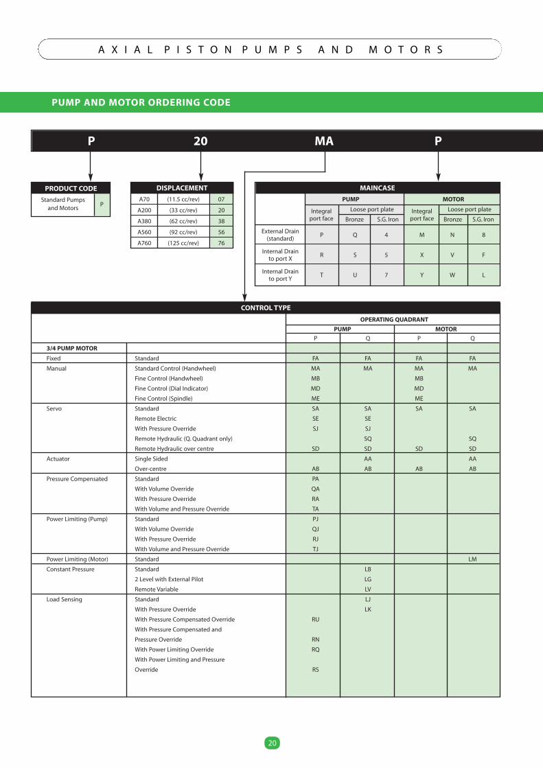
PUMP AND MOTOR ORDERING CODE
20
A X I A L P I S T O N P U M P S A N D M O T O R S
PRODUCT CODE
Standard Pumpsand Motors
P
DISPLACEMENT
A70 (11.5 cc/rev) 07
A200 (33 cc/rev) 20
A380 (62 cc/rev) 38
A560 (92 cc/rev) 56
A760 (125 cc/rev) 76
MAINCASE
PUMP MOTOR
Integral Loose port plate Integral Loose port plate
port face Bronze S.G. Iron port face Bronze S.G. Iron
External DrainP Q 4 M N 8
(standard)
Internal DrainR S 5 X V F
to port X
Internal DrainT U 7 Y W L
to port Y
P 20 MA P
CONTROL TYPE
OPERATING QUADRANT
PUMP MOTOR
P Q P Q
3/4 PUMP MOTOR
Fixed Standard FA FA FA FA
Manual Standard Control (Handwheel) MA MA MA MA
Fine Control (Handwheel) MB MB
Fine Control (Dial Indicator) MD MD
Fine Control (Spindle) ME ME
Servo Standard SA SA SA SA
Remote Electric SE SE
With Pressure Override SJ SJ
Remote Hydraulic (Q. Quadrant only) SQ SQ
Remote Hydraulic over centre SD SD SD SD
Actuator Single Sided AA AA
Over-centre AB AB AB AB
Pressure Compensated Standard PA
With Volume Override QA
With Pressure Override RA
With Volume and Pressure Override TA
Power Limiting (Pump) Standard PJ
With Volume Override QJ
With Pressure Override RJ
With Volume and Pressure Override TJ
Power Limiting (Motor) Standard LM
Constant Pressure Standard LB
2 Level with External Pilot LG
Remote Variable LV
Load Sensing Standard LJ
With Pressure Override LK
With Pressure Compensated Override RU
With Pressure Compensated and
Pressure Override RN
With Power Limiting Override RQ
With Power Limiting and Pressure
Override RS
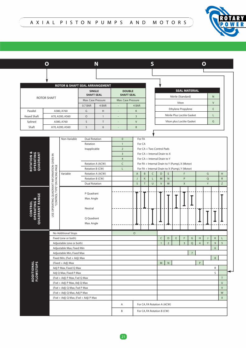
21
A X I A L P I S T O N P U M P S A N D M O T O R S
21
SEAL MATERIAL
Nitrile (Standard) N
Viton V
Ethylene Propylene E
Nitrile Plus Loctite Gasket L
Viton plus Loctite Gasket G
ROTOR & SHAFT SEAL ARRANGEMENT
SINGLE DOUBLESHAFT SEAL SHAFT SEAL
Max. Case Pressure Max. Case Pressure
0.7 BAR 4 BAR - 4 BAR
Parallel A380, A760 G H - K
Keyed Shaft A70, A200, A560 O 1 - 3
Splined A380, A760 S T - V
Shaft A70, A200, A560 5 6 - 8
O N S O
Non-Variable Dual Rotation 0 For FA
Rotation 1 For CA
Inapplicable 2 For CA + Two Control Pads
3 For CA + Internal Drain to X
4 For CA + Internal Drain to Y
Rotation A (ACW) C For FA + Internal Drain to Y (Pump), X (Motor)
Rotation B (CW) L For FA + Internal Drain to X (Pump),Y (Motor)
Variable Rotation A (ACW) A B C D E F G H
Rotation B (CW) J K L M N P Q R
Dual Rotation S T U V W X Y Z
P Quadrant
Max. Angle
Neutral
Q Quadrant
Max. Angle
No Additional Stops O
Fixed (one or both) C D E F G H J K L
Adjustable (one or both) 1 2 3 Q 4 Y 9 5
Adjustable Max, Fixed Min 6
Adjustable Min, Fixed Max 7
Fixed Min, (Fxd + Adj) Max 8
(Fixed + Adj) Max M N P
Adj P Max, Fixed Q Max R
Adj Q Max, Fixed P Max S
(Fxd + Adj) P Max, Fxd Q Max T
(Fxd + Adj) P Max, Adj Q Max U
(Fxd + Adj) Q Max, Fxd P Max V
(Fxd + Adj) Q Max, Adj P Max W
(Fxd + Adj) Q Max, (Fxd + Adj) P Max X
A For CA, FA Rotation A (ACW)
B For CA, FA Rotation B (CW)
ROTOR SHAFT
ROTA
TIO
N&
OPERATIN
GQUADRANT
CONTROL
OPERATIN
G&
QUADRANT
RANGE
ADDIT
IONAL
FLO
WSTOPS
USE
OPE
RAT
ING
QU
AD
RA
NT
INFO
RMAT
ION
GIV
ENIN
“CO
NTR
OL
TYPE
”ON
FAC
ING
PAG
E

FEATURES
Designed specifically for the
Polyurethane foam industry from
over 20 years application
experience and development.
Uniform fluid temperatures
throughout the pump.
Designed for high inlet pressure.
Twin PTFE seals running on a
ceramic bush allow up to 20 bar.
High metering accuracy. Matched
and balanced control components
minimise backlash errors.
No leakage return line, pump is
internally drained.
Leakage indicator and lubrication
ports included
All major components treated to
minimise corrosion.
Cartridge shaft seal to ease
service and minimise
maintenance time.
Certified to ATEX directive
94/9/EC
ROTARY POWER has over 35 years experience in the design anddevelopment of high quality Hydraulic equipment.
Our current product range includes :-
"A" Axial Piston Pumps for heavy-duty open circuit applications.Wide range of controls. Excellent life characteristics. Suitable formost fluids, including HLP, HFA, HFB, HFC, HFD, HFR, HFE, Isocyanates& Polyols. Fixed and variable capacities from 11.5 to 125 cm3/rev.
"C" Axial Piston Pumps for high accuracy fluid metering withprecision flow controls and high-pressure capability. Specificallydesigned for the Polyurethane Industry. Capacities from 2 to 62cm3/rev.
"XL" Cam Motors of radial piston configuration. Wheel/shaft/torquemodule configurations. Design offers high-speed capability.Capacities from 150 to 1120 cm3/rev.
" X K " C a m M o t o r s r a d i a l p i s t o n c o n f i g u r a t i o n o f f e r i n gstatic/dynamic brakes, single or 2 speed, wheel/shaft & torque-module mount options.
Heavy-Duty External Load & High-Speed options. Capacities from 1000 to 5000 cm3/rev.
"SMA" Motors heavy-duty radial piston/eccentric configuration,offering excellent life. Withstands high mechanical and hydraulicshock loads. 350bar Continuous pressure rating. Speed & powerratings significantly greater than standard HTLS motors.
Displacements from 150 to 10500 cm3/rev.
Wholly owned subsidiaries in the USA and Germany and anetwork of distributors throughout the world provide productsupport in most countries.
ROTARY POWER is a company within British Engines Ltd (BEL)group, which was established over 60 years ago.
The British Engines group of companies design manufactureand market a wide range of engineered products foroffshore, electrical, construction, engineering and otherindustries, employing nearly 1,000 people on a 4600 sq m site inNewcastle upon Tyne, England.
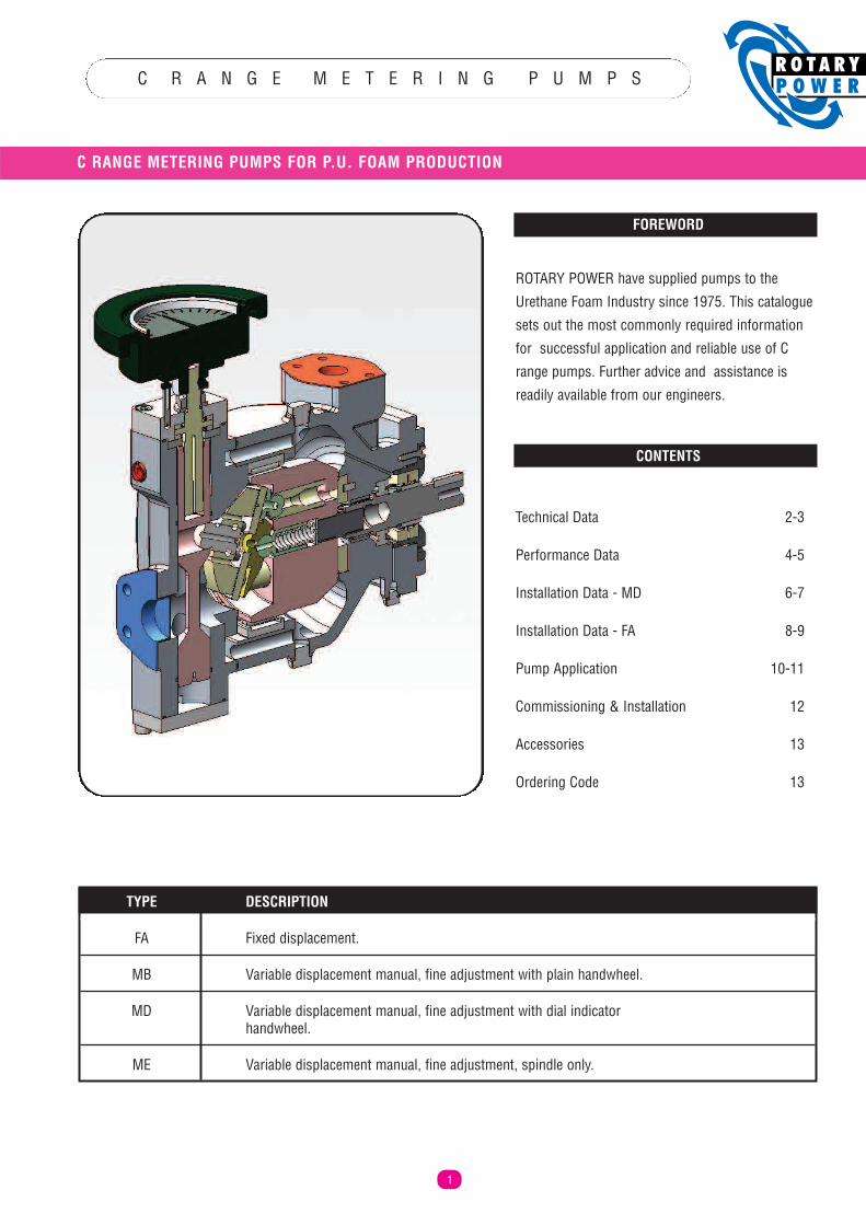
C R A N G E M E T E R I N G P U M P S
C RANGE METERING PUMPS FOR P.U. FOAM PRODUCTION
1
FOREWORD
ROTARY POWER have supplied pumps to theUrethane Foam Industry since 1975. This cataloguesets out the most commonly required informationfor successful application and reliable use of Crange pumps. Further advice and assistance isreadily available from our engineers.
CONTENTS
Technical Data 2-3
Performance Data 4-5
Installation Data - MD 6-7
Installation Data - FA 8-9
Pump Application 10-11
Commissioning & Installation 12
Accessories 13
Ordering Code 13
TYPE DESCRIPTION
FA Fixed displacement.
MB Variable displacement manual, fine adjustment with plain handwheel.
MD Variable displacement manual, fine adjustment with dial indicator handwheel.
ME Variable displacement manual, fine adjustment, spindle only.
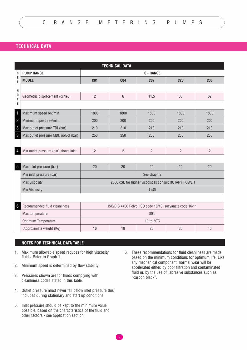
C R A N G E M E T E R I N G P U M P S
TECHNICAL DATA
2
NOTES FOR TECHNICAL DATA TABLE
1. Maximum allowable speed reduces for high viscosityfluids. Refer to Graph 1.
2. Minimum speed is determined by flow stability.
3. Pressures shown are for fluids complying withcleanliness codes stated in this table.
4. Outlet pressure must never fall below inlet pressure thisincludes during stationary and start up conditions.
5. Inlet pressure should be kept to the minimum valuepossible, based on the characteristics of the fluid andother factors - see application section.
6. These recommendations for fluid cleanliness are made,based on the minimum conditions for optimum life. Likeany mechanical component, normal wear will beaccelerated either, by poor filtration and contaminatedfluid or, by the use of abrasive substances such as“carbon black”.
TECHNICAL DATA
PUMP RANGE C - RANGE
MODEL C01 C04 C07 C20 C38
Geometric displacement (cc/rev) 2 6 11.5 33 62
1 Maximum speed rev/min 1800 1800 1800 1800 1800
2 Minimum speed rev/min 200 200 200 200 200
3 Max outlet pressure TDI (bar) 210 210 210 210 210
3 Max outlet pressure MDI, polyol (bar) 250 250 250 250 250
4 Min outlet pressure (bar) above inlet 2 2 2 2 2
5 Max inlet pressure (bar) 20 20 20 20 20
Min inlet pressure (bar) See Graph 2
Max viscosity 2000 cSt, for higher viscosities consult ROTARY POWER
Min Viscosity 1 cSt
6 Recommended fluid cleanliness ISO/DIS 4406 Polyol ISO code 18/13 Isocyanate code 16/11
Max temperature 80ºC
Optimum Temperature 10 to 50ºC
Approximate weight (Kg) 16 18 20 30 40
SEE
NOTE
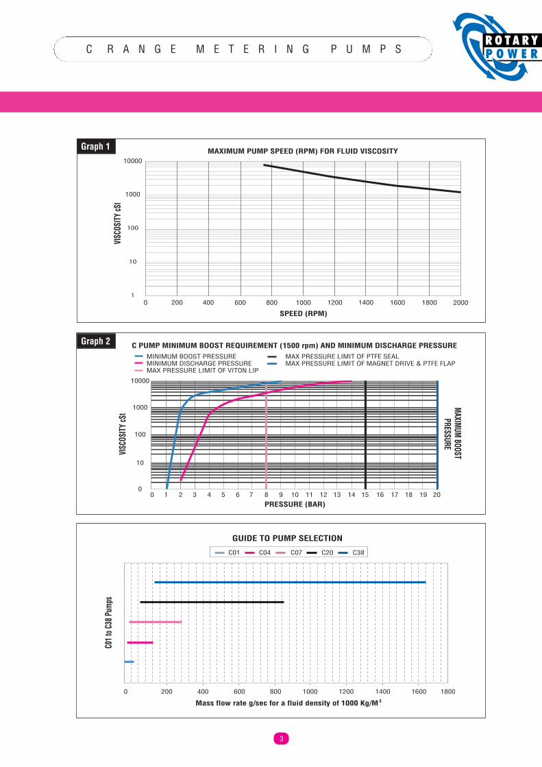
C R A N G E M E T E R I N G P U M P S
3
10000
1000
100
10
10 200 400 600 800 1000 14001200 1600 1800 2000
VISC
OSITY
cSt
SPEED (RPM)
MAXIMUM PUMP SPEED (RPM) FOR FLUID VISCOSITY
MINIMUM BOOST PRESSUREMINIMUM DISCHARGE PRESSUREMAX PRESSURE LIMIT OF VITON LIP
MAX PRESSURE LIMIT OF PTFE SEALMAX PRESSURE LIMIT OF MAGNET DRIVE & PTFE FLAP
0
10
100
1000
10000
0 1 2 3 4 5 6 7 8 9 10 11 12 13 14 15 16 17 18 19 20PRESSURE (BAR)
VISC
OSITY
cSt
MAXIMUM BOOST PRESSURE
C PUMP MINIMUM BOOST REQUIREMENT (1500 rpm) AND MINIMUM DISCHARGE PRESSURE
C07 C20C04C01 C38
0 200 400 600 800 1000 1200 1400 18001600
Mass flow rate g/sec for a fluid density of 1000 Kg/M3
GUIDE TO PUMP SELECTION
C01 t
o C38
Pum
ps
Graph 1
Graph 2
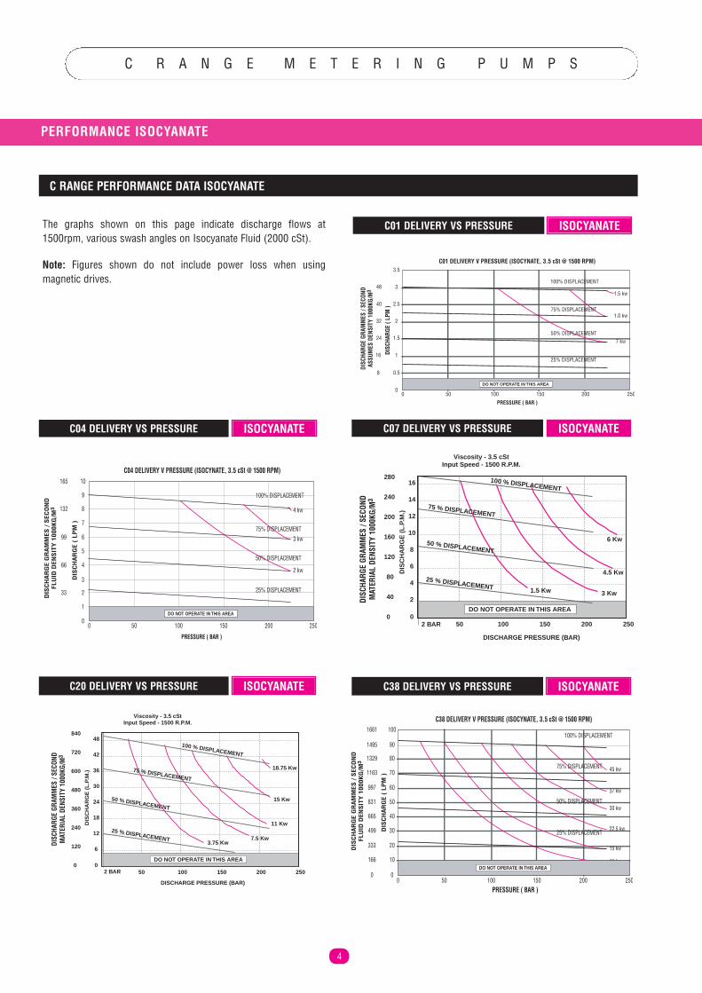
C R A N G E M E T E R I N G P U M P S
PERFORMANCE ISOCYANATE
4
ISOCYANATEThe graphs shown on this page indicate discharge flows at1500rpm, various swash angles on Isocyanate Fluid (2000 cSt).
Note: Figures shown do not include power loss when usingmagnetic drives.
DIS
CH
AR
GE
( LP
M )
DIS
CH
AR
GE
GR
AM
MES
/ S
ECO
ND
FLU
ID D
ENS
ITY
100
0KG
/M3
10
9
8
7
6
5
4
3
2
1
0
165
132
99
66
33
C04 DELIVERY V PRESSURE (ISOCYNATE, 3.5 cSt @ 1500 RPM)
4 kw
3 kw
2 kw
PRESSURE ( BAR )
0 50 100 200150 250
25% DISPLACEMENT
100% DISPLACEMENT
75% DISPLACEMENT
50% DISPLACEMENT
DO NOT OPERATE IN THIS AREA
0
6
12
18
24
30
36
42
48
DIS
CH
AR
GE
(L
.P.M
.)
0
120
240
360
480
600
720
840
50 100 150 200 250
DISCHARGE PRESSURE (BAR)
DO NOT OPERATE IN THIS AREA
2 BAR
100 % DISPLACEMENT
50 % DISPLACEMENT
25 % DISPLACEMENT
18.75 Kw
15 Kw
11 Kw
7.5 Kw3.75 Kw
Viscosity - 3.5 cStInput Speed - 1500 R.P.M.
75 % DISPLACEMENT
DISC
HARG
E GR
AMM
ES /
SECO
NDM
ATER
IAL
DENS
ITY
1000
KG/M
3
0
2
4
6
8
10
12
14
16
DIS
CH
AR
GE
(L
.P.M
.)
0
40
80
120
160
200
240
280
50 100 150 200 250
DISCHARGE PRESSURE (BAR)
DO NOT OPERATE IN THIS AREA
2 BAR
100 % DISPLACEMENT
25 % DISPLACEMENT
50 % DISPLACEMENT
75 % DISPLACEMENT
1.5 Kw 3 Kw
4.5 Kw
6 Kw
Viscosity - 3.5 cStInput Speed - 1500 R.P.M.
DISC
HARG
E GR
AMM
ES /
SECO
NDM
ATER
IAL
DENS
ITY
1000
KG/M
3
C38 DELIVERY V PRESSURE (ISOCYNATE, 3.5 cSt @ 1500 RPM)
PRESSURE ( BAR )
100% DISPLACEMENT
75% DISPLACEMENT
50% DISPLACEMENT
25% DISPLACEMENTDIS
CH
AR
GE
( LP
M )
DIS
CH
AR
GE
GR
AM
MES
/ S
ECO
ND
FLU
ID D
ENS
ITY
100
0KG
/M3
1661
1495
1329
1163
997
831
665
499
333
166
0
100
90
80
70
60
50
40
30
20
10
00 50 100 150 200 250
45 kw
37 kw
30 kw
22.5 kw
15 kw
11 kwDO NOT OPERATE IN THIS AREA
C04 DELIVERY VS PRESSURE ISOCYANATE C07 DELIVERY VS PRESSURE ISOCYANATE
C20 DELIVERY VS PRESSURE ISOCYANATE C38 DELIVERY VS PRESSURE ISOCYANATE
DISC
HARG
E ( L
PM )
DISC
HARG
E GR
AMM
ES /
SECO
NDAS
SUM
ES D
ENSI
TY 1
000K
G/M
3
48
40
32
24
16
8
3
3.5
2.5
2
1.5
1
0.5
0
C01 DELIVERY V PRESSURE (ISOCYNATE, 3.5 cSt @ 1500 RPM)
1.0 kw
7 kw
1.5 kw
25% DISPLACEMENT
100% DISPLACEMENT
75% DISPLACEMENT
50% DISPLACEMENT
PRESSURE ( BAR )0 50 100 200150 250
DO NOT OPERATE IN THIS AREA
C01 DELIVERY VS PRESSURE
C RANGE PERFORMANCE DATA ISOCYANATE
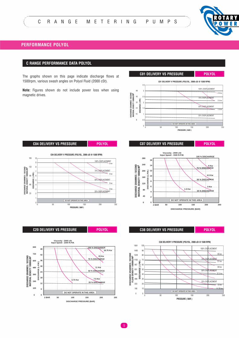
C R A N G E M E T E R I N G P U M P S
PERFORMANCE POLYOL
5
DIS
CHAR
GE
( LP
M )
DIS
CHAR
GE
GR
AMM
ES /
SECO
ND
MAT
ERIA
L D
ENSI
TY 1
000K
G/ M
3
165
132
99
66
33
10
9
8
7
6
5
4
3
2
1
0
C04 DELIVERY V PRESSURE (POLYOL, 2000 cSt @ 1500 RPM)
5 kw
4 kw
3 kw
2 kw25% DISPLACEMENT
100% DISPLACEMENT
75% DISPLACEMENT
50% DISPLACEMENT
PRESSURE ( BAR )0 50 100 200150 250
DO NOT OPERATE IN THIS AREA
0
6
12
18
24
30
36
42
48
DIS
CH
AR
GE
(L
.P.M
.)
0
120
240
360
480
600
720
840
50 100 150 200 250
DISCHARGE PRESSURE (BAR)
2 BAR
100 % DISCHARGE
75 % DISCHARGE
3.75 Kw 7.5 Kw
11 Kw
15 Kw
18.75 Kw
DO NOT OPERATE IN THIS AREA
50 % DISCHARGE
25 % DISCHARGE
Viscosity - 2000 cStInput Speed - 1500 R.P.M.
DISC
HARG
E GR
AMM
ES /
SECO
NDM
ATER
IAL
DENS
ITY
1000
KG/M
3
0
2
4
6
8
10
12
14
16
DIS
CH
AR
GE
(L
.P.M
.)
0
40
80
120
160
200
240
280
50 100 150 200 250
DISCHARGE PRESSURE (BAR)
DO NOT OPERATE IN THIS AREA
2 BAR
100 % DISCHARGE
50 % DISCHARGE
25 % DISCHARGE1.5 Kw
3 Kw
4.5 Kw
6 Kw75 % DISCHARGE
Viscosity - 2000 cStInput Speed - 1500 R.P.M.
DISC
HARG
E GR
AMM
ES /
SECO
NDM
ATER
IAL
DENS
ITY
1000
KG/M
3
C38 DELIVERY V PRESSURE (POLYOL, 2000 cSt @ 1500 RPM)
PRESSURE ( BAR )
100% DISPLACEMENT
75% DISPLACEMENT
50% DISPLACEMENT
25% DISPLACEMENT
DIS
CHAR
GE
( LP
M )
DIS
CHAR
GE
GR
AMM
ES /
SECO
ND
FLU
ID D
ENSI
TY 1
000K
G/M
3
1661
1495
1329
1163
997
831
665
499
333
166
0
100
90
80
70
60
50
40
30
20
10
00 50 100 150 200 250
45 kw
37 kw
30 kw
22.5 kw
15 kw
11.75 kwDO NOT OPERATE IN THIS AREA
C04 DELIVERY VS PRESSURE POLYOL C07 DELIVERY VS PRESSURE POLYOL
C20 DELIVERY VS PRESSURE POLYOL C38 DELIVERY VS PRESSURE POLYOL
DISC
HARG
E ( L
PM )
DISC
HARG
E GR
AMM
ES /
SECO
NDM
ATER
IAL
DENS
ITY
1000
KG/M
3
48
40
32
24
16
8
3
3.5
2.5
2
1.5
1
0.5
0
C01 DELIVERY V PRESSURE (POLYOL, 2000 cSt @ 1500 RPM)
2.0 kw
1.6 kw
2.6 kw
25% DISPLACEMENT
100% DISPLACEMENT
75% DISPLACEMENT
50% DISPLACEMENT
PRESSURE ( BAR )0 50 100 200150 250
DO NOT OPERATE IN THIS AREA
C01 DELIVERY VS PRESSURE POLYOL
C RANGE PERFORMANCE DATA POLYOL
The graphs shown on this page indicate discharge flows at1500rpm, various swash angles on Polyol Fluid (2000 cSt).
Note: Figures shown do not include power loss when usingmagnetic drives.
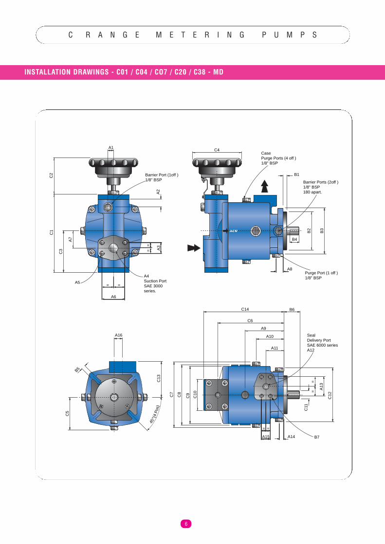
C R A N G E M E T E R I N G P U M P S
INSTALLATION DRAWINGS - C01 / C04 / CO7 / C20 / C38 - MD
6
A1
C2
C1
C3
A7
A2
Barrier Port (1off )1/8" BSP
A4Suction PortSAE 3000series.
A6
A5
== A
3
= =
A16
B5
C5
C13
45 (
4 P
os)
ACW
CasePurge Ports (4 off )1/8" BSP
C4
B1
B2
B3
A8
Barrier Ports (2off )1/8" BSP 180 apart.
B4
Purge Port (1 off )1/8" BSP
C14 B6
A9
A10
A11
C6
C7
C8
C9
C10
= =
A15
==
A13
C12
SealDelivery PortSAE 6000 seriesA12
A14
C11
B7
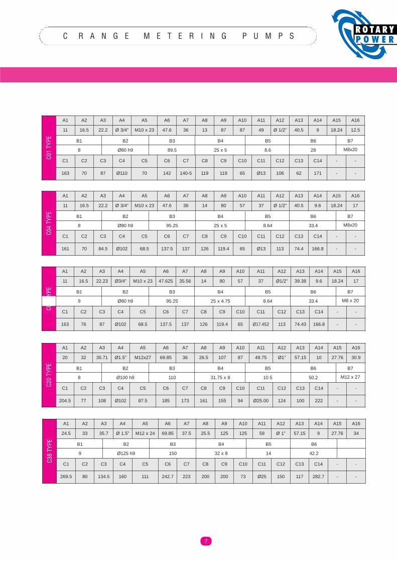
C R A N G E M E T E R I N G P U M P S
7
A1 A2 A3 A4 A5 A6 A7 A8 A9 A10 A11 A12 A13 A14 A15 A16
11 16.5 22.2 Ø 3/4” M10 x 23 47.6 36 13 87 87 49 Ø 1/2” 40.5 9 18.24 12.5
C1 C2 C3 C4 C5 C6 C7 C8 C9 C10 C11 C12 C13 C14 - -
163 70 87 Ø110 70 142 140-5 119 119 65 Ø13 106 62 171 - -
C01
TYPE B1 B6 B7B5B4B3B2
8 M8x20288.625 x 589.5Ø80 h9
A1 A2 A3 A4 A5 A6 A7 A8 A9 A10 A11 A12 A13 A14 A15 A16
11 16.5 22.2 Ø 3/4” M10 x 23 47.6 36 14 80 57 37 Ø 1/2” 40.5 9.6 18.24 17
C1 C2 C3 C4 C5 C6 C7 C8 C9 C10 C11 C12 C13 C14 - -
161 70 84.5 Ø102 68.5 137.5 137 126 119.4 65 Ø13 113 74.4 166.8 - -
C04
TYPE B1 B6 B7B5B4B3B2
8 M8x2033.48.6425 x 595.25Ø80 h9
A1 A2 A3 A4 A5 A6 A7 A8 A9 A10 A11 A12 A13 A14 A15 A16
24.5 33 35.7 Ø 1.5” M12 x 24 69.85 37.5 25.5 125 125 59 Ø 1” 57.15 9 27.76 34
C1 C2 C3 C4 C5 C6 C7 C8 C9 C10 C11 C12 C13 C14 - -
269.5 80 134.5 160 111 242.7 223 200 200 73 Ø25 150 117 282.7 - -
C38
TYPE B1 B6B5B4B3B2
9 42.21432 x 8150Ø125 h9
A1 A2 A3 A4 A5 A6 A7 A8 A9 A10 A11 A12 A13 A14 A15 A16
11 16.5 22.23 Ø3/4” M10 x 23 47.625 35.56 14 80 57 37 Ø1/2” 39.38 9.6 18.24 17
C1 C2 C3 C4 C5 C6 C7 C8 C9 C10 C11 C12 C13 C14 - -
163 76 87 Ø102 68.5 137.5 137 126 119.4 65 Ø17.452 113 74.43 166.8 - -
C07
TYPE B1 B6 B7B5B4B3B2
9 M8 x 2033.48.6425 x 4.7595.25Ø80 h9
A1 A2 A3 A4 A5 A6 A7 A8 A9 A10 A11 A12 A13 A14 A15 A16
20 32 35.71 Ø1.5” M12x27 69.85 36 26.5 107 87 49.75 Ø1” 57.15 10 27.76 30.9
C1 C2 C3 C4 C5 C6 C7 C8 C9 C10 C11 C12 C13 C14 - -
204.5 77 108 Ø102 87.5 185 173 161 155 94 Ø25.00 124 100 222 - -
C20
TYPE B1 B6 B7B5B4B3B2
8 M12 x 2750.210.531.75 x 8110Ø100 h9
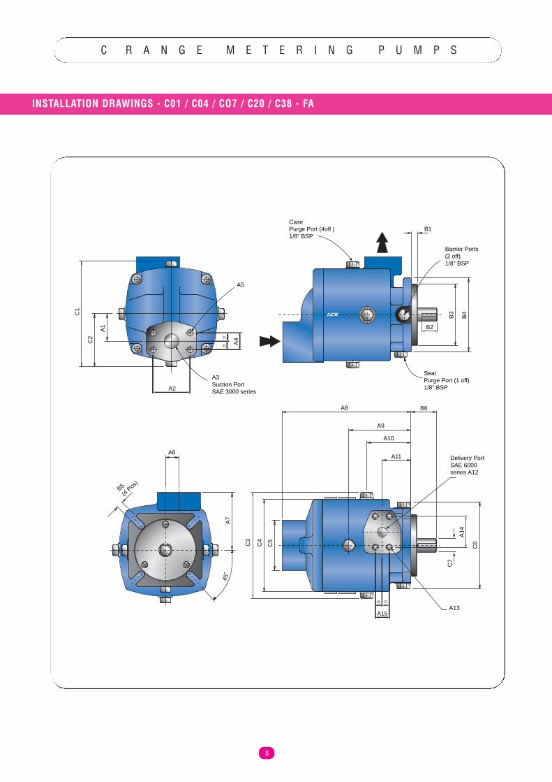
C R A N G E M E T E R I N G P U M P S
INSTALLATION DRAWINGS - C01 / C04 / CO7 / C20 / C38 - FA
8
ACWC1
C2
A1
==
A4
B1
B2
B3
B4
A8
A9
A10
A11
B6
C3
C4
C5
A2
==
A15
A14
C6
Delivery PortSAE 6000series A12
A13
A5
A3Suction PortSAE 3000 series
Barrier Ports(2 off)1/8" BSP
SealPurge Port (1 off)1/8" BSP
CasePurge Port (4off )1/8" BSP
A6
A7
B5(4
Pos
)
45˚
C7
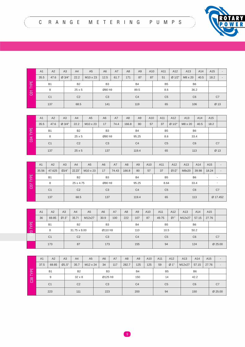
C R A N G E M E T E R I N G P U M P S
9
A1 A2 A3 A4 A5 A6 A7 A8 A9 A10 A11 A12 A13 A14 A15 -
35.5 47.6 Ø 3/4” 22.2 M10 x 23 12.5 61.7 171 87 87 51 Ø 1/2” M8 x 20 40.5 18.2 -
C01
TYPE B1 B6B5B4B3B2
8 36.28.689.5Ø80 h925 x 5
C1 C6C5C4C3C2
137 106
C7
Ø 136511914168.5
A1 A2 A3 A4 A5 A6 A7 A8 A9 A10 A11 A12 A13 A14 A15
35.5 47.6 Ø 3/4” 22.2 M10 x 23 17 74.4 166.8 80 57 37 Ø 1/2” M8 x 20 40.5 18.2
C04
TYPE B1 B6B5B4B3B2
8 33.48.695.25Ø80 h925 x 5
A1 A2 A3 A4 A5 A6 A7 A8 A9 A10 A11 A12 A13 A14 A15 -
37.5 69.85 Ø1.5” 35.7 M12 x 24 34 117 282.7 125 125 59 Ø 1” M12x27 57.15 27.76 -
C38
TYPE B1 B6B5B4B3B2
9 42.214150Ø125 h932 x 8
A1 A2 A3 A4 A5 A6 A7 A8 A9 A10 A11 A12 A13 A14 A15 -
35.56 47.625 Ø3/4” 22.23” M10 x 23 17 74.43 166.8 80 57 37 Ø1/2” M8x20 39.98 18.24 -
C07
TYPE B1 B6 -B5B4B3B2
8 -33.48.6495.25Ø80 h925 x 4.75
A1 A2 A3 A4 A5 A6 A7 A8 A9 A10 A11 A12 A13 A14 A15
36 69.85 Ø1.5” 35.71 M12x27 30.9 100 222 107 87 49.75 Ø1” M12x27 57.15 27.76
C20
TYPE B1 B6B5B4B3B2
8 50.210.5110Ø110 h931.75 x 8.00
C1 C6C5C4C3C2
137 113
C7
Ø 1365119.413725 x 5
C1 C6C5C4C3C2
137 113
C7
Ø 17.45265119.413768.5
C1 C6C5C4C3C2
173 124
C7
Ø 25.009415517387
C1 C6C5C4C3C2
223 150
C7
Ø 25.0094200223111
C R A N G E M E T E R I N G P U M P S
PUMP APPLICATION
10
IMPORTANT INFORMATION - PLEASE READ CAREFULLY
OPERATING PRESSURES - GENERAL
The pump design features hydrostatic bearing faces for optimumefficiency and long life. The hydrostatic balance required for thesebearings means that inlet pressure must never exceed outlet pressure,even when the pump is not rotating. This is normally simple to achieveon tank pressured systems. For systems using boost pump this may bepossible by using a relief valve or by placing a check valve in parallelwith the pump. This is to allow a possible flow from inlet to outlet so thatpressures can be balanced from inlet to outlet during start up of thepump (this valve should close as soon as outlet pressure exceeds inletpressure).
OUTLET PRESSURE
SHAFT SEAL
Outlet pressure from the pump must always exceed inlet pressureto the pump. Failure to comply with this instruction may lead todamage or complete failure of the pump.
If the fluid contains certain fillers, blowing agents or other additives,maximum outlet pressure may have to be limited in order to achievereliable running and reasonable life. For applications on fluids whichinclude the above, or other additives please consult ROTARY POWER forfurther advice.
Maximum pump outlet pressures should not exceed the following in anycircumstancesTDI fluid 210 BarMDI, Polyol fluid 250 Bar
Minimum outlet pressure 2 Bar or a value equal to or higher than inletpressure, whichever is greater.
To achieve the correct inlet pressure conditions, the following must beconsidered at the inlet port of the pump.
1. Inlet pressure must not exceed outlet pressure.2. Inlet pressure must be high enough to keep the fluid
stable in all conditions, consistent with the fluid manufacturers recommendations.
3. Inlet pressure must be high enough with more viscous fluids, to eliminate cavitation within the pump.
4. Shaft seal life is dependant upon the case pressure (also pump speed and fluid cleanliness). The lower the inlet pressure, the longer the seal life.
Therefore the correct procedure for specifying the required pressure atthe inlet port of the pump is:
A. Check requirements for the specified fluid with the fluid supplier/manufacturer.
B. Check with the chart 1 for the minimum inlet pressure at the inlet port for the specified fluid viscosity.
Shaft seal life is dependant upon many factors, some examples are :-
1. Shaft speed2. Fluid lubricity3. Fluid pressure4. Fluid contaminant level5. Nature and size of fillers used.
See seal selector chart, seal options are specified using the code onpage 13 and graph 2 on page 3.
WARNING
INLET PRESSURE
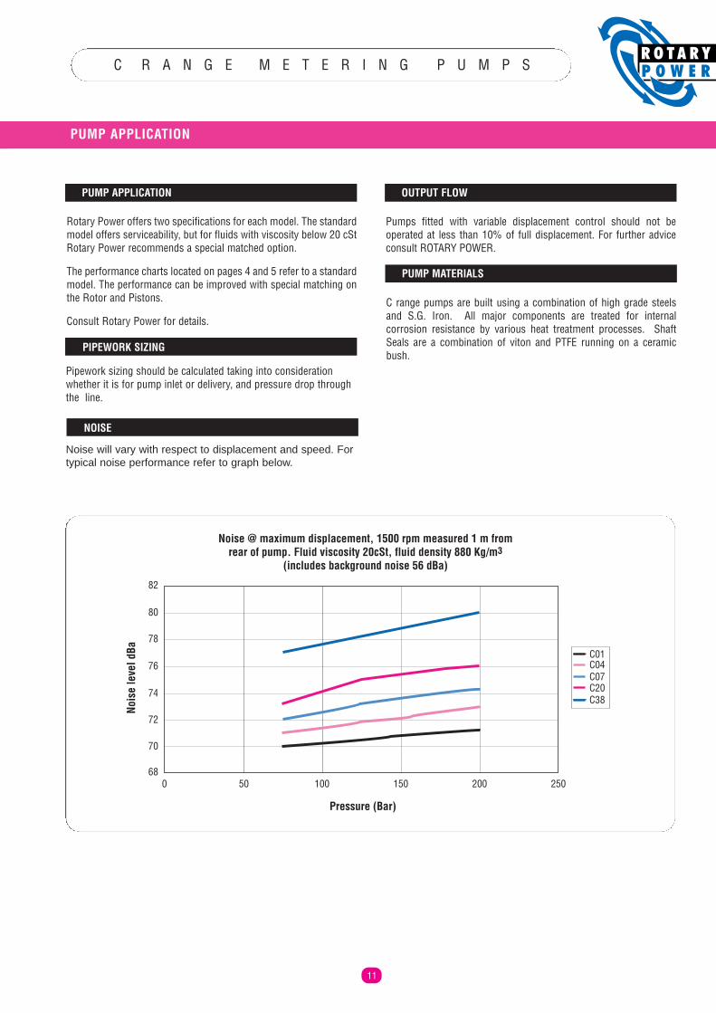
C R A N G E M E T E R I N G P U M P S
PUMP APPLICATION
11
Rotary Power offers two specifications for each model. The standardmodel offers serviceability, but for fluids with viscosity below 20 cStRotary Power recommends a special matched option.
The performance charts located on pages 4 and 5 refer to a standardmodel. The performance can be improved with special matching onthe Rotor and Pistons.
Consult Rotary Power for details.
PIPEWORK SIZING
Pipework sizing should be calculated taking into considerationwhether it is for pump inlet or delivery, and pressure drop throughthe line.LEA
Pumps fitted with variable displacement control should not beoperated at less than 10% of full displacement. For further adviceconsult ROTARY POWER.
C range pumps are built using a combination of high grade steelsand S.G. Iron. All major components are treated for internalcorrosion resistance by various heat treatment processes. ShaftSeals are a combination of viton and PTFE running on a ceramicbush.
PUMP APPLICATION OUTPUT FLOW
PUMP MATERIALS
Noise @ maximum displacement, 1500 rpm measured 1 m fromrear of pump. Fluid viscosity 20cSt, fluid density 880 Kg/m3
(includes background noise 56 dBa)
82
80
78
76
74
72
70
680 50 100 150 200 250
C01C04C07C20C38
Nois
e le
vel d
Ba
Pressure (Bar)
Noise will vary with respect to displacement and speed. Fortypical noise performance refer to graph below.
NOISE
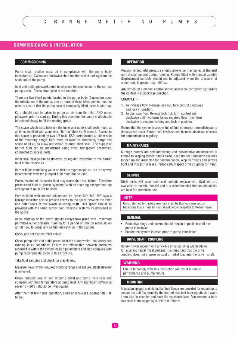
C R A N G E M E T E R I N G P U M P S
12
COMMISSIONING & INSTALLATION
Pump shaft rotation must be in compliance with the pump bodyindicators i.e. CW means clockwise shaft rotation whilst looking from theshaft end of the pump.
Inlet and outlet pipework must be checked for connection to the correctpump ports. A case drain pipe is not required.
There are five bleed points located in the pump body. Depending uponthe orientation of the pump, one or more of these bleed points must beused to ensure that the pump case is completely filled, prior to start up.
Care should also be taken to purge all air from the inlet, AND outletpipework, prior to start up. During this operation the pump shaft shouldbe rotated slowly to fill the rotating group.
The space which exits between the inner and outer shaft seals must, atall times be filled with a suitable, “Barrier” fluid i.e. Mesamol. Access tothis space is provided by two 1/8 inch BSP ports located at either sideof the mounting flange. Care must be taken to completely purge thisspace of all air, to allow lubrication of outer shaft seal. The supply ofbarrier fluid can be maintained using small transparent reservoirs,connected to access ports.
Inner seal leakage can be detected by regular inspection of the barrierfluid in the reservoirs.
Barrier fluids containing water or, that are hygroscopic or, are in any wayincompatible with the pumped fluid must not be used.
Pressurisation of the barrier fluid may cause shaft seal failure. Thereforepressurised fluid or grease systems, such as a sprung dashpot and taparrangement must not be used.
Pumps fitted with manual adjustment i.e. types MD, MB, ME have aleakage indicator port to provide access to the space between the innerand outer seals of the swash adjusting shaft. This space should beprovided with the same barrier fluid reservoir systems as described inthe above.
Initial start up of the pump should always take place with minimumpermitted outlet pressure, running for a period of time on recirculationat full flow, to purge any air that may still be in the system.
Check and set system relief valves.
Check pump inlet and outlet pressure at the pump whilst stationary andrunning in all conditions. Ensure the relationship between pressuresrecorded is within the system design parameters and also complies withpump requirements given in this brochure.
Take fluid samples and check for cleanliness.
Measure flows within required working range and ensure, stable deliveryis achieved.
Check temperatures of fluid at pump outlet and pump main case andcompare with fluid temperature at pump inlet. Any significant difference(over 15 - 20˚c) should be investigated.
After the first few hours operation, clean or renew (as appropriate) allfilters.
Recommended inlet pressure should always be maintained at the inletport at start up and during running. Pumps fitted with manual variabledisplacement controls should not be adjusted when the pressure, ateither port, is greater than 100 bar.
Adjustment of a manual control should always be completed by turningthe control in a clockwise direction.
EXAMPLE :-
1. To increase flow. Release lock nut, turn control clockwise and lock in position.
2. To decrease flow. Release lock nut, turn control anti clockwise until two turns below required flow. then turn clockwise to required setting and lock in position.
Ensure that the system is always full of fluid otherwise immediate pumpdamage will occur. Barrier fluid levels should be maintained and checkedfor contamination regularly.
C range pumps are self lubricating and preventative maintenance islimited to keeping system filters clean. Keep barrier lubrication systemstopped up and inspected for contamination, keep all fittings and screwstight and inspect for leaks. Periodically inspect drive coupling for wear.
Shaft seals will wear and need periodic replacement. Seal kits areavailable for on site renewal and it is recommended that on site stocksare held for immediate use.
• Protective plugs and covers should remain in position until the pump is installed.
• Ensure the system is clean prior to pump installation.
Rotary Power recommend a flexible drive coupling which allows for axial and radial misalignment. It is important that the drive coupling does not impose an axial or radial load into the drive shaft.
A location spiggot and slotted fair bolt flange are provided for mounting toensure the unit fits correctly the bore of recipient housing should have a1mm lead in chamfer and have flat machined face. Recommend a boresize clear of the spigot by 0.025 to 0.075mm
Failure to comply with this instruction will result in erraticperformance and pump failure.
WARNING
Units returned for factory overhaul must be flushed clean and allhazardous fluids must be neutralised before despatch to Rotary Power
NOTE:
COMMISSIONING
GENERAL
DRIVE SHAFT COUPLING
MOUNTING
OPERATION
MAINTENANCE
SERVICE
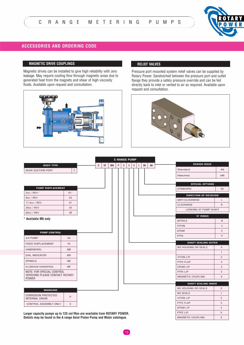
C R A N G E M E T E R I N G P U M P S
13
Larger capacity pumps up to 125 cm3/Rev are available from ROTARY POWER. Details may be found in the A range Axial Piston Pump and Motor catalogue.
* Available M6 only
Magnetic drives can be installed to give high reliability with zeroleakage. May require cooling flow through magnetic areas due togenerated heat from the magnets and shear of high viscosityfluids. Available upon request and consultation.
MAGNETIC DRIVE COUPLINGS
Pressure port mounted system relief valves can be supplied byRotary Power. Sandwiched between the pressure port and outletflange they provide a safety pressure override and can be feddirectly back to inlet or vented to air as required. Available uponrequest and consultation.
RELIEF VALVES
ACW
BODY TYPE
REAR SUCTION PORT C
SPECIAL OPTIONS
STANDARD 00
DESIGN ISSUE
Standard A6
Matched M6
DIRECTION OF ROTATION
ANTI-CLOCKWISE L
CLOCKWISE R
LOOKING AT PUMP SHAFT
PUMP DISPLACEMENT
2cc / REV* 01*
6cc / REV 04
11.5cc / REV 07
33cc / REV 20
62cc / REV 38‘O’ RINGS
NITRILE N
VITON V
EPDM E
PTFE P
SHAFT SEALING OUTER
NO HOUSING OR SEALS 0
NO SEALS 1
VITON LIP 2
PTFE FLAP 3
EPDM LIP 4
PTFE LIP 5
MAGNETIC COUPLING 6
SHAFT SEALING INNER
NO HOUSING OR SEALS 0
NO SEALS 1
VITON LIP 2
PTFE FLAP 3
EPDM LIP 4
PTFE LIP 5
MAGNETIC COUPLING 6
PUMP CONTROL
3/4 PUMP CA
FIXED DISPLACEMENT FA
HANDWHEEL MB
DIAL INDICATOR MD
SPINDLE ME
ALUMINIUM HANDWHEEL MF
NOTE: FOR SPECIAL CONTROLVERSIONS PLEASE CONTACT ROTARYPOWER
MAINCASE
CORROSION PROTECTEDINTERNAL DRAIN P
CONTROL ASSEMBLY ONLY 0
ACCESSORIES AND ORDERING CODE
C RANGE PUMP
C 07 MD P 3 3 V L 00 A6