shear strengthening of reinforced concrete beams with
TRANSCRIPT
Advances in Concrete Construction, Vol. 2, No. 4 (2014) 281-300
DOI: http://dx.doi.org/10.12989/acc.2014.2.4.281 281
Shear strengthening of reinforced concrete beams with rectangular web openings by FRP Composites
Ahmed H. Abdel-Kareem
Department of Civil Engineering, Benha faculty of engineering,
Benha university, Egypt
(Received June 22, 2013, Revised December 14, 2014, Accepted December 28, 2014)
Abstract. This study presents the experimental results of twenty three reinforced concrete beams with rectangular web openings externally strengthened with Fiber Reinforced Polymers (FRP) composites bonded around openings. All tested beams had the same geometry and reinforcement details. At openings locations, the stirrups intercepted the openings were cut during fabrication of reinforcement cage to simulate the condition of inclusion of an opening in an existing beam. Several design parameters are considered including the opening dimensions and location in the shear zone, the wrapping configurations, and the amount and the type of the FRP composites in the vicinity of the openings. The wrapping configurations of FRP included: sheets, strips, U-shape strips, and U- shape strips with bundles of FRP strands placed at the top and sides of the beam forming a fan under the strips to achieve closed wrapping. The effect of these parameters on the failure modes, the ultimate load, and the beam stiffness were investigated. The shear contribution of FRP on the shear capacity of tested beams with web openings was estimated according to ACI Committee 440-08, Canadian Standards S6-06, and Khalifa et al. model and examined against the test results. A modification factor to account for the dimensions of opening chords was applied to the predicted gain in the shear capacity according to ACI 440-08 and CSA S6-06 for bonded Glass Fiber Reinforced Polymers (GFRP) around openings. The analytical results after incorporating the modification factor into the codes guidelines showed good agreement with the test results. Keywords: GFRP; CFRP; shear strengthening; rectangular web opening; concrete beam
1. Introduction
The inclusion of transverse openings in existing reinforced concrete beams often confronts the
structural engineers to pass utility services; especially, when the height of the floor is not sufficient
to place the utilities underneath the soffit of the beams. However, the provision of openings in such
beams often results in many problems in the beam behavior including reduction in the beam
capacity and the beam stiffness, and early cracking around the openings. Thus, the beam's
openings need to be externally strengthened. External shear strengthening using Fiber Reinforced
Polymer (FRP) has been widely used for reinforced concrete beams (Khalifa et al. 1998;
Triantafillou and Antonopoulos 2000; Khalifa and Nanni 2002; Micelli et al. 2002; Bousselham
Corresponding author, Associated Professor , E-mail: [email protected]
Ahmed H. Abdel-Kareem
and Chaallal 2006a; Monti and Liotta 2007; Bousselham and Chaallal 2009; Panda et al.
2011 ,2012 ,2013; Mofidi and Chaallal 2014), and gained popularity over conventional
construction materials because of several reasons including high strength to weight ratio, ease of
application, and their non-corrosion characteristics.
The experimental data available in the literature for the study of RC beams with web openings
externally strengthened by FRP rather limited. The few studies on the subject investigated the use
of Glass Fiber Reinforced Polymer (GFRP) for strengthening T-beams with small circular
openings (Abdel Hafez et al. 2002), the use of Carbon Fiber Reinforced Polymer (CFRP) for
strengthening RC beams with rectangular openings (Abdalla et al. 2003; Allam 2005; El
Maaddawy and Sherief 2009; Chin et al 2012), and the use of CFRP for strengthening deep beams
with square openings (El Maaddawy and El-Ariss 2009). Also, the use of externally CFRP rods
diagonal to the beam axis along the opening was studied (Pimanmas 2010). It is obvious that the
majority of previous research was focus on using the CFRP strengthening material. The lower cost
of GFRP in comparison to other types of FRP, CFRP and aramid FRP (AFRP), makes the use of
GFRP in strengthening structural elements more attractive. Therefore, the present research focuses
on using GFRP as a strengthening material.
This research investigates the shear behavior of full scale rectangular RC beams containing
rectangular web openings with different dimensions and locations in the shear zone and externally
strengthened with different FRP strengthening system bonded around openings. The parameters in
the strengthening system included the wrapping configurations, and the amount and the type of
FRP (glass or carbon). The research includes experimental testing and analytical formulation.
The experimental part included testing of twenty two RC beams with web openings, in addition to
a beam with solid web. In the analytical part, the shear contribution of external bonded FRP in
resisting shear force was estimated according to ACI Committee 440-08 (ACI 2008), Canadian
Standards S6-06 (CSA 2006), and Khalifa et al. model (1998) and compared with the experimental
results. These comparisons showed to be satisfactory agreement between the experimental results
obtained from strengthening openings by GFRP and the analytical approach on the basis of codes
guidelines (ACI 2008 and CSA 2006); the dimensions of the opening chords have to be considered
in the shear contribution of GFRP in the beam shear strength. However, a modification factor to
account the dimensions of the opening chords was developed and incorporated into the codes
guidelines.
2. Experimental test program
2.1 Test specimens
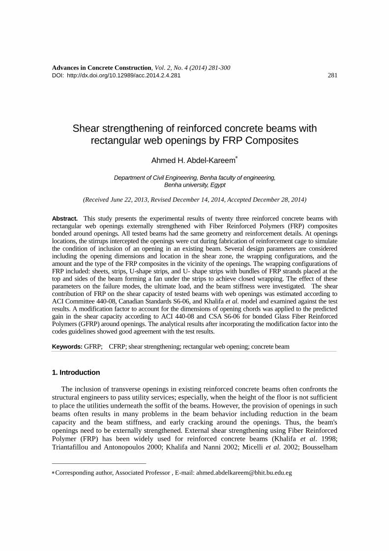
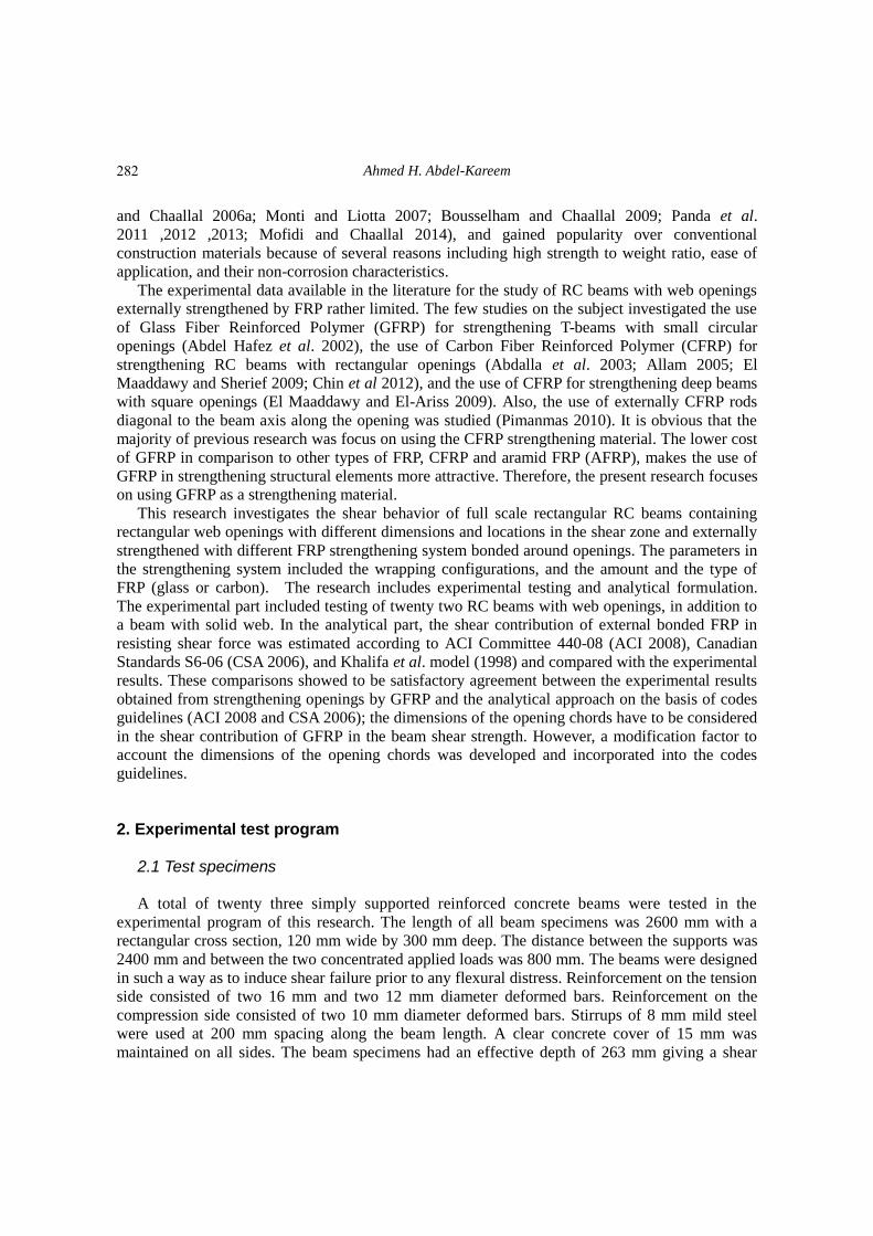
A total of twenty three simply supported reinforced concrete beams were tested in the
experimental program of this research. The length of all beam specimens was 2600 mm with a
rectangular cross section, 120 mm wide by 300 mm deep. The distance between the supports was
2400 mm and between the two concentrated applied loads was 800 mm. The beams were designed
in such a way as to induce shear failure prior to any flexural distress. Reinforcement on the tension
side consisted of two 16 mm and two 12 mm diameter deformed bars. Reinforcement on the
compression side consisted of two 10 mm diameter deformed bars. Stirrups of 8 mm mild steel
were used at 200 mm spacing along the beam length. A clear concrete cover of 15 mm was
maintained on all sides. The beam specimens had an effective depth of 263 mm giving a shear
282
Shear strengthening of reinforced concrete beams with rectangular web openings
Fig. 1 Longitudinal and cross section details of beam specimens (Note: all dimensions in mm)
span to depth ratio of 3.04. Longitudinal and cross section details of the beam specimens are
shown in Fig.1. One opening was created on a side of the test specimens. At opening locations,
each opening intercepted one or more of the stirrups. To simulate the condition of inclusion of an
opening in an existing beam, these stirrups were cut during fabrication of the reinforcement cage.
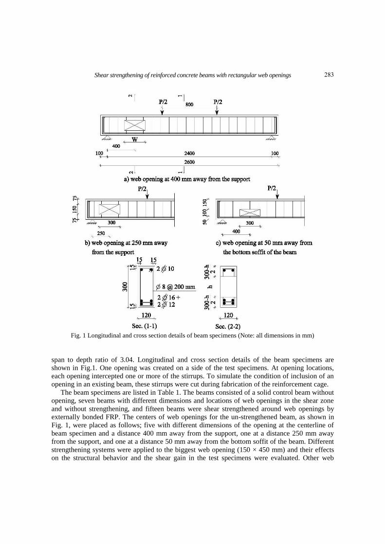
The beam specimens are listed in Table 1. The beams consisted of a solid control beam without
opening, seven beams with different dimensions and locations of web openings in the shear zone
and without strengthening, and fifteen beams were shear strengthened around web openings by
externally bonded FRP. The centers of web openings for the un-strengthened beam, as shown in
Fig. 1, were placed as follows; five with different dimensions of the opening at the centerline of
beam specimen and a distance 400 mm away from the support, one at a distance 250 mm away
from the support, and one at a distance 50 mm away from the bottom soffit of the beam. Different
strengthening systems were applied to the biggest web opening (150 × 450 mm) and their effects
on the structural behavior and the shear gain in the test specimens were evaluated. Other web
283
Tab
le 1
Tes
t var
iab
les
and
tes
t re
sult
s
Mo
de
of
F
ailu
re
Ult
imate
Lo
ad
(KN
)
Pro
per
ties
of
FR
P S
tren
gth
enin
g
Co
ncr
ete
Str
ength
f cu (
Mp
a)
Pro
per
ties
of
Op
enin
gs
Wra
pp
ing
Co
nfi
gura
tio
n
Nu
mb
er
of
layer
s
Typ
e H
eig
ht
(mm
)
Wid
th
(mm
)
Lo
cati
on
*
(mm
) b
eam
sp
ecim
en
Fle
xura
l S
hea
r F
ailu
re
18
5
—
—
—
37
—
—
—
SB
Shea
r at
op
enin
g
62
—
—
—
45
30
0
10
0
0†,4
00
‡
No
-10
x3
0-E
Shea
r at
op
enin
g
60
—
—
—
35
15
0
15
0
0,4
00
N
o-1
5x1
5-E
Shea
r at
op
enin
g
48
—
—
—
40
30
0
15
0
0,4
00
No
-15
x3
0-E
Shea
r at
op
enin
g
40
—
—
—
41
45
0
15
0
0,4
00
No
-15
x4
5-E
Shea
r at
op
enin
g
26
—
—
—
41
30
0
20
0
0,4
00
No
-20
x3
0-E
Shea
r at
op
enin
g
45
—
—
—
41
30
0
10
0
50
,400
No
-10
x3
0-B
Shea
r at
op
enin
g
40
—
—
—
38
30
0
15
0
0,2
50
No
-15
x3
0-S
Shea
r at
op
enin
g
63
Shee
ts
1
Gla
ss
42
45
0
15
0
0,4
00
TG
1-1
5x4
5-E
Shea
r at
op
enin
g
72
Str
ips
2
Gla
ss
38
45
0
15
0
0,4
00
TG
2-1
5x4
5-E
Shea
r at
op
enin
g
50
U-S
hap
e S
trip
s**
2
G
lass
3
5
45
0
15
0
0,4
00
TG
3-1
5x4
5-E
Shea
r at
op
enin
g
60
U-S
hap
e S
trip
s **
*
2
Gla
ss
40
45
0
15
0
0,4
00
TG
4-1
5x4
5-E
Shea
r at
op
enin
g
80
Str
ips
3
Gla
ss
37
45
0
15
0
0,4
00
TG
5-1
5x4
5-E
Shea
r at
op
enin
g
82
Str
ips
4
Gla
ss
36
45
0
15
0
0,4
00
TG
6-1
5x4
5-E
Shea
r at
op
enin
g
74
Str
ips
2
Car
bo
n
44
45
0
15
0
0,4
00
TC
1-1
5x4
5-E
Shea
r at
op
enin
g
55
U-S
hap
e S
trip
s**
2
C
arb
on
41
45
0
15
0
0,4
00
TC
2-1
5x4
5-E
Shea
r at
op
enin
g
76
U-S
hap
e S
trip
s **
*
2
Car
bo
n
43
45
0
15
0
0,4
00
TC
3-1
5x4
5-E
Shea
r at
op
enin
g
14
0
Str
ips
2
Gla
ss
42
30
10
0
0,4
00
TG
-10
x3
0-E
Shea
r at
op
enin
g
14
0
Str
ips
2
Gla
ss
38
15
0
15
0
0,4
00
TG
-15
x1
5-E
Shea
r at
op
enin
g
10
0
Str
ips
2
Gla
ss
44
30
0
15
0
0,4
00
TG
-15
x3
0-E
Shea
r at
op
enin
g
57
Str
ips
2
Gla
ss
44
30
0
20
0
0,4
00
TG
-20
x3
0-E
Shea
r at
op
enin
g
12
5
Str
ips
2
Gla
ss
44
30
0
10
0
50
,400
TG
-10
x3
0-B
Shea
r at
op
enin
g
88
Str
ips
2
Gla
ss
43
30
0
15
0
0,2
50
TG
-15
x3
0-S
*T
he
loca
tio
n o
f th
e ce
nte
r o
f o
pen
ing i
n t
he
ver
tica
l d
irec
tio
n f
rom
cente
rlin
e o
f th
e b
eam
† an
d i
n h
ori
zonta
l d
irec
tio
n f
rom
the
sup
po
rt‡
**W
rap
ped
the
top
cho
rd o
f th
e o
pen
ing
**
* U
- sh
ape
stri
ps
wit
h b
und
les
of
FR
P s
tran
ds
pla
ced
at
the t
op
and
the
bea
m s
ides
Ahmed H. Abdel-Kareem
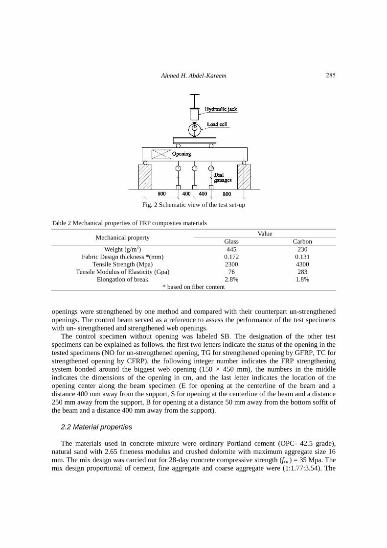
Fig. 2 Schematic view of the test set-up
Table 2 Mechanical properties of FRP composites materials
Mechanical property Value
Glass Carbon
Weight (g/m2) 445 230
Fabric Design thickness *(mm) 0.172 0.131
Tensile Strength (Mpa) 2300 4300
Tensile Modulus of Elasticity (Gpa) 76 283
Elongation of break 2.8% 1.8%
* based on fiber content
openings were strengthened by one method and compared with their counterpart un-strengthened
openings. The control beam served as a reference to assess the performance of the test specimens
with un- strengthened and strengthened web openings.
The control specimen without opening was labeled SB. The designation of the other test
specimens can be explained as follows. the first two letters indicate the status of the opening in the
tested specimens (NO for un-strengthened opening, TG for strengthened opening by GFRP, TC for
strengthened opening by CFRP), the following integer number indicates the FRP strengthening
system bonded around the biggest web opening (150 × 450 mm), the numbers in the middle
indicates the dimensions of the opening in cm, and the last letter indicates the location of the
opening center along the beam specimen (E for opening at the centerline of the beam and a
distance 400 mm away from the support, S for opening at the centerline of the beam and a distance
250 mm away from the support, B for opening at a distance 50 mm away from the bottom soffit of
the beam and a distance 400 mm away from the support).
2.2 Material properties The materials used in concrete mixture were ordinary Portland cement (OPC- 42.5 grade),
natural sand with 2.65 fineness modulus and crushed dolomite with maximum aggregate size 16
mm. The mix design was carried out for 28-day concrete compressive strength (fcu ) = 35 Mpa. The
mix design proportional of cement, fine aggregate and coarse aggregate were (1:1.77:3.54). The
285
Shear strengthening of reinforced concrete beams with rectangular web openings
water cement ratio by weight was 0.45. Three cubes, 150×150×150 mm, were cast at the same
time as the specimens and cured alongside the specimens. The concrete compressive strength at
the time of testing specimens is shown in Table 1. The longitudinal steel was deformed steel with
nominal yield strength of 400 MPa. The stirrups were mild steel with nominal yield strength of
240 MPa.
Unidirectional FRP were used for strengthening the opening region. Table 2 illustrated the
mechanical properties of the FRP. The FRP were bonded to the beam specimens with an epoxy
resin, Sikdadure 330 (SIKA Egypt 2010). For applying FRP around the web openings in beam
specimens, the bonded faces were cleaned until any loose material was removed. Epoxy adhesive
was applied to the concrete face in thin layer and pre-cut FRP layer was wrapped over it. The sheet
or strips were passed firmly and rolled uniformly by plastic rollers to squeeze out excess epoxy
and air bubbles. For applying more layers, epoxy was poured over the last layer and the procedure
was repeated.
2.3 Test setup The load was applied through a hydraulic jack and was transferred to the test beam through a
steel spreader beam that was supported on two steel rollers covering the entire width of the beam.
The load was measured using load cell under the hydraulic jack of maximum capacity 300 KN.
The deflections were measured by three dial gages with displacement up to 150 mm and a least
count of 0.01 mm. Two of the dial gages were placed under the two load points and the third one
was under the middle of the beam span. Schematic view of the test set-up is shown in Fig. 2. The
development and propagation of cracks were marked and the mode of failure was recorded.
2.4 FRP strengthening system
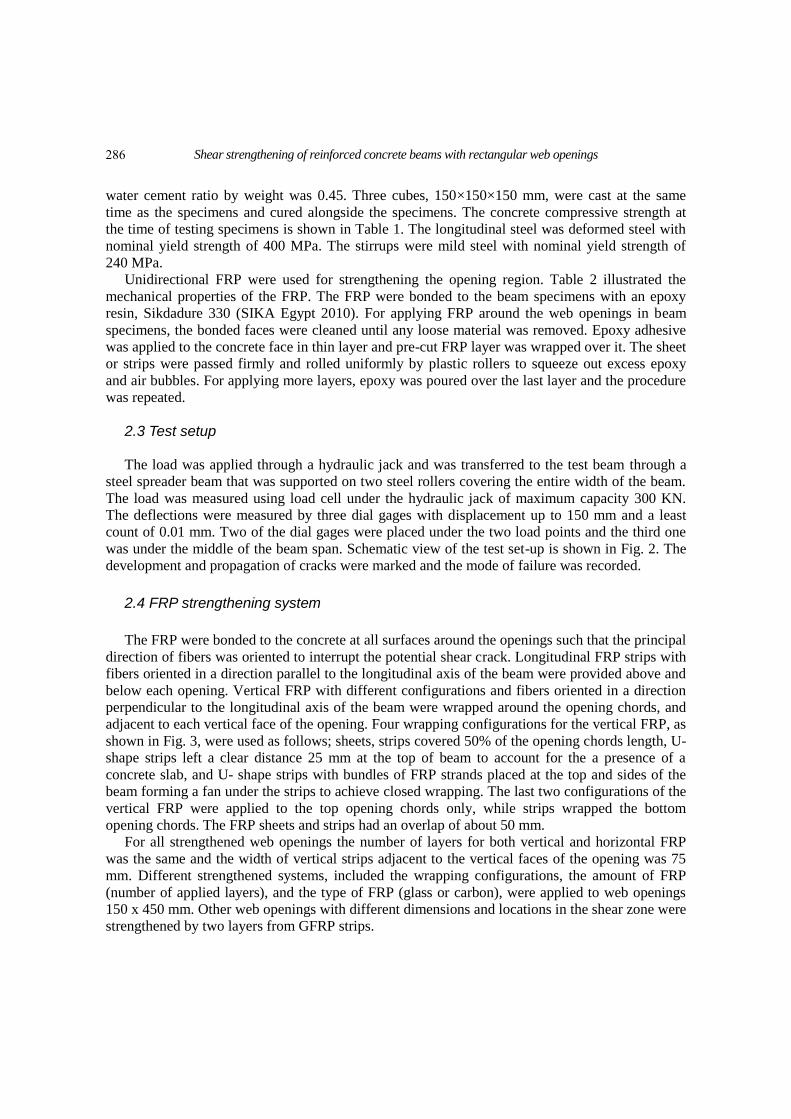
The FRP were bonded to the concrete at all surfaces around the openings such that the principal
direction of fibers was oriented to interrupt the potential shear crack. Longitudinal FRP strips with
fibers oriented in a direction parallel to the longitudinal axis of the beam were provided above and
below each opening. Vertical FRP with different configurations and fibers oriented in a direction
perpendicular to the longitudinal axis of the beam were wrapped around the opening chords, and
adjacent to each vertical face of the opening. Four wrapping configurations for the vertical FRP, as
shown in Fig. 3, were used as follows; sheets, strips covered 50% of the opening chords length, U-
shape strips left a clear distance 25 mm at the top of beam to account for the a presence of a
concrete slab, and U- shape strips with bundles of FRP strands placed at the top and sides of the
beam forming a fan under the strips to achieve closed wrapping. The last two configurations of the
vertical FRP were applied to the top opening chords only, while strips wrapped the bottom
opening chords. The FRP sheets and strips had an overlap of about 50 mm.
For all strengthened web openings the number of layers for both vertical and horizontal FRP
was the same and the width of vertical strips adjacent to the vertical faces of the opening was 75
mm. Different strengthened systems, included the wrapping configurations, the amount of FRP
(number of applied layers), and the type of FRP (glass or carbon), were applied to web openings
150 x 450 mm. Other web openings with different dimensions and locations in the shear zone were
strengthened by two layers from GFRP strips.
286
Ahmed H. Abdel-Kareem
Fig. 3 Description of different FRP wrapping configurations around openings
287
Shear strengthening of reinforced concrete beams with rectangular web openings
3. Experimental results and discussions
A brief summary of the test results is given in Table 1. The results of the solid beam are
compared with those of beam specimens with un-strengthened and strengthened openings.
Analysis and discussion of the results are introduced in the following sections.
3.1 Failure modes
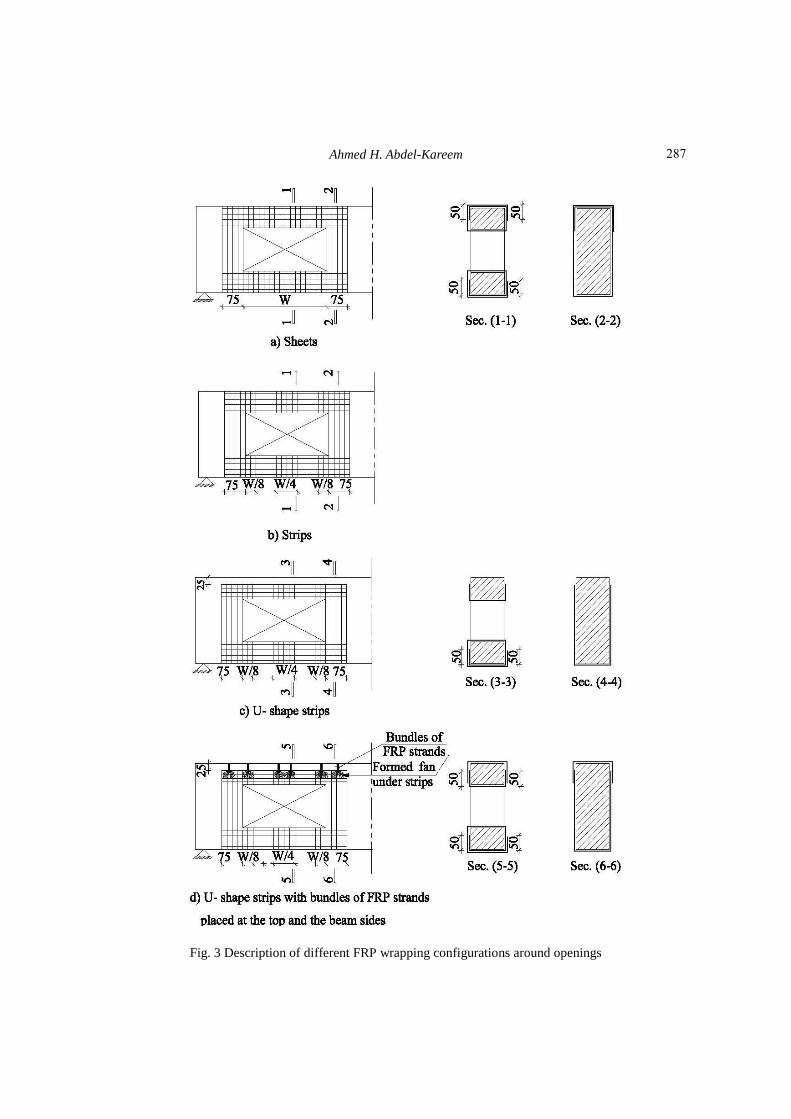
All beam specimens failed in shear. In the solid beam, crack lines appeared at the tension zone
and penetrated vertically up to the neutral axis of the beam. The number of flexural cracks
increased and followed by the formation of diagonal cracks. The crack width increased before
failure, and the shear failure was sudden and initiated at points of the applied loads to the supports,
as shown in Fig. 4.
The shear cracks in the beam specimens with un-strengthened openings, however, appeared
much earlier than in the solid beam. The shear cracks initiated at the top corner of the opening near
the point load and the bottom corner of the opening near the support followed by the remaining
corners of the opening. The beam specimens failed in shear with diagonal cracks initiated from the
top corner towards the point load and from the bottom corner towards the support and in the
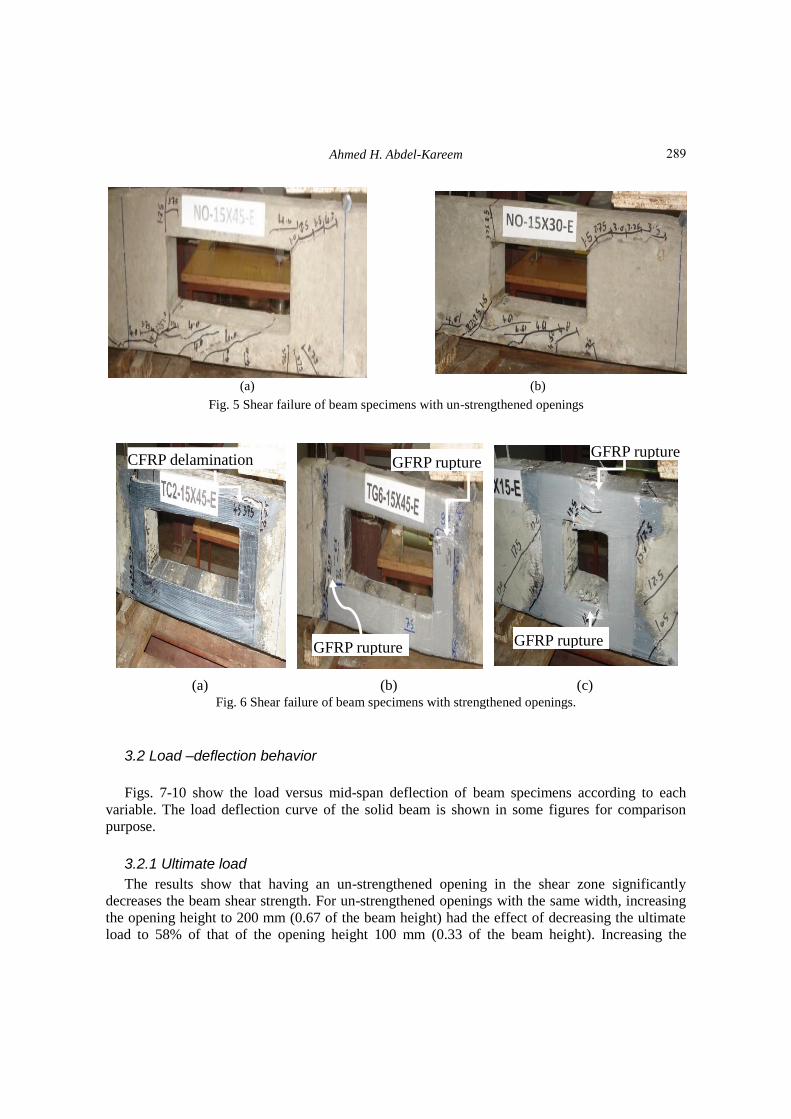
bottom chord of the opening. Fig. 5 shows typical shear failure of beam specimens with un-
strengthened openings.
Failure modes of the beam specimens with strengthened opening are shown in Fig. 6. For U-
shape strips around the top chord of the openings, in specimens TG3-15X45-E and TC3-15X30-E,
the beam failed by peeling the FRP together with concrete cover at the top corner of the opening
near the point load. For other strengthened specimens, and with increasing the applied load,
diagonal shear cracks formatted between FRP bonded around openings towards the point load and
the support. The failure was due to rupture of the FRP.
Fig. 4 Flexural – shear failure of the solid beam
288
Ahmed H. Abdel-Kareem
(a) (b)
Fig. 5 Shear failure of beam specimens with un-strengthened openings
(a) (b) (c) Fig. 6 Shear failure of beam specimens with strengthened openings.
3.2 Load –deflection behavior
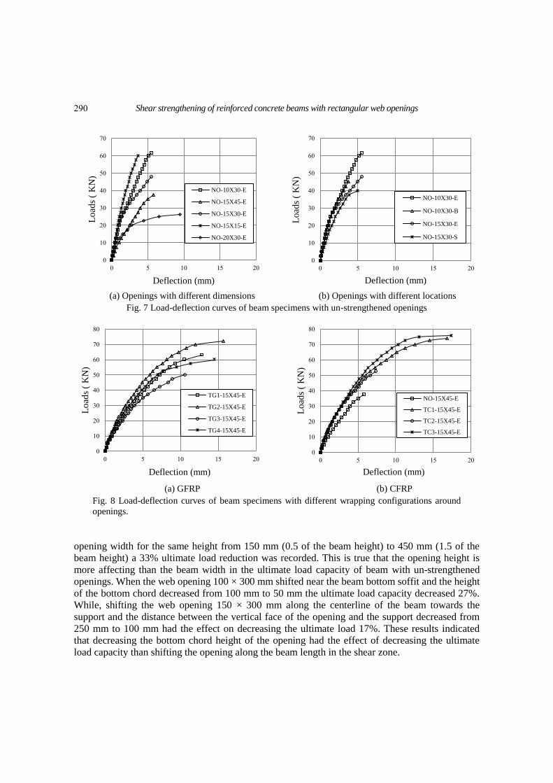
Figs. 7-10 show the load versus mid-span deflection of beam specimens according to each
variable. The load deflection curve of the solid beam is shown in some figures for comparison
purpose.
3.2.1 Ultimate load
The results show that having an un-strengthened opening in the shear zone significantly
decreases the beam shear strength. For un-strengthened openings with the same width, increasing
the opening height to 200 mm (0.67 of the beam height) had the effect of decreasing the ultimate
load to 58% of that of the opening height 100 mm (0.33 of the beam height). Increasing the
CFRP delamination
GFRP rupture
GFRP rupture GFRP rupture
GFRP rupture
289
Shear strengthening of reinforced concrete beams with rectangular web openings
(a) Openings with different dimensions (b) Openings with different locations
Fig. 7 Load-deflection curves of beam specimens with un-strengthened openings
(a) GFRP (b) CFRP
Fig. 8 Load-deflection curves of beam specimens with different wrapping configurations around
openings.
opening width for the same height from 150 mm (0.5 of the beam height) to 450 mm (1.5 of the
beam height) a 33% ultimate load reduction was recorded. This is true that the opening height is
more affecting than the beam width in the ultimate load capacity of beam with un-strengthened
openings. When the web opening 100 × 300 mm shifted near the beam bottom soffit and the height
of the bottom chord decreased from 100 mm to 50 mm the ultimate load capacity decreased 27%.
While, shifting the web opening 150 × 300 mm along the centerline of the beam towards the
support and the distance between the vertical face of the opening and the support decreased from
250 mm to 100 mm had the effect on decreasing the ultimate load 17%. These results indicated
that decreasing the bottom chord height of the opening had the effect of decreasing the ultimate
load capacity than shifting the opening along the beam length in the shear zone.
0
10
20
30
40
50
60
70
0 5 10 15 20
Lo
ads
( K
N)
Deflection (mm)
NO-10X30-E
NO-15X45-E
NO-15X30-E
NO-15X15-E
NO-20X30-E
0
10
20
30
40
50
60
70
0 5 10 15 20
Lo
ads
( K
N)
Deflection (mm)
NO-10X30-E
NO-10X30-B
NO-15X30-E
NO-15X30-S
0
10
20
30
40
50
60
70
80
0 5 10 15 20
Lo
ads
( K
N)
Deflection (mm)
TG1-15X45-E
TG2-15X45-E
TG3-15X45-E
TG4-15X45-E
0
10
20
30
40
50
60
70
80
0 5 10 15 20
Lo
ads
( K
N)
Deflection (mm)
NO-15X45-E
TC1-15X45-E
TC2-15X45-E
TC3-15X45-E
290
Ahmed H. Abdel-Kareem
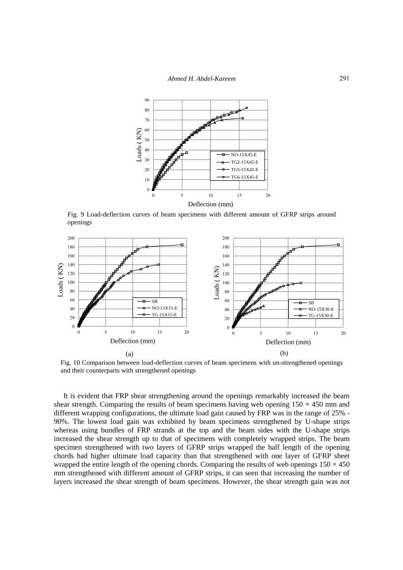
Fig. 9 Load-deflection curves of beam specimens with different amount of GFRP strips around
openings
It is evident that FRP shear strengthening around the openings remarkably increased the beam
shear strength. Comparing the results of beam specimens having web opening 150 × 450 mm and
different wrapping configurations, the ultimate load gain caused by FRP was in the range of 25% -
90%. The lowest load gain was exhibited by beam specimens strengthened by U-shape strips
whereas using bundles of FRP strands at the top and the beam sides with the U-shape strips
increased the shear strength up to that of specimens with completely wrapped strips. The beam
specimen strengthened with two layers of GFRP strips wrapped the half length of the opening
chords had higher ultimate load capacity than that strengthened with one layer of GFRP sheet
wrapped the entire length of the opening chords. Comparing the results of web openings 150 × 450
mm strengthened with different amount of GFRP strips, it can seen that increasing the number of
layers increased the shear strength of beam specimens. However, the shear strength gain was not
0
10
20
30
40
50
60
70
80
90
0 5 10 15 20
Lo
ads
( K
N)
Deflection (mm)
NO-15X45-E
TG2-15X45-E
TG5-15X45-E
TG6-15X45-E
(a) (b)
Fig. 10 Comparison between load-deflection curves of beam specimens with un-strengthened openings
and their counterparts with strengthened openings
0
20
40
60
80
100
120
140
160
180
200
0 5 10 15 20
Lo
ads
( K
N)
Deflection (mm)
SB
NO-15X15-E
TG-15X15-E
0
20
40
60
80
100
120
140
160
180
200
0 5 10 15 20
Lo
ads
( K
N)
Deflection (mm)
SB
NO-15X30-E
TG-15X30-E
291
Shear strengthening of reinforced concrete beams with rectangular web openings
proportional to the added layers of GFRP strips and increasing the number of layers became
insignificant when the number of layers increased more than three layers. Comparing the results of
the solid beam with beams having different web openings dimensions and strengthened by two
layers of GFRP strips indicated that for small openings size, 150 X150 mm, and small openings
height, 100 mm (0.33 of the beam height), the most loss in the ultimate load due to presence of the
opening could be retrieved.
3.2.2 Beam stiffness
For un-strengthened specimens, the beam stiffness reduced as the opening size, either the
height or the width, was increased. For example, at a 20 KN, the deflection of the specimens was
increased about 23% when the opening width was increased from 150 mm to 300 mm with 150
mm opening height. The beam stiffness reduced drastically when the opening width increased
from 150 mm to 450 mm with 150 mm opening height and when opening height increased from
100 mm to 200 mm with 300 mm opening width. At a 20 KN, the deflection of beam specimen
NO-20X30-E was about 2.7 times the deflection of specimen NO-10X30-E, and the deflection of
beam specimen NO-15X45-E was about three times the deflection of specimen NO-15X15-E.
It is seen in Fig. 7(b) that the stiffness of the un-strengthened specimens reduced when the
opening shifted near the support and not affected when the opening shifted near the bottom soffit
of the beam. For instance, at a 20 KN, the deflection of specimen NO-15X30-S increased about
50% than that of specimen NO-15X30-E.
FRP shear strengthening around the opening resulted in increasing the stiffness of the beam
specimens which was remarkable for specimens strengthened by FRP strips and U-shaped strips
with bundles of FRP strands at the top and the beam sides. For example, at a 20 KN, the
deflection of the strengthened specimens TG2-15X45-E, TG4-15X45-E, TC1-15X45-E and TC3-
15X45-E was on average 35% less than that of their counterpart un-strengthened specimen NO-
15X45-E. The stiffness of strengthened specimens was not affected by the amount of GFRP strips
around the openings, as shown in Fig. 8.
GFRP shear strengthening around the openings resulted in a pronounced improvement in the
beam stiffness as the opening size was increased. For instance, at a 20 KN, the deflection of the
strengthened specimens TG-10X30-E and TG-20X30-E was on average 10% and 45%,
respectively less than that their counterparts specimens NO-10X30-E and NO-20X30-E that had
the same opening size but not shear strengthened with GFRP strips.
4. Analytical study
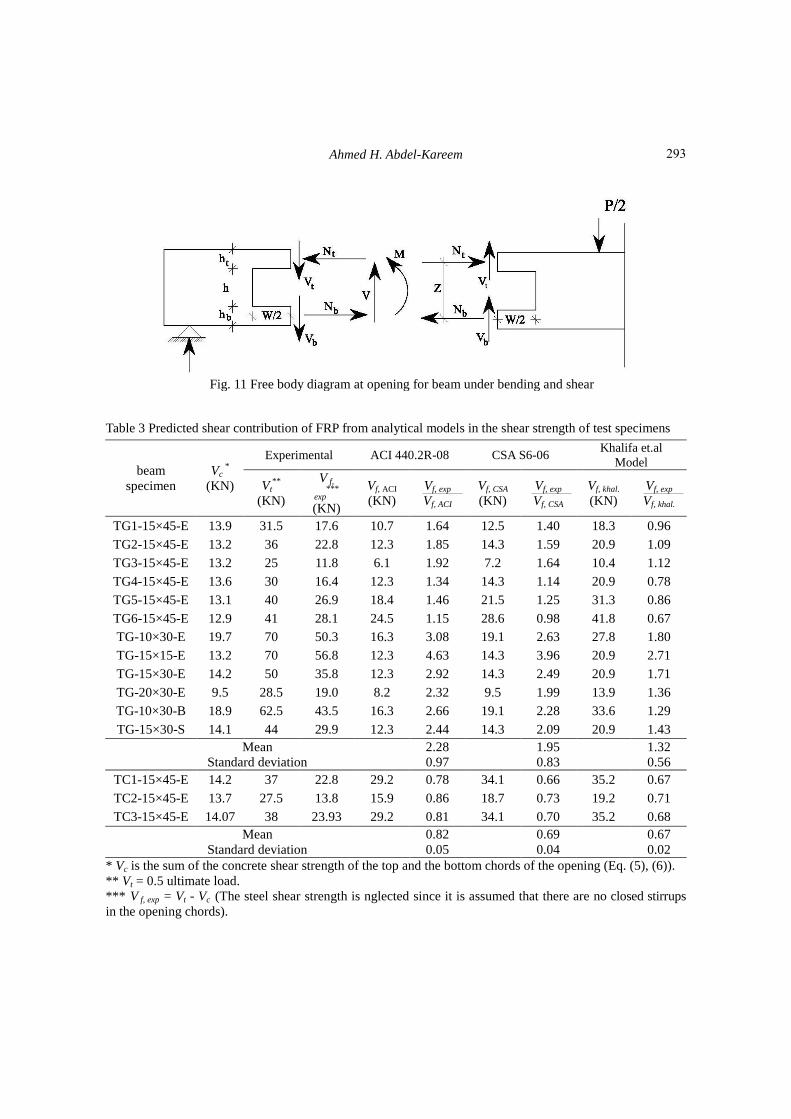
The free-body diagram through the center of opening is shown in Fig. 11. For the applied
moment (M) and shear (V) at the center of opening, the actions in the cord members are the axial
forces and the shear forces. The applied moment equals to N Z and the applied shear distributes
between the openings chords. Kennedy and Abdella (1992) suggested that the applied shear force
distributed between the top and bottom chords using the area ratio, inertia ratio, and the root ratio.
The shear force carried by the bottom chord, Vb, is given by
ttbb
bbb
IAIA
IA
V
V
(1)
292
Ahmed H. Abdel-Kareem
Fig. 11 Free body diagram at opening for beam under bending and shear
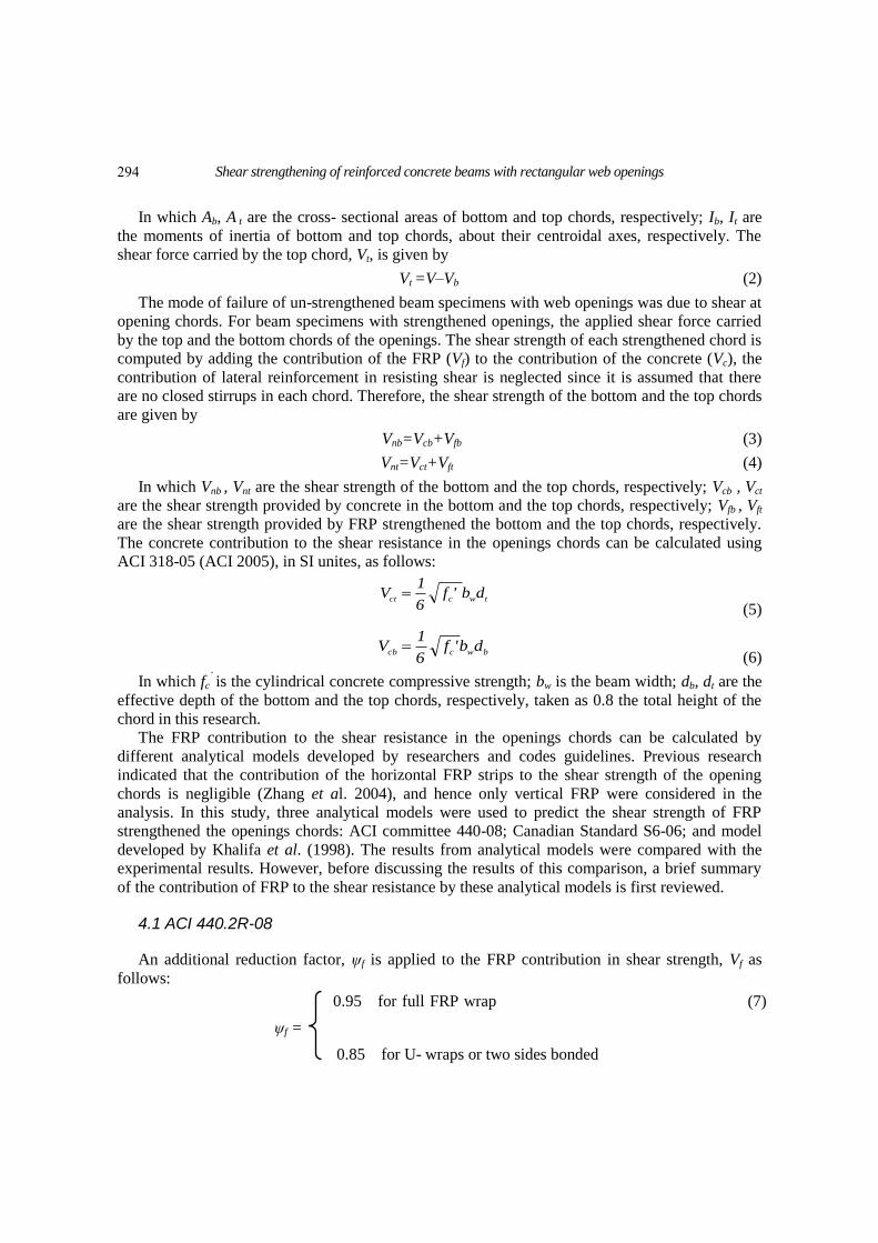
Table 3 Predicted shear contribution of FRP from analytical models in the shear strength of test specimens
Khalifa et.al
Model CSA S6-06 ACI 440.2R-08 Experimental
Vc *
(KN)
beam
specimen Vf, exp
Vf, khal.
Vf, khal.
(KN)
Vf, exp
Vf, CSA
Vf, CSA
(KN)
Vf, exp
Vf, ACI
Vf, ACI
(KN)
V f,
exp***
(KN)
Vt**
(KN)
0.96 18.3 1.40 12.5 1.64 10.7 17.6 31.5 13.9 TG1-15×45-E
1.09 20.9 1.59 14.3 1.85 12.3 22.8 36 13.2 TG2-15×45-E
1.12 10.4 1.64 7.2 1.92 6.1 11.8 25 13.2 TG3-15×45-E
0.78 20.9 1.14 14.3 1.34 12.3 16.4 30 13.6 TG4-15×45-E
0.86 31.3 1.25 21.5 1.46 18.4 26.9 40 13.1 TG5-15×45-E
0.67 41.8 0.98 28.6 1.15 24.5 28.1 41 12.9 TG6-15×45-E
1.80 27.8 2.63 19.1 3.08 16.3 50.3 70 19.7 TG-10×30-E
2.71 20.9 3.96 14.3 4.63 12.3 56.8 70 13.2 TG-15×15-E
1.71 20.9 2.49 14.3 2.92 12.3 35.8 50 14.2 TG-15×30-E
1.36 13.9 1.99 9.5 2.32 8.2 19.0 28.5 9.5 TG-20×30-E
1.29 33.6 2.28 19.1 2.66 16.3 43.5 62.5 18.9 TG-10×30-B
1.43 20.9 2.09 14.3 2.44 12.3 29.9 44 14.1 TG-15×30-S
1.32
0.56
1.95
0.83
2.28
0.97
Mean
Standard deviation
0.67 35.2 0.66 34.1 0.78 29.2 22.8 37 14.2 TC1-15×45-E
0.71 19.2 0.73 18.7 0.86 15.9 13.8 27.5 13.7 TC2-15×45-E
0.68 35.2 0.70 34.1 0.81 29.2 23.93 38 14.07 TC3-15×45-E
0.67
0.02
0.69
0.04
0.82
0.05
Mean
Standard deviation
* Vc is the sum of the concrete shear strength of the top and the bottom chords of the opening (Eq. (5), (6)).
** Vt = 0.5 ultimate load. *** V f, exp = Vt - Vc (The steel shear strength is nglected since it is assumed that there are no closed stirrups
in the opening chords).
293
Shear strengthening of reinforced concrete beams with rectangular web openings
In which Ab, A t are the cross- sectional areas of bottom and top chords, respectively; Ib, It are
the moments of inertia of bottom and top chords, about their centroidal axes, respectively. The
shear force carried by the top chord, Vt, is given by
Vt =V–Vb (2)
The mode of failure of un-strengthened beam specimens with web openings was due to shear at
opening chords. For beam specimens with strengthened openings, the applied shear force carried
by the top and the bottom chords of the openings. The shear strength of each strengthened chord is
computed by adding the contribution of the FRP (Vf) to the contribution of the concrete (Vc), the
contribution of lateral reinforcement in resisting shear is neglected since it is assumed that there
are no closed stirrups in each chord. Therefore, the shear strength of the bottom and the top chords
are given by
Vnb=Vcb+Vfb (3)
Vnt=Vct+Vft (4)
In which Vnb , Vnt are the shear strength of the bottom and the top chords, respectively; Vcb , Vct
are the shear strength provided by concrete in the bottom and the top chords, respectively; Vfb , Vft
are the shear strength provided by FRP strengthened the bottom and the top chords, respectively.
The concrete contribution to the shear resistance in the openings chords can be calculated using
ACI 318-05 (ACI 2005), in SI unites, as follows:
(5)
(6)
In which fc´ is the cylindrical concrete compressive strength; bw is the beam width; db, dt are the
effective depth of the bottom and the top chords, respectively, taken as 0.8 the total height of the
chord in this research.
The FRP contribution to the shear resistance in the openings chords can be calculated by
different analytical models developed by researchers and codes guidelines. Previous research
indicated that the contribution of the horizontal FRP strips to the shear strength of the opening
chords is negligible (Zhang et al. 2004), and hence only vertical FRP were considered in the
analysis. In this study, three analytical models were used to predict the shear strength of FRP
strengthened the openings chords: ACI committee 440-08; Canadian Standard S6-06; and model
developed by Khalifa et al. (1998). The results from analytical models were compared with the
experimental results. However, before discussing the results of this comparison, a brief summary
of the contribution of FRP to the shear resistance by these analytical models is first reviewed.
4.1 ACI 440.2R-08
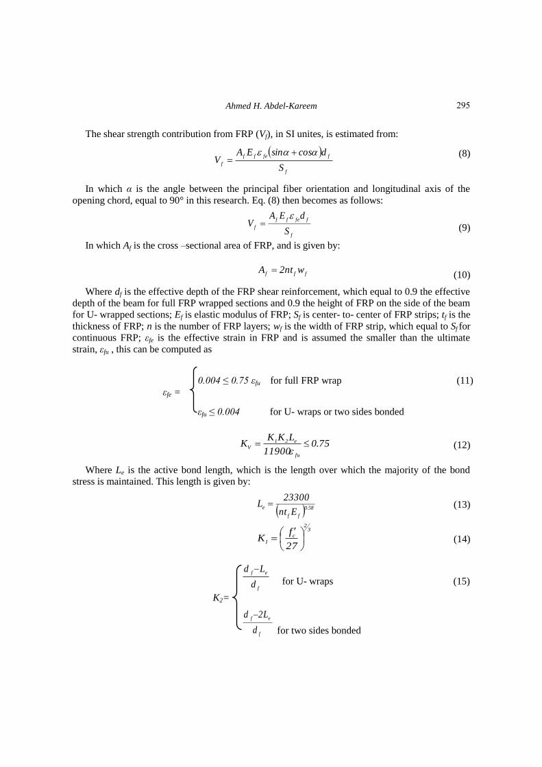
An additional reduction factor, ψf is applied to the FRP contribution in shear strength, Vf as
follows:
0.95 for full FRP wrap (7)
ψf =
0.85 for U- wraps or two sides bonded
twcctdb 'f
6
1V
bwccbdb'f
6
1V
294
Ahmed H. Abdel-Kareem
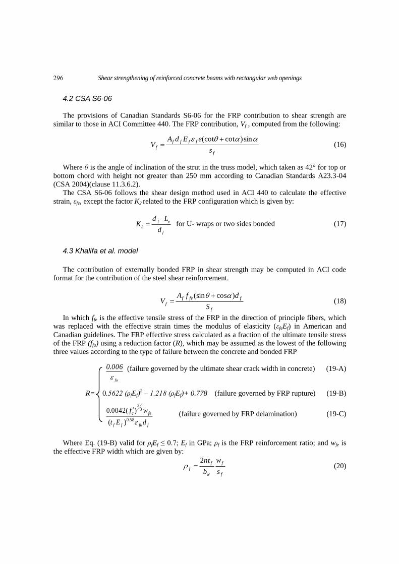
The shear strength contribution from FRP (Vf), in SI unites, is estimated from:
(8)
In which α is the angle between the principal fiber orientation and longitudinal axis of the
opening chord, equal to 90° in this research. Eq. (8) then becomes as follows:
(9)
In which Af is the cross –sectional area of FRP, and is given by:
(10)
Where df is the effective depth of the FRP shear reinforcement, which equal to 0.9 the effective
depth of the beam for full FRP wrapped sections and 0.9 the height of FRP on the side of the beam
for U- wrapped sections; Ef is elastic modulus of FRP; Sf is center- to- center of FRP strips; tf is the
thickness of FRP; n is the number of FRP layers; wf is the width of FRP strip, which equal to Sf for
continuous FRP; εfe is the effective strain in FRP and is assumed the smaller than the ultimate
strain, εfu , this can be computed as
0.004 ≤ 0.75 εfu for full FRP wrap (11)
εfe =
εfu ≤ 0.004 for U- wraps or two sides bonded
(12)
Where Le is the active bond length, which is the length over which the majority of the bond
stress is maintained. This length is given by:
(13)
(14)
for U- wraps (15)
K2=
for two sides bonded
f
ffeff
fS
dcossinEAV
f
ffeff
fS
dEAV
fffwnt2A
75.011900
LKKK
fu
e21
V
58.0
ff
eEnt
23300L
32
c
127
fK
f
ef
d
Ld
f
ef
d
L2d
295
Shear strengthening of reinforced concrete beams with rectangular web openings
4.2 CSA S6-06
The provisions of Canadian Standards S6-06 for the FRP contribution to shear strength are
similar to those in ACI Committee 440. The FRP contribution, Vf , computed from the following:
f
ffff
fs
eEdAV
sin)cot(cot (16)
Where θ is the angle of inclination of the strut in the truss model, which taken as 42° for top or
bottom chord with height not greater than 250 mm according to Canadian Standards A23.3-04
(CSA 2004)(clause 11.3.6.2).
The CSA S6-06 follows the shear design method used in ACI 440 to calculate the effective
strain, εfe, except the factor K2 related to the FRP configuration which is given by:
f
ef
2d
LdK
for U- wraps or two sides bonded (17)
4.3 Khalifa et al. model
The contribution of externally bonded FRP in shear strength may be computed in ACI code
format for the contribution of the steel shear reinforcement.
f
ffef
fS
dfAV
)cos(sin (18)
In which ffe is the effective tensile stress of the FRP in the direction of principle fibers, which
was replaced with the effective strain times the modulus of elasticity (εfeEf) in American and
Canadian guidelines. The FRP effective stress calculated as a fraction of the ultimate tensile stress
of the FRP (ffu) using a reduction factor (R), which may be assumed as the lowest of the following
three values according to the type of failure between the concrete and bonded FRP
(failure governed by the ultimate shear crack width in concrete) (19-A)
R= 0.5622 (ρfEf)2 – 1.218 (ρfEf)+ 0.778 (failure governed by FRP rupture) (19-B)
(failure governed by FRP delamination) (19-C)
Where Eq. (19-B) valid for ρfEf ≤ 0.7; Ef in GPa; ρf is the FRP reinforcement ratio; and wfe is
the effective FRP width which are given by:
f
f
w
f
fs
w
b
nt2 (20)
fu
006.0
ffuff
fec
dEt
wf
58.0
32
)(
)( 0042.0
296
Ahmed H. Abdel-Kareem
bonded sides for two2
wraps-for U
ef
ef
fe Ld
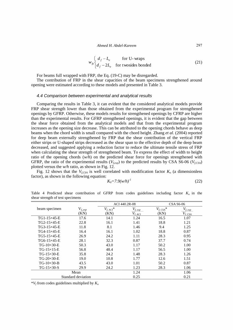
Ldw (21)
For beams full wrapped with FRP, the Eq. (19-C) may be disregarded. The contribution of FRP in the shear capacities of the beam specimens strengthened around
opening were estimated according to these models and presented in Table 3.
4.4 Comparison between experimental and analytical results
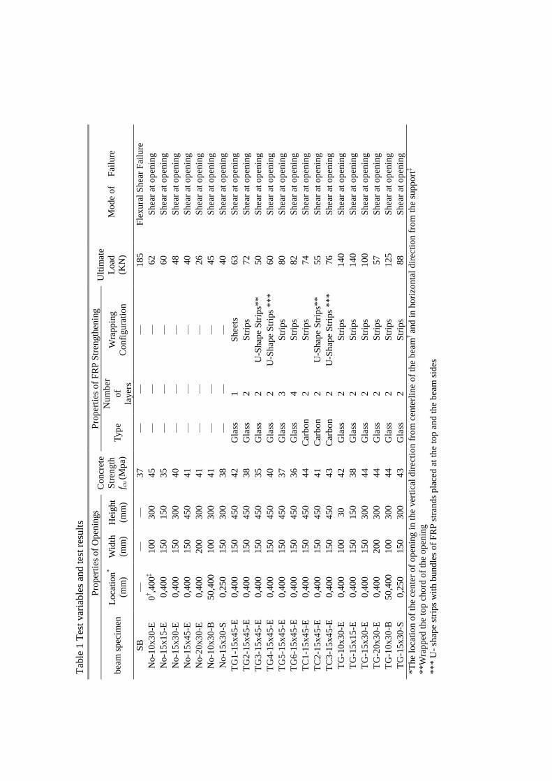
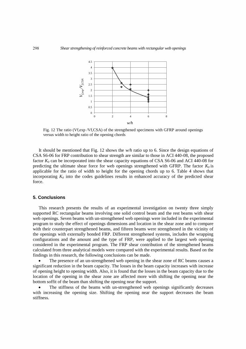
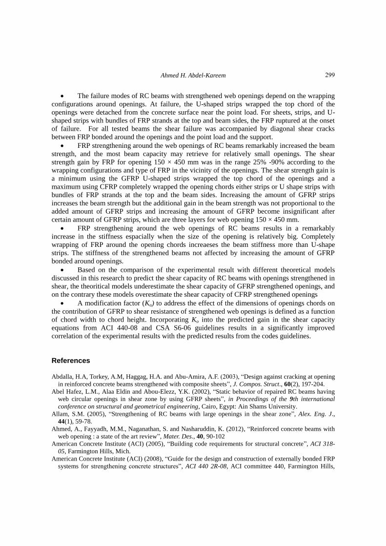
Comparing the results in Table 3, it can evident that the considered analytical models provide FRP shear strength lower than those obtained from the experimental program for strengthened openings by GFRP. Otherwise, these models results for strengthened openings by CFRP are higher than the experimental results. For GFRP strengthened openings, it is evident that the gap between the shear force obtained from the analytical models and that from the experimental program increases as the opening size decrease. This can be attributed to the opening chords behave as deep beams when the chord width is small compared with the chord height. Zhang et al. (2004) reported for deep beam externally strengthened by FRP that the shear contribution of the vertical FRP either strips or U-shaped strips decreased as the shear span to the effective depth of the deep beam decreased, and suggested applying a reduction factor to reduce the ultimate tensile stress of FRP when calculating the shear strength of strengthened beam. To express the effect of width to height ratio of the opening chords (w/h) on the predicted shear force for openings strengthened with GFRP, the ratio of the experimental results (Vf,exp) to the predicted results by CSA S6-06 (Vf,CSA) plotted versus the w/h ratio, as shown in Fig. 12.
Fig. 12 shows that the Vf,CSA is well correlated with modification factor Ko (a dimensionless factor), as shown in the following equation:
K0=7.9(w/h)-1
(22)
Table 4 Predicted shear contribution of GFRP from codes guidelines including factor Ko in the
shear strength of test specimens
CSA S6-06 ACI 440.2R-08
Vf,,exp
(KN)
beam specimen Vf, exp
Vf, CSA
Vf, CSA*
(KN)
Vf, exp
Vf, ACI
Vf, ACI*
(KN)
1.07 16.5 1.24 14.1 17.6 TG1-15×45-E
1.21 18.8 1.41 16.1 22.8 TG2-15×45-E
1.25 9.4 1.46 8.1 11.8 TG3-15×45-E
0.87 18.8 1.02 16.1 16.4 TG4-15×45-E
0.95 28.3 1.11 24.2 26.9 TG5-15×45-E
0.74 37.7 0.87 32.3 28.1 TG6-15×45-E
1.00 50.2 1.17 43.0 50.3 TG-10×30-E
1.00 56.5 1.17 48.4 56.8 TG-15×15-E
1.26 28.3 1.48 24.2 35.8 TG-15×30-E
1.51 12.6 1.77 10.8 19.0 TG-20×30-E
0.87 50.2 1.01 43.0 43.5 TG-10×30-B
1.06 28.3 1.23 24.2 29.9 TG-15×30-S
1.06
0.21
1.24
0.25
Mean
Standard deviation
*Vf from codes guidelines multiplied by Ko
297
Shear strengthening of reinforced concrete beams with rectangular web openings
Fig. 12 The ratio (Vf,exp /Vf,CSA) of the strengthened specimens with GFRP around openings
versus width to height ratio of the opening chords
It should be mentioned that Fig. 12 shows the w/h ratio up to 6. Since the design equations of
CSA S6-06 for FRP contribution to shear strength are similar to those in ACI 440-08, the proposed
factor K0 can be incorporated into the shear capacity equations of CSA S6-06 and ACI 440-08 for
predicting the ultimate shear force for web openings strengthened with GFRP. The factor K0 is
applicable for the ratio of width to height for the opening chords up to 6. Table 4 shows that
incorporating K0 into the codes guidelines results in enhanced accuracy of the predicted shear
force.
5. Conclusions
This research presents the results of an experimental investigation on twenty three simply
supported RC rectangular beams involving one solid control beam and the rest beams with shear
web openings. Seven beams with un-strengthened web openings were included in the experimental
program to study the effect of openings dimensions and location in the shear zone and to compare
with their counterpart strengthened beams, and fifteen beams were strengthened in the vicinity of
the openings with externally bonded FRP. Different strengthened systems, includes the wrapping
configurations and the amount and the type of FRP, were applied to the largest web opening
considered in the experimental program. The FRP shear contribution of the strengthened beams
calculated from three analytical models were compared with the experimental results. Based on the
findings in this research, the following conclusions can be made.
The presence of an un-strengthened web opening in the shear zone of RC beams causes a
significant reduction in the beam capacity. The losses in the beam capacity increases with increase
of opening height to opening width. Also, it is found that the losses in the beam capacity due to the
location of the opening in the shear zone are affected more with shifting the opening near the
bottom soffit of the beam than shifting the opening near the support.
The stiffness of the beams with un-strengthened web openings significantly decreases
with increasing the opening size. Shifting the opening near the support decreases the beam
stiffness.
0
0.5
1
1.5
2
2.5
3
3.5
4
4.5
0 2 4 6 8
Vf,
exp /V
f,C
SA
w/h
298
Ahmed H. Abdel-Kareem
The failure modes of RC beams with strengthened web openings depend on the wrapping
configurations around openings. At failure, the U-shaped strips wrapped the top chord of the
openings were detached from the concrete surface near the point load. For sheets, strips, and U-
shaped strips with bundles of FRP strands at the top and beam sides, the FRP ruptured at the onset
of failure. For all tested beams the shear failure was accompanied by diagonal shear cracks
between FRP bonded around the openings and the point load and the support.
FRP strengthening around the web openings of RC beams remarkably increased the beam
strength, and the most beam capacity may retrieve for relatively small openings. The shear
strength gain by FRP for opening 150 × 450 mm was in the range 25% -90% according to the
wrapping configurations and type of FRP in the vicinity of the openings. The shear strength gain is
a minimum using the GFRP U-shaped strips wrapped the top chord of the openings and a
maximum using CFRP completely wrapped the opening chords either strips or U shape strips with
bundles of FRP strands at the top and the beam sides. Increasing the amount of GFRP strips
increases the beam strength but the additional gain in the beam strength was not proportional to the
added amount of GFRP strips and increasing the amount of GFRP become insignificant after
certain amount of GFRP strips, which are three layers for web opening 150 × 450 mm.
FRP strengthening around the web openings of RC beams results in a remarkably
increase in the stiffness espacially when the size of the opening is relatively big. Completely
wrapping of FRP around the opening chords increaeses the beam stiffness more than U-shape
strips. The stiffness of the strengthened beams not affected by increasing the amount of GFRP
bonded around openings.
Based on the comparison of the experimental result with different theoretical models
discussed in this research to predict the shear capacity of RC beams with openings strengthened in
shear, the theoritical models underestimate the shear capacity of GFRP strengthened openings, and
on the contrary these models overestimate the shear capacity of CFRP strengthened openings
A modification factor (Ko) to address the effect of the dimensions of openings chords on
the contribution of GFRP to shear resistance of strengthened web openings is defined as a function
of chord width to chord height. Incorporating Ko into the predicted gain in the shear capacity
equations from ACI 440-08 and CSA S6-06 guidelines results in a significantly improved
correlation of the experimental results with the predicted results from the codes guidelines.
References Abdalla, H.A, Torkey, A.M, Haggag, H.A. and Abu-Amira, A.F. (2003), “Design against cracking at opening
in reinforced concrete beams strengthened with composite sheets”, J. Compos. Struct., 60(2), 197-204.
Abel Hafez, L.M., Alaa Eldin and Abou-Elezz, Y.K. (2002), “Static behavior of repaired RC beams having
web circular openings in shear zone by using GFRP sheets”, in Proceedings of the 9th international
conference on structural and geometrical engineering, Cairo, Egypt: Ain Shams University.
Allam, S.M. (2005), “Strengthening of RC beams with large openings in the shear zone”, Alex. Eng. J.,
44(1), 59-78.
Ahmed, A., Fayyadh, M.M., Naganathan, S. and Nasharuddin, K. (2012), “Reinforced concrete beams with
web opening : a state of the art review”, Mater. Des., 40, 90-102
American Concrete Institute (ACI) (2005), “Building code requirements for structural concrete”, ACI 318-
05, Farmington Hills, Mich.
American Concrete Institute (ACI) (2008), “Guide for the design and construction of externally bonded FRP
systems for strengthening concrete structures”, ACI 440 2R-08, ACI committee 440, Farmington Hills,
299
Shear strengthening of reinforced concrete beams with rectangular web openings
Mich.
Bousselham, A. and Chaallal, O. (2006a), “Behavior of reinforced concrete T-beams strengthened in shear
with carbon fiber-reinforced polymer- An experimental study”, ACI Struct. J., 103(3), 339-347.
Bousselham, A. and Chaallal, O. (2009), “Maximum shear strength of RC beams retrofitted in shear with
FRP composites”, J. Compos. Struct., 13(4), 302-314.
Canadian Standards Association (CSA) (2004), “Design of concrete structures for buildings”, CSA A233.3-
04, Rexdale, Ont., Canada.
Canadian Standards Association (CSA) (2006), “Canadian highway bridge design code”, CSA-S6-06,
Rexdale, Ont., Canada.
Chin, S.C., Shafig, N. and Nurddin, M.F. (2012), “Strengthening of RC beams with large openings in shear
by CFRP laminates: experimental and 2D nonlinear finite element analysis." Res. J. App. Sci. Eng. Tech.,
4(9), 1180-2012.
El Maaddawy, T. and Sherief, S. (2009), “FRP composites for shear strengthening of reinforced concrete
deep beams with openings”, Compos. Struct., 89(1), 60-69.
El Maaddawy, T. and El-Ariss, B. (2012), “Behavior of concrete beams with short shear span and web
openings strengthened in shear with CFRP composites”, J. Compos. Struct., 16(1), 47-59.
Khalifa, A., Gold, W.J., Nanni, A. and Abdel Aziz, M.I. (1998), “Contribution of externally bonded FRP to
shear capacity of RC flexural members”, J. Compos. Constr., 2(4), 195-202.
Khalifa, A. and Nanni, A. (2002), “Rehabilitation of rectangular simply supported RC beams with shear
deficiencies using CFRP composites”, Constr. Build. Mater., 16(3), 135-146.
Kennedy, J.B. and Abdella, H.A. (1992), “Static response of prestressed girders with openings”, ASCE J.
Struct. Eng., 118(2), 488-504.
Mansur, M. (1988), “Ultimate strength design of beams with large openings”, Int. J. Struct., 8(2), 107-125.
Mansur, M. (1998), “Effect of openings on the behavior and strength of R/C beams in shear”, Cement
Concrete Compos., 20(6), 477-486.
Mansur, M., Tan, K. and Wel, W. (1999), “Effects of creating an opening in existing beam”, ACI Struct. J.,
96(6), 899-906.
Micelli, F., Annaiah, R. and Nanni, A. (2002), “Strengthening of short shear span reinforced concrete T
joints with fiber-reinforced plastic composites”, J. Compos. Struct., 6(4), 264-271.
Mofidi, A. and Chaallal, O. (2014), “Tests and design provisions for reinforced-concrete beams strengthened
in shear using FRP sheets and strips”, Int. J. Concr. Struct. Mater., 8(2), 117-128
Monti, G. and Liotta, M. (2007), “Tests and design equations for FRP –strengthening in shear”, Constr.
Build. Mater., 21, 799-809.
Panda, K.C., Bhattacharyya, S.K. and Barai, S.V. (2011), “Shear strengthening of RC T-beams with
externally side bonded GFRP sheet”, J. Reinf. Plast. Compos., 30, 1139-1154
Panda, K.C., Bhattacharyya, S.K. and Barai, S.V. (2012), “Shear behaviour of RC T-beams strengthened
with U-wrapped GFRP sheet”, Steel Compos. Struct., 12 (2), 149-166.
Panda, K.C., Bhattacharyya, S.K. and Barai, S.V. (2013), “Shear strengthening effect by bonded GFRP strips
and transverse steel on RC T-beams”, Struct. Eng. Mech., 47 (1), 75-98.
Pimanmas, A. (2010), “Strengthening R/C beams opening by externally installed FRP rods: behavior and
analysis”, Compos. Struct., 92 (8), 1957-1976.
SIKA Egypt (2010), “Technical Data of Sikawrap-230C/Sikawrap-430G/Sikadur-330”, SIKA, Cairo, Egypt.
Triantafillou, T. and Antonopoulos, C. (2000), “Design of concrete flexural members strengthened in shear
with FRP”, J. Compos. Constr., 4(4), 198-205.
Zhang, Z., Hsu, C. and Moren, J. (2004). “Shear strengthening of reinforced concrete deep beam using
carbon fiber reinforced laminates”, ASCE Compos. Constr., 8(5), 403-413.
300