shear behaviour of reinforced phyllite concrete beams
TRANSCRIPT
Materials & Design, 43, 438-446
1
Shear behaviour of reinforced phyllite concrete beams
Mark Adom-Asamoah , Russell Owusu Afrifa Department of Civil Engineering, Kwame Nkrumah University of Science and Technology, College of
Engineering, Kumasi, Ghana.
* Corresponding author. Tel: +233-51-60226 Fax: +233-51-60226
Email: [email protected]; [email protected]
(Dr Mark Adom-Asamoah)
ABSTRACT
The shear behaviour of concrete beams made from phyllite aggregates subjected to
monotonic and cyclic loading is reported. First diagonal shear crack load of beams with and
without shear reinforcement was between 42–58% and 42–92% of the failure loads
respectively. The phyllite concrete beams without shear links had lower post-diagonal
cracking shear resistance compared to corresponding phyllite beams with shear links. As a
result of hysteretic energy dissipation, limited cyclic loading affected the stiffness, strength
and deformation of the phyllite beams with shear reinforcement. Generally, beams with and
without shear reinforcement showed anchorage bond failure in addition to the shear failure
due to high stress concentration near the supports. The ACI, BS and EC codes are
conservative for the prediction of phyllite concrete beams without shear reinforcement but
they all overestimate the shear strength of phyllite concrete beams with shear reinforcement.
It is recommended that the predicted shear capacity of phyllite beams reinforced with steel
stirrups be modified by a reduction factor of 0.7 in order to specify a high enough safety
factor on their ultimate strength. It is also recommended that susceptibility of phyllite
concrete beams to undergo anchorage bond failure is averted in design by the provision of
greater anchorage lengths than usually permitted.
1. Introduction
As the population of the world increases and urban centres expand, the levels of construction
are also expected to increase. The construction industry in most countries makes use of
aggregates extracted from natural sources for the production of concrete. In the UK alone,
nearly 208 million tonnes of sand, gravel and crushed rock aggregates are mined for
construction annually [1]. The use of aggregates in concrete is primarily dependent on their
Materials & Design, 43, 438-446
2
availability. The depletion and over-exploitation of sources of conventional aggregates (such
as granite and sandstone) used in the production of conventional (normal) concrete has led to
the use of other available aggregates. One of such aggregates, phyllites; are foliated rocks
with preferential cleavage that has the property of easily breaking up into thin slabs [2]. The
presence of phyllites has been reported in several parts of the world such as Europe [3,4],
South America [5], the Himalayan region [6] and Africa [7]. In Ghana (especially the gold
mining areas), phyllite aggregates have become convenient in their use as a construction
material as a result of its availability in addition the scarcity of material coupled with the high
cost of normal aggregates. The lack of information regarding the properties and structural
performance of concrete members made from phyllite aggregates is a hindrance to the use of
the material by engineers both during the design and construction phases of structures.
Reports of collapsed reinforced concrete (RC) buildings made of phyllite aggregates are
documented [7,8].
Earlier work [7] has expressed concerns about the low compression and flexural strengths
of plain phyllite concrete. This was attributed to the flakiness and elongation properties
coupled with the reactive materials in phyllite aggregates that affect the absorption and bond
characteristics of its concrete. A study [8] of the flexural behaviour of reinforced concrete
phyllite beams adequately reinforced with shear stirrups indicated concerns about their shear
capacity as a result of the formation of diagonal tension cracks at failure. It was concluded
that the BS8110 [9] theoretical shear strength of the concrete made from phyllite aggregates
be reduced as a result of the early formation of diagonal tension cracks observed during the
testing of the beams.
Shear mechanism is an important aspect of structural concrete behaviour, yet this is an area
lacking in-depth understanding and consensus amongst researchers [10]. It is therefore not
surprising that neither the distribution of shear stress across a flexurally cracked beam nor the
determination of shear stress magnitude have been fully understood. The complex nature of
this phenomenon-non has been attributed to the many different parameters that are identified
to influence shear strength. However, it is generally accepted [11,12] that the shear capacity
of reinforced normal concrete beams without shear reinforcement derive its contributions
from compression shear zone (ranging between 20% and 40%), aggregate interlock
mechanism (ranging between 35% and 50%) and the dowel action of longitudinal
reinforcement (ranging between 15% and 25%). Walraven [13] reported that shear failure is
Materials & Design, 43, 438-446
3
usually caused by a large amount of shear force that is transferred along the cracked surface
via aggregate interlock which provides resistance against slip. The effect of aggregate
interlock on concrete shear resistance reduces as the depth of beam increases. This is because
an increase in crack widths at points above the main reinforcement weakens the aggregate
interlock capacity and reduces concrete shear capacity [14–17]. It is also known that
aggregate interlock is dependent on longitudinal reinforcement ratio. Higher percentages of
longitudinal reinforcement results in smaller crack widths which in turn enhance aggregate
interlock and shear capacity. For beams with very small shear-span to depth ratio, Kani [18]
explained that the shear resistance may be affected because the applied shear force may be
transmitted directly to the supports by arch action (compressive struts) of the concrete.
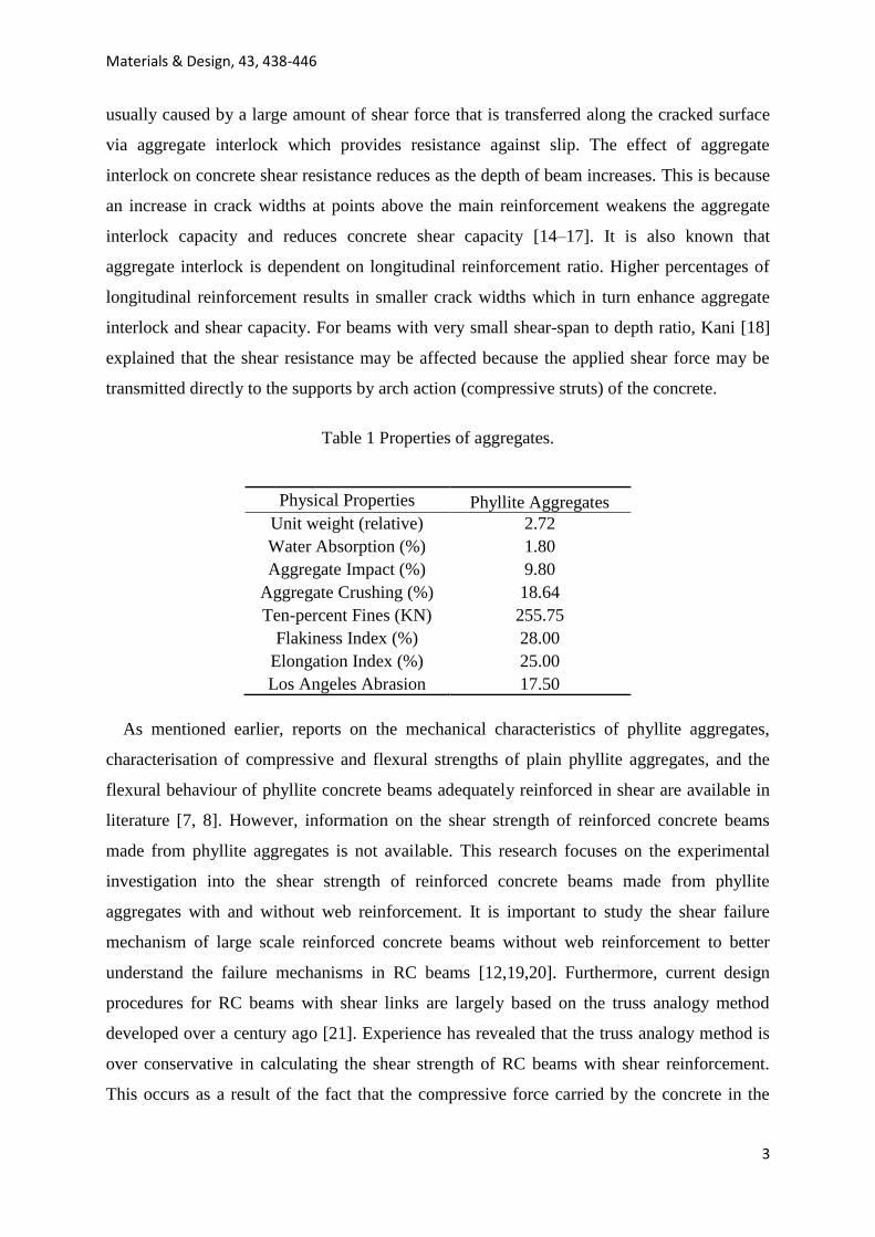
Table 1 Properties of aggregates.
Physical Properties Phyllite Aggregates
Unit weight (relative) 2.72
Water Absorption (%) 1.80
Aggregate Impact (%) 9.80
Aggregate Crushing (%) 18.64
Ten-percent Fines (KN) 255.75
Flakiness Index (%) 28.00
Elongation Index (%) 25.00
Los Angeles Abrasion 17.50
As mentioned earlier, reports on the mechanical characteristics of phyllite aggregates,
characterisation of compressive and flexural strengths of plain phyllite aggregates, and the
flexural behaviour of phyllite concrete beams adequately reinforced in shear are available in
literature [7, 8]. However, information on the shear strength of reinforced concrete beams
made from phyllite aggregates is not available. This research focuses on the experimental
investigation into the shear strength of reinforced concrete beams made from phyllite
aggregates with and without web reinforcement. It is important to study the shear failure
mechanism of large scale reinforced concrete beams without web reinforcement to better
understand the failure mechanisms in RC beams [12,19,20]. Furthermore, current design
procedures for RC beams with shear links are largely based on the truss analogy method
developed over a century ago [21]. Experience has revealed that the truss analogy method is
over conservative in calculating the shear strength of RC beams with shear reinforcement.
This occurs as a result of the fact that the compressive force carried by the concrete in the
Materials & Design, 43, 438-446
4
compression zone (top chord of the truss) is ignored [20, 22].
The aim of the study is to investigate the shear strength of rein-forced concrete beams
made from phyllite aggregates. Sixteen (16) beams were manufactured and tested in the
laboratory. Ten (10) of the beams were without stirrups whilst the other six (6) were made
with different levels of shear reinforcement. The 10 beams without shear reinforcement in
addition to 3 of those with shear stirrups were tested under monotonic four point bending
tests whilst the rest were tested under limited cyclic tests of 20 loading–unloading cycles. The
experimental shear capacity results
Were compared with shear capacity prediction obtained from ACI 308-02 [23], BS 8110 [9]
and EC 2 [24] codes of practice.
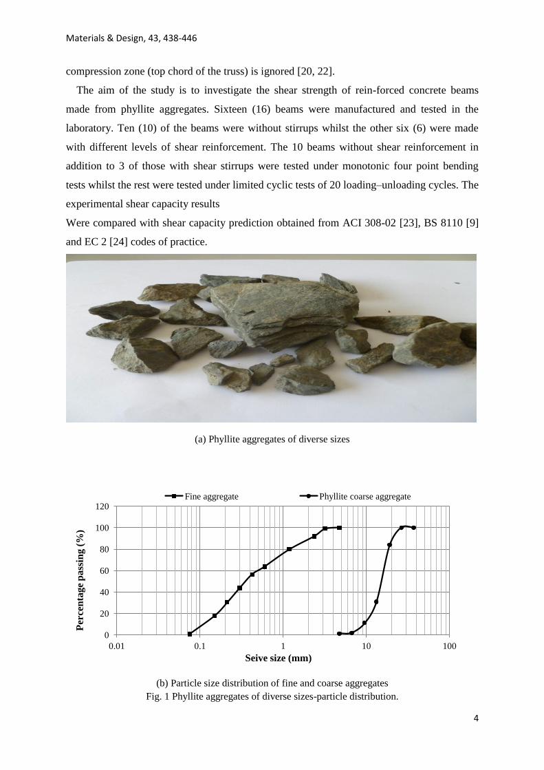
(a) Phyllite aggregates of diverse sizes
(b) Particle size distribution of fine and coarse aggregates
Fig. 1 Phyllite aggregates of diverse sizes-particle distribution.
0
20
40
60
80
100
120
0.01 0.1 1 10 100
Per
cen
tag
e p
ass
ing
(%
)
Seive size (mm)
Fine aggregate Phyllite coarse aggregate
Materials & Design, 43, 438-446
5
2. Experimental and test program 2.1. Materials
Ordinary Portland Cement (OPC) to the specifications of BS 12:1989 [25] was used for
concrete manufacture. Grading of fine and coarse aggregates were done to the specifications
of appropriate codes [26]. River sand was used as fine aggregates whilst crushed phyllite
stones were used as coarse aggregates in phyllite concrete beams. Table 1 shows the physical
properties of the phyllite aggregates performed according to specifications [27]. Fig 1a shows
phyllite aggregates of diverse sizes whilst Fig 1b shows particle size distribution curves for
fine and coarse aggregates. The average yield strength of the tensile reinforcing bars was 375
N/ mm2 with nominal diameter (size) of 12 mm. Steel bar size of 6 mm was used as nominal
top reinforcement having average yield strength of 250 N/mm2.
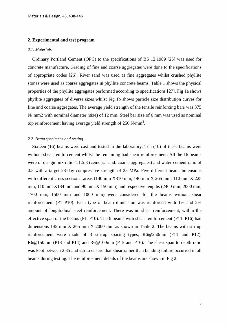
2.2. Beam specimens and testing
Sixteen (16) beams were cast and tested in the laboratory. Ten (10) of these beams were
without shear reinforcement whilst the remaining had shear reinforcement. All the 16 beams
were of design mix ratio 1:1.5:3 (cement: sand: coarse aggregates) and water-cement ratio of
0.5 with a target 28-day compressive strength of 25 MPa. Five different beam dimensions
with different cross sectional areas (140 mm X310 mm, 140 mm X 265 mm, 110 mm X 225
mm, 110 mm X184 mm and 90 mm X 150 mm) and respective lengths (2400 mm, 2000 mm,
1700 mm, 1500 mm and 1000 mm) were considered for the beams without shear
reinforcement (P1–P10). Each type of beam dimension was reinforced with 1% and 2%
amount of longitudinal steel reinforcement. There was no shear reinforcement, within the
effective span of the beams (P1–P10). The 6 beams with shear reinforcement (P11–P16) had
dimensions 145 mm X 265 mm X 2000 mm as shown in Table 2. The beams with stirrup
reinforcement were made of 3 stirrup spacing types; R6@250mm (P11 and P12),
R6@150mm (P13 and P14) and R6@100mm (P15 and P16). The shear span to depth ratio
was kept between 2.35 and 2.5 to ensure that shear rather than bending failure occurred in all
beams during testing. The reinforcement details of the beams are shown in Fig 2.
Materials & Design, 43, 438-446
6
Table 2 Beam description
BEAM
No.
B X D
(mm x mm)
Length
(mm)
Shear
span/eff.
depth ratio
(av/d)
Shear
reinforcement
& spacing
Percentage
Longitudinal
reinforcement
ρ (%)
28days
Concrete
compressive
strength,
fcu (N/mm2)
28days
Concrete
flexural
strength,
fcr(N/mm2)
P1 140 X 310 2400 2.45 - 1 23.50 3.40
P2 140 X 310 2400 2.45 - 2 23.50 3.40
P3 140 X 265 2000 2.45 - 1 23.50 3.40
P4 140 X 265 2000 2.45 - 2 23.50 3.40
P5 110 X 225 1700 2.45 - 1 23.00 3.38
P6 110 X 225 1700 2.45 - 2 23.00 3.38
P7 110 X 184 1500 2.45 - 1 23.00 3.38
P8 110 X 184 1500 2.45 - 2 23.00 3.38
P9 90 X 150 1000 2.35 - 1 23.00 3.38
P10 90 X 150 1000 2.35 - 2 23.00 3.38
PS4A 140 X 265 2000 2.45 R6@250mm 2 23.50 3.40
PS4B 140 X 265 2000 2.45 R6@250mm 2 23.50 4.00
PS4C 140 X 265 2000 2.45 R6@150mm 2 23.50 2.50
PS4D 140 X 265 2000 2.45 R6@150mm 2 23.50 3.40
PS4E 140 X 265 2000 2.45 R6@100mm 2 23.50 4.00
PS4F 140 X 265 2000 2.45 R6@100mm 2 23.50 2.50
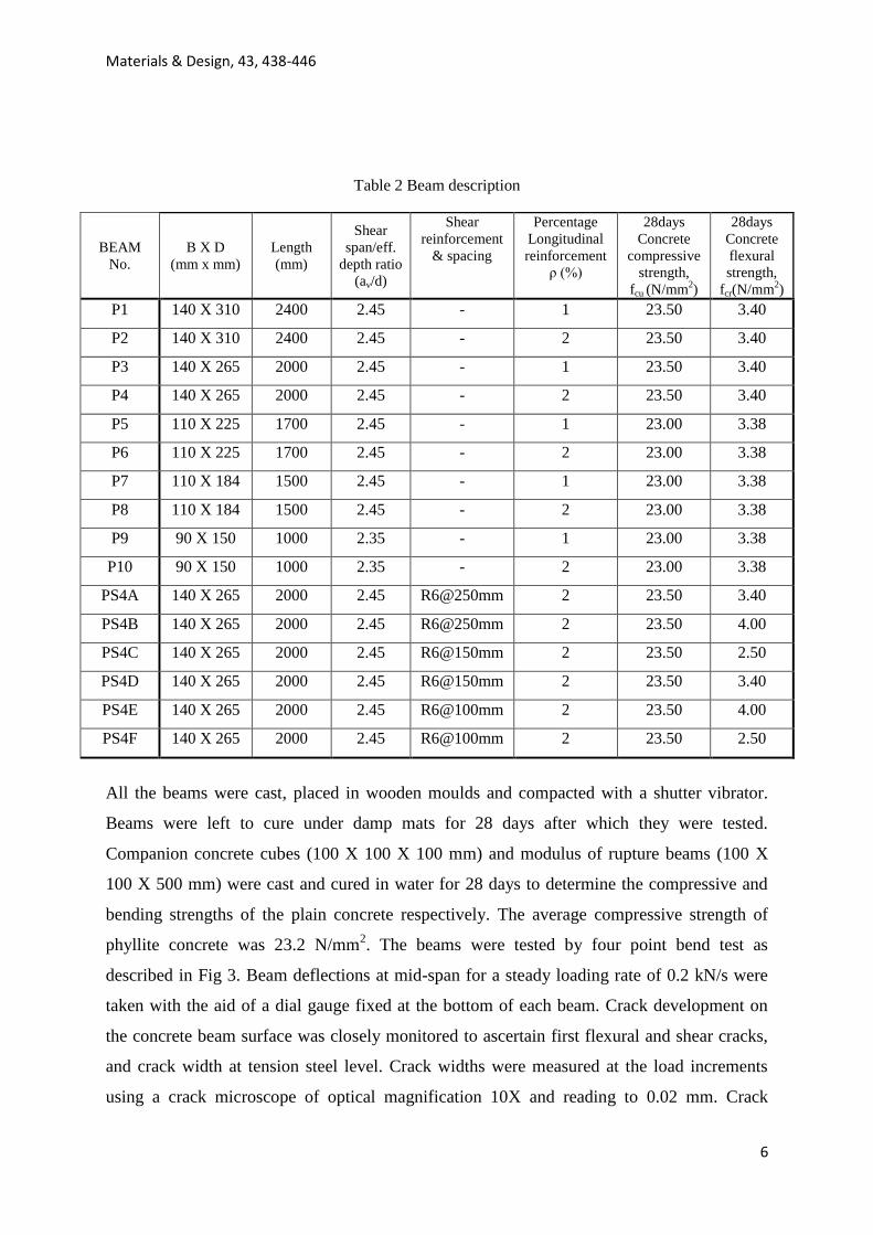
All the beams were cast, placed in wooden moulds and compacted with a shutter vibrator.
Beams were left to cure under damp mats for 28 days after which they were tested.
Companion concrete cubes (100 X 100 X 100 mm) and modulus of rupture beams (100 X
100 X 500 mm) were cast and cured in water for 28 days to determine the compressive and
bending strengths of the plain concrete respectively. The average compressive strength of
phyllite concrete was 23.2 N/mm2. The beams were tested by four point bend test as
described in Fig 3. Beam deflections at mid-span for a steady loading rate of 0.2 kN/s were
taken with the aid of a dial gauge fixed at the bottom of each beam. Crack development on
the concrete beam surface was closely monitored to ascertain first flexural and shear cracks,
and crack width at tension steel level. Crack widths were measured at the load increments
using a crack microscope of optical magnification 10X and reading to 0.02 mm. Crack
Materials & Design, 43, 438-446
7
patterns were marked on the beams after failure.
Fig.2 Beam details
a) Schematic diagram of experimental set-up
(b) Test set-up and instrumentation
Fig. 3 Schematic diagram of experiment set
265mm
2000 mm
1800 mm 145mm
D
B
(a) Beam without shear reinforcement (P1-P10)
900 – 2100 mm
1000 – 2400 mm
(b) Beam with shear reinforcement (P11-P16)
Link spacing varies (R6@250, R6@150 ,R6@100)
Materials & Design, 43, 438-446
8
3. Test results and discussions
Results obtained from testing both phyllite aggregate concrete beams with and without
shear reinforcement are discussed in this section. Experimental first flexural crack, first shear
crack and failure loads were identified. Load–deflection behaviour, failure behaviour, number
of cracks and maximum crack width of RC beams are also discussed using Fig. 4–7 and
Tables 3–5. Further analysis and comparisons are made with respect to shear strength
prediction made by other design codes of practice.
3.1. Load–deflection behaviour
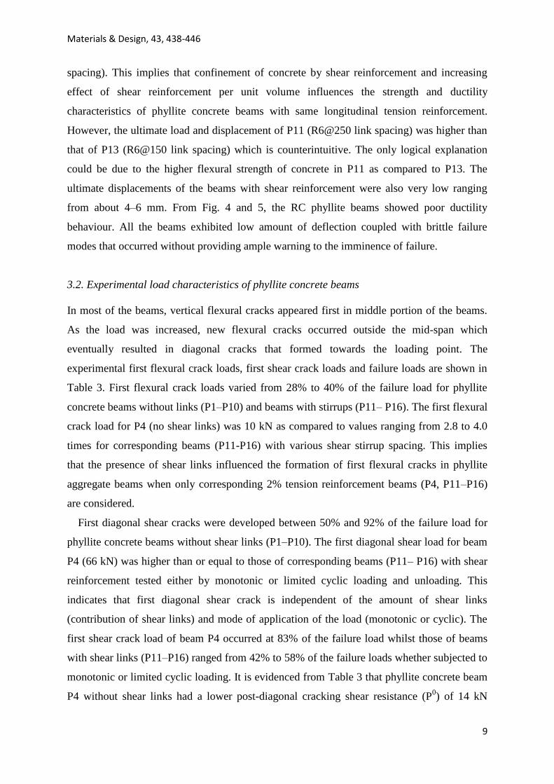
Typical load versus mid-span deflection curves of the beams without stirrups are compared
for phyllite concrete beams in Fig 4. The initial linear portion of the beams without links
subjected to monotonic loading (P1–P10) before first flexural cracking was similar. The
initial stiffness of the beams was independent of the percentage of tension reinforcement (1%
or 2%) as shown in Fig 4 for corresponding beam pairs (P1–P2, P3–P4 and P7–P8). In all
cases, the beams with lower tension reinforcement (P1, P3 and P7) failed at lower ultimate
loads but higher mid-span deflections when compared with those of higher reinforcement
(P2, P4 and P8). This observation about beams with lower tension reinforcement exhibiting
higher displacement ductility at failure has been made by other researchers who worked on
reinforced concrete beams made from other coarse aggregates [28–30]. It is worthy of note
that even though RC phyllite concrete beams without shear reinforcement (P1–P10) has
exhibited this behaviour, RC beams made from phyllite aggregates with adequate shear
reinforcement in an earlier work [8] showed counter behaviour. The ultimate loads of the
beams with same percent tension reinforcement de-creased with decreasing beam cross-
section capacity. Very low ultimate displacements of 3–6 mm were measured for the beams
without shear reinforcement (P1–P10).
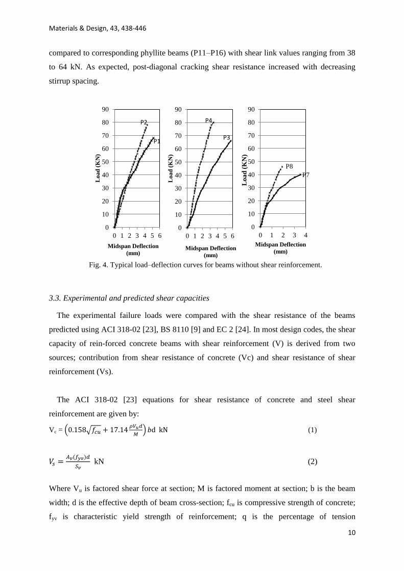
The load–deflection characteristics of 4 beams with same dimensions and tension
reinforcement (2%) but different shear reinforcement; P4 (no links), P11 (R6@250), P13
(R6@150) and P15 (R6@100) are shown in Fig 5. The beams which had similar concrete
compressive strength but slightly different flexural strengths as shown in Table 2 were
subjected to monotonic static loading. The initial stiffness, ultimate loads and ultimate
displacements of the curves generally increased with increasing shear reinforcement (or link
Materials & Design, 43, 438-446
9
spacing). This implies that confinement of concrete by shear reinforcement and increasing
effect of shear reinforcement per unit volume influences the strength and ductility
characteristics of phyllite concrete beams with same longitudinal tension reinforcement.
However, the ultimate load and displacement of P11 (R6@250 link spacing) was higher than
that of P13 (R6@150 link spacing) which is counterintuitive. The only logical explanation
could be due to the higher flexural strength of concrete in P11 as compared to P13. The
ultimate displacements of the beams with shear reinforcement were also very low ranging
from about 4–6 mm. From Fig. 4 and 5, the RC phyllite beams showed poor ductility
behaviour. All the beams exhibited low amount of deflection coupled with brittle failure
modes that occurred without providing ample warning to the imminence of failure.
3.2. Experimental load characteristics of phyllite concrete beams
In most of the beams, vertical flexural cracks appeared first in middle portion of the beams.
As the load was increased, new flexural cracks occurred outside the mid-span which
eventually resulted in diagonal cracks that formed towards the loading point. The
experimental first flexural crack loads, first shear crack loads and failure loads are shown in
Table 3. First flexural crack loads varied from 28% to 40% of the failure load for phyllite
concrete beams without links (P1–P10) and beams with stirrups (P11– P16). The first flexural
crack load for P4 (no shear links) was 10 kN as compared to values ranging from 2.8 to 4.0
times for corresponding beams (P11-P16) with various shear stirrup spacing. This implies
that the presence of shear links influenced the formation of first flexural cracks in phyllite
aggregate beams when only corresponding 2% tension reinforcement beams (P4, P11–P16)
are considered.
First diagonal shear cracks were developed between 50% and 92% of the failure load for
phyllite concrete beams without shear links (P1–P10). The first diagonal shear load for beam
P4 (66 kN) was higher than or equal to those of corresponding beams (P11– P16) with shear
reinforcement tested either by monotonic or limited cyclic loading and unloading. This
indicates that first diagonal shear crack is independent of the amount of shear links
(contribution of shear links) and mode of application of the load (monotonic or cyclic). The
first shear crack load of beam P4 occurred at 83% of the failure load whilst those of beams
with shear links (P11–P16) ranged from 42% to 58% of the failure loads whether subjected to
monotonic or limited cyclic loading. It is evidenced from Table 3 that phyllite concrete beam
P4 without shear links had a lower post-diagonal cracking shear resistance (P0) of 14 kN
Materials & Design, 43, 438-446
10
compared to corresponding phyllite beams (P11–P16) with shear link values ranging from 38
to 64 kN. As expected, post-diagonal cracking shear resistance increased with decreasing
stirrup spacing.
Fig. 4. Typical load–deflection curves for beams without shear reinforcement.
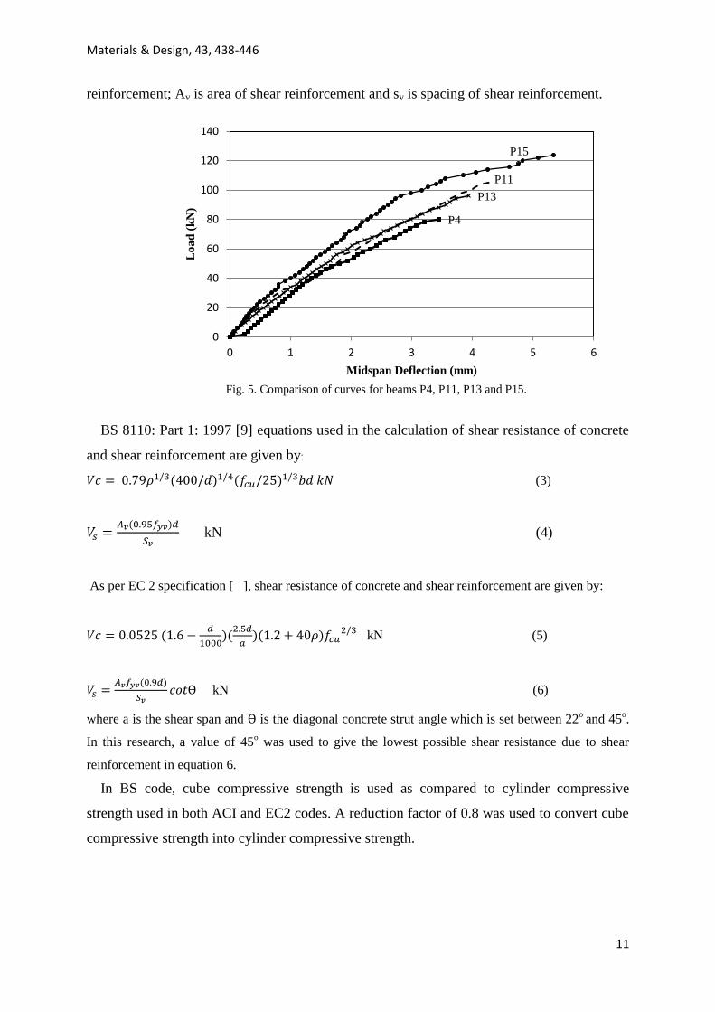
3.3. Experimental and predicted shear capacities
The experimental failure loads were compared with the shear resistance of the beams
predicted using ACI 318-02 [23], BS 8110 [9] and EC 2 [24]. In most design codes, the shear
capacity of rein-forced concrete beams with shear reinforcement (V) is derived from two
sources; contribution from shear resistance of concrete (Vc) and shear resistance of shear
reinforcement (Vs).
The ACI 318-02 [23] equations for shear resistance of concrete and steel shear
reinforcement are given by:
Vc =
(1)
kN (2)
Where Vu is factored shear force at section; M is factored moment at section; b is the beam
width; d is the effective depth of beam cross-section; fcu is compressive strength of concrete;
fyv is characteristic yield strength of reinforcement; q is the percentage of tension
P1
P2
0
10
20
30
40
50
60
70
80
90
0 1 2 3 4 5 6
Load
(K
N)
Midspan Deflection
(mm)
P3
P4
0
10
20
30
40
50
60
70
80
90
0 1 2 3 4 5 6
Load
(K
N)
Midspan Deflection
(mm)
P7
P8
0
10
20
30
40
50
60
70
80
90
0 1 2 3 4
Lo
ad
(K
N)
Midspan Deflection
(mm)
Materials & Design, 43, 438-446
11
reinforcement; Av is area of shear reinforcement and sv is spacing of shear reinforcement.
Fig. 5. Comparison of curves for beams P4, P11, P13 and P15.
BS 8110: Part 1: 1997 [9] equations used in the calculation of shear resistance of concrete
and shear reinforcement are given by:
(3)
kN (4)
As per EC 2 specification [ ], shear resistance of concrete and shear reinforcement are given by:
kN (5)
kN (6)
where a is the shear span and is the diagonal concrete strut angle which is set between 22o
and 45o.
In this research, a value of 45o was used to give the lowest possible shear resistance due to shear
reinforcement in equation 6.
In BS code, cube compressive strength is used as compared to cylinder compressive
strength used in both ACI and EC2 codes. A reduction factor of 0.8 was used to convert cube
compressive strength into cylinder compressive strength.
P11
P4
P13
P15
0
20
40
60
80
100
120
140
0 1 2 3 4 5 6
Lo
ad
(k
N)
Midspan Deflection (mm)
Materials & Design, 43, 438-446
12
(a) Comparison of P11 (monotonic loading) with P12 (cyclic loading)
(b) Comparison of P13 (monotonic loading) with P14 (cyclic loading)
P12
P11
0
20
40
60
80
100
120
0 1 2 3 4 5 6 7 8
Load
(kN
)
Midspan deflection (mm)
P14
P13
0
20
40
60
80
100
120
0 1 2 3 4 5 6 7 8
Load
(kN
)
Midspan deflection (mm)
Materials & Design, 43, 438-446
13
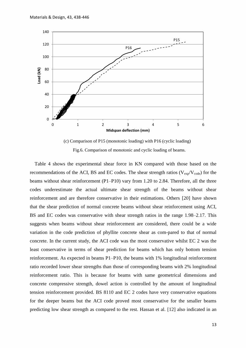
(c) Comparison of P15 (monotonic loading) with P16 (cyclic loading)
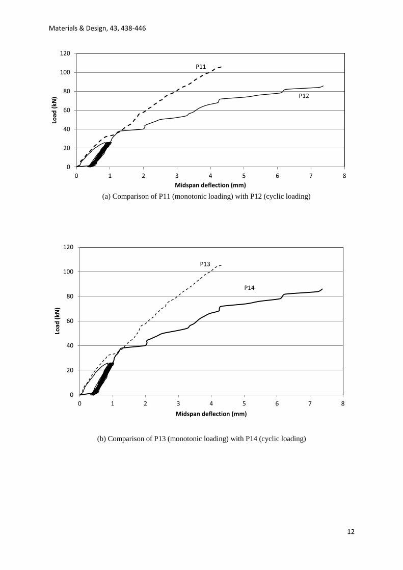
Fig.6. Comparison of monotonic and cyclic loading of beams.
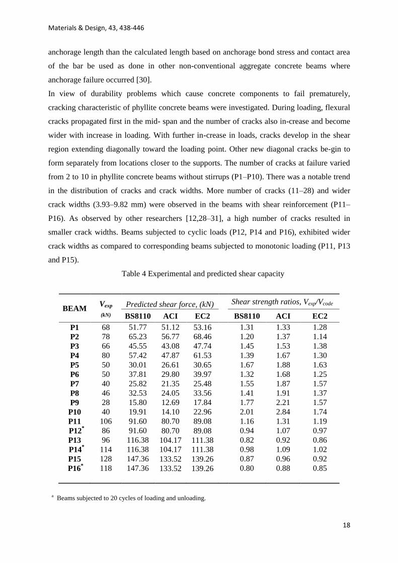
Table 4 shows the experimental shear force in KN compared with those based on the
recommendations of the ACI, BS and EC codes. The shear strength ratios (Vexp/Vcode) for the
beams without shear reinforcement (P1–P10) vary from 1.20 to 2.84. Therefore, all the three
codes underestimate the actual ultimate shear strength of the beams without shear
reinforcement and are therefore conservative in their estimations. Others [20] have shown
that the shear prediction of normal concrete beams without shear reinforcement using ACI,
BS and EC codes was conservative with shear strength ratios in the range 1.98–2.17. This
suggests when beams without shear reinforcement are considered, there could be a wide
variation in the code prediction of phyllite concrete shear as com-pared to that of normal
concrete. In the current study, the ACI code was the most conservative whilst EC 2 was the
least conservative in terms of shear prediction for beams which has only bottom tension
reinforcement. As expected in beams P1–P10, the beams with 1% longitudinal reinforcement
ratio recorded lower shear strengths than those of corresponding beams with 2% longitudinal
reinforcement ratio. This is because for beams with same geometrical dimensions and
concrete compressive strength, dowel action is controlled by the amount of longitudinal
tension reinforcement provided. BS 8110 and EC 2 codes have very conservative equations
for the deeper beams but the ACI code proved most conservative for the smaller beams
predicting low shear strength as compared to the rest. Hassan et al. [12] also indicated in an
P16
P15
0
20
40
60
80
100
120
140
0 1 2 3 4 5 6
Load
(kN
)
Midspan deflection (mm)
Materials & Design, 43, 438-446
14
experimental study on normal concrete and self-consolidating concrete beams in shear that
the ACI code is conservative for smaller beams. The unconservative prediction of the ACI
code for larger beams with low reinforcement ratios has also been recognized by others
[12,32].
As expected, the experimental shear capacities (Vexp) for the beam without shear
reinforcement (P4) is lower than those of cor-responding beams with stirrups (P11–P16).
Shear capacities in beams with stirrups, generally increased with decreasing stirrup spacing.
The experimental shear strength for beams with shear reinforcement (P11–P16) was
generally lower than those derived from the code prediction. The strength ratios for P11–P16
for all the 3 codes were generally less than one (1) for all the 3 codes. In-fact, 75% of the
shear strength ratios had values from 0.8 to 0.98. These results are in contrast to tests done on
both normal concrete and palm kernel shell concrete beams with shear reinforcement by
Alengaram et al. [20]. In that experimental study, the experimental to predicted shear
capacities varied from 1.57 to 2.83 for both type of beams using the ACI, BS and EC codes.
Higher experimental shear capacities obtained for beams made of normal concrete and palm
kernel shell concrete beams could be attributed to good aggregate interlock [20,33].
A reduction factor of 0.8 recommended for the modification of the BS 8110 code shear
capacity prediction against early formation of shear cracks in an earlier study on flexural
behaviour of phyllite beams [8] may still not be safe because of the limits of the unsafe ratios.
Structural concrete codes of practice (e.g. ACI, BS and EC) al-low for strength adjustments
to be made for shear strength calculation of non-conventional aggregates. The ACI code
permits the use of a reduction factor for shear strength calculation of light weight concrete
(LWC). The ACI code allows for respective reduction factors of 0.85 and 0.75 for sand-
lightweight concrete and all-lightweight concrete. BS code makes provision for a reduction
factor of 0.8 for LWC whilst EC 2 also provides for a reduction factor varying from 0.6 to
0.94 for LWC depending on the dry density of the concrete. Based on the unsafe ratio range
obtained in this limited study, it is recommendation that a reduction factor of 0.7 must be
applied to code prediction of shear capacity when designing RC beams with shear
reinforcement made from phyllite aggregates. This will ensure the specification of a high
enough safety factor on ultimate strength. It must be emphasised that whilst all the 3 codes
are conservative for the prediction of phyllite concrete beams without shear reinforcement,
they over predict the shear strength of beams with shear reinforcement. It can therefore be
inferred that the shear contribution of the steel stirrups in the phyllite concrete beams could
Materials & Design, 43, 438-446
15
not be effectively mobilised. This could be attributed to the flaky nature of the aggregates
which indirectly affects the load transfer mechanism between the concrete and steel rods.
3.4. Effect of cyclic loading
The effect of limited cyclic loading on the behaviour of phyllite beams with stirrups (P11–
P16) was studied. Three (3) of the beams with stirrups (P12, P14 and P16) were subjected to
20 loading– unloading cycles at service loads and their load–deflection behaviour studied.
This was to investigate the effect of limited cyclic loading on the stiffness and strength of the
beams. The individual load–deflection curves of the corresponding monotonically loaded
beams with stirrups (P11, P13 and P15) are expected to envelope the corresponding cyclically
loaded beams (P12, P14 and P16) to indicate either loss of structural integrity or not. For
beams with low shear reinforcement, in this case beams with stirrup specifications of
R6@250mm and R6@150mm (P11–P14), initial stiffness of the beams remained constant
beyond cracking of concrete and up to yielding of reinforcement for both monotonic and
cyclic loading (Fig 6a and b). Beyond the yielding of reinforcement, the stiffness of the
beams degraded and their strengths deteriorated as a result of the lower shear failure capacity
of the shear reinforcement. However, there was an increase in ultimate deflection probably as
a result of the strain hardening and ductility of the steel reinforcement. For the corresponding
beams of high shear reinforcement (P15 and P16), subjected to respective monotonic and
cyclic loads, the stiffness and strengths did not change up to the point of failure of P16 (Fig
6c). As a result of hysteretic energy dissipation, the beam subjected to cyclic load (P16)
failed at a lower ultimate load and deflection compared to P15 which was subjected to
monotonic loading. It was therefore observed that cyclic loading affected the stiffness,
strength and deformation of the phyllite beams with shear reinforcement.
Materials & Design, 43, 438-446
16
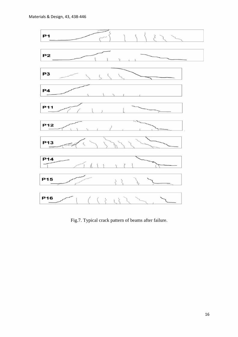
Fig.7. Typical crack pattern of beams after failure.
Materials & Design, 43, 438-446
17
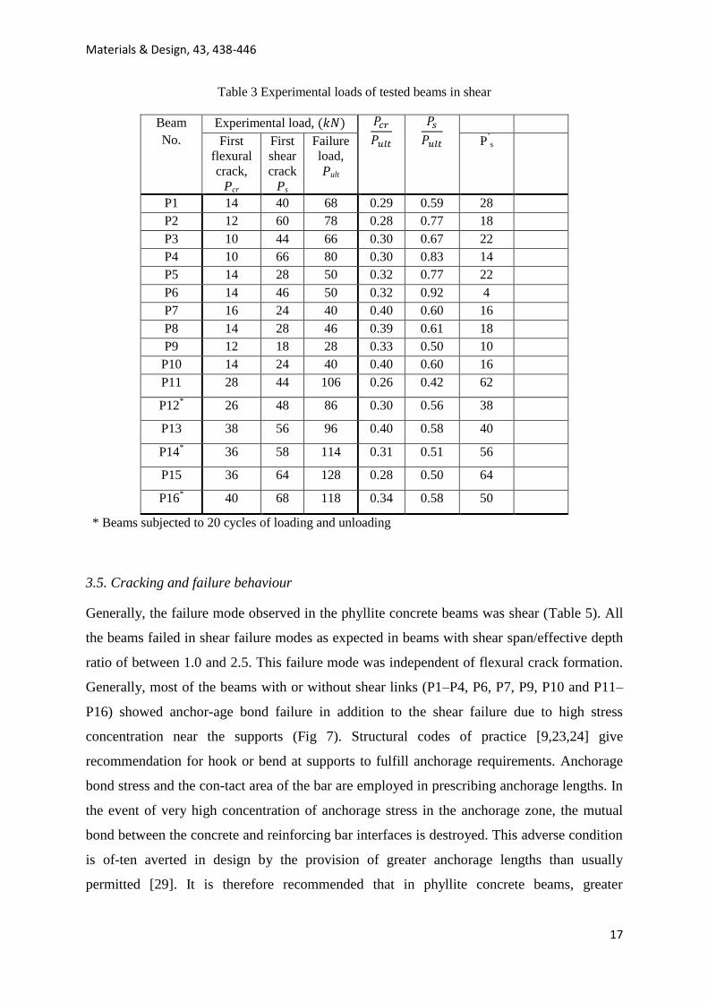
Table 3 Experimental loads of tested beams in shear
Beam
No.
Experimental load,
First
flexural
crack,
Pcr
First
shear
crack
Ps
Failure
load,
Pult
P’s
P1 14 40 68 0.29 0.59 28
P2 12 60 78 0.28 0.77 18
P3 10 44 66 0.30 0.67 22
P4 10 66 80 0.30 0.83 14
P5 14 28 50 0.32 0.77 22
P6 14 46 50 0.32 0.92 4
P7 16 24 40 0.40 0.60 16
P8 14 28 46 0.39 0.61 18
P9 12 18 28 0.33 0.50 10
P10 14 24 40 0.40 0.60 16
P11 28 44 106 0.26 0.42 62
P12*
26 48 86 0.30 0.56 38
P13 38 56 96 0.40 0.58 40
P14*
36 58 114 0.31 0.51 56
P15 36 64 128 0.28 0.50 64
P16* 40 68 118 0.34 0.58 50
* Beams subjected to 20 cycles of loading and unloading
3.5. Cracking and failure behaviour Generally, the failure mode observed in the phyllite concrete beams was shear (Table 5). All
the beams failed in shear failure modes as expected in beams with shear span/effective depth
ratio of between 1.0 and 2.5. This failure mode was independent of flexural crack formation.
Generally, most of the beams with or without shear links (P1–P4, P6, P7, P9, P10 and P11–
P16) showed anchor-age bond failure in addition to the shear failure due to high stress
concentration near the supports (Fig 7). Structural codes of practice [9,23,24] give
recommendation for hook or bend at supports to fulfill anchorage requirements. Anchorage
bond stress and the con-tact area of the bar are employed in prescribing anchorage lengths. In
the event of very high concentration of anchorage stress in the anchorage zone, the mutual
bond between the concrete and reinforcing bar interfaces is destroyed. This adverse condition
is of-ten averted in design by the provision of greater anchorage lengths than usually
permitted [29]. It is therefore recommended that in phyllite concrete beams, greater
Materials & Design, 43, 438-446
18
anchorage length than the calculated length based on anchorage bond stress and contact area
of the bar be used as done in other non-conventional aggregate concrete beams where
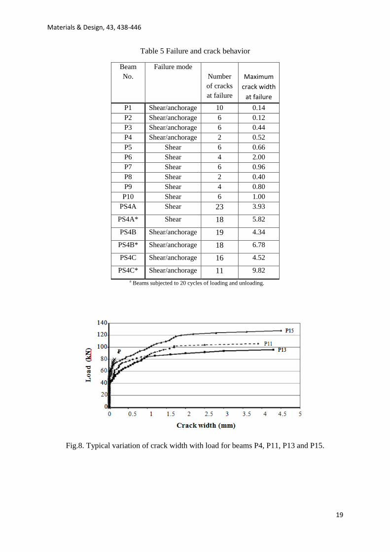
anchorage failure occurred [30]. In view of durability problems which cause concrete components to fail prematurely,
cracking characteristic of phyllite concrete beams were investigated. During loading, flexural
cracks propagated first in the mid- span and the number of cracks also in-crease and become
wider with increase in loading. With further in-crease in loads, cracks develop in the shear
region extending diagonally toward the loading point. Other new diagonal cracks be-gin to
form separately from locations closer to the supports. The number of cracks at failure varied
from 2 to 10 in phyllite concrete beams without stirrups (P1–P10). There was a notable trend
in the distribution of cracks and crack widths. More number of cracks (11–28) and wider
crack widths (3.93–9.82 mm) were observed in the beams with shear reinforcement (P11–
P16). As observed by other researchers [12,28–31], a high number of cracks resulted in
smaller crack widths. Beams subjected to cyclic loads (P12, P14 and P16), exhibited wider
crack widths as compared to corresponding beams subjected to monotonic loading (P11, P13
and P15). Table 4 Experimental and predicted shear capacity
BEAM Vexp
(kN) Predicted shear force, (kN) Shear strength ratios, Vexp/Vcode
BS8110 ACI EC2 BS8110 ACI EC2
P1 68 51.77 51.12 53.16
1.31 1.33 1.28
P2 78 65.23 56.77 68.46 1.20 1.37 1.14
P3 66 45.55 43.08 47.74 1.45 1.53 1.38
P4 80 57.42 47.87 61.53 1.39 1.67 1.30
P5 50 30.01 26.61 30.65 1.67 1.88 1.63
P6 50 37.81 29.80 39.97 1.32 1.68 1.25
P7 40 25.82 21.35 25.48 1.55 1.87 1.57
P8 46 32.53 24.05 33.56 1.41 1.91 1.37
P9 28 15.80 12.69 17.84 1.77 2.21 1.57
P10 40 19.91 14.10 22.96 2.01 2.84 1.74
P11 106 91.60 80.70 89.08 1.16 1.31 1.19
P12* 86 91.60 80.70 89.08 0.94 1.07 0.97
P13 96 116.38 104.17 111.38 0.82 0.92 0.86
P14* 114 116.38 104.17 111.38 0.98 1.09 1.02
P15 128 147.36 133.52 139.26 0.87 0.96 0.92
P16* 118 147.36 133.52 139.26 0.80 0.88 0.85
a Beams subjected to 20 cycles of loading and unloading.
Materials & Design, 43, 438-446
19
Table 5 Failure and crack behavior
Beam
No.
Failure mode
Number
of cracks
at failure
Maximum
crack width
at failure
P1 Shear/anchorage 10 0.14
P2 Shear/anchorage 6 0.12
P3 Shear/anchorage 6 0.44
P4 Shear/anchorage 2 0.52
P5 Shear 6 0.66
P6 Shear 4 2.00
P7 Shear 6 0.96
P8 Shear 2 0.40
P9 Shear 4 0.80
P10 Shear 6 1.00
PS4A Shear 23 3.93
PS4A* Shear 18 5.82
PS4B Shear/anchorage 19 4.34
PS4B* Shear/anchorage 18 6.78
PS4C Shear/anchorage 16 4.52
PS4C* Shear/anchorage 11 9.82
a Beams subjected to 20 cycles of loading and unloading.
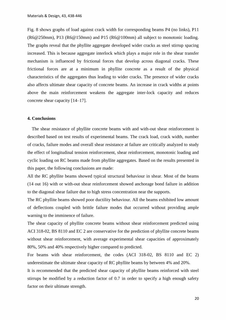
Fig.8. Typical variation of crack width with load for beams P4, P11, P13 and P15.
Materials & Design, 43, 438-446
20
Fig. 8 shows graphs of load against crack width for corresponding beams P4 (no links), P11
(R6@250mm), P13 (R6@150mm) and P15 (R6@100mm) all subject to monotonic loading.
The graphs reveal that the phyllite aggregate developed wider cracks as steel stirrup spacing
increased. This is because aggregate interlock which plays a major role in the shear transfer
mechanism is influenced by frictional forces that develop across diagonal cracks. These
frictional forces are at a minimum in phyllite concrete as a result of the physical
characteristics of the aggregates thus leading to wider cracks. The presence of wider cracks
also affects ultimate shear capacity of concrete beams. An increase in crack widths at points
above the main reinforcement weakens the aggregate inter-lock capacity and reduces
concrete shear capacity [14–17].
4. Conclusions
The shear resistance of phyllite concrete beams with and with-out shear reinforcement is
described based on test results of experimental beams. The crack load, crack width, number
of cracks, failure modes and overall shear resistance at failure are critically analyzed to study
the effect of longitudinal tension reinforcement, shear reinforcement, monotonic loading and
cyclic loading on RC beams made from phyllite aggregates. Based on the results presented in
this paper, the following conclusions are made:
All the RC phyllite beams showed typical structural behaviour in shear. Most of the beams
(14 out 16) with or with-out shear reinforcement showed anchorage bond failure in addition
to the diagonal shear failure due to high stress concentration near the supports.
The RC phyllite beams showed poor ductility behaviour. All the beams exhibited low amount
of deflections coupled with brittle failure modes that occurred without providing ample
warning to the imminence of failure.
The shear capacity of phyllite concrete beams without shear reinforcement predicted using
ACI 318-02, BS 8110 and EC 2 are conservative for the prediction of phyllite concrete beams
without shear reinforcement, with average experimental shear capacities of approximately
80%, 50% and 40% respectively higher compared to predicted.
For beams with shear reinforcement, the codes (ACI 318-02, BS 8110 and EC 2)
underestimate the ultimate shear capacity of RC phyllite beams by between 4% and 20%.
It is recommended that the predicted shear capacity of phyllite beams reinforced with steel
stirrups be modified by a reduction factor of 0.7 in order to specify a high enough safety
factor on their ultimate strength.
Materials & Design, 43, 438-446
21
References [1] FIP manual of lightweight aggregate concrete. 2nd ed. London: Surrey University
Press; 1983.
[2] Valera TS, Ribeiro AP, Valenzuela-Diaz FR, Yoshiga A, Ormanji W, Toffoll SM.
The effect of phyllite as a filler for PVC plastisols. In: Annual technical conference –
society of plastics engineers, vol. 60, no. 3; 2002. p. 3949–53.
[3] Garzon E, Sanchez-Soto PJ, Romero E. Physical and geotechnical properties of clay
phyllites. Appl Clay Sci 2010;48:307–18.
[4] Vazquez J, Garzon E, Romerosa A, Serrano-Ruiz M, Sanchez-Soto P, Galera M.
South Spain soils containing phyllites improved by using cement and lime. Concr Sustain
Agri 2005:299–304.
[5] Montenari M, Servais T, Paris F. Palynological dating (acritarchs and chitinozoans) of
lower Paleozoic phyllites from the Black Forest/ southwestern Germany. Ser IIA – Earth
Planet Sci 2000;330(7):493–9.
[6] Ramamurthy T, Venkatappa RG, Singh J. Engineering behaviour of phyllites. Eng
Geol 1993;33(3):209–25.
[7] Adom-Asamoah M, Afrifa Owusu RA. Study of concrete properties using phyllite as
coarse aggregates. J Mater Des 2010;31(9):4561–6.
[8] Adom-Asamoah M, Afrifa Owusu R. Investigation on the flexural behaviour of
reinforced concrete beams using phyllite aggregates from mining waste. J Mater Des
2011;2011(32):5132–40.
[9] British Standards Institution: structural use of concrete. BS 8110: Part 1; 1997. [10]
Kong Evans. Reinforced and prestressed concrete. 3rd ed. London: Chapman &
Hall; 1994. [11] Taylor HPJ. The fundamental behaviour of reinforced concrete beams in bending and
shear. In: Proceedings ACI-ASCE shear symposium, Ottawa, 1973 (ACI Special
Publication SP42) ACI, Detroit; 1974. p. 43–77.
[12] Hassan AAA, Hossain KMA, Lachemi M. Behavior of full-scale self-consolidated
concrete beams in shear. Cem Concr Compos 2008;30:588–96.
[13] Walraven JC. Fundamental analysis of aggregate interlock. J Struct Div ASCE
1981;108:2245–70.
[14] Collins MP, Mitchell D, Adebar A, Vecchio FJA. General shear design method. ACI
Struct J 1996;93(1):36.
[15] Bazant ZP, Kim JK. Size effect in shear failure of longitudinally reinforced beams. ACI
J 1984;81:456–68.
[16] Bazant ZP, Kazemi MI. Size effect on diagonal shear failure of beams without stirrups.
ACI J 1991;88:268–76.
[17] Walraven J, Lehwalter N. Size effects in short beams loaded in shear. ACI Struct J
1994;91(5):585–93.
[18] Kani GNJ. Basic facts concerning shear failure. ACI J 1966;63(6):675–90. [19] Zararis PD, Papadakis GC. Diagonal shear failure and size effect in RC beams without
web reinforcement. ASCE J Struct Div 2001;127(7):733–41.
[20] Alengaran UJ, Jumaat MZ, Mahmud H, Fayyadh MM. Shear behaviour of reinforced
palm kernel shell concrete beams. Constr Build Mater 2011:2918–27.
Materials & Design, 43, 438-446
22
[21] Vecchio FJ, Collins MP. Predicting the response of reinforced concrete beams subjected
to shear using modified compression field theory. ACI Struct J 1988;85(S27):258–68.
[22] Waner RF, Rangan BV, Hall AS, Faulkes KA. Concrete structures. 1st ed. South
Melbourne: Addison Wesley Longman Australia Pty Ltd.; 1999.
[23] ACI ACI committee 318. Building code requirements for structural concrete (ACI 318-
02) and commentary (ACI 318R-05) USA; 2002.
[24] EC2. Design of concrete structures Part I. General rules and rules for buildings.
European Committee for Standardization. Brussels; 2002.
[25] British Standard Institute: specification for ordinary Portland cement. BS12; 1989. [26] British Standard Institute: specification of aggregates fo0r concrete. BS882; 1983. [27] British Standard Institute: specification of aggregates for concrete. BS812: part 1; 1975.
[28] Teo DL, Mannan MA, Kurian JV. Flexural behavior of reinforced lightweight concrete
beams made with oil palm shell (OPS). J Adv Concr Technol 2006;4(3):1–10.
[29] Lim HS, Wee TH, Mansour MA, Kong KH. Flexural Behaviour of reinforced
lightweight aggregate concrete beams. In: Proceedings of the 6th Asia-pacific structural
engineering and construction conference, Kuala Lumpur; 2006. p. A68–82.
[30] Swamy RN, Adepegba D. Shear resistance of reinforced beams without web steel. Build
Sci 1969;3:207–20.
[31] Kumar PS, Mannan MA, Kurian VJ, Achuytha H. Investigation on the flexural
behaviour of high-performance reinforced concrete beams using sandstone aggregates.
Build Environ 2007;42:2622–9.
[32] Collins MP, Kuchma D. How safe are our large, lightly reinforced concrete beams, slabs
and footings? ACI Struct J 1999;96(4):482–90.
[33] Jumaat MZ, Alengaram UJ, Mahmud H. Shear strength of oil palm shell foamed
concrete beams. Mater Des 2009;30:2227–36.