separation of gas particle using venturi-type wet scrubber in ashaka cement factory plc
TRANSCRIPT

91
Separation of Gas Particle Using Venturi-Type Wet Scrubber in Ashaka Cement Factory PLC
Tela, B.M.1, Ngala, G.M.2, and Abubakar, A.B.3
1Nigerian Nuclear Regulatory Authority, Nigeria 2Department of Mechanical Engineering, University of Maiduguri, Nigeria
3Department of Mechanical Engineering, Ramat Polytechnic, Maiduguri, Nigeria
International Journal of Research in Mechanical Engineering Volume 2, Issue 6, November-December, 2014, pp. 91-98
ISSN Online: 2347-5188 Print: 2347-8772, DOA : 27122014 © IASTER 2014, www.iaster.com
ABSTRACT
A Venturi Type Wet Scrubber is air pollution control equipment. The choice of right equipment depends on the compromise between available resources and efficiency. This study carries out the design, construction and performance evaluation of Scrubber for removing of dust from cement production process. The methodology adopted in this work involved the collection of relevant data and sample, analysis and experimentation through passage of cement dust; design and construction of the Venturi-type wet Scrubber using available empirical formula and appropriate technology. Performance tests were carried out using the constructed scrubber and dust content were evaluated in the effluent in University of Maiduguri Mechanical Workshop. Hence, the system optimum efficiency was determined to be 85% and cost of construction is about =N= 80,000:00. The study demonstrated an abatement strategy for dust produced in cement production in Ashaka Cement Industry Plc .
Keywords: Wet Scrubber, Cut Diameter, Particulate Matter, Penetration. 1. INTRODUCTION In 1863, a control device was developed for processing the exhaust gas via washing it. It is believed to be the world’s first chemical discharge control (1). The modern day wet scrubbing process was originally developed in 1930s by Imperial Chemical Industries (ICI) in England (2). Industrial effluents into the air or water bodies can cause environmental pollution when not treated properly prior to exposure (3). Some of these effluents are toxic and can directly or indirectly endanger the lives of people, as well as destroying the environment (4). All efforts should focus on waste minimization (5). Implementing measures to reduce the adverse impacts of dust on health and the environment costs money. But it also saves money by reducing adverse effects on human health and on the environment. The term wet scrubber describes a variety of devices that remove pollutants from a furnace flue gas or from other gas streams (6). A wet scrubber is used to clean air, flue gas or other gases of various pollutants and dust particles. Wet scrubbing works via the contact of target compounds or particulate matter with the scrubbing solution. Solutions may simply be water (for dust) or solutions of reagents that specifically target certain compounds (7).

International Journal of Research in Mechanical Engineering Volume-2, Issue-6, November-December, 2014, www.iaster.com ISSN
(O) 2347-5188 (P) 2347-8772
92
The design of wet scrubbers or any air pollution control device depends on the industrial process conditions and the nature of the air pollutants involved. Inlet gas characteristics and dust properties (if particles are present) are of primary importance. Scrubbers can be designed to collect particulate matter and/or gaseous pollutants. The versatility of wet scrubbers allows them to be built in numerous configurations, all designed to provide good contact between the liquid and polluted gas stream (6).
A wet scrubber's ability to collect small particles is often directly proportional to the power input into the scrubber. Low energy devices such as spray towers are used to collect particles larger than 5 micrometers. To obtain high efficiency removal of 1 micrometer (or less) particles generally requires high energy devices such as venturi scrubbers or augmented devices such as condensation scrubbers. Additionally, a properly designed and operated entrainment separator or mist eliminator is important to achieve high removal efficiencies. The greater the number of liquid droplets that are not captured by the mist eliminator the higher the potential emission levels (6). If the gas stream contains both particle matter and gases, wet scrubbers are generally the only single air pollution control device that can remove both pollutants. Wet scrubbers can achieve high removal efficiencies for either particles or gases and, in some instances, can achieve a high removal efficiency for both pollutants in the same system. However, in many cases, the best operating conditions for particles collection are the poorest for gas removal.
The dust problem in Ashaka has resulted in increase in respiratory disease within the people leaving in the community and the workers within the industry (such as asthma, bronchitis, tuberculosis etc (8). Due to the excessive dust emission which settle on the plants, the photosynthesis is impeded thereby affecting the plant yield around the Ashaka community. Cars and other metals that are exposed to the dust are not spared because of the effect of the corrosion.
This study stresses the important of the global air pollution control hence designing and constructing a system that will reduce the rate of industrial emission in to the atmosphere, and at the same time economically collecting the dust for reuse in production. This lead to the idea of designing constructing and testing of venture type wet scrubber. 2. MATERIALS AND METHOD
Design of Component Parts: Sizing of the Scrubber In practice, the overall dimensions of the scrubber are sized to achieve the desired gas velocities within the various parts (9). Although there are variations among the scrubber manufacturers, the typical inlet gas velocity of high energy orifice scrubber ranges from 17m/s to 19m/s and the superficial velocity inlet velocity to the separator is 3m/s. Spray tower and chambers can operate with either gravity or high pressure spray systems. The gravity system can obtain effective aerodynamic cut diameter of about 2μm, while the pressure spray systems (up to 27 atmospheres) can achieve a cut diameter of about 0.7μm, when the superficial velocity through the tower is between 0.305m/s to 0.914m/s (10).
The cross sectional area of the scrubber separator is determined by the gas volume flow rate and the desired velocity in the separator, hence for compressible fluids (11). 1 A 1V 1 2 A 2 V 2 …………………………………..……..1.0

International Journal of Research in Mechanical Engineering Volume-2, Issue-6, November-December, 2014, www.iaster.com ISSN
(O) 2347-5188 (P) 2347-8772
93
Where 1 and 2 are the respective densities at inlet, and the separator respectively.
A1and A2 are the cross sectional areas at inlet and that of the separator.
V1and V2 are the velocities at inlet and that of the separator respectively.
Data obtained in Ashaka cement plc for the exhaust gases indicate the following:
Volume flow rate of 317,749 m3/hr = 88.26 m3/s; Temperature of 475o C; Mass flow rate of 7580 kg/hr = 2.11 kg/s; Cement dust particules size, 10µm - 50µm ; Density is 0.024 kg/m3 and Pressure is 270 mmH2O
We know that
m VA
11.2 2V 2 A 2
But 22
outin
31 /024.0 mkgin
Tis satout Where T=30OC From the saturated steam table
3/0304.093.32
11 mkgvout
2
0304.0024.02
32 /027.0 mkg
Then, 21027.011.2 A
For gravity type spray tower
4
2
2dA
But A2 215.78
027.011.2 m
22 4 Ad =
415.78
49.99d md 10 The diameter of the Separator is therefore 10 meters. But for ‘nozzle type’, which has a superficial inlet velocity of 3 m/s, inlet diameter is completed thus:
23027.011.2 A
3027.011.2
2 A = 05.26 2m

International Journal of Research in Mechanical Engineering Volume-2, Issue-6, November-December, 2014, www.iaster.com ISSN
(O) 2347-5188 (P) 2347-8772
94
4
22
2dA
222 16.3305.264 md
md 8.516.332 m0.6 The typical H/D (height to diameter) ratio of the separator is approximately 2:1 (9).Therefore the height of the ‘gravity type’ separator will be m20102 While the height of the nozzles type separator will be m1262 Determination of Throat Diameter: To determine the diameter of the throat dt, from the (9) inlet velocity of the gas to venturi-type wet scrubber ranges from 3300 – 3700 ft/min. the value taken is 3300 ft/min = 16.77 m/s.
vQ4d
md 6.2 Determination of Inlet Diameter of Separator: To determine the inlet diameter of the Separator ds, from the (9) inlet velocity of the gas to venture-type wet scrubber is 600 ft/min = 3.05 m/s
vQ4ds
mds 07.6
Determining Metal Thickness
SDbt
SDCbtW 416.55
2/
…………………………………….1.1 Where C is the dimensionless conversion factor, S is the design safety factor and B is the critical buckling stress.
Another alternative formula for the determination of the metal thickness of the scrubber separator is the one used to in determining the collapsing pressure on a submerge submarine and vacuum tanks. This formula is given by (1)
3
DtKEWC ……………………………………….1.2
Where t, is the thickness D, the outside diameter, E is the Modulus of elasticity and K a numerical coefficient which depends upon the L/D and D/t ratios (D is the outside shell diameter).
Assumptions:- The external design pressure on the separator is atmospheric. The safety factor is 2. The Poison ratio of the material is 0.3.
International Journal of Research in Mechanical Engineering Volume-2, Issue-6, November-December, 2014, www.iaster.com ISSN
(O) 2347-5188 (P) 2347-8772
95
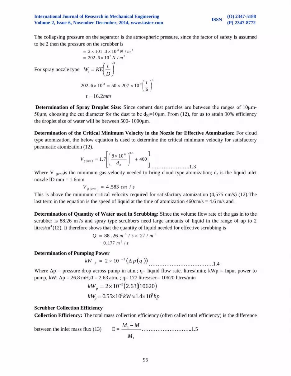
The collapsing pressure on the separator is the atmospheric pressure, since the factor of safety is assumed to be 2 then the pressure on the scrubber is 23 /103.1012 mN 23 /106.202 mN
For spray nozzle type 3
DtKEWc
3
93
61020750106.202
t
mmt 2.16
Determination of Spray Droplet Size: Since cement dust particles are between the ranges of 10μm-50μm, choosing the cut diameter for the dust to be d50=10μm. From (12), for us to attain 90% efficiency the droplet size of water will be between 500- 1000μm. Determination of the Critical Minimum Velocity in the Nozzle for Effective Atomization: For cloud type atomization, the below equation is used to determine the critical minimum velocity for satisfactory pneumatic atomization (12).
4601087.1
5.06
)(n
critg dV
………………….1.3
Where V g(crit)is the minimum gas velocity needed to bring cloud type atomization; dn is the liquid inlet nozzle ID mm = 1.6mm scmV critg /583,4)( This is above the minimum critical velocity required for satisfactory atomization (4,575 cm/s) (12).The last term in the equation is the speed of liquid at the time of atomization 460cm/s = 4.6 m/s and. Determination of Quantity of Water used in Scrubbing: Since the volume flow rate of the gas in to the scrubber is 88.26 m3/s and spray type scrubbers need large amounts of liquid in the range of up to 2 litres/m3 (12). It therefore shows that the quantity of liquid needed for effective scrubbing is 33 /2/26.88 mlsmQ = sm /177.0 3
Determination of Pumping Power qpkW p 3102 ……………………………….1.4
Where Δp = pressure drop across pump in atm.; q= liquid flow rate, litres/.min; kWp = Input power to pump, kW; Δp = 26.8 mH20 = 2.63 atm. ; q= 177 litres/sec= 10620 litres/min
1062063.2102 3pkW
hpkWkWp32 104.11055.0
Scrubber Collection Efficiency
Collection Efficiency: The total mass collection efficiency (often called total efficiency) is the difference
between the inlet mass flux (13) E = .
1
.
1
M
MM ………………………..1.5

International Journal of Research in Mechanical Engineering Volume-2, Issue-6, November-December, 2014, www.iaster.com ISSN
(O) 2347-5188 (P) 2347-8772
96
The total penetration is just
1
.
MM ……………………………………………..….1.6
it is the fraction of the mass that penetrates the device, often more important than the efficiency for comparing devices. The efficiency for a particular size i (or narrow size range) is called the fractional efficiency and is
Ei =iMMM)(
)(
1
1 ………………..…………..1.7
Plate 1: Model Venturi Wet Scrubber
Cost of Manufacture and Material Bill of Engineering Measurement and Evaluation
S/NO. DESCRIPTION QTY UNIT RATE AMOUNT(N) 1. 16G Mild Steel plate
(1mm). 4’x8’x1 2plate No 7,500.00 15,000.00
2 3mm x 2" Mild Steel flat plate
2 m 2,5000.00 2,500.00
3. 2" x 3 mm Angle Iron 2 m 2,000.00 2,000.00 4. 1" Mild Steel flat plate 6 m 700.00 700.00 5. 0.3 mm Wire mesh 2 m2 300.00 600.00 6. 1⅟2" Mild Steel pipe 24 m 1,200.00 4,800.00 7. 100 Ø GI pipe, 100x100 1 mm 300.00 300.00 8. 180 Ø GI pipe, 100x100 1 mm 500.00 500.00 9. Nozzles 12 Pieces 200.00 2,400.00
10. Brass rod 5 Pieces 200.00 1,000.00 11. Welding Electrodes ⅟2 Packet 800.00 800.00 12. 12" Ø GI pipe 1 m 4,000.00 4,000.00 13. Body filler ⅟2 Tin 800.00 800.00 14. Anti rust ⅟2 Tin 700.00 700.00 15. Paint ⅟2 Tin 1,500.00 1,500.00 16. Filling Disc 2 Pieces 300.00 600.00 17. Cutting Disc 2 Pieces 300.00 600.00 18. Water pump (0.75 kw) 1 No 8,000.00 8,000.00 19. Blower with flow control
1800 rpm 1 No 12,000.00 12,000.00
20. 2" Ø GI pipe 1 m 800.00 800.00 21. 50 liters Collector 1 Liter 500.00 500.00 22. 100 Ø GI pipe 1 m 2,000.00 2,000.00 23. 100 Ø Elbow 2 mm 1,500.00 3,000.00 24 Total 66,600.00 25. Labour cost 13,320.00 26. Grand Total =N=79,920.00

International Journal of Research in Mechanical Engineering Volume-2, Issue-6, November-December, 2014, www.iaster.com ISSN
(O) 2347-5188 (P) 2347-8772
97
The table below shows the results of the experiment, the efficiency and penetration were computed using equation 1.6 and 1.7 respectively. 3. RESULTS AND DISCUSSION
Experiments Inlet Mass Flux of Cement
Dust (MI) Kg/Min
Mass of Cement Dust + Water (Kg)
Outlet Mass Flux of
Cement Dust (M) Kg
Mass of Cement
Dust (MI – M)
Kg
Efficiency (MI – M)
MI
Penetration _M_ MI
1 1 16.75 0.25 0.75 75 0.22 2 2 18.50 0.38 1.62 81 0.19 3 3 20.70 0.50 2.50 83 0.16 4 4 22.20 0.59 3.41 85 0.14 5 5 23.50 0.59 4.41 88 0.12 6 6 24.51 0.59 5.41 90 0.09
4. CONCLUSION The aim of designing, constructing and testing of a Venturi-Type wet scrubber has been achieved (Plate 1), hence the collection efficiency for the scrubber was found to be directly proportional to the inlet concentration. That means efficiency increases with increase in dust loading up to a certain point, this suggests that scrubber removal efficiency is not constant for a given scrubber design unless it is referenced to specific inlet dust loading. In contrast, it has been shown that scrubber outlet dust concentration is a constant, when the inlet dust loading is greater than 3kg/min. Hence, relationship between inlet dust concentration (loading) and collection efficiency for fine PM was determined. The efficiency of scrubbers that rely on inertial impaction can be improved, however, by increasing the relative velocity between the Particulate Matter and the liquid droplets. Increasing the velocity will result in more momentum for all Particulate Matter, enabling smaller particles to be collected by impaction. This can be accomplished in most scrubbers by increasing the gas stream velocity. Unfortunately, increasing the gas velocity will also increase the pressure drop, energy demand, and operating cost for scrubbers. REFERENCES [1] Government of Japan (1998) Air Pollution Control Technology Manual. FY 1997 Project for
Advancement of Sustainable Development Support Commissioned by Environmental Agency Government of Japan. March, 1998 pp206-236
[2] M.M. El-Wakil (1984). Power Plant Technology. Mc Grawhills International Editions Copyright © 1984 pp 727.
[3] André Peeters Weem (2010) Reduction of Mercury Emissions from Coal Fired Power Plants Convention on Long-range Transboundary Air Pollution Working Group on Strategies and Review, 47th session Informal document No 6, Agenda item 4, The Netherlands. August 3.

International Journal of Research in Mechanical Engineering Volume-2, Issue-6, November-December, 2014, www.iaster.com ISSN
(O) 2347-5188 (P) 2347-8772
98
[4] Rafael Marin Galvin (1996) Occurrence of Metals in Waters: An Overview: Water SA, Vol. 22 No. 1, January.
[5] East African Community (EAC) (2010) Air Quality -Emissions to the Air by Cement Factories Guidelines, East African Standard, First edition.
[6] US EPA Air Pollution Training Institute Developed in Collaboration with North Carolina State University, College of Engineering (NCSU)
[7] Kelly Martin et al., (1999) Elemental Mercury Removal Using a Wet Scrubber. http://www.osti.gov/bridge/purl.cover.jsp?purl=/11821-8y5zOt/webviewable/11821.pdf .retrieved on 21st December 2011.
[8] Susarumso, D. E. (2003) Design and Construction of a Model of Cyclone Dust Particulate Collector for Ashaka Cement plc, unpublished B. Eng. Thesis, University of Maiduguri, Nigeria.
[9] Cheremisinoff P.N. and Young A.R. (1976). Pollution Engineering Handbook;Second printing, pp. VI, 125 – 184.
[10] Maas J.H. (1979) Handbook of Separation Technicques for Chemical Engineers, Edited by Philip Schweitzer, Mc Grawhill, Inc p.370
[11] Hwang, N.H.C. and Hita, C.E. (1987) Fundamentals of Hydraulic Engineering System. Second edition. Prentice-Hall, Inc., Eaglewood cliffs, New Jersey p.370.
[12] Hesketh, H.E. (1979). Air Pollution Control Ann Arbor Science, U.S.A. PP217 – 347.
[13] Hestroni, Gad (1982). Handbook of Multiphase Systems, Hemisphere Publishing Co-Operation Copyright 1982. pp 9-5 to 9-41.