seismic performance of non-ductile rc frames with brick infill
TRANSCRIPT

Seismic Performance of Non-Ductile RC Frames with Brick Infill
P. Benson Shing1, Andreas Stavridis1, Ioannis Koutromanos1, Kaspar Willam2, Ben Blackard2, Marios A. Kyriakides3, Sarah L. Billington3, and Scott Arnold4
1Department of Structural Engineering, University of California, San Diego, CA 92093-0085; email: [email protected] 2Department of Civil, Environmental, and Architectural Engineering, University of Colorado, Boulder, CO 80202-0428; email: [email protected] 3Department of Civil and Environmental Engineering, Stanford University, Stanford, CA 94305-4020; email: [email protected] 4Fyfe Co., 8380 Miralani Drive, Suite A, San Diego, CA 92126; email: [email protected] ABSTRACT
This paper summarizes some of the findings of a research project that investigates the seismic performance of masonry-infilled, non-ductile, RC frames, including the development of reliable analytical methods for performance assessment and effective retrofit techniques. Quasi-static tests were conducted on small and large-scale, single-story, single-bay, RC frames infilled with brick masonry walls with and without openings. Some of the infill walls were strengthened with an engineered cementitious composite material. Furthermore, two 2/3-scale, three-story, two-bay, masonry-infilled, RC frames were tested on a shake table. One was tested with no retrofit measures, and the other had infill walls strengthened with the engineered cementitious composite and fiber reinforced polymeric material in the first and second stories, respectively. The tests have demonstrated the effectiveness of the retrofit measures. Computation models that combine smeared and discrete cracks have been developed and validated by the experimental data. Some of the experimental and numerical results are presented in this paper.
INRODUCTION
Many reinforced concrete and steel frame structures have unreinforced masonry infill walls to serve as interior and exterior partitions. Such construction can be found in many older buildings in the western United States, including pre-1930’s buildings in California, and in numerous newer buildings in the midwestern and eastern parts of the country. In fact, RC frames with brick infill are common construction practice in many parts of the world, such as China and Mediterranean countries. However, in spite of the fact that unreinforced masonry infill walls are usually treated as non-structural components, they will interact with the bounding frames when subjected to earthquake loads.
1117ATC & SEI 2009 Conference on Improving the Seismic Performance of Existing Buildings and Other Structures
Copyright ASCE 2009

Many engineers have recognized the benefits of infill walls in protecting a structure against earthquake loads. Nevertheless, infill walls were sometimes associated with catastrophic failures and undesired soft-story mechanisms of RC structures in a number of severe earthquake events (e.g., see EERI 2000). These failures were mostly caused by the poor quality of the structural systems, inferior infill materials, and/or the absence of infill walls in some critical locations such as open first stories. The ability to assess the performance and safety of these structures is important for retrofit decisions. However, such analysis presents a major challenge. The interaction of an RC frame with masonry infill can result in a number of possible failure mechanisms including the cracking and crushing of the infill walls and the shear failure of the columns. The lateral load resistance of an infilled frame highly depends on the failure mechanism that develops. Guidelines for the evaluation of infilled frames have been provided in FEMA reports (FEMA 1998, 2000), International Existing Building Codes (ICBO 2001), and ASCE/SEI 41: Seismic Rehabilitation of Existing Buildings (ACSE/SEI 2007), but they are far from satisfactory in terms of completeness and reliability. ASCE/SEI 41 allows the use of nonlinear finite element models, but it does not provide any guidelines for such analysis. In addition, there are few validated simple retrofit methods that can be used for these structures.
To address the aforementioned issues, a collaborative research project has been carried out by a team of researchers from the University of California at San Diego, Stanford University, and the University of Colorado at Boulder. The research objectives are two-fold. One is to develop rational and reliable analytical methods for assessing the seismic performance of masonry-infilled RC frames, and the other is to develop effective seismic retrofit techniques. The retrofit schemes and analytical tools have been validated with experimental data obtained from small and large-scale frame specimens representing 1920-era construction in California. In addition to quasi-static tests, shake-table tests were conducted on two 2/3-scale, three-story, two-bay, infilled RC frames. One was tested without retrofit measures, and the other had infill walls strengthened with an engineered cementitious composite (ECC) and glass fiber reinforced polymeric (GFRP) material in the first and second stories, respectively. The development of the retrofit method using the ECC is presented in a companion paper (Billington et al. 2009). This paper presents a summary of some of the findings, including the computation model developed and the experimental and numerical results. PROTOTYPE BUILDING
The focal point of the experimental study is a prototype building typical of 1920-era RC construction in California. The structure has a non-ductile RC frame with unreinforced masonry infill walls on the exterior. The plan view of the structure and the elevation view of an external infilled frame are presented in Figures 1 and 2, respectively. The design is, however, based on contemporary construction materials, which were used in the experimental investigation. A working stress design approach has been used with the allowable stresses calculated with the factors of safety that
1118ATC & SEI 2009 Conference on Improving the Seismic Performance of Existing Buildings and Other Structures
Copyright ASCE 2009

were used in the 1920’s. In accordance with the engineering practice of that period, the RC members are designed only for gravity loads that include the self-weight, the weight of the slabs, toppings, ceilings, masonry walls, parapets, and the live load. The design live load is 75 psf for the 1st and 2nd stories, and 20 psf for the roof. The live load is reduced by 60% for the column design, and 20 and 40% for the design of the exterior and interior beams, respectively.
Figure 1. Plan view of prototype structure.
Figure 2. Elevation view of an exterior frame (in inches).
FINITE ELEMENT MODELING
A finite element modeling approach has been developed to capture different possible failure mechanisms of an infilled frame under in-plane lateral loads (Stavridis and Shing 2007). It combines smeared and discrete crack models. The smeared crack approach has been commonly used to model diffused cracks in reinforced concrete structures. However, this approach suffers from some inherent limitations including the inability to capture the brittle behavior of an RC member induced by diagonal shear cracks. To overcome this deficiency, the proposed model incorporates zero-thickness interface elements to represent cracks in RC columns in a discrete fashion and to capture the fracture behavior of mortar joints in infill walls, while smeared crack elements are used to model the body of the concrete members and brick units. The reinforcing bars are modeled with elastic-plastic truss elements. Discretization Scheme. Concrete columns, which may develop shear cracks, are modeled with the discretization scheme presented in Figure 3. The proposed scheme combines smeared crack triangular elements with line interface elements. Thus, it allows for the development of diffused cracks as well as discrete shear cracks that may dominate the behavior of a concrete member. According to the mesh geometry adopted, discrete cracks can develop at angles of 0o, 90o, and ± θ, while θ is normally close to 45o to represent shear cracks.
A B C D22’
18’
3
18’
22’ 22’
2
1
Exterior frame considered
1119ATC & SEI 2009 Conference on Improving the Seismic Performance of Existing Buildings and Other Structures
Copyright ASCE 2009

Reinforcing steel is modeled with truss elements, and strategies for connecting truss elements to triangular smeared crack elements are shown in Figure 3. The area of each longitudinal bar is divided into multiple bars so that every triangular element is attached to bars at two of its nodes. For the shear reinforcement, the total steel area at each location is distributed over two bars, which are placed in a zigzag pattern. This scheme allows a crack to cross the same quantity of reinforcement as in an actual RC column.
(a) with shear reinforcement (b) with flexural reinforcement.
Figure 3. Discretization scheme for reinforced concrete columns.
Masonry walls are modeled
with the scheme shown in Figure 4. Each masonry unit is modeled with two rectangular smeared crack elements that are connected with a vertical, zero-thickness interface element. The interface element is employed to model tensile splitting of a brick unit, and subsequent rotation and shearing of the fractured brick. Bed and head joints are modeled
with interface elements that can simulate the shear sliding and opening of the joints. With this simplified approach, the failure of a brick-mortar interface is not distinguished from that of the mortar layer itself and the brick-mortar interaction is not directly accounted for as the Poisson effect of the mortar is not considered. However, the influence of the brick-mortar interaction is indirectly accounted for by having the compressive strength of the brick units to be the same as the compressive strength of masonry prisms. The stiffness of the interface elements representing mortar joints is determined so that the stiffness of the masonry assembly is properly modeled.
Constitutive Models. The smeared crack model used in this study was developed by Lotfi and Shing (1991). The uncracked material is modeled with J2-plasticity
Figure 4. Discretization scheme for masonry infill.
Interface element
Smeared crack
element
Smeared crack element
Interface element
Smeared crack brick element
Interface elements for mortar joints
Interface element for brick interface
1120ATC & SEI 2009 Conference on Improving the Seismic Performance of Existing Buildings and Other Structures
Copyright ASCE 2009

combined with a tension cut-off surface. When the maximum principal stress reaches the tensile strength tf ′ of the material, cracks initiate in a direction normal to the direction of the maximum principal stress. A cracked material is considered orthotropic with the axes of orthotropy normal and parallel to the direction of the crack. In this study, crack orientation is assumed fixed and, therefore, the axes of orthotropy remain constant. After cracking, the tensile stress is an exponentially decaying function of the strain. The compressive stress-strain relation in the orthogonal direction is modeled and calibrated in such a way that it closely matches the compressive behavior exhibited by the plasticity model to allow a smooth transition from one state to the other.
A cohesive interface model developed by Lotfi and Shing (1994) is used to model critical cracks in a discrete fashion. It is implemented as a 4-node, zero-thickness, isopararametric, line element. The model can simulate the initiation and propagation of cracks under combined normal and shear stresses. It also accounts for the shear dilatation that can have a significant effect on the response of a confined crack. The yield surface is hyperbolic and its evolution is controlled with internal variables whose values are updated according to softening rules that account for the mode-I and mode-II fracture energies as well as frictional work. EXPERIMENTAL AND NUMERICAL RESULTS FROM QUASI-STATC TESTS
In this project, four 1/5-scale models of a bottom-story bay extracted from the prototype frame shown in Figure 2 were tested quasi-statically at Stanford University (Billington et al. 2009). These tests were to provide a first evaluation of a retrofit scheme that involves the application of a layer of engineered cementitious composite (ECC) on masonry infill walls. Furthermore, six 2/3-scale, single-story, single-bay, infilled frames were tested quasi-statically at the University of Colorado, Boulder to further evaluate the retrofit method and to study the influence of window and door openings on the in-plane resistance of infilled frames (Blackard et al. 2009). In both test series, vertical loads were exerted on the frame specimens simulating the gravity load from the upper stories. Two of the quasi-static tests conducted on the 2/3-scale specimens are presented below together with numerical simulation results obtained with the finite element models discussed above. One had a solid infill and the other had a window opening. Both specimens had the frame design shown in Figure 5(a), representing a bottom-story bay of the three-story prototype shown in Figure 2. The lap splices for the flexural reinforcement at the base of the columns were omitted. The infill consisted of two wythes of unreinforced brick masonry.
Figure 5 shows the test and numerical results for the frame that had a solid infill. As shown in Figure 5(d), the specimen developed a maximum resistance of about 153 kips at a story drift ratio of 0.25% in each loading direction. The first load drop was caused by the occurrence of a diagonal/horizontal shear-sliding crack in the infill that is shown in Figure 5(b). This was observed in both loading directions. After the occurrence of these cracks, the specimen was able to maintain more than 90% of
1121ATC & SEI 2009 Conference on Improving the Seismic Performance of Existing Buildings and Other Structures
Copyright ASCE 2009
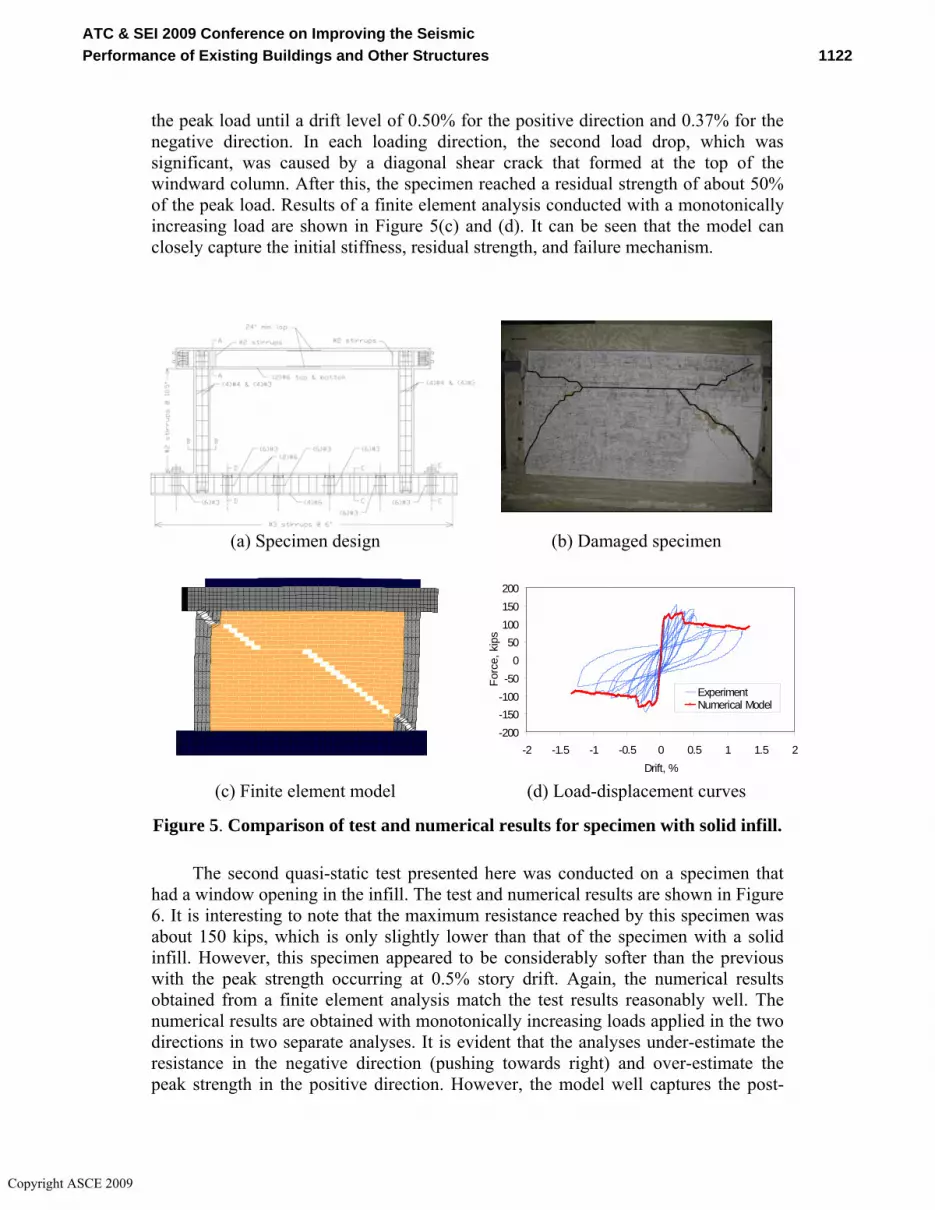
the peak load until a drift level of 0.50% for the positive direction and 0.37% for the negative direction. In each loading direction, the second load drop, which was significant, was caused by a diagonal shear crack that formed at the top of the windward column. After this, the specimen reached a residual strength of about 50% of the peak load. Results of a finite element analysis conducted with a monotonically increasing load are shown in Figure 5(c) and (d). It can be seen that the model can closely capture the initial stiffness, residual strength, and failure mechanism.
(a) Specimen design (b) Damaged specimen
-200-150-100-50
050
100150200
-2 -1.5 -1 -0.5 0 0.5 1 1.5 2Drift, %
Forc
e, k
ipss
ExperimentNumerical Model
(c) Finite element model (d) Load-displacement curves
Figure 5. Comparison of test and numerical results for specimen with solid infill.
The second quasi-static test presented here was conducted on a specimen that had a window opening in the infill. The test and numerical results are shown in Figure 6. It is interesting to note that the maximum resistance reached by this specimen was about 150 kips, which is only slightly lower than that of the specimen with a solid infill. However, this specimen appeared to be considerably softer than the previous with the peak strength occurring at 0.5% story drift. Again, the numerical results obtained from a finite element analysis match the test results reasonably well. The numerical results are obtained with monotonically increasing loads applied in the two directions in two separate analyses. It is evident that the analyses under-estimate the resistance in the negative direction (pushing towards right) and over-estimate the peak strength in the positive direction. However, the model well captures the post-
1122ATC & SEI 2009 Conference on Improving the Seismic Performance of Existing Buildings and Other Structures
Copyright ASCE 2009

peak behavior. The discrepancy in the peak strengths is very likely caused by the cyclic load effect, which is not accounted for in the analyses. The formation of a horizontal bed-joint crack at the mid-height of the wall when loaded in the negative direction could have weaken the resistance in the positive direction by causing shear failure at the mid-height of the left column when the load was reversed as it was observed in the test.
-200
-150
-100
-50
0
50
100
150
200
-2 -1 0 1 2Drift, %
Forc
e, k
ips
Numerical ModelTEST
(a) Damaged specimen (b) Load-displacement curves
(c) Loaded towards right (d) Loaded towards left Figure 6. Comparison of test and numerical results for specimen with window opening. SHAKE-TABLE TESTS
Two 2/3-scale models of the prototype frame shown in Figure 2 were tested on the outdoor shake table at the University of California, San Diego. The design of the concrete frame specimens is shown in Figure 7, and the test structures and setup are shown in Figure 8. In the shake-table tests, the specimens were subjected to a sequence of scaled ground motion records. They were the Gilroy record obtained in the 1989 Loma Prieta Earthquake and the NS component of the 1940 El Centro record. The time scale of the records was compressed to satisfy the similitude requirements for the scale models that also had reduced seismic mass.
1123ATC & SEI 2009 Conference on Improving the Seismic Performance of Existing Buildings and Other Structures
Copyright ASCE 2009

To assure that the RC columns had sufficient capacity to resist the overturning moment if infill walls in the second specimen were to be strengthened, they had a higher quantity of flexural reinforcement than the original design. Moreover, lap splices were eliminated at the base of the bottom-story columns. All the infill walls had two wythes of brick units. The first specimen (Figure 8(a)) had solid infill walls in one bay and infill walls with window openings in the other. Similar to the first, the second specimen (Figure 8(b)) had solid infill walls in one bay and window openings in the second and third stories in the other bay. However, the solid infill in the bottom story was strengthened with an overlay of engineered cementitious composite (ECC) on each side. This retrofit technique is described in Billington et al. (2009). The ECC was sprayed on the wall and had wire-mesh reinforcement and shear dowels to connect to the beam and base slab. Each overlay was about 1-in. thick near the mid-height of the wall and 2-in. thick near the top and bottom to provide appropriate cover for the shear dowels. Each ECC overlay was attached to the wall with stitch dowels spaced at 12-in. on center in each direction. Specimen 2 was tested under several scenarios. At the beginning, the bottom story had an unretrofitted infill wall with a door opening in one bay. Later, after mild damage had developed in the second-story infill walls, the bottom-story wall with the door opening was removed (as shown in Figure 8(b)), and the specimen was tested again. After the second-story walls had suffered moderate damage, they were repaired with epoxy injection and strengthened with a thin glass fiber reinforced polymeric (GFRP) overlay on one side. The GFRP overlay consisted of epoxy and one layer of bi-direction glass fabric with fibers oriented at 45o with respect to the bed joints of masonry. In addition, the masonry around the window opening was reinforced with one-foot-wide straps of uni-directional glass fabric.
In general, Specimen 1 performed well with only minor cracks after the 67% Gilroy, which corresponds to a Design Basis Earthquake (DBE). After the 100% Gilroy, the specimen had severe cracks in the bottom-story infill walls, but remained structurally stable. Shear failure developed in the middle column during the 120% Gilroy (which in reality was 40% higher than the Maximum Considered Earthquake (MCE) level because of the shake-table dynamics).
Damage was localized at the bottom story as shown in Figure 9(a) and (b). Severe
0.5" thick construction joint 0.5" thick construction joint
1'-478"
G
B
B
C
C
H H H H
B
B
C
C
I I I I
J J
3'-378"
J J
A
A
A
A
3'-378"
19" lap splice
#[email protected]''#[email protected]''
4#8
2#8
2#8 4#8
2#8
2#8
#3 @6''
2#8
2#8
2#8
2#8
G
H H
I I
J J
1'-10"
1'-712"
1'-6"
7'-4"
7'-4"
7'-4"
1'-212"
11"11"
4#8
2#8
2#8 4#8
2#8
2#8
2#8
2#8
2#8
2#8
4#8
2#8
2#8 4#8 2#82#8
#[email protected]''#[email protected]''#[email protected]''
2#5+1#42#5+1#4 2#4
2#4+1#32#4+1#3 2#3#[email protected]''
2#4+1#32#4+1#3 2#3#[email protected]''
2#4+1#32#4+1#3 2#3
3#53#5 2#5
19" lap splice
3#53#5 2#53#53#5 2#5
2#5+1#42#5+1#4 2#4 2#5+1#42#5+1#4 2#4
4#84#8
2#8
2#8
2#8
2#8
2#8
2#8
1'-712"
A
A
B
B
C
C
2' 2' 2' 2' 2' 2' 2' 2' 2' 2' 2' 2' 2' 2'
D
D
D
D
D
D
E
E
E
E
E
E
F
F
F
F
F
F
PVC tubes, =2.5'' @ 2'
1'-212"
1'-212"
/
Figure 7. Design of shake-table test specimen.
1124ATC & SEI 2009 Conference on Improving the Seismic Performance of Existing Buildings and Other Structures
Copyright ASCE 2009

damage with shear failures developed in the exterior columns occurred when the specimen was subjected to the 250% El Centro as shown in Figure 9(c) and (d). The wall with a window opening almost completely collapsed because of the lack of an arching mechanism.
The bottom-story shear-vs.-story drift hysteresis curves for the two specimens are compared in Figure 10. It can be observed that even though Specimen 2 had one infill wall in the bottom story removed, the strength and stiffness of Specimen 2 are significantly higher than those of Specimen 1 due to the ECC overlays. Furthermore, the infill walls in Specimen 2 were found to be significantly weaker than those in Specimen 1 due to weaker mortar. This can be observed by comparing the hysteresis curves in Figure 10(a) and Figure 11(a). Damage developed in the second-story walls of Specimen 2 at a story shear much lower than expected. The effect of the epoxy injection and GFRP strengthening in the second story of Specimen 2 is shown in Figure 11. The repair and retrofit enhanced both the strength and stiffness. No additional damage was observed in the infill walls in the second story after the retrofit.
The interstory drift time histories for the first two stories of the specimens under the Gilroy ground motion scaled to a level that is 40% higher than the Maximum Considered Earthquake (MCE) are shown in Figure 12. Specimen 2 in that test had one infill wall in the bottom story already removed. Figure 12 shows that Specimen 2 had a smaller drift in the bottom story but a much larger drift in the second story than Specimen 1. Specimen 1 exhibited a distinct weak first story which isolated the second story from severe seismic force. As a result, no major cracks were developed in the second and third stories of the specimen. Damage was comparatively more distributed in Specimen 2, which had severe cracks even in the infill walls in the third story. While all three bottom-story columns in Specimen 1 had shear failures, Specimen 2 had only a severe shear crack developed in the beam-to-column joint over the left exterior column shown in Figure 8(b). The shear dowels connecting the ECC to the beam in Specimen 2 developed some damage as evidenced by mild concrete spalling. As a result, noticeable sliding occurred between the ECC and the
(a) Specimen 1 (b) Specimen 2
Figure 8. Shake-table test setup.
1125ATC & SEI 2009 Conference on Improving the Seismic Performance of Existing Buildings and Other Structures
Copyright ASCE 2009

beam. In summary, Specimen 2 had significantly less damage than Specimen 1 under similar ground motion levels.
(a) Right after 120% Gilroy
(b) Right after 120% Gilroy
(c) Right after 250% El Centro
(d) Right after 250% El Centro
Figure 9. Damage of Specimen 1.
-1.0 -0.5 0.0 0.5 1.0-300
-200
-100
0
100
200
300
interstory drift (in)
shea
r fo
rce
(kip
s)
Gilroy 67%Gilroy 83%Gilroy 91%Gilroy 100%Gilroy 120%
-1.0 -0.5 0.0 0.5 1.0-300
-200
-100
0
100
200
300
interstory drift (in)
shea
r for
ce (k
ips)
Gilroy 67%Gilroy 83%Gilroy 91%Gilroy 100%Gilroy 120%Gilroy 150%
(a) Specimen 1 with no retrofit (b) Specimen 2 with ECC retrofit and one bottom-story infill removed
Figure 10. Comparison of shear force-vs.-interstory drift hysteresis curves for the bottom stories of the two shake-table specimens. CONCLUSIONS
The research effort presented here is aimed at developing reliable analytical models and effective retrofit techniques to assess and improve the seismic performance of masonry-infilled, non-ductile, RC frames. A prototype building was
1126ATC & SEI 2009 Conference on Improving the Seismic Performance of Existing Buildings and Other Structures
Copyright ASCE 2009

designed, and subassemblages of the prototype structure were tested to validate the analytical tools and retrofit methods developed in this research. These include two 2/3-scale, three-story, two-bay, infilled frames, which were tested on a shake table. A finite element modeling strategy combining the discrete and smeared crack approaches has been successfully used to capture the nonlinear load-displacement response and the complicated failure mechanisms of infilled frames that were characterized by the shear failure of the columns and the fracture of the masonry infill. The experimental results have shown that unreinforced masonry infill walls can contribute significantly to the seismic resistance of a concrete frame. However, the failure behavior of such structures could be brittle, and could lead to a sudden collapse associated with the development of a weak-story mechanism. The quasi-static tests have shown that the presence of a window opening had little influence on the strength of an infilled frame, but could reduce the lateral stiffness of the structure. The shake-table tests have shown that an infill wall with an opening could be more vulnerable to collapse because of the lack of an arching action. This was not shown in the quasi-static test. The shake-table tests have demonstrated the effectiveness of the retrofit measures using the ECC and GFRP overlays, which can increase both the stiffness and strength of an infilled frame.
-0.3 -0.2 -0.1 0.0 0.1 0.2 0.3-300
-200
-100
0
100
200
300
interstory drift (in)
shea
r fo
rce
(kip
s)
Gilroy 67%Gilroy 83%Gilroy 91%Gilroy 100%
-0.3 -0.2 -0.1 0.0 0.1 0.2 0.3-300
-200
-100
0
100
200
300
interstory drift (in)
shea
r fo
rce
(kip
s)
Gilroy 67%Gilroy 83%Gilroy 91%Gilroy 100%Gilroy 120%Gilroy 150%
(a) Before retrofit with GFRP (b) After retrofit with GFRP Figure 11. Comparison of 2nd story shear force-vs.-interstory drift hysteresis curves before and after retrofit.
10 12 14 16 18 20-1.0
-0.5
0.0
0.5
1.0
time (sec)
stor
y dr
ift (
in)
specimen 1specimen 2
10 12 14 16 18 20-0.25
-0.20
-0.15
-0.10
-0.05
-0.00
0.05
0.10
0.15
0.20
0.25
time (sec)
stor
y dr
ift (
in)
specimen 1specimen 2
(a) 1st story (b) 2nd story
Figure 12. Interstory drift time histories with Gilroy record scaled to 40% higher than MCE.
1127ATC & SEI 2009 Conference on Improving the Seismic Performance of Existing Buildings and Other Structures
Copyright ASCE 2009

ACKNOWLEDGMENTS
The study presented in this paper is supported by the National Science Foundation Grant No. 0530709 awarded under the George E. Brown, Jr. Network for Earthquake Engineering Simulation (NEES) program. The tests conducted at the University of Colorado and UCSD used NEES facilities. Input of the Professional Advisory Panel (PAP) throughout this study is gratefully acknowledged. The panel members are David Breiholz, John Kariotis, Gregory Kingsley, Joe Maffei, Ron Mayes, Paul Murray, and Michael Valley. However, the opinions expressed in this paper are those of the authors and do not necessarily represent those of the NSF or PAP. REFERENCES ASCE/SEI (2007), Seismic Rehabilitation of Existing Buildings, ASCE/SEI Standard
41-06. ASCE/SEI, Reston, VA. Billington, S.L., Kyriakides, M.A., Blackard, B., Willam, K., Stavridis, A. and Shing,
P.B. (2009). “Evaluation of a sprayable, ductile cement-based composite for the seismic retrofit of unreinforced masonry infills.” Proceedings, ATC & SEI Conference on Improving the Seismic Performance of Existing Buildings and Other Structures, Applied Technology Council and Structural Engineering Institute, San Francisco, CA.
Blackard, B., Willam, K., and Mettupulayam, S. (2009). “Experimental observations of masonry infilled RC frames with openings.” ACI Special Publication SP-265, American Concrete Institute, Farmington Hills, MI.
EERI (2000). “1999 Kocaeli, Turkey earthquake reconnaissance report.” Earthquake Spectra, Vol. 16, Issue S1.
FEMA (1998). “Evaluation of earthquake damaged concrete and masonry wall buildings: basic procedures manual.” FEMA 306, Federal Emergency Management Agency, Washington, D.C.
FEMA (2000). “Prestandard and commentary for the seismic rehabilitation of buildings.” FEMA 356, Federal Emergency Management Agency, Washington, D.C.
ICBO (2001). Guidelines for seismic retrofit of existing buildings. International Conference of Building Officials, Whittier, CA.
Lotfi, H. R. and Shing, P.B. (1994). “An interface model applied to fracture of masonry structures.” Journal of Structural Engineering, ASCE, 120(1): 63-80.
Lotfi, H. R. and Shing, P. B. (1991). “An appraisal of smeared crack models for masonry shear wall analysis.” Journal of Computers and Structures, ASCE, Vol. 120(1): 63-80.
Stavridis, A. and Shing, P.B. (2007). “Modeling of masonry infilled reinforced concrete frames with smeared and discrete crack elements”, Proceedings, ECCOMAS Thematic Conference on Computational Methods on Structural Dynamics and Earthquake Engineering, Crete, Greece.
1128ATC & SEI 2009 Conference on Improving the Seismic Performance of Existing Buildings and Other Structures
Copyright ASCE 2009