segway v1.042-eng-segway atv snarler manual_(t3b & l7e)
TRANSCRIPT

1
AAATTT666 SSS AAATTT666 LLL
USER MANUAL
OBSLUZE T3b
L7e
2
WELCOME Thank you for buying Segway ATV.
Segway Off-road vehicles will bring you a
new driving experience.
For your driving safety, please read this manual before
riding. This manual contains important safety
instructions, operation instructions, maintenance
instructions and safety warnings.
A careful reading of this manual will help you to
quickly understand the vehicle and will help your driving.
Periodic maintenance procedures are included in this
manual. They must be performed regularly to maintain
vehicle´s safety.
! WARNING
Read, understand, and follow all of the instructions
and safety precautions in this manual and all product
labels.
Failure to follow the safety precautions could result
in serious injury or death.
Read this manual carefully, it contains important safety information.
3
IMPORTANT NOTICE
This vehicle is designed and manufactured for off-road
use and complies with all applicable off-road noise, vibration and
emission regulations.
Before driving the vehicle, please understand the local laws
and regulations, follow local traffic regulations.
This manual is applicable to the Segway ATV fuel series
and describes all equipment including optional components.
Therefore, some of the optional equipment described in the
manual may be not installed on your vehicle.
If your vehicle needs service or repair, please contact our dealer.
He will provide you professional service in a timely manner. All
specifications provided in this manual are up to date at the time
of printing. However, due to continuous product improvement,
the contents of this manual can be updated at any time without
prior notice. The descriptions and/or procedures in this manual
are for informational purposes only. We take no responsibility for
omissions or inaccuracies. Express prohibition or reuse of
descriptions and/or programs contained in whole or in part.
4
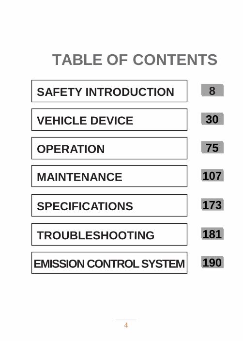
TABLE OF CONTENTS
SAFETY INTRODUCTION
VEHICLE DEVICE
OPERATION
MAINTENANCE
SPECIFICATIONS
TROUBLESHOOTING
EMISSION CONTROL SYSTEM
8
30
75
107
173
181
190
5
INTRODUCTION
BEFORE YOU RIDE This Segway ATV is an off-road vehicle. Familiarize
yourself with all laws and regulations concerning the
operation of this vehicle in your area.
! WARNING
◆ Failure to observe warnings and safety precautions
in this manual can result in severe injury or
death. Your Segway ATV is not a toy and can be
hazardous to operate. ATVs handle differently
from cars, trucks or the off-road vehicles. A
collision or rollover can occur quickly, even during
routine maneuvers like turning, driving on hills
or over obstacles, if you fail to take proper
precautions.
◆ Read this manual that came with your vehicle.
Understand all safety warnings, precautions and
operating procedures before operating the
vehicle. Keep this manual with the vehicle.
◆ Never operate this vehicle without proper instruction.
6
◆ This vehicle is an ADULT VEHICLE ONLY. You MUST
be at least of age 16 and have a valid driver's
license to operate this vehicle.
◆ Always wear a helmet, eye protection, gloves,
long- sleeve shirt, long pants and over-the-ankle
boots.
◆ Never consume alcohol or drugs before or
while operating this vehicle, as these they
impair judgment and reduce the operator's ability
to react.
◆ Complete the New Operator Driving
Procedures outlined this manual. Never allow a
other person to operate this vehicle until he/she
has completed the New Operator Driving
Procedures.
◆ Never permit other person to operate this vehicle
unless he/she has read this owner's manual and
all safety labels, and has completed safety training.
7
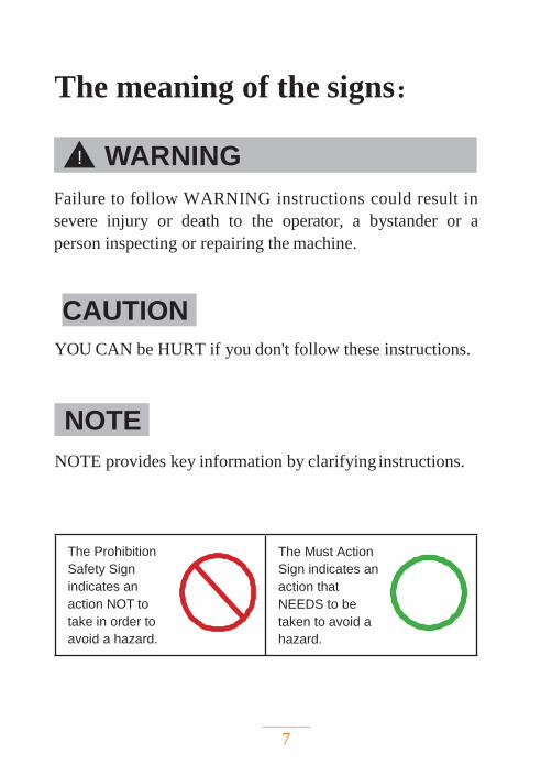
The meaning of the signs:
Failure to follow WARNING instructions could result in
severe injury or death to the operator, a bystander or a
person inspecting or repairing the machine.
CAUTION
YOU CAN be HURT if you don't follow these instructions.
NOTE
NOTE provides key information by clarifying instructions.
The Prohibition
Safety Sign
indicates an
action NOT to
take in order to
avoid a hazard.
The Must Action
Sign indicates an
action that
NEEDS to be
taken to avoid a
hazard.
! WARNING
8
SAFETY INTRODUCTION
WARNING LABELS ………….……..…… 11
GENERAL SAFETY PRECAUTIONS …… 18
IMPORTANT SAFETY INFORMATION ... 22
Reading the manual ………………………………… 22
Safe driving age …………………………………… 23
Riding equipment ………………...………………… 24
Vehicle modifications ……………..………………… 26
Passengers …………………………………………… 27
Exhaust gases are dangerous ……………………… 28
Fuel safety ………………………………..……………. 29
SAFETY INTRODUCTION
9
Failure to follow the warnings and safety precautions in
this manual may result in serious injury or death. It can be
dangerous to operate an ATV that is not regulated and
drives differently from other vehicles, such as motorcycles
and cars. If proper precautions are not taken, a collision
or roll-over may occur during normal maneuvers such as
turning, driving on hills or over obstacles . Understand
all safety warnings, precautions and operating procedures
before operating this vehicle. Bring this manual with you.
SAFETY INTRODUCTION
11
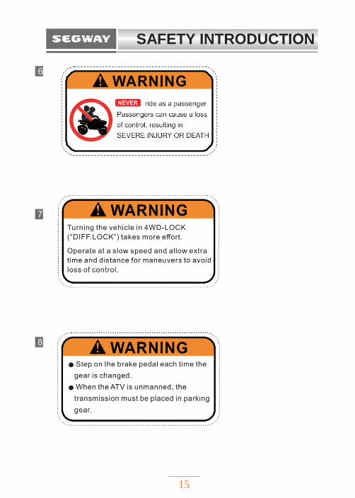
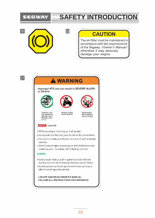
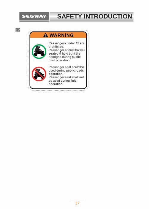
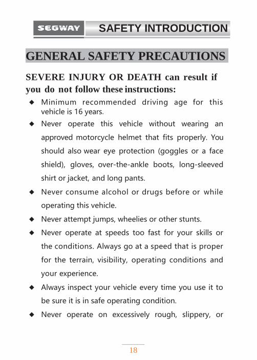
WARNING LABELS Warning labels have been placed on the vehicle for your
protection. Read and follow the instructions on the labels
carefully. If any of the labels depicted in this manual differ
from the labels on your vehicle, always read and follow the
instructions on the vehicle. If any label becomes
unreadable or comes off, contact your Segway
Powersports dealer for a replacement.
SAFETY INTRODUCTION
12
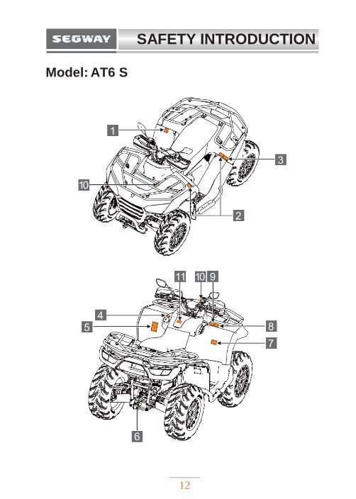
Model: AT6 S
SAFETY INTRODUCTION
13
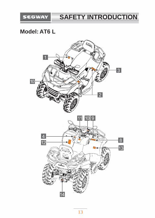
Model: AT6 L
SAFETY INTRODUCTION
14
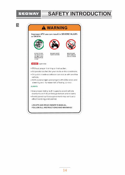
5
SAFETY INTRODUCTION
15
6
7
8
SAFETY INTRODUCTION
16
9 10
11
SAFETY INTRODUCTION
17
12
SAFETY INTRODUCTION
18
GENERAL SAFETY PRECAUTIONS
SEVERE INJURY OR DEATH can result if
you do not follow these instructions:
◆ Minimum recommended driving age for this vehicle is 16 years.
◆ Never operate this vehicle without wearing an
approved motorcycle helmet that fits properly. You
should also wear eye protection (goggles or a face
shield), gloves, over-the-ankle boots, long-sleeved
shirt or jacket, and long pants.
◆ Never consume alcohol or drugs before or while
operating this vehicle.
◆ Never attempt jumps, wheelies or other stunts.
◆ Never operate at speeds too fast for your skills or
the conditions. Always go at a speed that is proper
for the terrain, visibility, operating conditions and
your experience.
◆ Always inspect your vehicle every time you use it to
be sure it is in safe operating condition.
◆ Never operate on excessively rough, slippery, or
SAFETY INTRODUCTION
19
loose terrain until you have learned and practiced
the skills necessary to control the vehicle in such
terrain. Always be especially cautious on these kinds
of terrain.
◆ Always follow the inspection and maintenance
procedures and schedules described in this manual.
◆ Never operate on hills that are slippery or ones where
you will not be able to see far enough ahead of you.
Never go over the top of a hill at speed if you
cannot see what is on other side.
◆ Always keep hands, arms, feet, and legs inside the
vehicle at all times during operation. Keep your
feet on the floorboard. Never hold onto the
enclosure. Otherwise, your hands could be injured
if it is caught between the enclosure and an
obstacle outside the vehicle.
◆ Always keep both hands on the handlebars when
driving.
◆ Always go slowly and be extra careful when
operating on unfamiliar terrain. Always be alert to
changing terrain conditions when driving.
◆ Never turn at excessive speed. Practice turning at
SAFETY INTRODUCTION
20
slow speeds before attempting to turn at faster
speeds. Do not attempt turns on steep inclines.
◆ Always follow proper procedures when going uphill.
If you lose control and cannot continue up a hill,
back down the hill with the engine in reverse
gear. Use engine braking to help you to slow
down. If necessary, use the brakes gradually to
help you go slowly.
◆ Never operate the vehicle on hills that are too
steep for it or for your abilities. Go straight up and
down the hills where possible.
◆ Never operate the vehicle in fast flowing water or
water deeper than the floorboards on this model.
Remember that wet brakes may have reduced
stopping ability. Test your brakes after leaving water.
If necessary, apply the brake several times to let
friction dry out the linings.
◆ Always be sure there are no obstacles or people
behind you when you operate in reverse. When it is
safe to proceed in reverse, go slowly.
◆ Always check the terrain before going downhill. Go
as slowly as possible. Never go down a hill at high
SAFETY INTRODUCTION
21
speed.
◆ Always check for obstacles before operating in a
new area.
◆ Do not brake abruptly when carrying loads.
◆ Always use the size and type of tires specified in
this manual.
◆ Always maintain proper tire pressure as described
in this manual.
◆ Never exceed stated load capacity. Cargo should be
distributed evenly on front and rear rack. Be sure
that cargo is secured so that it cannot move
around during t h e ride. Reduce speed and
follow instructions in this manual for carrying
cargo or pulling a trailer. Allow greater
distance for braking.
◆ Brake discs can be over-heated after continuous
braking. Allow brake disc to cool before serving.
◆ Risks related to contact with hot surfaces, including
residual risks such as filling of oil or coolant, hot
engines or transmissions.
SAFETY INTRODUCTION
22
IMPORTANT SAFETY INFORMATION
Reading the manual
! WARNING
Driving an ATV improperly increases the risk of accident.
The driver must know how to drive the vehicle correctly
in different situations and on different terrain.
Before driving the vehicle, all drivers must complete the
required driving safety training. Please ensure that each
driver has read this manual and all product warning labels
and has passed the safety training course. Otherwise, the
vehicle will not be allowed to drive.
SAFETY INTRODUCTION
23
Safe driving age
! WARNING
The minimum recommended age for driving this
vehicle is 16 years. Children under the age of 16 must
not drive this vehicle. Do not drive the vehicle without
proper driving training; training courses are required.
Please ensure that every driver has read this manual
and all Warning labels and has completed a safety
training course.
SAFETY INTRODUCTION
24
Riding equipment
! WARNING
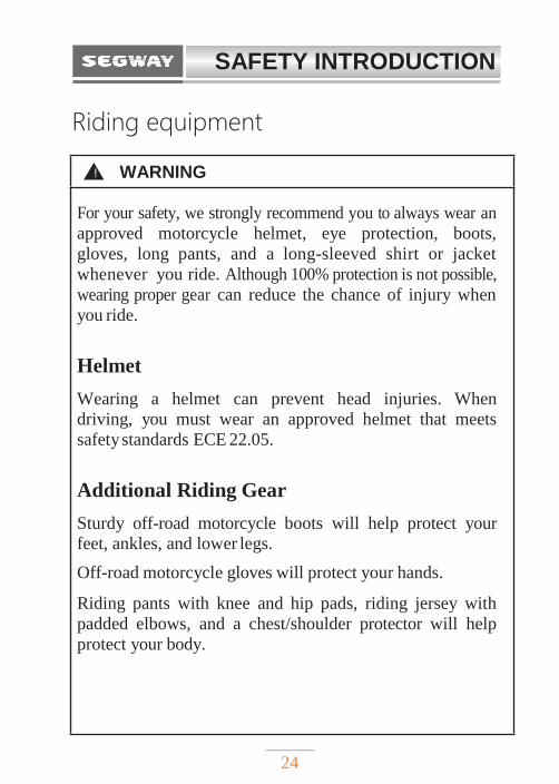
For your safety, we strongly recommend you to always wear an
approved motorcycle helmet, eye protection, boots,
gloves, long pants, and a long-sleeved shirt or jacket
whenever you ride. Although 100% protection is not possible,
wearing proper gear can reduce the chance of injury when
you ride.
Helmet
Wearing a helmet can prevent head injuries. When
driving, you must wear an approved helmet that meets
safety standards ECE 22.05.
Additional Riding Gear
Sturdy off-road motorcycle boots will help protect your
feet, ankles, and lower legs.
Off-road motorcycle gloves will protect your hands.
Riding pants with knee and hip pads, riding jersey with
padded elbows, and a chest/shoulder protector will help
protect your body.
SAFETY INTRODUCTION
25
! WARNING
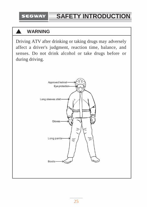
Driving ATV after drinking or taking drugs may adversely
affect a driver's judgment, reaction time, balance, and
senses. Do not drink alcohol or take drugs before or
during driving.
SAFETY INTRODUCTION
26
Vehicle modifications
! WARNING
We strongly recommend you not to attempt to increase
vehicle speed or use any equipment that increases the
power of the vehicle. If any equipment is added to the
vehicle, or if any modifications are made to the vehicle
to increase the vehicle speed or power, the warranty may
be influenced. The addition of certain accessories may
change the handling of the vehicle, including (but not
limited to) mowers, sledges, tires, sprayers, or large
luggage racks.
SAFETY INTRODUCTION
27
Carrying passengers
! WARNING
Riding with passenger largely reduces driver's
ability to control an ATV, which can lead to accidents
or rollovers. Do not ride with this ATV carrying more
riders / passengers than is this vehicle designed for.
Never carry more passengers than your vehicle is
designed for.
SAFETY INTRODUCTION
28
Exhaust gases are dangerous
! WARNING
Exhaust gas is toxic and can cause loss of consciousness
or death in a short time. Do not start or run a motor
in a closed space. The engine exhaust of this product
contains chemicals that can cause cancer, birth
defects or other reproductive damage. You can only
start it outside the room or in a well-ventilated area.
SAFETY INTRODUCTION
29
Fuel safety
! WARNING
Gasoline is flammable!
◆ Be extremely careful when dealing with gasoline.
◆ When refueling, the engine must be shut off and
must be done outdoors or in a well-ventilated area.
◆ At, or near the refueling or gasoline storage place
do not smoke, avoid open flame or sparks.
◆ Do not overflow the tank when refueling. Do not fill
the tank up to the neck.
◆ If gasoline gets on your skin or clothes, wash
them with soap and water immediately and change
clothes.
30
VEHICLE DEVICE
VEHICLE ACTIVATION…..…………………32
First activation ………………………………32
APP FUNCTION ………………………………35
FEATURES AND CONTROLS ………………36
Location of parts and controls ………….……36
Handlebar switches …………..………………37
Ignition switch ………………………………38
Engine Start/Stop switch ……...……………39
Headlight switch … ..…………….…………..40
Turn signal switch………………….………41
Hazard Switch ………….………..…………42
Force-multiplier / Override switch ……..……43
Winch controller ………………….…………44
Drive select switch …………...………………45
Throttle lever …………………………………50
12V Accessory outlet / USB Port……………51
Shifting ………..………...………………...…52
31
VEHICLE DEVICE
Parking brake …….………………………………53
Parking brake lever free play ……………..……54
Foot brake…………………………………………55
Front (auxiliary) brake ……………..……………57
Fuel tank cap……………...………………………58
Storage box ……………………………………….59
INSTRUMENTS ……………………………………60
Indicators / Warning lights………………...….…61
LCD Display ………………………..…….……64
Diagnostic trouble codes ……………..…………67
Display Setting …………….………..…….…...73
HANDLEBARS ADJUSTMENT……………………74
VEHICLE DEVICE
32
VEHICLE ACTIVATION
This vehicle is equipped with DTS system. DTS is used to
communicate between vehicle systems and mobile APP to
obtain vehicle information and to control the vehicle with
your mobile APP. To make you familiar with and use
the system, please read the User manual carefully and
understand the application operation.
First Activation Download the APP from the “APP Store” in your mobile
phone before you try to activate the ATV for the first
time. Search for “Segway Powersports” in the APP Store
in your mobile phone, and then download the APP.
After successful installation, your vehicle can be registered
and activated. First, locate the VIN number on the vehicle
and register it to the APP.
NOTE
New vehicle must be activated through the APP
for the first time. Otherwise vehicle will not start.
VEHICLE DEVICE
33
The registration procedure is as follows:
1. Power-up the vehicle with the key;
Input or scan vehicle´s VIN number as the APP prompts
you, and step on the foot brake at the same time.
Note:
If the VIN number cannot be scanned by the phone, for
example due to the low light, you can enter the VIN
number manually. The vehicle VIN number you will find
on the frame (see Page 179) and on the Identification plate
(see Page 180).
2. Complete the registration and activate the connection;
3. Start the engine.
VEHICLE DEVICE
34
Vehicle activation
There are 3 ways to activate your vehicle:
1. With the vehicle key (preferred)
2. Keyless activation via the APP
Keyless APP unlocking is based on 4G network. As long as
your area is covered with the 4G network, you can activate
your vehicle via the APP.
3. Keyless activation via Bluetooth
When both vehicle and your mobile phone are within the
Bluetooth distance, the vehicle Bluetooth module will
automatically activate the vehicle when receiving
Bluetooth signal of your mobile phone, and automatically
switch off the vehicle when your mobile phone gets away.
Ignition key is the optimal activation method for your
vehicle. If you don´t want to use the remote activation
function, you can switch this possibility off in the APP.
NOTE
After switching off the vehicle with the key, it cannot be
activated again by the phone. You need to disconnect the
phone and reconnect it to the vehicle to activate.
VEHICLE DEVICE
35
APP FUNCTION
Main features:
Driving control analysis, vehicle data analysis etc.
For detailed information please see the APP User Manual.
VEHICLE DEVICE
36
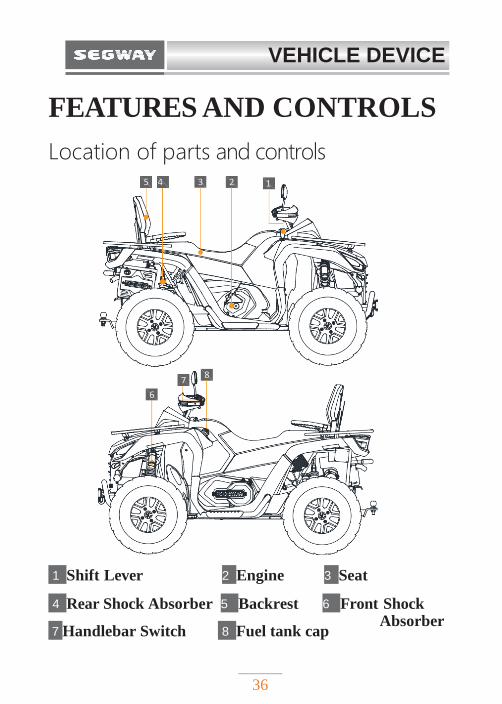
FEATURES AND CONTROLS
Location of parts and controls
1 Shift Lever 2 Engine 3 Seat
4 Rear Shock Absorber 5 Backrest 6 Front Shock
7 Handlebar Switch 8 Fuel tank cap
5 4 3 2 1
7 8
6
5 4 3 2 1
7 8
6
Absorber
VEHICLE DEVICE
37
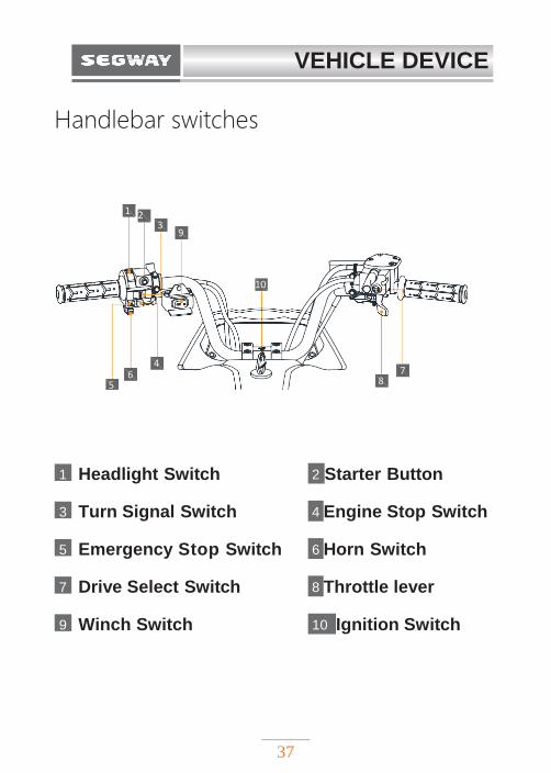
Handlebar switches
1 Headlight Switch 2 Starter Button
3 Turn Signal Switch 4 Engine Stop Switch
5 Emergency Stop Switch 6 Horn Switch
7 Drive Select Switch 8 Throttle lever
9 Winch Switch 10 Ignition Switch
1 2
3 9
10
6 4
7 5 8
1 2
3 9
10
4 6 7
5 8
VEHICLE DEVICE
38
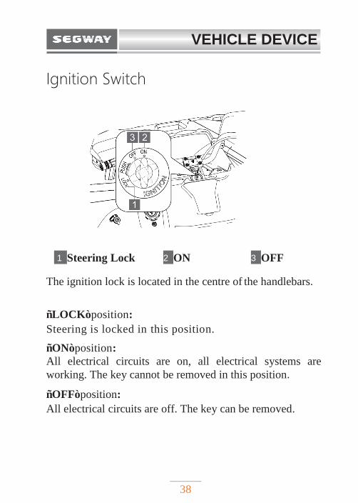
Ignition Switch
1 Steering Lock 2 ON 3 OFF
The ignition lock is located in the centre of the handlebars.
“LOCK”position:
Steering is locked in this position.
“ON”position:
All electrical circuits are on, all electrical systems are
working. The key cannot be removed in this position.
“OFF”position:
All electrical circuits are off. The key can be removed.
VEHICLE DEVICE
39
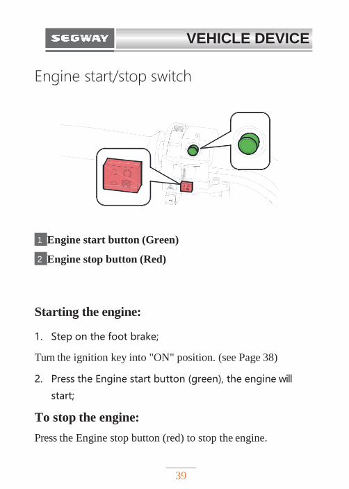
Engine start/stop switch
1 Engine start button (Green)
2 Engine stop button (Red)
Starting the engine:
1. Step on the foot brake;
Turn the ignition key into "ON" position. (see Page 38)
2. Press the Engine start button (green), the engine will
start;
To stop the engine:
Press the Engine stop button (red) to stop the engine.
VEHICLE DEVICE
40
1
2
3
4
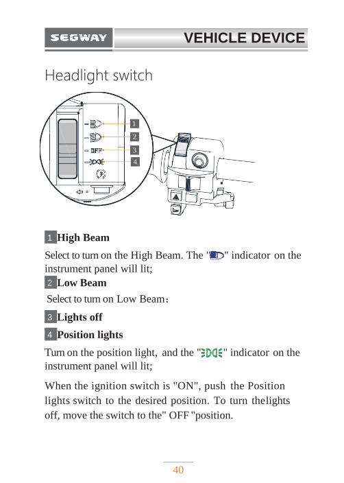
Headlight switch
1 High Beam
Select to turn on the High Beam. The " " indicator on the
instrument panel will lit;
2 Low Beam
Select to turn on Low Beam;
3 Lights off
4 Position lights
Turn on the position light, and the " " indicator on the
instrument panel will lit;
When the ignition switch is "ON", push the Position
lights switch to the desired position. To turn the lights
off, move the switch to the" OFF "position.
VEHICLE DEVICE
41
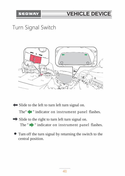
Turn Signal Switch
Slide to the left to turn left turn signal on.
The" " indicator on instrument panel flashes.
Slide to the right to turn left turn signal on.
The " " indicator on instrument panel flashes.
Turn off the turn signal by returning the switch to the
central position.
VEHICLE DEVICE
42
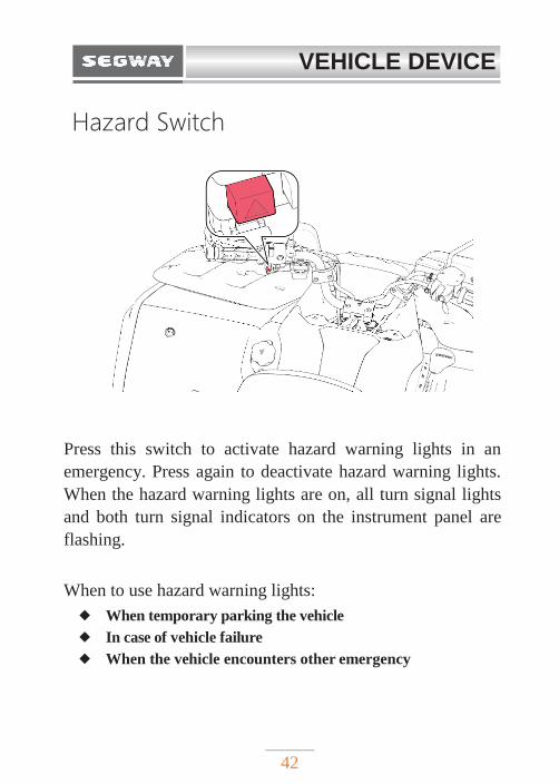
Hazard Switch
Press this switch to activate hazard warning lights in an
emergency. Press again to deactivate hazard warning lights.
When the hazard warning lights are on, all turn signal lights
and both turn signal indicators on the instrument panel are
flashing.
When to use hazard warning lights:
◆ When temporary parking the vehicle
◆ In case of vehicle failure
◆ When the vehicle encounters other emergency
VEHICLE DEVICE
43
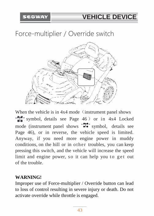
Force-multiplier / Override switch
When the vehicle is in 4x4 mode(instrument panel shows
symbol, details see Page 46) or in 4x4 Locked
mode (instrument panel shows symbol, details see
Page 46), or in reverse, the vehicle speed is limited.
Anyway, if you need more engine power in muddy
conditions, on the hill or in o the r troubles, you can keep
pressing this switch, and the vehicle will increase the speed
limit and engine power, so it can help you t o g e t out
of the trouble.
WARNING!
Improper use of Force-multiplier / Override button can lead
to loss of control resulting in severe injury or death. Do not
activate override while throttle is engaged.
VEHICLE DEVICE
44
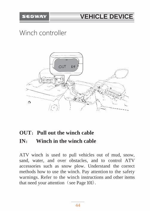
Winch controller
OUT:Pull out the winch cable
IN: Winch in the winch cable
ATV winch is used to pull vehicles out of mud, snow,
sand, water, and over obstacles, and to control ATV
accessories such as snow plow. Understand the correct
methods how to use the winch. Pay attention to the safety
warnings. Refer to the winch instructions and other items
that need your attention(see Page 101).
VEHICLE DEVICE
45
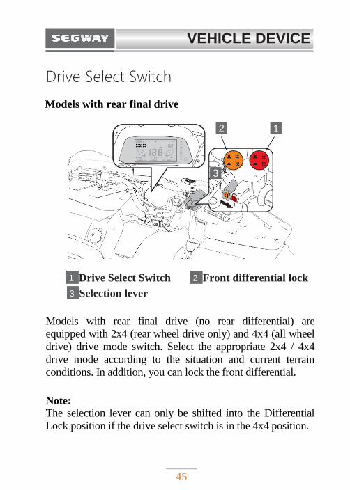
Drive Select Switch
Models with rear final drive
1 Drive Select Switch 2 Front differential lock
3 Selection lever
Models with rear final drive (no rear differential) are
equipped with 2x4 (rear wheel drive only) and 4x4 (all wheel
drive) drive mode switch. Select the appropriate 2x4 / 4x4
drive mode according to the situation and current terrain
conditions. In addition, you can lock the front differential.
Note: The selection lever can only be shifted into the Differential
Lock position if the drive select switch is in the 4x4 position.
1
2
1
3
VEHICLE DEVICE
46
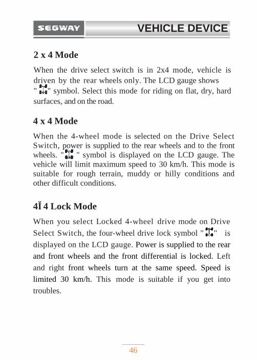
2 x 4 Mode
When the drive select switch is in 2x4 mode, vehicle is
driven by the rear wheels only. The LCD gauge shows
" " symbol. Select this mode for riding on flat, dry, hard
surfaces, and on the road.
4 x 4 Mode
When the 4-wheel mode is selected on the Drive Select
Switch, power is supplied to the rear wheels and to the front
wheels. " " symbol is displayed on the LCD gauge. The
vehicle will limit maximum speed to 30 km/h. This mode is
suitable for rough terrain, muddy or hilly conditions and
other difficult conditions.
4×4 Lock Mode
When you select Locked 4-wheel drive mode on Drive
Select Switch, the four-wheel drive lock symbol " " is
displayed on the LCD gauge. Power is supplied to the rear
and front wheels and the front differential is locked. Left
and right front wheels turn at the same speed. Speed is
limited 30 km/h. This mode is suitable if you get into
troubles.
VEHICLE DEVICE
47
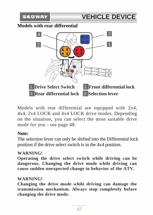
Models with rear differential
1 Drive Select Switch 2 Front differential lock
3 Rear differential lock 3 Selection lever
Models with rear differential are equipped with 2x4,
4x4, 2x4 LOCK and 4x4 LOCK drive modes. Depending
on the situation, you can select the most suitable drive
mode for you - see page 48.
Note: The selection lever can only be shifted into the Differential lock
position if the drive select switch is in the 4x4 position.
WARNING!
Operating the drive select switch while driving can be
dangerous. Changing the drive mode while driving can
cause sudden unexpected change in behavior of the ATV.
WARNING!
Changing the drive mode while driving can damage the
transmission mechanism. Always stop completely before
changing the drive mode.
2
1
3
4
VEHICLE DEVICE
48
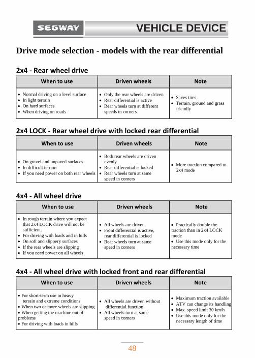
Drive mode selection - models with the rear differential
2x4 - Rear wheel drive
When to use Driven wheels Note
Normal driving on a level surface
In light terrain On hard surfaces
When driving on roads
Only the rear wheels are driven Rear differential is active
Rear wheels turn at different
speeds in corners
Saves tires Terrain, ground and grass
friendly
2x4 LOCK - Rear wheel drive with locked rear differential
When to use Driven wheels Note
On gravel and unpaved surfaces In difficult terrain
If you need power on both rear wheels
Both rear wheels are driven
evenly
Rear differential is locked
Rear wheels turn at same
speed in corners
More traction compared to
2x4 mode
4x4 - All wheel drive
When to use Driven wheels Note
In rough terrain where you expect
that 2x4 LOCK drive will not be
sufficient. For driving with loads and in hills
On soft and slippery surfaces
If the rear wheels are slipping
If you need power on all wheels
All wheels are driven Front differential is active,
rear differential is locked
Rear wheels turn at same
speed in corners
Practically double the
traction than in 2x4 LOCK
mode Use this mode only for the
necessary time
4x4 - All wheel drive with locked front and rear differential
When to use Driven wheels Note
For short-term use in heavy
terrain and extreme conditions
When two or more wheels are slipping
When getting the machine out of
problems For driving with loads in hills
All wheels are driven without
differential function
All wheels turn at same
speed in corners
Maximum traction available
ATV can change its handling
Max. speed limit 30 km/h Use this mode only for the
necessary length of time
VEHICLE DEVICE
49
WARNING!
Before using the front or rear differential lock, or when
changing drive mode from 2x4 to 4x4 and vice versa, stop
the vehicle and ride again only after the gears properly
engage.
Driving in 4x4 mode with locked front differential can be
dangerous. When driving with locked front differential,
reduce your speed and allow for greater maneuvering
distances. Locking the front differential can unexpectedly
change the handling characteristics of the ATV. Expect a
slower turning and respect the changed handling
characteristics. If you cannot make a sharp enough turn
for the speed you are traveling, you may lose control, which
can lead to an accident.
With locked front differential the maximum speed is
limited to 30 km/h.
VEHICLE DEVICE
50
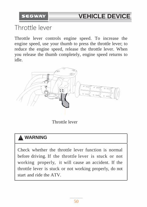
Throttle lever
Throttle lever controls engine speed. To increase the
engine speed, use your thumb to press the throttle lever; to
reduce the engine speed, release the throttle lever. When
you release the thumb completely, engine speed returns to
idle.
Throttle lever
! WARNING
Check whether the throttle lever function is normal
before driving. If the throttle lever is stuck or not
working properly, it will cause an accident. If the
throttle lever is stuck or not working properly, do not
start and ride the ATV.
VEHICLE DEVICE
51
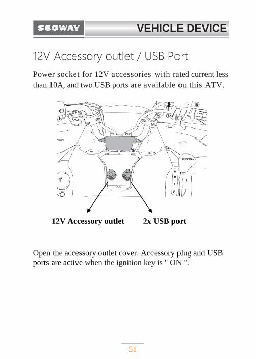
12V Accessory outlet / USB Port
Power socket for 12V accessories with rated current less
than 10A, and two USB ports are available on this ATV.
12V Accessory outlet 2x USB port
Open the accessory outlet cover. Accessory plug and USB
ports are active when the ignition key is " ON ".
VEHICLE DEVICE
52
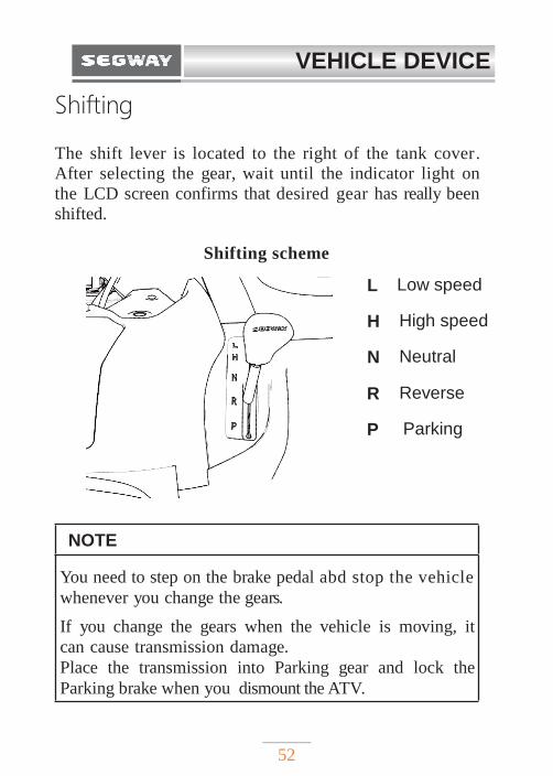
Shifting
The shift lever is located to the right of the tank cover.
After selecting the gear, wait until the indicator light on
the LCD screen confirms that desired gear has really been
shifted.
Shifting scheme
L Low speed
H High speed
N Neutral
R Reverse
P Parking
NOTE
You need to step on the brake pedal abd stop the vehicle
whenever you change the gears.
If you change the gears when the vehicle is moving, it
can cause transmission damage.
Place the transmission into Parking gear and lock the
Parking brake when you dismount the ATV.
VEHICLE DEVICE
53
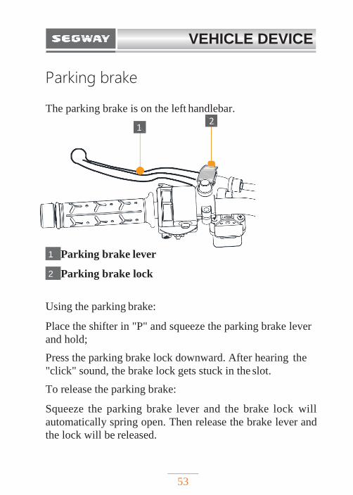
Parking brake
The parking brake is on the left handlebar.
1 Parking brake lever
2 Parking brake lock
Using the parking brake:
Place the shifter in "P" and squeeze the parking brake lever
and hold;
Press the parking brake lock downward. After hearing the
"click" sound, the brake lock gets stuck in the slot.
To release the parking brake:
Squeeze the parking brake lever and the brake lock will
automatically spring open. Then release the brake lever and
the lock will be released.
1
2
54
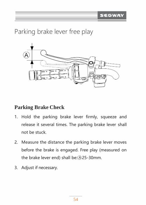
Parking brake lever free play
Parking Brake Check
1. Hold the parking brake lever firmly, squeeze and
release it several times. The parking brake lever shall
not be stuck.
2. Measure the distance the parking brake lever moves
before the brake is engaged. Free play (measured on
the brake lever end) shall be: A 25-30mm.
3. Adjust if necessary.
MAINTENANCE
VEHICLE DEVICE
55
Foot brake
The foot brake is the main brake system of the vehicle. The
foot brake is located on the right floorboard. When you
need to slow down or stop, step on the foot brake pedal
gradually.
Warning:
Emergency braking can cause the vehicle to skid or roll
over. Do not use emergency braking when not necessary.
VEHICLE DEVICE
56
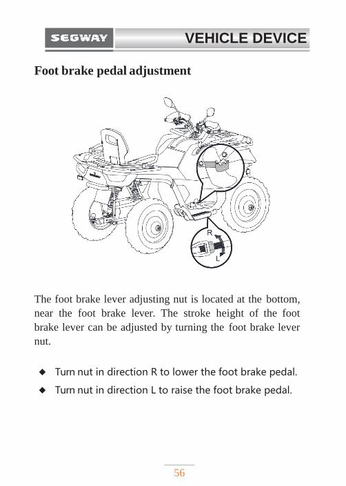
Foot brake pedal adjustment
The foot brake lever adjusting nut is located at the bottom,
near the foot brake lever. The stroke height of the foot
brake lever can be adjusted by turning the foot brake lever
nut.
◆ Turn nut in direction R to lower the foot brake pedal.
◆ Turn nut in direction L to raise the foot brake pedal.
VEHICLE DEVICE
57
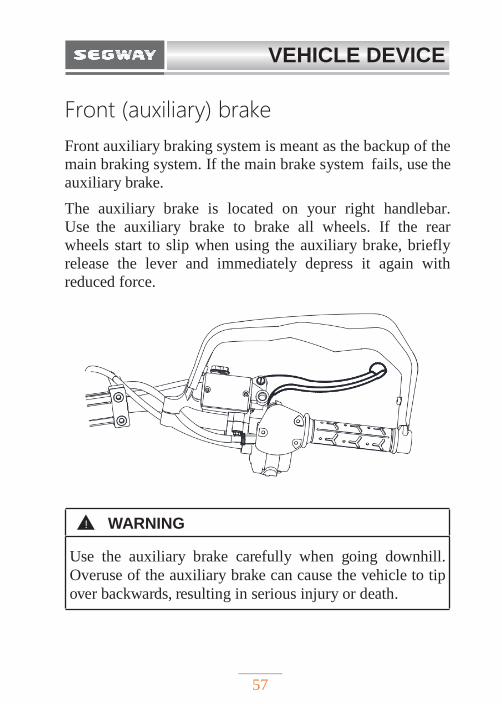
Front (auxiliary) brake
Front auxiliary braking system is meant as the backup of the
main braking system. If the main brake system fails, use the
auxiliary brake.
The auxiliary brake is located on your right handlebar.
Use the auxiliary brake to brake all wheels. If the rear
wheels start to slip when using the auxiliary brake, briefly
release the lever and immediately depress it again with
reduced force.
! WARNING
Use the auxiliary brake carefully when going downhill.
Overuse of the auxiliary brake can cause the vehicle to tip
over backwards, resulting in serious injury or death.
VEHICLE DEVICE
58
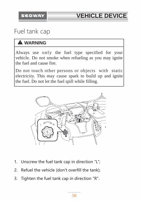
Fuel tank cap
1. Unscrew the fuel tank cap in direction "L";
2. Refuel the vehicle (don't overfill the tank);
3. Tighten the fuel tank cap in direction "R".
! WARNING
Always use only the fuel type specified for your
vehicle. Do not smoke when refueling as you may ignite
the fuel and cause fire.
Do not touch other persons or objects with static
electricity. This may cause spark to build up and ignite
the fuel. Do not let the fuel spill while filling.
VEHICLE DEVICE
59
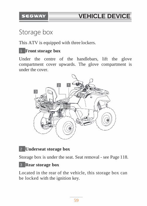
Storage box
This ATV is equipped with three lockers.
1 Front storage box
Under the centre of the handlebars, lift the glove
compartment cover upwards. The glove compartment is
under the cover.
2 Underseat storage box
Storage box is under the seat. Seat removal - see Page 118.
3 Rear storage box
Located in the rear of the vehicle, this storage box can
be locked with the ignition key.
VEHICLE DEVICE
60
INSTRUMENT PANEL Instrument panel provides operator with the actual
vehicle information. The driver should understand the
meaning of various indicators, warning lights and
display information on the instrument panel so as to
immediately understand vehicle status.
NOTE
LCD display may be damaged by using a high
pressure washer.
Do not clean the instrument panel with alcohol or
corrosive detergents. Corrosive liquids will corrode
the surface of the LCD display and cause damage
to the instrument panel.
VEHICLE DEVICE
61
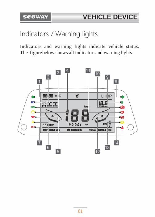
Indicators / Warning lights
Indicators and warning lights indicate vehicle status.
The figure below shows all indicator and warning lights.
VEHICLE DEVICE
62
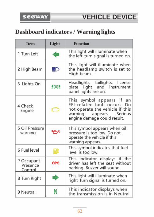
Dashboard indicators / Warning lights
Item Light Function
1 Turn Left
This light will illuminate when the left turn signal is turned on.
2 High Beam
This light will illuminate when the headlamp switch is set to High beam.
3 Lights On
Headlights, taillights, license plate light and instrument panel lights are on.
4 Check Engine
This symbol appears if an EFI-related fault occurs. Do not operate the vehicle if this warning appears. Serious engine damage could result.
5 Oil Pressure warning
This symbol appears when oil pressure is too low. Do not operate the vehicle if this warning appears.
6 Fuel level
This symbol indicates that fuel level is too low.
7 Occupant Presence Control
This indicator displays if the driver has left the seat without parking. Buzzer will sound.
8 Turn Right
This light will illuminate when right turn signal is turned on.
9 Neutral
This indicator displays when the transmission is in Neutral.
VEHICLE DEVICE
63
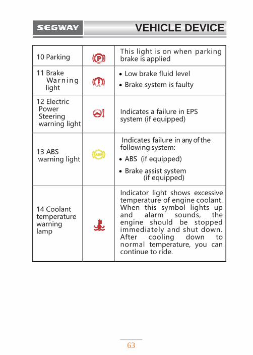
10 Parking
This light is on when parking brake is applied
11 Brake Warn in g light
Low brake fluid level
Brake system is faulty
12 Electric Power Steering warning light
Indicates a failure in EPS system (if equipped)
13 ABS warning light
ABS
Indicates failure in any of the following system:
ABS (if equipped)
Brake assist system (if equipped)
14 Coolant temperature warning lamp
Indicator light shows excessive temperature of engine coolant. When this symbol lights up and alarm sounds, the engine should be stopped immediately and shut down. After cooling down to normal temperature, you can continue to ride.
VEHICLE DEVICE
64
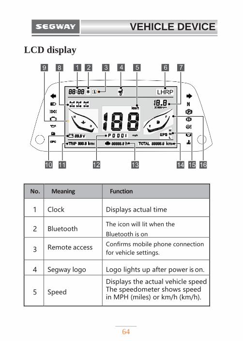
LCD display
No. Meaning Function
1 Clock Displays actual time
2
Bluetooth The icon will lit when the
Bluetooth is on
3 Remote access Confirms mobile phone connection
for vehicle settings.
4 Segway logo Logo lights up after power is on.
5
Speed
Displays the actual vehicle speed The speedometer shows speed in MPH (miles) or km/h (km/h).
VEHICLE DEVICE
65
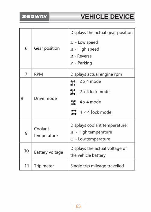
6
Gear position
Displays the actual gear position
L - Low speed
H - High speed
R - Reverse
P - Parking
7 RPM Displays actual engine rpm
8 Drive mode
2 x 4 mode
2 x 4 lock mode
4 x 4 mode
4 × 4 lock mode
9 Coolant
temperature
Displays coolant temperature:
H - High temperature
C - Low temperature
10 Battery voltage Displays the actual voltage of
the vehicle battery
11 Trip meter Single trip mileage travelled
VEHICLE DEVICE
66
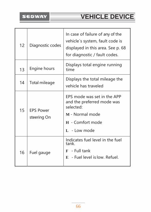
12
Diagnostic codes
In case of failure of any of the
vehicle´s system, fault code is
displayed in this area. See p. 68
for diagnostic / fault codes.
13 Engine hours Displays total engine running time
14
Total mileage Displays the total mileage the
vehicle has traveled
15
EPS Power
steering On
EPS mode was set in the APP and the preferred mode was selected:
M - Normal mode
H - Comfort mode
L - Low mode
16
Fuel gauge
Indicates fuel level in the fuel tank. F - Full tank
E - Fuel level is low. Refuel.
VEHICLE DEVICE
67
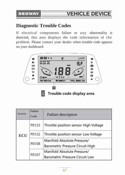
Diagnostic Trouble Codes
If electrical components failure or a n y abnormality is
detected, this area displays the code information of t h e
problem. Please contact your dealer when trouble code appears
on your dashboard.
1 Trouble code display area
System
Failure
Code
Failure description
ECU
P0123
Throttle position sensor High Voltage
P0122 Throttle position sensor Low Voltage
P0108 Manifold Absolute Pressure/
Barometric Pressure Circuit High
P0107 Manifold Absolute Pressure/
Barometric Pressure Circuit Low
VEHICLE DEVICE
68
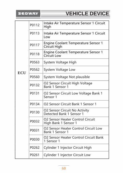
ECU
P0112 Intake Air Temperature Sensor 1 Circuit High
P0113 Intake Air Temperature Sensor 1 Circuit Low
P0117 Engine Coolant Temperature Sensor 1 Circuit High
P0118 Engine Coolant Temperature Sensor 1 Circuit Low
P0563 System Voltage High
P0562 System Voltage Low
P0560 System Voltage Not plausible
P0132 O2 Sensor Circuit High Voltage Bank 1 Sensor 1
P0131 O2 Sensor Circuit Low Voltage Bank 1 Sensor 1
P0134 O2 Sensor Circuit Bank 1 Sensor 1
P0130 O2 Sensor Circuit No Activity Detected Bank 1 Sensor 1
P0032 O2 Sensor Heater Control Circuit High Bank 1 Sensor 1
P0031 O2 Sensor Heater Control Circuit Low Bank 1 Sensor 1
P0030 O2 Sensor Heater Control Circuit Bank 1 Sensor 1
P0262 Cylinder 1 Injector Circuit High
P0261 Cylinder 1 Injector Circuit Low
VEHICLE DEVICE
69
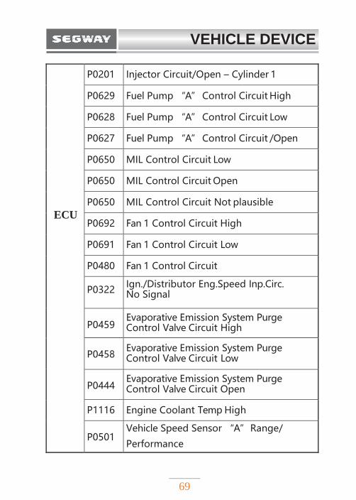
ECU
P0201 Injector Circuit/Open – Cylinder 1
P0629 Fuel Pump “A” Control Circuit High
P0628 Fuel Pump “A” Control Circuit Low
P0627 Fuel Pump “A” Control Circuit /Open
P0650 MIL Control Circuit Low
P0650 MIL Control Circuit Open
P0650 MIL Control Circuit Not plausible
P0692 Fan 1 Control Circuit High
P0691 Fan 1 Control Circuit Low
P0480 Fan 1 Control Circuit
P0322 Ign./Distributor Eng.Speed Inp.Circ. No Signal
P0459 Evaporative Emission System Purge Control Valve Circuit High
P0458 Evaporative Emission System Purge Control Valve Circuit Low
P0444 Evaporative Emission System Purge Control Valve Circuit Open
P1116 Engine Coolant Temp High
P0501 Vehicle Speed Sensor “A” Range/
Performance
VEHICLE DEVICE
70
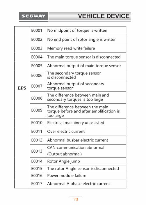
EPS
E0001 No midpoint of torque is written
E0002 No end point of rotor angle is written
E0003 Memory read write failure
E0004 The main torque sensor is disconnected
E0005 Abnormal output of main torque sensor
E0006 The secondary torque sensor is disconnected
E0007 Abnormal output of secondary torque sensor
E0008 The difference between main and secondary torques is too large
E0009 The difference between the main torque before and after amplification is too large
E0010 Electrical machinery unassisted
E0011 Over electric current
E0012 Abnormal busbar electric current
E0013 CAN communication abnormal
(Output abnormal)
E0014 Rotor Angle jump
E0015 The rotor Angle sensor is disconnected
E0016 Power module failure
E0017 Abnormal A phase electric current
VEHICLE DEVICE
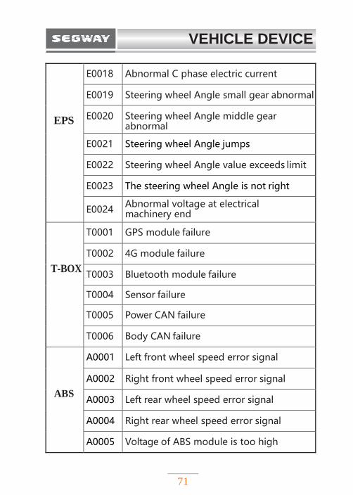
71
EPS
E0018 Abnormal C phase electric current
E0019 Steering wheel Angle small gear abnormal
E0020 Steering wheel Angle middle gear abnormal
E0021 Steering wheel Angle jumps
E0022 Steering wheel Angle value exceeds limit
E0023 The steering wheel Angle is not right
E0024 Abnormal voltage at electrical machinery end
T-BOX
T0001 GPS module failure
T0002 4G module failure
T0003 Bluetooth module failure
T0004 Sensor failure
T0005 Power CAN failure
T0006 Body CAN failure
ABS
A0001 Left front wheel speed error signal
A0002 Right front wheel speed error signal
A0003 Left rear wheel speed error signal
A0004 Right rear wheel speed error signal
A0005 Voltage of ABS module is too high
VEHICLE DEVICE
72
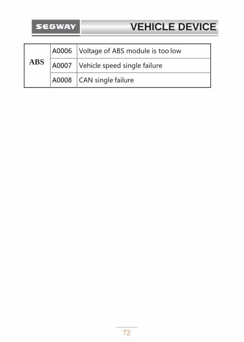
ABS
A0006 Voltage of ABS module is too low
A0007 Vehicle speed single failure
A0008 CAN single failure
VEHICLE DEVICE
73
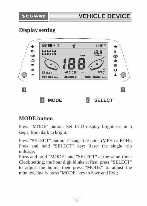
Display setting
1 MODE 2 SELECT
MODE button
Press "MODE" button: Set LCD display brightness in 5
steps, from dark to bright.
Press "SELECT" button: Change the units (MPH or KPH);
Press and hold "SELECT" key: Reset the single trip
mileage;
Press and hold "MODE" and "SELECT" at the same time:
Clock setting; the hour digit blinks at first, press "SELECT"
to adjust the hours, then press "MODE" to adjust the
minutes, finally press "MODE" key to Save and Exit;
74
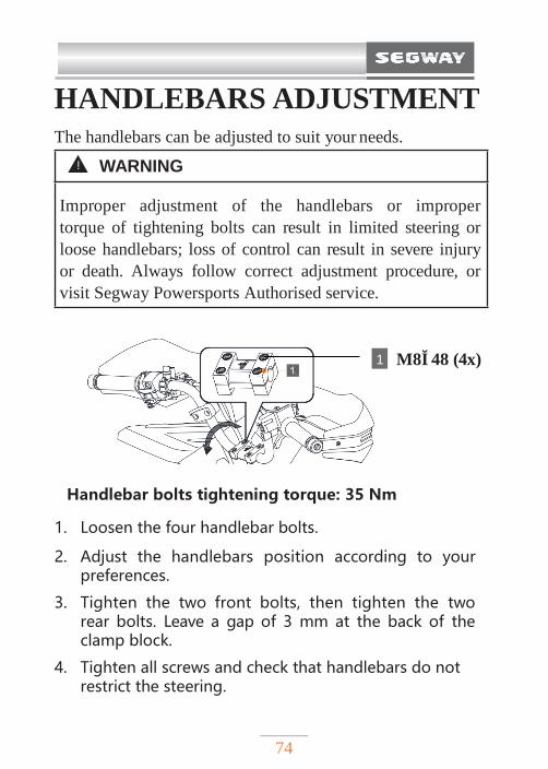
HANDLEBARS ADJUSTMENT The handlebars can be adjusted to suit your needs.
1 M8×48 (4x)
Handlebar bolts tightening torque: 35 Nm
1. Loosen the four handlebar bolts.
2. Adjust the handlebars position according to your preferences.
3. Tighten the two front bolts, then tighten the two rear bolts. Leave a gap of 3 mm at the back of the clamp block.
4. Tighten all screws and check that handlebars do not restrict the steering.
! WARNING
Improper adjustment of the handlebars or improper
torque of tightening bolts can result in limited steering or
loose handlebars; loss of control can result in severe injury
or death. Always follow correct adjustment procedure, or
visit Segway Powersports Authorised service.
MAINTENANCE
75
OPERATION
BASIC DRIVING GUIDE……………...……77
Trail etiquette …………………………………77
Know your riding area …….…………………78
Break–in period …………….………………78
Burnishing Brake Pads ………………………78
CVT clutch / Drive belt ………………………79
Mounting the ATV …………………..…………79
Starting the engine …………..…………………80
Parking………………………….………………80
Turns……………………………….……………80
Riding in reverse……………...…………………81
Turning around on a hill (k-turns) …..…………82
Riding on slippery surfaces……………………83
Riding through water……………………………84
Crossing obstacles……………….………………85
Riding uphill…………….………………………86
Riding downhill……...…………………………88
Driving on a sidehill / Traversing………....……89
76
OPERATION
Parking on an incline …………………………90
Braking …… …………………………………91
Parking the vehicle ………………….…………91
Break-in ……………….……………………….92
PRE-RIDE INSPECTION……………………93
Pre-ride checklist………...…………………93
LOAD LIMITS & GUIDELINES……………95
Maximum loading capacities……...…………97
Loading Guidelines…………………………98
Trailer…………………………...…………..99
WINCH GUIDE ………..…………………101
OPERATION
77
This section provides you with basic operating
instructions including how to start and stop the vehicle,
driving skills and precautions when driving on different
terrains.
Even if you've ridden other ATVs, you must take time to
familiarize yourself with how this ATV handles. Practice in
flat wide open area until you are familiar with this model.
BASIC DRIVING GUIDE Trail etiquette
Always practice good etiquette when riding. Allow a
safe distance between your vehicle and other vehicles
operating in the same area. Communicate to oncoming
riders by signaling the number of vehicles in your group.
When stopping, park your vehicle at the edge of the trail as
far as possible to allow others to pass safely.
! WARNING
Failure to inspect that your vehicle is in safe
operating condition before ride increases the risk of an
accident. Always perform Pre-Ride Inspection as
described in this manual before every ride to make
sure your vehicle in safe operating condition. Always
follow the inspection and maintenance procedures and
schedules described in this manual. See also the
Periodic Maintenance section.
OPERATION
78
Know your riding area
Familiarize yourself with all laws and regulations
concerning the operation of this vehicle in your area.
Respect the environment in which you ride your vehicle.
Find out where the designated riding areas are by
contacting your dealer, a local riding club, or local officials.
Break-in period
Break-in period is the first 300 km of operation. Careful
break-in of new engine and drivetrain components will
improve the performance and service life of your ATV.
Follow these steps carefully. After break-in, change the
engine oil and oil filter.
Burnishing brake pads
To achieve full braking performance, the brakes need about
200 km of running-in.
Heavy or excessive braking when brake system is new
may damage your pads and brake discs.
OPERATION
79
CVT clutch / Drive belt
Proper break-in of the C V T clutch and drive belt will
ensure longer life and better performance. Break-in the
clutch and drive belt at low speeds for the recommended
period, with pulling only light loads. Avoid violent
acceleration and high-speeds during break-in period. If the
drive belt is broken, be sure to clean also the intake and
outlet ducts. Take out any debris from the clutch and
engine compartment when belt is replaced.
Mounting the ATV
1. Wear protective riding gear. See the Safe Riding
Gear section.
2. Perform the pre-ride inspection.
3. Place the transmission in Park.
4. Mount the vehicle from the left side.
5. Sit upright with both feet on the footrests and both
hands on the handlebars.
6. Start the engine and allow it to warm up.
7. Drive slowly. Practice maneuvering and using the
throttle and brakes on flat surfaces.
OPERATION
80
Starting the engine
1. Apply forcefully the foot brake.
2. Turn the ignition key to the“ON”position (P. 38).
3. Press the start button (green) to start the engine; (P. 39)
4. Allow the engine to warm up.
Parking
1. Apply the foot brake and set the shift lever to the "P" position;
2. Press the engine stop button (red) to stop the engine; (P. 39)
3. Turn the key to the "OFF" position (P. 38); the key can be taken out of the main switch.
4. Lock the Parking brake lever; (P. 53)
Turns
Turning on ATV involves moving your body. You must learn to lean and shift body weight into turns to maintain control.
1. Slow down.
2. Steer in the direction of the turn.
3. Keep both feet on the footrests.
4. Lean your upper body to the inside of the turn while supporting your weight on the outer footrest. This technique alters the balance of
OPERATION
81
traction between the rear wheels, allowing the turn to be made smoothly. The same leaning technique should be used for turning in reverse.
5. Practice turns at slow speeds before attempting to turn at faster speeds.
Riding in reverse
If you need to reverse, make sure the area behind you is
clear, and operate at low speed.
Do not use the Override switch unless additional wheel
speed is required for vehicle movement. Use the Override
button with caution as it greatly increase rearward speed. Do
not operate at wide open throttle. Operate the throttle just
enough to maintain a desired momentum.
To reverse, follow the following procedure:
1. Always check for obstacles or people behind you;
be sure there are no obstacles or people in your way.
2. Press brake pedal and change the gears to "R";
! WARNING
Turning improperly can result in vehicle overturn. Never turn abruptly or at sharp angles. Never turn at high speeds. Never turn quickly when carrying cargo.
OPERATION
82
Turning around on a hill (k-turns)
If the engine stalls while riding uphill, or if wheels start to spin, never back down the hill! Use the k-turn instead to turn your ATV around from the hill.
1. Stop and lock the parking brake while keeping
your body weight shifted forward.
2. The machine allows engine braking when driving downhill.
3. Leave the transmission in gear and stop the engine.
4. Dismount the vehicle on the uphill side, or on the left if the vehicle is pointing straight uphill. While staying uphill of the vehicle, turn the handlebars fully to the left.
5. While holding the brake lever, release the parking brake lock and slowly allow the vehicle to roll around to your right until it's pointing across the hill or slightly downward.
6. Lock the parking brake. Remount the vehicle from
the uphill side, keeping your body weight uphill.
7. Keep the transmission in gear and start the engine.
8. Release the parking brake and proceed slowly, controlling speed with the brake lever until you get on more level surface.
OPERATION
83
Riding on slippery surfaces
Whenever riding on slippery surfaces such as wet trails
or loose gravel, or during freezing weather, follow these
precautions:
1. Do not operate on excessively rough, slippery or
loose terrain.
2. Slow down when entering slippery areas.
3. Engage 4x4 drive before wheels begin to lose traction.
4. Maintain high level of alertness, reading the trail and
avoiding quick turns which can cause slides.
5. Never apply the brakes during the slide. Correct the
slide by turning the handlebars in the direction of the
slide.
NOTE
Severe damage to drivetrain may occur if the 4x4 is
engaged while the wheels are turning. Allow the rear
wheels to stop before engaging 4x4, or engage 4x4
before wheels begin to lose traction.
OPERATION
84
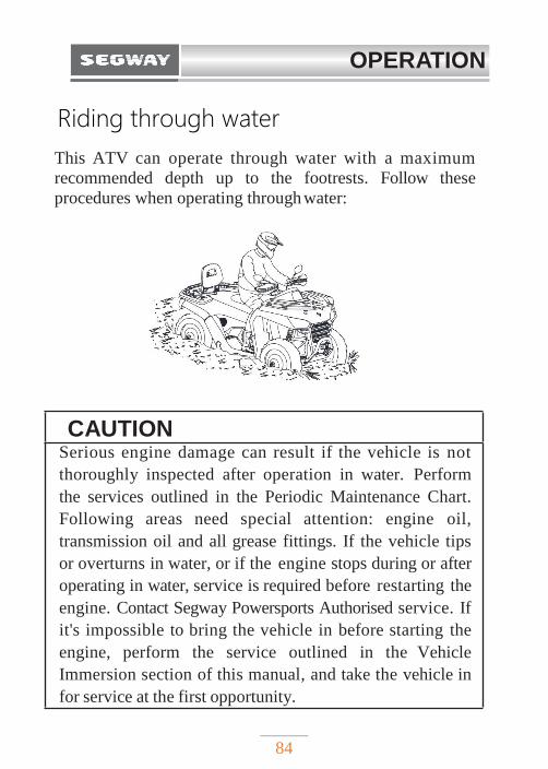
Riding through water
This ATV can operate through water with a maximum
recommended depth up to the footrests. Follow these
procedures when operating through water:
CAUTION Serious engine damage can result if the vehicle is not
thoroughly inspected after operation in water. Perform
the services outlined in the Periodic Maintenance Chart.
Following areas need special attention: engine oil,
transmission oil and all grease fittings. If the vehicle tips
or overturns in water, or if the engine stops during or after
operating in water, service is required before restarting the
engine. Contact Segway Powersports Authorised service. If
it's impossible to bring the vehicle in before starting the
engine, perform the service outlined in the Vehicle
Immersion section of this manual, and take the vehicle in
for service at the first opportunity.
OPERATION
85
1. Determine water depth and current before entering the water.
2. Choose a crossing where both banks have gradual inclines.
3. Avoid operating through deep or fast-flowing water.
4. After leaving the water, test the brakes. Apply them
lightly several times while driving slowly. The friction will help dry out the pads.
If it´s unavoidable to enter water deeper than to the footrests:
◆ Proceed slowly. Avoid rocks and obstacles.
◆ Balance your weight. Avoid sudden movements.
◆ Maintain steady speed. Do not make sudden turns
or stops. Do not make sudden throttle changes.
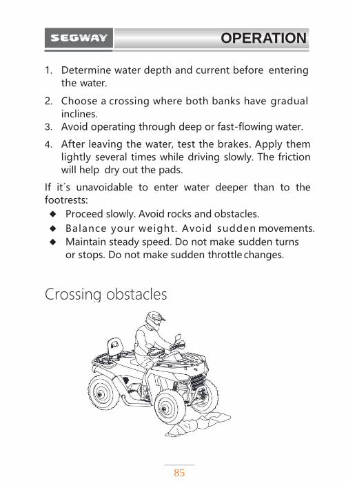
Crossing obstacles
OPERATION
86
Follow these precautions when crossing obstacles:
1. Before operating in a new area, check for obstacles.
2. Watch out for bumps, potholes and other obstacles in the terrain.
3. When you approach the obstacle, reduce your
speed, be prepared to stop.
4. Never try to ride over large obstacles such as large rocks or fallen logs.
5. Always have a passenger dismount when you approach the obstacle that could cause a fall from the vehicle, or tip over.
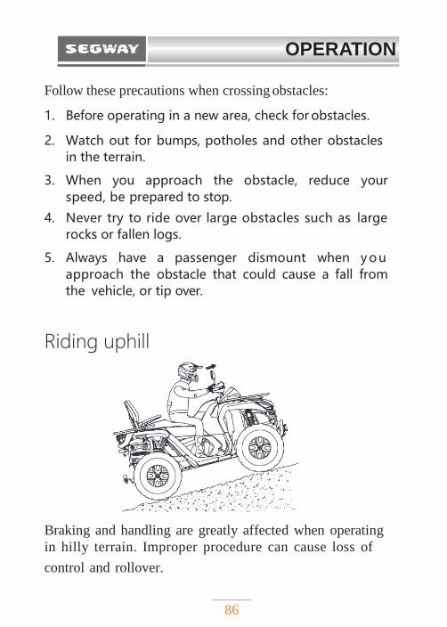
Riding uphill
Braking and handling are greatly affected when operating
in hilly terrain. Improper procedure can cause loss of
control and rollover.
OPERATION
87
Whenever riding uphill, follow this method:
1. Always shift to 4x4 mode before ascending or
descending a hill. Never ride in TURF mode (2x2
without differential lock) when operating on a hill or
other irregular terrain.
2. Drive straight uphill.
3. Avoid steep hills. Maximum incline is:
◆ AT6 S:25°
◆ AT6 L:15°
4. Always check the terrain carefully before ascending
any hill.
5. Never climb hills with excessively slippery or loose
surfaces.
6. Keep both feet on the footrests.
7. Lean as far forward as possible. A passenger should
also shift his / her body weight uphill.
8. Proceed at a steady pace and steady throttle.
Suddenly opening the throttle can cause the ATV to
flip over backwards.
OPERATION
88
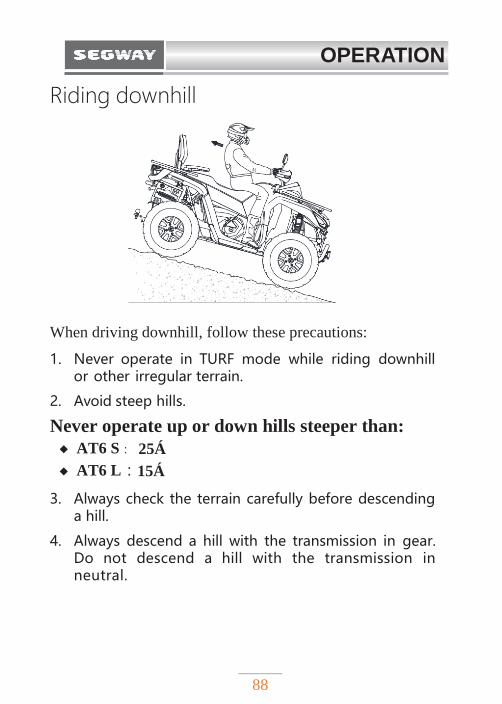
Riding downhill
When driving downhill, follow these precautions:
1. Never operate in TURF mode while riding downhill or other irregular terrain.
2. Avoid steep hills.
Never operate up or down hills steeper than:
◆ AT6 S: 25°
◆ AT6 L:15°
3. Always check the terrain carefully before descending a hill.
4. Always descend a hill with the transmission in gear. Do not descend a hill with the transmission in neutral.
OPERATION
89
5. Slow down. Never go down a hill at high speed.
6. Steer straight downhill. Avoid descending a hill at an angle, this would cause the vehicle to lean sharply to one side.
7. Lean as far backward as possible. A passenger should also shift his / her body weight uphill.
8. Apply the brakes slightly. Applying the brakes too much may cause the rear wheels to lock, which could result in loss of control.
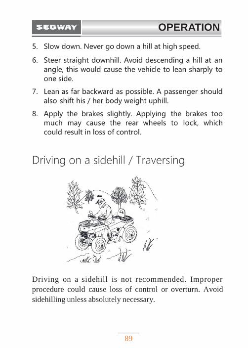
Driving on a sidehill / Traversing
Driving on a sidehill is not recommended. Improper
procedure could cause loss of control or overturn. Avoid
sidehilling unless absolutely necessary.
OPERATION
90
If sidehilling is unavoidable, follow this method:
1. Slow down.
2. Avoid crossing the side of a steep hill.
3. Lean into the hill, transferring your body weight toward the hill while keeping your feet on the footrests.
4. If the vehicle begins to tip, quickly turn the handlebar downhill, if possible, or get off on the uphill side immediately!
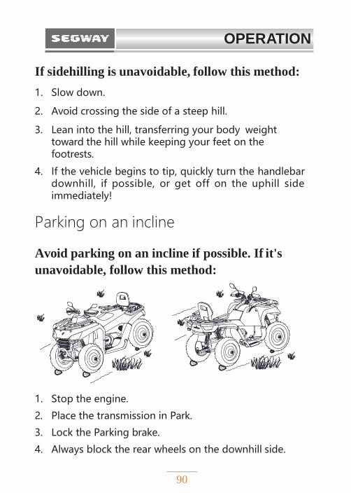
Parking on an incline
Avoid parking on an incline if possible. If it's
unavoidable, follow this method:
1. Stop the engine.
2. Place the transmission in Park.
3. Lock the Parking brake.
4. Always block the rear wheels on the downhill side.
OPERATION
91
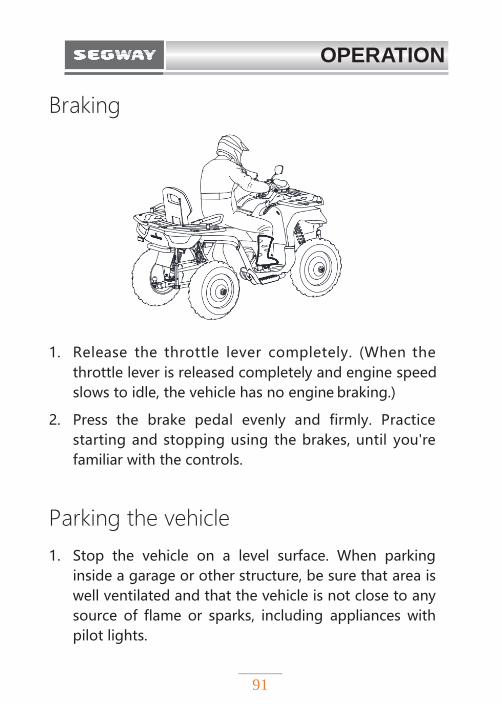
Braking
1. Release the throttle lever completely. (When the
throttle lever is released completely and engine speed
slows to idle, the vehicle has no engine braking.)
2. Press the brake pedal evenly and firmly. Practice
starting and stopping using the brakes, until you're
familiar with the controls.
Parking the vehicle
1. Stop the vehicle on a level surface. When parking
inside a garage or other structure, be sure that area is
well ventilated and that the vehicle is not close to any
source of flame or sparks, including appliances with
pilot lights.
OPERATION
92
2. Place the transmission in Park.
3. Turn the engine off.
4. Engage the Parking brake.
5. Slowly release the brake pedal and make sure
the transmission is in Park before exiting the vehicle.
6. Remove the ignition key to prevent unauthorized use.
Break-in
The engine needs 300 km break-in period.
During break-in:
◆ Avoid using full throttle.
◆ Always use less than 3/4 throttle.
◆ Do not pull or carry heavy loads.
◆ Avoid hard or continuous acceleration.
◆ Vary the engine RPM
The brakes need a 200km run-in period.
New brakes will not operate at their maximum efficiency
until the run-in period is over. Brake performance may be
compromised, so be careful.
NOTE
During this period, avoid full-throttle operation,
rapid acceleration, and riding in constant RPM.
OPERATION
93
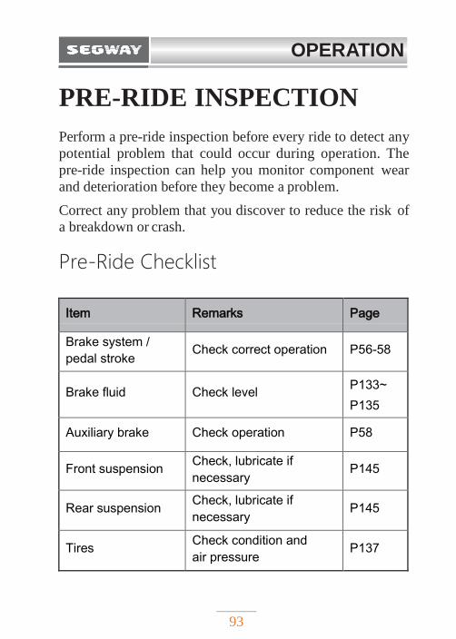
PRE-RIDE INSPECTION
Perform a pre-ride inspection before every ride to detect any
potential problem that could occur during operation. The
pre-ride inspection can help you monitor component wear
and deterioration before they become a problem.
Correct any problem that you discover to reduce the risk of
a breakdown or crash.
Pre-Ride Checklist
Item Remarks Page
Brake system /
pedal stroke Check correct operation P56-58
Brake fluid Check level P133~
P135
Auxiliary brake Check operation P58
Front suspension Check, lubricate if
necessary P145
Rear suspension Check, lubricate if
necessary P145
Tires Check condition and
air pressure P137
OPERATION
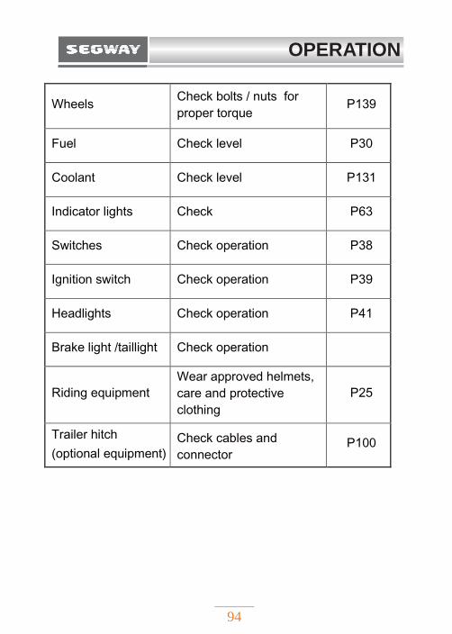
94
Wheels Check bolts / nuts for
proper torque P139
Fuel Check level P30
Coolant Check level P131
Indicator lights Check P63
Switches Check operation P38
Ignition switch Check operation P39
Headlights Check operation P41
Brake light /taillight Check operation
Riding equipment Wear approved helmets,
care and protective
clothing
P25
Trailer hitch
(optional equipment) Check cables and
connector P100
OPERATION
95
HAULING CARGO & LOAD LIMITS
Front and rear racks are capable of carrying goods up to
specified capacity. Tow hitch behind the vehicle can tow
trailers and accessories.
Loads carried by the vehicle will affect the vehicle's
operation, stability and braking distance. Do not exceed
the vehicle load limit, including driver, passenger, cargo,
accessories and tongue weight. Unsecured loads can create
unstable operating conditions, which could result in loss of
control of the vehicle.
! WARNING
◆ Strictly follow instructions in the operator´s manual
of the mounted or towed machinery or trailer.
Do not operate the tractor-machine or tractor-
trailer combination unless all instructions have
been followed.
◆ Stay clear of the area between vehicle and trailer.
◆ Reduce speed and allow greater braking distance
when carrying loads.
◆ Carry loads as low on the racks as possible. Too
much cargo on the racks can raise the vehicle's
center of gravity and reduce stability.
OPERATION
96
! WARNING
◆ Fix all loads before operation. Unstable load can
create unstable driving conditions, which can
result the vehicle to lose control.
◆ Heavy loading causes braking and control
problems. Take extra care when using the brakes of
a loaded vehicle. Avoid terrain or conditions
that may result in backing downhill.
◆ Take extra care when riding with load beyond the
edges of the rack. Stability and maneuverability
may be adversely affected, causing the vehicle to
tip over.
◆ Do not block the headlight beam when loading the
front rack.
◆ Don't drive faster than in recommended
speeds. When towing loads on flat ground, the
vehicle should not exceed 15 km/h. When towing
loads over rough terrain, turning, climbing or
descending a hill, you must not exceed speeds of 8
km/h.
OPERATION
97
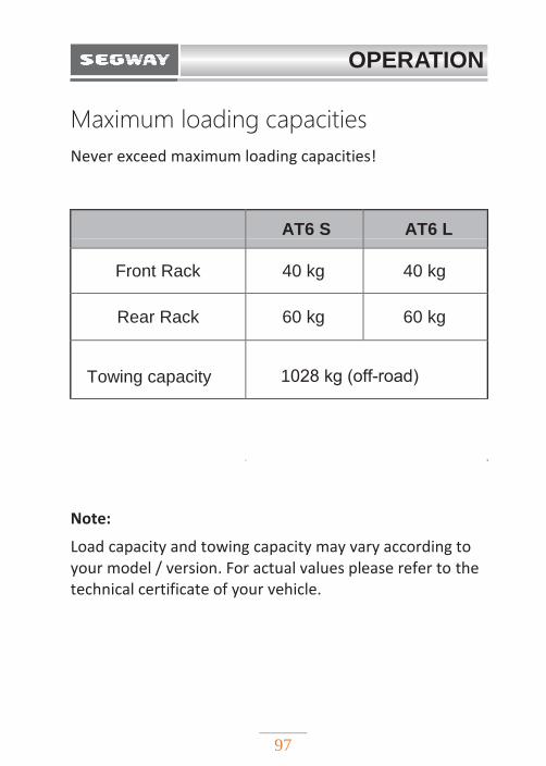
Maximum loading capacities
Never exceed maximum loading capacities!
AT6 S AT6 L
Front Rack 40 kg 40 kg
Rear Rack 60 kg 60 kg
Towing capacity 1028 kg (off-road)
Note:
Load capacity and towing capacity may vary according to your model / version. For actual values please refer to the technical certificate of your vehicle.
OPERATION
98
Loading guidelines
When transporting cargo, please follow these
instructions:
1. Do not exceed the weight capacities specified on the
warning labels and in this manual.
2. Never ride with a passenger on the front or rear rack.
3. Cargo weight distribution should be 1/3 on the
front rack and 2/3 on the rear rack.
4. Make sure that the cargo is firmly secured to the rack
before driving.
5. Avoid riding on steep slopes when carrying cargo
or pulling a trailer.
6. Use low-speed gear when hauling heavy cargo.
7. When hauling or towing cargo, operate the vehicle with
great caution.
OPERATION
99
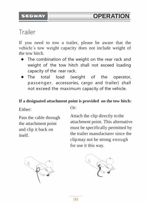
Trailer
If you need to tow a trailer, please be aware that the
vehicle´s tow weight capacity does not include weight of
the tow hitch.
◆ The combination of the weight on the rear rack and
weight of the tow hitch shall not exceed loading
capacity of the rear rack.
◆ The total load (weight of the operator,
passenger , accessories, cargo and trailer) shall
not exceed the maximum capacity of the vehicle.
If a designated attachment point is provided on the tow hitch:
Either:
Pass the cable through
the attachment point
and clip it back on
itself.
Or:
Attach the clip directly to the
attachment point. This alternative
must be specifically permitted by
the trailer manufacturer since the
clip may not be strong enough
for use it this way.
OPERATION
100
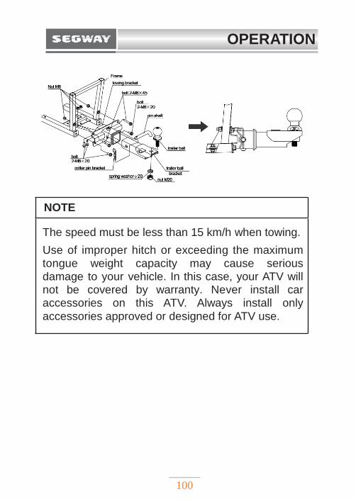
NOTE
The speed must be less than 15 km/h when towing.
Use of improper hitch or exceeding the maximum tongue weight capacity may cause serious damage to your vehicle. In this case, your ATV will not be covered by warranty. Never install car accessories on this ATV. Always install only
accessories approved or designed for ATV use.
OPERATION
101
WINCH GUIDE If your model is equipped with a winch, please read this
guide before use to understand and to familiarize yourself
with safety precautions and operating instructions.
◆ It is strictly prohibited for people under 16 years to
operate this winch.
◆ Before and during operation, pay attention to
the safety and environmental conditions within
the operating range of the winch
◆ Do not overload the winch. Ensure that all winch
accessories meet or exceed working load limit of the
cable. We recommend using an optional pulley
block and double rope winching to reduce the
load on the winch, cable and battery. When using
double rope winching, the rated value of the pulley
block should be 2x the pulling capacity of the winch.
◆ Do not try to pull heavy loads for a long period of
time. Electric winches are only designed for limited
time use, winch should not be used under constant
! WARNING
The user must read and understand the operating
instructions and warnings of this operation manual. If the
instructions or warnings are not followed, serious property
damage or personal injury may occur.
OPERATION
102
load. Do not pull for more than 1 minute, or near to
maximum rated load. If the winch motor gets very
hot, stop winching and let it cool down for a few
minutes.
◆ Always be sure that at least five (5) full turns of
winch cable are wrapped around the winch drum.
◆ Avoid pulling from extreme angles, as this will
cause the winch cable to accumulate at one end
of the drum and damage the cable.
◆ Be aware, that the maximum pulling capacity of the
winch is the maximum pulling capacity on the first
layer only - only the first layer can be pulled in max.
winch capacity. Do not overload the winch.
◆ Never hook the cable back to itself; otherwise the
cable will be damaged. Use trunk protection
protector.
◆ Before operation, make sure that the winch is
firmly fixed to the vehicle or bracket.
◆ Before moving heavy objects, check the winch
cable to prevent kinks and uneven wire layers. The
slacked cable must be properly tightened under a
weight of about 50 kg.
◆ When pulling the load, be sure to lay a blanket or
protective cloth on the cable near the hook end.
This will prevent the possibility of breaking the
wire cable and help prevent serious injuries and
damage.
OPERATION
103
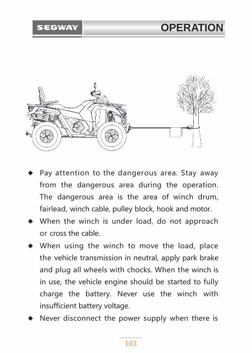
◆ Pay attention to the dangerous area. Stay away
from the dangerous area during the operation.
The dangerous area is the area of winch drum,
fairlead, winch cable, pulley block, hook and motor.
◆ When the winch is under load, do not approach
or cross the cable.
◆ When using the winch to move the load, place
the vehicle transmission in neutral, apply park brake
and plug all wheels with chocks. When the winch is
in use, the vehicle engine should be started to fully
charge the battery. Never use the winch with
insufficient battery voltage.
◆ Never disconnect the power supply when there is
OPERATION
104
a load on the winch.
◆ After the winching, release the load
immediately. Do not tighten the cable.
◆ Always stay away from cable, hook and winch.
◆ Check winch, cables, hook, and broken strands of
worn wires regularly. When operating with the
steel wire cable, wear thick leather gloves. Never let
the steel wire cable run through your hands. Check
the steel cable before use. Crushed, pinched, worn or
kinked areas seriously reduce cable working load
limit. Damaged wire cable should be replaced.
◆ The clutch should be disconnected first, and then the
winch cable should be pulled by the hook of the
protective lever.
◆ Always use the hook strap when handling the hook.
◆ After the use, pull the winch cable tightly with about
50 kg of tension, using the hook strap.
◆ Do not operate the winch under the influence of
alcohol or drugs.
◆ If there is a problem, cut off the battery
immediately and check carefully.
OPERATION
105
◆ Wear goggles, long sleeves, non-slip boots, work
cap, thick leather gloves. Keep your hair under the
work cap and remove all personal jewelry.
◆ Do not repair or modify any part of the winch.
◆ When the winch is in use, be sure to start the
vehicle engine and set the gear position to "N" to
make sure battery is charged;
◆ When the winch is working, the current is large. You
must start the engine and apply throttle lightly to
avoid damage to the battery;
◆ Winch cable and pulled vehicle should be in a
straight line. Too big an angle will change the
direction of the pulling force and damage the cable;
◆ If severe noise or vibration occurs during winching,
stop the winch immediately.
OPERATION
106
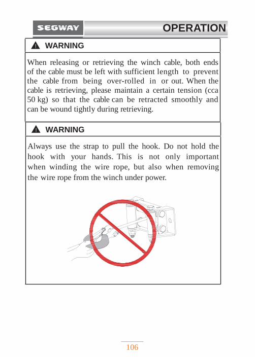
! WARNING
Always use the strap to pull the hook. Do not hold the
hook with your hands. This is not only important
when winding the wire rope, but also when removing
the wire rope from the winch under power.
! WARNING
When releasing or retrieving the winch cable, both ends
of the cable must be left with sufficient length to prevent
the cable from being over-rolled in or out. When the
cable is retrieving, please maintain a certain tension (cca
50 kg) so that the cable can be retracted smoothly and
can be wound tightly during retrieving.
107
MAINTENANCE
REGULAR MAINTENANCE…………….… 111
PERIODIC MAINTENANCE TABLE….....…112
LUBRICATING GUIDE……………………… 117
SEAT REMOVAL …………………………… 118
TANK COVER…………………………………119
FRONT MAINTENANCE PANEL REMOVAL..120
INSTRUMENT COVER REMOVAL …….... 121
ENGINE OIL ……………………………...… 122
Oil recommendation………………………… 123
Engine oil level check……………………… 124
Changing engine oil and filter………..……… 126
Front / Rear Differential oil and Final Drive oil..127
COOLANT………………………………………129
Adding Coolant ………..……………………129
BRAKE SYSTEM…………...…………………131
Brake fluid……………………………………132
108
MAINTENANCE Front brake fluid .……………………………134
Brake pad inspection ………………..………135
TIRES …………………………………………136
Tire pressure………………….……..………136
Tire tread depth ……………..…………………137
When to Change a tire ……………….………138
Wheels removal………………………………138
Tire replacement ………………………………140
SHOCK ABSORBERS ADJUSTMENT………141
Oil shock absorber……………………………141
Adjustable shock absorber……………….……142
SUSPENSION LUBRICATION…………....…144
FRONT AND REAR AXLE BOOTS …………145
AIR FILTER ………………………………… 146
LIGHTS…………………………………………148
Headlamps replacement ………………………149
Taillight / rear turn light replacement ……....…151
High beam adjustment……………….…………152
SPARK PLUG………..…………………………155
Spark plug inspection…………………………156
109
MAINTENANCE
SPARK ARRESTOR……………………………158
BATTERY………….……………………………160
Battery removal….……………..………………161
Battery charging………………..………………162
Battery installation………………………………163
Jump-starting……………..……..….……………164
FUSES …………….…...………….…….……… 165
Fuse box……………………...…..……..………166
Fuse/relay ratings and location ……..……...……167
Fuse replacement………………….……………170
APPEARANCE CARE………..………...………171
Cleaning the vehicle……………………………172
Cleaning tips……………………………………172
Vehicle storage…………………………………172
MAINTENANCE
110
Proper maintenance is essential for safe operation of this
vehicle. To help you properly maintain your vehicle, this
part of this manual provides a maintenance plan.
Maintenance schedule intervals assume the vehicle is
operated under normal conditions. If your vehicle often
drives on rough roads or environments, it may require
additional and more frequent maintenance. If you have
some mechanical knowledge and basic tools, many
maintenance items can be completed by yourself.
However, we suggest to ask for certain maintenance a
S e g w a y Powersports service. Some maintenance may
require special tools and professional skills. These tasks are
best done by authorized Segway Powersports services.
Even if you have extensive self-maintenance experience,
we still recommend carrying out repairs and maintenance
by authorized Segway Powersports service.
! WARNING
Failure to perform maintenance instructions and
precautions correctly can result in serious injury or death.
Please follow the steps and precautions in this manual.
MAINTENANCE
111
REGULAR MAINTENANCE
Any qualified repair shop can maintain, replace or repair
the emission control device or system on your vehicle.
Authorized Segway Powersports dealers can perform any
services that may be required for your vehicle.
If any part, provided by an after-sales component
manufacturer, reduces the effectiveness of vehicle emission
controls, it is a potential violation of the Clean Air Act.
The user is responsible for performing the regular
maintenance specified in this manual. Careful regular
maintenance will help keep your vehicle in safe and
reliable condition. Check, clean, lubricate, adjust and
replace parts when necessary. When the inspection
shows that the parts need to be replaced, new parts are
available from the dealer.
If you are not familiar with safe service and adjustment
procedures, qualified dealers can perform these
operations. The maintenance intervals in the chart below
are based on average riding conditions. Frequently used
vehicle must be checked and repaired more frequently.
MAINTENANCE
112
PERIODIC MAINTENANCE CHART Careful periodic maintenance will help keep your
vehicle in the safest, most reliable condition.
Inspection, adjustment and lubrication of important
components are explained in the periodic
maintenance chart.
Inspect, clean, lubricate, adjust and replace
parts as necessary. When inspection reveals the
need for replacement parts, use genuine parts
available from your authorized dealer. Service and
adjustments are important for proper vehicle
operation. If you're not familiar with safe service
and adjustment procedures, have a qualified dealer
perform these operations.
Maintenance intervals in the following chart are
based upon average riding conditions. Vehicles
subjected to severe use must be inspected and
serviced more frequently.
Severe use is defined as:
◆ Frequent riding in mud, water, or sand
◆ Frequent or prolonged operation in dusty environments
◆ Short trips in cold weather
◆ Racing or racing-style with high RPM use
◆ Prolonged low speed, heavy load operation
◆ Extended idle
MAINTENANCE
113
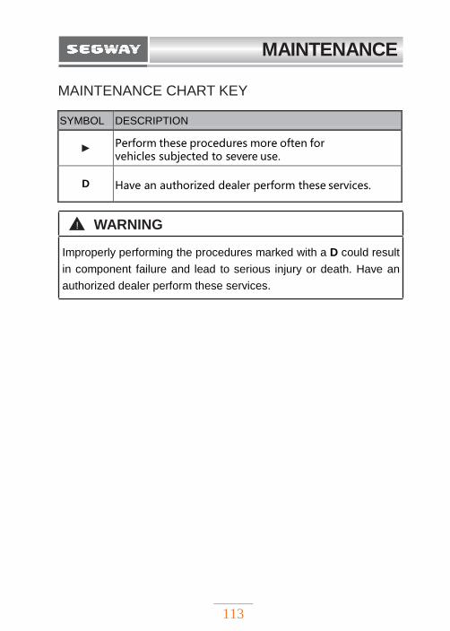
MAINTENANCE CHART KEY
SYMBOL DESCRIPTION
► Perform these procedures more often for vehicles subjected to severe use.
D Have an authorized dealer perform these services.
! WARNING
Improperly performing the procedures marked with a D could result
in component failure and lead to serious injury or death. Have an
authorized dealer perform these services.
MAINTENANCE
114
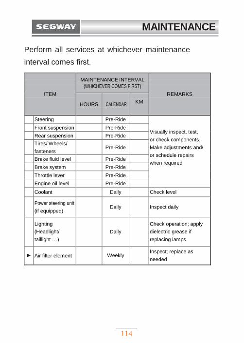
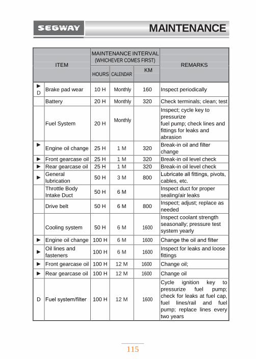
Perform all services at whichever maintenance
interval comes first.
ITEM
MAINTENANCE INTERVAL
(WHICHEVER COMES FIRST)
REMARKS
HOURS
CALENDAR
KM
Steering Pre-Ride
Visually inspect, test,
or check components.
Make adjustments and/
or schedule repairs
when required
Front suspension Pre-Ride Rear suspension Pre-Ride Tires/ Wheels/
fasteners Pre-Ride
Brake fluid level Pre-Ride Brake system Pre-Ride Throttle lever Pre-Ride Engine oil level Pre-Ride Coolant Daily Check level
Power steering unit
(if equipped)
Daily
Inspect daily
Lighting
(Headlight/
taillight …)
Daily
Check operation; apply
dielectric grease if
replacing lamps
► Air filter element
Weekly
Inspect; replace as
needed
MAINTENANCE
115
ITEM
MAINTENANCE INTERVAL
(WHICHEVER COMES FIRST)
REMARKS
HOURS CALENDAR KM
►
D Brake pad wear 10 H Monthly 160 Inspect periodically
Battery 20 H Monthly 320 Check terminals; clean; test
Fuel System
20 H
Monthly Inspect; cycle key to
pressurize
fuel pump; check lines and
fittings for leaks and
abrasion ►
Engine oil change 25 H 1 M 320 Break-in oil and filter
change ► Front gearcase oil 25 H 1 M 320 Break-in oil level check ► Rear gearcase oil 25 H 1 M 320 Break-in oil level check
► General
lubrication 50 H 3 M 800 Lubricate all fittings, pivots,
cables, etc.
Throttle Body
Intake Duct 50 H 6 M Inspect duct for proper
sealing/air leaks
Drive belt 50 H 6 M 800 Inspect; adjust; replace as
needed
Cooling system
50 H
6 M
1600
Inspect coolant strength
seasonally; pressure test
system yearly
► Engine oil change 100 H 6 M 1600 Change the oil and filter
► Oil lines and
fasteners 100 H 6 M 1600 Inspect for leaks and loose
fittings ► Front gearcase oil 100 H 12 M 1600 Change oil;
► Rear gearcase oil 100 H 12 M 1600 Change oil
D
Fuel system/filter
100 H
12 M
1600
Cycle ignition key to
pressurize fuel pump;
check for leaks at fuel cap,
fuel lines/rail and fuel
pump; replace lines every
two years
MAINTENANCE
116
ITEM
MAINTENANCE INTERVAL
(WHICHEVER COMES FIRST)
REMARKS
) HOURS CALENDAR KM
► Radiator 100 H 12 M 1600 Inspect; clean fins /
external surfaces
► Cooling hoses 100 H 12 M 1600 Inspect for leaks
► Engine mounts 100 H 12 M 1600 Inspect
Exhaust muffler/
pipe / Joints 100 H 12 M 1600 Inspect; clean; replace
worn parts
D Spark plug 100 H 12 M 1600 Inspect; replace as
needed
D Clutches
(drive and driven) 100 H 12 M 1600 Inspect; clean; replace
worn parts
D Front wheel
bearings 100 H 12 M 1600 Inspect; replace as
needed
D Brake fluid 200 H 24 M 3200 Change every two years
Spark arrester 300 H 36 M 4800 Clean out
► Coolant 60 M Replace coolant
D
Valve clearance
500 H
8000
) Inspect; adjust
D
Toe adjustment
Inspect periodically;
adjust when parts are
replaced
Headlight aim Adjust as needed
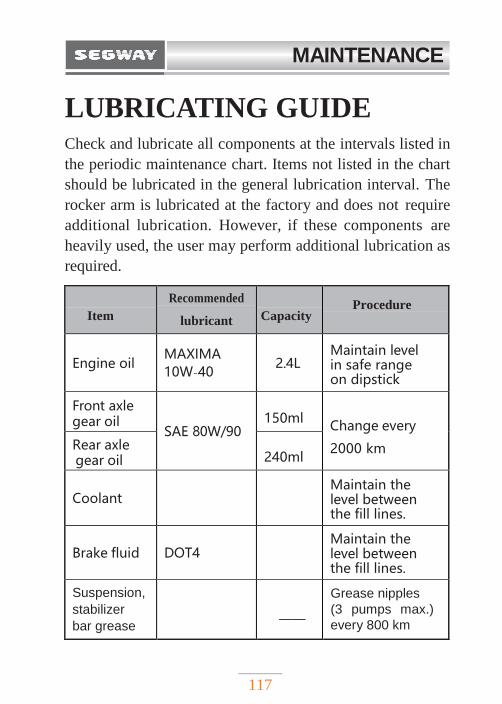
MAINTENANCE
117
LUBRICATING GUIDE Check and lubricate all components at the intervals listed in
the periodic maintenance chart. Items not listed in the chart
should be lubricated in the general lubrication interval. The
rocker arm is lubricated at the factory and does not require
additional lubrication. However, if these components are
heavily used, the user may perform additional lubrication as
required.
Item Recommended
lubricant Capacity Procedure
Engine oil MAXIMA10W-40
2.4L Maintain level in safe range on dipstick
Front axle gear oil
SAE 80W/90 150ml
Change every
2000 km
.
Rear axle gear oil 240ml
Coolant Maintain the level between the fill lines.
Brake fluid DOT4 Maintain the level between the fill lines.
Suspension,
stabilizer
bar grease ——
Grease nipples
(3 pumps max.)
every 800 km
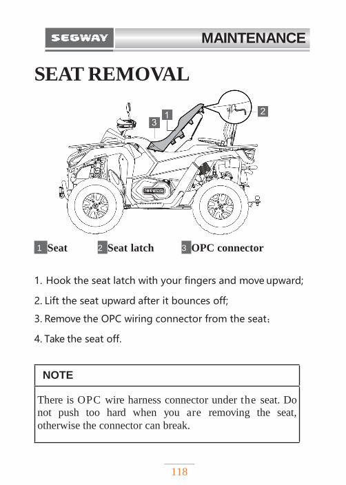
MAINTENANCE
118
SEAT REMOVAL
1 Seat 2 Seat latch 3 OPC connector
1. Hook the seat latch with your fingers and move upward;
2. Lift the seat upward after it bounces off;
3. Remove the OPC wiring connector from the seat;
4. Take the seat off.
NOTE
There is OPC wire harness connector under the seat. Do
not push too hard when you are removing the seat,
otherwise the connector can break.
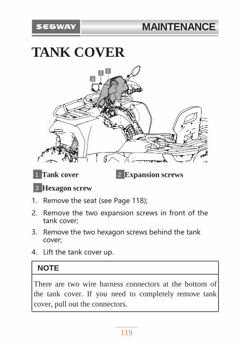
MAINTENANCE
119
TANK COVER
1 Tank cover 2 Expansion screws
3 Hexagon screw
1. Remove the seat (see Page 118);
2. Remove the two expansion screws in front of the tank cover;
3. Remove the two hexagon screws behind the tank cover;
4. Lift the tank cover up.
NOTE
There are two wire harness connectors at the bottom of
the tank cover. If you need to completely remove tank
cover, pull out the connectors.
3 2
1
2 1
3
1
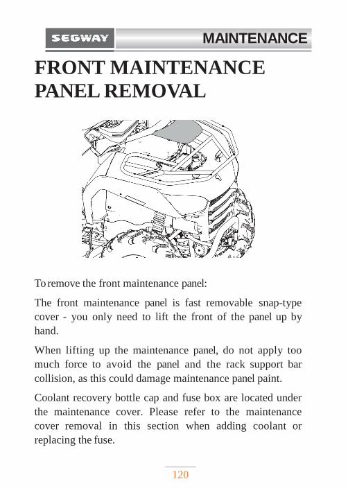
MAINTENANCE
120
FRONT MAINTENANCE
PANEL REMOVAL
To remove the front maintenance panel:
The front maintenance panel is fast removable snap-type
cover - you only need to lift the front of the panel up by
hand.
When lifting up the maintenance panel, do not apply too
much force to avoid the panel and the rack support bar
collision, as this could damage maintenance panel paint.
Coolant recovery bottle cap and fuse box are located under
the maintenance cover. Please refer to the maintenance
cover removal in this section when adding coolant or
replacing the fuse.
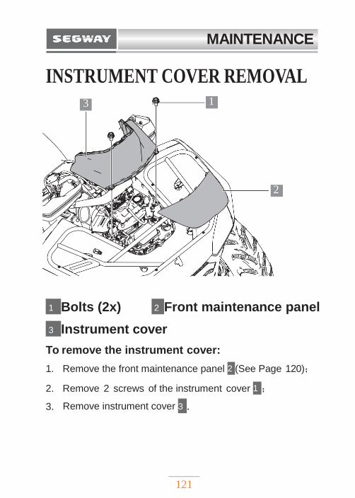
MAINTENANCE
121
3 1
2
INSTRUMENT COVER REMOVAL
1 Bolts (2x) 2 Front maintenance panel
3 Instrument cover
To remove the instrument cover:
1. Remove the front maintenance panel 2 (See Page 120);
2. Remove 2 screws of the instrument cover 1 ;
3. Remove instrument cover 3 .
MAINTENANCE
122
ENGINE OIL
Be sure to check and change the oil at the time required
by the regular maintenance chart. Be sure to use
recommended engine oil. Oil filter must be changed after
the break-in and every time when the oil is changed. Pay
special attention to the oil level. If the oil level is low, add
the oil. If the oil level starts to rise (especially in cold
weather), stop using the machine and contact an
authorized Segway Powersports service.
! WARNING
Operation with insufficient , degraded or
contaminated engine oil will cause accelerated wear, and
may result in engine failure, accident and injury. Always
perform the maintenance procedures listed in to Periodic
maintenance chart.
MAINTENANCE
123
Oil recommendation
Note: Oil filter must be changed every time the oil is changed.
Segway recommends using MAXIMA 10W-40 four-cycle oil for this engine. Please refer to the Lubricating
guide section for oil recommendations and capacity.
Recommended oil:
Maxima ATV PREMIUM 10W-40
CAUTION
Mixing brands or using non-recommended oils may cause
serious engine damage. Always use the recommended oil.
Never substitute or mix oil brands.
MAINTENANCE
124
Engine oil level check
1. Park the vehicle on a level ground. Wait at least
5 minutes to allow the oil to flow back to the
bottom of the engine.
2. Put a piece of cotton cloth under the end of the oil
dipstick, then pull the oil dipstick out.
3. Wipe the oil dipstick clean.
4. Reinsert oil dipstick completely;
5. Put a piece of cotton cloth under the end of the oil
dipstick, then pull out the oil dipstick and check the
oil level.
Note:
Oil level should be between the Upper mark 1 and Lower
mark 2 of the dipstick. Oil below the lower mark means the
oil is too low and should be added, oil on the upper level
means there is too much oil in the engine.
NOTE
Running the engine with an improper oil level can cause
serious engine damage.
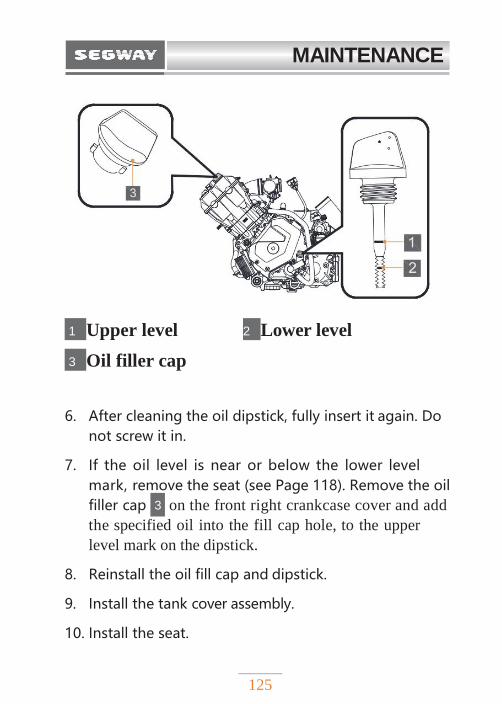
MAINTENANCE
125
1 Upper level 2 Lower level
3 Oil filler cap
6. After cleaning the oil dipstick, fully insert it again. Do
not screw it in.
7. If the oil level is near or below the lower level
mark, remove the seat (see Page 118). Remove the oil
filler cap 3 on the front right crankcase cover and add
the specified oil into the fill cap hole, to the upper
level mark on the dipstick.
8. Reinstall the oil fill cap and dipstick.
9. Install the tank cover assembly.
10. Install the seat.

MAINTENANCE
126
Changing engine oil and filter Have the engine oil changed by an authorized Segway
Powersports service. As part of the replacement, the service
will also clean the oil strainer and replace the oil filter.
! WARNING
◆ Used engine oil contains potentially hazardous
pollutants, which can cause skin diseases such as
dermatitis and skin cancer. Care should be taken
to avoid prolonged and repeated exposure to the
used oil. Wash the skin thoroughly with soap and
hot water to remove engine oil from your skin.
◆ Used oil and used oil filter must be disposed in a
safe way compliant with environmental
regulations. Do not dispose used oil and oil filter
in domestic garbage, sewers or on the ground. For
information on oil recycling or scrapping, please
consult your Segway Powersports dealer.
◆ Do not leave used engine oil in a place where
children can reach.
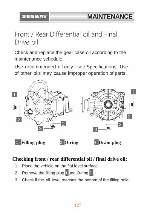
MAINTENANCE
127
Front / Rear Differential oil and Final Drive oil
Check and replace the gear case oil according to the
maintenance schedule.
Use recommended oil only - see Specifications. Use
of other oils may cause improper operation of parts.
1 Filling plug 2 O-ring 3 Drain plug
Checking front / rear differential oil / final drive oil:
1. Place the vehicle on the flat level surface
2. Remove the filling plug 1 and O-ring 2 ;
3. Check if the oil level reaches the bottom of the filling hole.
MAINTENANCE
128
4. Add the recommended oil if needed.
5. Reinstall the O-ring and filling plug.
Torque to specification:
6. Check for the leak.
Changing the front / rear differential oil / final drive oil
Have the front / rear differential oil / final drive oil changed
by an authorized Segway Powersports service according to
the Maintenance chart.
Torque Filling Plug: 16~20Nm
MAINTENANCE
129
COOLANT The coolant circulates in the engine, taking away the
excess heat generated during the engine operation and
making the engine operates at normal temperature
range. Maintaining the coolant will allow cooling system
to work properly and prevent freezing, overheating, and
corrosion. Check coolant level frequently. Mix antifreeze
according to mixing instructions of the coolant liquid used.
The coolant needs to be mixed to suit your operating
conditions. If you use your ATV in extreme climatic
conditions, mixing ratio should be adjusted accordingly.
Use only distilled or demineralized water for mixing.
Adding coolant
The recovery bottle is located on the left side of the vehicle.
1. Observe the coolant level in recovery bottle.
2. If the coolant level is low, remove the cap and add coolant as needed. Maintain the coolant level between minimum 2 and maximum 1 marks on the bottle (when coolant is cool).
3. Remove front maintenance panel (see Page 120);
4. Unscrew the cap, pour in new coolant. Pay attention to the coolant level, do not exceed the maximum mark.
5. Reinstall the recovery bottle cap.
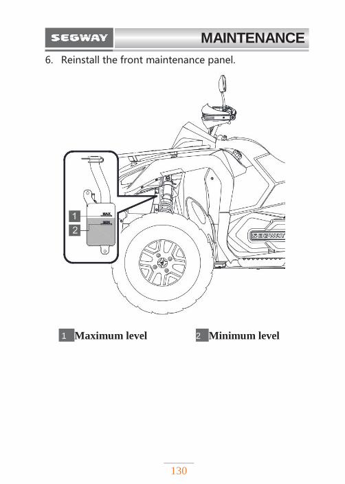
MAINTENANCE
130
6. Reinstall the front maintenance panel.
1 Maximum level 2 Minimum level
MAINTENANCE
131
BRAKE SYSTEM The front and rear brakes are hydraulic disc brakes that
are activated by brake pedal or hand lever. Brakes are self-
adjusting. As the brake pads wear, brake fluid level will
be dropping slowly. Leakage in the brake system can also
cause the brake fluid to drop.
The following inspection is recommended to keep the
braking system in good condition. If the brake is in heavy
use, check it more frequently.
1. Always keep the brake fluid at an correct level.
Please refer to master cylinder/brake fluid section
for details.
2. Check the braking system for leakage.
3. Check whether the brake travels too long or feels soft.
! WARNING
Check brake fluid level periodically. Overfilling the brake cylinder may cause brake drag or brake locking, which may result in serious injury or death. Keep brake fluid at the recommended level, do not overfill. You must check brake pads wear and brake disc condition regularly. If brake pads or disc wear, they should be replaced.
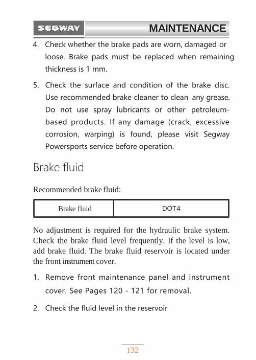
MAINTENANCE
132
4. Check whether the brake pads are worn, damaged or
loose. Brake pads must be replaced when remaining
thickness is 1 mm.
5. Check the surface and condition of the brake disc.
Use recommended brake cleaner to clean any grease.
Do not use spray lubricants or other petroleum-
based products. If any damage (crack, excessive
corrosion, warping) is found, please visit Segway
Powersports service before operation.
Brake fluid
Recommended brake fluid:
No adjustment is required for the hydraulic brake system.
Check the brake fluid level frequently. If the level is low,
add brake fluid. The brake fluid reservoir is located under
the front instrument cover.
1. Remove front maintenance panel and instrument
cover. See Pages 120 - 121 for removal.
2. Check the fluid level in the reservoir
Brake fluid DOT4
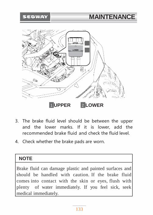
MAINTENANCE
133
1 UPPER 2 LOWER
3. The brake fluid level should be between the upper
and the lower marks. If it is lower, add the
recommended brake fluid and check the fluid level.
4. Check whether the brake pads are worn.
NOTE
Brake fluid can damage plastic and painted surfaces and
should be handled with caution. If the brake fluid
comes into contact with the skin or eyes, flush with
plenty of water immediately. If you feel sick, seek
medical immediately.
1
2
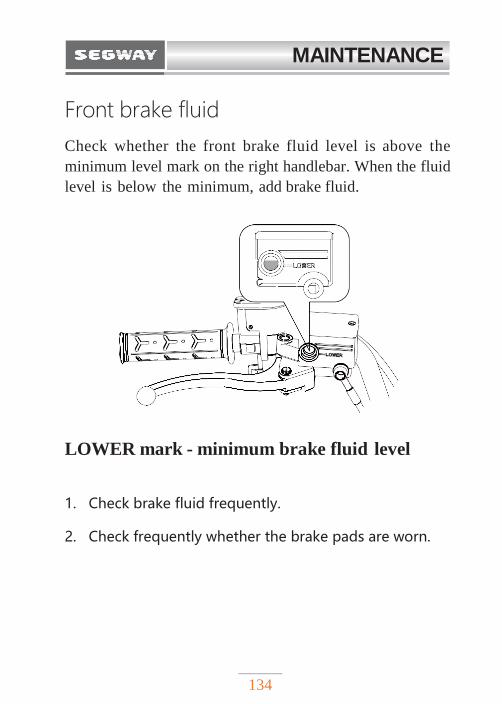
MAINTENANCE
134
Front brake fluid
Check whether the front brake fluid level is above the
minimum level mark on the right handlebar. When the fluid
level is below the minimum, add brake fluid.
LOWER mark - minimum brake fluid level
1. Check brake fluid frequently.
2. Check frequently whether the brake pads are worn.
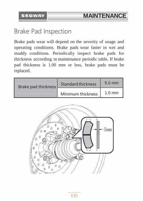
MAINTENANCE
135
Brake Pad Inspection
Brake pads wear will depend on the severity of usage and
operating conditions. Brake pads wear faster in wet and
muddy conditions. Periodically inspect brake pads for
thickness according to maintenance periodic table. If brake
pad thickness is 1.00 mm or less, brake pads must be
replaced.
Brake pad thickness Standard thickness 5.0 mm
Minimum thickness 1.0 mm
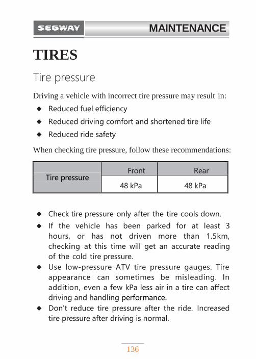
MAINTENANCE
136
TIRES
Tire pressure
Driving a vehicle with incorrect tire pressure may result in:
◆ Reduced fuel efficiency
◆ Reduced driving comfort and shortened tire life
◆ Reduced ride safety
When checking tire pressure, follow these recommendations:
Tire pressure Front Rear
48 kPa 48 kPa
◆ Check tire pressure only after the tire cools down.
◆ If the vehicle has been parked for at least 3
hours, or has not driven more than 1.5km,
checking at this time will get an accurate reading
of the cold tire pressure.
◆ Use low-pressure ATV tire pressure gauges. Tire
appearance can sometimes be misleading. In
addition, even a few kPa less air in a tire can affect
driving and handling performance.
◆ Don't reduce tire pressure after the ride. Increased
tire pressure after driving is normal.
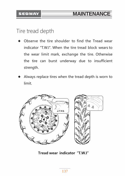
MAINTENANCE
137
Tire tread depth
◆ Observe the tire shoulder to find the Tread wear
indicator "T.W.I". When the tire tread block wears to
the wear limit mark, exchange the tire. Otherwise
the tire can burst underway due to insufficient
strength.
◆ Always replace tires when the tread depth is worn to
limit.
Tread wear indicator“T.W.I”
T.W.I.
T.W.I.
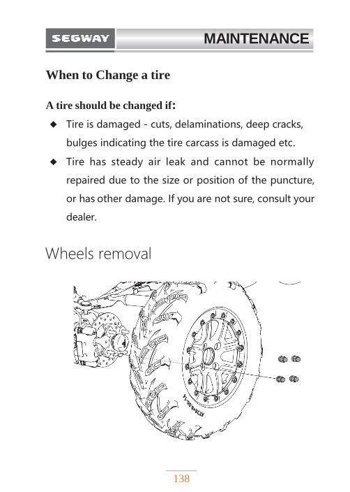
MAINTENANCE
138
When to Change a tire
A tire should be changed if:
◆ Tire is damaged - cuts, delaminations, deep cracks,
bulges indicating the tire carcass is damaged etc.
◆ Tire has steady air leak and cannot be normally
repaired due to the size or position of the puncture,
or has other damage. If you are not sure, consult your
dealer.
Wheels removal
MAINTENANCE
139
Tightening torque:
1. Stop the engine.
2. Place the transmission in Park ("P" position).
3. Lock the Parking brake.
4. Loosen the wheel nuts slightly.
5. Lift the side of the vehicle by placing a suitable jack
or stand under the foot rest frame.
6. Loosen and remove 4 wheel nuts.
7. Remove the wheel.
CAUTION
Loose nut may cause wheel to come off during
ride, which may cause an accident or rollover. Always
ensure that all nuts are tightened to 70-80 Nm. Do not
use lubricating oil or grease on wheel bolts / nuts.
Lubricating oil / grease may cause excessive tightening
of wheel nuts, resulting in damage to bolts or wheels. In
addition, lubricating oil or grease can cause wheel nuts
to become loose and wheels may come off, which can
lead to accidents and serious injuries. Clean all
lubricating oil or grease from wheel bolts / wheel nuts.
Torque Wheel nuts: 70-80 Nm
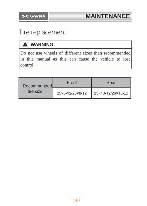
MAINTENANCE
140
Tire replacement
Recommended
tire size
Front Rear
25×8-12/26×8-12 25×10-12/26×10-12
! WARNING
Do not use wheels of different sizes than recommended
in this manual as this can cause the vehicle to lose
control.
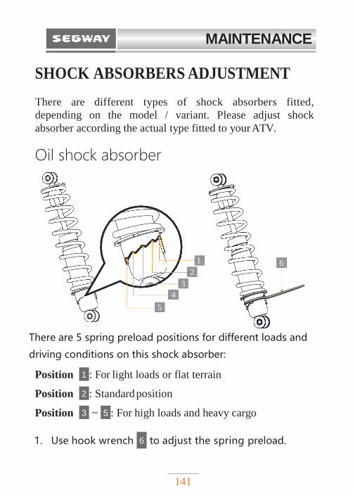
MAINTENANCE
141
6
1
2
3
4
5
SHOCK ABSORBERS ADJUSTMENT
There are different types of shock absorbers fitted,
depending on the model / variant. Please adjust shock
absorber according the actual type fitted to your ATV.
Oil shock absorber
There are 5 spring preload positions for different loads and
driving conditions on this shock absorber:
Position 1 : For light loads or flat terrain
Position 2 : Standard position
Position 3 ~ 5 : For high loads and heavy cargo
1. Use hook wrench 6 to adjust the spring preload.
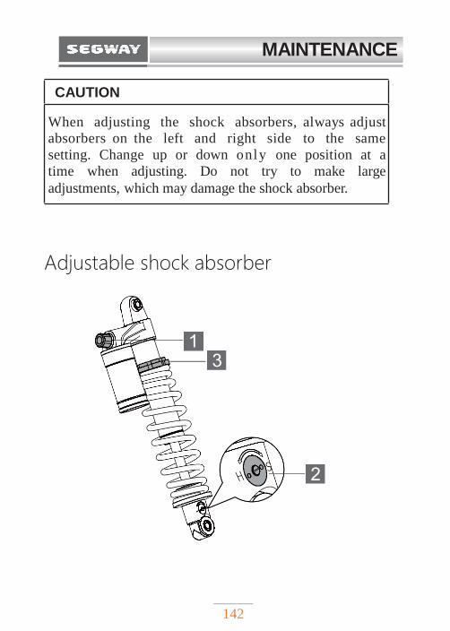
MAINTENANCE
142
Adjustable shock absorber
CAUTION
When adjusting the shock absorbers, always adjust
absorbers on the left and right side to the same
setting. Change up or down only one position at a
time when adjusting. Do not try to make large
adjustments, which may damage the shock absorber.
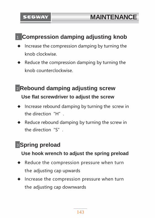
MAINTENANCE
143
1 Compression damping adjusting knob
◆ Increase the compression damping by turning the
knob clockwise.
◆ Reduce the compression damping by turning the
knob counterclockwise.
2 Rebound damping adjusting screw
Use flat screwdriver to adjust the screw
◆ Increase rebound damping by turning the screw in
the direction“H”.
◆ Reduce rebound damping by turning the screw in
the direction“S”.
3 Spring preload
Use hook wrench to adjust the spring preload
◆ Reduce the compression pressure when turn
the adjusting cap upwards
◆ Increase the compression pressure when turn
the adjusting cap downwards
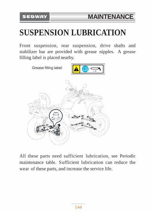
MAINTENANCE
144
SUSPENSION LUBRICATION
Front suspension, rear suspension, drive shafts and
stabilizer bar are provided with grease nipples. A grease
filling label is placed nearby.
Grease filling label:
All these parts need sufficient lubrication, see Periodic
maintenance table. Sufficient lubrication can reduce the
wear of these parts, and increase the service life.
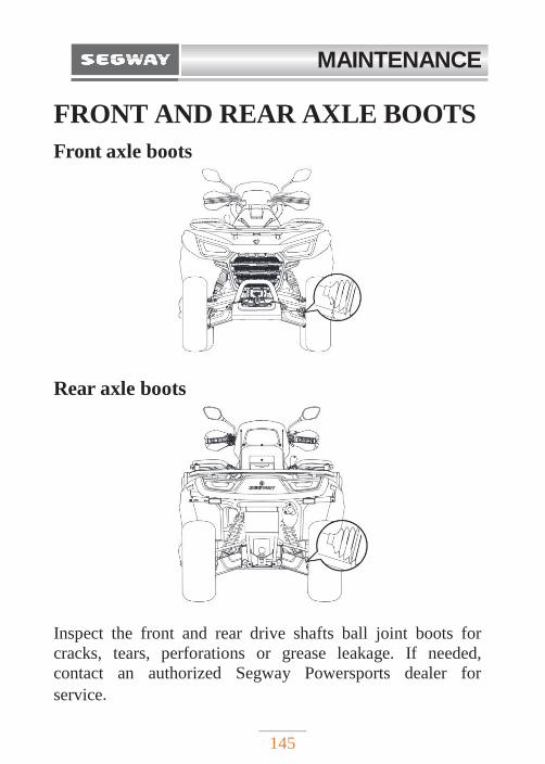
MAINTENANCE
145
FRONT AND REAR AXLE BOOTS
Front axle boots
Rear axle boots
Inspect the front and rear drive shafts ball joint boots for
cracks, tears, perforations or grease leakage. If needed,
contact an authorized Segway Powersports dealer for
service.
MAINTENANCE
146
AIR FILTER The air filter of this vehicle is paper filter element. Air
filter needs to be regularly cleaned and replaced, see the
periodic maintenance table (Page 114) for details. First,
remove the filter element for inspection. If the filter
element is seriously soaked with oil or dust, do not
clean it, and instead replace it with a new filter element. If
there is no oil or heavy dust, put the air filter element with
intake side down, knock on the ground, and shake off most
of the dust.
It is better if you have compressed air - you can blow from
the filter element side (do not blow from the air intake
side), until the dust is blown off.
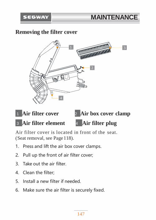
MAINTENANCE
147
1 3
4
2
Removing the filter cover
1 Air filter cover 2 Air box cover clamp
3 Air filter element 4 Air filter plug
Air filter cover is located in front of the seat.
(Seat removal, see Page 118).
1. Press and lift the air box cover clamps.
2. Pull up the front of air filter cover;
3. Take out the air filter.
4. Clean the filter;
5. Install a new filter if needed.
6. Make sure the air filter is securely fixed.
MAINTENANCE
148
LIGHTS
Headlights replacement
LED lights
LED lights consist of multiple lights. Have your dealer
replace the entire assembly if an LED is damaged or has
failed.
Halogen lights
Burned out halogen bulb can be replaced. You can
replace the following lamps by yourself. Difficulty of
replacement varies according to the bulb types. Due to
possible damage, we recommend that these parts are better
to be replaced by the dealer.
When there are big beads of water inside the lens, or
water condensation inside the headlamp, contact your
dealer for more information. It doesn’t mean
malfunction if condensed water appears inside the
headlamp lens temporarily.
CAUTION
Poor lighting can result in reduced visibility while driving. If the headlights and taillights get dirty, clean them promptly. Replace burnt lamps / bulbs immediately. To ensure optimum visibility, make sure the lights are properly adjusted.
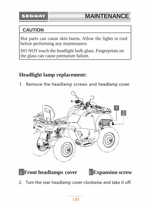
MAINTENANCE
149
Headlight lamp replacement:
1. Remove the headlamp screws and headlamp cover.
1 Front headlamps cover 2 Expansion screw
2. Turn the rear headlamp cover clockwise and take it off.
CAUTION
Hot parts can cause skin burns. Allow the lights to cool before performing any maintenance.
DO NOT touch the headlight bulb glass. Fingerprints on the glass can cause premature failure.
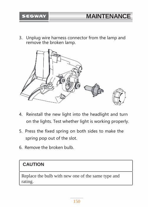
MAINTENANCE
150
3. Unplug wire harness connector from the lamp and remove the broken lamp.
4. Reinstall the new light into the headlight and turn
on the lights. Test whether light is working properly.
5. Press the fixed spring on both sides to make the
spring pop out of the slot.
6. Remove the broken bulb.
CAUTION
Replace the bulb with new one of the same type and
rating.
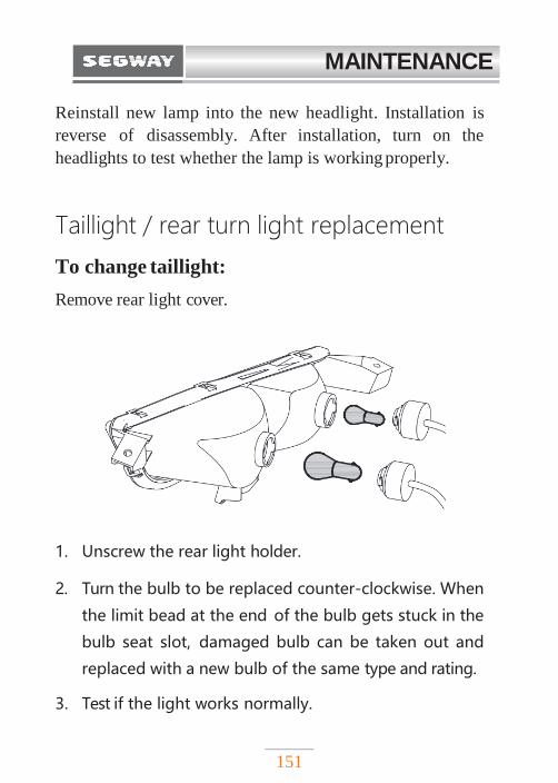
MAINTENANCE
151
Reinstall new lamp into the new headlight. Installation is
reverse of disassembly. After installation, turn on the
headlights to test whether the lamp is working properly.
Taillight / rear turn light replacement
To change taillight:
Remove rear light cover.
1. Unscrew the rear light holder.
2. Turn the bulb to be replaced counter-clockwise. When
the limit bead at the end of the bulb gets stuck in the
bulb seat slot, damaged bulb can be taken out and
replaced with a new bulb of the same type and rating.
3. Test if the light works normally.
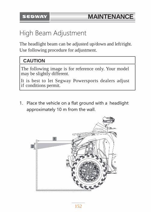
MAINTENANCE
152
High Beam Adjustment
The headlight beam can be adjusted up/down and left/right.
Use following procedure for adjustment.
1. Place the vehicle on a flat ground with a headlight
approximately 10 m from the wall.
CAUTION
The following image is for reference only. Your model may be slightly different.
It is best to let Segway Powersports dealers adjust if conditions permit.
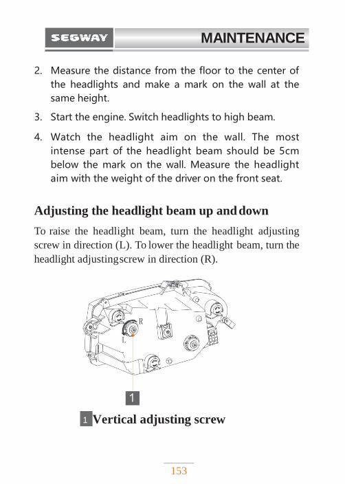
MAINTENANCE
153
2. Measure the distance from the floor to the center of
the headlights and make a mark on the wall at the
same height.
3. Start the engine. Switch headlights to high beam.
4. Watch the headlight aim on the wall. The most
intense part of the headlight beam should be 5cm
below the mark on the wall. Measure the headlight
aim with the weight of the driver on the front seat.
Adjusting the headlight beam up and down
To raise the headlight beam, turn the headlight adjusting
screw in direction (L). To lower the headlight beam, turn the
headlight adjusting screw in direction (R).
1 Vertical adjusting screw
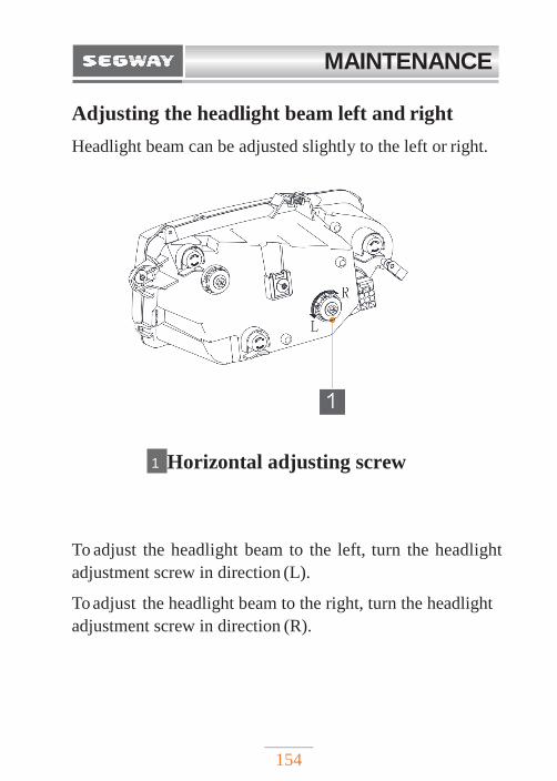
MAINTENANCE
154
Adjusting the headlight beam left and right
Headlight beam can be adjusted slightly to the left or right.
1 Horizontal adjusting screw
To adjust the headlight beam to the left, turn the headlight
adjustment screw in direction (L).
To adjust the headlight beam to the right, turn the headlight
adjustment screw in direction (R).
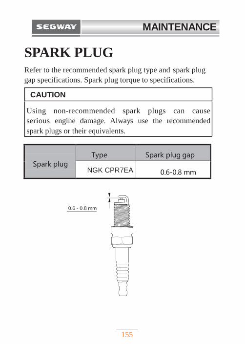
MAINTENANCE
155
SPARK PLUG Refer to the recommended spark plug type and spark plug
gap specifications. Spark plug torque to specifications.
Spark plug
Type Spark plug gap
NGK CPR7EA 0.6-0.8 mm
0.6 - 0.8 mm
CAUTION
Using non-recommended spark plugs can cause
serious engine damage. Always use the recommended
spark plugs or their equivalents.
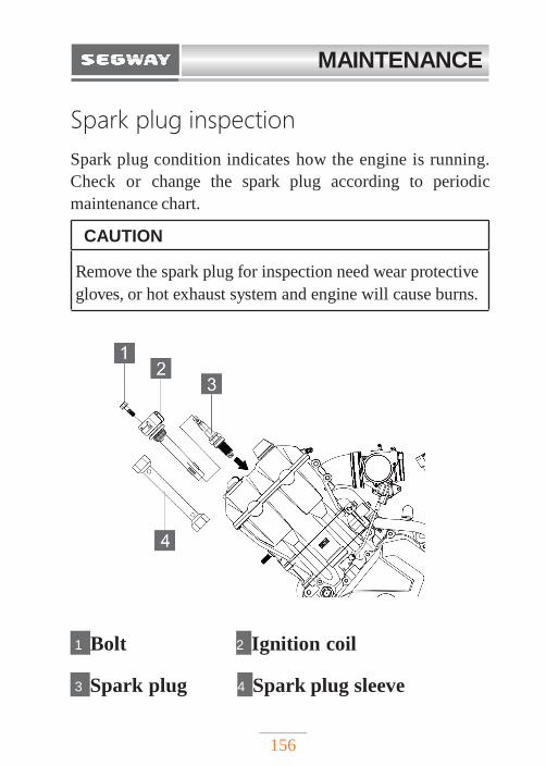
MAINTENANCE
156
Spark plug inspection
Spark plug condition indicates how the engine is running.
Check or change the spark plug according to periodic
maintenance chart.
1 Bolt 2 Ignition coil
3 Spark plug 4 Spark plug sleeve
CAUTION
Remove the spark plug for inspection need wear protective
gloves, or hot exhaust system and engine will cause burns.
MAINTENANCE
157
Spark plug is located under the seat. Refer to Page 118 for
removing the seat.
1. Remove the ignition coil fixing bolt;
2. Remove the ignition coil;
3. Spark plug is located under the ignition coil. Use
tool to turn the spark plug sleeve 1/4 turn and remove
it from the spark plug.
4. Rotate spark plug counter-clockwise and remove it.
5. Inspect spark plug.
Spark plug normal status:
The insulator tip is light gray, grayish yellow or light
brown, spark plug gap is about 0.6-0.8 mm.
Spark plug to be replaced:
The insulator tip is black. If there is electrode ablation,
carbon deposition, or gap is too large, spark plug should be
replaced.
MAINTENANCE
158
SPARK ARRESTOR Spark arrestor prevents random sparks from entering
other vehicles parts. Regular maintenance can prevent
carbon deposits; delayed maintenance will reduce engine
performance.
! WARNING
Make sure the engine has stopped running and the
exhaust pipes are cool. Let pipes completely cool down
to avoid heavy burns.
To reduce fire hazard, ensure that there are no
combustible materials nearby when removing spark plugs.
Safety glasses are recommended in this procedure.
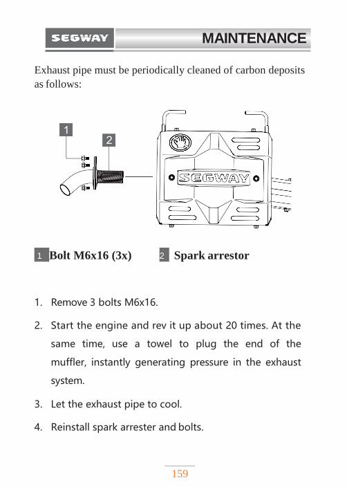
MAINTENANCE
159
Exhaust pipe must be periodically cleaned of carbon deposits
as follows:
1 Bolt M6x16 (3x) 2 Spark arrestor
1. Remove 3 bolts M6x16.
2. Start the engine and rev it up about 20 times. At the
same time, use a towel to plug the end of the
muffler, instantly generating pressure in the exhaust
system.
3. Let the exhaust pipe to cool.
4. Reinstall spark arrester and bolts.
MAINTENANCE
160
BATTERY Your ATV is equipped with a sealed MF battery, which
requires little maintenance. It is not necessary to check
the electrolyte or add distilled water to the battery. Due
to natural discharge and power consumption of some
electrical equipment, battery will discharge gradually
even when the vehicle is not in use. If the vehicle is parked
for a long time, the battery may discharge and may not start
the engine. Charge the battery every 30 days. This will
maintain the battery life.
! WARNING
12V batteries contain toxic and corrosive sulfuric acid
and may produce flammable explosive hydrogen gas. To
reduce the risk of serious injury or death, following
precautions should be observed when handling 12V
batteries or working near them:
◆ Do not smoke or light matches near a battery.
◆ Avoid electrolyte contact with eyes, skin and clothes.
◆ Wear safety goggles when working near the battery.
◆ Keep children away from 12V batteries.
Be sure to charge the battery in an open area. Do not
charge battery in a poorly ventilated garage or enclosed
room.
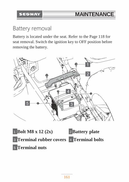
MAINTENANCE
161
Battery removal
Battery is located under the seat. Refer to the Page 118 for
seat removal. Switch the ignition key to OFF position before
removing the battery.
1 Bolt M8 x 12 (2x) 2 Battery plate
3 Terminal rubber covers 4 Terminal bolts
5 Terminal nuts
MAINTENANCE
162
1. Unscrew the battery plate screws 1 ;
2. Remove battery plate 2 ;
3. Pull the terminal rubber covers off;
4. Remove terminal screw and disconnect black
(negative) cable first.
5. Remove the terminal screw and disconnect red
(positive) cable.
6. Remove battery from the ATV.
Battery Charging
CAUTION
When charging, the 12V batteries produce hydrogen,
combustible and explosive gas. Therefore, please follow
the following precautions before battery charging:
If charging battery which is still installed in the ATV, be
sure to disconnect the ground cable.
Make sure the charger is off when connecting and
disconnecting the clamps to the battery.
Only charge slowly (5A or less). If charged quickly, the
batteries may explode.
MAINTENANCE
163
Battery installation
1. Clean battery terminals with a soft wire brush and
contact cleaner, such as the Maxima Electrical
Contact / Brake Cleaner. Finally, coat the terminals
and bolts with electrical contact grease.
2. Insert the battery in the tray.
3. Connect and tighten the red (positive) cable.
4. Connect and tighten the black (negative) cable.
5. Install a clear battery vent from the vehicle to
the battery vent. (For conventional batteries only).
6. Install the battery plate;
7. Tighten the battery terminal bolts;
8. Check that cables are properly routed.
NOTE
To reduce the chance of sparks: Whenever the battery is
removed, disconnect the black (negative) cable first. When
reinstalling the battery, finally install the black (negative)
cable.
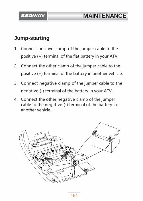
MAINTENANCE
164
Jump-starting
1. Connect positive clamp of the jumper cable to the
positive (+) terminal of the flat battery in your ATV.
2. Connect the other clamp of the jumper cable to the
positive (+) terminal of the battery in another vehicle.
3. Connect negative clamp of the jumper cable to the
negative (-) terminal of the battery in your ATV.
4. Connect the other negative clamp of the jumper cable to the negative (-) terminal of the battery in another vehicle.
MAINTENANCE
165
FUSES All circuits on this ATV are protected with fuses to
protect electrical systems from damage by high current
(short-circuit or overload).
If there is any electrical system failure, always check the
fuses first. You can consider electrical faults. If the fuse is
blown, replace it with a fuse of the same type and rating.
There are several spare fuses in the fuse box. Check all other
fuses for possible cause. Replace all blown fuses and check
the electrical system. All fuses are located in the fuse
box. In the event of a system failure, see "Fuse/relay
ratings and location" for details.
NOTE
◆ Always replace a blown fuse with the fuse of the
same type and rating.
◆ Do not replace the fuse with anything else.
◆ Never use wires instead of the proper fuses - even as
a temporary replacement this is strictly prohibited.
◆ If the fuse immediately blows again, contact your
dealer.
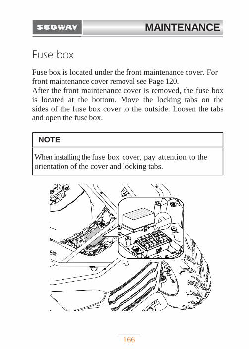
MAINTENANCE
166
Fuse box
Fuse box is located under the front maintenance cover. For
front maintenance cover removal see Page 120.
After the front maintenance cover is removed, the fuse box
is located at the bottom. Move the locking tabs on the
sides of the fuse box cover to the outside. Loosen the tabs
and open the fuse box.
NOTE
When installing the fuse box cover, pay attention to the
orientation of the cover and locking tabs.
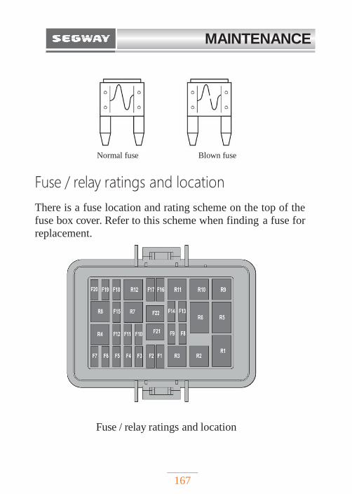
MAINTENANCE
167
Fuse / relay ratings and location
There is a fuse location and rating scheme on the top of the
fuse box cover. Refer to this scheme when finding a fuse for
replacement.
Fuse / relay ratings and location
Normal fuse Blown fuse
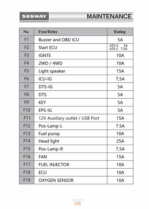
MAINTENANCE
168
No. Fuse/Relay Rating
F1 Buzzer and OBD ICU 5A
F2 Start ECU AT6 S: 5A AT6 L: 7,5A
F3 IGNTE 10A
F4 2WD / 4WD 10A
F5 Light speaker 15A
F6 ICU-IG 7,5A
F7 DTS-IG 5A
F8 DTS 5A
F9 KEY 5A
F10 EPS-IG 5A
F11 12V Auxiliary outlet / USB Port 15A
F12 Pos-Lamp-L 7.5A
F13 Fuel pump 10A
F14 Head light 25A
F15 Pos-Lamp-R 7,5A
F16 FAN 15A
F17 FUEL INJECTOR 10A
F18 ECU 10A
F19 OXYGEN SENSOR 10A
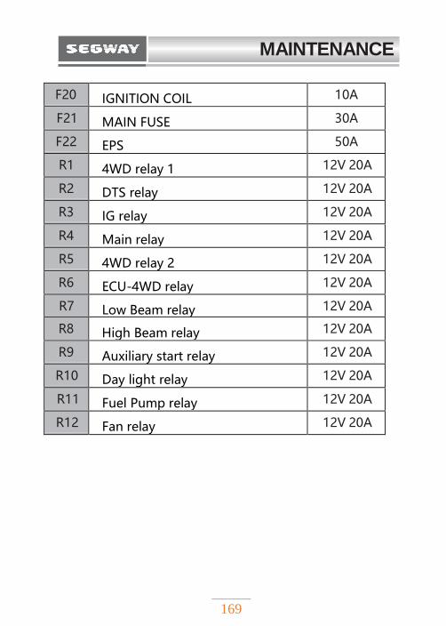
MAINTENANCE
169
F20 IGNITION COIL 10A
F21 MAIN FUSE 30A
F22 EPS 50A
R1 4WD relay 1 12V 20A
R2 DTS relay 12V 20A
R3 IG relay 12V 20A
R4 Main relay 12V 20A
R5 4WD relay 2 12V 20A
R6 ECU-4WD relay 12V 20A
R7 Low Beam relay 12V 20A
R8 High Beam relay 12V 20A
R9 Auxiliary start relay 12V 20A
R10 Day light relay 12V 20A
R11 Fuel Pump relay 12V 20A
R12 Fan relay 12V 20A
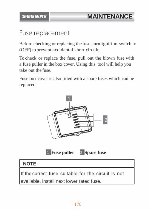
MAINTENANCE
170
1
Fuse replacement
Before checking or replacing the fuse, turn ignition switch to
(OFF) to prevent accidental short circuit.
To check or replace the fuse, pull out the blown fuse with
a fuse puller in the box cover. Using this tool will help you
take out the fuse.
Fuse box cover is also fitted with a spare fuses which can be
replaced.
2
1 Fuse puller 2 Spare fuse
NOTE
If the correct fuse suitable for the circuit is not
available, install next lower rated fuse.
MAINTENANCE
171
APPEARANCE CARE
Car wash not recommended.
Pressure water can damage parts and remove paint and decals.
1. Cover or plug the exhaust outlet prior to washing
your ATV.
2. Fill a bucket with water. Add mild neutral detergent,
preferably product made especially for washing
motorcycles or cars.
3. Wash your ATV with a sponge or soft towel. As you
wash, check for heavy grime. If necessary, use a mild
cleaner/ degreaser to remove the grime.
4. After washing, rinse your ATV thoroughly with plenty
of clean water to remove any residues. Detergent
residues can corrode alloy parts.
5. Dry your ATV with a chamois or a soft towel.
Leaving water on the surface to air dry can cause
dulling and water spots. As you dry, inspect for chips
and scratches.
6. Ride your ATV at a slow speed and apply the brakes
several times. This will help dry the brakes and
restore normal braking performance.
MAINTENANCE
172
Cleaning the vehicle
Wash the vehicle immediately after driving in salty or
corrosive environment.
It is recommended that you clean your vehicle with mild
automotive cleaners. Follow instructions on the container.
Cleaning tips
Avoid using harsh and abrasive products, some of
which may scratch your vehicle. Clean and polish
regularly with a clean cloth and mat. Old or reused cloth
and mats can contain dirt particles that can scratch the
finish.
Vehicle storage
When the vehicle is not used for a long time, it should be
appropriately stored. The vehicle should be serviced and
thoroughly cleaned prior storing. Avoid using a plastic
cover as moisture will collect on the ATV causing rusting.
Best storage is wel l vent i la ted indoor storage. For
storage, use a battery maintainer or charge the battery
regularly.
173
SPECIFICATIONS
TECHNICAL SPECIFICATIONS.………….174
VEHICLE IDENTIFICATION NUMBERS..179
IDENTIFICATION PLATE ……...……….180
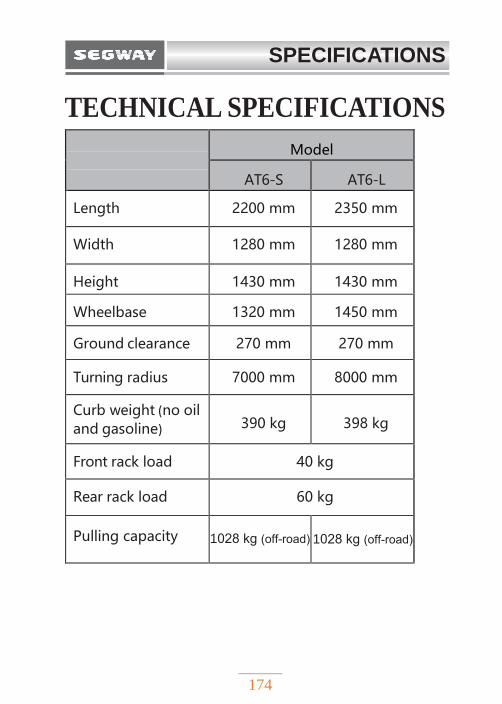
SPECIFICATIONS
174
TECHNICAL SPECIFICATIONS
Model
AT6-S AT6-L
Length 2200 mm 2350 mm
Width 1280 mm 1280 mm
Height 1430 mm 1430 mm
Wheelbase 1320 mm 1450 mm
Ground clearance 270 mm 270 mm
Turning radius 7000 mm 8000 mm
Curb weight (no oil and gasoline) 390 kg 398 kg
Front rack load 40 kg
Rear rack load 60 kg
Pulling capacity 1028 kg (off-road) 1028 kg (off-road)
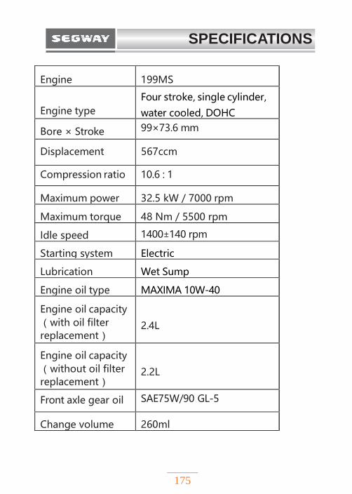
SPECIFICATIONS
175
Engine 199MS
Engine type
Four stroke, single cylinder,
water cooled, DOHC
Bore × Stroke 99×73.6 mm
Displacement 567ccm
Compression ratio 10.6 : 1
Maximum power 32.5 kW / 7000 rpm
Maximum torque 48 Nm / 5500 rpm
Idle speed 1400±140 rpm
Starting system Electric
Lubrication Wet Sump
Engine oil type MAXIMA 10W-40
Engine oil capacity
(with oil filter replacement)
2.4L
Engine oil capacity
(without oil filter replacement)
2.2L
Front axle gear oil SAE75W/90 GL-5
Change volume 260ml
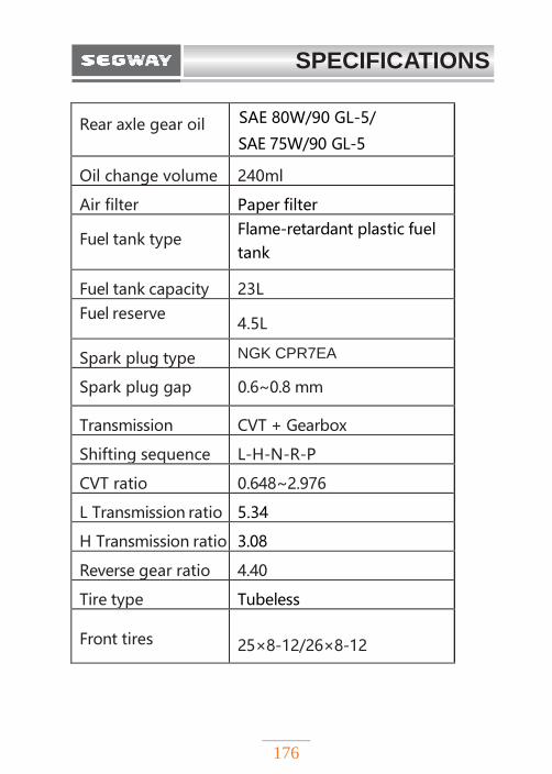
SPECIFICATIONS
176
Rear axle gear oil SAE 80W/90 GL-5/
SAE 75W/90 GL-5
Oil change volume 240ml
Air filter Paper filter
Fuel tank type Flame-retardant plastic fuel
tank
Fuel tank capacity 23L
Fuel reserve 4.5L
Spark plug type NGK CPR7EA
Spark plug gap 0.6~0.8 mm
Transmission CVT + Gearbox
Shifting sequence L-H-N-R-P
CVT ratio 0.648~2.976
L Transmission ratio 5.34
H Transmission ratio 3.08
Reverse gear ratio 4.40
Tire type Tubeless
Front tires
25×8-12/26×8-12
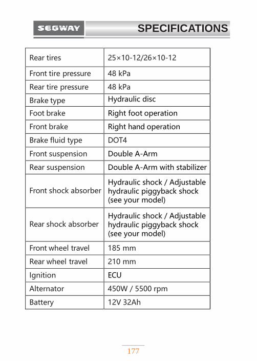
SPECIFICATIONS
177
Rear tires 25×10-12/26×10-12
Front tire pressure 48 kPa
Rear tire pressure 48 kPa
Brake type Hydraulic disc
Foot brake Right foot operation
Front brake Right hand operation
Brake fluid type DOT4
Front suspension Double A-Arm
Rear suspension Double A-Arm with stabilizer
Front shock absorber Hydraulic shock / Adjustable hydraulic piggyback shock (see your model)
Rear shock absorber Hydraulic shock / Adjustable hydraulic piggyback shock (see your model)
Front wheel travel 185 mm
Rear wheel travel 210 mm
Ignition ECU
Alternator 450W / 5500 rpm
Battery 12V 32Ah
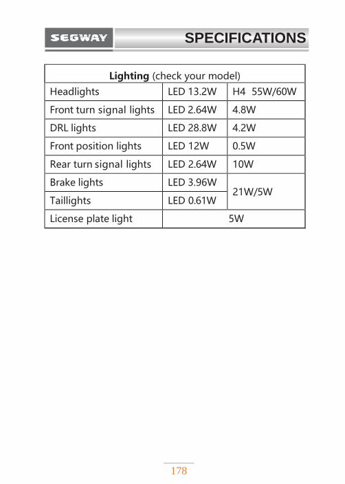
SPECIFICATIONS
178
Lighting (check your model)
Headlights LED 13.2W H4 55W/60W
Front turn signal lights LED 2.64W 4.8W
DRL lights LED 28.8W 4.2W
Front position lights LED 12W 0.5W
Rear turn signal lights LED 2.64W 10W
Brake lights LED 3.96W 21W/5W
Taillights LED 0.61W
License plate light 5W
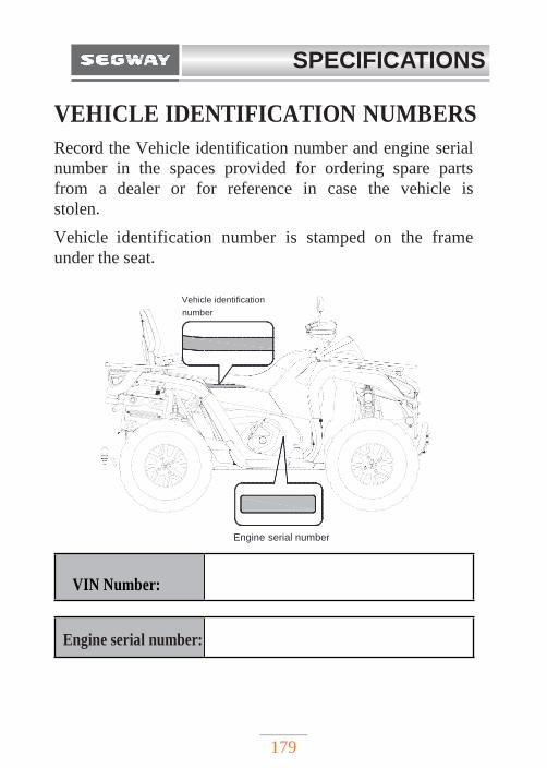
SPECIFICATIONS
179
VEHICLE IDENTIFICATION NUMBERS
Record the Vehicle identification number and engine serial
number in the spaces provided for ordering spare parts
from a dealer or for reference in case the vehicle is
stolen.
Vehicle identification number is stamped on the frame
under the seat.
Engine serial number
Engine serial number:
VIN Number:
Vehicle identification
number
XXXXXXXXXXXXXXXXXX
XXXXXXXXXXXXXXXXXX
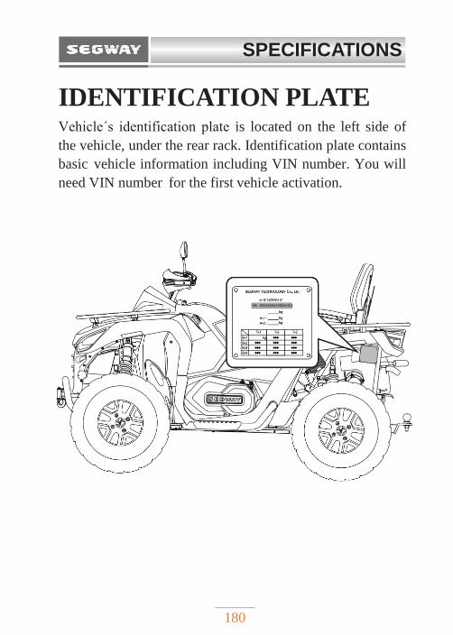
SPECIFICATIONS
180
IDENTIFICATION PLATE Vehicle´s identification plate is located on the left side of
the vehicle, under the rear rack. Identification plate contains
basic vehicle information including VIN number. You will
need VIN number for the first vehicle activation.
181
TROUBLESHOOTING
Drive belt wear / burn ……………….……… 182
Engine doesn´t turn over………..…………… 184
Engine pings or knocks…………….………… 184
Engine stops or loses power………………… 185
Engine turns over, fails to start……………… 185
Engine backfires……………………………… 186
Engine runs irregularly, stalls or misfires…… 187
Engine runs irregularly, stalls or misfires…… 187
Engine stops or loses power ……..…………… 189

TROUBLESHOOTING
182
With all the challenges you can encounter i n off-road
riding, there's chance that sometimes something may go
wrong. This section gives you practical advice to help
you deal with a wide range of problems. Take time to read
this section before you ride.
Drive belt wear / burn
Possible cause Solution
Driving onto a pickup or tall trailer in high range
Shift transmission to low range prior to loading ATV to prevent belt burning
Starting out going up a steep incline
When starting out on an incline, use low range
Driving at low RPM or low speed (approximately 5-10 km/h)
Drive at a higher speed or use low range more frequently. The use of low range is highly recommended for lower CVT operating temperatures and longer component life.
Insufficient warm- up at low ambient temperatures
Warm the engine before driving, the belt will become more flexible and prevent belt burning
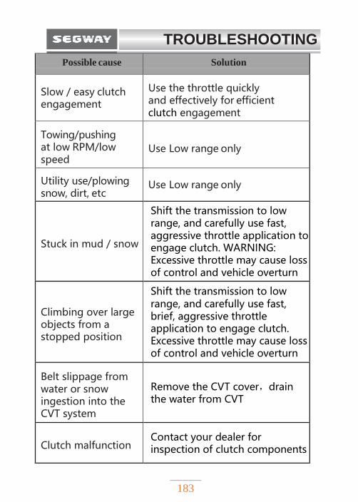
TROUBLESHOOTING
183
Possible cause Solution
Slow / easy clutch engagement
Use the throttle quickly and effectively for efficient clutch engagement
Towing/pushing at low RPM/low speed
Use Low range only
Utility use/plowing snow, dirt, etc
Use Low range only
Stuck in mud / snow
Shift the transmission to low range, and carefully use fast, aggressive throttle application to engage clutch. WARNING: Excessive throttle may cause loss of control and vehicle overturn
Climbing over large objects from a stopped position
Shift the transmission to low range, and carefully use fast, brief, aggressive throttle application to engage clutch. Excessive throttle may cause loss of control and vehicle overturn
Belt slippage from water or snow ingestion into the CVT system
Remove the CVT cover,drain the water from CVT
Clutch malfunction Contact your dealer for inspection of clutch components
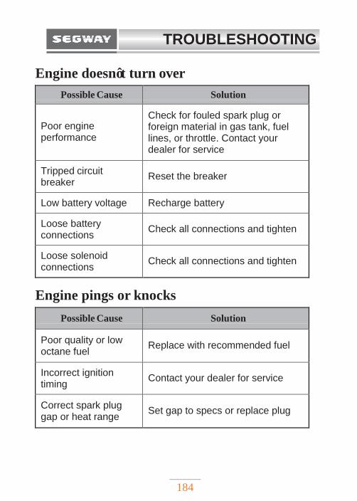
TROUBLESHOOTING
184
Engine doesn’t turn over
Possible Cause Solution
Poor engine performance
Check for fouled spark plug or foreign material in gas tank, fuel lines, or throttle. Contact your dealer for service
Tripped circuit breaker
Reset the breaker
Low battery voltage Recharge battery
Loose battery connections
Check all connections and tighten
Loose solenoid connections
Check all connections and tighten
Engine pings or knocks
Possible Cause Solution
Poor quality or low octane fuel
Replace with recommended fuel
Incorrect ignition timing
Contact your dealer for service
Correct spark plug gap or heat range
Set gap to specs or replace plug
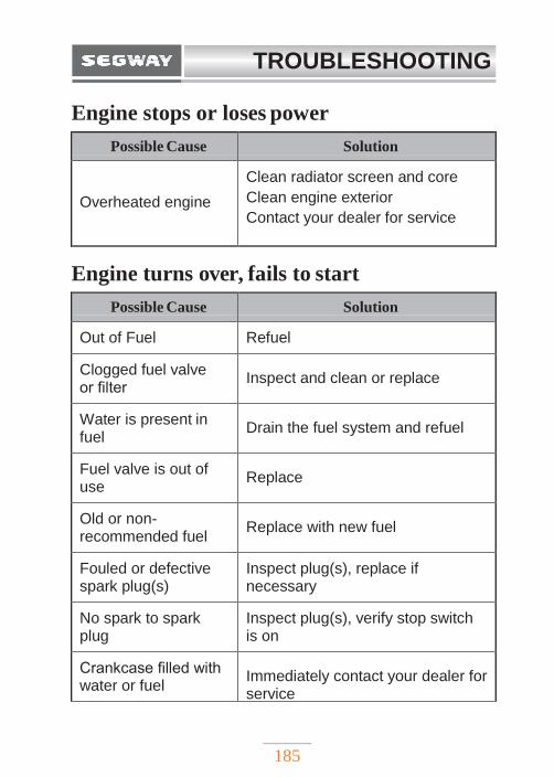
TROUBLESHOOTING
185
Engine stops or loses power
Possible Cause Solution
Overheated engine
Clean radiator screen and core
Clean engine exterior
Contact your dealer for service
Engine turns over, fails to start
Possible Cause Solution
Out of Fuel Refuel
Clogged fuel valve or filter
Inspect and clean or replace
Water is present in fuel
Drain the fuel system and refuel
Fuel valve is out of use
Replace
Old or non- recommended fuel
Replace with new fuel
Fouled or defective spark plug(s)
Inspect plug(s), replace if necessary
No spark to spark plug
Inspect plug(s), verify stop switch is on
Crankcase filled with water or fuel
Immediately contact your dealer for service
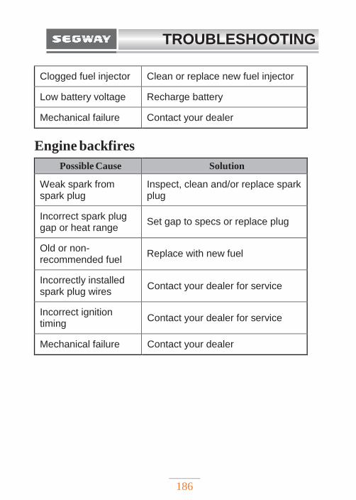
TROUBLESHOOTING
186
Clogged fuel injector Clean or replace new fuel injector
Low battery voltage Recharge battery
Mechanical failure Contact your dealer
Engine backfires
Possible Cause Solution
Weak spark from spark plug
Inspect, clean and/or replace spark plug
Incorrect spark plug gap or heat range
Set gap to specs or replace plug
Old or non- recommended fuel
Replace with new fuel
Incorrectly installed spark plug wires
Contact your dealer for service
Incorrect ignition timing
Contact your dealer for service
Mechanical failure Contact your dealer
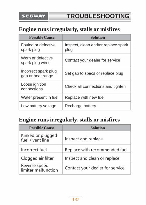
TROUBLESHOOTING
187
Engine runs irregularly, stalls or misfires
Possible Cause Solution
Fouled or defective spark plug
Inspect, clean and/or replace spark plug
Worn or defective spark plug wires
Contact your dealer for service
Incorrect spark plug gap or heat range
Set gap to specs or replace plug
Loose ignition connections
Check all connections and tighten
Water present in fuel Replace with new fuel
Low battery voltage Recharge battery
Engine runs irregularly, stalls or misfires
Possible Cause Solution
Kinked or plugged fuel / vent line
Inspect and replace
Incorrect fuel Replace with recommended fuel
Clogged air filter Inspect and clean or replace
Reverse speed limiter malfunction
Contact your dealer for service
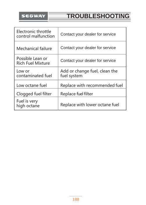
TROUBLESHOOTING
188
Electronic throttle control malfunction Contact your dealer for service
Mechanical failure Contact your dealer for service
Possible Lean or Rich Fuel Mixture
Contact your dealer for service
Low or contaminated fuel
Add or change fuel, clean the fuel system
Low octane fuel Replace with recommended fuel
Clogged fuel filter Replace fuel filter
Fuel is very high octane
Replace with lower octane fuel
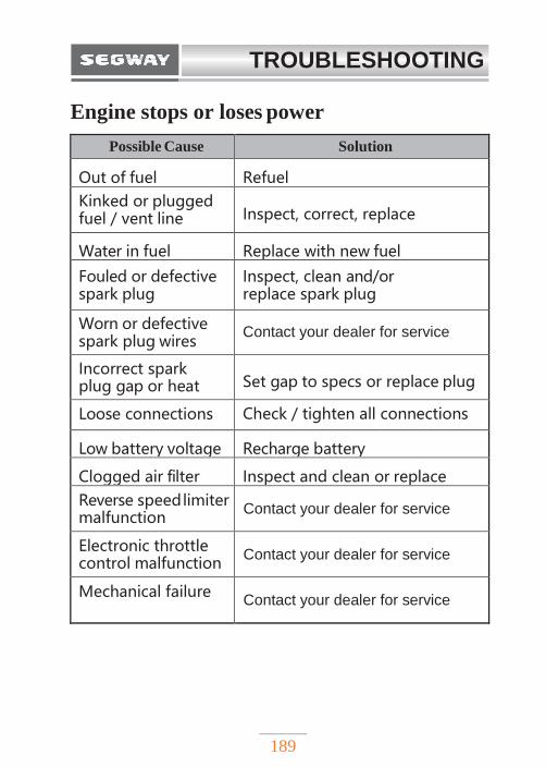
TROUBLESHOOTING
189
Engine stops or loses power
Possible Cause Solution
Out of fuel Refuel
Kinked or plugged fuel / vent line
Inspect, correct, replace
Water in fuel Replace with new fuel
Fouled or defective spark plug
Inspect, clean and/or replace spark plug
Worn or defective spark plug wires
Contact your dealer for service
Incorrect spark plug gap or heat range
Set gap to specs or replace plug
Loose connections Check / tighten all connections
Low battery voltage Recharge battery
Clogged air filter Inspect and clean or replace
Reverse speed limiter malfunction
Contact your dealer for service
Electronic throttle control malfunction
Contact your dealer for service
Mechanical failure Contact your dealer for service

190
EMISSION CONTROL SYSTEM
SOURCE OF EXHAUST EMISSIONS………..191
EXHAUST EMISSION CONTROL SYSTEM….191
CRANKCASE EMISSION CONTROL SYSTEM..192
NOISE CONTROL SYSTEM……………………192

EMISSION CONTROL SYSTEM
191
SOURCE OF EXHAUST EMISSIONS
The combustion process produces carbon monoxide (CO),
nitrogen oxides (NOx) and hydrocarbons (HC). Control of
hydrocarbons and oxides of nitrogen is very important
because, under certain conditions, they react to form
photochemical smog when subjected to sunlight. Carbon
monoxide does not react in the same way, but it is toxic.
EXHAUST EMISSION CONTROL SYSTEM
The exhaust emission control system includes a PGM-F
system and oxygen sensor.
No adjustments to this system should be made although
periodic inspection of the components is recommended.
The exhaust emission control system is separate from the
crankcase emission control system.
EMISSION CONTROL SYSTEM
192
CRANKCASE EMISSION
CONTROL SYSTEM The engine is equipped with a closed crankcase system to
prevent discharging crankcase emissions into the
atmosphere. Blow-by gas is returned to the combustion
chamber through the air cleaner.
NOISE CONTROL SYSTEM
Do not modify the engine, air intake or exhaust components,
in order to meet local noise level requirements.

SEGWAY TECHNOLOGY CO., LTD.
powersports.segway.com
DISTRIBUTED BY:
Segway reserves the right to make any technical changes to the construction and design without prior notice.
If in doubt, please contact your dealer, or Segway Powersports s.r.o directly.
© Copyright Segway Powersports s.r.o. 2021
All information contained within this publication is based on the latest product information at the time of publication. Due to
constant improvements in the design and quality, some depictions, information and specifications may differ from those
presented in this publication. Depictions and/or procedures in this publication are intended for reference use only. No
liability can be accepted for omissions or inaccuracies. Any reprinting or reuse of the depictions and/or procedures contained
within, whether whole or in part, is expressly prohibited.
Segway Powersports s.r.o.
Staroplzenecka 290, 326 00, Letkov
Czech Republic
+420 378 21 21 21
www.segwaypowersports.cz