design and manufacturing of steering system for atv - zenodo
TRANSCRIPT
9 Page 9-19 © MAT Journals 2019. All Rights Reserved
Journal of Recent Trends in Mechanics
Volume 4 Issue 1
Design and Manufacturing of steering system for ATV
Mr. Kartik Gavhale1, Ms. Nishigandha gurav
1, Prashant Zaware
2
1 Student, Department of Mechanical Engineering, D Y Patil School Of Engineering Academy, Ambi,
Pune, Maharashtra, India, 2 Assistant professor, Department of Mechanical Engineering, D Y Patil School Of Engineering
Academy, Ambi, Pune, Maharashtra, India
Email: [email protected]
Abstract Steering system is used to steer the vehicle according to need. In order to design a steering
system it is important to recognise and compensate the forces due to tracks. Steering system
of an ATV needs to be efficient as far as the parameters like rigidity, weight, spaces are
concerned. As we are designing a steering system of ATV we need to consider a rough
terrain. All the forces and torques encounter during the run are considered in order to design
the mechanisms which will sustain these rough terrains. As the vehicle needs to be frequently
steer in any direction so it is necessary that the mechanism should be responsive and also
sustain the fatigue loads due to terrain. Also the steering wheel is designed with
consideration on steering force. All the findings and values of the steering report is given in
this paper.
Keywords: Ackerman geometry, Wheelbase, Rack and Pinion.
INTRODUCTION
Steering system is used to steer the vehicle
as per need. It need to be stable,
responsive, and should sustain forces on it.
As we are designing the steering
mechanism of ATV we must consider
factor such as weight, space, value and
material selection as per its characteristics.
There are various steering available or
designed in market. But as per our need we
choose rack and pinion mechanism with
anti -Ackerman geometry. This gives the
most responsive turning of wheel with less
tuning of steering.
It should be noted that the steering is an
important aspect in every vehicle as it
plays key role in vehicle performance,
especially in racing industry.
DESIGN OF STEERING SYSTEM The task of steering mechanism in ATV is to turn the vehicle as per drivers need and give a lower turning radius in rough terrain. Design steps involved:
1. Identify vehicle requirement
2. Geometry set up
3. Geometry validation
4. Designing of mechanism
5. Manufacturing
Identify vehicle requirement
The initial stage of designing a steering
mechanism is to know its requirement. As
we are designing our vehicle for BAJA
SAE event we followed some guild lines
of these events. The vehicle chassis was
designed according to the rule book of
BAJA-2018, and following parameters
were finalized based on driver safety and
comfort ability:
front track width: 56”
2.rear track width: 54”
3wheel base (l): 57”
Using this basic parameter we started our
designing.
Geometry setup
It is the most important step of designing
because steering geometry plays a key role
in factors such as turning radius, slips,
etc. also for secondary factors such as

10 Page 9-19 © MAT Journals 2019. All Rights Reserved
Journal of Recent Trends in Mechanics
Volume 4 Issue 1
weight, cost and maintenance [1]. After
a lot of research and discussion we
decided to use anti-Ackerman geometry
as it gives a shorter turning radius which
is our main focus for the event [2].
Table 1: Geometry setup parameter Value
Track width (b) 54" = 1371.6mm
wheel base (l) 56” = 1422.4mm
Steering arm length(lst) 110 mm
Ackerman angle (α) 200
After a discussion the geometry was finalized with the following parameters :
Table 2: Discussion the Geometry Parameter Value
Angle of inside lock (θ) 460
Angle of outside lock (φ) 29.50
Turning radius of front inner 2514.2mm
wheel (Rif)
Turning radius of front outer 3885.8mm
wheel (Rof)
Geometry validation The geometry validation was done by reverse engineering and constantly validating it with calculations. Calculations performed in order to validate the geometry are as follows: Required condition is: Angle of inside lock (θ) = 46
0
According to Ackerman's geometry, the perfect steering condition would be: cot (φ) - cot (θ) = (b÷l) Hence rearranging and substituting values in above equation; cot (φ) = (b÷l) + cot (θ) cot (φ) = (1371.6÷1422.4) + cot (46) (φ) = 29.46
0
Also, (α) = tan
-1 [(sin (φ) - sin (θ))÷(cos (φ) +
cos (θ))] (α) = 20.73
0
l/sin (θ) = 1371.6÷ sin (46) (Rif) = 2514.2 mm (Rof) = l÷ sin (φ) = 1371.6÷sin(29.45) (Rof) = 3885.8mm (Rcg) =3200mm As the analytical and calculated data are near about same we can say that design is accurate and will satisfy the needs of vehicle. Design of mechanism We used rack and pinion mechanism as it is easy to manufacture, less complex, and it also accommodate in small spaces compared to other mechanism present. The steps involved are following: Selection of gear tooth profile A 20
0 full depth involute profile system
was selected because it reduces the under cutting and also reduces the interfering while meshing. Due to increase in pressure angle, the tooth became broader at its base,
11 Page 9-19 © MAT Journals 2019. All Rights Reserved
Journal of Recent Trends in Mechanics
Volume 4 Issue 1
which reduces the chances of bending failure.
The properties 200 full depth involute
profile system are:
Table 3: The properties 200
Parameter value Pressure angle (φ) 20
0
Addendum (ha) m
Dedendum (ha) 1.25m
Clearance (c) 0.25m
Working depth 2m
Whole depth 2.25m
Tooth thickness 1.5708m
Minimum number of teeth on pinion the minimum number of teeth on pinion required in order to avoid interference: Zp = 2*ha/ (m*sin
2(φ))
Substituting values in above equation; Zp = 2*m/( m*sin
2(φ)) = 2/ sin
2(φ)
Zp = 17.09 Hence minimum number of teeth on pinion is 18. Selection of material The materials used in the steering system targets precise operation and should be light in weight. Also the secondary needs such as cost of material cost of its manufacturing and reliability is also important. While designing the steering it is at most important that it is manufactured with high precision and given necessary tolerances to carry out smooth and effective steering of vehicle. There are various components in steering which require different types of material for there working and needs, so steering is sub divided in following components: 1. Steering casing 2. Steering rack 3. Pinion gear 4. Steering Wheel 5. Universal Joints
The primary purpose of Steering casing is
to give a support to rack and pinion and to
provide mounting for the mechanism.
When the driver turns the steering wheel, the pinion gear rotates and the rack moves laterally. The rack and the knuckle and joint by an intermediate component called tie rod [3]. The tie rod ends are fitted with POS which allows the mechanism to be flexible and adjust itself with the suspension moment. After lots of discussion we took AL6061 for casing and EN9 for the rack and pinion and, while for stub EN8 is used. All the materials selected based on the properties such as EN9 is has high surface wear resistance which is basic need of gear and rack, while AL6061 is light in weight and can sustain the force very well. Design of gear pair While turning steering system, mainly rack and pinion should exert required force to turn the vehicle. To overcome this rack and pinion should sustain bending and wear failure. For this we calculated the necessary strengths. The detailed procedure of designing is as follow:
Beam strength
The maximum tangential load a gear tooth
can bear without any damage to it is
known as its beam strength.
Assumptions in analysis of beam strength
Tip of single teeth bears the full load
The effect of radial force is neglected
The load is uniformly distributed over the
12 Page 9-19 © MAT Journals 2019. All Rights Reserved
Journal of Recent Trends in Mechanics
Volume 4 Issue 1
full face width
Effect of stress concentration is neglected
Frictional force are neglected
Analytical calculations
a. bending strength of pinion (σbp):
(σbp) = (Sut)/3 = 541/3 = 180
b. bending strength of gear (σbg):
(σbg) = (Sut)/3 = 541/3 = 180
c. Lewis form factor (Y):
YP = 0.484 - (2.87/ Zp) = 0.484 -
(2.87/17)
YP = 0.3151
Yg = 0.484 - (2.87/ Zg) = 0.484 - (2.87/29)
Yg = 0.3850
as , σbp* YP < σbg* Yg
as bending strength of gear is more than
bending strength of pinion, we need to
design a proper pinion first-assuming b =
10*m,
The beam strength is given by,
Pb = σbp*b*m*y
Pb = 180.33*10*m*m*0.4172
Pb = 752.336 m2 N
Wear strength
The wear of gear tooth mostly occurs due
to Pitting and Frosting. All this depends on
the wear strength of the material. Hence
wear resistance of the gear material should
be known.
This can be calculated by Buckingham
theorem.
Pw = b.Q.dp.k
Q = Rxternal gear pair factor = [ (2.Zg) /
(Zg + Zp) ]
Here Zg = 28 , Zp = 18 So that Q = 1.20
k = [ σc2. Cosϕ Sinϕ. ( 1/є1 + 1/є2) ] / 1.4
k= { [ ( 0.27). (9.81).(BHN) ]2.
Cos(20).Sin(20). (1/71700)}/1.4
k = 0.45. ( BHN/100)2
k= 0.45. (150/100)2
k = 1.0125
Hence wear strength can be calculated as
follow;
Pw = 255.15m2 N
Effective load
Effective load was calculated based on
requirement of the system. While
cornering the drive applies an effort to
steer the vehicle , this force be more to
overcome the frictional forces generated
between the road and tyres.
As human tents to apply brakes while
turning, we considered 50% distribution of
weight.
Thus the reaction forces are computed
based on above assumptions are calculated
as such-
So, FT = 50% weight of vehicle = 833.85
N
on both suspension joints.
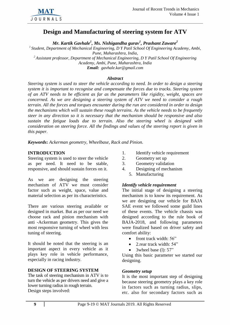
Figure 1: castor trail and scrub radius calculations
From this we can also deduce that,
13 Page 9-19 © MAT Journals 2019. All Rights Reserved
Journal of Recent Trends in Mechanics
Volume 4 Issue 1
FZR = 0.5 (FT)
FZR = 416.925N
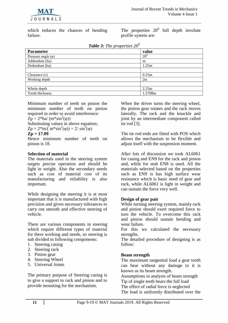
Required torque to overcome the steering axis inclination is given by;
Figure 2: Lateral forces on wheel while
cornering Moment to overcome offset of SAI axis-
= ( FZR + FZL). d.Sinλ.Sinδ
= (833.85).70.Sin4.Sin46
= -2928.90 N-mm
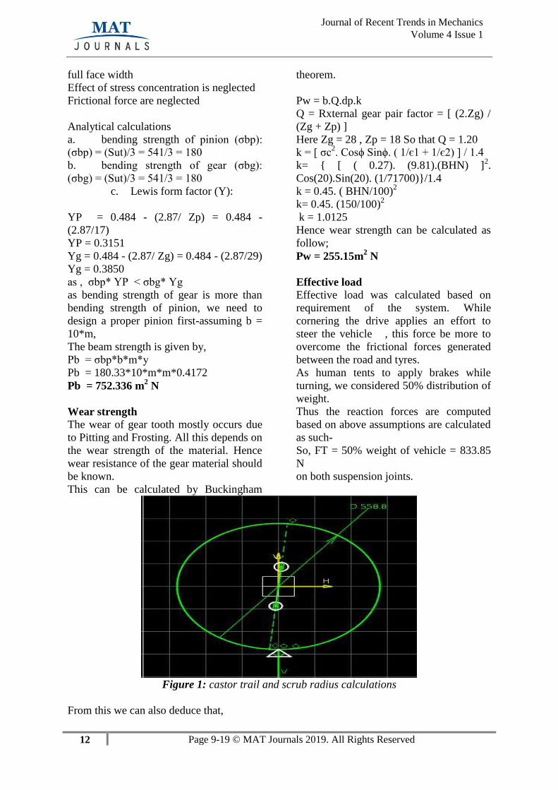
Aligning torque required to compensate caster trail offset is given by-
Figure 3: caster trail
Moment to overcome the offset of caster
trail
= (FZR – FZL)*d*Sinµ*Cosδ
= (416.925)*70*Sin5*Cos46
= 1766.945 N-mm
hence,
MT = -2928.90-(1766.945)
MT = 4695.845 N-mm
The friction couple generated while
cornering -
friction couple per wheel = m*v2/ 4*Rcg
= [170*((5/18)*v)2]/ 4*2.34
= 1317.739 N
Therefore,
Torque for friction couple (Mf) is given
by-
Torque (Mf) = 1317.739*(R/2)* Sinµ.*
sinδ
= 1317.739*(279)*sin(5)*sin(46)
= 23053.795 N-mm
14 Page 9-19 © MAT Journals 2019. All Rights Reserved
Journal of Recent Trends in Mechanics
Volume 4 Issue 1
Meff = (Mf + MT )
= ( 23053.795+4695.845)
= 27749.64 N-mm
The tangential force across the pinion is-
Meff = Ft * steering arm length
Hence; Ft = 252.26 N
From design data book;
For accurate mounting and moderate
shocks :
Ka = Application factor = 1
Km = Load concentration factor = 1.3
Kv = velocity factor = 1
Peff = (Ka * Km)* Ft / Kv
Peff = 327.935 N
Estimation of module
As gear pair is weaker in wear than in
bending so the parts must be designed
considering wear failure,
Assuming factor of safety (FOS) (Nf) =
1.8 For given system ;
Pw = Nf * Peff
255.15m2 = 1.8*327.925
m = 1.5 mm The module is estimated by the basic
parameters of gear design is given by;
Dimensions of pinion Table 4: Dimensions of pinion
Parameter Pinion
d (mm) 42.5
Addendum(ha) 1.5
Dedendum (hf) 1.875
Face width(b) 25
Circular pitch(Pc) 7.85
Module(m) 2.5
Zp 18
Dimensions of Rack Zg=28
F. Virtual prototyping of system using
CAD software
We did virtual prototyping using CATIA
V5R20.
As per the dimension obtain by
calculations, 3D models of pinion and rack
were generated in CATIA.
dimensions, weight and assembly of the
system.
The 3D CAD models are shown
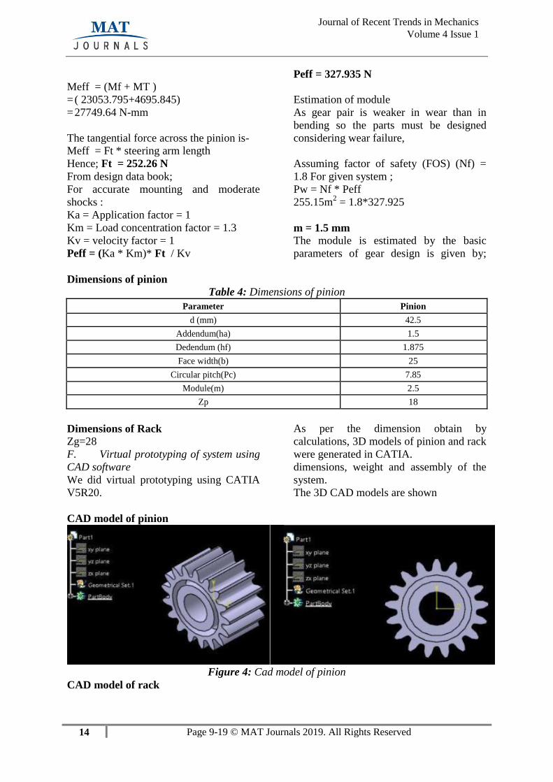
CAD model of pinion
Figure 4: Cad model of pinion
CAD model of rack
15 Page 9-19 © MAT Journals 2019. All Rights Reserved
Journal of Recent Trends in Mechanics
Volume 4 Issue 1
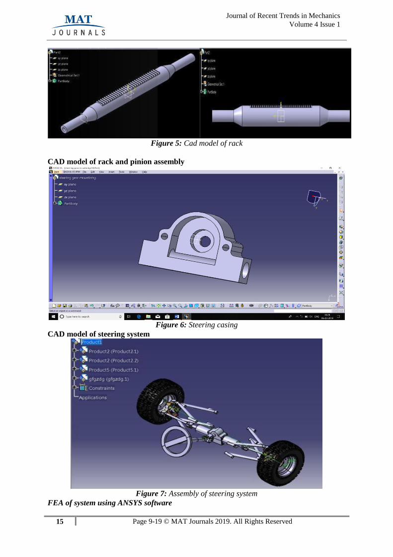
Figure 5: Cad model of rack
CAD model of rack and pinion assembly
Figure 6: Steering casing
CAD model of steering system
Figure 7: Assembly of steering system
FEA of system using ANSYS software
17 Page 9-19 © MAT Journals 2019. All Rights Reserved
Journal of Recent Trends in Mechanics
Volume 4 Issue 1
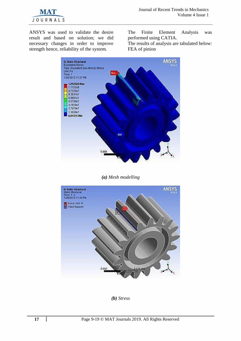
ANSYS was used to validate the desire
result and based on solution; we did
necessary changes in order to improve
strength hence, reliability of the system.
The Finite Element Analysis was
performed using CATIA.
The results of analysis are tabulated below:
FEA of pinion
(a) Mesh modelling
(b) Stress
17 Page 9-19 © MAT Journals 2019. All Rights Reserved
Journal of Recent Trends in Mechanics
Volume 4 Issue 1
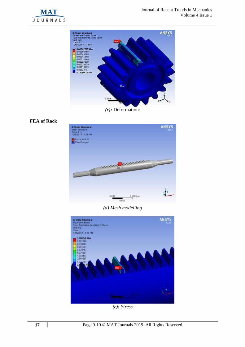
(c): Deformation:
FEA of Rack
(d) Mesh modelling
(e): Stress
18 Page 9-19 © MAT Journals 2019. All Rights Reserved
Journal of Recent Trends in Mechanics
Volume 4 Issue 1
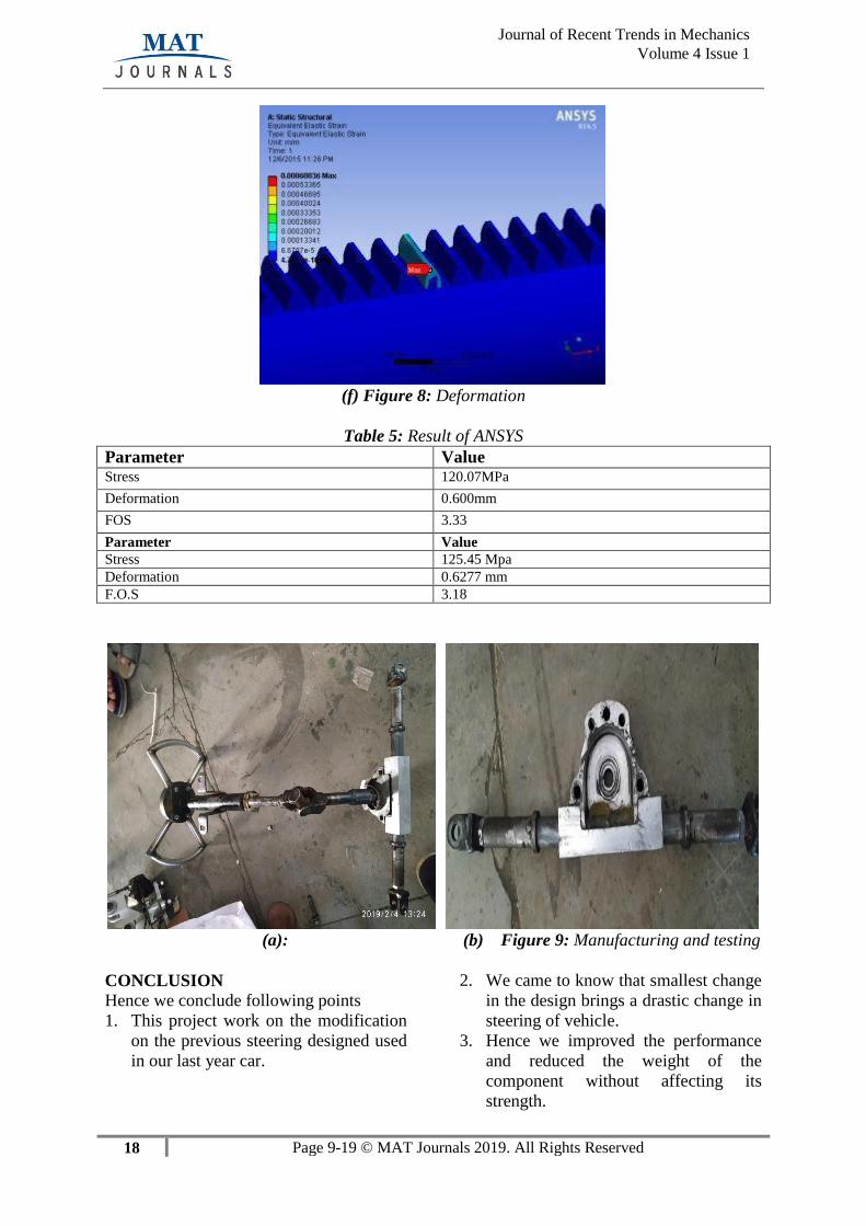
(f) Figure 8: Deformation
Table 5: Result of ANSYS
Parameter Value Stress 120.07MPa
Deformation 0.600mm
FOS 3.33
Parameter Value
Stress 125.45 Mpa
Deformation 0.6277 mm
F.O.S 3.18
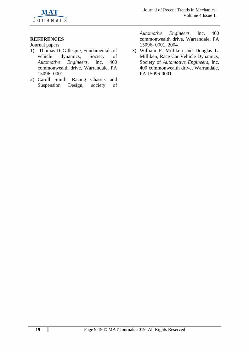
(a): (b) Figure 9: Manufacturing and testing
CONCLUSION
Hence we conclude following points
1. This project work on the modification
on the previous steering designed used
in our last year car.
2. We came to know that smallest change
in the design brings a drastic change in
steering of vehicle.
3. Hence we improved the performance
and reduced the weight of the
component without affecting its
strength.
19 Page 9-19 © MAT Journals 2019. All Rights Reserved
Journal of Recent Trends in Mechanics
Volume 4 Issue 1
REFERENCES
Journal papers
1) Thomas D. Gillespie, Fundamentals of
vehicle dynamics, Society of
Automotive Engineers, Inc. 400
commonwealth drive, Warrandale, PA
15096- 0001
2) Caroll Smith, Racing Chassis and
Suspension Design, society of
Automotive Engineers, Inc. 400
commonwealth drive, Warrandale, PA
15096- 0001, 2004
3) William F. Milliken and Douglas L.
Milliken, Race Car Vehicle Dynamics,
Society of Automotive Engineers, Inc.
400 commonwealth drive, Warrandale,
PA 15096-0001