securing virtual private lan service by efficient key management
TRANSCRIPT

SECURITY AND COMMUNICATION NETWORKSSecurity Comm. Networks (2013)
Published online in Wiley Online Library (wileyonlinelibrary.com). DOI: 10.1002/sec.701
REVIEW ARTICLE
Securing virtual private LAN service by efficient keymanagementMadhusanka Liyanage* and Andrei Gurtov
Centre for Wireless Communications, University of Oulu, Oulu, Finland
ABSTRACT
Virtual private local area network service (VPLS) is a layer 2 service provider-provisioned virtual private network service.Security is one of the key system requirements of a VPLS because it delivers the frames via an untrusted network. SeveralVPLS architectures are proposed during the recent years. However, many of them do not provide a sufficient level ofsecurity. On the other hand, the existing secure VPLS architectures are also suffering from the scalability issues, and theyare infeasible to implement in large scale networks.
Hence, we present a scalable secure VPLS architecture based on host identity protocol (HIP). It includes a new sessionkey-based security mechanism that provides the scalability both in forwarding and security planes. The initial simulationsverify that our proposal comparatively reduces the complexity of the key storage at a node, the total key storage of thenetwork, and the number of encryption per a broadcast frame. Additionally, it offers an efficient broadcast mechanismand comparably higher degree of security features than other existing VPLS proposals. The simulation results furtherconfirm that our proposal is able to protect the control protocol of the VPLS from the Internet Protocol (IP)/transmissioncontrol protocol-(TCP) based attacks. Copyright © 2013 John Wiley & Sons, Ltd.
KEYWORDS
VPN; VPLS; HIP; security; session key
*Correspondence
Madhusanka Liyanage, Centre for Wireless Communications, University of Oulu, PO Box 4500, FI-90014 Oulu, Finland.E-mail: [email protected]
1. INTRODUCTION
Virtual private networks (VPNs) are popular in the widearea Internet to extend the private network domain togeographical distributed locations via an unsecured publicnetwork. Several techniques have been defined to provideVPNs at different layers of the open systems interconnectionmodel, for instance, layer 1 (e.g., L1VPN), layer 2 (e.g.,virtual local area network (LAN), virtual private LANservice (VPLS), and pseudowire (PW)) layer 3 (e.g., virtualrouter, multiprotocol label switching (MPLS) VPNs), andlayer 4 (e.g., transport layer security (TLS)/secure socketlayer VPNs).
We focus on VPLS, which is one of the most popularlayer 2 VPN (L2VPN) services on this paper.
The general system requirements of a VPLS are speci-fied by the Internet Engineering Task Force (IETF) [1].Among them, VPLS security is a key system requirementas a VPLS network delivers the private frames viauntrusted public network. Several VPLS architectures wereproposed to build a functional VPLS over the providernetwork by fulfilling some of the VPLS requirements.
Copyright © 2013 John Wiley & Sons, Ltd.
However, none of these proposals are able to fulfill thesecurity requirements other than host identity protocol(HIP)-based virtual private LAN service (HIPLS) [2].
To the best of our knowledge, HIPLS is the first andonly secure VPLS proposal that was proposed until now.HIPLS used HIP protocol to build secure tunnels betweenthe provider edge (PE) equipment, and it inherits the strongsecurity properties found in HIP protocol. However,HIPLS encounters several issues, mainly it is lacking ofthe scalability because of massive key storage requirementand inefficient broadcast mechanism.
In this paper, we propose a secure and scalable VPLSarchitecture. We introduce a session key-based securecommunication by customizing the HIP. Our architecturehas better performance than HIPLS in terms of security,scalability, and the efficiency of the broadcast mechanism.It supports all security features that are provided byHIPLS, such as data encapsulations, user authentication,secure address learning, and robustness to several knownattacks. In addition, it provides some level of robustnessto misfeasor attacks from customer edge (CE) and PEequipment. A misfeasor is a legitimate user who accesses

Securing virtual private LAN service by efficient key management M. Liyanage and A. Gurtov
unauthorized data, programs, or resources. Furthermore,our proposal significantly reduces the key storage com-plexity at a VPLS node and the whole network thanHIPLS. As a result, new architecture has security planescalability to implement even in large scale provider net-works. On the other hand, it provides forwarding planescalability by proposing an efficient broadcast mechanismthat is able to process the broadcast frames efficiently andrapidly at the entry PE.
The rest of the paper is organized as follows. Relatedwork is mentioned in Section 2. A description of VPLS,HIP, and HIPLS contains in Section 3. The proposedVPLS architecture is described in Section 4. We discussour simulation model and the numerical results in Section5. Section 6 and 7, respectively, contain the discussionand conclusions of the research.
2. RELATED WORK
The research on L2VPNs became popular in the recentyears. Many scholars paid close attention for L2VPNs,particularly on VPLS networks.
A framework for provider-provisioned L2VPNs is pro-vided in [3]. A provider-provisioned VPN is a VPN wherethe service provider participates in management and provi-sioning of the VPN. It discussed a number of differenttechnical approaches to implement L2VPNs, namelyvirtual private wire service (VPWS), virtual private LANservice (VPLS), and Internet Protocol (IP)-only LAN-likeservice (IPLS). Furthermore, it revealed the correlationbetween different approaches and mentioned the issuesassociated with each approach.
The service requirements for the provider-provisionedL2VPNs are discussed in [1]. Detailed requirements areexpressed by both a customer and a service providerperspectives. These system requirements are topology gen-eration, control signaling, control and data plane security,membership discovery, path management, redundancy,and failure recovery.
There are many research studies focused on VPWS.Martini et al. [4] specifies a protocol for establishing andmaintaining the PWs by using label distribution protocol(LDP). The encapsulation methods of carrying Ethernet/802.3 protocol data units (PDUs) over MPLS networks isdiscussed in [5], and the encapsulation methods of carryingpoint to point protocol or high-level data link control PDUsover an MPLS is presented in [6]. Y. Stein [7] proposed anextension to MPLS PW format called PWsec to enhancePW user plane security.
However, a VPLS is more complex to implement than aVPWS as it provides multipoint to multipoint connectivity.Hence, VPLS emulates a LAN that requires full mesh con-nectivity between PEs. Initially, the IETF proposed twomethods to develop a full mesh establishment for a VPLSby using border gateway protocol (BGP) [8] and LDP [9].
In [8], the authors proposed a VPLS architecture basedon BGP. It uses BGP as the control plane protocol to
provide the autodiscovery and signaling for PEs. Each PEsimultaneously discovers all other PEs in the same VPNthrough the use of BGP and establishes a full mesh ofPWs between these PEs.
A VPLS architecture based on LDP is proposed in [9].A full mesh of LDP sessions is established between PEsthat belong to the same VPN. Thereafter, these LDPsessions are used to establish a full mesh of PWs betweenthe PEs. Furthermore, authors proposed a hierarchicalVPLS architecture to reduce the number of LDP sessionsin the provider network.
An analysis of LDP-based and BGP-based VPLS solu-tions is contained in [10]. Further, the authors mentionedthe advantages and disadvantages of eachVPLS architecture.
A simplified version of VPLS is proposed as IPLSin [11]. IPLS provides a VPLS-like service and uses itexclusively for IP traffic only. Furthermore, the authorsexplained the possible simplifications to the operation ofthe general VPLS. However, none of these architecturesare able to provide a sufficient level of security featuresfor the VPLS network. Specially, the control protocols ofthese systems are vulnerable to IP/transmission controlprotocol (TCP)-based attacks such as denial of service(DoS) and TCP reset attacks.
In [2], Henderson et al. described a use case of the HIParchitecture, which is to provide an HIPLS over anuntrusted network. They used HIP protocol to build securetunnels between the PE equipment. It provides a secureVPLS in terms of data encapsulation, strong authentica-tion, secure control protocol, and some level of robustnessto the possible known attacks.
The proposed architecture uses a group key-basedsecure communication by customizing HIP. HIP-basedmulticast service also uses group key-based communica-tion. Several HIP-based secure multicast models havebeen proposed during the last few years [12,13]. However,HIP-based VPLS is exclusively different from HIP-basedmulticast services. The requirements for a VPLS serviceare different and more complex than for a multicast ser-vice. On the other hand, a VPLS service included an inbuiltmulticast/broadcast mechanism. Furthermore, HIP multi-cast schemes are designed for end systems, whereas VPLSservices are designed for PE nodes as a “bump-in-the-wire”architecture. Hence, these existing HIP-based group key-based secure communication architectures cannot be usedfor a secure VPLS implementation.
3. BACKGROUND
In this section, we present the background informationrelated to the research and a brief introduction for the usedprotocols.
3.1. Virtual private LAN service
Virtual private LAN service (VPLS) is a provider-provisioned L2VPN service. It provides Ethernet-based
Security Comm. Networks (2013) © 2013 John Wiley & Sons, Ltd.DOI: 10.1002/sec
Securing virtual private LAN service by efficient key managementM. Liyanage and A. Gurtov
multipoint to multipoint communication overlaid on top ofa standard IPv4 and/or IPv6 provider network. VPLSservices are becoming popular among entrepreneurs andservice providers as it offers a successful solution to manyproblems such as high-speed connectivity and any-to-anyforwarding at layer 2 and makes their work much easieras it supports many applications such as IP telephony andEthernet multipoint services.
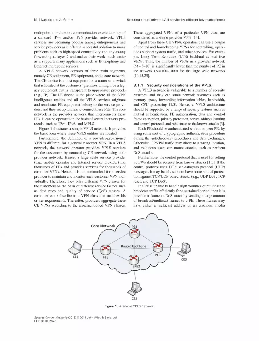
A VPLS network consists of three main segments,namely CE equipment, PE equipment, and a core network.The CE device is a host equipment or a router or a switchthat is located at the customers’ premises. It might be a leg-acy equipment that is transparent to upper-layer protocols(e.g., IP). The PE device is the place where all the VPNintelligence resides and all the VPLS services originateand terminate. PE equipment belong to the service provi-ders, and they set up tunnels to connect these PEs. The corenetwork is the provider network that interconnects thesePEs. It can be operated on the basis of several network pro-tocols, such as IPv4, IPv6, and MPLS.
Figure 1 illustrates a simple VPLS network. It providesthe basic idea where these VPLS entities are located.
Furthermore, the definition of a provider-provisionedVPN is different for a general customer VPN. In a VPLSnetwork, the network operator provides VPLS servicesfor the customers by connecting CE network using theirprovider network. Hence, a large scale service provider(e.g., mobile operator and Internet service provider) hasthousands of PEs and provides services for thousands ofcustomer VPNs. Hence, it is not economical for a serviceprovider to maintain and monitor each customer VPN indi-vidually. Therefore, they offer different VPN classes forthe customers on the basis of different service factors suchas data rates and quality of service (QoS) classes. Acustomer can subscribe to a VPN class that matches hisor her requirements. Thereafter, providers aggregate theseCE VPNs according to the aforementioned VPN classes.
Figure 1. A simple
Security Comm. Networks (2013) © 2013 John Wiley & Sons, Ltd.DOI: 10.1002/sec
These aggregated VPNs of a particular VPN class areconsidered as a single provider VPN [14].
Apart from these CE VPNs, operators can use a coupleof control and housekeeping VPNs for controlling, opera-tions support system traffic, and other services. For exam-ple, Long Term Evolution (LTE) backhaul defined fiveVPNs. Thus, the number of VPNs in a provider network(M= 3–10) is significantly lower than the number of PE inthe network (N=100–1000) for the large scale networks[14,15,25].
3.1.1. Security considerations of the VPLS.A VPLS network is vulnerable to a number of security
breaches, and they can strain network resources such asmemory space, forwarding information tables, bandwidth,and CPU processing [1,3]. Hence, a VPLS architectureshould be supported by a range of security features such asmutual authentication, PE authorization, data and controlframe encryption, privacy protection, secure address learningand control protocol, and robustness to the known attacks [3].
Each PE should be authenticated with other peer PEs byusing some sort of cryptographic authentication procedureduring the autodiscovery procedures and data exchanges.Otherwise, L2VPN traffic may direct to a wrong location,and malicious users can mount attacks, such as performDoS attacks.
Furthermore, the control protocol that is used for settingup PWs should be secured from knows attacks [1,3]. If thecontrol protocol uses TCP/user datagram protocol (UDP)messages, it may be advisable to have some sort of protec-tion against TCP/UDP-based attacks (e.g., UDP DoS, TCPreset, and TCP DoS).
If a PE is unable to handle high volumes of multicast orbroadcast traffic efficiently for a sustained period, then it ispossible to launch a DoS attack by sending a large amountof broadcast/multicast frames to a PE. These frames mayhave either a multicast address or an unknown media
VPLS network.

Securing virtual private LAN service by efficient key management M. Liyanage and A. Gurtov
access control (MAC) address in their MAC destinationaddress fields. Then, PE will not be able to process allthese bogus frames, and ultimately, it will be unable toserve the legitimate frames as well.
If VPLS data packets are transmitted in the clear(unencrypted) form via untrusted public network, then aman-in-the-middle can eavesdrop and may be able to injectpackets into the data stream. If control packets aremaliciously and undetectably altered while in flight, DoSattacks or alteration of the expected QoS level may result.
Hence, it is important to provide a sufficient level ofsecurity features for a VPLS network for a proper operation.
3.2. Host identity protocol
The HIP is a new security and mobility protocol by theIETF [16,17]. In other terms, it is a novel host identifica-tion technology for use in IP networks, such as the Internet.In the Internet, IP addresses are used for dual roles as thehost identifiers and as the location identifiers. HIP intro-duces a new layer to TCP/IP-layered model in betweenthe transport and the internetworking layers. Hence, itseparates the dual roles of IP addresses.
The HIP provides a host identity (HI) name space basedon a public key security infrastructure, and these HIs areused as the end-point (host) identifiers. A 128-bit hash ofHI is called host identity tag (HIT), and it is used by the up-per-layer applications. Hence, all occurrences of IPaddresses in the upper-layer applications are eliminatedand replaced with these cryptographic host identifiers thatare provided by HIP [18].
The HIP nodes use IP security (IPsec) encapsulatingsecurity payload (ESP) protocol on bound end to endtunnel mode tunnels [19] to communicate each other.Hence, the HIP-based traffic is always encrypted. Further,security associations for the IPsec tunnels are exchangedby using HIP base exchange (BEX). HIP BEX is a four-way initial handshake procedure between two users thatnot only makes security associations but also mutuallyauthenticates the users.
3.3. HIP-based virtual private LAN service
The HIPLS [2] is proposed to provide a secure VPLSarchitecture. Basically, HIP is used here to create a VPLSoverlay on top of a standard IPv4 and/or IPv6 providernetwork. HIP signaling between PE devices works as thecontrol protocol of the VPLS that is used to establish andmaintain the HIP tunnels between PEs.
This application of HIP for the HIPLS differs from the tra-ditional implementation of HIP. There are two main differ-ences. First, HIP is implemented within the middle boxesas a “bump-in-the-wire” implementation not within the endhosts. Second, the payloads of the ESP-encrypted datagramsare layer 2 frames instead of transport Protocol Data Units(PDUs) [2].
The HIPLS inherits the strong security properties found inHIP, including strong authentication mechanism, data packet
encapsulation, and some level of robustness from attacks.The strong authentication mechanism and data packet encap-sulation solve many of the aforementioned security threatsin a VPLS. It provides secure PE registration, secure data/control packet exchange, secure auto discovery mechanism,and secure control protocol and avoids several known attacks(e.g., eavesdropping, spoofing, and DoS attacks).
3.3.1. The issues related to HIPLS.Although HIPLS provides a secure VPLS service, several
issues can be identified.First, it has a massive key storage complexity. Every PE
equipment has to store O(N) keys, where N is the numberof PE equipment. As a result, the whole network has tostore O(N(N+ 1)) keys. This is a serious issue as it reducesthe available memory of a PE for other important functionssuch as routing tables. Furthermore, the extensive keysearches need extra processing power at the PE andincrease the packet transmission delay.
Second, HIPLS has an inefficient broadcast mechanism.It performs O(N) encryptions per broadcast frame at entryPE by using O(N) different keys. Hence, it requires exten-sive processing at PEs and vulnerable to broadcast-basedDoS attacks.
Third, it is not possible to integrate the distribution ofmulticast or broadcast frames of HIPLS with the packetdistribution mechanisms such as spanning trees and multi-cast trees of the underlay network. Hence, the routing ofthese multicast and broadcast frames may not be optimal,and it expenses network bandwidth inefficiently. Becauseof the previously stated three reasons, HIPLS is lackingof both security and forwarding plane scalability to imple-ment in large scale networks.
Fourth, HIPLS is vulnerable to misfeasor attacks thatoriginated from CEs and PEs as HIPLS does not specifyany mechanism to avoid such attacks.
4. PROPOSED SECURE VPLSARCHITECTURE
We propose a novel secure VPLS architecture in this jour-nal. Our architecture is inspired by the HIPLS [2] architec-ture and uses HIP to create a VPLS overlay on top of astandard IPv4 and/or IPv6 provider network. The main ideabehind our proposal is to use a new session key mechanismwith a customized version HIP. Hence, we can call ourarchitecture as session key-based HIPLS (S-HIPLS).
Our architecture uses two types of keys as contentencryption key (CEK) and key encryption key (KEK).CEK is a symmetric key that is used to encrypt and decryptall messages in a single VPN. Every PE has a unique KEKthat is used to encrypt and decrypt the correspondingCEKs. There is a key distribution center (KDC) that isthe responsible entity to distribute CEKs to the PEs.Furthermore, KDC also works as the authentication server(AS) that maintains the access control lists (ACLs) ofVPNs. Operators update ACLs according to the CE
Security Comm. Networks (2013) © 2013 John Wiley & Sons, Ltd.DOI: 10.1002/sec

Securing virtual private LAN service by efficient key managementM. Liyanage and A. Gurtov
subscriptions. Thereafter, KDC uses these ACLs to grantthe access to new PEs. HIP signaling is used as the controlprotocol to build and maintain the tunnels between PEs.
Our VPLS architecture can be categorized in to foursubsections as PE registration and deletion, data communi-cation, control protocol, and key management.
4.1. PE registration and deletion
The PE registration is the initial procedure for a new PEwho wishes to join for the VPLS. The potential PE needsto send a request to the KDC to gain access to VPNs.Hence, the new user has to establish an HIP tunnel withthe KDC. A mandatory HIP BEX will run between thenew PE and the KDC to establish this HIP tunnel. Duringthis HIP BEX, the new PE is authenticated by a public keyinfrastructure and authorized according to ACLs.
Few modifications are proposed to the original HIPBEX that was proposed in [16]. Figure 2 illustrates themodified BEX.
First three message exchanges are similar to the originalHIP BEX. HIT-based authorization is sufficient enough toavoid spoofing attacks. Even if an attacker is able to gener-ate a valid HIT, it would fail to complete the initial BEXbecause of lack of knowledge of the private key [20].The symmetric key that is shared by Diffie–Hellman(D–H) key exchange uses as the KEK for this user.
The identity of the initiator is verified after the arrival ofthe I2 packet. Then, KDC checks the ACL and sends a cer-tificate in R2 encrypted by using the KEK key of the user.This certificate contains important information, such as theauthorized VPNs, QoS policies, and other VPN manage-ment details. This certificate is also important to avoidthe misfeasor attacks that originate from the legitimateCEs and PEs. For instance, a customer may subscribe fora VPLS service to obtain the connectivity among certainsites. However, if the customer tries to direct the traffic toa nonsubscribed site via this VPLS, PEs can discard suchtraffic on the basis of the information in these certificates.
The removal of inactive PEs is also important for theefficient operation and the security of the VPLS network.When a PE leaves or becomes inactive, KDC removesthe KEK of that PE and no longer provides CEKs for thatPE. An inactive user can be identified by using eitheractive notification or passive notification. The PEs willactively notify their departure to the KDC before they
Figure 2. Modified HIP BEX for PE registration.
Security Comm. Networks (2013) © 2013 John Wiley & Sons, Ltd.DOI: 10.1002/sec
leave, or failure to acknowledge for the periodic hellomessages will passively notify the inactiveness.
4.2. Data communication
Our VPLS architecture uses HIP tunnels between PEs tocommunicate. Hence, the sender PE must build an HIPtunnel to each target PE before any data exchange. HIPuses bound end to end tunnel mode IPsec tunnels, and allthe frames are encrypted to avoid eavesdropping by the un-authorized party. The source PE encrypts the layer 2 (L2)frame by using the corresponding CEK of the VPN. Then,source PE will wrap it within the ESP payload, fragments itif necessary, and sends it to the remote PE. The remote PEdetunnels it and places it on the remote access networksegment again as an L2 frame.
4.3. Control protocol
The control protocol is used to maintain the proper opera-tion of the VPLS network. It is responsible for three mainfunctions, namely tunnel establishment, address learning,and key distribution. Our architecture provides a securecontrol protocol by using secure HIP signaling.
4.3.1. Tunnel establishment.An HIP tunnel establishment between two users is man-
datory before any type of communication in the VPLS.The HIP tunnel establishment follows an HIP BEX, andit mutually authenticates the users. This HIP BEX isslightly different than the original HIP BEX [16]. As weuse CSKs for data encryption for ESP, D–H key exchangeis omitted here. Hence, modified HIP BEX is slightly fas-ter, and it needs less processing than the original HIP BEX.
Figure 3 illustrates the modified BEX for the tunnelestablishment.
4.3.2. Address learning.The VPLS is an L2VPN solution, and frames are
delivered on the basis of MAC addresses. Hence, PEsshould learn the MAC addresses of remote CEs and thenetwork address of the PE that is responsible for eachCE. Hence, each PE maintains a dynamic MAC–PEmapping table. The address-learning procedure can bedescribed as follows.
Figure 3. Modified HIP BEX for tunnel establishment.

Figure 4. A simple hierarchical KDC structure.
Securing virtual private LAN service by efficient key management M. Liyanage and A. Gurtov
When a PE receives a frame from costumer accessnetwork, PE learns that it is the responsible PE device forthe source MAC address of the frame and records the entryin MAC–PE mapping table. If the PE does not have the des-tinationMAC address of the frame on its MAC–PEmappingtable, PE has to learn about the responsible PE. Hence, PEbroadcasts an encrypted address request frame to all PEs thatbelongs to the same VPN. Then, the responsible PE sends aunicast frame as a reply, and PE updates its MAC–PEmapping table.
4.3.3. Key distribution.Key distribution is the most important process of our
architecture. We present a secure key distribution todeliver the keys only to authorized PEs. Otherwise, faulttraffic generation and unauthorized eavesdropping can bepossible. Although key distribution is a duty of the controlprotocol, we describe it under the key management sectionfor the continuation.
4.4. Key management
The key management procedure of our VPLS architecturehas three sections as KEK distribution, CEK distribution,and KDC architecture.
4.4.1. KEK distribution.Each PE shares a unique symmetric key with the KDC
that is used as the KEK for that PE. This KEK is sharedusing D–H key exchange during the PE registrationprocess. It is used by KDC to send the encrypted CEKs,certificates, and any other control information to the PE.There are periodic HIP BEX instances between each PEand KDC to renew the KEK. This process is called asrekeying, and it is recommended by the HIP architecture[16]. Initially, we define the rekeying timeout as 10 s, andit can be changed according to the requirements of theoperator.
4.4.2. CEK distribution.The KDC is the responsible entity for the CEK distribu-
tion. It periodically sends the CEK to PEs. These CEKs areencrypted by using the KEK of each PE. Hence, an eaves-dropper cannot extract the CEK. There are three instancesthat a new CEK distribution is triggered.
First, KDC periodically generates new CEKs to securethe VPLS communication session. Although an intruderis able to capture a CEK somehow, it will not be valid afterthe rekeying time out. As the membership of the VPLS isdynamic, it may need to provide forward and backwardconfidentiality for the VPLS. Second and third CEK distri-bution events are used to ensure these optional securityfeatures. KDC generates new CEKs after a new PE regis-tration to protect the backward confidentiality. Backwardconfidentiality means new members cannot access the olddata. KDC generates the CEKs of the VPNs that have thenew PE as a member. Thereafter, it sends new CEKs toall the corresponding PEs.
The KDC generates new CEKs after a PE deletion toensure the forward confidentiality. Forward confidentialitydefines as an old member cannot access the new data of theVPN. It generates the CEKs of the VPNs that had theinactive PE as a member. Then, KDC sends new CEKsto the corresponding PEs.
4.4.3. KDC architecture.The KDC is the heart of the key distribution mecha-
nism. It plays a dual role as the key distributor and theAS. Hence, it is responsible for PE registration, PEdeletion, and CEK generation and distribution. We proposea distributed KDC structure that is preferred for the largescale networks. A distributed KDC architecture providesseveral benefits such as reducing the work load, distribut-ing the key storage complexity, and avoiding the singlepoint of failure.
We propose two distributed KDC architectures ashierarchical server and mesh server structures.
Hierarchical server structure is suitable for a providernetwork that has a hierarchical underlay network topology.Figure 4 illustrates a simple hierarchical KDC structurewith two tiers.
Each tier 2 KDC is responsible for a section of theVPLS. It conducts the PE registration, KEK storage,CEK distribution, and PE deletion functions of the particu-lar section. For instance, B is responsible for PE1 and PE2.In addition, these tier 2 KDCs can operate local VPNs if allthe member PEs of the local VPN are resided under thatKDC. For example, B can operate a local VPLS only forPE1 and PE2. Tier 1 KDC is responsible for CEK distribu-tion (only VPNs spend at least two tier 2 KDCs) andcontrols the operation of the tier 2 KDCs. Tier 1 KDClearns the relevant membership alternation from tier 2
Security Comm. Networks (2013) © 2013 John Wiley & Sons, LtdDOI: 10.1002/se
.c

Securing virtual private LAN service by efficient key managementM. Liyanage and A. Gurtov
KDC advisement. Furthermore, operator changes the ACLonly in tier 1 KDC(AS), and it securely broadcasts them totier 2 KDCs.
Mesh structure is suitable for a provider network thathas mesh underlay network. Figure 5 illustrates a simplemesh structure with two KDCs.
Each KDC is responsible for a section of the VPLS, andall KDCs are connected to each other by forming a meshnetwork. Local VPNs are possible in this scenario as well.If it is necessary, KDC has to notify regional membershipchanges to other KDCs. If new CSKs are required, respon-sible KDCs generate the new CEK and securely transferthem to the corresponding PEs via other KDCs. Further-more, one KDC in the mesh is elected for periodic CEKdistribution.
4.5. Broadcast mechanism
Broadcast and multicast messages are important for a LANservice. For instance, broadcast messages are used bynetwork protocols such as address resolution protocol(ARP) and dynamic host configuration protocol (DHCP),and multicast messages are used by Ethernet services suchas IP telephony and television webcast.
However, HIPLS [2] does not provide an efficientbroadcast/multicast mechanism, and HIPLS is useful onlyfor a constrained system such as a unicast-only IPLSVPN. Hence, Henderson et al. [2] proposed to deployHIPLS only in the systems that neither support multicastor broadcast nor bridge PDUs.
Our architecture provides an efficient broadcast mecha-nism and relaxes the unicast-only IPLS VPN constrain. Wesignificantly reduce the number of encryptions and packetgeneration per broadcast frame at the entry PE. Our VPLSsolution uses one session key for one VPN. Hence, it needsonly one encryption per broadcast frame at the entry PE,and only one encrypted broadcast frame is developed.Therefore, this packet can be replicated at entry PE and/or at the immediate nodes according to the spanning treeprotocol or multicast tree. Thus, this broadcast frame distri-bution is exactly similar to the other nonsecure VPLSarchitectures [8,9]. The proposed architecture is capable
Figure 5. A simple mesh KDC structure.
Security Comm. Networks (2013) © 2013 John Wiley & Sons, Ltd.DOI: 10.1002/sec
enough to distribute the broadcast/multicast frames effi-ciently in the network.
5. NUMERICAL RESULTS
This section contains the description of the simulationmodel and its important results.
5.1. Security performance
We model and simulate our architecture on MATLAB tocompare the performance with other VPLS architectures.Especially, we conduct several extended simulations tostudy the performance under known attacks.
The control protocol is the vein of the VPLS. It isdesigned on the basis of the BGP [21] or LDP [22] formost of the existing VPLS solutions (Section 2). LDP-based VPLS architecture proposed a full mesh of LDPsessions as the control protocol. According to the LDPspecification [22], the LDP sessions are built by using theTCP protocol. BGP-based VPLS architecture proposed touse BGP as the control plane protocol, and it also usesTCP as its transport protocol [21]. However, these TCP-based control protocols are vulnerable to IP/TCP-basedattacks. Therefore, the attackers try to perform TCP-basedattacks such as TCP synchronization (SYN) DoS, TCPSYN distributed DoS (DDoS), and TCP reset attacks toturn down the controlling plane of the VPLS network [25].
Hence, we compare the robustness of the control protocolof these solutions with our VPLS architecture under severalknown attacks, namely TCP reset, TCP SYN DoS, andTCP SYN DDoS attacks. We use LDP-based VPLS modelthat was presented in [9] and HIPLS [2] as the referencemodels to compare the performance of the proposedarchitecture.
5.1.1. Performance under TCP SYN DoS attack.TCP SYN DoS attack is also called TCP SYN flood
attack. Basically, an attacker sends a succession of TCPSYN requests to the target system or server. As the serverallocates some resources (a TCP port) for each successfullyreceived SYN request, the attacker is able to consumeserver resources to make the system unresponsive for thelegitimate traffic.
Our simulation model contains a VPLS network with300 nodes. We assume that all the nodes are equivalentand the bandwidth of the network is set to 100Mbps. Thereis an attacker that tries to attack a node in the network.Hence, it sends TCP SYN packets to the underattackednode to occupy all the ports and IP address combinationswith other nodes in the network. Then, the rest of the nodesin the network will not be able to send any data traffic forthe underattacked node as it does not have any port tomake a connection. We assume that the attacker also hasthe same bandwidth, which is 100Mbps. According tothe values that were presented in [23], we use the numberof ports per user as 64,000 and the TCP timeout value as

Figure 7. Impact of TCP SYN DDoS attack.
Securing virtual private LAN service by efficient key management M. Liyanage and A. Gurtov
270 s. We run the simulation for 500 s, and the attack isplaced between 25 and 75 s time intervals.
Figure 6 illustrates the percentage packet drop at theunderattacked user over the simulation time.
The simulation result clearly indicates that there is nopacket drop during the attack period for the HIPLS andour architecture. They have the same performance for bothattacking and nonattacking periods. However, LDP archi-tecture has dropped almost all the packets during the DoSattack period, and it requires at least a TCP timeout period,which is 270 s, to fully recover from the attack. Hence, ourarchitecture is capable enough to provide the protection forTCP SYN DoS attack.
5.1.2. Performance under TCP SYN DDoS attack.We further investigate the performance of the proposed
architecture under the coordinated DDoS attack scenario.We use the same simulation setup and the attack modelthat is used for the previous TCP SYN DoS attackscenario. However, we increase the number of attackersand investigate the time required to successfully attack asingle user in the VPLS network. We compare the perfor-mance with LDP-based VPLS architecture [9].
Figure 7 illustrates the average time required to success-fully attack the user.
We run the simulation for 500 s and place the attack forthe whole duration of the simulation time. We do not seeany successful attack for our architecture. Hence, the averagetime required to successfully attack remains in the initialvalue, which is zero, at the end of the simulation for our archi-tecture. However, the simulation result verifies that LDP-based architecture is vulnerable for DDoS attack as well.Furthermore, the time required to successfully attack thesystem is inversely proportional to the numbers of attackers.
5.1.3. Performance under TCP reset attack.The TCP reset attack is a TCP/IP-based attack that is
used to terminate an ongoing TCP connection betweentwo users. At first, the attacker has to hijack the connec-tion. In other words, the attacker monitors and learns the
Figure 6. Impact of TCP SYN DoS attack.
TCP header parameters such as IP addresses, portnumbers, and sequence numbers of the TCP connection.Secondly, attacker generates fake TCP packets with TCPparameters which are learnt by hijacking the connectionand sends these packets with reset flag ON to both usersor any one of the user. As the end users do not aware ofthese fake TCP packets, end users treat these packets as le-gitimate packets. Therefore, they reset the TCP connection,and communication session between users is terminated.
We compare the performance of the LDP-based VPLSarchitecture and HIPLS with our architecture under theTCP reset attack scenario. It is assumed that both VPLSusers and the attacker have the same bandwidth of100Mbps. We calculate the probability of successful at-tack against the size of the file. In [24], the authors statedthat the file sizes in the Internet have a Pareto distributionwith the minimum file size of 4.5 kB and the maximumsize of 20MB. Hence, we change the file sizes within thisrange, and Figure 8 illustrates the simulation results.
The simulation result shows that our architecture has azero probability of a successful attack. It verifies the pro-tection against the TCP reset attacks. However, we observe
Figure 8. Impact of TCP reset attack.
Security Comm. Networks (2013) © 2013 John Wiley & Sons, Ltd.DOI: 10.1002/sec

0 20 40 60 80 1000
20
40
60
80
100
120
Number of PEs
Num
ber
of k
eys
HIPLSOur Proposal
Figure 9. The key storage complexity at a PE.
80
100
120
eys
HIPLSOur Proposal
Securing virtual private LAN service by efficient key managementM. Liyanage and A. Gurtov
some probability of a successful attack for LDP-basedVPLS architecture, and it is directly proportional to the filesize. Larger files have longer transmission time, and theattacker gets more time to reset the connection.
We further analyze the impact of the TCP reset attackby varying the connection speed of the attacker (Table I).
The simulations are conducted for 500 s, and we do notobserve any successful attacks for our proposal under anyof the connection speeds. However, we obtain some valuesfor the LDP-based VPLS architecture. The experimentresult indicates that connection speed of the attacker isinversely propositional to the average time requirementfor a successful attack.
5.2. Security plane scalability
Several VPLS architectures are proposed to provide anefficient VPLS network. However, HIPLS [2] is the onlyVPLS scheme that was able to provide a secure VPLS ar-chitecture. Furthermore, it is the first and the only schemethat proposed to use a public key authentication structureand the data traffic encryption mechanism in VPLS. Wesimulate the proposed architecture and HIPLS onMATLAB environment. We consider a VPLS network thathas 100 PEs and a bandwidth of 100Mbps. The followingsection contains a comparison of performance securitymechanisms and broadcast mechanism in the HIPLS andour architecture.
The key storage requirement at each entity of the VPLSnetwork has been compared. It is a major evidence tojustify the security plane scalability.
5.2.1. Key storage at a PE.Figure 9 illustrates the key storage complexity at a PE
against the number of PEs in the provider network. Weuse the number of VPNs asM= 5 (which is within the gen-eral number of VPNs used in an LTE backhaul network[14,15] and change the PEs from 1 to 100.
The simulation result in Figure 9 indicates a linearincrement of the number of keys at a PE for the HIPLSscheme, whereas it remains constant for the proposedarchitecture. Thus, the number of keys stored at a PE inthe proposed scheme is significantly reduced. The numeri-cal analysis shows that the complexity of HIPLS is O(N),where N is the number of PEs, and the complexity of ourmodel is O(M+ 1), where M is the number of VPNs andit is independent of the number of PEs in the provider
Table I. The impact of TCP reset attack for LDP architecture.
Attacker’s connectionspeed (Mbps)
Average time requirement for asuccessfully attack (s)
1.544 (T1) 64.1306.312 (DS2) 13.45144.736 (DS3) 1.85551.84 (OC1) 1.771155.52 (OC3) 0.593
Security Comm. Networks (2013) © 2013 John Wiley & Sons, Ltd.DOI: 10.1002/sec
network. This numerical analysis explains the simulationresults.
Figure 10 illustrates the key storage complexity at a PEagainst the number of VPNs in the provider network. Weuse the number of PEs as N= 100 and change VPNs from1 to 100.
The simulation result in Figure 10 indicates a linearincrement of the number of keys at a PE for our architec-ture, whereas it remains constant for the HIPLS architec-ture. Hence, the number of keys at a PE for HIPLS isindependent of the number of VPNs in the provider net-work. By comparing the HIPLS scheme and the proposedscheme, the number of keys stored at a PE in the proposedscheme is reduced as long as the number of VPNs is lessthan the number of PEs in the network. Furthermore, wealready stated that N>>>M for most of the real-worlduse cases (Section3.1).
5.2.2. Key storage in the authentication server/keydistribution center.
Figure 11 illustrates the key storage complexity at theAS/KDC against the number of PEs. HIPLS uses an AS,and our architecture uses a KDC that provides AS services
0 20 40 60 80 1000
20
40
60
Number of VPNs
Num
ber
of k
Figure 10. The key storage complexity at a PE.

0 20 40 60 80 1000
20
40
60
80
100
120
Number of PEs
Num
ber
of k
eys
HIPLSOur Proposal
Figure 11. The key storage complexity at the AS/KDC.
Securing virtual private LAN service by efficient key management M. Liyanage and A. Gurtov
and additional CEK distribution service. We use the numberof VPNs as M=5 and change the PEs from 1 to 100.
The simulation result in Figure 11 indicates a linearincrement of the number of keys at the AS for the HIPLSscheme. We observe an almost similar gradual incrementof the number of keys at a KDC for our scheme as well.However, the number of keys stored at a KDC in theproposed scheme is slightly higher than HIPLS. This isdue to the fact that the number of keys stored at a KDCin the proposed scheme is dependent on both the numberof PEs and VPNs, whereas it depends only on the numberof PEs in the HIPLS model. However, N>>>M for mostof the real-world use cases (M= 3–10 and N= 100–1000)[14,15], and the difference is less significant for largescale networks. The numerical analysis shows that thecomplexity of HIPLS is O(N) and the complexity of ourmodel is O(N+M). It explains the simulation results.
Figure 12 illustrates the key storage complexity at theAS/KDC against the number of VPNs in the provider net-work. We use the number of PEs as N= 100 and changethe PEs from 1 to 100.
The simulation result in Figure 12 indicates a linearincrement of the number of keys stored at the KDC for
0 20 40 60 80 1000
20
40
60
80
100
120
140
160
180
200
Number of VPNs
Num
ber
of k
eys
HIPLSOur Proposal
Figure 12. The key storage complexity at the AS/KDC.
our architecture, whereas it remains constant for the HIPLSarchitecture. Hence, the number of keys at the AS forHIPLS is independent of the number of VPNs in theprovider network. By comparing the HIPLS scheme andthe proposed scheme, the number of keys stored at theAS/KDC is higher in our scheme. The difference is equalto the number of VPNs in the network, and as long as thenumbers of VPNs are limited, difference is less significant.Furthermore, the proposed distributed server systems cansignificantly reduce the key storage per server.
5.2.3. Total key storage in the network.Figure 13 illustrates the total key storage complexity of
the VPLS network against the number of PEs. We use thenumber of VPNs as M= 5 and change PEs from 1 to 100.
The simulation result in Figure 13 indicates an expo-nential increment of the total number of keys stored inthe network for the HIPLS scheme, whereas it has a linearincrement for the proposed architecture. Thus, the totalnumber of keys stored in the network is significantlyreduced in the proposed scheme. The complexity ofHIPLS is O(N(N+ 1)), and the complexity of our modelis O(N(M+ 2) +M). It further explains the validity of thesimulation results.
Figure 14 illustrates the total key storage complexity inthe network against the number of VPNs in the providernetwork. We use the number of PEs as N = 100 and changePEs from 1 to 100.
The simulation result in Figure 14 indicates a linearincrement of the total number of keys stored in the networkfor our scheme, whereas it remains constant the HIPLS ar-chitecture. Hence, the number of keys at an AS for HIPLSis independent of the number of VPNs in the provider net-work. By comparing the HIPLS scheme and the proposedscheme, the total number of keys stored in the network isreduced by the proposed scheme as long as the numberof VPNs is less than the number of PEs in the network.
The experiment results of this section verify that theproposed architecture significantly reduces the key storagecomplexities of the PEs and the network. Further, it shows
0 20 40 60 80 1000
2000
4000
6000
8000
10000
12000
Number of PEs
Num
ber
of k
eys
HIPLSOur Proposal
Figure 13. Total key storage complexity of the VPLS network.
Security Comm. Networks (2013) © 2013 John Wiley & Sons, Ltd.DOI: 10.1002/sec

0 20 40 60 80 1000
2000
4000
6000
8000
10000
12000
Number of VPNs
Num
ber
of k
eys
HIPLSOur Proposal
Figure 14. Total key storage complexity of the VPLS network.
0 20 40 60 80 1000
10
20
30
40
50
60
70
80
90
100
Number of PEs
Num
ber
of e
ncry
ptio
ns
HIPLSOur Proposal
Figure 15. The number of encryption per broadcast frame.
Securing virtual private LAN service by efficient key managementM. Liyanage and A. Gurtov
that the security-related work load on a PE is independentof the number of PEs in the network. Hence, our architec-ture is able to provide the security plane scalability. Inother words, operators can extend the network withoutany additional work load on top of a PE but in the ASs.If it is needed, operators have an option to use resourcefuland/or distributed AS systems to compensate this addi-tional workload.
5.3. Forwarding plane scalability
An efficient broadcast mechanism is the key indicator toverity the forwarding plane scalability. An efficient broad-cast mechanism is mandatory for the proper operation of alayer 2 network because many layer 2 network protocolssuch as address resolution protocol use Ethernet broadcastmessages. If the broadcast mechanism is inefficient, layer 2nodes are unable to forward frames in larger networks. Itcauses to decrease the forwarding plane scalability.
5.3.1. Comparison of broadcast mechanism.The performance of the frame broadcasting mechanism
in different schemes has been compared in this section.Figure 15 illustrates the number of encryption per
broadcast frame at the entry PE of the provider network.The simulation result in Figure 15 indicates a linear in-
crement of the number of encryptions per broadcast frameat a PE for the HIPLS scheme, whereas it remains constantat value 1 for the proposed architecture. Thus, the numberof encryptions per broadcast frame at a PE in the proposedscheme is significantly reduced. The complexity of HIPLSis O(N), the complexity of our model is O(1), and it furtherexplains the simulation result.
The experiment clearly shows that the proposed archi-tecture reduces the number of broadcast packet generationcomplexity at the entry PE from O(N) to O(1). Hence, thebroadcast mechanism is almost similar to the broadcastmechanism of other nonsecure VPLS architectures. Hence,it provides the forwarding plane scalability.
Security Comm. Networks (2013) © 2013 John Wiley & Sons, Ltd.DOI: 10.1002/sec
6. DISCUSSION
6.1. Security features
Our VPLS architecture is able to provide a wide range ofsecurity features to the VPLS network, namely mutualauthentication, PE authorization, payload encryption,privacy protection, secure address learning and controlprotocol, and robustness to known attacks.
6.1.1. Mutual authentication.The identities of the PEs are verified by using a public
key authentication during HIP BEX. An HIP BEX instanceis mandatory at a PE registration and prior to any dataexchange between two PEs. It provides the mutualauthentication between PEs and prevents outside breachesto the VPN.
6.1.2. PE authorization.The KDC is the responsible entity for PE authorization.
It grants the access to PEs according to the ACLs that areprovided by the operator. Hence, malicious users (not inthe ACL) will not gain access to the VPN, and it alsorestricts the misbehavior actions of legitimate CEs.
6.1.3. Payload encryption.Our VPLS scheme proposed to use IPsec ESP mode.
Hence, payload is always encrypted by using the CEK ofthe particular VPN.
6.1.4. Privacy protection.Our proposal provides the privacy protection of both
CEs and PEs. All the frames are encrypted and wrappedin IPsec ESP packets. Hence, the source and destinationMAC address of CEs are encrypted and protected. As longas HI is exposed to the outside world, the original IPaddresses of the PEs are also encrypted during the commu-nication. It secures the privacy of the PEs.

Securing virtual private LAN service by efficient key management M. Liyanage and A. Gurtov
6.1.5. Protection for the KDC.The KDC is a highly important element in the VPLS
network. Especially, intruders try to attack the KDC. How-ever, every user who wishes to communicate with theKDC has to establish an HIP tunnel as the first step. ThisHIP tunnel establishment phase (HIP BEX) authenticatesthe users on the basis of public key infrastructure mecha-nism and authorizes on the basis of ACLs. Hence, intruderswill not get the access. Furthermore, HIP BEX has inbuiltmechanisms to prevent DoS and spoofing attacks [16,17].Hence, the KDC is well secured for such attacks.
6.1.6. Secure control protocol.Our model use IPsec ESP mode to transmit the address
learning and control frames. Also, remote PEs are mutuallyauthenticated before the communication. Hence, faultaddress advertisements and eavesdropping of addressesare restricted in the VPLS. Furthermore, the control proto-col uses the HIP signaling though HIP tunnels that are pro-tected from IP/TCP-based attacks. Further, our simulationresults verify the protection for the control protocol.
6.1.7. Robustness to the known attacks.Secure address learning and mutual authentication
avoid the delivery of L2VPN traffic to the wrong destina-tions and access of the malicious user to the network.The secure control protocol prevents the several types ofDoS attacks and unauthorized alteration of the QoS levelsof VPNs. Furthermore, our proposal for efficient broad-cast/multicast frame-processing mechanism at PEs preventsthe broadcast frame-based DoS attacks. Payload encryptionsecures the VPLS traffic from unauthorized man-in-the-middle eavesdropping attacks and in flight alterations.
6.2. Comparison of our architecture andHIPLS
Both HIPLS and our VPLS architectures provide a secureVPLS architecture on top of a standard IPv4 and/or IPv6provider network. Both architectures are based on HIPprotocol. Hence, they inherit the strong security propertiesfound in HIP protocol. Both proposals are able to providestrong authentication mechanism, payload encryption, PEauthorization, privacy protection, robustness to severalknown attacks, and secure control protocol. However, ourproposal outruns the HIPLS because of scalability andadditional security features. These advantages are discussedas follows.
Our VPLS architecture provides an efficient VPLS so-lution than HIPLS. It significantly reduces the complexityof the key storage at a VPLS node from O(N) to O(M)and the total key storage of the network from O(N(N+ 1))to O(N(M+ 2) +M), where N>>>M. Hence, it directlyreduces the storage requirements and memory usage at PEs.Furthermore, it indirectly decreases the frame-processingdelay at PE by eliminating extensive key searchesand encryptions.
Our architecture provides an efficient broadcast/multicast frame-processing mechanism that reduces thecomplexity of the number of encryption per broadcast framefrom O(N) to O(1) at a PE. As a result, broadcast/multicastframe-processing delay at a PE is reduced, and our proposalprovides some level of robustness to broadcast/multicastframe-based DoS attacks. Furthermore, it needs to generateonly one broadcast frame at the entry PE, and it can bereplicated either at entry PE or/and at the immediate nodesaccording to the spanning tree protocol or the multicast tree.This is a similar scenario that is used by other VPLS archi-tectures [8,9,11]. Therefore, our VPLS scenario saves thenetwork bandwidth and reduces the transmission delay thanHIPLS. Also, our architecture relaxes the constrain to useHIPLS only for unicast-only IPLS services.
The proposed architecture provides a faster and lowprocessing tunnel generation phase than HIPLS as it omitsthe extensive D–H key exchange in HIP BEX during theHIP tunnel generation between PEs (Figure 3). Theadditional certificate (Figure 2) that is sent from KDC toPEs provides some level of robustness to misfeasor attacksfrom CEs and PEs. Furthermore, our architecture providesthe opportunity to operate separate VPNs for user and con-trol plane traffic. Hence, it indirectly provides additionalsecurity for important system entity from the attackers.This certificate mechanism and dedicated control VPNinstances were not present in HIPLS.
The only drawback of our proposal compared withHIPLS is the additional key storage requirement needed atthe KDC (Figure 12). However, it is less significant as longas the number of PEs is significantly higher than the numberof VPNs. In addition, a distributed KDC architecture decen-tralizes key storage requirement and solves this issue.
7. CONCLUSION
In this paper, we proposed a novel HIP-based VPLS archi-tecture to provide a secure VPLS network. Our VPLSarchitecture is able to provide a range of security such asmutual authentication, PE authorization, data and controlframe encryption, privacy protection, secure control proto-col, and robustness to the several attacks. Hence, it pro-vides a higher degree of security features than any othersecure VPLS architectures. In addition, our proposal pro-vides scalability both in security and forwarding planes.The numerical analysis verified outrun of our architecturethan other secured VPLS solutions by significantly reduc-ing the complexity of the key storage at a VPLS node,the total key storage of the network, and the number ofencryption per a broadcast frame. The simulation resultsfurther verify the protection against the TCP/IP-basedattacks such as TCP DoS, TCP DDoS, and reset attacks.Hence, the proposed VPLS architecture is a scalable secureVPLS architecture.
Future works focus on extending our architecture for se-cure hierarchical VPLS networks and secure virtual private
Security Comm. Networks (2013) © 2013 John Wiley & Sons, Ltd.DOI: 10.1002/sec

Securing virtual private LAN service by efficient key managementM. Liyanage and A. Gurtov
multicast services. Further, we will study the impact of themobile nodes on the security of the VPLS network.
ACKNOWLEDGEMENTS
This work has been performed in the framework of theCELTIC project CP7-011 MEVICO. The authors wouldlike to acknowledge the contributions of their colleagues.This information reflects the consortium’s view, but theconsortium is not liable for any use that may be made ofany of the information contained therein.
REFERENCES
1. Augustyn W, Serbest Y. Service requirements for layer2 provider-provisioned virtual private networks. RFC4665 September 2006.
2. Henderson T, Venema S, Mattes D. HIP-based virtualprivate LAN service (HIPLS). Internet Draft September2011.
3. Andersson L, Rosen E. Framework for layer 2 virtual pri-vate networks (L2VPNs). RFC 4664 September 2006.
4. Martini L, Rosen E, El-Aawar N, Smith T, Heron G.Pseudowire setup and maintenance using the labeldistribution protocol (LDP). RFC 4447 April 2006.
5. Martini L, Rosen E, El-Aawar N, Heron G. Encapsula-tion methods for transport of Ethernet over MPLSnetworks. RFC 4448 April 2006.
6. Martini L, Rosen E, Heron G, Malis A. Encapsulationmethods for transport of PPP/high-level data linkcontrol (HDLC) over MPLS networks. RFC 4618September 2006.
7. Stein Y. Pseudowire security (PWsec). Internet DraftOctober 2006.
8. Kompella K, Rekhter Y. Virtual private LAN service(VPLS) using BGP for auto-discovery and signaling.RFC 4761 January 2007.
9. Lasserre M, Kompella V. Virtual private LAN service(VPLS) using label distribution protocol (LDP) signal-ing. RFC 4762 January 2007.
10. Gu R, Dong J, Chen M, Zeng Q, Liu Z. Analysis ofvirtual private LAN service (VPLS) deployment. Inter-net Draft September 2011.
11. Shah H, Rosen E. IP-only LAN service (IPLS).Internet Draft February 2007.
Security Comm. Networks (2013) © 2013 John Wiley & Sons, Ltd.DOI: 10.1002/sec
12. Shields C, Garcia-Luna-Aceves J. The HIP protocolfor hierarchical multicast routing. Proc. 17th AnnualACM Symposium on Principles of DistributedComputing, Puerto Vallarta, IEEE, 1998.
13. Kovacshazi Z, Vida R. Host identity specific multicast.Networking and Services, 2007. ICNS. Third Interna-tional Conference on, IEEE, 2007; 1–1.
14. Architectural considerations for backhaul of 2G/3Gand long term evolution networks. Technical Report,CISCO Cooperation. 2010.
15. Alvarez MA, Jounay F, Major T, Volpato P. LTEbackhauling deployment scenarios. Technical Report,Next Generation Mobile Networks Alliancen. 2011.
16. Moskowitz R, Nikander P, Jokela P. Host identityprotocol. RFC 5201 April 2008.
17. Gurtov A. Host Identity Protocol (HIP): Towards theSecure Mobile Internet. Wiley, 2008.
18. Nikander P, Gurtov A, Henderson T. Host identityprotocol (HIP): connectivity, mobility, multi-homing,security, and privacy over IPv4 and IPv6 networks.Communications Surveys & Tutorials, IEEE 2010;12(2):186–204.
19. Jokela P, Moskowitz R, Nikander P. Using the encap-sulating security payload (ESP) transport format withthe host identity protocol (HIP). RFC 5202 April 2008.
20. Kuptsov D, Khurri A, Gurtov A. Distributed userauthentication in Wireless LANs. World of Wireless,Mobile and Multimedia Networks & Workshops,IEEE, 2009.
21. Rekhter Y, Li T, Hares S. A border gateway protocol 4(BGP-4). RFC 4271 January 2006.
22. Andersson L, Doolan P, Feldman N, Fredette A,Thomas B. LDP specification. RFC 3036 January2001.
23. Eddy W. TCP SYN flooding attacks and commonmitigations. RFC 4987 August 2007.
24. Keller G, Beylot A. Improving flow level fairness andinteractivity in WLANs using size-based schedulingpolicies. The 11th International Symposium on Model-ing, Analysis and Simulation of Wireless and MobileSystem. 2008.
25. Liyanage M, Gurtov A. Secured VPN Models for LTEBackhaul Networks , in Proc. of IEEE 76th VehicularTechnology Conference: VTC2012-Fall, Québec City,Canada September 2012.