sd6 manual - atb automation
TRANSCRIPT
SD6M
06/en
anua
2015
l
442426.04
ID 4 2
Table of contentsMa
Ta
1
2
3
4
5
6
7
8
9
10
11
12
13
14
15
16
42426.04 WE KEEP THINGS MOVING
nual SD6
ble of contents
General instructions . . . . . . . . . . . . . . . . . . . . . . . . . . . . . . . . . . . .3
Safety information, UL-compliant use . . . . . . . . . . . . . . . . . . .10
Components of the drive system .. . . . . . . . . . . . . . . . . . . . . . .15
Technical data . . . . . . . . . . . . . . . . . . . . . . . . . . . . . . . . . . . . . . . . .27
Transportation and storage . . . . . . . . . . . . . . . . . . . . . . . . . . . . .71
Installation . . . . . . . . . . . . . . . . . . . . . . . . . . . . . . . . . . . . . . . . . . . .74
Connection .. . . . . . . . . . . . . . . . . . . . . . . . . . . . . . . . . . . . . . . . . . .85
Basic properties . . . . . . . . . . . . . . . . . . . . . . . . . . . . . . . . . . . . . .145
Drive controller . . . . . . . . . . . . . . . . . . . . . . . . . . . . . . . . . . . . . . .155
Motor . . . . . . . . . . . . . . . . . . . . . . . . . . . . . . . . . . . . . . . . . . . . . . . .208
Holding brake . . . . . . . . . . . . . . . . . . . . . . . . . . . . . . . . . . . . . . . .229
Encoder .. . . . . . . . . . . . . . . . . . . . . . . . . . . . . . . . . . . . . . . . . . . . .249
Mechanical drive model . . . . . . . . . . . . . . . . . . . . . . . . . . . . . . .259
Communication .. . . . . . . . . . . . . . . . . . . . . . . . . . . . . . . . . . . . . .264
Optimize . . . . . . . . . . . . . . . . . . . . . . . . . . . . . . . . . . . . . . . . . . . . .295
Diagnosis . . . . . . . . . . . . . . . . . . . . . . . . . . . . . . . . . . . . . . . . . . . .363
ID 4 3
General instructions1Ma
1Ov
1.1
1.2
1.3
1.4
1.5
1.6
1.7
42426.04 WE KEEP THINGS MOVING
nual SD6
General instructionserview of sections
About this manual . . . . . . . . . . . . . . . . . . . . . . . . . . . . . . . . . . . . . .4
Further documentation . . . . . . . . . . . . . . . . . . . . . . . . . . . . . . . . . .5
Further support . . . . . . . . . . . . . . . . . . . . . . . . . . . . . . . . . . . . . . . . .5
Directives and norms . . . . . . . . . . . . . . . . . . . . . . . . . . . . . . . . . . .5
Abbreviations, formula symbols and indices . . . . . . . . . . . . . .6
Symbols, identifiers, marks . . . . . . . . . . . . . . . . . . . . . . . . . . . . . .8
Licenses . . . . . . . . . . . . . . . . . . . . . . . . . . . . . . . . . . . . . . . . . . . . . . .9

ID 4 4
General instructions1Ma
Theautcomfromof cthe
Pro•••••••
1.Thifollo•••••
•••Thecarma
manual is in German.
lies to the following devices:om 0-F and 0-F
Changes• General correctionsSupplemented:• Size 3 • Quick DC-Link • Terminal modules RI6 and IO6• Synchronous linear motors and LA6 adapter
box• UL-compliant use
Electrical data: size 3, derating
• General corrections• Electrical data: derating• Mechanical drive model, CiA 402
42426.04 WE KEEP THINGS MOVING
nual SD6
new SD6 drive controller offers maximum precision and productivity for omation technology and machine manufacturing despite ever more plex functions. Highly dynamic drives ensure the shortest recovery times fast changes in reference value and load jumps. You also have the option
onnecting the drive controllers in a DC intermediate circuit, which improves energy footprint of the entire system.
pertiesLarge power range using 4 sizesQuick DC-Link: Innovative installation concept for the DC link connection Very good control performanceEasy to serviceIsochronous system bus (in preparation)Modular safety technology (in preparation)Free, graphical programming in accordance with IEC 61131-3 CFC (in preparation)
1 About this manuals manual describes the SD6 drive controller. It contains information on the wing topics:ProjectingTransport and storageInstallationConnectionOperation and setup of the drive controller, motor and its attachments and the entire drive.Communication between the startup computer and drive controllerOptimization of the drive controllerDiagnostics in the event of errors safety function Safe Torque off (STO) is implemented by means of safety
d ST6. Detailed information about ST6 can be found in the corresponding nual (see section 1.2 Further documentation).
Original versionThe original version of this
This documentation app• Drive controller SD6 fr
DriveControlSuite V 6.Firmware version V 6.
What is new?
Index Date02 06/2014
03 12/2014 •
04 06/2015

ID 4 5
General instructions1Ma
1.ThetheYou
pportions that are not answered by this document, please
3060stoeber.de
and normseets the requirements of the following directives and
06/42/EC2006/95/EC08/EC
DeSD
Co(C
Como
Como
MC
ST
AbSu
42426.04 WE KEEP THINGS MOVING
nual SD6
2 Further documentation documentation listed in the following table provides relevant information on
SD6 drive controller. can find the latest document versions at www.stoeber.de.
1.3 Further suIf you have technical questcontact:• Phone: +49 7231 582-• E-mail: applications@
1.4 Directives The SD6 drive controller mstandards:• Machinery Directive 20• Low Voltage Directive • EMC Directive 2004/1• EN 61326-3-1:2008• EN 61800-3:2004• EN 61800-5-1:2007• EN 61800-5-2:2007• EN 50178:1997
vice/software Documentation Contents ID6 drive controllers Commissioning
instructionsInstallation and functional test
442537
ntroller Based Mode BM) application
Manual Operation and setup, commissioning
442454
mmunication dule EtherCAT EC6
Operating manual Installation, connection, setup, commissioning and customer service
442516
mmunication dule CANopen CA6
Operating manual Installation, connection, setup, commissioning and customer service
442637
6 Motion Controller Manual Projecting, installation, connection, setup, customer service and maintenance
442461
6 safety technology Manual Projecting, connection, setup
442478
solute Encoder pport AES
Operating manual Function, connection
442343
ID 4 6
General instructions1Ma
1.
AbAAACAEAEAWBABABEBGCACBCHCiACNcspcstcsvCUDCI/OEMEMHTI/O
tion Altitudeted Buslated position modetional Protectionwitch
-Access-Control temperature sensortive Earthtive Extra Low Voltagemmable Logic Controller (dt.: SPS)e Temperature Coefficient UnitWidth ModulationResistornce Switchal Current protective Devicemmable logic controllerSynchronous Interfaceorque Offstor-transistor logic tions per minute
writers Laboratoriesand Shakekulse
42426.04 WE KEEP THINGS MOVING
nual SD6
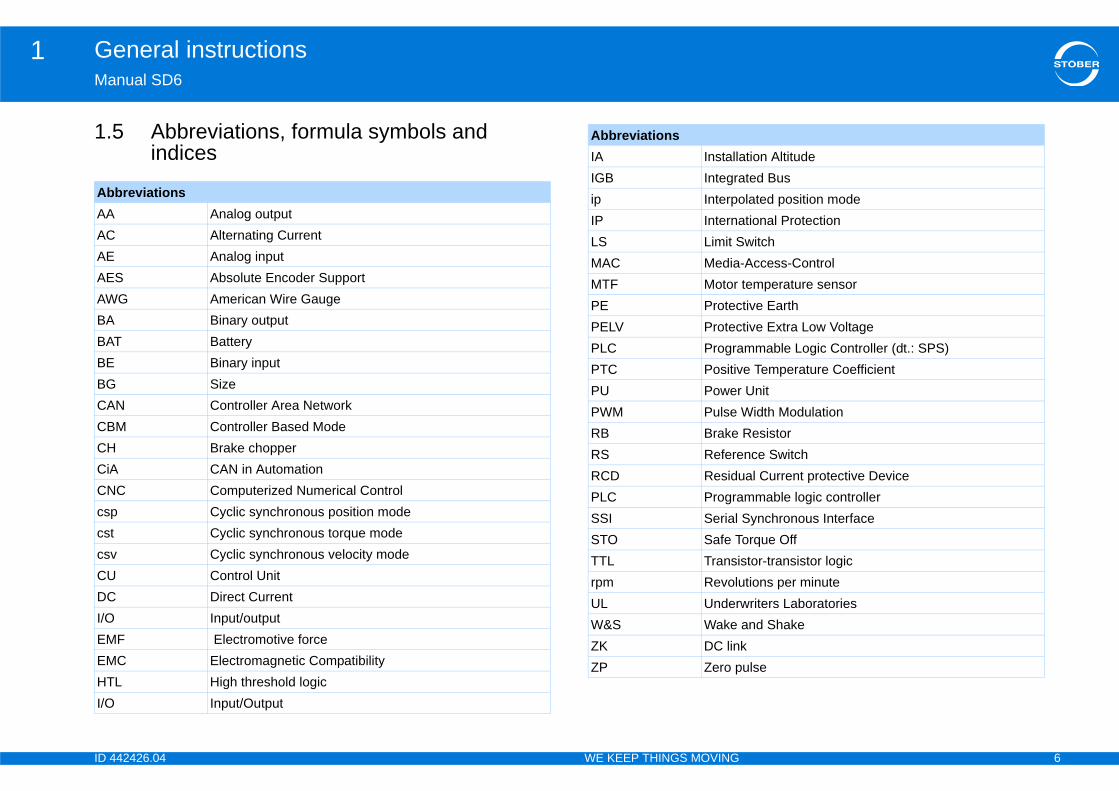
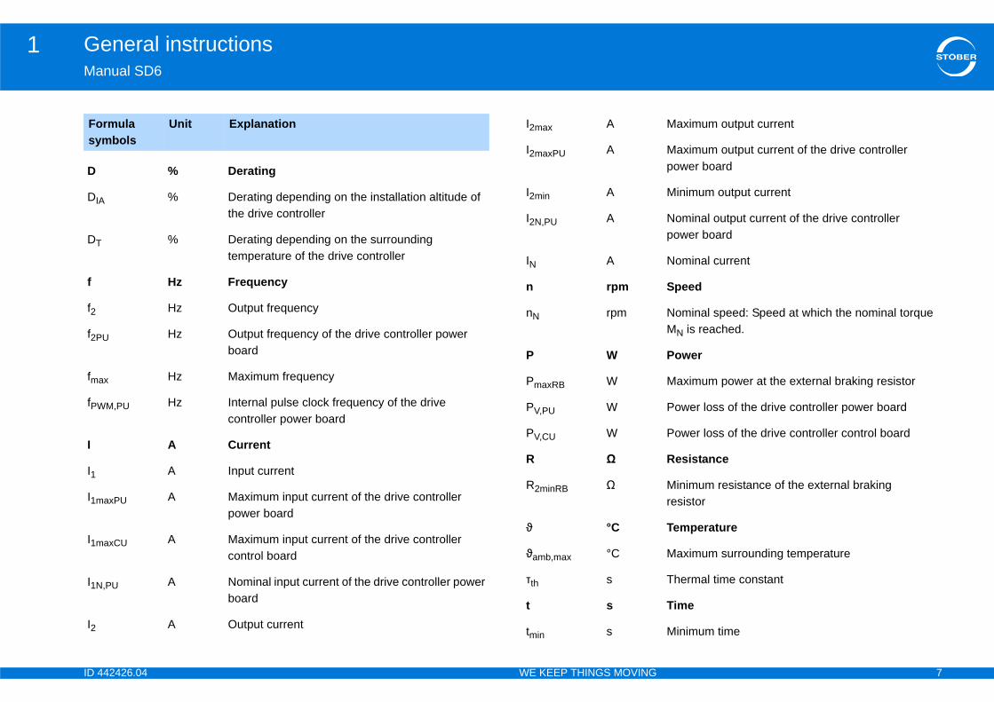
5 Abbreviations, formula symbols and indices
breviationsAnalog outputAlternating CurrentAnalog input
S Absolute Encoder SupportG American Wire Gauge
Binary outputT Battery
Binary inputSize
N Controller Area NetworkM Controller Based Mode
Brake chopperCAN in Automation
C Computerized Numerical ControlCyclic synchronous position modeCyclic synchronous torque modeCyclic synchronous velocity modeControl UnitDirect CurrentInput/output
F Electromotive forceC Electromagnetic CompatibilityL High threshold logic
Input/Output
IA InstallaIGB Integraip InterpoIP InternaLS Limit SMAC MediaMTF Motor PE ProtecPELV ProtecPLC PrograPTC PositivPU PowerPWM Pulse RB Brake RS RefereRCD ResiduPLC PrograSSI Serial STO Safe TTTL Transirpm RevoluUL UnderW&S Wake ZK DC linZP Zero p
Abbreviations
ID 4 7
General instructions1Ma
Fosy
D
DIA
DT
f
f2
f2P
fma
fPW
I
I1
I1m
I1m
I1N
I2
Maximum output current
Maximum output current of the drive controller power board
Minimum output current
Nominal output current of the drive controller power board
Nominal current
Speed
Nominal speed: Speed at which the nominal torque MN is reached.
Power
Maximum power at the external braking resistor
Power loss of the drive controller power board
Power loss of the drive controller control board
Resistance
Minimum resistance of the external braking resistor
Temperature
Maximum surrounding temperature
Thermal time constant
Time
Minimum time
42426.04 WE KEEP THINGS MOVING
nual SD6
rmula mbols
Unit Explanation
% Derating
% Derating depending on the installation altitude of the drive controller
% Derating depending on the surrounding temperature of the drive controller
Hz Frequency
Hz Output frequency
U Hz Output frequency of the drive controller power board
x Hz Maximum frequency
M,PU Hz Internal pulse clock frequency of the drive controller power board
A Current
A Input current
axPU A Maximum input current of the drive controller power board
axCU A Maximum input current of the drive controller control board
,PU A Nominal input current of the drive controller power board
A Output current
I2max A
I2maxPU A
I2min A
I2N,PU A
IN A
n rpm
nN rpm
P W
PmaxRB W
PV,PU W
PV,CU W
R Ω
R2minRB Ω
ϑ °C
ϑamb,max °C
τth s
t s
tmin s
ID 4 8
General instructions1Ma
dentifiers, marksR
U1
U1
U1
U1
U2
U2
U2
Um
Um
Uo
Uo
p
λLi
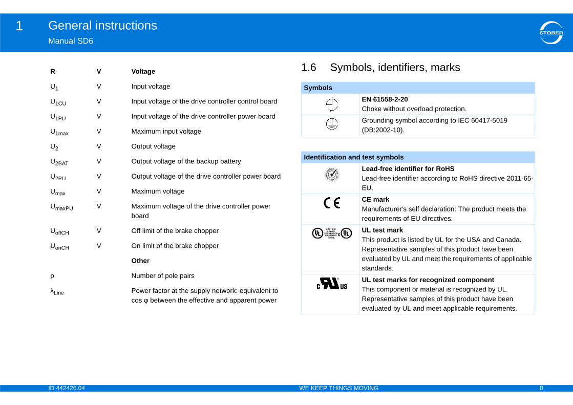
558-2-20 without overload protection.
ding symbol according to IEC 60417-5019 002-10).
ymbolsfree identifier for RoHSfree identifier according to RoHS directive 2011-65-
arkfacturer's self declaration: The product meets the ements of EU directives.
st markroduct is listed by UL for the USA and Canada. sentative samples of this product have been ted by UL and meet the requirements of applicable rds.
st marks for recognized componentomponent or material is recognized by UL. sentative samples of this product have been ted by UL and meet applicable requirements.
42426.04 WE KEEP THINGS MOVING
nual SD6
1.6 Symbols, iV Voltage
V Input voltage
CU V Input voltage of the drive controller control board
PU V Input voltage of the drive controller power board
max V Maximum input voltage
V Output voltage
BAT V Output voltage of the backup battery
PU V Output voltage of the drive controller power board
ax V Maximum voltage
axPU V Maximum voltage of the drive controller power board
ffCH V Off limit of the brake chopper
nCH V On limit of the brake chopper
Other
Number of pole pairs
ne Power factor at the supply network: equivalent to cos φ between the effective and apparent power
SymbolsEN 61Choke
Groun(DB:2
Identification and test sLead-Lead-EU.
CE mManurequir
UL teThis pRepreevaluastanda
UL teThis cRepreevalua
ID 4 9
General instructions1Ma
Theequoth
All own
Prodocutili
cense provider is used in SD6:GmbH & Co. KG
omr.com
Tr
CACiA
En
Eth
HIW
MiWiWi
PRPR
42426.04 WE KEEP THINGS MOVING
nual SD6
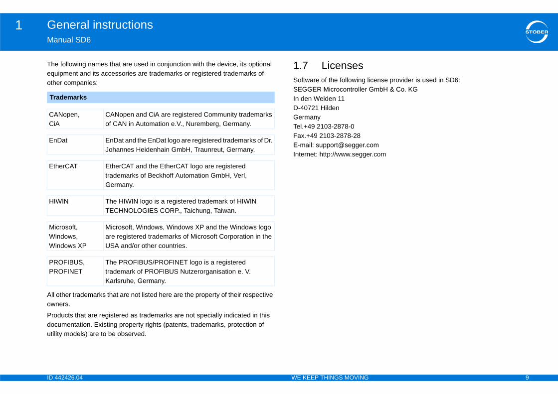
following names that are used in conjunction with the device, its optional ipment and its accessories are trademarks or registered trademarks of er companies:
other trademarks that are not listed here are the property of their respective ers.
ducts that are registered as trademarks are not specially indicated in this umentation. Existing property rights (patents, trademarks, protection of ty models) are to be observed.
1.7 LicensesSoftware of the following liSEGGER Microcontroller In den Weiden 11D-40721 HildenGermanyTel.+49 2103-2878-0Fax.+49 2103-2878-28E-mail: [email protected]: http://www.segge
ademarks
Nopen, CANopen and CiA are registered Community trademarks of CAN in Automation e.V., Nuremberg, Germany.
Dat EnDat and the EnDat logo are registered trademarks of Dr. Johannes Heidenhain GmbH, Traunreut, Germany.
erCAT EtherCAT and the EtherCAT logo are registered trademarks of Beckhoff Automation GmbH, Verl, Germany.
IN The HIWIN logo is a registered trademark of HIWIN TECHNOLOGIES CORP., Taichung, Taiwan.
crosoft,ndows,ndows XP
Microsoft, Windows, Windows XP and the Windows logo are registered trademarks of Microsoft Corporation in the USA and/or other countries.
OFIBUS,OFINET
The PROFIBUS/PROFINET logo is a registered trademark of PROFIBUS Nutzerorganisation e. V. Karlsruhe, Germany.
ID 4 10
Safety information, UL-compliant use2Ma
2Ov
2.1
2.2
2.3
2.4
2.5
2.6
2.7
2.8
42426.04 WE KEEP THINGS MOVING
nual SD6
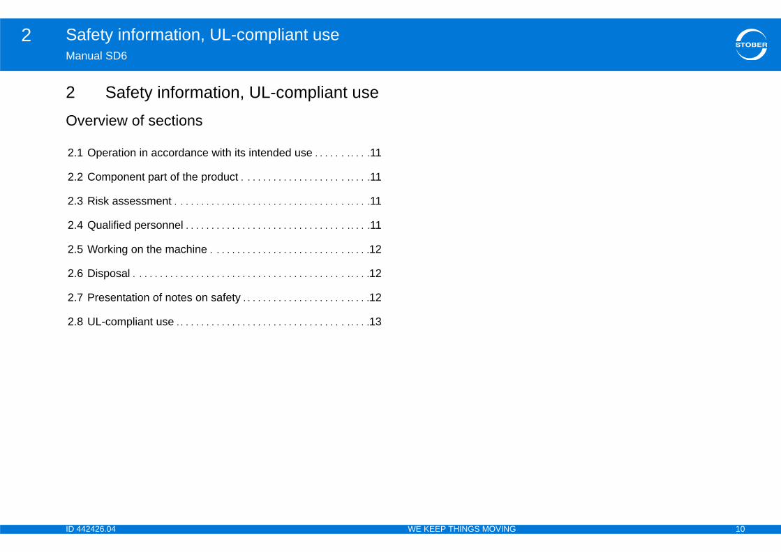
Safety information, UL-compliant useerview of sections
Operation in accordance with its intended use . . . . . . . . . . .11
Component part of the product . . . . . . . . . . . . . . . . . . . . . . . . .11
Risk assessment . . . . . . . . . . . . . . . . . . . . . . . . . . . . . . . . . . . . . .11
Qualified personnel . . . . . . . . . . . . . . . . . . . . . . . . . . . . . . . . . . . .11
Working on the machine . . . . . . . . . . . . . . . . . . . . . . . . . . . . . . .12
Disposal . . . . . . . . . . . . . . . . . . . . . . . . . . . . . . . . . . . . . . . . . . . . . .12
Presentation of notes on safety . . . . . . . . . . . . . . . . . . . . . . . . .12
UL-compliant use . . . . . . . . . . . . . . . . . . . . . . . . . . . . . . . . . . . . . .13
ID 4 11
Safety information, UL-compliant use2Ma
The•
•STOwithma
2.
As eleenein s••Des
2.The•
•
smentay bring a machine onto the market, he must
t according to Machine Directive 06/42/EC. As a with the use of the machine are determined. The
-stage and iterative process. On no account can achine Directive be given as part of this son, seek detailed information about the norms and
ling the drive controller in machines, commissioning n determined that the machine meets the
ive 06/42/EC.
ersonnelal risks. For this reason, all work on the devices as osal must only be performed by qualified personnel ible dangers.rsons who have acquired the authorisation to ts and/orlists
e
le regulations, legal provisions, rules and standards documentation including the safety information
42426.04 WE KEEP THINGS MOVING
nual SD6
devices can represent a source of danger. Therefore observethe safety guidelines, technical rules and regulations given in the following sectionsand points.BER shall assume no liability for damage resulting from failure to comply the instruction manual or relevant regulations. We reserve the right to
ke technical changes for the purpose of improving the devices.
1 Operation in accordance with its intended use
defined by DIN EN 50178 (previously VDE 0160), the drive controllers are ctrical equipment operating as power electronics to control the flow of rgy in high voltage systems. They are designed exclusively for installation witching cabinets, protection class at least IP54, and for supplyingsynchronous servo motors andasynchronous motors.ignated use does not include connecting other electrical loads!
2 Component part of the product technical documentation is a component part of a product.Since the technical documentation contains important information, always keep it handy in the vicinity of the device until the machine is disposed of.If the product is sold, disposed of, or rented out, always include the technical documentation with the product.
2.3 Risk assesBefore the manufacturer mconduct a risk assessmenresult, the risks associatedrisk assessment is a multisufficient insight into the Mdocumentation. For this realegal position. When instalis forbidden until it has beerequirements of EC Direct
2.4 Qualified pDevices may cause residuwell as operation and dispwho are aware of the possQualified personnel are peperform these activities by• Training from specialis• Instruction from speciaIn addition, they must hav• read,• understood and • observed the applicab
and existing technical contained in it.
ID 4 12
Safety information, UL-compliant use2Ma
2.Appma1.
2.3.4.5.
2.Pleindreg•••••
on of notes on safety
ge may occur
ary measures are not taken.
s that minor injury may occur
ary measures are not taken.
serious danger of death
ary measures are not taken.
r of death exists
ary measures are not taken.
ant information about the product or serves to ction in the documentation to which the reader
cial attention.
42426.04 WE KEEP THINGS MOVING
nual SD6
5 Working on the machinely the 5 safety rules in the order stated before performing any work on the
chine:Disconnect.Also ensure that the auxiliary circuits are disconnected.Protect against being turned on again.Check that voltage is not present.Ground and short circuit.Cover or block off adjacent live parts.
6 Disposalase comply with the latest national and regional regulations! Dispose of the ividual parts separately depending on their nature and currently valid ulations such as, for example:Electronic scrap (PCBs)PlasticSheet metalCopperAluminum
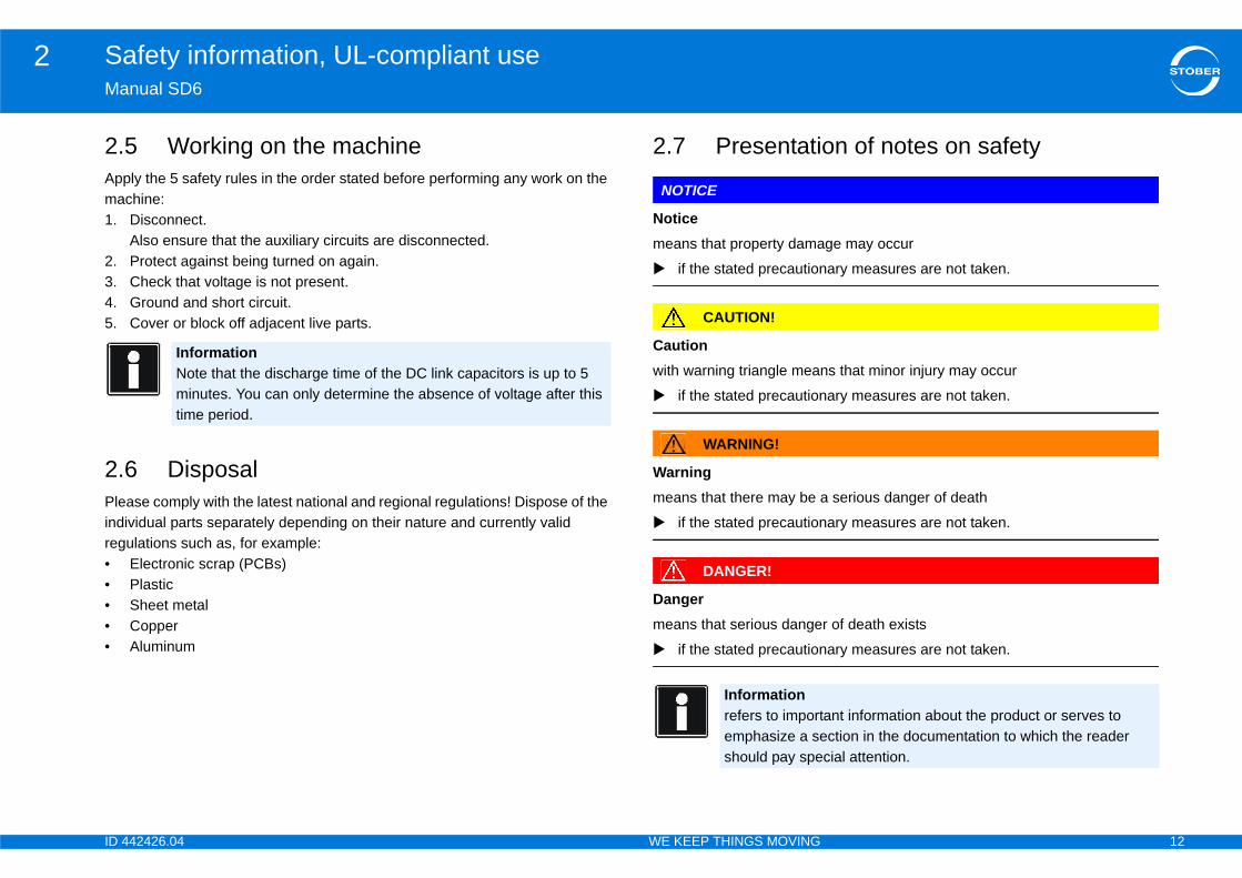
2.7 Presentati
NOTICE
Noticemeans that property dama
if the stated precaution
CAUTION!
Cautionwith warning triangle mean
if the stated precaution
WARNING!
Warningmeans that there may be a
if the stated precaution
DANGER!
Dangermeans that serious dange
if the stated precaution
InformationNote that the discharge time of the DC link capacitors is up to 5 minutes. You can only determine the absence of voltage after this time period.
Informationrefers to importemphasize a seshould pay spe
ID 4 13
Safety information, UL-compliant use2Ma
2.AddLab
SurTheObpol
MaAll ope
PowObsee
MaObAppDeppos•
•
generation drive controllers have a certified i²t l for thermal monitoring of the motor. This fulfils the uctor motor overload protection in accordance with ed May 2013. To activate the protective function and g parameter settings – which differ from the default nd U11 = 1.00 s. This module can be used as an motor protection with temperature monitoring as
or generation drive controllers have connections for °C) or KTY temperature sensors (KT84-130). ription X2 for proper connection, see section 7.3.8.
e fitted with an externally mounted braking resistor, protection must be made available.
be supplied by an isolated source whose maximum ceed 28.8 V. Note also the technical specifications is regard, see section7.3.3.
rs for an surrounding temperature of 60/75 °C.
mends using PTC thermistors as thermal motor
42426.04 WE KEEP THINGS MOVING
nual SD6
8 UL-compliant useitional information for use under UL conditions (UL – Underwriters oratories).
rounding temperature and pollution degree maximum surrounding temperature for UL-compliant operation is 45 °C.
serve the specifications in the general data for use in an environment with a lution degree, see section 4.4.
ins configurationdevice types that are supplied with 480 V are designed exclusively for ration on Wye source with 480/277 V.
er supply and motor overload protectionserve the specifications in the electrical data of the drive controller for this, section 4.2.
ins fuse serve the specifications for the UL-compliant mains fuse in section 4.6.1.lies to use in Canada in accordance with CSA-C22.2 No. 14-13ending on the device type, additional overvoltage protection must be itioned mains-side from the device that meets the following conditions. Single-phase – SD6A02: - Overvoltage category 3- Phase ground = 240 V (permissible rating surge voltage = 4 kV peak)- phase-phase (or N) = 240 V (permissible rating surge voltage = 4 kV peak)Three-phase – from SD6A04: - Overvoltage category 3- Phase ground = 277 V (permissible peak rating surge voltage = 4 kV peak)- phase-phase (or N) = 480 V (permissible rating surge voltage = 6 kV peak)
Motor protectionAll models of STOBER 6thmodel, a calculation moderequirements for semicondthe change to UL 508C datset it up, make the followinvalues: U10 = 2:Warning aalternative or in addition todescribed in section 7.3.8.
Motor temperature sensAll models of STOBER 6thPTC thermistors (NAT 145Observe the terminal desc
Braking resistorIf the drive controllers will bseparate overtemperature
24 V power supplyLow voltage circuits must output voltage does not exfor the X11 connector in th
LinesUse only copper conducto
InformationSTOBER recomprotection.
ID 4 14
Safety information, UL-compliant use2Ma
FusFus•
•
•
BraAn procircSTOreg
ULDurandin tSÜ
42426.04 WE KEEP THINGS MOVING
nual SD6
eses must be approved according to UL 248.Use a 1 A fuse (delayed-action) upstream from relay 1. Note also terminal description X1, pin 1, see section 7.3.4.Protect the supply of the motor holding brake with a 4 A fuse (delayed-action). Note also terminal description X6, see section 7.3.7The following points apply to extended interfaces with terminal module XI6, RI6 or IO6: Protect the 24-V supply with a 1 A fuse (delayed-action). Note also terminal description X101, pin 18 or 19, see section 7.4.2.
nch circuit protectionintegral solid state short circuit protection does not provide branch circuit tection. If you would like to branch the output of the drive controller, branch uit protection must be ensured in conformity with the instructions of BER, the National Electrical Code and all additional applicable local
ulations or equivalent specifications.
testing the UL acceptance process of STOBER, only risks for electrical shock fire hazard were examined. Aspects of functional safety were not assessed
he UL acceptance. These aspects are assessed for STOBER by the TÜV D certification authority, for example.
ID 4 15
Components of the drive system3Ma
3Ov
3.1
3.2
3.3
3.4
. . . . . . . . . . . . . . . . . . . . . . . . . . . . . . . . . . . . . . 25
er box . . . . . . . . . . . . . . . . . . . . . . . . . . . . . . . . . 25
for encoder buffering . . . . . . . . . . . . . . . . . . . . 26
ta storage .. . . . . . . . . . . . . . . . . . . . . . . . . . . . . 26
. . . . . . . . . . . . . . . . . . . . . . . . . . . . . . . . . . . . . . 26
42426.04 WE KEEP THINGS MOVING
nual SD6
Components of the drive systemerview of sections
Drive controller . . . . . . . . . . . . . . . . . . . . . . . . . . . . . . . . . . . . . . . .16
3.1.1 Nameplate . . . . . . . . . . . . . . . . . . . . . . . . . . . . . . . . . . . . . . . . . 16
3.1.2 Type designation . . . . . . . . . . . . . . . . . . . . . . . . . . . . . . . . . . . . 17
3.1.3 Sizes . . . . . . . . . . . . . . . . . . . . . . . . . . . . . . . . . . . . . . . . . . . . . 17
Motors . . . . . . . . . . . . . . . . . . . . . . . . . . . . . . . . . . . . . . . . . . . . . . . .18
3.2.1 Synchronous servo motors and asynchronous motors . . . . . . . 18
3.2.2 Synchronous linear motors . . . . . . . . . . . . . . . . . . . . . . . . . . . . 18
Controller . . . . . . . . . . . . . . . . . . . . . . . . . . . . . . . . . . . . . . . . . . . . .19
Accessories . . . . . . . . . . . . . . . . . . . . . . . . . . . . . . . . . . . . . . . . . .19
3.4.1 Safety technology . . . . . . . . . . . . . . . . . . . . . . . . . . . . . . . . . . . 19
3.4.2 Terminal modules . . . . . . . . . . . . . . . . . . . . . . . . . . . . . . . . . . . 20
3.4.3 Communication . . . . . . . . . . . . . . . . . . . . . . . . . . . . . . . . . . . . . 22
3.4.4 DC link connection . . . . . . . . . . . . . . . . . . . . . . . . . . . . . . . . . . 24
3.4.5 Braking Resistors . . . . . . . . . . . . . . . . . . . . . . . . . . . . . . . . . . . 24
3.4.6 Chokes . . . . . . . . . . . . . . . . . . . . . . . . . . . . . . . . . . . . . . . . . . . 24
3.4.7 EMC shroud ..
3.4.8 Encoder adapt
3.4.9 Battery module
3.4.10 Removable da
3.4.11 Product CD . .
ID 4 16
Components of the drive system3Ma
3.3.1
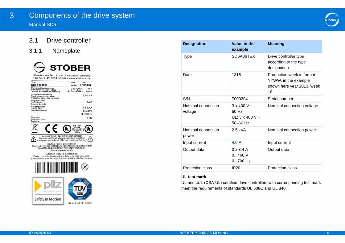
tified drive controllers with corresponding test mark standards UL 508C and UL 840.
Value in the example
Meaning
SD6A06TEX Drive controller type according to the type designation
1318 Production week in format YYWW, in the example shown here year 2013, week 18
7000204 Serial number
3 x 400 V ~ 50 HzUL: 3 x 480 V ~ 50–60 Hz
Nominal connection voltage
2.5 kVA Nominal connection power
4.0 A Input current
3 x 3.4 A0...460 V0...700 Hz
Output data
IP20 Protection class
42426.04 WE KEEP THINGS MOVING
nual SD6
1 Drive controller.1 Nameplate
UL test markUL and cUL (CSA-UL) cermeet the requirements of
Designation
Type
Date
S/N
Nominal connection voltage
Nominal connection power
Input current
Output data
Protection class
ID 4 17
Components of the drive system3Ma
3.1Sam
Exp
cludes the following types and sizes:
Size0
0
0
1
1
2
2
3
3
3
42426.04 WE KEEP THINGS MOVING
nual SD6
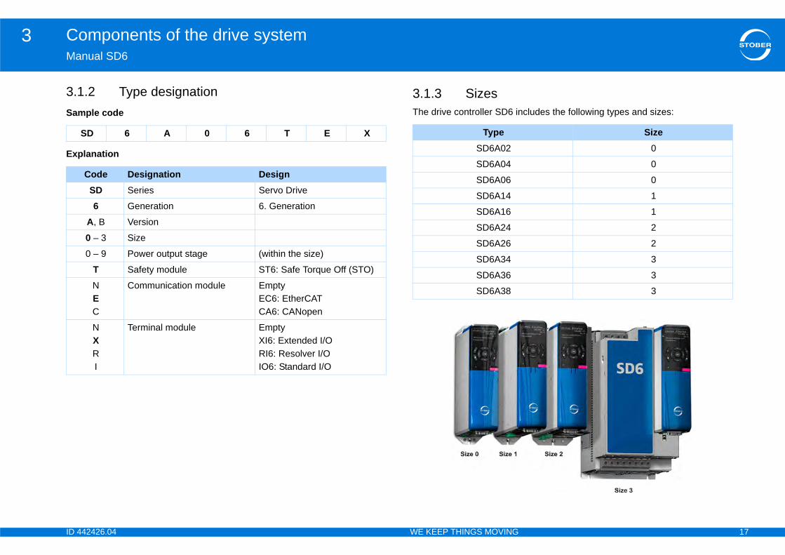
.2 Type designationple code
lanation
3.1.3 SizesThe drive controller SD6 in
SD 6 A 0 6 T E X
Code Designation DesignSD Series Servo Drive
6 Generation 6. Generation
A, B Version
0 – 3 Size
0 – 9 Power output stage (within the size)
T Safety module ST6: Safe Torque Off (STO)
NEC
Communication module EmptyEC6: EtherCATCA6: CANopen
NXRI
Terminal module EmptyXI6: Extended I/ORI6: Resolver I/OIO6: Standard I/O
TypeSD6A02
SD6A04
SD6A06
SD6A14
SD6A16
SD6A24
SD6A26
SD6A34
SD6A36
SD6A38
ID 4 18
Components of the drive system3Ma
3.3.2
YouexaEvafollo•••
Othmo••••
All cona 2
3.2ThelineGmLinincrTheind
magnetic tape that determines the position of the with a read head or probe. r transfers this information to the drive controller as
uirement in each specific case (for example speed, ear encoders (together with accessories) can be
ns for PTC thermistors or KTY temperature sensors brake as standard.
t system (linear encoders)stems: 2.2 digital
tems:HTL and TTL): connection via optional terminal module RI6
ith relative measurement systems using:r box LA6 (see section 3.4.8 Encoder adapter box)S)
es it possible to connect sensor signals of various The adapter box is responsible for splitting the hich are in some cases combined on one connector, pe, and for the level adjustment and potential als. motor manufacturers, the signals are forwarded via b 15-pin, D-sub 9-pin or free cable ends).
42426.04 WE KEEP THINGS MOVING
nual SD6
2 Motors.1 Synchronous servo motors and asynchronous
motors can use the SD6 drive controller to operate synchronous servo motors (for mple the STOBER series EZ) or asynchronous motors. luation options for feedback are available on the X4 connection for wing encoder types:Absolute value encoder EnDat 2.1/2.2 digitalAbsolute value encoder SSIIncremental encoder (HTL and TTL)
er encoder types can be connected via the optionally available terminal dules (see section 3.4.2 Terminal modules), for example:Resolver Absolute value encoder EnDat 2.1 sin/cosSin/cos encoderIncremental encoder (HTL and TTL), single-ended
modules from the 6th generation of STOBER drive controllers have nections for PTC thermistors or KTY temperature sensors and can control 4 V/DC brake as standard.
.2 Synchronous linear motors SD6 drive controller supports control of iron-core, permanent-magnet ar motors from a wide range of different manufacturers such as HIWIN bH, isel Germany AG and Siemens AG.ear motors are used for linear movements when speed, acceleration and eased positional accuracy are primary concerns. position of the linear motor is determined based on an optical, magnetic or
uctive measurement system. These measurement systems consist of
a dimensional element or motor through interaction An additional linear encodeposition data. Depending on the key reqaccuracy, etc.), different linused. All modules have connectioand can control a 24 V/DC
Supported measuremenAbsolute measurement sy• Linear encoder EnDat• Linear encoder SSI
Relative measurement sys• Incremental encoder (• Sin/cos linear encoder
(terminal X140)
Determine commutation w• Hall sensor via adapte• Wake and Shake (W&
Adapter box LA6The LA6 adapter box maklinear motor types to SD6.different sensor signals, wdepending on the motor tyseparation of the Hall signDepending on the differentdifferent connections (D-su
ID 4 19
Components of the drive system3Ma
3.
3.3.4
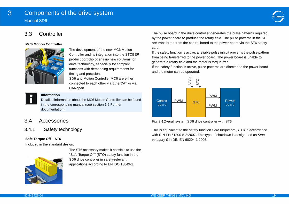
e controller generates the pulse patterns required duce the rotary field. The pulse patterns in the SD6 ntrol board to the power board via the ST6 safety
ve, a reliable pulse inhibit prevents the pulse pattern he power board. The power board is unable to the motor is torque-free.ive, pulse patterns are directed to the power board rated.
6 drive controller with ST6
fety function Safe torque off (STO) in accordance 07. This type of shutdown is designated as Stop 4-1:2006.
MC
SaInc
STO
b
STO
a
PowerboardST6
PWM
PWM
42426.04 WE KEEP THINGS MOVING
nual SD6
3 Controller
4 Accessories .1 Safety technology
The pulse board in the drivby the power board to proare transferred from the cocard.If the safety function is actifrom being transferred to tgenerate a rotary field andIf the safety function is actand the motor can be ope
Fig. 3-1Overall system SD
This is equivalent to the sawith DIN EN 61800-5-2:20category 0 in DIN EN 6020
6 Motion ControllerThe development of the new MC6 Motion Controller and its integration into the STOBER product portfolio opens up new solutions for drive technology, especially for complex functions with demanding requirements for timing and precision.SD6 and Motion Controller MC6 are either connected to each other via EtherCAT or via CANopen.
InformationDetailed information about the MC6 Motion Controller can be found in the corresponding manual (see section 1.2 Further documentation).
fe Torque Off – ST6luded in the standard design.
The ST6 accessory makes it possible to use the "Safe Torque Off" (STO) safety function in the SD6 drive controller in safety-relevant applications according to EN ISO 13849-1.
PWMControlboard

ID 4 20
Components of the drive system3Ma
In tconbas
Fig
Detcandoc
odules
Terminal module for connecting analog and binary signals as well as encoders.
Supported inputs and outputs:• 13 binary inputs (24 V)• 10 binary outputs (24 V)• 3 analog inputs (± 10 V, 1 x 0 – 20 mA, 16
bits)• 2 analog outputs (± 10 V, 12 bits)
Supported encoders / interfaces:• SSI encoder (simulation and evaluation)• TTL incremental encoder, differential
(simulation and evaluation)• HTL incremental encoder, single-ended
(simulation and evaluation)• TTL pulse train, differential (simulation and
evaluation)• HTL pulse train, single-ended (simulation
and evaluation)
42426.04 WE KEEP THINGS MOVING
nual SD6
he safety block diagram (Fig. 3-2 Safety block diagram) the SD6 drive troller with the ST6 safety card corresponds to the actuator and forms the is for a restart inhibit:
. 3-2Safety block diagram
ailed information about using the safety technology and the ST6 safety card be found in the corresponding manual (see section 1.2 Further umentation).
3.4.2 Terminal m
Terminal module XI6ID no. 138421
ID 4 21
Components of the drive system3Ma
TeID Encoder cables that were connected to a
POSIDYN SDS 4000 can be connected via the AP6 interface adapter to the X140 encoder interface of the RI6 terminal module.
The following versions are available:
AP6A00ID no. 56498Adapter X140 resolver, 9/15-pin.
AP6A01 ID no. 56522Adapter X140 resolver, 9/15-pin with motor temperature sensor - lead through.
AP6A02ID no. 56523Adapter X140 EnDat 2.1 sin/cos, 15/15-pin with motor temperature sensor - lead through.
42426.04 WE KEEP THINGS MOVING
nual SD6
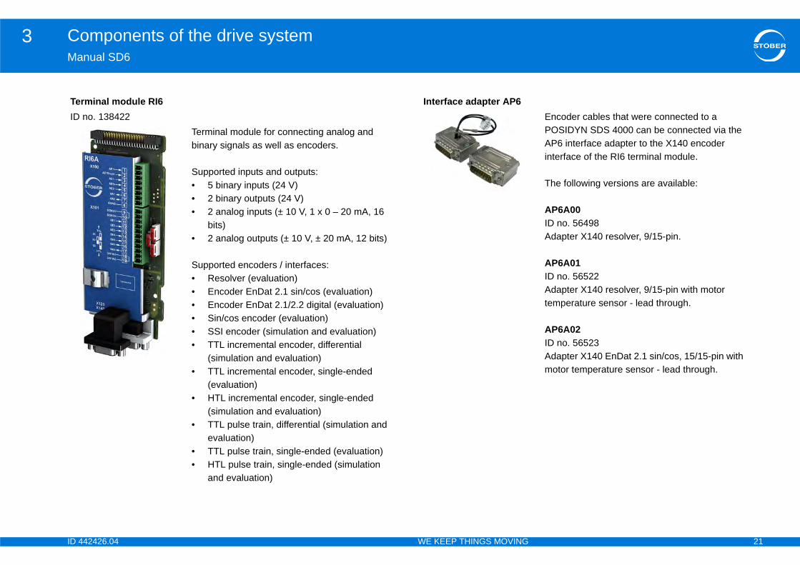
rminal module RI6no. 138422
Terminal module for connecting analog and binary signals as well as encoders.
Supported inputs and outputs:• 5 binary inputs (24 V)• 2 binary outputs (24 V)• 2 analog inputs (± 10 V, 1 x 0 – 20 mA, 16
bits)• 2 analog outputs (± 10 V, ± 20 mA, 12 bits)
Supported encoders / interfaces:• Resolver (evaluation)• Encoder EnDat 2.1 sin/cos (evaluation)• Encoder EnDat 2.1/2.2 digital (evaluation)• Sin/cos encoder (evaluation)• SSI encoder (simulation and evaluation)• TTL incremental encoder, differential
(simulation and evaluation)• TTL incremental encoder, single-ended
(evaluation)• HTL incremental encoder, single-ended
(simulation and evaluation)• TTL pulse train, differential (simulation and
evaluation)• TTL pulse train, single-ended (evaluation)• HTL pulse train, single-ended (simulation
and evaluation)
Interface adapter AP6
ID 4 22
Components of the drive system3Ma
cation
as two interfaces for IGB communication on the top
le is installed in the shaft at the top and the drive the field bus system via it. ion modules are available:connection andconnection
TeID
Cable for connecting the X3A or X3B interface for IGB, CAT5e, magenta.
The following versions are available:
ID no. 56489: 0.4 m.ID no. 56490: 2 m.
42426.04 WE KEEP THINGS MOVING
nual SD6
3.4.3 Communi
The SD6 drive controller hof the device as standard.The communication moducontroller is connected to The following communicat• EC6 for the EtherCAT • CA6 for the CANopen
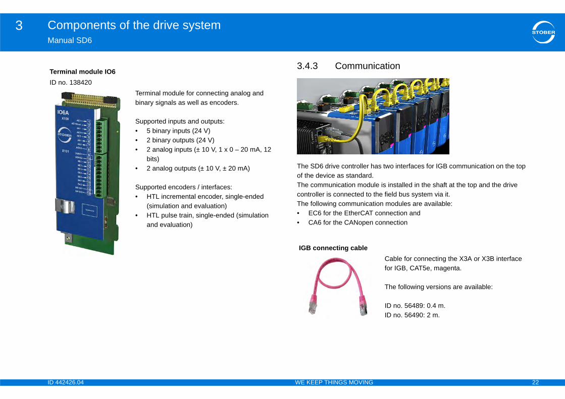
rminal module IO6no. 138420
Terminal module for connecting analog and binary signals as well as encoders.
Supported inputs and outputs:• 5 binary inputs (24 V)• 2 binary outputs (24 V)• 2 analog inputs (± 10 V, 1 x 0 – 20 mA, 12
bits)• 2 analog outputs (± 10 V, ± 20 mA)
Supported encoders / interfaces:• HTL incremental encoder, single-ended
(simulation and evaluation)• HTL pulse train, single-ended (simulation
and evaluation)
IGB connecting cable
ID 4 23
Components of the drive system3Ma
PCID
Hi-ID
ECID
EtherNet patch cable, CAT5e, yellow.
The following versions are available:
ID no. 49313: approx. 0.2 m. ID no. 49314: approx. 0.35 m.
dule
Communication module for the CANopen connection.
42426.04 WE KEEP THINGS MOVING
nual SD6
connecting cableno. 49857
To connect the X3 A or X3 B interface to PC, CAT5e, blue, 5m.
speed USB 2.0 Ethernet adapterno. 49940
Adapter for connecting Ethernet to a USB connection.
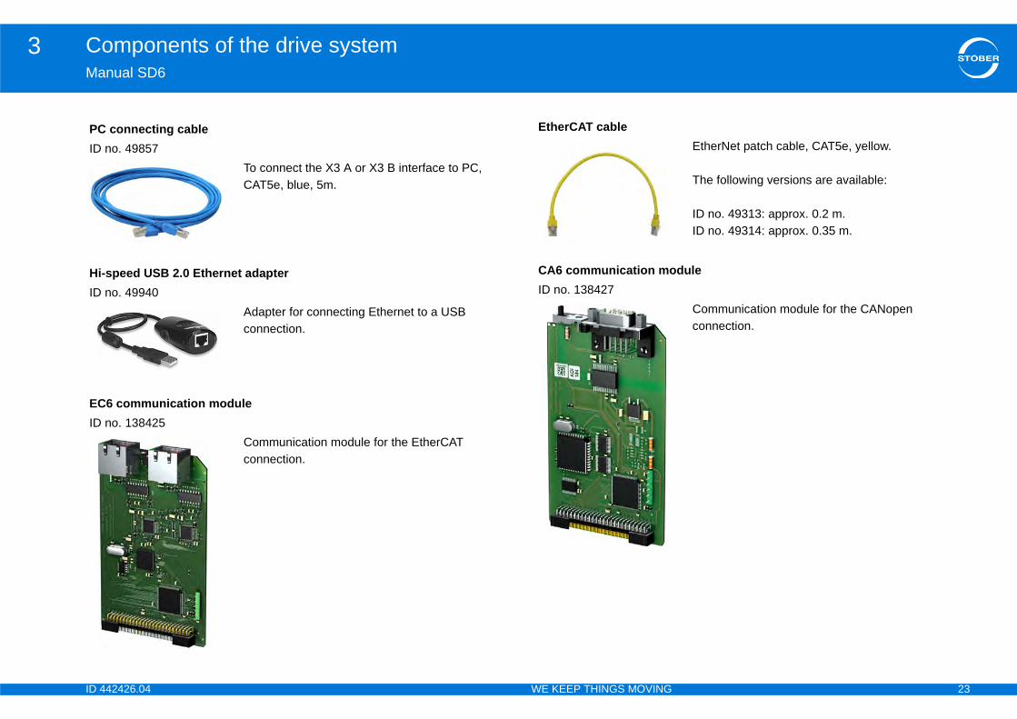
6 communication moduleno. 138425
Communication module for the EtherCAT connection.
EtherCAT cable
CA6 communication moID no. 138427
ID 4 24
Components of the drive system3Ma
3.4If yneesev
esistorse controller reduces its speed reference value, the system is fed back to the DC link capacitors of the e capacity of these capacitors is limited to a defined
certain voltage level, an integrated brake chopper tor as a consumer – this absorbs the existing braking and the kinetic energy is mostly converted to heat. drive controllers, STOBER offers corresponding t sizes and performance classes (see 4.11 Braking
ce the susceptibility of drive systems and offset thus used to protect components, devices or power ly increase their interference immunity and
d output deraters corresponding to your application
Qu
42426.04 WE KEEP THINGS MOVING
nual SD6
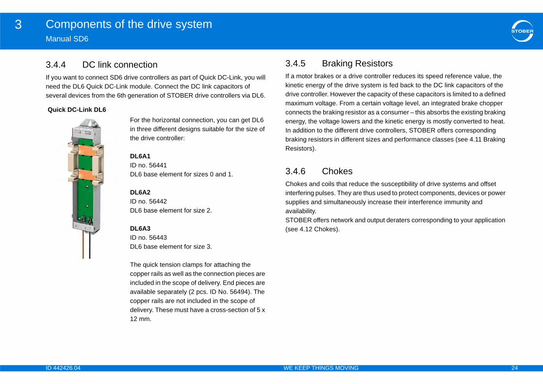
.4 DC link connectionou want to connect SD6 drive controllers as part of Quick DC-Link, you will d the DL6 Quick DC-Link module. Connect the DC link capacitors of eral devices from the 6th generation of STOBER drive controllers via DL6.
3.4.5 Braking RIf a motor brakes or a drivkinetic energy of the drivedrive controller. However thmaximum voltage. From aconnects the braking resisenergy, the voltage lowersIn addition to the different braking resistors in differenResistors).
3.4.6 ChokesChokes and coils that reduinterfering pulses. They aresupplies and simultaneousavailability.STOBER offers network an(see 4.12 Chokes).
ick DC-Link DL6For the horizontal connection, you can get DL6 in three different designs suitable for the size of the drive controller:
DL6A1ID no. 56441DL6 base element for sizes 0 and 1.
DL6A2ID no. 56442DL6 base element for size 2.
DL6A3ID no. 56443DL6 base element for size 3.
The quick tension clamps for attaching the copper rails as well as the connection pieces are included in the scope of delivery. End pieces are available separately (2 pcs. ID No. 56494). The copper rails are not included in the scope of delivery. These must have a cross-section of 5 x 12 mm.
ID 4 25
Components of the drive system3Ma
3.4Youcab
dapter box
EMID
EMID
6A00
LA6 for connecting HIWIN-TTL.Encoder adapter box for transferring TTL and Hall sensor signals from HIWIN synchronous linear motors to the SD6 drive controller. LA6 for the adaptation of additional linear motors on request.
le X120
Cable for connecting the TTL interface X120 to the SD6 drive controller (on terminal module RI6 or XI6) with the X301 interface on the LA6 adapter box for transferring Hall sensor signals. 0.3 m.
cableCable for connecting terminals X4 to the SD6 drive controller and X300 on the LA6 adapter box for transferring incremental encoder signals.
The following versions are available:
ID no. 45405: 0.5 m. ID no. 45386: 2.5 m.
42426.04 WE KEEP THINGS MOVING
nual SD6
.7 EMC shroud can use the EMC shroud EM6 to connect the cable shield of the power le. Two different designs are available.
3.4.8 Encoder a
C shroud EM6A0no. 135115
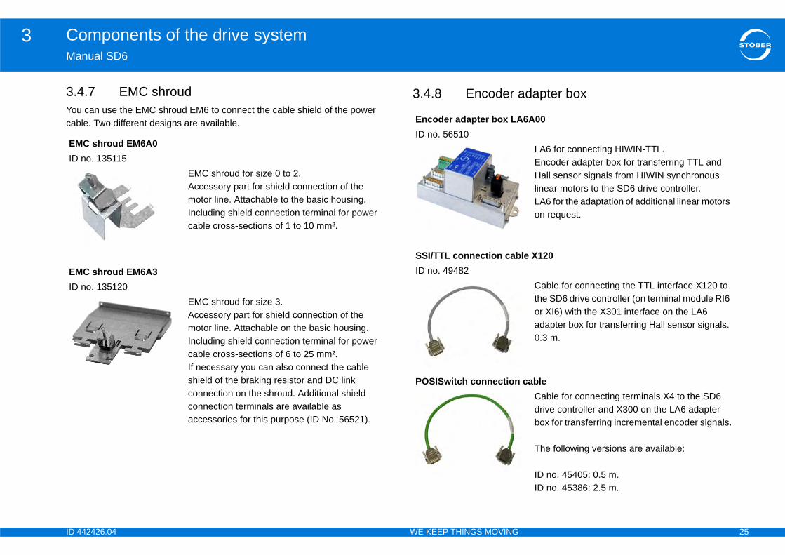
EMC shroud for size 0 to 2. Accessory part for shield connection of the motor line. Attachable to the basic housing.Including shield connection terminal for power cable cross-sections of 1 to 10 mm².
C shroud EM6A3no. 135120
EMC shroud for size 3.Accessory part for shield connection of the motor line. Attachable on the basic housing.Including shield connection terminal for power cable cross-sections of 6 to 25 mm². If necessary you can also connect the cable shield of the braking resistor and DC link connection on the shroud. Additional shield connection terminals are available as accessories for this purpose (ID No. 56521).
Encoder adapter box LAID no. 56510
SSI/TTL connection cabID no. 49482
POSISwitch connection
ID 4 26
Components of the drive system3Ma
3.4 le data storage
D
AbID
ReID
e Paramoduleesign.
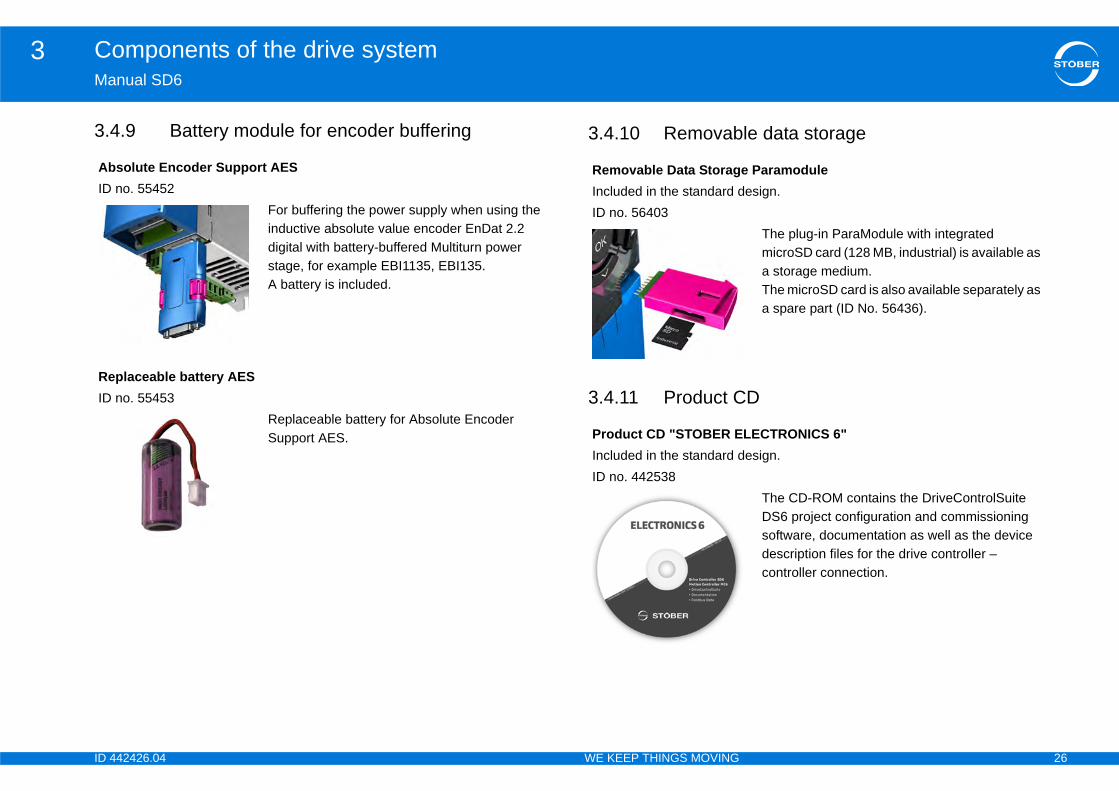
The plug-in ParaModule with integrated microSD card (128 MB, industrial) is available as a storage medium. The microSD card is also available separately as a spare part (ID No. 56436).
LECTRONICS 6"esign.
The CD-ROM contains the DriveControlSuite DS6 project configuration and commissioning software, documentation as well as the device description files for the drive controller – controller connection.
42426.04 WE KEEP THINGS MOVING
nual SD6
.9 Battery module for encoder buffering 3.4.10 Removab
3.4.11 Product C
solute Encoder Support AESno. 55452
For buffering the power supply when using the inductive absolute value encoder EnDat 2.2 digital with battery-buffered Multiturn power stage, for example EBI1135, EBI135.A battery is included.
placeable battery AESno. 55453
Replaceable battery for Absolute Encoder Support AES.
Removable Data StoragIncluded in the standard dID no. 56403
Product CD "STOBER EIncluded in the standard dID no. 442538
ID 4 27
Technical data4Ma
4Ov
4.1
4.2
4.3
4.4
4.5
coders . . . . . . . . . . . . . . . . . . . . . . . . . . . . . . . . 36
ection X4 . . . . . . . . . . . . . . . . . . . . . . . . . . . . . . 36
ection X120 . . . . . . . . . . . . . . . . . . . . . . . . . . . . 37
ection X101 (binary input encoder) . . . . . . . . . . 37
ection X140 . . . . . . . . . . . . . . . . . . . . . . . . . . . . 38
akes . . . . . . . . . . . . . . . . . . . . . . . . . . . . . . . . . . 39
otor temperature sensors . . . . . . . . . . . . . . . . . . 39
res . . . . . . . . . . . . . . . . . . . . . . . . . . . . . . . . . . .40
. . . . . . . . . . . . . . . . . . . . . . . . . . . . . . . . . . . . . . 40
nt safety device .. . . . . . . . . . . . . . . . . . . . . . . . . 41
d . . . . . . . . . . . . . . . . . . . . . . . . . . . . . . . . . . . . . 42
. . . . . . . . . . . . . . . . . . . . . . . . . . . . . . . . . . . . . .43
. . . . . . . . . . . . . . . . . . . . . . . . . . . . . . . . . . . . . .45
XI6 . . . . . . . . . . . . . . . . . . . . . . . . . . . . . . . . . . . 45
RI6 . . . . . . . . . . . . . . . . . . . . . . . . . . . . . . . . . . . 48
IO6 .. . . . . . . . . . . . . . . . . . . . . . . . . . . . . . . . . . 49
odules . . . . . . . . . . . . . . . . . . . . . . . . . . . . . . .50
cation module . . . . . . . . . . . . . . . . . . . . . . . . . . . 50
. . . . . . . . . . . . . . . . . . . . . . . . . . . . . . . . . . . . . .50
a . . . . . . . . . . . . . . . . . . . . . . . . . . . . . . . . . . . . . 52
42426.04 WE KEEP THINGS MOVING
nual SD6
Technical dataerview of sections
Notes on safety .. . . . . . . . . . . . . . . . . . . . . . . . . . . . . . . . . . . . . . .29
Electrical Data . . . . . . . . . . . . . . . . . . . . . . . . . . . . . . . . . . . . . . . . .29
4.2.1 Control board .. . . . . . . . . . . . . . . . . . . . . . . . . . . . . . . . . . . . . . 29
4.2.2 Power board . . . . . . . . . . . . . . . . . . . . . . . . . . . . . . . . . . . . . . . 30
4.2.2.1 Size 0: SD6A0x . . . . . . . . . . . . . . . . . . . . . . . . . . . . . 30
4.2.2.2 Size 1: SD6A1x . . . . . . . . . . . . . . . . . . . . . . . . . . . . . 31
4.2.2.3 Size 2: SD6A2x . . . . . . . . . . . . . . . . . . . . . . . . . . . . . 31
4.2.2.4 Size 3: SD6A3x . . . . . . . . . . . . . . . . . . . . . . . . . . . . . 32
4.2.2.5 Derating . . . . . . . . . . . . . . . . . . . . . . . . . . . . . . . . . . . 32
4.2.2.5.1 Effect of the clock frequency . . . . . . . . . . 32
4.2.2.5.2 Effect of surrounding temperature .. . . . . . 33
4.2.2.5.3 Effect of installation altitude . . . . . . . . . . . 33
4.2.2.5.4 Calculating the derating . . . . . . . . . . . . . . 33
Device features .. . . . . . . . . . . . . . . . . . . . . . . . . . . . . . . . . . . . . . .33
Transportation, storage and operating environment . . . . . . . . . . . . . . . . . . . . . . . . . . . . . . . . . . . . . . . . . . .34
Operating motors . . . . . . . . . . . . . . . . . . . . . . . . . . . . . . . . . . . . . .35
4.5.1 Evaluatable en
4.5.1.1 Conn
4.5.1.2 Conn
4.5.1.3 Conn
4.5.1.4 Conn
4.5.2 Controllable br
4.5.3 Evaluatable m
4.6 Protective measu
4.6.1 Line fuse . . . .
4.6.2 Residual curre
4.6.3 Housing groun
4.7 Dimensions . . . . .
4.8 Terminal modules
4.8.1 Specification -
4.8.2 Specification –
4.8.3 Specification –
4.9 Communication m
4.9.1 EC6 communi
4.10 Quick DC-Link . .
4.10.1 Electrical Dat
ID 4 28
Technical data4Ma
4.1
4.1
42426.04 WE KEEP THINGS MOVING
nual SD6
4.10.2 Power supply . . . . . . . . . . . . . . . . . . . . . . . . . . . . . . . . . . . . . . 53
4.10.3 Line fuse . . . . . . . . . . . . . . . . . . . . . . . . . . . . . . . . . . . . . . . . . 54
4.10.4 Power contactor . . . . . . . . . . . . . . . . . . . . . . . . . . . . . . . . . . . 55
4.10.5 Projecting . . . . . . . . . . . . . . . . . . . . . . . . . . . . . . . . . . . . . . . . 56
1 Braking Resistors . . . . . . . . . . . . . . . . . . . . . . . . . . . . . . . . . . . . .58
4.11.1 FZMU, FZZMU . . . . . . . . . . . . . . . . . . . . . . . . . . . . . . . . . . . . 58
4.11.2 FGFKU . . . . . . . . . . . . . . . . . . . . . . . . . . . . . . . . . . . . . . . . . . 59
4.11.3 GVADU, GBADU . . . . . . . . . . . . . . . . . . . . . . . . . . . . . . . . . . . 61
4.11.4 Bottom brake resistor RB 5000 . . . . . . . . . . . . . . . . . . . . . . . 62
2 Chokes . . . . . . . . . . . . . . . . . . . . . . . . . . . . . . . . . . . . . . . . . . . . . .63
4.12.1 Power choke . . . . . . . . . . . . . . . . . . . . . . . . . . . . . . . . . . . . . . 64
4.12.2 Output derater . . . . . . . . . . . . . . . . . . . . . . . . . . . . . . . . . . . . . 67

ID 4 29
Technical data4Ma
4.DrivIECThethaIn ainte
Thethathe
AlwThe••
Impobt•
ata
ard
of the most important formula symbols can be found bbreviations, formula symbols and indices.
All SD6 drive controller types20.4 – 28.8 V
used.
1.5 A
ules and encoders connected.
Size 0 – Size 2: max. 30 WSize 3: max. 55 W
42426.04 WE KEEP THINGS MOVING
nual SD6
1 Notes on safetye controllers are products subject to sales restrictions in accordance with 61800-3. drive controllers are not designed for use in a public low frequency network
t supplies residential areas. residential environment this product may cause high-frequency rference. If this occurs the user may be asked to take suitable measures.
drive controllers are not designed for use in a public low frequency network t supplies residential areas. High-frequency interference can be expected if drive controllers are used in a network of this type.
ays operate the devices within the limits specified in the technical data. following applications are prohibited:Use in areas subject to explosion hazardUse in environments with harmful substances as specified by EN 60721, for example oils, acids, gases, vapors, dust and radiation
lementation of the following applications is only permitted after approval is ained from STOBER:Use in non-stationary applications
4.2 Electrical D
4.2.1 Control bo
InformationAn explanation in section 1.5 A
TypeU1CU
I1maxCU a)
a) Depending on the accessories
PV,CU (I2 = 0 A)b)
b) Depending on the option mod
ID 4 30
Technical data4Ma
4.2
4.2
hopper
TyU1
f2P
U2
PV
TyfPW
a) C
I1N
I2N
I2m
TyfPW
a) C
I1N
I2N
I2m
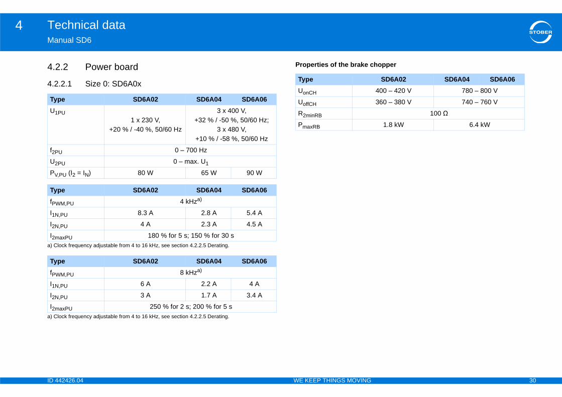
SD6A02 SD6A04 SD6A06400 – 420 V 780 – 800 V
360 – 380 V 740 – 760 V
100 Ω
1.8 kW 6.4 kW
42426.04 WE KEEP THINGS MOVING
nual SD6
.2 Power board
.2.1 Size 0: SD6A0x
Properties of the brake c
pe SD6A02 SD6A04 SD6A06
PU1 x 230 V,
+20 % / -40 %, 50/60 Hz
3 x 400 V, +32 % / -50 %, 50/60 Hz;
3 x 480 V,+10 % / -58 %, 50/60 Hz
U 0 – 700 Hz
PU 0 – max. U1
,PU (I2 = IN) 80 W 65 W 90 W
pe SD6A02 SD6A04 SD6A06
M,PU 4 kHza)
lock frequency adjustable from 4 to 16 kHz, see section 4.2.2.5 Derating.
,PU 8.3 A 2.8 A 5.4 A
,PU 4 A 2.3 A 4.5 A
axPU 180 % for 5 s; 150 % for 30 s
pe SD6A02 SD6A04 SD6A06
M,PU 8 kHza)
lock frequency adjustable from 4 to 16 kHz, see section 4.2.2.5 Derating.
,PU 6 A 2.2 A 4 A
,PU 3 A 1.7 A 3.4 A
axPU 250 % for 2 s; 200 % for 5 s
TypeUonCH
UoffCH
R2minRB
PmaxRB

ID 4 31
Technical data4Ma
4.2
Pro
A2x
hopper
TyU1
f2P
U2
PV
TyfPW
a) C
I1N
I2N
I2m
TyfPW
a) C
I1N
I2N
I2m
TyUo
Uo
R2
Pm
SD6A24 SD6A263 400 V, +32 % / -50 %, 50/60 Hz; 3 480 V, +10 % / -58 %, 50/60 Hz
0 – 700 Hz
0 – max. U1
220 W 280 W
SD6A24 SD6A264 kHza)
m 4 to 16 kHz, see section 4.2.2.5 Derating.
26.4 A 38.4 A
22 A 32 A
180 % for 5 s; 150 % for 30 s
SD6A24 SD6A268 kHza)
m 4 to 16 kHz, see section 4.2.2.5 Derating.
24.5 A 32.6 A
14 A 20 A
250 % for 2 s; 200 % for 5 s
SD6A24 SD6A26780 – 800 V
740 – 760 V
22 Ω
29.1 kW 29.1 kW
42426.04 WE KEEP THINGS MOVING
nual SD6
.2.2 Size 1: SD6A1x
perties of the brake chopper
4.2.2.3 Size 2: SD6
Properties of the brake c
pe SD6A14 SD6A16
PU 3 400 V, +32 % / -50 %, 50/60 Hz; 3 480 V, +10 % / -58 %, 50/60 Hz
U 0 – 700 Hz
PU 0 – max. U1
,PU (I2 = IN) 170 W 200 W
pe SD6A14 SD6A16
M,PU 4 kHza)
lock frequency adjustable from 4 to 16 kHz, see section 4.2.2.5 Derating.
,PU 12 A 19.2 A
,PU 10 A 16 A
axPU 180 % for 2 s; 150 % for 30 s
pe SD6A14 SD6A16
M,PU 8 kHza)
lock frequency adjustable from 4 to 16 kHz, see section 4.2.2.5 Derating.
,PU 9.3 A 15.8 A
,PU 6 A 10 A
axPU 250 % for 2 s; 200 % for 5 s
pe SD6A14 SD6A16
nCH 780 – 800 V
ffCH 740 – 760 V
minRB 47 Ω
axRB 13.6 kW 13.6 kW
TypeU1PU
f2PU
U2PU
PV,PU (I2 = IN)
TypefPWM,PU
a) Clock frequency adjustable fro
I1N,PU
I2N,PU
I2maxPU
TypefPWM,PU
a) Clock frequency adjustable fro
I1N,PU
I2N,PU
I2maxPU
TypeUonCH
UoffCH
R2minRB
PmaxRB
ID 4 32
Technical data4Ma
4.2
Pro
ive controller, observe the derating of the nominal on the clock frequency, surrounding temperature, ere is no restriction for a surrounding temperature
installation altitude of 0 m to 1000 m. The details s outside these ranges.
lock frequencyncy fPWM affects the amount of noise produced by ings. However, increasing the clock frequency . During project configuration, define the highest to determine the nominal output current I2N,PU for troller.
2N,PU [A]
Ty
U1
f2P
U2
PV
TyfPW
a) C
I1N
I2N
b) S
I2m
TyfPW
a) C
I1N
I2N
I2m
TyUo
Uo
R2
Pm
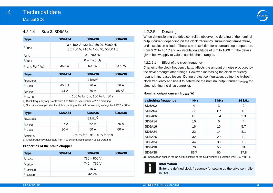
4 kHz 8 kHz 16 kHz4 3 2
2.3 1.7 1.14.5 3.4 2.310 6 416 10 5.722 14 8.132 20 1244 30 1870 50 31
85a)
fault setting of the field weakening voltage limit: B92 = 80 %.60 37.8
d clock frequency for setting up the drive controller
42426.04 WE KEEP THINGS MOVING
nual SD6
.2.4 Size 3: SD6A3x
perties of the brake chopper
4.2.2.5 DeratingWhen dimensioning the droutput current depending and installation altitude. Thfrom 0 °C to 45 °C and angiven below apply to value
4.2.2.5.1 Effect of the cChanging the clock frequethe drive amongst other thresults in increased lossesclock frequency and use itdimensioning the drive con
Nominal output current I
pe SD6A34 SD6A36 SD6A38
PU3 x 400 V, +32 % / -50 %, 50/60 Hz; 3 x 480 V, +10 % / -58 %, 50/60 Hz
U 0 – 700 Hz
PU 0 – max. U1
,PU (I2 = IN) 350 W 600 W 1000 W
pe SD6A34 SD6A36 SD6A38
M,PU 4 kHza)
lock frequency adjustable from 4 to 16 kHz, see section 4.2.2.5 Derating.
,PU 45.3 A 76 A 76 A
,PU 44 A 70 A 85 Ab)
pecification applies for the default setting of the field weakening voltage limit: B92 = 80 %.
axPU 180 % for 5 s; 150 % for 30 s
pe SD6A34 SD6A36 SD6A38
M,PU 8 kHza)
lock frequency adjustable from 4 to 16 kHz, see section 4.2.2.5 Derating.
,PU 37 A 62 A 76 A
,PU 30 A 50 A 60 A
axPU 250 % for 2 s; 200 % for 5 s
pe SD6A34 SD6A36 SD6A38
nCH 780 – 800 V
ffCH 740 – 760 V
minRB 15 Ω
axRB 42 kW
switching frequencySD6A02SD6A04SD6A06SD6A14SD6A16SD6A24SD6A26SD6A34SD6A36SD6A38
a) Specification applies for the de
InformationEnter the definein B24.

ID 4 33
Technical data4Ma
4.2Der••
ExaTheTheDT
4.2Der••
ExaTheTheDIA
4.2Fol1.
2.
3.
A dat a50 The
alculated as follows:7.5 %
calculated as follows: 92.5 %bserved for project configuration is:925 = 2.75 A
tures
ler with accessory parts, the weight is increased as
le: 50 gg
IP20
At least IP54
EN 61800-3, interference emission class C3
III to EN 61800-5-1
Weightout packaging [kg] With packaging [kg]
2,53 3.52
3.7 5.47
5.05 6.49
13.3 14.8
42426.04 WE KEEP THINGS MOVING
nual SD6
.2.5.2 Effect of surrounding temperatureating depending on the surrounding temperature is determined as follows:0 °C to 45 °C: no restrictions (DT = 100 %)45 °C to 55 °C: Derating -2,5 % / K
mple drive controller will be operated at 50 °C. derating factor DT is calculated as follows= 100 % - 5 2.5 % = 87.5 %
.2.5.3 Effect of installation altitudeating depending on the installation altitude is determined as follows:0 m to 1000 m above sea level: no restriction (DIA = 100 %)1000 to 2000 m above sea level: Derating -1.5 % / 100 m
mple drive controller will be installed at an altitude of 1500 m above sea level. derating factor DIA is calculated as follows: = 100 % - 5 1,5 % = 92.5 %
.2.5.4 Calculating the deratinglow these steps for the calculation:Determine the highest clock frequency (fPWM) that will be used during operation and use it to determine the nominal current I2N,PU.Determine the derating factors for installation altitude and surrounding temperature.Calculate the nominal output current I2N,PU according to the following formula: I2N,PU = I2N,PU DT DIA
rive controller of type SD6A06 will be operated at a clock frequency of 8 kHz n altitude of 1500 m above sea level and an surrounding temperature of
°C. nominal current of the SD6A06 at 8 kHz is 3.4 A.
The derating factor DT is cDT = 100 % - 5 2.5 % = 8The derating factor DIA is DIA = 100 % - 5 1.5 % =The output current to be oI2N,PU = 3.4 A 0.875 0.
4.3 Device fea
If you order a drive controlfollows:• Communication modu• Terminal module: 135
Protection class of the deviceProtection class of the control cabinetRadio interference suppressionOvervoltage category
SizeWith
0
1
2
3
ID 4 34
Technical data4Ma
4.
NO
MaThestrefrom
SutemSttraRe
InsPoVeVi
Vi
42426.04 WE KEEP THINGS MOVING
nual SD6
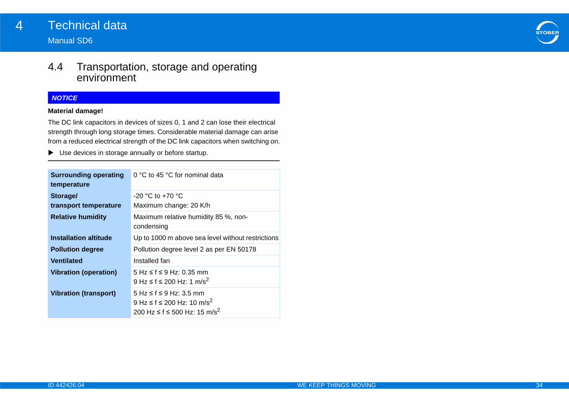
4 Transportation, storage and operating environment
TICE
terial damage! DC link capacitors in devices of sizes 0, 1 and 2 can lose their electrical ngth through long storage times. Considerable material damage can arise a reduced electrical strength of the DC link capacitors when switching on.
Use devices in storage annually or before startup.
rrounding operating perature
0 °C to 45 °C for nominal data
orage/nsport temperature
-20 °C to +70 °C Maximum change: 20 K/h
lative humidity Maximum relative humidity 85 %, non-condensing
tallation altitude Up to 1000 m above sea level without restrictions
llution degree Pollution degree level 2 as per EN 50178
ntilated Installed fan
bration (operation) 5 Hz ≤ f ≤ 9 Hz: 0.35 mm9 Hz ≤ f ≤ 200 Hz: 1 m/s2
bration (transport) 5 Hz ≤ f ≤ 9 Hz: 3.5 mm9 Hz ≤ f ≤ 200 Hz: 10 m/s2200 Hz ≤ f ≤ 500 Hz: 15 m/s2
ID 4 35
Technical data4Ma
4.You
Not . If you would like to optimize your drive, find a des
Mo racteristics
Syse
dynamics, high accuracy, very stant speed, high overcurrent ection dynamics, high accuracy, very
stant speed, high overcurrent ection, greater speed range, but also er current requirement
Sylin
h dynamics, high overcurrent ection
Asmo
dynamics, high accuracy, very stant speed, high overcurrent ectionamics, accuracy, constant speed, rcurrent protection
y constant speed, accuracy
y constant speed, accuracy, especially able for fan applications
y constant speed
y constant speed, especially suitable an applications
42426.04 WE KEEP THINGS MOVING
nual SD6
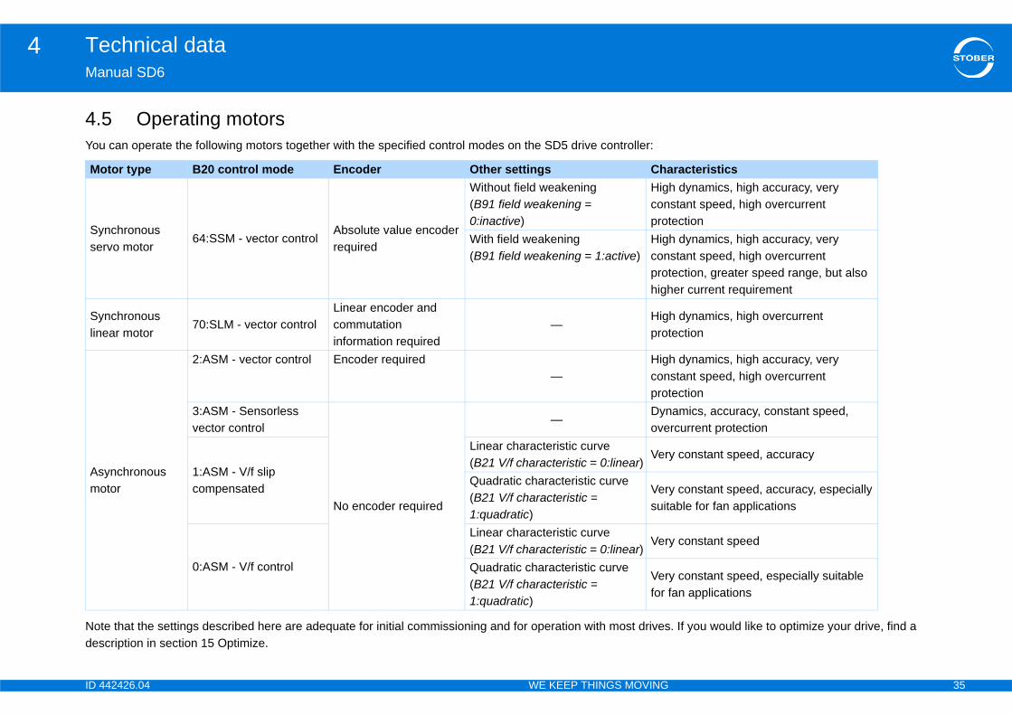
5 Operating motors can operate the following motors together with the specified control modes on the SD5 drive controller:
e that the settings described here are adequate for initial commissioning and for operation with most drivescription in section 15 Optimize.
tor type B20 control mode Encoder Other settings Cha
nchronous rvo motor
64:SSM - vector controlAbsolute value encoder required
Without field weakening(B91 field weakening = 0:inactive)
Highconprot
With field weakening(B91 field weakening = 1:active)
Highconprothigh
nchronous ear motor
70:SLM - vector controlLinear encoder and commutation information required
—Higprot
ynchronous tor
2:ASM - vector control Encoder required—
Highconprot
3:ASM - Sensorless vector control
No encoder required
—Dynove
1:ASM - V/f slip compensated
Linear characteristic curve(B21 V/f characteristic = 0:linear)
Ver
Quadratic characteristic curve(B21 V/f characteristic = 1:quadratic)
Versuit
0:ASM - V/f control
Linear characteristic curve(B21 V/f characteristic = 0:linear)
Ver
Quadratic characteristic curve(B21 V/f characteristic = 1:quadratic)
Verfor f
ID 4 36
Technical data4Ma
4.5
4.5
GeU2I2m
I2mMalen
SpEnSw
SpEnSw
SSSwSaCoEnfor
Tra
SpfmSig
ample – limit frequency fmaxer with 2,048 pulses per revolution: ns per minute (equivalent to 50 revolutions per pulses per revolution
es per second 1 MHz
ughder sense line ected to pin 12 (sense)
STOBER synchronous servo motorsStandard: EnDat 2.1/2.2
2 (sense) bridged with (U2)
STOBER asynchronous motorsTTL (for customer-specific solutions),without cable compensationPin 12 (sense) not used
2 (sense) bridged with (GND)
STOBER asynchronous motorsHTL encoder: Bridge created in the cable plug that is connected to X4SSI encoder: Bridge for U2 is created in the bracket flange socket
42426.04 WE KEEP THINGS MOVING
nual SD6
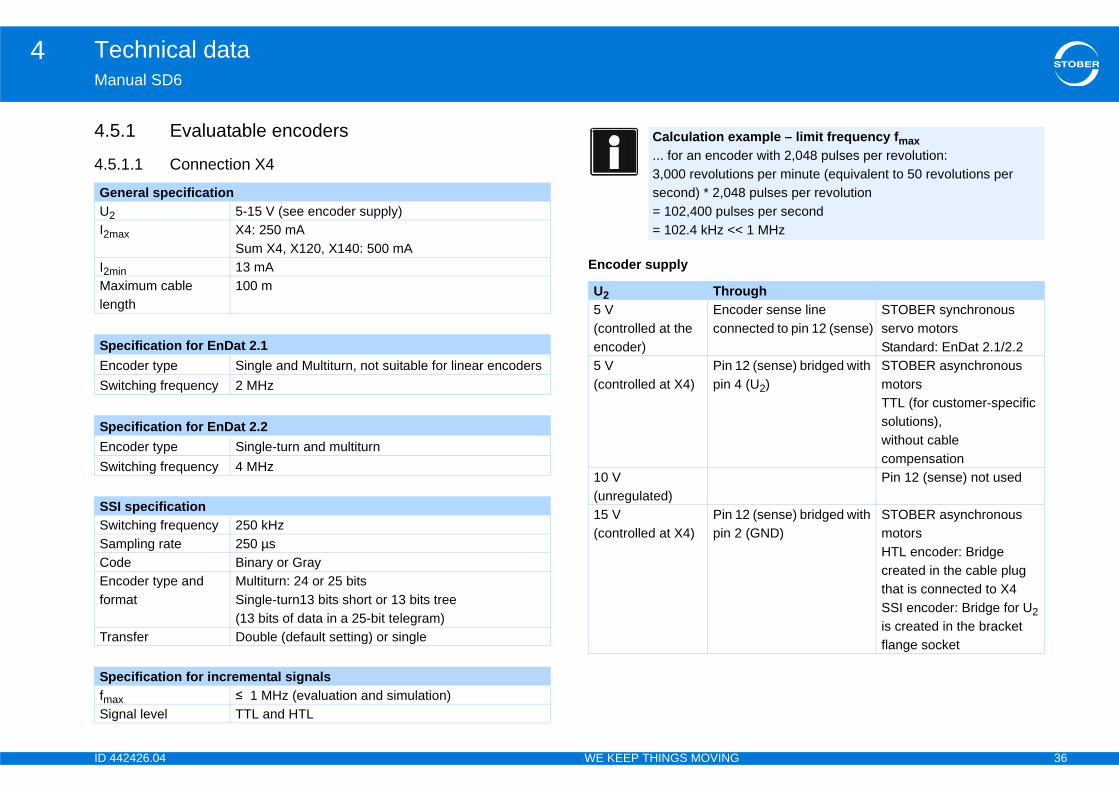
.1 Evaluatable encoders
.1.1 Connection X4
Encoder supply
neral specification5-15 V (see encoder supply)
ax X4: 250 mASum X4, X120, X140: 500 mA
in 13 mAximum cable gth
100 m
ecification for EnDat 2.1coder type Single and Multiturn, not suitable for linear encoders itching frequency 2 MHz
ecification for EnDat 2.2coder type Single-turn and multiturnitching frequency 4 MHz
I specificationitching frequency 250 kHzmpling rate 250 µsde Binary or Graycoder type and mat
Multiturn: 24 or 25 bitsSingle-turn13 bits short or 13 bits tree (13 bits of data in a 25-bit telegram)
nsfer Double (default setting) or single
ecification for incremental signalsax ≤ 1 MHz (evaluation and simulation)nal level TTL and HTL
Calculation ex... for an encod3,000 revolutiosecond) * 2,048= 102,400 puls= 102.4 kHz <<
U2 Thro5 V (controlled at the encoder)
Encoconn
5 V(controlled at X4)
Pin 1pin 4
10 V (unregulated)15 V(controlled at X4)
Pin 1pin 2
ID 4 37
Technical data4Ma
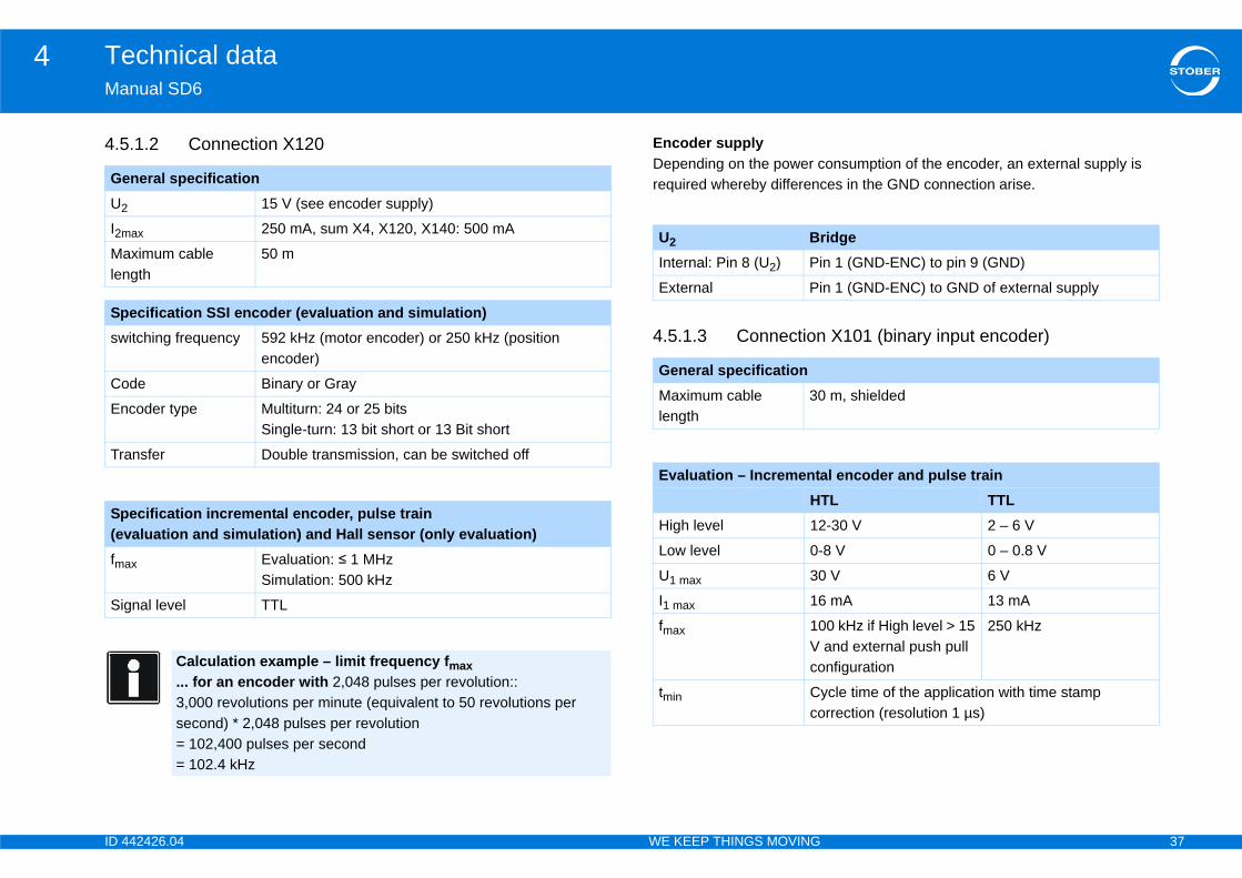
4.5onsumption of the encoder, an external supply is es in the GND connection arise.
X101 (binary input encoder)
GeU2
I2m
Malen
Spsw
Co
En
Tra
Sp(evfm
Sig
idgen 1 (GND-ENC) to pin 9 (GND)
n 1 (GND-ENC) to GND of external supply
m, shielded
l encoder and pulse trainL TTL-30 V 2 – 6 V
8 V 0 – 0.8 V
V 6 V
mA 13 mA
0 kHz if High level > 15 and external push pull nfiguration
250 kHz
cle time of the application with time stamp rrection (resolution 1 µs)
42426.04 WE KEEP THINGS MOVING
nual SD6
.1.2 Connection X120 Encoder supplyDepending on the power crequired whereby differenc
4.5.1.3 Connection
neral specification15 V (see encoder supply)
ax 250 mA, sum X4, X120, X140: 500 mA
ximum cable gth
50 m
ecification SSI encoder (evaluation and simulation)itching frequency 592 kHz (motor encoder) or 250 kHz (position
encoder)
de Binary or Gray
coder type Multiturn: 24 or 25 bits Single-turn: 13 bit short or 13 Bit short
nsfer Double transmission, can be switched off
ecification incremental encoder, pulse train aluation and simulation) and Hall sensor (only evaluation)
ax Evaluation: ≤ 1 MHzSimulation: 500 kHz
nal level TTL
Calculation example – limit frequency fmax ... for an encoder with 2,048 pulses per revolution:: 3,000 revolutions per minute (equivalent to 50 revolutions per second) * 2,048 pulses per revolution= 102,400 pulses per second = 102.4 kHz
U2 BrInternal: Pin 8 (U2) Pi
External Pi
General specificationMaximum cable length
30
Evaluation – IncrementaHT
High level 12
Low level 0-
U1 max 30
I1 max 16
fmax 10V co
tmin Cyco

ID 4 38
Technical data4Ma
4.5
SiU2
I2m
Ef
fm
Exfre
ReU2
I2m
f2Pm
Tra
Nu
Ph
Malen
nDat 2.1 digital, EnDat 2.1 sin/cos and tion)
– 12 V, see encoder supply
0 mA, m X4, X120 and X140 (EnDat): 500 mA
mA
5 kHz
ngle-turn and multiturn
0 m
ample – limit frequency fmax ith 2,048 pulses per revolution:
ns per minute (equivalent to 50 revolutions per pulses per revolution
es per second
nDat 2.2 digital (evaluation)ngle-turn and multiturn
MHz
42426.04 WE KEEP THINGS MOVING
nual SD6
.1.4 Connection X140
mulation – Incremental encoder and pulse train18–28,8 V
ax XI6: 50 mA, RI6 and IO6: 100 mA
f. Update rate 4 kHz
ax 250 kHz(Maximum output frequency for one track)
trapolation quency
66 MHz
Calculation example – limit frequency ... for encoder with 2,048 pulses per revolution: 3,000 revolutions per minute (equivalent to 50 revolutions per second) * 2,048 pulses per revolution= 102,400 pulses per second = 102.4 kHz
solver specification (evaluation)-10 V ... +10 V
ax 80 mA
7 – 9 kHz
ax 0.8 W
nsfer ratio 0.5 ± 5 %
mber of poles 2, 4 and 6
ase shift ± 20 el.°
ximum cable gth
100 m
Specification encoder Esin/cos encoder (evaluaU2 5
I2max 25su
I2min 13
fmax 22
Encoder type Si
Maximum cable length
10
Calculation ex... for encoder w3,000 revolutiosecond) * 2,048= 102,400 puls= 102.4 kHz
Specification encoder EEncoder type Si
switching frequency 4
ID 4 39
Technical data4Ma
Enc le brakesng brakes:d directly to X5 (in accordance with the technical
rakes with different nominal voltage (controlled via itching device).6.
le motor temperature sensorsgs in series or one KTY-84 can be connected to the
U2
5 V(cothe
5 V(coX4
10(un
24–30 V
3.0 A
1 Hz
KTY, note that motor protection is not ensured to the when monitoring with PTC drilling.
ation of the temperature sensors is always active. If ut temperature sensor is permitted, the connections on X2. Otherwise a fault will be triggered when the ed on.
42426.04 WE KEEP THINGS MOVING
nual SD6
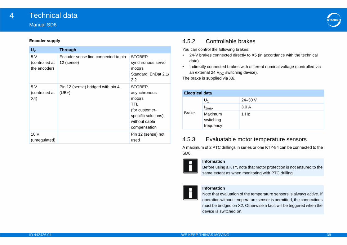
oder supply 4.5.2 ControllabYou can control the followi• 24-V brakes connecte
data).• Indirectly connected b
an external 24 VDC swThe brake is supplied via X
4.5.3 EvaluatabA maximum of 2 PTC drillinSD6.
Through ntrolled at encoder)
Encoder sense line connected to pin 12 (sense)
STOBER synchronous servo motors Standard: EnDat 2.1/2.2
ntrolled at )
Pin 12 (sense) bridged with pin 4 (UB+)
STOBER asynchronous motorsTTL (for customer-specific solutions), without cable compensation
V regulated)
Pin 12 (sense) not used
Electrical data
Brake
U1
I1max
Maximum switching frequency
InformationBefore using a same extent as
InformationNote that evaluoperation withomust be bridgeddevice is switch

ID 4 40
Technical data4Ma
4.Thefor symtab
4.6TheYou•
••
ze 3 (SD6A34, SD6A36, SD6A38): commutation reactors and mains fuse for operating e fuses" > "Full range safety melt fuses").
SiSiz
Siz
rrent kHz)
Input current I1N,PU (4 kHz)
Recommended mains fuse (max.)
A 8.3 A 10 A
A 2.8 A 10 A
5.4 A 10 A
A 12 A 16 A
A 19.2 A 20 A
A 26.4 A 35 A
A 38.4 A 50 A
A 45.3 A 50 A
A 76 A 80 A
A 76 A 80 A
values apply only to the drive controllers that are e mains individually. Different parameters apply to
s in a Quick DC-Link system.
42426.04 WE KEEP THINGS MOVING
nual SD6
6 Protective measures drive controllers are only suitable for operation on TN networks and only use in supply current networks that are able to provide a maximally metrical nominal short circuit current at 480 volts according to the following
le.
.1 Line fuse mains fuse ensures line and power protection in the drive controller. can use the following protective devices:Full range safety melt fuses for cable and circuit protection to IEC 60269-2-1/DIN VDE 0636, part 201 NH fuses (operating class gG in accordance with IEC operating class specification or slow blow in accordance with VDE)Circuit breaker with trigger characteristics C in accordance with EN 60898Power circuit breaker
The following applies to siOperation only with mainsclass gG (see section "Lin
ze Max. symmetrical nominal short-circuit currente 0 – size 2 5000 A
e 3 10,000 A
Type Input cuI1N,PU (8
SD6A02 5.9
SD6A04 2.2
SD6A06 4 A
SD6A14 9.3
SD6A16 15.8
SD6A24 24.5
SD6A26 32.6
SD6A34 37
SD6A36 62
SD6A38 76
InformationNote that theseconnected to thdrive controller
ID 4 41
Technical data4Ma
ULUse•••
See
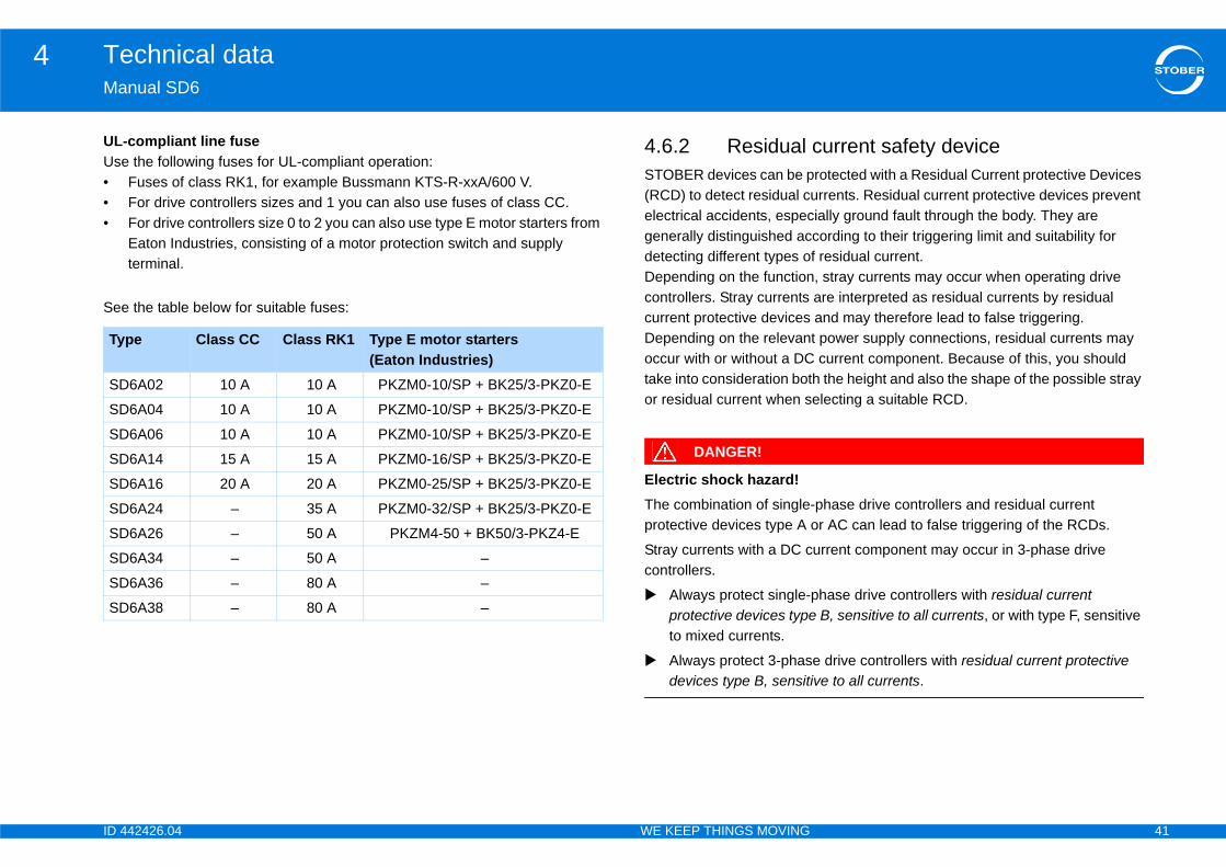
current safety devicerotected with a Residual Current protective Devices
urrents. Residual current protective devices prevent ially ground fault through the body. They are cording to their triggering limit and suitability for f residual current. , stray currents may occur when operating drive are interpreted as residual currents by residual and may therefore lead to false triggering. t power supply connections, residual currents may current component. Because of this, you should h the height and also the shape of the possible stray electing a suitable RCD.
-phase drive controllers and residual current or AC can lead to false triggering of the RCDs.
urrent component may occur in 3-phase drive
phase drive controllers with residual current B, sensitive to all currents, or with type F, sensitive
e drive controllers with residual current protective ve to all currents.
Ty
SD
SD
SD
SD
SD
SD
SD
SD
SD
SD
42426.04 WE KEEP THINGS MOVING
nual SD6
-compliant line fuse the following fuses for UL-compliant operation:Fuses of class RK1, for example Bussmann KTS-R-xxA/600 V. For drive controllers sizes and 1 you can also use fuses of class CC.For drive controllers size 0 to 2 you can also use type E motor starters from Eaton Industries, consisting of a motor protection switch and supply terminal.
the table below for suitable fuses:
4.6.2 Residual STOBER devices can be p(RCD) to detect residual celectrical accidents, especgenerally distinguished acdetecting different types oDepending on the functioncontrollers. Stray currents current protective devicesDepending on the relevanoccur with or without a DCtake into consideration botor residual current when s
DANGER!
Electric shock hazard!The combination of singleprotective devices type A
Stray currents with a DC ccontrollers.
Always protect single-protective devices typeto mixed currents.
Always protect 3-phasdevices type B, sensiti
pe Class CC Class RK1 Type E motor starters(Eaton Industries)
6A02 10 A 10 A PKZM0-10/SP + BK25/3-PKZ0-E
6A04 10 A 10 A PKZM0-10/SP + BK25/3-PKZ0-E
6A06 10 A 10 A PKZM0-10/SP + BK25/3-PKZ0-E
6A14 15 A 15 A PKZM0-16/SP + BK25/3-PKZ0-E
6A16 20 A 20 A PKZM0-25/SP + BK25/3-PKZ0-E
6A24 – 35 A PKZM0-32/SP + BK25/3-PKZ0-E
6A26 – 50 A PKZM4-50 + BK50/3-PKZ4-E
6A34 – 50 A –
6A36 – 80 A –
6A38 – 80 A –
ID 4 42
Technical data4Ma
FalDepma
•
•
•
Ins
EleStrafun
roundtion on the connection of the protective earth to tly:
uence:
return spring and nuts are supplied with the drive
m
can arise in normal operation. To fulfill DIN EN 04-1, connect the earth bolts with a copper the following table:
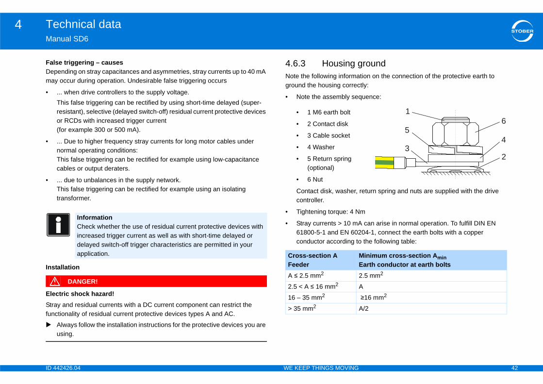
Minimum cross-section Amin Earth conductor at earth bolts2.5 mm2
A
≥16 mm2
A/2
1
43
65
2
42426.04 WE KEEP THINGS MOVING
nual SD6
se triggering – causesending on stray capacitances and asymmetries, stray currents up to 40 mA
y occur during operation. Undesirable false triggering occurs
... when drive controllers to the supply voltage.This false triggering can be rectified by using short-time delayed (super-resistant), selective (delayed switch-off) residual current protective devices or RCDs with increased trigger current (for example 300 or 500 mA).
... Due to higher frequency stray currents for long motor cables under normal operating conditions: This false triggering can be rectified for example using low-capacitance cables or output deraters.
... due to unbalances in the supply network. This false triggering can be rectified for example using an isolating transformer.
tallation
DANGER!
ctric shock hazard!y and residual currents with a DC current component can restrict the
ctionality of residual current protective devices types A and AC.
Always follow the installation instructions for the protective devices you are using.
4.6.3 Housing gNote the following informaground the housing correc
• Note the assembly seq
• 1 M6 earth bolt
• 2 Contact disk
• 3 Cable socket
• 4 Washer
• 5 Return spring (optional)
• 6 Nut
Contact disk, washer, controller.
• Tightening torque: 4 N
• Stray currents > 10 mA61800-5-1 and EN 602conductor according to
InformationCheck whether the use of residual current protective devices with increased trigger current as well as with short-time delayed or delayed switch-off trigger characteristics are permitted in your application. Cross-section A
FeederA ≤ 2.5 mm2
2.5 < A ≤ 16 mm2
16 – 35 mm2
> 35 mm2
ID 4 43
Technical data4Ma
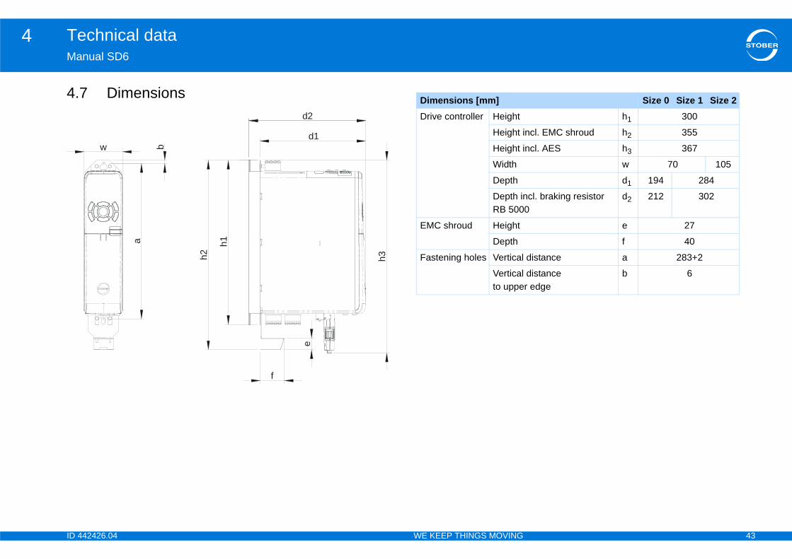
4. Size 0 Size 1 Size 2h1 300
ncl. EMC shroud h2 355
ncl. AES h3 367
w 70 105
d1 194 284
cl. braking resistor 0
d2 212 302
e 27
f 40
distance a 283+2
distance r edge
b 6
42426.04 WE KEEP THINGS MOVING
nual SD6
7 Dimensionsd2
d1
h2
h1
h3
e
f
a
bw
Dimensions [mm]Drive controller Height
Height i
Height i
Width
Depth
Depth inRB 500
EMC shroud Height
Depth
Fastening holes Vertical
Verticalto uppe
ID 4 44
Technical data4Ma
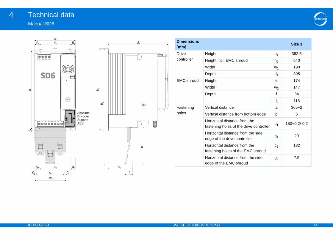
Size 3
h1 382.5
cl. EMC shroud h2 540
w1 190
d1 305
e 174
w2 147
f 34
d2 113
istance a 365+2
istance from bottom edge b 6
l distance from the holes of the drive controller
c1 150+0.2/-0.2
l distance from the side he drive controller
g1 20
l distance from the holes of the EMC shroud
c2 132
l distance from the side he EMC shroud
g2 7.5
42426.04 WE KEEP THINGS MOVING
nual SD6
Dimensions [mm]Drive controller
Height
Height in
Width
Depth
EMC shroud Height
Width
Depth
Fastening holes
Vertical d
Vertical d
Horizontafastening
Horizontaedge of t
Horizontafastening
Horizontaedge of t
ID 4 45
Technical data4Ma
4.4.8X10
GeMalen
ElAnAE
AnAE(Abri
AnAA
m, shielded
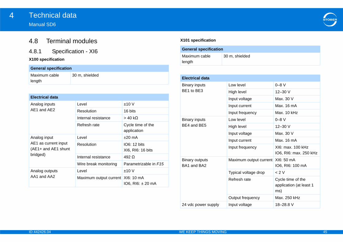
Low level 0–8 V
High level 12–30 V
Input voltage Max. 30 V
Input current Max. 16 mA
Input frequency Max. 10 kHz
Low level 0–8 V
High level 12–30 V
Input voltage Max. 30 V
Input current Max. 16 mA
Input frequency XI6: max. 100 kHzIO6, RI6: max. 250 kHz
Maximum output current XI6: 50 mA IO6, RI6: 100 mA
Typical voltage drop < 2 V
Refresh rate Cycle time of the application (at least 1 ms)
Output frequency Max. 250 kHz
Input voltage 18–28.8 V
42426.04 WE KEEP THINGS MOVING
nual SD6
8 Terminal modules.1 Specification - XI60 specification
X101 specification
neral specificationximum cable gth
30 m, shielded
ectrical dataalog inputs 1 and AE2
Level ±10 V
Resolution 16 bits
Internal resistance > 40 kΩ
Refresh rate Cycle time of the application
alog input 1 as current input
E1+ and AE1 shunt dged)
Level ±20 mA
Resolution IO6: 12 bitsXI6, RI6: 16 bits
Internal resistance 492 Ω
Wire break monitoring Parametrizable in F15
alog outputs 1 and AA2
Level ±10 V
Maximum output current XI6: 10 mAIO6, RI6: ± 20 mA
General specificationMaximum cable length
30
Electrical dataBinary inputs BE1 to BE3
Binary inputs BE4 and BE5
Binary outputs BA1 and BA2
24 vdc power supply
ID 4 46
Technical data4Ma
X10
GeMalen
ElAn
m, shielded
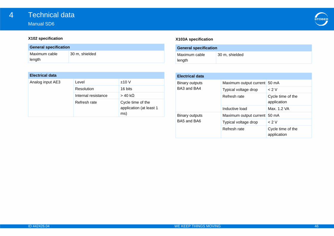
Maximum output current 50 mA
Typical voltage drop < 2 V
Refresh rate Cycle time of the application
Inductive load Max. 1.2 VA
Maximum output current 50 mA
Typical voltage drop < 2 V
Refresh rate Cycle time of the application
42426.04 WE KEEP THINGS MOVING
nual SD6
2 specification X103A specification
neral specificationximum cable gth
30 m, shielded
ectrical dataalog input AE3 Level ±10 V
Resolution 16 bits
Internal resistance > 40 kΩ
Refresh rate Cycle time of the application (at least 1 ms)
General specificationMaximum cable length
30
Electrical dataBinary outputs BA3 and BA4
Binary outputs BA5 and BA6

ID 4 47
Technical data4Ma
X10
GeMalen
ElBinBA
Bin
m, shielded
Low level 0–8 V
High level 12–30 V
Input voltage Max. 30 V
Input current Max. 16 mA
Input frequency Max. 3 kHz
42426.04 WE KEEP THINGS MOVING
nual SD6
3B specification X103C specification
neral specificationximum cable gth
30 m, shielded
ectrical dataary outputs 7 to BA10
Maximum output current 50 mA
Typical voltage drop < 2 V
Refresh rate Cycle time of the application
ary input BE6 Low level 0–8 V
High level 12–30 V
Input voltage Max. 30 V
Input current Max. 16 mA
Input frequency Max. 3 kHz
General specificationMaximum cable length
30
Electrical dataBinary inputs BE7 to BE13

ID 4 48
Technical data4Ma
4.8X10
ElAnAE
AnAE(Abri
AnAA(sh
Low level 0–8 V
High level 12–30 V
Input voltage Max. 30 V
Input current Max. 16 mA
Input frequency Max. 10 kHz
Low level 0–8 V
High level 12–30 V
Input voltage Max. 30 V
Input current Max. 16 mA
Input frequency Max. 400 kHz
Maximum output current 100 mA
Typical voltage drop < 2 V
Refresh rate Cycle time of the application
Maximum output current 50 mA
Typical voltage drop < 2 V
Output frequency Max. 1 MHz
Input voltage 18–28.8 V
42426.04 WE KEEP THINGS MOVING
nual SD6
.2 Specification – RI60 specification
X101 specification
ectrical dataalog inputs 1 and AE2
Level ± 10 V
Resolution 16 bits
Internal resistance > 40 kΩ
Refresh rate Cycle time of the application
alog input 1 as current input
E1+ and AE1 shunt dged)
Level ± 20 mA
Resolution 16 bits
Internal resistance 492 Ω
Wire break monitoring Parameterizable in F15
alog outputs 1 and AA2ort-circuit-proof)
Level ± 10 V, ± 20mA
Maximum output current ± 20mA
Electrical dataBinary inputs BE1 to BE3
Binary inputs BE4 and BE5
Binary outputs BA1 and BA2
Binary outputs BA1 and BA2 as encoder output
24-V power supply
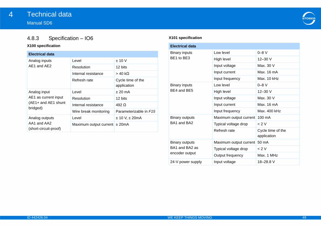
ID 4 49
Technical data4Ma
4.8X10
ElAnAE
AnAE(Abri
AnAA(sh
Low level 0–8 V
High level 12–30 V
Input voltage Max. 30 V
Input current Max. 16 mA
Input frequency Max. 10 kHz
Low level 0–8 V
High level 12–30 V
Input voltage Max. 30 V
Input current Max. 16 mA
Input frequency Max. 400 kHz
Maximum output current 100 mA
Typical voltage drop < 2 V
Refresh rate Cycle time of the application
Maximum output current 50 mA
Typical voltage drop < 2 V
Output frequency Max. 1 MHz
Input voltage 18–28.8 V
42426.04 WE KEEP THINGS MOVING
nual SD6
.3 Specification – IO60 specification
X101 specification
ectrical dataalog inputs 1 and AE2
Level ± 10 V
Resolution 12 bits
Internal resistance > 40 kΩ
Refresh rate Cycle time of the application
alog input 1 as current input
E1+ and AE1 shunt dged)
Level ± 20 mA
Resolution 12 bits
Internal resistance 492 Ω
Wire break monitoring Parameterizable in F15
alog outputs 1 and AA2ort-circuit-proof)
Level ± 10 V, ± 20mA
Maximum output current ± 20mA
Electrical dataBinary inputs BE1 to BE3
Binary inputs BE4 and BE5
Binary outputs BA1 and BA2
Binary outputs BA1 and BA2 as encoder output
24-V power supply
ID 4 50
Technical data4Ma
4.4.9Acc
CabSTOcabIt is
Linkryed act like generators: in operation with an active rt the kinetic energy inherent in the movement into
d into the DC link capacitors of the drive controller. It driving motors if the DC intermediate circuits are or efficient use. voltage in the DC intermediate circuit increases. the DC link are only able to absorb a limited amount ltage increases above a defined limit, a chopper verts excess energy to heat via a connected braking
voltage is reached, it is important to prevent e controller takes on the "Fault" status and switches
e DC link capacitors of the relevant drive controllers at increases the maximum amount of energy that intermediate circuit in comparison to an individual
nology that use motors for permanent braking or in ation and braking cycles, the DC link connection
PlQuSh
mergency stop, all drive controllers may possibly be ame time. You should take this into consideration in etermine whether a central braking resistor is able to stop system parts safely within a specified
42426.04 WE KEEP THINGS MOVING
nual SD6
9 Communication modules.1 EC6 communication moduleessory part EC6 is required for an accessory part.
le specificationBER provides ready-made cables for the EtherCAT connection. These
les must be used to ensure proper functionality. also possible to use cables with the following specification:
4.10 Quick DC-Electrical energy recoveMotors that are being brakdrive controller, they conveelectrical energy. This electrical energy is fecan be made available to connected, which makes fWhen a motor brakes, theHowever, the capacitors inof energy. If the DC link vocircuit is activated that conresistor. If the maximum admissiblepossible damage: The drivoff. In a DC link connection, thare switched in parallel. Thcan be absorbed in the DCdevice.
Especially in winding techgeneral for regular accelersaves energy and money.
InformationFor more extensive information about EtherCAT consult the EtherCAT operating instructions (see section 1.2 Further documentation)!
ug wiring Patch or crossover
ality CAT5e
ielding SFTP or PIMF
InformationIn a controlled ebraking at the sthe design to dnecessary to betime.
ID 4 51
Technical data4Ma
CoTheSDyou
RelNotDC
42426.04 WE KEEP THINGS MOVING
nual SD6
nnecting Quick DC-Link – drive controller DC link capacitors of exactly two drive controllers can be connected via the
6 output terminals. To connect the capacitors of multiple drive controllers, need a separate module DL6. (see also 6.5 Quick DC-Link).
evant design and operating instructionse the following factors in the planning phase and during subsequent Quick -Link operation:• the capacity of the charging circuits of the drive controllers that are
supplied with power• the sizes of the drive controllers and• their maximum output power.•
InformationNote that you can only connect the 6th generation of STOBER drive controllers.
InformationQuick DC-Link may be subject to system-specific or country-specific standards.
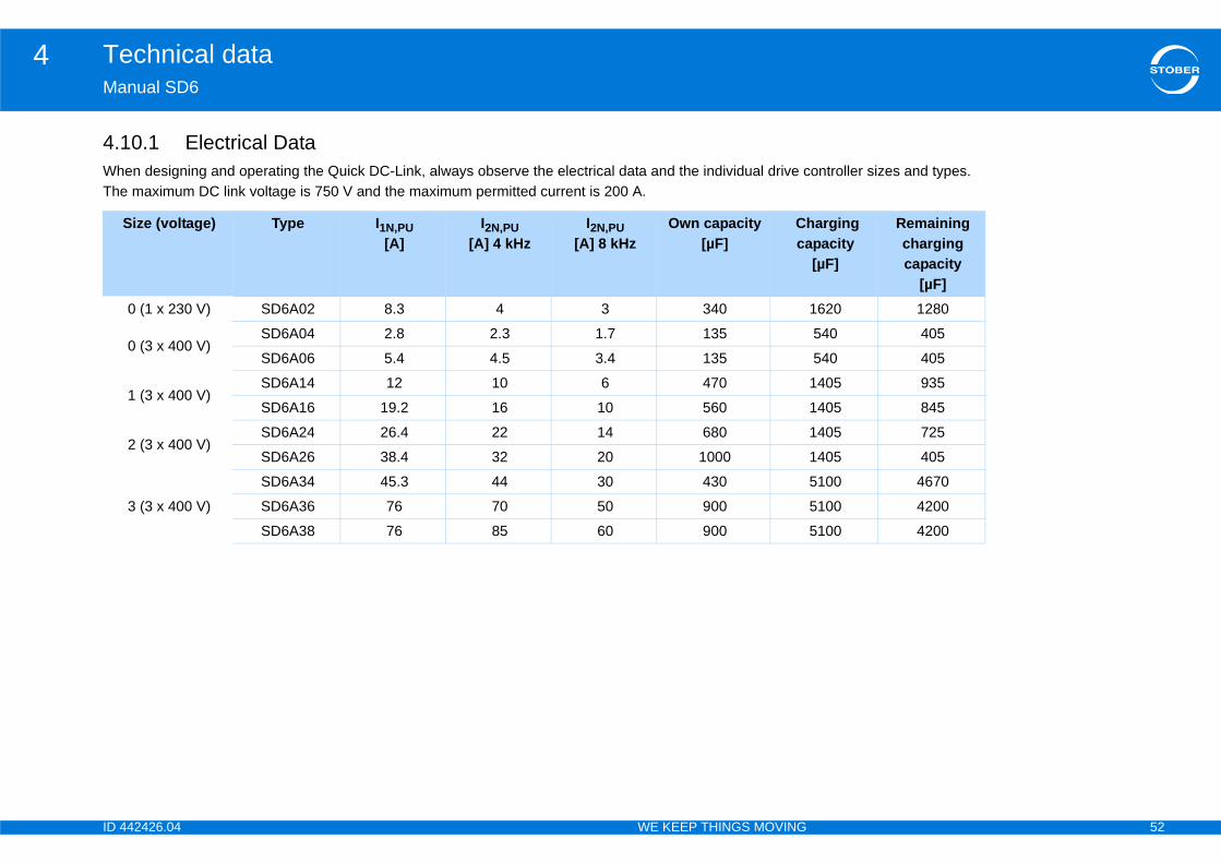
ID 4 52
Technical data4Ma
4.1Wh ontroller sizes and types. The
arging pacity[µF]
Remaining charging capacity
[µF]1620 1280
540 405
540 405
1405 935
1405 845
1405 725
1405 405
5100 4670
5100 4200
5100 4200
42426.04 WE KEEP THINGS MOVING
nual SD6
0.1 Electrical Dataen designing and operating the Quick DC-Link, always observe the electrical data and the individual drive c maximum DC link voltage is 750 V and the maximum permitted current is 200 A.
Size (voltage) Type I1N,PU[A]
I2N,PU[A] 4 kHz
I2N,PU[A] 8 kHz
Own capacity[µF]
Chca
0 (1 x 230 V) SD6A02 8.3 4 3 340
0 (3 x 400 V)SD6A04 2.8 2.3 1.7 135
SD6A06 5.4 4.5 3.4 135
1 (3 x 400 V)SD6A14 12 10 6 470
SD6A16 19.2 16 10 560
2 (3 x 400 V)SD6A24 26.4 22 14 680
SD6A26 38.4 32 20 1000
3 (3 x 400 V)
SD6A34 45.3 44 30 430
SD6A36 76 70 50 900
SD6A38 76 85 60 900
ID 4 53
Technical data4Ma
4.1MaOpQu
DevIf sphaCon
Not•
•
Spe•
•
•
exceeded while a DC link connection is in operation, maintain electromagnetic compatibility.d DC link connections as short as possible. If they y must be shielded.
e of a drive controller
e! oller in the DC link can cause damage to other drive , a failure must initiate the separation of the stem from the network.
wiring and parameterization of relay 1 in 7.3.9 X30: g resistor, page 103].
42426.04 WE KEEP THINGS MOVING
nual SD6
0.2 Power supplyins supplyerate only drive controllers with the same power supply voltage as part of ick DC-Link.
DANGER!
ice damage!ingle-phase and three-phase drive controllers are connected, the single-se drive controllers will be damaged.nect either all one-phase or else all three-phase drive controllers.
e also the following rules: All single-phase drive controllers must be connected to the same external conductor.All three-phase drive controllers must be connected to the same mains power supply.
cial features for a connection with drive controllers size 3AC supplyIf a Quick DC-Link consists of drive controllers of sizes 0, 1, 2 and 3, only those of size three may be supplied with power. The others must be supplied exclusively with DC voltage.Number The maximum number of size 3 drive controllers you can connect is 3.Power chokeA power choke of type TEP4010-2US00 must be installed for each size 3 drive controller supplied with power (see 4.12.1 Power choke).
NOTICE
Material damage!If the EMC limit values are take suitable measures to Always route the compounare longer than 30 cm, the
Protection against failur
NOTICE
Danger of device damagThe failure of a drive contrcontrollers. For this reasoncomplete Quick DC-link sy
Note in this regard theQuick DC-Link, brakin
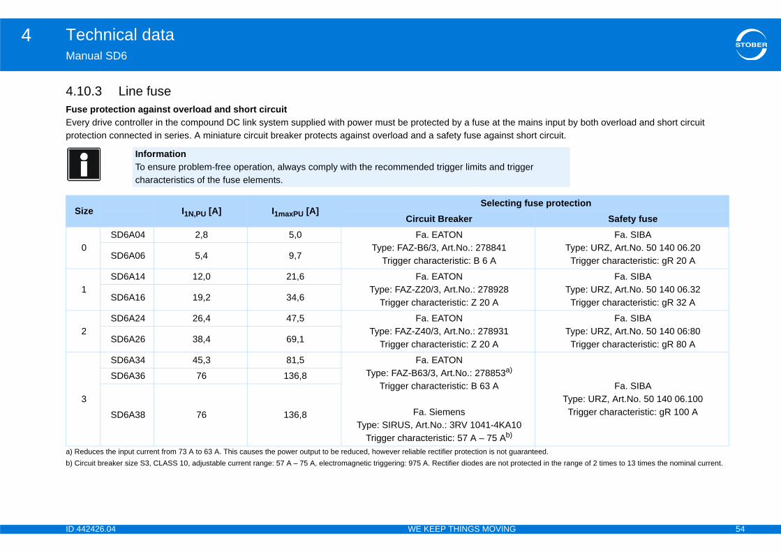
ID 4 54
Technical data4Ma
4.1FusEve mains input by both overload and short circuit pro short circuit.
ger
Sg fuse protection
Safety fuseFa. SIBA
Type: URZ, Art.No. 50 140 06.20Trigger characteristic: gR 20 A
Fa. SIBAType: URZ, Art.No. 50 140 06.32Trigger characteristic: gR 32 A
Fa. SIBAType: URZ, Art.No. 50 140 06:80Trigger characteristic: gR 80 A
0
a) R aranteed.b) C otected in the range of 2 times to 13 times the nominal current.
Fa. SIBAType: URZ, Art.No. 50 140 06.100Trigger characteristic: gR 100 A
42426.04 WE KEEP THINGS MOVING
nual SD6
0.3 Line fusee protection against overload and short circuitry drive controller in the compound DC link system supplied with power must be protected by a fuse at the
tection connected in series. A miniature circuit breaker protects against overload and a safety fuse against
InformationTo ensure problem-free operation, always comply with the recommended trigger limits and trigcharacteristics of the fuse elements.
ize I1N,PU [A] I1maxPU [A]Selectin
Circuit Breaker
0SD6A04 2,8 5,0 Fa. EATON
Type: FAZ-B6/3, Art.No.: 278841Trigger characteristic: B 6 ASD6A06 5,4 9,7
1SD6A14 12,0 21,6 Fa. EATON
Type: FAZ-Z20/3, Art.No.: 278928Trigger characteristic: Z 20 ASD6A16 19,2 34,6
2SD6A24 26,4 47,5 Fa. EATON
Type: FAZ-Z40/3, Art.No.: 278931Trigger characteristic: Z 20 ASD6A26 38,4 69,1
3
SD6A34 45,3 81,5 Fa. EATON Type: FAZ-B63/3, Art.No.: 278853a)
Trigger characteristic: B 63 A
Fa. SiemensType: SIRUS, Art.No.: 3RV 1041-4KA1
Trigger characteristic: 57 A – 75 Ab)
educes the input current from 73 A to 63 A. This causes the power output to be reduced, however reliable rectifier protection is not guircuit breaker size S3, CLASS 10, adjustable current range: 57 A – 75 A, electromagnetic triggering: 975 A. Rectifier diodes are not pr
SD6A36 76 136,8
SD6A38 76 136,8
ID 4 55
Technical data4Ma
MaMufusconconTo pon
NO
MaTo supturn To evapow
ntactord with power must be connected with the mains
tactor. Make certain to observe the instructions in braking resistor.
sed, the charge resistors of the drive controllers will ring of switching times that will occur.
42426.04 WE KEEP THINGS MOVING
nual SD6
ins fuse – maximum number of drive controllersltiple drive controllers with the power can be connected via a common mains e. The size of the mains fuse as well as the mains input current of the drive trollers that are supplied with power correspond to that of a single drive troller.revent damage to the safety fuse, the number of possible drive controllers
a common mains fuse is limited as follows:• Size 0 Maximum 4 drive controllers,• Size 1 Maximum 2 drive controllers,• Size 2 Maximum 5 drive controllers,• Size 3 Maximum 2 drive controllers.
TICE
terial damage!ensure uniform distribution of the charge current to all the drive controllers plied with AC power, all fuses must be closed when the supply voltage is ed on.
ensure that the input rectifier is not overloaded in case a fuse fails, the luation of phase monitoring of the drive controllers that are supplied with AC er must result in the entire compound DC link system being disabled.
4.10.4 Power coAll drive controllers supplievoltage via a common con7.3.9 X30: Quick DC-Link,
NOTICE
Material damage!Use only one contactor! If multiple contactors are ube damaged by the scatte
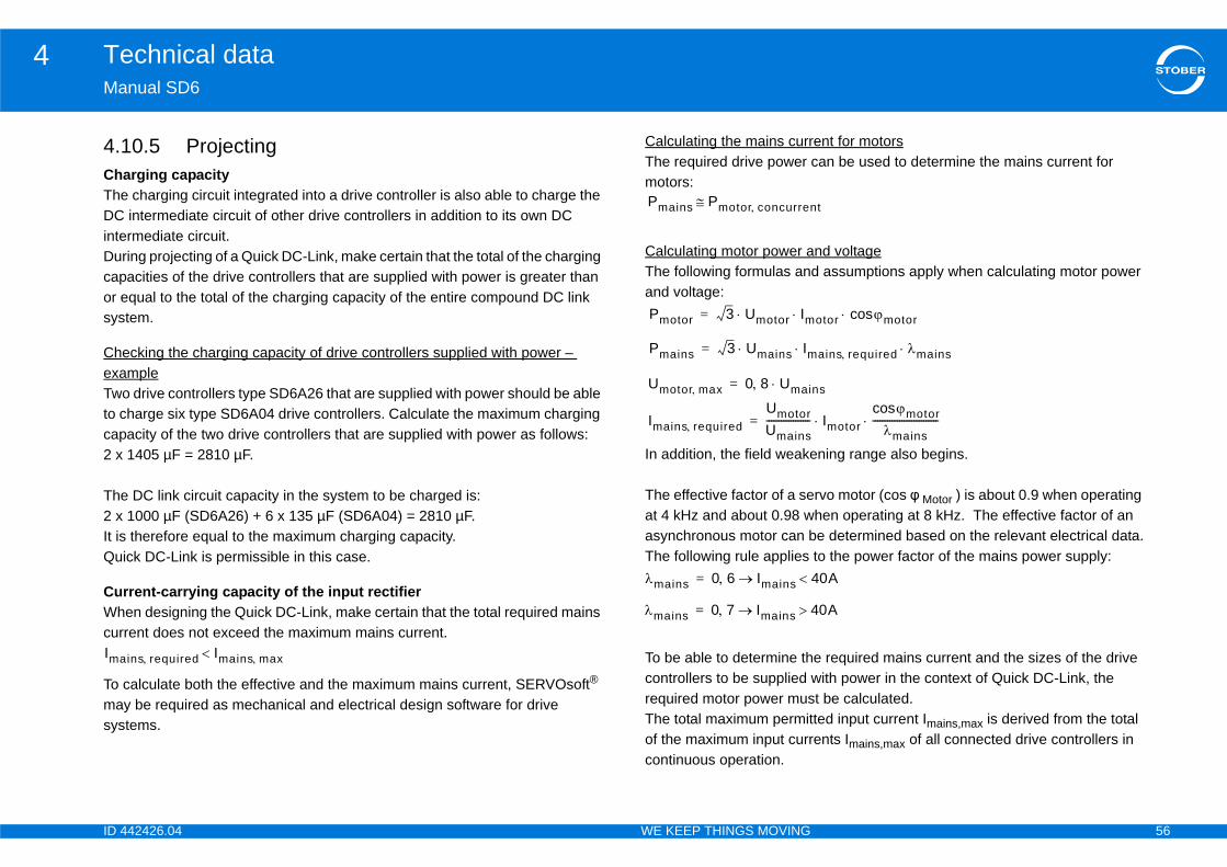
ID 4 56
Technical data4Ma
4.1ChTheDCinteDurcapor esys
CheexaTwoto ccap2 xThe2 xIt isQu
CuWhcur
To masys
ent for motorscan be used to determine the mains current for
nd voltaged assumptions apply when calculating motor power
ning range also begins.
rvo motor (cos φ Motor ) is about 0.9 when operating hen operating at 8 kHz. The effective factor of an e determined based on the relevant electrical data.to the power factor of the mains power supply:
e required mains current and the sizes of the drive with power in the context of Quick DC-Link, the t be calculated. ted input current Imains,max is derived from the total ents Imains,max of all connected drive controllers in
Ima
t
otor motorcos
ains required mains
ns
Imotormotorcos
mains---------------------------
40A
0A
42426.04 WE KEEP THINGS MOVING
nual SD6
0.5 Projectingarging capacity charging circuit integrated into a drive controller is also able to charge the
intermediate circuit of other drive controllers in addition to its own DC rmediate circuit. ing projecting of a Quick DC-Link, make certain that the total of the charging acities of the drive controllers that are supplied with power is greater than qual to the total of the charging capacity of the entire compound DC link tem.
cking the charging capacity of drive controllers supplied with power – mple drive controllers type SD6A26 that are supplied with power should be able harge six type SD6A04 drive controllers. Calculate the maximum charging acity of the two drive controllers that are supplied with power as follows: 1405 µF = 2810 µF.
DC link circuit capacity in the system to be charged is: 1000 µF (SD6A26) + 6 x 135 µF (SD6A04) = 2810 µF. therefore equal to the maximum charging capacity. ick DC-Link is permissible in this case.
rrent-carrying capacity of the input rectifieren designing the Quick DC-Link, make certain that the total required mains rent does not exceed the maximum mains current.
calculate both the effective and the maximum mains current, SERVOsoft® y be required as mechanical and electrical design software for drive tems.
Calculating the mains currThe required drive power motors:
Calculating motor power aThe following formulas anand voltage:
In addition, the field weake
The effective factor of a seat 4 kHz and about 0.98 wasynchronous motor can bThe following rule applies
To be able to determine thcontrollers to be supplied required motor power musThe total maximum permitof the maximum input currcontinuous operation.
ins required Imains max
Pmains Pmotor concurren
Pmotor 3 Umotor Im =
Pmains 3 Umains Im =
Umotor max 0 8 Umai=
Imains requiredUmotorUmains------------------=
mains 0 6 Imains =
mains 0 7 Imains 4=

ID 4 57
Technical data4Ma
DynranThecon•
•
To havequ
Cu"DCothclamThe
MinThecircswiwiriresam
circuit capacity in the system being charged, the o mains power-on processes can be determined by acity of the drive controllers connected to the mains
are worst-case values for a regularly recurring e of the DC link circuit capacity. or a single instance of repeated power-on, or if the emain entirely or partially charged.
ollers are connected and two of them are connected can be calculated according to the formula s:
n two mains power-on processes is three minutes
Factor KMinimum time between
two mains power-on processes [min]
≤ 0.5 1≥ 0.5 2≤ 0.427 1
0.428 – 0.570 20.571 – 0.712 30.713 – 0.854 4
> 0.854 50.5
42426.04 WE KEEP THINGS MOVING
nual SD6
amic movements of the connected motors are possible in the permitted ge, see 4.2.2 Power board. following applies for the total of the input currents of the connected drive troller: If all the drive controllers supplied with power have the same power, the total of maximum mains-side input currents can be calculated using the formulaImains, max = 0.8 · n supply · Imains, individual device
If all drive controllers supplied with power do not have the same power, the total of the input current can be calculated by multiplying the input current of the smallest drive controller supplied with power by the number of all drive controllers supplied with power:Imains,max = 0.9 · n supply · Imains, individual device, min
prevent current asymmetries, all drive controllers supplied with power that e different power must have the same fuse protection, which must also be ivalent to the drive controller with the lowest power.
rrent-carrying capacity of the copper wires rails" connect the DC link capacitors of the drive controllers with each
er. These are copper rails that are mounted with corresponding holding ps and must have a cross-sectional dimension of 5 x 12 mm.
maximum permitted current-carrying capacity of the copper rails is 200 A.
imum time between two mains power-on processes drive controllers have temperature-dependent resistors in the charging uit to prevent the devices from being destroyed when the mains current is tched after an error – such as a short-circuited DC intermediate circuit, ng error, etc. When the DC intermediate circuit is being charged, the istors heat up. To prevent an overload, it is essential to maintain a minimum ount of time between two power-on processes.
Depending on the DC linkminimum time between twthe maximum charging cap(K factor).
The times specified belowpower-on with full dischargThese times are reduced fDC link circuit capacities r
Calculation exampleThree SD6A16 drive contrto the mains. The K factorpreviously noted as follow
The minimum time betwee(see table).
AC-supplied drive controllers
Size 0
Sizes 1, 2
Size 3
1680F2810F--------------------- 0 598==

ID 4 58
Technical data4Ma
4.In adiffWhSD
4.1Pro
Thestrades
Co
controller assignment
TyIDRe
Po
Th
Pu
Um
W
Pr
Te
CoRi
Fle
ZMU 400x65 FZZMU 400x650 55445 53895 55447
— — —
— — —
— — —
— X —
— X —
X (X) X
X (X) X
(X) — (X)
(X) — (X)
(X) — (X)
42426.04 WE KEEP THINGS MOVING
nual SD6
11 Braking Resistorsddition to the different drive controllers, STOBER offers braking resistors in
erent sizes and performance classes described in the following. en selecting, note the minimum permitted braking resistors of the individual 6 types (see 4.2.2, page 30).
1.1 FZMU, FZZMUperties
internal connections are wired with heat-resistant, silicon-insulated nds of wire on terminals. Also ensure a heat-resistant and stress-resistance ign for the connection!
nductor cross-section
Braking resistor – drive
Not possible: —Recommended: XPossible: (X)
pe FZMU 400x65 FZZMU 400x65 no. 49010 55445 53895 55447sistance [Ω] 100 22 47 22
wer [W] 600 1200
erm. time const. τth [s] 40 40
lse power for < 1 s [kW] 18 36
ax [V] 848 848
eight [kg] approx. 2.2 approx. 4.2
otection class IP20 IP20
st marks
nnection type Conductor cross-section [mm2]gid 0.5 – 4.0
xible with cable end sleeve 0.5 – 2.5
Type FID no. 4901SD6A02 X
SD6A04 X
SD6A06 X
SD6A14 (X)
SD6A16 (X)
SD6A24 —
SD6A26 —
SD6A34 —
SD6A36 —
SD6A38 —
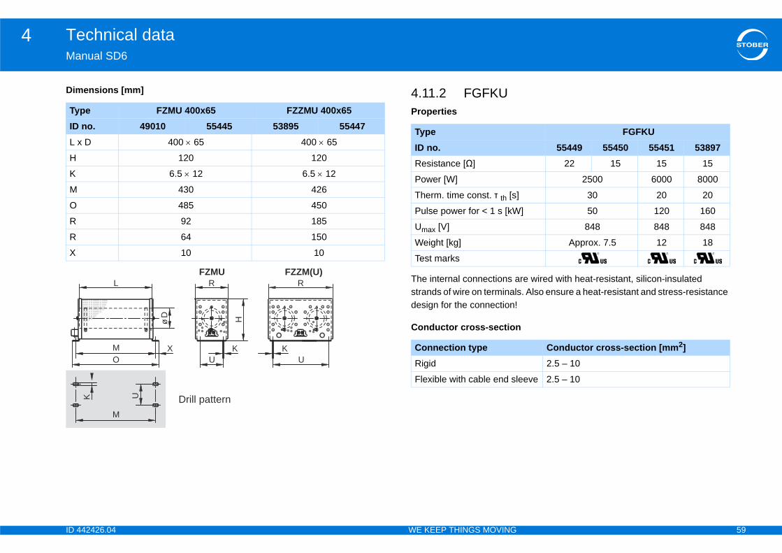
ID 4 59
Technical data4Ma
Dim
re wired with heat-resistant, silicon-insulated . Also ensure a heat-resistant and stress-resistance
TyIDL x
H
K
M
O
R
R
X
FGFKU55449 55450 55451 53897
22 15 15 15
2500 6000 8000
30 20 20
] 50 120 160
848 848 848
Approx. 7.5 12 18
Conductor cross-section [mm2]2.5 – 10
eeve 2.5 – 10
42426.04 WE KEEP THINGS MOVING
nual SD6
ensions [mm] 4.11.2 FGFKUProperties
The internal connections astrands of wire on terminalsdesign for the connection!
Conductor cross-section
pe FZMU 400x65 FZZMU 400x65 no. 49010 55445 53895 55447 D 400 65 400 65
120 120
6.5 12 6.5 12
430 426
485 450
92 185
64 150
10 10
R RFZMU FZZM(U)
L
U UOK KM
K U
M
X
HøD
Drill pattern
TypeID no.Resistance [Ω]
Power [W]
Therm. time const. τ th [s]
Pulse power for < 1 s [kW
Umax [V]
Weight [kg]
Test marks
Connection typeRigid
Flexible with cable end sl

ID 4 60
Technical data4Ma
Bra
NotRecPos
Dim
TyIDSD
SD
SD
SD
SD
TyID
A
B
C
C
A
B
Ø10,5
260
A
10,5
380l pattern
42426.04 WE KEEP THINGS MOVING
nual SD6
king resistor – drive controller assignment
possible: —ommended: Xsible: (X)
ensions [mm]
pe FGFKU no. 55449 55450 55451 538976A24 X — — —
6A26 X — — —
6A34 (X) X X X
6A36 (X) X X X
6A38 (X) X X X
pe FGFKU no. 55449
5545055451 53897
270 370 570
295 395 595
355 455 655
490
380
Dril
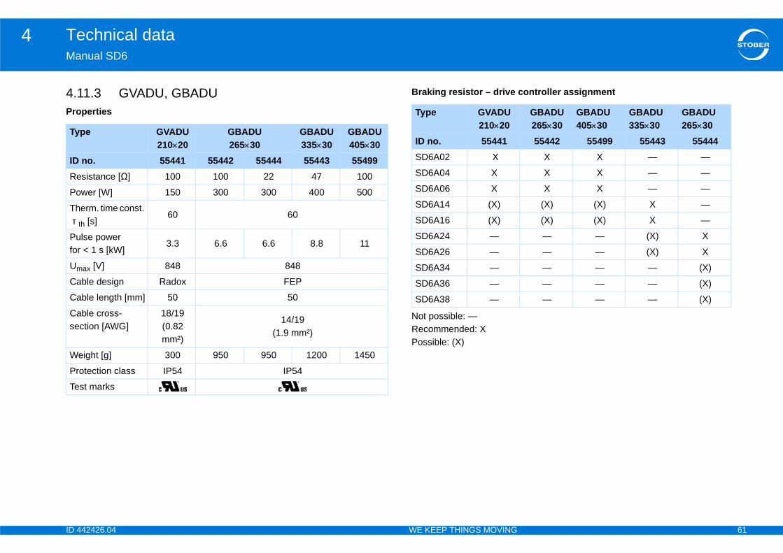
ID 4 61
Technical data4Ma
4.1Pro
controller assignment
Ty
IDRe
Po
Th τ
Pufor
Um
Ca
Ca
Case
W
Pr
Te
GBADU 26530
GBADU 40530
GBADU 33530
GBADU 26530
55442 55499 55443 55444X X — —
X X — —
X X — —
(X) (X) X —
(X) (X) X —
— — (X) X
— — (X) X
— — — (X)
— — — (X)
— — — (X)
42426.04 WE KEEP THINGS MOVING
nual SD6
1.3 GVADU, GBADUperties
Braking resistor – drive
Not possible: —Recommended: XPossible: (X)
pe GVADU 21020
GBADU 26530
GBADU 33530
GBADU 40530
no. 55441 55442 55444 55443 55499sistance [Ω] 100 100 22 47 100
wer [W] 150 300 300 400 500
erm. time const. th [s]
60 60
lse power < 1 s [kW]
3.3 6.6 6.6 8.8 11
ax [V] 848 848
ble design Radox FEP
ble length [mm] 50 50
ble cross-ction [AWG]
18/19 (0.82 mm²)
14/19(1.9 mm²)
eight [g] 300 950 950 1200 1450
otection class IP54 IP54
st marks
Type GVADU 21020
ID no. 55441SD6A02 X
SD6A04 X
SD6A06 X
SD6A14 (X)
SD6A16 (X)
SD6A24 —
SD6A26 —
SD6A34 —
SD6A36 —
SD6A38 —

ID 4 62
Technical data4Ma
Dim ake resistor RB 5000 Ty
IDA
H
C
D
E
F
G
K
J
RB 5022 RB 5047 RB 510045618 44966 44965
22 47 100
100 60 60
8
] 1.5 1.0 1.0
800
Approx. 640 Approx. 460 Approx. 440
Radox
250
] 18/19 (0.82 mm²)
s 5
IP40
42426.04 WE KEEP THINGS MOVING
nual SD6
ensions [mm] 4.11.4 Bottom brPropertiespe GVADU
21020GBADU 26530
GBADU 33530
GBADU 40530
no. 55441 55442 55444 55443 55449210 265 335 405
192 246 316 386
20 30 30 30
40 60 60 60
18.2 28.8 28.8 28.8
6.2 10.8 10.8 10.8
2 3 3 3
2.5 4 4 4
4.3 5.3 5.3 5.3
65° 73° 73° 73°
TypeID no.Resistance [Ω]
Power [W]
Therm. time const. τ th [s]
Pulse power for < 1 s [kW
Umax [V]
Weight [g]
Cable design
Cable length [mm]
Cable cross-section [AWG
Maximum torque for stud[Nm]
Protection class
Test marks

ID 4 63
Technical data4Ma
Dri
NotRecPos
Not
Dim
currents on electrical cables and thus increase the availability of drive systems, coils such as network d – corresponding to your application.
uctive metal wire coils that reduce undesired the network (e.g. for commutation of the current ve the DC-Link circuit capacity of the drive
harge current peaks due to the cycle signal and line otor cables possible, increase the motor service life
ents.
Ty
SD
SD
SD
SD
SD
SD
SD
SD
SD
TyIDHe
W
De
Drsiz
42426.04 WE KEEP THINGS MOVING
nual SD6
ve controller – braking resistor assignment
possible: —ommended: Xsible: (X)
e the attachment to the drive controller (section 6.6 Bottom brake resistor)!
ensions [mm]
4.12 ChokesTo reduce high-frequency interference immunity andor output deraters are use
Power chokes involve indharmonics or distortion in flow). In addition, they reliecontroller.
Output deraters reduce ccapacity. They make long mand reduce harmonic curr
pe RB 5022 RB 5047 RB 5100ID no. 45618 ID no. 44966 ID no. 44965
6A04 — — X
6A06 — — X
6A14 — X (X)
6A16 — X (X)
6A24 X — —
6A26 X — —
6A34 — — —
6A36 — — —
6A38 — — —
pe RB 5022 RB 5047 RB 5100 no. 45618 44966 44965ight 300 300
idth 94 62
pth 18 18
illing pattern corresponds to e
2 1 0 and 1
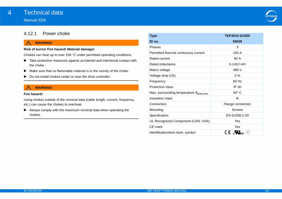
ID 4 64
Technical data4Ma
4.1
RisCho
FireUsietc
TEP4010-2US0056528
3
ous current 100 A
90 A
0.1410 mH
480 V
2 %
60 Hz
IP 00
ature ϑamb,max 40° C
B
Flange connection
Screws
EN 61558-2-20
nt (CAN; USA) Yes
Yes
ymbol , ,
42426.04 WE KEEP THINGS MOVING
nual SD6
2.1 Power choke
WARNING!
k of burns! Fire hazard! Material damage!kes can heat up to over 100 °C under permitted operating conditions.
Take protective measures against accidental and intentional contact with the choke.
Make sure that no flammable material is in the vicinity of the choke.
Do not install chokes under or near the drive controller.
WARNING!
hazard! ng chokes outside of the nominal data (cable length, current, frequency, .) can cause the chokes to overheat.
Always comply with the maximum nominal data when operating the chokes.
TypeID no.Phases
Permitted thermal continu
Rated current
Rated inductance
Mains voltage
Voltage drop (Uk)
Frequency
Protection class
Max. surrounding temper
Insulation class
Connection
Mounting
Specification
UL Recognized Compone
CE mark
Identification/test mark, s

ID 4 65
Technical data4Ma
DiHe
W
De
Vefas
Vefas
Hofas
Hofas
Dr
Dr
Sc
W
42426.04 WE KEEP THINGS MOVING
nual SD6
mensions TEP4010-2US00ight [mm] 235
idth [mm] 219
pth [mm] 118
rtical distance 1 – tening holes [mm]
201
rtical distance 2 – tening holes [mm]
136
rizontal distance 1 – tening holes [mm]
88
rizontal distance 2 – tening holes [mm]
75
ill holes – depth [mm] 7
ill holes – width [mm] 12
rew connection – M M6
eight [kg] 10
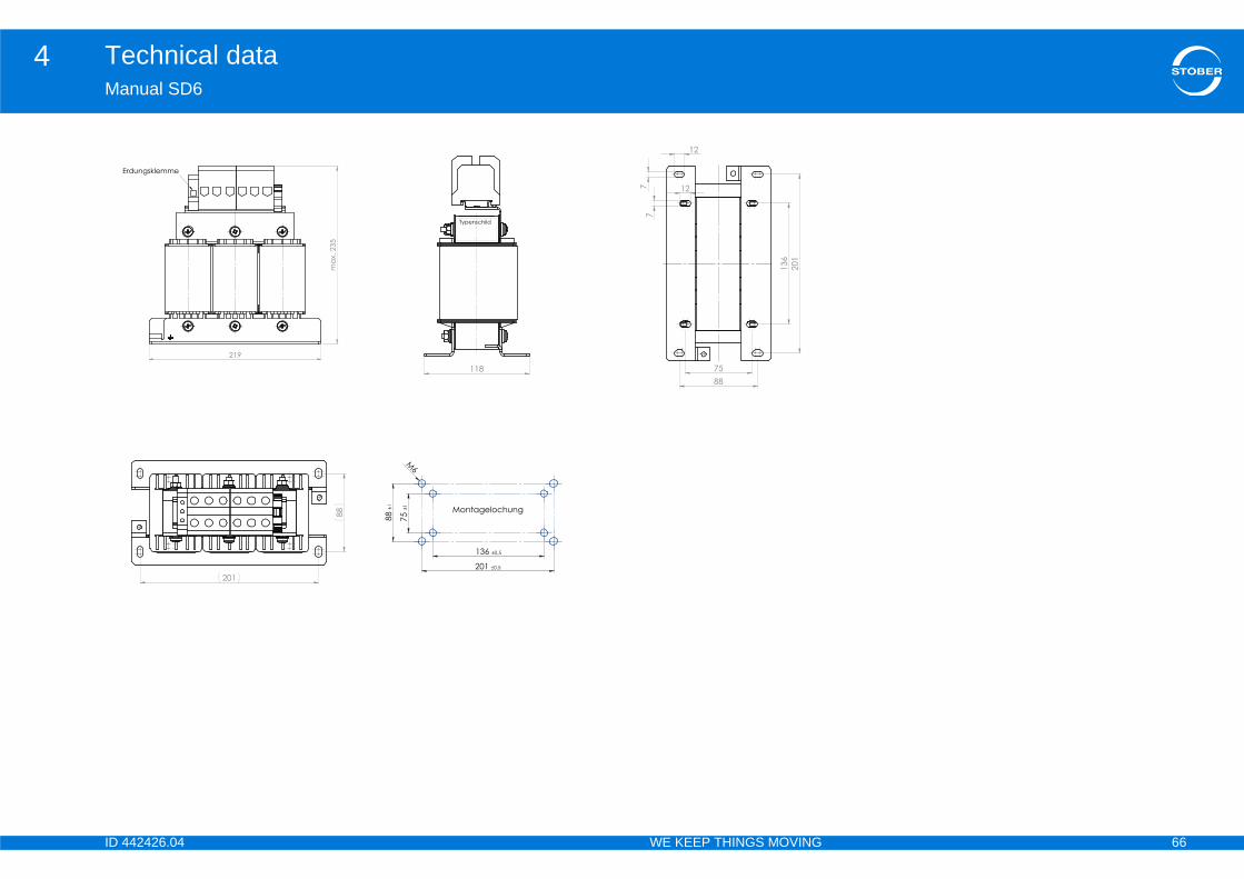
ID 4 66
Technical data4Ma
42426.04 WE KEEP THINGS MOVING
nual SD6

ID 4 67
Technical data4Ma
4.1
RisCho
FireUsietc
NO
DanThecap
chnical data applies for a rotary field frequency of mple, this rotary field frequency is achieved with a le pairs and a nominal speed of 3000 rpm. the specified derating for higher rotary field
e dependency of the cycle frequency.
TEP3720-0ES41
TEP3820-0CS41
TEP4020-0RS41
53188 53189 531903 x 0 to 480 V0 to 200 Hz
4 A 17.5 A 38 A3.3 A 15.2 A 30.4 A
100 m
40 °C
Open11 W 29 W 61 W25 W 16 W 33 W
Screw terminals10 mm2
Yes
42426.04 WE KEEP THINGS MOVING
nual SD6
2.2 Output derater
WARNING!
k of burns! Fire hazard! Material damage!kes can heat up to over 100 °C under permitted operating conditions.
Take protective measures against accidental and intentional contact with the choke.
Make sure that no flammable material is in the vicinity of the choke.
Do not install chokes under or near the drive controller.
WARNING!
hazard! ng chokes outside of the nominal data (cable length, current, frequency, .) can cause the chokes to overheat.
Always comply with the maximum nominal data when operating the chokes.
TICE
ger of machine standstill! motor temperature sensor evaluation is malfunctioning due to cable acities.
If you use cables which are longer than 50 m and the cables are not from STOBER, the cores for the motor temperature sensor and the brake must be separate (maximum length: 100 m).
InformationThe following te200 Hz. For examotor with 4 poAlways observefrequencies. Also observe th
Type
ID no.Voltage rangeFrequency rangeIN at 4 kHz IN at 8 kHz Max. permitted motor cable length with output deraterMax. surrounding temperature ϑ amb,maxDesignWinding lossesIron lossesConnectionsMax. conductor cross-section UL Recognized Component (CAN; USA) Test marks
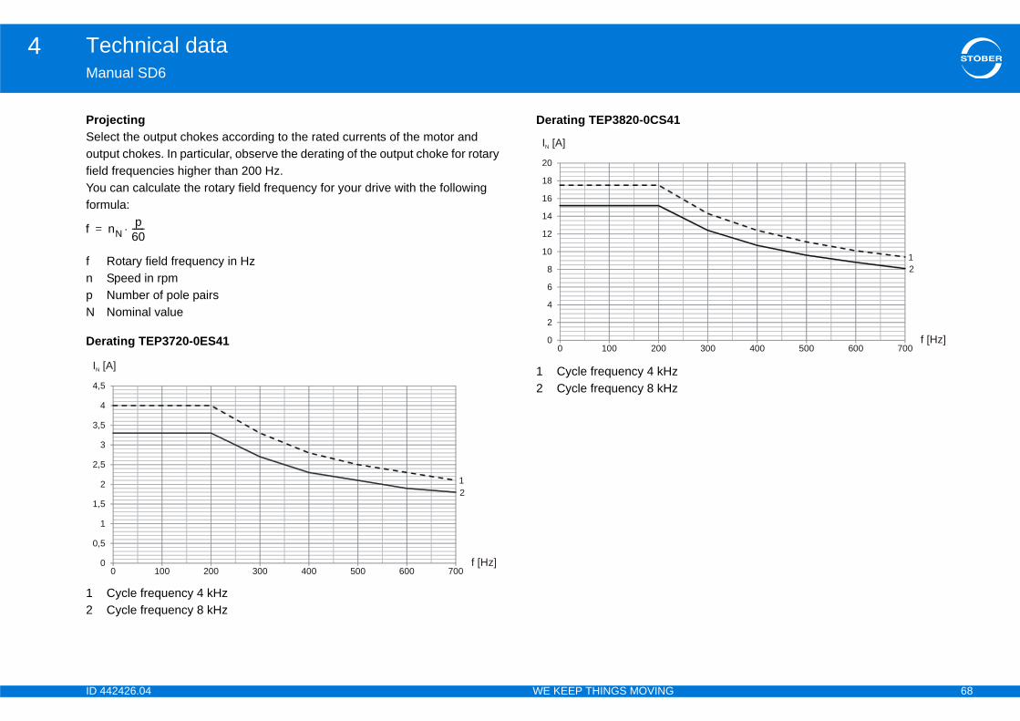
ID 4 68
Technical data4Ma
ProSeloutfieldYouform
fnpN
Der
12
f =
0
0,5
1
1,5
2
2,5
3
3,5
4
4,5
IN 300 400 500 600 700
12
f [Hz]
42426.04 WE KEEP THINGS MOVING
nual SD6
jectingect the output chokes according to the rated currents of the motor and put chokes. In particular, observe the derating of the output choke for rotary frequencies higher than 200 Hz. can calculate the rotary field frequency for your drive with the following ula:
Rotary field frequency in HzSpeed in rpm Number of pole pairs Nominal value
ating TEP3720-0ES41
Cycle frequency 4 kHzCycle frequency 8 kHz
Derating TEP3820-0CS41
1 Cycle frequency 4 kHz2 Cycle frequency 8 kHz
nNp
60------
0 100 200 300 400 500 600 700
12
[A]
f [Hz]
0
2
4
6
8
10
12
14
16
18
20
0 100 200
IN [A]
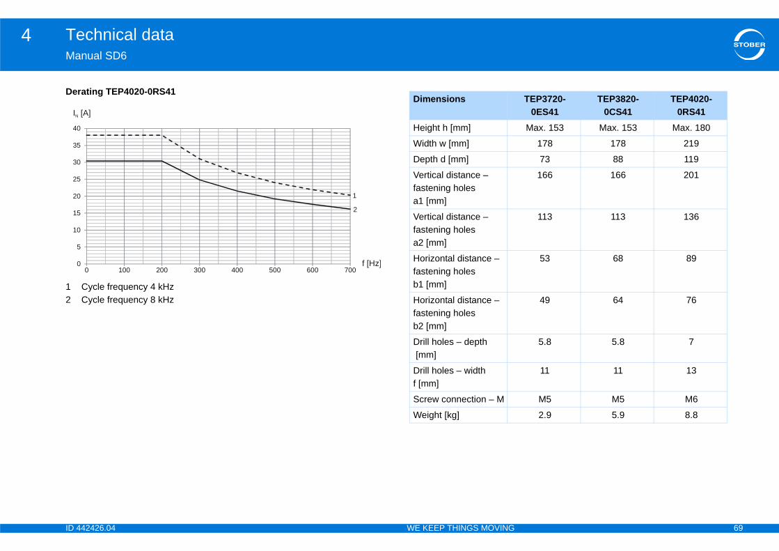
ID 4 69
Technical data4Ma
Der
12
0
5
10
15
20
25
30
35
40
IN
TEP3720-0ES41
TEP3820-0CS41
TEP4020-0RS41
Max. 153 Max. 153 Max. 180
178 178 219
73 88 119
166 166 201
113 113 136
53 68 89
49 64 76
5.8 5.8 7
11 11 13
M5 M5 M6
2.9 5.9 8.8
42426.04 WE KEEP THINGS MOVING
nual SD6
ating TEP4020-0RS41
Cycle frequency 4 kHzCycle frequency 8 kHz
0 100 200 300 400 500 600 700
1
2
[A]
f [Hz]
Dimensions
Height h [mm]
Width w [mm]
Depth d [mm]
Vertical distance – fastening holesa1 [mm]
Vertical distance – fastening holesa2 [mm]
Horizontal distance – fastening holesb1 [mm]
Horizontal distance – fastening holesb2 [mm]
Drill holes – depth [mm]
Drill holes – width f [mm]
Screw connection – M
Weight [kg]
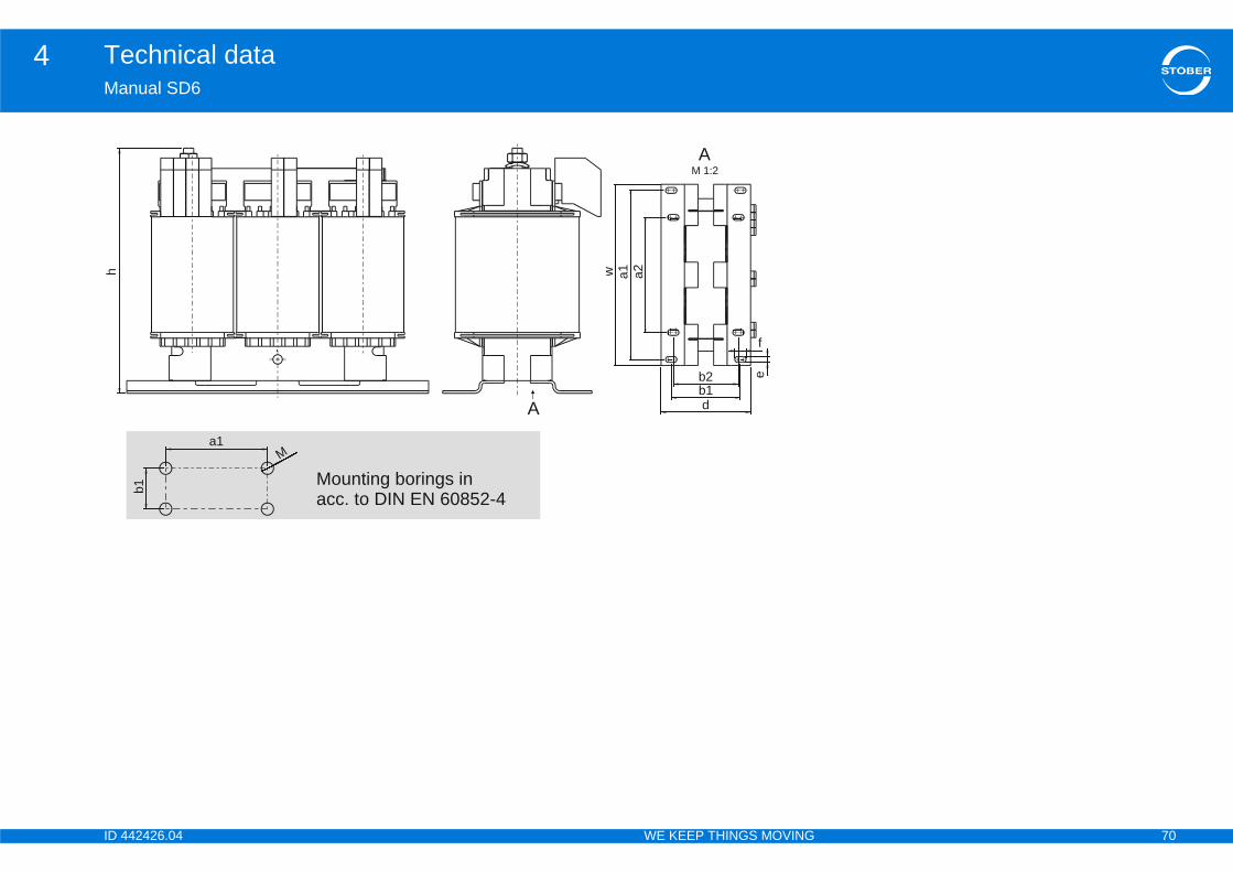
ID 4 70
Technical data4Ma
h
42426.04 WE KEEP THINGS MOVING
nual SD6
a1w
Ab1b2
f
e
d
AM 1:2
a2
a1
b1
M
Mounting borings inacc. to DIN EN 60852-4

ID 4 71
Transportation and storage5Ma
5Ov
5.1
5.2
5.3
42426.04 WE KEEP THINGS MOVING
nual SD6
Transportation and storageerview of sections
Notes on safety .. . . . . . . . . . . . . . . . . . . . . . . . . . . . . . . . . . . . . . .72
Transportation . . . . . . . . . . . . . . . . . . . . . . . . . . . . . . . . . . . . . . . . .72
Storage . . . . . . . . . . . . . . . . . . . . . . . . . . . . . . . . . . . . . . . . . . . . . . .72
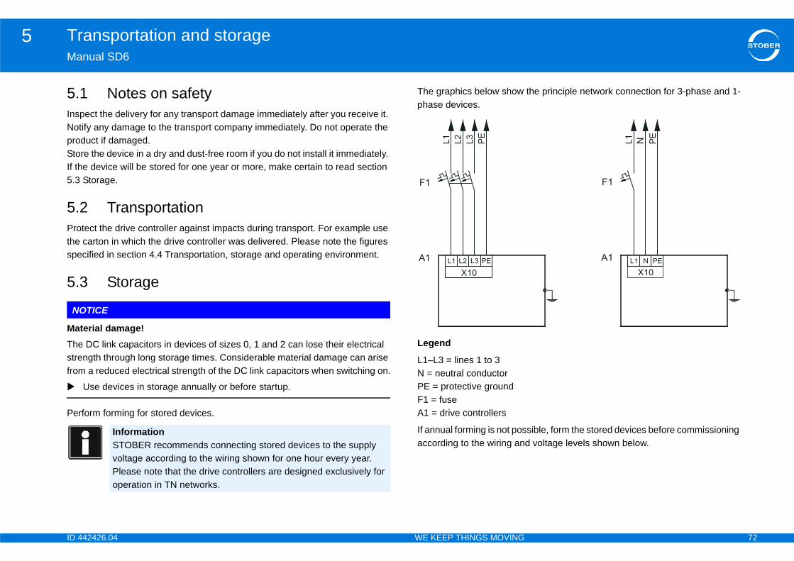
ID 4 72
Transportation and storage5Ma
5.InsNotproStoIf th5.3
5.Prothespe
5.
NO
MaThestrefrom
Per
the principle network connection for 3-phase and 1-
sible, form the stored devices before commissioning d voltage levels shown below.
42426.04 WE KEEP THINGS MOVING
nual SD6
1 Notes on safetypect the delivery for any transport damage immediately after you receive it. ify any damage to the transport company immediately. Do not operate the duct if damaged. re the device in a dry and dust-free room if you do not install it immediately. e device will be stored for one year or more, make certain to read section Storage.
2 Transportationtect the drive controller against impacts during transport. For example use carton in which the drive controller was delivered. Please note the figures cified in section 4.4 Transportation, storage and operating environment.
3 Storage
TICE
terial damage! DC link capacitors in devices of sizes 0, 1 and 2 can lose their electrical ngth through long storage times. Considerable material damage can arise a reduced electrical strength of the DC link capacitors when switching on.
Use devices in storage annually or before startup.
form forming for stored devices.
The graphics below show phase devices.
Legend
L1–L3 = lines 1 to 3N = neutral conductorPE = protective groundF1 = fuseA1 = drive controllers
If annual forming is not posaccording to the wiring an
InformationSTOBER recommends connecting stored devices to the supply voltage according to the wiring shown for one hour every year. Please note that the drive controllers are designed exclusively for operation in TN networks.
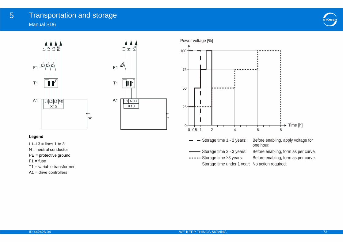
ID 4 73
Transportation and storage5Ma
Leg
L1–N =PEF1 T1 A1
F
A
T
4 6 8Time [h]
- 2 years: Before enabling, apply voltage forone hour.
- 3 years: Before enabling, form as per curve. 3 years: Before enabling, form as per curve.nder 1 year: No action required.
42426.04 WE KEEP THINGS MOVING
nual SD6
end
L3 = lines 1 to 3 neutral conductor = protective ground= fuse= variable transformer= drive controllers
X10
L1
L2
1
L3
PE
L1 L2 L3 PE1
X10
L1
F1
PE
L1 N PEA1
N
1 T1
10.500
25
50
75
100
2
Power voltage [%]
Storage time 1
Storage time 2Storage time Storage time u
ID 4 74
Installation6Ma
6Ov
6.1
6.2
6.3
6.4
6.5
6.6
6.7
6.8
42426.04 WE KEEP THINGS MOVING
nual SD6
Installationerview of sections
Notes on safety .. . . . . . . . . . . . . . . . . . . . . . . . . . . . . . . . . . . . . . .75
Drive controller . . . . . . . . . . . . . . . . . . . . . . . . . . . . . . . . . . . . . . . .75
Terminal modules .. . . . . . . . . . . . . . . . . . . . . . . . . . . . . . . . . . . . .77
Communication modules . . . . . . . . . . . . . . . . . . . . . . . . . . . . . . .78
Quick DC-Link .. . . . . . . . . . . . . . . . . . . . . . . . . . . . . . . . . . . . . . . .79
Bottom brake resistor . . . . . . . . . . . . . . . . . . . . . . . . . . . . . . . . . .81
EMC shroud .. . . . . . . . . . . . . . . . . . . . . . . . . . . . . . . . . . . . . . . . . .83
Encoder adapter box .. . . . . . . . . . . . . . . . . . . . . . . . . . . . . . . . . .84
6.8.1 Top-hat rail fastening . . . . . . . . . . . . . . . . . . . . . . . . . . . . . . . . . 84
6.8.2 Screw fastening . . . . . . . . . . . . . . . . . . . . . . . . . . . . . . . . . . . . . 84
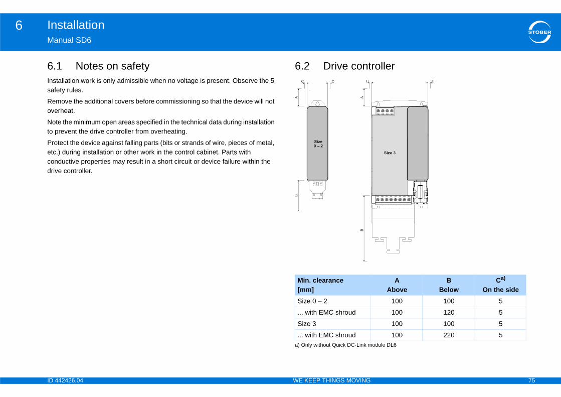
ID 4 75
Installation6Ma
6.Inssaf
Remove
Notto p
Proetccondriv
roller
A Above
B Below
Ca) On the side
odule DL6
100 100 5
100 120 5
100 100 5
100 220 5
42426.04 WE KEEP THINGS MOVING
nual SD6
1 Notes on safetytallation work is only admissible when no voltage is present. Observe the 5 ety rules.
ove the additional covers before commissioning so that the device will not rheat.
e the minimum open areas specified in the technical data during installation revent the drive controller from overheating.
tect the device against falling parts (bits or strands of wire, pieces of metal, .) during installation or other work in the control cabinet. Parts with ductive properties may result in a short circuit or device failure within the e controller.
6.2 Drive cont
Min. clearance[mm]
a) Only without Quick DC-Link m
Size 0 – 2
... with EMC shroud
Size 3
... with EMC shroud
ID 4 76
Installation6Ma
TheQuQu
Req•
•
•
•••
•
•
You••
tion
a terminal module and a communication module inal modules). plate according to the separately enclosed drilling
ller on the mounting plate. Make certain chips and e mounting plate.
ground (see section 4.6.3 Housing ground).troller, terminal module and communication module ct plan.
42426.04 WE KEEP THINGS MOVING
nual SD6
clearance dimensions noted here apply only to installation without a DL6 ick DC-Link module. If you would like to operate drive controllers as part of ick DC-Link, see the applicable dimensions 6.5 Quick DC-Link.
uirements:Prevent condensation, for example with anti-condensation heating elements.Note that drive controllers in storage must be used annually or no later than before commissioning.For reasons related to EMC, use mounting plates with a conductive surface (unpainted, etc.).Fasten the devices onto the mounting plate with M5 screws.Attach the devices vertically.Avoid installation above or in the immediate vicinity of heat-generating devices such as output deraters or braking resistors.To ensure there is sufficient air circulation in the control cabinet, observe the minimum clearances.A contact plan of the system in which the connection of the drive controller is described must be present.
need:a tool to drill the tapped holes in the mounting plate.a tool to tighten the fastening screws.
Drive controller installa
1. If present, install both(see section 6.3 Term
2. Prepare the mountingdiagram.
3. Install the drive controoil are cleaned from th
4. Connect the housing 5. Connect the drive con
according to the conta

ID 4 77
Installation6Ma
6.
Dan
Danoth
AnaXI6You••
tion
on the front cover lightly to unlock it.own as far as it will go.ards the front.
dule so that the recesses on the module and the isms on the drive controller can be guided past one e plug-in card must be resting against the drive
dule up so that the pin contacts are pushed into the .odule onto the drive controller with the fastening
42426.04 WE KEEP THINGS MOVING
nual SD6
3 Terminal modules
WARNING!
ger of personal injury and material damage due to electric shock!Always switch off all power supply voltage before working on the drive controller! Note that the discharge time of the DC link capacitors is 5 minutes. You can only determine the absence of voltage after this time period.
CAUTION!
ger of property damage due to electrostatic discharge, among ers!Provide suitable protective measures while handling open PCBs (e.g., ESD clothing, environment free of dirt and grease).
Do not touch the contact surfaces.
log and binary signals can only be connected via one of terminal modules , RI6 or IO6. Installation is identical for all terminal modules. need:A Torx screwdriver TX10.The accessory enclosed with the terminal module.
Terminal module installa
1. Press the spring lock 2. Push the front cover d3. Remove the cover tow4. Insert the terminal mo
holding down mechananother. The rear of thcontroller.
5. Push the terminal mofemale connector strip
6. Fasten the terminal mscrew.
ID 4 78
Installation6Ma
6.
Dan
Danoth
Dan
Dan
A6 communication module to connect EtherCAT or on the upper slot, the same as CA6. The installation nication modules.
10.ncluded with the communication module.
unication module
screw for the dummy cover on the top of the drive
ion module into the drive controller on the guide
that the pin contacts are pushed into the female
over included with the communication module into at an angle. the drive controller so that the tips are resting under
the two screws.
42426.04 WE KEEP THINGS MOVING
nual SD6
4 Communication modules
WARNING!
ger of personal injury and material damage due to electric shock!Always switch off all power supply voltage before working on the drive controller! Note that the discharge time of the DC link capacitors is 5 minutes. You can only determine the absence of voltage after this time period.
CAUTION!
ger of property damage due to electrostatic discharge, among ers!Provide suitable protective measures while handling open PCBs (e.g., ESD clothing, environment free of dirt and grease).Do not touch the contact surfaces.
WARNING!
ger of personal injury and material damage due to electric shock!Always switch off all power supply voltage before working on the drive controller! Note that the discharge time of the DC link capacitors is up to 5 minutes. You can only determine the absence of voltage after this time period.
CAUTION!
ger of material damage due for example to electrostatic discharge!Take suitable protective measures when handling open printed circuit boards, for example clothing appropriate for ESD and an environment free of dirt and grease.Do not touch the contact surfaces.
You will need the EC6 or CCANopen. EC6 is installedis identical for both commu
You need:• A Torx screwdriver TX• The cover and screw i
Installation of the comm
1. Loosen the fastening controller.
2. Push the communicatrails.
3. Push the module in soconnector strip.
4. Insert the tips of the cthe recess in the front
5. Set the cover down onthe edge.
6. Fasten the cover with
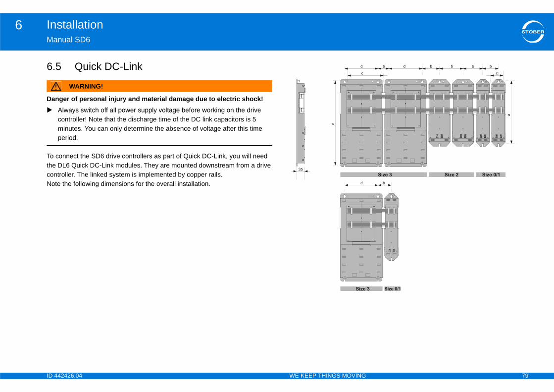
ID 4 79
Installation6Ma
6.
Dan
To theconNot
42426.04 WE KEEP THINGS MOVING
nual SD6
5 Quick DC-Link
WARNING!
ger of personal injury and material damage due to electric shock!Always switch off all power supply voltage before working on the drive controller! Note that the discharge time of the DC link capacitors is 5 minutes. You can only determine the absence of voltage after this time period.
connect the SD6 drive controllers as part of Quick DC-Link, you will need DL6 Quick DC-Link modules. They are mounted downstream from a drive troller. The linked system is implemented by copper rails.e the following dimensions for the overall installation.
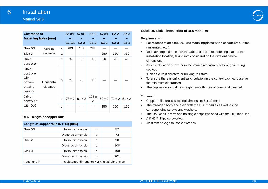
ID 4 80
Installation6Ma
DL
tion of DL6 modules
EMC, use mounting plates with a conductive surface
for threaded bolts on the mounting plate at the king into consideration the different device
e or in the immediate vicinity of heat-generating
s or braking resistors.icient air circulation in the control cabinet, observe es.be straight, smooth, free of burrs and cleaned.
ctional dimension: 5 x 12 mm).closed with the DL6 modules as well as the and washers.nd holding clamps enclosed with the DL6 modules.
river.cket wrench.
Clfas
Siz
Siz
Drco
Drcowibobrares
Drcowi
LeSiz
Siz
Siz
To
42426.04 WE KEEP THINGS MOVING
nual SD6
6 – length of copper rails
Quick DC-Link – installa
Requirements:• For reasons related to
(unpainted, etc.).• You have tapped holes
installation location, tadimensions.
• Avoid installation abovdevices such as output derater
• To ensure there is suffthe minimum clearanc
• The copper rails must
You need:• Copper rails (cross-se• The threaded bolts en
corresponding screws• The insulation inserts a• A PH2 Phillips screwd• An 8 mm hexagonal so
earance of tening holes [mm]
SZ 0/1 –
SZ 0/1
SZ 0/1 –
SZ 2
SZ 2 –
SZ 2
SZ0/1 –
SZ 3
SZ 2 –
SZ 3
SZ 3 –
SZ 3e 0/1 Vertical
distancea 283 283 283 — — —
e 3 a — — — 380 380 380
ive ntroller
Horizontal distance
b 75 93 110 56 73 45
ive ntroller th ttom king istor
b 75 93 110 — — —
ive ntroller th DL6
b 73 ± 2 91 ± 2108 ±
262 ± 2 79 ± 2 51 ± 2
d — — — 150 150 150
ngth of copper rails (5 x 12) [mm]e 0/1 Initial dimension c 57
Distance dimension b 73
e 2 Initial dimension c 90
Distance dimension b 108
e 3 Initial dimension c 198
Distance dimension b 201
tal length n x distance dimension + 2 x initial dimension
ID 4 81
Installation6Ma
ke resistor
y and material damage due to electric shock!ower supply voltage before working on the drive e discharge time of the DC link capacitors is 5 determine the absence of voltage after this time
for threaded bolts on the mounting plate in the nstallation location, taking into consideration the sions. The threaded bolts are included with the esistor.
luded with the submounting brake resistor.rs included with the submounting brake resistor.
river.cket wrench.
Ins
1.2.3.4.
5.6.
7.
8.9.10
11
12
42426.04 WE KEEP THINGS MOVING
nual SD6
6.6 Bottom bra
WARNING!
Danger of personal injur Always switch off all p
controller! Note that thminutes. You can onlyperiod.
Requirements:• You have tapped holes
control cabinet at the idifferent device dimensubmounting braking r
You need:• The threaded bolts inc• The screws and washe• A PH2 Phillips screwd• An 8 mm hexagonal so
tallation of DL6 modules
Fasten the DL6 modules onto the mounting plate with the threaded bolts.Insert the insulation inserts between the modules and on both ends.Clean the copper rails, especially on the contact points.Insert the two copper rails one after the other and fasten them in place with two holding clamps per module. Make certain the contact points of the copper rails do not become contaminated.Pull the X30 clamps off the relevant drive controllers.Connect the brown cables D+ to X30 terminals D+ and the black cables D- to X30 terminals D-.Size 3: Mount the EM6A3 EMC shrouds as described in section 6.7 EMC shroud.Place the drive controllers on the respective guides.Press the drive controllers down on the respective guides.
. Sizes 0 – 2: Mount the EM6A0 EMC shrouds as described in section 6.7 EMC shroud.
. Attach each drive controller to the corresponding threaded bolt with the enclosed screws and washers.
. Fasten the X30 terminals to the bottoms of the corresponding drive controllers.
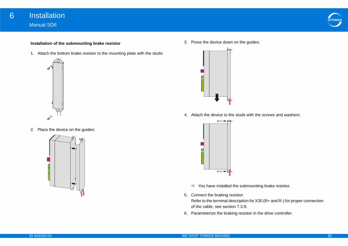
ID 4 82
Installation6Ma
Ins
1.
2.
n on the guides:
e studs with the screws and washers:
the submounting brake resistor.
esistor.escription for X30 (R+ and R-) for proper connection ion 7.3.9.ing resistor in the drive controller.
42426.04 WE KEEP THINGS MOVING
nual SD6
tallation of the submounting brake resistor
Attach the bottom brake resistor to the mounting plate with the studs:
Place the device on the guides:
3. Press the device dow
4. Attach the device to th
You have installed
5. Connect the braking rRefer to the terminal dof the cable, see sect
6. Parameterize the brak
ID 4 83
Installation6Ma
6.
Dan
YoucabAtta0 to
Pre•
You••
ud EM6A0 to a drive controller size 0, 1 or 2
ing screw and washers of the drive controller.the openings on the bottom of the drive controller at
shroud either directly on the mounting plate or on .he drive controller and mounting plate or studs with nd washers.
ud EM6A3 to a drive controller size 3
o the bottom of the drive controller with the enclosed e tapped holes provided for that purpose (max. Nm).
42426.04 WE KEEP THINGS MOVING
nual SD6
7 EMC shroud
WARNING!
ger of personal injury and material damage due to electric shock!Always switch off all power supply voltage before working on the drive controller! Note that the discharge time of the DC link capacitors is 5 minutes. You can only determine the absence of voltage after this time period.
can use the EM6 EMC shroud to connect the cable shield of the power le. Different designs are available for sizes 0 to 2 and also for size 3. chment of this accessory part accordingly differs on drive controllers sizes 2 compared to attachment on drive controllers size 3.
conditions:Sizes 0 – 2: You have already installed the drive controller in the control cabinet, if necessary in combination with a Quick DC-Link or a bottom brake resistor.
need:A PH2 Phillips screwdriver. Size 3: The two enclosed screws and washers (combination screws with toothed lock washer, M4x8).
Attaching the EMC shro
1. Undo the lower fasten2. Insert the shroud into
a slight angle.3. Press the back of the
the stud in the bottom4. Attach the shroud to t
the fastening screw a
Attaching the EMC shro
1. Fasten the shroud ontfastening screws in thtightening torque: 2.4

ID 4 84
Installation6Ma
6.
Dan
TheThe
The
il fastening
m wide and symmetrical top-hat rail according to
tening
10 for loosening the installation aid.cluded with delivery).
x on a top-hat rail
e installation aid on the back of the adapter box on
up and back until you hear the clamping
dapter box
n aid on the back of the adapter box before oosen the two screws.x onto the mounting plate with the M5 screws.
42426.04 WE KEEP THINGS MOVING
nual SD6
8 Encoder adapter box
WARNING!
ger of personal injury and material damage due to electric shock!Always switch off all power supply voltage before working on the drive controller! Note that the discharge time of the DC link capacitors is 5 minutes. You can only determine the absence of voltage after this time period.
adapter box LA6 should be directly mounted next to the drive controller. following dimensions apply for installation:
permissible installation possibilities are described in the following sections.
6.8.1 Top-hat raPreconditions:• Already mounted, 35 m
EN 50022 (TS 35)
6.8.2 Screw fasYou need:• A Torx screwdriver TX• Two M5 screws (not in
Mounting an adapter bo
1. Place the spring of ththe top-hat rail.
2. Press the adapter boxmechanism engage.
Direct mounting of the a
1. Remove the installatioassembly. To do this l
2. Fasten the adapter bo

ID 4 85
Connection7Ma
7Ov
7.1
7.2
7.3
chnology . . . . . . . . . . . . . . . . . . . . . . . . . . . . . . . 98
. . . . . . . . . . . . . . . . . . . . . . . . . . . . . . . . . . . . . . 99
holding brake . . . . . . . . . . . . . . . . . . . . . . . . . . 101
perature sensor . . . . . . . . . . . . . . . . . . . . . . . . . 102
-Link, braking resistor .. . . . . . . . . . . . . . . . . . . 103
, IGB . . . . . . . . . . . . . . . . . . . . . . . . . . . . . . . . 104
. . . . . . . . . . . . . . . . . . . . . . . . . . . . . . . . . . . . . . 104
. . . . . . . . . . . . . . . . . . . . . . . . . . . . . . . . . . . . .107
. . . . . . . . . . . . . . . . . . . . . . . . . . . . . . . . . . . . . 108
. . . . . . . . . . . . . . . . . . . . . . . . . . . . . . . . . . . . . 109
. . . . . . . . . . . . . . . . . . . . . . . . . . . . . . . . . . . . . 112
. . . . . . . . . . . . . . . . . . . . . . . . . . . . . . . . . . . . . 112
. . . . . . . . . . . . . . . . . . . . . . . . . . . . . . . . . . . . . 113
. . . . . . . . . . . . . . . . . . . . . . . . . . . . . . . . . . . . . 114
. . . . . . . . . . . . . . . . . . . . . . . . . . . . . . . . . . . . . 115
. . . . . . . . . . . . . . . . . . . . . . . . . . . . . . . . . . . . . 117
odules . . . . . . . . . . . . . . . . . . . . . . . . . . . . . .122
therCAT . . . . . . . . . . . . . . . . . . . . . . . . . . . . . . 122
n .. . . . . . . . . . . . . . . . . . . . . . . . . . . . . . . . . . . 122
box . . . . . . . . . . . . . . . . . . . . . . . . . . . . . . . . . .123
42426.04 WE KEEP THINGS MOVING
nual SD6
Connectionerview of sections
Notes on safety .. . . . . . . . . . . . . . . . . . . . . . . . . . . . . . . . . . . . . . .87
General information .. . . . . . . . . . . . . . . . . . . . . . . . . . . . . . . . . . .87
7.2.1 Wiring . . . . . . . . . . . . . . . . . . . . . . . . . . . . . . . . . . . . . . . . . . . . 87
7.2.2 Protective measures . . . . . . . . . . . . . . . . . . . . . . . . . . . . . . . . . 87
7.2.2.1 Line fuse .. . . . . . . . . . . . . . . . . . . . . . . . . . . . . . . . . . 88
7.2.2.2 Residual current safety device . . . . . . . . . . . . . . . . . . 89
7.2.2.3 Housing ground . . . . . . . . . . . . . . . . . . . . . . . . . . . . . 90
7.2.3 EMC connection . . . . . . . . . . . . . . . . . . . . . . . . . . . . . . . . . . . . 90
7.2.4 Selecting the cables . . . . . . . . . . . . . . . . . . . . . . . . . . . . . . . . . 91
Drive controller . . . . . . . . . . . . . . . . . . . . . . . . . . . . . . . . . . . . . . . .91
7.3.1 Overview of terminals . . . . . . . . . . . . . . . . . . . . . . . . . . . . . . . . 91
7.3.1.1 Size 0 . . . . . . . . . . . . . . . . . . . . . . . . . . . . . . . . . . . . . 92
7.3.1.2 Size 1 . . . . . . . . . . . . . . . . . . . . . . . . . . . . . . . . . . . . . 93
7.3.1.3 Size 2 . . . . . . . . . . . . . . . . . . . . . . . . . . . . . . . . . . . . . 94
7.3.1.4 Size 3 . . . . . . . . . . . . . . . . . . . . . . . . . . . . . . . . . . . . . 95
7.3.2 X10: 230 V/400 V power . . . . . . . . . . . . . . . . . . . . . . . . . . . . . . 96
7.3.3 X11: 24 V power . . . . . . . . . . . . . . . . . . . . . . . . . . . . . . . . . . . . 96
7.3.4 X1: Enable and relay 1 . . . . . . . . . . . . . . . . . . . . . . . . . . . . . . . 97
7.3.5 X12: Safety te
7.3.6 X20: Motor . .
7.3.7 X5, X6: Motor
7.3.8 X2: Motor tem
7.3.9 X30: Quick DC
7.3.10 X3A, X3B: PC
7.3.11 X4: Encoder
7.4 Terminal modules
7.4.1 X100 . . . . . . .
7.4.2 X101 . . . . . . .
7.4.3 X102 . . . . . . .
7.4.4 X103A . . . . . .
7.4.5 X103B . . . . . .
7.4.6 X103C . . . . . .
7.4.7 X120 . . . . . . .
7.4.8 X140 . . . . . . .
7.5 Communication m
7.5.1 X200, X201: E
7.5.2 X200: CANope
7.6 Encoder adapter
ID 4 86
Connection7Ma
7.7
42426.04 WE KEEP THINGS MOVING
nual SD6
7.6.1 Linear encoder . . . . . . . . . . . . . . . . . . . . . . . . . . . . . . . . . . . . 123
7.6.1.1 Linear encoder EnDat 2.1/2.2 digital and SSI .. . . . . 123
7.6.1.2 Linear encoder TTL with Wake and Shake . . . . . . . 123
7.6.1.3 Linear encoder TTL with Hall sensor . . . . . . . . . . . . 123
7.6.1.4 Sin/cos linear encoder with Wake and Shake .. . . . . 123
7.6.2 Overview of terminals . . . . . . . . . . . . . . . . . . . . . . . . . . . . . . . 124
7.6.3 X300 . . . . . . . . . . . . . . . . . . . . . . . . . . . . . . . . . . . . . . . . . . . . 125
7.6.4 X301 . . . . . . . . . . . . . . . . . . . . . . . . . . . . . . . . . . . . . . . . . . . . 126
7.6.5 X302 . . . . . . . . . . . . . . . . . . . . . . . . . . . . . . . . . . . . . . . . . . . . 126
7.6.6 X303 . . . . . . . . . . . . . . . . . . . . . . . . . . . . . . . . . . . . . . . . . . . . 127
7.6.7 X304: Connection via D-sub connector . . . . . . . . . . . . . . . . . . 127
7.6.8 X305, X306: Connection via loose cable ends . . . . . . . . . . . . 128
Cables . . . . . . . . . . . . . . . . . . . . . . . . . . . . . . . . . . . . . . . . . . . . . . .129
7.7.1 Power cable .. . . . . . . . . . . . . . . . . . . . . . . . . . . . . . . . . . . . . . 129
7.7.2 Encoder Cables . . . . . . . . . . . . . . . . . . . . . . . . . . . . . . . . . . . . 131
7.7.2.1 Encoder EnDat 2.1/2.2 digital and SSI .. . . . . . . . . . 131
7.7.2.2 EnDat 2.1 sin/cos encoder . . . . . . . . . . . . . . . . . . . . 135
7.7.2.3 Encoder HTL . . . . . . . . . . . . . . . . . . . . . . . . . . . . . . 139
7.7.2.4 Encoder TTL . . . . . . . . . . . . . . . . . . . . . . . . . . . . . . 140
7.7.2.5 Resolver . . . . . . . . . . . . . . . . . . . . . . . . . . . . . . . . . 141

ID 4 87
Connection7Ma
7.Consaf
Ma•
•
•
Theon:••••
Proetccondriv
Useconwel
Theadmreq
Theinte
t designed for use in a public low frequency network eas. High-frequency interference can be expected if ed in a network of this type.
cts subject to sales restrictions in accordance with
t designed for use in a public low frequency network eas.nt this product may cause high-frequency the user may be asked to take suitable measures.
formation
plicable for your machine or system when installing .g. DIN IEC 60364 or DIN EN 50110.
measuresnly suitable for operation on TN networks and only etworks that are able to provide a maximally circuit current at 480 volts according to the following
ax. symmetrical nominal short-circuit current000 A
0,000 A
42426.04 WE KEEP THINGS MOVING
nual SD6
1 Notes on safetynection work is only admissible when no voltage is present. Observe the 5
ety rules (see chapter 2.5 Working on the machine).
ke note of the following points:The drive controller housing must be closed before you turn on the power supply voltage.When the power supply voltage is turned on, hazardous voltages may be present on the connection terminals and the cables connected to them.The device is not reliably free of voltage simply because all the displays are blank!
following actions are prohibited while the power supply voltage is turned
Opening the housingConnecting or disconnecting connection clampsConnecting or disconnecting connection wiringRemoving or installing accessories.
tect the device against falling parts (bits or strands of wire, pieces of metal, .) during installation or other work in the control cabinet. Parts with ductive properties may result in a short circuit or device failure within the e controller.
only copper conductors. For the corresponding lead cross-sections sult standards DIN VDE 0298-4 or DIN EN 60204-1 (appendices D, G) as l as the relevant terminal specifications in this documentation.
protection class is protective grounding. Because of this, operation is only issible if the protective ground wire is connected according to
uirements.
essential protective ground connections are identified by "PE" or the rnational symbol for grounding (IEC 60417, symbol 5019 ).
The drive controllers are nothat supplies residential arthe drive controllers are us
Drive controllers are produIEC 61800-3. The drive controllers are nothat supplies residential arIn a residential environmeinterference. If this occurs
7.2 General in7.2.1 WiringObserve the regulations apthe electrical equipment, e
7.2.2 ProtectiveThe drive controllers are ofor use in supply current nsymmetrical nominal shorttable.
Size MSize 0 – size 2 5
Size 3 1
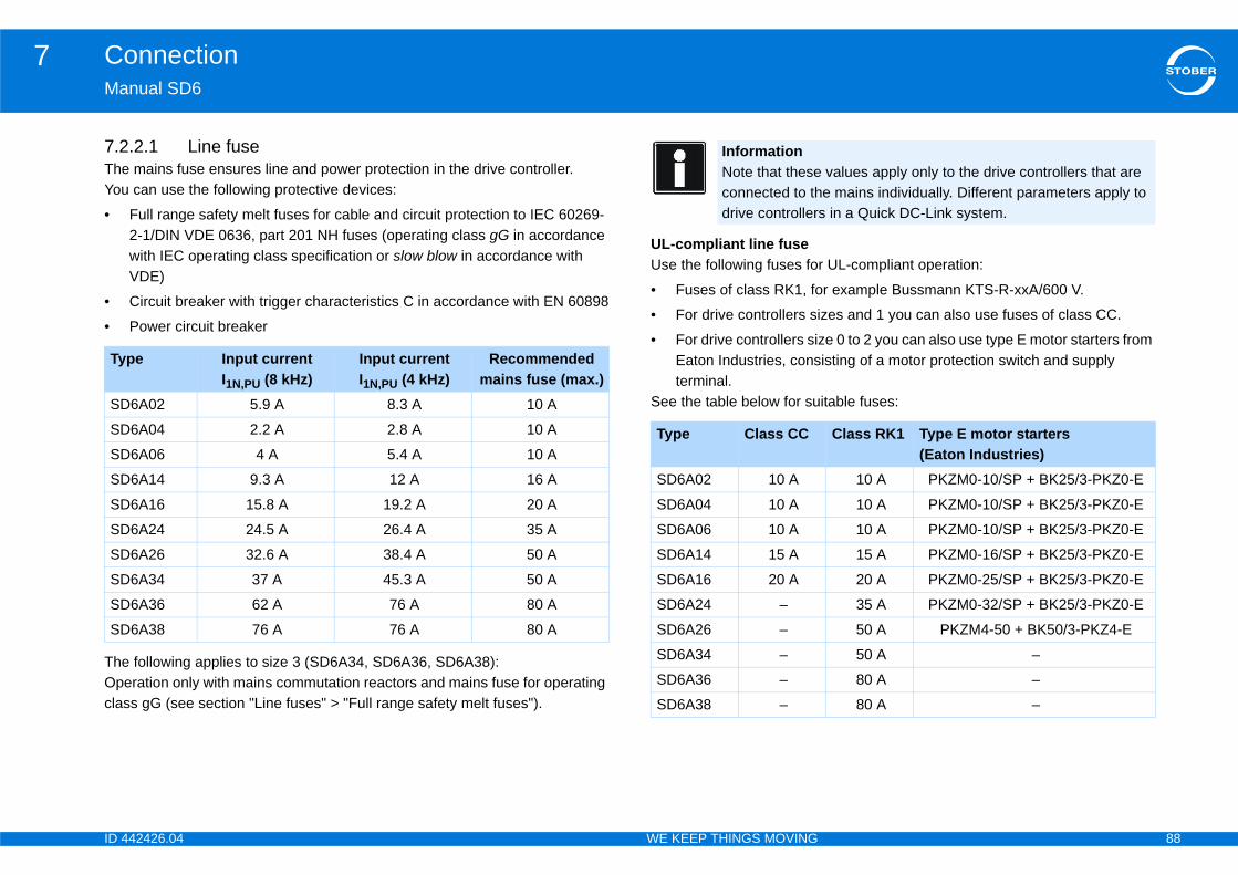
ID 4 88
Connection7Ma
7.2TheYou
•
•
•
TheOpclas
r UL-compliant operation:
r example Bussmann KTS-R-xxA/600 V.
zes and 1 you can also use fuses of class CC.
e 0 to 2 you can also use type E motor starters from isting of a motor protection switch and supply
itable fuses:
Ty
SD
SD
SD
SD
SD
SD
SD
SD
SD
SD
values apply only to the drive controllers that are e mains individually. Different parameters apply to
s in a Quick DC-Link system.
Class RK1 Type E motor starters(Eaton Industries)
10 A PKZM0-10/SP + BK25/3-PKZ0-E
10 A PKZM0-10/SP + BK25/3-PKZ0-E
10 A PKZM0-10/SP + BK25/3-PKZ0-E
15 A PKZM0-16/SP + BK25/3-PKZ0-E
20 A PKZM0-25/SP + BK25/3-PKZ0-E
35 A PKZM0-32/SP + BK25/3-PKZ0-E
50 A PKZM4-50 + BK50/3-PKZ4-E
50 A –
80 A –
80 A –
42426.04 WE KEEP THINGS MOVING
nual SD6
.2.1 Line fuse mains fuse ensures line and power protection in the drive controller. can use the following protective devices:
Full range safety melt fuses for cable and circuit protection to IEC 60269-2-1/DIN VDE 0636, part 201 NH fuses (operating class gG in accordance with IEC operating class specification or slow blow in accordance with VDE)
Circuit breaker with trigger characteristics C in accordance with EN 60898
Power circuit breaker
following applies to size 3 (SD6A34, SD6A36, SD6A38): eration only with mains commutation reactors and mains fuse for operating s gG (see section "Line fuses" > "Full range safety melt fuses").
UL-compliant line fuseUse the following fuses fo
• Fuses of class RK1, fo
• For drive controllers si
• For drive controllers sizEaton Industries, consterminal.
See the table below for su
pe Input current I1N,PU (8 kHz)
Input current I1N,PU (4 kHz)
Recommended mains fuse (max.)
6A02 5.9 A 8.3 A 10 A
6A04 2.2 A 2.8 A 10 A
6A06 4 A 5.4 A 10 A
6A14 9.3 A 12 A 16 A
6A16 15.8 A 19.2 A 20 A
6A24 24.5 A 26.4 A 35 A
6A26 32.6 A 38.4 A 50 A
6A34 37 A 45.3 A 50 A
6A36 62 A 76 A 80 A
6A38 76 A 76 A 80 A
InformationNote that theseconnected to thdrive controller
Type Class CC
SD6A02 10 A
SD6A04 10 A
SD6A06 10 A
SD6A14 15 A
SD6A16 20 A
SD6A24 –
SD6A26 –
SD6A34 –
SD6A36 –
SD6A38 –
ID 4 89
Connection7Ma
7.2STO(RCeleThesuit
DepconcurDepocctakor r
EleThepro
Stracon
stances and asymmetries, stray currents up to 40 mA n. Undesirable false triggering occurs
rs to the supply voltage.n be rectified by using short-time delayed (super-layed switch-off) residual current protective devices d trigger current 0 mA).
ncy stray currents for long motor cables under itions: n be rectified for example using low-capacitance rs.
n the supply network. n be rectified for example using an isolating
s with a DC current component can restrict the rrent protective devices types A and AC.
llation instructions for the protective devices you are
the use of residual current protective devices with er current as well as with short-time delayed or -off trigger characteristics are permitted in your
42426.04 WE KEEP THINGS MOVING
nual SD6
.2.2 Residual current safety deviceBER devices can be protected with a Residual Current protective Devices D) to detect residual currents. Residual current protective devices prevent
ctrical accidents, especially ground fault through the body. y are generally distinguished according to their triggering limit and ability for detecting different types of residual current.
ending on the function, stray currents may occur when operating drive trollers. Stray currents are interpreted as residual currents by residual rent protective devices and may therefore lead to false triggering. ending on the relevant power supply connections, residual currents may ur with or without a DC current component. Because of this, you should e into consideration both the height and also the shape of the possible stray esidual current when selecting a suitable RCD.
DANGER!
ctric shock hazard! combination of single-phase drive controllers and residual current
tective devices type A or AC can lead to false triggering of the RCDs.
y currents with a DC current component may occur in 3-phase drive trollers.
Always protect single-phase drive controllers with residual current protective devices type B, sensitive to all currents, or with type F, sensitive to mixed currents.
Always protect 3-phase drive controllers with residual current protective devices type B, sensitive to all currents.
False triggering – causeDepending on stray capacimay occur during operatio
• ... when drive controlleThis false triggering caresistant), selective (deor RCDs with increase(for example 300 or 50
• ... Due to higher frequenormal operating condThis false triggering cacables or output derate
• ... due to unbalances iThis false triggering catransformer.
Installation
DANGER!
Electric shock hazard!Stray and residual currentfunctionality of residual cu
Always follow the instausing.
InformationCheck whetherincreased triggdelayed switchapplication.
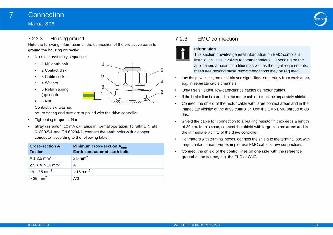
ID 4 90
Connection7Ma
7.2Notgro
•
•
•
nection
tor cable and signal lines separately from each other, channels.
-capacitance cables as motor cables.
ed in the motor cable, it must be separately shielded.
he motor cable with large contact areas and in the e drive controller. Use the EM6 EMC shroud to do
nnection to a braking resistor if it exceeds a length connect the shield with large contact areas and in of the drive controller.
al boxes, connect the shield to the terminal box with r example, use EMC cable screw connections.
he control lines on one side with the reference e.g. the PLC or CNC.
CrFeA
2.5
16
> 3
vides general information on EMC-compliant s involves recommendations. Depending on the bient conditions as well as the legal requirements, nd these recommendations may be required.
42426.04 WE KEEP THINGS MOVING
nual SD6
.2.3 Housing grounde the following information on the connection of the protective earth to und the housing correctly:
Note the assembly sequence:
• 1 M6 earth bolt• 2 Contact disk• 3 Cable socket• 4 Washer• 5 Return spring
(optional)• 6 NutContact disk, washer, return spring and nuts are supplied with the drive controller.
Tightening torque: 4 Nm
Stray currents > 10 mA can arise in normal operation. To fulfill DIN EN 61800-5-1 and EN 60204-1, connect the earth bolts with a copper conductor according to the following table:
7.2.3 EMC con
• Lay the power line, moe.g. in separate cable
• Only use shielded, low
• If the brake line is carri
• Connect the shield of timmediate vicinity of ththis.
• Shield the cable for coof 30 cm. In this case,the immediate vicinity
• For motors with terminlarge contact areas. Fo
• Connect the shield of tground of the source,
oss-section Aeder
Minimum cross-section Amin Earth conductor at earth bolts
≤ 2.5 mm2 2.5 mm2
< A ≤ 16 mm2 A
– 35 mm2 ≥16 mm2
5 mm2 A/2
1
43
65
2
InformationThis section proinstallation. Thiapplication, ammeasures beyo

ID 4 91
Connection7Ma
7.2Notwhiin imto iTaklea
•
•
•
•
roller of terminalscribed in this section show the SD6 drive controller nt in the pictures:
le EC6 (EtherCAT)
also optionally available as an alternative:
r IO6
le CA6 (CANopen)
42426.04 WE KEEP THINGS MOVING
nual SD6
.4 Selecting the cablese that the motor, cables and drive controller each have electrical properties ch influence one another. Unfavorable combinations could possibly result
permissible voltage peaks on the motor and drive controller and therefore ncreased wear.e into consideration the following instructions when selecting suitable ds:
Lead cross-sections for the cables to the motor: Make certain you choose the permissible continuous open-circuit current for the motor.
Lead cross-sections for the power connection of the drive controller: When choosing the mains fuse, make certain to select the maximum admissible conductor cross-section of terminal X10. Be careful of how the cables are laid and the surrounding temperature.
Pay attention also to the trailability and torsional strength of the leads.
When using a motor brake, pay attention to the voltage drop in the supply voltage on the lead.
7.3 Drive cont7.3.1 OverviewThe terminal overview deswith the following equipme
• Safety technology ST6
• Terminal module XI6
• Communication moduThe following equipment is
• Terminal module RI6 o
• Communication modu
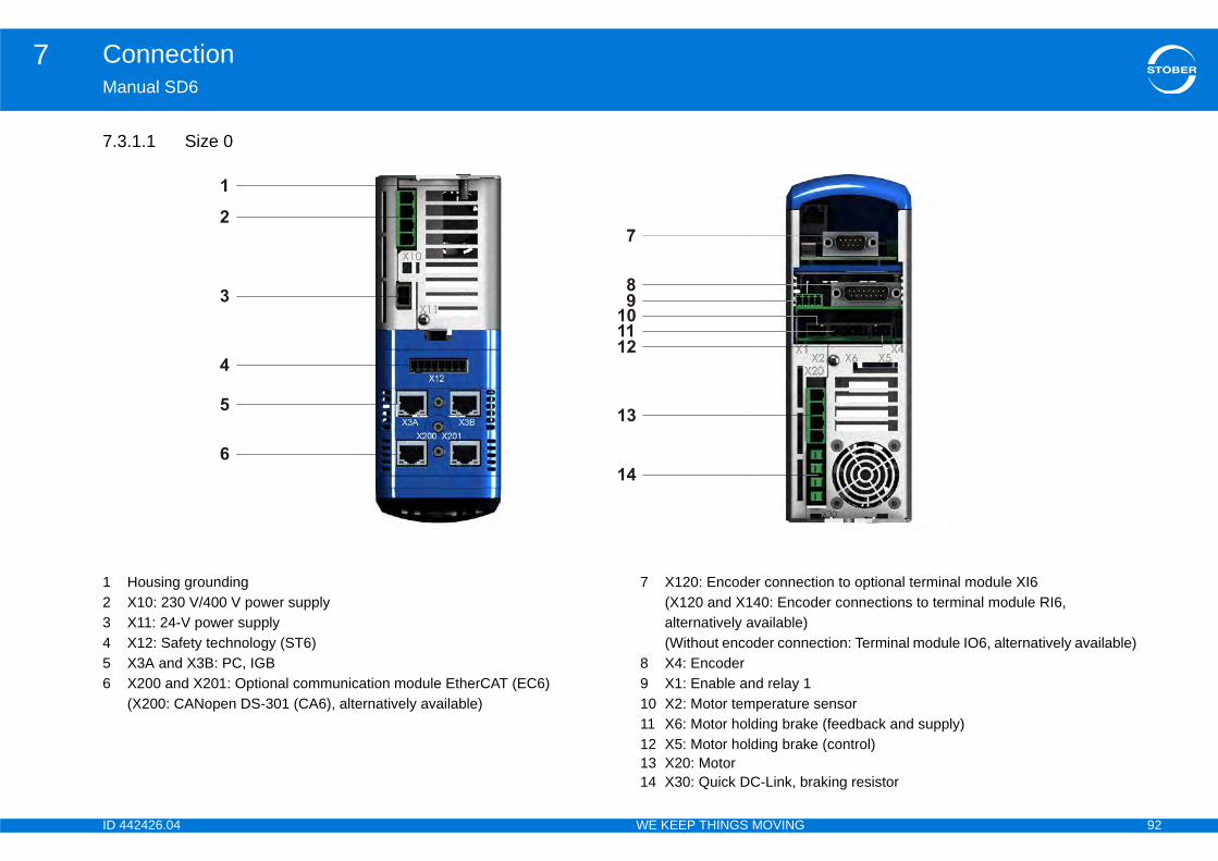
ID 4 92
Connection7Ma
7.3
123456
tion to optional terminal module XI6der connections to terminal module RI6, ection: Terminal module IO6, alternatively available)
sensore (feedback and supply)e (control)
raking resistor
42426.04 WE KEEP THINGS MOVING
nual SD6
.1.1 Size 0
Housing groundingX10: 230 V/400 V power supplyX11: 24-V power supplyX12: Safety technology (ST6)X3A and X3B: PC, IGBX200 and X201: Optional communication module EtherCAT (EC6)(X200: CANopen DS-301 (CA6), alternatively available)
7 X120: Encoder connec(X120 and X140: Encoalternatively available)(Without encoder conn
8 X4: Encoder9 X1: Enable and relay 110 X2: Motor temperature11 X6: Motor holding brak12 X5: Motor holding brak13 X20: Motor14 X30: Quick DC-Link, b
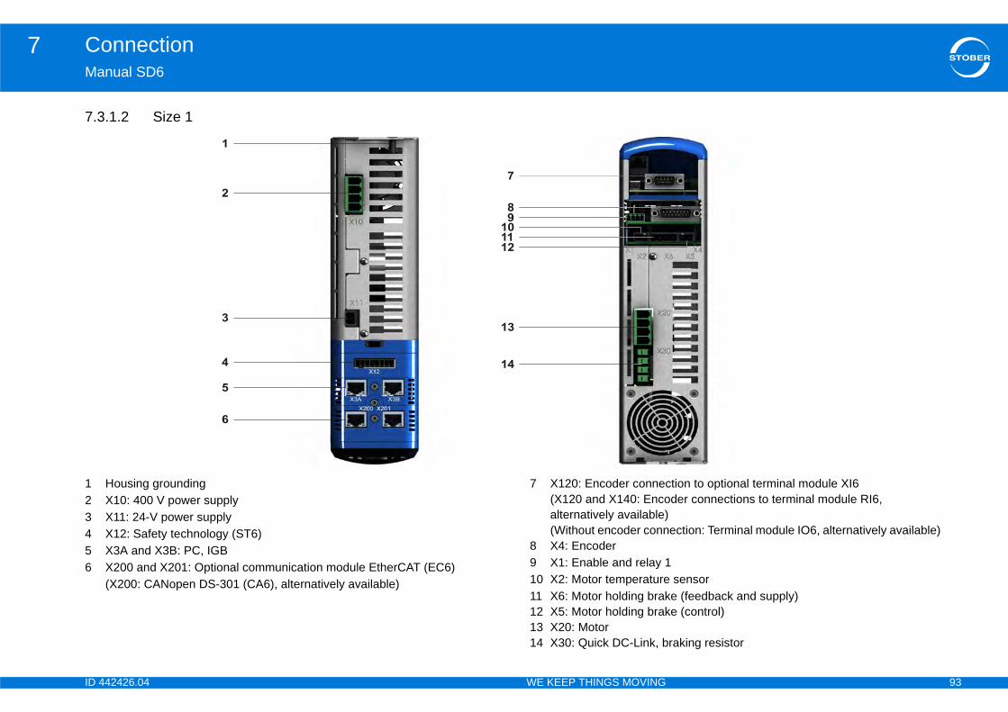
ID 4 93
Connection7Ma
7.3
123456
tion to optional terminal module XI6der connections to terminal module RI6, ection: Terminal module IO6, alternatively available)
sensore (feedback and supply)e (control)
raking resistor
42426.04 WE KEEP THINGS MOVING
nual SD6
.1.2 Size 1
Housing groundingX10: 400 V power supplyX11: 24-V power supplyX12: Safety technology (ST6)X3A and X3B: PC, IGBX200 and X201: Optional communication module EtherCAT (EC6)(X200: CANopen DS-301 (CA6), alternatively available)
7 X120: Encoder connec(X120 and X140: Encoalternatively available)(Without encoder conn
8 X4: Encoder9 X1: Enable and relay 110 X2: Motor temperature11 X6: Motor holding brak12 X5: Motor holding brak13 X20: Motor14 X30: Quick DC-Link, b

ID 4 94
Connection7Ma
7.3
123456
tion to terminal module XI6der connections to optional terminal module RI6, ection: Terminal module IO6, alternatively available)
e (feedback and supply) sensore (control)
raking resistor
42426.04 WE KEEP THINGS MOVING
nual SD6
.1.3 Size 2
Housing groundingX10: 400 V power supplyX11: 24 V power supplyX12: Safety technology (ST6)X3A and X3B: PC, IGBX200 and X201: Optional communication module EtherCAT (EC6)(X200: CANopen DS-301 (CA6), alternatively available)
7 X120: Encoder connec(X120 and X140: encoalternatively available)(Without encoder conn
8 X4: Encoder9 X1: Enable and relay 110 X6: Motor holding brak11 X2: Motor temperature12 X5: Motor holding brak13 X20: Motor14 X30: Quick DC-Link, b
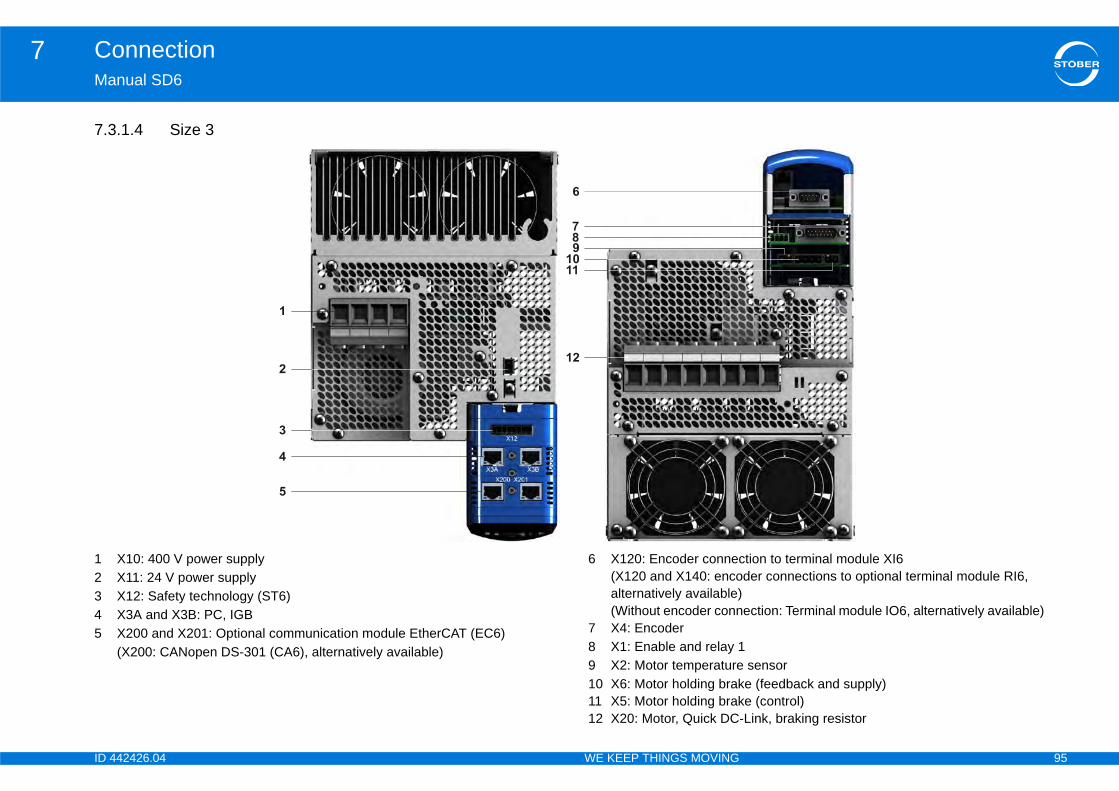
ID 4 95
Connection7Ma
7.3
12345
tion to terminal module XI6der connections to optional terminal module RI6, ection: Terminal module IO6, alternatively available)
sensore (feedback and supply)e (control)Link, braking resistor
42426.04 WE KEEP THINGS MOVING
nual SD6
.1.4 Size 3
X10: 400 V power supplyX11: 24 V power supplyX12: Safety technology (ST6)X3A and X3B: PC, IGBX200 and X201: Optional communication module EtherCAT (EC6)(X200: CANopen DS-301 (CA6), alternatively available)
6 X120: Encoder connec(X120 and X140: encoalternatively available)(Without encoder conn
7 X4: Encoder8 X1: Enable and relay 19 X2: Motor temperature10 X6: Motor holding brak11 X5: Motor holding brak12 X20: Motor, Quick DC-

ID 4 96
Connection7Ma
7.3Ter
Ter1 a
Ter
ss-section of power supply connection
power is required for powering the control part.
verload! to multiple devices via terminal X11, the device may
that is too high.
urrent via terminal X11 does not exceed 15 A (UL:
Pi
PiS
Pi
0 1 2 3
2.5 46
(10 for rigid conductors)
25 (35 for rigid conductors)
20.4 – 28.8 V
1.5 A
42426.04 WE KEEP THINGS MOVING
nual SD6
.2 X10: 230 V/400 V powerminal description – single-phase power connection size 0
minal description – three-phase power supply connection size 0, size nd size 2
minal description – three-phase power supply connection size 3
Maximum conductor croterminals
7.3.3 X11: 24 VConnection of 24 V to X11
NOTICE
Device damage due to oIf the 24-V supply is loopedbe damaged by a current
Make certain that the c10 A).
n Designation Function— Plastic dummy plug
L1 Input voltage
N Neutral conductor
PE Protective ground
n Designation Functionize 0 Size 1 Size 2 L1
Input voltageL2
L3
PE Protective ground
n Designation FunctionL1
Input voltageL2
L3
PE Protective ground
L1N
PE
L1L2
L3PE
L1L2
L3PE
L1L2
L3PE
L1L2
L3PE
SizeMax. cross-section for conductor with ferrule [mm2]
Control boardU1
I1maxa)
a) Depending on the accessories

ID 4 97
Connection7Ma
Ter
Ma
le and relay 1nable the power pack of the drive controller. The adjusted in parameter F75.
Pi
CoRi
Fle
Flewi
Flepla
2 lse
+
30 m
30 V
1,0 A
y Mechanical: min. of 5,000,000 switching operations
At 24 V/1A (ohmic load): 300,000 switching operations.
12–30 V
0–8 V
16 mA
Designation FunctionContact 1 Relay 1
Recommended fuse: max. 1 ATa)
) upstream from relay 1 for fuse protection. Make certain for UL- has been approved for the requirements of UL 248.
Contact 2
GNDEnable
Input
42426.04 WE KEEP THINGS MOVING
nual SD6
minal description X11
ximum conductor cross-section
7.3.4 X1: EnabUse the enable signal to efunction of relay 1 can be
Terminal description X1
n Designation Function+ + 24 V 24 V DC supply of the control unit, design
according to EN 60204:PELV, secondary earthed,max. line length 30 m
+ + 24 V
– GND Reference potential for 24 V; bridged in the terminal– GND
InformationThe drive controller may not be connected to a DC mains supply. Instead supply the drive controller via a local 24 V DC power supply.
nnection type Maximum conductor cross-section [mm2]gid 2.5
xible 2.5
xible with cable end, thout plastic sleeve
2,5
xible with cable end, with stic sleeve
2,5
eads with the same cross-ction with double cable end
—
_
General specificationMaximum cable length
Electrical Data
Relay 1
U2max
I2max
Life expectanc
Enable
High level
Low level
I1max
Pin1
a) Use a 1 A fuse (delayed-actioncompliant operation that the fuse
2
3
4
12
34
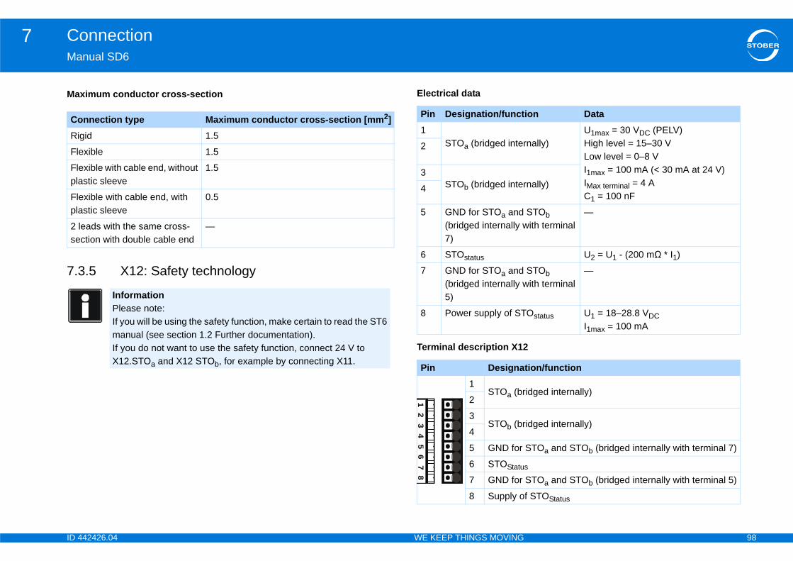
ID 4 98
Connection7Ma
7.3
Ma
CoRi
Fle
Flepla
Flepla
2 lse
ion Data
nally)U1max = 30 VDC (PELV)High level = 15–30 VLow level = 0–8 VI1max = 100 mA (< 30 mA at 24 V)IMax terminal = 4 AC1 = 100 nF
nally)
STOb ith terminal
—
U2 = U1 - (200 mΩ * I1)
STOb ith terminal
—
Ostatus U1 = 18–28.8 VDCI1max = 100 mA
tion/function
idged internally)
idged internally)
STOa and STOb (bridged internally with terminal 7)
s
STOa and STOb (bridged internally with terminal 5)
f STOStatus
42426.04 WE KEEP THINGS MOVING
nual SD6
.5 X12: Safety technology
Electrical data
Terminal description X12
ximum conductor cross-section
nnection type Maximum conductor cross-section [mm2]gid 1.5
xible 1.5
xible with cable end, without stic sleeve
1.5
xible with cable end, with stic sleeve
0.5
eads with the same cross-ction with double cable end
—
InformationPlease note:If you will be using the safety function, make certain to read the ST6 manual (see section 1.2 Further documentation).If you do not want to use the safety function, connect 24 V to X12.STOa and X12 STOb, for example by connecting X11.
Pin Designation/funct1
STOa (bridged inter2
3STOb (bridged inter4
5 GND for STOa and (bridged internally w7)
6 STOstatus
7 GND for STOa and (bridged internally w5)
8 Power supply of ST
Pin Designa1
STOa (br2
3STOb (br
4
5 GND for
6 STOStatu
7 GND for
8 Supply o
12
34
56
78
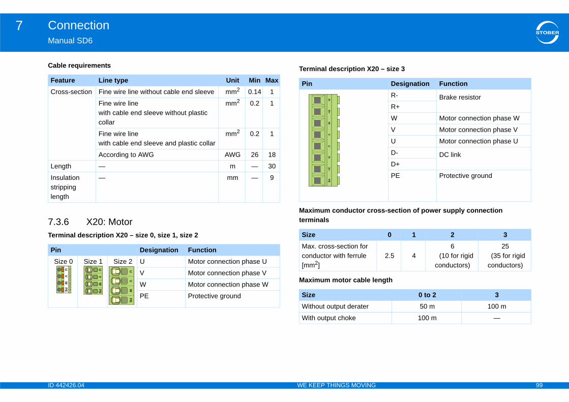
ID 4 99
Connection7Ma
Cab
7.3Ter
– size 3
ss-section of power supply connection
ngth
FeCr
Le
Insstrlen
PiS
Designation FunctionR- Brake resistorR+
W Motor connection phase W
V Motor connection phase V
U Motor connection phase U
D- DC link D+
PE Protective ground
0 1 2 3
2.5 46
(10 for rigid conductors)
25 (35 for rigid conductors)
0 to 2 350 m 100 m
100 m —
42426.04 WE KEEP THINGS MOVING
nual SD6
le requirements
.6 X20: Motor minal description X20 – size 0, size 1, size 2
Terminal description X20
Maximum conductor croterminals
Maximum motor cable le
ature Line type Unit Min Maxoss-section Fine wire line without cable end sleeve mm2 0.14 1
Fine wire line with cable end sleeve without plastic collar
mm2 0.2 1
Fine wire line with cable end sleeve and plastic collar
mm2 0.2 1
According to AWG AWG 26 18
ngth — m — 30
ulation ipping gth
— mm — 9
n Designation Functionize 0 Size 1 Size 2 U Motor connection phase U
V Motor connection phase V
W Motor connection phase W
PE Protective ground
UV
WPE
UV
WPE
UV
WPE
Pin
SizeMax. cross-section for conductor with ferrule [mm2]
SizeWithout output derater
With output choke
R-
R+
WV
UD
-D
+PE

ID 4 100
Connection7Ma
CoObder
•
•
CoOb
•
•
Thewith
1V1 1V2 1W1 1W2
42426.04 WE KEEP THINGS MOVING
nual SD6
nnection without output deraterserve the following points when connecting the motor without the output ater:
Ground the shield of the motor cable with the shield connection clamp on the EMC shroud.
Keep the exposed conductor as short as possible. All devices and circuits that are sensitive to EMC must be kept at a distance of at least 0.3 m.
nnection with output deraterserve the following points when connecting the motor to the output derater:
Ground the shield of the motor cable with large area contacts in the immediate vicinity of the output derater, for example with electrically conductive metal cable terminals on a grounded connection rail.
Keep the exposed conductor as short as possible. All devices and circuits that are sensitive to EMC must be kept at a distance of at least 0.3 m. graphic below shows an example for the shielded connection of a motor output derater (graphic: icotek GmbH).
Pin 7 and8 arebridged atthe outputderator
1U1 1U27
PE8
PE
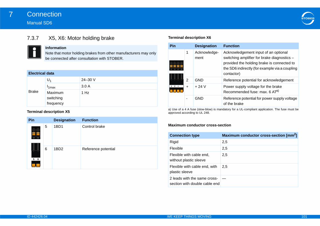
ID 4 101
Connection7Ma
7.3
Ter
El
Br
Pi
on Functionge- Acknowledgement input of an optional
switching amplifier for brake diagnostics – provided the holding brake is connected to the SD6 indirectly (for example via a coupling contactor)
Reference potential for acknowledgement
Power supply voltage for the brakeRecommended fuse: max. 6 ATa)
) is mandatory for a UL-compliant application. The fuse must be
Reference potential for power supply voltage of the brake
ss-section
Maximum conductor cross-section [mm2]2,5
2,5
2,5
ith 2,5
ss- end
—
42426.04 WE KEEP THINGS MOVING
nual SD6
.7 X5, X6: Motor holding brake
minal description X5
Terminal description X6
InformationNote that motor holding brakes from other manufacturers may only be connected after consultation with STOBER.
ectrical data
ake
U1 24–30 V
I1max 3.0 A
Maximum switching frequency
1 Hz
n Designation Function5 1BD1 Control brake
6 1BD2 Reference potential
5 6
Pin Designati1 Acknowled
ment
2 GND
+ + 24 V
a) Use of a 4 A fuse (slow-blowapproved according to UL 248.
- GND
Maximum conductor cro
Connection typeRigid
Flexible
Flexible with cable end, without plastic sleeve
Flexible with cable end, wplastic sleeve
2 leads with the same crosection with double cable
1 _+2
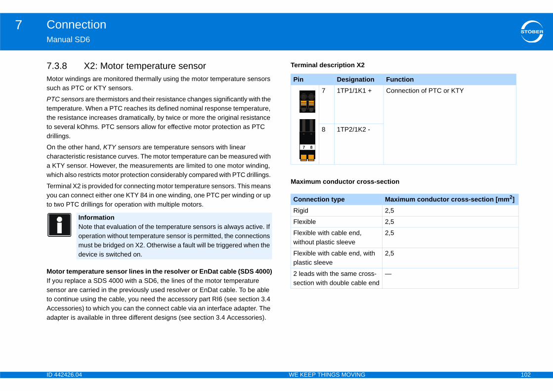
ID 4 102
Connection7Ma
7.3Mosuc
PTCtemtheto sdril
Onchaa Kwhi
Teryouto t
MoIf ysento cAccada
on Function + Connection of PTC or KTY
-
ss-section
Maximum conductor cross-section [mm2]2,5
2,5
2,5
ith 2,5
ss- end
—
42426.04 WE KEEP THINGS MOVING
nual SD6
.8 X2: Motor temperature sensortor windings are monitored thermally using the motor temperature sensors h as PTC or KTY sensors.
sensors are thermistors and their resistance changes significantly with the perature. When a PTC reaches its defined nominal response temperature,
resistance increases dramatically, by twice or more the original resistance everal kOhms. PTC sensors allow for effective motor protection as PTC
lings.
the other hand, KTY sensors are temperature sensors with linear racteristic resistance curves. The motor temperature can be measured with TY sensor. However, the measurements are limited to one motor winding, ch also restricts motor protection considerably compared with PTC drillings.
minal X2 is provided for connecting motor temperature sensors. This means can connect either one KTY 84 in one winding, one PTC per winding or up wo PTC drillings for operation with multiple motors.
tor temperature sensor lines in the resolver or EnDat cable (SDS 4000)ou replace a SDS 4000 with a SD6, the lines of the motor temperature sor are carried in the previously used resolver or EnDat cable. To be able ontinue using the cable, you need the accessory part RI6 (see section 3.4 essories) to which you can the connect cable via an interface adapter. The pter is available in three different designs (see section 3.4 Accessories).
Terminal description X2
InformationNote that evaluation of the temperature sensors is always active. If operation without temperature sensor is permitted, the connections must be bridged on X2. Otherwise a fault will be triggered when the device is switched on.
Pin Designati7 1TP1/1K1
8 1TP2/1K2
Maximum conductor cro
Connection typeRigid
Flexible
Flexible with cable end, without plastic sleeve
Flexible with cable end, wplastic sleeve
2 leads with the same crosection with double cable
7 8
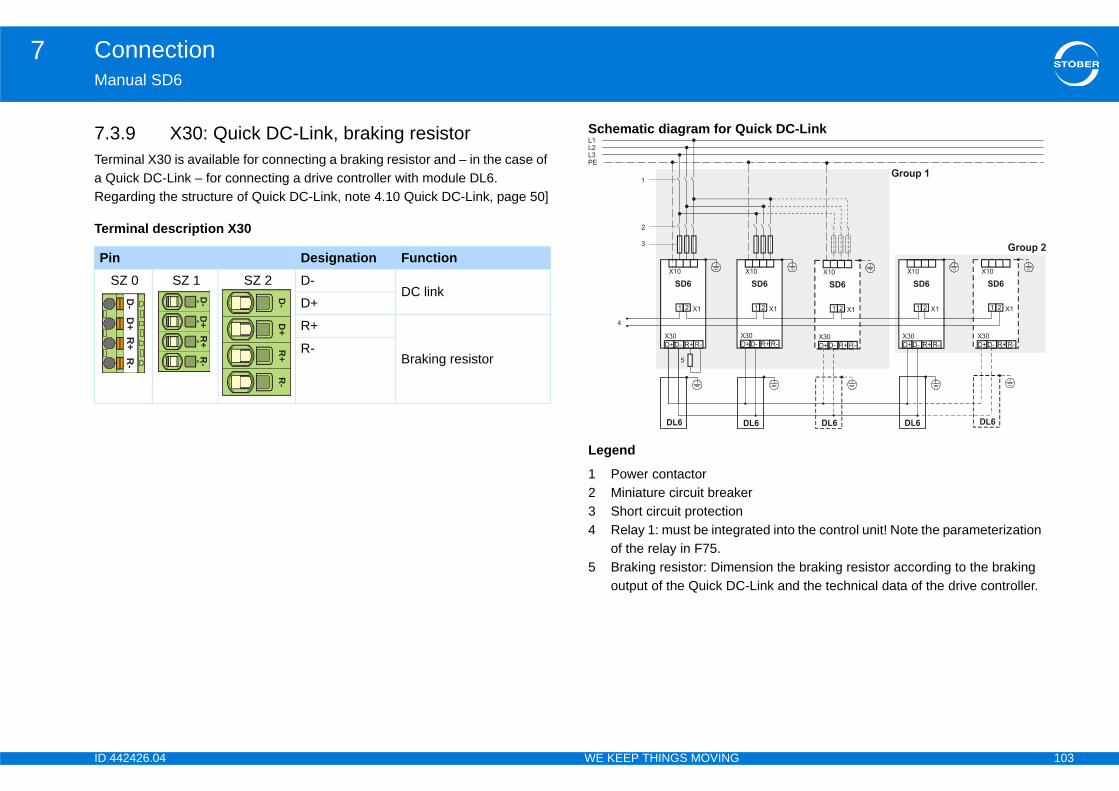
ID 4 103
Connection7Ma
7.3Tera QReg
Ter
uick DC-Link
er
rated into the control unit! Note the parameterization
nsion the braking resistor according to the braking -Link and the technical data of the drive controller.
PiS
42426.04 WE KEEP THINGS MOVING
nual SD6
.9 X30: Quick DC-Link, braking resistorminal X30 is available for connecting a braking resistor and – in the case of uick DC-Link – for connecting a drive controller with module DL6. arding the structure of Quick DC-Link, note 4.10 Quick DC-Link, page 50]
minal description X30
Schematic diagram for Q
Legend
1 Power contactor2 Miniature circuit break3 Short circuit protection4 Relay 1: must be integ
of the relay in F75.5 Braking resistor: Dime
output of the Quick DC
n Designation FunctionZ 0 SZ 1 SZ 2 D-
DC linkD+
R+
Braking resistorR-
D-
D+
R+
R-
D-
D+
R+
R-
D-
D+
R+
R-
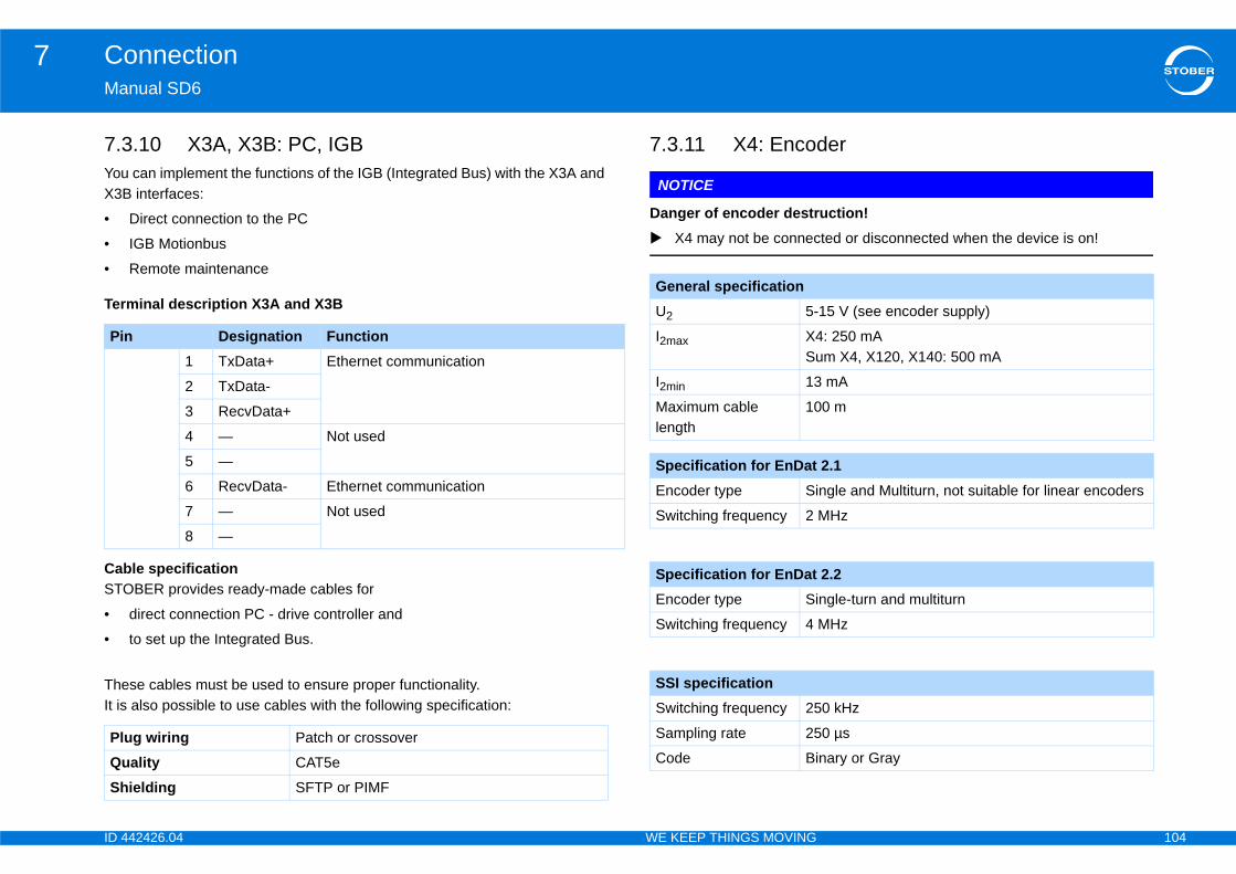
ID 4 104
Connection7Ma
7.3YouX3B
•
•
•
Ter
CabSTO
•
•
TheIt is
er
uction!ted or disconnected when the device is on!
Pi
PlQuSh
15 V (see encoder supply)
: 250 mAm X4, X120, X140: 500 mA
mA
0 m
2.1ngle and Multiturn, not suitable for linear encoders
MHz
2.2ngle-turn and multiturn
MHz
0 kHz
0 µs
nary or Gray
42426.04 WE KEEP THINGS MOVING
nual SD6
.10 X3A, X3B: PC, IGB can implement the functions of the IGB (Integrated Bus) with the X3A and interfaces:
Direct connection to the PC
IGB Motionbus
Remote maintenance
minal description X3A and X3B
le specificationBER provides ready-made cables for
direct connection PC - drive controller and
to set up the Integrated Bus.
se cables must be used to ensure proper functionality. also possible to use cables with the following specification:
7.3.11 X4: Encod
NOTICE
Danger of encoder destr X4 may not be connec
n Designation Function1 TxData+ Ethernet communication
2 TxData-
3 RecvData+
4 — Not used
5 —
6 RecvData- Ethernet communication
7 — Not used
8 —
ug wiring Patch or crossover
ality CAT5e
ielding SFTP or PIMF
General specificationU2 5-
I2max X4Su
I2min 13
Maximum cable length
10
Specification for EnDatEncoder type Si
Switching frequency 2
Specification for EnDatEncoder type Si
Switching frequency 4
SSI specificationSwitching frequency 25
Sampling rate 25
Code Bi
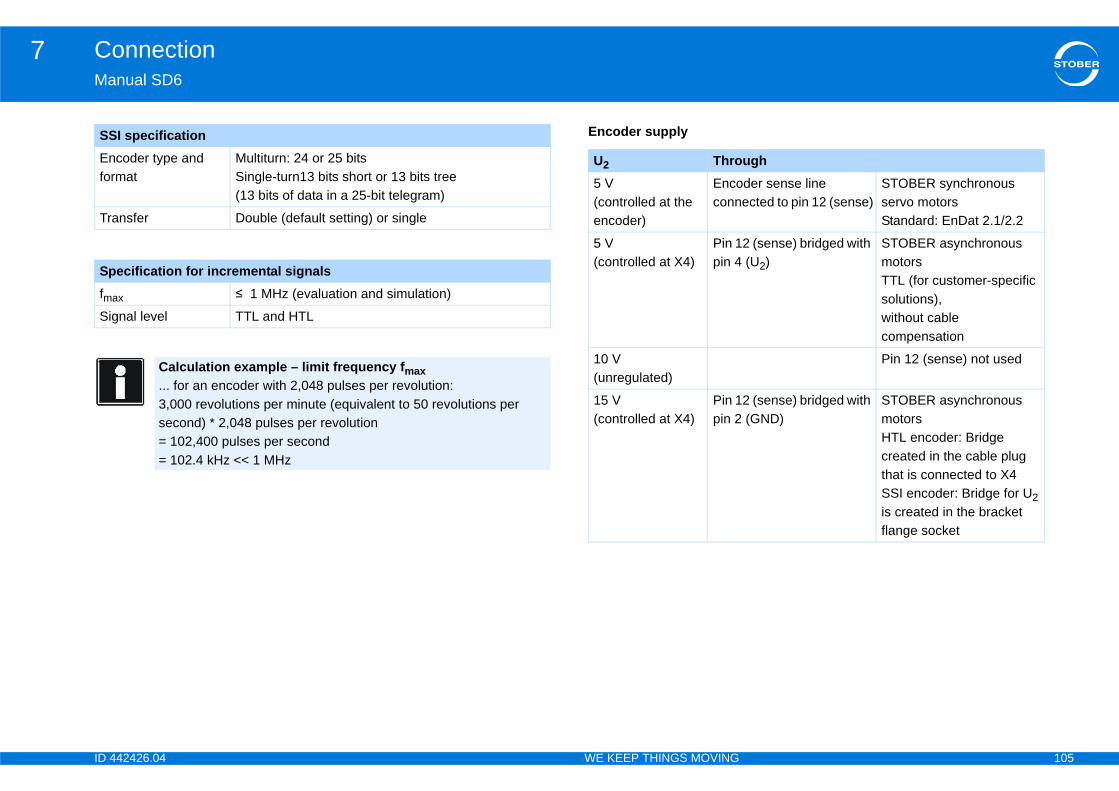
ID 4 105
Connection7Ma
Enfor
Tra
SpfmSig
SS
ughder sense line ected to pin 12 (sense)
STOBER synchronous servo motorsStandard: EnDat 2.1/2.2
2 (sense) bridged with (U2)
STOBER asynchronous motorsTTL (for customer-specific solutions),without cable compensation
Pin 12 (sense) not used
2 (sense) bridged with (GND)
STOBER asynchronous motorsHTL encoder: Bridge created in the cable plug that is connected to X4SSI encoder: Bridge for U2 is created in the bracket flange socket
42426.04 WE KEEP THINGS MOVING
nual SD6
Encoder supply
coder type and mat
Multiturn: 24 or 25 bitsSingle-turn13 bits short or 13 bits tree (13 bits of data in a 25-bit telegram)
nsfer Double (default setting) or single
ecification for incremental signals
ax ≤ 1 MHz (evaluation and simulation)
nal level TTL and HTL
Calculation example – limit frequency fmax... for an encoder with 2,048 pulses per revolution: 3,000 revolutions per minute (equivalent to 50 revolutions per second) * 2,048 pulses per revolution= 102,400 pulses per second = 102.4 kHz << 1 MHz
I specification
U2 Thro5 V (controlled at the encoder)
Encoconn
5 V(controlled at X4)
Pin 1pin 4
10 V (unregulated)
15 V(controlled at X4)
Pin 1pin 2
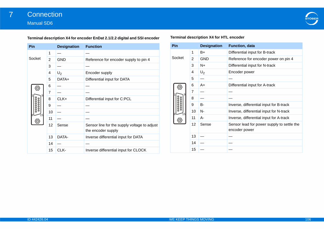
ID 4 106
Connection7Ma
Ter for HTL encoder
Pi
So
1
8
tion Function, dataDifferential input for B-track
Reference for encoder power on pin 4
Differential input for N-track
Encoder power
—
Differential input for A-track
—
—
Inverse, differential input for B-track
Inverse, differential input for N-track
Inverse, differential input for A-track
Sensor lead for power supply to settle the encoder power
—
—
—
42426.04 WE KEEP THINGS MOVING
nual SD6
minal description X4 for encoder EnDat 2.1/2.2 digital and SSI encoder Terminal description X4
n Designation Function
cket1 — —
2 GND Reference for encoder supply to pin 4
3 — —
4 U2 Encoder supply
5 DATA+ Differential input for DATA
6 — —
7 — —
8 CLK+ Differential input for C:PCL
9 — —
10 — —
11 — —
12 Sense Sensor line for the supply voltage to adjust the encoder supply
13 DATA- Inverse differential input for DATA
14 — —
15 CLK- Inverse differential input for CLOCK
9
15
Pin Designa
Socket1 B+
2 GND
3 N+
4 U2
5 —
6 A+
7 —
8 —
9 B-
10 N-
11 A-
12 Sense
13 —
14 —
15 —
9
15
1
8
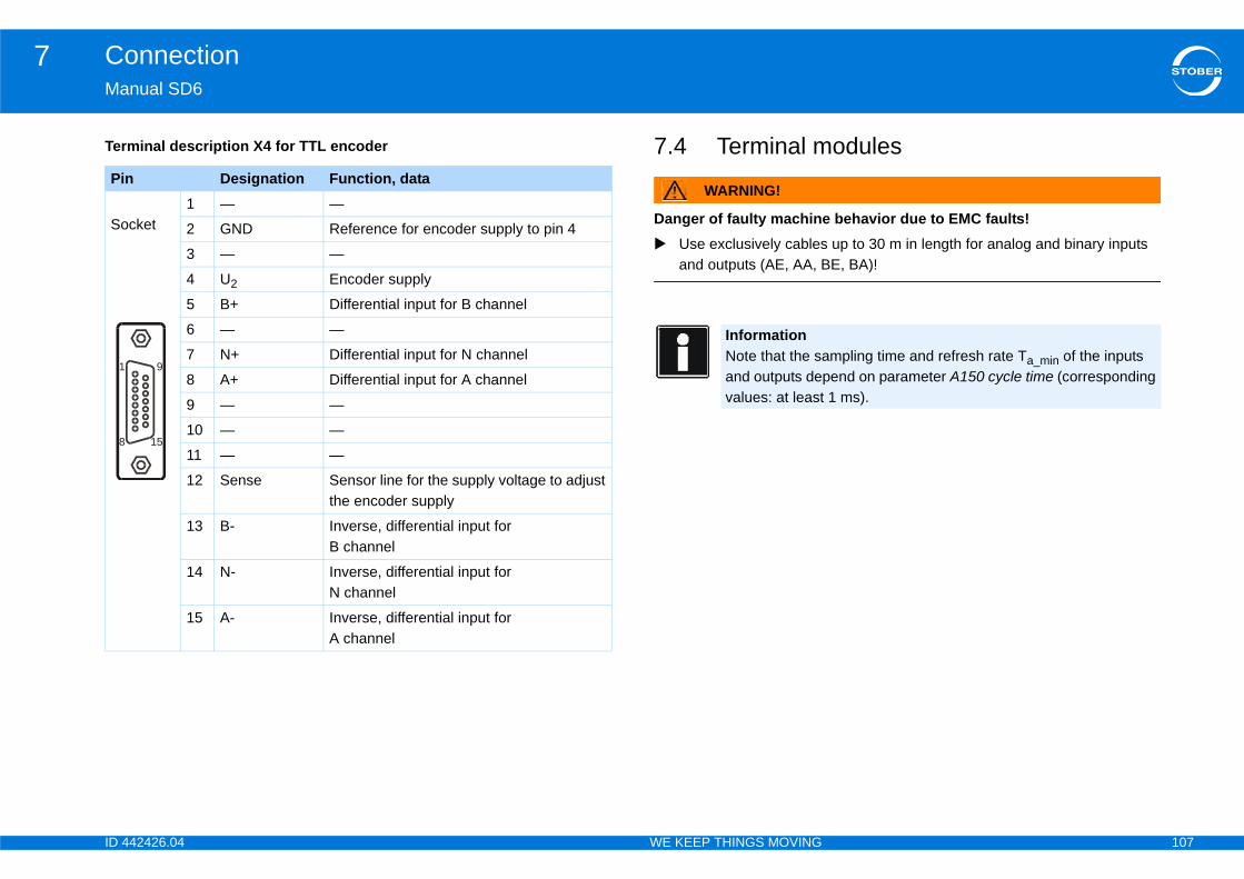
ID 4 107
Connection7Ma
Ter odules
e behavior due to EMC faults! up to 30 m in length for analog and binary inputs E, BA)!
Pi
So
1
8
mpling time and refresh rate Ta_min of the inputs pend on parameter A150 cycle time (corresponding 1 ms).
42426.04 WE KEEP THINGS MOVING
nual SD6
minal description X4 for TTL encoder 7.4 Terminal m
WARNING!
Danger of faulty machin Use exclusively cables
and outputs (AE, AA, B
n Designation Function, data
cket1 — —
2 GND Reference for encoder supply to pin 4
3 — —
4 U2 Encoder supply
5 B+ Differential input for B channel
6 — —
7 N+ Differential input for N channel
8 A+ Differential input for A channel
9 — —
10 — —
11 — —
12 Sense Sensor line for the supply voltage to adjust the encoder supply
13 B- Inverse, differential input for B channel
14 N- Inverse, differential input for N channel
15 A- Inverse, differential input for A channel
9
15
InformationNote that the saand outputs devalues: at least
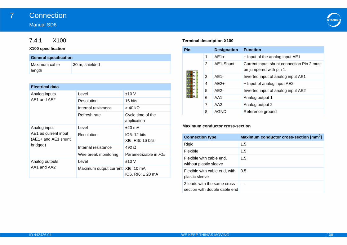
ID 4 108
Connection7Ma
7.4X10
0
GeMalen
ElAnAE
AnAE(Abri
AnAA
tion Function+ Input of the analog input AE1
nt Current input; shunt connection Pin 2 must be jumpered with pin 1.
Inverted input of analog input AE1
+ Input of analog input AE2
Inverted input of analog input AE2
Analog output 1
Analog output 2
Reference ground
ss-section
Maximum conductor cross-section [mm2]1.5
1.5
1.5
ith 0.5
ss- end
—
42426.04 WE KEEP THINGS MOVING
nual SD6
.1 X1000 specification
Terminal description X10
neral specificationximum cable gth
30 m, shielded
ectrical dataalog inputs 1 and AE2
Level ±10 V
Resolution 16 bits
Internal resistance > 40 kΩ
Refresh rate Cycle time of the application
alog input 1 as current input
E1+ and AE1 shunt dged)
Level ±20 mA
Resolution IO6: 12 bitsXI6, RI6: 16 bits
Internal resistance 492 Ω
Wire break monitoring Parametrizable in F15
alog outputs 1 and AA2
Level ±10 V
Maximum output current XI6: 10 mAIO6, RI6: ± 20 mA
Pin Designa1 AE1+
2 AE1-Shu
3 AE1-
4 AE2+
5 AE2-
6 AA1
7 AA2
8 AGND
Maximum conductor cro
Connection typeRigid
Flexible
Flexible with cable end, without plastic sleeve
Flexible with cable end, wplastic sleeve
2 leads with the same crosection with double cable
12
34
56
78
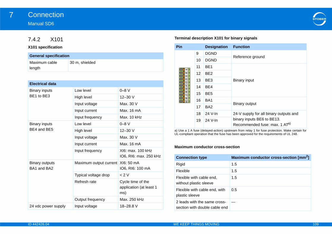
ID 4 109
Connection7Ma
7.4X10
1 for binary signals
GeMalen
ElBinBE
BinBE
BinBA
24
tion Function
Reference ground
Binary input
Binary output
24-V supply for all binary outputs and binary inputs BE6 to BE13.Recommended fuse: max. 1 ATa)
n) upstream from relay 1 for fuse protection. Make certain for use has been approved for the requirements of UL 248.
ss-section
Maximum conductor cross-section [mm2]1.5
1.5
1.5
ith 0.5
ss- end
—
42426.04 WE KEEP THINGS MOVING
nual SD6
.2 X1011 specification
Terminal description X10
neral specificationximum cable gth
30 m, shielded
ectrical dataary inputs 1 to BE3
Low level 0–8 V
High level 12–30 V
Input voltage Max. 30 V
Input current Max. 16 mA
Input frequency Max. 10 kHz
ary inputs 4 and BE5
Low level 0–8 V
High level 12–30 V
Input voltage Max. 30 V
Input current Max. 16 mA
Input frequency XI6: max. 100 kHzIO6, RI6: max. 250 kHz
ary outputs 1 and BA2
Maximum output current XI6: 50 mA IO6, RI6: 100 mA
Typical voltage drop < 2 V
Refresh rate Cycle time of the application (at least 1 ms)
Output frequency Max. 250 kHz
vdc power supply Input voltage 18–28.8 V
Pin Designa9 DGND
10 DGND
11 BE1
12 BE2
13 BE3
14 BE4
15 BE5
16 BA1
17 BA2
18 24 V-In
a) Use a 1 A fuse (delayed-actioUL-compliant operation that the f
19 24 V-In
Maximum conductor cro
Connection typeRigid
Flexible
Flexible with cable end, without plastic sleeve
Flexible with cable end, wplastic sleeve
2 leads with the same crosection with double cable
910
1112
1314
1516
1718
19
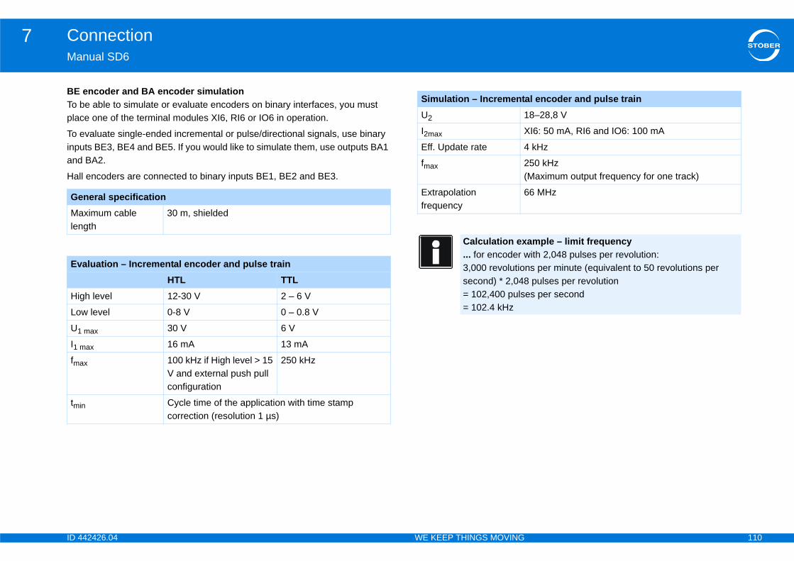
ID 4 110
Connection7Ma
BETo pla
To inpand
Hal
GeMalen
Ev
Hi
Lo
U1
I1
fm
tm
al encoder and pulse train8–28,8 V
I6: 50 mA, RI6 and IO6: 100 mA
kHz
50 kHzMaximum output frequency for one track)
6 MHz
ample – limit frequency ith 2,048 pulses per revolution:
ns per minute (equivalent to 50 revolutions per pulses per revolution
es per second
42426.04 WE KEEP THINGS MOVING
nual SD6
encoder and BA encoder simulationbe able to simulate or evaluate encoders on binary interfaces, you must ce one of the terminal modules XI6, RI6 or IO6 in operation.
evaluate single-ended incremental or pulse/directional signals, use binary uts BE3, BE4 and BE5. If you would like to simulate them, use outputs BA1 BA2.
l encoders are connected to binary inputs BE1, BE2 and BE3.
neral specificationximum cable gth
30 m, shielded
aluation – Incremental encoder and pulse trainHTL TTL
gh level 12-30 V 2 – 6 V
w level 0-8 V 0 – 0.8 V
max 30 V 6 V
max 16 mA 13 mA
ax 100 kHz if High level > 15 V and external push pull configuration
250 kHz
in Cycle time of the application with time stamp correction (resolution 1 µs)
Simulation – IncrementU2 1
I2max X
Eff. Update rate 4
fmax 2(
Extrapolation frequency
6
Calculation ex... for encoder w3,000 revolutiosecond) * 2,048= 102,400 puls= 102.4 kHz
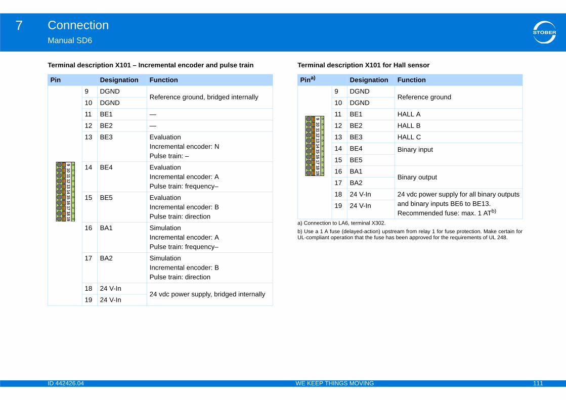
ID 4 111
Connection7Ma
Ter 1 for Hall sensor
Pi
302.
tion Function
Reference ground
HALL A
HALL B
HALL C
Binary input
Binary output
24 vdc power supply for all binary outputs and binary inputs BE6 to BE13.Recommended fuse: max. 1 ATb)
n) upstream from relay 1 for fuse protection. Make certain for use has been approved for the requirements of UL 248.
42426.04 WE KEEP THINGS MOVING
nual SD6
minal description X101 – Incremental encoder and pulse train Terminal description X10
n Designation Function9 DGND
Reference ground, bridged internally10 DGND
11 BE1 —
12 BE2 —
13 BE3 EvaluationIncremental encoder: NPulse train: –
14 BE4 EvaluationIncremental encoder: APulse train: frequency–
15 BE5 EvaluationIncremental encoder: B Pulse train: direction
16 BA1 Simulation Incremental encoder: A Pulse train: frequency–
17 BA2 Simulation Incremental encoder: B Pulse train: direction
18 24 V-In 24 vdc power supply, bridged internally
19 24 V-In
910
1112
1314
1516
1718
19
Pina)
a) Connection to LA6, terminal X
Designa9 DGND
10 DGND
11 BE1
12 BE2
13 BE3
14 BE4
15 BE5
16 BA1
17 BA2
18 24 V-In
b) Use a 1 A fuse (delayed-actioUL-compliant operation that the f
19 24 V-In
910
1112
1314
1516
1718
19

ID 4 112
Connection7Ma
7.4X10
Ter
GeMalen
ElAn
Pi
ss-section
Maximum conductor cross-section [mm2]1.51.51.5
ith 0.5
ss- end
—
m, shielded
Maximum output current 50 mA
Typical voltage drop < 2 V
Refresh rate Cycle time of the application
Inductive load Max. 1.2 VA
Maximum output current 50 mA
Typical voltage drop < 2 V
Refresh rate Cycle time of the application
42426.04 WE KEEP THINGS MOVING
nual SD6
.3 X1022 specification
minal description X102
7.4.4 X103AX103A specification
neral specificationximum cable gth
30 m, shielded
ectrical dataalog input AE3 Level ±10 V
Resolution 16 bits
Internal resistance > 40 kΩ
Refresh rate Cycle time of the application (at least 1 ms)
n Designation Function1 AE3+ + input of analog input AE3
Differential input voltage
2 AE3- Inverted input of analog input AE3
12
Maximum conductor cro
Connection typeRigidFlexibleFlexible with cable end, without plastic sleeveFlexible with cable end, wplastic sleeve2 leads with the same crosection with double cable
General specificationMaximum cable length
30
Electrical dataBinary outputs BA3 and BA4
Binary outputs BA5 and BA6
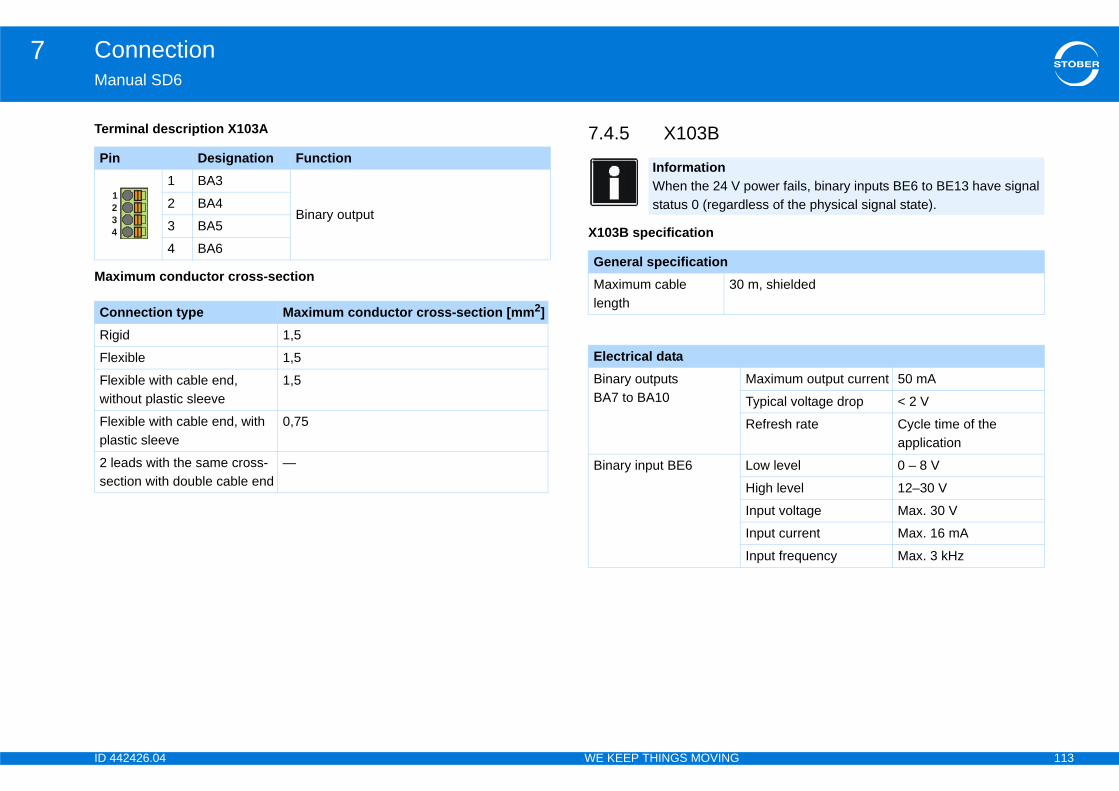
ID 4 113
Connection7Ma
Ter
Pi
Ma
CoRi
Fle
Flewi
Flepla
2 lse
4
power fails, binary inputs BE6 to BE13 have signal less of the physical signal state).
m, shielded
Maximum output current 50 mA
Typical voltage drop < 2 V
Refresh rate Cycle time of the application
Low level 0 – 8 V
High level 12–30 V
Input voltage Max. 30 V
Input current Max. 16 mA
Input frequency Max. 3 kHz
42426.04 WE KEEP THINGS MOVING
nual SD6
minal description X103A 7.4.5 X103B
X103B specification
n Designation Function1 BA3
Binary output2 BA4
3 BA5
4 BA6
ximum conductor cross-section
nnection type Maximum conductor cross-section [mm2]gid 1,5
xible 1,5
xible with cable end, thout plastic sleeve
1,5
xible with cable end, with stic sleeve
0,75
eads with the same cross-ction with double cable end
—
123
InformationWhen the 24 Vstatus 0 (regard
General specificationMaximum cable length
30
Electrical dataBinary outputs BA7 to BA10
Binary input BE6
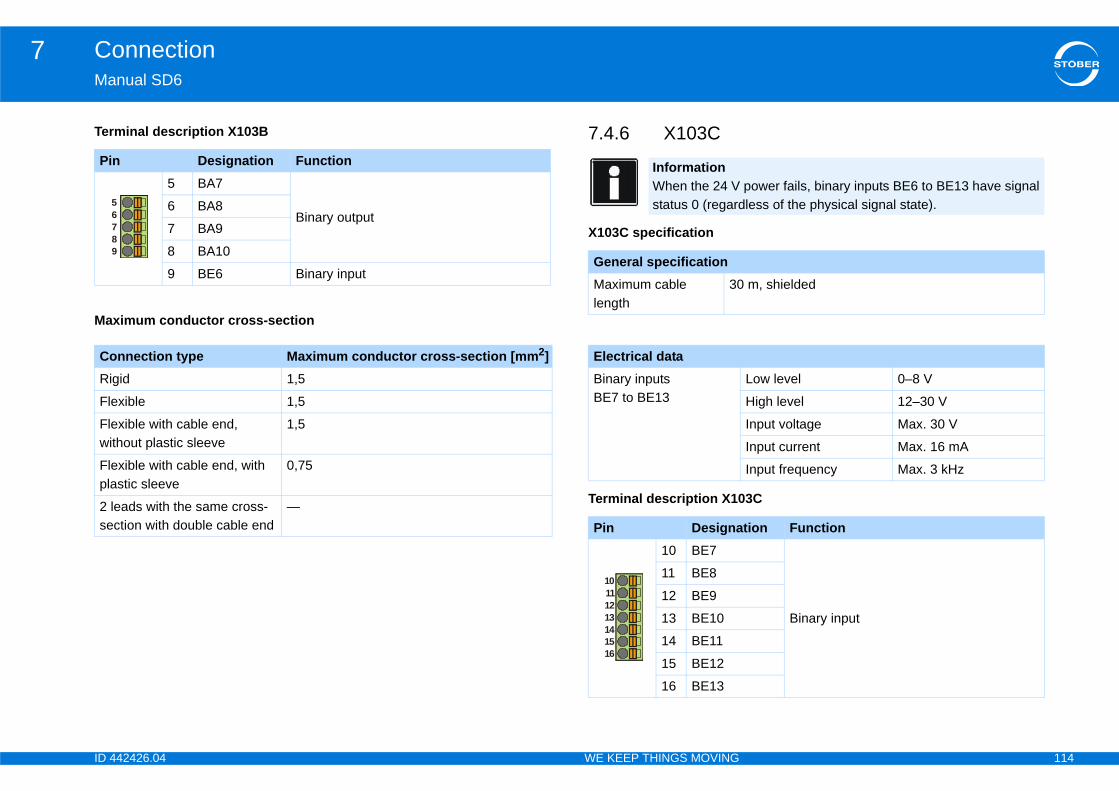
ID 4 114
Connection7Ma
Ter
3C
Pi
Ma
CoRi
Fle
Flewi
Flepla
2 lse
9
78
56
power fails, binary inputs BE6 to BE13 have signal less of the physical signal state).
m, shielded
Low level 0–8 V
High level 12–30 V
Input voltage Max. 30 V
Input current Max. 16 mA
Input frequency Max. 3 kHz
tion Function
Binary input
42426.04 WE KEEP THINGS MOVING
nual SD6
minal description X103B 7.4.6 X103C
X103C specification
Terminal description X10
n Designation Function5 BA7
Binary output6 BA8
7 BA9
8 BA10
9 BE6 Binary input
ximum conductor cross-section
nnection type Maximum conductor cross-section [mm2]gid 1,5
xible 1,5
xible with cable end, thout plastic sleeve
1,5
xible with cable end, with stic sleeve
0,75
eads with the same cross-ction with double cable end
—
InformationWhen the 24 Vstatus 0 (regard
General specificationMaximum cable length
30
Electrical dataBinary inputs BE7 to BE13
Pin Designa10 BE7
11 BE8
12 BE9
13 BE10
14 BE11
15 BE12
16 BE13
10111213141516
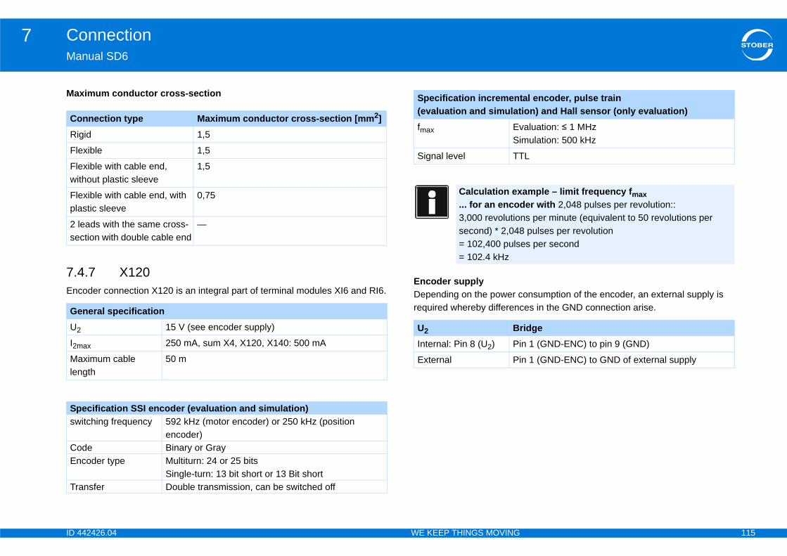
ID 4 115
Connection7Ma
7.4Enc onsumption of the encoder, an external supply is
es in the GND connection arise.
Ma
CoRi
Fle
Flewi
Flepla
2 lse
GeU2
I2m
Malen
Spsw
CoEn
Tra
al encoder, pulse train ion) and Hall sensor (only evaluation)aluation: ≤ 1 MHz
mulation: 500 kHz
L
ample – limit frequency fmax er with 2,048 pulses per revolution::
ns per minute (equivalent to 50 revolutions per pulses per revolution
es per second
idgen 1 (GND-ENC) to pin 9 (GND)
n 1 (GND-ENC) to GND of external supply
42426.04 WE KEEP THINGS MOVING
nual SD6
.7 X120oder connection X120 is an integral part of terminal modules XI6 and RI6.
Encoder supplyDepending on the power crequired whereby differenc
ximum conductor cross-section
nnection type Maximum conductor cross-section [mm2]gid 1,5
xible 1,5
xible with cable end, thout plastic sleeve
1,5
xible with cable end, with stic sleeve
0,75
eads with the same cross-ction with double cable end
—
neral specification15 V (see encoder supply)
ax 250 mA, sum X4, X120, X140: 500 mA
ximum cable gth
50 m
ecification SSI encoder (evaluation and simulation)itching frequency 592 kHz (motor encoder) or 250 kHz (position
encoder)de Binary or Graycoder type Multiturn: 24 or 25 bits
Single-turn: 13 bit short or 13 Bit shortnsfer Double transmission, can be switched off
Specification increment(evaluation and simulatfmax Ev
Si
Signal level TT
Calculation ex... for an encod3,000 revolutiosecond) * 2,048= 102,400 puls= 102.4 kHz
U2 BrInternal: Pin 8 (U2) Pi
External Pi
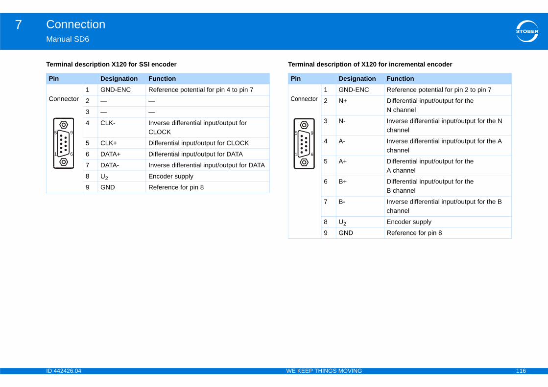
ID 4 116
Connection7Ma
Ter 120 for incremental encoder
Pi
Co
5
1
tion FunctionC Reference potential for pin 2 to pin 7
Differential input/output for the N channel
Inverse differential input/output for the N channel
Inverse differential input/output for the A channel
Differential input/output for the A channel
Differential input/output for theB channel
Inverse differential input/output for the B channel
Encoder supply
Reference for pin 8
42426.04 WE KEEP THINGS MOVING
nual SD6
minal description X120 for SSI encoder Terminal description of X
n Designation Function
nnector1 GND-ENC Reference potential for pin 4 to pin 7
2 — —
3 — —
4 CLK- Inverse differential input/output for CLOCK
5 CLK+ Differential input/output for CLOCK
6 DATA+ Differential input/output for DATA
7 DATA- Inverse differential input/output for DATA
8 U2 Encoder supply
9 GND Reference for pin 8
9
6
Pin Designa
Connector1 GND-EN
2 N+
3 N-
4 A-
5 A+
6 B+
7 B-
8 U2
9 GND
5
1
9
6
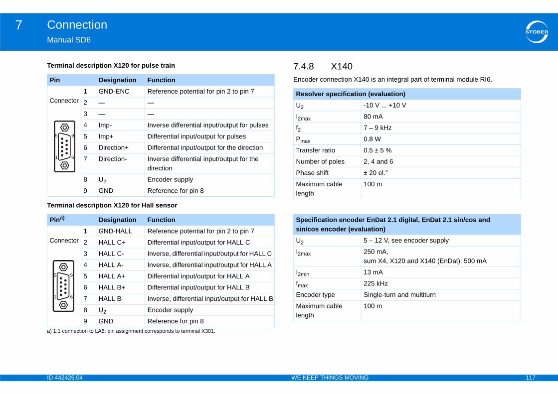
ID 4 117
Connection7Ma
Ter
Ter
is an integral part of terminal module RI6.Pi
Co
Pi
a) 1
Co
5
1
5
1
evaluation)0 V ... +10 V
mA
– 9 kHz
8 W
5 ± 5 %
4 and 6
20 el.°
0 m
nDat 2.1 digital, EnDat 2.1 sin/cos and tion)
– 12 V, see encoder supply
0 mA, m X4, X120 and X140 (EnDat): 500 mA
mA
5 kHz
ngle-turn and multiturn
0 m
42426.04 WE KEEP THINGS MOVING
nual SD6
minal description X120 for pulse train
minal description X120 for Hall sensor
7.4.8 X140Encoder connection X140n Designation Function
nnector1 GND-ENC Reference potential for pin 2 to pin 7
2 — —
3 — —
4 Imp- Inverse differential input/output for pulses
5 Imp+ Differential input/output for pulses
6 Direction+ Differential input/output for the direction
7 Direction- Inverse differential input/output for the direction
8 U2 Encoder supply
9 GND Reference for pin 8
na)
:1 connection to LA6: pin assignment corresponds to terminal X301.
Designation Function
nnector1 GND-HALL Reference potential for pin 2 to pin 7
2 HALL C+ Differential input/output for HALL C
3 HALL C- Inverse, differential input/output for HALL C
4 HALL A- Inverse, differential input/output for HALL A
5 HALL A+ Differential input/output for HALL A
6 HALL B+ Differential input/output for HALL B
7 HALL B- Inverse, differential input/output for HALL B
8 U2 Encoder supply
9 GND Reference for pin 8
9
6
9
6
Resolver specification (U2 -1
I2max 80
f2 7
Pmax 0.
Transfer ratio 0.
Number of poles 2,
Phase shift ±
Maximum cable length
10
Specification encoder Esin/cos encoder (evaluaU2 5
I2max 25su
I2min 13
fmax 22
Encoder type Si
Maximum cable length
10

ID 4 118
Connection7Ma
Enc
0 for resolver
SpEn
sw
U2
5 V(cothe
5 V(coX4
10(un
tion FunctionSin input
Resolver excitation signal
Cos input
—
—
Resolver excitation signal
—
—
Sin input (inverse)
—
Cos input (inverse)
—
—
—
—
42426.04 WE KEEP THINGS MOVING
nual SD6
oder supply
Terminal description X14Calculation example – limit frequency fmax ... for encoder with 2,048 pulses per revolution: 3,000 revolutions per minute (equivalent to 50 revolutions per second) * 2,048 pulses per revolution= 102,400 pulses per second = 102.4 kHz
ecification encoder EnDat 2.2 digital (evaluation)coder type Single-turn and multiturn
itching frequency 4 MHz
Through ntrolled at encoder)
Encoder sense line connected to pin 12 (sense)
STOBER synchronous servo motors Standard: EnDat 2.1/2.2
ntrolled at )
Pin 12 (sense) bridged with pin 4 (UB+)
STOBER asynchronous motorsTTL (for customer-specific solutions), without cable compensation
V regulated)
Pin 12 (sense) not used
Pina)
a) View of D-sub
Designa
Socket1 Sin+
2 R1 Ref-
3 Cos+
4 —
5 —
6 R2 Ref+
7 —
8 —
9 Sin-
10 —
11 Cos-
12 —
13 —
14 —
15 —
9
15
1
8
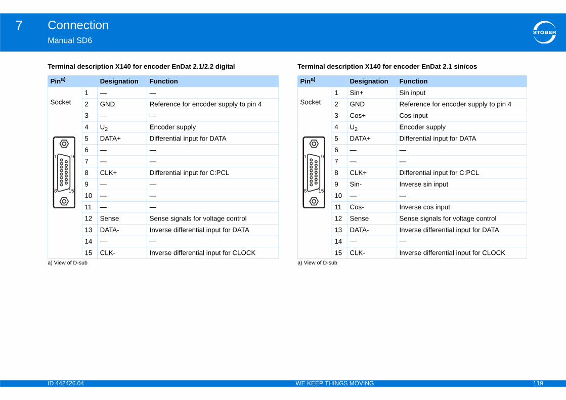
ID 4 119
Connection7Ma
Ter 0 for encoder EnDat 2.1 sin/cos
Pi
a) V
So
1
8
tion FunctionSin input
Reference for encoder supply to pin 4
Cos input
Encoder supply
Differential input for DATA
—
—
Differential input for C:PCL
Inverse sin input
—
Inverse cos input
Sense signals for voltage control
Inverse differential input for DATA
—
Inverse differential input for CLOCK
42426.04 WE KEEP THINGS MOVING
nual SD6
minal description X140 for encoder EnDat 2.1/2.2 digital Terminal description X14
na)
iew of D-sub
Designation Function
cket1 — —
2 GND Reference for encoder supply to pin 4
3 — —
4 U2 Encoder supply
5 DATA+ Differential input for DATA
6 — —
7 — —
8 CLK+ Differential input for C:PCL
9 — —
10 — —
11 — —
12 Sense Sense signals for voltage control
13 DATA- Inverse differential input for DATA
14 — —
15 CLK- Inverse differential input for CLOCK
9
15
Pina)
a) View of D-sub
Designa
Socket1 Sin+
2 GND
3 Cos+
4 U2
5 DATA+
6 —
7 —
8 CLK+
9 Sin-
10 —
11 Cos-
12 Sense
13 DATA-
14 —
15 CLK-
9
15
1
8

ID 4 120
Connection7Ma
Ter interface adapter AP6A00 (RI6)
Pi
a) V
So
1
8
onnection of the SDS 4000-compatible resolver cable
tion Function Pinb)
onnection to the SD6, terminal X140 (RI6)
— —Connector— —
Sin input (inverse) 9
Cos input (inverse) 11
Reference to ExcitationResolv
2
— —
Sin input 1
Cos input 3
nResolv Resolver excitation signal
6
15
9
8
1
42426.04 WE KEEP THINGS MOVING
nual SD6
minal description X140 sin/cos encoder Terminal description for
na)
iew of D-sub
Designation
Function
cket1 Sin+ Sin input
2 GND Reference for encoder supply to pin 4
3 Cos+ Cos input
4 U2 Encoder supply
5 — —
6 — —
7 — —
8 — —
9 Sin- Inverse sin input
10
— —
11
Cos- Inverse cos input
12
Sense Sense signals for voltage control
13
— —
14
— —
15
— —
9
15
Pina)
a) View of D-sub 9-pole for the c
Designa
b) View of D-sub 15-pin for the c
Socket1 —
2 —
3 Sin-
4 Cos-
5 GND
6 —
7 Sin+
8 Cos+
9 Excitatio
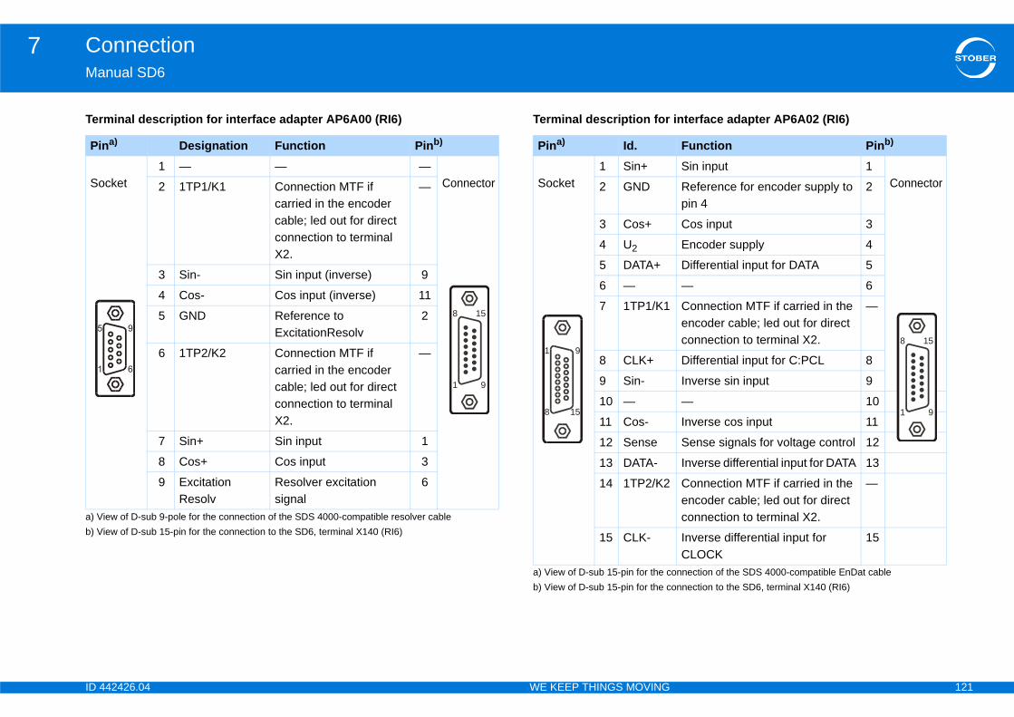
ID 4 121
Connection7Ma
Ter interface adapter AP6A02 (RI6)
Pi
a) Vb) V
So
onnection of the SDS 4000-compatible EnDat cable
Function Pinb)
onnection to the SD6, terminal X140 (RI6)
Sin input 1ConnectorReference for encoder supply to
pin 42
Cos input 3
Encoder supply 4
Differential input for DATA 5
— 6
Connection MTF if carried in the encoder cable; led out for direct connection to terminal X2.
—
Differential input for C:PCL 8
Inverse sin input 9
— 10
Inverse cos input 11
Sense signals for voltage control 12
Inverse differential input for DATA 13
Connection MTF if carried in the encoder cable; led out for direct connection to terminal X2.
—
Inverse differential input for CLOCK
15
15
9
8
1
42426.04 WE KEEP THINGS MOVING
nual SD6
minal description for interface adapter AP6A00 (RI6) Terminal description for
na)
iew of D-sub 9-pole for the connection of the SDS 4000-compatible resolver cable
Designation Function Pinb)
iew of D-sub 15-pin for the connection to the SD6, terminal X140 (RI6)
cket1 — — —
Connector2 1TP1/K1 Connection MTF if carried in the encoder cable; led out for direct connection to terminal X2.
—
3 Sin- Sin input (inverse) 9
4 Cos- Cos input (inverse) 11
5 GND Reference to ExcitationResolv
2
6 1TP2/K2 Connection MTF if carried in the encoder cable; led out for direct connection to terminal X2.
—
7 Sin+ Sin input 1
8 Cos+ Cos input 3
9 ExcitationResolv
Resolver excitation signal
6
15
9
8
1
Pina)
a) View of D-sub 15-pin for the c
Id.
b) View of D-sub 15-pin for the c
Socket1 Sin+
2 GND
3 Cos+
4 U2
5 DATA+
6 —
7 1TP1/K1
8 CLK+
9 Sin-
10 —
11 Cos-
12 Sense
13 DATA-
14 1TP2/K2
15 CLK-
9
15
1
8
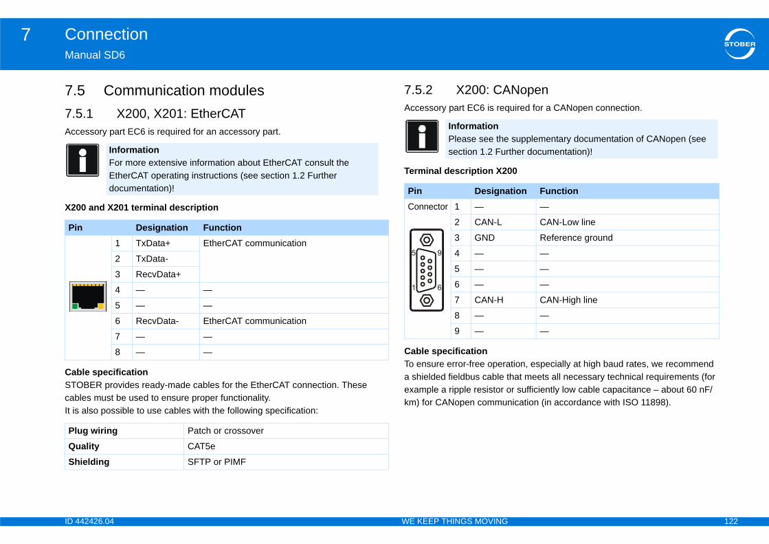
ID 4 122
Connection7Ma
7.7.5Acc
X20
CabSTOcabIt is
Nopenuired for a CANopen connection.
0
tion, especially at high baud rates, we recommend hat meets all necessary technical requirements (for r sufficiently low cable capacitance – about 60 nF/ication (in accordance with ISO 11898).
Pi
PlQuSh
supplementary documentation of CANopen (see ther documentation)!
tion Function—
CAN-Low line
Reference ground
—
—
—
CAN-High line
—
—
42426.04 WE KEEP THINGS MOVING
nual SD6
5 Communication modules.1 X200, X201: EtherCATessory part EC6 is required for an accessory part.
0 and X201 terminal description
le specificationBER provides ready-made cables for the EtherCAT connection. These
les must be used to ensure proper functionality. also possible to use cables with the following specification:
7.5.2 X200: CAAccessory part EC6 is req
Terminal description X20
Cable specificationTo ensure error-free operaa shielded fieldbus cable texample a ripple resistor okm) for CANopen commun
InformationFor more extensive information about EtherCAT consult the EtherCAT operating instructions (see section 1.2 Further documentation)!
n Designation Function1 TxData+ EtherCAT communication
2 TxData-
3 RecvData+
4 — —
5 — —
6 RecvData- EtherCAT communication
7 — —
8 — —
ug wiring Patch or crossover
ality CAT5e
ielding SFTP or PIMF
InformationPlease see thesection 1.2 Fur
Pin DesignaConnector 1 —
2 CAN-L
3 GND
4 —
5 —
6 —
7 CAN-H
8 —
9 —
ID 4 123
Connection7Ma
7.7.6A ndep
7.6LintermWitthemo
7.6TTLdet
7.6TTLcomis rto tconTheThe
•
•
•Pre
ar encoder with Wake and Shakeith W&S can be connected directly with SD6 via onverts the analog sin/cos signals in digital signals. n be connected to terminal X140 on RI6.
42426.04 WE KEEP THINGS MOVING
nual SD6
6 Encoder adapter box.1 Linear encoder
umber of different linear encoders are supported. The connection differs ending on the encoder type selected.
.1.1 Linear encoder EnDat 2.1/2.2 digital and SSIear encoder EnDat 2.1/2.2 digital or SSI are connected directly to SD6 via
inal X4. h EnDat 2.2 digital, the drive controller evaluates the internal information of encoder and determines automatically whether an encoder of a rotary tor or an encoder of a linear motor is connected.
.1.2 Linear encoder TTL with Wake and Shake incremental encoders with Wake and Shake (W&S) as a process for
ermining commutation are connected directly to terminal X4 with SD6.
.1.3 Linear encoder TTL with Hall sensor incremental encoder in combination with a Hall sensor for determining mutation are connected to the drive controller via the LA6 adapter box. LA6
esponsible for the signal adjustment of the Hall sensor signals. In addition he adapter box, one of terminal modules XI6, IO6 or RI6 is required for necting the Hall sensor to the SD6. incremental encoder is connected to terminal X4 of the drive controller. connection of the Hall sensor varies depending on the terminal module:
XI6: connection to terminal X120 or X101
IO6: connection to X101
RI6: connection to terminal X120 or X101 -assembled cables are available for connecting to the SD6.
7.6.1.4 Sin/cos lineSin/cos linear encoders wterminal module RI6. RI6 cSin/cos linear encoders ca
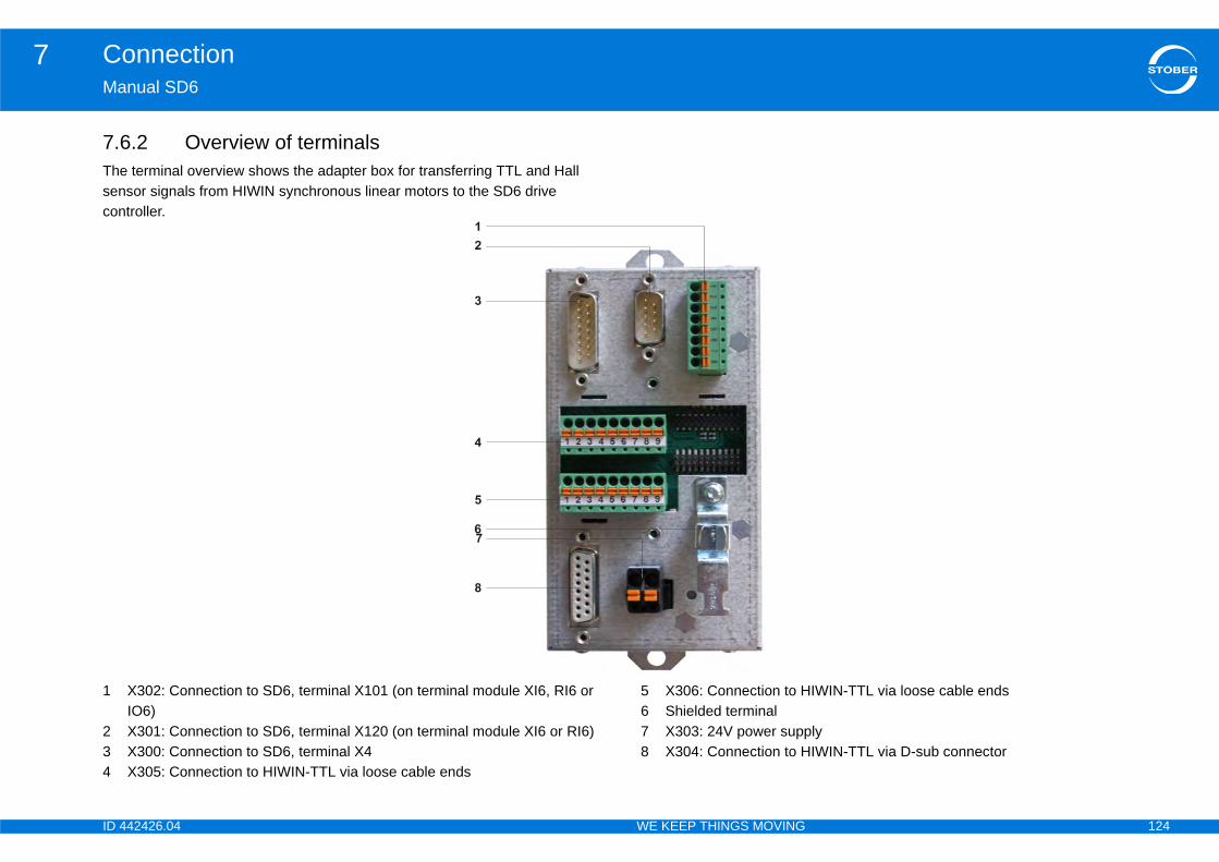
ID 4 124
Connection7Ma
7.6Thesencon
1
234
IWIN-TTL via loose cable ends
lyIWIN-TTL via D-sub connector
42426.04 WE KEEP THINGS MOVING
nual SD6
.2 Overview of terminals terminal overview shows the adapter box for transferring TTL and Hall sor signals from HIWIN synchronous linear motors to the SD6 drive troller.
X302: Connection to SD6, terminal X101 (on terminal module XI6, RI6 or IO6)X301: Connection to SD6, terminal X120 (on terminal module XI6 or RI6)X300: Connection to SD6, terminal X4X305: Connection to HIWIN-TTL via loose cable ends
5 X306: Connection to H6 Shielded terminal7 X303: 24V power supp8 X304: Connection to H
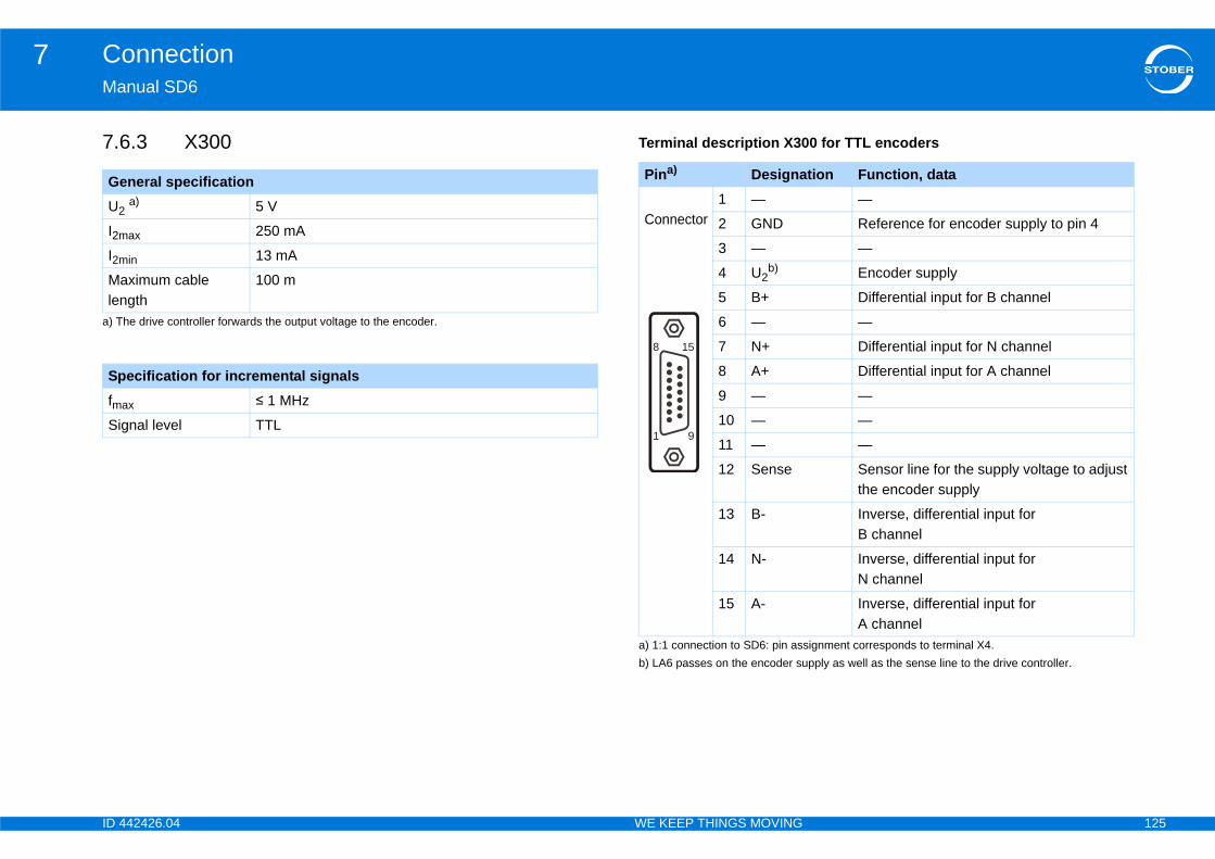
ID 4 125
Connection7Ma
7.6 0 for TTL encoders
GeU2
a) T
I2m
I2m
Malen
SpfmSig
signment corresponds to terminal X4.
tion Function, data—
Reference for encoder supply to pin 4
—
pply as well as the sense line to the drive controller.
Encoder supply
Differential input for B channel
—
Differential input for N channel
Differential input for A channel
—
—
—
Sensor line for the supply voltage to adjust the encoder supply
Inverse, differential input for B channel
Inverse, differential input for N channel
Inverse, differential input for A channel
42426.04 WE KEEP THINGS MOVING
nual SD6
.3 X300 Terminal description X30
neral specification a)
he drive controller forwards the output voltage to the encoder.
5 V
ax 250 mA
in 13 mA
ximum cable gth
100 m
ecification for incremental signals
ax ≤ 1 MHz
nal level TTL
Pina)
a) 1:1 connection to SD6: pin as
Designa
Connector1 —
2 GND
3 —
4 U2b)
b) LA6 passes on the encoder su
5 B+
6 —
7 N+
8 A+
9 —
10 —
11 —
12 Sense
13 B-
14 N-
15 A-
15
9
8
1
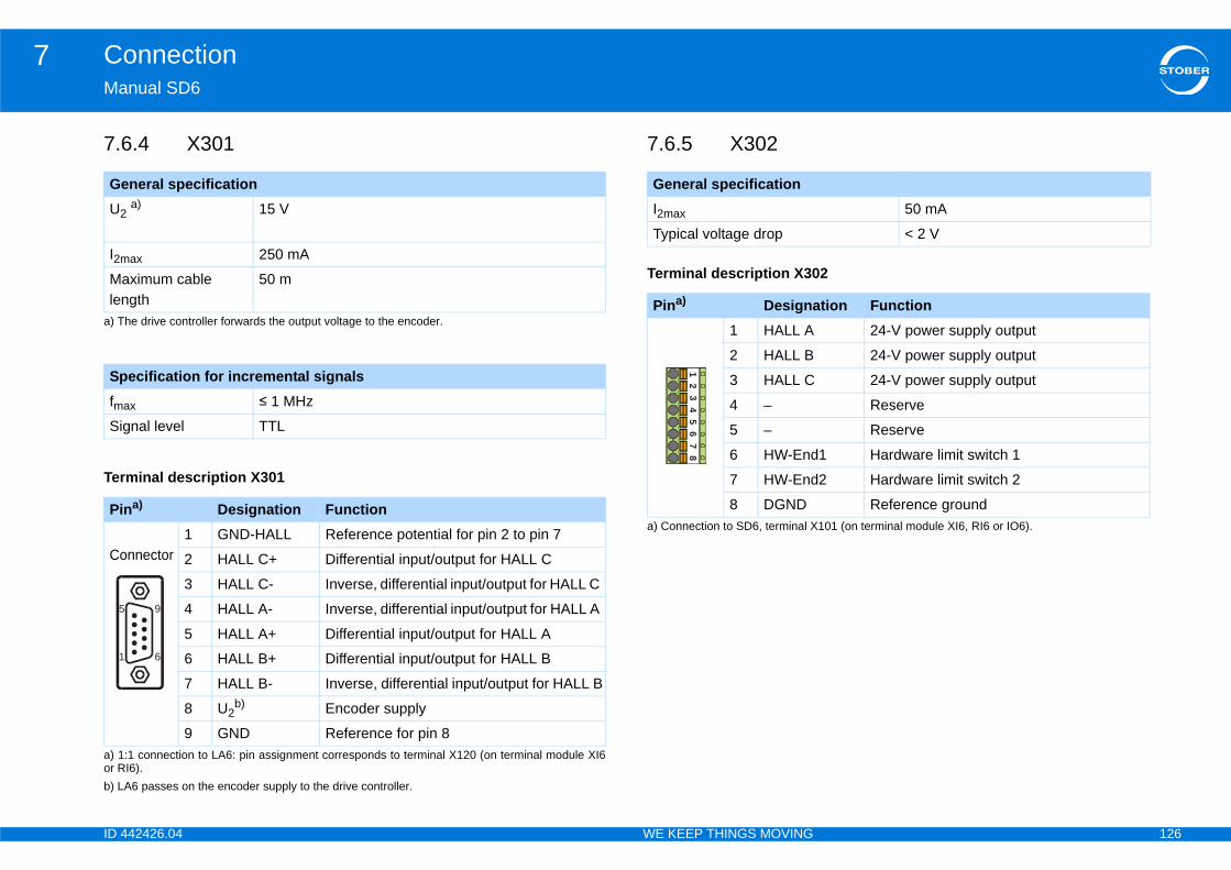
ID 4 126
Connection7Ma
7.6
Ter
2
GeU2
a) T
I2m
Malen
SpfmSig
Pi
a) 1or R
Co
b) L
5
1
50 mA
< 2 V
101 (on terminal module XI6, RI6 or IO6).
tion Function24-V power supply output
24-V power supply output
24-V power supply output
Reserve
Reserve
1 Hardware limit switch 1
2 Hardware limit switch 2
Reference ground
42426.04 WE KEEP THINGS MOVING
nual SD6
.4 X301
minal description X301
7.6.5 X302
Terminal description X30
neral specification a)
he drive controller forwards the output voltage to the encoder.
15 V
ax 250 mA
ximum cable gth
50 m
ecification for incremental signals
ax ≤ 1 MHz
nal level TTL
na)
:1 connection to LA6: pin assignment corresponds to terminal X120 (on terminal module XI6 I6).
Designation Function
nnector1 GND-HALL Reference potential for pin 2 to pin 7
2 HALL C+ Differential input/output for HALL C
3 HALL C- Inverse, differential input/output for HALL C
4 HALL A- Inverse, differential input/output for HALL A
5 HALL A+ Differential input/output for HALL A
6 HALL B+ Differential input/output for HALL B
7 HALL B- Inverse, differential input/output for HALL B
8 U2b)
A6 passes on the encoder supply to the drive controller.
Encoder supply
9 GND Reference for pin 8
9
6
General specificationI2max
Typical voltage drop
Pina)
a) Connection to SD6, terminal X
Designa1 HALL A
2 HALL B
3 HALL C
4 –
5 –
6 HW-End
7 HW-End
8 DGND
12
34
56
78

ID 4 127
Connection7Ma
7.6
Ter
nnection via D-sub connector
y and material damage due to electric shock!ration in the LA6 adapter box.
mperature sensor without potential separation must Instead they must be connected directly to the drive ).
GeU1
I1m
Pi
V
0 mA
mA
0 m
ental signals1 MHz
L
ample – limit frequencyith 2,048 pulses per revolution:
ns per minute (equivalent to 50 revolutions per pulses per revolution
es per second
42426.04 WE KEEP THINGS MOVING
nual SD6
.6 X303
minal description X303
7.6.7 X304: Co
WARNING!
Danger of personal injurThere is no potential sepa
Signals of the motor tenot be routed via LA6. controller (terminal X2
neral specification20.4-28.8 V
ax 100 mA
n Designation Function1 + 24 V 24-V power supply
2 GND Reference potential for + 24 V
+ –
General specificationU2 5
I2max 25
I2min 13
Maximum cable length
10
Specification for incremfmax ≤
Signal level TT
Calculation ex... for encoder w3,000 revolutiosecond) * 2,048= 102,400 puls= 102.4 kHz
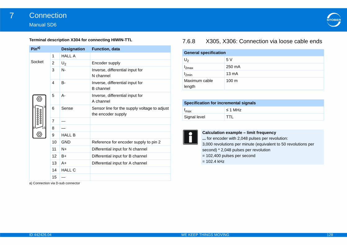
ID 4 128
Connection7Ma
Ter 06: Connection via loose cable endsPi
a) C
So
1
8
V
0 mA
mA
0 m
ental signals1 MHz
L
ample – limit frequency ith 2,048 pulses per revolution:
ns per minute (equivalent to 50 revolutions per pulses per revolution
es per second
42426.04 WE KEEP THINGS MOVING
nual SD6
minal description X304 for connecting HIWIN-TTL 7.6.8 X305, X3na)
onnection via D-sub connector
Designation Function, data
cket1 HALL A
2 U2 Encoder supply
3 N- Inverse, differential input for N channel
4 B- Inverse, differential input for B channel
5 A- Inverse, differential input for A channel
6 Sense Sensor line for the supply voltage to adjust the encoder supply
7 —
8 —
9 HALL B
10 GND Reference for encoder supply to pin 2
11 N+ Differential input for N channel
12 B+ Differential input for B channel
13 A+ Differential input for A channel
14 HALL C
15 —
9
15
General specificationU2 5
I2max 25
I2min 13
Maximum cable length
10
Specification for incremfmax ≤
Signal level TT
Calculation ex... for encoder w3,000 revolutiosecond) * 2,048= 102,400 puls= 102.4 kHz
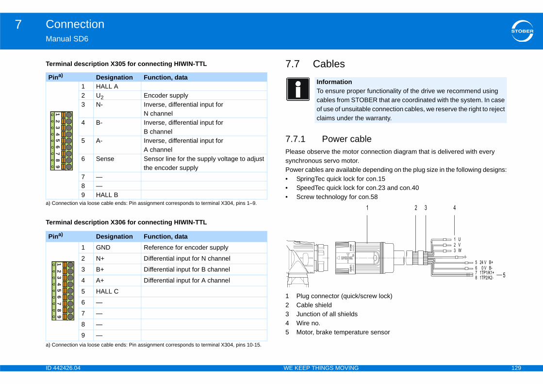
ID 4 129
Connection7Ma
Ter
Ter
ble connection diagram that is delivered with every depending on the plug size in the following designs:r con.15r con.23 and con.40on.58
screw lock)
ure sensor
Pi
a) C
Pi
a) C
er functionality of the drive we recommend using OBER that are coordinated with the system. In case ble connection cables, we reserve the right to reject
e warranty.
42426.04 WE KEEP THINGS MOVING
nual SD6
minal description X305 for connecting HIWIN-TTL
minal description X306 for connecting HIWIN-TTL
7.7 Cables
7.7.1 Power caPlease observe the motorsynchronous servo motor.Power cables are available• SpringTec quick lock fo• SpeedTec quick lock fo• Screw technology for c
1 Plug connector (quick/2 Cable shield3 Junction of all shields4 Wire no.5 Motor, brake temperat
na)
onnection via loose cable ends: Pin assignment corresponds to terminal X304, pins 1–9.
Designation Function, data1 HALL A2 U2 Encoder supply3 N- Inverse, differential input for
N channel 4 B- Inverse, differential input for
B channel 5 A- Inverse, differential input for
A channel 6 Sense Sensor line for the supply voltage to adjust
the encoder supply 7 —8 —9 HALL B
na)
onnection via loose cable ends: Pin assignment corresponds to terminal X304, pins 10-15.
Designation Function, data1 GND Reference for encoder supply
2 N+ Differential input for N channel
3 B+ Differential input for B channel
4 A+ Differential input for A channel
5 HALL C
6 —
7 —
8 —
9 —
98
76
54
32
19
87
65
43
21
InformationTo ensure propcables from STof use of unsuitaclaims under th
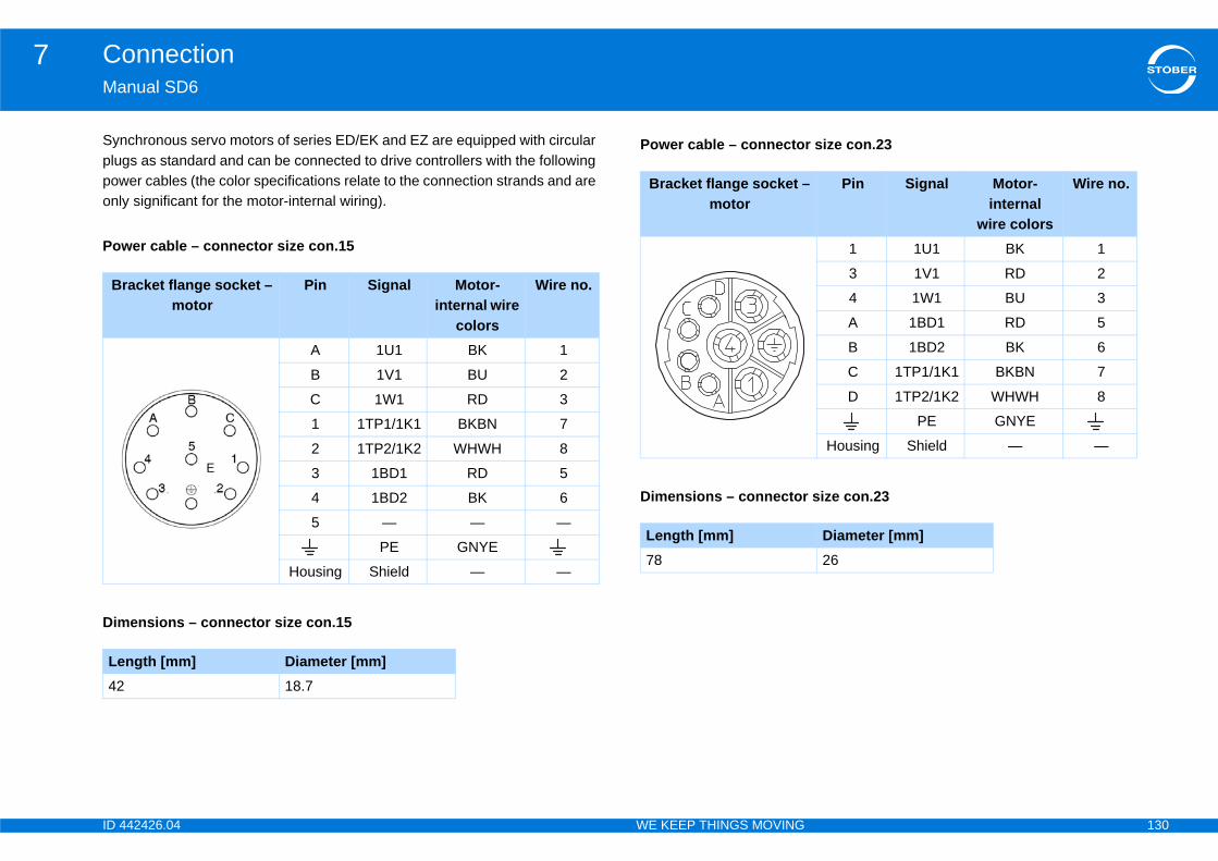
ID 4 130
Connection7Ma
Synplupowonl
Pow
B
Dim
Le42
r size con.23
Pin Signal Motor-internal
wire colors
Wire no.
1 1U1 BK 1
3 1V1 RD 2
4 1W1 BU 3
A 1BD1 RD 5
B 1BD2 BK 6
C 1TP1/1K1 BKBN 7
D 1TP2/1K2 WHWH 8
PE GNYE
Housing Shield — —
size con.23
Diameter [mm]26
42426.04 WE KEEP THINGS MOVING
nual SD6
chronous servo motors of series ED/EK and EZ are equipped with circular gs as standard and can be connected to drive controllers with the following er cables (the color specifications relate to the connection strands and are
y significant for the motor-internal wiring).
er cable – connector size con.15
racket flange socket – motor
Pin Signal Motor-internal wire
colors
Wire no.
A 1U1 BK 1
B 1V1 BU 2
C 1W1 RD 3
1 1TP1/1K1 BKBN 7
2 1TP2/1K2 WHWH 8
3 1BD1 RD 5
4 1BD2 BK 6
5 — — —
PE GNYE
Housing Shield — —
ensions – connector size con.15
ngth [mm] Diameter [mm]18.7
Power cable – connecto
Bracket flange socket –motor
Dimensions – connector
Length [mm]78
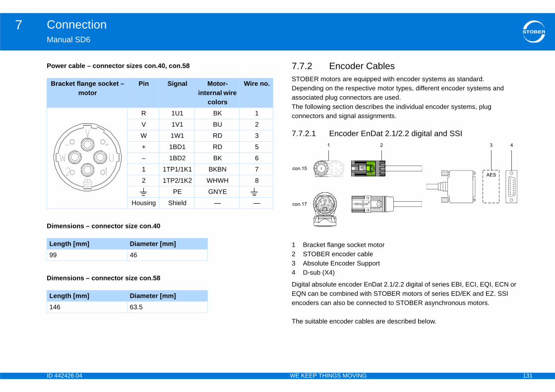
ID 4 131
Connection7Ma
ablesped with encoder systems as standard.
ive motor types, different encoder systems and s are used. ribes the individual encoder systems, plug ignments.
Dat 2.1/2.2 digital and SSI
motorleport
nDat 2.1/2.2 digital of series EBI, ECI, EQI, ECN or h STOBER motors of series ED/EK and EZ. SSI nected to STOBER asynchronous motors.
es are described below.
Pow
B
Dim
Le99
Dim
Le14
42426.04 WE KEEP THINGS MOVING
nual SD6
7.7.2 Encoder CSTOBER motors are equipDepending on the respectassociated plug connectorThe following section descconnectors and signal ass
7.7.2.1 Encoder En
1 Bracket flange socket 2 STOBER encoder cab3 Absolute Encoder Sup4 D-sub (X4)
Digital absolute encoder EEQN can be combined witencoders can also be con
The suitable encoder cabl
er cable – connector sizes con.40, con.58
racket flange socket – motor
Pin Signal Motor-internal wire
colors
Wire no.
R 1U1 BK 1
V 1V1 BU 2
W 1W1 RD 3
+ 1BD1 RD 5
– 1BD2 BK 6
1 1TP1/1K1 BKBN 7
2 1TP2/1K2 WHWH 8
PE GNYE
Housing Shield — —
ensions – connector size con.40
ngth [mm] Diameter [mm]46
ensions – connector size con.58
ngth [mm] Diameter [mm]6 63.5

ID 4 132
Connection7Ma
EncThe n function. In this case, pin 2 and pin 3 are assigned to t t to the Absolute Encoder Support (AES) for these enc
a) O
Dim
Le42
42426.04 WE KEEP THINGS MOVING
nual SD6
oder cable – plug connector con.15 voltage supply is buffered for the inductive EnDat 2.2 digital encoders "EBI 1135" and "EBI 135" with multitur
he backup battery U2BAT. Note that the encoder cable must not be connected to X4 of the drive controller buoders.
Motor Signal Wire colors D-sub (X4)Angle flange socket Pin Motor-
internalEncoder Pin
1 CLK+ VT YE 8
2Sense
BU PK 12U2BAT+
a)
nly relevant for EBI encoders.
3—
WH GY 3U2BAT-
a)
4 — — — —
5 DATA- PK BN 13
6 DATA+ GY WH 5
7 — — — —
8 CLK- YE GN 15
9 — — — —
10 GND WHGN BU 2
11 — — — —
12 U2 BNGN RD 4
Housing Shield
ensions – connector size con.15
ngth [mm] Diameter [mm]18.7
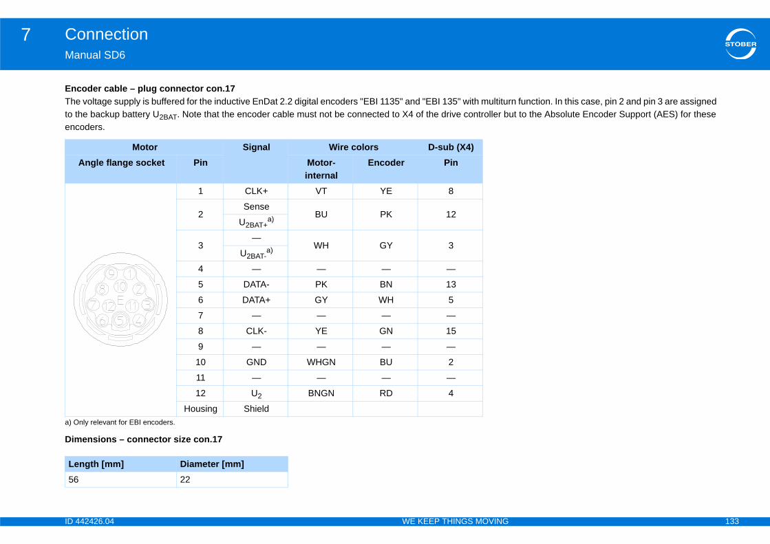
ID 4 133
Connection7Ma
EncThe n function. In this case, pin 2 and pin 3 are assigned to t t to the Absolute Encoder Support (AES) for these enc
a) O
Dim
Le56
42426.04 WE KEEP THINGS MOVING
nual SD6
oder cable – plug connector con.17 voltage supply is buffered for the inductive EnDat 2.2 digital encoders "EBI 1135" and "EBI 135" with multitur
he backup battery U2BAT. Note that the encoder cable must not be connected to X4 of the drive controller buoders.
Motor Signal Wire colors D-sub (X4)Angle flange socket Pin Motor-
internalEncoder Pin
1 CLK+ VT YE 8
2Sense
BU PK 12U2BAT+
a)
nly relevant for EBI encoders.
3—
WH GY 3U2BAT-
a)
4 — — — —
5 DATA- PK BN 13
6 DATA+ GY WH 5
7 — — — —
8 CLK- YE GN 15
9 — — — —
10 GND WHGN BU 2
11 — — — —
12 U2 BNGN RD 4
Housing Shield
ensions – connector size con.17
ngth [mm] Diameter [mm]22

ID 4 134
Connection7Ma
EncCab hronous servo motors ED/EK; connect these with asy
Dim
Le58
42426.04 WE KEEP THINGS MOVING
nual SD6
oder cable – plug connector con.23le with plug connector con.23 in combination with EnDat 2.1/2.2 digital encoders can be connected to syncnchronous motors in combination with SSI encoders.
Motor Signal Wire colors D-sub (X4)Angle flange socket Pin Motor-
internalEncoder Pin
1 CLK+ VT YE 8
2 Sense BNGN PK 12
3 — — — —
4 — — — —
5 DAT- PK BN 13
6 DAT+ GY WH 5
7 — — — —
8 CLK- YE GN 15
9 — — — —
10 GND WHGN BU 2
11 — — — —
12 U2 BNGN RD 4
Housing Shield
ensions – connector size con.23
ngth [mm] Diameter [mm]26

ID 4 135
Connection7Ma
7.7
123
Abscom
The
42426.04 WE KEEP THINGS MOVING
nual SD6
.2.2 EnDat 2.1 sin/cos encoder
Bracket flange socket motorSTOBER encoder cableD-sub (X140)
olute encoder EnDat 2.1 sin/cos of series ECI, EQI, ECN or EQN can be bined with STOBER motors of series ED/EK and EZ.
suitable encoder cables are described below.
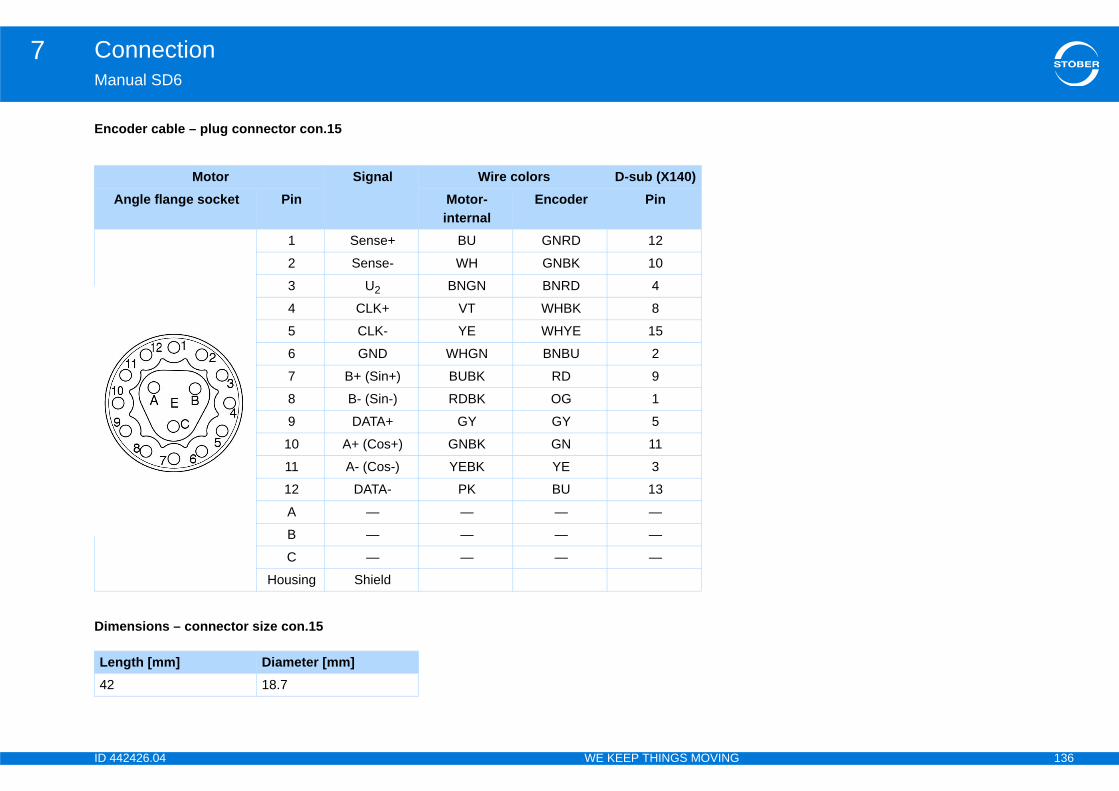
ID 4 136
Connection7Ma
Enc
Dim
Le42
42426.04 WE KEEP THINGS MOVING
nual SD6
oder cable – plug connector con.15
Motor Signal Wire colors D-sub (X140)Angle flange socket Pin Motor-
internalEncoder Pin
1 Sense+ BU GNRD 12
2 Sense- WH GNBK 10
3 U2 BNGN BNRD 4
4 CLK+ VT WHBK 8
5 CLK- YE WHYE 15
6 GND WHGN BNBU 2
7 B+ (Sin+) BUBK RD 9
8 B- (Sin-) RDBK OG 1
9 DATA+ GY GY 5
10 A+ (Cos+) GNBK GN 11
11 A- (Cos-) YEBK YE 3
12 DATA- PK BU 13
A — — — —
B — — — —
C — — — —
Housing Shield
ensions – connector size con.15
ngth [mm] Diameter [mm]18.7

ID 4 137
Connection7Ma
Enc
Dim
Le56
42426.04 WE KEEP THINGS MOVING
nual SD6
oder cable – plug connector con.17
Motor Signal Wire colors D-sub (X140) Angle flange socket Pin Motor-
internalEncoder Pin
1 Sense+ BU GNRD 12
2 — — — —
3 — — — —
4 Sense- WH GNBK 10
5 — — — —
6 — — — —
7 U2 BNGN BNRD 4
8 CLK+ VT WHBK 8
9 CLK- YE WHYE 15
10 GND WHGN BNBU 2
11 — — — —
12 B+ (Sin+) BUBK RD 9
13 B- (Sin-) RDBK OG 1
14 DATA+ GY GY 5
15 A+ (Cos+) GNBK GN 11
16 A- (Cos-) YEBK YE 3
17 DATA- PK BU 13
Housing Shield
ensions – connector size con.17
ngth [mm] Diameter [mm]22
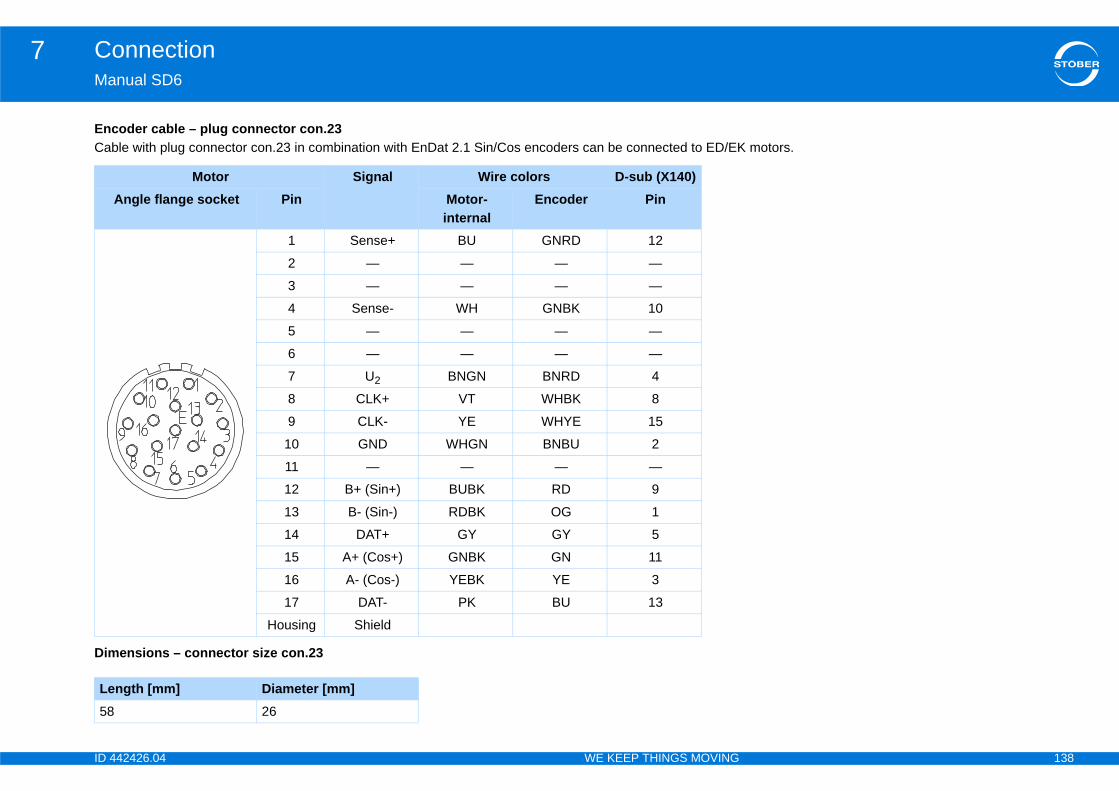
ID 4 138
Connection7Ma
EncCab motors.
Dim
Le58
42426.04 WE KEEP THINGS MOVING
nual SD6
oder cable – plug connector con.23le with plug connector con.23 in combination with EnDat 2.1 Sin/Cos encoders can be connected to ED/EK
Motor Signal Wire colors D-sub (X140)Angle flange socket Pin Motor-
internalEncoder Pin
1 Sense+ BU GNRD 12
2 — — — —
3 — — — —
4 Sense- WH GNBK 10
5 — — — —
6 — — — —
7 U2 BNGN BNRD 4
8 CLK+ VT WHBK 8
9 CLK- YE WHYE 15
10 GND WHGN BNBU 2
11 — — — —
12 B+ (Sin+) BUBK RD 9
13 B- (Sin-) RDBK OG 1
14 DAT+ GY GY 5
15 A+ (Cos+) GNBK GN 11
16 A- (Cos-) YEBK YE 3
17 DAT- PK BU 13
Housing Shield
ensions – connector size con.23
ngth [mm] Diameter [mm]26
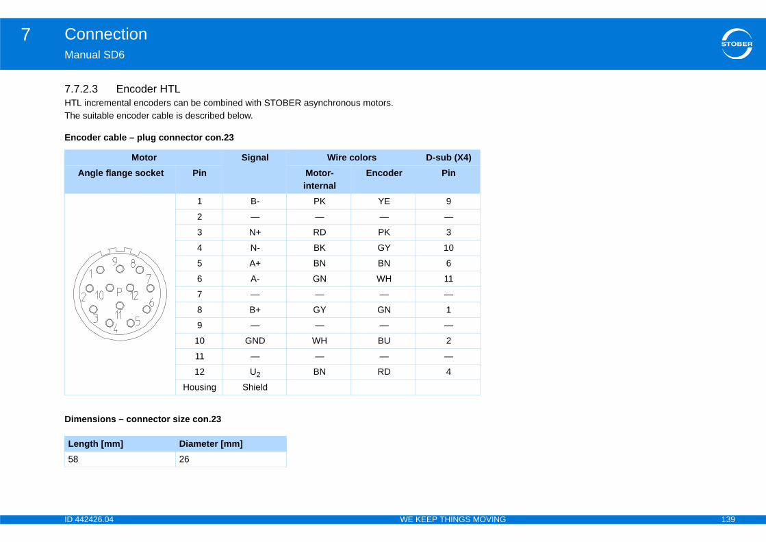
ID 4 139
Connection7Ma
7.7HTThe
Enc
Dim
Le58
42426.04 WE KEEP THINGS MOVING
nual SD6
.2.3 Encoder HTLL incremental encoders can be combined with STOBER asynchronous motors. suitable encoder cable is described below.
oder cable – plug connector con.23
Motor Signal Wire colors D-sub (X4)Angle flange socket Pin Motor-
internalEncoder Pin
1 B- PK YE 9
2 — — — —
3 N+ RD PK 3
4 N- BK GY 10
5 A+ BN BN 6
6 A- GN WH 11
7 — — — —
8 B+ GY GN 1
9 — — — —
10 GND WH BU 2
11 — — — —
12 U2 BN RD 4
Housing Shield
ensions – connector size con.23
ngth [mm] Diameter [mm]26
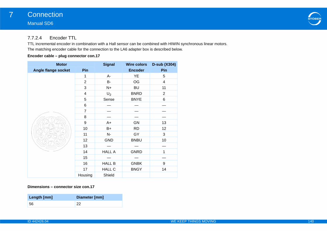
ID 4 140
Connection7Ma
7.7TTL otors. The
Enc
Dim
Le56
42426.04 WE KEEP THINGS MOVING
nual SD6
.2.4 Encoder TTL incremental encoder in combination with a Hall sensor can be combined with HIWIN synchronous linear m matching encoder cable for the connection to the LA6 adapter box is described below.
oder cable – plug connector con.17
Motor Signal Wire colors D-sub (X304)Angle flange socket Pin Encoder Pin
1 A- YE 52 B- OG 43 N+ BU 114 U2 BNRD 25 Sense BNYE 66 — — —7 — — —8 — — —9 A+ GN 13
10 B+ RD 1211 N- GY 312 GND BNBU 1013 — — —14 HALL A GNRD 115 — — —16 HALL B GNBK 917 HALL C BNGY 14
Housing Shield
ensions – connector size con.17
ngth [mm] Diameter [mm]22
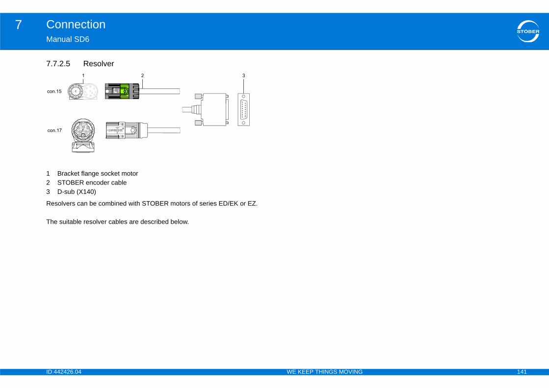
ID 4 141
Connection7Ma
7.7
123
Res
The
42426.04 WE KEEP THINGS MOVING
nual SD6
.2.5 Resolver
Bracket flange socket motorSTOBER encoder cableD-sub (X140)
olvers can be combined with STOBER motors of series ED/EK or EZ.
suitable resolver cables are described below.
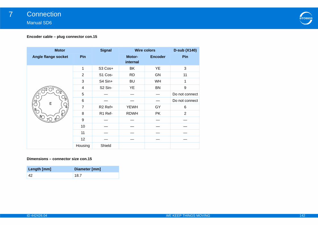
ID 4 142
Connection7Ma
Enc
Dim
Le42
42426.04 WE KEEP THINGS MOVING
nual SD6
oder cable – plug connector con.15
Motor Signal Wire colors D-sub (X140) Angle flange socket Pin Motor-
internalEncoder Pin
1 S3 Cos+ BK YE 3
2 S1 Cos- RD GN 11
3 S4 Sin+ BU WH 1
4 S2 Sin- YE BN 9
5 — — — Do not connect
6 — — — Do not connect
7 R2 Ref+ YEWH GY 6
8 R1 Ref- RDWH PK 2
9 — — — —
10 — — — —
11 — — — —
12 — — — —
Housing Shield
ensions – connector size con.15
ngth [mm] Diameter [mm]18.7
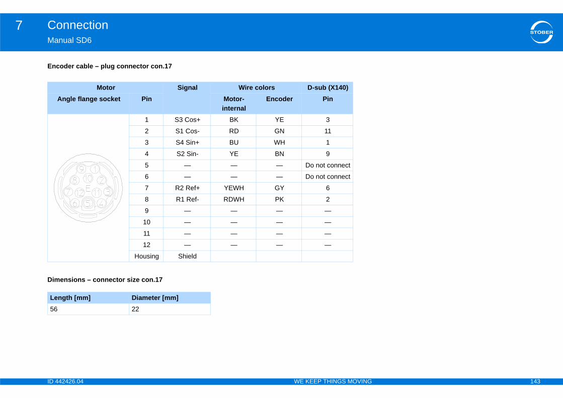
ID 4 143
Connection7Ma
Enc
Dim
Le56
42426.04 WE KEEP THINGS MOVING
nual SD6
oder cable – plug connector con.17
Motor Signal Wire colors D-sub (X140)Angle flange socket Pin Motor-
internalEncoder Pin
1 S3 Cos+ BK YE 3
2 S1 Cos- RD GN 11
3 S4 Sin+ BU WH 1
4 S2 Sin- YE BN 9
5 — — — Do not connect
6 — — — Do not connect
7 R2 Ref+ YEWH GY 6
8 R1 Ref- RDWH PK 2
9 — — — —
10 — — — —
11 — — — —
12 — — — —
Housing Shield
ensions – connector size con.17
ngth [mm] Diameter [mm]22

ID 4 144
Connection7Ma
EncCab otors ED/EK.
Cab
Dim
Le58
BKBNBUGNGYOG
42426.04 WE KEEP THINGS MOVING
nual SD6
oder cable – plug connector con.23le with plug connector con.23 in combination with resolvers can only be connected to synchronous servo m
le color – key
Motor Signal Wire colors D-sub (X140)Angle flange socket Pin Motor-
internalEncoder Pin
1 S3 Cos+ BK YE 32 S1 Cos- RD GN 113 S4 Sin+ BU WH 14 S2 Sin- YE BN 95 — — — Do not connect6 — — — Do not connect7 R2 Ref+ YEWH GY 68 R1 Ref- RDWH PK 29 — — — —
10 — — — —11 — — — —12 — — — —
Housing Shield
ensions – connector size con.23
ngth [mm] Diameter [mm]26
BLACK PK PINKBROWN RD REDBLUE VT VIOLETGREEN WH WHITEGREY YE YELLOWORANGE
ID 4 145
Basic properties8Ma
8Ov
8.1
8.2
ite .. . . . . . . . . . . . . . . . . . . . . . . . . . . . . . . . . . 153
. . . . . . . . . . . . . . . . . . . . . . . . . . . . . . . . . . . . .153
l . . . . . . . . . . . . . . . . . . . . . . . . . . . . . . . . . . . . 153
evel . . . . . . . . . . . . . . . . . . . . . . . . . . . . . . . . . . 153
. . . . . . . . . . . . . . . . . . . . . . . . . . . . . . . . . . . . .154
42426.04 WE KEEP THINGS MOVING
nual SD6
Basic propertieserview of sections
Parameters . . . . . . . . . . . . . . . . . . . . . . . . . . . . . . . . . . . . . . . . . .146
8.1.1 Parameter address . . . . . . . . . . . . . . . . . . . . . . . . . . . . . . . . . 146
8.1.2 Parameter description . . . . . . . . . . . . . . . . . . . . . . . . . . . . . . . 147
8.1.3 Parameter data . . . . . . . . . . . . . . . . . . . . . . . . . . . . . . . . . . . . 148
8.1.4 Visibility . . . . . . . . . . . . . . . . . . . . . . . . . . . . . . . . . . . . . . . . . . 148
8.1.4.1 Access level . . . . . . . . . . . . . . . . . . . . . . . . . . . . . . . 148
8.1.4.2 Skip functions .. . . . . . . . . . . . . . . . . . . . . . . . . . . . . 149
8.1.4.3 Applications . . . . . . . . . . . . . . . . . . . . . . . . . . . . . . . 149
8.1.4.4 Firmware . . . . . . . . . . . . . . . . . . . . . . . . . . . . . . . . . 149
8.1.5 Data types . . . . . . . . . . . . . . . . . . . . . . . . . . . . . . . . . . . . . . . . 149
Interfaces . . . . . . . . . . . . . . . . . . . . . . . . . . . . . . . . . . . . . . . . . . . .150
8.2.1 Operator panel . . . . . . . . . . . . . . . . . . . . . . . . . . . . . . . . . . . . 150
8.2.1.1 Setup . . . . . . . . . . . . . . . . . . . . . . . . . . . . . . . . . . . . 150
8.2.1.2 Menu structure and navigation .. . . . . . . . . . . . . . . . 151
8.2.1.3 Status display . . . . . . . . . . . . . . . . . . . . . . . . . . . . . . 152
8.2.1.4 Languages . . . . . . . . . . . . . . . . . . . . . . . . . . . . . . . . 152
8.2.2 DriveControlSu
8.3 Access level . . . . .
8.3.1 Parameter leve
8.3.2 Configuration l
8.4 Events . . . . . . . . . .
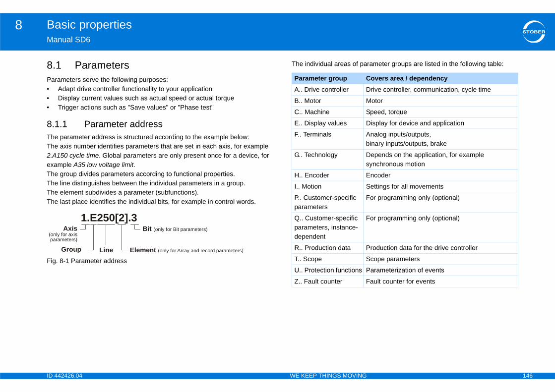
ID 4 146
Basic properties8Ma
8.Par•••
8.1TheThe2.AexaTheTheTheThe
Fig
rameter groups are listed in the following table:
(onpa
overs area / dependencyrive controller, communication, cycle time
otor
peed, torque
isplay for device and application
nalog inputs/outputs, inary inputs/outputs, brake
epends on the application, for example ynchronous motion
ncoder
ettings for all movements
or programming only (optional)
or programming only (optional)
roduction data for the drive controller
cope parameters
arameterization of events
ault counter for events
42426.04 WE KEEP THINGS MOVING
nual SD6
1 Parametersameters serve the following purposes:Adapt drive controller functionality to your applicationDisplay current values such as actual speed or actual torqueTrigger actions such as "Save values" or "Phase test"
.1 Parameter address parameter address is structured according to the example below: axis number identifies parameters that are set in each axis, for example 150 cycle time. Global parameters are only present once for a device, for mple A35 low voltage limit. group divides parameters according to functional properties. line distinguishes between the individual parameters in a group. element subdivides a parameter (subfunctions). last place identifies the individual bits, for example in control words.
. 8-1 Parameter address
The individual areas of pa
1.E250[2].3Axis
ly for axisrameters)
Group Line
Bit (only for Bit parameters)
Element (only for Array and record parameters)
Parameter group CA.. Drive controller D
B.. Motor M
C.. Machine S
E.. Display values D
F.. Terminals Ab
G.. Technology Ds
H.. Encoder E
I.. Motion S
P.. Customer-specific parameters
F
Q.. Customer-specific parameters, instance-dependent
F
R.. Production data P
T.. Scope S
U.. Protection functions P
Z.. Fault counter F
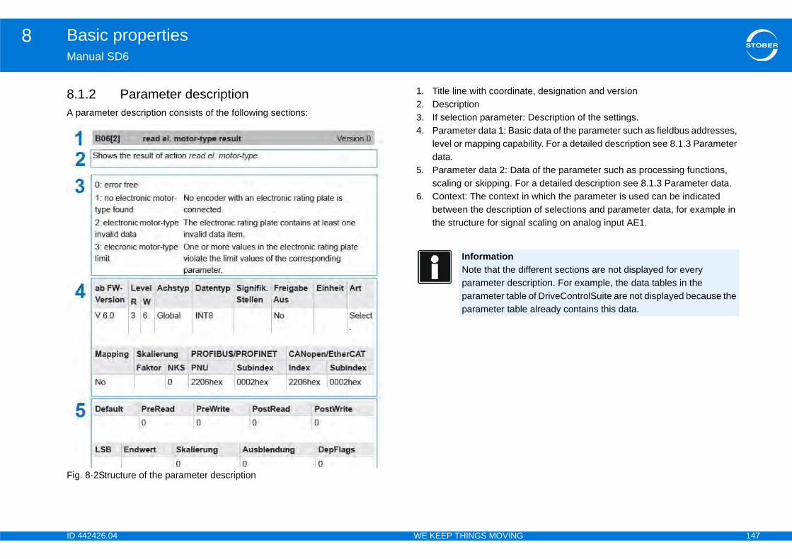
ID 4 147
Basic properties8Ma
8.1A p
Fig
te, designation and version
Description of the settings.ic data of the parameter such as fieldbus addresses, ility. For a detailed description see 8.1.3 Parameter
a of the parameter such as processing functions, r a detailed description see 8.1.3 Parameter data.n which the parameter is used can be indicated n of selections and parameter data, for example in scaling on analog input AE1.
ifferent sections are not displayed for every ription. For example, the data tables in the of DriveControlSuite are not displayed because the already contains this data.
42426.04 WE KEEP THINGS MOVING
nual SD6
.2 Parameter descriptionarameter description consists of the following sections:
. 8-2Structure of the parameter description
1. Title line with coordina2. Description3. If selection parameter:4. Parameter data 1: Bas
level or mapping capabdata.
5. Parameter data 2: Datscaling or skipping. Fo
6. Context: The context ibetween the descriptiothe structure for signal
InformationNote that the dparameter descparameter tableparameter table

ID 4 148
Basic properties8Ma
8.1The
Par•
•
•
•••
•••
••
•
of the parameter.he PreRead function.he PreWrite function. the PostRead function. the PostWrite function.
kip function.
isible depends on the following factors:
nn which a parameter was introduced
elvel in DriveControlSuite, note the operating manual er documentation). e following interfaces in the elements of parameter
ess via operator paneless via CANopen or EtherCAT ess via PROFIBUS or PROFINET4] are present but are not currently in effect.
42426.04 WE KEEP THINGS MOVING
nual SD6
.3 Parameter data following data items are specified for a parameter description:
ameter data 1from FW version: The earliest firmware version in which a parameter is present (see 8.1.4.4 Firmware).Level R/W: Read and write level of the parameter (see 8.1.4.1 Access level).Axis type: – Global: The parameter is assigned to the drive controller.– Axis: The parameter is assigned to the axis range.Data type: see 8.1.5 Data types.Significant places:EnableOff:– Yes: Parameter can only be changed if the enable is switched off.– No: Parameter can be changed regardless of the status of enable.Unit: Unit of the parameter, for example A or mm.Type: Parameter type.Mapping: Mapping capability of the parameter.– Yes: Parameter can be replaced by cyclic data exchange.– No: Parameter can only be replaced by acyclic data exchange.Significant places for gain/NKS: PROFIBUS/PROFINET PNU/Subindex: Address for PROFIBUS or PROFINET connection.CANopen/EtherCAT Index/Subindex: Address for CANopen or EtherCAT connection.
Parameter data 2• Default: Default value• PreRead: Number of t• PreWrite: Number of t• PostRead: Number of• PostWrite: Number of• LSB• Limit value• Scaling• Skip: Number of the s• DepFlags
8.1.4 VisibilityWhether parameters are v• The set access level• Skip functions• The selected applicatio• The firmware version i
8.1.4.1 Access levWhen setting the access lefor the software (1.2 FurthSet the access level for thA10:• A10[0]: Parameter acc• A10[2]: Parameter acc• A10[3]: Parameter accElements A10[1] and A10[
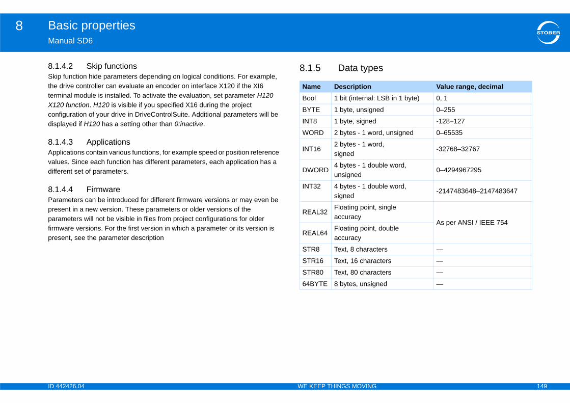
ID 4 149
Basic properties8Ma
8.1SkithetermX12condisp
8.1Appvaludiff
8.1Parpreparfirmpre
s
Value range, decimalLSB in 1 byte) 0, 1
d 0–255
-128–127
d, unsigned 0–65535
d, -32768–32767
ble word, 0–4294967295
ble word, -2147483648–2147483647
single
As per ANSI / IEEE 754double
ers —
cters —
cters —
ed —
42426.04 WE KEEP THINGS MOVING
nual SD6
.4.2 Skip functionsp function hide parameters depending on logical conditions. For example, drive controller can evaluate an encoder on interface X120 if the XI6
inal module is installed. To activate the evaluation, set parameter H120 0 function. H120 is visible if you specified X16 during the project figuration of your drive in DriveControlSuite. Additional parameters will be layed if H120 has a setting other than 0:inactive.
.4.3 Applicationslications contain various functions, for example speed or position reference es. Since each function has different parameters, each application has a
erent set of parameters.
.4.4 Firmwareameters can be introduced for different firmware versions or may even be sent in a new version. These parameters or older versions of the ameters will not be visible in files from project configurations for older ware versions. For the first version in which a parameter or its version is sent, see the parameter description
8.1.5 Data type
Name DescriptionBool 1 bit (internal:
BYTE 1 byte, unsigne
INT8 1 byte, signed
WORD 2 bytes - 1 wor
INT162 bytes - 1 worsigned
DWORD4 bytes - 1 douunsigned
INT32 4 bytes - 1 dousigned
REAL32Floating point, accuracy
REAL64Floating point, accuracy
STR8 Text, 8 charact
STR16 Text, 16 chara
STR80 Text, 80 chara
64BYTE 8 bytes, unsign
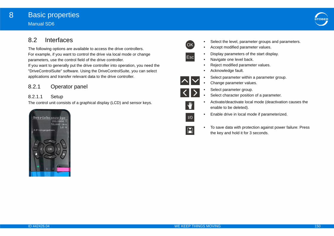
ID 4 150
Basic properties8Ma
8.TheForparIf y"Drapp
8.2
8.2The
the level, parameter groups and parameters.t modified parameter values.
y parameters of the start display.te one level back. modified parameter values.wledge fault.
parameter within a parameter group.e parameter values.
parameter group. character position of a parameter.
te/deactivate local mode (deactivation causes the to be deleted).
drive in local mode if parameterized.
e data with protection against power failure: Press y and hold it for 3 seconds.
42426.04 WE KEEP THINGS MOVING
nual SD6
2 Interfaces following options are available to access the drive controllers. example, if you want to control the drive via local mode or change ameters, use the control field of the drive controller. ou want to generally put the drive controller into operation, you need the iveControlSuite" software. Using the DriveControlSuite, you can select lications and transfer relevant data to the drive controller.
.1 Operator panel
.1.1 Setup control unit consists of a graphical display (LCD) and sensor keys.
• Select• Accep
• Displa• Naviga• Reject• Ackno
• Select• Chang
• Select• Select
• Activaenable
• Enable
• To savthe ke
OK
Esc
I/0
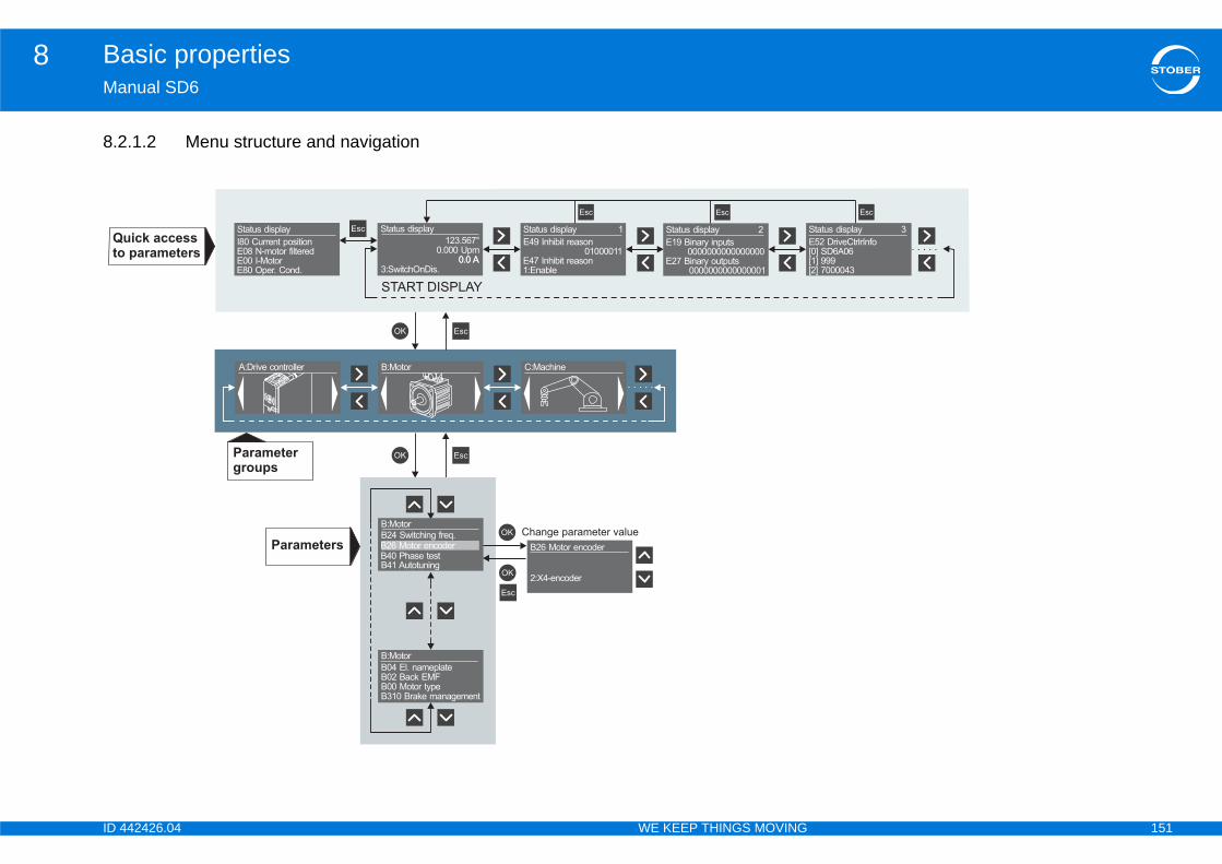
ID 4 151
Basic properties8Ma
8.2
Q
to
Esc
0.0 A
Status display 3
E52 DriveCtrlrInfo
[0] SD6A06
[1] 999
[2] 7000043
42426.04 WE KEEP THINGS MOVING
nual SD6
.1.2 Menu structure and navigation
OK EscParameter
groups
A:Drive controller
OK
C:MachineB:Motor
Esc
B:Motor
B41 Autotuning
B40 Phase test
B24 Switching freq.
EscEsc
OK
OK
B26 Motor encoder
2:X4-encoder
Change parameter value
B26 Motor encoder
B:Motor
B04 El. nameplate
B02 Back EMF
B00 Motor type
B310 Brake management
Parameters
uick access
parameters
Status display
123.567°
0.000 Upm
0.0 A
3:SwitchOnDis.
0.0 A 0.0 A
Status display 1
E49 Inhibit reason
01000011
E47 Inhibit reason
1:Enable
0.0 A
Status display 2
E19 Binary inputs
0000000000000000
E27 Binary outputs
0000000000000001
EscStatus display
I80 Current position
E08 N-motor filtered
E00 I-Motor
E80 Oper. Cond.
START DISPLAY
Esc Esc
ID 4 152
Basic properties8Ma
ParQu(diaoveStadisainptyplevePrethe
ParParproetcone
ParYouSelchothecha
layg of the status display depends on the application. are displayed in the default setting:
n
sponding parameter addresses for the values in the old the ESC key in the basic view. nge the status display:
parameters: to do this enter the addresses of the o display in parameter A144.x status display le A10[1] or 1.I400. controller display as the output medium of a higher-his set A142 = 1:Terminal. Then the controller must ay A141.x (one parameter element for each display oes not transfer any values, the display remains
read display lines you can read via the controller being displayed in which line of the display. The nted in a parameter element. Depending on how the ll lines and therefore not all parameter elements will
e for the display in parameter A12. German, English vailable for selection.
42426.04 WE KEEP THINGS MOVING
nual SD6
ameters – quick accessick access gives you direct access to the status of the most important gnostic) parameters. This level consists of a start display and four rviews of specific content: tus display 1 provides information about the causes of a possible switch on ble; status display 2 provides information about the analog and binary
uts and outputs; status display 3 for general drive controller data including e, firmware, integrated option modules, etc. You can navigate within this l with the right and left arrow keys.
ss "ESC" to reach the parameters associated with the values that appear in start display. These parameters are individually configurable.
ameter groupsameters are combined together in groups based on their functional perties, for example "Drive controller," "Motor," "Machine," "Terminals", .You can navigate within this level with the right and left arrow keys; Select of the possible groups with "OK.
ameters can navigate in a parameter group with the upper and lower arrow keys. ect one of the possible parameters with "OK." To change a parameter value, ose the corresponding character position with the right and left arrow keys, n select the new value with the upper and lower arrow keys. Accept nges with "OK" or reject them with "Esc.
8.2.1.3 Status dispNote that the default settinThe following parameters
• I80 current position
• E08 n-motor filtered
• E00 I-Motor
• E80 operating conditio
To find out which the correstatus display, press and hThere are two ways to cha
• You can display other parameters you want tparameter , for examp
• You can use the drive level controller: to do tdescribe parameter arrline). If the controller dempty.
In parameter array A140.xwhich content is currently content of a line is represedisplay is configured, not abe filled.
8.2.1.4 LanguagesYou can select the languagand French are currently a
InformationNote that a modified parameter value can only be saved so it will be retained through a power failure with the save key on the control unit.
ID 4 153
Basic properties8Ma
8.2Youan Driv sco
8.Thecaucer
8.3You
•
•
•
•
You
•
•
•
Ele
tion level
termines the programming options.
configuration window is available on this level.
meterize applications, but not program them.
and parameterize applications on this level. The ned up to the first program level. You cannot
and parameterize applications. The application can cond program level. You cannot program.
am (currently not supported).
ation level only levels 0 to 2 are freely adjustable. is currently not supported.
42426.04 WE KEEP THINGS MOVING
nual SD6
.2 DriveControlSuite can place the drive in operation with the DriveControlSuite software. Select
application in the software and parameterize it for your purposes. eControlSuite also provides extensive options for diagnostics, for example pe functionality.
3 Access levelre are separate access levels for configuration and parameters. This ses parameters to be hidden and the configuration view is locked after a tain level. You can select between levels 0, 1, 2 and 3.
.1 Parameter level can select between the following parameter levels:
0: Observer; the elementary displays can be seen. General parameters can be changed.
1: Normal; the essential parameters of the selected application can be observed and changed.
2: Extended; all parameters for startup and optimization of the selected application can be observed and modified.
3: Service; Service parameters. They are used to provide comprehensive diagnostics.
can set different levels for different interfaces in parameter A10[x]:
A10[0]: Access via the operator panel on the drive controller
A10[2]: Access via fieldbus systems CANopen or EtherCAT
A10[3]: Access via fieldbus systems PROFIBUS or PROFINET
ments A10[1] and A10[4] have no function.
8.3.2 Configura
The configuration level de
• Level 0: No view of the
You can load and para
• Level 1: You can load application can be opeprogram.
• Level 2: You can load be opened up to the se
• Level 3: You can progr
InformationOn the configurLevel 3 enable
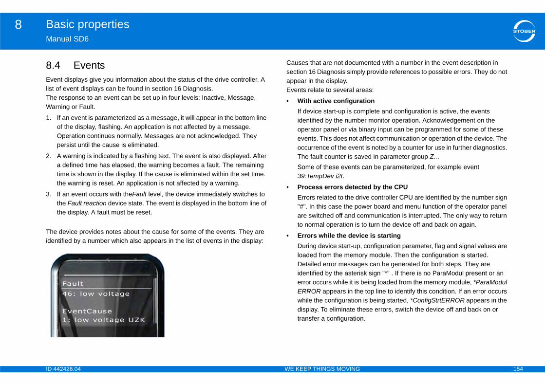
ID 4 154
Basic properties8Ma
8.Evelist TheWa
1.
2.
3.
Theide
ented with a number in the event description in ly provide references to possible errors. They do not
eas:
tionmplete and configuration is active, the events er monitor operation. Acknowledgement on the inary input can be programmed for some of these ffect communication or operation of the device. The t is noted by a counter for use in further diagnostics. ved in parameter group Z... can be parameterized, for example event
ted by the CPUive controller CPU are identified by the number sign wer board and menu function of the operator panel mmunication is interrupted. The only way to return
to turn the device off and back on again.
ce is starting, configuration parameter, flag and signal values are ry module. Then the configuration is started. es can be generated for both steps. They are sk sign "*" . If there is no ParaModul present or an being loaded from the memory module, *ParaModul top line to identify this condition. If an error occurs
is being started, *ConfigStrtERROR appears in the ese errors, switch the device off and back on or .
42426.04 WE KEEP THINGS MOVING
nual SD6
4 Eventsnt displays give you information about the status of the drive controller. A of event displays can be found in section 16 Diagnosis. response to an event can be set up in four levels: Inactive, Message, rning or Fault.
If an event is parameterized as a message, it will appear in the bottom line of the display, flashing. An application is not affected by a message. Operation continues normally. Messages are not acknowledged. They persist until the cause is eliminated.
A warning is indicated by a flashing text. The event is also displayed. After a defined time has elapsed, the warning becomes a fault. The remaining time is shown in the display. If the cause is eliminated within the set time. the warning is reset. An application is not affected by a warning.
If an event occurs with theFault level, the device immediately switches to the Fault reaction device state. The event is displayed in the bottom line of the display. A fault must be reset.
device provides notes about the cause for some of the events. They are ntified by a number which also appears in the list of events in the display:
Causes that are not documsection 16 Diagnosis simpappear in the display.Events relate to several ar
• With active configuraIf device start-up is coidentified by the numboperator panel or via bevents. This does not aoccurrence of the evenThe fault counter is saSome of these events 39:TempDev i2t.
• Process errors detecErrors related to the dr"#". In this case the poare switched off and coto normal operation is
• Errors while the deviDuring device start-uploaded from the memoDetailed error messagidentified by the asterierror occurs while it is ERROR appears in thewhile the configurationdisplay. To eliminate thtransfer a configuration

ID 4 155
Drive controller9Ma
9Ov
9.1
9.2
t . . . . . . . . . . . . . . . . . . . . . . . . . . . . . . . . . . . .177
eter sets . . . . . . . . . . . . . . . . . . . . . . . . . . . . . . 178
. . . . . . . . . . . . . . . . . . . . . . . . . . . . . . . . . . . . . 178
. . . . . . . . . . . . . . . . . . . . . . . . . . . . . . . . . . . . . 179
. . . . . . . . . . . . . . . . . . . . . . . . . . . . . . . . . . . . .181
ent . . . . . . . . . . . . . . . . . . . . . . . . . . . . . . . . . .184
. . . . . . . . . . . . . . . . . . . . . . . . . . . . . . . . . . . . . 184
meterize power input . . . . . . . . . . . . . . . . . . . . 184
w voltage . . . . . . . . . . . . . . . . . . . . . . . . . . . . . 185
lay . . . . . . . . . . . . . . . . . . . . . . . . . . . . . . . . . . . 186
.. . . . . . . . . . . . . . . . . . . . . . . . . . . . . . . . . . . . . 186
ation . . . . . . . . . . . . . . . . . . . . . . . . . . . . . . . . . 188
mpDev i2t . . . . . . . . . . . . . . . . . . . . . . . . . . . . 188
mpBrakeRes . . . . . . . . . . . . . . . . . . . . . . . . . . 189
empMot. i2t . . . . . . . . . . . . . . . . . . . . . . . . . . . 190
mpDev. i2t . . . . . . . . . . . . . . . . . . . . . . . . . . . . 191
meters . . . . . . . . . . . . . . . . . . . . . . . . . . . . . . . . 192
. . . . . . . . . . . . . . . . . . . . . . . . . . . . . . . . . . . . . 193
. . . . . . . . . . . . . . . . . . . . . . . . . . . . . . . . . . . . .193
. . . . . . . . . . . . . . . . . . . . . . . . . . . . . . . . . . . . .193
42426.04 WE KEEP THINGS MOVING
nual SD6
Drive controllererview of sections
Introduction . . . . . . . . . . . . . . . . . . . . . . . . . . . . . . . . . . . . . . . . . .157
Device controller . . . . . . . . . . . . . . . . . . . . . . . . . . . . . . . . . . . . .157
9.2.1 STOBER device state machine . . . . . . . . . . . . . . . . . . . . . . . . 157
9.2.1.1 Controlword and Statusword . . . . . . . . . . . . . . . . . . 161
9.2.2 Device state machine according to CiA 402 . . . . . . . . . . . . . . 164
9.2.2.1 Controlword and Statusword . . . . . . . . . . . . . . . . . . 169
9.2.3 Enable . . . . . . . . . . . . . . . . . . . . . . . . . . . . . . . . . . . . . . . . . . . 171
9.2.3.1 STOBER device state machine . . . . . . . . . . . . . . . . 171
9.2.3.2 Device state machine according to CiA 402 . . . . . . 171
9.2.3.3 Parameters .. . . . . . . . . . . . . . . . . . . . . . . . . . . . . . . 171
9.2.4 Auto-start . . . . . . . . . . . . . . . . . . . . . . . . . . . . . . . . . . . . . . . . . 173
9.2.5 Quick stop . . . . . . . . . . . . . . . . . . . . . . . . . . . . . . . . . . . . . . . . 174
9.2.5.1 STOBER device state machine . . . . . . . . . . . . . . . . 175
9.2.5.2 Device state machine according to CiA 402 . . . . . . 175
9.2.5.3 Parameters .. . . . . . . . . . . . . . . . . . . . . . . . . . . . . . . 175
9.2.6 Acknowledgement . . . . . . . . . . . . . . . . . . . . . . . . . . . . . . . . . . 176
9.2.7 Operational state . . . . . . . . . . . . . . . . . . . . . . . . . . . . . . . . . . . 177
9.2.8 Display .. . . . . . . . . . . . . . . . . . . . . . . . . . . . . . . . . . . . . . . . . . 177
9.3 Axis managemen
9.3.1 Axes as param
9.3.2 Selecting axes
9.3.3 Parameters . .
9.4 Local mode .. . . . .
9.5 Energy managem
9.5.1 Power input . .
9.5.1.1 Para
9.5.1.2 46:Lo
9.5.1.3 Disp
9.5.2 Brake resistor
9.5.3 Energetic utiliz
9.5.3.1 39:Te
9.5.3.2 42:Te
9.5.3.3 45:oT
9.5.3.4 59:Te
9.5.3.5 Para
9.5.4 Thermal . . . . .
9.6 Cycle time .. . . . . .
9.7 Components .. . . .

ID 4 156
Drive controller9Ma
9.8
9.9
42426.04 WE KEEP THINGS MOVING
nual SD6
Input and output signals .. . . . . . . . . . . . . . . . . . . . . . . . . . . . . .196
9.8.1 Binary inputs . . . . . . . . . . . . . . . . . . . . . . . . . . . . . . . . . . . . . . 196
9.8.2 Binary outputs . . . . . . . . . . . . . . . . . . . . . . . . . . . . . . . . . . . . . 196
9.8.3 Analog inputs .. . . . . . . . . . . . . . . . . . . . . . . . . . . . . . . . . . . . . 198
9.8.3.1 AE1 . . . . . . . . . . . . . . . . . . . . . . . . . . . . . . . . . . . . . 198
9.8.3.2 AE2 . . . . . . . . . . . . . . . . . . . . . . . . . . . . . . . . . . . . . 199
9.8.3.3 AE3 . . . . . . . . . . . . . . . . . . . . . . . . . . . . . . . . . . . . . 200
9.8.4 Analog outputs . . . . . . . . . . . . . . . . . . . . . . . . . . . . . . . . . . . . 201
9.8.4.1 AA1 . . . . . . . . . . . . . . . . . . . . . . . . . . . . . . . . . . . . . 201
9.8.4.2 AA2 . . . . . . . . . . . . . . . . . . . . . . . . . . . . . . . . . . . . . 203
9.8.5 Position simulation . . . . . . . . . . . . . . . . . . . . . . . . . . . . . . . . . 205
9.8.6 Display .. . . . . . . . . . . . . . . . . . . . . . . . . . . . . . . . . . . . . . . . . . 206
Saving data with protection against power failure . . . . . . .206
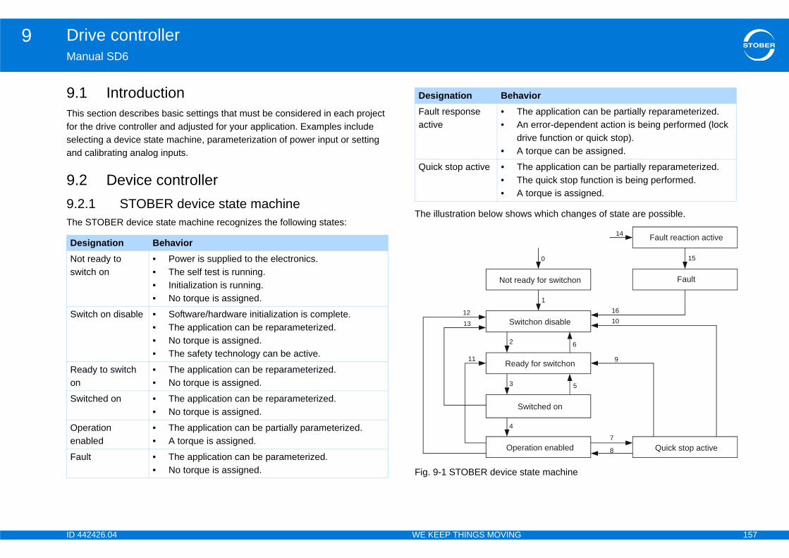
ID 4 157
Drive controller9Ma
9.Thifor seleand
9.9.2The
s which changes of state are possible.
tate machine
DeNosw
Sw
Reon
Sw
Open
Fa
he application can be partially reparameterized.n error-dependent action is being performed (lock rive function or quick stop). torque can be assigned.
he application can be partially reparameterized.he quick stop function is being performed. torque is assigned.
vior
t Einschaltbereit
schaltsperre
nschaltbereit
ingeschaltet
ieb freigegeben Schnellhalt aktiv
Störung
Störungsreaktion aktiv
0
1
5
6
9
7
8
14
15
1610
ady for switchon
Fault reaction active
Fault
Quick stop active
tchon disable
y for switchon
witched on
ration enabled
42426.04 WE KEEP THINGS MOVING
nual SD6
1 Introductions section describes basic settings that must be considered in each project the drive controller and adjusted for your application. Examples include cting a device state machine, parameterization of power input or setting calibrating analog inputs.
2 Device controller.1 STOBER device state machine STOBER device state machine recognizes the following states:
The illustration below show
Fig. 9-1 STOBER device s
signation Behaviort ready to itch on
• Power is supplied to the electronics.• The self test is running.• Initialization is running.• No torque is assigned.
itch on disable • Software/hardware initialization is complete.• The application can be reparameterized.• No torque is assigned.• The safety technology can be active.
ady to switch • The application can be reparameterized.• No torque is assigned.
itched on • The application can be reparameterized.• No torque is assigned.
eration abled
• The application can be partially parameterized.• A torque is assigned.
ult • The application can be parameterized.• No torque is assigned.
Fault response active
• T• A
d• A
Quick stop active • T• T• A
Designation Beha
Nich
Ein
Ei
E
Betr
2
3
4
11
1213
Not re
Swi
Read
S
Ope
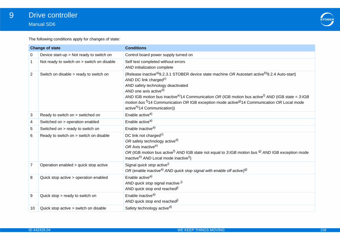
ID 4 158
Drive controller9Ma
The
Ch0
1
2 e OR Autostart activeb)9.2.4 Auto-start)
GB motion bus activef) AND (IGB state = 3:IGB activeg)14 Communication OR Local mode
3
4
5
6
3:IGB motion bus g) AND IGB exception mode
7 off active)g)
8
9
10
42426.04 WE KEEP THINGS MOVING
nual SD6
following conditions apply for changes of state:
ange of state ConditionsDevice start-up > Not ready to switch on Control board power supply turned on
Not ready to switch on > switch on disable Self test completed without errors AND initialization complete
Switch on disable > ready to switch on (Release inactivea)9.2.3.1 STOBER device state machinAND DC link chargedc)
AND safety technology deactivatedAND one axis actived)
AND IGB motion bus inactivee)14 Communication OR (Imotion bus f)14 Communication OR IGB exception modeactiveh)14 Communication))
Ready to switch on > switched on Enable activea)
Switched on > operation enabled Enable activea)
Switched on > ready to switch on Enable inactivea)
Ready to switch on > switch on disable DC link not chargedc)
OR safety technology actived) OR Axis inactivee)
OR (IGB motion bus activef) AND IGB state not equal toinactiveh) AND Local mode inactivei))
Operation enabled > quick stop active Signal quick stop activei)
OR (enable inactivea) AND quick stop signal with enable
Quick stop active > operation enabled Enable activea)
AND quick stop signal inactive j)
AND quick stop end reachedj)
Quick stop > ready to switch on Enable inactivea)
AND quick stop end reachedj)
Quick stop active > switch on disable Safety technology actived)
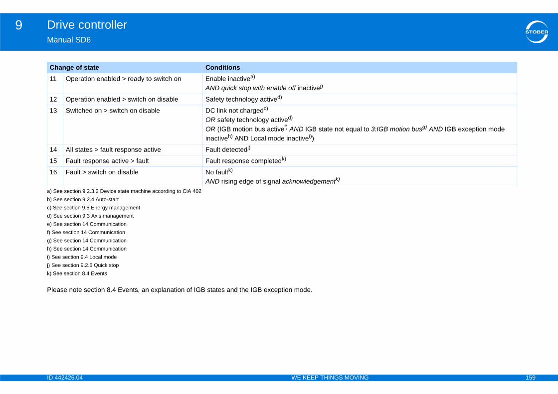
ID 4 159
Drive controller9Ma
Ple
11
12
13
3:IGB motion busg) AND IGB exception mode
14
15
16
a) Sb) Sc) Sd) Se) Sf) Seg) Sh) Si) Sej) Sek) S
Ch
42426.04 WE KEEP THINGS MOVING
nual SD6
ase note section 8.4 Events, an explanation of IGB states and the IGB exception mode.
Operation enabled > ready to switch on Enable inactivea)
AND quick stop with enable off inactivej)
Operation enabled > switch on disable Safety technology actived)
Switched on > switch on disable DC link not chargedc)
OR safety technology actived)
OR (IGB motion bus activef) AND IGB state not equal toinactiveh) AND Local mode inactivei))
All states > fault response active Fault detectedj)
Fault response active > fault Fault response completedk)
Fault > switch on disable No faultk)
AND rising edge of signal acknowledgementk)
ee section 9.2.3.2 Device state machine according to CiA 402ee section 9.2.4 Auto-startee section 9.5 Energy managementee section 9.3 Axis managementee section 14 Communicatione section 14 Communicationee section 14 Communicationee section 14 Communicatione section 9.4 Local modee section 9.2.5 Quick stop
ee section 8.4 Events
ange of state Conditions
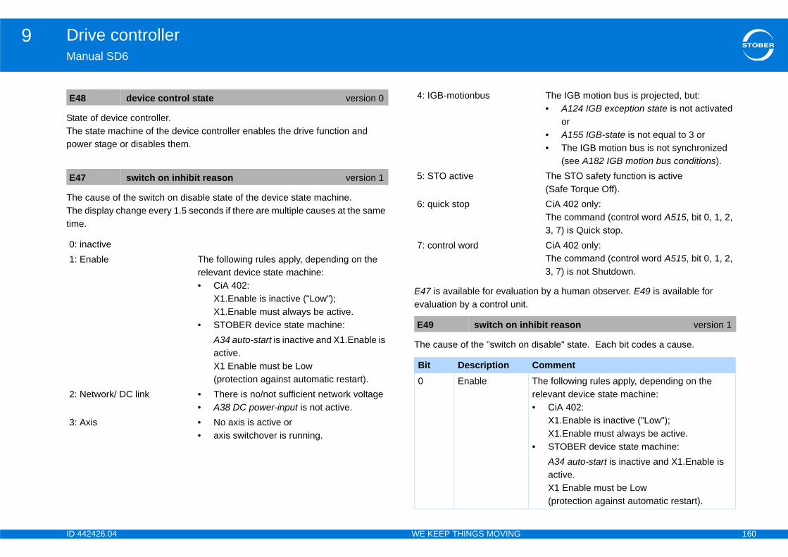
ID 4 160
Drive controller9Ma
StaThepow
TheThetim
tion by a human observer. E49 is available for it.
n disable" state. Each bit codes a cause.
E4
E4
0: 1:
2:
3:
The IGB motion bus is projected, but:• A124 IGB exception state is not activated
or• A155 IGB-state is not equal to 3 or• The IGB motion bus is not synchronized
(see A182 IGB motion bus conditions).The STO safety function is active (Safe Torque Off).CiA 402 only:The command (control word A515, bit 0, 1, 2, 3, 7) is Quick stop.CiA 402 only:The command (control word A515, bit 0, 1, 2, 3, 7) is not Shutdown.
nhibit reason version 1
CommentThe following rules apply, depending on the relevant device state machine:• CiA 402:
X1.Enable is inactive ("Low"); X1.Enable must always be active.
• STOBER device state machine:A34 auto-start is inactive and X1.Enable is active. X1 Enable must be Low (protection against automatic restart).
42426.04 WE KEEP THINGS MOVING
nual SD6
te of device controller. state machine of the device controller enables the drive function and er stage or disables them.
cause of the switch on disable state of the device state machine. display change every 1.5 seconds if there are multiple causes at the same
e.
E47 is available for evaluaevaluation by a control un
The cause of the "switch o
8 device control state version 0
7 switch on inhibit reason version 1
inactiveEnable The following rules apply, depending on the
relevant device state machine:• CiA 402:
X1.Enable is inactive ("Low"); X1.Enable must always be active.
• STOBER device state machine:A34 auto-start is inactive and X1.Enable is active. X1 Enable must be Low (protection against automatic restart).
Network/ DC link • There is no/not sufficient network voltage• A38 DC power-input is not active.
Axis • No axis is active or• axis switchover is running.
4: IGB-motionbus
5: STO active
6: quick stop
7: control word
E49 switch on i
Bit Description0 Enable
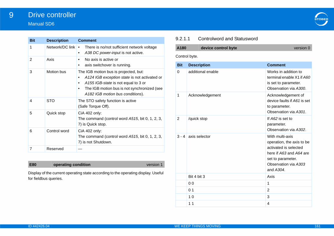
ID 4 161
Drive controller9Ma
Disfor
d and Statusword
1
2
3
4
5
6
7
E8
Bi
trol byte version 0
CommentWorks in addition to terminal enable X1 if A60 is set to parameter.Observation via A300.
Acknowledgement of device faults if A61 is set to parameter.Observation via A301.
If A62 is set to parameter.Observation via A302.
With multi-axis operation, the axis to be activated is selected here if A63 and A64 are set to parameter.Observation via A303 and A304.
Axis
1
2
3
4
42426.04 WE KEEP THINGS MOVING
nual SD6
play of the current operating state according to the operating display. Useful fieldbus queries.
9.2.1.1 Controlwor
Control byte.
Network/DC link • There is no/not sufficient network voltage• A38 DC power-input is not active.
Axis • No axis is active or• axis switchover is running.
Motion bus The IGB motion bus is projected, but:• A124 IGB exception state is not activated or• A155 IGB-state is not equal to 3 or• The IGB motion bus is not synchronized (see
A182 IGB motion bus conditions).
STO The STO safety function is active (Safe Torque Off).
Quick stop CiA 402 only:The command (control word A515, bit 0, 1, 2, 3, 7) is Quick stop.
Control word CiA 402 only:The command (control word A515, bit 0, 1, 2, 3, 7) is not Shutdown.
Reserved —
0 operating condition version 1
t Description Comment
A180 device con
Bit Description0 additional enable
1 Acknowledgement
2 /quick stop
3 - 4 axis selector
Bit 4 bit 3
0 0
0 1
1 0
1 1

ID 4 162
Drive controller9Ma
Con
5
6
7
A1
Bi0
1 -
Bi determines the response of the drive controller
aintenance. It could be accidentally overwritten y a remote maintenance process, resulting in nality (connection broken, loss of data, etc.). There prevent accidental changes: from the drive controller when setting up the
file associated with the drive controller in which this t correctly.
us byte version 0
Comment1 = The drive is ready, no faultCorresponds to E48 = 4
1 = The drive has a fault or a fault response is activeCorresponds to E48 = 5 or 6
1 = Fast stop active.Corresponds to E48 = 7
Display of the active axis in multi axis mode.
Axis
42426.04 WE KEEP THINGS MOVING
nual SD6
trol byte 2.
Status byte.• Element 0:
axis disable Deactivate all axes (no motor switched on) if A65 is set to parameter.Observation via A305.
Open the brake unconditionally Open brake override if F06 is set to parameter and F92 is set to internal.
Handshake bit Bit 7 in A180 is copied to bit 7 in E200 with each cycle of the device controllerIf bit 7 in A180 is toggled by the higher-level PLC, this can be detected by E200, a terminated communication cycle (send data, evaluate, return).
81 device control byte 2 version 0
t Description CommentRemote maintenance If the source A167 is set
to parameter.Observation via A300
7 Reserved No function
t Description Comment InformationThis parameterduring remote mand changed bimpaired functioare two ways to- Read the dataconnection.- Use a project parameter is se
E200 device stat
Bit Description0 Enabled
1 Fault
2 Quick stop active
3 - 4 Active axis
Bit 4 bit 3
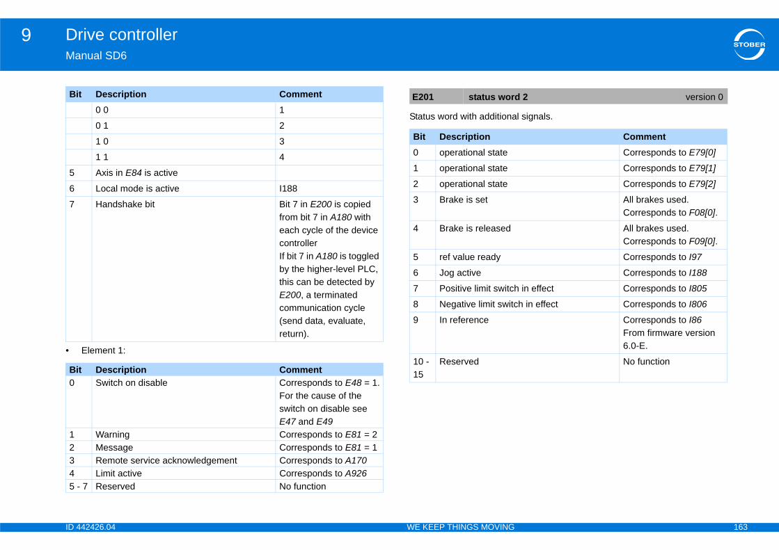
ID 4 163
Drive controller9Ma
•
l signals.
5
6
7
Bi0
12345 -
Bi 2 version 0
CommentCorresponds to E79[0]
Corresponds to E79[1]
Corresponds to E79[2]
All brakes used. Corresponds to F08[0].
All brakes used. Corresponds to F09[0].
Corresponds to I97
Corresponds to I188
in effect Corresponds to I805
h in effect Corresponds to I806
Corresponds to I86From firmware version 6.0-E.
No function
42426.04 WE KEEP THINGS MOVING
nual SD6
Element 1:
Status word with additiona0 0 1
0 1 2
1 0 3
1 1 4
Axis in E84 is active
Local mode is active I188
Handshake bit Bit 7 in E200 is copied from bit 7 in A180 with each cycle of the device controllerIf bit 7 in A180 is toggled by the higher-level PLC, this can be detected by E200, a terminated communication cycle (send data, evaluate, return).
t Description CommentSwitch on disable Corresponds to E48 = 1.
For the cause of the switch on disable see E47 and E49
Warning Corresponds to E81 = 2Message Corresponds to E81 = 1Remote service acknowledgement Corresponds to A170Limit active Corresponds to A926
7 Reserved No function
t Description Comment E201 status word
Bit Description0 operational state
1 operational state
2 operational state
3 Brake is set
4 Brake is released
5 ref value ready
6 Jog active
7 Positive limit switch
8 Negative limit switc
9 In reference
10 - 15
Reserved
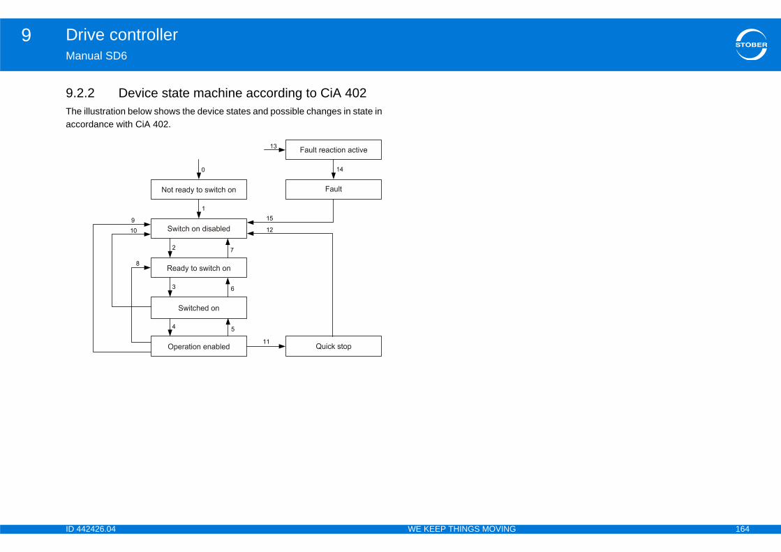
ID 4 164
Drive controller9Ma
9.2Theacc
42426.04 WE KEEP THINGS MOVING
nual SD6
.2 Device state machine according to CiA 402 illustration below shows the device states and possible changes in state in ordance with CiA 402.

ID 4 165
Drive controller9Ma
The
Ch0
1
2
(IGB state = 3:IGB motion bus OR IGB exception
3
4
5
6
7
otion bus AND IGB exception mode inactive AND
8
42426.04 WE KEEP THINGS MOVING
nual SD6
table below shows the conditions for changes in the state machine.
ange of state ConditionsDevice start-up > self test Control board power supply turned on.
Self test > switch on disable Self test completed without errors AND initialization complete.
Switch on disable > ready to switch on Enable activeAND DC link chargedAND command Shutdown AND safety technology deactivatedAND IGB motion bus inactive OR (IGB motion bus active ANDmode active OR Local mode active)).
Ready to switch on > switched on Enable activeAND command Switch On
Switched on > operation enabled Enable activeAND command Enable operation
Operation enabled > switched on Enable activeAND command Disable operation
Switched on > ready to switch on Enable activeAND command Shutdown
Ready to switch on > switch on disable Enable inactiveOR DC link not chargedOR command Quick stopOR command Disable voltageOR safety technology activeOR (IGB motion bus active AND IGB state not equal to 3:IGB mlocal mode inactive)
Operation enabled > ready to switch on Shutdown command

ID 4 166
Drive controller9Ma
9
10
otion bus AND IGB exception mode inactive AND
11nal active)
12
13
14
15
Ch
42426.04 WE KEEP THINGS MOVING
nual SD6
Operation enabled > switch on disable Enable inactiveOR command Disable voltageOR safety technology active
Switched on > switch on disable Enable inactiveOR DC link not chargedOR command Quick stopOR command Disable voltageOR safety technology activeOR (IGB motion bus active AND IGB state not equal to 3:IGB mlocal mode inactive)
Operation enabled > quick stop Command Quick stopOR (Enable inactive AND Quick stop signal with enable off sig
Quick stop > switch on disable Quick stop complete OR DC link below 130 VOR safety technology activeOR command Disable voltage
All states > fault response active Fault detected
Fault response active > fault Fault response complete
Fault > switch on disable Command Fault reset (positive edge)
ange of state Conditions

ID 4 167
Drive controller9Ma
Thestaaccsho(bit
ThemaTheacc
evice controller enables the drive function and em.
Co
Sh
Sw
Di
Qu
Di
En
Fa
Designation according to CiA 402
Not ready to switch on
Switch on disabled
Ready to switch on
Switched on
Operation enabled
Fault
Fault reaction active
Quick stop active
trol state version 0
42426.04 WE KEEP THINGS MOVING
nual SD6
device state machine must receive specific commands for changes of te. The commands are given as a bit combination in the control word in ordance with CiA402 (parameter A515 Control word). The table below ws the states of the bits in A515 and how they are combined for commands s marked with X are irrelevant).
standard device state machine has the same states as in the device state chine according to CANopen device profile CiA 402. table below lists manufacturer-specific designations and the designations ording to CiA.
State of device controller.The state machine of the dpower stage or disables th
mmand
Bit of the control word (A515 control word)Bit 7 Bit 3 Bit 2 Bit 1 Bit 0Fault reset
Enable operation
Quick stop
Enable voltage
Switch on
utdown 0 X 1 1 0
itch on 0 0 1 1 1
sable voltage 0 X X 0 X
ick stop 0 X 0 1 X
sable operation 0 0 1 1 1
able operation 0 1 1 1 1
ult resetPos. of edge
X X X X
Manufacturer-specific designationSelf test
Switch on disable
Ready to switch on
Switched on
Operation enabled
Fault
Fault reaction active
Quick stop active
E48 device con

ID 4 168
Drive controller9Ma
TheThetim
tion by a human observer. E49 is available for it.
n disable" state. Each bit codes a cause.
E4
0: 1:
2:
3:
4:
5:
CiA 402 only:The command (control word A515, bit 0, 1, 2, 3, 7) is Quick stop.CiA 402 only:The command (control word A515, bit 0, 1, 2, 3, 7) is not Shutdown.
nhibit reason version 1
CommentThe following rules apply, depending on the relevant device state machine:• CiA 402:
X1.Enable is inactive ("Low"); X1.Enable must always be active.
• STOBER device state machine:A34 auto-start is inactive and X1.Enable is active. X1 Enable must be Low (protection against automatic restart).
• There is no/not sufficient network voltage• A38 DC power-input is not active.
• No axis is active or• axis switchover is running.
42426.04 WE KEEP THINGS MOVING
nual SD6
cause of the switch on disable state of the device state machine. display change every 1.5 seconds if there are multiple causes at the same
e.
E47 is available for evaluaevaluation by a control un
The cause of the "switch o
7 switch on inhibit reason version 1
inactiveEnable The following rules apply, depending on the
relevant device state machine:• CiA 402:
X1.Enable is inactive ("Low"); X1.Enable must always be active.
• STOBER device state machine:A34 auto-start is inactive and X1.Enable is active. X1 Enable must be Low (protection against automatic restart).
Network/ DC link • There is no/not sufficient network voltage• A38 DC power-input is not active.
Axis • No axis is active or• axis switchover is running.
IGB-motionbus The IGB motion bus is projected, but:• A124 IGB exception state is not activated
or• A155 IGB-state is not equal to 3 or• The IGB motion bus is not synchronized
(see A182 IGB motion bus conditions).STO active The STO safety function is active
(Safe Torque Off).
6: quick stop
7: control word
E49 switch on i
Bit Description0 Enable
1 Network/DC link
2 Axis
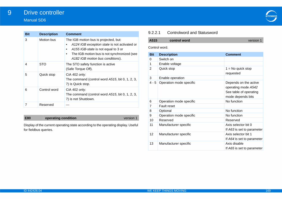
ID 4 169
Drive controller9Ma
Disfor
d and Statusword
3
4
5
6
7
E8
Bi
rd version 1
Comment
1 = No quick stop requested
ecific Depends on the active operating mode A542See table of operating mode depends bits
ecific No function
No functionecific No function
Reservedific Axis selector bit 0
If A63 is set to parameterific Axis selector bit 1
If A64 is set to parameterific Axis disable
If A65 is set to parameter
42426.04 WE KEEP THINGS MOVING
nual SD6
play of the current operating state according to the operating display. Useful fieldbus queries.
9.2.2.1 Controlwor
Control word.
Motion bus The IGB motion bus is projected, but:• A124 IGB exception state is not activated or• A155 IGB-state is not equal to 3 or• The IGB motion bus is not synchronized (see
A182 IGB motion bus conditions).
STO The STO safety function is active (Safe Torque Off).
Quick stop CiA 402 only:The command (control word A515, bit 0, 1, 2, 3, 7) is Quick stop.
Control word CiA 402 only:The command (control word A515, bit 0, 1, 2, 3, 7) is not Shutdown.
Reserved —
0 operating condition version 1
t Description Comment
A515 control wo
Bit Description0 Switch on1 Enable voltage2 Quick stop
3 Enable operation4 - 5 Operation mode sp
6 Operation mode sp7 Fault reset8 Optional9 Operation mode sp10 Reserved11 Manufacturer spec
12 Manufacturer spec
13 Manufacturer spec

ID 4 170
Drive controller9Ma
Des
Corwith
Sta
ode dependent bits
x 6041hex subindex 0hex status word in accordance
14
15
Bi4
4
4
5
A5
Bi01
Bi
1 = No quick stop active
ific 1 = Message
ecific Depends on the active operating mode A542See table of operating mode depends bits
ific PLL A298 bit 0PLL A298 bit 1
Comment1 = Reference reached
n mode 1 = Interpolation active position mode 1 = Drive follows velocity mode 1 = Drive follows torque mode 1 = Drive follows
1 = Error during referencing
position mode 1 = Lag error
Comment
42426.04 WE KEEP THINGS MOVING
nual SD6
cription of operating mode dependent bits
responds to object index 6040hex subindex 0hex control word in accordance CiA 402.
tus word.
Description of operating m
Corresponds to object indewith CiA 402.
Manufacturer specific Brake control1 = Release override with internal brake control if F06 is set to internal and F92 is set to parameter.1 = Release brake with external brake control if F06 set to external.
Manufacturer specific No function
t Operating mode CommentHoming mode 1 = Start referencing
Interpolated position 1 = Activation of interpolation
Jog 1 = Jog in positive direction
Jog 1 = Jog in negative direction
16 Statusword version 1
t Description CommentReady to switch onSwitched on
t Description Comment2 Operation enabled3 Fault4 Voltage enabled5 Quick stop6 Switch on disabled7 Warning8 Manufacturer spec9 Remote10 Target reached11 Internal limit active12 - 13
Operation mode sp
14 - 15
Manufacturer spec
Bit Operating mode12 Homing mode12 Interpolated positio12 Cyclic synchronous12 Cyclic synchronous12 Cyclic synchronous13 Homing mode
13 Cyclic synchronous
Bit Description
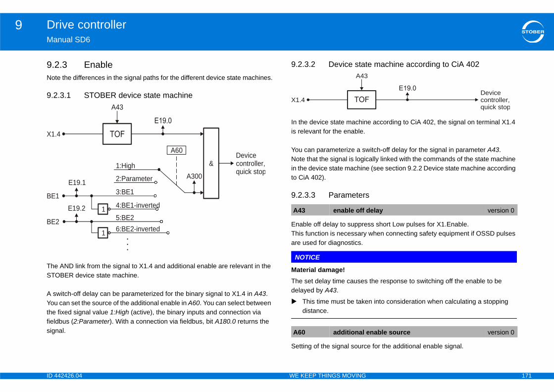
ID 4 171
Drive controller9Ma
9.2Not
9.2
TheSTO
A sYouthefieldsign
e machine according to CiA 402
e according to CiA 402, the signal on terminal X1.4
itch-off delay for the signal in parameter A43.ally linked with the commands of the state machine (see section 9.2.2 Device state machine according
ss short Low pulses for X1.Enable. when connecting safety equipment if OSSD pulses
the response to switching off the enable to be
n into consideration when calculating a stopping
e for the additional enable signal.
BE
X1.
BEdelay version 0
enable source version 0
Devicecontroller,quick stop
42426.04 WE KEEP THINGS MOVING
nual SD6
.3 Enablee the differences in the signal paths for the different device state machines.
.3.1 STOBER device state machine
AND link from the signal to X1.4 and additional enable are relevant in the BER device state machine.
witch-off delay can be parameterized for the binary signal to X1.4 in A43. can set the source of the additional enable in A60. You can select between
fixed signal value 1:High (active), the binary inputs and connection via bus (2:Parameter). With a connection via fieldbus, bit A180.0 returns the al.
9.2.3.2 Device stat
In the device state machinis relevant for the enable.
You can parameterize a swNote that the signal is logicin the device state machineto CiA 402).
9.2.3.3 Parameters
Enable off delay to suppreThis function is necessaryare used for diagnostics.
NOTICE
Material damage!The set delay time causesdelayed by A43.
This time must be takedistance.
Setting of the signal sourc
&Devicecontroller,quick stop
1
2:Parameter
1
1 4:BE1-inverted
5:BE26:BE2-inverted
1:HighA300
E19.1
E19.2
A60
A43
3:BE1
4
.
.
.
2A43 enable off
A60 additional
X1.4
A43

ID 4 172
Drive controller9Ma
Con
the AdditEna signal (additional enable) on the troller (configuration, module 100107).al works just like the Enable signal from terminal X1. d. Therefore the power output stage of the drive f both signals are HIGH.
ary signal on the input of the device controller is
A1
Bi0
1
2
3 -
Deactivate all axes (no motor switched on) if A65 is set to parameter.Observation via A305.
conditionally Open brake override if F06 is set to parameter and F92 is set to internal.
Bit 7 in A180 is copied to bit 7 in E200 with each cycle of the device controllerIf bit 7 in A180 is toggled by the higher-level PLC, this can be detected by E200, a terminated communication cycle (send data, evaluate, return).
enable version 0
version 0
Comment
42426.04 WE KEEP THINGS MOVING
nual SD6
trol byte.
Display of current value ofinterface to the device conThe additional Enable signThe two signals are ANDecontroller is only enabled i
The level of the Enable bindisplayed.
80 device control byte version 0
t Description Commentadditional enable Works in addition to
terminal enable X1 if A60 is set to parameter.Observation via A300.
Acknowledgement Acknowledgement of device faults if A61 is set to parameter.Observation via A301.
/quick stop If A62 is set to parameter.Observation via A302.
4 axis selector With multi-axis operation, the axis to be activated is selected here if A63 and A64 are set to parameter.Observation via A303 and A304.
Bit 4 bit 3 Axis
0 0 1
0 1 2
1 0 3
1 1 4
5 axis disable
6 Open the brake un
7 Handshake bit
A300 additional
A306 X1.Enable
Bit Description
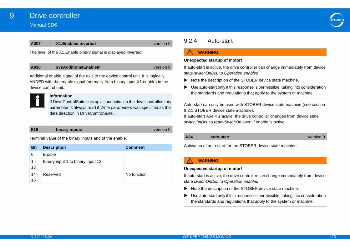
ID 4 173
Drive controller9Ma
The
AddANdev
Ter
otor!rive controller can change immediately from device ration enabled!
f the STOBER device state machine.
is response is permissible, taking into consideration ulations that apply to the system or machine.
d with STOBER device state machine (see section e machine). , the drive controller changes from device state
chOn even if enable is active.
the STOBER device state machine.
otor!rive controller can change immediately from device ration enabled!
f the STOBER device state machine.
is response is permissible, taking into consideration ulations that apply to the system or machine.
A3
A9
E1
Bi0
1 -13
1415
version 0
42426.04 WE KEEP THINGS MOVING
nual SD6
level of the X1.Enable binary signal is displayed inverted.
itional enable signal of the axis to the device control unit. It is logically DED with the enable signal (normally from binary input X1.enable) in the ice control unit.
minal value of the binary inputs and of the enable.
9.2.4 Auto-start
WARNING!
Unexpected startup of mIf auto-start is active, the dstate switchOnDis. to Ope
Note the description o
Use auto-start only if ththe standards and reg
Auto-start can only be use9.2.1 STOBER device statIf auto-start A34 = 1:activeswitchOnDis. to readySwt
Activation of auto-start for
WARNING!
Unexpected startup of mIf auto-start is active, the dstate switchOnDis. to Ope
Note the description o
Use auto-start only if ththe standards and reg
07 X1.Enabled inverted version 0
10 sysAdditionalEnableIn version 0
InformationIf DriveControlSuite sets up a connection to the drive controller, this parameter is always read if Write parameters was specified as the data direction in DriveControlSuite.
9 binary inputs version 0
t Description CommentEnable
Binary input 1 to binary input 13
- Reserved No function
A34 auto-start
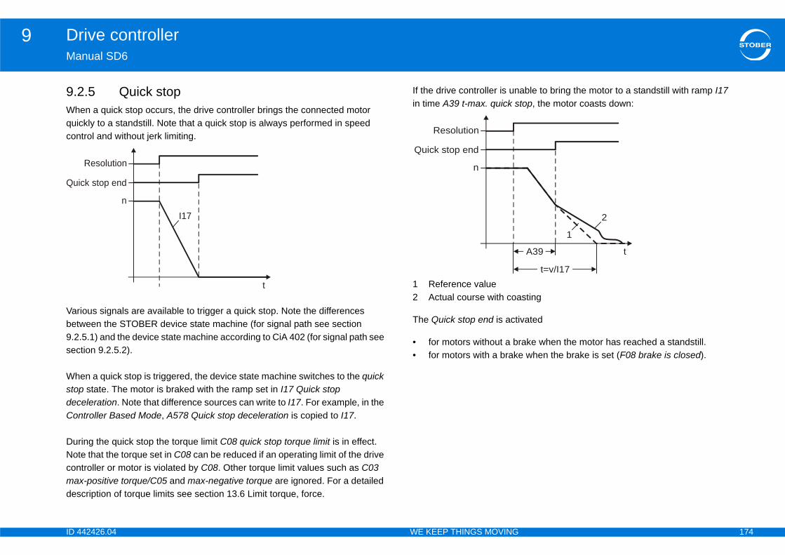
ID 4 174
Drive controller9Ma
9.2Whquicon
Varbet9.2sec
WhstodecCon
DurNotconmades
able to bring the motor to a standstill with ramp I17 top, the motor coasts down:
sting
vated
ake when the motor has reached a standstill. when the brake is set (F08 brake is closed).
Qui
t
2
1
A39
t=v/I17
42426.04 WE KEEP THINGS MOVING
nual SD6
.5 Quick stopen a quick stop occurs, the drive controller brings the connected motor ckly to a standstill. Note that a quick stop is always performed in speed trol and without jerk limiting.
ious signals are available to trigger a quick stop. Note the differences ween the STOBER device state machine (for signal path see section .5.1) and the device state machine according to CiA 402 (for signal path see tion 9.2.5.2).
en a quick stop is triggered, the device state machine switches to the quick p state. The motor is braked with the ramp set in I17 Quick stop eleration. Note that difference sources can write to I17. For example, in the troller Based Mode, A578 Quick stop deceleration is copied to I17.
ing the quick stop the torque limit C08 quick stop torque limit is in effect. e that the torque set in C08 can be reduced if an operating limit of the drive troller or motor is violated by C08. Other torque limit values such as C03 x-positive torque/C05 and max-negative torque are ignored. For a detailed cription of torque limits see section 13.6 Limit torque, force.
If the drive controller is unin time A39 t-max. quick s
1 Reference value2 Actual course with coa
The Quick stop end is acti
• for motors without a br• for motors with a brake
Resolution
ck stop end
n
t
I17
Resolution
Quick stop end
n
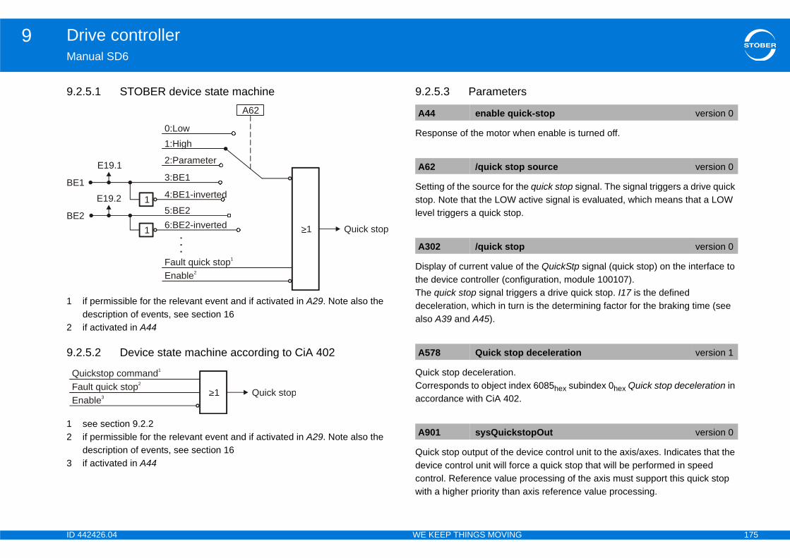
ID 4 175
Drive controller9Ma
9.2
1
2
9.2
12
3
en enable is turned off.
e quick stop signal. The signal triggers a drive quick ctive signal is evaluated, which means that a LOW
the QuickStp signal (quick stop) on the interface to iguration, module 100107).ers a drive quick stop. I17 is the defined is the determining factor for the braking time (see
x 6085hex subindex 0hex Quick stop deceleration in
vice control unit to the axis/axes. Indicates that the e a quick stop that will be performed in speed rocessing of the axis must support this quick stop axis reference value processing.
BE
BE
FaEn
Q
k-stop version 0
source version 0
version 0
deceleration version 1
topOut version 0
42426.04 WE KEEP THINGS MOVING
nual SD6
.5.1 STOBER device state machine
if permissible for the relevant event and if activated in A29. Note also the description of events, see section 16if activated in A44
.5.2 Device state machine according to CiA 402
see section 9.2.2if permissible for the relevant event and if activated in A29. Note also the description of events, see section 16if activated in A44
9.2.5.3 Parameters
Response of the motor wh
Setting of the source for thstop. Note that the LOW alevel triggers a quick stop.
Display of current value ofthe device controller (confThe quick stop signal triggdeceleration, which in turnalso A39 and A45).
Quick stop deceleration.Corresponds to object indeaccordance with CiA 402.
Quick stop output of the dedevice control unit will forccontrol. Reference value pwith a higher priority than
Quick stop
A62
>1
Fault quick stop1
Enable2
1
2:Parameter
1
1 4:BE1-inverted
5:BE26:BE2-inverted
1:High0:Low
E19.1
E19.2
3:BE1
.
.
.
2
Quick stop>1ult quick stop2
able3
uickstop command1
A44 enable quic
A62 /quick stop
A302 /quick stop
A578 Quick stop
A901 sysQuicks
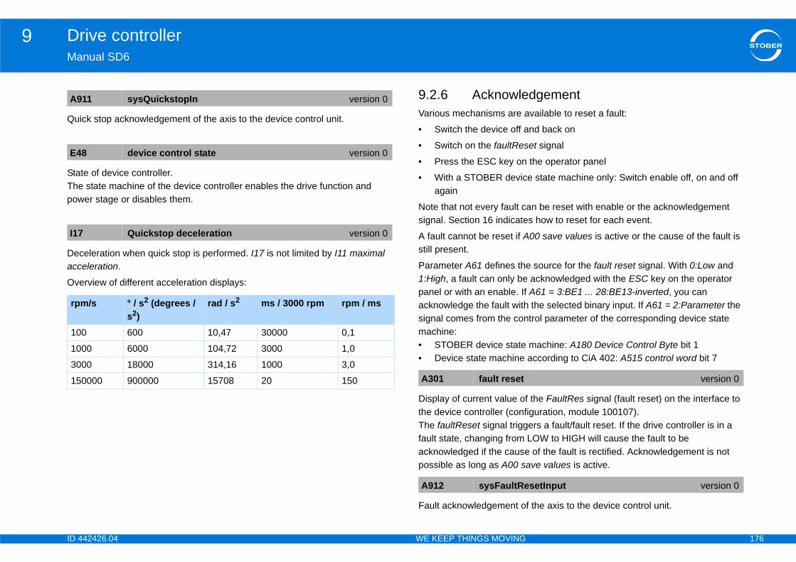
ID 4 176
Drive controller9Ma
Qu
StaThepow
Decacc
Ove
dgementvailable to reset a fault:
nd back on
et signal
the operator panel
e state machine only: Switch enable off, on and off
an be reset with enable or the acknowledgement s how to reset for each event.
00 save values is active or the cause of the fault is
source for the fault reset signal. With 0:Low and acknowledged with the ESC key on the operator A61 = 3:BE1 ... 28:BE13-inverted, you can the selected binary input. If A61 = 2:Parameter the trol parameter of the corresponding device state
machine: A180 Device Control Byte bit 1according to CiA 402: A515 control word bit 7
the FaultRes signal (fault reset) on the interface to iguration, module 100107).ers a fault/fault reset. If the drive controller is in a LOW to HIGH will cause the fault to be of the fault is rectified. Acknowledgement is not ve values is active.
f the axis to the device control unit.
A9
E4
I17
rp
10
10
30
15 version 0
setInput version 0
42426.04 WE KEEP THINGS MOVING
nual SD6
ick stop acknowledgement of the axis to the device control unit.
te of device controller. state machine of the device controller enables the drive function and er stage or disables them.
eleration when quick stop is performed. I17 is not limited by I11 maximal eleration.
rview of different acceleration displays:
9.2.6 AcknowleVarious mechanisms are a
• Switch the device off a
• Switch on the faultRes
• Press the ESC key on
• With a STOBER devicagain
Note that not every fault csignal. Section 16 indicate
A fault cannot be reset if Astill present.
Parameter A61 defines the1:High, a fault can only bepanel or with an enable. Ifacknowledge the fault withsignal comes from the conmachine:• STOBER device state• Device state machine
Display of current value ofthe device controller (confThe faultReset signal triggfault state, changing from acknowledged if the causepossible as long as A00 sa
Fault acknowledgement o
11 sysQuickstopIn version 0
8 device control state version 0
Quickstop deceleration version 0
m/s ° / s2 (degrees / s2)
rad / s2 ms / 3000 rpm rpm / ms
0 600 10,47 30000 0,1
00 6000 104,72 3000 1,0
00 18000 314,16 1000 3,0
0000 900000 15708 20 150 A301 fault reset
A912 sysFaultRe
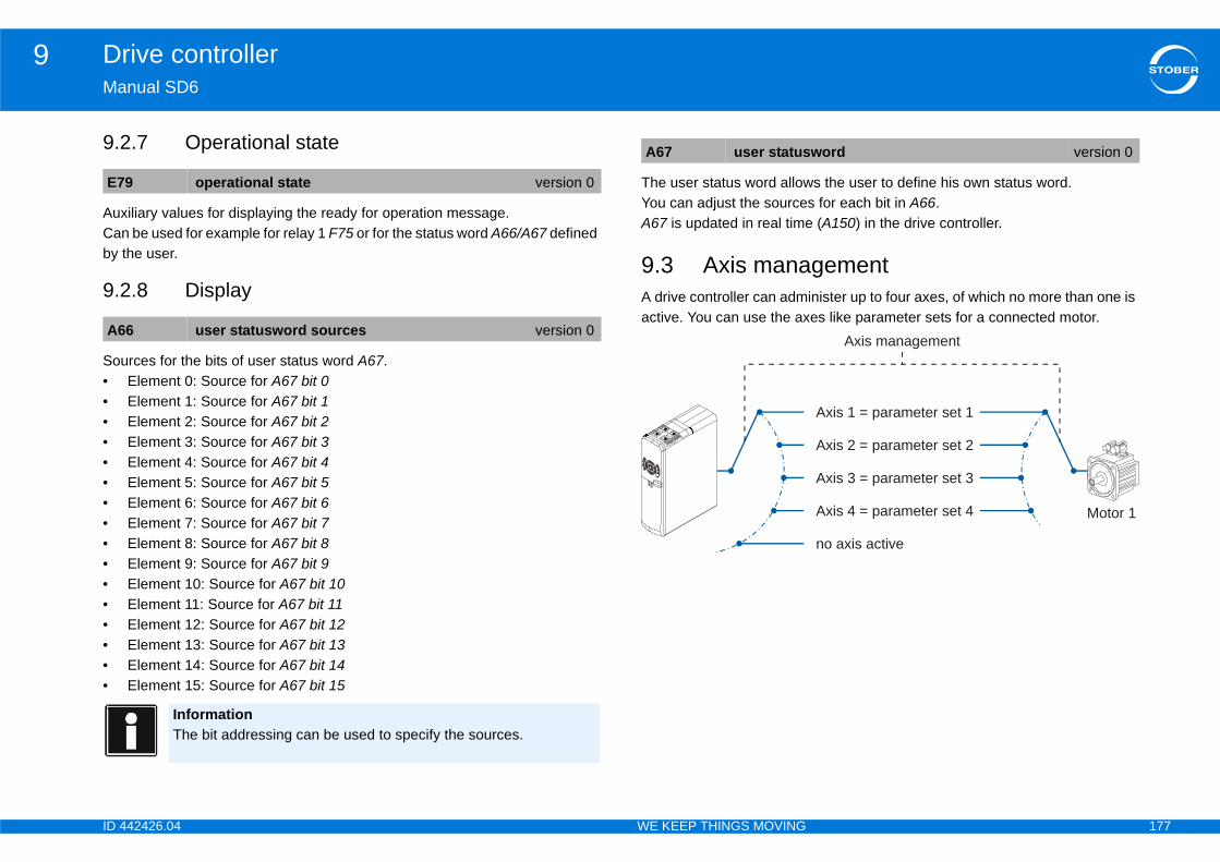
ID 4 177
Drive controller9Ma
9.2
AuxCanby
9.2
Sou••••••••••••••••
s the user to define his own status word.s for each bit in A66. (A150) in the drive controller.
gementinister up to four axes, of which no more than one is es like parameter sets for a connected motor.
E7
A6
word version 0
Axis 1 = parameter set 1
Axis management
Axis 2 = parameter set 2
Axis 3 = parameter set 3
Axis 4 = parameter set 4
no axis active
Motor 1
42426.04 WE KEEP THINGS MOVING
nual SD6
.7 Operational state
iliary values for displaying the ready for operation message. be used for example for relay 1 F75 or for the status word A66/A67 defined
the user.
.8 Display
rces for the bits of user status word A67.Element 0: Source for A67 bit 0Element 1: Source for A67 bit 1Element 2: Source for A67 bit 2Element 3: Source for A67 bit 3Element 4: Source for A67 bit 4Element 5: Source for A67 bit 5Element 6: Source for A67 bit 6Element 7: Source for A67 bit 7Element 8: Source for A67 bit 8Element 9: Source for A67 bit 9Element 10: Source for A67 bit 10Element 11: Source for A67 bit 11Element 12: Source for A67 bit 12Element 13: Source for A67 bit 13Element 14: Source for A67 bit 14Element 15: Source for A67 bit 15
The user status word allowYou can adjust the sourceA67 is updated in real time
9.3 Axis manaA drive controller can admactive. You can use the ax
9 operational state version 0
6 user statusword sources version 0
InformationThe bit addressing can be used to specify the sources.
A67 user status

ID 4 178
Drive controller9Ma
9.3If y
Not
axes
h signals axis selector bit 0 and axis selector bit 1. d assignment applies:
be used to switch off all axes independently of the plications show which parameters to use to achieve
the status of axis management in parameters E84
Se
1.
2.
3.4.
5.6.7.8.9.
is only possible under the following conditions:ched off.ntrol state is not 5:fault. ive.
it 0 Axis selector bit 10
0
1
1
42426.04 WE KEEP THINGS MOVING
nual SD6
.1 Axes as parameter setsou would like to use multiple axes as parameter sets, follow these steps:
e that the same motor must be parameterized for all the axes.
9.3.2 Selecting
You can select an axis witThe following binary-code
The ax.disable signal can state of the axis selectors.The descriptions of the apthese signals. You can viewand E200 bit 3 to bit 5.
tting up axes as parameter sets
In your project in DriveControlSuite, right click on the entry for the drive controller that will use multiple axes. In the context menu select Show free axes. The free axes in addition to axis 1 appear below the drive controller.Click on the free axis that will be used as an additional parameter set.Click on the Projecting button in the bottom part of the window. The projecting dialog for the axis appears. On the Properties tab, activate the Use axis .Switch to the Application tab.Select the application that will be used on this axis.Confirm the projecting dialog with OK.Repeat steps 3 to 8 if you want to use additional axes as parameter sets.You are using multiple axes as parameter sets.
InformationSwitching axes- Enable is swit- E48 device co- No STO is act
Axis Axis selector bAxle 1 0
Axle 2 1
Axle 3 0
Axle 4 1
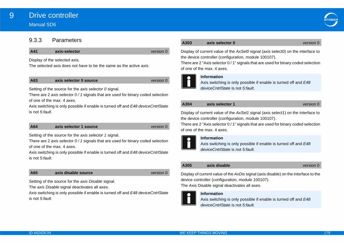
ID 4 179
Drive controller9Ma
9.3
DisThe
SetTheof oAxiis n
SetTheof oAxiis n
SetTheAxiis n
the AxSel0 signal (axis select0) on the interface to iguration, module 100107). / 1" signals that are used for binary coded selection
the AxSel1 signal (axis select1) on the interface to iguration, module 100107). / 1" signals that are used for binary coded selection
the AxDis signal (axis disable) on the interface to the ation, module 100107).activates all axes.
A4
A6
A6
A6
or 0 version 0
is only possible if enable is turned off and E48 e is not 5:fault.
or 1 version 0
is only possible if enable is turned off and E48 e is not 5:fault.
e version 0
is only possible if enable is turned off and E48 e is not 5:fault.
42426.04 WE KEEP THINGS MOVING
nual SD6
.3 Parameters
play of the selected axis. selected axis does not have to be the same as the active axis.
ting of the source for the axis selector 0 signal.re are 2 axis selector 0 / 1 signals that are used for binary coded selection ne of the max. 4 axes.
s switching is only possible if enable is turned off and E48 deviceCntrlState ot 5:fault.
ting of the source for the axis selector 1 signal.re are 2 axis selector 0 / 1 signals that are used for binary coded selection ne of the max. 4 axes.
s switching is only possible if enable is turned off and E48 deviceCntrlState ot 5:fault.
ting of the source for the axis Disable signal. axis Disable signal deactivates all axes.
s switching is only possible if enable is turned off and E48 deviceCntrlState ot 5:fault.
Display of current value ofthe device controller (confThere are 2 "Axis selector 0of one of the max. 4 axes.
Display of current value ofthe device controller (confThere are 2 "Axis selector 0of one of the max. 4 axes.
Display of current value of device controller (configurThe Axis Disable signal de
1 axis-selector version 0
3 axis selector 0 source version 0
4 axis selector 1 source version 0
5 axis disable source version 0
A303 axis select
InformationAxis switching deviceCntrlStat
A304 axis select
InformationAxis switching deviceCntrlStat
A305 axis disabl
InformationAxis switching deviceCntrlStat
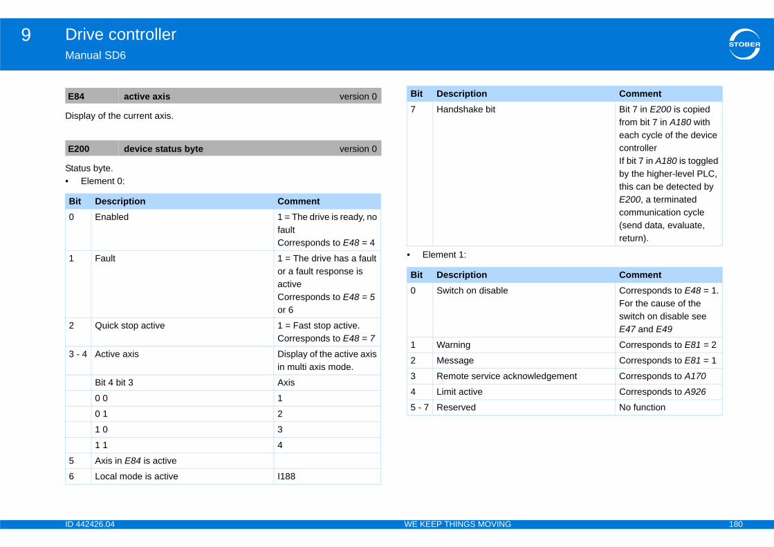
ID 4 180
Drive controller9Ma
Dis
Sta•
E8
E2
Bi0
1
2
3 -
5
6
Bit 7 in E200 is copied from bit 7 in A180 with each cycle of the device controllerIf bit 7 in A180 is toggled by the higher-level PLC, this can be detected by E200, a terminated communication cycle (send data, evaluate, return).
CommentCorresponds to E48 = 1.For the cause of the switch on disable see E47 and E49
Corresponds to E81 = 2
Corresponds to E81 = 1
knowledgement Corresponds to A170
Corresponds to A926
No function
Comment
42426.04 WE KEEP THINGS MOVING
nual SD6
play of the current axis.
tus byte.Element 0:
• Element 1:
4 active axis version 0
00 device status byte version 0
t Description CommentEnabled 1 = The drive is ready, no
faultCorresponds to E48 = 4
Fault 1 = The drive has a fault or a fault response is activeCorresponds to E48 = 5 or 6
Quick stop active 1 = Fast stop active.Corresponds to E48 = 7
4 Active axis Display of the active axis in multi axis mode.
Bit 4 bit 3 Axis
0 0 1
0 1 2
1 0 3
1 1 4
Axis in E84 is active
Local mode is active I188
7 Handshake bit
Bit Description0 Switch on disable
1 Warning
2 Message
3 Remote service ac
4 Limit active
5 - 7 Reserved
Bit Description
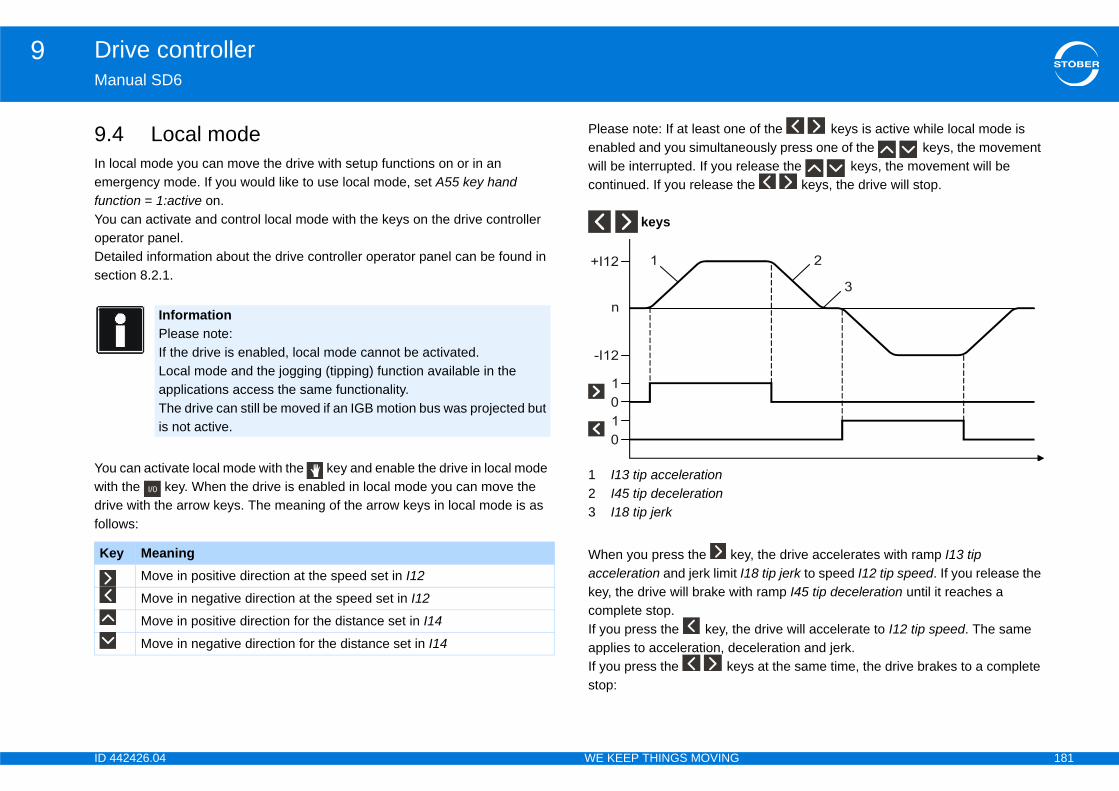
ID 4 181
Drive controller9Ma
9.In lemfunYouopeDetsec
Youwithdrivfollo
of the keys is active while local mode is ously press one of the keys, the movement
elease the keys, the movement will be he keys, the drive will stop.
y, the drive accelerates with ramp I13 tip I18 tip jerk to speed I12 tip speed. If you release the th ramp I45 tip deceleration until it reaches a
e drive will accelerate to I12 tip speed. The same celeration and jerk.ys at the same time, the drive brakes to a complete
Ke
42426.04 WE KEEP THINGS MOVING
nual SD6
4 Local modeocal mode you can move the drive with setup functions on or in an ergency mode. If you would like to use local mode, set A55 key hand ction = 1:active on. can activate and control local mode with the keys on the drive controller rator panel.ailed information about the drive controller operator panel can be found in tion 8.2.1.
can activate local mode with the key and enable the drive in local mode the key. When the drive is enabled in local mode you can move the e with the arrow keys. The meaning of the arrow keys in local mode is as ws:
Please note: If at least oneenabled and you simultanewill be interrupted. If you rcontinued. If you release t
keys
1 I13 tip acceleration2 I45 tip deceleration3 I18 tip jerk
When you press the keacceleration and jerk limit key, the drive will brake wicomplete stop.If you press the key, thapplies to acceleration, deIf you press the kestop:
InformationPlease note:If the drive is enabled, local mode cannot be activated.Local mode and the jogging (tipping) function available in the applications access the same functionality.The drive can still be moved if an IGB motion bus was projected but is not active.
y MeaningMove in positive direction at the speed set in I12
Move in negative direction at the speed set in I12
Move in positive direction for the distance set in I14
Move in negative direction for the distance set in I14
I/0
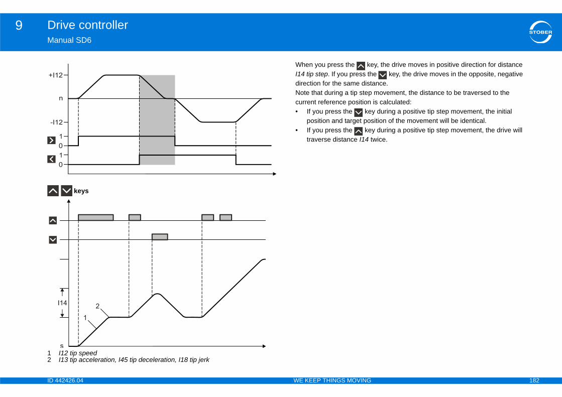
ID 4 182
Drive controller9Ma
12
y, the drive moves in positive direction for distance e key, the drive moves in the opposite, negative ance. movement, the distance to be traversed to the is calculated:y during a positive tip step movement, the initial ition of the movement will be identical.
y during a positive tip step movement, the drive will wice.
42426.04 WE KEEP THINGS MOVING
nual SD6
keys
I12 tip speedI13 tip acceleration, I45 tip deceleration, I18 tip jerk
When you press the keI14 tip step. If you press thdirection for the same distNote that during a tip stepcurrent reference position • If you press the ke
position and target pos• If you press the ke
traverse distance I14 t
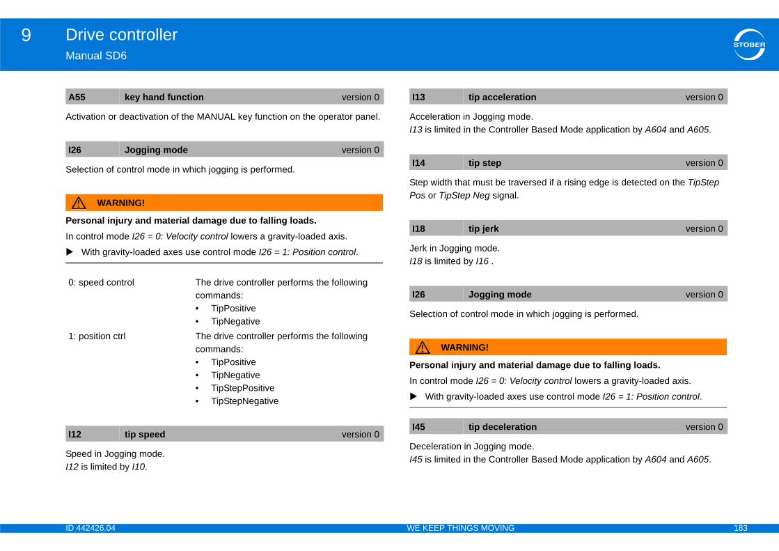
ID 4 183
Drive controller9Ma
Act
Sel
PerIn c
SpeI12
ode.ller Based Mode application by A604 and A605.
versed if a rising edge is detected on the TipStep .
in which jogging is performed.
rial damage due to falling loads.elocity control lowers a gravity-loaded axis.
es use control mode I26 = 1: Position control.
ode.ller Based Mode application by A604 and A605.
A5
I26
0:
1:
I12
tion version 0
version 0
version 0
ode version 0
ation version 0
42426.04 WE KEEP THINGS MOVING
nual SD6
ivation or deactivation of the MANUAL key function on the operator panel.
ection of control mode in which jogging is performed.
WARNING!
sonal injury and material damage due to falling loads.ontrol mode I26 = 0: Velocity control lowers a gravity-loaded axis.
With gravity-loaded axes use control mode I26 = 1: Position control.
ed in Jogging mode. is limited by I10.
Acceleration in Jogging mI13 is limited in the Contro
Step width that must be traPos or TipStep Neg signal
Jerk in Jogging mode.I18 is limited by I16 .
Selection of control mode
WARNING!
Personal injury and mateIn control mode I26 = 0: V
With gravity-loaded ax
Deceleration in Jogging mI45 is limited in the Contro
5 key hand function version 0
Jogging mode version 0
speed control The drive controller performs the following commands:• TipPositive• TipNegative
position ctrl The drive controller performs the following commands:• TipPositive• TipNegative• TipStepPositive• TipStepNegative
tip speed version 0
I13 tip accelera
I14 tip step
I18 tip jerk
I26 Jogging m
I45 tip deceler

ID 4 184
Drive controller9Ma
9.9.5
9.5To par•
••
LowIf thena
ConThelink
SSM - vector control affects A36 the field weakening ed from A36 . DC link voltages above this limit value ation in field weakening mode to prevent oscillations
adjust whether the drive controller will be supplied e via the DC link.
A3
A3
input version 0
ection in the manual describing the DC link
42426.04 WE KEEP THINGS MOVING
nual SD6
5 Energy management.1 Power input
.1.1 Parameterize power inputensure correct parameterization of the power input, edit the following ameters:A35 low voltage limit: Specify in this parameter the minimum voltage that must be applied in the DC link during operation. A36 mains voltage: connected to X10, effective supply voltage.A38 DC power-input: Leave the default setting 0:inactive if the drive controller will be fed with power via the supply voltage connected to terminal X10. If the drive controller will be supplied with power exclusively via the DC link, set the parameter to 1:active.
er limit value for the voltage in the DC link.e DC link voltage is less than the set value while the drive controller is bled, event 46:low voltage with cause 1:low Voltage is triggered.
nected to X10, effective supply voltage. charge relay is controlled to ensure low wear depending on the current DC voltage and A36.
In control mode B20 = 64: mode. A limit value is derivare not taken into considerin the motor current.
In this parameter you can exclusively with DC voltag
InformationNote that to ensure correct functionality of the DC link, parameter A38 DC power-input must be set to:Group 1: A38 = 0:inactiveGroup 2: A38 = 1:active
5 low voltage limit version 0
6 mains voltage version 0
A38 DC power-
InformationNote also the sconnection.
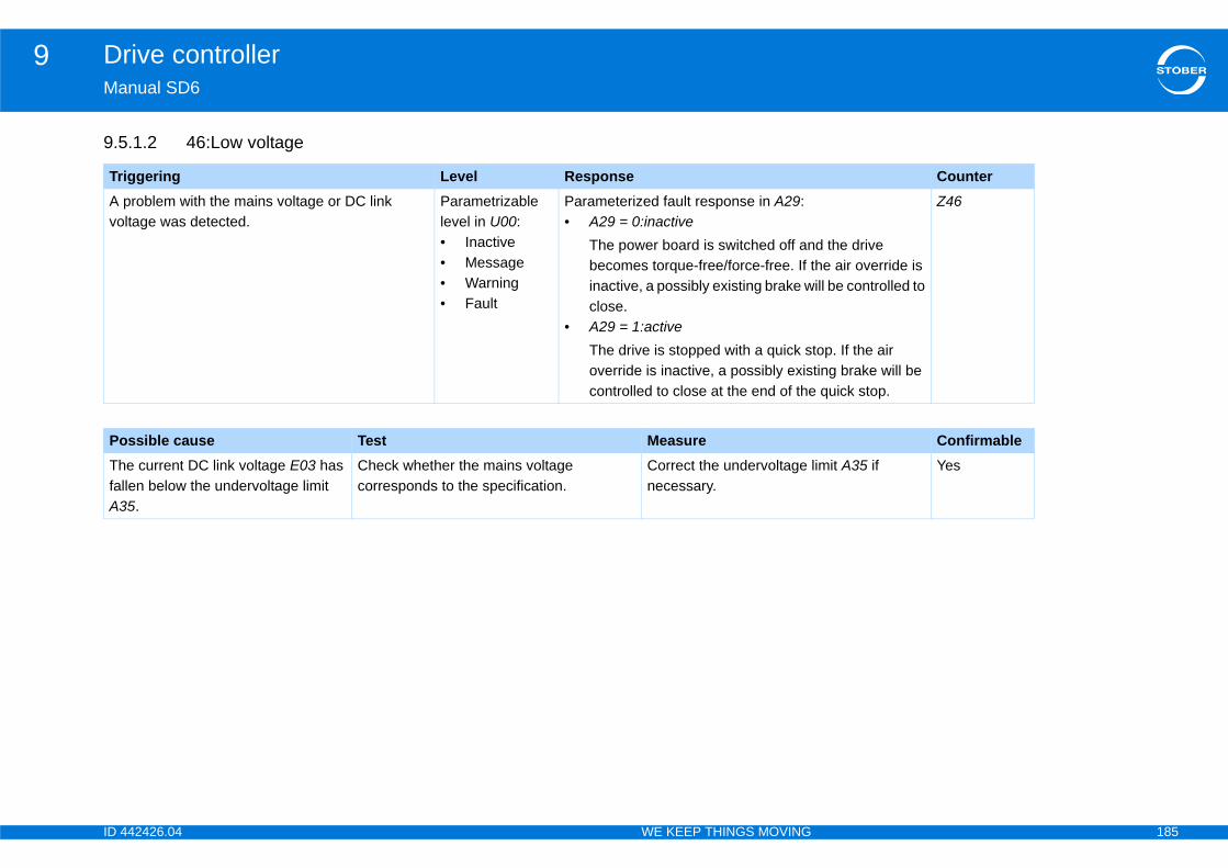
ID 4 185
Drive controller9Ma
9.5
Tr CounterA vo
d the drive he air override is ill be controlled to
top. If the air ting brake will be quick stop.
Z46
Po ConfirmableThfalA3
imit A35 if Yes
42426.04 WE KEEP THINGS MOVING
nual SD6
.1.2 46:Low voltage
iggering Level Responseproblem with the mains voltage or DC link ltage was detected.
Parametrizable level in U00:• Inactive• Message• Warning• Fault
Parameterized fault response in A29:• A29 = 0:inactive
The power board is switched off anbecomes torque-free/force-free. If tinactive, a possibly existing brake wclose.
• A29 = 1:activeThe drive is stopped with a quick soverride is inactive, a possibly exiscontrolled to close at the end of the
ssible cause Test Measuree current DC link voltage E03 has len below the undervoltage limit 5.
Check whether the mains voltage corresponds to the specification.
Correct the undervoltage lnecessary.
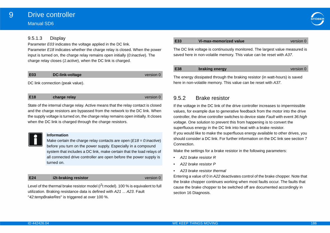
ID 4 186
Drive controller9Ma
9.5ParParinpcha
DC
Staandthewhe
Levutili"42
tinuously monitored. The largest value measured is memory. This value can be reset with A37.
ugh the braking resistor (in watt-hours) is saved ry. This value can be reset with A37.
istork of the drive controller increases to impermissible generative feedback from the motor into the drive
ller switches to device state Fault with event 36:high event this from happening is to convert the DC link into heat with a brake resistor. e superfluous energy available to other drives, you
For further information on the DC link see section 7
ke resistor in the following parameters:
rmal2 deactivates control of the brake chopper. Note that es working when most faults occur. The faults that o be switched off are documented accordingly in
E0
E1
E2
morized value version 0
ergy version 0
42426.04 WE KEEP THINGS MOVING
nual SD6
.1.3 Displayameter E03 indicates the voltage applied in the DC link.ameter E18 indicates whether the charge relay is closed. When the power ut is turned on, the charge relay remains open initially (0:inactive). The rge relay closes (1:active), when the DC link is charged.
link connection (peak value).
te of the internal charge relay. Active means that the relay contact is closed the charge resistors are bypassed from the network to the DC link. When
supply voltage is turned on, the charge relay remains open initially. It closes n the DC link is charged through the charge resistors.
el of the thermal brake resistor model (i2t model). 100 % is equivalent to full zation. Braking resistance data is defined with A21 ... A23. Fault :tempBrakeRes" is triggered at over 100 %.
The DC link voltage is consaved here in non-volatile
The energy dissipated throhere in non-volatile memo
9.5.2 Brake resIf the voltage in the DC linvalues, for example due tocontroller, the drive controvoltage. One solution to prsuperfluous energy in the If you would like to make thshould consider a DC link.Connection.
Make the settings for a bra
• A21 brake resistor R
• A22 brake resistor P
• A23 brake resistor theEntering a value of 0 in A2the brake chopper continucause the brake chopper tsection 16 Diagnosis.
3 DC-link-voltage version 0
8 charge relay version 0
InformationMake certain the charge relay contacts are open (E18 = 0:inactive) before you turn on the power supply. Especially in a compound system that includes a DC link, make certain that the load relays of all connected drive controller are open before the power supply is turned on.
4 i2t-braking resistor version 0
E33 Vi-max-me
E38 braking en

ID 4 187
Drive controller9Ma
Res
Ou
The
Theher
Thenon
A2
A2
A2
E3
E4
42426.04 WE KEEP THINGS MOVING
nual SD6
istance value of the braking resistor that is used.
tput of the braking resistor that is used.
rmal time constant of the braking resistor.
energy dissipated through the braking resistor (in watt-hours) is saved e in non-volatile memory. This value can be reset with A37.
maximum value of the thermal utilization of the braking resistor is saved in -volatile memory here. This value can be reset with A37.
1 brake resistor R version 0
2 brake resistor P version 0
InformationIf A22 = 0, the brake chopper is deactivated.
3 brake resistor thermal version 0
8 braking energy version 0
1 i2t braking resistor peak value version 0
Information- This parameter does not specify the maximum value of E24.- - E24 is initialized with 80 % when the device starts. By contrast the parameter based on the model is 0 %.- For a meaningful maximum value measurement, the braking resistance when the device starts must be approximately at ambient temperature.

ID 4 188
Drive controller9Ma
9.5
9.5
Tr CounterThtheFrTo
d the drive he air override is ill be controlled to
top. If the air ting brake will be quick stop.f 100%, current es with vector e the fault quick
Z39
Po ConfirmableDr the drive.
e condition rication, etc.)
Yes
Cyable power
42426.04 WE KEEP THINGS MOVING
nual SD6
.3 Energetic utilization
.3.1 39:TempDev i2t
iggering Level Responsee i2t model for the drive controller is exceeding maximum allowable thermal utilization.
om firmware V 6.0-G: A27 rom firmware V 6.0-F: 100%
Parameterized level in U02:• Inactive• Message• Warning• Fault
Parameterized fault response in A29:• A29 = 0:inactive
The power board is switched off anbecomes torque-free/force-free. If tinactive, a possibly existing brake wclose.
• A29 = 1:activeThe drive is stopped with a quick soverride is inactive, a possibly exiscontrolled to close at the end of the
If the event is triggered at a threshold olimiting is performed in the control modcontrol. Reducing the current can causstop to no longer perform correctly.
ssible cause Test Measureive controller overloaded Check the load situation of your drive. • Correct the design of
• Check the maintenancof the drive (block, lub
cle frequency too high (B24) Check the load situation of your drive under consideration of the derating.
• Reduce B24.• Use a drive with a suit
rating.

ID 4 189
Drive controller9Ma
9.5
Tr CounterTh10
d the drive he air override is ill be controlled to
top. If the air ting brake will be quick stop.er is switched off.
Z42
Po ConfirmableThdeap
tion. Consider a use of a braking r rating.
Yes
42426.04 WE KEEP THINGS MOVING
nual SD6
.3.2 42:TempBrakeRes
iggering Level Responsee i2t model for the braking resistor exceeds 0% load.
Fault Parameterized fault response in A29:• A29 = 0:inactive
The power board is switched off anbecomes torque-free/force-free. If tinactive, a possibly existing brake wclose.
• A29 = 1:activeThe drive is stopped with a quick soverride is inactive, a possibly exiscontrolled to close at the end of the
Up to firmware V 6.0-F the brake chopp
ssible cause Test Measuree braking resistor may not be signed according to the plication.
Check whether the load state of the braking resistor has caused overheating.
Check the drive configuraDC link connection or the resistor with a larger powe

ID 4 190
Drive controller9Ma
9.5
Tr CounterTh
d the drive he air override is ill be controlled to
top. If the air ting brake will be quick stop.
Z45
Po ConfirmableTh t the
perating
ockages.e drive design.
Yes
42426.04 WE KEEP THINGS MOVING
nual SD6
.3.3 45:oTempMot. i2t
iggering Level Responsee i2t model for the motor reaches 100 % load. Parameterized
level in U10:• Inactive• Message• Warning• Fault
Parameterized fault response in A29:• A29 = 0:inactive
The power board is switched off anbecomes torque-free/force-free. If tinactive, a possibly existing brake wclose.
• A29 = 1:activeThe drive is stopped with a quick soverride is inactive, a possibly exiscontrolled to close at the end of the
ssible cause Test Measuree motor is overloaded Check whether the operating conditions
have caused the motor to overheat (load state, surrounding temperature of the motor, etc.).
• Take measures to meerequirements for the oconditions.
• Rectify any existing bl• If necessary, correct th

ID 4 191
Drive controller9Ma
9.5
Tr CounterThex
d the drive he air override is ill be controlled to
top. If the air ting brake will be quick stop.
Z59
Po ConfirmableDr ads (lubrications,
able power rating.
Yes
Cyable power rating.
42426.04 WE KEEP THINGS MOVING
nual SD6
.3.4 59:TempDev. i2t
iggering Level Responsee i2t model calculated for the drive controller ceeds 105% of thermal load.
Fault Parameterized fault response in A29:• A29 = 0:inactive
The power board is switched off anbecomes torque-free/force-free. If tinactive, a possibly existing brake wclose.
• A29 = 1:activeThe drive is stopped with a quick soverride is inactive, a possibly exiscontrolled to close at the end of the
ssible cause Test Measureive controller overloaded Check the load situation of your drive. • Reduce any existing lo
blockages, etc.).• Use a drive with a suit
cle frequency too high Check the load situation of your drive under consideration of the derating.
• Reduce B24.• Use a drive with a suit

ID 4 192
Drive controller9Ma
9.5
CloIncampowIn sitse
Shoto tesp
l (i2t model). Fault "39:Temp.Dev i2t" is triggered at en 100 % of the limit is reached the drive controller
ev i2t" with the level indicated in U02. The output rmitted nominal device current for control modes SM - vector control (B20 = 2 or 64).
en off in Wh.
uously monitored. The largest value measured is memory. This value can be reset with A37.
ugh the braking resistor (in watt-hours) is saved ry. This value can be reset with A37.
B2
B2
4: 8: 16171819
E2
ntroller version 0
nter version 0
orized value version 0
ergy version 0
42426.04 WE KEEP THINGS MOVING
nual SD6
.3.5 Parameters
ck frequency of the drive controller power board.reasing the clock frequency improves the control dynamics and reduces the ount of noise produced, but also leads to increased losses (derating of the er stage R04, R26).ome operating states the clock frequency is changed by the drive controller lf. The currently active clock frequency is displayed in E151.
ws the current utilization of the drive controller as a %. 100 % is equivalent he nominal power loss of the drive controller. Utilization is affected ecially by the output current (E00) and the PWM clock frequency (B24).
Level of the thermal mode105 % of full utilization. Whtriggers event "39:Temp.Dcurrent is limited to the peASM - vector control and S
Display of total energy giv
The motor current is continsaved here in non-volatile
The energy dissipated throhere in non-volatile memo
4 switching frequency version 2
4 switching frequency version 2
InformationThe factory setting of this parameter depends on B20. If a synchronous servo motor or synchronous linear motor is used, the value 8:8kHz is entered in B24. If an asynchronous machine is used, B24 has a value of 4:4kHz.
4 kHz8 kHz: 16 kHz: 4 + 8 kHz automatic: 8 + 16 kHz automatic: 4 + 8 + 16 kHz automatic
0 drive controller utilization version 0
E22 i2t-drive co
E32 energy cou
E34 I-max-mem
E38 braking en

ID 4 193
Drive controller9Ma
9.5The
••
Thepar••The
Thepar••The
9.Theconis to
.27 57:Runtime usage. In this case set A150 to a
e drive controller can be found in parameter E191 eter has a value > 75 %, you should set A150 to a
91 starts at 0 % when you have changed A150.
figuration in the axis. task can be checked in parameter E191 runtime ad is too heavy event 57:runtime usage is triggered.
tsprovide information about which components were which ones are actually present.
ler designation including SafetyModule and options,
x 1008hex subindex 0hex Manufacturer device name 1.
n DriveControlSuite (without options modules), for
E2
E3
E3
version 0
oller version 0
ive controller version 0
oller information version 0
42426.04 WE KEEP THINGS MOVING
nual SD6
.4 Thermal following display parameter provides you with further information:
Element 0: Current temperature of the power board/ IGBT in °C.Element 1: Current temperature of the control board in °C.
lowest measured temperatures are saved in the elements of this ameter in non-volatile memory. Element 0: Temperature of the power board/IGBT Element 1: Temperature of the control board se values can be reset with A37.
highest measured temperatures are saved in the elements of this ameter in non-volatile memory. Element 0: Temperature of the power board/IGBT Element 1: Temperature of the control board se values can be reset with A37.
6 Cycle time application is processed with the cycle time set in A150. If the drive troller is unable to process the application in the set time because utilization o high, fault 57: runtime load is triggered. A detailed description of the fault
can be found in section 16higher value.The current utilization of thruntime usage. If the paramhigher value. Note that E1
Cycle time of real-time conThe usage of the real-timeusage. If the computing lo
9.7 ComponenThe following parameters created in your project and
Display of the drive controlfor example SD6A06TEX.Corresponds to object indein accordance with CiA 30
Projected drive controller iexample SD6A06.
5 drive controller temperature version 0
5 Tmin-memorized value version 0
6 Tmax-memorized value version 0
A150 cycle time
E50 drive contr
E51 required dr
E52 drive contr
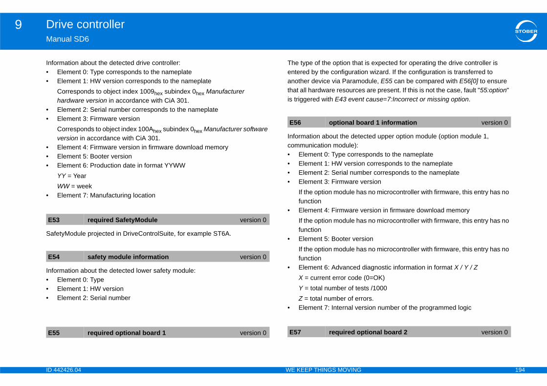
ID 4 194
Drive controller9Ma
Info••
••
•••
•
Saf
Info•••
is expected for operating the drive controller is n wizard. If the configuration is transferred to dule, E55 can be compared with E56[0] to ensure
s are present. If this is not the case, fault "55:option" t cause=7:Incorrect or missing option.
cted upper option module (option module 1,
sponds to the nameplate corresponds to the nameplate
ber corresponds to the nameplateersions no microcontroller with firmware, this entry has no
ersion in firmware download memorys no microcontroller with firmware, this entry has no
ions no microcontroller with firmware, this entry has no
diagnostic information in format X / Y / Z (0=OK)ts /1000ors.rsion number of the programmed logic
E5
E5
E5
ard 1 information version 0
tional board 2 version 0
42426.04 WE KEEP THINGS MOVING
nual SD6
rmation about the detected drive controller:Element 0: Type corresponds to the nameplateElement 1: HW version corresponds to the nameplateCorresponds to object index 1009hex subindex 0hex Manufacturer hardware version in accordance with CiA 301.Element 2: Serial number corresponds to the nameplateElement 3: Firmware versionCorresponds to object index 100Ahex subindex 0hex Manufacturer software version in accordance with CiA 301.Element 4: Firmware version in firmware download memoryElement 5: Booter versionElement 6: Production date in format YYWWYY = YearWW = weekElement 7: Manufacturing location
etyModule projected in DriveControlSuite, for example ST6A.
rmation about the detected lower safety module:Element 0: TypeElement 1: HW versionElement 2: Serial number
The type of the option thatentered by the configuratioanother device via Paramothat all hardware resourceis triggered with E43 even
Information about the detecommunication module):• Element 0: Type corre• Element 1: HW version• Element 2: Serial num• Element 3: Firmware v
If the option module hafunction
• Element 4: Firmware vIf the option module hafunction
• Element 5: Booter versIf the option module hafunction
• Element 6: Advanced X = current error codeY = total number of tesZ = total number of err
• Element 7: Internal ve
3 required SafetyModule version 0
4 safety module information version 0
5 required optional board 1 version 0
E56 optional bo
E57 required op
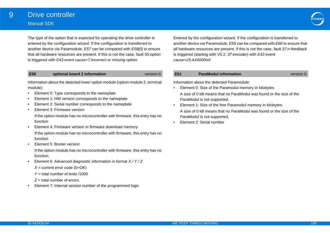
ID 4 195
Drive controller9Ma
Theentanothais tr
Infomo••••
•
•
•
•
on wizard. If the configuration is transferred to dule, E59 can be compared with E60 to ensure that present. If this is not the case, fault 37:n-feedback 5.2: 37:encoder) with E43 event
cted Paramodule: Paramodul memory in kilobyteshat no ParaModul was found or the size of the orted. free Paramodul memory in kilobytes.hat no ParaModul was found or the size of the orted.ber
E5 information version 0
42426.04 WE KEEP THINGS MOVING
nual SD6
type of the option that is expected for operating the drive controller is ered by the configuration wizard. If the configuration is transferred to ther device via Paramodule, E57 can be compared with E58[0] to ensure
t all hardware resources are present. If this is not the case, fault 55:option iggered with E43 event cause=7:Incorrect or missing option.
rmation about the detected lower option module (option module 2, terminal dule):Element 0: Type corresponds to the nameplateElement 1: HW version corresponds to the nameplateElement 2: Serial number corresponds to the nameplateElement 3: Firmware versionIf the option module has no microcontroller with firmware, this entry has no functionElement 4: Firmware version in firmware download memoryIf the option module has no microcontroller with firmware, this entry has no functionElement 5: Booter versionIf the option module has no microcontroller with firmware, this entry has no function.Element 6: Advanced diagnostic information in format X / Y / ZX = current error code (0=OK)Y = total number of tests /1000Z = total number of errors.Element 7: Internal version number of the programmed logic
Entered by the configuratianother device via Paramoall hardware resources areis triggered (starting with Vcause=23:AX6000ref.
Information about the dete• Element 0: Size of the
A size of 0 kB means tParaModul is not supp
• Element 1: Size of theA size of 0 kB means tParaModul is not supp
• Element 2: Serial num
8 optional board 2 information version 0 E61 ParaModul
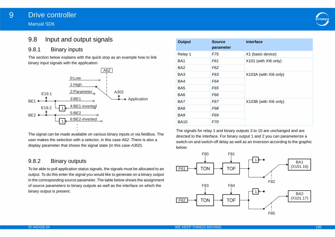
ID 4 196
Drive controller9Ma
9.9.8Thebin
Theusedisp
9.8To boutin thof sbin
binary outputs 3 to 10 are unchanged and are or binary output 1 and 2 you can parameterize a lay as well as an inversion according to the graphic
BE
BE
e eter
interface
X1 (basic device)
X101 (with XI6 only)
X103A (with XI6 only)
X103B (with XI6 only)
1
F82
F81
1
F85
F84
BA1(X101.16)
BA2(X101.17)
42426.04 WE KEEP THINGS MOVING
nual SD6
8 Input and output signals.1 Binary inputs section below explains with the quick stop as an example how to link
ary input signals with the application:
signal can be made available on various binary inputs or via fieldbus. The r makes the selection with a selector, in this case A62. There is also a lay parameter that shows the signal state (in this case A302).
.2 Binary outputse able to poll application status signals, the signals must be allocated to an
put. To do this enter the signal you would like to generate on a binary output e corresponding source parameter. The table below shows the assignment ource parameters to binary outputs as well as the interface on which the
ary output is present.
The signals for relay 1 anddirected to the interface. Fswitch-on and switch-off debelow:
A62
1
2:Parameter
1
1 4:BE1-inverted
5:BE26:BE2-inverted
1:High0:Low
E19.1
E19.2
3:BE1
.
.
.
2
A302
Application
Output Sourcparam
Relay 1 F75
BA1 F61
BA2 F62
BA3 F63
BA4 F64
BA5 F65
BA6 F66
BA7 F67
BA8 F68
BA9 F69
BA10 F70
F80
F61
F83
F62
ID 4 197
Drive controller9Ma
The(X1
The(X1
The(X1
The(X1
rized coordinate is generated on binary output 5
rized coordinate is generated on binary output 6
rized coordinate is generated on binary output 7
rized coordinate is generated on binary output 8
rized coordinate is generated on binary output 9
rized coordinate is generated on binary output 10
F6
F6
F6
F6
e version 0
e version 0
e version 0
e version 0
e version 0
ce version 0
42426.04 WE KEEP THINGS MOVING
nual SD6
value of the parameterized coordinate is generated on binary output 1 01.8).
value of the parameterized coordinate is generated on binary output 2 01.9).
value of the parameterized coordinate is generated on binary output 3 03.1).
value of the parameterized coordinate is generated on binary output 4 03.2).
The value of the paramete(X103.3).
The value of the paramete(X103.4).
The value of the paramete(X103.5).
The value of the paramete(X103.6).
The value of the paramete(X103.7).
The value of the paramete(X103.8).
1 BA1-source version 0
InformationNote that if encoder simulation is being used via the binary outputs, binary output BA1 is already being used. In this case no entry is permitted in F61.
2 BA2-source version 0
InformationNote that if encoder simulation is being used via the binary outputs, binary output BA2 is already being used. In this case no entry is permitted in F62.
3 BA3-source version 0
4 BA4-source version 0
F65 BA5-sourc
F66 BA6-sourc
F67 BA7-sourc
F68 BA8-sourc
F69 BA9-sourc
F70 BA10-sour
ID 4 198
Drive controller9Ma
9.8
9.8
Tau
Wir
Op
.lue of the analog input before filtering.
lue of the analog input before calibration.value of the analog input.
put.
f the filtered analog input.
f the filtered analog input.
alog input.
e of the calibrated analog input.
e of the calibrated analog input.
F1
F1
0: 1:
F1
0: 1:
2:
version 0
ut 1 zero value version 0
ut 1 maximum positive value version 0
ut 1 maximum negative value version 0
ut 1 deadband value version 0
ut 1 minimum % value version 0
ut 1 maximum % value version 0
42426.04 WE KEEP THINGS MOVING
nual SD6
.3 Analog inputs
.3.1 AE1
for reference value smoothing for analog input 1.
e break monitoring for analog input.
erating mode of the analog input.
Values of the analog input• Element 0: Terminal va• Element 1: Filtered va• Element 2: Calibrated
Zero value of the analog in
Maximum positive value o
Maximum negative value o
Deadband value of the an
Minimum percentage valu
Maximum percentage valu
3 AE1 ref low pass filter version 0
5 wire breakage sensing version 0
InformationThe wire break monitoring function is only possible in AE1 mode F116=2: 4 to 20mA.
inactiveactive
16 AE1-mode selector version 0
-10V to 10V0 to 20mA An internal precision resistor (shunt 500 ohms)
is integrated into X100.2. A bridge must be set between X100.1 and X100.2.
4 to 20mA An internal precision resistor (shunt 500 ohms) is integrated into X100.2. A bridge must be set between X100.1 and X100.2.
E110 AE1
F110 Analog inp
F111 Analog inp
F112 Analog inp
F113 Analog inp
F114 Analog inp
F115 Analog inp
ID 4 199
Drive controller9Ma
9.8
Tau
Val•••
Zer
Ma
Ma
Dea
Min
e of the calibrated analog input.F2
E1
F1
F1
F1
F1
F1
ut 2 maximum % value version 0
42426.04 WE KEEP THINGS MOVING
nual SD6
.3.2 AE2
for reference value smoothing for analog input 2.
ues of the analog input.Element 0: Terminal value of the analog input before filtering.Element 1: Filtered value of the analog input before calibration.Element 2: Calibrated value of the analog input.
o value of the analog input.
ximum positive value of the filtered analog input.
ximum negative value of the filtered analog input.
dband value of the analog input.
imum percentage value of the calibrated analog input.
Maximum percentage valu3 AE2 ref low pass filter version 0
11 AE2 version 0
20 Analog input 2 zero value version 0
21 Analog input 2 maximum positive value version 0
22 Analog input 2 maximum negative value version 0
23 Analog input 2 deadband value version 0
24 Analog input 2 minimum % value version 0
F125 Analog inp

ID 4 200
Drive controller9Ma
9.8
Tau
Val•••
Zer
Ma
Ma
Dea
Min
e of the calibrated analog input.F3
E1
F1
F1
F1
F1
F1
ut 3 maximum % value version 0
42426.04 WE KEEP THINGS MOVING
nual SD6
.3.3 AE3
for reference value smoothing for analog input 3.
ues of the analog input.Element 0: Terminal value of the analog input before filtering.Element 1: Filtered value of the analog input before calibration.Element 2: Calibrated value of the analog input.
o value of the analog input.
ximum positive value of the filtered analog input.
ximum negative value of the filtered analog input.
dband value of the analog input.
imum percentage value of the calibrated analog input.
Maximum percentage valu3 AE3 ref low pass filter version 0
12 AE3 version 0
30 Analog input 3 zero value version 0
31 Analog input 3 maximum positive value version 0
32 Analog input 3 maximum negative value version 0
33 Analog input 3 deadband value version 0
34 Analog input 3 minimum % value version 0
F135 Analog inp
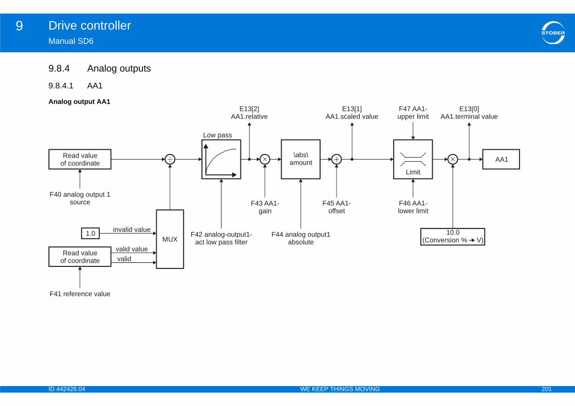
ID 4 201
Drive controller9Ma
9.8
9.8
An
F46 AA1-lower limit
F47 AA1-upper limit
Limit
F4
AA1
E13[0]AA1.terminal value
10.0(Conversion % V)
F4
42426.04 WE KEEP THINGS MOVING
nual SD6
.4 Analog outputs
.4.1 AA1
alog output AA1
F42 analog-output1-act low pass filter
Read valueof coordinate
F43 AA1-gain
F45 AA1-offset
Low pass
\abs\amount
F44 analog output1absolute
0 analog output 1source
Read valueof coordinate
MUXvalid value
1.0 invalid value
E13[2]AA1.relative
E13[1]AA1.scaled value
valid
1 reference value
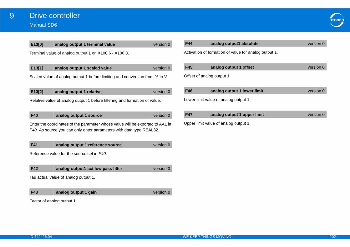
ID 4 202
Drive controller9Ma
Ter
Sca
Rel
EntF40
Ref
Tau
Fac
alue for analog output 1.
output 1.
output 1.
E1
E1
E1
F4
F4
F4
F4
put1 absolute version 0
put 1 offset version 0
put 1 lower limit version 0
put 1 upper limit version 0
42426.04 WE KEEP THINGS MOVING
nual SD6
minal value of analog output 1 on X100.6 - X100.8.
led value of analog output 1 before limiting and conversion from % to V.
ative value of analog output 1 before filtering and formation of value.
er the coordinates of the parameter whose value will be exported to AA1 in . As source you can only enter parameters with data type REAL32.
erence value for the source set in F40.
actual value of analog output 1.
tor of analog output 1.
Activation of formation of v
Offset of analog output 1.
Lower limit value of analog
Upper limit value of analog
3[0] analog output 1 terminal value version 0
3[1] analog output 1 scaled value version 0
3[2] analog output 1 relative version 0
0 analog output 1 source version 0
1 analog output 1 reference source version 0
2 analog-output1-act low pass filter version 0
3 analog output 1 gain version 0
F44 analog out
F45 analog out
F46 analog out
F47 analog out
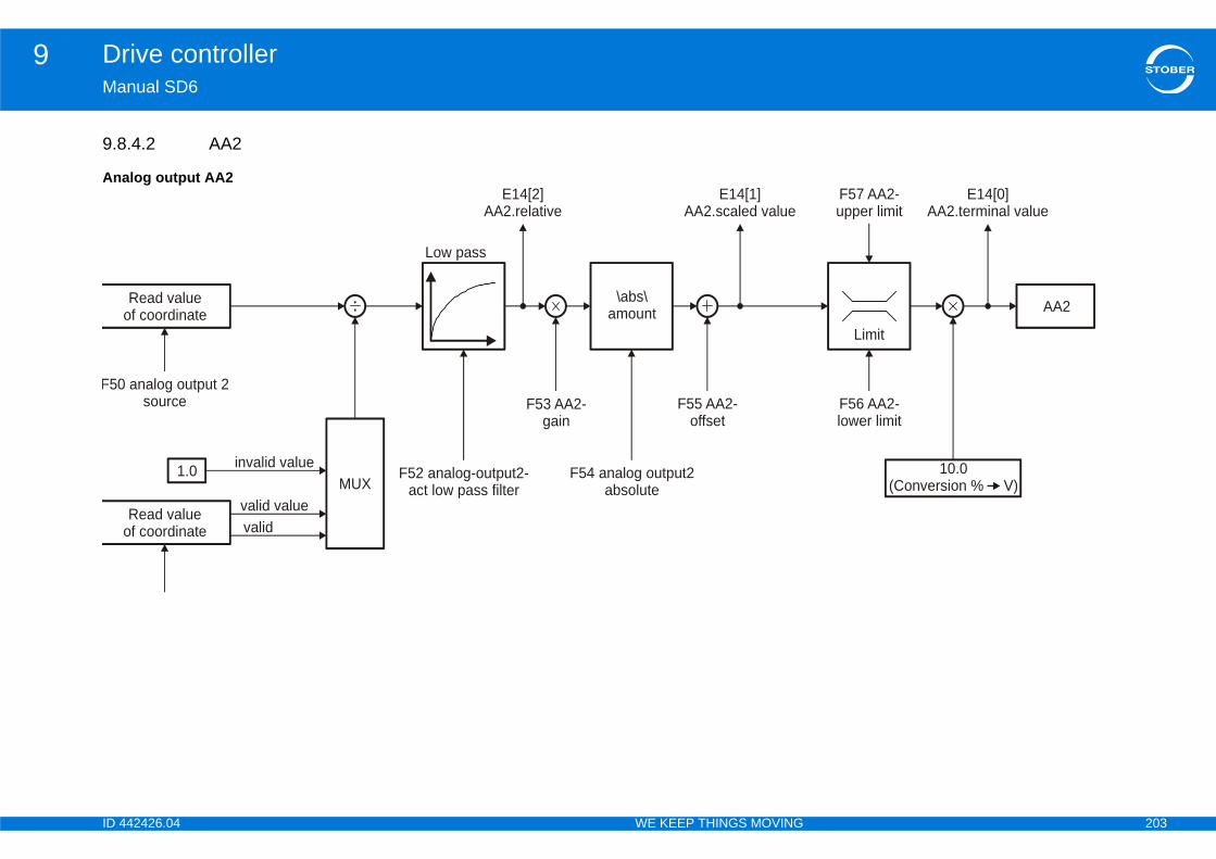
ID 4 203
Drive controller9Ma
9.8
An
F56 AA2-lower limit
F57 AA2-upper limit
Limit
F50
AA2
E14[0]AA2.terminal value
10.0(Conversion % V)
42426.04 WE KEEP THINGS MOVING
nual SD6
.4.2 AA2
alog output AA2
F52 analog-output2-act low pass filter
Read valueof coordinate
F53 AA2-gain
F55 AA2-offset
Low pass
F54 analog output2absolute
analog output 2source
Read valueof coordinate
MUXvalid value
1.0 invalid value
E14[2]AA2.relative
E14[1]AA2.scaled value
\abs\amount
valid

ID 4 204
Drive controller9Ma
Ter
Sca
Rel
EntF50
Ref
Tau
Fac
log output 2.
output 2.
output 2.
E1
E1
E1
F5
F5
F5
F5
put2 absolute version 0
put 2 offset version 0
put 2 lower limit version 0
put 2 upper limit version 0
42426.04 WE KEEP THINGS MOVING
nual SD6
minal value of analog output 2 on X100.7 - X100.8.
led value of analog output 2 before limiting and conversion from % to V.
ative value of analog output 2 before filtering and formation of value.
er the coordinates of the parameter whose value will be exported to AA2 in . As source you can enter all parameters with data type REAL32.
erence value for the source set in F50.
actual value of analog input 2.
tor of analog output 2.
Formation of value for ana
Offset of analog output 2.
Lower limit value of analog
Upper limit value of analog
4[0] analog output 2 terminal value version 0
4[1] analog output 2 scaled value version 0
4[2] analog output 2 relative version 0
0 analog output 2 source version 0
1 analog output 2 reference source version 0
2 analog-output2-act low pass filter version 0
3 analog output 2 gain version 0
F54 analog out
F55 analog out
F56 analog out
F57 analog out
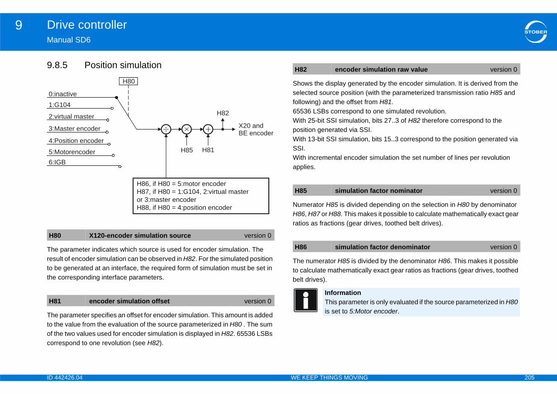
ID 4 205
Drive controller9Ma
9.8
Theresto bthe
Theto tof tcor
ted by the encoder simulation. It is derived from the ith the parameterized transmission ratio H85 and
om H81. one simulated revolution.
, bits 27..3 of H82 therefore correspond to the I., bits 15..3 correspond to the position generated via
simulation the set number of lines per revolution
depending on the selection in H80 by denominator es it possible to calculate mathematically exact gear ives, toothed belt drives).
ed by the denominator H86. This makes it possible y exact gear ratios as fractions (gear drives, toothed
H8
H8
2:v
4:P
5:M6:I
1:G0:i
3:M
mulation raw value version 0
factor nominator version 0
factor denominator version 0
is only evaluated if the source parameterized in H80 r encoder.
42426.04 WE KEEP THINGS MOVING
nual SD6
.5 Position simulation
parameter indicates which source is used for encoder simulation. The ult of encoder simulation can be observed in H82. For the simulated position e generated at an interface, the required form of simulation must be set in corresponding interface parameters.
parameter specifies an offset for encoder simulation. This amount is added he value from the evaluation of the source parameterized in H80 . The sum he two values used for encoder simulation is displayed in H82. 65536 LSBs respond to one revolution (see H82).
Shows the display generaselected source position (wfollowing) and the offset fr65536 LSBs correspond toWith 25-bit SSI simulationposition generated via SSWith 13-bit SSI simulationSSI.With incremental encoder applies.
Numerator H85 is divided H86, H87 or H88. This makratios as fractions (gear dr
The numerator H85 is dividto calculate mathematicallbelt drives).
0 X120-encoder simulation source version 0
1 encoder simulation offset version 0
H85 H81
H86, if H80 = 5:motor encoderH87, if H80 = 1:G104, 2:virtual masteror 3:master encoderH88, if H80 = 4:position encoder
H82irtual master
osition encoder
otorencoderGB
104nactive
H80
aster encoder X20 andBE encoder
H82 encoder si
H85 simulation
H86 simulation
InformationThis parameteris set to 5:Moto

ID 4 206
Drive controller9Ma
Theto cbel
Theto cbel
9.8The
Ter
a with protection against power
ta from DriveControlSuite to the drive controller or ttings, the data in the drive controller must be saved. ved, it is not protected for subsequent use against a er is turned off and back on.rive controller with action A00 save values. With the rameters, all parameters and the configuration are ule.
alues
e operator panel (an explanation of the keys can be 1 Setup)
arameter menu (an explanation of the parameter section 8.2.1.2 Menu structure and navigation)
ect connection) in the DriveControlSuite parameter eControlSuite manual. The ID of the manual can be rther documentation)
H8
H8
E1
Bi01 -131415
ff the power supply of the control board while the still active. If you do turn of the power supply, the rtERROR parameters lost or *Paramodul ERROR - appear in the display next time the device is scription of faults can be found in sections 16.54 ROR parameters lostand 16.51 *ParaModul t found. application must be transferred to the drive .
42426.04 WE KEEP THINGS MOVING
nual SD6
numerator H85 is divided by the denominator H87. This makes it possible alculate mathematically exact gear ratios as fractions (gear drives, toothed t drives).
numerator H85 is divided by the denominator H88. This makes it possible alculate mathematically exact gear ratios as fractions (gear drives, toothed t drives).
.6 Display following display parameter provides you with further information:
minal value of the binary inputs and of the enable.
9.9 Saving datfailure
If you have transferred dachanged the parameter seUntil the data has been sapower failure or if the powYou can save data in the dexception of the display pastored in the memory mod
You can reach A00 save v
• with the Save key on thfound in section 8.2.1.
• in the operator panel pmenu can be found in
• (if there is an active dirlists (see also the Drivfound in section 1.2 Fu
7 simulation factor denominator version 0
InformationThis parameter is only evaluated if the source parameterized in H80 is a master position (selections 1,2,3).
8 simulation factor denominator version 0
InformationThis parameter is only evaluated if the selection 4:Position encoder is set in H80.
9 binary inputs version 0
t Description CommentEnable
Binary input 1 to binary input 13
- Reserved No function
InformationDo not switch osave process isfault *ConfigStaRead error will restarted. A de*ConfigStartERERROR: file noIn this case thecontroller again

ID 4 207
Drive controller9Ma
A gbeiparYou0: e10:12:ForIf th
42426.04 WE KEEP THINGS MOVING
nual SD6
reen LED flashes quickly on the operator panel, indicating that an action is ng performed. The A00[1] element shows the progress of the action in the ameter menu and in the parameter lists. can read the following results in the A00[2] element:rror free
write error write error results 10 to 12, an error was detected while saving to the memory module. e results occur repeatedly, the memory module should be replaced.
ID 4 208
Motor10Ma
10Ov
10
10
10
10
42426.04 WE KEEP THINGS MOVING
nual SD6
Motorerview of sections
.1 Introduction . . . . . . . . . . . . . . . . . . . . . . . . . . . . . . . . . . . . . . . . .209
.2 Motor settings . . . . . . . . . . . . . . . . . . . . . . . . . . . . . . . . . . . . . .209
10.2.1 Control modes . . . . . . . . . . . . . . . . . . . . . . . . . . . . . . . . . . . . 209
10.2.2 Parameterizing motor data . . . . . . . . . . . . . . . . . . . . . . . . . . . 211
10.2.2.1 Selecting a standard motor . . . . . . . . . . . . . . . . . . . 211
10.2.2.2 Activating an electronic rating plate . . . . . . . . . . . . . 212
10.2.2.3 Editing motor parameters .. . . . . . . . . . . . . . . . . . . . 212
10.2.2.3.1 Synchronous servo motor . . . . . . . . . . . 212
10.2.2.3.2 Synchronous linear motor . . . . . . . . . . . 214
10.2.2.3.3 Asynchronous motor . . . . . . . . . . . . . . . 217
10.2.3 Actions . . . . . . . . . . . . . . . . . . . . . . . . . . . . . . . . . . . . . . . . . . 222
10.2.3.1 Performing actions with enable . . . . . . . . . . . . . . . . 222
10.2.3.2 B40 Phase test .. . . . . . . . . . . . . . . . . . . . . . . . . . . . 222
10.2.3.3 B41 Autotuning .. . . . . . . . . . . . . . . . . . . . . . . . . . . . 224
10.2.3.4 B45 action autotune SLVC . . . . . . . . . . . . . . . . . . . . 225
.3 Motor temperature sensor settings . . . . . . . . . . . . . . . . . . .227
.4 Display . . . . . . . . . . . . . . . . . . . . . . . . . . . . . . . . . . . . . . . . . . . . .227

ID 4 209
Motor10Ma
10Thi d encoder.
1010You
Mo racteristics
Syse
dynamics, high accuracy, very stant speed, high overcurrent ection dynamics, high accuracy, very
stant speed, high overcurrent ection, greater speed range, but also er current requirement
Sylin
h dynamics, high overcurrent ection
Asmo
dynamics, high accuracy, very stant speed, high overcurrent ectionamics, accuracy, constant speed, rcurrent protection
y constant speed, accuracy
y constant speed, accuracy, especially able for fan applications
y constant speed
y constant speed, especially suitable an applications
42426.04 WE KEEP THINGS MOVING
nual SD6
.1 Introductions section describes the settings you make for the motor, motor holding brake, motor temperature sensor an
.2 Motor settings.2.1 Control modes can operate the following motors together with the specified control modes on the SD5 drive controller:
tor type B20 control mode Encoder Other settings Cha
nchronous rvo motor 64:SSM - vector control Absolute value encoder
required
Without field weakening(B91 field weakening = 0:inactive)
Highconprot
With field weakening(B91 field weakening = 1:active)
Highconprothigh
nchronous ear motor 70:SLM - vector control
Linear encoder and commutation information required
— Higprot
ynchronous tor
2:ASM - vector control Encoder required—
Highconprot
3:ASM - Sensorless vector control
No encoder required
— Dynove
1:ASM - V/f slip compensated
Linear characteristic curve(B21 V/f characteristic = 0:linear) Ver
Quadratic characteristic curve(B21 V/f characteristic = 1:quadratic)
Versuit
0:ASM - V/f control
Linear characteristic curve(B21 V/f characteristic = 0:linear) Ver
Quadratic characteristic curve(B21 V/f characteristic = 1:quadratic)
Verfor f
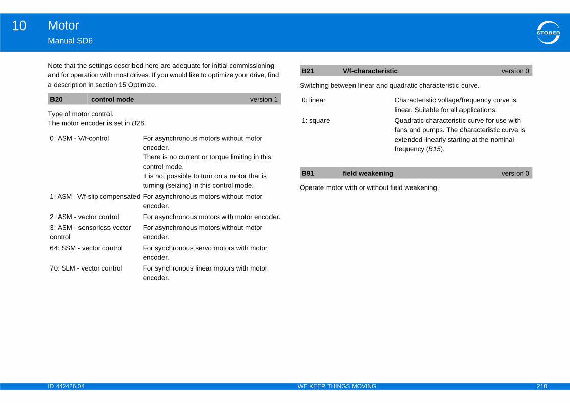
ID 4 210
Motor10Ma
Notanda d
TypThe
nd quadratic characteristic curve.
out field weakening.
B2
0:
1:
2: 3: co64
70
eristic version 0
Characteristic voltage/frequency curve is linear. Suitable for all applications.Quadratic characteristic curve for use with fans and pumps. The characteristic curve is extended linearly starting at the nominal frequency (B15).
ning version 0
42426.04 WE KEEP THINGS MOVING
nual SD6
e that the settings described here are adequate for initial commissioning for operation with most drives. If you would like to optimize your drive, find
escription in section 15 Optimize.
e of motor control. motor encoder is set in B26.
Switching between linear a
Operate motor with or with
0 control mode version 1
ASM - V/f-control For asynchronous motors without motor encoder.There is no current or torque limiting in this control mode.It is not possible to turn on a motor that is turning (seizing) in this control mode.
ASM - V/f-slip compensated For asynchronous motors without motor encoder.
ASM - vector control For asynchronous motors with motor encoder.ASM - sensorless vector ntrol
For asynchronous motors without motor encoder.
: SSM - vector control For synchronous servo motors with motor encoder.
: SLM - vector control For synchronous linear motors with motor encoder.
B21 V/f-charact
0: linear
1: square
B91 field weake
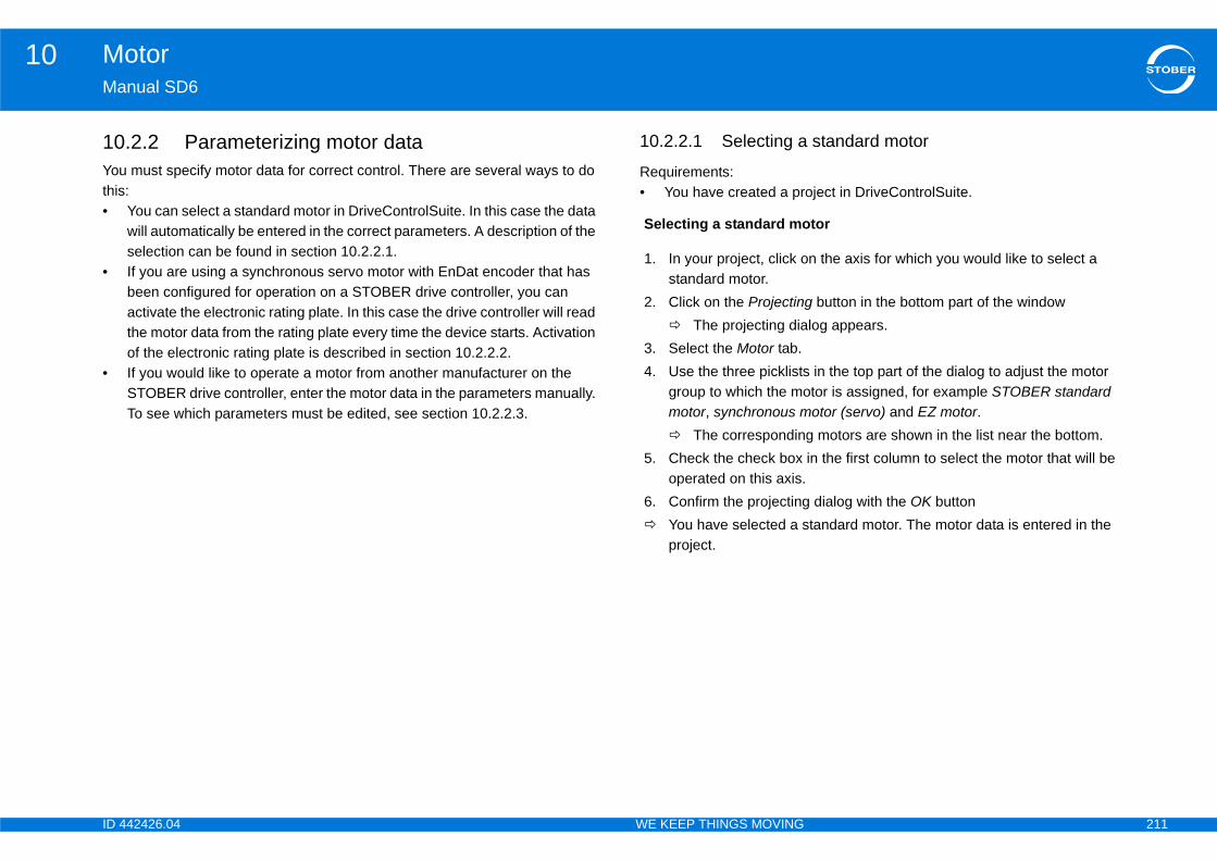
ID 4 211
Motor10Ma
10Youthis•
•
•
standard motor
oject in DriveControlSuite.
tor
n the axis for which you would like to select a
g button in the bottom part of the windowlog appears.
in the top part of the dialog to adjust the motor tor is assigned, for example STOBER standard otor (servo) and EZ motor.
g motors are shown in the list near the bottom.in the first column to select the motor that will be
dialog with the OK buttontandard motor. The motor data is entered in the
42426.04 WE KEEP THINGS MOVING
nual SD6
.2.2 Parameterizing motor data must specify motor data for correct control. There are several ways to do :You can select a standard motor in DriveControlSuite. In this case the data will automatically be entered in the correct parameters. A description of the selection can be found in section 10.2.2.1.If you are using a synchronous servo motor with EnDat encoder that has been configured for operation on a STOBER drive controller, you can activate the electronic rating plate. In this case the drive controller will read the motor data from the rating plate every time the device starts. Activation of the electronic rating plate is described in section 10.2.2.2.If you would like to operate a motor from another manufacturer on the STOBER drive controller, enter the motor data in the parameters manually. To see which parameters must be edited, see section 10.2.2.3.
10.2.2.1 Selecting a
Requirements:• You have created a pr
Selecting a standard mo
1. In your project, click ostandard motor.
2. Click on the Projectin The projecting dia
3. Select the Motor tab.4. Use the three picklists
group to which the momotor, synchronous m The correspondin
5. Check the check box operated on this axis.
6. Confirm the projecting You have selected a s
project.

ID 4 212
Motor10Ma
10Synencappbra
If yodatThe
Evethechapla
If thconwhaB81
If yact
or parametersr on the drive controller without and electronic rating ER motor, you must enter the motor data in the
otors from other manufacturers and special s you need to edit depends on the motor type.
servo motortor data for a synchronous servo motor, edit the e E parameters show internally calculated values.
ion as text.
r. voltage between two phases at 1000 rpm for and asynchronous motors or the peak value of the r synchronous linear motors.S) value is specified for third-party motors, the value before it is entered.
position relative to the motor.chronous servo motors and asynchronous motors.
version 0
version 0
on-offset version 0
42426.04 WE KEEP THINGS MOVING
nual SD6
.2.2.2 Activating an electronic rating platechronous servo motors from STOBER are generally equipped with EnDat oders that have a special parameter memory. If the motor is configured ropriately when it is ordered, the motor data including data for any holding ke will be saved in this memory.
u have set B04 = 64:active, the drive controller will automatically read in all a as soon as an electronic rating plate is detected. n you have the option of making optimizations.
ry time the device is restarted after that, the drive controller checks whether motor, holding brake, motor temperature sensor or commutation have been nged. If no changes were made, no data is read from the electronic rating te. Therefore the optimized data will not be overwritten.
e drive controller detects changes, the modified data will be read. The drive troller shows fault 81:motor allocation in the display. The cause indicates t changes were detected. You will receive addition feedback via parameter 0.
ou would like to read the electronic rating plate completely again, apply ion B06.
10.2.2.3 Editing motIf you are operating a motoplate and it is not a STOBparameters (for example mmotors). Which parameter
10.2.2.3.1 SynchronousIf you have to enter the mofollowing B parameters. Th
Shows the motor designat
EMC constant of the motoPeak value of the inducedsynchronous servo motorsinduced voltage at 1m/s foIf a root mean square (RMmust be multiplied by 1.41
Offset of the encoder zeroCommutation offset for syn
B00 motor-type
B02 back EMF
B05 commutati
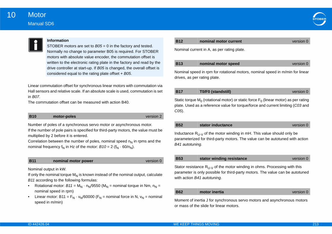
ID 4 213
Motor10Ma
LinHalin BThe
NumIf thmuCornom
NomIf oB11•
•
er rating plate.
rotational motors, nominal speed in m/min for linear
l motor) or static force F0 (linear motor) as per rating value for torque/force and current limiting (C03 and
tor winding in mH. This value should only be rty motors. The value can be autotuned with action
he motor winding in ohms. Processing with this for third-party motors. The value can be autotuned .
chronous servo motors and asynchronous motors ear motors.
B1
B1
otor current version 0
otor speed version 0
dstill) version 0
ctance version 0
ing resistance version 0
ia version 0
42426.04 WE KEEP THINGS MOVING
nual SD6
ear commutation offset for synchronous linear motors with commutation via l sensors and relative scale. If an absolute scale is used, commutation is set 07. commutation offset can be measured with action B40.
ber of poles of a synchronous servo motor or asynchronous motor.e number of pole pairs is specified for third-party motors, the value must be ltiplied by 2 before it is entered.relation between the number of poles, nominal speed nN in rpms and the inal frequency fN in Hz of the motor: B10 = 2·(fN · 60/nN).
inal output in kW.nly the nominal torque MN is known instead of the nominal output, calculate according to the following formulas:Rotational motor: B11 = MN · nN/9550 (MN = nominal torque in Nm, nN = nominal speed in rpm)Linear motor: B11 = FN · vN/60000 (FN = nominal force in N, vN = nominal speed in m/min)
Nominal current in A, as p
Nominal speed in rpm for drives, as per rating plate.
Static torque M0 (rotationaplate. Used as a referenceC05).
Inductance RU-V of the moparameterized for third-paB41 autotuning.
Stator resistance RU-V of tparameter is only possiblewith action B41 autotuning
Moment of inertia J for synor mass of the slide for lin
InformationSTOBER motors are set to B05 = 0 in the factory and tested. Normally no change to parameter B05 is required. For STOBER motors with absolute value encoder, the commutation offset is written to the electronic rating plate in the factory and read by the drive controller at start-up. If B05 is changed, the overall offset is considered equal to the rating plate offset + B05.
0 motor-poles version 2
1 nominal motor power version 0
B12 nominal m
B13 nominal m
B17 T0/F0 (stan
B52 stator indu
B53 stator wind
B62 motor inert

ID 4 214
Motor10Ma
MaForbef
Ma
Inte
ue generating reference current.rent for asynchronous motors and the standstill rvo motors.
oint for the emergency braking that can be activated efined by the drive controller based on the motor orque is motor-dependent.
ue that can be requested as a reference value for rent reference value is displayed in E165 Id-ref.
linear motortor data for a synchronous linear motor, edit the e E parameters show internally calculated values.
ion as text.
r. voltage between two phases at 1000 rpm for and asynchronous motors or the peak value of the r synchronous linear motors.
B8
B8
E1
ve
V 6
PDca
No
De
LS
e version 0
stop current version 0
version 0
version 0
version 0
42426.04 WE KEEP THINGS MOVING
nual SD6
ximum permitted motor current. synchronous servo motors of STOBER, the maximum permitted current ore the motor is demagnetized.
ximum permitted speed for the motor.
rnally calculated magnetization reference current for asynchronous motors.
(Internally) calculated torqEquivalent to the rated curcurrent for synchronous se
Display of the current setpwith U30. This current is ddata. The resulting brake t
Display of the smallest valE92 Id by control. The cur
10.2.2.3.2 SynchronousIf you have to enter the mofollowing B parameters. Th
Shows the motor designat
EMC constant of the motoPeak value of the inducedsynchronous servo motorsinduced voltage at 1m/s fo
2 I-max version 0
3 v-max motor version 0
71 Id-reference version 0
rsionLevel Axis
typeData type Signifi.
digitsEnable off
Unit Para typeR W
.0 4 6 Physical REAL32 No A Number
O-pable
Scaling PKW1 PROFIBUS/PROFINET
SDO CANopen/EtherCAT
Factor NKS PNU Subindex Index Subindex1 3 28ABhex 0000hex 28ABhex 0000hex
fault PreRead PreWrite PostRead PostWrite0 0 0 0
B Final value Scaling Hiding DepFlags0 0 0
E172 Iq-referenc
E940 emergency
E941 Id-minimum
B00 motor-type
B02 back EMF
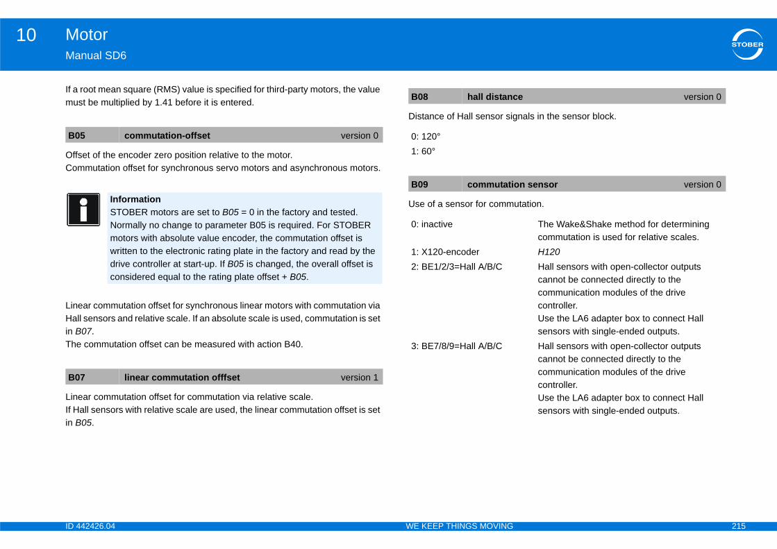
ID 4 215
Motor10Ma
If amu
OffCom
LinHalin BThe
LinIf Hin B
nals in the sensor block.
utation.
B0
B0
e version 0
on sensor version 0
The Wake&Shake method for determining commutation is used for relative scales.H120Hall sensors with open-collector outputs cannot be connected directly to the communication modules of the drive controller.Use the LA6 adapter box to connect Hall sensors with single-ended outputs.Hall sensors with open-collector outputs cannot be connected directly to the communication modules of the drive controller.Use the LA6 adapter box to connect Hall sensors with single-ended outputs.
42426.04 WE KEEP THINGS MOVING
nual SD6
root mean square (RMS) value is specified for third-party motors, the value st be multiplied by 1.41 before it is entered.
set of the encoder zero position relative to the motor.mutation offset for synchronous servo motors and asynchronous motors.
ear commutation offset for synchronous linear motors with commutation via l sensors and relative scale. If an absolute scale is used, commutation is set 07. commutation offset can be measured with action B40.
ear commutation offset for commutation via relative scale.all sensors with relative scale are used, the linear commutation offset is set 05.
Distance of Hall sensor sig
Use of a sensor for comm
5 commutation-offset version 0
InformationSTOBER motors are set to B05 = 0 in the factory and tested. Normally no change to parameter B05 is required. For STOBER motors with absolute value encoder, the commutation offset is written to the electronic rating plate in the factory and read by the drive controller at start-up. If B05 is changed, the overall offset is considered equal to the rating plate offset + B05.
7 linear commutation offfset version 1
B08 hall distanc
0: 120°1: 60°
B09 commutati
0: inactive
1: X120-encoder2: BE1/2/3=Hall A/B/C
3: BE7/8/9=Hall A/B/C
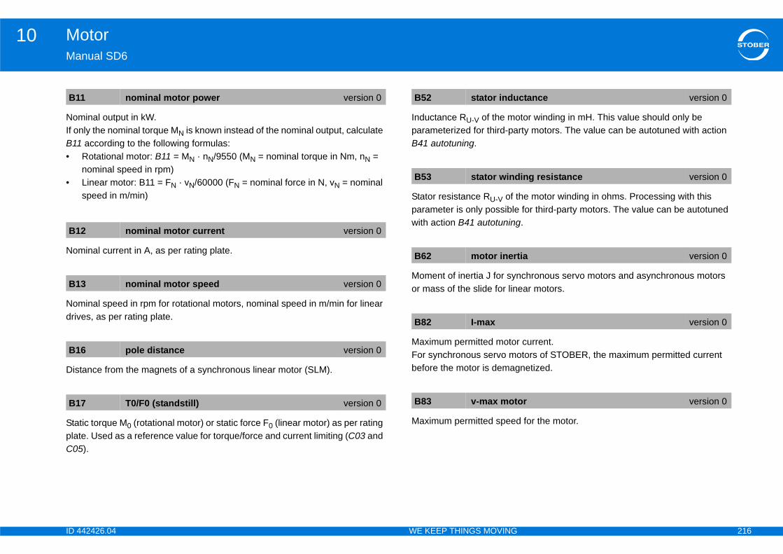
ID 4 216
Motor10Ma
NomIf oB11•
•
Nom
Nomdriv
Dis
StaplaC05
tor winding in mH. This value should only be rty motors. The value can be autotuned with action
he motor winding in ohms. Processing with this for third-party motors. The value can be autotuned .
chronous servo motors and asynchronous motors ear motors.
current.tors of STOBER, the maximum permitted current netized.
for the motor.
B1
B1
B1
B1
B1
ctance version 0
ing resistance version 0
ia version 0
version 0
or version 0
42426.04 WE KEEP THINGS MOVING
nual SD6
inal output in kW.nly the nominal torque MN is known instead of the nominal output, calculate according to the following formulas:Rotational motor: B11 = MN · nN/9550 (MN = nominal torque in Nm, nN = nominal speed in rpm)Linear motor: B11 = FN · vN/60000 (FN = nominal force in N, vN = nominal speed in m/min)
inal current in A, as per rating plate.
inal speed in rpm for rotational motors, nominal speed in m/min for linear es, as per rating plate.
tance from the magnets of a synchronous linear motor (SLM).
tic torque M0 (rotational motor) or static force F0 (linear motor) as per rating te. Used as a reference value for torque/force and current limiting (C03 and ).
Inductance RU-V of the moparameterized for third-paB41 autotuning.
Stator resistance RU-V of tparameter is only possiblewith action B41 autotuning
Moment of inertia J for synor mass of the slide for lin
Maximum permitted motorFor synchronous servo mobefore the motor is demag
Maximum permitted speed
1 nominal motor power version 0
2 nominal motor current version 0
3 nominal motor speed version 0
6 pole distance version 0
7 T0/F0 (standstill) version 0
B52 stator indu
B53 stator wind
B62 motor inert
B82 I-max
B83 v-max mot
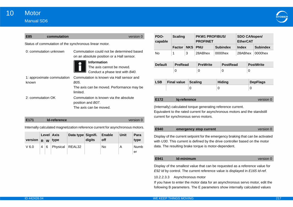
ID 4 217
Motor10Ma
Sta
Inte
ue generating reference current.rent for asynchronous motors and the standstill rvo motors.
oint for the emergency braking that can be activated efined by the drive controller based on the motor orque is motor-dependent.
ue that can be requested as a reference value for rent reference value is displayed in E165 Id-ref.
s motortor data for an asynchronous servo motor, edit the e E parameters show internally calculated values
E8
0:
1: kn
2:
E1
ve
V 6
PKW1 PROFIBUS/PROFINET
SDO CANopen/EtherCAT
PNU Subindex Index Subindex28ABhex 0000hex 28ABhex 0000hex
PreWrite PostRead PostWrite0 0 0
aling Hiding DepFlags0 0
e version 0
stop current version 0
version 0
42426.04 WE KEEP THINGS MOVING
nual SD6
tus of commutation of the synchronous linear motor.
rnally calculated magnetization reference current for asynchronous motors.
(Internally) calculated torqEquivalent to the rated curcurrent for synchronous se
Display of the current setpwith U30. This current is ddata. The resulting brake t
Display of the smallest valE92 Id by control. The cur
10.2.2.3.3 AsynchronouIf you have to enter the mofollowing B parameters. Th
5 commutation version 0
commutation unknown Commutation could not be determined based on an absolute position or a Hall sensor.
InformationThe axis cannot be moved.Conduct a phase test with B40.
approximate commutation own
Commutation is known via Hall sensor and B05.The axis can be moved. Performance may be limited.
commutation OK Commutation is known via the absolute position and B07.The axis can be moved.
71 Id-reference version 0
rsionLevel Axis
typeData type Signifi.
digitsEnable off
Unit Para typeR W
.0 4 6 Physical REAL32 No A Number
PDO-capable
Scaling
Factor NKSNo 1 3
Default PreRead0
LSB Final value Sc0
E172 Iq-referenc
E940 emergency
E941 Id-minimum
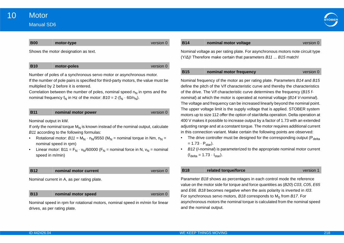
ID 4 218
Motor10Ma
Sho
NumIf thmuCornom
NomIf oB11•
•
Nom
Nomdriv
ing plate. For asynchronous motors note circuit type tain that parameters B11 ... B15 match!
motor as per rating plate. Parameters B14 and B15 haracteristic curve and thereby the characteristics
cteristic curve determines the frequency (B15 f-or is operated at nominal voltage (B14 V-nominal). can be increased linearly beyond the nominal point. he supply voltage that is applied. STOBER system the option of star/delta operation. Delta operation at increase output by a factor of 1.73 with an extended nstant torque. The motor requires additional current Make certain the following points are observed:st be designed for the corresponding output (Pdelta
meterized to the appropriate nominal motor current
percentages in each control mode the reference torque and force quantities as (B20) C03, C05, E65 gative when the axis polarity is inverted in I03.tors, B18 corresponds to M0 from B17. For ominal torque is calculated from the nominal speed
B0
B1
B1
B1
B1
otor voltage version 0
otor frequency version 0
ue/force version 1
42426.04 WE KEEP THINGS MOVING
nual SD6
ws the motor designation as text.
ber of poles of a synchronous servo motor or asynchronous motor.e number of pole pairs is specified for third-party motors, the value must be ltiplied by 2 before it is entered.relation between the number of poles, nominal speed nN in rpms and the inal frequency fN in Hz of the motor: B10 = 2·(fN · 60/nN).
inal output in kW.nly the nominal torque MN is known instead of the nominal output, calculate according to the following formulas:Rotational motor: B11 = MN · nN/9550 (MN = nominal torque in Nm, nN = nominal speed in rpm)Linear motor: B11 = FN · vN/60000 (FN = nominal force in N, vN = nominal speed in m/min)
inal current in A, as per rating plate.
inal speed in rpm for rotational motors, nominal speed in m/min for linear es, as per rating plate.
Nominal voltage as per rat(Y/∆)! Therefore make cer
Nominal frequency of the define the pitch of the V/f cof the drive. The V/f charanominal) at which the motThe voltage and frequencyThe upper voltage limit is tmotors up to size 112 offer400 V makes it possible toadjusting range and at a coin this connection variant. • The drive controller mu
= 1.73 · Pstar).• B12 (I-nominal) is para
(Idelta = 1.73 · Istar).
Parameter B18 shows as value on the motor side forand E66. B18 becomes neFor synchronous servo moasynchronous motors the nand the nominal output.
0 motor-type version 0
0 motor-poles version 0
1 nominal motor power version 0
2 nominal motor current version 0
3 nominal motor speed version 0
B14 nominal m
B15 nominal m
B18 related torq

ID 4 219
Motor10Ma
cos
Feeaccvecdiff
PromoNoTheis pspesma mdamspe
roximation. Affects the dynamic properties of the he faster the motor model can follow the actual
checked by means of the speed curve. If an encoder ioning, E15 n-motor encoder should be considered, r can not follow the set speed ramp despite its, B48 must be increased. Values that are too large ed
B1
B4
B4
rt of speed approximation version 0
tor-encoder B48 ( too small)tor-encoder B47 ( too large)
frequency
42426.04 WE KEEP THINGS MOVING
nual SD6
φ as per rating plate.
dback from the observer of the asynchronous machine. Affects the uracy of the speed approximation of the control mode 3:ASM - Sensorless tor control. For values that are too large or too high, the stationary erence between the reference and actual speed increases.
portional gain of speed approximation. Affects the dynamic properties of the tor (especially the stability and overshoot behavior of the speed)tes on settings correct setting can be checked by means of the speed curve. If an encoder resent during commissioning, E15 should be considered as the actual ed, otherwise E91. B47 should not be less than 1% of B48. If values are too
all the drive may become instable and the resulting vibration will oscillate at echanical frequency. By increasing B47, overshoots in the speed can be pened. Values that are too large lead to vibrations in the current and
ed.
Integral gain of speed appmotor. The larger B48 is, tspeed.Notes on settingsThe correct setting can be is present during commissotherwise E91. If the motosufficiently large torque limlead to a fault 56:Overspe
9 cos(phi) version 0
6 observer feedback version 0
InformationThe amount of feedback is an option for reporting to the ASM observer how exact the machine constants B54 leakage factor, B52 stator inductance and B53 stator winding resistance were determined. The smaller the feedback selected, the more the ASM observer depends on these constants.
7 proportional part of speed approximation version 0
B48 integral pa
E07 n-post-rampE91 n-motor E15 n-mo or E91 n-motor E15 n-mo or
mech.
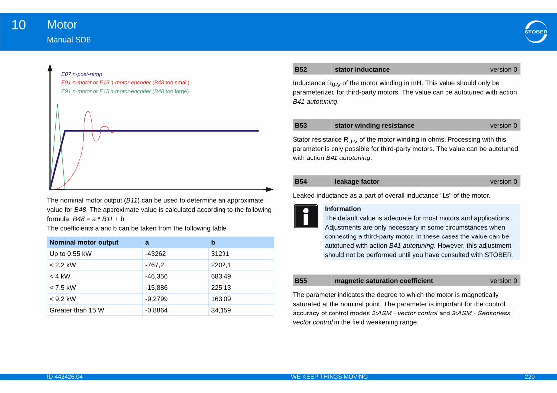
ID 4 220
Motor10Ma
ThevaluformThe
tor winding in mH. This value should only be rty motors. The value can be autotuned with action
he motor winding in ohms. Processing with this for third-party motors. The value can be autotuned .
rt of overall inductance "Ls" of the motor.
e degree to which the motor is magnetically oint. The parameter is important for the control 2:ASM - vector control and 3:ASM - Sensorless eakening range.
NoUp
< 2
< 4
< 7
< 9
Gr
ctance version 0
ing resistance version 0
tor version 0
ue is adequate for most motors and applications. e only necessary in some circumstances when ird-party motor. In these cases the value can be action B41 autotuning. However, this adjustment erformed until you have consulted with STOBER.
aturation coefficient version 0
42426.04 WE KEEP THINGS MOVING
nual SD6
nominal motor output (B11) can be used to determine an approximate e for B48. The approximate value is calculated according to the following ula: B48 = a * B11 + b coefficients a and b can be taken from the following table.
Inductance RU-V of the moparameterized for third-paB41 autotuning.
Stator resistance RU-V of tparameter is only possiblewith action B41 autotuning
Leaked inductance as a pa
The parameter indicates thsaturated at the nominal paccuracy of control modesvector control in the field w
minal motor output a b to 0.55 kW -43262 31291
.2 kW -767,2 2202,1
kW -46,356 683,49
.5 kW -15,886 225,13
.2 kW -9,2799 163,09
eater than 15 W -0,8864 34,159
E07 n-post-rampE91 n-motor E15 n-motor-encoder B48 or ( too small)E91 n-motor E15 n-motor-encoder B48 or ( too large)
B52 stator indu
B53 stator wind
B54 leakage fac
InformationThe default valAdjustments arconnecting a thautotuned with should not be p
B55 magnetic s
ID 4 221
Motor10Ma
Moor m
Rat
MaForbef
Ma
Inte
ue generating reference current.rent for asynchronous motors and the standstill rvo motors.
B6
B6
B8
B8
E1
e version 0
42426.04 WE KEEP THINGS MOVING
nual SD6
ment of inertia J for synchronous servo motors and asynchronous motors ass of the slide for linear motors.
io of the tilting moment of the motor to the nominal torque.
ximum permitted motor current. synchronous servo motors of STOBER, the maximum permitted current ore the motor is demagnetized.
ximum permitted speed for the motor.
rnally calculated magnetization reference current for asynchronous motors.
(Internally) calculated torqEquivalent to the rated curcurrent for synchronous se
InformationThe default value is adequate for most motors and applications. Adjustments are only necessary in some circumstances when connecting a third-party motor. In these cases the value can be autotuned with action B41 autotuning. However, this adjustment should not be performed until you have consulted with STOBER.
2 motor inertia version 0
3 Mmax/Mnom version 0
2 I-max version 0
3 v-max motor version 0
71 Id-reference version 0
E172 Iq-referenc
ID 4 222
Motor10Ma
10The•••
Not10.whi
10
Notshosaf
test
rial damageng this action.
r is able to turn freely during the action!
onents fastened to the motor are sufficiently secured es (by feather keys, coupling elements, etc).
o motors and synchronous linear motors. The formed:ber (B10)ection (phase reversal)mmutation offset (B05)
bration B40[0], observe the progress in B40[1] and obtain
setest, set B40[0] = 1:active. The action may only be rvo motors. The following functions are performed:ber (B10)ection (phase reversal)mmutation offset (B05)
Pe
1.2.3.
4.5.
version 1
tart version 0
42426.04 WE KEEP THINGS MOVING
nual SD6
.2.3 Actions following actions provide support for you in making motor settings:B40 phase testB41 autotuningB45 autotune SLVC-HP (only if B20 = 3:ASM - sensorless vector control)
e that the drive controller must be enabled for these actions. Section 2.3.1 Performing actions with enabledescribes how to perform actions for ch the drive controller must be enabled.
.2.3.1 Performing actions with enable
e that parameter values are determined specifically for these actions. You uld therefore next perform action A00 save values so that the values will be ely stored if the power fails or is turned off.
10.2.3.2 B40 Phase
WARNING!
Personal injury and mateThe motor shaft turns duri
Make certain the moto
Make certain the compagainst centrifugal forc
Only for synchronous servfollowing functions are per1. Test of motor pole num2. Test of the phase conn3. Measurement of the co4. Sin/Cos amplitude caliYou can start the action inthe result in B40[2].
To activate action B40 phaused with synchronous se1. Test of motor pole num2. Test of the phase conn3. Measurement of the co
rforming actions with enable
Change to the device state readySwtchOn.Set the first element of the action to a value of 1 (for example B40[0] = 1).Enable the motor. Element 1 shows the progress of the action (for example B40[1] = 33
%).Wait until element 1 shows a value of 100 % (for example B40[1] = 100 %).Switch off enable.Element 2 shows the result of the action (for example B40[2] = 0:error free).
B40 phase test
B40[0] phase test s
ID 4 223
Motor10Ma
PerStanotexa
Pro
Afte
0: 1:
B4
B4
0: 1:
2:
The action is not supported by the control mode selected in B20.The axis was not stopped immediately after enable was activated.The phase sequence is incorrect. Exchange two phase connections and start the action again.The number of poles detected differs from the value in B10.The commutation offset did not match the value entered in B05. The correct values was successfully written to B05.The test run with the determined commutation offset was not successful. Check the parameterization of the motor, encoder and speed controller.Turn off the enable to end the action.
42426.04 WE KEEP THINGS MOVING
nual SD6
WARNING!
sonal injury and material damage due to falling loads.rting the action will cause the motor brake to be vented. Since the motor is adequately powered by the action, it is unable to hold any loads (for mple in a lifting function).
Use the action only for motor that are not under any load.
gress of the phase test as a %.
r action B40 phasetest is complete, the result can be queried here.
InformationTo start the action, change from Low level to High level of the enable. If there is a brake present it will be released automatically. After the end of the action the enable must be aborted.
inactiveactive
0[1] phase test process version 0
0[2] phase test result version 1
error free The action was performed with no errors.aborted The enable was shut off by the user or
because of a fault before the action could be completed.
timeout The enable was not activated within 30 seconds after starting the action.
3: illegal
4: axis load
5: phase order
6: motor poles
7: commutation offset
8: test run
98: remove enable!

ID 4 224
Motor10Ma
10
PerThe
The1.2.3.4.Youthe
To The1.2.3.4.Thepla
motor as a %.
g is complete, the result can be queried here.
B4
B4
on, change from Low level to High level of the is a brake present it will be released automatically. f the action the enable must be aborted.
process version 0
result version 1
The action was performed with no errors.The enable was shut off by the user or because of a fault before the action could be completed.The enable was not activated within 30 seconds after starting the action.The action is not supported by the control mode selected in B20.The axis was not stopped immediately after enable was activated.Turn off the enable to end the action.
42426.04 WE KEEP THINGS MOVING
nual SD6
.2.3.3 B41 Autotuning
WARNING!
sonal injury and material damage motor shaft turns during this action.
Make certain the motor is able to turn freely during the action!
Make certain the components fastened to the motor are sufficiently secured against centrifugal forces (by feather keys, coupling elements, etc).
following functions are performed:Measurement of the winding resistance (B53)Measurement of the winding inductance (B52)For ASM: Measurement of B54 leakage factorFor ASM: Measurement of B55 saturation coefficient can start the action in B41[0], observe the progress in B41[1] and obtain
result in B41[2].
activate action B41 autotuning, set B41[0] = 1:active. following functions are performed:Measurement of the winding resistance (B53)Measurement of the winding inductance (B52)For ASM: Measurement of B54 leakage factorFor ASM: Measurement of B55 saturation coefficient cycle time is set to 32 ms internally during the action. The change takes
ce when the action is activated.
Progress of autotuning the
After action B41 autotunin
1 autotuning version 0
1[0] autotuning start version 0
InformationTo start the actienable. If thereAfter the end o
0: inactive1: active
B41[1] autotuning
B41[2] autotuning
0: error free1: aborted
2: timeout
3: illegal
4: axis load
98: remove enable!
ID 4 225
Motor10Ma
10
RisThe
NO
UnThe
TheSen•••WhB48Youthe
e SLVC, set B45[0] = 1:active. following parameters for control mode 3:ASM -
bserverof speed approximationeed approximation
rial damage due to falling loads.se the motor brake to be vented. Since the motor is y the action, it is unable to hold any loads (for n).
motor that are not under any load.
%.
B4
VC-HP start version 0
on, change from Low level to High level of the is a brake present it will be released automatically. f the action the enable must be aborted.
VC-HP process version 0
42426.04 WE KEEP THINGS MOVING
nual SD6
.2.3.4 B45 action autotune SLVC
WARNING!
k of injury due to high speeds! action accelerates the motor up to twice its nominal speed.
Make certain the components fastened to the motor are sufficiently secured against centrifugal forces (by feather keys, coupling elements, etc).
Make sure that any mechanical systems (gear units, etc.) that are attached can reach these speeds.
TICE
suitable optimization results! results are falsified if the action is performed with a loaded motor.
If possible, only perform the action when the motor is not connected to a mechanical system (gear units, etc.).
If it is not possible to disconnect the mechanical system, make sure that the load torque is not more than 10 % of the nominal torque.
action determines the following parameters for control mode 3: ASM - sorless vector control:B46 Feedback ASM ObserverB47 Proportional part of speed approximationB48 Integral part of speed approximationen the action is complete you can read the new parameter values in B46 ... . can start the action in B45[0], observe the progress in B45[1] and obtain
result in B45[2].
To start action B45 autotunThe action determines theSensorless vector control:• B46 Feedback ASM O• B47 Proportional part • B48 Integral part of sp
WARNING!
Personal injury and mateStarting the action will caunot adequately powered bexample in a lifting functio
Use the action only for
Progress of the action as a
5 autotune SLVC-HP version 0
B45[0] autotune SL
InformationTo start the actienable. If thereAfter the end o
0: inactive1: active
B45[1] autotune SL
ID 4 226
Motor10Ma
AfteWhB48
B4
0: 1: 2: 3:
4: 98
42426.04 WE KEEP THINGS MOVING
nual SD6
r action B45 autotune SLVC is complete, the result can be queried here. en the action is complete you can read the new parameter values in B46 ... .
5[2] autotune SLVC-HP result version 1
error freeabortedtimeoutillegal The action cannot be performed in the control
mode selected in B20 or else the maximum speed set in I10 is less than the maximum reference speed of the action (2 * B13).
axis load: remove enable! Turn off the enable to end the action.
ID 4 227
Motor10Ma
10
In tPTCIn Bof tThetem
10The
Sho
Dis
or torque as a %. The reference value for ide is C09, for consideration on the motor side B18. isplay. Access to the unsmoothed variable is
S value).
pplied to the motor.
ed. current motor speed E91 to show in a display.ms for a current controller cycle time of 62.5us and
otor encoder.ers, the encoder position is continuously read and
all operating modes. E09 is simulated (not s without motor encoder. This parameter is r the axis starts up again, i.e. the position is not
E0
E0
ue/force filtered version 0
version 0
version 0
ered version 1
tion version 1
42426.04 WE KEEP THINGS MOVING
nual SD6
.3 Motor temperature sensor settings
he B38 motor temperature sensor parameter, set whether you will evaluate drilling or a KTY 84-1xx.39 maximum motor temperature, set the maximum permitted temperature
he motor. If this is reached, the 41:TempMotorTMP fault is triggered. motor temperature measured by the KTY is displayed in E12 motor-perature.
.4 Display following display parameter provides you with further information:
ws the current motor current as an amount in amps.
play of the current effective output of the motor in kW.
Display of the current motconsideration on the load sSmoothed for the device dpossible through E90.
Motor voltage (chained RM
Frequency of the voltage a
Filtered current motor speCorresponds to the filteredFiltering is performed at 50100ms for 125us.
Position of the motor or mWith absolute value encodentered in this parameter.This position is available inprecisely) for control modereinitialized each time afteretained.
InformationPlease note that temperature sensor evaluation is always active in the drive controller. If operation without motor temperature sensor is permitted, the connections must be bridged on X2. If the connections are not bridged when the drive controller is switched on, a fault will be triggered.
0 I-Motor version 0
1 P-Motor version 0
E02 actual torq
E04 U-Motor
E05 f1-Motor
E08 n-motor filt
E09 motor posi
ID 4 228
Motor10Ma
ShonomdeplossstatheThefor
LevutiliB.. parove
Curcon
Curvaluside
ps.
in amps.
(linked peak voltage).
(linked peak voltage).
gnetization current.
rque generating current as a A.
E2
E2
E6
E6
version 0
version 0
version 1
version 1
version 0
version 0
version 0
42426.04 WE KEEP THINGS MOVING
nual SD6
ws the current utilization of the motor as a %. The reference quantity is the inal power loss of the motor. It is derived from copper losses and speed-endent losses from magnetic reversal and friction. The nominal copper es are derived from the nominal motor current (B12) calculated with the
tor resistance (B53). Speed-dependent nominal losses are calculated from nominal motor speed (B13) and the coefficients of friction (B73 and B74). motor utilization that is displayed accordingly depends on the actual values motor current (E00) and motor speed (E91).
el of the thermal motor model (i2t model). 100 % is equivalent to full zation. The thermal model is based on the rating data entered under group (motor), i.e. continuous operation (S1 operation). The response ameterized in U10, U11 for the event"45:overtemp.motor i2t" is triggered at r 100 %.
rently active positive torque/force limit. The reference value for sideration on the load side is C09, for consideration on the motor side B18.
rently active negative torque/force limit in reference to B18. The reference e for consideration on the load side is C09, for consideration on the motor B18.
Magnetizing current in am
Torque generating current
Voltage in d direction in V
Voltage in q direction in V
Current cos(phi).
Reference value of the ma
Reference value for the to
1 motor util version 0
3 i2t-motor version 0
5 actual positive T-max version 0
6 actual negative T-max version 0
E92 I-d
E93 I-q
E98 Ud
E99 Uq
E150 cos(phi)
E165 Id-ref
E166 Iq-ref
ID 4 229
Holding brake11Ma
11Ov
11
11
11
11
11
11
11
11
11
eration . . . . . . . . . . . . . . . . . . . . . . . . . . . . . . . 245
ration .. . . . . . . . . . . . . . . . . . . . . . . . . . . . . . . . 246
function .. . . . . . . . . . . . . . . . . . . . . . . . . . . . .246
peration .. . . . . . . . . . . . . . . . . . . . . . . . . . . . . . 247
eration . . . . . . . . . . . . . . . . . . . . . . . . . . . . . . . . 248
42426.04 WE KEEP THINGS MOVING
nual SD6
Holding brakeerview of sections
.1 Activating the brake control unit . . . . . . . . . . . . . . . . . . . . . .230
.2 Direct and indirect brake connection . . . . . . . . . . . . . . . . . .231
.3 Internal and external brake control . . . . . . . . . . . . . . . . . . .232
.4 B20 = 64:SSM and 70:LSM - vector control . . . . . . . . . . .234
.5 B20 = 2:ASM - vector control . . . . . . . . . . . . . . . . . . . . . . . .236
.6 B20 = 3:ASM - sensorless vector control .. . . . . . . . . . . . .237
.7 B20 = V/f control mode (0 or 1) .. . . . . . . . . . . . . . . . . . . . . .239
.8 Brake management . . . . . . . . . . . . . . . . . . . . . . . . . . . . . . . . .241
11.8.1Single-axis operation .. . . . . . . . . . . . . . . . . . . . . . . . . . . . . . . 241
11.8.2Multi-axis operation . . . . . . . . . . . . . . . . . . . . . . . . . . . . . . . . . 242
.9 Brake test . . . . . . . . . . . . . . . . . . . . . . . . . . . . . . . . . . . . . . . . . .243
11.9.1Torque calculation . . . . . . . . . . . . . . . . . . . . . . . . . . . . . . . . . . 243
11.9.1.1 Synchronous servo motor . . . . . . . . . . . . . . . . . . . . 243
11.9.1.2 Asynchronous motor . . . . . . . . . . . . . . . . . . . . . . . . 244
11.9.1.3 Gravity-loaded axes . . . . . . . . . . . . . . . . . . . . . . . . . 245
11.9.2 Single-axis op
11.9.3 Multi-axis ope
11.10 Brake grinding
11.10.1 Single-axis o
11.10.2 Multi-axis op
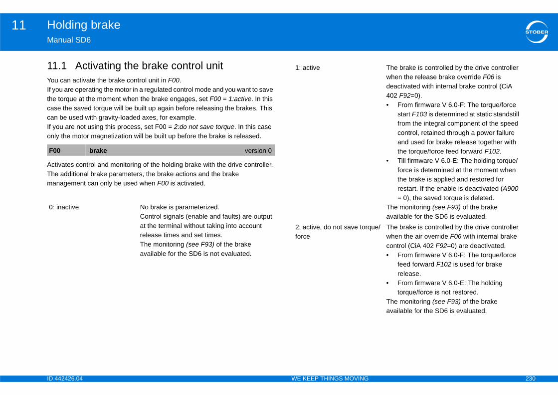
ID 4 230
Holding brake11Ma
11YouIf yothecascanIf yonl
ActThema
F0
0:
The brake is controlled by the drive controller when the release brake override F06 is deactivated with internal brake control (CiA 402 F92=0).• From firmware V 6.0-F: The torque/force
start F103 is determined at static standstill from the integral component of the speed control, retained through a power failure and used for brake release together with the torque/force feed forward F102.
• Till firmware V 6.0-E: The holding torque/force is determined at the moment when the brake is applied and restored for restart. If the enable is deactivated (A900 = 0), the saved torque is deleted.
The monitoring (see F93) of the brake available for the SD6 is evaluated.
ue/ The brake is controlled by the drive controller when the air override F06 with internal brake control (CiA 402 F92=0) are deactivated.• From firmware V 6.0-F: The torque/force
feed forward F102 is used for brake release.
• From firmware V 6.0-E: The holding torque/force is not restored.
The monitoring (see F93) of the brake available for the SD6 is evaluated.
42426.04 WE KEEP THINGS MOVING
nual SD6
.1 Activating the brake control unit can activate the brake control unit in F00.u are operating the motor in a regulated control mode and you want to save
torque at the moment when the brake engages, set F00 = 1:active. In this e the saved torque will be built up again before releasing the brakes. This be used with gravity-loaded axes, for example.
ou are not using this process, set F00 = 2:do not save torque. In this case y the motor magnetization will be built up before the brake is released.
ivates control and monitoring of the holding brake with the drive controller. additional brake parameters, the brake actions and the brake
nagement can only be used when F00 is activated.
0 brake version 0
inactive No brake is parameterized.Control signals (enable and faults) are output at the terminal without taking into account release times and set times.The monitoring (see F93) of the brake available for the SD6 is not evaluated.
1: active
2: active, do not save torqforce
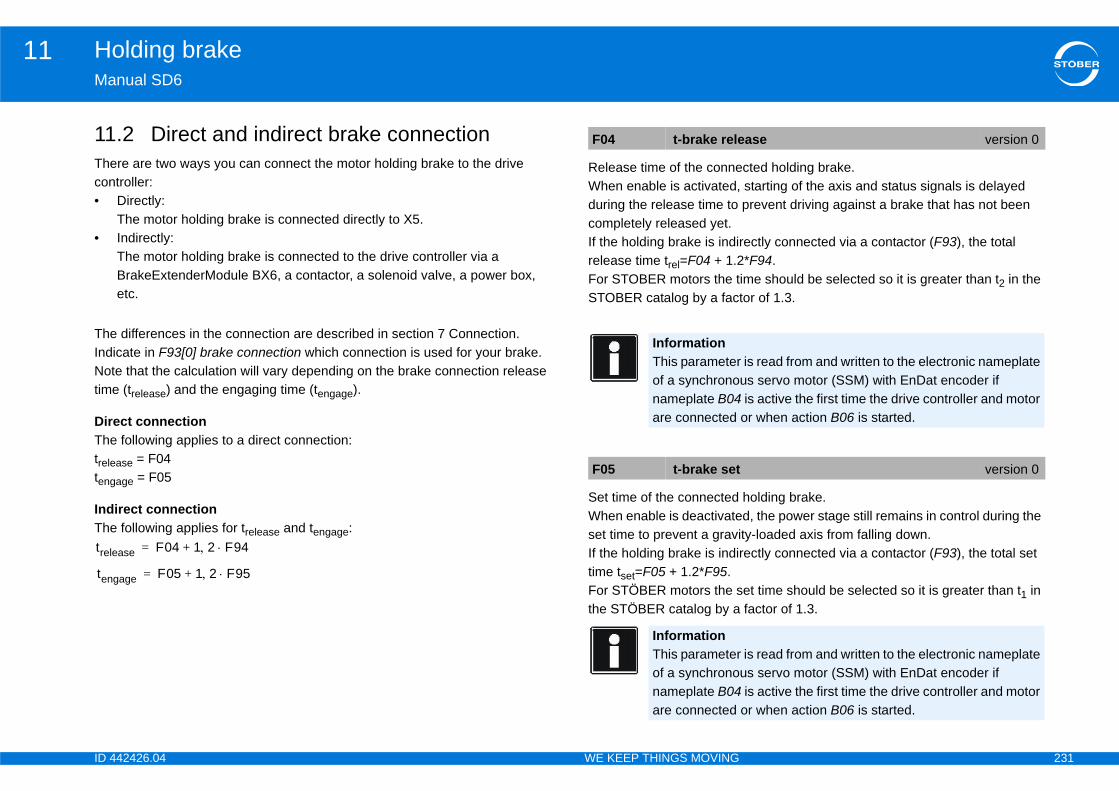
ID 4 231
Holding brake11Ma
11Thecon•
•
TheIndNottim
DirThetreleteng
IndThe
cted holding brake. starting of the axis and status signals is delayed prevent driving against a brake that has not been
ectly connected via a contactor (F93), the total *F94.
ime should be selected so it is greater than t2 in the or of 1.3.
holding brake.d, the power stage still remains in control during the ty-loaded axis from falling down.ectly connected via a contactor (F93), the total set
et time should be selected so it is greater than t1 in factor of 1.3.
trel
ten
ase version 0
is read from and written to the electronic nameplate us servo motor (SSM) with EnDat encoder if is active the first time the drive controller and motor or when action B06 is started.
version 0
is read from and written to the electronic nameplate us servo motor (SSM) with EnDat encoder if is active the first time the drive controller and motor or when action B06 is started.
42426.04 WE KEEP THINGS MOVING
nual SD6
.2 Direct and indirect brake connectionre are two ways you can connect the motor holding brake to the drive troller:Directly: The motor holding brake is connected directly to X5.Indirectly: The motor holding brake is connected to the drive controller via a BrakeExtenderModule BX6, a contactor, a solenoid valve, a power box, etc.
differences in the connection are described in section 7 Connection.icate in F93[0] brake connection which connection is used for your brake. e that the calculation will vary depending on the brake connection release e (trelease) and the engaging time (tengage).
ect connection following applies to a direct connection:ase = F04age = F05
irect connection following applies for trelease and tengage:
Release time of the conneWhen enable is activated,during the release time to completely released yet.If the holding brake is indirrelease time trel=F04 + 1.2For STOBER motors the tSTOBER catalog by a fact
Set time of the connected When enable is deactivateset time to prevent a graviIf the holding brake is indirtime tset=F05 + 1.2*F95.For STÖBER motors the sthe STÖBER catalog by a
ease F04 1 2 F94+=
gage F05 1 2 F95+=
F04 t-brake rele
InformationThis parameterof a synchrononameplate B04are connected
F05 t-brake set
InformationThis parameterof a synchrononameplate B04are connected

ID 4 232
Holding brake11Ma
Con
SwswiWhdurcomSwif a
SwWhsetSwif a
d external brake controlased Mode (CBM) application, you have the option
(automatic) to an external (controller) brake
(Automatic) by the drive controller or externally by a
ponse! brake does not automatically engage after enable lts occur.
suitable process in the control unit. Take suitable fety.
6 and F92:
F9
0:
1:
2:
F9
F9
ol version 2
Brake controlled byl Internal automatic.
Release override via terminal input.
l External via terminal input.No release override.
l Internal automatic.Release override via parameter (CiA 402 A515 bit 14).
l External via parameter (CiA 402 A515 bit 14).No release override.
42426.04 WE KEEP THINGS MOVING
nual SD6
nection type of the brake.
itching time (release) of the contactor by which the connected brake is tched.en enable is activated, starting of the axis and status signals is delayed ing the release time to prevent driving against a brake that has not been pletely released yet.
itching times F94 and F95 can be determined automatically with the action feedback signal is present and connected.
itching time (set) of the contactor by which the connected brake is switched.en enable is deactivated, the power stage still remains in control during the time to prevent a gravity-loaded axis from falling down.itching times F94 and F95 can be determined automatically with the action feedback signal is present and connected.
11.3 Internal anIn the CiA 402 Controller Bto switch from an internal controller.
Brake controlled internallycontrol unit.
CAUTION!
Unexpected machine resDuring external control theis turned off and when fau
Make certain there is ameasures to ensure sa
Relationship between F0
3 brake connection version 0
direct The brake is connected directly X5.Monitoring of a short circuit, open load and undervoltage of the brake controller takes place.
indirect with feedback The brake is connected via a contactor at X4.Monitoring of a short circuit and undervoltage of the brake controller takes place. Instead of open load monitoring, a NO contact of a contactor connected to X6.1/2 is monitored.
indirect without feedback The brake is connected via a contactor at X4.Monitoring of a short circuit and undervoltage of the brake controller takes place.
4 contactor response time when brake is released version 0
5 contactor response time when brake is set version 0
F92 brake contr
F06= F92=BE Interna
BE Externa
Parameters Interna
Parameters Externa
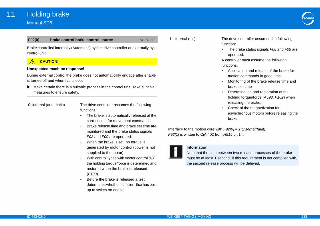
ID 4 233
Holding brake11Ma
Bracon
UnDuris tu
e with F92[0] = 1:External(fault).2 from A515 bit 14.
F9
0:
The drive controller assumes the following function:• The brake status signals F08 and F09 are
operated.A controller must assume the following functions:• Application and release of the brake for
motion commands in good time.• Monitoring of the brake release time and
brake set time• Determination and restoration of the
holding torque/force (A593, F102) when releasing the brake.
• Check of the magnetization for asynchronous motors before releasing the brake.
e between two release processes of the brake t 1 second. If this requirement is not complied with, ase process will be delayed.
42426.04 WE KEEP THINGS MOVING
nual SD6
ke controlled internally (Automatic) by the drive controller or externally by a trol unit.
CAUTION!
expected machine response!ing external control the brake does not automatically engage after enable rned off and when faults occur.
Make certain there is a suitable process in the control unit. Take suitable measures to ensure safety.
Interface to the motion corF92[1] is written to CiA 40
2[0] brake control brake control source version 1
internal (automatic) The drive controller assumes the following functions:• The brake is automatically released at the
correct time for movement commands.• Brake release time and brake set time are
monitored and the brake status signals F08 and F09 are operated.
• When the brake is set, no torque is generated by motor control (power is not supplied to the motor).
• With control types with vector control B20, the holding torque/force is determined and restored when the brake is released (F103).
• Before the brake is released a test determines whether sufficient flux has built up to switch on enable.
1: external (plc)
InformationNote that the timmust be at leasthe second rele

ID 4 234
Holding brake11Ma
UnDuris tu
Cur
SM and 70:LSM - vector control
d topen note section 11.2 Direct and indirect brake
ameter descriptions for explanations of the function s.
ue specification only. Reference torque or reference the speed controller. The reference value for ide is C09, for consideration on the motor side B18.
version 0
42426.04 WE KEEP THINGS MOVING
nual SD6
CAUTION!
expected machine response!ing external control the brake does not automatically engage after enable rned off and when faults occur.
Make certain there is a suitable process in the control unit. Take suitable measures to ensure safety.
rent setting of the brake control.
11.4 B20 = 64:S
When calculating tclose anconnection.Note also the following parof the specified parameter
For control modes with torqforce currently required byconsideration on the load s
F09 brake is open
F08 brake is closed
t1 sec
Delay due to notreaching the minimumrelease-release time
Releas
e brak
e
Engag
e brak
e
Releas
e brak
e
F04 t-brake release F05 t-brake set
E170 T-reference
ID 4 235
Holding brake11Ma
DisThebra•••
F08app
F08app
DisThethe•••
ther both brakes are released (after brake release back through the brake module). The axis is ready
ther brake 1 is released (after brake release time through the brake module). The axis is ready to
will delay setting the brake (J27, I410) after lute, MC_MoveRelativ, MC_MoveAdditiv, MC_Stop
ed. I42 is not relevant for any other commands.rform several commands one after the other without een.
F0
F0
F0
F0
en all utilized brakes version 0
en brake 1 version 0
rake set version 0
42426.04 WE KEEP THINGS MOVING
nual SD6
play of the Brakes are set state. state is calculated from the brake set time F05 and the activation of the
ke.Element 0: Both brakes are set.Element 1: Brake 1 is set.Element 2: Brake 2 is set.
[0] shows whether both brakes are set (after brake engaging time and if licable feedback through the brake module).
[1] shows whether brake 1 is set (after brake engaging time and if licable feedback through the brake module).
play of the Brakes are released state. state is calculated from the brake release time F04 and the activation of
brake.Element 0: Both brakes are released.Element 1: Brake 1 is released.Element 2: Brake 2 is released.
The parameter shows whetime and if applicable feedto move.
The parameter shows wheand if applicable feedbackmove.
The wait time, if any, whichcommands MC_MoveAbsoand MC_Halt, are processI42 makes it possible to pethe brake engaging in betw
8 brake is closed version 0
8[0] brake is closed all utilized brakes version 0
8[1] brake is closed brake 1 version 0
9 brake is open version 0
F09[0] brake is op
F09[1] brake is op
I42 wait time b

ID 4 236
Holding brake11Ma
11
WhconNotof t
e motor will continue to be powered with the brake . This is especially useful for positioning. After a stop wered for time B27. After this time has elapsed, el specified in B25. With a setting of 0 % and the p) the motor is unpowered and flux is removed. This tter thermal results for the motor because the motor se times. The disadvantage is the additional ime constant, about 0.5 s). The time required is ntroller and added to the brake release time F04.
t flux B25, the full flux current will be maintained for t and the power board is active.
ue specification only. Reference torque or reference the speed controller. The reference value for ide is C09, for consideration on the motor side B18.
set state. the brake set time F05 and the activation of the
s are set.set.set.
version 0
ux version 0
version 0
sed version 0
42426.04 WE KEEP THINGS MOVING
nual SD6
.5 B20 = 2:ASM - vector control
en calculating tclose and topen note section 11.2 Direct and indirect brake nection.e also the following parameter descriptions for explanations of the function he specified parameters.
B25 determines whether thset for stop and quick stopthe motor remains fully popower is lowered to the levbrake set (stop or quick stooffers the advantage of becan cool off during the paumagnetization time (rotor tdetermined by the drive co
In the case of reduced haltime B27 if the brake is se
For control modes with torqforce currently required byconsideration on the load s
Display of the Brakes are The state is calculated frombrake.• Element 0: Both brake• Element 1: Brake 1 is • Element 2: Brake 2 is
B25 halt flux
B27 time halt-fl
E170 T-reference
F08 brake is clo
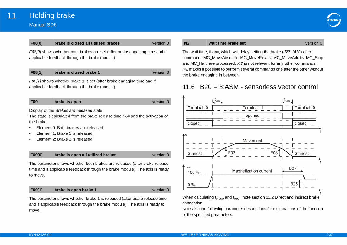
ID 4 237
Holding brake11Ma
F08app
F08app
DisThethe•••
Thetimto m
Theandmo
will delay setting the brake (J27, I410) after lute, MC_MoveRelativ, MC_MoveAdditiv, MC_Stop
ed. I42 is not relevant for any other commands.rform several commands one after the other without een.
M - sensorless vector control
d topen note section 11.2 Direct and indirect brake
ameter descriptions for explanations of the function s.
F0
F0
F0
F0
F0
rake set version 0
42426.04 WE KEEP THINGS MOVING
nual SD6
[0] shows whether both brakes are set (after brake engaging time and if licable feedback through the brake module).
[1] shows whether brake 1 is set (after brake engaging time and if licable feedback through the brake module).
play of the Brakes are released state. state is calculated from the brake release time F04 and the activation of
brake.Element 0: Both brakes are released.Element 1: Brake 1 is released.Element 2: Brake 2 is released.
parameter shows whether both brakes are released (after brake release e and if applicable feedback through the brake module). The axis is ready
ove.
parameter shows whether brake 1 is released (after brake release time if applicable feedback through the brake module). The axis is ready to
ve.
The wait time, if any, whichcommands MC_MoveAbsoand MC_Halt, are processI42 makes it possible to pethe brake engaging in betw
11.6 B20 = 3:AS
When calculating tclose anconnection.Note also the following parof the specified parameter
8[0] brake is closed all utilized brakes version 0
8[1] brake is closed brake 1 version 0
9 brake is open version 0
9[0] brake is open all utilized brakes version 0
9[1] brake is open brake 1 version 0
I42 wait time b
ID 4 238
Holding brake11Ma
B25setthepowbraoffecanmadet
In ttim
Forforccon
In csenwheWhfrom
If threle
/f control, ASM - slip compensated and ASM - B20), the brake is already set if the speed falls below set in F03 during stopping.aking ramp is used which is calculated from the total
ectly connected via a contactor (F93), the total set
set state. the brake set time F05 and the activation of the
s are set.set.set.
h brakes are set (after brake engaging time and if gh the brake module).
ke 1 is set (after brake engaging time and if gh the brake module).
B2
B2
E1
F0
peed version 0
sed version 0
sed all utilized brakes version 0
sed brake 1 version 0
42426.04 WE KEEP THINGS MOVING
nual SD6
determines whether the motor will continue to be powered with the brake for stop and quick stop. This is especially useful for positioning. After a stop motor remains fully powered for time B27. After this time has elapsed, er is lowered to the level specified in B25. With a setting of 0 % and the
ke set (stop or quick stop) the motor is unpowered and flux is removed. This rs the advantage of better thermal results for the motor because the motor cool off during the pause times. The disadvantage is the additional gnetization time (rotor time constant, about 0.5 s). The time required is ermined by the drive controller and added to the brake release time F04.
he case of reduced halt flux B25, the full flux current will be maintained for e B27 if the brake is set and the power board is active.
control modes with torque specification only. Reference torque or reference e currently required by the speed controller. The reference value for sideration on the load side is C09, for consideration on the motor side B18.
ontrol modes ASM - U/f control, ASM - slip compensated and ASM - sorless vector control (B20), the brake is released so it will be released n the motor-related velocity in F02 is reached.
ile the brake is released, an acceleration ramp is used which is calculated the total set time trel and F02.
e holding brake is indirectly connected via a contactor (F93), the total ase time trel=F04 + 1.2*F94.
In control modes ASM - Vsensorless vector control (the motor-related velocity While the brake is set, a brset time tset and F03.
If the holding brake is indirtime tset=F05 + 1.2*F95.
Display of the Brakes are The state is calculated frombrake.• Element 0: Both brake• Element 1: Brake 1 is • Element 2: Brake 2 is
F08[0] shows whether botapplicable feedback throu
F08[1] shows whether braapplicable feedback throu
5 halt flux version 0
7 time halt-flux version 0
70 T-reference version 0
2 brake release speed version 0
F03 brake set s
F08 brake is clo
F08[0] brake is clo
F08[1] brake is clo
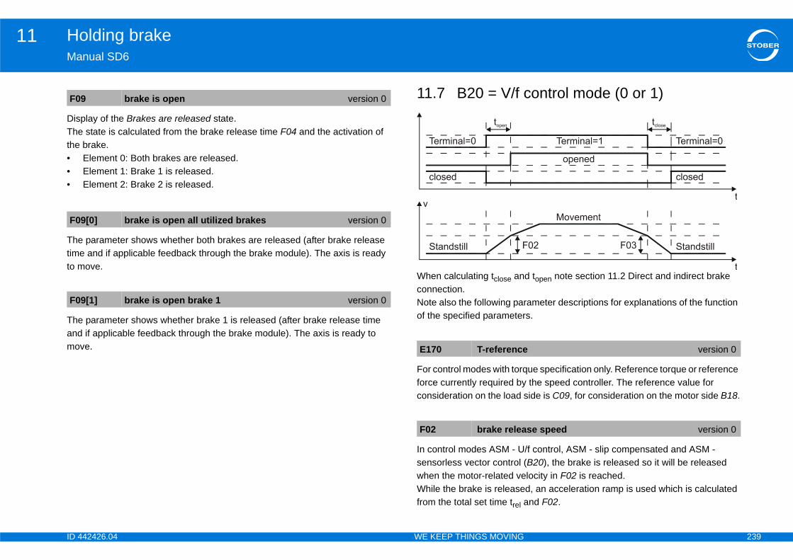
ID 4 239
Holding brake11Ma
DisThethe•••
Thetimto m
Theandmo
ontrol mode (0 or 1)
d topen note section 11.2 Direct and indirect brake
ameter descriptions for explanations of the function s.
ue specification only. Reference torque or reference the speed controller. The reference value for ide is C09, for consideration on the motor side B18.
/f control, ASM - slip compensated and ASM - B20), the brake is released so it will be released locity in F02 is reached.d, an acceleration ramp is used which is calculated nd F02.
F0
F0
F0
version 0
se speed version 0
42426.04 WE KEEP THINGS MOVING
nual SD6
play of the Brakes are released state. state is calculated from the brake release time F04 and the activation of
brake.Element 0: Both brakes are released.Element 1: Brake 1 is released.Element 2: Brake 2 is released.
parameter shows whether both brakes are released (after brake release e and if applicable feedback through the brake module). The axis is ready
ove.
parameter shows whether brake 1 is released (after brake release time if applicable feedback through the brake module). The axis is ready to
ve.
11.7 B20 = V/f c
When calculating tclose anconnection.Note also the following parof the specified parameter
For control modes with torqforce currently required byconsideration on the load s
In control modes ASM - Usensorless vector control (when the motor-related veWhile the brake is releasefrom the total set time trel a
9 brake is open version 0
9[0] brake is open all utilized brakes version 0
9[1] brake is open brake 1 version 0
E170 T-reference
F02 brake relea
ID 4 240
Holding brake11Ma
If threle
In csentheWhset
If thtim
DisThebra•••
F08app
F08app
released state. the brake release time F04 and the activation of
s are released.released.released.
ther both brakes are released (after brake release back through the brake module). The axis is ready
ther brake 1 is released (after brake release time through the brake module). The axis is ready to
F0
F0
F0
F0
en version 0
en all utilized brakes version 0
en brake 1 version 0
42426.04 WE KEEP THINGS MOVING
nual SD6
e holding brake is indirectly connected via a contactor (F93), the total ase time trel=F04 + 1.2*F94.
ontrol modes ASM - V/f control, ASM - slip compensated and ASM - sorless vector control (B20), the brake is already set if the speed falls below motor-related velocity set in F03 during stopping.ile the brake is set, a braking ramp is used which is calculated from the total time tset and F03.
e holding brake is indirectly connected via a contactor (F93), the total set e tset=F05 + 1.2*F95.
play of the Brakes are set state. state is calculated from the brake set time F05 and the activation of the
ke.Element 0: Both brakes are set.Element 1: Brake 1 is set.Element 2: Brake 2 is set.
[0] shows whether both brakes are set (after brake engaging time and if licable feedback through the brake module).
[1] shows whether brake 1 is set (after brake engaging time and if licable feedback through the brake module).
Display of the Brakes are The state is calculated fromthe brake.• Element 0: Both brake• Element 1: Brake 1 is • Element 2: Brake 2 is
The parameter shows whetime and if applicable feedto move.
The parameter shows wheand if applicable feedbackmove.
3 brake set speed version 0
8 brake is closed version 0
8[0] brake is closed all utilized brakes version 0
8[1] brake is closed brake 1 version 0
F09 brake is op
F09[0] brake is op
F09[1] brake is op
ID 4 241
Holding brake11Ma
11BratheThe
•
•
Thefea
Bra
•
•
•
Notma
is operation
d and parameterized the brake control unit.
with the following state machine:
ement
rake management to 1:global.t the time after which the drive controller will that a brake test is required. You can set maximum ours of operating time.rs to the drive controller and save them.
oller off and back on again. activated after start-up.
42426.04 WE KEEP THINGS MOVING
nual SD6
.8 Brake managementke management monitors to ensure brake tests are performed regularly, reby controlling the functional capability of the brake. SD6 provides the following options for axis management:
Single axis operation: An axis projected in DriveControlSuite is used for the connected motor.
Multi-axis operation: Two, three or four axes projected in DriveControlSuite are used for the connected motor.
procedure for single axis operation is explained first. Then the special tures of multi-axis operation will be explained.
ke management can be used provided the following conditions are met:
Self-activating brakes are used, which means they brake in a de-energized state.The braking torque MBrake must be at least 1.3 times the maximum braking torque.
The drive has an encoder.
e this information during projecting and during commissioning of the chine.
11.8.1 Single-axPreconditions:• You have now activate
Brake management works
Activating brake manag
1. Set parameter B310 B2. In parameter B311 se
generate a message 1 year = 52 or 8760 h
3. Transfer the paramete4. Switch the drive contr Brake management is
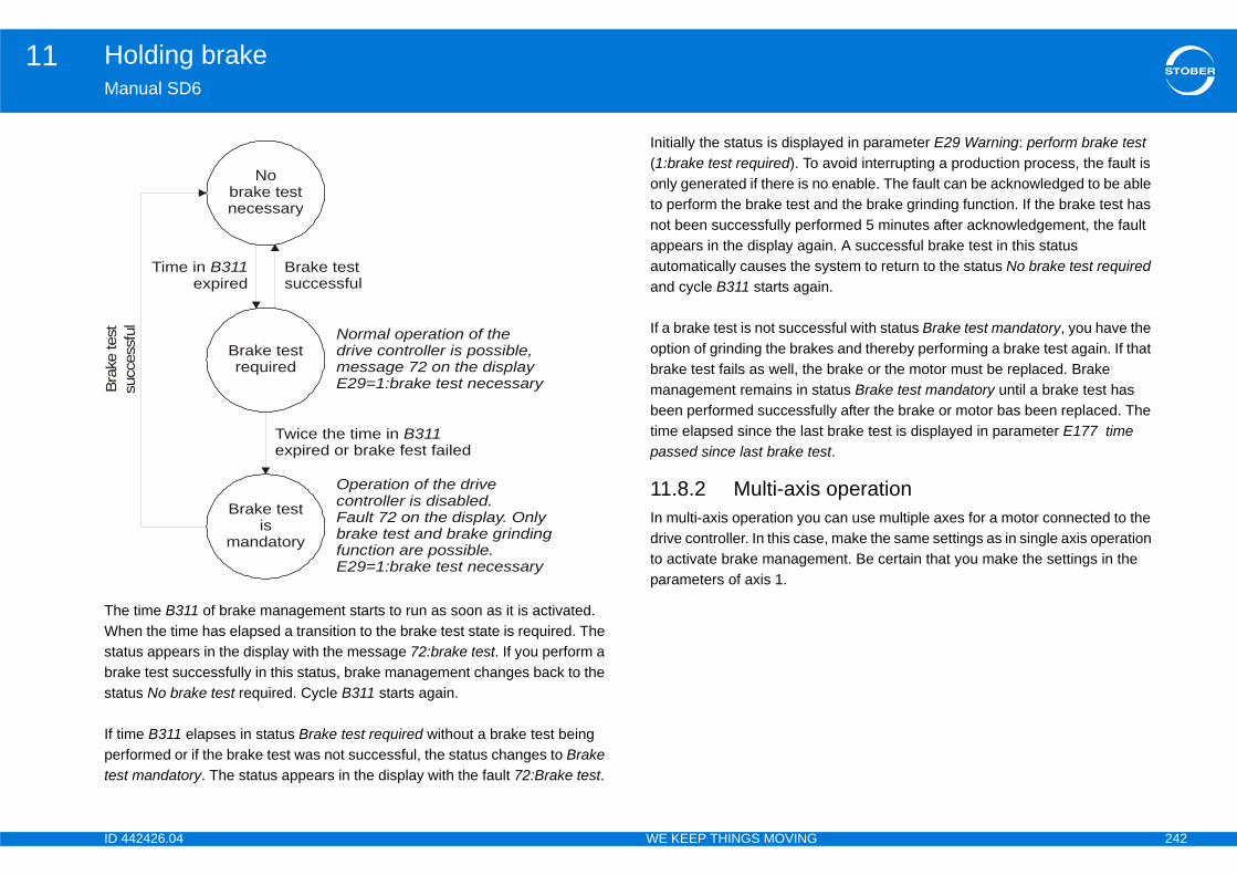
ID 4 242
Holding brake11Ma
TheWhstabrasta
If tipertes
yed in parameter E29 Warning: perform brake test avoid interrupting a production process, the fault is o enable. The fault can be acknowledged to be able nd the brake grinding function. If the brake test has ormed 5 minutes after acknowledgement, the fault in. A successful brake test in this status ystem to return to the status No brake test required
in.
sful with status Brake test mandatory, you have the es and thereby performing a brake test again. If that brake or the motor must be replaced. Brake tatus Brake test mandatory until a brake test has lly after the brake or motor bas been replaced. The t brake test is displayed in parameter E177 time st.
operation can use multiple axes for a motor connected to the , make the same settings as in single axis operation ent. Be certain that you make the settings in the
Bra
ke te
st
42426.04 WE KEEP THINGS MOVING
nual SD6
time B311 of brake management starts to run as soon as it is activated. en the time has elapsed a transition to the brake test state is required. The tus appears in the display with the message 72:brake test. If you perform a ke test successfully in this status, brake management changes back to the tus No brake test required. Cycle B311 starts again.
me B311 elapses in status Brake test required without a brake test being formed or if the brake test was not successful, the status changes to Brake t mandatory. The status appears in the display with the fault 72:Brake test.
Initially the status is displa(1:brake test required). Toonly generated if there is nto perform the brake test anot been successfully perfappears in the display agaautomatically causes the sand cycle B311 starts aga
If a brake test is not succesoption of grinding the brakbrake test fails as well, themanagement remains in sbeen performed successfutime elapsed since the laspassed since last brake te
11.8.2 Multi-axisIn multi-axis operation youdrive controller. In this caseto activate brake managemparameters of axis 1.
No brake testnecessary
Brake testsuccessful
Time in expired
B311
succ
essf
ul
Twice the time in expired or brake fest failed
B311
Normal operation of the drive controller is possible,message 72 on the displayE29=1:brake test necessary
Operation of the drive controller is disabled. Fault 72 on the display. Only brake test and brake grinding function are possible. E29=1:brake test necessary
Brake testis
mandatory
Brake testrequired
ID 4 243
Holding brake11Ma
11ThetorqFirstesdirethetorqandFin
DanmoThemoturnrota
TheThe64:
lculation
us servo motor must be entered in B304[0] and B305[0] for the following instructions:e required:rque of the brake.
he drive controller
rake test is defined for a STOBER drive (geared e). Always make certain the technical requirements system have been clarified before using
e to perform the action and brake management ke test mandatory (fault 72), the fault must be before the action starts. Once you have the malfunction, you can continue with the perform uction.
otor torque is limited to the values in C03 max and C05 max negative torque. If higher values are [0] and B305[0], it will not be possible to reach
E65 actual positive T-max und E66 actual negative other torque limits are still active.
42426.04 WE KEEP THINGS MOVING
nual SD6
.9 Brake test brake test checks whether the brake can still apply the required holding ue. t the encoder is tested with the brake open. The brake then engages and a
t torque that can be parameterized is applied to the drive in each permitted ction of rotation. If the drive detects movement, the brake could not apply
required countertorque and the test has failed. The parameterizable test ues can be entered in parameters B304[0] max-positive torque for B300 B305[0] max negative torque for B300.
ally the encoder is tested again.
WARNING!
ger of personal injury and material damage due to unexpected drive vements! brake is released after the start of the brake test. If a brake is faulty,
vements of the drive axis could occur. During the encoder test the motor s at approximately 60 rpm with a maximum of 45° in both directions of tion.
Make certain that no damage could be caused by the movement.
Take special precautionary measures, especially in the case of gravity loaded axes.
If the drive should not turn in one direction of rotation, restrict that direction of rotation in B306.
brake test can be used provided the following conditions are met: drive is operated with a motor encoder in one of the control modes B20 =
SSM vector control or B20 = 2:ASM vector control.
11.9.1 Torque ca
11.9.1.1 SynchronoCalculate the torques thatbrake test according to theThe following values will b• MBstat static holding to• M0 static torque • I0 static current • IN nominal current of t
InformationNote that the bmotor with brakfor a third-party
InformationIf you would likconsiders a braacknowledged acknowledged brake test instr
InformationNote that the mpositive torque entered in B304them. Check inT-max whether

ID 4 244
Holding brake11Ma
In t
If V
In t
Com1.
2.
Exa••••
Res
us motor must be entered in B304[0] and B305[0] for the following instructions:e required:
e brake the motor rque to nominal torque
he drive controller
ain the correct values from E171 and E172 in the complete projecting for the motor, transfer the ler, save the project and then read the values from ode.
e ratio of torques VM as a percentage:
= 200 %. MK/MN * 100 %.
the current associated with MB:
the drive controller:
VM
I0B
V
I0
I0
1722
42426.04 WE KEEP THINGS MOVING
nual SD6
he first step calculate the ratio of torques VM as a percentage:
M > 200 %, restrict VM = 200 %.
he next step, determine the current associated with MBstat:
pare I0Bstat with IN of the drive controller:If I0Bstat ≤ 2 * IN: B304[0] = VM, B305[0] = -VMIf I0Bstat > 2 * IN: VM2 = 100 * 2 * IN/I0; B304[0] = VM2, B305[0] = -VM2
mpleMBstat = 10 Nm M0 = 6.6 Nm I0 = 4.43 A IN = 6 A
ult: B304[0] = 151 %, B305[0] = -151 %
11.9.1.2 AsynchronoCalculate the torques thatbrake test according to theThe following values will b
• MB holding torque of th• MN nominal torque of • MK/MN ratio of tilting to• IN nominal current of t
• E171 Id,nom
• E172 Iq,nom
Note that you can only obtfollowing manner: Performproject to the drive controlE171 and E172 in online m
In the first step calculate th
If VM > 200 %, restrict VM If MK/MN < 2, restrict VM =
In the next step, determine
Compare I0Bstat with IN of
MBstatM0
----------------- 100=
stat I0 VM=
M10Nm6 6Nm------------------- 100 151%= =
Bstat 4 43A 151% 6 69A= =
Bstat 6 69A 2 IN 12A= =
VMMBM0-------- 100%=
I0B E1712 VM E+=

ID 4 245
Holding brake11Ma
1.
2.
Exa••••
•
•
Res
ded axes axes, the torque to be applied by the motor for the h loads are lowered is calculated as follows:dtered in B304[0] or B305[0]e applied by the brake, calculated according to .
is operation
ted and parameterized.4[0] which the brake must maintain for the positive
5[0] which the brake must maintain for the negative
itted to turn in one direction, restrict the direction of arameter B306.ion which the drive evaluates as a standstill in B307.
e result yet, check B300[2]:
VM
I0
I0
state readySwtchOn.] brake test and start to 1:active.signal.r starts the brake test and the motor turns300[1] shows a result of 100 % and parameter rror free.signal.en successfully completed.
42426.04 WE KEEP THINGS MOVING
nual SD6
If I0B ≤ 1.8 * IN: B304[0] = VM, B305[0] = -VM
If I0B > 1.8 * IN: B304[0] = VM2, B305[0] = -VM2 where:
mpleMB = 10 Nm MN = 5.12 Nm MK/MN = 2.3IN = 2.3 A
E171 Id,nom = 1.383 A
E172 Iq,nom = 1.581 A
ult: B304[0] = 195 %, B305[0] = -195 %
11.9.1.3 Gravity-loaNote that for gravity loadeddirection of rotation in whicMParameter = MBrake - MLoaMParameter: torque to be enMBrake: Holding torque to bsection11.9.1.1 or 11.9.1.2MLoad: Load torque
11.9.2 Single-axRequirements:
• Brake control is activa• Enter the torque in B30
direction of rotation.• Enter the torque in B30
direction of rotation.• If the drive is only perm
rotation for the test in p• Enter the angle of rotat
If you have not reached th
VM21 8 IN 2 E1712–
E1722--------------------------------------------------=
10Nm5 12Nm----------------------- 100 195%= =
B 1 383A 2 195% 1 581A 2+ 3 38A= =
B 3 38A 1 8 IN 4 14A= = Performing a brake test
1. Change to the device2. Set parameter B300[03. Switch on the enable The drive controlle
4. Wait until parameter BB300[2] a result of 0:e
5. Switch off the enable The brake test has be

ID 4 246
Holding brake11Ma
AfteThefromnegthebraThedireabotorqsysin tmois oholdrivfittehavmo
ThefromnegthebraThediredistdistbotgea
vement in the positive direction is performed first. s only valid if the brake is intact. If the tested brake d holding torque, the distance traversed cannot be drive controller switches off within < 10 ms. The
operationst be selected for the action when you use multi-axis
ding functionnction is performed, the brake engages repeatedly
is then released for about 0.7 seconds while the m. This grinds off coatings that have accumulated ental effect on the holding function. You can
gages while turning in one direction (B308),l turn in each direction (B309) andof rotation will be disabled (B306).versed is B308 × 0.5 motor revolutions. If a
nected, the transmission ratio of the gear must also ions. If both directions of rotation are permitted in e positive direction is performed first.
B3
42426.04 WE KEEP THINGS MOVING
nual SD6
r the brake test action is complete, the result can be queried here. drive controller keeps an internal brake test memory with the last 20 results B300[2] as well as the holding torques actually achieved in positive and
ative direction. When the result is 0:error free these torques correspond to values parameterized in B304[x] and B305[x]. If the values retained in ke test memory are smaller, the brake test was not successful. maximum distance traversed during the brake test is about 45° in both ctions. If one direction of rotation is restricted, the distance traversed is ut 2 × 45° in the permitted direction. A stopping distance depending on the ue limit and mass moment of inertia is added in both cases. If a mechanical tem is connected, the transmission ratio of the gear must also be included he calculations. If both directions of rotation are permitted in B306, the vement in the positive direction is performed first. Note that this calculation nly valid if the brake is intact. If the tested brake does not apply the required ding torque, the distance traversed cannot be calculated. In this case the e controller switches off within < 10 ms and closes a second brake if one is d. The set time and performance level of the second brake will therefore e a significant effect on stopping the drive. If there is no second brake, the tor coasts down.
drive controller keeps an internal brake test memory with the last 20 results B300[2] as well as the holding torques actually achieved in positive and
ative direction. When the result is 0:error free these torques correspond to values parameterized in B304[0] and B305[0]. If the values retained in ke test memory are smaller, the brake test was not successful. maximum distance traversed during the brake test is about 45° in both ctions on the motor side. If one direction of rotation is restricted, the ance traversed is about 2 × 45° in the permitted direction. A stopping ance depending on the torque limit and mass moment of inertia is added in h cases. If a mechanical system is connected, the transmission ratio of the r must also be included in the calculations. If both directions of rotation are
permitted in B306, the moNote that this calculation idoes not apply the requirecalculated. In this case themotor coasts down.
11.9.3 Multi-axisPlease note that axis 1 muoperation.
11.10 Brake grinWhen the brake grinding fufor about 0.7 seconds andmotor turns at about 20 rpwhich could have a detrimparameterize:• how often the brake en• how often the drive wil• whether one direction The maximum distance tramechanical system is conbe included in the calculatB306, the movement in th
00[2] brake test result version 1

ID 4 247
Holding brake11Ma
DanrotaEns
is operation brake grinding function:eterized and activated.ake should engage while turning in one direction in
ive should be ground in each direction in B309.irection of rotation is disabled in B306.round at its maximum holding torque. Make certain the drive controller permits this. To do this check positive T-max and E66 actual negative T-max. Also t torque, force.
function
state readySwitchOn.] brake 1 grind & start to 1:active.signal.rning as specified by the parameters.301[1] shows a result of 100 % and parameter rror free.
nction has been successfully completed.
42426.04 WE KEEP THINGS MOVING
nual SD6
WARNING!
ger due to movement of the drive. During the action, the motor tes at approx. 20 Rpm and with the torque entered in C03 or C05. ure the following.
Before the function starts, make sure the drive is in a position in which it is permissible for it to move at this speed and torque.
Restrict the direction of rotation in B306 if the drive is not permitted to rotate in a particular direction.
Check E62 and E66 to see whether other torque limits are also in effect.
11.10.1 Single-axPreconditions for using the• Brake control is param• Enter how often the br
B308.• Enter how often the dr• Specify whether one d• The brake should be g
that the torque limit in parameters E65 actualnote section 13.6 Limi
Proceed as follows:InformationNote that the brake grinding function is defined for a STOBER drive (geared motor with brake). For example, it is not permitted to use the brake grinding function for brakes that are attached to the output drive of the gear. Always make certain the technical requirements for a third-party system have been clarified before using.
InformationIf you would like to perform the action and brake management considers a brake test mandatory (fault 72), the fault must be acknowledged before the action starts. Once you have acknowledge the malfunction, you can continue with the brake grinding function instruction.
Run the brake grinding
1. Change to the device2. Set parameter B301[03. Switch on the enable The drive starts tu
4. Wait until parameter BB301[2] a result of 0:e
5. Switch off enable. The brake grinding fu

ID 4 248
Holding brake11Ma
If y
AfteThelastcou
Thelastcou
11Pleope
B3
42426.04 WE KEEP THINGS MOVING
nual SD6
ou have not reached the result yet, check B301[2]:
r the brk 1 grind action is complete, the result can be queried here. drive controller keeps an internal memory with the operating times of the 40 grinding processes that were successfully completed. Parameter E176 nter grind actions counts all grinding processes regardless of the result.
drive controller keeps an internal memory with the operating times of the 40 grinding processes that were successfully completed. Parameter E176 nts all grinding processes regardless of the result.
.10.2 Multi-axis operationase note that axis 1 must be selected for the action when you use multi-axis ration
01[2] brake grind result version 1

ID 4 249
Encoder12Ma
12Ov
12
12
12
12
12
12
12
12
42426.04 WE KEEP THINGS MOVING
nual SD6
Encodererview of sections
.1 Types . . . . . . . . . . . . . . . . . . . . . . . . . . . . . . . . . . . . . . . . . . . . . .250
.2 Deactivating an encoder . . . . . . . . . . . . . . . . . . . . . . . . . . . . .250
.3 Selecting an interface . . . . . . . . . . . . . . . . . . . . . . . . . . . . . . .251
.4 Connection X4 . . . . . . . . . . . . . . . . . . . . . . . . . . . . . . . . . . . . . .252
.5 Connection X120 . . . . . . . . . . . . . . . . . . . . . . . . . . . . . . . . . . .254
.6 Connection X101 (binary input encoder) . . . . . . . . . . . . . .256
.7 Connection X140 . . . . . . . . . . . . . . . . . . . . . . . . . . . . . . . . . . .256
.8 Display . . . . . . . . . . . . . . . . . . . . . . . . . . . . . . . . . . . . . . . . . . . . .257
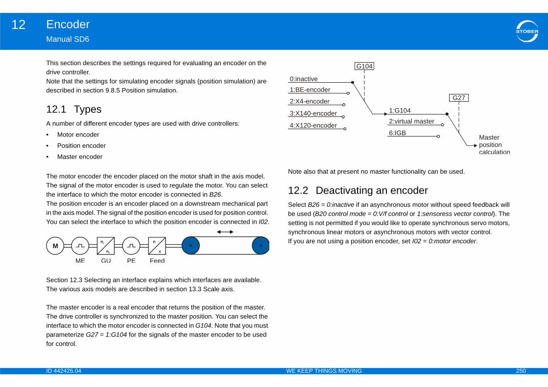
ID 4 250
Encoder12Ma
ThidrivNotdes
12A n
•
•
•
TheThetheThein thYou
SecThe
TheTheinteparfor
o master functionality can be used.
g an encodern asynchronous motor without speed feedback will
e = 0:V/f control or 1:sensoress vector control). The ou would like to operate synchronous servo motors, or asynchronous motors with vector control.tion encoder, set I02 = 0:motor encoder.
M
04
Masterpositioncalculation
6:IGB
2:virtual master1:G104
G27
42426.04 WE KEEP THINGS MOVING
nual SD6
s section describes the settings required for evaluating an encoder on the e controller.e that the settings for simulating encoder signals (position simulation) are cribed in section 9.8.5 Position simulation.
.1 Typesumber of different encoder types are used with drive controllers:
Motor encoder
Position encoder
Master encoder
motor encoder the encoder placed on the motor shaft in the axis model. signal of the motor encoder is used to regulate the motor. You can select
interface to which the motor encoder is connected in B26. position encoder is an encoder placed on a downstream mechanical part e axis model. The signal of the position encoder is used for position control. can select the interface to which the position encoder is connected in I02.
tion 12.3 Selecting an interface explains which interfaces are available. various axis models are described in section 13.3 Scale axis.
master encoder is a real encoder that returns the position of the master. drive controller is synchronized to the master position. You can select the rface to which the motor encoder is connected in G104. Note that you must ameterize G27 = 1:G104 for the signals of the master encoder to be used control.
Note also that at present n
12.2 DeactivatinSelect B26 = 0:inactive if abe used (B20 control modsetting is not permitted if ysynchronous linear motorsIf you are not using a posin1
n2
n
x
GUME PE Feed
2:X4-encoder
4:X120-encoder
1:BE-encoder0:inactive
G1
3:X140-encoder

ID 4 251
Encoder12Ma
12The er that belongs to the interface contains the setting of B coder signals that will be evaluated on the interface.Not described in sections 12.4 Connection X4 to 12.6 Con
Ensig
a) O
b)
b) O
X101c)
c) O
ncoder B26/I02 = 1:BE encoderEn —
Enith sin/cos
—
SS —
Re r —
Sin —
Ha —
Inc H40 = 1:Incremental encoder In
IncH40 = 1:Incremental encoder In b)
SteHT
H40 = 5:stepper motor
SteTT
H40 = 5:stepper motor b)
42426.04 WE KEEP THINGS MOVING
nual SD6
.3 Selecting an interface table below gives you a summary of which encoder signals can be evaluated on which interface. The head26 motor encoder and I02 position encoder. The cells indicate the setting with which you will parameterize ene that other settings must also be made for the encoder signals to be evaluated correctly. The settings are nection X101 (binary input encoder).
coder nals
X4 X120a)
nly with one of terminal modules XI6, RI6
X140
nly with terminal module RI6nly with one of terminal modules XI6, RI6, IO6
B26/I02 = 2:X4 encoder B26/I02 = 4:X120 encoder B26/I02 = 3:X140 eDat® 2.2 H00 = 64:EnDat — H140 = 70:EnDat
Dat® 2.1 H00 = 64:EnDat —H140 = 71:EnDat wchannels
I H00 = 65:SSI master H120 = 67:SSI master —
solver — — H140 = 66:Resolve
/cos — — H140 = 6:Sin/cos
ll sensor — H120 = 70:Hall sensor —
remental HTL H00 = 3:Incremental encoder In — —
remental TTLH00 = 3:Incremental encoder In H120 = 4:Incremental encoder In
—
pper motor L
— — —
pper motor L
—H120 = 5:stepper motor input
—
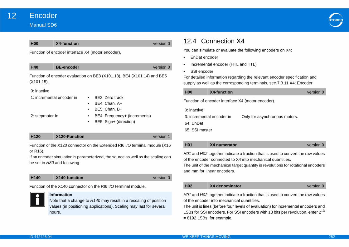
ID 4 252
Encoder12Ma
Fun
Fun(X1
Funor RIf abe
Fun
n X4ate the following encoders on X4:
HTL and TTL)
garding the relevant encoder specification and sponding terminals, see 7.3.11 X4: Encoder.
ce X4 (motor encoder).
cate a fraction that is used to convert the raw values to X4 into mechanical quantities. target quantity is revolutions for rotational encoders s.
cate a fraction that is used to convert the raw values nical quantities.r levels of evaluation) for incremental encoders and r SSI encoders with 13 bits per revolution, enter 213 .
H0
H4
0: 1:
2:
H1
H1
version 0
Only for asynchronous motors.
tor version 0
nator version 0
42426.04 WE KEEP THINGS MOVING
nual SD6
ction of encoder interface X4 (motor encoder).
ction of encoder evaluation on BE3 (X101.13), BE4 (X101.14) and BE5 01.15).
ction of the X120 connector on the Extended RI6 I/O terminal module (X16 16).
n encoder simulation is parameterized, the source as well as the scaling can set in H80 and following.
ction of the X140 connector on the RI6 I/O terminal module.
12.4 ConnectioYou can simulate or evalu
• EnDat encoder
• Incremental encoder (
• SSI encoderFor detailed information resupply as well as the corre
Function of encoder interfa
H01 and H02 together indiof the encoder connected The unit of the mechanicaland mm for linear encoder
H01 and H02 together indiof the encoder into mechaThe unit is lines (before fouLSBs for SSI encoders. Fo= 8192 LSBs, for example
0 X4-function version 0
0 BE-encoder version 0
inactiveincremental encoder in • BE3: Zero track
• BE4: Chan. A+• BE5: Chan. B+
stepmotor In • BE4: Frequency+ (increments) • BE5: Sign+ (direction)
20 X120-Function version 1
40 X140-function version 0
InformationNote that a change to H140 may result in a rescaling of position values (in positioning applications). Scaling may last for several hours.
H00 X4-function
0: inactive3: incremental encoder in64: EnDat65: SSI master
H01 X4 numera
H02 X4 denomi
ID 4 253
Encoder12Ma
Indmewhe
Cod
AdjA htranHow
Sho
EleForFor<nu"SSenc
EleElelenconV m
rrent measured on X4.
e number of data bits transferred via SSI. The specified with parameters H01 and H02. Typically
ution for rotational SSI encoders. This corresponds 01 = 10,000 revolutions.
r for SSI encoder. When double transfer is activated in a row with a continuous clock to achieve greater r does not support double transfer, double transfer parameter. If double transfer is turned off, the drive nerate a second query.
H0
H0
H0
H0
bits version 0
transmission version 0
that is used allows it, double transfer should not be
42426.04 WE KEEP THINGS MOVING
nual SD6
icates whether the encoder connected to X4 is a rotational or translational asuring system. This affects the unit of measure of H01 and determines ther the encoder will be located before or after the feed in the axis model.
ing type of the angle by the SSI encoder.
usts the clock frequency of the serial transfer for querying the SSI encoder. igher clock frequency allows for better control because the position is sferred faster and can therefore be queried more frequently overall. ever, not all SSI encoders support the high clock frequencies.
ws a description of the encoder found on X4.
ment 0 EnDat® 2.2 this is the designation of the encoder. EnDat® 2.1 the string is formatted as follows: "ED 2.1 <number of bits> mber of multi-turns>MT"I" is displayed for SSI encoders and "Incremental enc." for incremental oders.
ment 1ment 1 is the output voltage measured on X4. It varies according to the gth and cross-section of the encoder cable as well as the encoder power sumption. If the sense signal is used, the voltage is controlled so that the 5 atch exactly at the location of the encoder (in the motor).
Element 2Element 2 is the output cu
The parameter indicates thmeaning of the bits can bethere are 13 bits per revolto H02 = 8192 LSBs and H
Switches off double transfethe angle is queried twice data security. If the encodemust be turned off with thiscontroller will no longer ge
3 encoder type version 1
5 X4-SSI-code version 0
6 SSI clock frequency version 0
9 X4 info version 0
H10 X4-SSI data
H11 X4 double
InformationIf the hardwaredeactivated.
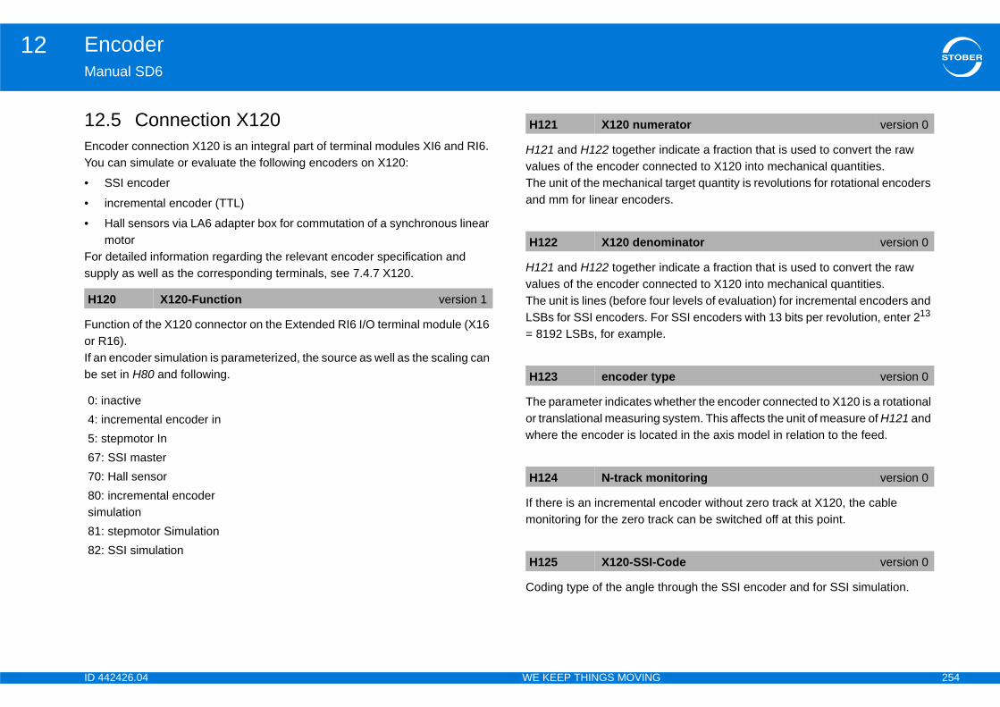
ID 4 254
Encoder12Ma
12EncYou
•
•
•
Forsup
Funor RIf abe
ndicate a fraction that is used to convert the raw nected to X120 into mechanical quantities. target quantity is revolutions for rotational encoders s.
ndicate a fraction that is used to convert the raw nected to X120 into mechanical quantities.r levels of evaluation) for incremental encoders and r SSI encoders with 13 bits per revolution, enter 213 .
hether the encoder connected to X120 is a rotational system. This affects the unit of measure of H121 and ted in the axis model in relation to the feed.
ncoder without zero track at X120, the cable ck can be switched off at this point.
hrough the SSI encoder and for SSI simulation.
H1
0: 4: 5: 677080sim8182
rator version 0
minator version 0
pe version 0
nitoring version 0
ode version 0
42426.04 WE KEEP THINGS MOVING
nual SD6
.5 Connection X120oder connection X120 is an integral part of terminal modules XI6 and RI6. can simulate or evaluate the following encoders on X120:
SSI encoder
incremental encoder (TTL)
Hall sensors via LA6 adapter box for commutation of a synchronous linear motor detailed information regarding the relevant encoder specification and ply as well as the corresponding terminals, see 7.4.7 X120.
ction of the X120 connector on the Extended RI6 I/O terminal module (X16 16).
n encoder simulation is parameterized, the source as well as the scaling can set in H80 and following.
H121 and H122 together ivalues of the encoder conThe unit of the mechanicaland mm for linear encoder
H121 and H122 together ivalues of the encoder conThe unit is lines (before fouLSBs for SSI encoders. Fo= 8192 LSBs, for example
The parameter indicates wor translational measuring where the encoder is loca
If there is an incremental emonitoring for the zero tra
Coding type of the angle t
20 X120-Function version 1
inactiveincremental encoder instepmotor In: SSI master: Hall sensor: incremental encoder ulation
: stepmotor Simulation: SSI simulation
H121 X120 nume
H122 X120 deno
H123 encoder ty
H124 N-track mo
H125 X120-SSI-C
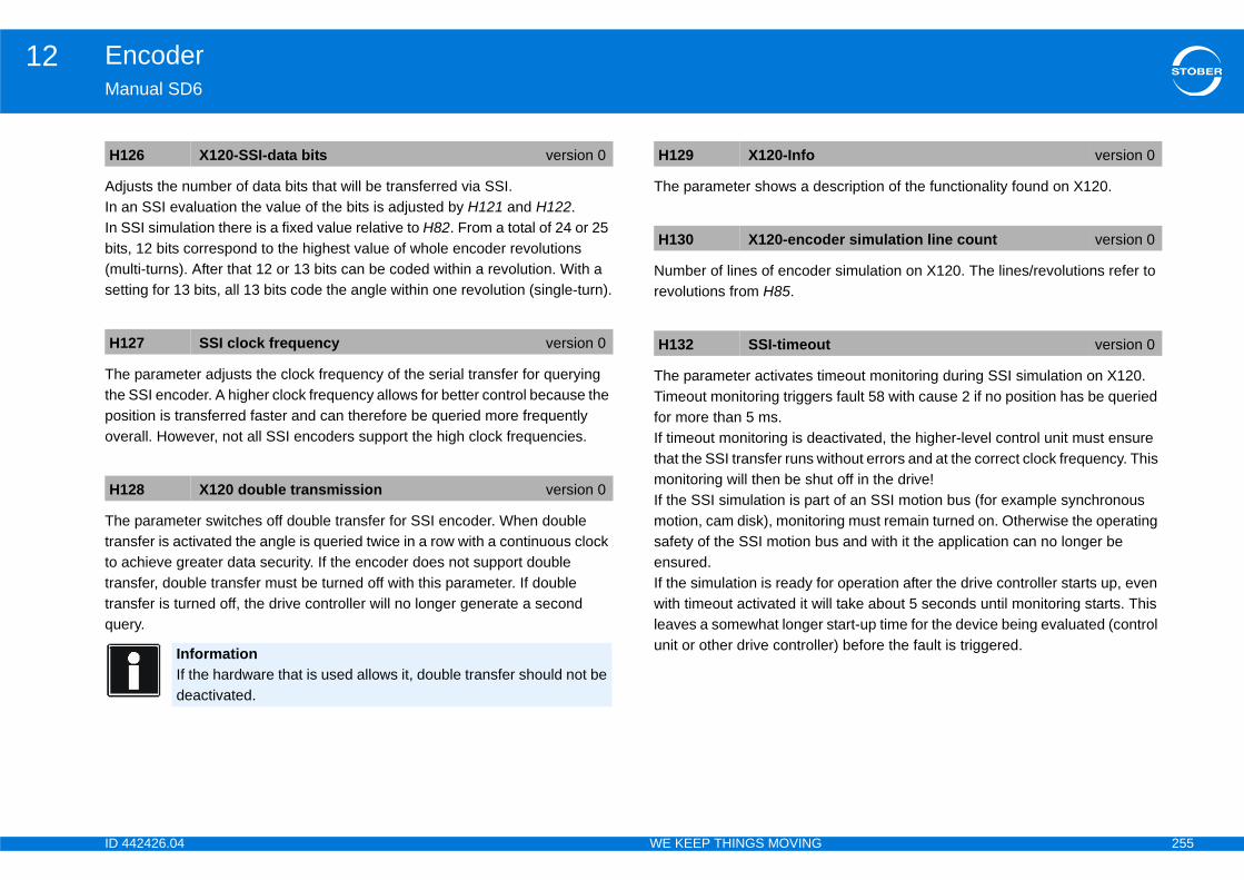
ID 4 255
Encoder12Ma
AdjIn aIn Sbits(muset
Thetheposove
Thetranto atrantranque
scription of the functionality found on X120.
r simulation on X120. The lines/revolutions refer to
meout monitoring during SSI simulation on X120. s fault 58 with cause 2 if no position has be queried
activated, the higher-level control unit must ensure ithout errors and at the correct clock frequency. This t off in the drive!t of an SSI motion bus (for example synchronous ing must remain turned on. Otherwise the operating us and with it the application can no longer be
r operation after the drive controller starts up, even ill take about 5 seconds until monitoring starts. This start-up time for the device being evaluated (control r) before the fault is triggered.
H1
H1
H1
version 0
der simulation line count version 0
t version 0
42426.04 WE KEEP THINGS MOVING
nual SD6
usts the number of data bits that will be transferred via SSI.n SSI evaluation the value of the bits is adjusted by H121 and H122.SI simulation there is a fixed value relative to H82. From a total of 24 or 25 , 12 bits correspond to the highest value of whole encoder revolutions lti-turns). After that 12 or 13 bits can be coded within a revolution. With a
ting for 13 bits, all 13 bits code the angle within one revolution (single-turn).
parameter adjusts the clock frequency of the serial transfer for querying SSI encoder. A higher clock frequency allows for better control because the ition is transferred faster and can therefore be queried more frequently rall. However, not all SSI encoders support the high clock frequencies.
parameter switches off double transfer for SSI encoder. When double sfer is activated the angle is queried twice in a row with a continuous clock chieve greater data security. If the encoder does not support double sfer, double transfer must be turned off with this parameter. If double sfer is turned off, the drive controller will no longer generate a second ry.
The parameter shows a de
Number of lines of encoderevolutions from H85.
The parameter activates tiTimeout monitoring triggerfor more than 5 ms.If timeout monitoring is dethat the SSI transfer runs wmonitoring will then be shuIf the SSI simulation is parmotion, cam disk), monitorsafety of the SSI motion bensured.If the simulation is ready fowith timeout activated it wleaves a somewhat longerunit or other drive controlle
26 X120-SSI-data bits version 0
27 SSI clock frequency version 0
28 X120 double transmission version 0
InformationIf the hardware that is used allows it, double transfer should not be deactivated.
H129 X120-Info
H130 X120-enco
H132 SSI-timeou
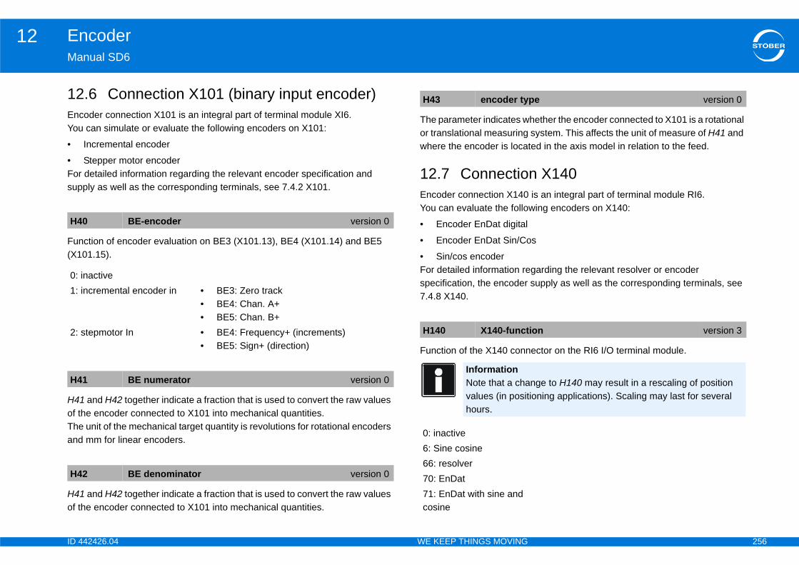
ID 4 256
Encoder12Ma
12EncYou
•
•Forsup
Fun(X1
H41of tTheand
H41of t
hether the encoder connected to X101 is a rotational system. This affects the unit of measure of H41 and ted in the axis model in relation to the feed.
n X140 is an integral part of terminal module RI6. wing encoders on X140:
s
garding the relevant resolver or encoder supply as well as the corresponding terminals, see
ector on the RI6 I/O terminal module.
H4
0: 1:
2:
H4
H4
pe version 0
ion version 3
nge to H140 may result in a rescaling of position ioning applications). Scaling may last for several
42426.04 WE KEEP THINGS MOVING
nual SD6
.6 Connection X101 (binary input encoder)oder connection X101 is an integral part of terminal module XI6. can simulate or evaluate the following encoders on X101:
Incremental encoder
Stepper motor encoder detailed information regarding the relevant encoder specification and ply as well as the corresponding terminals, see 7.4.2 X101.
ction of encoder evaluation on BE3 (X101.13), BE4 (X101.14) and BE5 01.15).
and H42 together indicate a fraction that is used to convert the raw values he encoder connected to X101 into mechanical quantities. unit of the mechanical target quantity is revolutions for rotational encoders mm for linear encoders.
and H42 together indicate a fraction that is used to convert the raw values he encoder connected to X101 into mechanical quantities.
The parameter indicates wor translational measuringwhere the encoder is loca
12.7 ConnectioEncoder connection X140You can evaluate the follo
• Encoder EnDat digital
• Encoder EnDat Sin/Co
• Sin/cos encoderFor detailed information respecification, the encoder 7.4.8 X140.
Function of the X140 conn
0 BE-encoder version 0
inactiveincremental encoder in • BE3: Zero track
• BE4: Chan. A+• BE5: Chan. B+
stepmotor In • BE4: Frequency+ (increments) • BE5: Sign+ (direction)
1 BE numerator version 0
2 BE denominator version 0
H43 encoder ty
H140 X140-funct
InformationNote that a chavalues (in posithours.
0: inactive6: Sine cosine66: resolver70: EnDat71: EnDat with sine and cosine
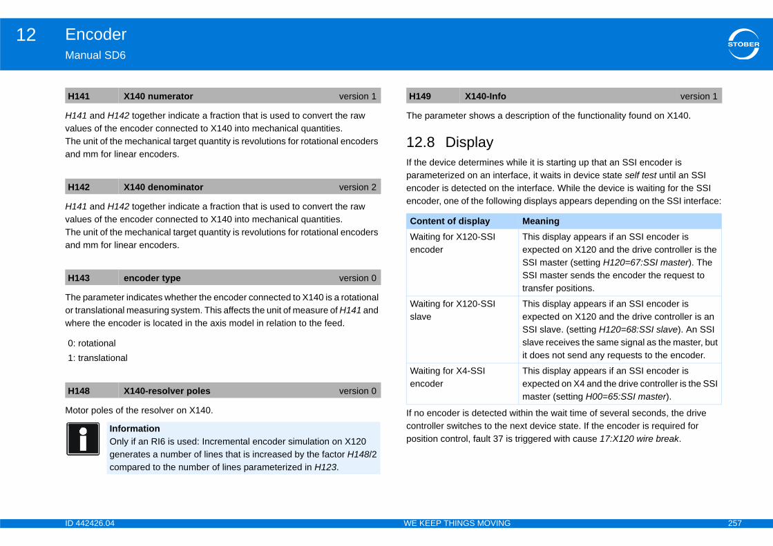
ID 4 257
Encoder12Ma
H14valuTheand
H14valuTheand
Theor twhe
Mo
scription of the functionality found on X140.
hile it is starting up that an SSI encoder is ace, it waits in device state self test until an SSI interface. While the device is waiting for the SSI
ng displays appears depending on the SSI interface:
ithin the wait time of several seconds, the drive ext device state. If the encoder is required for triggered with cause 17:X120 wire break.
H1
H1
H1
0: 1:
H1
version 1
MeaningThis display appears if an SSI encoder is expected on X120 and the drive controller is the SSI master (setting H120=67:SSI master). The SSI master sends the encoder the request to transfer positions.
This display appears if an SSI encoder is expected on X120 and the drive controller is an SSI slave. (setting H120=68:SSI slave). An SSI slave receives the same signal as the master, but it does not send any requests to the encoder.
This display appears if an SSI encoder is expected on X4 and the drive controller is the SSI master (setting H00=65:SSI master).
42426.04 WE KEEP THINGS MOVING
nual SD6
1 and H142 together indicate a fraction that is used to convert the raw es of the encoder connected to X140 into mechanical quantities. unit of the mechanical target quantity is revolutions for rotational encoders mm for linear encoders.
1 and H142 together indicate a fraction that is used to convert the raw es of the encoder connected to X140 into mechanical quantities. unit of the mechanical target quantity is revolutions for rotational encoders mm for linear encoders.
parameter indicates whether the encoder connected to X140 is a rotational ranslational measuring system. This affects the unit of measure of H141 and re the encoder is located in the axis model in relation to the feed.
tor poles of the resolver on X140.
The parameter shows a de
12.8 DisplayIf the device determines wparameterized on an interfencoder is detected on theencoder, one of the followi
If no encoder is detected wcontroller switches to the nposition control, fault 37 is
41 X140 numerator version 1
42 X140 denominator version 2
43 encoder type version 0
rotationaltranslational
48 X140-resolver poles version 0
InformationOnly if an RI6 is used: Incremental encoder simulation on X120 generates a number of lines that is increased by the factor H148/2 compared to the number of lines parameterized in H123.
H149 X140-Info
Content of displayWaiting for X120-SSI encoder
Waiting for X120-SSI slave
Waiting for X4-SSI encoder
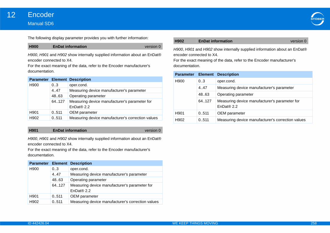
ID 4 258
Encoder12Ma
The
H90encFordoc
H90encFordoc
w internally supplied information about an EnDat®
he data, refer to the Encoder manufacturer's
H9
PaH9
H9H9
H9
PaH9
H9H9
rmation version 0
escriptionper.cond.
easuring device manufacturer's parameter
perating parameter
easuring device manufacturer's parameter for nDat® 2.2
EM parameter
easuring device manufacturer's correction values
42426.04 WE KEEP THINGS MOVING
nual SD6
following display parameter provides you with further information:
0, H901 and H902 show internally supplied information about an EnDat® oder connected to X4. the exact meaning of the data, refer to the Encoder manufacturer's umentation.
0, H901 and H902 show internally supplied information about an EnDat® oder connected to X4. the exact meaning of the data, refer to the Encoder manufacturer's umentation.
H900, H901 and H902 shoencoder connected to X4.For the exact meaning of tdocumentation.
00 EnDat information version 0
rameter Element Description00 0..3 oper.cond.
4..47 Measuring device manufacturer's parameter48..63 Operating parameter64..127 Measuring device manufacturer's parameter for
EnDat® 2.201 0..511 OEM parameter02 0..511 Measuring device manufacturer's correction values
01 EnDat information version 0
rameter Element Description00 0..3 oper.cond.
4..47 Measuring device manufacturer's parameter48..63 Operating parameter64..127 Measuring device manufacturer's parameter for
EnDat® 2.201 0..511 OEM parameter02 0..511 Measuring device manufacturer's correction values
H902 EnDat info
Parameter Element DH900 0..3 o
4..47 M
48..63 O
64..127 ME
H901 0..511 O
H902 0..511 M

ID 4 259
Mechanical drive model13Ma
13Ov
13
13
13
13
13
13
42426.04 WE KEEP THINGS MOVING
nual SD6
Mechanical drive modelerview of sections
.1 Introduction . . . . . . . . . . . . . . . . . . . . . . . . . . . . . . . . . . . . . . . . .260
13.1.1 Rotary drives . . . . . . . . . . . . . . . . . . . . . . . . . . . . . . . . . . . . . 260
13.1.2 Translational drives . . . . . . . . . . . . . . . . . . . . . . . . . . . . . . . . 261
.2 Define axis model . . . . . . . . . . . . . . . . . . . . . . . . . . . . . . . . . . .262
.3 Scale axis . . . . . . . . . . . . . . . . . . . . . . . . . . . . . . . . . . . . . . . . . .262
.4 Limit position . . . . . . . . . . . . . . . . . . . . . . . . . . . . . . . . . . . . . . .262
.5 Limit speed, acceleration, jerk . . . . . . . . . . . . . . . . . . . . . . .262
.6 Limit torque, force . . . . . . . . . . . . . . . . . . . . . . . . . . . . . . . . . . .263
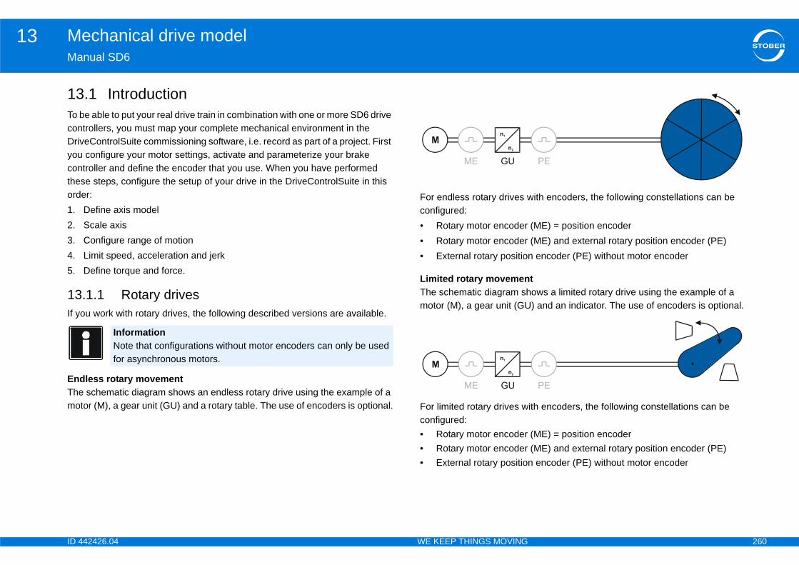
ID 4 260
Mechanical drive model13Ma
13To bconDrivyoucontheord1.2.3.4.5.
13If y
EndThemo
ith encoders, the following constellations can be
(ME) = position encoder (ME) and external rotary position encoder (PE) encoder (PE) without motor encoder
tows a limited rotary drive using the example of a ) and an indicator. The use of encoders is optional.
ith encoders, the following constellations can be
(ME) = position encoder (ME) and external rotary position encoder (PE) encoder (PE) without motor encoder
42426.04 WE KEEP THINGS MOVING
nual SD6
.1 Introductione able to put your real drive train in combination with one or more SD6 drive trollers, you must map your complete mechanical environment in the eControlSuite commissioning software, i.e. record as part of a project. First configure your motor settings, activate and parameterize your brake troller and define the encoder that you use. When you have performed se steps, configure the setup of your drive in the DriveControlSuite in this er:Define axis modelScale axisConfigure range of motionLimit speed, acceleration and jerkDefine torque and force.
.1.1 Rotary drivesou work with rotary drives, the following described versions are available.
less rotary movement schematic diagram shows an endless rotary drive using the example of a
tor (M), a gear unit (GU) and a rotary table. The use of encoders is optional.
For endless rotary drives wconfigured:• Rotary motor encoder • Rotary motor encoder • External rotary position
Limited rotary movemenThe schematic diagram shmotor (M), a gear unit (GU
For limited rotary drives wconfigured:• Rotary motor encoder • Rotary motor encoder • External rotary position
InformationNote that configurations without motor encoders can only be used for asynchronous motors.

ID 4 261
Mechanical drive model13Ma
13If yava
EndTheexaof e
Forbe •••
••
LimTheof ais o
ives with encoders, the following constellations can
(ME) = position encoder (ME) and external rotary position encoder (PE) (ME) and external translational position encoder
encoder (PE) without motor encoder osition encoder (PE) without motor encoder
ows a limited translational drive using the example der.
wing encoder constellations can be configured:coder (ME) = position encoder coder (ME) and external translational position
42426.04 WE KEEP THINGS MOVING
nual SD6
.1.2 Translational drivesou work with translational drives, the following described versions are ilable.
less translational movement schematic diagram shows an endless translational drive using the mple of a motor (M), a gear unit (GU), a feed and a conveyor belt. The use ncoders is optional.
endless translational drives with encoders, the following constellations can configured:Rotary motor encoder (ME) = position encoder Rotary motor encoder (ME) and external rotary position encoder (PE)Rotary motor encoder (ME) and external translational position encoder (PE)External rotary position encoder (PE) without motor encoder External translational position encoder (PE) without motor encoder
ited translational movement schematic diagram shows a limited translational drive using the example motor (M), a gear unit (GU), a feed and a tool slide. The use of encoders ptional.
For limited translational drbe configured:• Rotary motor encoder • Rotary motor encoder • Rotary motor encoder
(PE)• External rotary position• External translational p
Linear motorsThe schematic diagram shof a linear motor with enco
For linear motors, the follo• Translational motor en• Translational motor en
encoder (PE)
InformationNote that configurations without motor encoders can only be used for asynchronous motors.

ID 4 262
Mechanical drive model13Ma
13Def•••
The••••
13Youmo
Theis b
CiA•••••
ionion of your axis using a software or hardware limit ure the range of motion.
are – depending on the application that the software r position limiting.
d Mode
d, acceleration, jerkum permitted speed as well as the acceleration and
are – depending on the application that the software r limiting speed, acceleration and jerk.
42426.04 WE KEEP THINGS MOVING
nual SD6
.2 Define axis modeline your axis by configuring the range of motion (endless or limited),defining the axis type (rotational or translational) and specifying which encoder you use (no encoder, motor- and/or Position encoder).
following parameters are important for the definition of the axis model: I05B26I02I00
.3 Scale axis can scale an axis by configuring the overall transmission between the
tor and drive as well as information about the user units.
following parameters are – depending on the application that the software ased on – important for axis scaling.
402 Controller Based ModeA584[0], A584[1]A585[1], A585[0]I06, I09A571A568
STOBER Drive Based• C15, C16• C18, C17• I08, I07• I06, I09• I03• I01
13.4 Limit positIf necessary limit the positswitch and as a result sec
The following parameters is based on – important fo
CiA 402 Controller Base• I00• A570[1], A570[0]• I101, I102
STOBER Drive Based• I00• I50, I51• I101, I102
13.5 Limit speeIf necessary limit the maximjerk.
The following parameters is based on – important fo
ID 4 263
Mechanical drive model13Ma
CiA••••
STO••••
13If n
Theis b
CiA•••
STO••
42426.04 WE KEEP THINGS MOVING
nual SD6
402 Controller Based ModeI10A604, A605I16A578
BER Drive BasedI10I11I16I17
.6 Limit torque, forceecessary limit the maximum permitted torque/force.
following parameters are – depending on the application that the software ased on – important for torque/force limiting.
402 Controller Based ModeC03, C05C08A559
BER Drive BasedC03, C05C08

ID 4 264
Communication14Ma
14Ov
14
14
14
14
LAN connection . . . . . . . . . . . . . . . . . . . . . . . . 278
internet connection . . . . . . . . . . . . . . . . . . . . . 279
net settings for DriveControlSuite . . . . . . . . . . . 279
. . . . . . . . . . . . . . . . . . . . . . . . . . . . . . . . . . . . . 280
emote maintenance . . . . . . . . . . . . . . . . . . . . . 280
t of a connection . . . . . . . . . . . . . . . . . . . . . . . . 281
f remote maintenance . . . . . . . . . . . . . . . . . . . 282
ote maintenance . . . . . . . . . . . . . . . . . . . . . . . 283
. . . . . . . . . . . . . . . . . . . . . . . . . . . . . . . . . . . . . 284
nditions for maintenance of the 6th ration of drive controllers . . . . . . . . . . . . . . . . . 290
42426.04 WE KEEP THINGS MOVING
nual SD6
Communicationerview of sections
.1 Introduction . . . . . . . . . . . . . . . . . . . . . . . . . . . . . . . . . . . . . . . . .265
.2 Components . . . . . . . . . . . . . . . . . . . . . . . . . . . . . . . . . . . . . . . .265
14.2.1 Basics of IGB communication . . . . . . . . . . . . . . . . . . . . . . . . 266
14.2.2 Diagnosis . . . . . . . . . . . . . . . . . . . . . . . . . . . . . . . . . . . . . . . . 268
14.2.2.1 IGB network . . . . . . . . . . . . . . . . . . . . . . . . . . . . . . . 268
14.2.2.2 Drive controller . . . . . . . . . . . . . . . . . . . . . . . . . . . . . 269
.3 Direct connection . . . . . . . . . . . . . . . . . . . . . . . . . . . . . . . . . . .270
14.3.1 Prerequisites . . . . . . . . . . . . . . . . . . . . . . . . . . . . . . . . . . . . . 270
14.3.2 Setting up a connection automatically . . . . . . . . . . . . . . . . . . 270
14.3.2.1 Prerequisites . . . . . . . . . . . . . . . . . . . . . . . . . . . . . . 270
14.3.2.2 Setting up a direct connection automatically . . . . . . 271
14.3.3 Setting up a connection manually . . . . . . . . . . . . . . . . . . . . . 272
14.3.3.1 IP address and subnet mask . . . . . . . . . . . . . . . . . . 272
14.3.3.2 Adjusting the IP address of the drive controller .. . . . . 273
14.3.3.3 Setting up a direct connection manually . . . . . . . . . 274
.4 Remote maintenance . . . . . . . . . . . . . . . . . . . . . . . . . . . . . . .276
14.4.1 System administration . . . . . . . . . . . . . . . . . . . . . . . . . . . . . . 277
14.4.2 Settings for a
14.4.3 Settings for an
14.4.3.1 Inter
14.4.4 Security .. . . .
14.4.5 Activation of r
14.4.6 Establishmen
14.4.7 Deactivation o
14.4.8 Monitoring rem
14.4.9 Diagnosis . . .
14.4.10 Terms and coSTOBER gene
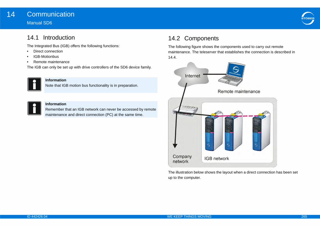
ID 4 265
Communication14Ma
14The•••The
ts the components used to carry out remote er that establishes the connection is described in
s the layout when a direct connection has been set
42426.04 WE KEEP THINGS MOVING
nual SD6
.1 Introduction Integrated Bus (IGB) offers the following functions:Direct connectionIGB-MotionbusRemote maintenance IGB can only be set up with drive controllers of the SD6 device family.
14.2 ComponenThe following figure showsmaintenance. The teleserv14.4.
The illustration below showup to the computer.
InformationNote that IGB motion bus functionality is in preparation.
InformationRemember that an IGB network can never be accessed by remote maintenance and direct connection (PC) at the same time.

ID 4 266
Communication14Ma
Youthedoc
IGB communication
s apply
mote maintenance and without a proxy server uses port 80 and TCP/IP port 37915. For remote oxy server the HTTP protocol uses the proxy port.
direct connection must be possible with TCP/IP and 5 and 37916.
this port by the personal firewall. Share these ports wing programs:
default installation directory: C:/Windows/ ANTRIEBSTECHNIK/DriveControlSuite (V6.0)/
service SATMICLSVC.exe in:
:/Windows/System
:/Windows/SysWOW64twork administrator.
et the following conditions:
s may be connected in one network.
olved in the IGB network must be directly connected er components such as hubs and switches are
m in the circuit.
yout must be a line topology.
t an IGB network can never be accessed by remote nd direct connection (PC) at the same time.
42426.04 WE KEEP THINGS MOVING
nual SD6
can also set up communication to a controller via the fieldbus in parallel to IGB. Observe the fieldbus documentation for this (see section 1.2 Further umentation).
14.2.1 Basics of
The following requirement
• Communication with rethe HTTP protocol via maintenance with a pr
• Communication with aUDP/IP via ports 3791
You may be asked to sharein your firewall for the follo
• for DriveControlSuite (Programme/STOEBERbin/DS6A.exe)
• for the communication
– Windows 32 bit: C
– Windows 64 bit: CTo do this, contact your ne
The IGB network must me
• A maximum of 32 SD6
• All drive controllers invwith each other. No othpermitted between the
• The overall resulting la
InformationRemember that when a fieldbus and the IGB-Motion bus are used at the same time, the fieldbus communication cannot be synchronized on the controller.
InformationRemember thamaintenance a

ID 4 267
Communication14Ma
•
•
•
•
42426.04 WE KEEP THINGS MOVING
nual SD6
The X3 A interfaces may only be connected with X3 B interfaces of other drive controllers and vice versa.
Suitable cables must be used. STOBER provides ready-made cables for the layout of the Integrated Bus. These cables must be used to ensure proper functionality. Also note section 4.9 Communication modules.
The maximum overall extent of the IGB network is 100 m.
The IGB does not require an explicit master and the extensive configuration typically required for Ethernet is eliminated.
ID 4 268
Communication14Ma
PCup con
•
•
To netIGBinte
k
rrently logged in on the IGB.ribers are currently connected with this drive
t is displayed corresponds to the number of drive IGB network.
troller.
node number version 0
version 0
The IGB boots up.The connected drive controllers declare themselves in the IGB network and are synchronized.Currently no IGB network is set up with other drive controllers.Possible causes:• The drive controller has not found any
other drive controllers with which an IGB network can be set up
• An already existing connection to other drive controllers via IGB has been disconnected
42426.04 WE KEEP THINGS MOVING
nual SD6
or the internet are connected to a free outer socket. The IGB network is set automatically when you turn on at least one drive controller. The following ditions apply when integrating additional drive controllers into the network:
You have connected these drive controllers to the IGB network.
The drive controllers in the network must be receiving a 24 vdc power supply
start the integration, the 24 vdc power supply of the drive controller in the work must be turned on. When the 24 vdc power supply is turned on, the network is restructured and up to 32 connected drive controllers will be grated.
14.2.2 Diagnosis
14.2.2.1 IGB networ
Number of subscribers cu• 0 or 1: No other subsc
controller via IGB.• 2..32: The number tha
controllers found in the
IGB status of the drive conInformationMAC address range of the STOBER hardware:00:11:39:00:00:00 - 00:11:39:FF:FF:FF
InformationRemember that sockets X3 A and X3 B are not electrically connected. If you turn off a device in an IGB network or disconnect an IGB cable, two partial networks are created to the left and right of this device or the disconnected cable.
A153 IGB actual
A155 IGB-state
0: IGB booting
1: single
ID 4 269
Communication14Ma
oller
e controller in the IGB network.
3A3B
2:
3:
4:
n version 0
The drive controller is not connected with any other IGB subscribers.The two RJ45 sockets are connected with other drive controllers.Additional IGB subscribers are connected on both sides of the drive controller.The drive controller is located on the outer left end of the IGB. No valid drive controller is connected to its X3 A socket.The drive controller is located on the outer right end of the IGB.No valid drive controller is connected to its X3B socket or more than 32 drive controllers were connected to each other. In this case the IGB will be logically complete after the 32nd drive controller and that status will be displayed.
version 2
42426.04 WE KEEP THINGS MOVING
nual SD6
14.2.2.2 Drive contr
Current position of the driv
State of the Ethernet port.• Element 0: Interface X• Element 1: Interface X• Element 2: No function
IGB running Several drive controllers have set up an IGB network.The IGB motion bus is not used or cannot be used.Possible causes:• The IGB motion bus has not been
activated in all subscribers A119.• The IGB address A120 has not been
unambiguously set in all subscribers.• The IGB nominal number A121 has not
been correctly parameterized in all subscribers.
IGB-motionbus The IGB motion bus has been successfully set up.Turning on additional drive controllers has no effect on the existing IGB motion bus n this status.
IGB-Motionbus Error Status A155 = 3:IGB Motionbus was already reached once and was left due to an error.Possible causes:• An IGB cable was pulled• There is a massive EMC fault present• The synchronicity of the drive controllers
among each other has been violated
A152 IGB positio
0: single
1: IGB-internal
2: gateway-X3A
3: gateway-X3B
A154 Port state
ID 4 270
Communication14Ma
Numvolt
nection the direct connection of a computer with 6 or an IGB network in the same subnet for the
, diagnostics or maintenance. up a direct connection:atic connection setup, see section 14.3.2 Setting up cally.nection manually, see section 14.3.3 Setting up a
itesthe direct connection:way device and the computer's network connection s on the same subnet.
a connection automatically
eswhen setting up a direct connection automatically::standard must be set in the drive controller or .
P addresses and subnetwork masks of the Ethernet
3A3B
0: 1:
2:
3:
4:
A1
-delivery version 1
42426.04 WE KEEP THINGS MOVING
nual SD6
ber of times IGB has been booted up since the last time the power supply age was turned on.
14.3 Direct conA direct connection meansDriveControlSuite to an SDpurpose of commissioningThere are two ways to set• You can use the autom
a connection automati• You can make the con
connection manually.
14.3.1 PrerequisNote the following rule for • The socket of the gate
must have IP addresse
14.3.2 Setting up
14.3.2.1 PrerequisitThe following rule applies • Parameter A166[x] = 1
Address reference of the Iports.• Element 0: Interface X• Element 1: Interface X• Element 2: No function
error The state of the socket is not known.co connection The socket is not connected with the other
devices.10 MBit/s There is a connection to a subscriber at a
transmission rate of 10 Mbit/s with full-duplex capable communication. The subscriber is not an SD6.
100 MBit/s There is a connection to a subscriber at a transmission rate of 100 Mbit/s. Communication with this subscriber is not full-duplex capable and the subscriber is not an SD6.
link OK There is a connection to a subscriber at a transmission rate of 100 Mbit/s with full-duplex capable communication.
56 IGB number bootups version 0
A166 IP-address

ID 4 271
Communication14Ma
14Theaut•
••
0:
1:
2:
ection automatically
eControlSuite, select the module with which you direct connection.e project window click the Make connection button.tion dialog for the module opens:
all the gateway devices that are connected with the
vice with which you would like to set up a direct or yellow dot appears in the IP address column for ion can be set up automatically. If a red dot appears, t up the connection.
42426.04 WE KEEP THINGS MOVING
nual SD6
.3.2.2 Setting up a direct connection automatically following requirements must be met to set up a direct connection
omatically:The computer and gateway device or the IGB network must be connected via a network.The drive controller must be turned on.You have created a project in DriveControlSuite.
InformationA change to the parameter will not take effect until- the value is saved with action A00[0] and the drive controller is turned off and back on again- or the physical connection is terminated.
manual The drive controller is using exclusively assignments from A164[x] and A165[x].The active values are displayed in parameter A157[x] and A158[x].
standard The drive controller uses the assignments from the DHCP server or DriveControlSuite.If no assignment is received by the DHCP server or DriveControlSuite within 3 minutes after connection to the network, assigned values from A164[x] and A165[x] are used.The active values are displayed in parameters A157[x], A158[x], A160[x] and A161[x].
only DHCP The drive controller uses exclusively assignments from the DHCP server.The active values are displayed in parameters A157[x], A158[x], A160[x] and A161[x].
Setting up a direct conn
1. In your project in Drivwould like to set up a
2. In the bottom part of th The Make connec
The dialog showsnetwork.
3. Select the gateway deconnection. If a greenthis device, a connectit is not possible to se
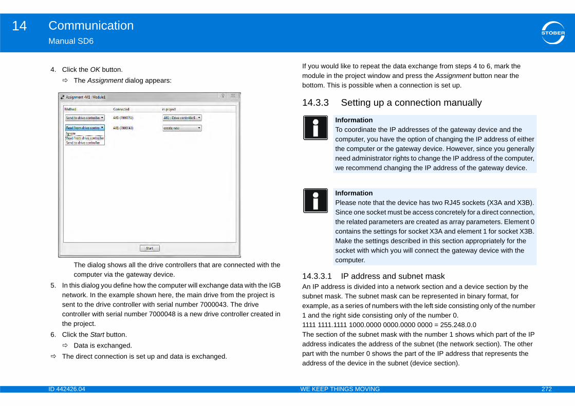
ID 4 272
Communication14Ma
the data exchange from steps 4 to 6, mark the ow and press the Assignment button near the hen a connection is set up.
a connection manually
and subnet maskto a network section and a device section by the mask can be represented in binary format, for
bers with the left side consisting only of the number ting only of the number 0. 0000.0000 0000 = 255.248.0.0mask with the number 1 shows which part of the IP ress of the subnet (the network section). The other ws the part of the IP address that represents the e subnet (device section).
4.
5.
6.
he IP addresses of the gateway device and the ave the option of changing the IP address of either
r the gateway device. However, since you generally tor rights to change the IP address of the computer, changing the IP address of the gateway device.
t the device has two RJ45 sockets (X3A and X3B). et must be access concretely for a direct connection, meters are created as array parameters. Element 0 ttings for socket X3A and element 1 for socket X3B. gs described in this section appropriately for the ch you will connect the gateway device with the
42426.04 WE KEEP THINGS MOVING
nual SD6
If you would like to repeat module in the project windbottom. This is possible w
14.3.3 Setting up
14.3.3.1 IP addressAn IP address is divided insubnet mask. The subnet example, as a series of num1 and the right side consis1111 1111.1111 1000.0000The section of the subnet address indicates the addpart with the number 0 shoaddress of the device in th
Click the OK button. The Assignment dialog appears:
The dialog shows all the drive controllers that are connected with the computer via the gateway device.
In this dialog you define how the computer will exchange data with the IGB network. In the example shown here, the main drive from the project is sent to the drive controller with serial number 7000043. The drive controller with serial number 7000048 is a new drive controller created in the project.Click the Start button. Data is exchanged.The direct connection is set up and data is exchanged.
InformationTo coordinate tcomputer, you hthe computer oneed administrawe recommend
InformationPlease note thaSince one sockthe related paracontains the seMake the settinsocket with whicomputer.
ID 4 273
Communication14Ma
TheThetheSubTheandaddsec
A p100
14Foladd
e Ethernet port. 3A3B
are used by the drive controller if A166[x]=0: manual if no IP address is assigned by DriveControlSuite or
P addresses and subnetwork masks of the Ethernet
3A3B
IP
Ad
1.
2.
3.
0:manual or 1:standard is entered in A166[x]. Note at A166[0] applies to X3A, while A166[1] applies to
0:manual or 1:standard, correct the setting.th A00 Save values. IP address of the drive controller.
ddress version 1
parameter will not take effect untilved with action A00[0] and the drive controller is ack on againl connection is terminated.
-delivery version 1
42426.04 WE KEEP THINGS MOVING
nual SD6
following example illustrates how to calculate the IP address. IP address 128.206.17.177 with subnet mask 255.240.0.0 is entered for
network interface of the computer:net mask:1111 1111.1111 0000.0000 0000.0000 0000 12 numbers on the left of the IP address indicate the address of the subnet must be identical in the IP address of the device. The 20 number of the IP ress on the right indicate the address of the computer in the subnet. This tion must be different in the IP address of the device.
ossible IP address for the device could therefore be:0 0000.1100 1111.0001 0001.1011 0001 = 128.207.17.177
.3.3.2 Adjusting the IP address of the drive controllerlow these steps to adjust the IP address of the drive controller to the IP ress of the computer:
Manual IP addresses of th• Element 0: Interface X• Element 1: Interface X• Element 2: No functionThe manual IP addresses or if A166[x]=1: Standard (the DHCP server).
Address reference of the Iports.• Element 0: Interface X• Element 1: Interface X• Element 2: No function
address: 1000 0000.1100 1110.0001 0001.1011 0001
Network section, must be identical in the device and PC
Device section, must be different in the device and PC
justing the IP address of the drive controller
Determine the IP address and subnet mask of the computer, for example from the control panel of your computer.Determine an IP address that is in the same subnet as the PC's IP address.Use the operator panel of the gateway device to enter that address in parameter A164[x]. Use A164[0] if the direct connection is via X3A. Use A164[1] if you are connecting the PC via X3B.
4. Check whether eitherin this case as well thX3B.
5. If A166[x] is not set to6. Save your settings wi You have adjusted the
A164 Manual IP a
InformationA change to the- the value is saturned off and b- or the physica
A166 IP-address
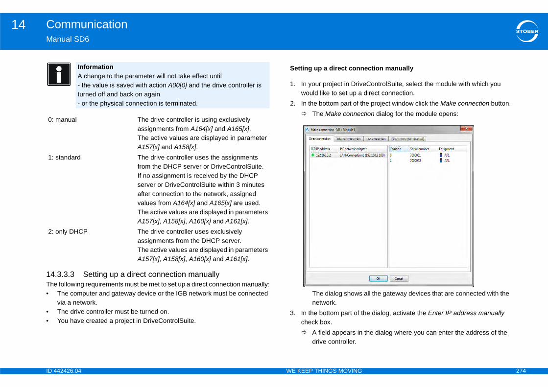
ID 4 274
Communication14Ma
14The•
••
0:
1:
2:
ection manually
eControlSuite, select the module with which you direct connection.e project window click the Make connection button.tion dialog for the module opens:
all the gateway devices that are connected with the
he dialog, activate the Enter IP address manually
the dialog where you can enter the address of the
42426.04 WE KEEP THINGS MOVING
nual SD6
.3.3.3 Setting up a direct connection manually following requirements must be met to set up a direct connection manually:The computer and gateway device or the IGB network must be connected via a network.The drive controller must be turned on.You have created a project in DriveControlSuite.
InformationA change to the parameter will not take effect until- the value is saved with action A00[0] and the drive controller is turned off and back on again- or the physical connection is terminated.
manual The drive controller is using exclusively assignments from A164[x] and A165[x].The active values are displayed in parameter A157[x] and A158[x].
standard The drive controller uses the assignments from the DHCP server or DriveControlSuite.If no assignment is received by the DHCP server or DriveControlSuite within 3 minutes after connection to the network, assigned values from A164[x] and A165[x] are used.The active values are displayed in parameters A157[x], A158[x], A160[x] and A161[x].
only DHCP The drive controller uses exclusively assignments from the DHCP server.The active values are displayed in parameters A157[x], A158[x], A160[x] and A161[x].
Setting up a direct conn
1. In your project in Drivwould like to set up a
2. In the bottom part of th The Make connec
The dialog showsnetwork.
3. In the bottom part of tcheck box. A field appears in
drive controller.
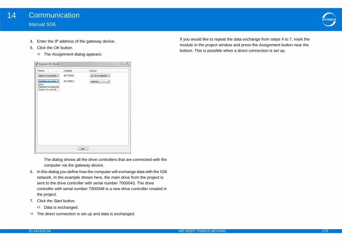
ID 4 275
Communication14Ma
the data exchange from steps 4 to 7, mark the ow and press the Assignment button near the hen a direct connection is set up.
4.5.
6.
7.
42426.04 WE KEEP THINGS MOVING
nual SD6
If you would like to repeat module in the project windbottom. This is possible w
Enter the IP address of the gateway device.Click the OK button. The Assignment dialog appears:
The dialog shows all the drive controllers that are connected with the computer via the gateway device.
In this dialog you define how the computer will exchange data with the IGB network. In the example shown here, the main drive from the project is sent to the drive controller with serial number 7000043. The drive controller with serial number 7000048 is a new drive controller created in the project.Click the Start button. Data is exchanged.The direct connection is set up and data is exchanged.

ID 4 276
Communication14Ma
14
Eacintrremdire
•
•
•
•
ChandThe
ays involved in remote maintenance: who performs the remote maintenance. For service employee of STOBER or the machine
n initiates and concludes the remote maintenance ns are safe at all times. This can be a qualified
ine manufacturer or the user
he components involved in remote maintenance via
he components involved in remote maintenance via
42426.04 WE KEEP THINGS MOVING
nual SD6
.4 Remote maintenance
h indirect connection from the start-up computer via a local network, anet or the internet with a drive controller or an IGB network counts for ote maintenance. You can perform all the functions that are possible via a ct connection with remote maintenance. These are:
Diagnostic functions
Changing parameters
Programming/configuration and
Live firmware update
WARNING!
anging the parameters may change the properties of a machine during after remote maintenance. person responsible for the machine must
Keep people away from the hazardous areas of the machine during remote maintenance.
After remote maintenance is finished, ensure that the behavior of the machine is correct.
The machine may not be released until after this has taken place. Make sure this sequence is organizationally safeguarded.
At least two people are alw• The service employee
example, this can be amanufacturer.
• The machine techniciaand ensures that persoemployee of the mach
The screen below shows tthe internet:
The screen below shows tthe local network:
InformationOn the usage of remote maintenance it is imperative you observe our maintenance conditions in chapter 14.4.10.
InformationRemember that an IGB network can never be accessed by remote maintenance and direct connection (PC) at the same time.
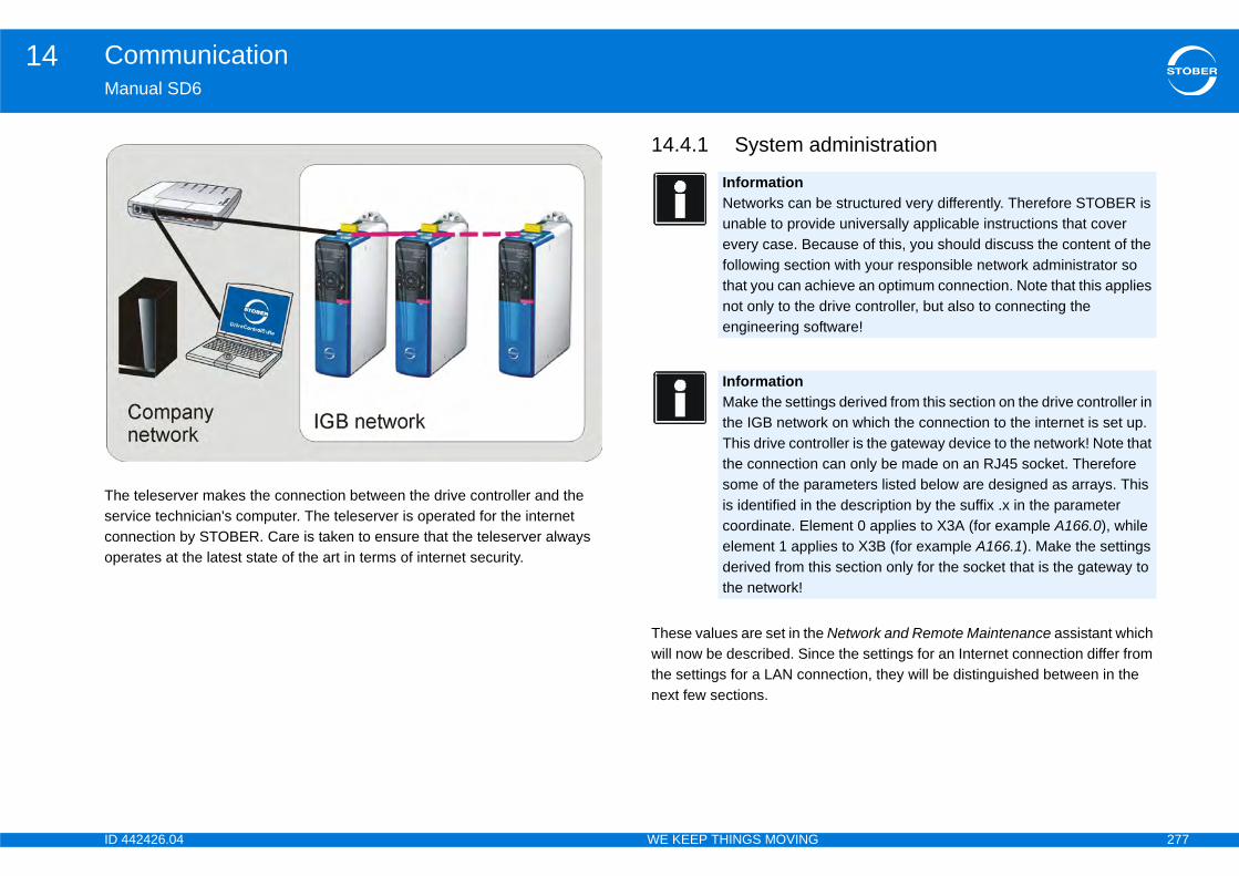
ID 4 277
Communication14Ma
Theserconope
dministration
Network and Remote Maintenance assistant which ce the settings for an Internet connection differ from nection, they will be distinguished between in the
e structured very differently. Therefore STOBER is de universally applicable instructions that cover cause of this, you should discuss the content of the n with your responsible network administrator so hieve an optimum connection. Note that this applies drive controller, but also to connecting the ftware!
gs derived from this section on the drive controller in k on which the connection to the internet is set up. oller is the gateway device to the network! Note that can only be made on an RJ45 socket. Therefore rameters listed below are designed as arrays. This he description by the suffix .x in the parameter ment 0 applies to X3A (for example A166.0), while ies to X3B (for example A166.1). Make the settings is section only for the socket that is the gateway to
42426.04 WE KEEP THINGS MOVING
nual SD6
teleserver makes the connection between the drive controller and the vice technician's computer. The teleserver is operated for the internet nection by STOBER. Care is taken to ensure that the teleserver always rates at the latest state of the art in terms of internet security.
14.4.1 System a
These values are set in thewill now be described. Sinthe settings for a LAN connext few sections.
InformationNetworks can bunable to provievery case. Befollowing sectiothat you can acnot only to the engineering so
InformationMake the settinthe IGB networThis drive contrthe connection some of the pais identified in tcoordinate. Eleelement 1 applderived from ththe network!
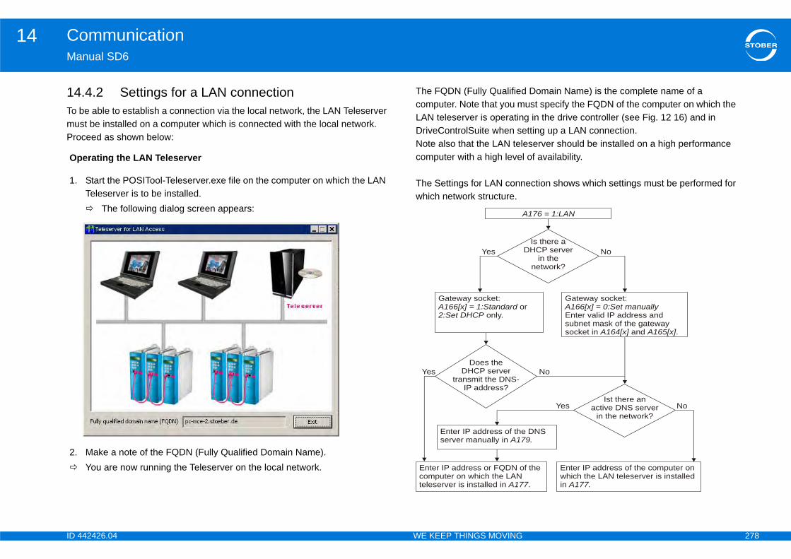
ID 4 278
Communication14Ma
14To muPro
Domain Name) is the complete name of a ust specify the FQDN of the computer on which the g in the drive controller (see Fig. 12 16) and in tting up a LAN connection.
eserver should be installed on a high performance of availability.
ection shows which settings must be performed for
Op
1.
2.
176 = 1:LAN
f the
.7
DNS9.
Enter IP address of the computer onwhich the LAN teleserver is installedin A177.
rGateway socket:
Enter valid IP address andsubnet mask of the gatewaysocket in and .
A166[x] = 0:Set manually
A164[x] A165[x]
Is there a DHCP server
in thenetwork?
Ist there anactive DNS server
in the network?No
No
No
Yes
42426.04 WE KEEP THINGS MOVING
nual SD6
.4.2 Settings for a LAN connectionbe able to establish a connection via the local network, the LAN Teleserver st be installed on a computer which is connected with the local network. ceed as shown below:
The FQDN (Fully Qualifiedcomputer. Note that you mLAN teleserver is operatinDriveControlSuite when seNote also that the LAN telcomputer with a high level
The Settings for LAN connwhich network structure.
erating the LAN Teleserver
Start the POSITool-Teleserver.exe file on the computer on which the LAN Teleserver is to be installed. The following dialog screen appears:
Make a note of the FQDN (Fully Qualified Domain Name).You are now running the Teleserver on the local network.
A
Enter IP address or FQDN ocomputer on which the LANteleserver is installed in A17
Enter IP address of theserver manually in A17
Gateway socket: o
only.A166[x] = 1:Standard2:Set DHCP
Does the DHCP server
transmit the DNS-IP address?
Yes
Yes
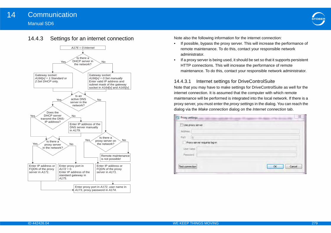
ID 4 279
Communication14Ma
14 ormation for the internet connection: proxy server. This will increase the performance of o do this, contact your responsible network
g used, it should be set so that it supports persistent is will increase the performance of remote is, contact your responsible network administrator.
tings for DriveControlSuite make settings for DriveControlSuite as well for the ssumed that the computer with which remote med is integrated into the local network. If there is a er the proxy settings in the dialog. You can reach the ction dialog on the Internet connection tab.
Ye
Y
EntFQser
42426.04 WE KEEP THINGS MOVING
nual SD6
.4.3 Settings for an internet connection Note also the following inf• If possible, bypass the
remote maintenance. Tadministrator.
• If a proxy server is beinHTTP connections. Thmaintenance. To do th
14.4.3.1 Internet setNote that you may have tointernet connection. It is amaintenance will be perforproxy server, you must entdialog via the Make conne
A176 = 0:Internet
Enter IP address of theDNS server manuallyin .A179
Enter proxy port in= 0.
Enter IP address of thestandard gateway in
.
A172
A175
Is there a DHCP server in
the network?
Is anactive DNS server in the
network?
Does theDHCP server
transmit the DNS-IP address?
Is there a proxy server
in the network?
No
No
No
No
Yes
s
es
Yes
Yes
er IP address orDN of the proxyver in .A171
Enter IP address orFQDN of the proxyserver in .A171
Remote maintenanceis not possible!
Is there a proxy server on
the network?No
Enter proxy port in , user name in, proxy password in .
A172 A173 A174
Gateway socket: or
only.A166[x] = 1:Standard2:Set DHCP
Gateway socket:
Enter valid IP address andsubnet mask of the gatewaysocket in and .
A166[x] = 0:Set manually
A164[x] A165[x]

ID 4 280
Communication14Ma
14Her
It isremaut
•
•
•
Theunaacccircthe
You
•
•
UsiAn Thaposthe
of remote maintenance
s must be met before remote maintenance can be
onnected with the local network, intranet or internet.s the valid information needed to be able to cal network, intranet or internet (see section 14.4.1
). signal in parameter A167 remote service source by ance can be started, for example a binary signal to
he drive controller that is the gateway to the network, ote service with session-ID whether remote cured by a session ID. has a computer that is connected with the local ernet and the DriveControlSuite software is installed
esponsible for the machine, ensure (e.g., by the device is accessed for remote maintenance by erson.request to exist for an unnecessarily long period of
42426.04 WE KEEP THINGS MOVING
nual SD6
.4.4 Securitye, Security means protection against the unauthorized manipulation of data
also possible to change safety-relevant parameters of a drive controller via ote maintenance. To ensure that this does not happen without
horization or accidentally, the following security mechanisms are installed:
A remote maintenance process can only be started locally on the machine.
The service technician who is performing remote maintenance must know the serial number of the drive controller that will be maintained.
If the Session ID option is selected (parameter A168 remote service with session-ID), the temporarily valid session ID must be given to the service technician by the person responsible for the machine. It appears in the display when remote maintenance is activated or in parameter A151.
se first three mechanisms practically exclude the possibility of uthorized access. There does remain a residual risk of unauthorized ess, for example by a former employee intent on sabotage. In some umstances such a person could with great effort set up a connection before service technician did, if he knew the time when this would occur.
would know that such unauthorized access was occurring because:
the remote maintenance LED would be continuously lit and
the connection request of the authorized service technician would fail.
ng a session ID involves more effort, but it excludes this last possibility.outgoing connection on the machine is always created by the local request. t request always connects with the teleserver. No other connection is sible. It is also not possible to set up an internet connection to the SD6 if connection was not requested on the SD6.
14.4.5 Activation
The following preconditionactivated:1. The drive controller is c2. The drive controller ha
communicate via the loSystem administration
3. You have indicated thewhich remote maintenbinary input BE1.
4. You have indicated in tin parameter A168 remmaintenance will be se
5. The service techniciannetwork, intranet or inton it.
InformationAs the person rtelephone) thatan authorized pDo not allow a time.
ID 4 281
Communication14Ma
Pro
TheIf pprocon
If thyou
ent of a connectionAc
1.
n starts DriveControlSuite. creates a new project or opens an existing project.
n selects the module in the project and clicks the on near the bottom of the project window.tion dialog appears.ce technician switches to the Internet connection or epending on the specific application. specifies the serial number and if applicable the
being set up: The service technician clicks the LAN tton.ng the DNS designation or the IP address of the s. being set up: The service technician enters the DNS address of the teleserver and confirms the dialog
on is being set up: The service technician clicks the
g the necessary proxy entries appears.n is being set up: The service technician makes the
the proxy server and confirms the dialog with OK.n dialog the service technician clicks the OK button.rk is displayed in DriveControlSuite. The drive t shared for remote maintenance are identified by a the drive controllers shared for remote
rive controllers orta to the drive controllers or re update.
42426.04 WE KEEP THINGS MOVING
nual SD6
ceed as follows:
session ID provides additional security for remote maintenance. arameter A168 is set in the gateway device so that the session ID will be mpted for remote maintenance, the service technician can only make the nection to the drive controller by specifying the session ID.
e blue LED does not flash even though remote maintenance is activated, can see the cause in parameter A178.
14.4.6 Establishmtivate remote maintenance
The person responsible for the machine turns on the signal parameterized in A167 for the drive controllers that will participate in remote maintenance. The drive controllers declare themselves. The LEDs on sockets X3A
and X3B flash very rapidly. When the connection to the teleserver is set up, the blue LEDs for
sockets X3A and X3B flash regularly. The drive controller shows its serial number in the display.
If A168 = 1:with session ID is set in the gateway device, the session ID is displayed in addition to the serial number.
The person responsible for the machine has activated remote maintenance. He sends a message to the service technician and tells him the serial number of a device in the IGB network and if applicable the session ID.
Setting up a connection
1. The service technicia2. The service technician3. The service technicia
Make connection butt The Make connec
4. In the dialog the serviLAN connection tab, d
5. The service techniciansession ID.
6. If a LAN connection isteleserver settings bu A dialog for enteri
teleserver appear7. If a LAN connection is
designation or the IP with OK.
8. If an internet connectiProxy settings button. A dialog for makin
9. If an internet connectionecessary entries for
10. In the Make connectio The entire IGB netwo
controllers that are nored prohibition sign. Inmaintenance you can- read data from the d- initiate sending of da- perform a live firmwa
ID 4 282
Communication14Ma
Not
•
•
•
ion of remote maintenance
e teleserver!maintenance by turning the device off and on again ong timeout times on the teleserver.
g methods to deactivate remote maintenance.
e deactivated by remote maintenance:e for the machine turns off the signal defined in A167 in the IGB network (Low level). ends remote maintenance in DriveControlSuite.n is interrupted, for example by a timeout. In all comes invalid if one was assigned. The blue LED is new connection, the process in section 14.4.5 aintenance must be performed again.
maintenance, note parameter A178. A numeric icates why the deactivation occurred and whether it
ote maintenance in DriveControlSuite that before ance again, the signal defined in A167 must first be next change to High level will activate remote
ote maintenance immediately after the job is t let a request exist for an unnecessarily long period
42426.04 WE KEEP THINGS MOVING
nual SD6
e the following points when remote maintenance is active:
At least one drive controller must be shared for remote maintenance in the IGB network to be able to maintain the internet connection properly. You can share or block drive controllers in the IGB network for remote maintenance at any time with an active internet connection. This is done with the signal defined in A167 remote service start.
If you download a new configuration via remote maintenance, set the parameters related to remote maintenance so they are identical to the previous configuration to prevent the connection from being disconnected prematurely because it is parameterized incorrectly. This is especially important for parameter A167 remote service start in which the signal for starting remote maintenance is defined.
If you perform a live firmware update by remote maintenance and then restart the drive controller immediately, the remote maintenance connection will be terminated.
14.4.7 Deactivat
NOTICE
Long timeout times on thDo not deactivate remote because this will result in l
Use one of the followin
The following events can b• The person responsibl
for all drive controllers• The service technician• The Internet connectio
cases a session-ID beturned off. To set up a Activation of remote m
When deactivating remotevalue in this parameter indwas error-free.
Note also when ending remactivating remote maintenswitched to Low level. Themaintenance again.
InformationDeactivate remfinished. Do noof time.
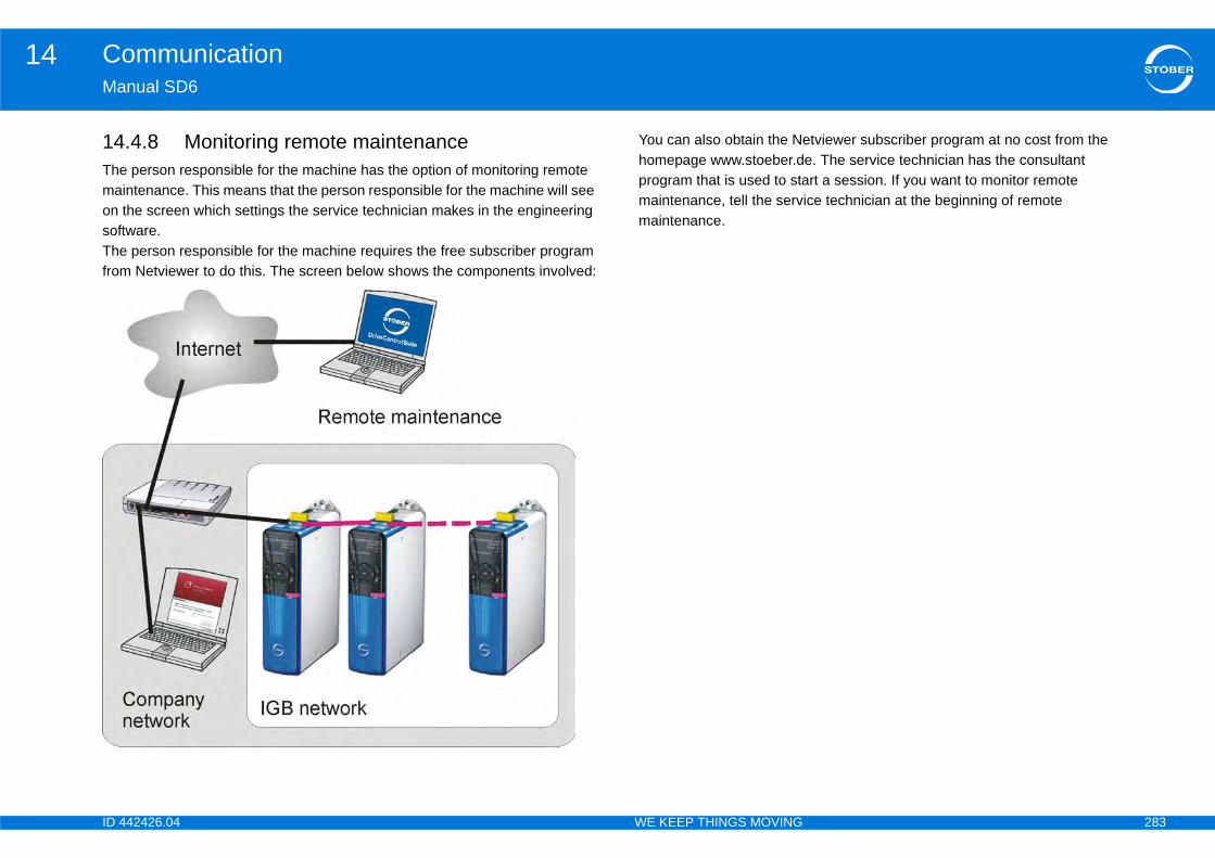
ID 4 283
Communication14Ma
14Themaon sofThefrom
tviewer subscriber program at no cost from the e. The service technician has the consultant rt a session. If you want to monitor remote
ice technician at the beginning of remote
42426.04 WE KEEP THINGS MOVING
nual SD6
.4.8 Monitoring remote maintenance person responsible for the machine has the option of monitoring remote
intenance. This means that the person responsible for the machine will see the screen which settings the service technician makes in the engineering tware. person responsible for the machine requires the free subscriber program Netviewer to do this. The screen below shows the components involved:
You can also obtain the Nehomepage www.stoeber.dprogram that is used to stamaintenance, tell the servmaintenance.
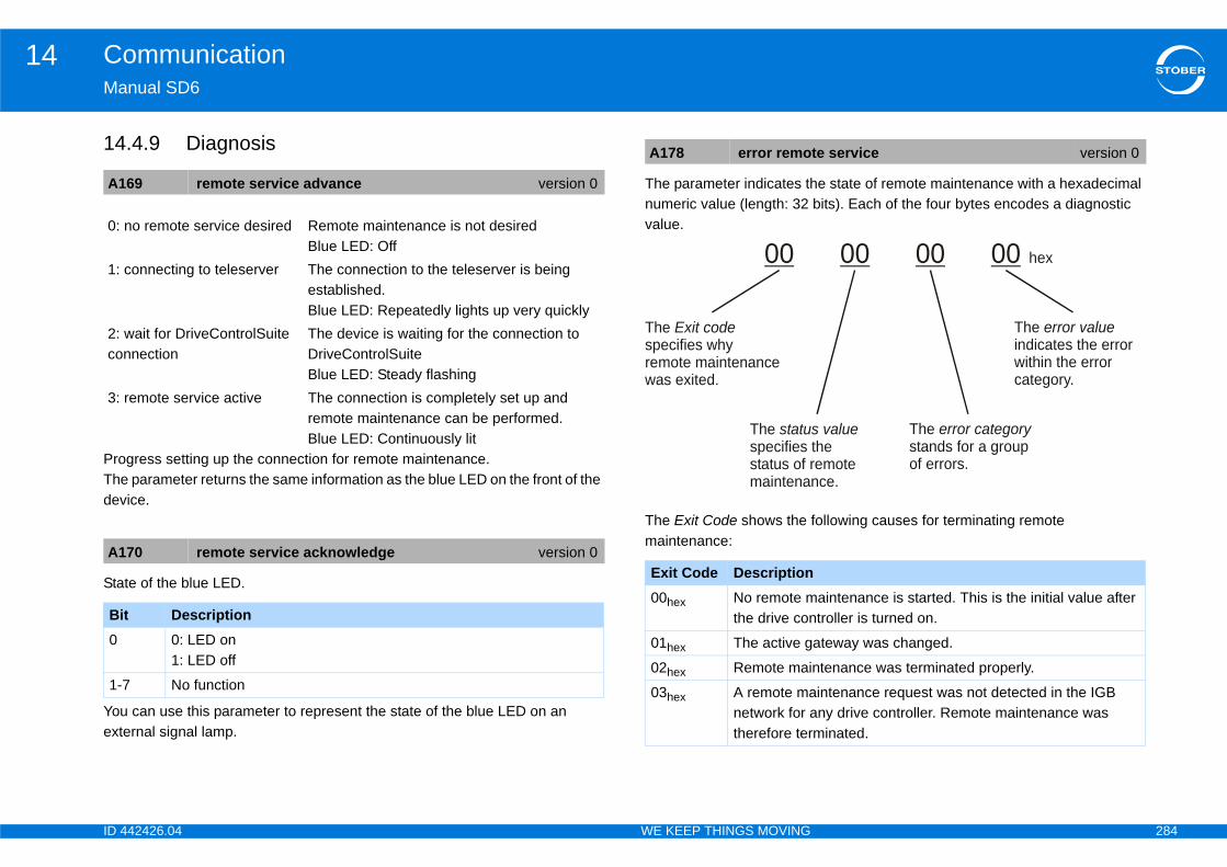
ID 4 284
Communication14Ma
14
ProThedev
Sta
Youext
e state of remote maintenance with a hexadecimal bits). Each of the four bytes encodes a diagnostic
following causes for terminating remote
A1
0:
1:
2: co
3:
A1
Bi0
1-7
te service version 0
aintenance is started. This is the initial value after troller is turned on.
ateway was changed.
ntenance was terminated properly.
intenance request was not detected in the IGB ny drive controller. Remote maintenance was
minated.
00 00 00 hex
The indicates the errorwithin the errorcategory.
error value
theemotece.
s value The stands for a groupof errors.
error category
42426.04 WE KEEP THINGS MOVING
nual SD6
.4.9 Diagnosis
gress setting up the connection for remote maintenance. parameter returns the same information as the blue LED on the front of the ice.
te of the blue LED.
can use this parameter to represent the state of the blue LED on an ernal signal lamp.
The parameter indicates thnumeric value (length: 32 value.
The Exit Code shows the maintenance:
69 remote service advance version 0
no remote service desired Remote maintenance is not desiredBlue LED: Off
connecting to teleserver The connection to the teleserver is being established.Blue LED: Repeatedly lights up very quickly
wait for DriveControlSuite nnection
The device is waiting for the connection to DriveControlSuiteBlue LED: Steady flashing
remote service active The connection is completely set up and remote maintenance can be performed.Blue LED: Continuously lit
70 remote service acknowledge version 0
t Description0: LED on1: LED off
No function
A178 error remo
Exit Code Description00hex No remote m
the drive con
01hex The active g
02hex Remote mai
03hex A remote manetwork for atherefore ter
00
The specifies why remote maintenancewas exited.
Exit code
The specifies status of rmaintenan
statu
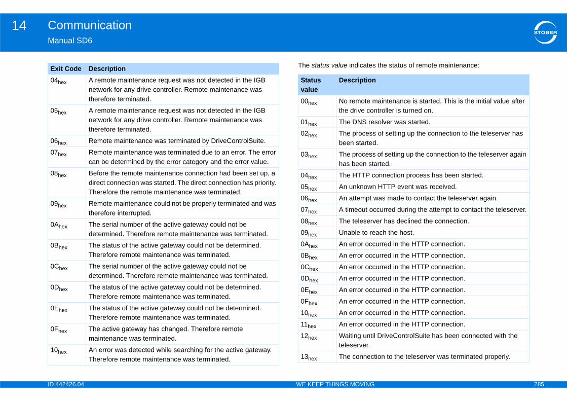
ID 4 285
Communication14Ma
the status of remote maintenance:
04
05
06
07
08
09
0A
0B
0C
0D
0E
0F
10
Ex
aintenance is started. This is the initial value after troller is turned on.
olver was started.
of setting up the connection to the teleserver has .
of setting up the connection to the teleserver again rted.
onnection process has been started.
HTTP event was received.
as made to contact the teleserver again.
curred during the attempt to contact the teleserver.
er has declined the connection.
ach the host.
urred in the HTTP connection.
urred in the HTTP connection.
urred in the HTTP connection.
urred in the HTTP connection.
urred in the HTTP connection.
urred in the HTTP connection.
urred in the HTTP connection.
urred in the HTTP connection.
DriveControlSuite has been connected with the
ion to the teleserver was terminated properly.
42426.04 WE KEEP THINGS MOVING
nual SD6
The status value indicates
hex A remote maintenance request was not detected in the IGB network for any drive controller. Remote maintenance was therefore terminated.
hex A remote maintenance request was not detected in the IGB network for any drive controller. Remote maintenance was therefore terminated.
hex Remote maintenance was terminated by DriveControlSuite.
hex Remote maintenance was terminated due to an error. The error can be determined by the error category and the error value.
hex Before the remote maintenance connection had been set up, a direct connection was started. The direct connection has priority. Therefore the remote maintenance was terminated.
hex Remote maintenance could not be properly terminated and was therefore interrupted.
hex The serial number of the active gateway could not be determined. Therefore remote maintenance was terminated.
hex The status of the active gateway could not be determined. Therefore remote maintenance was terminated.
hex The serial number of the active gateway could not be determined. Therefore remote maintenance was terminated.
hex The status of the active gateway could not be determined. Therefore remote maintenance was terminated.
hex The status of the active gateway could not be determined. Therefore remote maintenance was terminated.
hex The active gateway has changed. Therefore remote maintenance was terminated.
hex An error was detected while searching for the active gateway. Therefore remote maintenance was terminated.
it Code DescriptionStatus value
Description
00hex No remote mthe drive con
01hex The DNS res
02hex The processbeen started
03hex The processhas been sta
04hex The HTTP c
05hex An unknown
06hex An attempt w
07hex A timeout oc
08hex The teleserv
09hex Unable to re
0Ahex An error occ
0Bhex An error occ
0Chex An error occ
0Dhex An error occ
0Ehex An error occ
0Fhex An error occ
10hex An error occ
11hex An error occ
12hex Waiting untilteleserver.
13hex The connect
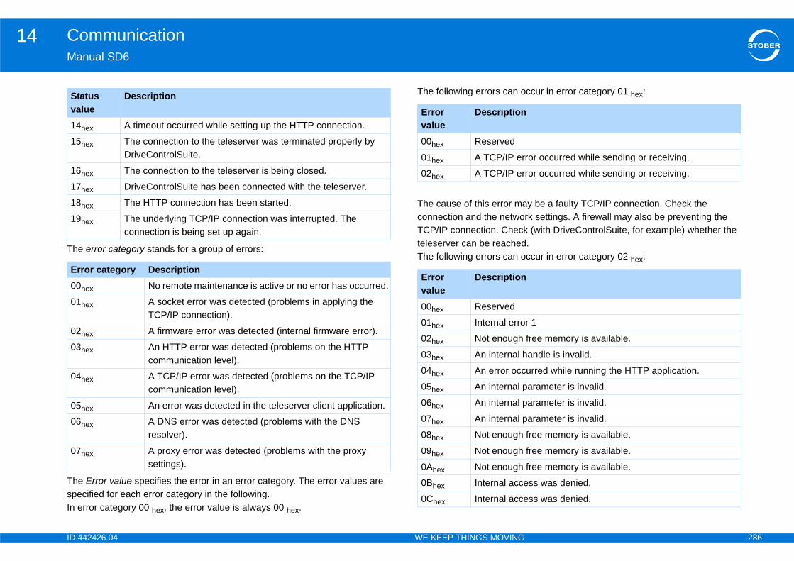
ID 4 286
Communication14Ma
The
ThespeIn e
ccur in error category 01 hex:
y be a faulty TCP/IP connection. Check the rk settings. A firewall may also be preventing the (with DriveControlSuite, for example) whether the .ccur in error category 02 hex:
14
15
16
17
18
19
Er00
01
02
03
04
05
06
07
Stva
ror occurred while sending or receiving.
ror occurred while sending or receiving.
r 1
free memory is available.
andle is invalid.
urred while running the HTTP application.
arameter is invalid.
arameter is invalid.
arameter is invalid.
free memory is available.
free memory is available.
free memory is available.
ss was denied.
ss was denied.
42426.04 WE KEEP THINGS MOVING
nual SD6
error category stands for a group of errors:
Error value specifies the error in an error category. The error values are cified for each error category in the following.rror category 00 hex, the error value is always 00 hex.
The following errors can o
The cause of this error maconnection and the netwoTCP/IP connection. Checkteleserver can be reachedThe following errors can o
hex A timeout occurred while setting up the HTTP connection.
hex The connection to the teleserver was terminated properly by DriveControlSuite.
hex The connection to the teleserver is being closed.
hex DriveControlSuite has been connected with the teleserver.
hex The HTTP connection has been started.
hex The underlying TCP/IP connection was interrupted. The connection is being set up again.
ror category Description
hex No remote maintenance is active or no error has occurred.
hex A socket error was detected (problems in applying the TCP/IP connection).
hex A firmware error was detected (internal firmware error).
hex An HTTP error was detected (problems on the HTTP communication level).
hex A TCP/IP error was detected (problems on the TCP/IP communication level).
hex An error was detected in the teleserver client application.
hex A DNS error was detected (problems with the DNS resolver).
hex A proxy error was detected (problems with the proxy settings).
atus lue
DescriptionError value
Description
00hex Reserved
01hex A TCP/IP er
02hex A TCP/IP er
Error value
Description
00hex Reserved
01hex Internal erro
02hex Not enough
03hex An internal h
04hex An error occ
05hex An internal p
06hex An internal p
07hex An internal p
08hex Not enough
09hex Not enough
0Ahex Not enough
0Bhex Internal acce
0Chex Internal acce
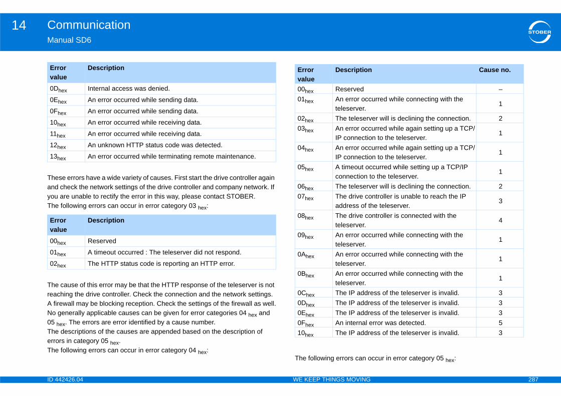
ID 4 287
Communication14Ma
TheandyouThe
ThereaA fiNo 05 TheerroThe
ccur in error category 05 hex:
0D
0E
0F
10
11
12
13
Erva00
01
02
Erva
Cause no.
–urred while connecting with the
1
er will is declining the connection. 2urred while again setting up a TCP/n to the teleserver.
1
urred while again setting up a TCP/n to the teleserver.
1
curred while setting up a TCP/IP o the teleserver.
1
er will is declining the connection. 2ntroller is unable to reach the IP e teleserver.
3
ntroller is connected with the 4
urred while connecting with the 1
urred while connecting with the 1
urred while connecting with the 1
ss of the teleserver is invalid. 3ss of the teleserver is invalid. 3ss of the teleserver is invalid. 3rror was detected. 5ss of the teleserver is invalid. 3
42426.04 WE KEEP THINGS MOVING
nual SD6
se errors have a wide variety of causes. First start the drive controller again check the network settings of the drive controller and company network. If are unable to rectify the error in this way, please contact STOBER. following errors can occur in error category 03 hex:
cause of this error may be that the HTTP response of the teleserver is not ching the drive controller. Check the connection and the network settings. rewall may be blocking reception. Check the settings of the firewall as well.generally applicable causes can be given for error categories 04 hex and hex. The errors are error identified by a cause number. descriptions of the causes are appended based on the description of rs in category 05 hex. following errors can occur in error category 04 hex:
The following errors can o
hex Internal access was denied.
hex An error occurred while sending data.
hex An error occurred while sending data.
hex An error occurred while receiving data.
hex An error occurred while receiving data.
hex An unknown HTTP status code was detected.
hex An error occurred while terminating remote maintenance.
ror lue
Description
hex Reserved
hex A timeout occurred : The teleserver did not respond.
hex The HTTP status code is reporting an HTTP error.
ror lue
Description Error value
Description
00hex Reserved01hex An error occ
teleserver.02hex The teleserv03hex An error occ
IP connectio04hex An error occ
IP connectio05hex A timeout oc
connection t06hex The teleserv07hex The drive co
address of th08hex The drive co
teleserver.09hex An error occ
teleserver.0Ahex An error occ
teleserver.0Bhex An error occ
teleserver.0Chex The IP addre0Dhex The IP addre0Ehex The IP addre0Fhex An internal e10hex The IP addre
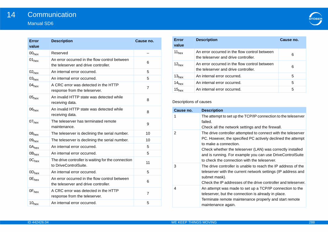
ID 4 288
Communication14Ma
Erva00
01
02
03
04
05
06
07
08
09
0A
0B
0C
0D
0E
0F
10
urred in the flow control between r and drive controller.
6
urred in the flow control between r and drive controller.
6
rror occurred. 5
rror occurred. 5
rror occurred. 5
ionpt to set up the TCP/IP connection to the teleserver
l the network settings and the firewall. controller attempted to connect with the teleserver ever, the specified PC actively declined the attempt connection.ether the teleserver (LAN) was correctly installed ning. For example you can use DriveControlSuite
the connection with the teleserver. controller is unable to reach the IP address of the r with the current network settings (IP address and ask).e IP addresses of the drive controller and teleserver.pt was made to set up a TCP/IP connection to the r, but the connection is already in place. remote maintenance properly and start remote nce again.
Cause no.
42426.04 WE KEEP THINGS MOVING
nual SD6
Descriptions of causes
ror lue
Description Cause no.
hex Reserved –
hex An error occurred in the flow control between the teleserver and drive controller.
6
hex An internal error occurred. 5
hex An internal error occurred. 5
hex A CRC error was detected in the HTTP response from the teleserver.
7
hex An invalid HTTP state was detected while receiving data.
8
hex An invalid HTTP state was detected while receiving data.
8
hex The teleserver has terminated remote maintenance.
9
hex The teleserver is declining the serial number. 10
hex The teleserver is declining the serial number. 10
hex An internal error occurred. 5
hex An internal error occurred. 5
hex The drive controller is waiting for the connection to DriveControlSuite.
11
hex An internal error occurred. 5
hex An error occurred in the flow control between the teleserver and drive controller.
6
hex A CRC error was detected in the HTTP response from the teleserver.
7
hex An internal error occurred. 5
11hex An error occthe teleserve
12hex An error occthe teleserve
13hex An internal e
14hex An internal e
15hex An internal e
Cause no. Descript1 The attem
failed.Check al
2 The drivePC. Howto make aCheck whand is runto check
3 The driveteleservesubnet mCheck th
4 An attemteleserveTerminatemaintena
Error value
Description
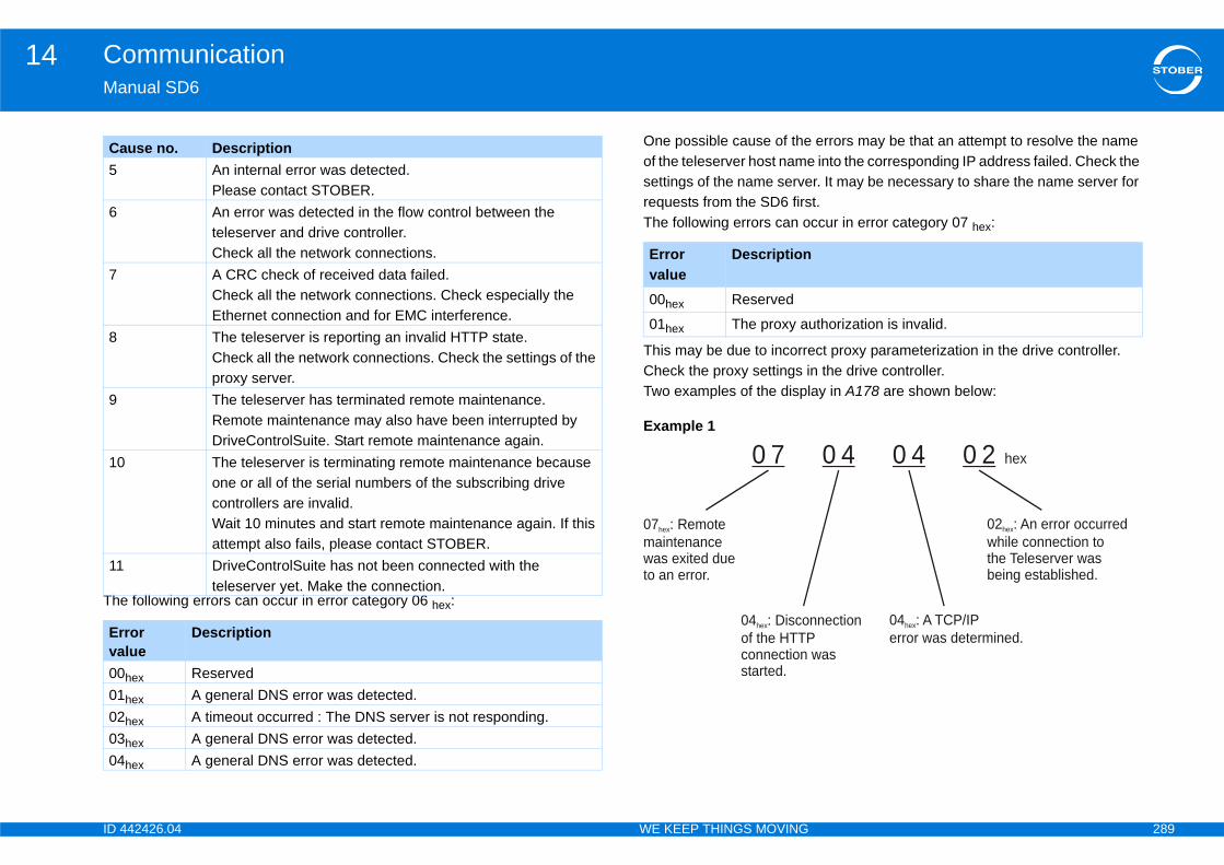
ID 4 289
Communication14Ma
The
errors may be that an attempt to resolve the name into the corresponding IP address failed. Check the r. It may be necessary to share the name server for t.ccur in error category 07 hex:
ct proxy parameterization in the drive controller. n the drive controller.ay in A178 are shown below:
5
6
7
8
9
10
11
Erva0001020304
Ca
thorization is invalid.
0 4 0 4 0 2 hex
02 : An error occurredwhile connection tothe Teleserver wasbeing established
hex
.
nnection
was
04 : A TCP/IPerror was determined
hex
.
42426.04 WE KEEP THINGS MOVING
nual SD6
following errors can occur in error category 06 hex:
One possible cause of theof the teleserver host namesettings of the name serverequests from the SD6 firsThe following errors can o
This may be due to incorreCheck the proxy settings iTwo examples of the displ
Example 1
An internal error was detected.Please contact STOBER.An error was detected in the flow control between the teleserver and drive controller.Check all the network connections.A CRC check of received data failed.Check all the network connections. Check especially the Ethernet connection and for EMC interference.The teleserver is reporting an invalid HTTP state.Check all the network connections. Check the settings of the proxy server.The teleserver has terminated remote maintenance.Remote maintenance may also have been interrupted by DriveControlSuite. Start remote maintenance again.The teleserver is terminating remote maintenance because one or all of the serial numbers of the subscribing drive controllers are invalid.Wait 10 minutes and start remote maintenance again. If this attempt also fails, please contact STOBER.DriveControlSuite has not been connected with the teleserver yet. Make the connection.
ror lue
Description
hex Reserved
hex A general DNS error was detected.
hex A timeout occurred : The DNS server is not responding.
hex A general DNS error was detected.
hex A general DNS error was detected.
use no. Description
Error value
Description
00hex Reserved
01hex The proxy au
0 7
07 : Remotemaintenancewas exited dueto an error
hex
.
04 : Discoof the HTTPconnection started
hex
.
ID 4 290
Communication14Ma
14
Ver1.
2.
eks. In case of doubt, the content of the order he supplier shall be binding for the Contract unless s contradicted the content of the order confirmation
ination, setting of deadlines and reminders by the equire the written form for their validity. Contractual undertakings, in particular those going beyond the eneral Terms and Conditions, shall require the
ten confirmation of the supplier. ates for fulfillment are not fixed dates unless they ssly declared as fixed dates by the supplier in stomer sets deadlines or periods of grace for sequent fulfillment or for remedying a situation, or periods must be reasonable, at least 5 working fruitless expiry of a deadline or grace period result of the contractual relationship or a reduction in the this must be expressly threatened by the Customer ting the deadline or grace period. The above ll require the written form for their validity.
ll be dictated by the order confirmation. Should the payment according to outlay, the outlay shall be ice or in a separate annex to the invoice. Should the
ntradict the evidenced outlay in writing within two (2) mer shall bear the burden of proof for the
the outlay. Additional services requested by the e invoiced on the basis of the supplier's price list. In ny other written agreement, the prices in the latest
42426.04 WE KEEP THINGS MOVING
nual SD6
.4.10 Terms and conditions for maintenance of the 6th STOBER generation of drive controllers
sion: 06/2013Scope of application1.1. The present maintenance terms shall apply exclusively to all
contractual relationships under which STÖBER ANTRIEBSTECHNIK GmbH & Co. KG (hereinafter referred to as supplier) carries out maintenance services on the SD6 drive controller for other companies, legal entities under public law or special funds under public law (hereinafter referred to as "Customer"). Contradictory and supplementary terms of the Customer shall not – other than with the prior written consent of Stöber Antriebstechnik – form part of the Contract, even if the supplier should undertake a contract or carry out services without expressly contradicting such terms.
1.2. These General Terms and Conditions cover the maintenance services for the SD6 drive controller offered by the supplier, such as the provision of standardized software updates, remote maintenance of the drive controllers by remote access, telephone support and maintenance services on site.
1.3. Furthermore, the Terms of Sale and Delivery of the supplier shall apply accordingly, whereby the maintenance terms shall take priority in the event of contradictions between the two documents.
Conclusion of Contract, Written Form, Time of Performance2.1. Quotations by the supplier are subject to confirmation and not binding
unless they have been expressly declared as a binding quotation. Orders from the Customer may be made informally by e-mail, telefax or telephone. The supplier can accept the orders from the Customer
within two (2) weconfirmation by tthe Customer hawithout delay.
2.2. All notices of termCustomer shall rguarantees and scope of these Gexpress and writDeadlines and dhave been exprewriting. If the Cufulfillment or subthese deadlines days. Should thein the dissolutionprice to be paid, at the time of setdeclarations sha
3. Payment3.1. The payment sha
Parties agree onshown in the invoCustomer not coweeks, the Custoincorrectness of Customer shall bthe absence of a
ID 4 291
Communication14Ma
4.
urthermore, modifications to and editing of the ation, reverse engineering, decoding, translation, the prior written authorization of the supplier.
as supplied to the Customer electronically, any software by the Customer to third parties – whether yment – shall not be permitted without the prior tion of the supplier.nts the rights of use to the software initially only t to a condition precedent of complete remuneration can, in the event of a delay in payment and after f a reasonable grace period, revoke the granting of to the extent to which no remuneration or payment d.
updates to the Customer electronically or shall offer ding on the company's website. A physical data de and the installation on the Customer's premises ates can contain additional functions, whereby the o claim to the implementation of specific functions updates. The supplier shall thus decide alone on the ncy of updates for the software of the supplier. In all ions of § 4 shall apply analogously.
ftwaren, the software supplied must be adequately tested ontractual software and the documentation supplied ediately on receipt and any faults discovered
iting. § 377 German Commercial Code (HGB) shall
42426.04 WE KEEP THINGS MOVING
nual SD6
price list of the supplier shall apply, according to which services are invoiced according to person-days and hours plus the expenses incurred.
3.2. In the event of an unjustified notification of defects, the supplier can invoice the Customer for the time taken for the troubleshooting on the basis of the current price list, in particular if the Customer reports a fault that cannot be demonstrable or reproducible, or if the fault is not attributable to the supplier.
Rights to Software4.1. All intellectual property rights to the software supplied to the
Customer and to the work results, including the documentation (e.g. copyrights, trademark rights, technical property rights), in the relationship with the Customer shall be due to the supplier, even if and insofar as the work results are obtained on the basis of the specifications from or in cooperation with the Customer. The supplier grants the Customer a simple, non-exclusive right of use to the software supplied. The Customer shall only be entitled to use the software for its own purposes in conjunction with the SD6 drive controller.
4.2. The Customer may make the requisite number of backup copies of the software, all of which, however, must bear the supplier copyright mark and subsequently be kept safely. The Customer may decompile the software and parts thereof (such as interface information) only within the limitation of § 69e German Copyright Act (UrhG) and only when this intention is notified to the supplier in writing with a reasonable period of notice for provision of the necessary information. Information on the source code shall thereby be subject to the strictest confidentiality, irrespective of whether it was provided by the supplier or a third party or became known during the course of
decompilation. Fsoftware (modificetc.) shall require
4.3. If the software wpassing on of theor not against pawritten authoriza
4.4. The supplier grarevocably subjecor payment and fruitless expiry othe rights of use has been receive
5. UpdatesThe supplier shall sendthe update for downloamedium, the source coare not owed. The updCustomer shall have nwithin the scope of the type, scope and frequeother points, the provis
6. Testing of Supplied SoBefore use in productioby the Customer. The cmust be examined immreported in detail in wr
ID 4 292
Communication14Ma
7.
8.
r, if the session ID method is selected, the mporarily valid session ID by telephone and then number to the remote access server.enance process, the Customer must ensure the and equipment by clearing and cordoning off the
d slewing circle or danger zone of the machine axes drive controller. The maintenance and the safety t be carried out and monitored on the Customer's ian familiar with and trained in the operation of the n particular with the SD6 manual and these ms. The supplier assumes no liability for any from the failure to observe these safety
e process will be started by the supplier only when the remote access, a telephone connection to the and adequate safety precautions are verified by the the corresponding notification, the telephone be recorded by the supplier. The technician must e and family name, and verify the establishment
of the personal and equipment safety.onversation will be stored by the supplier for urposes. The recording will not be used by third tomer must therefore obtain the consent of his recording and storage.f the maintenance process, the Customer must first mote maintenance and establish the safety of the ns of a test run. Only after a succcessful test run is process concluded so that the Customer can then he danger zone of the machine again.
42426.04 WE KEEP THINGS MOVING
nual SD6
apply. If no such immediate notice is given, the service shall be regarded as having been approved, except in cases of non-recognizable faults. Should such a fault be discovered later, notice of the fault must be given immediately on discovery of this fault, otherwise the service shall be regarded as having been approved also with regard to this fault. If the supplier has fraudulently concealed the fault, the supplier may not claim a failure to notify or delayed notification of the fault by the Customer.
Customer Hotline7.1. The supplier shall provide a 24 h customer hotline for the Customer.
The supplier receives fault reports and orders via this hotline and passes them on to the responsible service technicians. The hotline serves furthermore to support the Customer through telephone advice on remedying faults, avoiding faults and working around faults. A fault elimination guarantee and reaction or recovery times are neither assured nor owed.
7.2. Further maintenance and support services (e.g. on site) shall only be provided on the basis of a separate order and shall be invoiced according to time on the basis of the supplier price list valid at the time of the placement of the order.
Remote maintenance8.1. If the Customer places an order with STÖBER ANTRIEBSTECHNIK
for the remote maintenance of the drive controller, a date for the maintenance will be agreed with the Customer. The remote access is effected via an Internet connection set up by the Customer in accordance with the SD6 manual of the remote access server. For this the Customer must inform the supplier of the serial number of the
drive controller ocorresponding tealso validate the
8.2. Before the maintsafety of personswhole turning ancontrolled by theprecautions musside by a technicdrive controller, imaintenance terdamage resultingprecautions.
8.3. The maintenancafter establishingCustomer exists Customer. After conversation willstate his first namand maintaining
8.4. The telephone cdocumentation pparties. The Cusemployee for the
8.5. Before the end odeactivate the remachine by meathe maintenanceallow access to t

ID 4 293
Communication14Ma
9.
ration of the Customer shall be at no expense to EBSTECHNIK.
Title of the Software Delivery of the supplier shall apply to all defects in r providing a service, the supplier supplies the oftware version to remedy defects in quality and title, ept this new software version in order to maintain ofar as the acceptance is not unreasonable.
uitable for acceptance testing and for all services for e testing has been agreed, the supplier may declaration of acceptance from the Customer or the f an acceptance protocol immediately after a pleted acceptance test. Individual services that can dently of one another shall be accepted separately.ptance testing is carried out pursuant to 11.1, the nspect the results of the work within one month and e acceptance or notify STÖBER
NIK in detail and in writing of any faults discovered. se of the work results in production shall be deemed nce.
ess relationship between the supplier and the e subject to the law of the Federal Republic of exclusion of the UN Sales Convention and the ate international law. Place of fulfillment and venue
42426.04 WE KEEP THINGS MOVING
nual SD6
8.6. The remote maintenance by remote access is linked to IT security measures, such as the session ID method, the use of which is decided upon exclusively by the Customer. The supplier is responsible only for its own observance of the IT security measures offered and selected by the Customer. The Customer decides also on the selection of the connection of the drive controller to the remote access server of the supplier and bears the sole responsibility for its establishment, maintenance and security.
Other Cooperation Obligations of the Customer9.1. The Customer shall report malfunctions, errors and damage without
delay. The report must furthermore describe the symptoms of the fault so precisely that the supplier is able to support the Customer in the purposeful remedying of the fault.
9.2. The Customer shall bear the responsibility for a regular data backup and the IT security in accordance with the state-of-the-art. The supplier may assume that all data with which employees of the supplier come into contact have been previously backed up elsewhere by the Customer.
9.3. The warranty of quality and liability do not cover faults or damage resulting from the use of the software in a hardware and software environment that does not meet the technical requirements.
9.4. Further cooperation obligations of the Customer result from the individual order and from the general obligation to maintain safety and the duty to take due care. The risk of damage in the event of infringements of the cooperation obligation must be borne by the Customer. The supplier shall not be responsible for monitoring whether the Customer complies with the cooperation obligations.
9.5. The whole coopeSTÖBER ANTRI
10. Defects in Quality andThe Terms of Sale andquality and title. If, afteCustomer with a new sthe Customer shall accthe warranty rights, ins
11. Acceptance11.1. For all services s
which acceptancdemand a writtencountersigning osuccessfully combe used indepen
11.2. If no formal acceCustomer shall ieither declare thANTRIEBSTECHThe unqualified uto be an accepta
12. Final Provisions12.1. The whole busin
Customer shall bGermany, to the provisions of priv
ID 4 294
Communication14Ma
42426.04 WE KEEP THINGS MOVING
nual SD6
for all disputes arising out of and/or in conjunction with this Contract shall the registered offices of the supplier. In the event of legal disputes, the supplier can also opt to take action at the Customer's general venue.
12.2. The Customer warrants to have established all necessary preconditions in order that the supplier can carry out the agreed services without infringement of the provision of data protection law.
12.3. Amendments and supplements to the contracts between the supplier and the Customer must be made in written form for their validity. A notification in text form (e.g. e-mail) shall also be sufficient to meet the written form requirement unless the receiving party insists on notification in written form.
12.4. Should any of the above provisions be or become invalid or unenforceable, this shall not affect the validity or enforceability of the other provisions. The Contract parties shall make efforts to replace the invalid or unenforceable provision with a valid and enforceable provision coming as close as possible to the business intention of the original invalid or unforceable provision.
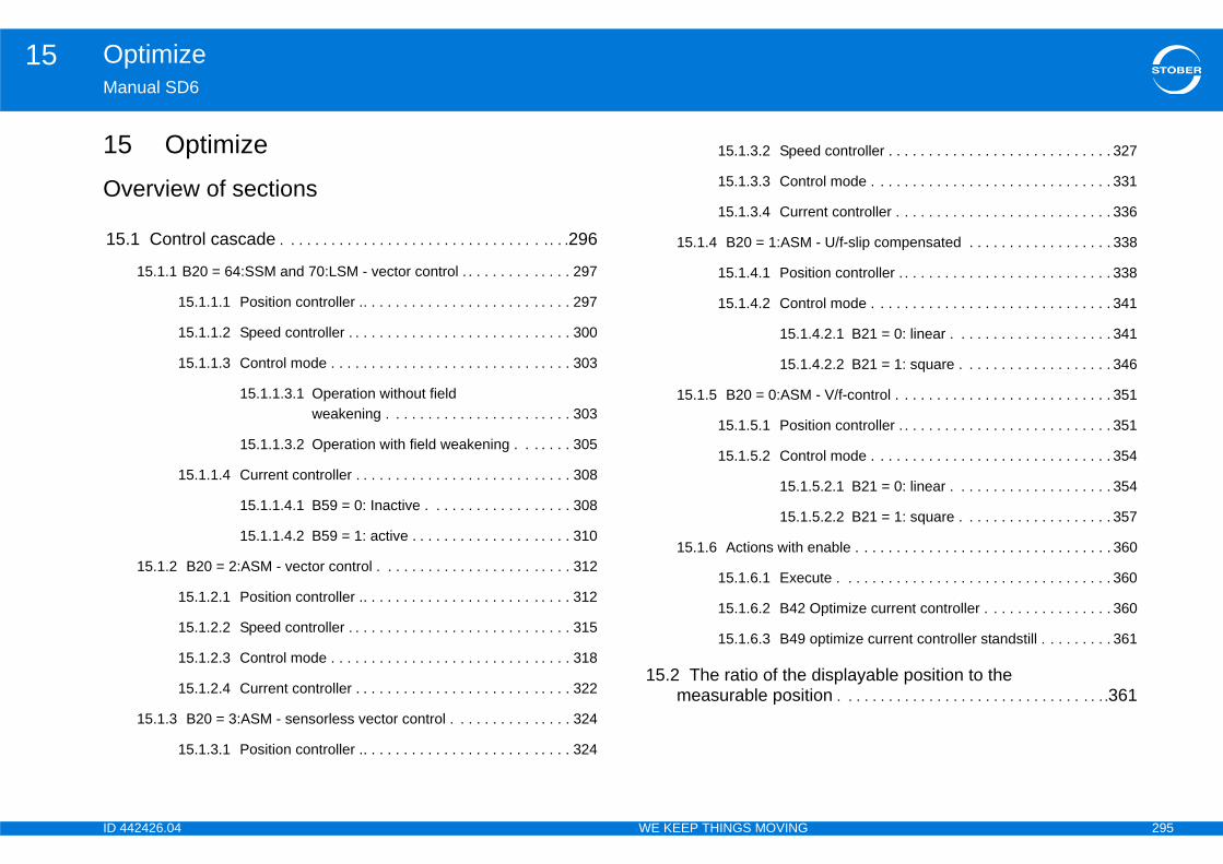
ID 4 295
Optimize15Ma
15Ov
15
d controller . . . . . . . . . . . . . . . . . . . . . . . . . . . . 327
rol mode . . . . . . . . . . . . . . . . . . . . . . . . . . . . . . 331
nt controller . . . . . . . . . . . . . . . . . . . . . . . . . . . 336
- U/f-slip compensated . . . . . . . . . . . . . . . . . . 338
ion controller . . . . . . . . . . . . . . . . . . . . . . . . . . . 338
rol mode . . . . . . . . . . . . . . . . . . . . . . . . . . . . . . 341
4.2.1 B21 = 0: linear . . . . . . . . . . . . . . . . . . . . 341
4.2.2 B21 = 1: square . . . . . . . . . . . . . . . . . . . 346
- V/f-control . . . . . . . . . . . . . . . . . . . . . . . . . . . 351
ion controller . . . . . . . . . . . . . . . . . . . . . . . . . . . 351
rol mode . . . . . . . . . . . . . . . . . . . . . . . . . . . . . . 354
5.2.1 B21 = 0: linear . . . . . . . . . . . . . . . . . . . . 354
5.2.2 B21 = 1: square . . . . . . . . . . . . . . . . . . . 357
nable . . . . . . . . . . . . . . . . . . . . . . . . . . . . . . . . 360
ute . . . . . . . . . . . . . . . . . . . . . . . . . . . . . . . . . . 360
Optimize current controller . . . . . . . . . . . . . . . . 360
optimize current controller standstill . . . . . . . . . 361
displayable position to the ion . . . . . . . . . . . . . . . . . . . . . . . . . . . . . . . . . .361
42426.04 WE KEEP THINGS MOVING
nual SD6
Optimizeerview of sections
.1 Control cascade . . . . . . . . . . . . . . . . . . . . . . . . . . . . . . . . . . . .296
15.1.1 B20 = 64:SSM and 70:LSM - vector control . . . . . . . . . . . . . . 297
15.1.1.1 Position controller .. . . . . . . . . . . . . . . . . . . . . . . . . . 297
15.1.1.2 Speed controller . . . . . . . . . . . . . . . . . . . . . . . . . . . . 300
15.1.1.3 Control mode . . . . . . . . . . . . . . . . . . . . . . . . . . . . . . 303
15.1.1.3.1 Operation without field weakening . . . . . . . . . . . . . . . . . . . . . . . 303
15.1.1.3.2 Operation with field weakening . . . . . . . 305
15.1.1.4 Current controller . . . . . . . . . . . . . . . . . . . . . . . . . . . 308
15.1.1.4.1 B59 = 0: Inactive . . . . . . . . . . . . . . . . . . 308
15.1.1.4.2 B59 = 1: active . . . . . . . . . . . . . . . . . . . . 310
15.1.2 B20 = 2:ASM - vector control . . . . . . . . . . . . . . . . . . . . . . . . 312
15.1.2.1 Position controller .. . . . . . . . . . . . . . . . . . . . . . . . . . 312
15.1.2.2 Speed controller . . . . . . . . . . . . . . . . . . . . . . . . . . . . 315
15.1.2.3 Control mode . . . . . . . . . . . . . . . . . . . . . . . . . . . . . . 318
15.1.2.4 Current controller . . . . . . . . . . . . . . . . . . . . . . . . . . . 322
15.1.3 B20 = 3:ASM - sensorless vector control . . . . . . . . . . . . . . . 324
15.1.3.1 Position controller .. . . . . . . . . . . . . . . . . . . . . . . . . . 324
15.1.3.2 Spee
15.1.3.3 Cont
15.1.3.4 Curre
15.1.4 B20 = 1:ASM
15.1.4.1 Posit
15.1.4.2 Cont
15.1.
15.1.
15.1.5 B20 = 0:ASM
15.1.5.1 Posit
15.1.5.2 Cont
15.1.
15.1.
15.1.6 Actions with e
15.1.6.1 Exec
15.1.6.2 B42
15.1.6.3 B49
15.2 The ratio of the measurable posit

ID 4 296
Optimize15Ma
15Thereq
TheYou
Wh
•
•
•
42426.04 WE KEEP THINGS MOVING
nual SD6
.1 Control cascade control cascade generates the appropriate control of the motor for a
uired movement.
structure of the control cascade depends on the control mode set in B20. can find this structure in the sections that follow.
en optimizing the control cascade, note the following points
The display of the control cascade follows the signal curve: From position controller to current controller. However, optimization should be in the opposite order: From current controller to position controller.
Before optimization, especially for third-party motors, perform action B41 autotuning (see section 10.2.3.3).
Before manual current controller optimization perform actions B42 optimize current controller(see section 15.1.6.2) and B49 optimize current controller standstill (see section 15.1.6.3).

ID 4 297
Optimize15Ma
15
15
E07
N(M
42426.04 WE KEEP THINGS MOVING
nual SD6
.1.1 B20 = 64:SSM and 70:LSM - vector control
.1.1.1 Position controller
Limit
-I10 I10
Low pass
C33
x-ref from profilegenerator
I80
I84
Deadband
I23
P controller
I20
v-ref from profilegenerator
E161
I25
ot for motion commands without position controlOVE_SPEED and MOVE_TORQUE)

ID 4 298
Optimize15Ma
Refvalu
DisprooutPossha
Thecon
Ma••
TrigI10TheFroE91
response only). The Kv factor is also referred to as
cated with a unit of measure [m/min/mm]. This is · I20.
controller. Useful for avoiding idle oscillations versal, especially if an external position encoder is
ust be less than positioning window I22. Otherwise target position.
e position controller.file is switched to the output of the position
s the load on the position controller, thereby r.
ve moves at a constant speed without a stationary tend to overshoot at the target position. Because of n is in the range of 60 ... 95 %., overshooting in the target position can also 32 (time constant I-part).
C3
E0
E1
I10
roportional gain position control) version 0
position control version 0
forward version 0
42426.04 WE KEEP THINGS MOVING
nual SD6
erence value smoothing. C33 should be increased in response to reference e noise, vibrating mechanics or large extraneous weights.
play of the current speed reference value (RV) in user units based on the file generator and the v-RV low pass. The total of the position controller put and speedFeedFwd (=speed controller reference value) is displayed in ition operating mode. E06 shows the same value in reference to the motor ft.
speed reference value at the output of the profile generator. With position trol corresponds to the speed feed forward.
ximum velocity as a limit forCiA 402 Homing mode: A587CiA 402 Jogging mode: I12
gering limit for event 56:Overspeed: x 1.111 > measured velocity. measured velocity is equivalent to I88.m firmware 6.0-B: If the motor and position encoder are separated, I88 and x I240[1] are checked.
Position controller gain (P-the speed gain.Occasionally it is also indiequivalent to exactly 0.06
Dead zone of the position resulting from friction or reused.
Note that I23 deadband mthe drive will not reach its
Velocity feed forward of thThe calculated velocity procontroller.
Speed feed forward relievereducing the following erro
When I25 = 100 %, the drifollowing error, but it does this, I25 in most applicatioIn addition to reducing I25alleviated by increasing C
3 lowpass reference speed version 0
7 ref speed for v controller version 0
61 v-rmpg version 0
maximal speed version 0
InformationThe limit is set without event 54:following error occurring.
I20 Kv-factor (p
I23 deadband
I25 speed feed
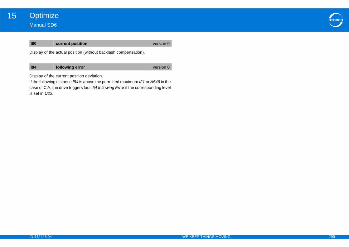
ID 4 299
Optimize15Ma
Dis
DisIf thcasis s
I80
I84
42426.04 WE KEEP THINGS MOVING
nual SD6
play of the actual position (without backlash compensation).
play of the current position deviation.e following distance I84 is above the permitted maximum I21 or A546 in the e of CiA, the drive triggers fault 54 following Error if the corresponding level et in U22.
current position version 0
following error version 0
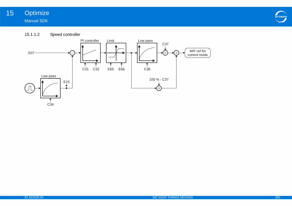
ID 4 300
Optimize15Ma
15
F-ref fortrol modeE
42426.04 WE KEEP THINGS MOVING
nual SD6
.1.1.2 Speed controllerLimit
E65 E66
Low pass
C36
E15
PI controller
C31
M/con07
Low pass
C34
C32
C37
100 % - C37
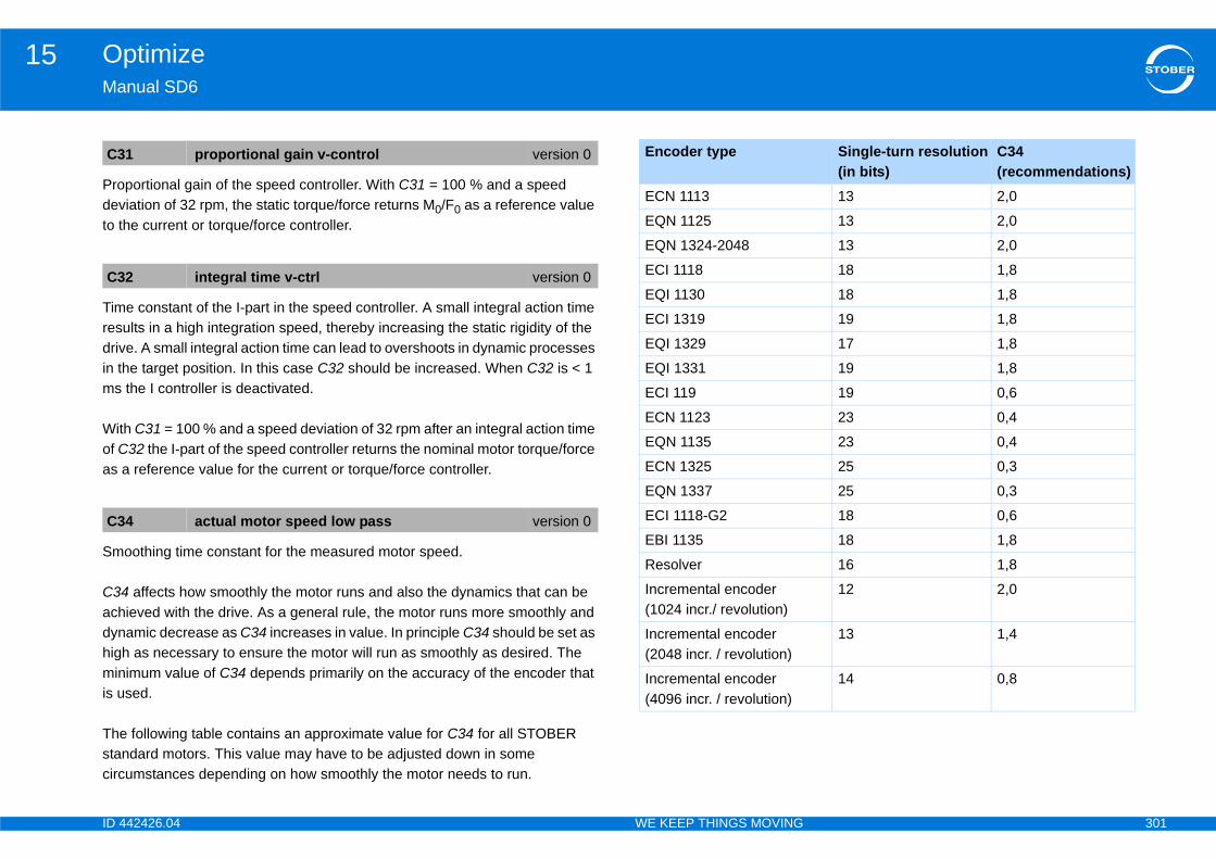
ID 4 301
Optimize15Ma
Prodevto t
Timresdrivin tms
Witof Cas
Sm
C34achdynhigminis u
Thestacirc
C3
C3
C3
Single-turn resolution(in bits)
C34 (recommendations)
13 2,0
13 2,0
13 2,0
18 1,8
18 1,8
19 1,8
17 1,8
19 1,8
19 0,6
23 0,4
23 0,4
25 0,3
25 0,3
18 0,6
18 1,8
16 1,8
12 2,0
13 1,4
14 0,8
42426.04 WE KEEP THINGS MOVING
nual SD6
portional gain of the speed controller. With C31 = 100 % and a speed iation of 32 rpm, the static torque/force returns M0/F0 as a reference value he current or torque/force controller.
e constant of the I-part in the speed controller. A small integral action time ults in a high integration speed, thereby increasing the static rigidity of the e. A small integral action time can lead to overshoots in dynamic processes
he target position. In this case C32 should be increased. When C32 is < 1 the I controller is deactivated.
h C31 = 100 % and a speed deviation of 32 rpm after an integral action time 32 the I-part of the speed controller returns the nominal motor torque/force
a reference value for the current or torque/force controller.
oothing time constant for the measured motor speed.
affects how smoothly the motor runs and also the dynamics that can be ieved with the drive. As a general rule, the motor runs more smoothly and amic decrease as C34 increases in value. In principle C34 should be set as
h as necessary to ensure the motor will run as smoothly as desired. The imum value of C34 depends primarily on the accuracy of the encoder that sed.
following table contains an approximate value for C34 for all STOBER ndard motors. This value may have to be adjusted down in some umstances depending on how smoothly the motor needs to run.
1 proportional gain v-control version 0
2 integral time v-ctrl version 0
4 actual motor speed low pass version 0
Encoder type
ECN 1113
EQN 1125
EQN 1324-2048
ECI 1118
EQI 1130
ECI 1319
EQI 1329
EQI 1331
ECI 119
ECN 1123
EQN 1135
ECN 1325
EQN 1337
ECI 1118-G2
EBI 1135
Resolver
Incremental encoder (1024 incr./ revolution)
Incremental encoder (2048 incr. / revolution)
Incremental encoder(4096 incr. / revolution)
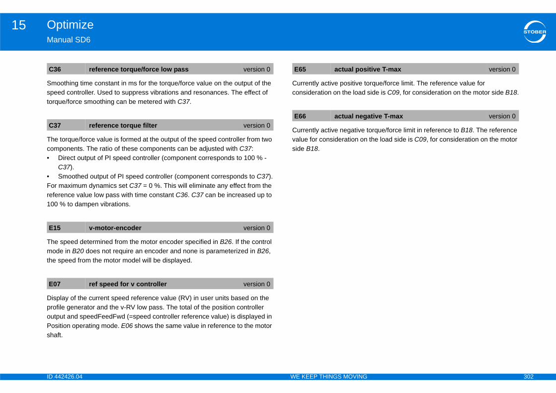
ID 4 302
Optimize15Ma
Smspetorq
Thecom•
•Forrefe100
Themothe
DisprooutPossha
rque/force limit. The reference value for ide is C09, for consideration on the motor side B18.
orque/force limit in reference to B18. The reference the load side is C09, for consideration on the motor
C3
C3
E1
E0
tive T-max version 0
tive T-max version 0
42426.04 WE KEEP THINGS MOVING
nual SD6
oothing time constant in ms for the torque/force value on the output of the ed controller. Used to suppress vibrations and resonances. The effect of ue/force smoothing can be metered with C37.
torque/force value is formed at the output of the speed controller from two ponents. The ratio of these components can be adjusted with C37:Direct output of PI speed controller (component corresponds to 100 % - C37).Smoothed output of PI speed controller (component corresponds to C37). maximum dynamics set C37 = 0 %. This will eliminate any effect from the rence value low pass with time constant C36. C37 can be increased up to % to dampen vibrations.
speed determined from the motor encoder specified in B26. If the control de in B20 does not require an encoder and none is parameterized in B26, speed from the motor model will be displayed.
play of the current speed reference value (RV) in user units based on the file generator and the v-RV low pass. The total of the position controller put and speedFeedFwd (=speed controller reference value) is displayed in ition operating mode. E06 shows the same value in reference to the motor ft.
Currently active positive toconsideration on the load s
Currently active negative tvalue for consideration on side B18.
6 reference torque/force low pass version 0
7 reference torque filter version 0
5 v-motor-encoder version 0
7 ref speed for v controller version 0
E65 actual posi
E66 actual nega

ID 4 303
Optimize15Ma
1515.
NumIf thmuCornom
pplied to the motor.
m the motor encoder specified in B26. If the control uire an encoder and none is parameterized in B26, model will be displayed.
e or force as a percentage. Unsmoothed, in contrast e for consideration on the load side is C09, for r side B18.
r speed. Unsmoothed, in contrast to E08. If the drive ck, this speed is determined by calculations using
al motor speed may differ in this case from the
in amps.
gnetization current.
B1
pe
E15
E93
version 0
coder version 0
ue/ force version 0
version 0
version 0
version 0
42426.04 WE KEEP THINGS MOVING
nual SD6
.1.1.3 Control mode1.1.3.1 Operation without field weakening
ber of poles of a synchronous servo motor or asynchronous motor.e number of pole pairs is specified for third-party motors, the value must be ltiplied by 2 before it is entered.relation between the number of poles, nominal speed nN in rpms and the inal frequency fN in Hz of the motor: B10 = 2·(fN · 60/nN).
Frequency of the voltage a
The speed determined fromode in B20 does not reqthe speed from the motor
Display of the current torquto E02. The reference valuconsideration on the moto
Display of the current motois operated without feedbathe motor model (the actucalculated speed).
Torque generating current
Reference value of the ma
0 motor-poles version 0
E172
E166
E170M/F-ref for
speed controller
Maximumrmitted current
Maximumpermitted torque
n f
E91
B10
E172
E172
0 E165
E05
E90
E05 f1-Motor
E15 v-motor-en
E90 actual torq
E91 v-motor
E93 I-q
E165 Id-ref
ID 4 304
Optimize15Ma
Ref
Forforccon
(Int
E1
E1
E1
42426.04 WE KEEP THINGS MOVING
nual SD6
erence value for the torque generating current as a A.
control modes with torque specification only. Reference torque or reference e currently required by the speed controller. The reference value for sideration on the load side is C09, for consideration on the motor side B18.
ernally) calculated torque generating nominal current.
66 Iq-ref version 0
70 T-reference version 0
72 Iq-nominal version 0

ID 4 305
Optimize15Ma
15.
E0
E0
pe
rque
E1
E9 E90
E05
E165
E166
42426.04 WE KEEP THINGS MOVING
nual SD6
1.1.3.2 Operation with field weakening
E172
E170M/F-ref for
speed controller
Field weakeningcontrol
3
B92
4
Limit
Maximumrmitted current
Current limit Maximumpermitted to
Limit
E65 E66
0
n f
E91
B10
5
E172
3
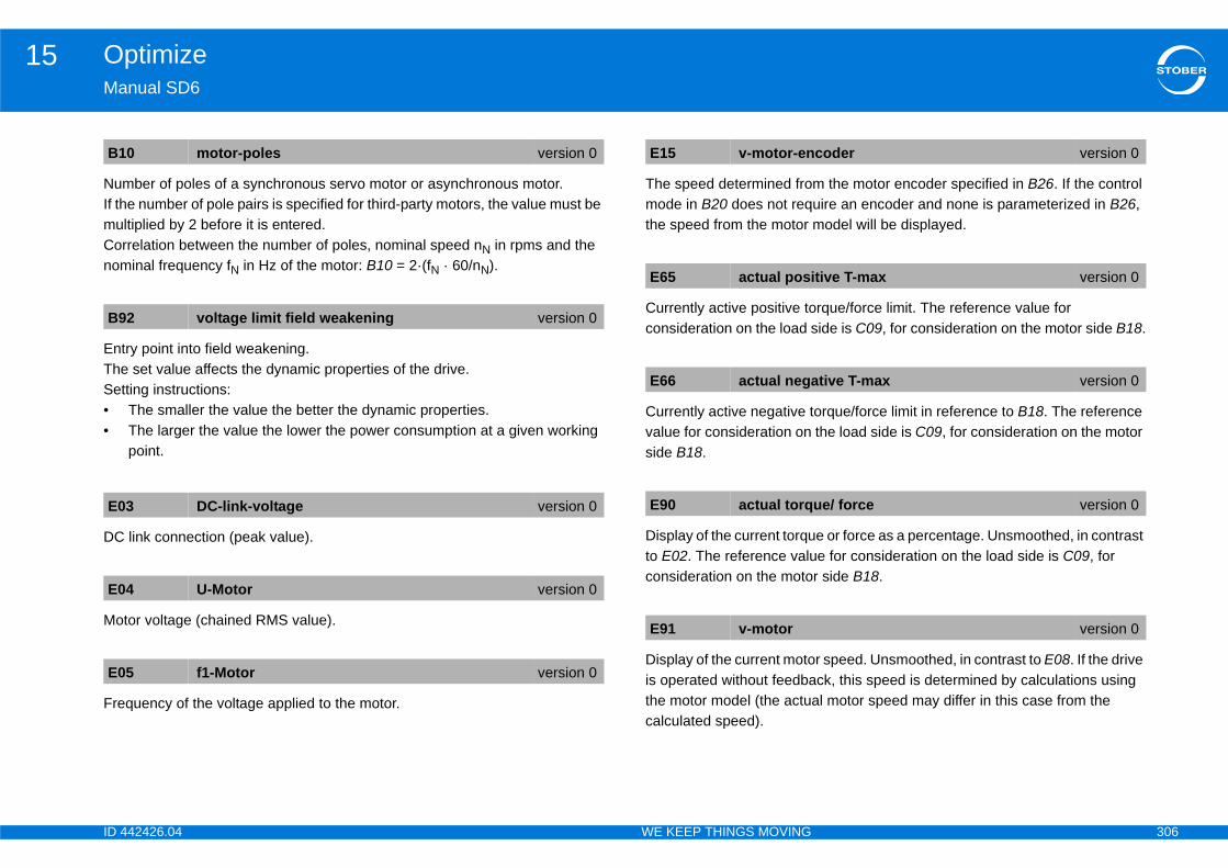
ID 4 306
Optimize15Ma
NumIf thmuCornom
EntTheSet••
DC
Mo
Fre
m the motor encoder specified in B26. If the control uire an encoder and none is parameterized in B26, model will be displayed.
rque/force limit. The reference value for ide is C09, for consideration on the motor side B18.
orque/force limit in reference to B18. The reference the load side is C09, for consideration on the motor
e or force as a percentage. Unsmoothed, in contrast e for consideration on the load side is C09, for r side B18.
r speed. Unsmoothed, in contrast to E08. If the drive ck, this speed is determined by calculations using l motor speed may differ in this case from the
B1
B9
E0
E0
E0
coder version 0
tive T-max version 0
tive T-max version 0
ue/ force version 0
version 0
42426.04 WE KEEP THINGS MOVING
nual SD6
ber of poles of a synchronous servo motor or asynchronous motor.e number of pole pairs is specified for third-party motors, the value must be ltiplied by 2 before it is entered.relation between the number of poles, nominal speed nN in rpms and the inal frequency fN in Hz of the motor: B10 = 2·(fN · 60/nN).
ry point into field weakening. set value affects the dynamic properties of the drive.ting instructions:The smaller the value the better the dynamic properties.The larger the value the lower the power consumption at a given working point.
link connection (peak value).
tor voltage (chained RMS value).
quency of the voltage applied to the motor.
The speed determined fromode in B20 does not reqthe speed from the motor
Currently active positive toconsideration on the load s
Currently active negative tvalue for consideration on side B18.
Display of the current torquto E02. The reference valuconsideration on the moto
Display of the current motois operated without feedbathe motor model (the actuacalculated speed).
0 motor-poles version 0
2 voltage limit field weakening version 0
3 DC-link-voltage version 0
4 U-Motor version 0
5 f1-Motor version 0
E15 v-motor-en
E65 actual posi
E66 actual nega
E90 actual torq
E91 v-motor
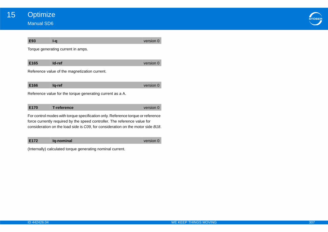
ID 4 307
Optimize15Ma
Tor
Ref
Ref
Forforccon
(Int
E9
E1
E1
E1
E1
42426.04 WE KEEP THINGS MOVING
nual SD6
que generating current in amps.
erence value of the magnetization current.
erence value for the torque generating current as a A.
control modes with torque specification only. Reference torque or reference e currently required by the speed controller. The reference value for sideration on the load side is C09, for consideration on the motor side B18.
ernally) calculated torque generating nominal current.
3 I-q version 0
65 Id-ref version 0
66 Iq-ref version 0
70 T-reference version 0
72 Iq-nominal version 0

ID 4 308
Optimize15Ma
1515.
ChadrivBecat ichadisp
ontroller for the torque/ force-generating part in ms. result in an integral gain of 0 (equivalent to an infinite
rque/ force controller.
ontroller for the flow generating part in ms. A setting an integral gain of 0 (equivalent to an infinite action
w controller.
B2
E16
E16
setting of this parameter depends on B20. When ctor control is selected, a value of 8:8kHz is entered asynchronous machine is used (ASM - V/f-control, ip compensated, ASM - sensorless vector control or r control), a value of 4:4kHz is assigned to B24.
B20 = 64:SSM - vector control then you should set z for better controller performance.
e torque/force controller version 0
al gain torque/force controller version 0
e Id version 0
al gain flux version 0
42426.04 WE KEEP THINGS MOVING
nual SD6
.1.1.4 Current controller1.1.4.1 B59 = 0: Inactive
nging the clock frequency affects the amount of noise produced by the e. However, increasing the clock frequency results in increased losses. ause of this, the admissible nominal motor current (B12) must be reduced
ncreased clock frequency. In some operating states the clock frequency is nged by the drive controller itself. The currently active clock frequency is layed in E151.
Action time of the current cA setting below 0.3 ms will action time).
Proportional gain of the to
Action time of the current cbelow 0.3 ms will result in time).
Proportional gain of the flo
4 switching frequency version 0
5
E92
PID controller
B64 B65 B68
E98
PWM
B24
M
6
E93
PID controller
B66 B67 B68
E99
InformationThe factory 64:SSM - vein B24. If anASM - V/f-slASM - vecto
InformationNote that if B24 = 8:8kH
B64 integral tim
B65 proportion
B66 integral tim
B67 proportion
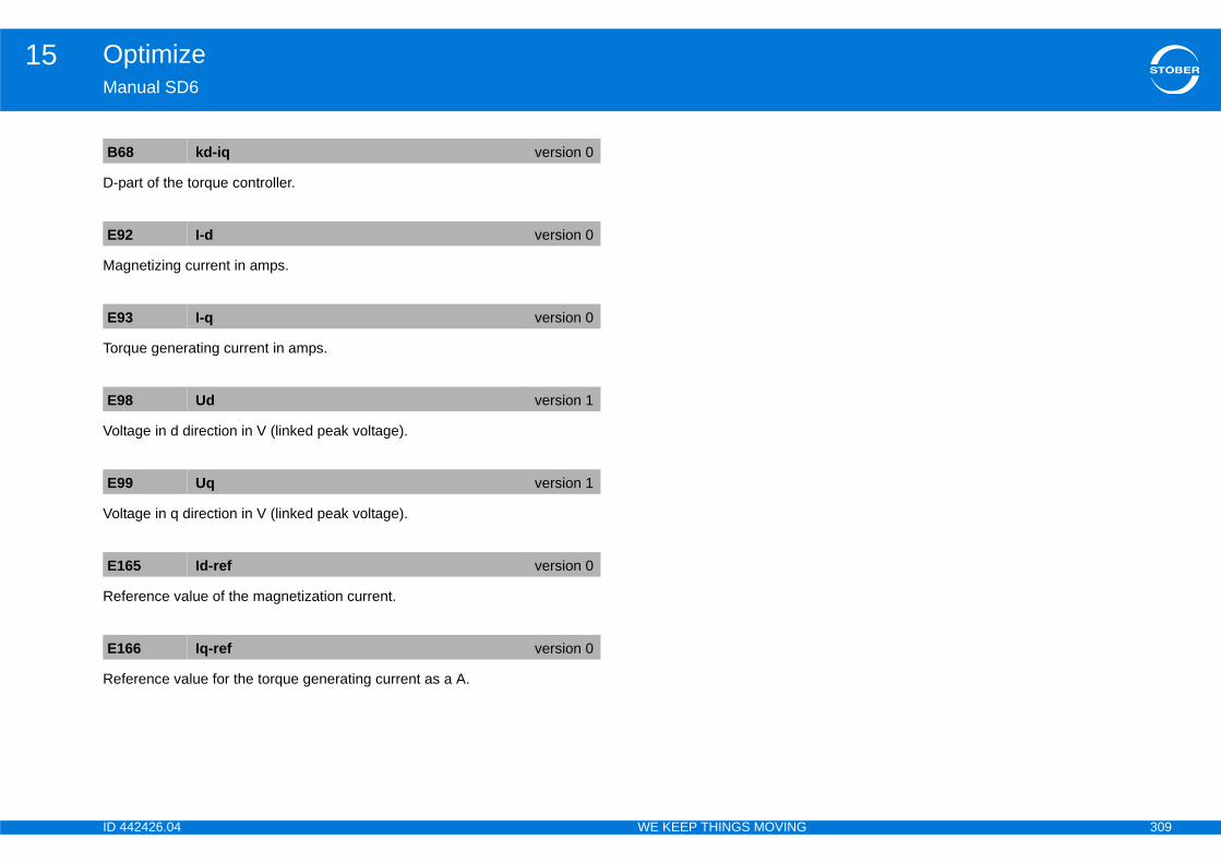
ID 4 309
Optimize15Ma
D-p
Ma
Tor
Vol
Vol
Ref
Ref
B6
E9
E9
E9
E9
E1
E1
42426.04 WE KEEP THINGS MOVING
nual SD6
art of the torque controller.
gnetizing current in amps.
que generating current in amps.
tage in d direction in V (linked peak voltage).
tage in q direction in V (linked peak voltage).
erence value of the magnetization current.
erence value for the torque generating current as a A.
8 kd-iq version 0
2 I-d version 0
3 I-q version 0
8 Ud version 1
9 Uq version 1
65 Id-ref version 0
66 Iq-ref version 0
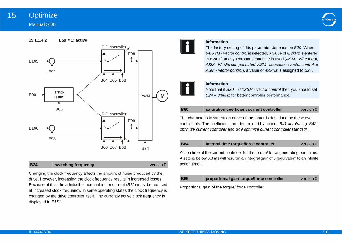
ID 4 310
Optimize15Ma
15.
ChadrivBecat ichadisp
on curve of the motor is described by these two ts are determined by actions B41 autotuning, B42 and B49 optimize current controller standstill.
ontroller for the torque/ force-generating part in ms. result in an integral gain of 0 (equivalent to an infinite
rque/ force controller.
B2
E16
E16
E00
setting of this parameter depends on B20. When ctor control is selected, a value of 8:8kHz is entered asynchronous machine is used (ASM - V/f-control, ip compensated, ASM - sensorless vector control or r control), a value of 4:4kHz is assigned to B24.
B20 = 64:SSM - vector control then you should set z for better controller performance.
coefficient current controller version 0
e torque/force controller version 0
al gain torque/force controller version 0
42426.04 WE KEEP THINGS MOVING
nual SD6
1.1.4.2 B59 = 1: active
nging the clock frequency affects the amount of noise produced by the e. However, increasing the clock frequency results in increased losses. ause of this, the admissible nominal motor current (B12) must be reduced
ncreased clock frequency. In some operating states the clock frequency is nged by the drive controller itself. The currently active clock frequency is layed in E151.
The characteristic saturaticoefficients. The coefficienoptimize current controller
Action time of the current cA setting below 0.3 ms will action time).
Proportional gain of the to
4 switching frequency version 0
5
E92
PID controller
B64 B65 B68
E98
PWM
B24
M
6
E93
PID controller
B66 B67 B68
E99
Trackgains
B60
InformationThe factory 64:SSM - vein B24. If anASM - V/f-slASM - vecto
InformationNote that if B24 = 8:8kH
B60 saturation
B64 integral tim
B65 proportion

ID 4 311
Optimize15Ma
Actbeltim
Pro
D-p
Sho
Ma
Tor
Vol
(linked peak voltage).
gnetization current.
rque generating current as a A.
B6
B6
B6
E0
E9
E9
E9
version 1
version 0
version 0
42426.04 WE KEEP THINGS MOVING
nual SD6
ion time of the current controller for the flow generating part in ms. A setting ow 0.3 ms will result in an integral gain of 0 (equivalent to an infinite action e).
portional gain of the flow controller.
art of the torque controller.
ws the current motor current as an amount in amps.
gnetizing current in amps.
que generating current in amps.
tage in d direction in V (linked peak voltage).
Voltage in q direction in V
Reference value of the ma
Reference value for the to
6 integral time Id version 0
7 proportional gain flux version 0
8 kd-iq version 0
0 I-Motor version 0
2 I-d version 0
3 I-q version 0
8 Ud version 1
E99 Uq
E165 Id-ref
E166 Iq-ref
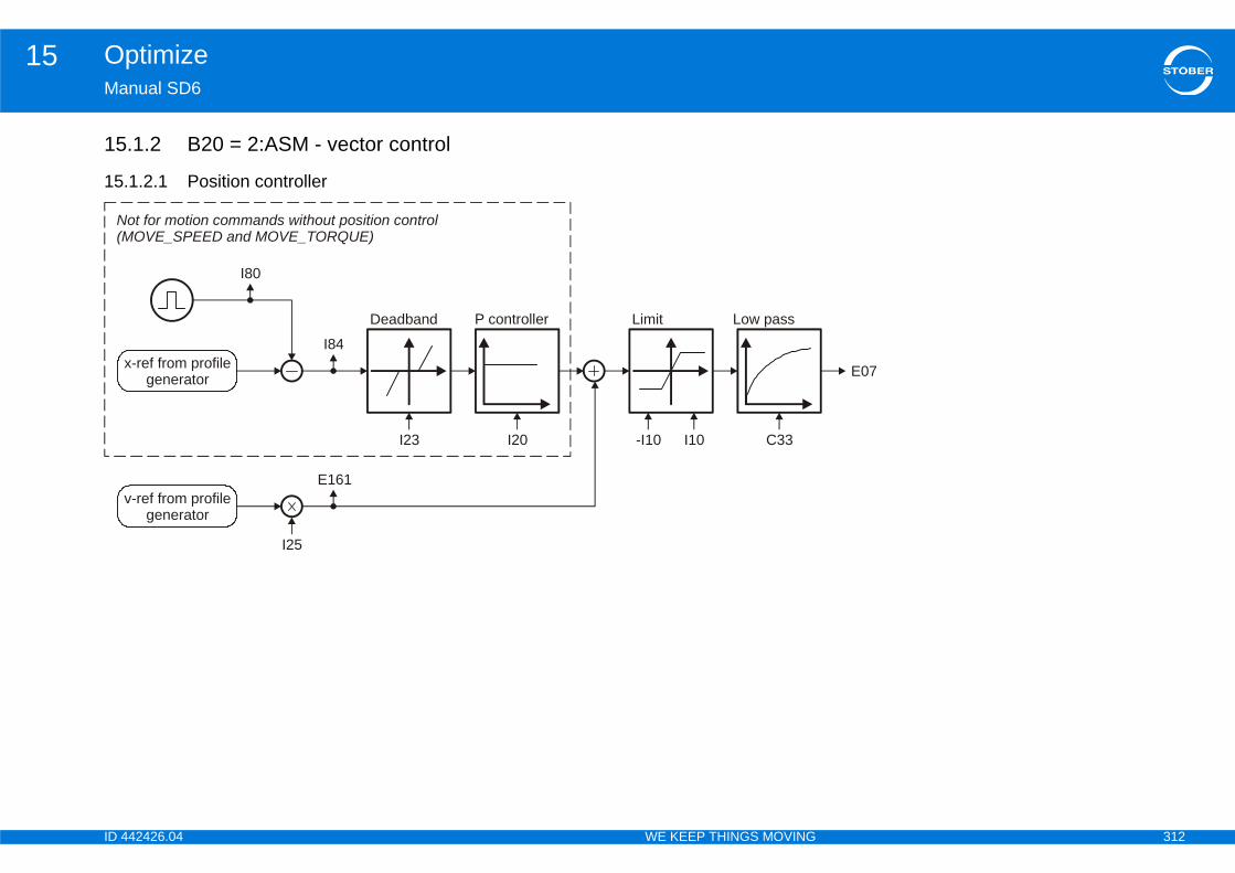
ID 4 312
Optimize15Ma
15
15
E07
N(M
42426.04 WE KEEP THINGS MOVING
nual SD6
.1.2 B20 = 2:ASM - vector control
.1.2.1 Position controller
Limit
-I10 I10
Low pass
C33
x-ref from profilegenerator
I80
I84
Deadband
I23
P controller
I20
v-ref from profilegenerator
E161
I25
ot for motion commands without position controlOVE_SPEED and MOVE_TORQUE)

ID 4 313
Optimize15Ma
Refvalu
DisprooutPossha
Thecon
Ma
Theass
response only). The Kv factor is also referred to as
cated with a unit of measure [m/min/mm]. This is · I20.
controller.scillations resulting from friction or reversal, sition encoder is used.
e position controller.file is switched to the output of the position
s the load on the position controller, thereby r.ve moves at a constant speed without a stationary tend to overshoot at the target position. Because of n is in the range of 60 ... 95 %.
C3
E0
E1
I10
y 1.111 is equivalent to the triggering limit for event
roportional gain position control) version 0
position control version 0
ust be less than the positioning window I22, rive will not reach its target position.
forward version 0
42426.04 WE KEEP THINGS MOVING
nual SD6
erence value smoothing. C33 should be increased in response to reference e noise, vibrating mechanics or large extraneous weights.
play of the current speed reference value (RV) in user units based on the file generator and the v-RV low pass. The total of the position controller put and speedFeedFwd (=speed controller reference value) is displayed in ition operating mode. E06 shows the same value in reference to the motor ft.
speed reference value at the output of the profile generator. With position trol corresponds to the speed feed forward.
ximum speed as a limit for calculating reference value with the motion core.
restriction does not apply with cyclically synchronous reference values igned in Controller Based mode.
Position controller gain (P-the speed gain.Occasionally it is also indiequivalent to exactly 0.06
Dead zone of the position Useful for preventing idle oespecially if an external po
Velocity feed forward of thThe calculated velocity procontroller.Speed feed forward relievereducing the following erroWhen I25 = 100 %, the drifollowing error, but it does this, I25 in most applicatio
3 lowpass reference speed version 0
7 ref speed for v controller version 0
61 v-rmpg version 0
maximal speed version 1
InformationThe limit is set without event 54:following error occurring.
InformationI10 multiplied b56:Overspeed.
I20 Kv-factor (p
I23 deadband
InformationI23 deadband motherwise the d
I25 speed feed
ID 4 314
Optimize15Ma
In aalle
Dis
DisIf thtrig
I80
I84
42426.04 WE KEEP THINGS MOVING
nual SD6
ddition to reducing I25, overshooting in the target position can also viated by increasing C32 (time constant I-part).
play of the actual position (without backlash compensation).
play of the current position deviation. e following distance I84 is above the permitted maximum I21, the drive
gers fault 54 following Error if the corresponding level is set in U22.
current position version 0
following error version 0
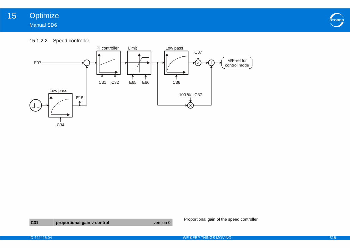
ID 4 315
Optimize15Ma
15
eed controller.
F-ref fortrol modeE
C3
42426.04 WE KEEP THINGS MOVING
nual SD6
.1.2.2 Speed controller
Proportional gain of the sp
Limit
E65 E66
Low pass
C36
E15
PI controller
C31
M/con07
Low pass
C34
C32
C37
100 % - C37
1 proportional gain v-control version 0

ID 4 316
Optimize15Ma
WitandstaWitmorefe
Timresdrivin tmsWitof Cas
Filt
C34achdynaccvalu
n ms for the torque/force value on the output of the uppress vibrations and resonances. The effect of
n be metered with C37.
C3
C3
Encoder evaluation Approximate value of C34 [ms]
EnDat 2.1 0,8 - 1,2
EnDat 2.1 0,8 - 1,2
EnDat 2.1 1,4 - 1,8
EnDat 2.1 1,2 - 1,8
EnDat 2.2 0,4 - 0,6
EnDat 2.2 0,4 - 0,6
EnDat 2.2 0,1 - 0,4
EnDat 2.2 0,0 - 0,2
EnDat 2.2 0,4 - 0,6
EnDat SinCos 512 0,4 - 0,8
EnDat SinCos 2048 0,2 - 0,8
Hiperface SinCos 128 0,6 - 1,0
Similar 1,4 - 2,0
HTL/TTL 2,0
HTL/TTL 1,4
HTL/TTL 0,8
orque/force low pass version 0
42426.04 WE KEEP THINGS MOVING
nual SD6
h C31 = 100% and a speed deviation of 32 rpm for asynchronous motors synchronous servo motors, the P part of the speed controller returns the
ll torque M0 as a reference value to the current or torque controller.h C31 = 100% and a speed deviation of 3.2 m/min for synchronous linear tors, the P part of the speed controller returns the static force F0 as a rence value to the current or force controller.
e constant of the I-part in the speed controller. A small integral action time ults in a high integration speed, thereby increasing the static rigidity of the e. A small integral action time can lead to overshoots in dynamic processes
he target position. In this case C32 should be increased. When C32 is < 1 the I controller is deactivated.h C31 = 100 % and a speed deviation of 32 rpm after an integral action time 32 the I-part of the speed controller returns the nominal motor torque/force
a reference value for the current or torque/force controller.
er time constant for the current motor encoder speed E15.
affects how smoothly the motor runs and the dynamics that can be ieved with the drive. As C34 increases, the motor runs more quietly and amics decrease. The minimum value of C34 depends primarily on the uracy of the encoder that is used. The table below contains approximate es for C34.
Smoothing time constant ispeed controller. Used to storque/force smoothing ca
2 integral time v-ctrl version 0
4 actual motor speed low pass version 0
Encoder designation
ECN 1113, EQN 1125
EQN 1325
ECI 1118, EQI 1130
ECI 1319, EQI 1329, EQI1331
ECI 1119, EQI 1131
ECI 119, EBI 135
ECN 1123, EQN 1135
ECN 1325, EQN 1337
ECI 1118-G2, EBI 1135
EQN 1125
EQN 1325
SKS36, SKM36
Resolver (2-pole)
Incremental 1024
Incremental 2048
Incremental 4096
C36 reference t
ID 4 317
Optimize15Ma
Thecom•
•Forrefe100
DisprooutPossha
CurThewithIf thpardisp
rque/force limit. The reference value for ide is C09, for consideration on the motor side B18.
orque/force limit in reference to B18. The reference the load side is C09, for consideration on the motor
C3
E0
E1
tive T-max version 0
tive T-max version 0
42426.04 WE KEEP THINGS MOVING
nual SD6
torque/force value is formed at the output of the speed controller from two ponents. The ratio of these components can be adjusted with C37:Direct output of PI speed controller (component corresponds to 100 % - C37).Smoothed output of PI speed controller (component corresponds to C37). maximum dynamics set C37 = 0 %. This will eliminate any effect from the rence value low pass with time constant C36. C37 can be increased up to % to dampen vibrations.
play of the current speed reference value (RV) in user units based on the file generator and the v-RV low pass. The total of the position controller put and speedFeedFwd (=speed controller reference value) is displayed in ition operating mode. E06 shows the same value in reference to the motor ft.
rent motor encoder speed. speed determined from the motor encoder specified in B26 and filtered the motor encoder speed low pass C34.e control mode in B20 does not require an encoder and no encoder is ameterized in B26, the speed calculated from the motor model will be layed.
Currently active positive toconsideration on the load s
Currently active negative tvalue for consideration on side B18.
7 reference torque filter version 0
7 ref speed for v controller version 0
5 v-motor-encoder version 1
E65 actual posi
E66 actual nega
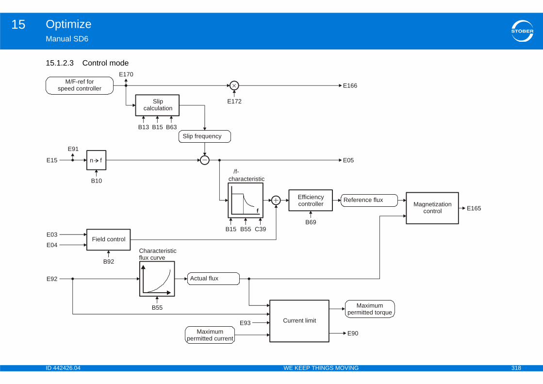
ID 4 318
Optimize15Ma
15
E15
E03
E04
E92
aximumitted torque
nce fluxMagnetization
control E165
42426.04 WE KEEP THINGS MOVING
nual SD6
.1.2.3 Control mode
Slipcalculation
B13 B15 B63
Characteristicflux curve
B55
n f
E91
B10
Slip frequency
E172
E170M/F-ref for
speed controller
Field control
B92
f
/f-characteristic
Actual flux
Maximumpermitted current
Current limit
Mperm
E90
B15 B55
Efficiencycontroller Refere
E93
B69
E05
E166
C39
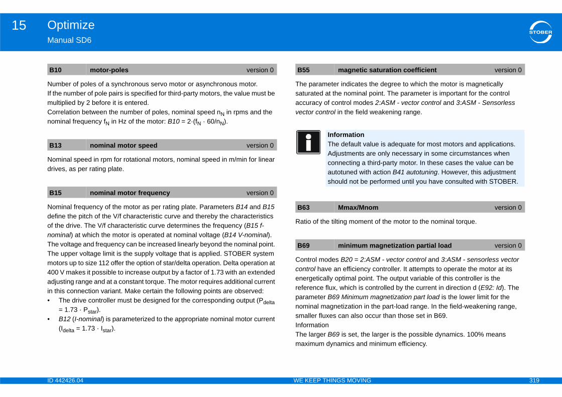
ID 4 319
Optimize15Ma
NumIf thmuCornom
Nomdriv
Nomdefof tnomTheThemo400adjin t•
•
e degree to which the motor is magnetically oint. The parameter is important for the control 2:ASM - vector control and 3:ASM - Sensorless eakening range.
of the motor to the nominal torque.
M - vector control and 3:ASM - sensorless vector controller. It attempts to operate the motor at its . The output variable of this controller is the ntrolled by the current in direction d (E92: Id). The agnetization part load is the lower limit for the
he part-load range. In the field-weakening range, cur than those set in B69.
larger is the possible dynamics. 100% means inimum efficiency.
B1
B1
B1
aturation coefficient version 0
ue is adequate for most motors and applications. e only necessary in some circumstances when ird-party motor. In these cases the value can be action B41 autotuning. However, this adjustment erformed until you have consulted with STOBER.
m version 0
agnetization partial load version 0
42426.04 WE KEEP THINGS MOVING
nual SD6
ber of poles of a synchronous servo motor or asynchronous motor.e number of pole pairs is specified for third-party motors, the value must be ltiplied by 2 before it is entered.relation between the number of poles, nominal speed nN in rpms and the inal frequency fN in Hz of the motor: B10 = 2·(fN · 60/nN).
inal speed in rpm for rotational motors, nominal speed in m/min for linear es, as per rating plate.
inal frequency of the motor as per rating plate. Parameters B14 and B15 ine the pitch of the V/f characteristic curve and thereby the characteristics he drive. The V/f characteristic curve determines the frequency (B15 f-inal) at which the motor is operated at nominal voltage (B14 V-nominal). voltage and frequency can be increased linearly beyond the nominal point. upper voltage limit is the supply voltage that is applied. STOBER system
tors up to size 112 offer the option of star/delta operation. Delta operation at V makes it possible to increase output by a factor of 1.73 with an extended
usting range and at a constant torque. The motor requires additional current his connection variant. Make certain the following points are observed:The drive controller must be designed for the corresponding output (Pdelta = 1.73 · Pstar).B12 (I-nominal) is parameterized to the appropriate nominal motor current (Idelta = 1.73 · Istar).
The parameter indicates thsaturated at the nominal paccuracy of control modesvector control in the field w
Ratio of the tilting moment
Control modes B20 = 2:AScontrol have an efficiency energetically optimal pointreference flux, which is coparameter B69 Minimum mnominal magnetization in tsmaller fluxes can also ocInformationThe larger B69 is set, the maximum dynamics and m
0 motor-poles version 0
3 nominal motor speed version 0
5 nominal motor frequency version 0
B55 magnetic s
InformationThe default valAdjustments arconnecting a thautotuned with should not be p
B63 Mmax/Mno
B69 minimum m
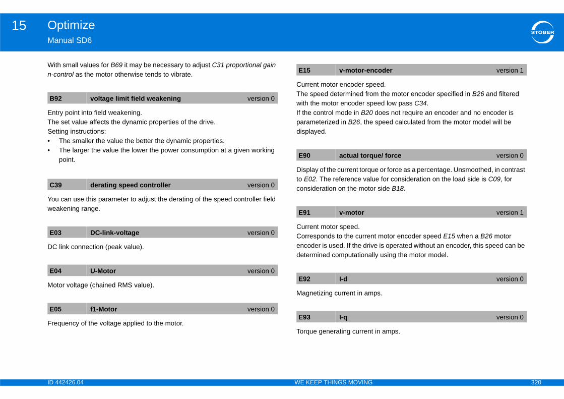
ID 4 320
Optimize15Ma
Witn-c
EntTheSet••
Youwea
DC
Mo
Fre
eed.m the motor encoder specified in B26 and filtered eed low pass C34. does not require an encoder and no encoder is speed calculated from the motor model will be
e or force as a percentage. Unsmoothed, in contrast e for consideration on the load side is C09, for r side B18.
t motor encoder speed E15 when a B26 motor e is operated without an encoder, this speed can be ly using the motor model.
ps.
in amps.
B9
C3
E0
E0
E0
coder version 1
ue/ force version 0
version 1
version 0
version 0
42426.04 WE KEEP THINGS MOVING
nual SD6
h small values for B69 it may be necessary to adjust C31 proportional gain ontrol as the motor otherwise tends to vibrate.
ry point into field weakening. set value affects the dynamic properties of the drive.ting instructions:The smaller the value the better the dynamic properties.The larger the value the lower the power consumption at a given working point.
can use this parameter to adjust the derating of the speed controller field kening range.
link connection (peak value).
tor voltage (chained RMS value).
quency of the voltage applied to the motor.
Current motor encoder spThe speed determined frowith the motor encoder spIf the control mode in B20parameterized in B26, thedisplayed.
Display of the current torquto E02. The reference valuconsideration on the moto
Current motor speed.Corresponds to the currenencoder is used. If the drivdetermined computational
Magnetizing current in am
Torque generating current
2 voltage limit field weakening version 0
9 derating speed controller version 0
3 DC-link-voltage version 0
4 U-Motor version 0
5 f1-Motor version 0
E15 v-motor-en
E90 actual torq
E91 v-motor
E92 I-d
E93 I-q
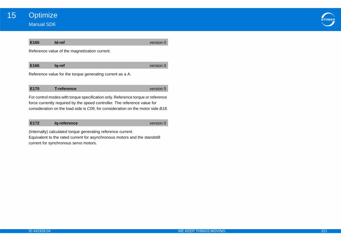
ID 4 321
Optimize15Ma
Ref
Ref
Forforccon
(IntEqucur
E1
E1
E1
E1
42426.04 WE KEEP THINGS MOVING
nual SD6
erence value of the magnetization current.
erence value for the torque generating current as a A.
control modes with torque specification only. Reference torque or reference e currently required by the speed controller. The reference value for sideration on the load side is C09, for consideration on the motor side B18.
ernally) calculated torque generating reference current.ivalent to the rated current for asynchronous motors and the standstill
rent for synchronous servo motors.
65 Id-ref version 0
66 Iq-ref version 0
70 T-reference version 0
72 Iq-reference version 0
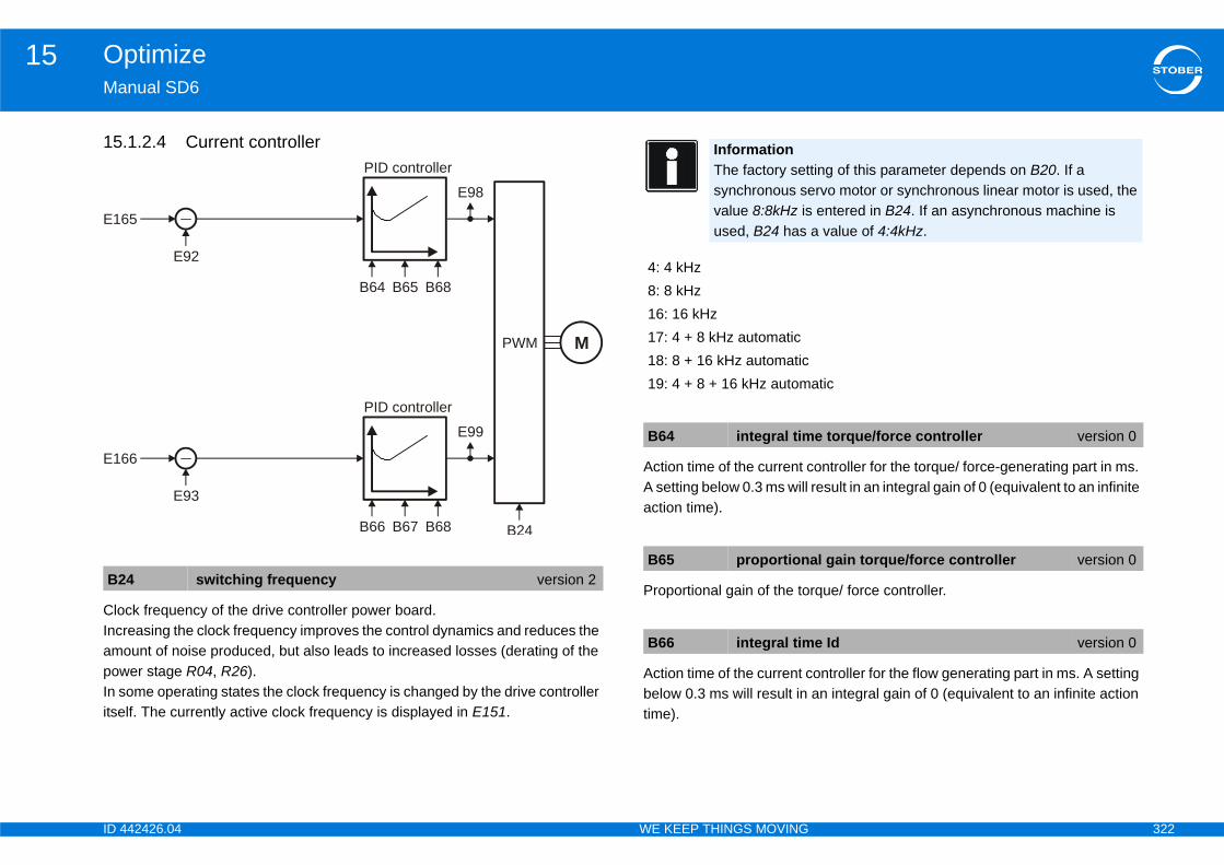
ID 4 322
Optimize15Ma
15
CloIncampowIn sitse
ontroller for the torque/ force-generating part in ms. result in an integral gain of 0 (equivalent to an infinite
rque/ force controller.
ontroller for the flow generating part in ms. A setting an integral gain of 0 (equivalent to an infinite action
B2
E16
E16
ting of this parameter depends on B20. If a rvo motor or synchronous linear motor is used, the entered in B24. If an asynchronous machine is a value of 4:4kHz.
atic
e torque/force controller version 0
al gain torque/force controller version 0
e Id version 0
42426.04 WE KEEP THINGS MOVING
nual SD6
.1.2.4 Current controller
ck frequency of the drive controller power board.reasing the clock frequency improves the control dynamics and reduces the ount of noise produced, but also leads to increased losses (derating of the er stage R04, R26).ome operating states the clock frequency is changed by the drive controller lf. The currently active clock frequency is displayed in E151.
Action time of the current cA setting below 0.3 ms will action time).
Proportional gain of the to
Action time of the current cbelow 0.3 ms will result in time).
4 switching frequency version 2
5
E92
PID controller
B64 B65 B68
E98
PWM
B24
M
6
E93
PID controller
B66 B67 B68
E99
InformationThe factory setsynchronous sevalue 8:8kHz isused, B24 has
4: 4 kHz8: 8 kHz16: 16 kHz17: 4 + 8 kHz automatic18: 8 + 16 kHz automatic19: 4 + 8 + 16 kHz autom
B64 integral tim
B65 proportion
B66 integral tim
ID 4 323
Optimize15Ma
Pro
D-p
Ma
Tor
Vol
Vol
Ref
Ref
B6
B6
E9
E9
E9
E9
E1
E1
42426.04 WE KEEP THINGS MOVING
nual SD6
portional gain of the flow controller.
art of the torque controller.
gnetizing current in amps.
que generating current in amps.
tage in d direction in V (linked peak voltage).
tage in q direction in V (linked peak voltage).
erence value of the magnetization current.
erence value for the torque generating current as a A.
7 proportional gain flux version 0
8 kd-iq version 0
2 I-d version 0
3 I-q version 0
8 Ud version 1
9 Uq version 1
65 Id-ref version 0
66 Iq-ref version 0
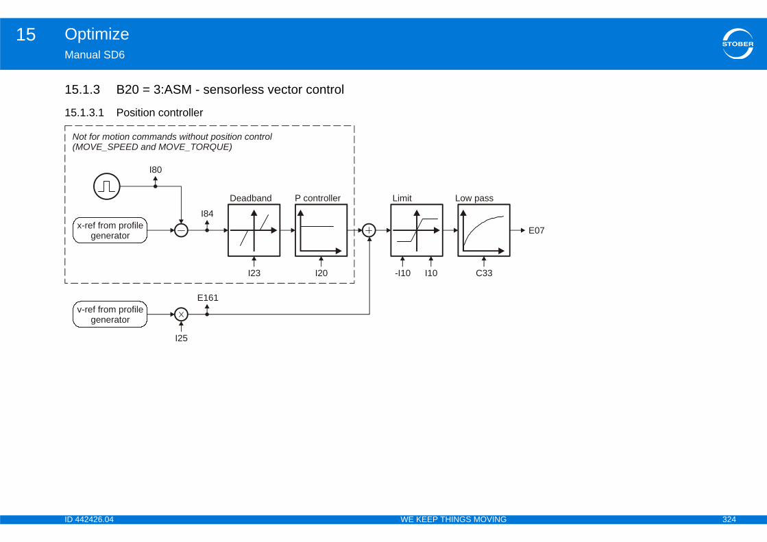
ID 4 324
Optimize15Ma
15
15
E07
N(M
42426.04 WE KEEP THINGS MOVING
nual SD6
.1.3 B20 = 3:ASM - sensorless vector control
.1.3.1 Position controller
Limit
-I10 I10
Low pass
C33
x-ref from profilegenerator
I80
I84
Deadband
I23
P controller
I20
v-ref from profilegenerator
E161
I25
ot for motion commands without position controlOVE_SPEED and MOVE_TORQUE)
ID 4 325
Optimize15Ma
Refvalu
DisprooutPossha
Thecon
Ma
Theass
response only). The Kv factor is also referred to as
cated with a unit of measure [m/min/mm]. This is · I20.
controller.scillations resulting from friction or reversal, sition encoder is used.
e position controller.file is switched to the output of the position
s the load on the position controller, thereby r.ve moves at a constant speed without a stationary tend to overshoot at the target position. Because of n is in the range of 60 ... 95 %., overshooting in the target position can also 32 (time constant I-part).
C3
E0
E1
I10
roportional gain position control) version 0
position control version 0
ust be less than the positioning window I22, rive will not reach its target position.
forward version 0
42426.04 WE KEEP THINGS MOVING
nual SD6
erence value smoothing. C33 should be increased in response to reference e noise, vibrating mechanics or large extraneous weights.
play of the current speed reference value (RV) in user units based on the file generator and the v-RV low pass. The total of the position controller put and speedFeedFwd (=speed controller reference value) is displayed in ition operating mode. E06 shows the same value in reference to the motor ft.
speed reference value at the output of the profile generator. With position trol corresponds to the speed feed forward.
ximum speed as a limit for calculating reference value with the motion core.
restriction does not apply with cyclically synchronous reference values igned in Controller Based mode.
Position controller gain (P-the speed gain.Occasionally it is also indiequivalent to exactly 0.06
Dead zone of the position Useful for preventing idle oespecially if an external po
Velocity feed forward of thThe calculated velocity procontroller.Speed feed forward relievereducing the following erroWhen I25 = 100 %, the drifollowing error, but it does this, I25 in most applicatioIn addition to reducing I25alleviated by increasing C
3 lowpass reference speed version 0
7 ref speed for v controller version 0
61 v-rmpg version 0
maximal speed version 1
InformationThe limit is set without event 54:following error occurring.
InformationI10 multiplied by 1.111 is equivalent to the triggering limit for event 56:Overspeed.
I20 Kv-factor (p
I23 deadband
InformationI23 deadband motherwise the d
I25 speed feed

ID 4 326
Optimize15Ma
Dis
DisIf thtrig
I80
I84
42426.04 WE KEEP THINGS MOVING
nual SD6
play of the actual position (without backlash compensation).
play of the current position deviation. e following distance I84 is above the permitted maximum I21, the drive
gers fault 54 following Error if the corresponding level is set in U22.
current position version 0
following error version 0

ID 4 327
Optimize15Ma
15
M/F-ref forcontrol mode
E07
E91
E06
B15
42426.04 WE KEEP THINGS MOVING
nual SD6
.1.3.2 Speed controller
Limit
E65 E66
Low pass
C36
PIcontroller
C31 C32C37
100 % - C37
Deratingspeed controller
B15 C39
Controlledtorque assignment
B62 C21 C30
TRUE
FALSE
>=5 %

ID 4 328
Optimize15Ma
Nomdefof tnomTheThemo400adjin t•
•
Moor m
Spein Cmerefealw
f an acceleration torque and C21 together. The lated from the mass moment of inertia of the overall n. C21 is not included in the braking torque, which ing ramp only. seen in the E166 Iq-ref. If the load torque that is rably less than C21, jerks may occur during startup deviations in speed. If C21 is considerably less than cannot accelerate.
of inertia of the load to the motor. C30 is included in tion and braking torques in the low speed range (< 5
B1
B6
C2otor version 0
constant travel brake
brake torque
42426.04 WE KEEP THINGS MOVING
nual SD6
inal frequency of the motor as per rating plate. Parameters B14 and B15 ine the pitch of the V/f characteristic curve and thereby the characteristics he drive. The V/f characteristic curve determines the frequency (B15 f-inal) at which the motor is operated at nominal voltage (B14 V-nominal). voltage and frequency can be increased linearly beyond the nominal point. upper voltage limit is the supply voltage that is applied. STOBER system
tors up to size 112 offer the option of star/delta operation. Delta operation at V makes it possible to increase output by a factor of 1.73 with an extended
usting range and at a constant torque. The motor requires additional current his connection variant. Make certain the following points are observed:The drive controller must be designed for the corresponding output (Pdelta = 1.73 · Pstar).B12 (I-nominal) is parameterized to the appropriate nominal motor current (Idelta = 1.73 · Istar).
ment of inertia J for synchronous servo motors and asynchronous motors ass of the slide for linear motors.
cify the constant load torque for slow speeds (<5% of B13 Nominal speed) 21 in control mode B20 = 3:ASM - Sensorless vector control. C21 has no
aning for higher speeds. (friction, force of gravity for vertical axes, etc.). The rence quantity for C21 is B18 related torque. The torque specified in C21 ays refers to the motor shaft.
The total torque consists oacceleration torque is calcusystem and the acceleratiois calculated from the brakThe effects of C21 can beactually applied is consideas well as large stationary the load torque, the motor
Ratio of the mass momentthe calculation of accelera% of nominal speed).
5 nominal motor frequency version 0
2 motor inertia version 0
1 start-up torque version 0
M load
Mmotor C21
n1
n2
C30 J-Last / J-M
E166 Iq-ref
acceleration torque
C21
acceleration

ID 4 329
Optimize15Ma
ProWitandstaWitmorefe
Timresdrivin tmsWitof Cas
Smspetorq
ormed at the output of the speed controller from two hese components can be adjusted with C37:ed controller (component corresponds to 100 % -
speed controller (component corresponds to C37).t C37 = 0 %. This will eliminate any effect from the ith time constant C36. C37 can be increased up to s.
r to adjust the derating of the speed controller field
d reference value in reference to the motor shaft.
d reference value (RV) in user units based on the -RV low pass. The total of the position controller (=speed controller reference value) is displayed in 06 shows the same value in reference to the motor
C3
C3
C3
orque filter version 0
eed controller version 0
motor version 0
or v controller version 0
42426.04 WE KEEP THINGS MOVING
nual SD6
portional gain of the speed controller.h C31 = 100% and a speed deviation of 32 rpm for asynchronous motors synchronous servo motors, the P part of the speed controller returns the
ll torque M0 as a reference value to the current or torque controller.h C31 = 100% and a speed deviation of 3.2 m/min for synchronous linear tors, the P part of the speed controller returns the static force F0 as a rence value to the current or force controller.
e constant of the I-part in the speed controller. A small integral action time ults in a high integration speed, thereby increasing the static rigidity of the e. A small integral action time can lead to overshoots in dynamic processes
he target position. In this case C32 should be increased. When C32 is < 1 the I controller is deactivated.h C31 = 100 % and a speed deviation of 32 rpm after an integral action time 32 the I-part of the speed controller returns the nominal motor torque/force
a reference value for the current or torque/force controller.
oothing time constant in ms for the torque/force value on the output of the ed controller. Used to suppress vibrations and resonances. The effect of ue/force smoothing can be metered with C37.
The torque/force value is fcomponents. The ratio of t• Direct output of PI spe
C37).• Smoothed output of PIFor maximum dynamics sereference value low pass w100 % to dampen vibration
You can use this parameteweakening range.
Display of the current spee
Display of the current speeprofile generator and the voutput and speedFeedFwdPosition operating mode. Eshaft.
1 proportional gain v-control version 0
2 integral time v-ctrl version 0
6 reference torque/force low pass version 0
C37 reference t
C39 derating sp
E06 v-reference
E07 ref speed f
ID 4 330
Optimize15Ma
Curcon
Curvaluside
CurCorencdet
E6
E6
E9
42426.04 WE KEEP THINGS MOVING
nual SD6
rently active positive torque/force limit. The reference value for sideration on the load side is C09, for consideration on the motor side B18.
rently active negative torque/force limit in reference to B18. The reference e for consideration on the load side is C09, for consideration on the motor B18.
rent motor speed.responds to the current motor encoder speed E15 when a B26 motor oder is used. If the drive is operated without an encoder, this speed can be ermined computationally using the motor model.
5 actual positive T-max version 0
6 actual negative T-max version 0
1 v-motor version 1

ID 4 331
Optimize15Ma
15
E15
E03
E04
E92
aximumitted torque
nce fluxMagnetization
control E165
42426.04 WE KEEP THINGS MOVING
nual SD6
.1.3.3 Control mode
Slipcalculation
B13 B15 B63
Characteristicflux curve
B55
n f
E91
B10
Slip frequency
E172
E170M/F-ref for
speed controller
Field control
B92
f
/f-characteristic
Actual flux
Maximumpermitted current
Current limit
Mperm
E90
B15 B55
Efficiencycontroller Refere
E93
B69
E05
E166
C39
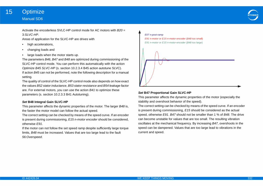
ID 4 332
Optimize15Ma
Act3:SAre
•
•
•TheSLVOpIf asetThethearepar
SetThitheTheis pothIf thlimi56:
in SLVC-HP dynamic properties of the motor (especially the avior of the speed).
checked by means of the speed curve. If an encoder ioning, E15 should be considered as the actual 7 should not be smaller than 1 % of B48. The drive alues that are too small. The resulting vibration al frequency. By increasing B47, overshoots in the Values that are too large lead to vibrations in the
r-encoder B48 ( too small)r-encoder B48 ( too large)
42426.04 WE KEEP THINGS MOVING
nual SD6
ivate the encoderless SVLC-HP control mode for AC motors with B20 = LVC-HP.as of application for the SLVC-HP are drives with
high accelerations,
changing loads and
large loads when the motor starts up. parameters B46, B47 and B48 are optimized during commissioning of the C-HP control mode. You can perform this automatically with the action
timize B45 SLVC-HP (s. section 10.2.3.4 B45 action autotune SLVC).ction B45 can not be performed, note the following description for a manual ting. quality of control of the SLVC-HP control mode also depends on how exact
values B52 stator inductance, B53 stator resistance and B54 leakage factor . For external motors, you can use the action B41 to optimize these ameters (s. section 10.2.3.3 B41 Autotuning).
B48 Integral Gain SLVC-HPs parameter affects the dynamic properties of the motor. The larger B48 is, faster the motor model can follow the actual speed. correct setting can be checked by means of the speed curve. If an encoder resent during commissioning, E15 n-motor encoder should be considered, erwise E91.e motor can not follow the set speed ramp despite sufficiently large torque ts, B48 must be increased. Values that are too large lead to the fault Overspeed.
Set B47 Proportional GaThis parameter affects thestability and overshoot behThe correct setting can be is present during commissspeed, otherwise E91. B4can become unstable for voscillates at the mechanicspeed can be dampened. current and speed.
E07 n-post-rampE91 n-motor E15 n-moto or E91 n-motor E15 n-moto or
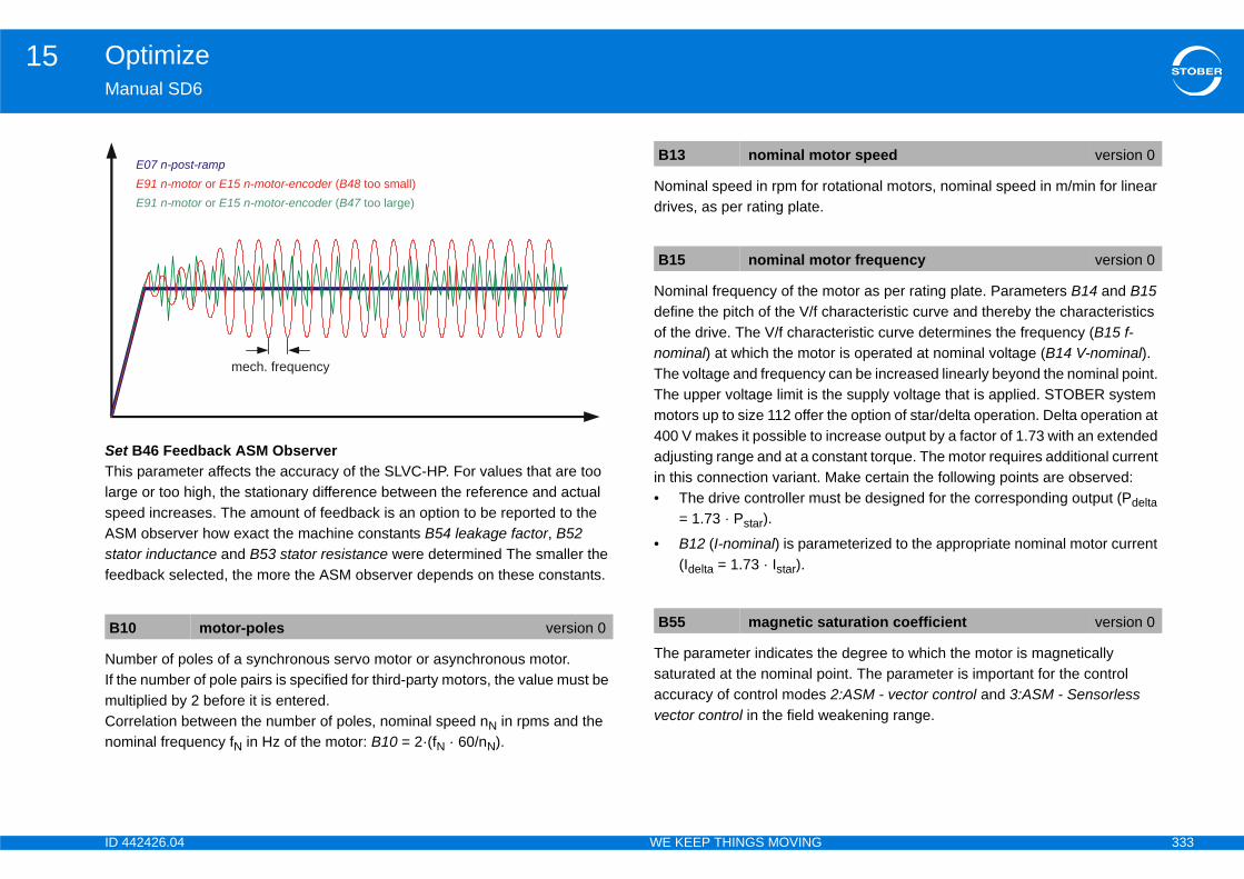
ID 4 333
Optimize15Ma
SetThilargspeASstafee
NumIf thmuCornom
rotational motors, nominal speed in m/min for linear
motor as per rating plate. Parameters B14 and B15 haracteristic curve and thereby the characteristics
cteristic curve determines the frequency (B15 f-or is operated at nominal voltage (B14 V-nominal). can be increased linearly beyond the nominal point. he supply voltage that is applied. STOBER system the option of star/delta operation. Delta operation at increase output by a factor of 1.73 with an extended nstant torque. The motor requires additional current Make certain the following points are observed:st be designed for the corresponding output (Pdelta
meterized to the appropriate nominal motor current
e degree to which the motor is magnetically oint. The parameter is important for the control 2:ASM - vector control and 3:ASM - Sensorless eakening range.
B1
otor speed version 0
otor frequency version 0
aturation coefficient version 0
42426.04 WE KEEP THINGS MOVING
nual SD6
B46 Feedback ASM Observers parameter affects the accuracy of the SLVC-HP. For values that are too e or too high, the stationary difference between the reference and actual ed increases. The amount of feedback is an option to be reported to the M observer how exact the machine constants B54 leakage factor, B52 tor inductance and B53 stator resistance were determined The smaller the dback selected, the more the ASM observer depends on these constants.
ber of poles of a synchronous servo motor or asynchronous motor.e number of pole pairs is specified for third-party motors, the value must be ltiplied by 2 before it is entered.relation between the number of poles, nominal speed nN in rpms and the inal frequency fN in Hz of the motor: B10 = 2·(fN · 60/nN).
Nominal speed in rpm for drives, as per rating plate.
Nominal frequency of the define the pitch of the V/f cof the drive. The V/f charanominal) at which the motThe voltage and frequencyThe upper voltage limit is tmotors up to size 112 offer400 V makes it possible toadjusting range and at a coin this connection variant. • The drive controller mu
= 1.73 · Pstar).
• B12 (I-nominal) is para(Idelta = 1.73 · Istar).
The parameter indicates thsaturated at the nominal paccuracy of control modesvector control in the field w
0 motor-poles version 0
E07 n-post-rampE91 n-motor E15 n-motor-encoder B48 or ( too small)E91 n-motor E15 n-motor-encoder B47 or ( too large)
mech. frequency
B13 nominal m
B15 nominal m
B55 magnetic s
ID 4 334
Optimize15Ma
Rat
ConconenerefeparnomsmInfoThemaWitn-c
ening.ynamic properties of the drive.
the better the dynamic properties.e lower the power consumption at a given working
r to adjust the derating of the speed controller field
value).
S value).
pplied to the motor.
eed.m the motor encoder specified in B26 and filtered eed low pass C34.
B6
B6
it field weakening version 0
eed controller version 0
ltage version 0
version 0
version 0
coder version 1
42426.04 WE KEEP THINGS MOVING
nual SD6
io of the tilting moment of the motor to the nominal torque.
trol modes B20 = 2:ASM - vector control and 3:ASM - sensorless vector trol have an efficiency controller. It attempts to operate the motor at its rgetically optimal point. The output variable of this controller is the rence flux, which is controlled by the current in direction d (E92: Id). The
ameter B69 Minimum magnetization part load is the lower limit for the inal magnetization in the part-load range. In the field-weakening range,
aller fluxes can also occur than those set in B69.rmation larger B69 is set, the larger is the possible dynamics. 100% means
ximum dynamics and minimum efficiency.h small values for B69 it may be necessary to adjust C31 proportional gain ontrol as the motor otherwise tends to vibrate.
Entry point into field weakThe set value affects the dSetting instructions:• The smaller the value • The larger the value th
point.
You can use this parameteweakening range.
DC link connection (peak
Motor voltage (chained RM
Frequency of the voltage a
Current motor encoder spThe speed determined frowith the motor encoder sp
InformationThe default value is adequate for most motors and applications. Adjustments are only necessary in some circumstances when connecting a third-party motor. In these cases the value can be autotuned with action B41 autotuning. However, this adjustment should not be performed until you have consulted with STOBER.
3 Mmax/Mnom version 0
9 minimum magnetization partial load version 0
B92 voltage lim
C39 derating sp
E03 DC-link-vo
E04 U-Motor
E05 f1-Motor
E15 v-motor-en

ID 4 335
Optimize15Ma
If thpardisp
Disto Econ
CurCorencdet
Ma
Tor
Ref
rque generating current as a A.
ue specification only. Reference torque or reference the speed controller. The reference value for ide is C09, for consideration on the motor side B18.
ue generating reference current.rent for asynchronous motors and the standstill rvo motors.
E9
E9
E9
E9
E1
version 0
version 0
e version 0
42426.04 WE KEEP THINGS MOVING
nual SD6
e control mode in B20 does not require an encoder and no encoder is ameterized in B26, the speed calculated from the motor model will be layed.
play of the current torque or force as a percentage. Unsmoothed, in contrast 02. The reference value for consideration on the load side is C09, for sideration on the motor side B18.
rent motor speed.responds to the current motor encoder speed E15 when a B26 motor oder is used. If the drive is operated without an encoder, this speed can be ermined computationally using the motor model.
gnetizing current in amps.
que generating current in amps.
erence value of the magnetization current.
Reference value for the to
For control modes with torqforce currently required byconsideration on the load s
(Internally) calculated torqEquivalent to the rated curcurrent for synchronous se
0 actual torque/ force version 0
1 v-motor version 1
2 I-d version 0
3 I-q version 0
65 Id-ref version 0
E166 Iq-ref
E170 T-reference
E172 Iq-referenc
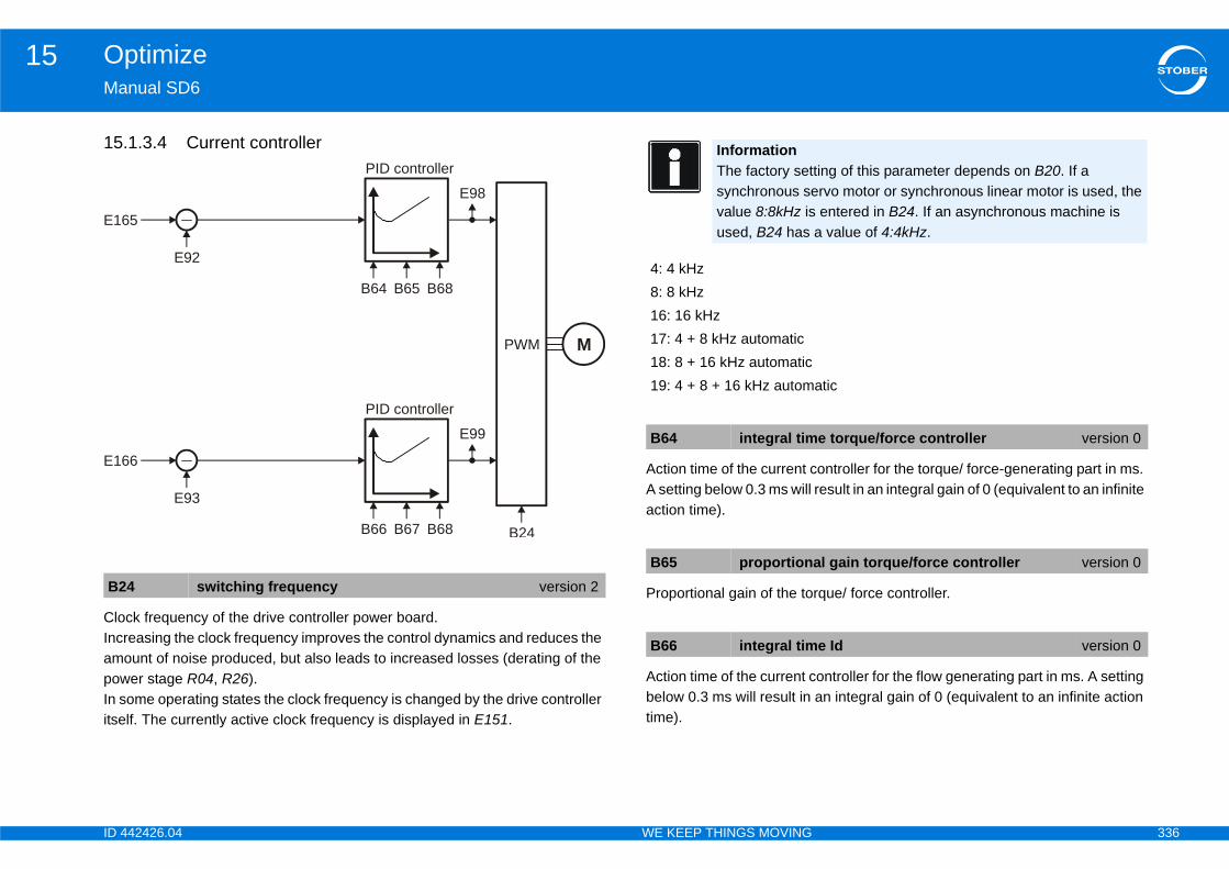
ID 4 336
Optimize15Ma
15
CloIncampowIn sitse
ontroller for the torque/ force-generating part in ms. result in an integral gain of 0 (equivalent to an infinite
rque/ force controller.
ontroller for the flow generating part in ms. A setting an integral gain of 0 (equivalent to an infinite action
B2
E16
E16
ting of this parameter depends on B20. If a rvo motor or synchronous linear motor is used, the entered in B24. If an asynchronous machine is a value of 4:4kHz.
atic
e torque/force controller version 0
al gain torque/force controller version 0
e Id version 0
42426.04 WE KEEP THINGS MOVING
nual SD6
.1.3.4 Current controller
ck frequency of the drive controller power board.reasing the clock frequency improves the control dynamics and reduces the ount of noise produced, but also leads to increased losses (derating of the er stage R04, R26).ome operating states the clock frequency is changed by the drive controller lf. The currently active clock frequency is displayed in E151.
Action time of the current cA setting below 0.3 ms will action time).
Proportional gain of the to
Action time of the current cbelow 0.3 ms will result in time).
4 switching frequency version 2
5
E92
PID controller
B64 B65 B68
E98
PWM
B24
M
6
E93
PID controller
B66 B67 B68
E99
InformationThe factory setsynchronous sevalue 8:8kHz isused, B24 has
4: 4 kHz8: 8 kHz16: 16 kHz17: 4 + 8 kHz automatic18: 8 + 16 kHz automatic19: 4 + 8 + 16 kHz autom
B64 integral tim
B65 proportion
B66 integral tim

ID 4 337
Optimize15Ma
Pro
D-p
Ma
Tor
Vol
Vol
Ref
Ref
B6
B6
E9
E9
E9
E9
E1
E1
42426.04 WE KEEP THINGS MOVING
nual SD6
portional gain of the flow controller.
art of the torque controller.
gnetizing current in amps.
que generating current in amps.
tage in d direction in V (linked peak voltage).
tage in q direction in V (linked peak voltage).
erence value of the magnetization current.
erence value for the torque generating current as a A.
7 proportional gain flux version 0
8 kd-iq version 0
2 I-d version 0
3 I-q version 0
8 Ud version 1
9 Uq version 1
65 Id-ref version 0
66 Iq-ref version 0

ID 4 338
Optimize15Ma
15
15
E07
N(M
42426.04 WE KEEP THINGS MOVING
nual SD6
.1.4 B20 = 1:ASM - U/f-slip compensated
.1.4.1 Position controller
Limit
-I10 I10
Low pass
C33
x-ref from profilegenerator
I80
I84
Deadband
I23
P controller
I20
v-ref from profilegenerator
E161
I25
ot for motion commands without position controlOVE_SPEED and MOVE_TORQUE)

ID 4 339
Optimize15Ma
Refvalu
DisprooutPossha
Thecon
Ma
Theass
response only). The Kv factor is also referred to as
cated with a unit of measure [m/min/mm]. This is · I20.
controller.scillations resulting from friction or reversal, sition encoder is used.
e position controller.file is switched to the output of the position
s the load on the position controller, thereby r.ve moves at a constant speed without a stationary tend to overshoot at the target position. Because of n is in the range of 60 ... 95 %.
C3
E0
E1
I10
y 1.111 is equivalent to the triggering limit for event
roportional gain position control) version 0
position control version 0
ust be less than the positioning window I22, rive will not reach its target position.
forward version 0
42426.04 WE KEEP THINGS MOVING
nual SD6
erence value smoothing. C33 should be increased in response to reference e noise, vibrating mechanics or large extraneous weights.
play of the current speed reference value (RV) in user units based on the file generator and the v-RV low pass. The total of the position controller put and speedFeedFwd (=speed controller reference value) is displayed in ition operating mode. E06 shows the same value in reference to the motor ft.
speed reference value at the output of the profile generator. With position trol corresponds to the speed feed forward.
ximum speed as a limit for calculating reference value with the motion core.
restriction does not apply with cyclically synchronous reference values igned in Controller Based mode.
Position controller gain (P-the speed gain.Occasionally it is also indiequivalent to exactly 0.06
Dead zone of the position Useful for preventing idle oespecially if an external po
Velocity feed forward of thThe calculated velocity procontroller.Speed feed forward relievereducing the following erroWhen I25 = 100 %, the drifollowing error, but it does this, I25 in most applicatio
3 lowpass reference speed version 0
7 ref speed for v controller version 0
61 v-rmpg version 0
maximal speed version 1
InformationThe limit is set without event 54:following error occurring.
InformationI10 multiplied b56:Overspeed.
I20 Kv-factor (p
I23 deadband
InformationI23 deadband motherwise the d
I25 speed feed

ID 4 340
Optimize15Ma
In aalle
Dis
DisIf thtrig
I80
I84
42426.04 WE KEEP THINGS MOVING
nual SD6
ddition to reducing I25, overshooting in the target position can also viated by increasing C32 (time constant I-part).
play of the actual position (without backlash compensation).
play of the current position deviation. e following distance I84 is above the permitted maximum I21, the drive
gers fault 54 following Error if the corresponding level is set in U22.
current position version 0
following error version 0
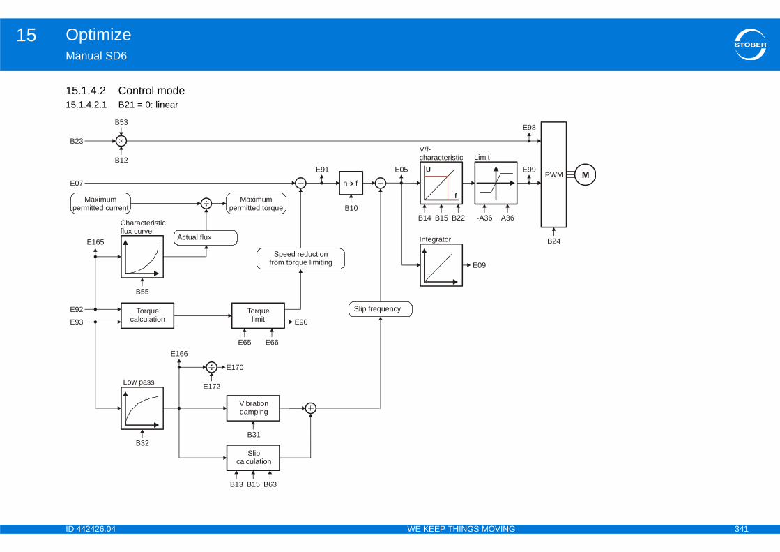
ID 4 341
Optimize15Ma
1515.
B2
E99
E98
PWM
B24
E0M
pe
E9
E9
42426.04 WE KEEP THINGS MOVING
nual SD6
.1.4.2 Control mode1.4.2.1 B21 = 0: linear
B53
n f
3
B12E05
V/f-characteristic Limit
B14 B15 B22 -A36 A36
E09
Integrator
7
E91
B10
Slip frequency
Speed reductionfrom torque limiting
Maximumpermitted torque
Actual flux
Maximumrmitted current
Characteristicflux curve
Torquecalculation
Torquelimit
Vibrationdamping
Slipcalculation
Low pass
B55
E65 E66
E90
E165
2
3
E166
E170
E172
B13 B15 B63
B31B32
U
f
ID 4 342
Optimize15Ma
ConThelinkIn cmoarein t
NumIf thmuCornom
Nom
Nomdriv
Nom(Y/∆
motor as per rating plate. Parameters B14 and B15 haracteristic curve and thereby the characteristics
cteristic curve determines the frequency (B15 f-or is operated at nominal voltage (B14 V-nominal). can be increased linearly beyond the nominal point. he supply voltage that is applied. STOBER system the option of star/delta operation. Delta operation at increase output by a factor of 1.73 with an extended nstant torque. The motor requires additional current Make certain the following points are observed:st be designed for the corresponding output (Pdelta
meterized to the appropriate nominal motor current
tch of the V/f characteristic curve. The pitch with V/ined by V-nominal (B14) and f-nominal (B15).
e in voltage in the lower speed range, which makes ailable. A boost of 100 % means the nominal motor determine the required boost voltage, the stator st be known. perform B41 autotuning for motors without an
tors, the stator resistance of the motor is defined .
A3
B1
B1
B1
B1
otor frequency version 0
version 0
version 0
42426.04 WE KEEP THINGS MOVING
nual SD6
nected to X10, effective supply voltage. charge relay is controlled to ensure low wear depending on the current DC voltage and A36.ontrol mode B20 = 64: SSM - vector control affects A36 the field weakening de. A limit value is derived from A36 . DC link voltages above this limit value not taken into consideration in field weakening mode to prevent oscillations he motor current.
ber of poles of a synchronous servo motor or asynchronous motor.e number of pole pairs is specified for third-party motors, the value must be ltiplied by 2 before it is entered.relation between the number of poles, nominal speed nN in rpms and the inal frequency fN in Hz of the motor: B10 = 2·(fN · 60/nN).
inal current in A, as per rating plate.
inal speed in rpm for rotational motors, nominal speed in m/min for linear es, as per rating plate.
inal voltage as per rating plate. For asynchronous motors note circuit type )! Therefore make certain that parameters B11 ... B15 match!
Nominal frequency of the define the pitch of the V/f cof the drive. The V/f charanominal) at which the motThe voltage and frequencyThe upper voltage limit is tmotors up to size 112 offer400 V makes it possible toadjusting range and at a coin this connection variant. • The drive controller mu
= 1.73 · Pstar).• B12 (I-nominal) is para
(Idelta = 1.73 · Istar).
Correction factor for the pif-factor = 100 % is determ
Boost refers to an increasa greater starting torque avcurrent will flow at 0 Hz. Toresistance of the motor muYou must therefore alwayselectronic rating plate.For STOBER standard mowhen the motor is selected
6 mains voltage version 0
0 motor-poles version 0
2 nominal motor current version 0
3 nominal motor speed version 0
4 nominal motor voltage version 0
B15 nominal m
B22 V/f-factor
B23 V/f boost

ID 4 343
Optimize15Ma
CloIncampowIn sitse
LarparV/f-pro
trol mode 1:ASM - V/f slip compensated to changes h B32. The smaller B32 is, the greater the dynamics
he motor winding in ohms. Processing with this for third-party motors. The value can be autotuned .
of the motor to the nominal torque.
pplied to the motor.
d reference value (RV) in user units based on the -RV low pass. The total of the position controller (=speed controller reference value) is displayed in 06 shows the same value in reference to the motor
B2
4: 8: 16171819
B3
mics version 0
ing resistance version 0
m version 0
version 0
or v controller version 0
42426.04 WE KEEP THINGS MOVING
nual SD6
ck frequency of the drive controller power board.reasing the clock frequency improves the control dynamics and reduces the ount of noise produced, but also leads to increased losses (derating of the er stage R04, R26).ome operating states the clock frequency is changed by the drive controller lf. The currently active clock frequency is displayed in E151.
ge motors may be subject to resonant vibrations at idle. Increasing ameter B31 has the effect of dampening these vibrations if B20 = 1:ASM - slip compensated. Values in the range of 60 ... 100 % are suitable for blematic drives.
The reaction rate of the conin load can be adjusted witof the drive.
Stator resistance RU-V of tparameter is only possiblewith action B41 autotuning
Ratio of the tilting moment
Frequency of the voltage a
Display of the current speeprofile generator and the voutput and speedFeedFwdPosition operating mode. Eshaft.
4 switching frequency version 2
InformationThe factory setting of this parameter depends on B20. If a synchronous servo motor or synchronous linear motor is used, the value 8:8kHz is entered in B24. If an asynchronous machine is used, B24 has a value of 4:4kHz.
4 kHz8 kHz: 16 kHz: 4 + 8 kHz automatic: 8 + 16 kHz automatic: 4 + 8 + 16 kHz automatic
1 oscillation damping version 0
B32 SLVC-dyna
B53 stator wind
B63 Mmax/Mno
E05 f1-Motor
E07 ref speed f

ID 4 344
Optimize15Ma
PosWitentThiprereinreta
Curcon
Curvaluside
Disto Econ
t motor encoder speed E15 when a B26 motor e is operated without an encoder, this speed can be ly using the motor model.
ps.
in amps.
(linked peak voltage).
(linked peak voltage).
gnetization current.
rque generating current as a A.
E0
E6
E6
E9
version 1
version 0
version 0
version 1
version 1
version 0
version 0
42426.04 WE KEEP THINGS MOVING
nual SD6
ition of the motor or motor encoder.h absolute value encoders, the encoder position is continuously read and ered in this parameter.s position is available in all operating modes. E09 is simulated (not cisely) for control modes without motor encoder. This parameter is itialized each time after the axis starts up again, i.e. the position is not ined.
rently active positive torque/force limit. The reference value for sideration on the load side is C09, for consideration on the motor side B18.
rently active negative torque/force limit in reference to B18. The reference e for consideration on the load side is C09, for consideration on the motor B18.
play of the current torque or force as a percentage. Unsmoothed, in contrast 02. The reference value for consideration on the load side is C09, for sideration on the motor side B18.
Current motor speed.Corresponds to the currenencoder is used. If the drivdetermined computational
Magnetizing current in am
Torque generating current
Voltage in d direction in V
Voltage in q direction in V
Reference value of the ma
Reference value for the to
9 motor position version 0
5 actual positive T-max version 0
6 actual negative T-max version 0
0 actual torque/ force version 0
E91 v-motor
E92 I-d
E93 I-q
E98 Ud
E99 Uq
E165 Id-ref
E166 Iq-ref
ID 4 345
Optimize15Ma
Forforccon
(IntEqucur
E1
E1
42426.04 WE KEEP THINGS MOVING
nual SD6
control modes with torque specification only. Reference torque or reference e currently required by the speed controller. The reference value for sideration on the load side is C09, for consideration on the motor side B18.
ernally) calculated torque generating reference current.ivalent to the rated current for asynchronous motors and the standstill
rent for synchronous servo motors.
70 T-reference version 0
72 Iq-reference version 0

ID 4 346
Optimize15Ma
15.
B23
A36
E99
E98
PWM
B24
E07M
E92
E93
per
42426.04 WE KEEP THINGS MOVING
nual SD6
1.4.2.2 B21 = 1: squareB53
n f
B12U
f
E05
B14 B15 B22 -A36
E09
Integrator
E91
B10
B55
E90
E165
E166
E170
E172
B13 B15 B63
B31B32
E65 E66
V/f-characteristic
Slip frequency
Limit
Maximumpermitted torque
Characteristicflux curve
Actual flux
Torquecalculation
Torquelimit
Vibrationdamping
Slipcalculation
Low pass
Speed reductionfrom torque limiting
Maximummitted current
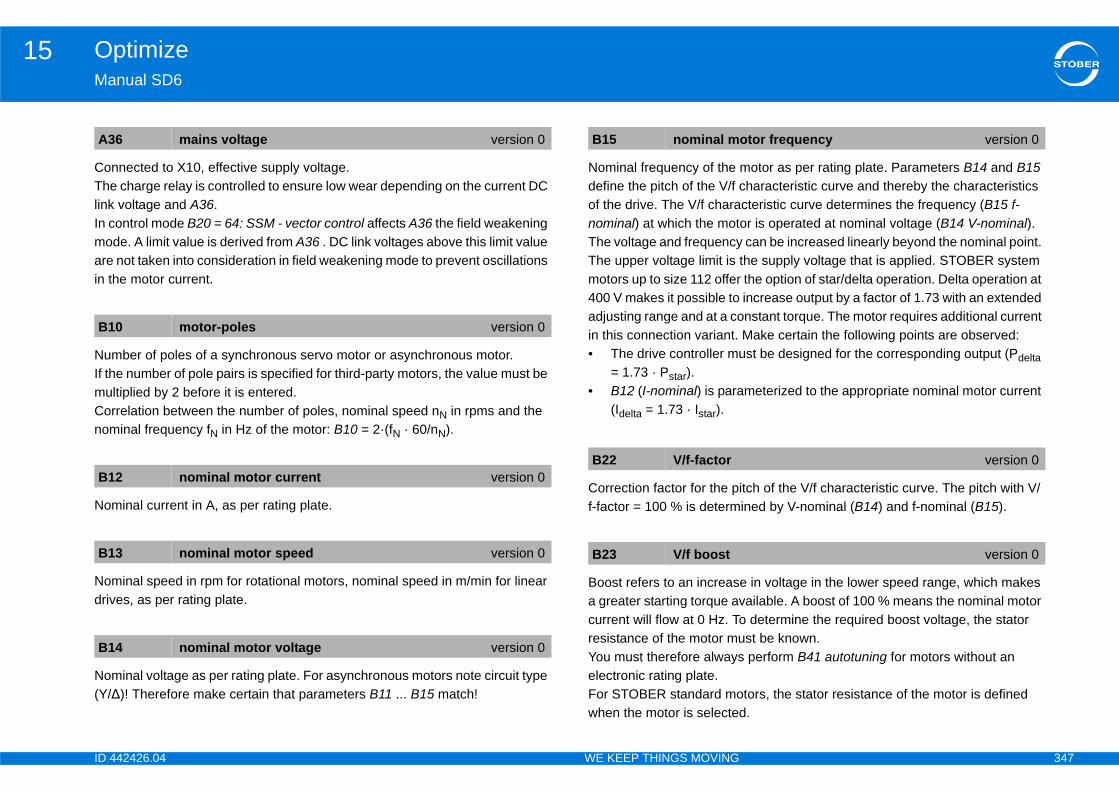
ID 4 347
Optimize15Ma
ConThelinkIn cmoarein t
NumIf thmuCornom
Nom
Nomdriv
Nom(Y/∆
motor as per rating plate. Parameters B14 and B15 haracteristic curve and thereby the characteristics
cteristic curve determines the frequency (B15 f-or is operated at nominal voltage (B14 V-nominal). can be increased linearly beyond the nominal point. he supply voltage that is applied. STOBER system the option of star/delta operation. Delta operation at increase output by a factor of 1.73 with an extended nstant torque. The motor requires additional current Make certain the following points are observed:st be designed for the corresponding output (Pdelta
meterized to the appropriate nominal motor current
tch of the V/f characteristic curve. The pitch with V/ined by V-nominal (B14) and f-nominal (B15).
e in voltage in the lower speed range, which makes ailable. A boost of 100 % means the nominal motor determine the required boost voltage, the stator st be known. perform B41 autotuning for motors without an
tors, the stator resistance of the motor is defined .
A3
B1
B1
B1
B1
otor frequency version 0
version 0
version 0
42426.04 WE KEEP THINGS MOVING
nual SD6
nected to X10, effective supply voltage. charge relay is controlled to ensure low wear depending on the current DC voltage and A36.ontrol mode B20 = 64: SSM - vector control affects A36 the field weakening de. A limit value is derived from A36 . DC link voltages above this limit value not taken into consideration in field weakening mode to prevent oscillations he motor current.
ber of poles of a synchronous servo motor or asynchronous motor.e number of pole pairs is specified for third-party motors, the value must be ltiplied by 2 before it is entered.relation between the number of poles, nominal speed nN in rpms and the inal frequency fN in Hz of the motor: B10 = 2·(fN · 60/nN).
inal current in A, as per rating plate.
inal speed in rpm for rotational motors, nominal speed in m/min for linear es, as per rating plate.
inal voltage as per rating plate. For asynchronous motors note circuit type )! Therefore make certain that parameters B11 ... B15 match!
Nominal frequency of the define the pitch of the V/f cof the drive. The V/f charanominal) at which the motThe voltage and frequencyThe upper voltage limit is tmotors up to size 112 offer400 V makes it possible toadjusting range and at a coin this connection variant. • The drive controller mu
= 1.73 · Pstar).• B12 (I-nominal) is para
(Idelta = 1.73 · Istar).
Correction factor for the pif-factor = 100 % is determ
Boost refers to an increasa greater starting torque avcurrent will flow at 0 Hz. Toresistance of the motor muYou must therefore alwayselectronic rating plate.For STOBER standard mowhen the motor is selected
6 mains voltage version 0
0 motor-poles version 0
2 nominal motor current version 0
3 nominal motor speed version 0
4 nominal motor voltage version 0
B15 nominal m
B22 V/f-factor
B23 V/f boost
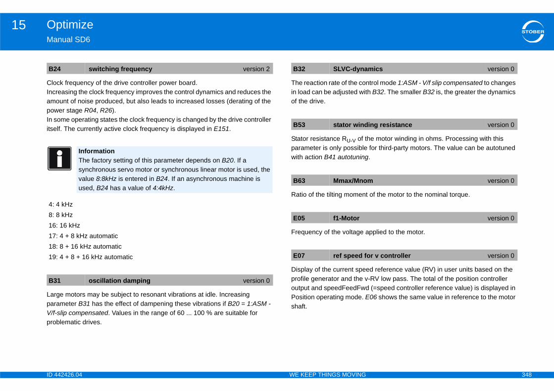
ID 4 348
Optimize15Ma
CloIncampowIn sitse
LarparV/f-pro
trol mode 1:ASM - V/f slip compensated to changes h B32. The smaller B32 is, the greater the dynamics
he motor winding in ohms. Processing with this for third-party motors. The value can be autotuned .
of the motor to the nominal torque.
pplied to the motor.
d reference value (RV) in user units based on the -RV low pass. The total of the position controller (=speed controller reference value) is displayed in 06 shows the same value in reference to the motor
B2
4: 8: 16171819
B3
mics version 0
ing resistance version 0
m version 0
version 0
or v controller version 0
42426.04 WE KEEP THINGS MOVING
nual SD6
ck frequency of the drive controller power board.reasing the clock frequency improves the control dynamics and reduces the ount of noise produced, but also leads to increased losses (derating of the er stage R04, R26).ome operating states the clock frequency is changed by the drive controller lf. The currently active clock frequency is displayed in E151.
ge motors may be subject to resonant vibrations at idle. Increasing ameter B31 has the effect of dampening these vibrations if B20 = 1:ASM - slip compensated. Values in the range of 60 ... 100 % are suitable for blematic drives.
The reaction rate of the conin load can be adjusted witof the drive.
Stator resistance RU-V of tparameter is only possiblewith action B41 autotuning
Ratio of the tilting moment
Frequency of the voltage a
Display of the current speeprofile generator and the voutput and speedFeedFwdPosition operating mode. Eshaft.
4 switching frequency version 2
InformationThe factory setting of this parameter depends on B20. If a synchronous servo motor or synchronous linear motor is used, the value 8:8kHz is entered in B24. If an asynchronous machine is used, B24 has a value of 4:4kHz.
4 kHz8 kHz: 16 kHz: 4 + 8 kHz automatic: 8 + 16 kHz automatic: 4 + 8 + 16 kHz automatic
1 oscillation damping version 0
B32 SLVC-dyna
B53 stator wind
B63 Mmax/Mno
E05 f1-Motor
E07 ref speed f
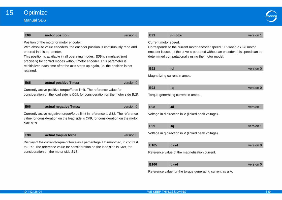
ID 4 349
Optimize15Ma
PosWitentThiprereinreta
Curcon
Curvaluside
Disto Econ
t motor encoder speed E15 when a B26 motor e is operated without an encoder, this speed can be ly using the motor model.
ps.
in amps.
(linked peak voltage).
(linked peak voltage).
gnetization current.
rque generating current as a A.
E0
E6
E6
E9
version 1
version 0
version 0
version 1
version 1
version 0
version 0
42426.04 WE KEEP THINGS MOVING
nual SD6
ition of the motor or motor encoder.h absolute value encoders, the encoder position is continuously read and ered in this parameter.s position is available in all operating modes. E09 is simulated (not cisely) for control modes without motor encoder. This parameter is itialized each time after the axis starts up again, i.e. the position is not ined.
rently active positive torque/force limit. The reference value for sideration on the load side is C09, for consideration on the motor side B18.
rently active negative torque/force limit in reference to B18. The reference e for consideration on the load side is C09, for consideration on the motor B18.
play of the current torque or force as a percentage. Unsmoothed, in contrast 02. The reference value for consideration on the load side is C09, for sideration on the motor side B18.
Current motor speed.Corresponds to the currenencoder is used. If the drivdetermined computational
Magnetizing current in am
Torque generating current
Voltage in d direction in V
Voltage in q direction in V
Reference value of the ma
Reference value for the to
9 motor position version 0
5 actual positive T-max version 0
6 actual negative T-max version 0
0 actual torque/ force version 0
E91 v-motor
E92 I-d
E93 I-q
E98 Ud
E99 Uq
E165 Id-ref
E166 Iq-ref

ID 4 350
Optimize15Ma
Forforccon
(IntEqucur
E1
E1
42426.04 WE KEEP THINGS MOVING
nual SD6
control modes with torque specification only. Reference torque or reference e currently required by the speed controller. The reference value for sideration on the load side is C09, for consideration on the motor side B18.
ernally) calculated torque generating reference current.ivalent to the rated current for asynchronous motors and the standstill
rent for synchronous servo motors.
70 T-reference version 0
72 Iq-reference version 0
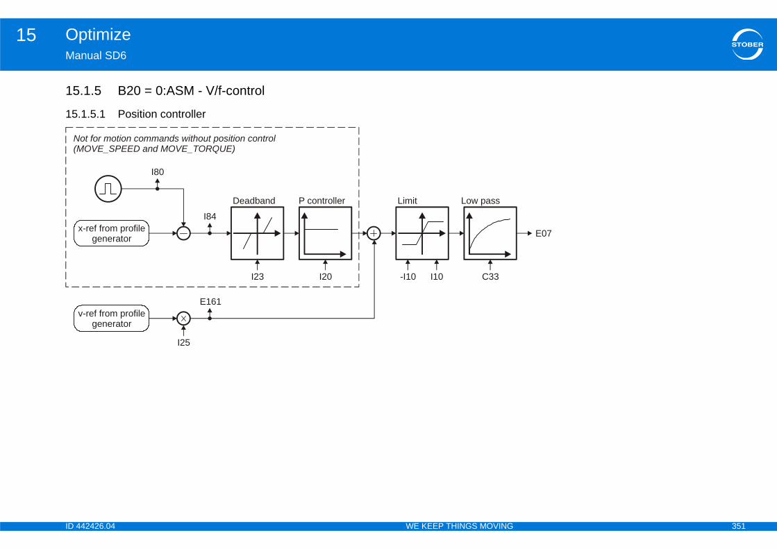
ID 4 351
Optimize15Ma
15
15
E07
N(M
42426.04 WE KEEP THINGS MOVING
nual SD6
.1.5 B20 = 0:ASM - V/f-control
.1.5.1 Position controller
Limit
-I10 I10
Low pass
C33
x-ref from profilegenerator
I80
I84
Deadband
I23
P controller
I20
v-ref from profilegenerator
E161
I25
ot for motion commands without position controlOVE_SPEED and MOVE_TORQUE)
ID 4 352
Optimize15Ma
Refvalu
DisprooutPossha
Thecon
Ma
Theass
response only). The Kv factor is also referred to as
cated with a unit of measure [m/min/mm]. This is · I20.
controller.scillations resulting from friction or reversal, sition encoder is used.
e position controller.file is switched to the output of the position
s the load on the position controller, thereby r.ve moves at a constant speed without a stationary tend to overshoot at the target position. Because of n is in the range of 60 ... 95 %.
C3
E0
E1
I10
y 1.111 is equivalent to the triggering limit for event
roportional gain position control) version 0
position control version 0
ust be less than the positioning window I22, rive will not reach its target position.
forward version 0
42426.04 WE KEEP THINGS MOVING
nual SD6
erence value smoothing. C33 should be increased in response to reference e noise, vibrating mechanics or large extraneous weights.
play of the current speed reference value (RV) in user units based on the file generator and the v-RV low pass. The total of the position controller put and speedFeedFwd (=speed controller reference value) is displayed in ition operating mode. E06 shows the same value in reference to the motor ft.
speed reference value at the output of the profile generator. With position trol corresponds to the speed feed forward.
ximum speed as a limit for calculating reference value with the motion core.
restriction does not apply with cyclically synchronous reference values igned in Controller Based mode.
Position controller gain (P-the speed gain.Occasionally it is also indiequivalent to exactly 0.06
Dead zone of the position Useful for preventing idle oespecially if an external po
Velocity feed forward of thThe calculated velocity procontroller.Speed feed forward relievereducing the following erroWhen I25 = 100 %, the drifollowing error, but it does this, I25 in most applicatio
3 lowpass reference speed version 0
7 ref speed for v controller version 0
61 v-rmpg version 0
maximal speed version 1
InformationThe limit is set without event 54:following error occurring.
InformationI10 multiplied b56:Overspeed.
I20 Kv-factor (p
I23 deadband
InformationI23 deadband motherwise the d
I25 speed feed
ID 4 353
Optimize15Ma
In aalle
Dis
DisIf thtrig
I80
I84
42426.04 WE KEEP THINGS MOVING
nual SD6
ddition to reducing I25, overshooting in the target position can also viated by increasing C32 (time constant I-part).
play of the actual position (without backlash compensation).
play of the current position deviation. e following distance I84 is above the permitted maximum I21, the drive
gers fault 54 following Error if the corresponding level is set in U22.
current position version 0
following error version 0
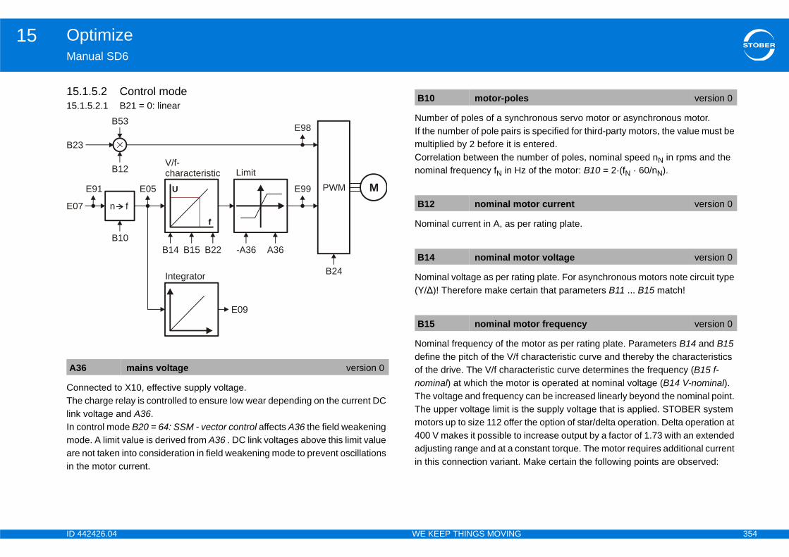
ID 4 354
Optimize15Ma
1515.
ConThelinkIn cmoarein t
hronous servo motor or asynchronous motor.is specified for third-party motors, the value must be entered.umber of poles, nominal speed nN in rpms and the of the motor: B10 = 2·(fN · 60/nN).
er rating plate.
ing plate. For asynchronous motors note circuit type tain that parameters B11 ... B15 match!
motor as per rating plate. Parameters B14 and B15 haracteristic curve and thereby the characteristics
cteristic curve determines the frequency (B15 f-or is operated at nominal voltage (B14 V-nominal). can be increased linearly beyond the nominal point. he supply voltage that is applied. STOBER system the option of star/delta operation. Delta operation at increase output by a factor of 1.73 with an extended nstant torque. The motor requires additional current Make certain the following points are observed:
A3
B23
E07
s version 0
otor current version 0
otor voltage version 0
otor frequency version 0
42426.04 WE KEEP THINGS MOVING
nual SD6
.1.5.2 Control mode1.5.2.1 B21 = 0: linear
nected to X10, effective supply voltage. charge relay is controlled to ensure low wear depending on the current DC voltage and A36.ontrol mode B20 = 64: SSM - vector control affects A36 the field weakening de. A limit value is derived from A36 . DC link voltages above this limit value not taken into consideration in field weakening mode to prevent oscillations he motor current.
Number of poles of a syncIf the number of pole pairs multiplied by 2 before it is Correlation between the nnominal frequency fN in Hz
Nominal current in A, as p
Nominal voltage as per rat(Y/∆)! Therefore make cer
Nominal frequency of the define the pitch of the V/f cof the drive. The V/f charanominal) at which the motThe voltage and frequencyThe upper voltage limit is tmotors up to size 112 offer400 V makes it possible toadjusting range and at a coin this connection variant.
6 mains voltage version 0
B53
n f
B12
U
f
E05
V/f-characteristic Limit
B14 B15 B22 -A36 A36
E99
E98
PWM
E09
B24Integrator
E91
B10
M
B10 motor-pole
B12 nominal m
B14 nominal m
B15 nominal m
ID 4 355
Optimize15Ma
•
•
Corf-fa
Booa gcurresYoueleForwhe
CloIncampowIn sitse
he motor winding in ohms. Processing with this for third-party motors. The value can be autotuned .
pplied to the motor.
d reference value (RV) in user units based on the -RV low pass. The total of the position controller (=speed controller reference value) is displayed in 06 shows the same value in reference to the motor
B2
B2
B2
ting of this parameter depends on B20. If a rvo motor or synchronous linear motor is used, the entered in B24. If an asynchronous machine is a value of 4:4kHz.
atic
ing resistance version 0
version 0
or v controller version 0
42426.04 WE KEEP THINGS MOVING
nual SD6
The drive controller must be designed for the corresponding output (Pdelta = 1.73 · Pstar).B12 (I-nominal) is parameterized to the appropriate nominal motor current (Idelta = 1.73 · Istar).
rection factor for the pitch of the V/f characteristic curve. The pitch with V/ctor = 100 % is determined by V-nominal (B14) and f-nominal (B15).
st refers to an increase in voltage in the lower speed range, which makes reater starting torque available. A boost of 100 % means the nominal motor rent will flow at 0 Hz. To determine the required boost voltage, the stator istance of the motor must be known. must therefore always perform B41 autotuning for motors without an
ctronic rating plate. STOBER standard motors, the stator resistance of the motor is defined n the motor is selected.
ck frequency of the drive controller power board.reasing the clock frequency improves the control dynamics and reduces the ount of noise produced, but also leads to increased losses (derating of the er stage R04, R26).ome operating states the clock frequency is changed by the drive controller lf. The currently active clock frequency is displayed in E151.
Stator resistance RU-V of tparameter is only possiblewith action B41 autotuning
Frequency of the voltage a
Display of the current speeprofile generator and the voutput and speedFeedFwdPosition operating mode. Eshaft.
2 V/f-factor version 0
3 V/f boost version 0
4 switching frequency version 2
InformationThe factory setsynchronous sevalue 8:8kHz isused, B24 has
4: 4 kHz8: 8 kHz16: 16 kHz17: 4 + 8 kHz automatic18: 8 + 16 kHz automatic19: 4 + 8 + 16 kHz autom
B53 stator wind
E05 f1-Motor
E07 ref speed f
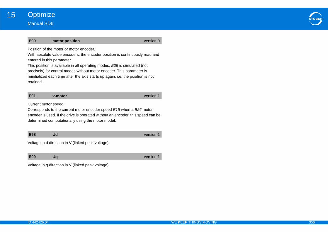
ID 4 356
Optimize15Ma
PosWitentThiprereinreta
CurCorencdet
Vol
Vol
E0
E9
E9
E9
42426.04 WE KEEP THINGS MOVING
nual SD6
ition of the motor or motor encoder.h absolute value encoders, the encoder position is continuously read and ered in this parameter.s position is available in all operating modes. E09 is simulated (not cisely) for control modes without motor encoder. This parameter is itialized each time after the axis starts up again, i.e. the position is not ined.
rent motor speed.responds to the current motor encoder speed E15 when a B26 motor oder is used. If the drive is operated without an encoder, this speed can be ermined computationally using the motor model.
tage in d direction in V (linked peak voltage).
tage in q direction in V (linked peak voltage).
9 motor position version 0
1 v-motor version 1
8 Ud version 1
9 Uq version 1

ID 4 357
Optimize15Ma
15.
ConThelinkIn cmoarein t
hronous servo motor or asynchronous motor.is specified for third-party motors, the value must be entered.umber of poles, nominal speed nN in rpms and the of the motor: B10 = 2·(fN · 60/nN).
er rating plate.
ing plate. For asynchronous motors note circuit type tain that parameters B11 ... B15 match!
motor as per rating plate. Parameters B14 and B15 haracteristic curve and thereby the characteristics
cteristic curve determines the frequency (B15 f-or is operated at nominal voltage (B14 V-nominal). can be increased linearly beyond the nominal point. he supply voltage that is applied. STOBER system the option of star/delta operation. Delta operation at increase output by a factor of 1.73 with an extended nstant torque. The motor requires additional current Make certain the following points are observed:
A3
B23
E07
s version 0
otor current version 0
otor voltage version 0
otor frequency version 0
42426.04 WE KEEP THINGS MOVING
nual SD6
1.5.2.2 B21 = 1: square
nected to X10, effective supply voltage. charge relay is controlled to ensure low wear depending on the current DC voltage and A36.ontrol mode B20 = 64: SSM - vector control affects A36 the field weakening de. A limit value is derived from A36 . DC link voltages above this limit value not taken into consideration in field weakening mode to prevent oscillations he motor current.
Number of poles of a syncIf the number of pole pairs multiplied by 2 before it is Correlation between the nnominal frequency fN in Hz
Nominal current in A, as p
Nominal voltage as per rat(Y/∆)! Therefore make cer
Nominal frequency of the define the pitch of the V/f cof the drive. The V/f charanominal) at which the motThe voltage and frequencyThe upper voltage limit is tmotors up to size 112 offer400 V makes it possible toadjusting range and at a coin this connection variant.
6 mains voltage version 0
B53
n f
B12
U
f
E05
Limit
B14 B15 B22 -A36 A36
E99
E98
PWM
E09
B24Integrator
E91 M
V/f-characteristic
B10 motor-pole
B12 nominal m
B14 nominal m
B15 nominal m

ID 4 358
Optimize15Ma
•
•
Corf-fa
Booa gcurresYoueleForwhe
CloIncampowIn sitse
he motor winding in ohms. Processing with this for third-party motors. The value can be autotuned .
pplied to the motor.
d reference value (RV) in user units based on the -RV low pass. The total of the position controller (=speed controller reference value) is displayed in 06 shows the same value in reference to the motor
otor encoder.ers, the encoder position is continuously read and
B2
B2
B2
ting of this parameter depends on B20. If a rvo motor or synchronous linear motor is used, the entered in B24. If an asynchronous machine is a value of 4:4kHz.
ing resistance version 0
version 0
or v controller version 0
tion version 0
42426.04 WE KEEP THINGS MOVING
nual SD6
The drive controller must be designed for the corresponding output (Pdelta = 1.73 · Pstar).B12 (I-nominal) is parameterized to the appropriate nominal motor current (Idelta = 1.73 · Istar).
rection factor for the pitch of the V/f characteristic curve. The pitch with V/ctor = 100 % is determined by V-nominal (B14) and f-nominal (B15).
st refers to an increase in voltage in the lower speed range, which makes reater starting torque available. A boost of 100 % means the nominal motor rent will flow at 0 Hz. To determine the required boost voltage, the stator istance of the motor must be known. must therefore always perform B41 autotuning for motors without an
ctronic rating plate. STOBER standard motors, the stator resistance of the motor is defined n the motor is selected.
ck frequency of the drive controller power board.reasing the clock frequency improves the control dynamics and reduces the ount of noise produced, but also leads to increased losses (derating of the er stage R04, R26).ome operating states the clock frequency is changed by the drive controller lf. The currently active clock frequency is displayed in E151.
Stator resistance RU-V of tparameter is only possiblewith action B41 autotuning
Frequency of the voltage a
Display of the current speeprofile generator and the voutput and speedFeedFwdPosition operating mode. Eshaft.
Position of the motor or mWith absolute value encodentered in this parameter.
2 V/f-factor version 0
3 V/f boost version 0
4 switching frequency version 0
InformationThe factory setsynchronous sevalue 8:8kHz isused, B24 has
B53 stator wind
E05 f1-Motor
E07 ref speed f
E09 motor posi
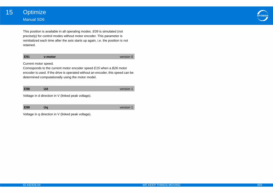
ID 4 359
Optimize15Ma
Thiprereinreta
CurCorencdet
Vol
Vol
E9
E9
E9
42426.04 WE KEEP THINGS MOVING
nual SD6
s position is available in all operating modes. E09 is simulated (not cisely) for control modes without motor encoder. This parameter is itialized each time after the axis starts up again, i.e. the position is not ined.
rent motor speed.responds to the current motor encoder speed E15 when a B26 motor oder is used. If the drive is operated without an encoder, this speed can be ermined computationally using the motor model.
tage in d direction in V (linked peak voltage).
tage in q direction in V (linked peak voltage).
1 v-motor version 0
8 Ud version 1
9 Uq version 1
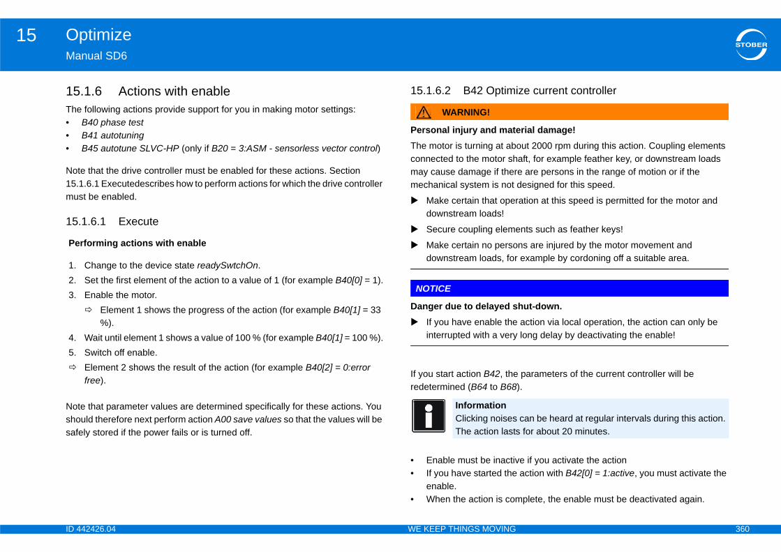
ID 4 360
Optimize15Ma
15The•••
Not15.mu
15
Notshosaf
ze current controller
rial damage!out 2000 rpm during this action. Coupling elements aft, for example feather key, or downstream loads e are persons in the range of motion or if the designed for this speed.
ation at this speed is permitted for the motor and
nts such as feather keys!
ns are injured by the motor movement and example by cordoning off a suitable area.
hut-down. action via local operation, the action can only be long delay by deactivating the enable!
parameters of the current controller will be ).
e if you activate the action action with B42[0] = 1:active, you must activate the
plete, the enable must be deactivated again.
Pe
1.2.3.
4.5.
can be heard at regular intervals during this action. for about 20 minutes.
42426.04 WE KEEP THINGS MOVING
nual SD6
.1.6 Actions with enable following actions provide support for you in making motor settings:B40 phase testB41 autotuningB45 autotune SLVC-HP (only if B20 = 3:ASM - sensorless vector control)
e that the drive controller must be enabled for these actions. Section 1.6.1 Executedescribes how to perform actions for which the drive controller st be enabled.
.1.6.1 Execute
e that parameter values are determined specifically for these actions. You uld therefore next perform action A00 save values so that the values will be ely stored if the power fails or is turned off.
15.1.6.2 B42 Optimi
WARNING!
Personal injury and mateThe motor is turning at abconnected to the motor shmay cause damage if thermechanical system is not
Make certain that operdownstream loads!
Secure coupling eleme
Make certain no persodownstream loads, for
NOTICE
Danger due to delayed s If you have enable the
interrupted with a very
If you start action B42, theredetermined (B64 to B68
• Enable must be inactiv• If you have started the
enable.• When the action is com
rforming actions with enable
Change to the device state readySwtchOn.Set the first element of the action to a value of 1 (for example B40[0] = 1).Enable the motor. Element 1 shows the progress of the action (for example B40[1] = 33
%).Wait until element 1 shows a value of 100 % (for example B40[1] = 100 %).Switch off enable.Element 2 shows the result of the action (for example B40[2] = 0:error free).
InformationClicking noisesThe action lasts

ID 4 361
Optimize15Ma
TheIf aimmTheYou
0: e
1: a
15
The... BturnYoutheWhB64
To act(B5mo
Pro
urrent controller (standstill) is complete, the result
f the displayable position to the e position
odel yield the smallest position step that can be 0.0001 mm). I160 shows how many measurement sed has in the smallest position step that can be t possible to determine the expected control
hout cyclic real-time assignment of reference values nit. greater than 1 per position step, there will be no ue to quantization. However, the encoder resolution reference value is assigned or with position display. it is used with cyclic assignment of reference value, erformance. Position control in the drive controller r resolution regardless of the position steps that can
real-time assignment of reference values by a
d for the control unit connection are used, the result er position step. Then the encoder resolution will be l unit.
B4
B4
B4
rrent controller (standstill) result version 1
solution version 0
42426.04 WE KEEP THINGS MOVING
nual SD6
n you can read the measured values in B64 to B68. quick stop request occurs during the action, the drive is stopped ediately. cycle time is set to 32 ms internally for the duration of the action. can read the following results in the third element (B42.2):
rror free: The action was performed and completed without errors.
borted: The action was interrupted by switching off the enable.
.1.6.3 B49 optimize current controller standstill
action redetermines the parameters for current controller gain (B53, B64 68). In contrast to action B42 optimize current controller the motor does not during the action. can start the action in B49[0], observe the progress in B49[1] and obtain
result in B49[2].en the action is complete you can read the new values in B53 as well as ... B68.
start action B49 current controller optimization, set B49[0] = 1:active. The ion determines the parameters for current controller optimization again 3, B64 ... B68). In contrast to action B42 current controller optimization the tor does not turn during the action.
gress of current controller optimization as a %.
After action B49 optimize ccan be queried here.
15.2 The ratio omeasurabl
The settings of the axis mrepresented (for example steps the encoder that is urepresented. This makes iperformance.
I160 > 1:Typical for applications witby a higher-level control uIf the encoder resolution isposition control problems dcannot be fully utilized if a If a higher-level control unthis can lead to losses in palways uses the full encodebe displayed in user units.
I160 = 1:For applications with cyclichigher-level control unit.If the settings recommendewill be a quantization of 1 ppassed along to the contro
9 optimize current controller (standstill) version 0
9[0] optimize current controller (standstill) start version 0
9[1] optimize current controller (standstill) process version 0
B49[2] optimize cu
I160 position re
ID 4 362
Optimize15Ma
I16Theenccondispdecis ulea
42426.04 WE KEEP THINGS MOVING
nual SD6
0 < 1:se setting are not recommended, but can be used with restrictions. If the oder resolution is less than 1 per position step, there may be position trol problems due to quantization, since not every position that can be layed can be approached. Check whether you can do without some imal places or if the application requires a better encoder. If position control sed in the drive controller, the deadband and position window must be at st as large as quantization.
ID 4 363
Diagnosis16Ma
16Ov
16
16
16
16
16
16
16
16
16
16
16
16
16
16
16
42426.04 WE KEEP THINGS MOVING
nual SD6
Diagnosiserview of sections
.1 31:Short/ground .. . . . . . . . . . . . . . . . . . . . . . . . . . . . . . . . . . . .367
.2 32:Short/gr.int .. . . . . . . . . . . . . . . . . . . . . . . . . . . . . . . . . . . . . .367
.3 33:Overcurrent .. . . . . . . . . . . . . . . . . . . . . . . . . . . . . . . . . . . . .368
.4 34:Hardw.fault . . . . . . . . . . . . . . . . . . . . . . . . . . . . . . . . . . . . . .369
.5 35:Watchdog . . . . . . . . . . . . . . . . . . . . . . . . . . . . . . . . . . . . . . .370
.6 36:High voltage . . . . . . . . . . . . . . . . . . . . . . . . . . . . . . . . . . . . .371
.7 37:Encoder . . . . . . . . . . . . . . . . . . . . . . . . . . . . . . . . . . . . . . . . .372
.8 38:TempDev.sens . . . . . . . . . . . . . . . . . . . . . . . . . . . . . . . . . . .376
.9 39:TempDev i2t . . . . . . . . . . . . . . . . . . . . . . . . . . . . . . . . . . . . .377
.10 40:Invalid data . . . . . . . . . . . . . . . . . . . . . . . . . . . . . . . . . . . . .378
.11 41:Temp.MotorTMS . . . . . . . . . . . . . . . . . . . . . . . . . . . . . . . .379
.12 42:TempBrakeRes . . . . . . . . . . . . . . . . . . . . . . . . . . . . . . . . .380
.13 43: AE1 wire break .. . . . . . . . . . . . . . . . . . . . . . . . . . . . . . . .381
.14 44:External fault . . . . . . . . . . . . . . . . . . . . . . . . . . . . . . . . . . .382
.15 45:oTempMot. i2t . . . . . . . . . . . . . . . . . . . . . . . . . . . . . . . . . .383

ID 4 364
Diagnosis16Ma
16
16
16
16
16
16
16
16
16
16
16
16
16
16
16
16
16
42426.04 WE KEEP THINGS MOVING
nual SD6
.16 46:Low voltage . . . . . . . . . . . . . . . . . . . . . . . . . . . . . . . . . . . .384
.17 47:TorqueLimit .. . . . . . . . . . . . . . . . . . . . . . . . . . . . . . . . . . . .385
.18 48:Brake release monitoring . . . . . . . . . . . . . . . . . . . . . . . .386
.19 49:brake . . . . . . . . . . . . . . . . . . . . . . . . . . . . . . . . . . . . . . . . . .387
.20 50:Safety function .. . . . . . . . . . . . . . . . . . . . . . . . . . . . . . . . .388
.21 51:Virtual master limit switch . . . . . . . . . . . . . . . . . . . . . . .389
.22 52:Communication . . . . . . . . . . . . . . . . . . . . . . . . . . . . . . . . .390
.23 53: Limit switch . . . . . . . . . . . . . . . . . . . . . . . . . . . . . . . . . . . .393
.24 54:following Error . . . . . . . . . . . . . . . . . . . . . . . . . . . . . . . . . .395
.25 55:Option module . . . . . . . . . . . . . . . . . . . . . . . . . . . . . . . . . .396
.26 56:Overspeed . . . . . . . . . . . . . . . . . . . . . . . . . . . . . . . . . . . . .397
.27 57:Runtime usage . . . . . . . . . . . . . . . . . . . . . . . . . . . . . . . . .398
.28 58:Encoder simulation . . . . . . . . . . . . . . . . . . . . . . . . . . . . .399
.29 59:TempDev. i2t . . . . . . . . . . . . . . . . . . . . . . . . . . . . . . . . . . .400
.30 60-67:Application events 0-7 . . . . . . . . . . . . . . . . . . . . . . .401
.31 68: External fault .. . . . . . . . . . . . . . . . . . . . . . . . . . . . . . . . . .402
.32 69:Motor connect. .. . . . . . . . . . . . . . . . . . . . . . . . . . . . . . . . .403

ID 4 365
Diagnosis16Ma
16
16
16
16
16
16
16
16
16
16
16
16
16
16
16
16
16
42426.04 WE KEEP THINGS MOVING
nual SD6
.33 70:Param.consist . . . . . . . . . . . . . . . . . . . . . . . . . . . . . . . . . .404
.34 71:Firmware . . . . . . . . . . . . . . . . . . . . . . . . . . . . . . . . . . . . . . .406
.35 72:Brake test . . . . . . . . . . . . . . . . . . . . . . . . . . . . . . . . . . . . . .407
.36 73:Ax2braketest . . . . . . . . . . . . . . . . . . . . . . . . . . . . . . . . . . .408
.37 74:Ax3braketest . . . . . . . . . . . . . . . . . . . . . . . . . . . . . . . . . . .409
.38 75:Ax4braketest . . . . . . . . . . . . . . . . . . . . . . . . . . . . . . . . . . .410
.39 76:position encoder . . . . . . . . . . . . . . . . . . . . . . . . . . . . . . . .411
.40 77:Master encoder . . . . . . . . . . . . . . . . . . . . . . . . . . . . . . . . .415
.41 78:position limit cyclic . . . . . . . . . . . . . . . . . . . . . . . . . . . . . .419
.42 79:Motor/position monitor . . . . . . . . . . . . . . . . . . . . . . . . . .420
.43 80:illegal action . . . . . . . . . . . . . . . . . . . . . . . . . . . . . . . . . . . .421
.44 81:motor allocation .. . . . . . . . . . . . . . . . . . . . . . . . . . . . . . . .422
.45 82:Hall sensor . . . . . . . . . . . . . . . . . . . . . . . . . . . . . . . . . . . . .424
.46 83:Failure of one/all mains phases . . . . . . . . . . . . . . . . . .425
.47 84:Drop in network with power stage active . . . . . . . . . .426
.48 85:Excessive jump in reference value . . . . . . . . . . . . . . .427
.49 #<Placeholder> . . . . . . . . . . . . . . . . . . . . . . . . . . . . . . . . . . . .428
ID 4 366
Diagnosis16Ma
16
16
16
16
16
16
16
16
16
16
16
16
16
16
16
16
16
42426.04 WE KEEP THINGS MOVING
nual SD6
.50 *ParaModul ERROR:update firmware! . . . . . . . . . . . . . .428
.51 *ParaModul ERROR: file not found .. . . . . . . . . . . . . . . . .429
.52 *ParaModul ERROR: Checksum error .. . . . . . . . . . . . . .429
.53 *ParaModul ERROR: ksb write error . . . . . . . . . . . . . . . .430
.54 *ConfigStartERROR parameters lost . . . . . . . . . . . . . . . .430
.55 *ConfigStartERROR remanents lost . . . . . . . . . . . . . . . . .431
.56 *ConfigStartERROR unknown block .. . . . . . . . . . . . . . . .431
.57 *ConfigStartERROR unknown string . . . . . . . . . . . . . . . .432
.58 *ConfigStartERROR unknown scale .. . . . . . . . . . . . . . . .432
.59 *ConfigStartERROR unknown limit . . . . . . . . . . . . . . . . . .433
.60 *ConfigStartERROR unknown post-wr .. . . . . . . . . . . . . .433
.61*ConfigStartERROR unknown pre-rd . . . . . . . . . . . . . . . . .434
.62 *ConfigStartERROR unknown hiding . . . . . . . . . . . . . . . .434
.63 no configuration paramodul error .. . . . . . . . . . . . . . . . . . .435
.64 no configuration start error .. . . . . . . . . . . . . . . . . . . . . . . . .435
.65 configuration stopped . . . . . . . . . . . . . . . . . . . . . . . . . . . . . .436
.66 HW defective FirmwareStartErr . . . . . . . . . . . . . . . . . . . . .436
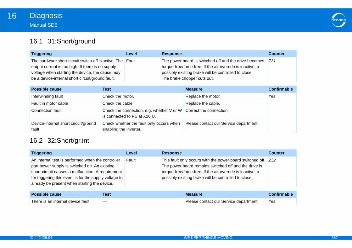
ID 4 367
Diagnosis16Ma
16
16
Tr CounterThouvobe
e drive becomes e is inactive, a d to close.
Z31
Po ConfirmableInt Yes
Fa
Co
Defau
e department.
Tr CounterAnpashforalr
oard switched off.and the drive is e is inactive, a d to close.
Z32
Po ConfirmableTh e department. Yes
42426.04 WE KEEP THINGS MOVING
nual SD6
.1 31:Short/ground
.2 32:Short/gr.int
iggering Level Responsee hardware short-circuit switch-off is active. The tput current is too high. If there is no supply ltage when starting the device, the cause may a device-internal short circuit/ground fault.
Fault The power board is switched off and thtorque-free/force-free. If the air overridpossibly existing brake will be controlleThe brake chopper cuts out.
ssible cause Test Measureerwinding fault Check the motor. Replace the motor.
ult in motor cable Check the cable Replace the cable.
nnection fault Check the connection, e.g. whether V or W is connected to PE at X20 U.
Correct the connection.
vice-internal short circuit/ground lt
Check whether the fault only occurs when enabling the inverter.
Please contact our Servic
iggering Level Response internal test is performed when the controller rt power supply is switched on. An existing ort-circuit causes a malfunction. A requirement triggering this event is for the supply voltage to eady be present when starting the device.
Fault This fault only occurs with the power bThe power board remains switched off torque-free/force-free. If the air overridpossibly existing brake will be controlle
ssible cause Test Measureere is an internal device fault. — Please contact our Servic

ID 4 368
Diagnosis16Ma
16
Tr CounterThma
e drive becomes y braking U30
V 6.0-F). If the air brake will be
Z33
Po ConfirmableAc ation. Yes
Incan
ation.
42426.04 WE KEEP THINGS MOVING
nual SD6
.3 33:Overcurrent
iggering Level Responsee total motor current exceeds the permitted ximum value.
Fault The power board is switched off and thtorque-free/force-free unless emergenc(A29) is parameterized (from firmware override is inactive, a possibly existing controlled to close.
ssible cause Test Measureceleration times too short. Extend the ramps. Apply this setting for oper
orrectly set torque limits in the C03 d C05 parameters.
Set smaller values in C03 and C05. Apply this setting for oper
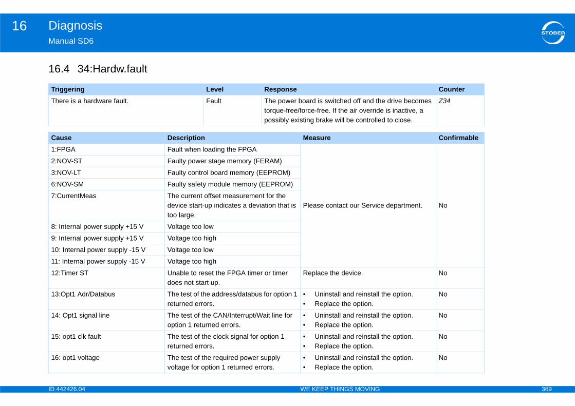
ID 4 369
Diagnosis16Ma
16
Tr CounterTh e drive becomes
e is inactive, a d to close.
Z34
Ca Confirmable1:F
e department. No
2:N
3:N
6:N
7:C
8:
9:
10
11
12 No
13 the option. No
14 the option. No
15 the option. No
16 the option. No
42426.04 WE KEEP THINGS MOVING
nual SD6
.4 34:Hardw.fault
iggering Level Responseere is a hardware fault. Fault The power board is switched off and th
torque-free/force-free. If the air overridpossibly existing brake will be controlle
use Description MeasurePGA Fault when loading the FPGA
Please contact our Servic
OV-ST Faulty power stage memory (FERAM)
OV-LT Faulty control board memory (EEPROM)
OV-SM Faulty safety module memory (EEPROM)
urrentMeas The current offset measurement for the device start-up indicates a deviation that is too large.
Internal power supply +15 V Voltage too low
Internal power supply +15 V Voltage too high
: Internal power supply -15 V Voltage too low
: Internal power supply -15 V Voltage too high
:Timer ST Unable to reset the FPGA timer or timer does not start up.
Replace the device.
:Opt1 Adr/Databus The test of the address/databus for option 1 returned errors.
• Uninstall and reinstall • Replace the option.
: Opt1 signal line The test of the CAN/Interrupt/Wait line for option 1 returned errors.
• Uninstall and reinstall • Replace the option.
: opt1 clk fault The test of the clock signal for option 1 returned errors.
• Uninstall and reinstall • Replace the option.
: opt1 voltage The test of the required power supply voltage for option 1 returned errors.
• Uninstall and reinstall • Replace the option.
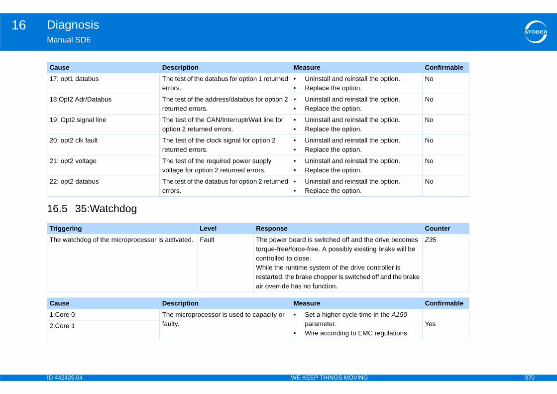
ID 4 370
Diagnosis16Ma
16
17 the option. No
18 the option. No
19 the option. No
20 the option. No
21 the option. No
22 the option. No
Tr CounterTh e drive becomes
ng brake will be
ontroller is off and the brake
Z35
Ca Confirmable1:C e in the A150
regulations.Yes2:C
Ca Confirmable
42426.04 WE KEEP THINGS MOVING
nual SD6
.5 35:Watchdog
: opt1 databus The test of the databus for option 1 returned errors.
• Uninstall and reinstall • Replace the option.
:Opt2 Adr/Databus The test of the address/databus for option 2 returned errors.
• Uninstall and reinstall • Replace the option.
: Opt2 signal line The test of the CAN/Interrupt/Wait line for option 2 returned errors.
• Uninstall and reinstall • Replace the option.
: opt2 clk fault The test of the clock signal for option 2 returned errors.
• Uninstall and reinstall • Replace the option.
: opt2 voltage The test of the required power supply voltage for option 2 returned errors.
• Uninstall and reinstall • Replace the option.
: opt2 databus The test of the databus for option 2 returned errors.
• Uninstall and reinstall • Replace the option.
iggering Level Responsee watchdog of the microprocessor is activated. Fault The power board is switched off and th
torque-free/force-free. A possibly existicontrolled to close.While the runtime system of the drive crestarted, the brake chopper is switchedair override has no function.
use Description Measureore 0 The microprocessor is used to capacity or
faulty.• Set a higher cycle tim
parameter.• Wire according to EMC
ore 1
use Description Measure
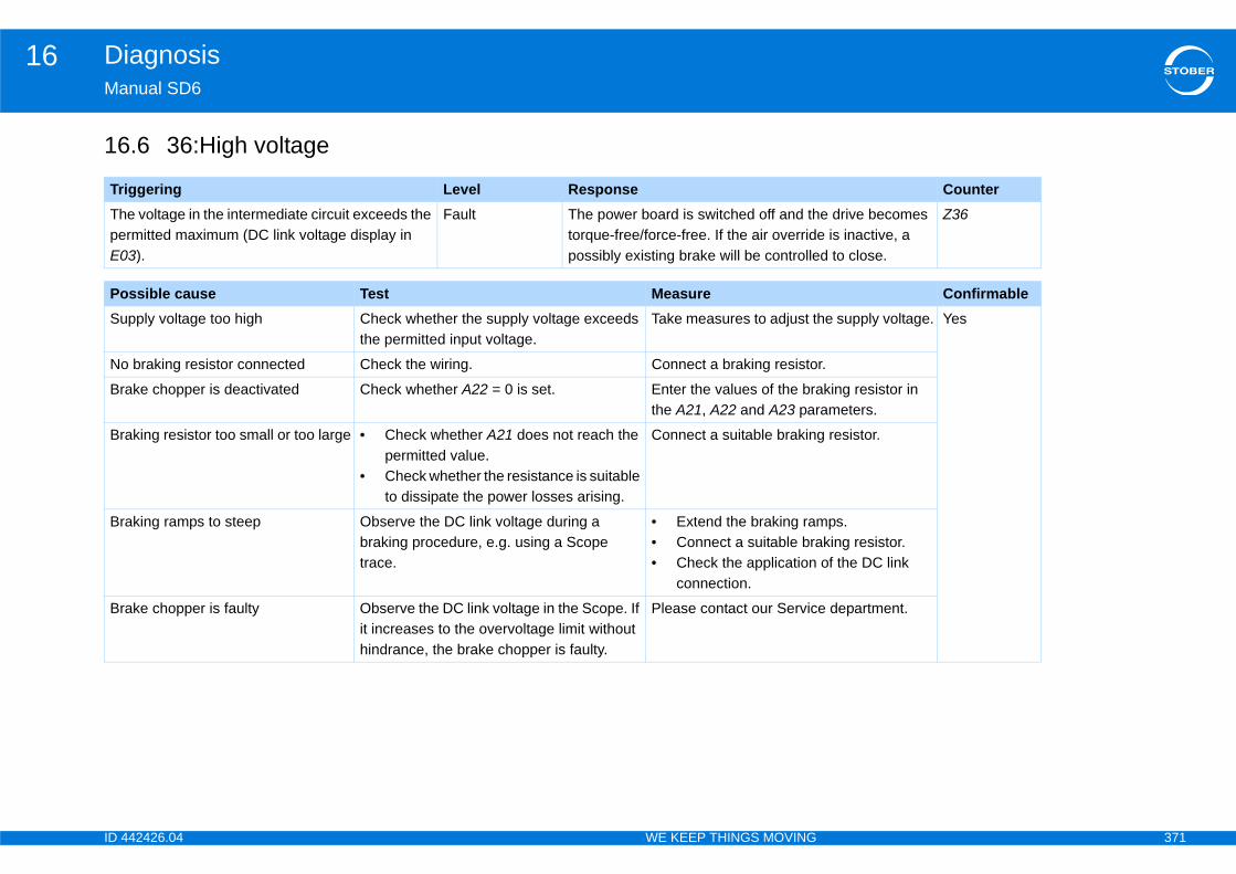
ID 4 371
Diagnosis16Ma
16
Tr CounterThpeE0
e drive becomes e is inactive, a d to close.
Z36
Po ConfirmableSu he supply voltage. Yes
No r.
Br king resistor in ameters.
Br resistor.
Br ps.king resistor.
of the DC link
Br e department.
42426.04 WE KEEP THINGS MOVING
nual SD6
.6 36:High voltage
iggering Level Responsee voltage in the intermediate circuit exceeds the rmitted maximum (DC link voltage display in 3).
Fault The power board is switched off and thtorque-free/force-free. If the air overridpossibly existing brake will be controlle
ssible cause Test Measurepply voltage too high Check whether the supply voltage exceeds
the permitted input voltage.Take measures to adjust t
braking resistor connected Check the wiring. Connect a braking resisto
ake chopper is deactivated Check whether A22 = 0 is set. Enter the values of the brathe A21, A22 and A23 par
aking resistor too small or too large • Check whether A21 does not reach the permitted value.
• Check whether the resistance is suitable to dissipate the power losses arising.
Connect a suitable braking
aking ramps to steep Observe the DC link voltage during a braking procedure, e.g. using a Scope trace.
• Extend the braking ram• Connect a suitable bra• Check the application
connection.
ake chopper is faulty Observe the DC link voltage in the Scope. If it increases to the overvoltage limit without hindrance, the brake chopper is faulty.
Please contact our Servic
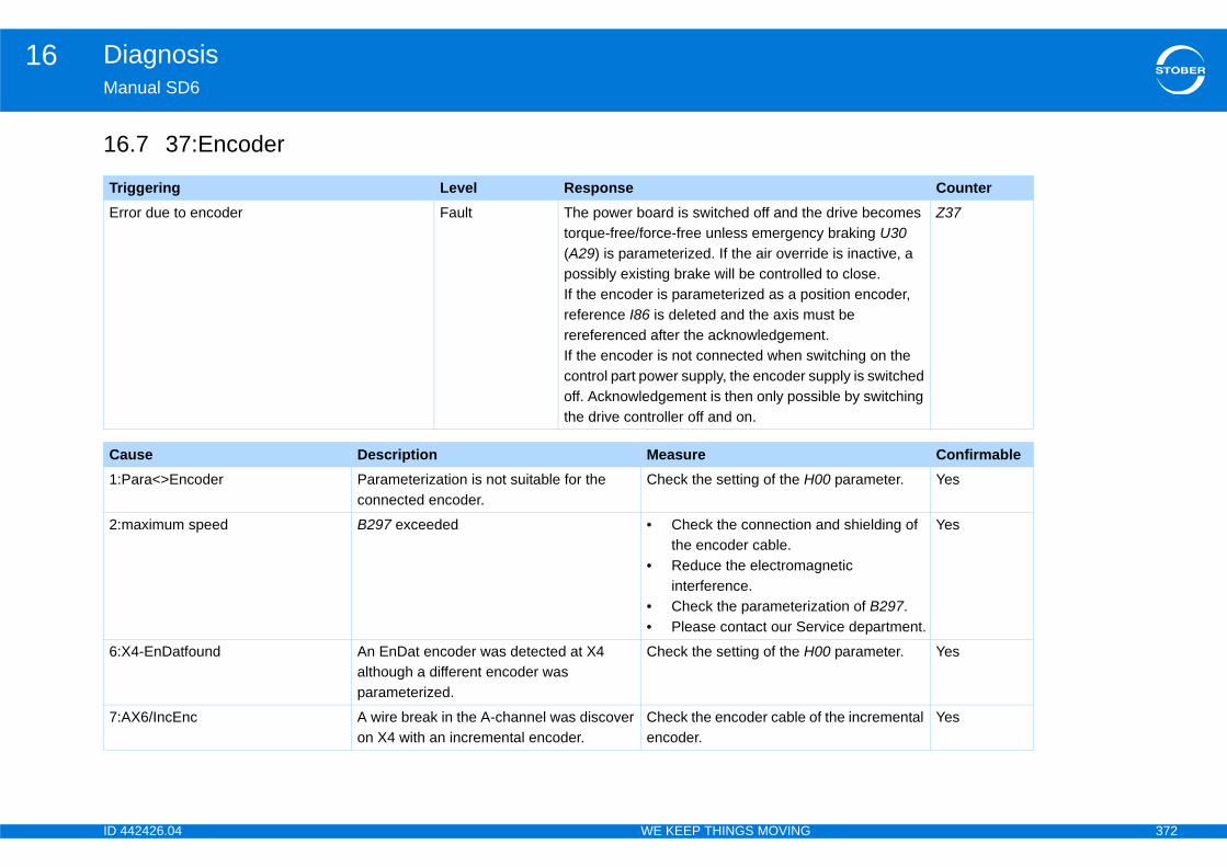
ID 4 372
Diagnosis16Ma
16
Tr CounterEr e drive becomes
y braking U30 de is inactive, a d to close.sition encoder, ust be nt.witching on the upply is switched ible by switching
Z37
Ca Confirmable1:P 00 parameter. Yes
2:m and shielding of
gnetic
ation of B297.rvice department.
Yes
6:X 00 parameter. Yes
7:A f the incremental Yes
42426.04 WE KEEP THINGS MOVING
nual SD6
.7 37:Encoder
iggering Level Responseror due to encoder Fault The power board is switched off and th
torque-free/force-free unless emergenc(A29) is parameterized. If the air overripossibly existing brake will be controlleIf the encoder is parameterized as a poreference I86 is deleted and the axis mrereferenced after the acknowledgemeIf the encoder is not connected when scontrol part power supply, the encoder soff. Acknowledgement is then only possthe drive controller off and on.
use Description Measureara<>Encoder Parameterization is not suitable for the
connected encoder.Check the setting of the H
aximum speed B297 exceeded • Check the connectionthe encoder cable.
• Reduce the electromainterference.
• Check the parameteriz• Please contact our Se
4-EnDatfound An EnDat encoder was detected at X4 although a different encoder was parameterized.
Check the setting of the H
X6/IncEnc A wire break in the A-channel was discover on X4 with an incremental encoder.
Check the encoder cable oencoder.

ID 4 373
Diagnosis16Ma
8:X of the encoder.ble.ply of the
e H00 parameter.
Yes
10 ble and replace if
rvice department.
Yes
11 Yes
12 Yes
13rvice department.
No
14 and shielding of
gnetic
rvice department.
Yes
15 and shielding of
gnetic
Yes
16 ble.ble encoder is
rvice department.
Yes
17 ollow the operating
Yes
Ca Confirmable
42426.04 WE KEEP THINGS MOVING
nual SD6
4-noEnc.found No encoder was found at X4 or a wire break was detected at the EnDat/SSI encoder.
• Correct the connection• Check the encoder ca• Correct the power sup
encoder.• Check the setting of th
:X4 chan. A/Clk Wire break track A/Clock • Check the encoder canecessary.
• Please contact our Se:X4-chan. B/Dat Wire break track B/Data
:X4-channel 0 Wire break channel 0
:X4-EnDatAlarm Alarm bit of EnDat encoder present. • Replace the motor.• Please contact our Se
:X4-EnDatCRC Errors accumulate during data transfer. • Check the connectionthe encoder cable.
• Reduce the electromainterference.
• Please contact our Se
:X4 double transmission Different positions are frequently determined at X4 during double transmission.
• Check the connectionthe encoder cable.
• Reduce the electromainterference.
:X4-Busy Encoder has not responded for too long. • Check the encoder ca• Check whether a suita
connected.• Please contact our Se
:Battery low (EBI) The AES accessory battery is weak. • Replace the battery. Finstructions in the AESmanual.
use Description Measure

ID 4 374
Diagnosis16Ma
18 ollow the operating
Yes
20 ble.ecification of the pecifications of
rvice department.
No
21
22
24 ble.rvice department.
Yes
30 cable (encoder or
ly of the SSI that simulates the
ttings of the SSI the SSI encoder
ulates the SSI
Yes
35 ble.rvice department.
No
36 ard that the to.troller.rvice department.
Yes
38 cable.ly of the SSI
Yes
Ca Confirmable
42426.04 WE KEEP THINGS MOVING
nual SD6
:Battery empty (EBI) The AES accessory battery is empty. • Replace the battery. Finstructions in the AESmanual.
:resol.carrier The resolver could not be calibrated or optimized.
• Check the encoder ca• Check whether the sp
resolver matches the sSTOBER.
• Please contact our Se
:X140-undervolt. Incorrect transfer factor
:X140-Overvltg
:resol.failure Wire break • Check the encoder ca• Please contact our Se
:X120-Wire break A wire break was detected at X120. • Check the connected SSI connection).
• Check the power suppencoder or the source SSI signals.
• Make sure that the semaster are matched toor the source that simsignals.
:X120-double transmission Different positions are frequently determined at X120 during double transmission.
• Check the encoder ca• Please contact our Se
:X120-Busy Encoder has not responded for too long; for SSI-slave: No telegram for 5 ms with drive enabled.
• Replace the option boencoder is connected
• Replace the drive con• Please contact our Se
:X120-Timeout No cycle signal was detected from the SSI master.
• Check the connected • Check the power supp
master.
use Description Measure
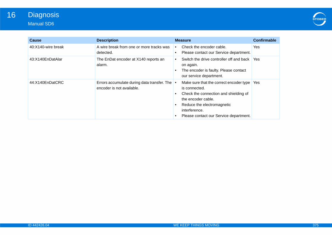
ID 4 375
Diagnosis16Ma
40 ble.rvice department.
Yes
43 oller off and back
Please contact t.
Yes
44 rect encoder type
and shielding of
gnetic
rvice department.
Yes
Ca Confirmable
42426.04 WE KEEP THINGS MOVING
nual SD6
:X140-wire break A wire break from one or more tracks was detected.
• Check the encoder ca• Please contact our Se
:X140EnDatAlar The EnDat encoder at X140 reports an alarm.
• Switch the drive contron again.
• The encoder is faulty. our service departmen
:X140EnDatCRC Errors accumulate during data transfer. The encoder is not available.
• Make sure that the coris connected.
• Check the connectionthe encoder cable.
• Reduce the electromainterference.
• Please contact our Se
use Description Measure
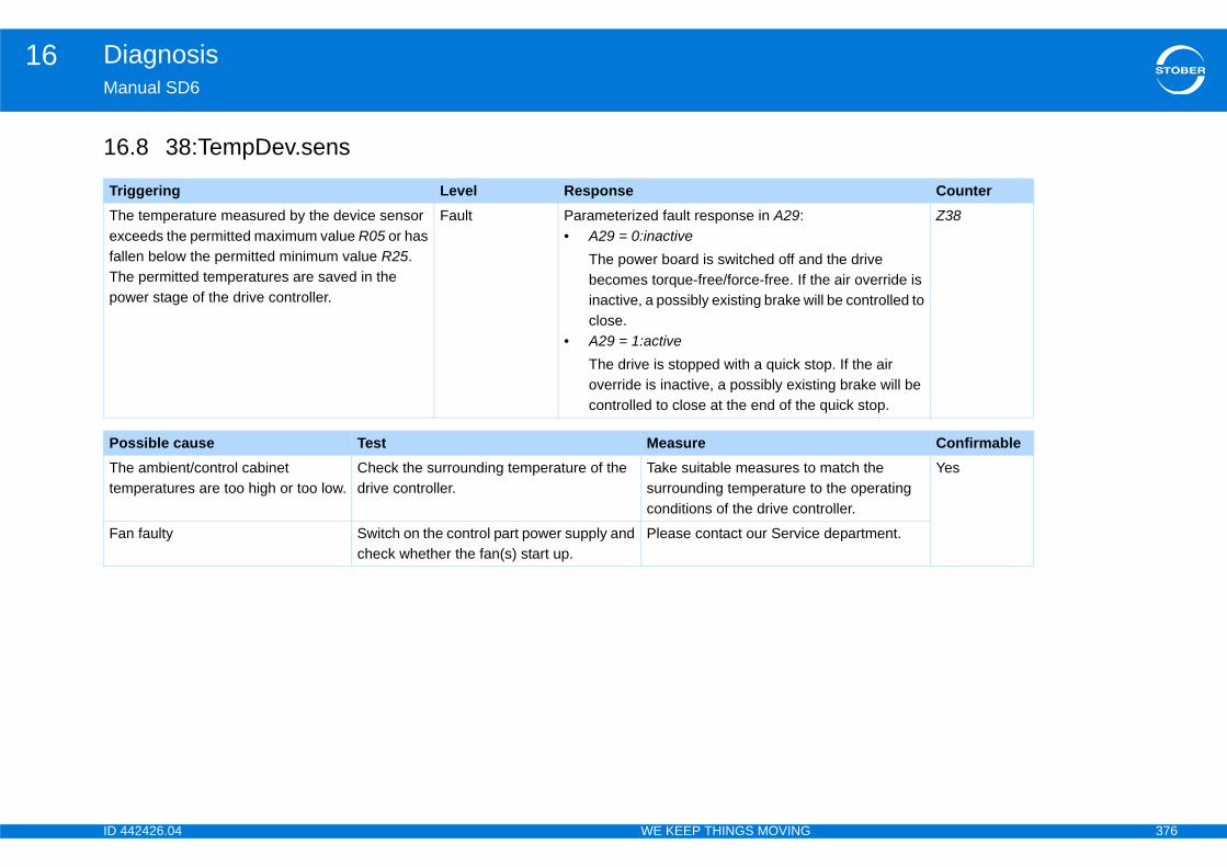
ID 4 376
Diagnosis16Ma
16
Tr CounterThexfalThpo
d the drive he air override is ill be controlled to
top. If the air ting brake will be quick stop.
Z38
Po ConfirmableThtem
match the o the operating troller.
Yes
Fa e department.
42426.04 WE KEEP THINGS MOVING
nual SD6
.8 38:TempDev.sens
iggering Level Responsee temperature measured by the device sensor ceeds the permitted maximum value R05 or has len below the permitted minimum value R25.e permitted temperatures are saved in the wer stage of the drive controller.
Fault Parameterized fault response in A29:• A29 = 0:inactive
The power board is switched off anbecomes torque-free/force-free. If tinactive, a possibly existing brake wclose.
• A29 = 1:activeThe drive is stopped with a quick soverride is inactive, a possibly exiscontrolled to close at the end of the
ssible cause Test Measuree ambient/control cabinet peratures are too high or too low.
Check the surrounding temperature of the drive controller.
Take suitable measures tosurrounding temperature tconditions of the drive con
n faulty Switch on the control part power supply and check whether the fan(s) start up.
Please contact our Servic
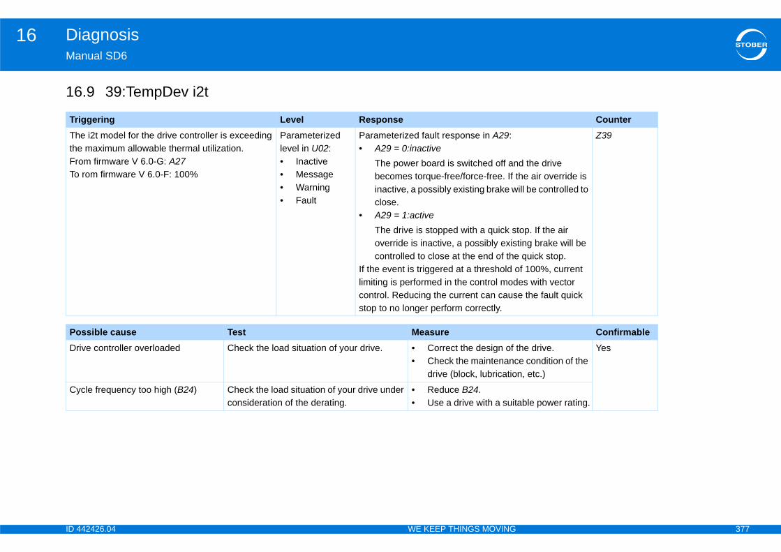
ID 4 377
Diagnosis16Ma
16
Tr CounterThtheFrTo
d the drive he air override is ill be controlled to
top. If the air ting brake will be quick stop.f 100%, current es with vector e the fault quick
Z39
Po ConfirmableDr the drive.
e condition of the n, etc.)
Yes
Cyable power rating.
42426.04 WE KEEP THINGS MOVING
nual SD6
.9 39:TempDev i2t
iggering Level Responsee i2t model for the drive controller is exceeding maximum allowable thermal utilization.
om firmware V 6.0-G: A27 rom firmware V 6.0-F: 100%
Parameterized level in U02:• Inactive• Message• Warning• Fault
Parameterized fault response in A29:• A29 = 0:inactive
The power board is switched off anbecomes torque-free/force-free. If tinactive, a possibly existing brake wclose.
• A29 = 1:activeThe drive is stopped with a quick soverride is inactive, a possibly exiscontrolled to close at the end of the
If the event is triggered at a threshold olimiting is performed in the control modcontrol. Reducing the current can causstop to no longer perform correctly.
ssible cause Test Measureive controller overloaded Check the load situation of your drive. • Correct the design of
• Check the maintenancdrive (block, lubricatio
cle frequency too high (B24) Check the load situation of your drive under consideration of the derating.
• Reduce B24.• Use a drive with a suit
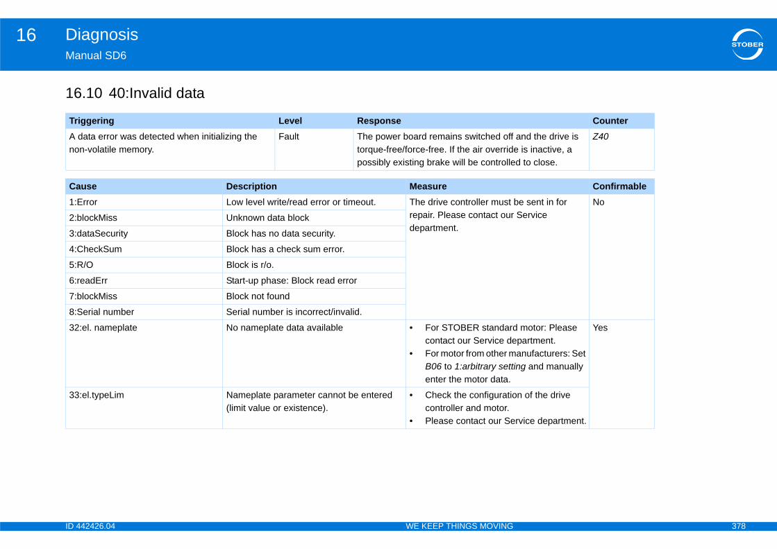
ID 4 378
Diagnosis16Ma
16
Tr CounterA no
and the drive is e is inactive, a d to close.
Z40
Ca Confirmable1:E be sent in for
Service No
2:b
3:d
4:C
5:R
6:r
7:b
8:S
32 motor: Please partment.anufacturers: Set
ing and manually
Yes
33 n of the drive
rvice department.
42426.04 WE KEEP THINGS MOVING
nual SD6
.10 40:Invalid data
iggering Level Responsedata error was detected when initializing the n-volatile memory.
Fault The power board remains switched off torque-free/force-free. If the air overridpossibly existing brake will be controlle
use Description Measurerror Low level write/read error or timeout. The drive controller must
repair. Please contact ourdepartment.
lockMiss Unknown data block
ataSecurity Block has no data security.
heckSum Block has a check sum error.
/O Block is r/o.
eadErr Start-up phase: Block read error
lockMiss Block not found
erial number Serial number is incorrect/invalid.
:el. nameplate No nameplate data available • For STOBER standardcontact our Service de
• For motor from other mB06 to 1:arbitrary settenter the motor data.
:el.typeLim Nameplate parameter cannot be entered (limit value or existence).
• Check the configuratiocontroller and motor.
• Please contact our Se

ID 4 379
Diagnosis16Ma
16
Tr CounterMoov
d the drive he air override is ill be controlled to
top. If the air ting brake will be quick stop.
Z41
Po ConfirmableThco
y. Yes
Th ry, correct the
kage caused
42426.04 WE KEEP THINGS MOVING
nual SD6
.11 41:Temp.MotorTMS
iggering Level Responsetor temperature sensor reports
ertemperature (connection clamp X2).Parameterized level in U15:• Warning• Fault
Parameterized fault response in A29:• A29 = 0:inactive
The power board is switched off anbecomes torque-free/force-free. If tinactive, a possibly existing brake wclose.
• A29 = 1:activeThe drive is stopped with a quick soverride is inactive, a possibly exiscontrolled to close at the end of the
ssible cause Test Measuree motor temperature sensor is not nnected.
Check whether the motor temperature sensor is connected to X2 and whether the wiring is OK.
Connect the cable properl
e motor is overloaded. Check whether the operating conditions have caused the motor to overheat (load state, surrounding temperature of the motor, etc.).
• Check and, if necessadrive design.
• Check whether a blocoverheating.
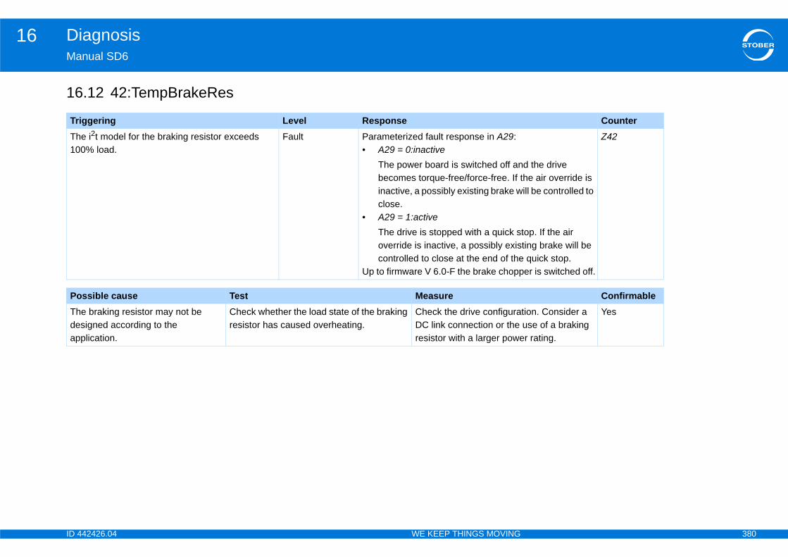
ID 4 380
Diagnosis16Ma
16
Tr CounterTh10
d the drive he air override is ill be controlled to
top. If the air ting brake will be quick stop.er is switched off.
Z42
Po ConfirmableThdeap
tion. Consider a use of a braking r rating.
Yes
42426.04 WE KEEP THINGS MOVING
nual SD6
.12 42:TempBrakeRes
iggering Level Responsee i2t model for the braking resistor exceeds 0% load.
Fault Parameterized fault response in A29:• A29 = 0:inactive
The power board is switched off anbecomes torque-free/force-free. If tinactive, a possibly existing brake wclose.
• A29 = 1:activeThe drive is stopped with a quick soverride is inactive, a possibly exiscontrolled to close at the end of the
Up to firmware V 6.0-F the brake chopp
ssible cause Test Measuree braking resistor may not be signed according to the plication.
Check whether the load state of the braking resistor has caused overheating.
Check the drive configuraDC link connection or the resistor with a larger powe
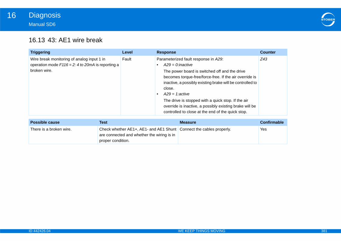
ID 4 381
Diagnosis16Ma
16
Tr CounterWopbro d the drive
he air override is ill be controlled to
top. If the air ting brake will be quick stop.
Z43
Po ConfirmableTh rly. Yes
42426.04 WE KEEP THINGS MOVING
nual SD6
.13 43: AE1 wire break
iggering Level Responseire break monitoring of analog input 1 in eration mode F116 = 2: 4 to 20mA is reporting a ken wire.
Fault Parameterized fault response in A29:• A29 = 0:inactive
The power board is switched off anbecomes torque-free/force-free. If tinactive, a possibly existing brake wclose.
• A29 = 1:activeThe drive is stopped with a quick soverride is inactive, a possibly exiscontrolled to close at the end of the
ssible cause Test Measureere is a broken wire. Check whether AE1+, AE1- and AE1 Shunt
are connected and whether the wiring is in proper condition.
Connect the cables prope
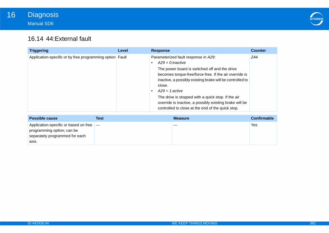
ID 4 382
Diagnosis16Ma
16
Tr CounterAp
d the drive he air override is ill be controlled to
top. If the air ting brake will be quick stop.
Z44
Po ConfirmableApproseax
Yes
42426.04 WE KEEP THINGS MOVING
nual SD6
.14 44:External fault
iggering Level Responseplication-specific or by free programming option Fault Parameterized fault response in A29:
• A29 = 0:inactiveThe power board is switched off anbecomes torque-free/force-free. If tinactive, a possibly existing brake wclose.
• A29 = 1:activeThe drive is stopped with a quick soverride is inactive, a possibly exiscontrolled to close at the end of the
ssible cause Test Measureplication-specific or based on free gramming option; can be
parately programmed for each is.
— —

ID 4 383
Diagnosis16Ma
16
Tr CounterTh
d the drive he air override is ill be controlled to
top. If the air ting brake will be quick stop.
Z45
Po ConfirmableTh t the
perating
ockages.e drive design.
Yes
42426.04 WE KEEP THINGS MOVING
nual SD6
.15 45:oTempMot. i2t
iggering Level Responsee i2t model for the motor reaches 100 % load. Parameterized
level in U10:• Inactive• Message• Warning• Fault
Parameterized fault response in A29:• A29 = 0:inactive
The power board is switched off anbecomes torque-free/force-free. If tinactive, a possibly existing brake wclose.
• A29 = 1:activeThe drive is stopped with a quick soverride is inactive, a possibly exiscontrolled to close at the end of the
ssible cause Test Measuree motor is overloaded Check whether the operating conditions
have caused the motor to overheat (load state, surrounding temperature of the motor, etc.).
• Take measures to meerequirements for the oconditions.
• Rectify any existing bl• If necessary, correct th
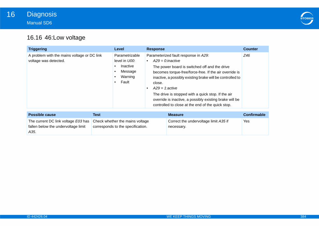
ID 4 384
Diagnosis16Ma
16
Tr CounterA vo
d the drive he air override is ill be controlled to
top. If the air ting brake will be quick stop.
Z46
Po ConfirmableThfalA3
imit A35 if Yes
42426.04 WE KEEP THINGS MOVING
nual SD6
.16 46:Low voltage
iggering Level Responseproblem with the mains voltage or DC link ltage was detected.
Parametrizable level in U00:• Inactive• Message• Warning• Fault
Parameterized fault response in A29:• A29 = 0:inactive
The power board is switched off anbecomes torque-free/force-free. If tinactive, a possibly existing brake wclose.
• A29 = 1:activeThe drive is stopped with a quick soverride is inactive, a possibly exiscontrolled to close at the end of the
ssible cause Test Measuree current DC link voltage E03 has len below the undervoltage limit 5.
Check whether the mains voltage corresponds to the specification.
Correct the undervoltage lnecessary.
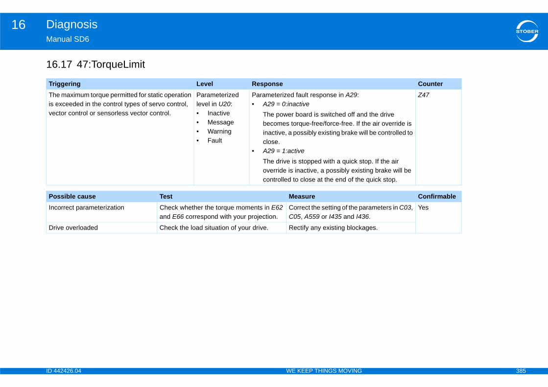
ID 4 385
Diagnosis16Ma
16
Tr CounterThis ve d the drive
he air override is ill be controlled to
top. If the air ting brake will be quick stop.
Z47
Po ConfirmableInc arameters in C03,
6.Yes
Dr ges.
42426.04 WE KEEP THINGS MOVING
nual SD6
.17 47:TorqueLimit
iggering Level Responsee maximum torque permitted for static operation exceeded in the control types of servo control, ctor control or sensorless vector control.
Parameterized level in U20:• Inactive• Message• Warning• Fault
Parameterized fault response in A29:• A29 = 0:inactive
The power board is switched off anbecomes torque-free/force-free. If tinactive, a possibly existing brake wclose.
• A29 = 1:activeThe drive is stopped with a quick soverride is inactive, a possibly exiscontrolled to close at the end of the
ssible cause Test Measureorrect parameterization Check whether the torque moments in E62
and E66 correspond with your projection.Correct the setting of the pC05, A559 or I435 and I43
ive overloaded Check the load situation of your drive. Rectify any existing blocka
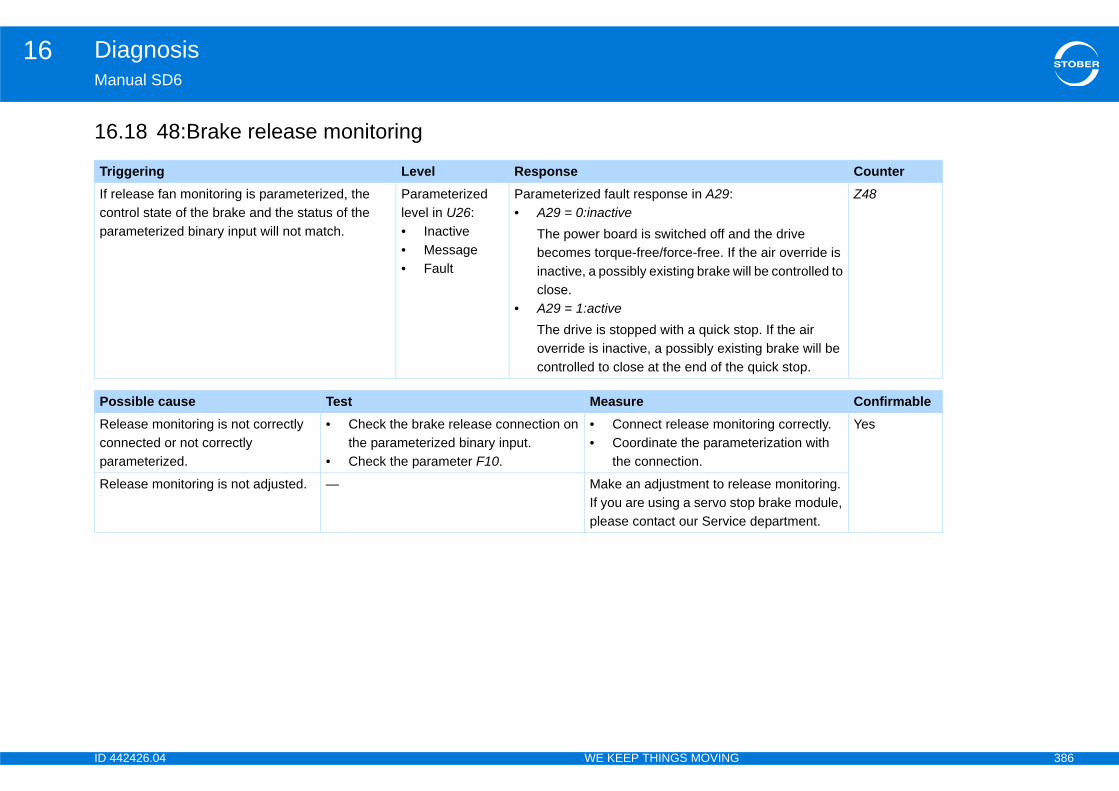
ID 4 386
Diagnosis16Ma
16
Tr CounterIf rcopa d the drive
he air override is ill be controlled to
top. If the air ting brake will be quick stop.
Z48
Po ConfirmableRecopa
toring correctly.eterization with
Yes
Re lease monitoring. op brake module, department.
42426.04 WE KEEP THINGS MOVING
nual SD6
.18 48:Brake release monitoring
iggering Level Responseelease fan monitoring is parameterized, the ntrol state of the brake and the status of the rameterized binary input will not match.
Parameterized level in U26:• Inactive• Message• Fault
Parameterized fault response in A29:• A29 = 0:inactive
The power board is switched off anbecomes torque-free/force-free. If tinactive, a possibly existing brake wclose.
• A29 = 1:activeThe drive is stopped with a quick soverride is inactive, a possibly exiscontrolled to close at the end of the
ssible cause Test Measurelease monitoring is not correctly nnected or not correctly rameterized.
• Check the brake release connection on the parameterized binary input.
• Check the parameter F10.
• Connect release moni• Coordinate the param
the connection.
lease monitoring is not adjusted. — Make an adjustment to reIf you are using a servo stplease contact our Service
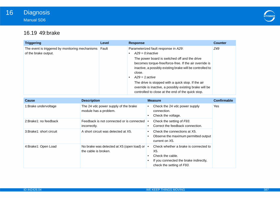
ID 4 387
Diagnosis16Ma
16
Tr CounterThof
d the drive he air override is ill be controlled to
top. If the air ting brake will be quick stop.
Z49
Ca Confirmable1:B er supply Yes
2:B 93.onnection.
3:B s at X5. permitted output
4:B e is connected to
rake indirectly, 3.
42426.04 WE KEEP THINGS MOVING
nual SD6
.19 49:brake
iggering Level Responsee event is triggered by monitoring mechanisms the brake output.
Fault Parameterized fault response in A29:• A29 = 0:inactive
The power board is switched off anbecomes torque-free/force-free. If tinactive, a possibly existing brake wclose.
• A29 = 1:activeThe drive is stopped with a quick soverride is inactive, a possibly exiscontrolled to close at the end of the
use Description Measurerake undervoltage The 24 vdc power supply of the brake
module has a problem.• Check the 24 vdc pow
connection.• Check the voltage.
rake1: no feedback Feedback is not connected or is connected incorrectly.
• Check the setting of F• Correct the feedback c
rake1: short circuit A short circuit was detected at X5. • Check the connection• Observe the maximum
current on X5.
rake1: Open Load No brake was detected at X5 (open load) or the cable is broken.
• Check whether a brakX5.
• Check the cable.• If you connected the b
check the setting of F9
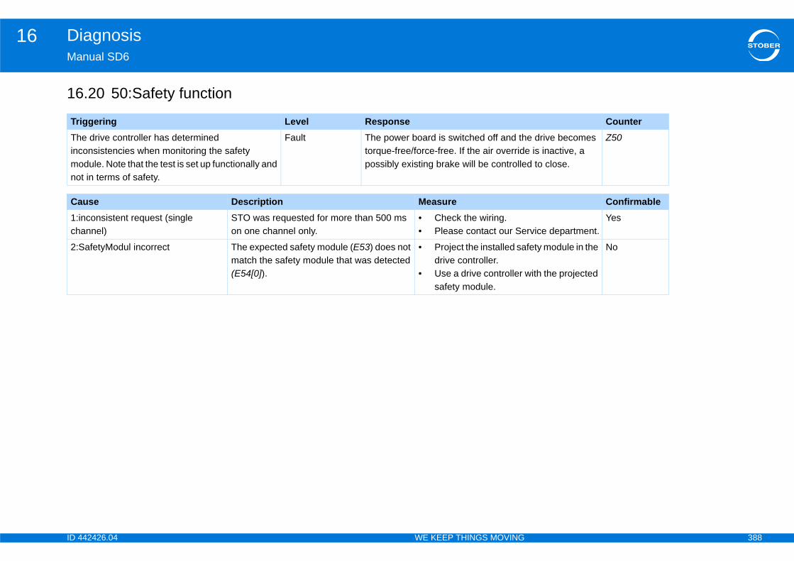
ID 4 388
Diagnosis16Ma
16
Tr CounterThincmono
e drive becomes e is inactive, a d to close.
Z50
Ca Confirmable1:ich rvice department.
Yes
2:S fety module in the
with the projected
No
42426.04 WE KEEP THINGS MOVING
nual SD6
.20 50:Safety function
iggering Level Responsee drive controller has determined onsistencies when monitoring the safety dule. Note that the test is set up functionally and t in terms of safety.
Fault The power board is switched off and thtorque-free/force-free. If the air overridpossibly existing brake will be controlle
use Description Measurenconsistent request (single annel)
STO was requested for more than 500 ms on one channel only.
• Check the wiring.• Please contact our Se
afetyModul incorrect The expected safety module (E53) does not match the safety module that was detected (E54[0]).
• Project the installed sadrive controller.
• Use a drive controller safety module.
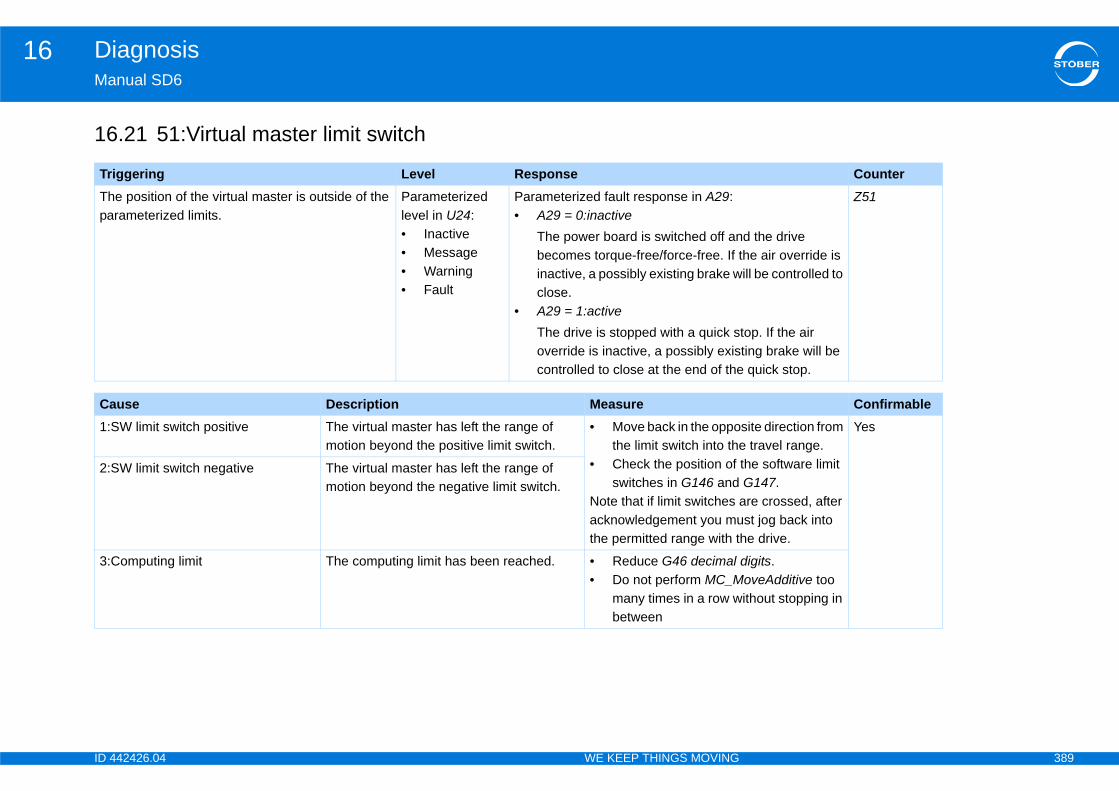
ID 4 389
Diagnosis16Ma
16
Tr CounterThpa
d the drive he air override is ill be controlled to
top. If the air ting brake will be quick stop.
Z51
Ca Confirmable1:S site direction from
travel range.the software limit G147.re crossed, after st jog back into
he drive.
Yes
2:S
3:C digits.oveAdditive too ithout stopping in
42426.04 WE KEEP THINGS MOVING
nual SD6
.21 51:Virtual master limit switch
iggering Level Responsee position of the virtual master is outside of the rameterized limits.
Parameterized level in U24:• Inactive• Message• Warning• Fault
Parameterized fault response in A29:• A29 = 0:inactive
The power board is switched off anbecomes torque-free/force-free. If tinactive, a possibly existing brake wclose.
• A29 = 1:activeThe drive is stopped with a quick soverride is inactive, a possibly exiscontrolled to close at the end of the
use Description MeasureW limit switch positive The virtual master has left the range of
motion beyond the positive limit switch.• Move back in the oppo
the limit switch into the• Check the position of
switches in G146 andNote that if limit switches aacknowledgement you muthe permitted range with t
W limit switch negative The virtual master has left the range of motion beyond the negative limit switch.
omputing limit The computing limit has been reached. • Reduce G46 decimal • Do not perform MC_M
many times in a row wbetween
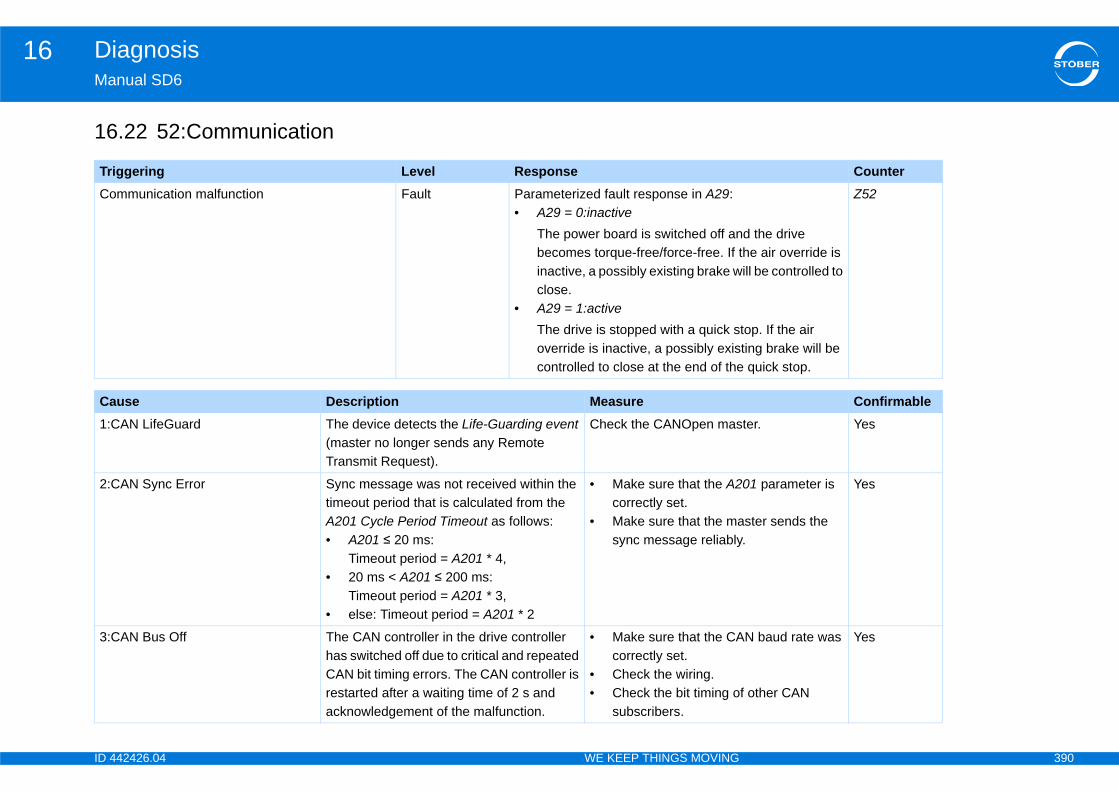
ID 4 390
Diagnosis16Ma
16
Tr CounterCo
d the drive he air override is ill be controlled to
top. If the air ting brake will be quick stop.
Z52
Ca Confirmable1:C ter. Yes
2:C 01 parameter is
ster sends the .
Yes
3:C N baud rate was
f other CAN
Yes
42426.04 WE KEEP THINGS MOVING
nual SD6
.22 52:Communication
iggering Level Responsemmunication malfunction Fault Parameterized fault response in A29:
• A29 = 0:inactiveThe power board is switched off anbecomes torque-free/force-free. If tinactive, a possibly existing brake wclose.
• A29 = 1:activeThe drive is stopped with a quick soverride is inactive, a possibly exiscontrolled to close at the end of the
use Description MeasureAN LifeGuard The device detects the Life-Guarding event
(master no longer sends any Remote Transmit Request).
Check the CANOpen mas
AN Sync Error Sync message was not received within the timeout period that is calculated from the A201 Cycle Period Timeout as follows:• A201 ≤ 20 ms:
Timeout period = A201 * 4,• 20 ms < A201 ≤ 200 ms:
Timeout period = A201 * 3,• else: Timeout period = A201 * 2
• Make sure that the A2correctly set.
• Make sure that the masync message reliably
AN Bus Off The CAN controller in the drive controller has switched off due to critical and repeated CAN bit timing errors. The CAN controller is restarted after a waiting time of 2 s and acknowledgement of the malfunction.
• Make sure that the CAcorrectly set.
• Check the wiring.• Check the bit timing o
subscribers.
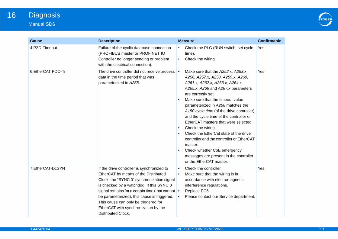
ID 4 391
Diagnosis16Ma
4:P switch, set cycle Yes
6:E 52.x, A253.x, 259.x, A260,
.x, A264.x, 7.x parameters
eout value matches the
e drive controller) he controller or t were selected.
ate of the drive roller or EtherCAT
mergency t in the controller er.
Yes
7:Eing is in romagnetic s.
rvice department.
Yes
Ca Confirmable
42426.04 WE KEEP THINGS MOVING
nual SD6
ZD-Timeout Failure of the cyclic database connection (PROFIBUS master or PROFINET IO Controller no longer sending or problem with the electrical connection).
• Check the PLC (RUN time).
• Check the wiring.
therCAT PDO-Ti The drive controller did not receive process data in the time period that was parameterized in A258.
• Make sure that the A2A256, A257.x, A258, AA261.x, A262.x, A263A265.x, A266 and A26are correctly set.
• Make sure that the timparameterized in A258A150 cycle time (of thand the cycle time of tEtherCAT masters tha
• Check the wiring.• Check the EtherCat st
controller and the contmaster.
• Check whether CoE emessages are presenor the EtherCAT mast
therCAT-DcSYN If the drive controller is synchronized to EtherCAT by means of the Distributed Clock, the "SYNC 0" synchronization signal is checked by a watchdog. If this SYNC 0 signal remains for a certain time (that cannot be parameterized), this cause is triggered. This cause can only be triggered for EtherCAT with synchronization by the Distributed Clock.
• Check the controller.• Make sure that the wir
accordance with electinterference regulation
• Replace EC6.• Please contact our Se
use Description Measure

ID 4 392
Diagnosis16Ma
8:I M-compliant
ust be sent in for our Service
Yes
9:I controllers in the hed on.ection cables are
Yes
10 Yes
11 in the drive
h this cause for a the drive t in for repair. rvice department
Yes
12 nce of the blocks, iguration to the there. Restart the
Yes
Ca Confirmable
42426.04 WE KEEP THINGS MOVING
nual SD6
GB µC failure The microcontroller for the IGB communication has failed.
• Check the wiring for Edesign.
• The drive controller mrepair. Please contactdepartment.
GB Lost Frame IGB motion bus: The subscriber has detected a loss of at least 2 consecutive data frames (double error). This cause can only occur when the IGB state = 3:Motionbus and the motor is powered.
• Make sure that all driveIGB network are switc
• Make sure that all connplugged in.
:IGB P. LostFr IGB motion bus: A different subscriber has detected a double error and reported this via A163. As a result, this drive controller is also faulty with this cause. This cause can only occur when the IGB state = 3:Motionbus and the motor is powered.
:IGB Sync Erro The synchronization within the drive controller is faulty as the configuration was stopped by the commissioning software. This cause can only occur when the IGB state = 3:Motionbus and the motor is powered.
• Start the configurationcontroller.
• If the result occurs witrunning configuration,controller must be senPlease contact our Se
:IGB ConfigTim An IGB Motionbus consumer block or producer block in the graphical programming was called up at the wrong time. The block was called up too early or closed too late. This cause can only occur when the IGB state = 3:Motionbus and the motor is powered.
Adjust the run-time sequetransfer the changed confdrive controller and save itdrive controller.
use Description Measure

ID 4 393
Diagnosis16Ma
16
13 that displays Yes
Tr CounterThswrefdri
d the drive he air override is ill be controlled to
top. If the air ting brake will be quick stop.
Z53
Ca Confirmable
42426.04 WE KEEP THINGS MOVING
nual SD6
.23 53: Limit switch
:IGBPartnerSyn There is a synchronization malfunction for another subscriber in the IGB network (see cause 11). This subscriber reported its fault via A163. As a result, this drive controller is also faulty with cause 13. This cause can only occur when the IGB state = 3:Motionbus and the motor is powered.
Check the drive controllerevent 52 with cause 11.
iggering Level Responsee drive has reached one of the hardware limit itches (except in jog mode or during erencing) or if a cyclic position is assigned the ve has reached the SW limit switches.
Fault Parameterized fault response in A29:• A29 = 0:inactive
The power board is switched off anbecomes torque-free/force-free. If tinactive, a possibly existing brake wclose.
• A29 = 1:activeThe drive is stopped with a quick soverride is inactive, a possibly exiscontrolled to close at the end of the
use Description Measure

ID 4 394
Diagnosis16Ma
Ca Confirmable1:H site direction from
travel range. of the hardware
ation of the signal 2.re crossed, after st jog back into
he drive.
Yes
2:H
3:S site direction from travel range.
the software limit 1.re crossed, after st jog back into
he drive.
Yes
4:S
5:C igits position.oveAdditive too ithout stopping in
Yes
42426.04 WE KEEP THINGS MOVING
nual SD6
use Description MeasureW limit switch positive The drive has reached the positive
hardware limit switch.• Move back in the oppo
the limit switch into the• Check the connection
limit switches.• Check the parameteriz
source in I101 and I10Note that if limit switches aacknowledgement you muthe permitted range with t
W limit switch negative The drive has reached the negative hardware limit switch.
W limit switch positive The drive has reached the positive software limit switch.
• Move back in the oppothe limit switch into the
• Check the position of switches in I50 and I5
Note that if limit switches aacknowledgement you muthe permitted range with t
W limit switch negative The drive has reached the negative software limit switch.
omputing limit The computing limit has been reached. • Reduce I06 decimal d• Do not perform MC_M
many times in a row wbetween

ID 4 395
Diagnosis16Ma
16
Tr CounterThpoall d the drive
he air override is ill be controlled to
top. If the air ting brake will be quick stop.
Z54
Po ConfirmableThgrema
ckages.ake: Check 0 and the
hydraulic or pensation: Check ient pressure
ror parameters
ters C03, C05,
Yes
42426.04 WE KEEP THINGS MOVING
nual SD6
.24 54:following Error
iggering Level Responsee difference between the actual and target sition exceeds the parameterized maximum owable following error.
Parameterized level in U22:• Inactive• Message• Warning• Fault
Parameterized fault response in A29:• A29 = 0:inactive
The power board is switched off anbecomes torque-free/force-free. If tinactive, a possibly existing brake wclose.
• A29 = 1:activeThe drive is stopped with a quick soverride is inactive, a possibly exiscontrolled to close at the end of the
ssible cause Test Measuree control deviation of the position is ater than the parameterized ximum allowable following error.
• Check whether there is a mechanical blockage, for example in the mechanical system or because a brake is not released.
• Rectify mechanical blo• If there is a holding br
parameterization in F0following parameters.
• For vertical axes with pneumatic weight comwhether there is sufficavailable.
• Check the following erA546, A547 and I21.
• Check control parameC31, C32, I20 and I25

ID 4 396
Diagnosis16Ma
16
Tr CounterEr
d the drive he air override is ill be controlled to
top. If the air ting brake will be quick stop.
Z55
Ca Confirmable1:i mmunication Yes
2:E ED6. Yes
3:C CA6. Yes
7:i rminal module. Yes
10 X16. Yes
12 orrect the 24 vdc Yes
42426.04 WE KEEP THINGS MOVING
nual SD6
.25 55:Option module
iggering Level Responseror when operating with option module. Fault Parameterized fault response in A29:
• A29 = 0:inactiveThe power board is switched off anbecomes torque-free/force-free. If tinactive, a possibly existing brake wclose.
• A29 = 1:activeThe drive is stopped with a quick soverride is inactive, a possibly exiscontrolled to close at the end of the
use Description MeasurencorrectOption1 Incorrect or missing communication module
(compare E54/E58 with E68/E69) • Install the projected co
module.• Adjust the projection.
C6failure EC6 was detected, installed and failed. • Uninstall and reinstall • Replace EC6.
A6failure CA6 was detected, installed and failed. • Uninstall and reinstall • Replace CA6.
ncorrectOption2 Incorrect or missing terminal module (compare E54/E58 with E68/E69)
• Install the projected te• Adjust the projection.
:XI6failure X16 was detected, installed and failed. • Uninstall and reinstall • Adjust the projection.
:24Vfailure A failure of the 24 vdc power supply of XI6 was detected.
Check and, if necessary, cpower supply of X16.
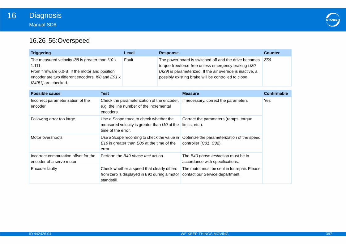
ID 4 397
Diagnosis16Ma
16
Tr CounterTh1.1FrenI24
e drive becomes y braking U30
de is inactive, a d to close.
Z56
Po ConfirmableIncen
arameters Yes
Fo mps, torque
Mo tion of the speed
Incen
must be in tions.
En for repair. Please tment.
42426.04 WE KEEP THINGS MOVING
nual SD6
.26 56:Overspeed
iggering Level Responsee measured velocity I88 is greater than I10 x 11.
om firmware 6.0-B: If the motor and position coder are two different encoders, I88 and E91 x 0[1] are checked.
Fault The power board is switched off and thtorque-free/force-free unless emergenc(A29) is parameterized. If the air overripossibly existing brake will be controlle
ssible cause Test Measureorrect parameterization of the coder
Check the parameterization of the encoder, e.g. the line number of the incremental encoders.
If necessary, correct the p
llowing error too large Use a Scope trace to check whether the measured velocity is greater than I10 at the time of the error.
Correct the parameters (ralimits, etc.).
tor overshoots Use a Scope recording to check the value in E16 is greater than E06 at the time of the error.
Optimize the parameterizacontroller (C31, C32).
orrect commutation offset for the coder of a servo motor
Perform the B40 phase test action. The B40 phase testactionaccordance with specifica
coder faulty Check whether a speed that clearly differs from zero is displayed in E91 during a motor standstill.
The motor must be sent incontact our Service depar
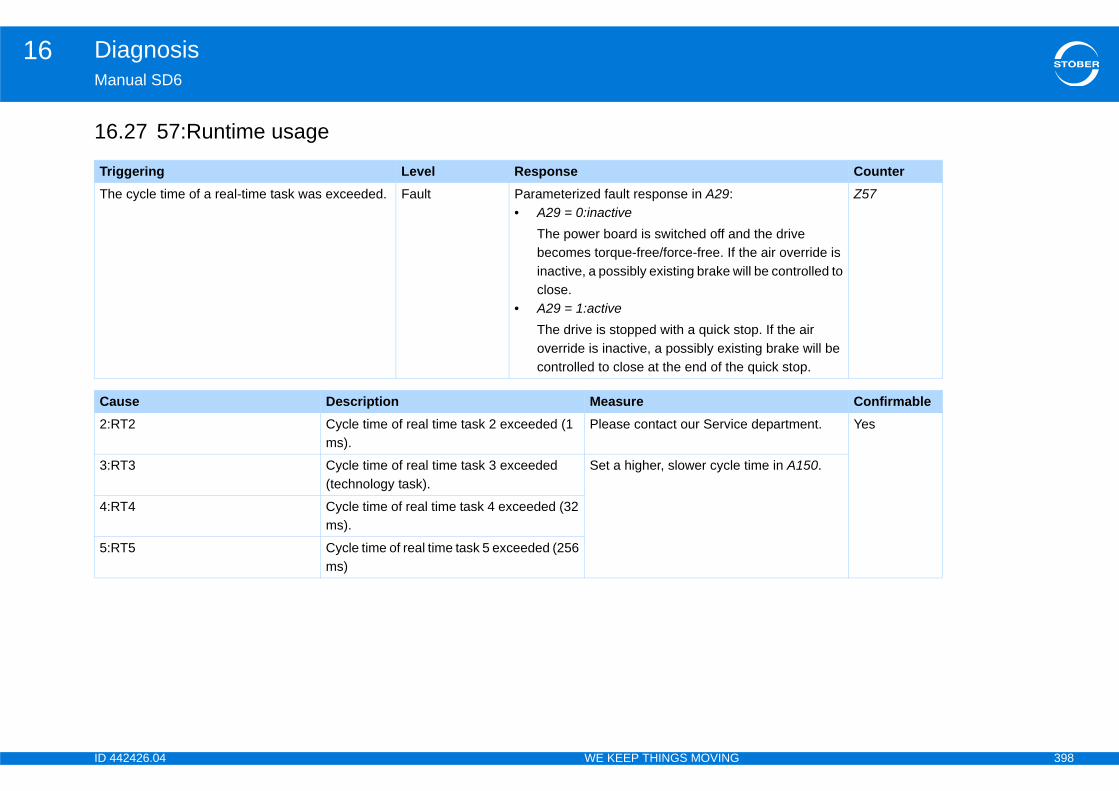
ID 4 398
Diagnosis16Ma
16
Tr CounterTh
d the drive he air override is ill be controlled to
top. If the air ting brake will be quick stop.
Z57
Ca Confirmable2:R e department. Yes
3:R time in A150.
4:R
5:R
42426.04 WE KEEP THINGS MOVING
nual SD6
.27 57:Runtime usage
iggering Level Responsee cycle time of a real-time task was exceeded. Fault Parameterized fault response in A29:
• A29 = 0:inactiveThe power board is switched off anbecomes torque-free/force-free. If tinactive, a possibly existing brake wclose.
• A29 = 1:activeThe drive is stopped with a quick soverride is inactive, a possibly exiscontrolled to close at the end of the
use Description MeasureT2 Cycle time of real time task 2 exceeded (1
ms).Please contact our Servic
T3 Cycle time of real time task 3 exceeded (technology task).
Set a higher, slower cycle
T4 Cycle time of real time task 4 exceeded (32 ms).
T5 Cycle time of real time task 5 exceeded (256 ms)
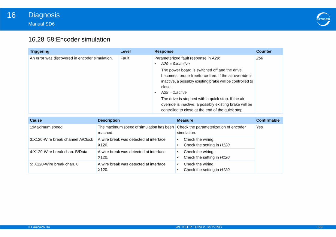
ID 4 399
Diagnosis16Ma
16
Tr CounterAn
d the drive he air override is ill be controlled to
top. If the air ting brake will be quick stop.
Z58
Ca Confirmable1:M n of encoder Yes
3:X120.
4:X120.
5: 120.
42426.04 WE KEEP THINGS MOVING
nual SD6
.28 58:Encoder simulation
iggering Level Response error was discovered in encoder simulation. Fault Parameterized fault response in A29:
• A29 = 0:inactiveThe power board is switched off anbecomes torque-free/force-free. If tinactive, a possibly existing brake wclose.
• A29 = 1:activeThe drive is stopped with a quick soverride is inactive, a possibly exiscontrolled to close at the end of the
use Description Measureaximum speed The maximum speed of simulation has been
reached.Check the parameterizatiosimulation.
120-Wire break channel A/Clock A wire break was detected at interface X120.
• Check the wiring.• Check the setting in H
120-Wire break chan. B/Data A wire break was detected at interface X120.
• Check the wiring.• Check the setting in H
X120-Wire break chan. 0 A wire break was detected at interface X120.
• Check the wiring.• Check the setting in H
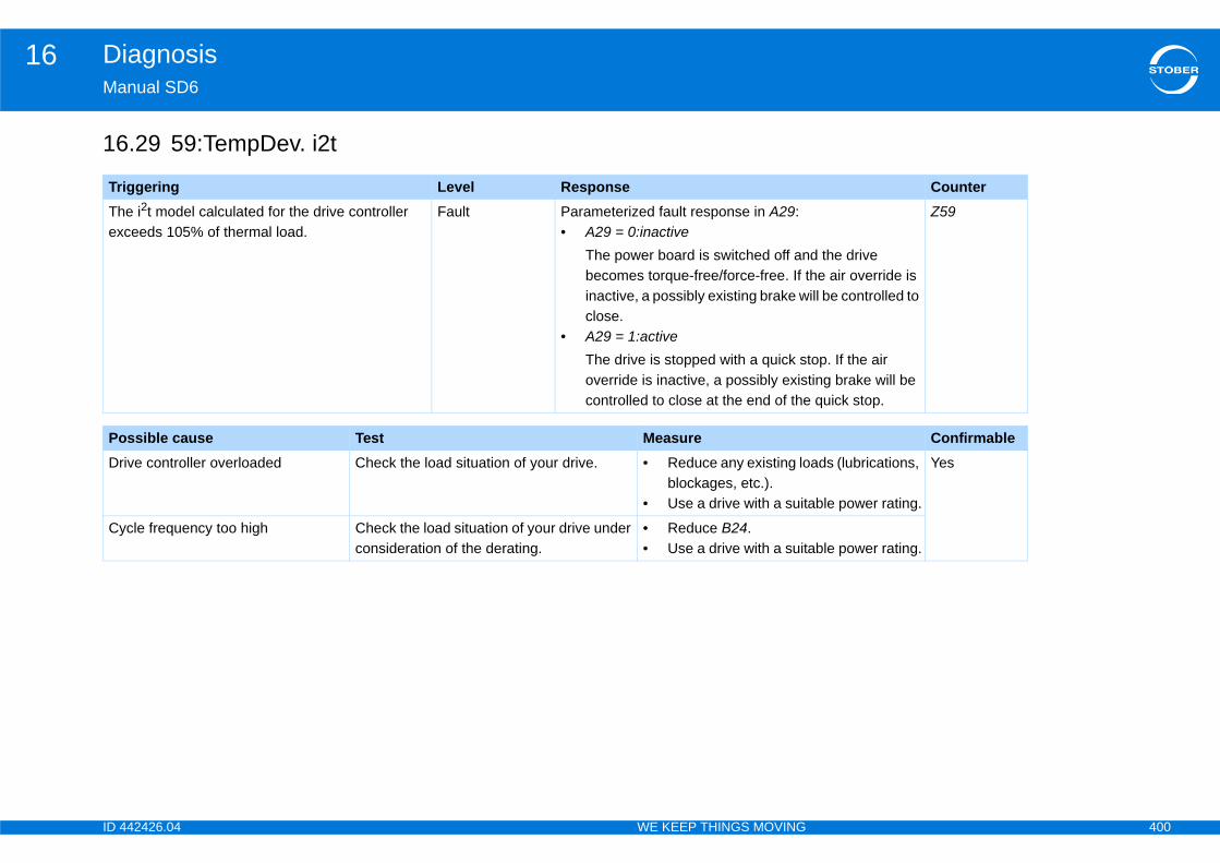
ID 4 400
Diagnosis16Ma
16
Tr CounterThex
d the drive he air override is ill be controlled to
top. If the air ting brake will be quick stop.
Z59
Po ConfirmableDr ads (lubrications,
able power rating.
Yes
Cyable power rating.
42426.04 WE KEEP THINGS MOVING
nual SD6
.29 59:TempDev. i2t
iggering Level Responsee i2t model calculated for the drive controller ceeds 105% of thermal load.
Fault Parameterized fault response in A29:• A29 = 0:inactive
The power board is switched off anbecomes torque-free/force-free. If tinactive, a possibly existing brake wclose.
• A29 = 1:activeThe drive is stopped with a quick soverride is inactive, a possibly exiscontrolled to close at the end of the
ssible cause Test Measureive controller overloaded Check the load situation of your drive. • Reduce any existing lo
blockages, etc.).• Use a drive with a suit
cle frequency too high Check the load situation of your drive under consideration of the derating.
• Reduce B24.• Use a drive with a suit
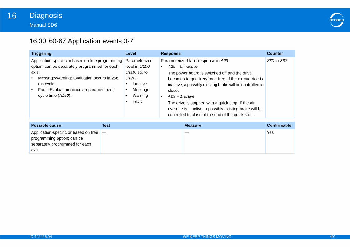
ID 4 401
Diagnosis16Ma
16
Tr CounterApopax•
•
d the drive he air override is ill be controlled to
top. If the air ting brake will be quick stop.
Z60 to Z67
Po ConfirmableApproseax
Yes
42426.04 WE KEEP THINGS MOVING
nual SD6
.30 60-67:Application events 0-7
iggering Level Responseplication-specific or based on free programming tion; can be separately programmed for each is:
Message/warning: Evaluation occurs in 256 ms cycle.Fault: Evaluation occurs in parameterized cycle time (A150).
Parameterized level in U100, U110, etc to U170:• Inactive• Message• Warning• Fault
Parameterized fault response in A29:• A29 = 0:inactive
The power board is switched off anbecomes torque-free/force-free. If tinactive, a possibly existing brake wclose.
• A29 = 1:activeThe drive is stopped with a quick soverride is inactive, a possibly exiscontrolled to close at the end of the
ssible cause Test Measureplication-specific or based on free gramming option; can be
parately programmed for each is.
— —
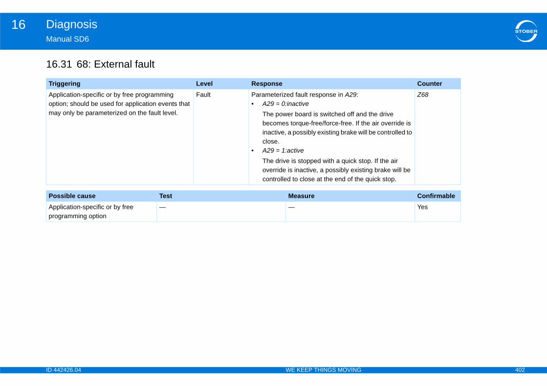
ID 4 402
Diagnosis16Ma
16
Tr CounterApopma d the drive
he air override is ill be controlled to
top. If the air ting brake will be quick stop.
Z68
Po ConfirmableAppro
Yes
42426.04 WE KEEP THINGS MOVING
nual SD6
.31 68: External fault
iggering Level Responseplication-specific or by free programming tion; should be used for application events that y only be parameterized on the fault level.
Fault Parameterized fault response in A29:• A29 = 0:inactive
The power board is switched off anbecomes torque-free/force-free. If tinactive, a possibly existing brake wclose.
• A29 = 1:activeThe drive is stopped with a quick soverride is inactive, a possibly exiscontrolled to close at the end of the
ssible cause Test Measureplication-specific or by free gramming option
— —
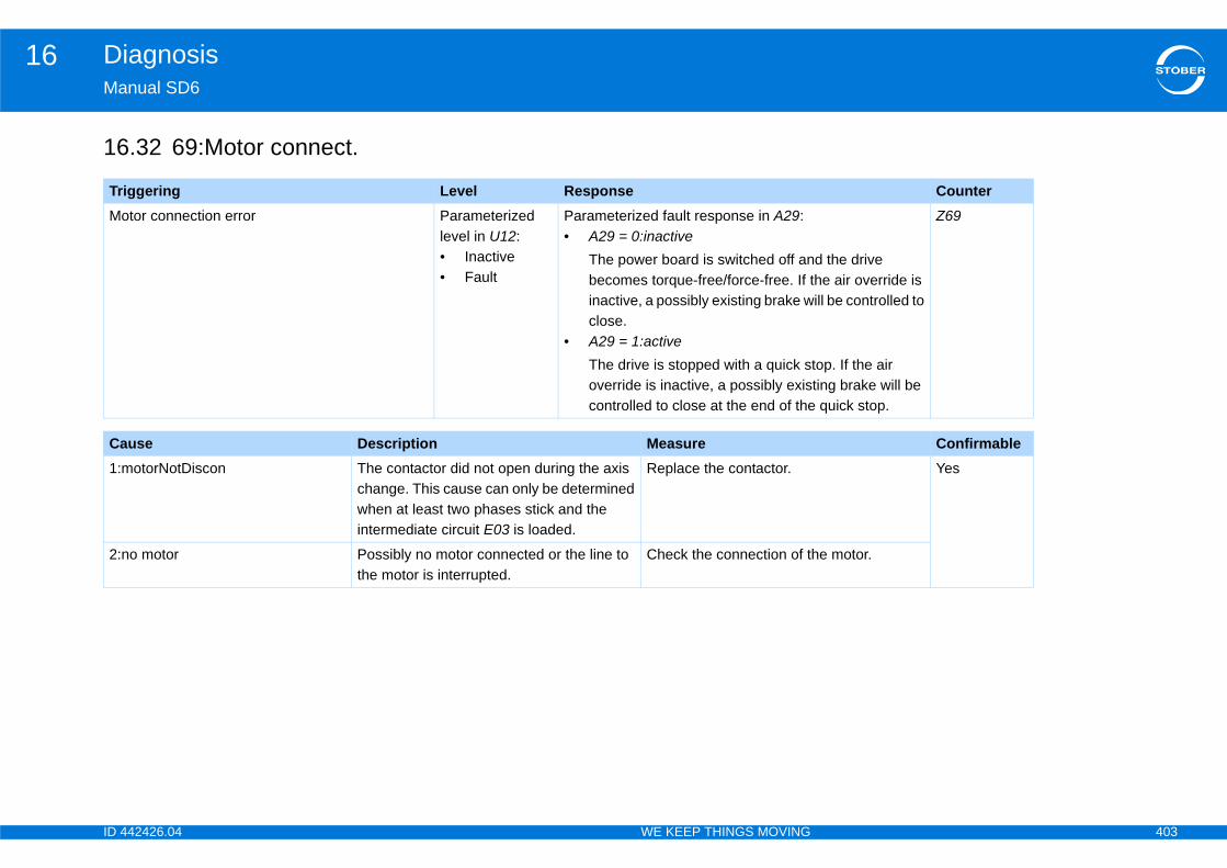
ID 4 403
Diagnosis16Ma
16
Tr CounterMo
d the drive he air override is ill be controlled to
top. If the air ting brake will be quick stop.
Z69
Ca Confirmable1:m Yes
2:n he motor.
42426.04 WE KEEP THINGS MOVING
nual SD6
.32 69:Motor connect.
iggering Level Responsetor connection error Parameterized
level in U12:• Inactive• Fault
Parameterized fault response in A29:• A29 = 0:inactive
The power board is switched off anbecomes torque-free/force-free. If tinactive, a possibly existing brake wclose.
• A29 = 1:activeThe drive is stopped with a quick soverride is inactive, a possibly exiscontrolled to close at the end of the
use Description MeasureotorNotDiscon The contactor did not open during the axis
change. This cause can only be determined when at least two phases stick and the intermediate circuit E03 is loaded.
Replace the contactor.
o motor Possibly no motor connected or the line to the motor is interrupted.
Check the connection of t
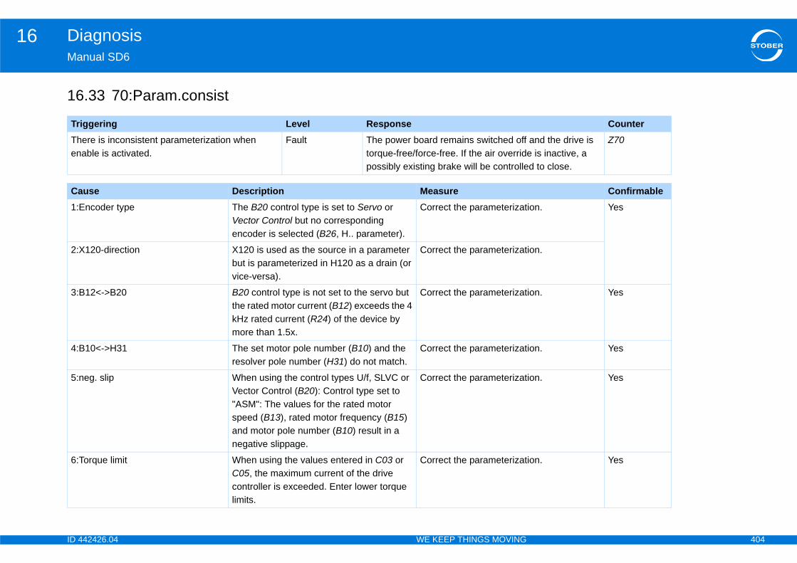
ID 4 404
Diagnosis16Ma
16
Tr CounterThen
and the drive is e is inactive, a d to close.
Z70
Ca Confirmable1:E ion. Yes
2:X ion.
3:B ion. Yes
4:B ion. Yes
5:n ion. Yes
6:T ion. Yes
42426.04 WE KEEP THINGS MOVING
nual SD6
.33 70:Param.consist
iggering Level Responseere is inconsistent parameterization when able is activated.
Fault The power board remains switched off torque-free/force-free. If the air overridpossibly existing brake will be controlle
use Description Measurencoder type The B20 control type is set to Servo or
Vector Control but no corresponding encoder is selected (B26, H.. parameter).
Correct the parameterizat
120-direction X120 is used as the source in a parameter but is parameterized in H120 as a drain (or vice-versa).
Correct the parameterizat
12<->B20 B20 control type is not set to the servo but the rated motor current (B12) exceeds the 4 kHz rated current (R24) of the device by more than 1.5x.
Correct the parameterizat
10<->H31 The set motor pole number (B10) and the resolver pole number (H31) do not match.
Correct the parameterizat
eg. slip When using the control types U/f, SLVC or Vector Control (B20): Control type set to "ASM": The values for the rated motor speed (B13), rated motor frequency (B15) and motor pole number (B10) result in a negative slippage.
Correct the parameterizat
orque limit When using the values entered in C03 or C05, the maximum current of the drive controller is exceeded. Enter lower torque limits.
Correct the parameterizat

ID 4 405
Diagnosis16Ma
7:B ion. Yes
8:I ion. Yes
Ca Confirmable
42426.04 WE KEEP THINGS MOVING
nual SD6
26:SSI-Slave SSI slave must not be used as a motor encoder (synchronization problems).
Correct the parameterizat
10>B83 I10 must not be greater than B83. Correct the parameterizat
use Description Measure
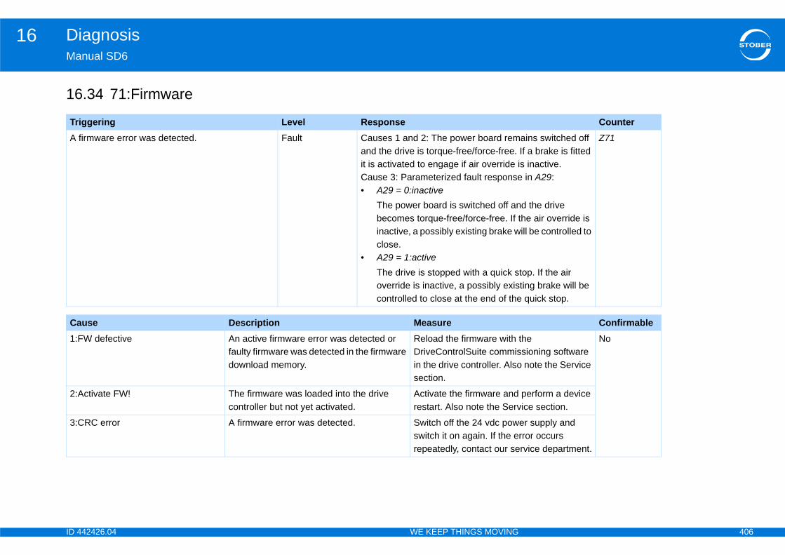
ID 4 406
Diagnosis16Ma
16
Tr CounterA ains switched off
If a brake is fitted s inactive. in A29:
d the drive he air override is ill be controlled to
top. If the air ting brake will be quick stop.
Z71
Ca Confirmable1:F the
sioning software note the Service
No
2:A perform a device ice section.
3:C er supply and rror occurs rvice department.
42426.04 WE KEEP THINGS MOVING
nual SD6
.34 71:Firmware
iggering Level Responsefirmware error was detected. Fault Causes 1 and 2: The power board rem
and the drive is torque-free/force-free. it is activated to engage if air override iCause 3: Parameterized fault response• A29 = 0:inactive
The power board is switched off anbecomes torque-free/force-free. If tinactive, a possibly existing brake wclose.
• A29 = 1:activeThe drive is stopped with a quick soverride is inactive, a possibly exiscontrolled to close at the end of the
use Description MeasureW defective An active firmware error was detected or
faulty firmware was detected in the firmware download memory.
Reload the firmware with DriveControlSuite commisin the drive controller. Alsosection.
ctivate FW! The firmware was loaded into the drive controller but not yet activated.
Activate the firmware andrestart. Also note the Serv
RC error A firmware error was detected. Switch off the 24 vdc powswitch it on again. If the erepeatedly, contact our se

ID 4 407
Diagnosis16Ma
16
Tr CounterThhawipeevB3
and the drive is e is inactive, a d to close.
Z72
Ca Confirmable1:B st action. Yes
For a duration of 5 minutes, to be able to perform action B300 brake test.
2:b ding function and
nt in for repair. rvice department.
3:B st action.
42426.04 WE KEEP THINGS MOVING
nual SD6
.35 72:Brake test
iggering Level Responsee time set in B311 timeout for brake test B300 s elapsed while brake management is active thout the B300 brake test action having been rformed. If B310 = 2: axis-specific is set, the ent only applies to axis 1. If a setting other than 10 is active, the event applies to all axes.
Causes 1 and 2: FaultCause 3: Message
The power board remains switched off torque-free/force-free. If the air overridpossibly existing brake will be controlle
use Description Measure311Timeout The time entered in B311 Timeout for brake
test B300 has elapsed twice without the B300 Brake test action having been performed.
Perform the B300 brake te
rakeDefective When performing the brake test action, the holding torque entered in B304 or B305 could not be applied or the encoder test run included in the brake test was completed with errors.
• Perform the brake grinthen the brake test.
• The motor must be sePlease contact our Se
rake test required The time entered in B311 Timeout for brake test B300 has elapsed once without the B300 brake test action having been performed.
Perform the B300 brake te

ID 4 408
Diagnosis16Ma
16
Tr CounterThhawipeev
and the drive is e is inactive, a d to close.
Z73
Ca Confirmable1:B st action. Yes
For a duration of 5 minutes, to be able to perform action B300 brake test.
2:b ding function and
nt in for repair. rvice department.
3:B st action.
42426.04 WE KEEP THINGS MOVING
nual SD6
.36 73:Ax2braketest
iggering Level Responsee time set in B311 timeout for brake test B300 s elapsed while brake management is active thout the B300 brake test action having been rformed. If B310 = 2: axis-specific is set, the ent only applies to axis 2.
Causes 1 and 2: FaultCause 3: Message
The power board remains switched off torque-free/force-free. If the air overridpossibly existing brake will be controlle
use Description Measure311Timeout The time entered in B311 Timeout for brake
test B300 has elapsed twice without the B300 Brake test action having been performed.
Perform the B300 brake te
rakeDefective When performing the brake test action, the holding torque entered in B304 or B305 could not be applied or the encoder test run included in the brake test was completed with errors.
• Perform the brake grinthen the brake test.
• The motor must be sePlease contact our Se
rake test required The time entered in B311 Timeout for brake test B300 has elapsed once without the B300 brake test action having been performed.
Perform the B300 brake te
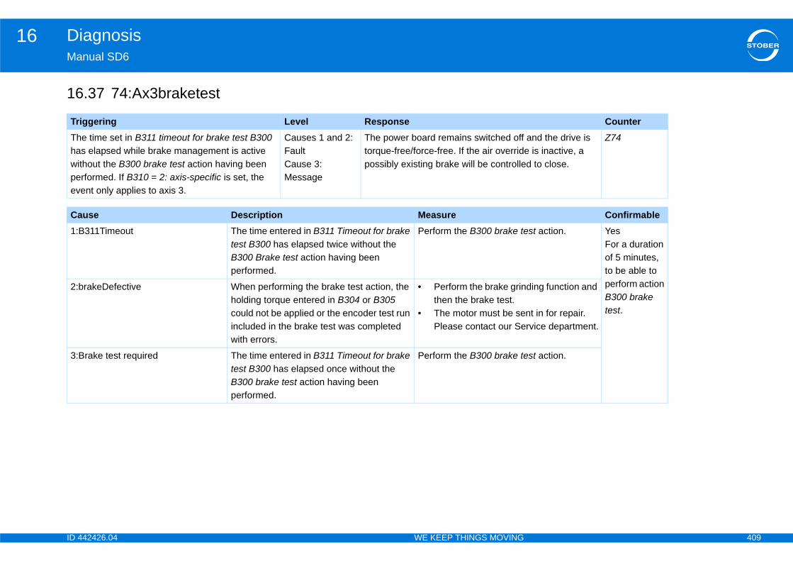
ID 4 409
Diagnosis16Ma
16
Tr CounterThhawipeev
and the drive is e is inactive, a d to close.
Z74
Ca Confirmable1:B st action. Yes
For a duration of 5 minutes, to be able to perform action B300 brake test.
2:b ding function and
nt in for repair. rvice department.
3:B st action.
42426.04 WE KEEP THINGS MOVING
nual SD6
.37 74:Ax3braketest
iggering Level Responsee time set in B311 timeout for brake test B300 s elapsed while brake management is active thout the B300 brake test action having been rformed. If B310 = 2: axis-specific is set, the ent only applies to axis 3.
Causes 1 and 2: FaultCause 3: Message
The power board remains switched off torque-free/force-free. If the air overridpossibly existing brake will be controlle
use Description Measure311Timeout The time entered in B311 Timeout for brake
test B300 has elapsed twice without the B300 Brake test action having been performed.
Perform the B300 brake te
rakeDefective When performing the brake test action, the holding torque entered in B304 or B305 could not be applied or the encoder test run included in the brake test was completed with errors.
• Perform the brake grinthen the brake test.
• The motor must be sePlease contact our Se
rake test required The time entered in B311 Timeout for brake test B300 has elapsed once without the B300 brake test action having been performed.
Perform the B300 brake te
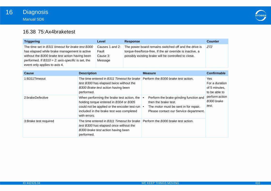
ID 4 410
Diagnosis16Ma
16
Tr CounterThhawipeev
and the drive is e is inactive, a d to close.
Z72
Ca Confirmable1:B st action. Yes
For a duration of 5 minutes, to be able to perform action B300 brake test.
2:b ding function and
nt in for repair. rvice department.
3:B st action.
42426.04 WE KEEP THINGS MOVING
nual SD6
.38 75:Ax4braketest
iggering Level Responsee time set in B311 timeout for brake test B300 s elapsed while brake management is active thout the B300 brake test action having been rformed. If B310 = 2: axis-specific is set, the ent only applies to axis 4.
Causes 1 and 2: FaultCause 3: Message
The power board remains switched off torque-free/force-free. If the air overridpossibly existing brake will be controlle
use Description Measure311Timeout The time entered in B311 Timeout for brake
test B300 has elapsed twice without the B300 Brake test action having been performed.
Perform the B300 brake te
rakeDefective When performing the brake test action, the holding torque entered in B304 or B305 could not be applied or the encoder test run included in the brake test was completed with errors.
• Perform the brake grinthen the brake test.
• The motor must be sePlease contact our Se
rake test required The time entered in B311 Timeout for brake test B300 has elapsed once without the B300 brake test action having been performed.
Perform the B300 brake te
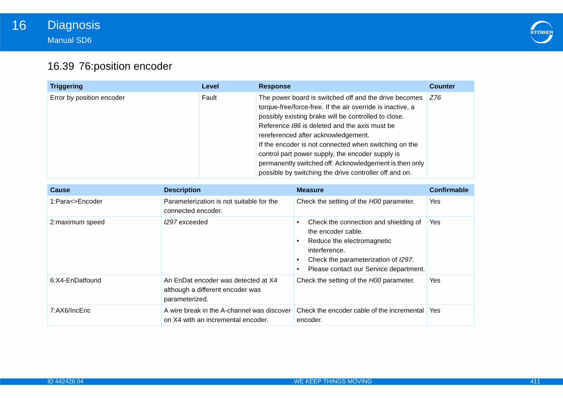
ID 4 411
Diagnosis16Ma
16
Tr CounterEr e drive becomes
e is inactive, a d to close.ust be
witching on the supply is ment is then only
er off and on.
Z76
Ca Confirmable1:P 00 parameter. Yes
2:m and shielding of
gnetic
ation of I297.rvice department.
Yes
6:X 00 parameter. Yes
7:A f the incremental Yes
42426.04 WE KEEP THINGS MOVING
nual SD6
.39 76:position encoder
iggering Level Responseror by position encoder Fault The power board is switched off and th
torque-free/force-free. If the air overridpossibly existing brake will be controlleReference I86 is deleted and the axis mrereferenced after acknowledgement. If the encoder is not connected when scontrol part power supply, the encoder permanently switched off. Acknowledgepossible by switching the drive controll
use Description Measureara<>Encoder Parameterization is not suitable for the
connected encoder.Check the setting of the H
aximum speed I297 exceeded • Check the connectionthe encoder cable.
• Reduce the electromainterference.
• Check the parameteriz• Please contact our Se
4-EnDatfound An EnDat encoder was detected at X4 although a different encoder was parameterized.
Check the setting of the H
X6/IncEnc A wire break in the A-channel was discover on X4 with an incremental encoder.
Check the encoder cable oencoder.
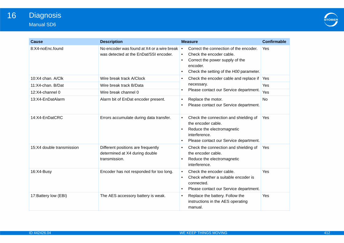
ID 4 412
Diagnosis16Ma
8:X of the encoder.ble.ply of the
e H00 parameter.
Yes
10 ble and replace if
rvice department.
Yes
11 Yes
12 Yes
13rvice department.
No
14 and shielding of
gnetic
rvice department.
Yes
15 and shielding of
gnetic
Yes
16 ble.ble encoder is
rvice department.
Yes
17 ollow the operating
Yes
Ca Confirmable
42426.04 WE KEEP THINGS MOVING
nual SD6
4-noEnc.found No encoder was found at X4 or a wire break was detected at the EnDat/SSI encoder.
• Correct the connection• Check the encoder ca• Correct the power sup
encoder.• Check the setting of th
:X4 chan. A/Clk Wire break track A/Clock • Check the encoder canecessary.
• Please contact our Se:X4-chan. B/Dat Wire break track B/Data
:X4-channel 0 Wire break channel 0
:X4-EnDatAlarm Alarm bit of EnDat encoder present. • Replace the motor.• Please contact our Se
:X4-EnDatCRC Errors accumulate during data transfer. • Check the connectionthe encoder cable.
• Reduce the electromainterference.
• Please contact our Se
:X4 double transmission Different positions are frequently determined at X4 during double transmission.
• Check the connectionthe encoder cable.
• Reduce the electromainterference.
:X4-Busy Encoder has not responded for too long. • Check the encoder ca• Check whether a suita
connected.• Please contact our Se
:Battery low (EBI) The AES accessory battery is weak. • Replace the battery. Finstructions in the AESmanual.
use Description Measure
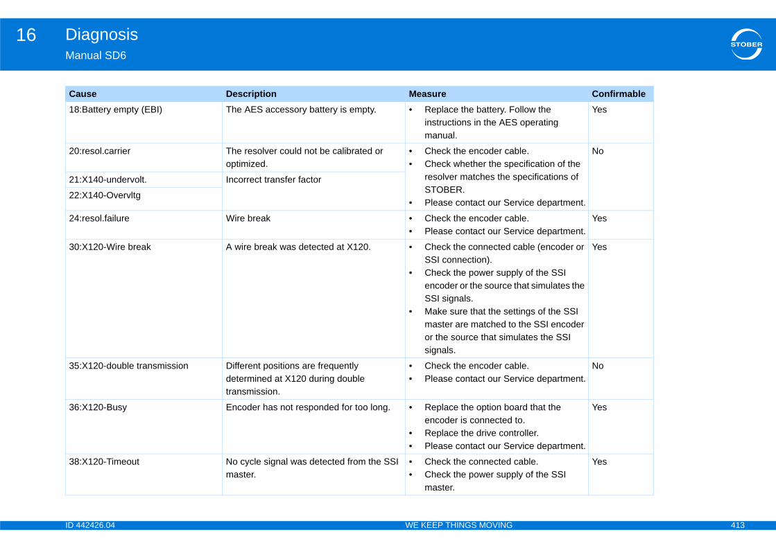
ID 4 413
Diagnosis16Ma
18 ollow the operating
Yes
20 ble.ecification of the pecifications of
rvice department.
No
21
22
24 ble.rvice department.
Yes
30 cable (encoder or
ly of the SSI that simulates the
ttings of the SSI the SSI encoder
ulates the SSI
Yes
35 ble.rvice department.
No
36 ard that the to.troller.rvice department.
Yes
38 cable.ly of the SSI
Yes
Ca Confirmable
42426.04 WE KEEP THINGS MOVING
nual SD6
:Battery empty (EBI) The AES accessory battery is empty. • Replace the battery. Finstructions in the AESmanual.
:resol.carrier The resolver could not be calibrated or optimized.
• Check the encoder ca• Check whether the sp
resolver matches the sSTOBER.
• Please contact our Se
:X140-undervolt. Incorrect transfer factor
:X140-Overvltg
:resol.failure Wire break • Check the encoder ca• Please contact our Se
:X120-Wire break A wire break was detected at X120. • Check the connected SSI connection).
• Check the power suppencoder or the source SSI signals.
• Make sure that the semaster are matched toor the source that simsignals.
:X120-double transmission Different positions are frequently determined at X120 during double transmission.
• Check the encoder ca• Please contact our Se
:X120-Busy Encoder has not responded for too long. • Replace the option boencoder is connected
• Replace the drive con• Please contact our Se
:X120-Timeout No cycle signal was detected from the SSI master.
• Check the connected • Check the power supp
master.
use Description Measure

ID 4 414
Diagnosis16Ma
43 oller off and back
Please contact t.
Yes
44 rect encoder type
and shielding of
gnetic
rvice department.
Yes
Ca Confirmable
42426.04 WE KEEP THINGS MOVING
nual SD6
:X140EnDatAlar The EnDat encoder at X140 reports an alarm.
• Switch the drive contron again.
• The encoder is faulty. our service departmen
:X140EnDatCRC Errors accumulate during data transfer. The encoder is not available.
• Make sure that the coris connected.
• Check the connectionthe encoder cable.
• Reduce the electromainterference.
• Please contact our Se
use Description Measure
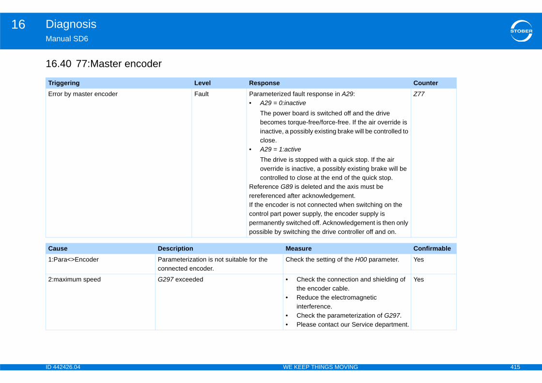
ID 4 415
Diagnosis16Ma
16
Tr CounterEr
d the drive he air override is ill be controlled to
top. If the air ting brake will be quick stop. must be
witching on the supply is ment is then only
er off and on.
Z77
Ca Confirmable1:P 00 parameter. Yes
2:m and shielding of
gnetic
ation of G297.rvice department.
Yes
42426.04 WE KEEP THINGS MOVING
nual SD6
.40 77:Master encoder
iggering Level Responseror by master encoder Fault Parameterized fault response in A29:
• A29 = 0:inactiveThe power board is switched off anbecomes torque-free/force-free. If tinactive, a possibly existing brake wclose.
• A29 = 1:activeThe drive is stopped with a quick soverride is inactive, a possibly exiscontrolled to close at the end of the
Reference G89 is deleted and the axisrereferenced after acknowledgement. If the encoder is not connected when scontrol part power supply, the encoder permanently switched off. Acknowledgepossible by switching the drive controll
use Description Measureara<>Encoder Parameterization is not suitable for the
connected encoder.Check the setting of the H
aximum speed G297 exceeded • Check the connectionthe encoder cable.
• Reduce the electromainterference.
• Check the parameteriz• Please contact our Se

ID 4 416
Diagnosis16Ma
6:X 00 parameter. Yes
7:A f the incremental Yes
8:X of the encoder.ble.ply of the
e H00 parameter.
Yes
10 ble and replace if
rvice department.
Yes
11 Yes
12 Yes
13rvice department.
No
14 and shielding of
gnetic
rvice department.
Yes
15 and shielding of
gnetic
Yes
16 ble.ble encoder is
rvice department.
Yes
Ca Confirmable
42426.04 WE KEEP THINGS MOVING
nual SD6
4-EnDatfound An EnDat encoder was detected at X4 although a different encoder was parameterized.
Check the setting of the H
X5000/IncEnc A wire break in the A-channel was discover on X4 with an incremental encoder.
Check the encoder cable oencoder.
4-noEnc.found No encoder was found at X4 or a wire break was detected at the EnDat/SSI encoder.
• Correct the connection• Check the encoder ca• Correct the power sup
encoder.• Check the setting of th
:X4 chan. A/Clk Wire break track A/Clock • Check the encoder canecessary.
• Please contact our Se:X4-chan. B/Dat Wire break track B/Data
:X4-channel 0 Wire break channel 0
:X4-EnDatAlarm Alarm bit of EnDat encoder present. • Replace the motor.• Please contact our Se
:X4-EnDatCRC Errors accumulate during data transfer. • Check the connectionthe encoder cable.
• Reduce the electromainterference.
• Please contact our Se
:X4 double transmission Different positions are frequently determined at X4 during double transmission.
• Check the connectionthe encoder cable.
• Reduce the electromainterference.
:X4-Busy Encoder has not responded for too long. • Check the encoder ca• Check whether a suita
connected.• Please contact our Se
use Description Measure
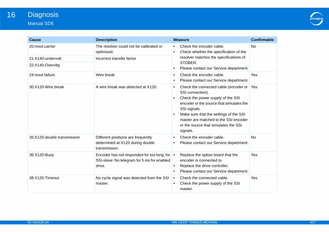
ID 4 417
Diagnosis16Ma
20 ble.ecification of the pecifications of
rvice department.
No
21
22
24 ble.rvice department.
Yes
30 cable (encoder or
ly of the SSI that simulates the
ttings of the SSI the SSI encoder
ulates the SSI
Yes
35 ble.rvice department.
No
36 ard that the to.troller.rvice department.
Yes
38 cable.ly of the SSI
Yes
Ca Confirmable
42426.04 WE KEEP THINGS MOVING
nual SD6
:resol.carrier The resolver could not be calibrated or optimized.
• Check the encoder ca• Check whether the sp
resolver matches the sSTOBER.
• Please contact our Se
:X140-undervolt. Incorrect transfer factor
:X140-Overvltg
:resol.failure Wire break • Check the encoder ca• Please contact our Se
:X120-Wire break A wire break was detected at X120. • Check the connected SSI connection).
• Check the power suppencoder or the source SSI signals.
• Make sure that the semaster are matched toor the source that simsignals.
:X120-double transmission Different positions are frequently determined at X120 during double transmission.
• Check the encoder ca• Please contact our Se
:X120-Busy Encoder has not responded for too long; for SSI-slave: No telegram for 5 ms for enabled drive.
• Replace the option boencoder is connected
• Replace the drive con• Please contact our Se
:X120-Timeout No cycle signal was detected from the SSI master.
• Check the connected • Check the power supp
master.
use Description Measure
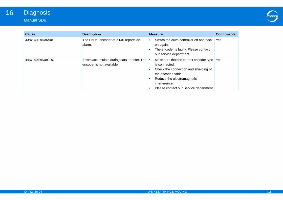
ID 4 418
Diagnosis16Ma
43 oller off and back
Please contact t.
Yes
44 rect encoder type
and shielding of
gnetic
rvice department.
Yes
Ca Confirmable
42426.04 WE KEEP THINGS MOVING
nual SD6
:X140EnDatAlar The EnDat encoder at X140 reports an alarm.
• Switch the drive contron again.
• The encoder is faulty. our service departmen
:X140EnDatCRC Errors accumulate during data transfer. The encoder is not available.
• Make sure that the coris connected.
• Check the connectionthe encoder cable.
• Reduce the electromainterference.
• Please contact our Se
use Description Measure
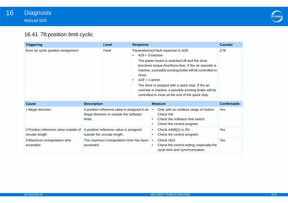
ID 4 419
Diagnosis16Ma
16
Tr CounterEr
d the drive he air override is ill be controlled to
top. If the air ting brake will be quick stop.
Z78
Ca Confirmable1:i ange of motion:
it switch.ram.
Yes
2:Pcir ram.
Yes
3:Mex ng, especially the
onization.
Yes
42426.04 WE KEEP THINGS MOVING
nual SD6
.41 78:position limit cyclic
iggering Level Responseror by cyclic position assignment Fault Parameterized fault response in A29:
• A29 = 0:inactiveThe power board is switched off anbecomes torque-free/force-free. If tinactive, a possibly existing brake wclose.
• A29 = 1:activeThe drive is stopped with a quick soverride is inactive, a possibly exiscontrolled to close at the end of the
use Description Measurellegal direction A position reference value is assigned in an
illegal direction or outside the software limits.
• Only with an endless rCheck I04.
• Check the software lim• Check the control prog
osition reference value outside of cular length
A position reference value is assigned outside the circular length.
• Check A568[1] or I01.• Check the control prog
aximum extrapolation time ceeded
The maximum extrapolation time has been exceeded.
• Check I423.• Check the control setti
cycle time and synchr
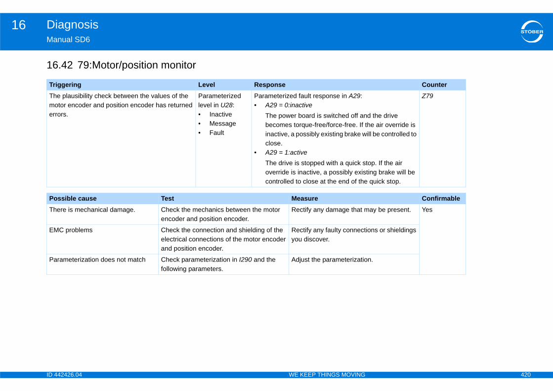
ID 4 420
Diagnosis16Ma
16
Tr CounterThmoerr d the drive
he air override is ill be controlled to
top. If the air ting brake will be quick stop.
Z79
Po ConfirmableTh ay be present. Yes
EM ions or shieldings
Pa n.
42426.04 WE KEEP THINGS MOVING
nual SD6
.42 79:Motor/position monitor
iggering Level Responsee plausibility check between the values of the tor encoder and position encoder has returned ors.
Parameterized level in U28:• Inactive• Message• Fault
Parameterized fault response in A29:• A29 = 0:inactive
The power board is switched off anbecomes torque-free/force-free. If tinactive, a possibly existing brake wclose.
• A29 = 1:activeThe drive is stopped with a quick soverride is inactive, a possibly exiscontrolled to close at the end of the
ssible cause Test Measureere is mechanical damage. Check the mechanics between the motor
encoder and position encoder.Rectify any damage that m
C problems Check the connection and shielding of the electrical connections of the motor encoder and position encoder.
Rectify any faulty connectyou discover.
rameterization does not match Check parameterization in I290 and the following parameters.
Adjust the parameterizatio

ID 4 421
Diagnosis16Ma
16
Tr CounterThno
e drive becomes e is inactive, a d to close.
Z80
Ca Confirmable1:i Yes
2:b start the action Yes
42426.04 WE KEEP THINGS MOVING
nual SD6
.43 80:illegal action
iggering Level Responsee event is triggered if an action that is started is t permitted.
Fault The power board is switched off and thtorque-free/force-free. If the air overridpossibly existing brake will be controlle
use Description Measurellegal The selected control mode does not support
the action.Check the control mode.
rake For actions that require the brake to open, the position is monitored for 1 second after the start of the action to detect a possible axis load. If an axis load is detected, the event with its cause is displayed.
Remove the axis load andagain.
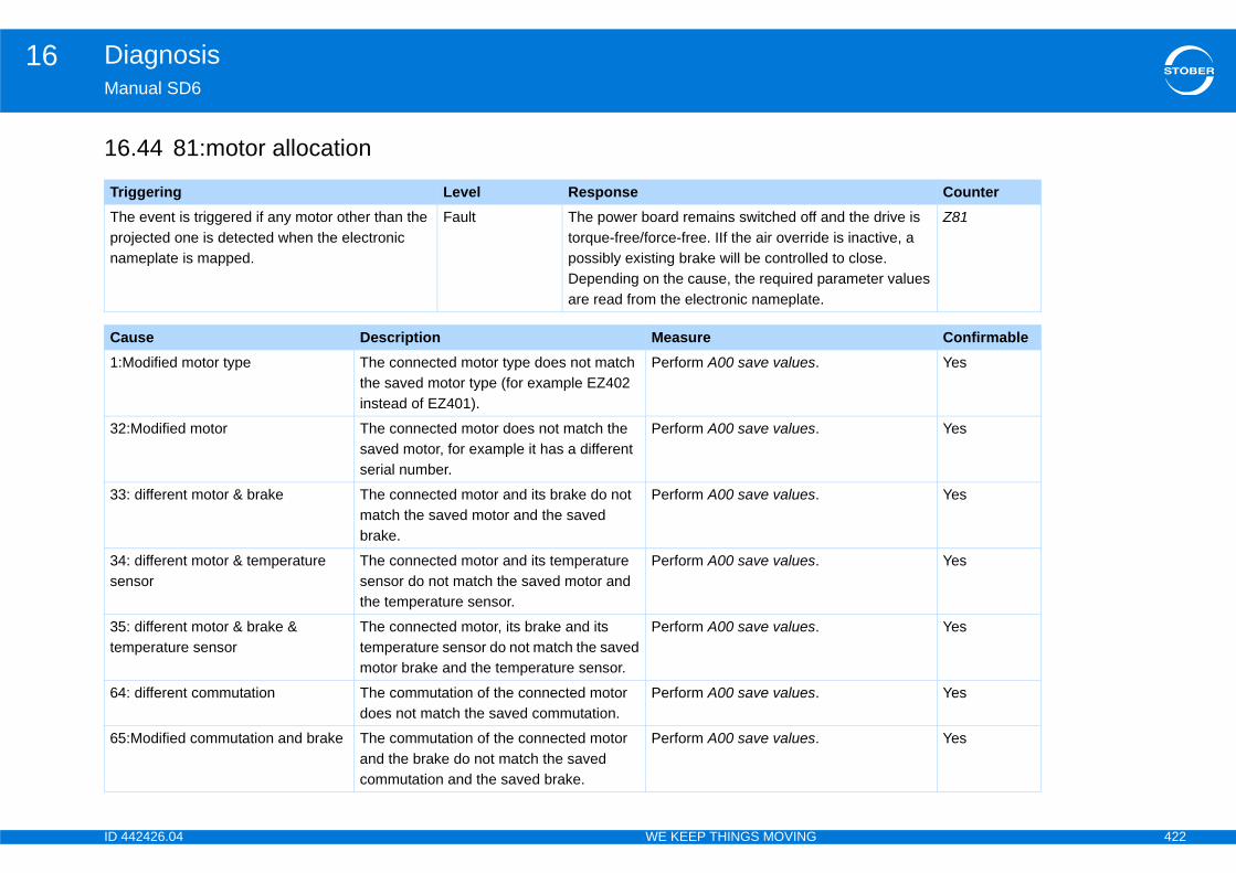
ID 4 422
Diagnosis16Ma
16
Tr CounterThprona
and the drive is e is inactive, a d to close.parameter values .
Z81
Ca Confirmable1:M Yes
32 Yes
33 Yes
34se
Yes
35tem
Yes
64 Yes
65 Yes
42426.04 WE KEEP THINGS MOVING
nual SD6
.44 81:motor allocation
iggering Level Responsee event is triggered if any motor other than the jected one is detected when the electronic
meplate is mapped.
Fault The power board remains switched off torque-free/force-free. IIf the air overridpossibly existing brake will be controlleDepending on the cause, the required are read from the electronic nameplate
use Description Measureodified motor type The connected motor type does not match
the saved motor type (for example EZ402 instead of EZ401).
Perform A00 save values.
:Modified motor The connected motor does not match the saved motor, for example it has a different serial number.
Perform A00 save values.
: different motor & brake The connected motor and its brake do not match the saved motor and the saved brake.
Perform A00 save values.
: different motor & temperature nsor
The connected motor and its temperature sensor do not match the saved motor and the temperature sensor.
Perform A00 save values.
: different motor & brake & perature sensor
The connected motor, its brake and its temperature sensor do not match the saved motor brake and the temperature sensor.
Perform A00 save values.
: different commutation The commutation of the connected motor does not match the saved commutation.
Perform A00 save values.
:Modified commutation and brake The commutation of the connected motor and the brake do not match the saved commutation and the saved brake.
Perform A00 save values.
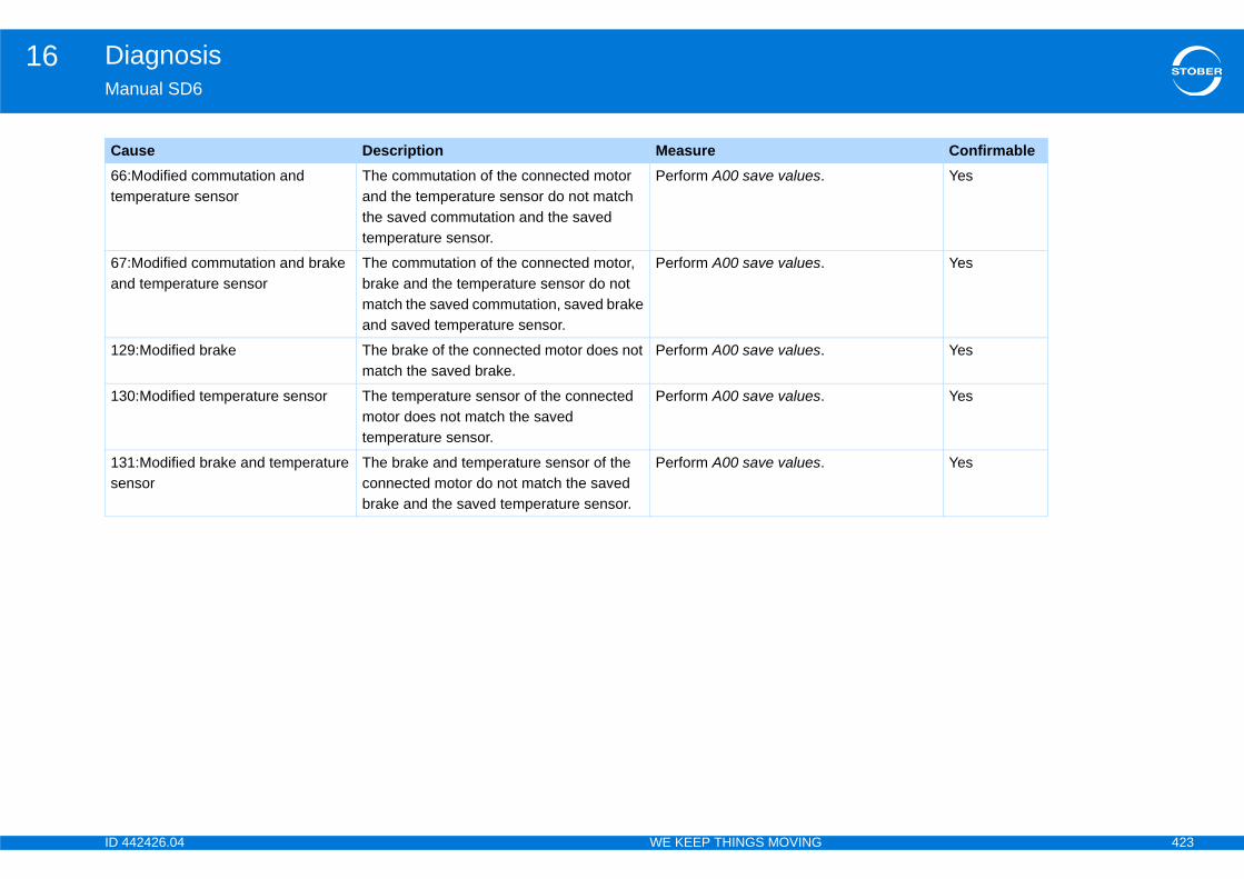
ID 4 423
Diagnosis16Ma
66tem
Yes
67an
Yes
12 Yes
13 Yes
13se
Yes
Ca Confirmable
42426.04 WE KEEP THINGS MOVING
nual SD6
:Modified commutation and perature sensor
The commutation of the connected motor and the temperature sensor do not match the saved commutation and the saved temperature sensor.
Perform A00 save values.
:Modified commutation and brake d temperature sensor
The commutation of the connected motor, brake and the temperature sensor do not match the saved commutation, saved brake and saved temperature sensor.
Perform A00 save values.
9:Modified brake The brake of the connected motor does not match the saved brake.
Perform A00 save values.
0:Modified temperature sensor The temperature sensor of the connected motor does not match the saved temperature sensor.
Perform A00 save values.
1:Modified brake and temperature nsor
The brake and temperature sensor of the connected motor do not match the saved brake and the saved temperature sensor.
Perform A00 save values.
use Description Measure
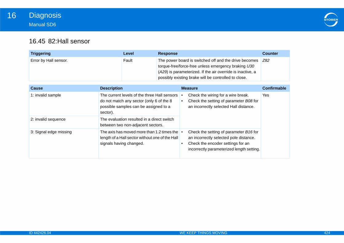
ID 4 424
Diagnosis16Ma
16
Tr CounterEr e drive becomes
y braking U30 de is inactive, a d to close.
Z82
Ca Confirmable1: wire break.
arameter B08 for Hall distance.
Yes
2:
3: arameter B16 for pole distance.ttings for an ed length setting.
42426.04 WE KEEP THINGS MOVING
nual SD6
.45 82:Hall sensor
iggering Level Responseror by Hall sensor. Fault The power board is switched off and th
torque-free/force-free unless emergenc(A29) is parameterized. If the air overripossibly existing brake will be controlle
use Description Measureinvalid sample The current levels of the three Hall sensors
do not match any sector (only 6 of the 8 possible samples can be assigned to a sector).
• Check the wiring for a• Check the setting of p
an incorrectly selected
invalid sequence The evaluation resulted in a direct switch between two non-adjacent sectors.
Signal edge missing The axis has moved more than 1.2 times the length of a Hall sector without one of the Hall signals having changed.
• Check the setting of pan incorrectly selected
• Check the encoder seincorrectly parameteriz
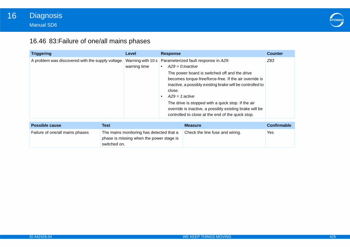
ID 4 425
Diagnosis16Ma
16
Tr CounterA p
d the drive he air override is ill be controlled to
top. If the air ting brake will be quick stop.
Z83
Po ConfirmableFa iring. Yes
42426.04 WE KEEP THINGS MOVING
nual SD6
.46 83:Failure of one/all mains phases
iggering Level Responseroblem was discovered with the supply voltage. Warning with 10 s
warning timeParameterized fault response in A29:• A29 = 0:inactive
The power board is switched off anbecomes torque-free/force-free. If tinactive, a possibly existing brake wclose.
• A29 = 1:activeThe drive is stopped with a quick soverride is inactive, a possibly exiscontrolled to close at the end of the
ssible cause Test Measureilure of one/all mains phases The mains monitoring has detected that a
phase is missing when the power stage is switched on.
Check the line fuse and w

ID 4 426
Diagnosis16Ma
16
Tr CounterA p e drive becomes
y braking U30 de is inactive, a d to close.
Z84
Po ConfirmableDr voltage
cation or whether Yes
42426.04 WE KEEP THINGS MOVING
nual SD6
.47 84:Drop in network with power stage active
iggering Level Responseroblem was discovered with the supply voltage. Fault The power board is switched off and th
torque-free/force-free unless emergenc(A29) is parameterized. If the air overripossibly existing brake will be controlle
ssible cause Test Measureop in network If the mains monitoring detects that the
mains is missing, the load relay is immediately switched off. Normal operation is maintained. If the mains return of the power board is still switched on, a fault is triggered after 0.5 s.
Check whether the mainscorresponds to the specifithere is a power failure.

ID 4 427
Diagnosis16Ma
16
Tr CounterIf rasthato coidl
d the drive he air override is ill be controlled to
top. If the air ting brake will be quick stop.
Z85
Ca Confirmable1: alues so that the
eration E64 can Yes
2:
42426.04 WE KEEP THINGS MOVING
nual SD6
.48 85:Excessive jump in reference value
iggering Level Responseeference value monitoring C100 is active, the signed reference values require an acceleration t the motor is unable to maintain while keeping the maximum output current of the drive ntroller power stage I2maxLT (R04*R26) – even in e (from firmware V 6.0-E).
Fault Parameterized fault response in A29:• A29 = 0:inactive
The power board is switched off anbecomes torque-free/force-free. If tinactive, a possibly existing brake wclose.
• A29 = 1:activeThe drive is stopped with a quick soverride is inactive, a possibly exiscontrolled to close at the end of the
use Description MeasurePosition Position reference values require an
acceleration that cannot be performed.Configure the reference vmaximum permitted accelbe performed. Speed Speed reference values require an
acceleration that cannot be performed.
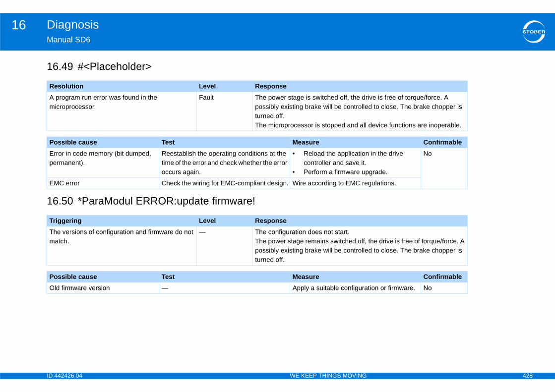
ID 4 428
Diagnosis16Ma
16
16
ReA mi
ive is free of torque/force. A d to close. The brake chopper is
device functions are inoperable.
Po ConfirmableErpe
in the drive
grade.
No
EM gulations.
TrThma the drive is free of torque/force. A
d to close. The brake chopper is
Po ConfirmableOl tion or firmware. No
42426.04 WE KEEP THINGS MOVING
nual SD6
.49 #<Placeholder>
.50 *ParaModul ERROR:update firmware!
solution Level Responseprogram run error was found in the croprocessor.
Fault The power stage is switched off, the drpossibly existing brake will be controlleturned off.The microprocessor is stopped and all
ssible cause Test Measureror in code memory (bit dumped, rmanent).
Reestablish the operating conditions at the time of the error and check whether the error occurs again.
• Reload the applicationcontroller and save it.
• Perform a firmware up
C error Check the wiring for EMC-compliant design. Wire according to EMC re
iggering Level Responsee versions of configuration and firmware do not tch.
— The configuration does not start.The power stage remains switched off, possibly existing brake will be controlleturned off.
ssible cause Test Measured firmware version — Apply a suitable configura
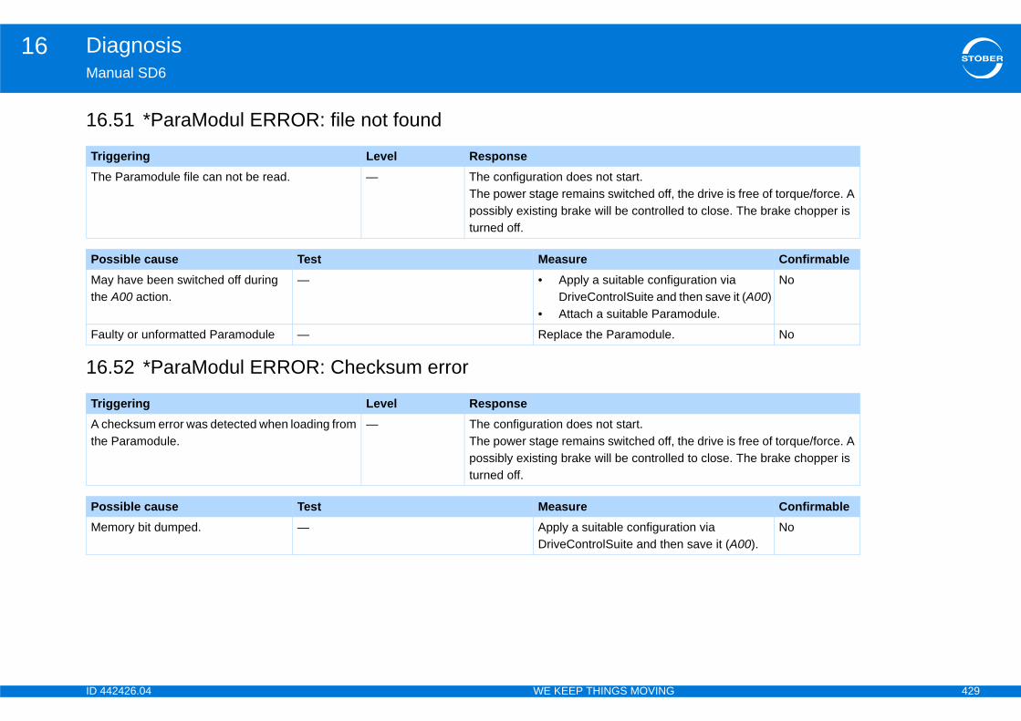
ID 4 429
Diagnosis16Ma
16
16
TrTh
the drive is free of torque/force. A d to close. The brake chopper is
Po ConfirmableMathe
uration via then save it (A00)module.
No
Fa No
TrA cthe the drive is free of torque/force. A
d to close. The brake chopper is
Po ConfirmableMe tion via
n save it (A00).No
42426.04 WE KEEP THINGS MOVING
nual SD6
.51 *ParaModul ERROR: file not found
.52 *ParaModul ERROR: Checksum error
iggering Level Responsee Paramodule file can not be read. — The configuration does not start.
The power stage remains switched off, possibly existing brake will be controlleturned off.
ssible cause Test Measurey have been switched off during A00 action.
— • Apply a suitable configDriveControlSuite and
• Attach a suitable Para
ulty or unformatted Paramodule — Replace the Paramodule.
iggering Level Responsehecksum error was detected when loading from Paramodule.
— The configuration does not start.The power stage remains switched off, possibly existing brake will be controlleturned off.
ssible cause Test Measuremory bit dumped. — Apply a suitable configura
DriveControlSuite and the
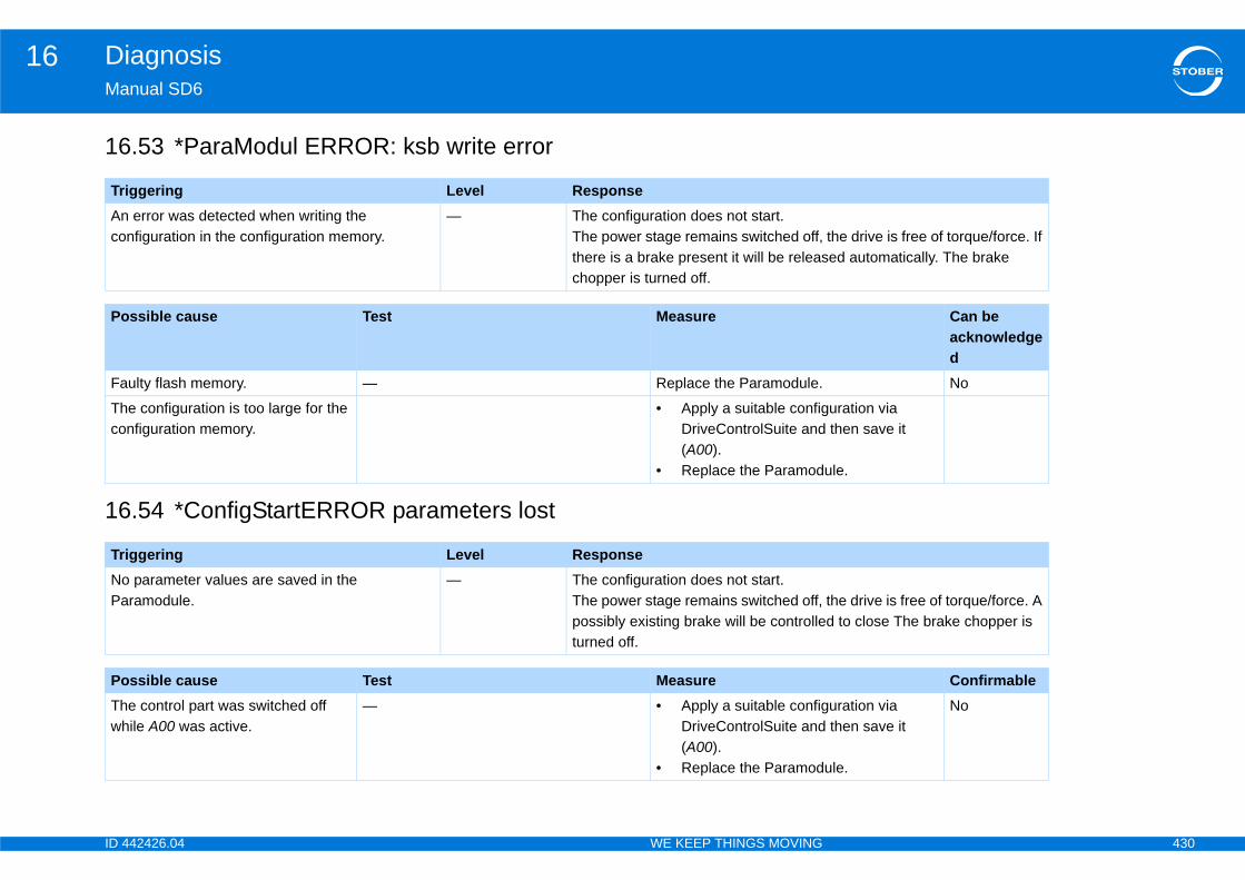
ID 4 430
Diagnosis16Ma
16
16
TrAnco the drive is free of torque/force. If
ed automatically. The brake
Po Can be acknowledged
Fa No
Thco
uration via then save it
ule.
TrNoPa the drive is free of torque/force. A
d to close The brake chopper is
Po ConfirmableThwh
uration via then save it
ule.
No
42426.04 WE KEEP THINGS MOVING
nual SD6
.53 *ParaModul ERROR: ksb write error
.54 *ConfigStartERROR parameters lost
iggering Level Response error was detected when writing the nfiguration in the configuration memory.
— The configuration does not start.The power stage remains switched off,there is a brake present it will be releaschopper is turned off.
ssible cause Test Measure
ulty flash memory. — Replace the Paramodule.
e configuration is too large for the nfiguration memory.
• Apply a suitable configDriveControlSuite and(A00).
• Replace the Paramod
iggering Level Response parameter values are saved in the ramodule.
— The configuration does not start.The power stage remains switched off, possibly existing brake will be controlleturned off.
ssible cause Test Measuree control part was switched off ile A00 was active.
— • Apply a suitable configDriveControlSuite and(A00).
• Replace the Paramod
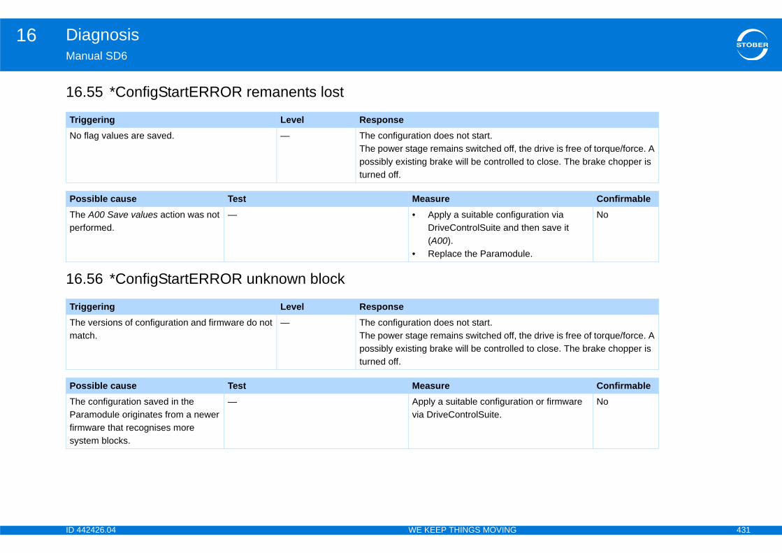
ID 4 431
Diagnosis16Ma
16
16
TrNo
the drive is free of torque/force. A d to close. The brake chopper is
Po ConfirmableThpe
uration via then save it
ule.
No
TrThma the drive is free of torque/force. A
d to close. The brake chopper is
Po ConfirmableThPafirmsy
tion or firmware No
42426.04 WE KEEP THINGS MOVING
nual SD6
.55 *ConfigStartERROR remanents lost
.56 *ConfigStartERROR unknown block
iggering Level Response flag values are saved. — The configuration does not start.
The power stage remains switched off, possibly existing brake will be controlleturned off.
ssible cause Test Measuree A00 Save values action was not rformed.
— • Apply a suitable configDriveControlSuite and(A00).
• Replace the Paramod
iggering Level Responsee versions of configuration and firmware do not tch.
— The configuration does not start.The power stage remains switched off, possibly existing brake will be controlleturned off.
ssible cause Test Measuree configuration saved in the ramodule originates from a newer ware that recognises more
stem blocks.
— Apply a suitable configuravia DriveControlSuite.
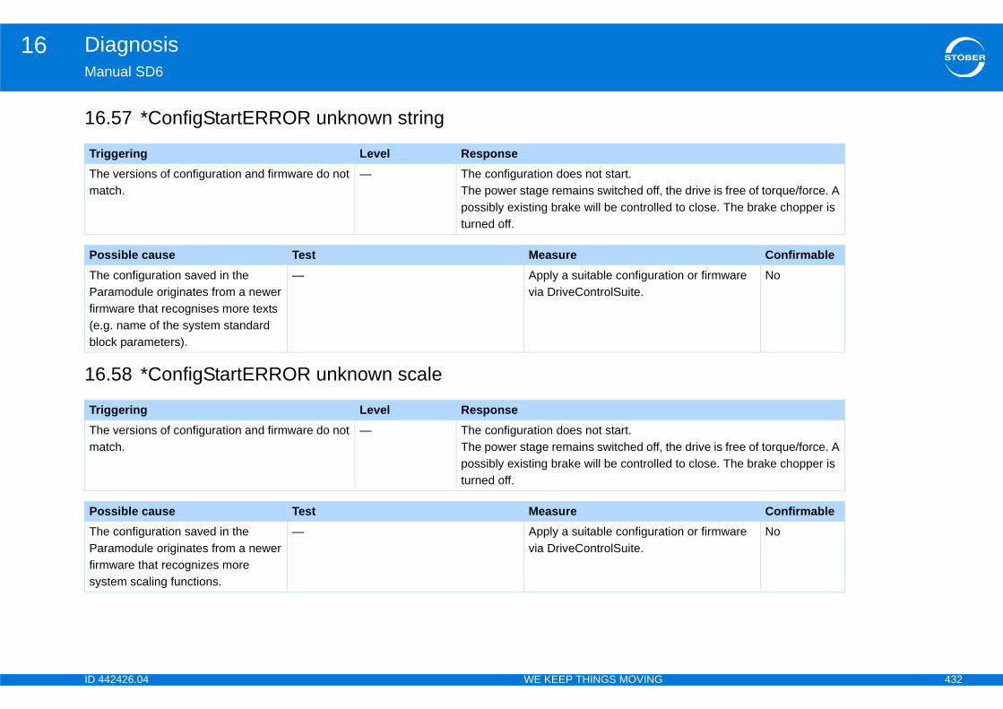
ID 4 432
Diagnosis16Ma
16
16
TrThma the drive is free of torque/force. A
d to close. The brake chopper is
Po ConfirmableThPafirm(e.blo
tion or firmware No
TrThma the drive is free of torque/force. A
d to close. The brake chopper is
Po ConfirmableThPafirmsy
tion or firmware No
42426.04 WE KEEP THINGS MOVING
nual SD6
.57 *ConfigStartERROR unknown string
.58 *ConfigStartERROR unknown scale
iggering Level Responsee versions of configuration and firmware do not tch.
— The configuration does not start.The power stage remains switched off, possibly existing brake will be controlleturned off.
ssible cause Test Measuree configuration saved in the ramodule originates from a newer ware that recognises more texts
g. name of the system standard ck parameters).
— Apply a suitable configuravia DriveControlSuite.
iggering Level Responsee versions of configuration and firmware do not tch.
— The configuration does not start.The power stage remains switched off, possibly existing brake will be controlleturned off.
ssible cause Test Measuree configuration saved in the ramodule originates from a newer ware that recognizes more
stem scaling functions.
— Apply a suitable configuravia DriveControlSuite.
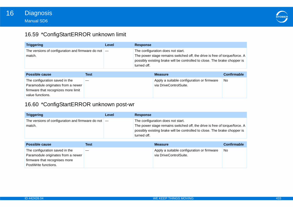
ID 4 433
Diagnosis16Ma
16
16
TrThma the drive is free of torque/force. A
d to close. The brake chopper is
Po ConfirmableThPafirmva
tion or firmware No
TrThma the drive is free of torque/force. A
d to close. The brake chopper is
Po ConfirmableThPafirmPo
tion or firmware No
42426.04 WE KEEP THINGS MOVING
nual SD6
.59 *ConfigStartERROR unknown limit
.60 *ConfigStartERROR unknown post-wr
iggering Level Responsee versions of configuration and firmware do not tch.
— The configuration does not start.The power stage remains switched off, possibly existing brake will be controlleturned off.
ssible cause Test Measuree configuration saved in the ramodule originates from a newer ware that recognizes more limit
lue functions.
— Apply a suitable configuravia DriveControlSuite.
iggering Level Responsee versions of configuration and firmware do not tch.
— The configuration does not start.The power stage remains switched off, possibly existing brake will be controlleturned off.
ssible cause Test Measuree configuration saved in the ramodule originates from a newer ware that recognises more
stWrite functions.
— Apply a suitable configuravia DriveControlSuite.

ID 4 434
Diagnosis16Ma
16
16
TrThma the drive is free of torque/force. A
d to close. The brake chopper is
Po ConfirmableThPafirmreapapa
tion or firmware No
TrThma the drive is free of torque/force. A
d to close. The brake chopper is
Po ConfirmableThPafirmfunshpa
tion or firmware No
42426.04 WE KEEP THINGS MOVING
nual SD6
.61 *ConfigStartERROR unknown pre-rd
.62 *ConfigStartERROR unknown hiding
iggering Level Responsee versions of configuration and firmware do not tch.
— The configuration does not start.The power stage remains switched off, possibly existing brake will be controlleturned off.
ssible cause Test Measuree configuration saved in the ramodule originates from a newer ware that recognises more Pre-d functions (mapping of firmware
rameters to configuration rameters).
— Apply a suitable configuravia DriveControlSuite.
iggering Level Responsee versions of configuration and firmware do not tch.
— The configuration does not start.The power stage remains switched off, possibly existing brake will be controlleturned off.
ssible cause Test Measuree configuration saved in the ramodule originates from a newer ware that knows more hide
ctions (hide parameters that ould be visible depending on other rameters).
— Apply a suitable configuravia DriveControlSuite.
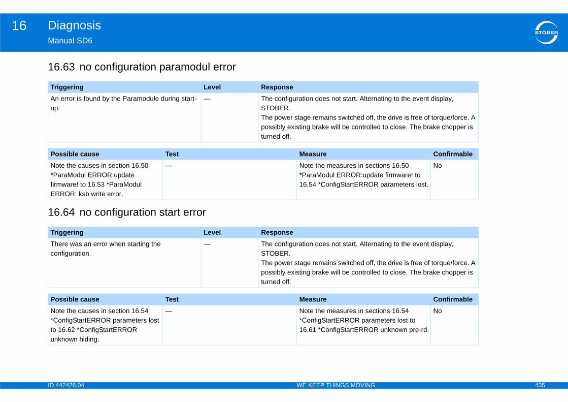
ID 4 435
Diagnosis16Ma
16
16
TrAnup
ating to the event display,
the drive is free of torque/force. A d to close. The brake chopper is
Po ConfirmableNo*PfirmER
tions 16.50 te firmware! to parameters lost.
No
TrThco
ating to the event display,
the drive is free of torque/force. A d to close. The brake chopper is
Po ConfirmableNo*Cto un
tions 16.54 eters lost to
unknown pre-rd.
No
42426.04 WE KEEP THINGS MOVING
nual SD6
.63 no configuration paramodul error
.64 no configuration start error
iggering Level Response error is found by the Paramodule during start-.
— The configuration does not start. AlternSTOBER.The power stage remains switched off, possibly existing brake will be controlleturned off.
ssible cause Test Measurete the causes in section 16.50 araModul ERROR:update
ware! to 16.53 *ParaModul ROR: ksb write error.
— Note the measures in sec*ParaModul ERROR:upda16.54 *ConfigStartERROR
iggering Level Responseere was an error when starting the nfiguration.
— The configuration does not start. AlternSTOBER.The power stage remains switched off, possibly existing brake will be controlleturned off.
ssible cause Test Measurete the causes in section 16.54 onfigStartERROR parameters lost 16.62 *ConfigStartERROR known hiding.
— Note the measures in sec*ConfigStartERROR param16.61 *ConfigStartERROR
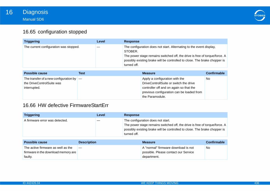
ID 4 436
Diagnosis16Ma
16
16
TrTh ating to the event display,
the drive is free of torque/force. A d to close. The brake chopper is
Po ConfirmableThtheint
the h the drive so that the be loaded from
No
TrA
the drive is free of torque/force. A d to close. The brake chopper is
Po ConfirmableThfirmfau
load is not ur Service
No
42426.04 WE KEEP THINGS MOVING
nual SD6
.65 configuration stopped
.66 HW defective FirmwareStartErr
iggering Level Responsee current configuration was stopped. — The configuration does not start. Altern
STOBER.The power stage remains switched off, possibly existing brake will be controlleturned off.
ssible cause Test Measuree transfer of a new configuration by DriveControlSuite was
errupted.
— Apply a configuration withDriveControllSuite or switccontroller off and on againprevious configuration canthe Paramodule.
iggering Level Responsefirmware error was detected. — The configuration does not start.
The power stage remains switched off, possibly existing brake will be controlleturned off.
ssible cause Description Measuree active firmware as well as the ware in the download memory are lty.
— A "normal" firmware downpossible. Please contact odepartment.

N
ID 4 437
otes
42426.04 WE KEEP THINGS MOVING
G
ID 4 438
Tefor
Glfor cou
SeGe
Seint
Singapore
Italy
Japan
le
2,
STOBER Singapore 50 Tagore Lane #05-06B Entrepreneur Centre Singapore 787494 Fon +65 65112912Fax +65 65112969 E-Mail: [email protected] www.stober.sg
STÖBER TRASMISSIONI S. r. l.Via Italo Calvino, 7 Palazzina D20017 Rho (MI)Fon +39 02 93909-570 Fax +39 02 93909-325E-Mail: [email protected]
STOBER JapanP.O. Box 113-002, 6 chome15-8, Hon-komagomeBunkyo-kuTokyoFon +81 3 5395-6788Fax +81 3 5395-6799 E-Mail: [email protected]
ST
lobal presence
42426.04 WE KEEP THINGS MOVING
chnical offices advice and marketing in Germany
obal presence advice and marketing in about 25 ntries
rvice network rmany
rvice network ernational
Austria
Switzerland
Great Britain
France
USA
China
STÖBER ANTRIEBSTECHNIKGmbHHauptstraße 41a4663 LaakirchenFon +43 7613 7600-0Fax +43 7613 7600-2525E-Mail: [email protected]
STÖBER SCHWEIZ AGRugghölzli 25453 RemetschwilFon +41 56 496 96 50 Fax +41 56 496 96 55E-Mail: [email protected]
STOBER DRIVES Ltd.Centrix House Upper Keys Business VillageKeys Park Road Hednesford, CannockSTAFFORDSHIRE WS12 2HAFon +44 1543 458 858Fax +44 1543 448 688E-Mail: [email protected]
STÖBER S.a.r.l.131, Chemin du Bac à TrailLes Portes du Rhône69300 Caluire et CuireFon +33 4 78989180 Fax +33 4 78985901E-Mail: [email protected]
STOBER DRIVES INC.1781 Downing DriveMaysville, KY 41056Fon +1 606 7595090 Fax +1 606 7595045E-Mail: [email protected]
STOBER CHINAGerman Centre BeijingUnit 2010, Landmark Tower8 North Dongsanhuan RoadChaoyang District100004 BeijingFon +86 10 65907391Fax +86 10 65907393 E-Mail: [email protected]
OBER subsidiaries
o. KG
STÖBER ANTRIEBSTECHNIK GmbH & CKieselbronner Str. 1275177 PFORZHEIMGERMANYTel. +49 7231 582-0Fax +49 7231 582-1000E-Mail: [email protected]
24h Service Hotline +49 180 5 786 323
Technische Änderungen vorbehaltenErrors and changes excepted
ID 442426.04
442426.04