rochester-b-manual.pdf - mike's carburetor parts
TRANSCRIPT

ROCHESTER CARBURETOR SERVICE MANUAL WWW.CARBURETOR-PARTS.COM
P a g e 2 | 43
AG
EN
DA
MODEL BC CARBURETOR
DISASSEMBLY PROCEDURE
CLEANING AND INSPECTION
ASSEMBLY PROCEDURE
HEAT SUCTION TUBE INSTALLATION
MODEL BC ADJUSTMENTS
MODEL B CARBURETOR
DISASSEMBLY PROCEDURE
CLEANING INSPECTION REPAIRS
ASSEMBLY
THROTTLE RETURN CHECK
ADJUSTMENTS
ROCHESTER CARBURETOR SERVICE MANUAL WWW.CARBURETOR-PARTS.COM
P a g e 3 | 43
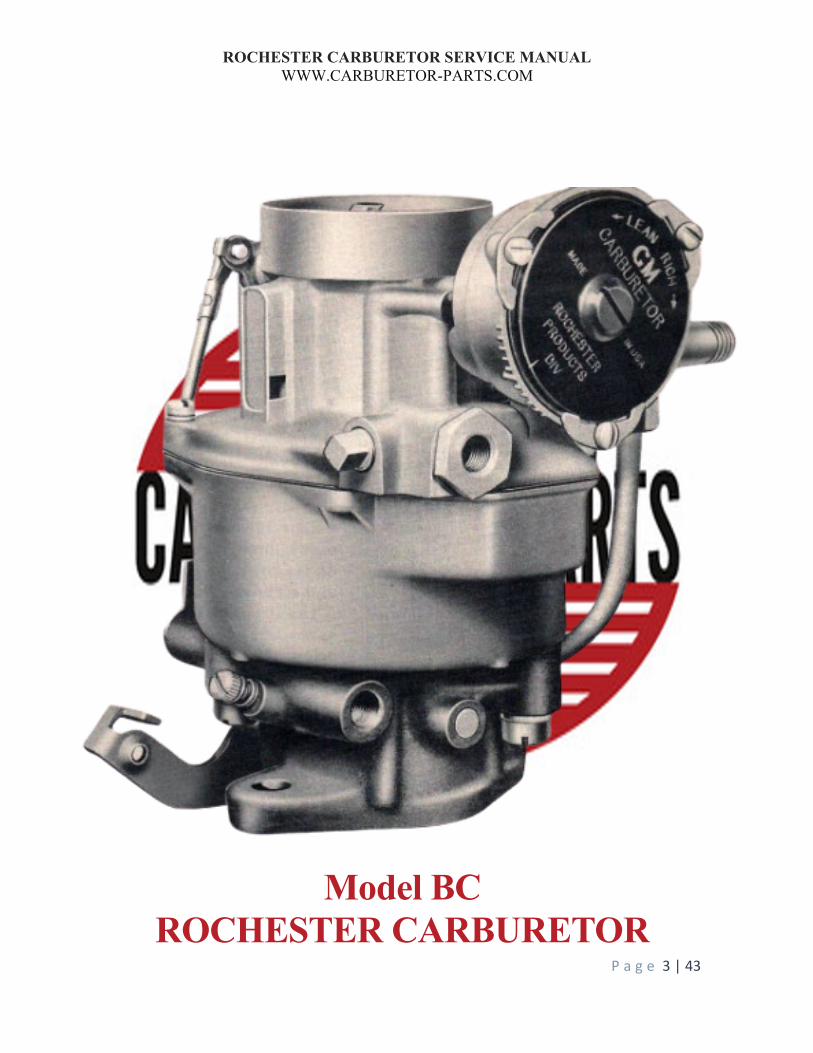
Model BC ROCHESTER CARBURETOR

ROCHESTER CARBURETOR SERVICE MANUAL WWW.CARBURETOR-PARTS.COM
P a g e 4 | 43
The Rochester Model BC carburetor was introduced in 1951. It is basically a conventional Model B
carburetor with the addition of an automatic choke.
Most of the metering parts are contained in the die-cast air horn assembly and can be serviced by simply
removing the air horn screws and lifting the air horn assembly from the float bowl. This carburetor
incorporates the conventional six systems of carburetion: Idle, Part Throttle, Power, Pump, Float, and
Choke.
This carburetor has been kept basically simple in design without sacrificing the distinctive features of all
Rochester carburetors—e.g., concentric float bowl suspended main metering jets, vacuum-operated power
system, centrally located main discharge nozzle, and a minimum of adjustments and moving parts.
IDLE SYSTEM
The Idle System controls and delivers the proper fuel-air mixture for idling and up to approximately 30 MPH.
As shown in Figure 2-1, the idle fuel first passes from the bowl through the calibrated Main Metering Jet attached to the bottom of the Main Well assembly. This fuel is then drawn up the Main Well by manifold vacuum to the crossbar of air horn. Air joins the fuel through the calibrated air bleeds in the center of the crossbar. This fuel-air mixture is then calibrated as it passes through the idle restriction and is drawn down the passage in the Float Bowl to the Throttle Body.
The idle fuel is then metered to the engine by the idle adjusting needle hole which is below the throttle valve. As the throttle valve is opened to a greater degree, the idle hole which was above the closed throttle valve is exposed to manifold vacuum and delivers additional fuel to meet the increased engine demand.

ROCHESTER CARBURETOR SERVICE MANUAL WWW.CARBURETOR-PARTS.COM
P a g e 5 | 43
Figure 2-1
PART THROTTLE SYSTEM
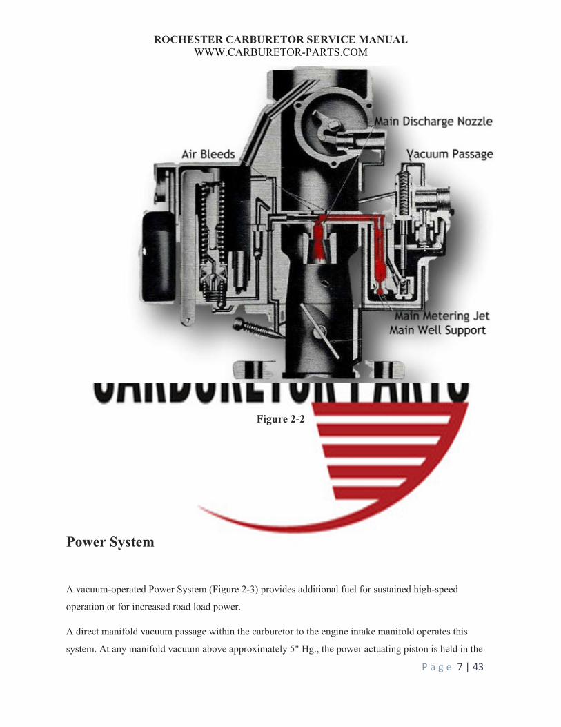
As the throttle valve is opened further (as shown in Figure 2-2), air at a higher velocity is drawn down the carburetor throat. This creates a pressure drop or suction in the venturi at the main discharge nozzle in the crossbar. As a consequence, fuel and air begin to pass from the main discharge nozzle to meet the increased engine demand. Further throttle opening will result in greater air velocity passing through the carburetor with resultant higher fuel flow from the nozzle and decreased flow from the idle system until it eventually cuts out altogether.

ROCHESTER CARBURETOR SERVICE MANUAL WWW.CARBURETOR-PARTS.COM
P a g e 6 | 43
The calibration of the Main Metering Jet and Air Bleeds in the crossbar maintain economical fuel-air ratios throughout the part throttle or cruising range.
ROCHESTER CARBURETOR SERVICE MANUAL WWW.CARBURETOR-PARTS.COM
P a g e 7 | 43
Figure 2-2
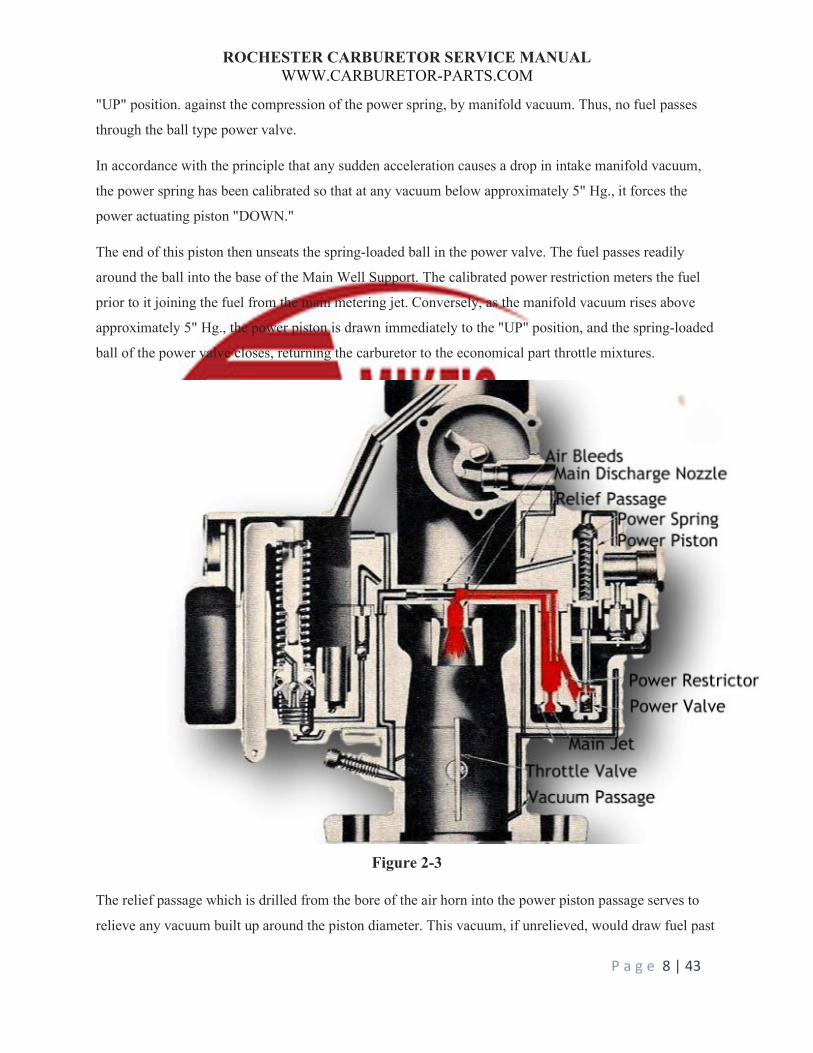
Power System
A vacuum-operated Power System (Figure 2-3) provides additional fuel for sustained high-speed
operation or for increased road load power.
A direct manifold vacuum passage within the carburetor to the engine intake manifold operates this
system. At any manifold vacuum above approximately 5" Hg., the power actuating piston is held in the
ROCHESTER CARBURETOR SERVICE MANUAL WWW.CARBURETOR-PARTS.COM
P a g e 8 | 43
"UP" position. against the compression of the power spring, by manifold vacuum. Thus, no fuel passes
through the ball type power valve.
In accordance with the principle that any sudden acceleration causes a drop in intake manifold vacuum,
the power spring has been calibrated so that at any vacuum below approximately 5" Hg., it forces the
power actuating piston "DOWN."
The end of this piston then unseats the spring-loaded ball in the power valve. The fuel passes readily
around the ball into the base of the Main Well Support. The calibrated power restriction meters the fuel
prior to it joining the fuel from the main metering jet. Conversely, as the manifold vacuum rises above
approximately 5" Hg., the power piston is drawn immediately to the "UP" position, and the spring-loaded
ball of the power valve closes, returning the carburetor to the economical part throttle mixtures.
Figure 2-3
The relief passage which is drilled from the bore of the air horn into the power piston passage serves to
relieve any vacuum built up around the piston diameter. This vacuum, if unrelieved, would draw fuel past

ROCHESTER CARBURETOR SERVICE MANUAL WWW.CARBURETOR-PARTS.COM
P a g e 9 | 43
the piston and down the vacuum passage into the manifold, resulting in an overly rich condition. The
relief passage which is drilled from the bore of the air horn into the power piston passage serves to relieve
any vacuum built up around the piston diameter. This vacuum, if unrelieved, would draw fuel past the
piston and down the vacuum passage into the manifold, resulting in an overly rich condition.
Figure 2-4
FLOAT SYSTEM
The Model "BC" carburetor employs the conventional float needle and seat to control the fuel level in the
float bowl. In accordance with the concentric float bowl design, dual floats are used to maintain the fuel
level (Figure 2-4).
The inlet screen as illustrated can also be a 1” bronze filter.

ROCHESTER CARBURETOR SERVICE MANUAL WWW.CARBURETOR-PARTS.COM
P a g e 10 | 43
This circuit is extremely important in that it controls the level of fuel in the float bowl. If this level
becomes too high or too low as a result of the improper adjustment, dirt, etc., the result can be poor
performance, poor mileage, or both.
On some applications, it is advisable to link the float and float needle with a pull clip, which serves to
retract the needle from its seat if gum deposits cause sticking.
PUMP SYSTEM
To provide fuel for smooth, quick acceleration, a double spring pump plunger is used in the Model "BC"
carburetor (as shown in Figure 2-5). The rate of compression of the top spring versus the bottom spring is
calibrated to ensure a smooth, sustained charge of fuel for acceleration.
To exclude dirt, all fuel for the pump system first passes through the pump screen in the bottom of the
float bowl. It is then drawn past the ball check into the pump well on the intake stroke of the plunger.
Upon acceleration, the force of the pump plunger seats the ball check and forces fuel up the discharge
passage. The pressure of the fuel lifts the pump outlet ball check from its seat. The fuel is then sprayed on
the edge of the venturi by the pump jet and delivered to the engine. The pump jet is targeted at the factory
and no adjustment is required.
CHOKE SYSTEM
To ensure proper starting and driving during cold weather operation, the Model "BC" carburetor employs
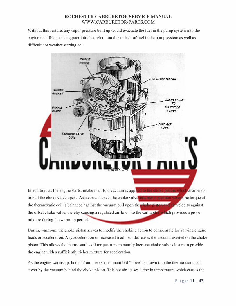
a fully automatic choke. (As shown in Figure 2-6.) This choke system is composed of a thermostatic coil,
choke piston, offset choke valve, and fast idle cam and linkage. It is controlled by a combination of intake
manifold vacuum, airflow past the offset choke valve, atmospheric temperature, and exhaust manifold
heat.
The bimetallic thermostatic coil is made up of two metals with different coefficients of expansion. This
coil is mounted firmly on one end to the stat cover and is linked on the other end to the choke valve shaft.
The coil is so calibrated as to hold the choke valve in the closed position when the engine is cold.
As the engine is started, air velocity against the offset choke valve causes the valve to open slightly
against the torque of the thermostatic up the passage in the plunger head and return to the float bowl.
ROCHESTER CARBURETOR SERVICE MANUAL WWW.CARBURETOR-PARTS.COM
P a g e 11 | 43
Without this feature, any vapor pressure built up would evacuate the fuel in the pump system into the
engine manifold, causing poor initial acceleration due to lack of fuel in the pump system as well as
difficult hot weather starting coil.
Figure 2-6
In addition, as the engine starts, intake manifold vacuum is applied to the choke piston, which also tends
to pull the choke valve open. As a consequence, the choke valve assumes a position where the torque of
the thermostatic coil is balanced against the vacuum pull upon the choke piston and air velocity against
the offset choke valve, thereby causing a regulated airflow into the carburetor which provides a proper
mixture during the warm-up period.
During warm-up, the choke piston serves to modify the choking action to compensate for varying engine
loads or acceleration. Any acceleration or increased road load decreases the vacuum exerted on the choke
piston. This allows the thermostatic coil torque to momentarily increase choke valve closure to provide
the engine with a sufficiently richer mixture for acceleration.
As the engine warms up, hot air from the exhaust manifold "stove" is drawn into the thermo-static coil
cover by the vacuum behind the choke piston. This hot air causes a rise in temperature which causes the
ROCHESTER CARBURETOR SERVICE MANUAL WWW.CARBURETOR-PARTS.COM
P a g e 12 | 43
coil to slowly relax its tension. Thus, the choke valve is allowed to move gradually to the fully open
position.
To prevent stalling during the warm-up period, it is necessary to run the engine at an idle speed slightly
higher than that for a warm engine. This is accomplished by the fast-idle cam which is linked to the choke
valve shaft and holds the throttle valve open sufficiently during the warm-up period to give the increased
idle RPM, until such time as the choke valve moves to the fully open position.
While the automatic choke is in operation, the driver may wish to advance the throttle to the full-wide
open position. Since this would decrease vacuum pull on the choke piston, thereby closing the choke
valve, it is necessary to provide increased carburetor airflow by opening the choke valve mechanically.
To accomplish this, a tang on the throttle lever is made to contact the fast-idle cam linkage at wide-open
throttle position so as to partially open the choke valve.
This will also relieve excess choking on starting by allowing more air to enter the carburetor when the
engine is cranked with the accelerator held fully depressed.
DISASSEMBLY PROCEDURE Take plenty of digital pictures as you go along. It will help you determine how parts fit. (assuming they were correct to start with).
CHOKE DISASSEMBLY
1. Loosen the 1/2" brass fitting on choke suction tube.
2. Remove the three attaching stat cover screws and retainers, then the stat cover, cover gasket, and
thermostat coil assembly from the carburetor.
3. Remove the choke baffle plate. These are often missing and not available. While it would be nice
for it to be there, the choke system will still operate without it.
4. Remove the pin spring and rod end clip from their respective ends of the choke rod and remove
the rod.
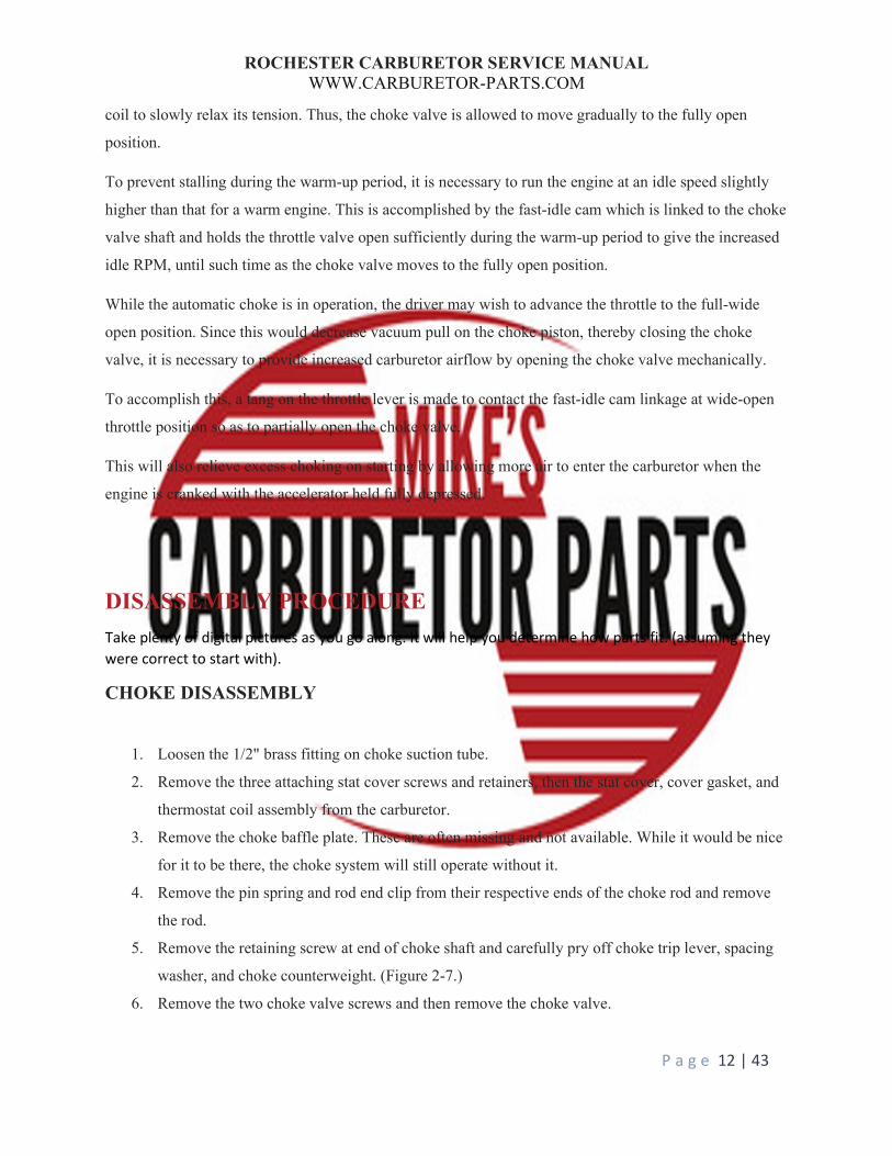
5. Remove the retaining screw at end of choke shaft and carefully pry off choke trip lever, spacing
washer, and choke counterweight. (Figure 2-7.)
6. Remove the two choke valve screws and then remove the choke valve.
ROCHESTER CARBURETOR SERVICE MANUAL WWW.CARBURETOR-PARTS.COM
P a g e 13 | 43
7. Rotate the choke shaft to free choke piston from housing and then remove the piston and choke
shaft from the carburetor.
8. Remove the choke piston pin and piston from choke shaft.
9. Remove the two-choke housing attaching screws. The choke housing and gasket may now be
removed from the air horn.
Figure 2-7
AIR HORN DISASSEMBLY
1. Remove filter screen retainer nut and gasket with 3/4" wrench and remove filter screen.
2. Remove air horn screws and lift air horns from the bowl.

ROCHESTER CARBURETOR SERVICE MANUAL WWW.CARBURETOR-PARTS.COM
P a g e 14 | 43
3. Place air horn upended on a flat surface. Re-move float hinge pin and lift float assembly from an
air horn.
4. Remove float needle
5. Remove float seat and gasket with 1/2" bit screwdriver.
6. Remove the main metering jet from the main well support.
7. Remove main well support. Air horn gasket may now be removed.
8. Remove power piston and spring.
NOTE: Do not remove the primary idle tube from the air horn.
BOWL DISASSEMBLY
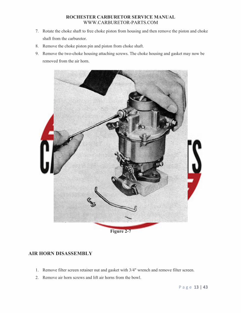
1. Remove the slotted brass pump discharge guide by using a small bit screwdriver to compress top
portions of the guide slightly as shown in Figure 2-8. Spring will cause the guide to pop out.
'Remove pump discharge guide spring and ball. (Note: If the guide is stamped type, remove from
slots in the bowl with a long-nosed pair of pliers.)
2. Remove two-pin springs from the pump link and remove the pump link from the throttle lever
and pump plunger arm.
3. Remove pump plunger from the bowl. Remove pump return spring and inlet ball from the pump
well.
4. Remove pump inlet screen from the bowl.
NOTE: Do not remove choke suction tube from the throttle body.
5. Upend carburetor bowl with suction tube projected over the edge of the flat surface and remove
two throttle body attaching screws. Remove throttle body and gasket.
ROCHESTER CARBURETOR SERVICE MANUAL WWW.CARBURETOR-PARTS.COM
P a g e 15 | 43
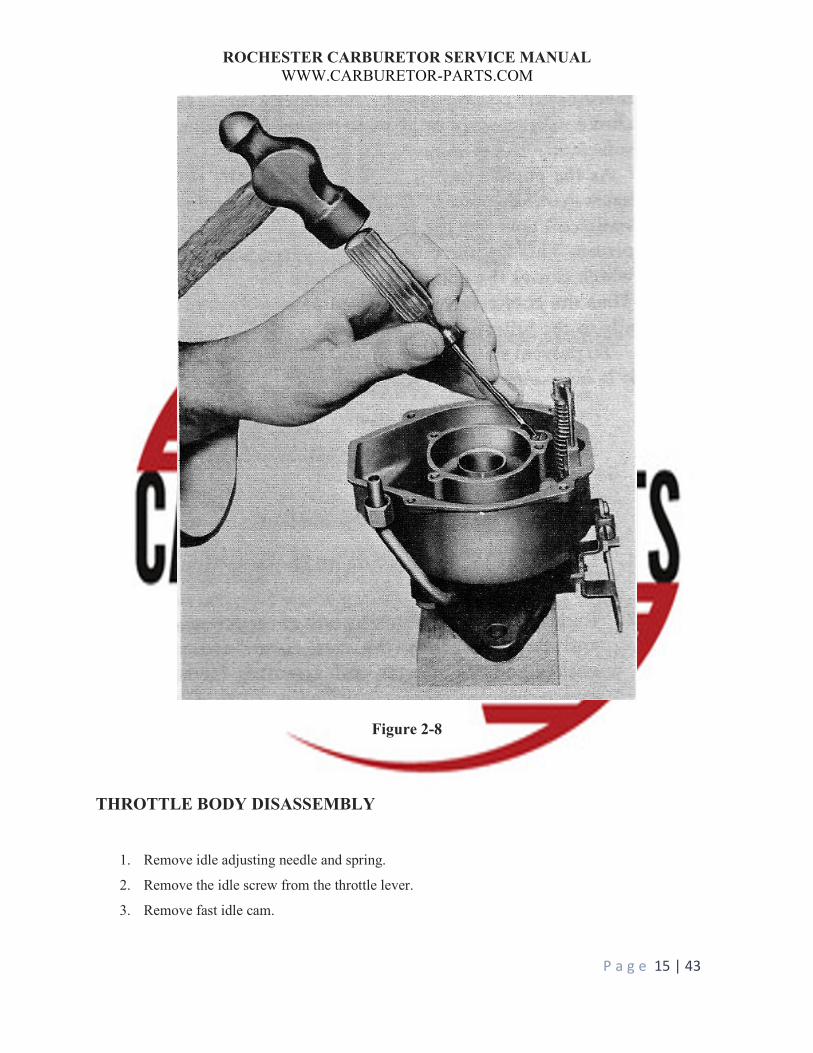
Figure 2-8
THROTTLE BODY DISASSEMBLY
1. Remove idle adjusting needle and spring.
2. Remove the idle screw from the throttle lever.
3. Remove fast idle cam.
ROCHESTER CARBURETOR SERVICE MANUAL WWW.CARBURETOR-PARTS.COM
P a g e 16 | 43
NOTE: Due to the close tolerance fit of the throttle valve in the bore of the throttle body, it is not
necessary to remove the throttle valve or shaft from the throttle body.
CLEANING AND INSPECTION
1. Thoroughly clean carburetor castings and metal parts in carburetor cleaning solvent.
CAUTION: Choke coil and housing and pump plunger should not be immersed in the solvent.
Blow all passages in castings dry with compressed air and blow off all parts until they are dry.
CAUTION: Do not pass drills or wires through calibrated jets or passages as this may enlarge
orifice and seriously affect carburetor calibration.
2. Check all parts for wear. Defective parts must be replaced. Note the following:
(a) Check float needle and seat for wear. If worn, the assembly must be replaced.
(b) Check the floating button for wear and float for dents. Check floats for leaks by shaking.
If the vehicle has been sitting for months then any gas inside the float may have
evaporated. A better test is to heat up a pan of water just prior to boiling and immerse the
float. Any bubbles indicates a leak.
(c) Check throttle and choke shaft bores in the throttle body and air horn castings for wear or
out of round.
(d) Inspect idle adjusting needle for burrs or ridges. If necessary, replace it.
(e) If steps of fast idle cam show wear, the cam should be replaced as it may upset engine
idle speed during the choking period.
(f) Inspect pump plunger leather. Replace the plunger if the leather is damaged.
3. Inspect gaskets to see if they appear hard or brittle, or if the edges are torn or distorted. If any
such condition is noted, replace it.
4. Check to see that the lower end of the suction tube is tight in the seal in the throttle body. If not, a
new seal will have to be installed after the carburetor is assembled or poor choke operation will
result from a vacuum leak.
5. Inspect suction tube hex nut packing. If it appears unduly compressed or out of round, it should
be replaced.
6. Check all filter screens for dirt or lint. Clean, and if distorted or still plugged, replace.
ROCHESTER CARBURETOR SERVICE MANUAL WWW.CARBURETOR-PARTS.COM
P a g e 17 | 43
7. The Rochester 1 barrel is prone to warpage. Check the float bowl for warpage with a flat metal
stock. If warped and you have the means to build a jig, the body can be straightened with heat,
otherwise as a last resort you can try double float bowl gaskets. Do not use gasket
ASSEMBLY PROCEDURE
1. Install idle stop screw in throttle lever.
2. Screw idle adjusting needle and spring into throttle body until it is finger tight. Back out screw 1
1/2 turns as a temporary idle adjustment. Make final adjustments on the engine when warmed up.
3. Install fast idle cam with letters RP facing outward.
4. With bowl upended and suction tube projected over the edge of the flat surface, place new throttle
body gasket into position and attach throttle body. Tighten screws evenly and securely.
Note: New choke suction tube seal, if needed, will be installed after carburetor is completely
assembled.
BOWL ASSEMBLY
1. Drop the small aluminum ball into the pump well hole, and replace pump return spring. Press
spring with finger to center it in the pump well. Some B’s have the intake ball located in the
bottom of the float bowl next to the pump well. There should be a screen covering the check ball.
2. Install pump plunger assembly and attach pump link to plunger arm and throttle lever. Attach pin
springs to each end of the pump link.
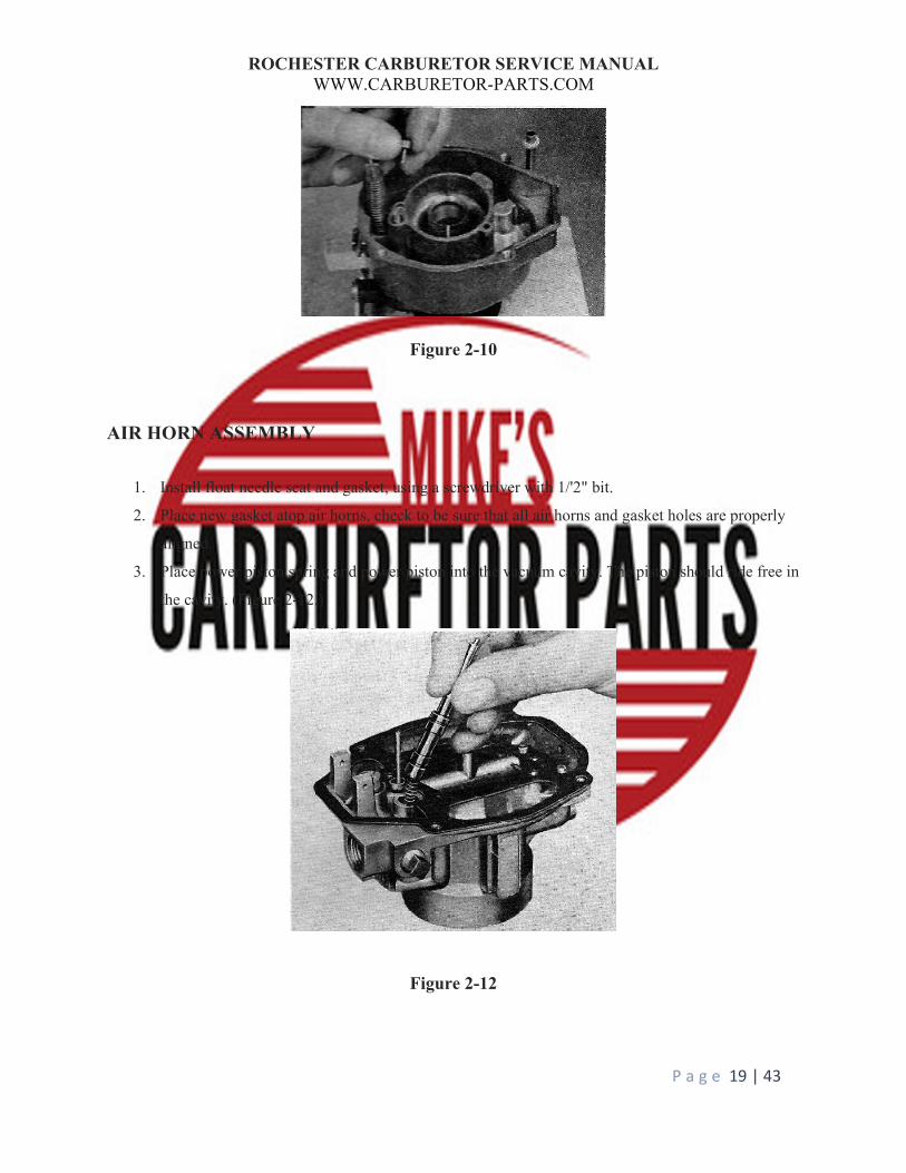
3. Install the larger steel ball in the pump discharge cavity. (Figure 2-9) Place spring and spring
guide atop the ball. (Figure 2-10) Spread spring guide slot slightly with a screwdriver blade to
keep in place. (Figure 2-11.)
NOTE If a stamped type guide is used, install a new guide into bowl slots until it is a press fit.
4. Press pump filter screen into position.

ROCHESTER CARBURETOR SERVICE MANUAL WWW.CARBURETOR-PARTS.COM
P a g e 18 | 43
Figure 2-9
Figure 2-9
ROCHESTER CARBURETOR SERVICE MANUAL WWW.CARBURETOR-PARTS.COM
P a g e 19 | 43
Figure 2-10
AIR HORN ASSEMBLY
1. Install float needle seat and gasket, using a screwdriver with 1/'2" bit.
2. Place new gasket atop air horns, check to be sure that all air horns and gasket holes are properly
aligned.
3. Place power piston spring and power piston into the vacuum cavity. The piston should ride free in
the cavity. (Figure 2-12.)
Figure 2-12
ROCHESTER CARBURETOR SERVICE MANUAL WWW.CARBURETOR-PARTS.COM
P a g e 20 | 43
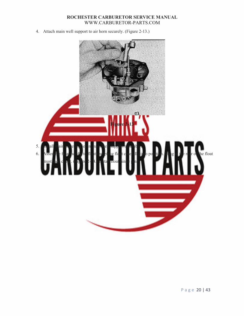
4. Attach main well support to air horn securely. (Figure 2-13.)
Figure 2-13
5. Install main metering jet in main well support assembly.
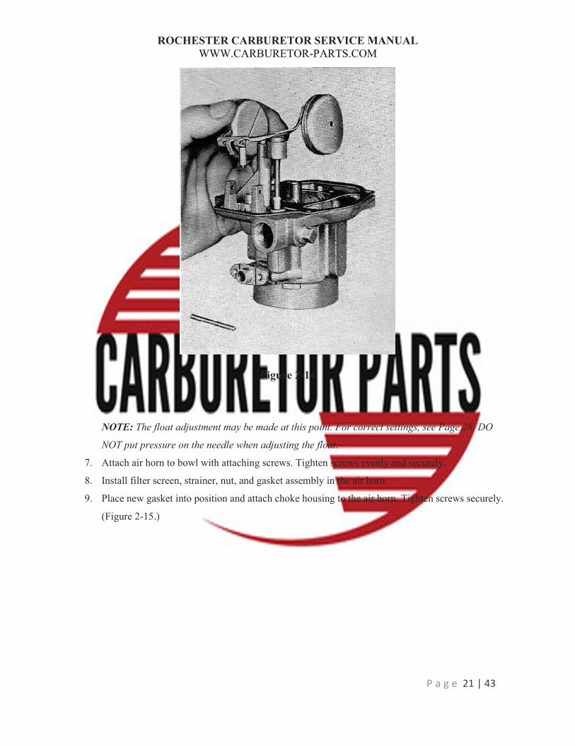
6. Assemble float needle to float and place float carefully into position. Tang at the rear of the float
must face cover. (Figure 2-14.) Install float hinge pin.
ROCHESTER CARBURETOR SERVICE MANUAL WWW.CARBURETOR-PARTS.COM
P a g e 21 | 43
Figure 2-14
NOTE: The float adjustment may be made at this point. For correct settings, see Page 28. DO
NOT put pressure on the needle when adjusting the float.
7. Attach air horn to bowl with attaching screws. Tighten screws evenly and securely.
8. Install filter screen, strainer, nut, and gasket assembly in the air horn.
9. Place new gasket into position and attach choke housing to the air horn. Tighten screws securely.
(Figure 2-15.)

ROCHESTER CARBURETOR SERVICE MANUAL WWW.CARBURETOR-PARTS.COM
P a g e 22 | 43
Figure 2-15
10. Assemble choke piston to the shaft with pin and place into choke housing bore as shown in
Figure 2-16. Rotate choke shaft so that piston rides in the housing cavity.
ROCHESTER CARBURETOR SERVICE MANUAL WWW.CARBURETOR-PARTS.COM
P a g e 23 | 43
Figure 2-16
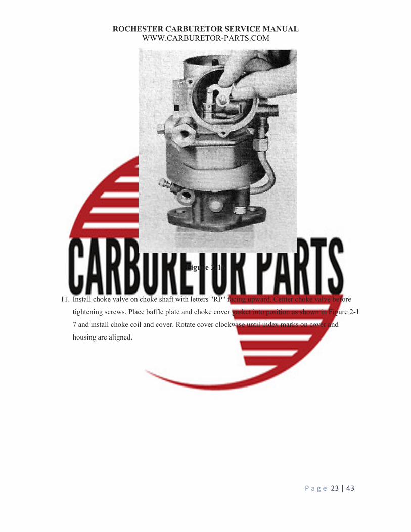
11. Install choke valve on choke shaft with letters "RP" facing upward. Center choke valve before
tightening screws. Place baffle plate and choke cover gasket into position as shown in Figure 2-1
7 and install choke coil and cover. Rotate cover clockwise until index marks on cover and
housing are aligned.
ROCHESTER CARBURETOR SERVICE MANUAL WWW.CARBURETOR-PARTS.COM
P a g e 24 | 43
Figure 2-17
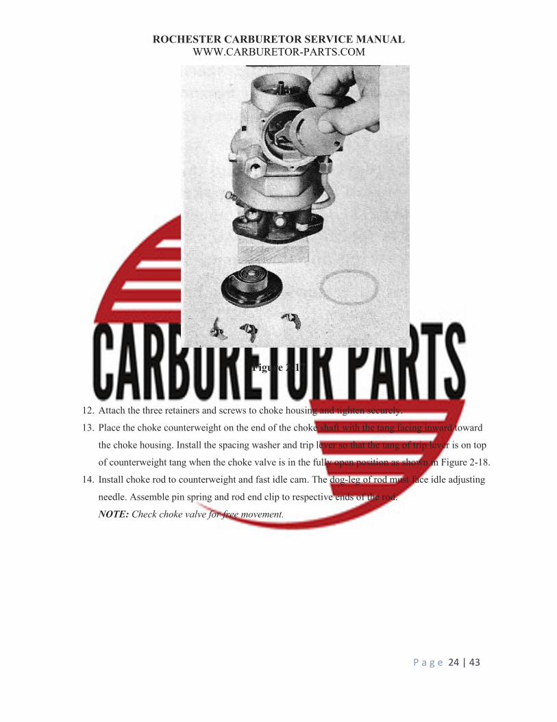
12. Attach the three retainers and screws to choke housing and tighten securely.
13. Place the choke counterweight on the end of the choke shaft with the tang facing inward toward
the choke housing. Install the spacing washer and trip lever so that the tang of trip lever is on top
of counterweight tang when the choke valve is in the fully open position as shown in Figure 2-18.
14. Install choke rod to counterweight and fast idle cam. The dog-leg of rod must face idle adjusting
needle. Assemble pin spring and rod end clip to respective ends of the rod.
NOTE: Check choke valve for free movement.
ROCHESTER CARBURETOR SERVICE MANUAL WWW.CARBURETOR-PARTS.COM
P a g e 25 | 43
Figure 2-18
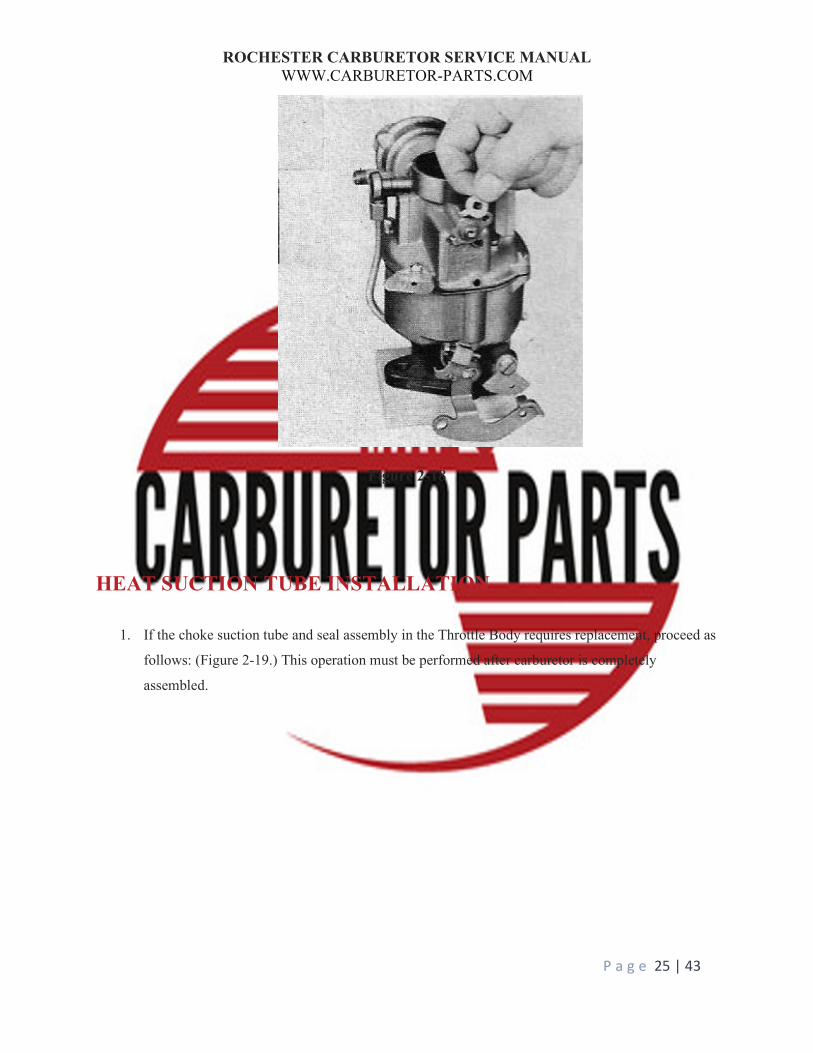
HEAT SUCTION TUBE INSTALLATION
1. If the choke suction tube and seal assembly in the Throttle Body requires replacement, proceed as
follows: (Figure 2-19.) This operation must be performed after carburetor is completely
assembled.
ROCHESTER CARBURETOR SERVICE MANUAL WWW.CARBURETOR-PARTS.COM
P a g e 26 | 43
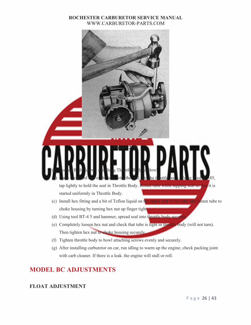
Figure 2-19
(a) Loosen Both Screws Attaching Throttle Body to Bowl.
(b) Place the flared end of the tube with the seal into the throttle body. Using Tool BT-45,
tap lightly to hold the seal in Throttle Body. Rotate tube while tapping seal so that it is
started uniformly in Throttle Body.
(c) Install hex fitting and a bit of Teflon liquid on the upper end of the tube and fasten tube to
choke housing by turning hex nut up finger tight.
(d) Using tool BT-4 5 and hammer, spread seal into throttle body securely.
(e) Completely loosen hex nut and check that tube is tight in throttle body (will not turn).
Then tighten hex nut to choke housing securely.
(f) Tighten throttle body to bowl attaching screws evenly and securely.
(g) After installing carburetor on car, run idling to warm up the engine; check packing joint
with carb cleaner. If there is a leak. the engine will stall or roll.
MODEL BC ADJUSTMENTS
FLOAT ADJUSTMENT
ROCHESTER CARBURETOR SERVICE MANUAL WWW.CARBURETOR-PARTS.COM
P a g e 27 | 43
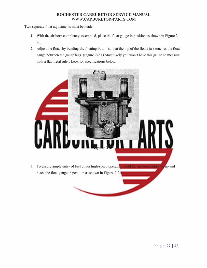
Two separate float adjustments must be made:
1. With the air horn completely assembled, place the float gauge in position as shown in Figure 2-
20.
2. Adjust the floats by bending the floating button so that the top of the floats just touches the float
gauge between the gauge legs. (Figure 2-20.) Most likely you won’t have this gauge so measure
with a flat metal ruler. Look for specifications below.
Figure 2-20
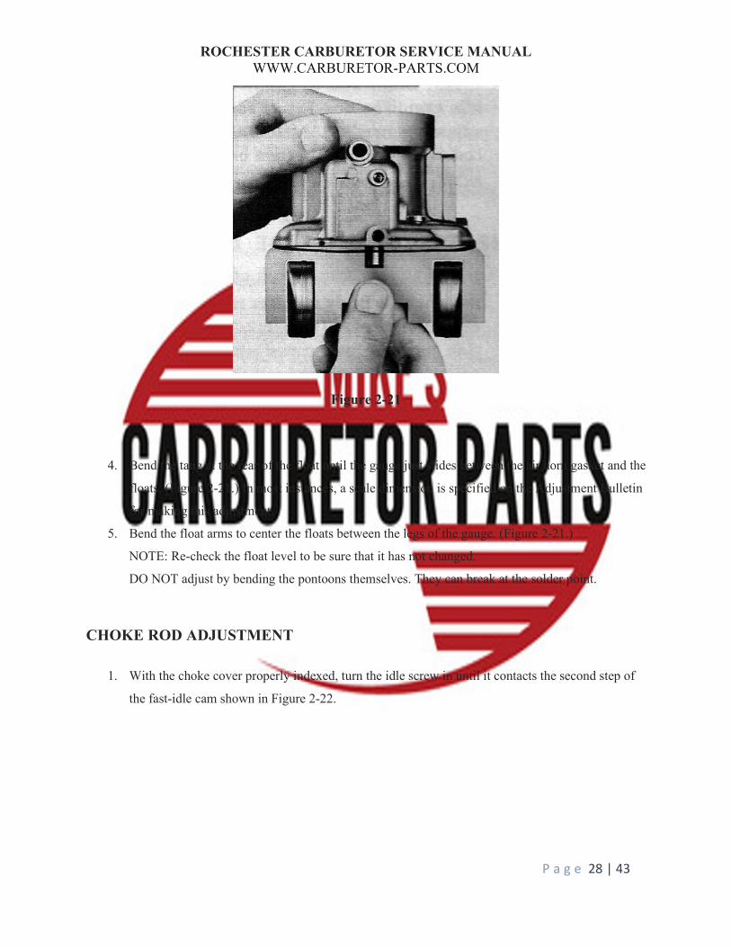
3. To ensure ample entry of fuel under high-speed operation, hold the air horn right side up and
place the float gauge in position as shown in Figure 2-21.
ROCHESTER CARBURETOR SERVICE MANUAL WWW.CARBURETOR-PARTS.COM
P a g e 28 | 43
Figure 2-21
4. Bend the tang at the rear of the float until the gauge just slides between the air horn gasket and the
floats. (Figure 2-21.) In most instances, a scale dimension is specified on the Adjustment Bulletin
for making this adjustment.
5. Bend the float arms to center the floats between the legs of the gauge. (Figure 2-21.)
NOTE: Re-check the float level to be sure that it has not changed.
DO NOT adjust by bending the pontoons themselves. They can break at the solder point.
CHOKE ROD ADJUSTMENT
1. With the choke cover properly indexed, turn the idle screw in until it contacts the second step of
the fast-idle cam shown in Figure 2-22.
ROCHESTER CARBURETOR SERVICE MANUAL WWW.CARBURETOR-PARTS.COM
P a g e 29 | 43
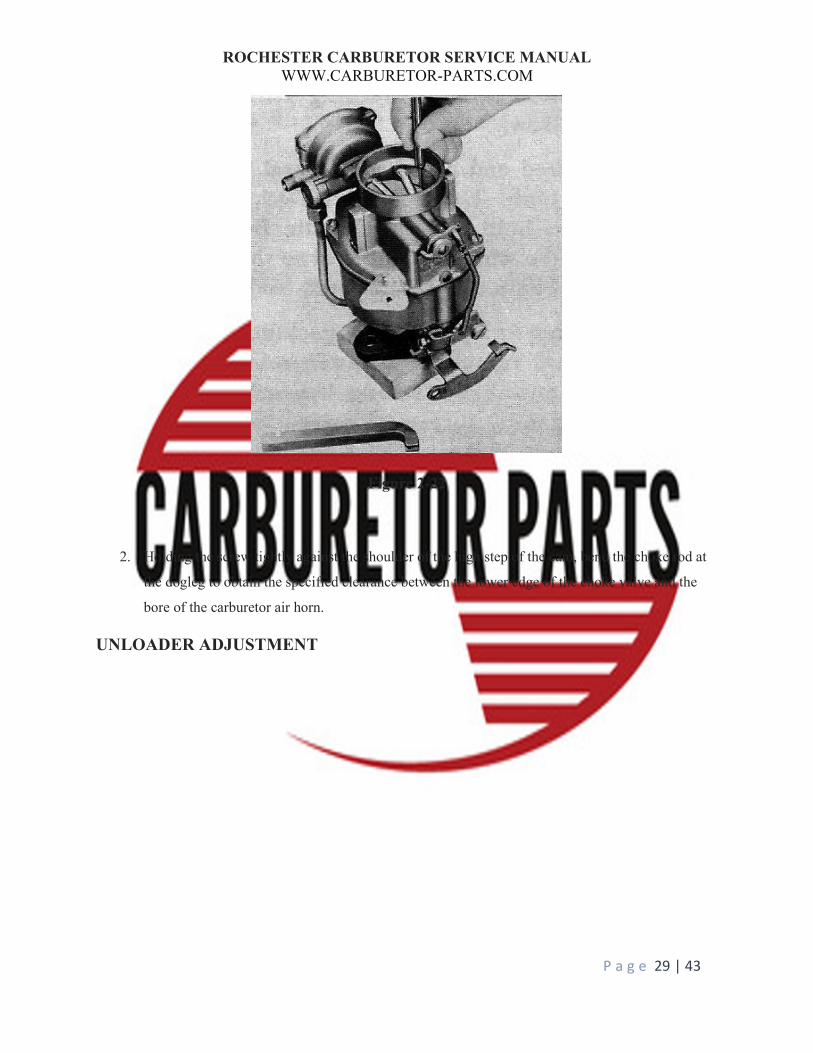
Figure 2-22
2. Holding the screw tightly against the shoulder of the high step of the cam, bend the choke rod at
the dogleg to obtain the specified clearance between the lower edge of the choke valve and the
bore of the carburetor air horn.
UNLOADER ADJUSTMENT
ROCHESTER CARBURETOR SERVICE MANUAL WWW.CARBURETOR-PARTS.COM
P a g e 30 | 43
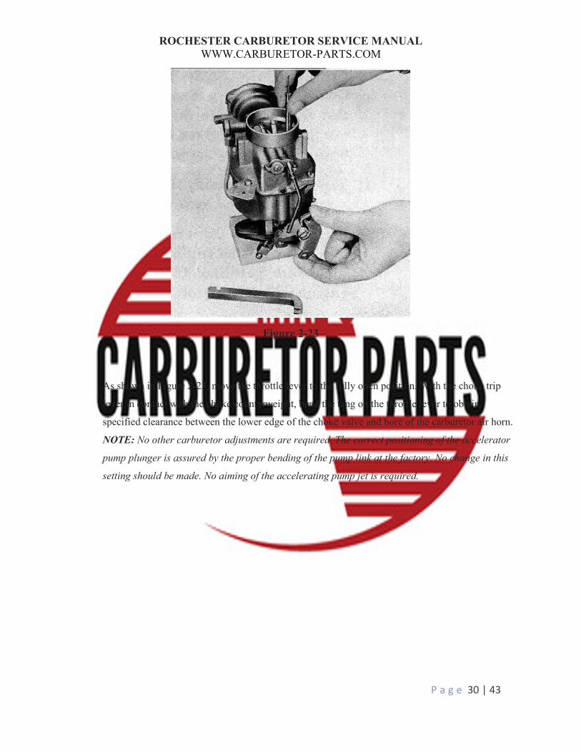
Figure 2-23
As shown in Figure 2-23, move the throttle lever to the fully open position. With the choke trip
lever in contact with the choke counterweight, bend the tang on the throttle lever to obtain
specified clearance between the lower edge of the choke valve and bore of the carburetor air horn.
NOTE: No other carburetor adjustments are required. The correct positioning of the accelerator
pump plunger is assured by the proper bending of the pump link at the factory. No change in this
setting should be made. No aiming of the accelerating pump jet is required.

ROCHESTER CARBURETOR SERVICE MANUAL WWW.CARBURETOR-PARTS.COM
P a g e 31 | 43
The Rochester Model B carburetor was introduced in 1950. A detailed description of the operation of its
basic systems has been omitted in this portion of the manual since the basic operating principles are
similar to those discussed under the Model BC carburetor on pages 20-22. This carburetor employs a
manually operated choke system rather than the automatic type, so the portion of the Model BC
discussion on the Automatic Choke will not apply to Model B.
In line with all other Rochester designed carburetors, this model has been kept basically simple and its
circuits are easily traceable and readily understood. The number of moving parts and adjustments have
Model B ROCHESTER CARBURETOR

ROCHESTER CARBURETOR SERVICE MANUAL WWW.CARBURETOR-PARTS.COM
P a g e 32 | 43
been kept to a minimum for ease of service. The following pages have been devoted to a detailed picture
story of the complete disassembly, inspection, and assembly of the Rochester Model B carburetor.
DISASSEMBLY PROCEDURE
1. Remove the four air horn screws. Then
hold the fast-idle Lever out of. the way
and remove the air horn assembly by lifting straight up.
2. Remove the air horn assembly as
described perilously and remove the float assembly from the air
horn.
3. In most cases., the air horn gasket
should be replaced, particularly if of the
early cork type. Remove the float
hinge pin and lift off the twin float
assembly.
4. Remove the main metering jet and power
valve assembly (consisting of retaining strew, spring and ball)
from the main well support.
5. Remove the main well support. Then lift out the power piston and spring.
6. Lift out the needle valve and unscrew the needle seat from the
air horn.
7. Remove the two retaining screws and
lift out the choke valve. Unhook the
spring from the choke shaft and
remove the shaft.
8. Remove the retainer, fast-idle cam, and
spring.
ROCHESTER CARBURETOR SERVICE MANUAL WWW.CARBURETOR-PARTS.COM
P a g e 33 | 43
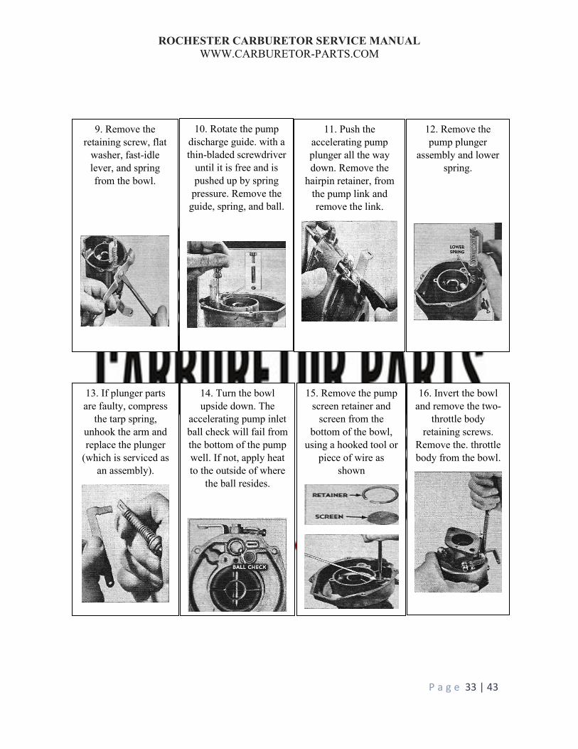
9. Remove the retaining screw, flat
washer, fast-idle lever, and spring from the bowl.
10. Rotate the pump discharge guide. with a thin-bladed screwdriver
until it is free and is pushed up by spring
pressure. Remove the guide, spring, and ball.
11. Push the accelerating pump plunger all the way down. Remove the
hairpin retainer, from the pump link and remove the link.
12. Remove the pump plunger
assembly and lower spring.
13. If plunger parts are faulty, compress
the tarp spring, unhook the arm and replace the plunger
(which is serviced as an assembly).
14. Turn the bowl upside down. The
accelerating pump inlet ball check will fail from the bottom of the pump well. If not, apply heat to the outside of where
the ball resides.
15. Remove the pump screen retainer and
screen from the bottom of the bowl,
using a hooked tool or piece of wire as
shown
16. Invert the bowl and remove the two-
throttle body retaining screws.
Remove the. throttle body from the bowl.

ROCHESTER CARBURETOR SERVICE MANUAL WWW.CARBURETOR-PARTS.COM
P a g e 34 | 43
CLEANING INSPECTION REPAIRS
17. Remove the idle mixture adjusting
needle and spring from the throttle body. Also, remove the distributor
vacuum fitting.
18. Wash all parts thoroughly,
preferably in carburetor cleaning
solvent.
19. Blow out all parts and passages and
make sure they are clean and free from carbon deposits, if
not return them to the solvent bath for further cleaning,
20. Inspect all mating surfaces of the
carburetor. Surfaces must be flat to within a few thousandths for the gasket to provide a
tight seal.
21. Inspect the throttle shaft arm for
looseness on the shaft and for wear at the throttle rod hole. Check the throttle
shaft for looseness in the body and the valve
for looseness or binding. 1/32” or less.

ROCHESTER CARBURETOR SERVICE MANUAL WWW.CARBURETOR-PARTS.COM
P a g e 35 | 43
22. If throttle assembly is faulty, the entire throttle
body assembly must be replaced because the idle discharge
and distributor vacuum ports are
drilled in relation to the throttle valve.
24. Inspect the floats for signs of leaks and
the hinge holes for wear. Also, check the hinge pin holes in the
air horn for wear.
25. Inspect the pump plunger leather and springs for damage.
Also, shake the plunger to make sure the by-
pass ball check is free.
26. Air leaks and rough idling may
also result in horn a loose, or improperly
seating power piston'. This
possibility can easily be checked as
follows-
23. Inspect the float needle for wear and Indications improper seating. If damaged, both needle and seat must be replaced as they are serviced as
an assembly. Always replace the needle &
seat.
28. Remove the idle
mixture adjusting screw and check the needle for ridges. A
ridged needle supplies erratic mixtures which
cause rough idling.
27. Check the fit of the power piston in the cover. It must be
free but without excess play, also
inspect the tapered seat on the upper and
of the piston.
ROCHESTER CARBURETOR SERVICE MANUAL WWW.CARBURETOR-PARTS.COM
P a g e 36 | 43
ASSEMBLY
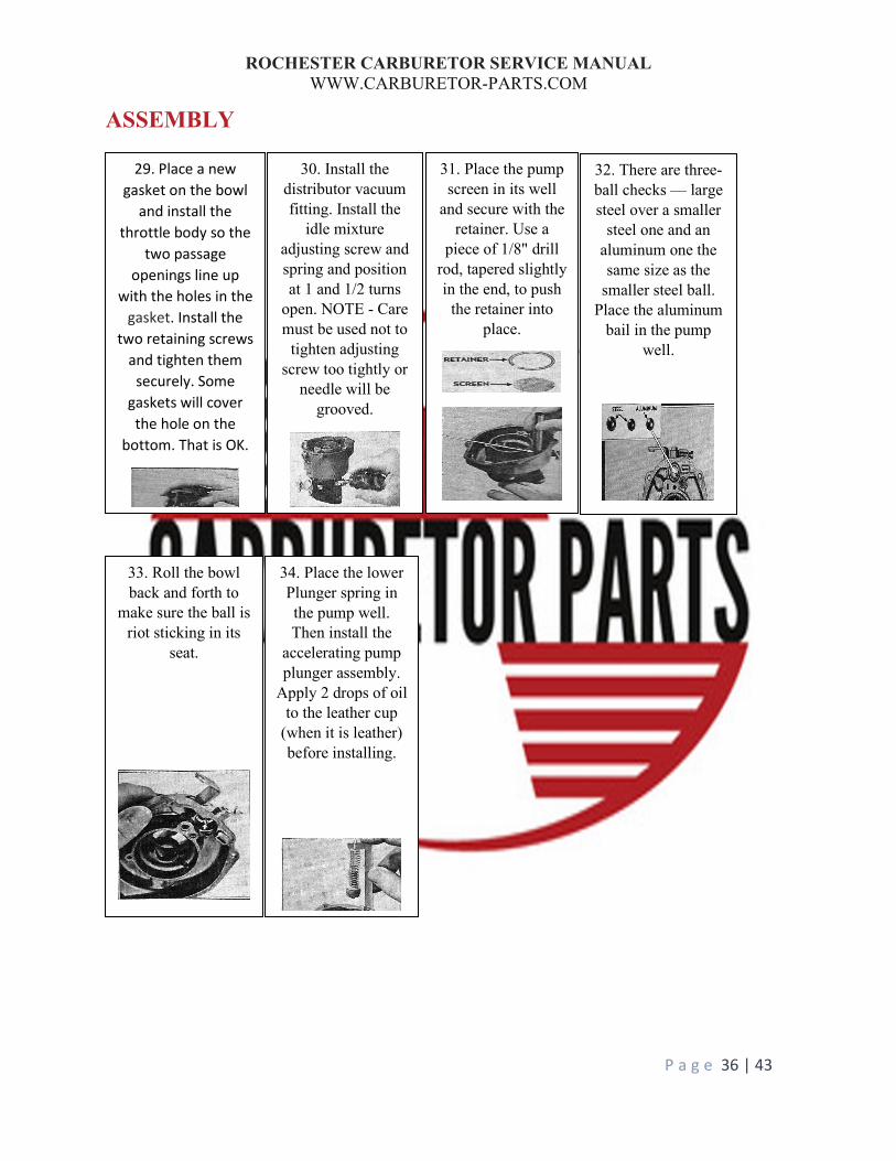
30. Install the distributor vacuum fitting. Install the
idle mixture adjusting screw and spring and position at 1 and 1/2 turns
open. NOTE - Care must be used not to
tighten adjusting screw too tightly or
needle will be grooved.
31. Place the pump screen in its well
and secure with the retainer. Use a
piece of 1/8" drill rod, tapered slightly in the end, to push
the retainer into place.
32. There are three-ball checks — large steel over a smaller
steel one and an aluminum one the same size as the
smaller steel ball. Place the aluminum
bail in the pump well.
33. Roll the bowl back and forth to
make sure the ball is riot sticking in its
seat.
34. Place the lower Plunger spring in the pump well. Then install the
accelerating pump plunger assembly.
Apply 2 drops of oil to the leather cup
(when it is leather) before installing.
29. Place a new gasket on the bowl
and install the throttle body so the
two passage openings line up
with the holes in the gasket. Install the
two retaining screws and tighten them
securely. Some gaskets will cover the hole on the
bottom. That is OK.
ROCHESTER CARBURETOR SERVICE MANUAL WWW.CARBURETOR-PARTS.COM
P a g e 37 | 43
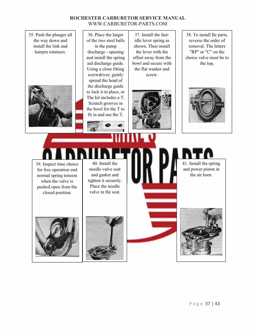
39. Inspect time choice for free operation end normal spring tension
when the valve is pushed open from the
closed position.
40. Install the needle valve seat and gasket and
tighten it securely. Place the needle valve in the seat.
41. Install the spring and power piston in
the air horn.
35. Push the plunger all the way down and install the link and hairpin retainers.
36. Place the larger of the two steel balls
in the pump discharge - opening and install the spring aid discharge guide. Using a close fitting screwdriver, gently spread the head of the discharge guide to lock it in place, or The kit includes a T. Scratch grooves in
the bowl for the T to fit in and use the T.
37. Install the fast-idle lever spring as shown. Then install the lever with the
offset away from the bowl and secure with the flat washer and
screw.
38. To install Ile parts, reverse the order of removal. The letters "RP" or "C" on the
choice valve must be to the top,
ROCHESTER CARBURETOR SERVICE MANUAL WWW.CARBURETOR-PARTS.COM
P a g e 38 | 43
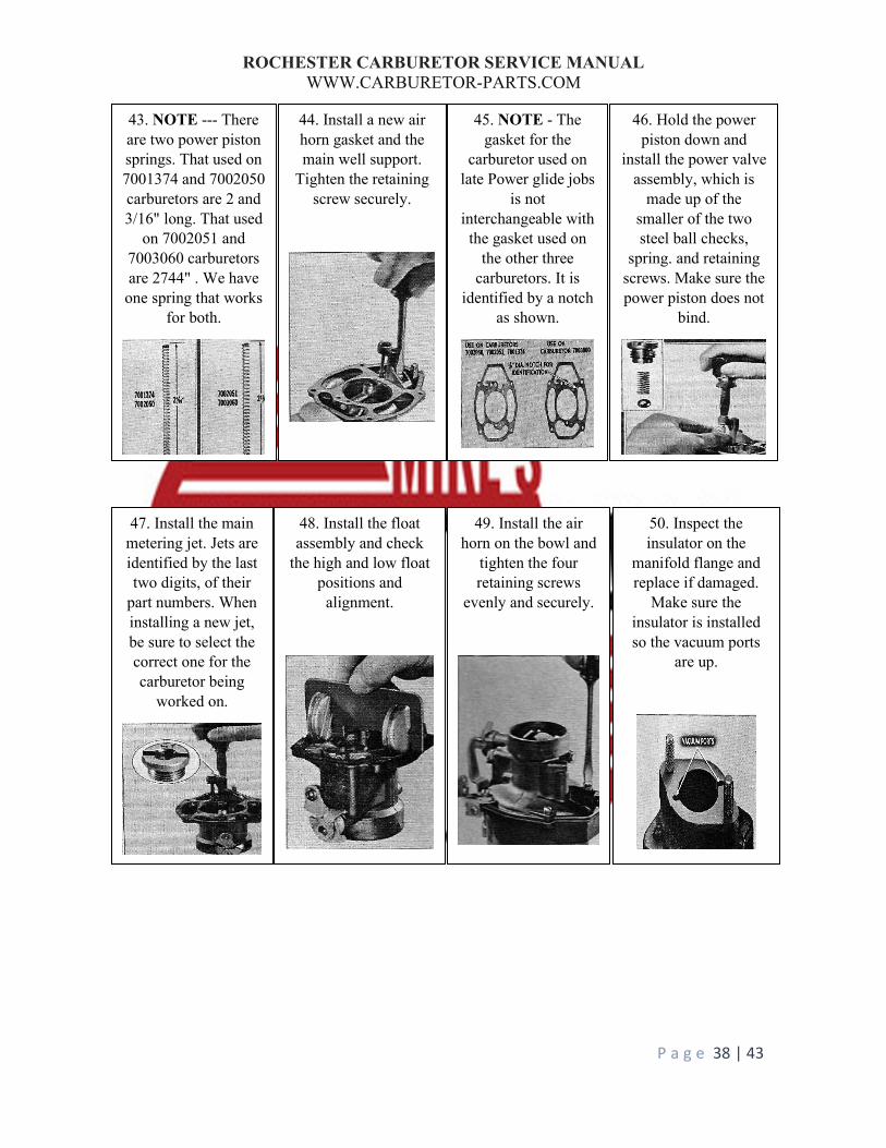
43. NOTE --- There are two power piston springs. That used on 7001374 and 7002050 carburetors are 2 and 3/16" long. That used
on 7002051 and 7003060 carburetors are 2744" . We have
one spring that works for both.
44. Install a new air horn gasket and the main well support.
Tighten the retaining screw securely.
45. NOTE - The gasket for the
carburetor used on late Power glide jobs
is not interchangeable with the gasket used on
the other three carburetors. It is
identified by a notch as shown.
46. Hold the power piston down and
install the power valve assembly, which is
made up of the smaller of the two steel ball checks,
spring. and retaining screws. Make sure the power piston does not
bind.
47. Install the main metering jet. Jets are identified by the last two digits, of their
part numbers. When installing a new jet, be sure to select the correct one for the carburetor being
worked on.
48. Install the float assembly and check
the high and low float positions and
alignment.
49. Install the air horn on the bowl and
tighten the four retaining screws
evenly and securely.
50. Inspect the insulator on the
manifold flange and replace if damaged.
Make sure the insulator is installed so the vacuum ports
are up.
ROCHESTER CARBURETOR SERVICE MANUAL WWW.CARBURETOR-PARTS.COM
P a g e 39 | 43
THROTTLE RETURN CHECK
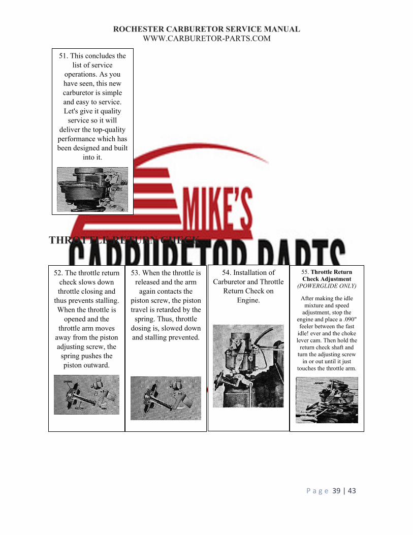
51. This concludes the list of service
operations. As you have seen, this new carburetor is simple and easy to service. Let's give it quality
service so it will deliver the top-quality performance which has been designed and built
into it.
52. The throttle return check slows down throttle closing and
thus prevents stalling. When the throttle is
opened and the throttle arm moves
away from the piston adjusting screw, the
spring pushes the piston outward.
53. When the throttle is released and the arm
again contacts the piston screw, the piston travel is retarded by the
spring. Thus, throttle dosing is, slowed down and stalling prevented.
54. Installation of Carburetor and Throttle
Return Check on Engine.
55. Throttle Return Check Adjustment
(POWERGLIDE ONLY)
After making the idle mixture and speed
adjustment, stop the engine and place a .090" feeler between the fast
idle! ever and the choke lever cam. Then hold the
return check shaft and turn the adjusting screw
in or out until it just touches the throttle arm.
ROCHESTER CARBURETOR SERVICE MANUAL WWW.CARBURETOR-PARTS.COM
P a g e 40 | 43
The Throttle Return Check unit is designed to retard throttle closing, gradually slowing the engine down
from a fast idle to the normal idle speed whenever the throttle is closed.
This assembly is a simple dash-pot mechanism, wherein a diaphragm, assembled to a shaft, is moved
between two covers, forcing air to close a valve and pass through a small bleed hole in the shaft. The
volume of air ahead of the diaphragm, being unable to escape quickly, resists the movement of the shaft
and consequently slows the shaft travel. The valve referred to above seats against one end of the shaft.
The closing of this valve prevents the passage of air through the large hole in the center of the shaft.
When pressure is removed from the shaft contact screw, the return spring tends to force the diaphragm in
the opposite direction. Air entering the shaft cross hole and moving up the large center hole in the shaft
lifts the valve from its seat and allows the diaphragm and shaft assembly to rapidly return to its normal
position.
The Throttle Return Check unit has an adjustable contact screw to provide various conditions of throttle
return control.
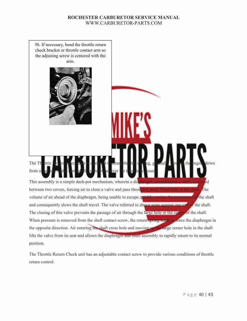
56. If necessary, bend the throttle return check bracket or throttle contact arm so the adjusting screw is centered with the
arm.
ROCHESTER CARBURETOR SERVICE MANUAL WWW.CARBURETOR-PARTS.COM
P a g e 41 | 43
ADJUSTMENTS
FLOAT LEVEL ADJUSTMENT
(New Type. Gauge M-250)
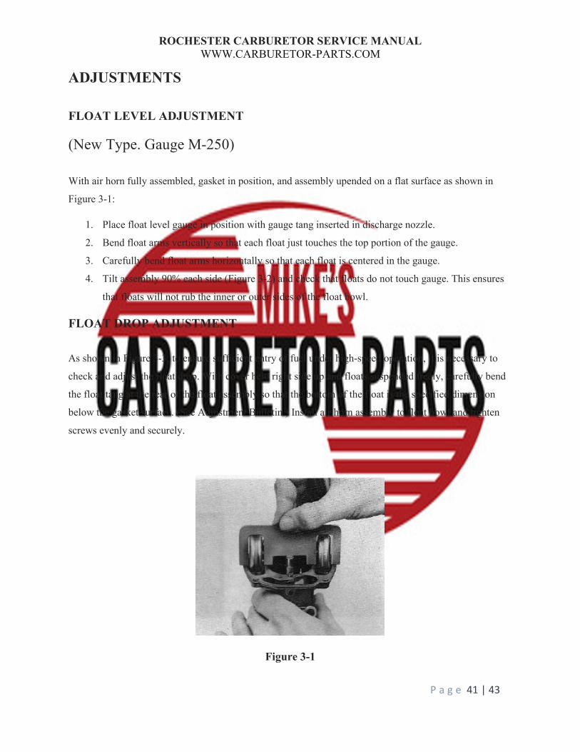
With air horn fully assembled, gasket in position, and assembly upended on a flat surface as shown in
Figure 3-1:
1. Place float level gauge in position with gauge tang inserted in discharge nozzle.
2. Bend float arms vertically so that each float just touches the top portion of the gauge.
3. Carefully bend float arms horizontally so that each float is centered in the gauge.
4. Tilt assembly 90% each side (Figure 3-2) and check that floats do not touch gauge. This ensures
that floats will not rub the inner or outer sides of the float bowl.
FLOAT DROP ADJUSTMENT
As shown in Figure 3-3, to ensure sufficient entry of fuel under high-speed operation, it is necessary to
check and adjust the float drop. With cover held right side up and floats suspended freely, carefully bend
the float tang at the rear of the float assembly so that the bottom of the float is the specified dimension
below the gasket surface. (See Adjustment Bulletin.) Install air horn assembly to float bowl and tighten
screws evenly and securely.
Figure 3-1

ROCHESTER CARBURETOR SERVICE MANUAL WWW.CARBURETOR-PARTS.COM
P a g e 42 | 43
Figure 3-2

ROCHESTER CARBURETOR SERVICE MANUAL WWW.CARBURETOR-PARTS.COM
P a g e 43 | 43
Figure 3-3

General Instructions
• Take lots of pictures as you take your carburetor apart. This will give you a reference of where
things go.
• Using a cookie sheet with folded up sides will help keep parts from falling on the floor.
• We suggest not removing the throttle shaft, valves, or choke shaft unless they are corroded, or
very dirty. These parts can be easily damaged and are difficult to re-assemble.
• Instruction sheets that come with our carburetor kits are somewhat generic. It may not match
your parts exactly.
• Do NOT use WD-40 around your carburetor. It reacts with ethanol.
• Using Silicon Spray Lubricant on the gaskets will help with sticking in case you need to take the
carburetor apart again.
• Be careful after taking the top of the carburetor off. Turning the carburetor upside down may
cause parts to fall out and you won’t know where they were.
• Screws and jets that are frozen can often be removed after heating outside the screw or jet.
• Stuck check balls can be removed by heating the outside of where the check ball resides and
tapping the carburetor on the work bench.
• Do not discard any parts until complete done. You may have to refer for size, or matching.
Cleaning:
• Clean with carburetor dis-assembled.
• Soak all parts except rubber & electrical in Simple Green for 2 hours. Aluminum parts will get
discolored if left longer.
• Wash parts with hot water if available to remove all chemicals.
• Blow out each passage way taking special notice of the smaller ones. Test each passage that air
goes through the entire passage.
• Blow out the idle mixture hole.
• Check any hole above the idle mixture hole (inside the bore). This is the idle discharge and often
becomes plugged.
• A tooth brush can facilitate cleaning parts.
• Soda blasting, then washing again will make the carburetor look good any will clean any minor
deposits.
• Any corrosion, or deposits that are hard to remove may indicate the passages are also corroded
and the carburetor should be replaced.
• If your engine has been sitting for 6 months or more, the gas has probably turned, and the gas
tank will need to be cleaned as well as the fuel lines. Flushing new gas through the tank will not
be enough.
Assembly:
• Do NOT apply any gasket sealant on any of the gaskets. Gas will break sealant part and the
particles will clog the small passages.
• Test your float.
o Brass floats should be immersed into hot water. As the air inside expands any leak will
be noticeable with air bubbles.
o Plastic, or Nitrophyl floats should be weighed. The weight is in grams. Check our
technical pages for any weight specification that we may have.
• Most gaskets will fit as expected, but you may have to trim some, especially under the venturis.
• Your kit may include multiple gaskets in order to get better coverage out of the kit. Use the one
that fits the best. Look for any opening the gasket may leave allowing air into the carburetor.
Some holes may be casting holes that don’t lead to anything and do not have to be covered.
• Mounting gaskets for multiple bore carburetors do not have to have matching holes. Example a
four-barrel gasket can be open in the middle instead of 4 holes as long as the carburetor has
some kind of passage between bores. The passage is between primary, or secondary, not both.
• When adjusting the float be careful not to put any pressure on the needle. The viton tip is easily
damaged.
• Most idle mixture screws can be cleaned using a soft wire wheel. Inspect for any scoring, which
would indicate over tightening. Screw with scoring should be replaced.
Accelerator Pumps:
• On leather cups run your finger around the inside of the cup to break any manufacturer sealant.
• Apply 2 drops of oil to cups (leather, or rubber) before inserting into carburetor. Do not soak the
cup in oil. The swelling of the cup needs to happen inside the carburetor. Allow the 2 drops of oil
and the gas to do its job naturally.
• Twist the pump as you are inserting to help keep the cup from curling or folding over.
• Test your accelerator pump circuit before putting the top of the carburetor back on. Our
technical pages have instructions on how to do this for most carburetor types.
• Pump wells are usually slight tapered, and the pump will not seal until it gets towards the
bottom.


General Instructions
• Take lots of pictures as you take your carburetor apart. This will give you a reference of where
things go.
• Using a cookie sheet with folded up sides will help keep parts from falling on the floor.
• We suggest not removing the throttle shaft, valves, or choke shaft unless they are corroded, or
very dirty. These parts can be easily damaged and are difficult to re-assemble.
• Instruction sheets that come with our carburetor kits are somewhat generic. It may not match
your parts exactly.
• Do NOT use WD-40 around your carburetor. It reacts with ethanol.
• Using Silicon Spray Lubricant on the gaskets will help with sticking in case you need to take the
carburetor apart again.
• Be careful after taking the top of the carburetor off. Turning the carburetor upside down may
cause parts to fall out and you won’t know where they were.
• Screws and jets that are frozen can often be removed after heating outside the screw or jet.
• Stuck check balls can be removed by heating the outside of where the check ball resides and
tapping the carburetor on the work bench.
• Do not discard any parts until complete done. You may have to refer for size, or matching.
Cleaning:
• Clean with carburetor dis-assembled.
• Soak all parts except rubber & electrical in Simple Green for 2 hours. Aluminum parts will get
discolored if left longer.
• Wash parts with hot water if available to remove all chemicals.
• Blow out each passage way taking special notice of the smaller ones. Test each passage that air
goes through the entire passage.
• Blow out the idle mixture hole.

• Check any hole above the idle mixture hole (inside the bore). This is the idle discharge and often
becomes plugged.
• A tooth brush can facilitate cleaning parts.
• Soda blasting, then washing again will make the carburetor look good any will clean any minor
deposits.
• Any corrosion, or deposits that are hard to remove may indicate the passages are also corroded
and the carburetor should be replaced.
• If your engine has been sitting for 6 months or more, the gas has probably turned, and the gas
tank will need to be cleaned as well as the fuel lines. Flushing new gas through the tank will not
be enough.
Assembly:
• Do NOT apply any gasket sealant on any of the gaskets. Gas will break sealant part and the
particles will clog the small passages.
• Test your float.
o Brass floats should be immersed into hot water. As the air inside expands any leak will
be noticeable with air bubbles.
o Plastic, or Nitrophyl floats should be weighed. The weight is in grams. Check our
technical pages for any weight specification that we may have.
• Most gaskets will fit as expected, but you may have to trim some, especially under the venturis.
• Your kit may include multiple gaskets in order to get better coverage out of the kit. Use the one
that fits the best. Look for any opening the gasket may leave allowing air into the carburetor.
Some holes may be casting holes that don’t lead to anything and do not have to be covered.
• Mounting gaskets for multiple bore carburetors do not have to have matching holes. Example a
four-barrel gasket can be open in the middle instead of 4 holes as long as the carburetor has
some kind of passage between bores. The passage is between primary, or secondary, not both.
• When adjusting the float be careful not to put any pressure on the needle. The viton tip is easily
damaged.
• Most idle mixture screws can be cleaned using a soft wire wheel. Inspect for any scoring, which
would indicate over tightening. Screw with scoring should be replaced.
Accelerator Pumps:
• On leather cups run your finger around the inside of the cup to break any manufacturer sealant.
• Apply 2 drops of oil to cups (leather, or rubber) before inserting into carburetor. Do not soak the
cup in oil. The swelling of the cup needs to happen inside the carburetor. Allow the 2 drops of oil
and the gas to do its job naturally.
• Twist the pump as you are inserting to help keep the cup from curling or folding over.
• Test your accelerator pump circuit before putting the top of the carburetor back on. Our
technical pages have instructions on how to do this for most carburetor types.
• Pump wells are usually slight tapered, and the pump will not seal until it gets towards the
bottom.


