vt5 manual.pdf - description
TRANSCRIPT

VT[5]
www.newtek.com
™
™

Software Engineering: Andrew Cross, Mike Watkins, James Killian, Jeremy Wiseman, Kirk Morger, Masaaki Konno, Kevin Nations / Argon Hennley, John Perkins, Abheeshta Seethepalli, Nathan Kovner, Brian Brice, Kenneth Long Hardware Engineering: Kevin Rouviere, Charles Steinkuehler, Dale Whitt, Menghua Wang Product Marketing: Michael Kornet, Donetta Colbach, Paul Lara, Michael “Aussie” Holten, Shay Johnson, Andrew Yaple, Tiffany Gabaldon Acknowledgements: Tim Jenison, Jim Plant, Kurt Henning, Ted Ruiz, Eugene Kosarovich,
Faraz Ahmed, All our resellers, and all of our Beta Testers
Documentatation: Paul Lara, Robin Kressbach
Preface.1
Credits
About the Manual This manual describes the settings in VT[5] and explains how to work with them in the context of a video production. Each chapter focuses on a specific VT[5] panel. As you will discover, this document is not strictly a reference manual. It contains numerous step-by-step examples, which were designed to illuminate the use of VT[5]'s features. Obviously, you do not need to go through every step. There will not be a pop quiz at the end of the chapter. Use the mini-tutorials as launch pads to explore the depth of the software. Also, sample video clips and stills have been provided on the VT[5] Manual Content CD. If you have your own clips that you want to use, please do so.
Every attempt was made to capture the screens from the shipping version of VT[5]. Since engineering was tweaking the product until the day it was shipped, (which is a good thing), you may find some images that do not exactly match what you are seeing on your screen. One of the advantages of packaging the manual in a loose-leaf binder is that you can download, print, and insert any changes and addenda. Also, all of the images were captured in color; and you have the full color version at your fingertips. You will find the color PDFs in the VT5 directory in the Documentation folder.
As always, we are attempting to make the best possible software and documentation. If you have any comments or suggestions on the manual, please email them to [email protected].
Manual Conventions
Attenticons
The Warning, Note and Hint attenticons draw your attention to special information about tools or features.
WARNING
Pay close attention to Warning icons; the information in a Warning is critical to working correctly with the software.
NOTE
You get useful information in a Note that may help you work more efficiently or help you understand the tool better.
HINT
Hints give you shortcuts or other approaches to working quickly with tools.
Text Formatting
Throughout the manual, formatting indicates how a tool or shortcut relates to the software and your computer.
Bold
Items in bold are options, buttons, or fields in the software interface, such as the Font option. Bold also indicates keys on the keyboard that you need to type, such Ctrl. If you need to hold down a key while typing another, the combination is shown with a +, for example, Ctrl + v.
Mouse Actions
The manual often directs you to click, double-click or right-click the mouse button. Click and double-click refer exclusively to the left mouse button. Double-clicking means to click the left mouse button twice in rapid succession. Right-click refers to the right button on your mouse. In VT[5], right-clicking often brings up a Context Menu specific to the location in which you are clicking.
Video 101
Occasionally, you will see shaded areas labeled Video 101. These sidebars contain information about video and video processes that are not essential to using VT[5], but may help you understand why some features work the way they do.
Preface.2
PLEASE READ CAREFULLY BEFORE INSTALLING AND/OR USING THIS SOFTWARE. BY INSTALLING AND/OR USING THIS SOFTWARE, YOU AGREE TO BECOME BOUND BY THE TERMS OF THIS LICENSE. IF
YOU DO NOT AGREE TO THE TERMS OF THIS LICENSE, RETURN THIS PACKAGE TO THE PLACE WHERE YOU OBTAINED IT WITHIN 15 DAYS OF PURCHASE FOR A FULL REFUND.
1. Grant of License
The enclosed computer program(s) (the "Software") is licensed, not sold, to you by NewTek, Inc. (NEWTEK) for use only under the terms of this License, and NEWTEK reserves any rights not expressly granted to you. You own the disk(s) on which the Software is recorded or fixed, but the Software and all copyright rights therein, foreign and domestic, is owned by NEWTEK or its suppliers and is protected by United States copyright laws and international treaty provisions.
The copyright restrictions of this license extend to any further updates, software patches, or bug fixes made available to you by NEWTEK, whether distributed by floppy disc, CD ROM, DVD ROM or in an electronic format via BBS, ftp, email, etc.
This License allows you to use one copy of the Software on a single computer at a time. To "use" the Software means that the Software is either loaded in the temporary memory (i.e., RAM) of a computer, or installed on the permanent memory of a computer (i.e., hard disk, CD ROM, DVD ROM, etc.).
You may use at one time as many copies of the Software as you have licenses for. You may install the Software on a common storage device shared by multiple computers, provided that if you have more computers having access to the common storage device than the number of licensed copies of the Software, you must have some software mechanism which locks out any concurrent user in excess of the number of licensed copies of the Software (an additional license is not needed for the one copy of Software stored on the common storage device accessed by multiple computers).
You may make one copy of the Software in machine readable form solely for backup purposes. The Software is protected by copyright law. As an express condition of this License, you must reproduce on the backup copy the NEWTEK copyright notice in the following format "(c) 1990 - 2007 NEWTEK"
You may permanently transfer all your rights under this License to another party by providing such party all copies of the Software licensed under this License together with a copy of this License and all written materials accompanying the Software, provided that the other party reads and agrees to accept the terms and conditions of this License.
2. Restrictions
The Software contains trade secrets in its human perceivable form and, to protect them, YOU MAY NOT REVERSE ENGINEER, DECOMPILE, DISASSEMBLE, OTHERWISE REDUCE THE SOFTWARE TO ANY HUMAN PERCEIVABLE FORM. YOU MAY NOT MODIFY, ADAPT, TRANSLATE, RENT, LEASE, LOAN, RESELL FOR PROFIT, OR CREATE ANY MODIFICATIONS OR OTHER DERIVATIVE WORKS BASED UPON THE SOFTWARE OR ANY PART THEREOF.
3. Termination
This License is effective until terminated. This License will terminate immediately without notice from NEWTEK or judicial resolution if you fail to comply with any provision of this License. Upon such termination you must destroy the Software, all accompanying written materials and all copies thereof. You may also terminate this License at any time by destroying the Software, all accompanying written materials and all copies thereof.
License.1
Software License and Limited Warranty
4. Export Law Assurances
You agree that neither the Software nor any direct product thereof is being or will be shipped, transferred or re-exported, directly or indirectly, into any country prohibited by the United States Export Administration Act and the regulations thereunder or will be used for any purpose prohibited by the Act.
5. Limited Warranty and Disclaimer, Limitation of Remedies and Damages.
YOU ACKNOWLEDGE THAT THE SOFTWARE MAY NOT SATISFY ALL YOUR REQUIREMENTS OR BE FREE FROM DEFECTS. NEWTEK WARRANTS THE MEDIA ON WHICH THE SOFTWARE IS RECORDED TO BE FREE FROM DEFECTS IN MATERIALS AND WORKMANSHIP UNDER NORMAL USE FOR 90 DAYS FROM PURCHASE, BUT THE SOFTWARE AND ACCOMPANYING WRITTEN MATERIALS ARE LICENSED "AS IS." ALL IMPLIED WARRANTIES AND CONDITIONS (INCLUDING ANY IMPLIED WARRANTY OF MERCHANTABILITY OR FITNESS FOR A PARTICULAR PURPOSE) ARE DISCLAIMED. YOUR EXCLUSIVE REMEDY FOR BREACH OF WARRANTY WILL BE THE REPLACEMENT OF THE MEDIA OR REFUND OF THE PURCHASE PRICE. IN NO EVENT WILL NEWTEK OR ITS DEVELOPERS, DIRECTORS, OFFICERS, EMPLOYEES OR AFFILIATES BE LIABLE TO YOU FOR ANY CONSEQUENTIAL, INCIDENTAL OR INDIRECT DAMAGES (INCLUDING DAMAGES FOR LOSS OF BUSINESS PROFITS, BUSINESS INTERRUPTION, LOSS OF BUSINESS INFORMATION, AND THE LIKE), WHETHER FORESEEABLE OR UNFORESEEABLE, ARISING OUT OF THE USE OR INABILITY TO USE THE SOFTWARE OR ACCOMPANYING WRITTEN MATERIALS, REGARDLESS OF THE BASIS OF THE CLAIM AND EVEN IF NEWTEK OR AN AUTHORIZED NEWTEK REPRESENTATIVE HAS BEEN ADVISED OF THE POSSIBILITY OF SUCH DAMAGES.
The above limitations will not apply in case of personal injury only where and to the extent that applicable law requires such liability. Because some jurisdictions do not allow the exclusion or limitation of implied warranties or liability for consequential or incidental damages, the above limitations may not apply to you.
NewTek is under no obligation to provide upgrades of Software. Any upgrades of the Software provided by NewTek are covered under this License and Limited Warranty but do not affect or extend any warranties on Hardware below.
6. General
This License will be construed under the laws of the State of Texas, except for that body of law dealing with conflicts of law. If any provision of this License shall be held by a court of competent jurisdiction to be contrary to law, that provision will be enforced to the maximum extent permissible and the remaining provisions of this License will remain in full force and effect.
7. Trademarks
VT[5], VT[4], VT, SX-SDI, SX-84, RS-8, Aura, TriCaster, TriCaster Pro and TriCaster STUDIO are trademarks of NewTek. LightWave and LightWave 3D are registered trademarks of NewTek. All other brand names, product names, or trademarks belong to their respective holders.
8. MPEG-2, MPEG-4
Use of this product commercially, including the distribution of content media, may require additional licenses from MPEG sources, depend-ing on your usage.
ANY USE OF THIS PRODUCT OTHER THAN CONSUMER PERSONAL USE IN ANY MANNER THAT COMPLIES WITH THE MPEG-2 STANDARD FOR ENCODING VIDEO INFORMATION FOR PACKAGED MEDIA IS EXPRESSLY PROHIBITED WITHOUT A LICENSE UNDER APPLICABLE PATENTS IN THE MPEG-2 PATENT PORTFOLIO, WHICH LICENSE IS AVAILABLE FROM MPEG LA, L.L.C., 250 STEELE STREET, SUITE 300, DENVER, COLORADO 80206.
THIS PRODUCT IS LICENSED UNDER THE MPEG-4 VISUAL PATENT PORTFOLIO LICENSE FOR THE PERSONAL AND NON-COMMERCIAL USE OF A CONSUMER FOR (i) ENCODING VIDEO IN COMPLIANCE WITH THE MPEG-4 VISUAL STANDARD (“MPEG-4 VIDEO”) AND/OR (ii) DECODING MPEG-4 VIDEO THAT WAS ENCODED BY A CONSUMER ENGAGED IN A PERSONAL AND NON-COMMERCIAL ACTIVITY AND/OR WAS OBTAINED FROM A VIDEO PROVIDER LICENSED BY MPEG LA TO PROVIDE MPEG-4 VIDEO. NO LICENSE IS GRANTED OR SHALL BE IMPLIED FOR ANY OTHER USE. ADDITIONAL INFORMATION INCLUDING THAT RELATING TO PROMOTIONAL, INTERNAL AND COMMERCIAL USES AND LICENSING MAY BE OBTAINED FROM MPEG LA, LLC. SEE HTTP://WWW.MPEGLA.COM.
9. Other MPEG – No warranty
Your use of this product to distribute CD’s, streaming video, or other media, or certain other commercial uses, may require additional licensing from other appropriate MPEG licensing sources, and no warranty is made otherwise.
10. US Government Restricted Provision
If this Software was acquired by or on behalf of a unit or agency of the United States Government this provision applies. This Software:
(a) Was developed at private expense, and no part of it was developed with government funds,
(b) Is a trade secret of NEWTEK for all purposes of the Freedom of Information Act,
(c) Is "commercial computer software" subject to limited utilization as provided in the contract between the vendor and the government entity, and
(d) In all respects is proprietary data belonging solely to NEWTEK.
License.2
License.3
For units of the Department of Defense (DoD), this Software is sold only with "Restricted Rights" as that term is defined in the DoD Supplement to the Federal Acquisition Regulations, 52.227-7013 (c) (1) (ii).
Use, duplication or disclosure is subject to restrictions as set forth in subdivision (c) (l) (ii) of the Rights in Technical Data and Computer Software clause at 52.227-7013. Manufacturer: NEWTEK, 5131 Beckwith Boulevard, San Antonio, TX 78249.
If this Software was acquired under a GSA Schedule, the US Government has agreed to refrain from changing or removing any insignia or lettering from the software or the accompanying written materials that are provided or from producing copies of manuals or disks (except one copy for backup purposes) and:
(e) Title to and ownership of this Software and documentation and any reproductions thereof shall remain with NEWTEK,
(f) Use of this Software and documentation shall be limited to the facility for which it is required, and,
(g) If use of the Software is discontinued to the installation specified in the purchase/delivery order and the US Government desires to use it at another location, it may do so by giving prior written notice to NEWTEK, specifying the type of computer and new location site. US Governmental personnel using this Software, other than under a DoD contract or GSA Schedule, are hereby on notice that use of this Software is subject to restrictions which are the same as or similar to those specified.
NewTek Inc. Limited Hardware Wa rranty
This warranty covers only the hardware portion of the VT[5] Product delivered (“Product”), if any, and extends to the original purchaser only. Software is licensed to you, not sold, under a separate license agreement, above, that has its own warranty terms.
The “Product” for purposes of this Limited Hardware Warranty consists of the VT[5] hardware card only, and does not include any other third party hardware, device, or computer which a dealer, distributor, or other third party may have the Product installed or sold with, and no such third party hardware, device or computer is covered in any way by this warranty.
This Limited Hardware Warranty is not extended in any way by the delivery of Software Upgrades, and any extension of Software
Warranties, above, does not in any way extend the Hardware Warranty.
NewTek warrants that for a period of 1 year from the date or your original purchase of our computer/video product (hardware), if any, it shall be free from defects in material and workmanship. If a defect is determined to be covered by this warranty as determined by NewTek, NewTek will correct it, and may do so using new or remanufactured components.
NewTek’s Liability and Limitations. NewTek’s obligations are only as expressly stated herein. NewTek is not liable for loss or damage for inconvenience or interruption of service, loss of business, data or anticipatory profits, or consequential, incidental or punitive dam-ages resulting from the use (or operation) of any of the products purchase by you. NewTek’s liability is limited solely to the repair or replacement of the defective product. NewTek is under no obligation or responsibility to enhance or update the product. This warranty does not cover damage or malfunctions resulting from improper handling, accident, misuse, abuse, neglect, electrical surges, failure of electrical power, use with other products not manufactured or approved by NewTek, installation or removal charges or damages, damage while in transit for repair, repair attempted by any unauthorized person, or any other reason not due to defects in materials and workmanship. This warranty is also void if any applicable serial number has been altered, defaced, or removed.
The hardware and software in this product are designed to work in conjunction with each other. Any termination of the Software License, including use of the software, or any portion of the software, not in conjunction with the hardware provided in the same computer, will void all warranties and any technical support service otherwise available.
To Obtain Warranty Service. To obtain free repair under this warranty, contact NewTek Technical Support for confirmation, receive a Returned Materials Authorization (RMA), and deliver the product along with proof of ownership (such as the original invoice, or a photocopy) to NewTek. You will be responsible for any costs associated with the delivery to and from our service center.
Other Legal Disclosures. The above warranty is exclusive and in lieu of all other warranties, expresses or implied (other than those warranties implied by state law). All applicable state statutory implied warranties, including, but not limited to implied warranties of merchantability or fitness for a particular purpose, shall be limited to a period of 1 year from the date of your original purchase. No warranties, either express or implied, will apply after this period.
Because so many states have different laws that are ever-changing, and because we have no desire to conflict with these laws, then any term of this warranty that is prohibited by applicable law shall not apply. Some states do not allow limitations on how long an implied warranty lasts or the exclusion of warranties or of incidental or consequential damages, so the above limitations or exclusions may not apply to you. This warranty gives you specific legal rights, and you may have other rights which vary from state to state.

License.4
TOC.1
Chapter 1: Introduction and Installation . . . . . . . . 1. 1System Requirements . . . . . . . . . . . . . . . . . .1.2
Video Hard Drive Requirements . . .1.2Installation VT[5] . . . . . . . . . . . . . . . . . . . . . .1.3
Hardware Installation: VT Card . . . .1.3Software Installation: VT[5] . . . . . .1.4
How to register your VT[5] . . . . . . . . . . . . . .1.5Launch VT[5] Software . . . . . . . . . . . . . . . . .1.7
Connecting the Video and Audio Cables to the VT Card . . . . . . . . . .1.7
Striping Hard Drives . . . . . . . . . . . .1.8Installing the SX-84 Hardware . . . . . . . . . . . .1.9
Attaching the SX-84 Hardware to the VT Card . . . . . . . . . . . . . . . .1.9Installing the RS-8 . . . . . . . . . . . . . . . . . . . . 1.10Installing the SX-SDI . . . . . . . . . . . . . . . . . . 1.11
PC Monitor Resolution and Refresh Rate . . . . . . . . . . . . . . . . . 1.11
Chapter 2: SX-84 and SX-SDI . . . . . . . . . . . . . . . . . .2.1SX-84 Expansion Hardware . . . . . . . . . . . . .2.1
Basic SX-84 Setup . . . . . . . . . . . . .2.2Video Signals . . . . . . . . . . . . . . . . .2.3Video Out . . . . . . . . . . . . . . . . . . . .2.4Audio In . . . . . . . . . . . . . . . . . . . . . .2.4Audio Out (medium heading) . . . . .2.5VTR (Video Tape Recorder) . . . . . .2.5Serial . . . . . . . . . . . . . . . . . . . . . . . .2.6Tally/GPI . . . . . . . . . . . . . . . . . . . . .2.6Genlock . . . . . . . . . . . . . . . . . . . . .2.6Alpha . . . . . . . . . . . . . . . . . . . . . . . .2.6SDI Devices . . . . . . . . . . . . . . . . . .2.6
SX-SDI Installation . . . . . . . . . . . . . . . . . . . . .2.7Selecting Composite and
Component Inputs . . . . . . . . . . . . 2.10SX Breakout Context Menu . . . . . 2.11Inputting Digital Video (DV) . . . . . 2.12
Table of Contents
Chapter 3: VT[5] Interface . . . . . . . . . . . . . . . . . . . .3.1Desktops . . . . . . . . . . . . . . . . . . . .3.1
Main Menu . . . . . . . . . . . . . . . . . . . . . . . . . .3.2VT[5] Panels . . . . . . . . . . . . . . . . . . . . . . . . .3.3
Context Menus . . . . . . . . . . . . . . . .3.4Skins . . . . . . . . . . . . . . . . . . . . . . . .3.5Tinting Panels . . . . . . . . . . . . . . . . .3.5Mouse Control Hints . . . . . . . . . . . .3.7Organization and Features . . . . . . .3.7Multiple Desktops . . . . . . . . . . . . . .3.9Keyboard Shortcuts/Hotkeys . . . . 3.10
Preferences Panel . . . . . . . . . . . . . . . . . . . . 3.12Audio/Video Signal . . . . . . . . . . . . 3.12Recording . . . . . . . . . . . . . . . . . . . 3.13Switcher . . . . . . . . . . . . . . . . . . . . 3.14Files. . . . . . . . . . . . . . . . . . . . . . . . 3.14Desktop . . . . . . . . . . . . . . . . . . . . 3.15SpeedEDIT . . . . . . . . . . . . . . . . . . 3.15Advanced . . . . . . . . . . . . . . . . . . . 3.18
File Formats . . . . . . . . . . . . . . . . . . . . . . . . . 3.18
Chapter 4: Video Monitor . . . . . . . . . . . . . . . . . . . . .4.1Basic Video Monitor Setup . . . . . . .4.2Video Monitor Controls . . . . . . . . . .4.3Video Monitor Gadgets . . . . . . . . . .4.5Video Monitor Context Menu . . . . .4.6
Chapter 5: Filebin & File Requester . . . . . . . . . . . . .5.1Basic Filebin Setup . . . . . . . . . . . . .5.1View Modes . . . . . . . . . . . . . . . . . .5.2File Properties Panel . . . . . . . . . . . .5.3Customizing the Filebin . . . . . . . . . .5.5Animated Icons . . . . . . . . . . . . . . . .5.6Play from the Filebin . . . . . . . . . . . .5.6Navigating . . . . . . . . . . . . . . . . . . .5.7Filebin Context Menu . . . . . . . . . . .5.9
TOC.2
Chapter 6: Deck Control . . . . . . . . . . . . . . . . . . . . . .6.1Basic Setup . . . . . . . . . . . . . . . . . . . . . . . . . .6.1
RS-422 . . . . . . . . . . . . . . . . . . . . . .6.1Adding a New DV Deck . . . . . . . . .6.2Adding a New RS-422 Deck . . . . . .6.3Cue . . . . . . . . . . . . . . . . . . . . . . . . .6.6Capture Panel . . . . . . . . . . . . . . . . .6.7Advanced Panel . . . . . . . . . . . . . . .6.7
Chapter 7: Capture & Batch . . . . . . . . . . . . . . . . . . . 7.1Capture Panel . . . . . . . . . . . . . . . . . . . . . . . . 7.1
Capturing Video and Audio in the Capture Panel . . . . . . . . . . . . . . 7.1
Resolution . . . . . . . . . . . . . . . . . . . .7.6Record . . . . . . . . . . . . . . . . . . . . . . 7.7
Record. . . . . . . . . . . . . . . . . . . . . . . . . . . . . .7.8Audio . . . . . . . . . . . . . . . . . . . . . . 7.11
Batch Capture . . . . . . . . . . . . . . . . . . . . . . . 7.11Basic Batch Capture Setup . . . . . 7.11Performing a Batch Capture . . . . . 7.14
Chapter 8: SpeedEDIT VT . . . . . . . . . . . . . . . . . . . . .8.1SpeedEDIT VT Basics . . . . . . . . . . . . . . . . .8.1Video Previews . . . . . . . . . . . . . . . . . . . . . . .8.4The Filebin . . . . . . . . . . . . . . . . . . . . . . . . . . .8.5Cut, Copy, Paste, and Delete . . . . . . . . . . . 8.11Deck Controls . . . . . . . . . . . . . . . . . . . . . . . 8.13Capturing Clips . . . . . . . . . . . . . . . . . . . . . . 8.15The Storyboard . . . . . . . . . . . . . . . . . . . . . . 8.17Timeline Editing . . . . . . . . . . . . . . . . . . . . . .8.20Transitions & DVEs . . . . . . . . . . . . . . . . . . .8.29The Trim Bay . . . . . . . . . . . . . . . . . . . . . . . .8.32Render. . . . . . . . . . . . . . . . . . . . . . . . . . . . .8.34IEE 1394 Output . . . . . . . . . . . . . . . . . . . . .8.39SpeedEDIT VT ADVANCED . . . . . . . . . . . . .8.40Custom Project Settings . . . . . . . . . . . . . . .8.41Clip Properties Panel . . . . . . . . . . . . . . . . . .8.45Sub-Projects . . . . . . . . . . . . . . . . . . . . . . . .8.54Asset Instances . . . . . . . . . . . . . . . . . . . . . .8.56Spreadsheet . . . . . . . . . . . . . . . . . . . . . . . .8.58File Menu . . . . . . . . . . . . . . . . . . . . . . . . . . .8.59Windows Menu . . . . . . . . . . . . . . . . . . . . . .8.63Control Tree . . . . . . . . . . . . . . . . . . . . . . . . .8.67Overview . . . . . . . . . . . . . . . . . . . . . . . . . . .8.67Video Controls . . . . . . . . . . . . . . . . . . . . . . .8.68Color Correction . . . . . . . . . . . . . . . . . . . . .8.78Chroma / Luma Keying . . . . . . . . . . . . . . . .8.94Audio Control Tree . . . . . . . . . . . . . . . . . . . .8.96Spline Editor . . . . . . . . . . . . . . . . . . . . . . . 8.108 TITLING — CG POST . . . . . . . . . . . . . . . . 8.120Creating CG Titles . . . . . . . . . . . . . . . . . . . 8.124CG Templates . . . . . . . . . . . . . . . . . . . . . . 8.132Advanced File Configuration . . . . . . . . . . . 8.133
Chapter 9: Switcher & RS-8 . . . . . . . . . . . . . . . . . . .9.1Program Out . . . . . . . . . . . . . . . . . .9.2
Switcher Interface . . . . . . . . . . . . . . . . . . . . .9.2Setting up a Take Transition . . . . . .9.3Setting up a Dissolve . . . . . . . . . . .9.4Adding Sources to the S witcher . .9.4Deleting Sources . . . . . . . . . . . . . . .9.5Rearranging Sources on the
Patch Bay . . . . . . . . . . . . . . . . . . . .9.6T-bar . . . . . . . . . . . . . . . . . . . . . . . .9.7
DVEs — Digital Video Effects . . . . . . . . . . . .9.8Locating the DVEs . . . . . . . . . . . . .9.8Adding a DVE on the Switcher . . . .9.9DVE QuickLoad . . . . . . . . . . . . . . 9.11Switcher Keyboard Shortcuts . . . 9.11
DSK . . . . . . . . . . . . . . . . . . . . . . . . . . . . . . . 9.12Switcher’s Tabbed Panels . . . . . . . . . . . . . . 9.15RS-8 Switcher Control SURFACE . . . . . . . . 9.16
RS-8 Interface & Functions . . . . . . 9.16
Chapter 10: Audio Mixer . . . . . . . . . . . . . . . . . . . . .10.1Basic Setup . . . . . . . . . . . . . . . . 10.2Audio Input . . . . . . . . . . . . . . . . .10.3Audio Input from DV . . . . . . . . . .10.3Audio Input from Computer Files .10.4Audio Input from Utility Croutons .10.5Standard Channel Controls. . . . . .10.5Master Controls . . . . . . . . . . . . . .10.7
Introduction to SX-84 . . . . . . . . . . . . . . . . .10.8Basic Setup (SX-84) . . . . . . . . . . .10.8SX-84 XLR Inputs . . . . . . . . . . . . .10.9SX-84 RCA Inputs (3 – 8) . . . . . .10.10SX-84 Aux Mix . . . . . . . . . . . . . . 10.11SX-84 PA Mix Output . . . . . . . . . 10.12Mixer Automation . . . . . . . . . . . . 10.13
Working With Audio . . . . . . . . . . . . . . . . . . 10.15
TOC.3
Chapter 11: Digital Disk Recorder . . . . . . . . . . . . . 11.1DDR and Switcher Basic Setup . . 11.1Adding Clips . . . . . . . . . . . . . . . . .11.2Playlist . . . . . . . . . . . . . . . . . . . . . .11.3Adjusting Clips in the DDR . . . . . .11.3Deck Controls . . . . . . . . . . . . . . . .11.5Timecode Display . . . . . . . . . . . . .11.6
Video 101: . . . . . . . . . . . . . . . . . . . . . . . . . .11.8Rewinding and
Fast Forwarding Clips . . . . . . . . . .11.8DDR and Audio . . . . . . . . . . . . . . .11.9Context Menu . . . . . . . . . . . . . . . 11.10
Chapter 12: CG Designer . . . . . . . . . . . . . . . . . . . .12.1Basic CG Designer Setup . . . . . 12.2File . . . . . . . . . . . . . . . . . . . . . . . 12.2Basic Editing Tools . . . . . . . . . . . 12.3Page Tools . . . . . . . . . . . . . . . . . 12.3Pages Panel . . . . . . . . . . . . . . . . 12.3
CG Designer Interface . . . . . . . . . . . . . . . . 12.4View Tab . . . . . . . . . . . . . . . . . . . 12.4Output Options . . . . . . . . . . . . . 12.6
Entering Text . . . . . . . . . . . . . . . . . . . . . . . 12.8Text Tools . . . . . . . . . . . . . . . . . . 12.8
Text Properties Panel . . . . . . . . . . . . . . . .12.13Importing Text . . . . . . . . . . . . . . .12.18Draw Tools . . . . . . . . . . . . . . . . .12.19
Styles . . . . . . . . . . . . . . . . . . . . . . . . . . . 12.30Filebin . . . . . . . . . . . . . . . . . . . . . . . . . . . .12.31
Loading a Background Image . . .12.31Layout . . . . . . . . . . . . . . . . . . . . . . . . . . . 12.32
Layers . . . . . . . . . . . . . . . . . . . . 12.32Adding Transparency . . . . . . . . 12.34
Creating a Motion Page . . . . . . . . . . . . . . .12.37Motion Panel . . . . . . . . . . . . . . .12.37
Chapter 13: LiveMatte and LiveSet . . . . . . . . . . . .13.1LiveMatte . . . . . . . . . . . . . . . . . . 13.2Practical Staging for LiveMatte . 13.5LiveSet . . . . . . . . . . . . . . . . . . . . .13.7Multi-Cam LiveSet. . . . . . . . . . . . 13.8
Chapter 14: Color Picker . . . . . . . . . . . . . . . . . . . . .14.1Basic Setup . . . . . . . . . . . . . . . . .14.1Tricks for Customizing your
Color Palette . . . . . . . . . . . . . . . .14.7
Chapter 15: Background Generator . . . . . . . . . . . .15.1Basic Setup . . . . . . . . . . . . . . . . .15.1Features . . . . . . . . . . . . . . . . . . . 15.2
Chapter 16: Video Scope & . . . . . . . . . . . . . . . . . .16.1Processing Amplifier . . . . . . . . . . . . . . . . . . . . . . . .16.1
Test Signals . . . . . . . . . . . . . . . . . 16.2Basic Setup . . . . . . . . . . . . . . . . 16.2Waveform . . . . . . . . . . . . . . . . . . 16.3Vectorscope . . . . . . . . . . . . . . . . 16.5
Processing Amplifier . . . . . . . . . . . . . . . . . .16.6Basic Setup . . . . . . . . . . . . . . . . .16.7Processing Amplifier and
Video Scope . . . . . . . . . . . . . . . .16.13Using the Proc Amp to
Tint Skin Tones . . . . . . . . . . . . . . 16.17VIDEO 101: . . . . . . . . . . . . . . . . .16.19
Chapter 17: Live Stream VT[5] AND THE WEB . . . 17.1Encoding . . . . . . . . . . . . . . . . . . . . 17.1Live Streaming with VT[5] . . . . . . .17.2The Live Stream Interface . . . . . . .17.3Windows Media Streaming
and VT[5] . . . . . . . . . . . . . . . . . . .17.4Getting Your Video on the Web . .17.4Getting Your Files on the Server . .17.5Preparing for Encoding . . . . . . . . .17.5Tips for Video on the Web . . . . . .17.6
Chapter 18: VGA Capture . . . . . . . . . . . . . . . . . . .18.1Programs & Windows . . . . . . . . . 18.2Stretch Mode . . . . . . . . . . . . . . . 18.3Stretch Factor . . . . . . . . . . . . . . . 18.3Keying . . . . . . . . . . . . . . . . . . . . . 18.3
Chapter 19: Title Templates . . . . . . . . . . . . . . . . . .19.1
Chapter 20: iVGA . . . . . . . . . . . . . . . . . . . . . . . . . .20.1
Appendix: Keyboard Shortcuts
Glossary
Aura VT ManualChapter 1: Introduction . . . . . . . . . . . . . . . . . . Aura 1 .1Chapter 2: File Management & . . . . . . . . . . . Aura 2 .1 User PreferencesChapter 3: Drawing & Selection Functions . . Aura 3 .1 Chapter 4: Drawing Tools . . . . . . . . . . . . . . . . Aura 4 .1Chapter 5: Working with Colors . . . . . . . . . . . Aura 5 .1Chapter 6: Drawing Modes & Paper . . . . . . . Aura 6 .1Chapter 7: Layers . . . . . . . . . . . . . . . . . . . . . . . .Aura 7 .1Chapter 8: Filters . . . . . . . . . . . . . . . . . . . . . . . Aura 8 .1Chapter 9: George Macros . . . . . . . . . . . . . . . Aura 9 .1Appendix . . . . . . . . . . . . . . . . . . . . . . Aura Appendix .1Index . . . . . . . . . . . . . . . . . . . . . . . . . . . . .Aura Index .1
Ulead® DVD Workshop™ 2 User Guide

TOC.4
VT[5] is a combination of hardware and software consisting of a 3/4-length, 32-bit PCI Capture card, a soft-ware bundle and video input and output cables to connect VT[5] to your video gear. The base unit includes:
ManualVT[5] PRO Card with daughtercard attachedSoftware CD Set of content CD's Two cables with five BNC connectors for Component, Y/C and Composite input and output
VT[5] is a Windows XP and Windows Vista-based production workstation that That captures, switches and edits pristine, uncompressed or compressed multi-format video in real-time.
VT[5] includes SpeedEDIT™, World’s Fastest Video Editor. SpeedEDIT is NewTek’s real-time nonlinear editor that is resolution independent for editing both standard and high definition project. SpeedEDIT supports mul-tiple video formats including .avi, MPEG-2, some popular QuickTime formats and more.
There is also live switching and keying, live virtual sets, batch capturing, character generation, audio and video processing, and simplified Internet streaming. Integrated into the VT[5] software bundle, LightWave 3D provides powerful 3D animation tools, and Video Paint brings a muscular video painting and compositing pro-gram to the graphics desk.
SX-84 Expansion Module
The optional SX-84 Switcher Expansion module provides 8 Component, 8 Y/C or 24 Composite video inputs. The rack-mountable unit also includes four video outputs each for Component, Y/C, and Composite, and balanced and unbalanced audio inputs and outputs. The three RS-422 ports furnish machine control con-nections to both playback and record decks. A fully integrated audio mixer is included as well. (For more infor-mation about the SX-84 functions, see Chapter 2.)
RS-8 Switcher Control Module
The optional RS-8 Switcher Control Module gives technical directors an external Switcher interface with backlit, magnetic reed switches and a T-bar you can wrap your hands around. This frees the keyboard for alternate control of CG Designer or DDR’s. The RS-8 connects to your computer with a USB cable, and can be used with or without the SX-84. (For more information about the RS-8 functions, see Chapter 9.)
SDI Switching
The optional Serial Digital expansion switcher allows switching, capture and output of SMPTE 259M Serial Digital Video. The SX-SDI switcher is an 8-in, 5-out, and connects through the SX-84 Switcher Expansion unit. (For more information about the SX-SDI switcher, see Chapter 2.)
Genlock is now integrated within VT[5]. Genlock receives house sync and genlocks VT[5] to an existing sync source being shared by other devices.
1.1
Chapter 1: Introduction and Installation
SyStem RequiRementSIf you have not bought a computer system for VT[5], or you are looking to upgrade, the first recommenda-
tion would be to consult your local NewTek authorized reseller. They have valuable experience in matching a system to your production needs.
Dealing with specific configurations is beyond the scope of this manual. What we do suggest is that you purchase the biggest, baddest computer you can. Because, when it comes to real-time video processing, VT[5] dispenses with the traditional custom hardware-centric approach and recruits the CPU for all the heavy lifting; meaning the faster your machine, the more video effects and manipulations you will be able to perform in real-time.
For reference, a good base system would be:• A free 66MHz PCI slot for the VT[5] card is recommended for best performance.
• Dual Intel or AMD processors that support SSE2 (Dual core CPUs recommended)• Front-side Bus speed of 800MHz or higher• PCI Express-based graphics card w/ 64MB RAM per display• 2 Gigabytes of System RAM.• Software-striped SATA drives for video storage/playback• 8 GB storage for DVEs and content.• System drive with 2 GB of free disk space• DVD Drive• Windows® XP Professional (SP2) or Windows Vista 32 or 64-bit
VT[5] is multi-threaded and fully supports dual or quad processors. You will see significant performance improvements in all VT[5] modules when you add a second processor to your machine. Also, more RAM will enhance VT[5]’s performance. Especially if you are using Aura and LightWave, opt for 1GB of RAM or more. If you regularly edit Hi Def in SpeedEDIT, 2GB of RAM is recommended.
Also consider using two monitors. A dual monitor setup affords you more room to spread out all the cool VT[5] modules and can make your workflow more efficient. It also can ease multi-tasking with other applications.
Different uses (e.g. live switching vs. DV editing) stress different system resources. While some require maximum disk throughput, other situations benefit from higher memory bandwidth. Therefore, we have posted suggestions for the minimum specifications suitable to your production requirements on our website: www.newtek.com. Additionally, as new technology and revised versions of VT[5] become available, system recom-mendations are updated. Again, refer to the website for the latest information.
Even if your system does not meet the minimum requirements outlined on the website, VT[5] is extremely scalable. Except for some live switcher tasks, the feature set gracefully adapts to less powerful machines.
Video Hard Drive RequirementsYou achieve optimum output with VT[5] with uncompressed video. To capture uncompressed video, you
need a software-striped drive array that meets the 70MB/second (or faster) data transfer requirement for VT[5]. Drive arrays stripe multiple drives together as a single, ultra-fast hard drive. Usually, you need at least three or four hard drives in your stripe set for a SATA or SCSI configuration to meet 70MB/second sustained through-put. VT[5] obtains the best performance using a software-striped RAID 0. Avoid using dedicated hardware RAID controllers, as they are not as fast as disk controllers when it comes to sustained bandwidth.
Hard drives are connected to your hard disk controller card (not supplied) which is either installed in a PCI slot or integrated on your computer motherboard. The key to a successful video array, or stripe set, is a fast, high performance hard drive controller. Hard drive technology is constantly evolving; but at this time, Ultra-SCSI or SATA are the recommended controller for VT[5] for dependable sustained throughput. Consult your NewTek dealer or our website VT forums for suggestions.
1.2
HINT
Some motherboard-based disk controllers do not share bandwidth between the PCI bus and disk controllers, and this leaves more PCI bandwidth for VT[5]. You’ll see increased performance with a disk controller on a 64-bit PCI bus.
Another consideration is storage space. One second of uncompressed video needs 22 MB of hard drive space. With 3,600 seconds in an hour, that equals 79,200 MB (79.2 GB) of hard drive space to digitally store one hour of uncompressed video.
VT[5] also supports compressed video formats at different frame rates. These formats and rates require less hard drive space. For example, an hour of footage captured as with a DV or the NewTek SpeedHQ™ codec takes only 12.9 GB of storage.
Because VT[5] uses the Windows NTFS file system, the video files that you capture are not limited to the old 2 GB partition size. The NTFS address size is 64 bits, which expands the maximum recording time to 27,854 years.
inStallation Vt[5]
Hardware Installation: VT Card
If you are not completely comfortable opening up your computer and installing hardware, then consider let-ting your friendly NewTek reseller get under the hood and install the hardware for you.
Take care when you install the VT PRO card. Avoid touching any of the components on the card. Ground yourself before you touch the card or your computer board.
If you are adding the optional SX-84 breakout box or SX-SDI switcher to your system, then please refer to those specific instructions later in the chapter. The following pertains to just installing the VT PRO card.
1. Turn off your computer and all peripherals, and disconnect the power cord from your computer. To avoid damaging the processor and electrical components in the system, take precautions against electrostatic discharge (ESD) by using ground straps, gloves, or ESD mats.
2. Remove the computer cover. Then locate a free PCI slot and remove the slot’s cover. Keep the retaining screw nearby.
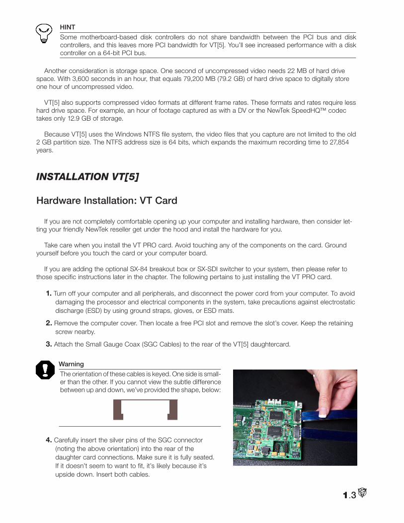
3. Attach the Small Gauge Coax (SGC Cables) to the rear of the VT[5] daughtercard.
Warning
The orientation of these cables is keyed. One side is small-er than the other. If you cannot view the subtle difference between up and down, we’ve provided the shape, below:
4. Carefully insert the silver pins of the SGC connector (noting the above orientation) into the rear of the daughter card connections. Make sure it is fully seated. If it doesn’t seem to want to fit, it’s likely because it’s upside down. Insert both cables.
1.3
1.4
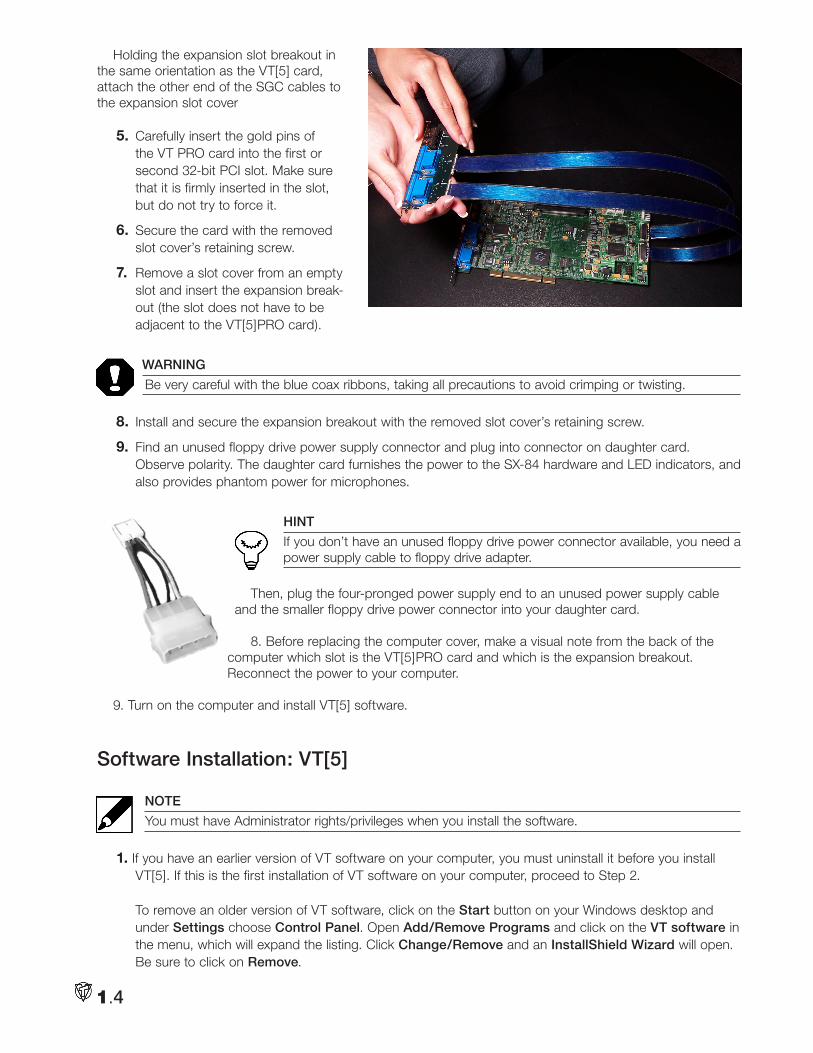
Holding the expansion slot breakout in the same orientation as the VT[5] card, attach the other end of the SGC cables to the expansion slot cover
5. Carefully insert the gold pins of the VT PRO card into the first or second 32-bit PCI slot. Make sure that it is firmly inserted in the slot, but do not try to force it.
6. Secure the card with the removed slot cover’s retaining screw.
7. Remove a slot cover from an empty slot and insert the expansion break-out (the slot does not have to be adjacent to the VT[5]PRO card).
WARNING
Be very careful with the blue coax ribbons, taking all precautions to avoid crimping or twisting.
8. Install and secure the expansion breakout with the removed slot cover’s retaining screw.
9. Find an unused floppy drive power supply connector and plug into connector on daughter card. Observe polarity. The daughter card furnishes the power to the SX-84 hardware and LED indicators, and also provides phantom power for microphones.
HINT
If you don’t have an unused floppy drive power connector available, you need a power supply cable to floppy drive adapter.
Then, plug the four-pronged power supply end to an unused power supply cable and the smaller floppy drive power connector into your daughter card.
8. Before replacing the computer cover, make a visual note from the back of the computer which slot is the VT[5]PRO card and which is the expansion breakout. Reconnect the power to your computer.
9. Turn on the computer and install VT[5] software.
Software Installation: VT[5]
NOTE
You must have Administrator rights/privileges when you install the software.
1. If you have an earlier version of VT software on your computer, you must uninstall it before you install VT[5]. If this is the first installation of VT software on your computer, proceed to Step 2. To remove an older version of VT software, click on the Start button on your Windows desktop and under Settings choose Control Panel. Open Add/Remove Programs and click on the VT software in the menu, which will expand the listing. Click Change/Remove and an InstallShield Wizard will open. Be sure to click on Remove.
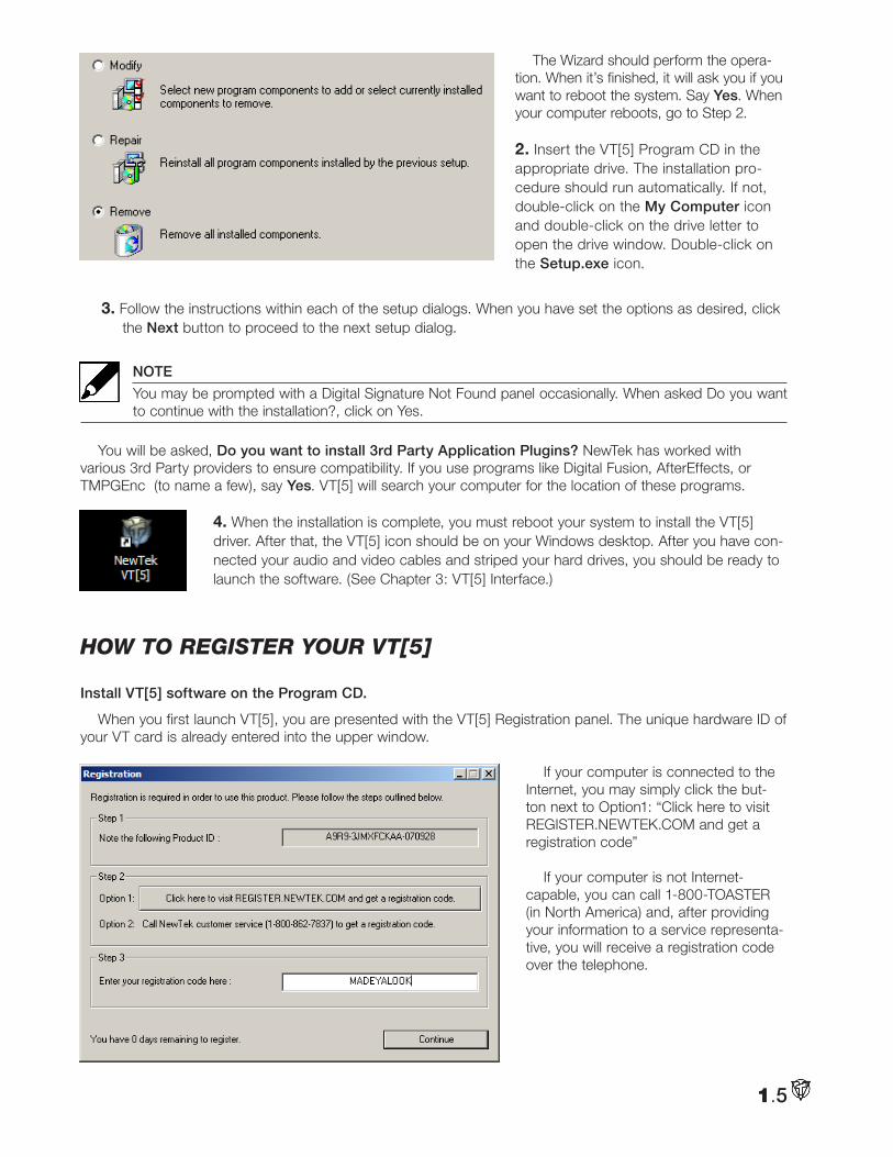
The Wizard should perform the opera-tion. When it’s finished, it will ask you if you want to reboot the system. Say Yes. When your computer reboots, go to Step 2.
2. Insert the VT[5] Program CD in the appropriate drive. The installation pro-cedure should run automatically. If not, double-click on the My Computer icon and double-click on the drive letter to open the drive window. Double-click on the Setup.exe icon.
3. Follow the instructions within each of the setup dialogs. When you have set the options as desired, click the Next button to proceed to the next setup dialog.
NOTE
You may be prompted with a Digital Signature Not Found panel occasionally. When asked Do you want to continue with the installation?, click on Yes.
You will be asked, Do you want to install 3rd Party Application Plugins? NewTek has worked with various 3rd Party providers to ensure compatibility. If you use programs like Digital Fusion, AfterEffects, or TMPGEnc (to name a few), say Yes. VT[5] will search your computer for the location of these programs.
4. When the installation is complete, you must reboot your system to install the VT[5] driver. After that, the VT[5] icon should be on your Windows desktop. After you have con-nected your audio and video cables and striped your hard drives, you should be ready to launch the software. (See Chapter 3: VT[5] Interface.)
How to RegiSteR youR Vt[5]
Install VT[5] software on the Program CD.
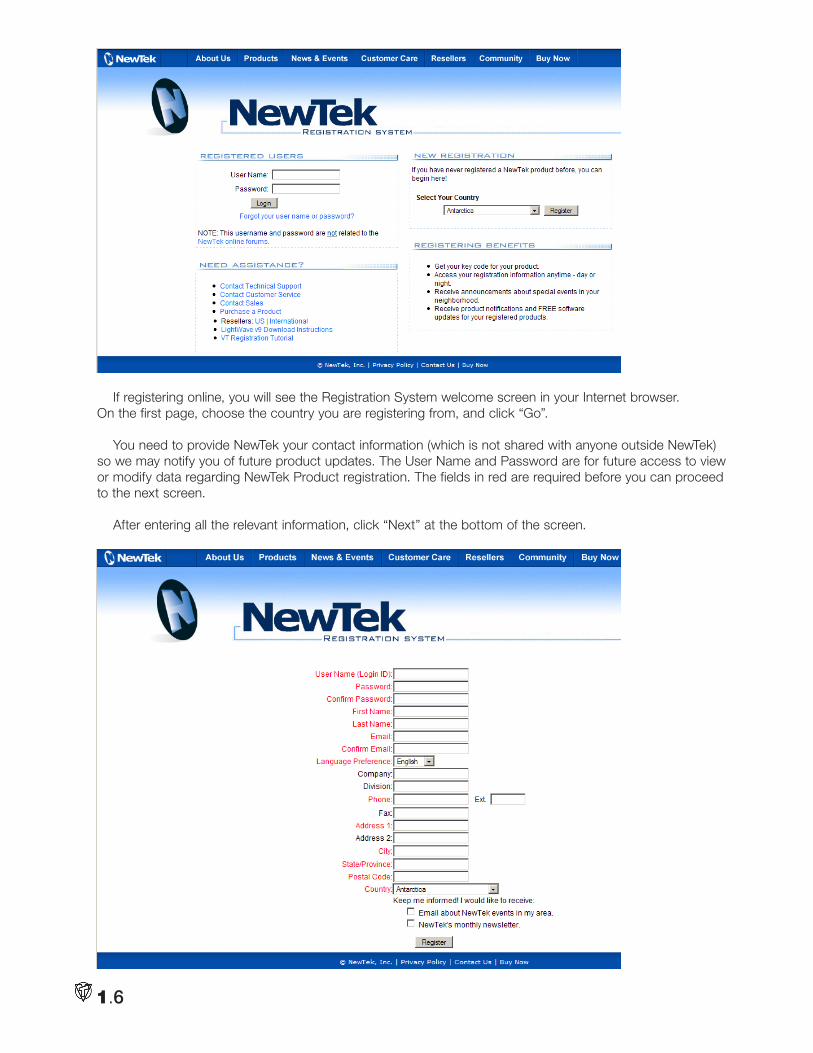
When you first launch VT[5], you are presented with the VT[5] Registration panel. The unique hardware ID of your VT card is already entered into the upper window.
If your computer is connected to the Internet, you may simply click the but-ton next to Option1: “Click here to visit REGISTER.NEWTEK.COM and get a registration code”
If your computer is not Internet-capable, you can call 1-800-TOASTER (in North America) and, after providing your information to a service representa-tive, you will receive a registration code over the telephone.
1.5
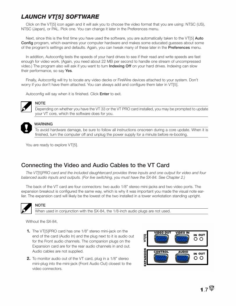
If registering online, you will see the Registration System welcome screen in your Internet browser. On the first page, choose the country you are registering from, and click “Go”.
You need to provide NewTek your contact information (which is not shared with anyone outside NewTek) so we may notify you of future product updates. The User Name and Password are for future access to view or modify data regarding NewTek Product registration. The fields in red are required before you can proceed to the next screen.
After entering all the relevant information, click “Next” at the bottom of the screen.
1.6
launcH Vt[5] SoftwaRe Click on the VT[5] icon again and it will ask you to choose the video format that you are using: NTSC (US),
NTSC (Japan), or PAL. Pick one. You can change it later in the Preferences menu.
Next, since this is the first time you have used the software, you are automatically taken to the VT[5] Auto Config program, which examines your computer hardware and makes some educated guesses about some of the program’s settings and defaults. Again, you can tweak many of these later in the Preferences menu.
In addition, Autoconfig tests the speeds of your hard drives to see if their read and write speeds are fast enough for video work. (Again, you need about 22 MB per second to handle one stream of uncompressed video.) The program also will ask if you want to turn Indexing Off on your hard drives. Indexing can slow their performance, so say Yes.
Finally, Autoconfig will try to locate any video decks or FireWire devices attached to your system. Don’t worry if you don’t have them attached. You can always add and configure them later in VT[5].
Autoconfig will say when it is finished. Click Enter to exit.
NOTE
Depending on whether you have the VT 33 or the VT PRO card installed, you may be prompted to update your VT core, which the software does for you.
WARNING
To avoid hardware damage, be sure to follow all instructions onscreen during a core update. When it is finished, turn the computer off and unplug the power supply for a minute before re-booting.
You are ready to explore VT[5].
Connecting the Video and Audio Cables to the VT CardThe VT[5]PRO card and the included daughtercard provides three inputs and one output for video and four
balanced audio inputs and outputs. (For live switching, you must have the SX-84. See Chapter 2.)
The back of the VT card are four connectors: two audio 1/8” stereo mini-jacks and two video ports. The expansion breakout is configured the same way, which is why it was important you made the visual note ear-lier. The expansion card will likely be the lowest of the two installed in a tower workstation standing upright.
NOTE
When used in conjunction with the SX-84, the 1/8-inch audio plugs are not used.
Without the SX-84,
1. The VT[5]PRO card has one 1/8” stereo mini-jack on the end of the card (Audio In) and the plug next to it is audio out for the Front audio channels. The companion plugs on the Expansion card are for the rear audio channels in and out. Audio cables are not supplied.
2. To monitor audio out of the VT card, plug in a 1/8” stereo mini-plug into the mini-jack (Front Audio Out) closest to the video connectors.
1.7
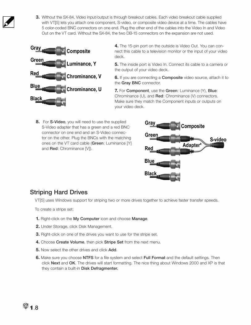
3. Without the SX-84, Video input/output is through breakout cables. Each video breakout cable supplied with VT[5] lets you attach one component, S-video, or composite video device at a time. The cables have 5 color-coded BNC connectors on one end. Plug the other end of the cables into the Video In and Video Out on the VT card. Without the SX-84, the two DB-15 connectors on the expansion are not used.
4. The 15-pin port on the outside is Video Out. You can con-nect this cable to a television monitor or the input of your video deck.
5. The inside port is Video In. Connect its cable to a camera or the output of your video deck.
6. If you are connecting a Composite video source, attach it to the Gray BNC connector.
7. For Component, use the Green: Luminance (Y), Blue: Chrominance (U), and Red: Chrominance (V) connectors. Make sure they match the Component inputs or outputs on your video deck.
8. For S-Video, you will need to use the supplied S-Video adapter that has a green and a red BNC connector on one end and an S-Video connec-tor on the other. Plug the BNCs with the matching ones on the VT card cable (Green: Luminance [Y] and Red: Chrominance [V]).
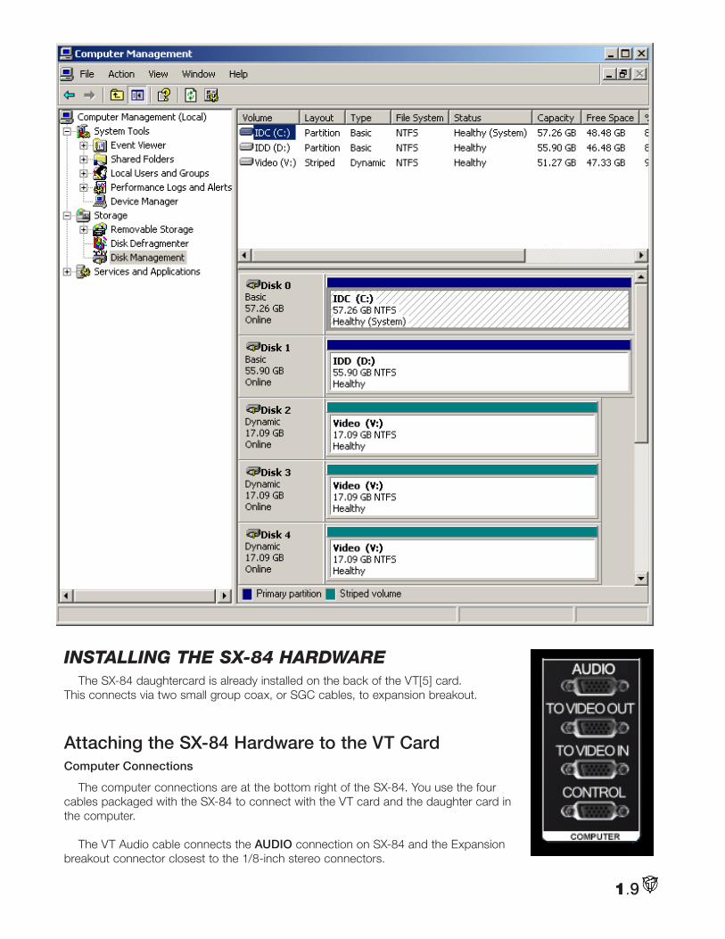
Striping Hard DrivesVT[5] uses Windows support for striping two or more drives together to achieve faster transfer speeds.
To create a stripe set:
1. Right-click on the My Computer icon and choose Manage.
2. Under Storage, click Disk Management.
3. Right-click on one of the drives you want to use for the stripe set.
4. Choose Create Volume, then pick Stripe Set from the next menu.
5. Now select the other drives and click Add.
6. Make sure you choose NTFS for a file system and select Full Format and the default settings. Then click Next and OK. The drives will start formatting. The nice thing about Windows 2000 and XP is that they contain a built-in Disk Defragmenter.
1.8
1.9
Windows 2000 Windows XP
inStalling tHe SX-84 HaRdwaReThe SX-84 daughtercard is already installed on the back of the VT[5] card.
This connects via two small group coax, or SGC cables, to expansion breakout.
Attaching the SX-84 Hardware to the VT Card Computer Connections
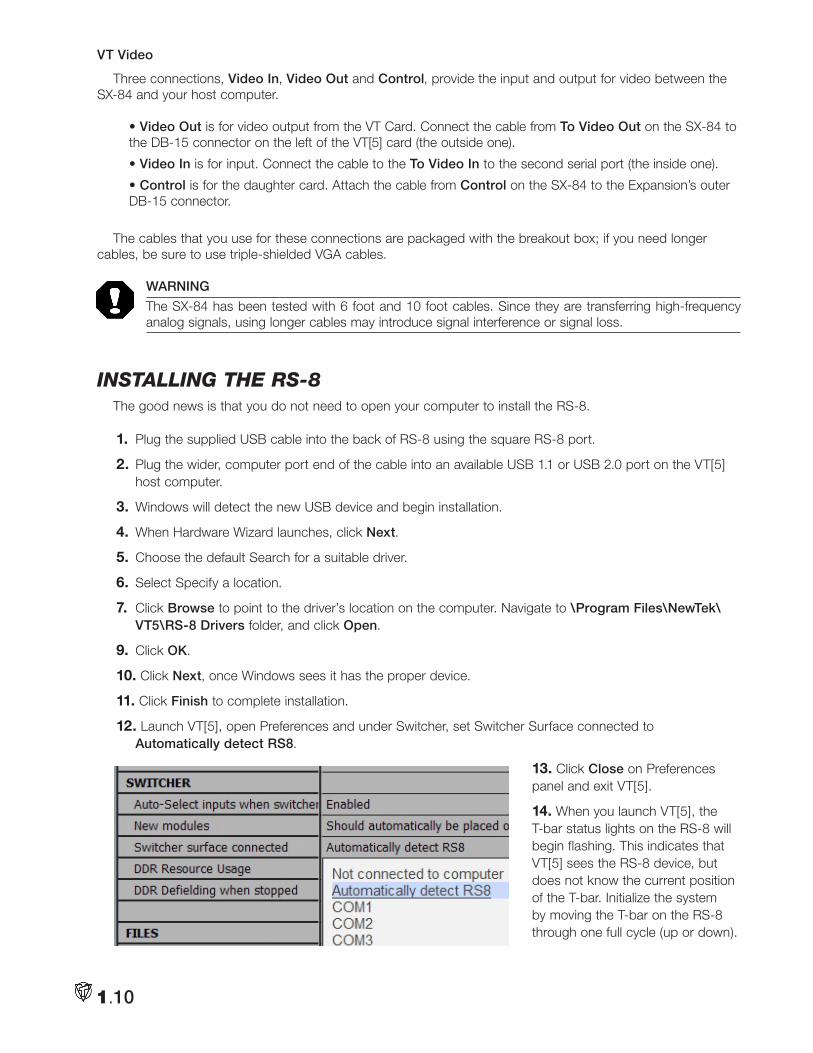
The computer connections are at the bottom right of the SX-84. You use the four cables packaged with the SX-84 to connect with the VT card and the daughter card in the computer.
The VT Audio cable connects the AUDIO connection on SX-84 and the Expansion breakout connector closest to the 1/8-inch stereo connectors.
1.10
VT Video
Three connections, Video In, Video Out and Control, provide the input and output for video between the SX-84 and your host computer.
• Video Out is for video output from the VT Card. Connect the cable from To Video Out on the SX-84 to the DB-15 connector on the left of the VT[5] card (the outside one).
• Video In is for input. Connect the cable to the To Video In to the second serial port (the inside one).
• Control is for the daughter card. Attach the cable from Control on the SX-84 to the Expansion’s outer DB-15 connector.
The cables that you use for these connections are packaged with the breakout box; if you need longer cables, be sure to use triple-shielded VGA cables.
WARNING
The SX-84 has been tested with 6 foot and 10 foot cables. Since they are transferring high-frequency analog signals, using longer cables may introduce signal interference or signal loss.
inStalling tHe RS-8The good news is that you do not need to open your computer to install the RS-8.
1. Plug the supplied USB cable into the back of RS-8 using the square RS-8 port.
2. Plug the wider, computer port end of the cable into an available USB 1.1 or USB 2.0 port on the VT[5] host computer.
3. Windows will detect the new USB device and begin installation.
4. When Hardware Wizard launches, click Next.
5. Choose the default Search for a suitable driver.
6. Select Specify a location.
7. Click Browse to point to the driver’s location on the computer. Navigate to \Program Files\NewTek\VT5\RS-8 Drivers folder, and click Open.
9. Click OK.
10. Click Next, once Windows sees it has the proper device.
11. Click Finish to complete installation.
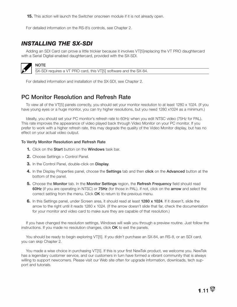
12. Launch VT[5], open Preferences and under Switcher, set Switcher Surface connected to Automatically detect RS8.
13. Click Close on Preferences panel and exit VT[5].
14. When you launch VT[5], the T-bar status lights on the RS-8 will begin flashing. This indicates that VT[5] sees the RS-8 device, but does not know the current position of the T-bar. Initialize the system by moving the T-bar on the RS-8 through one full cycle (up or down).
1.11
15. This action will launch the Switcher onscreen module if it is not already open.
For detailed information on the RS-8’s controls, see Chapter 2.
inStalling tHe SX-SdiAdding an SDI Card can prove a little trickier because it involves VT[5]replacing the VT PRO daughtercard
with a Serial Digital-enabled daughtercard, provided with the SX-SDI.
NOTE
SX-SDI requires a VT PRO card, this VT[5] software and the SX-84.
For detailed information and installation of the SX-SDI, see Chapter 2.
PC Monitor Resolution and Refresh RateTo view all of the VT[5] panels correctly, you should set your monitor resolution to at least 1280 x 1024. (If you
have young eyes or a huge monitor, you can try higher resolutions, but you need 1280 x1024 as a minimum.)
Ideally, you should set your PC monitor’s refresh rate to 60Hz when you edit NTSC video (75Hz for PAL). This rate improves the appearance of video played back through Video Monitor on your PC monitor. If you prefer to work with a higher refresh rate, this may degrade the quality of the Video Monitor display, but has no effect on your actual video output.
To Verify Monitor Resolution and Refresh Rate
1. Click on the Start button on the Windows task bar.
2. Choose Settings > Control Panel.
3. In the Control Panel, double-click on Display.
4. In the Display Properties panel, choose the Settings tab and then click on the Advanced button at the bottom of the panel.
5. Choose the Monitor tab. In the Monitor Settings region, the Refresh Frequency field should read 60Hz (if you are operating in NTSC) or 75Hz (for those in PAL). If not, click on the arrow and select the correct setting from the menu. Click OK to return to the previous menu.
6. In this Settings panel, under Screen area, it should read at least 1280 x 1024. If it doesn’t, slide the arrow to the right until it reads 1280 x 1024. (If the arrow doesn’t slide that far, check the documentation for your monitor and video card to make sure they are capable of that resolution.)
If you have changed the resolution settings, Windows will walk you through a preview routine. Just follow the instructions. If you made no resolution changes, click OK to exit the panels.
You should be ready to begin exploring VT[5]. If you didn’t purchase an SX-84, an RS-8, or an SDI card, you can skip Chapter 2.
You made a wise choice in purchasing VT[5]. If this is your first NewTek product, we welcome you. NewTek has a legendary customer service, and our customers in turn have formed a vibrant community that is always willing to support newcomers. Please visit our Web site often for upgrade information, downloads, tech sup-port and tutorials.

1.12
Notes:
Depending on whether your needs are with VT[5] Live or VT[5] Post, you can purchase two optional pieces of hardware, the SX-84 Switcher Expansion and the SDI Card.
NOTE
If you have not purchased the SX-84 or the SDI card, you can skip this chapter — unless you just enjoy reading manuals.
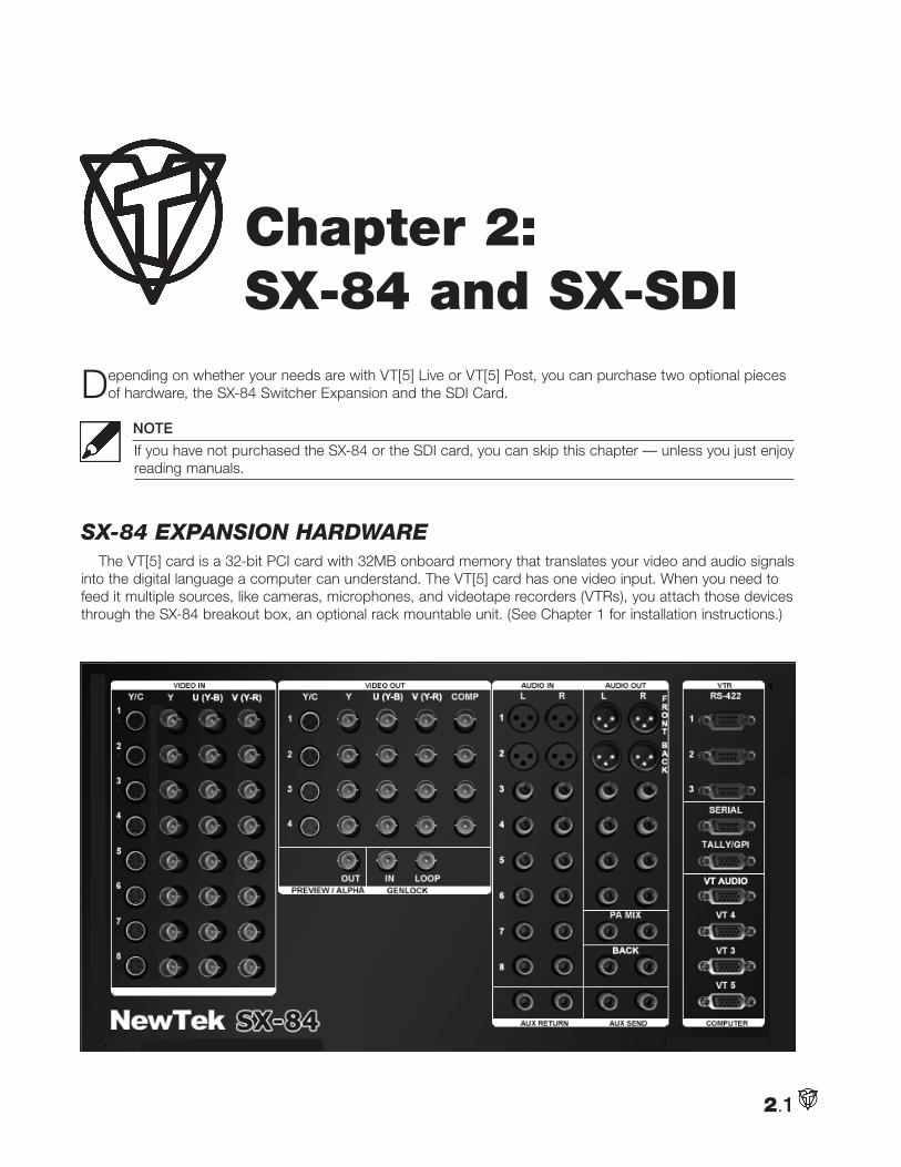
SX-84 EXpanSion HardwarEThe VT[5] card is a 32-bit PCI card with 32MB onboard memory that translates your video and audio signals
into the digital language a computer can understand. The VT[5] card has one video input. When you need to feed it multiple sources, like cameras, microphones, and videotape recorders (VTRs), you attach those devices through the SX-84 breakout box, an optional rack mountable unit. (See Chapter 1 for installation instructions.)
2.1
Chapter 2: SX-84 and SX-SDI
NOTE
Who is this BOB, anyway?NewTek has always been an informal — first name basis — sort of group. SX-84 has that techno- engineer ring to it; but after a couple of beers, everyone just started calling him BOB, (short for BreakOut Box). SX Breakout is his software doppelganger.
Basic SX-84 SetupWhen you first look at the SX-84, it may be a bit daunting with all the connectors staring back at you. The simplest approach is to work from left to right.
But first, this chapter assumes that you have installed the SX-84 daughter card into your computer; and then, con-nected the SX-84 expansion unit to the VT[5] card and the daughter card. (See Chapter 1 for these instructions.)
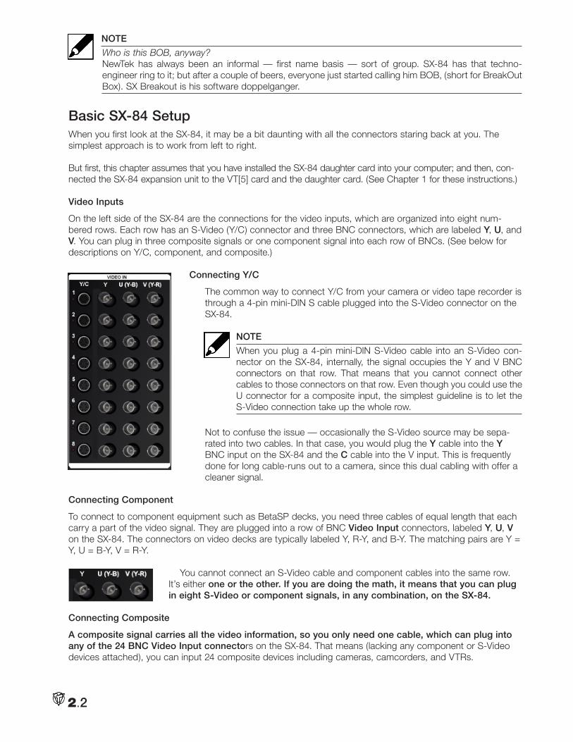
Video Inputs
On the left side of the SX-84 are the connections for the video inputs, which are organized into eight num-bered rows. Each row has an S-Video (Y/C) connector and three BNC connectors, which are labeled Y, U, and V. You can plug in three composite signals or one component signal into each row of BNCs. (See below for descriptions on Y/C, component, and composite.)
Connecting Y/C
The common way to connect Y/C from your camera or video tape recorder is through a 4-pin mini-DIN S cable plugged into the S-Video connector on the SX-84.
NOTE
When you plug a 4-pin mini-DIN S-Video cable into an S-Video con-nector on the SX-84, internally, the signal occupies the Y and V BNC connectors on that row. That means that you cannot connect other cables to those connectors on that row. Even though you could use the U connector for a composite input, the simplest guideline is to let the S-Video connection take up the whole row.
Not to confuse the issue — occasionally the S-Video source may be sepa-rated into two cables. In that case, you would plug the Y cable into the Y BNC input on the SX-84 and the C cable into the V input. This is frequently done for long cable-runs out to a camera, since this dual cabling with offer a cleaner signal.
Connecting Component
To connect to component equipment such as BetaSP decks, you need three cables of equal length that each carry a part of the video signal. They are plugged into a row of BNC Video Input connectors, labeled Y, U, V on the SX-84. The connectors on video decks are typically labeled Y, R-Y, and B-Y. The matching pairs are Y = Y, U = B-Y, V = R-Y.
You cannot connect an S-Video cable and component cables into the same row. It’s either one or the other. If you are doing the math, it means that you can plug in eight S-Video or component signals, in any combination, on the SX-84.
Connecting Composite
A composite signal carries all the video information, so you only need one cable, which can plug into any of the 24 BNC Video Input connectors on the SX-84. That means (lacking any component or S-Video devices attached), you can input 24 composite devices including cameras, camcorders, and VTRs.
2.2
High-end composite devices may use a cable with a BNC connector, but many consumer composite machines use an RCA phono jack. If they do, you will need a BNC adapter to attach it to the SX-84.
HINT
If you are live switching a multi-camera show, you want to individually monitor your cameras. Internally, VT[5] can monitor only two sources, the cameras on Preview and Main. If you have more than two com-posite cameras, then you will have to route your camera outputs to external monitors by splitting the camera’s signal as you are connecting it to the SX-84. One split goes into the SX-84, the other is sent to a small monitor assigned to that camera. Or you can loop through your isolated monitors and then route the signal to the SX-84 input.
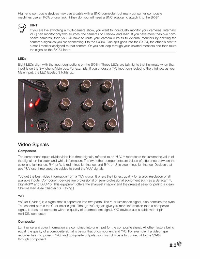
LEDs
Eight LEDs align with the input connections on the SX-84. These LEDs are tally lights that illuminate when that input is on the Switcher’s Main bus. For example, if you choose a Y/C input connected to the third row as your Main input, the LED labeled 3 lights up.
Video SignalsComponent
The component inputs divide video into three signals, referred to as YUV. Y represents the luminance value of the signal, or the black and white information. The two other components are values of difference between the color and luminance. R-Y, or V, is red minus luminance, and B-Y, or U, is blue minus luminance. Devices that use YUV use three separate cables to send the YUV signals. You get the best video information from a YUV signal. It offers the highest quality for analog resolution of all available inputs. Component devices are professional or semi-professional equipment such as a Betacam™, Digital-S™ and DVCPro. This equipment offers the sharpest imagery and the greatest ease for pulling a clean Chroma Key. (See Chapter 16: Keying.)
Y/C
Y/C (or S-Video) is a signal that is separated into two parts. The Y, or luminance signal, also contains the sync. The second part is the C, or color signal. Though Y/C signals give you more information than a composite signal, it does not compete with the quality of a component signal. Y/C devices use a cable with 4-pin mini-DIN connector.
Composite
Luminance and color information are combined into one input for the composite signal. All other factors being equal, the quality of a composite signal is below that of component and Y/C. For example, if a video tape recorder has component, Y/C, and composite outputs, your first choice is to connect it to the SX-84 through component.
2.3
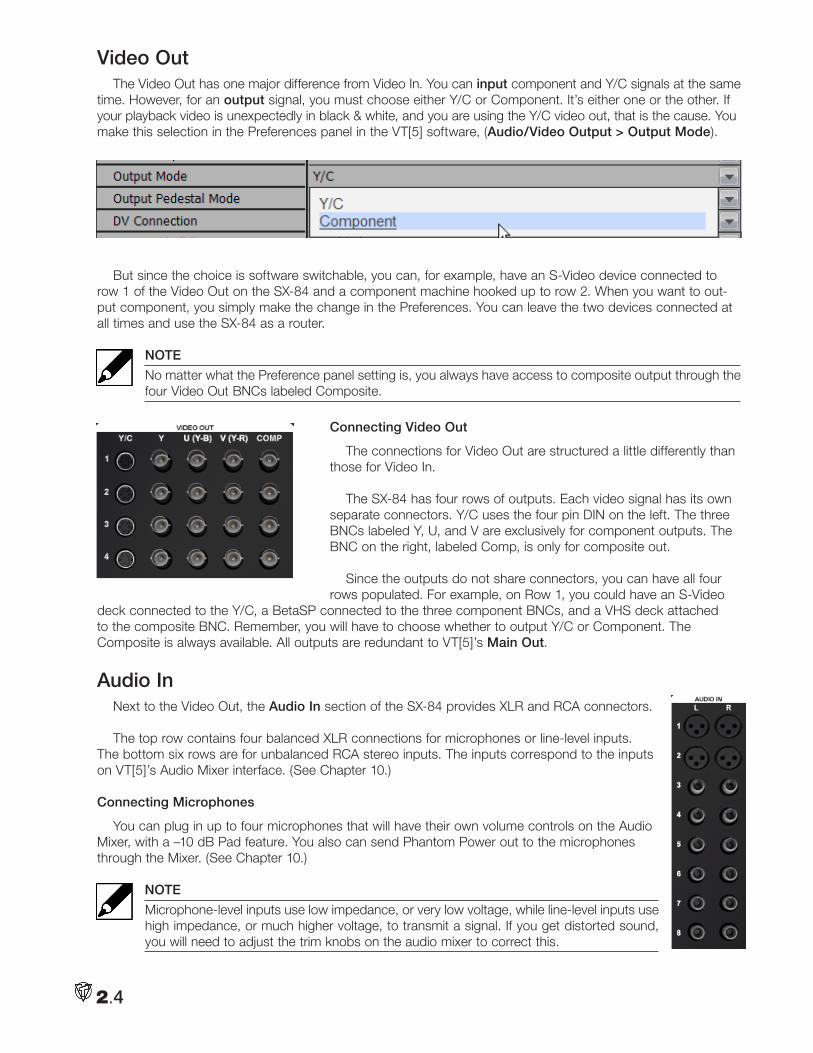
Video OutThe Video Out has one major difference from Video In. You can input component and Y/C signals at the same
time. However, for an output signal, you must choose either Y/C or Component. It’s either one or the other. If your playback video is unexpectedly in black & white, and you are using the Y/C video out, that is the cause. You make this selection in the Preferences panel in the VT[5] software, (Audio/Video Output > Output Mode).
But since the choice is software switchable, you can, for example, have an S-Video device connected to row 1 of the Video Out on the SX-84 and a component machine hooked up to row 2. When you want to out-put component, you simply make the change in the Preferences. You can leave the two devices connected at all times and use the SX-84 as a router.
NOTE
No matter what the Preference panel setting is, you always have access to composite output through the four Video Out BNCs labeled Composite.
Connecting Video Out
The connections for Video Out are structured a little differently than those for Video In.
The SX-84 has four rows of outputs. Each video signal has its own separate connectors. Y/C uses the four pin DIN on the left. The three BNCs labeled Y, U, and V are exclusively for component outputs. The BNC on the right, labeled Comp, is only for composite out.
Since the outputs do not share connectors, you can have all four rows populated. For example, on Row 1, you could have an S-Video
deck connected to the Y/C, a BetaSP connected to the three component BNCs, and a VHS deck attached to the composite BNC. Remember, you will have to choose whether to output Y/C or Component. The Composite is always available. All outputs are redundant to VT[5]’s Main Out.
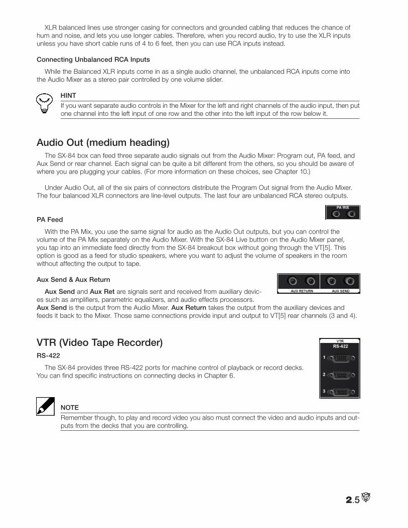
Audio InNext to the Video Out, the Audio In section of the SX-84 provides XLR and RCA connectors.
The top row contains four balanced XLR connections for microphones or line-level inputs. The bottom six rows are for unbalanced RCA stereo inputs. The inputs correspond to the inputs on VT[5]’s Audio Mixer interface. (See Chapter 10.)
Connecting Microphones
You can plug in up to four microphones that will have their own volume controls on the Audio Mixer, with a –10 dB Pad feature. You also can send Phantom Power out to the microphones through the Mixer. (See Chapter 10.)
NOTE
Microphone-level inputs use low impedance, or very low voltage, while line-level inputs use high impedance, or much higher voltage, to transmit a signal. If you get distorted sound, you will need to adjust the trim knobs on the audio mixer to correct this.
2.4
XLR balanced lines use stronger casing for connectors and grounded cabling that reduces the chance of hum and noise, and lets you use longer cables. Therefore, when you record audio, try to use the XLR inputs unless you have short cable runs of 4 to 6 feet, then you can use RCA inputs instead.
Connecting Unbalanced RCA Inputs
While the Balanced XLR inputs come in as a single audio channel, the unbalanced RCA inputs come into the Audio Mixer as a stereo pair controlled by one volume slider.
HINT
If you want separate audio controls in the Mixer for the left and right channels of the audio input, then put one channel into the left input of one row and the other into the left input of the row below it.
Audio Out (medium heading)The SX-84 box can feed three separate audio signals out from the Audio Mixer: Program out, PA feed, and
Aux Send or rear channel. Each signal can be quite a bit different from the others, so you should be aware of where you are plugging your cables. (For more information on these choices, see Chapter 10.)
Under Audio Out, all of the six pairs of connectors distribute the Program Out signal from the Audio Mixer. The four balanced XLR connectors are line-level outputs. The last four are unbalanced RCA stereo outputs.
PA Feed
With the PA Mix, you use the same signal for audio as the Audio Out outputs, but you can control the volume of the PA Mix separately on the Audio Mixer. With the SX-84 Live button on the Audio Mixer panel, you tap into an immediate feed directly from the SX-84 breakout box without going through the VT[5]. This option is good as a feed for studio speakers, where you want to adjust the volume of speakers in the room without affecting the output to tape.
Aux Send & Aux Return
Aux Send and Aux Ret are signals sent and received from auxiliary devic-es such as amplifiers, parametric equalizers, and audio effects processors. Aux Send is the output from the Audio Mixer. Aux Return takes the output from the auxiliary devices and feeds it back to the Mixer. Those same connections provide input and output to VT[5] rear channels (3 and 4).
VTR (Video Tape Recorder)RS-422
The SX-84 provides three RS-422 ports for machine control of playback or record decks. You can find specific instructions on connecting decks in Chapter 6.
NOTE
Remember though, to play and record video you also must connect the video and audio inputs and out-puts from the decks that you are controlling.
2.5
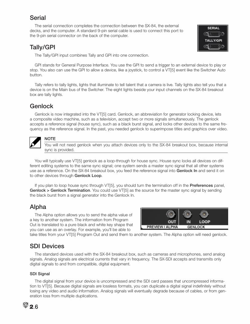
SerialThe serial connection completes the connection between the SX-84, the external
decks, and the computer. A standard 9-pin serial cable is used to connect this port to the 9-pin serial connector on the back of the computer.
Tally/GPIThe Tally/GPI input combines Tally and GPI into one connection.
GPI stands for General Purpose Interface. You use the GPI to send a trigger to an external device to play or stop. You also can use the GPI to allow a device, like a joystick, to control a VT[5] event like the Switcher Auto button.
Tally refers to tally lights, lights that illuminate to tell talent that a camera is live. Tally lights also tell you that a device is on the Main bus of the Switcher. The eight lights beside your input channels on the SX-84 breakout box are tally lights.
GenlockGenlock is now integrated into the VT[5] card. Genlock, an abbreviation for generator locking device, lets
a composite video machine, such as a television, accept two or more signals simultaneously. The genlock accepts a reference signal (house sync), such as a black burst signal, and locks other devices to the same fre-quency as the reference signal. In the past, you needed genlock to superimpose titles and graphics over video.
NOTE
You will not need genlock when you attach devices only to the SX-84 breakout box, because internal sync is provided.
You will typically use VT[5] genlock as a loop-through for house sync. House sync locks all devices on dif-ferent editing systems to the same sync signal; one system sends a master sync signal that all other systems use as a reference. On the SX-84 breakout box, you feed the reference signal into Genlock In and send it on to other devices through Genlock Loop.
If you plan to loop house sync through VT[5], you should turn the termination off in the Preferences panel, Genlock > Genlock Termination. You could use VT[5] as the source for the master sync signal by sending the black burst from a signal generator into the Genlock In.
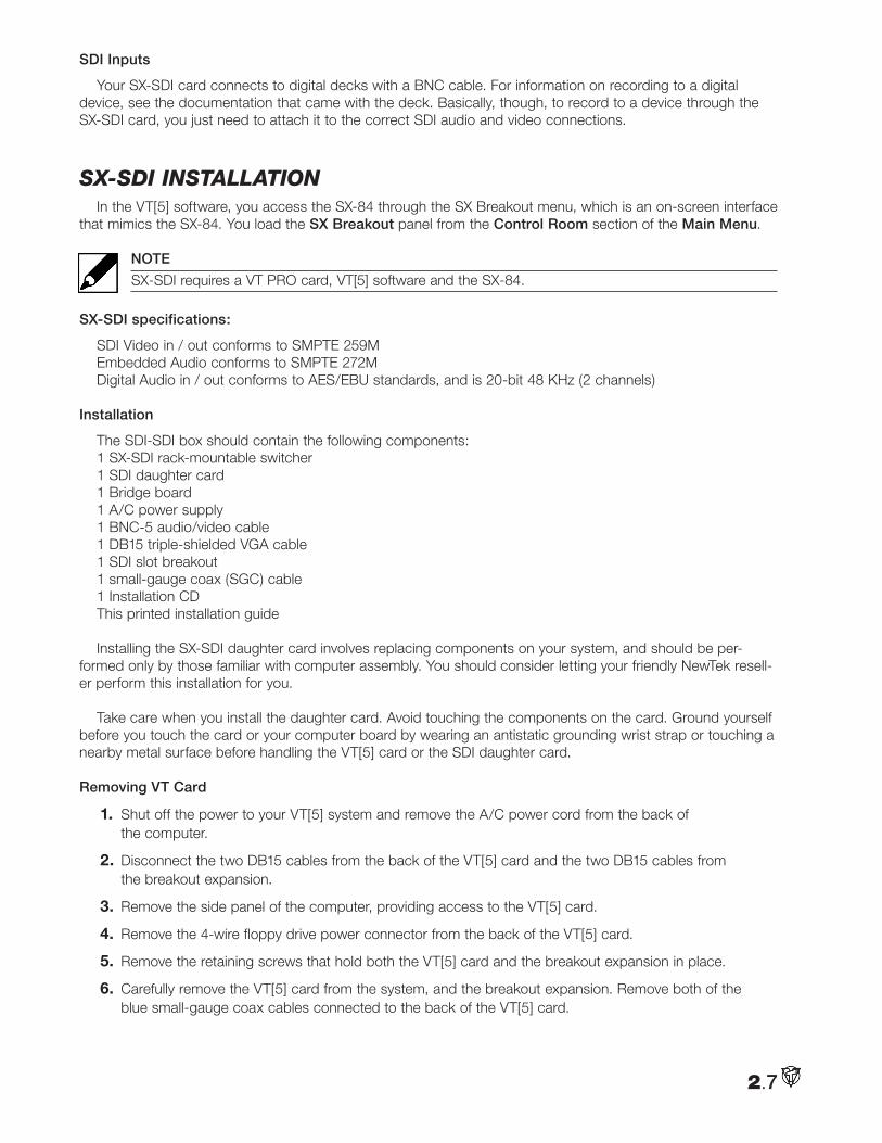
AlphaThe Alpha option allows you to send the alpha value of
a key to another system. The information from Program Out is translated to a pure black and white key shape that you can use as an overlay. For example, you’ll be able to take titles from your VT[5] Program Out and send them to another system. The Alpha option will need genlock.
SDI DevicesThe standard devices used with the SX-84 breakout box, such as cameras and microphones, send analog
signals. Analog signals are electrical currents that vary in frequency. The SX-SDI accepts and transmits only digital signals to and from compatible, digital equipment.
SDI Signal
The digital signal from your device is uncompressed and the SDI card passes that uncompressed informa-tion to VT[5]. Because digital signals are lossless formats, you can duplicate a digital signal indefinitely without losing any video and audio information. Analog signals will eventually degrade because of cables, or from gen-eration loss from multiple duplications.
2.6
SDI Inputs
Your SX-SDI card connects to digital decks with a BNC cable. For information on recording to a digital device, see the documentation that came with the deck. Basically, though, to record to a device through the SX-SDI card, you just need to attach it to the correct SDI audio and video connections.
SX-Sdi inStallationIn the VT[5] software, you access the SX-84 through the SX Breakout menu, which is an on-screen interface
that mimics the SX-84. You load the SX Breakout panel from the Control Room section of the Main Menu.
NOTE
SX-SDI requires a VT PRO card, VT[5] software and the SX-84.
SX-SDI specifications:
SDI Video in / out conforms to SMPTE 259MEmbedded Audio conforms to SMPTE 272MDigital Audio in / out conforms to AES/EBU standards, and is 20-bit 48 KHz (2 channels)
Installation
The SDI-SDI box should contain the following components:1 SX-SDI rack-mountable switcher1 SDI daughter card1 Bridge board1 A/C power supply 1 BNC-5 audio/video cable1 DB15 triple-shielded VGA cable1 SDI slot breakout 1 small-gauge coax (SGC) cable 1 Installation CDThis printed installation guide
Installing the SX-SDI daughter card involves replacing components on your system, and should be per-formed only by those familiar with computer assembly. You should consider letting your friendly NewTek resell-er perform this installation for you.
Take care when you install the daughter card. Avoid touching the components on the card. Ground yourself before you touch the card or your computer board by wearing an antistatic grounding wrist strap or touching a nearby metal surface before handling the VT[5] card or the SDI daughter card.
Removing VT Card
1. Shut off the power to your VT[5] system and remove the A/C power cord from the back of the computer.
2. Disconnect the two DB15 cables from the back of the VT[5] card and the two DB15 cables from the breakout expansion.
3. Remove the side panel of the computer, providing access to the VT[5] card.
4. Remove the 4-wire floppy drive power connector from the back of the VT[5] card.
5. Remove the retaining screws that hold both the VT[5] card and the breakout expansion in place.
6. Carefully remove the VT[5] card from the system, and the breakout expansion. Remove both of the blue small-gauge coax cables connected to the back of the VT[5] card.
2.7
Connecting SDI Daughter Card
1. If you have an SDI card installed, remove the bridge board from the Movie-2 bus at the top of the VT[5] card.
2. Using tweezers or needle-nose pliers, carefully pinch the ends of the three plastic stand-offs that anchor the daughter card to the VT[5] card while inserting a finger between the two to separate them.
3. Remove the daughter card, being careful to keep the 50-pin connector aligned while separating the card from the VT[5] main board.
4. Remove the 3 plastic stand-offs from the VT[5] card.
5. Carefully place the SDI daughter card on top of the VT[5], visually aligning the 50 pin connector on the top of the daughter card with the VT[5] connector block.
6. When placing the daughter card on top, make sure to align the protruding JP2 jumper pins on the VT[5] card with the two small holes on the daughter card. Gently squeeze the SDI daughter card into place, so the 50 pins fit firmly in the connector block and that all three stand-offs snap into place.
7. Connect the bridgeboard to the Movie2 bus at the top of both cards, taking care to note that this is keyed with a notch at one end, and can only be inserted with the notch aligned with the groove.
8. Insert the blue small-gauge coax cable of the SDI slot expansion into the connector on the SDI daughter card. Then, re-connect both of the cables to the SX-84 expansion, taking note that the connections are keyed, and must be oriented as shown:
9. Re-connect the both of the blue small gauge coax cables with the daughter card, noting that they are also notched and can only be inserted in one direction.
Installing The VT Card and Software
1. Carefully insert the VT[5] card back into its PCI slot, making sure not to bend or force it.
2. Secure the VT[5] card in place by reinserting the slot cover screw.
3. Re-connect the floppy drive power connector to the new daughter card here:
4. Re-insert the breakout expansion for the VT[5] into the slot cover and secure with the retaining screw.
5. Remove an empty slot cover from the computer and secure the SDI connector in that slot with the retaining screw.
6. Replace the side cover on the computer, and re-connect the Audio, Video In and Video Out cables from the SX-84 to the back of the computer.
7. Use the supplied DB-15 cable in your SX-SDI kit to connect the black 15-pin Control connector from the back of the computer to the SX-SDI CONTROL IN.
8. Using the supplied 5-BNC breakout, connect the color-coded cables to their respective connections on the SX-SDI, and connect the DB15 end to the SX-SDI slot breakout.
9. Connect the CONTROL OUT SX-SDI connector with the SX-84 CONTROL.
10. Connect the A/C cable to the computer and boot the system.
11. Install the SX-SDI Driver Install Disc. If it does not auto-run, launch the installer by double-clicking on the CD setup.exe and follow the instructions.
12. Following the manufacturer’s instructions that came with your camera or tape deck, you can now connect your devices to the SDI inputs and outputs
13. Connect the power supply.
2.8
SX-SDI Operation
NOTE
SX-SDI requires VT[5] version 4.6 or newer to function.
Launch VT[5] and in the Preferences Menu, under AUDIO/VIDEO SIGNAL, change the option SDI Card Installed to Installed. This will activate the SDI outputs.
If you are acquiring audio and video through the capture panel, you must also go to the RECORDING option in Preferences to ensure that the audio circuitry is set for Use SDI Audio. This will allow the capture either embedded or AES audio in the system.
Crosspoint Software
NewTek has provided the ultimate in flexible SDI operation by allowing the SX-SDI to operate both as a live switcher and a signal router.
User Routing
All 5 outputs are assignable using the supplied SDI X-Point Config interface. This is found in Preferences > Audio/Video Signal.
Select the particular SDI input you wish to route to any output, and that source is assigned to that coaxial output.
SDI Audio Source
The SX-SDI offers embedded audio, which transfers both audio and video across the same coaxial connection. You can choose any one input as your source for embedded audio.
Whichever source is chosen as embedded, that audio will appear on the VT[5] audio mixer once it is on either the Program or Preview bus of the switcher.
If no SDI source is selected in this window, then VT[5] will choose the AES audio connectors as the default SDI audio inputs.
NOTE
This choice does not limit the use of analog audio inputs or outputs on the SX-84.
Embedded Audio Source
This checkbox determines whether the VT[5] will expect digital audio from the AES connectors or from one of the chosen coaxial connectors. Audio output is embedded on Program Out if this is checked and if the selected source is on the switcher’s Program or Preview bus. AES audio is always available.
Live Switching
To place an SDI input on the VT[5] switcher, launch the switcher module and right click on one of the patch bays above that input number, and choose one of the existing SDI inputs for that Switcher input.
NOTE
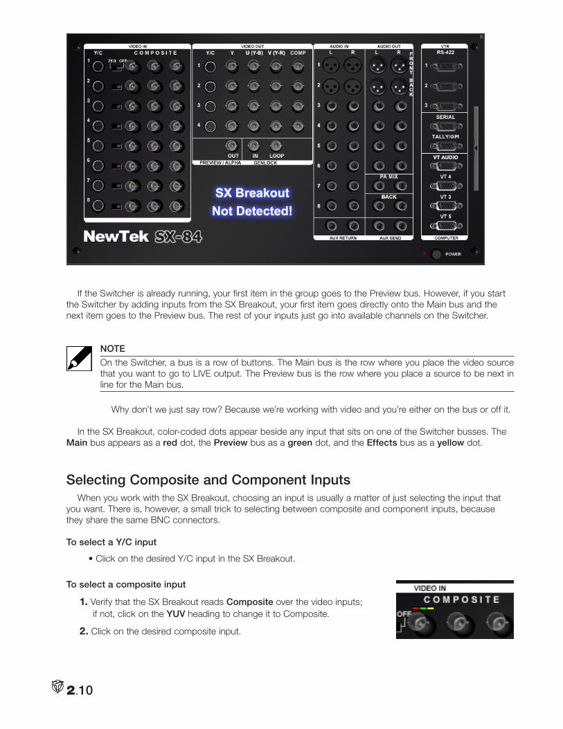
If you did not install the SX-84 breakout box, then the panel for the BOB barks at you, SX-84 Breakout Not Detected! (And you’re the one who just likes to read manuals.)
You can double-click on an active input in the SX Breakout panel and automatically add it to the Switcher. The item is placed in the first available channel. You can select multiple items simultaneously by either Shift-clicking to select a consecutive range of items or Ctrl-clicking to select items independently. Your items are added in the order that you select them.
2.9
2.10
If the Switcher is already running, your first item in the group goes to the Preview bus. However, if you start the Switcher by adding inputs from the SX Breakout, your first item goes directly onto the Main bus and the next item goes to the Preview bus. The rest of your inputs just go into available channels on the Switcher.
NOTE
On the Switcher, a bus is a row of buttons. The Main bus is the row where you place the video source that you want to go to LIVE output. The Preview bus is the row where you place a source to be next in line for the Main bus.
Why don’t we just say row? Because we’re working with video and you’re either on the bus or off it.
In the SX Breakout, color-coded dots appear beside any input that sits on one of the Switcher busses. The Main bus appears as a red dot, the Preview bus as a green dot, and the Effects bus as a yellow dot.
Selecting Composite and Component InputsWhen you work with the SX Breakout, choosing an input is usually a matter of just selecting the input that
you want. There is, however, a small trick to selecting between composite and component inputs, because they share the same BNC connectors.
To select a Y/C input
• Click on the desired Y/C input in the SX Breakout.
To select a composite input
1. Verify that the SX Breakout reads Composite over the video inputs; if not, click on the YUV heading to change it to Composite.
2. Click on the desired composite input.
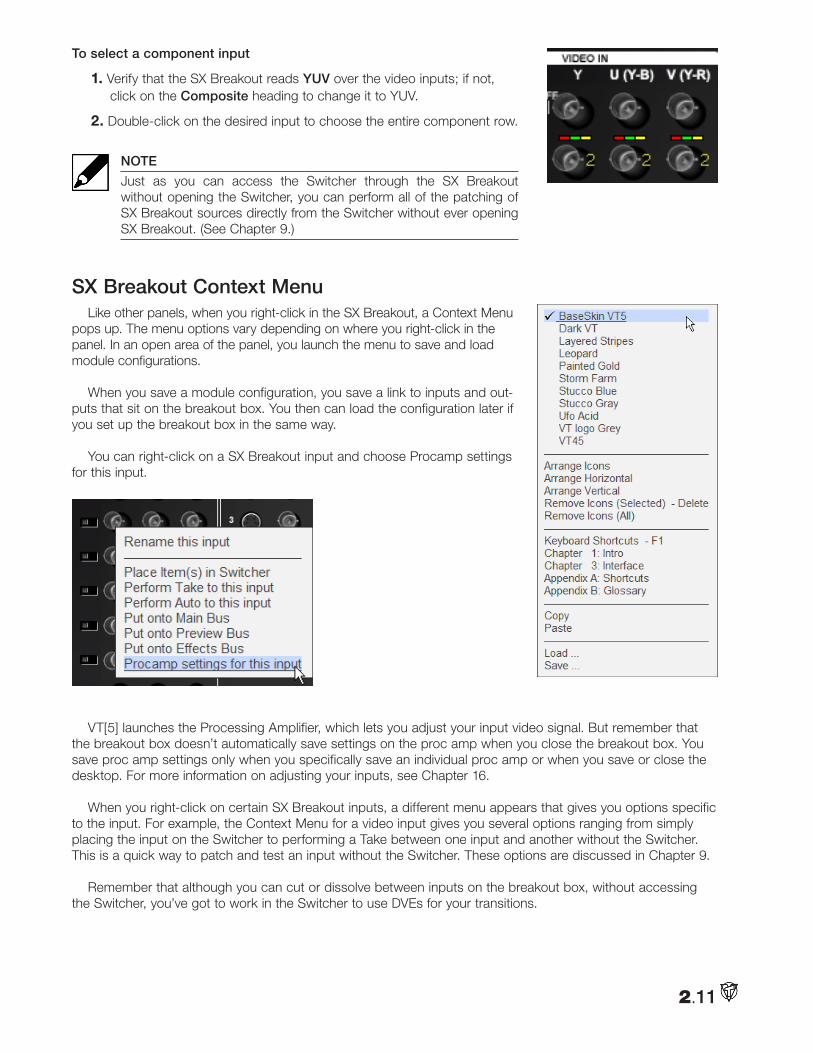
2.11
To select a component input
1. Verify that the SX Breakout reads YUV over the video inputs; if not, click on the Composite heading to change it to YUV.
2. Double-click on the desired input to choose the entire component row.
NOTE
Just as you can access the Switcher through the SX Breakout without opening the Switcher, you can perform all of the patching of SX Breakout sources directly from the Switcher without ever opening SX Breakout. (See Chapter 9.)
SX Breakout Context MenuLike other panels, when you right-click in the SX Breakout, a Context Menu
pops up. The menu options vary depending on where you right-click in the panel. In an open area of the panel, you launch the menu to save and load module configurations.
When you save a module configuration, you save a link to inputs and out-puts that sit on the breakout box. You then can load the configuration later if you set up the breakout box in the same way.
You can right-click on a SX Breakout input and choose Procamp settings for this input.
VT[5] launches the Processing Amplifier, which lets you adjust your input video signal. But remember that the breakout box doesn’t automatically save settings on the proc amp when you close the breakout box. You save proc amp settings only when you specifically save an individual proc amp or when you save or close the desktop. For more information on adjusting your inputs, see Chapter 16.
When you right-click on certain SX Breakout inputs, a different menu appears that gives you options specific to the input. For example, the Context Menu for a video input gives you several options ranging from simply placing the input on the Switcher to performing a Take between one input and another without the Switcher. This is a quick way to patch and test an input without the Switcher. These options are discussed in Chapter 9.
Remember that although you can cut or dissolve between inputs on the breakout box, without accessing the Switcher, you’ve got to work in the Switcher to use DVEs for your transitions.
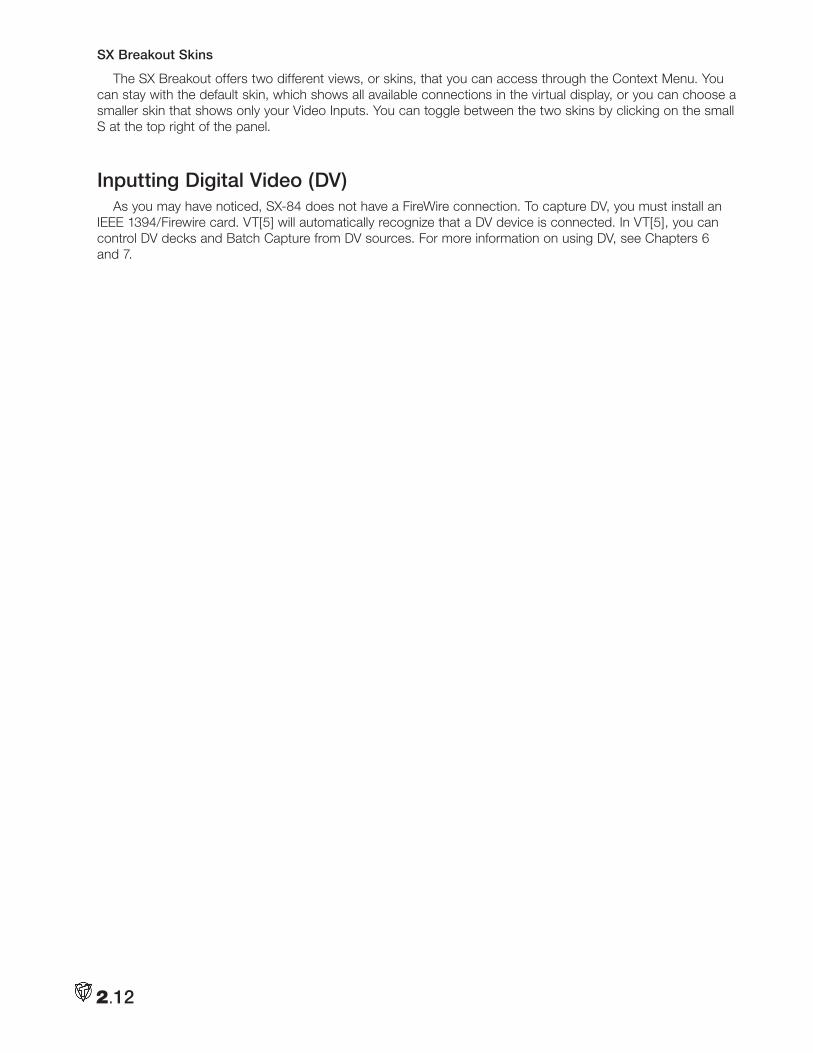
2.12
SX Breakout Skins
The SX Breakout offers two different views, or skins, that you can access through the Context Menu. You can stay with the default skin, which shows all available connections in the virtual display, or you can choose a smaller skin that shows only your Video Inputs. You can toggle between the two skins by clicking on the small S at the top right of the panel.
Inputting Digital Video (DV) As you may have noticed, SX-84 does not have a FireWire connection. To capture DV, you must install an
IEEE 1394/Firewire card. VT[5] will automatically recognize that a DV device is connected. In VT[5], you can control DV decks and Batch Capture from DV sources. For more information on using DV, see Chapters 6 and 7.
Now that you’ve set up your VT[5] card and installed the software, you’re ready to get acquainted with the VT[5] interface. If you are new to the neighborhood, stroll around introducing yourself to the many
available features.
VT[5] is organized into Modules, which usually are specific tools that have their own interfaces, called Panels. Some of the modules, like SpeedEDIT™, contain a huge amount of tools and their panels are multilay-ered. So, you may wish to start by exploring one of our simpler – though polychromatic – residents, the Color Picker (explained in Chapter 14). Before you skip ahead, this chapter will give you an overview of the VT[5] desktop and explain some of the global options available, which are commands or shortcuts that you can access in all of your VT[5] panels. Get to know these shortcuts, because they can simplify your workflow.
HINT
Though the manual provides plenty of reference images, you will find it useful to open up VT[5] and follow along.
Starting VT[5]
Start VT[5] by double-clicking the VT[5] icon on your Windows desktop. You also can browse to the VT[5] entry in the Start menu.
DesktopsVT[5] is organized around the familiar desktop concept, where you fill your screen with just the tools needed
for the task at hand. For example, if you are creating title pages for your video project, on your desktop, you would open CG Designer (CG), a Video Monitor, and perhaps the Switcher. Now, if you move on to editing your program, you would close the CG and the Switcher, leave the monitor, and open SpeedEDIT. Different desktops for different jobs.
If you are an inveterate multi-tasker, VT[5] makes it easy for you to jump from CG to SpeedEDIT to Batch Capture, since VT[5] supports multiple desktops. You can run several desktops at the same time. Before we talk about that later in this chapter, let’s begin with the basics.
Start with a Clear Desktop
Each time you open VT[5], it remembers your most recent configuration of panels. That is, panels you left onscreen when you last closed VT[5] will show up when you launch the program again. But, if you want a clear desktop, hold the Shift key down when you double-click on the VT[5] icon.
3.1
Chapter 3: VT[5] Interface
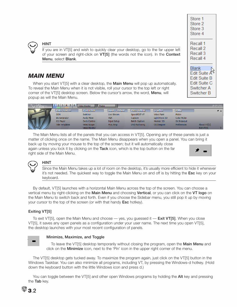
HINT
If you are in VT[5] and wish to quickly clear your desktop, go to the far upper left of your screen and right-click on VT[5] (the words not the icon). In the Context Menu, select Blank.
main menuWhen you start VT[5] with a clear desktop, the Main Menu will pop up automatically.
To reveal the Main Menu when it is not visible, roll your cursor to the top left or right corner of the VT[5] desktop screen. Below the cursor’s arrow, the word, Menu, will popup as will the Main Menu.
The Main Menu lists all of the panels that you can access in VT[5]. Opening any of these panels is just a matter of clicking once on the name. The Main Menu disappears when you open a panel. You can bring it back up by moving your mouse to the top of the screen; but it will automatically close again unless you lock it by clicking on the Tack icon, which is the top button on the far right side of the Main Menu.
HINT
Since the Main Menu takes up a lot of room on the desktop, it’s usually more efficient to hide it whenever it’s not needed. The quickest way to toggle the Main Menu on and off is by hitting the Esc key on your keyboard.
By default, VT[5] launches with a horizontal Main Menu across the top of the screen. You can choose a vertical menu by right-clicking on the Main Menu and choosing Vertical, or you can click on the VT logo on the Main Menu to switch back and forth. Even if you choose the Sidebar menu, you still pop it up by moving your cursor to the top of the screen (or with that handy Esc hotkey).
Exiting VT[5]
To exit VT[5], open the Main Menu and choose — yes, you guessed it — Exit VT[5]. When you close VT[5], it saves any open panels as a configuration under your user name. The next time you open VT[5], the desktop launches with your most recent configuration of panels.
Minimize, Maximize, and Toggle
To leave the VT[5] desktop temporarily without closing the program, open the Main Menu and click on the Minimize icon, next to the ‘Pin’ icon in the upper right corner of the menu.
The VT[5] desktop gets tucked away. To maximize the program again, just click on the VT[5] button in the Windows Taskbar. You can also minimize all programs, including VT, by pressing the Windows-d hotkey. (Hold down the keyboard button with the little Windows icon and press d.)
You can toggle between the VT[5] and other open Windows programs by holding the Alt key and pressing the Tab key.
3.2
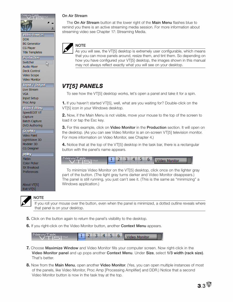
On Air Stream
The On Air Stream button at the lower right of the Main Menu flashes blue to remind you there is an active streaming media session. For more information about streaming video see Chapter 17: Streaming Media.
NOTE
As you will see, the VT[5] desktop is extremely user configurable, which means that you can move panels around, resize them, and tint them. So depending on how you have configured your VT[5] desktop, the images shown in this manual may not always reflect exactly what you will see on your desktop.
Vt[5] panelSTo see how the VT[5] desktop works, let’s open a panel and take it for a spin.
1. If you haven’t started VT[5], well, what are you waiting for? Double-click on the VT[5] icon in your Windows desktop.
2. Now, if the Main Menu is not visible, move your mouse to the top of the screen to load it or tap the Esc key.
3. For this example, click on Video Monitor in the Production section. It will open on the desktop. (As you can see Video Monitor is an on-screen VT[5] television monitor. For more information on Video Monitor, see Chapter 4.)
4. Notice that at the top of the VT[5] desktop in the task bar, there is a rectangular button with the panel’s name appears.
To minimize Video Monitor on the VT[5] desktop, click once on the lighter gray part of the button. (The light gray turns darker and Video Monitor disappears.) The panel is still running, you just can’t see it. (This is the same as “minimizing” a Windows application.)
NOTE
If you roll your mouse over the button, even when the panel is minimized, a dotted outline reveals where that panel is on your desktop.
5. Click on the button again to return the panel’s visibility to the desktop.
6. If you right-click on the Video Monitor button, another Context Menu appears.
7. Choose Maximize Window and Video Monitor fills your computer screen. Now right-click in the Video Monitor panel and up pops another Context Menu. Under Size, select 1/3 width (rack size). That’s better.
8. Now from the Main Menu, open another Video Monitor. (Yes, you can open multiple instances of most of the panels, like Video Monitor, Proc Amp [Processing Amplifier] and DDR.) Notice that a second Video Monitor button is now in the task tray at the top.
3.3
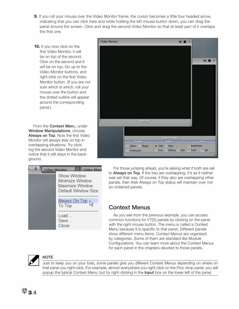
9. If you roll your mouse over the Video Monitor frame, the cursor becomes a little four headed arrow, indicating that you can click here and while holding the left mouse button down, you can drag the panel around the screen. Click and drag the second Video Monitor so that at least part of it overlaps the first one.
10. If you now click on the first Video Monitor, it will be on top of the second. Click on the second and it will be on top. Go up to the Video Monitor buttons, and right-click on the first Video Monitor button. (If you are not sure which is which, roll your mouse over the button and the dotted outline will appear around the corresponding panel.)
From the Context Menu, under Window Manipulations, choose Always on Top. Now the first Video Monitor will always stay on top in overlapping situations. Try click-ing the second Video Monitor and notice that it still stays in the back-ground.
For those jumping ahead, you’re asking what if both are set to Always on Top. If the two are overlapping, it’s as if neither was set that way. Of course, if they also are overlapping other panels, then their Always on Top status will maintain over not-so-ordained panels.
Context MenusAs you see from the previous example, you can access
common functions for VT[5] panels by clicking on the panel with the right mouse button. The menu is called a Context Menu because it is specific to that panel. Different panels show different menu items. Context Menus are organized by categories. Some of them are standard like Module Configurations. You can learn more about the Context Menus for each panel in the chapters devoted to those panels.
NOTE
Just to keep you on your toes, some panels give you different Context Menus depending on where on that panel you right-click. For example, almost everywhere you right-click on the Proc Amp panel, you will popup the typical Context Menu; but try right-clicking in the Input box on the lower left of the panel.
3.4
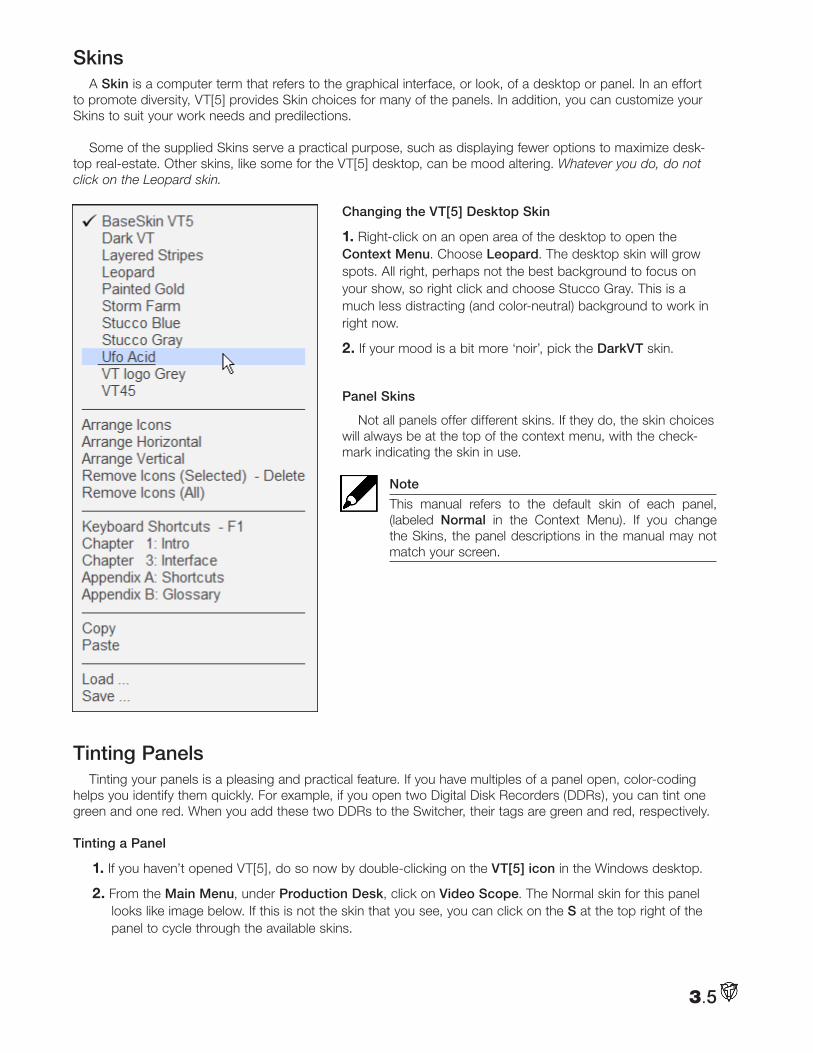
SkinsA Skin is a computer term that refers to the graphical interface, or look, of a desktop or panel. In an effort
to promote diversity, VT[5] provides Skin choices for many of the panels. In addition, you can customize your Skins to suit your work needs and predilections.
Some of the supplied Skins serve a practical purpose, such as displaying fewer options to maximize desk-top real-estate. Other skins, like some for the VT[5] desktop, can be mood altering. Whatever you do, do not click on the Leopard skin.
Changing the VT[5] Desktop Skin
1. Right-click on an open area of the desktop to open the Context Menu. Choose Leopard. The desktop skin will grow spots. All right, perhaps not the best background to focus on your show, so right click and choose Stucco Gray. This is a much less distracting (and color-neutral) background to work in right now.
2. If your mood is a bit more ‘noir’, pick the DarkVT skin.
Panel Skins
Not all panels offer different skins. If they do, the skin choices will always be at the top of the context menu, with the check-mark indicating the skin in use.
Note
This manual refers to the default skin of each panel, (labeled Normal in the Context Menu). If you change the Skins, the panel descriptions in the manual may not match your screen.
Tinting PanelsTinting your panels is a pleasing and practical feature. If you have multiples of a panel open, color-coding
helps you identify them quickly. For example, if you open two Digital Disk Recorders (DDRs), you can tint one green and one red. When you add these two DDRs to the Switcher, their tags are green and red, respectively.
Tinting a Panel
1. If you haven’t opened VT[5], do so now by double-clicking on the VT[5] icon in the Windows desktop.
2. From the Main Menu, under Production Desk, click on Video Scope. The Normal skin for this panel looks like image below. If this is not the skin that you see, you can click on the S at the top right of the panel to cycle through the available skins.
3.5
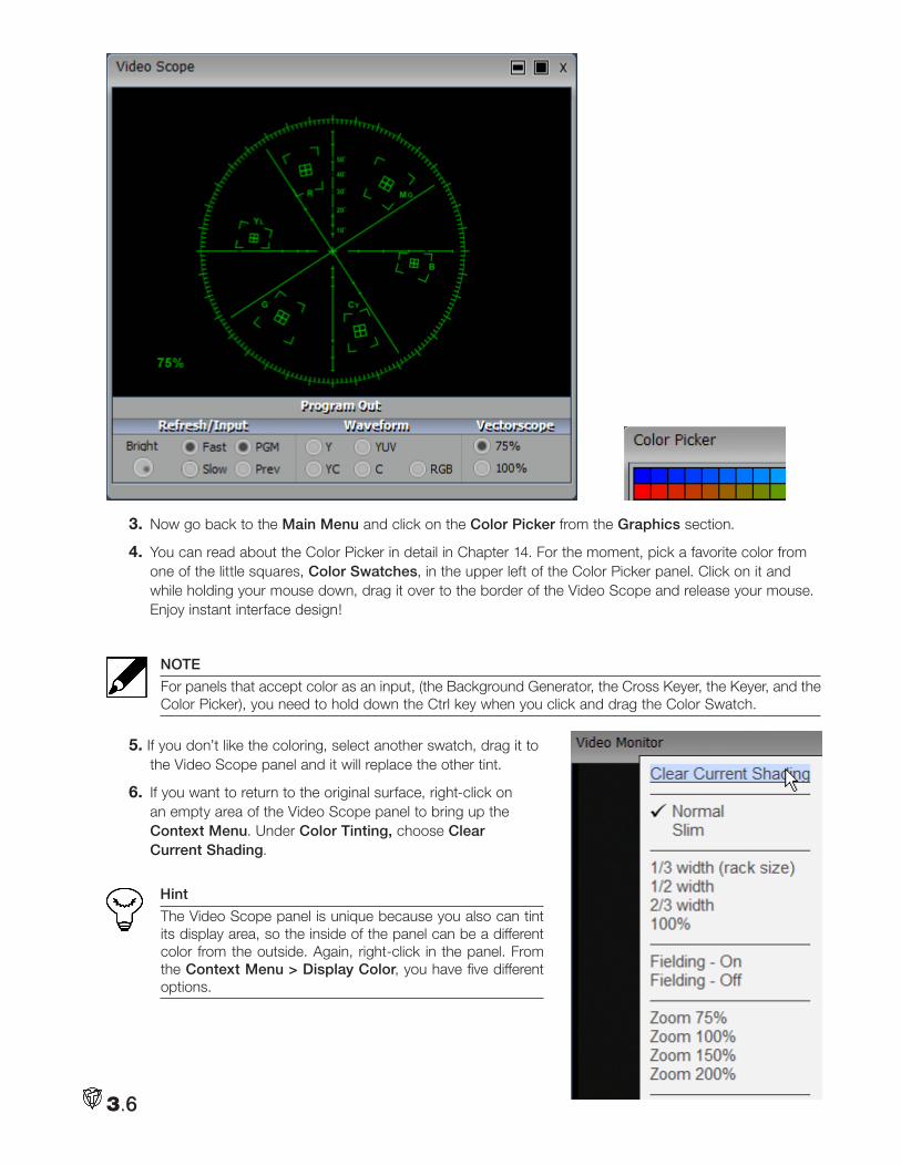
3. Now go back to the Main Menu and click on the Color Picker from the Graphics section.
4. You can read about the Color Picker in detail in Chapter 14. For the moment, pick a favorite color from one of the little squares, Color Swatches, in the upper left of the Color Picker panel. Click on it and while holding your mouse down, drag it over to the border of the Video Scope and release your mouse. Enjoy instant interface design!
NOTE
For panels that accept color as an input, (the Background Generator, the Cross Keyer, the Keyer, and the Color Picker), you need to hold down the Ctrl key when you click and drag the Color Swatch.
5. If you don’t like the coloring, select another swatch, drag it to the Video Scope panel and it will replace the other tint.
6. If you want to return to the original surface, right-click on an empty area of the Video Scope panel to bring up the Context Menu. Under Color Tinting, choose Clear Current Shading.
Hint
The Video Scope panel is unique because you also can tint its display area, so the inside of the panel can be a different color from the outside. Again, right-click in the panel. From the Context Menu > Display Color, you have five different options.
3.6
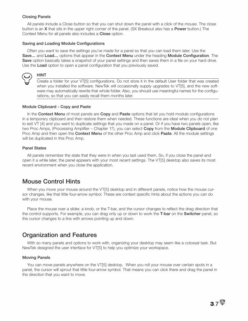
Closing Panels
All panels include a Close button so that you can shut down the panel with a click of the mouse. The close button is an X that sits in the upper right corner of the panel. (SX Breakout also has a Power button.) The Context Menu for all panels also includes a Close option.
Saving and Loading Module Configurations
Often you want to save the settings you’ve made for a panel so that you can load them later. Use the Save… and Load… options that appear in the Context Menu under the heading Module Configuration. The Save option basically takes a snapshot of your panel settings and then saves them in a file on your hard drive. Use the Load option to open a panel configuration that you previously saved.
HINT
Create a folder for your VT[5] configurations. Do not store it in the default User folder that was created when you installed the software. NewTek will occasionally supply upgrades to VT[5], and the new soft-ware may automatically rewrite that whole folder. Also, you should use meaningful names for the configu-rations, so that you can easily recall them months later.
Module Clipboard - Copy and Paste
In the Context Menu of most panels are Copy and Paste options that let you hold module configurations in a temporary clipboard and then restore them when needed. These functions are ideal when you do not plan to exit VT [4] and you want to duplicate settings that you made on a panel. Or if you have two panels open, like two Proc Amps, (Processing Amplifier – Chapter 17), you can select Copy from the Module Clipboard of one Proc Amp and then open the Context Menu of the other Proc Amp and click Paste. All the module settings will be duplicated in this Proc Amp.
Panel States
All panels remember the state that they were in when you last used them. So, if you close the panel and open it a while later, the panel appears with your most recent settings. The VT[5] desktop also saves its most recent environment when you close the application.
Mouse Control HintsWhen you move your mouse around the VT[5] desktop and in different panels, notice how the mouse cur-
sor changes, like that little four-arrow symbol. These are context specific hints about the actions you can do with your mouse.
Place the mouse over a slider, a knob, or the T-bar, and the cursor changes to reflect the drag direction that the control supports. For example, you can drag only up or down to work the T-bar on the Switcher panel, so the cursor changes to a line with arrows pointing up and down.
Organization and FeaturesWith so many panels and options to work with, organizing your desktop may seem like a colossal task. But
NewTek designed the user interface for VT[5] to help you optimize your workspace.
Moving Panels
You can move panels anywhere on the VT[5] desktop. When you roll your mouse over certain spots in a panel, the cursor will sprout that little four-arrow symbol. That means you can click there and drag the panel in the direction that you want to move.
3.7
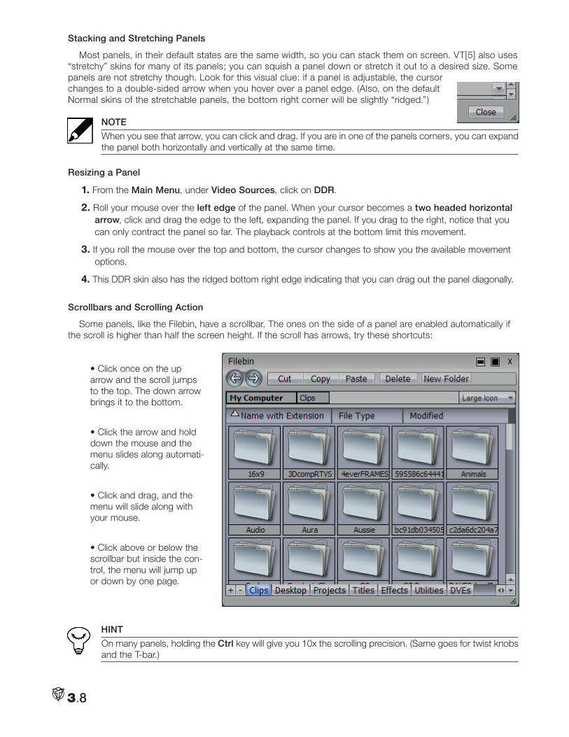
Stacking and Stretching Panels
Most panels, in their default states are the same width, so you can stack them on screen. VT[5] also uses “stretchy” skins for many of its panels; you can squish a panel down or stretch it out to a desired size. Some panels are not stretchy though. Look for this visual clue: if a panel is adjustable, the cursor changes to a double-sided arrow when you hover over a panel edge. (Also, on the default Normal skins of the stretchable panels, the bottom right corner will be slightly “ridged.”)
NOTE
When you see that arrow, you can click and drag. If you are in one of the panels corners, you can expand the panel both horizontally and vertically at the same time.
Resizing a Panel
1. From the Main Menu, under Video Sources, click on DDR.
2. Roll your mouse over the left edge of the panel. When your cursor becomes a two headed horizontal arrow, click and drag the edge to the left, expanding the panel. If you drag to the right, notice that you can only contract the panel so far. The playback controls at the bottom limit this movement.
3. If you roll the mouse over the top and bottom, the cursor changes to show you the available movement options.
4. This DDR skin also has the ridged bottom right edge indicating that you can drag out the panel diagonally.
Scrollbars and Scrolling Action
Some panels, like the Filebin, have a scrollbar. The ones on the side of a panel are enabled automatically if the scroll is higher than half the screen height. If the scroll has arrows, try these shortcuts:
• Click once on the up arrow and the scroll jumps to the top. The down arrow brings it to the bottom.
• Click the arrow and hold down the mouse and the menu slides along automati-cally.
• Click and drag, and the menu will slide along with your mouse.
• Click above or below the scrollbar but inside the con-trol, the menu will jump up or down by one page.
HINT
On many panels, holding the Ctrl key will give you 10x the scrolling precision. (Same goes for twist knobs and the T-bar.)
3.8
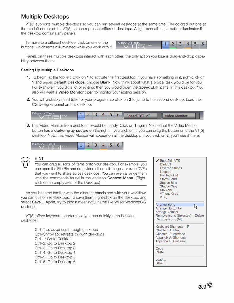
Multiple DesktopsVT[5] supports multiple desktops so you can run several desktops at the same time. The colored buttons at
the top left corner of the VT[5] screen represent different desktops. A light beneath each button illuminates if the desktop contains any panels.
To move to a different desktop, click on one of the buttons, which remain illuminated while you work with it.
Panels on these multiple desktops interact with each other; the only action you lose is drag-and-drop capa-bility between them.
Setting Up Multiple Desktops
1. To begin, at the top left, click on 1 to activate the first desktop. If you have something in it, right-click on 1 and under Default Desktops, choose Blank. Now think about what a typical task would be for you. For example, if you do a lot of editing, then you would open the SpeedEDIT panel in this desktop. You also will want a Video Monitor open to monitor your editing session.
2. You will probably need titles for your program, so click on 2 to jump to the second desktop. Load the CG Designer panel on this desktop.
3. That Video Monitor from desktop 1 would be handy. Click on 1 again. Notice that the Video Monitor button has a darker gray square on the right. If you click on it, you can drag the button onto the VT[5] desktop. Now, that Video Monitor will appear on all the desktops. If you click on 2, you’ll see it there.
HINT
You can drag all sorts of items onto your desktop. For example, you can open the File Bin and drag video clips, still images, or even DVEs that you want to share across desktops. You can even arrange them with the commands found in the desktop Context Menu. (Right-click on an empty area of the Desktop.)
As you become familiar with the different panels and with your workflow, you can customize desktops. To save them, right-click on the desktop, and select Save… Again, try to pick a meaningful name like WilsonWeddingCG desktop.
VT[5] offers keyboard shortcuts so you can quickly jump between desktops:
Ctrl+Tab: advances through desktops Ctrl+Shift+Tab: retreats through desktops Ctrl+1: Go to Desktop 1 Ctrl+2: Go to Desktop 2 Ctrl+3: Go to Desktop 3 Ctrl+4: Go to Desktop 4 Ctrl+5: Go to Desktop 5 Ctrl+6: Go to Desktop 6
3.9
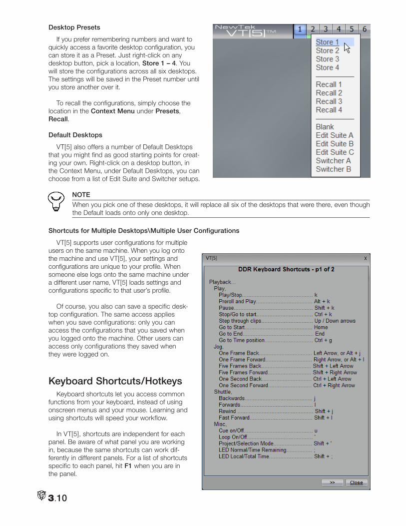
Desktop Presets
If you prefer remembering numbers and want to quickly access a favorite desktop configuration, you can store it as a Preset. Just right-click on any desktop button, pick a location, Store 1 – 4. You will store the configurations across all six desktops. The settings will be saved in the Preset number until you store another over it.
To recall the configurations, simply choose the location in the Context Menu under Presets, Recall.
Default Desktops
VT[5] also offers a number of Default Desktops that you might find as good starting points for creat-ing your own. Right-click on a desktop button, in the Context Menu, under Default Desktops, you can choose from a list of Edit Suite and Switcher setups.
NOTE
When you pick one of these desktops, it will replace all six of the desktops that were there, even though the Default loads onto only one desktop.
Shortcuts for Multiple Desktops\Multiple User Configurations
VT[5] supports user configurations for multiple users on the same machine. When you log onto the machine and use VT[5], your settings and configurations are unique to your profile. When someone else logs onto the same machine under a different user name, VT[5] loads settings and configurations specific to that user’s profile.
Of course, you also can save a specific desk-top configuration. The same access applies when you save configurations: only you can access the configurations that you saved when you logged onto the machine. Other users can access only configurations they saved when they were logged on.
Keyboard Shortcuts/HotkeysKeyboard shortcuts let you access common
functions from your keyboard, instead of using onscreen menus and your mouse. Learning and using shortcuts will speed your workflow.
In VT[5], shortcuts are independent for each panel. Be aware of what panel you are working in, because the same shortcuts can work dif-ferently in different panels. For a list of shortcuts specific to each panel, hit F1 when you are in the panel.
3.10
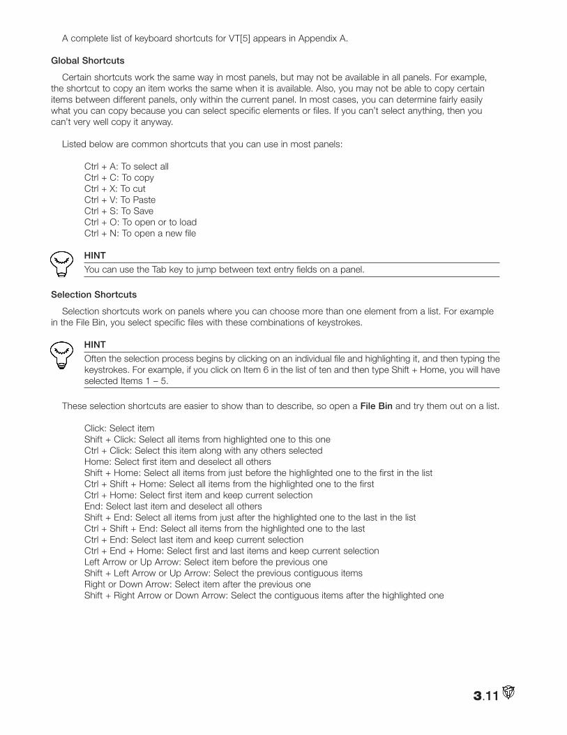
A complete list of keyboard shortcuts for VT[5] appears in Appendix A.
Global Shortcuts
Certain shortcuts work the same way in most panels, but may not be available in all panels. For example, the shortcut to copy an item works the same when it is available. Also, you may not be able to copy certain items between different panels, only within the current panel. In most cases, you can determine fairly easily what you can copy because you can select specific elements or files. If you can’t select anything, then you can’t very well copy it anyway.
Listed below are common shortcuts that you can use in most panels:
Ctrl + A: To select all Ctrl + C: To copy Ctrl + X: To cut Ctrl + V: To Paste Ctrl + S: To Save Ctrl + O: To open or to load Ctrl + N: To open a new file
HINT
You can use the Tab key to jump between text entry fields on a panel.
Selection Shortcuts
Selection shortcuts work on panels where you can choose more than one element from a list. For example in the File Bin, you select specific files with these combinations of keystrokes.
HINT
Often the selection process begins by clicking on an individual file and highlighting it, and then typing the keystrokes. For example, if you click on Item 6 in the list of ten and then type Shift + Home, you will have selected Items 1 – 5.
These selection shortcuts are easier to show than to describe, so open a File Bin and try them out on a list.
Click: Select item Shift + Click: Select all items from highlighted one to this one Ctrl + Click: Select this item along with any others selected Home: Select first item and deselect all others Shift + Home: Select all items from just before the highlighted one to the first in the list Ctrl + Shift + Home: Select all items from the highlighted one to the first Ctrl + Home: Select first item and keep current selection End: Select last item and deselect all others Shift + End: Select all items from just after the highlighted one to the last in the list Ctrl + Shift + End: Select all items from the highlighted one to the last Ctrl + End: Select last item and keep current selection Ctrl + End + Home: Select first and last items and keep current selection Left Arrow or Up Arrow: Select item before the previous one Shift + Left Arrow or Up Arrow: Select the previous contiguous items Right or Down Arrow: Select item after the previous one Shift + Right Arrow or Down Arrow: Select the contiguous items after the highlighted one
3.11
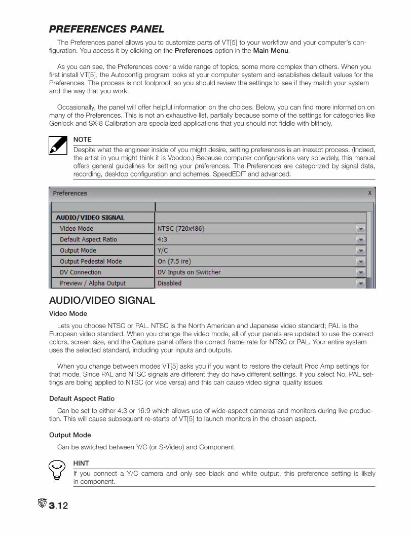
pRefeRenceS panelThe Preferences panel allows you to customize parts of VT[5] to your workflow and your computer’s con-
figuration. You access it by clicking on the Preferences option in the Main Menu.
As you can see, the Preferences cover a wide range of topics, some more complex than others. When you first install VT[5], the Autoconfig program looks at your computer system and establishes default values for the Preferences. The process is not foolproof, so you should review the settings to see if they match your system and the way that you work.
Occasionally, the panel will offer helpful information on the choices. Below, you can find more information on many of the Preferences. This is not an exhaustive list, partially because some of the settings for categories like Genlock and SX-8 Calibration are specialized applications that you should not fiddle with blithely.
NOTE
Despite what the engineer inside of you might desire, setting preferences is an inexact process. (Indeed, the artist in you might think it is Voodoo.) Because computer configurations vary so widely, this manual offers general guidelines for setting your preferences. The Preferences are categorized by signal data, recording, desktop configuration and schemes, SpeedEDIT and advanced.
AUDIO/VIDEO SIGNALVideo Mode
Lets you choose NTSC or PAL. NTSC is the North American and Japanese video standard; PAL is the European video standard. When you change the video mode, all of your panels are updated to use the correct colors, screen size, and the Capture panel offers the correct frame rate for NTSC or PAL. Your entire system uses the selected standard, including your inputs and outputs.
When you change between modes VT[5] asks you if you want to restore the default Proc Amp settings for that mode. Since PAL and NTSC signals are different they do have different settings. If you select No, PAL set-tings are being applied to NTSC (or vice versa) and this can cause video signal quality issues.
Default Aspect Ratio
Can be set to either 4:3 or 16:9 which allows use of wide-aspect cameras and monitors during live produc-tion. This will cause subsequent re-starts of VT[5] to launch monitors in the chosen aspect.
Output Mode
Can be switched between Y/C (or S-Video) and Component.
HINT
If you connect a Y/C camera and only see black and white output, this preference setting is likely in component.
3.12
Output Pedestal Mode
A setting used for Japanese NTSC television systems. If you record for U.S. broadcast, choose On (USA NTSC). If you record for Japanese broadcast, choose Off (Japanese NTSC).
The pedestal is a small DC voltage step within the video signal used to separate the black level from the blanking level, which is the reference for white and gray levels (i.e., luminance). With Japanese NTSC, the black and blanking levels are equal (IRE = 0). Black level on NTSC is set at 7.5 IRE, and 0 IRE is commonly referred to as super-black.
DV Connection
Since most computers lack the processing power to simultaneously input and output, this preference gives the flexibility on how IEEE 1394 inputs are routed in or out of VT[5]. The default, DV inputs on Switcher, allow those cameras to be input for video mixing. There are also options to output DV from the Main, Preview or Program Out.
HINT
Setting this to Main will provide a ‘clean’ feed, sans titles or keys, and setting to Preview allows for a DV-capable monitor to be used as a dedicated preview monitor.
Preview / Alpha Output
Disabled by default, this setting determines whether the SX-84 Preview connector displays full-frame video or transparency used in Alpha channel.
WindowsMedia playback
This determines whether Windows’ Media Player will play on the computer screen, or is instead mapped to the VT card for playback.
Windows Audio Inputs
This determines whether the computer system sounds are mapped from VT Output or Input.
SDI Card Installed
These settings determine whether the Serial Digital Interface daughtercard is installed, and if so, how the inputs routed to which SX-SDI outputs.
Audio Mixer Mono Dip
Once a stereo source is assigned as mono, placing the audio balance to center causes a slight dip in audio levels. This setting allows you to change behavior from No Dip to -12 decibels (dB).
Audio Mixer Front/Back Dip
This determines how audio levels behave when fading between the front and back stereo inputs.
RECORDING
Default DV Download Format
This can be set for either Type 2 DV, which uses PCM Audio, or Type 1, which uses DV Audio. Unless there is a specific need, stick with the Type 2 default.
Minimize PCI usage while recording
This exists for under-powered computers, and places black on unused inputs, keeping PCI bandwidth to a minimum during the recording.
3.13
Record Write Errors
If VT[5] drops frames during recording, this pops up a dialog alerting you. If you are recording a live show, however, you may not want to be interrupted by these notices, and can disable this setting.
Record File Errors
This setting will alert you if there are problems when copying large files, and should remain active.
SWITCHERAuto-Select inputs when switcher is not open
This preference will assign an active input to program out . So, if you launch SpeedEDIT, then that becomes the signal output. If you launch a DDR, it too would be the active output without having to open the switcher. New modules
Can be placed on the switcher’s first available preview row or not, based on this setting.
Switcher surface connected
Can be disabled, if you are not lucky enough to own an RS-8 switcher surface.If an RS-8 is connected, set this to Automatically detect RS-8.
DDR Resource Usage
Controls how much processor power you dedicate to playing back files in the Digital Disk Recorder. Simple files that use cuts-only video work well on Low resource usage. Files with only a few dissolves or other transi-tions display best on Medium resource usage. Complicated SpeedEDIT projects with a lot of special effects that are placed into a DDR work best on High resource usage. Remember, if you use more resources for the DDR, then your processor works harder, and other areas of VT[5] may slow down.
DDR Defielding when stopped
This preference determines whether to display both fields or just one field when a DDR is paused or stopped. Defielding ON presents a static image without jittering, which can occur if you stop on a frame with high motion. This only affects the Video Monitor display on-screen.
FILESMissing files search path
If you move video project files, SpeedEDIT doesn’t know where they are. This setting can be used to point to the new location of these files.
File Management, Confirm Deletion of Files
Determines whether a deleted file is sent to the Windows Recycle bin, or sent to never-never land. While deleted files CAN be recovered, it requires third-party software not supplied with VT[5]. It is recommended you choose either Confirm or Recycle.
File Naming
Gives you naming and numbering options for the files you create when you capture and save. You can choose a standard that starts numbering from 1 or 0 and you can choose a standard that uses between one to three digits.
3.14
Normally you want to choose a naming convention that starts with zero, which will guarantee that Windows will correctly order your clips in a sequence. Also, you should have some idea of how many clips you’ll use so that you can correctly choose the number of digits, again so that Windows puts your clips in the correct sequence.
Use Preview Generation
Lets you choose whether to dedicate CPU resources to creating previews of transitions and special effects that you can see in realtime. Choose Do not use preview generation if your system has trouble creating transitions and effects in realtime; the system will render any special effects. If you have a corrupt file (like an AVI or WMV) in a folder, then generating its preview may cause a problem. Changing to Do not use preview generation, will allow you to browse that folder correctly.
Rollover Previews for SpeedEDIT Projects
When enabled, this allows you to view a thumbnail playback of an edited project when the mouse is posi-tioned over an edit project icon. This is disabled by default because loading a SpeedEDIT project so that it can be previewed can take a lot of time or memory, especially for large projects.
Rollover Animated Previews
This is a useful tool in file bins, where holding the mouse over a video clip plays the thumbnail itself. This is beneficial to faster file selection, but may need to be turned off using an under-powered system.
DESKTOPDesktop Monitor
This setting provides control over how many computer monitors will be spanned by VT[5]. Span all moni-tors, the default, will stretch the desktop across 2 or more monitors. You may wish to leave one monitor free of the VT[5] display to keep other applications visible. The options for VGA Output denote the screen to be sent to the projector or full-screen monitor.
MenuBar pops up
This determines how to make the VT[5] menu appear (besides tapping the Esc key). When mouse is over hot-spots will reveal the menu every time your mouse goes to the upper right or left corners of the VT[5] desktop. If you find this is covering modules you were heading for, you can change the preference to When you click on the hot-spots. Now, placing your cursor in the upper corners of the screen will instead display a MENU tool-tip beneath the cursor, at which point a left-click will bring the menu bar into view.
Module Autosave
This will save the current state of all modules at the specified intervals.
Interface controls
Now available in VT[5] is the ability to change the look of your suite by adjusting Brightness, Contrast, Gamma, Lightness and Tint.
SpeedEDITSpeedEDIT Cache path
This is the location that will be used to store background renders and temporary files while editing. Consider setting up a Cache folder on your fastest video drive for this. It is not recommended to use the System C: par-tition, as these files can be rather large, especially if editing Hi Definition projects.
BG Rendering Profile
These two profiles help decide at what point background rendering takes effect to generate smooth play-back. If SpeedEDIT projects do not play smoothly, you should lower the render threshold.
3.15
Track Clip Jumps to
When used in conjunction with the Track Clip checkbox in SpeedEDIT VT, this will cause the edit line to jump to the beginning, middle or end of a selected clip.
HINT
Should you mysteriously find the edit line jumping to the timeline wherever you click, this function has been activated, most likely by pressing its keyboard shortcut of ‘u’.
Default Still Length
Sets the duration of a still image in SpeedEDIT and the DDR. This length is automatically applied to any graphic that you load. You can set the still image to hold for as little as one frame or as much as 30 seconds; the default length is five seconds. You always can manually adjust the still length in the DDR or SpeedEDIT.
Default Transition/DVE Length
Sets the transition length when its added to SpeedEDIT or a DDR playlist. The default setting is one second.
Maximum number of Undos
Affects how many distinct steps are saved while editing. Every action in SpeedEDIT is noted and saved in an undo stack. Setting a lower amount of Undos saves a small amount of hard drive space since Undo stacks are merely text pointers, and are not very large. Unless you never make a mistake, it is probably prudent to set your Undos to at least 100.
SpeedEDIT Extend In/Out edit points
If you choose Support extension of clip’s boundaries, then you can extend an in or Out point beyond the beginning or end of the clip. SpeedEDIT will freeze the first or last frame to cover the overage.
SpeedEDIT In/Out point display style
Lets you set where In and Out points are based when you use transitions. Center places the In and Out points at the center of the transition, Outside sets them on the outside edge of the transition, and inside sets them on the inside edge. This setting is irrelevant to croutons without transitions; In and Out points are placed at the edge of the clip.
Motion Removal When Jogging
Will remove interlace and give you a 100 percent still image when you scrub in the DDR or SpeedEDIT. If you Disable this option, you will see a fielded preview of all images when scrubbing and jogging.
Preview Rendering on Output
Sends each frame to the hardware output, but requires more PCI bandwidth.
Render Panel auto-close when finished
Shuts down the render panel after the last frame is rendered to its chosen path.
Use captured timecode by default
Will use the distinct timecode from the source tape, instead of beginning with a first frame of 00.00.00.00 for each clip.
SpeedEDIT Automatic In/Out Offset
Lets you adjust the clip padding inside the first and last frames. The default is one second. This allows you to use transitions between clips outside your chosen in and out points. If you have a 1-second fade between two clips, it will use 15 frames after the clip’s out point and 15 before the next clip’s in point.
3.16
SpeedEDIT Audio Only Auto-In/Out Offset
This setting applies to Audio and works like the one above.
SpeedEDIT Extend In/Out edit points
If you choose Support extension of clip’s boundaries, then you can extend an in or Out point beyond the beginning or end of the clip. SpeedEDIT will freeze the first or last frame to cover the overage.
SpeedEDIT In/Out point display style
Lets you set where In and Out points are based when you use transitions. Center places the In and Out points at the center of the transition, Outside sets them on the outside edge of the transition, and inside sets them on the inside edge. This setting is irrelevant to croutons without transitions; In and Out points are placed at the edge of the clip.
SpeedEDIT project start mode
Lets you choose where SpeedEDIT projects begin: at the first clip, at zero, or at whichever comes first.
SpeedEDIT Save Undo Buffer
When you save a SpeedEDIT project, you have the choice of saving the Undo Buffer that accompanies the project. Pick Yes and VT[5] will save the buffer without asking. No will not save the buffer. Ask will do just that when you save the project.
SpeedEDIT Storyboard A/B Track Editing
Lets you choose between Single Track-row Editing and A/B track editing. The Single track-row places all clips on one track when possible, one after another, while A/B track alternates clips between tracks.
SpeedEDIT StoryBoard, Auto-Perform Razor Delete
This determines the rule to be applied to clips deleted in Storyboard that are nested in the middle of a lon-ger clip. In the timeline, this can be obvious, but the storyboard would need to show this cut-away by showing the longer Clip A, Clip B and then the end of Clip A as three icons. When deleted, it will ask if you wish to razor that longer clip in the timeline.
SpeedEDIT Storyboard Insertion Mode
Controls how you work with croutons in the SpeedEDIT Storyboard. Choose Insertion if you want to drag-and-drop croutons. Choose Non-Insertion to disable drag-and-drop capability. When you choose Non-Insertion, you can move croutons in the storyboard only by selecting the crouton and then using the Cut, Copy, and Paste buttons.
Rollover Animated Previews
Lets you choose whether the icons animate when you move the mouse over them in the Filebin. If you disable this feature, you conserve some system resources.
Video Output Window Quality
This only affects the on-screen monitor, and allows you to have a precise display, using a newer graphics card, or can be downgraded to medium or low quality which is less processor intensive.
Direct3D Filtering
This determines the scaling method used for the on-screen Video Monitor.
Detect Dropped frames for Send to DV Tape
If set to the default of True, will alert you with a dialog box if any frames were dropped while transferring your SpeedEDIT project back to tape.
3.17
Advanced
Clamp output to legal colors
This setting addresses the difference in color ranges between computer and video sources. Do not force legal keeps images at their original levels, while Force legal will adjust the darkest and brightest colors to video allowances.
Clamp alpha output levels
This ensures that any source used for transparency remains within the gamut of video. While computer images can have a value of 0 to 256, video must reside within an RGB value of 16 to 235. The default is Enabled.
IEEE1394 Color Format
This option determines whether DV clips follow the “601 spec”. This can be changed if you notice black lev-els in the video are too dark.
Alpha Output Delay is used to adjust the phase of the SX-84 alpha transparency on the Key out.
Genlock
Numerous settings in the Advanced section are for aligning the VT[5] sync with an existing house sync, coming in on the SX-84 Genlock In. VT[5] internally generates sync, so this is not used unless your suite con-nects to multiple genlocked devices.
DirectShow AC3/AAC Support
This needs to be enabled if you are using audio plug-ins for AC3 surround-sound or AAC
file foRmatSVT[5] fully supports AVI format, including alpha channels, which is the video recording standard for
Windows. As the native format, AVI is great for compatibility with third-party applications and plug-ins. SpeedEDIT allows saving of entire projects as “wrapped” AVI files, negating any need to render a project to create a contiguous file. While AVI is available in both uncompressed and several different versions of com-pressed, the best performance is realized when capturing and editing in uncompressed. The NewTek RTV uncompressed format is still available.
Note
The AVI format in VT[5] is not limited to a 2GB file size.
VT[5] also supports video file formats playable in Windows Media Player. The following list identifies some of the most common compatible audio and video formats:
3.18
• RTV• AVI• DV
You can also load the following still image formats:
• MPEG-1• MPEG-2• M2t
• M2p• MOV* • WAV
• MP3 • AU• SND
• M3U• AIF• AIFC
• AIFF• WAX• WMA
• MPG• MPE
• MPV• M1V
*though not all QuickTime versions
• TGA• JPEG
• BMP• GIF
• IFF• TIF (not all varieties)
• PNG• PCX
• LBM• ILBM
• PGM• PPM
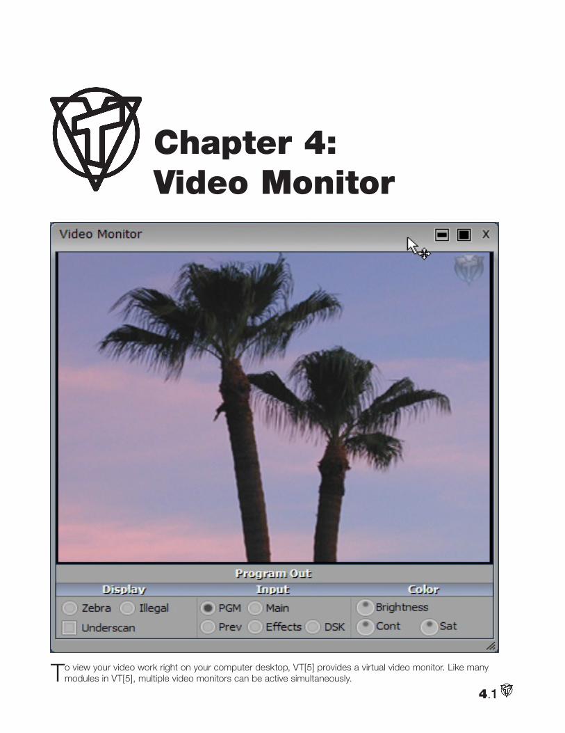
To view your video work right on your computer desktop, VT[5] provides a virtual video monitor. Like many modules in VT[5], multiple video monitors can be active simultaneously.
4.1
Chapter 4: Video Monitor
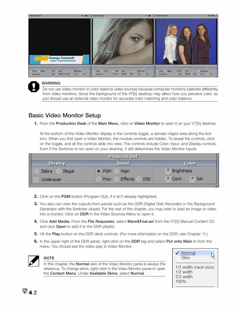
WARNING
Do not use Video monitor to color balance video sources because computer monitors calibrate differently from video monitors. Since the background of the VT[5] desktop may affect how you perceive color, so you should use an external video monitor for accurate color matching and color balance.
Basic Video Monitor Setup1. From the Production Desk of the Main Menu, click on Video Monitor to open it on your VT[5] desktop.
At the bottom of the Video Monitor display is the controls toggle, a slender ridged area along the bot-tom. When you first open a Video Monitor, the module controls are hidden. To reveal the controls, click on the toggle, and all the controls slide into view. The controls include Color, Input, and Display controls. Even if the Switcher is not open on your desktop, it still determines the Video Monitor inputs.
2. Click on the PGM button (Program Out), if it isn’t already highlighted.
3. You also can view the outputs from panels such as the DDR (Digital Disk Recorder) or the Background Generator with the Switcher closed. For the rest of the chapter, you may wish to load an image or video into a monitor. Click on DDR in the Video Sources Menu to open it.
4. Click Add Media. From the File Requester, select Mare&Foal.avi from the VT[5] Manual Content CD and click Open to add it to the DDR playlist.
5. Hit the Play button on the DDR deck controls. (For more information on the DDR, see Chapter 11.)
6. In the upper right of the DDR panel, right-click on the DDR tag and select Put onto Main In from the menu. You should see the video play in Video Monitor.
NOTE
In this chapter, the Normal skin of the Video Monitor panel is always the reference. To change skins, right-click in the Video Monitor panel to open the Context Menu. Under Available Skins, select Normal.
4.2
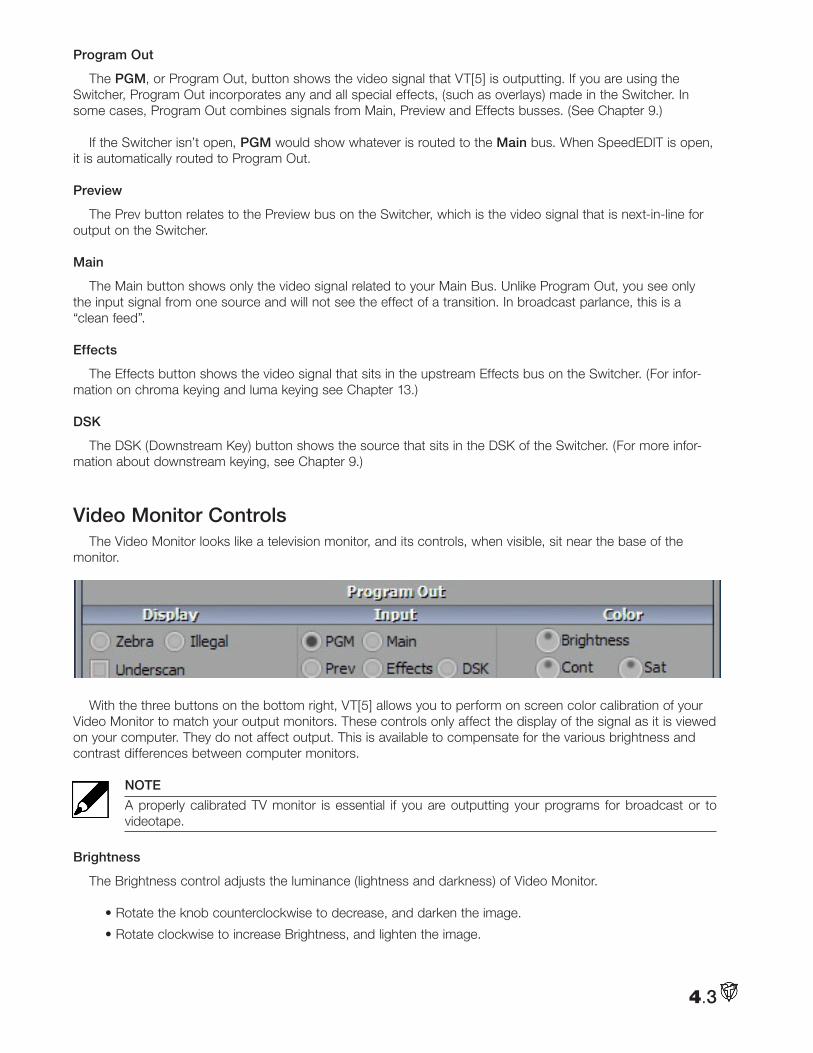
Program Out
The PGM, or Program Out, button shows the video signal that VT[5] is outputting. If you are using the Switcher, Program Out incorporates any and all special effects, (such as overlays) made in the Switcher. In some cases, Program Out combines signals from Main, Preview and Effects busses. (See Chapter 9.)
If the Switcher isn’t open, PGM would show whatever is routed to the Main bus. When SpeedEDIT is open, it is automatically routed to Program Out.
Preview
The Prev button relates to the Preview bus on the Switcher, which is the video signal that is next-in-line for output on the Switcher.
Main
The Main button shows only the video signal related to your Main Bus. Unlike Program Out, you see only the input signal from one source and will not see the effect of a transition. In broadcast parlance, this is a “clean feed”.
Effects
The Effects button shows the video signal that sits in the upstream Effects bus on the Switcher. (For infor-mation on chroma keying and luma keying see Chapter 13.)
DSK
The DSK (Downstream Key) button shows the source that sits in the DSK of the Switcher. (For more infor-mation about downstream keying, see Chapter 9.)
Video Monitor ControlsThe Video Monitor looks like a television monitor, and its controls, when visible, sit near the base of the
monitor.
With the three buttons on the bottom right, VT[5] allows you to perform on screen color calibration of your Video Monitor to match your output monitors. These controls only affect the display of the signal as it is viewed on your computer. They do not affect output. This is available to compensate for the various brightness and contrast differences between computer monitors.
NOTE
A properly calibrated TV monitor is essential if you are outputting your programs for broadcast or to videotape.
Brightness
The Brightness control adjusts the luminance (lightness and darkness) of Video Monitor.
• Rotate the knob counterclockwise to decrease, and darken the image.
• Rotate clockwise to increase Brightness, and lighten the image.
4.3
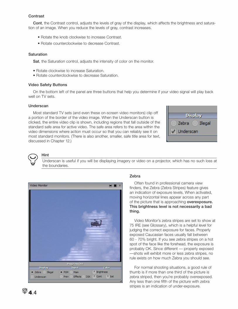
Contrast
Cont, the Contrast control, adjusts the levels of gray of the display, which affects the brightness and satura-tion of an image. When you reduce the levels of gray, contrast increases.
• Rotate the knob clockwise to increase Contrast.
• Rotate counterclockwise to decrease Contrast.
Saturation
Sat, the Saturation control, adjusts the intensity of color on the monitor.
• Rotate clockwise to increase Saturation.• Rotate counterclockwise to decrease Saturation.
Video Safety Buttons
On the bottom left of the panel are three buttons that help you determine if your video signal will play back well on TV sets.
Underscan
Most standard TV sets (and even these on-screen video monitors) clip off a portion of the border of the video image. When the Underscan button is clicked, the entire video clip is shown, including regions that fall outside of the standard safe area for active video. The safe area refers to the area within the video dimensions where action must occur so that you can reliably see it on most standard monitors. (There is also another, smaller, safe title area for text, discussed in Chapter 12.)
Hint
Underscan is useful if you will be displaying imagery or video on a projector, which has no such loss at the boundaries.
Zebra
Often found in professional camera view finders, the Zebra (Zebra Stripes) feature gives an indication of exposure levels. When activated, moving horizontal lines appear across any part of the picture that is approaching overexposure. This brightness level is not necessarily a bad thing.
Video Monitor’s zebra stripes are set to show at 75 IRE (see Glossary), which is a helpful level for judging the correct exposure for faces. Properly exposed Caucasian faces usually fall between 60 - 70% bright. If you see zebra stripes on a hot spot of the face like the forehead, the exposure is probably OK. Since different — properly exposed —shots will exhibit more or less zebra stripes, no rule exists on how much Zebra you should see.
For normal shooting situations, a good rule of
thumb is if more than one third of the picture is zebra striped, then you’re probably overexposed. Any less than one fifth of the picture with zebra stripes is an indication of under-exposure.
4.4
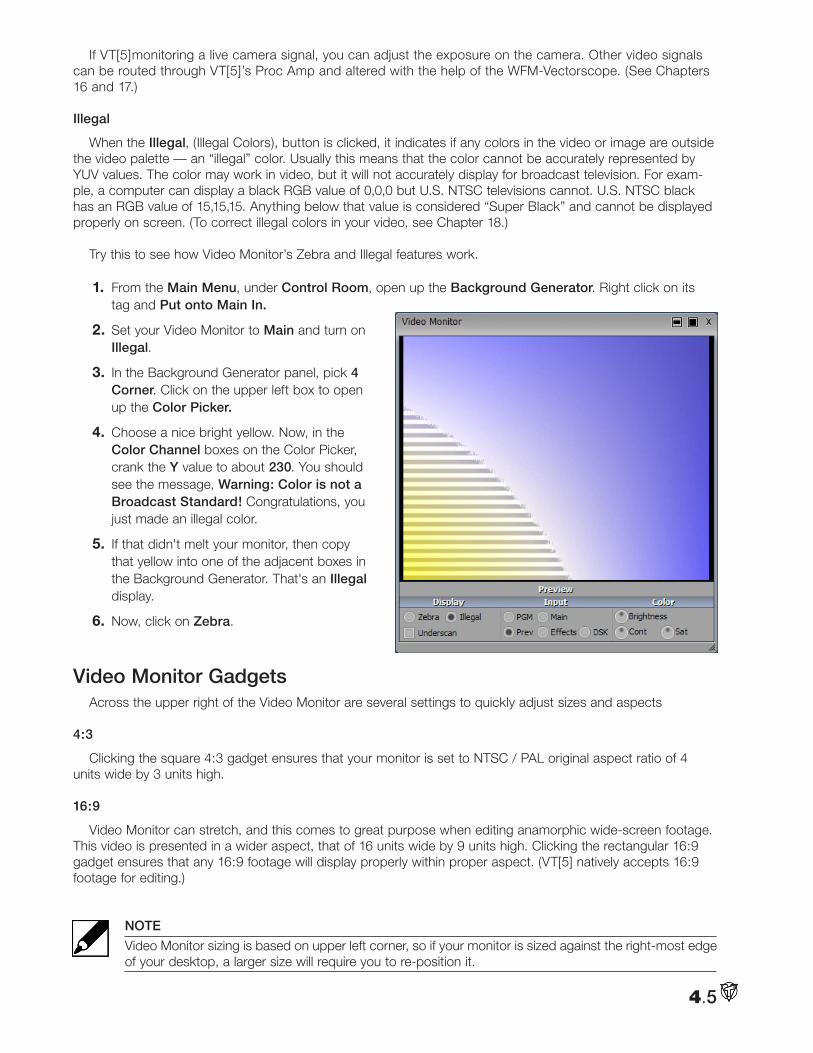
If VT[5]monitoring a live camera signal, you can adjust the exposure on the camera. Other video signals can be routed through VT[5]’s Proc Amp and altered with the help of the WFM-Vectorscope. (See Chapters 16 and 17.)
Illegal
When the Illegal, (Illegal Colors), button is clicked, it indicates if any colors in the video or image are outside the video palette — an “illegal” color. Usually this means that the color cannot be accurately represented by YUV values. The color may work in video, but it will not accurately display for broadcast television. For exam-ple, a computer can display a black RGB value of 0,0,0 but U.S. NTSC televisions cannot. U.S. NTSC black has an RGB value of 15,15,15. Anything below that value is considered “Super Black” and cannot be displayed properly on screen. (To correct illegal colors in your video, see Chapter 18.)
Try this to see how Video Monitor’s Zebra and Illegal features work.
1. From the Main Menu, under Control Room, open up the Background Generator. Right click on its tag and Put onto Main In.
2. Set your Video Monitor to Main and turn on Illegal.
3. In the Background Generator panel, pick 4 Corner. Click on the upper left box to open up the Color Picker.
4. Choose a nice bright yellow. Now, in the Color Channel boxes on the Color Picker, crank the Y value to about 230. You should see the message, Warning: Color is not a Broadcast Standard! Congratulations, you just made an illegal color.
5. If that didn't melt your monitor, then copy that yellow into one of the adjacent boxes in the Background Generator. That's an Illegal display.
6. Now, click on Zebra.
Video Monitor GadgetsAcross the upper right of the Video Monitor are several settings to quickly adjust sizes and aspects
4:3
Clicking the square 4:3 gadget ensures that your monitor is set to NTSC / PAL original aspect ratio of 4 units wide by 3 units high.
16:9
Video Monitor can stretch, and this comes to great purpose when editing anamorphic wide-screen footage. This video is presented in a wider aspect, that of 16 units wide by 9 units high. Clicking the rectangular 16:9 gadget ensures that any 16:9 footage will display properly within proper aspect. (VT[5] natively accepts 16:9 footage for editing.)
NOTE
Video Monitor sizing is based on upper left corner, so if your monitor is sized against the right-most edge of your desktop, a larger size will require you to re-position it.
4.5
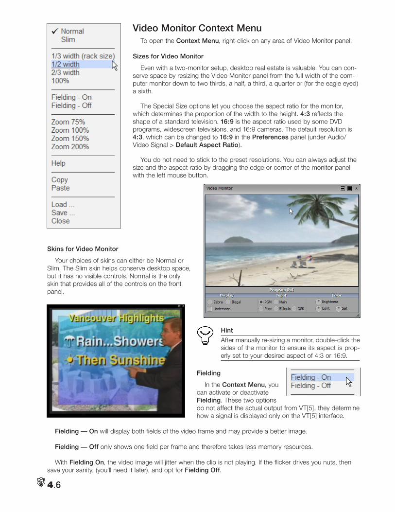
Video Monitor Context MenuTo open the Context Menu, right-click on any area of Video Monitor panel.
Sizes for Video Monitor
Even with a two-monitor setup, desktop real estate is valuable. You can con-serve space by resizing the Video Monitor panel from the full width of the com-puter monitor down to two thirds, a half, a third, a quarter or (for the eagle eyed) a sixth.
The Special Size options let you choose the aspect ratio for the monitor, which determines the proportion of the width to the height. 4:3 reflects the shape of a standard television. 16:9 is the aspect ratio used by some DVD programs, widescreen televisions, and 16:9 cameras. The default resolution is 4:3, which can be changed to 16:9 in the Preferences panel (under Audio/Video Signal > Default Aspect Ratio).
You do not need to stick to the preset resolutions. You can always adjust the size and the aspect ratio by dragging the edge or corner of the monitor panel with the left mouse button.
Skins for Video Monitor
Your choices of skins can either be Normal or Slim. The Slim skin helps conserve desktop space, but it has no visible controls. Normal is the only skin that provides all of the controls on the front panel.
Hint
After manually re-sizing a monitor, double-click the sides of the monitor to ensure its aspect is prop-erly set to your desired aspect of 4:3 or 16:9.
Fielding
In the Context Menu, you can activate or deactivate Fielding. These two options do not affect the actual output from VT[5], they determine how a signal is displayed only on the VT[5] interface.
Fielding — On will display both fields of the video frame and may provide a better image.
Fielding — Off only shows one field per frame and therefore takes less memory resources.
With Fielding On, the video image will jitter when the clip is not playing. If the flicker drives you nuts, then save your sanity, (you’ll need it later), and opt for Fielding Off.
4.6
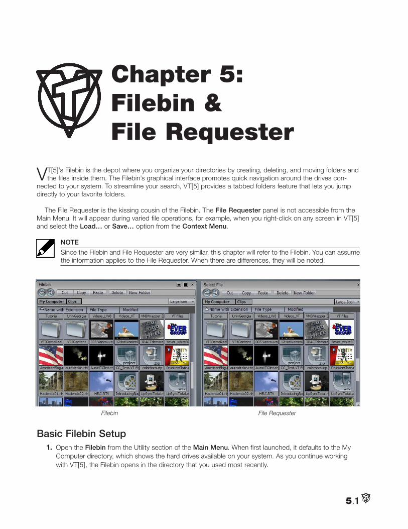
VT[5]’s Filebin is the depot where you organize your directories by creating, deleting, and moving folders and the files inside them. The Filebin’s graphical interface promotes quick navigation around the drives con-
nected to your system. To streamline your search, VT[5] provides a tabbed folders feature that lets you jump directly to your favorite folders.
The File Requester is the kissing cousin of the Filebin. The File Requester panel is not accessible from the Main Menu. It will appear during varied file operations, for example, when you right-click on any screen in VT[5] and select the Load… or Save… option from the Context Menu.
NOTE
Since the Filebin and File Requester are very similar, this chapter will refer to the Filebin. You can assume the information applies to the File Requester. When there are differences, they will be noted.
Basic Filebin Setup1. Open the Filebin from the Utility section of the Main Menu. When first launched, it defaults to the My
Computer directory, which shows the hard drives available on your system. As you continue working with VT[5], the Filebin opens in the directory that you used most recently.
5.1
Chapter 5: Filebin & File Requester
Filebin File Requester
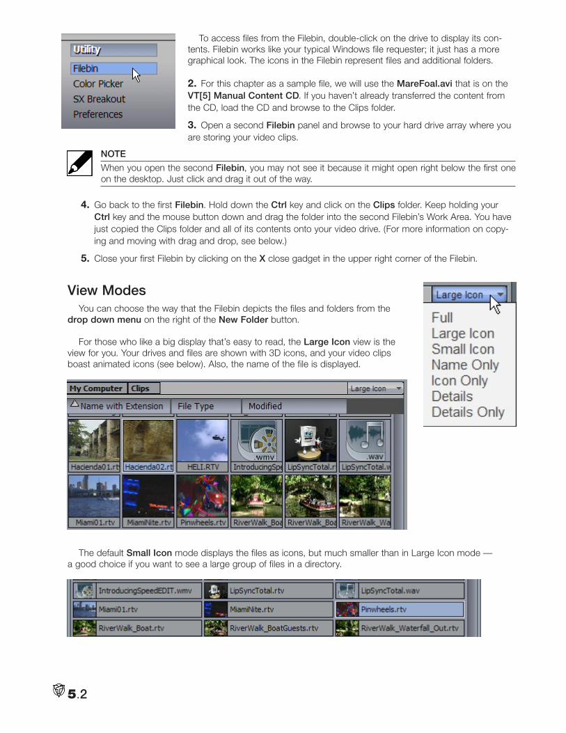
To access files from the Filebin, double-click on the drive to display its con-tents. Filebin works like your typical Windows file requester; it just has a more graphical look. The icons in the Filebin represent files and additional folders.
2. For this chapter as a sample file, we will use the MareFoal.avi that is on the VT[5] Manual Content CD. If you haven’t already transferred the content from the CD, load the CD and browse to the Clips folder.
3. Open a second Filebin panel and browse to your hard drive array where you are storing your video clips.
NOTE
When you open the second Filebin, you may not see it because it might open right below the first one on the desktop. Just click and drag it out of the way.
4. Go back to the first Filebin. Hold down the Ctrl key and click on the Clips folder. Keep holding your Ctrl key and the mouse button down and drag the folder into the second Filebin’s Work Area. You have just copied the Clips folder and all of its contents onto your video drive. (For more information on copy-ing and moving with drag and drop, see below.)
5. Close your first Filebin by clicking on the X close gadget in the upper right corner of the Filebin.
View ModesYou can choose the way that the Filebin depicts the files and folders from the
drop down menu on the right of the New Folder button.
For those who like a big display that’s easy to read, the Large Icon view is the view for you. Your drives and files are shown with 3D icons, and your video clips boast animated icons (see below). Also, the name of the file is displayed.
The default Small Icon mode displays the files as icons, but much smaller than in Large Icon mode — a good choice if you want to see a large group of files in a directory.
5.2
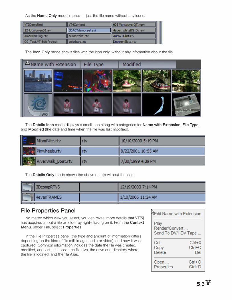
As the Name Only mode implies — just the file name without any icons.
The Icon Only mode shows files with the icon only, without any information about the file.
The Details Icon mode displays a small icon along with categories for Name with Extension, File Type, and Modified (the date and time when the file was last modified).
The Details Only mode shows the above details without the icon.
File Properties PanelNo matter which view you select, you can reveal more details that VT[5]
has acquired about a file or folder by right-clicking on it. From the Context Menu, under File, select Properties.
In the File Properties panel, the type and amount of information differs depending on the kind of file (still image, audio or video), and how it was captured. Common information includes the date the file was created, modified, and last accessed, the file size, the drive and directory where the file is located, and the file Alias.
5.3
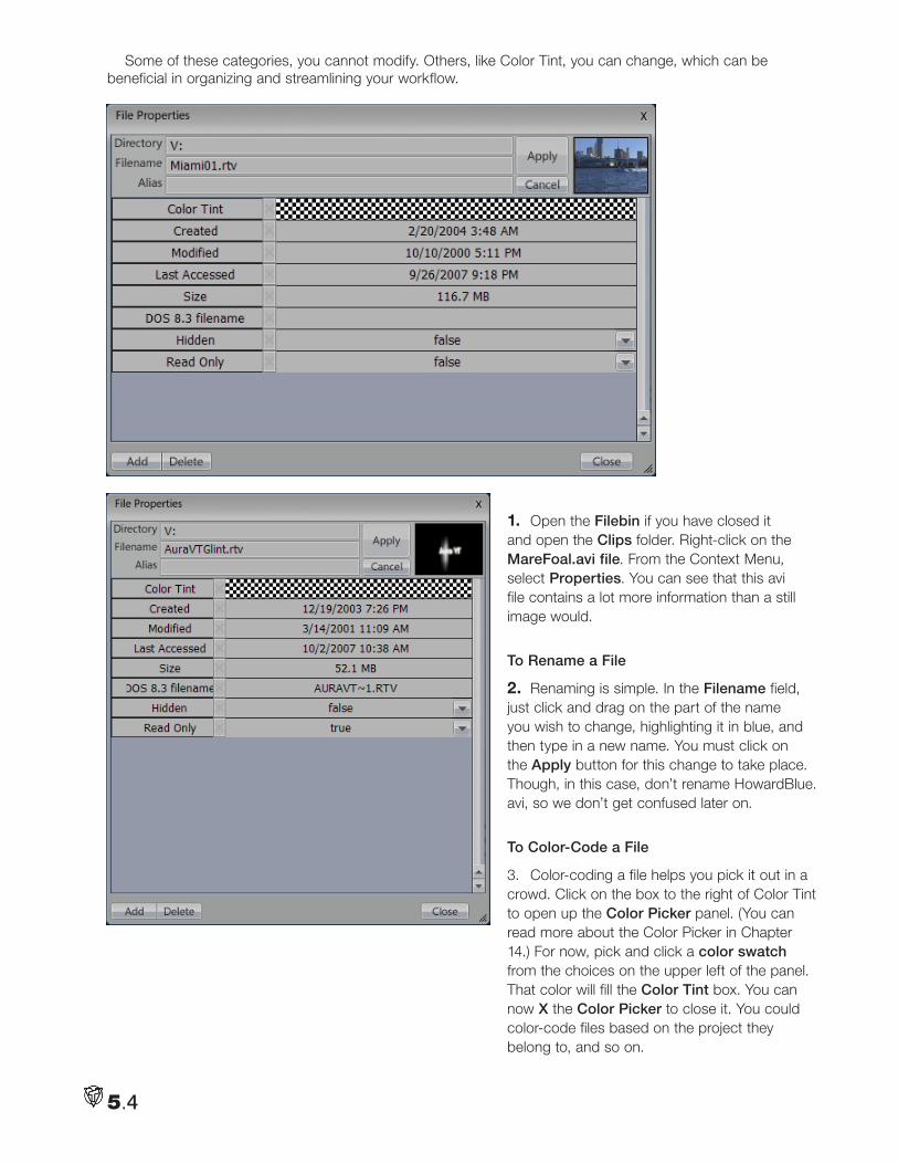
Some of these categories, you cannot modify. Others, like Color Tint, you can change, which can be beneficial in organizing and streamlining your workflow.
1. Open the Filebin if you have closed it and open the Clips folder. Right-click on the MareFoal.avi file. From the Context Menu, select Properties. You can see that this avi file contains a lot more information than a still image would.
To Rename a File
2. Renaming is simple. In the Filename field, just click and drag on the part of the name you wish to change, highlighting it in blue, and then type in a new name. You must click on the Apply button for this change to take place. Though, in this case, don’t rename HowardBlue.avi, so we don’t get confused later on.
To Color-Code a File
3. Color-coding a file helps you pick it out in a crowd. Click on the box to the right of Color Tint to open up the Color Picker panel. (You can read more about the Color Picker in Chapter 14.) For now, pick and click a color swatch from the choices on the upper left of the panel. That color will fill the Color Tint box. You can now X the Color Picker to close it. You could color-code files based on the project they belong to, and so on.
5.4
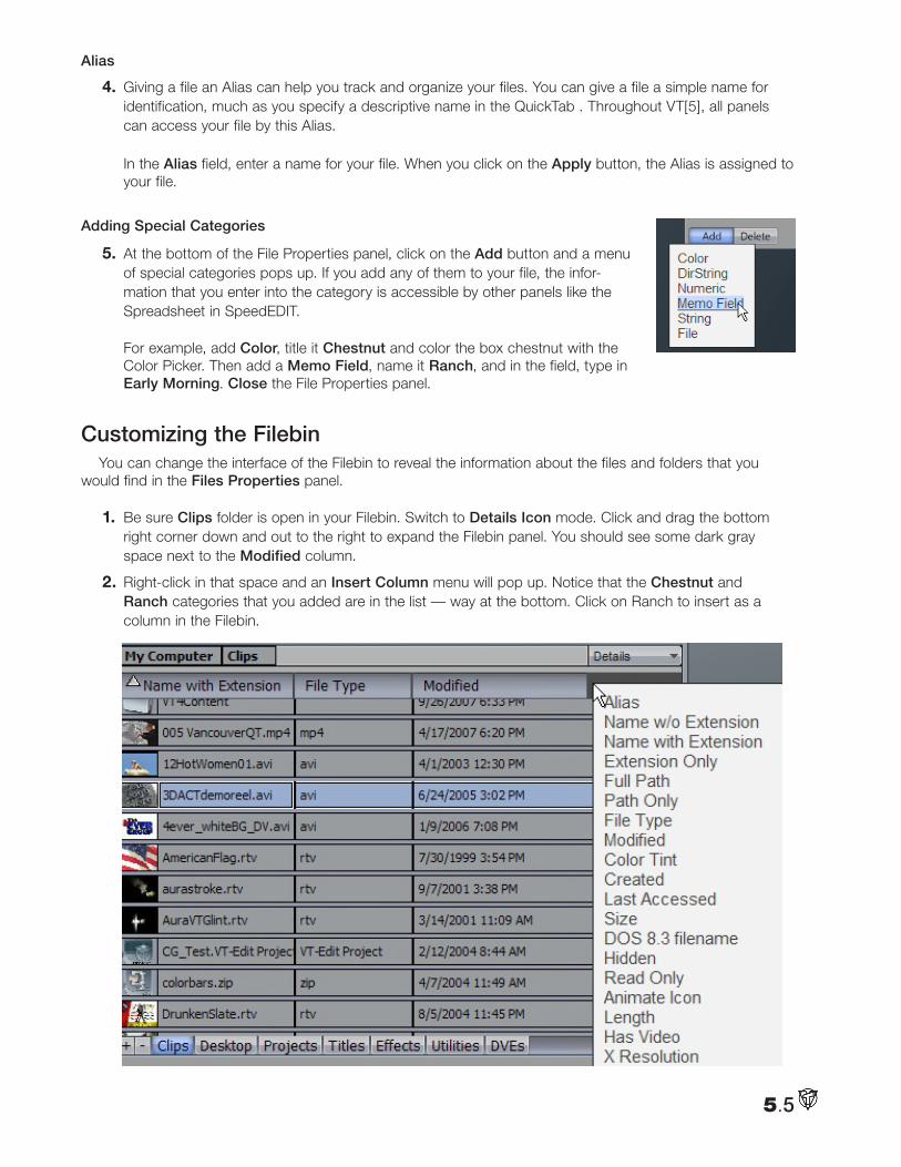
Alias
4. Giving a file an Alias can help you track and organize your files. You can give a file a simple name for identification, much as you specify a descriptive name in the QuickTab . Throughout VT[5], all panels can access your file by this Alias. In the Alias field, enter a name for your file. When you click on the Apply button, the Alias is assigned to your file.
Adding Special Categories
5. At the bottom of the File Properties panel, click on the Add button and a menu of special categories pops up. If you add any of them to your file, the infor-mation that you enter into the category is accessible by other panels like the Spreadsheet in SpeedEDIT. For example, add Color, title it Chestnut and color the box chestnut with the Color Picker. Then add a Memo Field, name it Ranch, and in the field, type in Early Morning. Close the File Properties panel.
Customizing the FilebinYou can change the interface of the Filebin to reveal the information about the files and folders that you
would find in the Files Properties panel.
1. Be sure Clips folder is open in your Filebin. Switch to Details Icon mode. Click and drag the bottom right corner down and out to the right to expand the Filebin panel. You should see some dark gray space next to the Modified column.
2. Right-click in that space and an Insert Column menu will pop up. Notice that the Chestnut and Ranch categories that you added are in the list — way at the bottom. Click on Ranch to insert as a column in the Filebin.
5.5
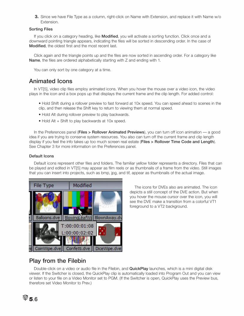
3. Since we have File Type as a column, right-click on Name with Extension, and replace it with Name w/o Extension.
Sorting Files
If you click on a category heading, like Modified, you will activate a sorting function. Click once and a downward pointing triangle appears, indicating the files will be sorted in descending order. In the case of Modified, the oldest first and the most recent last.
Click again and the triangle points up and the files are now sorted in ascending order. For a category like Name, the files are ordered alphabetically starting with Z and ending with 1.
You can only sort by one category at a time.
Animated IconsIn VT[5], video clip files employ animated icons. When you hover the mouse over a video icon, the video
plays in the icon and a box pops up that displays the current frame and the clip length. For added control:
• Hold Shift during a rollover preview to fast forward at 10x speed. You can speed ahead to scenes in the clip, and then release the Shift key to return to viewing them at normal speed.
• Hold Alt during rollover preview to play backwards.
• Hold Alt + Shift to play backwards at 10x speed.
In the Preferences panel (Files > Rollover Animated Previews), you can turn off icon animation — a good idea if you are trying to conserve system resources. You also can turn off the current frame and clip length display if you feel the info takes up too much screen real estate (Files > Rollover Time Code and Length). See Chapter 3 for more information on the Preferences panel.
Default Icons
Default icons represent other files and folders. The familiar yellow folder represents a directory. Files that can be played and edited in VT[5] may appear as film reels or as thumbnails of a frame from the video. Still images that you can insert into projects, such as bmp, jpg, and tif, appear as thumbnails of the actual image.
The icons for DVEs also are animated. The icon depicts a still concept of the DVE action. But when you hover the mouse cursor over the icon, you will see the DVE make a transition from a colorful VT1 foreground to a VT2 background.
Play from the FilebinDouble-click on a video or audio file in the Filebin, and QuickPlay launches, which is a mini digital disk
viewer. If the Switcher is closed, the QuickPlay clip is automatically loaded into Program Out and you can view or listen to your file on a Video Monitor set to PGM. (If the Switcher is open, QuickPlay uses the Preview bus, therefore set Video Monitor to Prev.)
5.6
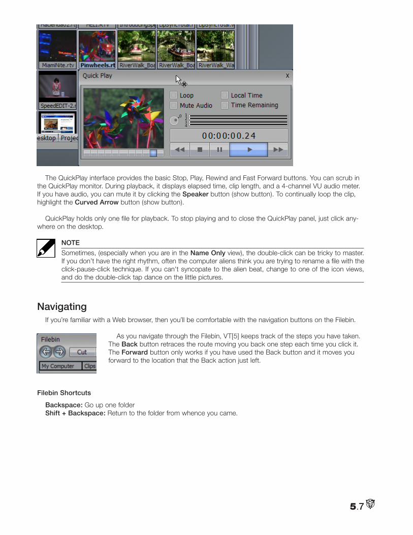
The QuickPlay interface provides the basic Stop, Play, Rewind and Fast Forward buttons. You can scrub in the QuickPlay monitor. During playback, it displays elapsed time, clip length, and a 4-channel VU audio meter. If you have audio, you can mute it by clicking the Speaker button (show button). To continually loop the clip, highlight the Curved Arrow button (show button).
QuickPlay holds only one file for playback. To stop playing and to close the QuickPlay panel, just click any-where on the desktop.
NOTE
Sometimes, (especially when you are in the Name Only view), the double-click can be tricky to master. If you don’t have the right rhythm, often the computer aliens think you are trying to rename a file with the click-pause-click technique. If you can't syncopate to the alien beat, change to one of the icon views, and do the double-click tap dance on the little pictures.
Navigating If you’re familiar with a Web browser, then you’ll be comfortable with the navigation buttons on the Filebin.
As you navigate through the Filebin, VT[5] keeps track of the steps you have taken. The Back button retraces the route moving you back one step each time you click it. The Forward button only works if you have used the Back button and it moves you forward to the location that the Back action just left.
Filebin Shortcuts
Backspace: Go up one folderShift + Backspace: Return to the folder from whence you came.
5.7
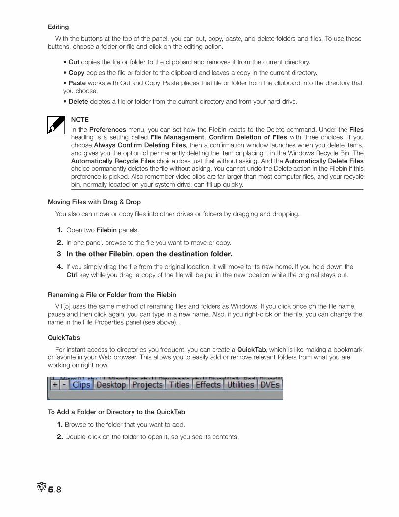
Editing
With the buttons at the top of the panel, you can cut, copy, paste, and delete folders and files. To use these buttons, choose a folder or file and click on the editing action.
• Cut copies the file or folder to the clipboard and removes it from the current directory.
• Copy copies the file or folder to the clipboard and leaves a copy in the current directory.
• Paste works with Cut and Copy. Paste places that file or folder from the clipboard into the directory that you choose.
• Delete deletes a file or folder from the current directory and from your hard drive.
NOTE
In the Preferences menu, you can set how the Filebin reacts to the Delete command. Under the Files heading is a setting called File Management, Confirm Deletion of Files with three choices. If you choose Always Confirm Deleting Files, then a confirmation window launches when you delete items, and gives you the option of permanently deleting the item or placing it in the Windows Recycle Bin. The Automatically Recycle Files choice does just that without asking. And the Automatically Delete Files choice permanently deletes the file without asking. You cannot undo the Delete action in the Filebin if this preference is picked. Also remember video clips are far larger than most computer files, and your recycle bin, normally located on your system drive, can fill up quickly.
Moving Files with Drag & Drop
You also can move or copy files into other drives or folders by dragging and dropping.
1. Open two Filebin panels.
2. In one panel, browse to the file you want to move or copy.
3 In the other Filebin, open the destination folder.
4. If you simply drag the file from the original location, it will move to its new home. If you hold down the Ctrl key while you drag, a copy of the file will be put in the new location while the original stays put.
Renaming a File or Folder from the Filebin
VT[5] uses the same method of renaming files and folders as Windows. If you click once on the file name, pause and then click again, you can type in a new name. Also, if you right-click on the file, you can change the name in the File Properties panel (see above).
QuickTabs
For instant access to directories you frequent, you can create a QuickTab, which is like making a bookmark or favorite in your Web browser. This allows you to easily add or remove relevant folders from what you are working on right now.
To Add a Folder or Directory to the QuickTab
1. Browse to the folder that you want to add.
2. Double-click on the folder to open it, so you see its contents.
5.8
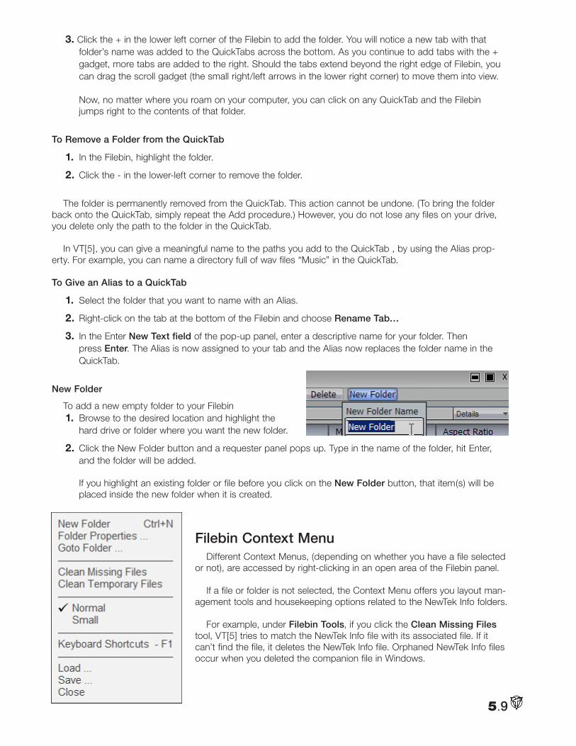
3. Click the + in the lower left corner of the Filebin to add the folder. You will notice a new tab with that folder’s name was added to the QuickTabs across the bottom. As you continue to add tabs with the + gadget, more tabs are added to the right. Should the tabs extend beyond the right edge of Filebin, you can drag the scroll gadget (the small right/left arrows in the lower right corner) to move them into view. Now, no matter where you roam on your computer, you can click on any QuickTab and the Filebin jumps right to the contents of that folder.
To Remove a Folder from the QuickTab
1. In the Filebin, highlight the folder.
2. Click the - in the lower-left corner to remove the folder.
The folder is permanently removed from the QuickTab. This action cannot be undone. (To bring the folder back onto the QuickTab, simply repeat the Add procedure.) However, you do not lose any files on your drive, you delete only the path to the folder in the QuickTab.
In VT[5], you can give a meaningful name to the paths you add to the QuickTab , by using the Alias prop-erty. For example, you can name a directory full of wav files “Music” in the QuickTab.
To Give an Alias to a QuickTab
1. Select the folder that you want to name with an Alias.
2. Right-click on the tab at the bottom of the Filebin and choose Rename Tab…
3. In the Enter New Text field of the pop-up panel, enter a descriptive name for your folder. Then press Enter. The Alias is now assigned to your tab and the Alias now replaces the folder name in the QuickTab.
New Folder
To add a new empty folder to your Filebin1. Browse to the desired location and highlight the
hard drive or folder where you want the new folder.
2. Click the New Folder button and a requester panel pops up. Type in the name of the folder, hit Enter, and the folder will be added. If you highlight an existing folder or file before you click on the New Folder button, that item(s) will be placed inside the new folder when it is created.
Filebin Context MenuDifferent Context Menus, (depending on whether you have a file selected
or not), are accessed by right-clicking in an open area of the Filebin panel.
If a file or folder is not selected, the Context Menu offers you layout man-agement tools and housekeeping options related to the NewTek Info folders.
For example, under Filebin Tools, if you click the Clean Missing Files tool, VT[5] tries to match the NewTek Info file with its associated file. If it can’t find the file, it deletes the NewTek Info file. Orphaned NewTek Info files occur when you deleted the companion file in Windows.
5.9
5.10
Clean Temporary Files will remove all the files that VT[5] generates, which will be regenerated when needed, for instance audio peak levels, icon files, etc. It does not delete files that are valuable and not automatically regenerated like asset management files. This is helpful when you have modified many clips in another program, and you wish to update all the icons.
Goto Folder… is a navigational tool for those who like type. If you click it, a dialog box pops up where you can enter a new path for the Filebin. For example, if you enter D:, the Filebin will jump to the root of your D drive. If you enter C:\Winnt, you are taken straight to Windows’ system folder.
With a file or folder selected, in addition to these Filebin options, you’ll find common file management and clipboard options, like Open, Cut, Copy, and Delete.
Render from the Filebin
You can render files in the Filebin to make a group of clips into one AVI, RTV, or other video file. Select the clips that you want to render, right-click to open the Context Menu, choose Render/Convert... The Render panel launches and you choose your codecs and resolution. For more information about the Render panel, see Chapter 7.
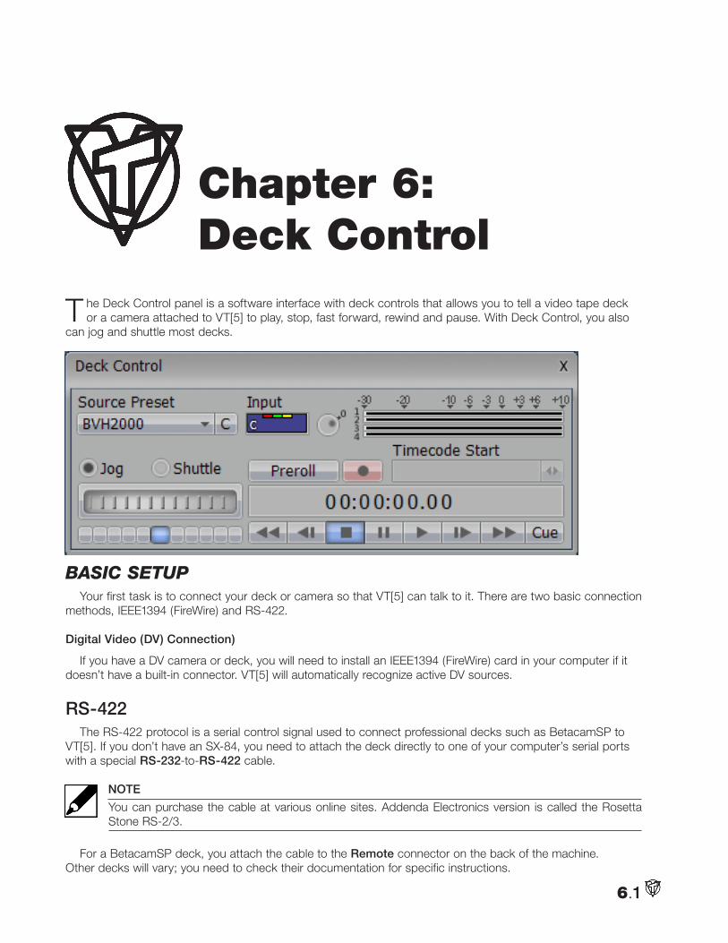
T he Deck Control panel is a software interface with deck controls that allows you to tell a video tape deck or a camera attached to VT[5] to play, stop, fast forward, rewind and pause. With Deck Control, you also
can jog and shuttle most decks.
BaSic SetupYour first task is to connect your deck or camera so that VT[5] can talk to it. There are two basic connection
methods, IEEE1394 (FireWire) and RS-422.
Digital Video (DV) Connection)
If you have a DV camera or deck, you will need to install an IEEE1394 (FireWire) card in your computer if it doesn’t have a built-in connector. VT[5] will automatically recognize active DV sources.
RS-422The RS-422 protocol is a serial control signal used to connect professional decks such as BetacamSP to
VT[5]. If you don’t have an SX-84, you need to attach the deck directly to one of your computer’s serial ports with a special RS-232-to-RS-422 cable.
NOTE
You can purchase the cable at various online sites. Addenda Electronics version is called the Rosetta Stone RS-2/3.
For a BetacamSP deck, you attach the cable to the Remote connector on the back of the machine. Other decks will vary; you need to check their documentation for specific instructions.
6.1
Chapter 6: Deck Control
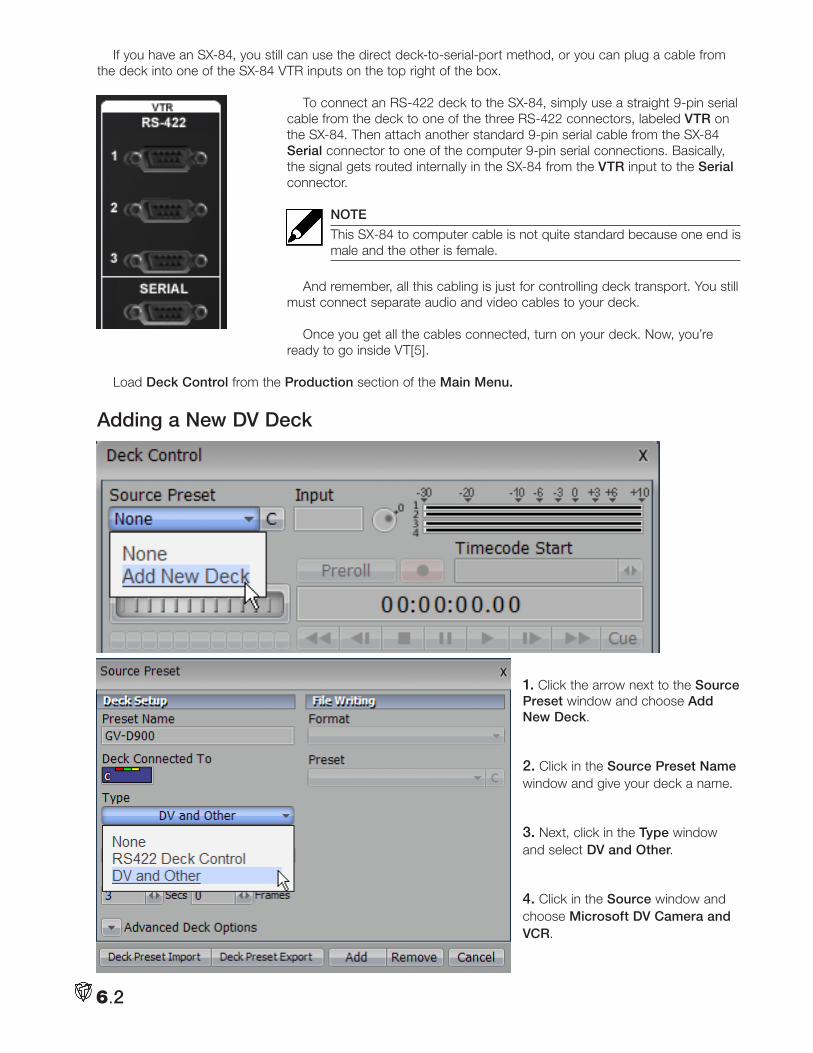
If you have an SX-84, you still can use the direct deck-to-serial-port method, or you can plug a cable from the deck into one of the SX-84 VTR inputs on the top right of the box.
To connect an RS-422 deck to the SX-84, simply use a straight 9-pin serial cable from the deck to one of the three RS-422 connectors, labeled VTR on the SX-84. Then attach another standard 9-pin serial cable from the SX-84 Serial connector to one of the computer 9-pin serial connections. Basically, the signal gets routed internally in the SX-84 from the VTR input to the Serial connector.
NOTE
This SX-84 to computer cable is not quite standard because one end is male and the other is female.
And remember, all this cabling is just for controlling deck transport. You still must connect separate audio and video cables to your deck.
Once you get all the cables connected, turn on your deck. Now, you’re ready to go inside VT[5].
Load Deck Control from the Production section of the Main Menu.
Adding a New DV Deck
1. Click the arrow next to the Source Preset window and choose Add New Deck.
2. Click in the Source Preset Name window and give your deck a name.
3. Next, click in the Type window and select DV and Other.
4. Click in the Source window and choose Microsoft DV Camera and VCR.
6.2
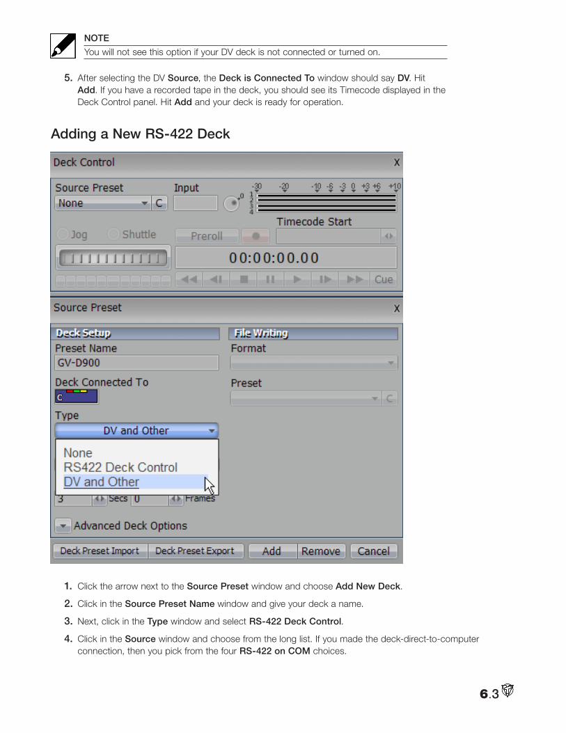
NOTE
You will not see this option if your DV deck is not connected or turned on.
5. After selecting the DV Source, the Deck is Connected To window should say DV. Hit Add. If you have a recorded tape in the deck, you should see its Timecode displayed in the Deck Control panel. Hit Add and your deck is ready for operation.
Adding a New RS-422 Deck
1. Click the arrow next to the Source Preset window and choose Add New Deck.
2. Click in the Source Preset Name window and give your deck a name.
3. Next, click in the Type window and select RS-422 Deck Control.
4. Click in the Source window and choose from the long list. If you made the deck-direct-to-computer connection, then you pick from the four RS-422 on COM choices.
6.3
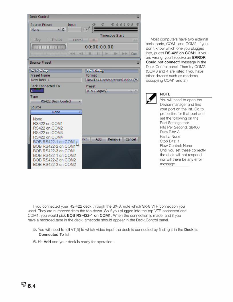
Most computers have two external serial ports, COM1 and COM2. If you don’t know which one you plugged into, guess RS-422 on COM1. If you are wrong, you’ll receive an ERROR. Could not connect! message in the Deck Control panel. Then try COM2. (COM3 and 4 are listed if you have other devices such as modems occupying COM1 and 2.)
NOTE
You will need to open the Device manager and find your port on the list. Go to properties for that port and set the following on the Port Settings tab: Pits Per Second: 38400 Data Bits: 8 Parity: None Stop Bits: 1 Flow Control: None Until you set these correctly, the deck will not respond nor will there be any error message.
If you connected your RS-422 deck through the SX-8, note which SX-8 VTR connection you used. They are numbered from the top down. So if you plugged into the top VTR connector and COM1, you would pick BOB RS-422-1 on COM1. When the connection is made, and if you have a recorded tape in the deck, timecode should appear in the Deck Control panel.
5. You will need to tell VT[5] to which video input the deck is connected by finding it in the Deck is Connected To list.
6. Hit Add and your deck is ready for operation.
6.4
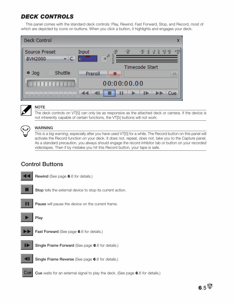
Deck controlsThis panel comes with the standard deck controls: Play, Rewind, Fast Forward, Stop, and Record, most of
which are depicted by icons on buttons. When you click a button, it highlights and engages your deck.
NOTE
The deck controls on VT[5] can only be as responsive as the attached deck or camera. If the device is not inherently capable of certain functions, the VT[5] buttons will not work.
WARNING
This is a big warning, especially after you have used VT[5] for a while. The Record button on this panel will activate the Record function on your deck. It does not, repeat, does not, take you to the Capture panel. As a standard precaution, you always should engage the record inhibitor tab or button on your recorded videotapes. Then if by mistake you hit this Record button, your tape is safe.
Control Buttons
Rewind (See page 6.6 for details.)
Stop tells the external device to stop its current action.
Pause will pause the device on the current frame.
Play
Fast Forward (See page 6.6 for details.)
Single Frame Forward (See page 6.6 for details.)
Single Frame Reverse (See page 6.6 for details.)
Cue waits for an external signal to play the deck. (See page 6.6 for details.)
6.5
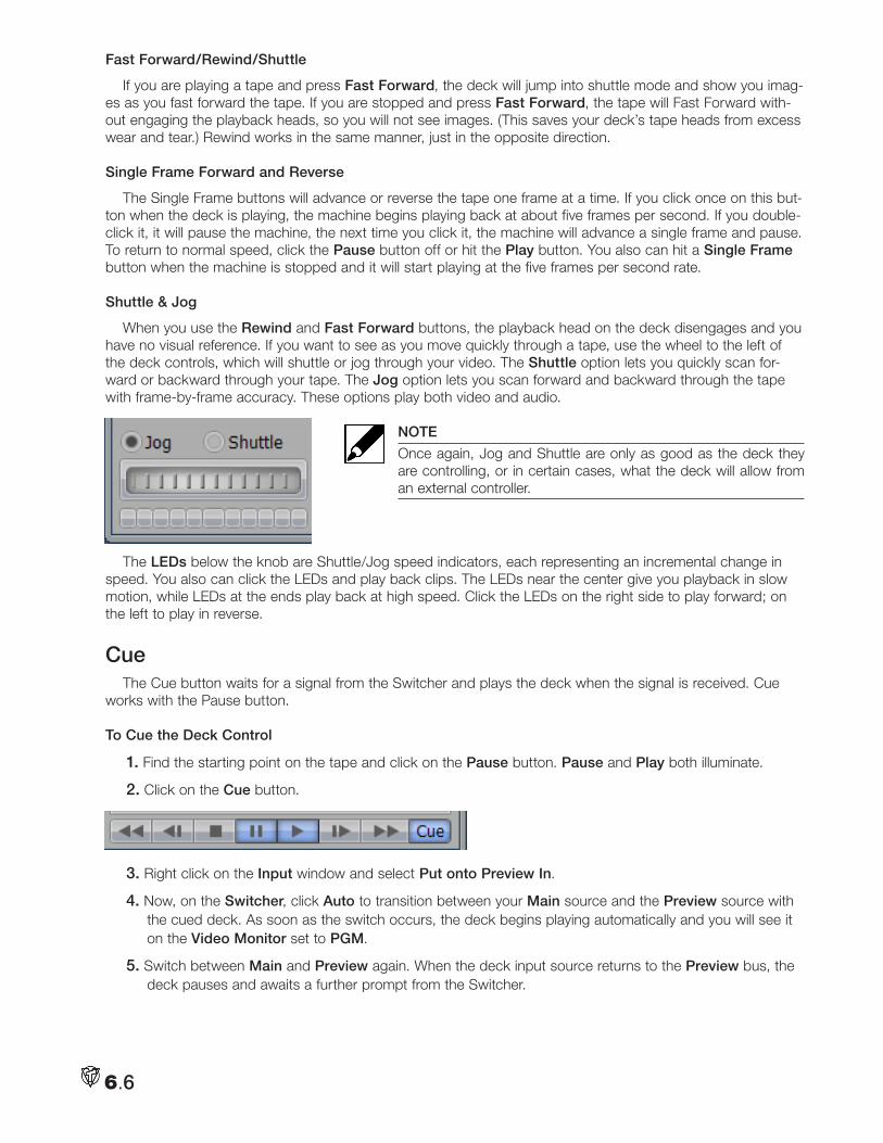
Fast Forward/Rewind/Shuttle
If you are playing a tape and press Fast Forward, the deck will jump into shuttle mode and show you imag-es as you fast forward the tape. If you are stopped and press Fast Forward, the tape will Fast Forward with-out engaging the playback heads, so you will not see images. (This saves your deck’s tape heads from excess wear and tear.) Rewind works in the same manner, just in the opposite direction.
Single Frame Forward and Reverse
The Single Frame buttons will advance or reverse the tape one frame at a time. If you click once on this but-ton when the deck is playing, the machine begins playing back at about five frames per second. If you double-click it, it will pause the machine, the next time you click it, the machine will advance a single frame and pause. To return to normal speed, click the Pause button off or hit the Play button. You also can hit a Single Frame button when the machine is stopped and it will start playing at the five frames per second rate.
Shuttle & Jog
When you use the Rewind and Fast Forward buttons, the playback head on the deck disengages and you have no visual reference. If you want to see as you move quickly through a tape, use the wheel to the left of the deck controls, which will shuttle or jog through your video. The Shuttle option lets you quickly scan for-ward or backward through your tape. The Jog option lets you scan forward and backward through the tape with frame-by-frame accuracy. These options play both video and audio.
NOTE
Once again, Jog and Shuttle are only as good as the deck they are controlling, or in certain cases, what the deck will allow from an external controller.
The LEDs below the knob are Shuttle/Jog speed indicators, each representing an incremental change in speed. You also can click the LEDs and play back clips. The LEDs near the center give you playback in slow motion, while LEDs at the ends play back at high speed. Click the LEDs on the right side to play forward; on the left to play in reverse.
CueThe Cue button waits for a signal from the Switcher and plays the deck when the signal is received. Cue
works with the Pause button.
To Cue the Deck Control
1. Find the starting point on the tape and click on the Pause button. Pause and Play both illuminate.
2. Click on the Cue button.
3. Right click on the Input window and select Put onto Preview In.
4. Now, on the Switcher, click Auto to transition between your Main source and the Preview source with the cued deck. As soon as the switch occurs, the deck begins playing automatically and you will see it on the Video Monitor set to PGM.
5. Switch between Main and Preview again. When the deck input source returns to the Preview bus, the deck pauses and awaits a further prompt from the Switcher.
6.6
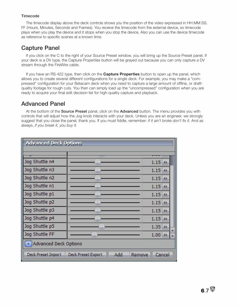
Timecode
The timecode display above the deck controls shows you the position of the video expressed in HH:MM:SS.FF (Hours, Minutes, Seconds and Frames). You receive the timecode from the external device, so timecode plays when you play the device and it stops when you stop the device. Also you can use the device timecode as reference to specific scenes at a known time.
Capture PanelIf you click on the C to the right of your Source Preset window, you will bring up the Source Preset panel. If
your deck is a DV type, the Capture Properties button will be grayed out because you can only capture a DV stream through the FireWire cable.
If you have an RS-422 type, then click on the Capture Properties button to open up the panel, which allows you to create several different configurations for a single deck. For example, you may make a “com-pressed” configuration for your Betacam deck when you need to capture a large amount of offline, or draft-quality footage for rough cuts. You then can simply load up the “uncompressed” configuration when you are ready to acquire your final edit decision list for high-quality capture and playback.
Advanced PanelAt the bottom of the Source Preset panel, click on the Advanced button. The menu provides you with
controls that will adjust how the Jog knob interacts with your deck. Unless you are an engineer, we strongly suggest that you close the panel, thank you. If you must fiddle, remember: if it ain’t broke don’t fix it. And as always, if you break it, you buy it.
6.7
Context Menu
Right-clicking on an empty area of the Deck Control panel brings up the Context Menu where you can Save and Load panel configurations, and exit the module. For more information on saving configurations, see Chapter 3.
Import & Export Presets
On the bottom of the Source Preset panel are buttons for Importing and Exporting Presets. If you click on Import Presets, a File Requester will open by default to VT5\UserData\DefaultUser\CaptureDevice\Presets. Inside there are Presets for generic Betacam, DV, U-matic, Hi-8, and VHS decks. Click on the one that applies to your type of deck and hit Open. The Presets will set the plug-in and the Advanced settings of the deck, so you need not go in there. You still will need to establish the connection with the deck, as usual, by selecting the Source.
6.8
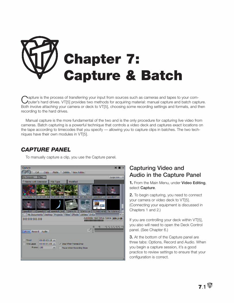
7.1
Capture is the process of transferring your input from sources such as cameras and tapes to your com-puter’s hard drives. VT[5] provides two methods for acquiring material: manual capture and batch capture.
Both involve attaching your camera or deck to VT[5], choosing some recording settings and formats, and then recording to the hard drives.
Manual capture is the more fundamental of the two and is the only procedure for capturing live video from cameras. Batch capturing is a powerful technique that controls a video deck and captures exact locations on the tape according to timecodes that you specify — allowing you to capture clips in batches. The two tech-niques have their own modules in VT[5].
captuRe panelTo manually capture a clip, you use the Capture panel.
Capturing Video and Audio in the Capture Panel1. From the Main Menu, under Video Editing, select Capture.
2. To begin capturing, you need to connect your camera or video deck to VT[5]. (Connecting your equipment is discussed in Chapters 1 and 2.) If you are controlling your deck within VT[5], you also will need to open the Deck Control panel. (See Chapter 6.)
3. At the bottom of the Capture panel are three tabs: Options, Record and Audio. When you begin a capture session, it’s a good practice to review settings to ensure that your configuration is correct.
Chapter 7: Capture & Batch
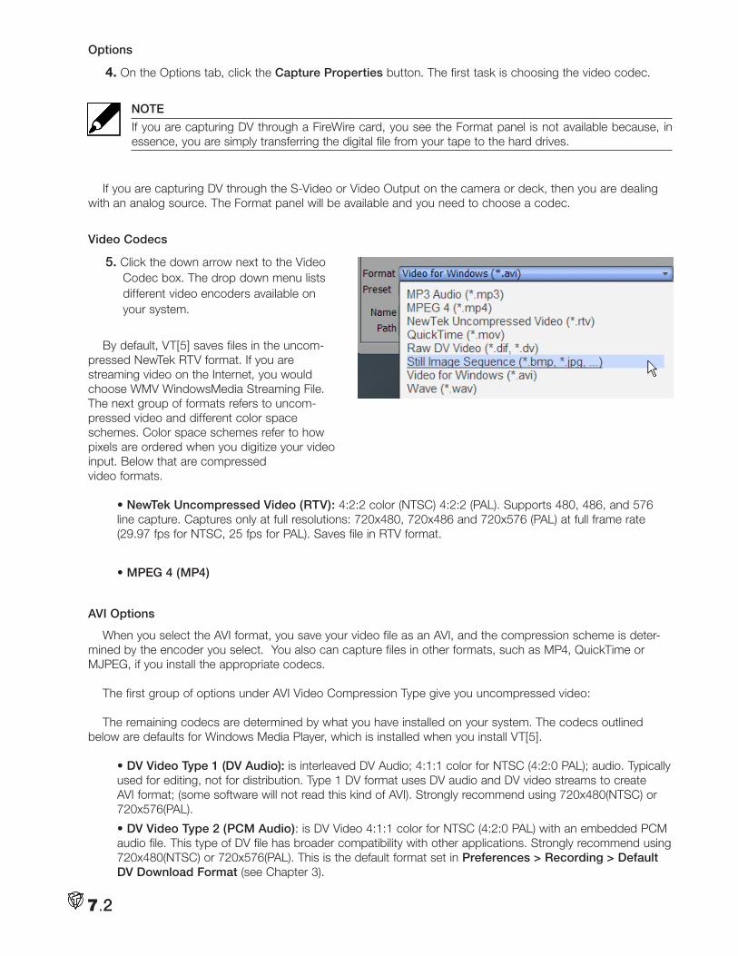
7.2
Options
4. On the Options tab, click the Capture Properties button. The first task is choosing the video codec.
NOTE
If you are capturing DV through a FireWire card, you see the Format panel is not available because, in essence, you are simply transferring the digital file from your tape to the hard drives.
If you are capturing DV through the S-Video or Video Output on the camera or deck, then you are dealing with an analog source. The Format panel will be available and you need to choose a codec.
Video Codecs
5. Click the down arrow next to the Video Codec box. The drop down menu lists different video encoders available on your system.
By default, VT[5] saves files in the uncom-
pressed NewTek RTV format. If you are streaming video on the Internet, you would choose WMV WindowsMedia Streaming File. The next group of formats refers to uncom-pressed video and different color space schemes. Color space schemes refer to how pixels are ordered when you digitize your video input. Below that are compressed video formats.
• NewTek Uncompressed Video (RTV): 4:2:2 color (NTSC) 4:2:2 (PAL). Supports 480, 486, and 576 line capture. Captures only at full resolutions: 720x480, 720x486 and 720x576 (PAL) at full frame rate (29.97 fps for NTSC, 25 fps for PAL). Saves file in RTV format.
• MPEG 4 (MP4)
AVI Options
When you select the AVI format, you save your video file as an AVI, and the compression scheme is deter-mined by the encoder you select. You also can capture files in other formats, such as MP4, QuickTime or MJPEG, if you install the appropriate codecs.
The first group of options under AVI Video Compression Type give you uncompressed video:
The remaining codecs are determined by what you have installed on your system. The codecs outlined below are defaults for Windows Media Player, which is installed when you install VT[5].
• DV Video Type 1 (DV Audio): is interleaved DV Audio; 4:1:1 color for NTSC (4:2:0 PAL); audio. Typically used for editing, not for distribution. Type 1 DV format uses DV audio and DV video streams to create AVI format; (some software will not read this kind of AVI). Strongly recommend using 720x480(NTSC) or 720x576(PAL).
• DV Video Type 2 (PCM Audio): is DV Video 4:1:1 color for NTSC (4:2:0 PAL) with an embedded PCM audio file. This type of DV file has broader compatibility with other applications. Strongly recommend using 720x480(NTSC) or 720x576(PAL). This is the default format set in Preferences > Recording > Default DV Download Format (see Chapter 3).
7.3
• WMVideo Encoder DMO (Windows Media Video Encoder): Enhanced version of Windows Media encoder for extremely high bit rates and connections (250-750 kbps). Used for downloadable movies. Rarely used.
• MSScreen Encoder DMO: Rarely used.
• DV Video Encoder: 4:1:1 color for NTSC (4:2:0 PAL); audio. Typically used for editing, not for distribu-tion. Type 2 DV format uses DV video only so that you can choose uncompressed audio to create an AVI. Strongly recommend using 720x480 (NTSC) or 720x576 (PAL).
• Indeo® Video 5.10 Compression Filter: YUV-9 color; progressive or streaming; scalable; supports transparency. Must use 480 or 240 lines – does not work with 486 or 243. Used for Web distribution. (This is a slow codec and is unlikely to work with full resolution. To use this codec you must drop the frame rate and the resolution.)
• MJPEG Compressor: 4:2:0 color. Used for editing and archiving, not for final delivery. (This codec is CPU intensive. You can find free MJPEG codecs at www.mjpeg.com that work in real-time.)
• Cinepak Codec by Radius: 16-bit color. Plays on older computers. It is commonly used for hard drive or CD-ROM playback.
• Intel Indeo Video 4.2:0 Video V2.50
• Intel Indeo Video R3.2: 16-bit color. Plays on slower computers with Windows Media Player. Inappropriate for Web, used for playback on hard drive or CD-ROM; commonly used format.
• Intel Indeo Video 4.5
• Indeo Video 5.10: Similar to Indeo Video 5.10 Compression Filter. Try substituting this codec if the Compression Filter gives inadequate results.
• Intel IYUV codec
• Microsoft H.261 Video Codec: 4:2:0 color. Videoconferencing codec used for slower connections (128-384 Kbits).
• Microsoft H.263 Video Codec: Same as above, but better quality video conferencing codec with motion compensation.
• Microsoft RLE (Run-length encoded): 32-bit color. Plays on slower computers; for hard drive or CD-ROM playback. (Not a great option for video, but supported on Windows 3.1.)
• Microsoft Video 1: 32-bit color. Plays on slower computers; for hard drive or CD-ROM playback. (Not really a great option for video, but supported on Windows 3.1.)
Apple, QuickTime File
It must be noted that these files are here strictly as a render component for VT[5] output, as there is not a computer fast enough to capture video, and convert it to QuickTime format in real time. Attempting to use these QuickTime codecs for video capture will quickly result in dropped frames.
• NewTek SpeedHQ™ Codec: Allows you to generate, load and save video files to and from any application that supports AVIs. This is the AVI wrapper codec used within VT-Edit and the video is always uncompressed and full resolution. The audio stream with the avi wrapper is compressed.
6. Click on the C (Configure) button, (next to the arrow), to automatically configure the codecs with their optimized settings. With some of the codecs, like WMV WindowsMedia Streaming File, clicking the C button will pop up a panel of configuration options.
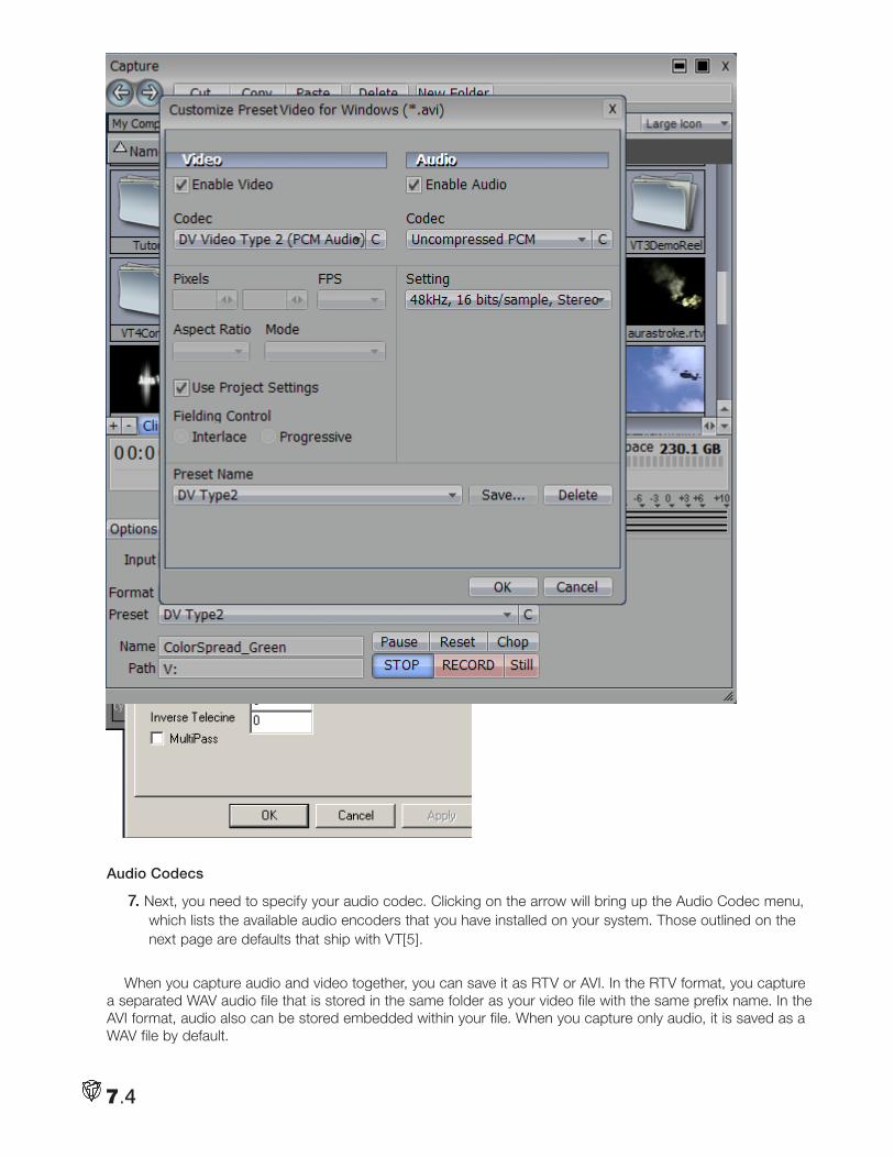
7.4
Audio Codecs
7. Next, you need to specify your audio codec. Clicking on the arrow will bring up the Audio Codec menu, which lists the available audio encoders that you have installed on your system. Those outlined on the next page are defaults that ship with VT[5].
When you capture audio and video together, you can save it as RTV or AVI. In the RTV format, you capture a separated WAV audio file that is stored in the same folder as your video file with the same prefix name. In the AVI format, audio also can be stored embedded within your file. When you capture only audio, it is saved as a WAV file by default.
7.5
These audio codecs will offer you different rates for sampling frequency, different bit sizes, and a choice of mono or stereo. These options determine the final size and quality of your file. Uncompressed audio should be captured at 48KHz, unless destined for an Audio CD. CDA can be sampled at 44.1KHz.
• WAV audio file: uncompressed windows audio format is the default for audio captures on VT[5] when ingesting RTV video streams.
• Uncompressed PCM: uncompressed Pulse Code Modulated audio. Use with uncompressed video at high bit rates.
• WMV WindowsMedia Streaming File (audio): Used with Windows Media. Best for low bit rate music; must use when you choose Windows Media encoder for video.
• DV Compressed Audio is for DV Type 1 captures, with the audio compressed and embedded in the video stream.
• WM Audio Encoder DMO: Enhanced version of Windows Media audio encoder for extremely high bit rates and connections (250-750 kbps). Used for downloadable movies.
• VT Audio Codec: the compressed audio format integrated with SpeedEDIT’s avi wrapper
• IAC2: 8:1 compression. Intended for use with Indeo 5.10 video codec.
• IMA ADPCM International Multimedia Association: 4:1 compression for multimedia. Not suited for Web; lossy compression. Used with QuickTime and Video for Windows.
• PCM: Pulse Code Modulated audio for voice encoding. Will quantize audio.
• Microsoft ADPCM Microsoft Adaptive Differential Pulse Code Modulation: 4:1 compression rate. Best used with high bit rate video; often used for multimedia CDs.
• ACELP.net Algebraic Code-Excited Linear-Prediction: Best for low bit rate voice recordings. Used for multimedia.
• DSP Group TrueSpeech™: You probably guessed that this codec is optimized for voices. Suited espe-cially over a modem or network. Compresses all sound to 1-bit.
• Windows Media Audio V1: Older version of Windows Media Audio.
• Windows Media Audio V2: Older version of Windows Media Audio.
• GSM 6.10: Low level audio for speech compression.
• Microsoft G.723.1: Low bit rate for video conferencing. Not good for music or special effects; creates streaming audio.
• CCITT A-Law: 2:1 compression. Used for telephony in Europe.
• CCITT µ-Law: 2:1 compression. Used for telephony in United States and Japan; general audio for Unix platform.
Note
The Apple audio formats listed are not for capture, but only for rendering out from SpeedEDIT.
Clicking the C button automatically configures the codecs with optimized settings.
Occasionally, when you pick a video codec, the audio codec will be selected automatically by VT[5]. Many of the video and audio codecs cannot be combined.
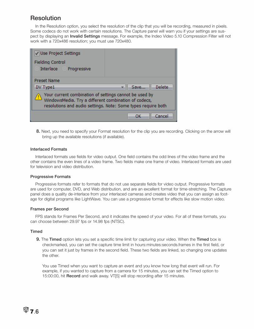
7.6
ResolutionIn the Resolution option, you select the resolution of the clip that you will be recording, measured in pixels.
Some codecs do not work with certain resolutions. The Capture panel will warn you if your settings are sus-pect by displaying an Invalid Settings message. For example, the Indeo Video 5.10 Compression Filter will not work with a 720x486 resolution; you must use 720x480.
8. Next, you need to specify your Format resolution for the clip you are recording. Clicking on the arrow will bring up the available resolutions (if available).
Interlaced Formats
Interlaced formats use fields for video output. One field contains the odd lines of the video frame and the other contains the even lines of a video frame. Two fields make one frame of video. Interlaced formats are used for television and video distribution.
Progressive Formats
Progressive formats refer to formats that do not use separate fields for video output. Progressive formats are used for computer, DVD, and Web distribution, and are an excellent format for time-stretching. The Capture panel does a quality de-interlace from your interlaced cameras and creates video that you can assign as foot-age for digital programs like LightWave. You can use a progressive format for effects like slow motion video.
Frames per Second
FPS stands for Frames Per Second, and it indicates the speed of your video. For all of these formats, you can choose between 29.97 fps or 14.98 fps (NTSC).
Timed
9. The Timed option lets you set a specific time limit for capturing your video. When the Timed box is checkmarked, you can set the capture time limit in hours:minutes:seconds.frames in the first field, or you can set it just by frames in the second field. These two fields are linked, so changing one updates the other. You use Timed when you want to capture an event and you know how long that event will run. For example, if you wanted to capture from a camera for 15 minutes, you can set the Timed option to 15:00:00, hit Record and walk away. VT[5] will stop recording after 15 minutes.
7.7
Recording Single Frames
One common use of the Timed option is to capture a still image. You set Timed to one frame (00:00:00:01). In the Format menu, pick a Progressive resolution, like 720x486 Progressive, NTSC. Now every time you click Record, it captures one frame, de-interlaces it and saves it. De-interlacing will eliminate the jitter inherent in interlaced video still frames that are displaying both fields.
Time Lapse
10. To create time-lapse photography, such as a flower opening, you use the Time Lapse option, which captures a frame of video at specific intervals. So if you enter 00:00:05:00, you tell VT[5] to capture one frame of video every five seconds. Now, if you also have Timed checked, then VT[5] will capture the number of frames specified in the Timed field. For example, if Timed was set to 2 minutes, it would capture 3600 frames of video (120 x 30 fps NTSC). If you have Time Lapse set to record one frame every minute, you will be recording that flower for 60 hours and end up with two minutes of video.
Stop When Frames Drop
11. When checkmarked, this option will stop capturing video if VT[5] ever drops frames during capture. Activate this option when you capture video from a tape so that you know if you’ve lost frames. If VT[5] drops frames, it may indicate that your hard drive can’t maintain a fast enough data transfer rate to record video. Deactivate this option when you capture a live event, so that you don’t stop recording at a critical point.
Pause When Recording Stops
12. This choice pauses the capture event and when you begin recording again, you record to the same clip (whereas when you Stop, you record to an entirely new clip when you record again).
RecordUnder the Record tab, decide what source to record, and whether to capture audio, video or both.
Input
13. You need to pick your source from the Input drop down menu. Basically, you are picking the source’s location in VT[5].
NOTE
If you have an SX-84, your list will be a lot longer because you have more input sources available.
For example, let’s say that you don’t have an SX-84 and your BetaSP deck is plugged into the Component input. Then, in the menu, under Select Analog Sources onto Main In, you would pick Component. VT[5] will route Component to Main In.
If you are capturing DV through a FireWire card, you would select Microsoft DV Camera and VCR. Remember, you need to have your DV deck or camera plugged in and turned on to see this choice in the menu.
You also can simply pick Main In or Preview In. When you choose Main In, you can capture video directly from the source that you have routed to Main In. If you choose Preview, you capture the source that sits on the Preview bus in the Switcher.
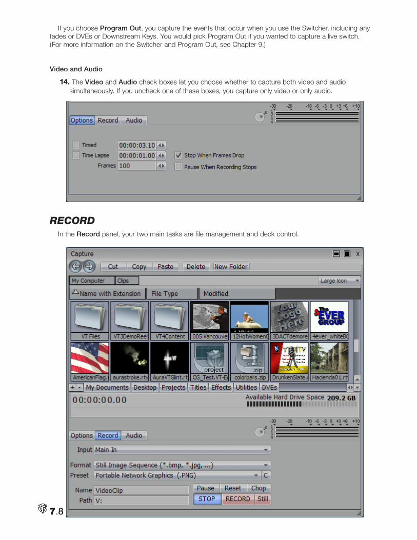
7.8
If you choose Program Out, you capture the events that occur when you use the Switcher, including any fades or DVEs or Downstream Keys. You would pick Program Out if you wanted to capture a live switch. (For more information on the Switcher and Program Out, see Chapter 9.)
Video and Audio
14. The Video and Audio check boxes let you choose whether to capture both video and audio simultaneously. If you uncheck one of these boxes, you capture only video or only audio.
RecoRdIn the Record panel, your two main tasks are file management and deck control.
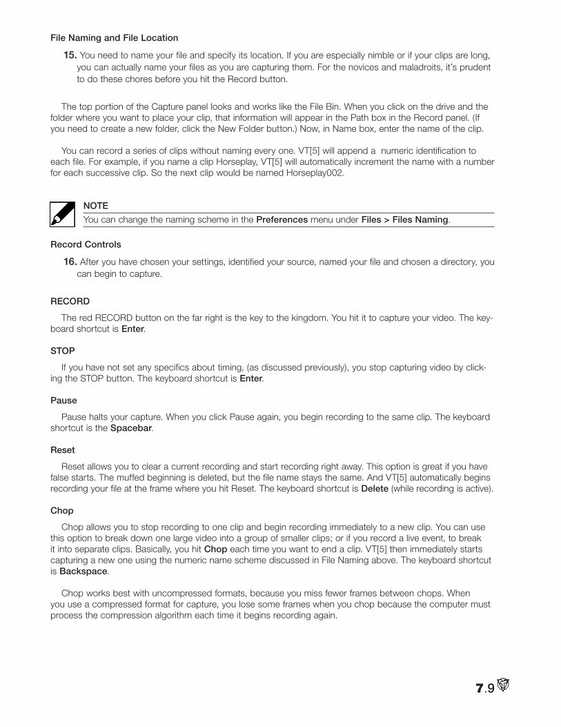
7.9
File Naming and File Location
15. You need to name your file and specify its location. If you are especially nimble or if your clips are long, you can actually name your files as you are capturing them. For the novices and maladroits, it’s prudent to do these chores before you hit the Record button.
The top portion of the Capture panel looks and works like the File Bin. When you click on the drive and the folder where you want to place your clip, that information will appear in the Path box in the Record panel. (If you need to create a new folder, click the New Folder button.) Now, in Name box, enter the name of the clip.
You can record a series of clips without naming every one. VT[5] will append a numeric identification to each file. For example, if you name a clip Horseplay, VT[5] will automatically increment the name with a number for each successive clip. So the next clip would be named Horseplay002.
NOTE
You can change the naming scheme in the Preferences menu under Files > Files Naming.
Record Controls
16. After you have chosen your settings, identified your source, named your file and chosen a directory, you can begin to capture.
RECORD
The red RECORD button on the far right is the key to the kingdom. You hit it to capture your video. The key-board shortcut is Enter.
STOP
If you have not set any specifics about timing, (as discussed previously), you stop capturing video by click-ing the STOP button. The keyboard shortcut is Enter.
Pause
Pause halts your capture. When you click Pause again, you begin recording to the same clip. The keyboard shortcut is the Spacebar.
Reset
Reset allows you to clear a current recording and start recording right away. This option is great if you have false starts. The muffed beginning is deleted, but the file name stays the same. And VT[5] automatically begins recording your file at the frame where you hit Reset. The keyboard shortcut is Delete (while recording is active).
Chop
Chop allows you to stop recording to one clip and begin recording immediately to a new clip. You can use this option to break down one large video into a group of smaller clips; or if you record a live event, to break it into separate clips. Basically, you hit Chop each time you want to end a clip. VT[5] then immediately starts capturing a new one using the numeric name scheme discussed in File Naming above. The keyboard shortcut is Backspace.
Chop works best with uncompressed formats, because you miss fewer frames between chops. When you use a compressed format for capture, you lose some frames when you chop because the computer must process the compression algorithm each time it begins recording again.
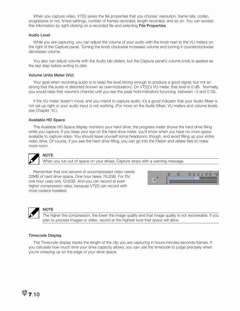
7.10
When you capture video, VT[5] saves the file properties that you choose: resolution, frame rate, codec, progressive or not, timed settings, number of frames recorded, length recorded, and so on. You can access this information by right-clicking on a recorded file and selecting File Properties.
Audio Level
While you are capturing, you can adjust the volume of your audio with the knob next to the VU meters on the right of the Capture panel. Turning the knob clockwise increases volume and turning it counterclockwise decreases volume.
You also can adjust volume with the Audio tab sliders, but the Capture panel’s volume knob is applied as the last step before writing to disk.
Volume Units Meter (VU)
Your goal when recording audio is to keep the level strong enough to produce a good signal, but not so strong that the audio is distorted (known as overmodulation). On VT[5]’s VU meter, that level is 0 dB. Normally, you would raise that volume’s channel until you see the peak hold indicators bouncing between –3 and 0 Db.
If the VU meter doesn’t move, and you intend to capture audio, it’s a good indicator that your Audio Mixer is not set up right or your audio input is not working. (For more on the Audio Mixer, VU meters and volume levels, see Chapter 10.).
Available HD Space
The Available HD Space display monitors your hard drive; the progress meter shows the hard drive filling while you capture. If you keep your eye on the hard drive meter, you’ll know when you have no more space available to capture video. You should leave yourself some headroom, though, and avoid filling up your entire video drive. Of course, if you see the hard drive filling, you can go into the Filebin and delete files to make more room.
NOTE
When you run out of space on your drives, Capture stops with a warning message.
Remember that one second of uncompressed video needs 22MB of hard drive space. One hour takes 79.2GB. For DV, one hour uses only 12.6GB. And you can record at even higher compression rates, because VT[5] can record with most codecs installed.
NOTE
The higher the compression, the lower the image quality and that image quality is not recoverable. If you plan to process images or video, record at the highest level that space will allow.
Timecode Display
The Timecode display tracks the length of the clip you are capturing in hours:minutes:seconds:frames. If you calculate how much time your drive capacity allows, you can use the timecode to judge precisely when you’re creeping up on the edge of your drive space.
7.11
AudioThe third tab on Capture allows you to adjust the incoming audio levels as you record, on a per-channel
basis. There are sliders for each discrete audio input on the SX-84 breakout, with the first four inputs the bal-anced mic or line ins. The remaining six inputs are the input controls for the unbalanced RCA inputs.
2 Chan
When capturing stereo sources, selecting 2 Chan will route all inputs to the first two, or front channels.
4 Chan
If you have 4 inputs active on the SX-84’s balanced inputs, selecting 4 Chan will route each input to its own source, with each input having its own level controls, and separate Vu metering.
Note
Adjusting audio inputs with the volume knob is applied globally to all the input sliders being used.
BatcH captuReUnlike manual capturing, (where you just play your tape and hit Record when you are ready to capture),
batch capturing is a more controllable procedure that works with precise timecodes on the source tapes. A batch capture session can be recorded and recalled later to repeat the process.
In the world of non-linear editing, there never seems to be enough hard drive space. Ultimately, you have to clear your video drives to make room for the next project. But if you have batch captured your clips, you can reproduce the capture session if you need to restore your project to make revisions.
Basic Batch Capture Setup1. From the Main Menu, in the Control Room section, load Batch Capture.
2. Since batch capturing relies on being able to communicate with and control a video deck, you begin by setting up your deck. You can do it directly in this panel by clicking on the arrow next to Source Preset in the lower left of the panel. The procedure also can be done in the Deck Control panel. (See Chapter 6 for detailed instructions.)
3. When you have your deck configured, load the tape. If everything is working, the Timecode display on the Batch Capture panel should be showing the timecode on the tape.
Auto Mark
4. Use the deck controls on the panel to find the beginning of the first spot on the tape that you want to capture. When you see it, hit the Auto Mark button, which sets your In Point. Let the tape roll and when you see the end point, hit the Auto Mark button again, which sets the Out Point for the clip. (You have just set your first batch capture points.) If you click Auto Mark a third time, you set the In Point of your next clip. And so it goes.
Mark In & Mark Out
Now, occasionally, you will click Auto Mark before you really wanted to set the In or Out Point. For example, the voice-over talent starts a take, you hit Auto Mark, and then he flubs after two sentences and starts over. If you hit Mark In, it will reset the In Point. Then he flubs again. Hit Mark In again. Mark In sets a temporary In Point that can be changed as long as you don’t move on to the next clip.
7.12
Mark Out works the same way. If you hit Auto Mark to set an Out Point and then realize that you need more of the take, you can click on Mark Out and it will reset the Out Point. Now, the fastest way to move to setting points for the next clip is to click on Auto Mark.
The problem is that when you do, it resets the Out Point. If you want to keep the Out Point made with Mark Out, you need to click on an empty area of the Batch Capture panel to deselect the clip. Now, when you hit Auto Mark, it begins a new clip without changing the Out Point of the previous clip. Try it to see how it works.
Keyboard Shortcuts
If you are a two-handed batch capturer, the keyboard shortcut for Auto Mark is the Spacebar. Mark In is i and Mark Out is o.
HINT
If you press F1 in any panel, the list of keyboard shortcuts for that panel will pop up.
Batch Capture Entry Field
Look at the data that is generated when you set In and Out Points.
Tape Name
5. VT[5] puts in a default Untitled Tape Name. It’s critical that you change this to the name that you labeled your tape. Each tape needs a unique label for Batch Capture to work efficiently. So you need to adopt a habit of titling your tapes. Batch Capture is relying on you to feed it the proper tape. If you don’t it will merrily go on capturing clips according to the timecode, oblivious to the fact that the tape is of your daughter’s birthday instead of the malpractice deposition.
You edit the Tape Name by clicking once in the field and start typing. The original name will be replaced by the new one. When you are finished, click in an empty area of the Batch Capture panel. If you hit Enter after typing, a new entry will be generated. This facilitates typing in a Batch Capture list, which is discussed below.
You also can right-click in field, choose Edit Tape Name from the Context Menu, and type in a new name.
HINT
If you want to change a number of entries to the same name, Shift-click or Ctrl-click to select them. Then when you type a new name, it will change the name for all the entries.
Capturing from Multiple Tapes
If you have clips to capture from more than one tape, the procedure is the same. You just put the new tape in the deck and continue setting In and Out Points. Again, it’s essential to put the new tape name in the Batch Capture list. When it comes time to perform your batch capturing, VT[5] will cue you to insert the new tape.
Editing In, Out, and Duration
The In Point, Out Point, and Duration fields can all be edited the same way: Click, type in a new value and click in an empty area of the panel. When changing Duration, it leaves the In Point and adjusts the Out Point.
Comments
This field is aptly titled. You can enter any sort of comments here, like “best take” or “plane noise.”
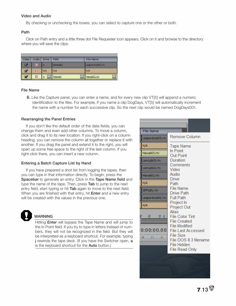
7.13
Video and Audio
By checking or unchecking the boxes, you can select to capture one or the other or both.
Path
Click on Path entry and a little three dot File Requester icon appears. Click on it and browse to the directory where you will save the clips.
File Name
6. Like the Capture panel, you can enter a name, and for every new clip VT[5] will append a numeric identification to the files. For example, if you name a clip DogDays, VT[5] will automatically increment the name with a number for each successive clip. So the next clip would be named DogDays001.
Rearranging the Panel Entries
If you don’t like the default order of the data fields, you can change them and even add other columns. To move a column, click and drag it to its new location. If you right-click on a column heading, you can remove the column all together or replace it with another. If you drag the panel and extend it to the right, you will open up some free space to the right of the last column. If you right-click there, you can insert a new column.
Entering a Batch Capture List by Hand
If you have prepared a shot list from logging the tapes, then you can type in that information directly. To begin, press the Spacebar to generate an entry. Click in the Tape Name field and type the name of the tape. Then, press Tab to jump to the next entry field, start typing or hit Tab again to move to the next field. When you are finished with that entry, hit Enter and a new entry will be created with the values in the previous one.
WARNING
Hitting Enter will bypass the Tape Name and will jump to the In Point field. If you try to type in letters instead of num-bers, they will not be recognized in the field. But they will be interpreted as a keyboard shortcut. For example, typing j rewinds the tape deck. (If you have the Switcher open, a is the keyboard shortcut for the Auto button.)
7.14
Performing a Batch Capture7. After you have set your In and Out Points, named your tapes and your clips, you are ready to start
the session.
Rehearse Capture
If you want to review your list, hit Rehearse Capture. VT[5] will run through the Batch Capture session; it just won’t actually capture the clips. If you are adjusting Proc Amp settings or Audio levels, rehearsing the capture gives you a chance to make all your notes.
Capture Selected & Capture All
If you only want to capture some of the clips in the list, Ctrl + click to select them and hit Capture Select. To record all of them, they don’t need to be selected, just click Capture All.
Two panels pop up. In the Insert Tape… panel, check to see if the right deck is listed in Source Preset.
Clip Padding
8. Then, on the left, you can set the Clip Padding, which is the length of time (in seconds) that VT[5] will extend your In and Out Points. For example, if you set an In Point at 00:02:03:00 and you tell VT[5] to pad it by one second, then the capture will begin at 00:02:02:00, a second earlier. Padding occurs on both ends of the clip. In this case, the capture would end a second after the Out Point. Clip padding affords a little slop factor when you are setting In and Outs, and gives you a little wiggle room when you are editing.
Start Capture
9. Hit Start Capture to begin the Batch Capture. The Insert Tape panel disappears, leaving the Batch Capture Progress display. VT[5] begins searching for the spot on the tape. When it finds it, it starts capturing. When it finishes the first clip, it searches for the second, and so on, until it finishes the list or it prompts you to change tapes. At the end of your session, the clips will be on your hard drives. If you select one in a Filebin and look at its Edit Properties, you will see that it has the Tape Name listed, which along with its timecode, is the information needed to reproduce the capture.
Saving a Batch Capture Project
10. To save the session, click on File and Save. A File Requester will open to the default Batch Capture Folder that is set up in the VT Files folder on your video drive. Depending on how you organize your material, you may wish to save the project in a more meaningful location. If so, browse to it and give your project a name.
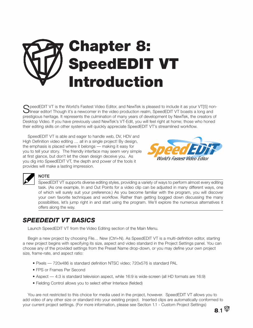
8.1
SpeedEDIT VT is the World’s Fastest Video Editor, and NewTek is pleased to include it as your VT[5] non-linear editor! Though it’s a newcomer in the video production realm, SpeedEDIT VT boasts a long and
prestigious heritage. It represents the culmination of many years of development by NewTek, the creators of Desktop Video. If you have previously used NewTek’s VT-Edit, you will feel right at home; those who honed their editing skills on other systems will quickly appreciate SpeedEDIT VT’s streamlined workflow.
SpeedEDIT VT is able and eager to handle web, DV, HDV and High Definition video editing … all in a single project! By design, the emphasis is placed where it belongs — making it easy for you to tell your story. The friendly interface may seem very simple at first glance, but don’t let the clean design deceive you. As you dig into SpeedEDIT VT, the depth and power of the tools it provides will make a lasting impression.
NOTE
SpeedEDIT VT supports diverse editing styles, providing a variety of ways to perform almost every editing task. (As one example, In and Out Points for a video clip can be adjusted in many different ways, one of which will surely suit your preference.) As you become familiar with the program, you will discover your own favorite techniques and workflow. Rather than getting bogged down discussing the many possibilities, let’s jump right in and start using the program. We’ll explore the numerous alternatives it offers along the way.
Speededit Vt BaSicS Launch SpeedEDIT VT from the Video Editing section of the Main Menu.
Begin a new project by choosing File… New (Ctrl+N). As SpeedEDIT VT is a multi-definition editor, starting a new project begins with specifying its size, aspect and video standard in the Project Settings panel. You can choose any of the provided settings from the Preset Name drop-down, or you may define your own project size, frame-rate, and aspect ratio:
• Pixels — 720x486 is standard definition NTSC video; 720x576 is standard PAL
• FPS or Frames Per Second
• Aspect — 4:3 is standard television aspect, while 16:9 is wide-screen (all HD formats are 16:9)
• Fielding Control allows you to select either Interlace (fielded)
You are not restricted to this choice for media used in the project, however. SpeedEDIT VT allows you to add video of any other size or standard into your existing project. Inserted clips are automatically conformed to your current project settings. (For more information, please see Section 1.1 - Custom Project Settings)
Chapter 8: SpeedEDIT VTIntroduction
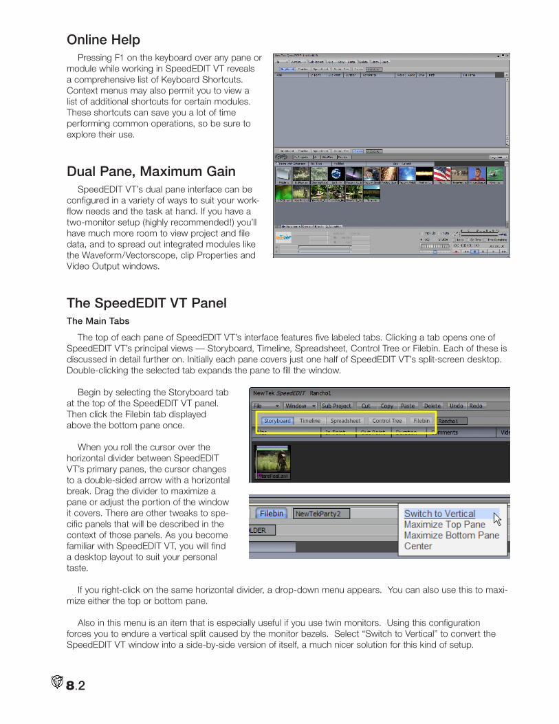
8.2
Online HelpPressing F1 on the keyboard over any pane or
module while working in SpeedEDIT VT reveals a comprehensive list of Keyboard Shortcuts. Context menus may also permit you to view a list of additional shortcuts for certain modules. These shortcuts can save you a lot of time performing common operations, so be sure to explore their use.
Dual Pane, Maximum GainSpeedEDIT VT’s dual pane interface can be
configured in a variety of ways to suit your work-flow needs and the task at hand. If you have a two-monitor setup (highly recommended!) you’ll have much more room to view project and file data, and to spread out integrated modules like the Waveform/Vectorscope, clip Properties and Video Output windows.
The SpeedEDIT VT PanelThe Main Tabs
The top of each pane of SpeedEDIT VT’s interface features five labeled tabs. Clicking a tab opens one of SpeedEDIT VT’s principal views — Storyboard, Timeline, Spreadsheet, Control Tree or Filebin. Each of these is discussed in detail further on. Initially each pane covers just one half of SpeedEDIT VT’s split-screen desktop. Double-clicking the selected tab expands the pane to fill the window.
Begin by selecting the Storyboard tab at the top of the SpeedEDIT VT panel. Then click the Filebin tab displayed above the bottom pane once.
When you roll the cursor over the horizontal divider between SpeedEDIT VT’s primary panes, the cursor changes to a double-sided arrow with a horizontal break. Drag the divider to maximize a pane or adjust the portion of the window it covers. There are other tweaks to spe-cific panels that will be described in the context of those panels. As you become familiar with SpeedEDIT VT, you will find a desktop layout to suit your personal taste.
If you right-click on the same horizontal divider, a drop-down menu appears. You can also use this to maxi-mize either the top or bottom pane.
Also in this menu is an item that is especially useful if you use twin monitors. Using this configuration forces you to endure a vertical split caused by the monitor bezels. Select “Switch to Vertical” to convert the SpeedEDIT VT window into a side-by-side version of itself, a much nicer solution for this kind of setup.
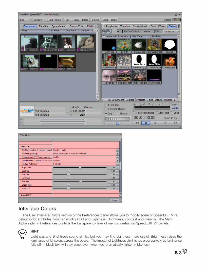
8.3
Interface ColorsThe User Interface Colors section of the Preferences panel allows you to modify some of SpeedEDIT VT’s
default color attributes. You can modify RBB and Lightness, Brightness, contrast and Gamma. The Menu Alpha slider in Preferences controls the transparency level of menus overlaid on SpeedEDIT VT panels.
HINT
Lightness and Brightness sound similar, but you may find Lightness more useful. Brightness raises the luminance of UI colors across the board. The impact of Lightness diminishes progressively as luminance falls off — black text will stay black even when you dramatically lighten midtones.)
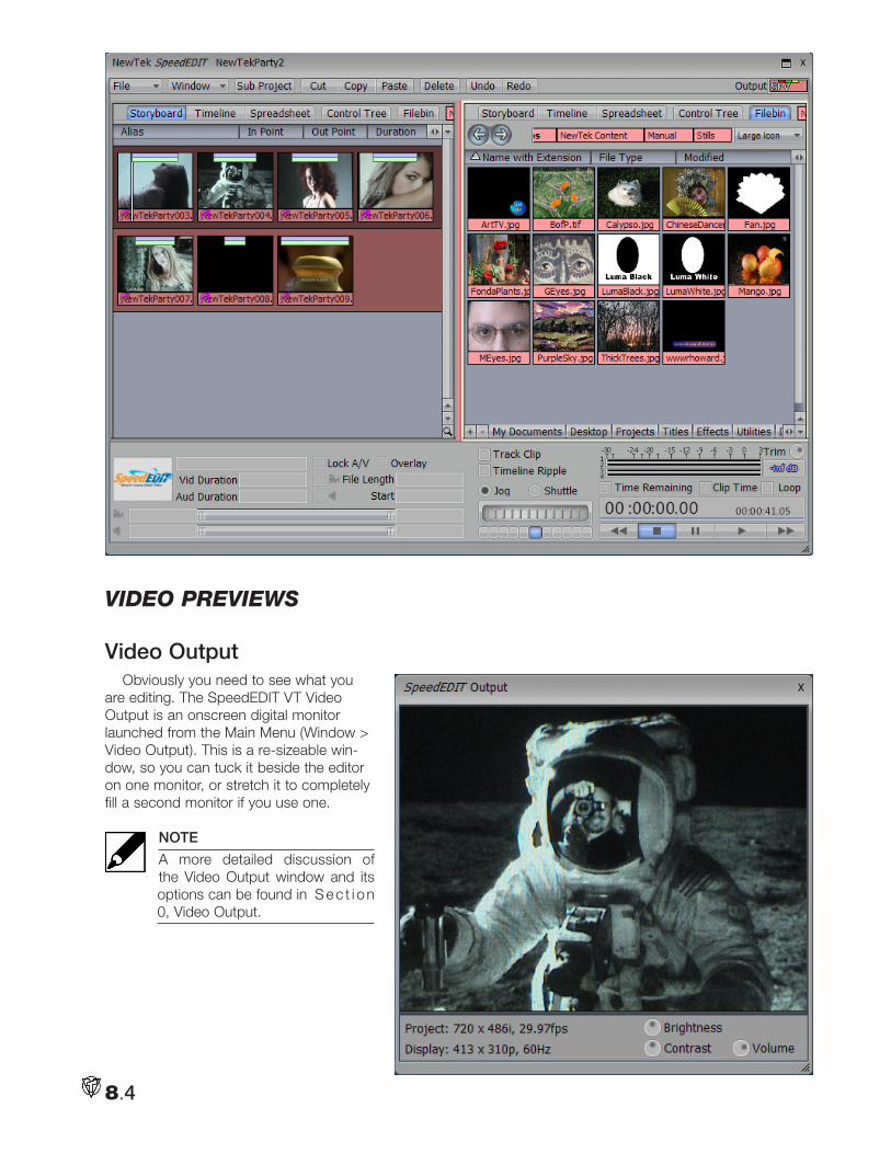
8.4
Video pReViewS
Video OutputObviously you need to see what you
are editing. The SpeedEDIT VT Video Output is an onscreen digital monitor launched from the Main Menu (Window > Video Output). This is a re-sizeable win-dow, so you can tuck it beside the editor on one monitor, or stretch it to completely fill a second monitor if you use one.
NOTE
A more detailed discussion of the Video Output window and its options can be found in S e c t i o n 0, Video Output.
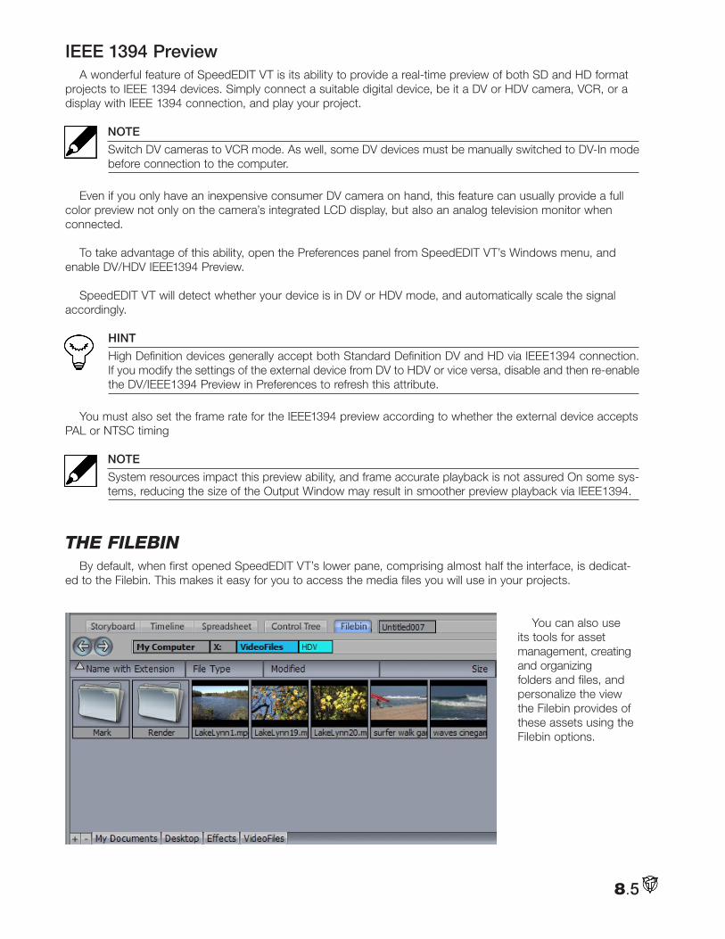
8.5
IEEE 1394 PreviewA wonderful feature of SpeedEDIT VT is its ability to provide a real-time preview of both SD and HD format
projects to IEEE 1394 devices. Simply connect a suitable digital device, be it a DV or HDV camera, VCR, or a display with IEEE 1394 connection, and play your project.
NOTE
Switch DV cameras to VCR mode. As well, some DV devices must be manually switched to DV-In mode before connection to the computer.
Even if you only have an inexpensive consumer DV camera on hand, this feature can usually provide a full color preview not only on the camera’s integrated LCD display, but also an analog television monitor when connected.
To take advantage of this ability, open the Preferences panel from SpeedEDIT VT’s Windows menu, and enable DV/HDV IEEE1394 Preview.
SpeedEDIT VT will detect whether your device is in DV or HDV mode, and automatically scale the signal accordingly.
HINT
High Definition devices generally accept both Standard Definition DV and HD via IEEE1394 connection. If you modify the settings of the external device from DV to HDV or vice versa, disable and then re-enable the DV/IEEE1394 Preview in Preferences to refresh this attribute.
You must also set the frame rate for the IEEE1394 preview according to whether the external device accepts PAL or NTSC timing
NOTE
System resources impact this preview ability, and frame accurate playback is not assured On some sys-tems, reducing the size of the Output Window may result in smoother preview playback via IEEE1394.
tHe fileBinBy default, when first opened SpeedEDIT VT’s lower pane, comprising almost half the interface, is dedicat-
ed to the Filebin. This makes it easy for you to access the media files you will use in your projects.
You can also use its tools for asset management, creating and organizing folders and files, and personalize the view the Filebin provides of these assets using the Filebin options.
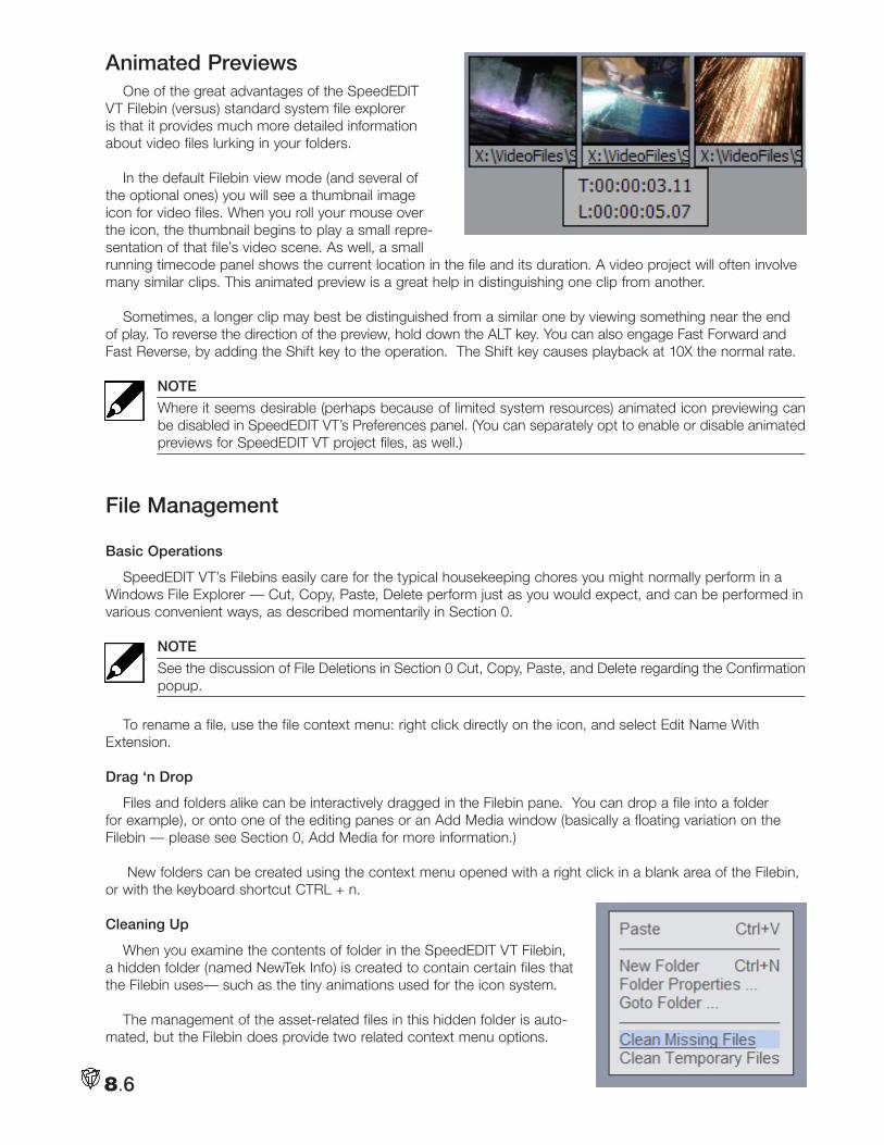
8.6
Animated PreviewsOne of the great advantages of the SpeedEDIT
VT Filebin (versus) standard system file explorer is that it provides much more detailed information about video files lurking in your folders.
In the default Filebin view mode (and several of the optional ones) you will see a thumbnail image icon for video files. When you roll your mouse over the icon, the thumbnail begins to play a small repre-sentation of that file’s video scene. As well, a small running timecode panel shows the current location in the file and its duration. A video project will often involve many similar clips. This animated preview is a great help in distinguishing one clip from another.
Sometimes, a longer clip may best be distinguished from a similar one by viewing something near the end of play. To reverse the direction of the preview, hold down the ALT key. You can also engage Fast Forward and Fast Reverse, by adding the Shift key to the operation. The Shift key causes playback at 10X the normal rate.
NOTE
Where it seems desirable (perhaps because of limited system resources) animated icon previewing can be disabled in SpeedEDIT VT’s Preferences panel. (You can separately opt to enable or disable animated previews for SpeedEDIT VT project files, as well.)
File Management
Basic Operations
SpeedEDIT VT’s Filebins easily care for the typical housekeeping chores you might normally perform in a Windows File Explorer — Cut, Copy, Paste, Delete perform just as you would expect, and can be performed in various convenient ways, as described momentarily in Section 0.
NOTE
See the discussion of File Deletions in Section 0 Cut, Copy, Paste, and Delete regarding the Confirmation popup.
To rename a file, use the file context menu: right click directly on the icon, and select Edit Name With Extension.
Drag ‘n Drop
Files and folders alike can be interactively dragged in the Filebin pane. You can drop a file into a folder for example), or onto one of the editing panes or an Add Media window (basically a floating variation on the Filebin — please see Section 0, Add Media for more information.)
New folders can be created using the context menu opened with a right click in a blank area of the Filebin, or with the keyboard shortcut CTRL + n.
Cleaning Up
When you examine the contents of folder in the SpeedEDIT VT Filebin, a hidden folder (named NewTek Info) is created to contain certain files that the Filebin uses— such as the tiny animations used for the icon system.
The management of the asset-related files in this hidden folder is auto-mated, but the Filebin does provide two related context menu options.
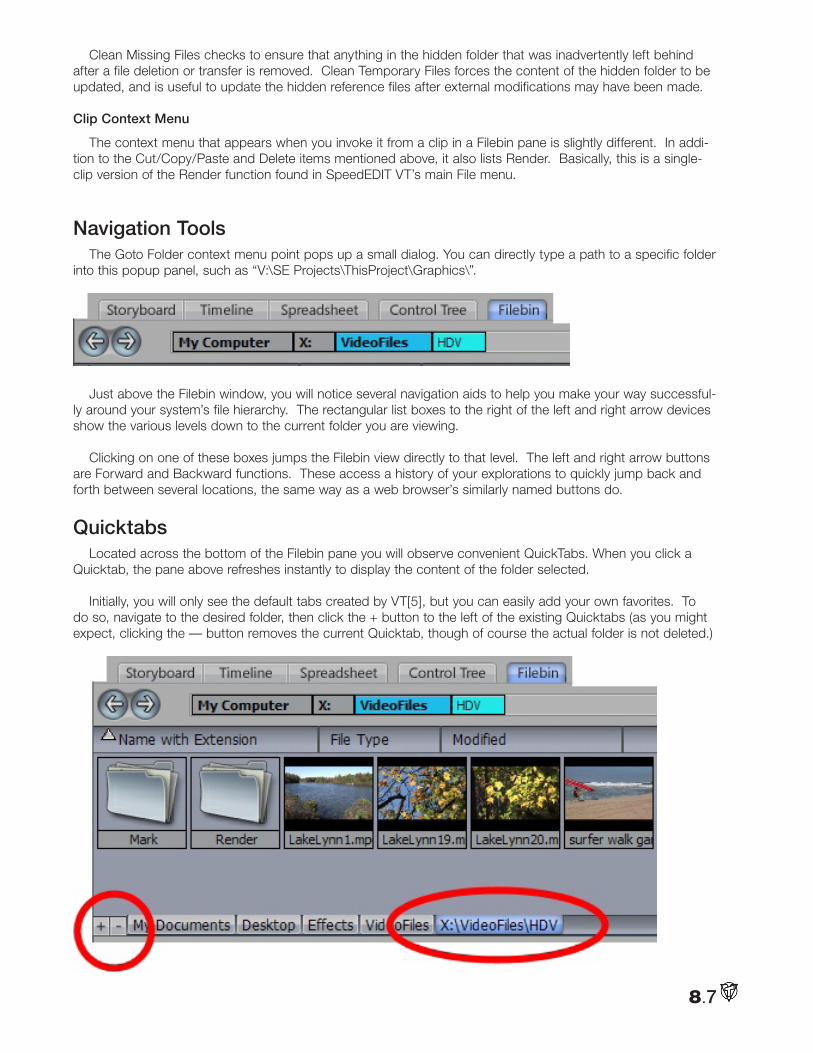
8.7
Clean Missing Files checks to ensure that anything in the hidden folder that was inadvertently left behind after a file deletion or transfer is removed. Clean Temporary Files forces the content of the hidden folder to be updated, and is useful to update the hidden reference files after external modifications may have been made.
Clip Context Menu
The context menu that appears when you invoke it from a clip in a Filebin pane is slightly different. In addi-tion to the Cut/Copy/Paste and Delete items mentioned above, it also lists Render. Basically, this is a single-clip version of the Render function found in SpeedEDIT VT’s main File menu.
Navigation ToolsThe Goto Folder context menu point pops up a small dialog. You can directly type a path to a specific folder
into this popup panel, such as “V:\SE Projects\ThisProject\Graphics\”.
Just above the Filebin window, you will notice several navigation aids to help you make your way successful-ly around your system’s file hierarchy. The rectangular list boxes to the right of the left and right arrow devices show the various levels down to the current folder you are viewing.
Clicking on one of these boxes jumps the Filebin view directly to that level. The left and right arrow buttons are Forward and Backward functions. These access a history of your explorations to quickly jump back and forth between several locations, the same way as a web browser’s similarly named buttons do.
QuicktabsLocated across the bottom of the Filebin pane you will observe convenient QuickTabs. When you click a
Quicktab, the pane above refreshes instantly to display the content of the folder selected.
Initially, you will only see the default tabs created by VT[5], but you can easily add your own favorites. To do so, navigate to the desired folder, then click the + button to the left of the existing Quicktabs (as you might expect, clicking the — button removes the current Quicktab, though of course the actual folder is not deleted.)
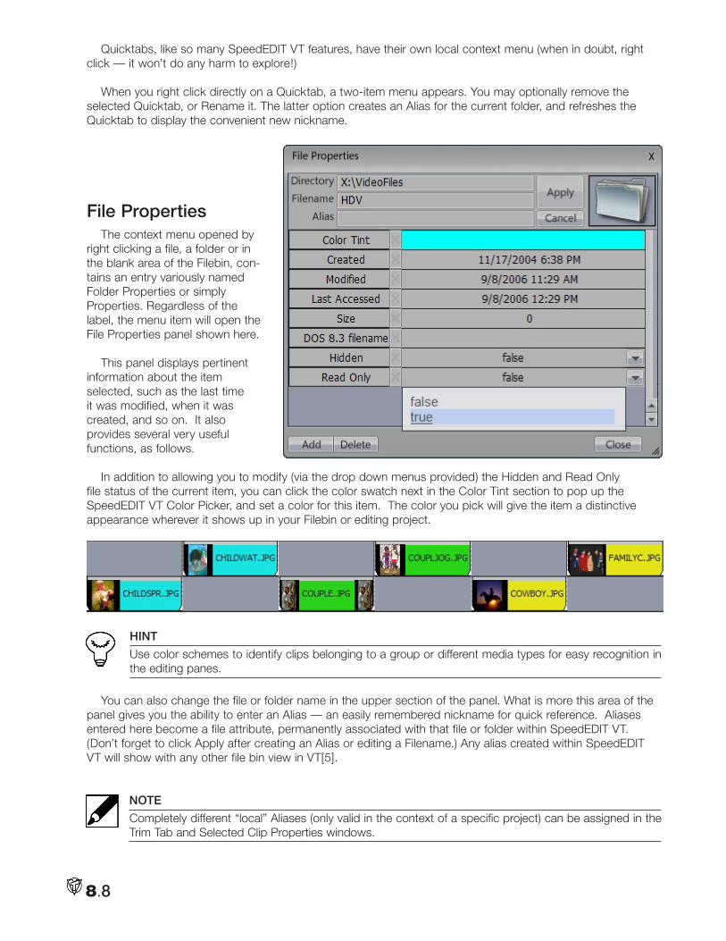
8.8
Quicktabs, like so many SpeedEDIT VT features, have their own local context menu (when in doubt, right click — it won’t do any harm to explore!)
When you right click directly on a Quicktab, a two-item menu appears. You may optionally remove the selected Quicktab, or Rename it. The latter option creates an Alias for the current folder, and refreshes the Quicktab to display the convenient new nickname.
File PropertiesThe context menu opened by
right clicking a file, a folder or in the blank area of the Filebin, con-tains an entry variously named Folder Properties or simply Properties. Regardless of the label, the menu item will open the File Properties panel shown here.
This panel displays pertinent information about the item selected, such as the last time it was modified, when it was created, and so on. It also provides several very useful functions, as follows.
In addition to allowing you to modify (via the drop down menus provided) the Hidden and Read Only file status of the current item, you can click the color swatch next in the Color Tint section to pop up the SpeedEDIT VT Color Picker, and set a color for this item. The color you pick will give the item a distinctive appearance wherever it shows up in your Filebin or editing project.
HINT
Use color schemes to identify clips belonging to a group or different media types for easy recognition in the editing panes.
You can also change the file or folder name in the upper section of the panel. What is more this area of the panel gives you the ability to enter an Alias — an easily remembered nickname for quick reference. Aliases entered here become a file attribute, permanently associated with that file or folder within SpeedEDIT VT. (Don’t forget to click Apply after creating an Alias or editing a Filename.) Any alias created within SpeedEDIT VT will show with any other file bin view in VT[5].
NOTE
Completely different “local” Aliases (only valid in the context of a specific project) can be assigned in the Trim Tab and Selected Clip Properties windows.
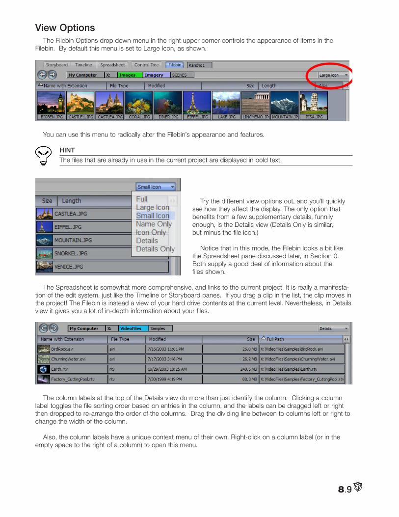
8.9
View OptionsThe Filebin Options drop down menu in the right upper corner controls the appearance of items in the
Filebin. By default this menu is set to Large Icon, as shown.
You can use this menu to radically alter the Filebin’s appearance and features.
HINT
The files that are already in use in the current project are displayed in bold text.
Try the different view options out, and you’ll quickly see how they affect the display. The only option that benefits from a few supplementary details, funnily enough, is the Details view (Details Only is similar, but minus the file icon.)
Notice that in this mode, the Filebin looks a bit like the Spreadsheet pane discussed later, in Section 0. Both supply a good deal of information about the files shown.
The Spreadsheet is somewhat more comprehensive, and links to the current project. It is really a manifesta-tion of the edit system, just like the Timeline or Storyboard panes. If you drag a clip in the list, the clip moves in the project! The Filebin is instead a view of your hard drive contents at the current level. Nevertheless, in Details view it gives you a lot of in-depth information about your files.
The column labels at the top of the Details view do more than just identify the column. Clicking a column label toggles the file sorting order based on entries in the column, and the labels can be dragged left or right then dropped to re-arrange the order of the columns. Drag the dividing line between to columns left or right to change the width of the column.
Also, the column labels have a unique context menu of their own. Right-click on a column label (or in the empty space to the right of a column) to open this menu.
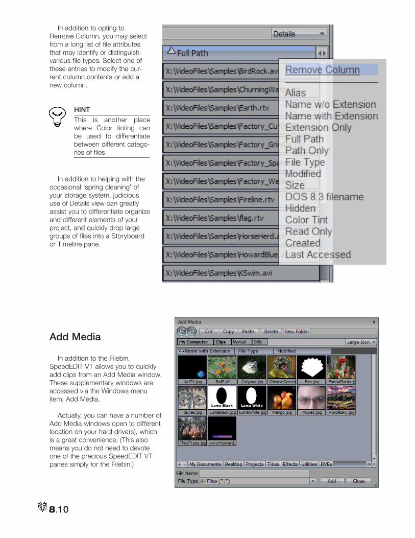
8.10
In addition to opting to Remove Column, you may select from a long list of file attributes that may identify or distinguish various file types. Select one of these entries to modify the cur-rent column contents or add a new column.
HINT
This is another place where Color tinting can be used to differentiate between different catego-ries of files.
In addition to helping with the occasional ‘spring cleaning’ of your storage system, judicious use of Details view can greatly assist you to differentiate organize and different elements of your project, and quickly drop large groups of files into a Storyboard or Timeline pane.
Add Media In addition to the Filebin,
SpeedEDIT VT allows you to quickly add clips from an Add Media window. These supplementary windows are accessed via the Windows menu item, Add Media.
Actually, you can have a number of Add Media windows open to different location on your hard drive(s), which is a great convenience. (This also means you do not need to devote one of the precious SpeedEDIT VT panes simply for the Filebin.)
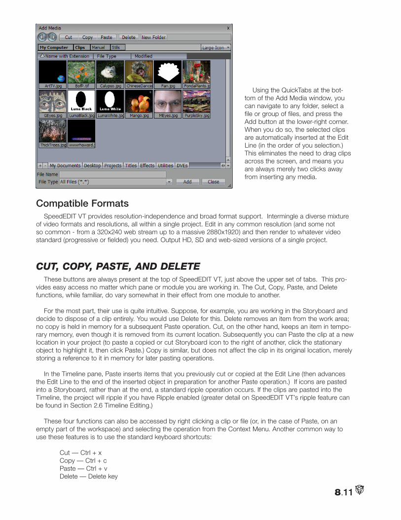
8.11
Using the QuickTabs at the bot-tom of the Add Media window, you can navigate to any folder, select a file or group of files, and press the Add button at the lower-right corner. When you do so, the selected clips are automatically inserted at the Edit Line (in the order of you selection.) This eliminates the need to drag clips across the screen, and means you are always merely two clicks away from inserting any media.
Compatible FormatsSpeedEDIT VT provides resolution-independence and broad format support. Intermingle a diverse mixture
of video formats and resolutions, all within a single project. Edit in any common resolution (and some not so common - from a 320x240 web stream up to a massive 2880x1920) and then render to whatever video standard (progressive or fielded) you need. Output HD, SD and web-sized versions of a single project.
cut, copy, paSte, and deleteThese buttons are always present at the top of SpeedEDIT VT, just above the upper set of tabs. This pro-
vides easy access no matter which pane or module you are working in. The Cut, Copy, Paste, and Delete functions, while familiar, do vary somewhat in their effect from one module to another.
For the most part, their use is quite intuitive. Suppose, for example, you are working in the Storyboard and decide to dispose of a clip entirely. You would use Delete for this. Delete removes an item from the work area; no copy is held in memory for a subsequent Paste operation. Cut, on the other hand, keeps an item in tempo-rary memory, even though it is removed from its current location. Subsequently you can Paste the clip at a new location in your project (to paste a copied or cut Storyboard icon to the right of another, click the stationary object to highlight it, then click Paste.) Copy is similar, but does not affect the clip in its original location, merely storing a reference to it in memory for later pasting operations.
In the Timeline pane, Paste inserts items that you previously cut or copied at the Edit Line (then advances the Edit Line to the end of the inserted object in preparation for another Paste operation.) If icons are pasted into a Storyboard, rather than at the end, a standard ripple operation occurs. If the clips are pasted into the Timeline, the project will ripple if you have Ripple enabled (greater detail on SpeedEDIT VT’s ripple feature can be found in Section 2.6 Timeline Editing.)
These four functions can also be accessed by right clicking a clip or file (or, in the case of Paste, on an empty part of the workspace) and selecting the operation from the Context Menu. Another common way to use these features is to use the standard keyboard shortcuts:
Cut — Ctrl + x Copy — Ctrl + c Paste — Ctrl + v Delete — Delete key
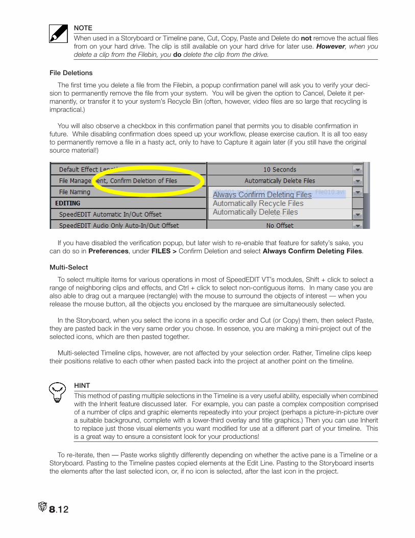
8.12
NOTE
When used in a Storyboard or Timeline pane, Cut, Copy, Paste and Delete do not remove the actual files from on your hard drive. The clip is still available on your hard drive for later use. However, when you delete a clip from the Filebin, you do delete the clip from the drive.
File Deletions
The first time you delete a file from the Filebin, a popup confirmation panel will ask you to verify your deci-sion to permanently remove the file from your system. You will be given the option to Cancel, Delete it per-manently, or transfer it to your system’s Recycle Bin (often, however, video files are so large that recycling is impractical.)
You will also observe a checkbox in this confirmation panel that permits you to disable confirmation in future. While disabling confirmation does speed up your workflow, please exercise caution. It is all too easy to permanently remove a file in a hasty act, only to have to Capture it again later (if you still have the original source material!)
If you have disabled the verification popup, but later wish to re-enable that feature for safety’s sake, you can do so in Preferences, under FILES > Confirm Deletion and select Always Confirm Deleting Files.
Multi-Select
To select multiple items for various operations in most of SpeedEDIT VT’s modules, Shift + click to select a range of neighboring clips and effects, and Ctrl + click to select non-contiguous items. In many case you are also able to drag out a marquee (rectangle) with the mouse to surround the objects of interest — when you release the mouse button, all the objects you enclosed by the marquee are simultaneously selected.
In the Storyboard, when you select the icons in a specific order and Cut (or Copy) them, then select Paste, they are pasted back in the very same order you chose. In essence, you are making a mini-project out of the selected icons, which are then pasted together.
Multi-selected Timeline clips, however, are not affected by your selection order. Rather, Timeline clips keep their positions relative to each other when pasted back into the project at another point on the timeline.
HINT
This method of pasting multiple selections in the Timeline is a very useful ability, especially when combined with the Inherit feature discussed later. For example, you can paste a complex composition comprised of a number of clips and graphic elements repeatedly into your project (perhaps a picture-in-picture over a suitable background, complete with a lower-third overlay and title graphics.) Then you can use Inherit to replace just those visual elements you want modified for use at a different part of your timeline. This is a great way to ensure a consistent look for your productions!
To re-iterate, then — Paste works slightly differently depending on whether the active pane is a Timeline or a Storyboard. Pasting to the Timeline pastes copied elements at the Edit Line. Pasting to the Storyboard inserts the elements after the last selected icon, or, if no icon is selected, after the last icon in the project.
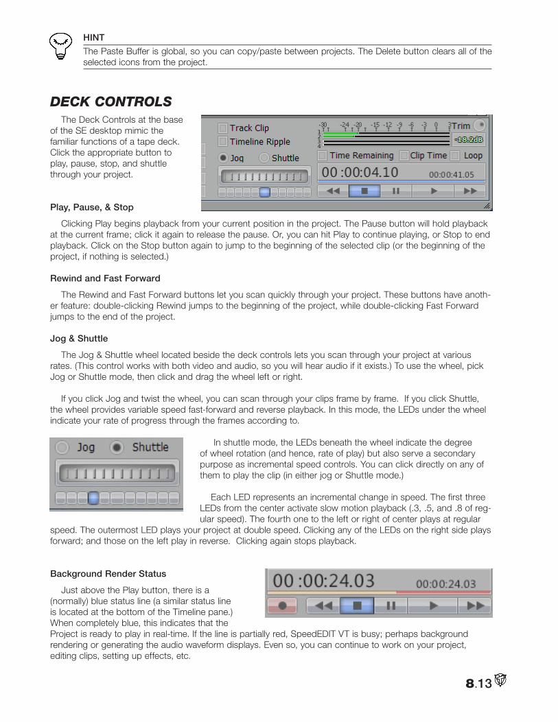
8.13
HINT
The Paste Buffer is global, so you can copy/paste between projects. The Delete button clears all of the selected icons from the project.
deck contRolSThe Deck Controls at the base
of the SE desktop mimic the familiar functions of a tape deck. Click the appropriate button to play, pause, stop, and shuttle through your project.
Play, Pause, & Stop
Clicking Play begins playback from your current position in the project. The Pause button will hold playback at the current frame; click it again to release the pause. Or, you can hit Play to continue playing, or Stop to end playback. Click on the Stop button again to jump to the beginning of the selected clip (or the beginning of the project, if nothing is selected.)
Rewind and Fast Forward
The Rewind and Fast Forward buttons let you scan quickly through your project. These buttons have anoth-er feature: double-clicking Rewind jumps to the beginning of the project, while double-clicking Fast Forward jumps to the end of the project.
Jog & Shuttle
The Jog & Shuttle wheel located beside the deck controls lets you scan through your project at various rates. (This control works with both video and audio, so you will hear audio if it exists.) To use the wheel, pick Jog or Shuttle mode, then click and drag the wheel left or right.
If you click Jog and twist the wheel, you can scan through your clips frame by frame. If you click Shuttle, the wheel provides variable speed fast-forward and reverse playback. In this mode, the LEDs under the wheel indicate your rate of progress through the frames according to.
In shuttle mode, the LEDs beneath the wheel indicate the degree of wheel rotation (and hence, rate of play) but also serve a secondary purpose as incremental speed controls. You can click directly on any of them to play the clip (in either jog or Shuttle mode.)
Each LED represents an incremental change in speed. The first three LEDs from the center activate slow motion playback (.3, .5, and .8 of reg-ular speed). The fourth one to the left or right of center plays at regular
speed. The outermost LED plays your project at double speed. Clicking any of the LEDs on the right side plays forward; and those on the left play in reverse. Clicking again stops playback.
Background Render Status
Just above the Play button, there is a (normally) blue status line (a similar status line is located at the bottom of the Timeline pane.) When completely blue, this indicates that the Project is ready to play in real-time. If the line is partially red, SpeedEDIT VT is busy; perhaps background rendering or generating the audio waveform displays. Even so, you can continue to work on your project, editing clips, setting up effects, etc.
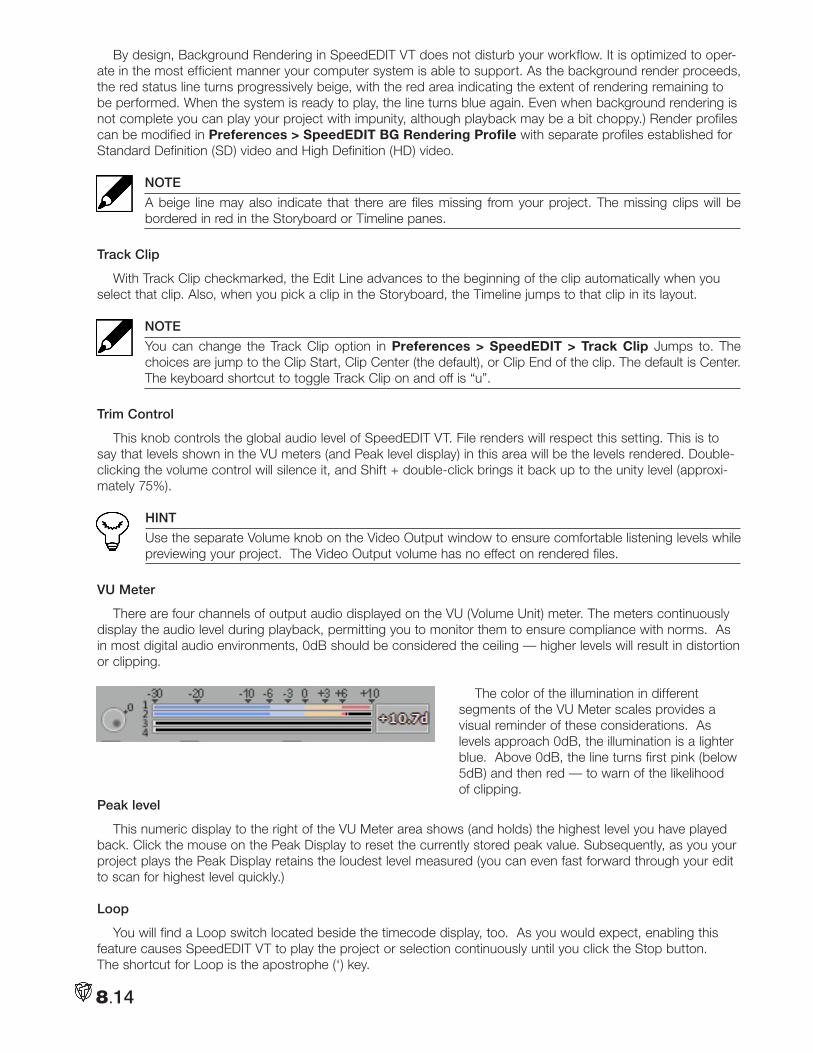
8.14
By design, Background Rendering in SpeedEDIT VT does not disturb your workflow. It is optimized to oper-ate in the most efficient manner your computer system is able to support. As the background render proceeds, the red status line turns progressively beige, with the red area indicating the extent of rendering remaining to be performed. When the system is ready to play, the line turns blue again. Even when background rendering is not complete you can play your project with impunity, although playback may be a bit choppy.) Render profiles can be modified in Preferences > SpeedEDIT BG Rendering Profile with separate profiles established for Standard Definition (SD) video and High Definition (HD) video.
NOTE
A beige line may also indicate that there are files missing from your project. The missing clips will be bordered in red in the Storyboard or Timeline panes.
Track Clip
With Track Clip checkmarked, the Edit Line advances to the beginning of the clip automatically when you select that clip. Also, when you pick a clip in the Storyboard, the Timeline jumps to that clip in its layout.
NOTE
You can change the Track Clip option in Preferences > SpeedEDIT > Track Clip Jumps to. The choices are jump to the Clip Start, Clip Center (the default), or Clip End of the clip. The default is Center. The keyboard shortcut to toggle Track Clip on and off is “u”.
Trim Control
This knob controls the global audio level of SpeedEDIT VT. File renders will respect this setting. This is to say that levels shown in the VU meters (and Peak level display) in this area will be the levels rendered. Double-clicking the volume control will silence it, and Shift + double-click brings it back up to the unity level (approxi-mately 75%).
HINT
Use the separate Volume knob on the Video Output window to ensure comfortable listening levels while previewing your project. The Video Output volume has no effect on rendered files.
VU Meter
There are four channels of output audio displayed on the VU (Volume Unit) meter. The meters continuously display the audio level during playback, permitting you to monitor them to ensure compliance with norms. As in most digital audio environments, 0dB should be considered the ceiling — higher levels will result in distortion or clipping.
The color of the illumination in different segments of the VU Meter scales provides a visual reminder of these considerations. As levels approach 0dB, the illumination is a lighter blue. Above 0dB, the line turns first pink (below 5dB) and then red — to warn of the likelihood of clipping.
Peak level
This numeric display to the right of the VU Meter area shows (and holds) the highest level you have played back. Click the mouse on the Peak Display to reset the currently stored peak value. Subsequently, as you your project plays the Peak Display retains the loudest level measured (you can even fast forward through your edit to scan for highest level quickly.)
Loop
You will find a Loop switch located beside the timecode display, too. As you would expect, enabling this feature causes SpeedEDIT VT to play the project or selection continuously until you click the Stop button. The shortcut for Loop is the apostrophe (‘) key.
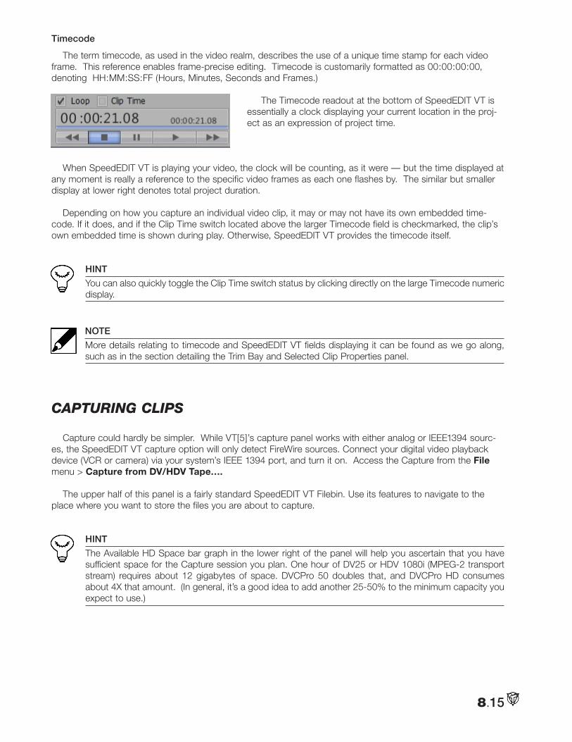
8.15
Timecode
The term timecode, as used in the video realm, describes the use of a unique time stamp for each video frame. This reference enables frame-precise editing. Timecode is customarily formatted as 00:00:00:00, denoting HH:MM:SS:FF (Hours, Minutes, Seconds and Frames.)
The Timecode readout at the bottom of SpeedEDIT VT is essentially a clock displaying your current location in the proj-ect as an expression of project time.
When SpeedEDIT VT is playing your video, the clock will be counting, as it were — but the time displayed at any moment is really a reference to the specific video frames as each one flashes by. The similar but smaller display at lower right denotes total project duration.
Depending on how you capture an individual video clip, it may or may not have its own embedded time-code. If it does, and if the Clip Time switch located above the larger Timecode field is checkmarked, the clip’s own embedded time is shown during play. Otherwise, SpeedEDIT VT provides the timecode itself.
HINT
You can also quickly toggle the Clip Time switch status by clicking directly on the large Timecode numeric display.
NOTE
More details relating to timecode and SpeedEDIT VT fields displaying it can be found as we go along, such as in the section detailing the Trim Bay and Selected Clip Properties panel.
captuRing clipS
Capture could hardly be simpler. While VT[5]’s capture panel works with either analog or IEEE1394 sourc-es, the SpeedEDIT VT capture option will only detect FireWire sources. Connect your digital video playback device (VCR or camera) via your system’s IEEE 1394 port, and turn it on. Access the Capture from the File menu > Capture from DV/HDV Tape….
The upper half of this panel is a fairly standard SpeedEDIT VT Filebin. Use its features to navigate to the place where you want to store the files you are about to capture.
HINT
The Available HD Space bar graph in the lower right of the panel will help you ascertain that you have sufficient space for the Capture session you plan. One hour of DV25 or HDV 1080i (MPEG-2 transport stream) requires about 12 gigabytes of space. DVCPro 50 doubles that, and DVCPro HD consumes about 4X that amount. (In general, it’s a good idea to add another 25-50% to the minimum capacity you expect to use.)
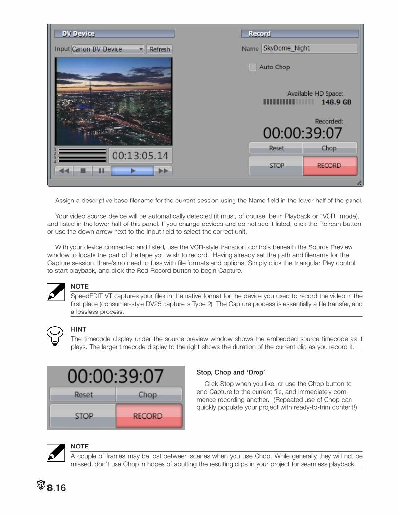
8.16
Assign a descriptive base filename for the current session using the Name field in the lower half of the panel.
Your video source device will be automatically detected (it must, of course, be in Playback or “VCR” mode), and listed in the lower half of this panel. If you change devices and do not see it listed, click the Refresh button or use the down-arrow next to the Input field to select the correct unit.
With your device connected and listed, use the VCR-style transport controls beneath the Source Preview window to locate the part of the tape you wish to record. Having already set the path and filename for the Capture session, there’s no need to fuss with file formats and options. Simply click the triangular Play control to start playback, and click the Red Record button to begin Capture.
NOTE
SpeedEDIT VT captures your files in the native format for the device you used to record the video in the first place (consumer-style DV25 capture is Type 2) The Capture process is essentially a file transfer, and a lossless process.
HINT
The timecode display under the source preview window shows the embedded source timecode as it plays. The larger timecode display to the right shows the duration of the current clip as you record it.
Stop, Chop and ‘Drop’
Click Stop when you like, or use the Chop button to end Capture to the current file, and immediately com-mence recording another. (Repeated use of Chop can quickly populate your project with ready-to-trim content!)
NOTE
A couple of frames may be lost between scenes when you use Chop. While generally they will not be missed, don’t use Chop in hopes of abutting the resulting clips in your project for seamless playback.
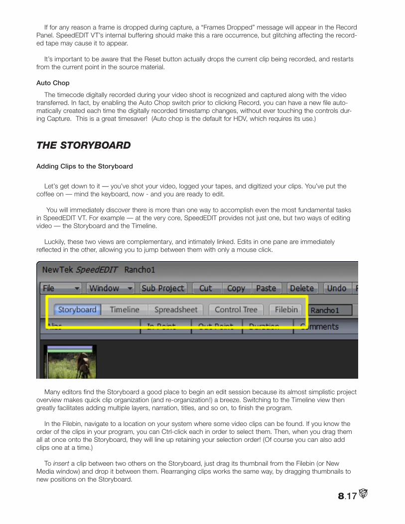
8.17
If for any reason a frame is dropped during capture, a “Frames Dropped” message will appear in the Record Panel. SpeedEDIT VT’s internal buffering should make this a rare occurrence, but glitching affecting the record-ed tape may cause it to appear.
It’s important to be aware that the Reset button actually drops the current clip being recorded, and restarts from the current point in the source material.
Auto Chop
The timecode digitally recorded during your video shoot is recognized and captured along with the video transferred. In fact, by enabling the Auto Chop switch prior to clicking Record, you can have a new file auto-matically created each time the digitally recorded timestamp changes, without ever touching the controls dur-ing Capture. This is a great timesaver! (Auto chop is the default for HDV, which requires its use.)
tHe StoRyBoaRd
Adding Clips to the Storyboard
Let’s get down to it — you’ve shot your video, logged your tapes, and digitized your clips. You’ve put the coffee on — mind the keyboard, now - and you are ready to edit.
You will immediately discover there is more than one way to accomplish even the most fundamental tasks in SpeedEDIT VT. For example — at the very core, SpeedEDIT provides not just one, but two ways of editing video — the Storyboard and the Timeline.
Luckily, these two views are complementary, and intimately linked. Edits in one pane are immediately reflected in the other, allowing you to jump between them with only a mouse click.
Many editors find the Storyboard a good place to begin an edit session because its almost simplistic project overview makes quick clip organization (and re-organization!) a breeze. Switching to the Timeline view then greatly facilitates adding multiple layers, narration, titles, and so on, to finish the program.
In the Filebin, navigate to a location on your system where some video clips can be found. If you know the order of the clips in your program, you can Ctrl-click each in order to select them. Then, when you drag them all at once onto the Storyboard, they will line up retaining your selection order! (Of course you can also add clips one at a time.)
To insert a clip between two others on the Storyboard, just drag its thumbnail from the Filebin (or New Media window) and drop it between them. Rearranging clips works the same way, by dragging thumbnails to new positions on the Storyboard.
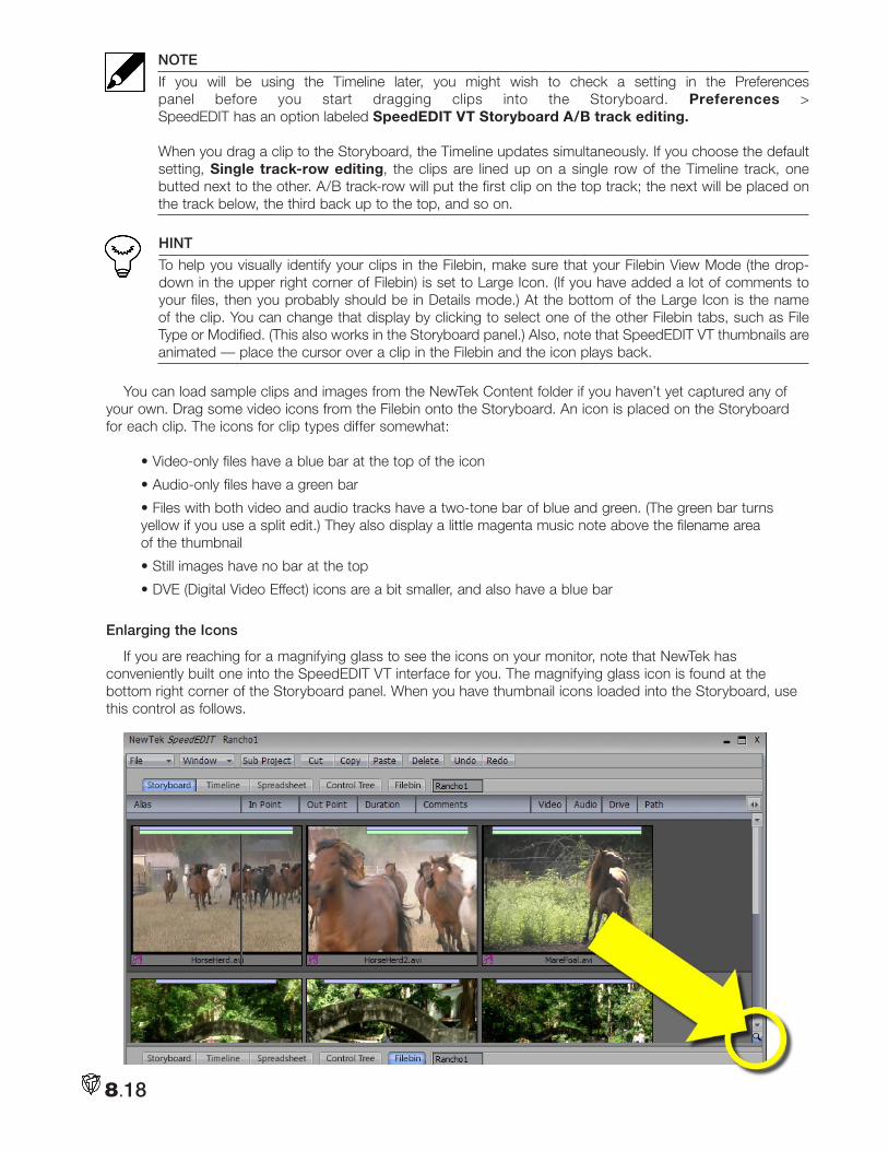
8.18
NOTE
If you will be using the Timeline later, you might wish to check a setting in the Preferences panel before you start dragging clips into the Storyboard. Preferences > SpeedEDIT has an option labeled SpeedEDIT VT Storyboard A/B track editing. When you drag a clip to the Storyboard, the Timeline updates simultaneously. If you choose the default setting, Single track-row editing, the clips are lined up on a single row of the Timeline track, one butted next to the other. A/B track-row will put the first clip on the top track; the next will be placed on the track below, the third back up to the top, and so on.
HINT
To help you visually identify your clips in the Filebin, make sure that your Filebin View Mode (the drop-down in the upper right corner of Filebin) is set to Large Icon. (If you have added a lot of comments to your files, then you probably should be in Details mode.) At the bottom of the Large Icon is the name of the clip. You can change that display by clicking to select one of the other Filebin tabs, such as File Type or Modified. (This also works in the Storyboard panel.) Also, note that SpeedEDIT VT thumbnails are animated — place the cursor over a clip in the Filebin and the icon plays back.
You can load sample clips and images from the NewTek Content folder if you haven’t yet captured any of your own. Drag some video icons from the Filebin onto the Storyboard. An icon is placed on the Storyboard for each clip. The icons for clip types differ somewhat:
• Video-only files have a blue bar at the top of the icon
• Audio-only files have a green bar
• Files with both video and audio tracks have a two-tone bar of blue and green. (The green bar turns yellow if you use a split edit.) They also display a little magenta music note above the filename area of the thumbnail
• Still images have no bar at the top
• DVE (Digital Video Effect) icons are a bit smaller, and also have a blue bar
Enlarging the Icons
If you are reaching for a magnifying glass to see the icons on your monitor, note that NewTek has conveniently built one into the SpeedEDIT VT interface for you. The magnifying glass icon is found at the bottom right corner of the Storyboard panel. When you have thumbnail icons loaded into the Storyboard, use this control as follows.
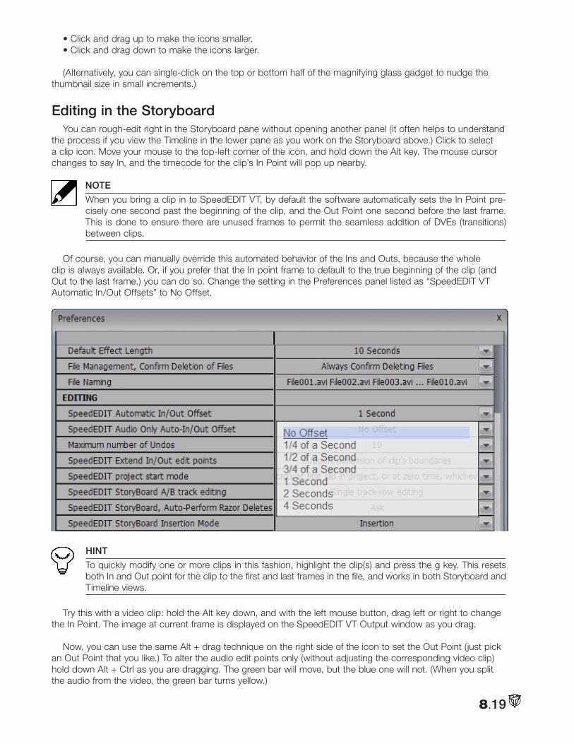
8.19
• Click and drag up to make the icons smaller.• Click and drag down to make the icons larger.
(Alternatively, you can single-click on the top or bottom half of the magnifying glass gadget to nudge the thumbnail size in small increments.)
Editing in the StoryboardYou can rough-edit right in the Storyboard pane without opening another panel (it often helps to understand
the process if you view the Timeline in the lower pane as you work on the Storyboard above.) Click to select a clip icon. Move your mouse to the top-left corner of the icon, and hold down the Alt key. The mouse cursor changes to say In, and the timecode for the clip’s In Point will pop up nearby.
NOTE
When you bring a clip in to SpeedEDIT VT, by default the software automatically sets the In Point pre-cisely one second past the beginning of the clip, and the Out Point one second before the last frame. This is done to ensure there are unused frames to permit the seamless addition of DVEs (transitions) between clips.
Of course, you can manually override this automated behavior of the Ins and Outs, because the whole clip is always available. Or, if you prefer that the In point frame to default to the true beginning of the clip (and Out to the last frame,) you can do so. Change the setting in the Preferences panel listed as “SpeedEDIT VT Automatic In/Out Offsets” to No Offset.
HINT
To quickly modify one or more clips in this fashion, highlight the clip(s) and press the g key. This resets both In and Out point for the clip to the first and last frames in the file, and works in both Storyboard and Timeline views.
Try this with a video clip: hold the Alt key down, and with the left mouse button, drag left or right to change the In Point. The image at current frame is displayed on the SpeedEDIT VT Output window as you drag.
Now, you can use the same Alt + drag technique on the right side of the icon to set the Out Point (just pick an Out Point that you like.) To alter the audio edit points only (without adjusting the corresponding video clip) hold down Alt + Ctrl as you are dragging. The green bar will move, but the blue one will not. (When you split the audio from the video, the green bar turns yellow.)
8.20
To move an In or Out while maintaining the length of a clip, you can perform a Slip and Slide operation. Hold down Alt + Shift and the cursor says S/S. As you drag the mouse, the bars move but remain the same length. Slip and Slide for audio only is Alt + Shift + Ctrl.
Now, click a second clip and choose In and Out Points.
NOTE
More details relating to timecode and SpeedEDIT VT fields displaying it can be found as we go along, such as in the sections detailing the Trim Bay and Selected Clip Properties panel. See the Index for a list of all references.
You have just performed the most common task of editing — adjusting the beginning and end of a clip, then adjoining it to another adjusted clip. The “cut” is the fundamental building block of both movies and TV pro-grams. You also can edit Storyboard clips in the Trim Bay, discussed later.
Storyboard Play OptionsTo play a clip, double-click it to start playing at the In Point and to stop at the Out Point. Hitting the
Spacebar will pause playing the clip. Hit the Spacebar again to resume playing. Whereas the double-click play ended at the last frame of the (trimmed) clip, however, pressing Enter puts SpeedEDIT VT into continuous play-back. The entire storyboard will play from left to right continuously, until it comes to its end or you manually Pause or Stop
NOTE
When a clip is playing, a vertical blue line, (called the edit line), crawls across the Storyboard icon giving you a visual reference of your current position in the clip. If you hit the right arrow key on the keyboard, the clip pauses. Click the arrow again and it advances one frame. Hold the arrow down and it plays the clip. Hold Shift + arrow and the clip will advance five frames at a time (the left arrow key plays in reverse.)
For a quick review of a clip, Shift + Spacebar begins playback three seconds prior to the actual current position in the project (this is especially useful for reviewing the cut point between two clips.)
You can play the whole project in a number of ways. On the keyboard, hit Home to jump to the beginning of the project, and then press the Spacebar. The keyboard shortcut, k, will also play the project (to be precise, the k shortcut toggles Play/Pause.) In fact, there is an extensive list of keyboard shortcuts for the SpeedEDIT VT panel — five pages of them. You can view the list when you are in the SpeedEDIT VT panel by pressing F1 (the Function 1 key located in the upper row of your keyboard).
timeline editingMany editors spend most of their time in the Timeline mode of SpeedEDIT VT, in appreciation of the clear
view it offers of the relationships between layers in a project. This makes it easier to create, visualize and adjust multi-layer compositions. The unique combination of the simplicity and speed of Storyboard editing with the depth of the Timeline for advanced work is one of SpeedEDIT VT’s greatest strengths.
Timeline InterfaceIf you have been following along, click on the Timeline tab in the bottom pane (unless it is already active.)
The display updates, replacing the Filebin with the Timeline pane. While you’re here, click in the Storyboard pane — notice that its background becomes lighter, indicating it is the active pane. Click again in the Timeline pane and the Storyboard pane darkens.
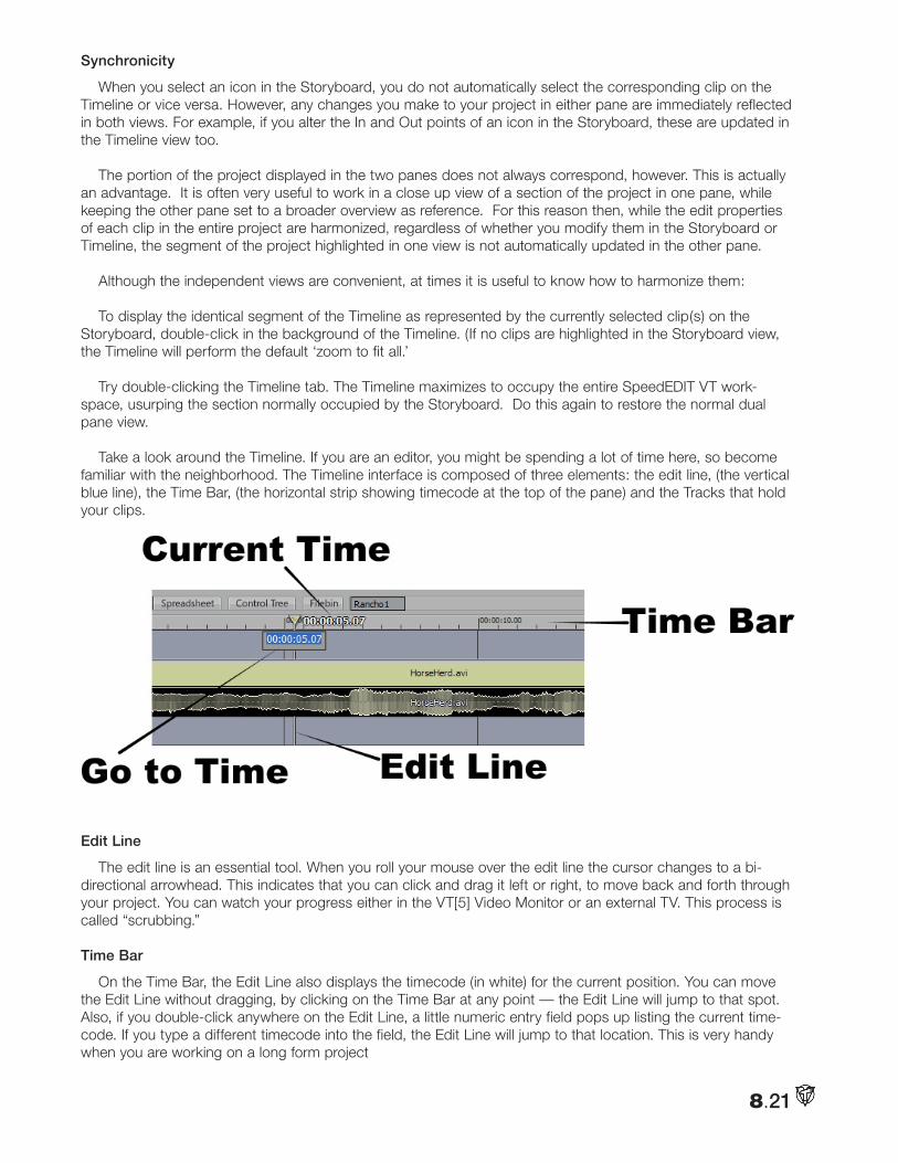
8.21
Synchronicity
When you select an icon in the Storyboard, you do not automatically select the corresponding clip on the Timeline or vice versa. However, any changes you make to your project in either pane are immediately reflected in both views. For example, if you alter the In and Out points of an icon in the Storyboard, these are updated in the Timeline view too.
The portion of the project displayed in the two panes does not always correspond, however. This is actually an advantage. It is often very useful to work in a close up view of a section of the project in one pane, while keeping the other pane set to a broader overview as reference. For this reason then, while the edit properties of each clip in the entire project are harmonized, regardless of whether you modify them in the Storyboard or Timeline, the segment of the project highlighted in one view is not automatically updated in the other pane.
Although the independent views are convenient, at times it is useful to know how to harmonize them:
To display the identical segment of the Timeline as represented by the currently selected clip(s) on the Storyboard, double-click in the background of the Timeline. (If no clips are highlighted in the Storyboard view, the Timeline will perform the default ‘zoom to fit all.’
Try double-clicking the Timeline tab. The Timeline maximizes to occupy the entire SpeedEDIT VT work-space, usurping the section normally occupied by the Storyboard. Do this again to restore the normal dual pane view.
Take a look around the Timeline. If you are an editor, you might be spending a lot of time here, so become familiar with the neighborhood. The Timeline interface is composed of three elements: the edit line, (the vertical blue line), the Time Bar, (the horizontal strip showing timecode at the top of the pane) and the Tracks that hold your clips.
Edit Line
The edit line is an essential tool. When you roll your mouse over the edit line the cursor changes to a bi-directional arrowhead. This indicates that you can click and drag it left or right, to move back and forth through your project. You can watch your progress either in the VT[5] Video Monitor or an external TV. This process is called “scrubbing.”
Time Bar
On the Time Bar, the Edit Line also displays the timecode (in white) for the current position. You can move the Edit Line without dragging, by clicking on the Time Bar at any point — the Edit Line will jump to that spot. Also, if you double-click anywhere on the Edit Line, a little numeric entry field pops up listing the current time-code. If you type a different timecode into the field, the Edit Line will jump to that location. This is very handy when you are working on a long form project
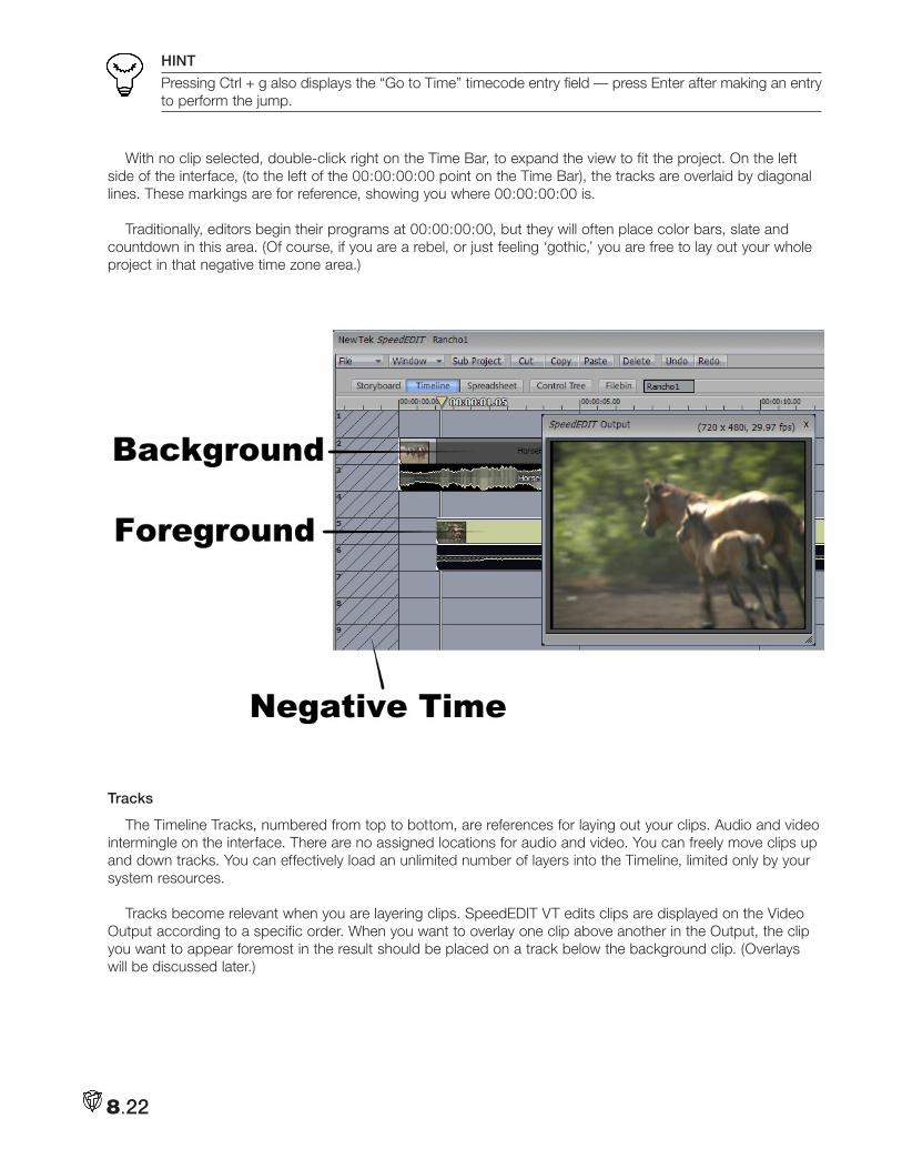
8.22
HINT
Pressing Ctrl + g also displays the “Go to Time” timecode entry field — press Enter after making an entry to perform the jump.
With no clip selected, double-click right on the Time Bar, to expand the view to fit the project. On the left side of the interface, (to the left of the 00:00:00:00 point on the Time Bar), the tracks are overlaid by diagonal lines. These markings are for reference, showing you where 00:00:00:00 is.
Traditionally, editors begin their programs at 00:00:00:00, but they will often place color bars, slate and countdown in this area. (Of course, if you are a rebel, or just feeling ‘gothic,’ you are free to lay out your whole project in that negative time zone area.)
Tracks
The Timeline Tracks, numbered from top to bottom, are references for laying out your clips. Audio and video intermingle on the interface. There are no assigned locations for audio and video. You can freely move clips up and down tracks. You can effectively load an unlimited number of layers into the Timeline, limited only by your system resources.
Tracks become relevant when you are layering clips. SpeedEDIT VT edits clips are displayed on the Video Output according to a specific order. When you want to overlay one clip above another in the Output, the clip you want to appear foremost in the result should be placed on a track below the background clip. (Overlays will be discussed later.)
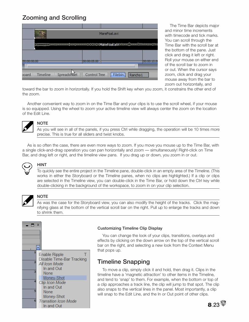
8.23
Zooming and Scrolling The Time Bar depicts major
and minor time increments with timecode and tick marks. You can scroll through the Time Bar with the scroll bar at the bottom of the pane. Just click and drag it left or right. Roll your mouse on either end of the scroll bar to zoom in or out. When the cursor says zoom, click and drag your mouse away from the bar to zoom out horizontally, and
toward the bar to zoom in horizontally. If you hold the Shift key when you zoom, it constrains the other end of the zoom.
Another convenient way to zoom in on the Time Bar and your clips is to use the scroll wheel, if your mouse is so equipped. Using the wheel to zoom your active timeline view will always center the zoom on the location of the Edit Line.
NOTE
As you will see in all of the panels, if you press Ctrl while dragging, the operation will be 10 times more precise. This is true for all sliders and twist knobs.
As is so often the case, there are even more ways to zoom. If you move you mouse up to the Time Bar, with a single click-and-drag operation you can pan horizontally and zoom — simultaneously! Right-click on Time Bar, and drag left or right, and the timeline view pans. If you drag up or down, you zoom in or out.
HINT
To quickly see the entire project in the Timeline pane, double-click in an empty area of the Timeline. (This works in either the Storyboard or the Timeline panes, when no clips are highlighted.) If a clip or clips are selected in the Timeline view, you can double-click in the Time Bar, or hold down the Ctrl key while double-clicking in the background of the workspace, to zoom in on your clip selection.
NOTE
As was the case for the Storyboard view, you can also modify the height of the tracks. Click the mag-nifying glass at the bottom of the vertical scroll bar on the right. Pull up to enlarge the tracks and down to shrink them.
Customizing Timeline Clip Display
You can change the look of your clips, transitions, overlays and effects by clicking on the down arrow on the top of the vertical scroll bar on the right, and selecting a new look from the Context Menu that pops up.
Timeline SnappingTo move a clip, simply click it and hold, then drag it. Clips in the
timeline have a ‘magnetic attraction’ to other items in the Timeline, and tend to ‘snap’ to them. For example, when the bottom or top of a clip approaches a track line, the clip will jump to that spot. The clip also snaps to the vertical lines in the panel. Most importantly, a clip will snap to the Edit Line, and the In or Out point of other clips.
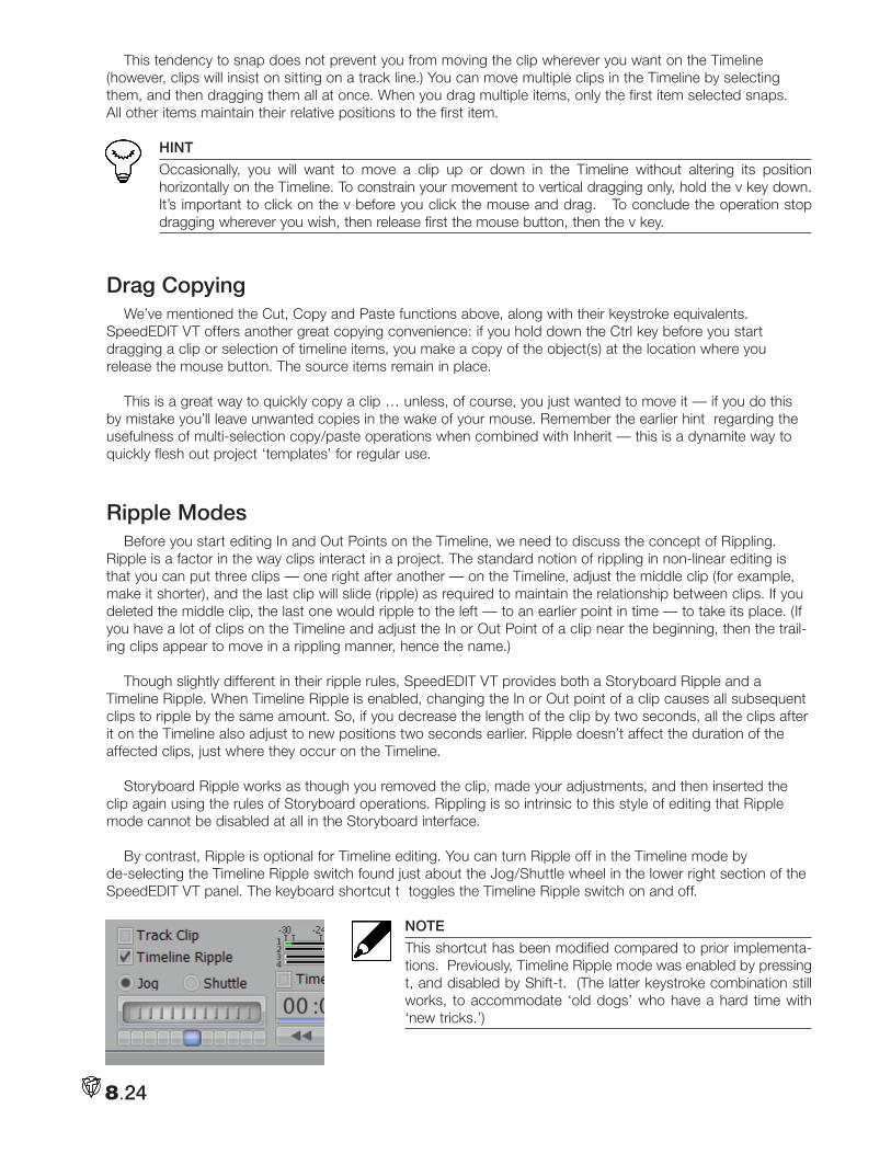
8.24
This tendency to snap does not prevent you from moving the clip wherever you want on the Timeline (however, clips will insist on sitting on a track line.) You can move multiple clips in the Timeline by selecting them, and then dragging them all at once. When you drag multiple items, only the first item selected snaps. All other items maintain their relative positions to the first item.
HINT
Occasionally, you will want to move a clip up or down in the Timeline without altering its position horizontally on the Timeline. To constrain your movement to vertical dragging only, hold the v key down. It’s important to click on the v before you click the mouse and drag. To conclude the operation stop dragging wherever you wish, then release first the mouse button, then the v key.
Drag Copying We’ve mentioned the Cut, Copy and Paste functions above, along with their keystroke equivalents.
SpeedEDIT VT offers another great copying convenience: if you hold down the Ctrl key before you start dragging a clip or selection of timeline items, you make a copy of the object(s) at the location where you release the mouse button. The source items remain in place.
This is a great way to quickly copy a clip … unless, of course, you just wanted to move it — if you do this by mistake you’ll leave unwanted copies in the wake of your mouse. Remember the earlier hint regarding the usefulness of multi-selection copy/paste operations when combined with Inherit — this is a dynamite way to quickly flesh out project ‘templates’ for regular use.
Ripple ModesBefore you start editing In and Out Points on the Timeline, we need to discuss the concept of Rippling.
Ripple is a factor in the way clips interact in a project. The standard notion of rippling in non-linear editing is that you can put three clips — one right after another — on the Timeline, adjust the middle clip (for example, make it shorter), and the last clip will slide (ripple) as required to maintain the relationship between clips. If you deleted the middle clip, the last one would ripple to the left — to an earlier point in time — to take its place. (If you have a lot of clips on the Timeline and adjust the In or Out Point of a clip near the beginning, then the trail-ing clips appear to move in a rippling manner, hence the name.)
Though slightly different in their ripple rules, SpeedEDIT VT provides both a Storyboard Ripple and a Timeline Ripple. When Timeline Ripple is enabled, changing the In or Out point of a clip causes all subsequent clips to ripple by the same amount. So, if you decrease the length of the clip by two seconds, all the clips after it on the Timeline also adjust to new positions two seconds earlier. Ripple doesn’t affect the duration of the affected clips, just where they occur on the Timeline.
Storyboard Ripple works as though you removed the clip, made your adjustments, and then inserted the clip again using the rules of Storyboard operations. Rippling is so intrinsic to this style of editing that Ripple mode cannot be disabled at all in the Storyboard interface.
By contrast, Ripple is optional for Timeline editing. You can turn Ripple off in the Timeline mode by de-selecting the Timeline Ripple switch found just about the Jog/Shuttle wheel in the lower right section of the SpeedEDIT VT panel. The keyboard shortcut t toggles the Timeline Ripple switch on and off.
NOTE
This shortcut has been modified compared to prior implementa-tions. Previously, Timeline Ripple mode was enabled by pressing t, and disabled by Shift-t. (The latter keystroke combination still works, to accommodate ‘old dogs’ who have a hard time with ‘new tricks.’)
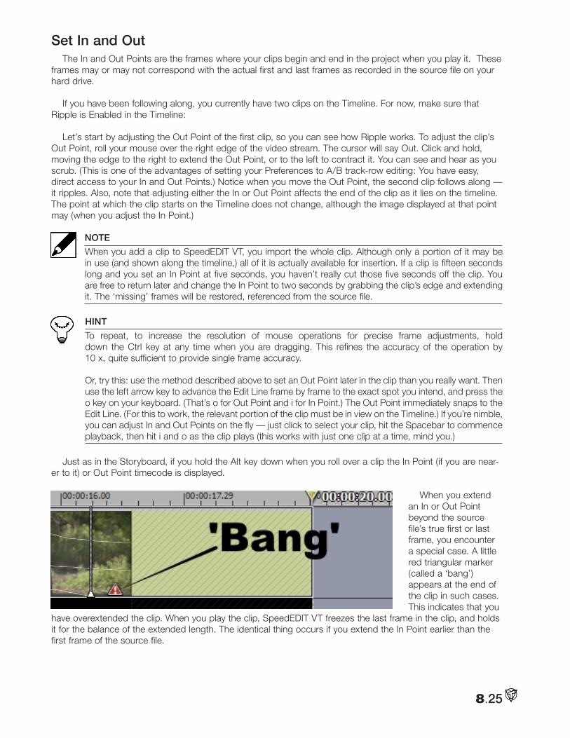
8.25
Set In and OutThe In and Out Points are the frames where your clips begin and end in the project when you play it. These
frames may or may not correspond with the actual first and last frames as recorded in the source file on your hard drive.
If you have been following along, you currently have two clips on the Timeline. For now, make sure that Ripple is Enabled in the Timeline:
Let’s start by adjusting the Out Point of the first clip, so you can see how Ripple works. To adjust the clip’s Out Point, roll your mouse over the right edge of the video stream. The cursor will say Out. Click and hold, moving the edge to the right to extend the Out Point, or to the left to contract it. You can see and hear as you scrub. (This is one of the advantages of setting your Preferences to A/B track-row editing: You have easy, direct access to your In and Out Points.) Notice when you move the Out Point, the second clip follows along — it ripples. Also, note that adjusting either the In or Out Point affects the end of the clip as it lies on the timeline. The point at which the clip starts on the Timeline does not change, although the image displayed at that point may (when you adjust the In Point.)
NOTE
When you add a clip to SpeedEDIT VT, you import the whole clip. Although only a portion of it may be in use (and shown along the timeline,) all of it is actually available for insertion. If a clip is fifteen seconds long and you set an In Point at five seconds, you haven’t really cut those five seconds off the clip. You are free to return later and change the In Point to two seconds by grabbing the clip’s edge and extending it. The ‘missing’ frames will be restored, referenced from the source file.
HINT
To repeat, to increase the resolution of mouse operations for precise frame adjustments, hold down the Ctrl key at any time when you are dragging. This refines the accuracy of the operation by 10 x, quite sufficient to provide single frame accuracy. Or, try this: use the method described above to set an Out Point later in the clip than you really want. Then use the left arrow key to advance the Edit Line frame by frame to the exact spot you intend, and press the o key on your keyboard. (That’s o for Out Point and i for In Point.) The Out Point immediately snaps to the Edit Line. (For this to work, the relevant portion of the clip must be in view on the Timeline.) If you’re nimble, you can adjust In and Out Points on the fly — just click to select your clip, hit the Spacebar to commence playback, then hit i and o as the clip plays (this works with just one clip at a time, mind you.)
Just as in the Storyboard, if you hold the Alt key down when you roll over a clip the In Point (if you are near-er to it) or Out Point timecode is displayed.
When you extend an In or Out Point beyond the source file’s true first or last frame, you encounter a special case. A little red triangular marker (called a ‘bang’) appears at the end of the clip in such cases. This indicates that you
have overextended the clip. When you play the clip, SpeedEDIT VT freezes the last frame in the clip, and holds it for the balance of the extended length. The identical thing occurs if you extend the In Point earlier than the first frame of the source file.
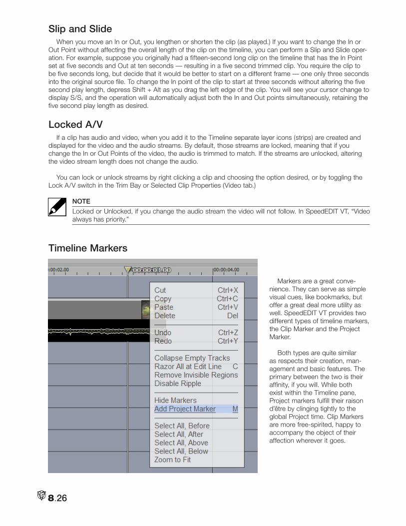
8.26
Slip and SlideWhen you move an In or Out, you lengthen or shorten the clip (as played.) If you want to change the In or
Out Point without affecting the overall length of the clip on the timeline, you can perform a Slip and Slide oper-ation. For example, suppose you originally had a fifteen-second long clip on the timeline that has the In Point set at five seconds and Out at ten seconds — resulting in a five second trimmed clip. You require the clip to be five seconds long, but decide that it would be better to start on a different frame — one only three seconds into the original source file. To change the In point of the clip to start at three seconds without altering the five second play length, depress Shift + Alt as you drag the left edge of the clip. You will see your cursor change to display S/S, and the operation will automatically adjust both the In and Out points simultaneously, retaining the five second play length as desired.
Locked A/VIf a clip has audio and video, when you add it to the Timeline separate layer icons (strips) are created and
displayed for the video and the audio streams. By default, those streams are locked, meaning that if you change the In or Out Points of the video, the audio is trimmed to match. If the streams are unlocked, altering the video stream length does not change the audio.
You can lock or unlock streams by right clicking a clip and choosing the option desired, or by toggling the Lock A/V switch in the Trim Bay or Selected Clip Properties (Video tab.)
NOTE
Locked or Unlocked, if you change the audio stream the video will not follow. In SpeedEDIT VT, “Video always has priority.”
Timeline Markers
Markers are a great conve-nience. They can serve as simple visual cues, like bookmarks, but offer a great deal more utility as well. SpeedEDIT VT provides two different types of timeline markers, the Clip Marker and the Project Marker.
Both types are quite similar as respects their creation, man-agement and basic features. The primary between the two is their affinity, if you will. While both exist within the Timeline pane, Project markers fulfill their raison d’être by clinging tightly to the global Project time. Clip Markers are more free-spirited, happy to accompany the object of their affection wherever it goes.
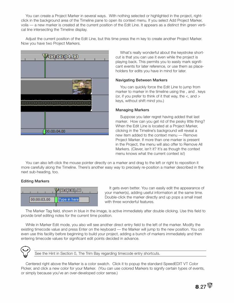
8.27
You can create a Project Marker in several ways. With nothing selected or highlighted in the project, right-click in the background area of the Timeline pane to open its context menu. If you select Add Project Marker, voila — a new marker is created at the current position of the Edit Line. It appears as a distinct thin green verti-cal line intersecting the Timeline display.
Adjust the current position of the Edit Line, but this time press the m key to create another Project Marker. Now you have two Project Markers.
What’s really wonderful about the keystroke short-cut is that you can use it even while the project is playing back. This permits you to easily mark signifi-cant events for later reference, or use them as place-holders for edits you have in mind for later.
Navigating Between Markers
You can quickly force the Edit Line to jump from marker to marker in the timeline using the , and . keys (or, if you prefer to think of it that way, the <, and > keys, without shift mind you.)
Managing Markers
Suppose you later regret having added that last marker. How can you get rid of the pesky little thing? When the Edit Line is located at a Project Marker, clicking in the Timeline’s background will reveal a new item added to the context menu — Remove Project Marker. If more than one marker is present in the Project, the menu will also offer to Remove All Markers. (Clever, isn’t it? It’s as though the context menu knows what the current context is!)
You can also left-click the mouse pointer directly on a marker and drag to the left or right to reposition it more carefully along the Timeline. There’s another easy way to precisely re-position a marker described in the next sub-heading, too.
Editing Markers
It gets even better. You can easily edit the appearance of your marker(s), adding useful information at the same time. Double-click the marker directly and up pops a small inset with three wonderful features.
The Marker Tag field, shown in blue in the image, is active immediately after double clicking. Use this field to provide brief editing notes for the current time position.
While in Marker Edit mode, you also will see another direct entry field to the left of the marker. Modify the existing timecode value and press Enter on the keyboard — the Marker will jump to the new position. You can even use this facility before beginning to build your project, adding a bunch of markers immediately and then entering timecode values for significant edit points decided in advance.
HINT
See the Hint in Section 0, The Trim Bay regarding timecode entry shortcuts.
Centered right above the Marker is a color swatch. Click it to popup the standard SpeedEDIT VT Color Picker, and click a new color for your Marker. (You can use colored Markers to signify certain types of events, or simply because you’ve an over-developed color sense.)
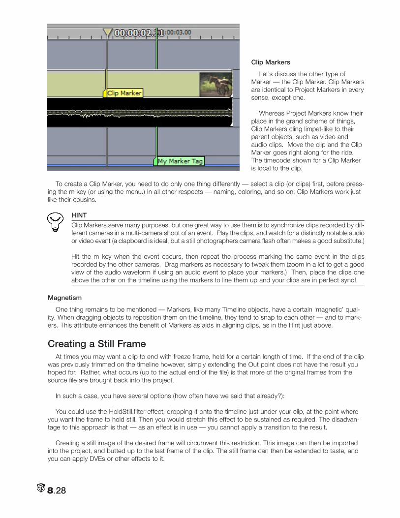
8.28
Clip Markers
Let’s discuss the other type of Marker — the Clip Marker. Clip Markers are identical to Project Markers in every sense, except one.
Whereas Project Markers know their place in the grand scheme of things, Clip Markers cling limpet-like to their parent objects, such as video and audio clips. Move the clip and the Clip Marker goes right along for the ride. The timecode shown for a Clip Marker is local to the clip.
To create a Clip Marker, you need to do only one thing differently — select a clip (or clips) first, before press-ing the m key (or using the menu.) In all other respects — naming, coloring, and so on, Clip Markers work just like their cousins.
HINT
Clip Markers serve many purposes, but one great way to use them is to synchronize clips recorded by dif-ferent cameras in a multi-camera shoot of an event. Play the clips, and watch for a distinctly notable audio or video event (a clapboard is ideal, but a still photographers camera flash often makes a good substitute.) Hit the m key when the event occurs, then repeat the process marking the same event in the clips recorded by the other cameras. Drag markers as necessary to tweak them (zoom in a lot to get a good view of the audio waveform if using an audio event to place your markers.) Then, place the clips one above the other on the timeline using the markers to line them up and your clips are in perfect sync!
Magnetism
One thing remains to be mentioned — Markers, like many Timeline objects, have a certain ‘magnetic’ qual-ity. When dragging objects to reposition them on the timeline, they tend to snap to each other — and to mark-ers. This attribute enhances the benefit of Markers as aids in aligning clips, as in the Hint just above.
Creating a Still FrameAt times you may want a clip to end with freeze frame, held for a certain length of time. If the end of the clip
was previously trimmed on the timeline however, simply extending the Out point does not have the result you hoped for. Rather, what occurs (up to the actual end of the file) is that more of the original frames from the source file are brought back into the project.
In such a case, you have several options (how often have we said that already?):
You could use the HoldStill.filter effect, dropping it onto the timeline just under your clip, at the point where you want the frame to hold still. Then you would stretch this effect to be sustained as required. The disadvan-tage to this approach is that — as an effect is in use — you cannot apply a transition to the result.
Creating a still image of the desired frame will circumvent this restriction. This image can then be imported into the project, and butted up to the last frame of the clip. The still frame can then be extended to taste, and you can apply DVEs or other effects to it.
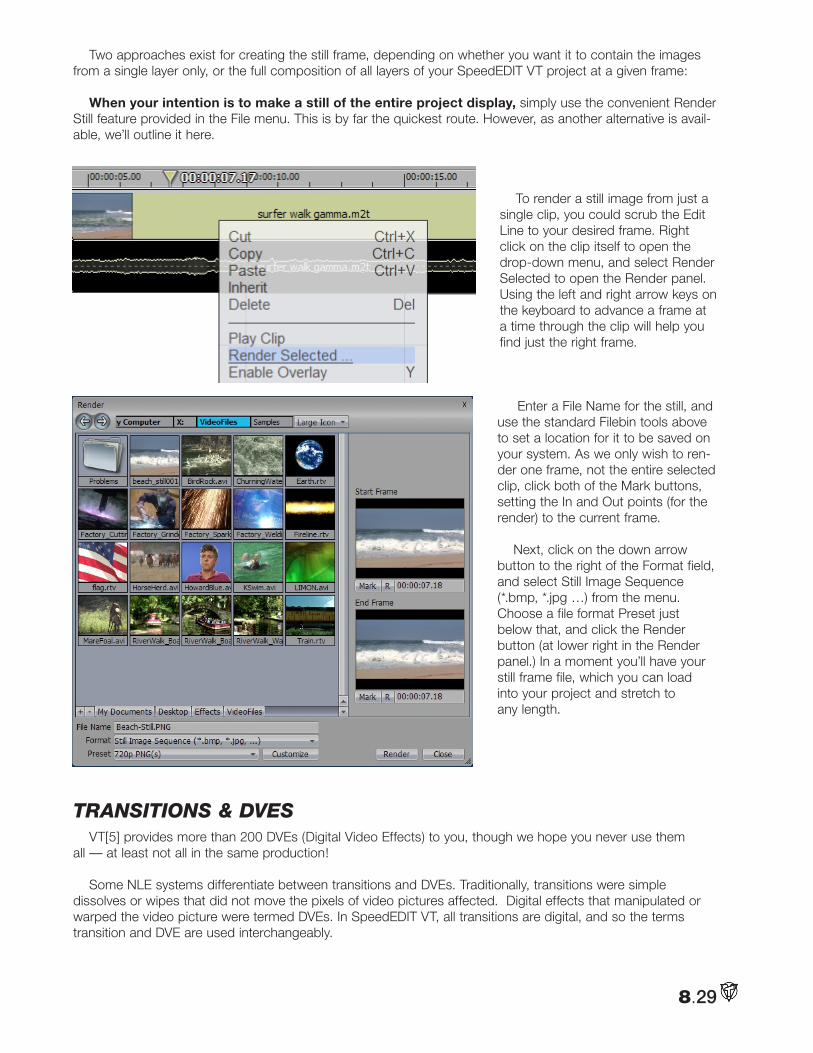
8.29
Two approaches exist for creating the still frame, depending on whether you want it to contain the images from a single layer only, or the full composition of all layers of your SpeedEDIT VT project at a given frame:
When your intention is to make a still of the entire project display, simply use the convenient Render Still feature provided in the File menu. This is by far the quickest route. However, as another alternative is avail-able, we’ll outline it here.
To render a still image from just a
single clip, you could scrub the Edit Line to your desired frame. Right click on the clip itself to open the drop-down menu, and select Render Selected to open the Render panel. Using the left and right arrow keys on the keyboard to advance a frame at a time through the clip will help you find just the right frame.
Enter a File Name for the still, and use the standard Filebin tools above to set a location for it to be saved on your system. As we only wish to ren-der one frame, not the entire selected clip, click both of the Mark buttons, setting the In and Out points (for the render) to the current frame.
Next, click on the down arrow button to the right of the Format field, and select Still Image Sequence (*.bmp, *.jpg …) from the menu. Choose a file format Preset just below that, and click the Render button (at lower right in the Render panel.) In a moment you’ll have your still frame file, which you can load into your project and stretch to any length.
tRanSitionS & dVeSVT[5] provides more than 200 DVEs (Digital Video Effects) to you, though we hope you never use them
all — at least not all in the same production!
Some NLE systems differentiate between transitions and DVEs. Traditionally, transitions were simple dissolves or wipes that did not move the pixels of video pictures affected. Digital effects that manipulated or warped the video picture were termed DVEs. In SpeedEDIT VT, all transitions are digital, and so the terms transition and DVE are used interchangeably.
8.30
Locating the DVEs
When you install VT[5], DVE’s are located in the directory C:\Program Files\NewTek\VT5\DVEs. Within that folder are sub-folders for a number of different categories of DVEs, ranging from Curls to Borders. The quick-est way to access your DVEs, then, is by clicking the DVE QuickTab at the bottom of a Filebin
Inserting a Cross FadeThe most common DVE is the dissolve or Cross Fade. You can easily add a Cross-Fade to your program
by selecting a clip (or range of clips) and pressing Alt + f. If you picked just one clip, the Cross-Fade automati-cally connects the end of the selected clip with the beginning of the next (assuming they are contiguous). If you selected a range of clips, Cross Fades are inserted between each of them (this works in both the Storyboard and the Timeline.)
NOTE
If you are very observant, you will notice in the first clip’s audio waveform that the track fades down over the duration of the Cross-Fade, and the second clip fades up. (You can change this Auto Fade behavior for individual clips in the Selected Clip Properties panel discussed later.)
Insertion Mode
When you use Alt + f, look closely at the Out Point of the first clip and the In Point of the second. By default, SpeedEDIT VT will extend the first clip forward by 15 frames past the original Out Point and the second clip back by 15 frames from its In Point. You can change this option in the Preferences panel, using the item EDITING: SpeedEDIT VT Storyboard Insertion Mode. When set to Non-Insertion, the second clip is extended back by 30 frames from its original In point. The first clip remains unchanged.
HINT
Per usual, there are many ways to add Cross Fades. If you like, you can simply drag and drop one clip on top of another, and SpeedEDIT VT will automatically insert a Cross Fade where the clips overlap.
Working with DVEsTo add any other DVE, open the Filebin pane and click the DVE folder Quicktab. Locate and drag the DVE
onto the Storyboard or Timeline. If you are in Storyboard mode, just drop the DVE between the two clips. SpeedEDIT VT will use the Storyboard Insertion mode described above to join the two clips.
NOTE
The default length for DVEs is also set in the Preferences menu: FILES: Default Transition/DVE Length. If the value is two seconds, when you drop a DVE into your program, its initial length will naturally be two seconds (you can always adjust it later, of course.)
Dropping DVEs into the Timeline is a more hands-on procedure. If you are not in Ripple mode, begin by overlapping the two clips horizontally, preferably on different Tracks — as shown in the accompanying image. Browse to the DVE folder and drag the DVE onto the end of one of the clips. The result should be as shown.
HINT
As mentioned earlier, the Add Media item in SpeedEDIT VT’s Windows menu launches a convenient standalone File Requester. Thus if you are totally immersed in your Storyboard and Timeline, you don’t need to open the Filebin tab to access files or DVEs. Just click on the Add button in this supplementary file window, and then stretch the DVE out to the desired length.
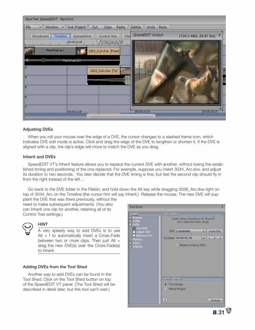
8.31
Adjusting DVEs
When you roll your mouse over the edge of a DVE, the cursor changes to a slashed frame icon, which indicates DVE edit mode is active. Click and drag the edge of the DVE to lengthen or shorten it. If the DVE is aligned with a clip, the clip’s edge will move to match the DVE as you drag.
Inherit and DVEs
SpeedEDIT VT’s Inherit feature allows you to replace the current DVE with another, without losing the estab-lished timing and positioning of the one replaced. For example, suppose you insert 3034_Arc.dve, and adjust its duration to two seconds. You later decide that the DVE timing is fine, but feel the second clip should fly in from the right instead of the left…
Go back to the DVE folder in the Filebin, and hold down the Alt key while dragging 3036_Arc.dve right on top of 3034_Arc on the Timeline (the cursor hint will say Inherit.) Release the mouse. The new DVE will sup-plant the DVE that was there previously, without the need to make subsequent adjustments. (You also can Inherit one clip for another, retaining all of its Control Tree settings.)
HINT
A very speedy way to add DVEs is to use Alt + f to automatically insert a Cross-Fade between two or more clips. Then just Alt + drag the new DVE(s) over the Cross-Fade(s) to Inherit.
Adding DVEs from the Tool Shed
Another way to add DVEs can be found in the Tool Shed. Click on the Tool Shed button on top of the SpeedEDIT VT panel. (The Tool Shed will be described in detail later, but this tool can’t wait.)
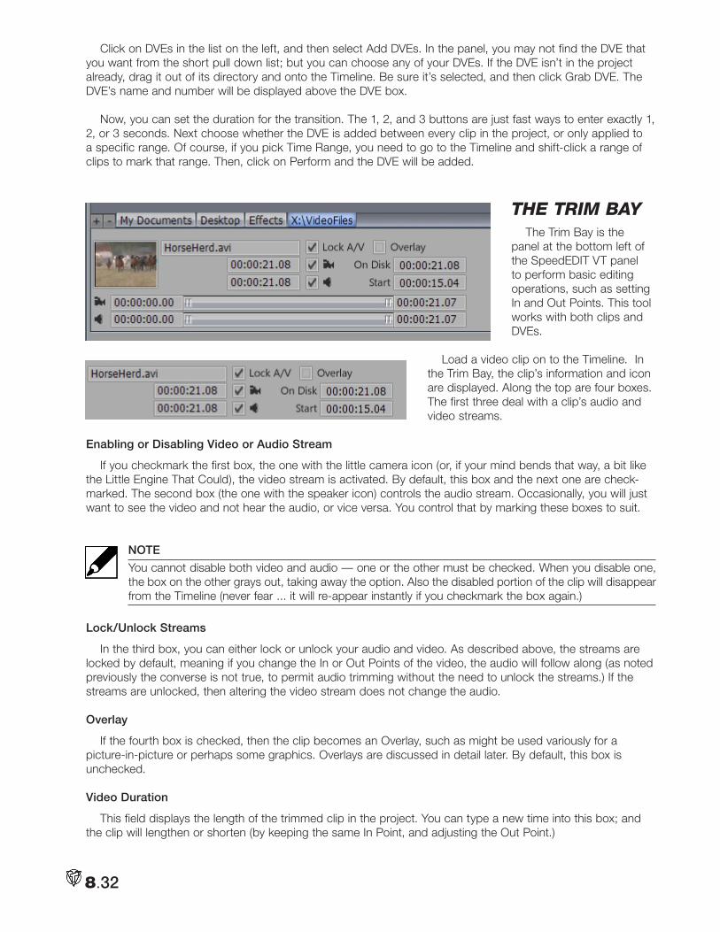
8.32
Click on DVEs in the list on the left, and then select Add DVEs. In the panel, you may not find the DVE that you want from the short pull down list; but you can choose any of your DVEs. If the DVE isn’t in the project already, drag it out of its directory and onto the Timeline. Be sure it’s selected, and then click Grab DVE. The DVE’s name and number will be displayed above the DVE box.
Now, you can set the duration for the transition. The 1, 2, and 3 buttons are just fast ways to enter exactly 1, 2, or 3 seconds. Next choose whether the DVE is added between every clip in the project, or only applied to a specific range. Of course, if you pick Time Range, you need to go to the Timeline and shift-click a range of clips to mark that range. Then, click on Perform and the DVE will be added.
tHe tRim BayThe Trim Bay is the
panel at the bottom left of the SpeedEDIT VT panel to perform basic editing operations, such as setting In and Out Points. This tool works with both clips and DVEs.
Load a video clip on to the Timeline. In the Trim Bay, the clip’s information and icon are displayed. Along the top are four boxes. The first three deal with a clip’s audio and video streams.
Enabling or Disabling Video or Audio Stream
If you checkmark the first box, the one with the little camera icon (or, if your mind bends that way, a bit like the Little Engine That Could), the video stream is activated. By default, this box and the next one are check-marked. The second box (the one with the speaker icon) controls the audio stream. Occasionally, you will just want to see the video and not hear the audio, or vice versa. You control that by marking these boxes to suit.
NOTE
You cannot disable both video and audio — one or the other must be checked. When you disable one, the box on the other grays out, taking away the option. Also the disabled portion of the clip will disappear from the Timeline (never fear ... it will re-appear instantly if you checkmark the box again.)
Lock/Unlock Streams
In the third box, you can either lock or unlock your audio and video. As described above, the streams are locked by default, meaning if you change the In or Out Points of the video, the audio will follow along (as noted previously the converse is not true, to permit audio trimming without the need to unlock the streams.) If the streams are unlocked, then altering the video stream does not change the audio.
Overlay
If the fourth box is checked, then the clip becomes an Overlay, such as might be used variously for a picture-in-picture or perhaps some graphics. Overlays are discussed in detail later. By default, this box is unchecked.
Video Duration
This field displays the length of the trimmed clip in the project. You can type a new time into this box; and the clip will lengthen or shorten (by keeping the same In Point, and adjusting the Out Point.)
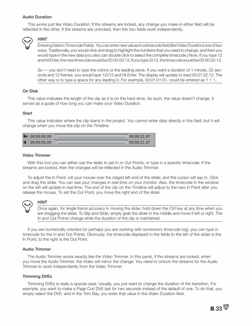
8.33
Audio Duration
This works just like Video Duration: If the streams are locked, any change you make in either field will be reflected in the other. If the streams are unlocked, then the two fields work independently.
HINT
Entering Data in Timecode Fields: You can enter new values in a timecode field (like Video Duration) one of two ways. Traditionally, you would click and drag to highlight the numbers that you need to change, and then you would type in the new data (you also can double click to select the complete timecode.) Now, if you type 12 and hit Enter, the new timecode would be 00:00:00:12. If you type 2212, the timecode would be 00:00:22:12. So — you don’t need to type the colons or the leading zeros. If you want a duration of 1 minute, 22 sec-onds and 12 frames, you would type 12212 and hit Enter. The display will update to read 00:01:22:12. The other way is to type a space for any leading 0. For example, 00:01:01:01, could be entered as 1 1 1.
On Disk
This value indicates the length of the clip as it is on the hard drive. As such, the value doesn’t change. It serves as a guide of how long you can make your Video Duration.
Start
This value indicates where the clip starts in the project. You cannot enter data directly in this field, but it will change when you move the clip on the Timeline.
Video Trimmer
With this tool you can either use the slider to set In or Out Points, or type in a specific timecode. If the streams are locked, then the changes will be reflected in the Audio Trimmer.
To adjust the In Point, roll your mouse over the ridged left end of the slider, and the cursor will say In. Click and drag the slider. You can see your changes in real-time on your monitor. Also, the timecode in the window on the left will update in real-time. The end of the clip on the Timeline will adjust to the new In Point after you release the mouse. To set the Out Point, you move the right end of the slider.
HINT
Once again, for single frame accuracy in moving the slider, hold down the Ctrl key at any time when you are dragging the slider. To Slip and Slide, simply grab the slider in the middle and move it left or right. The In and Out Points change while the duration of the clip is maintained.
If you are numerically oriented (or perhaps you are working with someone’s timecode log), you can type in timecode for the In and Out Points. Obviously, the timecode displayed in the fields to the left of the slider is the In Point; to the right is the Out Point.
Audio Trimmer
The Audio Trimmer works exactly like the Video Trimmer. In this panel, if the streams are locked, when you move the Audio Trimmer, the Video will mirror the change. You need to Unlock the streams for the Audio Trimmer to work independently from the Video Trimmer.
Trimming DVEs
Trimming DVEs is really a special case. Usually, you just want to change the duration of the transition. For example, you want to make a Page Curl DVE last for two seconds instead of the default of one. To do that, you simply select the DVE; and in the Trim Bay, you enter that value in the Video Duration field.
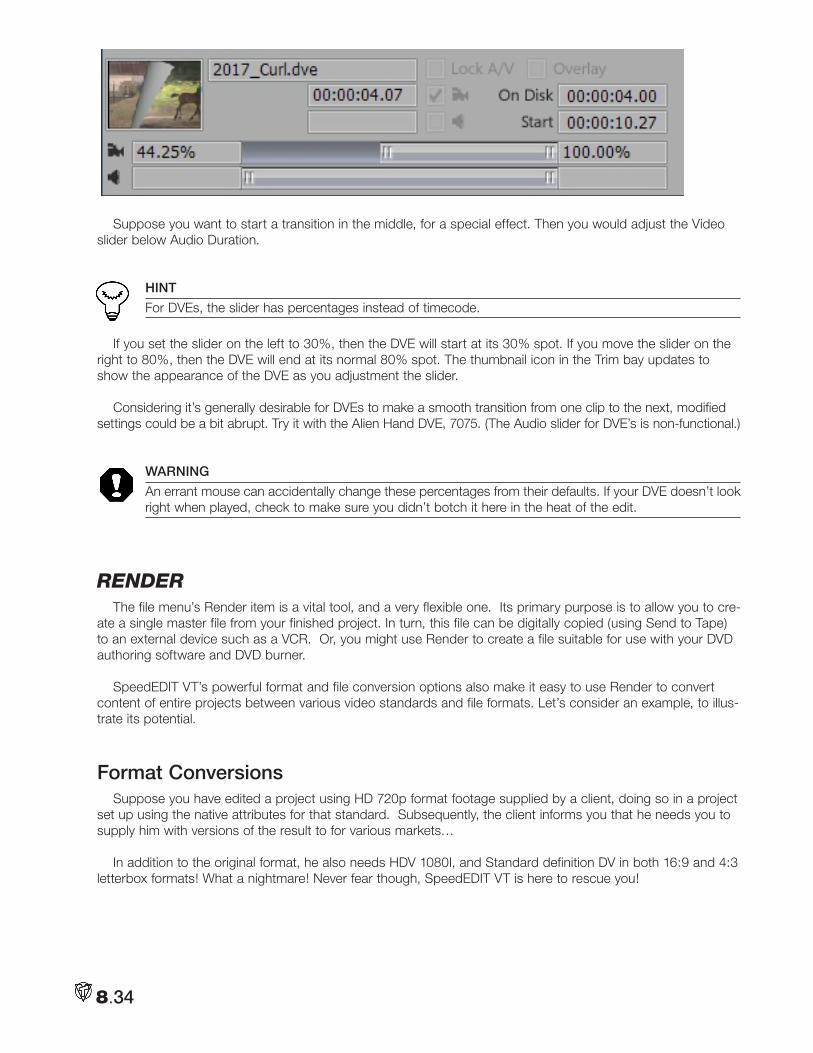
8.34
Suppose you want to start a transition in the middle, for a special effect. Then you would adjust the Video slider below Audio Duration.
HINT
For DVEs, the slider has percentages instead of timecode.
If you set the slider on the left to 30%, then the DVE will start at its 30% spot. If you move the slider on the right to 80%, then the DVE will end at its normal 80% spot. The thumbnail icon in the Trim bay updates to show the appearance of the DVE as you adjustment the slider.
Considering it’s generally desirable for DVEs to make a smooth transition from one clip to the next, modified settings could be a bit abrupt. Try it with the Alien Hand DVE, 7075. (The Audio slider for DVE’s is non-functional.)
WARNING
An errant mouse can accidentally change these percentages from their defaults. If your DVE doesn’t look right when played, check to make sure you didn’t botch it here in the heat of the edit.
RendeRThe file menu’s Render item is a vital tool, and a very flexible one. Its primary purpose is to allow you to cre-
ate a single master file from your finished project. In turn, this file can be digitally copied (using Send to Tape) to an external device such as a VCR. Or, you might use Render to create a file suitable for use with your DVD authoring software and DVD burner.
SpeedEDIT VT’s powerful format and file conversion options also make it easy to use Render to convert content of entire projects between various video standards and file formats. Let’s consider an example, to illus-trate its potential.
Format ConversionsSuppose you have edited a project using HD 720p format footage supplied by a client, doing so in a project
set up using the native attributes for that standard. Subsequently, the client informs you that he needs you to supply him with versions of the result to for various markets…
In addition to the original format, he also needs HDV 1080I, and Standard definition DV in both 16:9 and 4:3 letterbox formats! What a nightmare! Never fear though, SpeedEDIT VT is here to rescue you!
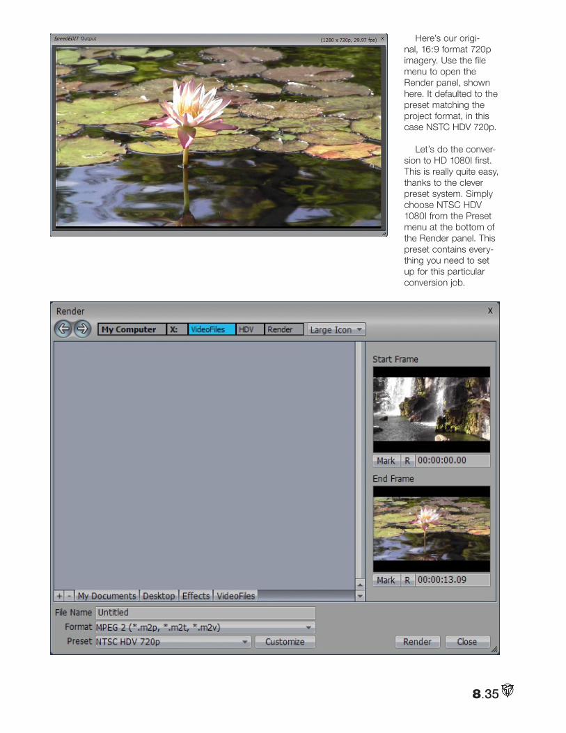
8.35
Here’s our origi-nal, 16:9 format 720p imagery. Use the file menu to open the Render panel, shown here. It defaulted to the preset matching the project format, in this case NSTC HDV 720p.
Let’s do the conver-sion to HD 1080I first. This is really quite easy, thanks to the clever preset system. Simply choose NTSC HDV 1080I from the Preset menu at the bottom of the Render panel. This preset contains every-thing you need to set up for this particular conversion job.

8.36
Having done that, you can provide a File Name in the space supplied, and use the standard SpeedEDIT VT Filebin tools in the upper part of the panel to designate a location for the rendered file. Use the Mark In/Out thumbnail windows at the right to select a range to export, if you like, then click the Render button to create the file.
HINT
The functionality of the In/Out thumbnails is similar to the corresponding feature described in the Selected Clip Properties discussion.
Let’s proceed to the next format conversion on our client’s list, NTSC DV 16:9. Open the Render panel again. Checking the Preset list, we find there is no corresponding preset! That’s because by definition DV is not an MPEG 2 compressed file format.
Use the down arrow next to Format to switch the Format setting to Video for windows (*.avi), and then check the available presets again. Now you should find NTSC DV Type2 16X9 listed, just what you need!
Go ahead and render again, using a
different filename of course, and then let’s dig a little deeper into the power of the Render panel to handle the next conversion.
This time, we are asked to render to the DV 4:3 format, scaling the 16:9 image down so it fits into the smaller frame with ‘letterboxing’ above and below. Locate the NTSC DV Type2 4:3 preset, then click the Customize button to gain access to some more options.
The Customize Preset options panel will appear, chock-full of useful settings. Among other things, this panel has Preset Name, Save and Delete buttons to permit you to set up and manage your own personal presets, perfectly suited to any purpose you might need from time to time.
At the moment, our goal is to make sure that our 16:9 video is scaled down to fit within the smaller 4:3 frame of a standard definition television set. The Mode switch in the Custom Preset panel will assist us here:
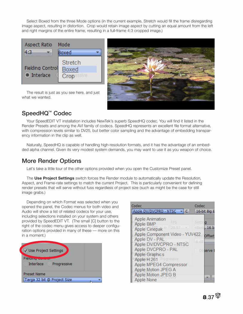
8.37
Select Boxed from the three Mode options (in the current example, Stretch would fill the frame disregarding image aspect, resulting in distortion. Crop would retain image aspect by cutting an equal amount from the left and right margins of the entire frame, resulting in a full-frame 4:3 cropped image.)
The result is just as you see here, and just what we wanted.
SpeedHQ™ CodecYour SpeedEDIT VT installation includes NewTek’s superb SpeedHQ codec. You will find it listed in the
Render Presets and among the AVI family of codecs. SpeedHQ represents an excellent file format alternative, with compression levels similar to DV25, but better color sampling and the advantage of embedding transpar-ency information in the clip as well.
Naturally, SpeedHQ is capable of handling high-resolution formats, and it has the advantage of an embed-ded alpha channel. Given its very modest system demands, you may want to use it as you weapon of choice.
More Render OptionsLet’s take a little tour of the other options provided when you open the Customize Preset panel.
The Use Project Settings switch forces the Render module to automatically update the Resolution, Aspect, and Frame-rate settings to match the current Project. This is particularly convenient for defining render presets that will serve without fuss regardless of project size (such as might be the case for still image grabs.)
Depending on which Format was selected when you opened the panel, the Codec menus for both video and Audio will show a list of related codecs for your use, including selections installed on your system and others provided by SpeedEDIT VT. (The small [C] button to the right of the codec menu gives access to deeper configu-ration options provided in many of these — more on this in a moment.)
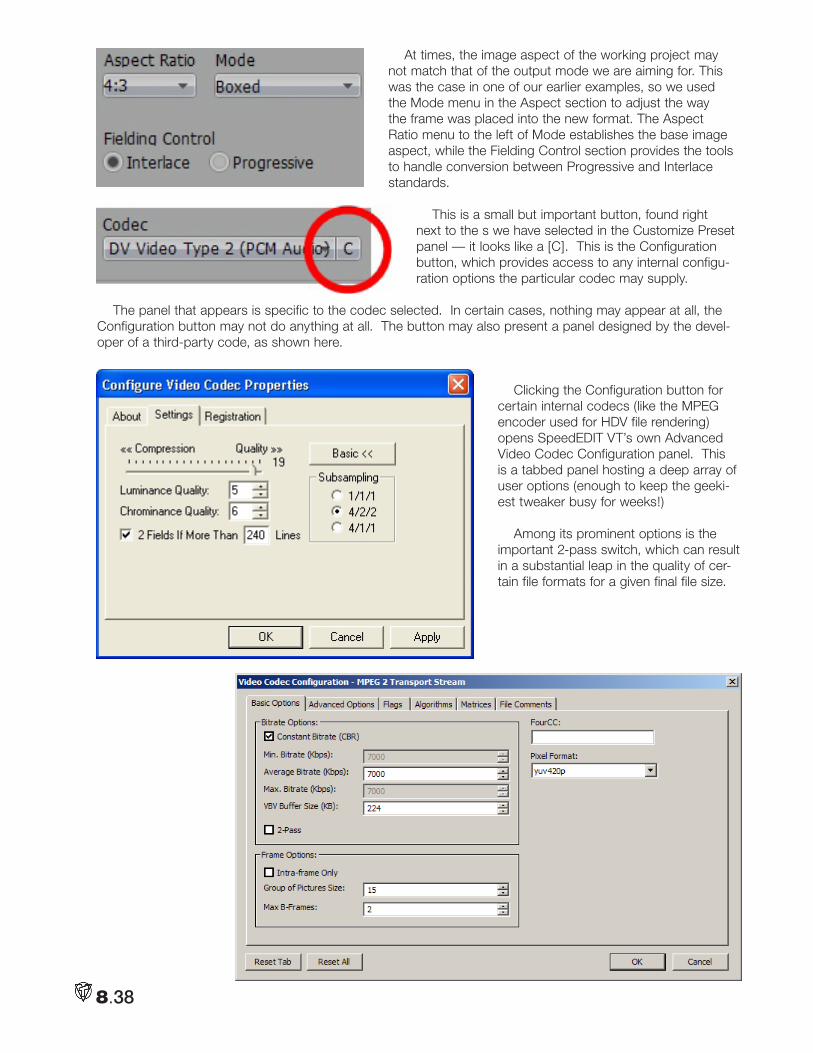
8.38
At times, the image aspect of the working project may not match that of the output mode we are aiming for. This was the case in one of our earlier examples, so we used the Mode menu in the Aspect section to adjust the way the frame was placed into the new format. The Aspect Ratio menu to the left of Mode establishes the base image aspect, while the Fielding Control section provides the tools to handle conversion between Progressive and Interlace standards.
This is a small but important button, found right next to the s we have selected in the Customize Preset panel — it looks like a [C]. This is the Configuration button, which provides access to any internal configu-ration options the particular codec may supply.
The panel that appears is specific to the codec selected. In certain cases, nothing may appear at all, the Configuration button may not do anything at all. The button may also present a panel designed by the devel-oper of a third-party code, as shown here.
Clicking the Configuration button for certain internal codecs (like the MPEG encoder used for HDV file rendering) opens SpeedEDIT VT’s own Advanced Video Codec Configuration panel. This is a tabbed panel hosting a deep array of user options (enough to keep the geeki-est tweaker busy for weeks!)
Among its prominent options is the important 2-pass switch, which can result in a substantial leap in the quality of cer-tain file formats for a given final file size.
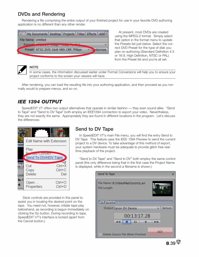
8.39
DVDs and RenderingRendering a file comprising the entire output of your finished project for use in your favorite DVD authoring
application is no different than any other render.
At present, most DVDs are created using the MPEG-2 format. Simply select that option in the format menu to update the Presets list just below. Select the cor-rect DVD Preset for the type of disk you plan on authoring (Standard Definition 4:3 or 16:9, High Definition, NTSC or PAL) from the Preset list and you’re all set.
NOTE
In some cases, the information discussed earlier under Format Conversions will help you to ensure your project conforms to the screen your viewers will have.
After rendering, you can load the resulting file into your authoring application, and then proceed as you nor-mally would to prepare menus, and so on.
iee 1394 outputSpeedEDIT VT offers two output alternatives that operate in similar fashion — they even sound alike. “Send
to Tape” and “Send to DV Tape” both employ an IEEE1394 connection to export your video. Nevertheless, they are not exactly the same. Appropriately they are found in different locations in the program. Let’s discuss the differences:
Send to DV TapeIn SpeedEDIT VT’s main File menu, you will find the entry Send to
DV Tape. This feature uses the IEEE 1394 Preview to send the current project to a DV device. To take advantage of this method of export, your system hardware must be adequate to provide glitch free real-time playback of the project.
“Send to DV Tape” and “Send to DV” both employ the same control panel (the only difference being that in the first case the Project Name is displayed, while in the second a filename is shown.)
Deck controls are provided in this panel to assist you in locating the desired point on the tape. You need not, however, initiate tape play beforehand, as recording is begun immediately on clicking the Go button. During recording to tape, SpeedEDIT VT’s interface is locked (apart from the Cancel button.)
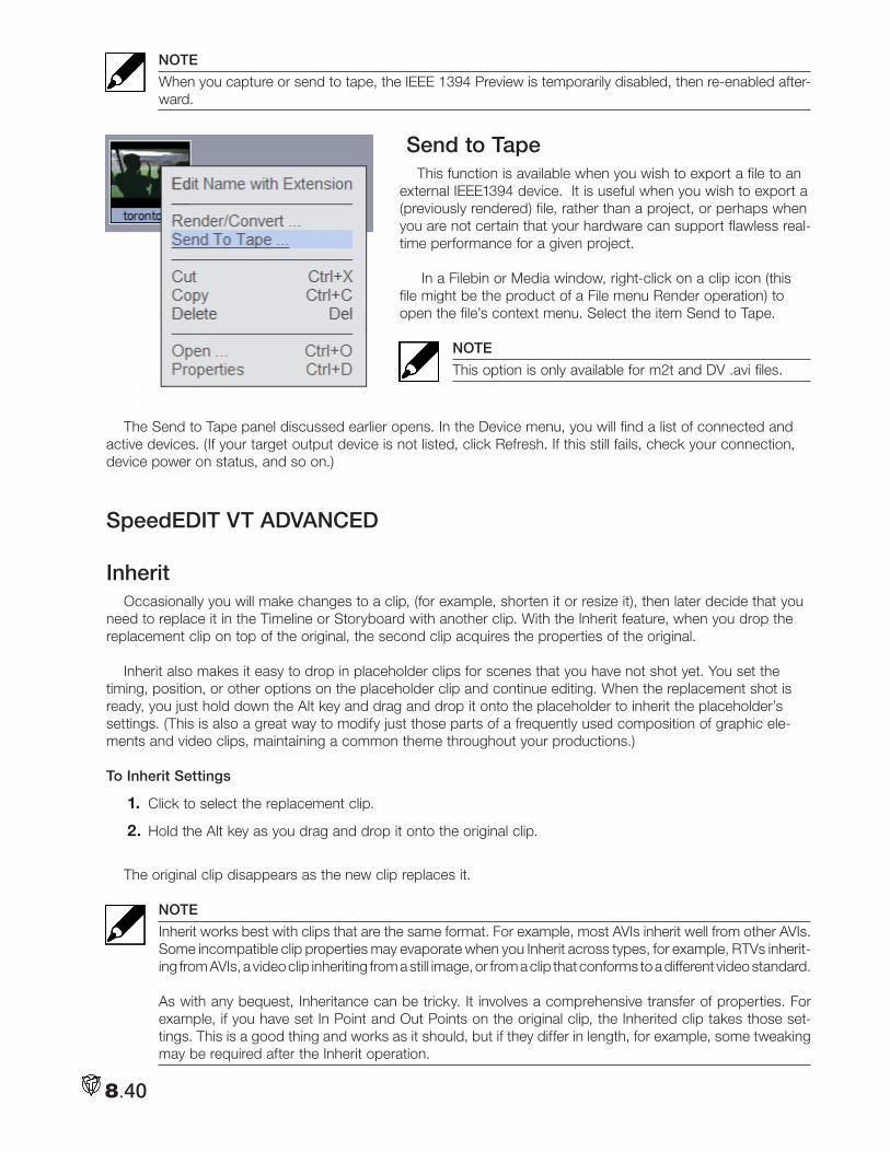
8.40
NOTE
When you capture or send to tape, the IEEE 1394 Preview is temporarily disabled, then re-enabled after-ward.
Send to TapeThis function is available when you wish to export a file to an
external IEEE1394 device. It is useful when you wish to export a (previously rendered) file, rather than a project, or perhaps when you are not certain that your hardware can support flawless real-time performance for a given project.
In a Filebin or Media window, right-click on a clip icon (this file might be the product of a File menu Render operation) to open the file’s context menu. Select the item Send to Tape.
NOTE
This option is only available for m2t and DV .avi files.
The Send to Tape panel discussed earlier opens. In the Device menu, you will find a list of connected and active devices. (If your target output device is not listed, click Refresh. If this still fails, check your connection, device power on status, and so on.)
SpeedEDIT VT ADVANCED
InheritOccasionally you will make changes to a clip, (for example, shorten it or resize it), then later decide that you
need to replace it in the Timeline or Storyboard with another clip. With the Inherit feature, when you drop the replacement clip on top of the original, the second clip acquires the properties of the original.
Inherit also makes it easy to drop in placeholder clips for scenes that you have not shot yet. You set the timing, position, or other options on the placeholder clip and continue editing. When the replacement shot is ready, you just hold down the Alt key and drag and drop it onto the placeholder to inherit the placeholder’s settings. (This is also a great way to modify just those parts of a frequently used composition of graphic ele-ments and video clips, maintaining a common theme throughout your productions.)
To Inherit Settings
1. Click to select the replacement clip.
2. Hold the Alt key as you drag and drop it onto the original clip.
The original clip disappears as the new clip replaces it.
NOTE
Inherit works best with clips that are the same format. For example, most AVIs inherit well from other AVIs. Some incompatible clip properties may evaporate when you Inherit across types, for example, RTVs inherit-ing from AVIs, a video clip inheriting from a still image, or from a clip that conforms to a different video standard. As with any bequest, Inheritance can be tricky. It involves a comprehensive transfer of properties. For example, if you have set In Point and Out Points on the original clip, the Inherited clip takes those set-tings. This is a good thing and works as it should, but if they differ in length, for example, some tweaking may be required after the Inherit operation.
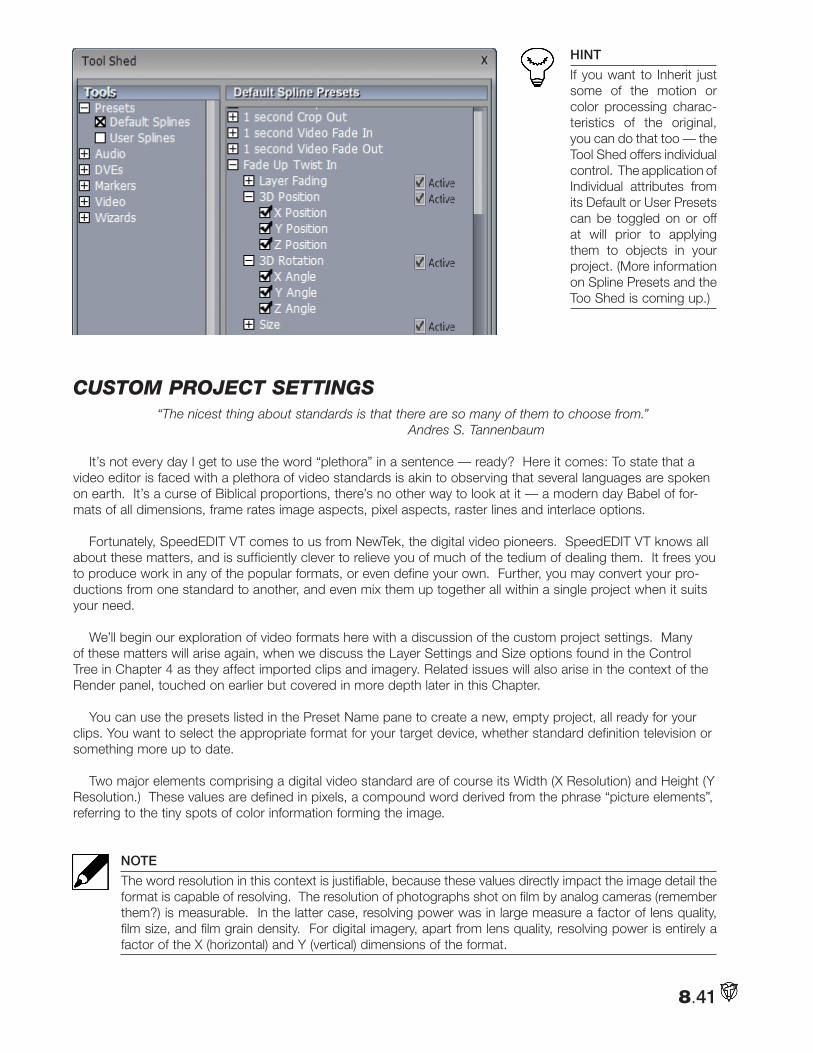
8.41
HINT
If you want to Inherit just some of the motion or color processing charac-teristics of the original, you can do that too — the Tool Shed offers individual control. The application of Individual attributes from its Default or User Presets can be toggled on or off at will prior to applying them to objects in your project. (More information on Spline Presets and the Too Shed is coming up.)
cuStom pRoject SettingS“The nicest thing about standards is that there are so many of them to choose from.”
Andres S. Tannenbaum
It’s not every day I get to use the word “plethora” in a sentence — ready? Here it comes: To state that a video editor is faced with a plethora of video standards is akin to observing that several languages are spoken on earth. It’s a curse of Biblical proportions, there’s no other way to look at it — a modern day Babel of for-mats of all dimensions, frame rates image aspects, pixel aspects, raster lines and interlace options.
Fortunately, SpeedEDIT VT comes to us from NewTek, the digital video pioneers. SpeedEDIT VT knows all about these matters, and is sufficiently clever to relieve you of much of the tedium of dealing them. It frees you to produce work in any of the popular formats, or even define your own. Further, you may convert your pro-ductions from one standard to another, and even mix them up together all within a single project when it suits your need.
We’ll begin our exploration of video formats here with a discussion of the custom project settings. Many of these matters will arise again, when we discuss the Layer Settings and Size options found in the Control Tree in Chapter 4 as they affect imported clips and imagery. Related issues will also arise in the context of the Render panel, touched on earlier but covered in more depth later in this Chapter.
You can use the presets listed in the Preset Name pane to create a new, empty project, all ready for your clips. You want to select the appropriate format for your target device, whether standard definition television or something more up to date.
Two major elements comprising a digital video standard are of course its Width (X Resolution) and Height (Y Resolution.) These values are defined in pixels, a compound word derived from the phrase “picture elements”, referring to the tiny spots of color information forming the image.
NOTE
The word resolution in this context is justifiable, because these values directly impact the image detail the format is capable of resolving. The resolution of photographs shot on film by analog cameras (remember them?) is measurable. In the latter case, resolving power was in large measure a factor of lens quality, film size, and film grain density. For digital imagery, apart from lens quality, resolving power is entirely a factor of the X (horizontal) and Y (vertical) dimensions of the format.
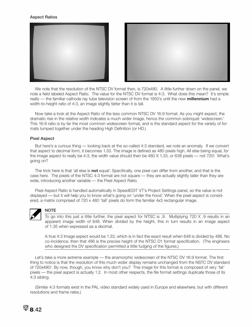
8.42
Aspect Ratios
We note that the resolution of the NTSC DV format then, is 720x480. A little further down on the panel, we note a field labeled Aspect Ratio. The value for the NTSC DV format is 4:3. What does this mean? It’s simple really — the familiar cathode ray tube television screen of from the 1950’s until the new millennium had a width-to-height ratio of 4:3, an image slightly fatter than it is tall.
Now take a look at the Aspect Ratio of the less common NTSC DV 16:9 format. As you might expect, the dramatic rise in the relative width indicates a much wider image, hence the common sobriquet ‘widescreen.’ This 16:9 ratio is by far the most common widescreen format, and is the standard aspect for the variety of for-mats lumped together under the heading High Definition (or HD.)
Pixel Aspect
But here’s a curious thing — looking back at the so-called 4:3 standard, we note an anomaly. If we convert that aspect to decimal form, it becomes 1.33. The image is defined as 480 pixels high. All else being equal, for the image aspect to really be 4:3, the width value should then be 480 X 1.33, or 638 pixels — not 720! What’s going on?
The trick here is that ‘all else is not equal’. Specifically, one pixel can differ from another, and that is the case here. The pixels of the NTSC 4:3 format are not square — they are actually slightly taller than they are wide, introducing another variable — the Pixel Aspect Ratio.
Pixel Aspect Ratio is handled automatically in SpeedEDIT VT’s Project Settings panel, so the value is not displayed — but it will help you to know what’s going on ‘under the hood.’ When the pixel aspect is consid-ered, a matrix comprised of 720 x 480 ‘tall’ pixels do form the familiar 4x3 rectangular image.
NOTE
To go into this just a little further, the pixel aspect for NTSC is .9. Multiplying 720 X .9 results in an apparent image width of 648. When divided by the height, this in turn results in an image aspect of 1.35 when expressed as a decimal. A true 4:3 Image aspect would be 1.33, which is in fact the exact result when 648 is divided by 486. No co-incidence, then that 486 is the precise height of the NTSC D1 format specification. (The engineers who designed the DV specification permitted a little fudging of the figures.)
Let’s take a more extreme example — the anamorphic widescreen of the NTSC DV 16:9 format. The first thing to notice is that the resolution of this much wider display remains unchanged from the NSTC DV standard of 720x480! By now, though, you know why don’t you? This image for this format is composed of very ‘fat’ pixels — the pixel aspect is actually 1.2. In most other respects, the file format settings duplicate those of its 4:3 sibling.
(Similar 4:3 formats exist in the PAL video standard widely used in Europe and elsewhere, but with different resolutions and frame rates.)
8.43
HINT
Another way to grasp the correlation of image aspect, pixel aspect, and resolution is to consider image aspect to be king. After all, the shape of the picture when displayed is really ‘the ten ton gorilla’ … every other attribute simply must conform to it. Each video standard has a defined height and image aspect. For example — HD 1080i is 1080 pixels high and (being an HD format) has an image aspect of 16:9. When displayed, the width simply must equal 16/9 the height. Now, you could do that with just one very fat pixel, but the result wouldn’t present a very pretty picture. Dividing the rows into more, skinnier pixels will improve things. If we use 1920 square pixels (as the HD 1080i format does), we’d have a very nice image with perfectly matched vertical and hori-zontal resolving power. We could instead use just 1440 slightly fatter pixels instead; the image would be only marginally softer laterally, and we’d have met the specification for HDV 1080. You can think of this as filling the wide, back row of a bus with passengers: you can fill the seat with a few very fat people (pixels), or you can squeeze in a larger number of slimmer ones. The row is full either way — but the latter way may make a nicer picture!
High Definition and HDV
With the (fairly recent) advent of High Definition television, you’d have thought that we’d escape the confu-sion by a welter of formats using non-square pixels. And we almost did.
High Definition formats fall into two broad camps, divided by resolution. While both have image aspects cor-responding to the 16:9 definition, one family is 720 pixels high and the other is a bit taller, at 1080 pixels.
In both cases, the pixel aspect is 1 — a perfect square. Thus, with a bit of basic math we can correctly conclude that the resolution of the former is 1280 X 720, and the taller family member is 1920 X 1080.
Naturally, there is a ‘black sheep’ in the family (both North American and overseas branches, as it happens.) In the interest of squeezing more data onto the recording medium, the prosumer class HDV format reverts to the age-old practice of ‘fat’ pixels to get its 16:9 image ratio. This results in dimensions of just 1440 X 1080 pixels for HDV.
Fielding and Frame rates
We’ll touch only lightly here on the subject of interlacing (a.k.a., fielding.) Video images do not instanta-neously appear on display screens as discreet images. Rather, each frame is painstakingly displayed as a composite of lines, each progressively painted horizontally by the device. Taking advantage of the persistence of both human vision and the display hardware, the full picture is composed in our mind’s eye ignoring the min-iscule delays involved in each line’s appearance on the screen.
For reasons too arcane to bother with here (and full of contradictions, compromises, politics, commercial interests and local exceptions) there are many regional variations in the specifics of these operations.
Our life would be simpler, too, if the video image on television screens the world over systematically started at the top of the screen, then painted each video line onto it one after the other. Again, decades ago engineer-ing compromise dictated another approach. Even today, in most of the world and on the majority of television screens, the image is subdivided into two portions called fields. The image is not simply divided in half, how-ever — or at least not in the manner you might expect. Each video field is composed of the image information from alternating lines of the whole. One field contains lines 1,3,5 and so on, and the other field contains lines 2, 4,6, etc.
The device scans across the screen to display one line, then skips one, passing on to create the following one and so on, until one field is displayed. Then, in less than the blink of an eye, the intervening lines are also painted, one after another.
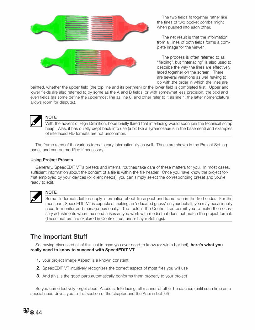
8.44
The two fields fit together rather like the tines of two pocket combs might when pushed into each other.
The net result is that the information from all lines of both fields forms a com-plete image for the viewer.
The process is often referred to as “fielding”, but “interlacing” is also used to describe the way the lines are effectively laced together on the screen. There are several variations as well having to do with the order in which the lines are
painted, whether the upper field (the top line and its brethren) or the lower field is completed first. Upper and lower fields are also referred to by some as the A and B fields, or with somewhat less precision, the odd and even fields (as some define the uppermost line as line 0, and other refer to it as line 1, the latter nomenclature allows room for dispute.).
NOTE
With the advent of High Definition, hope briefly flared that interlacing would soon join the technical scrap heap. Alas, it has quietly crept back into use (a bit like a Tyrannosaurus in the basement) and examples of interlaced HD formats are not uncommon.
The frame rates of the various formats vary internationally as well. These are shown in the Project Setting panel, and can be modified if necessary.
Using Project Presets
Generally, SpeedEDIT VT’s presets and internal routines take care of these matters for you. In most cases, sufficient information about the content of a file is within the file header. Once you have know the project for-mat employed by your devices (or client needs), you can simply select the corresponding preset and you’re ready to edit.
NOTE
Some file formats fail to supply information about file aspect and frame rate in the file header. For the most part, SpeedEDIT VT is capable of making an ‘educated guess’ on your behalf, you may occasionally need to monitor and manage personally. The tools in the Control Tree permit you to make the neces-sary adjustments when the need arises as you work with media that does not match the project format. (These matters are explored in Control Tree, under Layer Settings).
The Important StuffSo, having discussed all of this just in case you ever need to know (or win a bar bet), here’s what you
really need to know to succeed with SpeedEDIT VT:
1. your project Image Aspect is a known constant
2. SpeedEDIT VT intuitively recognizes the correct aspect of most files you will use
3. And (this is the good part) automatically conforms them properly to your project
So you can effectively forget about Aspects, Interlacing, all manner of other headaches (until such time as a special need drives you to this section of the chapter and the Aspirin bottle!)
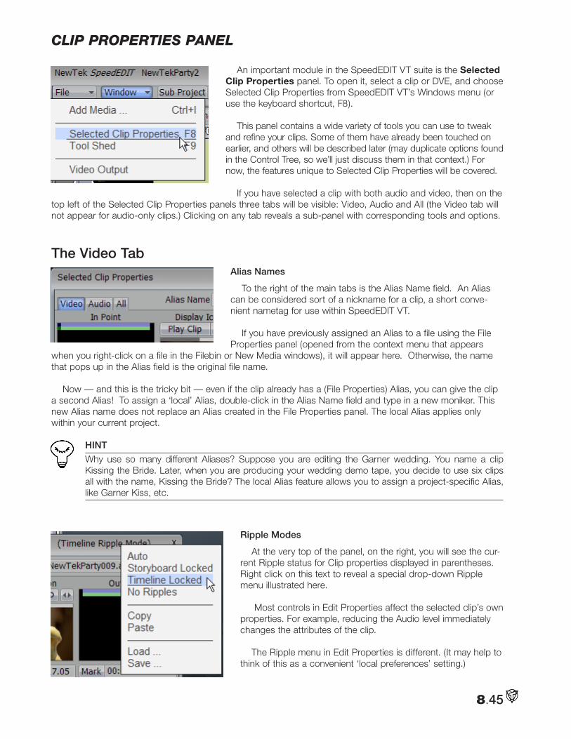
8.45
clip pRopeRtieS panel
An important module in the SpeedEDIT VT suite is the Selected Clip Properties panel. To open it, select a clip or DVE, and choose Selected Clip Properties from SpeedEDIT VT’s Windows menu (or use the keyboard shortcut, F8).
This panel contains a wide variety of tools you can use to tweak and refine your clips. Some of them have already been touched on earlier, and others will be described later (may duplicate options found in the Control Tree, so we’ll just discuss them in that context.) For now, the features unique to Selected Clip Properties will be covered.
If you have selected a clip with both audio and video, then on the top left of the Selected Clip Properties panels three tabs will be visible: Video, Audio and All (the Video tab will not appear for audio-only clips.) Clicking on any tab reveals a sub-panel with corresponding tools and options.
The Video TabAlias Names
To the right of the main tabs is the Alias Name field. An Alias can be considered sort of a nickname for a clip, a short conve-nient nametag for use within SpeedEDIT VT.
If you have previously assigned an Alias to a file using the File Properties panel (opened from the context menu that appears
when you right-click on a file in the Filebin or New Media windows), it will appear here. Otherwise, the name that pops up in the Alias field is the original file name.
Now — and this is the tricky bit — even if the clip already has a (File Properties) Alias, you can give the clip a second Alias! To assign a ‘local’ Alias, double-click in the Alias Name field and type in a new moniker. This new Alias name does not replace an Alias created in the File Properties panel. The local Alias applies only within your current project.
HINT
Why use so many different Aliases? Suppose you are editing the Garner wedding. You name a clip Kissing the Bride. Later, when you are producing your wedding demo tape, you decide to use six clips all with the name, Kissing the Bride? The local Alias feature allows you to assign a project-specific Alias, like Garner Kiss, etc.
Ripple Modes
At the very top of the panel, on the right, you will see the cur-rent Ripple status for Clip properties displayed in parentheses. Right click on this text to reveal a special drop-down Ripple menu illustrated here.
Most controls in Edit Properties affect the selected clip’s own properties. For example, reducing the Audio level immediately changes the attributes of the clip.
The Ripple menu in Edit Properties is different. (It may help to think of this as a convenient ‘local preferences’ setting.)
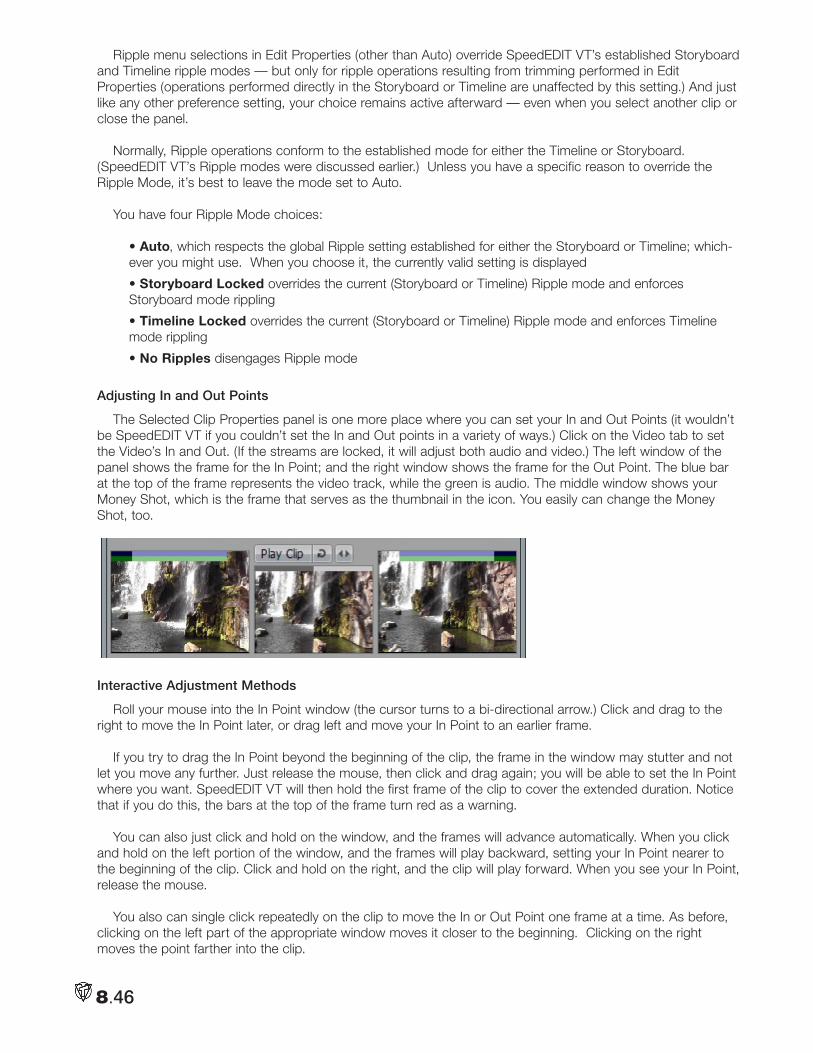
8.46
Ripple menu selections in Edit Properties (other than Auto) override SpeedEDIT VT’s established Storyboard and Timeline ripple modes — but only for ripple operations resulting from trimming performed in Edit Properties (operations performed directly in the Storyboard or Timeline are unaffected by this setting.) And just like any other preference setting, your choice remains active afterward — even when you select another clip or close the panel.
Normally, Ripple operations conform to the established mode for either the Timeline or Storyboard. (SpeedEDIT VT’s Ripple modes were discussed earlier.) Unless you have a specific reason to override the Ripple Mode, it’s best to leave the mode set to Auto.
You have four Ripple Mode choices:
• Auto, which respects the global Ripple setting established for either the Storyboard or Timeline; which-ever you might use. When you choose it, the currently valid setting is displayed
• Storyboard Locked overrides the current (Storyboard or Timeline) Ripple mode and enforces Storyboard mode rippling
• Timeline Locked overrides the current (Storyboard or Timeline) Ripple mode and enforces Timeline mode rippling
• No Ripples disengages Ripple mode
Adjusting In and Out Points
The Selected Clip Properties panel is one more place where you can set your In and Out Points (it wouldn’t be SpeedEDIT VT if you couldn’t set the In and Out points in a variety of ways.) Click on the Video tab to set the Video’s In and Out. (If the streams are locked, it will adjust both audio and video.) The left window of the panel shows the frame for the In Point; and the right window shows the frame for the Out Point. The blue bar at the top of the frame represents the video track, while the green is audio. The middle window shows your Money Shot, which is the frame that serves as the thumbnail in the icon. You easily can change the Money Shot, too.
Interactive Adjustment Methods
Roll your mouse into the In Point window (the cursor turns to a bi-directional arrow.) Click and drag to the right to move the In Point later, or drag left and move your In Point to an earlier frame.
If you try to drag the In Point beyond the beginning of the clip, the frame in the window may stutter and not let you move any further. Just release the mouse, then click and drag again; you will be able to set the In Point where you want. SpeedEDIT VT will then hold the first frame of the clip to cover the extended duration. Notice that if you do this, the bars at the top of the frame turn red as a warning.
You can also just click and hold on the window, and the frames will advance automatically. When you click and hold on the left portion of the window, and the frames will play backward, setting your In Point nearer to the beginning of the clip. Click and hold on the right, and the clip will play forward. When you see your In Point, release the mouse.
You also can single click repeatedly on the clip to move the In or Out Point one frame at a time. As before, clicking on the left part of the appropriate window moves it closer to the beginning. Clicking on the right moves the point farther into the clip.
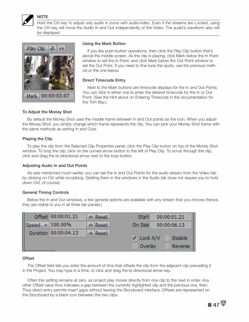
8.47
NOTE
Hold the Ctrl key to adjust only audio in icons with audio/video. Even if the streams are Locked, using the Ctrl key will move the Audio In and Out independently of the Video. The audio’s waveform also will be displayed.
Using the Mark Button
If you like push-button operations, then click the Play Clip button that’s above the middle screen. As the clip is playing, click Mark below the In Point window to set the In Point; and click Mark below the Out Point window to set the Out Point. If you need to fine-tune the spots, use the previous meth-od or the one below.
Direct Timecode Entry
Next to the Mark buttons are timecode displays for the In and Out Points. You can click in either one to enter the desired timecode for the In or Out Point. (See the Hint about on Entering Timecode in the documentation for the Trim Bay.)
To Adjust the Money Shot
By default the Money Shot uses the middle frame between In and Out points as the icon. When you adjust the Money Shot, you simply change which frame represents the clip. You can pick your Money Shot frame with the same methods as setting In and Outs.
Playing the Clip
To play the clip from the Selected Clip Properties panel, click the Play Clip button on top of the Money Shot window. To loop the clip, click on the curved arrow button to the left of Play Clip. To scrub through the clip, click and drag the bi-directional arrow next to the loop button.
Adjusting Audio In and Out Points
As was mentioned much earlier, you can set the In and Out Points for the audio stream from the Video tab by clicking on Ctrl while scrubbing. (Setting them in the windows in the Audio tab does not require you to hold down Ctrl, of course)
General Timing Controls
Below the In and Out windows, a few general options are available with any stream that you choose (hence, they are visible to you in all three tab panels.)
Offset
The Offset field lets you enter the amount of time that offsets the clip from the adjacent clip preceding it in the Project. You may type in a time, or click and drag the bi-directional arrow key.
Often this setting remains at zero, as project play moves directly from one clip to the next in order. Any other Offset value thus indicates a gap between the currently highlighted clip and the previous one, then. Thus direct entry permits insert gaps without leaving the Storyboard interface. Offsets are represented on the Storyboard by a black icon between the two clips.
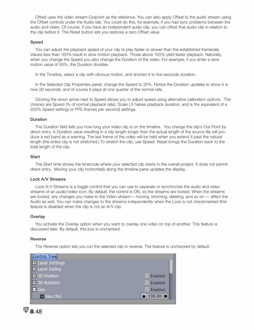
8.48
Offset uses the video stream Outpoint as the reference. You can also apply Offset to the audio stream using the Offset controls under the Audio tab. You could do this, for example, if you had sync problems between the audio and video. Of course, if you have an independent audio clip, you can offset that audio clip in relation to the clip before it. The Reset button lets you restores a zero Offset value.
Speed
You can adjust the playback speed of your clip to play faster or slower than the established framerate. Values less than 100% result in slow motion playback. Those above 100% yield faster playback. Naturally, when you change the Speed you also change the Duration of the video. For example, if you enter a slow motion value of 50%, the Duration doubles.
In the Timeline, select a clip with obvious motion, and shorten it to five seconds duration.
In the Selected Clip Properties panel, change the Speed to 25%. Notice the Duration updates to show it is now 20 seconds, and of course it plays at one quarter of the normal rate.
Clicking the down arrow next to Speed allows you to adjust speed using alternative calibration options. The choices are Speed (% of normal playback rate), Scale (.5 halves playback duration, and is the equivalent of a 200% Speed setting) or FPS (frames per second) settings.
Duration
The Duration field tells you how long your video clip is on the timeline. You change the clip’s Out Point by direct entry. A Duration value resulting in a clip length longer than the actual length of the source file will pro-duce a red band as a warning. The last frame of the video will be held when you extend it past the natural length (the entire clip is not stretched.) To stretch the clip, use Speed. Reset brings the Duration back to the total length of the clip.
Start
The Start time shows the timecode where your selected clip starts in the overall project. It does not permit direct entry. Moving your clip horizontally along the timeline pane updates the display.
Lock A/V Streams
Lock A/V Streams is a toggle control that you can use to separate or synchronize the audio and video streams of an audio/video icon. By default, the control is ON, so the streams are locked. When the streams are locked, any changes you make to the Video stream— moving, trimming, deleting, and so on — affect the Audio as well. You can make changes to the streams independently when the Lock is not checkmarked (this feature is disabled when the clip is not an A/V clip.
Overlay
You activate the Overlay option when you want to overlay one video on top of another. This feature is discussed later. By default, this box is unchecked.
Reverse
The Reverse option lets you run the selected clip in reverse. The feature is unchecked by default.
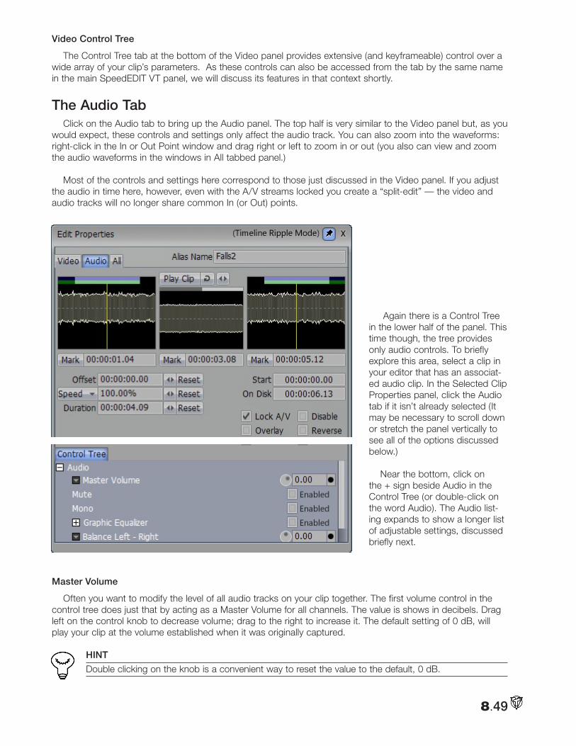
8.49
Video Control Tree
The Control Tree tab at the bottom of the Video panel provides extensive (and keyframeable) control over a wide array of your clip’s parameters. As these controls can also be accessed from the tab by the same name in the main SpeedEDIT VT panel, we will discuss its features in that context shortly.
The Audio TabClick on the Audio tab to bring up the Audio panel. The top half is very similar to the Video panel but, as you
would expect, these controls and settings only affect the audio track. You can also zoom into the waveforms: right-click in the In or Out Point window and drag right or left to zoom in or out (you also can view and zoom the audio waveforms in the windows in All tabbed panel.)
Most of the controls and settings here correspond to those just discussed in the Video panel. If you adjust the audio in time here, however, even with the A/V streams locked you create a “split-edit” — the video and audio tracks will no longer share common In (or Out) points.
Again there is a Control Tree in the lower half of the panel. This time though, the tree provides only audio controls. To briefly explore this area, select a clip in your editor that has an associat-ed audio clip. In the Selected Clip Properties panel, click the Audio tab if it isn’t already selected (It may be necessary to scroll down or stretch the panel vertically to see all of the options discussed below.)
Near the bottom, click on the + sign beside Audio in the Control Tree (or double-click on the word Audio). The Audio list-ing expands to show a longer list of adjustable settings, discussed briefly next.
Master Volume
Often you want to modify the level of all audio tracks on your clip together. The first volume control in the control tree does just that by acting as a Master Volume for all channels. The value is shows in decibels. Drag left on the control knob to decrease volume; drag to the right to increase it. The default setting of 0 dB, will play your clip at the volume established when it was originally captured.
HINT
Double clicking on the knob is a convenient way to reset the value to the default, 0 dB.
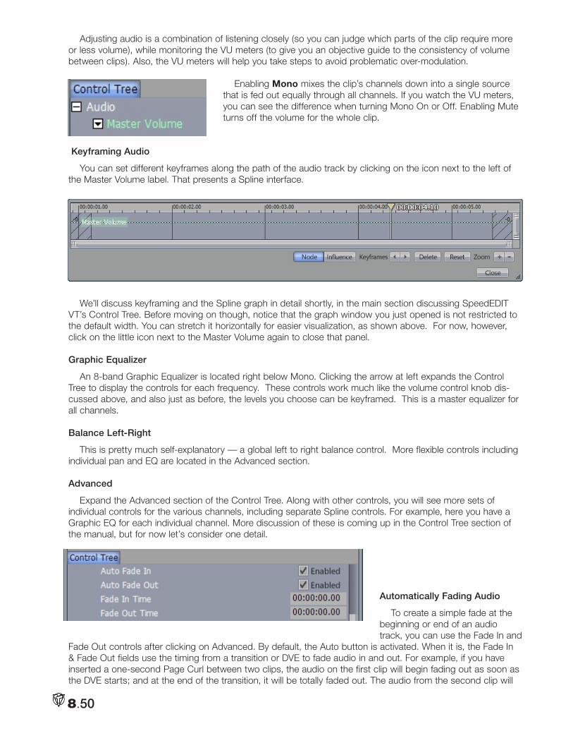
8.50
Adjusting audio is a combination of listening closely (so you can judge which parts of the clip require more or less volume), while monitoring the VU meters (to give you an objective guide to the consistency of volume between clips). Also, the VU meters will help you take steps to avoid problematic over-modulation.
Enabling Mono mixes the clip’s channels down into a single source that is fed out equally through all channels. If you watch the VU meters, you can see the difference when turning Mono On or Off. Enabling Mute turns off the volume for the whole clip.
Keyframing Audio
You can set different keyframes along the path of the audio track by clicking on the icon next to the left of the Master Volume label. That presents a Spline interface.
We’ll discuss keyframing and the Spline graph in detail shortly, in the main section discussing SpeedEDIT VT’s Control Tree. Before moving on though, notice that the graph window you just opened is not restricted to the default width. You can stretch it horizontally for easier visualization, as shown above. For now, however, click on the little icon next to the Master Volume again to close that panel.
Graphic Equalizer
An 8-band Graphic Equalizer is located right below Mono. Clicking the arrow at left expands the Control Tree to display the controls for each frequency. These controls work much like the volume control knob dis-cussed above, and also just as before, the levels you choose can be keyframed. This is a master equalizer for all channels.
Balance Left-Right
This is pretty much self-explanatory — a global left to right balance control. More flexible controls including individual pan and EQ are located in the Advanced section.
Advanced
Expand the Advanced section of the Control Tree. Along with other controls, you will see more sets of individual controls for the various channels, including separate Spline controls. For example, here you have a Graphic EQ for each individual channel. More discussion of these is coming up in the Control Tree section of the manual, but for now let’s consider one detail.
Automatically Fading Audio
To create a simple fade at the beginning or end of an audio track, you can use the Fade In and
Fade Out controls after clicking on Advanced. By default, the Auto button is activated. When it is, the Fade In & Fade Out fields use the timing from a transition or DVE to fade audio in and out. For example, if you have inserted a one-second Page Curl between two clips, the audio on the first clip will begin fading out as soon as the DVE starts; and at the end of the transition, it will be totally faded out. The audio from the second clip will
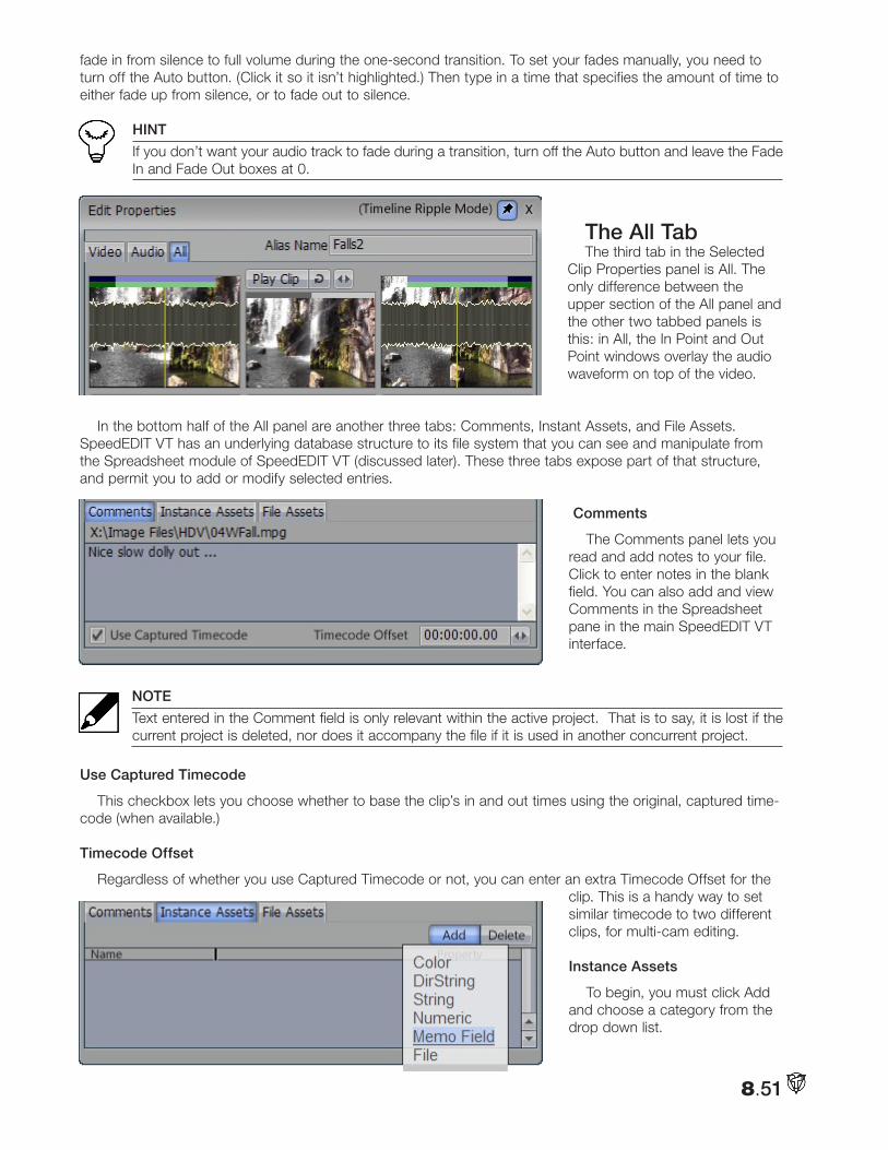
8.51
fade in from silence to full volume during the one-second transition. To set your fades manually, you need to turn off the Auto button. (Click it so it isn’t highlighted.) Then type in a time that specifies the amount of time to either fade up from silence, or to fade out to silence.
HINT
If you don’t want your audio track to fade during a transition, turn off the Auto button and leave the Fade In and Fade Out boxes at 0.
The All TabThe third tab in the Selected
Clip Properties panel is All. The only difference between the upper section of the All panel and the other two tabbed panels is this: in All, the In Point and Out Point windows overlay the audio waveform on top of the video.
In the bottom half of the All panel are another three tabs: Comments, Instant Assets, and File Assets. SpeedEDIT VT has an underlying database structure to its file system that you can see and manipulate from the Spreadsheet module of SpeedEDIT VT (discussed later). These three tabs expose part of that structure, and permit you to add or modify selected entries.
Comments
The Comments panel lets you read and add notes to your file. Click to enter notes in the blank field. You can also add and view Comments in the Spreadsheet pane in the main SpeedEDIT VT interface.
NOTE
Text entered in the Comment field is only relevant within the active project. That is to say, it is lost if the current project is deleted, nor does it accompany the file if it is used in another concurrent project.
Use Captured Timecode
This checkbox lets you choose whether to base the clip’s in and out times using the original, captured time-code (when available.)
Timecode Offset
Regardless of whether you use Captured Timecode or not, you can enter an extra Timecode Offset for the clip. This is a handy way to set similar timecode to two different clips, for multi-cam editing.
Instance Assets
To begin, you must click Add and choose a category from the drop down list.
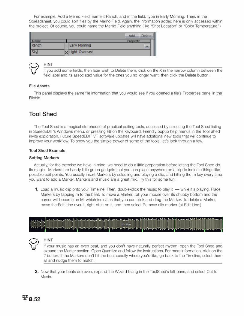
8.52
For example, Add a Memo Field, name it Ranch, and in the field, type in Early Morning. Then, in the Spreadsheet, you could sort files by the Memo Field. Again, the information added here is only accessed within the project. Of course, you could name the Memo Field anything (like “Shot Location” or “Color Temperature.”)
HINT
If you add some fields, then later wish to Delete them, click on the X in the narrow column between the field label and its associated value for the ones you no longer want, then click the Delete button.
File Assets
This panel displays the same file information that you would see if you opened a file’s Properties panel in the Filebin.
Tool Shed
The Tool Shed is a magical storehouse of practical editing tools, accessed by selecting the Tool Shed listing in SpeedEDIT’s Windows menu, or pressing F9 on the keyboard. Friendly popup help menus in the Tool Shed invite exploration. Future SpeedEDIT VT software updates will have additional new tools that will continue to improve your workflow. To show you the simple power of some of the tools, let’s look through a few.
Tool Shed Example
Setting Markers
Actually, for the exercise we have in mind, we need to do a little preparation before letting the Tool Shed do its magic. Markers are handy little green gadgets that you can place anywhere on a clip to indicate things like possible edit points. You usually insert Markers by selecting and playing a clip, and hitting the m key every time you want to add a Marker. Markers and music are a great mix. Try this for some fun:
1. Load a music clip onto your Timeline. Then, double-click the music to play it — while it’s playing. Place Markers by tapping m to the beat. To move a Marker, roll your mouse over its chubby bottom and the cursor will become an M, which indicates that you can click and drag the Marker. To delete a Marker, move the Edit Line over it, right-click on it, and then select Remove clip marker (at Edit Line.)
HINT
If your music has an even beat, and you don’t have naturally perfect rhythm, open the Tool Shed and expand the Marker section. Open Quantize and follow the instructions. For more information, click on the ? button. If the Markers don’t hit the beat exactly where you’d like, go back to the Timeline, select them all and nudge them to match.
2. Now that your beats are even, expand the Wizard listing in the ToolShed’s left pane, and select Cut to Music.
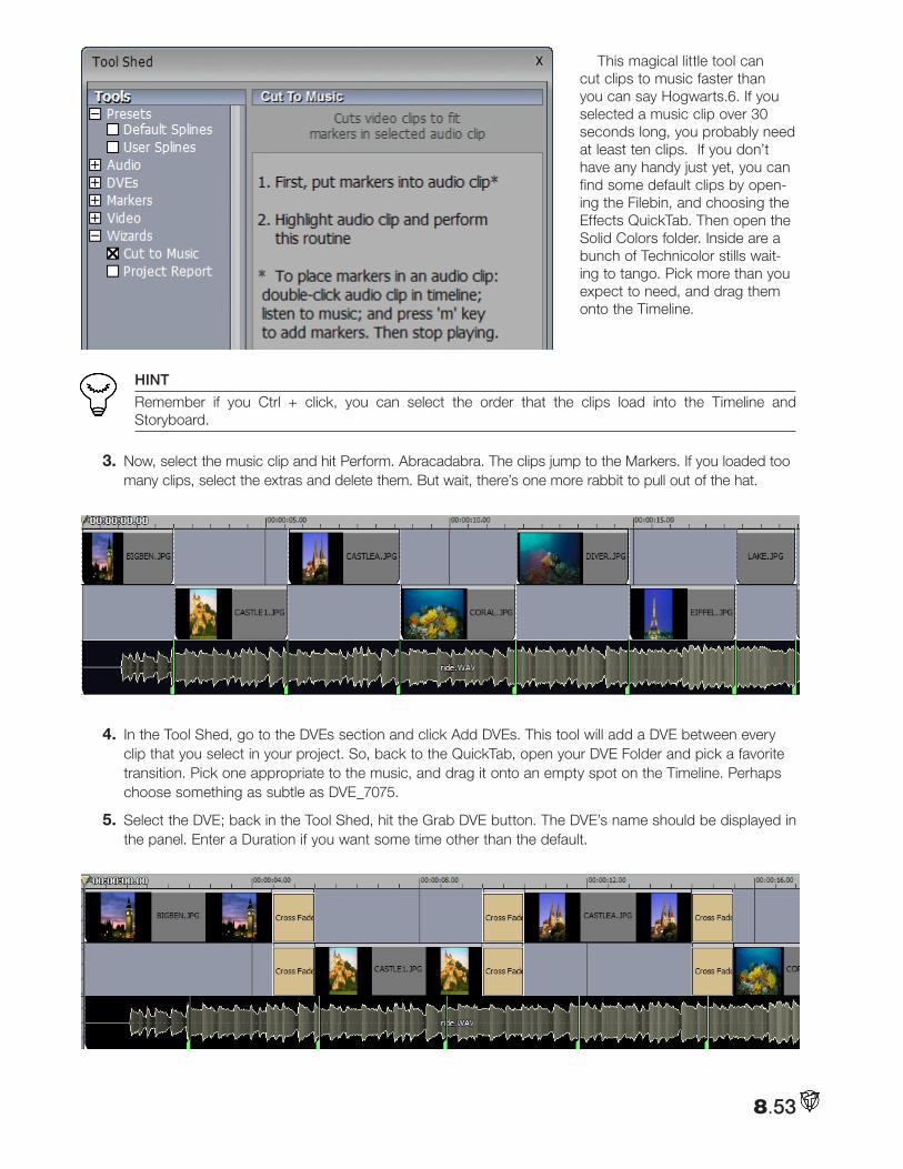
8.53
This magical little tool can cut clips to music faster than you can say Hogwarts.6. If you selected a music clip over 30 seconds long, you probably need at least ten clips. If you don’t have any handy just yet, you can find some default clips by open-ing the Filebin, and choosing the Effects QuickTab. Then open the Solid Colors folder. Inside are a bunch of Technicolor stills wait-ing to tango. Pick more than you expect to need, and drag them onto the Timeline.
HINT
Remember if you Ctrl + click, you can select the order that the clips load into the Timeline and Storyboard.
3. Now, select the music clip and hit Perform. Abracadabra. The clips jump to the Markers. If you loaded too many clips, select the extras and delete them. But wait, there’s one more rabbit to pull out of the hat.
4. In the Tool Shed, go to the DVEs section and click Add DVEs. This tool will add a DVE between every clip that you select in your project. So, back to the QuickTab, open your DVE Folder and pick a favorite transition. Pick one appropriate to the music, and drag it onto an empty spot on the Timeline. Perhaps choose something as subtle as DVE_7075.
5. Select the DVE; back in the Tool Shed, hit the Grab DVE button. The DVE’s name should be displayed in the panel. Enter a Duration if you want some time other than the default.
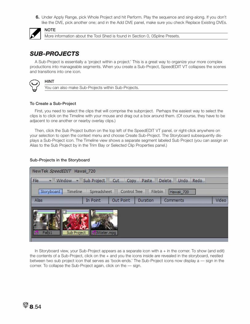
8.54
6. Under Apply Range, pick Whole Project and hit Perform. Play the sequence and sing-along. If you don’t like the DVE, pick another one; and in the Add DVE panel, make sure you check Replace Existing DVEs.
NOTE
More information about the Tool Shed is found in Section 0, 0Spline Presets.
SuB-pRojectSA Sub-Project is essentially a ‘project within a project.’ This is a great way to organize your more complex
productions into manageable segments. When you create a Sub-Project, SpeedEDIT VT collapses the scenes and transitions into one icon.
HINT
You can also make Sub-Projects within Sub-Projects.
To Create a Sub-Project
First, you need to select the clips that will comprise the subproject. Perhaps the easiest way to select the clips is to click on the Timeline with your mouse and drag out a box around them. (Of course, they have to be adjacent to one another or nearby overlay clips.)
Then, click the Sub Project button on the top left of the SpeedEDIT VT panel, or right-click anywhere on your selection to open the context menu and choose Create Sub-Project. The Storyboard subsequently dis-plays a Sub-Project icon. The Timeline view shows a separate segment labeled Sub Project (you can assign an Alias to the Sub Project by in the Trim Bay or Selected Clip Properties panel.)
Sub-Projects in the Storyboard
In Storyboard view, your Sub-Project appears as a separate icon with a + in the corner. To show (and edit) the contents of a Sub-Project, click on the + and you the icons inside are revealed in the storyboard, nestled between two sub project icon that serves as ‘book-ends.’ The Sub-Project icons now display a — sign in the corner. To collapse the Sub-Project again, click on the — sign.
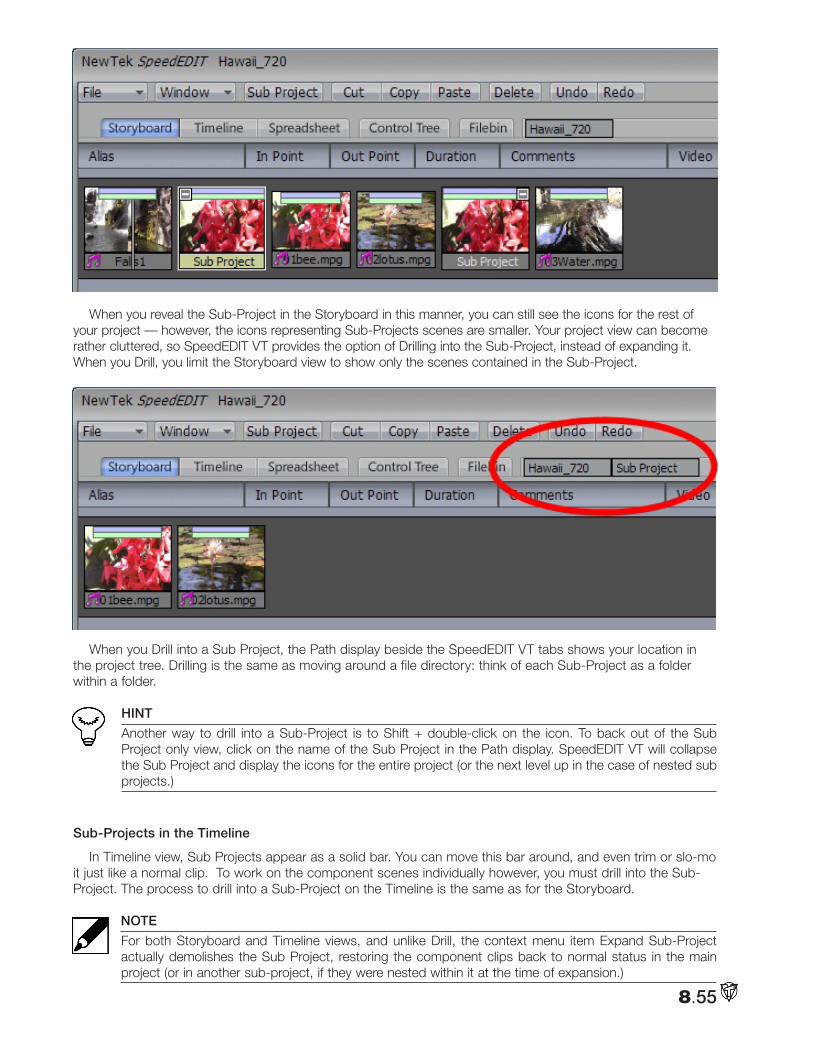
8.55
When you reveal the Sub-Project in the Storyboard in this manner, you can still see the icons for the rest of your project — however, the icons representing Sub-Projects scenes are smaller. Your project view can become rather cluttered, so SpeedEDIT VT provides the option of Drilling into the Sub-Project, instead of expanding it. When you Drill, you limit the Storyboard view to show only the scenes contained in the Sub-Project.
When you Drill into a Sub Project, the Path display beside the SpeedEDIT VT tabs shows your location in the project tree. Drilling is the same as moving around a file directory: think of each Sub-Project as a folder within a folder.
HINT
Another way to drill into a Sub-Project is to Shift + double-click on the icon. To back out of the Sub Project only view, click on the name of the Sub Project in the Path display. SpeedEDIT VT will collapse the Sub Project and display the icons for the entire project (or the next level up in the case of nested sub projects.)
Sub-Projects in the Timeline
In Timeline view, Sub Projects appear as a solid bar. You can move this bar around, and even trim or slo-mo it just like a normal clip. To work on the component scenes individually however, you must drill into the Sub-Project. The process to drill into a Sub-Project on the Timeline is the same as for the Storyboard.
NOTE
For both Storyboard and Timeline views, and unlike Drill, the context menu item Expand Sub-Project actually demolishes the Sub Project, restoring the component clips back to normal status in the main project (or in another sub-project, if they were nested within it at the time of expansion.)
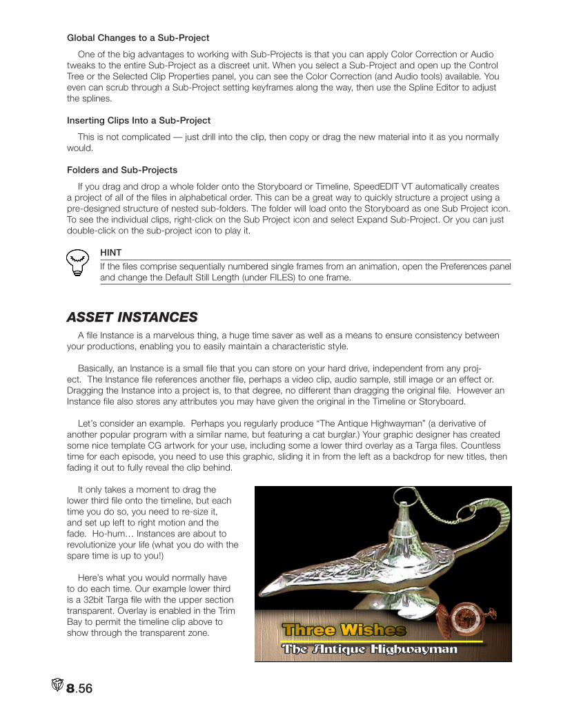
8.56
Global Changes to a Sub-Project
One of the big advantages to working with Sub-Projects is that you can apply Color Correction or Audio tweaks to the entire Sub-Project as a discreet unit. When you select a Sub-Project and open up the Control Tree or the Selected Clip Properties panel, you can see the Color Correction (and Audio tools) available. You even can scrub through a Sub-Project setting keyframes along the way, then use the Spline Editor to adjust the splines.
Inserting Clips Into a Sub-Project
This is not complicated — just drill into the clip, then copy or drag the new material into it as you normally would.
Folders and Sub-Projects
If you drag and drop a whole folder onto the Storyboard or Timeline, SpeedEDIT VT automatically creates a project of all of the files in alphabetical order. This can be a great way to quickly structure a project using a pre-designed structure of nested sub-folders. The folder will load onto the Storyboard as one Sub Project icon. To see the individual clips, right-click on the Sub Project icon and select Expand Sub-Project. Or you can just double-click on the sub-project icon to play it.
HINT
If the files comprise sequentially numbered single frames from an animation, open the Preferences panel and change the Default Still Length (under FILES) to one frame.
aSSet inStanceSA file Instance is a marvelous thing, a huge time saver as well as a means to ensure consistency between
your productions, enabling you to easily maintain a characteristic style.
Basically, an Instance is a small file that you can store on your hard drive, independent from any proj-ect. The Instance file references another file, perhaps a video clip, audio sample, still image or an effect or. Dragging the Instance into a project is, to that degree, no different than dragging the original file. However an Instance file also stores any attributes you may have given the original in the Timeline or Storyboard.
Let’s consider an example. Perhaps you regularly produce “The Antique Highwayman” (a derivative of another popular program with a similar name, but featuring a cat burglar.) Your graphic designer has created some nice template CG artwork for your use, including some a lower third overlay as a Targa files. Countless time for each episode, you need to use this graphic, sliding it in from the left as a backdrop for new titles, then fading it out to fully reveal the clip behind.
It only takes a moment to drag the lower third file onto the timeline, but each time you do so, you need to re-size it, and set up left to right motion and the fade. Ho-hum… Instances are about to revolutionize your life (what you do with the spare time is up to you!)
Here’s what you would normally have to do each time. Our example lower third is a 32bit Targa file with the upper section transparent. Overlay is enabled in the Trim Bay to permit the timeline clip above to show through the transparent zone.
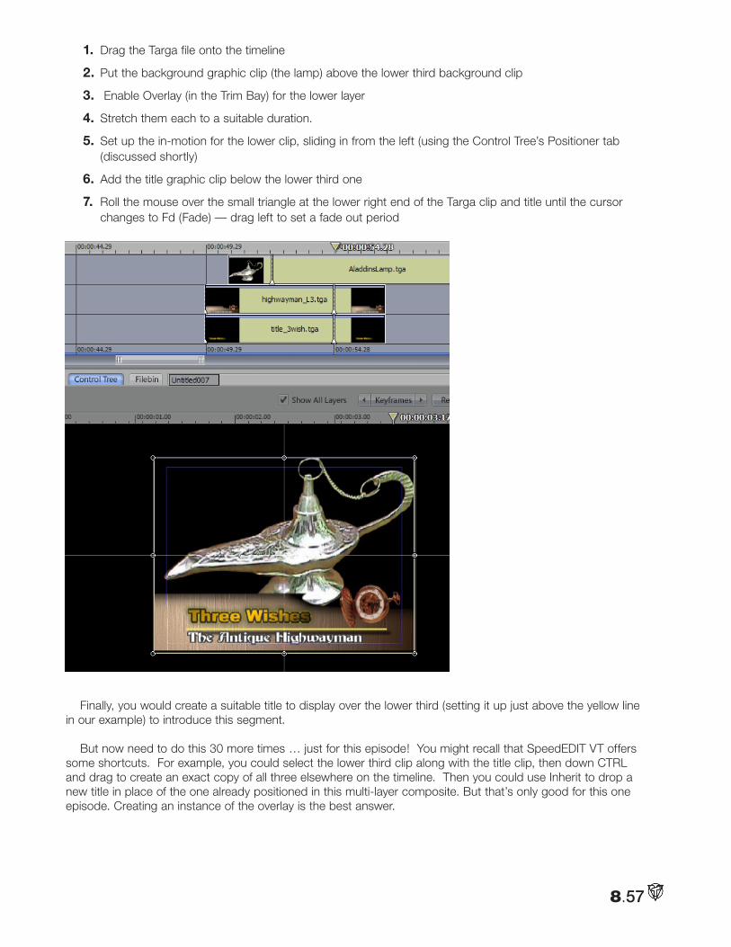
8.57
1. Drag the Targa file onto the timeline
2. Put the background graphic clip (the lamp) above the lower third background clip
3. Enable Overlay (in the Trim Bay) for the lower layer
4. Stretch them each to a suitable duration.
5. Set up the in-motion for the lower clip, sliding in from the left (using the Control Tree’s Positioner tab (discussed shortly)
6. Add the title graphic clip below the lower third one
7. Roll the mouse over the small triangle at the lower right end of the Targa clip and title until the cursor changes to Fd (Fade) — drag left to set a fade out period
Finally, you would create a suitable title to display over the lower third (setting it up just above the yellow line in our example) to introduce this segment.
But now need to do this 30 more times … just for this episode! You might recall that SpeedEDIT VT offers some shortcuts. For example, you could select the lower third clip along with the title clip, then down CTRL and drag to create an exact copy of all three elsewhere on the timeline. Then you could use Inherit to drop a new title in place of the one already positioned in this multi-layer composite. But that’s only good for this one episode. Creating an instance of the overlay is the best answer.
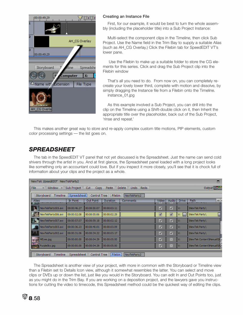
8.58
Creating an Instance File
First, for our example, it would be best to turn the whole assem-bly (including the placeholder title) into a Sub Project Instance:
Multi-select the component clips in the Timeline, then click Sub Project. Use the Name field in the Trim Bay to supply a suitable Alias (such as AH_CG Overlay.) Click the Filebin tab for SpeedEDIT VT’s lower pane.
Use the Filebin to make up a suitable folder to store the CG ele-ments for this series. Click and drag the Sub Project clip into the Filebin window
That’s all you need to do. From now on, you can completely re-create your lovely lower third, complete with motion and dissolve, by simply dragging the Instance file from a Filebin onto the Timeline.
instance_01.jpg
As this example involved a Sub Project, you can drill into the clip on the Timeline using a Shift-double click on it, then Inherit the appropriate title over the placeholder, back out of the Sub Project, ‘rinse and repeat.’
This makes another great way to store and re-apply complex custom title motions, PIP elements, custom color processing settings — the list goes on.
SpReadSHeetThe tab in the SpeedEDIT VT panel that not yet discussed is the Spreadsheet. Just the name can send cold
shivers through the artist in you. And at first glance, the Spreadsheet panel loaded with a long project looks like something only an accountant could love. But if you inspect it more closely, you’ll see that it is chock full of information about your clips and the project as a whole.
The Spreadsheet is another view of your project, with more in common with the Storyboard or Timeline view than a Filebin set to Details Icon view, although it somewhat resembles the latter. You can select and move clips or DVEs up or down the list, just like you would in the Storyboard. You can edit In and Out Points too, just as you might do in the Trim Bay. If you are working on a deposition project, and the lawyers gave you instruc-tions for cutting the video to timecode, this Spreadsheet method could be the quickest way of editing the clips.
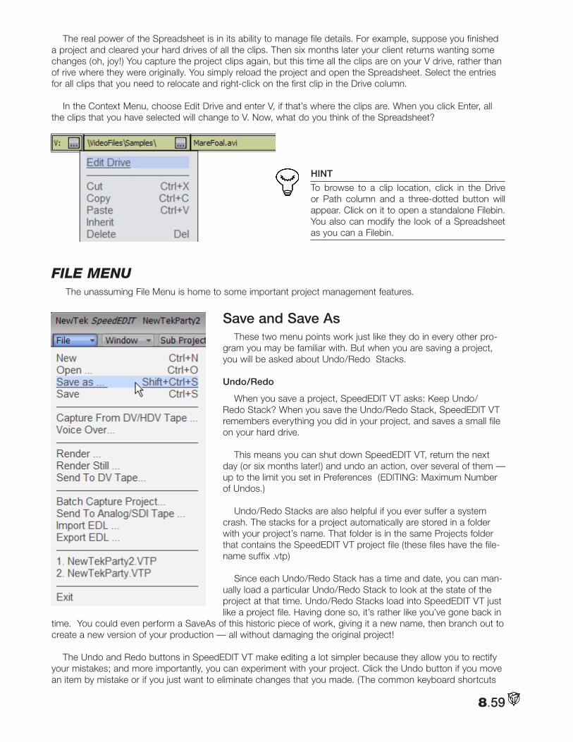
8.59
The real power of the Spreadsheet is in its ability to manage file details. For example, suppose you finished a project and cleared your hard drives of all the clips. Then six months later your client returns wanting some changes (oh, joy!) You capture the project clips again, but this time all the clips are on your V drive, rather than of rive where they were originally. You simply reload the project and open the Spreadsheet. Select the entries for all clips that you need to relocate and right-click on the first clip in the Drive column.
In the Context Menu, choose Edit Drive and enter V, if that’s where the clips are. When you click Enter, all the clips that you have selected will change to V. Now, what do you think of the Spreadsheet?
HINT
To browse to a clip location, click in the Drive or Path column and a three-dotted button will appear. Click on it to open a standalone Filebin. You also can modify the look of a Spreadsheet as you can a Filebin.
file menu The unassuming File Menu is home to some important project management features.
Save and Save AsThese two menu points work just like they do in every other pro-
gram you may be familiar with. But when you are saving a project, you will be asked about Undo/Redo Stacks.
Undo/Redo
When you save a project, SpeedEDIT VT asks: Keep Undo/Redo Stack? When you save the Undo/Redo Stack, SpeedEDIT VT remembers everything you did in your project, and saves a small file on your hard drive.
This means you can shut down SpeedEDIT VT, return the next day (or six months later!) and undo an action, over several of them — up to the limit you set in Preferences (EDITING: Maximum Number of Undos.)
Undo/Redo Stacks are also helpful if you ever suffer a system crash. The stacks for a project automatically are stored in a folder with your project’s name. That folder is in the same Projects folder that contains the SpeedEDIT VT project file (these files have the file-name suffix .vtp)
Since each Undo/Redo Stack has a time and date, you can man-ually load a particular Undo/Redo Stack to look at the state of the project at that time. Undo/Redo Stacks load into SpeedEDIT VT just like a project file. Having done so, it’s rather like you’ve gone back in
time. You could even perform a SaveAs of this historic piece of work, giving it a new name, then branch out to create a new version of your production — all without damaging the original project!
The Undo and Redo buttons in SpeedEDIT VT make editing a lot simpler because they allow you to rectify your mistakes; and more importantly, you can experiment with your project. Click the Undo button if you move an item by mistake or if you just want to eliminate changes that you made. (The common keyboard shortcuts
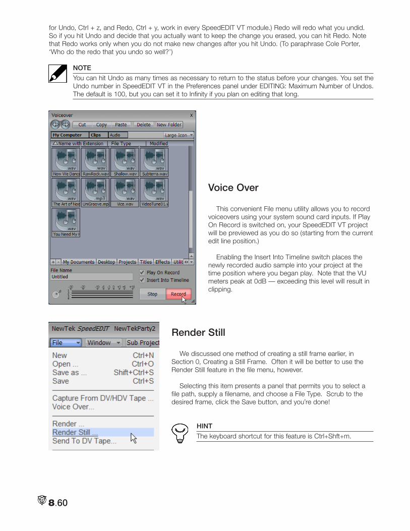
8.60
for Undo, Ctrl + z, and Redo, Ctrl + y, work in every SpeedEDIT VT module.) Redo will redo what you undid. So if you hit Undo and decide that you actually want to keep the change you erased, you can hit Redo. Note that Redo works only when you do not make new changes after you hit Undo. (To paraphrase Cole Porter, ‘Who do the redo that you undo so well?’)
NOTE
You can hit Undo as many times as necessary to return to the status before your changes. You set the Undo number in SpeedEDIT VT in the Preferences panel under EDITING: Maximum Number of Undos. The default is 100, but you can set it to Infinity if you plan on editing that long.
Voice Over This convenient File menu utility allows you to record
voiceovers using your system sound card inputs. If Play On Record is switched on, your SpeedEDIT VT project will be previewed as you do so (starting from the current edit line position.)
Enabling the Insert Into Timeline switch places the newly recorded audio sample into your project at the time position where you began play. Note that the VU meters peak at 0dB — exceeding this level will result in clipping.
Render Still
We discussed one method of creating a still frame earlier, in Section 0, Creating a Still Frame. Often it will be better to use the Render Still feature in the file menu, however.
Selecting this item presents a panel that permits you to select a file path, supply a filename, and choose a File Type. Scrub to the desired frame, click the Save button, and you’re done!
HINT
The keyboard shortcut for this feature is Ctrl+Shft+m.
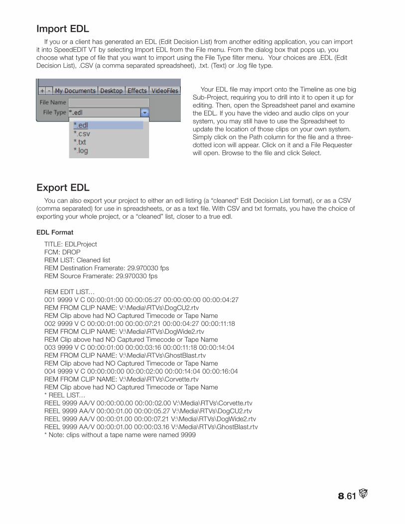
8.61
Import EDLIf you or a client has generated an EDL (Edit Decision List) from another editing application, you can import
it into SpeedEDIT VT by selecting Import EDL from the File menu. From the dialog box that pops up, you choose what type of file that you want to import using the File Type filter menu. Your choices are .EDL (Edit Decision List), .CSV (a comma separated spreadsheet), .txt. (Text) or .log file type.
Your EDL file may import onto the Timeline as one big Sub-Project, requiring you to drill into it to open it up for editing. Then, open the Spreadsheet panel and examine the EDL. If you have the video and audio clips on your system, you may still have to use the Spreadsheet to update the location of those clips on your own system. Simply click on the Path column for the file and a three-dotted icon will appear. Click on it and a File Requester will open. Browse to the file and click Select.
Export EDLYou can also export your project to either an edl listing (a “cleaned” Edit Decision List format), or as a CSV
(comma separated) for use in spreadsheets, or as a text file. With CSV and txt formats, you have the choice of exporting your whole project, or a “cleaned” list, closer to a true edl.
EDL Format
TITLE: EDLProjectFCM: DROPREM LIST: Cleaned listREM Destination Framerate: 29.970030 fpsREM Source Framerate: 29.970030 fps
REM EDIT LIST…001 9999 V C 00:00:01:00 00:00:05:27 00:00:00:00 00:00:04:27REM FROM CLIP NAME: V:\Media\RTVs\DogCU2.rtvREM Clip above had NO Captured Timecode or Tape Name002 9999 V C 00:00:01:00 00:00:07:21 00:00:04:27 00:00:11:18REM FROM CLIP NAME: V:\Media\RTVs\DogWide2.rtvREM Clip above had NO Captured Timecode or Tape Name003 9999 V C 00:00:01:00 00:00:03:16 00:00:11:18 00:00:14:04REM FROM CLIP NAME: V:\Media\RTVs\GhostBlast.rtvREM Clip above had NO Captured Timecode or Tape Name004 9999 V C 00:00:00:00 00:00:02:00 00:00:14:04 00:00:16:04REM FROM CLIP NAME: V:\Media\RTVs\Corvette.rtvREM Clip above had NO Captured Timecode or Tape Name* REEL LIST…REEL 9999 AA/V 00:00:00.00 00:00:02.00 V:\Media\RTVs\Corvette.rtvREEL 9999 AA/V 00:00:01.00 00:00:05.27 V:\Media\RTVs\DogCU2.rtvREEL 9999 AA/V 00:00:01.00 00:00:07.21 V:\Media\RTVs\DogWide2.rtvREEL 9999 AA/V 00:00:01.00 00:00:03.16 V:\Media\RTVs\GhostBlast.rtv* Note: clips without a tape name were named 9999
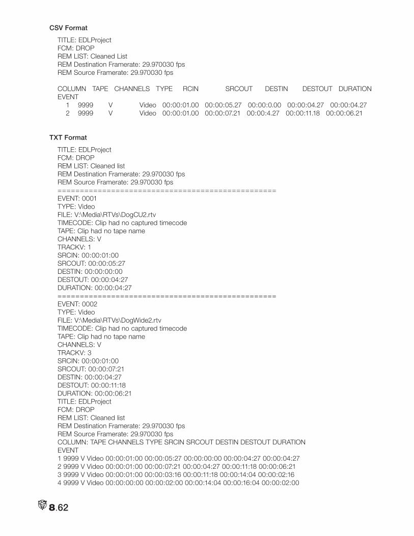
8.62
CSV Format
TITLE: EDLProjectFCM: DROPREM LIST: Cleaned ListREM Destination Framerate: 29.970030 fpsREM Source Framerate: 29.970030 fps
COLUMN TAPE CHANNELS TYPE RCIN SRCOUT DESTIN DESTOUT DURATIONEVENT 1 9999 V Video 00:00:01.00 00:00:05.27 00:00:0.00 00:00:04.27 00:00:04.27 2 9999 V Video 00:00:01.00 00:00:07.21 00:00:4.27 00:00:11.18 00:00:06.21
TXT Format
TITLE: EDLProjectFCM: DROPREM LIST: Cleaned listREM Destination Framerate: 29.970030 fpsREM Source Framerate: 29.970030 fps=================================================EVENT: 0001TYPE: VideoFILE: V:\Media\RTVs\DogCU2.rtvTIMECODE: Clip had no captured timecodeTAPE: Clip had no tape nameCHANNELS: VTRACKV: 1SRCIN: 00:00:01:00SRCOUT: 00:00:05:27DESTIN: 00:00:00:00DESTOUT: 00:00:04:27DURATION: 00:00:04:27=================================================EVENT: 0002TYPE: VideoFILE: V:\Media\RTVs\DogWide2.rtvTIMECODE: Clip had no captured timecodeTAPE: Clip had no tape nameCHANNELS: VTRACKV: 3SRCIN: 00:00:01:00SRCOUT: 00:00:07:21DESTIN: 00:00:04:27DESTOUT: 00:00:11:18DURATION: 00:00:06:21TITLE: EDLProjectFCM: DROPREM LIST: Cleaned listREM Destination Framerate: 29.970030 fpsREM Source Framerate: 29.970030 fpsCOLUMN: TAPE CHANNELS TYPE SRCIN SRCOUT DESTIN DESTOUT DURATIONEVENT1 9999 V Video 00:00:01:00 00:00:05:27 00:00:00:00 00:00:04:27 00:00:04:272 9999 V Video 00:00:01:00 00:00:07:21 00:00:04:27 00:00:11:18 00:00:06:213 9999 V Video 00:00:01:00 00:00:03:16 00:00:11:18 00:00:14:04 00:00:02:164 9999 V Video 00:00:00:00 00:00:02:00 00:00:14:04 00:00:16:04 00:00:02:00
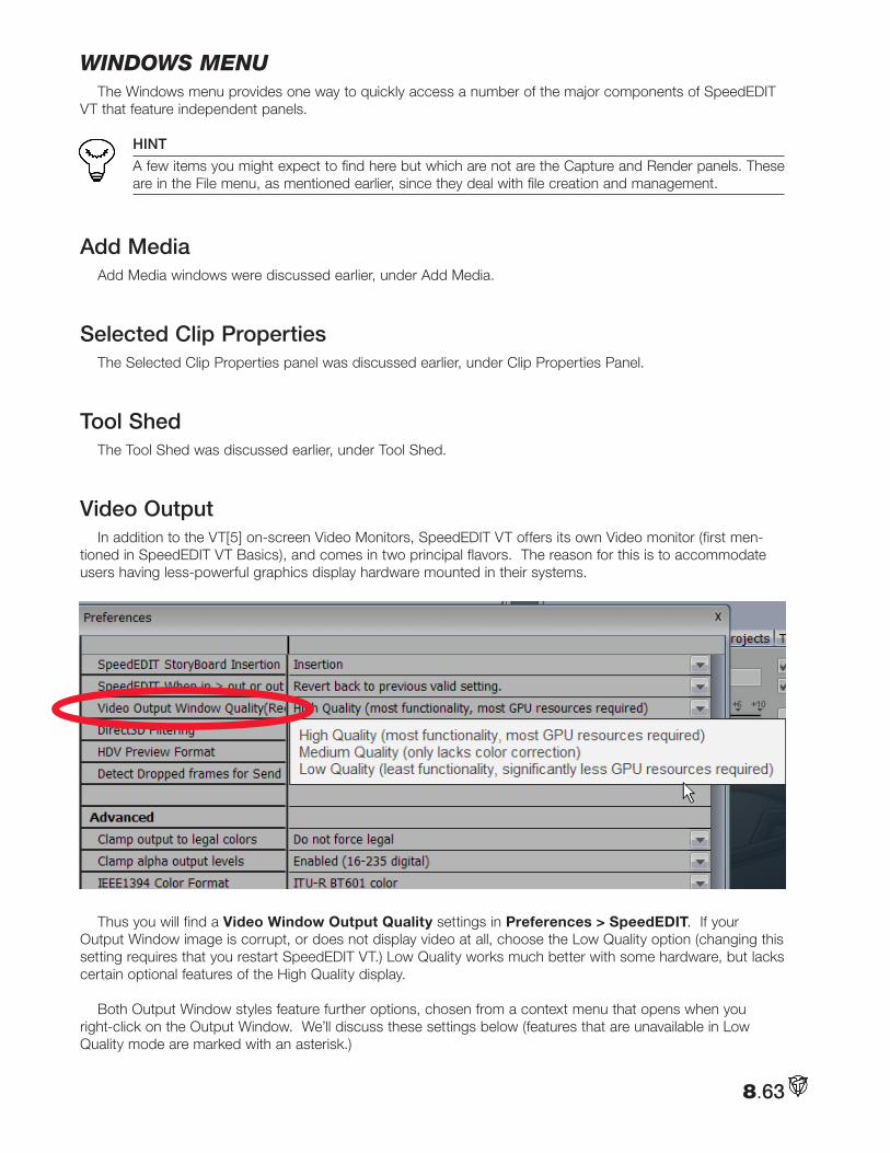
8.63
windowS menuThe Windows menu provides one way to quickly access a number of the major components of SpeedEDIT
VT that feature independent panels.
HINT
A few items you might expect to find here but which are not are the Capture and Render panels. These are in the File menu, as mentioned earlier, since they deal with file creation and management.
Add MediaAdd Media windows were discussed earlier, under Add Media.
Selected Clip PropertiesThe Selected Clip Properties panel was discussed earlier, under Clip Properties Panel.
Tool ShedThe Tool Shed was discussed earlier, under Tool Shed.
Video OutputIn addition to the VT[5] on-screen Video Monitors, SpeedEDIT VT offers its own Video monitor (first men-
tioned in SpeedEDIT VT Basics), and comes in two principal flavors. The reason for this is to accommodate users having less-powerful graphics display hardware mounted in their systems.
Thus you will find a Video Window Output Quality settings in Preferences > SpeedEDIT. If your
Output Window image is corrupt, or does not display video at all, choose the Low Quality option (changing this setting requires that you restart SpeedEDIT VT.) Low Quality works much better with some hardware, but lacks certain optional features of the High Quality display.
Both Output Window styles feature further options, chosen from a context menu that opens when you right-click on the Output Window. We’ll discuss these settings below (features that are unavailable in Low Quality mode are marked with an asterisk.)
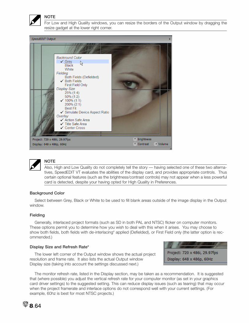
8.64
NOTE
For Low and High Quality windows, you can resize the borders of the Output window by dragging the resize gadget at the lower right corner.
NOTE
Also, High and Low Quality do not completely tell the story — having selected one of these two alterna-tives, SpeedEDIT VT evaluates the abilities of the display card, and provides appropriate controls. Thus certain optional features (such as the brightness/contrast controls) may not appear when a less powerful card is detected, despite your having opted for High Quality in Preferences.
Background Color
Select between Grey, Black or White to be used to fill blank areas outside of the image display in the Output window.
Fielding
Generally, interlaced project formats (such as SD in both PAL and NTSC) flicker on computer monitors. These options permit you to determine how you wish to deal with this when it arises. You may choose to show both fields, both fields with de-interlacing* applied (Defielded), or First Field only (the latter option is rec-ommended.)
Display Size and Refresh Rate*
The lower left corner of the Output window shows the actual project resolution and frame rate. It also lists the actual Output window Display size (taking into account the settings discussed next.)
The monitor refresh rate, listed in the Display section, may be taken as a recommendation. It is suggested that (where possible) you adjust the vertical refresh rate for your computer monitor (as set in your graphics card driver settings) to the suggested setting. This can reduce display issues (such as tearing) that may occur when the project framerate and interlace options do not correspond well with your current settings. (For example, 60hz is best for most NTSC projects.)
8.65
In High Quality mode, the Output Window context menu lists preset size ratios for the display surface, from 25-200%. Best Fit scales the output image to fit the current Window size, while retaining image aspect. The Low Quality option does not have size options; rather it is always in Best Fit mode.)
Simulate Device Aspect Ratio
When Simulate Device Aspect Ratio is disabled, every pixel is displayed on the computer monitor ‘as-is’; that is, without respect to the project pixel aspect settings that result in correct image proportions on the final target display.
For example: suppose your project is ultimately intended to be displayed on a traditional (4:3 image aspect) standard definition TV set. If you have a circular object in your video clip, with Simulate Device Aspect ratio off, each pixel of the clip will be show up in Output, but the circle appears to be an oval, because pixel aspect was not accounted for.
On the other hand, if this option is enabled, the display will be scaled horizontally to produce a properly pro-portioned image.
NOTE
Simulate Device Aspect has no effect whatever on the actual output from the project.
Overlay*
Typical television display devices crop the displayed image somewhat. The Action Safe Area and Title Safe Area options, when enabled, result in rectangular overlays that help you visualize where important features of your production will appear onscreen taking into account this factor
The Center Cross setting subdivides your image into quadrants to further assist with composition.
Output Volume Control
The volume control on the Output window has no effect whatsoever on the actual project levels (appropriately then, it likewise has no impact on the VU meter readings.) Rather, it allows you to adjust the sound level sent to your speaker system for comfort-able, undistorted audio monitoring during playback and editing operations.
NOTE
The maximum Output Volume control set does not permit gain to exceed Project levels; it can only throttle volume downward. So an improper setting of this control cannot be responsible for induced distortion. That said, you can still boost your sound card settings or speaker amplification up sufficiently to cause distortion (“Remember, only you can prevent hearing loss.”)
Brightness and Contrast*
In similar fashion to the Volume control just discussed, the knobs for Brightness and Contrast controls on the Output window have no effect on either rendered files or output signal (when a live DV/HDV preview is active.)
HINT
To modify the actual image characteristics, use the numerous color control options in SpeedEDIT VT’s Control Tree. *These controls offer some ability to customize your project display as viewed on your computer’s monitor.
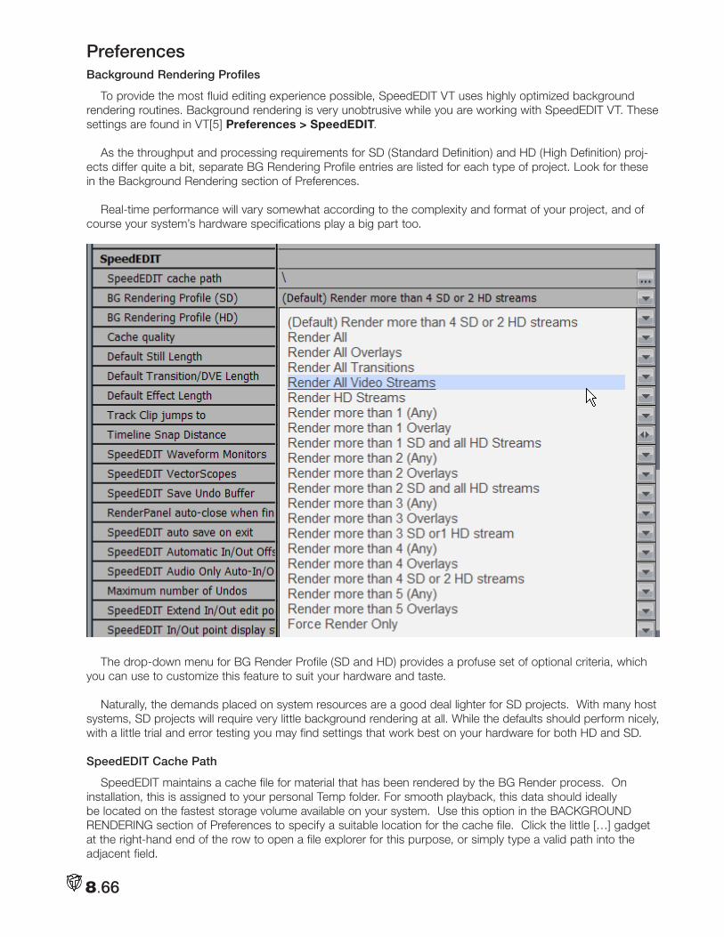
8.66
PreferencesBackground Rendering Profiles
To provide the most fluid editing experience possible, SpeedEDIT VT uses highly optimized background rendering routines. Background rendering is very unobtrusive while you are working with SpeedEDIT VT. These settings are found in VT[5] Preferences > SpeedEDIT.
As the throughput and processing requirements for SD (Standard Definition) and HD (High Definition) proj-ects differ quite a bit, separate BG Rendering Profile entries are listed for each type of project. Look for these in the Background Rendering section of Preferences.
Real-time performance will vary somewhat according to the complexity and format of your project, and of course your system’s hardware specifications play a big part too.
The drop-down menu for BG Render Profile (SD and HD) provides a profuse set of optional criteria, which you can use to customize this feature to suit your hardware and taste.
Naturally, the demands placed on system resources are a good deal lighter for SD projects. With many host systems, SD projects will require very little background rendering at all. While the defaults should perform nicely, with a little trial and error testing you may find settings that work best on your hardware for both HD and SD.
SpeedEDIT Cache Path
SpeedEDIT maintains a cache file for material that has been rendered by the BG Render process. On installation, this is assigned to your personal Temp folder. For smooth playback, this data should ideally be located on the fastest storage volume available on your system. Use this option in the BACKGROUND RENDERING section of Preferences to specify a suitable location for the cache file. Click the little […] gadget at the right-hand end of the row to open a file explorer for this purpose, or simply type a valid path into the adjacent field.
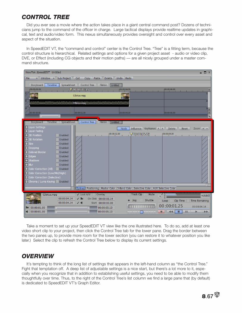
8.67
contRol tReeDid you ever see a movie where the action takes place in a giant central command post? Dozens of techni-
cians jump to the command of the officer in charge. Large tactical displays provide realtime updates in graphi-cal, text and audio/video form. This nexus simultaneously provides oversight and control over every asset and aspect of the situation.
In SpeedEDIT VT, the “command and control” center is the Control Tree. “Tree” is a fitting term, because the control structure is hierarchical. Related settings and options for a given project asset - audio or video clip, DVE, or Effect (including CG objects and their motion paths) — are all nicely grouped under a master com-mand structure.
Take a moment to set up your SpeedEDIT VT view like the one illustrated here. To do so, add at least one video short clip to your project, then click the Control Tree tab for the lower pane. Drag the border between the two panes up, to provide more room for the lower section (you can restore it to whatever position you like later.) Select the clip to refresh the Control Tree below to display its current settings.
oVeRViewIt’s tempting to think of the long list of settings that appears in the left-hand column as “the Control Tree.”
Fight that temptation off. A deep list of adjustable settings is a nice start, but there’s a lot more to it, espe-cially when you recognize that in addition to establishing useful settings, you need to be able to modify them thoughtfully over time. Thus, to the right of the Control Tree’s list column we find a large pane that (by default) is dedicated to SpeedEDIT VT’s Graph Editor.
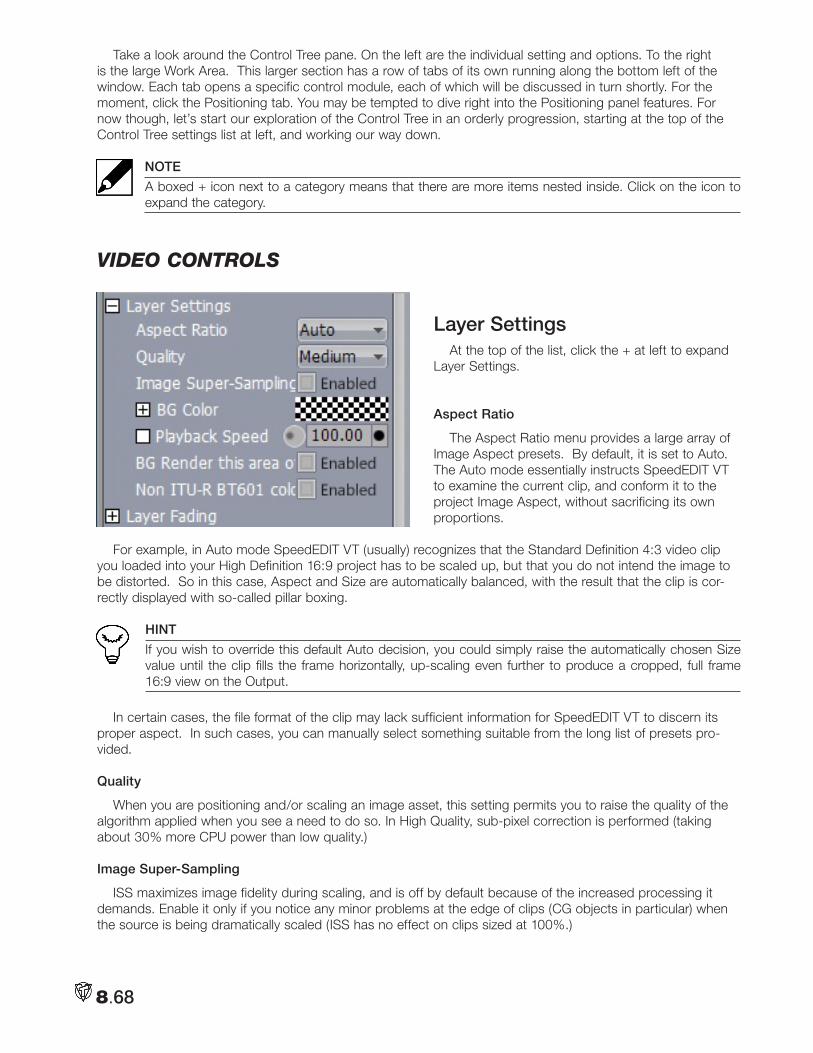
8.68
Take a look around the Control Tree pane. On the left are the individual setting and options. To the right is the large Work Area. This larger section has a row of tabs of its own running along the bottom left of the window. Each tab opens a specific control module, each of which will be discussed in turn shortly. For the moment, click the Positioning tab. You may be tempted to dive right into the Positioning panel features. For now though, let’s start our exploration of the Control Tree in an orderly progression, starting at the top of the Control Tree settings list at left, and working our way down.
NOTE
A boxed + icon next to a category means that there are more items nested inside. Click on the icon to expand the category.
Video contRolS
Layer SettingsAt the top of the list, click the + at left to expand
Layer Settings.
Aspect Ratio
The Aspect Ratio menu provides a large array of Image Aspect presets. By default, it is set to Auto. The Auto mode essentially instructs SpeedEDIT VT to examine the current clip, and conform it to the project Image Aspect, without sacrificing its own proportions.
For example, in Auto mode SpeedEDIT VT (usually) recognizes that the Standard Definition 4:3 video clip you loaded into your High Definition 16:9 project has to be scaled up, but that you do not intend the image to be distorted. So in this case, Aspect and Size are automatically balanced, with the result that the clip is cor-rectly displayed with so-called pillar boxing.
HINT
If you wish to override this default Auto decision, you could simply raise the automatically chosen Size value until the clip fills the frame horizontally, up-scaling even further to produce a cropped, full frame 16:9 view on the Output.
In certain cases, the file format of the clip may lack sufficient information for SpeedEDIT VT to discern its proper aspect. In such cases, you can manually select something suitable from the long list of presets pro-vided.
Quality
When you are positioning and/or scaling an image asset, this setting permits you to raise the quality of the algorithm applied when you see a need to do so. In High Quality, sub-pixel correction is performed (taking about 30% more CPU power than low quality.)
Image Super-Sampling
ISS maximizes image fidelity during scaling, and is off by default because of the increased processing it demands. Enable it only if you notice any minor problems at the edge of clips (CG objects in particular) when the source is being dramatically scaled (ISS has no effect on clips sized at 100%.)
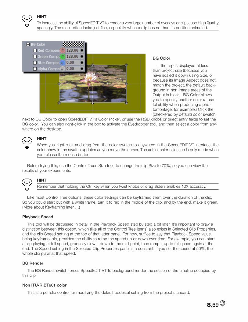
8.69
HINT
To increase the ability of SpeedEDIT VT to render a very large number of overlays or clips, use High Quality sparingly. The result often looks just fine, especially when a clip has not had its position animated.
BG Color
If the clip is displayed at less than project size (because you have scaled it down using Size, or because its Image Aspect does not match the project, the default back-ground in non-image areas of the Output is black. BG Color allows you to specify another color (a use-ful ability when producing a pho-tomontage, for example.) Click the (checkered by default) color swatch
next to BG Color to open SpeedEDIT VT’s Color Picker, or use the RGB knobs or direct entry fields to set the BG color. You can also right-click in the box to activate the Eyedropper tool, and then select a color from any-where on the desktop.
HINT
When you right click and drag from the color swatch to anywhere in the SpeedEDIT VT interface, the color show in the swatch updates as you move the cursor. The actual color selection is only made when you release the mouse button.
Before trying this, use the Control Trees Size tool, to change the clip Size to 70%, so you can view the results of your experiments.
HINT
Remember that holding the Ctrl key when you twist knobs or drag sliders enables 10X accuracy.
Like most Control Tree options, these color settings can be keyframed them over the duration of the clip. So you could start out with a white frame, turn it to red in the middle of the clip, and by the end, make it green. (More about Keyframing later …)
Playback Speed
This tool will be discussed in detail in the Playback Speed step by step a bit later. It’s important to draw a distinction between this option, which (like all of the Control Tree items) also exists in Selected Clip Properties, and the clip Speed setting at the top of that latter panel. For now, suffice to say that Playback Speed value, being keyframeable, provides the ability to ramp the speed up or down over time. For example, you can start a clip playing at full speed, gradually slow it down to the mid-point, then ramp it up to full speed again at the end. The Speed setting in the Selected Clip Properties panel is a constant. If you set the speed at 50%, the whole clip plays at that speed.
BG Render
The BG Render switch forces SpeedEDIT VT to background render the section of the timeline occupied by this clip.
Non ITU-R BT601 color
This is a per-clip control for modifying the default pedestal setting from the project standard.
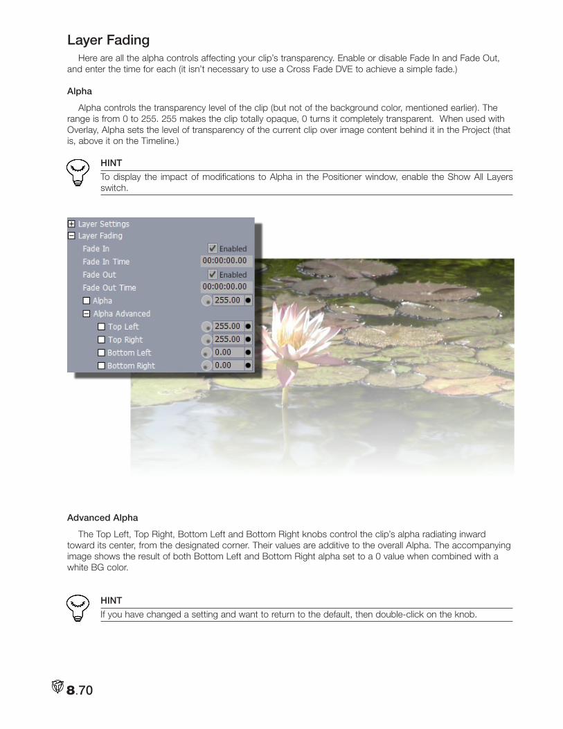
8.70
Layer FadingHere are all the alpha controls affecting your clip’s transparency. Enable or disable Fade In and Fade Out,
and enter the time for each (it isn’t necessary to use a Cross Fade DVE to achieve a simple fade.)
Alpha
Alpha controls the transparency level of the clip (but not of the background color, mentioned earlier). The range is from 0 to 255. 255 makes the clip totally opaque, 0 turns it completely transparent. When used with Overlay, Alpha sets the level of transparency of the current clip over image content behind it in the Project (that is, above it on the Timeline.)
HINT
To display the impact of modifications to Alpha in the Positioner window, enable the Show All Layers switch.
Advanced Alpha
The Top Left, Top Right, Bottom Left and Bottom Right knobs control the clip’s alpha radiating inward toward its center, from the designated corner. Their values are additive to the overall Alpha. The accompanying image shows the result of both Bottom Left and Bottom Right alpha set to a 0 value when combined with a white BG color.
HINT
If you have changed a setting and want to return to the default, then double-click on the knob.
8.71
3D Position Now the real fun begins. With the 3D tools, you can fly your clips around the screen, rotating them every
which way. When you click on the 3D Position box, you reveal three tools, which work on the same Cartesian system used in LightWave 3D.
X Position
Adjusting the X Position moves the clip to the left or right. Distance is measured in pixels. You can type in values. Negative numbers will move the clip to the left.
• Click and drag left on the circle in the square icon to move the image left.
• Click and drag right on the circle in the square icon to move the image right.
NOTE
If you look closely, you’ll see that the circle in the square icon will display graphically the status of your movement.
Y Position
Adjusting the Y Position moves the clip up or down. In this instance, negative numbers move the clip up.
• Click and drag left on the circle in the square icon to move the image up.
• Click and drag right on the circle in the square icon to move the image down.
Z Position
Adjusting the Z Position moves the clip back or forwards. Positive numbers move the clip back. Z Position is not measured in pixels. A setting of 0 is the normal default. If you move Z to 1 the clip will be exactly 50% size.
• Click and drag left on the circle in the square icon to move the image forward (larger).
• Click and drag right on the circle in the square icon to move the image backward (smaller).
3D Rotation When you are rotating a clip in 3D space in the Control Tree, imagine three rods going through the clip. The
X rod bisects the clip horizontally, the Y bisects vertically, and the Z goes right through the middle from front to back (‘into the monitor’, so to speak). So when you adjust the Angles, the clip rotates around those rods.
For example, when you adjust the X Angle, the clip is rotating around that horizontal rod. The rotation angle is measured in degrees. 360 degrees = one full rotation.
X Angle
• Click and drag left on the circle in the square icon to bring the bottom of the clip forward.• Click and drag right on the circle in the square icon to bring the top of the clip forward.
Y Angle
• Click and drag left on the circle in the square icon to bring the left side of the clip forward.• Click and drag right on the circle in the square icon to bring the right side of the clip forward.
Z Angle
• Click and drag left on the circle in the square icon to bring the left side of the clip down.• Click and drag right on the circle in the square icon to bring the right side of the clip down.
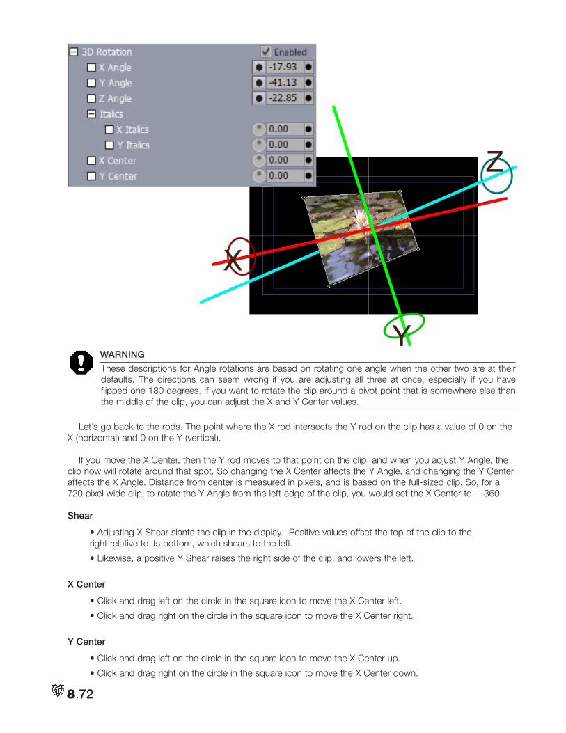
8.72
WARNING
These descriptions for Angle rotations are based on rotating one angle when the other two are at their defaults. The directions can seem wrong if you are adjusting all three at once, especially if you have flipped one 180 degrees. If you want to rotate the clip around a pivot point that is somewhere else than the middle of the clip, you can adjust the X and Y Center values.
Let’s go back to the rods. The point where the X rod intersects the Y rod on the clip has a value of 0 on the X (horizontal) and 0 on the Y (vertical).
If you move the X Center, then the Y rod moves to that point on the clip; and when you adjust Y Angle, the clip now will rotate around that spot. So changing the X Center affects the Y Angle, and changing the Y Center affects the X Angle. Distance from center is measured in pixels, and is based on the full-sized clip. So, for a 720 pixel wide clip, to rotate the Y Angle from the left edge of the clip, you would set the X Center to —360.
Shear
• Adjusting X Shear slants the clip in the display. Positive values offset the top of the clip to the right relative to its bottom, which shears to the left.
• Likewise, a positive Y Shear raises the right side of the clip, and lowers the left.
X Center
• Click and drag left on the circle in the square icon to move the X Center left.
• Click and drag right on the circle in the square icon to move the X Center right.
Y Center
• Click and drag left on the circle in the square icon to move the X Center up.
• Click and drag right on the circle in the square icon to move the X Center down.
8.73
NOTE
You also can flip an image by specifying a negative value in Size (%, X, or Y). Remember, too, that all these tools can be keyframed over the duration of the clip.
SizeWhen you load a clip or an image into SpeedEDIT, by default it is sized automatically based on a compari-
son of the clip’s own size and image aspect to those of the project. For still images (such as scanned photos) the process involves making the entire image visible on screen without altering image aspect. At times, even when Aspect is correct, you will wish to change the clip’s size in some manner.
HINT
There can be various reasons for doing this. You could want to ‘squash’ the last clip of a production on the horizontal axis, making room to scroll some titles to one side of the frame at the same time. Or, perhaps you want to set keyframes to pan a larger-than-project-size scanned photo slowly across the video frame. In this case, you would need to scale the source image up well beyond the normal size of your project (try to beware of going much larger than the image’s native size in pixels, to avoid seeing individual pixels greatly magnified in the result.)
Size %
This tool reduces or enlarges the image or clip by the percentage that you enter.
• Click and drag left on the circle in the square icon to reduce the size of the image.
• Click and drag right on the circle in the square icon to increase the size of the image.
HINT
Many common reformatting operations are included as Spline Presets in the Tool Shed.
X SIZEThis tool reduces or enlarges the width of the clip. The values are in pixels. By default the value is the origi-
nal width of the clip (or image) when it was loaded into SpeedEDIT VT. Notice that as you change X Size, the oval in the circle will reshape to reflect the new values.
• Click and drag left on the circle in the square icon to reduce the width of the image.
• Click and drag right on the circle in the square icon to increase the width of the image.
Y Size
This tool reduces or enlarges the height of the clip. The values are in pixels. By default the value is the origi-nal height of the clip or image when it was loaded into SpeedEDIT VT.
• Click and drag left on the circle in the square icon to reduce the height of the image.
• Click and drag right on the circle in the square icon to increase the height of the image.
CroppingWhen you crop a clip, you are cutting off portions of the image.
Crop %
This tool takes an equal percentage from each side of the clip, which can be useful if you want to trim off unwanted borders. Negative values have no effect. A 10% crop will take 5% of the clip’s width off the left edge and 5% off the right. It will take 5% of the height off the top and 5% off the bottom.
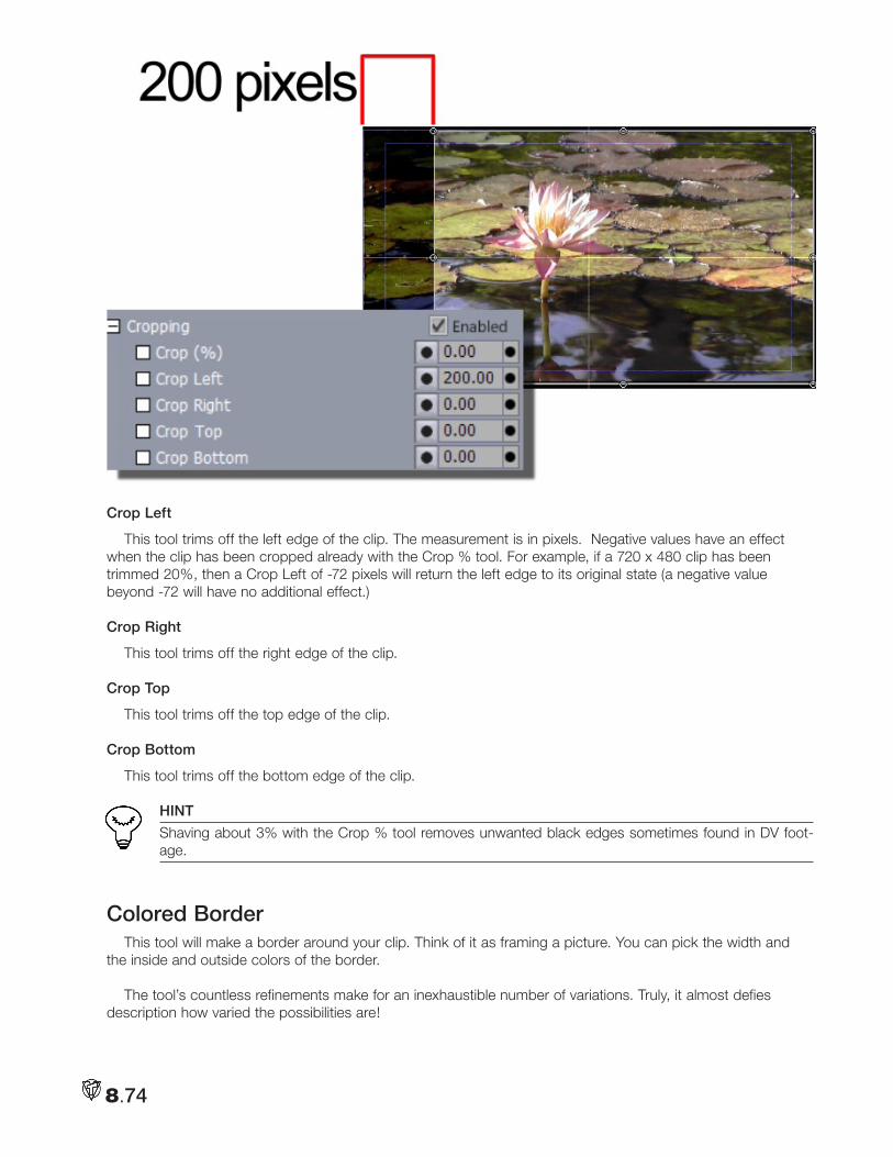
8.74
Crop Left
This tool trims off the left edge of the clip. The measurement is in pixels. Negative values have an effect when the clip has been cropped already with the Crop % tool. For example, if a 720 x 480 clip has been trimmed 20%, then a Crop Left of -72 pixels will return the left edge to its original state (a negative value beyond -72 will have no additional effect.)
Crop Right
This tool trims off the right edge of the clip.
Crop Top
This tool trims off the top edge of the clip.
Crop Bottom
This tool trims off the bottom edge of the clip.
HINT
Shaving about 3% with the Crop % tool removes unwanted black edges sometimes found in DV foot-age.
Colored BorderThis tool will make a border around your clip. Think of it as framing a picture. You can pick the width and
the inside and outside colors of the border.
The tool’s countless refinements make for an inexhaustible number of variations. Truly, it almost defies description how varied the possibilities are!
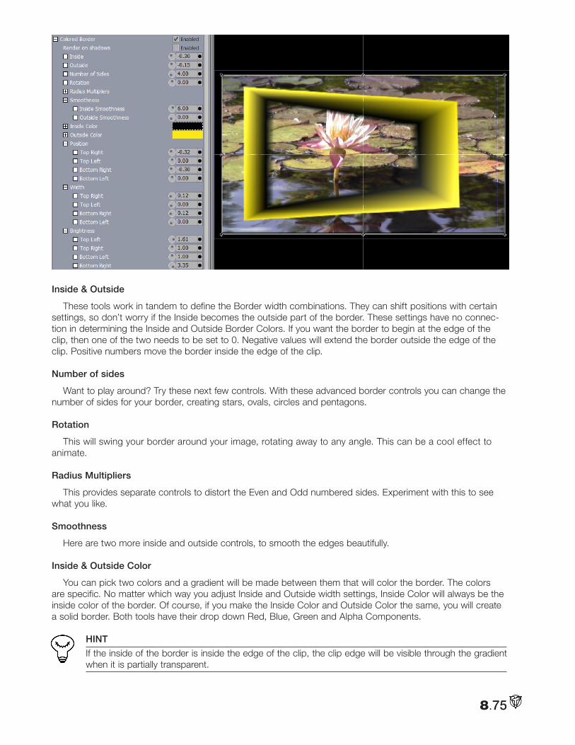
8.75
Inside & Outside
These tools work in tandem to define the Border width combinations. They can shift positions with certain settings, so don’t worry if the Inside becomes the outside part of the border. These settings have no connec-tion in determining the Inside and Outside Border Colors. If you want the border to begin at the edge of the clip, then one of the two needs to be set to 0. Negative values will extend the border outside the edge of the clip. Positive numbers move the border inside the edge of the clip.
Number of sides
Want to play around? Try these next few controls. With these advanced border controls you can change the number of sides for your border, creating stars, ovals, circles and pentagons.
Rotation
This will swing your border around your image, rotating away to any angle. This can be a cool effect to animate.
Radius Multipliers
This provides separate controls to distort the Even and Odd numbered sides. Experiment with this to see what you like.
Smoothness
Here are two more inside and outside controls, to smooth the edges beautifully.
Inside & Outside Color
You can pick two colors and a gradient will be made between them that will color the border. The colors are specific. No matter which way you adjust Inside and Outside width settings, Inside Color will always be the inside color of the border. Of course, if you make the Inside Color and Outside Color the same, you will create a solid border. Both tools have their drop down Red, Blue, Green and Alpha Components.
HINT
If the inside of the border is inside the edge of the clip, the clip edge will be visible through the gradient when it is partially transparent.
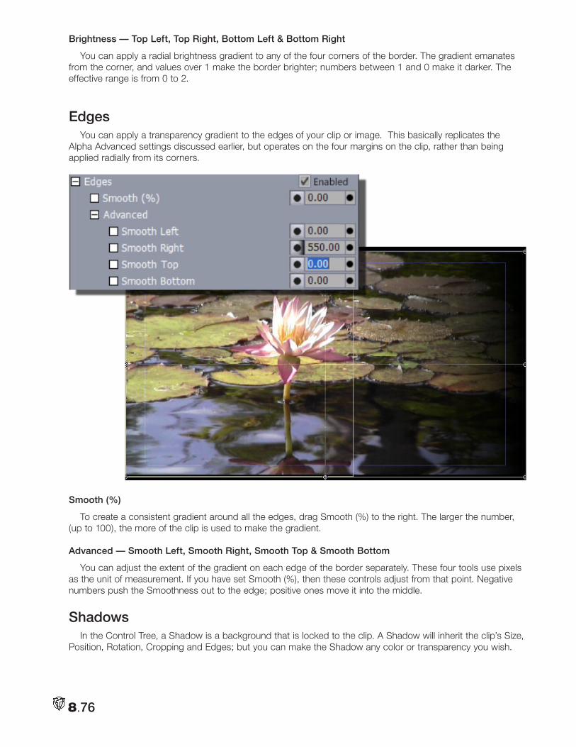
8.76
Brightness — Top Left, Top Right, Bottom Left & Bottom Right
You can apply a radial brightness gradient to any of the four corners of the border. The gradient emanates from the corner, and values over 1 make the border brighter; numbers between 1 and 0 make it darker. The effective range is from 0 to 2.
EdgesYou can apply a transparency gradient to the edges of your clip or image. This basically replicates the
Alpha Advanced settings discussed earlier, but operates on the four margins on the clip, rather than being applied radially from its corners.
Smooth (%)
To create a consistent gradient around all the edges, drag Smooth (%) to the right. The larger the number, (up to 100), the more of the clip is used to make the gradient.
Advanced — Smooth Left, Smooth Right, Smooth Top & Smooth Bottom
You can adjust the extent of the gradient on each edge of the border separately. These four tools use pixels as the unit of measurement. If you have set Smooth (%), then these controls adjust from that point. Negative numbers push the Smoothness out to the edge; positive ones move it into the middle.
ShadowsIn the Control Tree, a Shadow is a background that is locked to the clip. A Shadow will inherit the clip’s Size,
Position, Rotation, Cropping and Edges; but you can make the Shadow any color or transparency you wish.
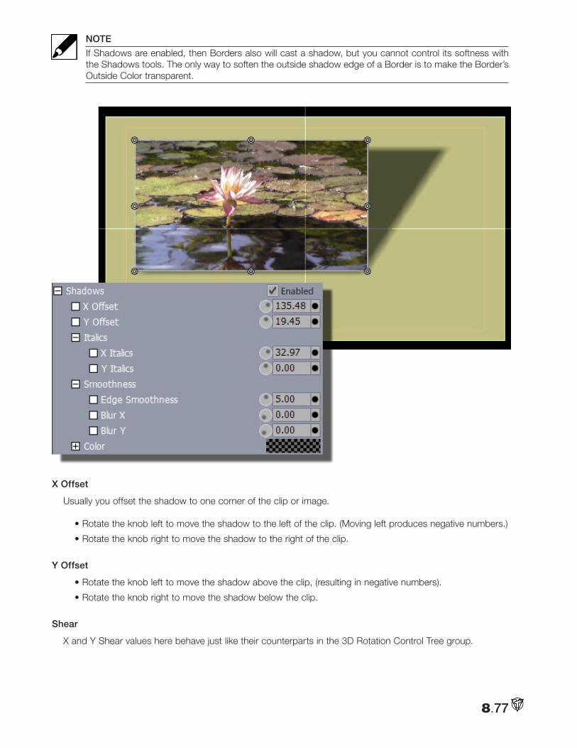
8.77
NOTE
If Shadows are enabled, then Borders also will cast a shadow, but you cannot control its softness with the Shadows tools. The only way to soften the outside shadow edge of a Border is to make the Border’s Outside Color transparent.
X Offset
Usually you offset the shadow to one corner of the clip or image.
• Rotate the knob left to move the shadow to the left of the clip. (Moving left produces negative numbers.)
• Rotate the knob right to move the shadow to the right of the clip.
Y Offset
• Rotate the knob left to move the shadow above the clip, (resulting in negative numbers).
• Rotate the knob right to move the shadow below the clip.
Shear
X and Y Shear values here behave just like their counterparts in the 3D Rotation Control Tree group.
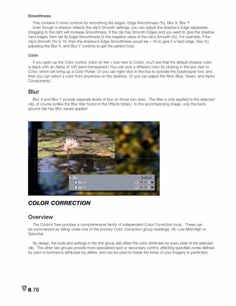
8.78
Smoothness
This contains 3 more controls for smoothing the edges: Edge Smoothness (%), Blur X, Blur YEven though a shadow reflects the clip’s Smooth settings, you can adjust the shadow’s Edge separately.
Dragging to the right will increase Smoothness. If the clip has Smooth Edges and you want to give the shadow hard edges, then set its Edge Smoothness to the negative value of the clip’s Smooth (%). For example, if the clip’s Smooth (%) is 10, then the shadow’s Edge Smoothness would be —10 to give it a hard edge. Also try adjusting the Blur X, and Blur Y controls to get the perfect look.
Color
If you open up the Color control, (click on the + box next to Color), you’ll see that the default shadow color is black with an Alpha of 100 (semi-transparent.) You can pick a different color by clicking in the box next to Color, which will bring up a Color Picker. Or you can right-click in the box to activate the Eyedropper tool, and then you can select a color from anywhere on the desktop. Or you can adjust the Red, Blue, Green, and Alpha Components.
BlurBlur X and Blur Y provide separate levels of blur on those two axes. The filter is only applied to the selected
clip, of course (unlike the Blur filter found in the Effects folder.) In the accompanying image, only the back-ground clip has Blur values applied
coloR coRRection
OverviewThe Control Tree provides a comprehensive family of independent Color Correction tools. These can
be summarized as falling under one of the primary Color Correction group headings, All, Low/Mid/High or Selective.
By design, the tools and settings in the first group (All) affect the color attributes for every pixel of the selected clip. The other two groups provide more specialized spot or secondary control, affecting specified zones defined by color or luminance attributes toy define, and can be used to tweak the tones of your imagery to perfection.
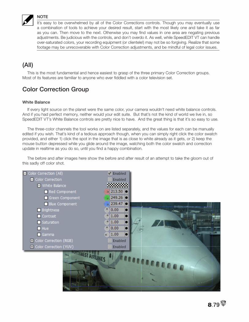
8.79
NOTE
It’s easy to be overwhelmed by all of the Color Corrections controls. Though you may eventually use a combination of tools to achieve your desired result, start with the most likely one and take it as far as you can. Then move to the next. Otherwise you may find values in one area are negating previous adjustments. Be judicious with the controls, and don’t overdo it. As well, while SpeedEDIT VT can handle over-saturated colors, your recording equipment (or clientele!) may not be so forgiving. Realize that some footage may be unrecoverable with Color Correction adjustments, and be mindful of legal color issues.
(All)This is the most fundamental and hence easiest to grasp of the three primary Color Correction groups.
Most of its features are familiar to anyone who ever fiddled with a color television set.
Color Correction Group
White Balance
If every light source on the planet were the same color, your camera wouldn’t need white balance controls. And if you had perfect memory, neither would your edit suite. But that’s not the kind of world we live in, so SpeedEDIT VT’s White Balance controls are pretty nice to have. And the great thing is that it’s so easy to use.
The three-color channels the tool works on are listed separately, and the values for each can be manually edited if you wish. That’s kind of a tedious approach though, when you can simply right click the color swatch provided, and either 1) click the spot in the image that is as close to white already as it gets, or 2) keep the mouse button depressed while you glide around the image, watching both the color swatch and correction update in realtime as you do so, until you find a happy combination.
The before and after images here show the before and after result of an attempt to take the gloom out of this sadly off color shot.
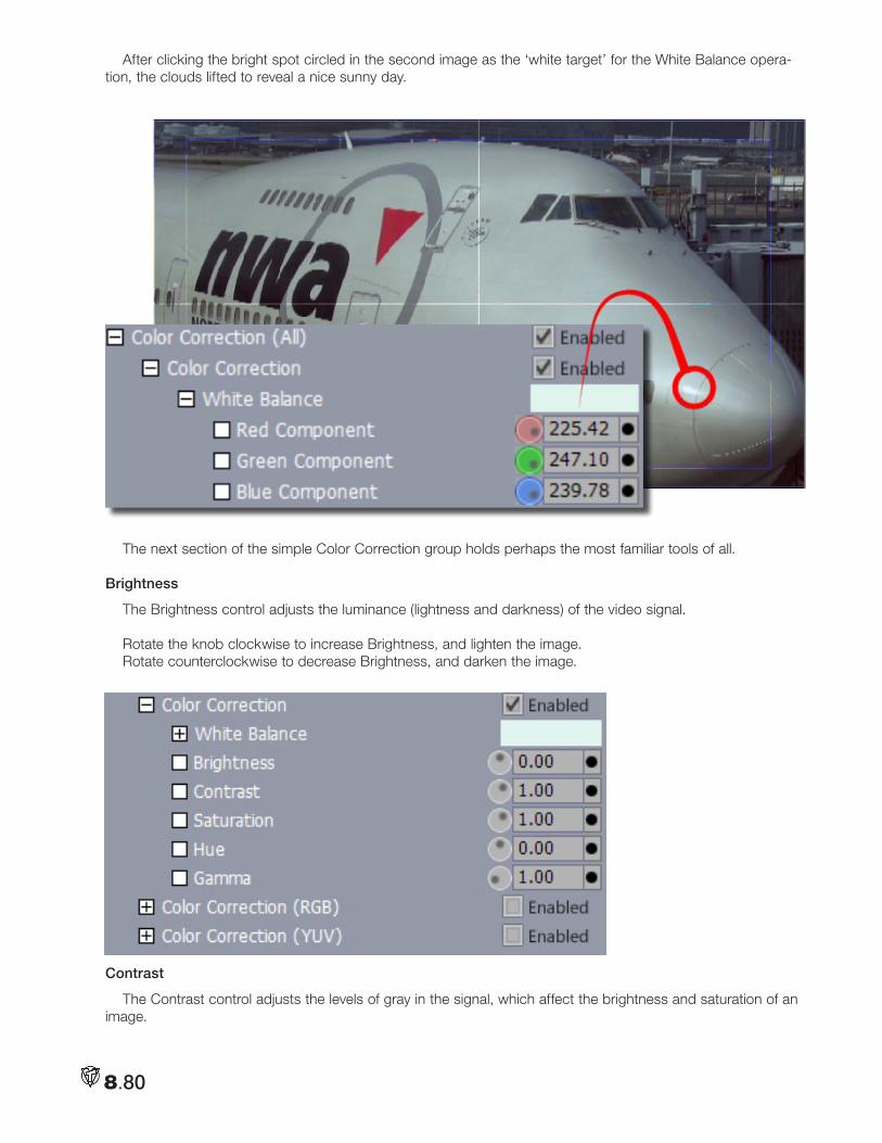
8.80
After clicking the bright spot circled in the second image as the ‘white target’ for the White Balance opera-tion, the clouds lifted to reveal a nice sunny day.
The next section of the simple Color Correction group holds perhaps the most familiar tools of all.
Brightness
The Brightness control adjusts the luminance (lightness and darkness) of the video signal.
Rotate the knob clockwise to increase Brightness, and lighten the image.Rotate counterclockwise to decrease Brightness, and darken the image.
Contrast
The Contrast control adjusts the levels of gray in the signal, which affect the brightness and saturation of an image.
8.81
Rotate the knob clockwise to increase Contrast; the image appears brighter and more saturated. Rotate counterclockwise to decrease Contrast; the image appears darker and less saturated.
An image with extreme areas of darkness and lightness might benefit from reduced Contrast. If your footage looks washed out, try increasing Contrast.
Saturation
Saturation refers to the intensity of color in the video signal. Low saturated pictures look gray; and overly saturated images show colors that bloom to the point of smearing.
Rotate clockwise to increase Saturation.Rotate counterclockwise to decrease Saturation.
A video where colors seem too intense, especially where some colors bleed into others, would benefit from decreased Saturation. Red colors are particularly susceptible to bleeding in composite and Y/C signals. The default Saturation value is 1. A value of 0 removes all color, resulting in black and white video. Negative Saturation values open up a whole new world of colors on the opposite end of the color-wheel.
Hue
The Hue control adjusts the relative phase of color and works on the principle of a color wheel. As you rotate the knob either way, you cycle through the colors. The functional range is between 0 and 360.
Gamma
In addition to serving a valuable role in the Greek alphabet, Gamma has special meaning in the image-pro-cessing realm. Basically, it can be thought of as a hybrid control — part brightness and part contrast. Properly applied, Gamma improves the contrast of the mid-range of an image’s tones, without damaging either its light-est and darkest values. The net result can be a more dynamic image, literally.
When you think about it, the use of either of brightness or contrast alone can often have unwanted effects on the darker and brighter regions of an image. Raising brightness to rescue some important but insufficiently lit detail can blow out highlights, and dropping contrast to soften the mood can result in a washed out image. What to do?
The basic premise of gamma is that it boosts (or drops) the image’s overall contrast while ‘pinning down‘ the brightest and darkest tones — white should stay white, and black stays black. Everything in between is tweaked according to a value you set to create a (usually) gentle contrast curve between those two points. Try it — you’ll like it.
The base value for gamma (no shift) is 1.0. Try raising it slowly, with values like 1.1 or 1.2. Values above 1.5 or so are seldom needed, though available for you if you wish
The Master Color TabBefore considering the rest of the tools in the Color Correction section, we need to pause and familiarize
ourselves with the features of the Master Color tabbed panel to the right of the Control Tree list column (in the same place as the Positioner. The knowledge gained here will serve us well as we get into more complex color correction matters, too.
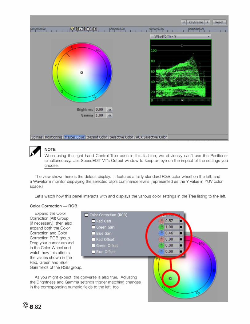
8.82
NOTE
When using the right hand Control Tree pane in this fashion, we obviously can’t use the Positioner simultaneously. Use SpeedEDIT VT’s Output window to keep an eye on the impact of the settings you choose.
The view shown here is the default display. It features a fairly standard RGB color wheel on the left, and a Waveform monitor displaying the selected clip’s Luminance levels (represented as the Y value in YUV color space.)
Let’s watch how this panel interacts with and displays the various color settings in the Tree listing to the left.
Color Correction — RGB
Expand the Color Correction (All) Group (if necessary), then also expand both the Color Correction and Color Correction RGB group. Drag your cursor around in the Color Wheel and watch how this affects the values shown in the Red, Green and Blue Gain fields of the RGB group.
As you might expect, the converse is also true. Adjusting the Brightness and Gamma settings trigger matching changes in the corresponding numeric fields to the left, too.
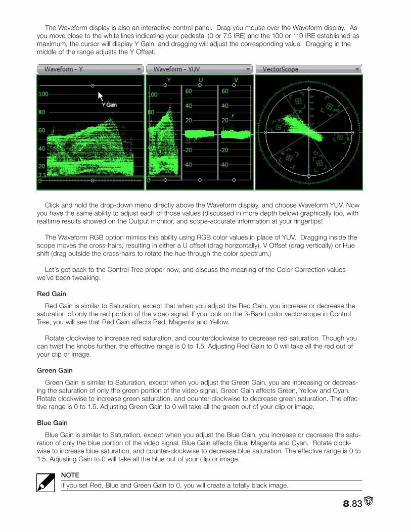
8.83
The Waveform display is also an interactive control panel. Drag you mouse over the Waveform display. As you move close to the white lines indicating your pedestal (0 or 7.5 IRE) and the 100 or 110 IRE established as maximum, the cursor will display Y Gain, and dragging will adjust the corresponding value. Dragging in the middle of the range adjusts the Y Offset.
Click and hold the drop-down menu directly above the Waveform display, and choose Waveform YUV. Now
you have the same ability to adjust each of those values (discussed in more depth below) graphically too, with realtime results showed on the Output monitor, and scope-accurate information at your fingertips!
The Waveform RGB option mimics this ability using RGB color values in place of YUV. Dragging inside the scope moves the cross-hairs, resulting in either a U offset (drag horizontally), V Offset (drag vertically) or Hue shift (drag outside the cross-hairs to rotate the hue through the color spectrum.)
Let’s get back to the Control Tree proper now, and discuss the meaning of the Color Correction values we’ve been tweaking:
Red Gain
Red Gain is similar to Saturation, except that when you adjust the Red Gain, you increase or decrease the saturation of only the red portion of the video signal. If you look on the 3-Band color vectorscope in Control Tree, you will see that Red Gain affects Red, Magenta and Yellow.
Rotate clockwise to increase red saturation, and counterclockwise to decrease red saturation. Though you can twist the knobs further, the effective range is 0 to 1.5. Adjusting Red Gain to 0 will take all the red out of your clip or image.
Green Gain
Green Gain is similar to Saturation, except when you adjust the Green Gain, you are increasing or decreas-ing the saturation of only the green portion of the video signal. Green Gain affects Green, Yellow and Cyan. Rotate clockwise to increase green saturation, and counter-clockwise to decrease green saturation. The effec-tive range is 0 to 1.5. Adjusting Green Gain to 0 will take all the green out of your clip or image.
Blue Gain
Blue Gain is similar to Saturation, except when you adjust the Blue Gain, you increase or decrease the satu-ration of only the blue portion of the video signal. Blue Gain affects Blue, Magenta and Cyan. Rotate clock-wise to increase blue saturation, and counter-clockwise to decrease blue saturation. The effective range is 0 to 1.5. Adjusting Gain to 0 will take all the blue out of your clip or image.
NOTE
If you set Red, Blue and Green Gain to 0, you will create a totally black image.
8.84
Red Offset
Red Offset is similar to Red Gain, except when you adjust the Red Offset, you are affecting every color in the video signal, even black. Rotate clockwise to increase red saturation, counter-clockwise to decrease it. Adjusting Red Offset shifts the signal diagonally in the vectorscope. The range is —255 to 255.
Green Offset
Green Offset is similar to Green Gain, except when you adjust the Green Offset, you are affecting every color in the video signal, even black. Rotate clockwise to increase green saturation, and counter-clockwise to decrease it. Adjusting Green Offset shifts the signal diagonally in the vectorscope. The range is —255 to 255.
Blue Offset
Blue Offset is similar to Blue Gain, except when you adjust the Blue Offset, you are affecting every color in the video signal (even black.) Rotate clockwise to increase blue saturation.
counter-clockwise to decrease it. Adjusting Blue Offset shifts the signal almost horizontally in the vector-scope. Blue Offset ranges from -255 to 255.
Color Correction — YUV
This set of tools is in many ways the same as the section just above, save that it uses a different color mea-surement system (one familiar to longtime analog video hands.)
Y Gain
The Y portion of the YUV signal carries the luminance information. Y Gain is similar to Contrast.
• Rotate the knob clockwise to increase Contrast; the image appears brighter and more saturated.
• Rotate counterclockwise to decrease Contrast; the image appears darker and less saturated.
U Gain
The U portion of the YUV signal carries the blue color information. Gain is similar to Saturation, except when you adjust the U Gain, you increase or decrease the saturation of the blue/yellow portion of the video signal.
• Rotate clockwise to increase blue and yellow saturation.
• Rotate counterclockwise to decrease blue and yellow saturation.
Tweaking the U Gain causes the signal to bloom over the blue and yellow segments or contract away from them.
V Gain
The V portion of the YUV signal carries the red color information. Gain is similar to Saturation, except when you adjust the V Gain, you increase or decrease the saturation of the red/green portion of the video signal.
• Rotate clockwise to increase red and green saturation.
• Rotate counterclockwise to decrease red and green saturation.
Tweaking the V Gain causes the signal to bloom over the red and green segments or contract away from them.
NOTE
If you set U and V Gain to 0, you’ll create a black and white image.
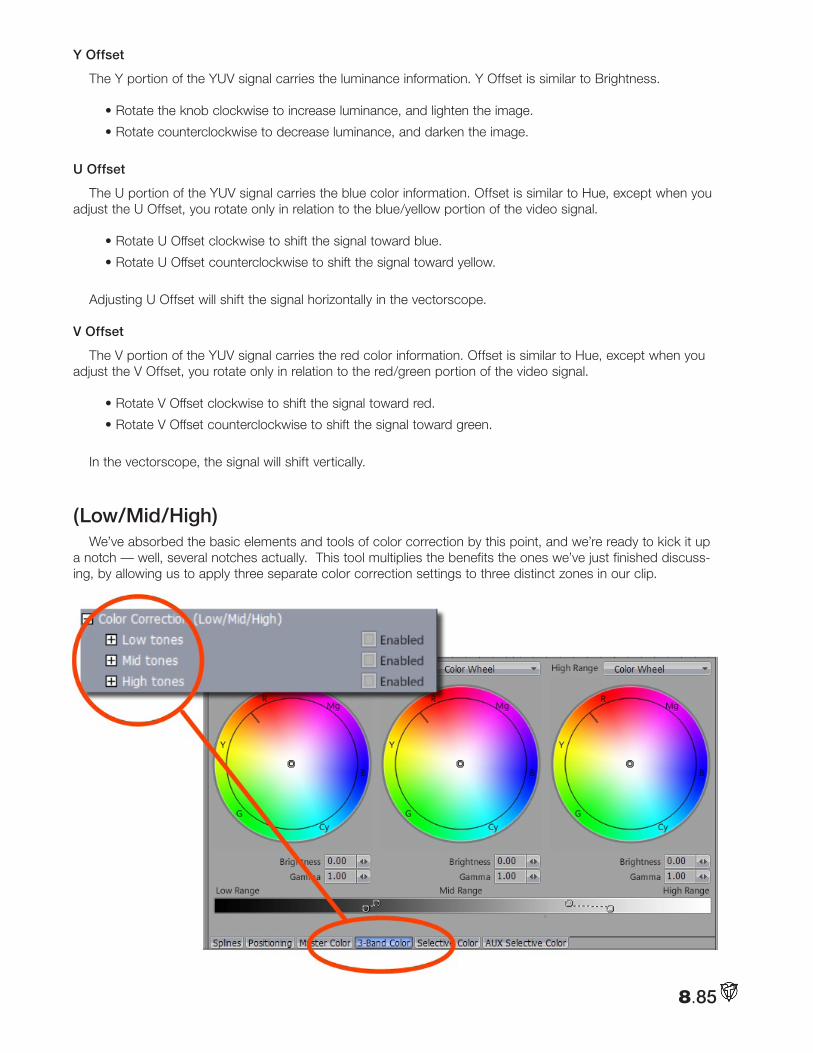
8.85
Y Offset
The Y portion of the YUV signal carries the luminance information. Y Offset is similar to Brightness.
• Rotate the knob clockwise to increase luminance, and lighten the image.
• Rotate counterclockwise to decrease luminance, and darken the image.
U Offset
The U portion of the YUV signal carries the blue color information. Offset is similar to Hue, except when you adjust the U Offset, you rotate only in relation to the blue/yellow portion of the video signal.
• Rotate U Offset clockwise to shift the signal toward blue.
• Rotate U Offset counterclockwise to shift the signal toward yellow.
Adjusting U Offset will shift the signal horizontally in the vectorscope.
V Offset
The V portion of the YUV signal carries the red color information. Offset is similar to Hue, except when you adjust the V Offset, you rotate only in relation to the red/green portion of the video signal.
• Rotate V Offset clockwise to shift the signal toward red.
• Rotate V Offset counterclockwise to shift the signal toward green.
In the vectorscope, the signal will shift vertically.
(Low/Mid/High)We’ve absorbed the basic elements and tools of color correction by this point, and we’re ready to kick it up
a notch — well, several notches actually. This tool multiplies the benefits the ones we’ve just finished discuss-ing, by allowing us to apply three separate color correction settings to three distinct zones in our clip.
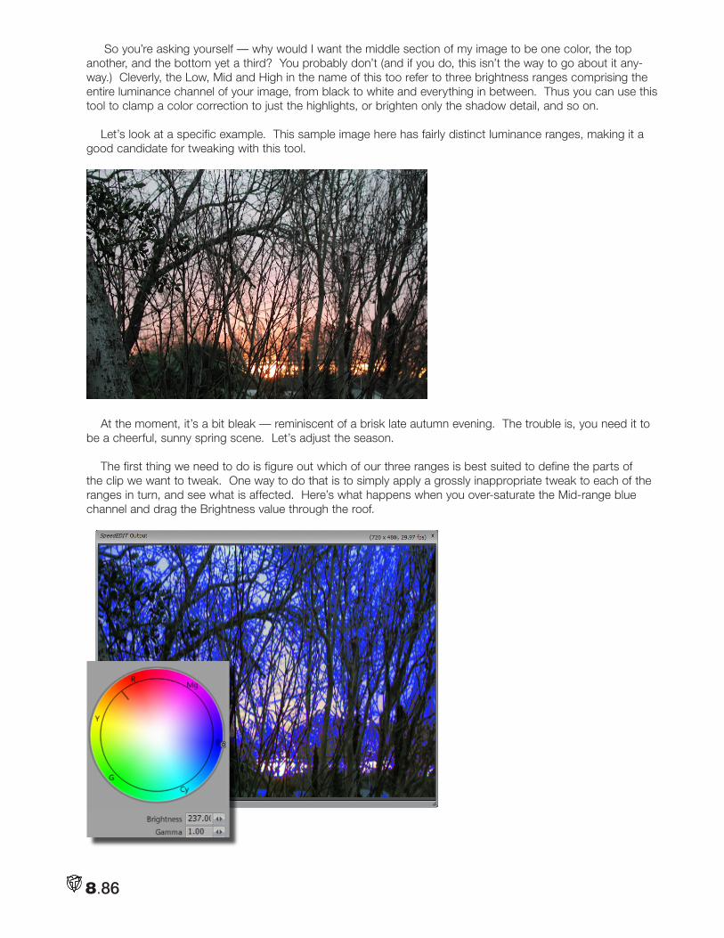
8.86
So you’re asking yourself — why would I want the middle section of my image to be one color, the top another, and the bottom yet a third? You probably don’t (and if you do, this isn’t the way to go about it any-way.) Cleverly, the Low, Mid and High in the name of this too refer to three brightness ranges comprising the entire luminance channel of your image, from black to white and everything in between. Thus you can use this tool to clamp a color correction to just the highlights, or brighten only the shadow detail, and so on.
Let’s look at a specific example. This sample image here has fairly distinct luminance ranges, making it a good candidate for tweaking with this tool.
At the moment, it’s a bit bleak — reminiscent of a brisk late autumn evening. The trouble is, you need it to be a cheerful, sunny spring scene. Let’s adjust the season.
The first thing we need to do is figure out which of our three ranges is best suited to define the parts of the clip we want to tweak. One way to do that is to simply apply a grossly inappropriate tweak to each of the ranges in turn, and see what is affected. Here’s what happens when you over-saturate the Mid-range blue channel and drag the Brightness value through the roof.
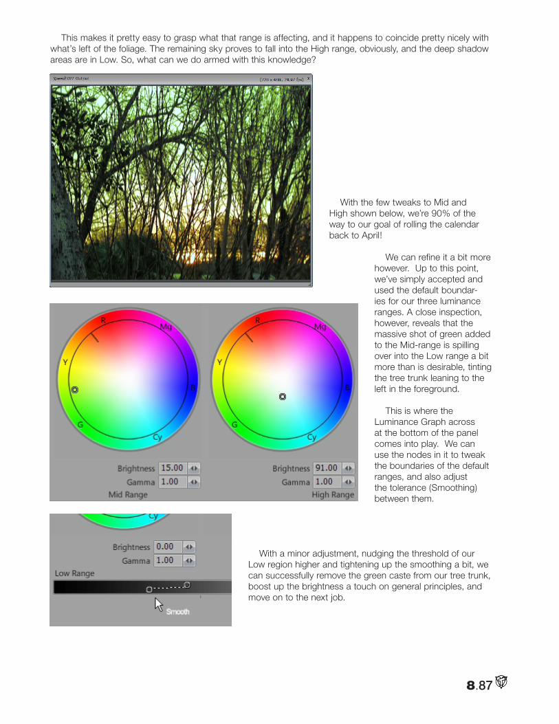
8.87
This makes it pretty easy to grasp what that range is affecting, and it happens to coincide pretty nicely with what’s left of the foliage. The remaining sky proves to fall into the High range, obviously, and the deep shadow areas are in Low. So, what can we do armed with this knowledge?
With the few tweaks to Mid and High shown below, we’re 90% of the way to our goal of rolling the calendar back to April!
We can refine it a bit more however. Up to this point, we’ve simply accepted and used the default boundar-ies for our three luminance ranges. A close inspection, however, reveals that the massive shot of green added to the Mid-range is spilling over into the Low range a bit more than is desirable, tinting the tree trunk leaning to the left in the foreground.
This is where the Luminance Graph across at the bottom of the panel comes into play. We can use the nodes in it to tweak the boundaries of the default ranges, and also adjust the tolerance (Smoothing) between them.
With a minor adjustment, nudging the threshold of our
Low region higher and tightening up the smoothing a bit, we can successfully remove the green caste from our tree trunk, boost up the brightness a touch on general principles, and move on to the next job.
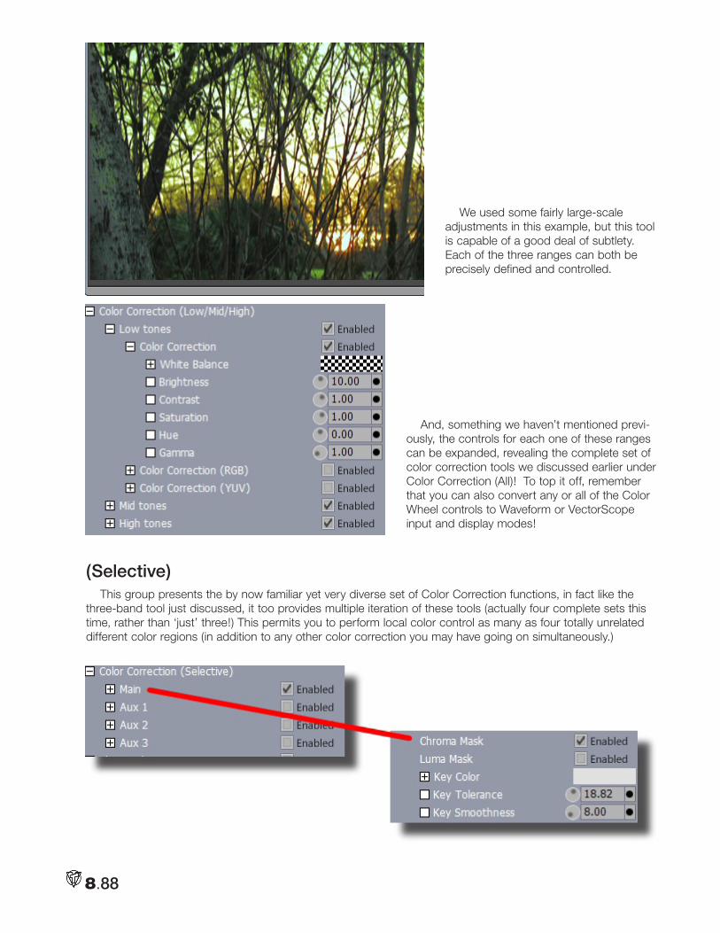
8.88
We used some fairly large-scale adjustments in this example, but this tool is capable of a good deal of subtlety. Each of the three ranges can both be precisely defined and controlled.
And, something we haven’t mentioned previ-ously, the controls for each one of these ranges can be expanded, revealing the complete set of color correction tools we discussed earlier under Color Correction (All)! To top it off, remember that you can also convert any or all of the Color Wheel controls to Waveform or VectorScope input and display modes!
(Selective) This group presents the by now familiar yet very diverse set of Color Correction functions, in fact like the
three-band tool just discussed, it too provides multiple iteration of these tools (actually four complete sets this time, rather than ‘just’ three!) This permits you to perform local color control as many as four totally unrelated different color regions (in addition to any other color correction you may have going on simultaneously.)
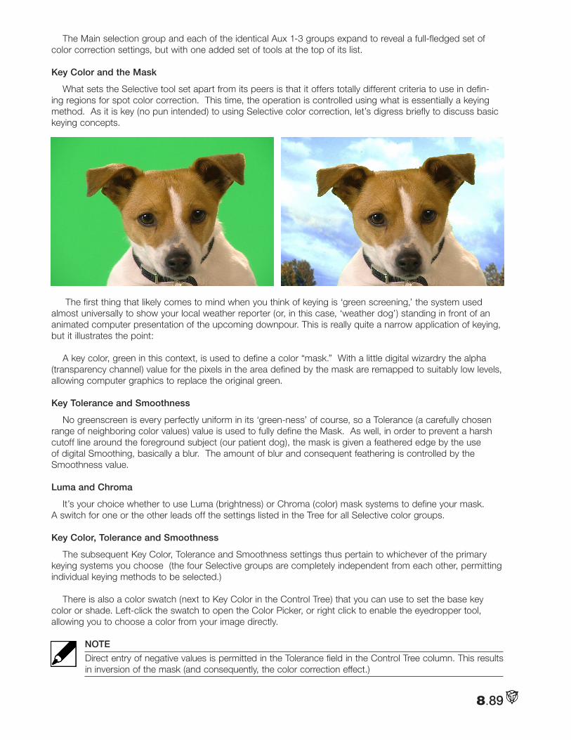
8.89
The Main selection group and each of the identical Aux 1-3 groups expand to reveal a full-fledged set of color correction settings, but with one added set of tools at the top of its list.
Key Color and the Mask
What sets the Selective tool set apart from its peers is that it offers totally different criteria to use in defin-ing regions for spot color correction. This time, the operation is controlled using what is essentially a keying method. As it is key (no pun intended) to using Selective color correction, let’s digress briefly to discuss basic keying concepts.
The first thing that likely comes to mind when you think of keying is ‘green screening,’ the system used almost universally to show your local weather reporter (or, in this case, ‘weather dog’) standing in front of an animated computer presentation of the upcoming downpour. This is really quite a narrow application of keying, but it illustrates the point:
A key color, green in this context, is used to define a color “mask.” With a little digital wizardry the alpha (transparency channel) value for the pixels in the area defined by the mask are remapped to suitably low levels, allowing computer graphics to replace the original green.
Key Tolerance and Smoothness
No greenscreen is every perfectly uniform in its ‘green-ness’ of course, so a Tolerance (a carefully chosen range of neighboring color values) value is used to fully define the Mask. As well, in order to prevent a harsh cutoff line around the foreground subject (our patient dog), the mask is given a feathered edge by the use of digital Smoothing, basically a blur. The amount of blur and consequent feathering is controlled by the Smoothness value.
Luma and Chroma
It’s your choice whether to use Luma (brightness) or Chroma (color) mask systems to define your mask. A switch for one or the other leads off the settings listed in the Tree for all Selective color groups.
Key Color, Tolerance and Smoothness
The subsequent Key Color, Tolerance and Smoothness settings thus pertain to whichever of the primary keying systems you choose (the four Selective groups are completely independent from each other, permitting individual keying methods to be selected.)
There is also a color swatch (next to Key Color in the Control Tree) that you can use to set the base key color or shade. Left-click the swatch to open the Color Picker, or right click to enable the eyedropper tool, allowing you to choose a color from your image directly.
NOTE
Direct entry of negative values is permitted in the Tolerance field in the Control Tree column. This results in inversion of the mask (and consequently, the color correction effect.)
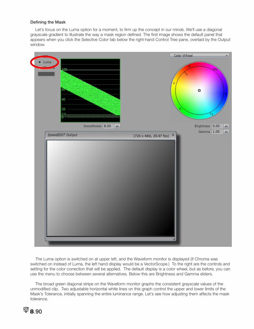
8.90
Defining the Mask
Let’s focus on the Luma option for a moment, to firm up the concept in our minds. We’ll use a diagonal grayscale gradient to illustrate the way a mask region defined. The first image shows the default panel that appears when you click the Selective Color tab below the right-hand Control Tree pane, overlaid by the Output window.
The Luma option is switched on at upper left, and the Waveform monitor is displayed (if Chroma was switched on instead of Luma, the left hand display would be a VectorScope.) To the right are the controls and setting for the color correction that will be applied. The default display is a color wheel, but as before, you can use the menu to choose between several alternatives. Below this are Brightness and Gamma sliders.
The broad green diagonal stripe on the Waveform monitor graphs the consistent grayscale values of the unmodified clip. Two adjustable horizontal white lines on this graph control the upper and lower limits of the Mask’s Tolerance, initially spanning the entire luminance range. Let’s see how adjusting them affects the mask tolerance.
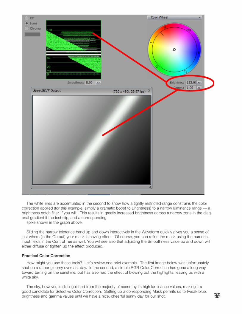
8.91
The white lines are accentuated in the second to show how a tightly restricted range constrains the color correction applied (for this example, simply a dramatic boost to Brightness) to a narrow luminance range — a brightness notch filter, if you will. This results in greatly increased brightness across a narrow zone in the diag-onal gradient if the test clip, and a corresponding
spike shown in the graph above.
Sliding the narrow tolerance band up and down interactively in the Waveform quickly gives you a sense of just where (in the Output) your mask is having effect. Of course, you can refine the mask using the numeric input fields in the Control Tee as well. You will see also that adjusting the Smoothness value up and down will either diffuse or tighten up the effect produced.
Practical Color Correction
How might you use these tools? Let’s review one brief example. The first image below was unfortunately shot on a rather gloomy overcast day. In the second, a simple RGB Color Correction has gone a long way toward turning on the sunshine, but has also had the effect of blowing out the highlights, leaving us with a white sky.
The sky, however, is distinguished from the majority of scene by its high luminance values, making it a good candidate for Selective Color Correction. Setting up a corresponding Mask permits us to tweak blue, brightness and gamma values until we have a nice, cheerful sunny day for our shot.
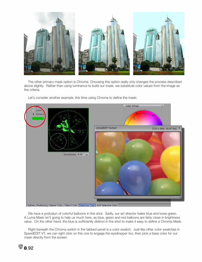
8.92
The other primary mask option is Chroma. Choosing this option really only changes the process described above slightly. Rather than using luminance to build our mask, we substitute color values from the image as the criteria.
Let’s consider another example, this time using Chroma to define the mask:
We have a profusion of colorful balloons in this shot. Sadly, our art director hates blue and loves green. A Luma Mask isn’t going to help us much here, as blue, green and red balloons are fairly close in brightness value. On the other hand, the blue is sufficiently distinct in the shot to make it easy to define a Chroma Mask.
Right beneath the Chroma switch in the tabbed panel is a color swatch. Just like other color swatches in SpeedEDIT VT, we can right click on this one to engage the eyedropper too, then pick a base color for our mask directly from the screen.
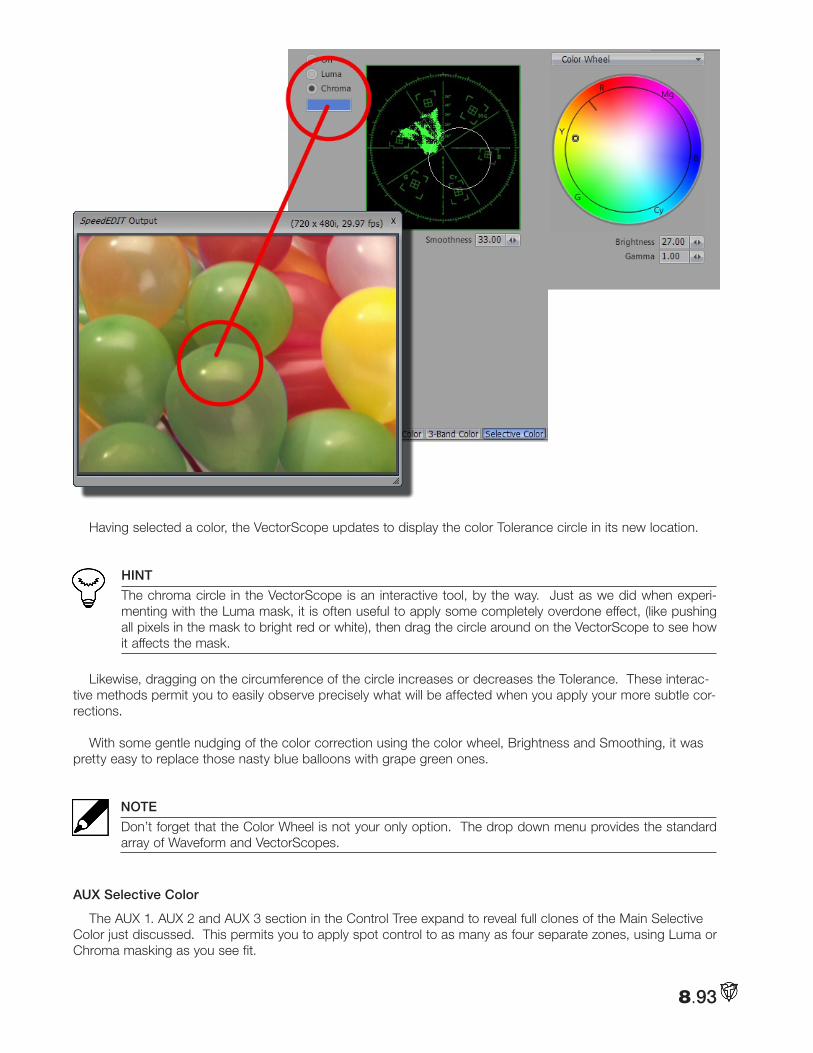
8.93
Having selected a color, the VectorScope updates to display the color Tolerance circle in its new location.
HINT
The chroma circle in the VectorScope is an interactive tool, by the way. Just as we did when experi-menting with the Luma mask, it is often useful to apply some completely overdone effect, (like pushing all pixels in the mask to bright red or white), then drag the circle around on the VectorScope to see how it affects the mask.
Likewise, dragging on the circumference of the circle increases or decreases the Tolerance. These interac-tive methods permit you to easily observe precisely what will be affected when you apply your more subtle cor-rections.
With some gentle nudging of the color correction using the color wheel, Brightness and Smoothing, it was pretty easy to replace those nasty blue balloons with grape green ones.
NOTE
Don’t forget that the Color Wheel is not your only option. The drop down menu provides the standard array of Waveform and VectorScopes.
AUX Selective Color
The AUX 1. AUX 2 and AUX 3 section in the Control Tree expand to reveal full clones of the Main Selective Color just discussed. This permits you to apply spot control to as many as four separate zones, using Luma or Chroma masking as you see fit.
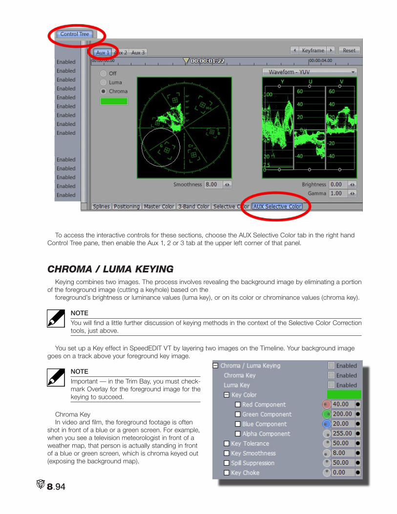
8.94
To access the interactive controls for these sections, choose the AUX Selective Color tab in the right hand Control Tree pane, then enable the Aux 1, 2 or 3 tab at the upper left corner of that panel.
cHRoma / luma keyingKeying combines two images. The process involves revealing the background image by eliminating a portion
of the foreground image (cutting a keyhole) based on theforeground’s brightness or luminance values (luma key), or on its color or chrominance values (chroma key).
NOTE
You will find a little further discussion of keying methods in the context of the Selective Color Correction tools, just above.
You set up a Key effect in SpeedEDIT VT by layering two images on the Timeline. Your background image goes on a track above your foreground key image.
NOTE
Important — in the Trim Bay, you must check-mark Overlay for the foreground image for the keying to succeed.
Chroma KeyIn video and film, the foreground footage is often
shot in front of a blue or a green screen. For example, when you see a television meteorologist in front of a weather map, that person is actually standing in front of a blue or green screen, which is chroma keyed out (exposing the background map).
8.95
Key Color
This is the color in the foreground image that you will key out. The basic steps to set up a chroma-keyed composite are:
Load a suitable greenscreen clip, and place the desired background scene above it on the timeline. In the Trim Bay, turn on Overlay for the greenscreen sample. Don’t checkmark Enabled (next to Chroma Key) just yet though.
First pick your key color, which you can do right from the Control Tree. Right-click on the color swatch next to Key Color, and pick your color by using the Eyedropper Tool. Drag it over to the SpeedEDIT VT Output, and release it above the desired key color. Now is the time to Enable Chroma Key. The key color will become trans-parent, and the background image will show through.
NOTE
If you don’t see the background image show through in the Positioning panel display, go to the top of the panel and checkmark Show All Layers.
Key Tolerance
Key Tolerance determines the amount of color variance from your base key color. For example, if your base color was RGB 100, 125, 210, then a Key Tolerance of 10 includes only colors with values of 90 to 110 on the Red component, 115 to 135 on the Green, and 200 to 220 on the Blue.
If your key color in your clip is extremely consistent, then you can use a low tolerance. By default,
Key Tolerance is set at 50, which is just a starting point. Increase it if the color isn’t totally keyed out, or decrease it you are keying out colors that you want to retain. The range is from 0 to 255.
Key Smoothness
In most keying situations, you want to eliminate the sharp edges where your background and foreground meet. The Smoothing operation produces a blur effect on the edges of a key. Usually lower Key Smoothness values will provide a soft professional edge. The default value is 8. The range is from 0 to 255.
NOTE
Smoothness helps eliminate the blue or green glow around talent caused by light reflecting from the back-ground screen. However, as you increase smoothness, objects in your video can become transparent. Smoothing should be increased by fine increments.
Spill Suppression
This control helps remove any chroma key color that is spilling/bouncing back on to your talent. A larger value will remove more of spill.
Key Choke
This tool works exactly like the Contract tool in the Keyer module. It contracts the alpha channel generated by a key operation. For example, if you are keying out the blue background in a bluescreen clip, decreasing the Key Choke amount will thin or eat away the edges of the key. The default is 0. The range is —5 to 5. Negative values will thin the edges, usually what you want.
It’s best to begin by adjusting Key Tolerance. To see what you are avoiding, try it at 100. Then set it to 0 and slowly turn the knob clockwise. In this case, 50 is a good number. Set Key Smoothness to 100. Now, bring it to 0. In this case, the difference between 0 and the default of 8 is negligible. As a rule of thumb, if you can’t see a difference, then go with the setting that doesn’t apply the effect.
Adjust Key Choke last. To view what you don’t want in a typical keying, try a setting of 5. Now set Key Choke back to 0 and slowly twist the knob counterclockwise so you can see how negative values will eat around the head and shoulders.
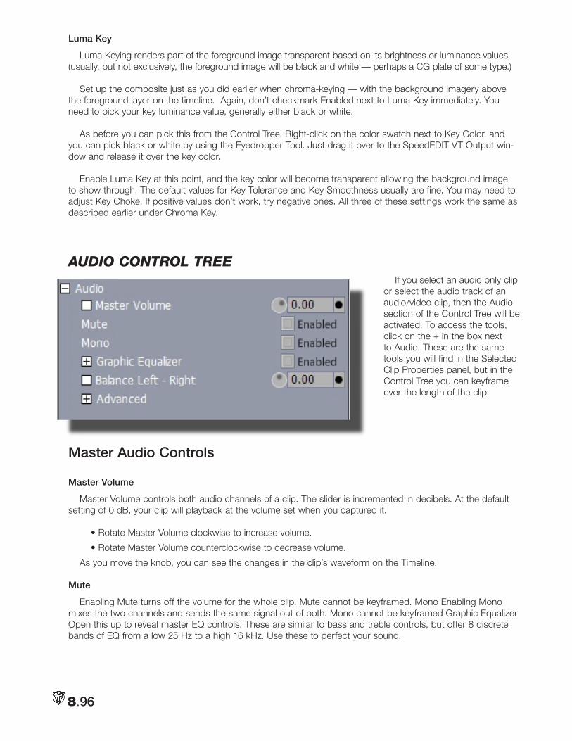
8.96
Luma Key
Luma Keying renders part of the foreground image transparent based on its brightness or luminance values (usually, but not exclusively, the foreground image will be black and white — perhaps a CG plate of some type.)
Set up the composite just as you did earlier when chroma-keying — with the background imagery above the foreground layer on the timeline. Again, don’t checkmark Enabled next to Luma Key immediately. You need to pick your key luminance value, generally either black or white.
As before you can pick this from the Control Tree. Right-click on the color swatch next to Key Color, and you can pick black or white by using the Eyedropper Tool. Just drag it over to the SpeedEDIT VT Output win-dow and release it over the key color.
Enable Luma Key at this point, and the key color will become transparent allowing the background image to show through. The default values for Key Tolerance and Key Smoothness usually are fine. You may need to adjust Key Choke. If positive values don’t work, try negative ones. All three of these settings work the same as described earlier under Chroma Key.
audio contRol tReeIf you select an audio only clip
or select the audio track of an audio/video clip, then the Audio section of the Control Tree will be activated. To access the tools, click on the + in the box next to Audio. These are the same tools you will find in the Selected Clip Properties panel, but in the Control Tree you can keyframe over the length of the clip.
Master Audio Controls
Master Volume
Master Volume controls both audio channels of a clip. The slider is incremented in decibels. At the default setting of 0 dB, your clip will playback at the volume set when you captured it.
• Rotate Master Volume clockwise to increase volume.
• Rotate Master Volume counterclockwise to decrease volume.
As you move the knob, you can see the changes in the clip’s waveform on the Timeline.
Mute
Enabling Mute turns off the volume for the whole clip. Mute cannot be keyframed. Mono Enabling Mono mixes the two channels and sends the same signal out of both. Mono cannot be keyframed Graphic Equalizer Open this up to reveal master EQ controls. These are similar to bass and treble controls, but offer 8 discrete bands of EQ from a low 25 Hz to a high 16 kHz. Use these to perfect your sound.
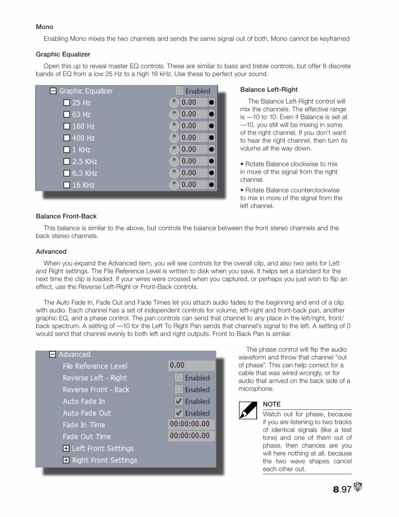
8.97
Mono
Enabling Mono mixes the two channels and sends the same signal out of both. Mono cannot be keyframed
Graphic Equalizer
Open this up to reveal master EQ controls. These are similar to bass and treble controls, but offer 8 discrete bands of EQ from a low 25 Hz to a high 16 kHz. Use these to perfect your sound.
Balance Left-Right
The Balance Left-Right control will mix the channels. The effective range is —10 to 10. Even if Balance is set at —10, you still will be mixing in some of the right channel. If you don’t want to hear the right channel, then turn its volume all the way down.
• Rotate Balance clockwise to mix in more of the signal from the right channel.
• Rotate Balance counterclockwise to mix in more of the signal from the left channel.
Balance Front-Back
This balance is similar to the above, but controls the balance between the front stereo channels and the back stereo channels.
Advanced
When you expand the Advanced item, you will see controls for the overall clip, and also two sets for Left and Right settings. The File Reference Level is written to disk when you save. It helps set a standard for the next time the clip is loaded. If your wires were crossed when you captured, or perhaps you just wish to flip an effect, use the Reverse Left-Right or Front-Back controls.
The Auto Fade In, Fade Out and Fade Times let you attach audio fades to the beginning and end of a clip with audio. Each channel has a set of independent controls for volume, left-right and front-back pan, another graphic EQ, and a phase control. The pan controls can send that channel to any place in the left/right, front/back spectrum. A setting of —10 for the Left To Right Pan sends that channel’s signal to the left. A setting of 0 would send that channel evenly to both left and right outputs. Front to Back Pan is similar.
The phase control will flip the audio
waveform and throw that channel “out of phase”. This can help correct for a cable that was wired wrongly, or for audio that arrived on the back side of a microphone.
NOTE
Watch out for phase, because if you are listening to two tracks of identical signals (like a test tone) and one of them out of phase, then chances are you will here nothing at all, because the two wave shapes cancel each other out.
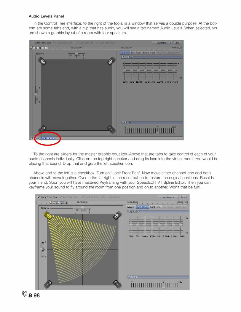
8.98
Audio Levels Panel
In the Control Tree interface, to the right of the tools, is a window that serves a double purpose. At the bot-tom are some tabs and, with a clip that has audio, you will see a tab named Audio Levels. When selected, you are shown a graphic layout of a room with four speakers.
To the right are sliders for the master graphic equalizer. Above that are tabs to take control of each of your audio channels individually. Click on the top right speaker and drag its icon into the virtual room. You would be placing that sound. Drop that and grab the left speaker icon.
Above and to the left is a checkbox, Turn on “Lock Front Pan”. Now move either channel icon and both channels will move together. Over in the far right is the reset button to restore the original positions. Reset is your friend. Soon you will have mastered Keyframing with your SpeedEDIT VT Spline Editor. Then you can keyframe your sound to fly around the room from one position and on to another. Won’t that be fun!
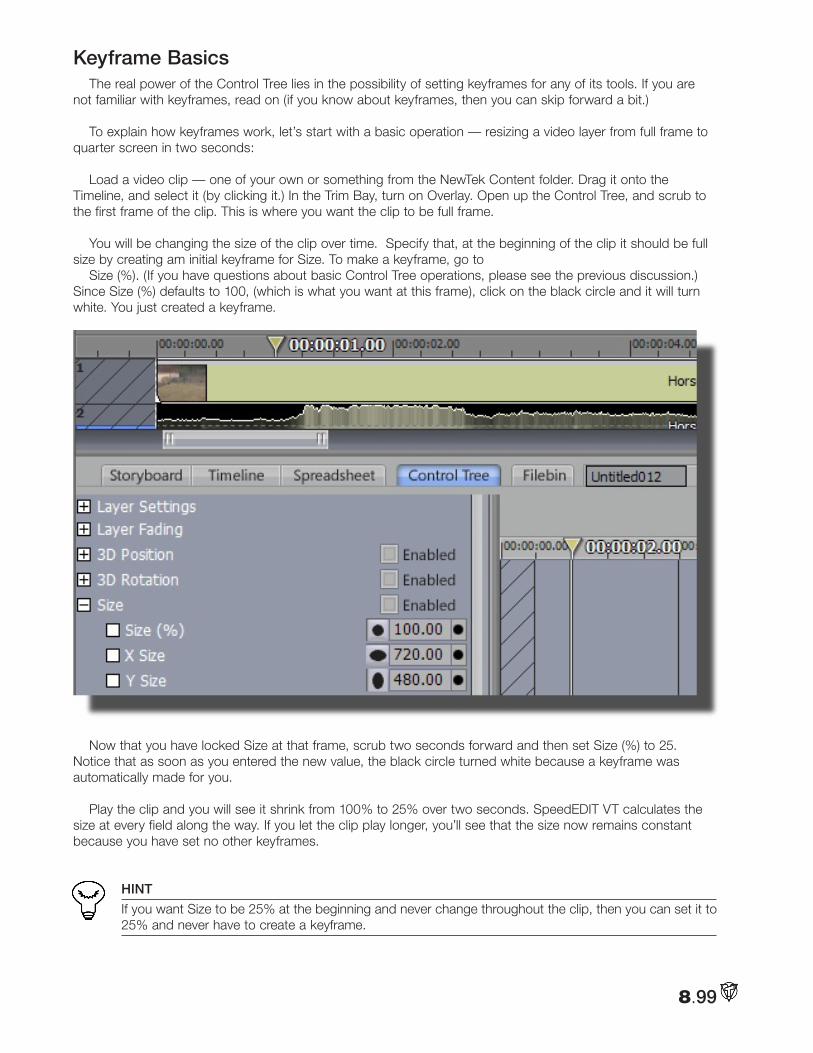
8.99
Keyframe BasicsThe real power of the Control Tree lies in the possibility of setting keyframes for any of its tools. If you are
not familiar with keyframes, read on (if you know about keyframes, then you can skip forward a bit.)
To explain how keyframes work, let’s start with a basic operation — resizing a video layer from full frame to quarter screen in two seconds:
Load a video clip — one of your own or something from the NewTek Content folder. Drag it onto the Timeline, and select it (by clicking it.) In the Trim Bay, turn on Overlay. Open up the Control Tree, and scrub to the first frame of the clip. This is where you want the clip to be full frame.
You will be changing the size of the clip over time. Specify that, at the beginning of the clip it should be full size by creating am initial keyframe for Size. To make a keyframe, go to
Size (%). (If you have questions about basic Control Tree operations, please see the previous discussion.) Since Size (%) defaults to 100, (which is what you want at this frame), click on the black circle and it will turn white. You just created a keyframe.
Now that you have locked Size at that frame, scrub two seconds forward and then set Size (%) to 25. Notice that as soon as you entered the new value, the black circle turned white because a keyframe was automatically made for you.
Play the clip and you will see it shrink from 100% to 25% over two seconds. SpeedEDIT VT calculates the size at every field along the way. If you let the clip play longer, you’ll see that the size now remains constant because you have set no other keyframes.
HINT
If you want Size to be 25% at the beginning and never change throughout the clip, then you can set it to 25% and never have to create a keyframe.
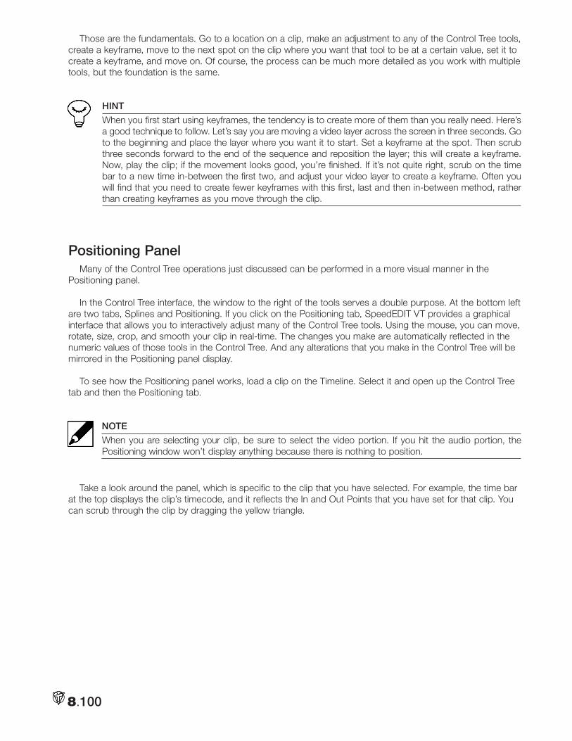
8.100
Those are the fundamentals. Go to a location on a clip, make an adjustment to any of the Control Tree tools, create a keyframe, move to the next spot on the clip where you want that tool to be at a certain value, set it to create a keyframe, and move on. Of course, the process can be much more detailed as you work with multiple tools, but the foundation is the same.
HINT
When you first start using keyframes, the tendency is to create more of them than you really need. Here’s a good technique to follow. Let’s say you are moving a video layer across the screen in three seconds. Go to the beginning and place the layer where you want it to start. Set a keyframe at the spot. Then scrub three seconds forward to the end of the sequence and reposition the layer; this will create a keyframe. Now, play the clip; if the movement looks good, you’re finished. If it’s not quite right, scrub on the time bar to a new time in-between the first two, and adjust your video layer to create a keyframe. Often you will find that you need to create fewer keyframes with this first, last and then in-between method, rather than creating keyframes as you move through the clip.
Positioning PanelMany of the Control Tree operations just discussed can be performed in a more visual manner in the
Positioning panel.
In the Control Tree interface, the window to the right of the tools serves a double purpose. At the bottom left are two tabs, Splines and Positioning. If you click on the Positioning tab, SpeedEDIT VT provides a graphical interface that allows you to interactively adjust many of the Control Tree tools. Using the mouse, you can move, rotate, size, crop, and smooth your clip in real-time. The changes you make are automatically reflected in the numeric values of those tools in the Control Tree. And any alterations that you make in the Control Tree will be mirrored in the Positioning panel display.
To see how the Positioning panel works, load a clip on the Timeline. Select it and open up the Control Tree tab and then the Positioning tab.
NOTE
When you are selecting your clip, be sure to select the video portion. If you hit the audio portion, the Positioning window won’t display anything because there is nothing to position.
Take a look around the panel, which is specific to the clip that you have selected. For example, the time bar at the top displays the clip’s timecode, and it reflects the In and Out Points that you have set for that clip. You can scrub through the clip by dragging the yellow triangle.
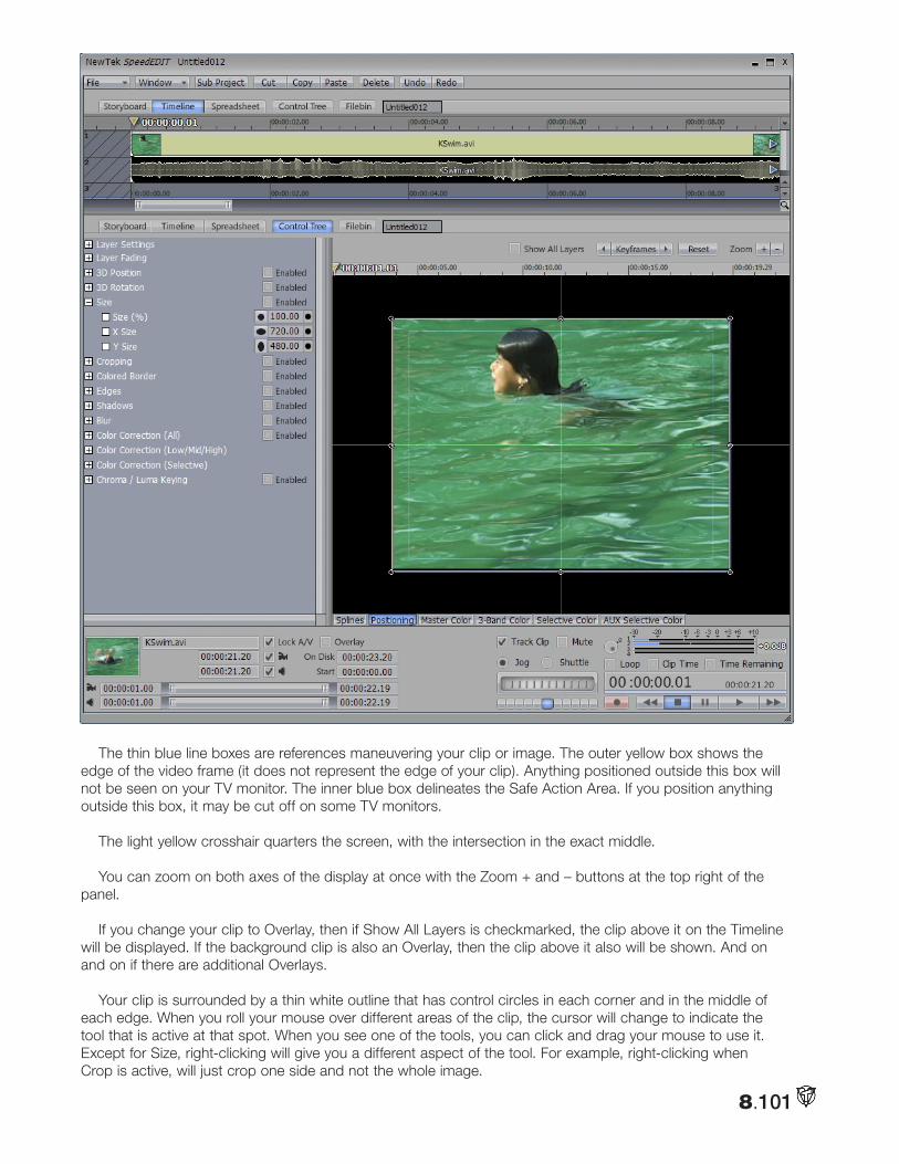
8.101
The thin blue line boxes are references maneuvering your clip or image. The outer yellow box shows the edge of the video frame (it does not represent the edge of your clip). Anything positioned outside this box will not be seen on your TV monitor. The inner blue box delineates the Safe Action Area. If you position anything outside this box, it may be cut off on some TV monitors.
The light yellow crosshair quarters the screen, with the intersection in the exact middle.
You can zoom on both axes of the display at once with the Zoom + and – buttons at the top right of the panel.
If you change your clip to Overlay, then if Show All Layers is checkmarked, the clip above it on the Timeline will be displayed. If the background clip is also an Overlay, then the clip above it also will be shown. And on and on if there are additional Overlays.
Your clip is surrounded by a thin white outline that has control circles in each corner and in the middle of each edge. When you roll your mouse over different areas of the clip, the cursor will change to indicate the tool that is active at that spot. When you see one of the tools, you can click and drag your mouse to use it. Except for Size, right-clicking will give you a different aspect of the tool. For example, right-clicking when Crop is active, will just crop one side and not the whole image.
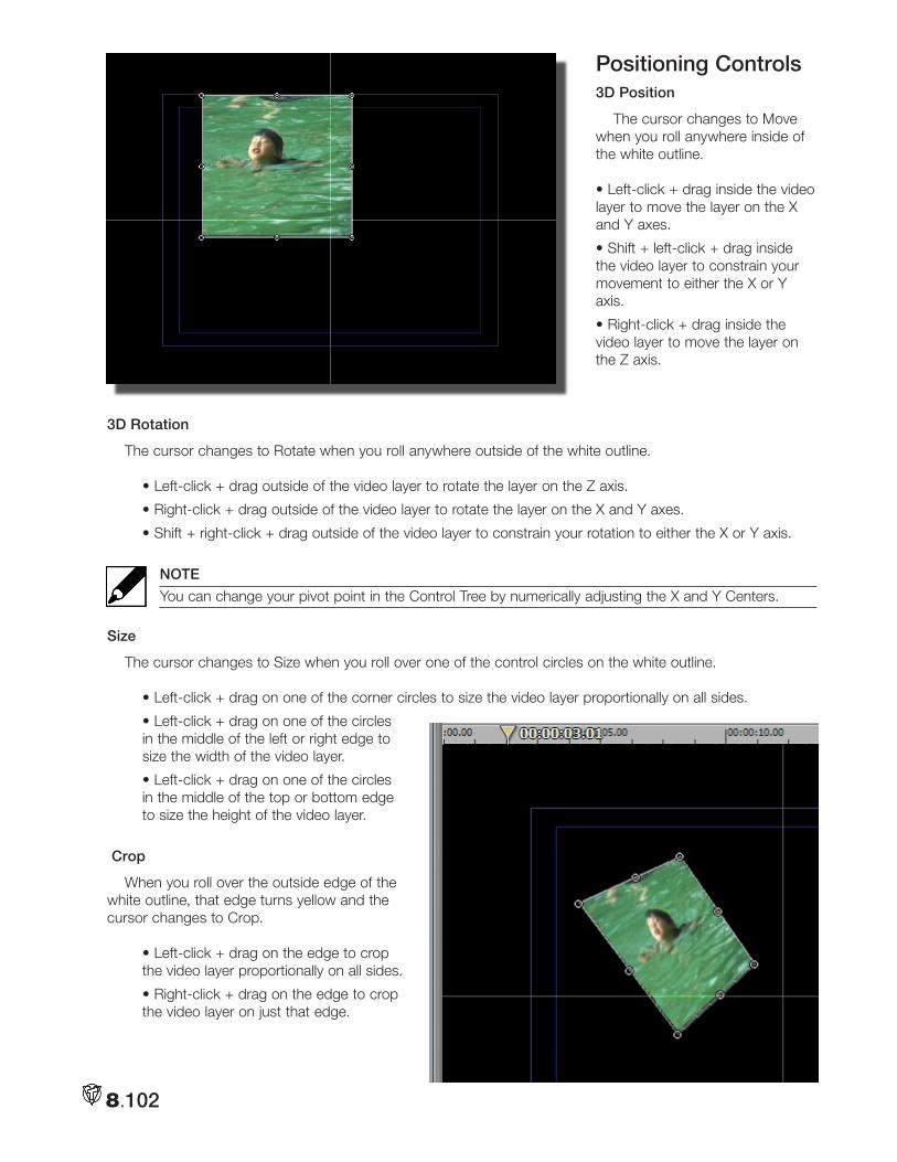
8.102
Positioning Controls3D Position
The cursor changes to Move when you roll anywhere inside of the white outline.
• Left-click + drag inside the video layer to move the layer on the X and Y axes.
• Shift + left-click + drag inside the video layer to constrain your movement to either the X or Y axis.
• Right-click + drag inside the video layer to move the layer on the Z axis.
3D Rotation
The cursor changes to Rotate when you roll anywhere outside of the white outline.
• Left-click + drag outside of the video layer to rotate the layer on the Z axis.
• Right-click + drag outside of the video layer to rotate the layer on the X and Y axes.
• Shift + right-click + drag outside of the video layer to constrain your rotation to either the X or Y axis.
NOTE
You can change your pivot point in the Control Tree by numerically adjusting the X and Y Centers.
Size
The cursor changes to Size when you roll over one of the control circles on the white outline.
• Left-click + drag on one of the corner circles to size the video layer proportionally on all sides.
• Left-click + drag on one of the circles in the middle of the left or right edge to size the width of the video layer.
• Left-click + drag on one of the circles in the middle of the top or bottom edge to size the height of the video layer.
Crop
When you roll over the outside edge of the white outline, that edge turns yellow and the cursor changes to Crop.
• Left-click + drag on the edge to crop the video layer proportionally on all sides.
• Right-click + drag on the edge to crop the video layer on just that edge.
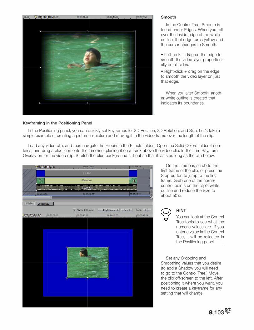
8.103
Smooth
In the Control Tree, Smooth is found under Edges. When you roll over the inside edge of the white outline, that edge turns yellow and the cursor changes to Smooth.
• Left-click + drag on the edge to smooth the video layer proportion-ally on all sides.
• Right-click + drag on the edge to smooth the video layer on just that edge.
When you alter Smooth, anoth-er white outline is created that indicates its boundaries.
Keyframing in the Positioning Panel
In the Positioning panel, you can quickly set keyframes for 3D Position, 3D Rotation, and Size. Let’s take a simple example of creating a picture-in-picture and moving it in the video frame over the length of the clip.
Load any video clip, and then navigate the Filebin to the Effects folder. Open the Solid Colors folder it con-tains, and drag a blue icon onto the Timeline, placing it on a track above the video clip. In the Trim Bay, turn Overlay on for the video clip. Stretch the blue background still out so that it lasts as long as the clip below.
On the time bar, scrub to the first frame of the clip, or press the Stop button to jump to the first frame. Grab one of the corner control points on the clip’s white outline and reduce the Size to about 50%.
HINT
You can look at the Control Tree tools to see what the numeric values are. If you enter a value in the Control Tree, it will be reflected in the Positioning panel.
Set any Cropping and Smoothing values that you desire (to add a Shadow you will need to go to the Control Tree.) Move the clip off-screen to the left. After positioning it where you want, you need to create a keyframe for any setting that will change.
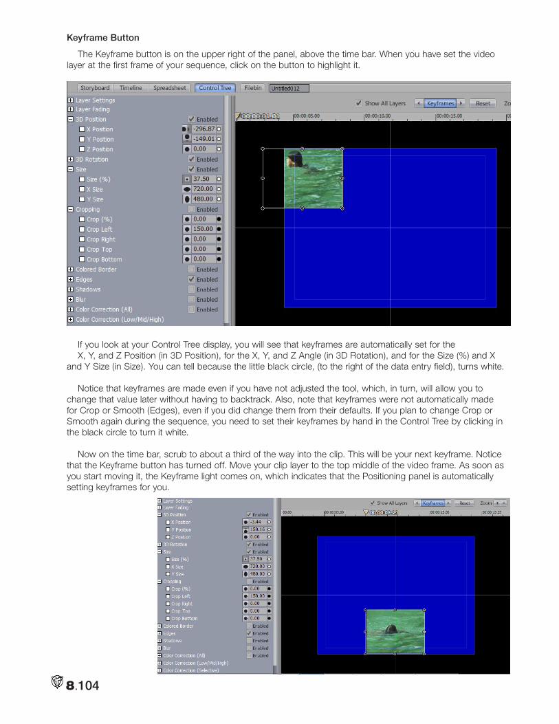
8.104
Keyframe Button
The Keyframe button is on the upper right of the panel, above the time bar. When you have set the video layer at the first frame of your sequence, click on the button to highlight it.
If you look at your Control Tree display, you will see that keyframes are automatically set for the X, Y, and Z Position (in 3D Position), for the X, Y, and Z Angle (in 3D Rotation), and for the Size (%) and X
and Y Size (in Size). You can tell because the little black circle, (to the right of the data entry field), turns white.
Notice that keyframes are made even if you have not adjusted the tool, which, in turn, will allow you to change that value later without having to backtrack. Also, note that keyframes were not automatically made for Crop or Smooth (Edges), even if you did change them from their defaults. If you plan to change Crop or Smooth again during the sequence, you need to set their keyframes by hand in the Control Tree by clicking in the black circle to turn it white.
Now on the time bar, scrub to about a third of the way into the clip. This will be your next keyframe. Notice that the Keyframe button has turned off. Move your clip layer to the top middle of the video frame. As soon as you start moving it, the Keyframe light comes on, which indicates that the Positioning panel is automatically setting keyframes for you.
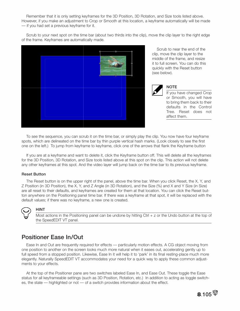
8.105
Remember that it is only setting keyframes for the 3D Position, 3D Rotation, and Size tools listed above. However, if you make an adjustment to Crop or Smooth at this location, a keyframe automatically will be made — if you had set a previous keyframe for it.
Scrub to your next spot on the time bar (about two thirds into the clip), move the clip layer to the right edge of the frame. Keyframes are automatically made.
Scrub to near the end of the clip, move the clip layer to the middle of the frame, and resize it to full screen. You can do this quickly with the Reset button (see below).
NOTE
If you have changed Crop or Smooth, you will have to bring them back to their defaults in the Control Tree. Reset does not affect them.
To see the sequence, you can scrub it on the time bar, or simply play the clip. You now have four keyframe spots, which are delineated on the time bar by thin purple vertical hash marks. (Look closely to see the first one on the left.) To jump from keyframe to keyframe, click one of the arrows that flank the Keyframe button
If you are at a keyframe and want to delete it, click the Keyframe button off. This will delete all the keyframes for the 3D Position, 3D Rotation, and Size tools listed above at this spot on the clip. This action will not delete any other keyframes at this spot. And the video layer will jump back on the time bar to its previous keyframe.
Reset Button
The Reset button is on the upper right of the panel, above the time bar. When you click Reset, the X, Y, and Z Position (in 3D Position), the X, Y, and Z Angle (in 3D Rotation), and the Size (%) and X and Y Size (in Size) are all reset to their defaults, and keyframes are created for them at that location. You can click the Reset but-ton anywhere on the Positioning panel time bar. If there was a keyframe at that spot, it will be replaced with the default values; if there was no keyframe, a new one is created.
HINT
Most actions in the Positioning panel can be undone by hitting Ctrl + z or the Undo button at the top of the SpeedEDIT VT panel.
Positioner Ease In/OutEase In and Out are frequently required for effects — particularly motion effects. A CG object moving from
one position to another on the screen looks much more natural when it eases out, accelerating gently up to full speed from a stopped position. Likewise, Ease In it will help it to ‘park’ in its final resting-place much more elegantly. Naturally SpeedEDIT VT accommodates your need for a quick way to apply these common adjust-ments to your effects.
At the top of the Positioner pane are two switches labeled Ease In, and Ease Out. These toggle the Ease status for all keyframeable settings (such as 3D Position, Rotation, etc.) In addition to acting as toggle switch-es, the state — highlighted or not — of a switch provides information about the effect.
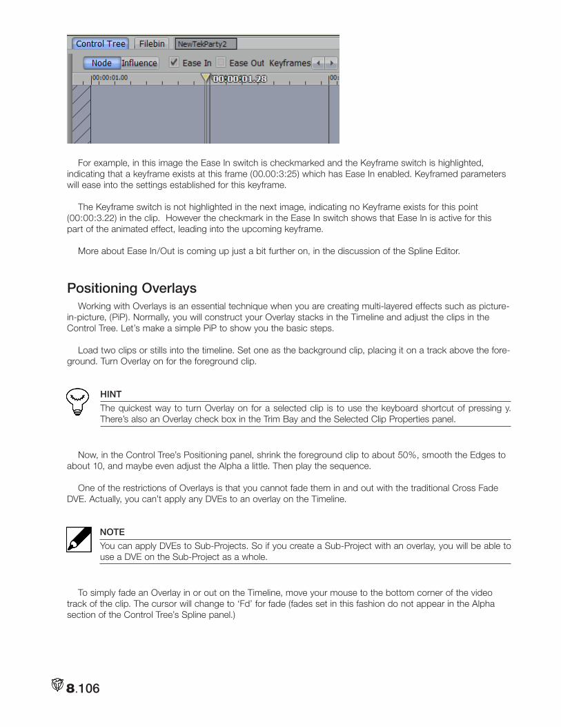
8.106
For example, in this image the Ease In switch is checkmarked and the Keyframe switch is highlighted, indicating that a keyframe exists at this frame (00.00:3:25) which has Ease In enabled. Keyframed parameters will ease into the settings established for this keyframe.
The Keyframe switch is not highlighted in the next image, indicating no Keyframe exists for this point (00:00:3.22) in the clip. However the checkmark in the Ease In switch shows that Ease In is active for this part of the animated effect, leading into the upcoming keyframe.
More about Ease In/Out is coming up just a bit further on, in the discussion of the Spline Editor.
Positioning OverlaysWorking with Overlays is an essential technique when you are creating multi-layered effects such as picture-
in-picture, (PiP). Normally, you will construct your Overlay stacks in the Timeline and adjust the clips in the Control Tree. Let’s make a simple PiP to show you the basic steps.
Load two clips or stills into the timeline. Set one as the background clip, placing it on a track above the fore-ground. Turn Overlay on for the foreground clip.
HINT
The quickest way to turn Overlay on for a selected clip is to use the keyboard shortcut of pressing y. There’s also an Overlay check box in the Trim Bay and the Selected Clip Properties panel.
Now, in the Control Tree’s Positioning panel, shrink the foreground clip to about 50%, smooth the Edges to about 10, and maybe even adjust the Alpha a little. Then play the sequence.
One of the restrictions of Overlays is that you cannot fade them in and out with the traditional Cross Fade DVE. Actually, you can’t apply any DVEs to an overlay on the Timeline.
NOTE
You can apply DVEs to Sub-Projects. So if you create a Sub-Project with an overlay, you will be able to use a DVE on the Sub-Project as a whole.
To simply fade an Overlay in or out on the Timeline, move your mouse to the bottom corner of the video track of the clip. The cursor will change to ‘Fd’ for fade (fades set in this fashion do not appear in the Alpha section of the Control Tree’s Spline panel.)
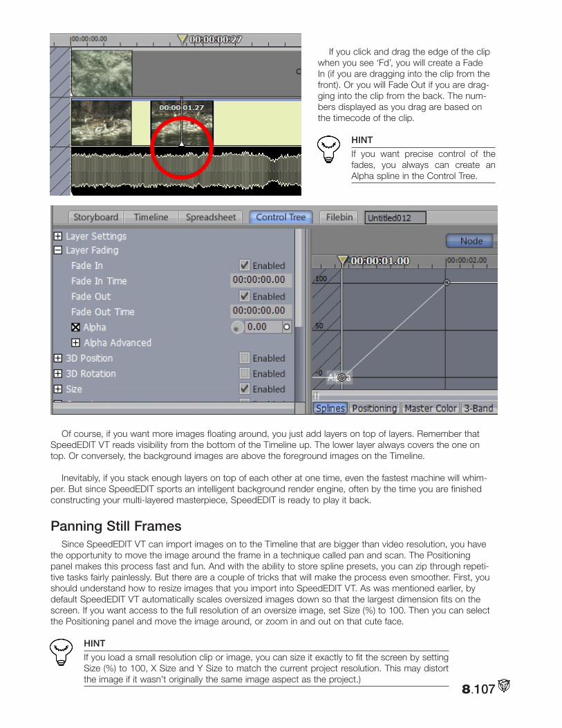
8.107
If you click and drag the edge of the clip when you see ‘Fd’, you will create a Fade In (if you are dragging into the clip from the front). Or you will Fade Out if you are drag-ging into the clip from the back. The num-bers displayed as you drag are based on the timecode of the clip.
HINT
If you want precise control of the fades, you always can create an Alpha spline in the Control Tree.
Of course, if you want more images floating around, you just add layers on top of layers. Remember that SpeedEDIT VT reads visibility from the bottom of the Timeline up. The lower layer always covers the one on top. Or conversely, the background images are above the foreground images on the Timeline.
Inevitably, if you stack enough layers on top of each other at one time, even the fastest machine will whim-per. But since SpeedEDIT sports an intelligent background render engine, often by the time you are finished constructing your multi-layered masterpiece, SpeedEDIT is ready to play it back.
Panning Still FramesSince SpeedEDIT VT can import images on to the Timeline that are bigger than video resolution, you have
the opportunity to move the image around the frame in a technique called pan and scan. The Positioning panel makes this process fast and fun. And with the ability to store spline presets, you can zip through repeti-tive tasks fairly painlessly. But there are a couple of tricks that will make the process even smoother. First, you should understand how to resize images that you import into SpeedEDIT VT. As was mentioned earlier, by default SpeedEDIT VT automatically scales oversized images down so that the largest dimension fits on the screen. If you want access to the full resolution of an oversize image, set Size (%) to 100. Then you can select the Positioning panel and move the image around, or zoom in and out on that cute face.
HINT
If you load a small resolution clip or image, you can size it exactly to fit the screen by setting Size (%) to 100, X Size and Y Size to match the current project resolution. This may distort the image if it wasn’t originally the same image aspect as the project.)
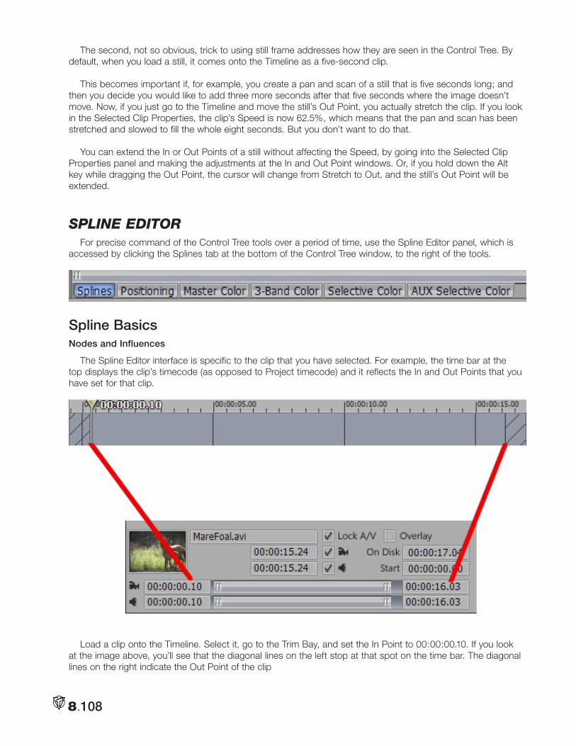
8.108
The second, not so obvious, trick to using still frame addresses how they are seen in the Control Tree. By default, when you load a still, it comes onto the Timeline as a five-second clip.
This becomes important if, for example, you create a pan and scan of a still that is five seconds long; and then you decide you would like to add three more seconds after that five seconds where the image doesn’t move. Now, if you just go to the Timeline and move the still’s Out Point, you actually stretch the clip. If you look in the Selected Clip Properties, the clip’s Speed is now 62.5%, which means that the pan and scan has been stretched and slowed to fill the whole eight seconds. But you don’t want to do that.
You can extend the In or Out Points of a still without affecting the Speed, by going into the Selected Clip Properties panel and making the adjustments at the In and Out Point windows. Or, if you hold down the Alt key while dragging the Out Point, the cursor will change from Stretch to Out, and the still’s Out Point will be extended.
Spline editoRFor precise command of the Control Tree tools over a period of time, use the Spline Editor panel, which is
accessed by clicking the Splines tab at the bottom of the Control Tree window, to the right of the tools.
Spline BasicsNodes and Influences
The Spline Editor interface is specific to the clip that you have selected. For example, the time bar at the top displays the clip’s timecode (as opposed to Project timecode) and it reflects the In and Out Points that you have set for that clip.
Load a clip onto the Timeline. Select it, go to the Trim Bay, and set the In Point to 00:00:00.10. If you look at the image above, you’ll see that the diagonal lines on the left stop at that spot on the time bar. The diagonal lines on the right indicate the Out Point of the clip
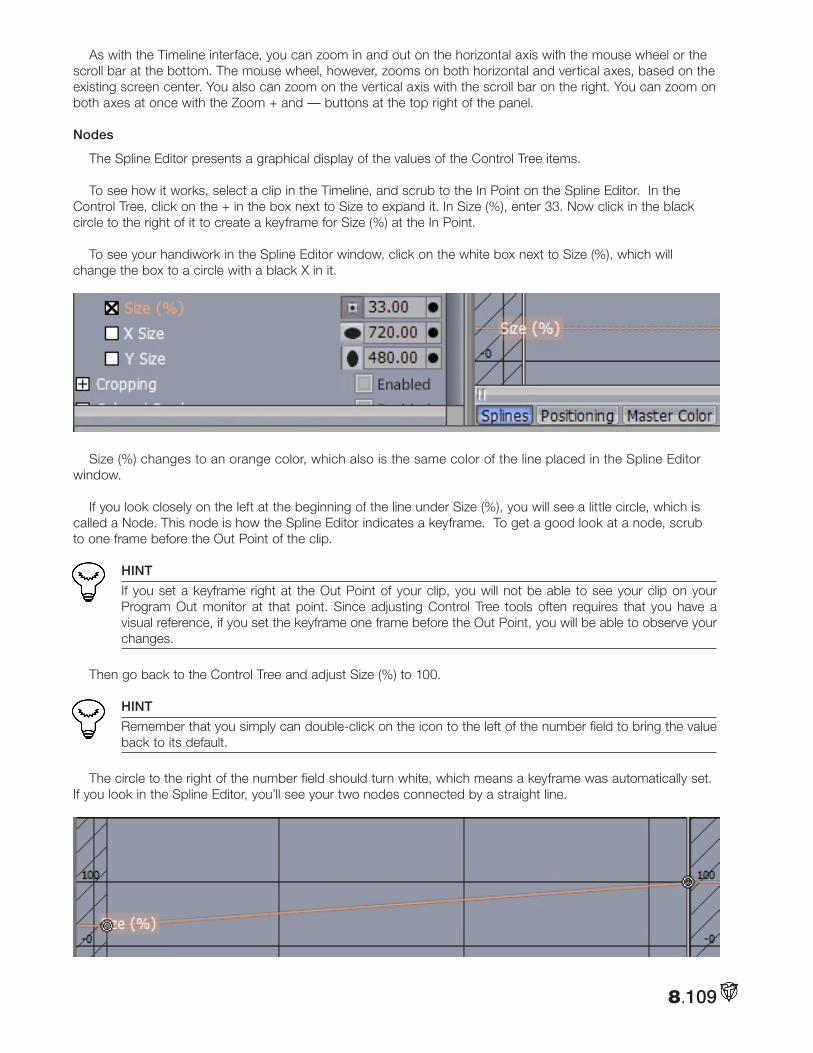
8.109
As with the Timeline interface, you can zoom in and out on the horizontal axis with the mouse wheel or the scroll bar at the bottom. The mouse wheel, however, zooms on both horizontal and vertical axes, based on the existing screen center. You also can zoom on the vertical axis with the scroll bar on the right. You can zoom on both axes at once with the Zoom + and — buttons at the top right of the panel.
Nodes
The Spline Editor presents a graphical display of the values of the Control Tree items.
To see how it works, select a clip in the Timeline, and scrub to the In Point on the Spline Editor. In the Control Tree, click on the + in the box next to Size to expand it. In Size (%), enter 33. Now click in the black circle to the right of it to create a keyframe for Size (%) at the In Point.
To see your handiwork in the Spline Editor window, click on the white box next to Size (%), which will change the box to a circle with a black X in it.
Size (%) changes to an orange color, which also is the same color of the line placed in the Spline Editor window.
If you look closely on the left at the beginning of the line under Size (%), you will see a little circle, which is called a Node. This node is how the Spline Editor indicates a keyframe. To get a good look at a node, scrub to one frame before the Out Point of the clip.
HINT
If you set a keyframe right at the Out Point of your clip, you will not be able to see your clip on your Program Out monitor at that point. Since adjusting Control Tree tools often requires that you have a visual reference, if you set the keyframe one frame before the Out Point, you will be able to observe your changes.
Then go back to the Control Tree and adjust Size (%) to 100.
HINT
Remember that you simply can double-click on the icon to the left of the number field to bring the value back to its default.
The circle to the right of the number field should turn white, which means a keyframe was automatically set. If you look in the Spline Editor, you’ll see your two nodes connected by a straight line.
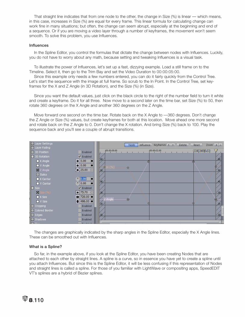
8.110
That straight line indicates that from one node to the other, the change in Size (%) is linear — which means, in this case, increases in Size (%) are equal for every frame. This linear formula for calculating change can work fine in many situations; but often, the change can seem abrupt, especially at the beginning and end of a sequence. Or if you are moving a video layer through a number of keyframes, the movement won’t seem smooth. To solve this problem, you use Influences.
Influences
In the Spline Editor, you control the formulas that dictate the change between nodes with Influences. Luckily, you do not have to worry about any math, because setting and tweaking Influences is a visual task.
To illustrate the power of Influences, let’s set up a fast, dizzying example. Load a still frame on to the Timeline. Select it, then go to the Trim Bay and set the Video Duration to 00:00:05:00.
Since this example only needs a few numbers entered, you can do it fairly quickly from the Control Tree. Let’s start the sequence with the image at full frame. So scrub to the In Point. In the Control Tree, set key-frames for the X and Z Angle (in 3D Rotation), and the Size (%) (in Size).
Since you want the default values, just click on the black circle to the right of the number field to turn it white and create a keyframe. Do it for all three. Now move to a second later on the time bar, set Size (%) to 50, then rotate 360 degrees on the X Angle and another 360 degrees on the Z Angle.
Move forward one second on the time bar. Rotate back on the X Angle to —360 degrees. Don’t change the Z Angle or Size (%) values, but create keyframes for both at this location. Move ahead one more second and rotate back on the Z Angle to 0. Don’t change the X rotation. And bring Size (%) back to 100. Play the sequence back and you’ll see a couple of abrupt transitions.
The changes are graphically indicated by the sharp angles in the Spline Editor, especially the X Angle lines. These can be smoothed out with Influences.
What is a Spline?
So far, in the example above, if you look at the Spline Editor, you have been creating Nodes that are attached to each other by straight lines. A spline is a curve, so in essence you have yet to create a spline until you attach Influences. But since this is the Spline Editor, it will be less confusing if this representation of Nodes and straight lines is called a spline. For those of you familiar with LightWave or compositing apps, SpeedEDIT VT’s splines are a hybrid of Bezier splines.
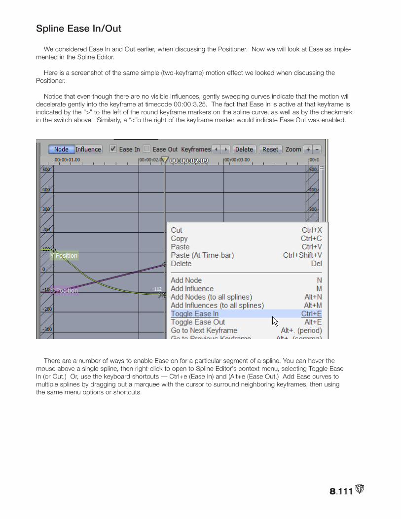
8.111
Spline Ease In/Out
We considered Ease In and Out earlier, when discussing the Positioner. Now we will look at Ease as imple-mented in the Spline Editor.
Here is a screenshot of the same simple (two-keyframe) motion effect we looked when discussing the Positioner.
Notice that even though there are no visible Influences, gently sweeping curves indicate that the motion will decelerate gently into the keyframe at timecode 00:00:3.25. The fact that Ease In is active at that keyframe is indicated by the “>” to the left of the round keyframe markers on the spline curve, as well as by the checkmark in the switch above. Similarly, a “<”o the right of the keyframe marker would indicate Ease Out was enabled.
There are a number of ways to enable Ease on for a particular segment of a spline. You can hover the mouse above a single spline, then right-click to open to Spline Editor’s context menu, selecting Toggle Ease In (or Out.) Or, use the keyboard shortcuts — Ctrl+e (Ease In) and (Alt+e (Ease Out.) Add Ease curves to multiple splines by dragging out a marquee with the cursor to surround neighboring keyframes, then using the same menu options or shortcuts.
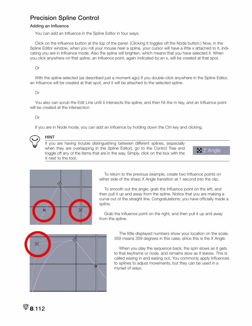
8.112
Precision Spline ControlAdding an Influence
You can add an Influence in the Spline Editor in four ways.
Click on the Influence button at the top of the panel. (Clicking it toggles off the Node button.) Now, in the Spline Editor window, when you roll your mouse near a spline, your cursor will have a little x attached to it, indi-cating you are in Influence mode. Also the spline will brighten, which means that you have selected it. When you click anywhere on that spline, an Influence point, again indicated by an x, will be created at that spot.
Or
With the spline selected (as described just a moment ago) if you double-click anywhere in the Spline Editor, an Influence will be created at that spot, and it will be attached to the selected spline.
Or
You also can scrub the Edit Line until it intersects the spline, and then hit the m key, and an Influence point will be created at the intersection.
Or
If you are in Node mode, you can add an Influence by holding down the Ctrl key and clicking.
HINT
If you are having trouble distinguishing between different splines, (especially when they are overlapping in the Spline Editor), go to the Control Tree and toggle off any of the items that are in the way. Simply, click on the box with the X next to the tool.
To return to the previous example, create two Influence points on
either side of the sharp X Angle transition at 1 second into the clip.
To smooth out the angle, grab the Influence point on the left, and then pull it up and away from the spline. Notice that you are making a curve out of the straight line. Congratulations, you have officially made a spline.
Grab the Influence point on the right, and then pull it up and away from the spline.
The little displayed numbers show your location on the scale. 359 means 359 degrees in this case, since this is the X Angle.
When you play the sequence back, the spin slows as it gets to that keyframe or node, and remains slow as it leaves. This is called easing in and easing out. You commonly apply Influences to splines to adjust movements, but they can be used in a myriad of ways.
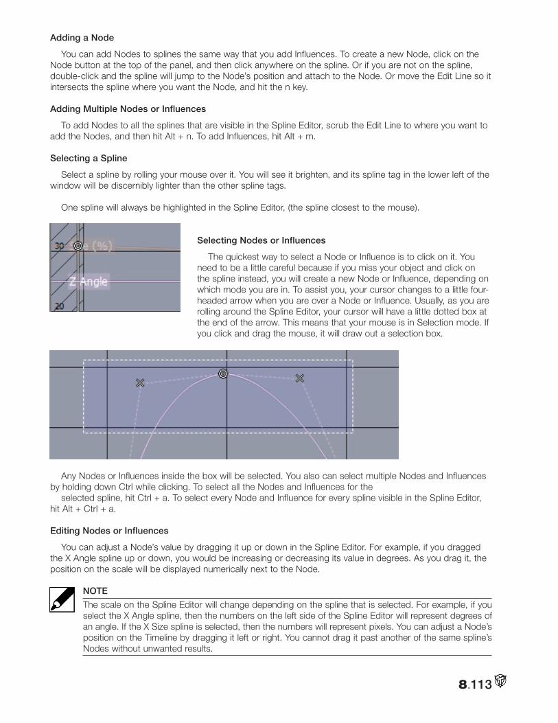
8.113
Adding a Node
You can add Nodes to splines the same way that you add Influences. To create a new Node, click on the Node button at the top of the panel, and then click anywhere on the spline. Or if you are not on the spline, double-click and the spline will jump to the Node’s position and attach to the Node. Or move the Edit Line so it intersects the spline where you want the Node, and hit the n key.
Adding Multiple Nodes or Influences
To add Nodes to all the splines that are visible in the Spline Editor, scrub the Edit Line to where you want to add the Nodes, and then hit Alt + n. To add Influences, hit Alt + m.
Selecting a Spline
Select a spline by rolling your mouse over it. You will see it brighten, and its spline tag in the lower left of the window will be discernibly lighter than the other spline tags.
One spline will always be highlighted in the Spline Editor, (the spline closest to the mouse).
Selecting Nodes or Influences
The quickest way to select a Node or Influence is to click on it. You need to be a little careful because if you miss your object and click on the spline instead, you will create a new Node or Influence, depending on which mode you are in. To assist you, your cursor changes to a little four-headed arrow when you are over a Node or Influence. Usually, as you are rolling around the Spline Editor, your cursor will have a little dotted box at the end of the arrow. This means that your mouse is in Selection mode. If you click and drag the mouse, it will draw out a selection box.
Any Nodes or Influences inside the box will be selected. You also can select multiple Nodes and Influences by holding down Ctrl while clicking. To select all the Nodes and Influences for the
selected spline, hit Ctrl + a. To select every Node and Influence for every spline visible in the Spline Editor, hit Alt + Ctrl + a.
Editing Nodes or Influences
You can adjust a Node’s value by dragging it up or down in the Spline Editor. For example, if you dragged the X Angle spline up or down, you would be increasing or decreasing its value in degrees. As you drag it, the position on the scale will be displayed numerically next to the Node.
NOTE
The scale on the Spline Editor will change depending on the spline that is selected. For example, if you select the X Angle spline, then the numbers on the left side of the Spline Editor will represent degrees of an angle. If the X Size spline is selected, then the numbers will represent pixels. You can adjust a Node’s position on the Timeline by dragging it left or right. You cannot drag it past another of the same spline’s Nodes without unwanted results.
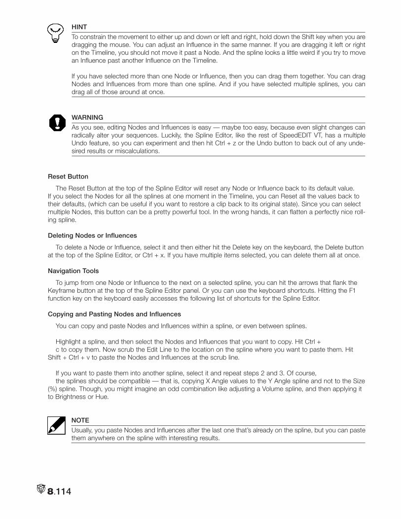
8.114
HINT
To constrain the movement to either up and down or left and right, hold down the Shift key when you are dragging the mouse. You can adjust an Influence in the same manner. If you are dragging it left or right on the Timeline, you should not move it past a Node. And the spline looks a little weird if you try to move an Influence past another Influence on the Timeline. If you have selected more than one Node or Influence, then you can drag them together. You can drag Nodes and Influences from more than one spline. And if you have selected multiple splines, you can drag all of those around at once.
WARNING
As you see, editing Nodes and Influences is easy — maybe too easy, because even slight changes can radically alter your sequences. Luckily, the Spline Editor, like the rest of SpeedEDIT VT, has a multiple Undo feature, so you can experiment and then hit Ctrl + z or the Undo button to back out of any unde-sired results or miscalculations.
Reset Button
The Reset Button at the top of the Spline Editor will reset any Node or Influence back to its default value. If you select the Nodes for all the splines at one moment in the Timeline, you can Reset all the values back to their defaults, (which can be useful if you want to restore a clip back to its original state). Since you can select multiple Nodes, this button can be a pretty powerful tool. In the wrong hands, it can flatten a perfectly nice roll-ing spline.
Deleting Nodes or Influences
To delete a Node or Influence, select it and then either hit the Delete key on the keyboard, the Delete button at the top of the Spline Editor, or Ctrl + x. If you have multiple items selected, you can delete them all at once.
Navigation Tools
To jump from one Node or Influence to the next on a selected spline, you can hit the arrows that flank the Keyframe button at the top of the Spline Editor panel. Or you can use the keyboard shortcuts. Hitting the F1 function key on the keyboard easily accesses the following list of shortcuts for the Spline Editor.
Copying and Pasting Nodes and Influences
You can copy and paste Nodes and Influences within a spline, or even between splines.
Highlight a spline, and then select the Nodes and Influences that you want to copy. Hit Ctrl +c to copy them. Now scrub the Edit Line to the location on the spline where you want to paste them. Hit
Shift + Ctrl + v to paste the Nodes and Influences at the scrub line.
If you want to paste them into another spline, select it and repeat steps 2 and 3. Of course,the splines should be compatible — that is, copying X Angle values to the Y Angle spline and not to the Size
(%) spline. Though, you might imagine an odd combination like adjusting a Volume spline, and then applying it to Brightness or Hue.
NOTE
Usually, you paste Nodes and Influences after the last one that’s already on the spline, but you can paste them anywhere on the spline with interesting results.
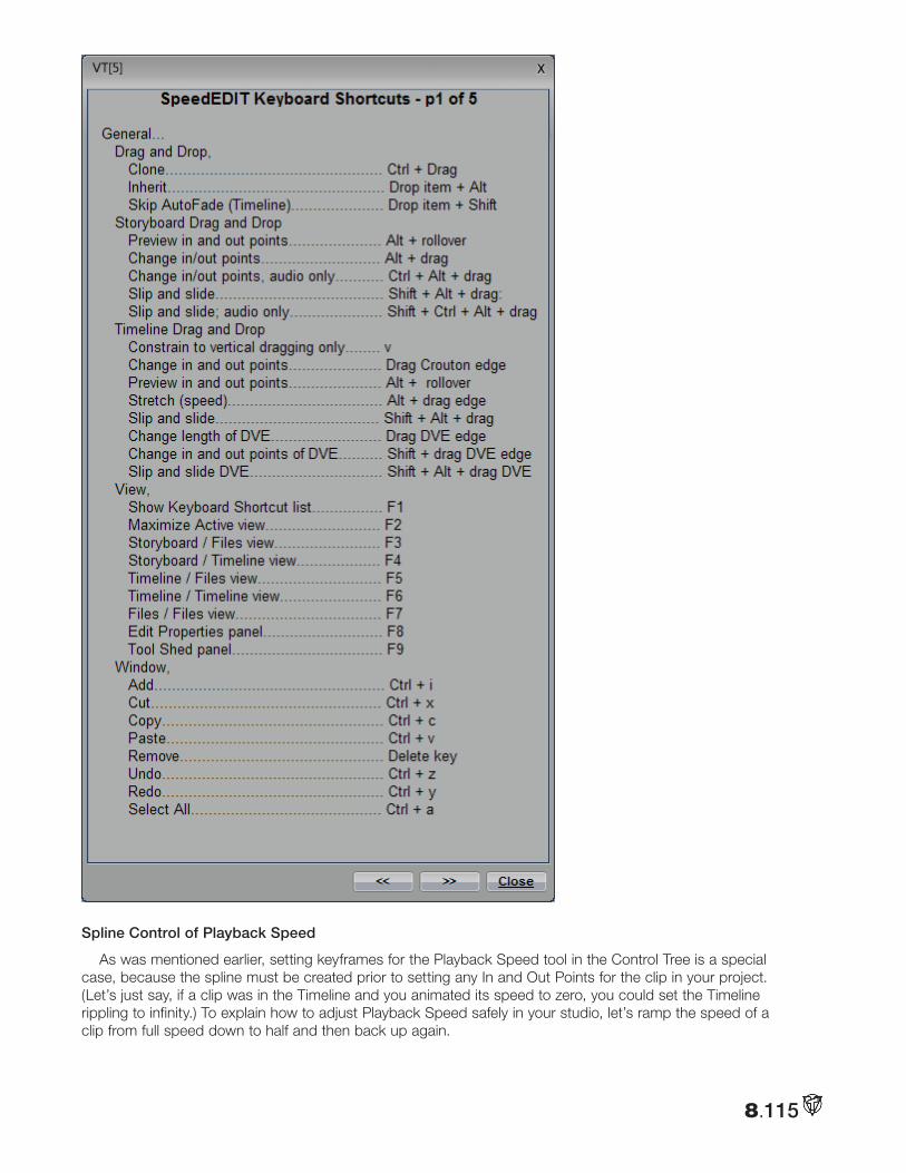
8.115
Spline Control of Playback Speed
As was mentioned earlier, setting keyframes for the Playback Speed tool in the Control Tree is a special case, because the spline must be created prior to setting any In and Out Points for the clip in your project. (Let’s just say, if a clip was in the Timeline and you animated its speed to zero, you could set the Timeline rippling to infinity.) To explain how to adjust Playback Speed safely in your studio, let’s ramp the speed of a clip from full speed down to half and then back up again.
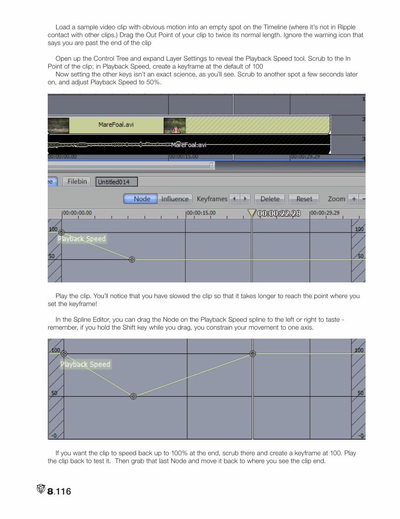
8.116
Load a sample video clip with obvious motion into an empty spot on the Timeline (where it’s not in Ripple contact with other clips.) Drag the Out Point of your clip to twice its normal length. Ignore the warning icon that says you are past the end of the clip
Open up the Control Tree and expand Layer Settings to reveal the Playback Speed tool. Scrub to the In Point of the clip; in Playback Speed, create a keyframe at the default of 100
Now setting the other keys isn’t an exact science, as you’ll see. Scrub to another spot a few seconds later on, and adjust Playback Speed to 50%.
Play the clip. You’ll notice that you have slowed the clip so that it takes longer to reach the point where you set the keyframe!
In the Spline Editor, you can drag the Node on the Playback Speed spline to the left or right to taste - remember, if you hold the Shift key while you drag, you constrain your movement to one axis.
If you want the clip to speed back up to 100% at the end, scrub there and create a keyframe at 100. Play the clip back to test it. Then grab that last Node and move it back to where you see the clip end.
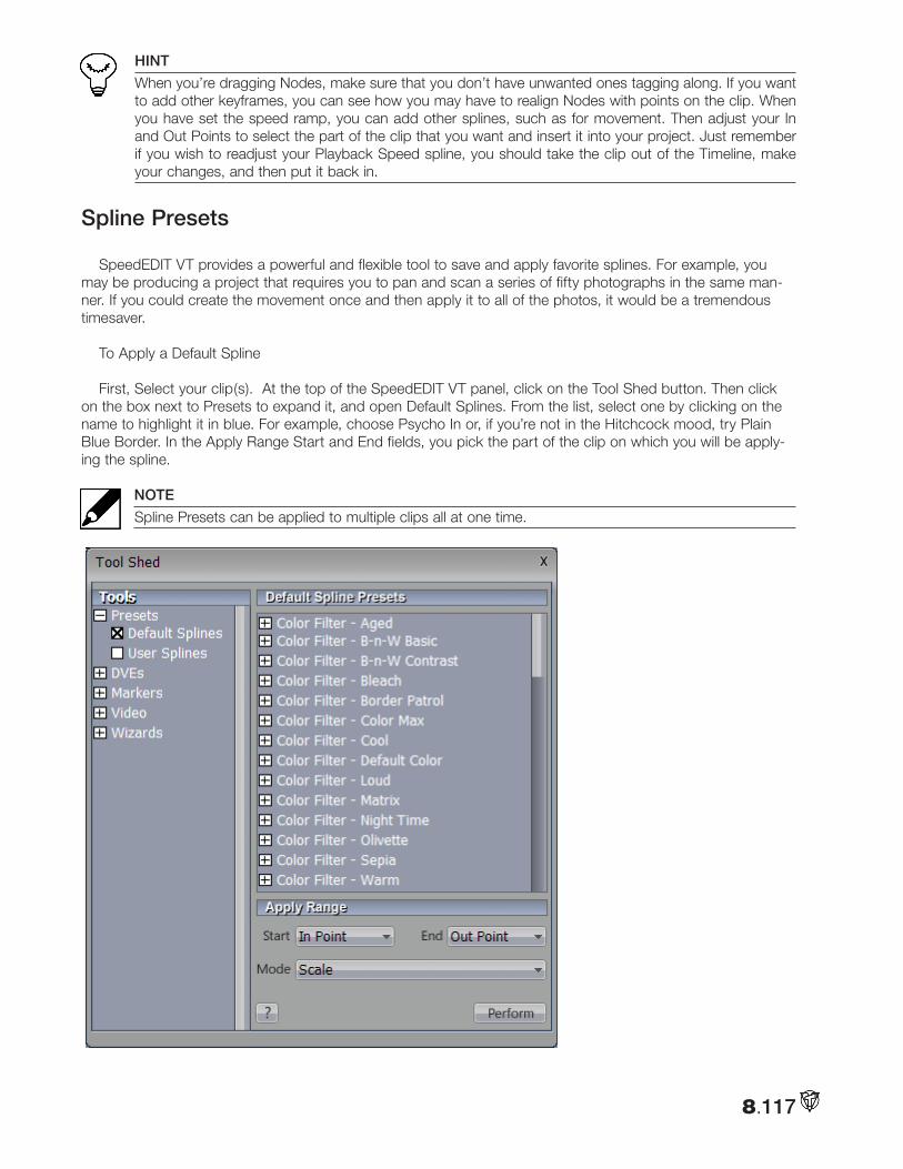
8.117
HINT
When you’re dragging Nodes, make sure that you don’t have unwanted ones tagging along. If you want to add other keyframes, you can see how you may have to realign Nodes with points on the clip. When you have set the speed ramp, you can add other splines, such as for movement. Then adjust your In and Out Points to select the part of the clip that you want and insert it into your project. Just remember if you wish to readjust your Playback Speed spline, you should take the clip out of the Timeline, make your changes, and then put it back in.
Spline Presets
SpeedEDIT VT provides a powerful and flexible tool to save and apply favorite splines. For example, you may be producing a project that requires you to pan and scan a series of fifty photographs in the same man-ner. If you could create the movement once and then apply it to all of the photos, it would be a tremendous timesaver.
To Apply a Default Spline
First, Select your clip(s). At the top of the SpeedEDIT VT panel, click on the Tool Shed button. Then click on the box next to Presets to expand it, and open Default Splines. From the list, select one by clicking on the name to highlight it in blue. For example, choose Psycho In or, if you’re not in the Hitchcock mood, try Plain Blue Border. In the Apply Range Start and End fields, you pick the part of the clip on which you will be apply-ing the spline.
NOTE
Spline Presets can be applied to multiple clips all at one time.
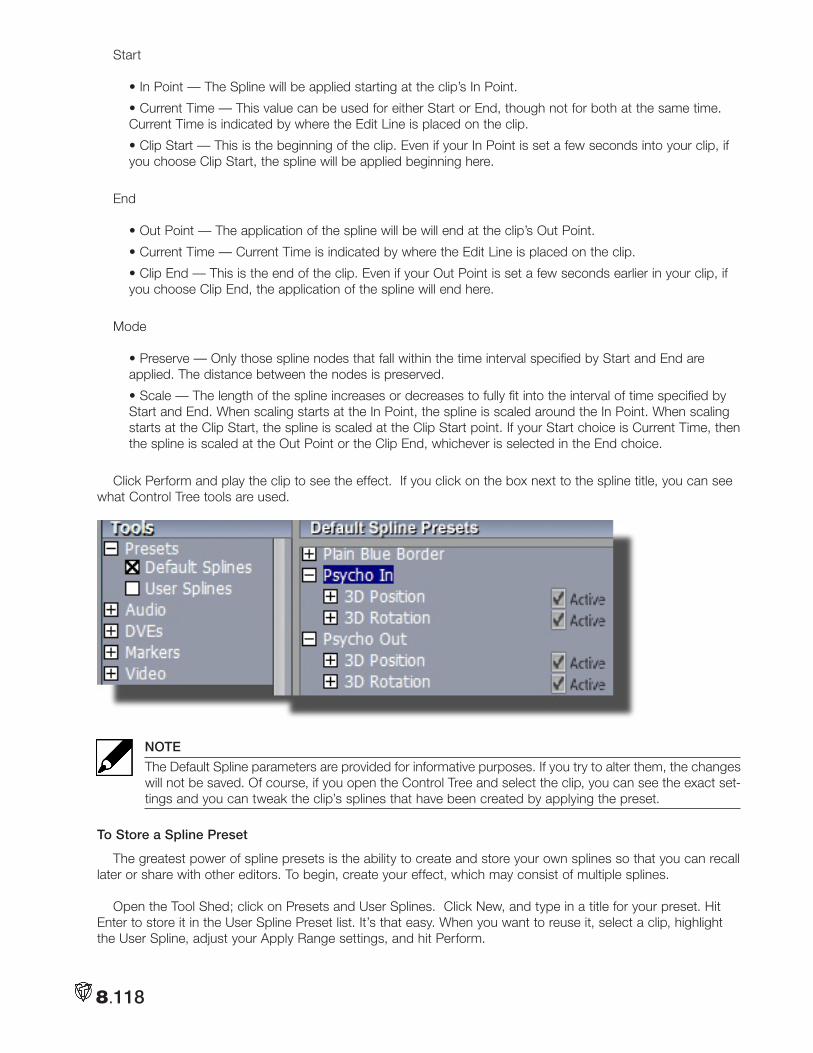
8.118
Start
• In Point — The Spline will be applied starting at the clip’s In Point.
• Current Time — This value can be used for either Start or End, though not for both at the same time. Current Time is indicated by where the Edit Line is placed on the clip.
• Clip Start — This is the beginning of the clip. Even if your In Point is set a few seconds into your clip, if you choose Clip Start, the spline will be applied beginning here.
End
• Out Point — The application of the spline will be will end at the clip’s Out Point.
• Current Time — Current Time is indicated by where the Edit Line is placed on the clip.
• Clip End — This is the end of the clip. Even if your Out Point is set a few seconds earlier in your clip, if you choose Clip End, the application of the spline will end here.
Mode
• Preserve — Only those spline nodes that fall within the time interval specified by Start and End are applied. The distance between the nodes is preserved.
• Scale — The length of the spline increases or decreases to fully fit into the interval of time specified by Start and End. When scaling starts at the In Point, the spline is scaled around the In Point. When scaling starts at the Clip Start, the spline is scaled at the Clip Start point. If your Start choice is Current Time, then the spline is scaled at the Out Point or the Clip End, whichever is selected in the End choice.
Click Perform and play the clip to see the effect. If you click on the box next to the spline title, you can see what Control Tree tools are used.
NOTE
The Default Spline parameters are provided for informative purposes. If you try to alter them, the changes will not be saved. Of course, if you open the Control Tree and select the clip, you can see the exact set-tings and you can tweak the clip’s splines that have been created by applying the preset.
To Store a Spline Preset
The greatest power of spline presets is the ability to create and store your own splines so that you can recall later or share with other editors. To begin, create your effect, which may consist of multiple splines.
Open the Tool Shed; click on Presets and User Splines. Click New, and type in a title for your preset. Hit Enter to store it in the User Spline Preset list. It’s that easy. When you want to reuse it, select a clip, highlight the User Spline, adjust your Apply Range settings, and hit Perform.
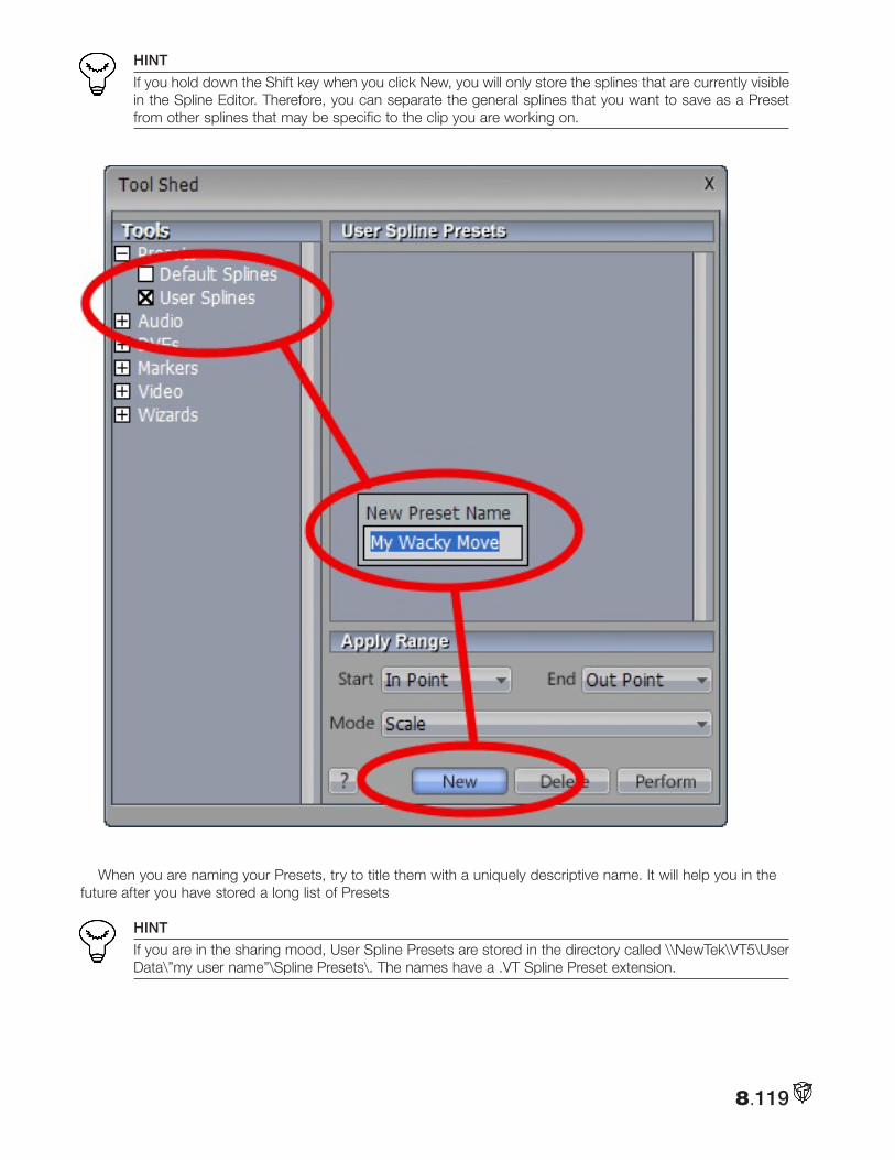
8.119
HINT
If you hold down the Shift key when you click New, you will only store the splines that are currently visible in the Spline Editor. Therefore, you can separate the general splines that you want to save as a Preset from other splines that may be specific to the clip you are working on.
When you are naming your Presets, try to title them with a uniquely descriptive name. It will help you in the future after you have stored a long list of Presets
HINT
If you are in the sharing mood, User Spline Presets are stored in the directory called \\NewTek\VT5\User Data\”my user name”\Spline Presets\. The names have a .VT Spline Preset extension.
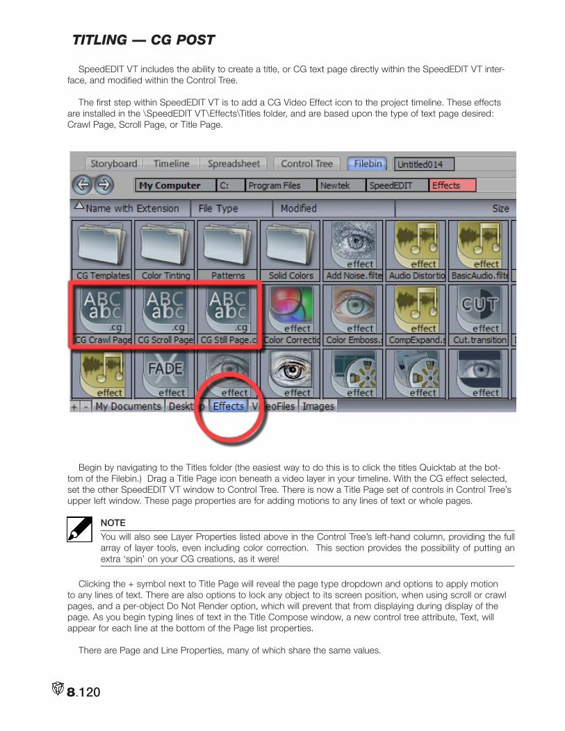
8.120
titling — cg poSt
SpeedEDIT VT includes the ability to create a title, or CG text page directly within the SpeedEDIT VT inter-face, and modified within the Control Tree.
The first step within SpeedEDIT VT is to add a CG Video Effect icon to the project timeline. These effects are installed in the \SpeedEDIT VT\Effects\Titles folder, and are based upon the type of text page desired: Crawl Page, Scroll Page, or Title Page.
Begin by navigating to the Titles folder (the easiest way to do this is to click the titles Quicktab at the bot-tom of the Filebin.) Drag a Title Page icon beneath a video layer in your timeline. With the CG effect selected, set the other SpeedEDIT VT window to Control Tree. There is now a Title Page set of controls in Control Tree’s upper left window. These page properties are for adding motions to any lines of text or whole pages.
NOTE
You will also see Layer Properties listed above in the Control Tree’s left-hand column, providing the full array of layer tools, even including color correction. This section provides the possibility of putting an extra ‘spin’ on your CG creations, as it were!
Clicking the + symbol next to Title Page will reveal the page type dropdown and options to apply motion to any lines of text. There are also options to lock any object to its screen position, when using scroll or crawl pages, and a per-object Do Not Render option, which will prevent that from displaying during display of the page. As you begin typing lines of text in the Title Compose window, a new control tree attribute, Text, will appear for each line at the bottom of the Page list properties.
There are Page and Line Properties, many of which share the same values.
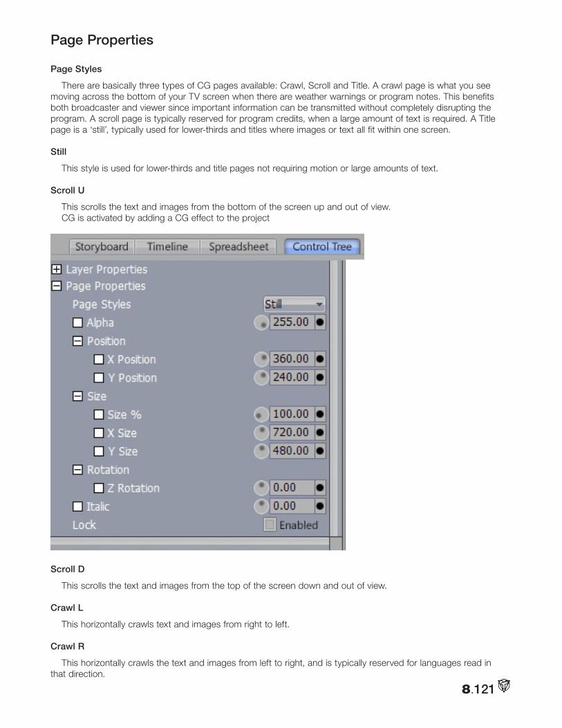
8.121
Page Properties
Page Styles
There are basically three types of CG pages available: Crawl, Scroll and Title. A crawl page is what you see moving across the bottom of your TV screen when there are weather warnings or program notes. This benefits both broadcaster and viewer since important information can be transmitted without completely disrupting the program. A scroll page is typically reserved for program credits, when a large amount of text is required. A Title page is a ‘still’, typically used for lower-thirds and titles where images or text all fit within one screen.
Still
This style is used for lower-thirds and title pages not requiring motion or large amounts of text.
Scroll U
This scrolls the text and images from the bottom of the screen up and out of view.CG is activated by adding a CG effect to the project
Scroll D
This scrolls the text and images from the top of the screen down and out of view.
Crawl L
This horizontally crawls text and images from right to left.
Crawl R
This horizontally crawls the text and images from left to right, and is typically reserved for languages read in that direction.
8.122
Control Tree OptionsPosition
This determines the position on the video screen, and as a Control Tree attribute, can be keyframed with full motion controls. (For more information, see 3D Position) The position is expressed in pixels starting from the upper left corner of the screen.
X Position
X Position moves the page horizontally across the screen. Dialing the spinner counter-clockwise, or reduc-ing the numeric value moves the text to the left. Dialing the spinner clockwise, or increasing the numeric value moves the page to the right.
Y Position
Y Position moves the page vertically across the screen. Dialing the spinner counter-clockwise, or reducing the numeric value moves the text up. Dialing the spinner clockwise, or increasing the numeric value moves the page down.
SizeThis determines the height of the page. This is measured in pixels.
Size %
Size% is a quick way to re-size pages, based on its existing size.
NOTE
As Size% is a value relative to the current object size, useable values are generally above 50. Entering a negative value will flip the page’s X and Y orientation.
X Size
X Size constrains the change of the page size to the horizontal, or X axis.
Y Size
Y Size constrains the change of the page size to the vertical, or Y axis.
RotationZ Rotation
Z Rotation determines the object rotation on a line extending through the object and into the distance. The center of rotation is based on the object’s center.
ItalicItalic will modify the slant of the page to the left or right, based on the page center. Dialing the spinner
clockwise or increasing the numeric value causes the entire page to slant to the right. Dialing the spinner coun-ter-clockwise or decreasing the numeric value causes the page to slant to the left.
LockWhen Lock is checked, the item that is selected will remain stationary, which is helpful when working with
Motion Pages.
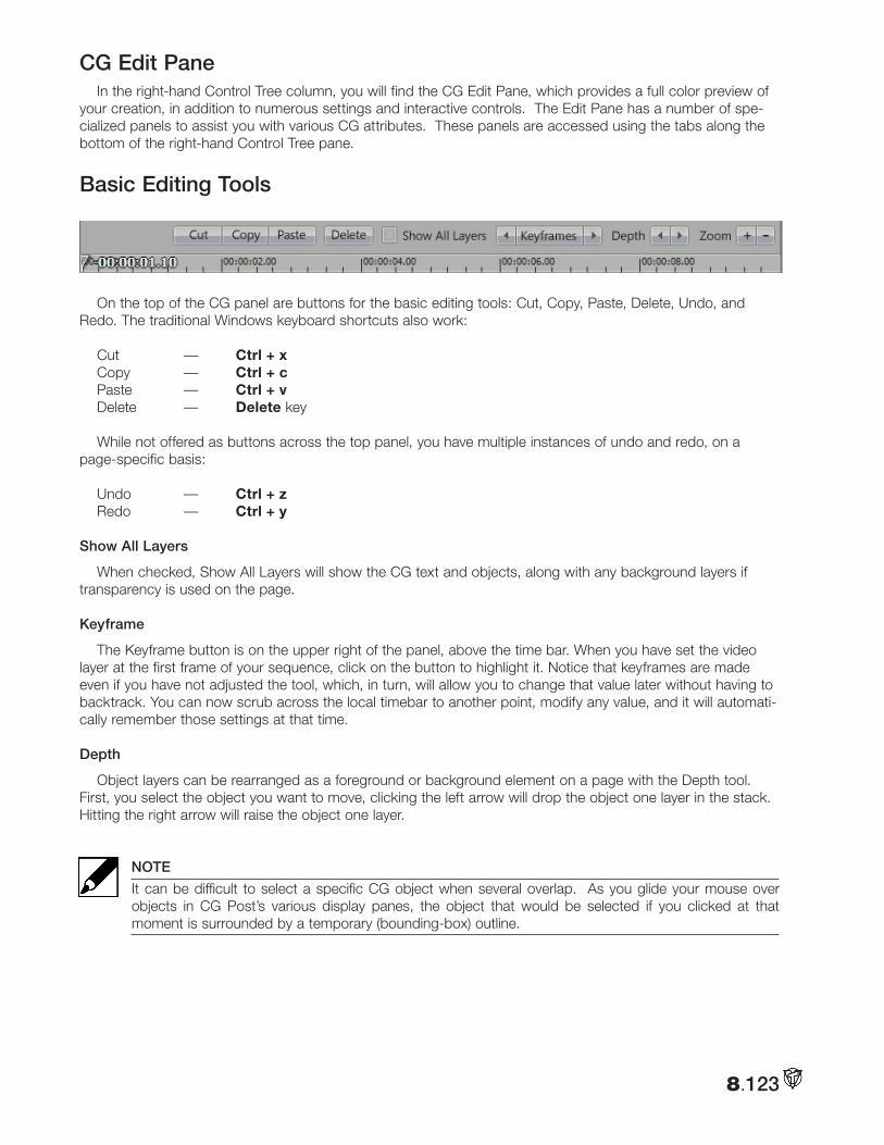
8.123
CG Edit PaneIn the right-hand Control Tree column, you will find the CG Edit Pane, which provides a full color preview of
your creation, in addition to numerous settings and interactive controls. The Edit Pane has a number of spe-cialized panels to assist you with various CG attributes. These panels are accessed using the tabs along the bottom of the right-hand Control Tree pane.
Basic Editing Tools
On the top of the CG panel are buttons for the basic editing tools: Cut, Copy, Paste, Delete, Undo, and Redo. The traditional Windows keyboard shortcuts also work:
Cut — Ctrl + xCopy — Ctrl + cPaste — Ctrl + vDelete — Delete key
While not offered as buttons across the top panel, you have multiple instances of undo and redo, on a page-specific basis:
Undo — Ctrl + zRedo — Ctrl + y
Show All Layers
When checked, Show All Layers will show the CG text and objects, along with any background layers if transparency is used on the page.
Keyframe
The Keyframe button is on the upper right of the panel, above the time bar. When you have set the video layer at the first frame of your sequence, click on the button to highlight it. Notice that keyframes are made even if you have not adjusted the tool, which, in turn, will allow you to change that value later without having to backtrack. You can now scrub across the local timebar to another point, modify any value, and it will automati-cally remember those settings at that time.
Depth
Object layers can be rearranged as a foreground or background element on a page with the Depth tool. First, you select the object you want to move, clicking the left arrow will drop the object one layer in the stack. Hitting the right arrow will raise the object one layer.
NOTE
It can be difficult to select a specific CG object when several overlap. As you glide your mouse over objects in CG Post’s various display panes, the object that would be selected if you clicked at that moment is surrounded by a temporary (bounding-box) outline.
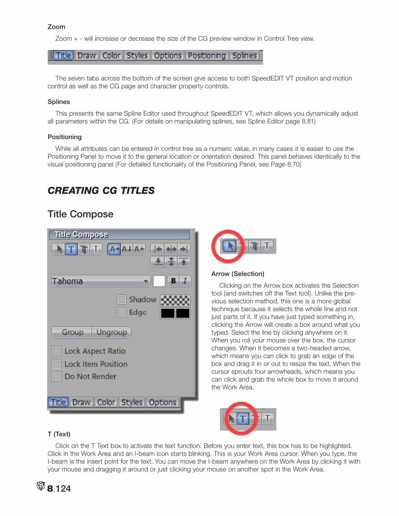
8.124
Zoom
Zoom + - will increase or decrease the size of the CG preview window in Control Tree view.
The seven tabs across the bottom of the screen give access to both SpeedEDIT VT position and motion control as well as the CG page and character property controls.
Splines
This presents the same Spline Editor used throughout SpeedEDIT VT, which allows you dynamically adjust all parameters within the CG. (For details on manipulating splines, see Spline Editor page 8.81)
Positioning
While all attributes can be entered in control tree as a numeric value, in many cases it is easier to use the Positioning Panel to move it to the general location or orientation desired. This panel behaves identically to the visual positioning panel (For detailed functionality of the Positioning Panel, see Page 8.70)
cReating cg titleS
Title Compose
Arrow (Selection)
Clicking on the Arrow box activates the Selection tool (and switches off the Text tool). Unlike the pre-vious selection method, this one is a more global technique because it selects the whole line and not just parts of it. If you have just typed something in, clicking the Arrow will create a box around what you typed. Select the line by clicking anywhere on it. When you roll your mouse over the box, the cursor changes. When it becomes a two-headed arrow, which means you can click to grab an edge of the box and drag it in or out to resize the text. When the cursor sprouts four arrowheads, which means you can click and grab the whole box to move it around the Work Area.
T (Text)
Click on the T Text box to activate the text function. Before you enter text, this box has to be highlighted. Click in the Work Area and an I-beam icon starts blinking. This is your Work Area cursor. When you type, the I-beam is the insert point for the text. You can move the I-beam anywhere on the Work Area by clicking it with your mouse and dragging it around or just clicking your mouse on another spot in the Work Area.
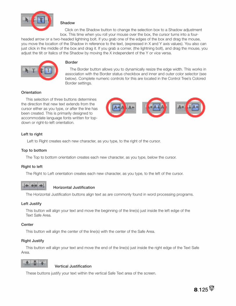
8.125
Shadow
Click on the Shadow button to change the selection box to a Shadow adjustment box. This time when you roll your mouse over the box, the cursor turns into a four-
headed arrow or a two-headed lightning bolt. If you grab one of the edges of the box and drag the mouse, you move the location of the Shadow in reference to the text, (expressed in X and Y axis values). You also can just click in the middle of the box and drag it. If you grab a corner, (the lightning bolt), and drag the mouse, you adjust the tilt or Italics of the Shadow by moving the X independent of the Y or vice versa.
Border
The Border button allows you to dynamically resize the edge width. This works in association with the Border status checkbox and inner and outer color selector (see below). Complete numeric controls for this are located in the Control Tree’s Colored Border settings.
Orientation
This selection of three buttons determines the direction that new text extends from the cursor either as you type, or after the line has been created. This is primarily designed to accommodate language fonts written for top-down or right-to-left orientation.
Left to right
Left to Right creates each new character, as you type, to the right of the cursor.
Top to bottom
The Top to bottom orientation creates each new character, as you type, below the cursor.
Right to left
The Right to Left orientation creates each new character, as you type, to the left of the cursor.
Horizontal Justification
The Horizontal Justification buttons align text as are commonly found in word processing programs.
Left Justify
This button will align your text and move the beginning of the line(s) just inside the left edge of theText Safe Area.
Center
This button will align the center of the line(s) with the center of the Safe Area.
Right Justify
This button will align your text and move the end of the line(s) just inside the right edge of the Text Safe Area.
Vertical Justification
These buttons justify your text within the vertical Safe Text area of the screen.
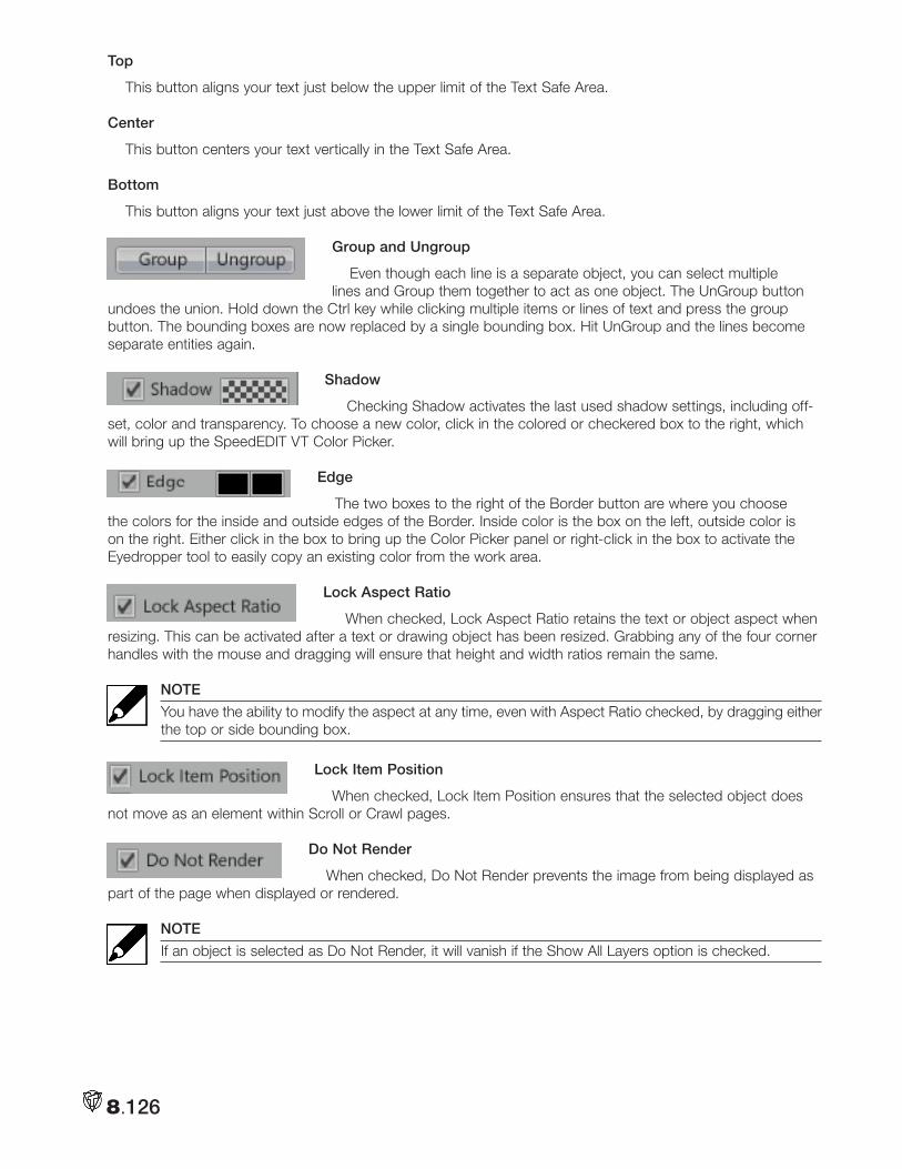
8.126
Top
This button aligns your text just below the upper limit of the Text Safe Area.
Center
This button centers your text vertically in the Text Safe Area.
Bottom
This button aligns your text just above the lower limit of the Text Safe Area.
Group and Ungroup
Even though each line is a separate object, you can select multiple lines and Group them together to act as one object. The UnGroup button
undoes the union. Hold down the Ctrl key while clicking multiple items or lines of text and press the group button. The bounding boxes are now replaced by a single bounding box. Hit UnGroup and the lines become separate entities again.
Shadow
Checking Shadow activates the last used shadow settings, including off-set, color and transparency. To choose a new color, click in the colored or checkered box to the right, which will bring up the SpeedEDIT VT Color Picker.
Edge
The two boxes to the right of the Border button are where you choose the colors for the inside and outside edges of the Border. Inside color is the box on the left, outside color is on the right. Either click in the box to bring up the Color Picker panel or right-click in the box to activate the Eyedropper tool to easily copy an existing color from the work area.
Lock Aspect Ratio
When checked, Lock Aspect Ratio retains the text or object aspect when resizing. This can be activated after a text or drawing object has been resized. Grabbing any of the four corner handles with the mouse and dragging will ensure that height and width ratios remain the same.
NOTE
You have the ability to modify the aspect at any time, even with Aspect Ratio checked, by dragging either the top or side bounding box.
Lock Item Position
When checked, Lock Item Position ensures that the selected object does not move as an element within Scroll or Crawl pages.
Do Not Render
When checked, Do Not Render prevents the image from being displayed as part of the page when displayed or rendered.
NOTE
If an object is selected as Do Not Render, it will vanish if the Show All Layers option is checked.
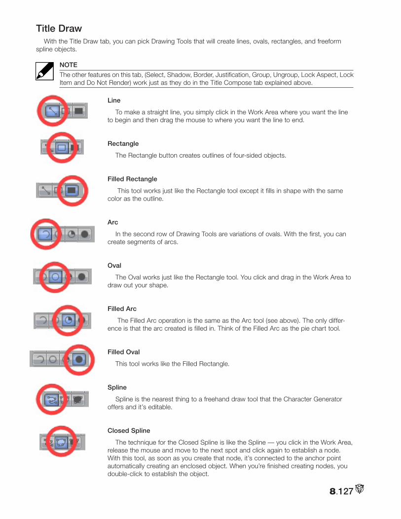
8.127
Title DrawWith the Title Draw tab, you can pick Drawing Tools that will create lines, ovals, rectangles, and freeform
spline objects.
NOTE
The other features on this tab, (Select, Shadow, Border, Justification, Group, Ungroup, Lock Aspect, Lock Item and Do Not Render) work just as they do in the Title Compose tab explained above.
Line
To make a straight line, you simply click in the Work Area where you want the line to begin and then drag the mouse to where you want the line to end.
Rectangle
The Rectangle button creates outlines of four-sided objects.
Filled Rectangle
This tool works just like the Rectangle tool except it fills in shape with the same color as the outline.
Arc
In the second row of Drawing Tools are variations of ovals. With the first, you can create segments of arcs.
Oval
The Oval works just like the Rectangle tool. You click and drag in the Work Area to draw out your shape.
Filled Arc
The Filled Arc operation is the same as the Arc tool (see above). The only differ-ence is that the arc created is filled in. Think of the Filled Arc as the pie chart tool.
Filled Oval
This tool works like the Filled Rectangle.
Spline
Spline is the nearest thing to a freehand draw tool that the Character Generator offers and it’s editable.
Closed Spline
The technique for the Closed Spline is like the Spline — you click in the Work Area, release the mouse and move to the next spot and click again to establish a node. With this tool, as soon as you create that node, it’s connected to the anchor point automatically creating an enclosed object. When you’re finished creating nodes, you double-click to establish the object.
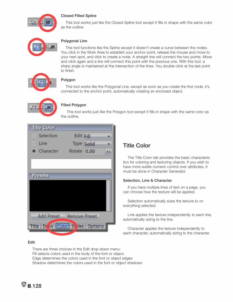
8.128
Closed Filled Spline
This tool works just like the Closed Spline tool except it fills in shape with the same color as the outline.
Polygonal Line
This tool functions like the Spline except it doesn’t create a curve between the nodes. You click in the Work Area to establish your anchor point, release the mouse and move to your next spot, and click to create a node. A straight line will connect the two points. Move and click again and a line will connect this point with the previous one. With this tool, a sharp angle is maintained at the intersection of the lines. You double-click at the last point to finish.
Polygon
This tool works like the Polygonal Line, except as soon as you create the first node, it’s connected to the anchor point, automatically creating an enclosed object.
Filled Polygon
This tool works just like the Polygon tool except it fills in shape with the same color as the outline.
Title Color
The Title Color tab provides the basic characteris-tics for coloring and texturing objects. If you wish to have more subtle numeric control over attributes, it must be done in Character Generator.
Selection, Line & Character
If you have multiple lines of text on a page, you can choose how the texture will be applied.
Selection automatically sizes the texture to on everything selected.
Line applies the texture independently to each line, automatically sizing to the line.
Character applies the texture independently to each character, automatically sizing to the character.
Edit
There are three choices in the Edit drop-down menu: Fill selects colors used in the body of the font or object. Edge determines the colors used in the font or object edgesShadow determines the colors used in the font or object shadows
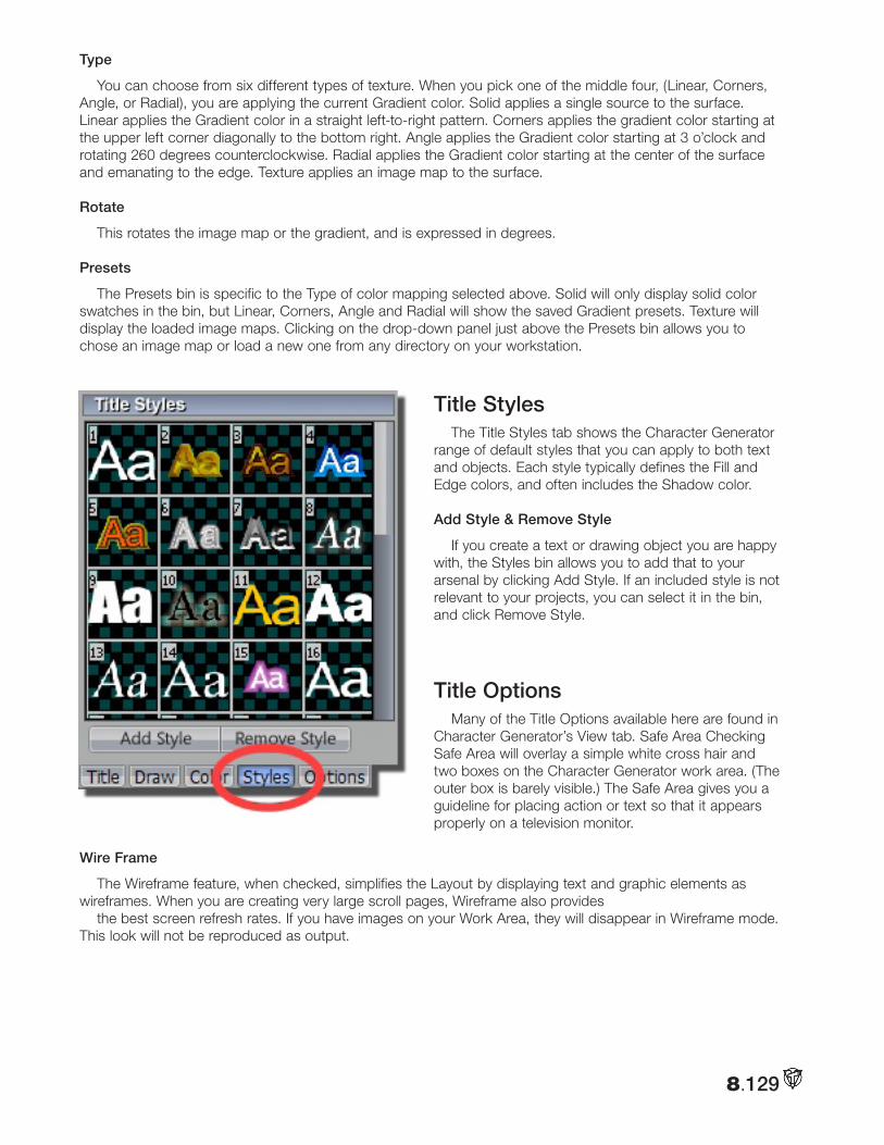
8.129
Type
You can choose from six different types of texture. When you pick one of the middle four, (Linear, Corners, Angle, or Radial), you are applying the current Gradient color. Solid applies a single source to the surface. Linear applies the Gradient color in a straight left-to-right pattern. Corners applies the gradient color starting at the upper left corner diagonally to the bottom right. Angle applies the Gradient color starting at 3 o’clock and rotating 260 degrees counterclockwise. Radial applies the Gradient color starting at the center of the surface and emanating to the edge. Texture applies an image map to the surface.
Rotate
This rotates the image map or the gradient, and is expressed in degrees.
Presets
The Presets bin is specific to the Type of color mapping selected above. Solid will only display solid color swatches in the bin, but Linear, Corners, Angle and Radial will show the saved Gradient presets. Texture will display the loaded image maps. Clicking on the drop-down panel just above the Presets bin allows you to chose an image map or load a new one from any directory on your workstation.
Title StylesThe Title Styles tab shows the Character Generator
range of default styles that you can apply to both text and objects. Each style typically defines the Fill and Edge colors, and often includes the Shadow color.
Add Style & Remove Style
If you create a text or drawing object you are happy with, the Styles bin allows you to add that to your arsenal by clicking Add Style. If an included style is not relevant to your projects, you can select it in the bin, and click Remove Style.
Title OptionsMany of the Title Options available here are found in
Character Generator’s View tab. Safe Area Checking Safe Area will overlay a simple white cross hair and two boxes on the Character Generator work area. (The outer box is barely visible.) The Safe Area gives you a guideline for placing action or text so that it appears properly on a television monitor.
Wire Frame
The Wireframe feature, when checked, simplifies the Layout by displaying text and graphic elements as wireframes. When you are creating very large scroll pages, Wireframe also provides
the best screen refresh rates. If you have images on your Work Area, they will disappear in Wireframe mode. This look will not be reproduced as output.
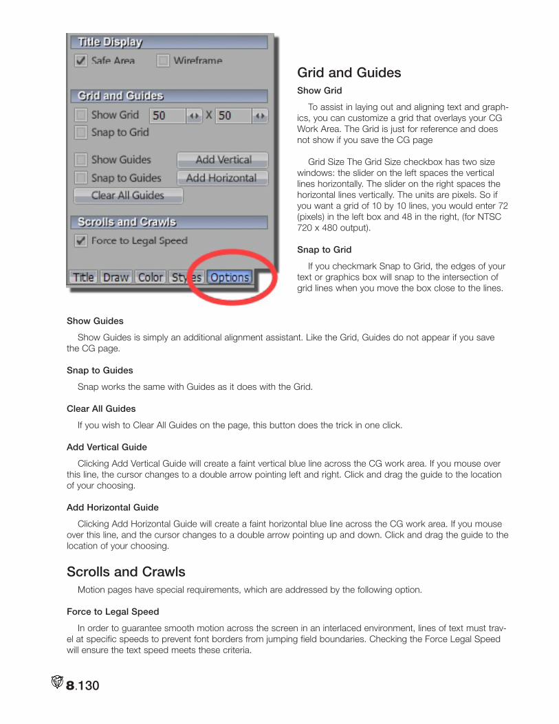
8.130
Grid and GuidesShow Grid
To assist in laying out and aligning text and graph-ics, you can customize a grid that overlays your CG Work Area. The Grid is just for reference and does not show if you save the CG page
Grid Size The Grid Size checkbox has two size windows: the slider on the left spaces the vertical lines horizontally. The slider on the right spaces the horizontal lines vertically. The units are pixels. So if you want a grid of 10 by 10 lines, you would enter 72 (pixels) in the left box and 48 in the right, (for NTSC 720 x 480 output).
Snap to Grid
If you checkmark Snap to Grid, the edges of your text or graphics box will snap to the intersection of grid lines when you move the box close to the lines.
Show Guides
Show Guides is simply an additional alignment assistant. Like the Grid, Guides do not appear if you save the CG page.
Snap to Guides
Snap works the same with Guides as it does with the Grid.
Clear All Guides
If you wish to Clear All Guides on the page, this button does the trick in one click.
Add Vertical Guide
Clicking Add Vertical Guide will create a faint vertical blue line across the CG work area. If you mouse over this line, the cursor changes to a double arrow pointing left and right. Click and drag the guide to the location of your choosing.
Add Horizontal Guide
Clicking Add Horizontal Guide will create a faint horizontal blue line across the CG work area. If you mouse over this line, and the cursor changes to a double arrow pointing up and down. Click and drag the guide to the location of your choosing.
Scrolls and CrawlsMotion pages have special requirements, which are addressed by the following option.
Force to Legal Speed
In order to guarantee smooth motion across the screen in an interlaced environment, lines of text must trav-el at specific speeds to prevent font borders from jumping field boundaries. Checking the Force Legal Speed will ensure the text speed meets these criteria.
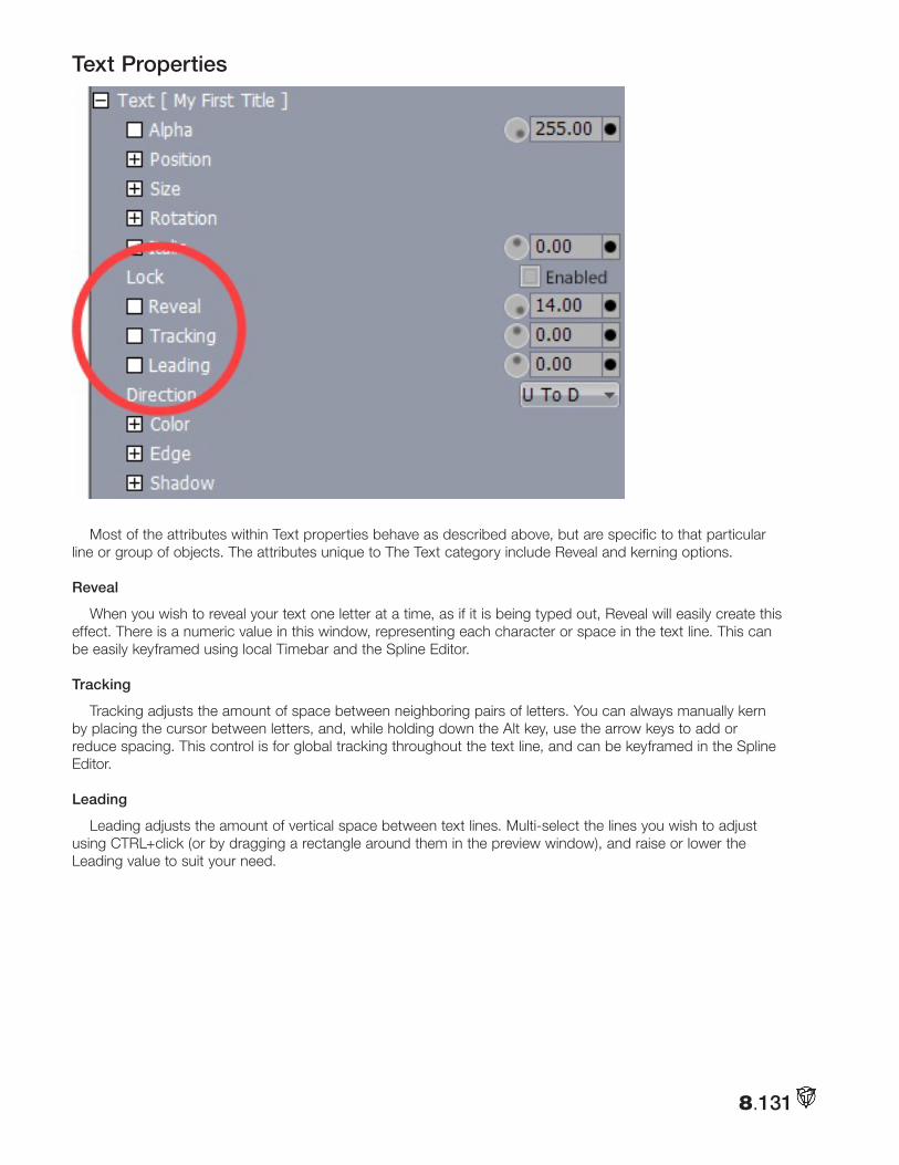
8.131
Text Properties
Most of the attributes within Text properties behave as described above, but are specific to that particular line or group of objects. The attributes unique to The Text category include Reveal and kerning options.
Reveal
When you wish to reveal your text one letter at a time, as if it is being typed out, Reveal will easily create this effect. There is a numeric value in this window, representing each character or space in the text line. This can be easily keyframed using local Timebar and the Spline Editor.
Tracking
Tracking adjusts the amount of space between neighboring pairs of letters. You can always manually kern by placing the cursor between letters, and, while holding down the Alt key, use the arrow keys to add or reduce spacing. This control is for global tracking throughout the text line, and can be keyframed in the Spline Editor.
Leading
Leading adjusts the amount of vertical space between text lines. Multi-select the lines you wish to adjust using CTRL+click (or by dragging a rectangle around them in the preview window), and raise or lower the Leading value to suit your need.
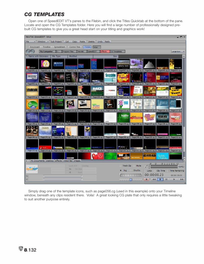
8.132
cg templateSOpen one of SpeedEDIT VT’s panes to the Filebin, and click the Titles Quicktab at the bottom of the pane.
Locate and open the CG Templates folder. Here you will find a large number of professionally designed pre-built CG templates to give you a great head start on your titling and graphics work!
Simply drag one of the template icons, such as page056.cg (used in this example) onto your Timeline window, beneath any clips resident there. Voila! A great looking CG plate that only requires a little tweaking to suit another purpose entirely.
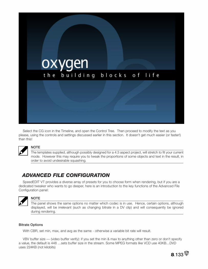
8.133
Select the CG icon in the Timeline, and open the Control Tree. Then proceed to modify the text as you please, using the controls and settings discussed earlier in this section. It doesn’t get much easier (or faster!) than this!
NOTE
The templates supplied, although possibly designed for a 4:3 aspect project, will stretch to fit your current mode. However this may require you to tweak the proportions of some objects and text in the result, in order to avoid undesirable squashing.
adVanced file configuRationSpeedEDIT VT provides a diverse array of presets for you to choose form when rendering, but if you are a
dedicated tweaker who wants to go deeper, here is an introduction to the key functions of the Advanced File Configuration panel:
NOTE
The panel shows the same options no matter which codec is in use. Hence, certain options, although displayed, will be irrelevant (such as changing bitrate in a DV clip) and will consequently be ignored during rendering.
Bitrate Options
With CBR, set min, max, and avg as the same - otherwise a variable bit rate will result.
VBV buffer size — (video buffer verify): if you set the min & max to anything other than zero or don’t specify a value, the default is 448 …sets buffer size in the stream. Some MPEG formats like VCD use 40KB…DVD uses 224KB (not kilobits)
8.134
2-pass — enable or disable two-pass rendering. When enabled, rendering takes noticeably longer, but generally results in greater precision for a given bitrate or filesize.
Intra-fame options turns on or off. The recommendation for NTSC DVD files is 15, for PAL use 12 HDV vari-ously uses 15 or 16.
Max B-frames is the number of consecutive b-frames that appear between non b-frames. 2 is the most common setting (DVD , HDV). The usual sequence is IBBPBBPBBP... to the end of the group.
This applies to MPEG-1, MPEG-2, MP4 and even flash
FourCC: is the four-character code header for the video stream. You can, for example enter divx in this win-dow, and the DIVX codec will recognize it as such. MP4 version 3 requires “MP43” as a valid header.
Pixel format —defines the colorspace to be used. Some codecs don’t offer this option, or only list one, hence do not permit changes.
Advanced Tab
This is primarily for MPEG, and is perhaps the most confusing. Provisions permit you to tweak video quality, compression rates, and how strictly you want the codec to conform to the bitrate.
Min/Max Quantize scales — MPEG has a scale ranging from 1 to 51. Lower values result in higher image quality. Using the minimum value of 1 is not recommended, as some decoders won’t recognize it. 2 is the mini-mum default. A good max range is 10-31, although 1-51 is ‘legal.’
Difference between quantizer scales is the maximum difference between consecutive I or P frames. When the scale is moving from an I to a P frame, this limits the amount of adjustment permitted within that range.
Quantizer scale compression — ranges from 0 to 1.0. Lower values result in stricter adherence to the CBR.Quantizer scale blur — value of 0 to 1.0. Larger values average the quantizer change over greater time.
QP Factor — play a part offsetting between I and P and P and B frames.
Lagrange Factor — controls the lagrange multiplier for (bit) rate control. The settings limit the weighting fac-tor, balancing rate vs. distortion. This also limits the quality. The minimum recommended setting is <= mini-mum quantizer scale.
Intra DC Precision — can be set to either 8, 9 or 10 bits. DVD is usually 9-bit.
Standards Compliance permits bypassing certain set encoder rules that are expected (for example, MPEG can only have certain framerates). The renderer can violate a standard the encoder is expecting, and process the file anyway. While available for experimentation, it’s not recommended for production use.
FLAGS Bitexact is for testing algorithms, and should remain off
Closed GOP is there for editing, and results in B frames not looking to the next I frame for information
Trellis Quantization (?) recommended it be left on
Rate distortion optimization CBP (Coded Block Pattern) lets CBP minimize the distortion. Use of this is in conjunction with Trellis Quanitization.
Always try… (Macro Block) (motion vector) encode each macro block with the motion vector starting at <0,0> and choose a better one. When doing the motion vector between P and B frames, the codec will reset at the beginning instead of starting where it left off last time. This increases render times but helps in choosing better motion vectors and improves rendered video quality.
8.135
Strictly Enforce GOP size (that had been selected in Frame options earlier) it can produce a small improve-ment in video quality.
Algorithms Tab (probably the least changed).
Default settings are already at the best quality. Move along. Nothing to see here. The settings that are on auto will choose the best for your system, and deal with MMX or SSE optimization.
Macroblock decision mode has three options. It takes the image and divides it into 8x8 blocks for DCT operations.
Simple — probably the least intelligent option and will try to choose the mode that uses the fewest bits.
Rate distortion — is probably the most commonly used mode. Most SpeedEDIT VT presets use this. Going to remove prediction method
Matrix — intra-DC and non-intraDC matrix options
File comments —if the format supports it (QT, WMV) this comment will be added into the file stream.

8.136
Notes:
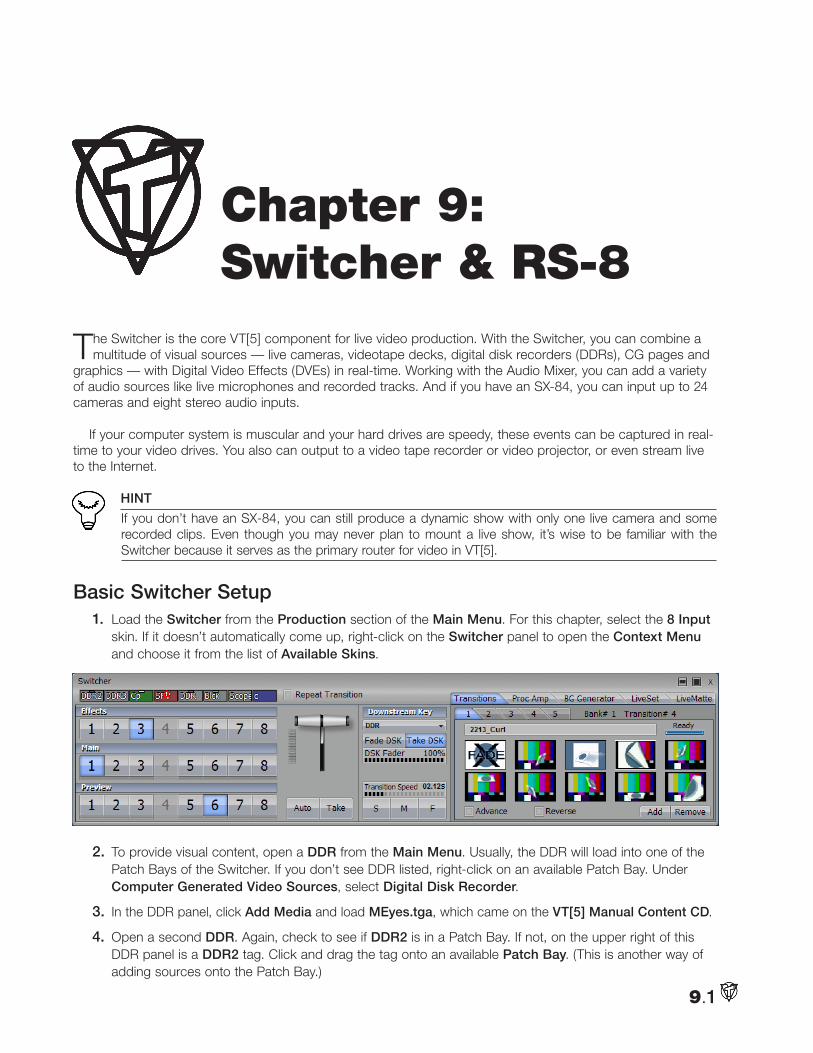
The Switcher is the core VT[5] component for live video production. With the Switcher, you can combine a multitude of visual sources — live cameras, videotape decks, digital disk recorders (DDRs), CG pages and
graphics — with Digital Video Effects (DVEs) in real-time. Working with the Audio Mixer, you can add a variety of audio sources like live microphones and recorded tracks. And if you have an SX-84, you can input up to 24 cameras and eight stereo audio inputs.
If your computer system is muscular and your hard drives are speedy, these events can be captured in real-time to your video drives. You also can output to a video tape recorder or video projector, or even stream live to the Internet.
HINT
If you don’t have an SX-84, you can still produce a dynamic show with only one live camera and some recorded clips. Even though you may never plan to mount a live show, it’s wise to be familiar with the Switcher because it serves as the primary router for video in VT[5].
Basic Switcher Setup1. Load the Switcher from the Production section of the Main Menu. For this chapter, select the 8 Input
skin. If it doesn’t automatically come up, right-click on the Switcher panel to open the Context Menu and choose it from the list of Available Skins.
2. To provide visual content, open a DDR from the Main Menu. Usually, the DDR will load into one of the Patch Bays of the Switcher. If you don’t see DDR listed, right-click on an available Patch Bay. Under Computer Generated Video Sources, select Digital Disk Recorder.
3. In the DDR panel, click Add Media and load MEyes.tga, which came on the VT[5] Manual Content CD.
4. Open a second DDR. Again, check to see if DDR2 is in a Patch Bay. If not, on the upper right of this DDR panel is a DDR2 tag. Click and drag the tag onto an available Patch Bay. (This is another way of adding sources onto the Patch Bay.)
9.1
Chapter 9: Switcher & RS-8
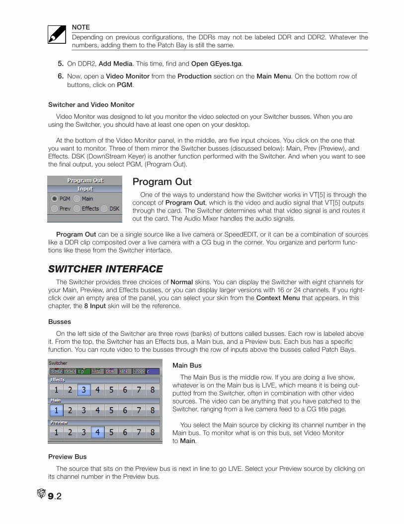
NOTE
Depending on previous configurations, the DDRs may not be labeled DDR and DDR2. Whatever the numbers, adding them to the Patch Bay is still the same.
5. On DDR2, Add Media. This time, find and Open GEyes.tga.
6. Now, open a Video Monitor from the Production section on the Main Menu. On the bottom row of buttons, click on PGM.
Switcher and Video Monitor
Video Monitor was designed to let you monitor the video selected on your Switcher busses. When you are using the Switcher, you should have at least one open on your desktop.
At the bottom of the Video Monitor panel, in the middle, are five input choices. You click on the one that you want to monitor. Three of them mirror the Switcher busses (discussed below): Main, Prev (Preview), and Effects. DSK (DownStream Keyer) is another function performed with the Switcher. And when you want to see the final output, you select PGM, (Program Out).
Program OutOne of the ways to understand how the Switcher works in VT[5] is through the
concept of Program Out, which is the video and audio signal that VT[5] outputs through the card. The Switcher determines what that video signal is and routes it out the card. The Audio Mixer handles the audio signals.
Program Out can be a single source like a live camera or SpeedEDIT, or it can be a combination of sources like a DDR clip composited over a live camera with a CG bug in the corner. You organize and perform func-tions like these from the Switcher interface.
SwitcHeR inteRfaceThe Switcher provides three choices of Normal skins. You can display the Switcher with eight channels for
your Main, Preview, and Effects busses, or you can display larger versions with 16 or 24 channels. If you right-click over an empty area of the panel, you can select your skin from the Context Menu that appears. In this chapter, the 8 Input skin will be the reference.
Busses
On the left side of the Switcher are three rows (banks) of buttons called busses. Each row is labeled above it. From the top, the Switcher has an Effects bus, a Main bus, and a Preview bus. Each bus has a specific function. You can route video to the busses through the row of inputs above the busses called Patch Bays.
Main Bus
The Main Bus is the middle row. If you are doing a live show, whatever is on the Main bus is LIVE, which means it is being out-putted from the Switcher, often in combination with other video sources. The video can be anything that you have patched to the Switcher, ranging from a live camera feed to a CG title page.
You select the Main source by clicking its channel number in the Main bus. To monitor what is on this bus, set Video Monitor to Main.
Preview Bus
The source that sits on the Preview bus is next in line to go LIVE. Select your Preview source by clicking on its channel number in the Preview bus.
9.2
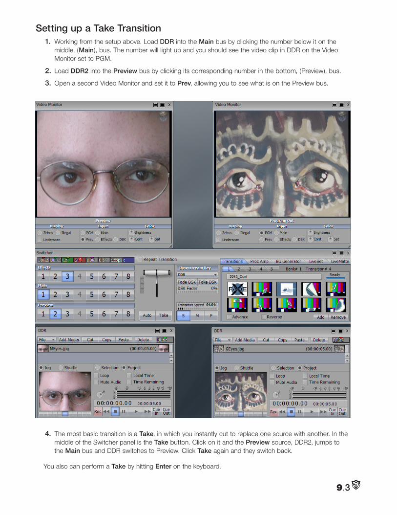
Setting up a Take Transition 1. Working from the setup above. Load DDR into the Main bus by clicking the number below it on the
middle, (Main), bus. The number will light up and you should see the video clip in DDR on the Video Monitor set to PGM.
2. Load DDR2 into the Preview bus by clicking its corresponding number in the bottom, (Preview), bus.
3. Open a second Video Monitor and set it to Prev, allowing you to see what is on the Preview bus.
4. The most basic transition is a Take, in which you instantly cut to replace one source with another. In the middle of the Switcher panel is the Take button. Click on it and the Preview source, DDR2, jumps to the Main bus and DDR switches to Preview. Click Take again and they switch back.
You also can perform a Take by hitting Enter on the keyboard.
9.3
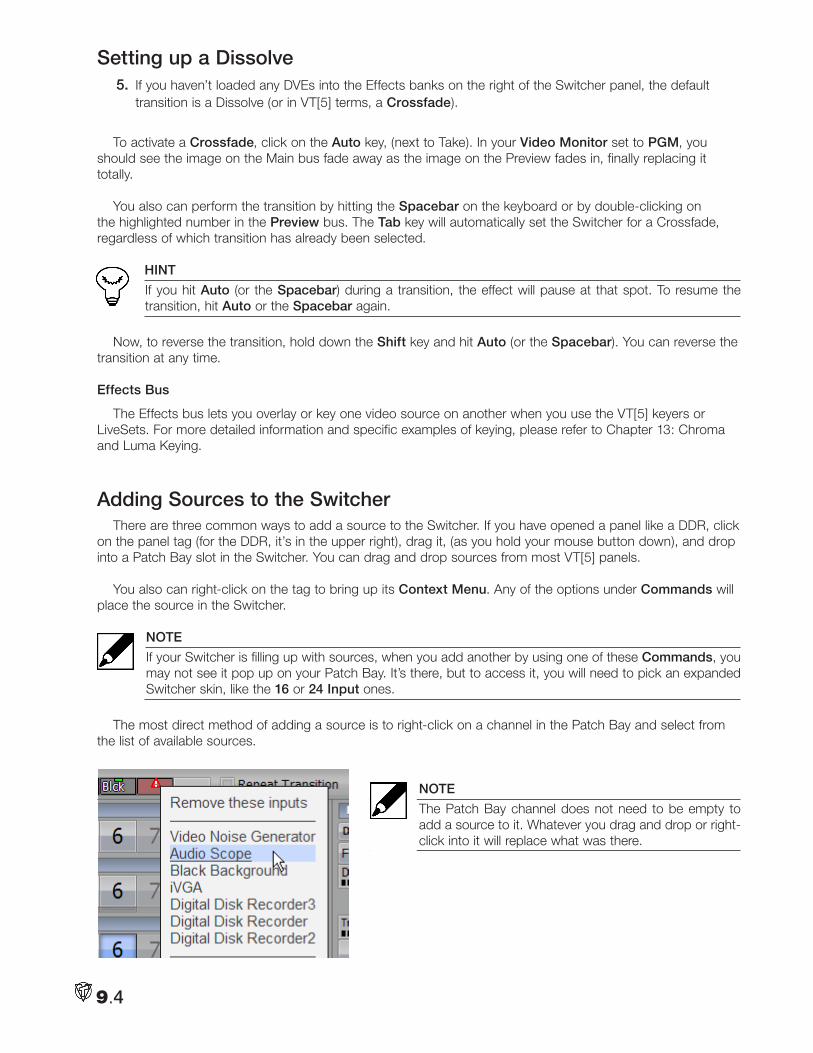
Setting up a Dissolve 5. If you haven’t loaded any DVEs into the Effects banks on the right of the Switcher panel, the default
transition is a Dissolve (or in VT[5] terms, a Crossfade).
To activate a Crossfade, click on the Auto key, (next to Take). In your Video Monitor set to PGM, you should see the image on the Main bus fade away as the image on the Preview fades in, finally replacing it totally.
You also can perform the transition by hitting the Spacebar on the keyboard or by double-clicking on the highlighted number in the Preview bus. The Tab key will automatically set the Switcher for a Crossfade, regardless of which transition has already been selected.
HINT
If you hit Auto (or the Spacebar) during a transition, the effect will pause at that spot. To resume the transition, hit Auto or the Spacebar again.
Now, to reverse the transition, hold down the Shift key and hit Auto (or the Spacebar). You can reverse the transition at any time.
Effects Bus
The Effects bus lets you overlay or key one video source on another when you use the VT[5] keyers or LiveSets. For more detailed information and specific examples of keying, please refer to Chapter 13: Chroma and Luma Keying.
Adding Sources to the SwitcherThere are three common ways to add a source to the Switcher. If you have opened a panel like a DDR, click
on the panel tag (for the DDR, it’s in the upper right), drag it, (as you hold your mouse button down), and drop into a Patch Bay slot in the Switcher. You can drag and drop sources from most VT[5] panels.
You also can right-click on the tag to bring up its Context Menu. Any of the options under Commands will place the source in the Switcher.
NOTE
If your Switcher is filling up with sources, when you add another by using one of these Commands, you may not see it pop up on your Patch Bay. It’s there, but to access it, you will need to pick an expanded Switcher skin, like the 16 or 24 Input ones.
The most direct method of adding a source is to right-click on a channel in the Patch Bay and select from the list of available sources.
NOTE
The Patch Bay channel does not need to be empty to add a source to it. Whatever you drag and drop or right-click into it will replace what was there.
9.4
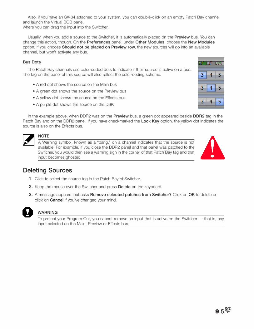
Also, if you have an SX-84 attached to your system, you can double-click on an empty Patch Bay channel and launch the Virtual BOB panel, where you can drag the input into the Switcher.
Usually, when you add a source to the Switcher, it is automatically placed on the Preview bus. You can change this action, though. On the Preferences panel, under Other Modules, choose the New Modules option. If you choose Should not be placed on Preview row, the new sources will go into an available channel, but won’t activate any bus.
Bus Dots
The Patch Bay channels use color-coded dots to indicate if their source is active on a bus. The tag on the panel of this source will also reflect the color-coding scheme.
• A red dot shows the source on the Main bus
• A green dot shows the source on the Preview bus
• A yellow dot shows the source on the Effects bus
• A purple dot shows the source on the DSK
In the example above, when DDR2 was on the Preview bus, a green dot appeared beside DDR2 tag in the Patch Bay and on the DDR2 panel. If you have checkmarked the Lock Key option, the yellow dot indicates the source is also on the Effects bus.
NOTE
A Warning symbol, known as a “bang,” on a channel indicates that the source is not available. For example, if you close the DDR2 panel and that panel was patched to the Switcher, you would then see a warning sign in the corner of that Patch Bay tag and that input becomes ghosted.
Deleting Sources1. Click to select the source tag in the Patch Bay of Switcher.
2. Keep the mouse over the Switcher and press Delete on the keyboard.
3. A message appears that asks Remove selected patches from Switcher? Click on OK to delete or click on Cancel if you’ve changed your mind.
WARNING
To protect your Program Out, you cannot remove an input that is active on the Switcher — that is, any input selected on the Main, Preview or Effects bus.
9.5
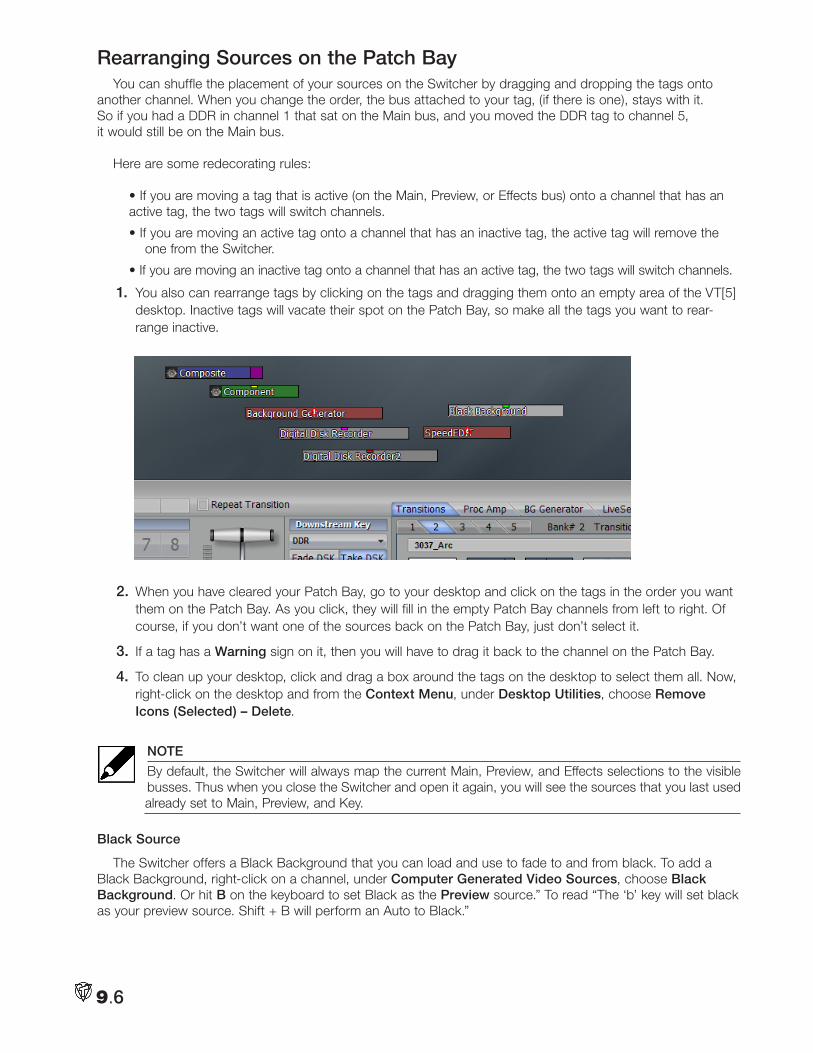
Rearranging Sources on the Patch BayYou can shuffle the placement of your sources on the Switcher by dragging and dropping the tags onto
another channel. When you change the order, the bus attached to your tag, (if there is one), stays with it. So if you had a DDR in channel 1 that sat on the Main bus, and you moved the DDR tag to channel 5, it would still be on the Main bus.
Here are some redecorating rules:
• If you are moving a tag that is active (on the Main, Preview, or Effects bus) onto a channel that has an active tag, the two tags will switch channels.
• If you are moving an active tag onto a channel that has an inactive tag, the active tag will remove the one from the Switcher.
• If you are moving an inactive tag onto a channel that has an active tag, the two tags will switch channels.
1. You also can rearrange tags by clicking on the tags and dragging them onto an empty area of the VT[5] desktop. Inactive tags will vacate their spot on the Patch Bay, so make all the tags you want to rear-range inactive.
2. When you have cleared your Patch Bay, go to your desktop and click on the tags in the order you want them on the Patch Bay. As you click, they will fill in the empty Patch Bay channels from left to right. Of course, if you don’t want one of the sources back on the Patch Bay, just don’t select it.
3. If a tag has a Warning sign on it, then you will have to drag it back to the channel on the Patch Bay.
4. To clean up your desktop, click and drag a box around the tags on the desktop to select them all. Now, right-click on the desktop and from the Context Menu, under Desktop Utilities, choose Remove Icons (Selected) – Delete.
NOTE
By default, the Switcher will always map the current Main, Preview, and Effects selections to the visible busses. Thus when you close the Switcher and open it again, you will see the sources that you last used already set to Main, Preview, and Key.
Black Source
The Switcher offers a Black Background that you can load and use to fade to and from black. To add a Black Background, right-click on a channel, under Computer Generated Video Sources, choose Black Background. Or hit B on the keyboard to set Black as the Preview source.” To read “The ‘b’ key will set black as your preview source. Shift + B will perform an Auto to Black.”
9.6
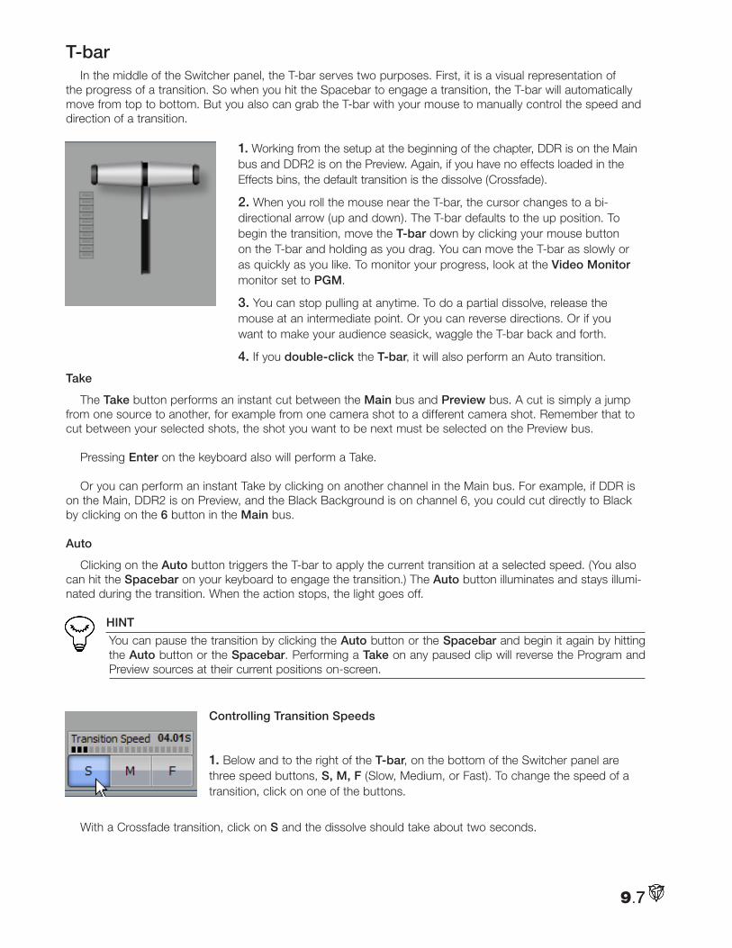
T-barIn the middle of the Switcher panel, the T-bar serves two purposes. First, it is a visual representation of
the progress of a transition. So when you hit the Spacebar to engage a transition, the T-bar will automatically move from top to bottom. But you also can grab the T-bar with your mouse to manually control the speed and direction of a transition.
1. Working from the setup at the beginning of the chapter, DDR is on the Main bus and DDR2 is on the Preview. Again, if you have no effects loaded in the Effects bins, the default transition is the dissolve (Crossfade).
2. When you roll the mouse near the T-bar, the cursor changes to a bi- directional arrow (up and down). The T-bar defaults to the up position. To begin the transition, move the T-bar down by clicking your mouse button on the T-bar and holding as you drag. You can move the T-bar as slowly or as quickly as you like. To monitor your progress, look at the Video Monitor monitor set to PGM.
3. You can stop pulling at anytime. To do a partial dissolve, release the mouse at an intermediate point. Or you can reverse directions. Or if you want to make your audience seasick, waggle the T-bar back and forth.
4. If you double-click the T-bar, it will also perform an Auto transition.
Take
The Take button performs an instant cut between the Main bus and Preview bus. A cut is simply a jump from one source to another, for example from one camera shot to a different camera shot. Remember that to cut between your selected shots, the shot you want to be next must be selected on the Preview bus.
Pressing Enter on the keyboard also will perform a Take.
Or you can perform an instant Take by clicking on another channel in the Main bus. For example, if DDR is on the Main, DDR2 is on Preview, and the Black Background is on channel 6, you could cut directly to Black by clicking on the 6 button in the Main bus.
Auto
Clicking on the Auto button triggers the T-bar to apply the current transition at a selected speed. (You also can hit the Spacebar on your keyboard to engage the transition.) The Auto button illuminates and stays illumi-nated during the transition. When the action stops, the light goes off.
HINT
You can pause the transition by clicking the Auto button or the Spacebar and begin it again by hitting the Auto button or the Spacebar. Performing a Take on any paused clip will reverse the Program and Preview sources at their current positions on-screen.
Controlling Transition Speeds
1. Below and to the right of the T-bar, on the bottom of the Switcher panel are three speed buttons, S, M, F (Slow, Medium, or Fast). To change the speed of a transition, click on one of the buttons.
With a Crossfade transition, click on S and the dissolve should take about two seconds.
9.7
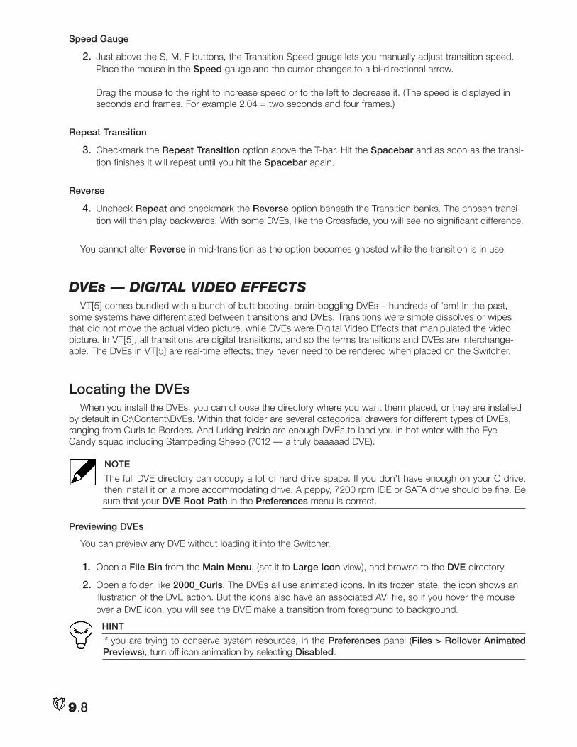
Speed Gauge
2. Just above the S, M, F buttons, the Transition Speed gauge lets you manually adjust transition speed. Place the mouse in the Speed gauge and the cursor changes to a bi-directional arrow. Drag the mouse to the right to increase speed or to the left to decrease it. (The speed is displayed in seconds and frames. For example 2.04 = two seconds and four frames.)
Repeat Transition
3. Checkmark the Repeat Transition option above the T-bar. Hit the Spacebar and as soon as the transi-tion finishes it will repeat until you hit the Spacebar again.
Reverse
4. Uncheck Repeat and checkmark the Reverse option beneath the Transition banks. The chosen transi-tion will then play backwards. With some DVEs, like the Crossfade, you will see no significant difference.
You cannot alter Reverse in mid-transition as the option becomes ghosted while the transition is in use.
dVes — digital Video effectSVT[5] comes bundled with a bunch of butt-booting, brain-boggling DVEs – hundreds of ‘em! In the past,
some systems have differentiated between transitions and DVEs. Transitions were simple dissolves or wipes that did not move the actual video picture, while DVEs were Digital Video Effects that manipulated the video picture. In VT[5], all transitions are digital transitions, and so the terms transitions and DVEs are interchange-able. The DVEs in VT[5] are real-time effects; they never need to be rendered when placed on the Switcher.
Locating the DVEsWhen you install the DVEs, you can choose the directory where you want them placed, or they are installed
by default in C:\Content\DVEs. Within that folder are several categorical drawers for different types of DVEs, ranging from Curls to Borders. And lurking inside are enough DVEs to land you in hot water with the Eye Candy squad including Stampeding Sheep (7012 — a truly baaaaad DVE).
NOTE
The full DVE directory can occupy a lot of hard drive space. If you don’t have enough on your C drive, then install it on a more accommodating drive. A peppy, 7200 rpm IDE or SATA drive should be fine. Be sure that your DVE Root Path in the Preferences menu is correct.
Previewing DVEs
You can preview any DVE without loading it into the Switcher.
1. Open a File Bin from the Main Menu, (set it to Large Icon view), and browse to the DVE directory.
2. Open a folder, like 2000_Curls. The DVEs all use animated icons. In its frozen state, the icon shows an illustration of the DVE action. But the icons also have an associated AVI file, so if you hover the mouse over a DVE icon, you will see the DVE make a transition from foreground to background.
HINT
If you are trying to conserve system resources, in the Preferences panel (Files > Rollover Animated Previews), turn off icon animation by selecting Disabled.
9.8
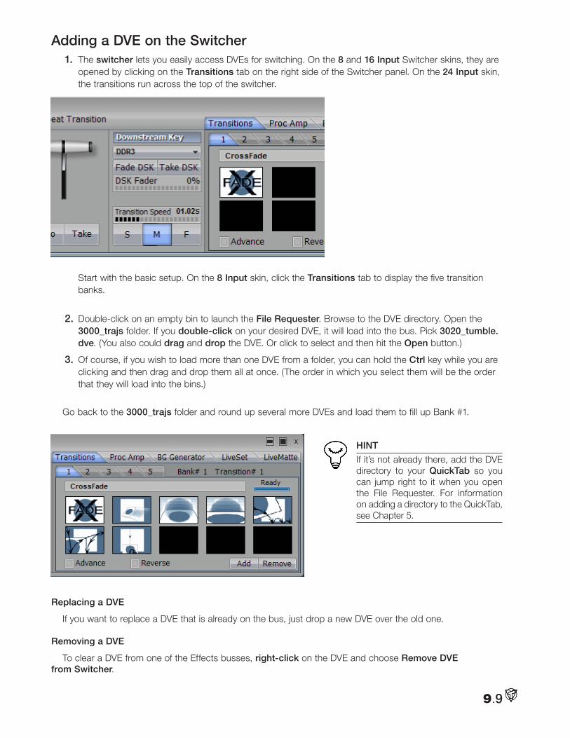
Adding a DVE on the Switcher1. The switcher lets you easily access DVEs for switching. On the 8 and 16 Input Switcher skins, they are
opened by clicking on the Transitions tab on the right side of the Switcher panel. On the 24 Input skin, the transitions run across the top of the switcher.
Start with the basic setup. On the 8 Input skin, click the Transitions tab to display the five transition banks.
2. Double-click on an empty bin to launch the File Requester. Browse to the DVE directory. Open the 3000_trajs folder. If you double-click on your desired DVE, it will load into the bus. Pick 3020_tumble.dve. (You also could drag and drop the DVE. Or click to select and then hit the Open button.)
3. Of course, if you wish to load more than one DVE from a folder, you can hold the Ctrl key while you are clicking and then drag and drop them all at once. (The order in which you select them will be the order that they will load into the bins.)
Go back to the 3000_trajs folder and round up several more DVEs and load them to fill up Bank #1.
HINT
If it’s not already there, add the DVE directory to your QuickTab so you can jump right to it when you open the File Requester. For information on adding a directory to the QuickTab, see Chapter 5.
Replacing a DVE
If you want to replace a DVE that is already on the bus, just drop a new DVE over the old one.
Removing a DVE
To clear a DVE from one of the Effects busses, right-click on the DVE and choose Remove DVE from Switcher.
9.9
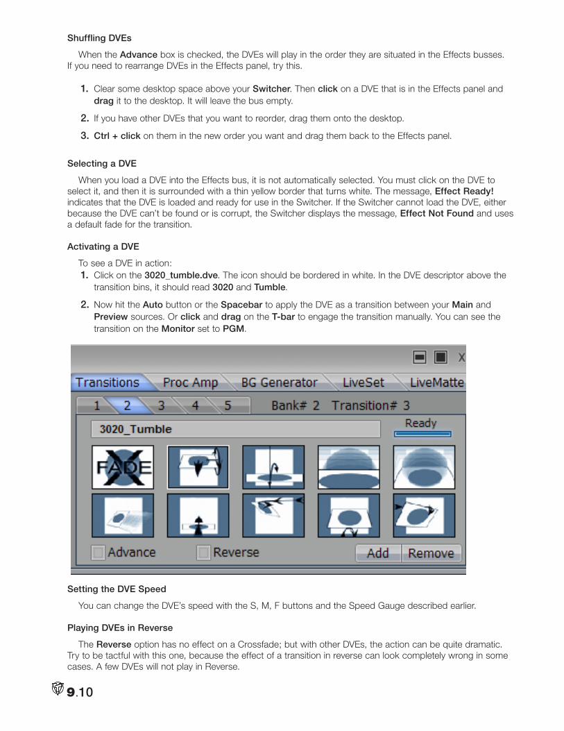
Shuffling DVEs
When the Advance box is checked, the DVEs will play in the order they are situated in the Effects busses. If you need to rearrange DVEs in the Effects panel, try this.
1. Clear some desktop space above your Switcher. Then click on a DVE that is in the Effects panel and drag it to the desktop. It will leave the bus empty.
2. If you have other DVEs that you want to reorder, drag them onto the desktop.
3. Ctrl + click on them in the new order you want and drag them back to the Effects panel.
Selecting a DVE
When you load a DVE into the Effects bus, it is not automatically selected. You must click on the DVE to select it, and then it is surrounded with a thin yellow border that turns white. The message, Effect Ready! indicates that the DVE is loaded and ready for use in the Switcher. If the Switcher cannot load the DVE, either because the DVE can’t be found or is corrupt, the Switcher displays the message, Effect Not Found and uses a default fade for the transition.
Activating a DVE
To see a DVE in action:1. Click on the 3020_tumble.dve. The icon should be bordered in white. In the DVE descriptor above the
transition bins, it should read 3020 and Tumble.
2. Now hit the Auto button or the Spacebar to apply the DVE as a transition between your Main and Preview sources. Or click and drag on the T-bar to engage the transition manually. You can see the transition on the Monitor set to PGM.
Setting the DVE Speed
You can change the DVE’s speed with the S, M, F buttons and the Speed Gauge described earlier.
Playing DVEs in Reverse
The Reverse option has no effect on a Crossfade; but with other DVEs, the action can be quite dramatic. Try to be tactful with this one, because the effect of a transition in reverse can look completely wrong in some cases. A few DVEs will not play in Reverse.
9.10
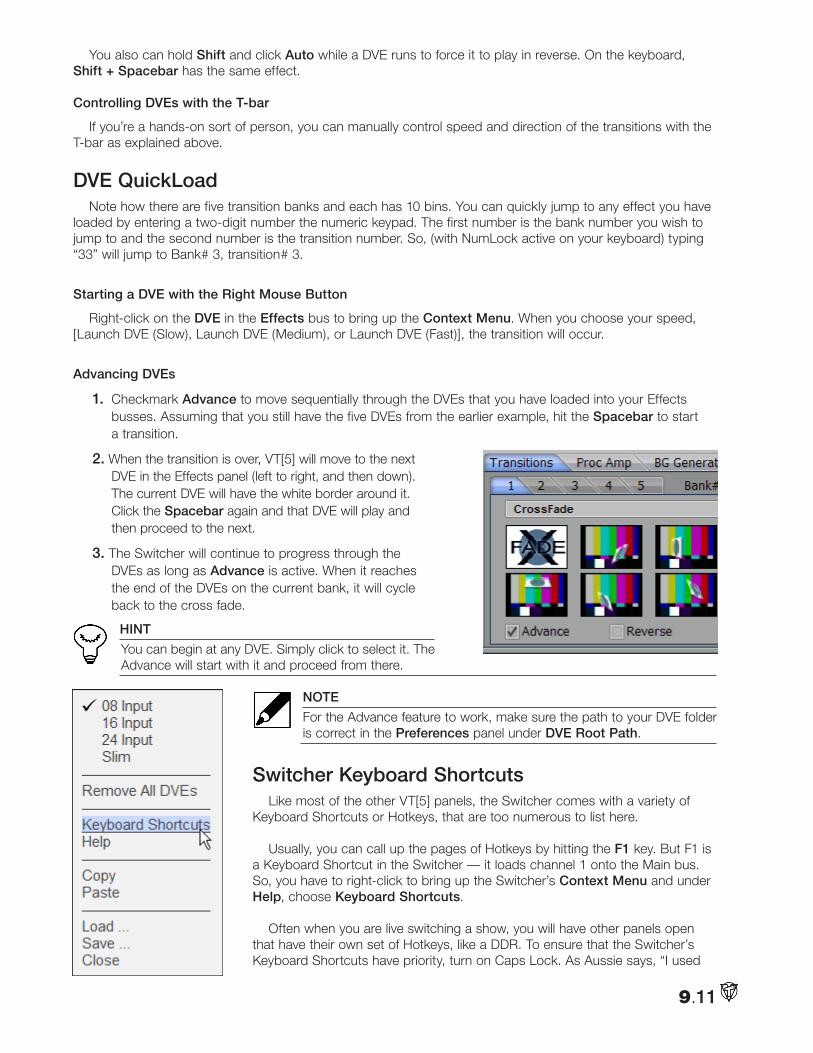
You also can hold Shift and click Auto while a DVE runs to force it to play in reverse. On the keyboard, Shift + Spacebar has the same effect.
Controlling DVEs with the T-bar
If you’re a hands-on sort of person, you can manually control speed and direction of the transitions with the T-bar as explained above.
DVE QuickLoad Note how there are five transition banks and each has 10 bins. You can quickly jump to any effect you have
loaded by entering a two-digit number the numeric keypad. The first number is the bank number you wish to jump to and the second number is the transition number. So, (with NumLock active on your keyboard) typing “33” will jump to Bank# 3, transition# 3.
Starting a DVE with the Right Mouse Button
Right-click on the DVE in the Effects bus to bring up the Context Menu. When you choose your speed, [Launch DVE (Slow), Launch DVE (Medium), or Launch DVE (Fast)], the transition will occur.
Advancing DVEs
1. Checkmark Advance to move sequentially through the DVEs that you have loaded into your Effects busses. Assuming that you still have the five DVEs from the earlier example, hit the Spacebar to start a transition.
2. When the transition is over, VT[5] will move to the next DVE in the Effects panel (left to right, and then down). The current DVE will have the white border around it. Click the Spacebar again and that DVE will play and then proceed to the next.
3. The Switcher will continue to progress through the DVEs as long as Advance is active. When it reaches the end of the DVEs on the current bank, it will cycle back to the cross fade.
HINT
You can begin at any DVE. Simply click to select it. The Advance will start with it and proceed from there.
NOTE
For the Advance feature to work, make sure the path to your DVE folder is correct in the Preferences panel under DVE Root Path.
Switcher Keyboard Shortcuts Like most of the other VT[5] panels, the Switcher comes with a variety of
Keyboard Shortcuts or Hotkeys, that are too numerous to list here. Usually, you can call up the pages of Hotkeys by hitting the F1 key. But F1 is
a Keyboard Shortcut in the Switcher — it loads channel 1 onto the Main bus. So, you have to right-click to bring up the Switcher’s Context Menu and under Help, choose Keyboard Shortcuts.
Often when you are live switching a show, you will have other panels open that have their own set of Hotkeys, like a DDR. To ensure that the Switcher’s Keyboard Shortcuts have priority, turn on Caps Lock. As Aussie says, “I used
9.11
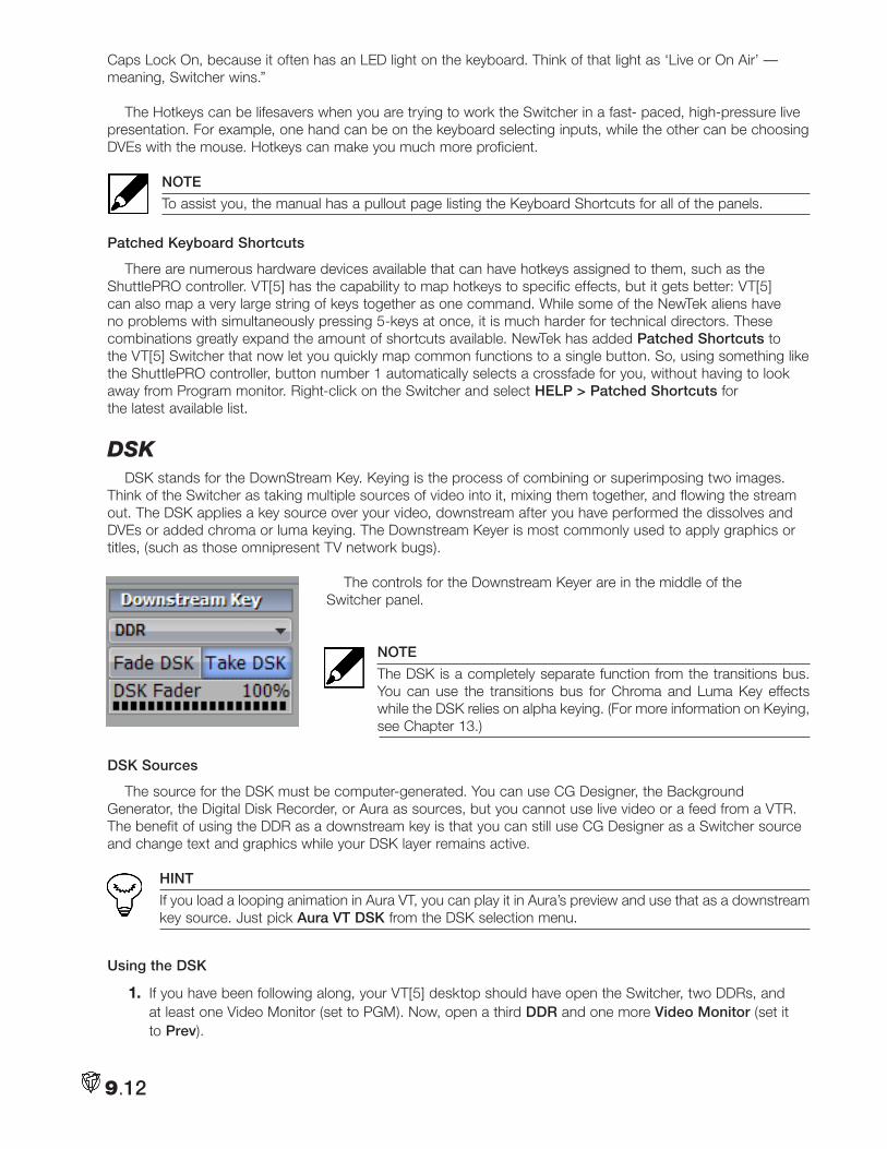
Caps Lock On, because it often has an LED light on the keyboard. Think of that light as ‘Live or On Air’ — meaning, Switcher wins.”
The Hotkeys can be lifesavers when you are trying to work the Switcher in a fast- paced, high-pressure live presentation. For example, one hand can be on the keyboard selecting inputs, while the other can be choosing DVEs with the mouse. Hotkeys can make you much more proficient.
NOTE
To assist you, the manual has a pullout page listing the Keyboard Shortcuts for all of the panels.
Patched Keyboard Shortcuts
There are numerous hardware devices available that can have hotkeys assigned to them, such as the ShuttlePRO controller. VT[5] has the capability to map hotkeys to specific effects, but it gets better: VT[5] can also map a very large string of keys together as one command. While some of the NewTek aliens have no problems with simultaneously pressing 5-keys at once, it is much harder for technical directors. These combinations greatly expand the amount of shortcuts available. NewTek has added Patched Shortcuts to the VT[5] Switcher that now let you quickly map common functions to a single button. So, using something like the ShuttlePRO controller, button number 1 automatically selects a crossfade for you, without having to look away from Program monitor. Right-click on the Switcher and select HELP > Patched Shortcuts for the latest available list.
dSkDSK stands for the DownStream Key. Keying is the process of combining or superimposing two images.
Think of the Switcher as taking multiple sources of video into it, mixing them together, and flowing the stream out. The DSK applies a key source over your video, downstream after you have performed the dissolves and DVEs or added chroma or luma keying. The Downstream Keyer is most commonly used to apply graphics or titles, (such as those omnipresent TV network bugs).
The controls for the Downstream Keyer are in the middle of the Switcher panel.
NOTE
The DSK is a completely separate function from the transitions bus. You can use the transitions bus for Chroma and Luma Key effects while the DSK relies on alpha keying. (For more information on Keying, see Chapter 13.)
DSK Sources
The source for the DSK must be computer-generated. You can use CG Designer, the Background Generator, the Digital Disk Recorder, or Aura as sources, but you cannot use live video or a feed from a VTR. The benefit of using the DDR as a downstream key is that you can still use CG Designer as a Switcher source and change text and graphics while your DSK layer remains active.
HINT
If you load a looping animation in Aura VT, you can play it in Aura’s preview and use that as a downstream key source. Just pick Aura VT DSK from the DSK selection menu.
Using the DSK
1. If you have been following along, your VT[5] desktop should have open the Switcher, two DDRs, and at least one Video Monitor (set to PGM). Now, open a third DDR and one more Video Monitor (set it to Prev).
9.12
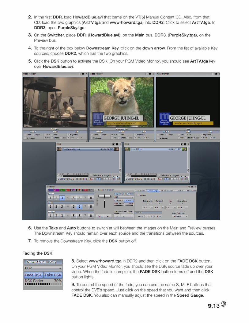
2. In the first DDR, load HowardBlue.avi that came on the VT[5] Manual Content CD. Also, from that CD, load the two graphics (ArtTV.tga and wwwrhoward.tga) into DDR2. Click to select ArtTV.tga. In DDR3, open PurpleSky.tga.
3. On the Switcher, place DDR, (HowardBlue.avi), on the Main bus. DDR3, (PurpleSky.tga), on the Preview bus.
4. To the right of the box below Downstream Key, click on the down arrow. From the list of available Key sources, choose DDR2, which has the two graphics.
5. Click the DSK button to activate the DSK. On your PGM Video Monitor, you should see ArtTV.tga key over HowardBlue.avi.
6. Use the Take and Auto buttons to switch at will between the images on the Main and Preview busses. The Downstream Key should remain over each source and the transitions between the sources.
7. To remove the Downstream Key, click the DSK button off.
Fading the DSK
8. Select wwwrhoward.tga in DDR2 and then click on the FADE DSK button. On your PGM Video Monitor, you should see the DSK source fade up over your video. When the fade is complete, the FADE DSK button turns off and the DSK button lights.
9. To control the speed of the fade, you can use the same S, M, F buttons that control the DVE’s speed. Just click on the speed that you want and then click FADE DSK. You also can manually adjust the speed in the Speed Gauge.
9.13
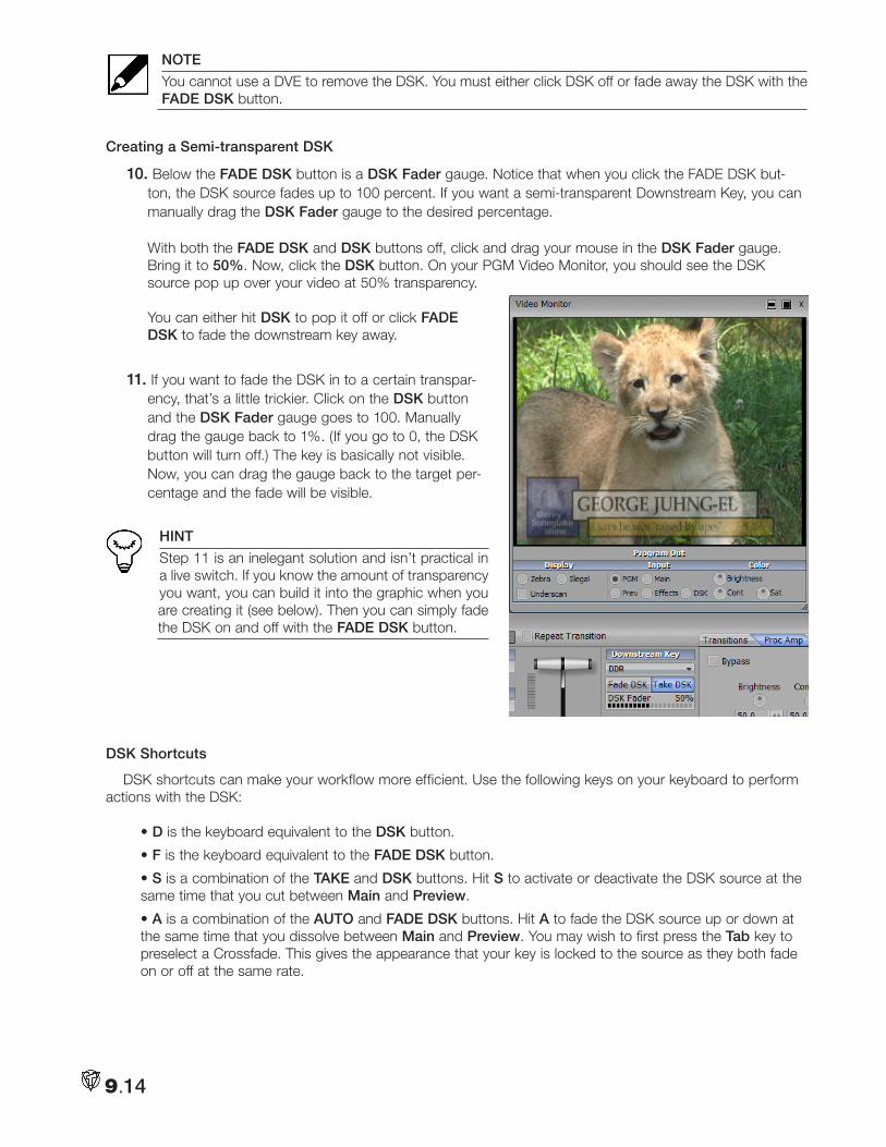
NOTE
You cannot use a DVE to remove the DSK. You must either click DSK off or fade away the DSK with the FADE DSK button.
Creating a Semi-transparent DSK
10. Below the FADE DSK button is a DSK Fader gauge. Notice that when you click the FADE DSK but-ton, the DSK source fades up to 100 percent. If you want a semi-transparent Downstream Key, you can manually drag the DSK Fader gauge to the desired percentage. With both the FADE DSK and DSK buttons off, click and drag your mouse in the DSK Fader gauge. Bring it to 50%. Now, click the DSK button. On your PGM Video Monitor, you should see the DSK source pop up over your video at 50% transparency. You can either hit DSK to pop it off or click FADE DSK to fade the downstream key away.
11. If you want to fade the DSK in to a certain transpar-ency, that’s a little trickier. Click on the DSK button and the DSK Fader gauge goes to 100. Manually drag the gauge back to 1%. (If you go to 0, the DSK button will turn off.) The key is basically not visible. Now, you can drag the gauge back to the target per-centage and the fade will be visible.
HINT
Step 11 is an inelegant solution and isn’t practical in a live switch. If you know the amount of transparency you want, you can build it into the graphic when you are creating it (see below). Then you can simply fade the DSK on and off with the FADE DSK button.
DSK Shortcuts
DSK shortcuts can make your workflow more efficient. Use the following keys on your keyboard to perform actions with the DSK:
• D is the keyboard equivalent to the DSK button.
• F is the keyboard equivalent to the FADE DSK button.
• S is a combination of the TAKE and DSK buttons. Hit S to activate or deactivate the DSK source at the same time that you cut between Main and Preview.
• A is a combination of the AUTO and FADE DSK buttons. Hit A to fade the DSK source up or down at the same time that you dissolve between Main and Preview. You may wish to first press the Tab key to preselect a Crossfade. This gives the appearance that your key is locked to the source as they both fade on or off at the same rate.
9.14
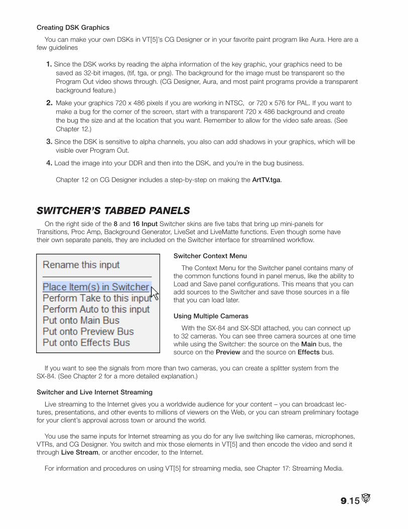
Creating DSK Graphics
You can make your own DSKs in VT[5]’s CG Designer or in your favorite paint program like Aura. Here are a few guidelines
1. Since the DSK works by reading the alpha information of the key graphic, your graphics need to be saved as 32-bit images, (tif, tga, or png). The background for the image must be transparent so the Program Out video shows through. (CG Designer, Aura, and most paint programs provide a transparent background feature.)
2. Make your graphics 720 x 486 pixels if you are working in NTSC, or 720 x 576 for PAL. If you want to make a bug for the corner of the screen, start with a transparent 720 x 486 background and create the bug the size and at the location that you want. Remember to allow for the video safe areas. (See Chapter 12.)
3. Since the DSK is sensitive to alpha channels, you also can add shadows in your graphics, which will be visible over Program Out.
4. Load the image into your DDR and then into the DSK, and you’re in the bug business. Chapter 12 on CG Designer includes a step-by-step on making the ArtTV.tga.
SwitcHeR’S taBBed panelS On the right side of the 8 and 16 Input Switcher skins are five tabs that bring up mini-panels for
Transitions, Proc Amp, Background Generator, LiveSet and LiveMatte functions. Even though some have their own separate panels, they are included on the Switcher interface for streamlined workflow.
Switcher Context Menu
The Context Menu for the Switcher panel contains many of the common functions found in panel menus, like the ability to Load and Save panel configurations. This means that you can add sources to the Switcher and save those sources in a file that you can load later.
Using Multiple Cameras
With the SX-84 and SX-SDI attached, you can connect up to 32 cameras. You can see three camera sources at one time while using the Switcher: the source on the Main bus, the source on the Preview and the source on Effects bus.
If you want to see the signals from more than two cameras, you can create a splitter system from the SX-84. (See Chapter 2 for a more detailed explanation.)
Switcher and Live Internet Streaming
Live streaming to the Internet gives you a worldwide audience for your content – you can broadcast lec-tures, presentations, and other events to millions of viewers on the Web, or you can stream preliminary footage for your client’s approval across town or around the world.
You use the same inputs for Internet streaming as you do for any live switching like cameras, microphones, VTRs, and CG Designer. You switch and mix those elements in VT[5] and then encode the video and send it through Live Stream, or another encoder, to the Internet.
For information and procedures on using VT[5] for streaming media, see Chapter 17: Streaming Media.
9.15
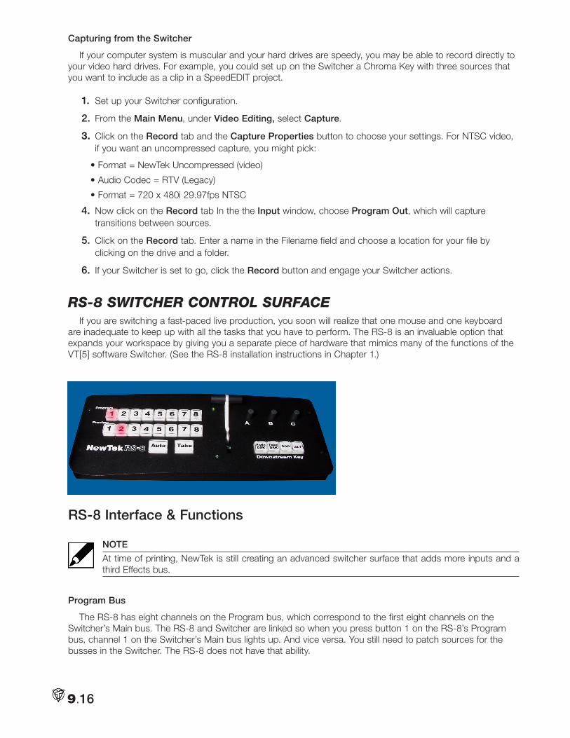
Capturing from the Switcher
If your computer system is muscular and your hard drives are speedy, you may be able to record directly to your video hard drives. For example, you could set up on the Switcher a Chroma Key with three sources that you want to include as a clip in a SpeedEDIT project.
1. Set up your Switcher configuration.
2. From the Main Menu, under Video Editing, select Capture.
3. Click on the Record tab and the Capture Properties button to choose your settings. For NTSC video, if you want an uncompressed capture, you might pick:
• Format = NewTek Uncompressed (video)
• Audio Codec = RTV (Legacy)
• Format = 720 x 480i 29.97fps NTSC
4. Now click on the Record tab In the the Input window, choose Program Out, which will capture transitions between sources.
5. Click on the Record tab. Enter a name in the Filename field and choose a location for your file by clicking on the drive and a folder.
6. If your Switcher is set to go, click the Record button and engage your Switcher actions.
RS-8 SwitcHeR contRol SuRfaceIf you are switching a fast-paced live production, you soon will realize that one mouse and one keyboard
are inadequate to keep up with all the tasks that you have to perform. The RS-8 is an invaluable option that expands your workspace by giving you a separate piece of hardware that mimics many of the functions of the VT[5] software Switcher. (See the RS-8 installation instructions in Chapter 1.)
RS-8 Interface & Functions
NOTE
At time of printing, NewTek is still creating an advanced switcher surface that adds more inputs and a third Effects bus.
Program Bus
The RS-8 has eight channels on the Program bus, which correspond to the first eight channels on the Switcher’s Main bus. The RS-8 and Switcher are linked so when you press button 1 on the RS-8’s Program bus, channel 1 on the Switcher’s Main bus lights up. And vice versa. You still need to patch sources for the busses in the Switcher. The RS-8 does not have that ability.
9.16
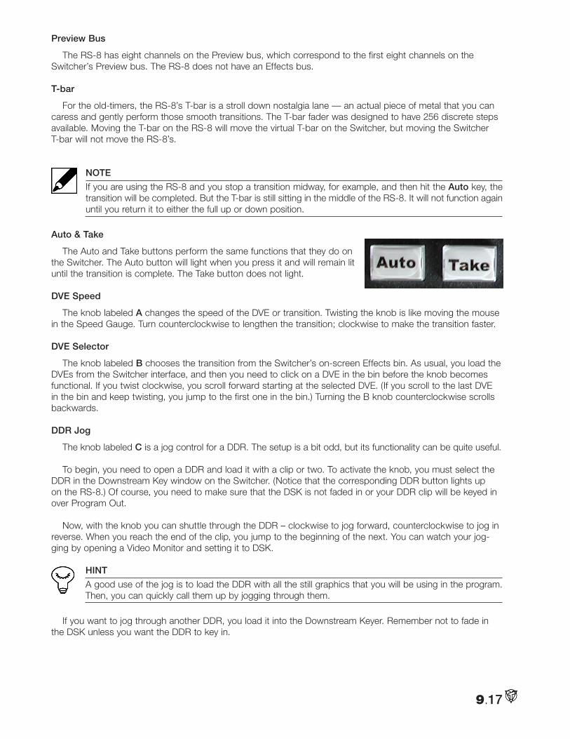
Preview Bus
The RS-8 has eight channels on the Preview bus, which correspond to the first eight channels on the Switcher’s Preview bus. The RS-8 does not have an Effects bus.
T-bar
For the old-timers, the RS-8’s T-bar is a stroll down nostalgia lane — an actual piece of metal that you can caress and gently perform those smooth transitions. The T-bar fader was designed to have 256 discrete steps available. Moving the T-bar on the RS-8 will move the virtual T-bar on the Switcher, but moving the Switcher T-bar will not move the RS-8’s.
NOTE
If you are using the RS-8 and you stop a transition midway, for example, and then hit the Auto key, the transition will be completed. But the T-bar is still sitting in the middle of the RS-8. It will not function again until you return it to either the full up or down position.
Auto & Take
The Auto and Take buttons perform the same functions that they do on the Switcher. The Auto button will light when you press it and will remain lit until the transition is complete. The Take button does not light.
DVE Speed
The knob labeled A changes the speed of the DVE or transition. Twisting the knob is like moving the mouse in the Speed Gauge. Turn counterclockwise to lengthen the transition; clockwise to make the transition faster.
DVE Selector
The knob labeled B chooses the transition from the Switcher’s on-screen Effects bin. As usual, you load the DVEs from the Switcher interface, and then you need to click on a DVE in the bin before the knob becomes functional. If you twist clockwise, you scroll forward starting at the selected DVE. (If you scroll to the last DVE in the bin and keep twisting, you jump to the first one in the bin.) Turning the B knob counterclockwise scrolls backwards.
DDR Jog
The knob labeled C is a jog control for a DDR. The setup is a bit odd, but its functionality can be quite useful.
To begin, you need to open a DDR and load it with a clip or two. To activate the knob, you must select the DDR in the Downstream Key window on the Switcher. (Notice that the corresponding DDR button lights up on the RS-8.) Of course, you need to make sure that the DSK is not faded in or your DDR clip will be keyed in over Program Out.
Now, with the knob you can shuttle through the DDR – clockwise to jog forward, counterclockwise to jog in reverse. When you reach the end of the clip, you jump to the beginning of the next. You can watch your jog-ging by opening a Video Monitor and setting it to DSK.
HINT
A good use of the jog is to load the DDR with all the still graphics that you will be using in the program. Then, you can quickly call them up by jogging through them.
If you want to jog through another DDR, you load it into the Downstream Keyer. Remember not to fade in the DSK unless you want the DDR to key in.
9.17
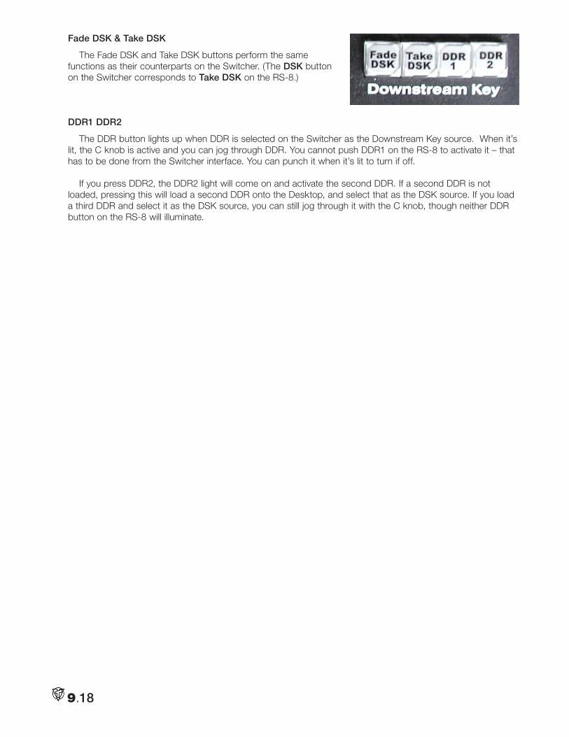
Fade DSK & Take DSK
The Fade DSK and Take DSK buttons perform the same functions as their counterparts on the Switcher. (The DSK button on the Switcher corresponds to Take DSK on the RS-8.)
DDR1 DDR2
The DDR button lights up when DDR is selected on the Switcher as the Downstream Key source. When it’s lit, the C knob is active and you can jog through DDR. You cannot push DDR1 on the RS-8 to activate it – that has to be done from the Switcher interface. You can punch it when it’s lit to turn if off.
If you press DDR2, the DDR2 light will come on and activate the second DDR. If a second DDR is not loaded, pressing this will load a second DDR onto the Desktop, and select that as the DSK source. If you load a third DDR and select it as the DSK source, you can still jog through it with the C knob, though neither DDR button on the RS-8 will illuminate.
9.18
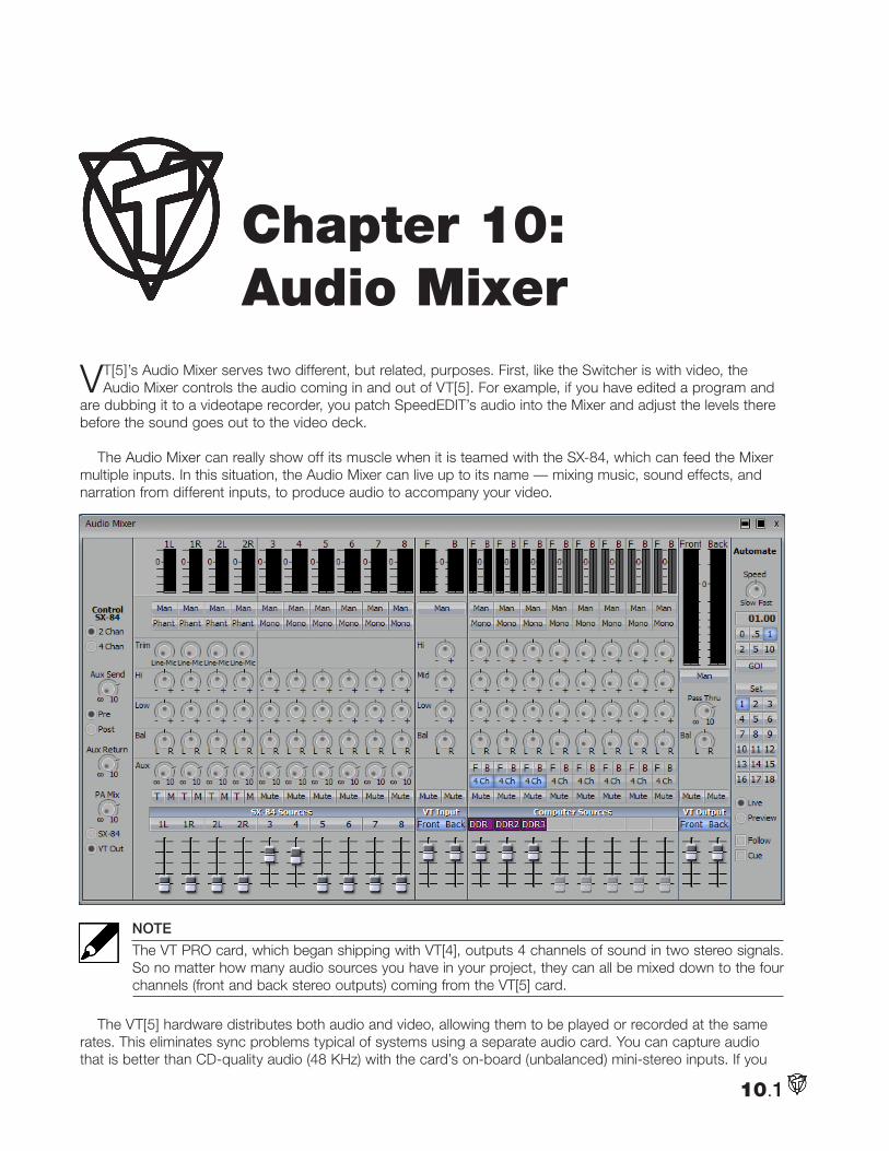
10.1
VT[5]’s Audio Mixer serves two different, but related, purposes. First, like the Switcher is with video, the Audio Mixer controls the audio coming in and out of VT[5]. For example, if you have edited a program and
are dubbing it to a videotape recorder, you patch SpeedEDIT’s audio into the Mixer and adjust the levels there before the sound goes out to the video deck.
The Audio Mixer can really show off its muscle when it is teamed with the SX-84, which can feed the Mixer multiple inputs. In this situation, the Audio Mixer can live up to its name — mixing music, sound effects, and narration from different inputs, to produce audio to accompany your video.
NOTE
The VT PRO card, which began shipping with VT[4], outputs 4 channels of sound in two stereo signals. So no matter how many audio sources you have in your project, they can all be mixed down to the four channels (front and back stereo outputs) coming from the VT[5] card.
The VT[5] hardware distributes both audio and video, allowing them to be played or recorded at the same rates. This eliminates sync problems typical of systems using a separate audio card. You can capture audio that is better than CD-quality audio (48 KHz) with the card’s on-board (unbalanced) mini-stereo inputs. If you
Chapter 10: Audio Mixer
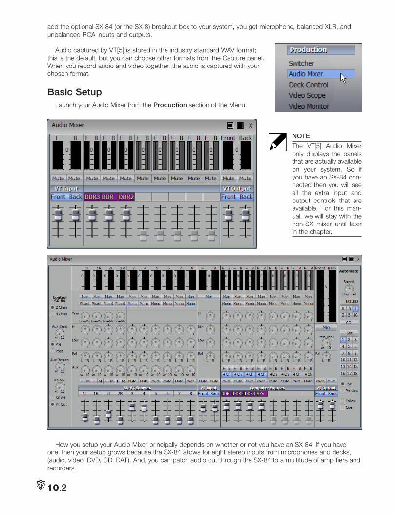
10.2
add the optional SX-84 (or the SX-8) breakout box to your system, you get microphone, balanced XLR, and unbalanced RCA inputs and outputs.
Audio captured by VT[5] is stored in the industry standard WAV format; this is the default, but you can choose other formats from the Capture panel. When you record audio and video together, the audio is captured with your chosen format.
Basic SetupLaunch your Audio Mixer from the Production section of the Menu.
NOTE
The VT[5] Audio Mixer only displays the panels that are actually available on your system. So if you have an SX-84 con-nected then you will see all the extra input and output controls that are available. For this man-ual, we will stay with the non-SX mixer until later in the chapter.
How you setup your Audio Mixer principally depends on whether or not you have an SX-84. If you have one, then your setup grows because the SX-84 allows for eight stereo inputs from microphones and decks, (audio, video, DVD, CD, DAT). And, you can patch audio out through the SX-84 to a multitude of amplifiers and recorders.
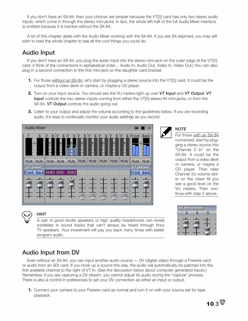
10.3
If you don’t have an SX-84, then your choices are simpler because the VT[5] card has only two stereo audio inputs, which come in through the stereo mini-jacks. In fact, the whole left half of the full Audio Mixer interface is omitted because it is inactive without the SX-84.
A lot of this chapter deals with the Audio Mixer working with the SX-84. If you are SX-deprived, you may still wish to read the whole chapter to see all the cool things you could do.
Audio Input If you don’t have an SX-84, you plug the audio input into the stereo mini-jack on the outer edge of the VT[5]
card. (I think of the connections in alphabetical order… Audio In, Audio Out, Video In, Video Out.) You can also plug in a second connection to the first mini-jack on the daughter card bracket.
1. For those without an SX-84, let’s start by plugging a stereo source into the VT[5] card. It could be the output from a video deck or camera, or maybe a CD player.
2. Turn on your input source. You should see the VU meters light up over VT Input and VT Output. VT Input controls the two stereo inputs coming from either the VT[5] stereo-IN mini-jacks, or from the SX-84. VT Output controls the audio going out.
3. Listen to your output and adjust the volume according to the guidelines below. If you are recording audio, it’s wise to continually monitor your audio settings as you record.
NOTE
For those with an SX-84 connected, start by plug-ging a stereo source into “Channel 3 In” on the SX-84. It could be the output from a video deck or camera, or maybe a CD player. Then raise Channel 3’s volume slid-er on the mixer till you see a good level on the VU meters. Then con-tinue with step 2 above.
HINT
A pair of good studio speakers or high quality headphones can reveal subtleties in sound tracks that can’t always be heard through tinny TV speakers. Your investment will pay you back many times with better program audio.
Audio Input from DV Even without an SX-84, you can input another audio source — DV (digital video) through a Firewire card
or audio from an SDI card. If you hook up a source this way, the audio will automatically be patched into the first available channel to the right of VT In. (See the discussion below about computer generated inputs.) Remember, if you are capturing a DV stream, you cannot adjust its audio during the “capture” process. There is also a control in preferences to set your DV connection as either an input or output.
1. Connect your camera to your Firewire card as normal and turn it on with your source set for tape playback.
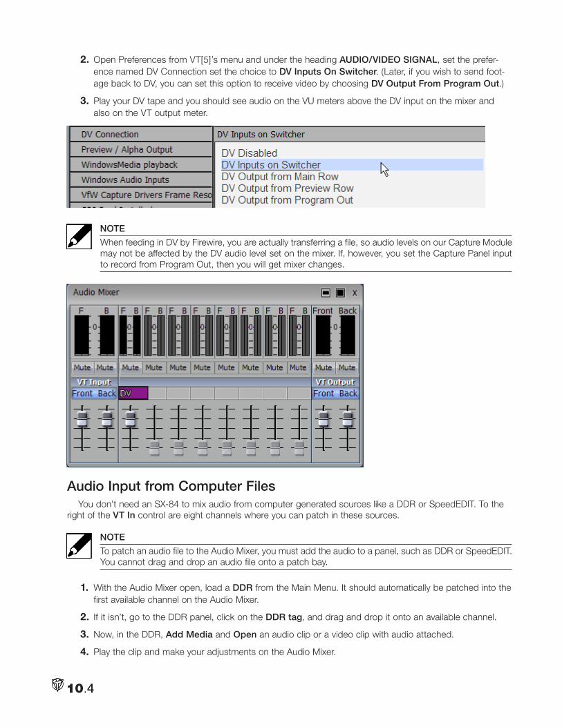
10.4
2. Open Preferences from VT[5]’s menu and under the heading AUDIO/VIDEO SIGNAL, set the prefer-ence named DV Connection set the choice to DV Inputs On Switcher. (Later, if you wish to send foot-age back to DV, you can set this option to receive video by choosing DV Output From Program Out.)
3. Play your DV tape and you should see audio on the VU meters above the DV input on the mixer and also on the VT output meter.
NOTE
When feeding in DV by Firewire, you are actually transferring a file, so audio levels on our Capture Module may not be affected by the DV audio level set on the mixer. If, however, you set the Capture Panel input to record from Program Out, then you will get mixer changes.
Audio Input from Computer FilesYou don’t need an SX-84 to mix audio from computer generated sources like a DDR or SpeedEDIT. To the
right of the VT In control are eight channels where you can patch in these sources.
NOTE
To patch an audio file to the Audio Mixer, you must add the audio to a panel, such as DDR or SpeedEDIT. You cannot drag and drop an audio file onto a patch bay.
1. With the Audio Mixer open, load a DDR from the Main Menu. It should automatically be patched into the first available channel on the Audio Mixer.
2. If it isn’t, go to the DDR panel, click on the DDR tag, and drag and drop it onto an available channel.
3. Now, in the DDR, Add Media and Open an audio clip or a video clip with audio attached.
4. Play the clip and make your adjustments on the Audio Mixer.
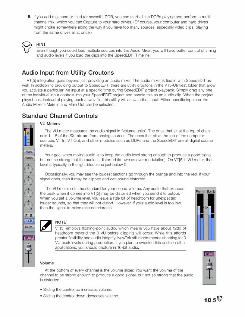
10.5
5. If you add a second or third (or seventh) DDR, you can start all the DDRs playing and perform a multi-channel mix, which you can Capture to your hard drives. (Of course, your computer and hard drives might choke somewhere along the way if you have too many sources, especially video clips, playing from the same drives all at once.)
HINT
Even though you could load multiple sources into the Audio Mixer, you will have better control of timing and audio levels if you load the clips into the SpeedEDIT Timeline.
Audio Input from Utility CroutonsVT[5] integration goes beyond just providing an audio mixer. The audio mixer is tied in with SpeedEDIT as
well. In addition to providing output to SpeedEDIT, there are utility croutons in the VT5\Utilities\ folder that allow you activate a particular live input at a specific time during SpeedEDIT project playback. Simply drag any one of the individual input controls into your SpeedEDIT project and handle this as an audio clip. When the project plays back, instead of playing back a .wav file, this utility will activate that input. Either specific inputs or the Audio Mixer’s Main In and Main Out can be selected.
Standard Channel ControlsVU Meters
The VU meter measures the audio signal in “volume units”. The ones that sit at the top of chan-nels 1 – 8 of the SX mix are from analog sources. The ones that sit at the top of the computer sources, VT In, VT Out, and other modules such as DDRs and the SpeedEDIT are all digital source meters.
Your goal when mixing audio is to keep the audio level strong enough to produce a good signal, but not so strong that the audio is distorted (known as over-modulation). On VT[5]’s VU meter, that level is typically in the light blue zone just below 0.
Occasionally, you may see the loudest sections go through the orange and into the red. If your signal does, then it may be clipped and can sound distorted.
The VU meter sets the standard for your sound volume. Any audio that exceeds the peak when it comes into VT[5] may be distorted when you send it to output. When you set a volume level, you leave a little bit of headroom for unexpected louder sounds, so that they will not distort. However, if your audio level is too low, then the signal-to-noise ratio deteriorates.
NOTE
VT[5] employs floating-point audio, which means you have about 12db of headroom beyond the 0 VU before clipping will occur. While this affords greater flexibility and audio integrity, NewTek still recommends shooting for 0 VU peak levels during production. If you plan to sweeten this audio in other applications, you should capture in 16-bit audio.
Volume
At the bottom of every channel is the volume slider. You want the volume of the channel to be strong enough to produce a good signal, but not so strong that the audio is distorted.
• Sliding the control up increases volume.
• Sliding the control down decreases volume.
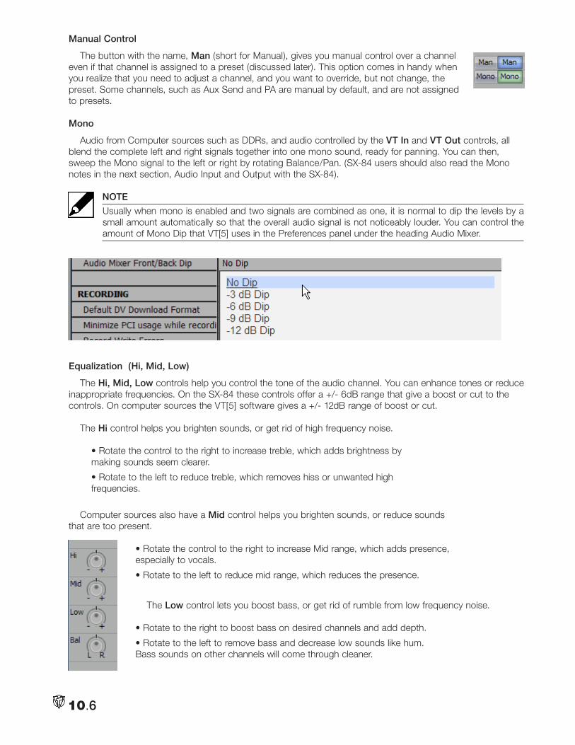
10.6
Manual Control
The button with the name, Man (short for Manual), gives you manual control over a channel even if that channel is assigned to a preset (discussed later). This option comes in handy when you realize that you need to adjust a channel, and you want to override, but not change, the preset. Some channels, such as Aux Send and PA are manual by default, and are not assigned to presets.
Mono
Audio from Computer sources such as DDRs, and audio controlled by the VT In and VT Out controls, all blend the complete left and right signals together into one mono sound, ready for panning. You can then, sweep the Mono signal to the left or right by rotating Balance/Pan. (SX-84 users should also read the Mono notes in the next section, Audio Input and Output with the SX-84).
NOTE
Usually when mono is enabled and two signals are combined as one, it is normal to dip the levels by a small amount automatically so that the overall audio signal is not noticeably louder. You can control the amount of Mono Dip that VT[5] uses in the Preferences panel under the heading Audio Mixer.
Equalization (Hi, Mid, Low)
The Hi, Mid, Low controls help you control the tone of the audio channel. You can enhance tones or reduce inappropriate frequencies. On the SX-84 these controls offer a +/- 6dB range that give a boost or cut to the controls. On computer sources the VT[5] software gives a +/- 12dB range of boost or cut.
The Hi control helps you brighten sounds, or get rid of high frequency noise.
• Rotate the control to the right to increase treble, which adds brightness by making sounds seem clearer.
• Rotate to the left to reduce treble, which removes hiss or unwanted high frequencies.
Computer sources also have a Mid control helps you brighten sounds, or reduce sounds that are too present.
• Rotate the control to the right to increase Mid range, which adds presence, especially to vocals.
• Rotate to the left to reduce mid range, which reduces the presence.
The Low control lets you boost bass, or get rid of rumble from low frequency noise.
• Rotate to the right to boost bass on desired channels and add depth.
• Rotate to the left to remove bass and decrease low sounds like hum. Bass sounds on other channels will come through cleaner.
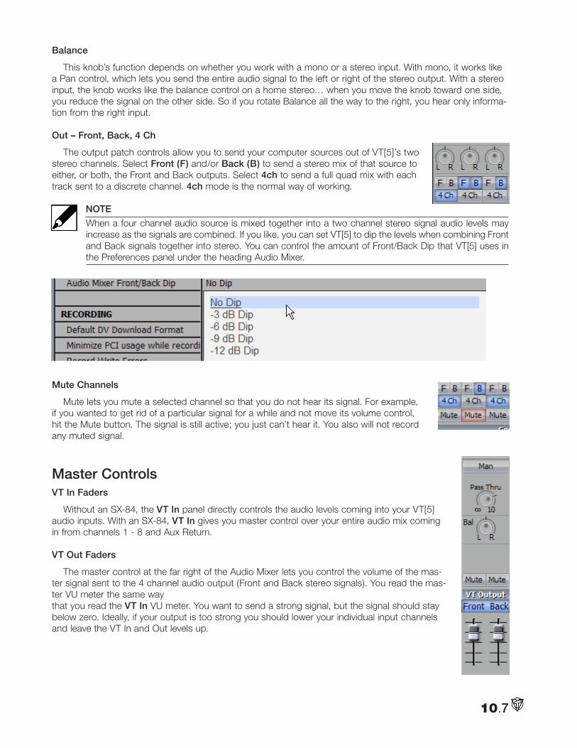
10.7
Balance
This knob’s function depends on whether you work with a mono or a stereo input. With mono, it works like a Pan control, which lets you send the entire audio signal to the left or right of the stereo output. With a stereo input, the knob works like the balance control on a home stereo… when you move the knob toward one side, you reduce the signal on the other side. So if you rotate Balance all the way to the right, you hear only informa-tion from the right input.
Out – Front, Back, 4 Ch
The output patch controls allow you to send your computer sources out of VT[5]’s two stereo channels. Select Front (F) and/or Back (B) to send a stereo mix of that source to either, or both, the Front and Back outputs. Select 4ch to send a full quad mix with each track sent to a discrete channel. 4ch mode is the normal way of working.
NOTE
When a four channel audio source is mixed together into a two channel stereo signal audio levels may increase as the signals are combined. If you like, you can set VT[5] to dip the levels when combining Front and Back signals together into stereo. You can control the amount of Front/Back Dip that VT[5] uses in the Preferences panel under the heading Audio Mixer.
Mute Channels
Mute lets you mute a selected channel so that you do not hear its signal. For example, if you wanted to get rid of a particular signal for a while and not move its volume control, hit the Mute button. The signal is still active; you just can’t hear it. You also will not record any muted signal.
Master ControlsVT In Faders
Without an SX-84, the VT In panel directly controls the audio levels coming into your VT[5] audio inputs. With an SX-84, VT In gives you master control over your entire audio mix coming in from channels 1 - 8 and Aux Return.
VT Out Faders
The master control at the far right of the Audio Mixer lets you control the volume of the mas-ter signal sent to the 4 channel audio output (Front and Back stereo signals). You read the mas-ter VU meter the same way that you read the VT In VU meter. You want to send a strong signal, but the signal should stay below zero. Ideally, if your output is too strong you should lower your individual input channels and leave the VT In and Out levels up.
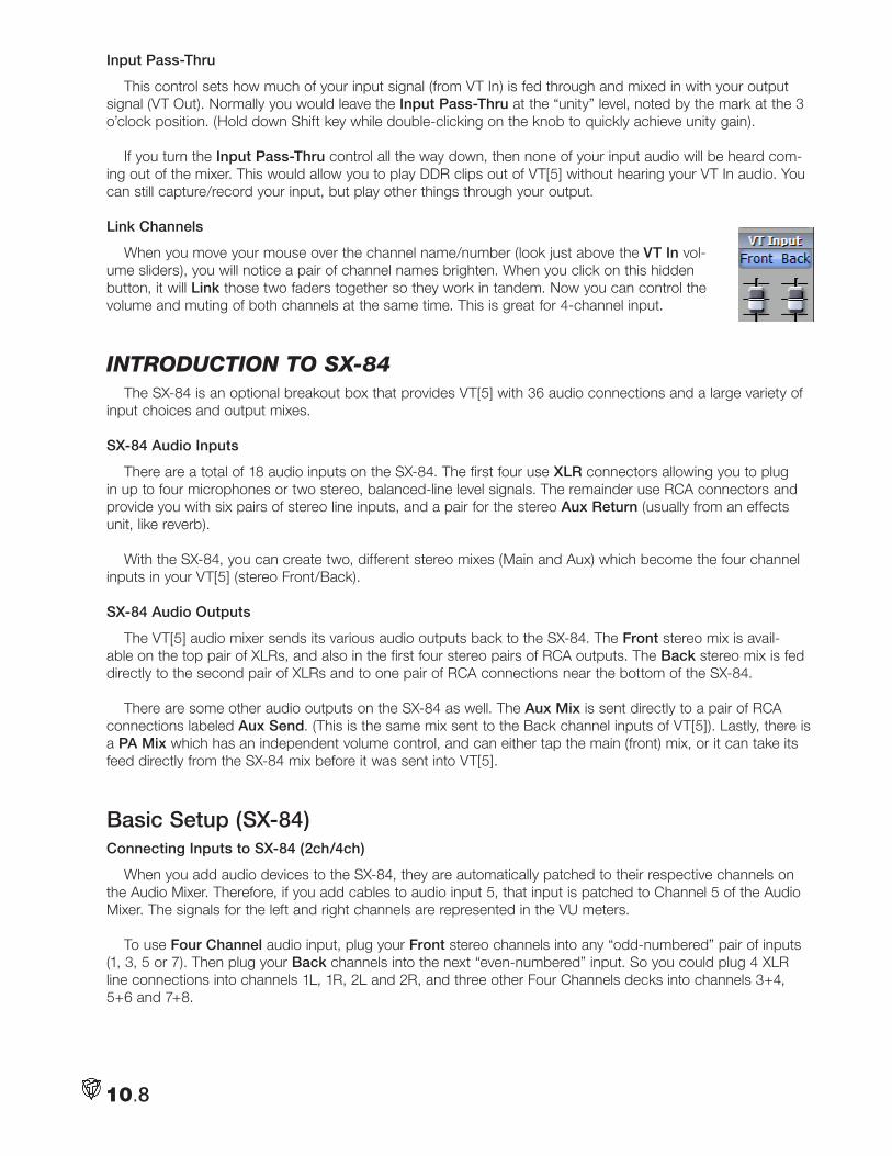
10.8
Input Pass-Thru
This control sets how much of your input signal (from VT In) is fed through and mixed in with your output signal (VT Out). Normally you would leave the Input Pass-Thru at the “unity” level, noted by the mark at the 3 o’clock position. (Hold down Shift key while double-clicking on the knob to quickly achieve unity gain).
If you turn the Input Pass-Thru control all the way down, then none of your input audio will be heard com-ing out of the mixer. This would allow you to play DDR clips out of VT[5] without hearing your VT In audio. You can still capture/record your input, but play other things through your output.
Link Channels
When you move your mouse over the channel name/number (look just above the VT In vol-ume sliders), you will notice a pair of channel names brighten. When you click on this hidden button, it will Link those two faders together so they work in tandem. Now you can control the volume and muting of both channels at the same time. This is great for 4-channel input.
intRoduction to SX-84The SX-84 is an optional breakout box that provides VT[5] with 36 audio connections and a large variety of
input choices and output mixes.
SX-84 Audio Inputs
There are a total of 18 audio inputs on the SX-84. The first four use XLR connectors allowing you to plug in up to four microphones or two stereo, balanced-line level signals. The remainder use RCA connectors and provide you with six pairs of stereo line inputs, and a pair for the stereo Aux Return (usually from an effects unit, like reverb).
With the SX-84, you can create two, different stereo mixes (Main and Aux) which become the four channel inputs in your VT[5] (stereo Front/Back).
SX-84 Audio Outputs
The VT[5] audio mixer sends its various audio outputs back to the SX-84. The Front stereo mix is avail-able on the top pair of XLRs, and also in the first four stereo pairs of RCA outputs. The Back stereo mix is fed directly to the second pair of XLRs and to one pair of RCA connections near the bottom of the SX-84.
There are some other audio outputs on the SX-84 as well. The Aux Mix is sent directly to a pair of RCA connections labeled Aux Send. (This is the same mix sent to the Back channel inputs of VT[5]). Lastly, there is a PA Mix which has an independent volume control, and can either tap the main (front) mix, or it can take its feed directly from the SX-84 mix before it was sent into VT[5].
Basic Setup (SX-84)Connecting Inputs to SX-84 (2ch/4ch)
When you add audio devices to the SX-84, they are automatically patched to their respective channels on the Audio Mixer. Therefore, if you add cables to audio input 5, that input is patched to Channel 5 of the Audio Mixer. The signals for the left and right channels are represented in the VU meters.
To use Four Channel audio input, plug your Front stereo channels into any “odd-numbered” pair of inputs (1, 3, 5 or 7). Then plug your Back channels into the next “even-numbered” input. So you could plug 4 XLR line connections into channels 1L, 1R, 2L and 2R, and three other Four Channels decks into channels 3+4, 5+6 and 7+8.
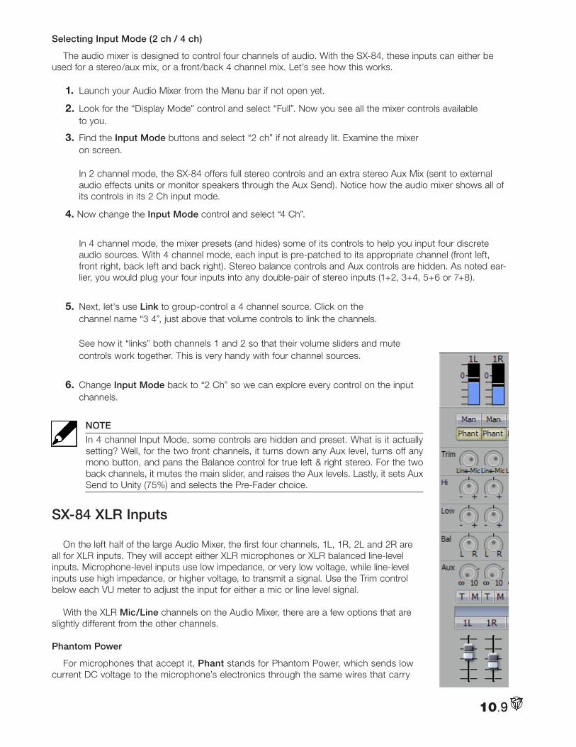
10.9
Selecting Input Mode (2 ch / 4 ch)
The audio mixer is designed to control four channels of audio. With the SX-84, these inputs can either be used for a stereo/aux mix, or a front/back 4 channel mix. Let’s see how this works.
1. Launch your Audio Mixer from the Menu bar if not open yet.
2. Look for the “Display Mode” control and select “Full”. Now you see all the mixer controls available to you.
3. Find the Input Mode buttons and select “2 ch” if not already lit. Examine the mixer on screen. In 2 channel mode, the SX-84 offers full stereo controls and an extra stereo Aux Mix (sent to external audio effects units or monitor speakers through the Aux Send). Notice how the audio mixer shows all of its controls in its 2 Ch input mode.
4. Now change the Input Mode control and select “4 Ch”.
In 4 channel mode, the mixer presets (and hides) some of its controls to help you input four discrete audio sources. With 4 channel mode, each input is pre-patched to its appropriate channel (front left, front right, back left and back right). Stereo balance controls and Aux controls are hidden. As noted ear-lier, you would plug your four inputs into any double-pair of stereo inputs (1+2, 3+4, 5+6 or 7+8).
5. Next, let's use Link to group-control a 4 channel source. Click on the channel name “3 4”, just above that volume controls to link the channels. See how it “links” both channels 1 and 2 so that their volume sliders and mute controls work together. This is very handy with four channel sources.
6. Change Input Mode back to “2 Ch” so we can explore every control on the input channels.
NOTE
In 4 channel Input Mode, some controls are hidden and preset. What is it actually setting? Well, for the two front channels, it turns down any Aux level, turns off any mono button, and pans the Balance control for true left & right stereo. For the two back channels, it mutes the main slider, and raises the Aux levels. Lastly, it sets Aux Send to Unity (75%) and selects the Pre-Fader choice.
SX-84 XLR Inputs
On the left half of the large Audio Mixer, the first four channels, 1L, 1R, 2L and 2R are all for XLR inputs. They will accept either XLR microphones or XLR balanced line-level inputs. Microphone-level inputs use low impedance, or very low voltage, while line-level inputs use high impedance, or higher voltage, to transmit a signal. Use the Trim control below each VU meter to adjust the input for either a mic or line level signal.
With the XLR Mic/Line channels on the Audio Mixer, there are a few options that are slightly different from the other channels.
Phantom Power
For microphones that accept it, Phant stands for Phantom Power, which sends low current DC voltage to the microphone’s electronics through the same wires that carry
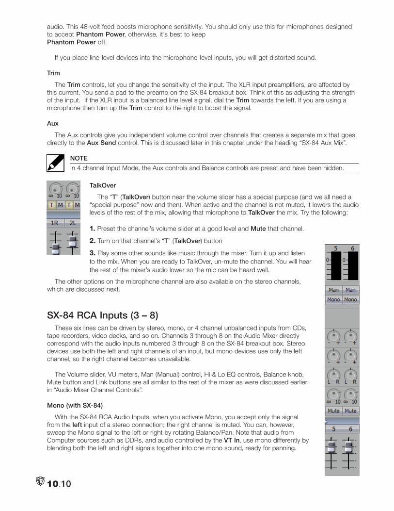
10.10
audio. This 48-volt feed boosts microphone sensitivity. You should only use this for microphones designed to accept Phantom Power, otherwise, it’s best to keep Phantom Power off.
If you place line-level devices into the microphone-level inputs, you will get distorted sound.
Trim
The Trim controls, let you change the sensitivity of the input. The XLR input preamplifiers, are affected by this current. You send a pad to the preamp on the SX-84 breakout box. Think of this as adjusting the strength of the input. If the XLR input is a balanced line level signal, dial the Trim towards the left. If you are using a microphone then turn up the Trim control to the right to boost the signal.
Aux
The Aux controls give you independent volume control over channels that creates a separate mix that goes directly to the Aux Send control. This is discussed later in this chapter under the heading “SX-84 Aux Mix”.
NOTE
In 4 channel Input Mode, the Aux controls and Balance controls are preset and have been hidden.
TalkOver
The “T” (TalkOver) button near the volume slider has a special purpose (and we all need a “special purpose” now and then). When active and the channel is not muted, it lowers the audio levels of the rest of the mix, allowing that microphone to TalkOver the mix. Try the following:
1. Preset the channel’s volume slider at a good level and Mute that channel.
2. Turn on that channel’s “T” (TalkOver) button
3. Play some other sounds like music through the mixer. Turn it up and listen to the mix. When you are ready to TalkOver, un-mute the channel. You will hear the rest of the mixer’s audio lower so the mic can be heard well.
The other options on the microphone channel are also available on the stereo channels, which are discussed next.
SX-84 RCA Inputs (3 – 8) These six lines can be driven by stereo, mono, or 4 channel unbalanced inputs from CDs,
tape recorders, video decks, and so on. Channels 3 through 8 on the Audio Mixer directly correspond with the audio inputs numbered 3 through 8 on the SX-84 breakout box. Stereo devices use both the left and right channels of an input, but mono devices use only the left channel, so the right channel becomes unavailable.
The Volume slider, VU meters, Man (Manual) control, Hi & Lo EQ controls, Balance knob,
Mute button and Link buttons are all similar to the rest of the mixer as were discussed earlier in “Audio Mixer Channel Controls”.
Mono (with SX-84)
With the SX-84 RCA Audio Inputs, when you activate Mono, you accept only the signal from the left input of a stereo connection; the right channel is muted. You can, however, sweep the Mono signal to the left or right by rotating Balance/Pan. Note that audio from Computer sources such as DDRs, and audio controlled by the VT In, use mono differently by blending both the left and right signals together into one mono sound, ready for panning.
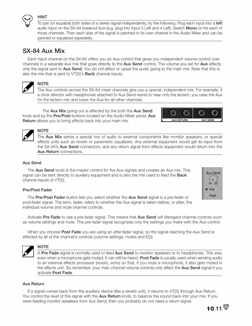
10.11
HINT
To pan (or equalize) both sides of a stereo signal independently, try the following. Plug each input into a left audio input on the SX-84 breakout box (e.g. plug into Input 3 Left and 4 Left). Switch Mono on for each of those channels. Then each side of the signal is patched to its own channel in the Audio Mixer and can be panned or equalized separately.
SX-84 Aux Mix Each input channel on the SX-84 offers you an Aux control that gives you independent volume control over
channels in a separate Aux mix that goes directly to the Aux Send control. The volume you set for Aux affects only the signal sent to Aux Send. You do not affect or upset the audio going to the main mix. Note that this is also the mix that is sent to VT[5]’s Back channel inputs.
NOTE
The Aux controls across the SX-84 mixer channels give you a special, independent mix. For example, if a choir director with headphones attached to Aux Send wants to hear only the lectern, you raise the Aux for the lectern mic and lower the Aux for all other channels.
The Aux Mix going out is affected by the both the Aux Send knob and by the Pre/Post buttons located on the Audio Mixer panel. Aux Return allows you to bring effects back into your main mix.
NOTE
The Aux Mix sends a special mix of audio to external components like monitor speakers, or special effects units such as reverb or parametric equalizers. Any external equipment would get its input from the SX-84’s Aux Send connectors, and any return signal from effects equipment would return into the Aux Return connections.
Aux Send
The Aux Send knob is the master control for the Aux signals and creates an Aux mix. This signal can be sent directly to auxiliary equipment and is also the mix used to feed the Back channel inputs of VT[5].
Pre/Post Fader
The Pre/Post Fader button lets you select whether the Aux Send signal is a pre-fader or post-fader signal. The term, fader, refers to whether the Aux signal is taken before, or after, the individual volume and mute channel controls.
Activate Pre Fade to use a pre-fader signal. This means that Aux Send will disregard channel controls such as volume settings and mute. The pre-fader signal recognizes only the settings you make with the Aux control.
When you choose Post Fade you are using an after-fader signal, so the signal reaching the Aux Send is affected by all of the channel’s controls (volume settings, mutes and EQ).
NOTE
A Pre Fade signal is normally used to feed Aux Send to monitor speakers or to headphones. This way, even when a microphone gets muted, it can still be heard. Post Fade is usually used when sending audio to an external effects processor (reverb, echo) so that, if you mute a microphone, it also gets muted in the effects unit. So remember, your main channel volume controls only affect the Aux Send signal if you activate Post Fade.
Aux Return
If a signal comes back from the auxiliary device (like a reverb unit), it returns to VT[5] through Aux Return. You control the level of this signal with the Aux Return knob, to balance the sound back into your mix. If you were feeding monitor speakers from Aux Send, then you probably do not need a return signal.
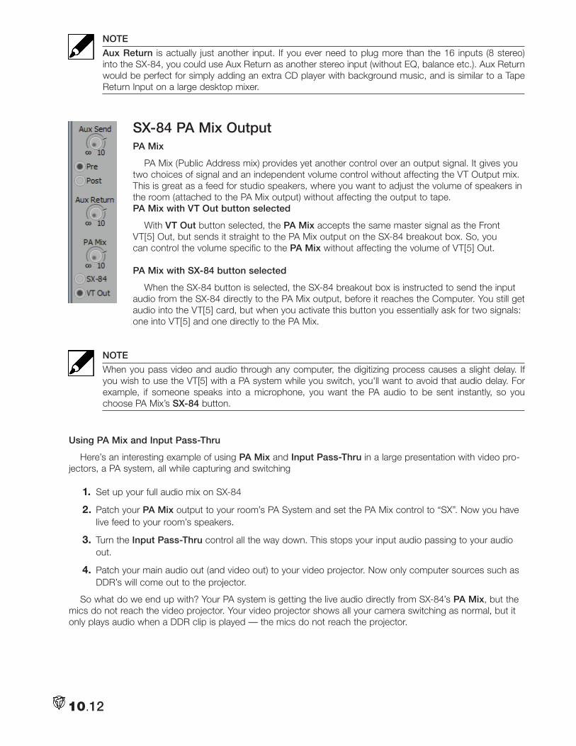
10.12
NOTE
Aux Return is actually just another input. If you ever need to plug more than the 16 inputs (8 stereo) into the SX-84, you could use Aux Return as another stereo input (without EQ, balance etc.). Aux Return would be perfect for simply adding an extra CD player with background music, and is similar to a Tape Return Input on a large desktop mixer.
SX-84 PA Mix OutputPA Mix
PA Mix (Public Address mix) provides yet another control over an output signal. It gives you two choices of signal and an independent volume control without affecting the VT Output mix. This is great as a feed for studio speakers, where you want to adjust the volume of speakers in the room (attached to the PA Mix output) without affecting the output to tape.PA Mix with VT Out button selected
With VT Out button selected, the PA Mix accepts the same master signal as the Front VT[5] Out, but sends it straight to the PA Mix output on the SX-84 breakout box. So, you can control the volume specific to the PA Mix without affecting the volume of VT[5] Out.
PA Mix with SX-84 button selected
When the SX-84 button is selected, the SX-84 breakout box is instructed to send the input audio from the SX-84 directly to the PA Mix output, before it reaches the Computer. You still get audio into the VT[5] card, but when you activate this button you essentially ask for two signals: one into VT[5] and one directly to the PA Mix.
NOTE
When you pass video and audio through any computer, the digitizing process causes a slight delay. If you wish to use the VT[5] with a PA system while you switch, you'll want to avoid that audio delay. For example, if someone speaks into a microphone, you want the PA audio to be sent instantly, so you choose PA Mix’s SX-84 button.
Using PA Mix and Input Pass-Thru
Here’s an interesting example of using PA Mix and Input Pass-Thru in a large presentation with video pro-jectors, a PA system, all while capturing and switching
1. Set up your full audio mix on SX-84
2. Patch your PA Mix output to your room’s PA System and set the PA Mix control to “SX”. Now you have live feed to your room’s speakers.
3. Turn the Input Pass-Thru control all the way down. This stops your input audio passing to your audio out.
4. Patch your main audio out (and video out) to your video projector. Now only computer sources such as DDR’s will come out to the projector.
So what do we end up with? Your PA system is getting the live audio directly from SX-84’s PA Mix, but the mics do not reach the video projector. Your video projector shows all your camera switching as normal, but it only plays audio when a DDR clip is played — the mics do not reach the projector.
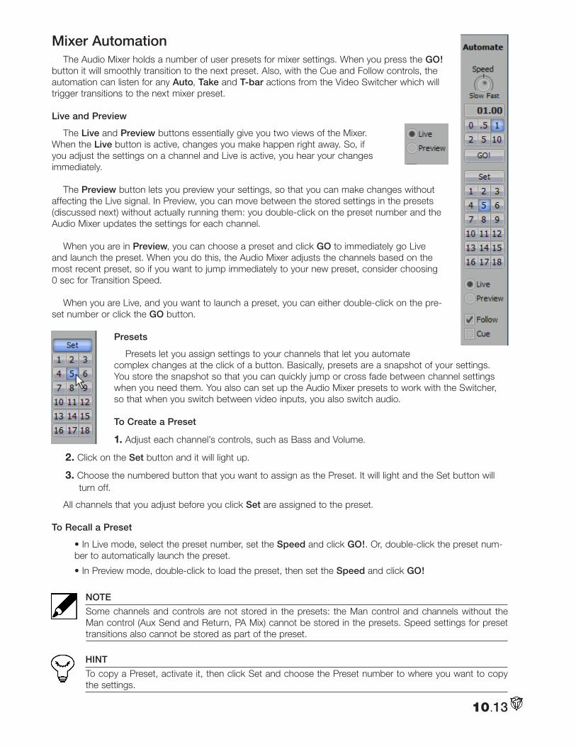
10.13
Mixer AutomationThe Audio Mixer holds a number of user presets for mixer settings. When you press the GO!
button it will smoothly transition to the next preset. Also, with the Cue and Follow controls, the automation can listen for any Auto, Take and T-bar actions from the Video Switcher which will trigger transitions to the next mixer preset.
Live and Preview
The Live and Preview buttons essentially give you two views of the Mixer. When the Live button is active, changes you make happen right away. So, if you adjust the settings on a channel and Live is active, you hear your changes immediately.
The Preview button lets you preview your settings, so that you can make changes without affecting the Live signal. In Preview, you can move between the stored settings in the presets (discussed next) without actually running them: you double-click on the preset number and the Audio Mixer updates the settings for each channel.
When you are in Preview, you can choose a preset and click GO to immediately go Live and launch the preset. When you do this, the Audio Mixer adjusts the channels based on the most recent preset, so if you want to jump immediately to your new preset, consider choosing 0 sec for Transition Speed.
When you are Live, and you want to launch a preset, you can either double-click on the pre-set number or click the GO button.
Presets
Presets let you assign settings to your channels that let you automate complex changes at the click of a button. Basically, presets are a snapshot of your settings. You store the snapshot so that you can quickly jump or cross fade between channel settings when you need them. You also can set up the Audio Mixer presets to work with the Switcher, so that when you switch between video inputs, you also switch audio.
To Create a Preset
1. Adjust each channel’s controls, such as Bass and Volume.
2. Click on the Set button and it will light up.
3. Choose the numbered button that you want to assign as the Preset. It will light and the Set button will turn off.
All channels that you adjust before you click Set are assigned to the preset.
To Recall a Preset
• In Live mode, select the preset number, set the Speed and click GO!. Or, double-click the preset num-ber to automatically launch the preset.
• In Preview mode, double-click to load the preset, then set the Speed and click GO!
NOTE
Some channels and controls are not stored in the presets: the Man control and channels without the Man control (Aux Send and Return, PA Mix) cannot be stored in the presets. Speed settings for preset transitions also cannot be stored as part of the preset.
HINT
To copy a Preset, activate it, then click Set and choose the Preset number to where you want to copy the settings.
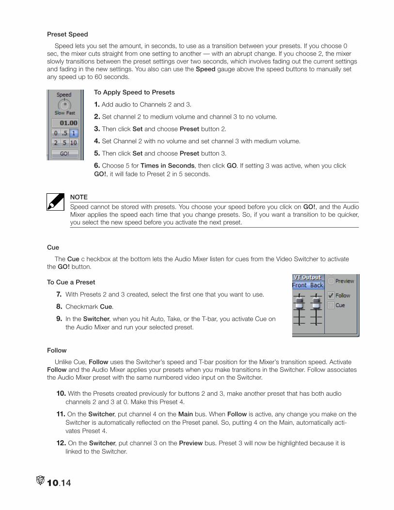
10.14
Preset Speed
Speed lets you set the amount, in seconds, to use as a transition between your presets. If you choose 0 sec, the mixer cuts straight from one setting to another — with an abrupt change. If you choose 2, the mixer slowly transitions between the preset settings over two seconds, which involves fading out the current settings and fading in the new settings. You also can use the Speed gauge above the speed buttons to manually set any speed up to 60 seconds.
To Apply Speed to Presets
1. Add audio to Channels 2 and 3.
2. Set channel 2 to medium volume and channel 3 to no volume.
3. Then click Set and choose Preset button 2.
4. Set Channel 2 with no volume and set channel 3 with medium volume.
5. Then click Set and choose Preset button 3.
6. Choose 5 for Times in Seconds, then click GO. If setting 3 was active, when you click GO!, it will fade to Preset 2 in 5 seconds.
NOTE
Speed cannot be stored with presets. You choose your speed before you click on GO!, and the Audio Mixer applies the speed each time that you change presets. So, if you want a transition to be quicker, you select the new speed before you activate the next preset.
Cue
The Cue c heckbox at the bottom lets the Audio Mixer listen for cues from the Video Switcher to activate the GO! button.
To Cue a Preset
7. With Presets 2 and 3 created, select the first one that you want to use.
8. Checkmark Cue.
9. In the Switcher, when you hit Auto, Take, or the T-bar, you activate Cue on the Audio Mixer and run your selected preset.
Follow
Unlike Cue, Follow uses the Switcher’s speed and T-bar position for the Mixer’s transition speed. Activate Follow and the Audio Mixer applies your presets when you make transitions in the Switcher. Follow associates the Audio Mixer preset with the same numbered video input on the Switcher.
10. With the Presets created previously for buttons 2 and 3, make another preset that has both audio channels 2 and 3 at 0. Make this Preset 4.
11. On the Switcher, put channel 4 on the Main bus. When Follow is active, any change you make on the Switcher is automatically reflected on the Preset panel. So, putting 4 on the Main, automatically acti-vates Preset 4.
12. On the Switcher, put channel 3 on the Preview bus. Preset 3 will now be highlighted because it is linked to the Switcher.
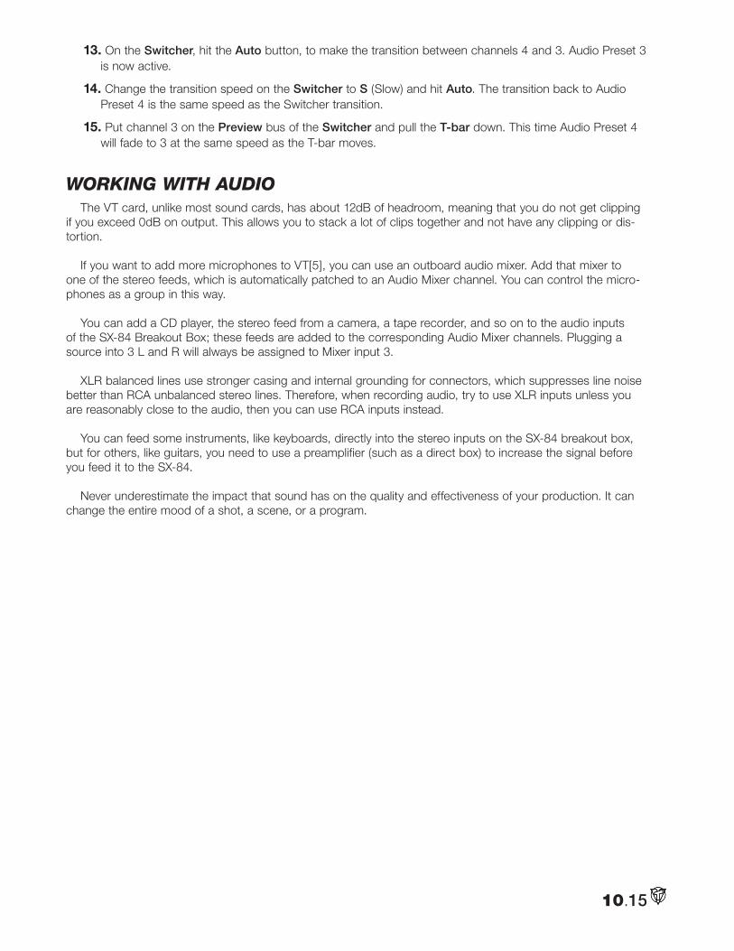
10.15
13. On the Switcher, hit the Auto button, to make the transition between channels 4 and 3. Audio Preset 3 is now active.
14. Change the transition speed on the Switcher to S (Slow) and hit Auto. The transition back to Audio Preset 4 is the same speed as the Switcher transition.
15. Put channel 3 on the Preview bus of the Switcher and pull the T-bar down. This time Audio Preset 4 will fade to 3 at the same speed as the T-bar moves.
woRking witH audioThe VT card, unlike most sound cards, has about 12dB of headroom, meaning that you do not get clipping
if you exceed 0dB on output. This allows you to stack a lot of clips together and not have any clipping or dis-tortion.
If you want to add more microphones to VT[5], you can use an outboard audio mixer. Add that mixer to one of the stereo feeds, which is automatically patched to an Audio Mixer channel. You can control the micro-phones as a group in this way.
You can add a CD player, the stereo feed from a camera, a tape recorder, and so on to the audio inputs of the SX-84 Breakout Box; these feeds are added to the corresponding Audio Mixer channels. Plugging a source into 3 L and R will always be assigned to Mixer input 3.
XLR balanced lines use stronger casing and internal grounding for connectors, which suppresses line noise better than RCA unbalanced stereo lines. Therefore, when recording audio, try to use XLR inputs unless you are reasonably close to the audio, then you can use RCA inputs instead.
You can feed some instruments, like keyboards, directly into the stereo inputs on the SX-84 breakout box, but for others, like guitars, you need to use a preamplifier (such as a direct box) to increase the signal before you feed it to the SX-84.
Never underestimate the impact that sound has on the quality and effectiveness of your production. It can change the entire mood of a shot, a scene, or a program.

10.16
Notes:
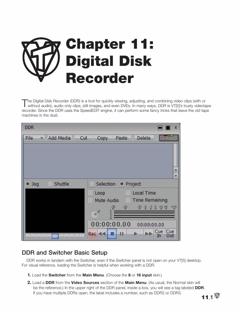
The Digital Disk Recorder (DDR) is a tool for quickly viewing, adjusting, and combining video clips (with or without audio), audio only clips, still images, and even DVEs. In many ways, DDR is VT[5]’s trusty videotape
recorder. Since the DDR uses the SpeedEDIT engine, it can perform some fancy tricks that leave the old tape machines in the dust.
DDR and Switcher Basic SetupDDR works in tandem with the Switcher, even if the Switcher panel is not open on your VT[5] desktop.
For visual reference, loading the Switcher is helpful when working with a DDR.
1. Load the Switcher from the Main Menu. (Choose the 8 or 16 input skin.)
2. Load a DDR from the Video Sources section of the Main Menu. (As usual, the Normal skin will be the reference.) In the upper right of the DDR panel, inside a box, you will see a tag labeled DDR. If you have multiple DDRs open, the label includes a number, such as DDR2 or DDR3.
11.1
Chapter 11: Digital Disk Recorder
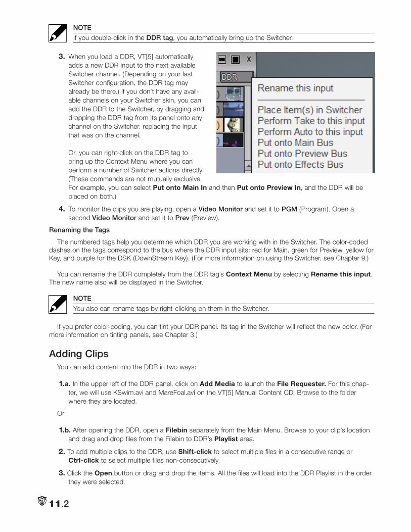
NOTE
If you double-click in the DDR tag, you automatically bring up the Switcher.
3. When you load a DDR, VT[5] automatically adds a new DDR input to the next available Switcher channel. (Depending on your last Switcher configuration, the DDR tag may already be there.) If you don’t have any avail-able channels on your Switcher skin, you can add the DDR to the Switcher, by dragging and dropping the DDR tag from its panel onto any channel on the Switcher. replacing the input that was on the channel. Or, you can right-click on the DDR tag to bring up the Context Menu where you can perform a number of Switcher actions directly. (These commands are not mutually exclusive. For example, you can select Put onto Main In and then Put onto Preview In, and the DDR will be placed on both.)
4. To monitor the clips you are playing, open a Video Monitor and set it to PGM (Program). Open a second Video Monitor and set it to Prev (Preview).
Renaming the Tags
The numbered tags help you determine which DDR you are working with in the Switcher. The color-coded dashes on the tags correspond to the bus where the DDR input sits: red for Main, green for Preview, yellow for Key, and purple for the DSK (DownStream Key). (For more information on using the Switcher, see Chapter 9.)
You can rename the DDR completely from the DDR tag’s Context Menu by selecting Rename this input. The new name also will be displayed in the Switcher.
NOTE
You also can rename tags by right-clicking on them in the Switcher.
If you prefer color-coding, you can tint your DDR panel. Its tag in the Switcher will reflect the new color. (For more information on tinting panels, see Chapter 3.)
Adding ClipsYou can add content into the DDR in two ways:
1.a. In the upper left of the DDR panel, click on Add Media to launch the File Requester. For this chap-ter, we will use KSwim.avi and MareFoal.avi on the VT[5] Manual Content CD. Browse to the folder where they are located.
Or
1.b. After opening the DDR, open a Filebin separately from the Main Menu. Browse to your clip’s location and drag and drop files from the Filebin to DDR’s Playlist area.
2. To add multiple clips to the DDR, use Shift-click to select multiple files in a consecutive range or Ctrl-click to select multiple files non-consecutively.
3. Click the Open button or drag and drop the items. All the files will load into the DDR Playlist in the order they were selected.
11.2
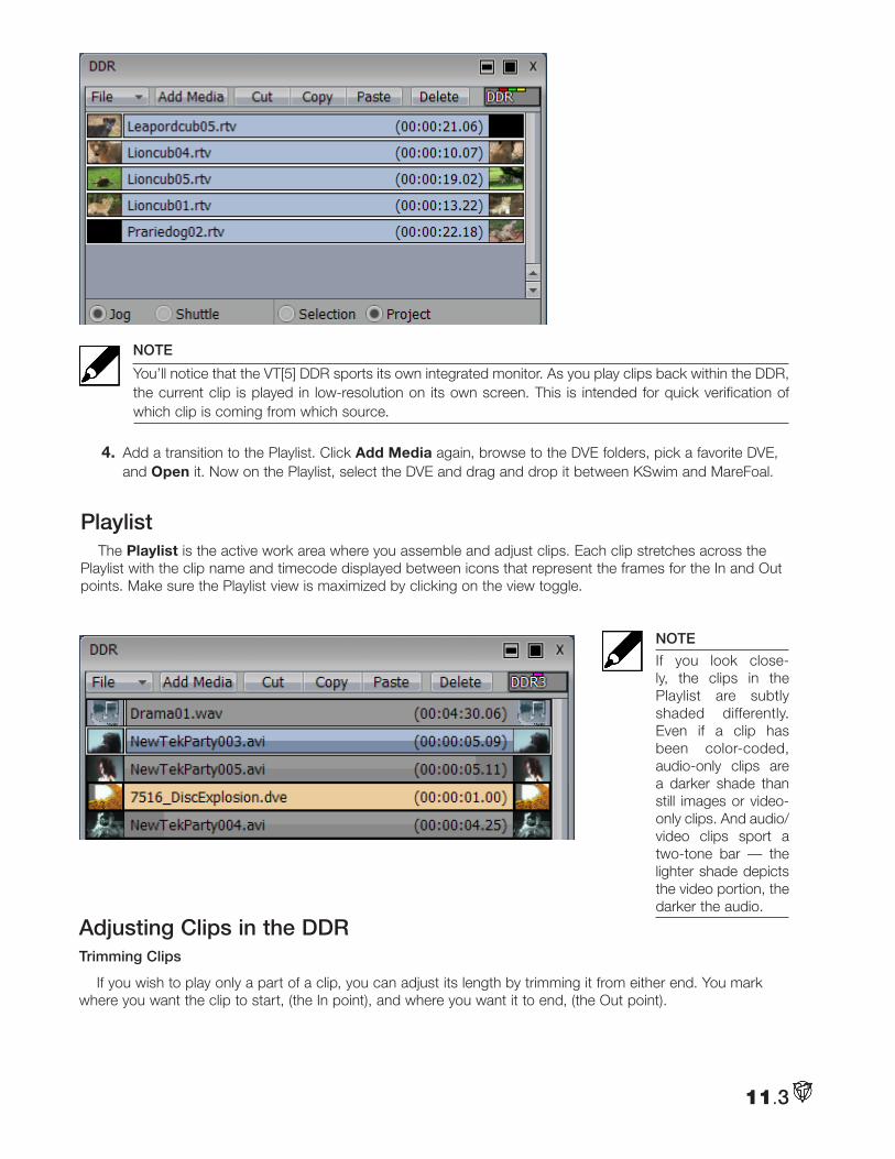
NOTE
You’ll notice that the VT[5] DDR sports its own integrated monitor. As you play clips back within the DDR, the current clip is played in low-resolution on its own screen. This is intended for quick verification of which clip is coming from which source.
4. Add a transition to the Playlist. Click Add Media again, browse to the DVE folders, pick a favorite DVE, and Open it. Now on the Playlist, select the DVE and drag and drop it between KSwim and MareFoal.
PlaylistThe Playlist is the active work area where you assemble and adjust clips. Each clip stretches across the
Playlist with the clip name and timecode displayed between icons that represent the frames for the In and Out points. Make sure the Playlist view is maximized by clicking on the view toggle.
NOTE
If you look close-ly, the clips in the Playlist are subtly shaded differently. Even if a clip has been color-coded, audio-only clips are a darker shade than still images or video-only clips. And audio/video clips sport a two-tone bar — the lighter shade depicts the video portion, the darker the audio.
11.3
Adjusting Clips in the DDRTrimming Clips
If you wish to play only a part of a clip, you can adjust its length by trimming it from either end. You mark where you want the clip to start, (the In point), and where you want it to end, (the Out point).
1. When you hover your mouse over the left edge of the clip, the cursor changes to crossbars with the word IN.
2. Click and drag the mouse to the right to move to the In point of your clip. (For visual reference, watch the playback in a Preview Video Monitor. If the clip has audio, you will hear it as you scrub.) Also, the timecode display on the clip’s icon changes from clip length to In point time.
3. When you reach the frame you want as the In point, release the mouse button. The new clip length updates.
4. Follow the same procedure to mark your Out point, except you must hover over the right edge of the clip and start by scrubbing to the left.
NOTE
If you need to adjust the In or Out point again, you must place the cursor over the appropriate end of the clip; do not place the cursor at the position of the In point or Out point.
5. If you want to adjust the In or Out point without changing the length of the clip, hover over one of the clip’s edges and hold the Shift key. The cursor will change to S/S (slip and slide). Now when you click and drag, the In and Out points move in tandem, leaving the clip’s length the same.
NOTE
Adjusting still images in the DDR is a little different since the clips do not have normal In and Out points. When you hover your mouse over either edge of the clip, the cursor changes to LEN for length. If you click and drag left (from either end of the clip), you shorten the length of the clip. Drag right and the clip is lengthened. The timecode display gives real-time updates.
Trimming Audio Clips
You trim audio-only clips the same as video clips. If your video clips have interleaved audio, you can trim the In and Out points for video and audio together or independently.
• To trim both audio and video, follow the procedure above for trimming a video clip.
• To trim only audio, hold the Ctrl key and follow the procedure for trimming a video clip. Notice that the word Audio appears on the clip.
Moving and Cloning Clips
You can easily change the order of items in the Playlist. Just select a clip and drag it up or down. When you find the new position for your clip, release the mouse button to accept. The item will insert between other clips in real-time.
To duplicate a clip in your Playlist, select it, Copy and Paste it. (Either use the buttons on the panel or the standard keyboard shortcuts, Ctrl + c [Copy] and Ctrl + v [Paste]. Or right-click on the clip and select the functions from the Context Menu.)
A clone in the Playlist allows you to play different parts of a clip by setting different In and Out points for the clones.
NOTE
When you copy a clip, you clone only on the DDR. This action does not put extra copies of the clip on your hard drive.
11.4
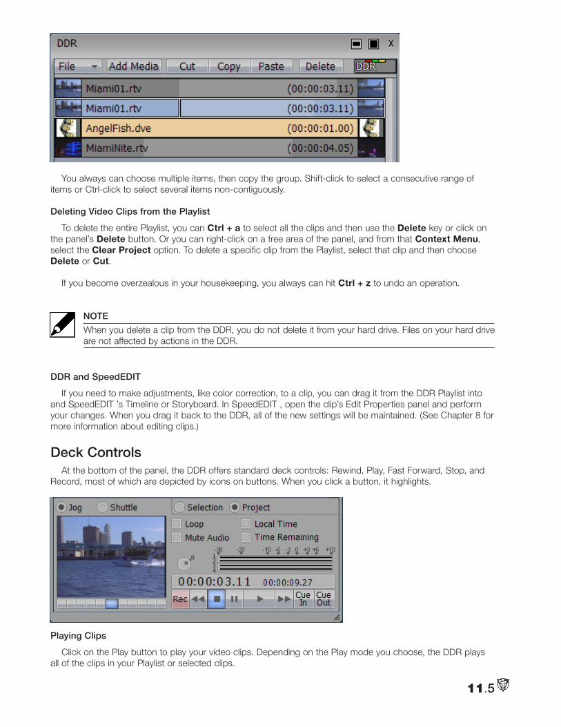
You always can choose multiple items, then copy the group. Shift-click to select a consecutive range of items or Ctrl-click to select several items non-contiguously.
Deleting Video Clips from the Playlist
To delete the entire Playlist, you can Ctrl + a to select all the clips and then use the Delete key or click on the panel’s Delete button. Or you can right-click on a free area of the panel, and from that Context Menu, select the Clear Project option. To delete a specific clip from the Playlist, select that clip and then choose Delete or Cut.
If you become overzealous in your housekeeping, you always can hit Ctrl + z to undo an operation.
NOTE
When you delete a clip from the DDR, you do not delete it from your hard drive. Files on your hard drive are not affected by actions in the DDR.
DDR and SpeedEDIT
If you need to make adjustments, like color correction, to a clip, you can drag it from the DDR Playlist into and SpeedEDIT ’s Timeline or Storyboard. In SpeedEDIT , open the clip’s Edit Properties panel and perform your changes. When you drag it back to the DDR, all of the new settings will be maintained. (See Chapter 8 for more information about editing clips.)
Deck ControlsAt the bottom of the panel, the DDR offers standard deck controls: Rewind, Play, Fast Forward, Stop, and
Record, most of which are depicted by icons on buttons. When you click a button, it highlights.
Playing Clips
Click on the Play button to play your video clips. Depending on the Play mode you choose, the DDR plays all of the clips in your Playlist or selected clips.
11.5
NOTE
A vertical line travels across the clip giving you a visual reference about your position when you use any of the deck controls.
To force the DDR to jump to the beginning of a clip, double-click on the Stop button.
NOTE
Remember to adjust the DDR Resource Usage, (in the Preferences panel under Switcher), for the types of clips you plan to play. Use Low resource usage for cuts-only, low-motion video, Medium resource usage for files with few transitions, and High resource usage for projects with a lot of special effects. Using more resources makes your processor work harder, and may slow other areas of VT[5].
Selection Mode
When you click the button labeled Selection, (below the Playlist), you instruct the DDR to recognize the clips individually when using the Cue function (explained below).
You choose a clip by clicking on it with your cursor. Shift-click to select a range of clips, and Ctrl-click to select multiple clips independently. Thus, you can select more than one video clip and the DDR plays only those items that you’ve selected and ignores any other clips in the Playlist.
The DDR also plays the clips in the order that you selected them. For example, let’s say you have ten clips named One through Ten. If you wish to play Three, Seven, Two, and Nine, just Ctrl-click to choose them in that order.
To unselect all clips, click on an empty part of the work area. When no clips are selected, the DDR plays all the clips — even when the Selection mode is chosen.
Project Mode
If you click the Project button, the DDR plays everything it sees in the Playlist, regardless of any selections you make. It is as if all the clips in the queue are one, long clip. When Cue is active, this also treats all clips as one extended clip.
Loop Play Mode
If the Loop button is checked, the selected clips will play repeatedly — continuously looping — until you click Stop.
If you double-click on any DDR clip, that selected clip loops; the DDR does not loop through the entire project. You can loop a group of clips by choosing either Selection or Project mode and choosing the clips that you want to repeat. The DDR runs through each selected clip until it reaches the end of the last clip and then it loops back to the first clip. To loop the entire project, either select all of the clips or make sure no single clip is selected.
Timecode DisplayNOTE
This manual often refers to timecode in the generic sense as the length of a clip (measured in hours, minutes, seconds, and frames). Though, it also uses it in the specific sense as an absolute address for each frame of video. (See below, Video 101: Timecode.) Depending on how you captured your clips, they will either have timecode already attached or VT[5] will give it timecode.
You can choose how the DDR shows timecode in the two time displays above the Deck Controls.
11.6
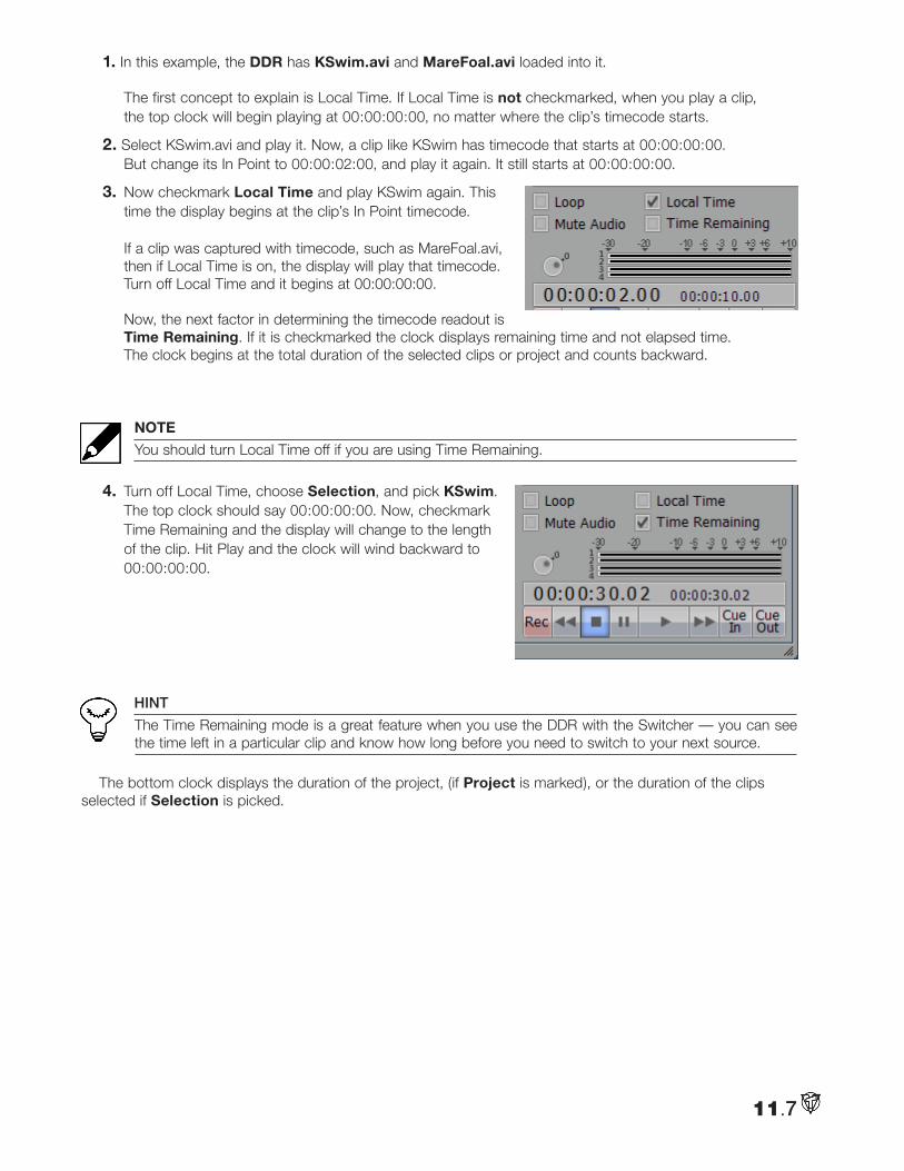
1. In this example, the DDR has KSwim.avi and MareFoal.avi loaded into it. The first concept to explain is Local Time. If Local Time is not checkmarked, when you play a clip, the top clock will begin playing at 00:00:00:00, no matter where the clip’s timecode starts.
2. Select KSwim.avi and play it. Now, a clip like KSwim has timecode that starts at 00:00:00:00. But change its In Point to 00:00:02:00, and play it again. It still starts at 00:00:00:00.
3. Now checkmark Local Time and play KSwim again. This time the display begins at the clip’s In Point timecode. If a clip was captured with timecode, such as MareFoal.avi, then if Local Time is on, the display will play that timecode. Turn off Local Time and it begins at 00:00:00:00. Now, the next factor in determining the timecode readout is Time Remaining. If it is checkmarked the clock displays remaining time and not elapsed time. The clock begins at the total duration of the selected clips or project and counts backward.
NOTE
You should turn Local Time off if you are using Time Remaining.
4. Turn off Local Time, choose Selection, and pick KSwim. The top clock should say 00:00:00:00. Now, checkmark Time Remaining and the display will change to the length of the clip. Hit Play and the clock will wind backward to 00:00:00:00.
HINT
The Time Remaining mode is a great feature when you use the DDR with the Switcher — you can see the time left in a particular clip and know how long before you need to switch to your next source.
The bottom clock displays the duration of the project, (if Project is marked), or the duration of the clips selected if Selection is picked.
11.7
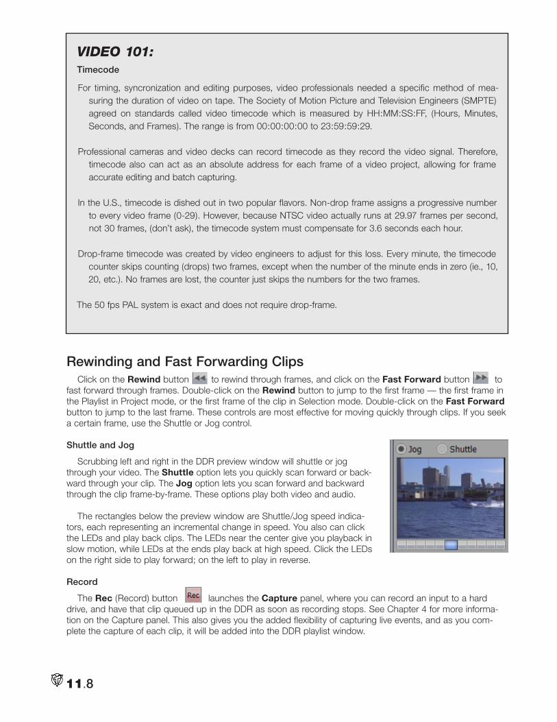
Rewinding and Fast Forwarding ClipsClick on the Rewind button to rewind through frames, and click on the Fast Forward button to
fast forward through frames. Double-click on the Rewind button to jump to the first frame — the first frame in the Playlist in Project mode, or the first frame of the clip in Selection mode. Double-click on the Fast Forward button to jump to the last frame. These controls are most effective for moving quickly through clips. If you seek a certain frame, use the Shuttle or Jog control.
Shuttle and Jog
Scrubbing left and right in the DDR preview window will shuttle or jog through your video. The Shuttle option lets you quickly scan forward or back-ward through your clip. The Jog option lets you scan forward and backward through the clip frame-by-frame. These options play both video and audio.
The rectangles below the preview window are Shuttle/Jog speed indica-tors, each representing an incremental change in speed. You also can click the LEDs and play back clips. The LEDs near the center give you playback in slow motion, while LEDs at the ends play back at high speed. Click the LEDs on the right side to play forward; on the left to play in reverse.
Record
The Rec (Record) button launches the Capture panel, where you can record an input to a hard drive, and have that clip queued up in the DDR as soon as recording stops. See Chapter 4 for more informa-tion on the Capture panel. This also gives you the added flexibility of capturing live events, and as you com-plete the capture of each clip, it will be added into the DDR playlist window.
11.8
Video 101:Timecode
For timing, syncronization and editing purposes, video professionals needed a specific method of mea-suring the duration of video on tape. The Society of Motion Picture and Television Engineers (SMPTE) agreed on standards called video timecode which is measured by HH:MM:SS:FF, (Hours, Minutes, Seconds, and Frames). The range is from 00:00:00:00 to 23:59:59:29.
Professional cameras and video decks can record timecode as they record the video signal. Therefore, timecode also can act as an absolute address for each frame of a video project, allowing for frame accurate editing and batch capturing.
In the U.S., timecode is dished out in two popular flavors. Non-drop frame assigns a progressive number to every video frame (0-29). However, because NTSC video actually runs at 29.97 frames per second, not 30 frames, (don’t ask), the timecode system must compensate for 3.6 seconds each hour.
Drop-frame timecode was created by video engineers to adjust for this loss. Every minute, the timecode counter skips counting (drops) two frames, except when the number of the minute ends in zero (ie., 10, 20, etc.). No frames are lost, the counter just skips the numbers for the two frames.
The 50 fps PAL system is exact and does not require drop-frame.
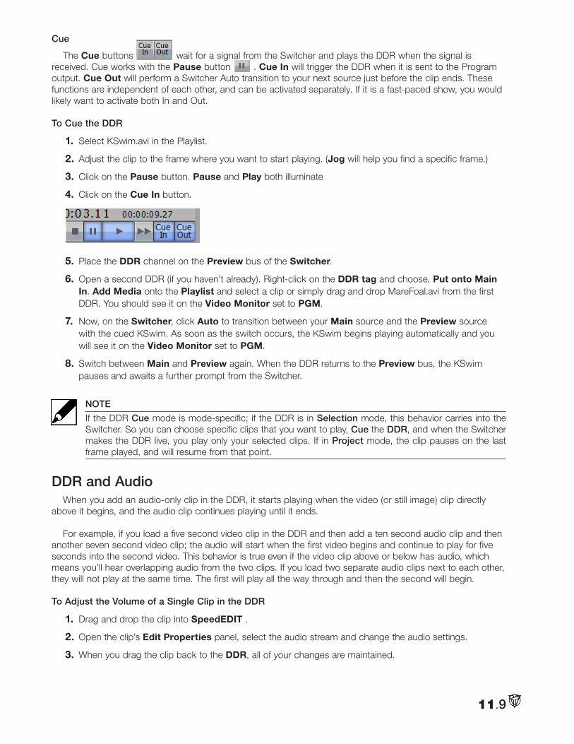
Cue
The Cue buttons wait for a signal from the Switcher and plays the DDR when the signal is received. Cue works with the Pause button . Cue In will trigger the DDR when it is sent to the Program output. Cue Out will perform a Switcher Auto transition to your next source just before the clip ends. These functions are independent of each other, and can be activated separately. If it is a fast-paced show, you would likely want to activate both In and Out.
To Cue the DDR
1. Select KSwim.avi in the Playlist.
2. Adjust the clip to the frame where you want to start playing. (Jog will help you find a specific frame.)
3. Click on the Pause button. Pause and Play both illuminate
4. Click on the Cue In button.
5. Place the DDR channel on the Preview bus of the Switcher.
6. Open a second DDR (if you haven’t already). Right-click on the DDR tag and choose, Put onto Main In. Add Media onto the Playlist and select a clip or simply drag and drop MareFoal.avi from the first DDR. You should see it on the Video Monitor set to PGM.
7. Now, on the Switcher, click Auto to transition between your Main source and the Preview source with the cued KSwim. As soon as the switch occurs, the KSwim begins playing automatically and you will see it on the Video Monitor set to PGM.
8. Switch between Main and Preview again. When the DDR returns to the Preview bus, the KSwim pauses and awaits a further prompt from the Switcher.
NOTE
If the DDR Cue mode is mode-specific; if the DDR is in Selection mode, this behavior carries into the Switcher. So you can choose specific clips that you want to play, Cue the DDR, and when the Switcher makes the DDR live, you play only your selected clips. If in Project mode, the clip pauses on the last frame played, and will resume from that point.
DDR and AudioWhen you add an audio-only clip in the DDR, it starts playing when the video (or still image) clip directly
above it begins, and the audio clip continues playing until it ends.
For example, if you load a five second video clip in the DDR and then add a ten second audio clip and then another seven second video clip; the audio will start when the first video begins and continue to play for five seconds into the second video. This behavior is true even if the video clip above or below has audio, which means you’ll hear overlapping audio from the two clips. If you load two separate audio clips next to each other, they will not play at the same time. The first will play all the way through and then the second will begin.
To Adjust the Volume of a Single Clip in the DDR
1. Drag and drop the clip into SpeedEDIT .
2. Open the clip’s Edit Properties panel, select the audio stream and change the audio settings.
3. When you drag the clip back to the DDR, all of your changes are maintained.
11.9
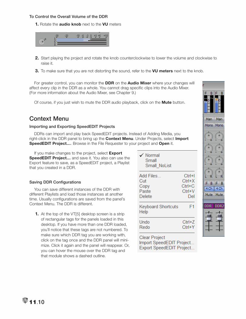
To Control the Overall Volume of the DDR
1. Rotate the audio knob next to the VU meters
2. Start playing the project and rotate the knob counterclockwise to lower the volume and clockwise to raise it.
3. To make sure that you are not distorting the sound, refer to the VU meters next to the knob.
For greater control, you can monitor the DDR on the Audio Mixer where your changes will affect every clip in the DDR as a whole. You cannot drag specific clips into the Audio Mixer. (For more information about the Audio Mixer, see Chapter 9.)
Of course, if you just wish to mute the DDR audio playback, click on the Mute button.
Context MenuImporting and Exporting SpeedEDIT Projects
DDRs can import and play back SpeedEDIT projects. Instead of Adding Media, you right-click in the DDR panel to bring up the Context Menu. Under Projects, select Import SpeedEDIT Project…. Browse in the File Requester to your project and Open it.
If you make changes to the project, select Export SpeedEDIT Project… and save it. You also can use the Export feature to save, as a SpeedEDIT project, a Playlist that you created in a DDR.
Saving DDR Configurations
You can save different instances of the DDR with different Playlists and load those instances at another time. Usually configurations are saved from the panel’s Context Menu. The DDR is different.
1. At the top of the VT[5] desktop screen is a strip of rectangular tags for the panels loaded in this desktop. If you have more than one DDR loaded, you’ll notice that these tags are not numbered. To make sure which DDR tag you are working with, click on the tag once and the DDR panel will mini-mize. Click it again and the panel will reappear. Or, you can hover the mouse over the DDR tag and that module shows a dashed outline.
11.10
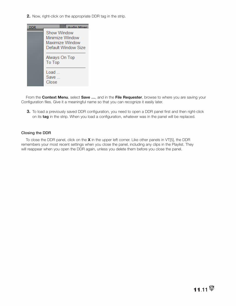
2. Now, right-click on the appropriate DDR tag in the strip.
From the Context Menu, select Save …, and in the File Requester, browse to where you are saving your Configuration files. Give it a meaningful name so that you can recognize it easily later.
3. To load a previously saved DDR configuration, you need to open a DDR panel first and then right-click on its tag in the strip. When you load a configuration, whatever was in the panel will be replaced.
Closing the DDR
To close the DDR panel, click on the X in the upper left corner. Like other panels in VT[5], the DDR remembers your most recent settings when you close the panel, including any clips in the Playlist. They will reappear when you open the DDR again, unless you delete them before you close the panel.
11.11

11.12
Notes:
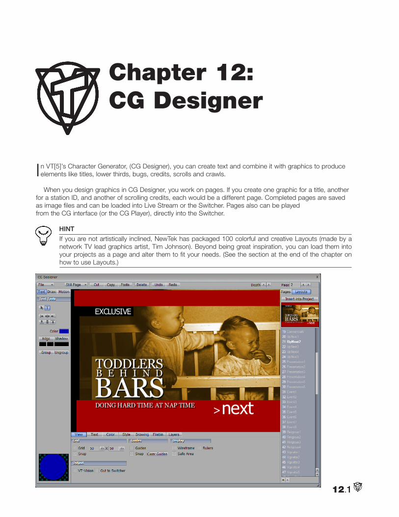
In VT[5]’s Character Generator, (CG Designer), you can create text and combine it with graphics to produce elements like titles, lower thirds, bugs, credits, scrolls and crawls.
When you design graphics in CG Designer, you work on pages. If you create one graphic for a title, another for a station ID, and another of scrolling credits, each would be a different page. Completed pages are saved as image files and can be loaded into Live Stream or the Switcher. Pages also can be played from the CG interface (or the CG Player), directly into the Switcher.
HINT
If you are not artistically inclined, NewTek has packaged 100 colorful and creative Layouts (made by a network TV lead graphics artist, Tim Johnson). Beyond being great inspiration, you can load them into your projects as a page and alter them to fit your needs. (See the section at the end of the chapter on how to use Layouts.)
12.1
Chapter 12: CG Designer
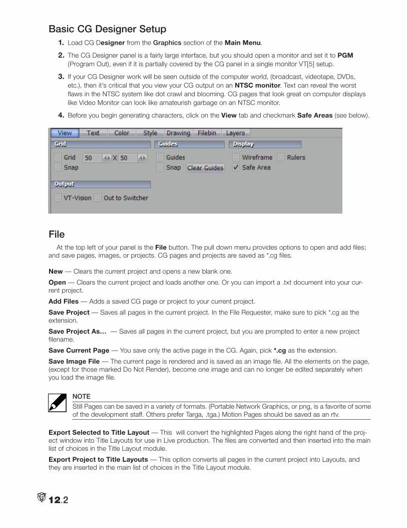
Basic CG Designer Setup 1. Load CG Designer from the Graphics section of the Main Menu.
2. The CG Designer panel is a fairly large interface, but you should open a monitor and set it to PGM (Program Out), even if it is partially covered by the CG panel in a single monitor VT[5] setup.
3. If your CG Designer work will be seen outside of the computer world, (broadcast, videotape, DVDs, etc.), then it’s critical that you view your CG output on an NTSC monitor. Text can reveal the worst flaws in the NTSC system like dot crawl and blooming. CG pages that look great on computer displays like Video Monitor can look like amateurish garbage on an NTSC monitor.
4. Before you begin generating characters, click on the View tab and checkmark Safe Areas (see below).
FileAt the top left of your panel is the File button. The pull down menu provides options to open and add files;
and save pages, images, or projects. CG pages and projects are saved as *.cg files.
New — Clears the current project and opens a new blank one.
Open — Clears the current project and loads another one. Or you can import a .txt document into your cur-rent project.
Add Files — Adds a saved CG page or project to your current project.
Save Project — Saves all pages in the current project. In the File Requester, make sure to pick *.cg as the extension.
Save Project As… — Saves all pages in the current project, but you are prompted to enter a new project filename.
Save Current Page — You save only the active page in the CG. Again, pick *.cg as the extension.
Save Image File — The current page is rendered and is saved as an image file. All the elements on the page, (except for those marked Do Not Render), become one image and can no longer be edited separately when you load the image file.
NOTE
Still Pages can be saved in a variety of formats. (Portable Network Graphics, or png, is a favorite of some of the development staff. Others prefer Targa, .tga.) Motion Pages should be saved as an rtv.
Export Selected to Title Layout — This will convert the highlighted Pages along the right hand of the proj-ect window into Title Layouts for use in Live production. The files are converted and then inserted into the main list of choices in the Title Layout module.
Export Project to Title Layouts — This option converts all pages in the current project into Layouts, and they are inserted in the main list of choices in the Title Layout module.
12.2
Export Selected to Title Layout File — This option is slightly different, in that you choose a location to save this file. These files can then be taken into TriCaster™ and imported as Layouts on the other machine.
Recent Projects — Lists your most recent CG projects for quick access.
Basic Editing Tools On the top of the CG panel are buttons for the basic editing tools: Cut, Copy, Paste, Delete, Undo, and
Redo. The traditional Windows keyboard shortcuts also work.
Cut — Ctrl + xCopy — Ctrl + cPaste — Ctrl + vDelete — Delete keyUndo — Ctrl + zRedo — Ctrl + y
You have multiple layers of Undo and Redo.
WARNING
Some operations, such as deleting a Style, cannot be undone.
Page ToolsThe basic unit of CG Designer is the page, which falls into two categories, Motion and Still.
Page Type
At the top of the panel is the Page Type selector. If you are creating scrolls or crawls, choose Motion Pages. All the other times, you pick Still Pages.
Page
On the right, above the Page panel, is the Page selector. You can quickly jump to a certain page in your project by entering the page number in the Page field. Or you can cycle up or down through the pages by clicking on the arrows next to the field — left moves up the list, right moves down.
Pages Panel This panel displays all the pages in your current project and provides basic page management tools.
Add
You click Add to add a blank page to your project. The page will be added under the page that is selected.
Delete
Click on a page to select it. (A thicker white edge will surround it.) Click Del in the Pages panel to erase the page from the project. Be forewarned, this operation cannot be undone.
Clone
Clone copies the page that is selected and pastes the copy below it — all with one click of the button.
Layouts Panel
The CG comes preloaded with 100 layouts from Tim Johnson. You can use the scroll bar to scan down the list of layouts. Click on a layout to see its thumbnail displayed above the list.
12.3
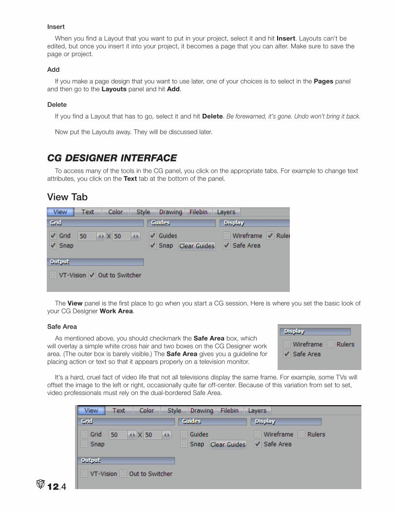
Insert
When you find a Layout that you want to put in your project, select it and hit Insert. Layouts can't be edited, but once you insert it into your project, it becomes a page that you can alter. Make sure to save the page or project.
Add
If you make a page design that you want to use later, one of your choices is to select in the Pages panel and then go to the Layouts panel and hit Add.
Delete
If you find a Layout that has to go, select it and hit Delete. Be forewarned, it’s gone. Undo won’t bring it back.
Now put the Layouts away. They will be discussed later.
cg deSigneR inteRfaceTo access many of the tools in the CG panel, you click on the appropriate tabs. For example to change text
attributes, you click on the Text tab at the bottom of the panel.
View Tab
The View panel is the first place to go when you start a CG session. Here is where you set the basic look of your CG Designer Work Area.
Safe Area
As mentioned above, you should checkmark the Safe Area box, which will overlay a simple white cross hair and two boxes on the CG Designer work area. (The outer box is barely visible.) The Safe Area gives you a guideline for placing action or text so that it appears properly on a television monitor.
It’s a hard, cruel fact of video life that not all televisions display the same frame. For example, some TVs will offset the image to the left or right, occasionally quite far off-center. Because of this variation from set to set, video professionals must rely on the dual-bordered Safe Area.
12.4
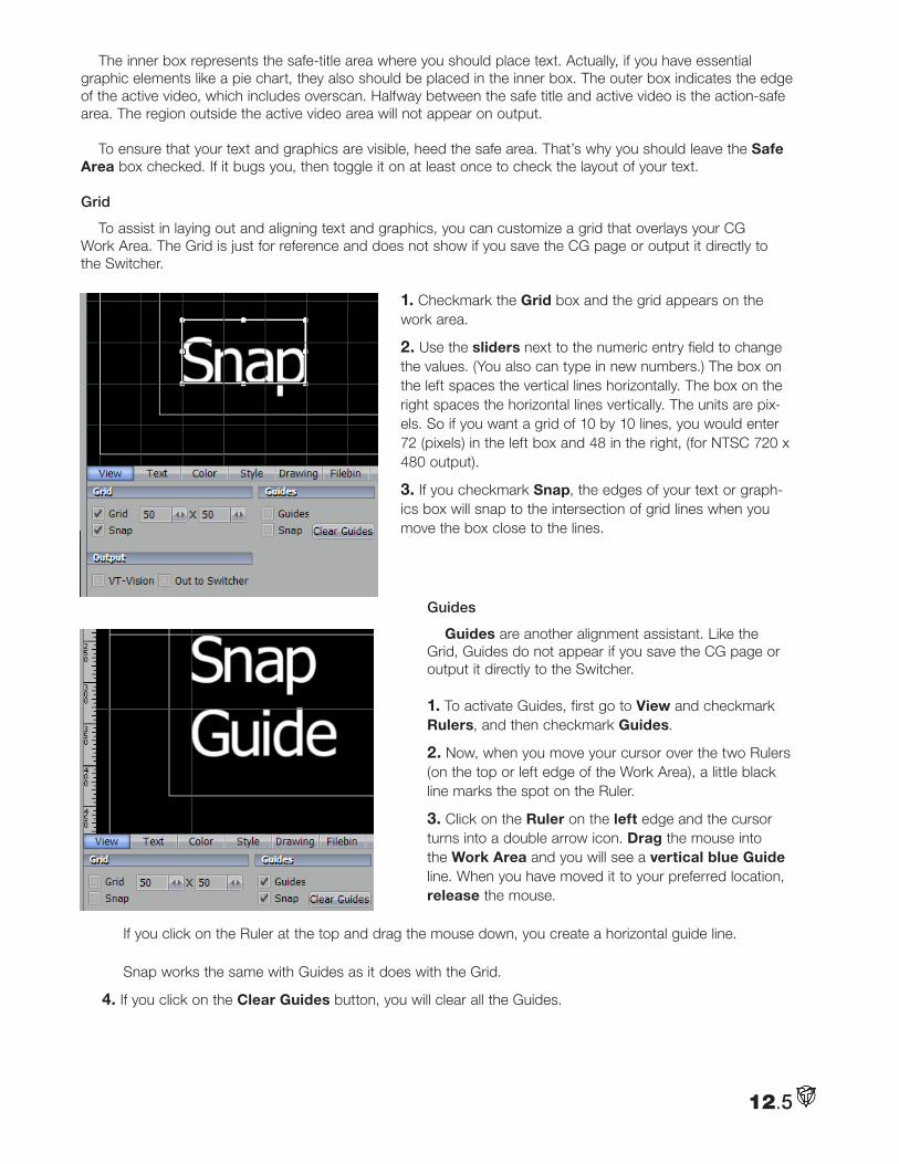
The inner box represents the safe-title area where you should place text. Actually, if you have essential graphic elements like a pie chart, they also should be placed in the inner box. The outer box indicates the edge of the active video, which includes overscan. Halfway between the safe title and active video is the action-safe area. The region outside the active video area will not appear on output.
To ensure that your text and graphics are visible, heed the safe area. That’s why you should leave the Safe Area box checked. If it bugs you, then toggle it on at least once to check the layout of your text.
Grid
To assist in laying out and aligning text and graphics, you can customize a grid that overlays your CG Work Area. The Grid is just for reference and does not show if you save the CG page or output it directly to the Switcher.
1. Checkmark the Grid box and the grid appears on the work area.
2. Use the sliders next to the numeric entry field to change the values. (You also can type in new numbers.) The box on the left spaces the vertical lines horizontally. The box on the right spaces the horizontal lines vertically. The units are pix-els. So if you want a grid of 10 by 10 lines, you would enter 72 (pixels) in the left box and 48 in the right, (for NTSC 720 x 480 output).
3. If you checkmark Snap, the edges of your text or graph-ics box will snap to the intersection of grid lines when you move the box close to the lines.
Guides
Guides are another alignment assistant. Like the Grid, Guides do not appear if you save the CG page or output it directly to the Switcher.
1. To activate Guides, first go to View and checkmark Rulers, and then checkmark Guides.
2. Now, when you move your cursor over the two Rulers (on the top or left edge of the Work Area), a little black line marks the spot on the Ruler.
3. Click on the Ruler on the left edge and the cursor turns into a double arrow icon. Drag the mouse into the Work Area and you will see a vertical blue Guide line. When you have moved it to your preferred location, release the mouse.
If you click on the Ruler at the top and drag the mouse down, you create a horizontal guide line. Snap works the same with Guides as it does with the Grid.
4. If you click on the Clear Guides button, you will clear all the Guides.
12.5
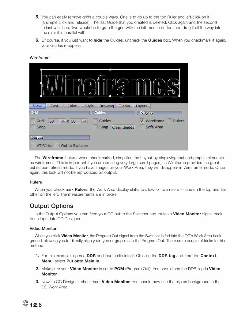
5. You can easily remove grids a couple ways. One is to go up to the top Ruler and left-click on it (a simple click and release). The last Guide that you created is deleted. Click again and the second to last vanishes. Two would be to grab the grid with the left mouse button, and drag it all the way into the ruler it is parallel with.
6. Of course, if you just want to hide the Guides, uncheck the Guides box. When you checkmark it again, your Guides reappear.
Wireframe
The Wireframe feature, when checkmarked, simplifies the Layout by displaying text and graphic elements as wireframes. This is important if you are creating very large scroll pages, as Wireframe provides the great-est screen refresh mode. If you have images on your Work Area, they will disappear in Wireframe mode. Once again, this look will not be reproduced on output.
Rulers
When you checkmark Rulers, the Work Area display shifts to allow for two rulers — one on the top and the other on the left. The measurements are in pixels.
Output Options In the Output Options you can feed your CG out to the Switcher and routes a Video Monitor signal back
to an input into CG Designer.
Video Monitor
When you click Video Monitor, the Program Out signal from the Switcher is fed into the CG’s Work Area back-ground, allowing you to directly align your type or graphics to the Program Out. There are a couple of tricks to this method.
1. For this example, open a DDR and load a clip into it. Click on the DDR tag and from the Context Menu, select Put onto Main In.
2. Make sure your Video Monitor is set to PGM (Program Out). You should see the DDR clip in Video Monitor.
3. Now, in CG Designer, checkmark Video Monitor. You should now see the clip as background in the CG Work Area.
12.6
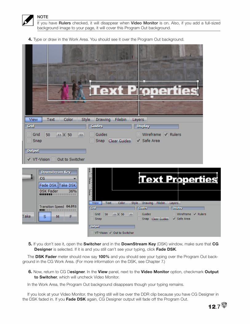
NOTE
If you have Rulers checked, it will disappear when Video Monitor is on. Also, if you add a full-sized background image to your page, it will cover this Program Out background.
4. Type or draw in the Work Area. You should see it over the Program Out background.
5. If you don’t see it, open the Switcher and in the DownStream Key (DSK) window, make sure that CG Designer is selected. If it is and you still can’t see your typing, click Fade DSK.
The DSK Fader meter should now say 100% and you should see your typing over the Program Out back-ground in the CG Work Area. (For more information on the DSK, see Chapter 7.)
6. Now, return to CG Designer. In the View panel, next to the Video Monitor option, checkmark Output to Switcher, which will uncheck Video Monitor.
In the Work Area, the Program Out background disappears though your typing remains.
If you look at your Video Monitor, the typing still will be over the DDR clip because you have CG Designer in the DSK faded in. If you Fade DSK again, CG Designer output will fade off the Program Out.
12.7
Out to Switcher
When you checkmark Out to Switcher, the current CG page is sent to the Switcher. The DownStream Key will select CG Designer but the director must fade the DSK on. Then, the page keys over the Program Out of the Switcher and you will see the result on your monitor set to PGM.
enteRing teXtYou control the text that you type in the Work Area from two complementary locations: the Text Tools tab
on the upper left and the Text attributes tab at the bottom. The two areas are linked. If you click on the Text tab on the left, the Text tab on the button will respond and open, and vice-versa.
Text ToolsT (Text)
Click on the T box to activate the text function. Before you enter text, this box must be highlighted.
1. For this example, start with a blank page. If you don’t have one, go to the right of the CG Designer panel, click on the Pages tab and click Add.
2. Go to the bottom of the CG panel and open the Styles tab. Click to pick Style #1 — a simple white Arial font.
3. Now, click in the Work Area and an I-beam icon starts blinking. This is your Work Area cursor. When you type, the I-beam is the insert point for the text. You can move the I-beam anywhere on the Work Area by clicking on it with your mouse and dragging it around or just clicking your mouse on another spot in the Work Area.
4. Turn on your Safe Area display and click the cursor near the left edge of the inside box.
5. Type in, Well begun.
HINT
Use the End and Home keys on your keyboard to navigate to the beginning and end of text lines. If you mistyped, you can use the Backspace key to erase or the keyboard arrow keys to go back or forth on the line or up and down between lines.
Selecting Letters or Words
6. You can click your cursor anywhere on the line and drag your mouse to select letters or whole words. They are displayed in the text’s reverse color.
HINT
This selection technique can be a little tricky. You need to click near the center (from top to bottom) of the line. If you get too low or high, you’ll just move the cursor around.
Arrow (Selection)
Clicking on the Arrow box activates the Selection tool (and switches off the Text tool). Unlike the previous selection method, this one is a more global technique because it selects the whole line and not just parts of it.
7. If you have just typed something in, clicking the Arrow will create a box around what you typed. If it didn’t, select the line by clicking anywhere on it.
8. When you roll your mouse over the box, the cursor changes.
12.8
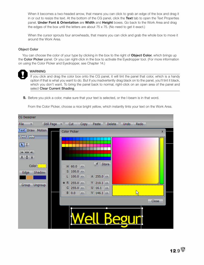
When it becomes a two-headed arrow, that means you can click to grab an edge of the box and drag it in or out to resize the text. At the bottom of the CG panel, click the Text tab to open the Text Properties panel. Under Font & Orientation are Width and Height boxes. Go back to the Work Area and drag the edges of the box until the letters are about 75 x 75. (No need to get it exact.) When the cursor sprouts four arrowheads, that means you can click and grab the whole box to move it around the Work Area.
Object Color
You can choose the color of your type by clicking in the box to the right of Object Color, which brings up the Color Picker panel. Or you can right-click in the box to activate the Eyedropper tool. (For more information on using the Color Picker and Eyedropper, see Chapter 14.)
WARNING
If you click and drag the color box onto the CG panel, it will tint the panel that color, which is a handy option if that is what you want to do. But if you inadvertently drag black on to the panel, you’ll tint it black, which you don’t want. To bring the panel back to normal, right-click on an open area of the panel and select Clear Current Shading.
9. Before you pick a color, make sure that your text is selected, or the I-beam is in that word. From the Color Picker, choose a nice bright yellow, which instantly tints your text on the Work Area.
12.9
Edge
The two boxes directly below the Edge button are where you choose the colors for the inside and outside edges of the Edge. Inside is the box on the left, outside is on the right. Again, you either click in the box to bring up the Color Picker panel or right-click in the box to activate the Eyedropper tool.
HINT
You have more Edge options in the Text panel at the bottom of the CG panel. Usually, you will want to set your Edges there along with all the other Edge attributes.
10. Click on the left box and pick a dark blue for the inside edge. This time you won’t see it appear on the Work Area.
11. Click on the other Edge box and pick a rosy red.
12. Now, click on the Edge button. The selection box turns into a Edge adjustment box. When you roll your mouse over the edges of this box around your text, the cursor turns into a diamond with a directional arrow attached. Click and drag the mouse away from the text. The edge will expand.
13. In the Text Properties panel, notice under Edge is a Size entry. As you play with the Edge adjustment box, you will see the numbers change. Around 10 seems good for now.
Shadow
The box directly below the Shadow button is where you select the colors for the Shadow. Like Edge, you have more Shadow options in the Text panel at the bottom of the CG panel.
14. Click in the Shadow box and choose a light green shadow. Make it semi-transparent by changing the Alpha value to 150.
HINT
You’ll notice the transparent shadow better when you put video or an image in the background.
15. Click on the Shadow button to change the selection box to a Shadow adjustment box. This time when you roll your mouse over the box, the cursor turns into a four-headed arrow or a two-headed lightning bolt.
Look at the Shadow area of the Text Properties panel.
If you grab one of the edges of the box and drag the mouse, you move the location of the Shadow in refer-ence to the text, (expressed in X and Y axes values). You also can just click in the middle of the box and drag it.
If you grab a corner, (the lightning bolt), and drag the mouse, you adjust the tilt or Italics of the Shadow by moving the X independent of the Y or vice versa.
Play around until you find a shadow that you like.
Justification ButtonsAbove the Edge and Shadow boxes upper left are four buttons for aligning text. The first three are justifica-
tion buttons commonly found in word processing programs.
NOTE
You can select justification of the text before you begin typing, or group-select multiple lines after they’re typed and apply justification then.
12.10
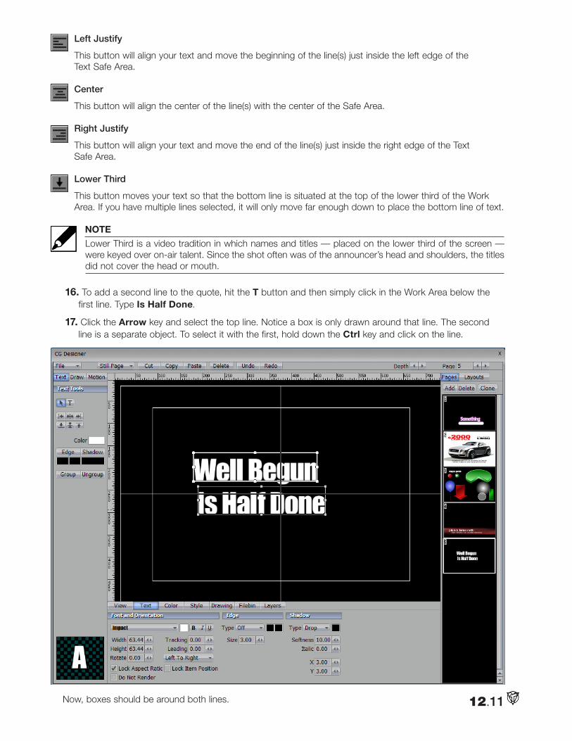
Left Justify
This button will align your text and move the beginning of the line(s) just inside the left edge of the Text Safe Area.
Center
This button will align the center of the line(s) with the center of the Safe Area.
Right Justify
This button will align your text and move the end of the line(s) just inside the right edge of the Text Safe Area.
Lower Third
This button moves your text so that the bottom line is situated at the top of the lower third of the Work Area. If you have multiple lines selected, it will only move far enough down to place the bottom line of text.
NOTE
Lower Third is a video tradition in which names and titles — placed on the lower third of the screen — were keyed over on-air talent. Since the shot often was of the announcer’s head and shoulders, the titles did not cover the head or mouth.
16. To add a second line to the quote, hit the T button and then simply click in the Work Area below the first line. Type Is Half Done.
17. Click the Arrow key and select the top line. Notice a box is only drawn around that line. The second line is a separate object. To select it with the first, hold down the Ctrl key and click on the line.
Now, boxes should be around both lines. 12.11
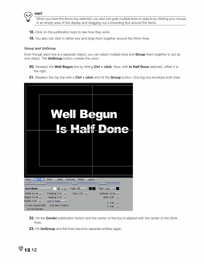
HINT
When you have the Arrow key selected, you also can grab multiple lines or objects by clicking your mouse in an empty area of the display and dragging out a bounding box around the items.
18. Click on the justification keys to see how they work.
19. You also can click in either box and drag them together around the Work Area.
Group and UnGroup
Even though each line is a separate object, you can select multiple lines and Group them together to act as one object. The UnGroup button undoes the union.
20. Deselect the Well Begun line by hitting Ctrl + click. Now, with Is Half Done selected, offset it to the right.
21. Reselect the top line with a Ctrl + click and hit the Group button. One big box envelops both lines.
22. Hit the Center justification button and the center of the box is aligned with the center of the Work Area.
23. Hit UnGroup and the lines become separate entities again.
12.12
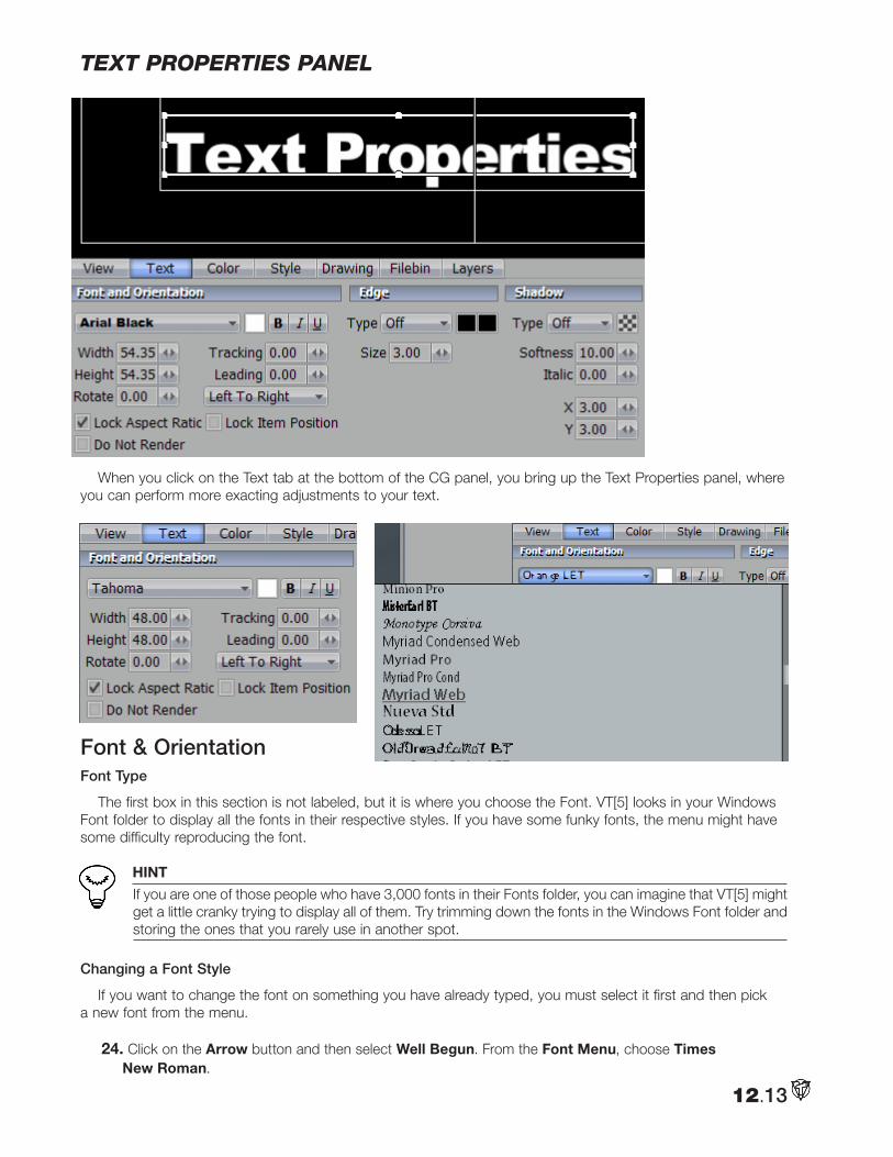
teXt pRopeRtieS panel
When you click on the Text tab at the bottom of the CG panel, you bring up the Text Properties panel, where you can perform more exacting adjustments to your text.
Font & OrientationFont Type
The first box in this section is not labeled, but it is where you choose the Font. VT[5] looks in your Windows Font folder to display all the fonts in their respective styles. If you have some funky fonts, the menu might have some difficulty reproducing the font.
HINT
If you are one of those people who have 3,000 fonts in their Fonts folder, you can imagine that VT[5] might get a little cranky trying to display all of them. Try trimming down the fonts in the Windows Font folder and storing the ones that you rarely use in another spot.
Changing a Font Style
If you want to change the font on something you have already typed, you must select it first and then pick a new font from the menu.
24. Click on the Arrow button and then select Well Begun. From the Font Menu, choose Times New Roman.
12.13
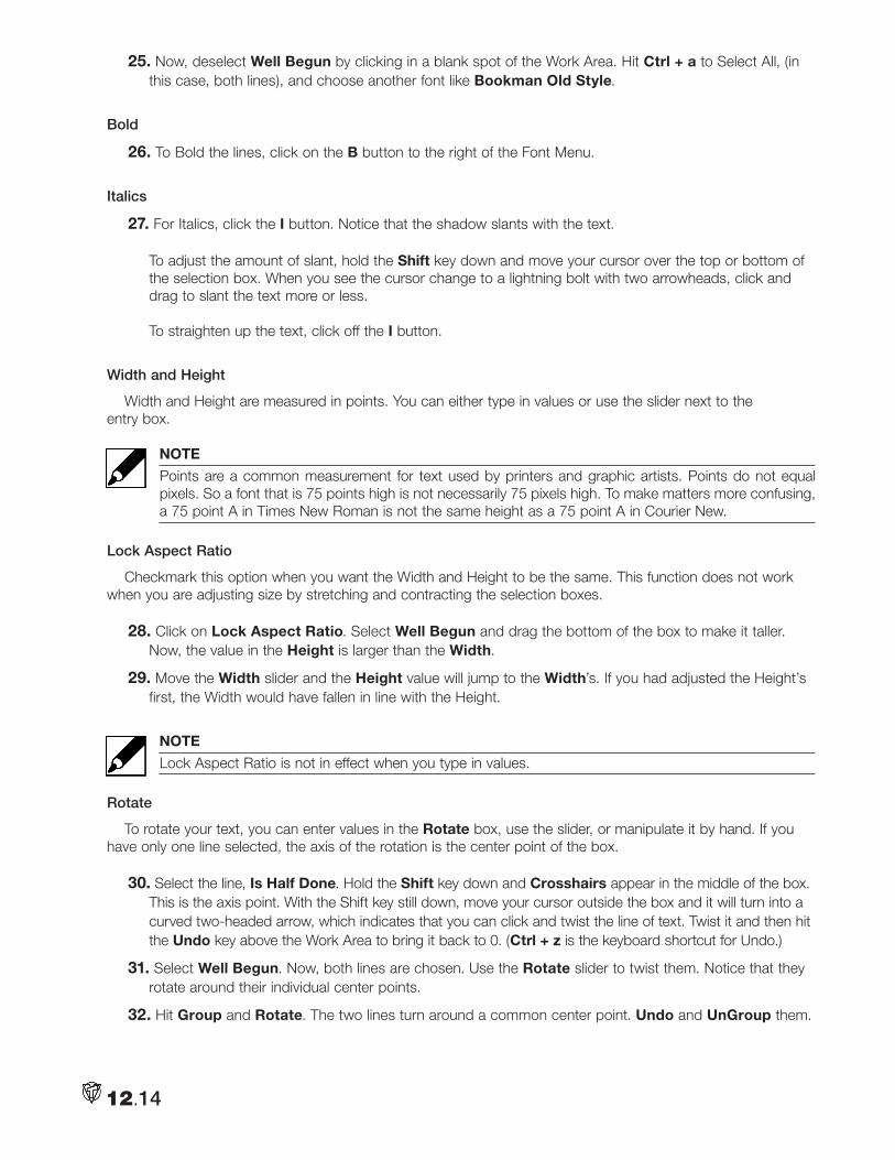
25. Now, deselect Well Begun by clicking in a blank spot of the Work Area. Hit Ctrl + a to Select All, (in this case, both lines), and choose another font like Bookman Old Style.
Bold
26. To Bold the lines, click on the B button to the right of the Font Menu.
Italics
27. For Italics, click the I button. Notice that the shadow slants with the text. To adjust the amount of slant, hold the Shift key down and move your cursor over the top or bottom of the selection box. When you see the cursor change to a lightning bolt with two arrowheads, click and drag to slant the text more or less. To straighten up the text, click off the I button.
Width and Height
Width and Height are measured in points. You can either type in values or use the slider next to the entry box.
NOTE
Points are a common measurement for text used by printers and graphic artists. Points do not equal pixels. So a font that is 75 points high is not necessarily 75 pixels high. To make matters more confusing, a 75 point A in Times New Roman is not the same height as a 75 point A in Courier New.
Lock Aspect Ratio
Checkmark this option when you want the Width and Height to be the same. This function does not work when you are adjusting size by stretching and contracting the selection boxes.
28. Click on Lock Aspect Ratio. Select Well Begun and drag the bottom of the box to make it taller. Now, the value in the Height is larger than the Width.
29. Move the Width slider and the Height value will jump to the Width’s. If you had adjusted the Height’s first, the Width would have fallen in line with the Height.
NOTE
Lock Aspect Ratio is not in effect when you type in values.
Rotate
To rotate your text, you can enter values in the Rotate box, use the slider, or manipulate it by hand. If you have only one line selected, the axis of the rotation is the center point of the box.
30. Select the line, Is Half Done. Hold the Shift key down and Crosshairs appear in the middle of the box. This is the axis point. With the Shift key still down, move your cursor outside the box and it will turn into a curved two-headed arrow, which indicates that you can click and twist the line of text. Twist it and then hit the Undo key above the Work Area to bring it back to 0. (Ctrl + z is the keyboard shortcut for Undo.)
31. Select Well Begun. Now, both lines are chosen. Use the Rotate slider to twist them. Notice that they rotate around their individual center points.
32. Hit Group and Rotate. The two lines turn around a common center point. Undo and UnGroup them.
12.14
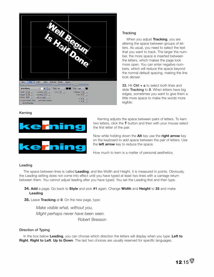
Tracking
When you adjust Tracking, you are altering the space between groups of let-ters. As usual, you need to select the text that you want to track. The larger the num-ber, the more space is inserted between the letters, which makes the page look more open. You can enter negative num-bers, which will reduce the space beyond the normal default spacing, making the line look denser.
33. Hit Ctrl + a to select both lines and slide Tracking to 8. When letters have big edges, sometimes you want to give them a little more space to make the words more legible.
Kerning
Kerning adjusts the space between pairs of letters. To kern two letters, click the T button and then with your mouse select the first letter of the pair.
Now while holding down the Alt key use the right arrow key on the keyboard to add space between the pair of letters. Use the left arrow key to reduce the space.
How much to kern is a matter of personal aesthetics.
Leading
The space between lines is called Leading; and like Width and Height, it is measured in points. Obviously, the Leading setting does not come into effect until you have typed at least two lines with a carriage return between them. You cannot adjust leading after you have typed. You set the Leading first and then type.
34. Add a page. Go back to Style and pick #1 again. Change Width and Height to 35 and make Leading
35. Leave Tracking at 0. On the new page, type:
Make visible what, without you, Might perhaps never have been seen. Robert Bresson
Direction of Typing
In the box below Leading, you can choose which direction the letters will display when you type: Left to Right, Right to Left, Up to Down. The last two choices are usually reserved for specific languages.
12.15
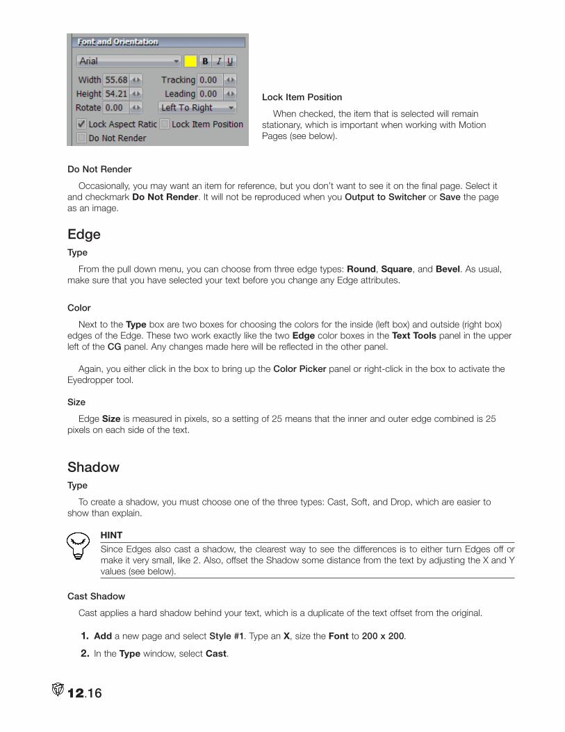
Lock Item Position
When checked, the item that is selected will remain stationary, which is important when working with Motion Pages (see below).
Do Not Render
Occasionally, you may want an item for reference, but you don’t want to see it on the final page. Select it and checkmark Do Not Render. It will not be reproduced when you Output to Switcher or Save the page as an image.
EdgeType
From the pull down menu, you can choose from three edge types: Round, Square, and Bevel. As usual, make sure that you have selected your text before you change any Edge attributes.
Color
Next to the Type box are two boxes for choosing the colors for the inside (left box) and outside (right box) edges of the Edge. These two work exactly like the two Edge color boxes in the Text Tools panel in the upper left of the CG panel. Any changes made here will be reflected in the other panel.
Again, you either click in the box to bring up the Color Picker panel or right-click in the box to activate the Eyedropper tool.
Size
Edge Size is measured in pixels, so a setting of 25 means that the inner and outer edge combined is 25 pixels on each side of the text.
ShadowType
To create a shadow, you must choose one of the three types: Cast, Soft, and Drop, which are easier to show than explain.
HINT
Since Edges also cast a shadow, the clearest way to see the differences is to either turn Edges off or make it very small, like 2. Also, offset the Shadow some distance from the text by adjusting the X and Y values (see below).
Cast Shadow
Cast applies a hard shadow behind your text, which is a duplicate of the text offset from the original.
1. Add a new page and select Style #1. Type an X, size the Font to 200 x 200.
2. In the Type window, select Cast.
12.16
3. To the right of that window, click in the Shadow color box and pick a light blue shadow from the Color Picker that pops up.
4. In the Shadow’s X box, enter 75 and Y = 50. These will give you a distinct separation between the text and the shadow.
Soft Shadow
A Soft shadow is similar to Cast except the shadow color is blended with the background and the edges are blurred.
5. From the Type pull down menu, change from Cast to Soft.
Softness
Softness lets you apply a blur amount to a Soft shadow for a softer edge. Use higher values to get softer shadows with more blur.
6. Set the Softness to 20.
Drop Shadow
Drop creates a hard shadow that originates from the base of the original text.
7. From the Type pull down menu, change from Soft to Drop. Often with shadows, you want to add some transparency to the shadow’s color.
8. Click on the Shadow’s color box and in the Color Picker change the A (Alpha) setting to 125.
Italic
Italic gives you independent italics for the shadow, which is separate from the object’s italics. You adjust your shadow italics by entering a number (measured in pixels) in the Italic box. This technique offsets the top of the text. A positive value moves the top to the left; negative values move it to the right.
9. In the Italic box enter –30. The shadow will lean to the right.
HINT
As described earlier, you can tilt the shadow by dragging either the top or bottom of the Shadow selec-tion box in the Work Area.
X and Y Offsets
You enter values (measured in pixels) in the X and Y boxes to separate the shadow from the text. You can either type in values or use the slider next to the entry boxes.
The X position moves the shadow horizontally. A negative number in X will offset the shadow to the left of the text; positive to the right.
The Y Position moves the shadow vertically. A negative number on the Y will offset the shadow above the text; a positive one below.
12.17
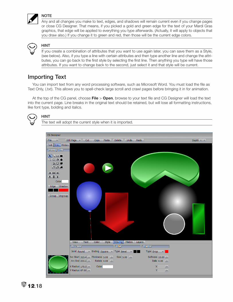
NOTE
Any and all changes you make to text, edges, and shadows will remain current even if you change pages or close CG Designer. That means, if you picked a gold and green edge for the text of your Mardi Gras graphics, that edge will be applied to everything you type afterwards. (Actually, it will apply to objects that you draw also.) If you change it to green and red, then those will be the current edge colors.
HINT
If you create a combination of attributes that you want to use again later, you can save them as a Style, (see below). Also, if you type a line with certain attributes and then type another line and change the attri-butes, you can go back to the first style by selecting the first line. Then anything you type will have those attributes. If you want to change back to the second, just select it and that style will be current.
Importing TextYou can import text from any word processing software, such as Microsoft Word. You must load the file as
Text Only, (.txt). This allows you to spell-check large scroll and crawl pages before bringing it in for animation.
At the top of the CG panel, choose File > Open, browse to your text file and CG Designer will load the text into the current page. Line breaks in the original text should be retained, but will lose all formatting instructions, like font type, bolding and italics.
HINT
The text will adopt the current style when it is imported.
12.18
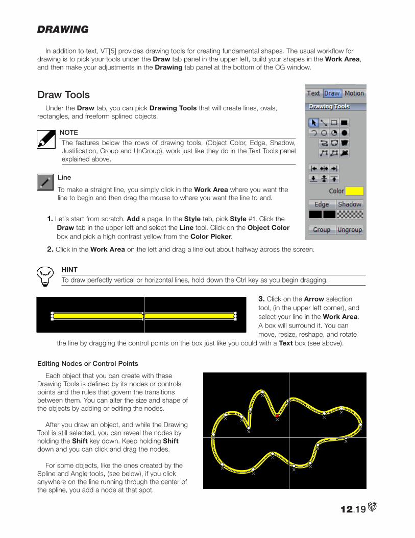
Drawing
In addition to text, VT[5] provides drawing tools for creating fundamental shapes. The usual workflow for drawing is to pick your tools under the Draw tab panel in the upper left, build your shapes in the Work Area, and then make your adjustments in the Drawing tab panel at the bottom of the CG window.
Draw ToolsUnder the Draw tab, you can pick Drawing Tools that will create lines, ovals,
rectangles, and freeform splined objects.
NOTE
The features below the rows of drawing tools, (Object Color, Edge, Shadow, Justification, Group and UnGroup), work just like they do in the Text Tools panel explained above.
Line
To make a straight line, you simply click in the Work Area where you want the line to begin and then drag the mouse to where you want the line to end.
1. Let’s start from scratch. Add a page. In the Style tab, pick Style #1. Click the Draw tab in the upper left and select the Line tool. Click on the Object Color box and pick a high contrast yellow from the Color Picker.
2. Click in the Work Area on the left and drag a line out about halfway across the screen.
HINT
To draw perfectly vertical or horizontal lines, hold down the Ctrl key as you begin dragging.
3. Click on the Arrow selection tool, (in the upper left corner), and select your line in the Work Area. A box will surround it. You can move, resize, reshape, and rotate
the line by dragging the control points on the box just like you could with a Text box (see above).
Editing Nodes or Control Points
Each object that you can create with these Drawing Tools is defined by its nodes or controls points and the rules that govern the transitions between them. You can alter the size and shape of the objects by adding or editing the nodes.
After you draw an object, and while the Drawing Tool is still selected, you can reveal the nodes by holding the Shift key down. Keep holding Shift down and you can click and drag the nodes.
For some objects, like the ones created by the Spline and Angle tools, (see below), if you click anywhere on the line running through the center of the spline, you add a node at that spot.
12.19
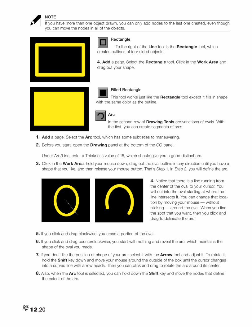
NOTE
If you have more than one object drawn, you can only add nodes to the last one created, even though you can move the nodes in all of the objects.
Rectangle
To the right of the Line tool is the Rectangle tool, which creates outlines of four sided objects.
4. Add a page. Select the Rectangle tool. Click in the Work Area and drag out your shape.
Filled Rectangle
This tool works just like the Rectangle tool except it fills in shape with the same color as the outline.
Arc
In the second row of Drawing Tools are variations of ovals. With the first, you can create segments of arcs.
1. Add a page. Select the Arc tool, which has some subtleties to maneuvering.
2. Before you start, open the Drawing panel at the bottom of the CG panel. Under Arc/Line, enter a Thickness value of 15, which should give you a good distinct arc.
3. Click in the Work Area, hold your mouse down, drag out the oval outline in any direction until you have a shape that you like, and then release your mouse button. That’s Step 1. In Step 2, you will define the arc.
4. Notice that there is a line running from the center of the oval to your cursor. You will cut into the oval starting at where the line intersects it. You can change that loca-tion by moving your mouse — without clicking — around the oval. When you find the spot that you want, then you click and drag to delineate the arc.
5. If you click and drag clockwise, you erase a portion of the oval.
6. If you click and drag counterclockwise, you start with nothing and reveal the arc, which maintains the shape of the oval you made.
7. If you don’t like the position or shape of your arc, select it with the Arrow tool and adjust it. To rotate it, hold the Shift key down and move your mouse around the outside of the box until the cursor changes into a curved line with arrow heads. Then you can click and drag to rotate the arc around its center.
8. Also, when the Arc tool is selected, you can hold down the Shift key and move the nodes that define the extent of the arc.
12.20
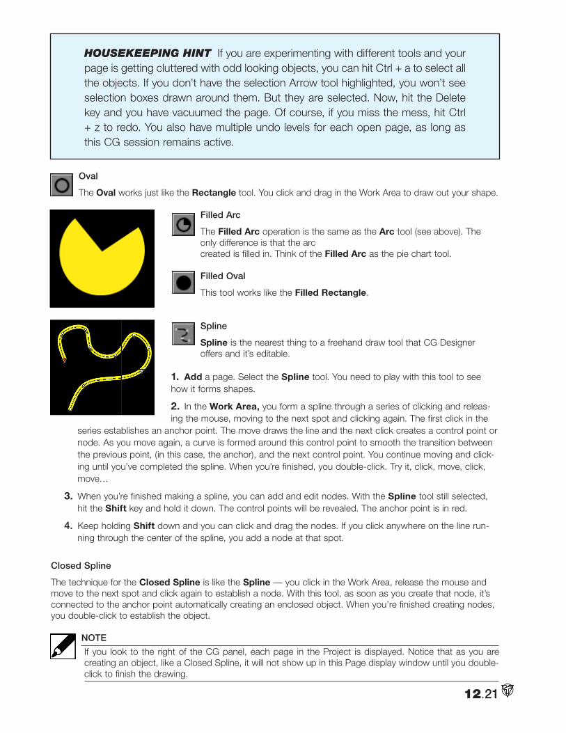
Housekeeping Hint If you are experimenting with different tools and your page is getting cluttered with odd looking objects, you can hit Ctrl + a to select all the objects. If you don’t have the selection Arrow tool highlighted, you won’t see selection boxes drawn around them. But they are selected. Now, hit the Delete key and you have vacuumed the page. Of course, if you miss the mess, hit Ctrl + z to redo. You also have multiple undo levels for each open page, as long as this CG session remains active.
Oval
The Oval works just like the Rectangle tool. You click and drag in the Work Area to draw out your shape.
Filled Arc
The Filled Arc operation is the same as the Arc tool (see above). The only difference is that the arc created is filled in. Think of the Filled Arc as the pie chart tool.
Filled Oval
This tool works like the Filled Rectangle.
Spline
Spline is the nearest thing to a freehand draw tool that CG Designer offers and it’s editable.
1. Add a page. Select the Spline tool. You need to play with this tool to see how it forms shapes.
2. In the Work Area, you form a spline through a series of clicking and releas-ing the mouse, moving to the next spot and clicking again. The first click in the
series establishes an anchor point. The move draws the line and the next click creates a control point or node. As you move again, a curve is formed around this control point to smooth the transition between the previous point, (in this case, the anchor), and the next control point. You continue moving and click-ing until you’ve completed the spline. When you’re finished, you double-click. Try it, click, move, click, move…
3. When you’re finished making a spline, you can add and edit nodes. With the Spline tool still selected, hit the Shift key and hold it down. The control points will be revealed. The anchor point is in red.
4. Keep holding Shift down and you can click and drag the nodes. If you click anywhere on the line run-ning through the center of the spline, you add a node at that spot.
Closed Spline
The technique for the Closed Spline is like the Spline — you click in the Work Area, release the mouse and move to the next spot and click again to establish a node. With this tool, as soon as you create that node, it’s connected to the anchor point automatically creating an enclosed object. When you’re finished creating nodes, you double-click to establish the object.
NOTE
If you look to the right of the CG panel, each page in the Project is displayed. Notice that as you are creating an object, like a Closed Spline, it will not show up in this Page display window until you double-click to finish the drawing.
12.21
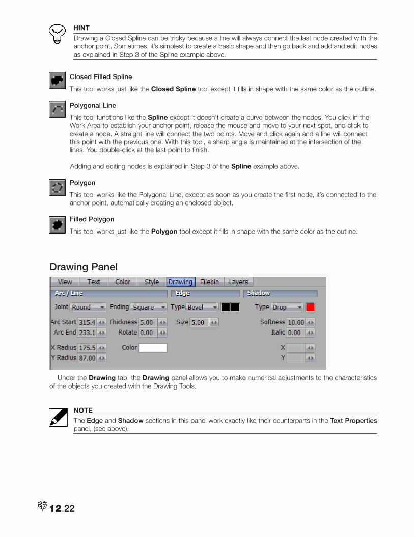
HINT
Drawing a Closed Spline can be tricky because a line will always connect the last node created with the anchor point. Sometimes, it’s simplest to create a basic shape and then go back and add and edit nodes as explained in Step 3 of the Spline example above.
Closed Filled Spline
This tool works just like the Closed Spline tool except it fills in shape with the same color as the outline.
Polygonal Line
This tool functions like the Spline except it doesn’t create a curve between the nodes. You click in the Work Area to establish your anchor point, release the mouse and move to your next spot, and click to create a node. A straight line will connect the two points. Move and click again and a line will connect this point with the previous one. With this tool, a sharp angle is maintained at the intersection of the lines. You double-click at the last point to finish.
Adding and editing nodes is explained in Step 3 of the Spline example above.
Polygon
This tool works like the Polygonal Line, except as soon as you create the first node, it’s connected to the anchor point, automatically creating an enclosed object.
Filled Polygon
This tool works just like the Polygon tool except it fills in shape with the same color as the outline.
Drawing Panel
Under the Drawing tab, the Drawing panel allows you to make numerical adjustments to the characteristics of the objects you created with the Drawing Tools.
NOTE
The Edge and Shadow sections in this panel work exactly like their counterparts in the Text Properties panel, (see above).
12.22
Arc/LineJoint
This feature pertains to the shape of the vertex of an object and therefore does not apply to a Line. You have three descriptive choices (Round, Square, and Bevel) that can best be seen by drawing a Rectangle and testing the options.
1. Add a page and click on the Rectangle button next to the Line. Click in the Work Area and drag out the shape. Hit Ctrl + a to select the rectangle.
2. Now open the Drawing panel at the bottom of the CG window. With the rectangle selected, cycle through the different Joint choices.
Ending
This feature applies to open-ended shapes, like a Line. Again, the choices are descriptive, (Square, Round, and Point). You cannot apply two different ends to one object.
3. Draw a Spline, click the Arrow button and select the Spline. Cycle through the Endings.
Arc Start & Arc End
These two settings only apply to objects created by the Arc and Oval tools.
Though the settings are based on 360 degrees in a circle, you can enter values from –360 to 360. 0 is the 3 o’clock position, (assuming that the object’s Rotation is set to 0). As usual, you need to select the object before you begin adjusting Arc Start & Arc End.
1. Add a page, select the Filled Arc tool, create an object, click the Arrow tool, and select your filled arc.
2. Set Arc Start to 0 and then move Arc End to 225.
X Radius & Y Radius
Again, these two settings only apply to objects created by the Arc and Oval tools. As usual, you need to select the object before you begin adjusting X Radius and Y Radius.
NOTE
The measurements are in pixels. And, if you remember your geometry, the radius is the length between the center of a circle and any point on its circumference (edge). In this case, if you draw a horizontal and a vertical line that intersect at the center of the object, the X Radius is measured from the center to the point where the horizontal line intersects with the edge of the object. The Y Radius is the vertical line intersection.
HINT
Of course, when you are drawing ovals, setting X and Y to the same values makes perfect circles.
Thickness
This setting adjusts the thickness of an object’s line, and therefore, applies to all the tools except for the filled ones. You can enter a Thickness value (measured in pixels) before you start drawing. Or you can select an object that you have created and change its Thickness.
12.23
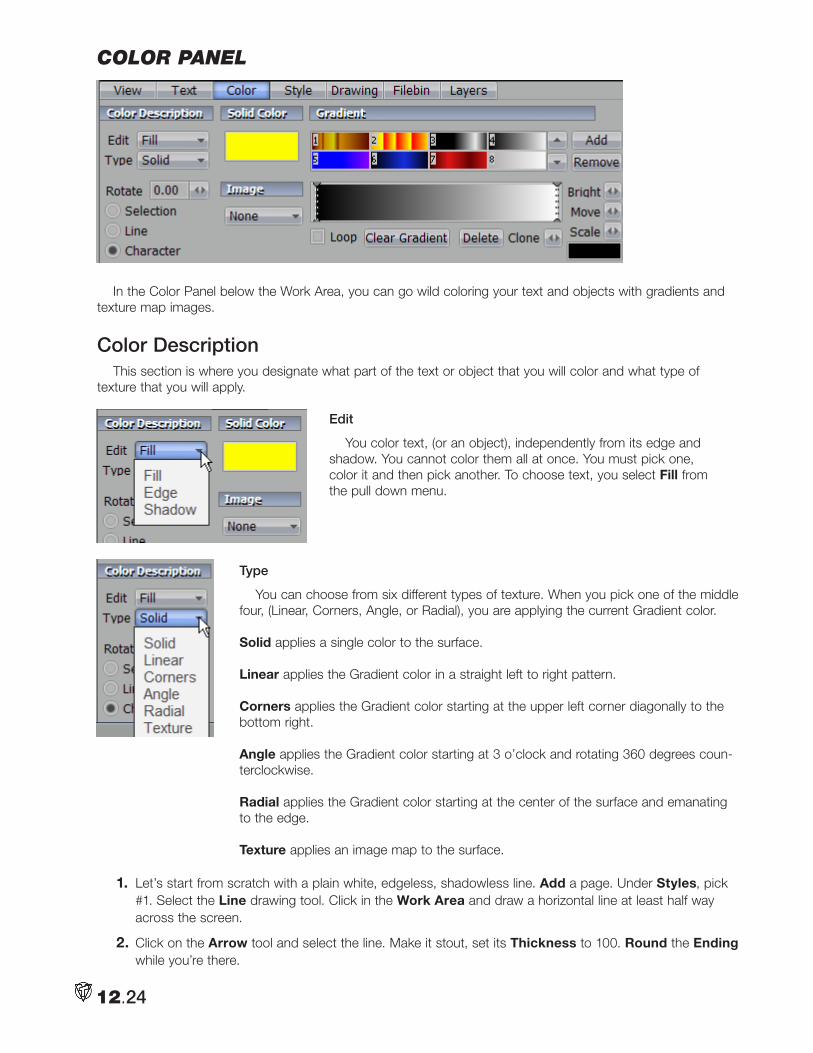
color panel
In the Color Panel below the Work Area, you can go wild coloring your text and objects with gradients and texture map images.
Color DescriptionThis section is where you designate what part of the text or object that you will color and what type of
texture that you will apply.
Edit
You color text, (or an object), independently from its edge and shadow. You cannot color them all at once. You must pick one, color it and then pick another. To choose text, you select Fill from the pull down menu.
Type
You can choose from six different types of texture. When you pick one of the middle four, (Linear, Corners, Angle, or Radial), you are applying the current Gradient color.
Solid applies a single color to the surface.
Linear applies the Gradient color in a straight left to right pattern.
Corners applies the Gradient color starting at the upper left corner diagonally to the bottom right.
Angle applies the Gradient color starting at 3 o’clock and rotating 360 degrees coun-terclockwise.
Radial applies the Gradient color starting at the center of the surface and emanating to the edge.
Texture applies an image map to the surface.
1. Let’s start from scratch with a plain white, edgeless, shadowless line. Add a page. Under Styles, pick #1. Select the Line drawing tool. Click in the Work Area and draw a horizontal line at least half way across the screen.
2. Click on the Arrow tool and select the line. Make it stout, set its Thickness to 100. Round the Ending while you’re there.
12.24
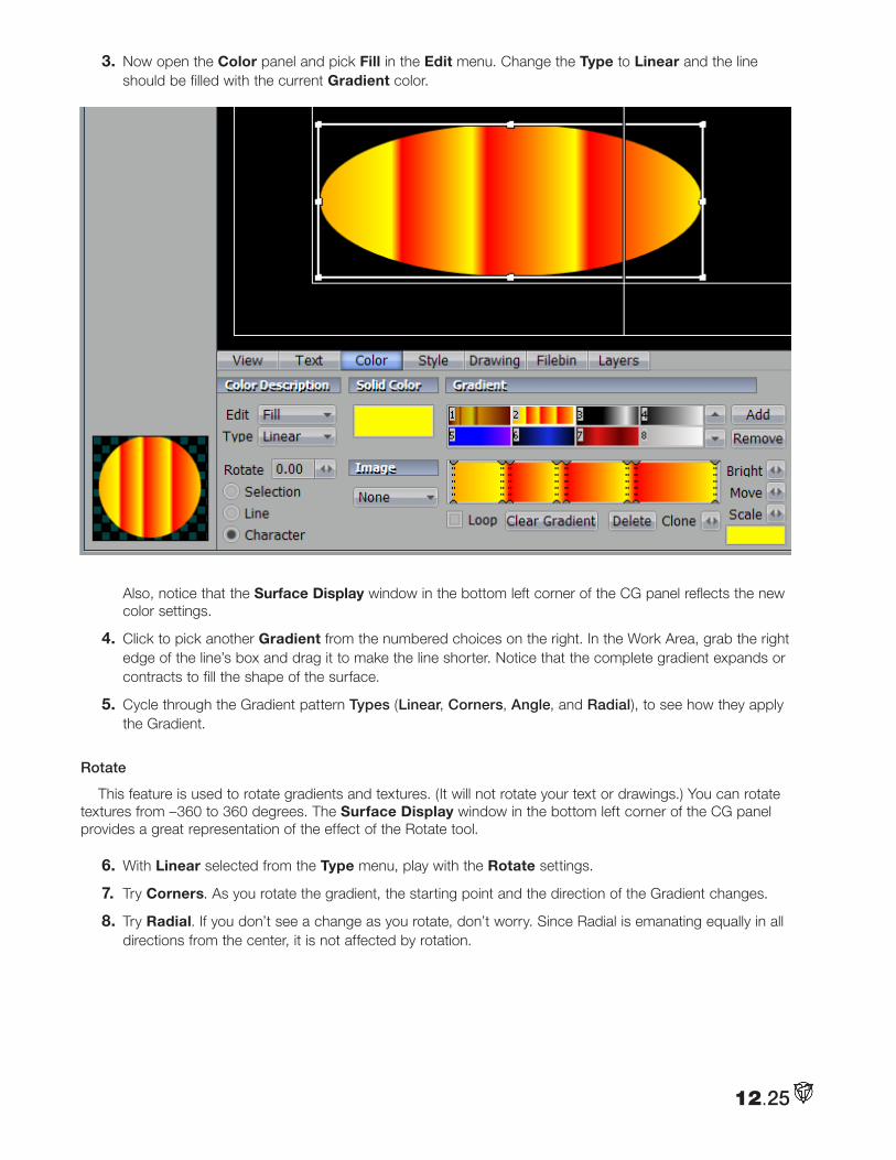
3. Now open the Color panel and pick Fill in the Edit menu. Change the Type to Linear and the line should be filled with the current Gradient color.
Also, notice that the Surface Display window in the bottom left corner of the CG panel reflects the new color settings.
4. Click to pick another Gradient from the numbered choices on the right. In the Work Area, grab the right edge of the line’s box and drag it to make the line shorter. Notice that the complete gradient expands or contracts to fill the shape of the surface.
5. Cycle through the Gradient pattern Types (Linear, Corners, Angle, and Radial), to see how they apply the Gradient.
Rotate
This feature is used to rotate gradients and textures. (It will not rotate your text or drawings.) You can rotate textures from –360 to 360 degrees. The Surface Display window in the bottom left corner of the CG panel provides a great representation of the effect of the Rotate tool.
6. With Linear selected from the Type menu, play with the Rotate settings.
7. Try Corners. As you rotate the gradient, the starting point and the direction of the Gradient changes.
8. Try Radial. If you don’t see a change as you rotate, don’t worry. Since Radial is emanating equally in all directions from the center, it is not affected by rotation.
12.25
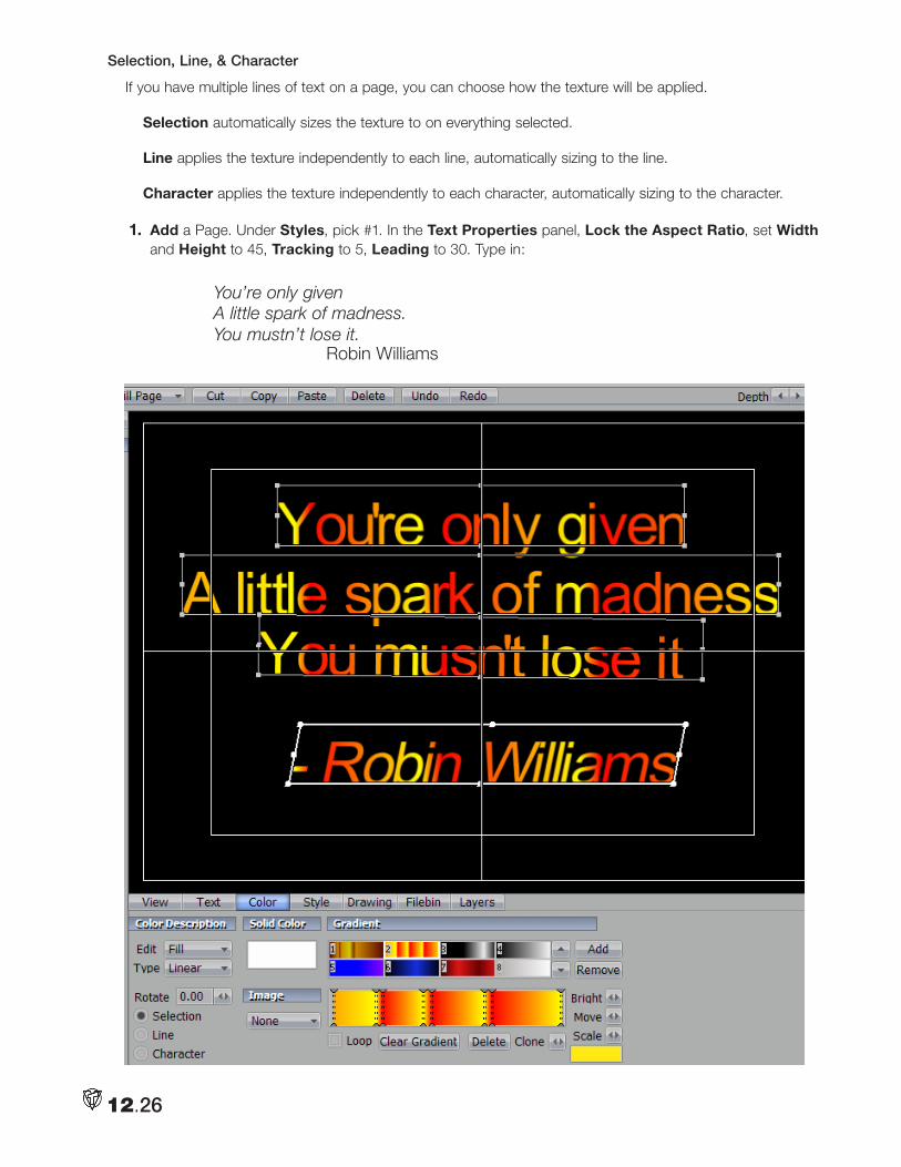
Selection, Line, & Character
If you have multiple lines of text on a page, you can choose how the texture will be applied.
Selection automatically sizes the texture to on everything selected.
Line applies the texture independently to each line, automatically sizing to the line.
Character applies the texture independently to each character, automatically sizing to the character.
1. Add a Page. Under Styles, pick #1. In the Text Properties panel, Lock the Aspect Ratio, set Width and Height to 45, Tracking to 5, Leading to 30. Type in:
You’re only given A little spark of madness. You mustn’t lose it. Robin Williams
12.26
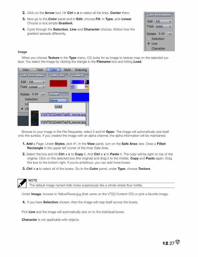
2. Click on the Arrow tool. Hit Ctrl + a to select all the lines. Center them.
3. Now go to the Color panel and in Edit, choose Fill. In Type, pick Linear. Choose a nice simple Gradient.
4. Cycle through the Selection, Line and Character choices. Notice how the gradient spreads differently.
Image
When you choose Texture in the Type menu, CG looks for an image to texture map on the selected sur-face. You select the image by clicking the triangle in the Filename box and hitting Load.
Browse to your image in the File Requester, select it and hit Open. The image will automatically size itself onto the surface. If you created the image with an alpha channel, the alpha information will be maintained.
1. Add a Page. Under Styles, pick #1. In the View panel, turn on the Safe Area view. Draw a Filled Rectangle in the upper left corner of the inner Safe Area.
2. Select the box and hit Ctrl + c to Copy it. And Ctrl + v to Paste it. The copy will be right on top of the original. Click on the selected box (the original) and drag it to the middle. Copy and Paste again. Drag this box to the bottom right. If you’re ambitious, you can add more boxes.
3. Ctrl + a to select all of the boxes. Go to the Color panel, under Type, choose Texture.
NOTE
The default image named hello looks suspiciously like a whole wheat flour tortilla.
Under Image, browse to YellowFlower.jpg (that came on the VT[5] Content CD) or pick a favorite image.
4. If you have Selection chosen, then the image will map itself across the boxes.
Pick Line and the image will automatically size on to the individual boxes.
Character is not applicable with objects.
12.27
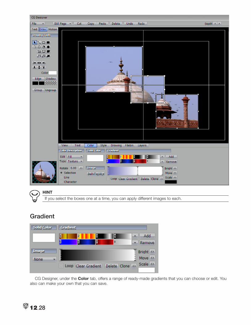
HINT
If you select the boxes one at a time, you can apply different images to each.
Gradient
CG Designer, under the Color tab, offers a range of ready-made gradients that you can choose or edit. You also can make your own that you can save.
12.28
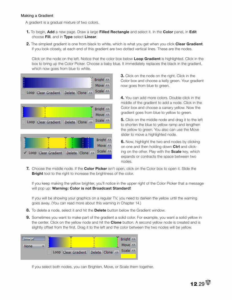
Making a Gradient
A gradient is a gradual mixture of two colors.
1. To begin, Add a new page. Draw a large Filled Rectangle and select it. In the Color panel, in Edit choose Fill, and in Type select Linear.
2. The simplest gradient is one from black to white, which is what you get when you click Clear Gradient. If you look closely, at each end of this gradient are two dotted vertical lines. These are the nodes. Click on the node on the left. Notice that the color box below Loop Gradient is highlighted. Click in the box to bring up the Color Picker. Choose a baby blue. It immediately replaces the black in the gradient, which now goes from blue to white.
3. Click on the node on the right. Click in the Color box and choose a kelly green. Your gradient now goes from blue to green.
4. You can add more colors. Double-click in the middle of the gradient to add a node. Click in the Color box and choose a canary yellow. Now the gradient goes from blue to yellow to green.
5. Click on the middle node and drag it to the left to shorten the blue to yellow ramp and lengthen the yellow to green. You also can use the Move slider to move a highlighted node.
6. Now, highlight the two end nodes by clicking on one and then holding down Ctrl and click-ing on the other. Play with the Scale key, which expands or contracts the space between two nodes.
7. Choose the middle node. If the Color Picker isn’t open, click on the Color box to open it. Slide the Bright tool to the right to increase the brightness of the color. If you keep making the yellow brighter, you’ll notice in the upper right of the Color Picker that a message will pop up: Warning: Color is not Broadcast Standard! If you will be showing your graphics on a regular TV, you need to darken the yellow until the warning goes away. (You can read more about this warning in Chapter 14.)
8. To delete a node, select it and hit the Delete button below the Gradient window.
9. Sometimes you want to make part of the gradient a solid color. For example, you want a solid yellow in the center. Click on the yellow node and hit the Clone button. A second yellow node is created and is slightly offset from the first. Drag it to the left and the color between the two nodes will be yellow.
If you select both nodes, you can Brighten, Move, or Scale them together.
12.29
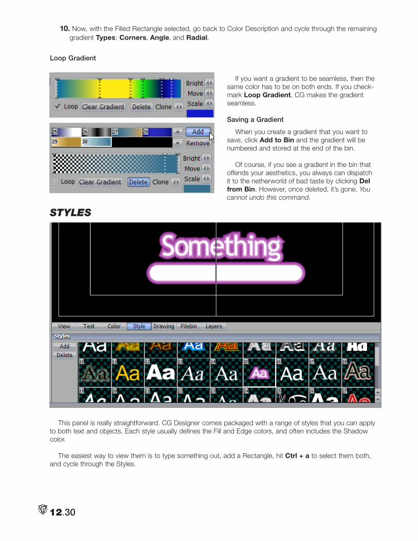
10. Now, with the Filled Rectangle selected, go back to Color Description and cycle through the remaining gradient Types: Corners, Angle, and Radial.
Loop Gradient
If you want a gradient to be seamless, then the same color has to be on both ends. If you check-mark Loop Gradient, CG makes the gradient seamless.
Saving a Gradient
When you create a gradient that you want to save, click Add to Bin and the gradient will be numbered and stored at the end of the bin.
Of course, if you see a gradient in the bin that offends your aesthetics, you always can dispatch it to the netherworld of bad taste by clicking Del from Bin. However, once deleted, it’s gone. You cannot undo this command.
styles
This panel is really straightforward. CG Designer comes packaged with a range of styles that you can apply to both text and objects. Each style usually defines the Fill and Edge colors, and often includes the Shadow color.
The easiest way to view them is to type something out, add a Rectangle, hit Ctrl + a to select them both, and cycle through the Styles.
12.30
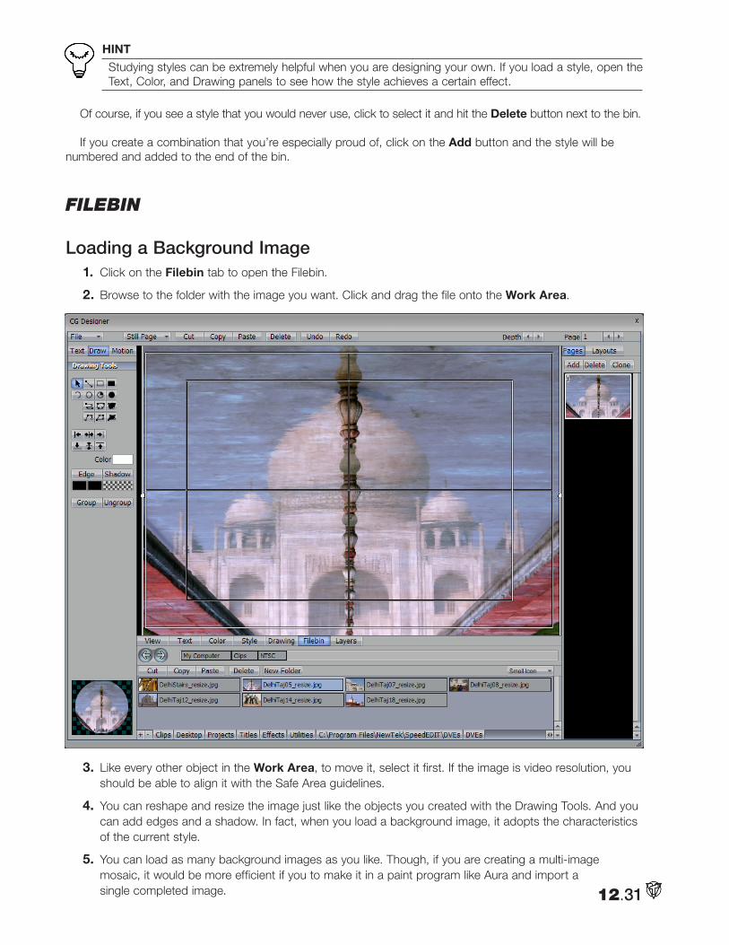
HINT
Studying styles can be extremely helpful when you are designing your own. If you load a style, open the Text, Color, and Drawing panels to see how the style achieves a certain effect.
Of course, if you see a style that you would never use, click to select it and hit the Delete button next to the bin.
If you create a combination that you’re especially proud of, click on the Add button and the style will be numbered and added to the end of the bin.
Filebin
Loading a Background Image1. Click on the Filebin tab to open the Filebin.
2. Browse to the folder with the image you want. Click and drag the file onto the Work Area.
3. Like every other object in the Work Area, to move it, select it first. If the image is video resolution, you should be able to align it with the Safe Area guidelines.
4. You can reshape and resize the image just like the objects you created with the Drawing Tools. And you can add edges and a shadow. In fact, when you load a background image, it adopts the characteristics of the current style.
5. You can load as many background images as you like. Though, if you are creating a multi-image mosaic, it would be more efficient if you to make it in a paint program like Aura and import a single completed image. 12.31
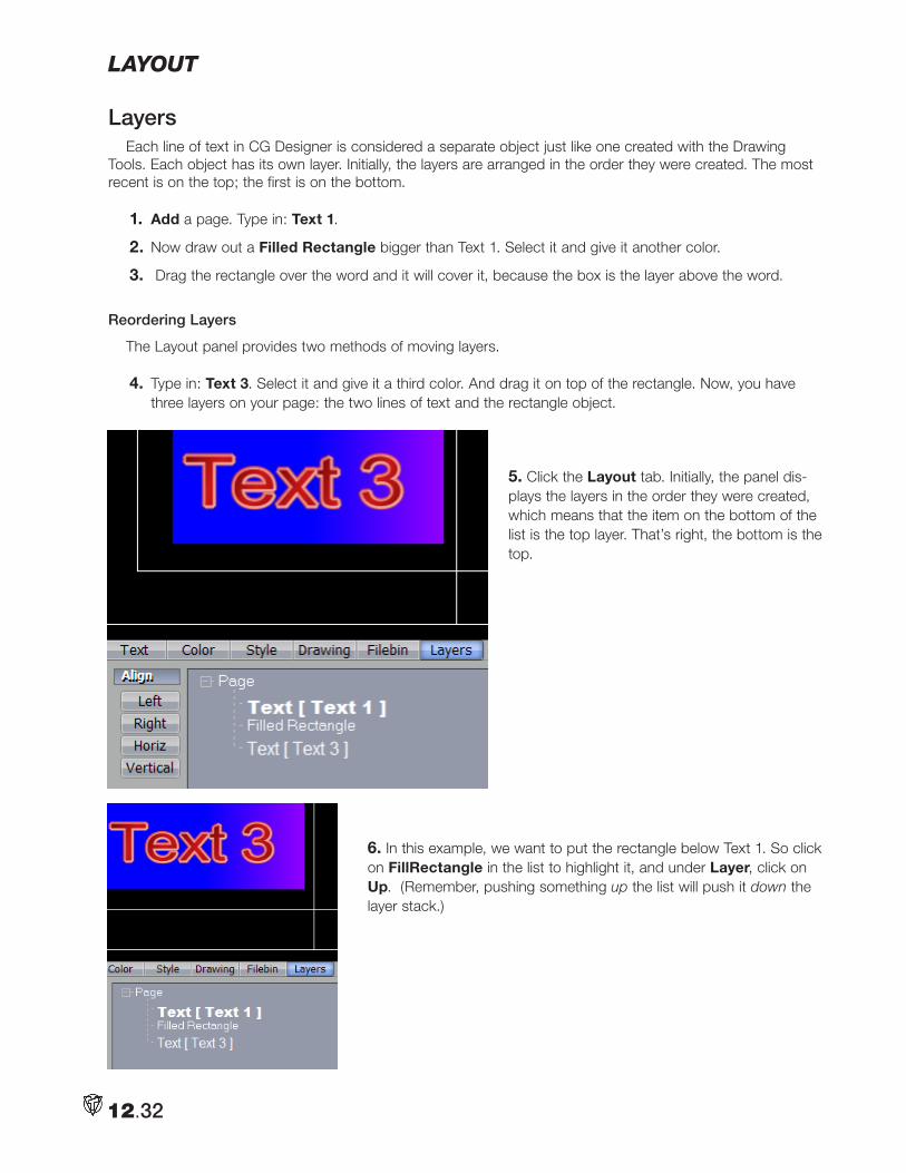
layout
LayersEach line of text in CG Designer is considered a separate object just like one created with the Drawing
Tools. Each object has its own layer. Initially, the layers are arranged in the order they were created. The most recent is on the top; the first is on the bottom.
1. Add a page. Type in: Text 1.
2. Now draw out a Filled Rectangle bigger than Text 1. Select it and give it another color.
3. Drag the rectangle over the word and it will cover it, because the box is the layer above the word.
Reordering Layers
The Layout panel provides two methods of moving layers.
4. Type in: Text 3. Select it and give it a third color. And drag it on top of the rectangle. Now, you have three layers on your page: the two lines of text and the rectangle object.
5. Click the Layout tab. Initially, the panel dis-plays the layers in the order they were created, which means that the item on the bottom of the list is the top layer. That’s right, the bottom is the top.
6. In this example, we want to put the rectangle below Text 1. So click on FillRectangle in the list to highlight it, and under Layer, click on Up. (Remember, pushing something up the list will push it down the layer stack.)
12.32
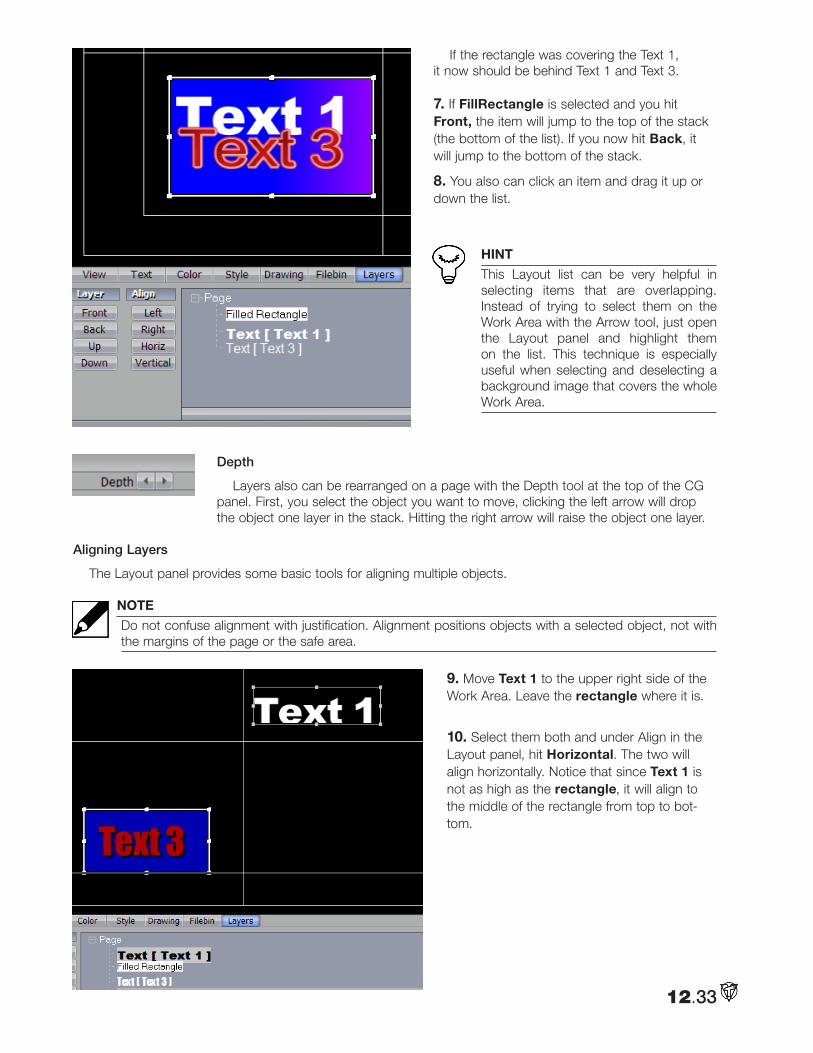
If the rectangle was covering the Text 1, it now should be behind Text 1 and Text 3.
7. If FillRectangle is selected and you hit Front, the item will jump to the top of the stack (the bottom of the list). If you now hit Back, it will jump to the bottom of the stack.
8. You also can click an item and drag it up or down the list.
HINT
This Layout list can be very helpful in selecting items that are overlapping. Instead of trying to select them on the Work Area with the Arrow tool, just open the Layout panel and highlight them on the list. This technique is especially useful when selecting and deselecting a background image that covers the whole Work Area.
Depth
Layers also can be rearranged on a page with the Depth tool at the top of the CG panel. First, you select the object you want to move, clicking the left arrow will drop the object one layer in the stack. Hitting the right arrow will raise the object one layer.
Aligning Layers
The Layout panel provides some basic tools for aligning multiple objects.
NOTE
Do not confuse alignment with justification. Alignment positions objects with a selected object, not with the margins of the page or the safe area.
9. Move Text 1 to the upper right side of the Work Area. Leave the rectangle where it is.
10. Select them both and under Align in the Layout panel, hit Horizontal. The two will align horizontally. Notice that since Text 1 is not as high as the rectangle, it will align to the middle of the rectangle from top to bot-tom.
12.33
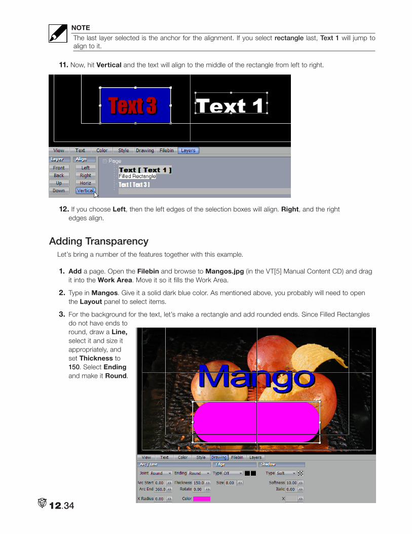
NOTE
The last layer selected is the anchor for the alignment. If you select rectangle last, Text 1 will jump to align to it.
11. Now, hit Vertical and the text will align to the middle of the rectangle from left to right.
12. If you choose Left, then the left edges of the selection boxes will align. Right, and the right edges align.
Adding TransparencyLet’s bring a number of the features together with this example.
1. Add a page. Open the Filebin and browse to Mangos.jpg (in the VT[5] Manual Content CD) and drag it into the Work Area. Move it so it fills the Work Area.
2. Type in Mangos. Give it a solid dark blue color. As mentioned above, you probably will need to open the Layout panel to select items.
3. For the background for the text, let’s make a rectangle and add rounded ends. Since Filled Rectangles do not have ends to round, draw a Line, select it and size it appropriately, and set Thickness to 150. Select Ending and make it Round.
12.34
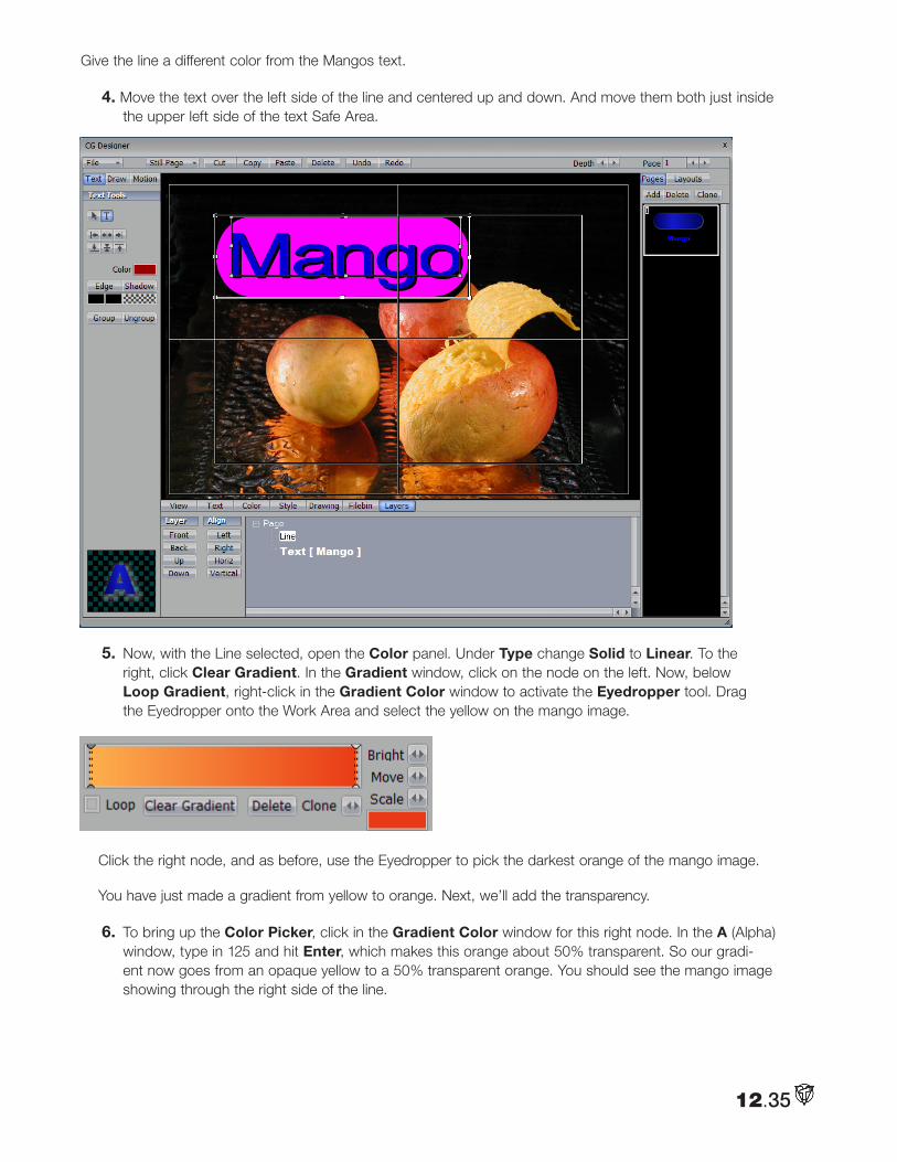
Give the line a different color from the Mangos text.
4. Move the text over the left side of the line and centered up and down. And move them both just inside the upper left side of the text Safe Area.
5. Now, with the Line selected, open the Color panel. Under Type change Solid to Linear. To the right, click Clear Gradient. In the Gradient window, click on the node on the left. Now, below Loop Gradient, right-click in the Gradient Color window to activate the Eyedropper tool. Drag the Eyedropper onto the Work Area and select the yellow on the mango image.
Click the right node, and as before, use the Eyedropper to pick the darkest orange of the mango image.
You have just made a gradient from yellow to orange. Next, we’ll add the transparency.
6. To bring up the Color Picker, click in the Gradient Color window for this right node. In the A (Alpha) window, type in 125 and hit Enter, which makes this orange about 50% transparent. So our gradi-ent now goes from an opaque yellow to a 50% transparent orange. You should see the mango image showing through the right side of the line.
12.35
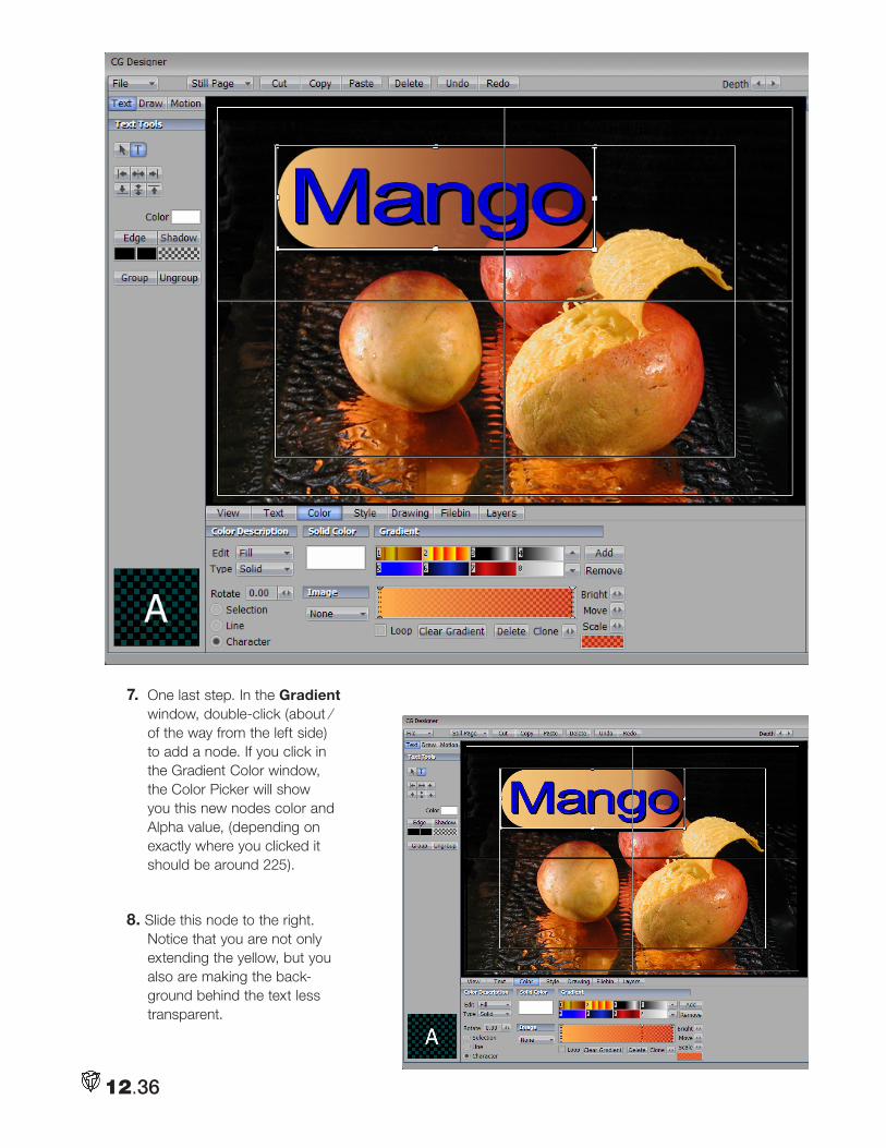
7. One last step. In the Gradient window, double-click (about ⁄ of the way from the left side) to add a node. If you click in the Gradient Color window, the Color Picker will show you this new nodes color and Alpha value, (depending on exactly where you clicked it should be around 225).
8. Slide this node to the right. Notice that you are not only extending the yellow, but you also are making the back-ground behind the text less transparent.
12.36
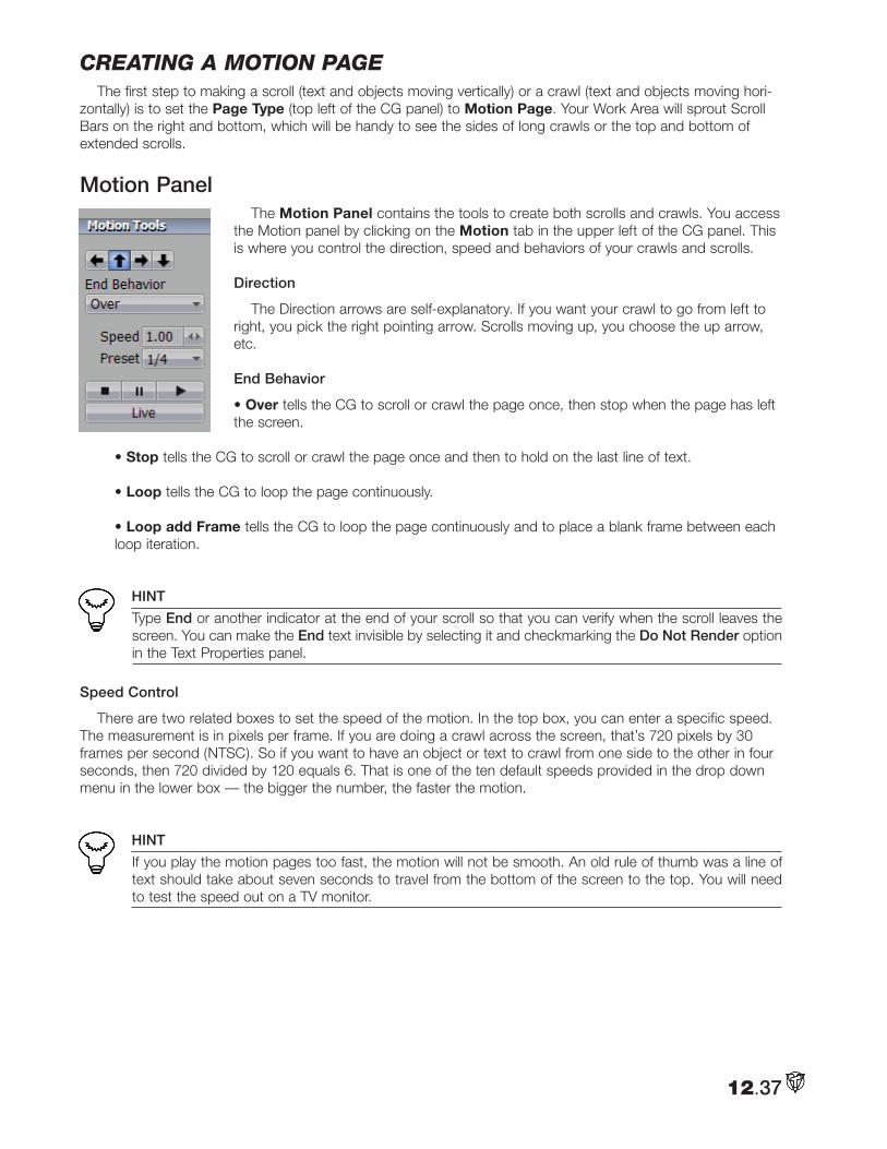
cReating a motion pageThe first step to making a scroll (text and objects moving vertically) or a crawl (text and objects moving hori-
zontally) is to set the Page Type (top left of the CG panel) to Motion Page. Your Work Area will sprout Scroll Bars on the right and bottom, which will be handy to see the sides of long crawls or the top and bottom of extended scrolls.
Motion Panel The Motion Panel contains the tools to create both scrolls and crawls. You access
the Motion panel by clicking on the Motion tab in the upper left of the CG panel. This is where you control the direction, speed and behaviors of your crawls and scrolls.
Direction
The Direction arrows are self-explanatory. If you want your crawl to go from left to right, you pick the right pointing arrow. Scrolls moving up, you choose the up arrow, etc.
End Behavior
• Over tells the CG to scroll or crawl the page once, then stop when the page has left the screen.
• Stop tells the CG to scroll or crawl the page once and then to hold on the last line of text. • Loop tells the CG to loop the page continuously.
• Loop add Frame tells the CG to loop the page continuously and to place a blank frame between each loop iteration.
HINT
Type End or another indicator at the end of your scroll so that you can verify when the scroll leaves the screen. You can make the End text invisible by selecting it and checkmarking the Do Not Render option in the Text Properties panel.
Speed Control
There are two related boxes to set the speed of the motion. In the top box, you can enter a specific speed. The measurement is in pixels per frame. If you are doing a crawl across the screen, that’s 720 pixels by 30 frames per second (NTSC). So if you want to have an object or text to crawl from one side to the other in four seconds, then 720 divided by 120 equals 6. That is one of the ten default speeds provided in the drop down menu in the lower box — the bigger the number, the faster the motion.
HINT
If you play the motion pages too fast, the motion will not be smooth. An old rule of thumb was a line of text should take about seven seconds to travel from the bottom of the screen to the top. You will need to test the speed out on a TV monitor.
12.37
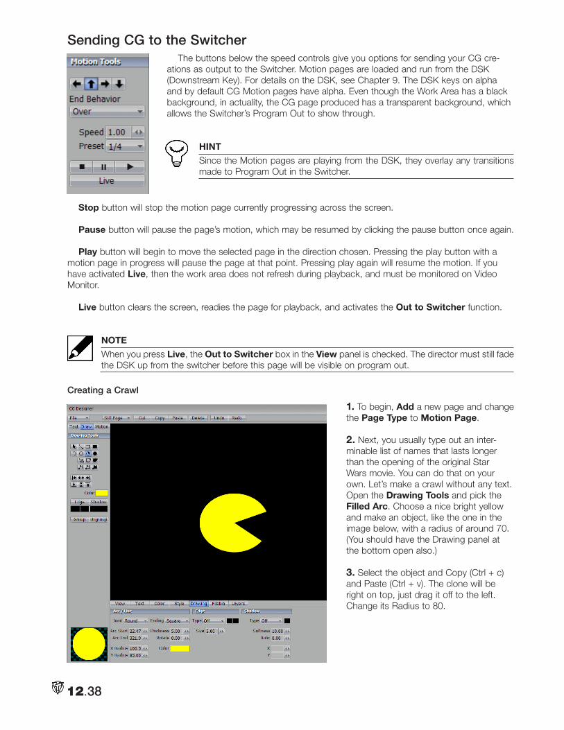
Sending CG to the SwitcherThe buttons below the speed controls give you options for sending your CG cre-
ations as output to the Switcher. Motion pages are loaded and run from the DSK (Downstream Key). For details on the DSK, see Chapter 9. The DSK keys on alpha and by default CG Motion pages have alpha. Even though the Work Area has a black background, in actuality, the CG page produced has a transparent background, which allows the Switcher’s Program Out to show through.
HINT
Since the Motion pages are playing from the DSK, they overlay any transitions made to Program Out in the Switcher.
Stop button will stop the motion page currently progressing across the screen.
Pause button will pause the page’s motion, which may be resumed by clicking the pause button once again.
Play button will begin to move the selected page in the direction chosen. Pressing the play button with a motion page in progress will pause the page at that point. Pressing play again will resume the motion. If you have activated Live, then the work area does not refresh during playback, and must be monitored on Video Monitor.
Live button clears the screen, readies the page for playback, and activates the Out to Switcher function.
NOTE
When you press Live, the Out to Switcher box in the View panel is checked. The director must still fade the DSK up from the switcher before this page will be visible on program out.
Creating a Crawl
1. To begin, Add a new page and change the Page Type to Motion Page.
2. Next, you usually type out an inter-minable list of names that lasts longer than the opening of the original Star Wars movie. You can do that on your own. Let’s make a crawl without any text. Open the Drawing Tools and pick the Filled Arc. Choose a nice bright yellow and make an object, like the one in the image below, with a radius of around 70. (You should have the Drawing panel at the bottom open also.)
3. Select the object and Copy (Ctrl + c) and Paste (Ctrl + v). The clone will be right on top, just drag it off to the left. Change its Radius to 80.
12.38
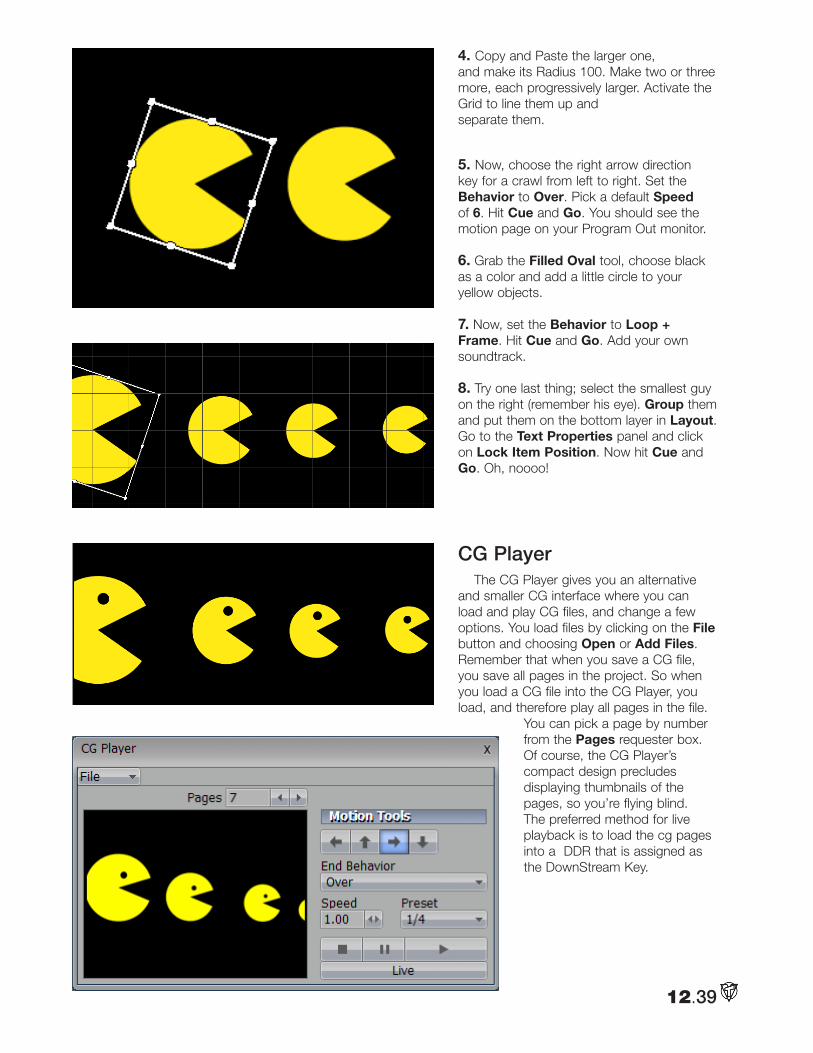
4. Copy and Paste the larger one, and make its Radius 100. Make two or three more, each progressively larger. Activate the Grid to line them up and separate them.
5. Now, choose the right arrow direction key for a crawl from left to right. Set the Behavior to Over. Pick a default Speed of 6. Hit Cue and Go. You should see the motion page on your Program Out monitor.
6. Grab the Filled Oval tool, choose black as a color and add a little circle to your yellow objects.
7. Now, set the Behavior to Loop + Frame. Hit Cue and Go. Add your own soundtrack.
8. Try one last thing; select the smallest guy on the right (remember his eye). Group them and put them on the bottom layer in Layout. Go to the Text Properties panel and click on Lock Item Position. Now hit Cue and Go. Oh, noooo!
CG PlayerThe CG Player gives you an alternative
and smaller CG interface where you can load and play CG files, and change a few options. You load files by clicking on the File button and choosing Open or Add Files. Remember that when you save a CG file, you save all pages in the project. So when you load a CG file into the CG Player, you load, and therefore play all pages in the file.
You can pick a page by number from the Pages requester box. Of course, the CG Player’s compact design precludes displaying thumbnails of the pages, so you’re flying blind. The preferred method for live playback is to load the cg pages into a DDR that is assigned as the DownStream Key.
12.39
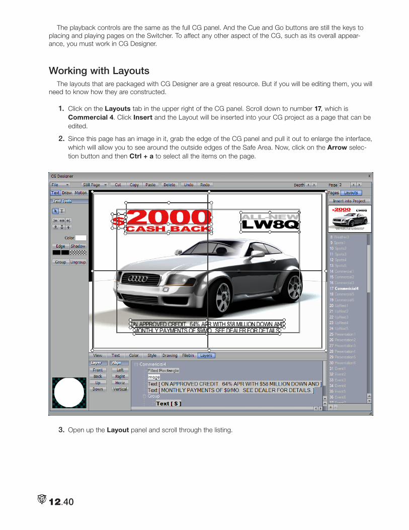
The playback controls are the same as the full CG panel. And the Cue and Go buttons are still the keys to placing and playing pages on the Switcher. To affect any other aspect of the CG, such as its overall appear-ance, you must work in CG Designer.
Working with Layouts The layouts that are packaged with CG Designer are a great resource. But if you will be editing them, you will
need to know how they are constructed.
1. Click on the Layouts tab in the upper right of the CG panel. Scroll down to number 17, which is Commercial 4. Click Insert and the Layout will be inserted into your CG project as a page that can be edited.
2. Since this page has an image in it, grab the edge of the CG panel and pull it out to enlarge the interface, which will allow you to see around the outside edges of the Safe Area. Now, click on the Arrow selec-tion button and then Ctrl + a to select all the items on the page.
3. Open up the Layout panel and scroll through the listing.
12.40
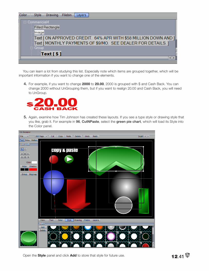
You can learn a lot from studying this list. Especially note which items are grouped together, which will be important information if you want to change one of the elements.
4. For example, if you want to change 2000 to 20.00, 2000 is grouped with $ and Cash Back. You can change 2000 without UnGrouping them, but if you want to realign 20.00 and Cash Back, you will need to UnGroup.
5. Again, examine how Tim Johnson has created these layouts. If you see a type style or drawing style that you like, grab it. For example in 96, CutNPaste, select the green pie chart, which will load its Style into the Color panel.
Open the Style panel and click Add to store that style for future use. 12.41
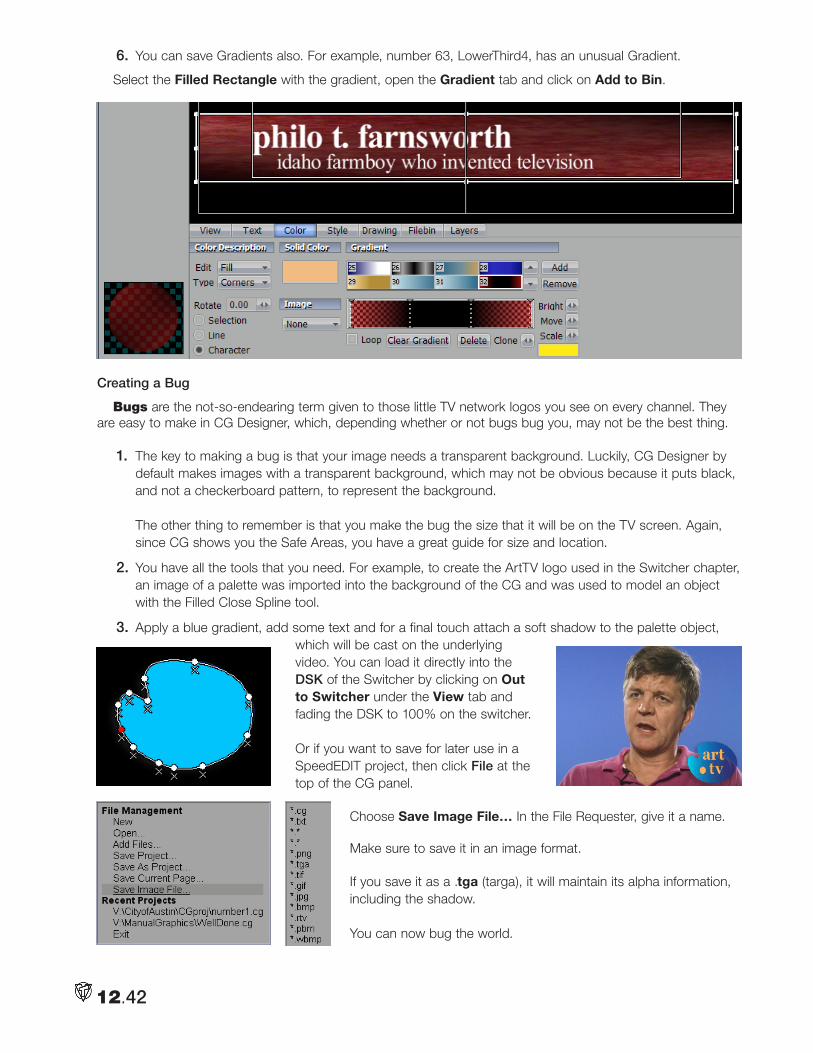
12.42
6. You can save Gradients also. For example, number 63, LowerThird4, has an unusual Gradient.
Select the Filled Rectangle with the gradient, open the Gradient tab and click on Add to Bin.
Creating a Bug
Bugs are the not-so-endearing term given to those little TV network logos you see on every channel. They are easy to make in CG Designer, which, depending whether or not bugs bug you, may not be the best thing.
1. The key to making a bug is that your image needs a transparent background. Luckily, CG Designer by default makes images with a transparent background, which may not be obvious because it puts black, and not a checkerboard pattern, to represent the background. The other thing to remember is that you make the bug the size that it will be on the TV screen. Again, since CG shows you the Safe Areas, you have a great guide for size and location.
2. You have all the tools that you need. For example, to create the ArtTV logo used in the Switcher chapter, an image of a palette was imported into the background of the CG and was used to model an object with the Filled Close Spline tool.
3. Apply a blue gradient, add some text and for a final touch attach a soft shadow to the palette object, which will be cast on the underlying video. You can load it directly into the DSK of the Switcher by clicking on Out to Switcher under the View tab and fading the DSK to 100% on the switcher. Or if you want to save for later use in a SpeedEDIT project, then click File at the top of the CG panel.
Choose Save Image File… In the File Requester, give it a name. Make sure to save it in an image format. If you save it as a .tga (targa), it will maintain its alpha information, including the shadow. You can now bug the world.
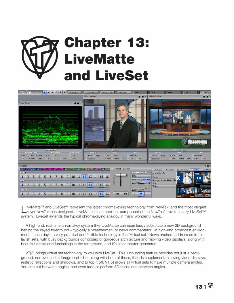
13.1
LiveMatte™ and LiveSet™ represent the latest chromakeying technology from NewTek, and the most elegant keyer NewTek has designed. LiveMatte is an important component of the NewTek’s revolutionary LiveSet™
system. LiveSet extends the typical chromakeying analogy in many wonderful ways.
A high-end, real-time chromakey system (like LiveMatte) can seamlessly substitute a new 2D background behind the keyed foreground – typically a ‘weatherman’ or news commentator. In high-end broadcast environ-ments these days, a very practical and flexible technology is the “virtual set.” News anchors address us from lavish sets, with busy backgrounds composed of gorgeous architecture and moving video displays, along with beautiful desks and furnishings in the foreground, and it’s all computer-generated.
VT[5] brings virtual set technology to you with LiveSet. This astounding feature provides not just a back-ground, nor even just a foreground – but along with both of those, it adds supplemental moving video displays, realistic reflections and shadows, and to top it off, VT[5] allows all virtual sets to have multiple camera angles. You can cut between angles, and even fade or perform 3D transitions between angles.
Chapter 13: LiveMatte and LiveSet
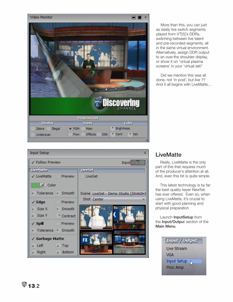
13.2
More than this, you can just as easily live switch segments played from VT[5]’s DDRs, switching between live talent and pre-recorded segments, all in the same virtual environment. Alternatively, assign DDR output to an over-the shoulder display, or show it on ‘virtual plasma screens’ in your ‘virtual set!’
Did we mention this was all done, not ‘in post’, but live ?? And it all begins with LiveMatte…
LiveMatte Really, LiveMatte is the only
part of this that requires much of the producer’s attention at all. And, even this bit is quite simple.
This latest technology is by far the best quality keyer NewTek has ever offered. Even so, when using LiveMatte, it’s crucial to start with good planning and physical preparation
Launch InputSetup from the Input/Output section of the Main Menu.
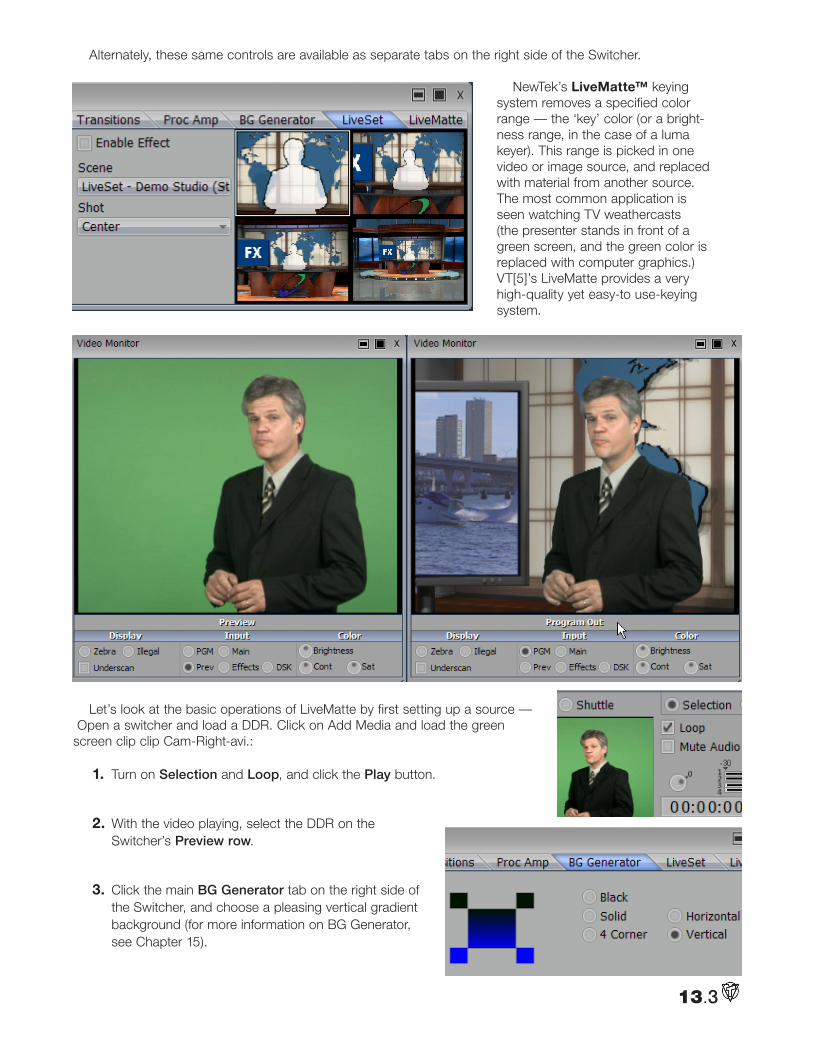
13.3
Alternately, these same controls are available as separate tabs on the right side of the Switcher.
NewTek’s LiveMatte™ keying system removes a specified color range — the ‘key’ color (or a bright-ness range, in the case of a luma keyer). This range is picked in one video or image source, and replaced with material from another source. The most common application is seen watching TV weathercasts (the presenter stands in front of a green screen, and the green color is replaced with computer graphics.) VT[5]’s LiveMatte provides a very high-quality yet easy-to use-keying system.
Let’s look at the basic operations of LiveMatte by first setting up a source — Open a switcher and load a DDR. Click on Add Media and load the green screen clip clip Cam-Right-avi.:
1. Turn on Selection and Loop, and click the Play button.
2. With the video playing, select the DDR on the Switcher’s Preview row.
3. Click the main BG Generator tab on the right side of the Switcher, and choose a pleasing vertical gradient background (for more information on BG Generator, see Chapter 15).
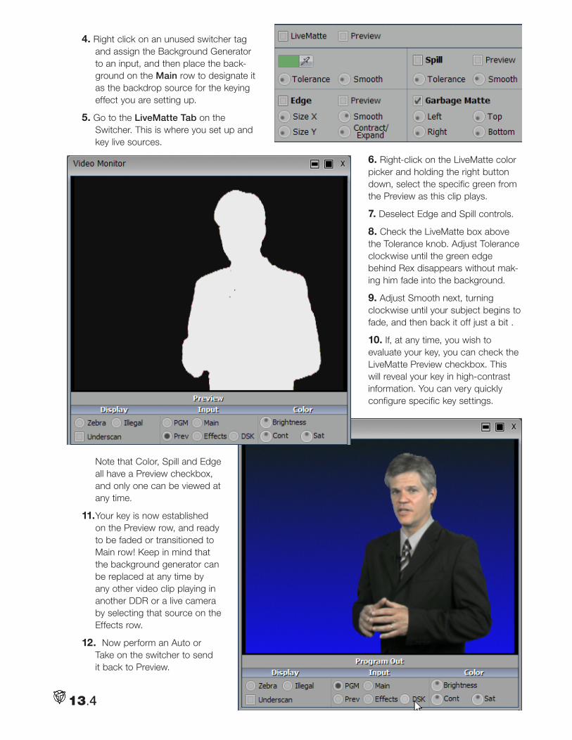
13.4
4. Right click on an unused switcher tag and assign the Background Generator to an input, and then place the back-ground on the Main row to designate it as the backdrop source for the keying effect you are setting up.
5. Go to the LiveMatte Tab on the Switcher. This is where you set up and key live sources.
6. Right-click on the LiveMatte color picker and holding the right button down, select the specific green from the Preview as this clip plays.
7. Deselect Edge and Spill controls.
8. Check the LiveMatte box above the Tolerance knob. Adjust Tolerance clockwise until the green edge behind Rex disappears without mak-ing him fade into the background.
9. Adjust Smooth next, turning clockwise until your subject begins to fade, and then back it off just a bit .
10. If, at any time, you wish to evaluate your key, you can check the LiveMatte Preview checkbox. This will reveal your key in high-contrast information. You can very quickly configure specific key settings.
Note that Color, Spill and Edge all have a Preview checkbox, and only one can be viewed at any time.
11. Your key is now established on the Preview row, and ready to be faded or transitioned to Main row! Keep in mind that the background generator can be replaced at any time by any other video clip playing in another DDR or a live camera by selecting that source on the Effects row.
12. Now perform an Auto or Take on the switcher to send it back to Preview.
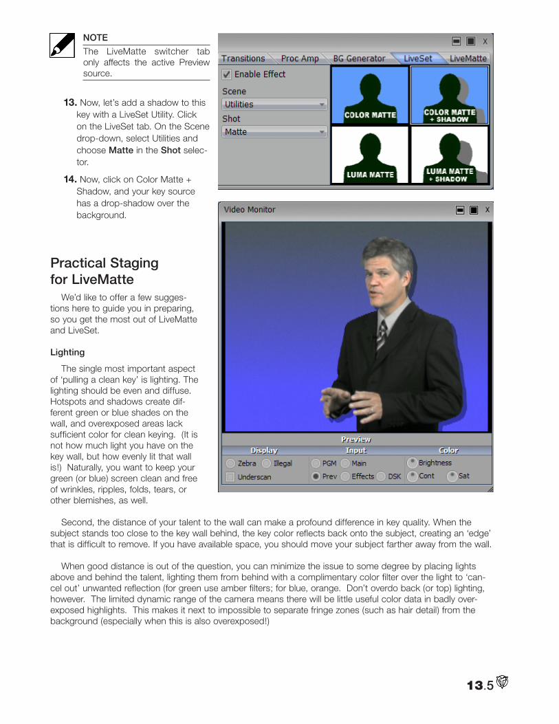
13.5
NOTE
The LiveMatte switcher tab only affects the active Preview source.
13. Now, let’s add a shadow to this key with a LiveSet Utility. Click on the LiveSet tab. On the Scene drop-down, select Utilities and choose Matte in the Shot selec-tor.
14. Now, click on Color Matte + Shadow, and your key source has a drop-shadow over the background.
Practical Staging for LiveMatte
We’d like to offer a few sugges-tions here to guide you in preparing, so you get the most out of LiveMatte and LiveSet.
Lighting
The single most important aspect of ‘pulling a clean key’ is lighting. The lighting should be even and diffuse. Hotspots and shadows create dif-ferent green or blue shades on the wall, and overexposed areas lack sufficient color for clean keying. (It is not how much light you have on the key wall, but how evenly lit that wall is!) Naturally, you want to keep your green (or blue) screen clean and free of wrinkles, ripples, folds, tears, or other blemishes, as well.
Second, the distance of your talent to the wall can make a profound difference in key quality. When the subject stands too close to the key wall behind, the key color reflects back onto the subject, creating an ‘edge’ that is difficult to remove. If you have available space, you should move your subject farther away from the wall.
When good distance is out of the question, you can minimize the issue to some degree by placing lights above and behind the talent, lighting them from behind with a complimentary color filter over the light to ‘can-cel out’ unwanted reflection (for green use amber filters; for blue, orange. Don’t overdo back (or top) lighting, however. The limited dynamic range of the camera means there will be little useful color data in badly over-exposed highlights. This makes it next to impossible to separate fringe zones (such as hair detail) from the background (especially when this is also overexposed!)
13.6
Through the Lens
As mentioned above, washed out areas in the source video signal lack sufficient color information to provide good separation. For similar reasons, it’s worth considering the color characteristics different types of video signals.
In the analog video realm, you will encounter three main types of camera feed. We present them here in ascending order of the quality of video signal they provide (and as things go, in the reverse order of their cost, and the likelihood that you will have access to them):
1) Composite — a two conductor design using the classic RCA connector that sends color and bright-ness signals in the same stream.
2) Y/C — typically using a round, 4-pin mini-DIN connector, Y/C keeps Y (luminance) and C (chromi-nance) signals separate.
HINT
Y/C is occasionally called “component” (which while technically correct, can be a bit confusing given the next class) or “S-Video” (completely incorrect, though a common error.)
3) Component, or YUV — a three wire system typically using BNC (push & twist-on) connectors. This format uses a little math to cleverly juggle the R, G, and B values into something less ‘bulky,’ in the interest of making best use of precious analog signal bandwidth.
Cameras and connections from either of the last two are preferred, but it is entirely possible to succeed with just a composite signal. When you have better available, however, use it! (Try to avoid downgrading the pre-LiveMatte signal from a Y/C camera, for example, by connecting it to your VT[5] using composite cabling.)
HINT
MiniDV cameras are not available in the Input Setup panel as live switching sources, for several reasons. However they may often be connected by Y/C cable, and in this configuration any actually provide a better color rendition for keying purpose than if they were connected by IEEE1394 cable.
This may well be true even for capturing footage for the purpose of chromakeying later in Edit Media. (HDV’s vastly superior resolution largely overcomes the problems DV’s reduced color sampling can cause.)
Calibration and Monitoring
Obviously, it is more than a pun to state that good color rendition is key for LiveMatte. VT[5] provides con-venient signal calibration tools in the Input Setup panel. Feed color bars from your camera(s) to the assigned Input(s), and calibrate them before beginning.
As well, a (properly calibrated) commercial-quality broadcast monitor can be a big help when judging light-ing and the effect of Proc Amp control settings.
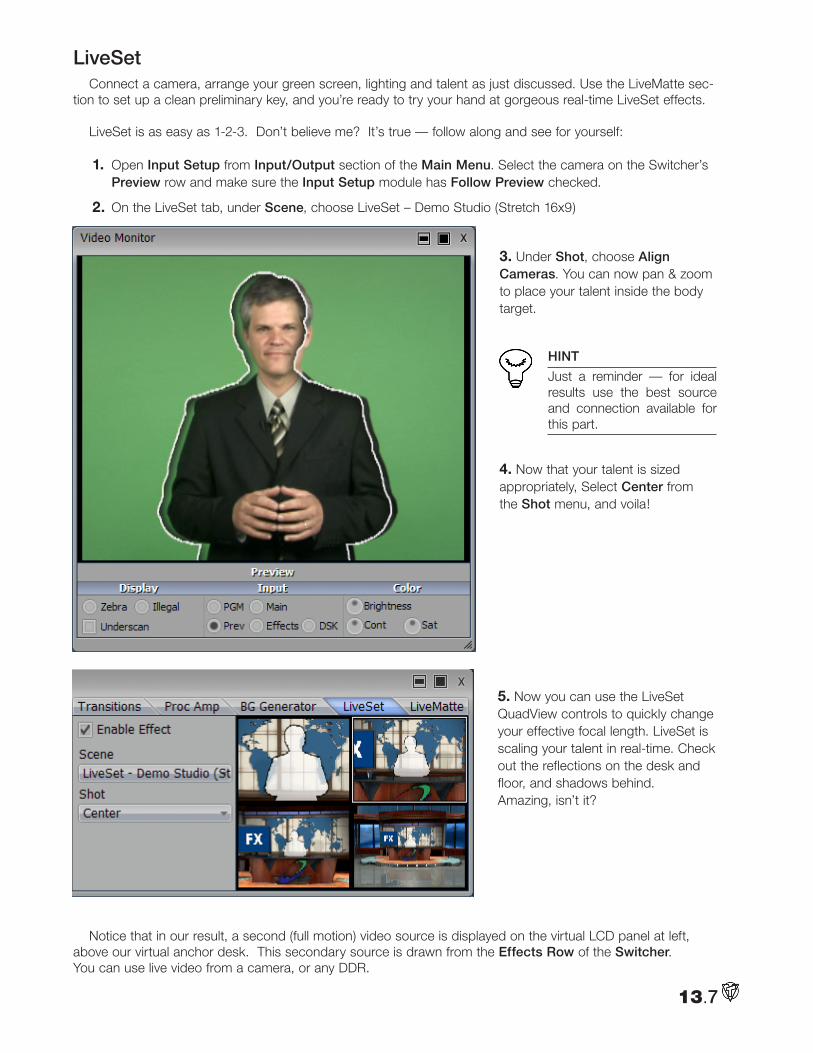
13.7
LiveSet Connect a camera, arrange your green screen, lighting and talent as just discussed. Use the LiveMatte sec-
tion to set up a clean preliminary key, and you’re ready to try your hand at gorgeous real-time LiveSet effects.
LiveSet is as easy as 1-2-3. Don’t believe me? It’s true — follow along and see for yourself:
1. Open Input Setup from Input/Output section of the Main Menu. Select the camera on the Switcher’s Preview row and make sure the Input Setup module has Follow Preview checked.
2. On the LiveSet tab, under Scene, choose LiveSet – Demo Studio (Stretch 16x9)
3. Under Shot, choose Align Cameras. You can now pan & zoom to place your talent inside the body target.
HINT
Just a reminder — for ideal results use the best source and connection available for this part.
4. Now that your talent is sized appropriately, Select Center from the Shot menu, and voila!
5. Now you can use the LiveSet QuadView controls to quickly change your effective focal length. LiveSet is scaling your talent in real-time. Check out the reflections on the desk and floor, and shadows behind. Amazing, isn’t it?
Notice that in our result, a second (full motion) video source is displayed on the virtual LCD panel at left, above our virtual anchor desk. This secondary source is drawn from the Effects Row of the Switcher. You can use live video from a camera, or any DDR.
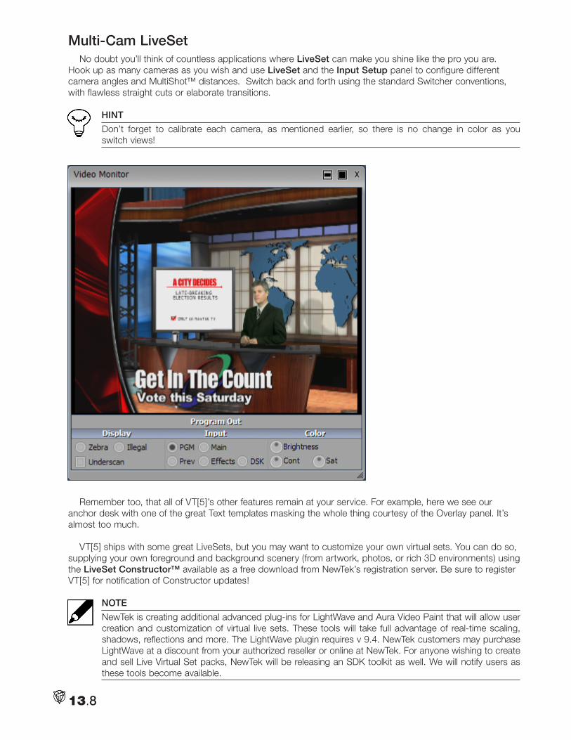
13.8
Multi-Cam LiveSetNo doubt you’ll think of countless applications where LiveSet can make you shine like the pro you are.
Hook up as many cameras as you wish and use LiveSet and the Input Setup panel to configure different camera angles and MultiShot™ distances. Switch back and forth using the standard Switcher conventions, with flawless straight cuts or elaborate transitions.
HINT
Don’t forget to calibrate each camera, as mentioned earlier, so there is no change in color as you switch views!
Remember too, that all of VT[5]’s other features remain at your service. For example, here we see our anchor desk with one of the great Text templates masking the whole thing courtesy of the Overlay panel. It’s almost too much.
VT[5] ships with some great LiveSets, but you may want to customize your own virtual sets. You can do so, supplying your own foreground and background scenery (from artwork, photos, or rich 3D environments) using the LiveSet Constructor™ available as a free download from NewTek’s registration server. Be sure to register VT[5] for notification of Constructor updates!
NOTE
NewTek is creating additional advanced plug-ins for LightWave and Aura Video Paint that will allow user creation and customization of virtual live sets. These tools will take full advantage of real-time scaling, shadows, reflections and more. The LightWave plugin requires v 9.4. NewTek customers may purchase LightWave at a discount from your authorized reseller or online at NewTek. For anyone wishing to create and sell Live Virtual Set packs, NewTek will be releasing an SDK toolkit as well. We will notify users as these tools become available.
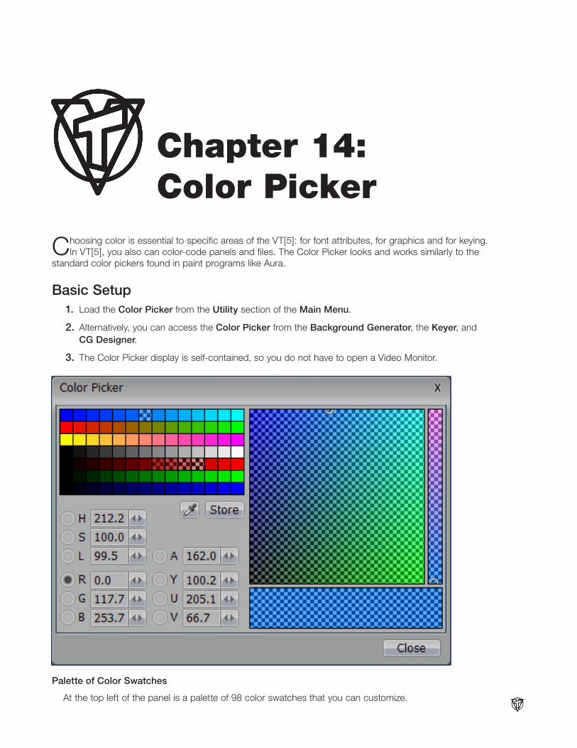
14.1
Choosing color is essential to specific areas of the VT[5]: for font attributes, for graphics and for keying. In VT[5], you also can color-code panels and files. The Color Picker looks and works similarly to the
standard color pickers found in paint programs like Aura.
Basic Setup 1. Load the Color Picker from the Utility section of the Main Menu.
2. Alternatively, you can access the Color Picker from the Background Generator, the Keyer, and CG Designer.
3. The Color Picker display is self-contained, so you do not have to open a Video Monitor.
Palette of Color Swatches
At the top left of the panel is a palette of 98 color swatches that you can customize.
Chapter 14: Color Picker
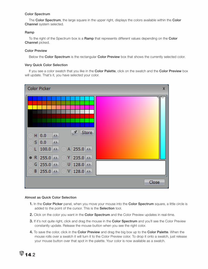
14.2
Color Spectrum
The Color Spectrum, the large square in the upper right, displays the colors available within the Color Channel system selected.
Ramp
To the right of the Spectrum box is a Ramp that represents different values depending on the Color Channel picked.
Color Preview
Below the Color Spectrum is the rectangular Color Preview box that shows the currently selected color.
Very Quick Color Selection
If you see a color swatch that you like in the Color Palette, click on the swatch and the Color Preview box will update. That’s it, you have selected your color.
Almost as Quick Color Selection
1. In the Color Picker panel, when you move your mouse into the Color Spectrum square, a little circle is added to the point of the cursor. This is the Selection tool.
2. Click on the color you want in the Color Spectrum and the Color Preview updates in real-time.
3. If it’s not quite right, click and drag the mouse in the Color Spectrum and you’ll see the Color Preview constantly update. Release the mouse button when you see the right color.
4. To save the color, click in the Color Preview and drag the big box up to the Color Palette. When the mouse rolls over a swatch it will turn it to the Color Preview color. To drop it onto a swatch, just release your mouse button over that spot in the palette. Your color is now available as a swatch.
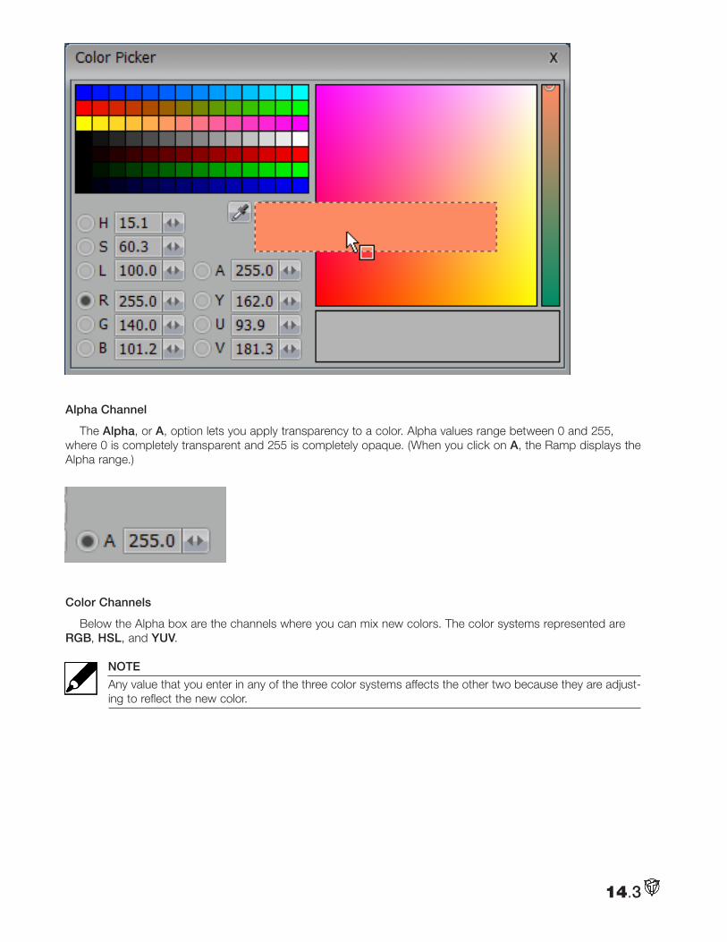
14.3
Alpha Channel
The Alpha, or A, option lets you apply transparency to a color. Alpha values range between 0 and 255, where 0 is completely transparent and 255 is completely opaque. (When you click on A, the Ramp displays the Alpha range.)
f
CU of A channelColor Channels
Below the Alpha box are the channels where you can mix new colors. The color systems represented are RGB, HSL, and YUV.
NOTE
Any value that you enter in any of the three color systems affects the other two because they are adjust-ing to reflect the new color.
Image: CPPanel.tif CU of color channels
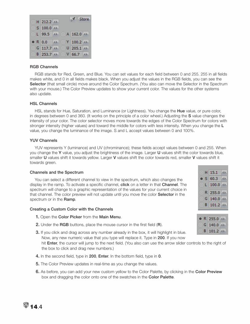
14.4
RGB Channels
RGB stands for Red, Green, and Blue. You can set values for each field between 0 and 255. 255 in all fields makes white, and 0 in all fields makes black. When you adjust the values in the RGB fields, you can see the Selector (that small circle) move around the Color Spectrum. (You also can move the Selector in the Spectrum with your mouse.) The Color Preview updates to show your current color. The values for the other systems also update.
HSL Channels
HSL stands for Hue, Saturation, and Luminance (or Lightness). You change the Hue value, or pure color, in degrees between 0 and 360. (It works on the principle of a color wheel.) Adjusting the S value changes the intensity of your color. The color selector moves more towards the edges of the Color Spectrum for colors with stronger intensity (higher values) and toward the middle for colors with less intensity. When you change the L value, you change the luminance of the image. S and L accept values between 0 and 100%.
YUV Channels
YUV represents Y (luminance) and UV (chrominance); these fields accept values between 0 and 255. When you change the Y value, you adjust the brightness of the image. Larger U values shift the color towards blue, smaller U values shift it towards yellow. Larger V values shift the color towards red, smaller V values shift it towards green.
Channels and the Spectrum
You can select a different channel to view in the spectrum, which also changes the display in the ramp. To activate a specific channel, click on a letter in that Channel. The spectrum will change to a graphic representation of the values for your current choice in that channel. The color preview will not update until you move the color Selector in the spectrum or in the Ramp.
Creating a Custom Color with the Channels
1. Open the Color Picker from the Main Menu.
2. Under the RGB buttons, place the mouse cursor in the first field (R).
3. If you click and drag across any number already in the box, it will highlight in blue. Now, any new numeric value that you type will replace it. Type in 200. If you now hit Enter, the cursor will jump to the next field. (You also can use the arrow slider controls to the right of the box to click and drag new numbers.)
4. In the second field, type in 200, Enter. In the bottom field, type in 0. tif
5. The Color Preview updates in real-time as you change the values.
6. As before, you can add your new custom yellow to the Color Palette, by clicking in the Color Preview box and dragging the color onto one of the swatches in the Color Palette.
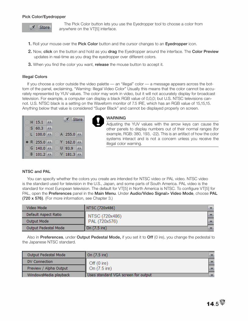
14.5
Pick Color/Eyedropper
The Pick Color button lets you use the Eyedropper tool to choose a color from anywhere on the VT[5] interface.
1. Roll your mouse over the Pick Color button and the cursor changes to an Eyedropper icon.
2. Now, click on the button and hold as you drag the Eyedropper around the interface. The Color Preview updates in real-time as you drag the eyedropper over different colors.
3. When you find the color you want, release the mouse button to accept it.
Illegal Colors
If you choose a color outside the video palette — an “illegal” color — a message appears across the bot-tom of the panel, exclaiming, “Warning: Illegal Video Color” Usually this means that the color cannot be accu-rately represented by YUV values. The color may work in video, but it will not accurately display for broadcast television. For example, a computer can display a black RGB value of 0,0,0; but U.S. NTSC televisions can-not. U.S. NTSC black is a setting on the Waveform monitor of 7.5 IRE, which has an RGB value of 15,15,15. Anything below that value is considered “Super Black” and cannot be displayed properly on screen.
WARNING
Adjusting the YUV values with the arrow keys can cause the other panels to display numbers out of their normal ranges (for example, RGB: 380, 193, -22). This is an artifact of how the color systems interact and is not a concern unless you receive the illegal color warning.
NTSC and PAL
You can specify whether the colors you create are intended for NTSC video or PAL video. NTSC video is the standard used for television in the U.S., Japan, and some parts of South America. PAL video is the standard for most European television. The default for VT[5] in North America is NTSC. To configure VT[5] for PAL, open the Preferences panel in the Main Menu. Under Audio/Video Signal> Video Mode, choose PAL (720 x 576). (For more information, see Chapter 3.)CP8.tif
Also in Preferences, under Output Pedestal Mode, if you set it to Off (0 ire), you change the pedestal to the Japanese NTSC standard.
: CP9.tif
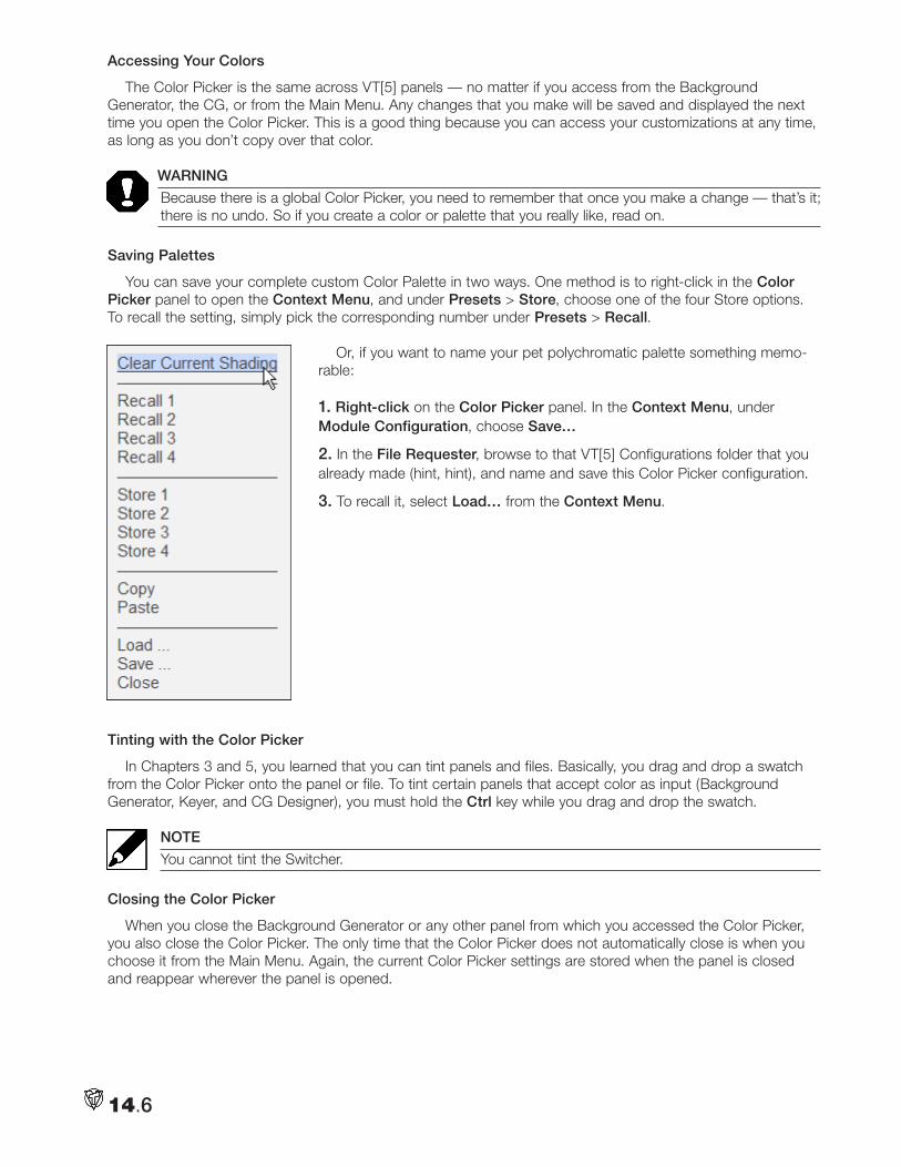
14.6
Accessing Your Colors
The Color Picker is the same across VT[5] panels — no matter if you access from the Background Generator, the CG, or from the Main Menu. Any changes that you make will be saved and displayed the next time you open the Color Picker. This is a good thing because you can access your customizations at any time, as long as you don’t copy over that color.
WARNING
Because there is a global Color Picker, you need to remember that once you make a change — that’s it; there is no undo. So if you create a color or palette that you really like, read on.
Saving Palettes
You can save your complete custom Color Palette in two ways. One method is to right-click in the Color Picker panel to open the Context Menu, and under Presets > Store, choose one of the four Store options. To recall the setting, simply pick the corresponding number under Presets > Recall.
Or, if you want to name your pet polychromatic palette something memo-rable:
1. Right-click on the Color Picker panel. In the Context Menu, under Module Configuration, choose Save…
2. In the File Requester, browse to that VT[5] Configurations folder that you already made (hint, hint), and name and save this Color Picker configuration.
3. To recall it, select Load… from the Context Menu.
Tinting with the Color Picker
In Chapters 3 and 5, you learned that you can tint panels and files. Basically, you drag and drop a swatch from the Color Picker onto the panel or file. To tint certain panels that accept color as input (Background Generator, Keyer, and CG Designer), you must hold the Ctrl key while you drag and drop the swatch.
NOTE
You cannot tint the Switcher.
Closing the Color Picker
When you close the Background Generator or any other panel from which you accessed the Color Picker, you also close the Color Picker. The only time that the Color Picker does not automatically close is when you choose it from the Main Menu. Again, the current Color Picker settings are stored when the panel is closed and reappear wherever the panel is opened.
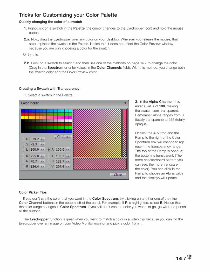
14.7
Tricks for Customizing your Color Palette Quickly changing the color of a swatch
1. Right-click on a swatch in the Palette (the cursor changes to the Eyedropper icon) and hold the mouse button.
2.a. Now, drag the Eyedropper over any color on your desktop. Wherever you release the mouse, that color replaces the swatch in the Palette. Notice that it does not affect the Color Preview window because you are only choosing a color for the swatch.
Or try this.
2.b. Click on a swatch to select it and then use one of the methods on page 14.2 to change the color. (Drag in the Spectrum or enter values in the Color Channels field). With this method, you change both the swatch color and the Color Preview color.
Creating a Swatch with Transparency
1. Select a swatch in the Palette.
2. In the Alpha Channel box, enter a value of 100, making the swatch semi-transparent. Remember Alpha ranges from 0 (totally transparent) to 255 (totally opaque). Or click the A button and the Ramp to the right of the Color Spectrum box will change to rep-resent the transparency range. The top of the Ramp is opaque; the bottom is transparent. (The more checkerboard pattern you can see, the more transparent the color). You can click in the Ramp to choose an Alpha value and the displays will update.
Color Picker Tips
If you don’t see the color that you want in the Color Spectrum, try clicking on another one of the nine Color Channel buttons in the bottom left of the panel. For example, if R is highlighted, select B. Notice that the color range changes in Color Spectrum. If you still don’t see the color you want, let go, go wild and punch all the buttons.
The Eyedropper function is great when you want to match a color in a video clip because you can roll the Eyedropper over an image on your Video Monitor monitor and pick a color from it.
14.8
Color Theory for Broadcast Television 101
Color is defined by two fundamental methods, each with its own set of primary colors. The traditional theory used in painting is called Subtractive Color, with its primaries: Red, Yellow and Blue. We perceive an object’s color by the wavelengths of light it reflects. All the other wavelengths are absorbed, or subtracted, by the object. When all three primary colors are combined, no light is reflected, giving us black.
In the video and computer world, Additive Color theory is more commonly used. It defines how we perceive color by combining (adding) wavelengths of light to form the visible spectrum from its primary colors of Red, Green and Blue. In a traditional (cathode ray tube) TV or computer monitor, the image on the screen is gen-erated by firing three (red, green, blue) components from electron guns in the picture tube, which make the phosphors on the screen luminescent. The resulting color for each pixel is a mix of the three primary colors determined by the amount of energy in each electron stream.
Each of the RGB components is described in eight bit values, 0 to 255. In Additive Color theory, the maxi-mum combination of RGB, (255, 255, 255), is white, which translates to 100% luminosity. Since luminescence plays an integral part in the equation, the old HSV or “Hue, Saturation and Value” scheme is referred to as “Hue, Saturation, and Luminance” or HSL.
In most video, the YUV system is the standard color system, and it also uses a scale between 0 and 255 for all values. The YUV system relies heavily on sending picture information through Y (luminance), the black and white part of an image. The video signal sends less information for U and V, which are the RG and BG color (chrominance) parts of the image.
Colors defined digitally in the computer tend to render brighter when translated to analog TV signals. Intense saturated colors (e.g. RGB: 255, 255, 0) can produce images that flare or smear on an NTSC analog TV set. Even if your computer generated graphics are in the “NTSC legal” range, they should be previewed on an NTSC monitor. If they don’t reproduce well, lower the luminosity or saturation.
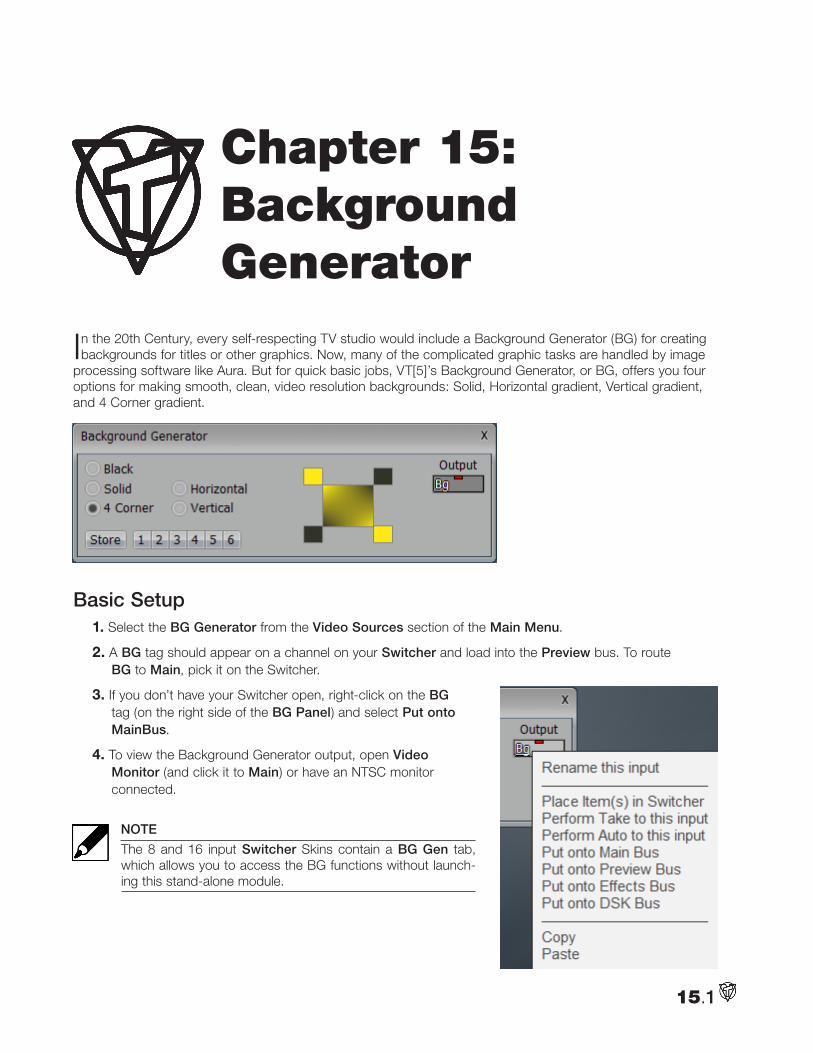
In the 20th Century, every self-respecting TV studio would include a Background Generator (BG) for creating backgrounds for titles or other graphics. Now, many of the complicated graphic tasks are handled by image
processing software like Aura. But for quick basic jobs, VT[5]’s Background Generator, or BG, offers you four options for making smooth, clean, video resolution backgrounds: Solid, Horizontal gradient, Vertical gradient, and 4 Corner gradient.
Basic Setup1. Select the BG Generator from the Video Sources section of the Main Menu.
2. A BG tag should appear on a channel on your Switcher and load into the Preview bus. To route BG to Main, pick it on the Switcher.
3. If you don’t have your Switcher open, right-click on the BG tag (on the right side of the BG Panel) and select Put onto MainBus.
4. To view the Background Generator output, open Video Monitor (and click it to Main) or have an NTSC monitor connected.
NOTE
The 8 and 16 input Switcher Skins contain a BG Gen tab, which allows you to access the BG functions without launch-ing this stand-alone module.
Chapter 15: Background Generator
15.1
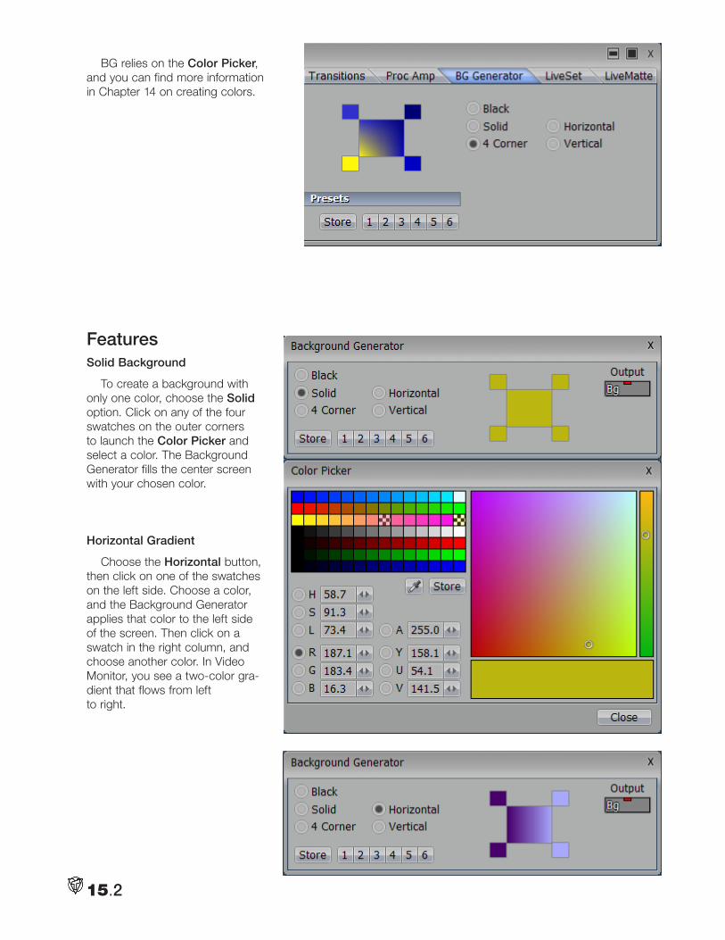
BG relies on the Color Picker, and you can find more information in Chapter 14 on creating colors.
FeaturesSolid Background
To create a background with only one color, choose the Solid option. Click on any of the four swatches on the outer corners to launch the Color Picker and select a color. The Background Generator fills the center screen with your chosen color.
Horizontal Gradient
Choose the Horizontal button, then click on one of the swatches on the left side. Choose a color, and the Background Generator applies that color to the left side of the screen. Then click on a swatch in the right column, and choose another color. In Video Monitor, you see a two-color gra-dient that flows from left to right.
15.2
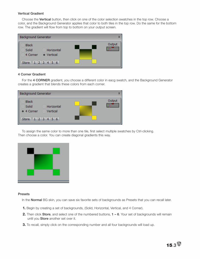
Vertical Gradient
Choose the Vertical button, then click on one of the color selection swatches in the top row. Choose a color, and the Background Generator applies that color to both tiles in the top row. Do the same for the bottom row. The gradient will flow from top to bottom on your output screen.
4 Corner Gradient
For the 4 CORNER gradient, you choose a different color in eacg swatch, and the Background Generator creates a gradient that blends these colors from each corner.
To assign the same color to more than one tile, first select multiple swatches by Ctrl-clicking. Then choose a color. You can create diagonal gradients this way.
Presets
In the Normal BG skin, you can save six favorite sets of backgrounds as Presets that you can recall later.
1. Begin by creating a set of backgrounds, (Solid, Horizontal, Vertical, and 4 Corner).
2. Then click Store, and select one of the numbered buttons, 1 – 6. Your set of backgrounds will remain until you Store another set over it.
3. To recall, simply click on the corresponding number and all four backgrounds will load up.
15.3
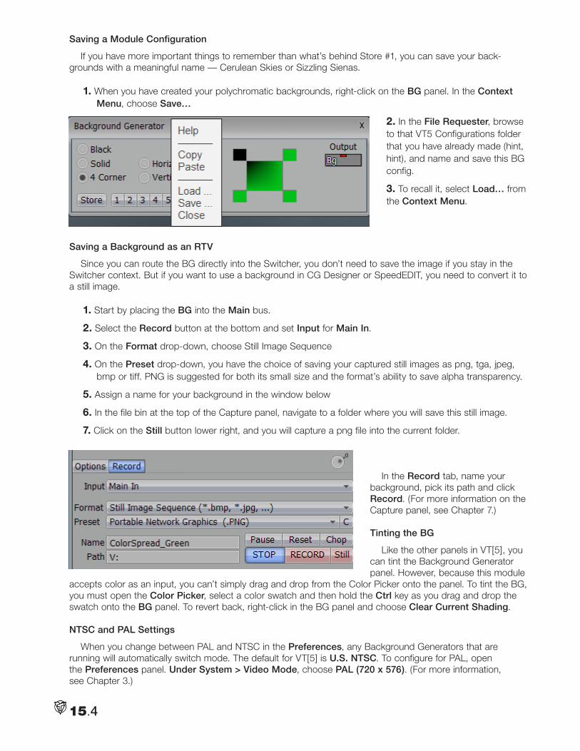
Saving a Module Configuration
If you have more important things to remember than what’s behind Store #1, you can save your back-grounds with a meaningful name — Cerulean Skies or Sizzling Sienas.
1. When you have created your polychromatic backgrounds, right-click on the BG panel. In the Context Menu, choose Save…
2. In the File Requester, browse to that VT5 Configurations folder that you have already made (hint, hint), and name and save this BG config.
3. To recall it, select Load… from the Context Menu.
Saving a Background as an RTV
Since you can route the BG directly into the Switcher, you don’t need to save the image if you stay in the Switcher context. But if you want to use a background in CG Designer or SpeedEDIT, you need to convert it to a still image.
1. Start by placing the BG into the Main bus.
2. Select the Record button at the bottom and set Input for Main In.
3. On the Format drop-down, choose Still Image Sequence
4. On the Preset drop-down, you have the choice of saving your captured still images as png, tga, jpeg, bmp or tiff. PNG is suggested for both its small size and the format’s ability to save alpha transparency.
5. Assign a name for your background in the window below
6. In the file bin at the top of the Capture panel, navigate to a folder where you will save this still image.
7. Click on the Still button lower right, and you will capture a png file into the current folder.
In the Record tab, name your background, pick its path and click Record. (For more information on the Capture panel, see Chapter 7.)
Tinting the BG
Like the other panels in VT[5], you can tint the Background Generator panel. However, because this module
accepts color as an input, you can’t simply drag and drop from the Color Picker onto the panel. To tint the BG, you must open the Color Picker, select a color swatch and then hold the Ctrl key as you drag and drop the swatch onto the BG panel. To revert back, right-click in the BG panel and choose Clear Current Shading.
NTSC and PAL Settings
When you change between PAL and NTSC in the Preferences, any Background Generators that are running will automatically switch mode. The default for VT[5] is U.S. NTSC. To configure for PAL, open the Preferences panel. Under System > Video Mode, choose PAL (720 x 576). (For more information, see Chapter 3.)
15.4
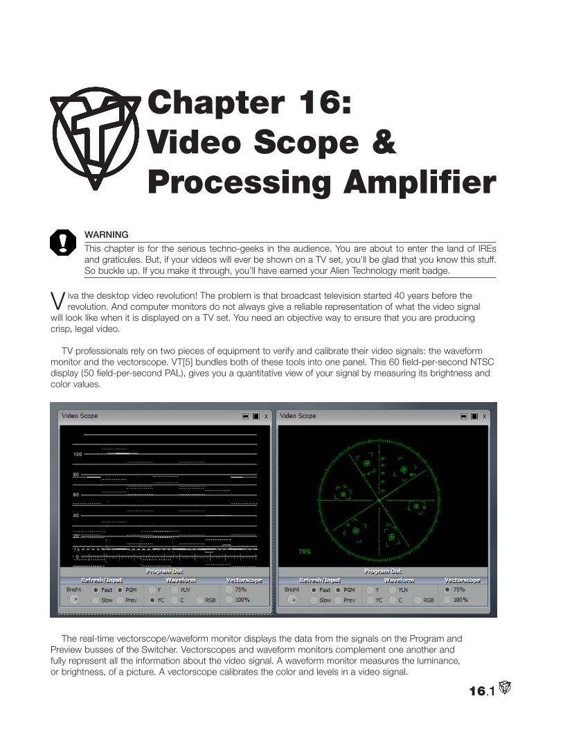
WARNING
This chapter is for the serious techno-geeks in the audience. You are about to enter the land of IREs and graticules. But, if your videos will ever be shown on a TV set, you’ll be glad that you know this stuff. So buckle up. If you make it through, you’ll have earned your Alien Technology merit badge.
V iva the desktop video revolution! The problem is that broadcast television started 40 years before the revolution. And computer monitors do not always give a reliable representation of what the video signal
will look like when it is displayed on a TV set. You need an objective way to ensure that you are producing crisp, legal video.
TV professionals rely on two pieces of equipment to verify and calibrate their video signals: the waveform monitor and the vectorscope. VT[5] bundles both of these tools into one panel. This 60 field-per-second NTSC display (50 field-per-second PAL), gives you a quantitative view of your signal by measuring its brightness and color values.
The real-time vectorscope/waveform monitor displays the data from the signals on the Program and Preview busses of the Switcher. Vectorscopes and waveform monitors complement one another and fully represent all the information about the video signal. A waveform monitor measures the luminance, or brightness, of a picture. A vectorscope calibrates the color and levels in a video signal.
16.1
Chapter 16: Video Scope & Processing Amplifier
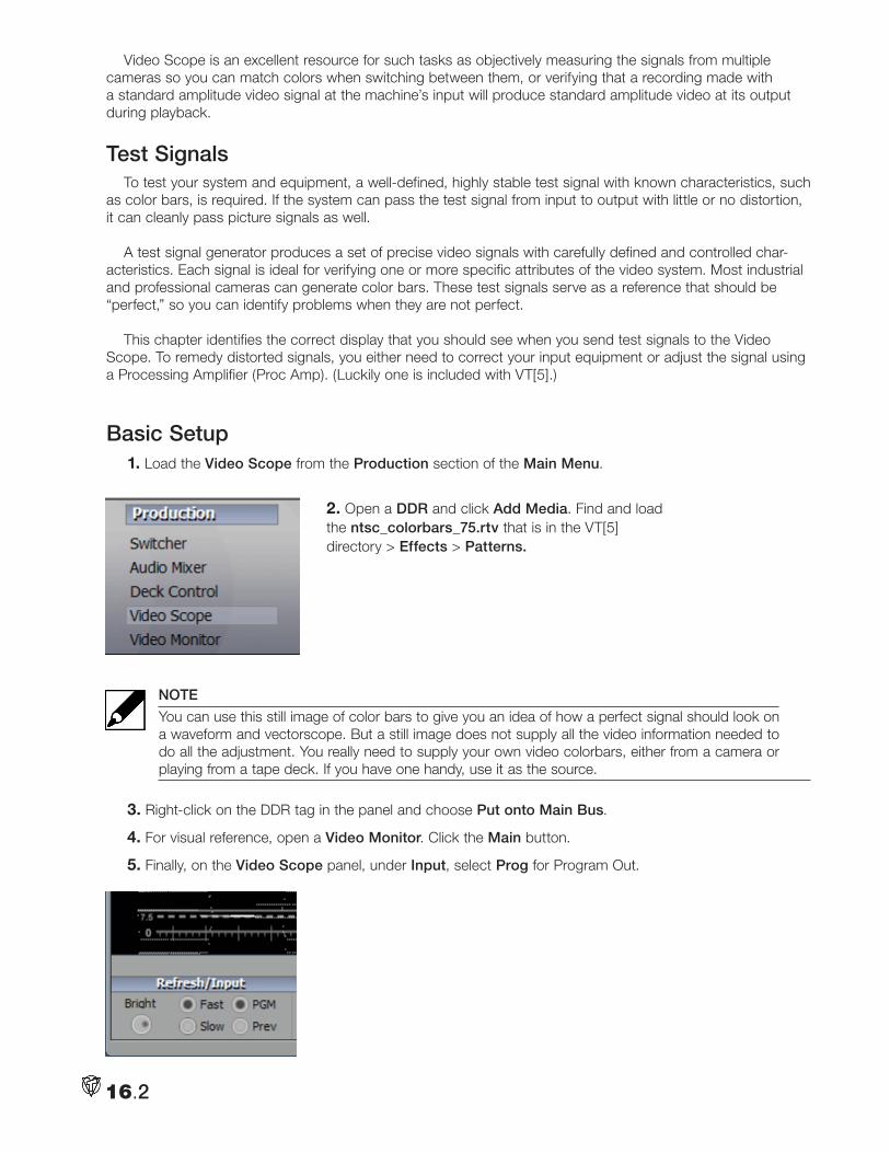
Video Scope is an excellent resource for such tasks as objectively measuring the signals from multiple cameras so you can match colors when switching between them, or verifying that a recording made with a standard amplitude video signal at the machine’s input will produce standard amplitude video at its output during playback.
Test SignalsTo test your system and equipment, a well-defined, highly stable test signal with known characteristics, such
as color bars, is required. If the system can pass the test signal from input to output with little or no distortion, it can cleanly pass picture signals as well.
A test signal generator produces a set of precise video signals with carefully defined and controlled char-acteristics. Each signal is ideal for verifying one or more specific attributes of the video system. Most industrial and professional cameras can generate color bars. These test signals serve as a reference that should be “perfect,” so you can identify problems when they are not perfect.
This chapter identifies the correct display that you should see when you send test signals to the Video Scope. To remedy distorted signals, you either need to correct your input equipment or adjust the signal using a Processing Amplifier (Proc Amp). (Luckily one is included with VT[5].)
Basic Setup1. Load the Video Scope from the Production section of the Main Menu.
2. Open a DDR and click Add Media. Find and load the ntsc_colorbars_75.rtv that is in the VT[5] directory > Effects > Patterns.
NOTE
You can use this still image of color bars to give you an idea of how a perfect signal should look on a waveform and vectorscope. But a still image does not supply all the video information needed to do all the adjustment. You really need to supply your own video colorbars, either from a camera or playing from a tape deck. If you have one handy, use it as the source.
3. Right-click on the DDR tag in the panel and choose Put onto Main Bus.
4. For visual reference, open a Video Monitor. Click the Main button.
5. Finally, on the Video Scope panel, under Input, select Prog for Program Out.
16.2
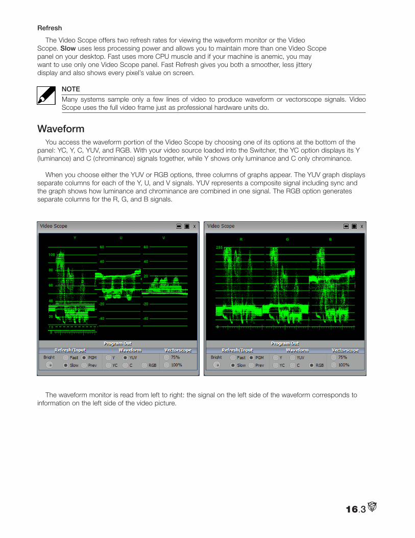
Refresh
The Video Scope offers two refresh rates for viewing the waveform monitor or the Video Scope. Slow uses less processing power and allows you to maintain more than one Video Scope panel on your desktop. Fast uses more CPU muscle and if your machine is anemic, you may want to use only one Video Scope panel. Fast Refresh gives you both a smoother, less jittery display and also shows every pixel’s value on screen.
NOTE
Many systems sample only a few lines of video to produce waveform or vectorscope signals. Video Scope uses the full video frame just as professional hardware units do.
WaveformYou access the waveform portion of the Video Scope by choosing one of its options at the bottom of the
panel: YC, Y, C, YUV, and RGB. With your video source loaded into the Switcher, the YC option displays its Y (luminance) and C (chrominance) signals together, while Y shows only luminance and C only chrominance.
When you choose either the YUV or RGB options, three columns of graphs appear. The YUV graph displays separate columns for each of the Y, U, and V signals. YUV represents a composite signal including sync and the graph shows how luminance and chrominance are combined in one signal. The RGB option generates separate columns for the R, G, and B signals.
The waveform monitor is read from left to right: the signal on the left side of the waveform corresponds to information on the left side of the video picture.
16.3
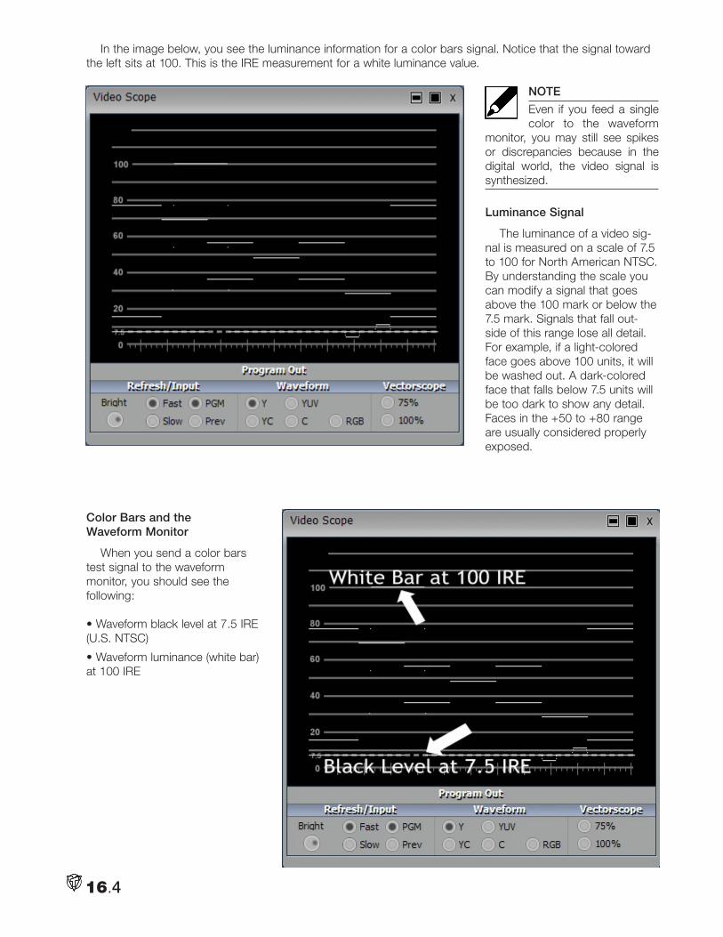
In the image below, you see the luminance information for a color bars signal. Notice that the signal toward the left sits at 100. This is the IRE measurement for a white luminance value.
NOTE
Even if you feed a single color to the waveform
monitor, you may still see spikes or discrepancies because in the digital world, the video signal is synthesized.
Luminance Signal
The luminance of a video sig-nal is measured on a scale of 7.5 to 100 for North American NTSC. By understanding the scale you can modify a signal that goes above the 100 mark or below the 7.5 mark. Signals that fall out-side of this range lose all detail. For example, if a light-colored face goes above 100 units, it will be washed out. A dark-colored face that falls below 7.5 units will be too dark to show any detail. Faces in the +50 to +80 range are usually considered properly exposed.
Color Bars and the Waveform Monitor
When you send a color bars test signal to the waveform monitor, you should see the following:
• Waveform black level at 7.5 IRE (U.S. NTSC)
• Waveform luminance (white bar) at 100 IRE
16.4
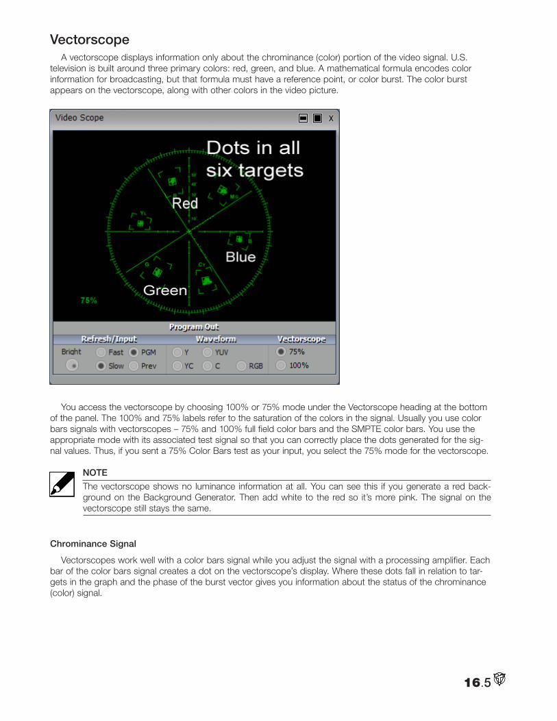
VectorscopeA vectorscope displays information only about the chrominance (color) portion of the video signal. U.S.
television is built around three primary colors: red, green, and blue. A mathematical formula encodes color information for broadcasting, but that formula must have a reference point, or color burst. The color burst appears on the vectorscope, along with other colors in the video picture.
You access the vectorscope by choosing 100% or 75% mode under the Vectorscope heading at the bottom of the panel. The 100% and 75% labels refer to the saturation of the colors in the signal. Usually you use color bars signals with vectorscopes – 75% and 100% full field color bars and the SMPTE color bars. You use the appropriate mode with its associated test signal so that you can correctly place the dots generated for the sig-nal values. Thus, if you sent a 75% Color Bars test as your input, you select the 75% mode for the vectorscope.
NOTE
The vectorscope shows no luminance information at all. You can see this if you generate a red back-ground on the Background Generator. Then add white to the red so it’s more pink. The signal on the vectorscope still stays the same.
Chrominance Signal
Vectorscopes work well with a color bars signal while you adjust the signal with a processing amplifier. Each bar of the color bars signal creates a dot on the vectorscope’s display. Where these dots fall in relation to tar-gets in the graph and the phase of the burst vector gives you information about the status of the chrominance (color) signal.
16.5
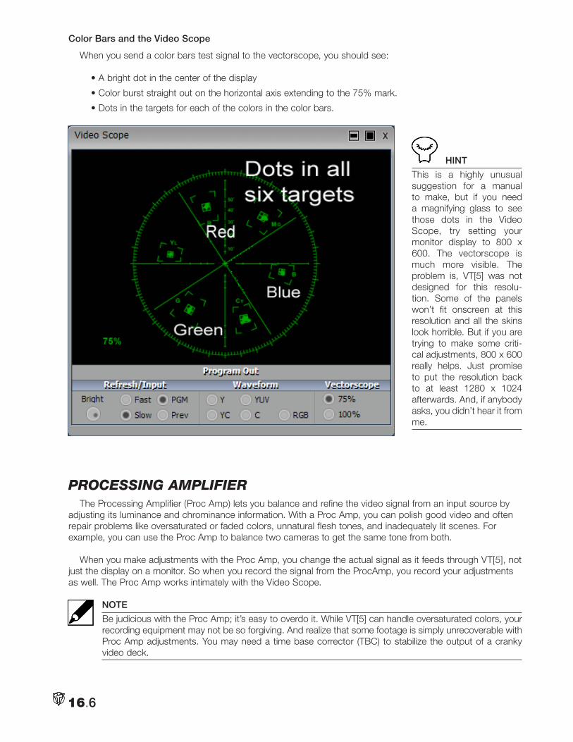
Color Bars and the Video Scope
When you send a color bars test signal to the vectorscope, you should see:
• A bright dot in the center of the display
• Color burst straight out on the horizontal axis extending to the 75% mark.
• Dots in the targets for each of the colors in the color bars.
HINT
This is a highly unusual suggestion for a manual to make, but if you need a magnifying glass to see those dots in the Video Scope, try setting your monitor display to 800 x 600. The vectorscope is much more visible. The problem is, VT[5] was not designed for this resolu-tion. Some of the panels won’t fit onscreen at this resolution and all the skins look horrible. But if you are trying to make some criti-cal adjustments, 800 x 600 really helps. Just promise to put the resolution back to at least 1280 x 1024 afterwards. And, if anybody asks, you didn’t hear it from me.
pRoceSSing amplifieRThe Processing Amplifier (Proc Amp) lets you balance and refine the video signal from an input source by
adjusting its luminance and chrominance information. With a Proc Amp, you can polish good video and often repair problems like oversaturated or faded colors, unnatural flesh tones, and inadequately lit scenes. For example, you can use the Proc Amp to balance two cameras to get the same tone from both.
When you make adjustments with the Proc Amp, you change the actual signal as it feeds through VT[5], not just the display on a monitor. So when you record the signal from the ProcAmp, you record your adjustments as well. The Proc Amp works intimately with the Video Scope.
NOTE
Be judicious with the Proc Amp; it’s easy to overdo it. While VT[5] can handle oversaturated colors, your recording equipment may not be so forgiving. And realize that some footage is simply unrecoverable with Proc Amp adjustments. You may need a time base corrector (TBC) to stabilize the output of a cranky video deck.
16.6
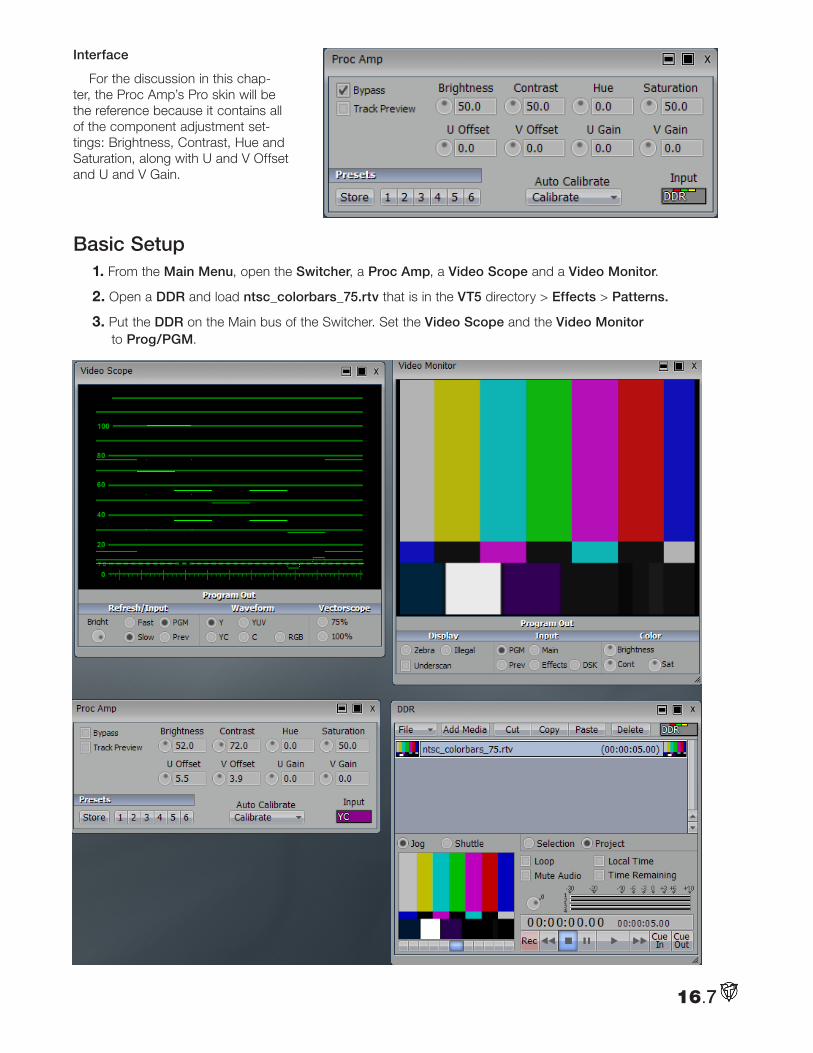
Interface
For the discussion in this chap-ter, the Proc Amp’s Pro skin will be the reference because it contains all of the component adjustment set-tings: Brightness, Contrast, Hue and Saturation, along with U and V Offset and U and V Gain.
Basic Setup1. From the Main Menu, open the Switcher, a Proc Amp, a Video Scope and a Video Monitor.
2. Open a DDR and load ntsc_colorbars_75.rtv that is in the VT5 directory > Effects > Patterns.
3. Put the DDR on the Main bus of the Switcher. Set the Video Scope and the Video Monitor to Prog/PGM.
16.7
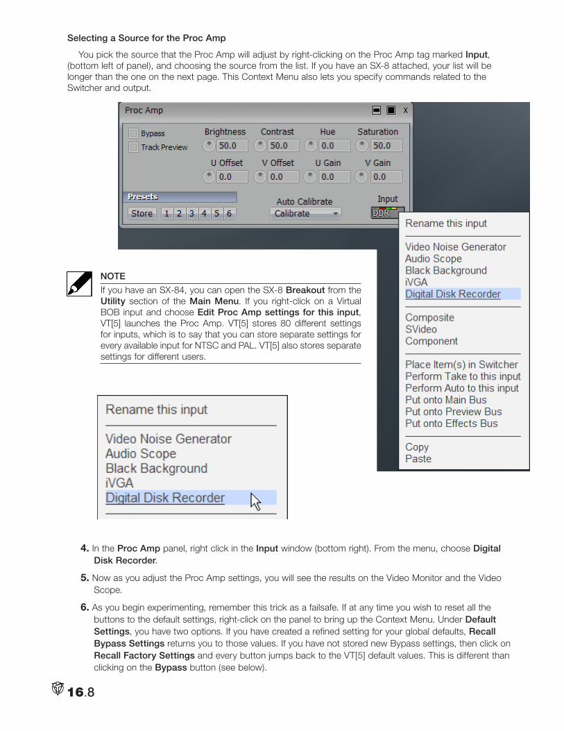
Selecting a Source for the Proc Amp
You pick the source that the Proc Amp will adjust by right-clicking on the Proc Amp tag marked Input, (bottom left of panel), and choosing the source from the list. If you have an SX-8 attached, your list will be longer than the one on the next page. This Context Menu also lets you specify commands related to the Switcher and output.
NOTE
If you have an SX-84, you can open the SX-8 Breakout from the Utility section of the Main Menu. If you right-click on a Virtual BOB input and choose Edit Proc Amp settings for this input, VT[5] launches the Proc Amp. VT[5] stores 80 different settings for inputs, which is to say that you can store separate settings for every available input for NTSC and PAL. VT[5] also stores separate settings for different users.
4. In the Proc Amp panel, right click in the Input window (bottom right). From the menu, choose Digital Disk Recorder.
5. Now as you adjust the Proc Amp settings, you will see the results on the Video Monitor and the Video Scope.
6. As you begin experimenting, remember this trick as a failsafe. If at any time you wish to reset all the buttons to the default settings, right-click on the panel to bring up the Context Menu. Under Default Settings, you have two options. If you have created a refined setting for your global defaults, Recall Bypass Settings returns you to those values. If you have not stored new Bypass settings, then click on Recall Factory Settings and every button jumps back to the VT[5] default values. This is different than clicking on the Bypass button (see below).
16.8
Brightness
The Brightness control adjusts the luminance (lightness and darkness) of the video signal.
• Rotate the knob clockwise to decrease Brightness and darken the image.
• Rotate counterclockwise to increase Brightness and lighten the image.
HINT
If you make a change in a setting, you can go back to the default by double-clicking the knob. For exam-ple, if you twist the brightness knob to 65, you can double-click it and it will return to the default of 50.
If you set your waveform monitor to Y, when you increase the brightness control to maximum, you can see
the Y signal rise to 110 IRE, (the 7.5 black will go to 100). It sinks toward 0 IRE when you decrease the control, (the white drops to 7.5).
NOTE
Luminance (brightness) values go back to the early days of TV, which was initially in black and white. The color signal piggy-backs on top of the black and white (luminance) signal so both can be broadcast simultaneously.
Contrast
The Contrast control adjusts the levels of gray in the signal, which affect the brightness and saturation of an image. If you look at the waveform set to Y, you can see the levels of gray as steps. Decreasing Contrast makes those steps closer together and turns your picture grayer. Increasing Contrast makes those steps far-ther apart.
• Rotate the knob clockwise to increase Contrast; the image appears brighter and more saturated.
• Rotate counterclockwise to decrease Contrast; the image appears darker and less saturated.
An image with extreme areas of darkness and lightness might benefit from reduced Contrast. If your footage looks washed out, try increasing Contrast.
Hue
The Hue control adjusts the relative phase of color and is monitored using a vectorscope with a color bars signal. On the Video Scope you can see the signal cycle around a color wheel as you rotate the Hue control.
You might use the Hue control when you have a video signal making a person look too green. You would rotate the control to the right toward red.
Saturation
Saturation is the intensity of color in the video signal. Low saturated pictures look gray and overly saturated images show colors that bloom to the point of smearing.
• Rotate clockwise to increase Saturation.
• Rotate counterclockwise to decrease Saturation.
On the Video Scope, you can see the signal spread or shrink when you adjust saturation.
A video where colors seem too intense, (especially with bleeding colors), would benefit from decreased Saturation. Red colors are particularly susceptible to bleeding in composite and Y/C signals.
If you turn Saturation all the way to the left, you remove all color, hence resulting in black and white video.
16.9
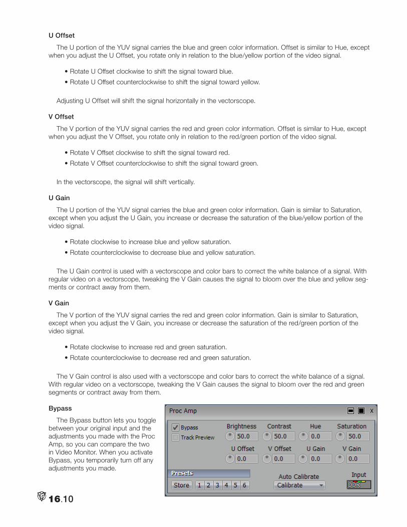
U Offset
The U portion of the YUV signal carries the blue and green color information. Offset is similar to Hue, except when you adjust the U Offset, you rotate only in relation to the blue/yellow portion of the video signal.
• Rotate U Offset clockwise to shift the signal toward blue.
• Rotate U Offset counterclockwise to shift the signal toward yellow.
Adjusting U Offset will shift the signal horizontally in the vectorscope.
V Offset
The V portion of the YUV signal carries the red and green color information. Offset is similar to Hue, except when you adjust the V Offset, you rotate only in relation to the red/green portion of the video signal.
• Rotate V Offset clockwise to shift the signal toward red.
• Rotate V Offset counterclockwise to shift the signal toward green.
In the vectorscope, the signal will shift vertically.
U Gain
The U portion of the YUV signal carries the blue and green color information. Gain is similar to Saturation, except when you adjust the U Gain, you increase or decrease the saturation of the blue/yellow portion of the video signal.
• Rotate clockwise to increase blue and yellow saturation.
• Rotate counterclockwise to decrease blue and yellow saturation.
The U Gain control is used with a vectorscope and color bars to correct the white balance of a signal. With regular video on a vectorscope, tweaking the V Gain causes the signal to bloom over the blue and yellow seg-ments or contract away from them.
V Gain
The V portion of the YUV signal carries the red and green color information. Gain is similar to Saturation, except when you adjust the V Gain, you increase or decrease the saturation of the red/green portion of the video signal.
• Rotate clockwise to increase red and green saturation.
• Rotate counterclockwise to decrease red and green saturation.
The V Gain control is also used with a vectorscope and color bars to correct the white balance of a signal. With regular video on a vectorscope, tweaking the V Gain causes the signal to bloom over the red and green segments or contract away from them.
Bypass
The Bypass button lets you toggle between your original input and the adjustments you made with the Proc Amp, so you can compare the two in Video Monitor. When you activate Bypass, you temporarily turn off any adjustments you made.
16.10
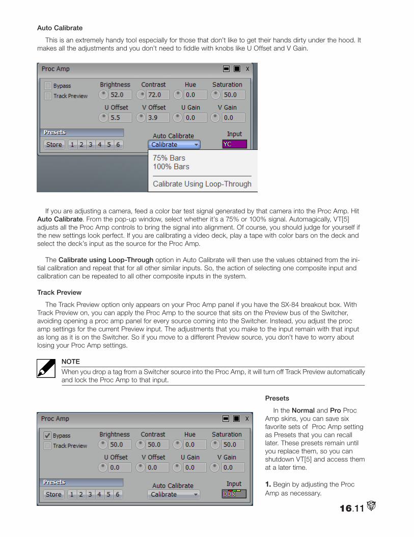
Auto Calibrate
This is an extremely handy tool especially for those that don’t like to get their hands dirty under the hood. It makes all the adjustments and you don’t need to fiddle with knobs like U Offset and V Gain.
If you are adjusting a camera, feed a color bar test signal generated by that camera into the Proc Amp. Hit Auto Calibrate. From the pop-up window, select whether it’s a 75% or 100% signal. Automagically, VT[5] adjusts all the Proc Amp controls to bring the signal into alignment. Of course, you should judge for yourself if the new settings look perfect. If you are calibrating a video deck, play a tape with color bars on the deck and select the deck’s input as the source for the Proc Amp.
The Calibrate using Loop-Through option in Auto Calibrate will then use the values obtained from the ini-tial calibration and repeat that for all other similar inputs. So, the action of selecting one composite input and calibration can be repeated to all other composite inputs in the system.
Track Preview
The Track Preview option only appears on your Proc Amp panel if you have the SX-84 breakout box. With Track Preview on, you can apply the Proc Amp to the source that sits on the Preview bus of the Switcher, avoiding opening a proc amp panel for every source coming into the Switcher. Instead, you adjust the proc amp settings for the current Preview input. The adjustments that you make to the input remain with that input as long as it is on the Switcher. So if you move to a different Preview source, you don’t have to worry about losing your Proc Amp settings.
NOTE
When you drop a tag from a Switcher source into the Proc Amp, it will turn off Track Preview automatically and lock the Proc Amp to that input.
Presets
In the Normal and Pro Proc Amp skins, you can save six favorite sets of Proc Amp setting as Presets that you can recall later. These presets remain until you replace them, so you can shutdown VT[5] and access them at a later time.
1. Begin by adjusting the Proc Amp as necessary.
16.11
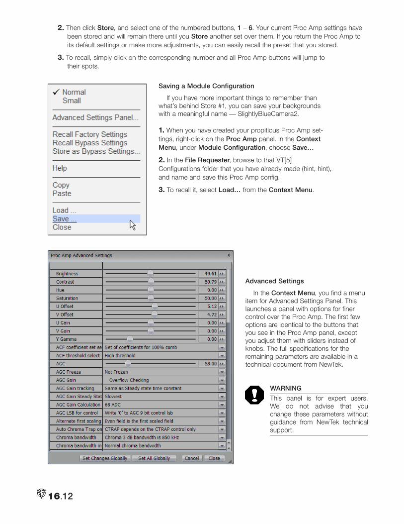
2. Then click Store, and select one of the numbered buttons, 1 – 6. Your current Proc Amp settings have been stored and will remain there until you Store another set over them. If you return the Proc Amp to its default settings or make more adjustments, you can easily recall the preset that you stored.
3. To recall, simply click on the corresponding number and all Proc Amp buttons will jump to their spots.
Saving a Module Configuration
If you have more important things to remember than what’s behind Store #1, you can save your backgrounds with a meaningful name — SlightlyBlueCamera2.
1. When you have created your propitious Proc Amp set-tings, right-click on the Proc Amp panel. In the Context Menu, under Module Configuration, choose Save…
2. In the File Requester, browse to that VT[5] Configurations folder that you have already made (hint, hint), and name and save this Proc Amp config.
3. To recall it, select Load… from the Context Menu.
Advanced Settings
In the Context Menu, you find a menu item for Advanced Settings Panel. This launches a panel with options for finer control over the Proc Amp. The first few options are identical to the buttons that you see in the Proc Amp panel, except you adjust them with sliders instead of knobs. The full specifications for the remaining parameters are available in a technical document from NewTek.
WARNING
This panel is for expert users. We do not advise that you change these parameters without guidance from NewTek technical support.
16.12
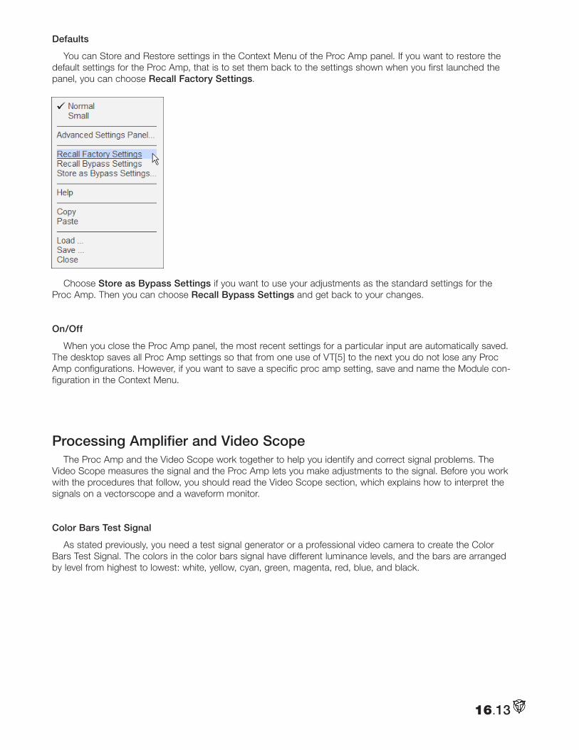
Defaults
You can Store and Restore settings in the Context Menu of the Proc Amp panel. If you want to restore the default settings for the Proc Amp, that is to set them back to the settings shown when you first launched the panel, you can choose Recall Factory Settings.
Choose Store as Bypass Settings if you want to use your adjustments as the standard settings for the Proc Amp. Then you can choose Recall Bypass Settings and get back to your changes.
On/Off
When you close the Proc Amp panel, the most recent settings for a particular input are automatically saved. The desktop saves all Proc Amp settings so that from one use of VT[5] to the next you do not lose any Proc Amp configurations. However, if you want to save a specific proc amp setting, save and name the Module con-figuration in the Context Menu.
Processing Amplifier and Video ScopeThe Proc Amp and the Video Scope work together to help you identify and correct signal problems. The
Video Scope measures the signal and the Proc Amp lets you make adjustments to the signal. Before you work with the procedures that follow, you should read the Video Scope section, which explains how to interpret the signals on a vectorscope and a waveform monitor.
Color Bars Test Signal
As stated previously, you need a test signal generator or a professional video camera to create the Color Bars Test Signal. The colors in the color bars signal have different luminance levels, and the bars are arranged by level from highest to lowest: white, yellow, cyan, green, magenta, red, blue, and black.
16.13
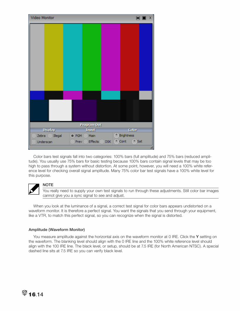
Color bars test signals fall into two categories: 100% bars (full amplitude) and 75% bars (reduced ampli-tude). You usually use 75% bars for basic testing because 100% bars contain signal levels that may be too high to pass through a system without distortion. At some point, however, you will need a 100% white refer-ence level for checking overall signal amplitude. Many 75% color bar test signals have a 100% white level for this purpose.
NOTE
You really need to supply your own test signals to run through these adjustments. Still color bar images cannot give you a sync signal to see and adjust.
When you look at the luminance of a signal, a correct test signal for color bars appears undistorted on a waveform monitor. It is therefore a perfect signal. You want the signals that you send through your equipment, like a VTR, to match this perfect signal, so you can recognize when the signal is distorted.
Amplitude (Waveform Monitor)
You measure amplitude against the horizontal axis on the waveform monitor at 0 IRE. Click the Y setting on the waveform. The blanking level should align with the 0 IRE line and the 100% white reference level should align with the 100 IRE line. The black level, or setup, should be at 7.5 IRE (for North American NTSC). A special dashed line sits at 7.5 IRE so you can verify black level.
16.14
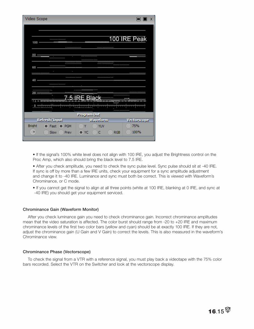
• If the signal’s 100% white level does not align with 100 IRE, you adjust the Brightness control on the Proc Amp, which also should bring the black level to 7.5 IRE.
• After you check amplitude, you need to check the sync pulse level. Sync pulse should sit at -40 IRE. If sync is off by more than a few IRE units, check your equipment for a sync amplitude adjustment and change it to -40 IRE. Luminance and sync must both be correct. This is viewed with Waveform’s Chrominance, or C mode.
• If you cannot get the signal to align at all three points (white at 100 IRE, blanking at 0 IRE, and sync at -40 IRE) you should get your equipment serviced.
Chrominance Gain (Waveform Monitor)
After you check luminance gain you need to check chrominance gain. Incorrect chrominance amplitudes mean that the video saturation is affected. The color burst should range from -20 to +20 IRE and maximum chrominance levels of the first two color bars (yellow and cyan) should be at exactly 100 IRE. If they are not, adjust the chrominance gain (U Gain and V Gain) to correct the levels. This is also measured in the waveform’s Chrominance view.
Chrominance Phase (Vectorscope)
To check the signal from a VTR with a reference signal, you must play back a videotape with the 75% color bars recorded. Select the VTR on the Switcher and look at the vectorscope display.
16.15
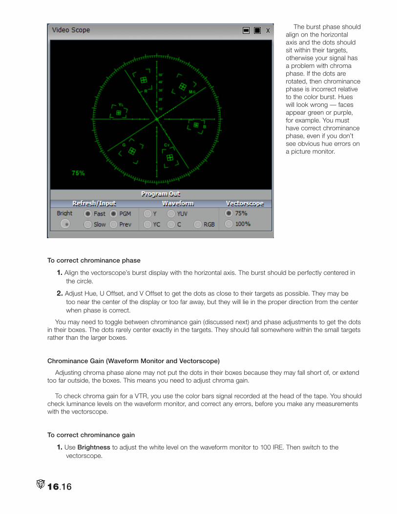
16.16
The burst phase should align on the horizontal axis and the dots should sit within their targets, otherwise your signal has a problem with chroma phase. If the dots are rotated, then chrominance phase is incorrect relative to the color burst. Hues will look wrong — faces appear green or purple, for example. You must have correct chrominance phase, even if you don’t see obvious hue errors on a picture monitor.
To correct chrominance phase
1. Align the vectorscope’s burst display with the horizontal axis. The burst should be perfectly centered in the circle.
2. Adjust Hue, U Offset, and V Offset to get the dots as close to their targets as possible. They may be too near the center of the display or too far away, but they will lie in the proper direction from the center when phase is correct.
You may need to toggle between chrominance gain (discussed next) and phase adjustments to get the dots in their boxes. The dots rarely center exactly in the targets. They should fall somewhere within the small targets rather than the larger boxes.
Chrominance Gain (Waveform Monitor and Vectorscope)
Adjusting chroma phase alone may not put the dots in their boxes because they may fall short of, or extend too far outside, the boxes. This means you need to adjust chroma gain.
To check chroma gain for a VTR, you use the color bars signal recorded at the head of the tape. You should check luminance levels on the waveform monitor, and correct any errors, before you make any measurements with the vectorscope.
To correct chrominance gain
1. Use Brightness to adjust the white level on the waveform monitor to 100 IRE. Then switch to the vectorscope.
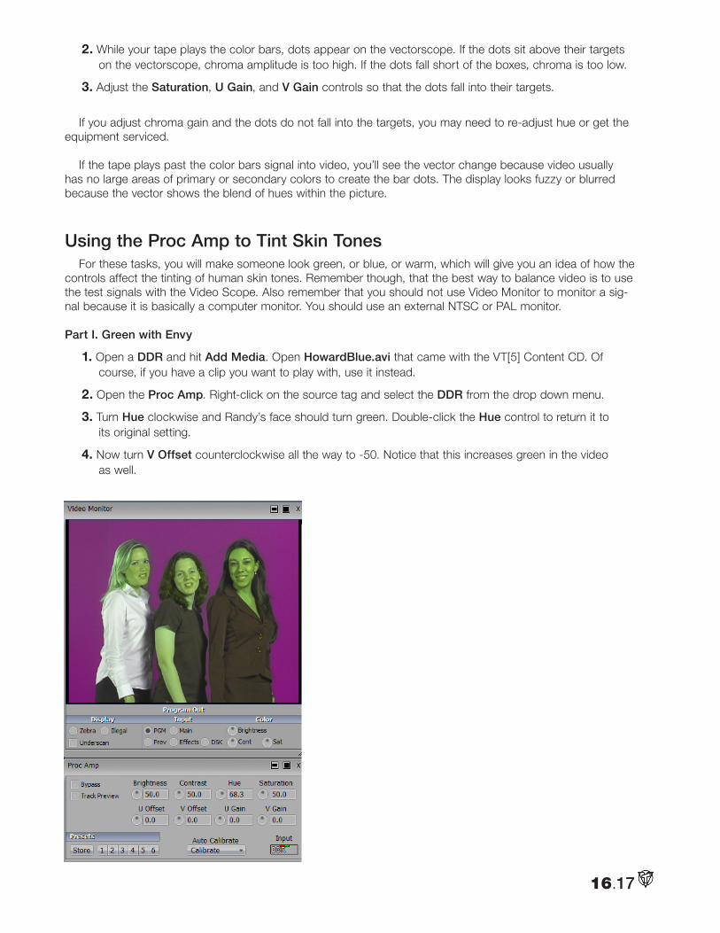
2. While your tape plays the color bars, dots appear on the vectorscope. If the dots sit above their targets on the vectorscope, chroma amplitude is too high. If the dots fall short of the boxes, chroma is too low.
3. Adjust the Saturation, U Gain, and V Gain controls so that the dots fall into their targets.
If you adjust chroma gain and the dots do not fall into the targets, you may need to re-adjust hue or get the equipment serviced.
If the tape plays past the color bars signal into video, you’ll see the vector change because video usually has no large areas of primary or secondary colors to create the bar dots. The display looks fuzzy or blurred because the vector shows the blend of hues within the picture.
Using the Proc Amp to Tint Skin TonesFor these tasks, you will make someone look green, or blue, or warm, which will give you an idea of how the
controls affect the tinting of human skin tones. Remember though, that the best way to balance video is to use the test signals with the Video Scope. Also remember that you should not use Video Monitor to monitor a sig-nal because it is basically a computer monitor. You should use an external NTSC or PAL monitor.
Part I. Green with Envy
1. Open a DDR and hit Add Media. Open HowardBlue.avi that came with the VT[5] Content CD. Of course, if you have a clip you want to play with, use it instead.
2. Open the Proc Amp. Right-click on the source tag and select the DDR from the drop down menu.
3. Turn Hue clockwise and Randy’s face should turn green. Double-click the Hue control to return it to its original setting.
4. Now turn V Offset counterclockwise all the way to -50. Notice that this increases green in the video as well.
16.17
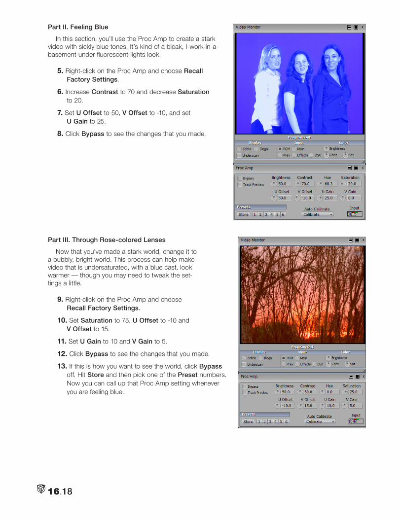
Part II. Feeling Blue
In this section, you’ll use the Proc Amp to create a stark video with sickly blue tones. It’s kind of a bleak, I-work-in-a-basement-under-fluorescent-lights look.
5. Right-click on the Proc Amp and choose Recall Factory Settings.
6. Increase Contrast to 70 and decrease Saturation to 20.
7. Set U Offset to 50, V Offset to -10, and set U Gain to 25.
8. Click Bypass to see the changes that you made.
Part III. Through Rose-colored Lenses
Now that you’ve made a stark world, change it to a bubbly, bright world. This process can help make video that is undersaturated, with a blue cast, look warmer — though you may need to tweak the set-tings a little.
9. Right-click on the Proc Amp and choose Recall Factory Settings.
10. Set Saturation to 75, U Offset to -10 and V Offset to 15.
11. Set U Gain to 10 and V Gain to 5.
12. Click Bypass to see the changes that you made.
13. If this is how you want to see the world, click Bypass off. Hit Store and then pick one of the Preset numbers. Now you can call up that Proc Amp setting whenever you are feeling blue.
16.18
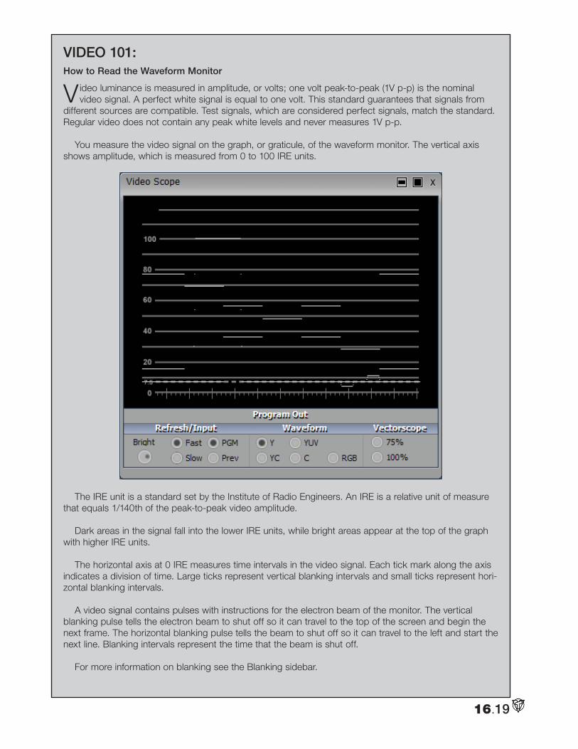
VIDEO 101:How to Read the Waveform Monitor
Video luminance is measured in amplitude, or volts; one volt peak-to-peak (1V p-p) is the nominal video signal. A perfect white signal is equal to one volt. This standard guarantees that signals from
different sources are compatible. Test signals, which are considered perfect signals, match the standard. Regular video does not contain any peak white levels and never measures 1V p-p.
You measure the video signal on the graph, or graticule, of the waveform monitor. The vertical axis shows amplitude, which is measured from 0 to 100 IRE units.
The IRE unit is a standard set by the Institute of Radio Engineers. An IRE is a relative unit of measure that equals 1/140th of the peak-to-peak video amplitude.
Dark areas in the signal fall into the lower IRE units, while bright areas appear at the top of the graph with higher IRE units.
The horizontal axis at 0 IRE measures time intervals in the video signal. Each tick mark along the axis indicates a division of time. Large ticks represent vertical blanking intervals and small ticks represent hori-zontal blanking intervals.
A video signal contains pulses with instructions for the electron beam of the monitor. The vertical blanking pulse tells the electron beam to shut off so it can travel to the top of the screen and begin the next frame. The horizontal blanking pulse tells the beam to shut off so it can travel to the left and start the next line. Blanking intervals represent the time that the beam is shut off.
For more information on blanking see the Blanking sidebar.
16.19
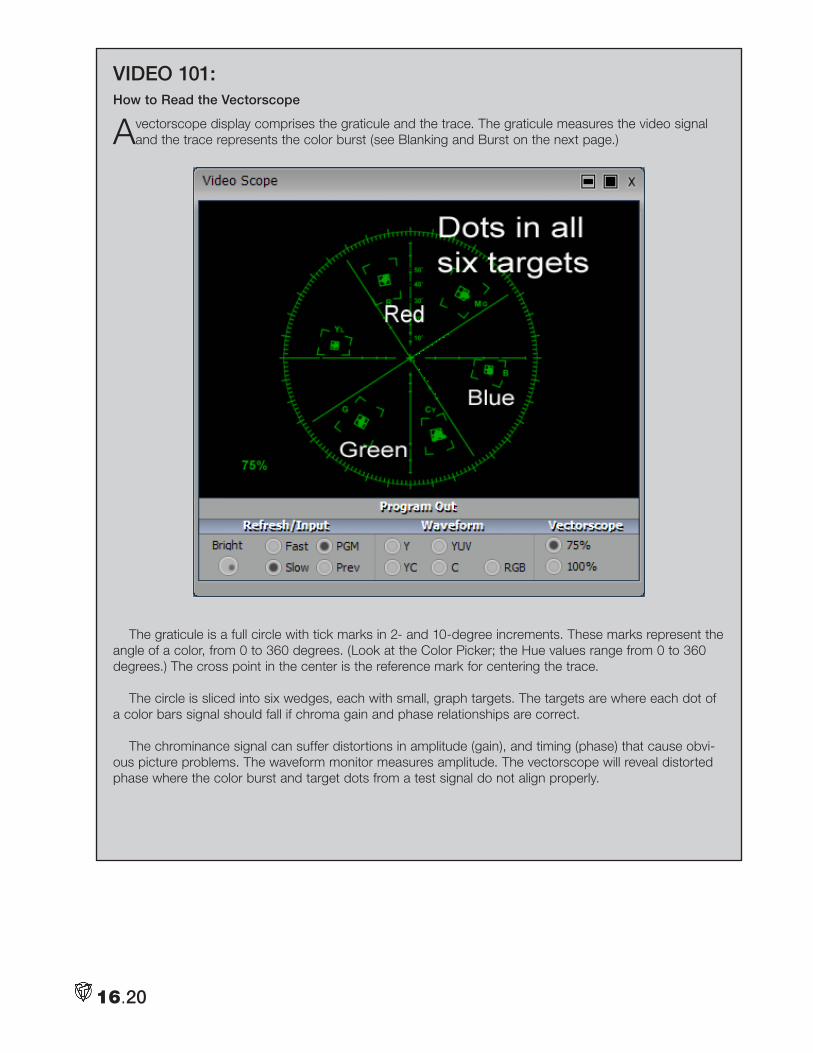
16.20
VIDEO 101:How to Read the Vectorscope
A vectorscope display comprises the graticule and the trace. The graticule measures the video signal and the trace represents the color burst (see Blanking and Burst on the next page.)
The graticule is a full circle with tick marks in 2- and 10-degree increments. These marks represent the angle of a color, from 0 to 360 degrees. (Look at the Color Picker; the Hue values range from 0 to 360 degrees.) The cross point in the center is the reference mark for centering the trace.
The circle is sliced into six wedges, each with small, graph targets. The targets are where each dot of a color bars signal should fall if chroma gain and phase relationships are correct.
The chrominance signal can suffer distortions in amplitude (gain), and timing (phase) that cause obvi-ous picture problems. The waveform monitor measures amplitude. The vectorscope will reveal distorted phase where the color burst and target dots from a test signal do not align properly.
16.21
VIDEO 101:Blanking and Burst
Images on a television screen are created by an electron beam that scans across the back of the pic-ture tube and causes the phosphor on the tube to glow. The beam sweeps across the tube 525 times (NTSC) for each video frame, in a process called interlaced scanning. Odd lines are scanned in the first pass, then the beam returns to the top to scan even lines.
The beam shuts off briefly when it moves from left to right, and this down time is called horizontal blanking. The beam also shuts off briefly when it moves from bottom to top, which is called vertical blanking.
Though the beam is shut off, the signal is not. During the blanking interval, syncronizing pulses (sync) and color reference (color burst) are sent. These bursts and pulses make sure the beam is in the right place at the right time, using the right color.
When the beam returns to the top of the screen, an equalizing pulse tells it which field the next scan represents, and a vertical syncing pulse verifies that the beam starts at the correct line.
When we talk about sync, we are referring to these phenomena of blanking and burst. You want your equipment to be synced, that is to be on the same line in different videos at the same time, especially during live switching. If one camera is scanning line 500 and another is scanning line 120, you will see a visible jump on screen when you switch between them. (However, VT[5] will sync all but the worst signals.) The same is true for color burst, you want the color reference for your inputs to match so that strange shifts in color do not occur when you switch between sources.

Notes:
16.22
17.1
Vt[5] and tHe weB
WWith more consumers and customers accessing the Internet through high-bandwidth connections, video has become viable web content. Now, you can send your own video from VT[5] to the Internet
using Live Stream or through a third-party encoder.
VT[5] comes packaged with Microsoft Windows Media Encoder, but you can use any encoders that accept Video for Windows devices as a source. The most widespread formats available are Flash, Real G2 for the Real Player, and the QuickTime formats.
On the Web, you have two options for viewing video. One option is a file downloaded to your hard drive and then played on your computer with a video player. The other option is streaming video, where you click on a link and the associated player launches and begins to load the file. As the file buffers, it begins to play, so you don’t need to wait for the whole file to download before viewing it.
EncodingEncoding a video file is compressing the file into a specific format. With a progressive format, you save
the file and users must download the entire file before they can view it. This is considered an on-demand file because it’s available to users at any time. When you use a streaming format, users download only the begin-ning of the file and they can view it while the rest of the file is being delivered. In real-time streaming, the video plays from a server and viewers can immediately watch it on their desktops.
To encode a file, you have two options: the first is to use Live Stream or launch your encoder and follow the instructions in the wizard. With 3rd party encoders, you choose your source file, enter a name for the destina-tion file, choose your audio and video codecs, choose a bit rate, and hit Start. The encoder compresses the file and then you upload that file to your Web site.
Downloadable Files
The advantage of downloadable files is that the quality is pre-determined. Changes in line speed may delay the download but they won’t cause fluctuations in frame rate, audio dropout, etc.
The following formats are typical for downloadable files:
• AVI is the video file for Windows.
• MOV is QuickTime, which works on both Apple and Windows operating systems.
• MPEG works on all platforms and operating systems.
Chapter 17: Live Stream
17.2
Streaming Video
The advantage of streaming video is that users avoid the long wait, so they can view the video while it downloads. This is a big advantage, especially with videos that may take hours to download. The disadvantage is that quality can suffer; and the quality depends on the data transmission channel. Some streaming software adjusts itself to the data rate as it plays, dropping as many frames as necessary in order to keep playing. Real-time streaming video tries to keep pace with the user’s connection speed in so that you don’t have dropped frames or pauses in the video.
Longer videos are most appropriate for streaming, where users can skip ahead to other parts of the clip and don’t have to download a huge video file. Users cannot download streaming content to their hard drives; streaming video clips sit on the server until you remove them.
The following formats are typical for streaming files:
• ASF, WMV, and WMA are the Windows Media formats for Mac and Windows
• MOV is the QuickTime format, which works on Mac and Windows.
• Rm is the format for Real, which works on all platforms.
• Flv is the file extension for Flash video.
Live Encoding
With Live Stream, you can have your live event streaming to the web within minutes. Encoding a live video stream takes a little more work than encoding a file; the source going to the encoder comes from audio and video capture cards on your computer. Before you encode you should consider the following variables:
• What format will you use: Windows Media, QuickTime or Real? Live Stream is link to Windows Media Encoder and handles all necessary settings for you.
• What data rate, frame rate, window size? These variables affect the final size of the file and its quality.
• Progressive download or real-time streaming?
Live Streaming with VT[5]Before you can begin encoding for streaming, you must first install the encoder. For our purposes, we refer
to the Windows Media Encoder. This should have already been installed on your system, but information for installing Windows Media Encoder is available in the help file in the Windows Media directory, but all you need to do is click on the setup file. Other encoders will provide information about installation and settings in their documentation.
1. Launch Live Stream by selecting Live Stream in the Input / Output section of the Main Menu.
2. Set up your SpeedEDIT project, video clips in a DDR or launch the Switcher module.
3. When you are ready to stream, click the "Start Stream" button on the Live Stream panel.
4. When Live Stream generates the "Stream location" (for a pull stream), simply give that address to anyone that you wish to view your stream.
NOTE
The number of people that can simultaneously view your stream is limited to the bandwidth of your Internet connection. You can increase the number of simultaneous viewers by lowering the quality or bit rate.
You can stream using the default setting in Live Stream but you can also choose to adjust the settings to increase or decrease the quality of your stream.
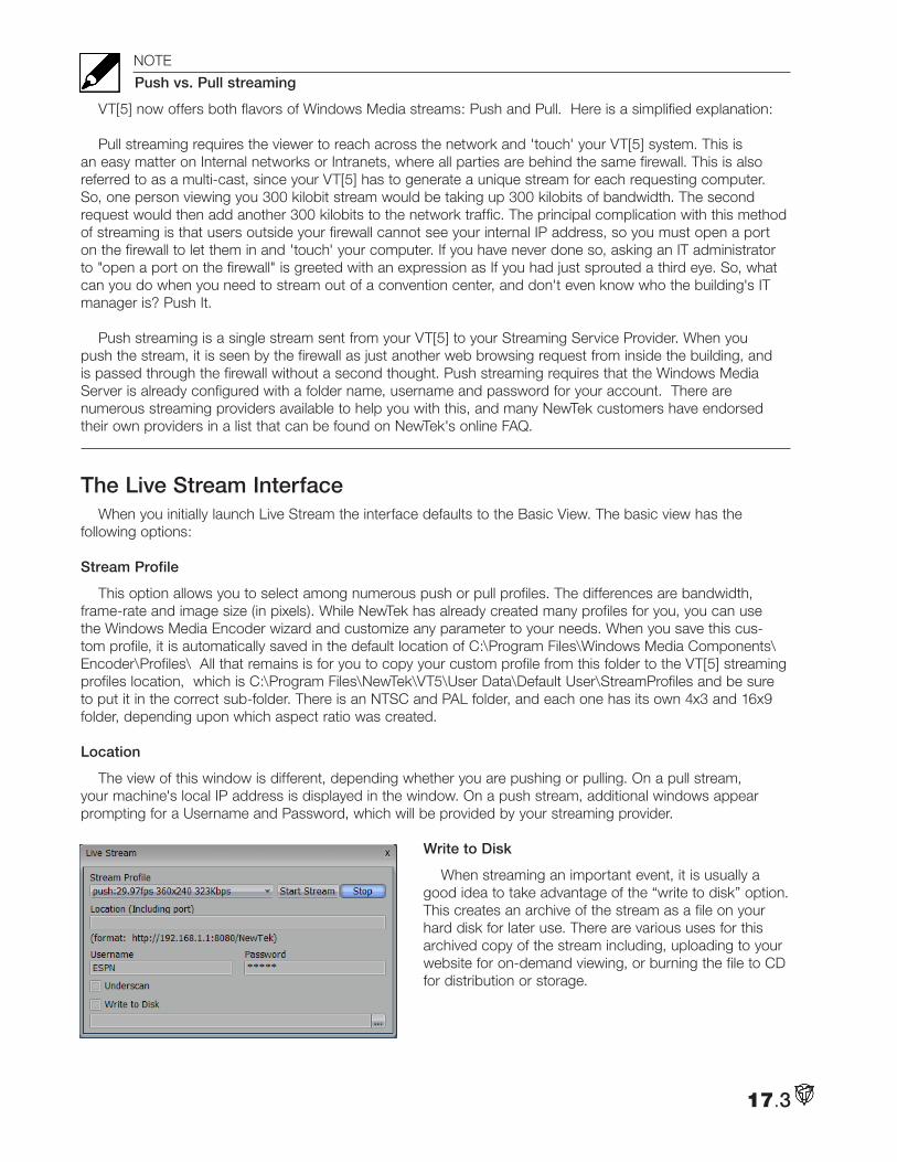
17.3
NOTE
Push vs. Pull streaming
VT[5] now offers both flavors of Windows Media streams: Push and Pull. Here is a simplified explanation:
Pull streaming requires the viewer to reach across the network and 'touch' your VT[5] system. This is an easy matter on Internal networks or Intranets, where all parties are behind the same firewall. This is also referred to as a multi-cast, since your VT[5] has to generate a unique stream for each requesting computer. So, one person viewing you 300 kilobit stream would be taking up 300 kilobits of bandwidth. The second request would then add another 300 kilobits to the network traffic. The principal complication with this method of streaming is that users outside your firewall cannot see your internal IP address, so you must open a port on the firewall to let them in and 'touch' your computer. If you have never done so, asking an IT administrator to "open a port on the firewall" is greeted with an expression as If you had just sprouted a third eye. So, what can you do when you need to stream out of a convention center, and don't even know who the building's IT manager is? Push It.
Push streaming is a single stream sent from your VT[5] to your Streaming Service Provider. When you
push the stream, it is seen by the firewall as just another web browsing request from inside the building, and is passed through the firewall without a second thought. Push streaming requires that the Windows Media Server is already configured with a folder name, username and password for your account. There are numerous streaming providers available to help you with this, and many NewTek customers have endorsed their own providers in a list that can be found on NewTek's online FAQ.
The Live Stream InterfaceWhen you initially launch Live Stream the interface defaults to the Basic View. The basic view has the
following options:
Stream Profile
This option allows you to select among numerous push or pull profiles. The differences are bandwidth, frame-rate and image size (in pixels). While NewTek has already created many profiles for you, you can use the Windows Media Encoder wizard and customize any parameter to your needs. When you save this cus-tom profile, it is automatically saved in the default location of C:\Program Files\Windows Media Components\Encoder\Profiles\ All that remains is for you to copy your custom profile from this folder to the VT[5] streaming profiles location, which is C:\Program Files\NewTek\VT5\User Data\Default User\StreamProfiles and be sure to put it in the correct sub-folder. There is an NTSC and PAL folder, and each one has its own 4x3 and 16x9 folder, depending upon which aspect ratio was created.
Location
The view of this window is different, depending whether you are pushing or pulling. On a pull stream, your machine's local IP address is displayed in the window. On a push stream, additional windows appear prompting for a Username and Password, which will be provided by your streaming provider.
Write to Disk
When streaming an important event, it is usually a good idea to take advantage of the “write to disk” option. This creates an archive of the stream as a file on your hard disk for later use. There are various uses for this archived copy of the stream including, uploading to your website for on-demand viewing, or burning the file to CD for distribution or storage.
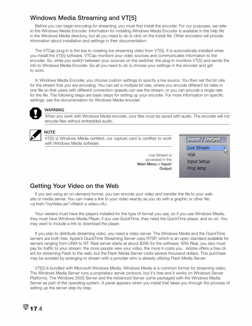
17.4
Live Stream is accessed in the
Main Menu > Input/Output
Windows Media Streaming and VT[5]Before you can begin encoding for streaming, you must first install the encoder. For our purposes, we refer
to the Windows Media Encoder. Information for installing Windows Media Encoder is available in the help file in the Windows Media directory, but all you need to do is click on the install file. Other encoders will provide information about installation and settings in their documentation.
The VTCap plug-in is the key to creating live streaming video from VT[5]. It is automatically installed when you install the VT[5] software. VTCap monitors your video sources and communicates information to the encoder. So, while you switch between your sources on the switcher, the plug-in monitors VT[5] and sends the info to Windows Media Encoder. So all you need to do is choose your settings in the encoder and get to work.
In Windows Media Encoder, you choose custom settings to specify a live source. You then set the bit rate for the stream that you are encoding. You can set a multiple bit rate, where you encode different bit rates in one file so that users with different connection speeds can see the stream, or you can encode a single rate for the file. The following steps are basic steps for setting up your encoder. For more information on specific settings, see the documentation for Windows Media encoder.
WARNING
When you work with Windows Media encoder, your files must be saved with audio. The encoder will not encode files without embedded audio.
NOTE
VT[5] is Windows Media certified; our capture card is certified to work with Windows Media software.
Getting Your Video on the WebIf you are using an on-demand format, you can encode your video and transfer the file to your web
site or media server. You can make a link to your video exactly as you do with a graphic or other file: <a href=”myVideo.avi”>Watch a video</A>
Your viewers must have the players installed for the type of format you use, so if you use Windows Media, they must have Windows Media Player, if you use QuickTime, they need the QuickTime player, and so on. You may want to include a link to download the player.
If you plan to distribute streaming video, you need a video server. The Windows Media and the QuickTime servers are both free. Apple’s QuickTime Streaming Server uses RTSP, which is an open standard available for servers ranging from UNIX to NT. Real server starts at about $295 for the software. With Real, you also must pay for traffic to your stream: the more people view your video, the more it costs you. Adobe offers a free cli-ent for streaming Flash to the web, but the Flash Media Server costs several thousand dollars. This purchase may be avoided by arranging to stream with a provider who is already utilizing Flash Media Server.
VT[5] is bundled with Microsoft Windows Media. Windows Media is a common format for streaming video. The Windows Media Server runs a proprietary server protocol, but it’s free and it works on Windows Server Platforms. The Windows 2000 Server and the Advanced Server come packaged with the Windows Media Server as part of the operating system. A panel appears when you install that takes you through the process of setting up the server step-by-step.
17.5
Note that when broadcast live, you can upload streaming media to your Web site without a video server. Up to 50 people can connect to your computer to watch streaming video without a server, if you are connecting with a constant, broadband connection such as DSL or cable modem. If more than 50 visitors will access your files, you will need a broadband distribution point, that is, a video server.
HINT
A good streaming media company to host your content is InstaWatch. Visit them on the web at www.instawatch.com
Getting Your Files on the ServerOnce you create and encode your streaming media and build the Web page for the media player and
related data, you must post your files on the appropriate Web servers. The process for setting up a stream-ing media server is more complex than setting up the encoder, and you need to contact your Internet Service Provider (ISP) for specific details. If you run your own server, and you can get information about installing a media server from the documentation that comes with the server software. However the following list contains the information that you need to get when you’re working with an ISP:
• a log-on identification number and password for the Internet servers where you will post your HTML pages and media
• the address for the HTML server where the layout and redirector files will be stored on the Web server; this is the directory path that you use to transfer files with a file transfer protocol (FTP) program
• the address for the video server where the streaming media will be stored; this is the directory path that you use to transfer the file with an FTP program
Before you upload your files, you must create a redirector file. As you may have noticed, it takes two serv-ers to get your streaming video on the Web — one for HTML pages, and the other for streaming media. A user requests streaming media from the HTML server, and a redirector file on the HTML server redirects the request to the media server. This file is usually placed in the same folder as the HTML page. For examples of redirector files visit www.msdn.microsoft.com and enter “asx” in the search window.
Preparing for EncodingBefore you create video for the Web, whether it is streaming video or downloadable video, you need to
make some preparations first. Of course, you should have an idea of how your final video will be assembled and you should have those elements — video, audio, graphics and effects — ready before you start.
Audience for Web Video
Your audience is the critical element when you create video for the Web. Your preparations and your final output will differ depending on whether you want a wide audience, which includes users with slow connec-tions, or if you are willing to limit your audience to those with high bandwidth connections, and offer higher quality output.
Audio Capture for the Web
You capture audio at the same time that you capture video. You want your audio to be CD quality, so it should be sampled at 44.1 KHz and 16 bits. The audio will be compressed as well, but again, you want to start with the best quality possible.
17.6
Video Capture for the Web
When you capture video for Web distribution, the best approach to ensure decent quality is usually to cap-ture it at the size that you will use for final output. When video is compressed, as it must be for the Web, you lose a lot of detail, and to compress a full-screen video down to a quarter or a sixteenth of its size is a lesson in humility. However, you still want to work with the highest resolution possible, so that you give good informa-tion for encoding. However, when working with VT[5], you should capture your video at full resolution. Then, when you activate the encoder, choose your compression settings to suit the intended audience.
Other Variables for Web Video
Other variables to keep in mind when you’re creating video for the Web are contrast and motion. When you encode video for the Web, you lose video information and detail, so good lighting of your source video is essential.
Web streaming doesn’t handle transitions and motion well and it doesn’t capture detail so your best shots should be close and without a lot of movement. Audio from cameras and camcorders is rarely as good as separate microphones, you should at least use a clip-on lavaliere microphone or a directional or shotgun microphone so you hear only what you want.
In streaming video, you can give your viewers some control over the video — they can skip ahead to infor-mation, for example. You must encode metadata into your file, choose the right delivery platforms, and code HTML pages to provide access. Metadata can also be used to encode information such as author, copyright, rating, and a description of the video. This information can be displayed in the media player as the content is streamed.
One of the most useful functions of metadata is that you can use it to run commands that will open a Web page or launch a Java application. You can syncronize these events to specific times and events in the streaming content. For instance, as the streaming audio describes a product, metadata could launch the browser and open a related Web page. Instructions on how to encode metadata are included in the documentation for your encoding software.
Tips for Video on the WebThese tips refer to creating video for a wide range of users, they are meant as guideline for creating video
that is targeted to low bandwidth viewers. When you create video for users with fast connections, these issues are less of a concern, but are still good guidelines.
Picture Size
Depending on your audience, your picture size may need to be very small. Typical web-based videos use a half or a quarter of a screen; when you use the VT[5] encoder, the lowest resolution available is 360 x 240.
Frame Rate
U.S. television (NTSC) delivers video at 29.97 frames per second (fps). The rate for European television (PAL) is 25 fps. Most computer video cuts the frame rate to 15 or 10 fps. If you expect your users to work on very slow connections, you should reduce frame rate down to five or six frames per second. However, the frame rate should always be a number that divides evenly into 30 fps (for NTSC) or 25 fps (for PAL).
Limit Your Palette and Use Bright Colors
Much like web graphics, web video looks best when you use bright and solid colors. Dark colors, gradients and patterns may not translate well over slow connections. 8-bit color (256 color palette) gives your video the best look for the widest range of viewers.
Reduce Motion
Fast motion and fancy transitions also do not translate well across slow connections; this also applies to special effects because they usually require motion and subtle coloration.
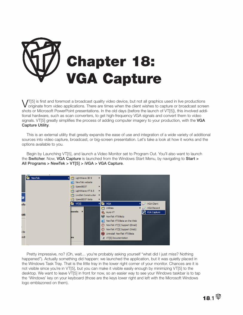
18.1
VT[5] is first and foremost a broadcast quality video device, but not all graphics used in live productions originate from video applications. There are times when the client wishes to capture or broadcast screen
shots or Microsoft PowerPoint presentations. In the old days (before the launch of VT[5]), this involved addi-tional hardware, such as scan converters, to get high-frequency VGA signals and convert them to video signals. VT[5] greatly simplifies the process of adding computer imagery to your production, with the VGA Capture Utility.
This is an external utility that greatly expands the ease of use and integration of a wide variety of additional sources into video capture, broadcast, or big-screen presentation. Let’s take a look at how it works and the options available to you.
Begin by Launching VT[5], and launch a Video Monitor set to Program Out. You’ll also want to launch the Switcher. Now, VGA Capture is launched from the Windows Start Menu, by navigating to Start > All Programs > NewTek > VT[5] > iVGA > VGA Capture.
Pretty impressive, no? (Oh, wait… you’re probably asking yourself “what did I just miss? Nothing happened”). Actually something did happen: we launched the application, but it was quietly placed in the Windows Task Tray. That is the little tray in the lower right corner of your monitor. Chances are it is not visible since you’re in VT[5], but you can make it visible easily enough by minimizing VT[5] to the desktop. We want to leave VT[5] in front for now, so an easier way to see your Windows taskbar is to tap the ‘Windows’ key on your keyboard (those are the keys lower right and left with the Microsoft Windows logo emblazoned on them).
Chapter 18:VGA Capture
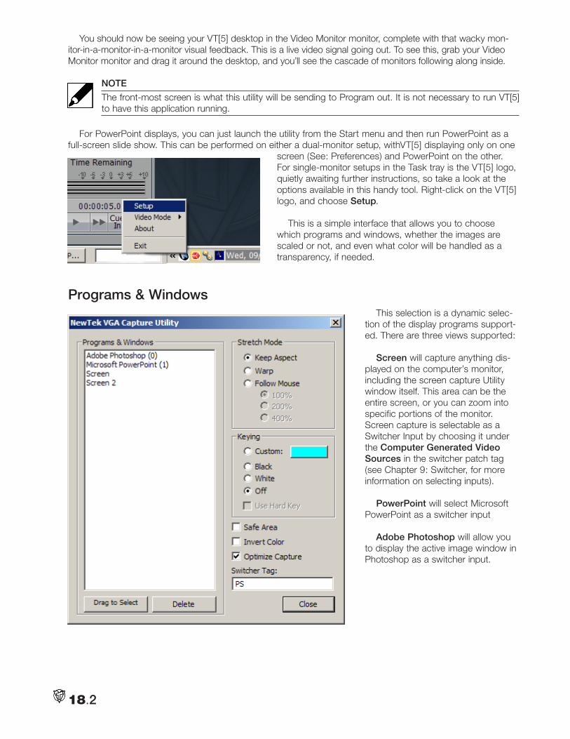
18.2
You should now be seeing your VT[5] desktop in the Video Monitor monitor, complete with that wacky mon-itor-in-a-monitor-in-a-monitor visual feedback. This is a live video signal going out. To see this, grab your Video Monitor monitor and drag it around the desktop, and you’ll see the cascade of monitors following along inside.
NOTE
The front-most screen is what this utility will be sending to Program out. It is not necessary to run VT[5] to have this application running.
For PowerPoint displays, you can just launch the utility from the Start menu and then run PowerPoint as a full-screen slide show. This can be performed on either a dual-monitor setup, withVT[5] displaying only on one
screen (See: Preferences) and PowerPoint on the other. For single-monitor setups in the Task tray is the VT[5] logo, quietly awaiting further instructions, so take a look at the options available in this handy tool. Right-click on the VT[5] logo, and choose Setup.
This is a simple interface that allows you to choose which programs and windows, whether the images are scaled or not, and even what color will be handled as a transparency, if needed.
Programs & WindowsThis selection is a dynamic selec-
tion of the display programs support-ed. There are three views supported:
Screen will capture anything dis-played on the computer’s monitor, including the screen capture Utility window itself. This area can be the entire screen, or you can zoom into specific portions of the monitor. Screen capture is selectable as a Switcher Input by choosing it under the Computer Generated Video Sources in the switcher patch tag (see Chapter 9: Switcher, for more information on selecting inputs).
PowerPoint will select Microsoft PowerPoint as a switcher input
Adobe Photoshop will allow you to display the active image window in Photoshop as a switcher input.
18.3
Stretch Mode This offers several methods of conforming the various VGA screen sizes to NTSC or PAL video aspects.
Keep Aspect is the default and this will fit the selection within the existing confines of the video outputs. For a 1280x1024 monitor, this means that the screen is scaled to fit vertically, with some blank areas on either side.
Warp will put a lower priority on the image’s aspect, and instead scale the selection to completely fill the horizontal and vertical confines of the video output.
Follow Mouse allows you to zoom in on a particular portion of the screen, based upon the screen cursor position. This feature works in tandem with Stretch Factor.
Stretch FactorThis is the amount that the selected window is zoomed in.
100% is the default and will show the entire window
200% will zoom into the center of the monitor, and is best used in conjunction with Follow Mouse.
400% will zoom quite far into the screen view, and is best used in the conjunction with Follow Mouse.
KeyingThis is where you can key out unwanted portions of the screen based on either luminance or chromi-
nance. (See Chapter 14: Chroma and Luma Keyer for a detailed discussion of keying and its operation in the Switcher). VGA Capture keys are activated in the Switcher’s Downstream Key.
Custom: This option allows you to select the particular color you wish to key out. If you have a PowerPoint presentation with, say, a Red background, you can select that particular color in the Custom dialog. Left-click-ing in the custom color well brings up the Global Color Picker, where you can choose the color you wish to be transparent (See Chapter 14: Color Picker for information on use of Color Picker).
Black will key out all black, or very dark portions of the selected screen.
White will key out all white, or very bright portions of the selected screen.
Off disables keying, and even if chosen as the Switcher’s Downstream key source, when Off is selected, there will not be any transparency in the selected screen.
Safe Area will shrink the selected screen in toward the center by about five percent, to make the screen fit within the action safe boundaries of the video signal.
Invert Color is useful for such applications such as Word Processors that display black text on a white background. Invert Color allows you to reverse this, since white text is usually easier to read with texture or video behind it.
Optimize Capture performs image smoothing operations on the scaled image, to make it look its best once converted to a video signal.
NOTE
As any veteran video producer can tell you, many images that look good on an XGA computer screen contain too much fine detail that cannot translate properly into a fielded video signal. The worst culprit is a very fine horizontal line. A horizontal line that is only one pixel high will only appear in every other field, causing a strobing or beating effect on screen. It is suggested that PowerPoint pages keep text large, and avoid detailed textures as backgrounds.

18.4
Notes:
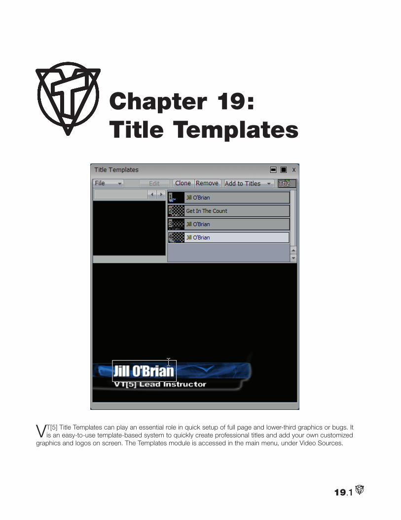
19.1
VT[5] Title Templates can play an essential role in quick setup of full page and lower-third graphics or bugs. It is an easy-to-use template-based system to quickly create professional titles and add your own customized
graphics and logos on screen. The Templates module is accessed in the main menu, under Video Sources.
Chapter 19: Title Templates
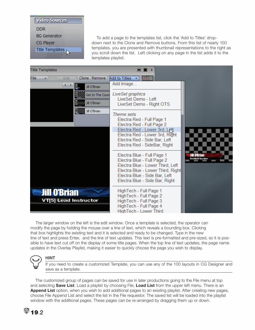
19.2
To add a page to the templates list, click the ‘Add to Titles’ drop-down next to the Clone and Remove buttons. From this list of nearly 100 templates, you are presented with thumbnail representations to the right as you scroll down the list. Left clicking on any page in the list adds it to the templates playlist.
The larger window on the left is the edit window. Once a template is selected, the operator can modify the page by holding the mouse over a line of text, which reveals a bounding box. Clicking that box highlights the existing text and it is selected and ready to be changed. Type in the new line of text and press Enter, and the line of text updates. This text is pre-formatted and pre-sized, so it is pos-sible to have text cut off on the display of some title pages. When the top line of text updates, the page name updates in the Overlay Playlist, making it easier to quickly choose the page you wish to display.
HINT
If you need to create a customized Template, you can use any of the 100 layouts in CG Designer and save as a template.
The customized group of pages can be saved for use in later productions going to the File menu at top and selecting Save List. Load a playlist by choosing File, Load List from the upper left menu. There is an Append List option, when you wish to add additional pages to an existing playlist. After creating new pages, choose File Append List and select the list in the File requestor. The saved list will be loaded into the playlist window with the additional pages. These pages can be re-arranged by dragging them up or down.
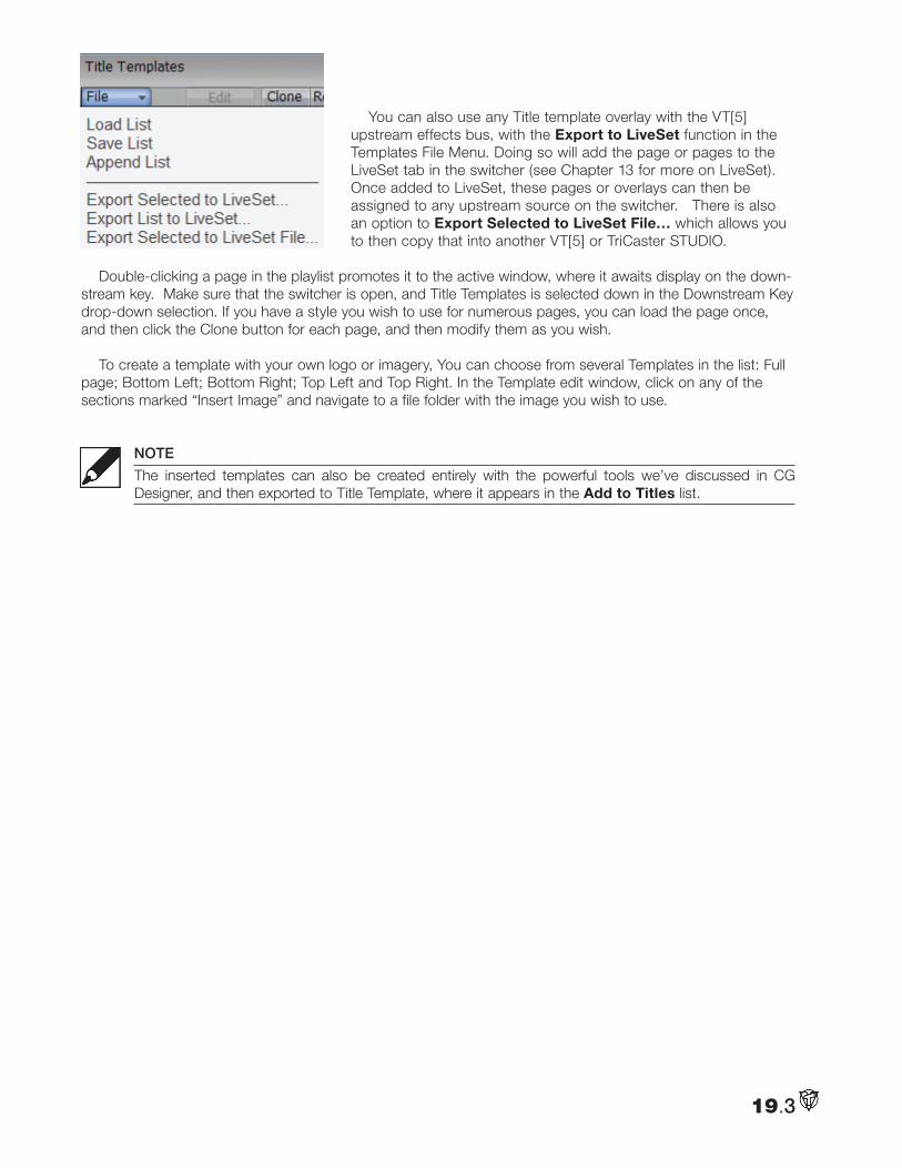
19.3
You can also use any Title template overlay with the VT[5] upstream effects bus, with the Export to LiveSet function in the Templates File Menu. Doing so will add the page or pages to the LiveSet tab in the switcher (see Chapter 13 for more on LiveSet). Once added to LiveSet, these pages or overlays can then be assigned to any upstream source on the switcher. There is also an option to Export Selected to LiveSet File… which allows you to then copy that into another VT[5] or TriCaster STUDIO.
Double-clicking a page in the playlist promotes it to the active window, where it awaits display on the down-stream key. Make sure that the switcher is open, and Title Templates is selected down in the Downstream Key drop-down selection. If you have a style you wish to use for numerous pages, you can load the page once, and then click the Clone button for each page, and then modify them as you wish.
To create a template with your own logo or imagery, You can choose from several Templates in the list: Full page; Bottom Left; Bottom Right; Top Left and Top Right. In the Template edit window, click on any of the sections marked “Insert Image” and navigate to a file folder with the image you wish to use.
NOTE
The inserted templates can also be created entirely with the powerful tools we’ve discussed in CG Designer, and then exported to Title Template, where it appears in the Add to Titles list.

19.4
Notes:
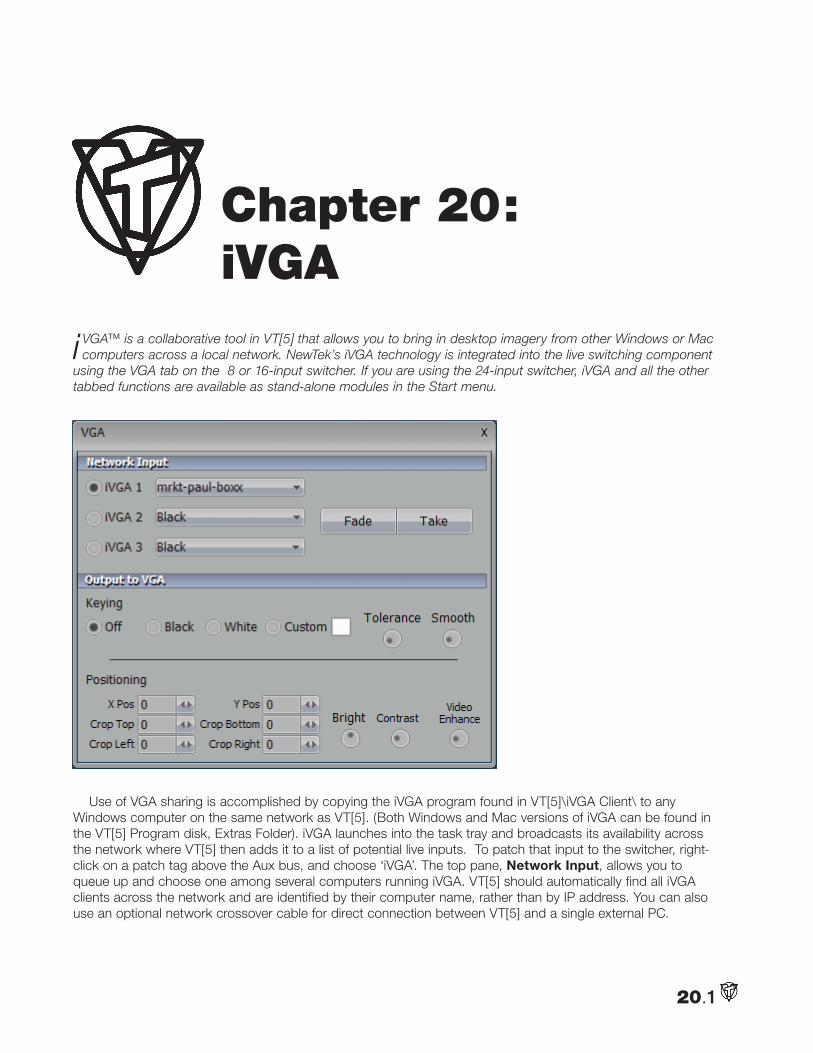
20.1
i VGA™ is a collaborative tool in VT[5] that allows you to bring in desktop imagery from other Windows or Mac computers across a local network. NewTek’s iVGA technology is integrated into the live switching component
using the VGA tab on the 8 or 16-input switcher. If you are using the 24-input switcher, iVGA and all the other tabbed functions are available as stand-alone modules in the Start menu.
Use of VGA sharing is accomplished by copying the iVGA program found in VT[5]\iVGA Client\ to any Windows computer on the same network as VT[5]. (Both Windows and Mac versions of iVGA can be found in the VT[5] Program disk, Extras Folder). iVGA launches into the task tray and broadcasts its availability across the network where VT[5] then adds it to a list of potential live inputs. To patch that input to the switcher, right-click on a patch tag above the Aux bus, and choose ‘iVGA’. The top pane, Network Input, allows you to queue up and choose one among several computers running iVGA. VT[5] should automatically find all iVGA clients across the network and are identified by their computer name, rather than by IP address. You can also use an optional network crossover cable for direct connection between VT[5] and a single external PC.
Chapter 20: iVGA
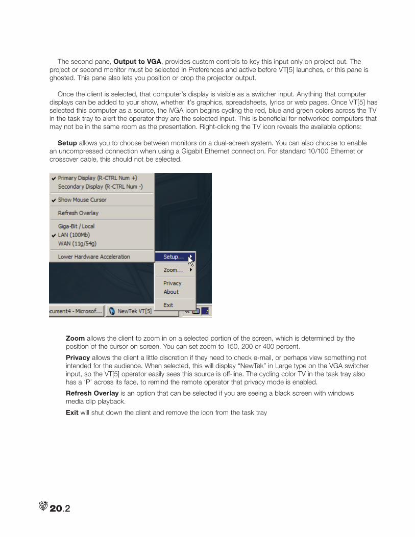
20.2
The second pane, Output to VGA, provides custom controls to key this input only on project out. The project or second monitor must be selected in Preferences and active before VT[5] launches, or this pane is ghosted. This pane also lets you position or crop the projector output.
Once the client is selected, that computer’s display is visible as a switcher input. Anything that computer displays can be added to your show, whether it’s graphics, spreadsheets, lyrics or web pages. Once VT[5] has selected this computer as a source, the iVGA icon begins cycling the red, blue and green colors across the TV in the task tray to alert the operator they are the selected input. This is beneficial for networked computers that may not be in the same room as the presentation. Right-clicking the TV icon reveals the available options:
Setup allows you to choose between monitors on a dual-screen system. You can also choose to enable an uncompressed connection when using a Gigabit Ethernet connection. For standard 10/100 Ethernet or crossover cable, this should not be selected.
Zoom allows the client to zoom in on a selected portion of the screen, which is determined by the position of the cursor on screen. You can set zoom to 150, 200 or 400 percent.
Privacy allows the client a little discretion if they need to check e-mail, or perhaps view something not intended for the audience. When selected, this will display “NewTek” in Large type on the VGA switcher input, so the VT[5] operator easily sees this source is off-line. The cycling color TV in the task tray also has a ‘P’ across its face, to remind the remote operator that privacy mode is enabled.
Refresh Overlay is an option that can be selected if you are seeing a black screen with windows media clip playback.
Exit will shut down the client and remove the icon from the task tray
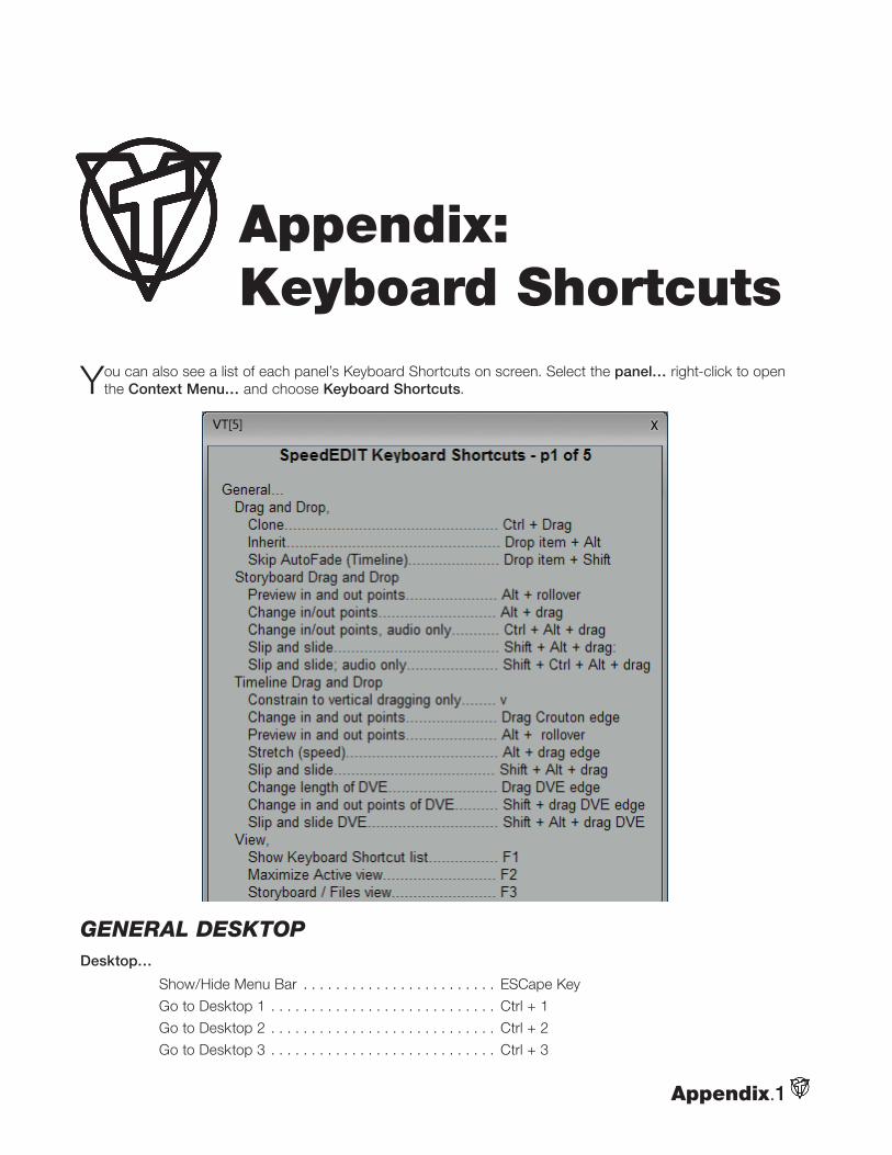
Appendix.1
You can also see a list of each panel’s Keyboard Shortcuts on screen. Select the panel… right-click to open the Context Menu… and choose Keyboard Shortcuts.
General DesktopDesktop…
Show/Hide Menu Bar . . . . . . . . . . . . . . . . . . . . . . . . ESCape Key
Go to Desktop 1 . . . . . . . . . . . . . . . . . . . . . . . . . . . . Ctrl + 1
Go to Desktop 2 . . . . . . . . . . . . . . . . . . . . . . . . . . . . Ctrl + 2
Go to Desktop 3 . . . . . . . . . . . . . . . . . . . . . . . . . . . . Ctrl + 3
Appendix: Keyboard Shortcuts
Appendix.2
Go to Desktop 4 . . . . . . . . . . . . . . . . . . . . . . . . . . . . Ctrl + 4
Go to Desktop 5 . . . . . . . . . . . . . . . . . . . . . . . . . . . . Ctrl + 5
Go to Desktop 6 . . . . . . . . . . . . . . . . . . . . . . . . . . . . Ctrl + 6
Go forwards through desktops . . . . . . . . . . . . . . . . . Ctrl + Tab
Go backwards through desktops . . . . . . . . . . . . . . . Ctrl + Shift + Tab
Remove Selected Icons from desktop. . . . . . . . . . . . Delete key
Remove All Icons from desktop. . . . . . . . . . . . . . . . . Shift + Delete key
General… (usable with many modules)
Show help . . . . . . . . . . . . . . . . . . . . . . . . . . . . . . . . . F1
Cut. . . . . . . . . . . . . . . . . . . . . . . . . . . . . . . . . . . . . . . Ctrl + x
Copy . . . . . . . . . . . . . . . . . . . . . . . . . . . . . . . . . . . . . Ctrl + c
Paste . . . . . . . . . . . . . . . . . . . . . . . . . . . . . . . . . . . . . Ctrl + v
Undo . . . . . . . . . . . . . . . . . . . . . . . . . . . . . . . . . . . . . Ctrl + z
Redo . . . . . . . . . . . . . . . . . . . . . . . . . . . . . . . . . . . . . Ctrl + y
New. . . . . . . . . . . . . . . . . . . . . . . . . . . . . . . . . . . . . . Ctrl + n
Open . . . . . . . . . . . . . . . . . . . . . . . . . . . . . . . . . . . . . Ctrl + o
Save . . . . . . . . . . . . . . . . . . . . . . . . . . . . . . . . . . . . . Ctrl + s
Save As . . . . . . . . . . . . . . . . . . . . . . . . . . . . . . . . . . . Ctrl Shift + s
Add Files . . . . . . . . . . . . . . . . . . . . . . . . . . . . . . . . . . Ctrl + i
Selection… (usable in many modules… including icons on desktop)
Select All . . . . . . . . . . . . . . . . . . . . . . . . . . . . . . . . . . Ctrl + a
Deselect All . . . . . . . . . . . . . . . . . . . . . . . . . . . . . . . . Ctrl Shift + a
Previous Item. . . . . . . . . . . . . . . . . . . . . . . . . . . . . . . Left/Up Arrow
Previous Item and keep current selection . . . . . . . . . Ctrl + Left/Up
Next Item. . . . . . . . . . . . . . . . . . . . . . . . . . . . . . . . . . Right/Down Arrow
Next Item and keep current selection . . . . . . . . . . . . Ctrl + Right/Down
First Item . . . . . . . . . . . . . . . . . . . . . . . . . . . . . . . . . . Home
First Item and keep current selection. . . . . . . . . . . . . Ctrl + Home
Last Item . . . . . . . . . . . . . . . . . . . . . . . . . . . . . . . . . . End
Last Item and keep current selection. . . . . . . . . . . . . Ctrl + End
Select All Previous Items . . . . . . . . . . . . . . . . . . . . . . Shift + Home
Select All Previous and keep current selection . . . . . Ctrl Shift + Home
Select All Following Items . . . . . . . . . . . . . . . . . . . . . Shift + End
Select All Following and keep current selection . . . . . Ctrl Shift + End
Batch captureNote: These keys are similar to the DDR
Deck Control…
Reverse Shuttle . . . . . . . . . . . . . . . . . . . . . . . . . . . . . J
Pause/Play. . . . . . . . . . . . . . . . . . . . . . . . . . . . . . . . . K
Forward Shuttle . . . . . . . . . . . . . . . . . . . . . . . . . . . . . L
Rewind . . . . . . . . . . . . . . . . . . . . . . . . . . . . . . . . . . . Shift + J
Stop . . . . . . . . . . . . . . . . . . . . . . . . . . . . . . . . . . . . . Shift + K
Fast Forward . . . . . . . . . . . . . . . . . . . . . . . . . . . . . . . Shift + L
One Frame Back . . . . . . . . . . . . . . . . . . . . . . . . . . . . Alt + J (when paused)
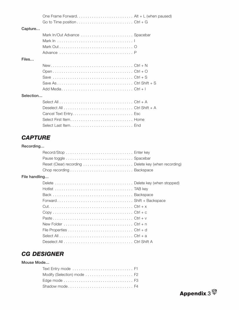
Appendix.3
One Frame Forward. . . . . . . . . . . . . . . . . . . . . . . . . . Alt + L (when paused)
Go to Time position . . . . . . . . . . . . . . . . . . . . . . . . . . Ctrl + G
Capture…
Mark In/Out Advance . . . . . . . . . . . . . . . . . . . . . . . . Spacebar
Mark In . . . . . . . . . . . . . . . . . . . . . . . . . . . . . . . . . . . I
Mark Out . . . . . . . . . . . . . . . . . . . . . . . . . . . . . . . . . . O
Advance . . . . . . . . . . . . . . . . . . . . . . . . . . . . . . . . . . P
Files…
New . . . . . . . . . . . . . . . . . . . . . . . . . . . . . . . . . . . . . . Ctrl + N
Open . . . . . . . . . . . . . . . . . . . . . . . . . . . . . . . . . . . . . Ctrl + O
Save . . . . . . . . . . . . . . . . . . . . . . . . . . . . . . . . . . . . . Ctrl + S
Save As . . . . . . . . . . . . . . . . . . . . . . . . . . . . . . . . . . . Ctrl Shift + S
Add Media . . . . . . . . . . . . . . . . . . . . . . . . . . . . . . . . . Ctrl + I
Selection…
Select All . . . . . . . . . . . . . . . . . . . . . . . . . . . . . . . . . . Ctrl + A
Deselect All . . . . . . . . . . . . . . . . . . . . . . . . . . . . . . . . Ctrl Shift + A
Cancel Text Entry. . . . . . . . . . . . . . . . . . . . . . . . . . . . Esc
Select First Item. . . . . . . . . . . . . . . . . . . . . . . . . . . . . Home
Select Last Item. . . . . . . . . . . . . . . . . . . . . . . . . . . . . End
captureRecording…
Record/Stop . . . . . . . . . . . . . . . . . . . . . . . . . . . . . . . Enter key
Pause toggle . . . . . . . . . . . . . . . . . . . . . . . . . . . . . . . Spacebar
Reset (Clear) recording . . . . . . . . . . . . . . . . . . . . . . . Delete key (when recording)
Chop recording . . . . . . . . . . . . . . . . . . . . . . . . . . . . . Backspace
File handling…
Delete . . . . . . . . . . . . . . . . . . . . . . . . . . . . . . . . . . . . Delete key (when stopped)
Hotlist . . . . . . . . . . . . . . . . . . . . . . . . . . . . . . . . . . . . TAB key
Back . . . . . . . . . . . . . . . . . . . . . . . . . . . . . . . . . . . . . Backspace
Forward . . . . . . . . . . . . . . . . . . . . . . . . . . . . . . . . . . . Shift + Backspace
Cut. . . . . . . . . . . . . . . . . . . . . . . . . . . . . . . . . . . . . . . Ctrl + x
Copy . . . . . . . . . . . . . . . . . . . . . . . . . . . . . . . . . . . . . Ctrl + c
Paste . . . . . . . . . . . . . . . . . . . . . . . . . . . . . . . . . . . . . Ctrl + v
New Folder . . . . . . . . . . . . . . . . . . . . . . . . . . . . . . . . Ctrl + n
File Properties . . . . . . . . . . . . . . . . . . . . . . . . . . . . . . Ctrl + d
Select All . . . . . . . . . . . . . . . . . . . . . . . . . . . . . . . . . . Ctrl + a
Deselect All . . . . . . . . . . . . . . . . . . . . . . . . . . . . . . . . Ctrl Shift A
cG DesiGnerMouse Mode…
Text Entry mode . . . . . . . . . . . . . . . . . . . . . . . . . . . . F1
Modify (Selection) mode . . . . . . . . . . . . . . . . . . . . . . F2
Edge mode . . . . . . . . . . . . . . . . . . . . . . . . . . . . . . . . F3
Shadow mode . . . . . . . . . . . . . . . . . . . . . . . . . . . . . . F4
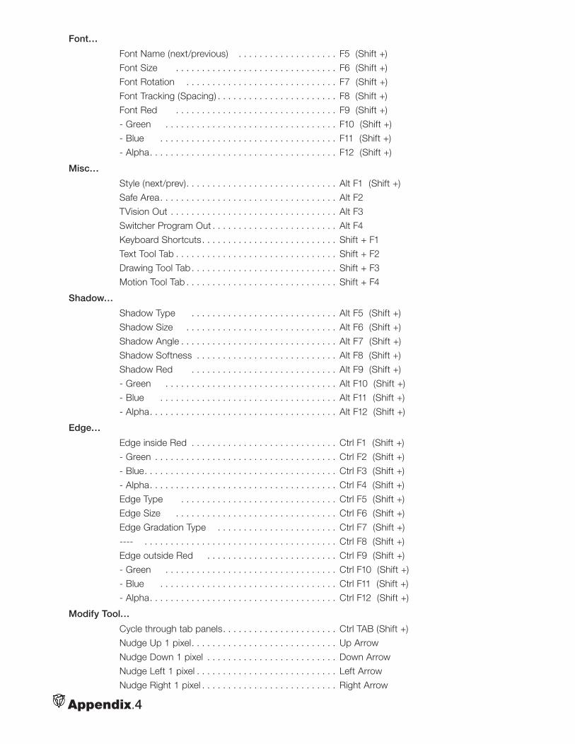
Appendix.4
Font…
Font Name (next/previous) . . . . . . . . . . . . . . . . . . . F5 (Shift +)
Font Size . . . . . . . . . . . . . . . . . . . . . . . . . . . . . . . F6 (Shift +)
Font Rotation . . . . . . . . . . . . . . . . . . . . . . . . . . . . . F7 (Shift +)
Font Tracking (Spacing) . . . . . . . . . . . . . . . . . . . . . . . F8 (Shift +)
Font Red . . . . . . . . . . . . . . . . . . . . . . . . . . . . . . . F9 (Shift +)
- Green . . . . . . . . . . . . . . . . . . . . . . . . . . . . . . . . . F10 (Shift +)
- Blue . . . . . . . . . . . . . . . . . . . . . . . . . . . . . . . . . . F11 (Shift +)
- Alpha. . . . . . . . . . . . . . . . . . . . . . . . . . . . . . . . . . . . F12 (Shift +)
Misc…
Style (next/prev). . . . . . . . . . . . . . . . . . . . . . . . . . . . . Alt F1 (Shift +)
Safe Area. . . . . . . . . . . . . . . . . . . . . . . . . . . . . . . . . . Alt F2
TVision Out . . . . . . . . . . . . . . . . . . . . . . . . . . . . . . . . Alt F3
Switcher Program Out . . . . . . . . . . . . . . . . . . . . . . . . Alt F4
Keyboard Shortcuts. . . . . . . . . . . . . . . . . . . . . . . . . . Shift + F1
Text Tool Tab . . . . . . . . . . . . . . . . . . . . . . . . . . . . . . . Shift + F2
Drawing Tool Tab . . . . . . . . . . . . . . . . . . . . . . . . . . . . Shift + F3
Motion Tool Tab . . . . . . . . . . . . . . . . . . . . . . . . . . . . . Shift + F4
Shadow…
Shadow Type . . . . . . . . . . . . . . . . . . . . . . . . . . . . Alt F5 (Shift +)
Shadow Size . . . . . . . . . . . . . . . . . . . . . . . . . . . . . Alt F6 (Shift +)
Shadow Angle . . . . . . . . . . . . . . . . . . . . . . . . . . . . . . Alt F7 (Shift +)
Shadow Softness . . . . . . . . . . . . . . . . . . . . . . . . . . . Alt F8 (Shift +)
Shadow Red . . . . . . . . . . . . . . . . . . . . . . . . . . . . Alt F9 (Shift +)
- Green . . . . . . . . . . . . . . . . . . . . . . . . . . . . . . . . . Alt F10 (Shift +)
- Blue . . . . . . . . . . . . . . . . . . . . . . . . . . . . . . . . . . Alt F11 (Shift +)
- Alpha. . . . . . . . . . . . . . . . . . . . . . . . . . . . . . . . . . . . Alt F12 (Shift +)
Edge…
Edge inside Red . . . . . . . . . . . . . . . . . . . . . . . . . . . . Ctrl F1 (Shift +)
- Green . . . . . . . . . . . . . . . . . . . . . . . . . . . . . . . . . . . Ctrl F2 (Shift +)
- Blue. . . . . . . . . . . . . . . . . . . . . . . . . . . . . . . . . . . . . Ctrl F3 (Shift +)
- Alpha. . . . . . . . . . . . . . . . . . . . . . . . . . . . . . . . . . . . Ctrl F4 (Shift +)
Edge Type . . . . . . . . . . . . . . . . . . . . . . . . . . . . . . Ctrl F5 (Shift +)
Edge Size . . . . . . . . . . . . . . . . . . . . . . . . . . . . . . . Ctrl F6 (Shift +)
Edge Gradation Type . . . . . . . . . . . . . . . . . . . . . . . Ctrl F7 (Shift +)
---- . . . . . . . . . . . . . . . . . . . . . . . . . . . . . . . . . . . . . Ctrl F8 (Shift +)
Edge outside Red . . . . . . . . . . . . . . . . . . . . . . . . . Ctrl F9 (Shift +)
- Green . . . . . . . . . . . . . . . . . . . . . . . . . . . . . . . . . Ctrl F10 (Shift +)
- Blue . . . . . . . . . . . . . . . . . . . . . . . . . . . . . . . . . . Ctrl F11 (Shift +)
- Alpha. . . . . . . . . . . . . . . . . . . . . . . . . . . . . . . . . . . . Ctrl F12 (Shift +)
Modify Tool…
Cycle through tab panels. . . . . . . . . . . . . . . . . . . . . . Ctrl TAB (Shift +)
Nudge Up 1 pixel. . . . . . . . . . . . . . . . . . . . . . . . . . . . Up Arrow
Nudge Down 1 pixel . . . . . . . . . . . . . . . . . . . . . . . . . Down Arrow
Nudge Left 1 pixel . . . . . . . . . . . . . . . . . . . . . . . . . . . Left Arrow
Nudge Right 1 pixel . . . . . . . . . . . . . . . . . . . . . . . . . . Right Arrow
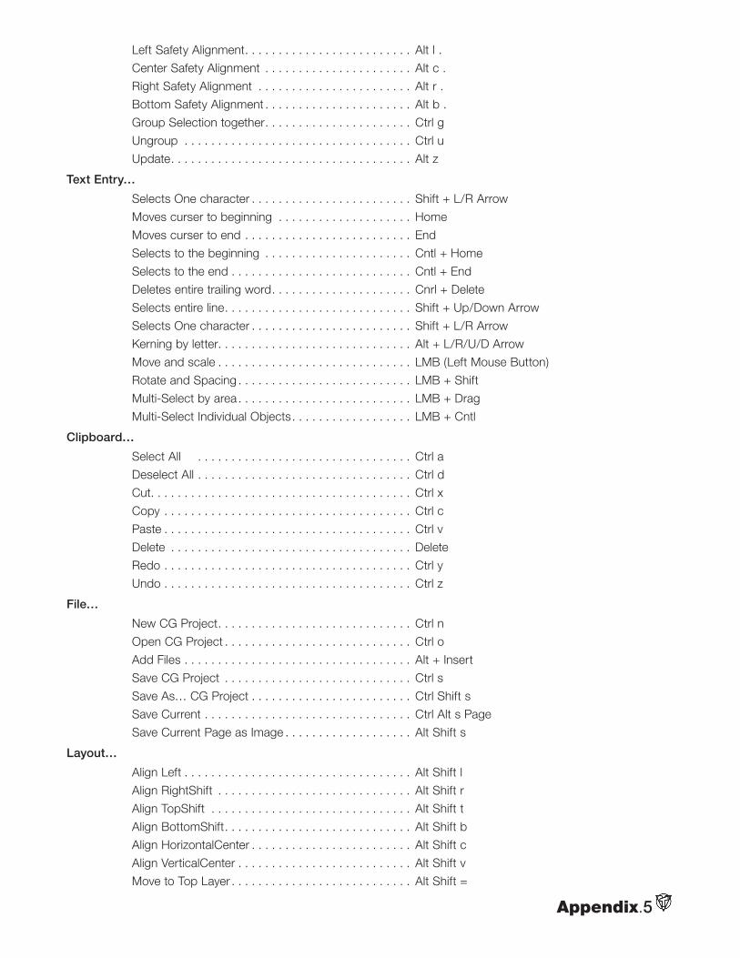
Appendix.5
Left Safety Alignment. . . . . . . . . . . . . . . . . . . . . . . . . Alt l .
Center Safety Alignment . . . . . . . . . . . . . . . . . . . . . . Alt c .
Right Safety Alignment . . . . . . . . . . . . . . . . . . . . . . . Alt r .
Bottom Safety Alignment . . . . . . . . . . . . . . . . . . . . . . Alt b .
Group Selection together. . . . . . . . . . . . . . . . . . . . . . Ctrl g
Ungroup . . . . . . . . . . . . . . . . . . . . . . . . . . . . . . . . . . Ctrl u
Update. . . . . . . . . . . . . . . . . . . . . . . . . . . . . . . . . . . . Alt z
Text Entry…
Selects One character . . . . . . . . . . . . . . . . . . . . . . . . Shift + L/R Arrow
Moves curser to beginning . . . . . . . . . . . . . . . . . . . . Home
Moves curser to end . . . . . . . . . . . . . . . . . . . . . . . . . End
Selects to the beginning . . . . . . . . . . . . . . . . . . . . . . Cntl + Home
Selects to the end . . . . . . . . . . . . . . . . . . . . . . . . . . . Cntl + End
Deletes entire trailing word. . . . . . . . . . . . . . . . . . . . . Cnrl + Delete
Selects entire line. . . . . . . . . . . . . . . . . . . . . . . . . . . . Shift + Up/Down Arrow
Selects One character . . . . . . . . . . . . . . . . . . . . . . . . Shift + L/R Arrow
Kerning by letter. . . . . . . . . . . . . . . . . . . . . . . . . . . . . Alt + L/R/U/D Arrow
Move and scale . . . . . . . . . . . . . . . . . . . . . . . . . . . . . LMB (Left Mouse Button)
Rotate and Spacing . . . . . . . . . . . . . . . . . . . . . . . . . . LMB + Shift
Multi-Select by area . . . . . . . . . . . . . . . . . . . . . . . . . . LMB + Drag
Multi-Select Individual Objects. . . . . . . . . . . . . . . . . . LMB + Cntl
Clipboard…
Select All . . . . . . . . . . . . . . . . . . . . . . . . . . . . . . . . Ctrl a
Deselect All . . . . . . . . . . . . . . . . . . . . . . . . . . . . . . . . Ctrl d
Cut. . . . . . . . . . . . . . . . . . . . . . . . . . . . . . . . . . . . . . . Ctrl x
Copy . . . . . . . . . . . . . . . . . . . . . . . . . . . . . . . . . . . . . Ctrl c
Paste . . . . . . . . . . . . . . . . . . . . . . . . . . . . . . . . . . . . . Ctrl v
Delete . . . . . . . . . . . . . . . . . . . . . . . . . . . . . . . . . . . . Delete
Redo . . . . . . . . . . . . . . . . . . . . . . . . . . . . . . . . . . . . . Ctrl y
Undo . . . . . . . . . . . . . . . . . . . . . . . . . . . . . . . . . . . . . Ctrl z
File…
New CG Project. . . . . . . . . . . . . . . . . . . . . . . . . . . . . Ctrl n
Open CG Project . . . . . . . . . . . . . . . . . . . . . . . . . . . . Ctrl o
Add Files . . . . . . . . . . . . . . . . . . . . . . . . . . . . . . . . . . Alt + Insert
Save CG Project . . . . . . . . . . . . . . . . . . . . . . . . . . . . Ctrl s
Save As… CG Project . . . . . . . . . . . . . . . . . . . . . . . . Ctrl Shift s
Save Current . . . . . . . . . . . . . . . . . . . . . . . . . . . . . . . Ctrl Alt s Page
Save Current Page as Image . . . . . . . . . . . . . . . . . . . Alt Shift s
Layout…
Align Left . . . . . . . . . . . . . . . . . . . . . . . . . . . . . . . . . . Alt Shift l
Align RightShift . . . . . . . . . . . . . . . . . . . . . . . . . . . . . Alt Shift r
Align TopShift . . . . . . . . . . . . . . . . . . . . . . . . . . . . . . Alt Shift t
Align BottomShift. . . . . . . . . . . . . . . . . . . . . . . . . . . . Alt Shift b
Align HorizontalCenter . . . . . . . . . . . . . . . . . . . . . . . . Alt Shift c
Align VerticalCenter . . . . . . . . . . . . . . . . . . . . . . . . . . Alt Shift v
Move to Top Layer . . . . . . . . . . . . . . . . . . . . . . . . . . . Alt Shift =
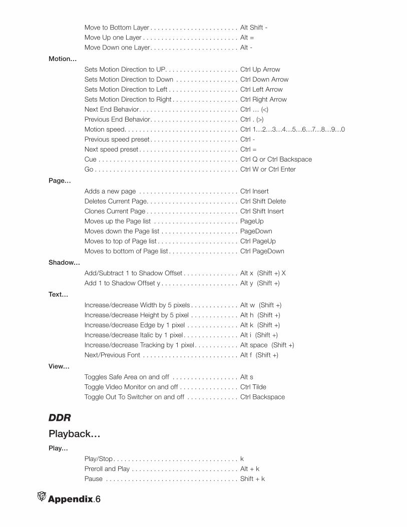
Appendix.6
Move to Bottom Layer . . . . . . . . . . . . . . . . . . . . . . . . Alt Shift -
Move Up one Layer . . . . . . . . . . . . . . . . . . . . . . . . . . Alt =
Move Down one Layer. . . . . . . . . . . . . . . . . . . . . . . . Alt -
Motion…
Sets Motion Direction to UP. . . . . . . . . . . . . . . . . . . . Ctrl Up Arrow
Sets Motion Direction to Down . . . . . . . . . . . . . . . . . Ctrl Down Arrow
Sets Motion Direction to Left . . . . . . . . . . . . . . . . . . . Ctrl Left Arrow
Sets Motion Direction to Right . . . . . . . . . . . . . . . . . . Ctrl Right Arrow
Next End Behavior. . . . . . . . . . . . . . . . . . . . . . . . . . . Ctrl … (<)
Previous End Behavior. . . . . . . . . . . . . . . . . . . . . . . . Ctrl . (>)
Motion speed. . . . . . . . . . . . . . . . . . . . . . . . . . . . . . . Ctrl 1…2…3…4…5…6…7…8…9…0
Previous speed preset . . . . . . . . . . . . . . . . . . . . . . . . Ctrl -
Next speed preset . . . . . . . . . . . . . . . . . . . . . . . . . . . Ctrl =
Cue . . . . . . . . . . . . . . . . . . . . . . . . . . . . . . . . . . . . . . Ctrl Q or Ctrl Backspace
Go . . . . . . . . . . . . . . . . . . . . . . . . . . . . . . . . . . . . . . . Ctrl W or Ctrl Enter
Page…
Adds a new page . . . . . . . . . . . . . . . . . . . . . . . . . . . Ctrl Insert
Deletes Current Page. . . . . . . . . . . . . . . . . . . . . . . . . Ctrl Shift Delete
Clones Current Page . . . . . . . . . . . . . . . . . . . . . . . . . Ctrl Shift Insert
Moves up the Page list . . . . . . . . . . . . . . . . . . . . . . . PageUp
Moves down the Page list . . . . . . . . . . . . . . . . . . . . . PageDown
Moves to top of Page list . . . . . . . . . . . . . . . . . . . . . . Ctrl PageUp
Moves to bottom of Page list . . . . . . . . . . . . . . . . . . . Ctrl PageDown
Shadow…
Add/Subtract 1 to Shadow Offset . . . . . . . . . . . . . . . Alt x (Shift +) X
Add 1 to Shadow Offset y . . . . . . . . . . . . . . . . . . . . . Alt y (Shift +)
Text…
Increase/decrease Width by 5 pixels . . . . . . . . . . . . . Alt w (Shift +)
Increase/decrease Height by 5 pixel . . . . . . . . . . . . . Alt h (Shift +)
Increase/decrease Edge by 1 pixel . . . . . . . . . . . . . . Alt k (Shift +)
Increase/decrease Italic by 1 pixel . . . . . . . . . . . . . . . Alt i (Shift +)
Increase/decrease Tracking by 1 pixel . . . . . . . . . . . . Alt space (Shift +)
Next/Previous Font . . . . . . . . . . . . . . . . . . . . . . . . . . Alt f (Shift +)
View…
Toggles Safe Area on and off . . . . . . . . . . . . . . . . . . Alt s
Toggle Video Monitor on and off . . . . . . . . . . . . . . . . Ctrl Tilde
Toggle Out To Switcher on and off . . . . . . . . . . . . . . Ctrl Backspace
DDr
Playback… Play…
Play/Stop. . . . . . . . . . . . . . . . . . . . . . . . . . . . . . . . . . k
Preroll and Play . . . . . . . . . . . . . . . . . . . . . . . . . . . . . Alt + k
Pause . . . . . . . . . . . . . . . . . . . . . . . . . . . . . . . . . . . . Shift + k
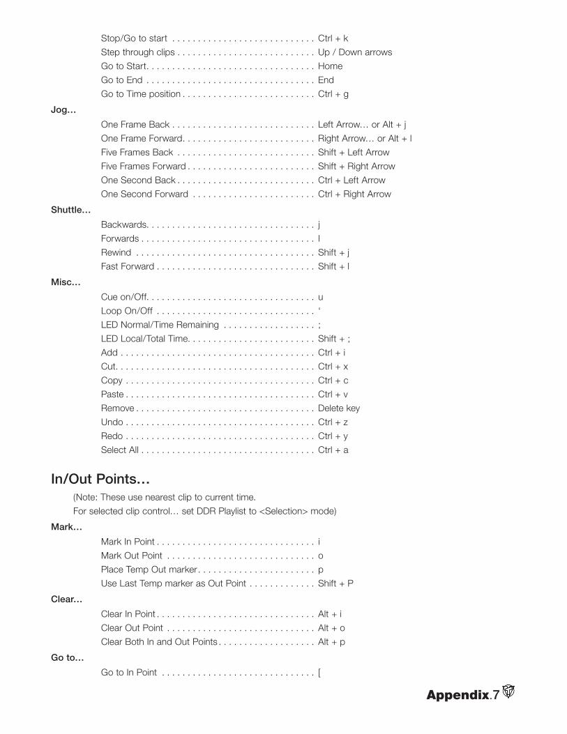
Appendix.7
Stop/Go to start . . . . . . . . . . . . . . . . . . . . . . . . . . . . Ctrl + k
Step through clips . . . . . . . . . . . . . . . . . . . . . . . . . . . Up / Down arrows
Go to Start. . . . . . . . . . . . . . . . . . . . . . . . . . . . . . . . . Home
Go to End . . . . . . . . . . . . . . . . . . . . . . . . . . . . . . . . . End
Go to Time position . . . . . . . . . . . . . . . . . . . . . . . . . . Ctrl + g
Jog…
One Frame Back . . . . . . . . . . . . . . . . . . . . . . . . . . . . Left Arrow… or Alt + j
One Frame Forward. . . . . . . . . . . . . . . . . . . . . . . . . . Right Arrow… or Alt + l
Five Frames Back . . . . . . . . . . . . . . . . . . . . . . . . . . . Shift + Left Arrow
Five Frames Forward . . . . . . . . . . . . . . . . . . . . . . . . . Shift + Right Arrow
One Second Back . . . . . . . . . . . . . . . . . . . . . . . . . . . Ctrl + Left Arrow
One Second Forward . . . . . . . . . . . . . . . . . . . . . . . . Ctrl + Right Arrow
Shuttle…
Backwards. . . . . . . . . . . . . . . . . . . . . . . . . . . . . . . . . j
Forwards . . . . . . . . . . . . . . . . . . . . . . . . . . . . . . . . . . l
Rewind . . . . . . . . . . . . . . . . . . . . . . . . . . . . . . . . . . . Shift + j
Fast Forward . . . . . . . . . . . . . . . . . . . . . . . . . . . . . . . Shift + l
Misc…
Cue on/Off. . . . . . . . . . . . . . . . . . . . . . . . . . . . . . . . . u
Loop On/Off . . . . . . . . . . . . . . . . . . . . . . . . . . . . . . . ‘
LED Normal/Time Remaining . . . . . . . . . . . . . . . . . . ;
LED Local/Total Time. . . . . . . . . . . . . . . . . . . . . . . . . Shift + ;
Add . . . . . . . . . . . . . . . . . . . . . . . . . . . . . . . . . . . . . . Ctrl + i
Cut. . . . . . . . . . . . . . . . . . . . . . . . . . . . . . . . . . . . . . . Ctrl + x
Copy . . . . . . . . . . . . . . . . . . . . . . . . . . . . . . . . . . . . . Ctrl + c
Paste . . . . . . . . . . . . . . . . . . . . . . . . . . . . . . . . . . . . . Ctrl + v
Remove . . . . . . . . . . . . . . . . . . . . . . . . . . . . . . . . . . . Delete key
Undo . . . . . . . . . . . . . . . . . . . . . . . . . . . . . . . . . . . . . Ctrl + z
Redo . . . . . . . . . . . . . . . . . . . . . . . . . . . . . . . . . . . . . Ctrl + y
Select All . . . . . . . . . . . . . . . . . . . . . . . . . . . . . . . . . . Ctrl + a
In/Out Points… (Note: These use nearest clip to current time.
For selected clip control… set DDR Playlist to <Selection> mode)
Mark…
Mark In Point . . . . . . . . . . . . . . . . . . . . . . . . . . . . . . . i
Mark Out Point . . . . . . . . . . . . . . . . . . . . . . . . . . . . . o
Place Temp Out marker. . . . . . . . . . . . . . . . . . . . . . . p
Use Last Temp marker as Out Point . . . . . . . . . . . . . Shift + P
Clear…
Clear In Point . . . . . . . . . . . . . . . . . . . . . . . . . . . . . . . Alt + i
Clear Out Point . . . . . . . . . . . . . . . . . . . . . . . . . . . . . Alt + o
Clear Both In and Out Points . . . . . . . . . . . . . . . . . . . Alt + p
Go to…
Go to In Point . . . . . . . . . . . . . . . . . . . . . . . . . . . . . . [
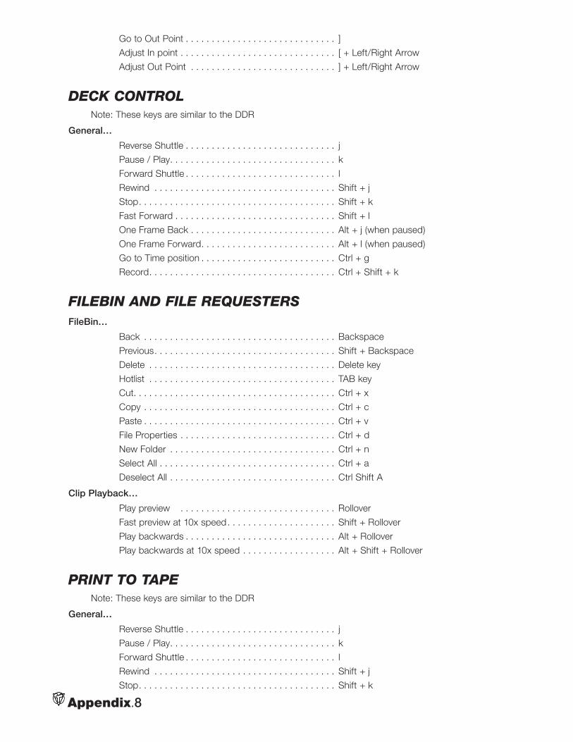
Appendix.8
Go to Out Point . . . . . . . . . . . . . . . . . . . . . . . . . . . . . ]
Adjust In point . . . . . . . . . . . . . . . . . . . . . . . . . . . . . . [ + Left/Right Arrow
Adjust Out Point . . . . . . . . . . . . . . . . . . . . . . . . . . . . ] + Left/Right Arrow
Deck controlNote: These keys are similar to the DDR
General…
Reverse Shuttle . . . . . . . . . . . . . . . . . . . . . . . . . . . . . j
Pause / Play. . . . . . . . . . . . . . . . . . . . . . . . . . . . . . . . k
Forward Shuttle . . . . . . . . . . . . . . . . . . . . . . . . . . . . . l
Rewind . . . . . . . . . . . . . . . . . . . . . . . . . . . . . . . . . . . Shift + j
Stop. . . . . . . . . . . . . . . . . . . . . . . . . . . . . . . . . . . . . . Shift + k
Fast Forward . . . . . . . . . . . . . . . . . . . . . . . . . . . . . . . Shift + l
One Frame Back . . . . . . . . . . . . . . . . . . . . . . . . . . . . Alt + j (when paused)
One Frame Forward. . . . . . . . . . . . . . . . . . . . . . . . . . Alt + l (when paused)
Go to Time position . . . . . . . . . . . . . . . . . . . . . . . . . . Ctrl + g
Record. . . . . . . . . . . . . . . . . . . . . . . . . . . . . . . . . . . . Ctrl + Shift + k
FileBin anD File requestersFileBin…
Back . . . . . . . . . . . . . . . . . . . . . . . . . . . . . . . . . . . . . Backspace
Previous. . . . . . . . . . . . . . . . . . . . . . . . . . . . . . . . . . . Shift + Backspace
Delete . . . . . . . . . . . . . . . . . . . . . . . . . . . . . . . . . . . . Delete key
Hotlist . . . . . . . . . . . . . . . . . . . . . . . . . . . . . . . . . . . . TAB key
Cut. . . . . . . . . . . . . . . . . . . . . . . . . . . . . . . . . . . . . . . Ctrl + x
Copy . . . . . . . . . . . . . . . . . . . . . . . . . . . . . . . . . . . . . Ctrl + c
Paste . . . . . . . . . . . . . . . . . . . . . . . . . . . . . . . . . . . . . Ctrl + v
File Properties . . . . . . . . . . . . . . . . . . . . . . . . . . . . . . Ctrl + d
New Folder . . . . . . . . . . . . . . . . . . . . . . . . . . . . . . . . Ctrl + n
Select All . . . . . . . . . . . . . . . . . . . . . . . . . . . . . . . . . . Ctrl + a
Deselect All . . . . . . . . . . . . . . . . . . . . . . . . . . . . . . . . Ctrl Shift A
Clip Playback…
Play preview . . . . . . . . . . . . . . . . . . . . . . . . . . . . . . Rollover
Fast preview at 10x speed. . . . . . . . . . . . . . . . . . . . . Shift + Rollover
Play backwards . . . . . . . . . . . . . . . . . . . . . . . . . . . . . Alt + Rollover
Play backwards at 10x speed . . . . . . . . . . . . . . . . . . Alt + Shift + Rollover
print to tapeNote: These keys are similar to the DDR
General…
Reverse Shuttle . . . . . . . . . . . . . . . . . . . . . . . . . . . . . j
Pause / Play. . . . . . . . . . . . . . . . . . . . . . . . . . . . . . . . k
Forward Shuttle . . . . . . . . . . . . . . . . . . . . . . . . . . . . . l
Rewind . . . . . . . . . . . . . . . . . . . . . . . . . . . . . . . . . . . Shift + j
Stop. . . . . . . . . . . . . . . . . . . . . . . . . . . . . . . . . . . . . . Shift + k
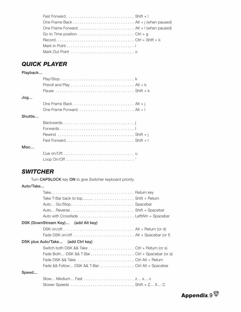
Appendix.9
Fast Forward . . . . . . . . . . . . . . . . . . . . . . . . . . . . . . . Shift + l
One Frame Back . . . . . . . . . . . . . . . . . . . . . . . . . . . . Alt + j (when paused)
One Frame Forward. . . . . . . . . . . . . . . . . . . . . . . . . . Alt + l (when paused)
Go to Time position . . . . . . . . . . . . . . . . . . . . . . . . . . Ctrl + g
Record. . . . . . . . . . . . . . . . . . . . . . . . . . . . . . . . . . . . Ctrl + Shift + k
Mark In Point . . . . . . . . . . . . . . . . . . . . . . . . . . . . . . . i
Mark Out Point . . . . . . . . . . . . . . . . . . . . . . . . . . . . . o
quick playerPlayback…
Play/Stop. . . . . . . . . . . . . . . . . . . . . . . . . . . . . . . . . . k
Preroll and Play . . . . . . . . . . . . . . . . . . . . . . . . . . . . . Alt + k
Pause . . . . . . . . . . . . . . . . . . . . . . . . . . . . . . . . . . . . Shift + k
Jog…
One Frame Back . . . . . . . . . . . . . . . . . . . . . . . . . . . . Alt + j
One Frame Forward. . . . . . . . . . . . . . . . . . . . . . . . . . Alt + l
Shuttle…
Backwards. . . . . . . . . . . . . . . . . . . . . . . . . . . . . . . . . j
Forwards . . . . . . . . . . . . . . . . . . . . . . . . . . . . . . . . . . l
Rewind . . . . . . . . . . . . . . . . . . . . . . . . . . . . . . . . . . . Shift + j
Fast Forward . . . . . . . . . . . . . . . . . . . . . . . . . . . . . . . Shift + l
Misc…
Cue on/Off. . . . . . . . . . . . . . . . . . . . . . . . . . . . . . . . . u
Loop On/Off . . . . . . . . . . . . . . . . . . . . . . . . . . . . . . . ‘
switcherTurn CAPSLOCK key ON to give Switcher keyboard priority
Auto/Take…
Take. . . . . . . . . . . . . . . . . . . . . . . . . . . . . . . . . . . . . . Return key
Take T-Bar back to top……… . . . . . . . . . . . . . . . . . . Shift + Return
Auto… Go/Stop. . . . . . . . . . . . . . . . . . . . . . . . . . . . . Spacebar
Auto… Reverse . . . . . . . . . . . . . . . . . . . . . . . . . . . . . Shift + Spacebar
Auto with Crossfade . . . . . . . . . . . . . . . . . . . . . . . . . LeftWin + Spacebar
DSK (DownStream Key)… (add Alt key)
DSK on/off. . . . . . . . . . . . . . . . . . . . . . . . . . . . . . . . . Alt + Return (or d)
Fade DSK on/off . . . . . . . . . . . . . . . . . . . . . . . . . . . . Alt + Spacebar (or f)
DSK plus Auto/Take… (add Ctrl key)
Switch both DSK && Take . . . . . . . . . . . . . . . . . . . . . Ctrl + Return (or s)
Fade Both… DSK && T-Bar . . . . . . . . . . . . . . . . . . . . Ctrl + Spacebar (or a)
Fade DSK && Take . . . . . . . . . . . . . . . . . . . . . . . . . . Ctrl Alt + Return
Fade && Follow… DSK && T-Bar . . . . . . . . . . . . . . . . Ctrl Alt + Spacebar
Speed…
Slow… Medium… Fast . . . . . . . . . . . . . . . . . . . . . . . z… x… c
Slower Speeds . . . . . . . . . . . . . . . . . . . . . . . . . . . . . Shift + Z… X… C
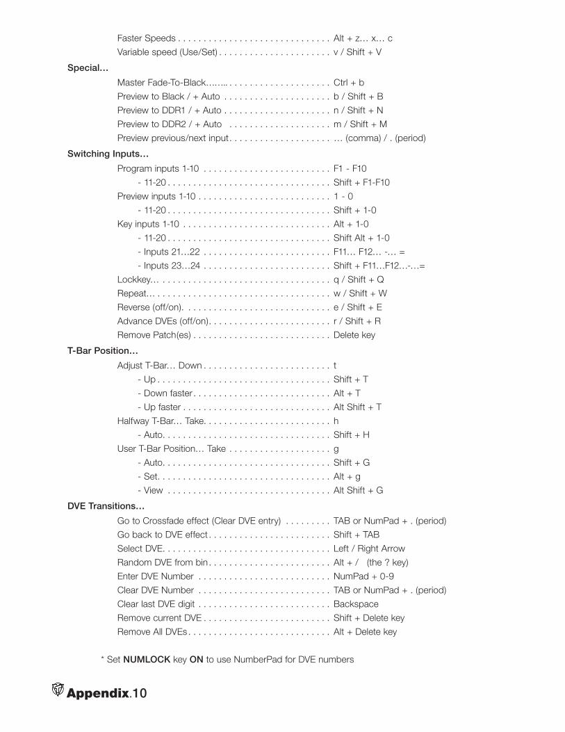
Appendix.10
Faster Speeds . . . . . . . . . . . . . . . . . . . . . . . . . . . . . . Alt + z… x… c
Variable speed (Use/Set) . . . . . . . . . . . . . . . . . . . . . . v / Shift + V
Special…
Master Fade-To-Black…….. . . . . . . . . . . . . . . . . . . . . Ctrl + b
Preview to Black / + Auto . . . . . . . . . . . . . . . . . . . . . b / Shift + B
Preview to DDR1 / + Auto . . . . . . . . . . . . . . . . . . . . . n / Shift + N
Preview to DDR2 / + Auto . . . . . . . . . . . . . . . . . . . . m / Shift + M
Preview previous/next input. . . . . . . . . . . . . . . . . . . . … (comma) / . (period)
Switching Inputs…
Program inputs 1-10 . . . . . . . . . . . . . . . . . . . . . . . . . F1 - F10
- 11-20 . . . . . . . . . . . . . . . . . . . . . . . . . . . . . . . . Shift + F1-F10
Preview inputs 1-10 . . . . . . . . . . . . . . . . . . . . . . . . . . 1 - 0
- 11-20 . . . . . . . . . . . . . . . . . . . . . . . . . . . . . . . . Shift + 1-0
Key inputs 1-10 . . . . . . . . . . . . . . . . . . . . . . . . . . . . . Alt + 1-0
- 11-20 . . . . . . . . . . . . . . . . . . . . . . . . . . . . . . . . Shift Alt + 1-0
- Inputs 21…22 . . . . . . . . . . . . . . . . . . . . . . . . . F11… F12… -… =
- Inputs 23…24 . . . . . . . . . . . . . . . . . . . . . . . . . Shift + F11…F12…-…=
Lockkey… . . . . . . . . . . . . . . . . . . . . . . . . . . . . . . . . . q / Shift + Q
Repeat… . . . . . . . . . . . . . . . . . . . . . . . . . . . . . . . . . . w / Shift + W
Reverse (off/on). . . . . . . . . . . . . . . . . . . . . . . . . . . . . e / Shift + E
Advance DVEs (off/on). . . . . . . . . . . . . . . . . . . . . . . . r / Shift + R
Remove Patch(es) . . . . . . . . . . . . . . . . . . . . . . . . . . . Delete key
T-Bar Position…
Adjust T-Bar… Down . . . . . . . . . . . . . . . . . . . . . . . . . t
- Up . . . . . . . . . . . . . . . . . . . . . . . . . . . . . . . . . . Shift + T
- Down faster . . . . . . . . . . . . . . . . . . . . . . . . . . . Alt + T
- Up faster . . . . . . . . . . . . . . . . . . . . . . . . . . . . . Alt Shift + T
Halfway T-Bar… Take. . . . . . . . . . . . . . . . . . . . . . . . . h
- Auto. . . . . . . . . . . . . . . . . . . . . . . . . . . . . . . . . Shift + H
User T-Bar Position… Take . . . . . . . . . . . . . . . . . . . . g
- Auto. . . . . . . . . . . . . . . . . . . . . . . . . . . . . . . . . Shift + G
- Set. . . . . . . . . . . . . . . . . . . . . . . . . . . . . . . . . . Alt + g
- View . . . . . . . . . . . . . . . . . . . . . . . . . . . . . . . . Alt Shift + G
DVE Transitions…
Go to Crossfade effect (Clear DVE entry) . . . . . . . . . TAB or NumPad + . (period)
Go back to DVE effect . . . . . . . . . . . . . . . . . . . . . . . . Shift + TAB
Select DVE. . . . . . . . . . . . . . . . . . . . . . . . . . . . . . . . . Left / Right Arrow
Random DVE from bin. . . . . . . . . . . . . . . . . . . . . . . . Alt + / (the ? key)
Enter DVE Number . . . . . . . . . . . . . . . . . . . . . . . . . . NumPad + 0-9
Clear DVE Number . . . . . . . . . . . . . . . . . . . . . . . . . . TAB or NumPad + . (period)
Clear last DVE digit . . . . . . . . . . . . . . . . . . . . . . . . . . Backspace
Remove current DVE . . . . . . . . . . . . . . . . . . . . . . . . . Shift + Delete key
Remove All DVEs . . . . . . . . . . . . . . . . . . . . . . . . . . . . Alt + Delete key
* Set NUMLOCK key ON to use NumberPad for DVE numbers
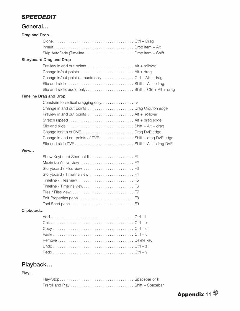
Appendix.11
speeDeDit
General…Drag and Drop…
Clone . . . . . . . . . . . . . . . . . . . . . . . . . . . . . . . . . . . . . Ctrl + Drag
Inherit. . . . . . . . . . . . . . . . . . . . . . . . . . . . . . . . . . . . . Drop item + Alt
Skip AutoFade (Timeline . . . . . . . . . . . . . . . . . . . . . . Drop item + Shift
Storyboard Drag and Drop
Preview in and out points . . . . . . . . . . . . . . . . . . . . . Alt + rollover
Change in/out points . . . . . . . . . . . . . . . . . . . . . . . . . Alt + drag
Change in/out points… audio only . . . . . . . . . . . . . . Ctrl + Alt + drag
Slip and slide . . . . . . . . . . . . . . . . . . . . . . . . . . . . . . . Shift + Alt + drag:
Slip and slide; audio only . . . . . . . . . . . . . . . . . . . . . . Shift + Ctrl + Alt + drag
Timeline Drag and Drop
Constrain to vertical dragging only. . . . . . . . . . . . . . . v
Change in and out points . . . . . . . . . . . . . . . . . . . . . Drag Crouton edge
Preview in and out points . . . . . . . . . . . . . . . . . . . . . Alt + rollover
Stretch (speed . . . . . . . . . . . . . . . . . . . . . . . . . . . . . . Alt + drag edge
Slip and slide . . . . . . . . . . . . . . . . . . . . . . . . . . . . . . . Shift + Alt + drag
Change length of DVE . . . . . . . . . . . . . . . . . . . . . . . . Drag DVE edge
Change in and out points of DVE. . . . . . . . . . . . . . . . Shift + drag DVE edge
Slip and slide DVE . . . . . . . . . . . . . . . . . . . . . . . . . . . Shift + Alt + drag DVE
View…
Show Keyboard Shortcut list . . . . . . . . . . . . . . . . . . . F1
Maximize Active view. . . . . . . . . . . . . . . . . . . . . . . . . F2
Storyboard / Files view . . . . . . . . . . . . . . . . . . . . . . . F3
Storyboard / Timeline view . . . . . . . . . . . . . . . . . . . . F4
Timeline / Files view. . . . . . . . . . . . . . . . . . . . . . . . . . F5
Timeline / Timeline view . . . . . . . . . . . . . . . . . . . . . . . F6
Files / Files view. . . . . . . . . . . . . . . . . . . . . . . . . . . . . F7
Edit Properties panel . . . . . . . . . . . . . . . . . . . . . . . . . F8
Tool Shed panel. . . . . . . . . . . . . . . . . . . . . . . . . . . . . F9
Clipboard…
Add . . . . . . . . . . . . . . . . . . . . . . . . . . . . . . . . . . . . . . Ctrl + i
Cut. . . . . . . . . . . . . . . . . . . . . . . . . . . . . . . . . . . . . . . Ctrl + x
Copy . . . . . . . . . . . . . . . . . . . . . . . . . . . . . . . . . . . . . Ctrl + c
Paste . . . . . . . . . . . . . . . . . . . . . . . . . . . . . . . . . . . . . Ctrl + v
Remove . . . . . . . . . . . . . . . . . . . . . . . . . . . . . . . . . . . Delete key
Undo . . . . . . . . . . . . . . . . . . . . . . . . . . . . . . . . . . . . . Ctrl + z
Redo . . . . . . . . . . . . . . . . . . . . . . . . . . . . . . . . . . . . . Ctrl + y
Playback…Play…
Play/Stop. . . . . . . . . . . . . . . . . . . . . . . . . . . . . . . . . . Spacebar or k
Preroll and Play . . . . . . . . . . . . . . . . . . . . . . . . . . . . . Shift + Spacebar
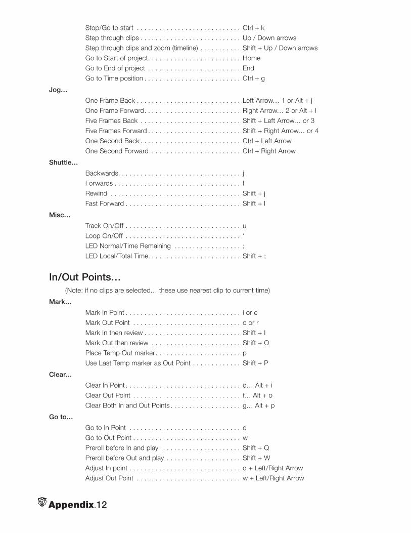
Appendix.12
Stop/Go to start . . . . . . . . . . . . . . . . . . . . . . . . . . . . Ctrl + k
Step through clips . . . . . . . . . . . . . . . . . . . . . . . . . . . Up / Down arrows
Step through clips and zoom (timeline) . . . . . . . . . . . Shift + Up / Down arrows
Go to Start of project. . . . . . . . . . . . . . . . . . . . . . . . . Home
Go to End of project . . . . . . . . . . . . . . . . . . . . . . . . . End
Go to Time position . . . . . . . . . . . . . . . . . . . . . . . . . . Ctrl + g
Jog…
One Frame Back . . . . . . . . . . . . . . . . . . . . . . . . . . . . Left Arrow… 1 or Alt + j
One Frame Forward. . . . . . . . . . . . . . . . . . . . . . . . . . Right Arrow… 2 or Alt + l
Five Frames Back . . . . . . . . . . . . . . . . . . . . . . . . . . . Shift + Left Arrow… or 3
Five Frames Forward . . . . . . . . . . . . . . . . . . . . . . . . . Shift + Right Arrow… or 4
One Second Back . . . . . . . . . . . . . . . . . . . . . . . . . . . Ctrl + Left Arrow
One Second Forward . . . . . . . . . . . . . . . . . . . . . . . . Ctrl + Right Arrow
Shuttle…
Backwards. . . . . . . . . . . . . . . . . . . . . . . . . . . . . . . . . j
Forwards . . . . . . . . . . . . . . . . . . . . . . . . . . . . . . . . . . l
Rewind . . . . . . . . . . . . . . . . . . . . . . . . . . . . . . . . . . . Shift + j
Fast Forward . . . . . . . . . . . . . . . . . . . . . . . . . . . . . . . Shift + l
Misc…
Track On/Off . . . . . . . . . . . . . . . . . . . . . . . . . . . . . . . u
Loop On/Off . . . . . . . . . . . . . . . . . . . . . . . . . . . . . . . ‘
LED Normal/Time Remaining . . . . . . . . . . . . . . . . . . ;
LED Local/Total Time. . . . . . . . . . . . . . . . . . . . . . . . . Shift + ;
In/Out Points…(Note: if no clips are selected… these use nearest clip to current time)
Mark…
Mark In Point . . . . . . . . . . . . . . . . . . . . . . . . . . . . . . . i or e
Mark Out Point . . . . . . . . . . . . . . . . . . . . . . . . . . . . . o or r
Mark In then review . . . . . . . . . . . . . . . . . . . . . . . . . . Shift + I
Mark Out then review . . . . . . . . . . . . . . . . . . . . . . . . Shift + O
Place Temp Out marker. . . . . . . . . . . . . . . . . . . . . . . p
Use Last Temp marker as Out Point . . . . . . . . . . . . . Shift + P
Clear…
Clear In Point . . . . . . . . . . . . . . . . . . . . . . . . . . . . . . . d… Alt + i
Clear Out Point . . . . . . . . . . . . . . . . . . . . . . . . . . . . . f… Alt + o
Clear Both In and Out Points . . . . . . . . . . . . . . . . . . . g… Alt + p
Go to…
Go to In Point . . . . . . . . . . . . . . . . . . . . . . . . . . . . . . q
Go to Out Point . . . . . . . . . . . . . . . . . . . . . . . . . . . . . w
Preroll before In and play . . . . . . . . . . . . . . . . . . . . . Shift + Q
Preroll before Out and play . . . . . . . . . . . . . . . . . . . . Shift + W
Adjust In point . . . . . . . . . . . . . . . . . . . . . . . . . . . . . . q + Left/Right Arrow
Adjust Out Point . . . . . . . . . . . . . . . . . . . . . . . . . . . . w + Left/Right Arrow
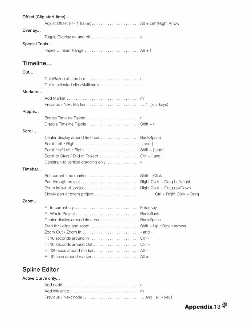
Appendix.13
Offset (Clip start time)…
Adjust Offset (-/+ 1 frame) . . . . . . . . . . . . . . . . . . . . . Alt + Left/Right Arrow
Overlay…
Toggle Overlay on and off . . . . . . . . . . . . . . . . . . . . . y
Special Tools…
Fades… Insert Range . . . . . . . . . . . . . . . . . . . . . . . . Alt + f
Timeline…Cut…
Cut (Razor) at time bar . . . . . . . . . . . . . . . . . . . . . . . c
Cut to selected clip (Multicam). . . . . . . . . . . . . . . . . . z
Markers…
Add Marker . . . . . . . . . . . . . . . . . . . . . . . . . . . . . . . . m
Previous / Next Marker . . . . . . . . . . . . . . . . . . . . . . . … / . (< > keys)
Ripple…
Enable Timeline Ripple. . . . . . . . . . . . . . . . . . . . . . . . t
Disable Timeline Ripple . . . . . . . . . . . . . . . . . . . . . . . Shift + t
Scroll…
Center display around time bar . . . . . . . . . . . . . . . . . BackSpace
Scroll Left / Right. . . . . . . . . . . . . . . . . . . . . . . . . . . . [ and ]
Scroll Half Left / Right . . . . . . . . . . . . . . . . . . . . . . . . Shift + [ and ]
Scroll to Start / End of Project . . . . . . . . . . . . . . . . . . Ctrl + [ and ]
Constrain to vertical dragging only. . . . . . . . . . . . . . . v
Timebar…
Set current time marker . . . . . . . . . . . . . . . . . . . . . . . Shift + Click
Pan through project . . . . . . . . . . . . . . . . . . . . . . . . . . Right Click + Drag Left/right
Zoom in/out of project . . . . . . . . . . . . . . . . . . . . . . . Right Click + Drag up/Down
Slowly pan or zoom project . . . . . . . . . . . . . . . . . . . . Ctrl + Right Click + Drag
Zoom…
Fit to current clip . . . . . . . . . . . . . . . . . . . . . . . . . . . . Enter key
Fit Whole Project . . . . . . . . . . . . . . . . . . . . . . . . . . . . BackSlash
Center display around time bar . . . . . . . . . . . . . . . . . BackSpace
Step thru clips and zoom. . . . . . . . . . . . . . . . . . . . . . Shift + Up / Down arrows
Zoom Out / Zoom In . . . . . . . . . . . . . . . . . . . . . . . . . - and =
Fit 10 seconds around In . . . . . . . . . . . . . . . . . . . . . Ctrl -
Fit 10 seconds around Out . . . . . . . . . . . . . . . . . . . . Ctrl =
Fit 120 secs around marker . . . . . . . . . . . . . . . . . . . . Alt -
Fit 10 secs around marker . . . . . . . . . . . . . . . . . . . . . Alt =
Spline EditorActive Curve only…
Add node. . . . . . . . . . . . . . . . . . . . . . . . . . . . . . . . . . n
Add influence. . . . . . . . . . . . . . . . . . . . . . . . . . . . . . . m
Previous / Next node . . . . . . . . . . . . . . . . . . . . . . . . . … and . (< > keys)
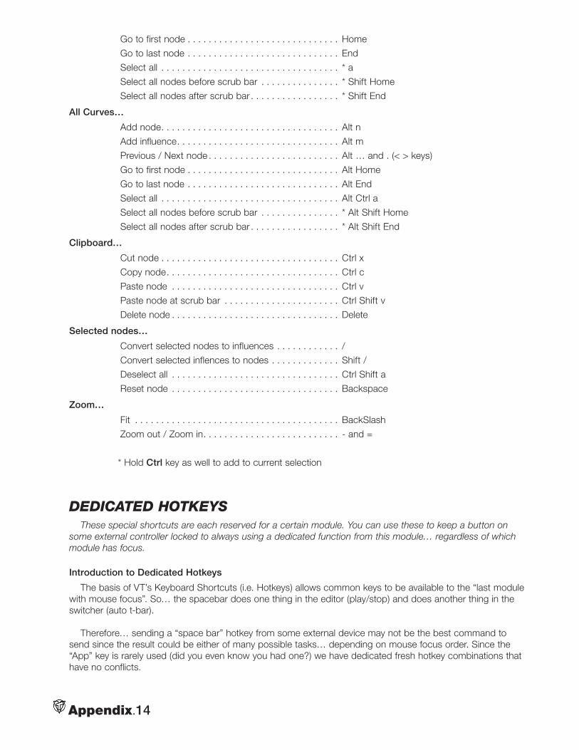
Appendix.14
Go to first node . . . . . . . . . . . . . . . . . . . . . . . . . . . . . Home
Go to last node . . . . . . . . . . . . . . . . . . . . . . . . . . . . . End
Select all . . . . . . . . . . . . . . . . . . . . . . . . . . . . . . . . . . * a
Select all nodes before scrub bar . . . . . . . . . . . . . . . * Shift Home
Select all nodes after scrub bar . . . . . . . . . . . . . . . . . * Shift End
All Curves…
Add node. . . . . . . . . . . . . . . . . . . . . . . . . . . . . . . . . . Alt n
Add influence. . . . . . . . . . . . . . . . . . . . . . . . . . . . . . . Alt m
Previous / Next node . . . . . . . . . . . . . . . . . . . . . . . . . Alt … and . (< > keys)
Go to first node . . . . . . . . . . . . . . . . . . . . . . . . . . . . . Alt Home
Go to last node . . . . . . . . . . . . . . . . . . . . . . . . . . . . . Alt End
Select all . . . . . . . . . . . . . . . . . . . . . . . . . . . . . . . . . . Alt Ctrl a
Select all nodes before scrub bar . . . . . . . . . . . . . . . * Alt Shift Home
Select all nodes after scrub bar . . . . . . . . . . . . . . . . . * Alt Shift End
Clipboard…
Cut node . . . . . . . . . . . . . . . . . . . . . . . . . . . . . . . . . . Ctrl x
Copy node. . . . . . . . . . . . . . . . . . . . . . . . . . . . . . . . . Ctrl c
Paste node . . . . . . . . . . . . . . . . . . . . . . . . . . . . . . . . Ctrl v
Paste node at scrub bar . . . . . . . . . . . . . . . . . . . . . . Ctrl Shift v
Delete node . . . . . . . . . . . . . . . . . . . . . . . . . . . . . . . . Delete
Selected nodes…
Convert selected nodes to influences . . . . . . . . . . . . /
Convert selected inflences to nodes . . . . . . . . . . . . . Shift /
Deselect all . . . . . . . . . . . . . . . . . . . . . . . . . . . . . . . . Ctrl Shift a
Reset node . . . . . . . . . . . . . . . . . . . . . . . . . . . . . . . . Backspace
Zoom…
Fit . . . . . . . . . . . . . . . . . . . . . . . . . . . . . . . . . . . . . . . BackSlash
Zoom out / Zoom in. . . . . . . . . . . . . . . . . . . . . . . . . . - and =
* Hold Ctrl key as well to add to current selection
DeDicateD hotkeysThese special shortcuts are each reserved for a certain module. You can use these to keep a button on
some external controller locked to always using a dedicated function from this module… regardless of which module has focus.
Introduction to Dedicated Hotkeys
The basis of VT’s Keyboard Shortcuts (i.e. Hotkeys) allows common keys to be available to the “last module with mouse focus”. So… the spacebar does one thing in the editor (play/stop) and does another thing in the switcher (auto t-bar).
Therefore… sending a “space bar” hotkey from some external device may not be the best command to send since the result could be either of many possible tasks… depending on mouse focus order. Since the “App” key is rarely used (did you even know you had one?) we have dedicated fresh hotkey combinations that have no conflicts.
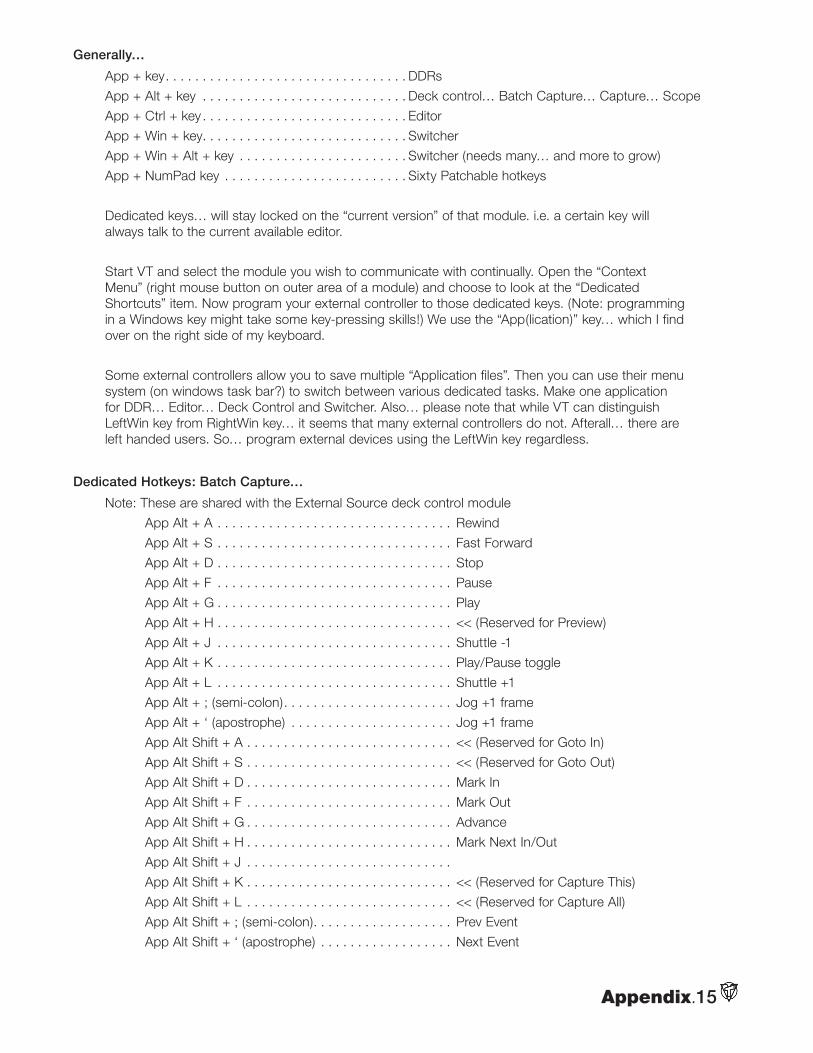
Appendix.15
Generally…
App + key. . . . . . . . . . . . . . . . . . . . . . . . . . . . . . . . . DDRs
App + Alt + key . . . . . . . . . . . . . . . . . . . . . . . . . . . . Deck control… Batch Capture… Capture… Scope
App + Ctrl + key . . . . . . . . . . . . . . . . . . . . . . . . . . . . Editor
App + Win + key. . . . . . . . . . . . . . . . . . . . . . . . . . . . Switcher
App + Win + Alt + key . . . . . . . . . . . . . . . . . . . . . . . Switcher (needs many… and more to grow)
App + NumPad key . . . . . . . . . . . . . . . . . . . . . . . . . Sixty Patchable hotkeys
Dedicated keys… will stay locked on the “current version” of that module. i.e. a certain key will always talk to the current available editor.
Start VT and select the module you wish to communicate with continually. Open the “Context Menu” (right mouse button on outer area of a module) and choose to look at the “Dedicated Shortcuts” item. Now program your external controller to those dedicated keys. (Note: programming in a Windows key might take some key-pressing skills!) We use the “App(lication)” key… which I find over on the right side of my keyboard.
Some external controllers allow you to save multiple “Application files”. Then you can use their menu system (on windows task bar?) to switch between various dedicated tasks. Make one application for DDR… Editor… Deck Control and Switcher. Also… please note that while VT can distinguish LeftWin key from RightWin key… it seems that many external controllers do not. Afterall… there are left handed users. So… program external devices using the LeftWin key regardless.
Dedicated Hotkeys: Batch Capture…
Note: These are shared with the External Source deck control module
App Alt + A . . . . . . . . . . . . . . . . . . . . . . . . . . . . . . . . Rewind
App Alt + S . . . . . . . . . . . . . . . . . . . . . . . . . . . . . . . . Fast Forward
App Alt + D . . . . . . . . . . . . . . . . . . . . . . . . . . . . . . . . Stop
App Alt + F . . . . . . . . . . . . . . . . . . . . . . . . . . . . . . . . Pause
App Alt + G . . . . . . . . . . . . . . . . . . . . . . . . . . . . . . . . Play
App Alt + H . . . . . . . . . . . . . . . . . . . . . . . . . . . . . . . . << (Reserved for Preview)
App Alt + J . . . . . . . . . . . . . . . . . . . . . . . . . . . . . . . . Shuttle -1
App Alt + K . . . . . . . . . . . . . . . . . . . . . . . . . . . . . . . . Play/Pause toggle
App Alt + L . . . . . . . . . . . . . . . . . . . . . . . . . . . . . . . . Shuttle +1
App Alt + ; (semi-colon). . . . . . . . . . . . . . . . . . . . . . . Jog +1 frame
App Alt + ‘ (apostrophe) . . . . . . . . . . . . . . . . . . . . . . Jog +1 frame
App Alt Shift + A . . . . . . . . . . . . . . . . . . . . . . . . . . . . << (Reserved for Goto In)
App Alt Shift + S . . . . . . . . . . . . . . . . . . . . . . . . . . . . << (Reserved for Goto Out)
App Alt Shift + D . . . . . . . . . . . . . . . . . . . . . . . . . . . . Mark In
App Alt Shift + F . . . . . . . . . . . . . . . . . . . . . . . . . . . . Mark Out
App Alt Shift + G . . . . . . . . . . . . . . . . . . . . . . . . . . . . Advance
App Alt Shift + H . . . . . . . . . . . . . . . . . . . . . . . . . . . . Mark Next In/Out
App Alt Shift + J . . . . . . . . . . . . . . . . . . . . . . . . . . . .
App Alt Shift + K . . . . . . . . . . . . . . . . . . . . . . . . . . . . << (Reserved for Capture This)
App Alt Shift + L . . . . . . . . . . . . . . . . . . . . . . . . . . . . << (Reserved for Capture All)
App Alt Shift + ; (semi-colon). . . . . . . . . . . . . . . . . . . Prev Event
App Alt Shift + ‘ (apostrophe) . . . . . . . . . . . . . . . . . . Next Event
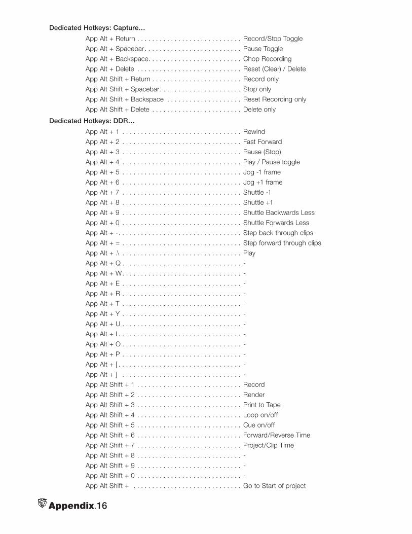
Appendix.16
Dedicated Hotkeys: Capture…
App Alt + Return . . . . . . . . . . . . . . . . . . . . . . . . . . . . Record/Stop Toggle
App Alt + Spacebar . . . . . . . . . . . . . . . . . . . . . . . . . . Pause Toggle
App Alt + Backspace. . . . . . . . . . . . . . . . . . . . . . . . . Chop Recording
App Alt + Delete . . . . . . . . . . . . . . . . . . . . . . . . . . . . Reset (Clear) / Delete
App Alt Shift + Return . . . . . . . . . . . . . . . . . . . . . . . . Record only
App Alt Shift + Spacebar. . . . . . . . . . . . . . . . . . . . . . Stop only
App Alt Shift + Backspace . . . . . . . . . . . . . . . . . . . . Reset Recording only
App Alt Shift + Delete . . . . . . . . . . . . . . . . . . . . . . . . Delete only
Dedicated Hotkeys: DDR…
App Alt + 1 . . . . . . . . . . . . . . . . . . . . . . . . . . . . . . . . Rewind
App Alt + 2 . . . . . . . . . . . . . . . . . . . . . . . . . . . . . . . . Fast Forward
App Alt + 3 . . . . . . . . . . . . . . . . . . . . . . . . . . . . . . . . Pause (Stop)
App Alt + 4 . . . . . . . . . . . . . . . . . . . . . . . . . . . . . . . . Play / Pause toggle
App Alt + 5 . . . . . . . . . . . . . . . . . . . . . . . . . . . . . . . . Jog -1 frame
App Alt + 6 . . . . . . . . . . . . . . . . . . . . . . . . . . . . . . . . Jog +1 frame
App Alt + 7 . . . . . . . . . . . . . . . . . . . . . . . . . . . . . . . . Shuttle -1
App Alt + 8 . . . . . . . . . . . . . . . . . . . . . . . . . . . . . . . . Shuttle +1
App Alt + 9 . . . . . . . . . . . . . . . . . . . . . . . . . . . . . . . . Shuttle Backwards Less
App Alt + 0 . . . . . . . . . . . . . . . . . . . . . . . . . . . . . . . . Shuttle Forwards Less
App Alt + -. . . . . . . . . . . . . . . . . . . . . . . . . . . . . . . . . Step back through clips
App Alt + = . . . . . . . . . . . . . . . . . . . . . . . . . . . . . . . . Step forward through clips
App Alt + .\ . . . . . . . . . . . . . . . . . . . . . . . . . . . . . . . . Play
App Alt + Q . . . . . . . . . . . . . . . . . . . . . . . . . . . . . . . . -
App Alt + W. . . . . . . . . . . . . . . . . . . . . . . . . . . . . . . . -
App Alt + E . . . . . . . . . . . . . . . . . . . . . . . . . . . . . . . . -
App Alt + R . . . . . . . . . . . . . . . . . . . . . . . . . . . . . . . . -
App Alt + T . . . . . . . . . . . . . . . . . . . . . . . . . . . . . . . . -
App Alt + Y . . . . . . . . . . . . . . . . . . . . . . . . . . . . . . . . -
App Alt + U . . . . . . . . . . . . . . . . . . . . . . . . . . . . . . . . -
App Alt + I . . . . . . . . . . . . . . . . . . . . . . . . . . . . . . . . . -
App Alt + O . . . . . . . . . . . . . . . . . . . . . . . . . . . . . . . . -
App Alt + P . . . . . . . . . . . . . . . . . . . . . . . . . . . . . . . . -
App Alt + [ . . . . . . . . . . . . . . . . . . . . . . . . . . . . . . . . . -
App Alt + ] . . . . . . . . . . . . . . . . . . . . . . . . . . . . . . . . -
App Alt Shift + 1 . . . . . . . . . . . . . . . . . . . . . . . . . . . . Record
App Alt Shift + 2 . . . . . . . . . . . . . . . . . . . . . . . . . . . . Render
App Alt Shift + 3 . . . . . . . . . . . . . . . . . . . . . . . . . . . . Print to Tape
App Alt Shift + 4 . . . . . . . . . . . . . . . . . . . . . . . . . . . . Loop on/off
App Alt Shift + 5 . . . . . . . . . . . . . . . . . . . . . . . . . . . . Cue on/off
App Alt Shift + 6 . . . . . . . . . . . . . . . . . . . . . . . . . . . . Forward/Reverse Time
App Alt Shift + 7 . . . . . . . . . . . . . . . . . . . . . . . . . . . . Project/Clip Time
App Alt Shift + 8 . . . . . . . . . . . . . . . . . . . . . . . . . . . . -
App Alt Shift + 9 . . . . . . . . . . . . . . . . . . . . . . . . . . . . -
App Alt Shift + 0 . . . . . . . . . . . . . . . . . . . . . . . . . . . . -
App Alt Shift + . . . . . . . . . . . . . . . . . . . . . . . . . . . . . Go to Start of project
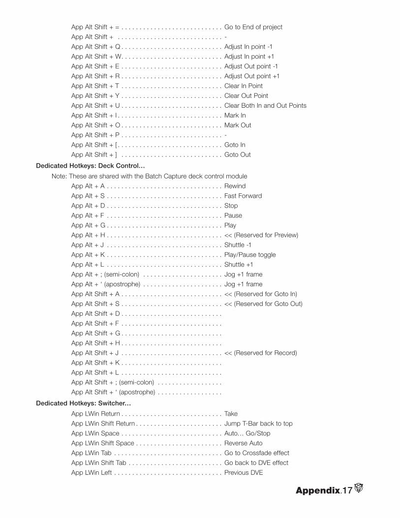
Appendix.17
App Alt Shift + = . . . . . . . . . . . . . . . . . . . . . . . . . . . . Go to End of project
App Alt Shift + . . . . . . . . . . . . . . . . . . . . . . . . . . . . . -
App Alt Shift + Q . . . . . . . . . . . . . . . . . . . . . . . . . . . . Adjust In point -1
App Alt Shift + W. . . . . . . . . . . . . . . . . . . . . . . . . . . . Adjust In point +1
App Alt Shift + E . . . . . . . . . . . . . . . . . . . . . . . . . . . . Adjust Out point -1
App Alt Shift + R . . . . . . . . . . . . . . . . . . . . . . . . . . . . Adjust Out point +1
App Alt Shift + T . . . . . . . . . . . . . . . . . . . . . . . . . . . . Clear In Point
App Alt Shift + Y . . . . . . . . . . . . . . . . . . . . . . . . . . . . Clear Out Point
App Alt Shift + U . . . . . . . . . . . . . . . . . . . . . . . . . . . . Clear Both In and Out Points
App Alt Shift + I . . . . . . . . . . . . . . . . . . . . . . . . . . . . . Mark In
App Alt Shift + O . . . . . . . . . . . . . . . . . . . . . . . . . . . . Mark Out
App Alt Shift + P . . . . . . . . . . . . . . . . . . . . . . . . . . . . -
App Alt Shift + [ . . . . . . . . . . . . . . . . . . . . . . . . . . . . . Goto In
App Alt Shift + ] . . . . . . . . . . . . . . . . . . . . . . . . . . . . Goto Out
Dedicated Hotkeys: Deck Control…
Note: These are shared with the Batch Capture deck control module
App Alt + A . . . . . . . . . . . . . . . . . . . . . . . . . . . . . . . . Rewind
App Alt + S . . . . . . . . . . . . . . . . . . . . . . . . . . . . . . . . Fast Forward
App Alt + D . . . . . . . . . . . . . . . . . . . . . . . . . . . . . . . . Stop
App Alt + F . . . . . . . . . . . . . . . . . . . . . . . . . . . . . . . . Pause
App Alt + G . . . . . . . . . . . . . . . . . . . . . . . . . . . . . . . . Play
App Alt + H . . . . . . . . . . . . . . . . . . . . . . . . . . . . . . . . << (Reserved for Preview)
App Alt + J . . . . . . . . . . . . . . . . . . . . . . . . . . . . . . . . Shuttle -1
App Alt + K . . . . . . . . . . . . . . . . . . . . . . . . . . . . . . . . Play/Pause toggle
App Alt + L . . . . . . . . . . . . . . . . . . . . . . . . . . . . . . . . Shuttle +1
App Alt + ; (semi-colon) . . . . . . . . . . . . . . . . . . . . . . Jog +1 frame
App Alt + ‘ (apostrophe) . . . . . . . . . . . . . . . . . . . . . . Jog +1 frame
App Alt Shift + A . . . . . . . . . . . . . . . . . . . . . . . . . . . . << (Reserved for Goto In)
App Alt Shift + S . . . . . . . . . . . . . . . . . . . . . . . . . . . . << (Reserved for Goto Out)
App Alt Shift + D . . . . . . . . . . . . . . . . . . . . . . . . . . . .
App Alt Shift + F . . . . . . . . . . . . . . . . . . . . . . . . . . . .
App Alt Shift + G . . . . . . . . . . . . . . . . . . . . . . . . . . . .
App Alt Shift + H . . . . . . . . . . . . . . . . . . . . . . . . . . . .
App Alt Shift + J . . . . . . . . . . . . . . . . . . . . . . . . . . . . << (Reserved for Record)
App Alt Shift + K . . . . . . . . . . . . . . . . . . . . . . . . . . . .
App Alt Shift + L . . . . . . . . . . . . . . . . . . . . . . . . . . . .
App Alt Shift + ; (semi-colon) . . . . . . . . . . . . . . . . . .
App Alt Shift + ‘ (apostrophe) . . . . . . . . . . . . . . . . . .
Dedicated Hotkeys: Switcher…
App LWin Return . . . . . . . . . . . . . . . . . . . . . . . . . . . . Take
App LWin Shift Return . . . . . . . . . . . . . . . . . . . . . . . . Jump T-Bar back to top
App LWin Space . . . . . . . . . . . . . . . . . . . . . . . . . . . . Auto… Go/Stop
App LWin Shift Space . . . . . . . . . . . . . . . . . . . . . . . . Reverse Auto
App LWin Tab . . . . . . . . . . . . . . . . . . . . . . . . . . . . . . Go to Crossfade effect
App LWin Shift Tab . . . . . . . . . . . . . . . . . . . . . . . . . . Go back to DVE effect
App LWin Left . . . . . . . . . . . . . . . . . . . . . . . . . . . . . . Previous DVE
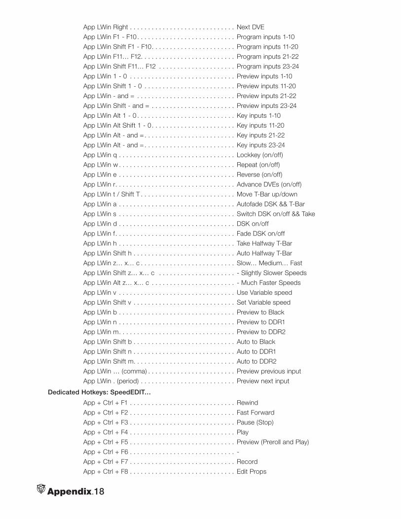
Appendix.18
App LWin Right . . . . . . . . . . . . . . . . . . . . . . . . . . . . . Next DVE
App LWin F1 - F10. . . . . . . . . . . . . . . . . . . . . . . . . . . Program inputs 1-10
App LWin Shift F1 - F10. . . . . . . . . . . . . . . . . . . . . . . Program inputs 11-20
App LWin F11… F12. . . . . . . . . . . . . . . . . . . . . . . . . . Program inputs 21-22
App LWin Shift F11… F12 . . . . . . . . . . . . . . . . . . . . . Program inputs 23-24
App LWin 1 - 0 . . . . . . . . . . . . . . . . . . . . . . . . . . . . . Preview inputs 1-10
App LWin Shift 1 - 0 . . . . . . . . . . . . . . . . . . . . . . . . . Preview inputs 11-20
App LWin - and = . . . . . . . . . . . . . . . . . . . . . . . . . . . Preview inputs 21-22
App LWin Shift - and = . . . . . . . . . . . . . . . . . . . . . . . Preview inputs 23-24
App LWin Alt 1 - 0 . . . . . . . . . . . . . . . . . . . . . . . . . . . Key inputs 1-10
App LWin Alt Shift 1 - 0. . . . . . . . . . . . . . . . . . . . . . . Key inputs 11-20
App LWin Alt - and = . . . . . . . . . . . . . . . . . . . . . . . . . Key inputs 21-22
App LWin Alt - and = . . . . . . . . . . . . . . . . . . . . . . . . . Key inputs 23-24
App LWin q . . . . . . . . . . . . . . . . . . . . . . . . . . . . . . . . Lockkey (on/off)
App LWin w . . . . . . . . . . . . . . . . . . . . . . . . . . . . . . . . Repeat (on/off)
App LWin e . . . . . . . . . . . . . . . . . . . . . . . . . . . . . . . . Reverse (on/off)
App LWin r. . . . . . . . . . . . . . . . . . . . . . . . . . . . . . . . . Advance DVEs (on/off)
App LWin t / Shift T . . . . . . . . . . . . . . . . . . . . . . . . . . Move T-Bar up/down
App LWin a . . . . . . . . . . . . . . . . . . . . . . . . . . . . . . . . Autofade DSK && T-Bar
App LWin s . . . . . . . . . . . . . . . . . . . . . . . . . . . . . . . . Switch DSK on/off && Take
App LWin d . . . . . . . . . . . . . . . . . . . . . . . . . . . . . . . . DSK on/off
App LWin f. . . . . . . . . . . . . . . . . . . . . . . . . . . . . . . . . Fade DSK on/off
App LWin h . . . . . . . . . . . . . . . . . . . . . . . . . . . . . . . . Take Halfway T-Bar
App LWin Shift h . . . . . . . . . . . . . . . . . . . . . . . . . . . . Auto Halfway T-Bar
App LWin z… x… c . . . . . . . . . . . . . . . . . . . . . . . . . . Slow… Medium… Fast
App LWin Shift z… x… c . . . . . . . . . . . . . . . . . . . . . - Slightly Slower Speeds
App LWin Alt z… x… c . . . . . . . . . . . . . . . . . . . . . . . - Much Faster Speeds
App LWin v . . . . . . . . . . . . . . . . . . . . . . . . . . . . . . . . Use Variable speed
App LWin Shift v . . . . . . . . . . . . . . . . . . . . . . . . . . . . Set Variable speed
App LWin b . . . . . . . . . . . . . . . . . . . . . . . . . . . . . . . . Preview to Black
App LWin n . . . . . . . . . . . . . . . . . . . . . . . . . . . . . . . . Preview to DDR1
App LWin m. . . . . . . . . . . . . . . . . . . . . . . . . . . . . . . . Preview to DDR2
App LWin Shift b . . . . . . . . . . . . . . . . . . . . . . . . . . . . Auto to Black
App LWin Shift n . . . . . . . . . . . . . . . . . . . . . . . . . . . . Auto to DDR1
App LWin Shift m. . . . . . . . . . . . . . . . . . . . . . . . . . . . Auto to DDR2
App LWin … (comma) . . . . . . . . . . . . . . . . . . . . . . . . Preview previous input
App LWin . (period) . . . . . . . . . . . . . . . . . . . . . . . . . . Preview next input
Dedicated Hotkeys: SpeedEDIT…
App + Ctrl + F1 . . . . . . . . . . . . . . . . . . . . . . . . . . . . . Rewind
App + Ctrl + F2 . . . . . . . . . . . . . . . . . . . . . . . . . . . . . Fast Forward
App + Ctrl + F3 . . . . . . . . . . . . . . . . . . . . . . . . . . . . . Pause (Stop)
App + Ctrl + F4 . . . . . . . . . . . . . . . . . . . . . . . . . . . . . Play
App + Ctrl + F5 . . . . . . . . . . . . . . . . . . . . . . . . . . . . . Preview (Preroll and Play)
App + Ctrl + F6 . . . . . . . . . . . . . . . . . . . . . . . . . . . . . -
App + Ctrl + F7 . . . . . . . . . . . . . . . . . . . . . . . . . . . . . Record
App + Ctrl + F8 . . . . . . . . . . . . . . . . . . . . . . . . . . . . . Edit Props
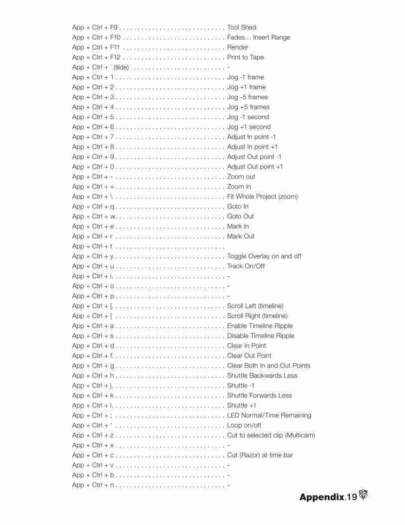
Appendix.19
App + Ctrl + F9 . . . . . . . . . . . . . . . . . . . . . . . . . . . . . Tool Shed
App + Ctrl + F10 . . . . . . . . . . . . . . . . . . . . . . . . . . . . Fades… Insert Range
App + Ctrl + F11 . . . . . . . . . . . . . . . . . . . . . . . . . . . . Render
App + Ctrl + F12 . . . . . . . . . . . . . . . . . . . . . . . . . . . . Print to Tape
App + Ctrl + ` (tilde) . . . . . . . . . . . . . . . . . . . . . . . . . -
App + Ctrl + 1 . . . . . . . . . . . . . . . . . . . . . . . . . . . . . . Jog -1 frame
App + Ctrl + 2 . . . . . . . . . . . . . . . . . . . . . . . . . . . . . . Jog +1 frame
App + Ctrl + 3 . . . . . . . . . . . . . . . . . . . . . . . . . . . . . . Jog -5 frames
App + Ctrl + 4 . . . . . . . . . . . . . . . . . . . . . . . . . . . . . . Jog +5 frames
App + Ctrl + 5 . . . . . . . . . . . . . . . . . . . . . . . . . . . . . . Jog -1 second
App + Ctrl + 6 . . . . . . . . . . . . . . . . . . . . . . . . . . . . . . Jog +1 second
App + Ctrl + 7 . . . . . . . . . . . . . . . . . . . . . . . . . . . . . . Adjust In point -1
App + Ctrl + 8 . . . . . . . . . . . . . . . . . . . . . . . . . . . . . . Adjust In point +1
App + Ctrl + 9 . . . . . . . . . . . . . . . . . . . . . . . . . . . . . . Adjust Out point -1
App + Ctrl + 0 . . . . . . . . . . . . . . . . . . . . . . . . . . . . . . Adjust Out point +1
App + Ctrl + - . . . . . . . . . . . . . . . . . . . . . . . . . . . . . . Zoom out
App + Ctrl + = . . . . . . . . . . . . . . . . . . . . . . . . . . . . . . Zoom in
App + Ctrl + \ . . . . . . . . . . . . . . . . . . . . . . . . . . . . . . Fit Whole Project (zoom)
App + Ctrl + q . . . . . . . . . . . . . . . . . . . . . . . . . . . . . . Goto In
App + Ctrl + w. . . . . . . . . . . . . . . . . . . . . . . . . . . . . . Goto Out
App + Ctrl + e . . . . . . . . . . . . . . . . . . . . . . . . . . . . . . Mark In
App + Ctrl + r . . . . . . . . . . . . . . . . . . . . . . . . . . . . . . Mark Out
App + Ctrl + t . . . . . . . . . . . . . . . . . . . . . . . . . . . . . .
App + Ctrl + y . . . . . . . . . . . . . . . . . . . . . . . . . . . . . . Toggle Overlay on and off
App + Ctrl + u . . . . . . . . . . . . . . . . . . . . . . . . . . . . . . Track On/Off
App + Ctrl + i. . . . . . . . . . . . . . . . . . . . . . . . . . . . . . . -
App + Ctrl + o . . . . . . . . . . . . . . . . . . . . . . . . . . . . . . -
App + Ctrl + p . . . . . . . . . . . . . . . . . . . . . . . . . . . . . . -
App + Ctrl + [. . . . . . . . . . . . . . . . . . . . . . . . . . . . . . . Scroll Left (timeline)
App + Ctrl + ] . . . . . . . . . . . . . . . . . . . . . . . . . . . . . . Scroll Right (timeline)
App + Ctrl + a . . . . . . . . . . . . . . . . . . . . . . . . . . . . . . Enable Timeline Ripple
App + Ctrl + s . . . . . . . . . . . . . . . . . . . . . . . . . . . . . . Disable Timeline Ripple
App + Ctrl + d . . . . . . . . . . . . . . . . . . . . . . . . . . . . . . Clear In Point
App + Ctrl + f. . . . . . . . . . . . . . . . . . . . . . . . . . . . . . . Clear Out Point
App + Ctrl + g . . . . . . . . . . . . . . . . . . . . . . . . . . . . . . Clear Both In and Out Points
App + Ctrl + h . . . . . . . . . . . . . . . . . . . . . . . . . . . . . . Shuttle Backwards Less
App + Ctrl + j. . . . . . . . . . . . . . . . . . . . . . . . . . . . . . . Shuttle -1
App + Ctrl + k . . . . . . . . . . . . . . . . . . . . . . . . . . . . . . Shuttle Forwards Less
App + Ctrl + l. . . . . . . . . . . . . . . . . . . . . . . . . . . . . . . Shuttle +1
App + Ctrl + ; . . . . . . . . . . . . . . . . . . . . . . . . . . . . . . LED Normal/Time Remaining
App + Ctrl + ‘ . . . . . . . . . . . . . . . . . . . . . . . . . . . . . . Loop on/off
App + Ctrl + z . . . . . . . . . . . . . . . . . . . . . . . . . . . . . . Cut to selected clip (Multicam)
App + Ctrl + x . . . . . . . . . . . . . . . . . . . . . . . . . . . . . . -
App + Ctrl + c . . . . . . . . . . . . . . . . . . . . . . . . . . . . . . Cut (Razor) at time bar
App + Ctrl + v . . . . . . . . . . . . . . . . . . . . . . . . . . . . . . -
App + Ctrl + b . . . . . . . . . . . . . . . . . . . . . . . . . . . . . . -
App + Ctrl + n . . . . . . . . . . . . . . . . . . . . . . . . . . . . . . -
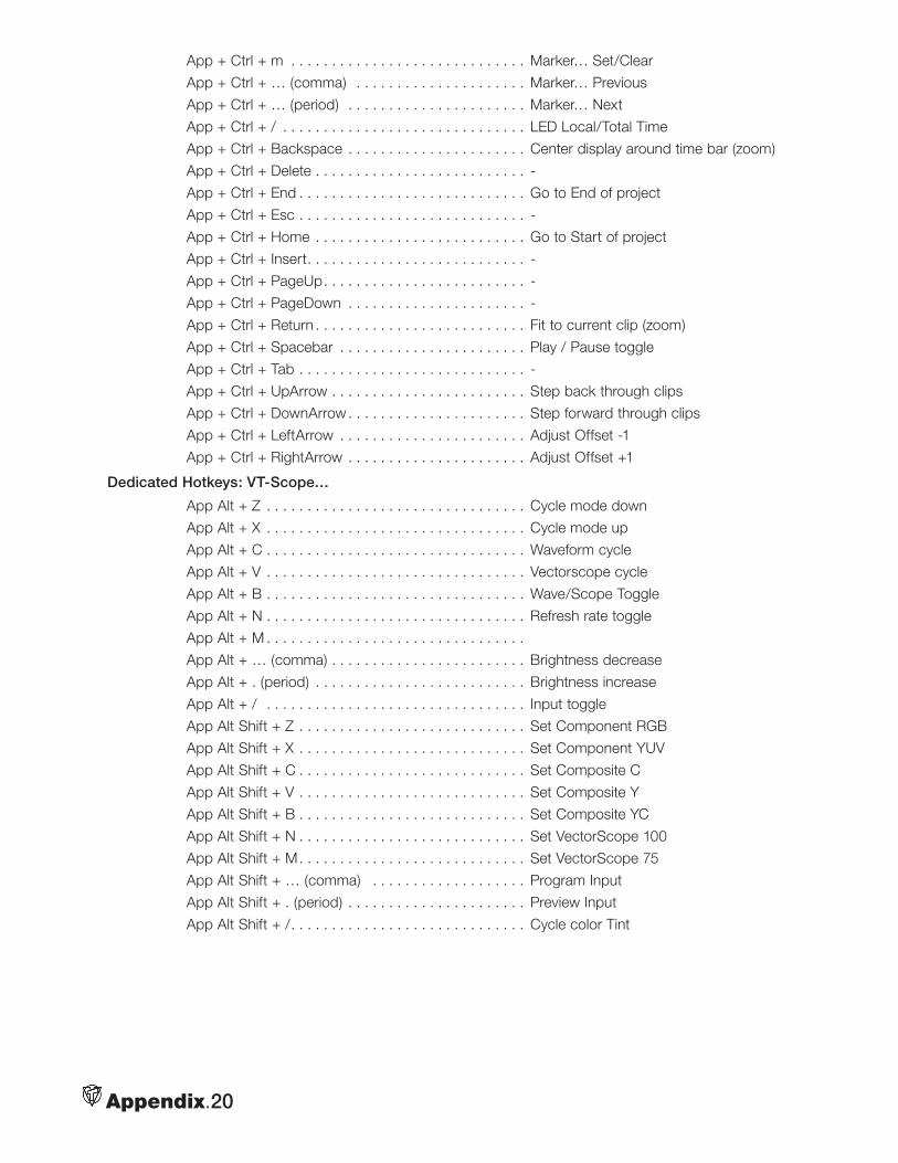
Appendix.20
App + Ctrl + m . . . . . . . . . . . . . . . . . . . . . . . . . . . . . Marker… Set/Clear
App + Ctrl + … (comma) . . . . . . . . . . . . . . . . . . . . . Marker… Previous
App + Ctrl + … (period) . . . . . . . . . . . . . . . . . . . . . . Marker… Next
App + Ctrl + / . . . . . . . . . . . . . . . . . . . . . . . . . . . . . . LED Local/Total Time
App + Ctrl + Backspace . . . . . . . . . . . . . . . . . . . . . . Center display around time bar (zoom)
App + Ctrl + Delete . . . . . . . . . . . . . . . . . . . . . . . . . . -
App + Ctrl + End . . . . . . . . . . . . . . . . . . . . . . . . . . . . Go to End of project
App + Ctrl + Esc . . . . . . . . . . . . . . . . . . . . . . . . . . . . -
App + Ctrl + Home . . . . . . . . . . . . . . . . . . . . . . . . . . Go to Start of project
App + Ctrl + Insert. . . . . . . . . . . . . . . . . . . . . . . . . . . -
App + Ctrl + PageUp. . . . . . . . . . . . . . . . . . . . . . . . . -
App + Ctrl + PageDown . . . . . . . . . . . . . . . . . . . . . . -
App + Ctrl + Return . . . . . . . . . . . . . . . . . . . . . . . . . . Fit to current clip (zoom)
App + Ctrl + Spacebar . . . . . . . . . . . . . . . . . . . . . . . Play / Pause toggle
App + Ctrl + Tab . . . . . . . . . . . . . . . . . . . . . . . . . . . . -
App + Ctrl + UpArrow . . . . . . . . . . . . . . . . . . . . . . . . Step back through clips
App + Ctrl + DownArrow . . . . . . . . . . . . . . . . . . . . . . Step forward through clips
App + Ctrl + LeftArrow . . . . . . . . . . . . . . . . . . . . . . . Adjust Offset -1
App + Ctrl + RightArrow . . . . . . . . . . . . . . . . . . . . . . Adjust Offset +1
Dedicated Hotkeys: VT-Scope…
App Alt + Z . . . . . . . . . . . . . . . . . . . . . . . . . . . . . . . . Cycle mode down
App Alt + X . . . . . . . . . . . . . . . . . . . . . . . . . . . . . . . . Cycle mode up
App Alt + C . . . . . . . . . . . . . . . . . . . . . . . . . . . . . . . . Waveform cycle
App Alt + V . . . . . . . . . . . . . . . . . . . . . . . . . . . . . . . . Vectorscope cycle
App Alt + B . . . . . . . . . . . . . . . . . . . . . . . . . . . . . . . . Wave/Scope Toggle
App Alt + N . . . . . . . . . . . . . . . . . . . . . . . . . . . . . . . . Refresh rate toggle
App Alt + M . . . . . . . . . . . . . . . . . . . . . . . . . . . . . . . .
App Alt + … (comma) . . . . . . . . . . . . . . . . . . . . . . . . Brightness decrease
App Alt + . (period) . . . . . . . . . . . . . . . . . . . . . . . . . . Brightness increase
App Alt + / . . . . . . . . . . . . . . . . . . . . . . . . . . . . . . . . Input toggle
App Alt Shift + Z . . . . . . . . . . . . . . . . . . . . . . . . . . . . Set Component RGB
App Alt Shift + X . . . . . . . . . . . . . . . . . . . . . . . . . . . . Set Component YUV
App Alt Shift + C . . . . . . . . . . . . . . . . . . . . . . . . . . . . Set Composite C
App Alt Shift + V . . . . . . . . . . . . . . . . . . . . . . . . . . . . Set Composite Y
App Alt Shift + B . . . . . . . . . . . . . . . . . . . . . . . . . . . . Set Composite YC
App Alt Shift + N . . . . . . . . . . . . . . . . . . . . . . . . . . . . Set VectorScope 100
App Alt Shift + M. . . . . . . . . . . . . . . . . . . . . . . . . . . . Set VectorScope 75
App Alt Shift + … (comma) . . . . . . . . . . . . . . . . . . . Program Input
App Alt Shift + . (period) . . . . . . . . . . . . . . . . . . . . . . Preview Input
App Alt Shift + /. . . . . . . . . . . . . . . . . . . . . . . . . . . . . Cycle color Tint
Glossary of Video Terms
Glossary.1
by Paul Lara & Molly Dinkins
0 and 1 — The two numbers in the binary system used to encode digital audio and digital video content. See bit.
4:1:1 — The numbers represent video color space and refer to the sampling of luminance (4) and color (1,1) when a video signal is converted to a digital signal. The luminance signal is sampled four times, while the color portion of the signal is sampled once (or for 4:2:2, twice, etc.). The more samples, the sharper the image (see 4:4:4). 4:1:1 is the color space used when capturing DV footage and is the sampling used for NTSC. Though resulting in sharp imagery, three quarters of the color data is discard-ed, making it quite difficult to pull a clean key using DV footage.
4:2:0 — The sampling for PAL DV where the last value, transparency, is discarded entirely. See 4:1:1.
4:2:2 — The specification for ITU-601 video. The color data is sampled at half the horizontal sampling rate of the luminance, (but twice 4:1:1). While some color data is discarded, the difference is impercep-tible to the human eye.
4:4:4 — Full resolution sampling of the color space. With no loss of data (RGB), 4:4:4 exceeds video requirements, but is used for computer graphics applications. See 4:1:1.
5:1 — The video compression ratio for DV footage.
24-bit — In computer graphics, a pixel or dot composed of 24 bits (8 for red, 8 for green, and 8 for blue). See 256.
32-bit — In computer graphics, 24-bit graphic depth plus 8 bits for a secondary (alpha) channel that stores 256 values of gray scale to indicate the transparency of that pixel.
256 — In computer graphics, the available num-ber of selections for each individual color — red, blue or green (255 + 0 for the absence of color). Combinations of RGB (256 x 256 x 256) equal about 16 million color variations per pixel, far more than humans can distinguish. A 255 in all 3 colors makes white; 0 in all colors makes black.
2D (2 dimensional) — A flat image.
3D (3 dimensional) — In LightWave’s Modeler module, virtual 2D and 3D objects and images are computer generated.
AC (Alternate Current) — An electric charge that regularly reverses direction as it travels through a conductor. See volt, waveform, ampere, ohm. Compare DC.
additive color — The color theory used for broad-cast and computers where color is a combination (by adding) of wavelengths of light that form the spectrum of primary colors: red, green, blue (RGB). The color of each pixel is a mix of the three primary colors determined by the amount of energy in an electron stream. Compare subtractive color.
aliasing — An undesirable video and graphics prop-erty that appears as jagged edges (stair-stepping pixels) on the edge of an object, especially obvious on curved borders. See antialiasing.
NOTE
All bolded words are defined in the Glossary.
alpha channel — A 256 gray scale color mask used to select degrees of transparency values in an image or video clip ranging between values of no transparency (255) to total transparency (0). VT[4] RTV values can be saved with alpha channel infor-mation embedded.
ampere (amp) — The standard unit of measure of the strength of an electrical current produced by the force of one volt passing through the resistance of one ohm.
analog — In video, data is sent by waves of electric-ity, with voltage levels fluctuating continuously over time, normally ranging between 0.7 to 1 volt. The VT[4] SX-84 (switcher expansion) module uses either analog or digital signals. Compare digital.
anamorphic widescreen — A distortion appearing in a large number of DVD’s where the horizontal and vertical dimensions magnify differently by squeezing a 1.78 picture shape into a 1.33 image area dur-ing capture. Anamorphic widescreen horizontally uncompresses the picture for a widescreen TV set with greater “vertical” information. Also annotated as 16:9. See aspect ratio.
ANSI (American National Standards Institute) — a nonprofit organization that promotes development of technological and electronic standards.
anti-aliasing — A computer graphic function that blends the colors of adjacent pixels in order to smooth the stair-stepping effect of aliasing.
artifacts — Undesirable elements or defects in a video picture — anything that appears in the video that you don’t want there, such as noise, pixelation, etc.
aspect ratio — The proportions of any monitor, defined by the width of a picture relative to its height. The aspect ratio for a standard television monitor is 4:3, or 4 wide by 3 high. HDTV, also known as widescreen, uses an aspect ratio of 16:9.
attenuation — A reduction in strength, electroni-cally measured in decibels (dBs). Turning down the volume is an example, as is the attenuation occurring over long distances with digital or analog transmis-sions. Compare gain.
audio mixer — A device that controls multiple audio inputs and outputs. VT[4] offers an on-screen audio mixer to control both outboard audio signals and the audio of Toaster modules, such as DDR’s.
Aura — 2D video paint engine, (included with VT[4]), capable of painting and video layering as well as pixel tracking and color isolation.
AVI (Audio Video Interleave) — A common video file format on PC’s and supported in VT[4].
background generator — A VT[4] module that creates, loads and saves background color mattes for use in live switching and production.
background render — The process in VT-Edit allowing the user to continue working while the com-puter is simultaneously creating a smaller file capable of real-time playback. This background task is com-pleted when the green “ready” line above the Play button in VT-Edit is lit.
balanced audio — Audio sent through a 3-wire con-ductor cable containing one wire with a positive sig-nal, a second with a negative signal, and a ground (carrying no signal). This separation allows longer cable-runs and lower chances of signal interference than unbalanced audio connections. The negative and positive cables send signals that are 180-degree opposites, while outside noise is sent evenly along both cables. The balanced receiving device ignores the even signals and uses only the varying informa-tion from the two cables.
banding — A visual artifact where smooth color gradients do not properly transition from one shade to the next. The resulting color boundaries appear as ‘bands’ in the image.
bandwidth — In computers, a measurement of the quantity of data that can be sent through a system each second. ITU-601 allows analog luminance bandwidth of 5.5MHz and chrominance bandwidth of 2.75MHz. It also refers to how much data in bytes that can be passed from computer storage to RAM (PCI bandwidth) and from the computer’s central processor to RAM (Front Side Bus bandwidth). In video, bandwidth refers to the range of frequencies, measured in Hz, that can pass through a device without distortion. A monitor’s refresh rate relies on high bandwidth: the higher the bandwidth, the more information you see and the sharper the picture you get.
baseband — Baseband transmission allows only one signal at time to be carried across a wire, as is the case with television broadcasting or computer networks. Compare broadband.
Betacam — A component video tape format developed by Sony.
Glossary.2
binary — A numeric system based on two values: zero or one, on or off. The binary system is the basis of digital computing.
bit (binary digit) — The smallest unit of data (com-posed of short pulses) in a computer or other digital equipment. A bit can be only 0 or 1, on or off. It is always represented in shorthand as a lower-case “b”. See bitmap.
bitmap — An image where brightness and color values are mapped to each pixel. Video display is a type of bitmap. Bitmaps drop in quality once they are enlarged beyond their original size. Compare vector graphics.
black burst — A video signal composed of sync, black video and color burst that can be used to synchronize the timing of multiple video devices to the same signal and color information. (See gen-lock). In video studios, black burst generators lock the entire facility to a common signal called house sync or house black.
black level — Measured electronically, the blackest video signal that can be produced on a TV screen. On a waveform monitor, the NTSC black level is 7.5 IRE units. The PAL level is 0 IRE. Any video darker than this will not be discerned on screen.
blanking — The invisible interruption of an electri-cal beam as it scans a line of a fresh image onto a TV monitor. Scanning from left to right every other line (either odd or even lines), the display interrupts (called horizontal blanking) to allow the beam to retrace to the left and down two lines. When the beam reaches the lower right corner of the tube, the display interrupts again (vertical blanking) until the beam returns to the top left corner to begin tracing the next field of the image.
blanking interval — The period of time when the electron beam turns off (horizontal or vertical blank-ing) between scans of an image onto the screen.
blanking level — A low voltage (0 IEEE units) at the end of each horizontal picture line that separates the picture information in the video signal from the syn-chronizing information. This voltage makes the elec-tron beam invisible as it retraces to draw the next line.
blooming — An effect seen on a monitor when color is too intense and bleeds over the edges of an object, hence making thin lines and sharp edges look thick and fuzzy. Blooming occurs when phosphors on the screen cannot handle the energy sent from the electron beam.
blue screen, green screen — The technique of filming or videotaping objects or talent in front of a deep blue (or green) wall or cloth (screen) to be elec-tronically replaced by another image. The weather-man is shot in front of a blue wall that will be replaced by weather maps.
BNC (British Naval Connector, Bayonet Nut Connector) — The connectors on the ends of video coaxial cables.
BOB (Breakout box) — Slang for SX-84 (switcher expansion) unit. breakout box (BOB)
broadband — Data transmission in which a single medium (wire) can carry several channels at once.
browse — To search through a data base.
buffer — A temporary computer storage area in memory for data being transferred between devices that operate at different speeds.
bug — In video, slang for a logo in the lower corner of the screen, usually displayed as a downstream key. Also, bug is slang for a computer problem.
burst — A combination of sync, color burst and black video. See colorburst.
bus — A data pathway. For example, the Switcher bus refers to Program, Preview and Key.
byte — 8 bits of data used to describe 256 dis-crete values. Almost all computer speeds or storage amounts are referred to in bytes, (not bits). Higher values include kilobyte (KB), (1000 bytes); mega-byte (MB), (one million bytes); gigabyte (GB), (one billion bytes); terabyte (TB), (one trillion bytes); and petabyte (PB), (a quadrillion bytes).
capture — The act of saving information or video to hard drives.
card — In computers, this refers to installable hard-ware. The VT[4] hardware is often referred to as a capture card.
cathode ray tube (CRT) — The principal technology behind computer monitors and televisions. It works by moving an electron beam across the face of the screen. Each time the beam traces (or scans) a line across the inside of the tube, it lights up phosphor dots, illuminating the active portion of the screen.
Glossary.3
CCIR (International Radio Consultative Committee) — Formerly the global organization responsible for establishing television standards; now regulated by ITU.
CD, (Compact Disc) — An optical disc format capable of storing approximately 650 MBs of data.
CD-R (Compact Disc Recordable) — A type of CDROM that can be written on by a CD recorder and read on a CDROM drive.
CDROM (Compact Disc Read-Only Memory) — An optical disc format that, once recorded on, can be read only.
CDRW (Compact Disc Rewritable) — An optical disc format that is erasable and reusable (or rewritable).
CG — In video, short for Character Generator. Also, computer graphics.
CGI (Computer Generated Imagery)
channel — An information pathway between two devices.
character — A letter or a symbol comprising one byte of information. A character can also be unseen, like a carriage return.
character generator (CG) — A VT[4] module that creates titles, scrolls, and crawls.
chip — An integrated circuit containing millions of transistors and other electronic components. Audio, video and computing itself are possible because of this technology.
chop — In VT[4], a capture function (Chop key) allows logging on the fly. When capturing video, chop stops the recording of one clip and immediately begins recording the next.
chroma key — In video, the process of revealing a portion of the background image by selecting a spe-cific color (or chrominance value) in the foreground image and making that chrominance transparent. See luma key, blue screen.
chrominance — The color value or color information in the video signal. Saturation and hue are aspects of chrominance. Luminance (black, gray, and white) have no chrominance.
clip — A video signal that has been digitized to disk. Also, a segment of video or film cut from a longer sequence.
clipping — The process of cutting off a portion of the video signal because the image is too dark or (more commonly), too bright. Also the cutting off of an audio signal usually resulting in a distortion.
coaxial or coax cables — Cables used to trans-fer video between cameras and recorders. Each consists of a center conductor surrounded by an insulating material and a concentric outer conductor. Pronounced co-AXE.
CODEC (COmpression DECompression) — The various means of saving video files to computer, while maximizing storage space. AVI, MJPEG and Indeo are codecs. Also refers to the algorithm that handles the compression and decompression of video or audio files.
color bars — A standard striped reference pattern of eight established color values used to calibrate the color and luminance of video production moni-tors, cameras, recording and playback equipment.
color burst — A synchronization reference that gives frequency and phase information about hue and saturation; the 8 to 10 cycles of unmodulated color subcarrier that enable color encoding of a composite video signal and decoding in the receiv-er. Color monitors use a color burst to decode the color portion of a video signal. See subcarrier.
color correction — Electronically changing or cor-recting the color, tint, brightness or shading of a video clip, which can be accomplished in real-time using the Proc Amp in VT[4].
color mattes — Background colors used behind text and symbols.
color phase — The correct timing relationship in a color display. Color is in phase when the hue is reproduced correctly.
color space — The geometric method for repre-senting color in 3-dimensional space. In video, the color space is defined in YUV; in computers as RGB.
color subcarrier — The frequency added to a luminance signal that carries color information (3.58 MHz for NTSC or 4.43 MHz for PAL signal). The subcarrier frequency is too high to be detected by black and white televisions. Color televisions use circuitry that detects and decodes the color compo-nent for display.
colorize — To color black and white images.
common formats — See Formats, common.
Glossary.4
component — A video signal that sends color information (chrominance and luminance) through three separate channels. The three channels can be RGB (Red, Green, and Blue) or YUV (where Y is luminance and UV is chrominance). The component signal offers the highest quality for production.
composite — A lower quality video signal that com-bines the chrominance, luminance, a sync pulse and color burst information and sends it through one channel.
compressed — A lossy format of storing video or images. Compare uncompressed.
compression — The process that decreases the data in a digital video so that it uses less storage space and transfers more quickly. Compare uncom-pressed.
computer graphics (CG) — Any graphic art or text items created with a computer. VT[4], LightWave and Aura are each capable versatile tools for graphics.
contract — In keying, refers to trimming, or con-tracting the edge of the key, which is useful to elim-inate the remaining color fringes around the object. See key choke.
CPU (computer processing unit) — The control unit of a computer that executes instructions. CPU speed is measured in megahertz and gigahertz.
crawl — A line of text that moves horizontally across the bottom of the screen, such as weather bulletins. Compare scroll.
Cross keyer — A specialized method of keying in VT[4] where multiple colors can be removed from the foreground layer of a video revealing a partial image from the background layer or video clip. (Named for creator Andrew Cross.)
crossfade — To fade out one audio track while another audio track simultaneously replaces it. Compare fade, dissolve.
crouton — File picture icon (or picon).
CRT (cathode ray tube)
cue — A “go” command to a person or device. DDR running in Cue mode, automatically pauses until the Switcher tells it to roll.
D1 — A digital videotape format for recording and playing back ITU-601 video, a component signal. Digitized video prevents problems such as
generation loss. Digital formats mainly use a 19mm wide magnetic tape (3/4”).
D2 and D3 — Digital videotape formats using composite video. Compare with D1, which uses component video. D2 is the tape standard for recording composite signals.
DA (Distribution Amplifier) — An electronic box or device that enables a single audio or video signal to be transmitted to several sources such as moni-tors or projectors; or to send them amplified across a longer cable run.
dB (decibel) — The unit used to measure the strength of audio and video signals. Consider the volume of music: from barely heard (0 dB) to painfully loud (130 dB).
DC (Direct Current) — Electric charges that flow in one direction through a conductor. Nearly all com-puter and electronic hardware require Direct Current. Compare AC.
DDR (Digital Disk Recorder) — In VT[4], a virtual tape deck for capturing and playback of video and graphics.
decibel (dB)
deck — Short for tape deck or video tape recorder or player.
deck controls — The buttons across the front of a videotape recorder or player to activate the videotape, most typically including Pause, Rewind, Play, Stop, Fast Forward and Eject. VT[4] uses virtual deck controls.
default (state) — The preset values that appear when you open a module in VT[4].
deinterlace — See interlace.
desktop — In VT[4], the monitor’s workspace. Six separate desktops can be customized, saved and recalled.
differential gain — A change in luminance level that causes a change in the subcarrier amplitude of a video signal. The television picture will show a change in color saturation caused by a simultane-ous change in picture brightness.
digital — A signal characterized by discrete states, 0 or 1; on or off. Analog signals rise and fall as waves, whereas digital signals instantly switch between states.
Glossary.5
digital video effects (DVE) — 3D video transitions on which video footage is mapped, like page curls.
Digital-S — A high quality, digital compressed (3:1) videotape format. The signal is captured in 4:2:2 color space.
disc — A circular platter designed to be read or written to by lasers. Compact discs (CD) or digital video discs (DVD). Not a disk.
disk — A circular platter that is coated with iron oxides. Small magnets then read and write informa-tion from the disk as it spins. Not a disc.
disk drives — A device that reads data stored on disks.
dissolve — The dissolution of one video signal while another video signal simultaneously replaces it. Compare with fade.
distribution amplifier (DA)
dongle — A hardware key employed by software manufacturers to ensure proof of ownership and dis-courage casual piracy.
download — Copying a file from the Internet or across a network to one’s own computer.
downstream key (DSK) — A keyer that over-lays text, video or graphics even while video transitions, switching or effects occur behind it.
drag — Pulling functions, information or images across the computer screen by holding down a mouse button while dragging the mouse.
drives — See Disk drives.
drop-frame timecode — A time measurement sys-tem that compensates for NTSC video that runs at 29.97 frames per second. The counter skips count-ing (drops) two frames every minute except the tenth; it drops 108 frames each hour. Since PAL runs pre-cisely at 25 frames per second, it does not require dropframe timecode.
dropout — A brief lapse of video or audio during playback on a tape machine, caused by flaws in the tape or a sudden loss of tape contact with the play-back head.
DSK (downstream key) — Graphics or text superimposed, or keyed downsteam of the primary switcher. This allows changing sources without interrupting the key.
DV (Digital Video) — A tape format compressed at 5:1 into a 4:1:1 signal.
DVCam — Sony’s particular flavor of the DV tape format.
DVD (Digital Versatile Disc or Digital Video Disc) — The 12cm optical disc format used to distrib-ute movies or to store more than 4.5 GB of data, Compare with CD.
DVE (Digital Video Effect) — See effect.
EDL (Edit Decision List) — An assembled list of edit decisions. Also a text file containing the timecode locations of each clip used in a project which can be recalled at a later date for automated re-capture of the video. The list typically includes the source, the in time and time out for each edit, and transitions.
effects — Any modification of a video during cap-ture or playback. This can include color-correction, blurring, or even superimposing titles or secondary images.
EFP (Electronic Field Production) — The equipment and techniques for commercial and corporate video production on location, or “in the field.”
ENG (Electronic News Gathering) — The accou- trement for gathering news and documentaries on location.
EPS (Encapsulated Postscript) — An Adobe image file format useful for its ability to be sized small or large without image degradation, because EPS files create a definition of all the lines and shapes in the image, instead of mapping to individual pixels. (See vector graphics.)
equalization — In audio, to improve sound quality by increasing or decreasing the gain of the signal at various frequencies.
expansion module — An auxiliary component to the VT[4] Switcher, such as the SX-84 or the RS-8.
fade — To dissolve a video picture to a color, usu-ally black. In audio, to decrease the volume until it is no longer audible. Compare dissolve.
field — One-half of an interlaced video picture; an NTSC field contains 262.5 lines while a PAL field contains 312.5 lines (PAL). Two fields make up a single video frame. Fields are continuously “painted” every-other-line onto the TV monitor with the upper (or odd) field remaining on screen while replacing the lower (or even) field, then reversing the action to the upper, or odd field. See blanking.
Glossary.6
file — Any data saved on a computer.
file bin — The location where you store your clips. VT[4] offers file bins, which are actually Windows file folders.
file formats — A listing of the most common com-puter formats for storage of graphics and video. In Windows, files are designated by “yourfilename.filetype” with the type is abbreviated to three letters; Macs often use four letters (.jpeg).
GRAPHICS FORMAT: .bmp — Windows bitmap image, uncompressed .iff — Interchange file format; primarily used on
the Amiga .jpg (JPEG) — Compressed, popular for Internet
graphics .pcx — PC Paintbrush, uncompressed .pdf (Portable Document Format) — An Adobe
Systems format used to encode text and images like manuals, and read with Acrobat
.png (Portable Network Graphics) — A newer format that can replace JPEG imagery, with or without alpha channel
.tga (Targa) — High image quality, with or without alpha channel
.tif (Tagged image file) — Uncompressed, with or without alpha channel
VIDEO FORMAT: .rtv (Real-Time Video) — VT[4]’s uncompressed
format .avi (Audio/Video Interleaved) — Uncompressed
or compressed .mpg (MPEG-1) — Highly compressed, useful for
video playback on CD-ROM and the Internet. .mp2 (MPEG-2) — Used for DVD .mov — Apple’s QuickTime movie format
AUDIO FORMATS: .wav — The audio standard on PC’s .aiff — The audio standard for Macs .au — The rare audio format for SUN computers .mp3 — Highly compressed audio format
ARCHIVAL FORMATS: .aur — Aura projects .dib — Aura brushes .lws — LightWave scene file .lwo — LightWave object file .zip — Popular file with high compression .sit — Popular Mac file with high compression
FireWire — A file transfer protocol (IEEE 1394) invented by Apple Computers to relay data between digital devices.
font — A single stylized alphabet with matching symbols.
frame — A complete video image that consists of two fields; a frame has 525 interlaced horizontal lines of picture information in NTSC, 625 in PAL.
frame buffer — The storage location in RAM for a single frame of video.
frames per second (FPS) — The number of frames in each second of video. NTSC uses 29.97 fps and PAL uses 25 fps.
frequency — The number of complete cycles of a periodic waveform that occur in a given length of time. Usually specified in cycles per second (Hertz).
Flyer — NewTek’s original nonlinear desktop editor for the Amiga Toaster, released in 1994.
FXmonkey — The LightWave wizard for creating 3D flying logos.
gain — The level of amplification of a signal. An increase in signal power or voltage when a signal is transmitted from one point to another through an amplifier. Gain is expressed in decibels above a reference level. Turning up the volume is an example of gain; turning it down is attenuation.
garbage matte — A rough, simple overlay that isolates unwanted elements (like wires and signs) from an image.
general purpose interface (GPI) — A wired con-nection allowing remote control over specific func-tions of a device, like VT[4]’s GPI for the Switcher and DDR. Also a non-specific interface between equipment, usually a serial connection (RS232 or RS422 format) between computer modules.
generation — The number of duplications between an original recording and a copy: Second generation is a copy of the original master; third generation is a copy of the copy of the original master, and so on.
generation loss — Loss of color, detail, sync, etc., that appears when you copy a videotape. Tape and circuitry limitations cause generation loss.
genlock (generator locking) — A device to elec-tronically synchronize several pieces of equipment such as switchers and cameras. VT[4] internally genlocks all sources to the SX-84 switcher. VT[4] can also connect to an external source called house sync.
Glossary.7
George — A plain-language script used in Aura to automate routine tasks.
gigabyte (GB) — 2 to the 30th power, or 1,024 megabytes, roughly one billion bytes.
GPI (general purpose interface)
graticule — The fine lines of a grid overlaying wave-form and vectorscope monitors providing refer-ence points for video calibration.
gray scale — The continuous tone in an image uti-lizing the range of shades from black to white. See alpha channel.
green screen — See blue screen.
ground — Electrically, a wire that conveys an electric current to the earth (or ground), resulting in protec-tion against electric shock. Also, a ground can pro-vide a shield from other electrical interference.
ground wire — The third wire in a grounded con-nection that ensures the signal will be isolated from external interference. In audio, this wire pro-tects against interference that may cause a back-ground hum. See balanced audio.
GUI (Graphical User Interface) — An interface employing visuals and graphics to make software easier and quicker to use, in contrast to Command interfaces such as DOS, where commands are entered in as text. Pronounced goo-ee.
hard drive — Large capacity computer storage units of multiple stacked disks, sealed in airtight cases that spin at high speeds inside the computer.
HDTV (high definition TV) — HDTV systems use 1125 lines of horizontal resolution (compared to 525 for NTSC and 625 for PAL) and an aspect ratio of 16:9. This gives an image quality approaching that of 35mm film photography.
hertz (Hz) — An international unit of frequency equal to one cycle per second.
hi res — Slang for high resolution. Sometimes spelled rez.
horizontal blanking — The process when an elec-tron beam on a monitor shuts off, or is blanked, so that the beam can return to the left side of the screen to begin a new scan line. See blanking and retrace.
house sync — A synchronized electronic signal shared by all audio and video equipment in a studio.
HSL (Hue, Saturation and Luminance) — In computer graphics, a method of representing color values from the 360 degree color wheel. Hue is pure color; saturation is the amount of color: and luminance is brightness. Compare RGB.
Hub — A LightWave utility that transfers real-time updates of models and textures between Modeler and Layout.
hue — In HSL, the dominant wavelength that dis-tinguishes a particular color. The actual color is represented by degrees in the color wheel, i.e. 240º is blue.
hum — An unwanted mix of 60Hz power sine wave into other electrical signals. In audio, a hum can be heard; in video, hum appears as waves in the picture.
IDE (Integrated Drive Electronics) — An interface for storage devices such as hard drives and CD-ROMs.
IEEE (Institute of Electrical and Electronics Engineers) — A group best known for formation of standards for computing.
IEEE 1394 — See FireWire.
illegal color — A color that cannot be reproduced on a standard TV. Use RGB and YUV colors for broadcasting.
impedance — The opposition, or load, to a signal. Circuits for audio or video signals work with a cer-tain load, or impedance; typical video impedances: 75 ohm or High Z.
Indeo — An audio/video codec with variable com-pression rates designed primarily for Internet use.
input — Anything going into a computer or tape deck is input, whether from a camera, a tape, or a mouseclick.
interface — The location where you interact with your computer, often comprised of on-screen menus and buttons. See GUI.
interlacing — Each video frame is divided into two fields; interlacing is the process of scanning every other line of the fields so that the two fields dove-tail or interweave together. See blanking. Compare progressive.
interleaved — Simultaneous reading or writing of data. AVI interleaves audio and video into the same file.
Glossary.8
Internet (Inter-network) — The Internet is an ever- expanding global network of computers.
I/O (input/output)
IRE (Institute of Radio Engineers) — A measurement of the luminance of the video signal that divides 1 volt of Peak-Peak video into 140 IRE units. The IRE unit is meant to make the numbers for luminance levels eas-ier to communicate. The amplitude of the video signal from blanking (zero volts) to peak white is 0.714286 volts or 100 IRE units. Synchronization signals extend from blanking to - 0.285714 volts or - 40 IRE units.
ITU (International Telecommunication Union) — An organization headquartered in Geneva, Switzerland responsible for adopting international treaties, regulations and standards to coordinate global telecom networks and services for govern-ments and the private sector. See ITU-601.
ITU-601 — The definitive standard for D1 compo-nent video.
JKL keys — Deck controls keys: “k” stops and starts playback, “j” slows it down, and “l” speeds it up.
jog — To rewind or fast forward your video. Jog is slower than shuttle and permits viewing frame by frame; it includes audio.
JPEG (Joint Photographic Experts Group) — A lossy compression technique ranging from 2:1 up to 100:1. See file format.
key — The technique of replacing a brightness value (luma key) or a specific color value, (chroma key) with a still image, video clip or live camera shot. VT[4]’s 4:2:2 uncompressed video improves pulling a clean key.
key choke — Reducing the outermost edge in a chroma key by trimming pixels. See contract.
kilobyte (KB) — 1024 bytes, rounded off to 1000.
lavaliere microphone — A small microphone that is attached to clothing, often used for live TV interviews.
Layout — LightWave’s digital stage where objects, lights and cameras are positioned to create a scene.
LED (Light Emitting Diode) — A light such as a tally or an on/off button. LED’s are also combined to cre-ate massive video billboards at casinos and stadiums.
LightWave® 3D (LW) — NewTek’s 3D modeling, surfacing, animation, and rendering software avail-able on the PC or Mac, (and included in VT[4]).
lines — A measure of resolution in video. In NTSC, 525 lines of information are scanned on a monitor across a single frame, every other line at a time, starting from top left down to bottom right. The first pass scans the odd lines, the second, the even ones. See blanking.
live — Videotaping or broadcasting an event as it happens.
log — A descriptive list of shots, (if video, usu-ally including a timecode). The VT[4] chop key allows logging on the fly.
lossy — The elimination (or loss) of information when a file is compressed. Continuous saving and re- saving further degrades the image or video.
lo res — Slang for low resolution. Sometimes spelled rez.
luma key — In video, the process of revealing a background image by selecting a specific lumi-nance value (black, white or a gray scale) in the fore-ground and making that luminance value transparent. See chroma key.
luminance — The amount of light radiating from a computer image or video signal. In HSL, the bright-ness (the lightness and darkness of color). 0 lumi-nance is no color; 100% is full color. Also, the black and white portion of the video signal.
LW (LightWave)
machine control — Remote control of external devices, such as tape decks, by a live switcher or computer.
Main — The primary Switcher image in VT[4] before adding downstream key images.
Megabyte (MB) — 2 to the 20th power, or roughly one million bytes.
Megahertz (MHz) — One million cycles (hertz) per second.
mint — Slang for a VT[4] module, such as the Switcher or VT-Edit.
microphone preamplifier — A signal path enhanc-er. Microphones produce very low signal levels and a preamplifier boosts to the output signal to a level compatible with audio circuitry.
MHz — Abbreviation for megahertz, a unit of measurement for a million cycles per second.
Glossary.9
MJPEG (Motion JPEG) — The application of JPEG compression to frames of video.
MPEG (Motion Pictures Experts Group) — An orga-nization that defines standards for compression of moving pictures. (See File Formats.)
Modeler — The LW module where 3D objects are created and surfaced.
Module — Any single component within the VT[4] suite, such as the Switcher or Color Picker.
monitor — A display device for computer or video images.
motherboard — The computer’s main circuit board connecting all other devices.
multi-cam — Slang for multiple-camera recording or editing.
multi-format — VT[4]’s ability to capture and play back footage from a wide variety of compressed or uncompressed formats.
multimedia — A presentation, delivered through a computer, that combines different types of content (video, audio, still images, graphics, animation, text, etc.).
network — A collection of computers all linked together to share data.
noise — Disturbance or interference to an elec-trical signal. Video noise appears as snow, graininess, ghost images or picture static induced by external sources such as the national power-line grid, electric motors, fluorescent lamps, etc. Audio noise appears as hiss, hum and/or static.
non-interlaced — Compare progressive.
non-linear — In editing, the ability to rearrange cap-tured clips in a quick, flexible manner irrespective of their original order on tape.
NTSC (National Television Systems Committee) — The standard established for color television in North America, parts of South America, and Japan. NTSC has 525 lines of information, played back at a rate of approximately 30 frames (29.97) per second at 60 Hz. See PAL.
offline — Production editing of lower resolution than broadcast standards; when a vast amount of raw footage exists, it is often captured at low resolu-tion to determine final edits, then only necessary clips are redigitized in full resolution. Compare online.
ohm — The unit of measure for electrical resistance. A resistance of 1 ohm will pass 1 ampere of cur-rent when a voltage of 1 volt is applied.
online — Editing at final, highest-quality output, used for broadcast or distribution. Compare offline.
on-the-air — The action in front of the camera is being broadcast over the air, or distributed internal-ly via closed-circuit tv. See live.
open architecture — A computer or peripheral with published specifications that allow third-party devel-opment.
optical disc format — A storage medium where data is written as pits in a groove on a plastic coated disc and read by lasers. (Some authorities use the word disk instead of disc.) See disc, CD and DVD.
output — The audio and video signals emanating from production equipment.
output bus — Any signal coming from VT[4], such as Program Out or Downstream Key.
overlay — To superimpose two or more images on top of one another, where portions of the top image(s) are transparent, revealing the image(s) below. Common in video titling.
overscan — Video images may exceed the size of the screen on a consumer monitor by five to ten percent. This excess video leaves some flexibility so that the active image will appear correctly on a variety of television sets. Video professionals plan for critical action to occur only in the center, which is the safe area. Professional monitors can display the overscan area. The area inside a 10% line is the safe title area. The overscan Test Pattern is VE T15 C7 or VE T17 C8.
PAL (Phase Alternate Line) — The standard for televi-sion broadcasting in Western Europe featuring 625 lines per frame and 25 frames per second at 50 Hz.
PCI (Peripheral Component Interconnect) — The data pathway between the computer and all installed cards. The bus (chip) communicates large amounts of information (high bandwidth) to the motherboard, usually 32-bit or 64-bit.
Glossary.10
petabyte — 2 to the 50th power, or roughly one qua-drillion bytes. Yes, one thousand terabytes. YIKES!
phantom power — The power supplied from the audio mixer board back to a sensitive microphone needing direct current. VT[4] provides phantom micro- phone power through the SX-84 Switcher module.
phase — The timing of a signal in relation to another signal; the timing of a color in relation to the color burst signal, so if you change the subcarrier phase of video, you change the hue of the colors in the signal.
PICON (picture icon) — In VT[4], croutons.
picture-in-picture (PiP) — The act of overlaying one or more smaller images on an image or video stream. VT-Edit can create an unlimited number of PiPs in a video stream.
PiP (picture in picture)
pixel (picture element) — A single (rectangular shaped) dot of light and color within a graphic or video as seen on the monitor. The number of the pixils determines the resolution of the image. The higher the resolution, the more detailed the image.
pixelation — A distortion of a digital image expos-ing the rectangular pixels. Especially pronounced when an image is magnified.
pixel tracking — An animation technique to lock one animation or video stream to another, based on the known location of pixels in the original.
playback — The playing of audio or video tape. A playback deck only plays and does not record.
polygon — A flat plane object consisting of three or more connected lines. LightWave uses polygons to construct 3D objects.
post, post production — The assembling of the final program: The process of editing, adding graphics, creating special effects, color correcting, and audio mixing after the footage is shot. VT[4] is a complete post production package.
preference settings — Values entered on the VT[4] Preferences panel that designate items like Default Still Length.
Preview — The Switcher bus in VT[4] ready for out-put — cued with video, graphics or a rolling camera — next in line to go live.
proc amp (processing amplifier) — The device used in video production to match the various incom-ing signals, especially useful in a multi-cam environ-ment to ensure comparable colors. VT[4] offers on-board Proc Amps for each input into the system.
Program, Program Out — The video stream going “on the air,” a combination of the Main input and any additional graphics or key layers.progressive — The combining of both fields in an interlaced frame into an image, especially help-ful when the final output is destined for an Internet stream or DVD. VT[4] can capture interlaced or pro-gressive mode footage. Compare interlace.
proxy render — The Aura function that continues to update any changes made in Aura’s timeline as a background task, allowing Aura animations to be immediately viewed or sent to either Program or Key out.
peripheral — An auxiliary computer device, such as a printer or CDROM.
PSA (Public Service Announcement) — A free TV or radio broadcast of an announcement (or commercial) for a non-profit organization.
pull a key — Slang for creating a chroma key.
pulse — A brief surge characterized by a rise and fall, such as with an electronic signal. A video pulse is a carrier for all the synchronous data correspond-ing to a given time stamp in a stream.
QuickTime — An Apple Computer audio/video file format that can be streamed over the Internet.
RAID (Redundant Array of Independent Drives) — RAID combines multiple small, inexpensive disk drives into a single logical drive or “disk array” with performance that exceeds a more expensive highspeed disk drive. VT[4] uses RAID 0, or soft-ware-striped drives.
RAM (Random Access Memory) — Memory that can be written to or read by the CPU. VT[4] requires at least 512 MB of RAM.
raster — The horizontal scan lines on a video display.
real estate — Slang for the amount of comput-er screen space you have available for your work.
Glossary.11
real-time — An operating mode where the com-puter receives and processes data almost instantly, hence real-time, so that the user does not wait while the computer processes or renders the output.
reboot — The act of re-starting a computer. There are two types of reboots: A warm boot is a reset of the operating system without powering down; a cold boot involves physically shutting down the power supply and then re-starting.
res — (Or rez). Slang for resolution.
reset — The process of returning a computer or module back to its default state.
resolution — In computer graphics, the quality of an image measured by the quantity of pixels; in video, as lines.
retrace — An electron beam scans a picture onto a screen from left to right; before scanning the next line, the beam must return to the left side of the screen, an action called retrace. See blanking.
RGB (red, green, blue) — The basic components of the color television system. Also they are primary colors, (not to be confused with the painter’s primary palette of red, blue and yellow). RGB colors are defined by mixing red, green and blue in values from 0 to 255. In this additive scheme, 255 R + 255 G + 255 B = white. All 0 values = black. Also one of the color palettes used for computer displays. See YUV and Y/V. Compare additive color with subtractive color.
RS (recommended standard) — A set of standards for serial connections adopted by the Electrical Industries Association.
RS-8 — NewTek’s physical switcher interface, with Tbar and buttons to provide a tactile control sur-face for technical directors.
RS–232 — An older communication standard replaced by RS-422.
RS-422 — A newer standard for serial connections supporting higher data rates and greater immunity to electrical interference. The VT[4] SX-84 switcher expansion unit contains three RS-422 ports.
RTV (real-time Video) — The uncompressed video format used by VT[4]. RTV files can also contain alpha channel information.
rundown — A production outline for the crew that highlights shots, angles, and locations of lights and talent during any given scene.
safe area or safe action area — The inner 80% of the video screen where images and action can safe-ly be placed to be seen on most consumer TVs.
safe title area — The inner area of the video screen where titling is recommended for standard TV’s, smaller than the safe action area.
sampling — The examination and capture of a sig-nal based on a brief time span. In audio, sample rates are expressed by how many thousand cycles are sampled and captured per second. See Kilohertz. In video, sample rates are expressed as ratios between the three video components (Y, R-Y, B-Y). See 4:1:1, 4:2:2. Compare compression.
saturation — In the HSL, the percentage of white in the color, or the density of color.
scan — The mechanical optical movement in suc-cessive lines across a surface that reproduce or transmit an image.
scan lines — The individual lines within each field of video. See field.
scanner — An optical (image acquisition) device used to copy and convert a printed image or page of text into a computer display.
scroll — The vertical movement of text or images on the video. Compare crawl.
scrub — With a mouse, grabbing an arrow or icon off the GUI and moving it back and forth to engage or see the full range of the selected item (such as a video clip). The movement resembles scrubbing.
SCSI (Small Computer System Interface) — A standard high-speed parallel connection between the computer and peripheral devices, such as disk drives, scanners and tape drives. Pronounced scuzzy.
SDI (Serial Digital Interface) — A system of receiv-ing and transmitting digital audio and video signals, ideal for long cable runs in post production houses.
serial digital video — A digital tape format that stores video at a standard of 270 Mb/sec SMPTE 259M component digital signal.
Glossary.12
serial port — A computer l/O (input/output) port on the computer. The serial port uses a single wire or pair of wires to transmit and receive data to and from external devices. The standard serial port uses RS-232 or RS-422 protocols.
shuttle — You can quickly fast forward or rewind (the image and audio) to scan video footage. Compare jog.
signal — A waveform that sends information from one point to another.
signal-to-noise ratio (S/N) — The strength of an audio or video signal in relation to background noise. The ratio is measured in decibels. A higher ratio in video gives you a cleaner picture, with less snow. A higher ratio in audio gives you cleaner sound.
sine, sine wave — A fundamental waveform produced by periodic, regular oscillation.
skins — The application of customized image bitmaps positioned over a hidden computer con-trol panel which alter the look of a module interface.
slo-mo — Slang for slow motion.
SMPTE (Society of Motion Picture and Television Engineers) — A global organization based in the United States that sets standards for baseband visual communications, including film and video.
SMPTE 259M — The standard for storing serial digital video.
source, source material — The original footage used to create a video program.
spot — Slang for a commercial.
stillstore — A device that sequences or randomly accesses a library of single frame images (stills).
stop motion — The technique of capturing a single frame of film or video, stopping to adjust the objects and or actors, before capturing the next frame.
storyboard — A graphic representation (on what-ever medium: paper, blackboard or computer) of a video, animation or film project. The storyline is illustrated indicating talent positions, camera angles, edits, etc.
storyboard editor — VT[4]’s editing system in which a single crouton represents a clip. The program
is edited by arranging and rearranging croutons, and inserting transitions. Storyboard editing is valu-able for quickly roughing out a project.
stream — Any continuous flow of data, such as audio or video.
streaming — The technique of sending audio and video across the Internet for remote viewing.
striped drives — Two or more hard drives joined together by the computer’s operating system to read and write a single file across the multiple drives, resulting in increasing bandwidth.
subcarrier (phase) — The electrical portion of a video signal that determines hue (color).
subtractive color — Color produced by light reflected from a surface, as compared to additive color. Subtractive color includes hues in color photos and colors created by inks on paper. Compare additive color.
S-VHS (Super-VHS) — An improved version of the VHS tape format capable of recording higher picture resolution.
S-Video (Separated Video) — A video signal that separates brightness or luminance (Y) from the chrominance (C) data. See Y/C.
sweetening — Slang for the post-production process of enhancing audio and acoustics of the source material.
switcher — A real-time device enabling a seamless (usually live) change of video inputs without interrup-tion or glitching. See SX-84.
SX-84 (switcher expansion) — The VT[4] Switcher expansion module, with 100 connectors for video, audio, and external machine control.
sync (synchronization) — The precise alignment of two video signals or functions. Horizontal sync is a timing pulse that identifies the start of each new line. Vertical sync identifies the start of a new field. Color burst, a sync reference, sends frequency and phase information.
sync pulse — The signal that conforms different video equipment to each other. If all your video gear is a marching band, then think of the sync pulse as the drum major.
T[4] — Short for VT[4].
Glossary.13
talent — An actor, newscaster, weatherman, etc., who will appear on screen.
tally, tally lamp — The signal light or LED atop a studio camera, signaling on-set personnel which camera is active, especially important when switching live.
tape — Short for videotape or audio tape.
Targa (TGA) — See File Formats.
TBC (time-base corrector) — A device that cor-rects problems with sync pulses by generating a clean time-base, and synchronizing incoming video to this reference.
terabyte — 2 to the 40th power, or roughly one trillion bytes.
test pattern — Pattern of colours, lines and/or shapes designed to assist equipment calibration.
time lapse — The technique for compressing time by repeatedly capturing one frame of video, pausing, and then capturing another. When played back, it speeds up the action, such as a flower blooming in a 30 second clip.
timecode — The unique reference on each frame of video, read as 00:00:00:00, HH:MM:SS:FF (Hours, Minutes, Seconds and Frames), hence enabling precise edits.
timeline — The visual representation of video clips or animations as a horizontal strip of film.
titling — Text and graphics added to a video image.
tracking — The angle and speed at which the tape passes the video heads. Due to small differences in head-to-tape alignment between VCRs, it is some-times necessary to adjust the tracking control on a VCR when playing a tape recorded on another deck. Also, for CG effects, a term referring to the track-ing of moving objects in shots, especially necessary when integrating CG animations with live action.
transitions — VT[4]’s generic effects used to end one clip and introduce another, such as a dissolve.
TrueType™ — The font format used by Microsoft Windows™.
TWAIN (Quote from Rudyard Kipling, “never the twain shall meet” or Technology Without An Interesting Name) — A non-profit organization with a sense of humor that establishes the public stan-dard to regulate communication between software applications and image acquisition devices, such as scanners and digital cameras.
unbalanced audio — A two-wire audio connection. Unbalanced audio is more susceptible to interfer-ence or noise on long cable runs than balanced audio.
uncompressed — A lossless means of storing video, ITU-601, or images. Compare compressed.
underscan — The portion along the outside edges of video not visible on regular TV sets. Production monitors provide an underscan mode to expose any problems during the blanking, and at the begin-ning and end of scan lines and frames.
vector graphics — Mathematically derived, objects created by a collection of lines, instead of individu-al pixels. Compare bitmap.
vectorscope — A device displaying an objective electronic measurement of the chrominance in a video signal. See waveform.
VHS — A popular consumer videotape format.
video — Recorded electronically, these captured moving images (and stills) are stored, transmitted and ultimately reproduced on an electronic device, (such as a TV), by horizontally scanning lines of an analog electronic signal. Also, the visual portion of television.
video bandwidth — The range between the low-est and highest signal frequency of a given video signal. In general, the higher the video bandwidth, the better the quality of the picture.
video capture card — PCI card that lets you record video onto your computer’s hard drive. These cards use hardware and/or software compression (CODEC) o digitize the video onto your hard drive.
video legalize — A filtering process to ensure that all color values will conform to the video broad-cast specification. Since computer paint programs can create colors outside the broadcast specs, VT[4] provides a video legalize filter.
video stream — Any distinct video or animation that is played back.
Glossary.14
virtual BOB — On-screen representation of the SX-84.
volt — A unit of electrical pressure. One volt is the electrical pressure that will cause one ampere of current to flow through one ohm of resistance.
voltage — Electromotive force expressed in volts.
VT-Edit — VT[4]’s nonlinear editor offering real-time, multi-format playback.
VT-Scope — VT[4]’s waveform monitor and vectorscope.
VTR (Video Tape Recorder) — A recording deck. Most professionals use the Betacam format.
VT-Vision — The onscreen monitors provided within VT[4] for viewing the Main, Preview, Program, Key and Downstream Key busses.
WAV — See File Formats.
wave — In physics, a series of advancing impulses generated by a disturbance, (in video, stimulated by electric current or voltage). At any instant of time, a wave is described by its “height” (amplitude) and its “length” (wavelength). Equally important is the phase of the wave, which is the number that describes the position of the “crests” or “troughs” with respect to a given reference position.
waveform — Electric impulses, or waves, come in many shapes (round, sawtoothed, square).The rounded sine wave is the most familiar waveform.
waveform monitor — The device displaying an objective electronic measurement of the luminance (brightness) of a video signal. See vectorscope.
white balance — The adjustment of the camera to the temperature of light source in the shot.
white level — The brightness of the brightest portion of the video image.
Windows 2000, Windows XP — Graphical operat-ing systems created by Microsoft and used by VT[4].
work area — The CG page or space on the screen where your creativity can be seen.
work space — All the computer screens you are using for VT[4]; your real estate.
XLR — A very robust, three-pin locking connec-tor widely used in professional audio; also called
a Cannon connector after one of its most prominent original manufacturers.
Y/C (Luminance / Chrominance) — A signal that separates video into luminance (Y) and chromi-nance (C). The chrominance combines the U and V from the YUV color system. Also called S-Video.
YUV — A color system that separates video into one luminance portion (Y) and two chrominance portions (UV): the U for blue, the Y for red. YUV, or component, is a professional format.
zebra — Not the animal, the stripes. This phrase refers to the angled stripes that appear on VT-Vision monitors and professional camera viewfind-ers to indicate that video is either approaching or exceeding nominal brightness. VT-Vision zebra indi-cates that video is exceeding 70 IRE.
Glossary.15

Glossary.16
Notes: