man01_89mxa-manual.pdf - haltec corporation
TRANSCRIPT
1
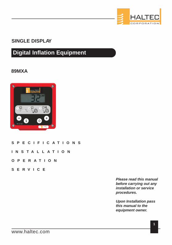
SINGLE DISPLAY
Digital Inflation Equipment
S P E C I F I C A T I O N S
I N S T A L L A T I O N
O P E R A T I O N
S E R V I C E
Please read this manual before carrying out any installation or service procedures.
Upon Installation pass this manual to the equipment owner.
89MXA
www.haltec.com
Contents
1.0 IntroductionThis ManualDigital Inflation OverviewGeneral Specifications
2.0 89MXA SpecificationsInstallation
3.0 OperationSwitch FunctionsInflation & DeflationVolume Adjustment
4.0 Troubleshooting
5.0 Wiring DiagramControl Wiring Diagram
6.0 Spare Parts & Accessories
7.0 Component Replacement
8.0 Compressed Air Systems
9.0 Warranty
10.0 Initial Verification Certificate
11.0 Glossary & Conversions
2
www.haltec.com
The hazard or unsafe practicecould result in minor injury.
! CAUTION
The hazard or unsafe practicecould result in severe injury ordeath.
! WARNING
1.0 Introduction
1.1 This Manual
Congratulations on selecting a Haltec Digital Tire Inflator. This equipment has a number of unique features that are explained in this manual.
Throughout the manual the following symbols will be used, this information is for your safety and to prevent damage to this product.
1.2 Digital Inflation Overview
Your Haltec Digital Tire Inflator has a dual pneumatic valve controlled by an Digital circuit that controls the inflation and deflation process.
The process will only commence when there is more that 3 psi, 20 kPa or 0.2 bar in the tire
when the hose is connected.
! WARNING
To avoid the risk of electrical shock, personal injury or death, disconnect power before servicing this equipment
3
www.haltec.com
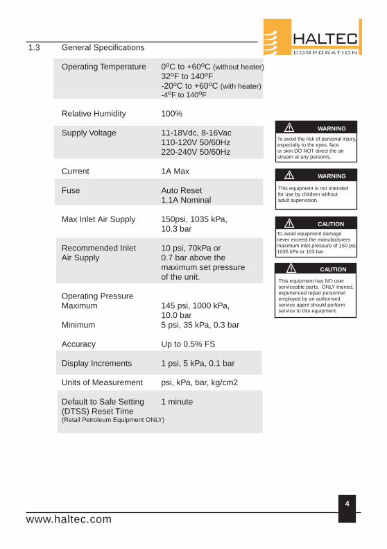
1.3 General Specifications
oOperating Temperature 0 C to +60 C (without heater)o o32 F to 140 Fo o-20 C to +60 C (with heater)
o o-4 F to 140 F
Relative Humidity 100%
Supply Voltage 11-18Vdc, 8-16Vac110-120V 50/60Hz220-240V 50/60Hz
Current 1A Max
Fuse Auto Reset1.1A Nominal
Max Inlet Air Supply 150psi, 1035 kPa,10.3 bar
Recommended Inlet 10 psi, 70kPa orAir Supply 0.7 bar above the
maximum set pressureof the unit.
Operating PressureMaximum 145 psi, 1000 kPa,
10.0 barMinimum 5 psi, 35 kPa, 0.3 bar
Accuracy Up to 0.5% FS
Display Increments 1 psi, 5 kPa, 0.1 bar
Units of Measurement psi, kPa, bar, kg/cm2
Default to Safe Setting 1 minute(DTSS) Reset Time(Retail Petroleum Equipment ONLY)
o
! WARNING
! WARNING
! CAUTION
! CAUTION
To avoid the risk of personal injury, especially to the eyes, face or skin DO NOT direct the air stream at any person/s.
This equipment is not intendedfor use by children withoutadult supervision.
To avoid equipment damagenever exceed the manufacturersmaximum inlet pressure of 150 psi,1035 kPa or 103 bar.
This equipment has NO userserviceable parts. ONLY trained,experienced repair personnelemployed by an authorisedservice agent should performservice to this equipment.
4
www.haltec.com
5
! WARNING
! CAUTION
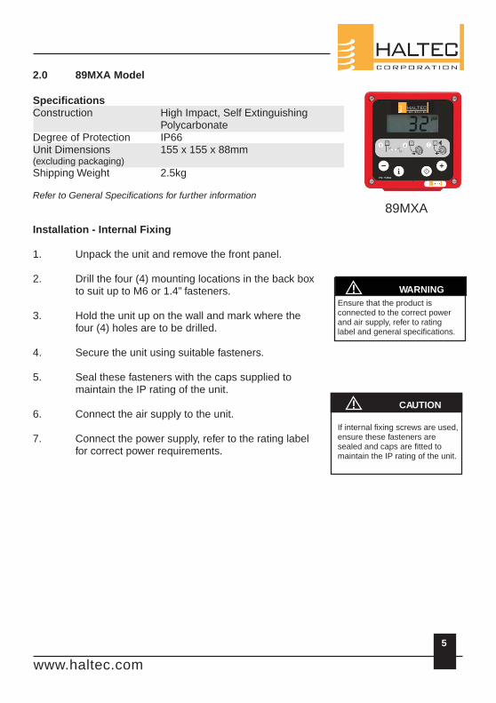
89MXA
2.0 89MXA Model
SpecificationsConstruction High Impact, Self Extinguishing
PolycarbonateDegree of Protection IP66Unit Dimensions 155 x 155 x 88mm(excluding packaging)
Shipping Weight 2.5kg
Refer to General Specifications for further information
Installation - Internal Fixing
1. Unpack the unit and remove the front panel.
2. Drill the four (4) mounting locations in the back boxto suit up to M6 or 1.4” fasteners.
3. Hold the unit up on the wall and mark where thefour (4) holes are to be drilled.
4. Secure the unit using suitable fasteners.
5. Seal these fasteners with the caps supplied to maintain the IP rating of the unit.
6. Connect the air supply to the unit.
7. Connect the power supply, refer to the rating labelfor correct power requirements.
Ensure that the product is connected to the correct power and air supply, refer to ratinglabel and general specifications.
If internal fixing screws are used,ensure these fasteners are sealed and caps are fitted tomaintain the IP rating of the unit.
! CAUTION
www.haltec.com
! WARNING
! WARNING
To avoid the risk of personal injury, especially to the eyes, face or skin DO NOT direct the air stream at any person/s.
This equipment is not intended For use by children without adult supervision.
3.0 Operation
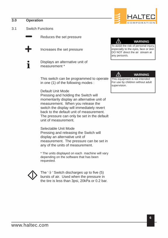
3.1 Switch Functions
Reduces the set pressure
Increases the set pressure
Displays an alternative unit of measurement *
This switch can be programmed to operate in one (1) of the following modes :
Default Unit ModePressing and holding the Switch will momentarily display an alternative unit of measurement. When you release the switch the display will immediately revert back to the default unit of measurement. The pressure can only be set in the default unit of measurement.
Selectable Unit ModePressing and releasing the Switch will display an alternative unit of measurement. The pressure can be set in any of the units of measurement.
* The units displayed on each machine will vary depending on the software that has been requested.
The ‘ ’ Switch discharges up to five (5) bursts of air. Used when the pressure in the tire is less than 3psi, 20kPa or 0.2 bar.
6
www.haltec.com
7
! WARNING
3.2 Inflation & Deflation
3.2.1 Set the desired pressure, refer to Section 3.1 for the function of each Switch.
3.2.2 Connect the hose to the tire, ensure the hose is connected securely. Air leaks will cause a error message to be displayed, refer to Section 4.0.
3.2.3 The pressure in the tire will be displayed.
3.2.4 The unit will inflate or deflate the tire to the set pressure. Periodically the process will stop and display the pressure in the tire.
3.2.5 If the pressure in the tire is less than 3psi, 20 kPa or 0.2 bar the process will not commence until the ‘ ’ Switch is pressed, refer Section 3.1.
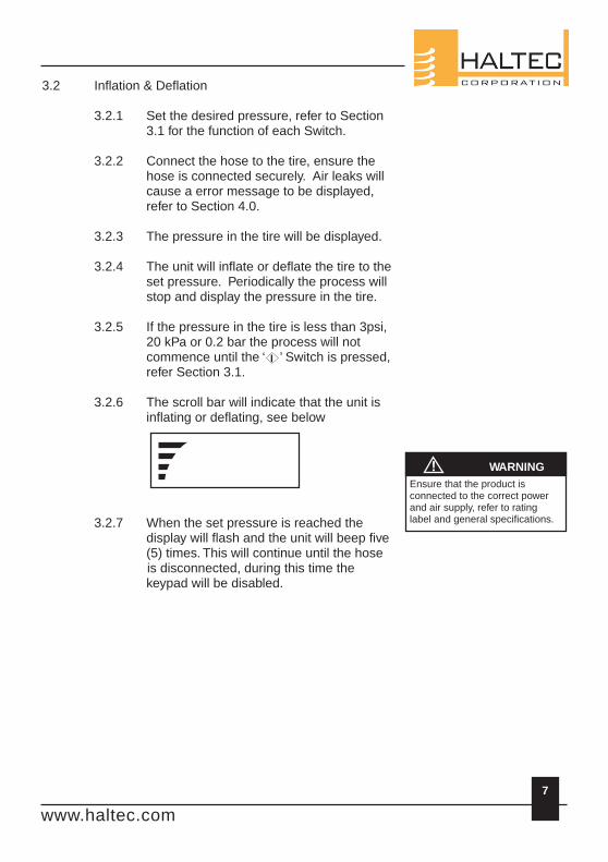
3.2.6 The scroll bar will indicate that the unit is inflating or deflating, see below
3.2.7 When the set pressure is reached the display will flash and the unit will beep five (5) times. This will continue until the hose
is disconnected, during this time the keypad will be disabled.
Ensure that the product is connected to the correct power and air supply, refer to rating label and general specifications.
www.haltec.com
3.3 Volume Adjustment
3.3.1 Turn off the unit.
3.3.2 Press and hold the ‘-’ and ‘ ’ switches, refer to Section 3.1.
3.3.3 Turn the unit on, VOL will be displayed.
3.3.4 Adjust the volume using ‘+’ and ‘-’ switches, refer to Section 3.1.
3.3.5 To store the settings press the ‘ ’ switch. Further changes can be made by repeating the above procedure.
8
www.haltec.com
139
4.0 Troubleshooting
The following chart has been prepared to assist with diagnosis of faults
No display. No power supply Check power supplyThe inflation process does not The tire is deflated below 3 Presscommence, even when the psi, 20 kPa or 0.2 bar.pressure is set and the hose is The hose connector is faulty. Replace the hose connected to the tire. Connector.The display will not move or is The faceplate/switch is Replace the faceplate/stuck on a particular value. damaged. switch.
The unit deflates very slowly. The silencer plug on the valve Remove and clean theblock is blocked. silencer plug.
The unit no longer beeps. The beeper is damaged. Replace the beeper.
The inflation process Low or nil supply pressure. Check the air compressorcommences but does not supply pressure.complete.ER1 Unstable pressure, faulty hose Replace the hose
connector. connector.ER2 Unstable pressure, faulty hose Replace the hose
connector. connector.Incorrect supply pressure. Check the air compressor
supply pressure.Inflate & Deflate valve Check the valveconnections are reversed. connections on the PCB.
ER3 Low or nil supply pressure. Check the air compressorsupply pressure.
ER4 Initial or final pressure is too Disconnect hose high, exceeding the maximum connector, reset pressure by more than 20 psi, processor by switching off 140 kPa or 1.4 bar. the power for a minimum
of 5 sec. If error message reappears replace PCB.
ER5 Low voltage supply. Check power supply. Themessage will clear when the correct voltage is restored.
PROBLEM POSSIBLE CAUSE SOLUTION
www.haltec.com
4.0 Troubleshooting, cont.
The following chart has been prepared to assist with diagnosis of faults
ER6 Programme or PCB Error Reset machine by switching off power for 5 seconds. If error
message reappears replace PCB.ER8 Calibration Error Unit requires calibration,
contact your local distributor or service agent.ER9 Automatic Calibration Check/ Disconnect hose connector, reset
Calibration Error machine by switching off power for 5 seconds. The ER9 message will clear automatically when the factory calibration is restored. If the ER9 message continues to reappear, replace the PCB.
PROBLEM POSSIBLE CAUSE SOLUTION
10
www.haltec.com
ERP Unstable supply pressure Check the supply pressure.Hose disconnection during inflate cycle Check hose connection.
ERU Short circuitry on valve connection Check and dry up the valve connection.ERB Short circuitry on buzzer connection Check and dry up the buzzer connection.
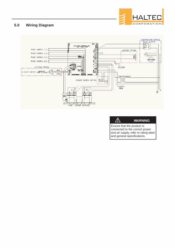
5.0 Wiring Diagram
! WARNING
Ensure that the product isconnected to the correct power and air supply, refer to rating label and general specifications.
6.0 Spare Parts & Accessories
Part Number Description
91.0214 Clip on Heavy Duty Hose Chuck 1/4”91.0211 Hold on Twin Chuck 1/4”
Hose Kit 61.1018 2m Black Hose fitted with Standard JP Coupling and
Heavy Duty Hose ChuckOther colours available on request
41.0702 Beeper, suits 89MXA
12
www.haltec.com
7.0 Component Replacement
7.1 Hose Connector (Clip On Hose Chuck)
The hose chuck has a screw on connector. Simply unscrew the existing hose and replace with the new hose chuck.
7.2 Beeper Replacement
89MXA
7.2.1 Remove the four (4) cover screws.
7.2.2 Remove the beeper lockring on the outside of the enclosure.
7.2.3 Remove the beeper by lifting off the cable terminal from the PCB.
Installation is the reversal of this procedure.
13
! WARNING
To avoid the risk of electrical shock, personal injury or death, disconnect power before servicing this equipment
www.haltec.com
8.0 Compressed Air Systems
The information in this section is designed to provide some basic information about compressed air systems and the use of Digital inflation equipment.
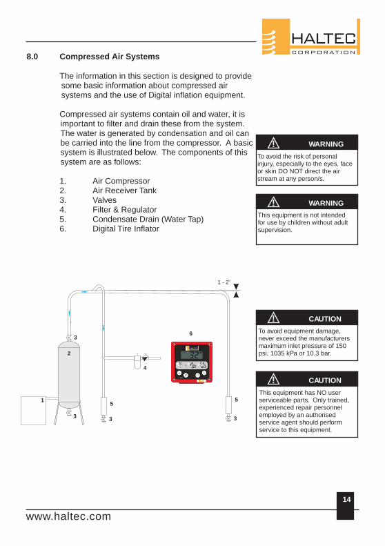
Compressed air systems contain oil and water, it is important to filter and drain these from the system. The water is generated by condensation and oil can be carried into the line from the compressor. A basic system is illustrated below. The components of this system are as follows:
1. Air Compressor2. Air Receiver Tank3. Valves4. Filter & Regulator5. Condensate Drain (Water Tap)6. Digital Tire Inflator
! WARNING
! WARNING
! CAUTION
! CAUTION
To avoid the risk of personal injury, especially to the eyes, face or skin DO NOT direct the air stream at any person/s.
To avoid equipment damage, never exceed the manufacturers maximum inlet pressure of 150 psi, 1035 kPa or 10.3 bar.
This equipment is not intended for use by children without adult supervision.
This equipment has NO user serviceable parts. Only trained, experienced repair personnel employed by an authorised service agent should perform service to this equipment.
14
5
3
6
o1 - 2
1
3
2
3
4
5
3
www.haltec.com
15
! WARNING
! CAUTION
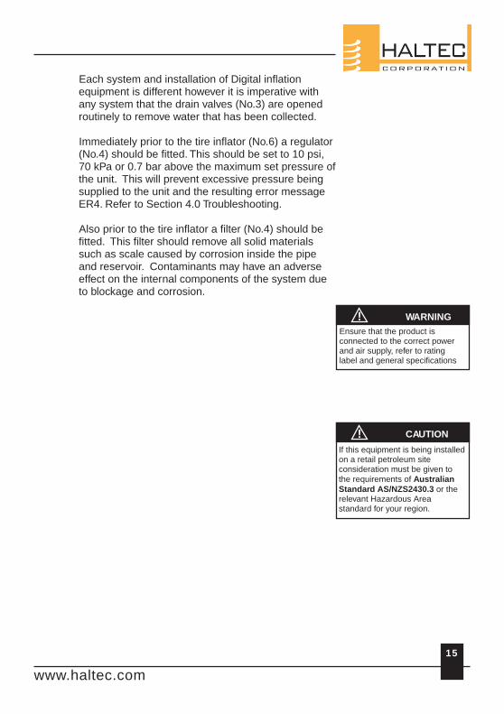
Each system and installation of Digital inflation equipment is different however it is imperative with any system that the drain valves (No.3) are opened routinely to remove water that has been collected.
Immediately prior to the tire inflator (No.6) a regulator (No.4) should be fitted. This should be set to 10 psi, 70 kPa or 0.7 bar above the maximum set pressure of the unit. This will prevent excessive pressure being supplied to the unit and the resulting error message ER4. Refer to Section 4.0 Troubleshooting.
Also prior to the tire inflator a filter (No.4) should be fitted. This filter should remove all solid materials such as scale caused by corrosion inside the pipe and reservoir. Contaminants may have an adverse effect on the internal components of the system due to blockage and corrosion.
Ensure that the product is connected to the correct power and air supply, refer to rating label and general specifications
If this equipment is being installed on a retail petroleum site consideration must be given to the requirements of Australian Standard AS/NZS2430.3 or the relevant Hazardous Area standard for your region.
www.haltec.com
16
9.0 Policy / Warranty
Your Haltec Digital Inflation Equipment is covered under warranty for 12 months from the date of invoice, subject to the following conditions:
9.1 ProductsSubject to change without notice. Haltec is not responsible for inadvertent typographical errors or omissions.
9.2 Returned GoodsNo return goods will be accepted unless authorized in writing by Haltec. All return goods must be shipped prepaid to the factory, and are subject to a restocking charge. Special items are not returnable.
9.3 WarrantyExcept where the product has been damaged by misuse, faulty installation, unauthorised repairs, incorrect maintenance or accidental damage, Haltec will at its own discretion repair or replace the defective product (or pay for the cost of repair or replacement).
Warranty does not include air hoses, hose connectors (hose chucks) or membrane keypads.
Haltec Corporation expressly excludes all other warranties expressed or implied, including without limitation the implied warranties of merchantability and fitness for any other purpose. Haltec Corporation further excludes liability for consequential and incidental losses including but not limited to the loss of profits which may arise out of the breakdown or failure of any product.
www.haltec.com
17
www.haltec.com
Model
O 89MXA
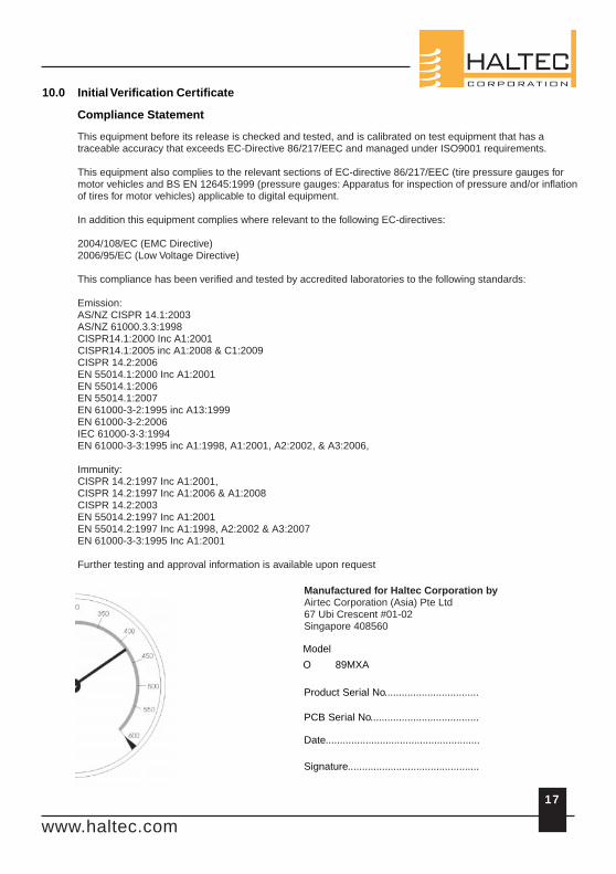
10.0 Initial Verification Certificate
Compliance Statement
Date......................................................
Signature..............................................
Product Serial No.................................
PCB Serial No......................................
Manufactured for Haltec Corporation byAirtec Corporation (Asia) Pte Ltd 67 Ubi Crescent #01-02Singapore 408560
This equipment before its release is checked and tested, and is calibrated on test equipment that has a traceable accuracy that exceeds EC-Directive 86/217/EEC and managed under ISO9001 requirements.
This equipment also complies to the relevant sections of EC-directive 86/217/EEC (tire pressure gauges for motor vehicles and BS EN 12645:1999 (pressure gauges: Apparatus for inspection of pressure and/or inflation of tires for motor vehicles) applicable to digital equipment.
In addition this equipment complies where relevant to the following EC-directives:
2004/108/EC (EMC Directive)2006/95/EC (Low Voltage Directive)
This compliance has been verified and tested by accredited laboratories to the following standards:
Emission: AS/NZ CISPR 14.1:2003 AS/NZ 61000.3.3:1998CISPR14.1:2000 Inc A1:2001CISPR14.1:2005 inc A1:2008 & C1:2009 CISPR 14.2:2006EN 55014.1:2000 Inc A1:2001EN 55014.1:2006EN 55014.1:2007 EN 61000-3-2:1995 inc A13:1999 EN 61000-3-2:2006 IEC 61000-3-3:1994EN 61000-3-3:1995 inc A1:1998, A1:2001, A2:2002, & A3:2006,
Immunity: CISPR 14.2:1997 Inc A1:2001, CISPR 14.2:1997 Inc A1:2006 & A1:2008CISPR 14.2:2003EN 55014.2:1997 Inc A1:2001EN 55014.2:1997 Inc A1:1998, A2:2002 & A3:2007EN 61000-3-3:1995 Inc A1:2001
Further testing and approval information is available upon request
11.0 Glossary & Conversions
Units of Measurementpsi Pounds per square inchkPa Kilopascalsbar Barometricatm AtmospheresKg/cm2 Kilograms per square centimetreIP International Protection RatingCFM Cubic Feet per MinuteLPM Litres per MinutePCB Printed Circuit BoardSample Tube Connects the valve block & PCBLCD Liquid Crystal Display
Conversions
1 psi = 6.8947 kPa0.0689479 bar0.06890459 atm0.0703069 kg/cm2
18
www.haltec.com

19
www.haltec.com
20
www.haltec.com
Haltec CorporationShipping Address:32585 North Price RoadSalem, Ohio 44460
Mailing Address:PO Box 1180Salem, Ohio 44460-8180
Phone: (330) 222-1501Toll Free: (800) 321-6471 (US & Canada)Fax: (330) 222-2302
http://www.haltec.com Haltec Corporation reserves the right to change specifications, modify designs and discontinue items without incurring obligation and whilst every effort is made to ensure descriptions, specifications and other information in this manual is correct, no warranty is given in respect thereof and the company shall not be liable for any error therein.
R2 (4 Jun 2012) C10-2