robo cylinder rca2 actuator slider type - iai america
TRANSCRIPT

IAI America, Inc.
ROBO Cylinder RCA2 Actuator
Slider Type
First Edition
Operating Manual
Motor coupling types: SA3C SA4C SA5C SA6C Motor reversing types: SA3R SA4R SA5R SA6R

Please Read Before Use Thank you for purchasing an IAI product. To ensure safe use of the actuator, be sure to read this operating manual and handle the actuator correctly. Do not handle or operate the actuator in any way not specified in this operating manual or the operation manual of your controller, by assuming that any such handling/use is prohibited.
[Applicable Models]
ROBO Cylinder RCA2 Actuator Motor coupling types
• RCA2-SA3C • RCA2-SA4C • RCA2-SA5C • RCA2-SA6C
Motor reversing types • RCA2-SA3R • RCA2-SA4R • RCA2-SA5R • RCA2-SA6R
• Unauthorized copy, duplication or reproduction of the information provided in this manual, whether in whole or part, is strictly prohibited.
• The information provided in this manual is subject to change without prior notice for the purpose of improvement.
• This manual has been written with due attention to precision and completeness. Should you find any error or if you have any feed back, please contact IAI.

Table of Contents
Safety Guide ................................................................................................................................ 1 Handling Precautions .................................................................................................................... 9 1. Part Names .......................................................................................................................... 12 2. External Dimensions ............................................................................................................ 13
2.1 RCA2-SA3C............................................................................................................................... 13 2.2 RCA2-SA3C- with Slider Cover................................................................................................. 14 2.3 RCA2-SA4C............................................................................................................................... 15 2.4 RCA2-SA4C- with Slider Cover................................................................................................. 16 2.5 RCA2-SA5C............................................................................................................................... 17 2.6 RCA2-SA5C- with Slider Cover................................................................................................. 18 2.7 RCA2-SA6C............................................................................................................................... 19 2.8 RCA2-SA6C- with Slider Cover................................................................................................. 20 2.9 RCA2-SA3R, Reversing to Left (Right) ..................................................................................... 21 2.10 RCA2-SA3R- with Slider Cover, Reversing to Left (Right)........................................................ 22 2.11 RCA2-SA4R, Reversing to Left (Right) ..................................................................................... 23 2.12 RCA2-SA4R- with Slider Cover, Reversing to Left (Right)........................................................ 24 2.13 RCA2-SA5R, Reversing to Left (Right) ..................................................................................... 25 2.14 RCA2-SA5R- with Slider Cover, Reversing to Left (Right)........................................................ 26 2.15 RCA2-SA6R, Reversing to Left (Right) ..................................................................................... 27 2.16 RCA2-SA6R- with Slider Cover, Reversing to Left (Right) ....................................................... 28
3. Cable Drawings .................................................................................................................... 29 3.1 ASEP Controller Cables ............................................................................................................ 29 3.2 ACON, ASEL Controller Cables ................................................................................................ 30
4. Options ................................................................................................................................. 31 4.1 Brake Type ................................................................................................................................ 31 4.2 Power-saving Measure.............................................................................................................. 31 4.3 No-cover Specification............................................................................................................... 31 4.4 Reversed-home Specification.................................................................................................... 31
5. Checking after Unpacking .................................................................................................... 32 5.1 Included Items ........................................................................................................................... 32 5.2 Operation Manuals Relating to This Product............................................................................. 32 5.3 How to Read Model Nameplate ................................................................................................ 32 5.4 How to Read Model ................................................................................................................... 33
6. Specifications ....................................................................................................................... 34 7. Selection Conditions............................................................................................................. 35
7.1 Selection Method....................................................................................................................... 35 8. Installation Environment and Storage Environment ............................................................. 37

8.1 Installation Environment ............................................................................................................ 37 8.2 Storage Environment................................................................................................................. 37
9. Installation ............................................................................................................................ 38 9.1 Installation of Actuator ............................................................................................................... 38 9.2 Installation Surface .................................................................................................................... 40 9.3 Installation of the Load .............................................................................................................. 41
10. Connecting with Controller ................................................................................................... 42 11. Notes on Operation .............................................................................................................. 46
11.1 Placing a Load on the Actuator ................................................................................................. 46 11.1.1 Positioning the guide to calculate the load moment .................................................... 48 11.1.2 Thrust direction external force ..................................................................................... 49
11.2 Adjusting the Home Position ..................................................................................................... 50 11.3 Changing the Home Position Direction ..................................................................................... 50 11.4 Stainless Sheet Section............................................................................................................. 51
12. Maintenance Inspection ....................................................................................................... 52 12.1 Inspection Items and Timing...................................................................................................... 52 12.2 External Visual Inspection ......................................................................................................... 52 12.3 Cleaning..................................................................................................................................... 52 12.4 Internal Inspections ................................................................................................................... 53 12.5 Internal Cleaning ....................................................................................................................... 54 12.6 Greasing Guides........................................................................................................................ 54
12.6.1 Applicable greases for guide ....................................................................................... 54 12.6.2 Applicable greases for ball screw ................................................................................ 54 12.6.3 How to apply grease .................................................................................................... 55
12.7 Belt............................................................................................................................................. 57 12.7.1 Inspection of belt.......................................................................................................... 57 12.7.2 Applicable belt.............................................................................................................. 57 12.7.3 Adjustment of belt tension ........................................................................................... 57
12.8 Stainless Sheet Replacement (for models with slider cover) .................................................... 58 12.9 Replacement of Motor (AC Servo Motor: RCA2) ...................................................................... 60 12.10 Replacement of Belt and Motor for Reversing Type (AC Servo Motor: RCA2) ........................ 64
13. Warranty............................................................................................................................... 68 14. Change History..................................................................................................................... 69 Appendix Using the home position marks................................................................................. 70


1
Safety Guide (Read This Section Before Use)
When designing and manufacturing a robot system, ensure safety by following the safety precautions provided below and taking the necessary measures. 1. Regulations and Standards Governing Industrial Robots Safety measures on mechanical devices are generally classified into four categories under the International Industrial Standard ISO/DIS 12100, “Safety of machinery,” as follows:
Safety measures Inherent safety design Protective guards --- Safety fence, etc. Additional safety measures --- Emergency stop device, etc. Information on use --- Danger sign, warnings, operation manual
Based on this classification, various standards are established in a hierarchical manner under the International Standards ISO/IEC. The safety standards that apply to industrial robots are as follows: Type C standards (individual safety standards) ISO10218 (Manipulating industrial robots – Safety)
JIS B 8433 (Manipulating industrial robots – Safety)
Also, Japanese laws regulate the safety of industrial robots, as follows: Industrial Safety and Health Law Article 59
Workers engaged in dangerous or harmful operations must receive special education. Ordinance on Industrial Safety and Health Article 36 --- Operations requiring special education
No. 31 (Teaching, etc.) --- Teaching and other similar work involving industrial robots (exceptions apply)
No. 32 (Inspection, etc.) --- Inspection, repair, adjustment and similar work involving industrial
robots (exceptions apply) Article 150 --- Measures to be taken by the user of an industrial robot

2
2. Requirements for Industrial Robots under Ordinance on Industrial
Safety and Health
Work area Work condition Cutoff of drive source Measure Article
Signs for starting operation Article 104 Outside movement
range
During automatic operation
Not cut off Installation of railings, enclosures, etc. Article 150-4
Cut off (including stopping of operation)
Sign, etc., indicating that work is in progress Article 150-3
Preparation of work rules Article 150-3
Measures to enable immediate stopping of operation Article 150-3
Sign, etc., indicating that work is in progress Article 150-3
Provision of special education Article 36-31
During teaching, etc.
Not cut off
Checkup, etc., before commencement of work Article 151
To be performed after stopping the operation Article 150-5
Cut off Sign, etc., indicating that work is in progress Article 150-5
Preparation of work rules Article 150-5
Measures to enable immediate stopping of operation Article 150-5
Sign, etc., indicating that work is in progress Article 150-5
Inside movement
range
During inspection, etc. Not cut off (when
inspection, etc., must be performed during operation)
Provision of special education (excluding cleaning and lubrication)
Article 36-32

3
3. Applicable Models of IAI’s Industrial Robots Machines meeting the following conditions are not classified as industrial robots according to Notice of Ministry of Labor No. 51 and Notice of Ministry of Labor/Labor Standards Office Director (Ki-Hatsu No. 340):
(1) Single-axis robot with a motor wattage of 80 W or less (2) Combined multi-axis robot whose X, Y and Z-axes are 300 mm or shorter and whose rotating
part, if any, has the maximum movement range of within 300 mm3 including the tip of the rotating part
(3) Multi-joint robot whose movable radius and Z-axis are within 300 mm Among the products featured in our catalogs, the following models are classified as industrial robots: 1. Single-axis ROBO Cylinders
RCS2/RCS2CR-SS8 whose stroke exceeds 300 mm 2. Single-axis robots
The following models whose stroke exceeds 300 mm and whose motor capacity also exceeds 80 W: ISA/ISPA, ISDA/ISPDA, ISWA/ISPWA, IF, FS, NS
3. Linear servo actuators All models whose stroke exceeds 300 mm
4. Cartesian robots Any robot that uses at least one axis corresponding to one of the models specified in 1 to 3
5. IX SCARA robots IX-NNN (NNW, NNC) 3515 IX-NNN (NNW, NNC) 50 /60 /70 /80 IX-NSN5016/6016 IX-TNN (UNN) 3015/3515 IX-HNN (INN) 50 /60 /70 /80

4
4. Notes on Safety of Our Products Common items you should note when performing each task on any IAI robot are explained below. No. Task Note 1 Model
selection This product is not planned or designed for uses requiring high degrees of safety. Accordingly, it cannot be used to sustain or support life and must not be used in the following applications: [1] Medical devices relating to maintenance, management, etc., of life or health [2] Mechanisms or mechanical devices (vehicles, railway facilities, aircraft
facilities, etc.) intended to move or transport people [3] Important safety parts in mechanical devices (safety devices, etc.)
Do not use this product in the following environments: [1] Place subject to flammable gases, ignitable objects, flammables, explosives,
etc. [2] Place that may be exposed to radiation [3] Place where the surrounding air temperature or relative humidity exceeds the
specified range [4] Place subject to direct sunlight or radiated heat from large heat sources [5] Place subject to sudden temperature shift and bedewing [6] Place subject to corrosive gases (sulfuric acid, hydrochloric acid, etc.) [7] Place subject to excessive dust, salt or iron powder [8] Place where the product receives direct vibration or impact
Do not use this product outside the specified ranges. Doing so may significantly shorten the life of the product or result in product failure or facility stoppage.
2 Transportation When transporting the product, exercise due caution not to bump or drop the product.
Use appropriate means for transportation. Do not step on the package. Do not place on the package any heavy article that may deform the package.
3 Storage The storage environment should conform to the installation environment. Among others, be careful not to cause bedewing.

5
No. Task Note
(1) Installing the robot, controller, etc. Be sure to firmly secure and affix the product (including its load). If the product tips over, drops, malfunctions, etc., damage or injury may result.
Do not step on the product or place any article on top. The product may tips over or the article may drop, resulting in injury, product damage, loss of/drop in product performance, shorter life, etc.
If the product is used in any of the following places, provide sufficient shielding measures: [1] Place subject to electrical noise [2] Place subject to a strong electric or magnetic field [3] Place where power lines or drive lines are wired nearby [4] Place subject to splashed water, oil or chemicals
(2) Wiring the cables Use IAI’s genuine cables to connect the actuator and controller or connect a teaching tool, etc.
Do not damage, forcibly bend, pull, loop round an object or pinch the cables or place heavy articles on top. Current leak or poor electrical continuity may occur, resulting in fire, electric shock or malfunction.
Wire the product correctly after turning off the power. When wiring a DC power supply (+24 V), pay attention to the positive and negative polarities. Connecting the wires in wrong polarities may result in fire, product failure or malfunction.
Be sure to connect the cable connectors without fail and firmly. Failing to do so may result in fire, electric shock or product malfunction.
Do not cut and reconnect the cables of the product to extend or shorten the cables. Doing so may result in fire or product malfunction.
(3) Grounding Be sure to provide class D (former class 3) grounding for the controller. Grounding is required to prevent electric shock and electrostatic charges, improve noise resistance and suppress unnecessary electromagnetic radiation.
4 Installation/ startup
(4) Safety measures Implement safety measures (such as installing safety fences, etc.) to prevent entry into the movement range of the robot when the product is moving or can be moved. Contacting the moving robot may result in death or serious injury.
Be sure to provide an emergency stop circuit so that the product can be stopped immediately in case of emergency during operation.
6
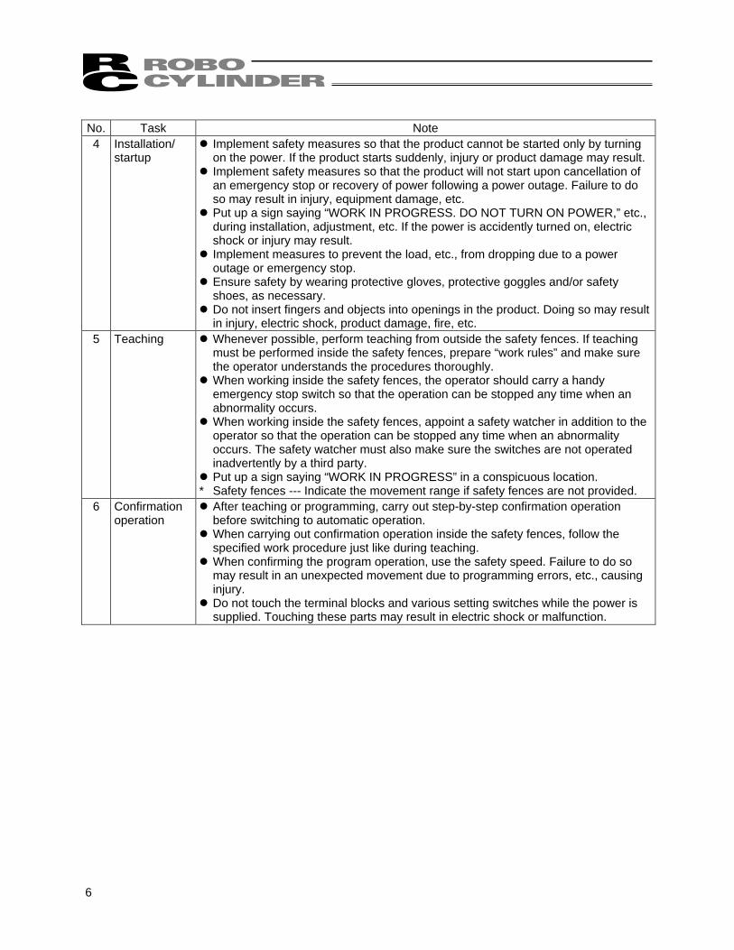
No. Task Note 4 Installation/
startup Implement safety measures so that the product cannot be started only by turning on the power. If the product starts suddenly, injury or product damage may result.
Implement safety measures so that the product will not start upon cancellation of an emergency stop or recovery of power following a power outage. Failure to do so may result in injury, equipment damage, etc.
Put up a sign saying “WORK IN PROGRESS. DO NOT TURN ON POWER,” etc., during installation, adjustment, etc. If the power is accidently turned on, electric shock or injury may result.
Implement measures to prevent the load, etc., from dropping due to a power outage or emergency stop.
Ensure safety by wearing protective gloves, protective goggles and/or safety shoes, as necessary.
Do not insert fingers and objects into openings in the product. Doing so may result in injury, electric shock, product damage, fire, etc.
5 Teaching Whenever possible, perform teaching from outside the safety fences. If teaching must be performed inside the safety fences, prepare “work rules” and make sure the operator understands the procedures thoroughly.
When working inside the safety fences, the operator should carry a handy emergency stop switch so that the operation can be stopped any time when an abnormality occurs.
When working inside the safety fences, appoint a safety watcher in addition to the operator so that the operation can be stopped any time when an abnormality occurs. The safety watcher must also make sure the switches are not operated inadvertently by a third party.
Put up a sign saying “WORK IN PROGRESS” in a conspicuous location. * Safety fences --- Indicate the movement range if safety fences are not provided.
6 Confirmation operation
After teaching or programming, carry out step-by-step confirmation operation before switching to automatic operation.
When carrying out confirmation operation inside the safety fences, follow the specified work procedure just like during teaching.
When confirming the program operation, use the safety speed. Failure to do so may result in an unexpected movement due to programming errors, etc., causing injury.
Do not touch the terminal blocks and various setting switches while the power is supplied. Touching these parts may result in electric shock or malfunction.
7
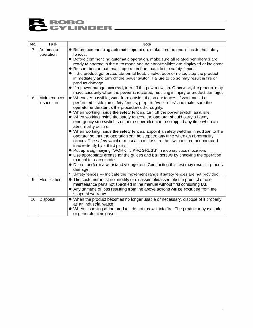
No. Task Note 7 Automatic
operation Before commencing automatic operation, make sure no one is inside the safety fences.
Before commencing automatic operation, make sure all related peripherals are ready to operate in the auto mode and no abnormalities are displayed or indicated.
Be sure to start automatic operation from outside the safety fences. If the product generated abnormal heat, smoke, odor or noise, stop the product immediately and turn off the power switch. Failure to do so may result in fire or product damage.
If a power outage occurred, turn off the power switch. Otherwise, the product may move suddenly when the power is restored, resulting in injury or product damage.
8 Maintenance/ inspection
Whenever possible, work from outside the safety fences. If work must be performed inside the safety fences, prepare “work rules” and make sure the operator understands the procedures thoroughly.
When working inside the safety fences, turn off the power switch, as a rule. When working inside the safety fences, the operator should carry a handy emergency stop switch so that the operation can be stopped any time when an abnormality occurs.
When working inside the safety fences, appoint a safety watcher in addition to the operator so that the operation can be stopped any time when an abnormality occurs. The safety watcher must also make sure the switches are not operated inadvertently by a third party.
Put up a sign saying “WORK IN PROGRESS” in a conspicuous location. Use appropriate grease for the guides and ball screws by checking the operation manual for each model.
Do not perform a withstand voltage test. Conducting this test may result in product damage.
* Safety fences --- Indicate the movement range if safety fences are not provided. 9 Modification The customer must not modify or disassemble/assemble the product or use
maintenance parts not specified in the manual without first consulting IAI. Any damage or loss resulting from the above actions will be excluded from the scope of warranty.
10 Disposal When the product becomes no longer usable or necessary, dispose of it properly as an industrial waste.
When disposing of the product, do not throw it into fire. The product may explode or generate toxic gases.
8
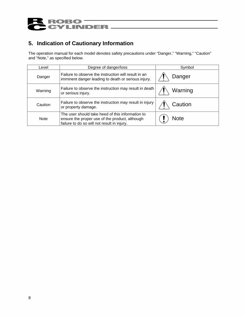
5. Indication of Cautionary Information The operation manual for each model denotes safety precautions under “Danger,” “Warning,” “Caution” and “Note,” as specified below.
Level Degree of danger/loss Symbol
Danger Failure to observe the instruction will result in an imminent danger leading to death or serious injury. Danger
Warning Failure to observe the instruction may result in death or serious injury. Warning
Caution Failure to observe the instruction may result in injury or property damage. Caution
Note The user should take heed of this information to ensure the proper use of the product, although failure to do so will not result in injury.
Note
9
Handling Precautions
1. Handling a Single Actuator Please adhere to the following when handling a single actuator. 1.1 Handling the Packed Unit Unless otherwise specified, single-axis actuators are shipped in individual packaging. Please handle packages carefully during transport to ensure that product is not damaged by bumping or dropping. • Never attempt to move heavy packages by yourself. • Always set packages down on a level surface. • Never climb on top of packages. • Never place heavy objects or objects where the load is concentrated in one place on top of packages,
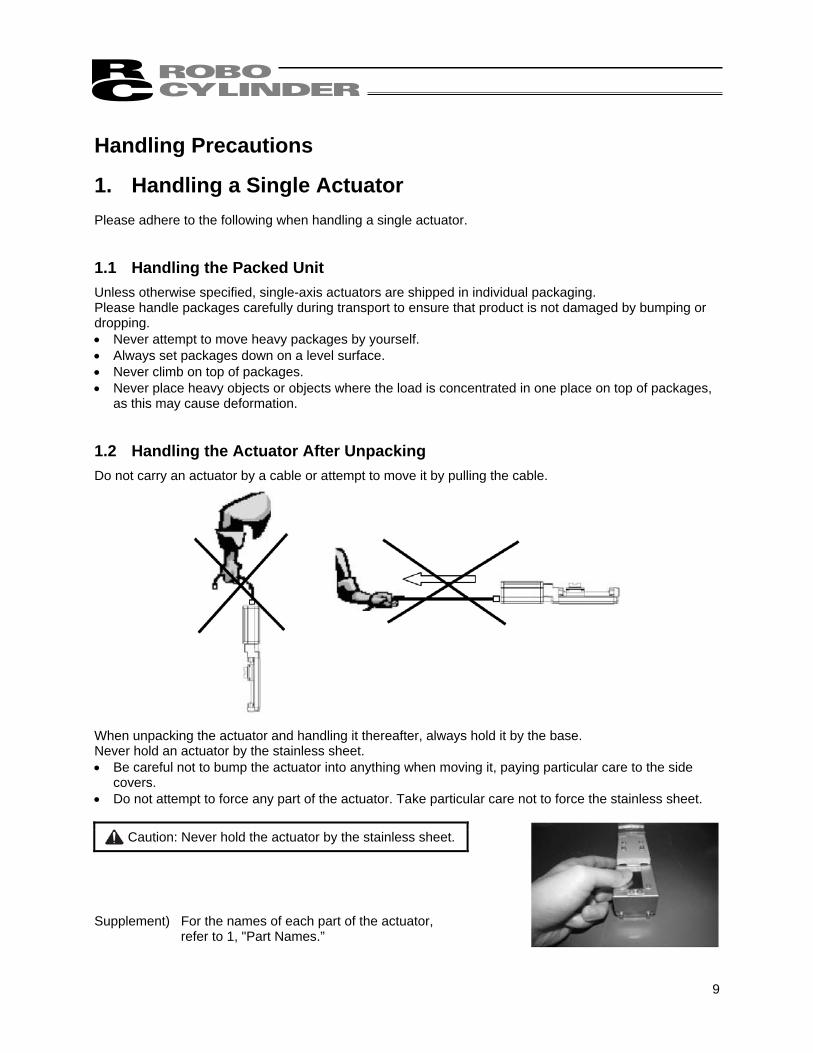
as this may cause deformation. 1.2 Handling the Actuator After Unpacking Do not carry an actuator by a cable or attempt to move it by pulling the cable. When unpacking the actuator and handling it thereafter, always hold it by the base. Never hold an actuator by the stainless sheet. • Be careful not to bump the actuator into anything when moving it, paying particular care to the side
covers. • Do not attempt to force any part of the actuator. Take particular care not to force the stainless sheet.
Caution: Never hold the actuator by the stainless sheet.
Supplement) For the names of each part of the actuator,
refer to 1, "Part Names.”

10
2. Handling the Actuator Assembly When transporting the actuator with its axes already assembled, take note of the following items. 2.1 Shipping from IAI Already Assembled After assembly at IAI, your machine undergoes a shipping inspection, is packed in a crate with skids, and finally shipped. If any of the combined actuators is a slider, the slider is securely fastened in place to prevent unexpected movement during shipping. Combined units have the ends of their actuators fastened so as to prevent them from moving significantly due to external vibration. • The crate is not designed to withstand dropping or collision. Please handle it carefully. It is also not
built to have items stacked on it, so please avoid placing heavy objects on top of the crate. • When lifting the package using belts or the like, be sure to pass the belts around the reinforcement
frames under the skids. The same applies for lifting the package with a forklift; please ensure that the forks are placed under the skids.
• When setting the package down, do not let the package receive an impact upon contacting the floor. 2.2 Handling After Unpacking Please adhere to the following instructions when handling the assembled unit, whether it was shipped pre-assembled at IAI or assembled on your site. • Secure the slider so that it does not move unexpectedly during transport. • If the end of the actuator is protruding, fasten it down properly so that it does not move significantly due
to external vibration. When transporting the assembly without the ends of the actuators fastened, do not subject the assembly to an impact of 0.3 G or more.
• When using belts or the like to lift an assembly consisting of an actuator and peripheral equipment, make sure the belts are not passed around the actuator itself or otherwise do not touch the actuator.
• Make sure the belts support the actuator load by its base by using appropriate cushioning materials. • Lift the end of the Y-axis with a separate belt, ensuring that the assembly remains level. At this time,
also make sure the load is not placed on the screw cover. • Make sure the load is not placed on the brackets, covers, or connector box.
Also make sure the cables are not pinched or deformed excessively.

11
3. Handling after Assembly with Peripheral Equipment When the machine assembled at IAI is transported as an assembly, also follow the handling precautions in 2.2, “Handling after Unpacking.”
12
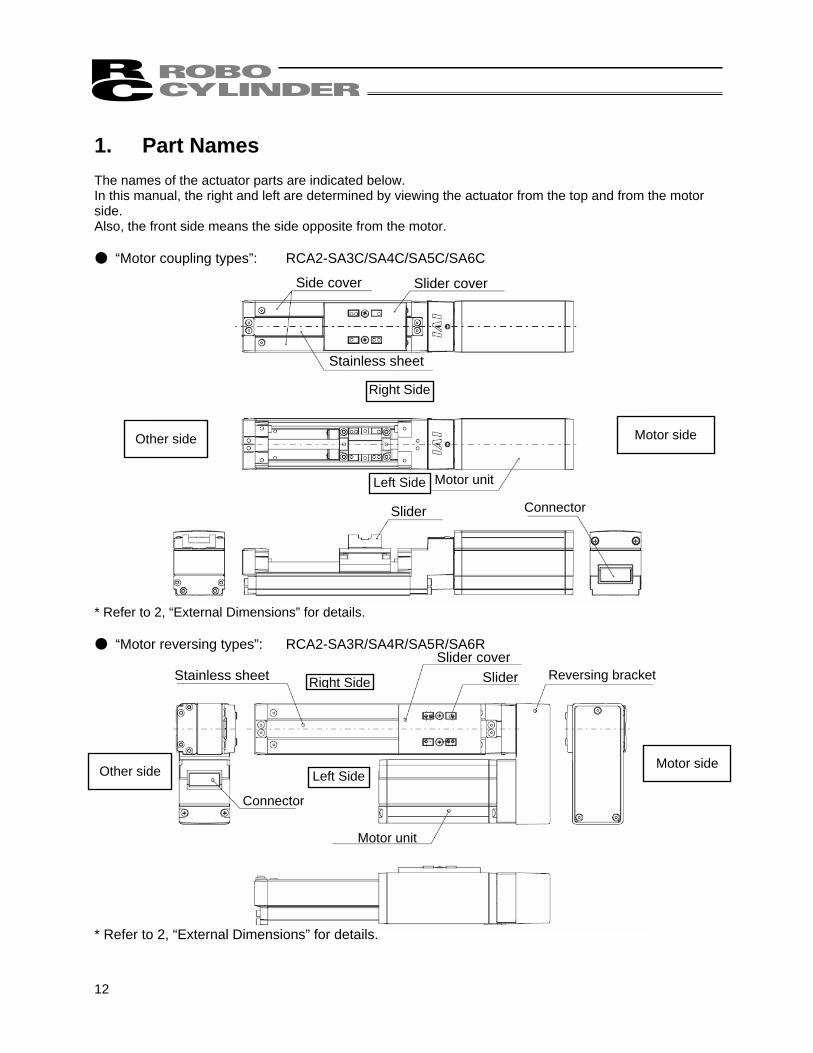
Side cover Slider cover
Stainless sheet
Right Side
Motor side
Motor unit Left Side
Slider Connector
Stainless sheet Slider
Left Side
Right Side
Other side
Connector
Motor unit
Motor side
Slider cover Reversing bracket
1. Part Names The names of the actuator parts are indicated below. In this manual, the right and left are determined by viewing the actuator from the top and from the motor side. Also, the front side means the side opposite from the motor. ● “Motor coupling types”: RCA2-SA3C/SA4C/SA5C/SA6C * Refer to 2, “External Dimensions” for details. ● “Motor reversing types”: RCA2-SA3R/SA4R/SA5R/SA6R * Refer to 2, “External Dimensions” for details.
Other side
13
2-∅
2H7,
dep
th 5
D-M
3, d
epth
5
∅2H
7, d
epth
4 (f
rom
bot
tom
face
of b
ase)
With
out b
rake
With
bra
ke
Det
ail v
iew
of F
S
cale
5:1
Bra
ke ty
pe
4-M
3, d
epth
6
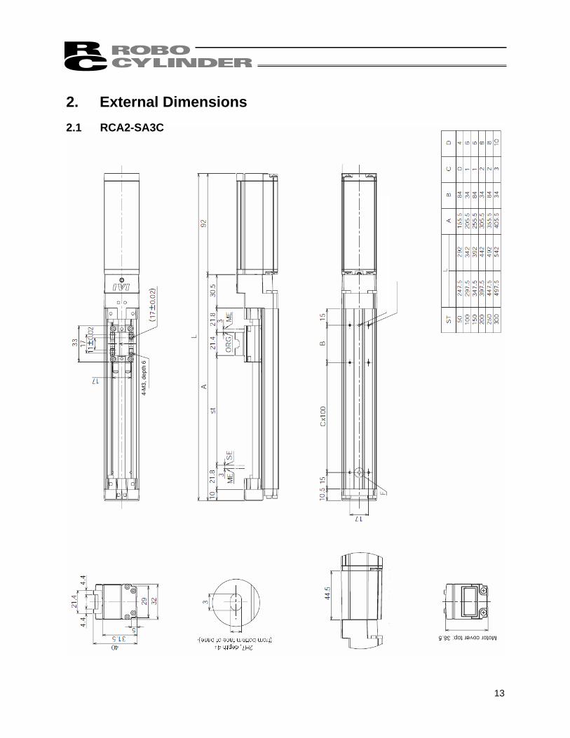
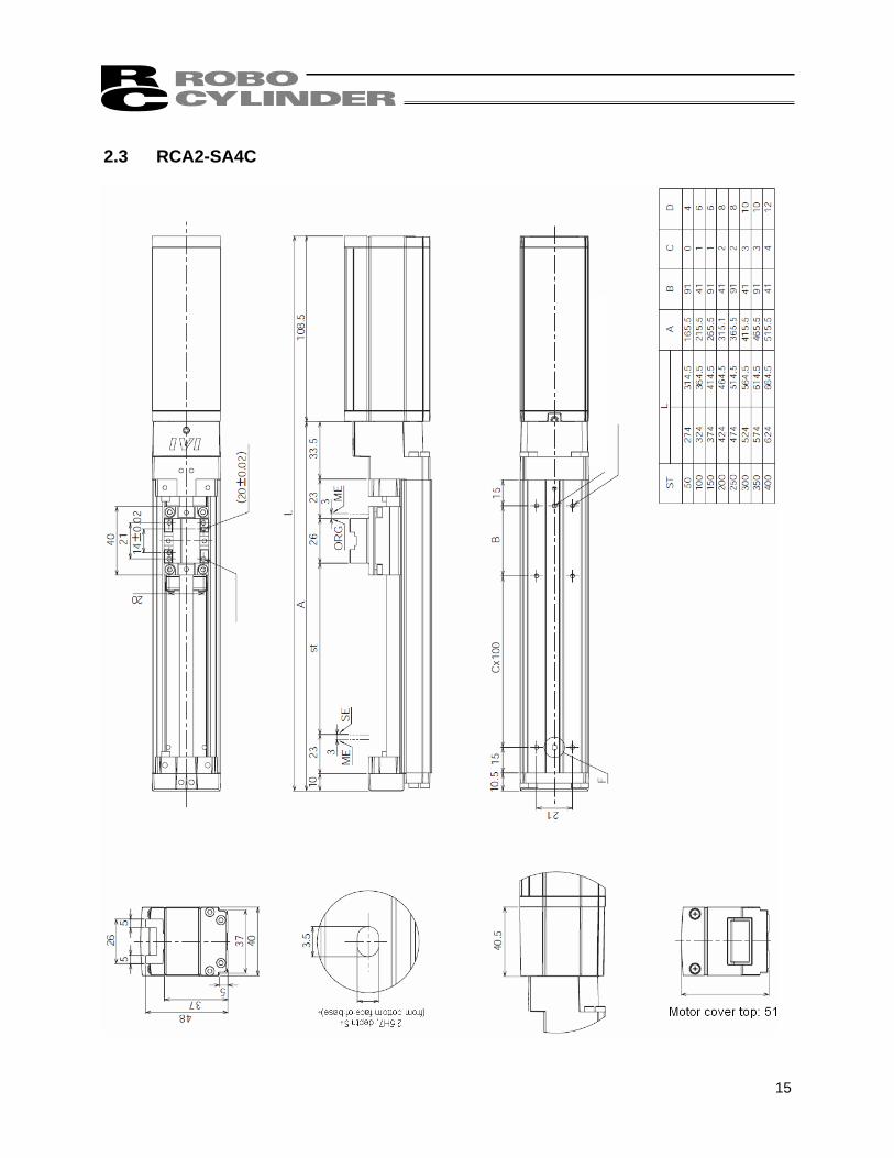
2. External Dimensions 2.1 RCA2-SA3C
14
4-M
3, d
epth
6
2-∅
2H7,
dep
th 5
D-M
3, d
epth
5
∅2H
7, d
epth
4 (f
rom
bot
tom
face
of b
ase)
Det
ail v
iew
of F
S
cale
5:1
With
out b
rake
With
bra
ke
Bra
ke ty
pe
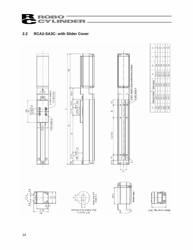
2.2 RCA2-SA3C- with Slider Cover
15
4-M
3, d
epth
6
2-∅
2.5H
7, d
epth
5
D-M
3, d
epth
5
∅2.
5H7,
dep
th 5
(fro
m b
otto
m fa
ce o
f bas
e)
Det
ail v
iew
of F
S
cale
5:1
With
out b
rake
With
bra
ke
Bra
ke ty
pe
2.3 RCA2-SA4C
16
4-M
3, d
epth
62-
∅2.
5H7,
dep
th 5
D-M
3, d
epth
5
∅2.
5H7,
dep
th 5
(fro
m b
otto
m fa
ce o
f bas
e)
Det
ail v
iew
of F
S
cale
5:1
With
out b
rake
W
ith b
rake
Bra
ke ty
pe
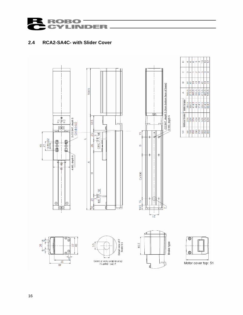
2.4 RCA2-SA4C- with Slider Cover
17
2-∅
2.5H
7, d
epth
5
∅2.
5H7,
dep
th 5
(fro
m b
otto
m fa
ce o
f bas
e)
4-M
4, d
epth
8
D-M
4, d
epth
7
With
out b
rake
W
ith b
rake
Det
ail v
iew
of F
S
cale
2:1
Bra
ke ty
pe
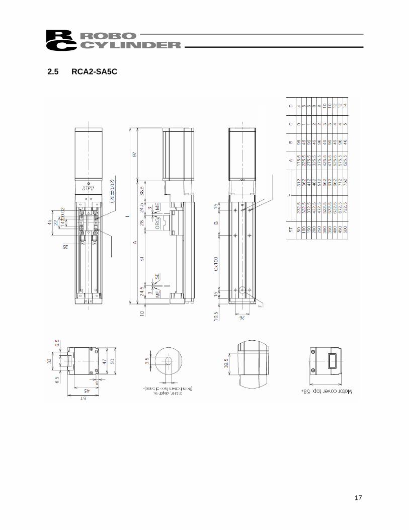
2.5 RCA2-SA5C
18
2-∅
2.5H
7, d
epth
5
∅2.
5H7,
dep
th 5
from
bot
tom
face
of
4-M
4, d
epth
8
D-M
4, d
epth
7
with
out b
rake
w
ith b
rake
Det
ail v
iew
of F
S
cale
2:1
Bra
ke ty
pe
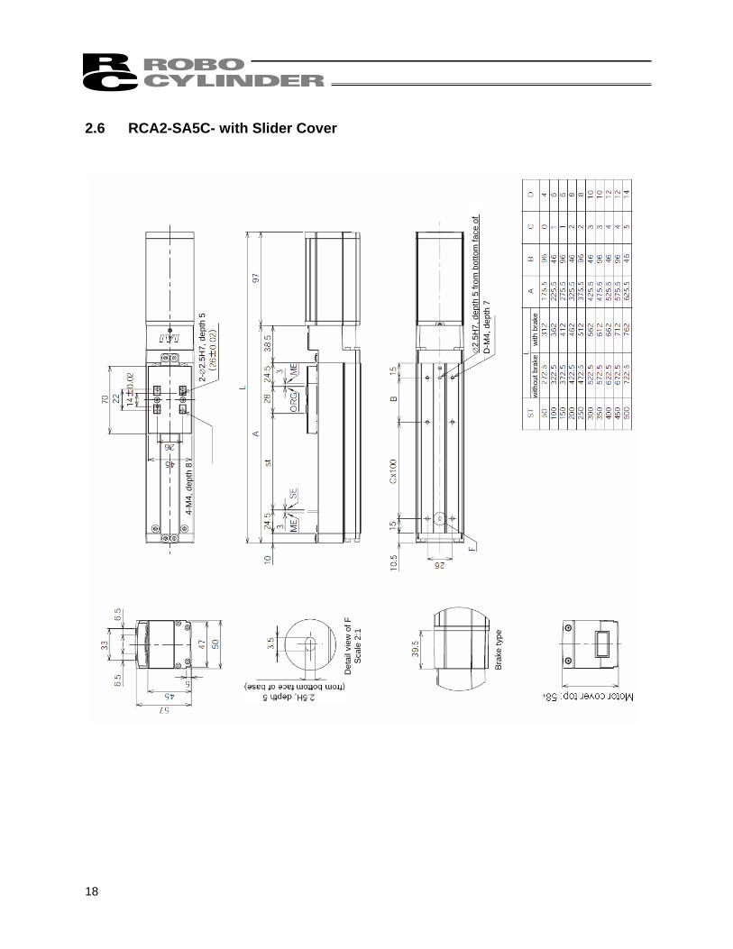
2.6 RCA2-SA5C- with Slider Cover
19
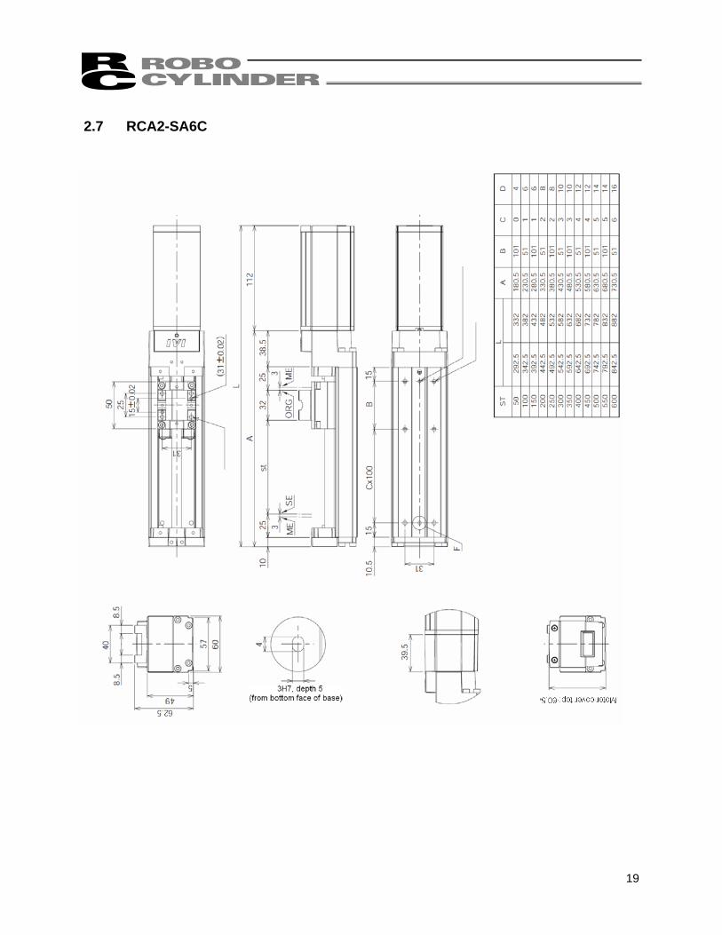
2-∅
3H7,
dep
th 5
∅3H
7, d
epth
5 (f
rom
bot
tom
face
of b
ase)
4-M
5, d
epth
10
2-M
5, d
epth
8
With
out b
rake
W
ith b
rake
Det
ail v
iew
of F
S
cale
2:1
Bra
ke ty
pe
2.7 RCA2-SA6C
20
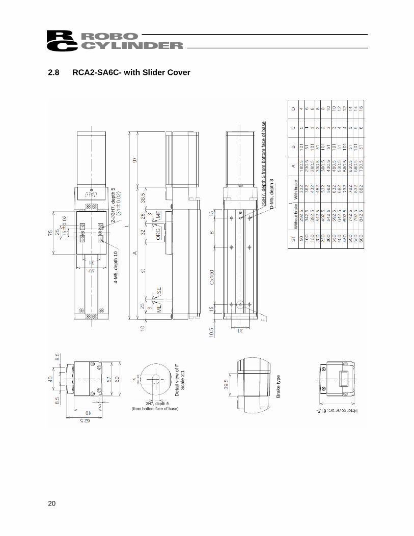
2-∅
3H7,
dep
th 5
∅3H
7, d
epth
5 fr
om b
otto
m fa
ce o
f bas
e
4-M
5, d
epth
10
D-M
5, d
epth
8
With
out b
rake
W
ith b
rake
Det
ail v
iew
of F
S
cale
2:1
Bra
ke ty
pe
2.8 RCA2-SA6C- with Slider Cover
21
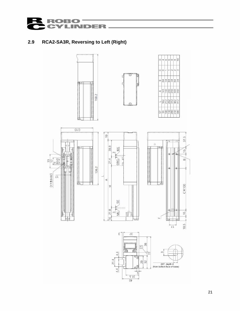
2-∅
2H7,
dep
th 5
∅2H
7, d
epth
4 (f
rom
bot
tom
face
of b
ase)
D
-M3,
dep
th 5
4-M
3, d
epth
6
(with
bra
ke)
Bra
ke ty
pe
Det
ail v
iew
of F
S
cale
5:1
(with
out b
rake
)
2.9 RCA2-SA3R, Reversing to Left (Right)
22
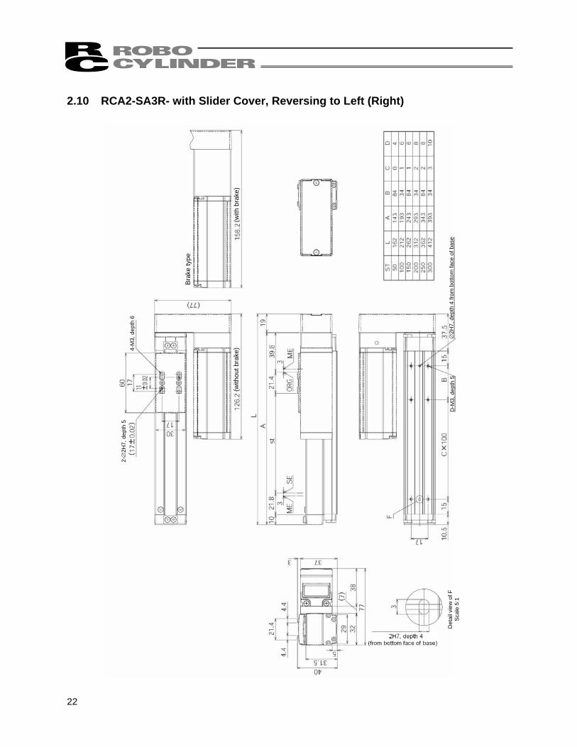
∅2H
7, d
epth
4 fr
om b
otto
m fa
ce o
f bas
e
4-M
3, d
epth
6
D-M
3, d
epth
5
(with
bra
ke)
Bra
ke ty
pe
(with
out b
rake
)
2-∅
2H7,
dep
th 5
Det
ail v
iew
of F
S
cale
5:1
2.10 RCA2-SA3R- with Slider Cover, Reversing to Left (Right)
23
2-∅
2.5H
7, d
epth
5
∅2.
5H7,
dep
th 5
(fro
m b
otto
m fa
ce o
f bas
e)
4-M
3, d
epth
6
D-M
3, d
epth
5 (with
out b
rake
) (w
ith b
rake
)
Bra
ke ty
pe
Det
ail v
iew
of F
S
cale
5:1
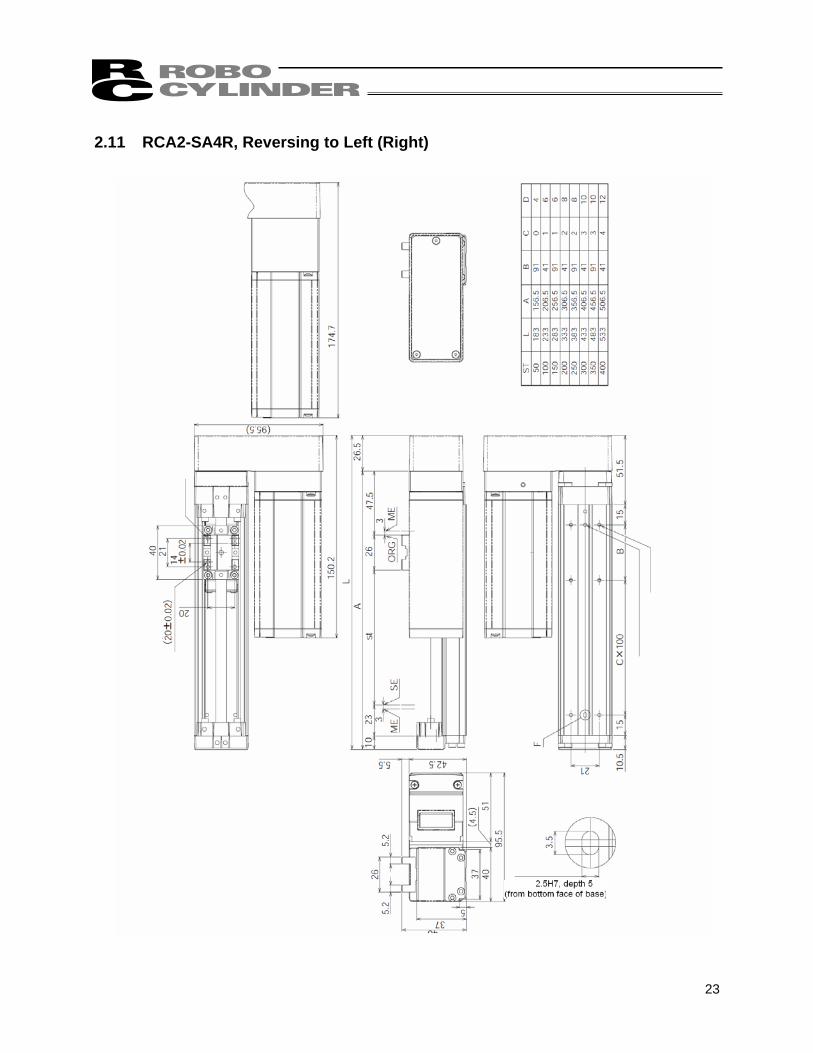
2.11 RCA2-SA4R, Reversing to Left (Right)
24
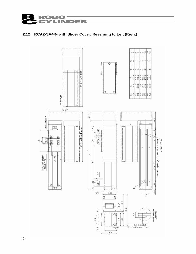
2-∅
2.5H
7, d
epth
5
4-M
3, d
epth
6
Bra
ke ty
pe
(with
bra
ke)
∅2.
5H7,
dep
th 5
(fro
m b
otto
m fa
ce o
f bas
e)
D-M
3, d
epth
5
(with
out b
rake
)
Det
ail v
iew
of F
S
cale
5:1
2.12 RCA2-SA4R- with Slider Cover, Reversing to Left (Right)
25
2-∅
2.5H
7, d
epth
54-
M4,
dep
th 8
Det
ail v
iew
of F
S
cale
2:1
Bra
ke ty
pe
(with
bra
ke)
∅2.
5H7,
dep
th 5
(fro
m b
otto
m fa
ce o
f bas
e)
D-M
4, d
epth
7 (w
ithou
t bra
ke)
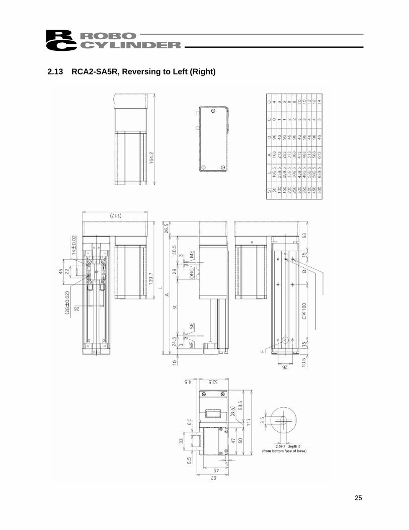
2.13 RCA2-SA5R, Reversing to Left (Right)
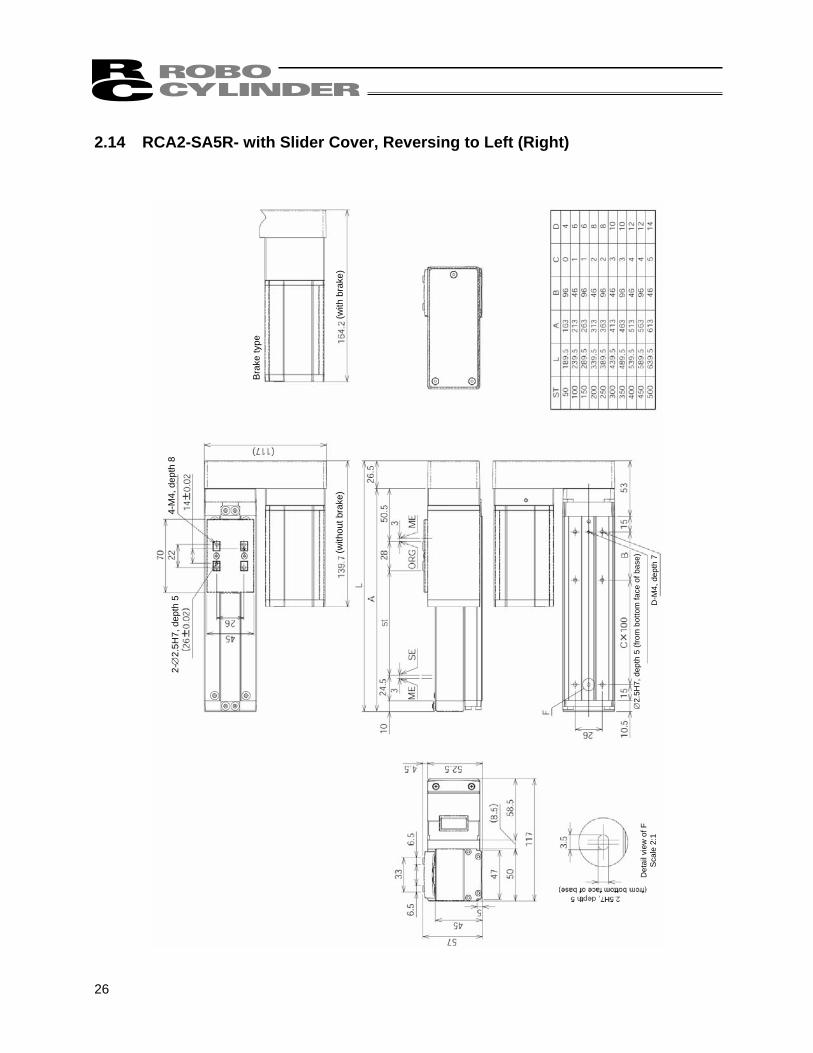
26
2-∅
2.5H
7, d
epth
5
4-M
4, d
epth
8
Bra
ke ty
pe
(with
bra
ke)
∅2.
5H7,
dep
th 5
(fro
m b
otto
m fa
ce o
f bas
e)
D-M
4, d
epth
7 (w
ithou
t bra
ke)
Det
ail v
iew
of F
S
cale
2:1
2.14 RCA2-SA5R- with Slider Cover, Reversing to Left (Right)
27
2-∅
3H7,
dep
th 5
4-
M5,
dep
th 1
0
Bra
ke ty
pe
(with
bra
ke)
∅3H
7, d
epth
5 (f
rom
bot
tom
face
of b
ase)
D-M
5, d
epth
8
(with
out b
rake
)
Det
ail v
iew
of F
S
cale
2:1
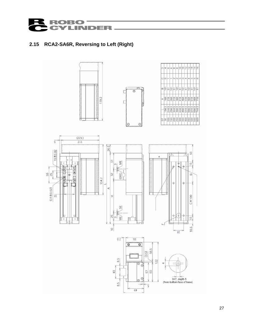
2.15 RCA2-SA6R, Reversing to Left (Right)
28
2-∅
3H7,
dep
th 5
4-M
5, d
epth
10
Bra
ke ty
pe
(with
bra
ke)
∅3H
7, d
epth
5 (f
rom
bot
tom
face
of b
ase)
D-M
5, d
epth
8
(with
out b
rake
)
Det
ail v
iew
of F
S
cale
2:1
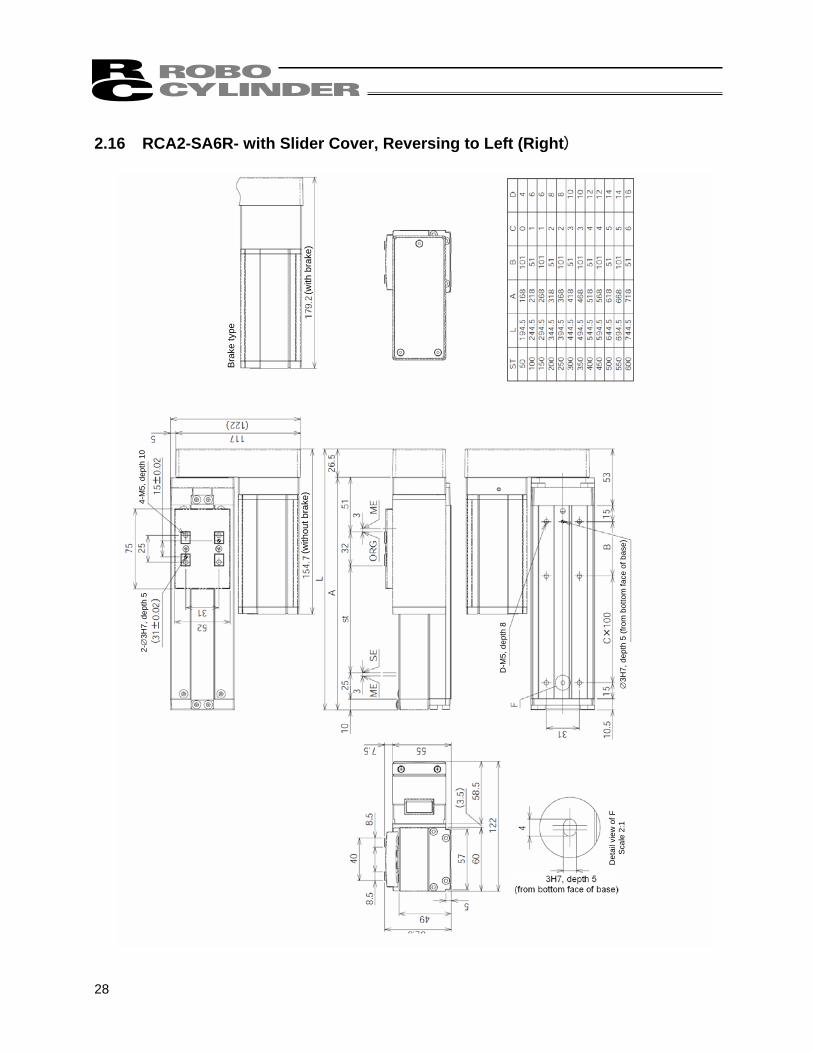
2.16 RCA2-SA6R- with Slider Cover, Reversing to Left (Right)
29
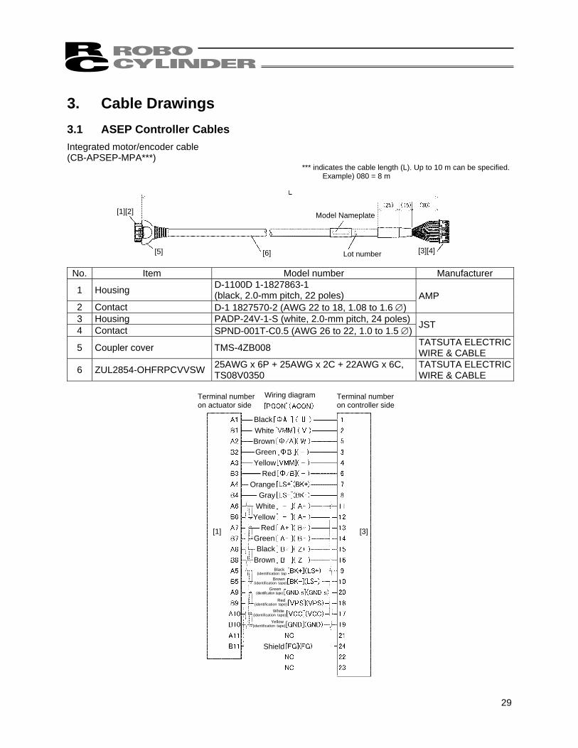
3. Cable Drawings 3.1 ASEP Controller Cables Integrated motor/encoder cable (CB-APSEP-MPA***)
*** indicates the cable length (L). Up to 10 m can be specified. Example) 080 = 8 m
No. Item Model number Manufacturer
1 Housing D-1100D 1-1827863-1 (black, 2.0-mm pitch, 22 poles)
2 Contact D-1 1827570-2 (AWG 22 to 18, 1.08 to 1.6 ∅) AMP
3 Housing PADP-24V-1-S (white, 2.0-mm pitch, 24 poles) 4 Contact SPND-001T-C0.5 (AWG 26 to 22, 1.0 to 1.5 ∅) JST
5 Coupler cover TMS-4ZB008 TATSUTA ELECTRIC WIRE & CABLE
6 ZUL2854-OHFRPCVVSW 25AWG x 6P + 25AWG x 2C + 22AWG x 6C, TS08V0350
TATSUTA ELECTRIC WIRE & CABLE
Terminal number on actuator side
Terminal number on controller side
Wiring diagram
BlackWhiteBrownGreenYellow
RedOrange
GrayWhite
YellowRed
GreenBlack
BrownBlack
(identification tapBrown
(identification tape)Green
(identification tape)
Red (identification tape)
White (identification tape)
Yellow (identification tape)
Shield
[1] [3]
[1][2]
[5] [6] [3][4]
Model Nameplate
Lot number
30
Terminal number on actuator side Wiring diagram [Signals]
[3]
[5]
[1]
BlackYellow
Red
Pink (Red•)
Pink (Blue•)
White (Red•)White (Blue•)
Orange (Red•)Orange (Blue•)
Gray (Red•)
Gray (Red/continuous)
Gray (Blue/continuous)
(Shield)
Terminal number on controller side
Gray (Blue•)
Yellow (Red•)
Yellow (Blue•)
Orange (Red/continuouOrange (Blue/continuous)
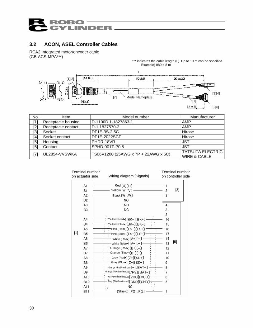
3.2 ACON, ASEL Controller Cables RCA2 Integrated motor/encoder cable (CB-ACS-MPA***)
*** indicates the cable length (L). Up to 10 m can be specified. Example) 080 = 8 m
No. Item Model number Manufacturer [1] Receptacle housing D-1100D 1-1827863-1 AMP [2] Receptacle contact D-1 1827570-2 AMP [3] Socket DF1E-3S-2.5C Hirose [4] Socket contact DF1E-2022SCF Hirose [5] Housing PHDR-18VR JST [6] Contact SPHD-001T-P0.5 JST
[7] UL2854-VVSWKA TS06V1200 (25AWG x 7P + 22AWG x 6C) TATSUTA ELECTRIC WIRE & CABLE
[1][2]
[7] [3][4]
[5][6]
Model Nameplate [7]
31
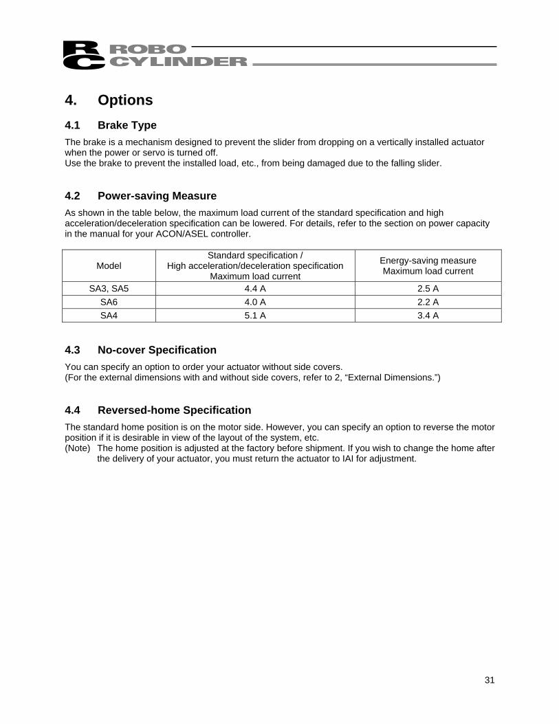
4. Options 4.1 Brake Type The brake is a mechanism designed to prevent the slider from dropping on a vertically installed actuator when the power or servo is turned off. Use the brake to prevent the installed load, etc., from being damaged due to the falling slider. 4.2 Power-saving Measure As shown in the table below, the maximum load current of the standard specification and high acceleration/deceleration specification can be lowered. For details, refer to the section on power capacity in the manual for your ACON/ASEL controller.
Model Standard specification /
High acceleration/deceleration specification Maximum load current
Energy-saving measure Maximum load current
SA3, SA5 4.4 A 2.5 A SA6 4.0 A 2.2 A SA4 5.1 A 3.4 A
4.3 No-cover Specification You can specify an option to order your actuator without side covers. (For the external dimensions with and without side covers, refer to 2, “External Dimensions.”) 4.4 Reversed-home Specification The standard home position is on the motor side. However, you can specify an option to reverse the motor position if it is desirable in view of the layout of the system, etc. (Note) The home position is adjusted at the factory before shipment. If you wish to change the home after
the delivery of your actuator, you must return the actuator to IAI for adjustment.

32
ModelSerial number
5. Checking after Unpacking After unpacking, check the product condition and the included items. 5.1 Included Items
No. Item Remarks
1 Actuator Refer to 5.3, “How to Read Model Nameplate” and 5.4, “How to Read Model.”
Accessories CB-APSEP-MPA : ASEP type 2 RCA integrated motor/encoder cable CB-ACS-MPA : ACON, ASEL type
3 First Step Guide 4 Operating Manual (CD) 5 Safety Guide
5.2 Operation Manuals Relating to This Product
No. Name Control No. 1 Operation Manual for ASEL Controller MJ0165 2 Operation Manual for ACON-C/CG/CF Controller MJ0176 3 Operation Manual for ACON-CY Controller MJ0167 4 Operation Manual for ACON-SE Controller MJ0171 5 Operation Manual for ACON-PL/PO Controller MJ0166 6 Operation Manual for ASEP Controller MJ0216 7 Operation Manual for PC Software RCM-101MW/RCM-101-USB MJ0155 8 Operation Manual for Teaching Pendant CON-T/TG MJ0178
9 Operation Manual for Dedicated ASEP/PSEP Touch Panel Teaching SEP-PT
MJ0217
10 Operation Manual for Simple Teaching Pendant RCM-E MJ0174 11 Operation Manual for Data Setter RCM-P MJ0175 12 Operation Manual for Touch Panel Display RCM-PM-01 MJ0182
5.3 How to Read Model Nameplate
33
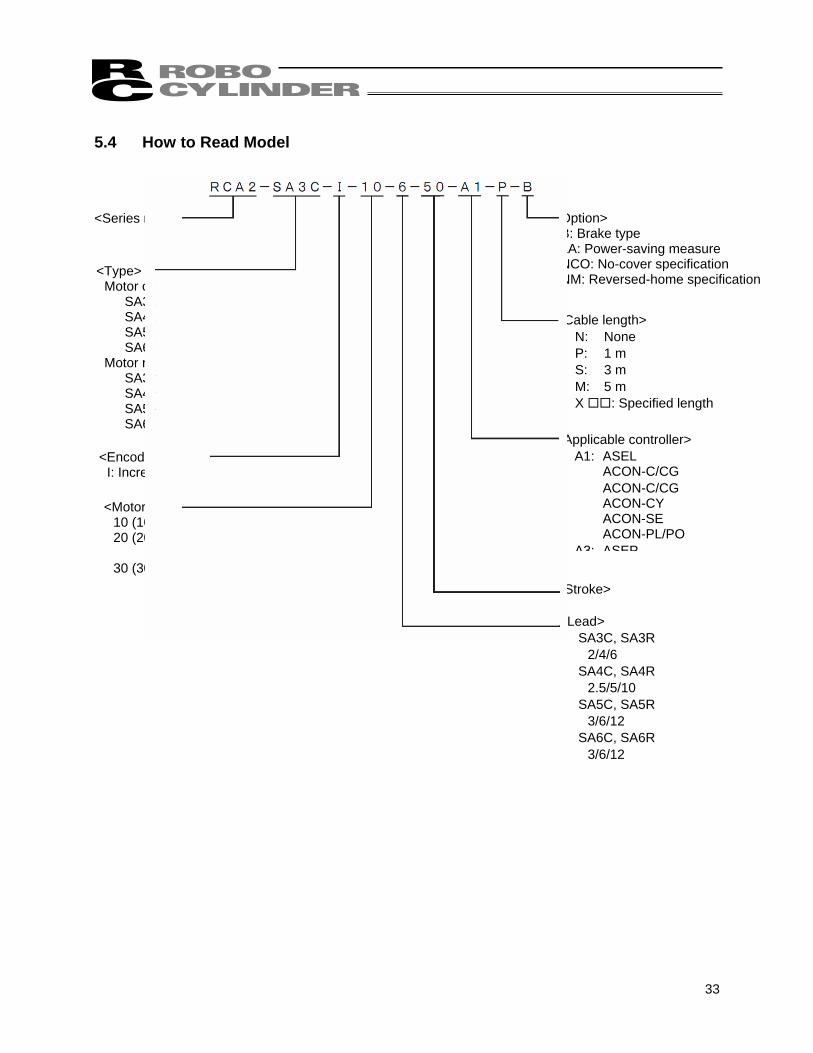
<Series name>
<Type> Motor coupling types
SA3C SA4C SA5C SA6C
Motor reversing SA3R SA4R SA5R SA6R
<Encoder type> I: Incremental
<Motor type> 10 (10 W): SA3C, SA3R 20 (20 W): SA4C, SA4R SA5C, SA5R 30 (30 W): SA6C, SA6R
<Option> B: Brake type LA: Power-saving measure NCO: No-cover specification NM: Reversed-home specification
<Cable length> N: None P: 1 m S: 3 m M: 5 m X : Specified length
<Applicable controller> A1: ASEL
ACON-C/CG ACON-C/CG
ACON-CY ACON-SE ACON-PL/PO
A3: ASEP
<Stroke>
<Lead> SA3C, SA3R
2/4/6 SA4C, SA4R
2.5/5/10 SA5C, SA5R
3/6/12 SA6C, SA6R
3/6/12
5.4 How to Read Model
34
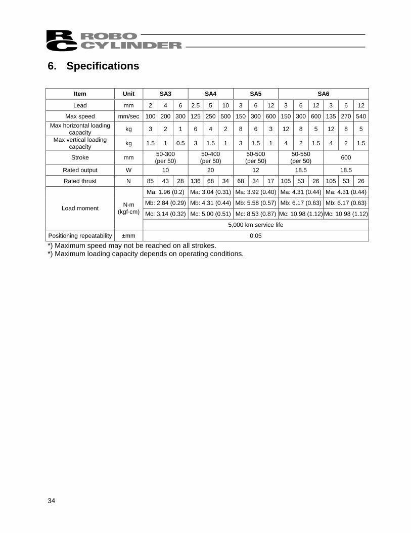
6. Specifications
Item Unit SA3 SA4 SA5 SA6
Lead mm 2 4 6 2.5 5 10 3 6 12 3 6 12 3 6 12
Max speed mm/sec 100 200 300 125 250 500 150 300 600 150 300 600 135 270 540Max horizontal loading
capacity kg 3 2 1 6 4 2 8 6 3 12 8 5 12 8 5
Max vertical loading capacity kg 1.5 1 0.5 3 1.5 1 3 1.5 1 4 2 1.5 4 2 1.5
Stroke mm 50-300 (per 50)
50-400 (per 50)
50-500 (per 50)
50-550 (per 50) 600
Rated output W 10 20 12 18.5 18.5
Rated thrust N 85 43 28 136 68 34 68 34 17 105 53 26 105 53 26
Ma: 1.96 (0.2) Ma: 3.04 (0.31) Ma: 3.92 (0.40) Ma: 4.31 (0.44) Ma: 4.31 (0.44)
Mb: 2.84 (0.29) Mb: 4.31 (0.44) Mb: 5.58 (0.57) Mb: 6.17 (0.63) Mb: 6.17 (0.63)
Mc: 3.14 (0.32) Mc: 5.00 (0.51) Mc: 8.53 (0.87) Mc: 10.98 (1.12) Mc: 10.98 (1.12)Load moment N·m
(kgf·cm)
5,000 km service life
Positioning repeatability ±mm 0.05
*) Maximum speed may not be reached on all strokes. *) Maximum loading capacity depends on operating conditions.

35
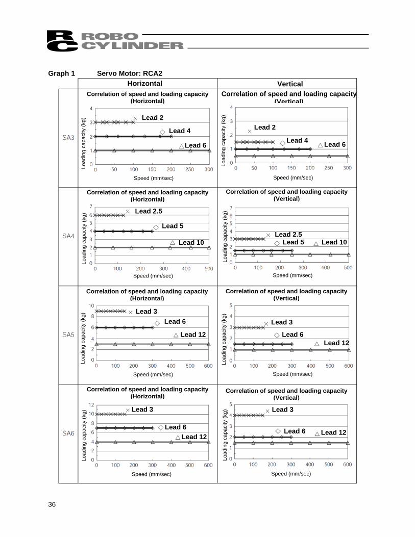
7. Selection Conditions 7.1 Selection Method [1] Maximum speed, loading capacity
Determine which models you can choose from by the maximum speed and loading capacity. • AC servo motor (Graph 1)
How to decide: If your maximum speed and loading capacity are within the usage range in the graph, you can use the model.
36
Horizontal Vertical Correlation of speed and loading capacity
(Horizontal) Correlation of speed and loading capacity
(Vertical)
Correlation of speed and loading capacity(Horizontal)
Correlation of speed and loading capacity(Vertical)
Correlation of speed and loading capacity(Horizontal)
Correlation of speed and loading capacity(Vertical)
Correlation of speed and loading capacity(Horizontal)
Correlation of speed and loading capacity(Vertical)
Lead 2
Lead 4
Lead 6
Lead 2
Lead 4 Lead 6
Lead 2.5
Lead 5
Lead 10 Lead 2.5
Lead 5 Lead 10
Lead 3 Lead 6
Lead 12
Lead 3
Lead 6 Lead 12
Lead 3
Lead 6Lead 12
Lead 3
Lead 6 Lead 12
Load
ing
capa
city
(kg)
Load
ing
capa
city
(kg)
Load
ing
capa
city
(kg)
Load
ing
capa
city
(kg)
Load
ing
capa
city
(kg)
Load
ing
capa
city
(kg)
Load
ing
capa
city
(kg)
Load
ing
capa
city
(kg)
Speed (mm/sec) Speed (mm/sec)
Speed (mm/sec) Speed (mm/sec)
Speed (mm/sec) Speed (mm/sec)
Speed (mm/sec) Speed (mm/sec)
Graph 1 Servo Motor: RCA2
37
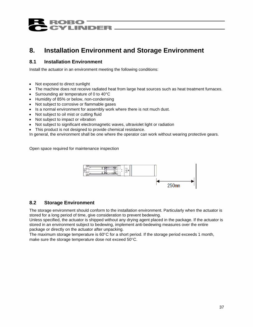
8. Installation Environment and Storage Environment 8.1 Installation Environment Install the actuator in an environment meeting the following conditions: • Not exposed to direct sunlight • The machine does not receive radiated heat from large heat sources such as heat treatment furnaces. • Surrounding air temperature of 0 to 40°C • Humidity of 85% or below, non-condensing • Not subject to corrosive or flammable gases • Is a normal environment for assembly work where there is not much dust. • Not subject to oil mist or cutting fluid • Not subject to impact or vibration • Not subject to significant electromagnetic waves, ultraviolet light or radiation • This product is not designed to provide chemical resistance. In general, the environment shall be one where the operator can work without wearing protective gears. Open space required for maintenance inspection 8.2 Storage Environment The storage environment should conform to the installation environment. Particularly when the actuator is stored for a long period of time, give consideration to prevent bedewing. Unless specified, the actuator is shipped without any drying agent placed in the package. If the actuator is stored in an environment subject to bedewing, implement anti-bedewing measures over the entire package or directly on the actuator after unpacking. The maximum storage temperature is 60°C for a short period. If the storage period exceeds 1 month, make sure the storage temperature dose not exceed 50°C.
38
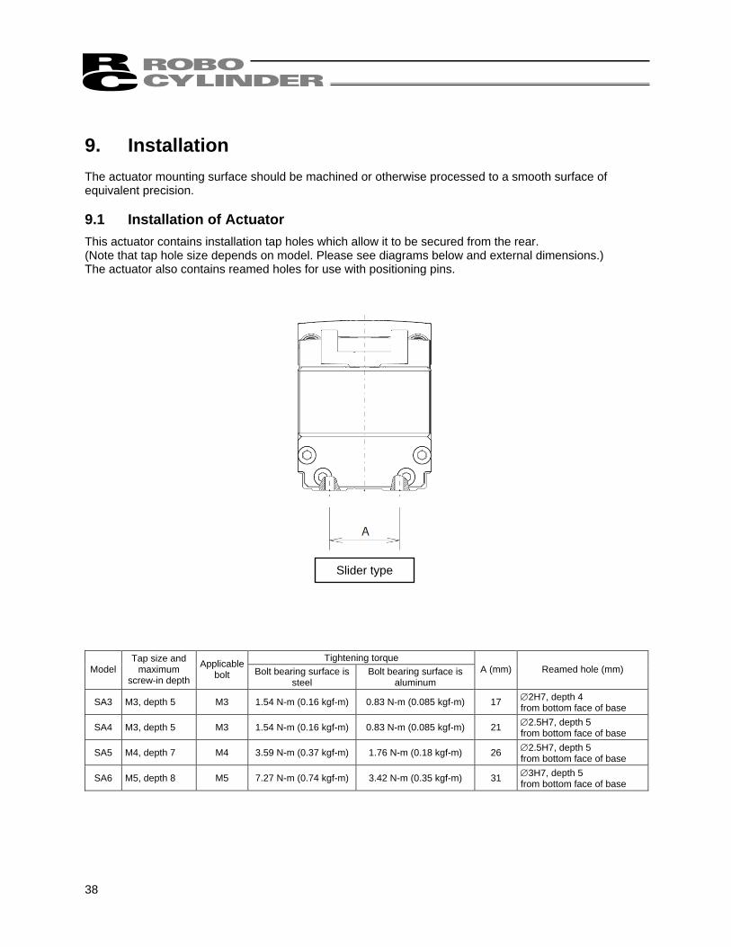
9. Installation The actuator mounting surface should be machined or otherwise processed to a smooth surface of equivalent precision. 9.1 Installation of Actuator This actuator contains installation tap holes which allow it to be secured from the rear. (Note that tap hole size depends on model. Please see diagrams below and external dimensions.) The actuator also contains reamed holes for use with positioning pins.
Tightening torque Model
Tap size and maximum
screw-in depth
Applicable bolt Bolt bearing surface is
steel Bolt bearing surface is
aluminum A (mm) Reamed hole (mm)
SA3 M3, depth 5 M3 1.54 N-m (0.16 kgf-m) 0.83 N-m (0.085 kgf-m) 17 ∅2H7, depth 4 from bottom face of base
SA4 M3, depth 5 M3 1.54 N-m (0.16 kgf-m) 0.83 N-m (0.085 kgf-m) 21 ∅2.5H7, depth 5 from bottom face of base
SA5 M4, depth 7 M4 3.59 N-m (0.37 kgf-m) 1.76 N-m (0.18 kgf-m) 26 ∅2.5H7, depth 5 from bottom face of base
SA6 M5, depth 8 M5 7.27 N-m (0.74 kgf-m) 3.42 N-m (0.35 kgf-m) 31 ∅3H7, depth 5 from bottom face of base
Slider type
39
Tightening screws • Use hexagonal socket head bolts for the male threads for installing the base. • Use of high-tension bolts meeting at least ISO 10.9 is recommended. • For the effective engagement length between the bolt and female thread, provide at least the
applicable value specified below: Female thread is made of steel material → Same length as the nominal diameter Female thread is made of aluminum → Twice the nominal diameter
Caution: Be careful when selecting the bolt length. If bolts of inappropriate lengths are used, the tapped holes may be damaged, actuator mounting strength may become insufficient, or contact with driving parts may occur, resulting in lower precision or unexpected accidents.
40
R0.3 or less
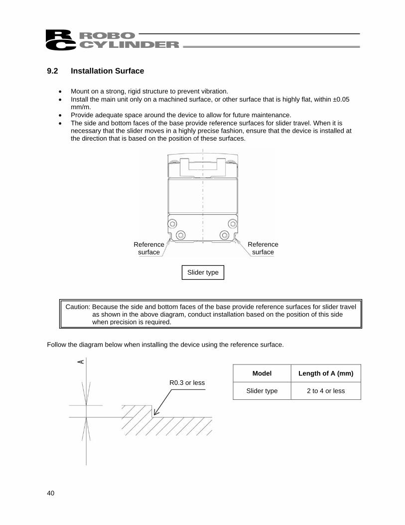
9.2 Installation Surface
• Mount on a strong, rigid structure to prevent vibration. • Install the main unit only on a machined surface, or other surface that is highly flat, within ±0.05
mm/m. • Provide adequate space around the device to allow for future maintenance. • The side and bottom faces of the base provide reference surfaces for slider travel. When it is
necessary that the slider moves in a highly precise fashion, ensure that the device is installed at the direction that is based on the position of these surfaces.
Follow the diagram below when installing the device using the reference surface.
Model Length of A (mm)
Slider type 2 to 4 or less
Caution: Because the side and bottom faces of the base provide reference surfaces for slider travel as shown in the above diagram, conduct installation based on the position of this side
when precision is required.
Reference surface
Reference surface
Slider type
41
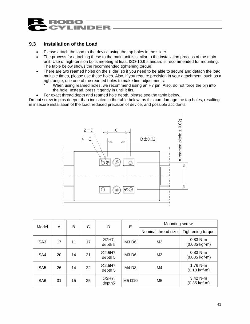
9.3 Installation of the Load
• Please attach the load to the device using the tap holes in the slider. • The process for attaching these to the main unit is similar to the installation process of the main
unit. Use of high-tension bolts meeting at least ISO-10.9 standard is recommended for mounting. The table below shows the recommended tightening torque.
• There are two reamed holes on the slider, so if you need to be able to secure and detach the load multiple times, please use these holes. Also, if you require precision in your attachment, such as a right angle, use one of the reamed holes to make fine adjustments. * When using reamed holes, we recommend using an H7 pin. Also, do not force the pin into
the hole. Instead, press it gently in until it fits. • For exact thread depth and reamed hole depth, please see the table below.
Do not screw in pins deeper than indicated in the table below, as this can damage the tap holes, resulting in insecure installation of the load, reduced precision of device, and possible accidents.
Mounting screw Model A B C D E
Nominal thread size Tightening torque
SA3 17 11 17 ∅2H7, depth 5 M3 D6 M3 0.83 N-m
(0.085 kgf-m)
SA4 20 14 21 ∅2.5H7, depth 5 M3 D6 M3 0.83 N-m
(0.085 kgf-m)
SA5 26 14 22 ∅2.5H7, depth 5 M4 D8 M4 1.76 N-m
(0.18 kgf-m)
SA6 31 15 25 ∅3H7, depth5 M5 D10 M5 3.42 N-m
(0.35 kgf-m)
A re
amed
pitc
h: ±
0.0
2)
42
RCA2-xx Dedicated connection cable (connects controller and RCA2)
r=68 mm min. (unfastened) r=34 mm min. (fastened)
Dedicated controller ASEP
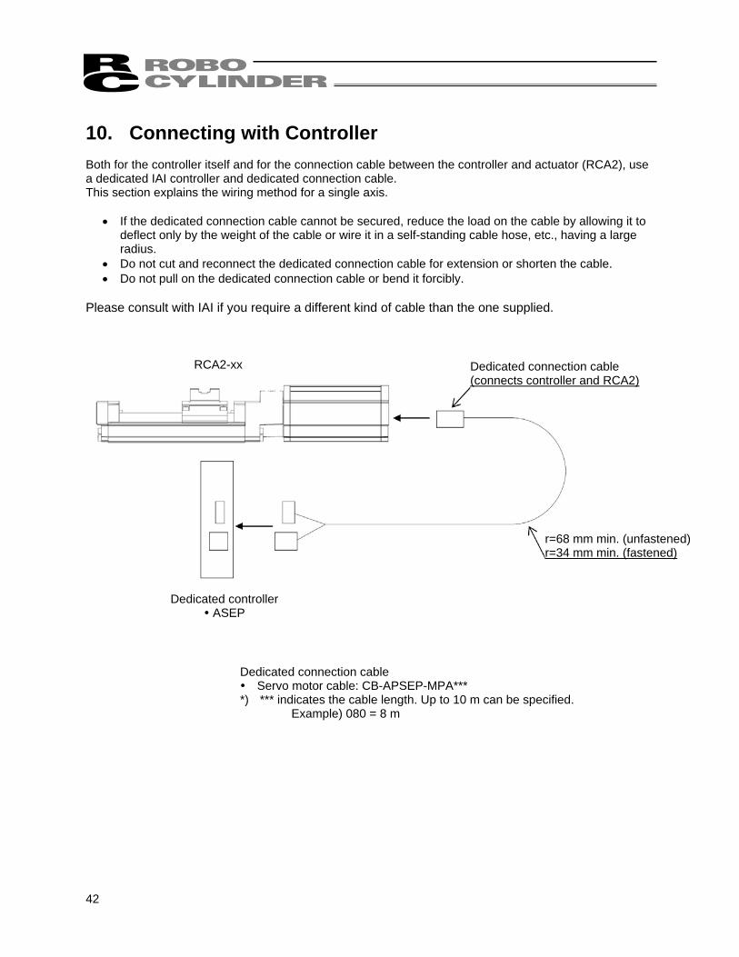
10. Connecting with Controller Both for the controller itself and for the connection cable between the controller and actuator (RCA2), use a dedicated IAI controller and dedicated connection cable. This section explains the wiring method for a single axis.
• If the dedicated connection cable cannot be secured, reduce the load on the cable by allowing it to deflect only by the weight of the cable or wire it in a self-standing cable hose, etc., having a large radius.
• Do not cut and reconnect the dedicated connection cable for extension or shorten the cable. • Do not pull on the dedicated connection cable or bend it forcibly.
Please consult with IAI if you require a different kind of cable than the one supplied.
Dedicated connection cable Servo motor cable: CB-APSEP-MPA***
*) *** indicates the cable length. Up to 10 m can be specified. Example) 080 = 8 m
43
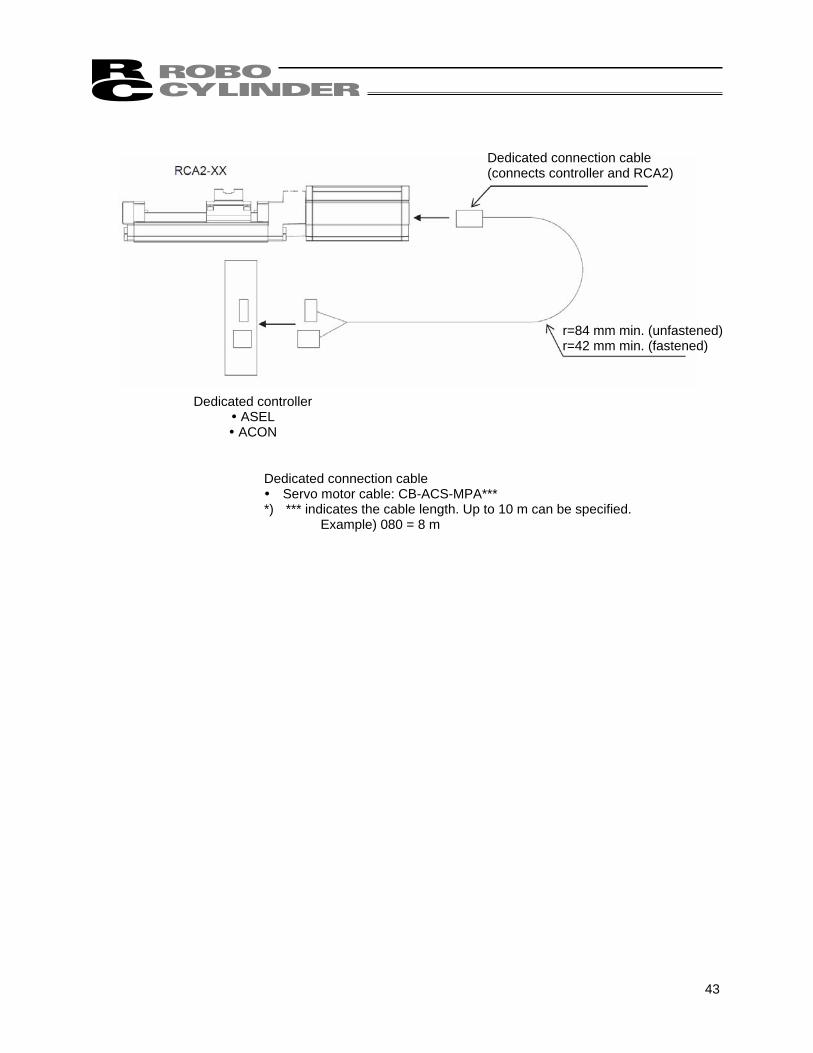
Dedicated connection cable Servo motor cable: CB-ACS-MPA***
*) *** indicates the cable length. Up to 10 m can be specified. Example) 080 = 8 m
Dedicated connection cable (connects controller and RCA2)
r=84 mm min. (unfastened) r=42 mm min. (fastened)
Dedicated controller ASEL ACON
44
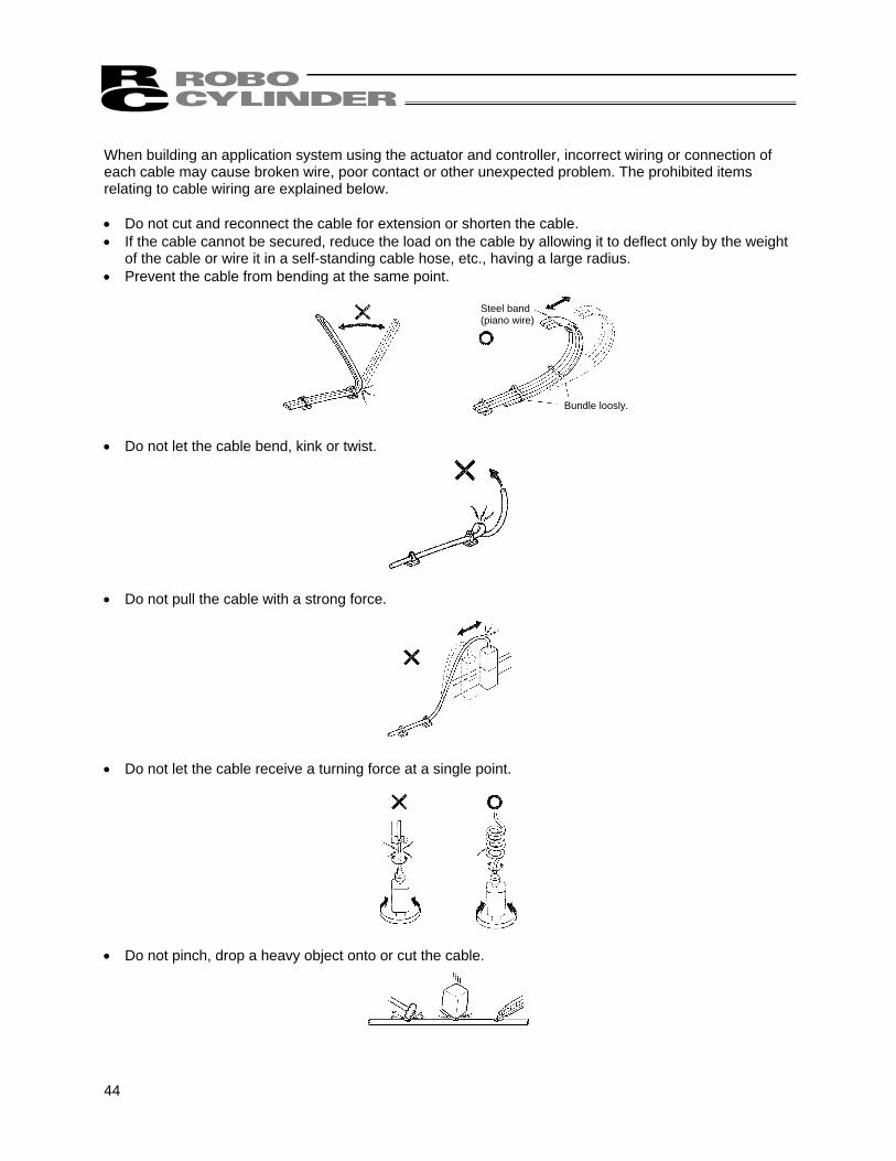
When building an application system using the actuator and controller, incorrect wiring or connection of each cable may cause broken wire, poor contact or other unexpected problem. The prohibited items relating to cable wiring are explained below. • Do not cut and reconnect the cable for extension or shorten the cable. • If the cable cannot be secured, reduce the load on the cable by allowing it to deflect only by the weight
of the cable or wire it in a self-standing cable hose, etc., having a large radius. • Prevent the cable from bending at the same point. • Do not let the cable bend, kink or twist. • Do not pull the cable with a strong force. • Do not let the cable receive a turning force at a single point. • Do not pinch, drop a heavy object onto or cut the cable.
Bundle loosly.
Steel band (piano wire)
45
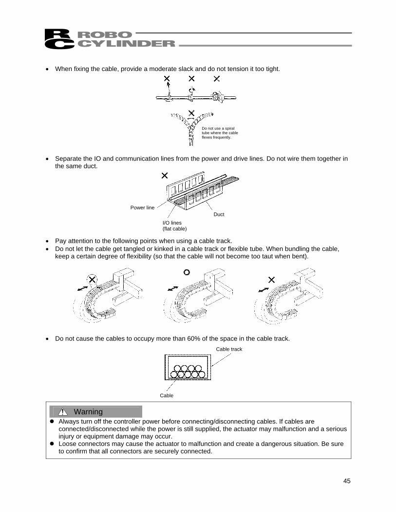
• When fixing the cable, provide a moderate slack and do not tension it too tight. • Separate the IO and communication lines from the power and drive lines. Do not wire them together in
the same duct. • Pay attention to the following points when using a cable track. • Do not let the cable get tangled or kinked in a cable track or flexible tube. When bundling the cable,
keep a certain degree of flexibility (so that the cable will not become too taut when bent). • Do not cause the cables to occupy more than 60% of the space in the cable track.
Warning Always turn off the controller power before connecting/disconnecting cables. If cables are
connected/disconnected while the power is still supplied, the actuator may malfunction and a serious injury or equipment damage may occur.
Loose connectors may cause the actuator to malfunction and create a dangerous situation. Be sure to confirm that all connectors are securely connected.
Do not use a spiral tube where the cable flexes frequently.
Power line
I/O lines (flat cable)
Duct
Cable
Cable track
46
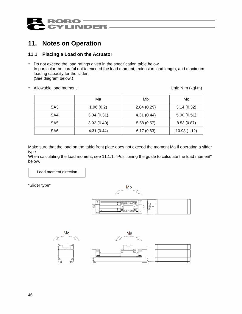
11. Notes on Operation 11.1 Placing a Load on the Actuator Do not exceed the load ratings given in the specification table below.
In particular, be careful not to exceed the load moment, extension load length, and maximum loading capacity for the slider. (See diagram below.)
Allowable load moment Unit: N·m (kgf·m)
Ma Mb Mc
SA3 1.96 (0.2) 2.84 (0.29) 3.14 (0.32)
SA4 3.04 (0.31) 4.31 (0.44) 5.00 (0.51)
SA5 3.92 (0.40) 5.58 (0.57) 8.53 (0.87)
SA6 4.31 (0.44) 6.17 (0.63) 10.98 (1.12)
Make sure that the load on the table front plate does not exceed the moment Ma if operating a slider type. When calculating the load moment, see 11.1.1, "Positioning the guide to calculate the load moment" below. "Slider type"
Load moment direction
47
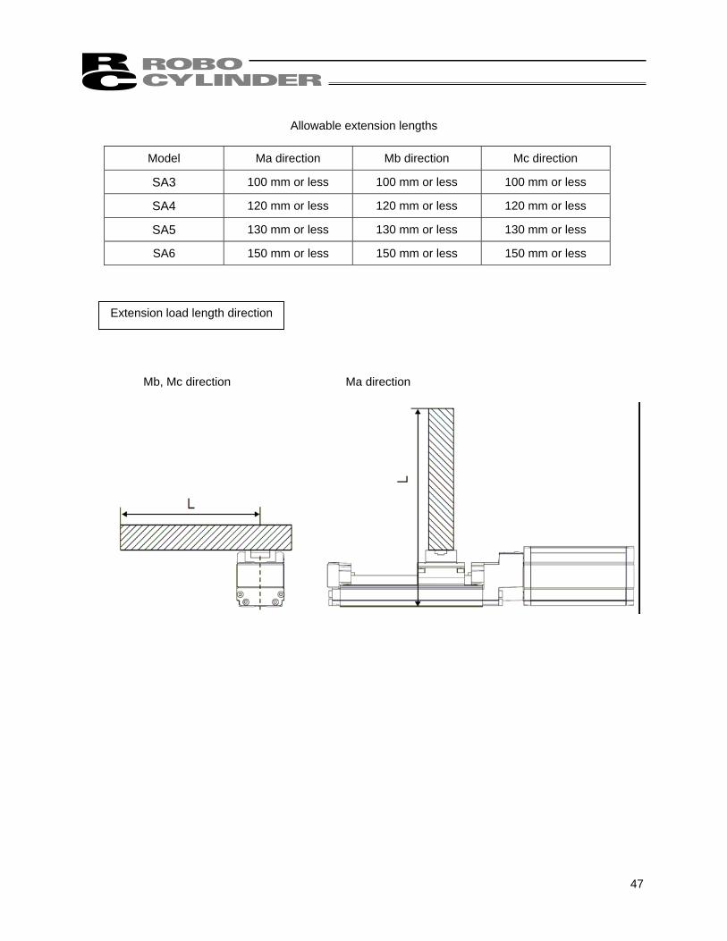
Allowable extension lengths
Model Ma direction Mb direction Mc direction
SA3 100 mm or less 100 mm or less 100 mm or less
SA4 120 mm or less 120 mm or less 120 mm or less
SA5 130 mm or less 130 mm or less 130 mm or less
SA6 150 mm or less 150 mm or less 150 mm or less
Mb, Mc direction Ma direction
Extension load length direction
48
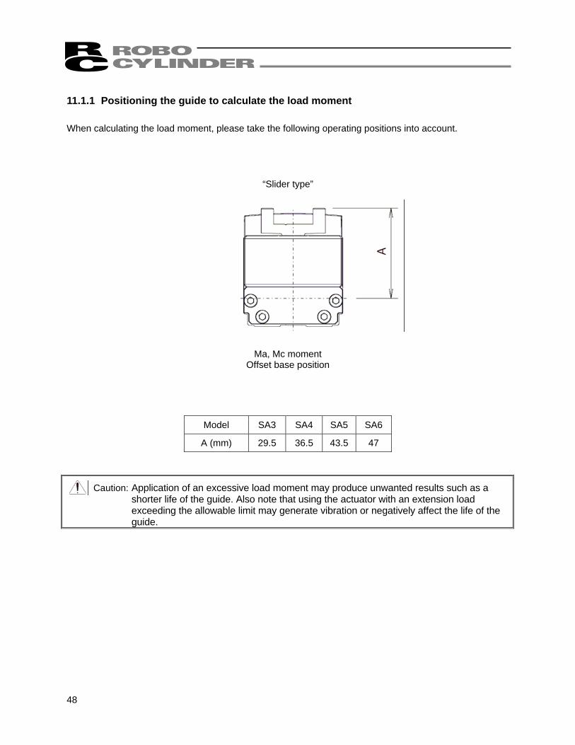
11.1.1 Positioning the guide to calculate the load moment When calculating the load moment, please take the following operating positions into account.
“Slider type”
Ma, Mc moment Offset base position
Model SA3 SA4 SA5 SA6
A (mm) 29.5 36.5 43.5 47
Caution: Application of an excessive load moment may produce unwanted results such as a shorter life of the guide. Also note that using the actuator with an extension load exceeding the allowable limit may generate vibration or negatively affect the life of the guide.
49
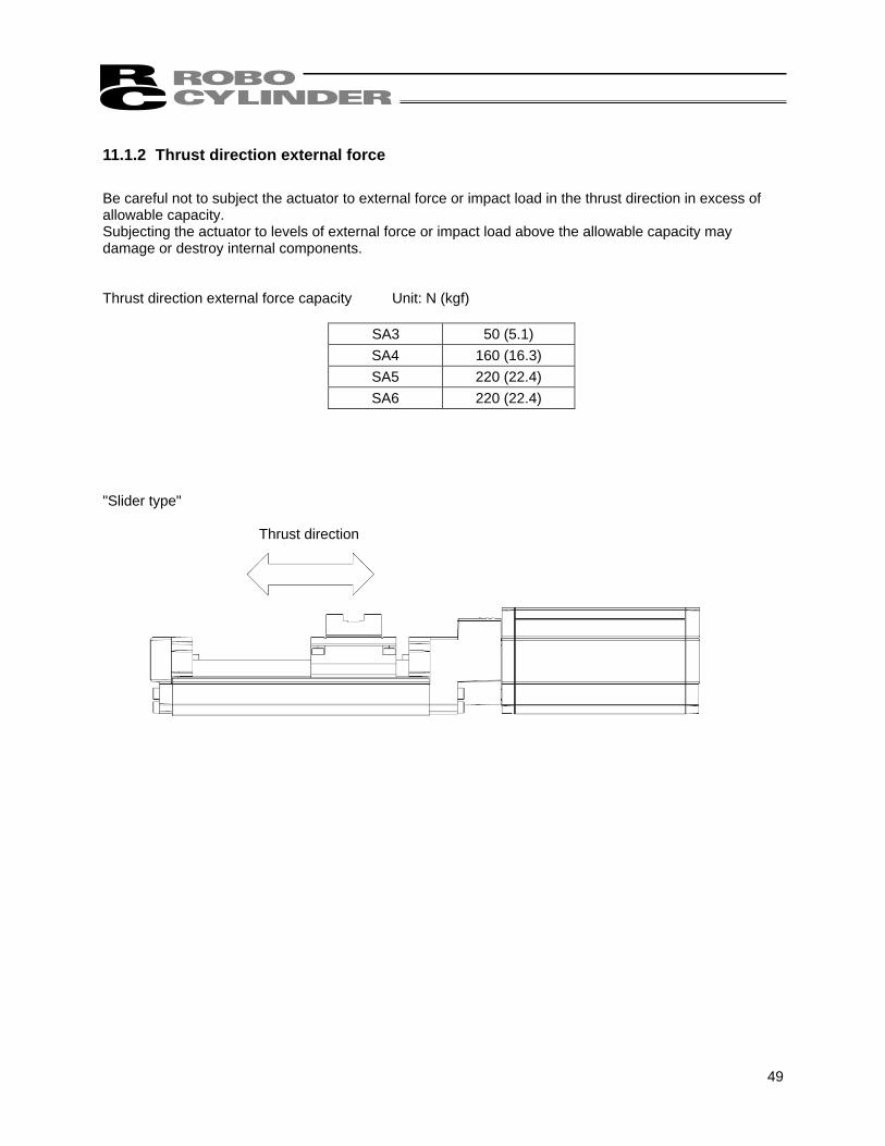
11.1.2 Thrust direction external force Be careful not to subject the actuator to external force or impact load in the thrust direction in excess of allowable capacity. Subjecting the actuator to levels of external force or impact load above the allowable capacity may damage or destroy internal components. Thrust direction external force capacity Unit: N (kgf)
SA3 50 (5.1) SA4 160 (16.3) SA5 220 (22.4) SA6 220 (22.4)
"Slider type"
Thrust direction
50
11.2 Adjusting the Home Position The actuator home position can be adjusted by changing parameter *1. In order to make adjustments, please do the following. [1] Verify the home position by performing a home return operation. [2] Move the actuator to the desired position, verify the distance between the old and new positions, and
adjust the parameter accordingly. The parameter can be set to a positive value in the direction of movement. (It cannot be set to a negative value.)
[3] Increasing the offset amount restricts the movement range by the amount of the increase. If you set an offset greater than 1 mm, please reset the stroke soft limit. *1 ACON controller: No. 22, home return offset distance
ASEL controller: Parameter No. 12 for each axis, home preset value ASEP controller: No. 16, home return preset value 11.3 Changing the Home Position Direction To change the home position direction after delivery, it is necessary to change the movement direction parameter. Please contact with IAI if you need to do this.
Warning: The encoder serves not only to detect the actuator’s position and the home position signal, it also plays a crucial role in phase switching for the AC servo power line, and its phase is adjusted precisely. Never touch the encoder in order to change the home position.
51
11.4 Stainless Sheet Section
• The stainless sheet is attached by adsorption to the side cover. If the environment contains high levels of iron filings or other magnetic matter, this may become adsorbed between the stainless sheet and the rubber and cause malfunction. For that reason, avoid usage in such an environment.
• Keep adhesive, paint, and other viscous material off the stainless sheet. Such material sticking to the stainless sheet can lead to defective slider operation and stainless sheet damage.
• Be careful to avoid localized force on the stainless sheet. Such force could deform the stainless sheet and cause malfunctions. Also, during installation and transport, do not hold on to or press on the stainless sheet. Doing so could damage the stainless sheet.
52
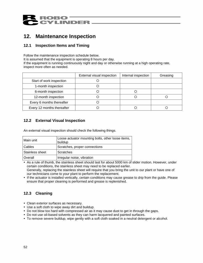
12. Maintenance Inspection 12.1 Inspection Items and Timing Follow the maintenance inspection schedule below. It is assumed that the equipment is operating 8 hours per day. If the equipment is running continuously night and day or otherwise running at a high operating rate, inspect more often as needed.
External visual inspection Internal inspection Greasing Start of work inspection
1-month inspection 6-month inspection
12-month inspection Every 6 months thereafter
Every 12 months thereafter 12.2 External Visual Inspection An external visual inspection should check the following things.
Main unit Loose actuator mounting bolts, other loose items, buildup
Cables Scratches, proper connections Stainless sheet Scratches Overall Irregular noise, vibration As a rule of thumb, the stainless sheet should last for about 5000 km of slider motion. However, under certain conditions, the stainless sheet may need to be replaced earlier. Generally, replacing the stainless sheet will require that you bring the unit to our plant or have one of our technicians come to your plant to perform the replacement.
If the actuator is installed vertically, certain conditions may cause grease to drip from the guide. Please ensure that proper cleaning is performed and grease is replenished.
12.3 Cleaning Clean exterior surfaces as necessary. Use a soft cloth to wipe away dirt and buildup. Do not blow too hard with compressed air as it may cause dust to get in through the gaps. Do not use oil-based solvents as they can harm lacquered and painted surfaces. To remove severe buildup, wipe gently with a soft cloth soaked in a neutral detergent or alcohol.
53
12.4 Internal Inspections Turn off the power and inspect visually after turning up or removing the stainless sheet in the case of stainless sheet types. With reversing types, inspect visually after removing the reversing bracket. When inspecting the interior, check the following items.
Main unit Loose mounting bolts, other loose items
Guide section Lubrication, buildup
Belt (Reversing type) Belt wear, damage
Visually inspect the interior of the equipment. Check whether dust or other foreign matter has gotten inside and check the lubrication state. The lubrication may have turned brown. This is not a problem as long as the travel surfaces shine as though they are wet. If the grease is mixed with dust and does not have a shiny appearance, or if the grease has lost its efficacy due to prolonged use, then clean each section and reapply grease. The procedure for internal inspections is outlined below. Refer to 12.7 for inspection and adjustment of the belt. "Slider type" --- Steps [2] through [5] are only necessary if the cover is attached. If you do not have a cover, only do step [1]. [1] Move the slider to the home position side. [2] Remove the cover. [3] Remove the sheet retainer screws. [4] Peek under the stainless sheet and check the interior. [5] When the checks are completed, reassemble the parts by following the same procedure in reverse. .
Cautions for attached cover:
When checking inside the equipment, be careful not to forcibly bend the stainless sheet or scratch it. Do not tug on the stainless sheet or in any way attempt to reposition it. If the sheet is repositioned, it may not be even which may shorten its service life. Should this happen, adjust the stainless sheet by referring to the replacement instructions. Keep in mind that the edges of the stainless sheet can cause injuries. Always wear gloves when working on it.
54
12.5 Internal Cleaning Use a soft cloth to wipe away dirt and buildup. Do not blow too hard with compressed air as it may cause dust to get in through the gaps. Do not use oil-based solvents, neutral detergent or alcohol.
12.6 Greasing Guides 12.6.1 Applicable greases for guide The grease initially used is lithium-based grease. IAI uses the following grease in our plant.
Idemitsu Kosan Daphne Eponex Grease No. 2
Other companies also sell similar types of grease. For details, give the above grease name to the manufacturer you want to purchase from and ask what corresponding product they have available. Here are some examples of similar products.
Showa Shell Oil Albania Grease No. 2
Mobil Oil Mobilax 2
Warning:
Never use anything other than synthetic poly-α olefin grease. Mixing poly-α grease with other grease not only reduces the performance of the grease, it may even cause damage to the actuator. 12.6.2 Applicable greases for ball screw The grease initially used is lithium-based grease. IAI uses the following grease in our plant. (Excludes SA3C type)
Kyodo Yushi Multitemp LRL 3
* RCA2 SA3C type uses the following grease.
Idemitsu Kosan Daphne Eponex Grease No. 2
55
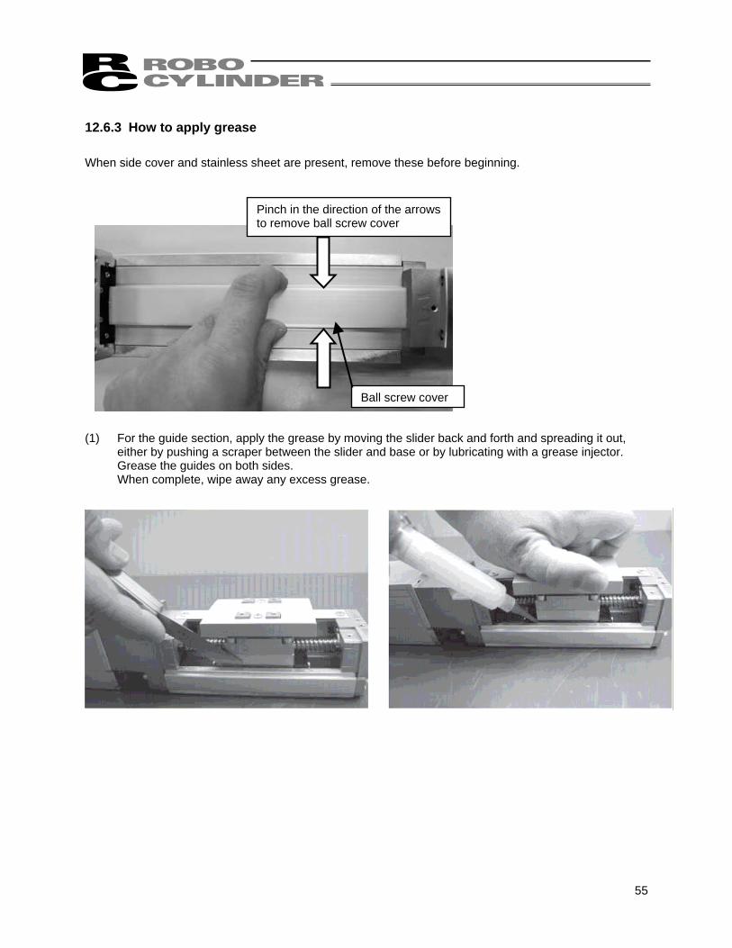
12.6.3 How to apply grease When side cover and stainless sheet are present, remove these before beginning. (1) For the guide section, apply the grease by moving the slider back and forth and spreading it out,
either by pushing a scraper between the slider and base or by lubricating with a grease injector. Grease the guides on both sides. When complete, wipe away any excess grease.
Pinch in the direction of the arrows to remove ball screw cover
Ball screw cover
56
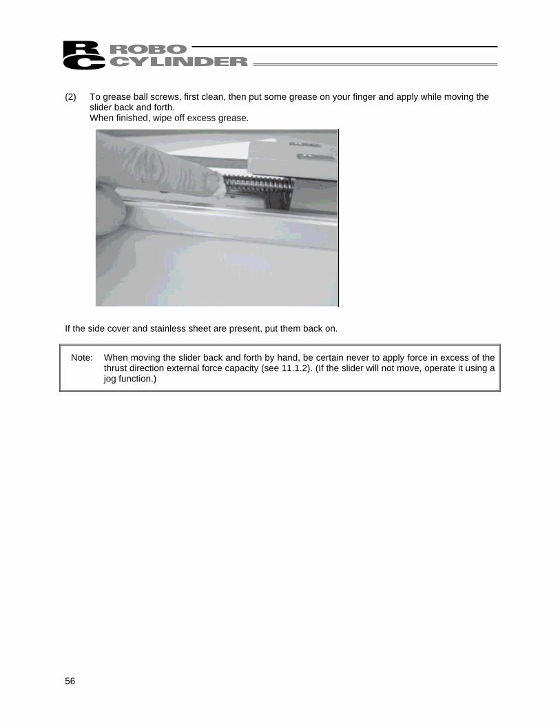
(2) To grease ball screws, first clean, then put some grease on your finger and apply while moving the
slider back and forth. When finished, wipe off excess grease.
If the side cover and stainless sheet are present, put them back on.
Note: When moving the slider back and forth by hand, be certain never to apply force in excess of the thrust direction external force capacity (see 11.1.2). (If the slider will not move, operate it using a jog function.)
57
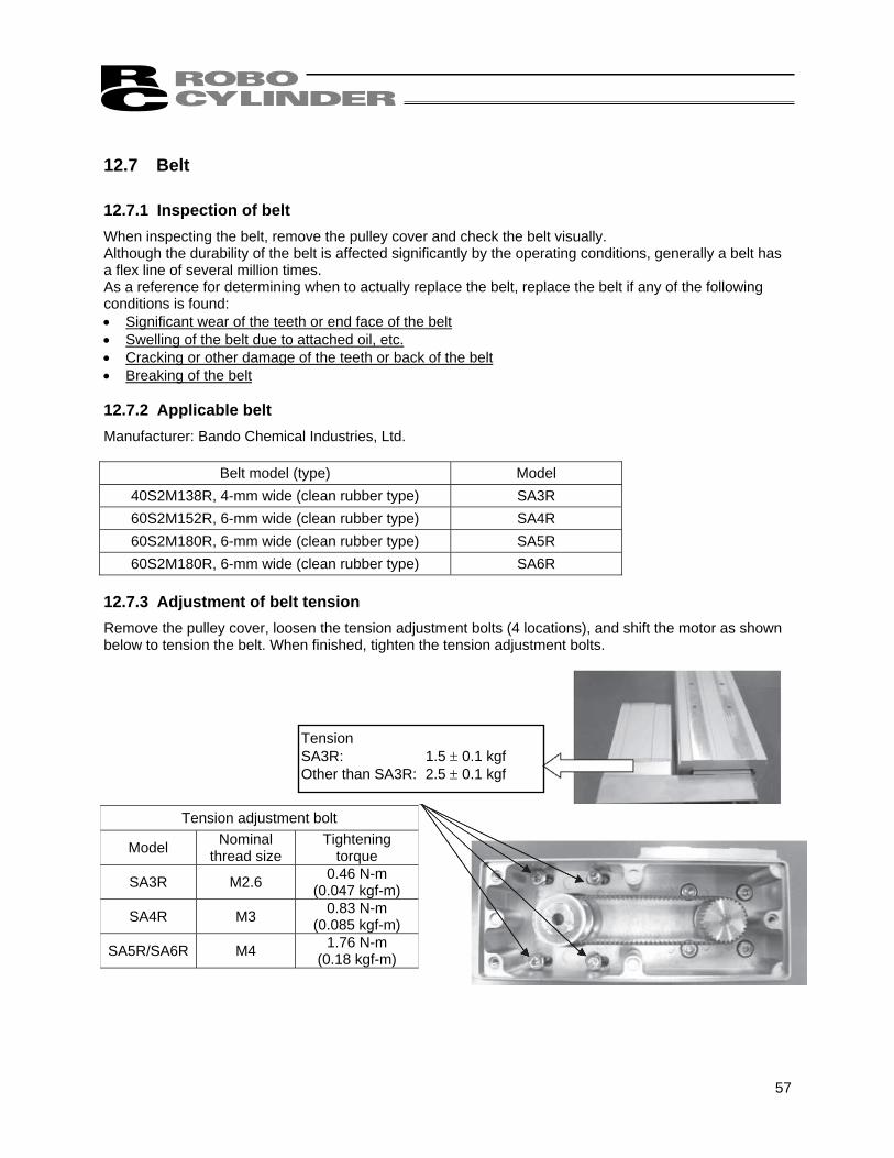
Tension SA3R: 1.5 ± 0.1 kgf Other than SA3R: 2.5 ± 0.1 kgf
Tension adjustment bolt
Model Nominal thread size
Tightening torque
SA3R M2.6 0.46 N-m (0.047 kgf-m)
SA4R M3 0.83 N-m (0.085 kgf-m)
SA5R/SA6R M4 1.76 N-m (0.18 kgf-m)
12.7 Belt 12.7.1 Inspection of belt When inspecting the belt, remove the pulley cover and check the belt visually. Although the durability of the belt is affected significantly by the operating conditions, generally a belt has a flex line of several million times. As a reference for determining when to actually replace the belt, replace the belt if any of the following conditions is found: • Significant wear of the teeth or end face of the belt • Swelling of the belt due to attached oil, etc. • Cracking or other damage of the teeth or back of the belt • Breaking of the belt 12.7.2 Applicable belt Manufacturer: Bando Chemical Industries, Ltd.
Belt model (type) Model 40S2M138R, 4-mm wide (clean rubber type) SA3R 60S2M152R, 6-mm wide (clean rubber type) SA4R 60S2M180R, 6-mm wide (clean rubber type) SA5R 60S2M180R, 6-mm wide (clean rubber type) SA6R
12.7.3 Adjustment of belt tension Remove the pulley cover, loosen the tension adjustment bolts (4 locations), and shift the motor as shown below to tension the belt. When finished, tighten the tension adjustment bolts.
58
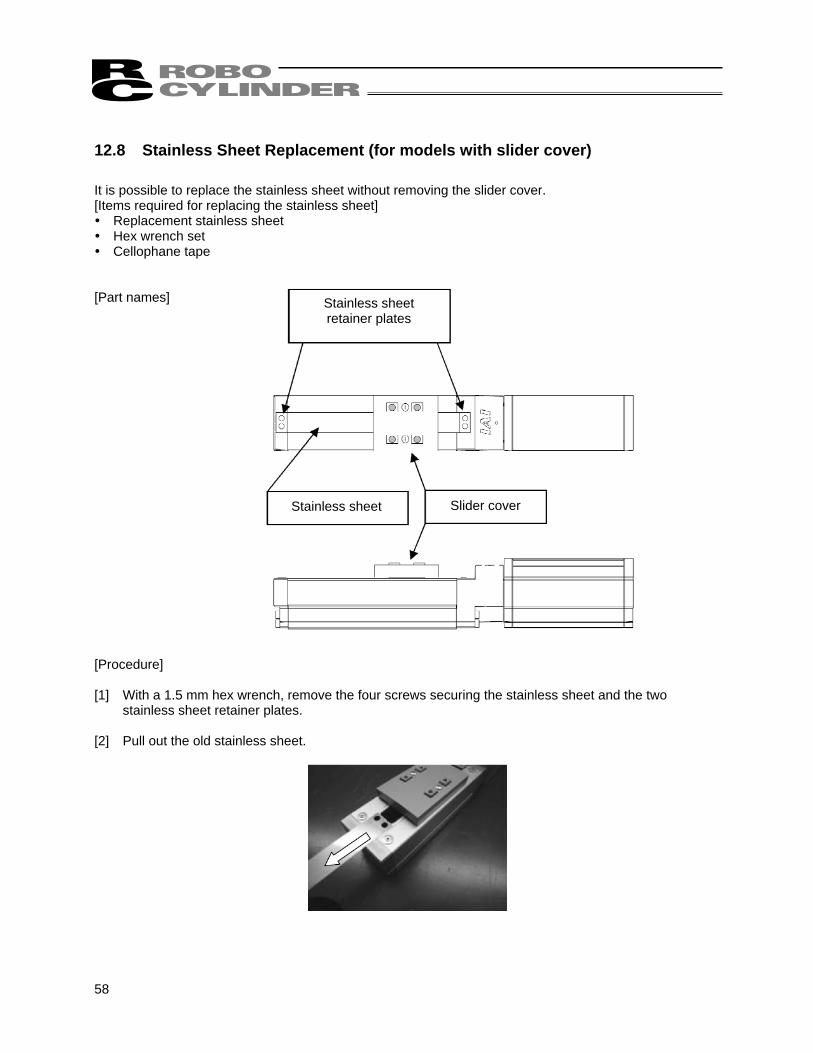
12.8 Stainless Sheet Replacement (for models with slider cover) It is possible to replace the stainless sheet without removing the slider cover. [Items required for replacing the stainless sheet] Replacement stainless sheet Hex wrench set Cellophane tape
[Part names] [Procedure] [1] With a 1.5 mm hex wrench, remove the four screws securing the stainless sheet and the two
stainless sheet retainer plates. [2] Pull out the old stainless sheet.
Stainless sheet retainer plates
Stainless sheet Slider cover
59
Cellophane tape
Stainless sheet Stainless sheet
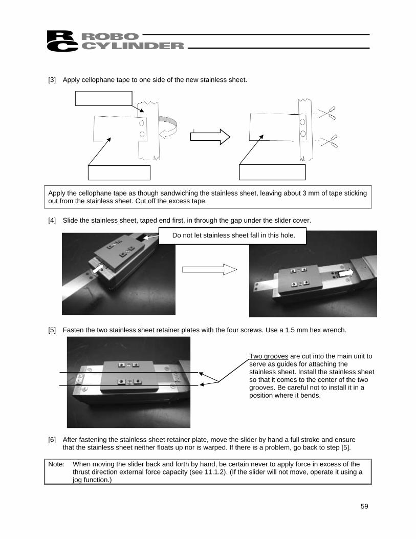
[3] Apply cellophane tape to one side of the new stainless sheet.
Apply the cellophane tape as though sandwiching the stainless sheet, leaving about 3 mm of tape sticking out from the stainless sheet. Cut off the excess tape.
[4] Slide the stainless sheet, taped end first, in through the gap under the slider cover. [5] Fasten the two stainless sheet retainer plates with the four screws. Use a 1.5 mm hex wrench. [6] After fastening the stainless sheet retainer plate, move the slider by hand a full stroke and ensure
that the stainless sheet neither floats up nor is warped. If there is a problem, go back to step [5]. Note: When moving the slider back and forth by hand, be certain never to apply force in excess of the
thrust direction external force capacity (see 11.1.2). (If the slider will not move, operate it using a jog function.)
Do not let stainless sheet fall in this hole.
Two grooves are cut into the main unit to serve as guides for attaching the stainless sheet. Install the stainless sheetso that it comes to the center of the two grooves. Be careful not to install it in a position where it bends.
60
Disconnect the cable.
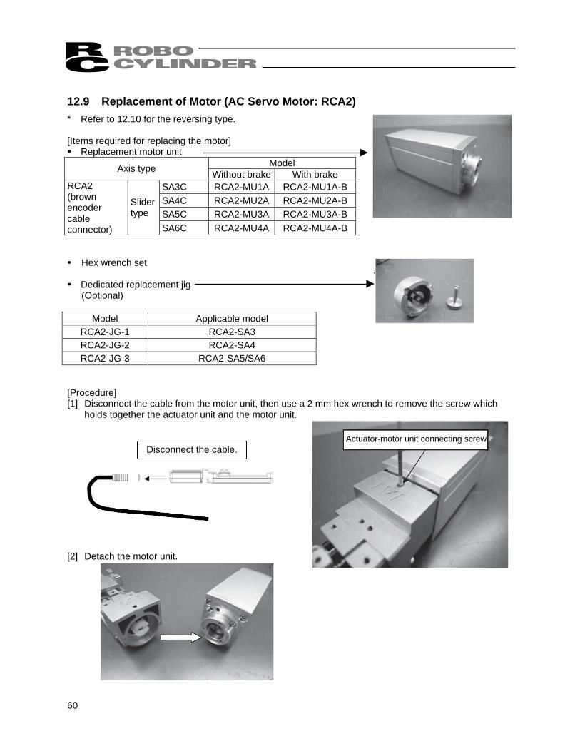
12.9 Replacement of Motor (AC Servo Motor: RCA2) * Refer to 12.10 for the reversing type. [Items required for replacing the motor] Replacement motor unit
Model Axis type Without brake With brake SA3C RCA2-MU1A RCA2-MU1A-B SA4C RCA2-MU2A RCA2-MU2A-B SA5C RCA2-MU3A RCA2-MU3A-B
RCA2 (brown encoder cable connector)
Slider type
SA6C RCA2-MU4A RCA2-MU4A-B Hex wrench set
Dedicated replacement jig
(Optional)
Model Applicable model RCA2-JG-1 RCA2-SA3 RCA2-JG-2 RCA2-SA4 RCA2-JG-3 RCA2-SA5/SA6
[Procedure] [1] Disconnect the cable from the motor unit, then use a 2 mm hex wrench to remove the screw which
holds together the actuator unit and the motor unit. [2] Detach the motor unit.
Actuator-motor unit connecting screw
61
Hole for tool
Pull apart
Coupling hub
Coupling spacer
Replacement jig (large) Line up holes in center
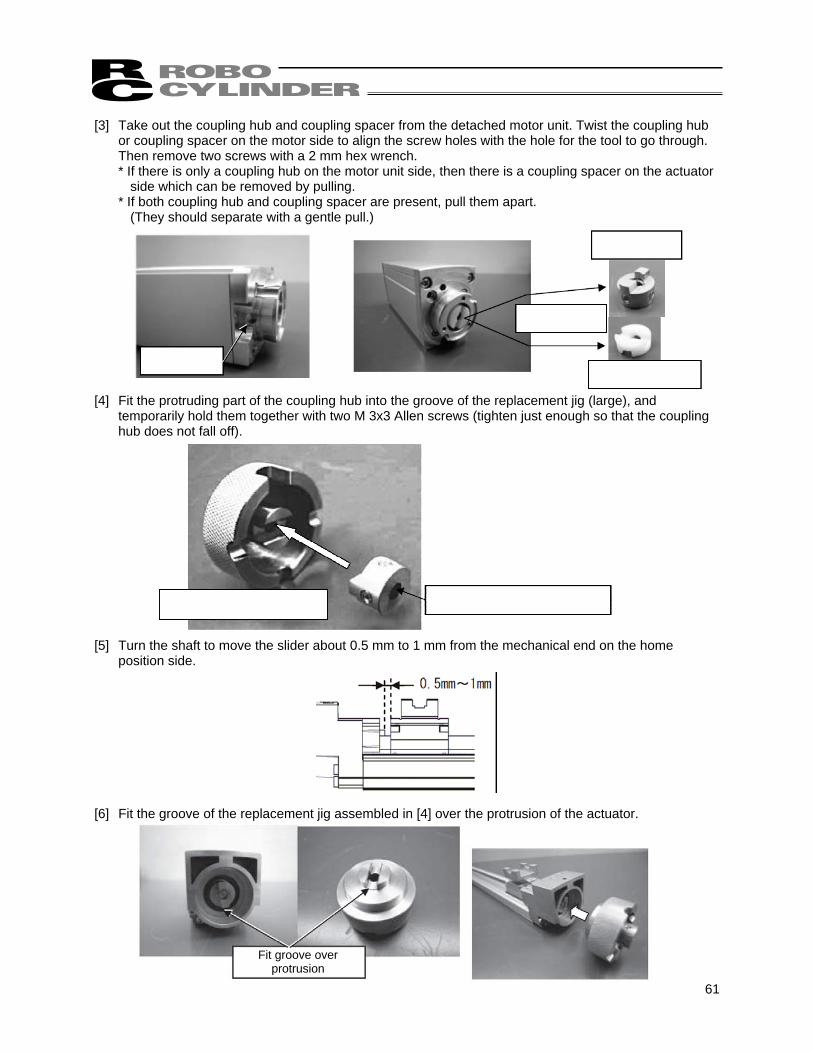
[3] Take out the coupling hub and coupling spacer from the detached motor unit. Twist the coupling hub or coupling spacer on the motor side to align the screw holes with the hole for the tool to go through. Then remove two screws with a 2 mm hex wrench. * If there is only a coupling hub on the motor unit side, then there is a coupling spacer on the actuator
side which can be removed by pulling. * If both coupling hub and coupling spacer are present, pull them apart.
(They should separate with a gentle pull.) [4] Fit the protruding part of the coupling hub into the groove of the replacement jig (large), and
temporarily hold them together with two M 3x3 Allen screws (tighten just enough so that the coupling hub does not fall off).
[5] Turn the shaft to move the slider about 0.5 mm to 1 mm from the mechanical end on the home
position side.
[6] Fit the groove of the replacement jig assembled in [4] over the protrusion of the actuator.
Fit groove over protrusion
62
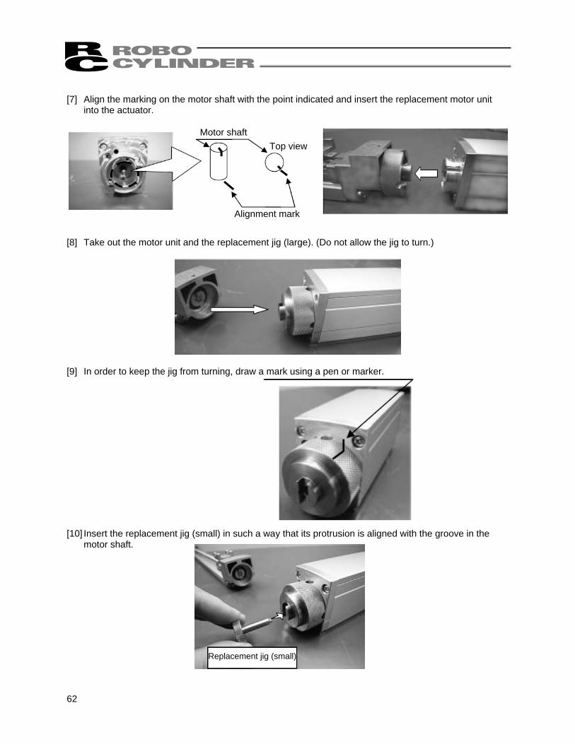
[7] Align the marking on the motor shaft with the point indicated and insert the replacement motor unit
into the actuator.
[8] Take out the motor unit and the replacement jig (large). (Do not allow the jig to turn.)
[9] In order to keep the jig from turning, draw a mark using a pen or marker. [10] Insert the replacement jig (small) in such a way that its protrusion is aligned with the groove in the
motor shaft.
Motor shaft
Alignment mark
Top view
Replacement jig (small)
63
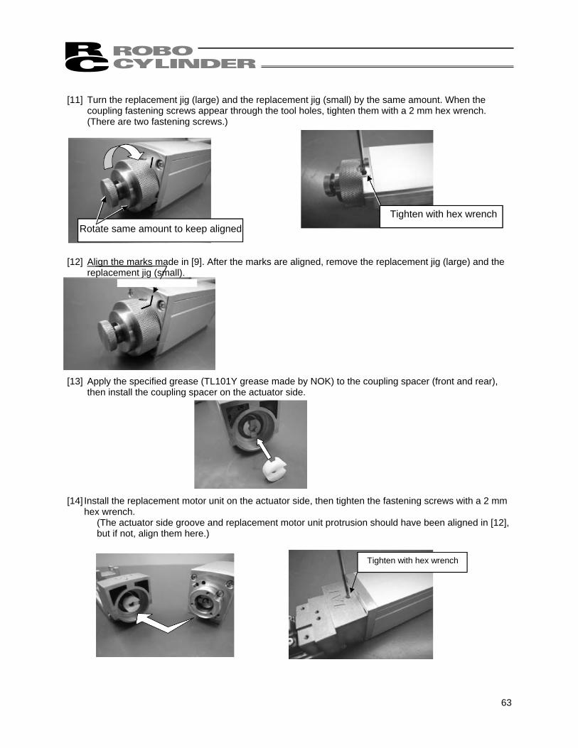
[11] Turn the replacement jig (large) and the replacement jig (small) by the same amount. When the
coupling fastening screws appear through the tool holes, tighten them with a 2 mm hex wrench. (There are two fastening screws.)
[12] Align the marks made in [9]. After the marks are aligned, remove the replacement jig (large) and the
replacement jig (small). [13] Apply the specified grease (TL101Y grease made by NOK) to the coupling spacer (front and rear),
then install the coupling spacer on the actuator side.
[14] Install the replacement motor unit on the actuator side, then tighten the fastening screws with a 2 mm
hex wrench. (The actuator side groove and replacement motor unit protrusion should have been aligned in [12], but if not, align them here.)
Rotate same amount to keep alignedTighten with hex wrench
Tighten with hex wrench
64
12.10 Replacement of Belt and Motor for Reversing Type (AC Servo Motor: RCA2) [Items required for replacing the motor] Replacement motor unit of reversing type
Model Axis type Without brake With brake SA3R RCA2-MU1B RCA2-MU1B-B SA4R RCA2-MU2B RCA2-MU2B-B SA5R RCA2-MU3B RCA2-MU3B-B
RCA2 (brown encoder cable connector)
Slider type
SA6R RCA2-MU4B RCA2-MU4B-B Belt
Manufacturer: Bando Chemical Industries, Ltd. Belt model (type) Model
40S2M138R, 4-mm wide(clean rubber type) SA3R 40S2M152R, 6-mm wide (clean rubber type) SA4R 40S2M180R, 6-mm wide (clean rubber type) SA5R 40S2M180R, 6-mm wide (clean rubber type) SA6R
Tension gauge Hex wrench set
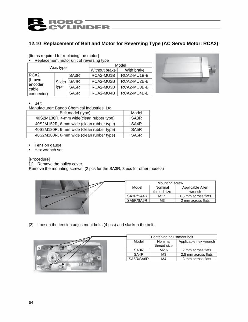
[Procedure] [1] Remove the pulley cover. Remove the mounting screws. (2 pcs for the SA3R, 3 pcs for other models) [2] Loosen the tension adjustment bolts (4 pcs) and slacken the belt.
Mounting screw Model Nominal
thread size Applicable Allen
wrench SA3R/SA4R M2.5 1.5 mm across flats SA5R/SA6R M3 2 mm across flats
Tightening adjustment bolt Model Nominal
thread size Applicable hex wrench
SA3R M2.6 2 mm across flats SA4R M3 2.5 mm across flats
SA5R/SA6R M4 3 mm across flats
65
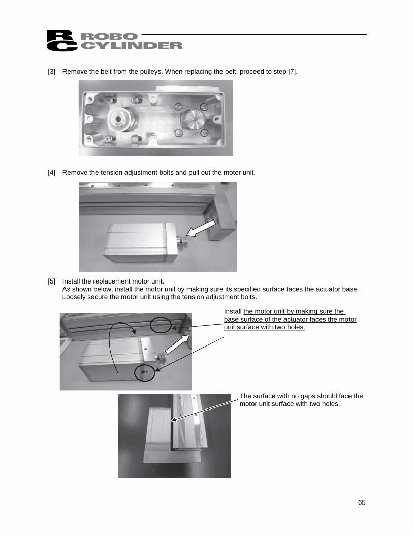
[3] Remove the belt from the pulleys. When replacing the belt, proceed to step [7]. [4] Remove the tension adjustment bolts and pull out the motor unit. [5] Install the replacement motor unit.
As shown below, install the motor unit by making sure its specified surface faces the actuator base. Loosely secure the motor unit using the tension adjustment bolts.
Install the motor unit by making sure the base surface of the actuator faces the motor unit surface with two holes.
The surface with no gaps should face the motor unit surface with two holes.
66
Tension gauge
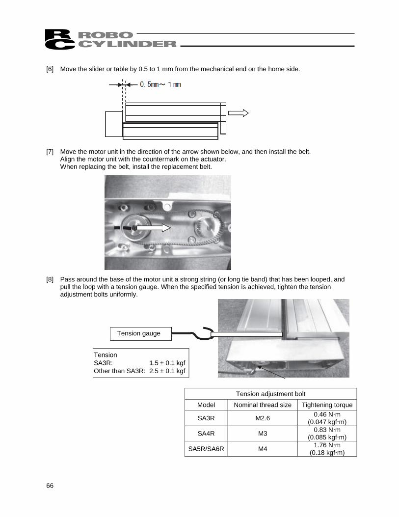
Tension SA3R: 1.5 ± 0.1 kgf Other than SA3R: 2.5 ± 0.1 kgf
[6] Move the slider or table by 0.5 to 1 mm from the mechanical end on the home side. [7] Move the motor unit in the direction of the arrow shown below, and then install the belt.
Align the motor unit with the countermark on the actuator. When replacing the belt, install the replacement belt.
[8] Pass around the base of the motor unit a strong string (or long tie band) that has been looped, and
pull the loop with a tension gauge. When the specified tension is achieved, tighten the tension adjustment bolts uniformly.
Tension adjustment bolt
Model Nominal thread size Tightening torque
SA3R M2.6 0.46 N m (0.047 kgf m)
SA4R M3 0.83 N m (0.085 kgf m)
SA5R/SA6R M4 1.76 N m (0.18 kgf m)
67
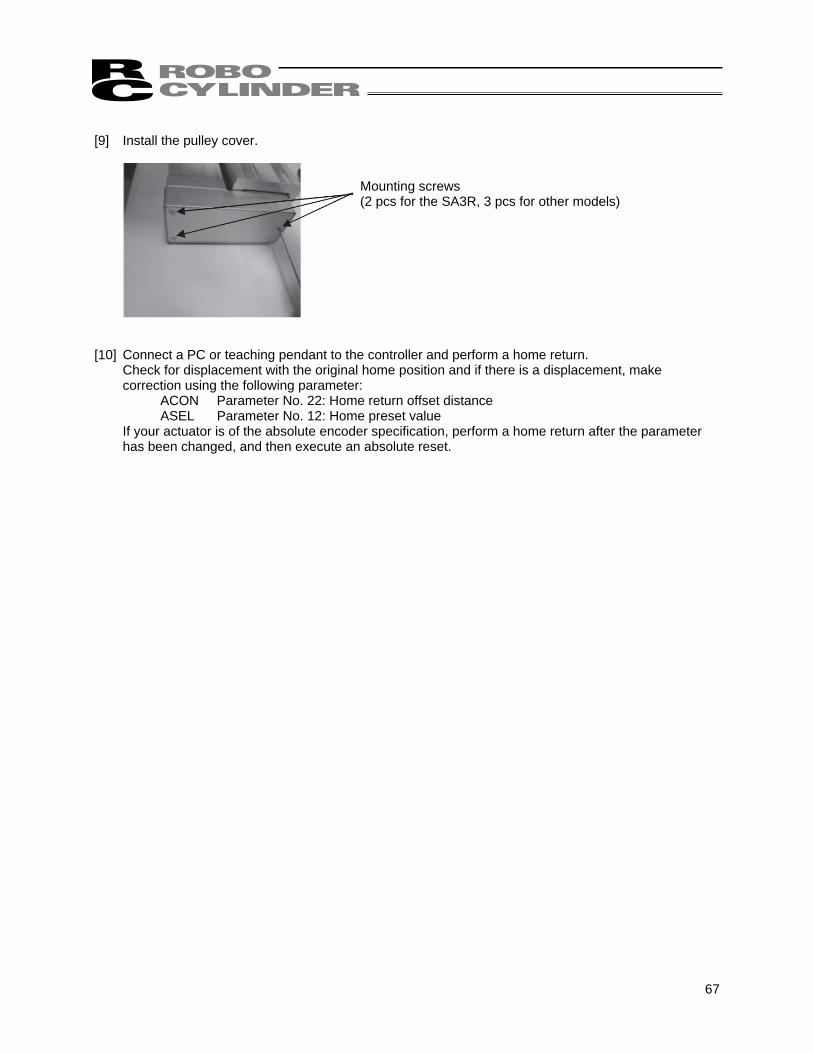
[9] Install the pulley cover. [10] Connect a PC or teaching pendant to the controller and perform a home return.
Check for displacement with the original home position and if there is a displacement, make correction using the following parameter:
ACON Parameter No. 22: Home return offset distance ASEL Parameter No. 12: Home preset value
If your actuator is of the absolute encoder specification, perform a home return after the parameter has been changed, and then execute an absolute reset.
Mounting screws (2 pcs for the SA3R, 3 pcs for other models)
68
13. Warranty The actuator you have purchased passed IAI's strict shipping inspection. The warranty information is provided below. (1) Warranty period
One of the following periods, whichever expires first: • 18 months after shipment from IAI • 12 months after delivery to the specified location • 2,500 hours of operation
(2) Scope of warranty
The warranty covers only the purchased and delivered IAI product. If any failure is found during the warranty period despite use in appropriate conditions and such failure is clearly attributable to IAI, IAI will provide a replacement or repair the defective product free of charge. However, failures due to the following causes are excluded from the scope of warranty: [1] Handling or use in any condition or environment not specified in the catalog, operation manual, etc. [2] Anything other than IAI's product [3] Modification or repair not performed by IAI or its agent [4] Not foreseeable at the science and technology standards available at the time of shipment from
IAI [5] Act of God, natural disaster, accident or any other cause beyond IAI's control [6] Natural discoloration of paint or other aging [7] Wear of consumable parts (stainless sheet, etc.) [8] Sound or other subjective feeling not affecting the facility Take note that the warranty specified herein covers only the delivered product. Any losses arising from a failure of the delivered product are excluded from the scope of warranty. The defective product is delivered to IAI for repair service.
(3) Limited liability IAI shall under no circumstance be held liable for any special, indirect or passive losses arising from its product.
(4) Scope of service
The price of the delivered product does not include the costs of programming, dispatching engineers, etc. Accordingly, separate fees are charged for the following services even during the warranty period: • Guidance of installation and adjustment, and witnessing of test operation • Maintenance and inspection • Technical guidance and training relating to operating methods, wiring methods, etc. • Technical guidance and training relating to programming and other matters relating to programs • Other services and tasks that are deemed subject to fees by IAI

69
14. Change History
Revision Date Description of Revision April 2009 First edition
70
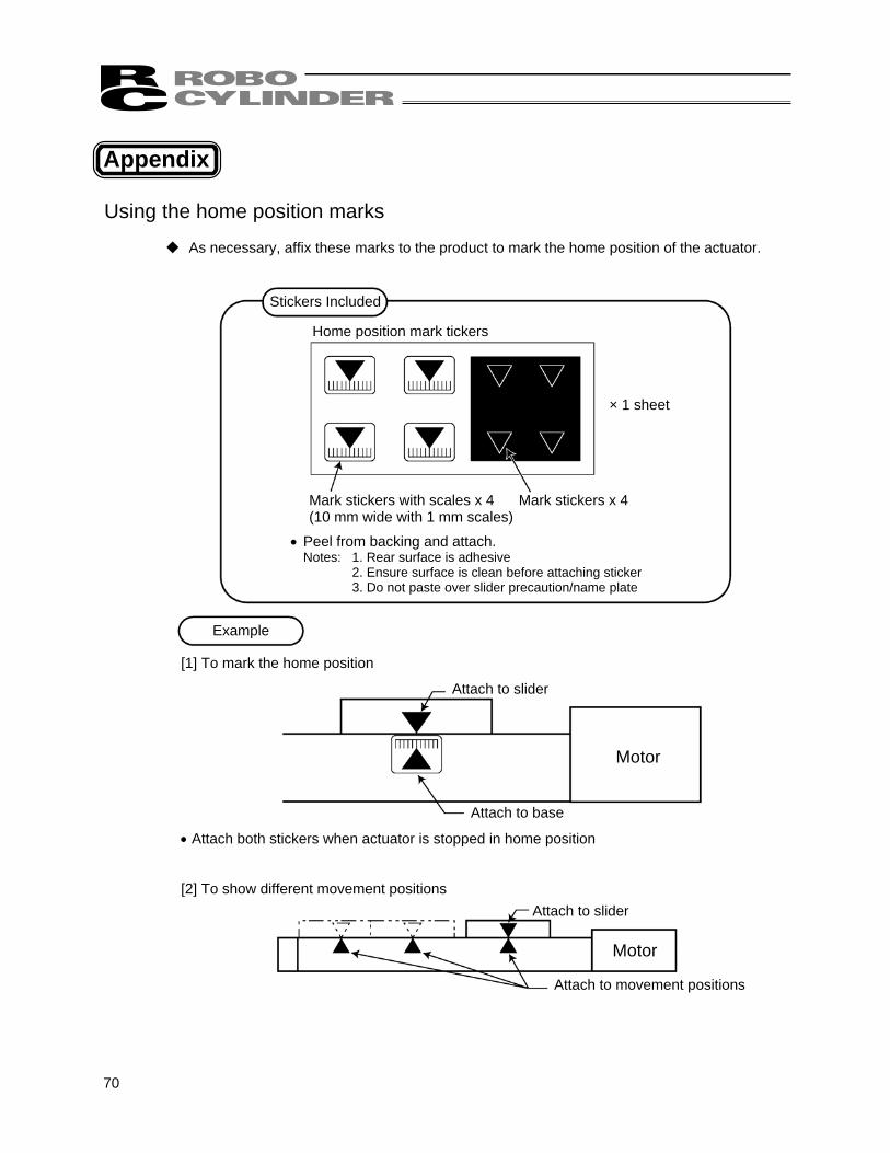
Appendix Using the home position marks
As necessary, affix these marks to the product to mark the home position of the actuator.
Stickers Included
Home position mark tickers
× 1 sheet
Mark stickers with scales x 4 Mark stickers x 4 (10 mm wide with 1 mm scales)
• Peel from backing and attach. Notes: 1. Rear surface is adhesive
2. Ensure surface is clean before attaching sticker 3. Do not paste over slider precaution/name plate
Example
[1] To mark the home position
Attach to slider
Motor
Attach to base
• Attach both stickers when actuator is stopped in home position [2] To show different movement positions
Attach to slider
Attach to movement positions
Motor


Catalog No.: ME3669-1A
Head Office: 2690 W. 237th Street, Torrance, CA 90505 TEL (310) 891-6015 FAX (310) 891-0815
Chicago Office: 1261 Hamilton Parkway, Itasca, IL 60143 TEL (630) 467-9900 FAX (630) 467-9912
Atlanta Office: 1220-E Kennestone Circle, Marrietta, GA 30066 TEL (678) 354-9470 FAX (678) 354-9471
website: www.intelligentactuator.com
Ober der Röth 4, D-65824 Schwalbach am Taunus, Germany TEL 06196-88950 FAX 06196-889524
The information contained in this document is subject to change without notice for purposes of product improvement. Copyright © April 2009 IAI Corporation. All rights reserved.