rm752a - honda
TRANSCRIPT


I
TABLE OF CONTENTS
SPECIFICATIONS ................................................................................................ 1
INTRODUCTION ................................................................................................... 2
CHECK LISTS ...................................................................................................... 3
GENERAL INFORMATION ................................................................................... 3
SAFETY RULES ................................................................................................... 4
SAFETY DECALS ................................................................................................. 6
TORQUE CHART ................................................................................................. 8
ASSEMBLY ........................................................................................................... 9
OPERATION ....................................................................................................... 13
OWNER SERVICE ............................................................................................. 18
DEALER MAINTENANCE .................................................................................. 21
TROUBLE SHOOTING ....................................................................................... 28
INDEX TO PARTS LISTS ................................................................................... 29
INDEX ................................................................................................................. 36
WARRANTY SERVICE ............................................................ Inside Back Cover
SPECIFICATIONS
Cutting Width ........................................................................................... 42"
Cutting Height Range ................................................................ 2-1/4" . 5-112"
Shipping Weight (approximate) .......................................................... 429 Ibs . Blade RPM ....................................................... 1. 076 @ 2. 000 rpm PTO
Blade Tip Speed (feet per minute) ....................... 11. 831 @ 2. 000 rpm PTO
Blade Spindle .............................................................................................. 1
Number of Blades .......................................................................................... 2
Universal Drive ......................................................................................... L6W
Maximum PTO Speed RPM ................................................................... 2, 000 Caster Wheels (Solid Rubber) ...................................................... 10.25 x 3.5
Mower Frame Thickness ....................................................................... 10 GA
F-7756 (1 0-89) 1

INTRODUCTION
Thank you for purchasing an HTA attachment for your Honda Tractor.
This manual covers the assembly, operation, and maintenance of the HTA Model RM752A Rear Mower. For your convenience, a parts guide and detailed warranty information are also included in this publication.
NOTE: The information in this publication is based on the latest product information available at the time of printing. American Honda Motor Co., Inc., reserves the right to make changes at any time without notice and without incurring any obligation.
No part of this publication may be reproduced without written permission.
Pay special attention to the statements preceded by the following symbols:
Indicates that serious injury or death WILL result if instructions are not followed.
Indicates a strong possibility that serious injury or death could result if instructions
Indicates a possibility that minor injury can result if instructions are not followed.
I UWORTANT NOTICE I Indicates that equipment or property damage can result if instructions are not followed.
NOTE: Gives helpful information.
are not followed.
HTA attachments are designed to give safe and dependable service if assembled and operated according to instructions.
If a problem should arise or if you have any questions about this attachment, consult an authorized Honda Tractor dealer.
2
CHECK LISTS
PRE-DELIVERY CHECK LIST I
Inspect the mower thoroughly after assembly to ensure it is set up properly before delivering it to the customer. The following check lists are a reminder of points to inspect. Check off each item as it is found satisfactory or after proper adjustment is made.
Check that all safety decals are installed and in good condition. Check that shieMs and guards are properly installed and in good condition. Check all bolts to be sure they are correctly torqued. Check that all cotter pins are properly installed. Lubricate all grease fittings; check to make sure a small amount of grease comes out of seal. Check that blades have been properly installed.
DELIVERY CHECK LIST - Inform customer to operate PTO at 2,000 tpm
maximum. - Check mower attitude and belt alignment. - Show customer how to make adjustments. - Explain importance of lubrication to customer
and point out lubrication points on mower.
- Present the Operator's Manual, and ask customer to become familiar with all sections.
- Explain to customer that when mower is trans- ported on road or highway, safety devices. should be used to give adequate warning to operators of other vehicles.
DAILY CHECK LIST Lubricate all grease fittings; check to make sure a small amount of grease comes out of seal. Check that tractor PTO spring-activated locking collar slides freely and is seated firmly in mower driveline spline groove. Check that both side skids, the left side shield and either the discharge chute or right side shield are installed. Make sure blades are sharp, free of nicks or cracks and are securely fastened. Make sure all hardware is securely fastened and in good condition. Check that mower is properly and securely attached to tractor. Check that all safety decals are installed and in good condition. Check that shields and guards are properly installed and in good condition.
GENERAL INFORMATION
The purpose of this manual is to assist you in operating and maintaining your mower. Read it carefully. It furnishes information and instructions that will help you achieve years of dependable performance. These instructions have been compiled from extensive field experience and engineering data. Some information may be general in nature due to unknown and varying operating conditions. However, through experience and these instructions you should be able to develop procedures suitable to your particular situation.
The illustrations and data used in this manual were current at the time of printing, but due to possible in- line production changes, your machine may vary slightly in detail.
\ I We reserve the right to redesign and change the
machines as mav be necessarv without notification.
Some lllustratlons In thls manual show the mower wlth shields and guards removed to provide a better view. The mower should never be operated wlth any shleldlng or guards removed. Throughout this manual, references are made to right and left directions. These are determined by standing behind the equipment facing the direction of forward travel. Blade rotation is clockwise as viewed from the top of the mower.
F-7756 (1 0-89) 3
SAFETY
A ATTENTION! BECOME ALERT! YOUR SAFETY IS INVOLVED! A Safety is a' primary concern in the design and manufacture of our products. Unfortunately, our efforts to provide safe equipment can be wiped out by a single careless act of an operator. In addition to the design and configuration of equipment, hazard control and accident prevention are dependent upon the awareness, concern, prudence and proper training of personnel involved in the operation, transport, maintenance and storage of equipment. It has been said "the best safety device is an informed, careful operator". We ask you to be that kind of an operator.
The designed and tested safety of this equipment depends on it being operated within the limitations as explained in this manual.
TRAINING W Safety instructions are important! Read this
manual, the tractor manual and all safety rules. W Know your controls and how to stop tractor
engine and mower quickly in an emergency. W Operators must be instructed in and be capable
of the safe operation of the equipment, its attachments and all controls. Do not allow anyone to operate this equipment without proper instructions.
W Do not allow children or unqualified persons to operate equipment.
PREPARATION W
W
W
Always wear relatively tight and belted clothing to avoid entanglement in moving parts. Wear sturdy, rough-soled work shoes and protective equipment for eyes, hands, hearing and head. Ensure mower is properly mounted, adjusted and in good operating condition. Remove accumulated debris from mower to avoid fire hazard. Make sure tractor PTO spring-activated locking collar slides freely and is seated firmly in mower driveline spline groove.
4
Ensure. all safety decals are installed and in good condition.
W Ensure shields and guards are properly installed and in good condition.
Ensure both side skids, the left side shield and either the discharge chute or right side shield are installed.
W A minimum 20% of tractor and equipment weight must be on tractor front wheels with mower in transport position. Without this weight, tractor could tip over causing personal injury or death. The weight may be attained with front wheel weights, ballast in tires or front tractor weights. When attaining the minimum 20% weight on the front wheels, you must not exceed the Roll Over Protection Structure (ROPS) weight certification. Weigh the tractor and equipment. DO NOT GUESS OR ESTIMATE.
W Inspect area to be cut and remove stones, branches or other hard objects that might be thrown, causing injury or damage.
OPERATIONAL SAFETY W
W W
W
W
W W
Keep bystanders away from equipment while it is in operation.
Never direct discharge toward anyone. Operate only in daylight or good artificial light. Keep hands and feet away from mower while tractor engine is running. Stay clear of all moving parts.
If your tractor is equipped with a ROPS, you must wear your seat belt.
Always comply with all state and local lighting and marking requirements.
No riders are allowed on tractor or mower.
Start engine from operator's seat after disengaging tractor PTO and placing trans- mission in neutral.
(Safety Rules continued on next page)
SR I1 F-7756 (1 0-89)

SAFETY RULES
A ATTENTION! BECOME ALERT! YOUR SAFETY IS INVOLVED! A (Safety Rules continued from previous page) H Turn tractor engine off, remove key and lower
Operate PTO at 2,000 rpm maximum.
Do not operate PTO during transport. Make sure area behind you is clear before operating in reverse.
Do not operate on steep slopes.
Do not stop, start or change directions suddenly on slopes. Use extreme care and reduce ground speed on slopes and rough terrain.
Watch for hidden hazards on the terrain during operation.
Stop mower and tractor immediately upon striking an obstruction. Turn off engine, remove key, inspect and repair any damage before resuming operation. Block mower securely before working under- neath. Disengage power to mower, lower to ground, stop engine, set parking brake and remove key before dismounting tractor.
mower to ground before performing-any service or maintenance.
BIO& mower securely before working under- neath.
Keep all persons away from operator control area while performing adjustments, service or maintenance.
Make certain all movement of mower compo- nents has stopped before opening blade access cover.
Frequently check blades. They should be sharp, free of nicks and cracks and securely fastened.
Your dealer can supply genuine replacement blades. Substitute blades may not meet original equipment specifications and may be dangerous.
Periodically tighten all bolts, nuts and screws and check that all cotter pins are properly installed to ensure mower is in a safe condition.
Ensure all safety decals are installed and in good condition.
Ensure shields and guards are properly MAINTENANCE SAFETY installed and in good condition.
Always wear relatively tight and belted clothing to avoid entanglement in moving parts. Wear STORAGE sturdy, rough-soled work shoes and protective equipment for eyes, hands, hearing and head. Block mower securely for storage.
NOTES
SR I1 F-7756 (1 0-89) 5

SAFETY DECALS
A ATTENTION! BECOME ALERT! YOUR SAFETY IS INVOLVED! A Replace Immediately If Damaged!
2 DO NOT OPEN BLADE ACCESS COVER UNTIL ALL COMPONENTS
AVE STOPPED. 12023/
1
KEEP AWAY! * ENTANGLEMENT WITH ROTATING
DRIVE PARTS OR FALLING OFF CAN CAUSE INJURY OR DEATH.
IN PLACE AND IN GOOD CONDITION. * KEEP ALL DRIVE SHIELDS & GUARDS
* ALLOW NO RIDERS. 7507.7
DE1458
TO AVOID SERIOUS INJURY OR DEATH: Sr READ OPERATOR'S MANUAL & FOLLOW Sr KNOW HOW TO STOP TRACTOR AND
ALL SAFETY PRECAUTIONS. EQUIPMENT QUICKLY IN AN EMERGENCY. * BLOCK UP IMPLEMENT AND REMOVE (CONTACT DEALER FOR MANUALS.)
* KEEP SHIELDS AND GUARDS IN PLACE. KEY BEFORE WORKING UNDERNEATH. KEEP CLEAR OF DRIVES AND BELTS. * ALLOW NO CHILDREN OR UNQUALIFIED * LOWER IMPLEMENT, STOP ENGINE AND PERSONS TO RUN EQUIPMENT.
* CLEAR MOWING AREA OF DEBRIS. DECREASE SPEED WHEN TURNING. * DO NOT OPERATE MOWER IN VICINITY * DO NOT OPERATE IN TRANSPORT
OF OTHER PERSONS. NO RIDERS. POSITION. 31 399
REMOVE KEY BEFORE DISMOUNTING. * BE CAREFUL ON UNEVEN TERRAIN.
DE1519 3
4
KEEP AWAY! THROWN OBJECTS OR BLADE CONTACT CAN CAUSE SERIOUS INJURY OR DEATH.
KEEP DISCHARGE CHUTE AND SHIELDS IN PLACE. finm
6
DB 1970
(Safety Decals continued on next page)
F-7756 (1 0-89)

SAFETY DECALS A ATTENTION! BECOME ALERT! YOUR SAFETY IS INVOLVED! A
Replace Immediately If Damaged!
(Safety Decals continued from previous page)
I 2000 RPM PTO ONLY HIGHER PTO SPEEDS CAN CAUSE EQUIPMENT FAILURE AND PERSONAL INJURY. I
5
6
KEEP AWAY! ROTATING DRIVE LINE * ENTANGLEMENT CAN CAUSE
SERIOUS INJURY OR DEATH. * KEEP ALL DRIVE SHIELDS AND GUARDS IN PLACE AND IN GOOD CONDITION. * TRACTOR PTO YOKE MUST BE LOCKED IN PLACE. * ADJUST TRACTOR HITCH TO PROPER DIMENSIONS. 29029
DB1518
DE3108 9
F-7756 (1 0-89)
SHIELD MISSING DO NOT OPERATE
SHIELD MISSING DO NOT OPERATE I
7
DE2410
8 - Serial Number Plate ~~ ~~
D m 7 1
7
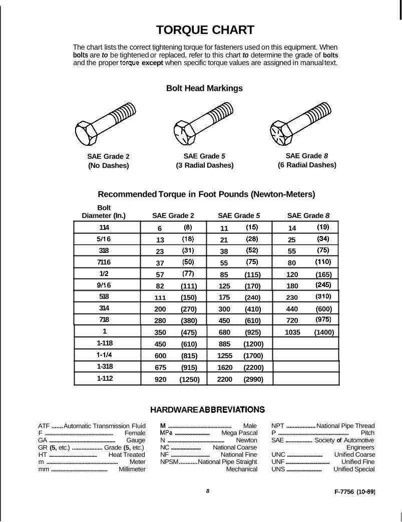
TORQUE CHART The chart lists the correct tightening torque for fasteners used on this equipment. When bolts are to be tightened or replaced, refer to this chart to determine the grade of bolts and the proper toque except when specific torque values are assigned in manual text.
Bolt Head Markings
SAE Grade 2 SAE Grade 5 SAE Grade 8 (No Dashes) (3 Radial Dashes) (6 Radial Dashes)
Recommended Torque in Foot Pounds (Newton-Meters) Bolt
Diameter (In.) SAE Grade 2 SAE Grade 5 SAE Grade 8
1 14
80 (1 10) 55 (75) 37 (50) 711 6 55 (75) 38 (52) 23 (31) 318 25 (34) 21 (28) 13 (1 8) 511 6 14 (1 9) 11 (1 5) 6 (8)
1 /2 120 (165) 85 (115) 57 (77) 911 6 180 (245) 125 (170) 82 (111)
~~~~~
518 230 (31 0) 1 75 (240) 111 (150) 314 440 (600) 300 (410) 200 (270) 718 720 (975) 450 (610) 280 (380) 1 1035 (1 400) 680 (925) 350 (475)
1-118
1255 (1 700) 600 (815) 1-114 885 (1200) 450 (610)
1-318 1620 (2200) 675 (915) 1-112 2200 (2990) 920 (1250)
HARDWARE ABBREVlATlONS
ATF ....... Automatic Transmission Fluid M ............................................. Male F ............................................... Female MPa ............................ Mega Pascal GA .............................................. Gauge N ......................................... Newton GR (5, etc.) ................... Grade (5, etc.) NC ......................... National Coarse HT ................................... Heat Treated NF .............................. National Fine
mm ........................................ Millimeter Mechanical m ................................................. Meter NPSM ........... National Pipe Straight
8
NPT .................. National Pipe Thread P ................................................. Pitch SAE ................. Society of Automotive
Engineers UNC ............................ Unified Coarse UNF ................................. Unified Fine UNS ............................ Unified Special
F-7756 (1 0-89)
ASSEMBLY
Be familiar with all safety practices on pages 4 and 5.
Make certain a l l movement of cutter components has stopped before openlng blade access cover.
Always wear relatively tight and belted clothing to avoid entanglement In moving parts. Wear sturdy, rough-soled work shoes and protective equlpment for eyes, hands, hearlng and head.
Operate PTO at 2,000 rpm maxlmum.
Turn tractor engine off, remove key, lower mower to ground before performing any senrke or rnalntenance.
Block mower securely before working under- neath.
Keep all persons away from operator control area whlle perfonnlng adjustments, senrlce or malntenance.
Make sure tractor PTO sprlng-activated locklng collar slldes freely and Is seated f lmly In mower drlvellne spline groove.
Removing Mower From Box
Remove mower components from the comer fillers.
Remove lag screws from crating brackets on both sides of the mower. Remove mower frame from box.
DEALER SET-UP INSTRUCTIONS
Assembly of this mower is the responsibility of the dealer. It should be delivered to the owner completely assembled, lubricated and adjusted for normal mowing conditions.
Complete check list on page 3 when assembly is complete.
The mower is shipped partially assembled. Assembly will be easier if components are aligned and loosely assembled before tightening hardware. Recommended torque. values for hardware are located on page '8.
Select a suitable working area. Lay parts and hardware out to make location easy. Refer to illustrations, accompanying text, parts lists and exploded view drawings.
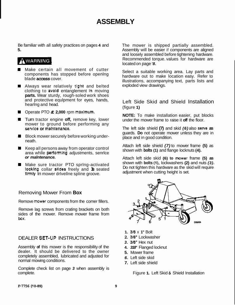
Left Side Skid and Shield Installation (figure 1)
NOTE: To make installation easier, put blocks under the mower frame to raise it off the floor.
The left side shield (7) and skid (6) also sewe as guards. Do not operate mower unless they are in place and in good condition.
Attach left side shield (7) to mower frame (5) as shown with bolts (1) and flange locknuts (4).
Attach left side skid (6) to mower frame (5) as shown with bolts (1). lockwashers (2) and nuts (3). Do not tighten this hardware as the skid will require adjustment when cutting height is set.
1. 318 x 1" Bolt 2. 318" Lockwasher 3. 3/8" Hex nut 4. 318" Flanged locknut 5. Mower frame 6. Left side skid 7. Left side shield
Figure 1. Left Skid & Shield Installation
F-7756 (1 0-89) 9
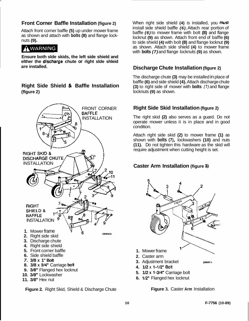
Front Corner Baffle Installation (figure 2)
Attach front corner baffle (5) up under mower frame as shown and attach with bolts (8) and flange lock- nuts (9).
Ensure both slde skids, the left side shield and elther the dkcharge chute or rlght slde shleid are installed.
Right Side Shield & Baffle Installation (flgure 2)
FRONT CORNER
INSTALLATION
INSTALLATION
INSTALLATION
1. Mower frame 2. Right side skid 3. Discharge chute 4. Right side shield 5. Front corner baffle 6. Side shield baffle 7. 3/8 x 1" Bolt 8. 3/8 x 3/4" Carriage bolt 9. 3/8" Flanged hex locknut
10. 3/8" Lockwasher 11. 3/8" Hex nut
D83052A
Figure 2. Right Skid, Shield & Discharge Chute
When right side shield (4) is installed, you must ~~ I install side shield baffle (6). Attach rear portion of baffle (6) to mower frame with bolt (8) and flange locknut (9) as shown. Attach front end of baffle (6) to side shield (4) with bolt (8) and flange locknut (9) as shown. Attach side shield (4) to mower frame with bolts (7) and flange locknuts (9) as shown.
Discharge Chute Installation (figure 2)
The discharge chute (3) may be installed in place of baffle (6) and side shield (4). Attach discharge chute (3) to right side of mower with bolts (7) and flange locknuts (9) as shown.
Right Side Skid Installation (figure 2)
The right skid (2) also serves as a guard. Do not operate mower unless it is in place and in good condition.
Attach right side skid (2) to mower frame (1) as shown with bolts (7), lockwashers (10) and nuts (11). Do not tighten this hardware as the skid will require adjustment when cutting height is set.
Caster Arm Installation (figure 3)
1. Mower frame 2. Caster arm 3. Adjustment bracket D m 1 A
5. 1/2 x 1-3/4" Carriage bolt 6. 1/2" Flanged hex locknut
4. 1/2 X 1-1/2" Bolt
Figure 3. Caster Arm Installation
10 F-7756 (1 0-89)
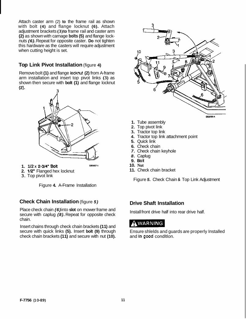
Attach caster arm (2) to the frame rail as shown with bolt (4) and flange locknut (6). Attach adjustment brackets (3) to frame rail and caster arm (2) as shown with carnage bolts (5) and flange lock- nuts (6). Repeat for opposite caster. Do not tighten this hardware as the casters will require adjustment when cutting height is set.
Top Link Pivot Installation (figure 4)
Remove bolt (1) and flange locknut (2) from A-frame arm installation and insert top pivot links (3) as shown then secure with bolt (1) and flange locknut (2) * 3
1. 1/2 X 2-3/4" BOR 083057 A
2. 1/2" Flanged hex locknut 3. Top pivot link
Figure 4. A-Frame Installation
Check Chain Installation (figure 5 )
Place check chain (6) into slot on mower frame and secure with caplug (8). Repeat for opposite check chain.
Insert chains through check chain brackets (1 1) and secure with quick links (5). Insert bolt (9) through check chain brackets (1 1) and secure with nut (10).
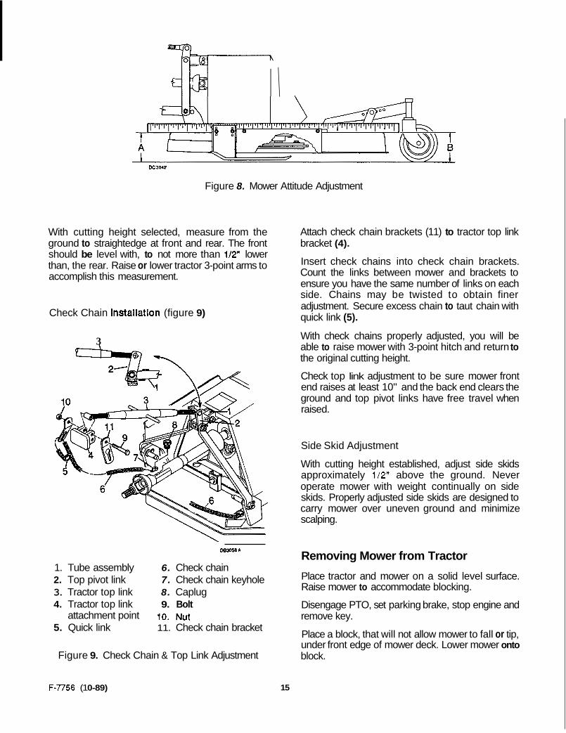
1. Tube assembly 2. Top pivot link 3. Tractor top link 4. Tractor top link attachment point 5. Quick link 6. Check chain 7. Check chain keyhole 8. Caplug 9. BoR
10. Nut 11. Check chain bracket
Figure 5. Check Chain & Top Link Adjustment
Drive Shaft Installation
Install front drive half into rear drive half.
Ensure shlelds and guards are properly Installed and In good condltlon.
F-7756 (1 0-89) 11

NOTES
12 F-7756 (1 0-89)

OPERATION
Safety is a primary concern in the design and manufacture of our products. Unfortunately, our efforts to provide safe equipment can be wiped out by ,a single careless act of an operator.
In addition to the design and configuration of equipment, hazard control and accident prevention are dependent upon the aware- ness, concern, prudence and proper training of personnel involved in the operation, transport, maintenance and storage of equipment.
It has been said "the best safety device is an informed, careful operator. We ask you to be that kind of an operator.
The operator is responsible for the safe operation of this mower. The operator must be properly qualified and trained. Operators should be familiar with the mower, tractor and all safety practices before starting operation. Read the safety information on pages 4 and 5.
This mower is designed for light brush shredding and grass mowing. It is especially useful in cane, berry, grape and vegetable crops for mowing and shredding prunings. It is equipped with low suction blades. Optional high suction blades are available for added suction and shredding.
Recommended mowing speed range for most conditions is from two to five mph.
Do not allow children or unqualified persons to operate equlpment.
Do not operate PTO durlng transport.
Keep bystanders away from equipment while it is in operation. Block mower securely before worklng under- neath. Keep all persons away from operator control area while performing adjustments, senrlce or maintenance.
No riders are allowed on tractor or mower. Operate PTO at 2,000 rpm maximum.
Never dlrect dlscharge toward anyone.
Ensure shields and guards are properly installed and In good condition.
Ensure both slde sklds, the left slde shield and either the dlscharge chute or right slde shleld are installed.
Make certain al l movement of mower components has stopped before opening blade access cover.
Stop mower and tractor lmmedlately upon striking an obstructlon. Turn off engine, remove key, Inspect and repair any damage before resumlng operation.
Always wear relatlvely tlght and belted clothing to avold entanglement In movlng parts. Wear sturdy, rough-soled work shoes and protective equlpment for eyes, hands, hearing and head.
F-7756 (1 0-89) 13

Attaching Mower to Tractor Tractor Stability (figure 6)
A minimum 20% of tractor and equipment weight must be on tractor front wheels with mower in transport position. Without this weight, tractor could tip over causing personal injury or death. The weight may be attained with front wheel weights, ballast in tires or front tractor weights. When attaining the minimum 20% weight on the front wheels, you must not exceed the Roil Over Protection Structure (ROPS) weight certification. Weigh the tractor and equipment. DO NOT GUESS OR ESTIMATE!
A
D B l W
Figure 6. Tractor Stability
Place mower on a level surface. Back tractor up to mower and attach lower 3-paint lift arms to mower hitch pins. Secure with Kiik pins.
Make sure tractor PTO spring-activated locking collar slides freely and is seated firmly in mower driveline spline groove.
Attach mower drive shaft to tractor PTO.
Attach tractor top link to mower top link pivots. Adjust tractor top link to raise mower front end at least lo", making sure the back end clears the ground and top pivot links have free travel when raised.
Cutting Height Adjustment (figure 7)
Place tractor and mower on a level surface. Check tractor tire pressure to make sure it is correct and equal.
The adjustments given are to provide you with a starting point. Adjustments are approximate and may vary due to machine wear. You may desire to fine tune them for your situation.
I IMPORTANT NOTICE I Avoid very low cutting heights. Striking the ground with blades gives one of the most damaging shock loads a mower can encounter. Severe shock loads can damage the mower drive and/or the tractor transmission.
Mower cutting height is raised, lowered, and main- tained with tractor hydraulics and top link adjust- ment, check chains and caster arms.
Place a straightedge along mower deck edge from front to rear (refer to figure 8). Measure from each front corner to the ground to be sure mower is level. Use tractor 3-point arm adjustment as required.
Refer to figure 7. Approximate cutting heights are provided for various hole combinations. Set caster arms to your desired cutting height.
E D
I Hole in Frame Rail
Hole in
5- 1 12 *Not usable in these holes
Figure 7. Caster Adjustment
14 F-7756 (1 0-89)
I \
D c 3 w
Figure 8. Mower Attitude Adjustment
With cutting height selected, measure from the ground to straightedge at front and rear. The front should be level with, to not more than 1/2" lower than, the rear. Raise or lower tractor 3-point arms to accomplish this measurement.
Check Chain installation (figure 9)
3
\-
1. Tube assembly 6. Check chain 2. Top pivot link 7. Check chain keyhole 3. Tractor top link 8. Caplug 4. Tractor top link 9. Bolt
attachment point 10. Nut 5. Quick link 11. Check chain bracket
Figure 9. Check Chain & Top Link Adjustment
F-7756 (1 0-89)
Attach check chain brackets (11) to tractor top link bracket (4).
Insert check chains into check chain brackets. Count the links between mower and brackets to ensure you have the same number of links on each side. Chains may be twisted to obtain finer adjustment. Secure excess chain to taut chain with quick link (5).
With check chains properly adjusted, you will be able to raise mower with 3-point hitch and return to the original cutting height.
Check top link adjustment to be sure mower front end raises at least 10" and the back end clears the ground and top pivot links have free travel when raised.
Side Skid Adjustment
With cutting height established, adjust side skids approximately 112" above the ground. Never operate mower with weight continually on side skids. Properly adjusted side skids are designed to carry mower over uneven ground and minimize scalping.
Removing Mower from Tractor
Place tractor and mower on a solid level surface. Raise mower to accommodate blocking.
Disengage PTO, set parking brake, stop engine and remove key.
Place a block, that will not allow mower to fall or tip, under front edge of mower deck. Lower mower onto block.
15
Pre-Operation Check List
Operate PTO at 2,000 rpm maximum.
Ensure both side skids, the left side shield and either the discharge chute or right side shield are installed.
No riders are allowed on tractor or mower.
Do not allow children or unqualified persons to operate equipment.
Blades should be sharp, free of nicks and cracks and securely fastened.'
Ensure shields and guards are properly installed and in good condition.
Inspect area to be cut and remove stones, branches or other hard objects that might be thrown, causing injury or damage.
Check mower cutting height and attitude adjust- ment.
Check to ensure caster wheels, spindles, drive shaft and universal joints are lubricated.
f IMPORTANT NOTICE I Mower vlbratlon tends to loosen bolts durlng Operation. All hardware should be checked regularly to malntaln proper torque. It Is a good practice to check mower before each operation to ensure all bolts are secure.
Power for operating mower is supplied by tractor PTO. Do not exceed tractor manufacturer's rated PTO speed of 2,000 rprn maximum. Know how to stop tractor and mower quickly in case of an emergency.
Should mower become plugged, causing belt to slip, immediately' maneuver equipment into a previously cut area and allow mower to clear accumulated material. Continue running at leas1 two minutes, allowing pulleys to cool. Stopping the mower with belt in contact with a very hot pulley will bake and ruin belt.
Stop mower and tractor Immediately upon striking an obstructlon. Turn off engine, remove key, Inspect and repair any damage before resuming Operation.
Operating Technique
Proper ground speed will depend upon the terrain and the height, type and density of material to be cut.
Normally, ground speed will range from two to five. mph. Tall dense material should be cut at a low speed; thin medium-height material can be cut at a faster ground speed.
Always operate tractor PTO at 2,000 rpm. This is necessary to maintain proper blade speed and produce a clean cut.
Under certain conditions, tractor tires may r o l l some grass down and prevent it from being cut at the same height as the surrounding area. When this occurs, reduce your ground speed, but maintain 2,000 rpm PTO speed. The lower ground speed will permit grass to at least partially rebound.
Under some conditions, grass will not rebound enough to be cut even. In general, lower cutting heights give a more even cut with less tendency to leave tire tracks. However, it is better to cut grass frequently rather than too short. Short grass deteriorates rapidly in hot weather and invites weed growth during growing seasons. Follow local recommendations for the suitable cutting height in your area.
Tips
Extremely tall material should be cut twice. Set mower at a higher cutting height for the first pass. Then cut at desired height at 90" to the first pass.
Remember, sharp blades produce cleaner cuts and require less power.
Analyze area to be cut to determine the best pro- cedure. Consider height and type of grass and terrain type: hilly, level or rough.
Plan your mowing pattern to travel straight forward whenever possible. Mow with uncut grass to the left. This will distribute the clippings over the cut area. Discharging clippings over uncut grass will cause a buildup and may prevent uniform cutting.
Inspect area to be cut and remove stones, branches or other hard objects that might be thrown, causing injury or damage.
16 F-7756 (1 0-89)
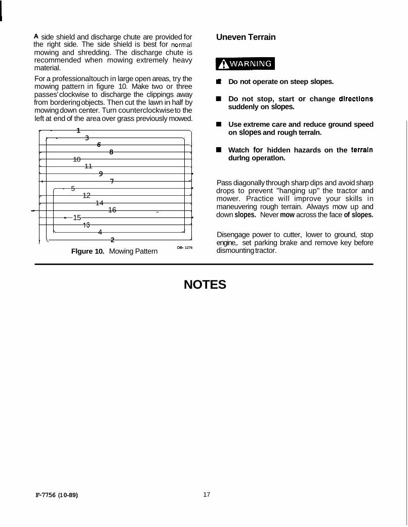
A side shield and discharge chute are provided for the right side. The side shield is best for normal mowing and shredding. The discharge chute is recommended when mowing extremely heavy material. For a professional touch in large open areas, try the mowing pattern in figure 10. Make two or three passes' clockwise to discharge the clippings away from bordering objects. Then cut the lawn in half by mowing down center. Turn counterclockwise to the left at end of the area over grass previously mowed.
r - 1 \
f - 3 \
6 \
f 8 \
I 10 c 11 7
c 9 , , 7 1
, / - 5
I
\ 14 I
12
d 16 - \
J
\ = 15 , 13 J
L 4 J
J t k 2
Flgure 10. Mowing Pattern DE- 1276
Uneven Terrain
H Do not operate on steep slopes.
Do not stop, start or change dlrectlons suddenly on slopes.
rn Use extreme care and reduce ground speed on slopes and rough terraln.
W Watch for hidden hazards on the terraln durlng operatlon.
Pass diagonally through sharp dips and avoid sharp drops to prevent "hanging up" the tractor and mower. Practice will improve your skills in maneuvering rough terrain. Always mow up and down slopes. Never mow across the face of slopes.
Disengage power to cutter, lower to ground, stop engine,. set parking brake and remove key before dismounting tractor.
NOTES
F-7756 (1 0-89) 17
OWNER
Be familiar with all safety practices on pages 4 and 5.
a
a
a
a
m
a
a
Make certain all movement of cutter compo- nents has stopped before opening blade access cover.
Always wear relatively Ulght and belted clothing to avoid entanglement In moving parts. Wear sturdy, rough-soled work shoes and protective equipment for eyes, hands, hearing and head.
Operate PTO at 2,000 rpm maximum.
Turn tractor engine off, remove key, lower mower t o ground before performing any service or malntenance.
Block mower securely before working underneath.
Keep all persons away from operator control area while performing adjustments, setvice or malntenance.
Make sure tractor PTO spring-activated locking collar slides freely and Is seated firmly In mower driveline spline groove.
,3
SERVICE
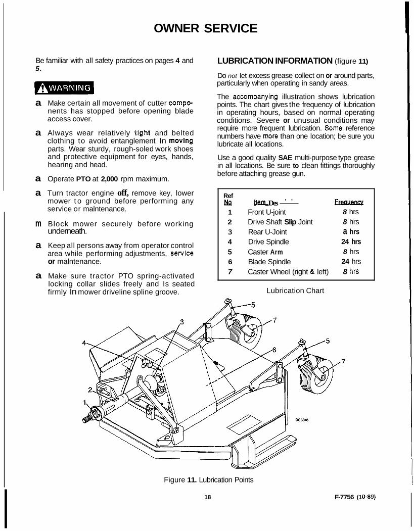
LUBRICATION INFORMATION (figure 11)
Do not let excess grease collect on or around parts, particularly when operating in sandy areas.
The accompanying illustration shows lubrication points. The chart gives the frequency of lubrication in operating hours, based on normal operating conditions. Severe or unusual conditions may require more frequent lubrication. Some reference numbers have more than one location; be sure you lubricate all locations.
Use a good quality SAE multi-purpose type grease in all locations. Be sure to clean fittings thoroughly before attaching grease gun.
Ref M Des- Freauencv . .
1 Front U-joint 8 hrs 2 Drive Shaft Slip Joint 8 hrs 3 Rear U-Joint a hrs 4 Drive Spindle 24 hrs 5 Caster Arm 8 hrs 6 Blade Spindle 24 hrs 7 Caster Wheel (right & left) 8 hrs
Lubrication Chart
Figure 11. Lubrication Points
18 F-7756 (1 0-89)
Drive Shaft Lubrication Lubricate the drive shaft slip joint every 8 operating hours. Failure to maintain proper lubrication could result in damage to U-joints, gearbox and drive shaft. Lower mower to ground, disconnect drive shaft and apply a bead of grease all around the male half where it meets the female half. Slide shaft in and out several times to distribute grease.
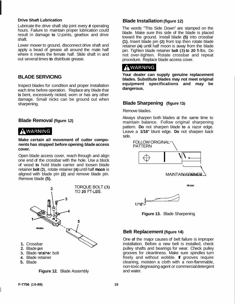
Blade Installation (figure 12)
The words "This Side Down" are stamped on the blade. Make sure this side of the blade is placed toward the ground. Install blade (5) into crossbar (1). Insert blade pin (2) from top then rotate blade retainer (4) until half moon is away from the blade pin. Tighten blade retainer bolt (3) to 20 ft-lbs. Do not over-tighten. Rotate crossbar and repeat procedure. Replace blade access cover.
BLADE SERVICING
Inspect blades for condition and proper installation each time before operation. Replace any blade that is bent, excessively nicked, worn or has any other damage. Small nicks can be ground out when sharpening.
Blade Removal (figure 12)
Make certain ail movement of cutter compo- nents has stopped before opening blade access cover.
Open blade access cover, reach through and align one end of the crossbar with the hole. Use a block of wood to hold blade carrier and loosen blade retainer bolt (3), rotate retainer (4) until half moon is aligned with blade pin (2) and remove blade pin. Remove blade (5).
2 TORQUE BOLT (3)
I TO 20 FT-LBS.
1. Crossbar 2. Blade Din 3. Blade ietainer bolt 4. Blade retainer 5. Blade
Figure 12. Blade Assembly
Your dealer can supply genuine replacement blades. Substltute blades may not meet original equipment specifications and may be dangerous.
Blade Sharpening (figure 13)
Remove blades.
Always sharpen both blades at the same time to maintain balance. Follow original sharpening pattern. Do not sharpen blade to a razor edge. Leave a 1/16" blunt edge. Do not sharpen back side.
FOLLOW ORIGINAL PATTERN 7
0 I \ \ ,
MAINTAIN 1 CORNER
DB 2530
Figure 13. Blade Sharpening
Belt Replacement (figure 14)
One of the major causes of belt failure is improper installation. Before a new belt is installed, check pulley shafts and bearings for wear. Check pulley grooves for cleanliness. Make sure spindles turn freely and without wobble. If grooves require cleaning, moisten a cloth with a non-flammable, non-toxic degreasing agent or commercial detergent and water.
F-7756 (1 0-89) 19
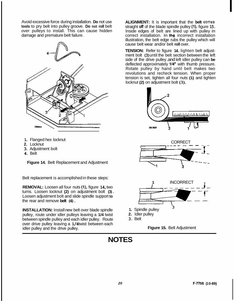
Avoid excessive force during installation. Do not use tools to pry belt into pulley groove. Do not roll belt over pulleys to install. This can cause hidden damage and premature belt failure.
1. Flanged hex locknut 2. Locknut 3. Adjustment bolt 4. Belt
Figure 14. Belt Replacement and Adjustment
ALIGNMENT: It is important that the belt comes straight off of the blade spindle pulley (l), figure 15. Inside edges of belt are lined up with pulley in correct installation. In the incorrect installation illustration, the belt edge rubs the pulley which will cause belt wear and/or belt roll over. TENSION: Refer to figure 14. lighten belt adjust- ment bolt (3) until the belt section between the left side of the drive pulley .and left idler pulley can be deflected approximately 1/4" with thumb pressure. Rotate pulley by hand until belt makes two revolutions and recheck tension. When proper tension is set, tighten all four nuts (1) and tighten locknut (2) on adjustment bolt (3).
CORRECT -.-
Belt replacement is accomplished in these steps: 1 INCORRECT I
REMOVAL: Loosen all four nuts (l), figure 14, two turns. Loosen locknut (2) on adjustment bolt (3). Loosen adjustment bolt and slide spindle support to the rear and remove belt (4).
INSTALLATION: Install new belt over blade spindle pulley, route under idler pulleys leaving a 1/4 twist between spindle pulley and each idler pulley. Route over drive pulley leaving a 1/4 twist between each idler pulley and the drive pulley.
- \ 1. Spindle pulley 2. Idler pulley 3. Belt
3
Figure 15. Belt Adjustment
NOTES
20 F-7756 (1 0-89)

DEALER MAINTENANCE
Be familiar with all safety practices on pages 4 and 5.
a
Make certain ail movement of cutter compo- nents has stopped before opening blade access cover.
Always wear relatively tlght and belted clothing to avoid entanglement In moving parts. Wear sturdy, rough-soled work shoes and protectlve equlpment for eyes, hands, hearing and head.
Operate PTO at. 2,000 rpm maximum.
Turn tractor engine off, remove key, lower mower to ground before performing any service or maintenance.
Block mower securely before working under- neath.
Keep ail persons away from operator control area whlle performing adjustments, service or maintenance.
Make sure tractor PTO spring-activated locking collar slides freely and is seated firmly in mower driveline spline groove.
SPINDLE REPAIR
Blade Spindle Removal
Remove blade from spindle.
Remove belt from pulleys.
Remove split taper bushing (located on top of pulley) by removing the two bolts and insetting them into the threaded holes in bushing flange. Tighten bolts alternately to remove split taper bushing.
Remove key and pulley.
Remove four bolts attaching spindle to mower frame and remove spindle.
F-7756 (1 0-89)
Spindle Repair Tips As a reference point, the grease fitting is in the top portion of spindle housing.
To minimize wear, bearing cups, cones and sleeves are press fit to shaft and will require a press or similar device for removal.
When disassembling, support housing casting to prevent damage.
Remove bearing cups by placing a punch in housing slots and driving cup out. Alternate punch positions from side to side. Use care to prevent housing damage.
Permatex 30 Aviation Form-A-Gasket@ or equiva- lent is recommended as a sealant for spindle repair.
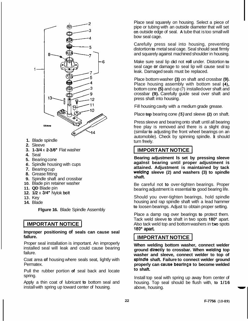
Blade Spindle Disassembly (figure 16)
Top and bottom washers (3) and sleeve (2) are tack welded to shaft. You must grind or break weld off before pressing shaft and crossbar (9) out of housing.
Support spindle in a press and push shaft and crossbar (9) down through housing (6).
Remove seals from housings.
Remove bearing cups from housing as described in Tips section above.
Blade Spindle Assembly (figure 16)
Bearing cups and cones are designed to work together. it is important to position them so bearing cone taper mates with bearing cup taper.
Lubricate new cups (7) with a light oil. Place them in spindle housing (6) so they will mate with cones (5). Seat cups (7) against machined shoulder of housing with a press or by placing a large soft drift on the flat lip and driving them into housing.
Place bottom bearing cone (5) into housing against bearing cup (7).
Pennatex 3D Aviation Form-A-Gasket is a registered trademark of the Permatex Corporation.
21
-4
5
083048
1. Blade spindle 2. Sleeve 3. 1-3/4 x 2-3/8" Flat washer 4. Seal 5. Bearing cone 6. Spindle housing with cups 7. Bearing cup 8. Grease fitting 9. Spindle shaft and crossbar
10. Blade pin retainer washer 11. QD Blade pin 12. 1/2 x 3/4" Nylok bolt 13. Key 14. Blade
Flgure 16. Blade Spindle Assembly
I IMPORTANT NOTICE I Improper positioning of seals can cause seal fallure. Proper seal installation is important. An improperly installed seal will leak and could cause bearing failure. Coat area of housing where seals seat, lightly with Permatex. Pull the rubber portion of seal back and locate spring. Apply a thin coat of lubricant to bottom seal and install with spring up toward center of housing.
Place seal squarely on housing. Select a piece of pipe or tubing with an outside diameter that will set on outside edge of seal. A tube that is too small will bow seal cage.
Carefully press seal into housing, preventing distortion to metal seal cage. Seal should seat firmly and squarely against machined shoulder in housing.
Make sure seal lip did not roll under. Distortion to seal cage or damage to seal lip will cause seal to leak. Damaged seals must be replaced.
Place bottom washer (3) on shaft and crossbar (9). Place housing assembly with bottom seal (4), bottom cone (5) and cup (7) installed over shaft and crossbar (9). Carefully guide seal over shaft and press shaft into housing.
Fill housing cavity with a medium grade grease.
Place top bearing cone (5) and sleeve (2) on shaft.
Press sleeve and bearing onto shaft until all bearing free play is removed and there is a slight drag (similar to adjusting the front wheel bearings on an automobile). Check by spinning spindle. It should turn freely.
I IMPORTANT NOTICE 1 Bearing adjustment Is set by pressing sleeve agalnst bearing until proper adjustment is attained. Adjustment is maintained by tack weldlng sleeve (2) and washers (3) to spindle shaft.
Be careful not to over-tighten bearings. Proper bearing adjustment is essential to good bearing life.
Should you over-tighten bearings, hold spindle housing and rap spindle shaft with a lead hammer to loosen bearings. Adjust to obtain proper setting.
Place a damp rag over bearings to protect them. Tack weld sleeve to shaft in two spots 180' apart. Also tack weld top and bottom washers in two spots 180" apart.
[ IMPORTANT NOTICE I When welding bottom washer, connect welder ground dlcectiy to crossbar. When weldlng top washer and sleeve, connect welder to top of splndle shaft. Failure to connect welder ground properly can cause.bearlngs to become welded to shaft.
Install top seal with spring up away from center of housing. Top seal should be flush with, to 1/16 above, housing. -
F-7756 (1 0-89) 22
Lubricate spindle with a medium grade grease. Rotate housing on spindle shaft, checking for free movement.
Blade Spindle Installation Insert spindle through bottom of mower deck and secure with four mounting bolts. Be sure to position grease fitting toward lubrication access area. Refer to Lubrication in Owner Service section.
Install pulley and key on spindle shaft. Place split taper bushing on pulley and drive down to seat against spindle shaft shoulder and alternately tighten split taper bushing bolts to 12 ft-lbs.
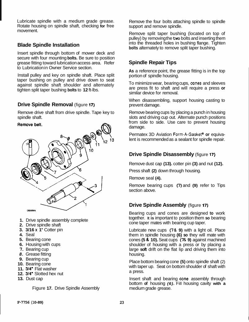
Drive Spindle Removal (figure 17)
Remove drive shaft from drive spindle. Tape key to spindle shaft.
1. Drive spindle assembly complete 2. Drive spindle shaft 3. 3/16 x 1" Cotter pin 4. Seal 5. Bearing cone 6. Housing with cups 7. Bearing cup 8. Grease fitting 9. Bearing cup
10. Bearing cone 11. 3/4" Flat washer 12. 3/4" Slotted hex nut 13. Dust cap
Figure 17. Drive Spindle Assembly
Remove the four bolts attaching spindle to spindle support and remove spindle.
Remove split taper bushing (located on top of pulley) by removing the two bolts and inserting them into the threaded holes in bushing flange. Tighten bolts alternately to remove split taper bushing.
Spindle Repair Tips As a reference point, the grease fitting is in the top portion of spindle housing.
To minimize wear, bearing cups, cones and sleeves are press fit to shaft and will require a press or similar device for removal.
When disassembling, support housing casting to prevent damage.
Remove bearing cups by placing a punch in housing slots and driving cup out. Alternate punch positions from side to side. Use care to prevent housing damage.
Permatex 3D Aviation Form-A-Gasket@ or equiva- lent is recommended as a sealant for spindle repair.
Drive Spindle Disassembly (figure 17)
Remove dust cap (13). cotter pin (3) and nut (12).
Press shaft (2) down through housing.
Remove seal (4).
Remove bearing cups (7) and (9) refer to Tips section above.
Drive Spindle Assembly (figure 17)
Bearing cups and cones are designed to work together. It is important to position them so bearing cone taper mates with bearing cup taper.
Lubricate new cups (7 & 9) with a light oil. Place them in spindle housing (6) so they will mate with cones (5 & 10). Seat cups (7 & 9) against machined shoulder of housing with a press or by placing a large soft drift on the flat lip and driving them into housing.
Place bottom bearing cone (5) onto spindle shaft (2) with taper up. Seat on bottom shoulder of shaft with a press.
Insert shaft and bearing cone assembly through bottom of housing (6). Fill housing cavity with a medium grade grease.
F-7756 (1 0-89) 23
Place top bearing cone (10) on shaft (2) to mate with top bearing cup (9).
Install washer (1 1) and nut (12) on shaft (2) and tighten until all bearing free play is removed and there is a slight drag (similar to adjusting the front wheel bearings on an automobile). Check by spinning spindle. It should turn freely.
Be careful not to over-tighten bearings. Proper bearing adjustment is essential to good bearing life.
Should you over-tighten bearings, hold spindle housing and rap spindle shaft with a lead hammer to loosen bearings. Adjust to obtain proper setting.
IMPORTANT NOTICE I Improper posltlonlng of seals can cause seal fallure.
Proper Seal installation is important. An improperly installed seal will leak and could cause bearing failure. Coat area of housing where seals seat, lightly, with Permatex.
Pull the rubber portion of seal back and locate spring.
Apply a thin coat of lubricant to bottom seal and install with spring up toward center of housing.
Place seal squarely on housing. Select a piece of pipe or tubing with an outside diameter that will set on outside edge of seal. A tube that is too small will bow seal cage.
Carefully press seal into housing, preventing distortion to metal seal cage. Seal should seat firmly and squarely against the machined shoulder in housing.
Make sure seal lip did not roll under. Distortion to seal cage or damage to seal lip will cause seal to leak. Damaged seals must be replaced.
Lubricate spindle with a medium grade grease. Rotate housing on spindle shaft, checking for free movement.
When desired adjustment is obtained, secure nut in position with cotter key and install dust cap (13).
Drive Spindle Installation Place key in shaft and position pulley on spindle shaft with split taper bushing so the center line of the pulley is 2-13/16 (+1/16 ,-0) from the top rear face of the spindle housing.
Alternately tighten split taper bushing bolts to secure pulley in proper alignment. Continue alternate tightening sequence until assembly is tight and all bolts are torqued to 12 ft-lbs. Check drive pulley and adjust if necessary. When aligned, peen keyway to prevent key from working out.
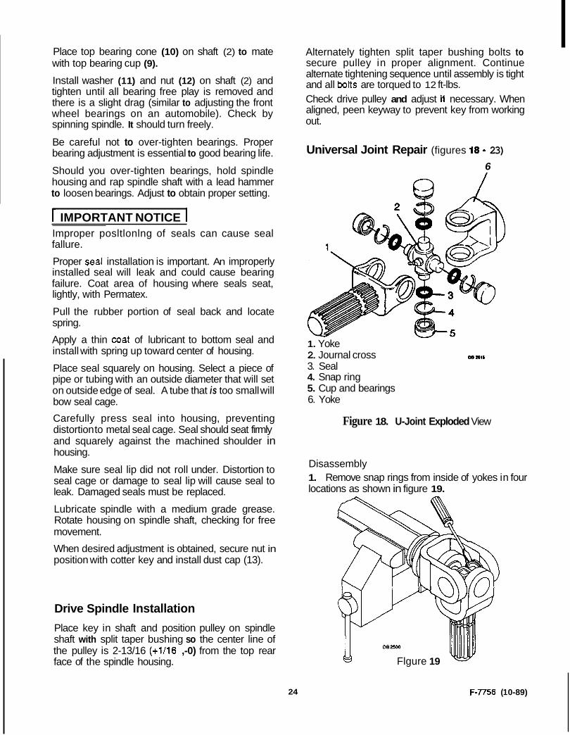
Universal Joint Repair (figures 18 - 23) 6
W
1. Yoke 2. Journal cross 3. Seal 4. Snap ring 5. Cup and bearings 6. Yoke
m l l l l
Figure 18. U-Joint Exploded View
Disassembly 1. Remove snap rings from inside of yokes in four locations as shown in figure 19.
Flgure 19
24 F-7756 (1 0-89)

2. With snap rings removed, support drive in vise, hold yoke in hand and tap on yoke to drive cup out of yoke. See figure 20.
082513
Figure 20
3. Clamp cup in vise as shown in figure 21 and tap on yoke to completely remove cup from yoke. Repeat steps two and three for opposite cup.
M
DB2514
Figure 21
4. Place universal cross in vise'as. shown in figure 22 and tap on yoke to remove cup. Repeat step three for final removal. Drive remaining cup out with drift and hammer.
Figure 22
Assembly
1. Place seals securely on bearing cups. Insert cup into yoke from outside and press in with hand pressure as far as possible. Insert journal cross into bearing cross with grease fitting away from shaft. Be careful not to disturb needle bearings. Insert another bearing cup across from first cup and press in as far as possible with hand pressure.
Trap cups in a vise and apply pressure. Be sure journal cross is started into bearings and continue pressure with vise, squeezing in as far as possible. Tap yoke to aid in process.
2. Seat cups by placing a drift (slightly smaller than the cup) on cup and rapping with hammer. (See figure 23.) Install snap ring and repeat on opposite cup.
F-7756 (1 0-89) 25

Figure 23
3. Repeat assembly steps one and two to install remaining cups in remaining yoke.
Move both yokes in all directions to check for free movement. Should movement be restricted, rap on yokes sharply with a hammer to relieve any tension, Repeat until both yokes move in all directions without restriction.
Make sure tractor PTO spring-activated locking collar Slides freely and is seated firmly In mower driveline spilne groove.
26
NOTES
F-7756 (1 0-89)

F-7756 (1 0-89)
NOTES
27

Problem
Grass cut lower in center of swath than at edge
Streaking conditions in swath
Material discharges from mower unevenly; bunches of material along swath
TROUBLE SHOOTING MOWING CONDITIONS
Possible Cause
Height of mower lower at rear or front
Conditions too wet for mowing
Blades unable to cut that part of grass pressed down by path of tractor tires
Dull blades
Material too high and too much material
Grass wet
Rear of mower too low, trap- ping material under mower
Solution
Adjust mower height and attitude so that mower rear and front are within 1/2" of same height. See instructions on page 14.
Allow grass to dry before mowing.
Slow ground speed of tractor but keep engine running at full PTO rpm. Cutting lower will help.
Sharpen or replace blades.
Reduce ground speed but maintain 2,000 rpm at tractor PTO, or make two passes over material. Raise the mower for the first pass and lower to desired height for the second and cut at 90" to first pass. Raise rear of mower high enough to permit mate- rial to discharge, but not so high that condi- tions listed above occur.
Allow grass to dry before mowing. Slow ground speed of tractor but keep engine running at full PTO rpm. Cutting lower will help.
Adjust mower height and attitude. See in- structions on page 14.
28 F-7756 (1 0-89)

F-7756 (1 0-89)
INDEX TO PARTS LISTS
MAIN FRAME ASSEMBLY ................................................................................. 30
MOUNTING FRAME ASSEMBLY ...................................................................... 32
FRONT DRIVE 81 SHIELD ASSEMBLY .............................................................. 34
REAR DRIVE & SHIELD ASSEMBLY ................................................................ 34
DRIVE SPINDLE ASSEMBLY ............................................................................ 35
BLADE SPINDLE ASSEMBLY ........................................................................... 35
29
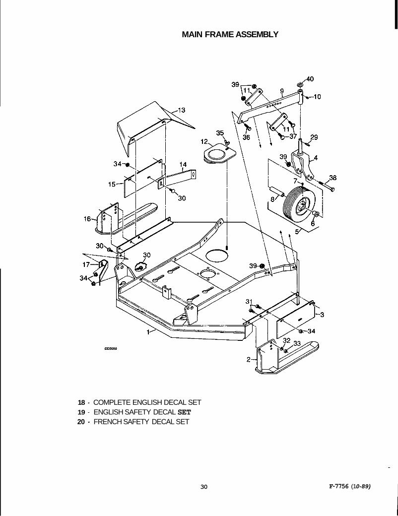
MAIN FRAME ASSEMBLY
18 - COMPLETE ENGLISH DECAL SET 19 - ENGLISH SAFETY DECAL SET 20 - FRENCH SAFETY DECAL SET
30
-
F-7756 (1 0-89) I

MAIN FRAME ASSEMBLY
Ref No. Mllsaci 1 1 2 1 3 1 4 2 5 2 6 2
6 2
6 2
6 2
7 2
7 2
8 2
8 2 9 2 10 2
11 4 12 1
Mower frame Left side skid Left side shield Caster wheel yoke assembly 10-1/4 Caster wheel with sleeve 5/8 ID Flange bearing for 1 -1/8 bore wheel
-or- 3/4 ID Flange bearing for 1 -1/8 bore wheel
-or- 5/8 ID Flange bearing for 13/8 bore wheel
-or- 3/4 ID Flange bearing with groove for 1 -3/8 bore polyethylene wheel Straight 1/4 setf-tap grease fitting (for steel wheel)
-or- Straight 1/8 pipe thread grease fitting (for polyethylene wheel) 1/2 x 3/4 x 3-3/8 Sleeve
17 GA Wall x 5/8 x 3-3/8 sleeve Caster arm assembly 1/4 - 28 Tapered thread grease fitting Caster arm adjustment bracket Access hole cover assembly
-or-
Ref Mi 13
14 15 16 17 18 19 20
Ref hlp 29 30 31 32 33 34 35 36 37 38 39 40
No, llsaci
1 P e s c r W
. .
Discharge chute (for use on mowers with CW blade rotation) Side shield baffle Right side shield Right side skid Front corner baffle Complete English decal set English safety decal set French safety decal set
HARDWARE
1 /4 x 1-1 /4 Spirol pin 3/8 NC x 3/4 Carriage bolt 318 NC x 1 Hex head cap screw GR5 3/8 Standard lockwasher 3/8 NC Hex nut, plated 3/8 NC Flanged hex locknut 318 NC Wing nut 1/2 NC x 1-1/2 Hex head cap screw GR5 1/2 NC x 1-3/4 Carriage bolt HT 112 NC x 5 Hex head cap screw GR5 1/2 NC Flanged hex locknut 3/4 SAE Flat washer
F-7756 (1 0-89) 31
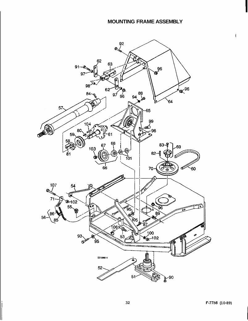
MOUNTING FRAME ASSEMBLY
i 32 F-7756 (1 0-89)

MOUNTING FRAME ASSEMBLY
HARDWARE
Ref Na J l h I l S e c a 51 1 52 2
52 2
53 2
54 2 55 2
56 2 57 -- 5 8 1
59 1 60 1 61 1
62 2 6 3 1 6 4 1 65 1 66 2 67 2
6 8 2 69 1 70 1 71 2
CW Blade spindle (see page 35) Twisted QD blade (for right hand rotation)
CW Welded fin blade (for right hand rotation) Mounting pin - Category 0, 3-7/8 long A-Frame bar 1-1/16 - 121 D SAE Thread plastic caplug Check chain with hardware Front & rear drives (see page 34) H 1 -3/8 Straight bore bushing (includes item #104) 1 BK, 3.9 H Sheave W44 V-Belt Drive spindle assembly (see page 35) Top pivot link Top link tube assembly Drive shield
-or-
Idler bracket assembly V-Groove idler with bearing 4.50 OD V-Groove idler less bearing .626 ID x 1.85 OD Ball bearing P1 1-1/4 Straight bore bushing 1 TB, 7.25 Sheave P Check chain bracket
Ref NQ 80 81 82 83 84 85 86 87 88 89 90 91 92 93
94 95 96 97 98 99
100 101 102 103 1 04
105 106 107
DescriDtion 114 x 114 x 1-114 Key 114 NC x 3/4 Hex head cap screw GR5 1/4 x 3 8 x 2 Key 5/16 NC x 1 Hex head cap screw GR5 5/16 x 1-34 Spirol pin Link, screw type 4/0 Twisted link chain, 27" 1/2 NC x 1 Carriage bolt 1/2 NF x 1 -1/4 Hex head cap screw GR5 1/2 NC x 1-114 Hex head cap screw GR5 1 /2 NC x 1-314 Hex head cap screw GR5 112 NC x 2-314 Hex head cap screw GR5 112 NC x 3-3/4 Hex head cap screw GR5 1/2 NC x 4-1/2 Hex head cap screw, full thread 1/2 Extra-heavy lockwasher 112 Standard f tat washer 112 NC Flanged hex locknut 1/2 x 314 x 318 Sleeve, HT 17 GA Wall x 5/8 x 1 -3/16 Sleeve 518 NC x 2-1/4 Carriage bolt 518 Heavy lockwasher 518 Standard flat washer 518 NC Hex nut 518 NC Hex locknut 5/16 x 5/16 x 2-114 Key (furnished with item #58 - not sold separately) 112 NC Heavy hex nut 3/16 x 1 Klik pin 5/8 NC x 3 Hex head cap screw GR5
F-7756 (1 0-89) 33
Ref I&! 1
2
No. llseca
1
1
n
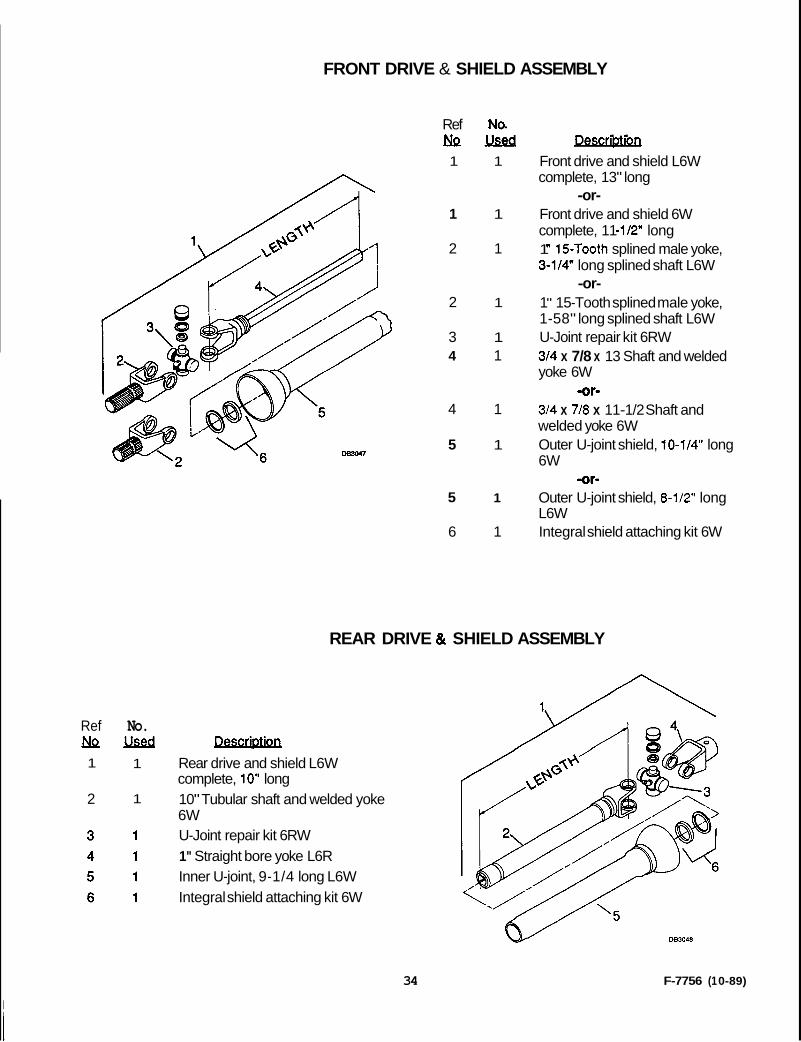
FRONT DRIVE & SHIELD ASSEMBLY
REAR DRIVE 8t SHIELD ASSEMBLY
Rear drive and shield L6W complete, 10" long 10" Tubular shaft and welded yoke 6W U-Joint repair kit 6RW 1" Straight bore yoke L6R Inner U-joint, 9-1/4 long L6W Integral shield attaching kit 6W
Ref No. NQM 1 1
1 1
2 1
2 1
3 1 4 1
4 1
5 1
5 1
6 1
P~~~~lRtlQIl . . Front drive and shield L6W complete, 13" long
-or- Front drive and shield 6W complete, 11 -1/2" long 1 " 15-Tooth splined male yoke, 3-1/4" long splined shaft L6W
1 " 15-Tooth splined male yoke, 1-58" long splined shaft L6W U-Joint repair kit 6RW 314 x 7/8 x 13 Shaft and welded yoke 6W
-or- 314 x 7/8 x 11-1/2 Shaft and welded yoke 6W Outer U-joint shield, 10-1/4" long 6W
Outer U-joint shield, 8-1/2" long L6W Integral shield attaching kit 6W
-or-
-or-
34 F-7756 (1 0-89)
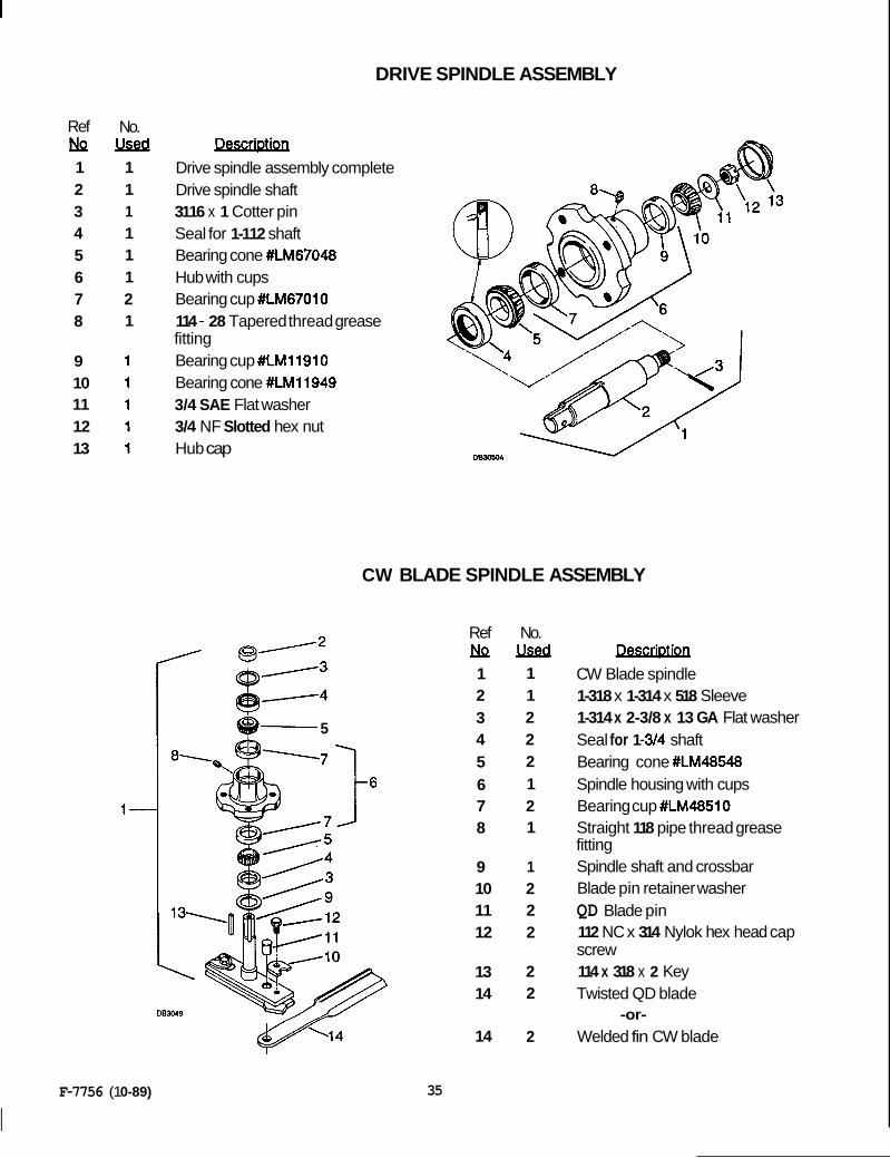
DRIVE SPINDLE ASSEMBLY
Ref r!k 1 2 3 4 5 6 7 8
9 10 11 12 13
No. llseca
1 1 1 1 1 1 2 1
Drive spindle assembly complete Drive spindle shaft 3116 x 1 Cotter pin Seal for 1-112 shaft Bearing cone #LM67048 Hub with cups Bearing cup #LM67010 114 - 28 Tapered thread grease fitting Bearing cup #LM11910 Bearing cone #LM11949 3/4 SAE Flat washer 3/4 NF Slotted hex nut Hub cap
D m A
CW BLADE SPINDLE ASSEMBLY
5
1-
D B U 9
Ref r!JQ 1 2 3 4 5 6 7 8
9 10 11 12
13 14
14
No. userd
1 1 2 2 2 1 2 1
1 2 2 2
2 2
2
CW Blade spindle 1-318 x 1-314 x 518 Sleeve 1-314 x 2-3/8 x 13 GA Flat washer Seal for 1 -3/4 shaft Bearing cone #LM48548 Spindle housing with cups Bearing cup #LM48510 Straight 118 pipe thread grease fitting Spindle shaft and crossbar Blade pin retainer washer QD Blade pin 112 NC x 314 Nylok hex head cap screw 114 x 318 x 2 Key Twisted QD blade
-or- Welded fin CW blade
F-7756 (1 0-89)
I 35

INDEX
ADJUSTMENTS Belt Tension Adjustment ........................................................................ 20 Cutting Height Adjustment ..................................................................... 12 Side Skid Adjustment ............................................................................ 15
ASSEMBLY Dealer Set-Up Instructions ...................................................................... 9
Blade Spindle Repair ............................................................................. 23 Drive Spindle Repair ............................................................................. 24 Universal Joint Repair ........................................................................... 24
General Information ................................................................................. 3 Introduction .............................................................................................. 2 Specifications ........................................................................................... 1 Table of Contents ..................................................................................... 1 Torque Chart ............................................................................................ 8
DEALER MAINTENANCE
GENERAL
OPERATION Attaching Mower to Tractor ................................................................... 14 Check Chain Installation ........................................................................ 15 Cutting Height Adjustment ..................................................................... 14
Pre-Operation Check List ...................................................................... 16 Removing Mower from Tractor .............................................................. 15
Tips .................................................................................................. 16 Tractor Stablllty ...................................................................................... 14 Uneven Terrain ...................................................................................... 17
Operating Technique .............................................................................. 16
Side Skid Adjustment ............................................................................ 15
..
OWNER SERVICE Belt Replacement .................................................................................. 19 Blade Servicing ...................................................................................... 19 Lubrication Information ........................................................................... 18
Index to Parts Lists ................................................................................ 29
Check Lists ..................................................................................... 3 & 16 Safety Decals ........................................................................................... 6 Safety Rules ............................................................................................. 4 Safety Symbol (explanation) ................................................................... 2 Uneven Terrain ...................................................................................... 17
PARTS
SAFETY
TROUBLE SHOOTING Mowing Conditions ................................................................................. 28
36 F-7756 (1 0-89)

WARRANTY SERVICE
IYour satisfaction and goodwill are important to your dealer and to us. All Honda wammty details are explained in the Distributor's Limited Warranty. Normally, any problems concerning the product will be handled by your dealer's service department. If you have a warranty problem that has not been handled to your satisfaction, we suggest you take the following action:
Discuss your problem with a member of dealership management. Often complaints can be quickly resolved at that level. If the problem has already been reviewed with the Service Manager, contact the owner pf the dealership or the General Manager.
If your problem still has not been resolved to your satisfaction, contact the Power Equipment .Customer Service Department of American Honda Motor C a , Inc:
American Honda Motor Co., Inc. Power Equipment Customer Service Duluth, Georgia 30136-9421 Telephone: (404) 497-6400
We will need the following in order to assist you: -Your name, address, and telephone number -Product model and serial number -Date of purchase -Dealer name and address -Nature of the problem
After reviewing all the facts involved, you will be advised of what action can be taken. Please bear in mind that your problem will likely be resolved at the dealership, using the dealer's facilities, equipment, and personnel. so it is very important that your initial contact be with the dealer.
Your purchase of a Honda product is greatly appreciated by both your dealer and American Honda Motor Company. We want to assist you in every way possible to assure your satisfaction with your purchase.