cbr1000st/sp - honda uk
TRANSCRIPT

OWNER’S MANUALEN
CBR
1000ST/SP
CBR1000ST/SP
32MKR80000X32-MKR-8000
XXX.XXXX.XX.LPRINTED IN XXXXX00X32-MKR-8000
This manual should be considered a permanent part of the vehicleand should remain with the vehicle when it is resold.
This publication includes the latest production information availablebefore printing. Honda Motor Co., Ltd. reserves the right to makechanges at any time without notice and without incurring anyobligation.
No part of this publication may be reproduced without writtenpermission.
The vehicle pictured in this owner’s manual may not match youractual vehicle.
India onlyFor any query or assistance, please call Customer care number: 1800103 3434 (Toll free)
© 2019 Honda Motor Co., Ltd.
20191113122725_32MKR8000_eng_BOOK Page 1 Wednesday, November 13 2019 12:40:27 JST
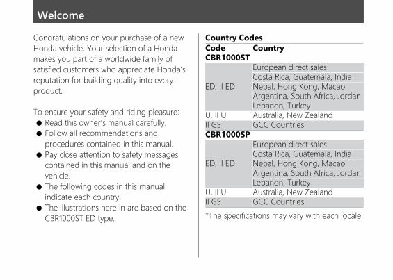
WelcomeCongratulations on your purchase of a newHonda vehicle. Your selection of a Hondamakes you part of a worldwide family ofsatisfied customers who appreciate Honda'sreputation for building quality into everyproduct.
To ensure your safety and riding pleasure:● Read this owner's manual carefully.● Follow all recommendations and
procedures contained in this manual.● Pay close attention to safety messages
contained in this manual and on thevehicle.
● The following codes in this manualindicate each country.
● The illustrations here in are based on theCBR1000ST ED type.
Country CodesCodeCBR1000ST
Country
ED, II ED
European direct salesCosta Rica, Guatemala, IndiaNepal, Hong Kong, MacaoArgentina, South Africa, JordanLebanon, Turkey
U, II U Australia, New ZealandII GS GCC CountriesCBR1000SP
ED, II ED
European direct salesCosta Rica, Guatemala, IndiaNepal, Hong Kong, MacaoArgentina, South Africa, JordanLebanon, Turkey
U, II U Australia, New ZealandII GS GCC Countries*The specifications may vary with each locale.
20191113122725_32MKR8000_eng_BOOK Page 2 Wednesday, November 13 2019 12:40:27 JST
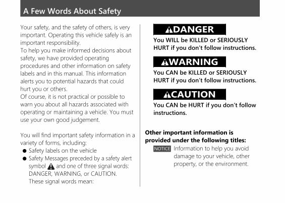
A Few Words About SafetyYour safety, and the safety of others, is veryimportant. Operating this vehicle safely is animportant responsibility.To help you make informed decisions aboutsafety, we have provided operatingprocedures and other information on safetylabels and in this manual. This informationalerts you to potential hazards that couldhurt you or others.Of course, it is not practical or possible towarn you about all hazards associated withoperating or maintaining a vehicle. You mustuse your own good judgement.
You will find important safety information in avariety of forms, including:● Safety labels on the vehicle● Safety Messages preceded by a safety alert
symbol and one of three signal words:DANGER, WARNING, or CAUTION.These signal words mean:
3DANGERYou WILL be KILLED or SERIOUSLYHURT if you don’t follow instructions.
3WARNINGYou CAN be KILLED or SERIOUSLYHURT if you don’t follow instructions.
3CAUTIONYou CAN be HURT if you don’t followinstructions.
Other important information isprovided under the following titles:
NOTICE Information to help you avoiddamage to your vehicle, otherproperty, or the environment.
20191113122725_32MKR8000_eng_BOOK Page 3 Wednesday, November 13 2019 12:40:27 JST
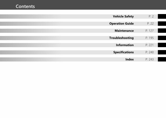
Contents
Vehicle Safety P. 2
Operation Guide P. 22
Maintenance P. 127
Troubleshooting P. 195
Information P. 221
Specifications P. 240
Index P. 243
20191113122725_32MKR8000_eng_BOOK Page 4 Wednesday, November 13 2019 12:40:27 JST
Safety Guidelines .................................................P. 3Image Labels.........................................................P. 7Safety Precautions.............................................P. 13Riding Precautions ............................................P. 15Accessories & Modifications...........................P. 20Loading ................................................................P. 21
20191113122725_32MKR8000_eng_BOOK Page 5 Wednesday, November 13 2019 12:40:27 JST
This section contains important information for safe riding of your vehicle.Please read this section carefully.
Vehicle Safety
Safety GuidelinesFollow these guidelines to enhance your safety:● Perform all routine and regular inspections
specified in this manual.● Stop the engine and keep sparks and flame
away before filling the fuel tank.● Do not run the engine in enclosed or partly
enclosed areas. Carbon monoxide inexhaust gases is toxic and can kill you.
Always Wear a HelmetIt's a proven fact: helmets and protectiveapparel significantly reduce the number andseverity of head and other injuries. So alwayswear an approved helmet and protectiveapparel. 2 P. 13
Before RidingMake sure that you are physically fit, mentallyfocused and free of alcohol and drugs. Checkthat you and your passenger are both wearingan approved helmet and protective apparel.Instruct your passenger on holding onto theseat strap or your waist, leaning with you inturns, and keeping their feet on the footpegs,even when the vehicle is stopped.
Take Time to Learn & PracticeEven if you have ridden other vehicles, practiceriding in a safe area to become familiar withhow this vehicle works and handles, and tobecome accustomed to the vehicle's size andweight.
20191113122725_32MKR8000_eng_BOOK Page 6 Wednesday, November 13 2019 12:40:27 JST
Safety GuidelinesVehicle Safety
3Continued
Ride DefensivelyAlways pay attention to other vehicles aroundyou, and do not assume that other drivers seeyou. Be prepared to stop quickly or perform anevasive maneuver.
Make Yourself Easy to SeeMake yourself more visible, especially at night,by wearing bright reflective clothing, positioningyourself so other drivers can see you, signalingbefore turning or changing lanes, and usingyour horn when necessary.
Ride within Your LimitsNever ride beyond your personal abilities orfaster than conditions warrant. Fatigue andinattention can impair your ability to use goodjudgement and ride safely.
Don't Drink and RideAlcohol and riding don't mix. Even one alcoholicdrink can reduce your ability to respond tochanging conditions, and your reaction timegets worse with every additional drink. Don'tdrink and ride, and don't let your friends drinkand ride either.
Keep Your Honda in Safe ConditionIt's important to keep your vehicle properlymaintained and in safe riding condition.Inspect your vehicle before every ride andperform all recommended maintenance. Neverexceed load limits (2 P. 21), and do not modifyyour vehicle or install accessories that wouldmake your vehicle unsafe (2 P. 20).
20191113122725_32MKR8000_eng_BOOK Page 7 Wednesday, November 13 2019 12:40:27 JST
Safety Guidelines
Vehicle Safety
4
If You are Involved in a CrashPersonal safety is your first priority. If you oranyone else has been injured, take time toassess the severity of the injuries and whether itis safe to continue riding. Call for emergencyassistance if needed. Also follow applicable lawsand regulations if another person or vehicle isinvolved in the crash.
If you decide to continue riding, first turn theelectrical system off, and evaluate the conditionof your vehicle. Inspect for fluid leaks, check thetightness of critical nuts and bolts, and checkthe handlebars, control levers, brakes, andwheels. Ride slowly and cautiously.Your vehicle may have suffered damage that isnot immediately apparent. Have your vehiclethoroughly checked at a qualified service facilityas soon as possible.
Lithium-Ion (Li-Ion) BatteryCBR1000SPIf you smell an unusual odor coming from thelithium-ion (li-ion) battery, park your vehicle in asafe place outside and away from flammableobjects, then turn the electrical system off. Haveyour vehicle inspected by your dealerimmediately.
20191113122725_32MKR8000_eng_BOOK Page 8 Wednesday, November 13 2019 12:40:27 JST
Safety GuidelinesVehicle Safety
5Continued
Carbon Monoxide HazardExhaust contains poisonous carbon monoxide, acolourless, odorless gas. Breathing carbonmonoxide can cause loss of consciousness andmay lead to death.
If you run the engine in confined or even partlyenclosed area, the air you breathe couldcontain a dangerous amount of carbonmonoxide.Never run your vehicle inside a garage or otherenclosure.
3WARNINGRunning the engine of your vehiclewhile in an enclosed or even partiallyenclosed area can cause a rapid build-up of toxic carbon monoxide gas.
Breathing this colourless, odorless gascan quickly cause unconsciousness andlead to death.
Only run your vehicle's engine when itis located in a well ventilated areaoutdoors.
20191113122725_32MKR8000_eng_BOOK Page 9 Wednesday, November 13 2019 12:40:27 JST
Safety Guidelines
Vehicle Safety
6
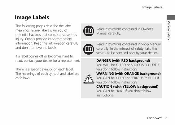
Image LabelsThe following pages describe the labelmeanings. Some labels warn you ofpotential hazards that could cause seriousinjury. Others provide important safetyinformation. Read this information carefullyand don't remove the labels.
If a label comes off or becomes hard toread, contact your dealer for a replacement.
There is a specific symbol on each label.The meanings of each symbol and label areas follows.
Read instructions contained in Owner'sManual carefully.
Read instructions contained in Shop Manualcarefully. In the interest of safety, take thevehicle to be serviced only by your dealer.
DANGER (with RED background)You WILL be KILLED or SERIOUSLY HURT ifyou don't follow instructions.WARNING (with ORANGE background)You CAN be KILLED or SERIOUSLY HURT ifyou don't follow instructions.CAUTION (with YELLOW background)You CAN be HURT if you don't followinstructions.
20191113122725_32MKR8000_eng_BOOK Page 10 Wednesday, November 13 2019 12:40:27 JST
Image LabelsVehicle Safety
7Continued
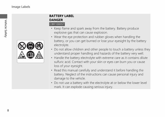
BATTERY LABELDANGERCBR1000ST• Keep flame and spark away from the battery. Battery produce
explosive gas that can cause explosion.• Wear the eye protection and rubber gloves when handling the
battery, or you can get burned or lose your eyesight by the batteryelectrolyte.
• Do not allow children and other people to touch a battery unless theyunderstand proper handling and hazards of the battery very well.
• Handle the battery electrolyte with extreme care as it contains dilutesulfuric acid. Contact with your skin or eyes can burn you or causeloss of your eyesight.
• Read this manual carefully and understand it before handling thebattery. Neglect of the instructions can cause personal injury anddamage to the vehicle.
• Do not use a battery with the electrolyte at or below the lower levelmark. It can explode causing serious injury.
20191113122725_32MKR8000_eng_BOOK Page 11 Wednesday, November 13 2019 12:40:27 JST
Image Labels
Vehicle Safety
8
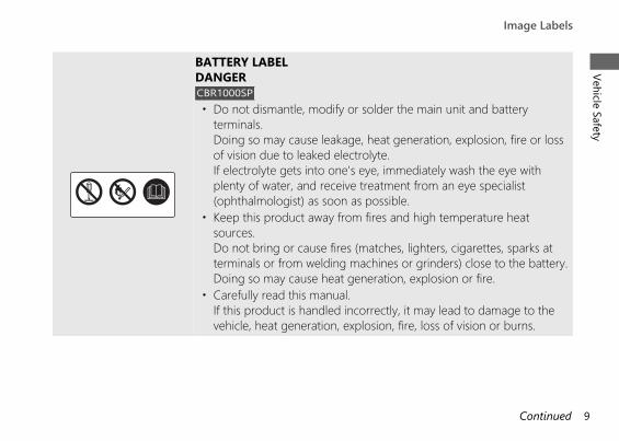
BATTERY LABELDANGERCBR1000SP• Do not dismantle, modify or solder the main unit and battery
terminals.Doing so may cause leakage, heat generation, explosion, fire or lossof vision due to leaked electrolyte.If electrolyte gets into one's eye, immediately wash the eye withplenty of water, and receive treatment from an eye specialist(ophthalmologist) as soon as possible.
• Keep this product away from fires and high temperature heatsources.Do not bring or cause fires (matches, lighters, cigarettes, sparks atterminals or from welding machines or grinders) close to the battery.Doing so may cause heat generation, explosion or fire.
• Carefully read this manual.If this product is handled incorrectly, it may lead to damage to thevehicle, heat generation, explosion, fire, loss of vision or burns.
20191113122725_32MKR8000_eng_BOOK Page 12 Wednesday, November 13 2019 12:40:27 JST
Image LabelsVehicle Safety
9Continued
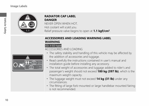
RADIATOR CAP LABELDANGERNEVER OPEN WHEN HOT.Hot coolant will scald you.Relief pressure valve begins to open at 1.1 kgf/cm2.
ACCESSORIES AND LOADING WARNING LABELWARNINGED, II ED typeACCESSORIES AND LOADING• The safety stability and handling of this vehicle may be affected by
the addition of accessories and luggage.• Read carefully the instructions contained in user's manual and
installation guide before installing any accessory.• The total weight of accessories and luggage added to rider's and
passenger's weight should not exceed 180 kg (397 lb), which is themaximum weight capacity.
• The luggage weight must not exceed 14 kg (31 lb) under anycircumstances.
• The fitting of large fork-mounted or large handlebar mounted fairingis not recommended.
20191113122725_32MKR8000_eng_BOOK Page 13 Wednesday, November 13 2019 12:40:27 JST
Image Labels
Vehicle Safety
10
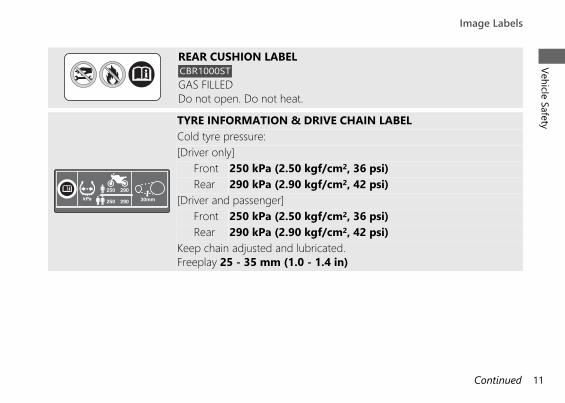
REAR CUSHION LABELCBR1000STGAS FILLEDDo not open. Do not heat.
TYRE INFORMATION & DRIVE CHAIN LABELCold tyre pressure:[Driver only]
Front 250 kPa (2.50 kgf/cm2, 36 psi)Rear 290 kPa (2.90 kgf/cm2, 42 psi)
[Driver and passenger]Front 250 kPa (2.50 kgf/cm2, 36 psi)Rear 290 kPa (2.90 kgf/cm2, 42 psi)
Keep chain adjusted and lubricated.Freeplay 25 - 35 mm (1.0 - 1.4 in)
20191113122725_32MKR8000_eng_BOOK Page 14 Wednesday, November 13 2019 12:40:27 JST
Image LabelsVehicle Safety
11Continued
ED, II ED type
U, II U type
II GS type
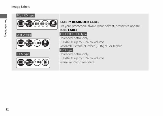
SAFETY REMINDER LABELFor your protection, always wear helmet, protective apparel.FUEL LABELED, II ED, U, II U typeUnleaded petrol onlyETHANOL up to 10 % by volumeResearch Octane Number (RON) 95 or higherII GS typeUnleaded petrol onlyETHANOL up to 10 % by volumePremium Recommended
20191113122725_32MKR8000_eng_BOOK Page 15 Wednesday, November 13 2019 12:40:27 JST
Image Labels
Vehicle Safety
12
Safety Precautions● Ride cautiously and keep your hands on the
handlebars and feet on the footpegs.● Keep passenger's hands onto the seat strap
or your waist, passenger's feet on thefootpegs while riding.
● Always consider the safety of yourpassenger, as well as other drivers andriders.
Protective ApparelMake sure that you and any passenger arewearing an approved helmet, eye protection,and high-visibility protective clothing. Avoidwearing loose clothes that could get caught onany part of the vehicle. Ride defensively inresponse to weather and road conditions.
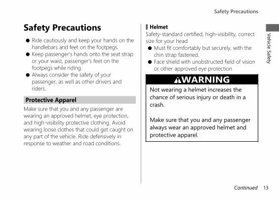
# HelmetSafety-standard certified, high-visibility, correctsize for your head● Must fit comfortably but securely, with the
chin strap fastened.● Face shield with unobstructed field of vision
or other approved eye protection
3WARNINGNot wearing a helmet increases thechance of serious injury or death in acrash.
Make sure that you and any passengeralways wear an approved helmet andprotective apparel.
20191113122725_32MKR8000_eng_BOOK Page 16 Wednesday, November 13 2019 12:40:27 JST
Safety PrecautionsVehicle Safety
13Continued
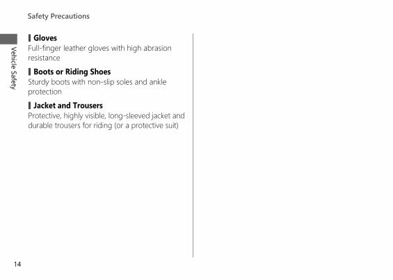
# GlovesFull-finger leather gloves with high abrasionresistance
# Boots or Riding ShoesSturdy boots with non-slip soles and ankleprotection
# Jacket and TrousersProtective, highly visible, long-sleeved jacket anddurable trousers for riding (or a protective suit)
20191113122725_32MKR8000_eng_BOOK Page 17 Wednesday, November 13 2019 12:40:27 JST
Safety Precautions
Vehicle Safety
14
Riding PrecautionsRunning-in Period
During the first 500 km (300 miles) of running,follow these guidelines to ensure your vehicle'sfuture reliability and performance.● Avoid full-throttle starts and rapid
acceleration.● Avoid hard braking and rapid down-shifts.● Ride conservatively.
BrakesObserve the following guidelines:● Avoid excessively hard braking and
downshifting.u Sudden braking can reduce the vehicle's
stability.u Where possible, reduce speed before
turning; otherwise you risk sliding out.
● Exercise caution on low traction surfaces.u The tyres slip more easily on such
surfaces and braking distances arelonger.
● Avoid continuous braking.u Repeated braking, such as when
descending long, steep slopes canseriously overheat the brakes, reducingtheir effectiveness. Use engine brakingwith intermittent use of the brakes toreduce speed.
● For full braking effectiveness, operate boththe front and rear brakes together.
20191113122725_32MKR8000_eng_BOOK Page 18 Wednesday, November 13 2019 12:40:27 JST
Riding PrecautionsVehicle Safety
15Continued
# Anti-lock Brake System (ABS)This model is equipped with an Anti-lock BrakeSystem (ABS) designed to help prevent thebrakes from locking up during hard braking.The ABS functions with information provided bythe IMU (Inertial Measurement Unit).● ABS does not reduce braking distance. In
certain circumstances, ABS may result in alonger stopping distance.
● ABS does not function at speeds below6 km/h (4 mph).
● The brake lever and pedal may recoil slightlywhen applying the brakes. This is normal.
● Always use the recommended front/reartyres and sprockets to ensure correct ABSoperation.
# Engine BrakingEngine braking helps slow your vehicle downwhen you release the throttle. For furtherslowing action, downshift to a lower gear. Useengine braking with intermittent use of thebrakes to reduce speed when descending long,steep slopes.
# Wet or Rainy ConditionsRoad surfaces are slippery when wet, and wetbrakes further reduce braking efficiency.Exercise extra caution when braking in wetconditions.If the brakes get wet, apply the brakes whileriding at low speed to help them dry.
20191113122725_32MKR8000_eng_BOOK Page 19 Wednesday, November 13 2019 12:40:27 JST
Riding Precautions
Vehicle Safety
16
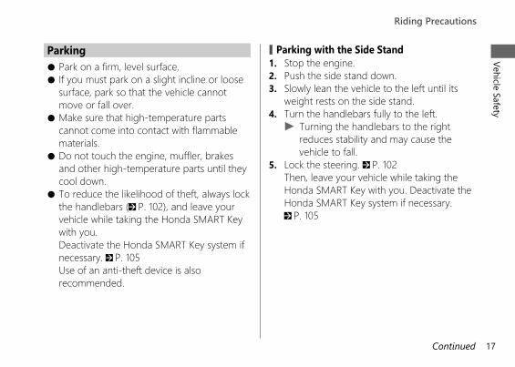
Parking● Park on a firm, level surface.● If you must park on a slight incline or loose
surface, park so that the vehicle cannotmove or fall over.
● Make sure that high-temperature partscannot come into contact with flammablematerials.
● Do not touch the engine, muffler, brakesand other high-temperature parts until theycool down.
● To reduce the likelihood of theft, always lockthe handlebars (2 P. 102), and leave yourvehicle while taking the Honda SMART Keywith you.Deactivate the Honda SMART Key system ifnecessary. 2 P. 105Use of an anti-theft device is alsorecommended.
# Parking with the Side Stand1. Stop the engine.2. Push the side stand down.3. Slowly lean the vehicle to the left until its
weight rests on the side stand.4. Turn the handlebars fully to the left.
u Turning the handlebars to the rightreduces stability and may cause thevehicle to fall.
5. Lock the steering. 2 P. 102Then, leave your vehicle while taking theHonda SMART Key with you. Deactivate theHonda SMART Key system if necessary.2 P. 105
20191113122725_32MKR8000_eng_BOOK Page 20 Wednesday, November 13 2019 12:40:27 JST
Riding PrecautionsVehicle Safety
17Continued
Refuelling and Fuel GuidelinesFollow these guidelines to protect the engine,fuel system and catalytic converter:● Use only unleaded petrol.● Use recommended octane number. Using
lower octane petrol will result in decreasedengine performance.
● Do not use fuels containing a highconcentration of alcohol. 2 P. 238
● Do not use stale or contaminated petrol oran oil/petrol mixture.
● Avoid getting dirt or water in the fuel tank.
20191113122725_32MKR8000_eng_BOOK Page 21 Wednesday, November 13 2019 12:40:27 JST
Riding Precautions
Vehicle Safety
18
Honda selectable torque controlWhen the Honda selectable torque control(Torque Control) detects rear wheel spin duringacceleration, the system will limit the amount oftorque applied to the rear wheel based on theTorque Control level selected.Additionally, the system ease the rapid motionduring accelerating based on the WheelieControl level selected.
Torque Control will allow some wheel spinduring acceleration at the lower Torque Controllevels settings. Select a level that is appropriatefor your skill and riding conditions.
Torque Control does not work duringdeceleration and will not prevent the rear wheelfrom skidding due to engine braking. Do notclose the throttle suddenly, especially whenriding on slippery surfaces.
Torque Control may not compensate for roughroad conditions or rapid throttle operation.Always consider road and weather conditions,as well as your skills and condition, whenapplying throttle.If your vehicle gets stuck in mud, snow or sand,it may be easier to free it by turning off theTorque Control temporarily.Temporarily turning off Torque Control alsomay help you maintain control and balancewhen riding on off-road terrain.
Always use the recommended tyres andsprockets to ensure correct Torque Controloperation.
20191113122725_32MKR8000_eng_BOOK Page 22 Wednesday, November 13 2019 12:40:27 JST
Riding PrecautionsVehicle Safety
19
Accessories &ModificationsWe strongly advise that you do not add anyaccessories that were not specifically designedfor your vehicle by Honda or makemodifications to your vehicle from its originaldesign. Doing so can make it unsafe.Modifying your vehicle may also void yourwarranty and make your vehicle illegal tooperate on public roads. Before deciding toinstall accessories on your vehicle be certain themodification is safe and legal.
3WARNINGImproper accessories or modificationscan cause a crash in which you can beseriously hurt or killed.
Follow all instructions in this owner'smanual regarding accessories andmodifications.
Do not pull a trailer with, or attach a sidecar to,your vehicle. Your vehicle was not designed forthese attachments, and their use can seriouslyimpair your vehicle's handling.
20191113122725_32MKR8000_eng_BOOK Page 23 Wednesday, November 13 2019 12:40:27 JST
Accessories & Modifications
Vehicle Safety
20
Loading● Carrying extra weight affects your vehicle's
handling, braking and stability.Always ride at a safe speed for the load youare carrying.
● Avoid carrying an excessive load and keepwithin specified load limits.Maximum weight capacity / Maximumluggage weight 2 P. 240
● Tie all luggage securely, evenly balancedand close to the centre of the vehicle.
● Do not place objects near the lights or themuffler.
3WARNINGOverloading or improper loading cancause a crash and you can be seriouslyhurt or killed.
Follow all load limits and other loadingguidelines in this manual.
20191113122725_32MKR8000_eng_BOOK Page 24 Wednesday, November 13 2019 12:40:27 JST
LoadingVehicle Safety
21
Parts Location
20191113122725_32MKR8000_eng_BOOK Page 25 Wednesday, November 13 2019 12:40:27 JST
Operation Guide
22
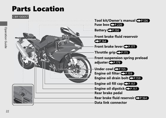
CBR1000ST
Under cowl (P.155)
Front suspension spring preloadadjuster (P.179)
Front brake fluid reservoir(P.164)
Battery (P.150)Fuse box (P.220)
Data link connector
Engine oil filter (P.159)
Tool kit/Owner's manual (P.126)
Engine oil fill cap (P.157)Engine oil dipstick (P.157)
Engine oil drain bolt (P.159)
Rear brake pedalRear brake fluid reservoir (P.164)
Throttle grip (P.175)
Front brake lever (P.177)
20191113122725_32MKR8000_eng_BOOK Page 26 Wednesday, November 13 2019 12:40:27 JST
Operation Guide
23Continued
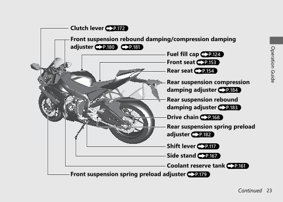
Clutch lever (P.172)
Rear suspension spring preloadadjuster (P.182)
Drive chain (P.168)
Side stand (P.167)Shift lever (P.117)
Front suspension rebound damping/compression dampingadjuster (P.180) (P.181)
Front seat (P.153)
Coolant reserve tank (P.161)
Fuel fill cap (P.124)
Rear seat (P.154)
Rear suspension compressiondamping adjuster (P.184)
Front suspension spring preload adjuster (P.179)
Rear suspension rebounddamping adjuster (P.183)
20191113122725_32MKR8000_eng_BOOK Page 27 Wednesday, November 13 2019 12:40:27 JST
Operation Guide
24
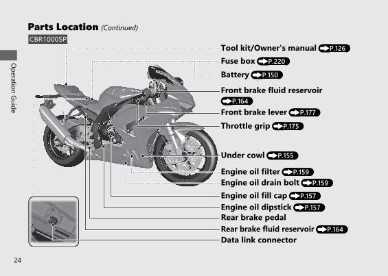
Parts Location (Continued)
Front brake lever (P.177)
Throttle grip (P.175)
Rear brake fluid reservoir (P.164)Rear brake pedal
Engine oil drain bolt (P.159)
Engine oil dipstick (P.157)Engine oil fill cap (P.157)
Tool kit/Owner's manual (P.126)
Engine oil filter (P.159)
Data link connector
Fuse box (P.220)
Battery (P.150)
Front brake fluid reservoir(P.164)
Under cowl (P.155)
CBR1000SP
20191113122725_32MKR8000_eng_BOOK Page 28 Wednesday, November 13 2019 12:40:27 JST
Operation Guide
25
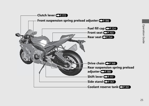
Coolant reserve tank (P.161)
Shift lever (P.117)Side stand (P.167)
Drive chain (P.168)Rear suspension spring preloadadjuster (P.188)
Rear seat (P.154)
Fuel fill cap (P.124)Front seat (P.153)
Front suspension spring preload adjuster (P.186)
Clutch lever (P.172)
InstrumentsThe display type consists of the following 5 patterns.• ANALOG (P.27)• DIGITAL (P.28)• BAR (P.29)• NO REV (P.30)• PRACTICE (P.31)
To change the display type: (P.63) (P.75)Each display type has the SPORT mode. (P.32)The operation of the instrument is mainly explained in the ANALOG display type.Factory default setting is ANALOG.
Do not operate the display functions for a long time with the engine stopped. It may result in alow (or dead) battery.
20191113122725_32MKR8000_eng_BOOK Page 29 Wednesday, November 13 2019 12:40:27 JST
Operation Guide
26

20191113122725_32MKR8000_eng_BOOK Page 30 Wednesday, November 13 2019 12:40:27 JST
Operation Guide
27Continued
( ) Coolanttemperaturegauge (P.51)
STD mode displayDisplay type: ANALOG (Factory default setting)
High beam indicator
Speedometer
Low oil pressureindicator (P.55)
Tachometer red zone(excessive engine rpm range)
ClockTo set the clock:(P.63) (P.84)
INFO area (P.35)
Pop-up information (P.52)Gear position indicator (P.55)ABS mode indicator (P.55)
Reserve fuel mode (P.49)
Current riding mode(P.109)
NOTICEDo not operate the engine in the tachometer red zone.Excessive engine speed can adversely affect engine life.
Tachometer
HESD (HondaElectronic SteeringDamper) indicator(P.55)
High coolant temperatureindicator (P.55)
20191113122725_32MKR8000_eng_BOOK Page 31 Wednesday, November 13 2019 12:40:27 JST
Operation Guide
28
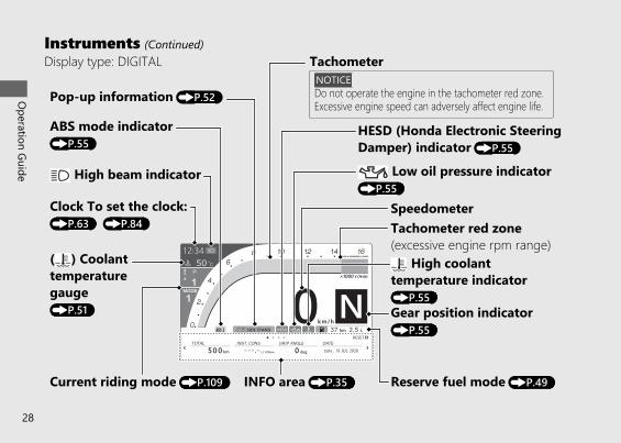
Instruments (Continued)Display type: DIGITAL
Pop-up information (P.52)
( ) Coolanttemperaturegauge(P.51)
Clock To set the clock:(P.63) (P.84)
High beam indicator
Current riding mode (P.109)
ABS mode indicator(P.55)
INFO area (P.35) Reserve fuel mode (P.49)
High coolanttemperature indicator(P.55)Gear position indicator(P.55)
Tachometer red zone(excessive engine rpm range)
Low oil pressure indicator(P.55)
Speedometer
HESD (Honda Electronic SteeringDamper) indicator (P.55)
TachometerNOTICEDo not operate the engine in the tachometer red zone.Excessive engine speed can adversely affect engine life.
20191113122725_32MKR8000_eng_BOOK Page 32 Wednesday, November 13 2019 12:40:27 JST
Operation Guide
29Continued
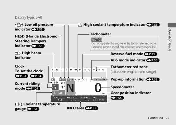
Display type: BAR
Pop-up information (P.52)
( ) Coolant temperaturegauge (P.51)
ClockTo set the clock:(P.63) (P.84)
High beamindicator
Current ridingmode (P.109)
ABS mode indicator (P.55)
INFO area (P.35)
Reserve fuel mode (P.49)
Gear position indicator(P.55)
Low oil pressureindicator (P.55)
Speedometer
Tachometer red zone(excessive engine rpm range)
NOTICEDo not operate the engine in the tachometer red zone.Excessive engine speed can adversely affect engine life.
TachometerHESD (Honda ElectronicSteering Damper)indicator (P.55)
High coolant temperature indicator (P.55)

20191113122725_32MKR8000_eng_BOOK Page 33 Wednesday, November 13 2019 12:40:27 JST
Operation Guide
30
Instruments (Continued)Display type: NO REV
Pop-up information (P.52)
( ) Coolanttemperaturegauge (P.51)
ClockTo set the clock:(P.63) (P.84)
High beam indicator
Current riding mode(P.109)
ABS mode indicator (P.55)
INFO area (P.35)
Reserve fuel mode(P.49)
Gear position indicator (P.55)
Low oil pressure indicator (P.55)
Speedometer
The tachometer is not displayed when NO REV is selected.
High coolant temperature indicator (P.55)
HESD (Honda Electronic Steering Damper)indicator (P.55)
20191113122725_32MKR8000_eng_BOOK Page 34 Wednesday, November 13 2019 12:40:27 JST
Operation Guide
31Continued
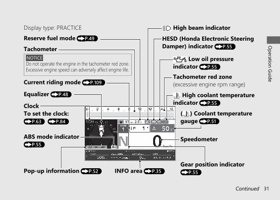
Display type: PRACTICE
Pop-up information (P.52)
( ) Coolant temperaturegauge (P.51)
ClockTo set the clock:(P.63) (P.84)
High beam indicator
Current riding mode (P.109)
ABS mode indicator(P.55)
INFO area (P.35)Gear position indicator(P.55)
Low oil pressureindicator (P.55)
Speedometer
Tachometer red zone(excessive engine rpm range)
Equalizer (P.48)
NOTICEDo not operate the engine in the tachometer red zone.Excessive engine speed can adversely affect engine life.
TachometerReserve fuel mode (P.49)
High coolant temperatureindicator (P.55)
HESD (Honda Electronic SteeringDamper) indicator (P.55)
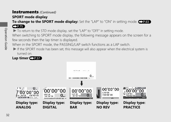
SPORT mode displayTo change to the SPORT mode display: Set the “LAP” to “ON” in setting mode. (P.63)(P.75)u To return to the STD mode display, set the “LAP” to “OFF” in setting mode.When switching to SPORT mode display, the following message appears on the screen for afew seconds then the lap timer is displayed.When in the SPORT mode, the PASSING/LAP switch functions as a LAP switch.u If the SPORT mode has been set, this message will also appear when the electrical system is
turned on.Lap timer (P.57)
20191113122725_32MKR8000_eng_BOOK Page 35 Wednesday, November 13 2019 12:40:27 JST
Operation Guide
32
Instruments (Continued)
Display type:DIGITAL
Display type:NO REV
Display type:ANALOG
Display type:BAR
Display type:PRACTICE
20191113122725_32MKR8000_eng_BOOK Page 36 Wednesday, November 13 2019 12:40:27 JST
Operation Guide
33Continued
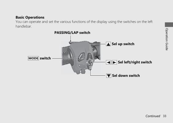
Basic OperationsYou can operate and set the various functions of the display using the switches on the lefthandlebar.
PASSING/LAP switch
Sel down switch
Sel up switch
Sel left/right switchMODE switch

When switching or setting the display, refer to the switch operation guide is displayed.
Type of the switch operation guide: or : Press the sel up switch or : Press the sel down switch
: Push the of the sel left/right switch: Push the of the sel left/right switch
or : Press and hold the sel up switch or : Press and hold the sel down switch
: Push and hold the of the sel left/right switch: Push and hold the of the sel left/right switch
20191113122725_32MKR8000_eng_BOOK Page 37 Wednesday, November 13 2019 12:40:27 JST
Operation Guide
34
Instruments (Continued)
Switch operation guide
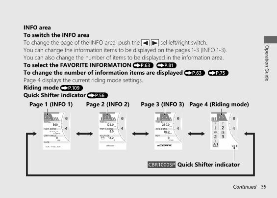
INFO areaTo switch the INFO areaTo change the page of the INFO area, push the sel left/right switch.You can change the information items to be displayed on the pages 1-3 (INFO 1-3).You can also change the number of items to be displayed in the information area.To select the FAVORITE INFORMATION (P.63) (P.81)To change the number of information items are displayed (P.63) (P.75)Page 4 displays the current riding mode settings.Riding mode (P.109)Quick Shifter indicator (P.56)
20191113122725_32MKR8000_eng_BOOK Page 38 Wednesday, November 13 2019 12:40:27 JST
Operation Guide
35Continued
Page 1 (INFO 1) Page 2 (INFO 2) Page 3 (INFO 3) Page 4 (Riding mode)
CBR1000SP Quick Shifter indicator
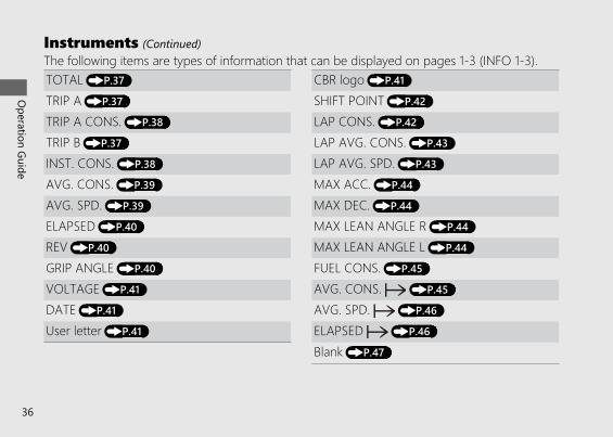
The following items are types of information that can be displayed on pages 1-3 (INFO 1-3).TOTAL (P.37) CBR logo (P.41)TRIP A (P.37) SHIFT POINT (P.42)TRIP A CONS. (P.38) LAP CONS. (P.42)TRIP B (P.37) LAP AVG. CONS. (P.43)INST. CONS. (P.38) LAP AVG. SPD. (P.43)AVG. CONS. (P.39) MAX ACC. (P.44)AVG. SPD. (P.39) MAX DEC. (P.44)ELAPSED (P.40) MAX LEAN ANGLE R (P.44)REV (P.40) MAX LEAN ANGLE L (P.44)GRIP ANGLE (P.40) FUEL CONS. (P.45)VOLTAGE (P.41) AVG. CONS. (P.45)DATE (P.41) AVG. SPD. (P.46)User letter (P.41) ELAPSED (P.46)
Blank (P.47)
20191113122725_32MKR8000_eng_BOOK Page 39 Wednesday, November 13 2019 12:40:27 JST
Operation Guide
36
Instruments (Continued)
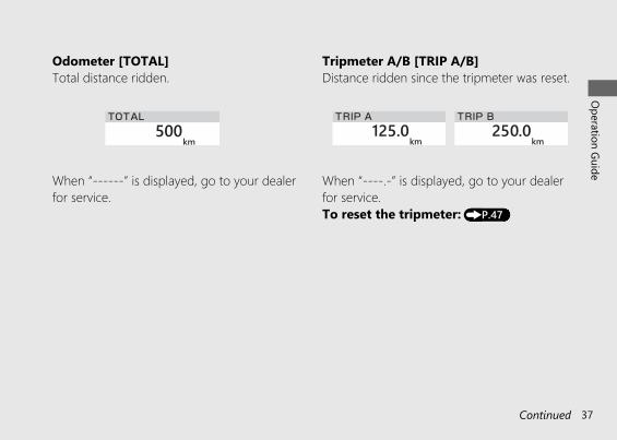
Odometer [TOTAL]Total distance ridden.
When “------” is displayed, go to your dealerfor service.
Tripmeter A/B [TRIP A/B]Distance ridden since the tripmeter was reset.
When “----.-” is displayed, go to your dealerfor service.To reset the tripmeter: (P.47)
20191113122725_32MKR8000_eng_BOOK Page 40 Wednesday, November 13 2019 12:40:27 JST
Operation Guide
37Continued
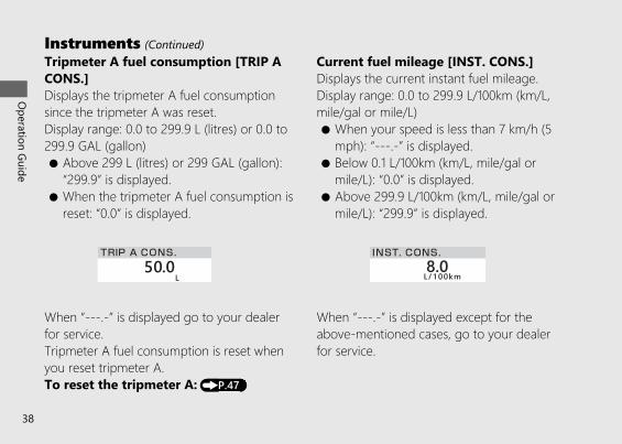
Tripmeter A fuel consumption [TRIP ACONS.]Displays the tripmeter A fuel consumptionsince the tripmeter A was reset.Display range: 0.0 to 299.9 L (litres) or 0.0 to299.9 GAL (gallon)● Above 299 L (litres) or 299 GAL (gallon):
“299.9” is displayed.● When the tripmeter A fuel consumption is
reset: “0.0” is displayed.
When “---.-” is displayed go to your dealerfor service.Tripmeter A fuel consumption is reset whenyou reset tripmeter A.To reset the tripmeter A: (P.47)
Current fuel mileage [INST. CONS.]Displays the current instant fuel mileage.Display range: 0.0 to 299.9 L/100km (km/L,mile/gal or mile/L)● When your speed is less than 7 km/h (5
mph): “---.-” is displayed.● Below 0.1 L/100km (km/L, mile/gal or
mile/L): “0.0” is displayed.● Above 299.9 L/100km (km/L, mile/gal or
mile/L): “299.9” is displayed.
When “---.-” is displayed except for theabove-mentioned cases, go to your dealerfor service.
20191113122725_32MKR8000_eng_BOOK Page 41 Wednesday, November 13 2019 12:40:27 JST
Operation Guide
38
Instruments (Continued)
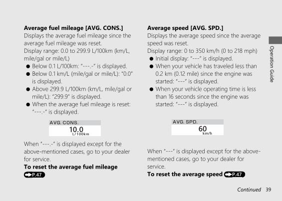
Average fuel mileage [AVG. CONS.]Displays the average fuel mileage since theaverage fuel mileage was reset.Display range: 0.0 to 299.9 L/100km (km/L,mile/gal or mile/L)● Below 0.1 L/100km: “---.-” is displayed.● Below 0.1 km/L (mile/gal or mile/L): “0.0”
is displayed.● Above 299.9 L/100km (km/L, mile/gal or
mile/L): “299.9” is displayed.● When the average fuel mileage is reset:
“---.-” is displayed.
When “---.-” is displayed except for theabove-mentioned cases, go to your dealerfor service.To reset the average fuel mileage(P.47)
Average speed [AVG. SPD.]Displays the average speed since the averagespeed was reset.Display range: 0 to 350 km/h (0 to 218 mph)● Initial display: “---” is displayed.● When your vehicle has traveled less than
0.2 km (0.12 mile) since the engine wasstarted: “---” is displayed.
● When your vehicle operating time is lessthan 16 seconds since the engine wasstarted: “---” is displayed.
When “---” is displayed except for the above-mentioned cases, go to your dealer forservice.To reset the average speed (P.47)
20191113122725_32MKR8000_eng_BOOK Page 42 Wednesday, November 13 2019 12:40:27 JST
Operation Guide
39Continued
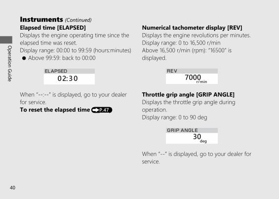
Elapsed time [ELAPSED]Displays the engine operating time since theelapsed time was reset.Display range: 00:00 to 99:59 (hours:minutes)● Above 99:59: back to 00:00
When “--:--” is displayed, go to your dealerfor service.To reset the elapsed time (P.47)
Numerical tachometer display [REV]Displays the engine revolutions per minutes.Display range: 0 to 16,500 r/minAbove 16,500 r/min (rpm): “16500” isdisplayed.
Throttle grip angle [GRIP ANGLE]Displays the throttle grip angle duringoperation.Display range: 0 to 90 deg
When “--” is displayed, go to your dealer forservice.
20191113122725_32MKR8000_eng_BOOK Page 43 Wednesday, November 13 2019 12:40:27 JST
Operation Guide
40
Instruments (Continued)
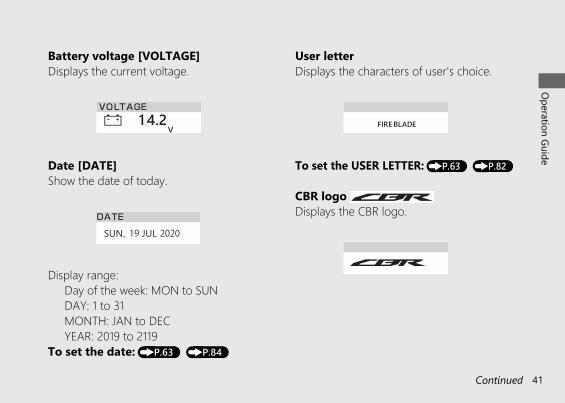
Battery voltage [VOLTAGE]Displays the current voltage.
Date [DATE]Show the date of today.
Display range:Day of the week: MON to SUNDAY: 1 to 31MONTH: JAN to DECYEAR: 2019 to 2119
To set the date: (P.63) (P.84)
User letterDisplays the characters of user's choice.
To set the USER LETTER: (P.63) (P.82)
CBR logo Displays the CBR logo.
20191113122725_32MKR8000_eng_BOOK Page 44 Wednesday, November 13 2019 12:40:27 JST
Operation Guide
41Continued
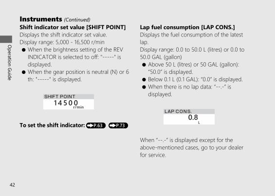
Shift indicator set value [SHIFT POINT]Displays the shift indicator set value.Display range: 5,000 - 16,500 r/min● When the brightness setting of the REV
INDICATOR is selected to off: "-----" isdisplayed.
● When the gear position is neutral (N) or 6th: "-----" is displayed.
To set the shift indicator: (P.63) (P.73)
Lap fuel consumption [LAP CONS.]Displays the fuel consumption of the latestlap.Display range: 0.0 to 50.0 L (litres) or 0.0 to50.0 GAL (gallon)● Above 50 L (litres) or 50 GAL (gallon):
“50.0” is displayed.● Below 0.1 L (0.1 GAL): “0.0” is displayed.● When there is no lap data: “--.-” is
displayed.
When “--.-” is displayed except for theabove-mentioned cases, go to your dealerfor service.
20191113122725_32MKR8000_eng_BOOK Page 45 Wednesday, November 13 2019 12:40:27 JST
Operation Guide
42
Instruments (Continued)
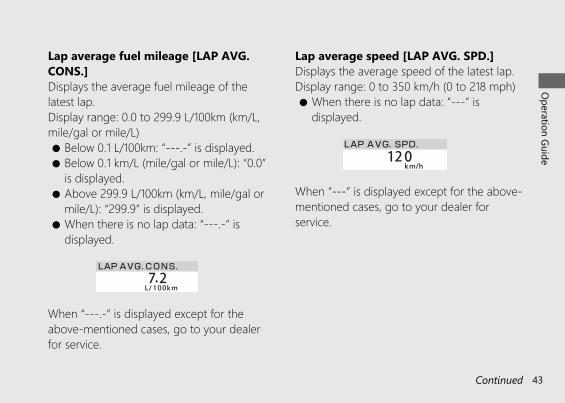
Lap average fuel mileage [LAP AVG.CONS.]Displays the average fuel mileage of thelatest lap.Display range: 0.0 to 299.9 L/100km (km/L,mile/gal or mile/L)● Below 0.1 L/100km: “---.-” is displayed.● Below 0.1 km/L (mile/gal or mile/L): “0.0”
is displayed.● Above 299.9 L/100km (km/L, mile/gal or
mile/L): “299.9” is displayed.● When there is no lap data: “---.-” is
displayed.
When “---.-” is displayed except for theabove-mentioned cases, go to your dealerfor service.
Lap average speed [LAP AVG. SPD.]Displays the average speed of the latest lap.Display range: 0 to 350 km/h (0 to 218 mph)● When there is no lap data: “---” is
displayed.
When “---” is displayed except for the above-mentioned cases, go to your dealer forservice.
20191113122725_32MKR8000_eng_BOOK Page 46 Wednesday, November 13 2019 12:40:27 JST
Operation Guide
43Continued
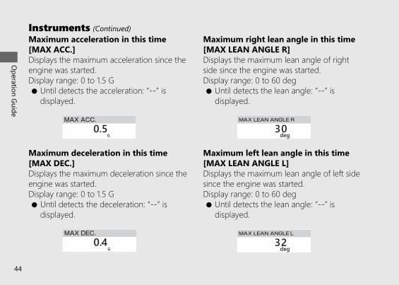
Maximum acceleration in this time[MAX ACC.]Displays the maximum acceleration since theengine was started.Display range: 0 to 1.5 G● Until detects the acceleration: “--” is
displayed.
Maximum deceleration in this time[MAX DEC.]Displays the maximum deceleration since theengine was started.Display range: 0 to 1.5 G● Until detects the deceleration: “--” is
displayed.
Maximum right lean angle in this time[MAX LEAN ANGLE R]Displays the maximum lean angle of rightside since the engine was started.Display range: 0 to 60 deg● Until detects the lean angle: “--” is
displayed.
Maximum left lean angle in this time[MAX LEAN ANGLE L]Displays the maximum lean angle of left sidesince the engine was started.Display range: 0 to 60 deg● Until detects the lean angle: “--” is
displayed.
20191113122725_32MKR8000_eng_BOOK Page 47 Wednesday, November 13 2019 12:40:27 JST
Operation Guide
44
Instruments (Continued)
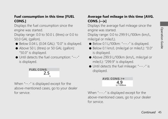
Fuel consumption in this time [FUELCONS.]Displays the fuel consumption since theengine was started.Display range: 0.0 to 50.0 L (litres) or 0.0 to50.0 GAL (gallon).● Below 0.04 L (0.04 GAL): “0.0” is displayed.● Above 50 L (litres) or 50 GAL (gallon):
“50.0” is displayed.● Until detects the fuel consumption: “--.-”
is displayed.
When “--.-” is displayed except for theabove-mentioned cases, go to your dealerfor service.
Average fuel mileage in this time [AVG.CONS. ]Displays the average fuel mileage since theengine was started.Display range: 0.0 to 299.9 L/100km (km/L,mile/gal or mile/L).● Below 0.1 L/100km: “---.-” is displayed.● Below 0.1 km/L (mile/gal or mile/L): “0.0”
is displayed.● Above 299.9 L/100km (km/L, mile/gal or
mile/L): “299.9” is displayed.● Until detects the fuel mileage: “---.-” is
displayed.
When “---.-” is displayed except for theabove-mentioned cases, go to your dealerfor service.
20191113122725_32MKR8000_eng_BOOK Page 48 Wednesday, November 13 2019 12:40:27 JST
Operation Guide
45Continued
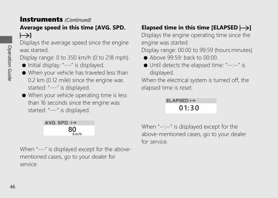
Average speed in this time [AVG. SPD.]
Displays the average speed since the enginewas started.Display range: 0 to 350 km/h (0 to 218 mph).● Initial display: “---” is displayed.● When your vehicle has traveled less than
0.2 km (0.12 mile) since the engine wasstarted: “---” is displayed.
● When your vehicle operating time is lessthan 16 seconds since the engine wasstarted: “---” is displayed.
When “---” is displayed except for the above-mentioned cases, go to your dealer forservice.
Elapsed time in this time [ELAPSED ]Displays the engine operating time since theengine was started.Display range: 00:00 to 99:59 (hours:minutes)● Above 99:59: back to 00:00.● Until detects the elapsed time: “--:--” is
displayed.When the electrical system is turned off, theelapsed time is reset.
When “--:--” is displayed except for theabove-mentioned cases, go to your dealerfor service.
20191113122725_32MKR8000_eng_BOOK Page 49 Wednesday, November 13 2019 12:40:27 JST
Operation Guide
46
Instruments (Continued)
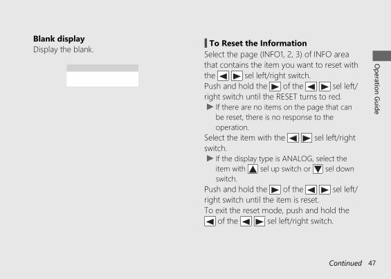
Blank displayDisplay the blank. # To Reset the Information
Select the page (INFO1, 2, 3) of INFO areathat contains the item you want to reset withthe sel left/right switch.Push and hold the of the sel left/right switch until the RESET turns to red.u If there are no items on the page that can
be reset, there is no response to theoperation.
Select the item with the sel left/rightswitch.u If the display type is ANALOG, select the
item with sel up switch or sel downswitch.
Push and hold the of the sel left/right switch until the item is reset.To exit the reset mode, push and hold the
of the sel left/right switch.
20191113122725_32MKR8000_eng_BOOK Page 50 Wednesday, November 13 2019 12:40:27 JST
Operation Guide
47Continued
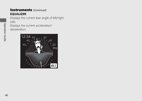
EQUALIZERDisplays the current lean angle of left/rightside.Displays the current acceleration/deceleration.
20191113122725_32MKR8000_eng_BOOK Page 51 Wednesday, November 13 2019 12:40:27 JST
Operation Guide
48
Instruments (Continued)
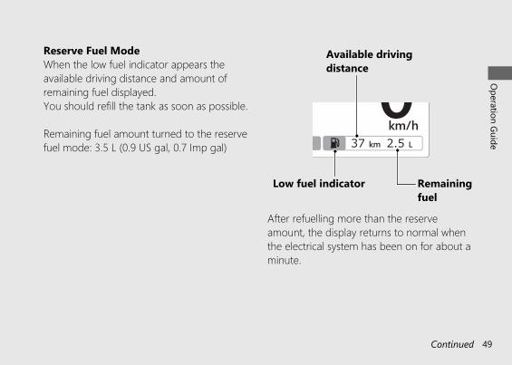
Reserve Fuel ModeWhen the low fuel indicator appears theavailable driving distance and amount ofremaining fuel displayed.You should refill the tank as soon as possible.
Remaining fuel amount turned to the reservefuel mode: 3.5 L (0.9 US gal, 0.7 Imp gal)
After refuelling more than the reserveamount, the display returns to normal whenthe electrical system has been on for about aminute.
20191113122725_32MKR8000_eng_BOOK Page 52 Wednesday, November 13 2019 12:40:27 JST
Operation Guide
49Continued
Low fuel indicator
Available drivingdistance
Remainingfuel
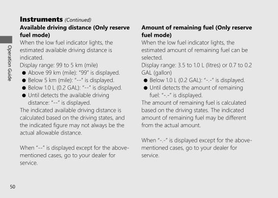
Available driving distance (Only reservefuel mode)When the low fuel indicator lights, theestimated available driving distance isindicated.Display range: 99 to 5 km (mile)● Above 99 km (mile): “99” is displayed.● Below 5 km (mile): “--” is displayed.● Below 1.0 L (0.2 GAL): “--” is displayed.● Until detects the available driving
distance: “--” is displayed.The indicated available driving distance iscalculated based on the driving states, andthe indicated figure may not always be theactual allowable distance.
When “--” is displayed except for the above-mentioned cases, go to your dealer forservice.
Amount of remaining fuel (Only reservefuel mode)When the low fuel indicator lights, theestimated amount of remaining fuel can beselected.Display range: 3.5 to 1.0 L (litres) or 0.7 to 0.2GAL (gallon)● Below 1.0 L (0.2 GAL): “-.-” is displayed.● Until detects the amount of remaining
fuel: “-.-” is displayed.The amount of remaining fuel is calculatedbased on the driving states. The indicatedamount of remaining fuel may be differentfrom the actual amount.
When “-.-” is displayed except for the above-mentioned cases, go to your dealer forservice.
20191113122725_32MKR8000_eng_BOOK Page 53 Wednesday, November 13 2019 12:40:27 JST
Operation Guide
50
Instruments (Continued)
Coolant temperature gauge ( )Display range: 35°C to 132°C● 34°C or less: “---” is displayed.● Between 122°C and 131°C:
- High coolant temperature indicator lights.- Coolant temperature digits flash.
● Above 132°C:- High coolant temperature indicator lights.- “132°C” flashes.
● Even if the engine coolant temperature is low, the cooling fan may start running when yourev up the engine. This is normal.
20191113122725_32MKR8000_eng_BOOK Page 54 Wednesday, November 13 2019 12:40:27 JST
Operation Guide
51Continued
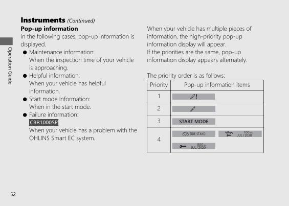
Pop-up informationIn the following cases, pop-up information isdisplayed.● Maintenance information:
When the inspection time of your vehicleis approaching.
● Helpful information:When your vehicle has helpfulinformation.
● Start mode Information:When in the start mode.
● Failure information:CBR1000SPWhen your vehicle has a problem with theÖHLINS Smart EC system.
When your vehicle has multiple pieces ofinformation, the high-priority pop-upinformation display will appear.If the priorities are the same, pop-upinformation display appears alternately.
The priority order is as follows:Priority Pop-up information items
1
2
3
4
20191113122725_32MKR8000_eng_BOOK Page 55 Wednesday, November 13 2019 12:40:27 JST
Operation Guide
52
Instruments (Continued)
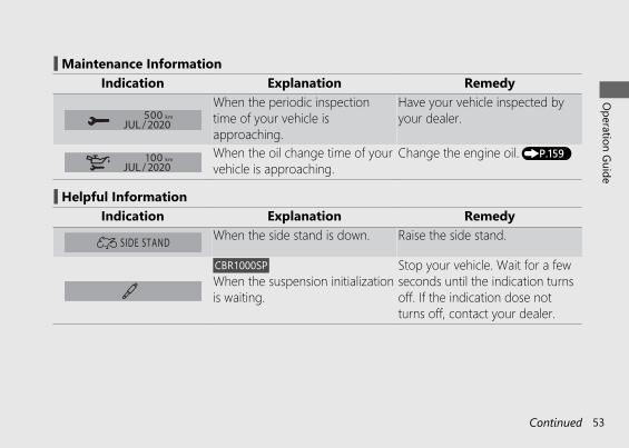
# Maintenance InformationIndication Explanation Remedy
When the periodic inspectiontime of your vehicle isapproaching.
Have your vehicle inspected byyour dealer.
When the oil change time of yourvehicle is approaching.
Change the engine oil. (P.159)
# Helpful InformationIndication Explanation Remedy
When the side stand is down. Raise the side stand.
CBR1000SPWhen the suspension initializationis waiting.
Stop your vehicle. Wait for a fewseconds until the indication turnsoff. If the indication dose notturns off, contact your dealer.
20191113122725_32MKR8000_eng_BOOK Page 56 Wednesday, November 13 2019 12:40:27 JST
Operation Guide
53Continued
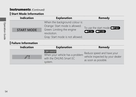
# Start Mode InformationIndication Explanation Remedy
When the background colour is:Orange: Start mode is allowed.Green: Limiting the enginerevolution.Gray: Start mode is not allowed.
To use the start mode (P.63)(P.74) (P.119)
# Failure InformationIndication Explanation Remedy
CBR1000SPWhen your vehicle has a problemwith the ÖHLINS Smart ECsystem.
Reduce speed and have yourvehicle inspected by your dealeras soon as possible.
20191113122725_32MKR8000_eng_BOOK Page 57 Wednesday, November 13 2019 12:40:27 JST
Operation Guide
54
Instruments (Continued)
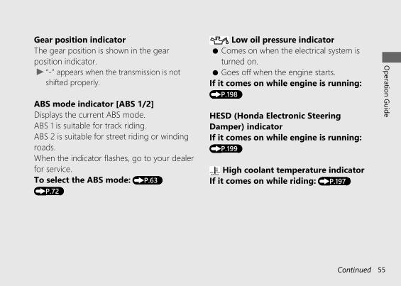
Gear position indicatorThe gear position is shown in the gearposition indicator.u “-” appears when the transmission is not
shifted properly.
ABS mode indicator [ABS 1/2]Displays the current ABS mode.ABS 1 is suitable for track riding.ABS 2 is suitable for street riding or windingroads.When the indicator flashes, go to your dealerfor service.To select the ABS mode: (P.63)(P.72)
Low oil pressure indicator● Comes on when the electrical system is
turned on.● Goes off when the engine starts.
If it comes on while engine is running:(P.198)
HESD (Honda Electronic SteeringDamper) indicatorIf it comes on while engine is running:(P.199)
High coolant temperature indicatorIf it comes on while riding: (P.197)
20191113122725_32MKR8000_eng_BOOK Page 58 Wednesday, November 13 2019 12:40:27 JST
Operation Guide
55Continued
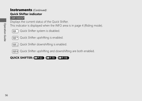
Quick Shifter indicatorCBR1000SPDisplays the current status of the Quick Shifter.This indicator is displayed when the INFO area is in page 4 (Riding mode).
Quick Shifter system is disabled.
Quick Shifter upshifting is enabled.
Quick Shifter downshifting is enabled.
Quick Shifter upshifting and downshifting are both enabled.
QUICK SHIFTER: (P.63) (P.70) (P.118)
20191113122725_32MKR8000_eng_BOOK Page 59 Wednesday, November 13 2019 12:40:27 JST
Operation Guide
56
Instruments (Continued)
20191113122725_32MKR8000_eng_BOOK Page 60 Wednesday, November 13 2019 12:40:27 JST
Operation Guide
57Continued
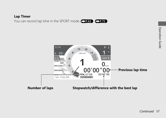
You can record lap time in the SPORT mode. (P.63) (P.75)Lap Timer
Previous lap time
Number of laps Stopwatch/difference with the best lap
20191113122725_32MKR8000_eng_BOOK Page 61 Wednesday, November 13 2019 12:40:27 JST
Operation Guide
58
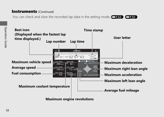
Instruments (Continued)You can check and clear the recorded lap data in the setting mode. (P.63) (P.83)
Best icon(Displayed when the fastest laptime displayed.)
Time stamp
Lap timeLap numberUser letter
Maximum decelerationMaximum right lean angleMaximum accelerationMaximum left lean angle
Average fuel mileage
Maximum engine revolutions
Maximum coolant temperature
Fuel consumptionAverage speedMaximum vehicle speed
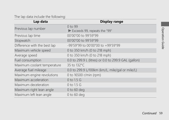
The lap data include the following:Lap data Display range
Previous lap number 0 to 99u Exceeds 99, repeats the “99”
Previous lap time 00'00"00 to 99'59"99Stopwatch 00'00"00 to 99'59"99Difference with the best lap -99'59"99 to 00'00"00 to +99'59"99Maximum vehicle speed 0 to 350 km/h (0 to 218 mph)Average speed 0 to 350 km/h (0 to 218 mph)Fuel consumption 0.0 to 299.9 L (litres) or 0.0 to 299.9 GAL (gallon)Maximum coolant temperature 35 to 132°CAverage fuel mileage 0.0 to 299.9 L/100km (km/L, mile/gal or mile/L)Maximum engine revolutions 0 to 16500 r/min (rpm)Maximum acceleration 0 to 1.5 GMaximum deceleration 0 to 1.5 GMaximum right lean angle 0 to 60 degMaximum left lean angle 0 to 60 deg
20191113122725_32MKR8000_eng_BOOK Page 62 Wednesday, November 13 2019 12:40:27 JST
Operation Guide
59Continued
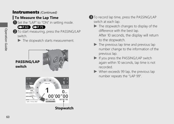
# To Measure the Lap Timea Set the “LAP” to “ON” in setting mode.(P.63) (P.75)
b To start measuring, press the PASSING/LAPswitch.u The stopwatch starts measurement.
c To record lap time, press the PASSING/LAPswitch at each lap.u The stopwatch changes to display of the
difference with the best lap.After 10 seconds, the display will returnto the stopwatch.
u The previous lap time and previous lapnumber change to the information of theprevious lap.
u If you press the PASSING/LAP switchagain within 10 seconds, lap time is notrecorded.
u When exceeds 99 lap, the previous lapnumber repeats the “LAP 99”.
20191113122725_32MKR8000_eng_BOOK Page 63 Wednesday, November 13 2019 12:40:27 JST
Operation Guide
60
Instruments (Continued)
Stopwatch
PASSING/LAPswitch
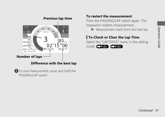
d To end measurement, press and hold thePASSING/LAP switch.
To restart the measurementPress the PASSING/LAP switch again. Thestopwatch restarts measurement.
u Measurement starts from the next lap.
# To Check or Clear the Lap TimeSelect the “LAP DATA” menu in the settingmode. (P.63) (P.83)
20191113122725_32MKR8000_eng_BOOK Page 64 Wednesday, November 13 2019 12:40:27 JST
Operation Guide
61Continued
Previous lap time
Difference with the best lapNumber of laps
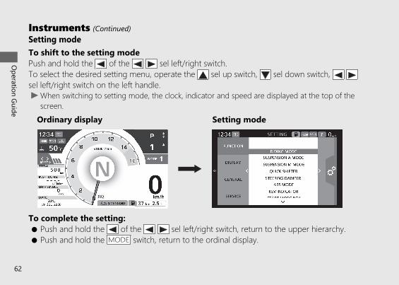
Setting modeTo shift to the setting modePush and hold the of the sel left/right switch.To select the desired setting menu, operate the sel up switch, sel down switch, sel left/right switch on the left handle.u When switching to setting mode, the clock, indicator and speed are displayed at the top of the
screen.
To complete the setting:● Push and hold the of the sel left/right switch, return to the upper hierarchy.● Push and hold the MODE switch, return to the ordinal display.
20191113122725_32MKR8000_eng_BOOK Page 65 Wednesday, November 13 2019 12:40:27 JST
Operation Guide
62
Instruments (Continued)
Ordinary display Setting mode
20191113122725_32MKR8000_eng_BOOK Page 66 Wednesday, November 13 2019 12:40:27 JST
Operation Guide
63Continued
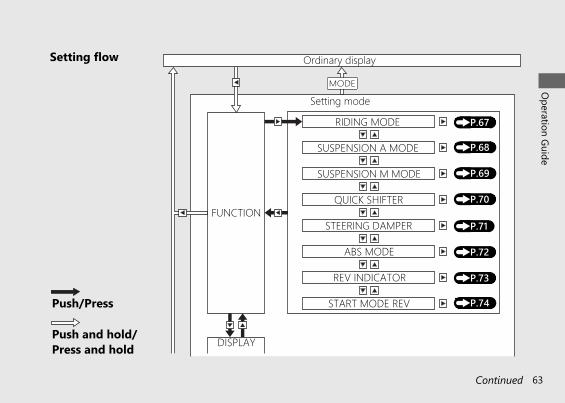
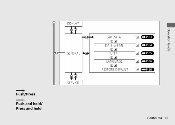
Setting flow
Push/Press
Push and hold/Press and hold
(P.67)
(P.68)
SUSPENSION M MODE
FUNCTION
DISPLAY
Ordinary display
RIDING MODE
SUSPENSION A MODE
QUICK SHIFTER
STEERING DAMPER
ABS MODE
REV INDICATOR
START MODE REV
(P.69)
(P.70)
(P.71)
(P.72)
(P.73)
(P.74)
Setting modeMODE
20191113122725_32MKR8000_eng_BOOK Page 67 Wednesday, November 13 2019 12:40:27 JST
Operation Guide
64
Instruments (Continued)
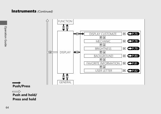
Push/Press
Push and hold/Press and hold
(P.75)
(P.78)
BRIGHTNESSDISPLAY
GENERAL
DISPLAY CUSTOMIZE
MECHANIC
BACKGROUND
FAVORITE INFORMATION
USER LETTER
(P.79)
(P.80)
(P.81)
(P.82)
FUNCTION
20191113122725_32MKR8000_eng_BOOK Page 68 Wednesday, November 13 2019 12:40:27 JST
Operation Guide
65Continued
Push/Press
Push and hold/Press and hold
(P.83)
(P.84)
UNITGENERAL
SERVICE
LAP DATA
DATE & TIME
LANGUAGE
RESTORE DEFAULT
(P.85)
(P.86)
(P.86)
DISPLAY
20191113122725_32MKR8000_eng_BOOK Page 69 Wednesday, November 13 2019 12:40:27 JST
Operation Guide
66
Instruments (Continued)
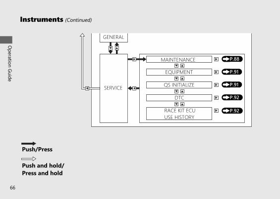
Push/Press
Push and hold/Press and hold
(P.88)
(P.91)
QS INITIALIZESERVICE
MAINTENANCE
EQUIPMENT
DTC
RACE KIT ECUUSE HISTORY
(P.91)
(P.92)
(P.92)
GENERAL
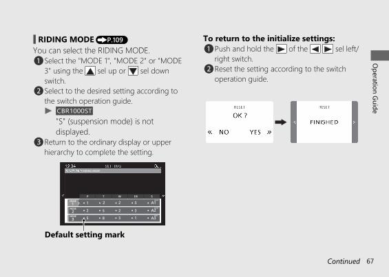
# RIDING MODE (P.109)You can select the RIDING MODE.a Select the "MODE 1", "MODE 2" or "MODE
3" using the sel up or sel downswitch.
b Select to the desired setting according tothe switch operation guide.u CBR1000ST
"S" (suspension mode) is notdisplayed.
c Return to the ordinary display or upperhierarchy to complete the setting.
To return to the initialize settings:a Push and hold the of the sel left/
right switch.b Reset the setting according to the switch
operation guide.
20191113122725_32MKR8000_eng_BOOK Page 70 Wednesday, November 13 2019 12:40:27 JST
Operation Guide
67Continued
Default setting mark
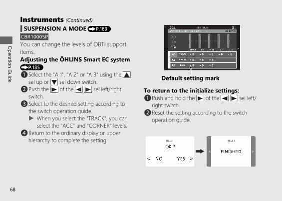
# SUSPENSION A MODE (P.189)CBR1000SPYou can change the levels of OBTi supportitems.Adjusting the ÖHLINS Smart EC system(P.185)a Select the "A 1", "A 2" or "A 3" using the
sel up or sel down switch.b Push the of the sel left/right
switch.c Select to the desired setting according to
the switch operation guide.u When you select the "TRACK", you can
select the "ACC" and "CORNER" levels.d Return to the ordinary display or upper
hierarchy to complete the setting.
To return to the initialize settings:a Push and hold the of the sel left/
right switch.b Reset the setting according to the switch
operation guide.
20191113122725_32MKR8000_eng_BOOK Page 71 Wednesday, November 13 2019 12:40:27 JST
Operation Guide
68
Instruments (Continued)
Default setting mark
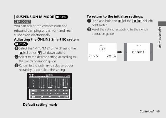
# SUSPENSION M MODE (P.192)CBR1000SPYou can adjust the compression andrebound damping of the front and rearsuspension electronically.Adjusting the ÖHLINS Smart EC system(P.185)a Select the "M 1", "M 2" or "M 3" using the
sel up or sel down switch.b Select to the desired setting according to
the switch operation guide.c Return to the ordinary display or upper
hierarchy to complete the setting.
To return to the initialize settings:a Push and hold the of the sel left/
right switch.b Reset the setting according to the switch
operation guide.
20191113122725_32MKR8000_eng_BOOK Page 72 Wednesday, November 13 2019 12:40:27 JST
Operation Guide
69Continued
Default setting mark
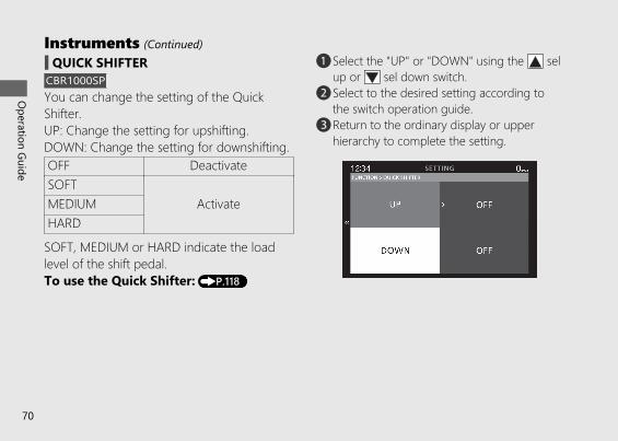
# QUICK SHIFTERCBR1000SPYou can change the setting of the QuickShifter.UP: Change the setting for upshifting.DOWN: Change the setting for downshifting.OFF DeactivateSOFT
ActivateMEDIUMHARD
SOFT, MEDIUM or HARD indicate the loadlevel of the shift pedal.To use the Quick Shifter: (P.118)
a Select the "UP" or "DOWN" using the selup or sel down switch.
b Select to the desired setting according tothe switch operation guide.
c Return to the ordinary display or upperhierarchy to complete the setting.
20191113122725_32MKR8000_eng_BOOK Page 73 Wednesday, November 13 2019 12:40:27 JST
Operation Guide
70
Instruments (Continued)
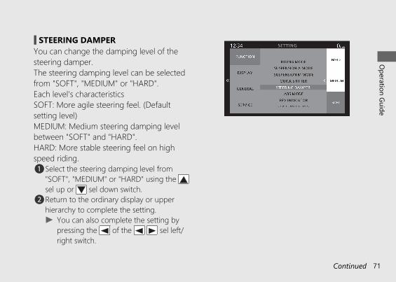
# STEERING DAMPERYou can change the damping level of thesteering damper.The steering damping level can be selectedfrom "SOFT", "MEDIUM" or "HARD".Each level's characteristicsSOFT: More agile steering feel. (Defaultsetting level)MEDIUM: Medium steering damping levelbetween "SOFT" and "HARD".HARD: More stable steering feel on highspeed riding.a Select the steering damping level from
"SOFT", "MEDIUM" or "HARD" using the sel up or sel down switch.
b Return to the ordinary display or upperhierarchy to complete the setting.u You can also complete the setting by
pressing the of the sel left/right switch.
20191113122725_32MKR8000_eng_BOOK Page 74 Wednesday, November 13 2019 12:40:27 JST
Operation Guide
71Continued
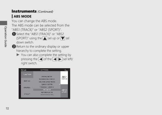
# ABS MODEYou can change the ABS mode.The ABS mode can be selected from the"ABS1 (TRACK)" or "ABS2 (SPORT)".a Select the "ABS1 (TRACK)" or "ABS2
(SPORT)" using the sel up or seldown switch.
b Return to the ordinary display or upperhierarchy to complete the setting.u You can also complete the setting by
pressing the of the sel left/right switch.
20191113122725_32MKR8000_eng_BOOK Page 75 Wednesday, November 13 2019 12:40:27 JST
Operation Guide
72
Instruments (Continued)
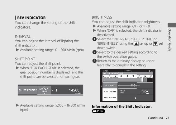
# REV INDICATORYou can change the setting of the shiftindicators.
INTERVALYou can adjust the interval of lighting theshift indicator.u Available setting range: 0 - 500 r/min (rpm)
SHIFT POINTYou can adjust the shift point.u When “FOR EACH GEAR” is selected, the
gear position number is displayed, and theshift point can be selected for each gear.
u Available setting range: 5,000 - 16,500 r/min(rpm)
BRIGHTNESSYou can adjust the shift indicator brightness.u Available setting range: OFF or 1 - 8u When "OFF" is selected, the shift indicator is
deactivated.a Select the "INTERVAL", "SHIFT POINT" or
"BRIGHTNESS" using the sel up or seldown switch.
b Select to the desired setting according tothe switch operation guide.
c Return to the ordinary display or upperhierarchy to complete the setting.
Information of the Shift Indicator:(P.96)
20191113122725_32MKR8000_eng_BOOK Page 76 Wednesday, November 13 2019 12:40:27 JST
Operation Guide
73Continued
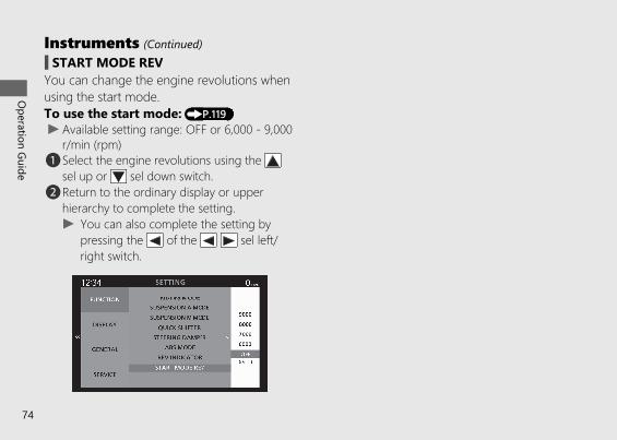
# START MODE REVYou can change the engine revolutions whenusing the start mode.To use the start mode: (P.119)u Available setting range: OFF or 6,000 - 9,000
r/min (rpm)a Select the engine revolutions using the
sel up or sel down switch.b Return to the ordinary display or upper
hierarchy to complete the setting.u You can also complete the setting by
pressing the of the sel left/right switch.
20191113122725_32MKR8000_eng_BOOK Page 77 Wednesday, November 13 2019 12:40:27 JST
Operation Guide
74
Instruments (Continued)
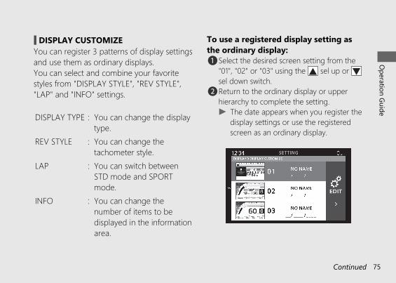
# DISPLAY CUSTOMIZEYou can register 3 patterns of display settingsand use them as ordinary displays.You can select and combine your favoritestyles from "DISPLAY STYLE", "REV STYLE","LAP" and "INFO" settings.
DISPLAY TYPE : You can change the displaytype.
REV STYLE : You can change thetachometer style.
LAP : You can switch betweenSTD mode and SPORTmode.
INFO : You can change thenumber of items to bedisplayed in the informationarea.
To use a registered display setting asthe ordinary display:a Select the desired screen setting from the
"01", "02" or "03" using the sel up or sel down switch.
b Return to the ordinary display or upperhierarchy to complete the setting.u The date appears when you register the
display settings or use the registeredscreen as an ordinary display.
20191113122725_32MKR8000_eng_BOOK Page 78 Wednesday, November 13 2019 12:40:27 JST
Operation Guide
75Continued
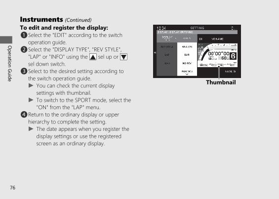
To edit and register the display:a Select the "EDIT" according to the switch
operation guide.b Select the "DISPLAY TYPE", "REV STYLE",
"LAP" or "INFO" using the sel up or sel down switch.
c Select to the desired setting according tothe switch operation guide.u You can check the current display
settings with thumbnail.u To switch to the SPORT mode, select the
"ON" from the "LAP" menu.d Return to the ordinary display or upper
hierarchy to complete the setting.u The date appears when you register the
display settings or use the registeredscreen as an ordinary display.
20191113122725_32MKR8000_eng_BOOK Page 79 Wednesday, November 13 2019 12:40:27 JST
Operation Guide
76
Instruments (Continued)
Thumbnail
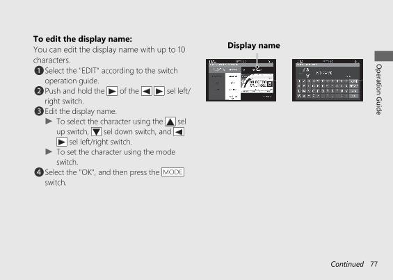
To edit the display name:You can edit the display name with up to 10characters.a Select the "EDIT" according to the switch
operation guide.b Push and hold the of the sel left/
right switch.c Edit the display name.
u To select the character using the selup switch, sel down switch, and
sel left/right switch.u To set the character using the mode
switch.d Select the "OK", and then press the MODE
switch.
20191113122725_32MKR8000_eng_BOOK Page 80 Wednesday, November 13 2019 12:40:27 JST
Operation Guide
77Continued
Display name
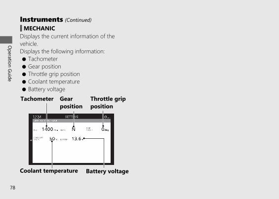
# MECHANICDisplays the current information of thevehicle.Displays the following information:● Tachometer● Gear position● Throttle grip position● Coolant temperature● Battery voltage
20191113122725_32MKR8000_eng_BOOK Page 81 Wednesday, November 13 2019 12:40:27 JST
Operation Guide
78
Instruments (Continued)
Tachometer Gearposition
Throttle gripposition
Coolant temperature Battery voltage
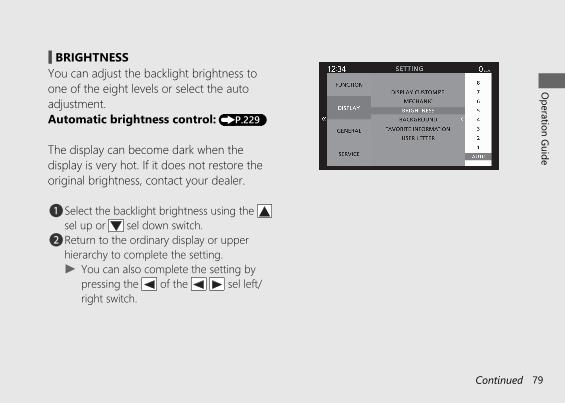
# BRIGHTNESSYou can adjust the backlight brightness toone of the eight levels or select the autoadjustment.Automatic brightness control: (P.229)
The display can become dark when thedisplay is very hot. If it does not restore theoriginal brightness, contact your dealer.
a Select the backlight brightness using the sel up or sel down switch.
b Return to the ordinary display or upperhierarchy to complete the setting.u You can also complete the setting by
pressing the of the sel left/right switch.
20191113122725_32MKR8000_eng_BOOK Page 82 Wednesday, November 13 2019 12:40:27 JST
Operation Guide
79Continued
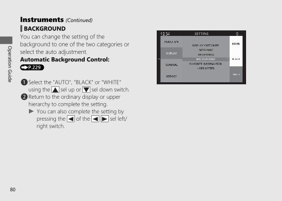
# BACKGROUNDYou can change the setting of thebackground to one of the two categories orselect the auto adjustment.Automatic Background Control:(P.229)
a Select the "AUTO", "BLACK" or "WHITE"using the sel up or sel down switch.
b Return to the ordinary display or upperhierarchy to complete the setting.u You can also complete the setting by
pressing the of the sel left/right switch.
20191113122725_32MKR8000_eng_BOOK Page 83 Wednesday, November 13 2019 12:40:27 JST
Operation Guide
80
Instruments (Continued)
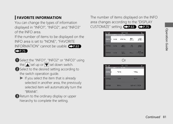
# FAVORITE INFORMATIONYou can change the types of informationdisplayed in "INFO1", "INFO2", and "INFO3"of the INFO area.If the number of items to be displayed on theINFO area is set to "NONE", "FAVORITEINFORMATION" cannot be usable. (P.63)(P.75)
a Select the "INFO1", "INFO2" or "INFO3" usingthe sel up or sel down switch.
b Select to the desired setting according tothe switch operation guide.u If you select the item that is already
selected in another area, the previouslyselected item will automatically turn the"BRANK".
c Return to the ordinary display or upperhierarchy to complete the setting.
The number of items displayed on the INFOarea changes according to the "DISPLAYCUSTOMIZE" setting. (P.63) (P.75)
20191113122725_32MKR8000_eng_BOOK Page 84 Wednesday, November 13 2019 12:40:27 JST
Operation Guide
81Continued
Or
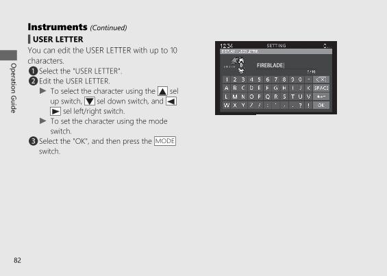
# USER LETTERYou can edit the USER LETTER with up to 10characters.a Select the "USER LETTER".b Edit the USER LETTER.
u To select the character using the selup switch, sel down switch, and
sel left/right switch.u To set the character using the mode
switch.c Select the "OK", and then press the MODE
switch.
20191113122725_32MKR8000_eng_BOOK Page 85 Wednesday, November 13 2019 12:40:27 JST
Operation Guide
82
Instruments (Continued)
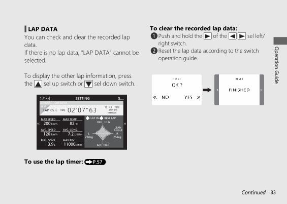
# LAP DATAYou can check and clear the recorded lapdata.If there is no lap data, "LAP DATA" cannot beselected.
To display the other lap information, pressthe sel up switch or sel down switch.
To use the lap timer: (P.57)
To clear the recorded lap data:a Push and hold the of the sel left/
right switch.b Reset the lap data according to the switch
operation guide.
20191113122725_32MKR8000_eng_BOOK Page 86 Wednesday, November 13 2019 12:40:27 JST
Operation Guide
83Continued
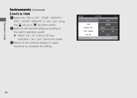
# DATE & TIMEa Select the "24h or 12h", "YEAR", "MONTH /
DAY", "HOUR / MINUTE" or "am / pm" usingthe sel up or sel down switch.
b Select to the desired setting according tothe switch operation guide.u When "24 / 12" is set to 24-hour
indication, "am / pm" cannot be usable.c Return to the ordinary display or upper
hierarchy to complete the setting.
20191113122725_32MKR8000_eng_BOOK Page 87 Wednesday, November 13 2019 12:40:27 JST
Operation Guide
84
Instruments (Continued)

# UNITED, II ED, II GS typeYou can change the speed and mileage, andfuel mileage meter units.a Select the "SPEED" or "FUEL CONS." using
the sel up or sel down switch.u "TEMP" is displayed but not usable.
b Select to the desired setting according tothe switch operation guide.
c Return to the ordinary display or upperhierarchy to complete the setting.
If you want to select "L/100km" or "km/L" forfuel consumption, "km/h" must be selected inthe "SPEED" menu in advance.When "mph" for speed is selected, "mile/gal"or "mile/L" can be selected.
20191113122725_32MKR8000_eng_BOOK Page 88 Wednesday, November 13 2019 12:40:27 JST
Operation Guide
85Continued
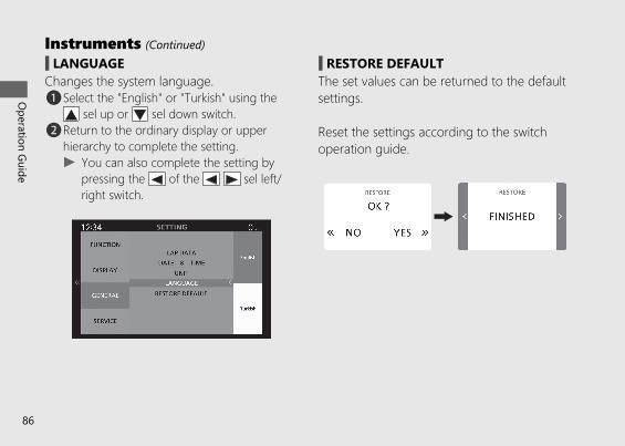
# LANGUAGEChanges the system language.a Select the "English" or "Turkish" using the
sel up or sel down switch.b Return to the ordinary display or upper
hierarchy to complete the setting.u You can also complete the setting by
pressing the of the sel left/right switch.
# RESTORE DEFAULTThe set values can be returned to the defaultsettings.
Reset the settings according to the switchoperation guide.
20191113122725_32MKR8000_eng_BOOK Page 89 Wednesday, November 13 2019 12:40:27 JST
Operation Guide
86
Instruments (Continued)
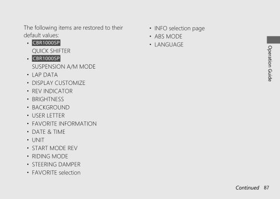
The following items are restored to theirdefault values:• CBR1000SP
QUICK SHIFTER• CBR1000SP
SUSPENSION A/M MODE• LAP DATA• DISPLAY CUSTOMIZE• REV INDICATOR• BRIGHTNESS• BACKGROUND• USER LETTER• FAVORITE INFORMATION• DATE & TIME• UNIT• START MODE REV• RIDING MODE• STEERING DAMPER• FAVORITE selection
• INFO selection page• ABS MODE• LANGUAGE
20191113122725_32MKR8000_eng_BOOK Page 90 Wednesday, November 13 2019 12:40:27 JST
Operation Guide
87Continued
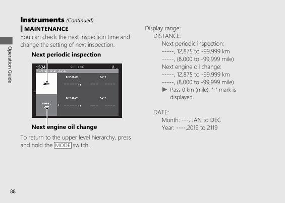
# MAINTENANCEYou can check the next inspection time andchange the setting of next inspection.
To return to the upper level hierarchy, pressand hold the MODE switch.
Display range:DISTANCE:
Next periodic inspection:-----, 12,875 to -99,999 km-----, (8,000 to -99,999 mile)Next engine oil change:-----, 12,875 to -99,999 km-----, (8,000 to -99,999 mile)u Pass 0 km (mile): “-” mark is
displayed.
DATE:Month: ---, JAN to DECYear: ----,2019 to 2119
20191113122725_32MKR8000_eng_BOOK Page 91 Wednesday, November 13 2019 12:40:27 JST
Operation Guide
88
Instruments (Continued)
Next periodic inspection
Next engine oil change
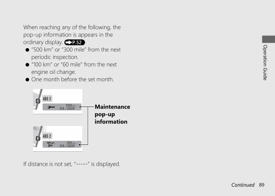
When reaching any of the following, thepop-up information is appears in theordinary display. (P.52)● “500 km” or “300 mile” from the next
periodic inspection.● “100 km” or “60 mile” from the next
engine oil change.● One month before the set month.
If distance is not set, “-----” is displayed.
20191113122725_32MKR8000_eng_BOOK Page 92 Wednesday, November 13 2019 12:40:27 JST
Operation Guide
89Continued
Maintenancepop-upinformation
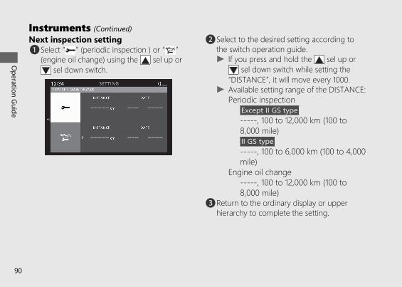
Next inspection settinga Select “ ” (periodic inspection ) or “ ”
(engine oil change) using the sel up or sel down switch.
b Select to the desired setting according tothe switch operation guide.u If you press and hold the sel up or
sel down switch while setting the“DISTANCE”, it will move every 1000.
u Available setting range of the DISTANCE:Periodic inspection
Except II GS type-----, 100 to 12,000 km (100 to8,000 mile)II GS type-----, 100 to 6,000 km (100 to 4,000mile)
Engine oil change-----, 100 to 12,000 km (100 to8,000 mile)
c Return to the ordinary display or upperhierarchy to complete the setting.
20191113122725_32MKR8000_eng_BOOK Page 93 Wednesday, November 13 2019 12:40:27 JST
Operation Guide
90
Instruments (Continued)
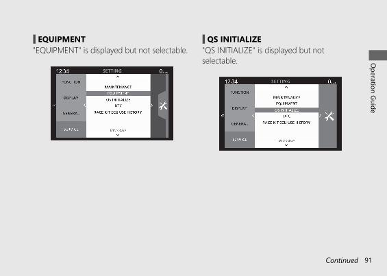
# EQUIPMENT"EQUIPMENT" is displayed but not selectable.
# QS INITIALIZE"QS INITIALIZE" is displayed but notselectable.
20191113122725_32MKR8000_eng_BOOK Page 94 Wednesday, November 13 2019 12:40:27 JST
Operation Guide
91Continued
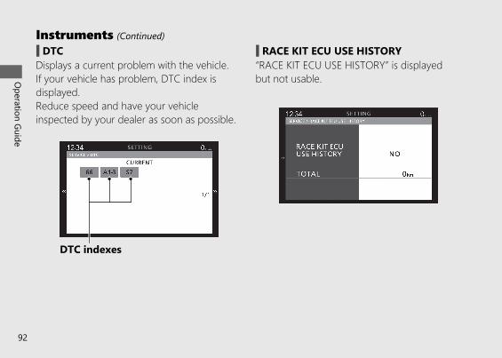
# DTCDisplays a current problem with the vehicle.If your vehicle has problem, DTC index isdisplayed.Reduce speed and have your vehicleinspected by your dealer as soon as possible.
# RACE KIT ECU USE HISTORY“RACE KIT ECU USE HISTORY” is displayedbut not usable.
20191113122725_32MKR8000_eng_BOOK Page 95 Wednesday, November 13 2019 12:40:27 JST
Operation Guide
92
Instruments (Continued)
DTC indexes
Indicators
20191113122725_32MKR8000_eng_BOOK Page 96 Wednesday, November 13 2019 12:40:27 JST
Operation Guide
93Continued
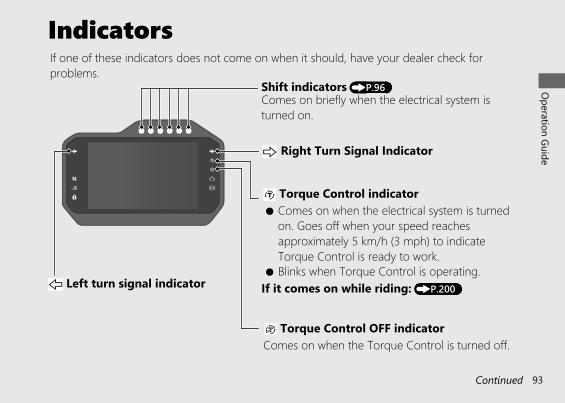
If one of these indicators does not come on when it should, have your dealer check forproblems.
● Blinks when Torque Control is operating. Left turn signal indicator
Right Turn Signal Indicator
Comes on briefly when the electrical system isturned on.
Shift indicators (P.96)
If it comes on while riding: (P.200)
● Comes on when the electrical system is turnedon. Goes off when your speed reachesapproximately 5 km/h (3 mph) to indicateTorque Control is ready to work.
Torque Control indicator
Comes on when the Torque Control is turned off. Torque Control OFF indicator
20191113122725_32MKR8000_eng_BOOK Page 97 Wednesday, November 13 2019 12:40:27 JST
Operation Guide
94
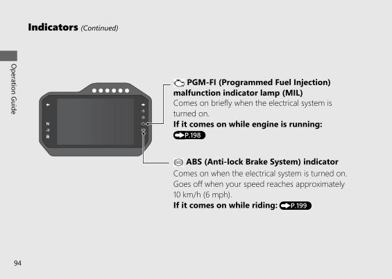
Indicators (Continued)
ABS (Anti-lock Brake System) indicatorComes on when the electrical system is turned on.Goes off when your speed reaches approximately10 km/h (6 mph).If it comes on while riding: (P.199)
Comes on briefly when the electrical system isturned on.If it comes on while engine is running:(P.198)
PGM-FI (Programmed Fuel Injection)malfunction indicator lamp (MIL)
20191113122725_32MKR8000_eng_BOOK Page 98 Wednesday, November 13 2019 12:40:27 JST
Operation Guide
95Continued
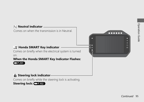
Steering lock indicatorComes on briefly while the steering lock is activating.Steering lock: (P.102)
Comes on briefly when the electrical system is turnedon.When the Honda SMART Key Indicator Flashes:(P.201)
Honda SMART Key indicator
Comes on when the transmission is in Neutral. Neutral indicator

20191113122725_32MKR8000_eng_BOOK Page 99 Wednesday, November 13 2019 12:40:27 JST
Operation Guide
96
Indicators (Continued)
The timing and brightness of the indicatorslight/blink depend on the "REV INDICATOR"setting.Setting of the Shift Indicators (P.63) (P.73)
The shift indicators light or blink by theengine revolutions.
Shift Indicators The indicator colours are as follows.
A: SHIFT POINT value B: INTERVAL value
A – (B × 6)Engine revolutionsEngine revolutionsEngine revolutionsEngine revolutionsEngine revolutionsEngine revolutionsEngine revolutionsEngine revolutions
A – (B × 5)A – (B × 4)A – (B × 3)A – (B × 2)A – (B × 1)
A
A – (B × 6)A – (B × 5)A – (B × 4)A – (B × 3)A – (B × 2)A – (B × 1)
A
WhiteRed
Blue
Definition:

20191113122725_32MKR8000_eng_BOOK Page 100 Wednesday, November 13 2019 12:40:27 JST
Operation Guide
97
Switches
20191113122725_32MKR8000_eng_BOOK Page 101 Wednesday, November 13 2019 12:40:27 JST
Operation Guide
98
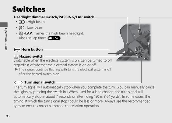
Headlight dimmer switch/PASSING/LAP switch• : High beam• : Low beam
Turn signal switch
Horn button
The turn signal will automatically stop when you complete the turn. (You can manually cancelthe lights by pressing the switch in.) When used for a lane change, the turn signal willautomatically stop in about 7 seconds or after riding 150 m (164 yards). In some cases, thetiming at which the turn signal stops could be less or more. Always use the recommendedtyres to ensure correct automatic cancellation operation.
• /LAP: Flashes the high beam headlight. Also use lap timer. (P.57)
Hazard switchSwitchable when the electrical system is on. Can be turned to offregardless of whether the electrical system is on or off.u The signals continue flashing with turn the electrical system is off
after the hazard switch is on.
20191113122725_32MKR8000_eng_BOOK Page 102 Wednesday, November 13 2019 12:40:27 JST
Operation Guide
99Continued
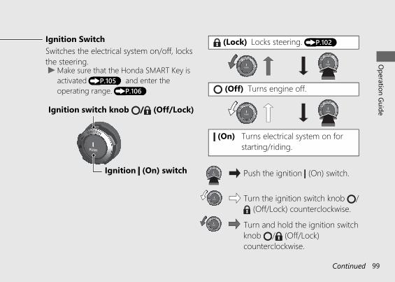
Ignition SwitchSwitches the electrical system on/off, locksthe steering.u Make sure that the Honda SMART Key is
activated (P.105) and enter theoperating range. (P.106)
Push the ignition (On) switch.
Turn the ignition switch knob / (Off/Lock) counterclockwise.
Turns electrical system on forstarting/riding.
Turns engine off.
Locks steering. (P.102)
Ignition (On) switch
Ignition switch knob / (Off/Lock)
Turn and hold the ignition switchknob / (Off/Lock)counterclockwise.
(Lock)
(Off)
(On)
20191113122725_32MKR8000_eng_BOOK Page 103 Wednesday, November 13 2019 12:40:27 JST
Operation Guide
100
Switches (Continued)
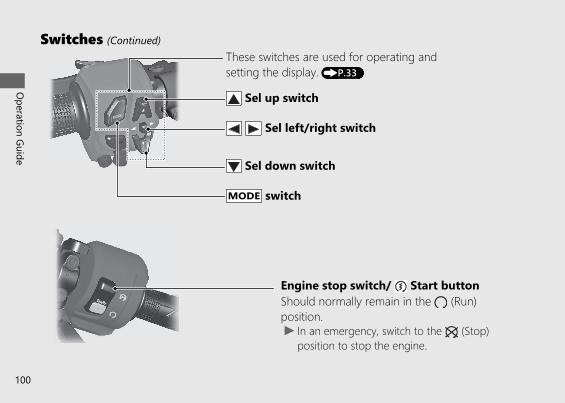
Sel up switch
u In an emergency, switch to the (Stop)position to stop the engine.
Should normally remain in the (Run)position.
Engine stop switch/ Start button
Sel left/right switch
Sel down switch
MODE switch
These switches are used for operating andsetting the display. (P.33)
20191113122725_32MKR8000_eng_BOOK Page 104 Wednesday, November 13 2019 12:40:27 JST
Operation Guide
101Continued
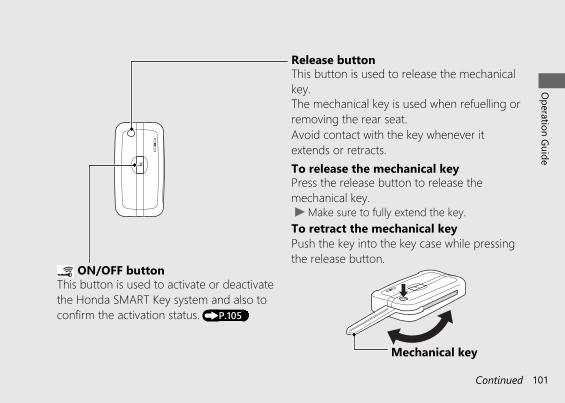
ON/OFF buttonThis button is used to activate or deactivatethe Honda SMART Key system and also toconfirm the activation status. (P.105)
Release buttonThis button is used to release the mechanicalkey.The mechanical key is used when refuelling orremoving the rear seat.
To release the mechanical keyPress the release button to release themechanical key.u Make sure to fully extend the key.To retract the mechanical keyPush the key into the key case while pressingthe release button.
Avoid contact with the key whenever itextends or retracts.
Mechanical key
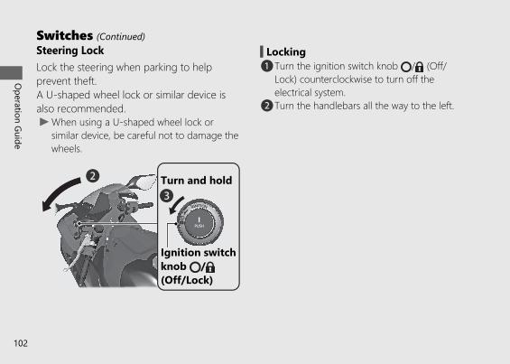
Steering LockLock the steering when parking to helpprevent theft.A U-shaped wheel lock or similar device isalso recommended.u When using a U-shaped wheel lock or
similar device, be careful not to damage thewheels.
# Lockinga Turn the ignition switch knob / (Off/
Lock) counterclockwise to turn off theelectrical system.
b Turn the handlebars all the way to the left.
20191113122725_32MKR8000_eng_BOOK Page 105 Wednesday, November 13 2019 12:40:27 JST
Operation Guide
102
Switches (Continued)
b
Ignition switchknob /(Off/Lock)
cTurn and hold
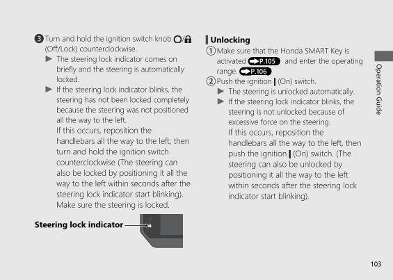
c Turn and hold the ignition switch knob /(Off/Lock) counterclockwise.u The steering lock indicator comes on
briefly and the steering is automaticallylocked.
u If the steering lock indicator blinks, thesteering has not been locked completelybecause the steering was not positionedall the way to the left.If this occurs, reposition thehandlebars all the way to the left, thenturn and hold the ignition switchcounterclockwise (The steering canalso be locked by positioning it all theway to the left within seconds after thesteering lock indicator start blinking).Make sure the steering is locked.
# UnlockingaMake sure that the Honda SMART Key is
activated (P.105) and enter the operatingrange. (P.106)
bPush the ignition (On) switch.u The steering is unlocked automatically.u If the steering lock indicator blinks, the
steering is not unlocked because ofexcessive force on the steering.If this occurs, reposition thehandlebars all the way to the left, thenpush the ignition (On) switch. (Thesteering can also be unlocked bypositioning it all the way to the leftwithin seconds after the steering lockindicator start blinking).
20191113122725_32MKR8000_eng_BOOK Page 106 Wednesday, November 13 2019 12:40:27 JST
Operation Guide
103
Steering lock indicator
Honda SMART Key SystemThe Honda SMART Key system allows you tooperate the main switch without inserting akey into a keyhole.The system runs a two-way authenticationbetween the vehicle and the Honda SMARTKey to verify if it is the registered HondaSMART Key.
The Honda SMART Key system uses low-intensity radio waves. It may affect medicalequipment such as a cardiac pacemakers.
20191113122725_32MKR8000_eng_BOOK Page 107 Wednesday, November 13 2019 12:40:27 JST
Operation Guide
104
Switching the Honda SMART KeySystem
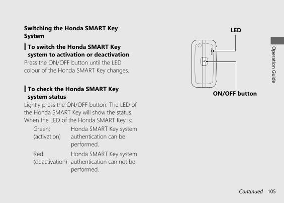
# To switch the Honda SMART Keysystem to activation or deactivation
Press the ON/OFF button until the LEDcolour of the Honda SMART Key changes.
# To check the Honda SMART Keysystem status
Lightly press the ON/OFF button. The LED ofthe Honda SMART Key will show the status.When the LED of the Honda SMART Key is:
Green:(activation)
Honda SMART Key systemauthentication can beperformed.
Red:(deactivation)
Honda SMART Key systemauthentication can not beperformed.
20191113122725_32MKR8000_eng_BOOK Page 108 Wednesday, November 13 2019 12:40:27 JST
Operation Guide
105Continued
LED
ON/OFF button

Operating RangeThe Honda SMART Key system uses low-intensity radio waves. Therefore theoperating range may become wider ornarrower, or the Honda SMART Key systemmay not work properly in the followingenvironments.• When the Honda SMART Key battery is
depleted.• When there are facilities nearby that
generate strong radio waves or noisesuch as TV towers, power stations, radiostations, or airports.
• When you carry the Honda SMART Keywith a laptop or wireless communicationdevice such as a radio or mobile phone.
• When the Honda SMART Key comes intocontact with or is covered by metalobjects.
The system can be operated when theHonda SMART Key is within the shaded areashown in the illustration.u Placing the Honda SMART Key on the fuel
tank may cause communication failure.
20191113122725_32MKR8000_eng_BOOK Page 109 Wednesday, November 13 2019 12:40:27 JST
Operation Guide
106
Honda SMART Key System (Continued)
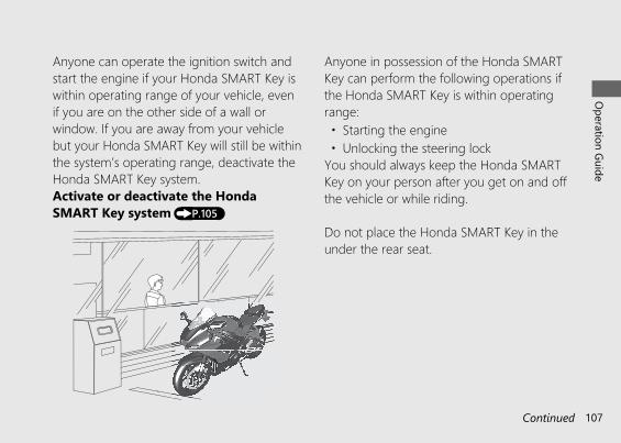
Anyone can operate the ignition switch andstart the engine if your Honda SMART Key iswithin operating range of your vehicle, evenif you are on the other side of a wall orwindow. If you are away from your vehiclebut your Honda SMART Key will still be withinthe system’s operating range, deactivate theHonda SMART Key system.Activate or deactivate the HondaSMART Key system (P.105)
Anyone in possession of the Honda SMARTKey can perform the following operations ifthe Honda SMART Key is within operatingrange:• Starting the engine• Unlocking the steering lock
You should always keep the Honda SMARTKey on your person after you get on and offthe vehicle or while riding.
Do not place the Honda SMART Key in theunder the rear seat.
20191113122725_32MKR8000_eng_BOOK Page 110 Wednesday, November 13 2019 12:40:27 JST
Operation Guide
107Continued
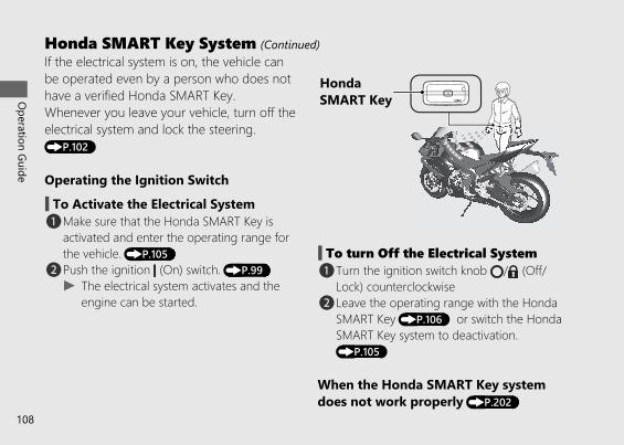
If the electrical system is on, the vehicle canbe operated even by a person who does nothave a verified Honda SMART Key.Whenever you leave your vehicle, turn off theelectrical system and lock the steering.(P.102)
Operating the Ignition Switch
# To Activate the Electrical Systema Make sure that the Honda SMART Key is
activated and enter the operating range forthe vehicle. (P.105)
b Push the ignition (On) switch. (P.99)u The electrical system activates and the
engine can be started.
# To turn Off the Electrical Systema Turn the ignition switch knob / (Off/
Lock) counterclockwiseb Leave the operating range with the Honda
SMART Key (P.106) or switch the HondaSMART Key system to deactivation.(P.105)
When the Honda SMART Key systemdoes not work properly (P.202)
20191113122725_32MKR8000_eng_BOOK Page 111 Wednesday, November 13 2019 12:40:27 JST
Operation Guide
108
Honda SMART Key System (Continued)
Honda SMART Key
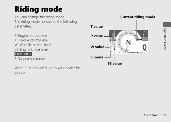
Riding modeYou can change the riding mode.The riding mode consists of the followingparameters.
P: Engine output levelT: Torque control levelW: Wheelie control levelEB: Engine brake levelCBR1000SPS: Suspension mode
When “-” is displayed, go to your dealer forservice.
20191113122725_32MKR8000_eng_BOOK Page 112 Wednesday, November 13 2019 12:40:27 JST
Operation Guide
109Continued
Current riding mode
P value
T value
EB valueS mode
W value
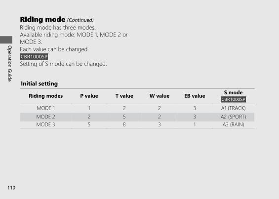
Initial setting
Riding modes P value T value W value EB value S modeCBR1000SP
MODE 1 1 2 2 3 A1 (TRACK)MODE 2 2 5 2 3 A2 (SPORT)MODE 3 5 8 3 1 A3 (RAIN)
Riding mode has three modes.Available riding mode: MODE 1, MODE 2 orMODE 3.Each value can be changed.CBR1000SPSetting of S mode can be changed.
20191113122725_32MKR8000_eng_BOOK Page 113 Wednesday, November 13 2019 12:40:27 JST
Operation Guide
110
Riding mode (Continued)
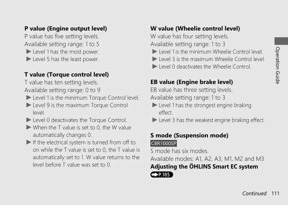
P value (Engine output level)P value has five setting levels.Available setting range: 1 to 5u Level 1 has the most power.u Level 5 has the least power.
T value (Torque control level)T value has ten setting levels.Available setting range: 0 to 9u Level 1 is the minimum Torque Control level.u Level 9 is the maximum Torque Control
level.u Level 0 deactivates the Torque Control.u When the T value is set to 0, the W value
automatically changes 0.u If the electrical system is turned from off to
on while the T value is set to 0, the T value isautomatically set to 1. W value returns to thelevel before T value was set to 0.
W value (Wheelie control level)W value has four setting levels. Available setting range: 1 to 3u Level 1 is the minimum Wheelie Control level.u Level 3 is the maximum Wheelie Control level.u Level 0 deactivates the Wheelie Control.
EB value (Engine brake level)EB value has three setting levels.Available setting range: 1 to 3u Level 1 has the strongest engine braking
effect.u Level 3 has the weakest engine braking effect.
S mode (Suspension mode)CBR1000SPS mode has six modes.Available modes: A1, A2, A3, M1, M2 and M3Adjusting the ÖHLINS Smart EC system(P.185)
20191113122725_32MKR8000_eng_BOOK Page 114 Wednesday, November 13 2019 12:40:27 JST
Operation Guide
111Continued
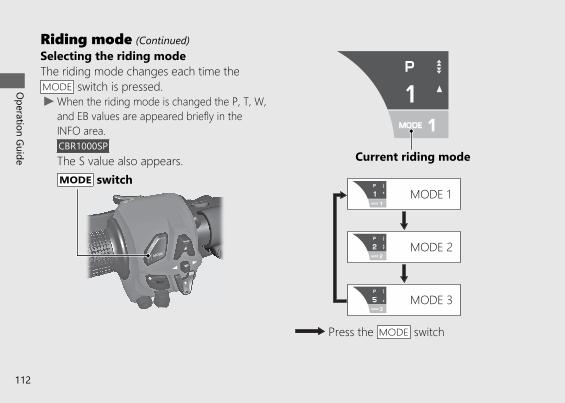
Selecting the riding modeThe riding mode changes each time theMODE switch is pressed.u When the riding mode is changed the P, T, W,
and EB values are appeared briefly in theINFO area.CBR1000SPThe S value also appears.
20191113122725_32MKR8000_eng_BOOK Page 115 Wednesday, November 13 2019 12:40:27 JST
Operation Guide
112
Riding mode (Continued)
MODE switchCurrent riding mode
Press the MODE switch
MODE 1
MODE 2
MODE 3
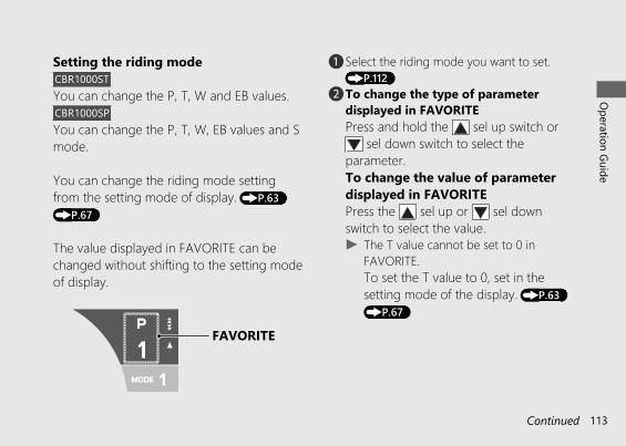
Setting the riding modeCBR1000STYou can change the P, T, W and EB values.CBR1000SPYou can change the P, T, W, EB values and Smode.
You can change the riding mode settingfrom the setting mode of display. (P.63)(P.67)
The value displayed in FAVORITE can bechanged without shifting to the setting modeof display.
a Select the riding mode you want to set.(P.112)
b To change the type of parameterdisplayed in FAVORITEPress and hold the sel up switch or
sel down switch to select theparameter.To change the value of parameterdisplayed in FAVORITEPress the sel up or sel downswitch to select the value.u The T value cannot be set to 0 in
FAVORITE.To set the T value to 0, set in thesetting mode of the display. (P.63)(P.67)
20191113122725_32MKR8000_eng_BOOK Page 116 Wednesday, November 13 2019 12:40:27 JST
Operation Guide
113Continued
FAVORITE
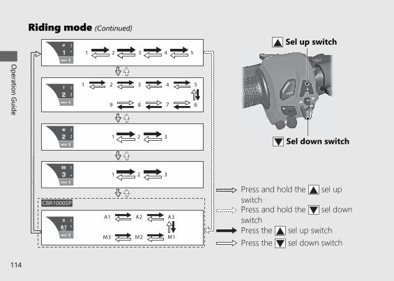
20191113122725_32MKR8000_eng_BOOK Page 117 Wednesday, November 13 2019 12:40:27 JST
Operation Guide
114
Riding mode (Continued)
CBR1000SP
Press and hold the sel upswitch
Press the sel down switchPress the sel up switch
Press and hold the sel downswitch
Sel up switch
Sel down switch
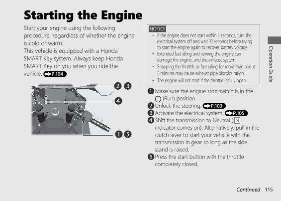
Starting the EngineStart your engine using the followingprocedure, regardless of whether the engineis cold or warm.This vehicle is equipped with a HondaSMART Key system. Always keep HondaSMART Key on you when you ride thevehicle. (P.104)
NOTICE• If the engine does not start within 5 seconds, turn the
electrical system off and wait 10 seconds before tryingto start the engine again to recover battery voltage.
• Extended fast idling and revving the engine candamage the engine, and the exhaust system.
• Snapping the throttle or fast idling for more than about5 minutes may cause exhaust pipe discolouration.
• The engine will not start if the throttle is fully open.
a Make sure the engine stop switch is in the (Run) position.
b Unlock the steering. (P.103)c Activate the electrical system. (P.105)d Shift the transmission to Neutral ( N
indicator comes on). Alternatively, pull in theclutch lever to start your vehicle with thetransmission in gear so long as the sidestand is raised.
e Press the start button with the throttlecompletely closed.
20191113122725_32MKR8000_eng_BOOK Page 118 Wednesday, November 13 2019 12:40:27 JST
Operation Guide
115Continued
a
b c
d
e
If the engine does not start:aOpen the throttle fully and press the start
button for 5 seconds.bRepeat the normal starting procedure.c If the engine starts, open the throttle slightly
if idling is unstable.d If the engine does not start, wait 10 seconds
before trying steps a & b again.
# If Engine Will Not Start (P.196)
20191113122725_32MKR8000_eng_BOOK Page 119 Wednesday, November 13 2019 12:40:27 JST
Operation Guide
116
Starting the Engine (Continued)
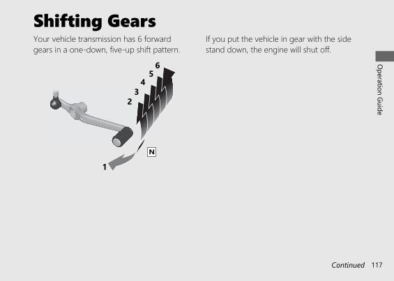
Shifting GearsYour vehicle transmission has 6 forwardgears in a one-down, five-up shift pattern.
If you put the vehicle in gear with the sidestand down, the engine will shut off.
20191113122725_32MKR8000_eng_BOOK Page 120 Wednesday, November 13 2019 12:40:27 JST
Operation Guide
117Continued
1N
23
45
6
Quick ShifterCBR1000SPThis system enables very quick up and downshifting without clutch and throttleoperations.u This system does not function when
upshifting with the throttle closed.u This system functions when the engine
speed is more than 1,500 r/min (rpm) onupshifting or more than the idle speed ondownshifting.
u This system does not function when theclutch lever is being operated.
● If “-” is displayed on the gear positionindicator, the Quick Shifter system doesnot operate.
● If the Quick Shifter does not operatenormally, the clutch can be used tocomplete the shift operation.
● The Quick Shifter can be individuallyturned ON (active) and OFF (deactivate),also the shift pedal load level foractivating the Quick Shifter can beadjusted during up and down shifting.
● If the PGM-FI malfunction indicator lampcomes on or the gear position indicatorflashes “-” in the current gear position, theQuick Shifter system may not operate. Ifeither of the above occurs, contact yourdealer as soon as possible.
# To Change the Setting of Quick Shifter(P.63) (P.70)
20191113122725_32MKR8000_eng_BOOK Page 121 Wednesday, November 13 2019 12:40:27 JST
Operation Guide
118
Shifting Gears (Continued)
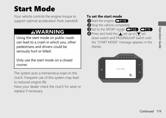
Start ModeYour vehicle controls the engine torque tosupport optimal acceleration from standstill.
3WARNINGUsing the start mode on public roadscan lead to a crash in which you, otherpedestrians and drivers could beseriously hurt or killed.
Only use the start mode on a closedcourse.
The system puts a tremendous load on theclutch. Frequent use of this system may leadto reduced engine life.Have your dealer check the clutch for wear orreplace if necessary.
To set the start modea Start the engine. (P.115)b Stop the vehicle completely.c Set to the SPORT mode. (P.63) (P.75)d Press and hold the sel up or sel
down switch and PASSING/LAP switch untilthe “START MODE” message appears in thedisplay.
20191113122725_32MKR8000_eng_BOOK Page 122 Wednesday, November 13 2019 12:40:27 JST
Operation Guide
119Continued
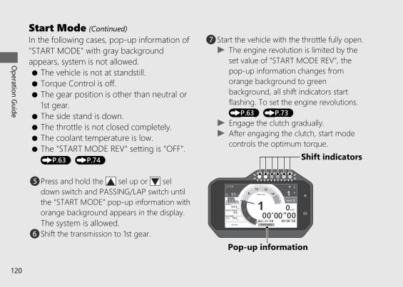
In the following cases, pop-up information of"START MODE" with gray backgroundappears, system is not allowed.● The vehicle is not at standstill.● Torque Control is off.● The gear position is other than neutral or
1st gear.● The side stand is down.● The throttle is not closed completely.● The coolant temperature is low.● The "START MODE REV" setting is "OFF".(P.63) (P.74)
e Press and hold the sel up or seldown switch and PASSING/LAP switch untilthe “START MODE” pop-up information withorange background appears in the display.The system is allowed.
f Shift the transmission to 1st gear.
g Start the vehicle with the throttle fully open.u The engine revolution is limited by the
set value of "START MODE REV", thepop-up information changes fromorange background to greenbackground, all shift indicators startflashing. To set the engine revolutions.(P.63) (P.73)
u Engage the clutch gradually.u After engaging the clutch, start mode
controls the optimum torque.
20191113122725_32MKR8000_eng_BOOK Page 123 Wednesday, November 13 2019 12:40:27 JST
Operation Guide
120
Start Mode (Continued)
Pop-up information
Shift indicators
After the vehicle has started, the system isdeactivated under one of the followingconditions.● Reach the 3rd gear.● Reach the engine revolution of the shift
indicator limit value in 1st gear. (P.63)(P.73)
● Reach the lean angle is more than 20degrees.
● Close the throttle.
NOTICETo prevent clutch damage, do not use the startmode repeatedly. You must wait 3 minutes afterinitial use.
20191209183442_32MKR8000_eng_BOOK Page 124 Monday, December 09 2019 18:48:26 JST
Operation Guide
121
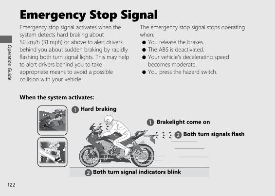
When the system activates:
Emergency Stop SignalEmergency stop signal activates when thesystem detects hard braking about50 km/h (31 mph) or above to alert driversbehind you about sudden braking by rapidlyflashing both turn signal lights. This may helpto alert drivers behind you to takeappropriate means to avoid a possiblecollision with your vehicle.
The emergency stop signal stops operatingwhen:● You release the brakes.● The ABS is deactivated.● Your vehicle's decelerating speed
becomes moderate.● You press the hazard switch.
20191113122725_32MKR8000_eng_BOOK Page 125 Wednesday, November 13 2019 12:40:27 JST
Operation Guide
122
Hard braking
Brakelight come on
Both turn signals flash
Both turn signal indicators blink
u The emergency stop signal is not a systemthat can prevent a possible rear-endcollision caused by your hard braking. It isalways recommended to avoid hard brakingunless it is absolutely necessary.
u The emergency stop signal does not activatewith the hazard switch pressed in.
u If the ABS stops working for a certain periodduring braking, the emergency stop signalmay not activate at all.
20191113122725_32MKR8000_eng_BOOK Page 126 Wednesday, November 13 2019 12:40:27 JST
Operation Guide
123
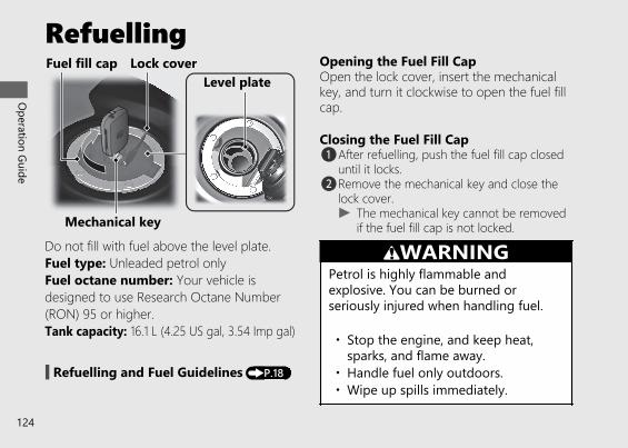
Refuelling
Do not fill with fuel above the level plate.Fuel type: Unleaded petrol onlyFuel octane number: Your vehicle isdesigned to use Research Octane Number(RON) 95 or higher.Tank capacity: 16.1 L (4.25 US gal, 3.54 Imp gal)
# Refuelling and Fuel Guidelines (P.18)
Opening the Fuel Fill CapOpen the lock cover, insert the mechanicalkey, and turn it clockwise to open the fuel fillcap.
Closing the Fuel Fill Capa After refuelling, push the fuel fill cap closed
until it locks.b Remove the mechanical key and close the
lock cover.u The mechanical key cannot be removed
if the fuel fill cap is not locked.
3WARNINGPetrol is highly flammable andexplosive. You can be burned orseriously injured when handling fuel.
• Stop the engine, and keep heat,sparks, and flame away.
• Handle fuel only outdoors.• Wipe up spills immediately.
20191113122725_32MKR8000_eng_BOOK Page 127 Wednesday, November 13 2019 12:40:27 JST
Operation Guide
124
Mechanical key
Level plateFuel fill cap Lock cover
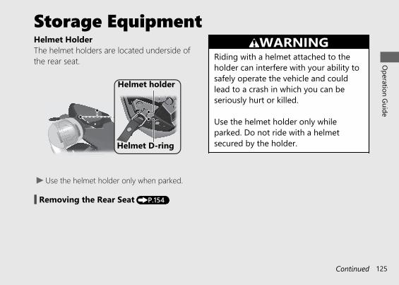
Storage EquipmentHelmet HolderThe helmet holders are located underside ofthe rear seat.
u Use the helmet holder only when parked.
# Removing the Rear Seat (P.154)
3WARNINGRiding with a helmet attached to theholder can interfere with your ability tosafely operate the vehicle and couldlead to a crash in which you can beseriously hurt or killed.
Use the helmet holder only whileparked. Do not ride with a helmetsecured by the holder.
20191113122725_32MKR8000_eng_BOOK Page 128 Wednesday, November 13 2019 12:40:27 JST
Operation Guide
125Continued
Helmet holder
Helmet D-ring
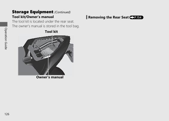
Tool kit/Owner's manualThe tool kit is located under the rear seat.The owner's manual is stored in the tool bag.
# Removing the Rear Seat (P.154)
20191113122725_32MKR8000_eng_BOOK Page 129 Wednesday, November 13 2019 12:40:27 JST
Operation Guide
126
Storage Equipment (Continued)
Tool kit
Owner's manual
Importance of Maintenance .........................P. 128Maintenance Schedule...................................P. 129Maintenance Fundamentals .........................P. 134Tool.....................................................................P. 149Removing & Installing Body Components ...................................................P. 150
Battery.................................................................. P. 150Clip........................................................................ P. 152Front Seat............................................................ P. 153Rear Seat ............................................................. P. 154Under Cowl......................................................... P. 155
Engine Oil ..........................................................P. 157Coolant ..............................................................P. 161Brakes.................................................................P. 164
Side Stand .........................................................P. 167Drive Chain .......................................................P. 168Clutch .................................................................P. 172Throttle ..............................................................P. 175Other Adjustments..........................................P. 176
Adjusting the Headlight Aim.......................... P. 176Adjusting the Brake Lever ............................... P. 177Adjusting the Front Suspension .................... P. 179Adjusting the Rear Suspension...................... P. 182Adjusting the ÖHLINS Smart EC System..... P. 185
Other Replacement.........................................P. 193Replacing the Honda SMART Key Battery .. P. 193
20191113122725_32MKR8000_eng_BOOK Page 130 Wednesday, November 13 2019 12:40:27 JST
Please read “Importance of Maintenance” and “Maintenance Fundamentals” carefullybefore attempting any maintenance. Refer to “Specifications” for service data.
Maintenance
Importance of Maintenance
Importance of MaintenanceKeeping your vehicle well-maintained isabsolutely essential to your safety and toprotect your investment, obtain maximumperformance, avoid breakdowns, and reduce airpollution. Maintenance is the owner'sresponsibility. Be sure to inspect your vehiclebefore each ride, and perform the periodicchecks specified in the Maintenance Schedule.2 P. 129
3WARNINGImproperly maintaining your vehicle orfailing to correct a problem before youride can cause a crash in which you canbe seriously hurt or killed.
Always follow the inspection andmaintenance recommendations andschedules in this owner's manual.
Maintenance SafetyAlways read the maintenance instructionsbefore you begin each task, and make sure thatyou have the tools, parts, and skills required.We cannot warn you of every conceivablehazard that can arise in performingmaintenance. Only you can decide whether ornot you should perform a given task.
Follow these guidelines when performingmaintenance.● Stop the engine and keep the electrical
system off.● Place your vehicle on a firm, level surface
using the side stand or a maintenance standto provide support.
● Allow the engine, muffler, brakes, and otherhigh-temperature parts to cool beforeservicing as you can get burned.
● Run the engine only when instructed, anddo so in a well-ventilated area.
20191113122725_32MKR8000_eng_BOOK Page 131 Wednesday, November 13 2019 12:40:27 JST
Maintenance
128
Maintenance ScheduleThe maintenance schedule specifies themaintenance requirements necessary to ensuresafe, dependable performance, and properemission control.
Maintenance work should be performed inaccordance with Honda's standards andspecifications by properly trained and equippedtechnicians. Your dealer meets all of theserequirements. Keep an accurate record ofmaintenance to help ensure that your vehicle isproperly maintained.Make sure that whomever performs themaintenance completes this record.
All scheduled maintenance is considered anormal owner operating cost and will becharged to you by your dealer. Retain allreceipts. If you sell the vehicle, these receiptsshould be transferred with the vehicle to thenew owner.
Honda recommends that your dealer shouldroad test your vehicle after each periodicmaintenance is carried out.
20191113122725_32MKR8000_eng_BOOK Page 132 Wednesday, November 13 2019 12:40:27 JST
Maintenance
129Continued
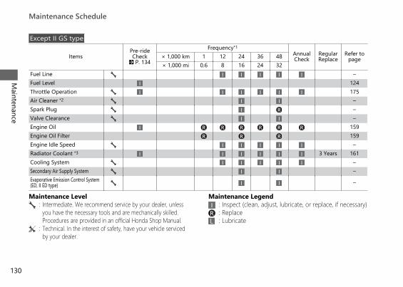
Except II GS type
ItemsPre-rideCheck
2 P. 134
Frequency*1AnnualCheck
RegularReplace
Refer topage× 1,000 km 1 12 24 36 48
× 1,000 mi 0.6 8 16 24 32Fuel Line –Fuel Level 124Throttle Operation 175Air Cleaner *2 –Spark Plug –Valve Clearance –Engine Oil 159Engine Oil Filter 159Engine Idle Speed –Radiator Coolant *3 3 Years 161Cooling System –Secondary Air Supply System –Evaporative Emission Control System (ED, II ED type) –
Maintenance Level Maintenance Legend: Intermediate. We recommend service by your dealer, unless
you have the necessary tools and are mechanically skilled.Procedures are provided in an official Honda Shop Manual.
:::
Inspect (clean, adjust, lubricate, or replace, if necessary)ReplaceLubricate
: Technical. In the interest of safety, have your vehicle servicedby your dealer.
20191113122725_32MKR8000_eng_BOOK Page 133 Wednesday, November 13 2019 12:40:27 JST
Maintenance Schedule
Maintenance
130
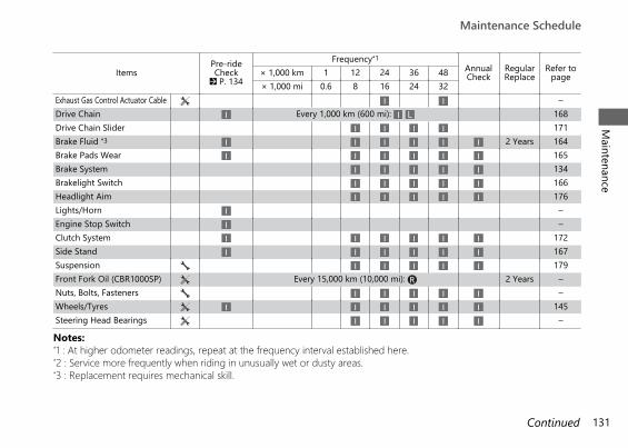
ItemsPre-rideCheck
2 P. 134
Frequency*1AnnualCheck
RegularReplace
Refer topage× 1,000 km 1 12 24 36 48
× 1,000 mi 0.6 8 16 24 32Exhaust Gas Control Actuator Cable –Drive Chain Every 1,000 km (600 mi): 168Drive Chain Slider 171Brake Fluid *3 2 Years 164Brake Pads Wear 165Brake System 134Brakelight Switch 166Headlight Aim 176Lights/Horn –Engine Stop Switch –Clutch System 172Side Stand 167Suspension 179Front Fork Oil (CBR1000SP) Every 15,000 km (10,000 mi): 2 Years –Nuts, Bolts, Fasteners –Wheels/Tyres 145Steering Head Bearings –
Notes:*1 : At higher odometer readings, repeat at the frequency interval established here.*2 : Service more frequently when riding in unusually wet or dusty areas.*3 : Replacement requires mechanical skill.
20191113122725_32MKR8000_eng_BOOK Page 134 Wednesday, November 13 2019 12:40:27 JST
Maintenance ScheduleM
aintenance
131Continued
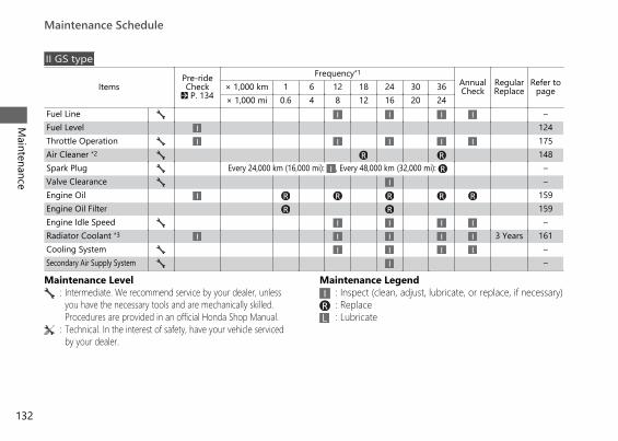
II GS type
ItemsPre-rideCheck
2 P. 134
Frequency*1AnnualCheck
RegularReplace
Refer topage× 1,000 km 1 6 12 18 24 30 36
× 1,000 mi 0.6 4 8 12 16 20 24Fuel Line –Fuel Level 124Throttle Operation 175Air Cleaner *2 148Spark Plug Every 24,000 km (16,000 mi): , Every 48,000 km (32,000 mi): –Valve Clearance –Engine Oil 159Engine Oil Filter 159Engine Idle Speed –Radiator Coolant *3 3 Years 161Cooling System –Secondary Air Supply System –
Maintenance Level Maintenance Legend: Intermediate. We recommend service by your dealer, unless
you have the necessary tools and are mechanically skilled.Procedures are provided in an official Honda Shop Manual.
:::
Inspect (clean, adjust, lubricate, or replace, if necessary)ReplaceLubricate
: Technical. In the interest of safety, have your vehicle servicedby your dealer.
20191113122725_32MKR8000_eng_BOOK Page 135 Wednesday, November 13 2019 12:40:27 JST
Maintenance Schedule
Maintenance
132
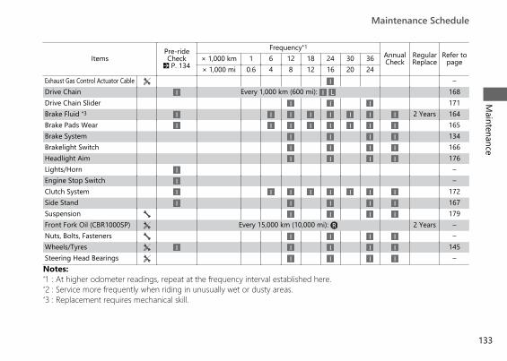
ItemsPre-rideCheck
2 P. 134
Frequency*1AnnualCheck
RegularReplace
Refer topage× 1,000 km 1 6 12 18 24 30 36
× 1,000 mi 0.6 4 8 12 16 20 24Exhaust Gas Control Actuator Cable –Drive Chain Every 1,000 km (600 mi): 168Drive Chain Slider 171Brake Fluid *3 2 Years 164Brake Pads Wear 165Brake System 134Brakelight Switch 166Headlight Aim 176Lights/Horn –Engine Stop Switch –Clutch System 172Side Stand 167Suspension 179Front Fork Oil (CBR1000SP) Every 15,000 km (10,000 mi): 2 Years –Nuts, Bolts, Fasteners –Wheels/Tyres 145Steering Head Bearings –Notes:*1 : At higher odometer readings, repeat at the frequency interval established here.*2 : Service more frequently when riding in unusually wet or dusty areas.*3 : Replacement requires mechanical skill.
20191113122725_32MKR8000_eng_BOOK Page 136 Wednesday, November 13 2019 12:40:27 JST
Maintenance ScheduleM
aintenance
133

Maintenance Fundamentals
Pre-ride InspectionTo ensure safety, it is your responsibility toperform a pre-ride inspection and make surethat any problem you find is corrected. A pre-ride inspection is a must, not only for safety, butbecause having a breakdown, or even a flattyre, can be a major inconvenience.
Check the following items before you get onyour vehicle:● Fuel level - Fill fuel tank when necessary.
2 P. 124● Throttle - Check for smooth opening and
full closing in all steering positions. 2 P. 175● Engine oil level - Add engine oil if necessary.
Check for leaks. 2 P. 157● Coolant level - Add coolant if required.
Check for leaks. 2 P. 161
● Drive chain - Check condition and slack,adjust and lubricate if necessary. 2 P. 168
● Brakes - Check operation;Front and Rear: check brake fluid level andpads wear. 2 P. 164, 2 P. 165
● Lights and horn - Check that lights,indicators and horn function properly.
● Engine stop switch - Check for properfunction. 2 P. 100
● Clutch - Check operation;Adjust freeplay if necessary. 2 P. 172
● Side stand ignition cut-off system - Checkfor proper function. 2 P. 167
● Wheels and tyres - Check condition, airpressure and adjust if necessary. 2 P. 145
20191113122725_32MKR8000_eng_BOOK Page 137 Wednesday, November 13 2019 12:40:27 JST
Maintenance
134

Replacing PartsAlways use Honda Genuine Parts or theirequivalents to ensure reliability and safety.Except II GS typeWhen ordering coloured components, specifythe model name, colour, and code mentionedon the colour label.The colour label is attached on the under therear seat.
3WARNINGInstalling non-Honda parts may makeyour vehicle unsafe and cause a crash inwhich you can be seriously hurt orkilled.
Always use Honda Genuine Parts orequivalents that have been designedand approved for your vehicle.
20191113122725_32MKR8000_eng_BOOK Page 138 Wednesday, November 13 2019 12:40:27 JST
Maintenance FundamentalsM
aintenance
135
Colour label
BatteryCBR1000SPYour vehicle has a lithium-ion (li-ion) battery.2 P. 138CBR1000STYour vehicle has a maintenance-free typebattery. You do not have to check the batteryelectrolyte level or add distilled water. Clean thebattery terminals if they become dirty orcorroded.Do not remove the battery cap seals. There isno need to remove the cap when charging.
NOTICEYour battery is a maintenance-free type and canbe permanently damaged if the cap strip isremoved.
This symbol on the battery means thatthis product must not be treated ashousehold waste.
NOTICEAn improperly disposed of battery can beharmful to the environment and human health.Always confirm local regulations for properbattery disposal instruction.
20191113122725_32MKR8000_eng_BOOK Page 139 Wednesday, November 13 2019 12:40:27 JST
Maintenance Fundamentals
Maintenance
136
Continued
# What to do in an emergencyIf any of the following occur, immediately seeyour doctor.● Electrolyte splashes into your eyes:
u Wash your eyes repeatedly with coolwater for at least 15 minutes. Using waterunder pressure can damage your eyes.
● Electrolyte splashes onto your skin:u Remove affected clothing and wash your
skin thoroughly using water.● Electrolyte splashes into your mouth:
u Rinse mouth thoroughly with water, anddo not swallow.
3WARNINGThe battery gives off explosivehydrogen gas during normal operation.
A spark or flame can cause the batteryto explode with enough force to kill orseriously hurt you.
Wear protective clothing and a faceshield, or have a skilled mechanic dothe battery servicing.
# Cleaning the Battery Terminals1. Remove the battery. 2 P. 1502. If the terminals are starting to corrode and
are coated with a white substance, washwith warm water and wipe clean.
20191113122725_32MKR8000_eng_BOOK Page 140 Wednesday, November 13 2019 12:40:27 JST
Maintenance FundamentalsM
aintenance
137
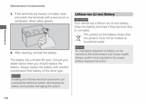
3. If the terminals are heavily corroded, cleanand polish the terminals with a wire brush orsandpaper. Wear safety glasses.
4. After cleaning, reinstall the battery.
The battery has a limited life span. Consult yourdealer about when you should replace thebattery. Always replace the battery with anothermaintenance-free battery of the same type.
NOTICEInstalling non-Honda electrical accessories canoverload the electrical system, discharging thebattery and possibly damaging the system.
Lithium-Ion (Li-Ion) BatteryCBR1000SPYour vehicle has a lithium-ion (li-ion) battery.Clean the battery terminals if they become dirtyor corroded.
This symbol on the battery means thatthis product must not be treated ashousehold waste.
NOTICEAn improperly disposed of battery can beharmful to the environment and human health.Always confirm local regulations for properbattery disposal instruction.
20191113122725_32MKR8000_eng_BOOK Page 141 Wednesday, November 13 2019 12:40:27 JST
Maintenance Fundamentals
Maintenance
138

Continued
# What to do in an emergencyIf any of the following occurs, immediately seeyour doctor.● Electrolyte splashes into your eyes:
u Wash your eyes repeatedly with coolwater for at 15 minutes. Using waterunder pressure can damage your eyes.
● Electrolyte splashes onto your skin:u Remove affected clothing and wash your
skin thoroughly using water.● Electrolyte splashes into your mouth
u Rinse mouth thoroughly with water, anddo not swallow.
3WARNINGThe battery contains flammable organicsolvent as electrolyte.
You can be burned or seriously injuredif the battery is handled improperly.
● Keep the battery away from heat,sparks, and flame.
● Keep the battery out of the reach ofchildren.
● Do not disassemble or modify thebattery or battery terminals.
● Do not short-circuit the battery withmetal tools or other metal objects.
● Do not subject the battery toimpacts.
20191113122725_32MKR8000_eng_BOOK Page 142 Wednesday, November 13 2019 12:40:27 JST
Maintenance FundamentalsM
aintenance
139
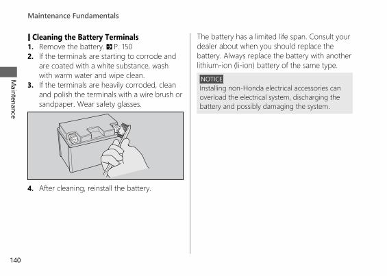
# Cleaning the Battery Terminals1. Remove the battery. 2 P. 1502. If the terminals are starting to corrode and
are coated with a white substance, washwith warm water and wipe clean.
3. If the terminals are heavily corroded, cleanand polish the terminals with a wire brush orsandpaper. Wear safety glasses.
4. After cleaning, reinstall the battery.
The battery has a limited life span. Consult yourdealer about when you should replace thebattery. Always replace the battery with anotherlithium-ion (li-ion) battery of the same type.
NOTICEInstalling non-Honda electrical accessories canoverload the electrical system, discharging thebattery and possibly damaging the system.
20191113122725_32MKR8000_eng_BOOK Page 143 Wednesday, November 13 2019 12:40:27 JST
Maintenance Fundamentals
Maintenance
140
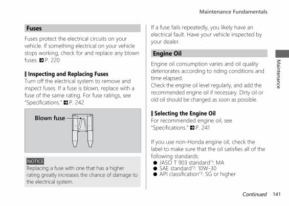
Continued
FusesFuses protect the electrical circuits on yourvehicle. If something electrical on your vehiclestops working, check for and replace any blownfuses. 2 P. 220
# Inspecting and Replacing FusesTurn off the electrical system to remove andinspect fuses. If a fuse is blown, replace with afuse of the same rating. For fuse ratings, see“Specifications.” 2 P. 242
NOTICEReplacing a fuse with one that has a higherrating greatly increases the chance of damage tothe electrical system.
If a fuse fails repeatedly, you likely have anelectrical fault. Have your vehicle inspected byyour dealer.
Engine OilEngine oil consumption varies and oil qualitydeteriorates according to riding conditions andtime elapsed.Check the engine oil level regularly, and add therecommended engine oil if necessary. Dirty oil orold oil should be changed as soon as possible.
# Selecting the Engine OilFor recommended engine oil, see“Specifications.” 2 P. 241
If you use non-Honda engine oil, check thelabel to make sure that the oil satisfies all of thefollowing standards:● JASO T 903 standard*1: MA● SAE standard*2: 10W-30● API classification*3: SG or higher
20191113122725_32MKR8000_eng_BOOK Page 144 Wednesday, November 13 2019 12:40:27 JST
Maintenance FundamentalsM
aintenance
141
Blown fuse
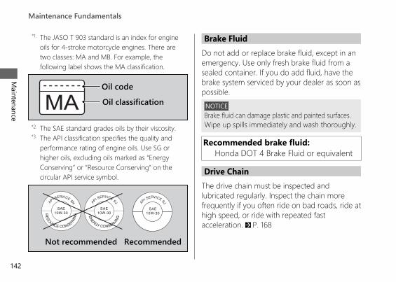
*1. The JASO T 903 standard is an index for engineoils for 4-stroke motorcycle engines. There aretwo classes: MA and MB. For example, thefollowing label shows the MA classification.
*2. The SAE standard grades oils by their viscosity.*3. The API classification specifies the quality and
performance rating of engine oils. Use SG orhigher oils, excluding oils marked as “EnergyConserving” or “Resource Conserving” on thecircular API service symbol.
Brake FluidDo not add or replace brake fluid, except in anemergency. Use only fresh brake fluid from asealed container. If you do add fluid, have thebrake system serviced by your dealer as soon aspossible.
NOTICEBrake fluid can damage plastic and painted surfaces.Wipe up spills immediately and wash thoroughly.
Recommended brake fluid:Honda DOT 4 Brake Fluid or equivalent
Drive ChainThe drive chain must be inspected andlubricated regularly. Inspect the chain morefrequently if you often ride on bad roads, ride athigh speed, or ride with repeated fastacceleration. 2 P. 168
20191113122725_32MKR8000_eng_BOOK Page 145 Wednesday, November 13 2019 12:40:27 JST
Maintenance Fundamentals
Maintenance
142
Oil codeOil classification
Not recommended Recommended
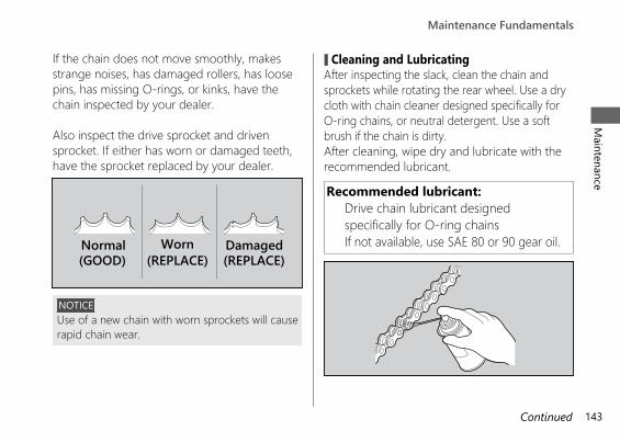
Continued
If the chain does not move smoothly, makesstrange noises, has damaged rollers, has loosepins, has missing O-rings, or kinks, have thechain inspected by your dealer.
Also inspect the drive sprocket and drivensprocket. If either has worn or damaged teeth,have the sprocket replaced by your dealer.
NOTICEUse of a new chain with worn sprockets will causerapid chain wear.
# Cleaning and LubricatingAfter inspecting the slack, clean the chain andsprockets while rotating the rear wheel. Use a drycloth with chain cleaner designed specifically forO-ring chains, or neutral detergent. Use a softbrush if the chain is dirty.After cleaning, wipe dry and lubricate with therecommended lubricant.
Recommended lubricant:Drive chain lubricant designedspecifically for O-ring chainsIf not available, use SAE 80 or 90 gear oil.
20191113122725_32MKR8000_eng_BOOK Page 146 Wednesday, November 13 2019 12:40:27 JST
Maintenance FundamentalsM
aintenance
143
Normal(GOOD)
Worn(REPLACE)
Damaged(REPLACE)
Do not use a steam cleaner, a high pressurecleaner, a wire brush, volatile solvent such aspetrol and benzene, abrasive cleaner, chaincleaner or lubricant NOT designed specificallyfor O-ring chains as these can damage therubber O-ring seals.Avoid getting lubricant on the brakes or tyres.Avoid applying excess chain lubricant to preventspray onto your clothes and the vehicle.
Recommended CoolantIndia, Nepal, Hong Kong, MacaoUse only genuine HONDA PRE-MIX COOLANTwithout diluting with water. Genuine HONDAPRE-MIX COOLANT is excellent at preventingcorrosion and overheating.The coolant should be inspected and replacedproperly by following the maintenanceschedule. 2 P. 129
Except India, Nepal, Hong Kong, MacaoPro Honda HP Coolant is a pre-mixed solutionof antifreeze and distilled water.
Concentration:50% antifreeze and 50% distilled water
A concentration of antifreeze below 40% willnot provide proper corrosion and coldtemperature protection.A concentration of up to 60% will provide betterprotection in colder climates.
NOTICEUsing coolant not specified for aluminium enginesor tap/mineral water can cause corrosion.
20191113122725_32MKR8000_eng_BOOK Page 147 Wednesday, November 13 2019 12:40:27 JST
Maintenance Fundamentals
Maintenance
144
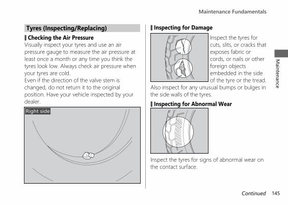
Tyres (Inspecting/Replacing)# Checking the Air PressureVisually inspect your tyres and use an airpressure gauge to measure the air pressure atleast once a month or any time you think thetyres look low. Always check air pressure whenyour tyres are cold.Even if the direction of the valve stem ischanged, do not return it to the originalposition. Have your vehicle inspected by yourdealer.
# Inspecting for DamageInspect the tyres forcuts, slits, or cracks thatexposes fabric orcords, or nails or otherforeign objectsembedded in the sideof the tyre or the tread.
Also inspect for any unusual bumps or bulges inthe side walls of the tyres.# Inspecting for Abnormal Wear
Inspect the tyres for signs of abnormal wear onthe contact surface.
20191113122725_32MKR8000_eng_BOOK Page 148 Wednesday, November 13 2019 12:40:27 JST
Maintenance FundamentalsM
aintenance
145Continued
Right side
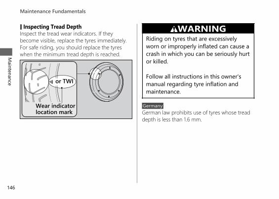
# Inspecting Tread DepthInspect the tread wear indicators. If theybecome visible, replace the tyres immediately.For safe riding, you should replace the tyreswhen the minimum tread depth is reached.
3WARNINGRiding on tyres that are excessivelyworn or improperly inflated can cause acrash in which you can be seriously hurtor killed.
Follow all instructions in this owner'smanual regarding tyre inflation andmaintenance.
GermanyGerman law prohibits use of tyres whose treaddepth is less than 1.6 mm.
20191113122725_32MKR8000_eng_BOOK Page 149 Wednesday, November 13 2019 12:40:27 JST
Maintenance Fundamentals
Maintenance
146
Wear indicatorlocation mark
or TWI
Have your tyres replaced by your dealer.For recommended tyres, air pressure andminimum tread depth, see “Specifications.”2 P. 241Follow these guidelines whenever you replacetyres.● Use the recommended tyres or equivalents
of the same size, construction, speed rating,and load range.
● Have the wheel balanced with HondaGenuine balance weights or equivalent afterthe tyre is installed.
● Do not install a tube inside a tubeless tyreon this vehicle. Excessive heat build-up cancause the tube to burst.
● Use only tubeless tyres on this vehicle.The rims are designed for tubeless tyres,and during hard acceleration or braking, atube-type tyre could slip on the rim andcause the tyre to rapidly deflate.
3WARNINGInstalling improper tyres on yourvehicle can adversely affect handlingand stability, and can cause a crash inwhich you can be seriously hurt orkilled.
Always use the size and type of tyresrecommended in this owner's manual.
20191113122725_32MKR8000_eng_BOOK Page 150 Wednesday, November 13 2019 12:40:27 JST
Maintenance FundamentalsM
aintenance
147
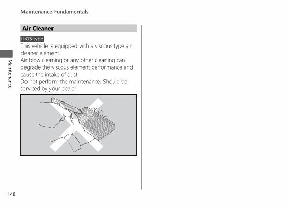
Air CleanerII GS typeThis vehicle is equipped with a viscous type aircleaner element.Air blow cleaning or any other cleaning candegrade the viscous element performance andcause the intake of dust.Do not perform the maintenance. Should beserviced by your dealer.
20191113122725_32MKR8000_eng_BOOK Page 151 Wednesday, November 13 2019 12:40:27 JST
Maintenance Fundamentals
Maintenance
148
ToolThe tool kit is stored under the rear seat.2 P. 154
You can perform some roadside repairs, minoradjustments and parts replacement with theprovided tools.
● 3 mm Hex wrench● 5 mm Hex wrench
20191113122725_32MKR8000_eng_BOOK Page 152 Wednesday, November 13 2019 12:40:27 JST
Maintenance
149
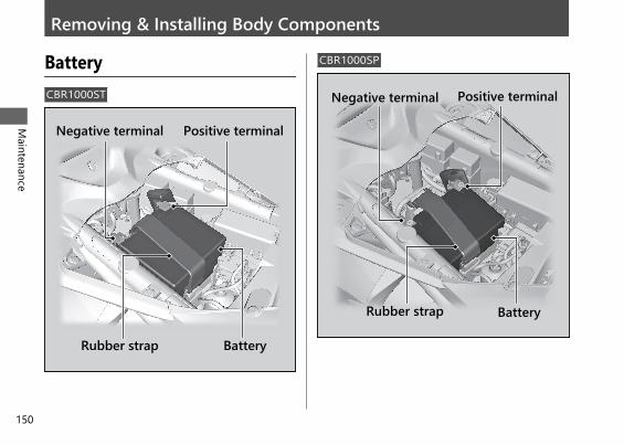
Removing & Installing Body Components
BatteryCBR1000ST
CBR1000SP
20191113122725_32MKR8000_eng_BOOK Page 153 Wednesday, November 13 2019 12:40:27 JST
Maintenance
150
Rubber strap
Positive terminalNegative terminal
Battery
Rubber strap
Positive terminalNegative terminal
Battery
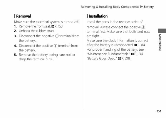
# RemovalMake sure the electrical system is turned off.1. Remove the front seat. 2 P. 1532. Unhook the rubber strap.3. Disconnect the negative - terminal from
the battery.4. Disconnect the positive + terminal from
the battery.5. Remove the battery taking care not to
drop the terminal nuts.
# InstallationInstall the parts in the reverse order ofremoval. Always connect the positive +terminal first. Make sure that bolts and nutsare tight.Make sure the clock information is correctafter the battery is reconnected. 2 P. 84For proper handling of the battery, see“Maintenance Fundamentals.” 2 P. 134“Battery Goes Dead.” 2 P. 218
20191113122725_32MKR8000_eng_BOOK Page 154 Wednesday, November 13 2019 12:40:27 JST
Removing & Installing Body Components u BatteryM
aintenance
151
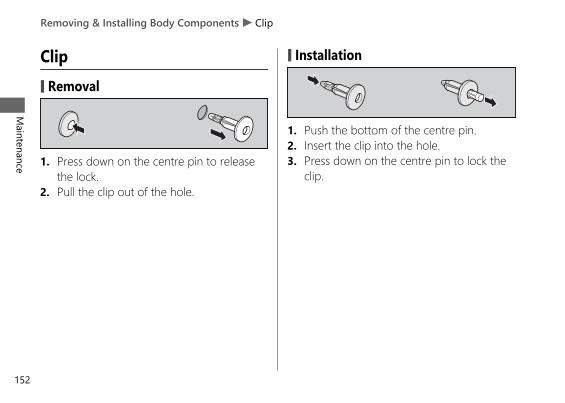
Clip# Removal
1. Press down on the centre pin to releasethe lock.
2. Pull the clip out of the hole.
# Installation
1. Push the bottom of the centre pin.2. Insert the clip into the hole.3. Press down on the centre pin to lock the
clip.
20191113122725_32MKR8000_eng_BOOK Page 155 Wednesday, November 13 2019 12:40:27 JST
Removing & Installing Body Components u Clip
Maintenance
152
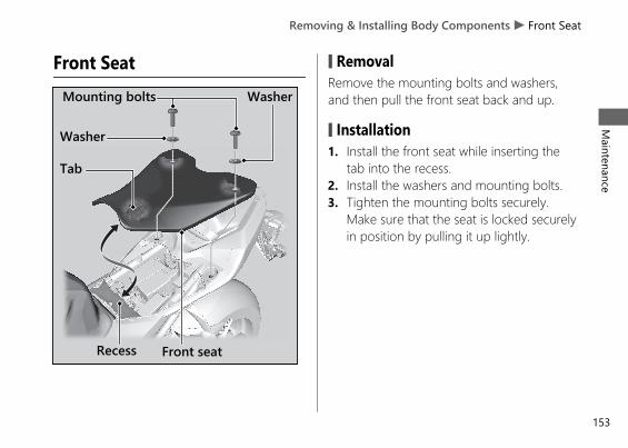
Front Seat # RemovalRemove the mounting bolts and washers,and then pull the front seat back and up.
# Installation1. Install the front seat while inserting the
tab into the recess.2. Install the washers and mounting bolts.3. Tighten the mounting bolts securely.
Make sure that the seat is locked securelyin position by pulling it up lightly.
20191113122725_32MKR8000_eng_BOOK Page 156 Wednesday, November 13 2019 12:40:27 JST
Removing & Installing Body Components u Front SeatM
aintenance
153
Tab
Front seatRecess
Mounting bolts
Washer
Washer
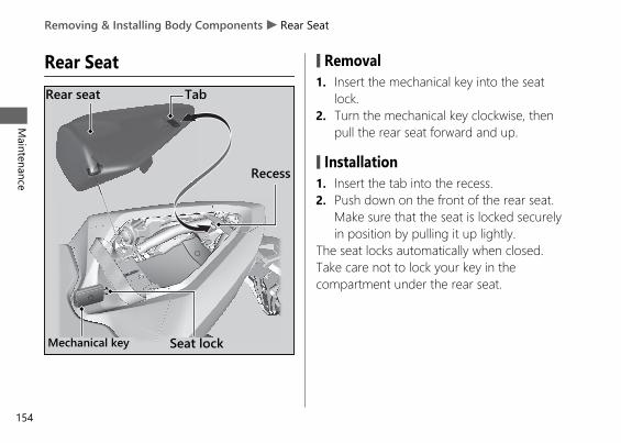
Rear Seat # Removal1. Insert the mechanical key into the seat
lock.2. Turn the mechanical key clockwise, then
pull the rear seat forward and up.
# Installation1. Insert the tab into the recess.2. Push down on the front of the rear seat.
Make sure that the seat is locked securelyin position by pulling it up lightly.
The seat locks automatically when closed.Take care not to lock your key in thecompartment under the rear seat.
20191113122725_32MKR8000_eng_BOOK Page 157 Wednesday, November 13 2019 12:40:27 JST
Removing & Installing Body Components u Rear Seat
Maintenance
154
Rear seat
Seat lockMechanical key
Tab
Recess
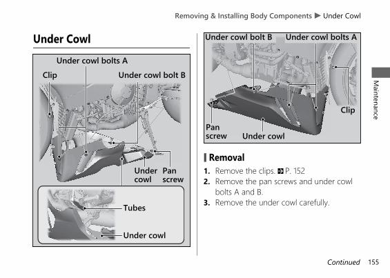
Under Cowl
# Removal1. Remove the clips. 2 P. 1522. Remove the pan screws and under cowl
bolts A and B.3. Remove the under cowl carefully.
20191113122725_32MKR8000_eng_BOOK Page 158 Wednesday, November 13 2019 12:40:27 JST
Removing & Installing Body Components u Under CowlM
aintenance
155Continued
Panscrew
Undercowl
Clip
Tubes
Under cowl bolts AUnder cowl bolt B
Under cowl
Panscrew
Under cowl bolt B Under cowl bolts A
Clip
Under cowl
# Installation1. Install the under cowl using reverse of the
removal procedure.2. Route the tubes through the opening of
the under cowl.3. Install and tighten the under cowl bolts A
and B securely.
Torque: 1.0 N·m (0.1 kgf·m, 0.7 lbf·ft)
4. Install and tighten the pan screwssecurely.
Torque: 10 N·m (1.0 kgf·m, 7 lbf·ft)
5. Install the clips.
20191113122725_32MKR8000_eng_BOOK Page 159 Wednesday, November 13 2019 12:40:27 JST
Removing & Installing Body Components u Under Cowl
Maintenance
156
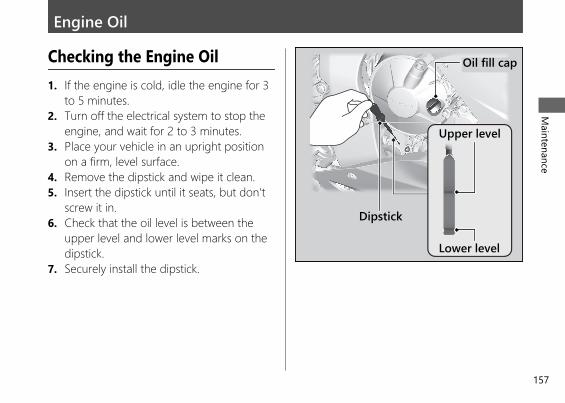
Engine Oil
Checking the Engine Oil1. If the engine is cold, idle the engine for 3
to 5 minutes.2. Turn off the electrical system to stop the
engine, and wait for 2 to 3 minutes.3. Place your vehicle in an upright position
on a firm, level surface.4. Remove the dipstick and wipe it clean.5. Insert the dipstick until it seats, but don't
screw it in.6. Check that the oil level is between the
upper level and lower level marks on thedipstick.
7. Securely install the dipstick.
20191113122725_32MKR8000_eng_BOOK Page 160 Wednesday, November 13 2019 12:40:27 JST
Maintenance
157
Oil fill cap
Upper level
Lower level
Dipstick
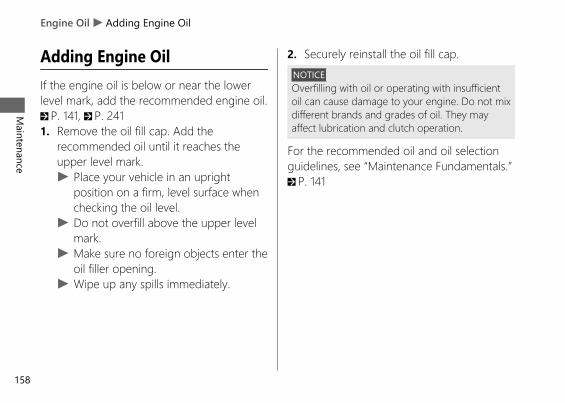
Adding Engine OilIf the engine oil is below or near the lowerlevel mark, add the recommended engine oil.2 P. 141, 2 P. 2411. Remove the oil fill cap. Add the
recommended oil until it reaches theupper level mark.u Place your vehicle in an upright
position on a firm, level surface whenchecking the oil level.
u Do not overfill above the upper levelmark.
u Make sure no foreign objects enter theoil filler opening.
u Wipe up any spills immediately.
2. Securely reinstall the oil fill cap.NOTICEOverfilling with oil or operating with insufficientoil can cause damage to your engine. Do not mixdifferent brands and grades of oil. They mayaffect lubrication and clutch operation.
For the recommended oil and oil selectionguidelines, see “Maintenance Fundamentals.”2 P. 141
20191113122725_32MKR8000_eng_BOOK Page 161 Wednesday, November 13 2019 12:40:27 JST
Engine Oil u Adding Engine Oil
Maintenance
158
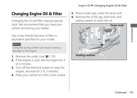
Changing Engine Oil & FilterChanging the oil and filter requires specialtools. We recommend that you have yourvehicle serviced by your dealer.
Use a new Honda Genuine oil filter orequivalent specified for your model.
NOTICEUsing the wrong oil filter can result in seriousdamage to the engine.
1. Remove the under cowl. 2 P. 1552. If the engine is cold, idle the engine for 3
to 5 minutes.3. Turn off the electrical system to stop the
engine, and wait for 2 to 3 minutes.4. Place your vehicle on a firm, level surface.
5. Place a drain pan under the drain bolt.6. Remove the oil fill cap, drain bolt, and
sealing washer to drain the oil.
20191113122725_32MKR8000_eng_BOOK Page 162 Wednesday, November 13 2019 12:40:27 JST
Engine Oil u Changing Engine Oil & FilterM
aintenance
159Continued
Sealing washer
Drain bolt
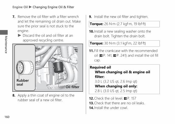
7. Remove the oil filter with a filter wrenchand let the remaining oil drain out. Makesure the prior seal is not stuck to theengine.u Discard the oil and oil filter at an
approved recycling centre.
8. Apply a thin coat of engine oil to therubber seal of a new oil filter.
9. Install the new oil filter and tighten.
Torque: 26 N·m (2.7 kgf·m, 19 lbf·ft)
10. Install a new sealing washer onto thedrain bolt. Tighten the drain bolt.
Torque: 30 N·m (3.1 kgf·m, 22 lbf·ft)
11.Fill the crankcase with the recommendedoil (2 P. 141, 2 P. 241) and install the oil fillcap.
Required oilWhen changing oil & engine oilfilter:3.0 L (3.2 US qt, 2.6 Imp qt)When changing oil only:2.8 L (3.0 US qt, 2.5 Imp qt)
12.Check the oil level. 2 P. 15713.Check that there are no oil leaks.14. Install the under cowl.
20191113122725_32MKR8000_eng_BOOK Page 163 Wednesday, November 13 2019 12:40:27 JST
Engine Oil u Changing Engine Oil & Filter
Maintenance
160
Rubberseal Oil filter
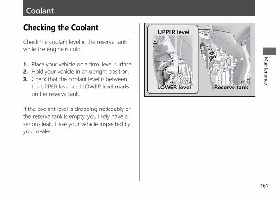
Coolant
Checking the CoolantCheck the coolant level in the reserve tankwhile the engine is cold.
1. Place your vehicle on a firm, level surface.2. Hold your vehicle in an upright position.3. Check that the coolant level is between
the UPPER level and LOWER level markson the reserve tank.
If the coolant level is dropping noticeably orthe reserve tank is empty, you likely have aserious leak. Have your vehicle inspected byyour dealer.
20191113122725_32MKR8000_eng_BOOK Page 164 Wednesday, November 13 2019 12:40:27 JST
Maintenance
161
UPPER level
LOWER level Reserve tank
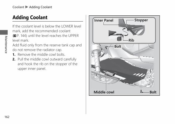
Adding CoolantIf the coolant level is below the LOWER levelmark, add the recommended coolant(2 P. 144) until the level reaches the UPPERlevel mark.Add fluid only from the reserve tank cap anddo not remove the radiator cap.1. Remove the middle cowl bolts.2. Pull the middle cowl outward carefully
and hook the rib on the stopper of theupper inner panel.
20191113122725_32MKR8000_eng_BOOK Page 165 Wednesday, November 13 2019 12:40:27 JST
Coolant u Adding Coolant
Maintenance
162
Middle cowl
Bolt
Bolt
Rib
StopperInner Panel
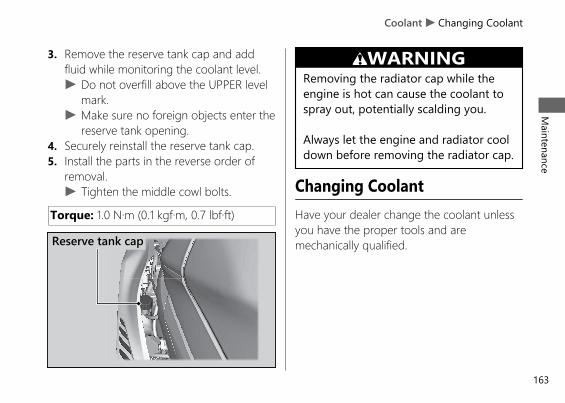
3. Remove the reserve tank cap and addfluid while monitoring the coolant level.u Do not overfill above the UPPER level
mark.u Make sure no foreign objects enter the
reserve tank opening.4. Securely reinstall the reserve tank cap.5. Install the parts in the reverse order of
removal.u Tighten the middle cowl bolts.
Torque: 1.0 N·m (0.1 kgf·m, 0.7 lbf·ft)
3WARNINGRemoving the radiator cap while theengine is hot can cause the coolant tospray out, potentially scalding you.
Always let the engine and radiator cooldown before removing the radiator cap.
Changing CoolantHave your dealer change the coolant unlessyou have the proper tools and aremechanically qualified.
20191113122725_32MKR8000_eng_BOOK Page 166 Wednesday, November 13 2019 12:40:27 JST
Coolant u Changing CoolantM
aintenance
163
Reserve tank cap
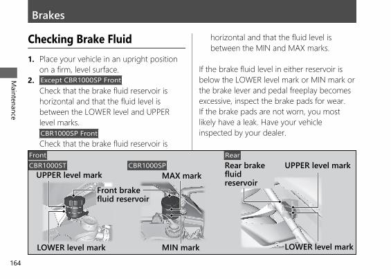
Brakes
Checking Brake Fluid1. Place your vehicle in an upright position
on a firm, level surface.2. Except CBR1000SP Front
Check that the brake fluid reservoir ishorizontal and that the fluid level isbetween the LOWER level and UPPERlevel marks.CBR1000SP FrontCheck that the brake fluid reservoir is
horizontal and that the fluid level isbetween the MIN and MAX marks.
If the brake fluid level in either reservoir isbelow the LOWER level mark or MIN mark orthe brake lever and pedal freeplay becomesexcessive, inspect the brake pads for wear.If the brake pads are not worn, you mostlikely have a leak. Have your vehicleinspected by your dealer.
20191113122725_32MKR8000_eng_BOOK Page 167 Wednesday, November 13 2019 12:40:27 JST
Maintenance
164
Front brakefluid reservoir
UPPER level mark
LOWER level mark
Rear brakefluidreservoir
Front RearUPPER level mark
LOWER level mark
CBR1000ST CBR1000SP
MIN mark
MAX mark
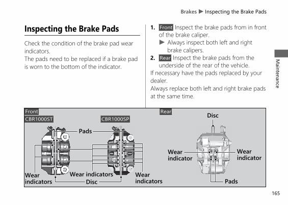
Inspecting the Brake PadsCheck the condition of the brake pad wearindicators.The pads need to be replaced if a brake padis worn to the bottom of the indicator.
1. Front Inspect the brake pads from in frontof the brake caliper.u Always inspect both left and right
brake calipers.2. Rear Inspect the brake pads from the
underside of the rear of the vehicle.If necessary have the pads replaced by yourdealer.Always replace both left and right brake padsat the same time.
20191113122725_32MKR8000_eng_BOOK Page 168 Wednesday, November 13 2019 12:40:27 JST
Brakes u Inspecting the Brake PadsM
aintenance
165
Front Rear
Pads
DiscWearindicators Pads
Wearindicator
Disc
Wear indicators
CBR1000ST CBR1000SP
Wearindicators
Wearindicator
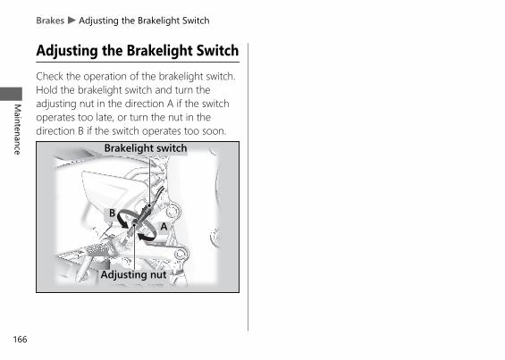
Adjusting the Brakelight SwitchCheck the operation of the brakelight switch.Hold the brakelight switch and turn theadjusting nut in the direction A if the switchoperates too late, or turn the nut in thedirection B if the switch operates too soon.
20191113122725_32MKR8000_eng_BOOK Page 169 Wednesday, November 13 2019 12:40:27 JST
Brakes u Adjusting the Brakelight Switch
Maintenance
166
Brakelight switch
Adjusting nut
BA
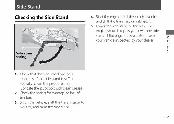
Side Stand
Checking the Side Stand
1. Check that the side stand operatessmoothly. If the side stand is stiff orsqueaky, clean the pivot area andlubricate the pivot bolt with clean grease.
2. Check the spring for damage or loss oftension.
3. Sit on the vehicle, shift the transmission toNeutral, and raise the side stand.
4. Start the engine, pull the clutch lever in,and shift the transmission into gear.
5. Lower the side stand all the way. Theengine should stop as you lower the sidestand. If the engine doesn't stop, haveyour vehicle inspected by your dealer.
20191113122725_32MKR8000_eng_BOOK Page 170 Wednesday, November 13 2019 12:40:27 JST
Maintenance
167
Side standspring
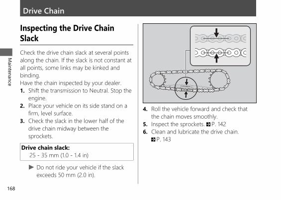
Drive Chain
Inspecting the Drive ChainSlackCheck the drive chain slack at several pointsalong the chain. If the slack is not constant atall points, some links may be kinked andbinding.Have the chain inspected by your dealer.1. Shift the transmission to Neutral. Stop the
engine.2. Place your vehicle on its side stand on a
firm, level surface.3. Check the slack in the lower half of the
drive chain midway between thesprockets.
Drive chain slack:25 - 35 mm (1.0 - 1.4 in)
u Do not ride your vehicle if the slackexceeds 50 mm (2.0 in).
4. Roll the vehicle forward and check thatthe chain moves smoothly.
5. Inspect the sprockets. 2 P. 1426. Clean and lubricate the drive chain.
2 P. 143
20191113122725_32MKR8000_eng_BOOK Page 171 Wednesday, November 13 2019 12:40:27 JST
Maintenance
168
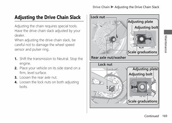
Adjusting the Drive Chain SlackAdjusting the chain requires special tools.Have the drive chain slack adjusted by yourdealer.When adjusting the drive chain slack, becareful not to damage the wheel speedsensor and pulser ring.
1. Shift the transmission to Neutral. Stop theengine.
2. Place your vehicle on its side stand on afirm, level surface.
3. Loosen the rear axle nut.4. Loosen the lock nuts on both adjusting
bolts.
20191113122725_32MKR8000_eng_BOOK Page 172 Wednesday, November 13 2019 12:40:27 JST
Drive Chain u Adjusting the Drive Chain SlackM
aintenance
169Continued
Lock nut
Adjusting bolt
Rear axle nut/washer
Adjusting plate
Scale graduations
Adjusting plate
Scale graduations
Lock nut
Adjusting bolt
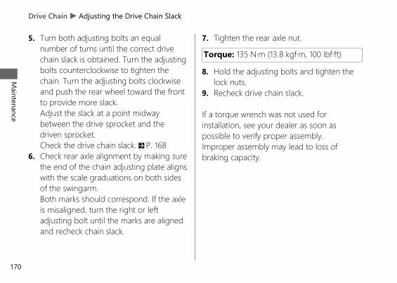
5. Turn both adjusting bolts an equalnumber of turns until the correct drivechain slack is obtained. Turn the adjustingbolts counterclockwise to tighten thechain. Turn the adjusting bolts clockwiseand push the rear wheel toward the frontto provide more slack.Adjust the slack at a point midwaybetween the drive sprocket and thedriven sprocket.Check the drive chain slack. 2 P. 168
6. Check rear axle alignment by making surethe end of the chain adjusting plate alignswith the scale graduations on both sidesof the swingarm.Both marks should correspond. If the axleis misaligned, turn the right or leftadjusting bolt until the marks are alignedand recheck chain slack.
7. Tighten the rear axle nut.
Torque: 135 N·m (13.8 kgf·m, 100 lbf·ft)
8. Hold the adjusting bolts and tighten thelock nuts.
9. Recheck drive chain slack.
If a torque wrench was not used forinstallation, see your dealer as soon aspossible to verify proper assembly.Improper assembly may lead to loss ofbraking capacity.
20191113122725_32MKR8000_eng_BOOK Page 173 Wednesday, November 13 2019 12:40:27 JST
Drive Chain u Adjusting the Drive Chain Slack
Maintenance
170
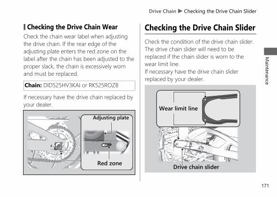
# Checking the Drive Chain WearCheck the chain wear label when adjustingthe drive chain. If the rear edge of theadjusting plate enters the red zone on thelabel after the chain has been adjusted to theproper slack, the chain is excessively wornand must be replaced.
Chain: DID525HV3KAI or RK525ROZ8
If necessary have the drive chain replaced byyour dealer.
Checking the Drive Chain SliderCheck the condition of the drive chain slider.The drive chain slider will need to bereplaced if the chain slider is worn to thewear limit line.If necessary have the drive chain sliderreplaced by your dealer.
20191113122725_32MKR8000_eng_BOOK Page 174 Wednesday, November 13 2019 12:40:27 JST
Drive Chain u Checking the Drive Chain SliderM
aintenance
171
Adjusting plate
Red zone
Wear limit line
Drive chain slider
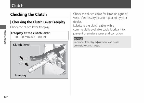
Clutch
Checking the Clutch# Checking the Clutch Lever FreeplayCheck the clutch lever freeplay.
Freeplay at the clutch lever:10 - 20 mm (0.4 - 0.8 in)
Check the clutch cable for kinks or signs ofwear. If necessary have it replaced by yourdealer.Lubricate the clutch cable with acommercially available cable lubricant toprevent premature wear and corrosion.NOTICEImproper freeplay adjustment can causepremature clutch wear.
20191113122725_32MKR8000_eng_BOOK Page 175 Wednesday, November 13 2019 12:40:27 JST
Maintenance
172
Clutch lever
Freeplay
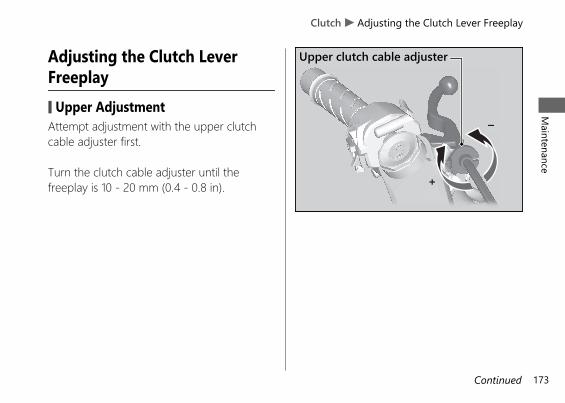
Adjusting the Clutch LeverFreeplay# Upper AdjustmentAttempt adjustment with the upper clutchcable adjuster first.
Turn the clutch cable adjuster until thefreeplay is 10 - 20 mm (0.4 - 0.8 in).
20191113122725_32MKR8000_eng_BOOK Page 176 Wednesday, November 13 2019 12:40:27 JST
Clutch u Adjusting the Clutch Lever FreeplayM
aintenance
173Continued
Upper clutch cable adjuster
–
+
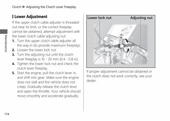
# Lower AdjustmentIf the upper clutch cable adjuster is threadedout near its limit, or the correct freeplaycannot be obtained, attempt adjustment withthe lower clutch cable adjusting nut.1. Turn the upper clutch cable adjuster all
the way in (to provide maximum freeplay).2. Loosen the lower lock nut.3. Turn the adjusting nut until the clutch
lever freeplay is 10 - 20 mm (0.4 - 0.8 in).4. Tighten the lower lock nut and check the
clutch lever freeplay.5. Start the engine, pull the clutch lever in,
and shift into gear. Make sure the enginedoes not stall and the vehicle does notcreep. Gradually release the clutch leverand open the throttle. Your vehicle shouldmove smoothly and accelerate gradually.
If proper adjustment cannot be obtained orthe clutch does not work correctly, see yourdealer.
20191113122725_32MKR8000_eng_BOOK Page 177 Wednesday, November 13 2019 12:40:27 JST
Clutch u Adjusting the Clutch Lever Freeplay
Maintenance
174
Lower lock nut Adjusting nut
+
–
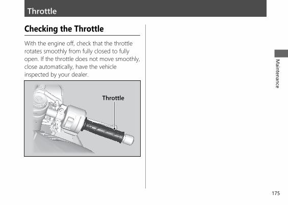
Throttle
Checking the ThrottleWith the engine off, check that the throttlerotates smoothly from fully closed to fullyopen. If the throttle does not move smoothly,close automatically, have the vehicleinspected by your dealer.
20191113122725_32MKR8000_eng_BOOK Page 178 Wednesday, November 13 2019 12:40:27 JST
Maintenance
175
Throttle
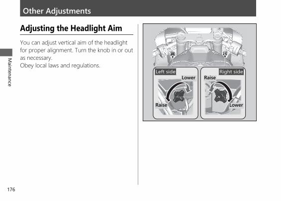
Other Adjustments
Adjusting the Headlight AimYou can adjust vertical aim of the headlightfor proper alignment. Turn the knob in or outas necessary.Obey local laws and regulations.
20191113122725_32MKR8000_eng_BOOK Page 179 Wednesday, November 13 2019 12:40:27 JST
Maintenance
176
Raise
LowerLeft side Right side
Raise
Lower
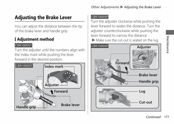
Adjusting the Brake LeverYou can adjust the distance between the tipof the brake lever and handle grip.
# Adjustment methodCBR1000STTurn the adjuster until the numbers align withthe index mark while pushing the leverforward in the desired position.
CBR1000SPTurn the adjuster clockwise while pushing thelever forward to widen the distance. Turn theadjuster counterclockwise while pushing thelever forward to narrow the distance.u Make sure the cut-out is seated on the lug.
20191113122725_32MKR8000_eng_BOOK Page 180 Wednesday, November 13 2019 12:40:27 JST
Other Adjustments u Adjusting the Brake LeverM
aintenance
177Continued
Index mark
AdjusterForward
Brake leverHandle grip
CBR1000ST
CBR1000SP
Brake leverHandle grip
Adjuster
Forward
Lug
Cut-out
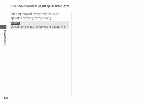
After adjustment, check that the leveroperates correctly before riding.NOTICEDo not turn the adjuster beyond its natural limit.
20191113122725_32MKR8000_eng_BOOK Page 181 Wednesday, November 13 2019 12:40:27 JST
Other Adjustments u Adjusting the Brake Lever
Maintenance
178
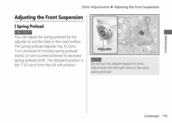
Adjusting the Front Suspension# Spring PreloadCBR1000STYou can adjust the spring preload by theadjuster to suit the load or the road surface.The spring preload adjuster has 15 turns.Turn clockwise to increase spring preload(hard), or turn counterclockwise to decreasespring preload (soft). The standard position isthe 7 1/2 turns from the full soft position.
NOTICEDo not turn the adjuster beyond its limits.Adjust both left and right forks to the samespring preload.
20191113122725_32MKR8000_eng_BOOK Page 182 Wednesday, November 13 2019 12:40:27 JST
Other Adjustments u Adjusting the Front SuspensionM
aintenance
179Continued
Adjuster
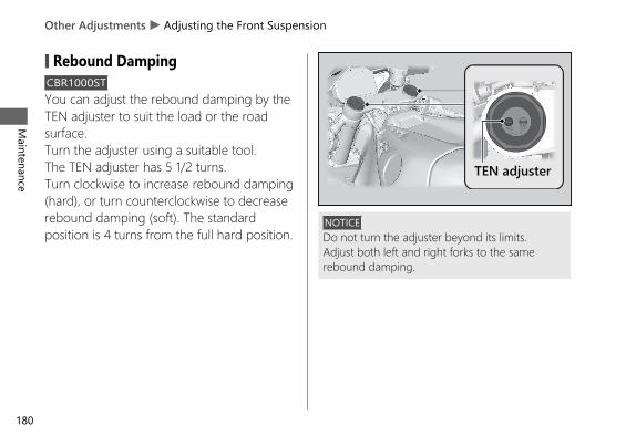
# Rebound DampingCBR1000STYou can adjust the rebound damping by theTEN adjuster to suit the load or the roadsurface.Turn the adjuster using a suitable tool.The TEN adjuster has 5 1/2 turns.Turn clockwise to increase rebound damping(hard), or turn counterclockwise to decreaserebound damping (soft). The standardposition is 4 turns from the full hard position.
NOTICEDo not turn the adjuster beyond its limits.Adjust both left and right forks to the samerebound damping.
20191113122725_32MKR8000_eng_BOOK Page 183 Wednesday, November 13 2019 12:40:27 JST
Other Adjustments u Adjusting the Front Suspension
Maintenance
180
TEN adjuster
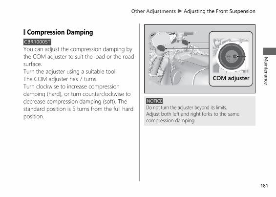
# Compression DampingCBR1000STYou can adjust the compression damping bythe COM adjuster to suit the load or the roadsurface.Turn the adjuster using a suitable tool.The COM adjuster has 7 turns.Turn clockwise to increase compressiondamping (hard), or turn counterclockwise todecrease compression damping (soft). Thestandard position is 5 turns from the full hardposition.
NOTICEDo not turn the adjuster beyond its limits.Adjust both left and right forks to the samecompression damping.
20191113122725_32MKR8000_eng_BOOK Page 184 Wednesday, November 13 2019 12:40:27 JST
Other Adjustments u Adjusting the Front SuspensionM
aintenance
181
COM adjuster
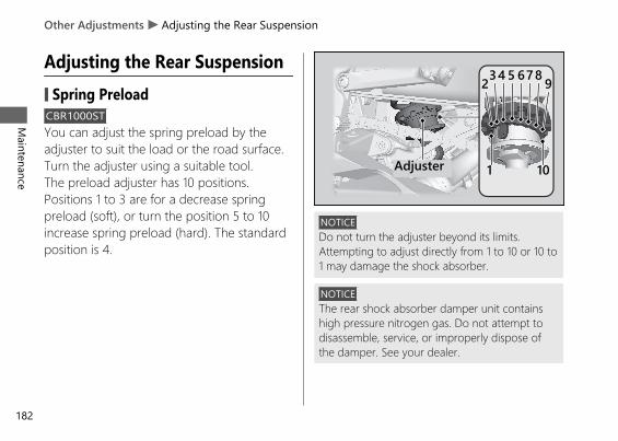
Adjusting the Rear Suspension# Spring PreloadCBR1000STYou can adjust the spring preload by theadjuster to suit the load or the road surface.Turn the adjuster using a suitable tool.The preload adjuster has 10 positions.Positions 1 to 3 are for a decrease springpreload (soft), or turn the position 5 to 10increase spring preload (hard). The standardposition is 4.
NOTICEDo not turn the adjuster beyond its limits.Attempting to adjust directly from 1 to 10 or 10 to1 may damage the shock absorber.
NOTICEThe rear shock absorber damper unit containshigh pressure nitrogen gas. Do not attempt todisassemble, service, or improperly dispose ofthe damper. See your dealer.
20191113122725_32MKR8000_eng_BOOK Page 185 Wednesday, November 13 2019 12:40:27 JST
Other Adjustments u Adjusting the Rear Suspension
Maintenance
182
1
234 5 678
10Adjuster
9
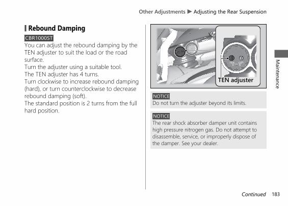
# Rebound DampingCBR1000STYou can adjust the rebound damping by theTEN adjuster to suit the load or the roadsurface.Turn the adjuster using a suitable tool.The TEN adjuster has 4 turns.Turn clockwise to increase rebound damping(hard), or turn counterclockwise to decreaserebound damping (soft).The standard position is 2 turns from the fullhard position.
NOTICEDo not turn the adjuster beyond its limits.
NOTICEThe rear shock absorber damper unit containshigh pressure nitrogen gas. Do not attempt todisassemble, service, or improperly dispose ofthe damper. See your dealer.
20191113122725_32MKR8000_eng_BOOK Page 186 Wednesday, November 13 2019 12:40:27 JST
Other Adjustments u Adjusting the Rear SuspensionM
aintenance
183Continued
TEN adjuster
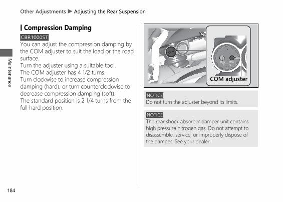
# Compression DampingCBR1000STYou can adjust the compression damping bythe COM adjuster to suit the load or the roadsurface.Turn the adjuster using a suitable tool.The COM adjuster has 4 1/2 turns.Turn clockwise to increase compressiondamping (hard), or turn counterclockwise todecrease compression damping (soft).The standard position is 2 1/4 turns from thefull hard position.
NOTICEDo not turn the adjuster beyond its limits.
NOTICEThe rear shock absorber damper unit containshigh pressure nitrogen gas. Do not attempt todisassemble, service, or improperly dispose ofthe damper. See your dealer.
20191113122725_32MKR8000_eng_BOOK Page 187 Wednesday, November 13 2019 12:40:27 JST
Other Adjustments u Adjusting the Rear Suspension
Maintenance
184
COM adjuster
Adjusting the ÖHLINS Smart ECSystemCBR1000SPThis model is equipped with the ÖHLINSSmart EC system.This system consists of front and rearsuspension and Suspension Control Unit(SCU).
This system provides the pre-programmeddamping characteristics optimized fordifferent situation to the front and rearsuspension.
SCU constantly determines riding conditionsfrom vehicle information. As a result, thissystem provides the optimum rebound andcompression damping characteristics.
The system continually adjusts compressionand rebound damping levels according tothe riding situation.
You can adjusts the front and rearsuspension preload manually.
ÖHLINS Smart EC is a trademark of ÖHLINS RACING AB, Sweden.
20191113122725_32MKR8000_eng_BOOK Page 188 Wednesday, November 13 2019 12:40:27 JST
Other Adjustments u Adjusting the ÖHLINS Smart EC SystemM
aintenance
185Continued
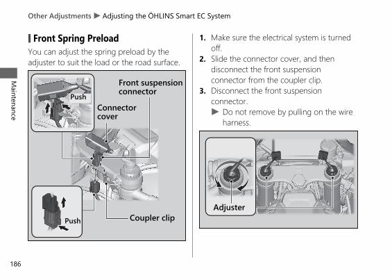
# Front Spring PreloadYou can adjust the spring preload by theadjuster to suit the load or the road surface.
1. Make sure the electrical system is turnedoff.
2. Slide the connector cover, and thendisconnect the front suspensionconnector from the coupler clip.
3. Disconnect the front suspensionconnector.u Do not remove by pulling on the wire
harness.
20191113122725_32MKR8000_eng_BOOK Page 189 Wednesday, November 13 2019 12:40:27 JST
Other Adjustments u Adjusting the ÖHLINS Smart EC System
Maintenance
186
Connectorcover
Front suspensionconnector
Coupler clip
Push
PushAdjuster
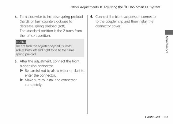
4. Turn clockwise to increase spring preload(hard), or turn counterclockwise todecrease spring preload (soft).The standard position is the 2 turns fromthe full soft position.
NOTICEDo not turn the adjuster beyond its limits.Adjust both left and right forks to the samespring preload.
5. After the adjustment, connect the frontsuspension connector.u Be careful not to allow water or dust to
enter the connector.u Make sure to install the connector
completely.
6. Connect the front suspension connectorto the coupler clip and then install theconnector cover.
20191113122725_32MKR8000_eng_BOOK Page 190 Wednesday, November 13 2019 12:40:27 JST
Other Adjustments u Adjusting the ÖHLINS Smart EC SystemM
aintenance
187Continued
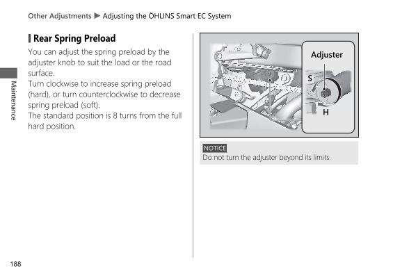
# Rear Spring PreloadYou can adjust the spring preload by theadjuster knob to suit the load or the roadsurface.Turn clockwise to increase spring preload(hard), or turn counterclockwise to decreasespring preload (soft).The standard position is 8 turns from the fullhard position.
NOTICEDo not turn the adjuster beyond its limits.
20191113122725_32MKR8000_eng_BOOK Page 191 Wednesday, November 13 2019 12:40:27 JST
Other Adjustments u Adjusting the ÖHLINS Smart EC System
Maintenance
188
Adjuster
H
S
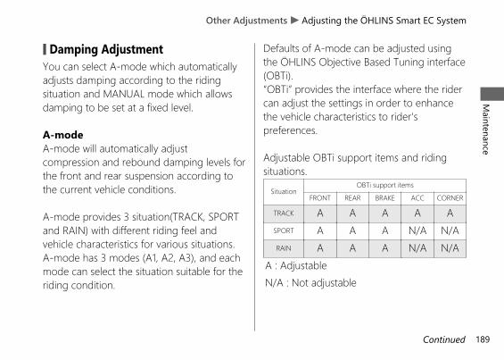
# Damping AdjustmentYou can select A-mode which automaticallyadjusts damping according to the ridingsituation and MANUAL mode which allowsdamping to be set at a fixed level.
A-modeA-mode will automatically adjustcompression and rebound damping levels forthe front and rear suspension according tothe current vehicle conditions.
A-mode provides 3 situation(TRACK, SPORTand RAIN) with different riding feel andvehicle characteristics for various situations.A-mode has 3 modes (A1, A2, A3), and eachmode can select the situation suitable for theriding condition.
Defaults of A-mode can be adjusted usingthe ÖHLINS Objective Based Tuning interface(OBTi).“OBTi” provides the interface where the ridercan adjust the settings in order to enhancethe vehicle characteristics to rider'spreferences.
Adjustable OBTi support items and ridingsituations.
SituationOBTi support items
FRONT REAR BRAKE ACC CORNER
TRACK A A A A ASPORT A A A N/A N/ARAIN A A A N/A N/A
A : AdjustableN/A : Not adjustable
20191113122725_32MKR8000_eng_BOOK Page 192 Wednesday, November 13 2019 12:40:27 JST
Other Adjustments u Adjusting the ÖHLINS Smart EC SystemM
aintenance
189Continued
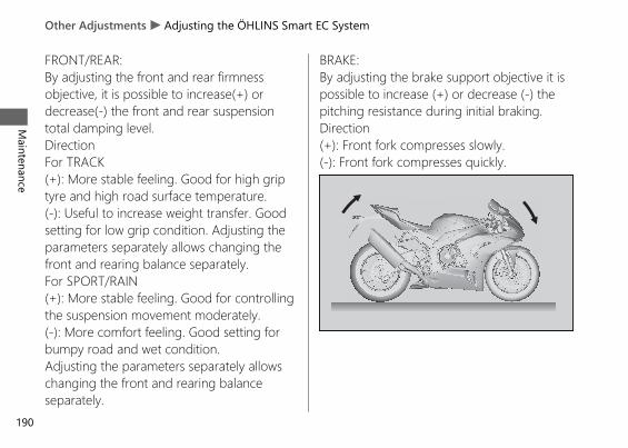
FRONT/REAR:By adjusting the front and rear firmnessobjective, it is possible to increase(+) ordecrease(-) the front and rear suspensiontotal damping level.DirectionFor TRACK(+): More stable feeling. Good for high griptyre and high road surface temperature.(-): Useful to increase weight transfer. Goodsetting for low grip condition. Adjusting theparameters separately allows changing thefront and rearing balance separately.For SPORT/RAIN(+): More stable feeling. Good for controllingthe suspension movement moderately.(-): More comfort feeling. Good setting forbumpy road and wet condition.Adjusting the parameters separately allowschanging the front and rearing balanceseparately.
BRAKE:By adjusting the brake support objective it ispossible to increase (+) or decrease (-) thepitching resistance during initial braking.Direction(+): Front fork compresses slowly.(-): Front fork compresses quickly.
20191113122725_32MKR8000_eng_BOOK Page 193 Wednesday, November 13 2019 12:40:27 JST
Other Adjustments u Adjusting the ÖHLINS Smart EC System
Maintenance
190
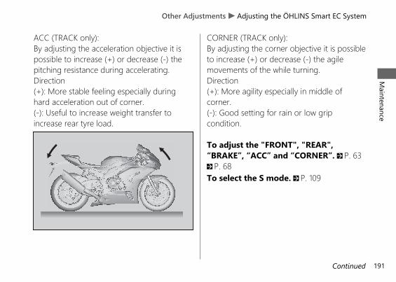
ACC (TRACK only):By adjusting the acceleration objective it ispossible to increase (+) or decrease (-) thepitching resistance during accelerating.Direction(+): More stable feeling especially duringhard acceleration out of corner.(-): Useful to increase weight transfer toincrease rear tyre load.
CORNER (TRACK only):By adjusting the corner objective it is possibleto increase (+) or decrease (-) the agilemovements of the while turning.Direction(+): More agility especially in middle ofcorner.(-): Good setting for rain or low gripcondition.
To adjust the "FRONT", "REAR",“BRAKE”, “ACC” and “CORNER”. 2 P. 632 P. 68To select the S mode. 2 P. 109
20191113122725_32MKR8000_eng_BOOK Page 194 Wednesday, November 13 2019 12:40:27 JST
Other Adjustments u Adjusting the ÖHLINS Smart EC SystemM
aintenance
191Continued
MANUAL modeThe suspension setting can be fixed at acertain value on compression and rebounddamping of the front and rear suspensions.
There is no automatic adjustment functionfor the front and rear suspension damping.
MANUAL mode provides 3 modes (M1, M2and M3).Preset of M1 is suitable for track riding.Preset of M2 is suitable for winding roads.Preset of M3 is suitable for street riding.
In MANUAL mode, the following dampinglevels can be adjusted as desired:FR COM: Compression damping for frontsuspensionFR REB: Rebound damping for frontsuspensionRR COM: Compression damping for rearsuspensionRR REB: Rebound damping for rearsuspension
To adjust the “FR COM”, “FR REB”, “RRCOM” and “RR REB”. 2 P. 63 2 P. 69To select the S mode. 2 P. 109
20191113122725_32MKR8000_eng_BOOK Page 195 Wednesday, November 13 2019 12:40:27 JST
Other Adjustments u Adjusting the ÖHLINS Smart EC System
Maintenance
192
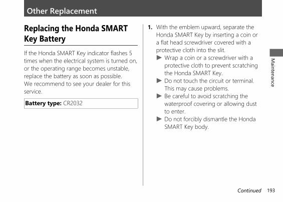
Other Replacement
Replacing the Honda SMARTKey BatteryIf the Honda SMART Key indicator flashes 5times when the electrical system is turned on,or the operating range becomes unstable,replace the battery as soon as possible.We recommend to see your dealer for thisservice.
Battery type: CR2032
1. With the emblem upward, separate theHonda SMART Key by inserting a coin ora flat head screwdriver covered with aprotective cloth into the slit.u Wrap a coin or a screwdriver with a
protective cloth to prevent scratchingthe Honda SMART Key.
u Do not touch the circuit or terminal.This may cause problems.
u Be careful to avoid scratching thewaterproof covering or allowing dustto enter.
u Do not forcibly dismantle the HondaSMART Key body.
20191113122725_32MKR8000_eng_BOOK Page 196 Wednesday, November 13 2019 12:40:27 JST
Maintenance
193Continued
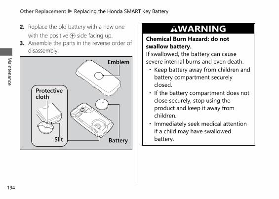
2. Replace the old battery with a new onewith the positive + side facing up.
3. Assemble the parts in the reverse order ofdisassembly.
3WARNINGChemical Burn Hazard: do notswallow battery.If swallowed, the battery can causesevere internal burns and even death.• Keep battery away from children and
battery compartment securelyclosed.
• If the battery compartment does notclose securely, stop using theproduct and keep it away fromchildren.
• Immediately seek medical attentionif a child may have swallowedbattery.
20191113122725_32MKR8000_eng_BOOK Page 197 Wednesday, November 13 2019 12:40:27 JST
Other Replacement u Replacing the Honda SMART Key Battery
Maintenance
194
Protectivecloth
Slit Battery
Emblem
Engine Will Not Start......................................P. 196Overheating (High coolant temperatureindicator is on) ...............................................P. 197
Warning Indicators On or Flashing.............P. 198Low Oil Pressure Indicator .............................. P. 198PGM-FI (Programmed Fuel Injection)Malfunction Indicator Lamp (MIL)............... P. 198
ABS (Anti-lock Brake System) Indicator ....... P. 199HESD (Honda Electronic Steering Damper)Indicator ............................................................ P. 199
Torque Control Indicator................................. P. 200Honda SMART Key Indicator.......................... P. 201
When the Honda SMART Key System Does NotOperate Properly...........................................P. 202
Activating the Electrical System in anEmergency ......................................................P. 204
Tyre Puncture ...................................................P. 209Electrical Trouble.............................................P. 218
Battery Goes Dead............................................ P. 218Burned-out Light Bulb ..................................... P. 219Blown Fuse.......................................................... P. 220
20191113122725_32MKR8000_eng_BOOK Page 198 Wednesday, November 13 2019 12:40:27 JST
Troubleshooting
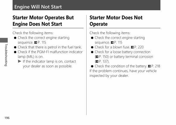
Engine Will Not Start
Starter Motor Operates ButEngine Does Not StartCheck the following items:● Check the correct engine starting
sequence. 2 P. 115● Check that there is petrol in the fuel tank.● Check if the PGM-FI malfunction indicator
lamp (MIL) is on.u If the indicator lamp is on, contact
your dealer as soon as possible.
Starter Motor Does NotOperateCheck the following items:● Check the correct engine starting
sequence. 2 P. 115● Check for a blown fuse. 2 P. 220● Check for a loose battery connection
(2 P. 150) or battery terminal corrosion(2 P. 137).
● Check the condition of the battery. 2 P. 218If the problem continues, have your vehicleinspected by your dealer.
20191113122725_32MKR8000_eng_BOOK Page 199 Wednesday, November 13 2019 12:40:27 JST
Troubleshooting
196
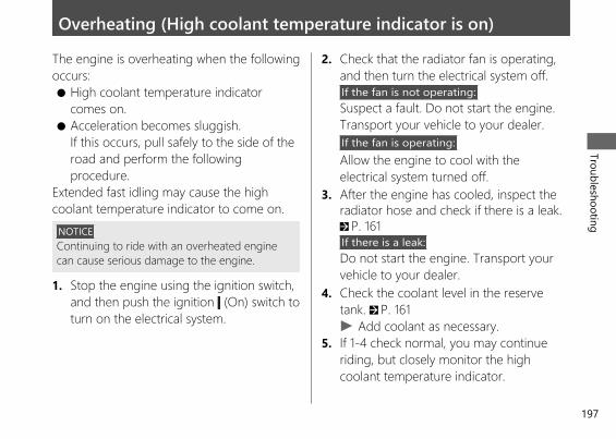
Overheating (High coolant temperature indicator is on)The engine is overheating when the followingoccurs:● High coolant temperature indicator
comes on.● Acceleration becomes sluggish.
If this occurs, pull safely to the side of theroad and perform the followingprocedure.
Extended fast idling may cause the highcoolant temperature indicator to come on.
NOTICEContinuing to ride with an overheated enginecan cause serious damage to the engine.
1. Stop the engine using the ignition switch,and then push the ignition (On) switch toturn on the electrical system.
2. Check that the radiator fan is operating,and then turn the electrical system off.If the fan is not operating:Suspect a fault. Do not start the engine.Transport your vehicle to your dealer.If the fan is operating:Allow the engine to cool with theelectrical system turned off.
3. After the engine has cooled, inspect theradiator hose and check if there is a leak.2 P. 161If there is a leak:Do not start the engine. Transport yourvehicle to your dealer.
4. Check the coolant level in the reservetank. 2 P. 161u Add coolant as necessary.
5. If 1-4 check normal, you may continueriding, but closely monitor the highcoolant temperature indicator.
20191113122725_32MKR8000_eng_BOOK Page 200 Wednesday, November 13 2019 12:40:27 JST
Troubleshooting
197
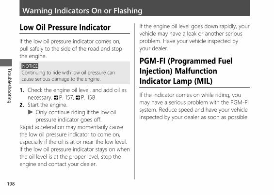
Warning Indicators On or Flashing
Low Oil Pressure IndicatorIf the low oil pressure indicator comes on,pull safely to the side of the road and stopthe engine.
NOTICEContinuing to ride with low oil pressure cancause serious damage to the engine.
1. Check the engine oil level, and add oil asnecessary. 2 P. 157, 2 P. 158
2. Start the engine.u Only continue riding if the low oil
pressure indicator goes off.Rapid acceleration may momentarily causethe low oil pressure indicator to come on,especially if the oil is at or near the low level.If the low oil pressure indicator stays on whenthe oil level is at the proper level, stop theengine and contact your dealer.
If the engine oil level goes down rapidly, yourvehicle may have a leak or another seriousproblem. Have your vehicle inspected byyour dealer.
PGM-FI (Programmed FuelInjection) MalfunctionIndicator Lamp (MIL)If the indicator comes on while riding, youmay have a serious problem with the PGM-FIsystem. Reduce speed and have your vehicleinspected by your dealer as soon as possible.
20191113122725_32MKR8000_eng_BOOK Page 201 Wednesday, November 13 2019 12:40:27 JST
Troubleshooting
198
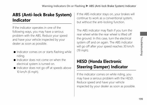
ABS (Anti-lock Brake System)IndicatorIf the indicator operates in one of thefollowing ways, you may have a seriousproblem with the ABS. Reduce your speedand have your vehicle inspected by yourdealer as soon as possible.
● Indicator comes on or starts flashing whileriding.
● Indicator does not come on when theelectrical system is turned on.
● Indicator does not go off at speeds above10 km/h (6 mph).
If the ABS indicator stays on, your brakes willcontinue to work as a conventional system,but without the anti-locking function.
The ABS indicator may flash if you turn therear wheel while the rear wheel is lifted offthe ground. In this case, turn the electricalsystem off and on again. The ABS indicatorwill go off after your speed reaches 30 km/h(19 mph).
HESD (Honda ElectronicSteering Damper) IndicatorIf the indicator comes on while riding, youmay have a serious problem with the HESD.Reduce speed and have your vehicleinspected by your dealer as soon as possible.
20191113122725_32MKR8000_eng_BOOK Page 202 Wednesday, November 13 2019 12:40:27 JST
Warning Indicators On or Flashing u ABS (Anti-lock Brake System) IndicatorTroubleshooting
199
Torque Control IndicatorIf the indicator operates in one of thefollowing ways, you may have a seriousproblem with the Torque Control. Reduceyour speed and have your vehicle inspectedby your dealer as soon as possible.
● Indicator comes and stays on (solid) whileriding.
● Indicator does not come on when theelectrical system is turned on.
● Indicator does not go off at speeds above5 km/h (3 mph).
Even when the Torque Control indicator ison, your vehicle will have normal riding abilitywithout Torque Control function.u When the indicator comes on while the
Torque Control is in operation, you willhave to completely close the throttle toregain normal riding ability.
The Torque Control indicator may come on ifyou rotate the rear wheel while your vehicleis lifted off the ground. In this case, turn theelectrical system off and on again. TheTorque Control indicator will go off after yourspeed reaches 5 km/h (3 mph).
20191113122725_32MKR8000_eng_BOOK Page 203 Wednesday, November 13 2019 12:40:27 JST
Warning Indicators On or Flashing u Torque Control Indicator
Troubleshooting
200
Honda SMART Key Indicator# When the Honda SMART Key
indicator flashes 5 timesReplacing the Honda SMART KeyBattery 2 P. 193
# When the Honda SMART Keyindicator is flashing while theelectrical system is on
The Honda SMART Key indicator flasheswhen communication between your vehicleand Honda SMART Key stops after turningon the electrical system.It is probably caused by the following:● Strong radio waves or noise are affecting
the system● You lose the Honda SMART Key while
riding
However, this does not affect the operation ofyour vehicle until the electrical system is off.
You may not be able to turn off the electricalsystem when losing the Honda SMART Keywhile riding, or if the battery is low, orbecause the system is affected by strongradio waves or noise. If this occurs, turn theignition switch knob / (Off/Lock)counterclockwise and hold it until theelectrical system shut off.You can also turn off the electrical system byturning the ignition switch knob / (Off/Lock) counterclockwise 3 times within 3seconds.
If the electrical system cannot be turned onbecause the Honda SMART Key batterybecomes weak (or dead), it can be activatedby means of emergency procedures. 2 P. 204
20191113122725_32MKR8000_eng_BOOK Page 204 Wednesday, November 13 2019 12:40:27 JST
Warning Indicators On or Flashing u Honda SMART Key IndicatorTroubleshooting
201
When the Honda SMART Key System Does Not Operate ProperlyWhen the Honda SMART Key system doesnot work properly, perform the following.● Check that the Honda SMART Key system
is activated.Lightly push the ON/OFF button on theHonda SMART Key.If the LED of the Honda SMART Key isred, switch the Honda SMART Key systemto activation. 2 P. 105If the LED of the Honda SMART Key doesnot respond, replace the battery of theHonda SMART Key.
● Check that there is no communicationfailure in the Honda SMART Key system.The Honda SMART Key system uses low-intensity radio waves. The Honda SMARTKey system may not work properly in thefollowing environments:u When there are facilities nearby that
generate strong radio waves or noisesuch as TV towers, power stations,radio stations, or airports.
u When you carry the Honda SMARTKey with a laptop or wirelesscommunication device such as a radioor mobile phone.
u When the Honda SMART Key comesinto contact with or is covered bymetal objects.
20191113122725_32MKR8000_eng_BOOK Page 205 Wednesday, November 13 2019 12:40:27 JST
Troubleshooting
202
● Check that a registered Honda SMARTKey is used.Use a registered Honda SMART Key.The Honda SMART Key system cannot beactivated without a registered HondaSMART Key.
● Make sure that you do not use a brokenHonda SMART Key.If you use a broken Honda SMART Key,the Honda SMART Key system cannot beactivated. Bring the ID tag to your dealer.
● Check the battery condition and batterylead in your vehicle.Check the battery and battery terminals. Ifthe battery is weak, contact your dealer.
If the Honda SMART Key system cannot beactivated due to other causes, contact yourdealer.
20191113122725_32MKR8000_eng_BOOK Page 206 Wednesday, November 13 2019 12:40:27 JST
When the Honda SMART Key System Does Not Operate ProperlyTroubleshooting
203
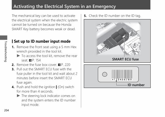
Activating the Electrical System in an EmergencyThe mechanical key can be used to activatethe electrical system when the electric systemcannot be turned on because the HondaSMART Key battery becomes weak or dead.
# Set up to ID number input mode1. Remove the front seat using a 5 mm Hex
wrench provided in the tool kit.u To access the tool kit, remove the rear
seat. 2 P. 1542. Remove the fuse box cover. 2 P. 2203. Pull out the SMART ECU fuse with the
fuse puller in the tool kit and wait about 2minutes before insert the SMART ECUfuse again.
4. Push and hold the ignition (On) switchfor more than 4 seconds.u The steering lock indicator comes on
and the system enters the ID numberinput mode.
5. Check the ID number on the ID tag.
20191113122725_32MKR8000_eng_BOOK Page 207 Wednesday, November 13 2019 12:40:27 JST
Troubleshooting
204
SMART ECU fuse
ID number
# ID number inputYou can input your ID number by pushingthe ignition (On) switch and Turn theignition switch knob / (Off/Lock)counterclockwise. Input the ID number onthe ID tag in order from the left in turn bypushing the ignition (On) switch.The ID number is input according to thenumber of times the ignition (On) switch ispushed.Push the ignition (On) switch the desirednumber of times, then turn the ignitionswitch knob / (Off/Lock)counterclockwise to fix the current digit (thesteering lock indicator goes off briefly andcomes on again), and input the next digit,and then repeat until all the digits are input.
While inputting the ID number, if the buttonis not pressed for about 60 seconds, theinputted ID number is cancelled and thesystem returns to the state before removingthe SMART ECU fuse (the steering lockindicator goes off).
20191113122725_32MKR8000_eng_BOOK Page 208 Wednesday, November 13 2019 12:40:27 JST
Activating the Electrical System in an EmergencyTroubleshooting
205Continued
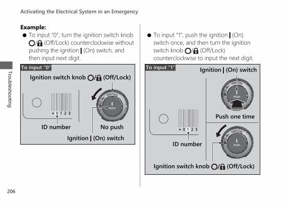
Example:● To input “0”, turn the ignition switch knob
/ (Off/Lock) counterclockwise withoutpushing the ignition (On) switch, andthen input next digit.
● To input “1”, push the ignition (On)switch once, and then turn the ignitionswitch knob / (Off/Lock)counterclockwise to input the next digit.
20191113122725_32MKR8000_eng_BOOK Page 209 Wednesday, November 13 2019 12:40:27 JST
Activating the Electrical System in an Emergency
Troubleshooting
206
To input “0”
Ignition switch knob / (Off/Lock)
ID number No pushIgnition (On) switch
Ignition switch knob / (Off/Lock)
ID number
Push one time
Ignition (On) switchTo input “1”
ID number input successAfter the last digit of the ID number isinputted, ID number is authenticated, thesteering lock indicator will flash every 2seconds.Push the ignition (On) switch within 30seconds after the ID number is authenticated.If the steering is lockedThe steering will be unlocked. To active theelectrical system, push the ignition (On)switch once again within 30 seconds after theID number is authenticated.If the steering is unlockedThe electrical system will be activated. Youcan start the engine.
You can turn off the engine and electricalsystem and also lock the steering using theignition switch. The ignition switch operationis disabled 30 seconds after the electricalsystem is turned off.
To activate the electrical system again, repeatthe procedures for activating the electricalsystem in an emergency.
20191113122725_32MKR8000_eng_BOOK Page 210 Wednesday, November 13 2019 12:40:27 JST
Activating the Electrical System in an EmergencyTroubleshooting
207Continued
ID number input failureIf the ID number is not authenticated afterinputting, the steering lock indicator goes off.The steering cannot be unlocked and theelectrical system will not activate.Repeat the procedures for activating theelectrical system in an emergency.
ID number input cancelIf you input the wrong number, you cancancel ID number input by not operating theswitch for about 60 seconds (the steeringlock indicator goes off ).Repeat the procedures for activating theelectrical system in an emergency.
20191113122725_32MKR8000_eng_BOOK Page 211 Wednesday, November 13 2019 12:40:27 JST
Activating the Electrical System in an Emergency
Troubleshooting
208
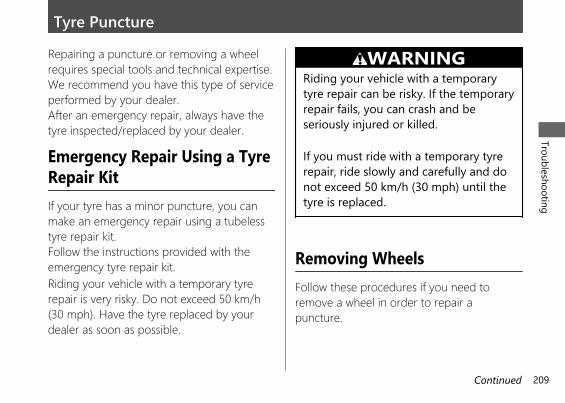
Tyre PunctureRepairing a puncture or removing a wheelrequires special tools and technical expertise.We recommend you have this type of serviceperformed by your dealer.After an emergency repair, always have thetyre inspected/replaced by your dealer.
Emergency Repair Using a TyreRepair KitIf your tyre has a minor puncture, you canmake an emergency repair using a tubelesstyre repair kit.Follow the instructions provided with theemergency tyre repair kit.Riding your vehicle with a temporary tyrerepair is very risky. Do not exceed 50 km/h(30 mph). Have the tyre replaced by yourdealer as soon as possible.
3WARNINGRiding your vehicle with a temporarytyre repair can be risky. If the temporaryrepair fails, you can crash and beseriously injured or killed.
If you must ride with a temporary tyrerepair, ride slowly and carefully and donot exceed 50 km/h (30 mph) until thetyre is replaced.
Removing WheelsFollow these procedures if you need toremove a wheel in order to repair apuncture.
20191113122725_32MKR8000_eng_BOOK Page 212 Wednesday, November 13 2019 12:40:27 JST
Troubleshooting
209Continued
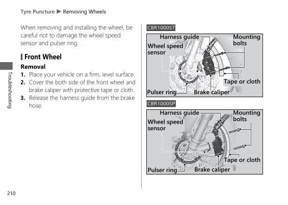
When removing and installing the wheel, becareful not to damage the wheel speedsensor and pulser ring.
# Front WheelRemoval1. Place your vehicle on a firm, level surface.2. Cover the both side of the front wheel and
brake caliper with protective tape or cloth.3. Release the harness guide from the brake
hose.
CBR1000ST
CBR1000SP
20191113122725_32MKR8000_eng_BOOK Page 213 Wednesday, November 13 2019 12:40:27 JST
Tyre Puncture u Removing Wheels
Troubleshooting
210
Mountingbolts
Tape or cloth
Wheel speedsensor
Pulser ring
Harness guide
Brake caliper
Mountingbolts
Pulser ring
Wheel speedsensor
Harness guide
Tape or clothBrake caliper
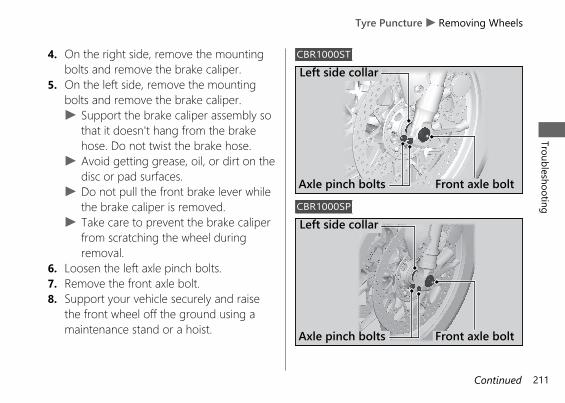
4. On the right side, remove the mountingbolts and remove the brake caliper.
5. On the left side, remove the mountingbolts and remove the brake caliper.u Support the brake caliper assembly so
that it doesn't hang from the brakehose. Do not twist the brake hose.
u Avoid getting grease, oil, or dirt on thedisc or pad surfaces.
u Do not pull the front brake lever whilethe brake caliper is removed.
u Take care to prevent the brake caliperfrom scratching the wheel duringremoval.
6. Loosen the left axle pinch bolts.7. Remove the front axle bolt.8. Support your vehicle securely and raise
the front wheel off the ground using amaintenance stand or a hoist.
CBR1000ST
CBR1000SP
20191113122725_32MKR8000_eng_BOOK Page 214 Wednesday, November 13 2019 12:40:27 JST
Tyre Puncture u Removing WheelsTroubleshooting
211Continued
Axle pinch bolts Front axle bolt
Left side collar
Left side collar
Axle pinch bolts Front axle bolt
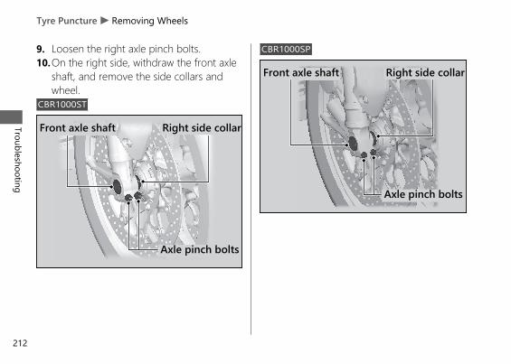
9. Loosen the right axle pinch bolts.10.On the right side, withdraw the front axle
shaft, and remove the side collars andwheel.
CBR1000ST
CBR1000SP
20191113122725_32MKR8000_eng_BOOK Page 215 Wednesday, November 13 2019 12:40:27 JST
Tyre Puncture u Removing Wheels
Troubleshooting
212
Axle pinch bolts
Front axle shaft Right side collar
Front axle shaft
Axle pinch bolts
Right side collar
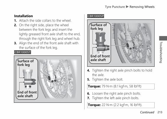
Installation1. Attach the side collars to the wheel.2. On the right side, place the wheel
between the fork legs and insert thelightly greased front axle shaft to the end,through the right fork leg and wheel hub.
3. Align the end of the front axle shaft withthe surface of the fork leg.
CBR1000ST
CBR1000SP
4. Tighten the right axle pinch bolts to holdthe axle.
5. Tighten the axle bolt.
Torque: 79 N·m (8.1 kgf·m, 58 lbf·ft)
6. Loosen the right axle pinch bolts.7. Tighten the left axle pinch bolts.
Torque: 22 N·m (2.2 kgf·m, 16 lbf·ft).
20191113122725_32MKR8000_eng_BOOK Page 216 Wednesday, November 13 2019 12:40:27 JST
Tyre Puncture u Removing WheelsTroubleshooting
213Continued
Surface offork leg
End of frontaxle shaft
Surface offork leg
End of frontaxle shaft
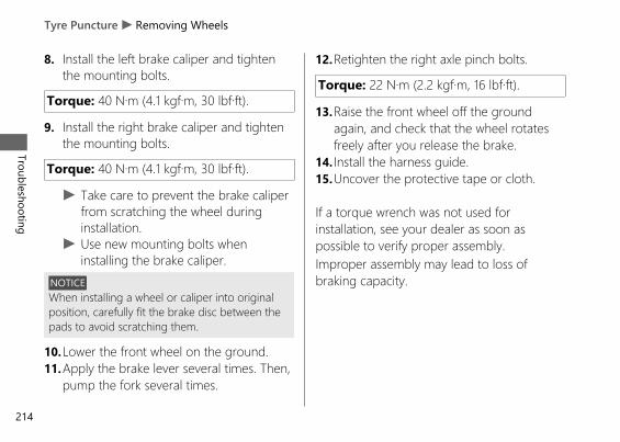
8. Install the left brake caliper and tightenthe mounting bolts.
Torque: 40 N·m (4.1 kgf·m, 30 lbf·ft).
9. Install the right brake caliper and tightenthe mounting bolts.
Torque: 40 N·m (4.1 kgf·m, 30 lbf·ft).
u Take care to prevent the brake caliperfrom scratching the wheel duringinstallation.
u Use new mounting bolts wheninstalling the brake caliper.
NOTICEWhen installing a wheel or caliper into originalposition, carefully fit the brake disc between thepads to avoid scratching them.
10.Lower the front wheel on the ground.11.Apply the brake lever several times. Then,
pump the fork several times.
12.Retighten the right axle pinch bolts.
Torque: 22 N·m (2.2 kgf·m, 16 lbf·ft).
13.Raise the front wheel off the groundagain, and check that the wheel rotatesfreely after you release the brake.
14. Install the harness guide.15.Uncover the protective tape or cloth.
If a torque wrench was not used forinstallation, see your dealer as soon aspossible to verify proper assembly.Improper assembly may lead to loss ofbraking capacity.
20191113122725_32MKR8000_eng_BOOK Page 217 Wednesday, November 13 2019 12:40:27 JST
Tyre Puncture u Removing Wheels
Troubleshooting
214
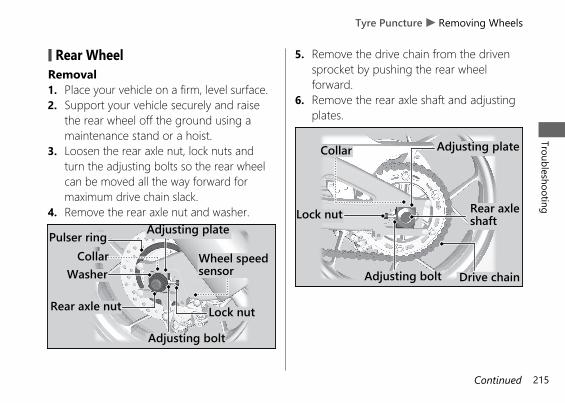
# Rear WheelRemoval1. Place your vehicle on a firm, level surface.2. Support your vehicle securely and raise
the rear wheel off the ground using amaintenance stand or a hoist.
3. Loosen the rear axle nut, lock nuts andturn the adjusting bolts so the rear wheelcan be moved all the way forward formaximum drive chain slack.
4. Remove the rear axle nut and washer.
5. Remove the drive chain from the drivensprocket by pushing the rear wheelforward.
6. Remove the rear axle shaft and adjustingplates.
20191113122725_32MKR8000_eng_BOOK Page 218 Wednesday, November 13 2019 12:40:27 JST
Tyre Puncture u Removing WheelsTroubleshooting
215Continued
Lock nut
CollarWasher
Rear axle nut
Adjusting bolt
Adjusting plate
Wheel speedsensor
Pulser ring
Rear axleshaft
Drive chain
Lock nut
Collar
Adjusting bolt
Adjusting plate
7. Remove the brake caliper bracket, rearwheel and side collars.u Support the brake caliper assembly so
that it doesn’t hang from the brakehose. Do not twist the brake hose.
u Avoid getting grease, oil, or dirt on thedisc or pad surfaces.
u Do not push the brake pedal while thewheel is removed.
Installation1. To install the rear wheel, reverse the
removal procedure.u Take care to prevent the brake caliper
from scratching the wheel duringinstallation.
NOTICEWhen installing a wheel or caliper into originalposition, carefully fit the brake disc between thepads to avoid scratching them.
20191113122725_32MKR8000_eng_BOOK Page 219 Wednesday, November 13 2019 12:40:27 JST
Tyre Puncture u Removing Wheels
Troubleshooting
216
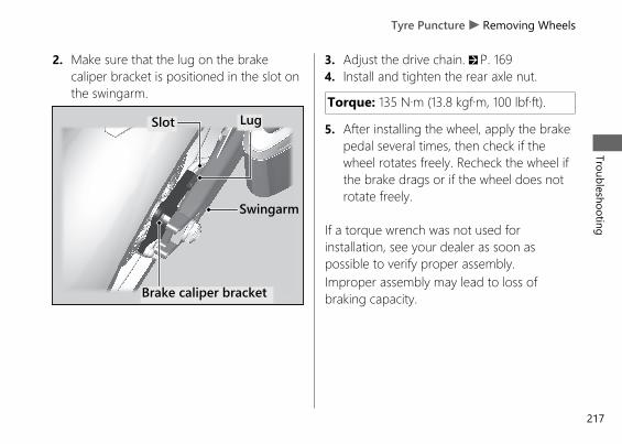
2. Make sure that the lug on the brakecaliper bracket is positioned in the slot onthe swingarm.
3. Adjust the drive chain. 2 P. 1694. Install and tighten the rear axle nut.
Torque: 135 N·m (13.8 kgf·m, 100 lbf·ft).
5. After installing the wheel, apply the brakepedal several times, then check if thewheel rotates freely. Recheck the wheel ifthe brake drags or if the wheel does notrotate freely.
If a torque wrench was not used forinstallation, see your dealer as soon aspossible to verify proper assembly.Improper assembly may lead to loss ofbraking capacity.
20191113122725_32MKR8000_eng_BOOK Page 220 Wednesday, November 13 2019 12:40:27 JST
Tyre Puncture u Removing WheelsTroubleshooting
217
Brake caliper bracket
Swingarm
LugSlot
Electrical Trouble
Battery Goes DeadCBR1000STCharge the battery using a motorcyclebattery charger.Remove the battery from the vehicle beforecharging.Do not use an automobile-type batterycharger, as these can overheat a motorcyclebattery and cause permanent damage. If thebattery does not recover after recharging,contact your dealer.
NOTICEJump starting using an automobile battery candamage your vehicle's electrical system and isnot recommended.
CBR1000SPBattery charging is needed.A battery charger recommended by yourlithium-ion (li-ion) battery manufacturer isneeded for battery charging.Contact your dealer before charging thebattery.Remove the battery from the vehicle beforecharging.
NOTICEOnly use a charger recommended by yourlithium-ion (li-ion) battery manufacturer. Using abattery charger that is not recommended cancause permanent damage to your battery.
If the battery does not recover afterrecharging, contact your dealer.
NOTICEDo not jump-start, as this can damage yourvehicle's electrical system and battery.
20191113122725_32MKR8000_eng_BOOK Page 221 Wednesday, November 13 2019 12:40:27 JST
Troubleshooting
218
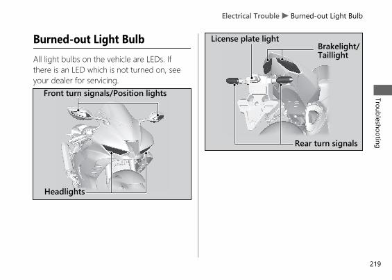
Burned-out Light BulbAll light bulbs on the vehicle are LEDs. Ifthere is an LED which is not turned on, seeyour dealer for servicing.
20191113122725_32MKR8000_eng_BOOK Page 222 Wednesday, November 13 2019 12:40:27 JST
Electrical Trouble u Burned-out Light BulbTroubleshooting
219
Headlights
Front turn signals/Position lights
Brakelight/Taillight
Rear turn signals
License plate light
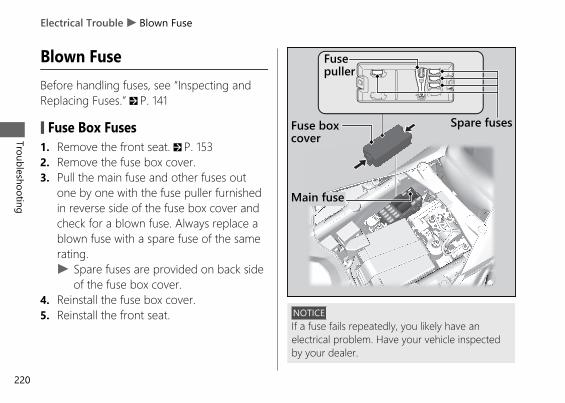
Blown FuseBefore handling fuses, see “Inspecting andReplacing Fuses.” 2 P. 141
# Fuse Box Fuses1. Remove the front seat. 2 P. 1532. Remove the fuse box cover.3. Pull the main fuse and other fuses out
one by one with the fuse puller furnishedin reverse side of the fuse box cover andcheck for a blown fuse. Always replace ablown fuse with a spare fuse of the samerating.u Spare fuses are provided on back side
of the fuse box cover.4. Reinstall the fuse box cover.5. Reinstall the front seat. NOTICE
If a fuse fails repeatedly, you likely have anelectrical problem. Have your vehicle inspectedby your dealer.
20191113122725_32MKR8000_eng_BOOK Page 223 Wednesday, November 13 2019 12:40:27 JST
Electrical Trouble u Blown Fuse
Troubleshooting
220
Fuse boxcover
Spare fuses
Main fuse
Fusepuller
Service Diagnostic Recorders.......................P. 222Keys.....................................................................P. 223Instruments, Controls, & Other Features...P. 227Caring for Your Vehicle..................................P. 229Storing Your Vehicle.......................................P. 234Transporting Your Vehicle ............................P. 235You & the Environment .................................P. 235Serial Numbers ................................................P. 237Fuels Containing Alcohol ..............................P. 238Catalytic Converter .........................................P. 239
20191113122725_32MKR8000_eng_BOOK Page 224 Wednesday, November 13 2019 12:40:27 JST
Information
Service DiagnosticRecordersYour vehicle is equipped with service-relateddevices that record information aboutpowertrain performance and driving conditions.The data can be used to help techniciansdiagnose, repair and maintain the vehicle. Thisdata may not be accessed by anyone elseexcept as legally required or with the permissionof the vehicle owner.However this data may be accessed by Honda,its authorised dealers and authorised repairers,employees, representatives and contractors onlyfor the purpose of the technical diagnosis,research and development of the vehicle.
20191113122725_32MKR8000_eng_BOOK Page 225 Wednesday, November 13 2019 12:40:27 JST
Service Diagnostic Recorders
Information
222
KeysHonda SMART Key
The Honda SMART Key is equipped with amechanical key.Carrying the Honda SMART Key allows you toperform the following operations:• Locking or unlocking the steering and
activating or deactivating the electrical system• Opening the fuel fill cap and rear seat
The ID number of the Honda SMART Key is onthe ID tag. You can also unlock the steering (if itis locked) and activating the electrical system byinputting the ID number.
Always carry the ID tag, but separate from theHonda SMART Key, to avoid losing all of themat the same time.
Also store the key tag and a copy of your IDnumber in a safe place other than your vehicle.
The Honda SMART Key contains electroniccircuits. If the circuits are damaged, the HondaSMART Key will not allow you to perform anyoperations.● Do not drop the Honda SMART Key or set
heavy objects on them.● Protect the Honda SMART Key from direct
sunlight, high temperature, and highhumidity.
● Do not scratch or puncture.● Do not store near any magnetized products
such as a magnetized key chain.● Always keep the Honda SMART Key away
from electric appliances such as a TV, radio,PC or low-frequency massage device.
● Keep the Honda SMART Key away fromliquids. If it gets wet, dry it immediately witha soft cloth.
● Keep the Honda SMART Key away from thevehicle while washing the vehicle.
● Do not burn.● Do not wash in the ultrasonic cleaner.
20191113122725_32MKR8000_eng_BOOK Page 226 Wednesday, November 13 2019 12:40:27 JST
KeysInform
ation
223Continued
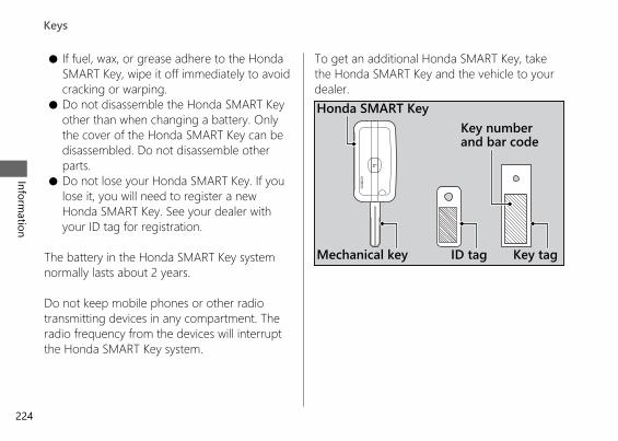
● If fuel, wax, or grease adhere to the HondaSMART Key, wipe it off immediately to avoidcracking or warping.
● Do not disassemble the Honda SMART Keyother than when changing a battery. Onlythe cover of the Honda SMART Key can bedisassembled. Do not disassemble otherparts.
● Do not lose your Honda SMART Key. If youlose it, you will need to register a newHonda SMART Key. See your dealer withyour ID tag for registration.
The battery in the Honda SMART Key systemnormally lasts about 2 years.
Do not keep mobile phones or other radiotransmitting devices in any compartment. Theradio frequency from the devices will interruptthe Honda SMART Key system.
To get an additional Honda SMART Key, takethe Honda SMART Key and the vehicle to yourdealer.
20191113122725_32MKR8000_eng_BOOK Page 227 Wednesday, November 13 2019 12:40:27 JST
Keys
Information
224
Honda SMART Key
Key tagID tag
Key numberand bar code
Mechanical key
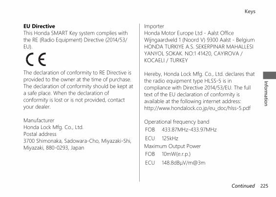
EU DirectiveThis Honda SMART Key system complies withthe RE (Radio Equipment) Directive (2014/53/EU).
The declaration of conformity to RE Directive isprovided to the owner at the time of purchase.The declaration of conformity should be kept ata safe place. When the declaration ofconformity is lost or is not provided, contactyour dealer.
ManufacturerHonda Lock Mfg. Co., Ltd.Postal address3700 Shimonaka, Sadowara-Cho, Miyazaki-Shi,Miyazaki, 880-0293, Japan
ImporterHonda Motor Europe Ltd - Aalst OfficeWijngaardveld 1 (Noord V) 9300 Aalst - BelgiumHONDA TURKIYE A.S. SEKERPINAR MAHALLESIYANYOL SOKAK. NO:1 41420, CAYIROVA /KOCAELI / TURKEY
Hereby, Honda Lock Mfg. Co., Ltd. declares thatthe radio equipment type HLSS-5 is incompliance with Directive 2014/53/EU. The fulltext of the EU declaration of conformity isavailable at the following internet address:http://www.hondalock.co.jp/eu_doc/hlss-5.pdf
Operational frequency bandFOB 433.87MHz-433.97MHzECU 125kHzMaximum Output PowerFOB 10mW(e.r.p.)ECU 148.8dBμV/m@3m
20191113122725_32MKR8000_eng_BOOK Page 228 Wednesday, November 13 2019 12:40:27 JST
KeysInform
ation
225Continued
Bahrain onlyManufacturerHonda Lock Mfg. Co., Ltd.Model nameHLSS-5
Vietnam only
20191113122725_32MKR8000_eng_BOOK Page 229 Wednesday, November 13 2019 12:40:27 JST
Keys
Information
226
Instruments, Controls, &Other FeaturesIgnition Switch
Leaving the electrical system on with the enginestopped will drain the battery.
Do not operate the ignition switch while riding.
Engine Stop SwitchDo not use the engine stop switch except in anemergency. Doing so when riding will cause theengine to suddenly turn off, making ridingunsafe.If you stop the engine using the engine stopswitch, turn the ignition switch knob / (Off/Lock) counterclockwise to turn off the electricalsystem. Failing to do so will drain the battery.
OdometerThe display locks at 999,999 when the read-outexceeds 999,999.
TripmeterThe tripmeters return to 0.0 when each read-out exceeds 9,999.9.
Owner's manualThe owner’s manual, registration, and insuranceinformation can be stored in the tool bag underthe rear seat. 2 P. 126
20191113122725_32MKR8000_eng_BOOK Page 230 Wednesday, November 13 2019 12:40:27 JST
Instruments, Controls, & Other FeaturesInform
ation
227Continued
Ignition Cut-off SystemIMU (Inertial Measurement Unit) sensorautomatically stops the engine and fuel pump ifthe vehicle falls over. To reset the IMU, youmust turn the electrical system off and back toon before the engine can be restarted.
If a failure of the IMU is detected, the engineand fuel pump will not stop automatically whenthe vehicle falls over.
HESDThe Honda Electronic Steering Damper (HESD)automatically controls the steering dampercharacteristics in accordance with vehicle speedand acceleration.HESD Indicator Comes On 2 P. 199
Assist-slipper Clutch SystemThe assist-slipper clutch system helps to preventthe rear tyre from locking up when thedeceleration of your vehicle produces a strongengine braking effect. It also makes the clutchlever operation feel lighter.
Use only MA classification engine oil for yourvehicle. Using engine oil other than MAclassification oil could result in damage to theassist-slipper clutch system.
Throttle by Wire SystemThis model is equipped with a Throttle by WireSystem.Do not put magnetized items or itemssusceptible to magnetic interference near theright handlebar switches.
20191113122725_32MKR8000_eng_BOOK Page 231 Wednesday, November 13 2019 12:40:27 JST
Instruments, Controls, & Other Features
Information
228
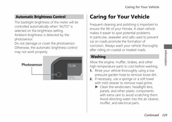
Automatic Brightness ControlThe backlight brightness of the meter will becontrolled automatically when “AUTO” isselected on the brightness setting.Ambient brightness is detected by thephotosensor.Do not damage or cover the photosensor.Otherwise, the automatic brightness controlmay not work properly.
Caring for Your VehicleFrequent cleaning and polishing is important toensure the life of your Honda. A clean vehiclemakes it easier to spot potential problems.In particular, seawater and salts used to preventice on roads promote the formation ofcorrosion. Always wash your vehicle thoroughlyafter riding on coastal or treated roads.
WashingAllow the engine, muffler, brakes, and otherhigh-temperature parts to cool before washing.1. Rinse your vehicle thoroughly using a low
pressure garden hose to remove loose dirt.2. If necessary, use a sponge or a soft towel
with mild cleaner to remove road grime.u Clean the windscreen, headlight lens,
panels, and other plastic componentswith extra care to avoid scratching them.Avoid directing water into the air cleaner,muffler, and electrical parts.
20191113122725_32MKR8000_eng_BOOK Page 232 Wednesday, November 13 2019 12:40:27 JST
Caring for Your VehicleInform
ation
229Continued
Photosensor
3. Thoroughly rinse your vehicle with plenty ofclean water and dry with a soft, clean cloth.
4. After the vehicle dries, lubricate any movingparts.u Make sure that no lubricant spills onto
the brakes or tyres. Brake discs, pads,drum or shoes contaminated with oil willsuffer greatly reduced brakingeffectiveness and can lead to a crash.
5. Lubricate the drive chain immediately afterwashing and drying the vehicle.
6. Apply a coat of wax to prevent corrosion.u Avoid products that contain harsh
detergents or chemical solvents. Thesecan damage the metal, paint, and plasticon your vehicle.Keep the wax clear of the tyres andbrakes.
u If your vehicle has any mat painted parts,do not apply a coat of wax to the matpainted surface.
# Washing PrecautionsFollow these guidelines when washing:● Do not use high-pressure washers:
u High-pressure water cleaners candamage moving parts and electricalparts, rendering them inoperable.
u Water in the air intake can be drawn intothe throttle body and/or enter the aircleaner.
● Do not direct water at the muffler:u Water in the muffler can prevent starting
and causes rust in the muffler.● Dry the brakes:
u Water adversely affects brakingeffectiveness. After washing, apply thebrakes intermittently at low speed tohelp dry them.
● Do not direct water under the seat:u Water in the under seat compartment
can damage your documents and otherbelongings.
20191113122725_32MKR8000_eng_BOOK Page 233 Wednesday, November 13 2019 12:40:27 JST
Caring for Your Vehicle
Information
230
● Do not direct water at the air cleaner:u Water in the air cleaner can prevent the
engine from starting.● Do not direct water near the headlight:
u The headlight's inside lens may fogtemporarily after washing or while ridingin the rain. This does not impact theheadlight function.However, if you see a large amount ofwater or ice accumulated inside thelens(es), have your vehicle inspected byyour dealer.
● Do not use wax or polishing compounds onmat painted surface:u Use a soft cloth or sponge, plenty of
water, and a mild detergent to clean matpainted surfaces. Dry with a soft cleancloth.
20191113122725_32MKR8000_eng_BOOK Page 234 Wednesday, November 13 2019 12:40:27 JST
Caring for Your VehicleInform
ation
231Continued
Aluminium ComponentsAluminium will corrode from contact with dirt,mud, or road salt. Clean aluminium partsregularly and follow these guidelines to avoidscratches:● Do not use stiff brushes, steel wool, or
cleaners containing abrasives.● Avoid riding over or scraping against curbs.
PanelsFollow these guidelines to prevent scratchesand blemishes:● Wash gently using a soft sponge and plenty
of water.● To remove stubborn stains, use diluted
detergent and rinse thoroughly with plentyof water.
● Avoid getting petrol, brake fluid, ordetergents on the instruments, panels, orheadlight.
WindscreenUsing plenty of water, clean the windscreen witha soft cloth or sponge. (Avoid using detergentsor any kind of chemical cleaner on thewindscreen.) Dry with a soft, clean cloth.
NOTICETo avoid possible scratching or other damage, useonly water and a soft cloth or sponge to clean thewindscreen.
For a dirtier windscreen, use a diluted neutraldetergent with a sponge and plenty of water.Make sure to wash off all the detergent.(Detergent residue may cause windscreencracks.)
Replace the windscreen if scratches cannot beremoved and they obstruct clear vision.
Take care to keep battery electrolyte, brakefluid, or other chemical solvents off thewindscreen and screen garnish. They willdamage the plastic.
20191113122725_32MKR8000_eng_BOOK Page 235 Wednesday, November 13 2019 12:40:27 JST
Caring for Your Vehicle
Information
232
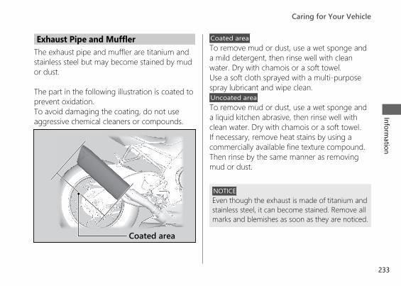
Exhaust Pipe and MufflerThe exhaust pipe and muffler are titanium andstainless steel but may become stained by mudor dust.
The part in the following illustration is coated toprevent oxidation.To avoid damaging the coating, do not useaggressive chemical cleaners or compounds.
Coated areaTo remove mud or dust, use a wet sponge anda mild detergent, then rinse well with cleanwater. Dry with chamois or a soft towel.Use a soft cloth sprayed with a multi-purposespray lubricant and wipe clean.Uncoated areaTo remove mud or dust, use a wet sponge anda liquid kitchen abrasive, then rinse well withclean water. Dry with chamois or a soft towel.If necessary, remove heat stains by using acommercially available fine texture compound.Then rinse by the same manner as removingmud or dust.
NOTICEEven though the exhaust is made of titanium andstainless steel, it can become stained. Remove allmarks and blemishes as soon as they are noticed.
20191113122725_32MKR8000_eng_BOOK Page 236 Wednesday, November 13 2019 12:40:27 JST
Caring for Your VehicleInform
ation
233
Coated area
Storing Your VehicleIf you store your vehicle outdoors, you shouldconsider using a full-body cover.If you won't be riding for an extended period,follow these guidelines:● Wash your vehicle and wax all painted
surfaces (except mat painted surfaces). Coatchrome pieces with rust-inhibiting oil.
● Lubricate the drive chain. 2 P. 143● Place your vehicle on a maintenance stand
and position a block so that both tyres areoff the ground.
● After rain, remove the body cover and allowthe vehicle to dry.
● Remove the battery (2 P. 150) to preventdischarge. Fully charge the battery and thenplace it in a shaded, well-ventilated area.u If you leave the battery in place,
disconnect the negative - terminal toprevent discharge.
After removing your vehicle from storage,inspect all maintenance items required by theMaintenance Schedule.
20191113122725_32MKR8000_eng_BOOK Page 237 Wednesday, November 13 2019 12:40:27 JST
Storing Your Vehicle
Information
234
Continued
Transporting Your VehicleIf your vehicle needs to be transported, itshould be carried on a motorcycle trailer or aflatbed truck or trailer that has a loading rampor lifting platform, and motorcycle tie-downstraps. Never try to tow your vehicle with awheel or wheels on the ground.
NOTICETowing your vehicle can cause serious damageto the transmission.
You & the EnvironmentOwning and riding a vehicle can be enjoyable,but you must do your part to protect theenvironment.
Choose Sensible CleanersUse a biodegradable detergent when you washyour vehicle. Avoid aerosol spray cleaners thatcontain chlorofluorocarbons (CFCs) whichdamage the atmosphere's protective ozonelayer.
20191113122725_32MKR8000_eng_BOOK Page 238 Wednesday, November 13 2019 12:40:27 JST
Transporting Your VehicleInform
ation
235
Recycle WastesPut oil and other toxic wastes in approvedcontainers and take them to a recycling centre.Call your local or state office of public works orenvironmental services to find a recycling centrein your area, and to get instructions on how todispose of non-recyclable wastes. Do not placeused engine oil in the trash, or pour it down adrain or on the ground. Used oil, petrol,coolant, and cleaning solvents contain poisonsthat can hurt refuse workers and contaminatedrinking water, lakes, rivers, and oceans.
20191113122725_32MKR8000_eng_BOOK Page 239 Wednesday, November 13 2019 12:40:27 JST
You & the Environment
Information
236
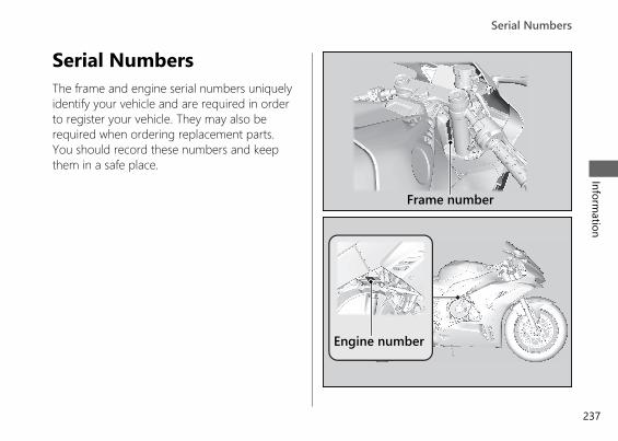
Serial NumbersThe frame and engine serial numbers uniquelyidentify your vehicle and are required in orderto register your vehicle. They may also berequired when ordering replacement parts.You should record these numbers and keepthem in a safe place.
20191113122725_32MKR8000_eng_BOOK Page 240 Wednesday, November 13 2019 12:40:27 JST
Serial NumbersInform
ation
237
Frame number
Engine number
Fuels Containing AlcoholSome conventional fuels blended with alcoholare available in some locales to help reduceemissions to meet clean air standards. If youplan to use blended fuel, check that it isunleaded and meets the minimum octanerating requirement.
The following fuel blends can be used in yourvehicle:● Ethanol (ethyl alcohol) up to 10% by volume.
u Petrol containing ethanol may bemarketed under the name Gasohol.
The use of petrol containing more than 10%ethanol may:● Damage the painting of the fuel tank.● Damage the rubber tubes of the fuel line.● Cause corrosion of the fuel tank.● Cause poor drivability.NOTICEUse of blended fuels containing higher thanapproved percentages can damage metal,rubber, plastic parts of your fuel system.
If you notice any undesirable operatingsymptoms or performance problems, try adifferent brand of petrol.
20191113122725_32MKR8000_eng_BOOK Page 241 Wednesday, November 13 2019 12:40:27 JST
Fuels Containing Alcohol
Information
238
Catalytic ConverterThis vehicle is equipped with a three-waycatalytic converter. The catalytic convertercontains precious metals that serve as catalystsin high temperature chemical reactions thatconvert hydrocarbons (HC), carbon monoxide(CO), and oxides of nitrogen (NOx) in theexhaust gasses into safe compounds.
A defective catalytic converter contributes to airpollution and can impair your engine'sperformance. A replacement unit must be anoriginal Honda part or equivalent.
Follow these guidelines to protect your vehicle'scatalytic converter.● Always use unleaded petrol. Leaded petrol
will damage the catalytic converter.● Keep the engine in good running condition.● Have your vehicle serviced if your engine is
misfiring, backfiring, stalling, or otherwisenot running properly, stop riding and turnoff the engine.
20191113122725_32MKR8000_eng_BOOK Page 242 Wednesday, November 13 2019 12:40:27 JST
Catalytic ConverterInform
ation
239
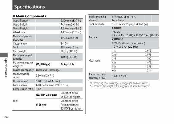
Specifications■ Main ComponentsOverall length 2,100 mm (82.7 in)Overall width 745 mm (29.3 in)Overall height 1,140 mm (44.9 in)Wheelbase 1,455 mm (57.3 in)Minimum groundclearance 115 mm (4.5 in)
Caster angle 24° 00′Trail 102 mm (4.0 in)Curb weight 201 kg (443 lb)Maximum weightcapacity *1 180 kg (397 lb)
Maximum luggageweight *2 (ED, II ED type) 14 kg (31 lb)
Passenger capacity Rider and 1 passengerMinimum turningradius 3.80 m (12.47 ft)
Displacement 1,000 cm3 (61.0 cu-in)Bore x stroke 81.0 x 48.5 mm (3.19 x 1.91 in)Compression ratio 13.2:1
Fuel
(ED, II ED, U, II U type) Unleaded petrol95 RON or higher
(II GS type)Unleaded petrolRecommended:95 RON or higher
Fuel containingalcohol
ETHANOL up to 10 %by volume
Tank capacity 16.1 L (4.25 US gal, 3.54 Imp gal)
Battery
CBR1000STYTZ7S12 V-6 Ah (10 HR) / 12 V-6.3 Ah (20 HR)CBR1000SPHY85S lithium-ion (li-ion)12 V-2.0 Ah (20 HR)
Gear ratio
1st 2.6152nd 2.0583rd 1.7004th 1.4785th 1.3336th 1.214
Reduction ratio(primary / final) 1.630 / 2.500
*1 : Including rider, passenger, all luggages, and accessories*2 : Includes the weight of the luggage and added accessories.
20191113122725_32MKR8000_eng_BOOK Page 243 Wednesday, November 13 2019 12:40:27 JST
Specifications
240

■ Service DataTyre size Front 120/70ZR17M/C (58W)
Rear 200/55ZR17M/C (78W)Tyre type Radial, tubeless
RecommendedTyre
Front BRIDGESTONE RS11FPIRELLI DIABLO SUPERCORSA SP V3
Rear BRIDGESTONE RS11R NPIRELLI DIABLO SUPERCORSA SP V3 E
Tyre category ofuse *1
Normal PermittedSpecial Not PermittedSnow Not PermittedMoped Not Permitted
Tyre air pressure Front 250 kPa (2.50 kgf/cm2, 36 psi)Rear 290 kPa (2.90 kgf/cm2, 42 psi)
Minimum treaddepth
Front 1.5 mm (0.06 in)Rear 2.0 mm (0.08 in)
Spark plug (standard) SILMAR10C9S (NGK)Spark plug gap 0.80 - 0.90 mm (0.031 - 0.035 in)Idle speed 1,400 ± 100 rpm
Recommendedengine oil
Honda 4-stroke motorcycle oil API ServiceClassification SG or higher, excluding oilsmarked as “Energy Conserving” or“Resource Conserving,” SAE 10W-30, JASO T903 standard MA
Engine oilcapacity
Afterdraining 2.8 L (3.0 US qt, 2.5 Imp qt)
Afterdraining &engine oilfilterchange
3.0 L (3.2 US qt, 2.6 Imp qt)
Afterdisassembly 4.0 L (4.2 US qt, 3.5 Imp qt)
Recommendedbrake fluid Honda DOT 4 Brake Fluid
Cooling systemcapacity 2.29 L (2.42 US qt, 2.01 Imp qt)
Recommendedcoolant
India, Nepal, HongKong, Macao
HONDA PRE-MIXCOOLANT
Except India, Nepal,Hong Kong, Macao
Pro Honda HPCoolant
Recommendeddrive chainlubricant
Drive chain lubricant designed specificallyfor O-ring chainsIf not available, use SAE 80 or 90 gear oil.
Drive chain slack 25 - 35 mm (1.0 - 1.4 in)Standard drivechain
DID525HV3KAI or RK525ROZ8No. of links 118
Standardsprocket size
Drive sprocket 16TDriven sprocket 40T
*1 : EU regulation
20191113122725_32MKR8000_eng_BOOK Page 244 Wednesday, November 13 2019 12:40:27 JST
SpecificationsSpecifications
241
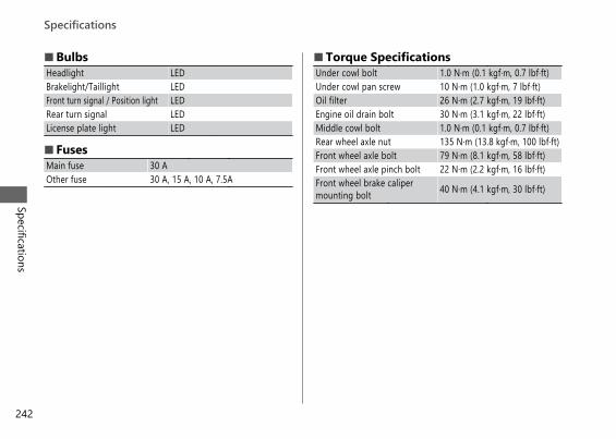
■ BulbsHeadlight LEDBrakelight/Taillight LEDFront turn signal / Position light LEDRear turn signal LEDLicense plate light LED
■ FusesMain fuse 30 AOther fuse 30 A, 15 A, 10 A, 7.5A
■ Torque SpecificationsUnder cowl bolt 1.0 N·m (0.1 kgf·m, 0.7 lbf·ft)Under cowl pan screw 10 N·m (1.0 kgf·m, 7 lbf·ft)Oil filter 26 N·m (2.7 kgf·m, 19 lbf·ft)Engine oil drain bolt 30 N·m (3.1 kgf·m, 22 lbf·ft)Middle cowl bolt 1.0 N·m (0.1 kgf·m, 0.7 lbf·ft)Rear wheel axle nut 135 N·m (13.8 kgf·m, 100 lbf·ft)Front wheel axle bolt 79 N·m (8.1 kgf·m, 58 lbf·ft)Front wheel axle pinch bolt 22 N·m (2.2 kgf·m, 16 lbf·ft)Front wheel brake calipermounting bolt 40 N·m (4.1 kgf·m, 30 lbf·ft)
20191113122725_32MKR8000_eng_BOOK Page 245 Wednesday, November 13 2019 12:40:27 JST
Specifications
Specifications
242
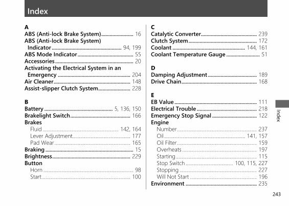
IndexAABS (Anti-lock Brake System)....................... 16ABS (Anti-lock Brake System) Indicator .................................................. 94, 199
ABS Mode Indicator........................................ 55Accessories ........................................................ 20Activating the Electrical System in anEmergency .................................................... 204
Air Cleaner....................................................... 148Assist-slipper Clutch System....................... 228
BBattery ................................................. 5, 136, 150Brakelight Switch........................................... 166Brakes
Fluid ........................................................... 142, 164Lever Adjustment............................................. 177Pad Wear ........................................................... 165
Braking ............................................................... 15Brightness........................................................ 229Button
Horn ...................................................................... 98Start..................................................................... 100
CCatalytic Converter........................................ 239Clutch System................................................. 172Coolant .................................................... 144, 161Coolant Temperature Gauge ........................ 51
DDamping Adjustment ................................... 189Drive Chain...................................................... 168
EEB Value ........................................................... 111Electrical Trouble ........................................... 218Emergency Stop Signal ................................ 122Engine
Number.............................................................. 237Oil ............................................................... 141, 157Oil Filter.............................................................. 159Overheats .......................................................... 197Starting............................................................... 115Stop Switch ..................................... 100, 115, 227Stopping ............................................................ 227Will Not Start .................................................... 196
Environment ................................................... 235
20191113122725_32MKR8000_eng_BOOK Page 246 Wednesday, November 13 2019 12:40:27 JST
Index
243
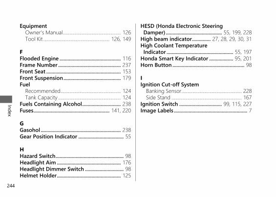
EquipmentOwner’s Manual............................................... 126Tool Kit ...................................................... 126, 149
FFlooded Engine .............................................. 116Frame Number ............................................... 237Front Seat ........................................................ 153Front Suspension........................................... 179Fuel
Recommended................................................. 124Tank Capacity ................................................... 124
Fuels Containing Alcohol............................. 238Fuses......................................................... 141, 220
GGasohol ............................................................ 238Gear Position Indicator .................................. 55
HHazard Switch................................................... 98Headlight Aim ................................................ 176Headlight Dimmer Switch ............................. 98Helmet Holder................................................ 125
HESD (Honda Electronic Steering Damper) .......................................... 55, 199, 228
High beam indicator.............. 27, 28, 29, 30, 31High Coolant Temperature Indicator .................................................. 55, 197
Honda Smart Key Indicator .................. 95, 201Horn Button ...................................................... 98
IIgnition Cut-off System
Banking Sensor................................................. 228Side Stand ......................................................... 167
Ignition Switch ................................ 99, 115, 227Image Labels ....................................................... 7
20191113122725_32MKR8000_eng_BOOK Page 247 Wednesday, November 13 2019 12:40:27 JST
Index
244
IndicatorABS (Anti-lock Brake System) ................ 94, 199ABS Mode............................................................ 55Gear Position....................................................... 55HESD (Honda Electronic Steering Damper).................................................... 55, 199
High Coolant Temperature .................... 55, 197Honda SMART Key ................................... 95, 201Left Turn Signal .................................................. 93Low Oil Pressure ....................................... 55, 198Neutral .................................................................. 95PGM-FI (Programmed Fuel Injection)Malfunction .............................................. 94, 198
Quick Shifter........................................................ 56Right Turn Signal................................................ 93Shift Indicators ............................................. 93, 96Steering Lock ...................................................... 95Torque Control.......................................... 93, 200Torque Control OFF .......................................... 93Warning ............................................................. 198
Indicators........................................................... 93INFO Area .......................................................... 35Instruments ....................................................... 26
LLabel
Accessories and Loading Warning ................ 10Battery ................................................................ 8, 9Colour................................................................. 135FUEL ...................................................................... 12Radiator Cap ....................................................... 10Rear Cushion....................................................... 11Safety Reminder ................................................. 12Tyre Information & Drive Chain ..................... 11
Labels.................................................................... 7Lap timer ..................................................... 32, 57Left Turn Signal Indicator .............................. 93Light
Bulb ..................................................................... 219Lithium-Ion (Li-Ion) Battery.................... 5, 138Load Limits ........................................................ 21Loading Guidelines.......................................... 21Low Oil Pressure Indicator .................... 55, 198
20191113122725_32MKR8000_eng_BOOK Page 248 Wednesday, November 13 2019 12:40:27 JST
Index
245
MMaintenance
Fundamentals ................................................... 134Importance........................................................ 128Safety .................................................................. 128Schedule ............................................................ 129
Maximum Weight Limit ................................. 21Meter
Odometer.......................................................... 227Tachometer Red Zone ................. 27, 28, 29, 31Tripmeter ........................................................... 227
ModeRiding.................................................................. 109Setting................................................................... 62
Modifications.................................................... 20
NNeutral Indicator ............................................. 95
OOdometer ........................................................ 227ÖHLINS Smart EC System............................ 185Oil
Engine ....................................................... 141, 157
Overheating .................................................... 197Owner's Manual .................................... 126, 227
PP Value ............................................................. 111Parking ............................................................... 17Parts Location................................................... 22PASSING/LAP Switch ...................................... 98Petrol........................................................ 124, 238PGM-FI (Programmed Fuel Injection)Malfunction Indicator Lamp (MIL).... 94, 198
Photosensor.................................................... 229Pop-up Information
Failure Information ............................................ 54Helpful .................................................................. 53Maintenance ....................................................... 53Start Mode Information.................................... 54
Protective Apparel........................................... 13
QQuick Shifter ................................................... 118Quick Shifter indicator ................................... 56
20191113122725_32MKR8000_eng_BOOK Page 249 Wednesday, November 13 2019 12:40:27 JST
Index
246
RRear Seat.......................................................... 154Rear Suspension ............................................ 182Recommended
Coolant............................................................... 144Fuel...................................................................... 124Oil ........................................................................ 141
Refuelling ........................................................ 124Removal
Battery ................................................................ 150Clip ...................................................................... 152Front Seat .......................................................... 153Rear Seat............................................................ 154Under Cowl ....................................................... 155
Repair Kit ......................................................... 209Reserve Fuel Mode.......................................... 49Riding Mode ................................................... 109Riding Precautions .......................................... 15Right Turn Signal Indicator ........................... 93
SS Mode............................................................. 111Safety Precautions........................................... 13Serial Numbers............................................... 237
Service Diagnostic Recorders ..................... 222Setting Mode.................................................... 62Shift Indicators ................................................. 93Shifting Gears ................................................. 117Side Stand ....................................................... 167Side Stand Ignition Cut-off System .......... 167Specifications.................................................. 240Speedometer ........................... 27, 28, 29, 30, 31SPORT Mode Display...................................... 32Start Button ............................................ 100, 115Start Mode ...................................................... 119Starting the Engine ....................................... 115STD mode display............................................ 27Steering Lock.................................................. 102Steering Lock Indicator .................................. 95Stopping Engine ............................................ 227Storage
Equipment ......................................................... 125Owner’s Manual............................................... 126Tool Kit ............................................................... 126
Storing.............................................................. 234
20191113122725_32MKR8000_eng_BOOK Page 250 Wednesday, November 13 2019 12:40:27 JST
Index
247
SuspensionFront.................................................................... 179ÖHLINS Smart EC System ............................. 185Rear..................................................................... 182S Mode............................................................... 111
SwitchBrakelight........................................................... 166Engine Stop.............................................. 100, 227Hazard .................................................................. 98Headlight Dimmer ............................................. 98Ignition.................................................................. 99MODE Switch.................................................... 100PASSING/LAP...................................................... 98Sel Down Switch............................................... 100Sel Left/Right Switch ....................................... 100Sel Up Switch .................................................... 100Turn Signal........................................................... 98
Switches ............................................................. 98
TT Value ............................................................. 111Tachometer .................................... 27, 28, 29, 31Tachometer Red Zone ................. 27, 28, 29, 31Throttle ............................................................ 175
Torque Control Indicator ............................... 93Torque Control OFF Indicator....................... 93Transporting ................................................... 235Tripmeter......................................................... 227Troubleshooting ............................................ 195Turn Signal Switch........................................... 98Tyres
Air Pressure ....................................................... 145Puncture............................................................. 209Replacing.................................................. 145, 209
WW Value............................................................ 111Washing Your Motorcycle........................... 229Weight Limit ..................................................... 21Wheels
Front Removal .................................................. 210Rear Removal.................................................... 215
20191113122725_32MKR8000_eng_BOOK Page 251 Wednesday, November 13 2019 12:40:27 JST
Index
248

OWNER’S MANUALEN
CBR
1000ST/SP
CBR1000ST/SP
32MKR80000X32-MKR-8000
XXX.XXXX.XX.LPRINTED IN XXXXX00X32-MKR-8000