ri 9253 - cdc stacks
TRANSCRIPT
RI 9253
() PLEASE 00 Nor REMOVE FRCM LIBRARY
REPORT OF INVESTIGATIONS/1989
u.s. Bureau of Mines ~ Spokane Research Center, E. 315 Montgomery:J~A. VI. I Spokane, WA 99207 .
II B RARY ~." .,/
Relationships Between Annulus Thickness and the Integrity of Resin-Grouted Roof Bolts
By Bryan F. Ulrich, William J. Wuest, and Raymond M. Stateham
BUREAU OF MINES
UNITED STATES DEPARTMENT OF THE INTERIOR
1-
Mission: As the Nation's principal conservation agency, the Department of the Interior has responsibility for most of our nationally-owned public lands and natural and cultural resources. This includes fostering wise use of our land and water resources, protecting our fish and wildlife, preserving the environmental and cultural values of our national parks and historical places, and providing for the enjoyment of life through outdoor recreation . The Department assesses our energy and mineral resources and works to assure that their development is in the best ifl-tefests of all our people. The Department also promotes the goals of the Take Pride in America campaign by encouraging stewardship and citizen responsibility for the public lands and promoting citizen participation in their care. The Department also has a major responsibility for American Indian reservation communities and for people who live in Island Territories under U.S. Administration.
Report of Investigations 9253
Relationships Between Annulus Thickness and the Integrity of Resin-Grouted Roof Bolts
By Bryan F. Ulrich, William J. Wuest, and Raymond M. Stateham
UNITED STATES DEPARTMENT OF THE INTERIOR Manuel Lujan, Jr., Secretary
BUREAU OF MINES --~ T S Ary, Director
Library of Congress ·Cataloging in Publication Data::----------
Ulrich, Bryan F. Relationships between annulus thickness and the integrity of resin-grouted roof
bolts.
(Report of investigations; 9253)
Bibliography: p. 13
Supt. of Docs. no.: I 28.23:9253.
1. Mine roof bolts, Resin. 2. Drilling and boring. 3. Holes. I. Wuest, William J. II. Stateham, Raymond M. III. Title. IV. Series: Report of investigations (United States , Bureau of Mines; 9253).
TN23.U43 [TN289.3] 622 s [622'.334] 88-60722
CONTENTS
U.S. Bureau of Mines Spc :-:i1e Research Center E. ~15 Montgomery Ave. " Spokane, WA 99207 LIBRARY - '---
Page
Abstract. . . . . . . . . . . . . . . . . . . . . . . . . . . . . . . . . . . . . . . . . . . . . . . . . . . . . . . . . . . . . . . . . . . . . . . . . . . 1 Introduction . . . . . . . . . . . . . . . . . . . . . . . . . . . . . . . . . . . . . . . . . . . . . . . . . . . . . . . . . . . . . . . . . . . . . . . . 2 Discussion of tests .... . ................................ . ............................. 2
Test 1 ............. . ....... .................. ... ... .. . .. ... ... .................. 2 Procedures . . . . . . . . . . . . . . . . . . . . . . . . . . . . . . . . . . . . . . . . . . . . . . . . . . . . . . . . . . . . . . . . . . . . . 2 Results ............................................................ ' ........... 2
Test 2 .......................................................................... 7 Procedures . . . . . . . . . . . . . . . . . . . . . . . . . . . . . . . . . . . . . . . . . . . . . . . . . . . . . . . . . . . . . . . . . . . . . 7 Results ....................................................................... 7 Analysis. . . . . . . . . . . . . . . . . . . . . . . . . . . . . . . . . . . . . . . . . . . . . . . . . . . . . . . . . . . . . . . . . . . . . . . 8 Visual examination of bolts . . . . . . . . . . . . . . . . . . . . . . . . . . . . . . . . . . . . . . . . . . . . . . . . . . . . . . . . . 9
Conclusions ............................ ..... . . .. ..................... . . '. . . . . . . . . . . . 13 References . . . . . . . . . . . . . . . . . . . . . . . . . . . . . . . . . . . . . . . . . . . . . . . . . . . . . . . . . . . . . . . . . . . . . . . . . 13
ILLUSTRATIONS
1. Bolts from l-in-diam holes, test 1 . . . . . . . . . . . . . . . . . . . . . . . . . . . . . . . . . . . . . . . . . . . . . . . . . . . . . . 5 2. Bolts from 1-3/8-in-diam holes, test 1 . . . . . . . . . . . . . . . . . . . . . . . . . . . . . . . . . . . . . . . . . . . . . . . . . . . 6 3. Bolt from 1-1/2-in-diam hole showing sleeving ............................................ 7 4. Mean stiffness versus hole diameter .................................................... 8 5. Bolts from l-in-diam holes, test 2 . . . . . . . . . . . . . . . . . . . . . . . . . . . . . . . . . . . . . . . . . . . . . . . . . . . . . . 9 6. Conditions at collar end of resin-grouted bolt when subjected to load ........................... 10 7. Bolts from 1-1/4-in-diam holes, test 2 . . . . . . . . . . . . . . . . . . . . . . . . . . . . . . . . . . . . . . . . . . . . . . . . . . . 11 8. Bolts from 1-1/2-in-diam holes, test 2 . . . . . . . . . . . . . . . . . . . . . . . . . . . . . . . . . . . . . . . . . . . . . . . . . . . 12
TABLES
1. Annulus-thickness investigation data . . . . . . . . . . . . . . . . . . . . . . . . . . . . . . . . . . . . . . . . . . . . . . . . . . . . 3 2. Test 2 pull-test results .............................................. .'............... 8 3. Test 2 postbreakout results ...................................... . ................... 10
UNIT OF MEASURE ABBREVIATIONS USED IN THIS REPORT
ft foot lb pound
m inch lb/in pound per inch
in2 square inch pct percent
in/s inch per second s second
1 RELATIONSHIPS BETWEEN ANNULUS THICKNESS
AND THE INTEGRITY OF RESIN-GROUTED ROOF BOLTS
By Bryan F. Ulrich,1 William J. Wuest,2 and Raymond M. Stateham3
ABSTRACT
If resin-grouted roof bolts are not installed correctly, mine roof reinforcement can be affected, and roof falls can result. A bolt installation variable that is readily controlled by the mine operator is annulus thickness. The objective of this U. S. Bureau of Mines investigation was to study the effect of annulus thickness variations on the integrity of 3/4-in-diam resin-grouted bolts. Forged-head test bolts, 2 and 1 ft long, were installed in concrete blocks that had been drilled with 1-, 1-1/8-, 1-1/4-, 1-3/8-, and 1-1/2-in-diam bits. Standard pull tests were performed; then the concrete was broken away from the bolts so that grout mix quality could be inspected. It was found that the optimum annulus thickness is 1/8-in (l-in-diam drill hole), and as annulus thickness increases from the optimum, there is a corresponding decrease in grout mix quality, effective grout ratio, and axial stiffness.
IMining engineer (now with Knight Piesold and Co., Denver, CO). 2Mining engineer. 3Supervisory geophysicist (retired). Denver Research Center, U.S. Bureau of Mines, Denver, CO.
2
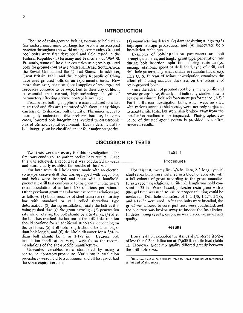
INTRODUCTION
The use of resin-grouted bolting systems to help stabilize underground mine workings has become an accepted practice throughout the world mining community. Grouted roof bolts were first developed and field tested in the Federal Republic of Germany and France about 1969-70. Presently, some of the other countries using resin-grouted bolts for ground control are Australia, Brazil, South Africa, the Soviet Union, and the United States. In addition, Great Britain, India, and the People's Republic of China have used grouted bolts on an experimental basis. Now more than ever, because global supplies of underground resources continue to be important to their way of life, it is essential that current, high-technology analysis of parameters affecting ground control is available.
From when bolting supplies are manufactured to when mine roof and ribs are reinforced with them, many things can happen to decrease bolt integrity. The miner needs to thoroughly understand this problem because, in some cases, lowered. bolt integrity has resulted in catastrophic loss of life and capital equipment. Events detrimental to bolt integrity can be classified under four major categories:
(1) manufacturing defects, (2) damage during transport,(3) improper storage procedures, and (4) inaccurate boltinstallation technique.
Examples of bolt-installation parameters are bolt strength, diameter, and length, grout type, penetration rate during bolt insertion, spin time during resin-catalyst mixing, rotational speed of drill head, type of drill, and drill-hole pattern, length, and diameter (annulus thickness). This U. S. Bureau of Mines investigation examines the effect of altering annulus thickness on the integrity of resin-grouted bolts.
Since the advent of grouted roof bolts, many public and private groups have, directly and indirectly, studied how to achieve maximum bolt reinforcement performance (1_7).4 For this Bureau investigation bolts, which were installed with various annulus thicknesses, were not orily subjected to axial-tensile tests, but were also broken away from the installation medium to be inspected. Photographic evidence of the steel-grout system is provided to confirm research results.
DISCUSSION OF TESTS
Two tests were necessary for this investigation. The first was conducted to gather preliminary results. Once this was achieved, a second test was conducted-to verify and more clearly establish the results of the first.
For both tests, drill holes were made with an electric, rotary-percussive drill that was equipped with auger bits, and bolts were inserted and spun with a handheld, pneumatic drill that conformed to the grout manufacturer's recommendation of at least 100 rotations per minute. Other pertinent grout manufacturer recommendations are as follows: (1) bolts must be of steel concrete reinforcing bar with standard or mill rolled threadbar type deformation, (2) during installation, rotate the bolt as it is being pushed through the grout cartridge, (3) penetration rate while rotating the bolt should be 2 to 4 in/s, (4) after the bolt has reached the bottom of the drill hole, rotation should continue for an additional 10 to 15 s, depending on the gel time, (5) drill-hole length should be 1 in longer than bolt length, and (6) drill-hole diameter for a 3/4-indiam bolt should be 1 or 1-1/8 in. Because bolt installation specifications vary, always follow the recommendations of the site-specific manufacturer.
Unwanted variables were eliminated by using a controlled laboratory procedure. Variations in installation procedures were held to a minimum and all test grout had the same expiration date.
TEST 1
Procedures...
For this test, twenty-five 3/4-in-diam, 2-ft-long, type 40 steel-rebar bolts were installed in a block of concrete with a full column of grout according to the grout manufacturer's recommendations. Drill-hole length was held constant at 25 in. Water-based, polyester-resin grout with a 9O-s gel time was used to assure proper spinning could be achieved. Drill-hole diameters of 1, 1-1/8, 1-1/4, 1-3/8, and 1-1/2 in were used. After the bolts were installed, the grout was allowed to cure, pull tests were conducted, and the concrete was broken away to inspect the installation. In determining results, emphasis was placed on grout mix quality.
Results
Every test bolt exceeded the standard pull-test criterion ofless than O.2-in deflection at 17,600-lb tensile load (table 1). However, grout mix quality differed greatly between the drill-hole sizes.
4ltalic numbers in parentheses refer to items in the list of references at the end of this report.
3
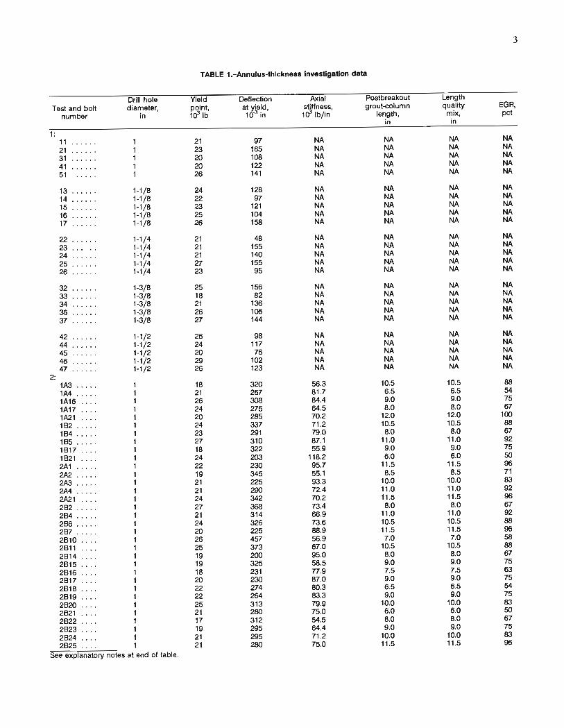
TABLE 1.-Annulus-thlckness Investigation data
Drill hole Yield Deflection Axial Postbreakout Length Test and bolt diameter, point, at yield, stiffness, grout-column quality EGA,
number in 103lb 10-3 in 103lb/in length, mix, pet in in
1 : 11 21 97 NA NA NA NA 21 23 165 NA NA NA NA 31 20 108 NA NA NA NA 41 20 122 NA NA NA NA 51 26 141 NA NA NA NA
13 1-1/8 24 128 NA NA NA NA 14 1-1/8 22 97 NA NA NA NA 15 1-1/8 23 121 NA NA NA NA 16 ...... 1-1 /8 25 104 NA NA NA NA 17 ...... 1-1/8 26 158 NA NA NA NA
22 . ..... 1-1/4 21 48 NA NA NA NA 23 .. .. .. _- 1-1/4 21 155 NA NA NA NA 24 1-1/4 21 140 NA NA NA NA 25 1-1/4 27 155 NA NA NA NA 26 1-1/4 23 95 NA NA NA NA
32 ... .. . 1-3/8 25 156 NA NA NA NA 33 ... ... 1-3/8 18 82 NA NA NA NA 34 .... .. 1-3/8 21 136 NA NA NA NA 36 ...... 1-3/8 26 106 NA NA NA NA 37 ...... 1-3/8 27 144 NA NA NA NA
42 .. .. .. 1-1/2 26 98 NA NA NA NA 44 . .. ... 1-1/2 24 117 NA NA NA NA 45 .. .... 1-1/2 20 76 NA NA NA NA 46 . . ... . 1-1/2 29 102 NA NA NA NA 47 .. .... 1-1/2 26 123 NA NA NA NA
2: 1A3 ..... 1 18 320 56.3 10.5 10.5 88 1A4 ..... - 1 21 257 81.7 6.5 6.5 54 1A16 . ... 1 26 308 84.4 9.0 9.0 75 1A17 .. .. 1 24 275 64.5 8.0 8.0 67 1A21 .... 1 20 285 70.2 12.0 12.0 100 182 .... . 1 24 337 71 .2 10.5 10.5 88 184 ..... 1 23 291 79.0 8.0 8.0 67 185 ... .. 1 27 310 87.1 11.0 11 .0 92 1817 .... 1 18 322 55.9 9.0 9.0 75 1821 .... 1 24 203 118.2 6.0 6.0 50 2A1 ..... 1 22 230 95.7 11 .5 11.5 96 2A2 ..... 1 19 345 55.1 8.5 8.5 71 2A3 ..... 1 21 225 93.3 10.0 10.0 83 2A4 ..... 1 21 290 72.4 11.0 11.0 92 2A21 .... 1 24 342 70.2 11 .5 11.5 96 282 ... .. 1 27 368 73.4 8.0 8.0 67 284 .. ... 1 21 314 66.9 11.0 11.0 92 286 ..... 1 24 326 73.6 10.5 10.5 88 287 ..... 1 20 225 88.9 11 .5 11.5 96 2810 .. .. 1 26 457 56.9 7.0 7.0 58 2811 .... 1 25 373 67.0 10.5 10.5 88 2814 .... 1 19 200 95.0 8.0 8.0 67 2815 . ... 1 19 325 58.5 9.0 9.0 75 2816 . . .. 1 18 231 n .9 7.5 7.5 63 2817 .... 1 20 230 87.0 9.0 9.0 75 2818 .... 1 22 274 80.3 6.5 6.5 54 2819 .... 1 22 264 83.3 9.0 9.0 75 2820 .... 1 25 313 79.9 10.0 10.0 83 2821 1 21 280 75.0 6.0 6.0 50 2822 . .. . 1 17 312 54.5 8.0 8.0 67 2823 ... . 1 19 295 64.4 9.0 9.0 75 2824 .... 1 21 295 71 .2 10.0 10.0 83 2825 .... 1 21 280 75.0 11 .5 11.5 96
See explanatory notes at end of table.
4
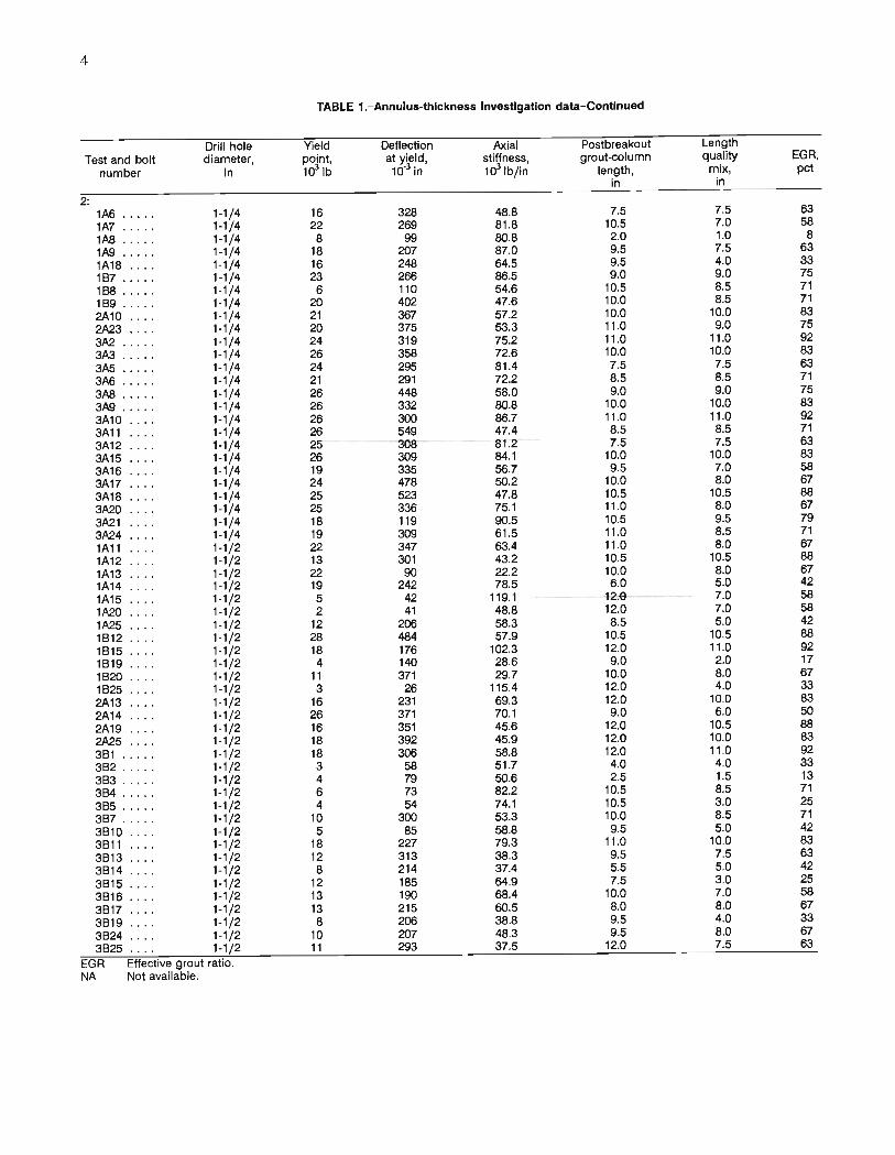
TABLE 1. - Annulus-thickness Investigation data-Continued
Drill hole Yield Deflection Axial Postbreakout Length
Test and bolt diameter, point, at yield, stiffness, grout-column quality EGR,
number in 1et Ib 10-3 in 103 1b/in length, mix, pet in in
2: 1A6 ..... 1-1/4 16 328 48.8 7.5 7.5 63
1A7 .... . 1·1/4 22 269 81.8 10.5 7.0 58
1AB .. ... 1·1/4 8 99 SO.8 2.0 1.0 8
1A9 . .... 1·1/4 18 207 87.0 9.5 7.5 63
1A18 .... 1-1/4 16 248 64.5 9.5 4.0 33
187 ..... -- 1-1/4 23 266 86.5 9.0 9.0 75
188 ... .. 1-1/4 6 110 54.6 10.5 8.5 71
189 ... .. 1-1/4 20 402 47.6 10.0 8.5 71
2A10 . .. . 1-1/4 21 367 57.2 10.0 10.0 83 2A23 .. .. 1-1/4 20 375 53.3 11 .0 9.0 75
3A2 ..... 1-1/4 24 319 75.2 11.0 11 .0 92
3A3 1-1/4 26 358 72.6 10.0 10.0 83 3A5 1-1/4 24 295 81.4 7.5 7.5 63
3A6 .. .. . 1-1/4 21 291 72.2 8.5 8.5 71
3AB ..... 1-1/4 26 448 58.0 9.0 9.0 75
3A9 ..... 1-1/4 26 332 SO.8 10.0 10.0 83 3A10 1-1/4 26 300 86.7 11.0 11.0 92
3A11 1-1/4 26 549 47.4 8.5 8.5 71
3A12 1-1/4 25 308 81.2 7.5 7.5 63
3A15 1-1/4 26 309 84.1 10.0 10.0 83 3A16 1-1/4 19 335 56.7 9.5 7.0 58
3A17 1-1/4 24 478 SO.2 10.0 8.0 67
3A18 1-1/4 25 523 47.8 10.5 10.5 88
3A20 1-1/4 25 336 75.1 11.0 8.0 67
3A21 1-1/4 18 119 90.5 10.5 9.5 79
3A24 1-1/4 19 309 61.5 11.0 8.5 71
1A11 1-1/2 22 347 63.4 11.0 8.0 67
1A12 1-1/2 13 301 43.2 10.5 10.5 88
1A13 1-1/2 22 90 22.2 10.0 8.0 67
1A14 1-1/2 19 242 78.5 6.0 5.0 42
1A15 1-1/2 5 42 119.1 --12.0 7.0 58
1A20 1-1/2 2 41 48.8 12.0 7.0 58
1A25 1-1/2 12 206 58.3 8.5 5.0 42
1812 .. .. 1-1/2 28 484 57.9 10.5 10.5 88
1815 .... 1-1/2 18 176 102.3 12.0 11.0 92
1819 1-1/2 4 140 28.6 9.0 2.0 17
1820 1-1/2 11 371 29.7 10.0 8.0 .67
1625 .. .. 1-1/2 3 26 115.4 12.0 4.0 33
2A13 1-1/2 16 231 69.3 12.0 10.0 83 2A14 1-1/2 26 371 70.1 9.0 6.0 SO
2A19 . ... 1-1/2 16 351 45.6 12.0 10.5 88
2A25 .... 1-1/2 18 392 45.9 12.0 10.0 83 361 . . . .. 1-1/2 18 306 58.8 12.0 11 .0 92
362 ..... 1-1/2 3 58 51.7 4.0 4.0 33
363 .... . 1-1/2 4 79 SO.6 2.5 1.5 13
364 ... .. 1-1/2 6 73 82.2 10.5 8.5 71
365 ..... 1-1/2 4 54 74.1 10.5 3.0 25
367 ..... 1-1/2 10 300 53.3 10.0 8.5 71
3610 . .. . 1-1/2 5 85 58.8 9.5 5.0 42
3611 1-1/2 18 227 79.3 11 .0 10.0 83 3613 1-1/2 12 313 38.3 9.5 7.5 63
3614 .. . . 1-1/2 8 214 37.4 5.5 5.0 42
3615 .... 1-1/2 12 185 64.9 7.5 3.0 25
3616 1-1/2 13 190 68.4 10.0 7.0 58
3617 1-1/2 13 215 60.5 8.0 8.0 67
3619 .... 1-1/2 8 206 38.8 9.5 4.0 33
3624 .... 1-1/2 10 207 48.3 9.5 8.0 67
3625 .. . . 1-1/2 11 293 37.5 12.0 7.5 63
EGR Effective grout ratio. NA Not available.
t I
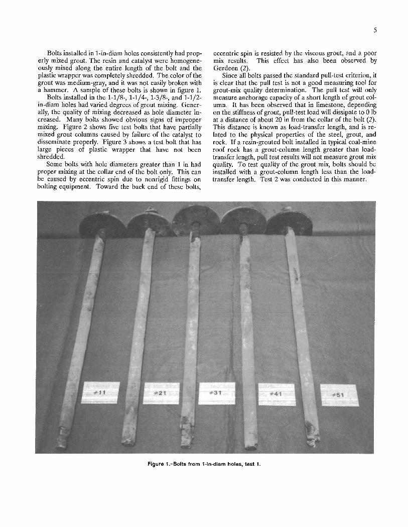
Bolts installed in 1-in-diam holes consistently had properly mixed grout. The resin and catalyst were homogeneously mixed along the entire length of the bolt and the plastic wrapper was completely shredded. The color of the grout was medium-gray, and it was not easily broken with a hammer. A sample of these bolts is shown in figure 1.
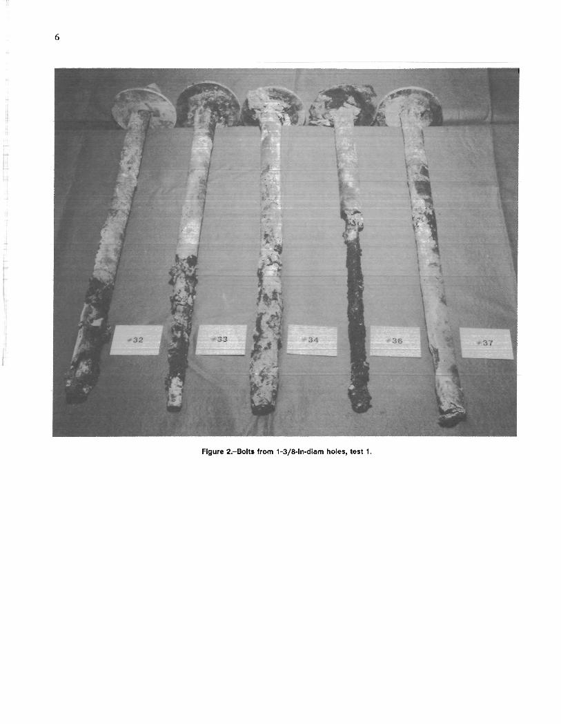
Bolts installed in the 1-1/8-, 1-1/4-, 1-3/8-, and 1-1/2-in-diam holes had varied degrees of grout mixing. Generally, the quality of mixing decreased as hole diameter increased. Many bolts showed obvious signs of improper mixing. Figure 2 shows five test bolts that have partially mixed grout columns caused by failure of the catalyst to disseminate properly. Figure 3 shows a test bolt that has large pieces of plastic wrapper that have not been shredded.
Some bolts with hole diameters greater than 1 in had proper mixing at the collar end of the bolt only. This can be caused by eccentric spin due to nonrigid fittings on bolting equipment. Toward the back end of these bolts,
5
eccentric spin is resisted by the viscous grout, and a poor mix results. This effect has also been observed by Gerdeen (2). ,
Since all bolts passed the standard pull-test criterion, it is clear that the pull test is not a good measuring tool for grout-mix quality determination. The pull test will only measure anchorage capacity of a short length of grout column. It has been observed that in limestone, depending on the stiffness of grout, pull-test load will dissipate to 0 lb at a distance of about 20 in from the collar of the bolt (2). This distance is known as load-transfer length, and is related to the physical properties of the steel, grout, and rock. If a resin-grouted bolt installed in typical coal-mine roof rock has a grout -column length greater than loadtransfer length, pull test results will not measure grout mix quality. To test quality of the grout mix, bolts should be installed with a grout-column length less than the loadtransfer length. Test 2 was conducted in this manner.
Figure 1. -Bolts from 1-ln-dlam holes, test 1.
6
Figure 2.-80lts from 1-3/8-ln-dlam holes, test 1.
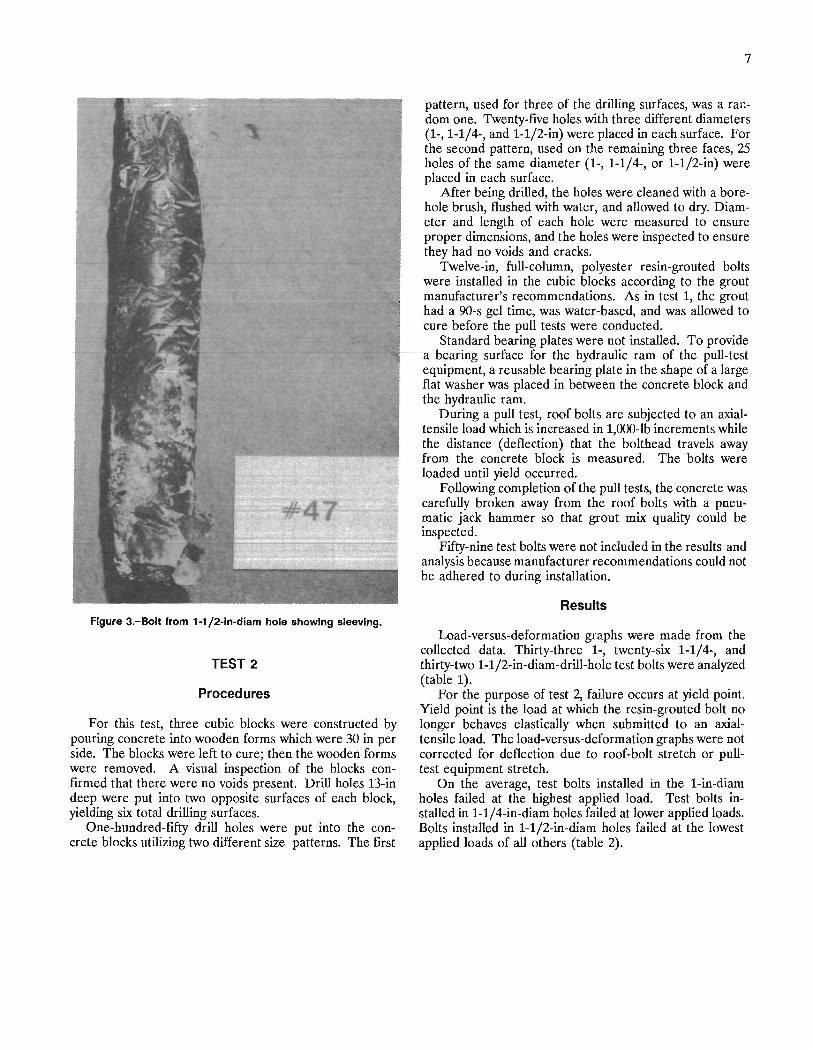
#47
Figure 3.-Bolt from 1-1/2-ln-dlam hole showing sleevlng.
TEST 2
Procedures
For this test, three cubic blocks were constructed by pouring concrete into wooden forms which were 30 in per side. The blocks were left to cure; then the wooden forms were removed. A visual inspection of the blocks confIrmed that there were no voids present. Drill holes 13-in deep were put into two opposite surfaces of each block, yielding six total drilling surfaces.
One-hundred-fIfty drill holes were put into the concrete blocks utilizing two different size patterns. The fIrst
7
pattern, used for three of the drilling surfaces, was a random one. Twenty-fIve holes with three different diameters (1-,1-1/4-, and 1-1/2-in) were placed in each surface. For the second pattern, used on the remaining three faces, 25 holes of the same diameter (1-, 1-1/4-, or 1-1/2-in) were placed in each surface.
After being drilled, the holes were cleaned with a borehole brush, flushed with water, and allowed to dry. Diameter and length of each hole were measured to ensure proper dimensions, and the holes were inspected to ensure they had no voids and cracks.
Twelve-in, full-column, polyester resin-grouted bolts were installed in the cubic blocks according to the grout manufacturer's recommendations. As in test 1, the grout had a 9O-s gel time, was water-based, and was allowed to cure before the pull tests were conducted.
Standard bearing plates were not installed. To provide a bearing surface for the hydraulic ram of the pull-test equipment, a reusable bearing plate in the shape of a large flat washer was placed in between the concrete block and the hydraulic ram.
During a pull test, roof bolts are subjected to an axialtensile load which is increased in 1,OOO-lb increments while the distance (deflection) that the bolthead travels away from the concrete block is measured. The bolts were loaded until yield occurred.
Following completion of the pull tests, the concrete was carefully broken away from the roof bolts with a pneumatic jack hammer so that grout mix quality could be inspected.
Fifty-nine test bolts were not included in the results and analysis because manufacturer recommendations could not be adhered to during installation.
Results
Load-versus-deformation graphs were made from the collected data. Thirty-three 1-, twenty-six 1-1/4-, and thirty-two 1-1/2-in-diam-drill-hole test bolts were analyzed (table 1).
For the purpose of test 2, failure occurs at yield point. Yield point is the load at which the resin-grouted bolt no longer behaves elastically when submitted to an axialtensile load. The load-versus-deformation graphs were not corrected for deflection due to roof-bolt stretch or pulltest equipment stretch.
On the average, test bolts installed in the 1-in-diam holes failed at the highest applied load. Test bolts installed in 1-1/4-in-diam holes failed at lower applied loads. Bolts installed in 1-1/2-in-diam holes failed at the lowest applied loads of all others (table 2).
8
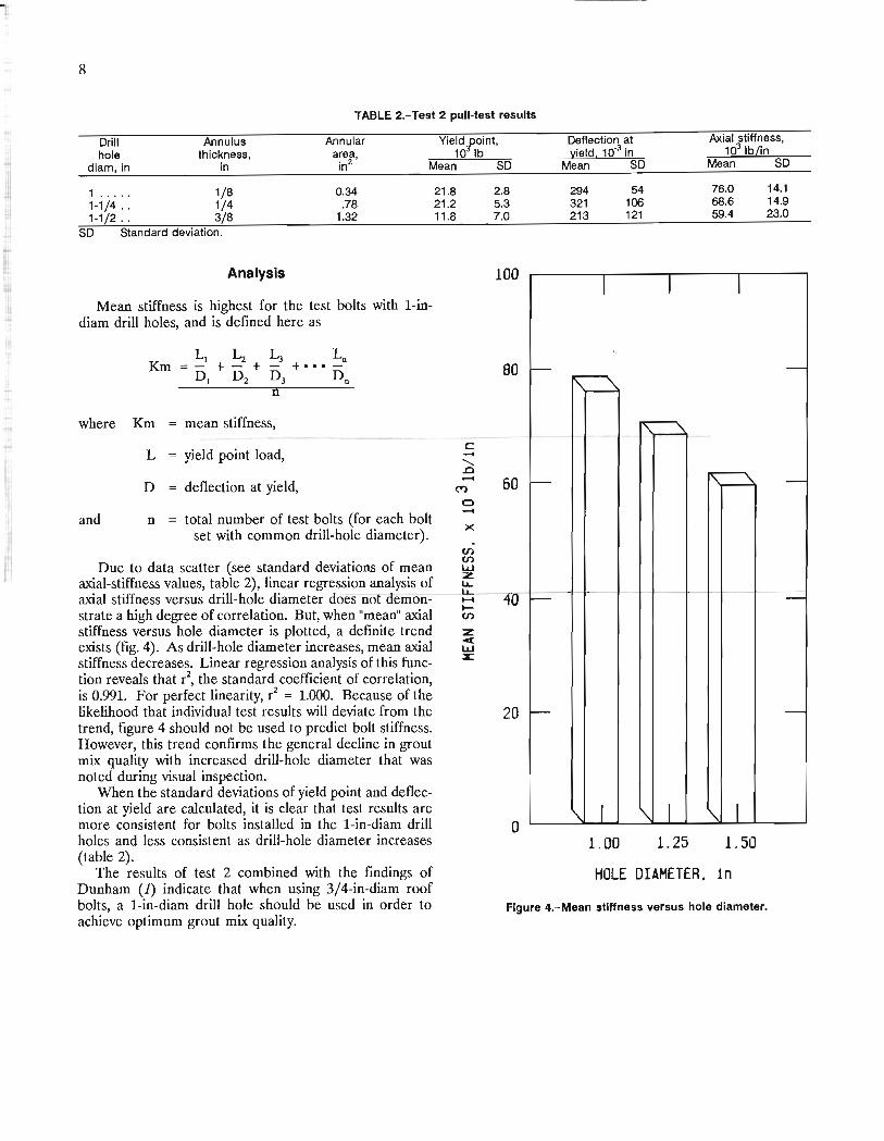
TABLE 2.-Test 2 pull-test results
Annular Yield f,oint, area, 10 Ib
Orill hole
diam, in
Annulus thickness,
in in2 Mean SO
1 . . . . . 1/8 0.34 1-1/4 . . 1/4 .78 1-1/2 . . 3/8 1.32
SO Standard deviation.
Analysis
Mean stiffness is highest for the test bolts with 1-indiam drill holes, and is defmed here as
Km
where Km mean stiffness,
L yield point load,
D deflection at yield,
and n total number of test bolts (for each bolt set with common drill-hole diameter).
Due to data scatter (see standard deviations of mean axial-stiffness values, table 2), linear regression analysis of axial stiffness versus drill-hole diameter ooes not demonstrate a high degree of correlation. But, when "mean" axial stiffness versus hole diameter is plotted, a defmite trend exists (fig. 4). As drill-hole diameter increases, mean axial stiffness decreases. Linear regression analysis of this function reveals that r2, the standard coefficient of correlation, is 0.991. For perfect linearity, r2 = 1.000. Because of the likelihood that individual test results will deviate from the trend, figure 4 should not be used to predict bolt stiffness. However, this trend confirms the general decline in grout mix quality with increased drill-hole diameter that was noted during visual inspection.
When the standard deviations of yield point and deflection at yield are calculated, it is clear that test results are more consistent for bolts installed in the 1-in-diam drill holes and less consistent as drill-hole diameter increases (table 2).
21 .8 21.2 11.8
c ..... ........ .0 ....
x
2.8 5.3 7.0
100
80
60
40
20
o
Deflection at Axial stiffness, llield, 10-3 in 103 Ib/in
Mean SO Mean SO
294 54 76.0 14.1 321 106 68.6 14.9 213 121 59.4 23.0
1.00 1.25 1.50
HOLE DIAMETER, in The results of test 2 combined with the fmdings of Dunham (1) indicate that when using 3/4-in-diam roof bolts, a 1-in-diam drill hole should be used in order to achieve optimum grout mix quality.
Figure 4.-Mean stiffness versus hole diameter.

f Visual Examination of Bolts
Once broken away from the concrete blocks, the bolts were inspected. The grout from test bolts installed in 1-in-diam drill holes was well mixed and hard to break with a hammer (fig. 5). Although these bolts were installed with a full grout column, 2 to 3 in of grout at the collar end of the drill hole was missing. This grout could have been absent because the impact from the jack hammer during bolt breakout separated the partially debonded portion of the grout column from the bolt. Tadolini (6) and Yap (7) have observed similar roof-bolt behavior. Yap's fmdings, which provide a possible explanation of this
9
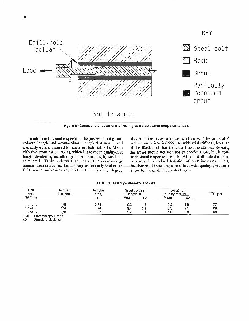
event, maintain that when a resin-grouted bolt is sUbjected to a pull test, a decrease of bolt diameter, due to Poisson's effect in the steel, causes partial debonding at the steelgrout interface near the collar end of the bolt (fig. 6).
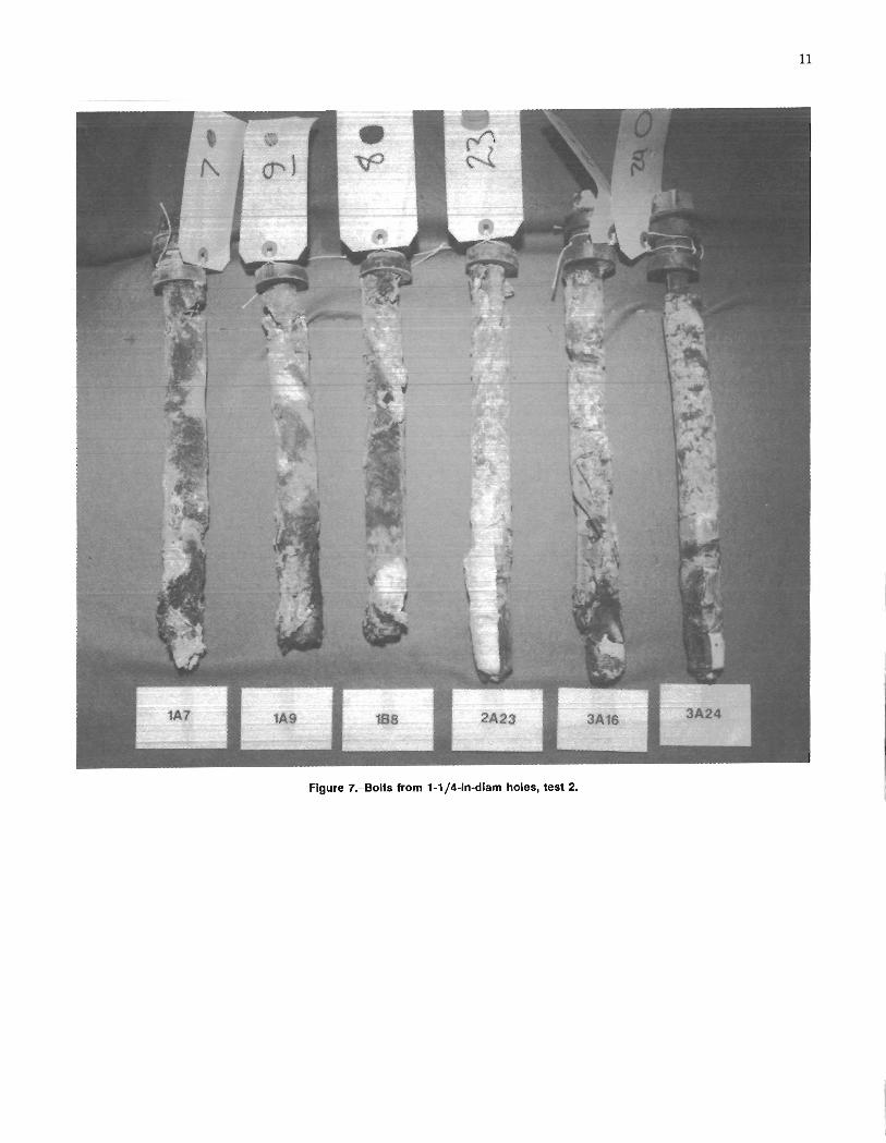
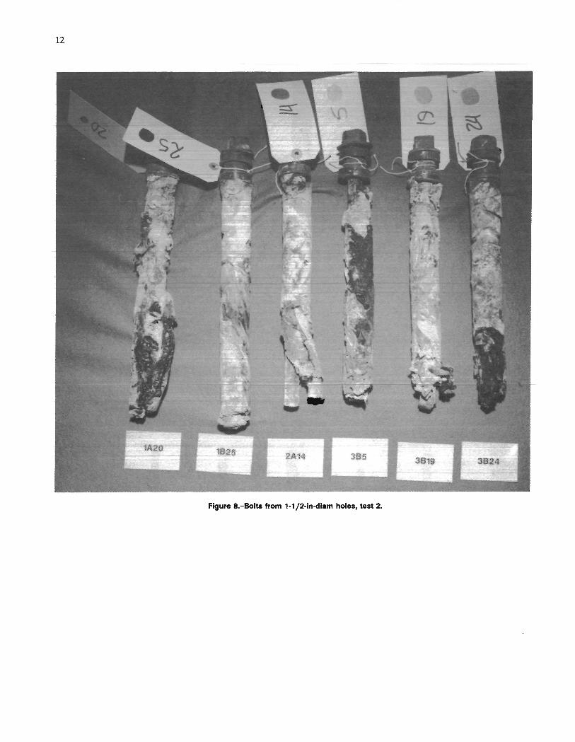
The grout from test bolts in the 1-1/4- and 1-1/2-in-diam drill holes was soft, black, and sticky. The remaining grout -column length was longer than that on bolts with 1-in-diam drill holes. Large pieces of plastic wrapper were present, especially in the grout from the set of bolts with 1-1/2-in-diam holes (figs. 7-8). The grout in the bottom 1 in of all tested drill-hole diameters was not mixed at all.
Figure 5.-Bolts from 1-ln-diam holes, test 2.
10
Dri II-hole collar
Load -
~
0
II
III
KEY
Steel bolt
Rock
Grout
Partially debonded grout
Not to scale Figure 6.-Condltlons at collar end of resin-grouted bolt when subjected to load.
In addition to visual inspection, the postbreakout groutcolumn length and grout-column length that was mixed correctly were measured for each test bolt (table 1). Mean effective grout ratio (EGR), which is the mean quality-mix length divided by installed grout -column length, was then calculated. Table 3 shows that mean EGR decreases as annular area increases. Linear-regression analysis of mean EGR and annular area reveals that there is a high degree
of correlation between these two factors. The value of r2 in this comparison is 0.999. As with axial stiffness, because of the likelihood that individual test results will deviate, this trend should not be used to predict EGR, but it confIrms visual inspection results. Also, as drill-hole diameter increases the standard deviation of EGR increases. Thus, the-chanGe-of installing-a TOgf bglt with quality grout mix is low for large diameter drill holes.
TABLE 3.-Test 2 postbreakout results
Drill Annulus Annular Grout-column Length of hole thickness, area, length, in guali~ mix, in EGR, pet
diam, in in in2 Mean SO Mean SO
1 ..... 1/8 0.34 9.2 1.8 9.2 1.8 77 1-1/4 .. 1/4 .78 9.4 1.9 8.3 2.1 69 1-1/2 .. 3/8 1.32 9.7 2.4 7.0 2.8 58
EGR Effective grout ratio SO Standard deviation
11
Figure 7.-80Its from 1-1/4-ln-dlam holes, test 2.
12
Figure a.-Bolts from 1-1/2-ln-dlam holes, test 2.
I
r
13
CONCLUSIONS
Resin-grouted roof bolt integrity is directly related to annulus thickness. The results of this investigation indicate that, for a 3/4-in diam roof bolt installed in competent rock, optimum annulus thickness is 1/8 in (l-in-diam drill hole). As annulus thickness increases from the optimum, grout mix quality, EGR, and axial stiffness will decrease.
When using a standard pull test to measure grouted bolt integrity, it is difficult to detect grout mix quality if
grout-column length is greater than load-transfer length. From this investigation it appears that visual examination, although somewhat subjective, is better than the pull test for determining grout mix quality, even for short column lengths.
REFERENCES
1. Dunham, R K Field Testing of Resin Anchored Rock Bolts. Colliery Guardian, May 1974, pp. 146-151.
2. Gerdeen, J. c., V. W. Snyder, G. L. Viegelahn, and J. Parker. Design Criteria for Roof Bolting Plans Using Fully Resin-Grouted Nontensioned Bolts To Reinforce Bedded Mine Roof. Volume 1. Executive Summary and Literature Review (contract J0366004, MI Techno!. Univ.). BuMines OFR 46(1)-80, 1977, pp. 31-202; NTIS PB 80-180052.
3. Grant, F., R M. Wigelsworth, and K Charlton. Underground Strata Control with Resin Grouted Roof Bolts in McIntyre Mines Coal Operations. Paper in Stability in Coal Mining (Proc. 1st Int. Symp. on Stability in Coal Mining, Vancouver, British Columbia, Canada, 1978). Miller Freeman, 1979, 203 pp.
• u.s. GOVERNMENT PRINTING OFFICE: 611-012100.094
4. Pettibone, H. C. Avoiding Anchorage Problems With ResinGrouted Roof Bolts. BuMines RI 9129, 1987, 28 pp.
5. Scott, J. J. Executive Summary. Research and Development Priorities: Summary Report for March 1, 1974 to March 31, 1977. Volume 1 (contract H0242034, Univ. MO-Rolla). BuMines OFR 80(1)-77, 1977, 148 pp.; NTIS PB 266786.
6. Tadolini, S. C. Anchorage Capacities in Thick Coal Roofs. BuMines IC 9058, 1986, 13 pp.
7. Yap, L. D., and A. A. Rodger. A Study of the Behavior of Vertical Rock Anchors Using the Finite Element Method. Int. J. Rock Mech. and Min. Sci., v. 21, No.2, 1984, pp. 47-61.
INT.BU.OF MINES,PGH.,PA 28939