references - uom ir
TRANSCRIPT
References
[1] Vladimir A. Rakov and Martin A. Uman, Lightning Physics and Effects,
Cambridge: Cambridge University Press, 2003, [E-Book]
Available:http://www.cambridge.org, [Accessed: 22nd September 201 0]
[2] A. Morched, B. Gustavsen, M. Tartibi, A Universal Line Model for Accurate Calculation ofElectromagnetic Transients on Overhead Lines and Cables, Paper PE-
112-PWRD-0-11-1997
[3] J. Rohan Lucas, High Voltage Engineering, Revised edition 2001, Open
University of Sri Lanka, Open University Press, 2001
[ 4] K.S.S. Kumara, "Lightning Performance of Sri Lankan Transmission Lines: A
Case Study", M.Sc. thesis, University of Moratuwa, Katubedda, Sri Lanka, 2009
[5] Gi-ichi Ikeda, "Report on Lightning Conditions in Ceylon, and Measures to
Reduce Damage to Electrical Equipment", Asian Productivity Project TES/68, 1969
[6] EPRI, "Handbook for Improving Overhead Transmission Line Lightning Performance", EPRI, Palo Alto, CA: 2004. 1002019
[7] M. Kizilcay, C. Neumann, "Back Flashover Analysis for II OkV Lines at MultiCircuit Overhead Line Towers", International Conference on Power Systems Transients (IPST'07) in Lyon, France on June 4-7,2007
[8] Canadian/American EMTP User Group: ATP Rule Book, Distributed by the
European EMTP-A TP Users Group Association, 2005
[9] Chisholm, W. A.; Chow, Y. L.; Srivastara, K.D: "Travel Time ofTransmission
Towers", IEEE Trans. on Power App. And Systems, Vol. PAS-104, No. 10, S.2922-
2928, October 1985
[I 0] CIGRE WG 33-0 I: "Guide to Procedures for Estimating the Lightning
Performance of Transmission Lines", Technical Brochure, October 1991.
[II] Manitoba HVDC Research Centre, "Applications of PSCAD/EMTDC",
Application Guide 2008, Manitoba HVDC Research Centre Inc., Canada
[ 12] IEEE Working Group 3 .4.1 I, "Modeling of Metal Oxide Surge Arresters," IEEE
Transactions ofPower Delivery, Vol. 7, No.I, January 1992, pp 302-309
[13] ABB, "High Voltage Surge Arresters" Buyer's Guide 2008-08, Ed.6, ABB AB,
Sweden
Page I 63
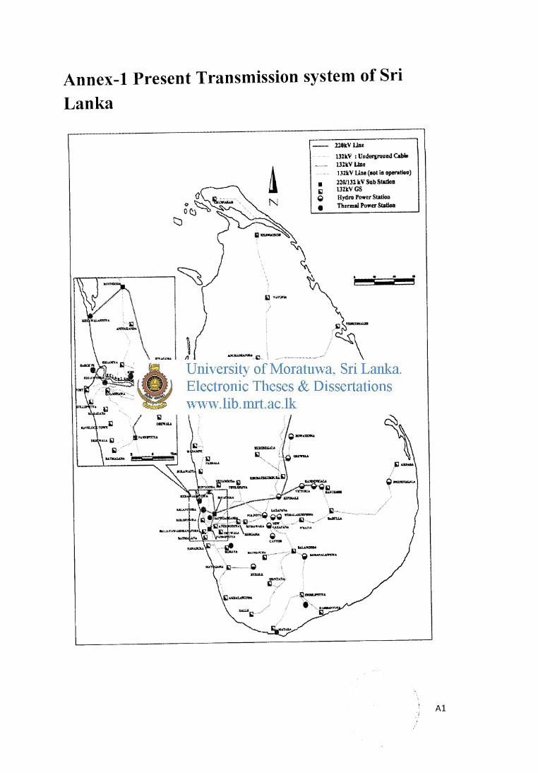
Annex-1 Present Transmission system of Sri
Lanka
1 :UOkV J..lM
13lkV : Undergroulld Clhle lJZlr.V Ulle 132kV Ulle (1101 ill openlloe)
• l2G/Ul leV Sub Stltloll 1iJ 132l:VGS Q Hydro Power SW:ion e TILermal Powu Station
•
"-"""" \
~ 'c > .l.d»&...,.
'""":OQ Q~ ......._...._ - lil """"' . . iil-,_. '\ fltnW.._,...._. ·~~,t.,"UJ. -~ lf'U.iU
....... _ (ii'••-U:tUfAl'"' '\"'" y-.,.,.,.......f'T(.. U .. ~
fa~· ..........
............ -..~~-"'"" >il ''Q ~~AW'n'-4
~ ..,.,... Dl.'ln4<1.\
lil
.. ·Sl--·
Al
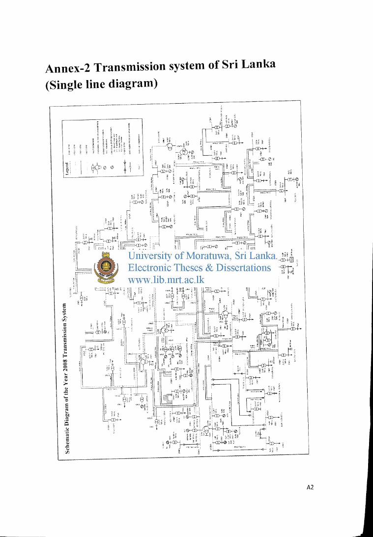
Annex-2 Transmission system of Sri Lanka
(Single line diagram)
"g "' ';~'
.:~
E ~ "' ....
rJ]
= 0 '<il ,.,. ·e 'Jl
= ,. :.. ~ 00 0 0 M .... ,. ... >-... ; '0 E ,. ,_ e£ ,. Q ·E ,. E ... .c 'J
rJ]
: g: ill}; H~ ~ ··--1'-<0·· ··· GL>-:i-0
' ;: "!Q-:-;~ i ,.''_ :.lll. ! "i .
,T .. • ~r~;~~. ~-~ .~-!-. ~-~~ ,~ ~~,~.:~ .--.. · "
i
" :: ; ~ ~;
i i i!~ ~
. . '-"~".. ~- iL I~ . . "'"·~, rr·~.;,:~' , . !-""'· . " ·r ,_; . 4-4t<I~~.~J·,.,lr~~; ~~~l: -~~-7:~~ l', t (\ ~ ! .·'~ rr·"' ; fF·«>WO V'~ ~ '"" '" ; l] >• i
'• ' . ·· ...... : Jl]f' !" I i
-~~~~l·~,~,JJ~~ -'::;-~,,-_ . ,l}, --L~.tt·· .. _; ~~... -r<;c ' .:: : ~;; ' -, ' +- i ' . . , , ;r, · ~ · I ···· , • ' • , iL1 J!' • "'"'" : ..... l ;; : - l'i,.~ -~
, I IU i:, !7:~ 1,\ ;,, .,~. · i ~ , B .. ,. •.. ,--<:D-J- .~:rt'
;T "-?~1·--·- ~:: 1 ~ ,,i I ; ... --t·l' • ! :,·,: ; 7t~:
,~, ' ,1, " l II Q~;;~ il 0 ~ ;; : <S!·co-' 'k~-' ;-'(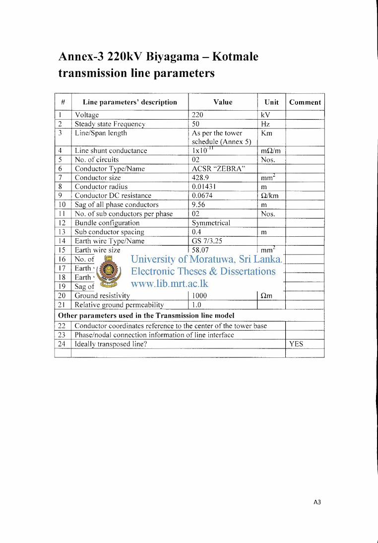
Annex-3 220kV Biyagama - Kotmale transmission line parameters
# Line parameters' description Value
I Voltage 220 2 Steady state Frequency 50 3 Line/Span length As per the tower
schedule (Annex 5) 4 Line shunt conductance 1x1o-" 5 No. of circuits 02 6 Conductor Type/Name ACSR"ZEBRA" 7 Conductor size 428.9 8 Conductor radius 0.01431 9 Conductor DC resistance 0.0674 10 Sag of all phase conductors 9.56 II No. of sub conductors per phase 02 12 Bundle configuration Symmetrical 13 Sub conductor spacing 0.4 14 Earth wire Type/Name GS 7/3.25 15 Earth wire size 58.07 16 No. of Earth wires 02 17 Earth wire radius 0.0049 18 Earth wire DC resistance 3.1 19 Sag of Earth wire 6.41 20 Ground resistivity 1000 21 Relative ground permeability 1.0
Other parameters used in the Transmission line model
Unit
kV Hz Km
mO/m Nos.
mm1
m 0/km m Nos.
m
mm1
Nos. m 0/km m Om
22 Conductor coordinates reference to the center of the tower base 23 Phase/nodal connection information of line interface 24 Ideally transposed line?
Comment
YES
A3
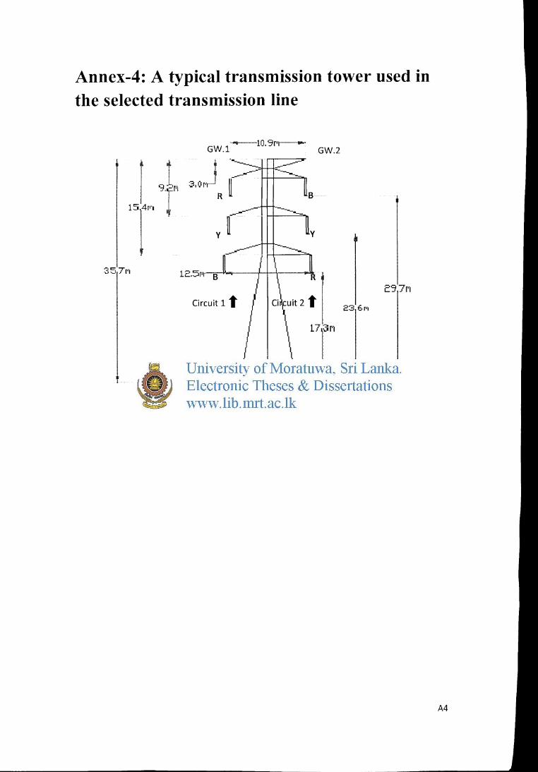
Annex-4: A typical transmission tower used in the selected transmission line
r 9t 15r r
I 35,7f"'
GW.l--10.9~
Circuit 1 t
----8.2~
GW.2
ESQf"'
23:6f"'
17;3f"'
A4
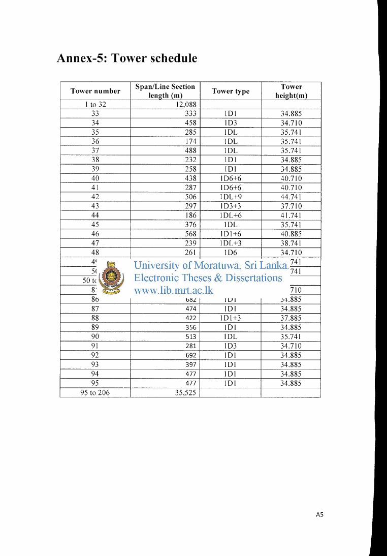
Annex-5: Tower schedule
Tower number Span/Line Section Tower type Tower
length (m) height(m) I to 32 I2,088
33 333 IOI 34.885 34 458 103 34.7IO 35 285 lOL 35.741 36 I74 10L 35.741 37 488 IOL 35.74I 38 232 IOI 34.885 39 258 IOI 34.885 40 438 I06+6 40.7IO 4I 287 I06+6 40.7IO 42 506 IOL+9 44.74I 43 297 I03+3 37.7I 0 44 I86 10L+6 41.74I 45 376 IOL 35.741 46 568 101+6 40.885 47 239 IOL+3 38.741 48 26I 106 34.7I 0 49 329 10L+6 41.74I 50 261 10L+9 44.74I
50 to 84 11,999 85 181 106 34.7IO 86 682 10I 34.885 87 474 IOI 34.885 88 422 IOI+3 37.885 89 356 101 34.885 90 513 10L 35.74I 91 281 103 34.7IO 92 692 IOI 34.885 93 397 10I 34.885 94 477 101 34.885 95 477 I OI 34.885
95 to 206 35,525 ---· ··-
AS
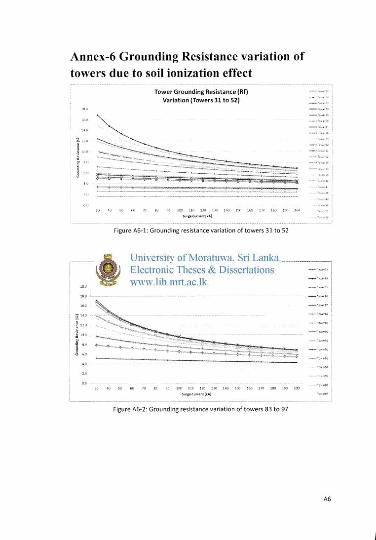
Annex-6 Grounding Resistance variation of towers due to soil ionization effect
18 l~
16 (!
11ll
~ uo ~
~ lc\0 ., ~
"' ~ d(l
~ 5 6 {l i3
40
l."Cl
16 0
2140
~ ; 121]
• .. : 10.0
1:' ~ 8.0 g . ~ 6.0
4.0
2.0
0.0
Tower Grounding Resistance (Rf) Variation (Towers 31 to 52)
i:::;;::;;;;;4~ ~->~no%,-";";,';;':::;;,7,":$:.7mn ,j; .~omu~<'"-•••••
)0 ·h'• r,o (,(l /() s~.J 100 IW 1m I~ WO !W I~ !M IW l% ~hl
Surg:e Curr~'Hlt (kA]
Figure A6-1: Grounding resistance variation of towers 31 to 52
Tower Grounding Resistance (Rf) Variation (Towers 83 to 97)
30 40 50 60 70 80 90 100 110 120 130 140 150 160 170 180 190 200
Surge Current [kA]
--"..:;,"'"0:
--:),)<;~.;,
--·.y:.:e<l~
--·,, ... -'}~ --·h:<-·'1')
---(.J.:.t?-'37
--~·)N~'?¢
-··c·<'>'t·:)
-··>l·,···~·•l
.-, .·.v<;}
~-~0>'·'<".:..;,
"·~A·r•r.:\B
.;,·~;<i?
.Vt'"~.o
',,._,,o:,?l
---.:>w~t33
--0.vo:-r8A
~--w·=·.:>wer35
---C~."<er26
--:J·so:-•37
~~-:>·.ve-r3S
---::>"81:'89
---:>wer90
"· -G~\'er91
---O"t\'<:''9~
""'-'Y''-' {f.:'f9;;.
·o.ver9-'
·ose-r95
:J<-:e•96
-ower97
········~~~~~~~~·~ ·-"·,," ... , ... ·--~-~---~--~--------· -------~----·· ,. _____ .J
Figure A6-2: Grounding resistance variation of towers 83 to 97
A6
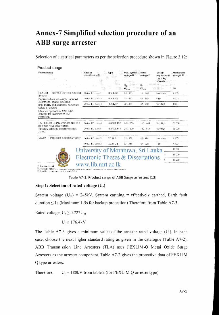
Annex-7 Simplified selection procedure of an ABB surge arrester
Selection of electrical parameters as per the selection procedure shown in Figure 3.12:
Product range Product lamily
PEXLIM - Silison'e pc>lyrnd-h•XISt'Cl ;:ure~.h?.r:;
Superiu 4-iller!? lew v:Ei>Jht. reduce.j ojEdl31lC8S. ~exit:ole nlOlinting, non-fragilit)• an·j additional pel':x•nnel safety is required tvlajm component for PEXLINIO:"' ·~oncEpt fer tran:mis::ion line proter:tioxr
An<>stm c1as~ification 1:'
li• k;\ II ( "k!e •;)
liJ I<:.'\ IH, ·;l,l:>' ~-~,
.• •0 'A IH. de; ·1
HS PEXLitvl - Hi[lll stren~1th sili·:on;, ;.oo k.'\ ILCclac:." ·1
Typ~ Moo;. syst!Jill volt09e 2l
Urn kllrm;;
PF::-J lt·.-r n :.•·1 1/0
1-'l..lJ .. Ir'~'l tl ;,;-· ·L/I.l
I·'L:<UMF :::,2 ·IC'O
lr';roJit•,ll' <:>.JC, bfr>
Rat!Jd l::n.;rgy Mechanicnl vottagQ 2:0 requimm<>nV str~ngth 31
Lightns1![r inWnsity
u, kVwm ~bll
p~ 1+1 r·.-lodct<.lf() 1 t:~::o ----
•t' :~fC lli;jl ·t ·::o··
,p :~!J) 1/>:.ry lli•]h ·~CO:!
1"0 4-14 '<.'•":.f'•/lliqh Z'Ll o:::o p(>lym-21-hous.<?rJ JJr"st<?rs. ------------------------------------srecJaJ 1)1 ~-Uited tc• el:treme ::,eisnl iC )0 k,\ IL C ci.E:: !:. I L PUJ.IJ..-1.1 24'· HD 1:.!0 Gl:! Vcfy l11~1h 2~ Z)._(J
zones. ------------------------------------
EXLitv\ - For·:81ain-llousecl iirtester w kil. 11 c, .;~:.,,; 2 DllM r~ :··.? 1!0
10 k .. \ I[ C ::::Ia•> ::; EXU tvl CJ F ~><_: ~M~5
JCi ki• .. ILC>::bs" 3 DllMCi.fl 17\) ·l~>'j
;;o k/1. IFC, •t•s•:: ·1 F):JJM P ::.2 e.rlo
20 k/• ... IE C da:::; "· EXLIM l 245; (}OJ
~-1 :~11 ~u ~] <:l:l::::Hic:ltion ,vn::Jdin•J 1.::1 1£" C Ci)//). -1 (n~·-rrinal di-:,ck11 t~c,:, CUI rent, lin·~l :·Ji~;;h.:1rCJ"'~ cb~,:-;1. · '.1 .:~IIP';tu •; ·,.,illl kr,t,\·Jf <:H J·llt!ILnr \"•.>lk.1•JV> rna~· t..:,i •. Jvahl.tk: on F<:1.11K(:;t lor ::~--t· .. :i;.1 -~1pf:olbjiLrL~ •. :~, ;:;pccilkxl :;l1<.tt· tt:.nn .~-.::=r·t"b> J<·:r.:11:::.::A •
.tJ W!
4.? :?Z!!
132 420
·1:! ·14·1
I'!O Gc~
Table A7-1: Product range of ABB Surge arresters [13]
Step 1: Selection of rated voltage (Ur)
fdrJdt:oto r r...::o
Hi;.l1 7 ~£)J
Hi;jl 18 COJ
v.·Jillil1h 1-:.J COJ
Vc,ry l1iqh 1n C(<J
System voltage (Urn) = 245kV, System earthing = effectively earthed, Earth fault
duration:::; ls (Maximum 1.5s for backup protection) Therefore from Table A7-3,
Rated voltage, Ur ~ 0.72*Um
Ur~ 176.4kV
The Table A 7-3 gives a minimum value of the arrester rated voltage (U .. ). In each
case, choose the next higher standard rating as given in the catalogue (Table A 7-2).
ABB Transmission Line Arresters (TLA) uses PEXLIM-Q Metal Oxide Surge
Arresters as the arrester component. Table A 7-2 gives the protective data of PEXLIM
Q type arresters.
Therefore, Ur = 180kV from table 2 (for PEXLIM Q arrester type)
A7-1
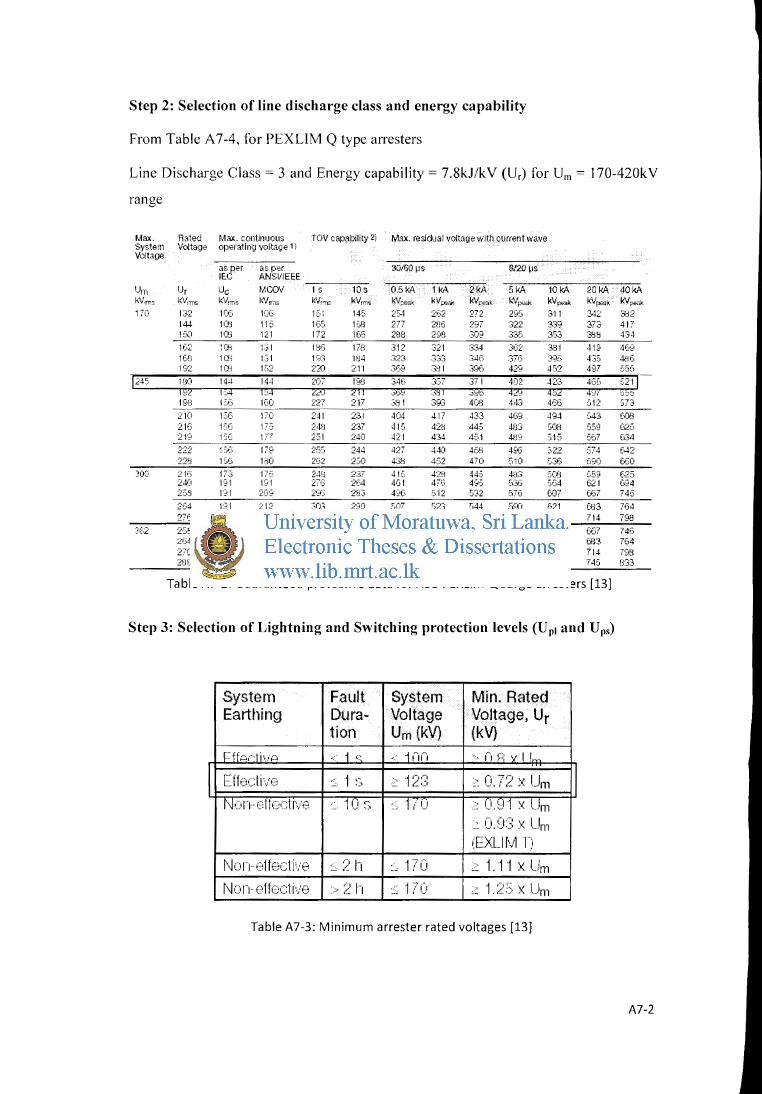
Step 2: Selection of line discharge class and energy capability
From Table A 7-4, for PEXLIM Q type arresters
Line Discharge Class= 3 and Energy capability= 7.8kJ/kV (Ur) for Urn= 170-420kV
range
Max. Rated Max. continuous TOV capability 2) Mu. residual voltage vtith current wave System Voltage operatln9 voltage I I Voltag101
as per as per IEC ANSI/IEEE
30/60 ~IS B/:20 >IS
Um Ur Uc MCOV 1 s iDs 0.5kA 1kA 2kA ~ 10kA 20~A 40kA
'"""'" kVnm kVnn> kVm, kVr!"lw kVrms k'dp;;,a>. kVf:;mJ.: kVP""' k\lr;>a4: kVp!Nlk kVp;:<lk kVpe-,fk
170 1"'J •.:".!. 1C6 l01S E•l 145 2C-4 2G2 2?2 2!:15 311 342 3iJ2 144 W;; 115 165 ICS 277 2H6 297 :322 339 373 417 1S.O lUi 121 1?2 155 2}3f3 298 309 .33:~ 353 3SS 434 1 ~)2 IC'O 131 1SG 17H 312 321 334 3(~2 3SI 419 409 lf·8 1C!:i 1:;1 I ~(i IH4 32~~ ,.. ... ..:)..) 34f, :376 3?:) 435 4.H6 192 IW Fi:? :2~\') 211 3U~ 3~1'1 39f) 42'? 452 4'07 556
34G ,_,:.)
,jt.)~ ;_'"I~
3!i I 393 40iJ 443 466 S12 573
210 1 ~d) 1:'0 241 231 404 417 433 469 494 ~43 URl 216 1GG 17:0- 24il 237 41G 42'3 445 4H3 G08 ~59 G2G 219 13G 177 2C•I 240 421 434 451 4il'~ S1S GG7 G34 222 13tl I'" 25C· 244 427 440 458 4S(i 2)22 674 f-1::' :228 15G 1~0 2(,2 2c.o 43S 452 470 SIO S36 f!'~O wo
:oo 21'i 17.3 170 24il 237 41C: 42B 445 4{J3 SCtfJ ~,59 625 24() 191 191 2?(; 2•:4 4()1 4/G 495 5:36 S64 521 G94 2,:;s 191 2(Pj 2'~.(; 2'8-3 4':•G 5'12 532 576 DJ? w7 746 2G4 181 212 303 290 [)07 ~,21 544 Sf'(l 621 Ul3 764 276 191 220 317 303 s:3o :'-47 569 617 649 714 798
362 2C>8 2C0 209 293 28.3 496 5'12 5:32 E1?G GJ7 f:F.7 "' 746 2(.4 211 212 303 290 507 523 544 59) G21 [fJ3 7G4 27Ci 221 221 .317 3CG Ei30 547 :.e.g 617 049 714 798 2flfl 2:3{1 2.JtJ 331 316 5S3 571 593 643 iJ77 748 !l33
Table A7-2: Guaranteed protective data for ABB PEXLIM Qsurge arresters [13]
Step 3: Selection of Lightning and Switching protection levels (Up1 and Ups)
System I Fault System Min. Rated Earthing Dura- Voltage Voltage, Ur
tion Um (kV) (kV}
r::::ffpr·1 i11P < 1 c: . 1nn , r, P vII,
II [ H•+:ti'•Jt:i .... -..,; ......... ~::. 1 ~::, .. ::.~ 1 /~:3 .::. 0. 72 X I..Jm II No::)n o11e·:::ti'-H:' ,.· 1 u ~) · 1 i I i .. :: I ._. :: U. SJ 1 X IJm
'0. X Um (EXUfvl n
~.J o 1-1- t:ifft.::cti·./(:? ~ 2 t-1 :" 17•J .::. 1.11 X Um ~Jon-Fffecti·-/o -- :2 r-~ ::;; 1 ? () .. : 1.:2!) X Um
Table A7-3: Minimum arrester rated voltages [13]
A7-2
System parameters for Uwl and Uws,
Lightning withstand voltage of the line Uwl = 1 ,050kV
Switching withstand voltage of the line Uws = 460kV
For insulation co-ordination purposes, consider the lightning impulse protection level
(Up!) at 10 kA for Um S362 kV and at 20 kA for higher voltages. Similarly, the
switching impulse protection levels (Ups) for co-ordination purposes range from
0.5kA (forUm S170 kV) to 2 kA (forUm 2:362kV).
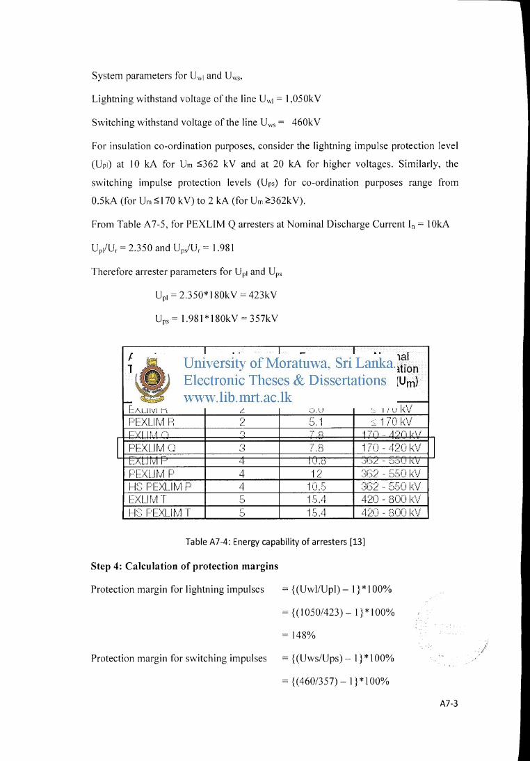
From Table A 7-5, for PEXLIM Q arresters at Nominal Discharge Current In= 1 OkA
UplUr = 2.350 and Up/Ur = 1.981
Therefore arrester parameters for Up1 and Ups
Upl = 2.350* 180kV = 423kV
Ups= 1.981 * 180kV = 357kV
Arrester Line Type discharge
class
EXL!tvl Fi 2 F-"EXLHv1 fl ()
<--r:--.,.,, 1 r .. ,, r1 l)
I F)E:X:Litv·l () ,.,., .. ,
t:l\LJI'II 1· ,:,
r:·EXLI [\il P 4 Ht: F·E:xu rv1 P 4 EXUfv·J T [::'
~)
H~:: F'L:XL.I f\;1 T ("' ::)
Energy Normal capability application
{2 impulses) range (Um} kJ/kV (Ur)
so 170 k\/ 5 1 :; 170 k\/ 7 p 1 7 , .. , ... 11 •":•1~ I ··'ol
7.8 1 T(J - 420 k\/ " "
IJ.o .3f5Z - :y)IJl',\7
12 r,,- 2 550 k' 1 • .. )~) .... - \.1
10.S :3(32 - 550 k\/ 15.4 420- 800 k\i 1 S.4 4~~o - noo k\t
Table A7-4: Energy capability of arresters [13]
Step 4: Calculation of protection margins
Protection margin for lightning impulses = { (Uwl/Upl)- 1} * 100%
={(I 050/423)- I}* 100%
= 148%
Protection margin for switching impulses = { (Uws/Ups)- 1} * 100%
= {(460/357)- 1 }*1 00%
I
A7-3
l
'I 1
l
Arrester Type
FXI ... Ifv1 r:: Pl-::XL.Itvl r:: FXLif·v·1 C•
II r::)r:.:··:<t 1r., ,, c·, .-.1 •..•. 'j .. :..1
E~XLitv1 r:::.
r=:·F:xurvl FJ f1:~; Pr:xur··.;l P
EXLit\il T
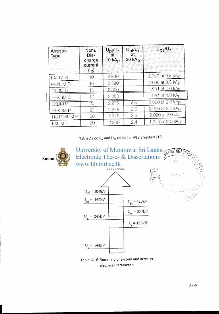
Nom. I Upt!Ur Upi/Ur I Ups/Ur Dis- at at
charge 10 kAp 20kAp current
On) 1 () :2 .. 590 ·; r-,r-:n rt 0 .r~ I<P.r~ ,._ • .._. .•. )•.,j 1.:! . ~-) '·)
1 () 2.590 2 (!(-() rit n r:: kf\r - •'·"' ._).,., (: v' • . .) •.}
1 () :2 ,:(::5() 1 .Df31 :::tt 1. 0 ki\r,
1 c~ rJ ,::: 1 nP 1 ·: t 1 ri 1 \r: II ,~ ... .... ,) ... ! , '••' v '·)
2C1 2 ·~}7.5 25 2 ior-1 :Jt 2 r, 1· '\r .. ~ •• __ .,:.._,_. L. _, ..... v~.)
2C} 2.2IS 25 2 i1·~)n -t 2 n I·J\r: , .... ,~ .. v (1 •'~ '\ '"•.)
20 2.27!) ~~.E) 2.020 .:tt :~:.UI<Ar:::>
20 2.2C(J :~! .4 1 o-,·~ ··t 2 n 1·'· • ..:./ !' 1,) cl ·-, ._,. -+Jp\p
Table A7-5: Up1 and Ups ratios for ABB arresters [13]
=29%
Summary of system and arrester electrical parameters
VOLTAGE
Uw1=lOSOkV
U = 460kV W5 up1=423kV
U = 357kV U = 245kV
ps
Ill
U = 180kV r
U = 144kV c
Table A7-6: Summary of system and arrester
electrical parameters
' ~! · .. -.
...: ~~ .. ~ N' ., ,,. ~· '
-··
A7-4