reference fp-14 - sam houston trails coalition
TRANSCRIPT

FOREST SERVICE SUPPLEMENTAL SPECIFCATIONS (FSSS)
FOR THE RICHARD RAVENS HORSE TRAILHEAD PARKING LOT CONSTRUCTION
A COOPERATIVE PROJECT OF THE U.S. FOREST SERVICE, THE
FEDERAL HIGHWAY ADMINISTRATION AND THE STATE OF TEXAS PARKS AND WILDLIFE DEPARTMENT THROUGH THE RECREATIONAL
TRAILS PROGRAM WITH THE SAM HOUSTON TRAILS COALITION
Reference FP-14: Standard Specifications for Construction of
Roads and Bridges on Federal Highway Projects
UNITED STATES DEPARTMENT OF TRANSPORTATION
Federal Highway Administration
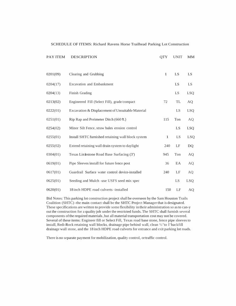
SCHEDULE OF ITEMS: Richard Ravens Horse Trailhead Parking Lot Construction
PAY ITEM
DESCRIPTION
QTY
UNIT
MM
0201(09) Clearing and Grubbing 1 LS LS
0204(17) Excavation and Embankment LS LS
0204(13) Finish Grading LS LSQ
0213(02) Engineered Fill (Select Fill), grade/compact 72 TL AQ
0222(01) Excavation & Displacement of Unsuitable Material LS LSQ
0251(01) Rip Rap and Perimeter Ditch (660 ft.) 115 Ton AQ
0254(02) Minor Silt Fence, straw bales erosion control LS LSQ
0255(01) Install SHTC furnished retaining wall block system 1 LS LSQ
0255(02) Extend retaining wall drain system to daylight 240 LF DQ
0304(01) Texas Lin1estone Road Base Surfacing (3") 945 Ton AQ
0619(01) Pipe Sleeves/install for future fence post 36 EA AQ
0617(01) Guardrail Surface water control device-installed 240 LF AQ
0625(01) Seeding and Mulch -use USFS seed mix spec LS LSQ
0620(01) 18 inch HDPE road culverts -installed 150 LF AQ
Bid Notes: This parking lot construction project shall be overseen by the Sam Houston Trails Coalition (SHTC) -the main contact shall be the SHTC Project Manager that is designated. These specifications are written to provide some flexibility in their administration so as to can-y out the construction for a quality job under the restricted funds. The SHTC shall furnish several components of the required materials , but all material transportation cost may not be covered. Several of these items: Engineer fill or Select Fill, Texas road base stone, fence pipe sleeves to install, Redi-Rock retaining wall blocks, drainage pipe behind wall, clean %"to l"backfill drainage wall stone, and the 18 inch HDPE road culverts for entrance and exit parking lot roads.
There is no separate payment for mobilization, quality control, or traffic control.
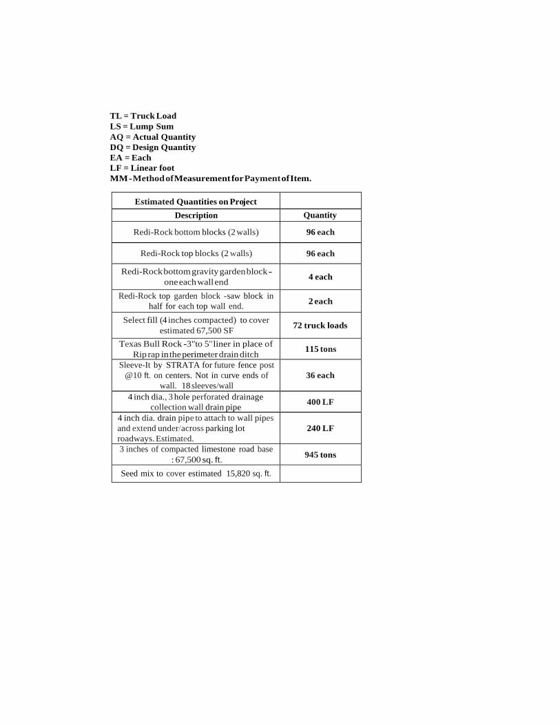
TL = Truck Load LS = Lump Sum AQ = Actual Quantity DQ = Design Quantity EA = Each LF = Linear foot MM - Method of Measurement for Payment of Item.
Estimated Quantities on Project
Description Quantity
Redi-Rock bottom blocks (2 walls) 96 each
Redi-Rock top blocks (2 walls) 96 each
Redi-Rock bottom gravity garden block - one each wall end
4 each
Redi-Rock top garden block -saw block in half for each top wall end. 2 each
Select fill (4 inches compacted) to cover estimated 67,500 SF
72 truck loads
Texas Bull Rock -3"to 5" liner in place of Rip rap in the perimeter drain ditch 115 tons
Sleeve-It by STRATA for future fence post @10 ft. on centers. Not in curve ends of
wall. 18 sleeves/wall
36 each
4 inch dia., 3 hole perforated drainage collection wall drain pipe 400 LF
4 inch dia. drain pipe to attach to wall pipes and extend under/across parking lot roadways. Estimated.
240 LF
3 inches of compacted limestone road base : 67,500 sq. ft. 945 tons
Seed mix to cover estimated 15,820 sq. ft.
1
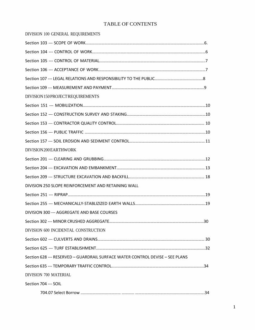
TABLE OF CONTENTS
DIVISION 100 GENERAL REQUIREMENTS
Section 103 --- SCOPE OF WORK…………………………………………………………………………………………………..6.
Section 104 --- CONTROL OF WORK………………………………………………………………………………………………6
Section 105 --- CONTROL OF MATERIAL………………………………………………………………………………………..7
Section 106 --- ACCEPTANCE OF WORK…………………………………………………………………………………………7
Section 107 --- LEGAL RELATIONS AND RESPONSIBILITY TO THE PUBLIC……………………………………….8
Section 109 --- MEASUREMENT AND PAYMENT…………………………………………………………………………….9
DIVISION 150 PROJECT REQUIREMENTS
Section 151 --- MOBILIZATION………………………………………………………………………………………………………10
Section 152 --- CONSTRUCTION SURVEY AND STAKING…………………………………………………………………10
Section 153 --- CONTRACTOR QUALITY CONTROL………………………………………………………………………… 10
Section 156 --- PUBLIC TRAFFIC …………………………………………………………………………………………………….10
Section 157 --- SOIL EROSION AND SEDIMENT CONTROL……………………………………………………………… 11
DIVISION 200 EARTHWORK
Section 201 --- CLEARING AND GRUBBING…………………………………………………………………………………….12
Section 204 --- EXCAVATION AND EMBANKMENT………………………………………………………………………… 13
Section 209 --- STRUCTURE EXCAVATION AND BACKFILL……………………………………………………………… 18
DIVISION 250 SLOPE REINFORCEMENT AND RETAINING WALL
Section 251 --- RIPRAP…………………………………………………………………………………………………………………..19
Section 255 --- MECHANICALLY-STABLIZIZED EARTH WALLS………………………………………………………….19
DIVISION 300 --- AGGREGATE AND BASE COURSES
Section 302 --- MINOR CRUSHED AGGREGATE………………………………………………………………………………30
DIVISION 600 INCIDENTAL CONSTRUCTION
Section 602 --- CULVERTS AND DRAINS………………………………………………………………………………………… 30
Section 625 --- TURF ESTABLISHMENT…………………………………………………………………………………………..32
Section 628 --- RESERVED – GUARDRAIL SURFACE WATER CONTROL DEVISE – SEE PLANS
Section 635 --- TEMPORARY TRAFFIC CONTROL…………………………………………………………………………….34
DIVISION 700 MATERIAL
Section 704 --- SOIL
704.07 Select Borrow ..……………………………… ………… ……………………………………………..………….34
2
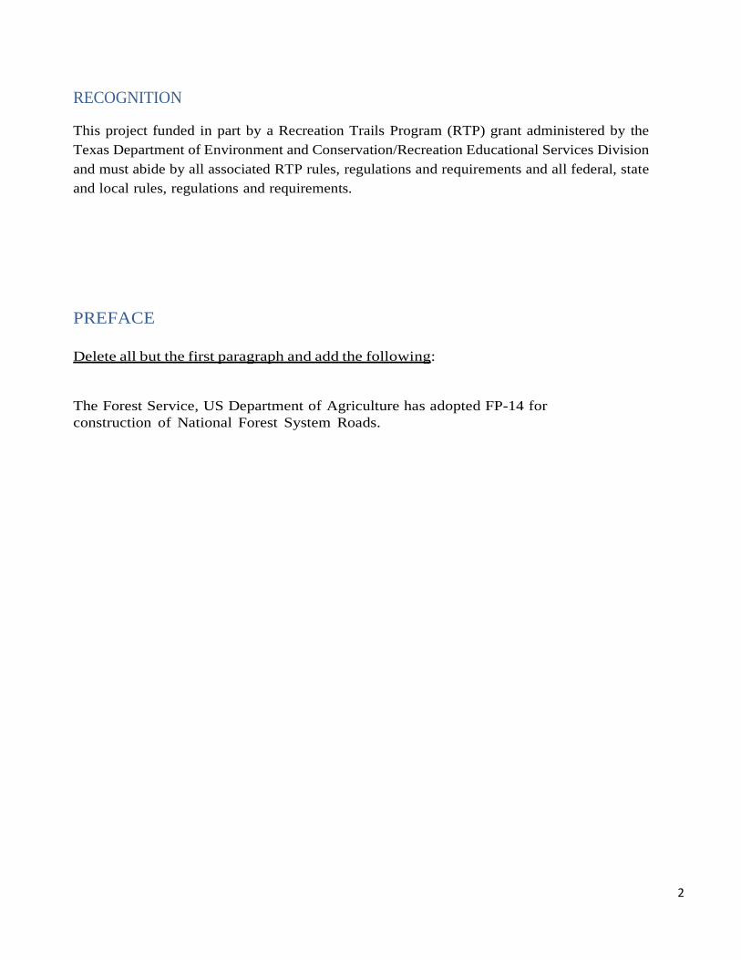
RECOGNITION This project funded in part by a Recreation Trails Program (RTP) grant administered by the Texas Department of Environment and Conservation/Recreation Educational Services Division and must abide by all associated RTP rules, regulations and requirements and all federal, state and local rules, regulations and requirements.
PREFACE
Delete all but the first paragraph and add the following:
The Forest Service, US Department of Agriculture has adopted FP-14 for construction of National Forest System Roads.
3
101 -Terms, Format, and Definitions 101.01 Meaning of Terms Delete all references to the TAR (Transportation Acquisition Regulations) in the specifications.
101.04 Definitions.
Delete the following definitions and substitute the following:
Bid Schedule--The Schedule of Items.
Culvert--No definition.
Add the following:
Adjustment in Contract Price--“Equitable adjustment,” as used in the Federal Acquisition Regulations, or “construction cost adjustment”.
Change--“Change” means “change order” as used in the Federal Acquisition Regulations.
Neat Line--A line defining the proposed or specified limits of an excavation or structure.
Road Order--An order affecting and controlling traffic on roads under Forest Service jurisdiction. Road Orders are issued by a designated Forest Officer under the authorities of 36 CFR, part 260.
Schedule of Items--A schedule in the contract that contains a listing and description of construction items, quantities, units of measure, unit price, and amount.
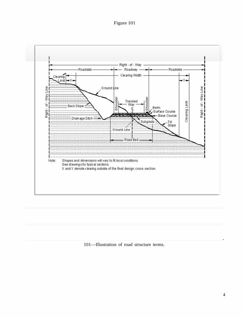
101-1—Illustration of road structure terms:
4
Figure 101
- 101—Illustration of road structure terms.
5
102 - Bid, Award, and Execution of Contract 102 Bid, Award, and Execution of Contract
Delete Section 102 in its entirety.
Add: The Sam Houston Trails Coalition received a trail grant from the National Recreational Trails Program, a Federal assistance program of the Federal Highways Administration, administered thru the Texas Parks and Wildlife Department – State Parks Division. The Sam Houston Trails Coalition, in conjunction with the National Forests and Grasslands in Texas – the Sam Houston Ranger District, shall bid, award and execute the construction requirements of Richard Ravens Horse Trailhead Parking area. The Sam Houston Trails Coalition designated Project Manager shall oversee the contract construction process with the awarded Contractor.
103 -Scope of Work
The Scope of the Richard Ravens Horse Trailhead Parking lot construction is the development of a gravel surface parking lot for trucks/car with horse trailer parking at the beginning of the 35 mile Richard Ravens horse trail system in Montgomery and Walker Counties. The project area is 100 ft. west off the paved FM 1791 road and directly north off FSR 209.
The project work is within an area limit of 343 ft. x 315 ft. The proposed aggregate surface road-parking area to be constructed to cover approximately 67,500 sq.ft. There are two – 199 ft. long x 3 ft. high Redi- Rock precast concrete block retaining wall systems to be constructed so as to separate three tiers of parking surfaces on the sloped project site. Work shall require clearing and grubbing, excavation and embankment, grading, wall installation, select fill placement, compaction, stone surfacing and compaction, drainage controls and culverts installation.
The SH Trails Coalition shall furnish the Redi-Rock retaining wall blocks, approximately 1,400 lbs. each and other designated materials. The Contractor shall be responsible for the required specified materials, labor and equipment for the retaining wall installation and other work.
104 - Control of Work
104.06 Use of Roads by Contractor
The Contractor is authorized to use roads (FDR 209) under the jurisdiction of the Forest Service for all activities necessary to complete this contract, subject to the limitations and authorizations designated in the Road Order(s) or described in the contract, when such use will not damage the roads or national forest resources, and when traffic can be accommodated safely.
6
105 - Control of Material 105.02 Material Sources.
105.02(a) – Sam Houston Trails Coalition provided sources to Contractor. The specified quantity of 206 total precast concrete Redi-Rock Retaining wall blocks, the parking area select surface fill material, the Texas DOT limestone road base surface stone, the quarry Bull rock for placement/lining of the perimeter drainage ditch, the retaining wall backfill ¾” clean drainage rock, and the 40 units of Strata Sleeve SD-1 to be installed by the Contractor for the future fence post adjacent to the retaining walls.
Delete 105.02 (a) and (b): 105.05 Use of Material Found in the Work.
Delete 105.05 (a) and (b) and the last sentence of the second paragraph and substitute the following:
Materials produced or processed from Government lands in excess of the quantities required for performance of this contract are the property of the Government. The Government is not obligated to make reimbursement for the cost of producing these materials.
106 - Acceptance of Work 106.01 Conformity with Contract Requirements.
Delete Subsection 106.01 and substitute the following:
Follow the requirements of FAR Clause 52.246-12 Inspection of Construction. References to standard test methods of AASHTO, ASTM, GSA, and other recognized standard authorities refer to the methods in effect on the date of solicitation for bids.
Perform all work to the lines, grades, cross-sections, dimensions, and processes or material requirements shown on the plans or specified in the contract.
Incorporate manufactured materials into the work according to the manufacturer’s recommendations or to these specifications, whichever are stricter.
Plan dimensions and contract specification values are the values to be strived for and complied with as the design values from which any deviations are allowed. Perform work and provide material that is uniform in character and reasonably close to the prescribed value or within the specified tolerance range. The purpose of a tolerance range is to accommodate occasional minor variations from the median zone that are unavoidable for practical reasons.
When standard manufactured items are specified (such as fence, wire, plates, rolled shapes, pipe conduits, etc., that are identified by gauge, unit mass, section dimensions, etc.), the identification will be considered to be nominal masses or dimensions. Unless specific contract tolerances are noted, established manufacturing tolerances will be accepted.

7
The Government may inspect, sample, or test all work at any time before final acceptance of the project. When the Government tests work, copies of test reports are furnished to the Contractor upon request. Government tests may or may not be performed at the work site. If Contractor testing and inspection is verified by the Government, the Contractor’s results may be used by the Government to evaluate work for acceptance. Do not rely on the availability of Government test results for process control.
Acceptable work conforming to the contract will be paid for at the contract unit bid price. Four methods of determining conformity and accepting work are described in Subsections 106.02 to 106.05 inclusive. The primary method of acceptance is specified in each Section of work. However, work may be rejected at any time it is found by any of the methods not to comply with the contract.
Remove and replace work that does not conform to the contract, or to prevailing industry standards where no specific contract requirements are noted, at no cost to the Coalition or the Government. (b) Alternatives to removing and replacing non-conforming work. As an alternative to removal and replacement, the Contractor may submit a written request to:
(1) Have the work accepted at a reduced price; or (2) Be given permission to perform corrective measures to bring the work into conformity.
The request must contain supporting rationale and documentation. Include references or data justifying the proposal based on an evaluation of test results, effect on service life, value of material or work, quality, aesthetics, and other tangible engineering basis. The CO will determine disposition of the nonconforming work. 106.05 Delete
106.07 Substitute
In the first paragraph…”at no cost to the government”, substitute “at no cost to the Sam Houston Trails Coalition” In (a) and (b) paragraphs whenever it stated “CO”, substitute “SHTC Project Manager”.
107 - Legal Relations and Responsibility to the Public
107.5 Responsibility for Damage Claims.
Delete the entire subsection.
107.6 Contractor’s Responsibility for Work.
Delete the following from the first paragraph.
107.9 Legal Relationship of the Parties.
Delete the last paragraph of this section.
8
107.10 Environmental Protection. Add the following: Before beginning any work, submit a Hazardous Spill Plan. List actions to be taken in the event of a spill. This may include the statement the Contractor shall have standard fluid spill kits on site at all times of operation to mitigate potential fuel, oil, or hydraulic fluid spills. Incorporate preventive measures to be taken, such as the location of mobile refueling facilities, storage and handling of hazardous materials, and similar information. Immediately notify the Project Manager of all hazardous material spills. Provide a written narrative report form no later than 24 hours after the initial report and include the following:
□ Description of the item spilled (including identity, quantity, manifest number, and other identifying information).
□ Whether the amount spilled is EPA or state reportable, and if so whether it was reported, and to whom.
□ The exact time and location of spill including a description of the area involved.
□ Containment procedures.
□ Summary of any communications the Contractor had with news media, Federal, state and local regulatory agencies and officials, or Forest Service officials.
□ Description of clean-up procedures employed or to be employed at the site including final disposition and disposal location of spill residue.
The Contractor is solely responsible for all spills or leaks that occur during the performance of this contract. Clean up spills or leaks to the satisfaction of the Project Manager and in a manner that complies with Federal, state, and local laws and regulations.
108 - Prosecution and Progress 108 Delete.
Delete Section 108 in its entirety.
109 - Measurement and Payment
109 Deletions
Delete the following entire subsections:
109.6 Pricing of Adjustments. 109.7 Eliminated Work.
109.8 Progress Payments.
109.9 Final Payment.
9
109.02 Measurement Terms and Definitions. (b) Contract quantity. Add the following: Contract quantities will be adjusted only when there are errors in the original design of 15% or more.
151 - Mobilization 151.03 Payment
Delete the entire subsection and add the following:
151.03 Payment Mobilization is considered an indirect cost of this contract and will not be compensated as a separate work item.
152 – Construction Survey and Staking
Delete all paragraphs from 152.03 to 152.06.
153 - Contractor Quality Control
153.04 Records.
Delete all but the first sentence 156 - Public Traffic
Delete Section 156 in its entirety and replace with the following:
156.1 This work consists of controlling and protecting public traffic adjacent to and within the project.
Construction sign panels 633 Retro-reflective sheeting 718.01 Temporary concrete barrier 618 Material Temporary plastic fence 710.11 Temporary traffic control devices 718.22
the following Sections and Subsections: 156.2 Conform to the MUTCD and
156.3 General. Unless otherwise provided for in Table 156-1, keep existing roads open to all traffic
10
during road improvement work, and maintain them in a condition that will adequately accommodate traffic. Perform no work that interferes or conflicts with traffic or existing access to the roadway surface until a traffic control plan has been approved. Post construction signs and traffic control devices in conformance with MUTCD. All required signs will be in place and approved prior to beginning work on project.
156.4 Temporary Traffic Control. Install and maintain temporary traffic control devices adjacent to and within the project as required by the approved traffic control plan and the MUTCD. Install and maintain traffic control devices as follows:
(a) Furnish and install traffic control devices before the start of construction operations. (b) Install only those traffic control devices needed for each stage or phase. (c) Relocate temporary traffic control devices as necessary. (d) Remove devices that no longer apply to the existing conditions. (e) Immediately replace any device that is lost, stolen, destroyed, or inoperative. (f) Keep temporary traffic control devices clean. (g) Remove all temporary traffic control devices upon contract completion or when approved. (h) Flaggers must wear high visibility safety apparel as required by MUTCD 6E.02.
156.6 Acceptance. Public traffic work will be evaluated- Subsection 106.02.
Measurement and Payment
156.7 Do not measure Public Traffic for payment. Compensation is made as an indirect payment.
157 – Soil Control
157.03 General Delete the entire subsection and replace with the following:
Prior to the start of construction, submit a written plan that provides permanent and temporary erosion control measures to minimize erosion and sedimentation during and after construction. Do not begin work until the necessary controls for that particular phase of work have been implemented. Do not modify the type, size, or location of any control. An alternate erosion control plan with all necessary permits may be submitted 30 days before intended use.
Incorporate all permanent erosion control features into the project at the earliest practicable time, as outlined in the approved plan.
When erosion control measures are not functioning as intended, immediately take corrective action.
11
201 - Clearing and Grubbing 201.2 Material:
Delete Tree wound dressing material reference.
201.3 General. Delete the last sentence.
201.4 Clearing.
Delete the last sentence of (d).
201.01 Description
Replace with the following
This work consists of clearing and grubbing within clearing limits and other designated areas. 201.04 Clearing. (c)
(c) In areas outside the excavation, embankment, and slope rounding limits, cut stumps to within 12 inches or one-third of the stump diameter of the ground, whichever is higher, measured on the side adjacent to the highest ground.
201.04 Clearing.
Delete subsection (d) and replace with the following: (d) Do not cut vegetation less than 3 feet tall and less than 3 inches in diameter, that is within the clearing limits but beyond the roadway and not in a decking area, and that does not interfere with sight distance along the road.
Add the following:
(e) Trim branches of remaining trees or shrubs to give a clear height of 14 feet above the roadbed unless otherwise indicated. Trim tree limbs as near flush with the trunk as practicable.
201.06 Disposal.
Delete the first sentence of this subsection:
12
204 - Excavation and Embankment Replace Section 204 in its entirety with the following:
204.03 Conform to the following Subsections:
Backfill material 704.03 Select borrow 704.07 Select topping 704.08 Topping 704.05 Unclassified borrow 704.06 Water 725.01
Description 204.1 This work consists of excavating material and constructing embankments. This includes furnishing, hauling, stockpiling, placing, disposing, sloping, shaping, compacting, and finishing earthen and rocky material.
204.2 Definitions.
(a) Excavation. Excavation consists of the following:
(1) Roadway excavation. All material excavated from within the right-of-way or easement areas, except sub-excavation covered in (2) below and structure excavation covered in Sections 208 and 209. Roadway excavation includes all material encountered regardless of its nature or characteristics.
(2) Sub-excavation. Material excavated from below subgrade elevation in cut sections or from below the original ground-line in embankment sections. Sub-excavation does not include the work required by Subsections 204.05, 204.06(b), and 204.06(c).
(3) Borrow excavation. Material used for embankment construction that is obtained from outside the roadway prism. Borrow excavation includes unclassified borrow, select borrow, and select topping.
(b) Embankment construction. Embankment construction consists of placing and compacting roadway or borrow excavation. This work includes:
(1) Preparing foundation for embankment; (2) Constructing roadway embankments; (3) Benching for side-hill embankments; (4) Constructing dikes, ramps, mounds, and berms; and (5) Backfilling sub-excavated areas, holes, pits, and other depressions.
(c) Conserved topsoil. Excavated material conserved from the roadway excavation and embankment foundation areas that is suitable for growth of grass, cover crops, or native vegetation.
(d) Waste. Excess and unsuitable roadway excavation and sub-excavation that cannot be used.
13
Material Construction Requirements
204.4 Preparation for Roadway Excavation and Embankment Construction. Clear the area of vegetation and obstructions according to Sections 201 and 203.
204.5 Reserved.
204.6 Roadway Excavation. Excavate as follows:
(a) General. Do not disturb material and vegetation outside the construction limits. Incorporate only suitable material into embankments. Replace any shortage of suitable material caused by premature disposal of roadway excavation. Dispose of unsuitable or excess excavation material according to Subsection 204.14. At the end of each day's operations, shape to drain and compact the work area to a uniform cross-section. Eliminate all ruts and low spots that could hold water. Retrieve material deposited outside of the clearing limits. Place unsuitable material in designated areas.
(b) Rock cuts. Blast rock according to Section 205. Excavate rock cuts to 6 inches below subgrade within the roadbed limits. Backfill to subgrade with topping or with other suitable material. Compact the material according to Subsection 204.11
(c) Earth cuts. Scarify earth cuts to 6 inches below subgrade within the roadbed limits. Compact the scarified material according to Subsection 204.11.
(d) Pioneer Roads. Road pioneering, slash disposal, and grubbing of stumps may proceed concurrently with excavation. Conduct excavation and placement operations so material to be treated under Section 201 will not be incorporated into the roadway unless specified in the slash treatment method. Maintain drainage during pioneering operations.
204.7 Sub-excavation. Excavate material to the limits designated. Prevent unsuitable material from becoming mixed with the backfill. Dispose of unsuitable material according to Subsection 204.14. Backfill the sub-excavation with topping, or other suitable material. Compact the material according to Subsection 204.11.
204.8 Borrow Excavation. Use all suitable roadway excavation in embankment construction. Do not use borrow excavation when it results in excess roadway excavation. Deduct excess borrow excavation from the appropriate borrow excavation quantity.
Obtain borrow source acceptance according to Subsection 105.02. Develop and restore borrow sources according to Subsection 105.03. Do not excavate beyond the established limits. When applicable, shape the borrow source to permit accurate measurements when excavation is complete.
204.9 Preparing Foundation for Embankment Construction. Prepare foundation for embankment construction as follows:
(a) Embankment less than 4 feet high over natural ground. When designated, remove topsoil and break up the ground surface to a minimum depth of 6 inches by plowing or scarifying. Compact the ground surface according to Subsection 204.11.
14
(b) Embankment across ground not capable of supporting equipment. Dump successive loads of embankment material in a uniformly distributed layer to construct the lower portion of the embankment. Limit the layer thickness to the minimum depth necessary to support the equipment.
(c) Embankment on an existing slope steeper than 1V:3H. Cut horizontal benches in the existing slope to a sufficient width to accommodate placement and compaction operations and equipment. Bench the slope as the embankment is placed and compacted in layers. Begin each bench at the intersection of the original ground and the vertical cut of the previous bench.
204.10 Embankment Construction. Incorporate only suitable roadway excavation material into the embankment. When the supply of suitable roadway excavation is exhausted, furnish unclassified borrow to complete the embankment. Obtain written approval before beginning construction of embankments over 6 feet high at subgrade centerline. Construct embankments as follows:
(a) General. At the end of each day's operations, shape to drain and compact the embankment surface to a uniform cross-section. Eliminate all ruts and low spots that could hold water. During all stages of construction, route and distribute hauling and leveling equipment over the width and length of each layer of material. Compact embankment side slopes flatter than 1V:1.75H with a tamping type roller or by walking with a dozer. For slopes 1V:1.75H or steeper, compact the slopes as construction of the embankment progresses. Where placing embankment on one side of abutments, wing walls, piers, or culvert headwalls, compact the material using methods that prevent excessive pressure against the structure. Where placing embankment material on both sides of a concrete wall or box structure, conduct operations so compacted embankment material is at the same elevation on both sides of the structure.
(b) Embankment within the roadway prism. Place embankment material in horizontal layers not
exceeding 12 inches in compacted thickness. Compact each layer according to Subsection 204.11 before placing the next layer. Material composed predominately of boulders or rock fragments too large for 12-inch layers may be placed in layers up to 24 inches thick. Incorporate oversize boulders or rock fragments into the 24-inch layer by reducing them in size or placing them individually according to (c) below. Place sufficient earth and smaller rocks to fill the voids. Compact each layer according to Subsection 204.11 before placing the next layer.
(c) Individual rock fragments and boulders. Place individual rock fragments and boulders greater than 24 inches in diameter as follows:
(1) Reduce rock to less than 48 inches in the largest dimension. (2) Distribute rock within the embankment to prevent nesting. (3) Place layers of embankment material around each rock to a depth not greater than that permitted by (b) above. Fill all the voids between rocks. (4) Compact each layer according to Subsection 204.11 before placing the next layer.
(d) Embankment outside of roadway prism. Where placing embankment outside the staked roadway prism, place material in horizontal layers not exceeding 24 inches in compacted thickness. Compact each layer according to Subsection 204.11.
15
204.11 Compaction. Compact the embankment using one of the following methods as specified:
(a) Compaction A.
(1) Adjust the moisture content to a level suitable for compaction. Fill the interstices around rock with earth or other fine material as practical. Use compression-type rollers at speeds less than 6 feet per second and vibratory rollers at speeds less than 3 feet per second. Compact each layer of material full width with one of the following and until there is no visible evidence of further consolidation.
(a) Four roller passes of a vibratory roller having a minimum dynamic force of 40,000 pounds impact per vibration and a minimum frequency of 1000 vibrations per minute. (b) Eight roller passes of a 20-ton compression-type roller. (c) Eight roller passes of a vibratory roller having a minimum dynamic force of 30,000 pounds impact per vibration and a minimum frequency of 1000 vibrations per minute.
Increase the compactive effort for layers deeper than 12 inches as follows: For each additional 6 inches or fraction thereof, increase the number of roller passes in (a) above by four passes. For each additional 6 inches or fraction thereof, increase the number of roller passes in (b) and (c) above, by eight passes.
(2) Classify the material according to AASHTO M 145. For material classified A-1 or A2-4,
determine the maximum density according to AASHTO T 180, method D. For other material classifications, determine the optimum moisture content and maximum density according to AASHTO T 99, method C.
Adjust the moisture content of material classified A-1 through A-5 to a moisture content suitable for compaction.
Use compression-type or vibratory rollers. Compact each layer of material full width to at least 95 percent of the maximum density or there is no more visual displacement.
(b) Compaction B. Place material by end dumping to the minimum depth needed for operation of spreading equipment. Adjust the moisture content of the material to obtain a mass that will not visibly deflect under the load of the hauling and spreading equipment. Operate compaction equipment over the full width of each layer until there is no visible evidence of further consolidation or, if when a sheeps-foot roller is used, the roller “walks out” of the layer. Make at least three complete passes.
(c) Compaction C. Place material by end dumping to the minimum depth needed for operation of spreading equipment. Level and smooth each embankment layer before placing the next layers. Operate hauling and spreading equipment uniformly over the full width of each layer. Construct a solid embankment with adequate compaction by working smaller rock and fines in with the larger rocks to fill the voids, and by operating hauling and spreading equipment uniformly over the full width of each layer as the embankment is constructed.
16
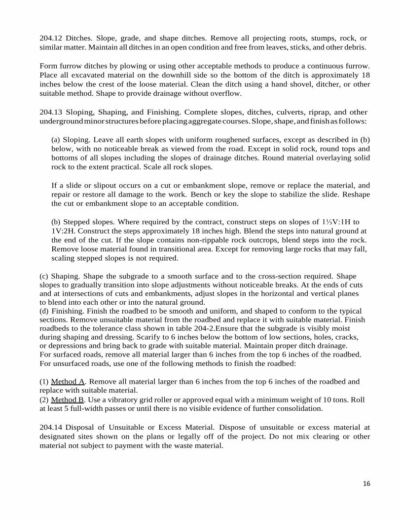
204.12 Ditches. Slope, grade, and shape ditches. Remove all projecting roots, stumps, rock, or similar matter. Maintain all ditches in an open condition and free from leaves, sticks, and other debris.
Form furrow ditches by plowing or using other acceptable methods to produce a continuous furrow. Place all excavated material on the downhill side so the bottom of the ditch is approximately 18 inches below the crest of the loose material. Clean the ditch using a hand shovel, ditcher, or other suitable method. Shape to provide drainage without overflow.
204.13 Sloping, Shaping, and Finishing. Complete slopes, ditches, culverts, riprap, and other underground minor structures before placing aggregate courses. Slope, shape, and finish as follows:
(a) Sloping. Leave all earth slopes with uniform roughened surfaces, except as described in (b) below, with no noticeable break as viewed from the road. Except in solid rock, round tops and bottoms of all slopes including the slopes of drainage ditches. Round material overlaying solid rock to the extent practical. Scale all rock slopes.
If a slide or slipout occurs on a cut or embankment slope, remove or replace the material, and repair or restore all damage to the work. Bench or key the slope to stabilize the slide. Reshape the cut or embankment slope to an acceptable condition.
(b) Stepped slopes. Where required by the contract, construct steps on slopes of 1⅓V:1H to 1V:2H. Construct the steps approximately 18 inches high. Blend the steps into natural ground at the end of the cut. If the slope contains non-rippable rock outcrops, blend steps into the rock. Remove loose material found in transitional area. Except for removing large rocks that may fall, scaling stepped slopes is not required.
(c) Shaping. Shape the subgrade to a smooth surface and to the cross-section required. Shape slopes to gradually transition into slope adjustments without noticeable breaks. At the ends of cuts and at intersections of cuts and embankments, adjust slopes in the horizontal and vertical planes to blend into each other or into the natural ground. (d) Finishing. Finish the roadbed to be smooth and uniform, and shaped to conform to the typical sections. Remove unsuitable material from the roadbed and replace it with suitable material. Finish roadbeds to the tolerance class shown in table 204-2.Ensure that the subgrade is visibly moist during shaping and dressing. Scarify to 6 inches below the bottom of low sections, holes, cracks, or depressions and bring back to grade with suitable material. Maintain proper ditch drainage. For surfaced roads, remove all material larger than 6 inches from the top 6 inches of the roadbed. For unsurfaced roads, use one of the following methods to finish the roadbed:
(1) Method A. Remove all material larger than 6 inches from the top 6 inches of the roadbed and replace with suitable material. (2) Method B. Use a vibratory grid roller or approved equal with a minimum weight of 10 tons. Roll at least 5 full-width passes or until there is no visible evidence of further consolidation.
204.14 Disposal of Unsuitable or Excess Material. Dispose of unsuitable or excess material at designated sites shown on the plans or legally off of the project. Do not mix clearing or other material not subject to payment with the waste material.
17
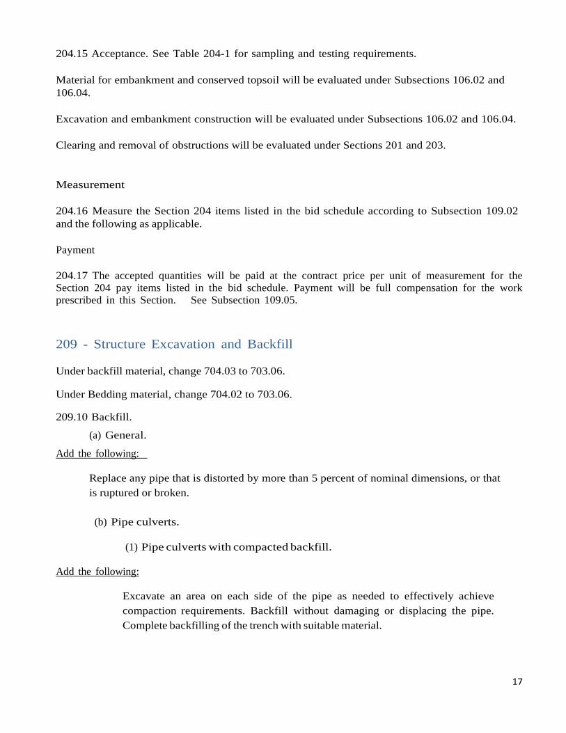
204.15 Acceptance. See Table 204-1 for sampling and testing requirements. Material for embankment and conserved topsoil will be evaluated under Subsections 106.02 and 106.04.
Excavation and embankment construction will be evaluated under Subsections 106.02 and 106.04.
Clearing and removal of obstructions will be evaluated under Sections 201 and 203.
Measurement
204.16 Measure the Section 204 items listed in the bid schedule according to Subsection 109.02 and the following as applicable.
Payment
204.17 The accepted quantities will be paid at the contract price per unit of measurement for the Section 204 pay items listed in the bid schedule. Payment will be full compensation for the work prescribed in this Section. See Subsection 109.05.
209 - Structure Excavation and Backfill
Under backfill material, change 704.03 to 703.06.
Under Bedding material, change 704.02 to 703.06.
209.10 Backfill.
(a) General.
Add the following:
Replace any pipe that is distorted by more than 5 percent of nominal dimensions, or that is ruptured or broken.
(b) Pipe culverts.
(1) Pipe culverts with compacted backfill.
Add the following:
Excavate an area on each side of the pipe as needed to effectively achieve compaction requirements. Backfill without damaging or displacing the pipe. Complete backfilling of the trench with suitable material.
18
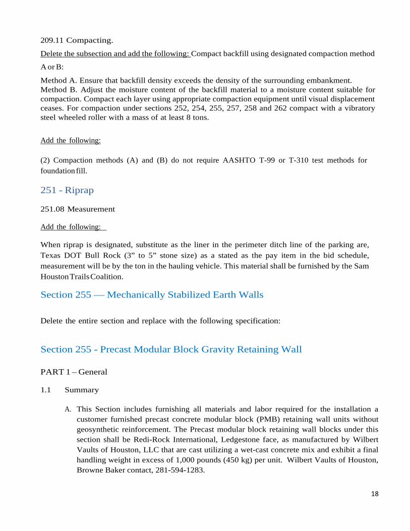
209.11 Compacting.
Delete the subsection and add the following: Compact backfill using designated compaction method
A or B:
Method A. Ensure that backfill density exceeds the density of the surrounding embankment. Method B. Adjust the moisture content of the backfill material to a moisture content suitable for compaction. Compact each layer using appropriate compaction equipment until visual displacement ceases. For compaction under sections 252, 254, 255, 257, 258 and 262 compact with a vibratory steel wheeled roller with a mass of at least 8 tons.
Add the following: (2) Compaction methods (A) and (B) do not require AASHTO T-99 or T-310 test methods for foundation fill.
251 - Riprap
251.08 Measurement
Add the following:
When riprap is designated, substitute as the liner in the perimeter ditch line of the parking are, Texas DOT Bull Rock (3” to 5” stone size) as a stated as the pay item in the bid schedule, measurement will be by the ton in the hauling vehicle. This material shall be furnished by the Sam Houston Trails Coalition.
Section 255 — Mechanically Stabilized Earth Walls Delete the entire section and replace with the following specification:
Section 255 - Precast Modular Block Gravity Retaining Wall
PART 1 – General
1.1 Summary
A. This Section includes furnishing all materials and labor required for the installation a
customer furnished precast concrete modular block (PMB) retaining wall units without geosynthetic reinforcement. The Precast modular block retaining wall blocks under this section shall be Redi-Rock International, Ledgestone face, as manufactured by Wilbert Vaults of Houston, LLC that are cast utilizing a wet-cast concrete mix and exhibit a final handling weight in excess of 1,000 pounds (450 kg) per unit. Wilbert Vaults of Houston, Browne Baker contact, 281-594-1283.
19
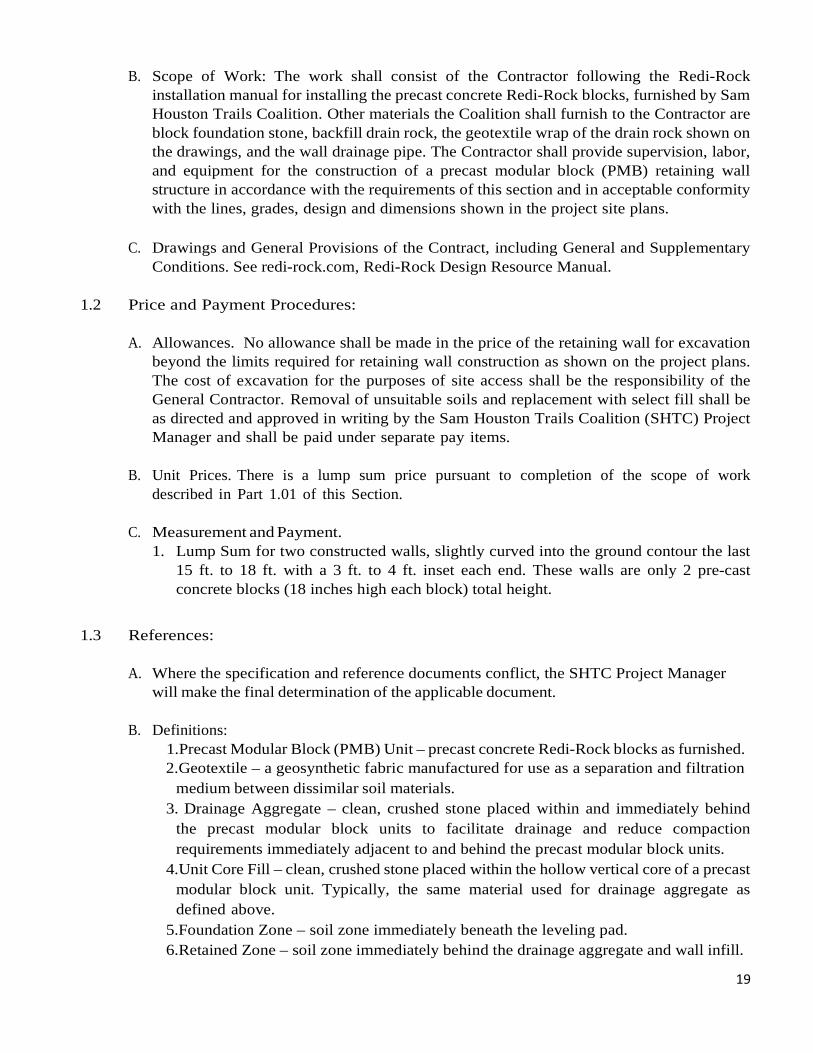
B. Scope of Work: The work shall consist of the Contractor following the Redi-Rock installation manual for installing the precast concrete Redi-Rock blocks, furnished by Sam Houston Trails Coalition. Other materials the Coalition shall furnish to the Contractor are block foundation stone, backfill drain rock, the geotextile wrap of the drain rock shown on the drawings, and the wall drainage pipe. The Contractor shall provide supervision, labor, and equipment for the construction of a precast modular block (PMB) retaining wall structure in accordance with the requirements of this section and in acceptable conformity with the lines, grades, design and dimensions shown in the project site plans.
C. Drawings and General Provisions of the Contract, including General and Supplementary
Conditions. See redi-rock.com, Redi-Rock Design Resource Manual. 1.2 Price and Payment Procedures:
A. Allowances. No allowance shall be made in the price of the retaining wall for excavation
beyond the limits required for retaining wall construction as shown on the project plans. The cost of excavation for the purposes of site access shall be the responsibility of the General Contractor. Removal of unsuitable soils and replacement with select fill shall be as directed and approved in writing by the Sam Houston Trails Coalition (SHTC) Project Manager and shall be paid under separate pay items.
B. Unit Prices. There is a lump sum price pursuant to completion of the scope of work
described in Part 1.01 of this Section.
C. Measurement and Payment. 1. Lump Sum for two constructed walls, slightly curved into the ground contour the last
15 ft. to 18 ft. with a 3 ft. to 4 ft. inset each end. These walls are only 2 pre-cast concrete blocks (18 inches high each block) total height.
1.3 References:
A. Where the specification and reference documents conflict, the SHTC Project Manager will make the final determination of the applicable document.
B. Definitions:
1. Precast Modular Block (PMB) Unit – precast concrete Redi-Rock blocks as furnished. 2.Geotextile – a geosynthetic fabric manufactured for use as a separation and filtration
medium between dissimilar soil materials. 3. Drainage Aggregate – clean, crushed stone placed within and immediately behind
the precast modular block units to facilitate drainage and reduce compaction requirements immediately adjacent to and behind the precast modular block units.
4. Unit Core Fill – clean, crushed stone placed within the hollow vertical core of a precast modular block unit. Typically, the same material used for drainage aggregate as defined above.
5.Foundation Zone – soil zone immediately beneath the leveling pad. 6. Retained Zone – soil zone immediately behind the drainage aggregate and wall infill.
20
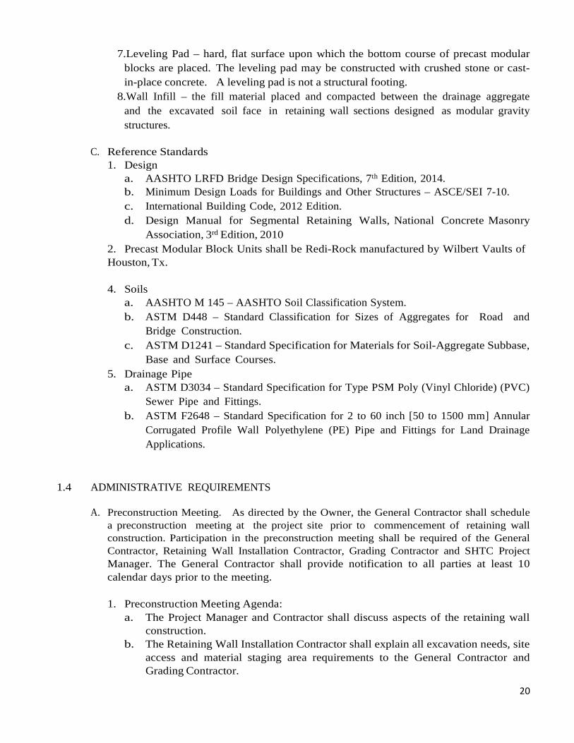
7. Leveling Pad – hard, flat surface upon which the bottom course of precast modular blocks are placed. The leveling pad may be constructed with crushed stone or cast- in-place concrete. A leveling pad is not a structural footing.
8. Wall Infill – the fill material placed and compacted between the drainage aggregate and the excavated soil face in retaining wall sections designed as modular gravity structures.
C. Reference Standards
1. Design a. AASHTO LRFD Bridge Design Specifications, 7th Edition, 2014. b. Minimum Design Loads for Buildings and Other Structures – ASCE/SEI 7-10. c. International Building Code, 2012 Edition. d. Design Manual for Segmental Retaining Walls, National Concrete Masonry
Association, 3rd Edition, 2010 2. Precast Modular Block Units shall be Redi-Rock manufactured by Wilbert Vaults of Houston, Tx.
4. Soils
a. AASHTO M 145 – AASHTO Soil Classification System. b. ASTM D448 – Standard Classification for Sizes of Aggregates for Road and
Bridge Construction. c. ASTM D1241 – Standard Specification for Materials for Soil-Aggregate Subbase,
Base and Surface Courses. 5. Drainage Pipe
a. ASTM D3034 – Standard Specification for Type PSM Poly (Vinyl Chloride) (PVC) Sewer Pipe and Fittings.
b. ASTM F2648 – Standard Specification for 2 to 60 inch [50 to 1500 mm] Annular Corrugated Profile Wall Polyethylene (PE) Pipe and Fittings for Land Drainage Applications.
1.4 ADMINISTRATIVE REQUIREMENTS
A. Preconstruction Meeting. As directed by the Owner, the General Contractor shall schedule
a preconstruction meeting at the project site prior to commencement of retaining wall construction. Participation in the preconstruction meeting shall be required of the General Contractor, Retaining Wall Installation Contractor, Grading Contractor and SHTC Project Manager. The General Contractor shall provide notification to all parties at least 10 calendar days prior to the meeting.
1. Preconstruction Meeting Agenda:
a. The Project Manager and Contractor shall discuss aspects of the retaining wall construction.
b. The Retaining Wall Installation Contractor shall explain all excavation needs, site access and material staging area requirements to the General Contractor and Grading Contractor.
21
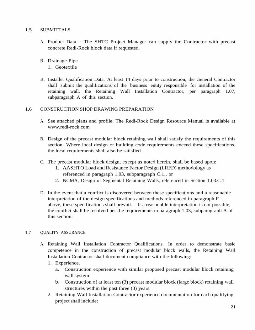
1.5 SUBMITTALS
A. Product Data – The SHTC Project Manager can supply the Contractor with precast concrete Redi-Rock block data if requested.
B. Drainage Pipe
1. Geotextile
B. Installer Qualification Data. At least 14 days prior to construction, the General Contractor shall submit the qualifications of the business entity responsible for installation of the retaining wall, the Retaining Wall Installation Contractor, per paragraph 1.07, subparagraph A of this section.
1.6 CONSTRUCTION SHOP DRAWING PREPARATION
A. See attached plans and profile. The Redi-Rock Design Resource Manual is available at
www.redi-rock.com
B. Design of the precast modular block retaining wall shall satisfy the requirements of this section. Where local design or building code requirements exceed these specifications, the local requirements shall also be satisfied.
C. The precast modular block design, except as noted herein, shall be based upon:
1. AASHTO Load and Resistance Factor Design (LRFD) methodology as referenced in paragraph 1.03, subparagraph C.1., or
2. NCMA, Design of Segmental Retaining Walls, referenced in Section 1.03.C.1
D. In the event that a conflict is discovered between these specifications and a reasonable interpretation of the design specifications and methods referenced in paragraph F above, these specifications shall prevail. If a reasonable interpretation is not possible, the conflict shall be resolved per the requirements in paragraph 1.03, subparagraph A of this section.
1.7 QUALITY ASSURANCE
A. Retaining Wall Installation Contractor Qualifications. In order to demonstrate basic
competence in the construction of precast modular block walls, the Retaining Wall Installation Contractor shall document compliance with the following: 1. Experience.
a. Construction experience with similar proposed precast modular block retaining wall system.
b. Construction of at least ten (3) precast modular block (large block) retaining wall structures within the past three (3) years.
2. Retaining Wall Installation Contractor experience documentation for each qualifying project shall include:
22
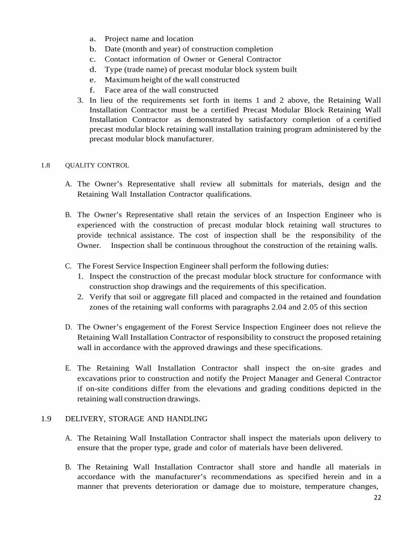
a. Project name and location b. Date (month and year) of construction completion c. Contact information of Owner or General Contractor d. Type (trade name) of precast modular block system built e. Maximum height of the wall constructed f. Face area of the wall constructed
3. In lieu of the requirements set forth in items 1 and 2 above, the Retaining Wall Installation Contractor must be a certified Precast Modular Block Retaining Wall Installation Contractor as demonstrated by satisfactory completion of a certified precast modular block retaining wall installation training program administered by the precast modular block manufacturer.
1.8 QUALITY CONTROL
A. The Owner’s Representative shall review all submittals for materials, design and the
Retaining Wall Installation Contractor qualifications.
B. The Owner’s Representative shall retain the services of an Inspection Engineer who is experienced with the construction of precast modular block retaining wall structures to provide technical assistance. The cost of inspection shall be the responsibility of the Owner. Inspection shall be continuous throughout the construction of the retaining walls.
C. The Forest Service Inspection Engineer shall perform the following duties:
1. Inspect the construction of the precast modular block structure for conformance with construction shop drawings and the requirements of this specification.
2. Verify that soil or aggregate fill placed and compacted in the retained and foundation zones of the retaining wall conforms with paragraphs 2.04 and 2.05 of this section
D. The Owner’s engagement of the Forest Service Inspection Engineer does not relieve the
Retaining Wall Installation Contractor of responsibility to construct the proposed retaining wall in accordance with the approved drawings and these specifications.
E. The Retaining Wall Installation Contractor shall inspect the on-site grades and
excavations prior to construction and notify the Project Manager and General Contractor if on-site conditions differ from the elevations and grading conditions depicted in the retaining wall construction drawings.
1.9 DELIVERY, STORAGE AND HANDLING
A. The Retaining Wall Installation Contractor shall inspect the materials upon delivery to
ensure that the proper type, grade and color of materials have been delivered.
B. The Retaining Wall Installation Contractor shall store and handle all materials in accordance with the manufacturer’s recommendations as specified herein and in a manner that prevents deterioration or damage due to moisture, temperature changes,
23
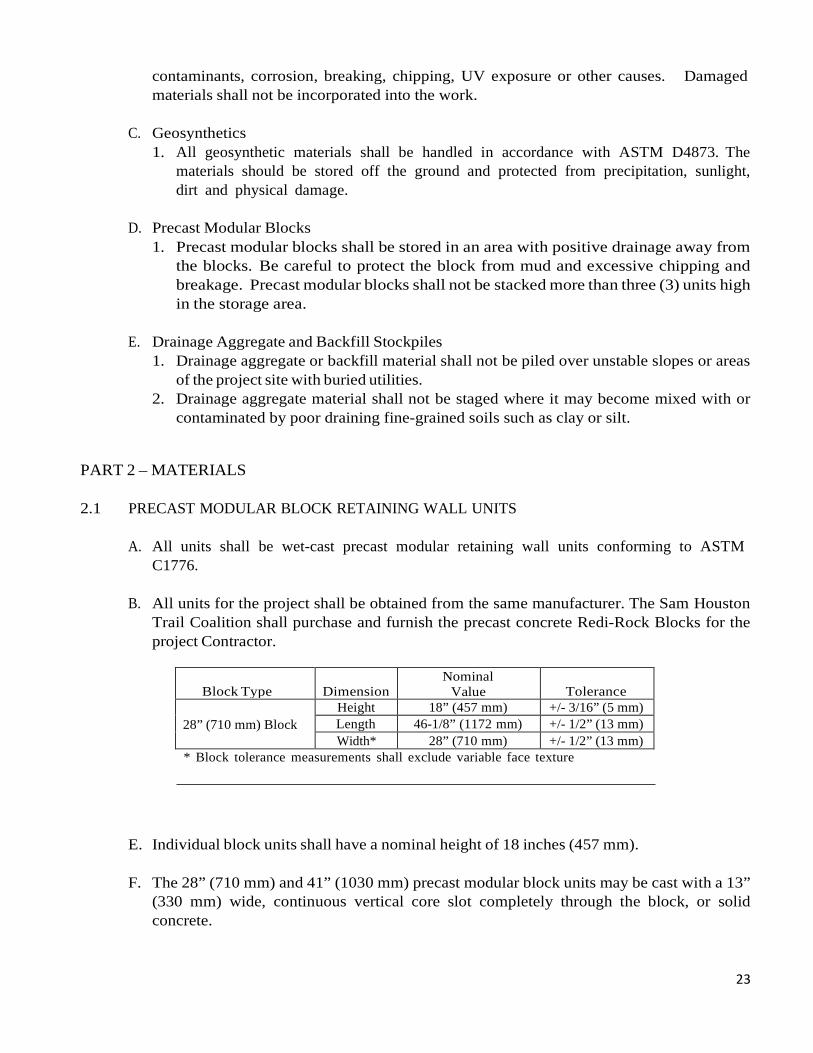
contaminants, corrosion, breaking, chipping, UV exposure or other causes. Damaged materials shall not be incorporated into the work.
C. Geosynthetics
1. All geosynthetic materials shall be handled in accordance with ASTM D4873. The materials should be stored off the ground and protected from precipitation, sunlight, dirt and physical damage.
D. Precast Modular Blocks
1. Precast modular blocks shall be stored in an area with positive drainage away from the blocks. Be careful to protect the block from mud and excessive chipping and breakage. Precast modular blocks shall not be stacked more than three (3) units high in the storage area.
E. Drainage Aggregate and Backfill Stockpiles
1. Drainage aggregate or backfill material shall not be piled over unstable slopes or areas of the project site with buried utilities.
2. Drainage aggregate material shall not be staged where it may become mixed with or contaminated by poor draining fine-grained soils such as clay or silt.
PART 2 – MATERIALS
2.1 PRECAST MODULAR BLOCK RETAINING WALL UNITS
A. All units shall be wet-cast precast modular retaining wall units conforming to ASTM
C1776.
B. All units for the project shall be obtained from the same manufacturer. The Sam Houston Trail Coalition shall purchase and furnish the precast concrete Redi-Rock Blocks for the project Contractor.
Block Type Dimension
Nominal Value
Tolerance
28” (710 mm) Block
Height 18” (457 mm) +/- 3/16” (5 mm) Length 46-1/8” (1172 mm) +/- 1/2” (13 mm) Width* 28” (710 mm) +/- 1/2” (13 mm)
* Block tolerance measurements shall exclude variable face texture
E. Individual block units shall have a nominal height of 18 inches (457 mm).
F. The 28” (710 mm) and 41” (1030 mm) precast modular block units may be cast with a 13” (330 mm) wide, continuous vertical core slot completely through the block, or solid concrete.
24
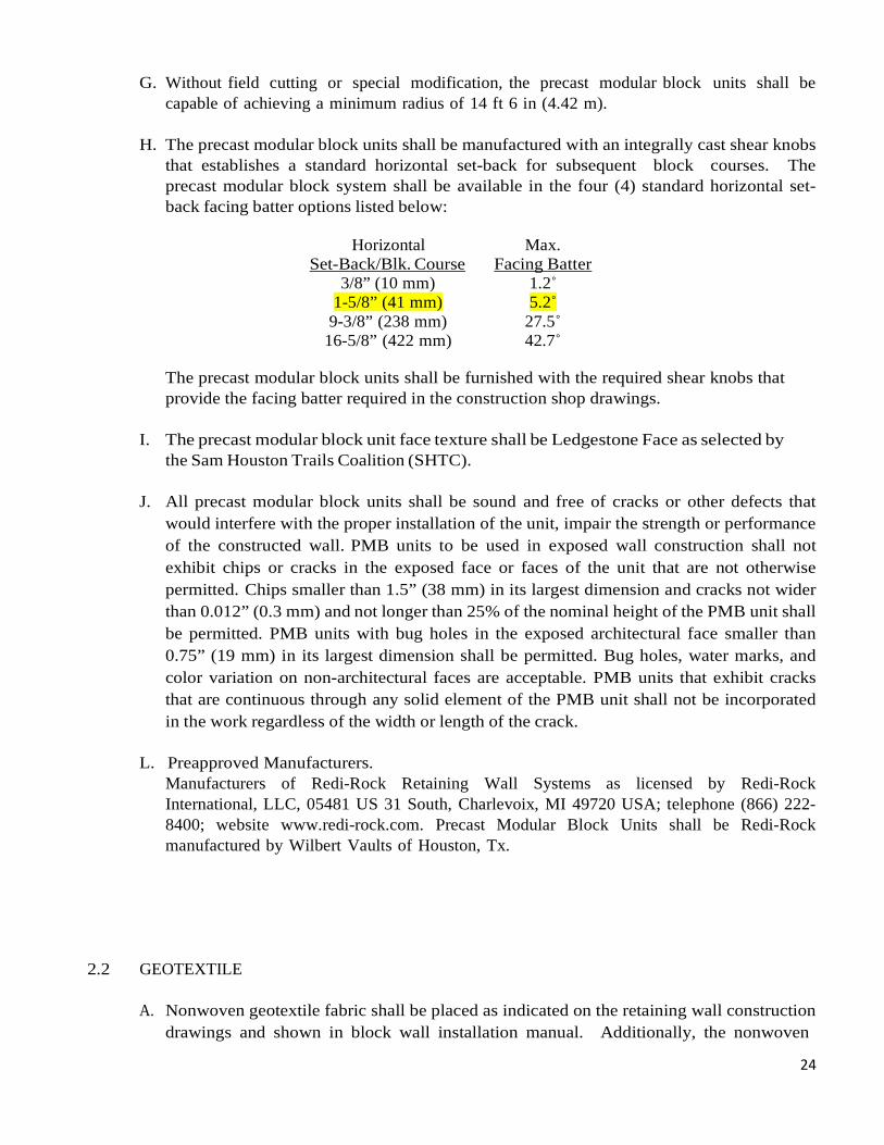
G. Without field cutting or special modification, the precast modular block units shall be capable of achieving a minimum radius of 14 ft 6 in (4.42 m).
H. The precast modular block units shall be manufactured with an integrally cast shear knobs
that establishes a standard horizontal set-back for subsequent block courses. The precast modular block system shall be available in the four (4) standard horizontal set- back facing batter options listed below:
Horizontal Set-Back/Blk. Course
Max. Facing Batter
3/8” (10 mm) 1.2˚ 1-5/8” (41 mm) 5.2˚
9-3/8” (238 mm) 27.5˚ 16-5/8” (422 mm) 42.7˚
The precast modular block units shall be furnished with the required shear knobs that provide the facing batter required in the construction shop drawings.
I. The precast modular block unit face texture shall be Ledgestone Face as selected by
the Sam Houston Trails Coalition (SHTC).
J. All precast modular block units shall be sound and free of cracks or other defects that would interfere with the proper installation of the unit, impair the strength or performance of the constructed wall. PMB units to be used in exposed wall construction shall not exhibit chips or cracks in the exposed face or faces of the unit that are not otherwise permitted. Chips smaller than 1.5” (38 mm) in its largest dimension and cracks not wider than 0.012” (0.3 mm) and not longer than 25% of the nominal height of the PMB unit shall be permitted. PMB units with bug holes in the exposed architectural face smaller than 0.75” (19 mm) in its largest dimension shall be permitted. Bug holes, water marks, and color variation on non-architectural faces are acceptable. PMB units that exhibit cracks that are continuous through any solid element of the PMB unit shall not be incorporated in the work regardless of the width or length of the crack.
L. Preapproved Manufacturers.
Manufacturers of Redi-Rock Retaining Wall Systems as licensed by Redi-Rock International, LLC, 05481 US 31 South, Charlevoix, MI 49720 USA; telephone (866) 222- 8400; website www.redi-rock.com. Precast Modular Block Units shall be Redi-Rock manufactured by Wilbert Vaults of Houston, Tx.
2.2 GEOTEXTILE
A. Nonwoven geotextile fabric shall be placed as indicated on the retaining wall construction drawings and shown in block wall installation manual. Additionally, the nonwoven
25
geotextile fabric shall be placed in the v-shaped joint between adjacent block units on the same course. The nonwoven geotextile fabric shall meet the requirements Class 3 construction survivability in accordance with AASHTO M 288.
B. Preapproved Nonwoven Geotextile Products 1. Mirafi 140N 2. Propex Geotex 451 3. Skaps GT-142 4. Thrace-Linq 140EX 5. Carthage Mills FX-40HS 6. Stratatex ST 142
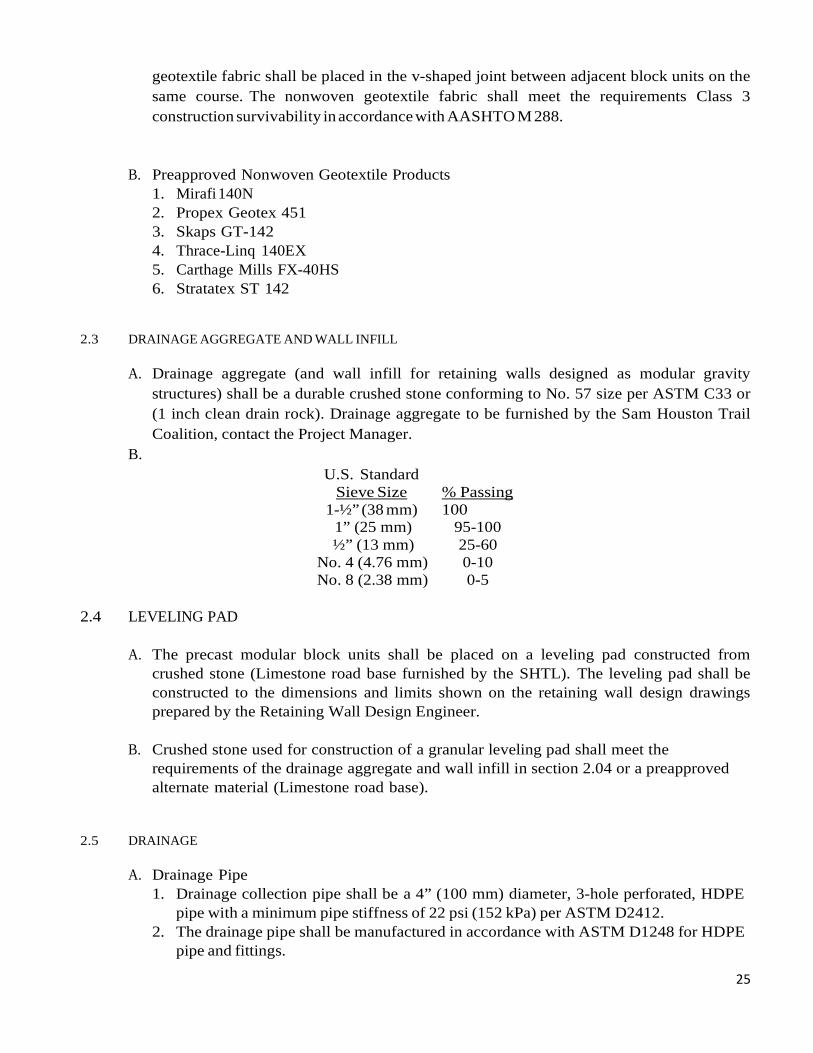
2.3 DRAINAGE AGGREGATE AND WALL INFILL
A. Drainage aggregate (and wall infill for retaining walls designed as modular gravity
structures) shall be a durable crushed stone conforming to No. 57 size per ASTM C33 or (1 inch clean drain rock). Drainage aggregate to be furnished by the Sam Houston Trail Coalition, contact the Project Manager.
B. U.S. Standard
Sieve Size % Passing 1-½” (38 mm) 100
1” (25 mm) 95-100 ½” (13 mm) 25-60
No. 4 (4.76 mm) 0-10 No. 8 (2.38 mm) 0-5
2.4 LEVELING PAD
A. The precast modular block units shall be placed on a leveling pad constructed from
crushed stone (Limestone road base furnished by the SHTL). The leveling pad shall be constructed to the dimensions and limits shown on the retaining wall design drawings prepared by the Retaining Wall Design Engineer.
B. Crushed stone used for construction of a granular leveling pad shall meet the
requirements of the drainage aggregate and wall infill in section 2.04 or a preapproved alternate material (Limestone road base).
2.5 DRAINAGE
A. Drainage Pipe
1. Drainage collection pipe shall be a 4” (100 mm) diameter, 3-hole perforated, HDPE pipe with a minimum pipe stiffness of 22 psi (152 kPa) per ASTM D2412.
2. The drainage pipe shall be manufactured in accordance with ASTM D1248 for HDPE pipe and fittings.
26
B. Preapproved Drainage Pipe Products 1. ADS 3000 Triple Wall pipe as manufactured by Advanced Drainage Systems. 2. Incorporate Carriff Corporation Engineered Fabric, 100 % polyester, 4” drain sleeve
filter sock over the drainage pipes, or an approved equal. PART 3 – EXECUTION
3.1 GENERAL
A. All work shall be performed in accordance with OSHA safety standards, state and local
building codes and manufacturer’s requirements.
B. The General Contractor is responsible to ensure that safe excavations and embankments are maintained throughout the course of the project.
C. All work shall be inspected by the Sam Houston Trail Coalition - Project Manager.
3.2 EXAMINATION
A. Prior to construction, the General Contractor, Grading Contractor, Retaining Wall
Installation Contractor and the Forest Service Inspection Engineer shall examine the areas in which the retaining wall will be constructed to evaluate compliance with the requirements for installation tolerances, worker safety and any site conditions affecting performance of the completed structure. Installation shall proceed only after unsatisfactory conditions have been corrected.
3.3 PREPARATION
A. Fill Soil.
1. The Project Manager shall coordinate with others to verify that retained backfill material placed within a horizontal distance of one (1.0) times the wall height behind the wall blocks satisfies the criteria of this section.
2. The Project Manager shall coordinate with others to verify that any fill soil installed in the foundation and retained soil zones of the retaining wall satisfies the specification of the Retaining Wall Design Engineer as shown on the construction drawings.
B. Excavation.
1. The Grading Contractor shall excavate to the lines and grades required for construction of the precast modular block retaining wall as shown on the construction drawings. The Grading Contractor shall minimize over-excavation. Excavation support, if required, shall be the responsibility of the Grading Contractor.
2. Over-excavated soil shall be replaced with suitable compacted fill. 3. Embankment excavations shall be bench cut.
C. Foundation Preparation.
27
1. Prior to construction of the precast modular block retaining wall, the leveling pad area and undercut zone (if applicable) shall be cleared and grubbed. All topsoil, brush, frozen soil and organic material shall be removed. Additional foundation soils found to be unsatisfactory beyond the specified undercut limits shall be undercut and replaced with approved fill as directed by the Project Manager. The Inspection Engineer shall ensure that the undercut limits are consistent with the requirements of the Project Manager and that all soil fill material is properly compacted according project specifications. The Inspection Engineer shall document the volume of undercut and replacement if available.
2. Following excavation for the leveling pad and undercut zone (if applicable), the Inspection Engineer shall evaluate the in-situ soil in the foundation and retained soil zones. a. The Forest Service Inspection Engineer shall visually verify that the shear
strength of the in-situ soil assumed by the Retaining Wall Design Engineer is appropriate. The Inspection Engineer shall immediately stop work and notify the Owner if the in-situ shear strength, soft - spongy soils, is found to be inconsistent with the retaining wall design assumptions.
D. Leveling Pad.
1. The leveling pad shall be constructed with SHTC furnished Limestone road base to provide a level, hard surface on which to place the first course of precast modular block units. The leveling pad shall be placed in the dimensions shown on the retaining wall construction drawings and extend to the limits indicated.
2. Crushed Stone Leveling Pad. Crushed stone shall be placed in uniform maximum lifts of 6” (150 mm). The crushed stone shall be compacted by a minimum of 3 passes of a vibratory compactor capable of exerting 2,000 lb (8.9 kN) of centrifugal force and to the satisfaction of the Inspection Engineer.
3.4 PRECAST MODULAR BLOCK WALL SYSTEM INSTALLATION
A. The precast modular block structure shall be constructed in accordance with the
construction drawings, these specifications and the recommendations of the retaining wall system component manufacturers. Where conflicts exist between the manufacturer’s recommendations and these specifications, these specifications shall prevail. See also the Redi-Rock Design Resource Manual at redi-rock.com.
B. Drainage components. Pipe, geotextile and drainage aggregate shall be installed as
shown on the construction shop drawings. Pre-approved is the ADS 3000 Triple Wall pipe as manufactured by Advanced Drainage Systems.
C. Precast Modular Block Installation 1. The first course of block units shall be placed with the front face edges tightly abutted
together on adjacent blocks, on the prepared leveling pad at the locations and elevations shown on the construction drawings. The Retaining Wall Installation Contractor shall take special care to ensure that the bottom course of block units are
28
in full contact with the leveling pad, are set level and true and are properly aligned according to the locations shown on the construction drawings.
2. Backfill shall be placed in front of the bottom course of blocks prior to placement of subsequent block courses. Nonwoven geotextile fabric shall be placed in the V- shaped joints between adjacent blocks. Drainage aggregate shall be placed in the V-shaped joints between adjacent blocks, and extend to a minimum distance of 12” (300 mm) behind the block unit.
3. Drainage aggregate shall be placed in 9 inch maximum lifts and compacted by a minimum of three (3) passes of a vibratory plate compactor capable exerting a minimum of 2,000 lb (8.9 kN) of centrifugal force.
4. Unit core fill shall be placed in the precast modular block unit vertical core slot. The core fill shall completely fill the slot to the level of the top of the block unit. The top of the block unit shall be broom-cleaned prior to placement of subsequent block courses. No additional courses of precast modular blocks may be stacked before the unit core fill is installed in the blocks on the course below.
5. Base course blocks for gravity wall designs (without geosynthetic soil reinforcement) may be furnished without vertical core slots. If so, disregard item 4 above, for the base course blocks in this application.
6. Nonwoven geotextile fabric shall be placed between the drainage aggregate and the retained soil (gravity wall design) if required on the retaining wall construction drawings.
7. Subsequent courses of block units shall be installed with a running bond (half block horizontal course-to-course offset). With the exception of 90 degree corner units, the shear channel of the upper block shall be fully engaged with the shear knobs of the block course below. The upper block course shall be pushed forward to fully engage the interface shear key between the blocks and to ensure consistent face batter and wall alignment. Drainage aggregate, unit core fill, geotextile and properly compacted backfill shall be complete and in-place for each course of block units before the next course of blocks is stacked.
8. The elevation of retained soil fill shall not be less than 1 block course (18” (457 mm)) below the elevation of the retained backfill throughout the construction of the retaining wall.
D. Construction Tolerance. Allowable construction tolerance of the retaining wall shall be
as follows: 1. Deviation from the design batter and horizontal alignment, when measured along a
10’ (3 m) straight wall section, shall not exceed 3/4” (19 mm). 2. Deviation from the overall design batter shall not exceed 1/2“ (13 mm) per 10’ (3 m)
of wall height. 3. The maximum allowable offset (horizontal bulge) of the face in any precast modular
block joint shall be 1/2” (13 mm). 4. The base of the precast modular block wall excavation shall be within 2” (50 mm) of
the staked elevations, unless otherwise approved by the Inspection Engineer. 5. Differential vertical settlement of the face shall not exceed 1’ (300 mm) along any 200’
(61 m) of wall length. 6. The maximum allowable vertical displacement of the face in any precast modular block
joint shall be 1/2“ (13 mm).
29
7. The wall face shall be placed within 2” (50 mm) of the horizontal location staked.
3.5 WALL INFILL AND BACKFILL PLACEMENT
A. Backfill material placed immediately behind the drainage aggregate shall be compacted as follows: 1. 98% of maximum dry density at ± 2% optimum moisture content per ASTM D698
standard proctor or 85% relative density per ASTM D4254, or until no additional visual displacement during specified compaction process.
B. Compactive effort within 3’ (0.9 m) of the back of the precast modular blocks should be
accomplished with walk-behind compactors. Compaction in this zone shall be within 95% of maximum dry density as measured in accordance with ASTM D698 standard proctor or 80% relative density per ASTM D 4254. Heavy equipment should not be operated within 3’ (0.9 m) of the back of the precast modular blocks.
C. Backfill material shall be installed in lifts that do not exceed a compacted thickness of 9”
(230 mm).
D. At the end of each work day, the Retaining Wall Installation Contractor shall grade the surface of the last lift of the granular wall infill to a 3% ± 1% slope away from the precast modular block wall face and compact it.
E. The General Contractor shall direct the Grading Contractor to protect the precast modular
block wall structure against surface water runoff at all times through the use of berms, diversion ditches, silt fence, temporary drains and/or any other necessary measures to prevent soil staining of the wall face, scour of the retaining wall foundation or erosion of the reinforced backfill or wall infill.
3.6 OBSTRUCTIONS IN THE INFILL ZONE
A. The Retaining Wall Installation Contractor shall make all required allowances for
obstructions behind and through the wall face in accordance with the construction shop drawings.
B. Should unplanned obstructions become apparent for which the construction shop
drawings do not account, the affected portion of the wall shall not be constructed until the Retaining Wall Design Engineer can appropriately address the required procedures for construction of the wall section in question.
30
3.7 COMPLETION
A. For walls supporting unpaved areas, a minimum of 12” (300 mm) of compacted, low- permeability fill shall be placed over the granular wall infill zone of the precast modular block retaining wall structure. The adjacent retained soil shall be graded to prevent ponding of water behind the completed retaining wall.
B. The General Contractor shall confirm that the as-built precast modular block wall
geometries conform to the requirements of this section. The General Contractor shall notify the Owner of any deviations. END OF SECTION 255
31
302 - Minor Crushed Aggregate 308.06 Acceptance Delete all reference to and Table 308-1
308.07
Delete the second paragraph and replace with the following:
Measure crushed aggregate by the ton.
602 - Culverts and Drains
602.2 Material:
Add to list: HDPE pipe for 18” Dia. culverts to meet AASHTO M294 or ASTM F2306. Once source is Advance Drainage Systems Dual Wall N-12 drainage pipe or an equal. Install to manufacturer recommendations.
Guardrail gravel road surface water control device – as shown in drawings and installed across parking lot access loop road to divert surface water, use HDG Q235 W-guardrail sections, new or used in very good condition guardrail sections.
602.3 General. Delete the six paragraphs and replace with the following:
The lengths and locations of individual pipe “as shown on the plans” are approximate. Do not order pipe until culvert locations are designated on the ground and a written list of the correct lengths is approved by the Project Manager.
Install the parking lot entrance and exist road culverts according to manufacturer’s recommendations/specifications assuming a Class III vehicle loading. The Contractor should consider a temporary entrance and exit crossing device means when hauling heavy rock and select fill onto the project site so not as to damage the culverts from overloading.
602.03 General.
Add the following:
Ensure that the final installed alignment of all pipe allows no reverse grades, and does not permit horizontal and vertical alignments to vary from a straight line drawn from center of inlet to center of outlet by more than 2 percent of pipe center length or 1.0 feet, whichever is less.
32
625 -Turf Establishment 625.3 General.
Delete this subsection and replace with the following:
Contractor to use The National Forest and Grasslands in Texas seed mix for application period, the fertilizer and rate, and the mulch as specified on the attached Forest Service seed mix document to this contract.
Apply turf establishment to the areas shown on the plans or worklists within 2 days after completion of ground disturbing activities. Seeded areas damaged by construction activities shall be reseeded within 10 days of the damage. Do not seed during windy weather or when the ground is excessively wet, frozen, or snow covered.
625.4 Preparing Seedbed. Delete entire subsection and replace with the following: Ensure that the surface soil is in a roughened condition favorable for germination and growth.
625.5 Watering
Delete entire subsection.
625.6 Fertilizing.
Delete entire subsection and replace with the following:
Apply fertilizer having a chemical analysis as listed on the attached US Forest Service seed mix document. It is estimated to be approximately 15,820 sq.ft. to be seeded, fertilized and mulched on the north and west edges of the Richard Ravens Trailhead parking construction site.
(a) Dry Method. Apply the fertilizer with approved mechanical equipment. Hand operated
methods are satisfactory on areas inaccessible to mechanical equipment.
(b) Hydraulic method. Use hydraulic-type equipment capable of providing a uniform application using water as the carrying agent. Add fertilizer to the slurry and mix before adding seed. Add the tracer material when designated by the CO.
625.7 Seeding.
Delete the first sentence and add the following.
Apply seed mix by the following methods:
(a) Dry method. Delete the third sentence.
33
Add the following after subsection (b). Seed Mix. See the attached National Forest of Texas required
seed mix and suppliers in the contract package. Determine the pounds of seed to be furnished per acre by dividing the pounds of pure live seed required per acre by the product of the percent purity and percent germination.
625.8 Mulching.
Delete the entire subsection and replace with the following: Apply Mulch within 0.5 hours after
seeding by the following methods. (a) Dry Method. Apply mulch with a hand spreader or a spreader utilizing forced air at a rate of 4,000 pounds per acre..
(b) Hydraulic Method. Apply mulch in a separate application from the seed using hydraulic-type equipment according to Subsection 625.07(b).
Inaccessible areas may be mulched by hand. Apply mulch uniformly over the entire disturbed area.
625.9 Protecting and Caring for Seeded Areas Protect and care for seeded areas until final acceptance.
625.11 Measurement.
Measure the Section 625 items listed in the bid schedule according to Subsection 109.02. The estimated area to receive seeding treatment is 15,820 sq. ft.
625.4 Preparing Seedbed.
Delete “2 inches in diameter and larger,” from the second sentence.
625.5 Watering.
Delete the entire subsection
34
635 - Temporary Traffic Control 635.03 General.
Add the following: Install temporary traffic control signs to temporary posts or approved temporary
sign mounts.
703 – Aggregate
703.03 Granular Backfill: Add – the Sam Houston Trails Coalition (SHTC) shall furnish the Contractor, through a separate SHTC stone/haul contract, The #57 or 1” minus clean angular drain rock to backfill the Redi-Rock retaining blocks.
703.05 Subbase, Base, Surface Course Aggregate: Add – the Sam Houston Trails Coalition shall furnish through their stone contract the Limestone Road Base that can be used for the Redi-Rock block 6 inch granular leveling/foundation base and the specified surface coarse layer material for the entire project parking lot.
704 – Soil
704.07 Select Borrow: Add (c) The proposed surface area to receive the Limestone road base surface stone, (approximately 67,500 sq. ft.) shall first be covered with 4 inches of Select Fill as furnished by a Sam Houston Trails Coalition contract for Select Fill. This material shall be spread, graded and sheep-foot roller compacted until there minimal visual displacement.