installer manual sam 40 - nibe.rs
TRANSCRIPT

Installer manual
LEK
SAM 40Supply air module
IHB EN 1846-1531368
LEK
LEK
Table of Contents
41 Important information4Safety information
4General
62 Delivery and handling6Transport
6Assembly
6Supplied components
6Removing the covers
73 The design of the supply air mod-
ule8Pipe connections
8HVAC components
8Sensors etc.
8Electrical components
8Ventilation
8Miscellaneous
94 Pipe and ventilation connections9General pipe connections
10Dimensions and pipe connections
10Heating medium side
13Installation alternative
15General ventilation connection
15Ventilation flow
15Adjusting ventilation
15Dimension and ventilation connections
165 Electrical connections16General
16Connections
176 Commissioning and adjusting17Preparations
17Filling and venting
18Start-up and inspection
197 Program settings19Menu system
208 Disturbances in comfort20Info-menu
20Troubleshooting
229 Accessories
2310 Technical data23Dimensions and setting-out coordinates
24Technical specifications
25Electrical circuit diagram
26Item register
27Contact information
3Table of Contents |SAM 40
Safety informationThismanual describes installationand serviceproceduresfor implementation by specialists.
The manual must be left with the customer.
This appliance can be used by childrenaged from 8 years and above and per-sons with reduced physical, sensory ormental capabilities or lack of experienceand knowledge if they have been givensupervisionor instruction concerninguseof the appliance in a safeway andunder-stand thehazards involved. Children shallnot play with the appliance. Cleaningandusermaintenance shall not bemadeby children without supervision.
Rights to make any design or technicalmodifications are reserved.
©NIBE 2018.
NOTE
If the supply cable is damaged, onlyNIBE, its service representative orsimilar authorised person may re-place it to prevent any danger anddamage.
Symbols
NOTE
This symbol indicates danger to person or ma-chine .
Caution
This symbol indicates important informationaboutwhatyoushouldobservewhenmaintain-ing your installation.
TIP
This symbol indicates tips on how to facilitateusing the product.
Marking
The CE mark is obligatory for most products soldin the EU, regardless of where they are made.
CE
Classification of enclosure of electro-technicalequipment.
IP21
Danger to person or machine.!
Read the User Manual.
General
Software versionThe heat pump must have software version 8432R2(F370)/3585R2 (F750)or later. Visitwww.nibeuplink.comand click on the tab "Software" to download the latestsoftware to your installation or use the enclosed USBmemory.
Serial numberThe serial number canbe foundat thebottom left insidethe front cover.
LEK
Serial number
LEK
Caution
You need the product's 14 digit serial numberfor servicing and support.
RecoveryLeave the disposal of the packaging to the in-staller who installed the product or to specialwaste stations.
When disposing of the product, its constituentmaterials and components, e.g. compressors,
fans, circulation pumps and circuit boards, must be dis-posed of at a special waste station or dealer whoprovides this type of service.
To access the separate components, refer to the sectionthat shows the construction of the product. No specialtools are required for access.
Improper disposal of the product by the user results inadministrativepenalties in accordancewith current legis-lation.
SAM 40Chapter 1 | Important information4
1 Important information

Inspection of the installationIn addition, fill in the page for the installation data in the User Manual.
Current regulations require the supply air module to be inspected before it is put into service. The inspection mustbe carried out by a suitably qualified person.
DateSignatureNotesDescription✔
Ventilation (page 15)
Setting ventilation flow exhaust air
Setting ventilation flow supply air
Heating medium (page 10)
System flushed
Accessories bled
Check against output and pressure dropdiagrams
Connected according to outline diagram
Electricity (page 16)
Supply connected 230 V
Connected communication
5Chapter 1 | Important informationSAM 40

TransportThe supply air module must be transported and storeddry.
AssemblySAM40 is mounted free-standing on brackets, alternat-ively above aVPB200 (for VPB300/VPBS300 installationis carried out using brackets). Noise from the fan can betransferred to the brackets.■ Install the brackets to anoutsidewall, ideally in a roomwhere noise does not matter, in order to eliminatenoise problems. If this is not possible, avoid placing itagainst awall behindabedroomorother roomwherenoise may be a problem.
■ Wherever the unit is located, walls to sound sensitiverooms should be fitted with sound insulation.
■ Route pipes so they are not fixed to an internal wallthat backs on to a bedroom or living room.
Installation areaLeave a free space of 800 mm in front of the supply airmodule. All service on SAM 40 can be carried out fromthe front.
800
NOTE
Ensure that there is sufficient space (300 mm)above the supply air module for installingventilation hoses.
Supplied components
LEK
Vent hose1 x
Support bushes2 x
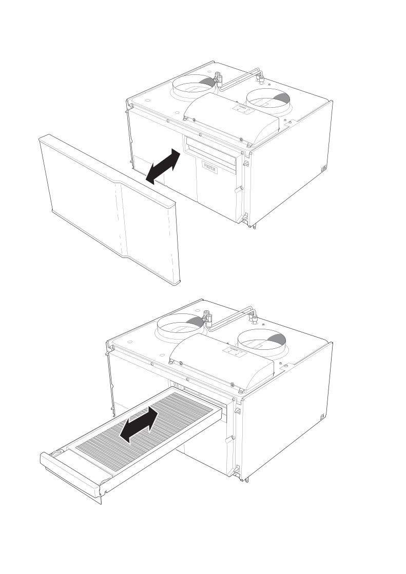
Removing the covers
Front cover1. Remove the service cover by pulling it straight out.
LEK
SAM 40Chapter 2 | Delivery and handling6
2 Delivery and handling

LEKLEK
S3 AA5-S2 AA5
AA5
AA5-S2
LEK
LEK
XL33 XL34QM20
PF1 HQ11
Svenskt produktblad
XL33 BT23
HQ11
XL34
AA100
QM20
PF 1
BT22
LEK
LEK
W6 W1
SF1
W101
SF1
W102
LEK
LEK
EP13 XL37 XL36
QN40
GQ3
Svenskt produktblad
GQ3EP13 XL36XL37
BT69 BT68QN40
7Chapter 3 | The design of the supply air moduleSAM 40
3 The design of the supply air module

Pipe connectionsVentilation connection supply airXL33Ventilation connection outdoor airXL34Connection, heating medium inXL36Connection, heating medium outXL37
HVAC componentsSupply air batteryEP13Venting heating mediumQM20Control valve heating mediumQN40
Sensors etc.Temperature sensor, supply airBT22Temperature sensor, outdoor airBT23Temperature sensor, flowBT68Temperature sensor, returnBT69
Electrical componentsAccessory cardAA5Dip switchAA5-S2Joint board1AA100Switch, position 0 - 1, main switchSF1Cord with connection plugW101Communication cableW102
VentilationSupply air fanGQ3Air filter supply airHQ11
MiscellaneousRating platePF1
1 Not visible in the image
Designations in component locations according tostandard IEC 81346-1 and 81346-2.
SAM 40Chapter 3 | The design of the supply air module8

General pipe connectionsPipe installationmust be carried out in accordance withcurrent norms and directives.
Compatible NIBE heat pumpsSAM 40 is installed together with a compatible exhaustair heat pump from NIBE. You adjust the settings andread off sensor values etc. for the supply air module inthe heat pump’s display.
Compatible products
■ F370
■ F750
Symbol key
MeaningSymbol
Control valve
Fan
System diagram
NOTE
External frost protection (outdoor air damper)should be installed in the outdoor air duct, ifSAM 40 is installed in a cold climate.
-AZ2SAM 40
For installation with F750, a buffer vessel (UKV) may berequired. See installation alternatives on page 14.
9Chapter 4 | Pipe and ventilation connectionsSAM 40
4 Pipe and ventilation connections
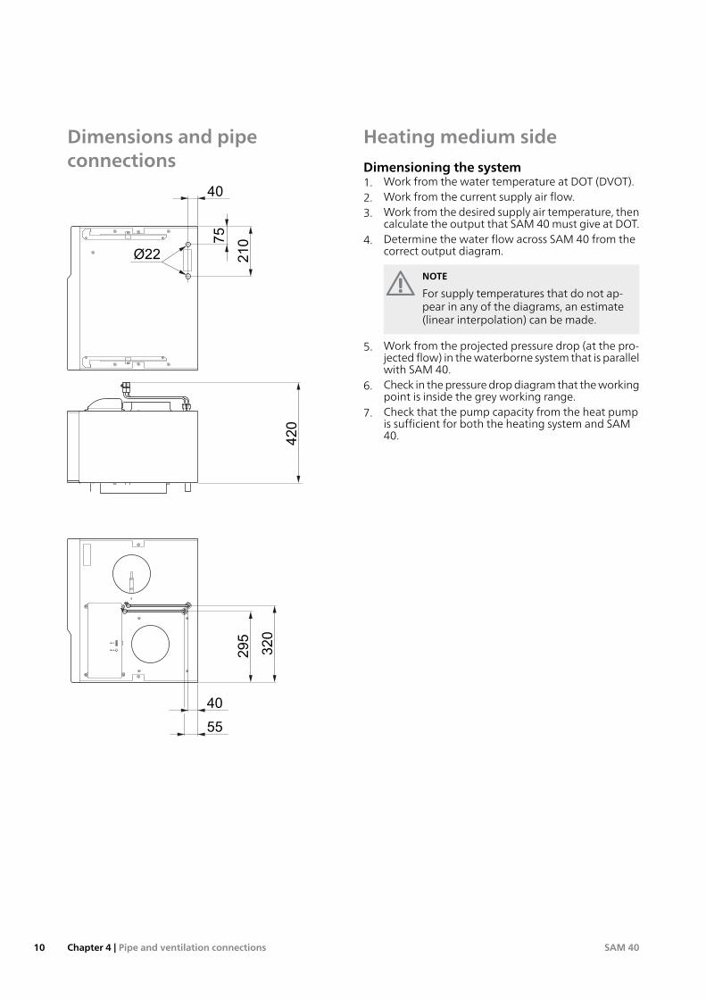
Dimensions and pipeconnections
40
55
295
320
75
40
210
Ø22
420
Heating medium side
Dimensioning the system1. Work from the water temperature at DOT (DVOT).2. Work from the current supply air flow.3. Work from the desired supply air temperature, then
calculate the output that SAM 40must give at DOT.4. Determine the water flow across SAM 40 from the
correct output diagram.
NOTE
For supply temperatures that do not ap-pear in any of the diagrams, an estimate(linear interpolation) can be made.
5. Work from the projected pressure drop (at the pro-jected flow) in thewaterborne system that is parallelwith SAM 40.
6. Check in thepressuredropdiagram that theworkingpoint is inside the grey working range.
7. Check that the pump capacity from the heat pumpis sufficient for both the heating system and SAM40.
SAM 40Chapter 4 | Pipe and ventilation connections10
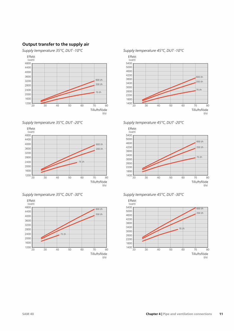
Output transfer to the supply airSupply temperature 45°C, DUT -10°C
140020 30 40 50 60 70 80
1800
2200
2600
3000
3400
3800
4200
4600
5000
5400
75 l/h
200 l/h
600 l/h
Effekt
(watt)
Tilluftsflöde
(l/s)
Effekt
Tilluftsflöde
Supply temperature 35°C, DUT -10°C
120040 5020 30 60 8070
1600
2000
2400
2800
3200
3600
4000
4400
4800
Effekt
(watt)
Tilluftsflöde
(l/s)
75 l/h
200 l/h
600 l/h
Effekt
Tilluftsflöde
Supply temperature 45°C, DUT -20°C
140020 30 40 50 60 70 80
1800
2200
2600
3000
3400
3800
4200
4600
5000
5400
200 l/h
600 l/h
75 l/h
Effekt
(watt)
Tilluftsflöde
(l/s)
Effekt
Tilluftsflöde
Supply temperature 35°C, DUT -20°C
120040 5020 30 60 8070
1600
2000
2400
2800
3200
3600
4000
4400
4800
Effekt
(watt)
Tilluftsflöde
(l/s)
200 l/h
600 l/h
75 l/h
Effekt
Tilluftsflöde
Supply temperature 45°C, DUT -30°C
140020 30 40 50 60 70 80
1800
2200
2600
3000
3400
3800
4200
4600
5000
5400
200 l/h
600 l/h
75 l/h
Effekt
(watt)
Tilluftsflöde
(l/s)
Effekt
Tilluftsflöde
Supply temperature 35°C, DUT -30°C
120040 5020 30 60 8070
1600
2000
2400
2800
3200
3600
4000
4400
4800
Effekt
(watt)
Tilluftsflöde
(l/s)
200 l/h
600 l/h
75 l/h
Effekt
Tilluftsflöde
11Chapter 4 | Pipe and ventilation connectionsSAM 40

Supply temperature 55°C, DUT -10°C
160020 40 50 60 7030 80
2000
2400
2800
3200
3600
4000
4400
4800
5200
5600
6000
6400
75 l/h
200 l/h
600 l/h
Effekt
(watt)
Tilluftsflöde
(l/s)
Effekt
Tilluftsflöde
Supply temperature 55°C, DUT -20°C
160020 40 50 60 7030 80
2000
2400
2800
3200
3600
4000
4400
4800
5200
5600
6000
6400
200 l/h
75 l/h
Effekt
(watt)
Tilluftsflöde
(l/s)
600 l/h
Effekt
Tilluftsflöde
Supply temperature 55°C, DUT -30°C
160020 40 50 60 7030 80
2000
2400
2800
3200
3600
4000
4400
4800
5200
5600
6000
6400
200 l/h
600 l/h
75 l/h
Effekt
(watt)
Tilluftsflöde
(l/s)
Effekt
Tilluftsflöde
Working range SAM 40
Recommended pressure drop in the system
00 0,200,150,100,05 l/s
5
10
15
20
25
30
35
Tillgängligt tryck
(kPa)
Flöde
0 800 l/h600400200
Pressure drop across theclimate system
Water flow
The diagram shows the climate system’s required pres-sure drop. The pressure drop across SAM 40 is the sameas that across the climate system that is parallel withSAM 40.
Check that the working point is inside the grey area. Iftheworking point is inside the dark grey area, to the leftin the diagram, it can give rise to an oscillating supplyair temperature. If there is too lowapressure drop acrossthe climate system that is parallel with SAM 40, there isa risk of ending up in the white area. In this area, thereis a risk of too low a water flow through the supply airmodule and there is then a risk of freezing.
SAM 40Chapter 4 | Pipe and ventilation connections12

Installation alternativeSAM 40 can be installed in several different ways, someof which are shown below.
More information about the options is available atnibe.eu.
Mounting
Installing on brackets1. Install SAM 40 on brackets (accessory BAU 10) as il-
lustrated below.2. Connect heating medium pipes and ventilation
ducts.
LEK
Installing on water heater
VPB 200
Caution
For connectionof VPB200 to F750, docking kitDEW 40 is used.
1. Remove the service cover from VPB 200.2. Remove the top panel from VPB 200 (installed with
6 screws).3. Install DEW 40 according to the instructions in the
installation manual. The pipes in VPB 200 can beadjusted/replaced in such a way that SAM 40 caneasily be installed above VPB 200.
4. Install SAM 40 from the top and slide into position.
LEK
5. Secure SAM 40 with the 2 screws supplied.
LEK
6. Connect heating medium and ventilation pipes.7. Reinstall the service cover on VPB 200.
AHPS
Caution
For connection of AHPS to F750, docking kitSCA 42 is used.
In order to locate SAM40 aboveAHPS, some conversionof AHPS is required. See the Installer Manual for SCA 42for more information.
13Chapter 4 | Pipe and ventilation connectionsSAM 40

Volume vesselDuring hot water production andwhen F750 is defrost-ing, no energy is supplied to the climate system. For thisreason, to achieve satisfactory function of the supply airmodule, stored energy must be available in the climatesystem during these operating cases. If there are closedthermostat valves blocking the flow through the radiat-ors/underfloor heating coils, the volume in these cannotbe included in the system volume.
If the total volume in the climate system (excluding theheat pump volume) is less than 40 litres, extra systemvolume, e.g. volume vessel UKV, has to be connected tothe supply line after the heat pump.
UKV
-AZ2SAM 40
Extra climate systemIn buildings with several climate systems that requiredifferent supply temperatures, the accessoryECS 40/ECS 41 can be connected. A shunt valve thenlowers the temperature to the underfloor heating sys-tem, for example.
SAM 40 is connected in parallel with the extra climatesystem.
UKV
-AZ2SAM 40
-EP21-GP10-EP21-BT2-EP21-AA25
-EP21-BT3
-EP21-QN25
-EP21ECS
SAM 40Chapter 4 | Pipe and ventilation connections14
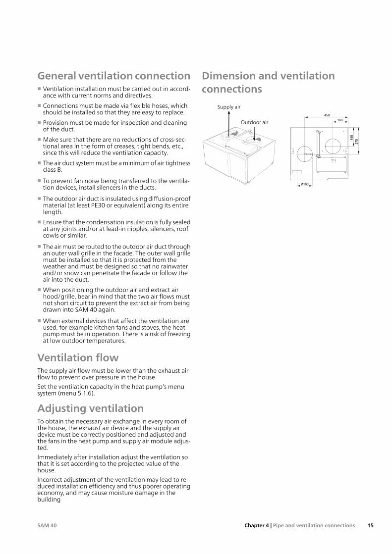
General ventilation connection■ Ventilation installation must be carried out in accord-ance with current norms and directives.
■ Connections must be made via flexible hoses, whichshould be installed so that they are easy to replace.
■ Provision must be made for inspection and cleaningof the duct.
■ Make sure that there are no reductions of cross-sec-tional area in the form of creases, tight bends, etc.,since this will reduce the ventilation capacity.
■ Theair duct systemmust beaminimumof air tightnessclass B.
■ To prevent fan noise being transferred to the ventila-tion devices, install silencers in the ducts.
■ Theoutdoor air duct is insulatedusingdiffusion-proofmaterial (at least PE30 or equivalent) along its entirelength.
■ Ensure that the condensation insulation is fully sealedat any joints and/or at lead-in nipples, silencers, roofcowls or similar.
■ The airmust be routed to theoutdoor air duct throughan outer wall grille in the facade. The outer wall grillemust be installed so that it is protected from theweather and must be designed so that no rainwaterand/or snow can penetrate the facade or follow theair into the duct.
■When positioning the outdoor air and extract airhood/grille, bear in mind that the two air flows mustnot short circuit to prevent the extract air from beingdrawn into SAM 40 again.
■When external devices that affect the ventilation areused, for example kitchen fans and stoves, the heatpumpmust be in operation. There is a risk of freezingat low outdoor temperatures.
Ventilation flowThe supply air flow must be lower than the exhaust airflow to prevent over pressure in the house.
Set the ventilation capacity in the heat pump’s menusystem (menu 5.1.6).
Adjusting ventilationTo obtain the necessary air exchange in every room ofthe house, the exhaust air device and the supply airdevice must be correctly positioned and adjusted andthe fans in the heat pump and supply air module adjus-ted.
Immediately after installation adjust the ventilation sothat it is set according to the projected value of thehouse.
Incorrect adjustment of the ventilation may lead to re-duced installation efficiency and thus poorer operatingeconomy, and may cause moisture damage in thebuilding
Dimension and ventilationconnections
Ø160
195
160
450
275
LEK
Supply air
Outdoor air
15Chapter 4 | Pipe and ventilation connectionsSAM 40

GeneralAll electrical equipment is connected at the factory.■ Disconnect SAM40before insulation testing thehousewiring.
■ For the supply air module wiring diagram, see page25.
■ Signal cables to external connectionsmust not be laidclose to high current cables.
■ If the supply cable is damaged, only NIBE, its servicerepresentativeor similar authorisedpersonmay replaceit to prevent any danger and damage.
NOTE
Electrical installation and service must be car-ried out under the supervision of a qualifiedelectrician. Electrical installation and wiringmust be carried out in accordance with thestipulations in force.
Connections
Connecting to compatible heat pump
The heat pump switch must be moved to position " "and the switch (SF1) on SAM40 toposition0, before anywork can be started.1. Ensure that the products are completely disconnec-
ted from the power source. Remove the front hatchand protective cover to the input card on the heatpump according to the instructions in its Installer'smanual.
2. Connect cable W102 to position X4 on the inputboard (AA3) in the heat pump according to thewir-ing diagramonpage 25. Use the cable lead-in in theheat pump when routing cables.
If several accessories are to be connected or arealready installed, the adjacent wiring diagrammustbe followed.
3. Fix external cable routing.4. Install the protective cover and the service cover ac-
cording to the heat pump Installation manual.5. Connect plug W101.
1
2
3
4
5
6
7
8
AA5-X4
15
A
B
GND
A
B
GND
A
B
GND
A
B
GND
A
B
GND
14
13
AA3-X4
1
2
3
4
5
6
7
8
AA5-X4
Accessory card 1
Accessory card 2
ON1
23
45
67
8
-X9
-X2
24 20212223 1516171819 1011121314 56789 1
1
N
L
PE
PE
1
2
3
4
5
6
7
8
2
3
4
5
6
7
8
9234
-X8
-X4
-X10
-X1
AA5-X4
ON1
23
45
67
8
-X9
-X2
24 20212223 1516171819 1011121314 56789 1
1
N
L
PE
PE
1
2
3
4
5
6
7
8
2
3
4
5
6
7
8
9234
-X8
-X4
-X10
-X1
AA5-X4
EB100
LEK
F750
AA3-X4
Connection of external frost protection(outdoor air damper)For connection of external frost protection (outdoor airdamper), see the Installer Manual for F750.
DIP switchThe DIP-switch (S2) on the accessory board (AA5) is setin the factory as below.
ON1
23
45
67
8
ON1
23
45
67
8
-X9
-X2
24 20212223 1516171819 1011121314 56789 1
1
N
L
PE
PE
1
2
3
4
5
6
7
8
2
3
4
5
6
7
8
9234
-X8
-X4
-X10
-X1
AA5-S2
SAM 40Chapter 5 | Electrical connections16
5 Electrical connections

Preparations1. Check that the switch (SF1) for the heat pump is in
position " .
Filling and venting
Filling the climate systemFill with water using the filler valve in the heat pump.
Venting the climate system1. Vent SAM 40 through the vent valve (QM20) and
the other climate systems through their respectivevent valves.
2. Keep topping up and venting until all air has beenremoved and the pressure is correct.
Caution
Check that the system has been vented priorto the heating season. Air in the supply airmodule entails a risk of frost damage in coldweather conditions.
-AZ2SAM 40
QM20
17Chapter 6 | Commissioning and adjustingSAM 40
6 Commissioning and adjusting

Start-up and inspection
Start-up with compatible heat pump
NOTE
There must be water in the climate system be-fore the switch on the heat pump is set to "".
1. Set switch (SF1) onSAM 40 in position "1".2. Set the heat pump's switch (SF1) to "".3. Follow the instructions in the start guide in the heat
pump display. If the start guide does not start whenyou start the heat pump, start it manually in menu5.7.
Commissioning with a compatible heat pump
The first time the installation is started a start guide isstarted. The start guide instructions statewhat needs tocarried out at the first start together with a run throughof the installation’s basic settings.
The start guide ensures that start-up is carried out cor-rectly and cannot be bypassed.The start guide can bestarted later in menu 5.7.
Caution
As long as the start guide is active, no functionin the installation will start automatically.
The guide will appear at each installation re-start until it is deselected on the last page.
Setting the ventilationVentilation must be set according to applicable stand-ards. The supply air flow is adjusted to approx. 80% ofthe exhaust air flow. The setting is made in menu 5.1.6.
Even if ventilation is roughly set at installation it is import-ant that a ventilation adjustment is ordered and permit-ted.
NOTE
Order a ventilation adjustment to completethe setting.
Ventilation capacity
00 10 20 30 40 50 60 70 80
50
100
150
200
250
350
300
400
Tillgängligt tryck
(Pa)
Luftflöde
(l/s)
100%80%
60%
40%
50%
70%
Available pressure
Airflow
Fan rating
00 10 20 30 40 50 60 70 80
10
20
30
40
50
60
90
70
80
100
Effekt
(W)
Luftflöde
(l/s)
100%
80%
60%
40%
50%
70%
Output
Airflow
Post-adjustment, ventingAir is initially released from the hot water and ventingmay be necessary. If gurgling sounds can be heard fromthe heat pump or climate system, the entire system re-quires additional venting. See section "Venting the cli-mate system"onpage17 for information about venting.
SAM 40Chapter 6 | Commissioning and adjusting18

Caution
See also the User/Installermanual for the heatpump.
Menu systemIf youdonotmakeall settings via the start guideor needto change any of the settings, this can be done in themenu system.
Menu 5.2 -system settingsActivating/deactivating of accessories.
Select: "ext sup air md"
Menu 5.3.9 - ext sup air mdSetting the supply air temperature.
When changing the supply air temperature, the settingsfor other parts of the climate systemmay need to beadjusted.
outdoor temp.T1
supply air temp. at T1
outdoor temp.T2
°C
°C
°C
ext sup air md 5.3.9
supply air temp. at low outdtemp.
supply air temp. at avg outdoortemp.
Caution
This accessorymay require a program softwareupdate in your heat pump.
The heat pump software must be version8432R2 (F370)/3585R2 (F750) or later.
19Chapter 7 | Program settingsSAM 40
7 Program settings

Inmost cases, theheat pumpnotes operational interfer-ence (operational interference can lead to disturbancein comfort) and indicates this with alarms and showsaction instructions in the display.
Info-menuAll the heat pump measurement values are gatheredundermenu3.1 in theheat pumpmenu system. Lookingthrough the values in this menu can often simplify find-ing the source of the fault. See help menu or usermanual for more information about menu 3.1.
All the heat pump measurement values are gatheredundermenu3.1 in theheat pumpmenu system. Lookingthrough the values in this menu can often simplify find-ing the source of the fault.
info / action
reset alarm
aid mode
Low pressure alarm
alarm
In the event of an alarm, some kind of malfunction hasoccurred,which is indicatedby the status lamp changingfromgreen continuously to red continuously. In addition,an alarm bell appears in the information window.
AlarmIn theeventof analarmwith a red status lampamalfunc-tion has occurred that the heat pump cannot remedyitself. In the display, by turning the control knob andpressing the OK button, you can see the type of alarm itis and reset it. You can also choose to set the heat pumpto aid mode.
info / action Here you can read what the alarm meansand receive tips on what you can do to correct theproblem that caused the alarm.
reset alarm In most cases it is sufficient to select "resetalarm" to correct the problem that caused the alarm. Ifa green light comes on after selecting "reset alarm", thealarm has been remedied. If a red light is still visible anda menu called "alarm" is visible in the display, the prob-lem causing the alarm remains. If the alarm disappearsand then returns, see the troubleshooting section (pageTroubleshooting).
aidmode ”aidmode” is a type of emergencymode. Thismeans that the heat pump produces heat and/or hotwater despite there being some kind of problem. Thiscan mean that the heat pump's compressor is not run-ning. In this case the immersion heater produces heatand/or hot water.
NOTE
To select aid mode an alarm action must beselected in the menu 5.1.4.
Caution
Selecting "aidmode” is not the sameas correct-ing the problem that caused the alarm. Thestatus lamp will therefore continue to be red.
TroubleshootingIf theoperational interference is not shown in thedisplaythe following tips can be used:
Basic actionsStart by checking the following items:■ That theheat pump is runningor that the supply cableto SAM 40 is connected.
■ Group and main fuses of the accommodation.
■ The property's earth circuit breaker.
■ The heat pump's miniature circuit breaker (FA1).
■ The heat pump's temperature limiter (FD1).
Low hot water temperature or a lack of hotwater■ The heat pump has temporarily prioritised supply airventilation to prevent too low temperatures in thesupply air coil.
Low room temperature■ Incorrect value set in supply air automatic control sys-tem.– Enter menu 5.3.9 (ext sup air md) and adjust thesetting for the supply air temperature.
High room temperature■ Incorrect value set in supply air automatic control sys-tem.– Enter menu 5.3.9 (ext sup air md) and adjust thesetting for the supply air temperature.
Low or a lack of ventilation■ Filter (HQ11) blocked.– Clean or replace the filter.
■ The ventilation is not adjusted.– Order/implement ventilation adjustment.
■ Supply air device closed, blocked or throttled downtoo much.– Check and clean the supply air device.
■ Check external frost protection (outdoor air damper).
High or distracting ventilation■ Filter (HQ11) blocked.– Clean or replace the filter.
■ The ventilation is not adjusted.– Order/implement ventilation adjustment.
SAM 40Chapter 8 | Disturbances in comfort20
8 Disturbances in comfort

Low supply air temperature■ Air in the heating medium system.– Vent SAM 40 using vent valve (QM20).
■ Incorrect value set in supply air automatic control sys-tem.– Enter menu 5.3.9 (ext sup air md) and reduce thesetting for the supply air temperature.
High supply air temperature■ Incorrect value set in supply air automatic control sys-tem.– Enter menu 5.3.9 (ext sup air md) and adjust thesetting for the supply air temperature.
21Chapter 8 | Disturbances in comfortSAM 40

Bracket BAU 10
Wall mounting of SAM 40.
Part no. 067 526
Buffer vessel UKV
UKV 40
Part no. 088 470
Top cabinet
Top cabinet that conceals the ventilation ducts.Height 345 mm
Part no. 067 518
Height 245 mm
Part no. 067 517
Height 385-635 mm
Part no. 067 519
SAM 40Chapter 9 | Accessories22
9 Accessories
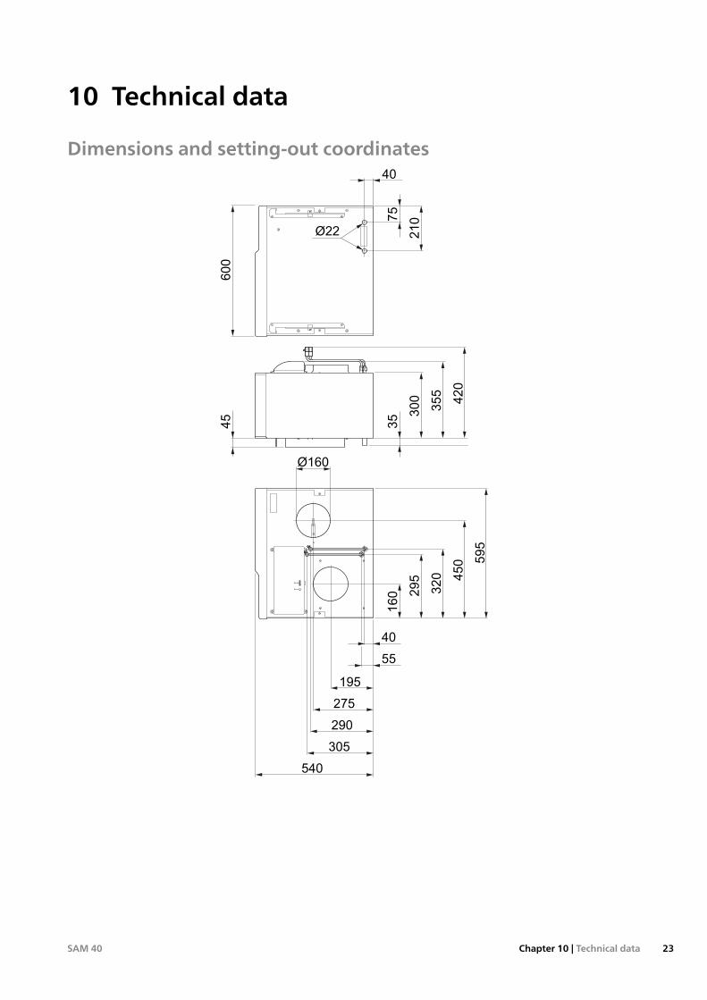
Dimensions and setting-out coordinates
Ø160
40
55
195
160 295
320 450 595
275
290
305
540
35
45 300
75
40
210
Ø22
355
420
600
23Chapter 10 | Technical dataSAM 40
10 Technical data

Technical specifications
IP 21
SAM 40
Electrical data
230 V ~ 50 HzVRated voltage
1.5WDrive output control valve
20-175WDriving power fan
IP 21Enclosure class
Heating medium circuit
0.05/0.5MPa/barMin pressure
0.25/2.5MPa/barMax pressure
Ventilation
ePM1 55%Filter type
Sound power level according to EN 12,102
45-50dB (A)Sound power level (Lw(A))1
Sound pressure levels
41-46dB (A)Sound pressure level in the boiler room (L(PA))2
Pipe connections
22mmHeating medium ext Ø
160mmVentilation Ø
Miscellaneous
600mmWidth
556mmDepth
396mmHeight
31kgWeight
067 147Part No.
1The value varies with the selected fan curve. For more detailedsound data including sound to channels visit nibe.eu.2 The value may vary with the room’s damping capacity. Thesevalues apply with 4 dB of damping.
SAM 40Chapter 10 | Technical data24

Electrical circuit diagramPart Specification Sheet 450192-3
Page 2/2 Created:2018-01-10 08:22
0.0
00
MJN
2018-0
1-1
0
Pro
duct
ion
SW
I2012-0
1-0
5
WIR
ING
DIA
GRAM
, SAM
40
ELSCH
EM
A, SAM
40
450192
3
25Chapter 10 | Technical dataSAM 40
Item register
AAccessories, 22Alarm, 20Assembly, 6
CCommissioning and adjusting, 17
Connecting to heating medium system, 17Preparations, 17Start-up and inspection, 18
Connecting to heating medium system, 17
DDelivery and handling, 6
Removing the covers, 6Dimensions and pipe connections, 10Dimensions and setting-out coordinates, 23Disturbances in comfort, 20
Alarm, 20Manage alarm, 20Troubleshooting, 20
EElectrical circuit diagram, 25Electrical connections, 16
Connections, 16General, 16
HHeating medium side, 10
Output transfer to the supply air, 11
IImportant information, 4
Marking, 4Recovery, 4Safety information, 4Serial number, 4Symbols, 4
Inspection of the installation, 5Installation alternative
Two or more climate systems, 14
MManage alarm, 20Marking, 4
OOutput transfer to the supply air, 11
PPipe and ventilation connections, 9
Dimensions and pipe connections, 10General pipe connections, 9Heating medium side, 10
Preparations, 17
RRemoving the covers, 6
SSafety information, 4
Inspection of the installation, 5Marking, 4Symbols on SAM 40, 4
Serial number, 4Start-up and inspection, 18
Setting the ventilation, 18Symbols, 4Symbols on SAM 40, 4
TTechnical data, 23
Dimensions and setting-out coordinates, 23Electrical circuit diagram, 25Technical Data, 24
Technical Data, 24The design of the supply air module, 7
List of components, 8Transport
Assembly, 6Troubleshooting, 20
SAM 40Chapter 11 | Item register26
11 Item register
Contact informationKNV Energietechnik GmbH, Gahberggasse 11, AT-4861 SchörflingTel: +43 (0)7662 8963 E-mail: [email protected] www.knv.at
AT
NIBE Wärmetechnik c/o ait Schweiz AG, Industriepark, CH-6246 AltishofenTel: +41 58 252 21 00 E-mail: [email protected] www.nibe.ch
CH
Druzstevni zavody Drazice s.r.o, Drazice 69, CZ - 294 71 Benatky nad JizerouTel: +420 326 373 801 E-mail: [email protected] www.nibe.cz
CZ
NIBE Systemtechnik GmbH, Am Reiherpfahl 3, 29223 CelleTel: +49 (0)5141 7546-0 E-mail: [email protected] www.nibe.de
DE
Vølund Varmeteknik A/S, Member of the Nibe Group, Brogårdsvej 7, 6920 VidebækTel: +45 97 17 20 33 E-mail: [email protected] www.volundvt.dk
DK
NIBE Energy Systems OY, Juurakkotie 3, 01510 VantaaTel: +358 (0)9-274 6970 E-mail: [email protected] www.nibe.fi
FI
NIBE Energy Systems France Sarl, Zone industrielle RD 28, Rue du Pou du Ciel, 01600 ReyrieuxTel : 04 74 00 92 92 E-mail: [email protected] www.nibe.fr
FR
NIBE Energy Systems Ltd, 3C Broom Business Park, Bridge Way, S419QG ChesterfieldTel: +44 (0)845 095 1200 E-mail: [email protected] www.nibe.co.uk
GB
NIBE Energietechniek B.V., Postbus 634, NL 4900 AP OosterhoutTel: 0168 477722 E-mail: [email protected] www.nibenl.nl
NL
ABK AS, Brobekkveien 80, 0582 Oslo, Postadresse: Postboks 64 Vollebekk, 0516 OsloTel: +47 23 17 05 20 E-mail: [email protected] www.nibe.no
NO
NIBE-BIAWAR Sp. z o. o. Aleja Jana Pawła II 57, 15-703 BIALYSTOKTel: +48 (0)85 662 84 90 E-mail: [email protected] www.biawar.com.pl
PL
© "EVAN" 17, per. Boynovskiy, RU-603024 Nizhny NovgorodTel: +7 831 419 57 06 E-mail: [email protected] www.nibe-evan.ru
RU
NIBE AB Sweden, Box 14, Hannabadsvägen 5, SE-285 21 MarkarydTel: +46 (0)433 73 000 E-mail: [email protected] www.nibe.se
SE
For countries not mention in this list, please contact Nibe Sweden or check www.nibe.eu for more information.

WS name: Anna SAMWS version: a2 (working edition)Publish date: 2018-11-21 08:36
NIBE AB Sweden
Hannabadsvägen 5Box 14 SE-285 21 [email protected]
531368