ray-tracing analysis of diffractive-refractive x-ray optics
TRANSCRIPT
electronic reprint
Journal of
SynchrotronRadiation
ISSN 0909-0495
Editors: A. Kvick, D. M. Mills and T. Ohta
Ray-tracing analysis of diffractive–refractive X-ray optics
Nikolay Artemiev, Jaromir Hrdy, Serguei Peredkov and Alexander Artemev
Copyright © International Union of Crystallography
Author(s) of this paper may load this reprint on their own web site provided that this cover page is retained. Republication of this article or itsstorage in electronic databases or the like is not permitted without prior permission in writing from the IUCr.
J. Synchrotron Rad. (2004). 11, 157–162 Nikolay Artemiev et al. � Diffractive–refractive X-ray optics
Ray-tracing analysis of diffractive±refractiveX-ray optics
Nikolay Artemiev,a* Jaromir HrdyÂ,b Serguei Peredkovc
and Alexander Artemevd
aLaboratoire d'Optique Appliquee ± ENSTA, EcolePolytechnique, France, bInstitute of Physics, Academy ofSciences, Czech Republic, cMAX-lab, Lund University, Sweden,and dRussian Research Centre, Kurchatov Institute, Russia.E-mail: [email protected]
Ray-tracing simulations of mistuned sagittal diffractive±refractive
X-ray lenses (DRXL) are presented. In this article, ®rstly the
characteristic aberrations for various types of crystal misalignments
within one-crystal and four-crystal DRXLs are considered, and the
sensitivity of such an optical system to the mutual misalignment of its
components is discussed. The simulations reveal that a DRXL is not
too sensitive to the adjustment of its components. In the second part
of this article the performance of such lenses with ideal and
approximate pro®les is examined. Comparative analysis of parabolic
and cylindrical DRXLs showed that, in the case when the linear
source size is comparable with the acceptance of the lens, the
performances of parabolic and cylindrical DRXLs are practically
the same.
Keywords: ray-tracing; diffractive±refractive X-ray lens; X-rayfocusing; X-ray monochromator.
1. Introduction
Application of the refraction effect for focusing synchrotron radia-
tion in the X-ray band is now well established. Compound refractive
lenses (Snigirev et al., 1996) are similar to ordinary lenses for visible
light. Such lenses are relatively simple to produce and work well in
the hard X-ray region. For longer wavelengths, however, gain in the
focus decreases due to absorption in the lens material. To overcome
this, some sophisticated solutions have been proposed (Lengeler et
al., 1999; Piestrup et al., 2000).
An alternative focusing method based on refraction was proposed
by Hrdy (1998). He proposed using the diffractive±refractive effect,
which is the refraction phenomenon occurring during Bragg diffrac-
tion. It was shown theoretically (HrdyÂ, 1998) and experimentally
(Hrdy & Siddons, 1999) that X-rays that are diffracted from a para-
bolic longitudinal groove machined into a single-crystal mono-
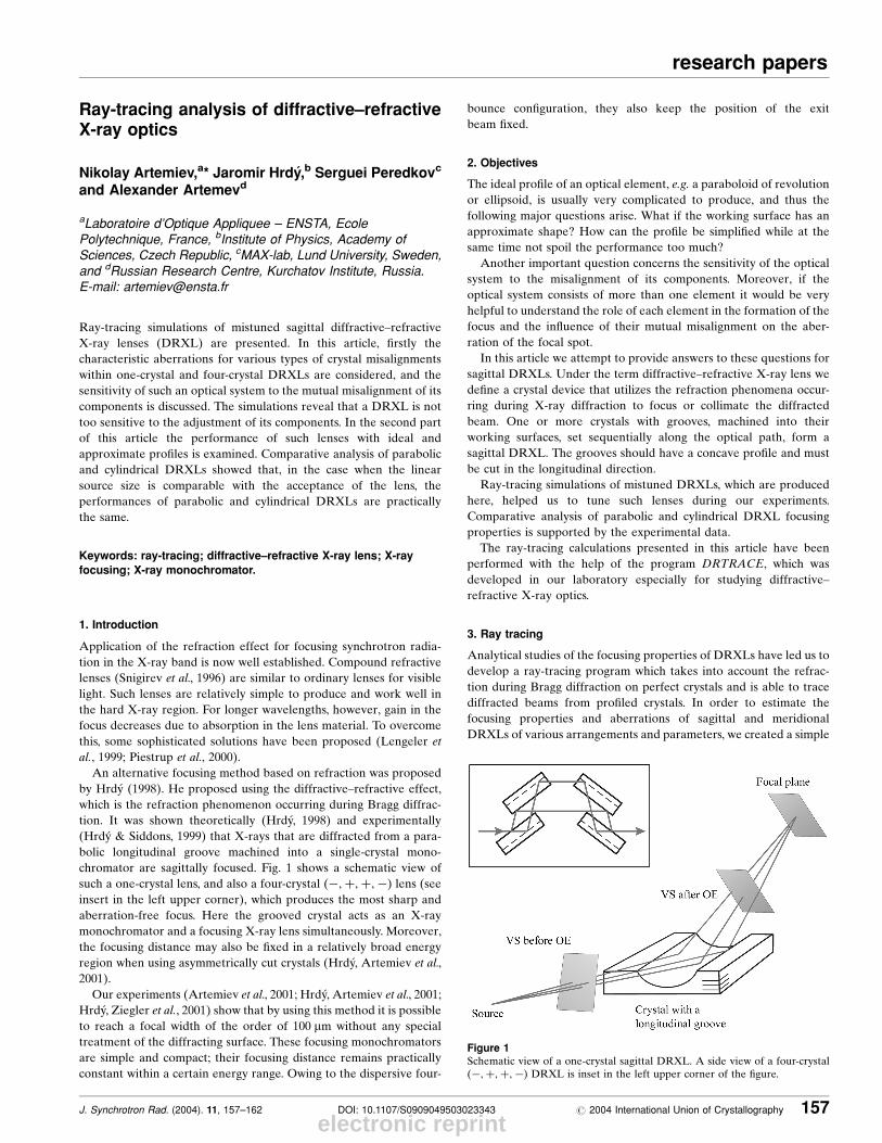
chromator are sagittally focused. Fig. 1 shows a schematic view of
such a one-crystal lens, and also a four-crystal (ÿ;�;�;ÿ) lens (see
insert in the left upper corner), which produces the most sharp and
aberration-free focus. Here the grooved crystal acts as an X-ray
monochromator and a focusing X-ray lens simultaneously. Moreover,
the focusing distance may also be ®xed in a relatively broad energy
region when using asymmetrically cut crystals (HrdyÂ, Artemiev et al.,
2001).
Our experiments (Artemiev et al., 2001; HrdyÂ, Artemiev et al., 2001;
HrdyÂ, Ziegler et al., 2001) show that by using this method it is possible
to reach a focal width of the order of 100 mm without any special
treatment of the diffracting surface. These focusing monochromators
are simple and compact; their focusing distance remains practically
constant within a certain energy range. Owing to the dispersive four-
bounce con®guration, they also keep the position of the exit
beam ®xed.
2. Objectives
The ideal pro®le of an optical element, e.g. a paraboloid of revolution
or ellipsoid, is usually very complicated to produce, and thus the
following major questions arise. What if the working surface has an
approximate shape? How can the pro®le be simpli®ed while at the
same time not spoil the performance too much?
Another important question concerns the sensitivity of the optical
system to the misalignment of its components. Moreover, if the
optical system consists of more than one element it would be very
helpful to understand the role of each element in the formation of the
focus and the in¯uence of their mutual misalignment on the aber-
ration of the focal spot.
In this article we attempt to provide answers to these questions for
sagittal DRXLs. Under the term diffractive±refractive X-ray lens we
de®ne a crystal device that utilizes the refraction phenomena occur-
ring during X-ray diffraction to focus or collimate the diffracted
beam. One or more crystals with grooves, machined into their
working surfaces, set sequentially along the optical path, form a
sagittal DRXL. The grooves should have a concave pro®le and must
be cut in the longitudinal direction.
Ray-tracing simulations of mistuned DRXLs, which are produced
here, helped us to tune such lenses during our experiments.
Comparative analysis of parabolic and cylindrical DRXL focusing
properties is supported by the experimental data.
The ray-tracing calculations presented in this article have been
performed with the help of the program DRTRACE, which was
developed in our laboratory especially for studying diffractive±
refractive X-ray optics.
3. Ray tracing
Analytical studies of the focusing properties of DRXLs have led us to
develop a ray-tracing program which takes into account the refrac-
tion during Bragg diffraction on perfect crystals and is able to trace
diffracted beams from pro®led crystals. In order to estimate the
focusing properties and aberrations of sagittal and meridional
DRXLs of various arrangements and parameters, we created a simple
J. Synchrotron Rad. (2004). 11, 157±162 DOI: 10.1107/S0909049503023343 # 2004 International Union of Crystallography 157
research papers
Figure 1Schematic view of a one-crystal sagittal DRXL. A side view of a four-crystal(ÿ;�;�;ÿ) DRXL is inset in the left upper corner of the ®gure.
electronic reprint
research papers
158 Nikolay Artemiev et al. � Diffractive±refractive X-ray optics J. Synchrotron Rad. (2004). 11, 157±162
program called DRTRACE which works with pro®led, but not bent,
crystals. Our aim was not to develop a universal program for all
possible cases, such as SHADOW (Welnak et al., 1994), for example,
but rather to create a very simple code quickly which would be able to
perform such calculations.
DRTRACE simulates the imaging properties of a diffractive±
refractive optical system. Randomly or regularly the program creates
a set of rays, emulating a light source, and traces them through an
optical system according to the laws of geometric optics. Diffraction
of a `ray' on an arbitrarily oriented crystal surface is calculated on the
basis of the dynamical theory of diffraction. Obviously we cannot talk
about diffraction of a ray ± it would be more correct to say that on the
basis of the dynamical theory of diffraction of X-rays on perfect
crystals we calculate the diffraction of a plane incident wave, the
wavevector of which is represented by the ray. The boundary
conditions are considered at the point where the ray hits the crystal
surface.
The diffraction of X-rays on a crystal surface is calculated in
accordance with some simpli®cations of the dynamical theory of
X-ray diffraction, described by Hrdy & Hrda (2000), Hrdy &
Pacherova (1993) and Hrdy (2001).
An optical element (OE) is a perfect crystal, which may have a ¯at
inclined and/or asymmetric working surface with respect to the
crystallographic planes as well as a cylindrical and parabolic shape.
Additionally, in the case of a meridional DRXL, the free pro®le of a
groove could be imported as an ASCII ®le. The number of optical
elements is unlimited. The program calculates the sagittal and
meridional deviations of a ray on an inclined and/or asymmetrical
surface of an optical element.
4. Alignment of optical elementsin a DRXL
In the following section we will
consider one of the most important
questions: how is a DRXL sensi-
tive to the misalignment of the
optical elements it consists of? For
this purpose, in the ray-tracing
program DRTRACE we intro-
duced the possibility of shifting
and turning any optical element
independently around its ideal
position. For practical reasons we
will discuss one- and four-crystal
(ÿ;�;�;ÿ) DRXLs.
Moreover, not all degrees of
freedom should be taken into
account, only two. It is simple to
realise that only the shift across
the incident beam in the sagittal
direction and the rotation around
the vertical axis perpendicular to
the incident beam have to be
considered.
There are six degrees of
freedom for each optical element:
three rotations and three transla-
tions. One rotation and one trans-
lation are supposed to be
responsible for the degradation of
the focusing properties of a lens;
the other four could be simply tuned experimentally or do not affect
the focusing at all:
(i) The rotation (rocking) of a crystal around the horizontal axis
perpendicular to the incident beam is the so-called � or Bragg rota-
tion, which is very sensitive to the incident angle. There is no problem
tuning this misalignment with microradian precision. It is suf®cient to
look at the intensity of the Bragg re¯ection.
(ii) The rotation (tilt) of a crystal around the axis, which is parallel
to the diffracting planes and lies in the diffraction plane, also affects
the intensity of the Bragg re¯ection and could also easily be tuned.
(iii) The translation of a crystal in the meridional direction could be
controlled by viewing the diffracted beam on an X-ray TV monitor.
By shifting each crystal up and down, one can easily position the
optical element by visual interception of the beam.
(iv) A short translation of the crystals along the beam does not
affect the focusing but changes the arms of the optical layout.
4.1. One-crystal DRXL
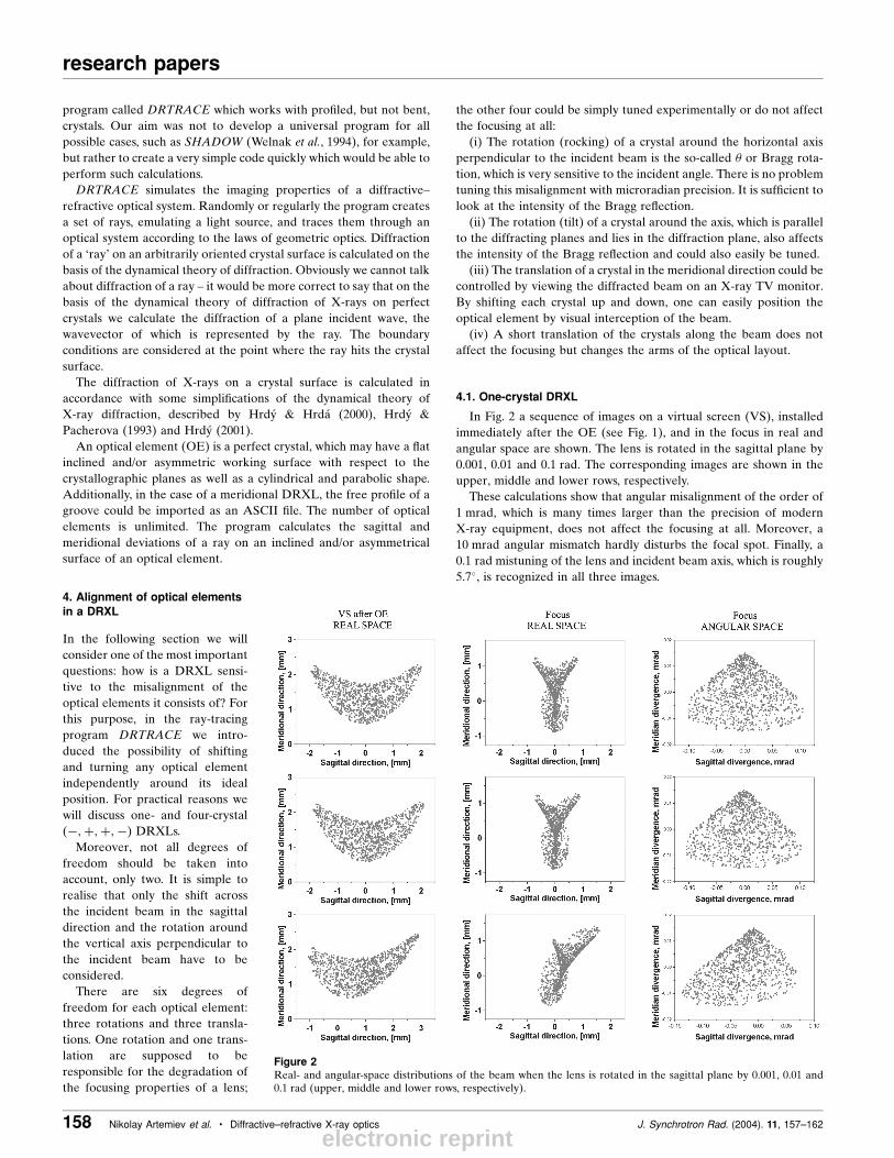
In Fig. 2 a sequence of images on a virtual screen (VS), installed
immediately after the OE (see Fig. 1), and in the focus in real and
angular space are shown. The lens is rotated in the sagittal plane by
0.001, 0.01 and 0.1 rad. The corresponding images are shown in the
upper, middle and lower rows, respectively.
These calculations show that angular misalignment of the order of
1 mrad, which is many times larger than the precision of modern
X-ray equipment, does not affect the focusing at all. Moreover, a
10 mrad angular mismatch hardly disturbs the focal spot. Finally, a
0.1 rad mistuning of the lens and incident beam axis, which is roughly
5.7�, is recognized in all three images.
Figure 2Real- and angular-space distributions of the beam when the lens is rotated in the sagittal plane by 0.001, 0.01 and0.1 rad (upper, middle and lower rows, respectively).
electronic reprint
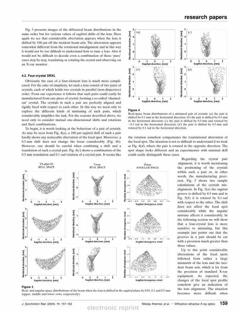
Fig. 3 presents images of the diffracted beam distributions in the
same order but for various values of sagittal shifts of the lens. Here
again we see that considerable aberration appears when the lens is
shifted by 100 mm off the incident beam axis. The aberration appears
somewhat different from the rotational misalignment and in this way
it would not be too dif®cult to understand how to tune a lens. Also it
would not be dif®cult to decode even a combination of these `pure'
cases step by step, translating or rotating the crystal and observing via
an X-ray monitor.
4.2. Four-crystal DRXL
Obviously the case of a four-element lens is much more compli-
cated. For the sake of simplicity, let such a lens consist of two pairs of
crystals, each of which holds two crystals in parallel (non-dispersive)
order. From our experience it follows that such pairs could easily be
manufactured from one piece of crystal, forming a so-called `channel-
cut' crystal. The crystals in such a pair are perfectly aligned and
rigidly ®xed with respect to each other. In this way we need only to
explore the different kinds of mistuning of such pairs, which
considerably simpli®es the task. For the reasons described above, we
need only to consider mutual one-dimensional shifts and rotations
and their combinations.
To begin, it is worth looking at the behaviour of a pair of crystals.
As may be seen from Fig. 4(a), a 100 mm sagittal shift of such a pair
hardly shows any noticeable aberration of the focal spot. Moreover, a
0.5 mm shift does not change the focus considerably (Fig. 4b).
However, one should be careful when combining a shift and a
translation of such a crystal pair. Fig. 4(c) shows a combination of the
0.5 mm translation and 0.1 rad rotation of a crystal pair. It seems like
the rotation somehow compensates the translational aberration of
the focal spot. The situation is not so dif®cult to understand if we look
at Fig. 4(d), where the pair is rotated in the opposite direction. The
spot shape looks different and an experimenter with minimal skill
could easily distinguish these cases.
Regarding the crystal pair
alignment, it is worth mentioning
the positioning of the crystals
within such a pair or, in other
words, the manufacturing preci-
sion. Fig. 5 shows two sample
calculations of the crystals mis-
alignment. In Fig. 5(a) the sagittal
groove is shifted by 0.5 mm and in
Fig. 5(b) it is rotated by 0.1 rad
with respect to the other. The shift
does not affect the focal spot
considerably while the angular
mistune affects it considerably. In
the following section we will show
that a four-crystal lens is more
sensitive to mistuning, but this
example just points out that the
grooves in a pair should be cut
with a precision much greater than
these values.
Up to this point considerable
aberrations of the focal spots
followed from rather a large
mismatch of the lens and the inci-
dent beam axis, which is far from
the precision of standard X-ray
equipment. As expected, the
changes of the focal spot pro®le
somehow give an indication of
the lens alignment. The situation
becomes more dif®cult when
J. Synchrotron Rad. (2004). 11, 157±162 Nikolay Artemiev et al. � Diffractive±refractive X-ray optics 159
research papers
Figure 3Real- and angular-space distributions of the beam when the lens is shifted in the sagittal plane by 0.01, 0.1 and 0.5 mm(upper, middle and lower rows, respectively).
Figure 4Real-space beam distributions of a mistuned pair of crystals: (a) the pair isshifted by 0.1 mm in the horizontal direction; (b) the pair is shifted by 0.5 mmin the horizontal direction; (c) the pair is shifted by 0.5 mm and rotated byÿ0.1 rad in the horizontal direction; (d ) the pair is shifted by 0.5 mm androtated by 0.1 rad in the horizontal direction.
electronic reprint
research papers
160 Nikolay Artemiev et al. � Diffractive±refractive X-ray optics J. Synchrotron Rad. (2004). 11, 157±162
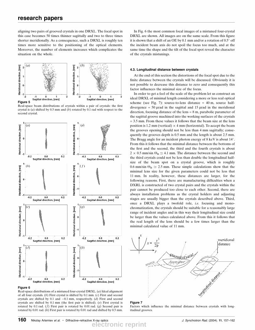
aligning two pairs of grooved crystals in one DRXL. The focal spot in
this case becomes 50 times thinner sagittally and two to three times
shorter meridionally. As a consequence, such a DRXL is roughly ten
times more sensitive to the positioning of the optical elements.
Moreover, the number of elements increases which complicates the
situation on the whole.
In Fig. 6 the most common focal images of a mistuned four-crystal
DRXL are shown. All images are on the same scale. From this ®gure
it is shown that a shift of an OE by 0.1 mm and/or a rotation of 0.5� off
the incident beam axis do not spoil the focus too much, and at the
same time the shape and the tilt of the focal spot reveal the character
of the crystals mistunings.
4.3. Longitudinal distance between crystals
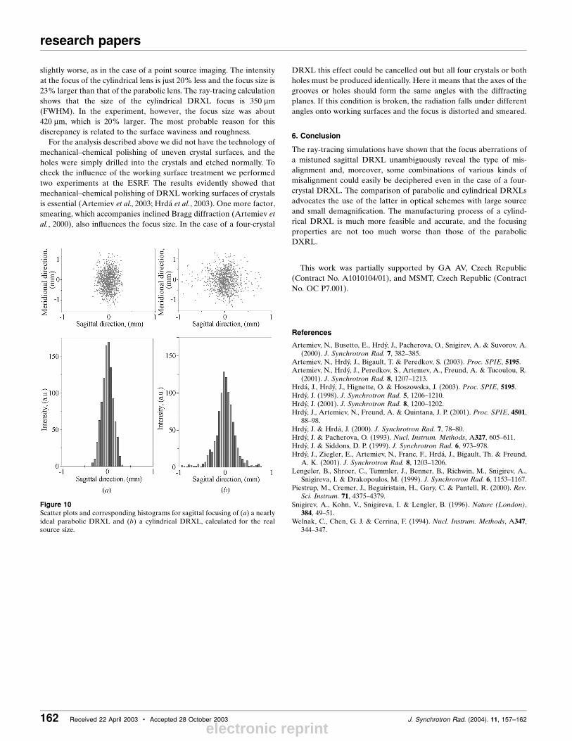
At the end of this section the distortions of the focal spot due to the
®nite distance between the crystals will be discussed. Obviously it is
not possible to decrease this distance to zero and consequently this
factor in¯uences the minimal size of the focus.
In order to get a feel of the scale of the problem let us construct an
ideal DRXL of minimal length considering a more or less real optical
scheme (see Fig. 7): source-to-lens distance = 40 m, source half-
divergence = 50 mrad in the sagittal and 15 mrad in the meridional
direction, focusing distance of the lens = 8 m, parabolic parameter of
the sagittal groove machined into the working surfaces of the crystals
= 3.5 mm. From these values it follows that the beam size at the lens
position is 1.2 mm (vertical)� 4 mm (horizontal). To accept the beam
the grooves opening should not be less than 4 mm sagittally; conse-
quently the grooves depth is 0.5 mm and the length is about 2.5 mm.
The Bragg angle for an incident photon energy of 8 keV is about 14�.From this it follows that the minimal distance between the bottoms of
the ®rst and the second, the third and the fourth crystals is about
2 � 0.5 mm/sin �B ' 4.1 mm. The distance between the second and
the third crystals could not be less than double the longitudinal half-
size of the beam spot on a crystal groove, which is roughly
0.6 mm/sin �B ' 2.5 mm. These simple calculations show that the
minimal lens size for the given parameters could not be less that
11 mm. In reality, however, these distances are larger, for the
following reasons. First, there are manufacturing dif®culties when a
DXRL is constructed of two crystal pairs and the crystals within the
pair cannot be produced too close to each other. Second, there are
always installation problems as the crystal holders and adjusting
stages are usually bigger than the crystals described above. Third,
once a DRXL plays a twofold role, i.e. focusing and mono-
chromatization, the crystals should be suitable for a reasonably large
range of incident angles and in this way their longitudinal size could
be larger than the values calculated above. From this it follows that
the real length of the lens should be a few times larger than the
minimal calculated value of 11 mm.
Figure 5Real-space beam distributions of crystals within a pair of crystals: the ®rstcrystal is (a) shifted by 0.5 mm and (b) rotated by 0.1 rad with respect to thesecond crystal.
Figure 6Real-space distributions of a mistuned four-crystal DRXL. (a) Ideal alignmentof all four crystals. (b) First crystal is shifted by 0.1 mm. (c) First and secondcrystals are shifted by 0.1 and ÿ0.1 mm, respectively. (d) First and secondcrystals are shifted by 0.1 mm (the ®rst pair is shifted). (e) First crystal isrotated by 0.1 rad. ( f ) First pair is rotated by 0.01 rad. (g) Second pair isrotated by 0.01 rad. (h) First pair is rotated by 0.01 rad and shifted by 0.5 mm.
Figure 7Factors which in¯uence the minimal distance between crystals with long-itudinal grooves.
electronic reprint
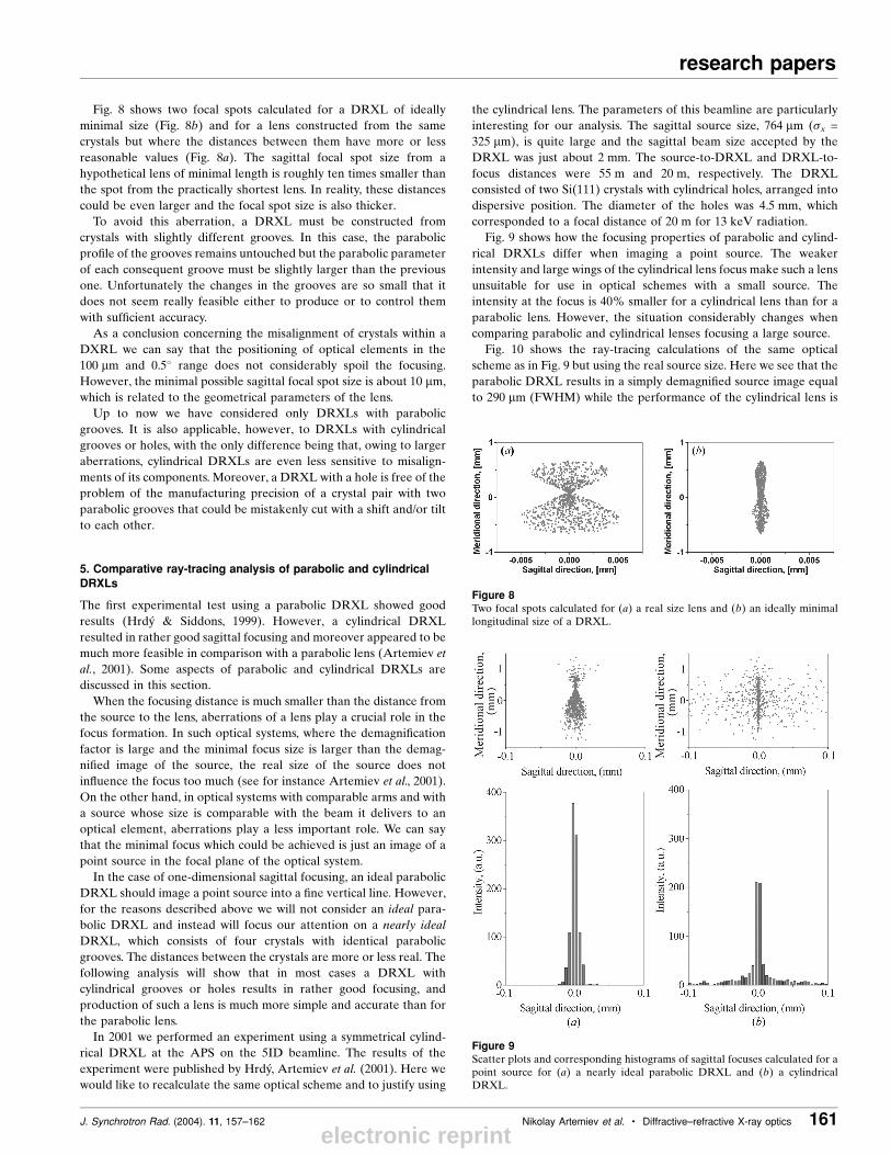
Fig. 8 shows two focal spots calculated for a DRXL of ideally
minimal size (Fig. 8b) and for a lens constructed from the same
crystals but where the distances between them have more or less
reasonable values (Fig. 8a). The sagittal focal spot size from a
hypothetical lens of minimal length is roughly ten times smaller than
the spot from the practically shortest lens. In reality, these distances
could be even larger and the focal spot size is also thicker.
To avoid this aberration, a DRXL must be constructed from
crystals with slightly different grooves. In this case, the parabolic
pro®le of the grooves remains untouched but the parabolic parameter
of each consequent groove must be slightly larger than the previous
one. Unfortunately the changes in the grooves are so small that it
does not seem really feasible either to produce or to control them
with suf®cient accuracy.
As a conclusion concerning the misalignment of crystals within a
DXRL we can say that the positioning of optical elements in the
100 mm and 0.5� range does not considerably spoil the focusing.
However, the minimal possible sagittal focal spot size is about 10 mm,
which is related to the geometrical parameters of the lens.
Up to now we have considered only DRXLs with parabolic
grooves. It is also applicable, however, to DRXLs with cylindrical
grooves or holes, with the only difference being that, owing to larger
aberrations, cylindrical DRXLs are even less sensitive to misalign-
ments of its components. Moreover, a DRXL with a hole is free of the
problem of the manufacturing precision of a crystal pair with two
parabolic grooves that could be mistakenly cut with a shift and/or tilt
to each other.
5. Comparative ray-tracing analysis of parabolic and cylindricalDRXLs
The ®rst experimental test using a parabolic DRXL showed good
results (Hrdy & Siddons, 1999). However, a cylindrical DRXL
resulted in rather good sagittal focusing and moreover appeared to be
much more feasible in comparison with a parabolic lens (Artemiev et
al., 2001). Some aspects of parabolic and cylindrical DRXLs are
discussed in this section.
When the focusing distance is much smaller than the distance from
the source to the lens, aberrations of a lens play a crucial role in the
focus formation. In such optical systems, where the demagni®cation
factor is large and the minimal focus size is larger than the demag-
ni®ed image of the source, the real size of the source does not
in¯uence the focus too much (see for instance Artemiev et al., 2001).
On the other hand, in optical systems with comparable arms and with
a source whose size is comparable with the beam it delivers to an
optical element, aberrations play a less important role. We can say
that the minimal focus which could be achieved is just an image of a
point source in the focal plane of the optical system.
In the case of one-dimensional sagittal focusing, an ideal parabolic
DRXL should image a point source into a ®ne vertical line. However,
for the reasons described above we will not consider an ideal para-
bolic DRXL and instead will focus our attention on a nearly ideal
DRXL, which consists of four crystals with identical parabolic
grooves. The distances between the crystals are more or less real. The
following analysis will show that in most cases a DRXL with
cylindrical grooves or holes results in rather good focusing, and
production of such a lens is much more simple and accurate than for
the parabolic lens.
In 2001 we performed an experiment using a symmetrical cylind-
rical DRXL at the APS on the 5ID beamline. The results of the
experiment were published by HrdyÂ, Artemiev et al. (2001). Here we
would like to recalculate the same optical scheme and to justify using
the cylindrical lens. The parameters of this beamline are particularly
interesting for our analysis. The sagittal source size, 764 mm (�x =
325 mm), is quite large and the sagittal beam size accepted by the
DRXL was just about 2 mm. The source-to-DRXL and DRXL-to-
focus distances were 55 m and 20 m, respectively. The DRXL
consisted of two Si(111) crystals with cylindrical holes, arranged into
dispersive position. The diameter of the holes was 4.5 mm, which
corresponded to a focal distance of 20 m for 13 keV radiation.
Fig. 9 shows how the focusing properties of parabolic and cylind-
rical DRXLs differ when imaging a point source. The weaker
intensity and large wings of the cylindrical lens focus make such a lens
unsuitable for use in optical schemes with a small source. The
intensity at the focus is 40% smaller for a cylindrical lens than for a
parabolic lens. However, the situation considerably changes when
comparing parabolic and cylindrical lenses focusing a large source.
Fig. 10 shows the ray-tracing calculations of the same optical
scheme as in Fig. 9 but using the real source size. Here we see that the
parabolic DRXL results in a simply demagni®ed source image equal
to 290 mm (FWHM) while the performance of the cylindrical lens is
J. Synchrotron Rad. (2004). 11, 157±162 Nikolay Artemiev et al. � Diffractive±refractive X-ray optics 161
research papers
Figure 8Two focal spots calculated for (a) a real size lens and (b) an ideally minimallongitudinal size of a DRXL.
Figure 9Scatter plots and corresponding histograms of sagittal focuses calculated for apoint source for (a) a nearly ideal parabolic DRXL and (b) a cylindricalDRXL.
electronic reprint
research papers
162 Received 22 April 2003 � Accepted 28 October 2003 J. Synchrotron Rad. (2004). 11, 157±162
slightly worse, as in the case of a point source imaging. The intensity
at the focus of the cylindrical lens is just 20% less and the focus size is
23% larger than that of the parabolic lens. The ray-tracing calculation
shows that the size of the cylindrical DRXL focus is 350 mm
(FWHM). In the experiment, however, the focus size was about
420 mm, which is 20% larger. The most probable reason for this
discrepancy is related to the surface waviness and roughness.
For the analysis described above we did not have the technology of
mechanical±chemical polishing of uneven crystal surfaces, and the
holes were simply drilled into the crystals and etched normally. To
check the in¯uence of the working surface treatment we performed
two experiments at the ESRF. The results evidently showed that
mechanical±chemical polishing of DRXL working surfaces of crystals
is essential (Artemiev et al., 2003; Hrda et al., 2003). One more factor,
smearing, which accompanies inclined Bragg diffraction (Artemiev et
al., 2000), also in¯uences the focus size. In the case of a four-crystal
DRXL this effect could be cancelled out but all four crystals or both
holes must be produced identically. Here it means that the axes of the
grooves or holes should form the same angles with the diffracting
planes. If this condition is broken, the radiation falls under different
angles onto working surfaces and the focus is distorted and smeared.
6. Conclusion
The ray-tracing simulations have shown that the focus aberrations of
a mistuned sagittal DRXL unambiguously reveal the type of mis-
alignment and, moreover, some combinations of various kinds of
misalignment could easily be deciphered even in the case of a four-
crystal DRXL. The comparison of parabolic and cylindrical DRXLs
advocates the use of the latter in optical schemes with large source
and small demagni®cation. The manufacturing process of a cylind-
rical DRXL is much more feasible and accurate, and the focusing
properties are not too much worse than those of the parabolic
DXRL.
This work was partially supported by GA AV, Czech Republic
(Contract No. A1010104/01), and MSMT, Czech Republic (Contract
No. OC P7.001).
References
Artemiev, N., Busetto, E., HrdyÂ, J., Pacherova, O., Snigirev, A. & Suvorov, A.(2000). J. Synchrotron Rad. 7, 382±385.
Artemiev, N., HrdyÂ, J., Bigault, T. & Peredkov, S. (2003). Proc. SPIE, 5195.Artemiev, N., HrdyÂ, J., Peredkov, S., Artemev, A., Freund, A. & Tucoulou, R.
(2001). J. Synchrotron Rad. 8, 1207±1213.Hrda , J., HrdyÂ, J., Hignette, O. & Hoszowska, J. (2003). Proc. SPIE, 5195.HrdyÂ, J. (1998). J. Synchrotron Rad. 5, 1206±1210.HrdyÂ, J. (2001). J. Synchrotron Rad. 8, 1200±1202.HrdyÂ, J., Artemiev, N., Freund, A. & Quintana, J. P. (2001). Proc. SPIE, 4501,
88±98.HrdyÂ, J. & Hrda , J. (2000). J. Synchrotron Rad. 7, 78±80.HrdyÂ, J. & Pacherova, O. (1993). Nucl. Instrum. Methods, A327, 605±611.HrdyÂ, J. & Siddons, D. P. (1999). J. Synchrotron Rad. 6, 973±978.HrdyÂ, J., Ziegler, E., Artemiev, N., Franc, F., Hrda , J., Bigault, Th. & Freund,
A. K. (2001). J. Synchrotron Rad. 8, 1203±1206.Lengeler, B., Shroer, C., Tummler, J., Benner, B., Richwin, M., Snigirev, A.,
Snigireva, I. & Drakopoulos, M. (1999). J. Synchrotron Rad. 6, 1153±1167.Piestrup, M., Cremer, J., Beguiristain, H., Gary, C. & Pantell, R. (2000). Rev.
Sci. Instrum. 71, 4375±4379.Snigirev, A., Kohn, V., Snigireva, I. & Lengler, B. (1996). Nature (London),
384, 49±51.Welnak, C., Chen, G. J. & Cerrina, F. (1994). Nucl. Instrum. Methods, A347,
344±347.
Figure 10Scatter plots and corresponding histograms for sagittal focusing of (a) a nearlyideal parabolic DRXL and (b) a cylindrical DRXL, calculated for the realsource size.
electronic reprint