demonstration of image-zooming capability for diffractive axicons
TRANSCRIPT
Demonstration of an infrared microcamera
inspired by Xenos peckii vision
Guillaume Druart,1,* Nicolas Guérineau,1 Riad Haïdar,1 Sophie Thétas,1
Jean Taboury,2 Sylvain Rommeluère,1 Jérôme Primot,1 and Manuel Fendler3
1ONERA, Chemin de la Hunière, 91761 Palaiseau cedex, France
2Institut d’Optique, Campus Polytechnique RD 128, 91127 Palaiseau cedex, France
3CEA-LETI/MINATEC, 17 rue des Martyrs, 38054 Grenoble cedex 9, France
*Corresponding author: [email protected]
Received 12 January 2009; revised 10 March 2009; accepted 13 May 2009;
posted 14 May 2009 (Doc. ID 106299); published 10 June 2009
We present an original and compact optical system inspired by the unusual eyes of a Strepsipteran insectcalledXenos peckii. It is designed for a field of view of 30° and is composed of multiple telescopes. An arrayof prisms of various angles is placed in front of these telescopes in order to set a different field of view foreach channel. This type of camera operates in the [ 3 − 5 μm] spectral bandwidth and is entirely inte-grated in a Dewar in order to maximize its compactness. Experimental images are presented to validatethis design. © 2009 Optical Society of America
OCIS codes: 110.0110, 110.3000, 110.3010, 110.3080, 110.4190, 130.3990.
1. Introduction
Considerable efforts are now being devoted to inex-pensive and miniaturized optical systems for bothcivilian and military applications because thesenew developments will open up newmarket opportu-nities. For this reason, industrialists are drivingtheir research and development units to designimage-capturing systems with reduced size, weight,energy consumption, and cost. However, these con-straints are so demanding that the downscaled ver-sions of classical optical systems with a single opticalaxis are reaching their limits. First, the decrease ofthe focal length of the lenses tends to increase thedifficulties of alignment, which leads to high manu-facturing costs. Second, the pixel size of the detectorsreaches technological limits and classical opticscannot be downscaled further without losing angularresolution. Nonconventional optical components in-tegrated in nonconventional architectures are thusbeing proposed to overcome these difficulties.
Nonconventional architectures can be found sim-ply by investigating the vision of small invertebrates[1–3]. In order to strike a balance between theirsmall size and the need to have a good vision to na-vigate, eat, and find a mate, invertebrates have de-veloped compound eyes. Multichannel architecture,inspired by invertebrate vision, offers interestingopportunities in optical design as the principle isto divide the information of the whole scene into sev-eral small eyes instead of a single eye. Indeed, inRefs. [4,5], it is demonstrated that combining the in-formation from a flexible array of low-cost camerascan greatly improve performance and even exceedthe capability of an individual camera. Moreover,state-of-the-art fabrication and replication technolo-gies for microlens arrays has allowed for the designof compact multichannel architectures in which ar-rays of lenses can be directly integrated on the detec-tor [6,7]. Several teams have proposed variousarchitectures that differ in the way of dividing theinformation contained in the observation scene.The scene can be spatially split into various channels[6,8–11], each channel imaging a small part of thescene. The high-frequency content of the scene can
0003-6935/09/183368-07$15.00/0© 2009 Optical Society of America
3368 APPLIED OPTICS / Vol. 48, No. 18 / 20 June 2009
be split into different channels also [12,13]. Theoptical system collects nonredundant undersampleimages from the same scene. The nonredundancyis usually obtained by subpixel shifts between theimages. By applying a superresolution reconstruc-tion on all these small images, a single image withan enhanced angular resolution can be reconstructed[14].Based on these studies, we have designed a com-
pact multichannel camera called MULTICAM, forthe [ 3 − 5 μm] spectral range [15]. The compactnessof this system has been obtained by integrating allthe optics directly in the Dewar used to cool the de-tector. The architecture of MULTICAM is inspired bythe unusual eyes of a Strepsipteran insect calledXenos peckii. It is made of multiple identical tele-scopes. An array of prisms of various angles placedin front of the optical system imposes a distinctoptical axis for each telescope. Section 2 summarizesthe advantages of designing multichannel opticalsystems, as well as the reason for choosing a micro-camera inspired by Xenos peckii vision. In Section 3,the design of MULTICAM will be described. Finally,Section 4 presents the experimental characterizationof MULTICAM, and the first image obtained withthis camera.
2. Value of Multichannel Architectures Inspired
by Invertebrate Vision
Traditional optical systems are inspired by single-eye architecture. These systems are based on a singleoptical axis and a single detector, and the complexityof a diffraction-limited monoaxis camera increaseswhen its field of view and its throughput increase.Besides, in the case of a single-lens system, itsangular resolution decreases when the field of viewincreases.To address this issue, invertebrates have devel-
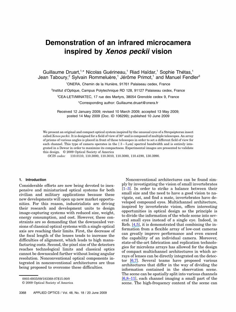
oped other architectures based on multiapertureoptical sensors that enable a wide field-of-view visionwith a constant angular resolution. Their eyes aremade of multiple simple and well-corrected opticalchannels, each viewing a small, different part ofthe global scene. A conceptual comparison of theangular resolution versus the field of view betweensingle andmultiple lenses has been made by Sandersand Halford [8] and is recalled in Fig. 1. This graphillustrates the strengths and weaknesses of thesestwo architecture types, where having multiple aper-tures is the simplest way to maintain a constantangular resolution over a wide fieldofview and wheresingle-aperture systems are ideal to obtain a high an-gular resolution.The compound eyes of the invertebrates can be
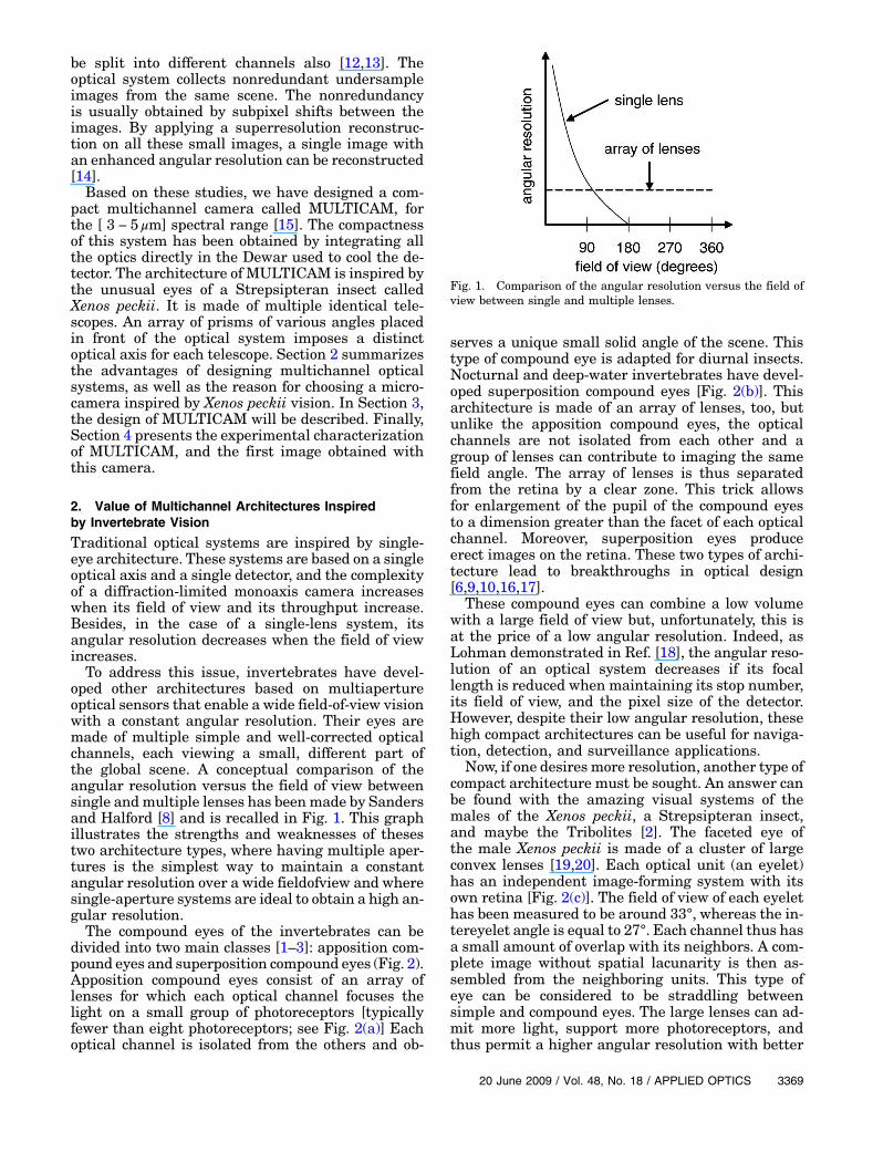
divided into two main classes [1–3]: apposition com-pound eyes and superposition compound eyes (Fig. 2).Apposition compound eyes consist of an array oflenses for which each optical channel focuses thelight on a small group of photoreceptors [typicallyfewer than eight photoreceptors; see Fig. 2(a)] Eachoptical channel is isolated from the others and ob-
serves a unique small solid angle of the scene. Thistype of compound eye is adapted for diurnal insects.Nocturnal and deep-water invertebrates have devel-oped superposition compound eyes [Fig. 2(b)]. Thisarchitecture is made of an array of lenses, too, butunlike the apposition compound eyes, the opticalchannels are not isolated from each other and agroup of lenses can contribute to imaging the samefield angle. The array of lenses is thus separatedfrom the retina by a clear zone. This trick allowsfor enlargement of the pupil of the compound eyesto a dimension greater than the facet of each opticalchannel. Moreover, superposition eyes produceerect images on the retina. These two types of archi-tecture lead to breakthroughs in optical design[6,9,10,16,17].
These compound eyes can combine a low volumewith a large field of view but, unfortunately, this isat the price of a low angular resolution. Indeed, asLohman demonstrated in Ref. [18], the angular reso-lution of an optical system decreases if its focallength is reduced when maintaining its stop number,its field of view, and the pixel size of the detector.However, despite their low angular resolution, thesehigh compact architectures can be useful for naviga-tion, detection, and surveillance applications.
Now, if one desires more resolution, another type ofcompact architecture must be sought. An answer canbe found with the amazing visual systems of themales of the Xenos peckii, a Strepsipteran insect,and maybe the Tribolites [2]. The faceted eye ofthe male Xenos peckii is made of a cluster of largeconvex lenses [19,20]. Each optical unit (an eyelet)has an independent image-forming system with itsown retina [Fig. 2(c)]. The field of view of each eyelethas been measured to be around 33°, whereas the in-tereyelet angle is equal to 27°. Each channel thus hasa small amount of overlap with its neighbors. A com-plete image without spatial lacunarity is then as-sembled from the neighboring units. This type ofeye can be considered to be straddling betweensimple and compound eyes. The large lenses can ad-mit more light, support more photoreceptors, andthus permit a higher angular resolution with better
Fig. 1. Comparison of the angular resolution versus the field ofview between single and multiple lenses.
20 June 2009 / Vol. 48, No. 18 / APPLIED OPTICS 3369
sensitivity. Indeed, if we compare the Xenos peckiiwith an insect having a comparable size, such as afruit fly, the Xenos peckii has 50 eyelets with around100 photoreceptors per eyelet, which gives about5000 resolved points. The fruit fly has only 700facets, which gives 700 resolved points. This higherresolution has a price: it requires a larger brain allo-cation to vision needs [20].We took advantage of this multichannel architec-
ture to design a compact high-resolution infraredcamera with a 30° field of view and using a HgCdTetechnology cooled detector. The detector has a stan-dard format, i.e., 320 × 240 pixels with a pitch of30 μm. This leads to a camera with a focal lengthequal to 13:3mm. Cooled detectors are usuallyintegrated in a Dewar and the optical architectureis designed outside the Dewar. These constraints un-fortunately increase the lengths of the optical sys-tems, the smallest Dewar length currently beingaround 30mm. In order to miniaturize this camera,we suggest integrating the optics directly into theDewar. However, due to the cooling limit of the De-war, the optical system must be as simple as possiblewithout losing optical performance. We thus decideto pack simple well-corrected cameras viewing thescene in different directions, as suggested in Ref. [4],to create the equivalent of a wide-field camera with ahigh resolution. Moreover, we took advantage of mi-crolens technologies to tightly pack these camerasand to address the integration issue. The necessaryoverlapping areas are reduced to a minimum, as wewill see in Section 3, in order to obtain a large num-ber of useful pixels.
3. Design of a Microcamera Inspired by Xenos peckii
Vision
If we want to design a multichannel optical system,we have to carefully divide the whole solid angle ofthe scene into different sectors. The ideal case is todivide this latter into adjacent sectors in order toavoid overlap areas. Invertebrates mainly tile thissolid angle sphere in nonuniform hexagonal units[8]. This type of architecture is possible thanks totheir curved retinas. Curved detectors and arraysof lenses are currently under development [21–24],but these technologies are not yet mature enoughand we have to mainly use on-the-shelf components
(i.e., planar arrays of microlenses and planardetectors).
The more convenient way to divide the scene witha planar detector is to divide it into squarelike areas.However, squares do not efficiently tile a sphere andoverlap areas have to be provided in order to imagethe whole scene without spatial lacunarity. We mustthen address two other difficulties: first, we have totilt the optical axis of each channel by using planarcomponents and then we have to suppress the crosstalk between adjacent units. Some solutions to avoidcross talk have been suggested: For optical systemswith short focal lengths, a separation layer can be in-serted between the microlenses and the detector[10,12]. In Ref. [10] a pinhole mask placed on the de-tector is also used to locally select the desired field.For optical systems with long focal lengths, multipletelescopes, each made of a focusing lens followed by afield lens, a pinhole mask, and a relay lens, have beensuggested [25]. An intermediate image of the scene isformed at the field lens where the pinhole mask se-lects the desired field. The selected field is then im-aged again by a relay lens. Despite the fact that anarchitecture with opaque walls can be simpler thanan architecture using three stages of lenses, thechoice between these two solutions depends on theability to make thin and long opaque walls.
Two solutions have been put forward to tilt the op-tical axis of each optical channel differently. The firstsolution is to use arrays with different pitches. InRefs. [6,10], an array of microlenses has been com-bined with an array of pinholes. These two arrayshave different pitches so that a different field of viewis selected at each channel. In Ref. [25] the three ar-rays of lenses that constitute the telescopes have adifferent pitch in order to make different tilted opti-cal axes. Each telescope, therefore, faces in a differ-ent direction. The drawback of this architecture isthat the lenses are decentered and unwanted off-axisaberrations, such as astigmatism, appear. Various el-lipsoidal microlenses are needed to correct theseaberrations, which leads to an array of lenses thatare more complicated to make [26]. Moreover, tiltingthe optical axis in such a way tends to tighten thetolerances of the lens array fabrication and assembly.Another solution suggested was to tilt the opticalaxis of each channel by adding a beam deflector in
(a) (b) (c)
Fig. 2. Illustration of different types of natural eyes of invertebrates: (a) apposition compound eyes, (b) superposition compound eyes,and (c) eyelets.
3370 APPLIED OPTICS / Vol. 48, No. 18 / 20 June 2009
the optical system. This beam deflector can be an ar-ray of prisms with different angles [10,12], an arrayof holograms, or a faceted fiber optic faceplate [27].Indeed, using a beam deflector can lead to compactsystems that would most likely have better toler-ances without adding off-axis aberration.In contrast, we have explored the use of an array of
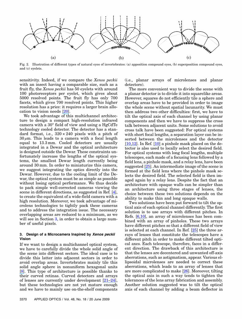
prisms at the front of the optical system in order touse planar lens arrays. According to Section 2, wehave designed a microcamera inspired by Xenospeckii vision in order to maximize the angularresolution. It is made of independent image-formingsystems sharing a common detector. This camera isan update of a previous optical system, calledMULTICAM, described in Ref. [15]. The MULTICAMcamera is entirely integrated in a Dewar and is madeof multiple identical optical channels observing thesame scene with an angular diameter of 8°. As thefocal length of this system is long, we have chosento design telescopes with three arrays of microlensesand an array of pinholes, as seen in Ref. [25]. The ar-ray of pinholes is used to avoid the cross talk betweeneach channel. Each telescope is equivalent to a lenswith a stop number equal to 8 and a focal lengthequal to 13:3mm. This camera works in the½3–5 μm� spectral bandwidth. We recall that the de-tector used has a standard format of an infrared focalplane array of 320 × 256 pixels with a pitch equal to30 μm. By integrating an array of prisms with differ-ent angles in front of the telescopes, they face in dif-ferent directions.The update of MULTICAMwith an array of prisms
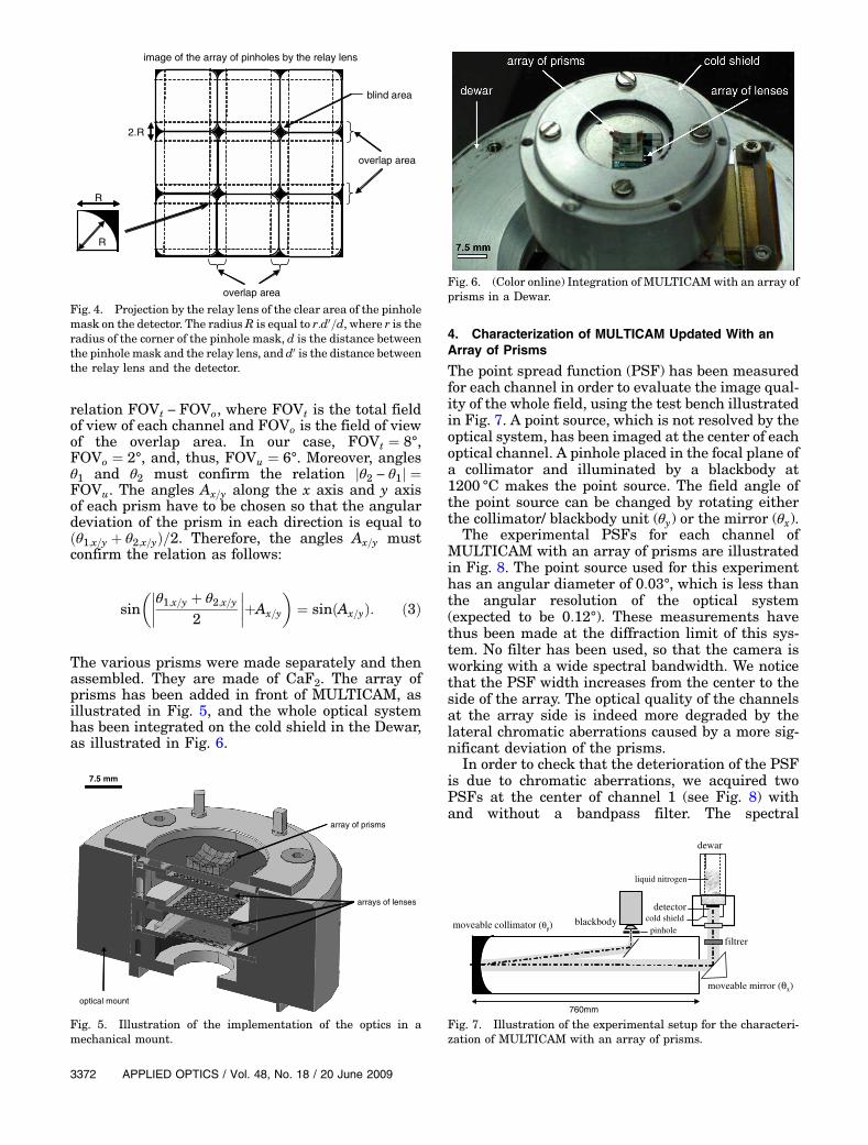
is illustrated in Fig. 3. The field of view of the up-dated MULTICAM is thus increased. As explainedbefore, an overlap area between each channel hasto be foreseen in order to image the whole scene with-out spatial lacunarity. In the case of MULTICAM, theoverlap area is mainly shaped by the pinholes of themask. The mask is imaged onto the detector by therelay lens. If the projection of the clear area by the
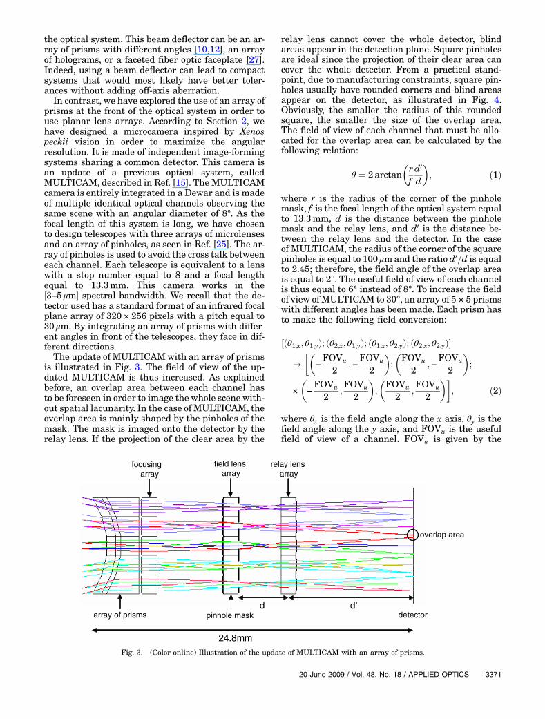
relay lens cannot cover the whole detector, blindareas appear in the detection plane. Square pinholesare ideal since the projection of their clear area cancover the whole detector. From a practical stand-point, due to manufacturing constraints, square pin-holes usually have rounded corners and blind areasappear on the detector, as illustrated in Fig. 4.Obviously, the smaller the radius of this roundedsquare, the smaller the size of the overlap area.The field of view of each channel that must be allo-cated for the overlap area can be calculated by thefollowing relation:
θ ¼ 2 arctan
�
r
f
d0
d
�
; ð1Þ
where r is the radius of the corner of the pinholemask, f is the focal length of the optical system equalto 13:3mm, d is the distance between the pinholemask and the relay lens, and d0 is the distance be-tween the relay lens and the detector. In the caseof MULTICAM, the radius of the corner of the squarepinholes is equal to 100 μmand the ratio d0=d is equalto 2.45; therefore, the field angle of the overlap areais equal to 2°. The useful field of view of each channelis thus equal to 6° instead of 8°. To increase the fieldof view ofMULTICAM to 30°, an array of 5 × 5 prismswith different angles has been made. Each prism hasto make the following field conversion:
½ðθ1;x; θ1;yÞ; ðθ2;x; θ1;yÞ; ðθ1;x; θ2;yÞ; ðθ2;x; θ2;yÞ�
→
��
−
FOVu
2;−
FOVu
2
�
;
�
FOVu
2;−
FOVu
2
�
;
×
�
−
FOVu
2;FOVu
2
�
;
�
FOVu
2;FOVu
2
��
; ð2Þ
where θx is the field angle along the x axis, θy is thefield angle along the y axis, and FOVu is the usefulfield of view of a channel. FOVu is given by the
focusing
array
field lensarray
relay lens
array
array of prisms detector
overlap area
pinhole maskd’d
24.8mm
Fig. 3. (Color online) Illustration of the update of MULTICAM with an array of prisms.
20 June 2009 / Vol. 48, No. 18 / APPLIED OPTICS 3371
relation FOVt − FOVo, where FOVt is the total fieldof view of each channel and FOVo is the field of viewof the overlap area. In our case, FOVt ¼ 8°,FOVo ¼ 2°, and, thus, FOVu ¼ 6°. Moreover, anglesθ1 and θ2 must confirm the relation jθ2 − θ1j ¼FOVu. The angles Ax=y along the x axis and y axisof each prism have to be chosen so that the angulardeviation of the prism in each direction is equal toðθ1;x=y þ θ2;x=yÞ=2. Therefore, the angles Ax=y mustconfirm the relation as follows:
sin
��
�
�
�
θ1;x=y þ θ2;x=y
2
�
�
�
�
þAx=y
�
¼ sinðAx=yÞ: ð3Þ
The various prisms were made separately and thenassembled. They are made of CaF2. The array ofprisms has been added in front of MULTICAM, asillustrated in Fig. 5, and the whole optical systemhas been integrated on the cold shield in the Dewar,as illustrated in Fig. 6.
4. Characterization of MULTICAM Updated With an
Array of Prisms
The point spread function (PSF) has been measuredfor each channel in order to evaluate the image qual-ity of the whole field, using the test bench illustratedin Fig. 7. A point source, which is not resolved by theoptical system, has been imaged at the center of eachoptical channel. A pinhole placed in the focal plane ofa collimator and illuminated by a blackbody at1200 °C makes the point source. The field angle ofthe point source can be changed by rotating eitherthe collimator/ blackbody unit (θy) or the mirror (θx).
The experimental PSFs for each channel ofMULTICAM with an array of prisms are illustratedin Fig. 8. The point source used for this experimenthas an angular diameter of 0:03°, which is less thanthe angular resolution of the optical system(expected to be 0:12°). These measurements havethus been made at the diffraction limit of this sys-tem. No filter has been used, so that the camera isworking with a wide spectral bandwidth. We noticethat the PSF width increases from the center to theside of the array. The optical quality of the channelsat the array side is indeed more degraded by thelateral chromatic aberrations caused by a more sig-nificant deviation of the prisms.
In order to check that the deterioration of the PSFis due to chromatic aberrations, we acquired twoPSFs at the center of channel 1 (see Fig. 8) withand without a bandpass filter. The spectral
blind area
image of the array of pinholes by the relay lens
R
R
overlap area
overlap area
2.R
Fig. 4. Projection by the relay lens of the clear area of the pinholemask on the detector. The radiusR is equal to r:d0=d, where r is theradius of the corner of the pinhole mask, d is the distance betweenthe pinhole mask and the relay lens, and d0 is the distance betweenthe relay lens and the detector.
optical mount
arrays of lenses
array of prisms
7.5 mm
Fig. 5. Illustration of the implementation of the optics in amechanical mount.
Fig. 6. (Color online) Integration of MULTICAM with an array ofprisms in a Dewar.
moveable collimator (θy)blackbody
liquid nitrogen
detectorcold shield
dewar
filtrer
pinhole
moveable mirror (θx)
760mm
Fig. 7. Illustration of the experimental setup for the characteri-zation of MULTICAM with an array of prisms.
3372 APPLIED OPTICS / Vol. 48, No. 18 / 20 June 2009
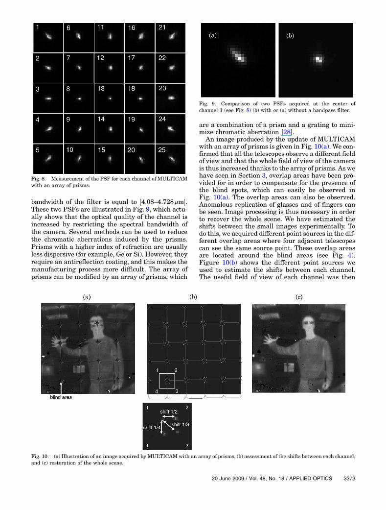
bandwidth of the filter is equal to ½4:08–4:728 μm�.These two PSFs are illustrated in Fig. 9, which actu-ally shows that the optical quality of the channel isincreased by restricting the spectral bandwidth ofthe camera. Several methods can be used to reducethe chromatic aberrations induced by the prisms.Prisms with a higher index of refraction are usuallyless dispersive (for example, Ge or Si). However, theyrequire an antireflection coating, and this makes themanufacturing process more difficult. The array ofprisms can be modified by an array of grisms, which
are a combination of a prism and a grating to mini-mize chromatic aberration [28].
An image produced by the update of MULTICAMwith an array of prisms is given in Fig. 10(a). We con-firmed that all the telescopes observe a different fieldof view and that the whole field of view of the camerais thus increased thanks to the array of prisms. As wehave seen in Section 3, overlap areas have been pro-vided for in order to compensate for the presence ofthe blind spots, which can easily be observed inFig. 10(a). The overlap areas can also be observed.Anomalous replication of glasses and of fingers canbe seen. Image processing is thus necessary in orderto recover the whole scene. We have estimated theshifts between the small images experimentally. Todo this, we acquired different point sources in the dif-ferent overlap areas where four adjacent telescopescan see the same source point. These overlap areasare located around the blind areas (see Fig. 4).Figure 10(b) shows the different point sources weused to estimate the shifts between each channel.The useful field of view of each channel was then
Fig. 8. Measurement of the PSF for each channel of MULTICAMwith an array of prisms.
Fig. 9. Comparison of two PSFs acquired at the center ofchannel 1 (see Fig. 8) (b) with or (a) without a bandpass filter.
Fig. 10. (a) Illustration of an image acquired by MULTICAM with an array of prisms, (b) assessment of the shifts between each channel,and (c) restoration of the whole scene.
20 June 2009 / Vol. 48, No. 18 / APPLIED OPTICS 3373
extracted and, thanks to the shift values obtainedpreviously, the whole scene observed by the camerawas recovered [see Fig. 10(c)]. As the overlap areawas well established, there are no spatial lacunari-ties in the observation scene.
5. Conclusion
Multichannel optical systems modeled on inverte-brate vision are simple and compact systems withconstant angular resolution over a large field of view.We believe that the eyes of the Xenos peckii offer thebest multichannel configuration for maximizing an-gular resolution. A compact infrared camera basedon the vision of the Xenos peckii and entirely inte-grated in a Dewar has been designed. It is made ofmultiple telescopes and an array of prisms of differ-ent angles. Thanks to these prisms, each telescopesees a different field of view. The overall field of viewof this compact camera is equal to 30°. Overlap areashave, however, been taken into account in order torestore the whole scene without spatial lacunarity.This camera has been made and characterized ex-
perimentally. Because of fabrication constraints, thechromatic aberrations were not corrected and theyappear at the side of the camera because of the highdispersive power of the prisms and because of theirhigh angles on the sides. Some solutions have beenproposed to correct these aberrations.Last, an image of this camera was acquired and,
after calibration, image processing was proposed toreconstruct the whole scene. Thanks to the overlapareas, no spatial lacunarity is observed on the image.
This work was sponsored by the Délégation Génér-ale de l’Armement (DGA) of the French Ministry ofDefense.
References
1. R. Völkel, “Natural optical design for microcameras,” LaserOptoelektron. 30, 47–55 (1998).
2. M. F. Land and D.-E. Nilsson, Animal Eyes, Oxford AnimalBiology Series (Oxford U. Press, 2002).
3. E. Warrant and D.-E. Nilsson, Invertebrate Vision (CambridgeU. Press 2006).
4. B. Wilburn, N. Joshi, V. Vaish, E.-V. Talvala, E. Antunez, A.Barth, A. Adams, M. Horowitz, and M. Levoy, “High perfor-mance imaging using large camera arrays,” ACM Trans.Graph. 24, 765–776 (2005).
5. P. M. Shankar, W. C. Hasenplaugh, R. L. Morrison, R. A. Stack,and M. A. Neifeld, “Multiaperture imaging,” Appl. Opt. 45,2871–2883 (2006).
6. J. Duparré, P. Dannberg, P. Shreiber, A. Bräuer, andA. Tünnermann, “Artificial apposition compound eye fabri-cated by micro-optics technology,” Appl. Opt. 43, 4303–4310(2004).
7. K. Fife, A. El Gamal, and H.-S. P. Wong, “A 3D multi-apertureimage sensor architecture,” in Proceedings of Custom Inte-
grated Circuits Conference, 2006 (IEEE, 2006), pp. 281–284.8. J. S. Sanders and C. E. Halford, “Design and analysis of
apposition compound eye optical sensors,” Opt. Eng. 34,222–235 (1995).
9. K. Hamanaka andH. Koshi, “An artificial compound eye usinga microlens array and its application to scale-invariant pro-cessing,” Opt. Rev. 3, 264–268 (1996).
10. J. Duparré, P. Dannberg, P. Schreiber, A. Bräuer, andA. Tünnermann, “Thin compound-eye camera,” Appl. Opt.44, 2949–2956 (2005).
11. J. W. Duparré and F. C. Wippermann, “Micro-optical artificialcompound eyes,” Bioinspir. Biomim. 1, R1–R16 (2006).
12. J. Tanida, T. Kumagai, K. Yamada, S. Miyatake, K. Ishida, T.Morimoto, N. Kondou, D. Miyazaki, and Y. Ichioka, “Thinobservation module by bound optics (TOMBO): concept andexperimental verification,” Appl. Opt. 40, 1806–1813 (2001).
13. M. Shankar, R. Willet, N. Pitsianis, T. Schulz, R. Gibbons, R. T.Kolste, J. Carriere, C. Chen, D. Prather, and D. Brady, “Thininfrared imaging systems through multichannel sampling,”Appl. Opt. 47, B1–B10 (2008).
14. Y.Kitamura,R.Shogenji,K.Yamada,S.Miyatake,M.Miyamoto,T.Morimoto, Y.Masaki,N.Kondou,D.Miyazaki, J. Tanida, andY. Ichioka, “Reconstruction of a high-resolution image ona compound-eye image-capturing system,” Appl. Opt. 43,1719–1727 (2004).
15. G. Druart, N. Guérineau, R. Haïdar, E. Lambert, M. Tauvy,S. Thétas, S. Rommeluère, J. Primot, and J. Deschamps,“MULTICAM: a miniature cryogenic camera for infrared de-tection,” Proc. SPIE 6992, 699215 (2008).
16. C. Hembd-Sölner, R. F. Stevens, and M. C. Hutley, “Imagingproperties of the Gabor superlens,” J. Opt. A Pure Appl.Opt. 1, 94–102 (1999).
17. V. Gubsky, M. Gertsenshteyn, and T. Jannson, “Lobster-eyeinfrared focusing optics,” Proc. SPIE 6295 62950F (2006).
18. A. W. Lohmann, “Scaling laws for lens systems,”Appl. Opt. 28,4996–4998 (1989).
19. E. K. Buschbeck, B. Ehmer, and R. R. Hoy, “Chunk versuspoint sampling: visual imaging in a small insect,” Science286, 1178–1180 (1999).
20. E. K. Buschbeck, B. Ehmer, and R. R. Hoy, “The unusual visualsystem of the Strepsiptera: external eye and neuropils,” J.Comp. Physiol. A 189, 617–630 (2003).
21. S.-B. Rim, P. B. Catrysse, R. Dinyari, K. Huang, andP. Peumans, “The optical advantages of curved focal planearrays,” Opt. Express 16, 4965–4971 (2008).
22. H. C. Ko,M. P. Stoykovich, J. Song, V. Malyarchuk,W.M. Choi,C.-J. Yu, J. B. Geddes III, J. Xiao, S. Wang, Y. Huang, and J. A.Rogers, “A hemispherical electronic eye camera based oncompressible silicon optoelectronics,” Nature 454, 748–752(2008).
23. K.-H. Jeong, J. Kim, and L. P. Lee, “Biologically inspired arti-ficial compound eyes,” Science 312, 557–561 (2006).
24. R. J. Martín-Palma, C. G. Pantano, and A. Lakhtakia,“Replication of fly eyes by the conformal-evaporated-film-by-rotation technique,” Science 312, 557–561 (2006).
25. J. Duparré, P. Schreiber, A. Matthes, E. Pshenay-Severin, A.Bräuer, A. Tünnermann, R. Völkel, M. Eisner, and T. Sharf,“Microoptical telescope compound eye,” Opt. Express 13,889–901 (2005).
26. J. Duparré, F. Wippermann, P. Dannberg, and A. Reimann,“Chirped arrays of refractive ellipsoidal microlenses for aber-ration correction under oblique incidence,” Opt. Express 13,10539–10550 (2005).
27. L. C. Laycock and V. A. Handerek, “Multi-aperture imagingdevice for airborne platforms,” Proc. SPIE 6737,673709 (2007).
28. C. B. Chen, “Beam steering and pointingwith counter-rotatinggrisms,” Proc. SPIE 6714, 671409 (2007).
3374 APPLIED OPTICS / Vol. 48, No. 18 / 20 June 2009