raising the standard - university of new brunswick
TRANSCRIPT
MEC ‘11Raising the Standard
University of New Brunswick’sInternational Conference on Advanced Limb Prosthetics
August 14 – 19, 2011Fredericton, New Brunswick, Canada
Symposium Proceedings


MEC ‘11Raising the Standard
University of New Brunswick’sInternational Conference on Advanced Limb Prosthetics
August 14 – 19, 2011Fredericton, New Brunswick, Canada
Symposium Proceedings
Additional copies of the proceedings are available for $ 40.00 CD from:
Institute of Biomedical EngineeringUniversity of New Brunswick
PO Box 4400Fredericton, NB E3B 5A3
CANADA
ISBN: 978-1-55131-160-9
MEC ‘11Raising the Standard
University of New Brunswick’sInternational Conference on Advanced Limb Prosthetics
Fredericton, NB CANADAAugust 14-19, 2011
Welcome to mec ‘11
To all MEC’11 participants:
On behalf of the members of the Institute of Biomedical Engineering I am pleased to welcome you to the 2011 Myoelectric Controls Symposium, MEC’11. The MEC symposium has been offered since 1972, later becoming a triennial symposium, and is geared toward professionals involved in both the research and application of myoelectrically controlled limb prosthetics. Several courses and clinics are offered; research, development and application papers are presented; state-of-the–art technologies are showcased by manufactures and vendors; and opportunities provided for interaction between the various disciplines.
Given the ever-increasing function of control systems and prosthetic devices, the theme of MEC’11 is Raising the Standard in prosthetics training, fitting, and assessment. Towards this end the Scientific Committee has put together an exciting program of keynote speakers, research and clinical presentations, and manufacturers’ demonstrations. The three keynotes are internationally recognized leaders in the rehabilitation field, providing insights in many aspects of limb prostheses development and application. There are over 85 presentations, contributed by participants from around the world, and covering important aspects of fitting, training and assessment. Representatives from all the major manufacturers of limb prostheses are exhibiting their latest developments in myoelectrically controlled devices. The scientific program activities take place at the university’s Wu Conference Center.
MEC’11 has received financial support from a number of sponsors, and we thank the manufacturers, and provincial, regional and federal organizations for their continued participation.
In keeping with traditional Maritime hospitality a number of social activities will allow time for relaxation and networking with friends and colleagues. A wine and cheese reception will be held at Fredericton’s new Convention Centre, and a banquet dinner at the Student Union Building’s Atrium.
We hope you will find the scientific program stimulating, and that you enjoy the lovely setting of UNB and Fredericton.
Philip A. Parker Organizing Committee Chair
MEC ‘11 ORGANIZING COMMITTEE
Phil Parker, Chair
Greg Bush Adam ClawsonKristel Desjardins Kevin EnglehartAngela Hamilton Wendy HillBernie Hudgins Peter Kyberd
John Landry Yves LosierDan Rogers Erik Scheme
Andrew Sexton Adam Wilson
VENDORS PRESENT WILL DISPLAY PRODUCTS FROM:
Otto Bock HealthCare TRS Inc.
Motion Control Liberating Technologies, Inc
Touch Bionics RSL Steeper
OrtoPed

Poster Sessions
Due to the number of posters to be presented we will be dividing the presentations into two sessions: Session A will be held on Wednesday, August 17 and Session B on Thursday, August 18.
On Wednesday, during the morning break and lunch, delegates will be able to view Session A posters. During the afternoon break, presenters will be at their posters, available to answer questions.
On Thursday, during the morning break and lunch, delegates will be able to view Session B posters. During the afternoon break, presenters will be at their posters, available to answer questions.
Social Events
Welcome Wine & Cheese Reception
On Wednesday, August 17, a Wine & Cheese reception, sponsored by Otto Bock Healthcare, will be held at Fredericton’s new Convention Centre. The Convention Centre is conveniently located on Queen Street, across from the Crowne Plaza Lord Beaverbrook Hotel.
Banquet Dinner & Dance
On Thursday, August 18, a Banquet Dinner & Dance will be held at the University’s SUB Atrium. Music will be provided by the local band “Southern Drive “, featuring drummer Jody Vincent. Jody has been a client at our Clinic for many years.
The buffet style meal will include seafood chowder, lobster, salmon, roast beef, and all the fixings.
Group Photo
Keeping with tradition, we will have a group photo taken at the Wu Conference Centre on Friday morning, during the Refreshment Break.

Wireless Internet Access
Inside the padfolio, each delegate will find instructions for your wireless access account, while attending MEC ’11. The accounts will be valid for the week of MEC ’11.
Notice Regarding Audio/Video Recording and Photography of Events
University of New Brunswick Institute of Biomedical Engineering (UNB IBME) may elect to take photographs of people and events during the MEC’11 Workshops & Symposium, from August 14 to 19, 2011. By attending MEC’11, you agree to permit UNB IBME to use your likeness in these photos in promotion of the conference. The release checked off when registering indicated that you agree that UNB IBME shall be the copyright owner of the photographs and may use and publish these photographs. UNB IBME is released from any and all claims and causes of action that you may have now or in the future based upon or in connection with photographs and UNB IBME’s use of the photographs in any manner. All rights granted to UNB IBME by you in the Release are irrevocable and perpetual. You waive all rights to any equitable relief in connection with the Release and the subject matter of the Release.
Education Credits
For each morning and afternoon session, a sign-up sheet will be at the Registration Desk. A Certificate of Attendance from IBME will be mailed to delegates in the fall.

clinical Prosthetic Program – 30th anniversary
The Institute of Biomedical Engineering was founded in 1965, as the Bio-engineering Institute. The Bio-engineering group was researching ‘myoelectric control’. The group was partially funded under the Prosthetics Research and Training Units” (PRTUs) funding from the Government of Canada. Four PRTUs were initiated in Canada in response to the birth defects caused by Thalidomide.
The first myoelectric fitting in Canada was in 1965 – a collaborative effort between the UNB group and a group in Toronto (at the time called Ontario Centre for Crippled Children). The UNB team developed and built the electronic hardware, while the terminal device and prosthetic fittings were done in Toronto.
The Institute of Biomedical Engineering’s Clinical Prosthetics Program was established in 1981. A prosthetist, an occupational therapist and a technician were hired to provide personalized diagnostic assessments, develop a fitting plan and set the training agenda.
The team approach allows the clinic to provide fully integrated upper limb prosthetic services, with training and technical support from one location. The team follows the client through the whole process.
Our affiliation with the Stan Cassidy Centre for Rehabilitation allows our clients to access other clinical services such as physiotherapy, psychology, social work, adapted driving program, augmentative communications program, and orthopedic and plastic surgery.
As part of the Institute of Biomedical Engineering the clinic team is able to access electronic and engineering support when needed, and access the motion analysis lab for research purposes. The clients are able to be involved in various research projects and can be fit with highly custom devices that would otherwise not be available.
2011 marks the 30th year since the opening of the Clinic. We are happy to celebrate this milestone with you at MEC ’11.

FINANCIAL SUPPORT
The Institute of Biomedical Engineering and the MEC’ 11 Organizing Committee would like to recognize the following organizations for their contributions to the symposium:
Regional Development Corp

Restorative & Reconstructive Surgery Group
Thank you for making this week a success.
TABLE OF CONTENTS
WEDNESDAY AT A GLANCE............................................................................................................... 1
Keynote: PErSPECTivE of A PrM SPECiALiST oN rEhAbiLiTATioN of PErSoNS foLLoWiNG UPPEr LiMb AMPUTATioN
HelenaBurger.....................................................................................................................................5
ASSESSMENT of CAPACiTY for MYoELECTriC CoNTroL - EvALUATioN of TASk DiffiCULTY, NEWLY MErGED iTEMS AND rEDEfiNED rATiNG SCALE
HelenLinder........................................................................................................................................8
A QUANTiTATivE oPErATioNAL PErforMANCE MEASUriNG SYSTEM for A MYoELECTriC hAND: A PrELiMiNArY STUDY
IsamuKajitani...................................................................................................................................12
ChALLENGES AND SoLUTioNS iN CoNTroL SYSTEMS for ELECTriCALLY PoWErED ArTiCULATiNG DiGiTS
MacJulianLang.................................................................................................................................15
CoMPAriSoN of TWo MYoELECTriC MULTi-ArTiCULATiNG ProSThETiC hANDS
BrianWaryck.....................................................................................................................................20
DESiGN of A hYDrAULiC hAND ProSThESiS, WiTh ArTiCULATiNG fNGErS
GerwinSmit......................................................................................................................................24
CASE STUDY: MULTiPLE-LiMb AMPUTEES fir WiTh PoWErED PArTiAL hAND ProSThESES
MelanieS.Harris..............................................................................................................................27
ThE hiGh-fiDELiTY iNTErfACE: SkELETAL STAbiLizATioN ThroUGh ALTErNATiNG SofT TiSSUE CoMPrESSioN AND rELEASE
RandallAlley.....................................................................................................................................31
CoNTroLLiNG TWo iNDEPENDENT JoiNT MoTioNS WiTh ThE ACroMioN
T.WalleyWilliams,III......................................................................................................................34
DEvELoPMENT of AN iNTrAoSSEoUS TrANSCUTANEoUS AMPUTATioN ProSThESES (iTAP)GordonW.Blunn..............................................................................................................................37
CASE STUDY: SUrGiCAL, ProSThETiC, AND ThErAPEUTiC CoNSiDErATioNS for A PATiENT WiTh iPSiLATErAL brAChiAL PLExUS iNJUrY AND TrANSrADiAL AMPUTATioN
RobertDodson..................................................................................................................................40

oSSEoiNTEGrATioN oN UPPEr LiMb AMPUTEE. ProSThETiC TrEATMENT
SteweJönsson...................................................................................................................................44
APPLiCATioN of hAPTiC fEEDbACk for iMProvED ProSThETiC CoNTroL
PrevinChaubey.................................................................................................................................47
fiTTiNG & SUSPENSioN TEChNiQUES for A TrANShUMErAL AMPUTEE WiTh bUrN iNJUriES: A foUr YEAr rETroSPECTivE CASE STUDY
RyanSpill..........................................................................................................................................50
ThE ProSThETiC hAbiLiTATioN of A CoNGENiTAL, TrANSrADiAL LiMb DEfiCiENT ChiLD: A CASE STUDY ANALYziNG ThE fUNCTioNAL EffECTivENESS AND ThE bENEfiTS of EArLY ProSThETiC fiTTiNG, APProPriATE ProSThETiC EQUiPMENT, AND CoNSiSTENT CArEGivEr foLLoW UP
JenniferPeterson...............................................................................................................................53
oCCUPATioNAL ThErAPY: TrAiNiNG PoSTUrAL CoNTroL for fUNCTioNAL UPPEr LiMb ProSThESiS USE
TiffanyRyan......................................................................................................................................57
ProSThESiS-GUiDED TrAiNiNG for PrACTiCAL USE of PATTErN rECoGNiTioN CoNTroL of ProSThESES
BlairA.Lock.....................................................................................................................................61
ProSThESiS-GUiDED TrAiNiNG iNCrESASE fUNCTioNAL WEAr TiME AND iMProvES ToLErANCE To MALfUNCTioNiNG iNPUTS of PATTErN rECoGNiTioN-CoNTroLLED ProSThESES
AnnM.Simon...................................................................................................................................65
PrELiMiNArY STUDY oN ThE iNfLUENCE of iNErTiA AND WEiGhT of ThE ProSThESiS oN ThE EMG PATTErN rECoGNiTioN robUSTNESS
ChristianCipriani..............................................................................................................................69
fEEDbACk iN voLUNTArY CLoSiNG ArM ProSThESES. InvestIgatIon of optImal force feedbacK In shoulder controlled arm prosthesIs operatIon
DickH.Plettenburg...........................................................................................................................74
CoNTiNUoUS PoSiTioN AND forCE CoNTroL of A MULTiGrASP MYoELECTriC TrANSrADiAL ProSThESiS
SkylerA.Dalley................................................................................................................................79
ThE DESiGN of A MYoELECTriCALLY CoNTroLLED hAND WiTh MULTiPLE ACTUATorS for fivE-YEAr oLD ChiLDrEN
ThomasRedman................................................................................................................................83
A oNE YEAr rETroSPECTivE ovErviEW of PArTiAL hAND PATiENTS USiNG ProDiGiTS
DianeJ.Atkins..................................................................................................................................87
LiST of WEDNESDAY’S PoSTEr PrESENTATioNS..................................................................91
A CoMPAriSoN STUDY of EMG fEATUrES for forCE PrEDiCTioN
A.Smidstrup.....................................................................................................................................93
ToWArDS AN oPTiMAL MoDEL for ThE ESTiMATioN of forCE froM iNTrAMUSCULAr EMGJ.C.Rosenvang..................................................................................................................................97
rESoLviNG ThE LiMb PoSiTioN EffECT
AndersFougner...............................................................................................................................101
ELECTriCALLY CoNDUCTivE SiLiCoNE iNTErfACE for MYoELECTriC ProSThESES WiTh SiLiCoNE SoCkET SUSPENSioN
IanWhatmough...............................................................................................................................105
CoDiNG SChEME for ChArACTEriSiNG GAzE bEhAvioUr of ProSThETiC USE
MohammadSobuh..........................................................................................................................106
A NEW voLUNTArY CLoSiNG hook ProSThESiS
DickH.Plettenburg.........................................................................................................................110
voLUNTArY CLoSiNG ProSThESES. an answer to user needs!DickH.Plettenburg.........................................................................................................................114
hANDY hook rEviSiTED
WayneDaly.....................................................................................................................................117
ToWArD oPTiMiziNG ELECTroDE CoNfiGUrATioNS To iMProvE MYoELECTriC PATTErN rECoGNiTioN
AaronYoung...................................................................................................................................119
A NovEL rESEArCh AND CLiNiCAL APProACh To USiNG GEL LiNErS for CoLLECTioN of SUrfACE MYoELECTriC SiGNALS for ProSThETiC CoNTroL
RobertD.Lipschutz........................................................................................................................123
virTUAL rEALiTY SiMULATor for TrAiNiNG AND EvALUATiNG MYoELECTriC USErS
JorisM.Lambrecht.........................................................................................................................127
ThUrSDAY AT A GLANCE............................................................................................................... 131
Keynote: ThE fUTUrE of brAiN CoMPUTEr iNTErfACES: MEETiNG ThE ExPECTATioNS
JonathanR.Wolpaw........................................................................................................................133
forEQUArTEr AMPUTEE AND Mirror ThErAPY; a case report on adaptIng the mIrror box desIgn
VeraG.vanHeijningen...................................................................................................................134
LoNG TErM rESULTS of EArLY MYoELECTriC fiTTiNGS
LiselotteNorlingHermansson........................................................................................................136
CoNTiNUoUS AND SiMULTANEoUS EMG-bASED NEUrAL NETWork CoNTroL of TrANSrADiAL ProSThESiS
ChristopherL.Pulliam....................................................................................................................140
SENSor oPTioNS for MULTi-ArTiCULATiNG PArTiAL hAND ProSThESES
StefanSchulz...................................................................................................................................144
UNiQUE SiTUATioNS iN ProSThETiC DESiGN WhEN APPLYiNG TArGETED MUSCLE rEiNNErvATioN iN TrANShUMErAL AND ShoULDEr DiSArTiCULATioN LEvEL
PatrickC.Prigge.............................................................................................................................148
METhoDS for CoLLECTiNG MYoELECTriC SiGNALS froM iNDiviDUAL WiTh LoWEr LiMb AMPUTATioNS
RobertD.Lipschutz........................................................................................................................151
rEAL-TiME rECoGNiTioN of USEr iNTENT for NEUrAL CoNTroL of ArTifiCiAL LEGS
FanZhang........................................................................................................................................155
MYoELECTriC CoNTroL of A PoWErED TrANSfEMorAL ProSThESiS DUriNG NoN-WEiGhT bEAriNG ACTiviTiES
LeviHargrove.................................................................................................................................159
MoTor CoNTroL ProCESSES WhEN LEArNiNG To USE A ProSThETiC DEviCE
RaoulM.Bongers...........................................................................................................................164
ThE EffECT of viSUAL biofEEDbACk forMS of MYoELECTriC SiGNAL oN MYoELECTriC SiGNAL SEPArATioN TrAiNiNG
KengoOhnishi................................................................................................................................167
TrAiNiNG iNDiviDUALS To USE PATTErN rECoGNiTioN To CoNTroL AN UPPEr LiMb ProSThESiS
KathyStubblefield...........................................................................................................................170
fUNCTioNiNG of ChiLDrEN WiTh UNiLATErAL CoNGENiTAL bELoW ELboW DEfiCiENCY: AN oNLiNE foCUS GroUP STUDY
CorryK.vanderSluis.....................................................................................................................174
UPPEr LiMb ProSThETiC SErviCES PoST hAiTi EArThQUAkE
ColleenO’Connell..........................................................................................................................176
DESiGNiNG for AfforDAbiLiTY, APPLiCATioN AND PErforMANCE: ThE iNTErNATioNAL TrANS-rADiAL ADJUSTAbLE LiM (iTAL) ProSThESiS
AlwynJohnson................................................................................................................................179
oCCUPATioNAL ThErAPY for A MULTiPLE LiMb LoSS MiLiTArY PATiENT, A CASE STUDY
JosefButkus....................................................................................................................................183
USiNG MULTiPLE oUTCoME MEASUrES To DETErMiNE SkiLL LEvEL iN MYoELECTriC ProSThESiS USE
HannekeBouwsema........................................................................................................................184
oUTCoME MEASUrE rESULTS of PATTErN rECoGNiTioN CoNTroL of A MULTifUNCTioN hAND-WriST SYSTEM: A CASE STUDY
LauraA.Miller................................................................................................................................186
A PrELiMiNArY STUDY of GAzE bEhAvioUr AND UPPEr LiMb kiNEMATiCS iN TrANS-rADiAL USErS
MohammadSobuh..........................................................................................................................189
MoTioN ANALYSiS To MEASUrE oUTCoMES foLLoWiNG TArGETED MUSCLE rEiNNErvATioN SUrGErY
JacquelineS.Hebert........................................................................................................................193
USiNG MoTioN ANALYSiS To AUGMENT UPPEr-LiMb ProSThETiCS oUTCoME MEASUrES
CraigW.Heckathorne.....................................................................................................................196
USE of A DYNAMiC LoAD STrAP iN ADJUSTAbLE ANAToMiCAL SUSPENSioN for TrANSrADiAL AMPUTATioNS
SamL.Phillips................................................................................................................................199
CoMPrEhENSivE ArM ProSThESiS AND rEhAbiLiTATioN oUTCoMES QUESTioNNAirE (CAProQ)ShawnSwansonJohnson................................................................................................................202
LiST of ThUrSDAY’S PoSTEr PrESENTATioNS...................................................................203
DESiGN of A MYoELECTriC CoNTroLLEr for A MULTi-Dof ProSThETiC hAND bASED oN PriNCiPAL CoMPoNENT ANALYSiS
JacobSegil......................................................................................................................................205
DEvELoPMENT of A PATTErN rECoGNiTioN-bASED MYoELECTriC TrANShUMErAL ProSThESiS WiTh MULTifUNCTioNAL SiMULTANEoUS CoNTroL USiNG A MoDEL-DrivEN APProACh for MEChATroNiC SYSTEMS
AlexanderBoschmann....................................................................................................................210
ThE ProSThETiCS NEEDS of fArMErS AND rANChErS WiTh UPPEr-LiMb AMPUTATioNS
CraitW.Heckathorne......................................................................................................................214
A CoMPAriSoN bETWEEN ThrEE PATTErN rECoGNiTioN ALGoriThMS for DECoDiNG fiNGEr MovEMENTS USiNG SUrfACE EMGChristianAntfolk.............................................................................................................................216
NEW borN ChiLD WiTh A rArE DiSorDEr rESULTiNG iN TrANShUMErAL AMPUTATioN, fiTTED WiTh A ProSThESiS AT ThE AGE of 6 MoNThS
BenedikteHolck..............................................................................................................................218
ThE hYbriD fLUiDiC DrivEN UPPEr LiMb orThoSiS - orThoJACkET
StefanSchulz...................................................................................................................................220
iDENTifiCATioN of PATTErNS iN UPPEr LiMb ProSThETiC USAGE bY ANALYSiS of viSUAL ATTENTioN To ArEAS of iNTErEST
F.A.Popa.........................................................................................................................................226
MULTiMoDAL iNPUT DEviCE WiTh SEMG AND CoNTACT forCE SENSorS
ØyvindStavdahl..............................................................................................................................230
USiNG A virTUAL rEALiTY ENviroNMENT (vrE) To fACiLiTATE TrAiNiNG WiTh AN ADvANCED UPPEr LiMb ProSThESiS
LindaResnik...................................................................................................................................234
GroWiNG UP WiTh UNiLATErAL CoNGENiTAL bELoW ELboW DEfiCiENCY: A QUALiTATivE STUDY of iNDiviDUALS Who CUrrENTLY WEAr A ProSThESiS
VivianJ.Yip....................................................................................................................................236
MovEMENT oNSET DETECTioN iN vArioUS PoSiTioNS for STATE-bASED MYo-CoNTroL SChEME
NingJiang.......................................................................................................................................237
ASSESSMENT AND vALiDATioN of ThE UNb TEST of ProSThETiCS fUNCTioN
EricKarosan....................................................................................................................................240
DESiGN of hAND ProSThESES bASED oN DATA CAPTUrED DUriNG rEAChiNG To GrASP ACTiviTiES of ThE hUMAN hAND
DoinaBucur....................................................................................................................................241
friDAY AT A GLANCE...................................................................................................................... 247
Keynote: CoNTroLLiNG hAND ProSThESES USiNG PEriPhErAL iNTrANEUrAL iNTErfACES
SilvestroMicera..............................................................................................................................249
AN ovErviEW of ThE UNb hAND SYSTEM
YvesLosier......................................................................................................................................251
DESiNG CoNSiDErATioNS iN UPPEr ExTrEMiTY ProSThESES
DavidE.Altobelli............................................................................................................................255
CLiNiCAL ExPEriENCES WiTh ThE MiChELANGELo hAND, A foUr-YEAr rEviEW
JohnM.Miguelez............................................................................................................................259
ThE i-LiMb PULSE hAND CoMPArED To ThE i-LiMb AND DMC PLUS hAND
OlgavanderNietOtr......................................................................................................................260
vA STUDY To oPTiMizE ThE GEN 2 DEkA ArM: QUALiTATivE fiNDiNGS
LindaResnik...................................................................................................................................262
USiNG ThE CoNTroLLEr ArEA NETWork for CoMMUNiCATioN bETWEEN ProSThESiS SENSorS AND CoNTroL SYSTEMS
ThomasM.Idstein..........................................................................................................................264
briDGiNG ThE GAP: ENSUriNG CoMMUNiCATioN bUS STANDArD CoMPATibiLiTY WiTh CUrrENT CoMMErCiALLY AvAiLAbLE ProSThETiC CoMPoNENTS
YvesLosier......................................................................................................................................269
ToWArDS A UNivErSAL CoUPLEr DESiGN for MoDErN PoWErED ProSThESES
LeviG.Sutton.................................................................................................................................271
brEAThAbLE LiNEr for TrANSrADiAL ProSThESES
ThomasBertels................................................................................................................................276
bEbioNiC ProSThETiC DESiGN
CourtneyMedynski.........................................................................................................................279
firST hExPEriENCES WiTh ThE viNCENT hAND
StefanSchulz...................................................................................................................................283
ThE ELECTriC TErMiNAL DEviCE (ETD) - CASE STUDiES & EvoLUTioN
HaroldH.Sears...............................................................................................................................287
hYbriDiziNG boDY PoWEr & bATTEriES: DEvELoPMENT of ThE ELECTroMEChANiCAL SUrE-Lok CAbLE CoNTroL SYSTEM
BradleyD.Veatch...........................................................................................................................289
CrEATivE SoLUTioNS To biLATErAL UPPEr ExTrEMiTY iNvoLvEMENT
DebraLatour...................................................................................................................................292
LiST of PrESENTErS AND CoNTribUTorS.................................................................................................294


1
InsItute of BIomedIcal engIneerIng
unIversIty of new BrunswIck
MEC ‘11raIsIng the standard
Wednesday, 17 August 2011
8:15 am WELCOME
8:30 am KEYNOTE - HELENA BURGER
Presentation of Papers
Time Paper Title Presenter
9:30 amAssessment of Capacity for Myoelectric Control - Evaluation of Task Difficulty, Newly Merged Items and Redefined Rating Scale
Helen Lindner
9:45 am A Quantitative Operational Performance Measuring System for a Myoelectric Hand: A Preliminary Study
Isamu Kajitani
10:00 am REFRESHMENT BREAK / EXHIBITOR SHOWCASE
10:30 amChallenges and Solutions in Control Schemes for Electrically Powered Articulating Digits
MacJulian Lang
10:45 amComparison of Two Myoelectric Multiarticulating Prosthetic Hands
Brian Waryck
11:00 amDesign of a Hydraulic Hand Prosthesis, with Articulating Fingers
Gerwin Smit
11:15 amCase Study: Multiple-Limb Amputees Fit with Powered Partial Hand Prostheses
Melanie S. Harris
11:30 amHigh-Fidelity Interface and the Principle of Compression-Release Stabilization
Randall Alley
11:45 amControlling Two Independent Joing Motions with the Acromion
T. Walley Williams
12:00 pm LUNCH BREAK
Wu Conference Centre Auditorium

2
MEC ‘11raIsIng the standard
InsItute of BIomedIcal engIneerIng
unIversIty of new BrunswIck
Wednesday, 17 August 2011
Time Paper Title Presenter
1:00 pmThe Development of Intraosseous Transcutaneous Amputation Prostheses
Gordon W Blunn
1:30 pm
Case Study: Surgical, Prosthetic, and Therapeutic Considerations for a Patient with Ipsilateral Brachial Plexus Injury and Transradial Amputation
Robert Dodson
1:45 pmOsseointegration of the Upper Limb – Prosthetic Treatment
Stewe Jönsson
2:00 pmApplication of Haptic Feedback for Improved Prosthetic Control
Pravin Chaubey
2:15 pmFitting & Suspension Techniques for a Transhumeral Amputee with Burn Injuries: A Four Year Retrospective Case Study
Ryan Spill
2:30 pm
The Prosthetic Habilitation of a Congenital, Transradial Limb Deficient Child: A Case Study Analyzing the Functional Effectiveness and the Benefits of Early Prosthetic Fitting, Appropriate Prosthetic Equipment, and Consistent Caregiver Follow up.
Jennifer Peterson
2:45 pmOccupational Therapy: Training Postural Control for Functional Upper Lim Prosthesis Use
Tiffany Ryan
3:00 pm REFRESHMENT BREAK / POSTER EXHIBITION
3:30 pmProsthesis-Guided Training for Practical Use of Pattern Recognition Prostheses
Blair Lock
3:45 pm
Prosthesis-guided Training Increases Functional Wear Time and Improves Tolerance to Malfunctioning Inputs of Pattern Recognition Controlled Prostheses
Ann Simon
4:00 pmInfluence of Inertia and Weight of the Prosthesis on the EMG Pattern Recognition Robustness
Christian Cipriani
Presentation of Papers (Continued)

3
InsItute of BIomedIcal engIneerIng
unIversIty of new BrunswIck
MEC ‘11raIsIng the standard
Wednesday, 17 August 2011
Presentation of Papers (Continued)
4:15 pm Feedback in Voluntary Closing Arm Prostheses Dick H. Plettenburg
Time Paper Title Presenter
4:30 pmContinuous Position and Force Control of a Multigrasp Myoelectric Transradial Prosthesis
Skyler Dalley
4:45 pmThe Design of a Myoelectrically Controlled Hand for a Five-year Old Chile with Multiple Actuators
Thomas Redman
5:00 pmA One Year Retrospective of Partial Hand Patients Using ProDigits
Diane Atkins

4
MEC ‘11raIsIng the standard
InsItute of BIomedIcal engIneerIng
unIversIty of new BrunswIck

5
InsItute of BIomedIcal engIneerIng
unIversIty of new BrunswIck
MEC ‘11raIsIng the standard
INTRODUCTION
The human upper limb, especially hand, is a verycomplex part of the body with many different functionsincludingmotor,sensoryandexpression.Afteramputation,all functions of the human hand are lost. The amputationdramatically changes a person’s sense of body image, ithas severe psychological consequences and it influencesa person’s satisfactionwith life (1).Due to lost functions,a person has problems atmany activities, leisure pursuits,socialcontactsaswellasatwork(2-9).Themainaimofrehabilitation is to enable persons of any age, gender orculture to become independent in performing individualmeaningfulactivitiesofdailylivingandtoreintegratethemintosociety(tobeabletoparticipateinallsocialroles).
TEAM WORK
Thekeytosuccessfulrehabilitationofpeoplefollowingupper limb amputation is teamwork (10) which improvesshort-andlong-termoutcomes(11,12).Theteamconsistsof the patient and his or her family, surgeons experiencedin upper limb amputation, specialists of physical andrehabilitation medicine (PRM), nurses, occupationaltherapists(OTs),physiotherapists(PTs),certifiedprosthetistorthotists(CPOs),psychologists,socialworkers,vocationalcounsellors, and others, all with special knowledge andexperienceinrehabilitationofpeoplefollowingupperlimbamputation. It is important that all the stakeholders areincludedintorehabilitationanditsplanning.Therehabilitationteamhas to contact the school forpersonswhoare still inthe educational process or the employer for thosewho areworkingandtogetherwiththemfindtheoptimalsolutionfortheindividual.RecommendationB(goodpractice)ofBritishguidelines for amputee and prosthetic rehabilitation is thatexperienced clinical counselling and psychological supportshouldbeavailabletoallupperlimbamputees(13).
The rehabilitation team has to work on all levels ofhumanfunctioning(14,15)inaninterdisciplinaryway.The
team also has to use valid, reliable and sensitive outcomemeasurestodemonstratetheimprovementandtheeffectsofwork.Allteammembershavetoparticipateintheresearchwork.Unfortunatelythereisonlylittlelow-qualityevidencewhichsupportsourworkanddemonstratedbenefitsofnewlydevelopedprostheticcomponents.
RESEARCH
Ourresearchworkfocusedonfourmainareas:outcomemeasurementforchildrenandadults;developmentofCADCAMsystemandfurtherprocedureswhichwillallowustomakesiliconepartialhandprosthesesasmirrorcopiesofthenon-amputatedhand;problemspeoplefollowingupperlimbamputationhaveatreturntowork;anddrivingabilities.
OutcomemeasurementOutcome measurement has always been an important
partofourclinicalandresearchwork.Inchildren,significantcorrelation between UNB spontaneity and skill score aswellasbetweentheparentalCAPPscoreandUNBtestwasfound (16).Foradultswe revised theOrthotics-ProstheticsUser Survey Upper Extremity Functional Scale (changedthe original scoring and deleted 4 items) andABILHANDquestionnaire (changed the original scoring, selected 22itemsappropriateforunilateralupperlimbamputees).Bothnewscalesarepromisinginstrumentstomeasurethedegreeofmanualfunctioningafterunilateralupperlimbamputation(17, 18). In both children and adults haptic interface wastested and found to be promising for assessing upper limbfunctioninupperlimbamputees.
CADCAMMajorAppearanceandcosmesisareveryimportantfor
people inmany countries (5, 19).Enhanced cosmesismayimplybetterpsychologicalwell-beingindependentlyofbody-image.Nowadays,prosthetistsproducesiliconepartialhandprosthesisusingtechnologywherepreviouslyanindividuallyconstructedmould defined the shape of the prostheses, orwith directmodelling of silicone on amodel of the stump
KEYNOTE:
PERSPECTIVE OF A PRM SPECIALIST ON REHABILITATION OF PERSONS FOLLOWING UPPER LIMB AMPUTATION
HelenaBurger
UniversityRehabilitationInstitute,RepublicofSlovenia,Ljubljana,Slovenia
6
MEC ‘11raIsIng the standard
InsItute of BIomedIcal engIneerIng
unIversIty of new BrunswIck
(20, 21). With both methods the shape of the prosthesesdiffers fromtheshapeof thenon-amputatedhand.For thatreasonwehavetriedtodevelopasystemwhichwouldenablemakingaprosthesisasamirrorcopyoftheotherhand.Withcollaborationof twoother institutions inSloveniawehavesucceededinourendeavour(22–24).
ReturntoworkFull-time employment leads to beneficial health
effectsandbeinghealthyleadstoincreasedchancesoffull-time employment (25). Employment of disabled peopleenhancestheirself-esteemandreducessocialisolation(26).Employmentratesofpeopleafterupperlimbamputationarelower than employment rates for general community andmay evendecreasewith timepassing from the amputation(27). Whether a person after upper limb amputation willbe still able todo the sameworkasbefore theamputationmainlydependsonthetypeofworkandtheamputationlevel(28).Wefoundoutthatpeoplewhowereyoungeratthetimeofamputationandhadlessseverephantompainhadfewerproblems, and those injured at work had more problemsreturningtowork(29).Lessthanhalfofthepatientswhohadhadapartialhandamputationwereabletodothesameworkasbeforeamputation(6).Thesubjectswhohadmanualworkand amputatedmore than two fingers hadmore problems.Lessthanone-thirdworetheirsiliconeprosthesisatwork(6).
DrivingabilitiesAnabilitytodriveisimportantforparticipation.Already
insomepreviousstudiestheauthorshavereportedthatpeoplefollowingupperlimbamputationhaveproblemswithdrivingandneedadaptationsof thecar (30)andapproximately25percent found prosthesis beneficial for driving (31). Wereview medical records of all the people following upperlimbamputationperformedinthelastfiveyearsandfoundout that most people had problems driving. They neededfromzerouptofourdifferentcaradaptations,2onaverage.The most frequently suggested adaptation was automatictransmission, followed by moving of the commands fromonesideofthewheeltothesideheldbythenon-amputatedlimb.Sixneededaballon thewheel,4 reinforcedassistedsteering and one was allowed to drive only with theprosthesis.Therewerenodifferencesinthenumberandtypeofneededadaptations in relation to the sideofupper limbamputationandtheamputationlevel.Itwasnotpossibletocompare differences between subjects using different typeofprosthesissinceallexcepttwohadbody-poweredones.Itis importantthatcliniciansworkingwithpersonsfollowingupper limbamputationareawareof that and refer them todrivingassessment.
SECONDARY PROBLEMS
There are not many articles about secondaryimpairmentspeoplefollowingupperlimbamputationhaveasaconsequenceofamputation.Inourpreliminarystudyof22subjectswefoundoutthattheyhadfromzero(fivesubjects)uptofourdifferentproblems(onesubject),mostfrequentlywiththeshoulderonthenon-amputatedsideandcarpaltunnelsyndrome, both presented in half of the included subjects.Personswho used their prosthesis less hadmore problemsand,surprisingly,thesamewasfoundinthosewhohadbeenamputatedmorerecently.
CONCLUSION
Rehabilitationofpeoplefollowingupperlimbamputationhas to be performed by a multi and interdisciplinaryrehabilitationteamwhosemembersregularlyassestheirworkandtrytoimproveit.TheteamincludesalsothepatientandaPRMspecialist.Therearestillmanyareasthatarenotreallysupportedbyevidencebutarebasedonexperts’experience.Good new multicentric clinical studies are needed to getbetterevidenceforourwork.
REFERENCES
Unless there are six authors ormore give all authors’names;donotuse“etal.”.Capitalizeonlythefirstwordinapapertitle,exceptforpropernounsandelementsymbols.
[1] A. Saradjian,AR.Thompson, DDatta, “The experience ofmenusinganupperlimbprosthesisfollowingamputation.Positivecopingandminimizingfeelingdifferent.”DisabilRehabil2008;30:871–883.
[2] K.Demet,N.Martinet,G.Francis, J.Paysant, J.Andre, “Healthrelatedqualityoflifeandrelatedfactorsin539personswithamputationofupperandlowerlimb.”DisabilRehabil2003;25:480–486.
[3] LE.Jones,JH.Davidson,“Thelong-termoutcomeofupperlimbamputees treated at a rehabilitation centre in Sydney, Australia.”DisabilRehabil1995;17:437–442.
[4] AS. Whyte, LJ. Carroll, “A preliminary examination of therelationshipbetweenemployment,painanddisability inanamputeepopulation.”DisabilRehabil2002;24:462–470.
[5] H.Burger,Č.Marinček,“UpperlimbprostheticuseinSlovenia.”ProsthetOrthotInt1994;18:82–87.
[6] BurgerH,MarinčekČ.Returntoworkafterlowerlimbamputation.DisabilRehabil2007;29:1323–1329.
[7] DH.Livingstone,D.Keenan,D.Kim,J.Elcavage,MA.Malangoni,“Extent of disability following traumatic extremity amputation.” JTrauma1994;37(3):495–499.
[8] CK.Van der Sluis, PP. Hartman, T. Schoppen, P. Dijkstra, “Jobadjustments,jobsatisfactionandhealthexperienceinupperandlowerlimbamputees.”ProsthetOrthotInt2009;33(1):41–51.
[9] D.Datta,K.Selvarajah,N.Davey,“Functionaloutcomeofpatientswithproximalupperlimbdeficiency-acquiredandcongenital.”ClinRehabil2004;18:172–177.
7
InsItute of BIomedIcal engIneerIng
unIversIty of new BrunswIck
MEC ‘11raIsIng the standard
[10] PF.Pasquina,PR.Bryant,ME.Huang,TL.Roberts,VS.Nelson,KM. Flood, “Advances inAmputeeCare.”Arch PhysMedRehabil2006;87(Suppl.1):34–43.
[11] EJ.MacKenzie,JA.MorrisJr,GJ.Jurkovichetal.“Returntoworkfollowinginjury:theroleofeconomic,social,andjob-relatedfactors.”AmJPublicHealth1998;88:1630–1637.
[12] LE.Pezzin,TR.Dillingham,EJ.MacKenzie,“Rehabilitationandthelong-termoutcomesofpersonswithtrauma-relatedamputations.”ArchPhysMedRehabil2000;81:292–300.
[13] “AmputeeandProstheticRehabilitation.StandardsandGuidelines.9.Standardsandguidelinesinamputeeandprostheticrehabilitation.”BSRMWorkingPartyReport,October2003;61–67.
[14] A.Esquenazi,“Amputationrehabilitationandprostheticrestoration.From surgery to community reintegration.” Disabil Rehabil 2004;26(14/15):831–836.
[15] LM.Smurr,K.Gulick,K.Yancosek,O.Ganz,“Managingtheupperextremityamputee:aprotocolforsuccess.”JHandTher2008;21(2):160–175.
[16] H.Burger,D.Brezovar,Č.Marinček,“Comparisonofclinicaltestandquestionnairesfortheevaluationofupperlimbprostheticuseinchildren.”DisabilRehabil2004;26:911–916.
[17] H. Burger, F. Franchignoni, AW. Heinemann, S. Kotnik, A.Giordano, “Validation of the orthotics and prosthetics user surveyUpperExtremityFunctionalStatusmodule inpeoplewithunilateralupperlimbamputation.”JRehabilMed2008;40(5):393–399.
[18] H. Burger, F. Franchignoni, S. Kotnik,A. Giordano, “A Rasch-based validation of a short version ofABILHANDas ameasure ofmanual ability in adults with unilateral upper limb amputation.”DisabilRehabil2009;31(24):2023–2030.
[19] M.LeBlanc,“Useofprostheticprehensors.”ProsthetOrthot Int.1988:12.
[20] M.Schäfer.“Exoskeletalprosthetictreatmentfollowingcongenitalor acquired defects of the upper extremities” [Article in German]HandchirMikrochirPlastChir.2008Feb;40(1):46-59.
[21] KF.Thomas,“TheartofclinicalAnaplastology.”S.Thomas,2006.[22] T. Maver, H. Burger, Č. Marinček, L. Botolin, J. Weingartner,
“TheuseofhighresolutionCAD-CAMsysteminthemanufacturingoffingerandhandprostheses,”Movingbeyonddisability12thWorldCongress of the International Society forProsthetics andOrthotics,Vancouver,July29-August3,2007.
[23] T. Maver, H. Burger, S. Gazvoda, J. Weingartner, A. Žužek,“Use and support of rapid prototyping in producing prostheses andepitheses.”V: Burger H (ur.).Proceedings of 5th Regional CentralEuropean ISPO Conference, Portorose, Slovenia, 19-21 September,2008.
[24] T.Maver,H.Burger,L.Botolin, J.Weingartner,A.Žužek, “Useof rapid prototyping technology in producing silicone partial handprostheses.”TrentInternationalProstheticSymposium,Loughborough18thto20thMay2009.str.57-58.
[25] C.Ross,J.Mirowskay,“Doesemploymentaffecthealth?”JournalofHealthandSocialBehaviour1995;36:230-43.
[26] CP.Dougherty, “Long-TermFollow-upStudyof bilateral above-the-kneeamputeesfromtheVietnamwar.”TheJournalofBoneandJointSurgery1999;81-A:1384–1390.
[27] J.Davidson,“Asurveyofthesatisfactionofupperlimbamputeeswith their prostheses, their lifestyle, and their abilities.” J HandSurgery2002;15:62-70.
[28] H. Burger, “Return to work after amputation.” In: Murray C.Amputation,prosthesisuse,andphantomlimbpain.Aninterdisciplinaryperspective.Springer:London2010:101–114.
[29] H.Burger,“Return toworkafter limbamputations.”G.Fazekas,H.Burger,A.Harth,A.Vilks.Proceedingsofthe10thCongressoftheEuropeanFederationforResearchinRehabilitation,Riga,Latvia,09-12September2009,(InternationalJournalofRehabilitationResearch,vol. 32, suppl. 1). London:WoltersKluwer: LippincottWilliams&Wilkins,2009,str.S72.
[30] A. Fernandez,MJ. López, R.Navarro. “Performance of personswithjuvenile-onsetamputationindrivingmotorvehicles.”ArchPhysMedRehabil2000,81.288-91.
[31] D. Datta, “Functional outcome of patients with proximal upperlimbdeficiency–acquiredandcongenital.”ClinRehabil2004;18:172-7.
8
MEC ‘11raIsIng the standard
InsItute of BIomedIcal engIneerIng
unIversIty of new BrunswIck
INTRODUCTION
TaskdifficultyandvalidityThe Assessment of Capacity for Myoelectric Control
(ACMC) isanobservationalassessmentdesigned toassessaprosthesisuser’sabilitytooperateamyoelectricprosthetichandinabimanualtask[1].Theprosthesisuserisencouragedto select a bimanual task for the assessment. Concern hasbeenraisedoverthetasksbeingusedintheassessments[2].Wouldaprosthesisuser receivedifferentACMCscoresondifferenttasks?
BimanualtasksaremostlyusedinACMCassessments.AnACMC rater observes the prosthesis user operates thehand during the task performance. TheACMC total scoreshowstheuser’sabilitytooperateaprosthetichandasdefinedbytheACMCitems.AdetaileddescriptionoftheACMCanditspsychometricevaluationscanbefoundelsewhere[1-3].
Although the reliability and validity of ACMC havebeenestablishedinupperlimbprostheticusers,thedifficultyof tasks being used inACMC assessments have not beenexamined yet. Task difficulty inACMC is defined as thedifficulty tohandledifferent taskobjectsanddifferent taskstepswithamyoelectricprosthetichand.Woulditbemoredifficult to use a myoelectric hand in a task with heavierobjectsandhencegeta lowerACMCscore?WouldauserreceivealowerACMCscoreinataskthatcontainmoretasksteps?IfdifferenttaskscanleadtodifferentACMCscores,thenachangeinACMCscorescanbeduetotaskdifferences,notduetoanimprovementinprostheticskills.
Thus, themainobjectiveof this studywas toestimatethe difficulty level of several bimanual tasks that are usedinACMCassessments.Thechosentaskswillhavedifferenttypesofobjectsand thesteps toperformthe tasksarealsodifferent.Raschanalysis[4],amathematicaltechniquethatestimates the difficulty of tasks based on the difficulty ofACMCitemsineachtask,willbeused.Raschfitstatisticswillbeusetoevaluatethevalidityofthesetasks,i.e.ifthetasksareappropriatetobeusedinACMC.Furthermore,itisimportanttoinvestigatewhetherallthetaskscanbeusedforgender,allagesandbothprostheticsides.Thus,differential
itemfunctioning(DIF)willbeperformedtoexamineifanyACMCitemconsistentlyfunctiondifferentlyinaparticulartaskforaparticularagegroup,genderandprostheticside.
Mergingitemsandre-definedratingscaleIn theevaluationof theACMCconstruct ,mergingof
relatedACMC itemswas suggested [3].Thus, the numberofACMCitemsisreducedfrom30to22items.Reducingthelengthofatestcanreduceadministrationtime,whichisgoodforabusyclinicenvironment.Wehavealsochangedthe definition of category-2 based on the result from theprevious analysis [3].ARasch analysis of 22-itemACMCthere-definedratingscalewouldthusprovideusinformationabout the functioning of merged items and the re-definedratingcategory.
Thus, thefirstaimwas toexamine(i) thedifficultyoftasksinACMCassessments,(ii)thevalidityofthetasks,(iii)iftheitemfunctioningineachtaskisinfluencedbygender,age,andprostheticside.Thesecondaimwastoassess(iv)the functioning of the 22-itemACMC and newly mergeditems,(v)theuseofthere-definedratingscale.
METHOD
SubjectsAsampleof58upperlimbprosthesisuserswasrecruited
from the Limb Deficiency and Arm Prosthetic Centre(LDAPC),ÖrebroUniversityHospital, Sweden. Subjects’demographicsareshowninTable1.
DevelopmentoftasksThedevelopmentoftaskswascarriedoutinfourstages.
In January 2009, ACMC raters from different countries(n=52,male=5)wereaskedtosuggest three tasks that theywouldnormallyuseintheirtrainingorassessment.ThetasksuggestionsaresummarizedinTable2.
ASSESSMENT OF CAPACITY FOR MYOELECTRIC CONTROL – EVALUATION OF TASK DIFFICULTY, NEWLY MERGED ITEMS AND REDEFINED RATING SCALE
HelenLindner,OT,MSc,1,2,LiselotteM.NorlingHermansson,OT,PhD2
1FromtheSchoolofHealthandMedicalSciences,ÖrebroUniversity,Sweden,2CentreforRehabilitationResearch,ÖrebroUniversityHospital,Sweden
9
InsItute of BIomedIcal engIneerIng
unIversIty of new BrunswIck
MEC ‘11raIsIng the standard
Table1:Demographiccharacteristicsofsubjects
Subject Characteristics N=58
MeanAge(range)Median
20(2-72)13
GenderMaleFemale
3127
Agegroup≥6yearsold 107to15yearsold 24≥16yearsold 24CauseofabsenceCongenital 48Trauma 9Illness
1
ProstheticsideRight(unilateral) 20Left(unilateral)Both(bilateral)
362
ProstheticlevelUnilateralShoulderdisarticulationoraboveelbow 3Belowelbow 49WristdisarticulationBilateralBelowelbowonbothsidesAboveelbow(left)&belowelbow(right)
4
11
ProstheticexperienceUnilateral<1year 71to4years 14≥5yearsBilateral<1yearonbothsides<1year(left)&>5years(right)
35
11
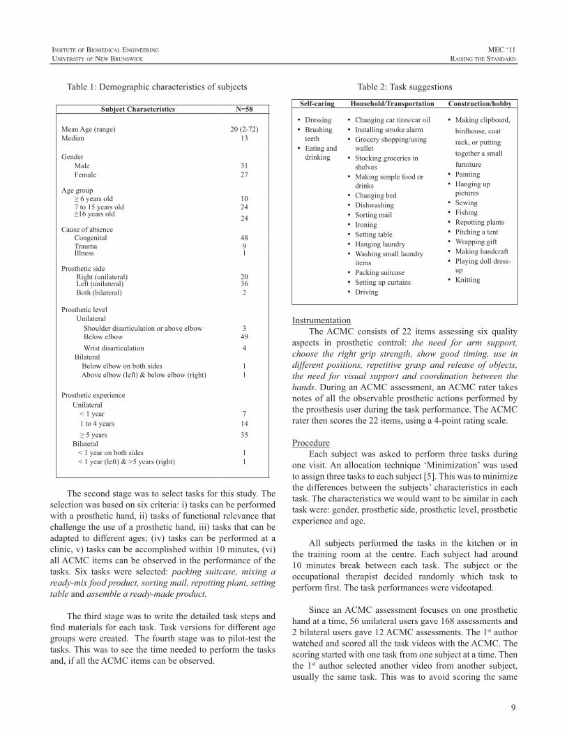
Thesecondstagewastoselecttasksforthisstudy.Theselectionwasbasedonsixcriteria:i)taskscanbeperformedwithaprosthetichand,ii)tasksoffunctionalrelevancethatchallengetheuseofaprosthetichand,iii)tasksthatcanbeadapted to different ages; (iv) tasks can be performed at aclinic,v)taskscanbeaccomplishedwithin10minutes,(vi)allACMCitemscanbeobservedintheperformanceofthetasks. Six tasks were selected: packing suitcase, mixing aready-mixfoodproduct,sortingmail,repottingplant,settingtableandassembleaready-madeproduct.
Thethirdstagewastowritethedetailedtaskstepsandfindmaterialsforeachtask.Taskversionsfordifferentagegroupswerecreated. Thefourthstagewastopilot-testthetasks.Thiswastoseethetimeneededtoperformthetasksand,ifalltheACMCitemscanbeobserved.
Table2:Tasksuggestions
Self-caring Household/Transportation Construction/hobby
• Dressing• Brushingteeth
• Eatinganddrinking
• Changingcartires/caroil• Installingsmokealarm• Groceryshopping/usingwallet
• Stockinggroceriesinshelves
• Makingsimplefoodordrinks
• Changingbed• Dishwashing• Sortingmail• Ironing• Settingtable• Hanginglaundry• Washingsmalllaundryitems
• Packingsuitcase• Settingupcurtains• Driving
• Makingclipboard,birdhouse,coatrack,orputtingtogetherasmallfurniture
• Painting• Hanginguppictures
• Sewing• Fishing• Repottingplants• Pitchingatent• Wrappinggift• Makinghandcraft• Playingdolldress-up
• Knitting
InstrumentationTheACMC consists of 22 items assessing six quality
aspects in prosthetic control: the need for arm support,choose the right grip strength, show good timing, use indifferent positions, repetitive grasp and release of objects,the need for visual support and coordination between thehands.DuringanACMCassessment,anACMCratertakesnotesofall theobservableprostheticactionsperformedbytheprosthesisuserduringthetaskperformance.TheACMCraterthenscoresthe22items,usinga4-pointratingscale.
ProcedureEach subjectwas asked to perform three tasks during
onevisit.Anallocation technique‘Minimization’wasusedtoassignthreetaskstoeachsubject[5].Thiswastominimizethedifferencesbetweenthesubjects’characteristicsineachtask.Thecharacteristicswewouldwanttobesimilarineachtaskwere:gender,prostheticside,prostheticlevel,prostheticexperienceandage.
All subjects performed the tasks in the kitchen or inthe training room at the centre. Each subject had around10 minutes break between each task. The subject or theoccupational therapist decided randomly which task toperformfirst.Thetaskperformanceswerevideotaped.
Since anACMCassessment focusesononeprosthetichandatatime,56unilateralusersgave168assessmentsand2bilateralusersgave12ACMCassessments.The1stauthorwatchedandscoredallthetaskvideoswiththeACMC.Thescoringstartedwithonetaskfromonesubjectatatime.Thenthe 1st author selected another video from another subject,usually the same task.Thiswas to avoid scoring the same
10
MEC ‘11raIsIng the standard
InsItute of BIomedIcal engIneerIng
unIversIty of new BrunswIck
subject in three tasks andhencegave similar scores to thethreetasks.AllthescoreswerewrittendownontheACMCscoring sheets. The 1st author consulted the 3rd author foradviceiftherewasanydoubtaboutthescoring.
DataanalysisRaschanalysiswascarriedoutusingWINSTEPS3.72.
Item difficultymeasures and person abilitymeasureswereconstructed using the ACMC raw scores. Task difficultymeasure is the average difficulty of the task-items for thetask.
Taskvaliditywasexaminedbythemean-square(MnSq)statistics. Infit and outfitMnSq andwere used to examineany measurement disturbance occurred in each task. Therange for an acceptable goodness-of-fit is between 0.6 to1.3 MnSq was selected. A task that shows an acceptablegoodness-of-fit is considered as an appropriate task for anACMC assessment. Differential item functioning (DIF)was performed to examine any item consistently functiondifferently in a particular task for a particular age group,genderandprostheticside.
Theperson-itemmapwasusedtoassessthealignmentbetweenthesubjectsandthe22items.Thedistributionoftheitemsshowsthedifficultyofthenewlymergeditemsrelativetotheexistingitems.
The rating scale was examined by (i) the “FrequencyofUse” of each category, (ii) “PersonMeasures” for eachcategory,whichshouldincreasefromacategoryrepresentinglowabilitytoonerepresentinghighability,(iii)“ThresholdMeasure”betweenanytworatings.Thisshouldalsoincreasewithincreasingcategorynumber.
RESULT
TaskdifficultyandvalidityBasedonthissample,packingsuitcase(-0.26logits)is
theeasiesttask(Table3).Assembleaready-madeproductandsettingtableareequallydifficult(0.13logits).Thedifficultyrangeis-0.26to0.13logits,i.e.0.39logitsdifference.FromtheACMCrawscoretologitsconversiontableinWinsteps,achangein0.5logitsisequivalentto2ACMCrawscores.Hence, a change in 0.39 logits is less than 2ACMC rawscores, suggesting that the impact of the task difficultydifferenceontheACMCscoreisminimal.
TheInfitandOutfitMnSqsareallwithintheacceptablerange(Table3),implyingthatthesetasksareappropriatetobeusedinACMCassessments.
No item exhibit DIF in gender and prosthetic side,implyingthatthetasksareappropriateforbothgendersand
both prosthetic sides. Two items ‘holding without visualfeedback’ and ‘holding inmotionwithout visual feedback’exhibit age DIF. These two items are relatively easier forthosewhoareage6oryounger.
Table 3: Task difficulty measures and task fit statistics
Task Mean age (yr)
Difficulty (in logits)
Infit MnSq
Outfit MnSq
Packingasuitcase 18.1 -0.26 1.15 0.88
Sortingmail 20.0 -0.13 0.81 0.63Mixingaready-to-eatproduct
18.5 0.05 0.94 0.73
Repottingplant 19.7 0.09 1.15 0.88
Assembleaready-madeproject
19.7 0.13 0.77 0.66
Settingtable 22.1 0.13 0.92 0.70
The22itemACMCwithnewlymergeditemsThe person-item map in Fig.1 clearly shows the
distributionofsubjectsinrelationtotheACMCitems.Themeanpersonabilityis2.34logits(meanitemdifficultyissetat0bydefault),indicatingthatthissamplehasahighabilityinoperatingamyoelectricprosthetichand.Since35outof58subjectshavemorethan5yearsofprostheticexperience,ahighmeanabilityisexpected.
The newly-merged items are circled (Fig.1). Theirpositionsalongtheverticalscalearesimilartotheirpositionsinthe30itemACMC[2],indicatingtheyarefunctioningasexpected.
TheredefinedratingscaleTheuseof4ratingcategoriesisshownintable4.The
observedpersonmeasuresincreaseasthecategoryincreases.The use of category-2 is slightly lower than we expected(22%). In Fig.2, however, it shows that the probability ofselecting category-2 is the same as selecting category 1,indicating that thenewcategory-2definitionhas improvedthefunctioningoftheratingscale.
DISCUSSION
UsingtheACMCitems,whichmeasurehowaprosthesisusergrasps,holdandreleasedifferentobjects,thesixtaskshave similar difficulties. This may be surprising for thereaders since; in general, as in our knowledge, some tasksaremoredifficult thanother tasks.However, theACMCisnotdesignedtomeasurehowwellaprosthesisuserperformsatask.TheACMCitemsdonotmeasure,forexample,iftheplantisnotstraightafterrepotting,orifthemilkisspiltonthetableduringmixingthefoodproduct.
11
InsItute of BIomedIcal engIneerIng
unIversIty of new BrunswIck
MEC ‘11raIsIng the standard
TheACMC itemsmeasure, for example, if theuser isabletograsptheplantwiththeprosthetichandusingtherightgripforce,or,iftheuserisabletomaintainholdingashoebagwhenputtingshoesinside.Inthetask‘packingasuitcase’,a few prosthesis users dropped the shoe bagwhen puttingshoesinside.Thiswasbecausetheusersdidnotincreasethegrip forcewhen the shoe bag got heavier after putting theshoesinit.
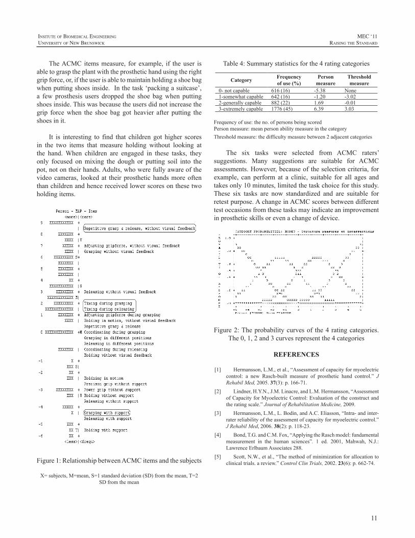
It is interesting to find that children got higher scoresin the two items that measure holding without looking atthe hand.When children are engaged in these tasks, theyonly focused onmixing the dough or putting soil into thepot,notontheirhands.Adults,whowerefullyawareofthevideocameras, lookedat theirprosthetichandsmoreoftenthanchildrenandhencereceivedlowerscoresonthesetwoholdingitems.
Figure1:RelationshipbetweenACMCitemsandthesubjects
X=subjects,M=mean,S=1standarddeviation(SD)fromthemean,T=2SDfromthemean
Table4:Summarystatisticsforthe4ratingcategories
Category Frequencyof use (%)
Person measure
Thresholdmeasure
0-notcapable 616(16) -5.38 None1-somewhatcapable 642(16) -1.20 -3.022-generallycapable 882(22) 1.69 -0.013-extremelycapable 1776(45) 6.39 3.03
Frequencyofuse:theno.ofpersonsbeingscoredPersonmeasure:meanpersonabilitymeasureinthecategoryThresholdmeasure:thedifficultymeasurebetween2adjacentcategories
The six tasks were selected from ACMC raters’suggestions. Many suggestions are suitable for ACMCassessments.However,becauseoftheselectioncriteria,forexample, can perform at a clinic, suitable for all ages andtakesonly10minutes,limitedthetaskchoiceforthisstudy.These six tasks are now standardized and are suitable forretestpurpose.AchangeinACMCscoresbetweendifferenttestoccasionsfromthesetasksmayindicateanimprovementinprostheticskillsorevenachangeofdevice.
Figure2:Theprobabilitycurvesof the4 ratingcategories.The0,1,2and3curvesrepresentthe4categories
REFERENCES
[1] Hermansson,L.M.,etal.,“Assessmentofcapacityformyoelectriccontrol: a new Rasch-built measure of prosthetic hand control.” JRehabilMed,2005.37(3):p.166-71.
[2] Lindner,H.Y.N.,J.M.Linacre,andL.M.Hermansson,“AssessmentofCapacityforMyoelectricControl:Evaluationoftheconstructandtheratingscale.”JournalofRehabilitationMedicine,2009.
[3] Hermansson,L.M.,L.Bodin,andA.C.Eliasson,“Intra-andinter-raterreliabilityoftheassessmentofcapacityformyoelectriccontrol.”JRehabilMed,2006.38(2):p.118-23.
[4] Bond,T.G.andC.M.Fox,“ApplyingtheRaschmodel:fundamentalmeasurement in the human sciences”. 1 ed. 2001, Mahwah, N.J.:LawrenceErlbaumAssociates288.
[5] Scott,N.W.,etal.,“Themethodofminimizationforallocationtoclinicaltrials.areview.”ControlClinTrials,2002.23(6):p.662-74.
12
MEC ‘11raIsIng the standard
InsItute of BIomedIcal engIneerIng
unIversIty of new BrunswIck
INTRODUCTION
Wearedevelopingaquantitativemeasuringsystemforbasic operation abilities of myoelectric prosthetic hands.Preliminaryresults for theprosthetichandusersareshowninthisreport.
While there are numerous activities for developingdexterous---multi functional---prosthetic hands, mostcommercialelectricpoweredprosthetichandsarelimitedtosingleactivefunctionsystems.Suchcommercialprosthetichandusers,however,haveabilitiestoperformvariousdailyorwork relatedactivitieseffectively,when theirprosthesesareappropriatelyfitted.
Control methods of the commercial prosthetic handswerecategorizedintothreedistinctgenerationsbyapreviouswork[1];firstgenerationusedanon-offswitchtypecontrolschemeforhandmotoractivation.Secondgenerationhandshave ability to adjust thresholds for motor activation, andproportional controllability of motor speed was providedin this generation. In the third generation, control optionscanbemodified easily, because theyutilizeprogrammablemicroprocessors.Eveninthethirdgenerationorproportionalcontrolsystems,motoractivationisbasedonthethresholdofcontroller inputsignal; therefore,appropriateadjustmentofthe threshold,oranamplifiergain inamyoelectric sensor,is a significant issue for high-performance uses of theprosthetichand,whichmayleadstohighacceptanceratioofmyoelectrichandprostheses.
Performanceofprosthetichanduse isalsoaffectedbyclinicaltraining:myoelectricsignaltraining,controltrainingandfunctionaltraining.[2]Ourtargetisthecontroltrainingstage,inwhichbothofabilitytocontrolremnantmusclesandsocket-sensorfittinghaveeffectsonmyoelectriccontrol;andtherefore,itiscrucialforclinicianstoevaluateperformanceinthisstage.
Suchperformancecanbeevaluatedintermsofbasicandfunctionaloperationability;thefunctionalabilityismeasuredbyvariousmethods,suchasarequiredperiodorqualityoftask completionwith the hand prosthesis. [3][4]The basic
operationabilityrelatestohowtheusercancontrolthehandopen-closefunctionastheyintendto,andthisisaffectedbytheadjustmentofthethresholdortheamplifiergain.
METHODS
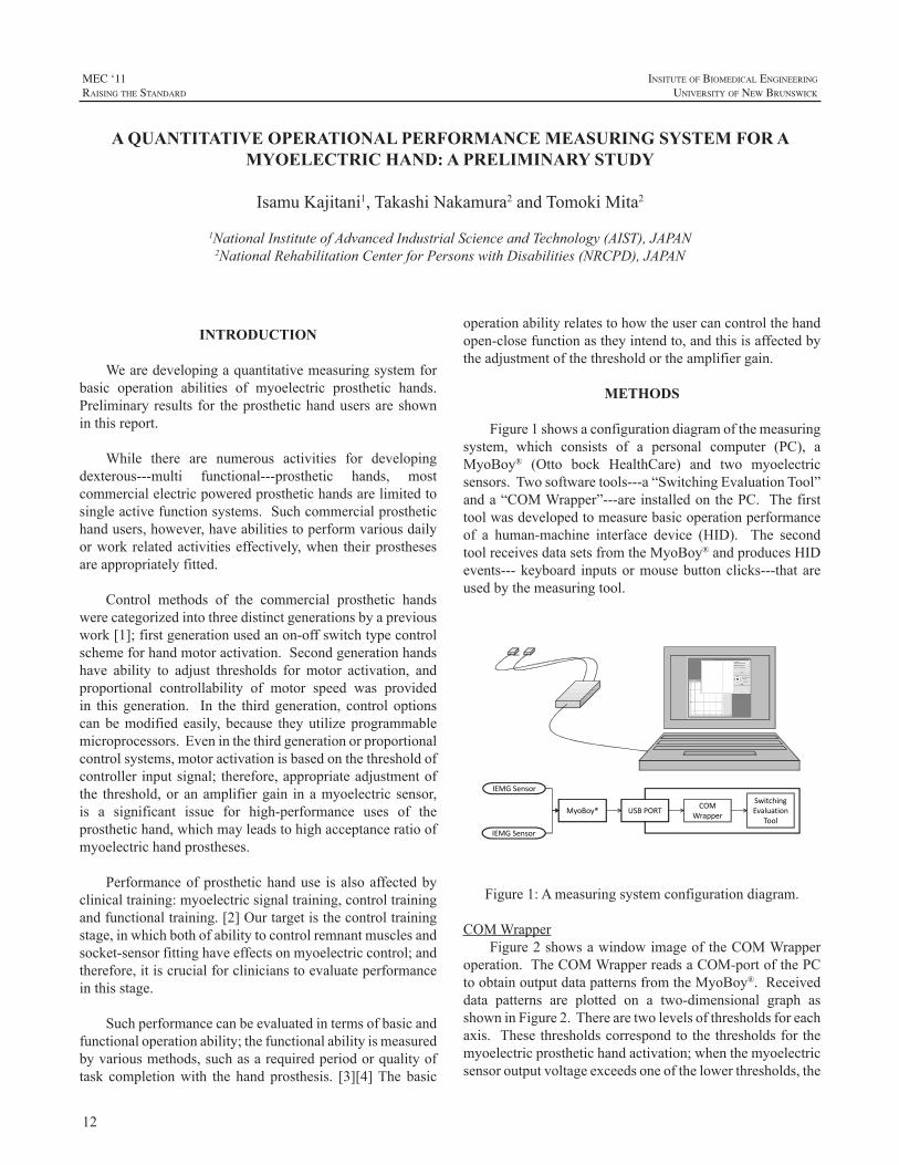
Figure1showsaconfigurationdiagramofthemeasuringsystem, which consists of a personal computer (PC), aMyoBoy® (Otto bock HealthCare) and two myoelectricsensors.Twosoftwaretools---a“SwitchingEvaluationTool”anda“COMWrapper”---areinstalledonthePC.Thefirsttoolwasdevelopedtomeasurebasicoperationperformanceof a human-machine interface device (HID). The secondtoolreceivesdatasetsfromtheMyoBoy®andproducesHIDevents---keyboard inputsormousebuttonclicks---thatareusedbythemeasuringtool.
IEMG Sensor
IEMG Sensor
MyoBoy® USB PORTCOM
Wrapper
Switching Evaluation
Tool
Figure1:Ameasuringsystemconfigurationdiagram.
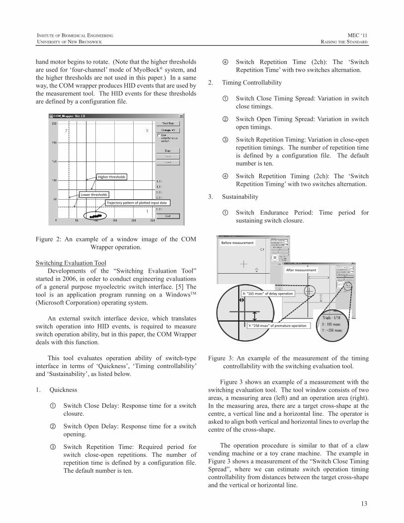
COMWrapperFigure2showsawindowimageoftheCOMWrapper
operation.TheCOMWrapperreadsaCOM-portofthePCtoobtainoutputdatapatternsfromtheMyoBoy®.Receiveddata patterns are plotted on a two-dimensional graph asshowninFigure2.Therearetwolevelsofthresholdsforeachaxis. Thesethresholdscorrespondtothethresholdsforthemyoelectricprosthetichandactivation;whenthemyoelectricsensoroutputvoltageexceedsoneofthelowerthresholds,the
A QUANTITATIVE OPERATIONAL PERFORMANCE MEASURING SYSTEM FOR A MYOELECTRIC HAND: A PRELIMINARY STUDY
IsamuKajitani1,TakashiNakamura2andTomokiMita2
1NationalInstituteofAdvancedIndustrialScienceandTechnology(AIST),JAPAN2NationalRehabilitationCenterforPersonswithDisabilities(NRCPD),JAPAN
13
InsItute of BIomedIcal engIneerIng
unIversIty of new BrunswIck
MEC ‘11raIsIng the standard
handmotorbeginstorotate.(Notethatthehigherthresholdsareusedfor‘four-channel’modeofMyoBock®system,andthehigherthresholdsarenotusedinthispaper.)Inasameway,theCOMwrapperproducesHIDeventsthatareusedbythemeasurementtool.TheHIDeventsforthesethresholdsaredefinedbyaconfigurationfile.
Trajectory pattern of plotted input data
Lower thresholds
Higher thresholds
Figure 2: An example of a window image of the COMWrapperoperation.
SwitchingEvaluationToolDevelopments of the “Switching Evaluation Tool”
startedin2006,inordertoconductengineeringevaluationsof a general purposemyoelectric switch interface. [5]Thetool is an application program running on a WindowsTM(MicrosoftCorporation)operatingsystem.
An external switch interface device, which translatesswitch operation into HID events, is required to measureswitchoperationability,butinthispaper,theCOMWrapperdealswiththisfunction.
This tool evaluates operation ability of switch-typeinterface in terms of ‘Quickness’, ‘Timing controllability’and‘Sustainability’,aslistedbelow.
1. Quickness
① SwitchCloseDelay:Response time for a switchclosure.
② SwitchOpenDelay:Response time for a switchopening.
③ Switch Repetition Time: Required period forswitch close-open repetitions. The number ofrepetition timeisdefinedbyaconfigurationfile.Thedefaultnumberisten.
④ Switch Repetition Time (2ch): The ‘SwitchRepetitionTime’withtwoswitchesalternation.
2. TimingControllability
① SwitchCloseTimingSpread:Variationinswitchclosetimings.
② SwitchOpenTimingSpread:Variation in switchopentimings.
③ SwitchRepetitionTiming:Variationinclose-openrepetitiontimings.Thenumberofrepetitiontimeis defined by a configuration file. The defaultnumberisten.
④ Switch Repetition Timing (2ch): The ‘SwitchRepetitionTiming’withtwoswitchesalternation.
3. Sustainability
① Switch Endurance Period: Time period forsustainingswitchclosure.
Before measurement
After measurement
X: “165 msec” of delay operation
Y: “258 msec” of premature operation
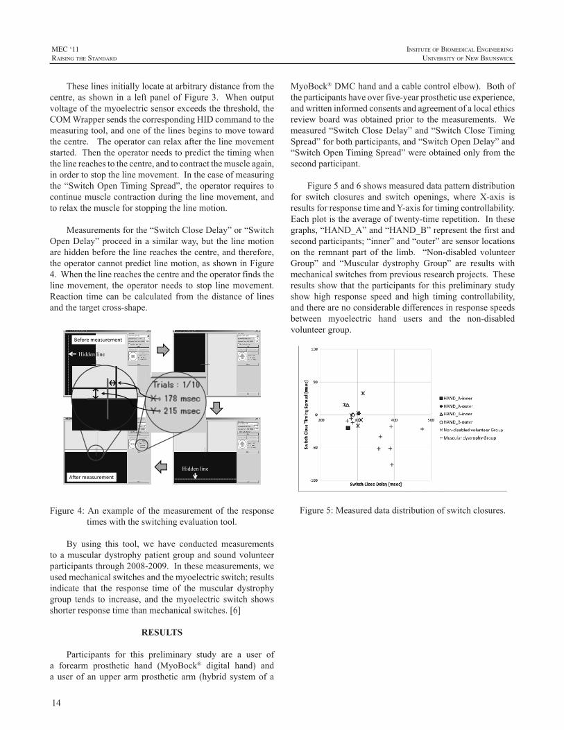
Figure 3: An example of the measurement of the timingcontrollabilitywiththeswitchingevaluationtool.
Figure3showsanexampleofameasurementwiththeswitchingevaluationtool.Thetoolwindowconsistsoftwoareas,ameasuringarea(left)andanoperationarea(right).In themeasuringarea, therearea target cross-shapeat thecentre,averticallineandahorizontalline.Theoperatorisaskedtoalignbothverticalandhorizontallinestooverlapthecentreofthecross-shape.
The operation procedure is similar to that of a clawvendingmachineora toycranemachine. Theexample inFigure3showsameasurementofthe“SwitchCloseTimingSpread”, where we can estimate switch operation timingcontrollabilityfromdistancesbetweenthetargetcross-shapeandtheverticalorhorizontalline.
14
MEC ‘11raIsIng the standard
InsItute of BIomedIcal engIneerIng
unIversIty of new BrunswIck
Theselinesinitiallylocateatarbitrarydistancefromthecentre, as shown ina leftpanelofFigure3. Whenoutputvoltageofthemyoelectricsensorexceedsthethreshold,theCOMWrappersendsthecorrespondingHIDcommandtothemeasuringtool,andoneofthelinesbeginstomovetowardthecentre.Theoperatorcanrelaxafterthelinemovementstarted.Thentheoperatorneedstopredictthetimingwhenthelinereachestothecentre,andtocontractthemuscleagain,inordertostopthelinemovement.Inthecaseofmeasuringthe“SwitchOpenTimingSpread”, theoperatorrequires tocontinuemusclecontractionduringthelinemovement,andtorelaxthemuscleforstoppingthelinemotion.
Measurementsforthe“SwitchCloseDelay”or“SwitchOpenDelay”proceedinasimilarway,but the linemotionarehiddenbeforethelinereachesthecentre,andtherefore,theoperatorcannotpredictlinemotion,asshowninFigure4.Whenthelinereachesthecentreandtheoperatorfindsthelinemovement, the operator needs to stop linemovement.Reaction time can be calculated from the distance of linesandthetargetcross-shape.
Hiddenline
Before measurement
After measurement
Hiddenline
Figure 4:An example of themeasurement of the responsetimeswiththeswitchingevaluationtool.
By using this tool, we have conducted measurementstoamusculardystrophypatientgroupandsoundvolunteerparticipantsthrough2008-2009.Inthesemeasurements,weusedmechanicalswitchesandthemyoelectricswitch;resultsindicate that the response time of the muscular dystrophygroup tends to increase, and themyoelectric switch showsshorterresponsetimethanmechanicalswitches.[6]
RESULTS
Participants for this preliminary study are a user ofa forearm prosthetic hand (MyoBock® digital hand) andauserof anupper armprosthetic arm (hybrid systemof a
MyoBock®DMChandandacablecontrolelbow).Bothoftheparticipantshaveoverfive-yearprostheticuseexperience,andwritteninformedconsentsandagreementofalocalethicsreviewboardwasobtainedprior to themeasurements. Wemeasured“SwitchCloseDelay”and“SwitchCloseTimingSpread”forbothparticipants,and“SwitchOpenDelay”and“SwitchOpenTimingSpread”wereobtainedonlyfromthesecondparticipant.
Figure5and6showsmeasureddatapatterndistributionfor switch closures and switch openings, where X-axis isresultsforresponsetimeandY-axisfortimingcontrollability.Eachplotistheaverageoftwenty-timerepetition.Inthesegraphs,“HAND_A”and“HAND_B”representthefirstandsecondparticipants;“inner”and“outer”aresensorlocationson the remnant part of the limb. “Non-disabled volunteerGroup” and “Muscular dystrophy Group” are results withmechanicalswitchesfrompreviousresearchprojects.Theseresultsshowthat theparticipantsfor thispreliminarystudyshow high response speed and high timing controllability,andtherearenoconsiderabledifferencesinresponsespeedsbetween myoelectric hand users and the non-disabledvolunteergroup.
Figure5:Measureddatadistributionofswitchclosures.
15
InsItute of BIomedIcal engIneerIng
unIversIty of new BrunswIck
MEC ‘11raIsIng the standard
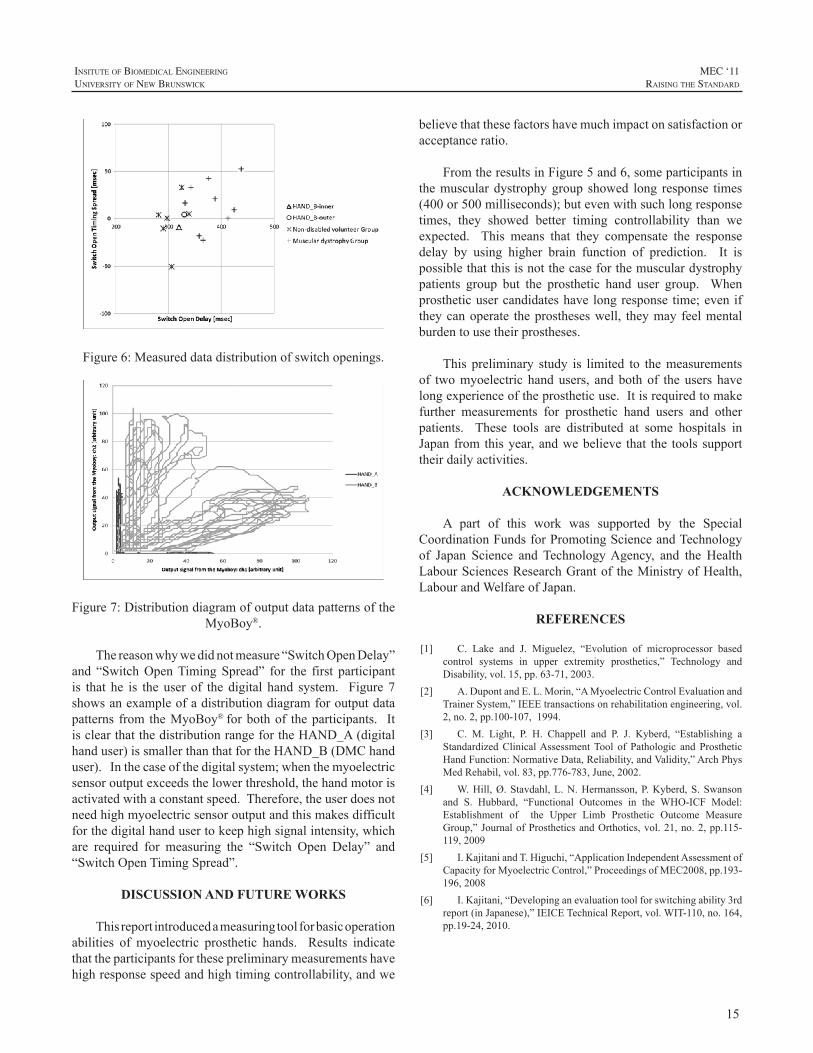
Figure6:Measureddatadistributionofswitchopenings.
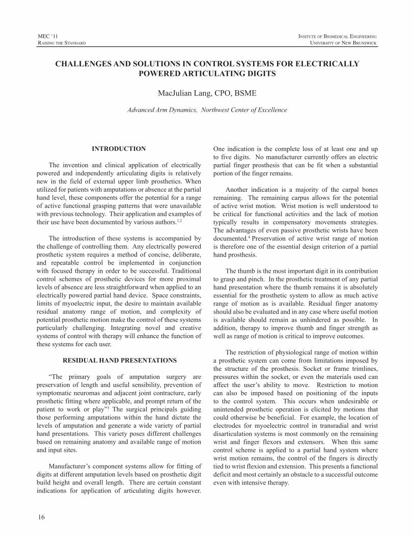
Figure7:DistributiondiagramofoutputdatapatternsoftheMyoBoy®.
Thereasonwhywedidnotmeasure“SwitchOpenDelay”and “SwitchOpenTimingSpread” for the first participantis that he is the user of the digital hand system. Figure 7showsanexampleofadistributiondiagramforoutputdatapatterns from theMyoBoy®forbothof theparticipants. ItisclearthatthedistributionrangefortheHAND_A(digitalhanduser)issmallerthanthatfortheHAND_B(DMChanduser).Inthecaseofthedigitalsystem;whenthemyoelectricsensoroutputexceedsthelowerthreshold,thehandmotorisactivatedwithaconstantspeed.Therefore,theuserdoesnotneedhighmyoelectricsensoroutputandthismakesdifficultforthedigitalhandusertokeephighsignalintensity,whichare required for measuring the “Switch Open Delay” and“SwitchOpenTimingSpread”.
DISCUSSION AND FUTURE WORKS
Thisreportintroducedameasuringtoolforbasicoperationabilities of myoelectric prosthetic hands. Results indicatethattheparticipantsforthesepreliminarymeasurementshavehighresponsespeedandhightimingcontrollability,andwe
believethatthesefactorshavemuchimpactonsatisfactionoracceptanceratio.
FromtheresultsinFigure5and6,someparticipantsinthemusculardystrophygroup showed long response times(400or500milliseconds);butevenwithsuchlongresponsetimes, they showed better timing controllability than weexpected. This means that they compensate the responsedelay by using higher brain function of prediction. It ispossiblethatthisisnotthecaseforthemusculardystrophypatients group but the prosthetic hand user group. Whenprostheticusercandidateshavelongresponse time;eveniftheycanoperate theprostheseswell, theymay feelmentalburdentousetheirprostheses.
This preliminary study is limited to themeasurementsof twomyoelectric handusers, andboth of the users havelongexperienceoftheprostheticuse.Itisrequiredtomakefurther measurements for prosthetic hand users and otherpatients. These tools are distributed at some hospitals inJapanfromthisyear,andwebelieve that the toolssupporttheirdailyactivities.
ACKNOWLEDGEMENTS
A part of this work was supported by the SpecialCoordinationFundsforPromotingScienceandTechnologyof Japan Science and TechnologyAgency, and the HealthLabourSciencesResearchGrantof theMinistryofHealth,LabourandWelfareofJapan.
REFERENCES
[1] C. Lake and J. Miguelez, “Evolution of microprocessor basedcontrol systems in upper extremity prosthetics,” Technology andDisability,vol.15,pp.63-71,2003.
[2] A.DupontandE.L.Morin,“AMyoelectricControlEvaluationandTrainerSystem,”IEEEtransactionsonrehabilitationengineering,vol.2,no.2,pp.100-107,1994.
[3] C. M. Light, P. H. Chappell and P. J. Kyberd, “Establishing aStandardizedClinicalAssessmentTool of Pathologic and ProstheticHandFunction:NormativeData,Reliability,andValidity,”ArchPhysMedRehabil,vol.83,pp.776-783,June,2002.
[4] W.Hill,Ø.Stavdahl,L.N.Hermansson,P.Kyberd,S.Swansonand S. Hubbard, “Functional Outcomes in the WHO-ICF Model:Establishment of the Upper Limb Prosthetic Outcome MeasureGroup,”JournalofProstheticsandOrthotics,vol.21,no.2,pp.115-119,2009
[5] I.KajitaniandT.Higuchi,“ApplicationIndependentAssessmentofCapacityforMyoelectricControl,”ProceedingsofMEC2008,pp.193-196,2008
[6] I.Kajitani,“Developinganevaluationtoolforswitchingability3rdreport(inJapanese),”IEICETechnicalReport,vol.WIT-110,no.164,pp.19-24,2010.
16
MEC ‘11raIsIng the standard
InsItute of BIomedIcal engIneerIng
unIversIty of new BrunswIck
INTRODUCTION
The invention and clinical application of electricallypowered and independently articulating digits is relativelynew in the field of external upper limb prosthetics.Whenutilizedforpatientswithamputationsorabsenceatthepartialhandlevel,thesecomponentsofferthepotentialforarangeofactivefunctionalgraspingpatternsthatwereunavailablewithprevioustechnology.Theirapplicationandexamplesoftheirusehavebeendocumentedbyvariousauthors.1,2
The introduction of these systems is accompanied bythechallengeofcontrollingthem.Anyelectricallypoweredprosthetic system requires amethodof concise, deliberate,and repeatable control be implemented in conjunctionwith focused therapy in order to be successful.Traditionalcontrol schemes of prosthetic devices for more proximallevelsofabsencearelessstraightforwardwhenappliedtoanelectricallypoweredpartialhanddevice.Spaceconstraints,limitsofmyoelectricinput,thedesiretomaintainavailableresidual anatomy range of motion, and complexity ofpotentialprostheticmotionmakethecontrolofthesesystemsparticularly challenging. Integrating novel and creativesystemsofcontrolwiththerapywillenhancethefunctionofthesesystemsforeachuser.
RESIDUAL HAND PRESENTATIONS
“The primary goals of amputation surgery arepreservation of length and useful sensibility, prevention ofsymptomaticneuromasandadjacentjointcontracture,earlyprostheticfittingwhereapplicable,andpromptreturnofthepatient to work or play”3 The surgical principals guidingthose performing amputations within the hand dictate thelevelsofamputationandgenerateawidevarietyofpartialhandpresentations. Thisvarietyposesdifferentchallengesbasedonremaininganatomyandavailablerangeofmotionandinputsites.
Manufacturer’scomponentsystemsallowforfittingofdigitsatdifferentamputationlevelsbasedonprostheticdigitbuildheightandoverall length. Therearecertainconstantindications for application of articulating digits however.
One indication is the complete loss of at least one and uptofivedigits. Nomanufacturercurrentlyoffersanelectricpartial finger prosthesis that can be fit when a substantialportionofthefingerremains.
Another indication is a majority of the carpal bonesremaining. The remaining carpus allows for the potentialofactivewristmotion. Wristmotioniswellunderstoodtobe critical for functional activities and the lack of motiontypically results in compensatory movements strategies.Theadvantagesofevenpassiveprostheticwristshavebeendocumented.4Preservation of active wrist range of motionisthereforeoneoftheessentialdesigncriterionofapartialhandprosthesis.
Thethumbisthemostimportantdigitinitscontributiontograspandpinch.Intheprosthetictreatmentofanypartialhandpresentationwhere the thumbremains it isabsolutelyessential for theprosthetic system toallowasmuchactiverange of motion as is available. Residual finger anatomyshouldalsobeevaluatedandinanycasewhereusefulmotionis available should remain as unhindered as possible. Inaddition, therapy to improve thumb and finger strength aswellasrangeofmotioniscriticaltoimproveoutcomes.
Therestrictionofphysiologicalrangeofmotionwithinaprosthetic systemcan come from limitations imposedbythe structure of the prosthesis. Socket or frame trimlines,pressureswithin thesocket,oreven thematerialsusedcanaffect the user’s ability to move. Restriction to motioncan also be imposed based on positioning of the inputsto the control system. This occurs when undesirable orunintended prosthetic operation is elicited bymotions thatcouldotherwisebebeneficial.Forexample,thelocationofelectrodes for myoelectric control in transradial and wristdisarticulationsystemsismostcommonlyontheremainingwrist and finger flexors and extensors. When this samecontrol scheme is applied to a partial hand system wherewristmotion remains, the control of the fingers is directlytiedtowristflexionandextension.Thispresentsafunctionaldeficitandmostcertainlyanobstacletoasuccessfuloutcomeevenwithintensivetherapy.
CHALLENGES AND SOLUTIONS IN CONTROL SYSTEMS FOR ELECTRICALLY POWERED ARTICULATING DIGITS
MacJulianLang,CPO,BSME
AdvancedArmDynamics,NorthwestCenterofExcellence
17
InsItute of BIomedIcal engIneerIng
unIversIty of new BrunswIck
MEC ‘11raIsIng the standard
MIRCROPROCCESOR CONTROL SCHEMES
Commonly electric prosthetic systems are designedwith myoelectric control of the various components. Thepreferred myoelectric control scheme consists of dual siteagonistandantagonistmusclepairs.Eachsitecontrolsonedegreeoffreedomforthecomponentbeingcontrolled:hand,wrist rotator, elbow, etc. A switching mechanism, eithermyoelectric or electro-mechanical, is used to change thecomponentcurrentlyoperating.Generallytheseschemesarewellunderstoodbyrehabilitationprofessionalsandtrainingforprosthesiscontrolisstraightforward.
Anothermorechallengingschemeissinglesitecontrol.Asinglemyoelectricinputisutilizedtooperateallfunctionsof the prosthesis. Microprocessors determine the directionofmotormotionbasedondifferingalgorithms.5Alternatingmotion,ratedependantdirection,andautomaticclosingareallexamplesofsinglesitecontrolmethods.Whenmorethanonecomponent iscontrolledanotherswitch isnecessary tomovebetweencomponents.
Rarelyisprosthesisfunctionasfluidwhenusingsinglesite control as compared to dual site. The necessity foradditional switching or the inability to change directionsseamlesslycreatesdelaysincontrol. However,whenotherinput options are not logical or unavailable, the ability toutilizeoneinputforcontrolcanbevitaltothesuccessofthesystem.
In addition to electrodes used formyoelectric control,alternateinputscanbeused.Forcesensingresistors(FSR’s),linear transducers, and strain gauges can all be used forproportional input intocontrolsystems.5Thesedevicescanbeusedinconjunctionwithorasreplacementstomyoelectricinputs.Insomecasesthreeinputsystemsareadvantageouswherethethirdinput,typicallyanalternateinput,hasdirectcontroloveracomponentorisusedasaswitch.
Patternrecognitionformyoelectriccontrolisanemergingtechnology that is very promising.With the application ofpatternrecognition,isolationofindividualmusclesbecomesmuch less important or problematic. The requirement ofsignal separation indual site control isdiminishedand thepotentialforcontrolofmoredegreesoffreedomisgained.6Undoubtedly when it becomes available to the prostheticsindustry there will be applications for the powered partialhandprosthesis.
The considerations in prosthesis design provide abasisforsocketdesignbutalsoforinputdeterminationandprosthesis control. Each partial hand presentation has itsown limitations and challenges but also provides differentopportunitiesforcontrol.
CONTROL SYSTEM CONSIDERATIONS
5fingersabsentThe prosthesis for the residual limb with all fingers
missing is arguably the easiest to control of any thosediscussed. The lack of fingers allows for the preferredmethod of dual site myoelectric control with intrinsicmusclesofthehand. Themostlogicalwhenavailablearethehypothenar and thenar eminencesdue to their size andtypicalsignalseparation.7
Thesimplicityofcontrolisbalancedbythedecreaseinresidualhandfunctionduetolackofathumb.Thelackofanydigitalsensationseverelycomplicatestrainingandfunction.Onedecisionthatmustbemadeiswhetherornottomotorizetheprostheticthumbbutthecontrolofeithersystemislikelytobesimilar.
4fingersmissing–thumbremainingThe presence of a thumbmakes the use of the thenar
eminenceasamyoelectricsiteinadvisableasthumbmotionandprosthesisfunctionwouldbelinked.Thiswouldcreateaconundrumofcontrolfortheuser.Hypothenarmusculatureisstillveryviableforcontrolwiththispresentation.
For dual site intrinsic myoelectric control the secondsite is likely the lumbricals or dorsal interossei. Imagined2nd-5th digitMP flexion alongwith PIP andDIP extensiongenerally results in the best signal for these groups. Thiscan be described as having the patient “fold” the hand attheknuckleswhilekeepingthefingersstraight.Thesesmallintrinsicmusclesareviablecontributorsofmyoelectricsignalbutcertainlyrequiretrainingtohavesufficientstaminaandstrengthtobeusedfunctionally.
Dualsitecontrolisstillthepreferredmethodofcontrol,butonlyifachievable,consistent,andfunctional.Singlesitecontrol is aviableoptionat this leveldue to the relativelystrongandisolatedhypothenarmuscles.
3fingersmissing–thumband2nddigitremainingHaving the 2nd digit and thumb with active range of
motionandsensibilityprovideswhatthepreviouslevelsdonothave: truepinchandgraspnative to the residualhand.Finedexterityistypicallynotanissue.Powerfulandstablegrasp of larger items, however, can still be a challenge asgraspislimitedtoa“ring”createdbythetwodigits.
Myoelectricinputiscertainlyavailablefromhypothenarmuscular if present. When attempting to find a secondmyoelectric site again the small intrinsic muscles of thelumbricals and dorsal interossei are candidates. Intensivetrainingtoseparate2nddigitmotionfromthissecondsiteisimperativeinordertohavethisbeasuccessfuloutcome.Due
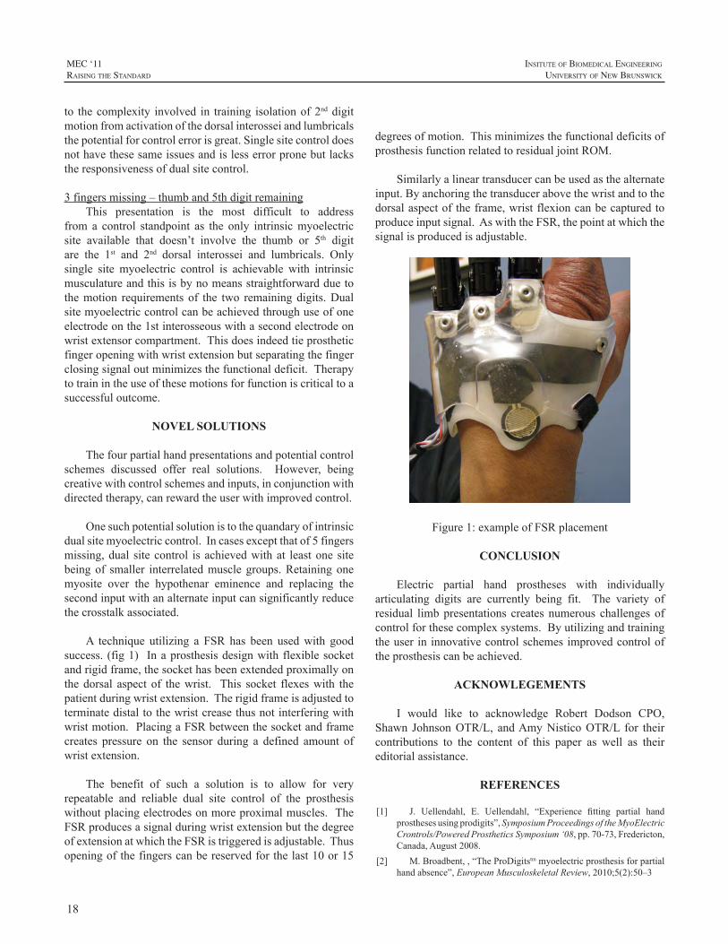
18
MEC ‘11raIsIng the standard
InsItute of BIomedIcal engIneerIng
unIversIty of new BrunswIck
to thecomplexity involved in training isolationof2nddigitmotionfromactivationofthedorsalinterosseiandlumbricalsthepotentialforcontrolerrorisgreat.Singlesitecontroldoesnothavethesesameissuesandislesserrorpronebutlackstheresponsivenessofdualsitecontrol.
3fingersmissing–thumband5thdigitremainingThis presentation is the most difficult to address
from a control standpoint as the only intrinsicmyoelectricsite available that doesn’t involve the thumb or 5th digitare the 1st and 2nd dorsal interossei and lumbricals. Onlysingle site myoelectric control is achievable with intrinsicmusculatureandthisisbynomeansstraightforwardduetothemotion requirements of the two remainingdigits.Dualsitemyoelectriccontrolcanbeachievedthroughuseofoneelectrodeonthe1stinterosseouswithasecondelectrodeonwristextensorcompartment.Thisdoesindeedtieprostheticfingeropeningwithwristextensionbutseparatingthefingerclosingsignaloutminimizesthefunctionaldeficit.Therapytotrainintheuseofthesemotionsforfunctioniscriticaltoasuccessfuloutcome.
NOVEL SOLUTIONS
Thefourpartialhandpresentationsandpotentialcontrolschemes discussed offer real solutions. However, beingcreativewithcontrolschemesandinputs,inconjunctionwithdirectedtherapy,canrewardtheuserwithimprovedcontrol.
Onesuchpotentialsolutionistothequandaryofintrinsicdualsitemyoelectriccontrol.Incasesexceptthatof5fingersmissing,dual sitecontrol is achievedwithat leastone sitebeingof smaller interrelatedmusclegroups.Retainingonemyosite over the hypothenar eminence and replacing thesecondinputwithanalternateinputcansignificantlyreducethecrosstalkassociated.
A technique utilizing a FSR has been usedwith goodsuccess. (fig1) Inaprosthesisdesignwithflexiblesocketandrigidframe,thesockethasbeenextendedproximallyonthedorsal aspect of thewrist. This socket flexeswith thepatientduringwristextension.Therigidframeisadjustedtoterminatedistaltothewristcreasethusnotinterferingwithwristmotion.PlacingaFSRbetweenthesocketandframecreates pressure on the sensor during a defined amount ofwristextension.
The benefit of such a solution is to allow for veryrepeatable and reliable dual site control of the prosthesiswithoutplacingelectrodesonmoreproximalmuscles.TheFSRproducesasignalduringwristextensionbutthedegreeofextensionatwhichtheFSRistriggeredisadjustable.Thusopeningofthefingerscanbereservedforthelast10or15
degreesofmotion.ThisminimizesthefunctionaldeficitsofprosthesisfunctionrelatedtoresidualjointROM.
Similarlyalineartransducercanbeusedasthealternateinput.Byanchoringthetransducerabovethewristandtothedorsalaspectoftheframe,wristflexioncanbecapturedtoproduceinputsignal.AswiththeFSR,thepointatwhichthesignalisproducedisadjustable.
Figure1:exampleofFSRplacement
CONCLUSION
Electric partial hand prostheses with individuallyarticulating digits are currently being fit. The variety ofresidual limbpresentations creates numerous challengesofcontrolforthesecomplexsystems.Byutilizingandtrainingtheuserininnovativecontrolschemesimprovedcontroloftheprosthesiscanbeachieved.
ACKNOWLEGEMENTS
I would like to acknowledge Robert Dodson CPO,Shawn JohnsonOTR/L, andAmyNisticoOTR/L for theircontributions to the content of this paper as well as theireditorialassistance.
REFERENCES
[1] J. Uellendahl, E. Uellendahl, “Experience fitting partial handprosthesesusingprodigits”,SymposiumProceedingsoftheMyoElectricCrontrols/PoweredProstheticsSymposium‘08,pp.70-73,Fredericton,Canada,August2008.
[2] M.Broadbent,,“TheProDigitstmmyoelectricprosthesisforpartialhandabsence”,EuropeanMusculoskeletalReview,2010;5(2):50–3
19
InsItute of BIomedIcal engIneerIng
unIversIty of new BrunswIck
MEC ‘11raIsIng the standard
[3] E.A. Ouellette, J. A. McAuliffe, R. Carneiro, “Partial-Handamputations:surgicalprincipals”,AtlasofLimbProsthetics:Surgical,Prosthetic,andRehabilitationPrincipals,2nded.,1992,pp.199-216
[4] T.Bertels,T. Schmalz,E.Ludwigs, “Objectifying the functionaladvantagesofprostheticwristflexion”,J.ProsthandOrth.,21(2),pp.74-78,2009
[5] C.Lake,J.Miguelez,“Comparativeanalysisofmicroprocessorsinupperlimbprosthetics”,JProsth.andOrth.,15(2),pp.48-63,2003
[6] B.Lock,A.Schultz,T.Kuiken “Clinically practical applicationsof pattern recognition for myoelectric prostheses”, SymposiumProceedings of the MyoElectric Crontrols/Powered ProstheticsSymposium‘08,pp.119-123,Fredericton,Canada,August2008.
[7] R. Weir, E. Grahn, S. Duff, “A new externally powered,myoelectrically controlled prosthesis for persons with partial-handamputationsat themetacarpals”,J.Prosth.andOrth.,13(2),pp.26-31,2001
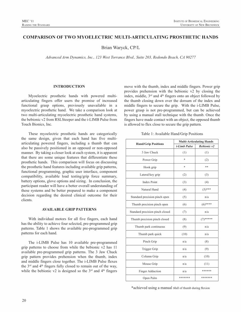
20
MEC ‘11raIsIng the standard
InsItute of BIomedIcal engIneerIng
unIversIty of new BrunswIck
INTRODUCTION
Myoelectric prosthetic hands with powered multi-articulating fingers offer users the promise of increasedfunctional grasp options, previously unavailable in amyoelectricprosthetichand.Wetakeacomparisonlookattwomulti-articulatingmyoelectricprosthetichandsystems,thebebionicv2fromRSLSteeperandthei-LIMBPulsefromTouchBionics,Inc.
These myoelectric prosthetic hands are categoricallythe same design, given that each hand has five multi-articulating powered fingers, including a thumb that canalsobepassivelypositioned inanopposedornon-opposedmanner.Bytakingacloserlookateachsystem,itisapparentthat there are some unique features that differentiate theseprosthetichands.Thiscomparisonwillfocusondiscussingtheprosthetichandfeaturesincludingavailablegrippatterns,functionalprogramming,graphicuser interface,componentcompatibility, available load testing/grip force summary,batteryoptions,gloveoptionsandsizing.Inconclusion,theparticipantreaderwillhaveabetteroverallunderstandingofthesesystemsandbebetterpreparedtomakeacomponentdecision regarding the desired clinical outcome for theirclients.
AVAILABLE GRIP PATTERNS
With individualmotors for all five fingers, each handhastheabilitytoachievefourselected,pre-programmedgrippatterns.Table1 shows theavailablepre-programmedgrippatternsforeachhand.
The i-LIMB Pulse has 10 available pre-programmedgrip patterns to choose fromwhile the bebionic v2 has 11available pre-programmed grip patterns.The 3 JawChuckgrip pattern provides prehension when the thumb, indexandmiddlefingersclosetogether.Thei-LIMBPulseflexesthe3rdand4thfingersfullyclosedtoremainoutoftheway,while thebebionicv2 isdesignedso the3rdand4th fingers
movewiththethumb,indexandmiddlefingers.Powergripprovides prehension with the bebionic v2 by closing theindex,middle,3rdand4thfingersontoanobjectfollowedbythe thumbclosingdownover thedorsumof the indexandmiddle fingers to secure thegrip. With the i-LIMBPulse,power grasp is not pre-programmed, but can be achievedbyusingamanualstalltechniquewiththethumb.Oncethefingershavemadecontactwithanobject,theopposedthumbisallowedtoflexclosetosecurethegrippattern.
Table1:AvailableHand/GripPositions
Hand/Grip PositionsMulti-Articulating Hands
i-Limb Pulse Bebionic v2
3JawChuck (1) (1)
PowerGrip * (2)
Hookgrip * **
Lateral/keygrip (2) (3)
IndexPoint (3) (4)
NaturalHand (4) (5)***
Standardprecisionpinchopen (5) n/a
Thumbprecisionpinchopen (6) (6)****
Standardprecisionpinchclosed (7) n/a
Thumbprecisionpinchclosed (8) (7)*****
Thumbparkcontinuous (9) n/a
Thumbparkquick (10) n/a
PinchGrip n/a (8)
TriggerGrip n/a (9)
ColumnGrip n/a (10)
MouseGrip n/a (11)
FingerAdduction n/a ******
OpenPalm ******* *******
*achievedusingamanualstallofthumbduringflexion
COMPARISON OF TWO MYOELECTRIC MULTI-ARTICULATING PROSTHETIC HANDS
BrianWaryck,CP/L
AdvancedArmDynamics,Inc.,123WestTorranceBlvd.,Suite203,RedondoBeach,CA90277
21
InsItute of BIomedIcal engIneerIng
unIversIty of new BrunswIck
MEC ‘11raIsIng the standard
**achievedinpowergripatthestartofthumbflexion
***calledrelaxedhandposition
****calledprecisionopengrip
*****calledprecisionclosedgrip
******non programmed grip pattern, achieved between index andmiddlefingersormiddleand3rdfingersastheyflexclosed,bestinpowergrip,keygripand3jawchuck
*******non programmed grip pattern, achieved with hand fullyopenedwiththumbnon-opposed
TheLateral/Keygripmoves the index,middle,3rdand4thfingerstoapartiallyclosed(bebionicv2)orfullyclosed(i-LIMB) position, at which time the thumb can be opened/closedagainsttheindexfinger.Indexpointisagrippatternwherethemiddle,3rdand4thfingersareflexedclosedwiththenonopposedthumbclosedagainstafullyextendedindexfinger.Thei-LIMB“NaturalHand”isagrippatternwhichmovesandholdsthefingersinaslightlyflexed,anatomicallyneutral position. This grip pattern is achieved with thebebionic v2 by accessing the Relaxed Hand Position grippattern.StandardPrecisionPinchOpen(i-LIMB)allowstheindexandthumbtoopen/closewhilethemiddle,3rdand4thfingers remainpositioned fully extended.ThumbPrecisionPinchOpen(i-LIMB) or PrecisionOpenGrip(bebionic v2)allows the index to close against apartially flexed,parkedthumb,whilethemiddle,3rdand4thfingersremainpositionedfully extended. Standard Precision Pinch Closed(i-LIMB)allowstheindexandthumbtoopen/closewhilethemiddle,3rd and 4th fingers remain positioned fully flexed. ThumbPrecision Pinch Closed(i-LIMB) or Precision ClosedGrip(bebionicv2)allowstheindextocloseagainstapartiallyflexed, parked thumbwhile themiddle, 3rd and 4th fingersremain positioned fully flexed. Thumb Park Continuous(i-LIMB)movesallthedigitstofullextensionandthethumbcanbeflexedorextendedbytheinputsignals.ThumbParkQuick(i-LIMB)movesallthedigitstofullextensionandthethumbcanbeoperatedbytheinputsignalforatimeperiodof1.5secondsatwhichtimethehandoperationautomaticallyreturnstonormalfunctionforalldigits.PinchGrip(bebionicv2) isdescribedas theopposed thumbclosing tomeet theclosing index finger, while the other fingers close untiltheymeetresistanceoruntiltheclosesignalstops.TriggerGrip(bebionicv2)iswhenthemiddle,3rdand4thfingersclosesecurelyontoahandleobjectfollowedbytheopposedthumbflexingclosedtosecurethegrip.Theindexfingercanthencloseonthetriggerofthedeviceoropentoafullyextendedposition before the other fingers will release their grip.ColumnGrip(bebionicv2)iswhenthenon-opposedthumbflexesintothepalm,followedbytheflexingindex,middle,3rdand4thfingerstoformafixedcolumnpointwiththePIPaspectoftheindexandmiddlefingers.MouseGrip(bebionicv2)flexesthenon-opposedthumband4thfingertosecurethesidesofacomputermouseandusesthemiddleand3rdfingers
toprovideadditionalstability.Theindexfingercloseswithaclosesignalandopenswithanopensignaltocompletethemouseclickcycle.
ACCESSING GRIP PATTERNS
The i-LimbPulsecanbeprogrammed toutilize4grippatternsusing4differentinputsignalsfromtheuser.Theseinput signals are described as hold open, double impulse,tripleimpulseandco-contraction.Eachoftheseinputscanbe programmed or linked to one of the 10 available pre-programmedgrippatternsbyusingtheBioSimGraphicUserInterface(GUI).Thei-LIMBPulseisunawareofthethumbpositionrelativetoselectedgrippattern.Thismeansthattheuser must coordinate the non-opposed or opposed thumbpositionwith theselectedgrippattern. Theusermustalsoselectthedegreeofthumbrotationdesiredfromopposedtonon-opposedendpointpositions.
Thebebionicv2handcanbeprogrammedtoutilize8pre-programmedgrippatternstotal.Theseinclude2inprimaryopposed thumb position, 2 in secondary opposed thumbposition,2inprimarynon-opposedthumbpositionand2insecondary non-opposed thumb position. The bebionic v2handaccesses thegrippatternsusing input signals thatarefirstdependentononeofthetwodefinitivethumbpositions,opposedornon-opposed.Whenthethumbissituatedintheopposedposition,3JawChuckmaybeprogrammedasthedefaultgrippatternwithaswitchinginputcausingthehandtoselectasecondarygrippattern,powergrasp,forexample.Whenthethumbisinthenon-opposedposition,KeyGripmaybeprogrammedasthedefaultgrippatternwithaswitchinginputcausingthehandtoselect thesecondarygrippattern,indexpoint,forexample.Regardlessofcurrentgrippattern,everytimethethumbisshiftedtotheothertoggledposition,the default grip pattern for that thumb position, opposedor non-opposed, is automatically selected. Switching grippatternswithinthecurrentthumbpositionisachievedinthefollowingmanner.Thehandmustfirstbefullyopenedandthenwithin1secondfollowingfullextension,theusermustprovideeitheran(open)impulseoraco-contractiontoselectthealternativegrippatternforthatthumbposition.Withthebebionic v2 hand switchedON, selecting the primary grippatternsorthesecondarygrippatternoptionscanbeachievedby pressing the program switch for less than 2 seconds.Theswitchcanbeaccompaniedbyanaudiblesoundandavibration if activated on bebalance.With The bebionic v2handswitchedOFF,theusercanenterglovedonningmodebypressingandholding theon/offmembrane switch for4seconds until the hand automaticallymoves into the glovedonningposition.Toexitglovedonningmode,theusermustpressandholdthemembraneswitchfor4secondsuntilthehandmovesoutofglovedonningmodeandintothedefaultgrippatternselected.
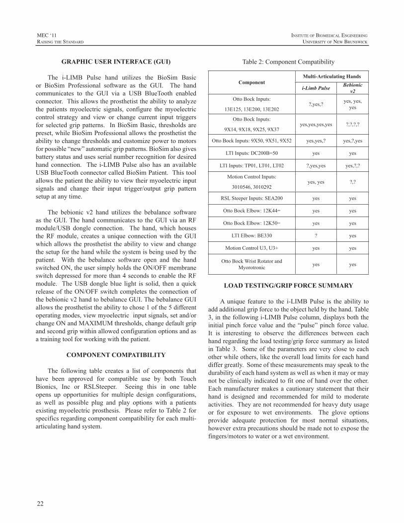
22
MEC ‘11raIsIng the standard
InsItute of BIomedIcal engIneerIng
unIversIty of new BrunswIck
GRAPHIC USER INTERFACE (GUI)
The i-LIMB Pulse hand utilizes the BioSim Basicor BioSim Professional software as the GUI. The handcommunicates to the GUI via a USB BlueTooth enabledconnector.Thisallowstheprosthetisttheabilitytoanalyzethe patientsmyoelectric signals, configure themyoelectriccontrol strategy and view or change current input triggersforselectedgrippatterns. InBioSimBasic, thresholdsarepreset,whileBioSimProfessionalallowstheprosthetisttheabilitytochangethresholdsandcustomizepowertomotorsforpossible“new”automaticgrippatterns.BioSimalsogivesbatterystatusandusesserialnumberrecognitionfordesiredhand connection. The i-LIMBPulse also has an availableUSBBlueToothconnectorcalledBioSimPatient.Thistoolallowsthepatienttheabilitytoviewtheirmyoelectricinputsignals and change their input trigger/output grip patternsetupatanytime.
The bebionic v2 hand utilizes the bebalance softwareas theGUI.Thehandcommunicates to theGUIviaanRFmodule/USB dongle connection. The hand,which housestheRFmodule, creates a unique connectionwith theGUIwhichallowstheprosthetist theability toviewandchangethesetupforthehandwhilethesystemisbeingusedbythepatient. With the bebalance software open and the handswitchedON,theusersimplyholdstheON/OFFmembraneswitchdepressedformorethan4secondstoenabletheRFmodule. TheUSBdongleblue light is solid, thenaquickreleaseof theON/OFFswitchcompletes theconnectionofthebebionicv2handtobebalanceGUI.ThebebalanceGUIallowstheprosthetisttheabilitytochose1ofthe5differentoperatingmodes,viewmyoelectricinputsignals,setand/orchangeONandMAXIMUMthresholds,changedefaultgripandsecondgripwithinallowedconfigurationoptionsandasatrainingtoolforworkingwiththepatient.
COMPONENT COMPATIBILITY
The following table creates a list of components thathave been approved for compatible use by both TouchBionics, Inc or RSLSteeper. Seeing this in one tableopens up opportunities for multiple design configurations,as well as possible plug and play options with a patientsexistingmyoelectricprosthesis. Pleaserefer toTable2forspecificsregardingcomponentcompatibilityforeachmulti-articulatinghandsystem.
Table2:ComponentCompatibility
ComponentMulti-Articulating Hands
i-Limb Pulse Bebionic v2
OttoBockInputs:
13E125,13E200,13E202?,yes,? yes,yes,
yes
OttoBockInputs:
9X14,9X18,9X25,9X37yes,yes,yes,yes ?,?,?,?
OttoBockInputs:9X50,9X51,9X52 yes,yes,? yes,?,yes
LTIInputs:DC200B=50 yes yes
LTIInputs:TP01,LT01,LT02 ?,yes,yes yes,?,?
MotionControlInputs:
3010546,3010292yes,yes ?,?
RSLSteeperInputs:SEA200 yes yes
OttoBockElbow:12K44= yes yes
OttoBockElbow:12K50= yes yes
LTIElbow:BE330 ? yes
MotionControlU3,U3+ yes yes
OttoBockWristRotatorandMyorotronic yes yes
LOAD TESTING/GRIP FORCE SUMMARY
Aunique feature to the i-LIMBPulse is the ability toaddadditionalgripforcetotheobjectheldbythehand.Table3,inthefollowingi-LIMBPulsecolumn,displaysboththeinitialpinchforcevalueand the“pulse”pinchforcevalue.It is interesting to observe the differences between eachhandregardingtheloadtesting/gripforcesummaryaslistedinTable3. Someof theparametersareveryclose toeachotherwhileothers,liketheoverallloadlimitsforeachhanddiffergreatly.Someofthesemeasurementsmayspeaktothedurabilityofeachhandsystemaswellaswhenitmayormaynotbeclinicallyindicatedtofitoneofhandovertheother.Eachmanufacturermakes a cautionary statement that theirhand is designed and recommended for mild to moderateactivities.Theyarenotrecommendedforheavydutyusageor for exposure to wet environments. The glove optionsprovide adequate protection for most normal situations,howeverextraprecautionsshouldbemadenottoexposethefingers/motorstowaterorawetenvironment.
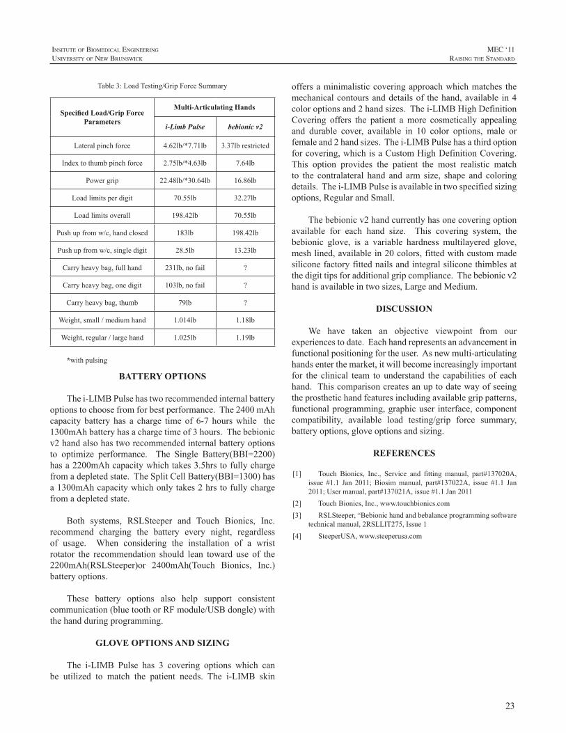
23
InsItute of BIomedIcal engIneerIng
unIversIty of new BrunswIck
MEC ‘11raIsIng the standard
Table3:LoadTesting/GripForceSummary
Specified Load/Grip Force Parameters
Multi-Articulating Hands
i-Limb Pulse bebionic v2
Lateralpinchforce 4.62lb/*7.71lb 3.37lbrestricted
Indextothumbpinchforce 2.75lb/*4.63lb 7.64lb
Powergrip 22.48lb/*30.64lb 16.86lb
Loadlimitsperdigit 70.55lb 32.27lb
Loadlimitsoverall 198.42lb 70.55lb
Pushupfromw/c,handclosed 183lb 198.42lb
Pushupfromw/c,singledigit 28.5lb 13.23lb
Carryheavybag,fullhand 231lb,nofail ?
Carryheavybag,onedigit 103lb,nofail ?
Carryheavybag,thumb 79lb ?
Weight,small/mediumhand 1.014lb 1.18lb
Weight,regular/largehand 1.025lb 1.19lb
*withpulsing
BATTERY OPTIONS
Thei-LIMBPulsehastworecommendedinternalbatteryoptionstochoosefromforbestperformance.The2400mAhcapacity battery has a charge timeof 6-7 hourswhile the1300mAhbatteryhasachargetimeof3hours.Thebebionicv2handalsohastworecommendedinternalbatteryoptionsto optimize performance. The Single Battery(BBI=2200)hasa2200mAhcapacitywhichtakes3.5hrstofullychargefromadepletedstate.TheSplitCellBattery(BBI=1300)hasa1300mAhcapacitywhichonlytakes2hrstofullychargefromadepletedstate.
Both systems, RSLSteeper and Touch Bionics, Inc.recommend charging the battery every night, regardlessof usage. When considering the installation of a wristrotator the recommendation should lean toward use of the2200mAh(RSLSteeper)or 2400mAh(Touch Bionics, Inc.)batteryoptions.
These battery options also help support consistentcommunication(bluetoothorRFmodule/USBdongle)withthehandduringprogramming.
GLOVE OPTIONS AND SIZING
The i-LIMB Pulse has 3 covering options which canbe utilized to match the patient needs. The i-LIMB skin
offersaminimalisticcoveringapproachwhichmatches themechanicalcontoursanddetailsof thehand,available in4coloroptionsand2handsizes.Thei-LIMBHighDefinitionCovering offers the patient amore cosmetically appealingand durable cover, available in 10 color options, male orfemaleand2handsizes.Thei-LIMBPulsehasathirdoptionforcovering,whichisaCustomHighDefinitionCovering.This option provides the patient the most realistic matchto the contralateral hand and arm size, shape and coloringdetails.Thei-LIMBPulseisavailableintwospecifiedsizingoptions,RegularandSmall.
Thebebionicv2handcurrentlyhasonecoveringoptionavailable for each hand size. This covering system, thebebionic glove, is a variable hardness multilayered glove,meshlined,availablein20colors,fittedwithcustommadesiliconefactoryfittednailsandintegralsiliconethimblesatthedigittipsforadditionalgripcompliance.Thebebionicv2handisavailableintwosizes,LargeandMedium.
DISCUSSION
We have taken an objective viewpoint from ourexperiencestodate.Eachhandrepresentsanadvancementinfunctionalpositioningfortheuser.Asnewmulti-articulatinghandsenterthemarket,itwillbecomeincreasinglyimportantfor the clinical team to understand the capabilities of eachhand.Thiscomparisoncreatesanuptodatewayofseeingtheprosthetichandfeaturesincludingavailablegrippatterns,functionalprogramming,graphicuser interface,componentcompatibility, available load testing/grip force summary,batteryoptions,gloveoptionsandsizing.
REFERENCES
[1] Touch Bionics, Inc., Service and fitting manual, part#137020A,issue #1.1 Jan 2011; Biosimmanual, part#137022A, issue #1.1 Jan2011;Usermanual,part#137021A,issue#1.1Jan2011
[2] TouchBionics,Inc.,www.touchbionics.com[3] RSLSteeper,“Bebionichandandbebalanceprogrammingsoftware
technicalmanual,2RSLLIT275,Issue1[4] SteeperUSA,www.steeperusa.com
24
MEC ‘11raIsIng the standard
InsItute of BIomedIcal engIneerIng
unIversIty of new BrunswIck
INTRODUCTION
Rejectionratesofbody-poweredhandsarehigherthanthat of hooks.1 Body powered hands are inefficient.As aresult they require an uncomfortable high activation force,andproducearelativelylowpinchforceinreturn(<15N).2Alsotheyhavestifffingers,whichdonotadapttotheshapeofthegraspedobject.Despiteallthedrawbacksofthecurrenthands, thedesignofbodypoweredhandprosthesesalmosthasnot changed since the1950’s.Theactivation forcehasnot been reduced. The pinch force is still low, and handprosthesesarestillquiteheavy.Therehavebeenattemptstoincreasetheefficiencyofbodypoweredhandprostheses,byusinghydraulics.3,4However,thesestudieshavenotresultedinthecommercialapplicationofhydraulicsinbodypoweredarmprostheses.
GOAL
Thegoalofthisstudywastodesignanewbody-powered,voluntary closing, hand prosthesis, which has articulatingfingers.Thishandshouldrequireanoperationforcewithinacomfortablelevelandshouldhavealowmass.
METHODS
An articulating voluntary closing hand was designedandprototyped.Beforethehandwasdesigned,anumberofdemandsandboundaryconditionsweredefined.
HydraulicsThe principle of hydraulics was used, to transfer the
energy of the bodymovements to the fingers of the handprosthesis.Usinghydraulicofferssomepotentialbenefits.Inthefirstplace,usinghydraulicsmakesitpossibletoabandontheuseofanBowden-cable.Thiscansignificantlyimprovethe efficiency of the entire system.3 The Bowden-cabledissipatesasignificantamountofenergy,duetothefrictioninthecurvesofthecable.Thecurvatureofahydraulichosehasnosignificantinfluenceontheefficiencyofthesystem.Inthesecondplace,theuseofhydraulicsmakestheenergydistributionamongsttheindividualjointsandfingerseasierandmoreefficient.
The hydraulic actuators should fit inside a finger, toenable actuation of the Proximal Interphalangeal (PIP)-joint.Anactuatorshouldweighless than10grams, tostaywithintheoverallmasslimitoftheentirehand.Theactuatorsshouldbeabletooperateapressurelevelof50bar,toenableahighmaximumpinchforce.Currentlytherearenostandardhydraulic components available, which meet such strictrequirements. Therefore miniature lightweight cylindersweredesigned,forthehydraulichandprototype.Waterwillbeusedasahydraulicmedium,insteadofhydraulicoil, toreducethenegativeeffectsincaseofasmallleakage.
Boundaryconditions- Itwasdecidedtodesignahandofwithasizeof7¾.
Thiscorrespondstoasmallsizeadultmalehand,oralargesizefemalehand.Onceaprototypehasbeenbuild,itcanbeslightlyexpandedorreducedtocreatealargerorasmallersize.
- Thehandprototypeshouldbesuitableforbodypoweredshouldercontrol.
- Theelementsofthehandshouldbemodular,toenableeasy replacement andupgradingof subsystemsof theprototype.
- ThreefingersshouldhaveatleasttwoactuatedDegreesof Freedom (DoF’s) each, the Metacarpophalangeal(MCP)-jointandthePIP-joint.Thelittlefingershouldhave at least one actuator and two actuated joints. Intotal the hand should have at least seven actuateddegreesoffreedom.
- ThethumbshouldhaveatleastonepassivecontrollableDoF.However,bymakinguseofmodularity,thethumbshouldbeeasilybereplaceablebyanactuatedthumb.
- ThewristshouldhaveatleasttwopassiveDoF’s.Onewhichenablesforpro-andsupination.Asecondwhichenablesforflexionandextensionofthehand.
Under-actuationThe multiple slave actuators in the hydraulic hand,
should all be controlled by onemaster cylinder.Thereforethe control will be done by using the principle of under-actuation. A system is by definition under-actuated when
DESIGN OF A HYDRAULIC HAND PROSTHESIS, WITH ARTICULATING FINGERS
GerwinSmit,DickH.Plettenburg
DelftInstituteofProstheticsandOrthotics,faculty3mE,BMechE,DelftUniversityofTechnology,Mekelweg2,2628CDDelft,TheNetherlands
[email protected];www.dipo.3me.tudelft.nl
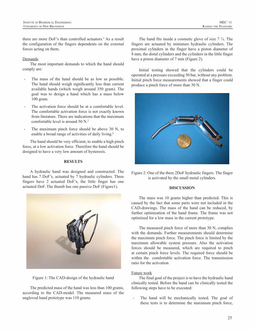
25
InsItute of BIomedIcal engIneerIng
unIversIty of new BrunswIck
MEC ‘11raIsIng the standard
therearemoreDoF’sthancontrolledactuators.5Asaresulttheconfigurationof the fingersdependentson theexternalforcesactingonthem.
DemandsThemostimportantdemandstowhichthehandshould
complyare:
- The mass of the hand should be as low as possible.Thehand shouldweigh significantly less thancurrentavailablehands (whichweigharound350gram).Thegoal was to design a hand which has a mass below100gram.
- Theactivationforceshouldbeatacomfortable level.Thecomfortableactivationforceisnotexactlyknownfromliterature.Thereareindicationsthatthemaximumcomfortablelevelisaround50N.2
- Themaximumpinch force should be above 30N, toenableabroadrangeofactivitiesofdailyliving.6
Thehandshouldbeveryefficient,toenableahighpinchforce,atalowactivationforce.Thereforethehandshouldbedesignedtohaveaverylowamountofhysteresis.
RESULTS
A hydraulic hand was designed and constructed. Thehandhas7DoF’s,actuatedby7hydrauliccylinders.Threefingers have 2 actuated DoF’s, the little finger has oneactuatedDoF.ThethumbhasonepassiveDoF(Figure1).
Figure1:TheCAD-designofthehydraulichand
Thepredictedmassofthehandwaslessthan100grams,according to the CAD-model. The measured mass of theunglovedhandprototypewas110grams.
Thehandfitsinsideacosmeticgloveofsize7¾.Thefingers are actuated byminiature hydraulic cylinders. Theproximal cylinders in the finger have a piston diameter of8mm,thedistalcylindersandthecylindersinthelittlefingerhaveapistondiameterof7mm(Figure2).
Initial testing showed that the cylinders could beoperatedatapressureexceeding50bar,withoutanyproblem.Initialpinchforcemeasurementsshowedthatafingercouldproduceapinchforceofmorethan30N.
Figure2:Oneofthethree2DoFhydraulicfingers.Thefingerisactivatedbythesmallmetalcylinders.
DISCUSSION
Themasswas10gramshigher thanpredicted.This iscausedbythefactthatsomepartswerenotincludedintheCAD-drawings. Themass of the hand can be reduced, byfurtheroptimisationof thehand frame.The framewasnotoptimisedforalowmassinthecurrentprototype.
Themeasuredpinchforceofmorethan30N,complieswith thedemands.Furthermeasurements shoulddeterminethemaximumpinchforce.Thepinchforceislimitedbythemaximum allowable system pressure. Also the activationforces should be measured, which are required to pinchat certain pinch force levels.The required force should bewithin the comfortable activation force. The transmissionratiofortheactivation
FutureworkThefinalgoaloftheprojectistohavethehydraulichand
clinicallytested.Beforethehandcanbeclinicallytestedthefollowingstepshavetobeexecuted:
- The hand will be mechanically tested. The goal ofthese tests is to determine themaximumpinch force,
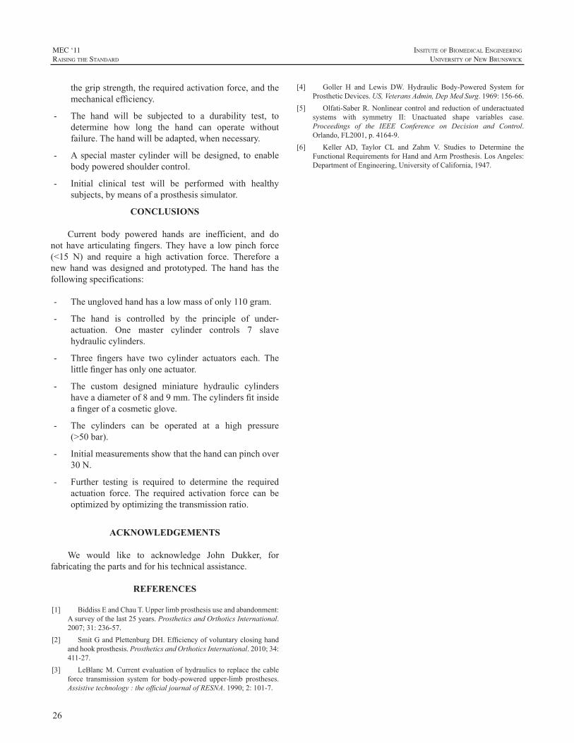
26
MEC ‘11raIsIng the standard
InsItute of BIomedIcal engIneerIng
unIversIty of new BrunswIck
thegripstrength,therequiredactivationforce,andthemechanicalefficiency.
- The hand will be subjected to a durability test, todetermine how long the hand can operate withoutfailure.Thehandwillbeadapted,whennecessary.
- A specialmaster cylinderwill be designed, to enablebodypoweredshouldercontrol.
- Initial clinical test will be performed with healthysubjects,bymeansofaprosthesissimulator.
CONCLUSIONS
Current body powered hands are inefficient, and donot have articulating fingers.Theyhave a lowpinch force(<15 N) and require a high activation force. Therefore anew handwas designed and prototyped.The hand has thefollowingspecifications:
- Theunglovedhandhasalowmassofonly110gram.
- The hand is controlled by the principle of under-actuation. One master cylinder controls 7 slavehydrauliccylinders.
- Three fingers have two cylinder actuators each. Thelittlefingerhasonlyoneactuator.
- The custom designed miniature hydraulic cylindershaveadiameterof8and9mm.Thecylindersfitinsideafingerofacosmeticglove.
- The cylinders can be operated at a high pressure(>50bar).
- Initialmeasurementsshowthatthehandcanpinchover30N.
- Further testing is required to determine the requiredactuation force. The required activation force can beoptimizedbyoptimizingthetransmissionratio.
ACKNOWLEDGEMENTS
We would like to acknowledge John Dukker, forfabricatingthepartsandforhistechnicalassistance.
REFERENCES
[1] BiddissEandChauT.Upperlimbprosthesisuseandabandonment:Asurveyofthelast25years.ProstheticsandOrthoticsInternational.2007;31:236-57.
[2] SmitGandPlettenburgDH.Efficiencyofvoluntaryclosinghandandhookprosthesis.ProstheticsandOrthoticsInternational.2010;34:411-27.
[3] LeBlancM.Currentevaluationofhydraulicstoreplacethecableforce transmission system for body-powered upper-limb prostheses.Assistivetechnology:theofficialjournalofRESNA.1990;2:101-7.
[4] Goller H and Lewis DW. Hydraulic Body-Powered System forProstheticDevices.US,VeteransAdmin,DepMedSurg.1969:156-66.
[5] Olfati-SaberR.Nonlinearcontrolandreductionofunderactuatedsystems with symmetry II: Unactuated shape variables case.Proceedings of the IEEE Conference on Decision and Control.Orlando,FL2001,p.4164-9.
[6] Keller AD, Taylor CL and Zahm V. Studies to Determine theFunctionalRequirementsforHandandArmProsthesis.LosAngeles:DepartmentofEngineering,UniversityofCalifornia,1947.
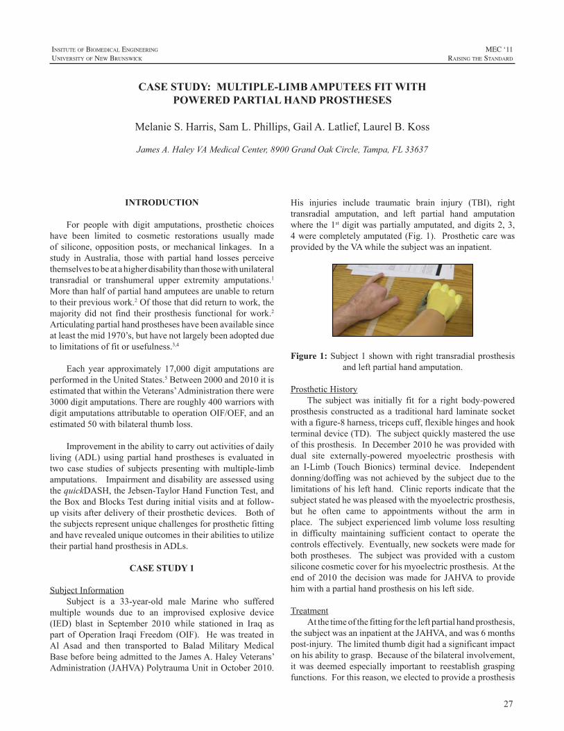
27
InsItute of BIomedIcal engIneerIng
unIversIty of new BrunswIck
MEC ‘11raIsIng the standard
INTRODUCTION
For people with digit amputations, prosthetic choiceshave been limited to cosmetic restorations usually madeof silicone, oppositionposts, ormechanical linkages. In astudy inAustralia, those with partial hand losses perceivethemselvestobeatahigherdisabilitythanthosewithunilateraltransradial or transhumeral upper extremity amputations.1Morethanhalfofpartialhandamputeesareunabletoreturntotheirpreviouswork.2Ofthosethatdidreturntowork,themajority did not find their prosthesis functional forwork.2Articulatingpartialhandprostheseshavebeenavailablesinceatleastthemid1970’s,buthavenotlargelybeenadoptedduetolimitationsoffitorusefulness.3,4
Each year approximately 17,000 digit amputations areperformedintheUnitedStates.5Between2000and2010itisestimatedthatwithintheVeterans’Administrationtherewere3000digitamputations.Thereareroughly400warriorswithdigitamputationsattributabletooperationOIF/OEF,andanestimated50withbilateralthumbloss.
Improvementintheabilitytocarryoutactivitiesofdailyliving (ADL) using partial hand prostheses is evaluated intwo case studies of subjects presentingwithmultiple-limbamputations.ImpairmentanddisabilityareassessedusingthequickDASH,theJebsen-TaylorHandFunctionTest,andtheBoxandBlocksTestduringinitialvisitsandatfollow-upvisitsafterdeliveryoftheirprostheticdevices.BothofthesubjectsrepresentuniquechallengesforprostheticfittingandhaverevealeduniqueoutcomesintheirabilitiestoutilizetheirpartialhandprosthesisinADLs.
CASE STUDY 1
SubjectInformationSubject is a 33-year-old male Marine who suffered
multiple wounds due to an improvised explosive device(IED) blast in September 2010 while stationed in Iraq aspart ofOperation IraqiFreedom (OIF). Hewas treated inAl Asad and then transported to Balad Military MedicalBasebeforebeingadmittedtotheJamesA.HaleyVeterans’Administration(JAHVA)PolytraumaUnitinOctober2010.
His injuries include traumatic brain injury (TBI), righttransradial amputation, and left partial hand amputationwhere the1stdigitwaspartiallyamputated,anddigits2,3,4werecompletelyamputated(Fig.1). ProstheticcarewasprovidedbytheVAwhilethesubjectwasaninpatient.
Figure 1:Subject1shownwithrighttransradialprosthesis
andleftpartialhandamputation.
ProstheticHistoryThe subject was initially fit for a right body-powered
prosthesisconstructedasa traditionalhard laminate socketwithafigure-8harness,tricepscuff,flexiblehingesandhookterminaldevice(TD).Thesubjectquicklymasteredtheuseofthisprosthesis.InDecember2010hewasprovidedwithdual site externally-powered myoelectric prosthesis withan I-Limb (Touch Bionics) terminal device. Independentdonning/doffingwasnotachievedbythesubjectduetothelimitationsofhis lefthand. Clinicreports indicatethat thesubjectstatedhewaspleasedwiththemyoelectricprosthesis,but he often came to appointments without the arm inplace. Thesubjectexperienced limbvolume loss resultingin difficulty maintaining sufficient contact to operate thecontrolseffectively.Eventually,newsocketsweremadeforboth prostheses. The subjectwas providedwith a customsiliconecosmeticcoverforhismyoelectricprosthesis.Attheendof2010 thedecisionwasmade for JAHVA toprovidehimwithapartialhandprosthesisonhisleftside.
TreatmentAtthetimeofthefittingfortheleftpartialhandprosthesis,
thesubjectwasaninpatientattheJAHVA,andwas6monthspost-injury.Thelimitedthumbdigithadasignificantimpactonhisabilitytograsp.Becauseofthebilateralinvolvement,itwas deemed especially important to reestablish graspingfunctions.Forthisreason,weelectedtoprovideaprosthesis
CASE STUDY: MULTIPLE-LIMB AMPUTEES FIT WITH POWERED PARTIAL HAND PROSTHESES
MelanieS.Harris,SamL.Phillips,GailA.Latlief,LaurelB.Koss
JamesA.HaleyVAMedicalCenter,8900GrandOakCircle,Tampa,FL33637
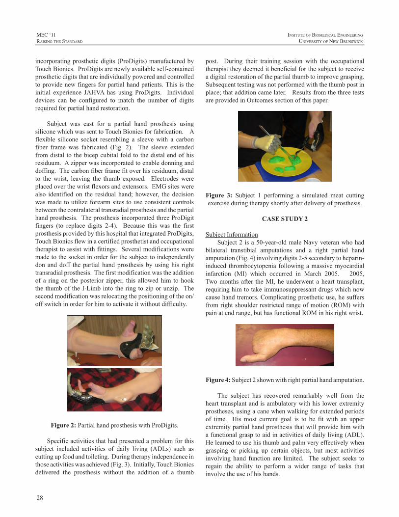
28
MEC ‘11raIsIng the standard
InsItute of BIomedIcal engIneerIng
unIversIty of new BrunswIck
incorporatingprostheticdigits (ProDigits)manufacturedbyTouchBionics.ProDigitsarenewlyavailableself-containedprostheticdigitsthatareindividuallypoweredandcontrolledtoprovidenewfingersforpartialhandpatients. Thisistheinitial experience JAHVA has using ProDigits. Individualdevices can be configured to match the number of digitsrequiredforpartialhandrestoration.
Subject was cast for a partial hand prosthesis usingsiliconewhichwassenttoTouchBionicsforfabrication.Aflexible silicone socket resembling a sleevewith a carbonfiber frame was fabricated (Fig. 2). The sleeve extendedfromdistal to thebicepcubitalfoldtothedistalendofhisresiduum.Azipperwasincorporatedtoenabledonninganddoffing.Thecarbonfiberframefitoverhisresiduum,distalto thewrist, leaving the thumb exposed. Electrodeswereplacedoverthewristflexorsandextensors.EMGsiteswerealso identified on the residual hand; however, the decisionwasmadetoutilizeforearmsitestouseconsistentcontrolsbetweenthecontralateraltransradialprosthesisandthepartialhandprosthesis.TheprosthesisincorporatedthreeProDigitfingers (to replace digits 2-4). Because this was the firstprosthesisprovidedbythishospitalthatintegratedProDigits,TouchBionicsflewinacertifiedprosthetistandoccupationaltherapisttoassistwithfittings.Severalmodificationsweremadetothesocketinorderforthesubjecttoindependentlydon anddoff the partial handprosthesis byusinghis righttransradialprosthesis.Thefirstmodificationwastheadditionofa ringon theposteriorzipper, thisallowedhim tohookthethumboftheI-Limbintotheringtoziporunzip. Thesecondmodificationwasrelocatingthepositioningoftheon/offswitchinorderforhimtoactivateitwithoutdifficulty.
Figure 2:PartialhandprosthesiswithProDigits.
Specificactivitiesthathadpresentedaproblemforthissubject included activities of daily living (ADLs) such ascuttingupfoodandtoileting.Duringtherapyindependenceinthoseactivitieswasachieved(Fig.3).Initially,TouchBionicsdelivered the prosthesis without the addition of a thumb
post. During their training session with the occupationaltherapisttheydeemeditbeneficialforthesubjecttoreceiveadigitalrestorationofthepartialthumbtoimprovegrasping.Subsequenttestingwasnotperformedwiththethumbpostinplace;thatadditioncamelater.ResultsfromthethreetestsareprovidedinOutcomessectionofthispaper.
Figure 3: Subject 1 performing a simulated meat cuttingexerciseduringtherapyshortlyafterdeliveryofprosthesis.
CASE STUDY 2
SubjectInformationSubject2isa50-year-oldmaleNavyveteranwhohad
bilateral transtibial amputations and a right partial handamputation(Fig.4)involvingdigits2-5secondarytoheparin-induced thrombocytopenia followingamassivemyocardialinfarction (MI) which occurred in March 2005. 2005,Twomonthsafter theMI,heunderwentaheart transplant,requiringhimtotakeimmunosuppressantdrugswhichnowcausehandtremors.Complicatingprostheticuse,hesuffersfromrightshoulderrestrictedrangeofmotion(ROM)withpainatendrange,buthasfunctionalROMinhisrightwrist.
Figure 4:Subject2shownwithrightpartialhandamputation.
The subject has recovered remarkably well from thehearttransplantandisambulatorywithhislowerextremityprostheses,usingacanewhenwalkingforextendedperiodsof time. Hismost current goal is to be fit with an upperextremitypartialhandprosthesisthatwillprovidehimwithafunctionalgrasptoaidinactivitiesofdailyliving(ADL).Helearnedtousehisthumbandpalmveryeffectivelywhengrasping or picking up certain objects, but most activitiesinvolving hand function are limited. The subject seeks toregain the ability to perform a wider range of tasks thatinvolvetheuseofhishands.
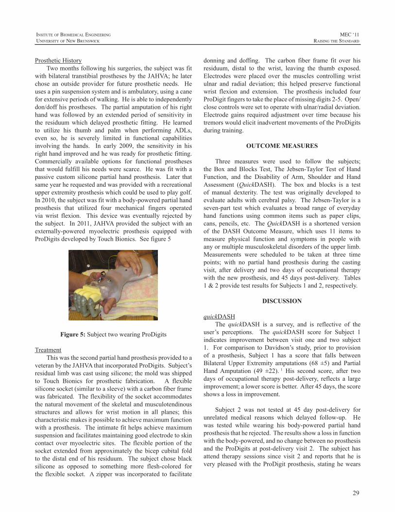
29
InsItute of BIomedIcal engIneerIng
unIversIty of new BrunswIck
MEC ‘11raIsIng the standard
ProstheticHistoryTwomonthsfollowinghissurgeries,thesubjectwasfit
withbilateral transtibialprosthesesbytheJAHVA;helaterchose an outside provider for future prosthetic needs. Heusesapinsuspensionsystemandisambulatory,usingacaneforextensiveperiodsofwalking.Heisabletoindependentlydon/doffhisprostheses.Thepartialamputationofhisrighthandwas followedby an extended period of sensitivity inthe residuumwhich delayed prosthetic fitting. He learnedto utilize his thumb and palm when performing ADLs,even so, he is severely limited in functional capabilitiesinvolving the hands. In early 2009, the sensitivity in hisrighthandimprovedandhewasreadyforprostheticfitting.Commercially available options for functional prosthesesthatwouldfulfillhisneedswerescarce. Hewasfitwithapassive custom siliconepartial handprosthesis. Later thatsameyearherequestedandwasprovidedwitharecreationalupperextremityprosthesiswhichcouldbeusedtoplaygolf.In2010,thesubjectwasfitwithabody-poweredpartialhandprosthesis that utilized four mechanical fingers operatedvia wrist flexion. This device was eventually rejected bythesubject. In2011,JAHVAprovided thesubjectwithanexternally-powered myoelectric prosthesis equipped withProDigitsdevelopedbyTouchBionics.Seefigure5
Figure 5: SubjecttwowearingProDigits
TreatmentThiswasthesecondpartialhandprosthesisprovidedtoa
veteranbytheJAHVAthatincorporatedProDigits.Subject’sresiduallimbwascastusingsilicone;themoldwasshippedto Touch Bionics for prosthetic fabrication. A flexiblesiliconesocket(similartoasleeve)withacarbonfiberframewasfabricated.Theflexibilityofthesocketaccommodatesthenaturalmovementoftheskeletalandmusculotendinousstructures and allows for wrist motion in all planes; thischaracteristicmakesitpossibletoachievemaximumfunctionwithaprosthesis. Theintimatefithelpsachievemaximumsuspensionandfacilitatesmaintaininggoodelectrodetoskincontact overmyoelectric sites. The flexibleportionof thesocket extended from approximately the bicep cubital foldto thedistalendofhis residuum. Thesubjectchoseblacksilicone as opposed to something more flesh-colored forthe flexible socket. Azipperwas incorporated to facilitate
donning and doffing. The carbon fiber frame fit over hisresiduum, distal to the wrist, leaving the thumb exposed.Electrodes were placed over themuscles controlling wristulnar and radial deviation; this helped preserve functionalwrist flexion and extension. The prosthesis included fourProDigitfingerstotaketheplaceofmissingdigits2-5.Open/closecontrolsweresettooperatewithulnar/radialdeviation.Electrode gains required adjustment over time because histremorswouldelicitinadvertentmovementsoftheProDigitsduringtraining.
OUTCOME MEASURES
Three measures were used to follow the subjects;theBox andBlocksTest,The Jebsen-TaylorTest ofHandFunction, and the Disability of Arm, Shoulder and HandAssessment (QuickDASH). The box and blocks is a testof manual dexterity. The test was originally developed toevaluateadultswithcerebralpalsy. TheJebsen-Taylorisaseven-part testwhich evaluates a broad range of everydayhand functions using common items such as paper clips,cans,pencils,etc. TheQuickDASHisashortenedversionof the DASH Outcome Measure, which uses 11 items tomeasure physical function and symptoms in people withanyormultiplemusculoskeletaldisordersoftheupperlimb.Measurements were scheduled to be taken at three timepoints; with no partial hand prosthesis during the castingvisit, after delivery and two days of occupational therapywiththenewprosthesis,and45dayspost-delivery. Tables1&2providetestresultsforSubjects1and2,respectively.
DISCUSSION
quickDASHThe quickDASH is a survey, and is reflective of the
user’s perceptions. The quickDASH score for Subject 1indicates improvement between visit one and two subject1. For comparison toDavidson’s study, prior to provisionof a prosthesis, Subject 1 has a score that falls betweenBilateralUpperExtremity amputations (68 ±5) andPartialHandAmputation (49 ±22). 1 His second score, after twodays of occupational therapy post-delivery, reflects a largeimprovement;alowerscoreisbetter.After45days,thescoreshowsalossinimprovement.
Subject 2 was not tested at 45 day post-delivery forunrelated medical reasons which delayed follow-up. Hewas tested while wearing his body-powered partial handprosthesisthatherejected.Theresultsshowalossinfunctionwiththebody-powered,andnochangebetweennoprosthesisand theProDigits atpost-deliveryvisit2. The subjecthasattend therapy sessions since visit 2 and reports that he isverypleasedwith theProDigitprosthesis, statinghewears
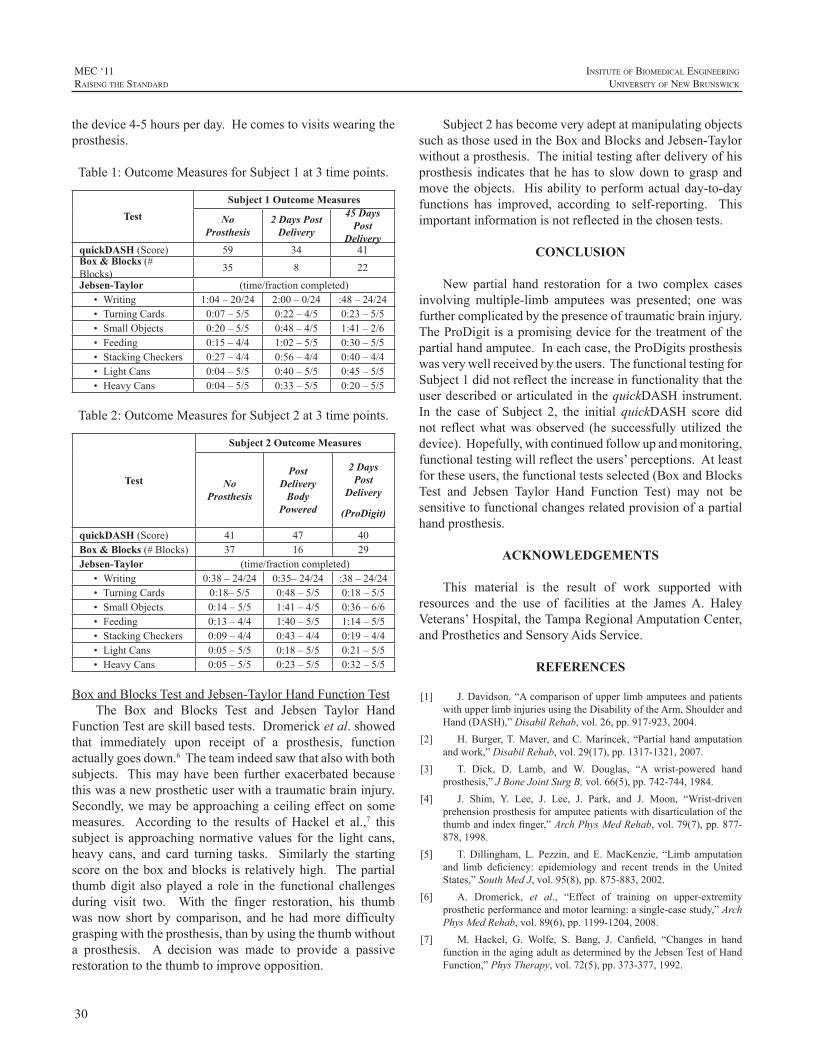
30
MEC ‘11raIsIng the standard
InsItute of BIomedIcal engIneerIng
unIversIty of new BrunswIck
thedevice4-5hoursperday.Hecomestovisitswearingtheprosthesis.
Table1:OutcomeMeasuresforSubject1at3timepoints.
TestSubject 1 Outcome Measures
No Prosthesis
2 Days Post Delivery
45 Days Post
DeliveryquickDASH(Score) 59 34 41Box & Blocks(#Blocks) 35 8 22
Jebsen-Taylor (time/fractioncompleted)• Writing 1:04–20/24 2:00–0/24 :48–24/24• TurningCards 0:07–5/5 0:22–4/5 0:23–5/5• SmallObjects 0:20–5/5 0:48–4/5 1:41–2/6• Feeding 0:15–4/4 1:02–5/5 0:30–5/5• StackingCheckers 0:27–4/4 0:56–4/4 0:40–4/4• LightCans 0:04–5/5 0:40–5/5 0:45–5/5• HeavyCans 0:04–5/5 0:33–5/5 0:20–5/5
Table2:OutcomeMeasuresforSubject2at3timepoints.
Test
Subject 2 Outcome Measures
No Prosthesis
Post Delivery
Body Powered
2 Days Post
Delivery
(ProDigit)
quickDASH(Score) 41 47 40Box & Blocks(#Blocks) 37 16 29Jebsen-Taylor (time/fractioncompleted)
• Writing 0:38–24/24 0:35–24/24 :38–24/24• TurningCards 0:18–5/5 0:48–5/5 0:18–5/5• SmallObjects 0:14–5/5 1:41–4/5 0:36–6/6• Feeding 0:13–4/4 1:40–5/5 1:14–5/5• StackingCheckers 0:09–4/4 0:43–4/4 0:19–4/4• LightCans 0:05–5/5 0:18–5/5 0:21–5/5• HeavyCans 0:05–5/5 0:23–5/5 0:32–5/5
BoxandBlocksTestandJebsen-TaylorHandFunctionTestThe Box and Blocks Test and Jebsen Taylor Hand
FunctionTestareskillbasedtests.Dromericketal.showedthat immediately upon receipt of a prosthesis, functionactuallygoesdown.6Theteamindeedsawthatalsowithbothsubjects. Thismayhavebeen further exacerbatedbecausethiswasanewprostheticuserwithatraumaticbraininjury.Secondly,wemaybeapproachingaceilingeffectonsomemeasures. According to the results of Hackel et al.,7 thissubject is approachingnormativevalues for the light cans,heavy cans, and card turning tasks. Similarly the startingscoreon theboxandblocks is relativelyhigh. Thepartialthumbdigit alsoplayed a role in the functional challengesduring visit two. With the finger restoration, his thumbwas now short by comparison, and he hadmore difficultygraspingwiththeprosthesis,thanbyusingthethumbwithouta prosthesis. A decision was made to provide a passiverestorationtothethumbtoimproveopposition.
Subject2hasbecomeveryadeptatmanipulatingobjectssuchasthoseusedintheBoxandBlocksandJebsen-Taylorwithoutaprosthesis.Theinitialtestingafterdeliveryofhisprosthesis indicates thathehas to slowdown tograspandmovetheobjects. Hisability toperformactualday-to-dayfunctions has improved, according to self-reporting. Thisimportantinformationisnotreflectedinthechosentests.
CONCLUSION
New partial hand restoration for a two complex casesinvolving multiple-limb amputees was presented; one wasfurthercomplicatedbythepresenceoftraumaticbraininjury.TheProDigitisapromisingdeviceforthetreatmentofthepartialhandamputee.Ineachcase,theProDigitsprosthesiswasverywellreceivedbytheusers.ThefunctionaltestingforSubject1didnotreflecttheincreaseinfunctionalitythattheuserdescribedorarticulatedinthequickDASHinstrument.In the case of Subject 2, the initial quickDASH score didnot reflectwhatwasobserved (he successfullyutilized thedevice).Hopefully,withcontinuedfollowupandmonitoring,functionaltestingwillreflecttheusers’perceptions.Atleastfortheseusers,thefunctionaltestsselected(BoxandBlocksTest and Jebsen Taylor Hand Function Test) may not besensitivetofunctionalchangesrelatedprovisionofapartialhandprosthesis.
ACKNOWLEDGEMENTS
This material is the result of work supported withresources and the use of facilities at the JamesA. HaleyVeterans’Hospital,theTampaRegionalAmputationCenter,andProstheticsandSensoryAidsService.
REFERENCES
[1] J.Davidson.“AcomparisonofupperlimbamputeesandpatientswithupperlimbinjuriesusingtheDisabilityoftheArm,ShoulderandHand(DASH),”DisabilRehab,vol.26,pp.917-923,2004.
[2] H.Burger,T.Maver, andC.Marincek, “Partialhandamputationandwork,”DisabilRehab,vol.29(17),pp.1317-1321,2007.
[3] T. Dick, D. Lamb, and W. Douglas, “A wrist-powered handprosthesis,”JBoneJointSurgB,vol.66(5),pp.742-744,1984.
[4] J. Shim, Y. Lee, J. Lee, J. Park, and J. Moon, “Wrist-drivenprehensionprosthesisforamputeepatientswithdisarticulationofthethumbandindexfinger,”ArchPhysMedRehab,vol.79(7),pp.877-878,1998.
[5] T.Dillingham,L. Pezzin, andE.MacKenzie, “Limb amputationand limb deficiency: epidemiology and recent trends in the UnitedStates,”SouthMedJ,vol.95(8),pp.875-883,2002.
[6] A. Dromerick, et al., “Effect of training on upper-extremityprostheticperformanceandmotorlearning:asingle-casestudy,”ArchPhysMedRehab,vol.89(6),pp.1199-1204,2008.
[7] M. Hackel, G. Wolfe, S. Bang, J. Canfield, “Changes in handfunctionintheagingadultasdeterminedbytheJebsenTestofHandFunction,”PhysTherapy,vol.72(5),pp.373-377,1992.
31
InsItute of BIomedIcal engIneerIng
unIversIty of new BrunswIck
MEC ‘11raIsIng the standard
ABSTRACT
Traditional interface designs have largely focused ontissuecontainmentoftheencapsulatedlimbandestablishingstabilityviaanatomicalcontouringintheareasoftheinterfaceclosest to the proximal joint of said limb. Firm control ofthe shaft of the underlying bone of the encapsulated limbhas either been wholly ignored or given only a cursoryexamination at best. Indeed, for many there still remainsa question whether or not the underlying bone can becontrolledatall.Limitedbiomechanicalknowledge,ageneralacceptance of Hydrostatic theory with regard to interfacedesign, a glaring absence in our quantification of windowedema and its relation to aperture design and location andtherelaxedpaceatwhichwehavebothdevelopedaninterestas well as the associated technology to assess the socketenvironment in a comprehensive fashionhaveall inhibitedrapid interface advancement.A new theory “Compression-ReleaseStabilization”(CRS)focusesprimarilyoncontroloftheunderlyingboneandformsthefoundationof theHigh-Fidelity Interface (HiFi) described herein. This paper willdiscussthetheoryaswellastheresultsofitsapplicationinbothupperandlowerlimbprostheticsandorthotics.
INTRODUCTION
Newton’s First law essentially states that an object atrestwillremainatrestunlessacteduponbysufficientforceto create a change in state.With regard to even the latestinterfacedesignsfromtheSymesleveltothehipandpartialhand to the shoulder, in nearly every case, the underlyingbone or bony structures translate significantly within theinterfacerelativetotheinterfacialboundaryduringvolitionalmovement and in response to externally applied loads.This unwantedmotion is predominantlydue to the lackofsufficientcounterforcegeneratedbythesofttissuebetweenthemovingboneandthesocketwall.Becausetheunderlyingboneistypicallyfixedatoneend,itswingsinsuchawayastocauseitsdistalendtostriketheinterfacewall,separatedby a very thin layer of highly compressed tissue. In thispaperIillustratetheinherentdesignweaknessoftraditionalsockets[1,2]andwhyadifferentmodelbasedonalternatingsoft tissuecompressionand releaseappliedalong the shaft
of theunderlyingboneorstrategicallyabout targetedbonystructuresoffersamoreefficientwaytogenerateprostheticmotion.Vastlyimprovedstability,enhancedfunctionalrangeofmotion, improved ability to handle (position and carry)or ambulatewith greater loadsmore comfortably, reducedenergy expenditure, increased gait speed and stride length,andaperceptionoftheprosthesisfeelingmorelikeapartofthewearerwereallachieved. Its intimateconnectionwiththelimboffersthewearerafeelingofagilityandprecisionthat,basedonthelawsofphysics,cannotbeequalledwithatraditionalapproach.Finally thepatient subjects reportedaperceptiontheirprosthesisweighedlessthantheirtraditionalsystem, even in instances where the prosthesis employingCompression-Release Stabilization weighed more than itstraditionalcounterpart.
The alternating soft tissue compression and releasetechniqueplaceslongitudinalcompressionareasalongnearlythe entire shaft of the bone or underlying bony structureswhile the release areas allow for soft tissue, includingskeletalmuscle, toescapeoutofthefieldsofcompression.Inmanycases,primarilyinupperlimb,thisoutwardflowoftissueiscompletelyunrestrictedtoallowforincreasedheatdissipationbutalsotoreducetheoverallvolumeoftissuethatlieswithin the field of compression.With correct aperturedesigntocontrolavarietyofcriticalvariablesincludingthevolumeofreleasedtissue,therateof“step-off”fromelevatedcompressiontozerocompression,exitingskintension,fluidand venous return, as well as the strategic location of therelease areas themselves,window edema is not a concern.Likewise, correctly applied compression to facilitate bonecaptureandcontrol,ifdesignedanddeployedwithprecisionregarding shape, location, extent and compression level,bloodperfusionisalsonotaconcern.
Because less tissue remains between the compressedarea and the shaft of the bone, additional compression-and therefore skeletal control-is gained. In essence, by“precompressing”theoverlyingsofttissuepriortovolitionalmovementorappliedexternalforce,itsdensityissignificantlyincreased.Subsequently,as thecompressed tissue’sdensityincreases, so toodoes itsability-when trappedbetween the
THE HIGH-FIDELITY INTERFACE: SKELETAL STABILIZATION THROUGH ALTERNATING SOFT TISSUE COMPRESSION AND RELEASE
RandallAlley,BSc,CP,LP,FAAOPceo,
biodesigns,inc.ThousandOaks,Ca.,91360
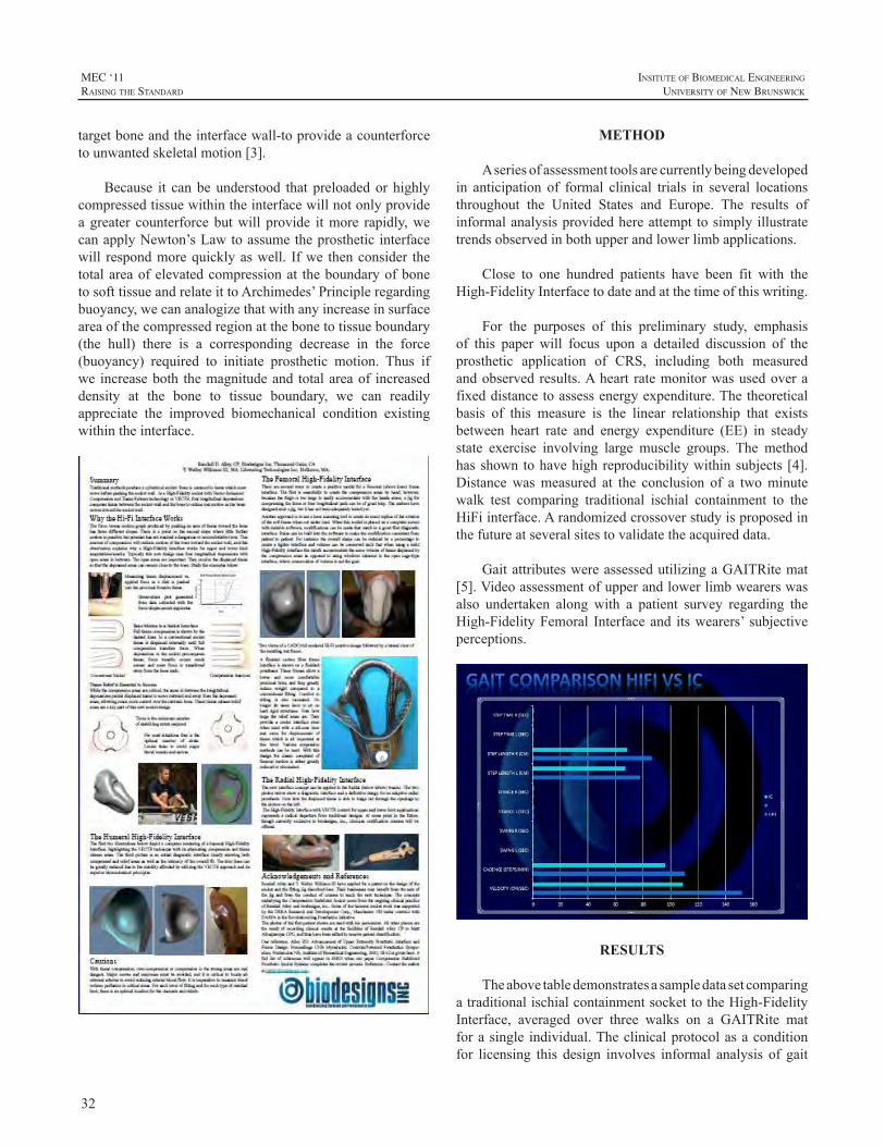
32
MEC ‘11raIsIng the standard
InsItute of BIomedIcal engIneerIng
unIversIty of new BrunswIck
targetboneandtheinterfacewall-toprovideacounterforcetounwantedskeletalmotion[3].
Because it canbeunderstood that preloadedor highlycompressedtissuewithintheinterfacewillnotonlyprovideagreater counterforcebutwill provide itmore rapidly,wecanapplyNewton’sLawtoassumetheprostheticinterfacewill respondmorequicklyaswell. Ifwe thenconsider thetotalareaofelevatedcompressionat theboundaryofbonetosofttissueandrelateittoArchimedes’Principleregardingbuoyancy,wecananalogizethatwithanyincreaseinsurfaceareaofthecompressedregionatthebonetotissueboundary(the hull) there is a corresponding decrease in the force(buoyancy) required to initiate prosthetic motion. Thus ifwe increaseboth themagnitudeand totalareaof increaseddensity at the bone to tissue boundary, we can readilyappreciate the improved biomechanical condition existingwithintheinterface.
METHOD
Aseriesofassessmenttoolsarecurrentlybeingdevelopedin anticipation of formal clinical trials in several locationsthroughout the United States and Europe. The results ofinformalanalysisprovidedhereattempttosimplyillustratetrendsobservedinbothupperandlowerlimbapplications.
Close to one hundred patients have been fit with theHigh-FidelityInterfacetodateandatthetimeofthiswriting.
For the purposes of this preliminary study, emphasisof this paper will focus upon a detailed discussion of theprosthetic application of CRS, including both measuredandobservedresults.Aheart ratemonitorwasusedoverafixeddistancetoassessenergyexpenditure.Thetheoreticalbasis of this measure is the linear relationship that existsbetween heart rate and energy expenditure (EE) in steadystate exercise involving large muscle groups. The methodhasshowntohavehighreproducibilitywithinsubjects [4].Distancewasmeasured at the conclusion of a twominutewalk test comparing traditional ischial containment to theHiFiinterface.Arandomizedcrossoverstudyisproposedinthefutureatseveralsitestovalidatetheacquireddata.
GaitattributeswereassessedutilizingaGAITRitemat[5].Videoassessmentofupperandlowerlimbwearerswasalso undertaken along with a patient survey regarding theHigh-FidelityFemoral Interfaceand itswearers’ subjectiveperceptions.
RESULTS
TheabovetabledemonstratesasampledatasetcomparingatraditionalischialcontainmentsockettotheHigh-FidelityInterface, averaged over three walks on a GAITRite matforasingle individual.Theclinicalprotocolasaconditionfor licensing this design involves informal analysis of gait
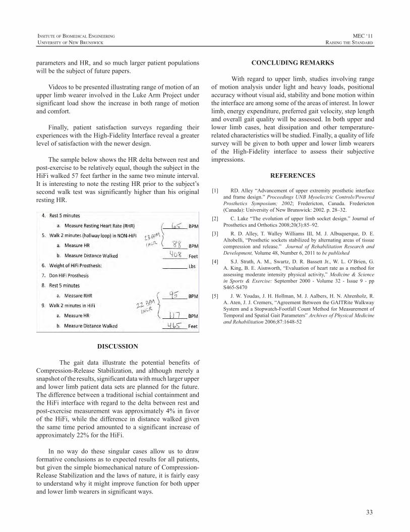
33
InsItute of BIomedIcal engIneerIng
unIversIty of new BrunswIck
MEC ‘11raIsIng the standard
parametersandHR,andsomuchlargerpatientpopulationswillbethesubjectoffuturepapers.
VideostobepresentedillustratingrangeofmotionofanupperlimbwearerinvolvedintheLukeArmProjectundersignificant load show the increase inboth rangeofmotionandcomfort.
Finally, patient satisfaction surveys regarding theirexperienceswiththeHigh-FidelityInterfacerevealagreaterlevelofsatisfactionwiththenewerdesign.
ThesamplebelowshowstheHRdeltabetweenrestandpost-exercisetoberelativelyequal,thoughthesubjectintheHiFiwalked57feetfartherinthesametwominuteinterval.ItisinterestingtonotetherestingHRpriortothesubject’ssecondwalk testwas significantly higher than his originalrestingHR.
DISCUSSION
The gait data illustrate the potential benefits ofCompression-Release Stabilization, and althoughmerely asnapshotoftheresults,significantdatawithmuchlargerupperandlower limbpatientdatasetsareplannedfor thefuture.ThedifferencebetweenatraditionalischialcontainmentandtheHiFiinterfacewithregardtothedeltabetweenrestandpost-exercisemeasurementwasapproximately4%in favorof theHiFi,while the difference in distancewalked giventhesame timeperiodamounted toasignificant increaseofapproximately22%fortheHiFi.
In no way do these singular cases allow us to drawformativeconclusionsastoexpectedresultsforallpatients,butgiventhesimplebiomechanicalnatureofCompression-ReleaseStabilizationandthelawsofnature,itisfairlyeasytounderstandwhyitmightimprovefunctionforbothupperandlowerlimbwearersinsignificantways.
CONCLUDING REMARKS
With regard to upper limb, studies involving rangeofmotion analysis under light and heavy loads, positionalaccuracywithoutvisualaid,stabilityandbonemotionwithintheinterfaceareamongsomeoftheareasofinterest.Inlowerlimb,energyexpenditure,preferredgaitvelocity,steplengthandoverallgaitqualitywillbeassessed.Inbothupperandlower limb cases, heat dissipation and other temperature-relatedcharacteristicswillbestudied.Finally,aqualityoflifesurveywillbegiventobothupperandlower limbwearersof the High-Fidelity interface to assess their subjectiveimpressions.
REFERENCES
[1] RD.Alley “Advancementofupper extremityprosthetic interfaceandframedesign.”ProceedingsUNBMyoelectricControls/PoweredProsthetics Symposium; 2002; Fredericton, Canada. Fredericton(Canada):UniversityofNewBrunswick:2002.p.28–32.
[2] C.Lake“Theevolutionofupper limbsocketdesign.”JournalofProstheticsandOrthotics2008;20(3):85–92.
[3] R. D. Alley, T. Walley Williams III, M. J. Albuquerque, D. E.Altobelli,“Prostheticsocketsstabilizedbyalternatingareasoftissuecompression and release.” Journal of Rehabilitation Research andDevelopment,Volume48,Number6,2011tobepublished
[4] S.J. Strath,A.M., Swartz, D. R. Bassett Jr.,W. L. O’Brien, G.A.King,B.E.Aisnworth,“Evaluationofheart rateasamethodforassessingmoderate intensity physical activity,”Medicine& Sciencein Sports& Exercise: September 2000 -Volume 32 - Issue 9 - ppS465-S470
[5] J.W.Youdas,J.H.Hollman,M.J.Aalbers,H.N.Ahrenholz,R.A.Aten,J.J.Cremers,“AgreementBetweentheGAITRiteWalkwaySystemandaStopwatch-FootfallCountMethodforMeasurementofTemporalandSpatialGaitParameters”ArchivesofPhysicalMedicineandRehabilitation2006;87:1648-52
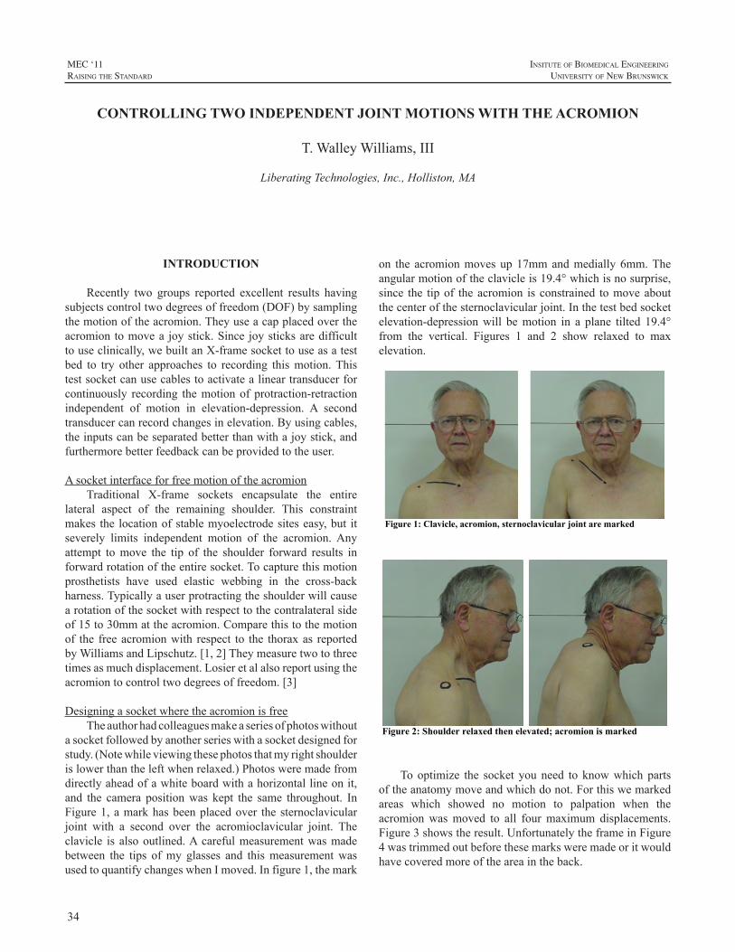
34
MEC ‘11raIsIng the standard
InsItute of BIomedIcal engIneerIng
unIversIty of new BrunswIck
INTRODUCTION
Recently two groups reported excellent results havingsubjectscontroltwodegreesoffreedom(DOF)bysamplingthemotionoftheacromion.Theyuseacapplacedovertheacromiontomovea joystick.Since joysticksaredifficulttouseclinically,webuiltanX-framesockettouseasatestbed to try other approaches to recording thismotion.Thistestsocketcanusecablestoactivatealineartransducerforcontinuously recording themotionof protraction-retractionindependent of motion in elevation-depression. A secondtransducercanrecordchangesinelevation.Byusingcables,theinputscanbeseparatedbetterthanwithajoystick,andfurthermorebetterfeedbackcanbeprovidedtotheuser.
AsocketinterfaceforfreemotionoftheacromionTraditional X-frame sockets encapsulate the entire
lateral aspect of the remaining shoulder. This constraintmakes the locationofstablemyoelectrodesiteseasy,but itseverely limits independent motion of the acromion.Anyattempt tomove the tip of the shoulder forward results inforwardrotationoftheentiresocket.Tocapturethismotionprosthetists have used elastic webbing in the cross-backharness.Typicallyauserprotractingtheshoulderwillcausearotationofthesocketwithrespecttothecontralateralsideof15to30mmattheacromion.Comparethistothemotionof the freeacromionwith respect to the thoraxas reportedbyWilliamsandLipschutz.[1,2]Theymeasuretwotothreetimesasmuchdisplacement.Losieretalalsoreportusingtheacromiontocontroltwodegreesoffreedom.[3]
DesigningasocketwheretheacromionisfreeTheauthorhadcolleaguesmakeaseriesofphotoswithout
asocketfollowedbyanotherserieswithasocketdesignedforstudy.(Notewhileviewingthesephotosthatmyrightshoulderislowerthantheleftwhenrelaxed.)Photosweremadefromdirectlyaheadofawhiteboardwithahorizontallineonit,and the camera positionwas kept the same throughout. InFigure1,amarkhasbeenplacedover thesternoclavicularjoint with a second over the acromioclavicular joint. Theclavicle is alsooutlined.Acarefulmeasurementwasmadebetween the tips ofmy glasses and thismeasurementwasusedtoquantifychangeswhenImoved.Infigure1,themark
on the acromionmovesup17mmandmedially6mm.Theangularmotionoftheclavicleis19.4°whichisnosurprise,since the tipof theacromion is constrained tomoveaboutthecenterofthesternoclavicularjoint.Inthetestbedsocketelevation-depressionwill bemotion in a plane tilted 19.4°from the vertical. Figures 1 and 2 show relaxed to maxelevation.
Figure 1: Clavicle, acromion, sternoclavicular joint are marked
Figure 2: Shoulder relaxed then elevated; acromion is marked
Tooptimize the socket youneed to knowwhich partsoftheanatomymoveandwhichdonot.Forthiswemarkedareas which showed no motion to palpation when theacromionwasmoved to all fourmaximum displacements.Figure3showstheresult.UnfortunatelytheframeinFigure4wastrimmedoutbeforethesemarksweremadeoritwouldhavecoveredmoreoftheareaintheback.
CONTROLLING TWO INDEPENDENT JOINT MOTIONS WITH THE ACROMION
T.WalleyWilliams,III
LiberatingTechnologies,Inc.,Holliston,MA
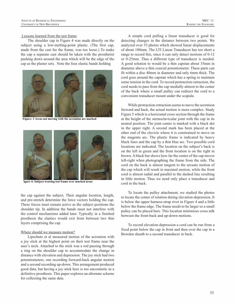
35
InsItute of BIomedIcal engIneerIng
unIversIty of new BrunswIck
MEC ‘11raIsIng the standard
LessonslearnedfromthetestframeTheshouldercapinFigure4wasmadedirectlyonthe
subject using a low-melting-point plastic. (The first cap,madefromthecastfor theframe,wastooloose.)Tomakethecapaseparatecastshouldbe takenwith theprosthetistpushingdownaroundtheareawhichwillbetheedgeofthecapastheplastersets.Notethefourelasticbandsholding
Figure: 3 Areas not moving with the acromion are marked
Figure 4: Subject wearing test frame over marked areas
the cap against the subject.Their angular location, length,andpre-stretchdeterminetheforcevectorsholdingthecap.Theseforcesmustremainactiveasthesubjectpositionstheshoulder tip. In addition the bandsmust not interferewiththecontrolmechanismsaddedlater.Typically inafinishedprosthesis the elastics would exit from between two thinlayerscomprisingthecap.
Whereshouldwemeasuremotion?Lipschutzetalmeasuredmotionof theacromionwith
a joystickat thehighestpointon their test framenear theuser’sneck.Attachedtothestickwasarodpassingthrougha ring on the shoulder cap to accommodate the change indistancewithelevationanddepression.Thejoystickhadtwopotentiometers,onerecordingforward-backangularmotionandasecondrecordingup-down.Thisarrangementproducedgooddata,buthavingajoystickhereistoouncosmeticinadefinitiveprosthesis.Thispaperexploresanalternateschemeforcollectingthesamedata.
A simple cord pulling a linear transducer is good fordetecting changes in the distance between two points.Weanalyzedover35photoswhichshowedlineardisplacementsofabout100mm.TheLTILinearTransducerhastooshortarangetorecordthis,sinceitcanonlydetectmotionsof0-12or 0-25mm.Thus a different type of transducer is needed.Agoodsolutiontowouldbeathincapstanabout35mmindiameteraboveathincoaxialpotentiometer.Thesepartscanfitwithinadisc40mmindiameterandonly6mmthick.Thecordgoesaroundthecapstanwhichhasaspringtomaintainsometensioninthecord.Torecordprotraction-retraction,thecordneedstopassfromthecapmediallyalmosttothecenterof thebackwhereasmallpulleycanredirect thecord toaconvenienttransducermountunderthescapula.
Whileprotraction-retractionseemstomovetheacromionforwardandback,theactualmotionismorecomplex.StudyFigure5whichisahorizontalcrosssectionthroughtheframeattheheightofthesternoclavicularjointwiththecapinitsneutralposition.Thejointcenterismarkedwithablackdotin the upper right.A second mark has been placed at theotherendoftheclaviclewhereitisconstrainedtomoveonthe magenta arc. The plastic frame is indicated by heavyblacklinesandthecapbyathinbluearc.Twopossiblecordlocationsareindicated.Thelocationonthesubject’sbackisontheleft ingreenandthefrontlocationisontherightinbrown.Ablackbarshowshowfarthecenterofthecapmovesleft-rightwhenphotographingtheframefromtheside.Thecordonthebackisalmosttangenttothearcuatemotionofthecapwhichwillresultinmaximalmotion,whilethefrontcordisalmostradialandparalleltothedashedlineresultingin littlemotion.Thusweneedonlyplacea transducerandcordintheback.
Tolocate thepulleyattachment,westudied thephotostolocatethecenterofrotationduringelevation-depression.Itisbelowtheupperharness-straprivetinFigure4andalittlebelowtheframeedge.Theframeneedstobelargersoasmallpulleycanbeplacedhere.Thislocationminimizescrosstalkbetweenthefront-backandup-downmotions.
Torecordelevation-depressionacordcanberunfromafixedpointbelowthecapinfrontandthenoverthecapinaBowdensheathtoasecondtransducerinback.
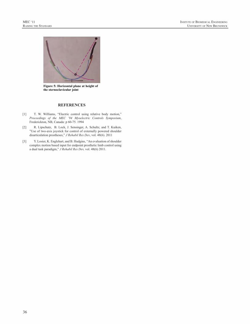
36
MEC ‘11raIsIng the standard
InsItute of BIomedIcal engIneerIng
unIversIty of new BrunswIck
Figure 5: Horizontal plane at height of the sternoclavicular joint
REFERENCES
[1] T. W. Williams, “Electric control using relative body motion,”Proceedings of the MEC ’94 Myoelectric Controls Symposium,Frederickton,NB,Canada:p60-75.1994
[2] R.Lipschutz, B.Lock, J.Sensinger,A.Schultz, andT.Kuiken,”Useoftwo-axisjoystickforcontrolofexternallypoweredshoulderdisarticulationprostheses,”JRehabilResDev,vol.48(6).2011
[3] Y.Losier,K.Englehart,andB.Hudgins,“Anevaluationofshouldercomplexmotionbasedinputforendpointprostheticlimbcontrolusingadualtaskparadigm,”JRehabilResDev,vol.48(6)2011.
37
InsItute of BIomedIcal engIneerIng
unIversIty of new BrunswIck
MEC ‘11raIsIng the standard
INTRODUCTION
Usingartificiallimbstorestorefunctionforamputeesisaconceptthatdatesbacktoapproximately700BC.Despitethis,attachingartificiallimbstothebodyremainsclinicallychallenging, with inadequate mechanical fixation, poorstump-socket fitting particularly to short residual limbs,frictionleadingtothedevelopmentofpressuresores,infectionofthestumpsofttissuesandsweatingoftenleadingtolimbdisuse[1-3].Eliminatingthesocket,bydirectlyattachingtheartificiallimbtotheresidualbonethroughosseointegrationtransmits forces through the bony skeleton alleviating theproblems associatedwith the socket. This technology alsohas the potential to increase the range of motion of theproximalresidualjointparticularlywithhumeralamputees,permitscomfortablesitting,andhasbeenshowntotransmitsensory signals to the bone; so called osseoperception.OsseointegrationtoattachtheexoprosthesiswasintroducedbyRickardBrånemark.InfectionwasthemaincomplicationinacohortoftransfemoralamputeesintheUnitedKingdombeing treated using osseointegrated amputation prostheses.Based on the osseointegration conceptwe have developedintraosseous transcutaneous amputation prostheses (ITAP)which attempts to overcome the problems associated withinfectionbyintegratingdermalandepidermaltissueswiththeimplant,creatingasofttissuesealaroundtheimplant[4-9].Thisarticleisasummaryoftheresearchanddevelopmentofanimplantwhichisabletosealtheskin-implantinterface.
DEER ANTLER STUDY
Theproblemsencounteredwithtranscutaneousdevicesare due to the natural processes associated with woundhealingwhereepithelialcellstrytomaintaincontinuitywithoneanother.Aroundatranscutaneousdevice,thisresultsinepithelialdowngrowth,creatingapocket,whichisfavorablefor bacterial proliferation and tissue infection. To gain anunderstandingof hownatural transcutaneous structures areviable without the problems of epithelial layer migrationandinfectionthatareobservedaroundartificialimplantsweanalysedtheskinboneinterfacearounddeerantlers[7].Theskinboneinterfacewasinvestigatedinover20pairsofantlersusing scanning electron microscopy (SEM) of macerated
specimens, transmission electron microscopy (TEM) andhardgraderesinhistology.Examinationdemonstratedacleardifference inmorphology of the bone surface between theantlerandthepediclebonebelowtheskinsurface,andSEMfurtherconfirmedthesefindings.Thesurfaceofthepedicleishighlyporouscomparedwiththeantlerandthemeanporediameter larger for thepediclecomparedwith theantlersurface. Histology and TEM demonstrated a continuoustightinterfacebetweenthesofttissuesandthepedicleboneinallspecimens.NumerousthickSharpey’s-likefibreswereobserved, orientated perpendicular to the pedicle surfaceand emanating from the pores and spanning the dermalsoft tissue-pedicle interface.The epithelial layer interfacedwiththepediclebonewithoutsignsofdowngrowth.Itwasconcluded that the sub-epithelialdermal tissue-pedical sealiscriticaltothesuccessoftheinfection-freetranscutaneousinterfacearounddeerantlerandthatintegrationofthedermaltissuewithan implantmaybe important inmaintaininganinfectionfreeinterface.
DEVELOPMENT OF A BIOMIMETIC ITAP
Inordertomimictheattachmentoftissuesseenwiththedeerantlers,aporousflangedstructureis incorporatedintotranscutaneousimplantinsertedacrossthetibiainacaprinemodel.Theporousflangestructureisusedtointegrateandtie in thedermal tissuepreventingrelativemotionbetweentheskinandtheimplant. Thetranscutaneousimplantwassecuredintothetibialwith theflangepositionedbelowthesurface epithelial layer . The dermal and epidermal sealaroundthebiomimeticimplantswerecomparedwithstraightpinsbymeasuringtheamountofdowngrowth,epitheliallayerattachment and dermal attachment.The implants remainedin situ for 4 weeks after which they we removed en blocand processed for hard grade resin histology. Longitudinalsectionsweretakenalongthelengthofeachimplantandusedto quantify epithelial downgrowth, epithelial and dermalattachment. Compared to the implants without a porousflange, the biomimetic implants significantly reduced thedegree of downgrowth and increased dermal attachment.Histological analysis demonstrated that complete dermalintegrationaroundtheporousflangesupportedtheoverlying
DEVELOPMENT OF AN INTRAOSSEOUS TRANSCUTANEOUS AMPUTATION PROSTHESES (ITAP)
GordonWBlunnPhD andCatherineJ.PendergrassPhD
JohnScalesCentreforBiomedicalEngineering,InstituteofOrthopaedicsandMusculo-SkeletalScience,UniversityCollegeLondon,RoyalNationalOrthopaedicHospital,Stanmore,Middlesex,UK
38
MEC ‘11raIsIng the standard
InsItute of BIomedIcal engIneerIng
unIversIty of new BrunswIck
epithelium,enhancingepithelial attachment andpreventingdown-growth.
CLINICAL TRANSLATION
The culmination of this research has led to thedevelopment of a clinical ITAP. This implant is fixedinto the intramedullary cavity of the remaining bone anda porous flange under the skin surface is used to enhancesoft tissue integration. This was first used successfully,in veterinary clinical cases where the animal received anamputation. Retrieval of the devices after the animal hasdied demonstrated good dermal integration into the flangewithminimalepithelialdowngrowth.ITAPhasbeenusedforhumanswithmajorlimbloss.Thefirsthumancasewasof awomanwho sufferedmultiple traumas in theLondontrainbombingof7thJuly2005[9].Thiswomanwasatrans-humeral amputee andwas unable and unwilling towear aconventional exoprosthesis attached to the body using asocketandstrap.ShereceivedanITAPdevicethatconsistedof an intramedullary cementless stempartially coatedwithhydroxyapatite and press fitted into the diaphysis of thehumerus.Therotationalforceswereresistedbysixcuttingflutes, orientated longitudinally along thedistal half of thestemandwhichcut into thediaphysealcorticalbone. Theporousflangewaspositionedoutsidetheboneandbelowthedermis. The skinoverlying the flangewas attached to theimplant.Themusclesweresuturedintoatitaniummeshthatwassecuredtotheboneusingcerclargewirejustproximaltothetransactionsite.Inthisway,amyodesiswiththeboneisachieved.After2years,thewomanisabletogoswimmingand the soft tissue seal at the skin interface is entire andremains infection free. Due to the lack of a socket andstraps,therangeofmotionthatthispatientachieveswithherexoprosthesisismuchmoreextensive.Aclinicaltrialon18transfemoralamputeesiscurrentlyunderway.
FURTHER IN VIVO RESEARCH
Continuedresearchaimstoaugmenttheepitheliumanddermalsealbyenhancingtheattachmentatacellularlevel.Thisworkhasconcentratedonspecificsurfacetopographies[5]andchemicallycoupledadhesionproteincoatings[6].Wehaveassessedkeratinocyteattachmenttotitaniumalloywithdifferent surface topographies using immunolocalisationofadhesion complex components including vinculin in focaladhesions, and plectin/BP180 in hemidesmosomes. TEMhasbeenusedtovisualizeattachmentbyhemidesmosomes.Smooth polished surfaces, acid etched surfaces, machinedsurfaces and grit blasted surfaces have been investigated.Smooth surfaces optimize cell adhesion in vitrowith bothhemidesmosomes and focal adhesions being up regulatedcomparedtotheroughersurfaces.
Fibronectinenhancesfibroblastattachmentinvitroandcanbecovalentlyattachedtoatitaniumimplantsurfacebysilanization. The durability of attachment of this proteinon a titanium surface has been measured and comparedwith adsorbed fibronectin when surfaces were incubatedwith serum. Silanized titanium alloy bound over twice theamountoffibronectincomparedtountreatedtitaniumalloy.Onsoakinginfetalcalfserumtherewasnosignificantlossof fibronectin from the silanized surface but a significantloss from untreated surfaces. The biological activity offibronectinboundtosilanizedtitaniumalloywasconfirmedby analyzing cell area, morphology, immunolocalizationof focal contacts, and metabolism of dermal fibroblasts.Fibroblastsonsilanized fibronectinhadsignificantly largercell areas and more vinculin focal contact markers whencompared to untreated surfaces. Silanization provides adurable fibronectin coating that up-regulates attachmentcomplexexpressioninfibroblastsover96hours.Theseresultsconfirm thedurabilityofsilanized fibronectin fromproteincompetition and bioactive effect on fibroblasts [6].A flowapparatustoassessthebiophysicalstrengthofcellattachmentto biomaterials used in ITAPhas alsobeendeveloped.Wehavedemonstratedthatdermalfibroblastattachmentstrengthincreasessignificantlyup to96hand thatdata fromdirectand indirectmethods of assessing cell attachment strengthhaveasignificantpositivecorrelation.Additionally,wehaveuseddirectandindirectassessmentmethodstodemonstratethat dermal fibroblast attachment strength is significantlygreateron fibronectin-coated titaniumalloycomparedwithuncoatedcontrolsat1,4,and24hours.
CONCLUSION
TheosseointegrationconceptdevelopedbyBrånemarkandutilisedindentalandorthopaedicapplicationshasbeendeveloped to treat amputees so that exoprostheses can beanchored into the skeleton avoiding problems associatedwith fitting and transmitting loads through sockets ontosoft tissues.The key issues are the fixation of the implantto the bone and importantly the creation of a soft tissueseal around the implant to prevent infection. Selectingan appropriate porous structure so that the soft tissuesattach to the implant surface is important in maintaininga biological seal. In future, techniques to further enhancethe formation of the seal and improve the strength ofadhesionofthesofttissueswiththeimplantmaybeutilised
REFERENCES
[1] E. Koc, M. Tunca, A. Akar, AH. Erbil, B. Demiralp, E. Arca,“Skin problems in amputees: a descriptive study.” Int J Dermatol2008;47(5):463-466.
[2] VSP. Lee, SE. Solomonidis, ED. Spence, “Stump-socketinterfacepressureasanaid to socketdesign inprostheses for trans-
39
InsItute of BIomedIcal engIneerIng
unIversIty of new BrunswIck
MEC ‘11raIsIng the standard
femoral amputees. A Preliminary study.” Proc Instn Mech Engrs1997;211(H):167-80.
[3] SW Levy, “Amputees: skin problems and prostheses.” Curtis1995;55:297-301.
[4] CJ. Pendegrass, CA. Middleton, D. Gordon, J. Jacob, GW.Blunn. “Measuring the strength of dermal fibroblast attachment tofunctionalizedtitaniumalloysinvitro.”JBMR2009;18.
[5] CJ.Pendegrass,D.Gordon,CA.Middleton,SN.Sun,GW.Blunn,“Sealing the skin barrier around transcutaneous implants: in vitrostudyofkeratinocyteproliferationandadhesioninresponsetosurfacemodificationsoftitaniumalloy.”JBJS2008(Br);90(1):114-21.
[6] CA. Middleton, CJ. Pendegrass, D. Gordon, J. Jacob, GW.Blunn, “Fibronectin silanized titanium alloy: a bioinductive anddurable coating to enhance fibroblast attachment in vitro.” JBMR2007;83(4):1032-8.
[7] CJ. Pendegrass,AE.Goodship, JS. Price,GW.Blunn, “Nature’sanswer tobreaching the skinbarrier: an innovativedevelopment foramputees.”JAnat2006;2009(1):59-67.
[8] CJ. Pendegrass, AE. Goodship, GW. Blunn, “Development ofa soft tissue seal around bone-anchored transcutaneous amputationprostheses.”Biomats2006;27(23):4183091.
[9] NV.Kang,C. Pendegrass, L.Marks,G.Blunn “OsseocutaneousIntegrationofanIntraosseousTranscutaneousAmputationProsthesisImplantUsed forReconstruction of aTranshumeralAmputee:CaseReport.”JHandSurgAm.2010Jun10.
40
MEC ‘11raIsIng the standard
InsItute of BIomedIcal engIneerIng
unIversIty of new BrunswIck
INTRODUCTION
Brachial plexus injured patients are difficult at best totreatfromanorthoticorprostheticperspective.Oftentimesthesepatientspresentwithmultipleproblemsresultingfromaflailarmpresentationwhichmayincludedistal“hanging”weight,lackofsupportingmusculature,chronicsubluxationof the glenohumeral joint, scapular instability, and chronicpain[1].Advancementsinsurgicalmanagementofbrachialplexus injurieshaveresulted ingreater returnof functionalcapacity in the affected arm. Timing of reconstruction iscriticalasdelaysinsurgicalinterventioncanprecludeoptionsforsuccessfuldirectrepairorneurotization[2].Delayedorlate presentations, typically 3-12 months after the initialinjury, can result in the need for free functioning muscletransfers for reliable elbow flexion [2].A free functioninggracilismuscletransferwithcorrespondinganteriordivisionof the obturator nerve has been described as a commonlyusedmuscle transfer in brachial plexus reconstruction dueto its proximally based muscle neurovascular pedicle anditslonglength[2].Thereestablishmentofelbowflexiontopositionthehandinspaceshouldbethefirstprioritytoanyreconstructionsurgery.Thesecondmostimportantpriorityisstabilizationoftheshouldercomplex[4].
Numerous orthotic and prosthetic designs have beencreated to accommodateand support the flaccid,paralyzedarm in an effort to provide protection and positioning tothe shoulder complex, arm and hand [3].An alternative tolong term orthotic intervention that has been described inthe literature involves amputating the patient’s paralyzedarm at the level of an elbow disarticulation or the midhumerus incombinationwitha shoulder fusion to increaseoverallstabilityoftheshouldercomplex[1,2].Thissurgicalprocedure usually coincides with some form of prostheticintervention.
Shin describes transradial amputation and prostheticintervention as a possibility when shoulder stability ismaintainedandwhenthereissomeelbowfunctionspared2.Hereportsthateveniftheelbowisflail,proprioceptionmaystillbeintactwarrantingthepossibilityofamoredistallevelamputation and some formof elboworthosis or prosthesis
that will allow for prepositioning of a terminal device inspace[2].
Arecentpatientcasewithinourclinicalsettingbroughtto light the consideration for treatment of this debilitatingpresentation.The followingquestionwas raisedwithinourrehabilitation team:coulda transradial amputationcoupledwith the utilization of a free-functioning gracilis muscletransferbeusedtoreturnactiveelbowflexionandallowforpositioningofaprosthetichandinspace?Couldthisprovidean alternative option for this patient whowas consideringamputationabovetheelbow?
CASE PRESENTATION
PatientPresentationThepatient,a21-yearoldfemale,wasseeninourclinic
onAugust9th,2009,toevaluateherpotentialforprostheticrehabilitation. The patient presented with a short, righttransradialamputationsecondarytoamotorvehicleaccidentinPakistanwhichoccurredonAugust8th,2004(Fig.1).Inadditiontotherighttransradialamputation,thepatientalsosustained a right brachial plexus injury resulting in flaccidparalysis of her shoulder and arm distal to the shouldercomplex(Fig.1).Ahumeralfracturewasalsotreatedatthistimeutilizingexternalfixationtechniques.
Upon evaluation of the patient’s current physicalcondition, it was noted at the time that her overall healthwasgood.Analysisofher residual limbshowedgoodskincoverage distally but significant scarringwas noted in theregionofthebicepsmuscle.Thepatientpresentedwithflaccidparalysisofherelbowwithnoobviousmotioninflexionorextension.Hershouldershowedsignificantsignsofwastingandatrophyandherscapulawasunstableresultinginsevereinstabilityandscapularwinging.
Atthetimeofevaluation,thepatienthadnotutilizedaprosthesisororthosisformanagementofherbrachialplexusinjuryoramputationpresentation.Thepatient’srehabilitationgoals included regaining functional independence inbimanual tasks, performance of vocational activities in anoffice setting, and minimizing the reliance on the sound
CASE STUDY: SURGICAL, PROSTHETIC, AND THERAPEUTIC CONSIDERATIONS FOR A PATIENT WITH IPSILATERAL BRACHIAL PLEXUS INJURY AND TRANSRADIAL
AMPUTATION
RobertDodson1,C.P.O.,TiffanyRyan1,O.T.R.,JonathanCheng2,M.D.
1AdvancedArmDynamics,3501N.MacArthurBlvd.650,Irving,TX750622UniversityofTexasSouthwesternMedicalCenteratDallas,DepartmentofPlasticSurgery,5323HarryHinesBlvd,Dallas,
Texas75390
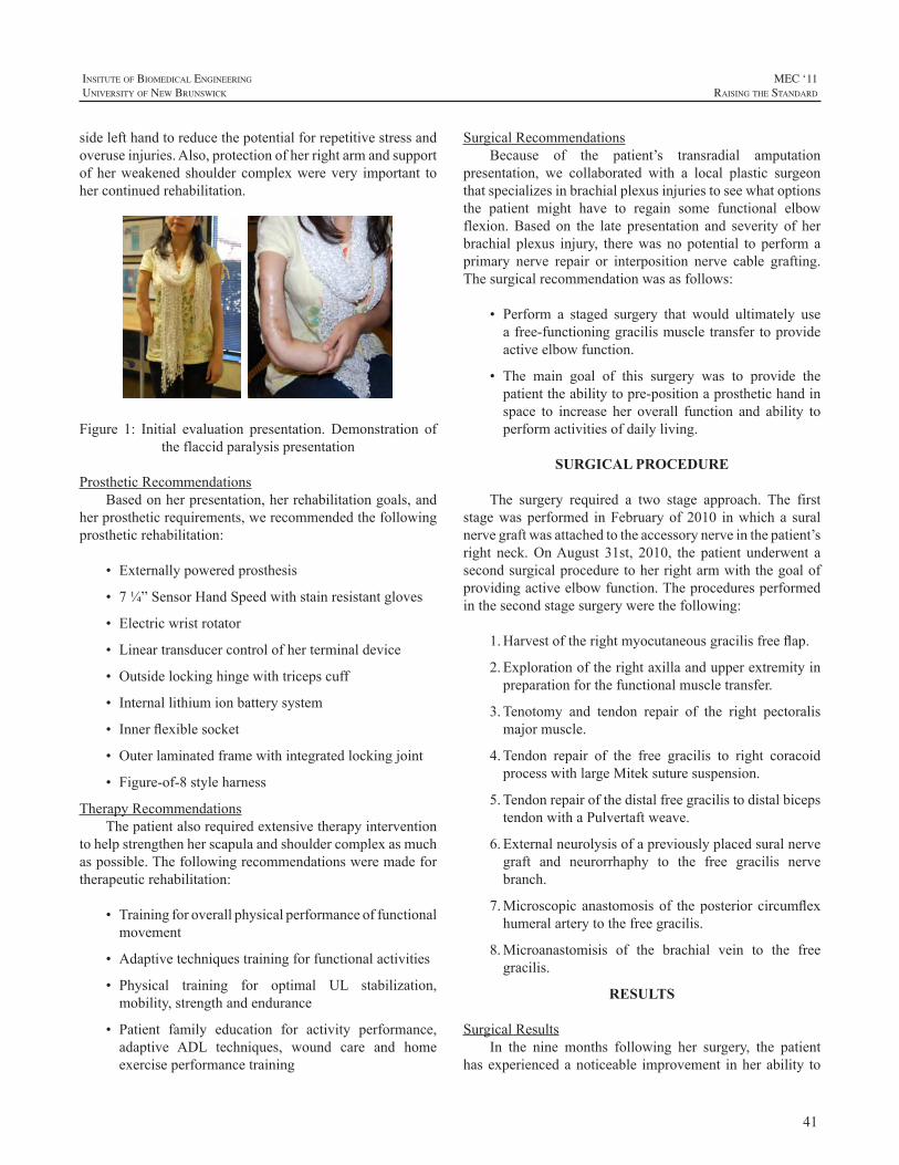
41
InsItute of BIomedIcal engIneerIng
unIversIty of new BrunswIck
MEC ‘11raIsIng the standard
sidelefthandtoreducethepotentialforrepetitivestressandoveruseinjuries.Also,protectionofherrightarmandsupportofherweakened shoulder complexwerevery important tohercontinuedrehabilitation.
Figure 1: Initial evaluation presentation. Demonstration oftheflaccidparalysispresentation
ProstheticRecommendationsBasedonherpresentation,herrehabilitationgoals,and
herprostheticrequirements,werecommendedthefollowingprostheticrehabilitation:
• Externallypoweredprosthesis
• 7¼”SensorHandSpeedwithstainresistantgloves
• Electricwristrotator
• Lineartransducercontrolofherterminaldevice
• Outsidelockinghingewithtricepscuff
• Internallithiumionbatterysystem
• Innerflexiblesocket
• Outerlaminatedframewithintegratedlockingjoint
• Figure-of-8styleharness
TherapyRecommendationsThepatientalsorequiredextensivetherapyintervention
tohelpstrengthenherscapulaandshouldercomplexasmuchaspossible.Thefollowingrecommendationsweremadefortherapeuticrehabilitation:
• Trainingforoverallphysicalperformanceoffunctionalmovement
• Adaptivetechniquestrainingforfunctionalactivities
• Physical training for optimal UL stabilization,mobility,strengthandendurance
• Patient family education for activity performance,adaptive ADL techniques, wound care and homeexerciseperformancetraining
SurgicalRecommendationsBecause of the patient’s transradial amputation
presentation, we collaborated with a local plastic surgeonthatspecializesinbrachialplexusinjuriestoseewhatoptionsthe patient might have to regain some functional elbowflexion.Based on the late presentation and severity of herbrachial plexus injury, therewas nopotential to performaprimary nerve repair or interposition nerve cable grafting.Thesurgicalrecommendationwasasfollows:
• Perform a staged surgery that would ultimately useafree-functioninggracilismuscletransfertoprovideactiveelbowfunction.
• The main goal of this surgery was to provide thepatienttheabilitytopre-positionaprosthetichandinspace to increase her overall function and ability toperformactivitiesofdailyliving.
SURGICAL PROCEDURE
The surgery required a two stage approach. The firststagewasperformed inFebruaryof2010 inwhicha suralnervegraftwasattachedtotheaccessorynerveinthepatient’sright neck.OnAugust 31st, 2010, the patient underwent asecondsurgicalproceduretoherrightarmwiththegoalofprovidingactiveelbowfunction.Theproceduresperformedinthesecondstagesurgerywerethefollowing:
1.Harvestoftherightmyocutaneousgracilisfreeflap.
2.Explorationoftherightaxillaandupperextremityinpreparationforthefunctionalmuscletransfer.
3.Tenotomy and tendon repair of the right pectoralismajormuscle.
4.Tendon repair of the free gracilis to right coracoidprocesswithlargeMiteksuturesuspension.
5.TendonrepairofthedistalfreegracilistodistalbicepstendonwithaPulvertaftweave.
6.Externalneurolysisofapreviouslyplacedsuralnervegraft and neurorrhaphy to the free gracilis nervebranch.
7.Microscopicanastomosisof theposterior circumflexhumeralarterytothefreegracilis.
8.Microanastomisis of the brachial vein to the freegracilis.
RESULTS
SurgicalResultsIn the nine months following her surgery, the patient
hasexperiencedanoticeable improvement inherability to
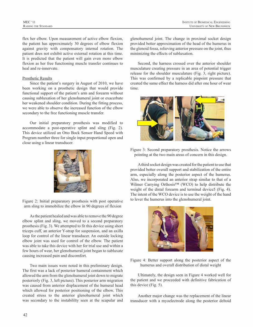
42
MEC ‘11raIsIng the standard
InsItute of BIomedIcal engIneerIng
unIversIty of new BrunswIck
flexherelbow.Uponmeasurementofactiveelbowflexion,the patient has approximately 30 degrees of elbow flexionagainst gravity with compensatory internal rotation. Thepatientdoesnotexhibitactiveexternalrotationatthistime.It is predicted that the patient will gain evenmore elbowflexionasherfreefunctioningmuscletransfercontinuestohealandre-innervate.
ProstheticResultsSincethepatient’ssurgeryinAugustof2010,wehave
been working on a prosthetic design that would providefunctionalsupportofthepatient’sarmandforearmwithoutcausingsubluxationofherglenohumeraljointorexacerbateherweakenedshouldercondition.Duringthefittingprocess,wewereabletoobservetheincreasedfunctionoftheelbowsecondarytothefreefunctioningmuscletransfer.
Our initial preparatory prosthesis was modified toaccommodate a post-operative splint and sling (Fig. 2).ThisdeviceutilizedanOttoBockSensorHandSpeedwithProgramnumberthreeforsingleinputproportionalopenandcloseusingalineartransducer.
Figure 2: Initial preparatory prosthesiswith post operativearmslingtoimmobilizetheelbowin90degreesofflexion
Asthepatienthealedandwasabletoremovethe90degreeelbow splint and sling,wemoved to a second preparatoryprosthesis(Fig.3).Weattemptedtofitthisdeviceusingshorttricepscuff,ananteriorY-strapforsuspension,andanaxillaloopforcontrolofthelineartransducer.Anoutsidelockingelbow jointwasused for controlof the elbow.Thepatientwasabletotakethisdevicewithherfortrialuseandwithinafewhoursofwear,herglenohumeraljointbegantosubluxatecausingincreasedpainanddiscomfort.
Twomainissueswerenotedinthispreliminarydesign.Thefirstwasalackofposteriorhumeralcontainmentwhichallowedthearmfromtheglenohumeraljointdowntomigrateposteriorly(Fig.3,leftpicture).Thisposteriorarmmigrationwascausedfromanteriordisplacementofthehumeralheadwhich allowed for posterior positioningof the elbow.Thiscreated stress to the anterior glenohumeral joint whichwas secondary to the instabililty seen at the scapular and
glenohumeral joint.The change in proximal socket designprovidedbetterapproximationoftheheadofthehumerusintheglenoidfossa,relievinganteriorpressureonthejoint,thusminimizingtheeffectsofsubluxation.
Second, theharnesscrossedover theanterior shouldermusculaturecreatingpressureinanareaofpotentialtriggerrelease for the shouldermusculature (Fig.3, rightpicture).This was confirmed by a replicable pinpoint pressure thatcreatedthesameeffecttheharnessdidafteronehourofweartime.
Figure3:Secondpreparatoryprosthesis.Notice thearrowspointingatthetwomainareasofconcerninthisdesign.
Athirdsocketdesignwascreatedforthepatienttousethatprovidedbetteroverallsupportandstabilizationoftheentirearm, especially along the posterior aspect of the humerus.Also,we incorporatedananterior strap similar to thatofaWilmer CarryingOrthosis™ (WCO) to help distribute theweightof thedistal forearmand terminaldevice5 (Fig.4).TheintentoftheWCOdeviceistousetheweightofthehandtoleverthehumerusintotheglenohumeraljoint.
Figure 4: Better support along the posterior aspect of thehumerusandoveralldistributionofdistalweight
Ultimately,thedesignseeninFigure4workedwellforthepatientandweproceededwithdefinitive fabricationofthisdevice(Fig.5).
Anothermajorchangewasthereplacementofthelineartransducerwith amyoelectrode along the posterior deltoid
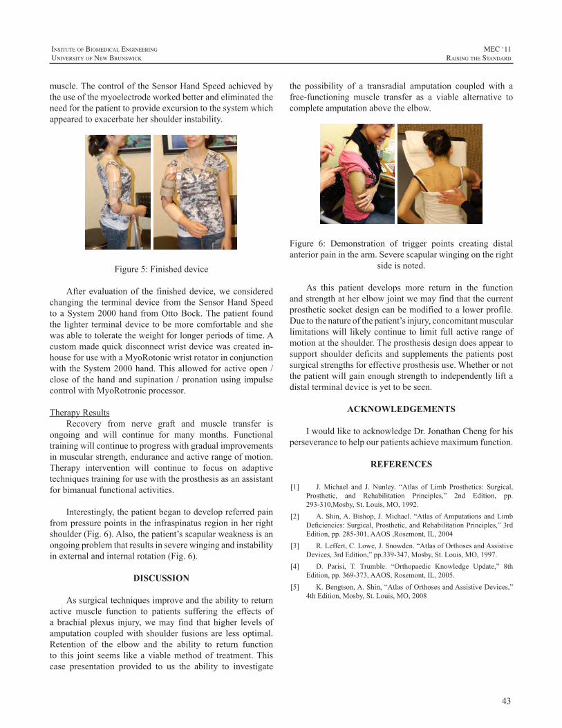
43
InsItute of BIomedIcal engIneerIng
unIversIty of new BrunswIck
MEC ‘11raIsIng the standard
muscle.ThecontroloftheSensorHandSpeedachievedbytheuseofthemyoelectrodeworkedbetterandeliminatedtheneedforthepatienttoprovideexcursiontothesystemwhichappearedtoexacerbatehershoulderinstability.
Figure5:Finisheddevice
After evaluationof the finisheddevice,weconsideredchanging the terminaldevice from theSensorHandSpeedtoaSystem2000handfromOttoBock.Thepatient foundthe lighter terminaldevice tobemorecomfortableandshewasabletotoleratetheweightforlongerperiodsoftime.Acustommadequickdisconnectwristdevicewascreatedin-houseforusewithaMyoRotonicwristrotatorinconjunctionwith theSystem2000hand.Thisallowedforactiveopen/closeof thehandandsupination /pronationusing impulsecontrolwithMyoRotronicprocessor.
TherapyResultsRecovery from nerve graft and muscle transfer is
ongoing and will continue for many months. Functionaltrainingwillcontinuetoprogresswithgradualimprovementsinmuscularstrength,enduranceandactiverangeofmotion.Therapy intervention will continue to focus on adaptivetechniquestrainingforusewiththeprosthesisasanassistantforbimanualfunctionalactivities.
Interestingly,thepatientbegantodevelopreferredpainfrompressurepointsintheinfraspinatusregioninherrightshoulder(Fig.6).Also,thepatient’sscapularweaknessisanongoingproblemthatresultsinseverewingingandinstabilityinexternalandinternalrotation(Fig.6).
DISCUSSION
Assurgicaltechniquesimproveandtheabilitytoreturnactive muscle function to patients suffering the effects ofa brachial plexus injury,wemay find that higher levels ofamputationcoupledwithshoulder fusionsare lessoptimal.Retention of the elbow and the ability to return functionto this joint seems like a viablemethodof treatment.Thiscase presentation provided to us the ability to investigate
the possibility of a transradial amputation coupled with afree-functioning muscle transfer as a viable alternative tocompleteamputationabovetheelbow.
Figure 6: Demonstration of trigger points creating distalanteriorpaininthearm.Severescapularwingingontheright
sideisnoted.
As this patient develops more return in the functionandstrengthatherelbowjointwemayfindthatthecurrentprostheticsocketdesigncanbemodifiedtoalowerprofile.Duetothenatureofthepatient’sinjury,concomitantmuscularlimitationswill likelycontinue to limit full active rangeofmotionattheshoulder.Theprosthesisdesigndoesappeartosupport shoulderdeficitsandsupplements thepatientspostsurgicalstrengthsforeffectiveprosthesisuse.Whetherornotthepatientwillgainenoughstrengthtoindependentlyliftadistalterminaldeviceisyettobeseen.
ACKNOWLEDGEMENTS
IwouldliketoacknowledgeDr.JonathanChengforhisperseverancetohelpourpatientsachievemaximumfunction.
REFERENCES
[1] J. Michael and J. Nunley. “Atlas of Limb Prosthetics: Surgical,Prosthetic, and Rehabilitation Principles,” 2nd Edition, pp.293-310,Mosby,St.Louis,MO,1992.
[2] A.Shin,A.Bishop,J.Michael.“AtlasofAmputationsandLimbDeficiencies:Surgical,Prosthetic,andRehabilitationPrinciples,”3rdEdition,pp.285-301,AAOS,Rosemont,IL,2004
[3] R.Leffert,C.Lowe,J.Snowden.“AtlasofOrthosesandAssistiveDevices,3rdEdition,”pp.339-347,Mosby,St.Louis,MO,1997.
[4] D. Parisi, T. Trumble. “Orthopaedic Knowledge Update,” 8thEdition,pp.369-373,AAOS,Rosemont,IL,2005.
[5] K.Bengtson,A.Shin,“AtlasofOrthosesandAssistiveDevices,”4thEdition,Mosby,St.Louis,MO,2008
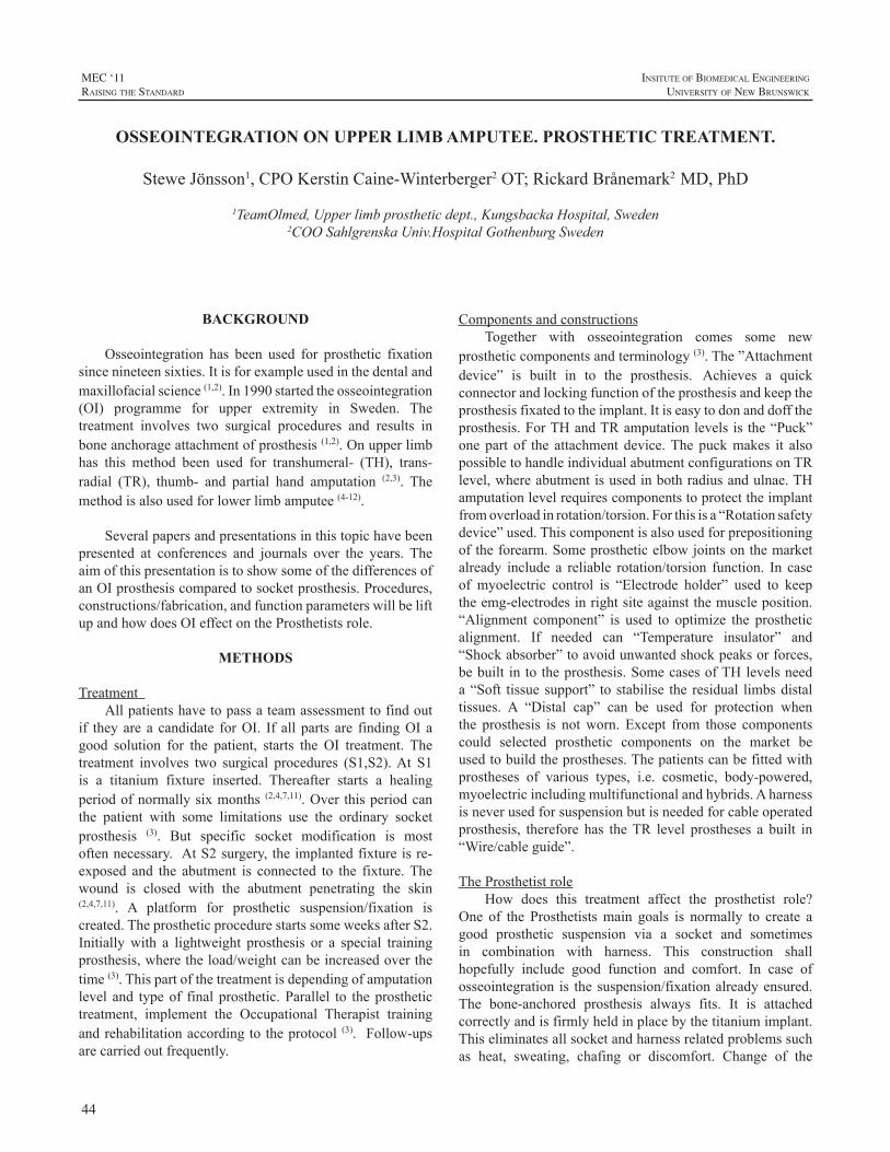
44
MEC ‘11raIsIng the standard
InsItute of BIomedIcal engIneerIng
unIversIty of new BrunswIck
BACKGROUND
Osseointegration has been used for prosthetic fixationsincenineteensixties.Itisforexampleusedinthedentalandmaxillofacialscience(1,2).In1990startedtheosseointegration(OI) programme for upper extremity in Sweden. Thetreatment involves two surgical procedures and results inboneanchorageattachmentofprosthesis(1,2).Onupperlimbhas this method been used for transhumeral- (TH), trans-radial (TR), thumb- and partial hand amputation (2,3). Themethodisalsousedforlowerlimbamputee(4-12).
Severalpapersandpresentationsinthistopichavebeenpresented at conferences and journals over the years. TheaimofthispresentationistoshowsomeofthedifferencesofanOIprosthesiscomparedtosocketprosthesis.Procedures,constructions/fabrication,andfunctionparameterswillbeliftupandhowdoesOIeffectontheProsthetistsrole.
METHODS
TreatmentAllpatientshavetopassateamassessmenttofindout
if theyare a candidate forOI. If all parts are findingOIagood solution for the patient, starts the OI treatment. Thetreatment involves two surgical procedures (S1,S2).At S1is a titanium fixture inserted. Thereafter starts a healingperiodofnormallysixmonths (2,4,7,11).Over thisperiodcanthe patient with some limitations use the ordinary socketprosthesis (3). But specific socket modification is mostoftennecessary. AtS2surgery,theimplantedfixtureisre-exposed and the abutment is connected to the fixture.Thewound is closed with the abutment penetrating the skin(2,4,7,11). A platform for prosthetic suspension/fixation iscreated.TheprostheticprocedurestartssomeweeksafterS2.Initiallywith a lightweight prosthesis or a special trainingprosthesis,wheretheload/weightcanbeincreasedoverthetime(3).Thispartofthetreatmentisdependingofamputationlevel and typeof finalprosthetic.Parallel to theprosthetictreatment, implement the Occupational Therapist trainingandrehabilitationaccordingtotheprotocol (3). Follow-upsarecarriedoutfrequently.
ComponentsandconstructionsTogether with osseointegration comes some new
prostheticcomponentsandterminology(3).The”Attachmentdevice” is built in to the prosthesis. Achieves a quickconnectorandlockingfunctionoftheprosthesisandkeeptheprosthesisfixatedtotheimplant.Itiseasytodonanddofftheprosthesis.ForTHandTRamputationlevelsis the“Puck”one part of the attachment device.The puckmakes it alsopossibletohandleindividualabutmentconfigurationsonTRlevel,whereabutmentisusedinbothradiusandulnae.THamputationlevelrequirescomponentstoprotecttheimplantfromoverloadinrotation/torsion.Forthisisa“Rotationsafetydevice”used.Thiscomponentisalsousedforprepositioningoftheforearm.Someprostheticelbowjointsonthemarketalready include a reliable rotation/torsion function. In caseof myoelectric control is “Electrode holder” used to keeptheemg-electrodesinrightsiteagainstthemuscleposition.“Alignment component” is used to optimize the prostheticalignment. If needed can “Temperature insulator” and“Shockabsorber”toavoidunwantedshockpeaksorforces,bebuilt in totheprosthesis.SomecasesofTHlevelsneeda“Soft tissuesupport” tostabilise the residual limbsdistaltissues. A “Distal cap” can be used for protection whenthe prosthesis is notworn. Except from those componentscould selected prosthetic components on the market beusedtobuildtheprostheses.Thepatientscanbefittedwithprostheses of various types, i.e. cosmetic, body-powered,myoelectricincludingmultifunctionalandhybrids.Aharnessisneverusedforsuspensionbutisneededforcableoperatedprosthesis, therefore has theTR level prostheses a built in“Wire/cableguide”.
TheProsthetistroleHow does this treatment affect the prosthetist role?
One of the Prosthetistsmain goals is normally to create agood prosthetic suspension via a socket and sometimesin combination with harness. This construction shallhopefully include good function and comfort. In case ofosseointegration is thesuspension/fixationalreadyensured.The bone-anchored prosthesis always fits. It is attachedcorrectlyandisfirmlyheldinplacebythetitaniumimplant.Thiseliminatesallsocketandharnessrelatedproblemssuchas heat, sweating, chafing or discomfort. Change of the
OSSEOINTEGRATION ON UPPER LIMB AMPUTEE. PROSTHETIC TREATMENT.
SteweJönsson1,CPOKerstinCaine-Winterberger2OT;RickardBrånemark2MD,PhD
1TeamOlmed,Upperlimbprostheticdept.,KungsbackaHospital,Sweden2COOSahlgrenskaUniv.HospitalGothenburgSweden
45
InsItute of BIomedIcal engIneerIng
unIversIty of new BrunswIck
MEC ‘11raIsIng the standard
residuallimbvolumeisnotanissueandtheProsthetistcanspendmorefocusontheprostheticfunctionandcomponenttechnology(3).
Involvedintheosseintegrationtreatment,theProsthetisthastobetrainedandlearnedto:
• Knowhowtheosseointegrationprincipalworks.
• ObservethepatientsOIstatus.Takeanactiveroleininformationflowintotheteamandtobeapartofateam.
• Supply the patient with an adequate prostheticconstruction that guarantees the patients a safetysituation. Never experimental construction that canrisktheimplant.
• Give the patient correct and relevant informationregarding both prosthetic use and times when notwearingprosthesis.
• Follow the prosthetic and rehabilitation protocol,includingcheckups.
• Insomecases,beapartofanassessment-team.
• And, listen to the patient, “listen to the bone” (PIBrånemark)
Direct bone-anchored prostheses always fit and havelong durability.The need for prosthetic replacement is notfrequentandworn-outsocketsareno longeran issue.Thisreducestheprostheticcostoveralongtimeperiod.Ordinaryprostheticcomponentservicesareofcoursenotreduced.
Withafixedreferencepointscan,alignments,prostheticlengthandelectrodesiteplacementbestored.Bysavingthosedata, can prosthetic duplicate be produced and comparedto socket prosthesis without a need of impressions andcheckout-sockets.Thepatientcanhaveafinishedprosthesisdelivereddirectly.
RESULTS/OUTCOME
ProstheticDifferent prosthetic types have been made and used
in combination with OI. Attachment devices and specialcomponents have made it possible to provide patientswith cosmetic, body-powered, myoelectric includingmultifunctional and hybrid prosthesis. Without any stumpvolume depending socket will the direct bone anchoredprosthesislastforaverylongtime(3).
PatientApproximately40patientshaveoperatedonupperlimb.
Differentamputationlevelshavebeentreated,TH,TR,partial
handandthumb.OIhasbeensuccessfulforbothshortandlongresiduallimbonTHandTRlevel.Causesofamputationhavebeentrauma,congenitaldeformities,andtumour(3).
Function/experienceTheprostheticsituationisimprovedbecauseofthestable
fixation.Thereisnoneedofharnessinginaimofsuspensionand the patients achieve full freedom ofmovement in theproximal joint. Problems with excessive irritation andsweating from the harness or socket do not exist.Withoutsocket is higher degree of comfort achieved. The patientsreport improved functionality (3). Clinical follow ups ofprostheticusers,showimprovedqualityoflifecomparedtothe situation before osseointegration. Patients experienceimproved sensory feedbackbecauseof thephenomenonofOsseoperception (13-16).Newprosthetic technology includesdifferentplatforms,whereosseointegrationisoneimportantpart.
REFERENCES
[1]. PI.Brånemark,BO.Hansson,R.Adell,U.Breine, J.Lindström,O.Hallén,A.Öhman,Osseointegrated implants in the treatment ofthe edentulous jaw. Experience from a ten year period. Stockholm;Almqvist&WiksellInternational,1977.p.132.
[2] PI. Brånemark, The osseointegration book: From calvarium tocalcaneus.Chicago(IL):QuintessencePublishing;2006.
[3] S. Jönsson, K. Caine-Winterberger, R. Brånemark,“Osseointegrationamputationprosthesisontheupperlimbs:Methods,ProstheticsandRehabilitation.”acceptedto.ProsthetOrthotInt,June2011
[4] R. Brånemark, PI. Brånemark, B. Rydevik, RR. Myers,“Osseointegration in skeletal reconstruction and rehabilitation: Areview.”JRehabilResDev2001;38(2),175-181
[5] K. Hagberg, and R. Branemark, “Consequences of non-vasculartrans-femoral amputation: a survey of quality of life, prosthetic useandproblems.”ProsthetOrthotInt2001;25(3),186-194
[6] J. Sullivan, M. Uden, KP. Robinson, S. Sooriakumaran,“Rehabilitationofthetrans-femoralamputeewithanosseointegratedprosthesis: the United Kingdom experience.” Prosthet Orthot Int2003;27(2),114-120.
[7] KP. Robinson, R Brånemark, DAWard, „Future developments:Osseintegration in transfemural amputees.” In: DG. Smith, JW.Michael,JH.Bowker,editors.Atlasofamputationandlimbdeficencies:Surgical,prostheticandrehabilitationprinciples.3rdedRosemont(IL):AmericanAcademyofOrthopaedicSurgeons,2004.p.673-682.
[8] K. Hagberg, E. Haggstrom, M. Uden, R. Brånemark. “Socketversus bone-anchored trans-femoral prostheses: hip rangeofmotionandsittingcomfort.”ProsthetOrthotInt2005;29(2),153-163.
[9] K. Hagberg, “Transfemoral Amputation, Quality of Life andProstheticFunction.Studiesfocusingonindividualswithamputationduetoreasonsotherthanperipheralvasculardisease,withsocketandosseointegratedprostheses.”Thesis,DeptofOrthopaedics,InstituteofClinicalSciences,TheSahlgrenskaAcademyatGöteborgUniversity,Göteborg.2006.
[10] L.Frossard,N.Stevenson,J.Smeathers,E.Häggström,K.Hagberg,J.Sullivan,D.Ewins,DL.Gow,S.Gray,R.Brånemark.“Monitoringoftheloadregimeappliedontheosseointegratedfixationofatrans-
46
MEC ‘11raIsIng the standard
InsItute of BIomedIcal engIneerIng
unIversIty of new BrunswIck
femoralamputee:atoolforevidence-basedpractice.”ProsthetOrthotInt2008;32(1),68-78.
[11] K. Hagberg, R. Brånemark, B. Gunteberg, B. Rydevik,“Osseointegrated trans-femoral amputation prostheses: prospectiveresultsofgeneralandcondition-specificqualityoflifein18patientsat2-yearfollow-up.”ProsthetOrthotInt2008;32(1),29-41.
[12] K. Hagberg, R. Brånemark, “One hundred patients treated withosseointegrated transfemoral amputation prostheses-Rehabilitationperspective.”JRehabilResDev2009;46(3),331-344.
[13] R. Jacobs, R. Brånemark, K. Olmarker, B. Rydevik, D. vanSteenberghe,P-IBrånemark,“Psychophysicaldetectionthresholdsforvibrotactile and pressure stimulation of prosthetic limbs using boneanchorage or soft tissue support.”Osseoperception/edited by JacobsR.-Leuven:DepartmentofPeriodontology,KULeuven;1998.p.125-141.
[14] G.Lundborg,A.Waites,A.Björkman,B.Rosén,E-M.Larsson,“Functionalmagneticresonanceimagingshowscorticalactivationonsensory stimulationofanosseointegratedprostheticthumb.”ScandJPlastReconstrSurgandHandSurg2006;40(4),234-239.
[15] E. Häggström, K. Hagberg, B. Rydevik, R. Brånemark. “Thepsychophysicaldetection level forvibrotactile stimulationover timeinbone-anchoredprosthesis:Preliminaryprospectiveresultsat2-yearfollow-upamong20transfemuralamputeepatients.”In:Proceedingsofthe12thWorldCongressoftheISPO;2007Jul29-Aug3;Vancouver,Canada.Toronto(Canada):p.367
[16] K. Hagberg, E. Häggström, S. Jönsson, B. Rydevik and R.Brånemark. “Osseoperception and osseointegrated prostheticslimbs.” In: Gallagher P, Desmond D, MacLachlan M, editors.Psychoprosthetics. London (England): Springer, 2008. p.131-40.DOI:10.1007/978-1-84628-980-410.
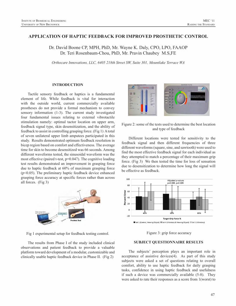
47
InsItute of BIomedIcal engIneerIng
unIversIty of new BrunswIck
MEC ‘11raIsIng the standard
INTRODUCTION
Tactile sensory feedback or haptics is a fundamentalelement of life. While feedback is vital for interactionwith the outside world, current commercially availableprostheses do not provide a formal mechanism to conveysensory information (1-3). The current study investigatedfour fundamental issues relating to external vibrotactilestimulation namely: optimal tactor location on upper arm,feedbacksignaltype,skindesensitization,andtheabilityoffeedbacktoassistincontrollinggraspingforce.(Fig1)Atotalofsevenunilateralupperlimbamputeesparticipatedinthisstudy.Resultsdemonstratedoptimumfeedbackresolutioninbicepregionbasedoncomfortandeffectiveness.Theaveragetimeforskintobecomedesensitizedwas66seconds.Amongdifferentwaveformstested,thesinusoidalwaveformwasthemosteffective(pairedt-test,p=0.047).Thecognitiveloadingtestresultsdemonstratedanimprovementingraspingforceduetohapticfeedbackat60%ofmaximumgraspingforce(p<0.05).Thepreliminaryhapticfeedbackdeviceenhancedgraspingforceaccuracyatspecificforcesratherthanacrossallforces.(Fig3)
Fig1experimentalsetupforfeedbacktestingcontrol.
Theresults fromPhaseIof thestudyincludedclinicalobservations and patient feedback to provide a valuableplatformtowarddevelopmentofamodular,customizableandclinicallyusablehapticfeedbackdeviceinPhaseII.(Fig2)
Figure2:someofthetestsusedtodeterminethebestlocation
andtypeoffeedback
Different locations were tested for sensitivity to thefeedback signal and then different frequencies of threedifferentwaveforms(square,sine,andsawtooth)wereusedtofindthemosteffectivefeedbacksignalforeachindividualastheyattemptedtomatchapercentageoftheirmaximumgripforce.(Fig3)Wethentestedthetimeforlossofsensationduetodesensitizationtodeterminehowlongthesignalwillbeeffectiveasfeedback.
Figure3:gripforceaccuracy
SUBJECT QUESTIONNAIRE RESULTS
The subjects’ perception plays an important role inacceptance of assistive devices(4). As part of this studysubjects were asked a set of questions relating to overallcomfort, ability to use haptic feedback for daily graspingtasks, confidence in using haptic feedback and usefulnessif such a device was commercially available (5-8). Theywereaskedtoratetheirresponsesasascorefrom1(worst)to
APPLICATION OF HAPTIC FEEDBACK FOR IMPROVED PROSTHETIC CONTROL
Dr.DavidBooneCP,MPH,PhD,Mr.WayneK.Daly,CPO,LPO,FAAOPDr.TeriRosenbaum-Chou,PhD,Mr.PravinChaubeyM.S,FE
OrthocareInnovations,LLC,6405218thStreetSW,Suite301,MountlakeTerraceWA
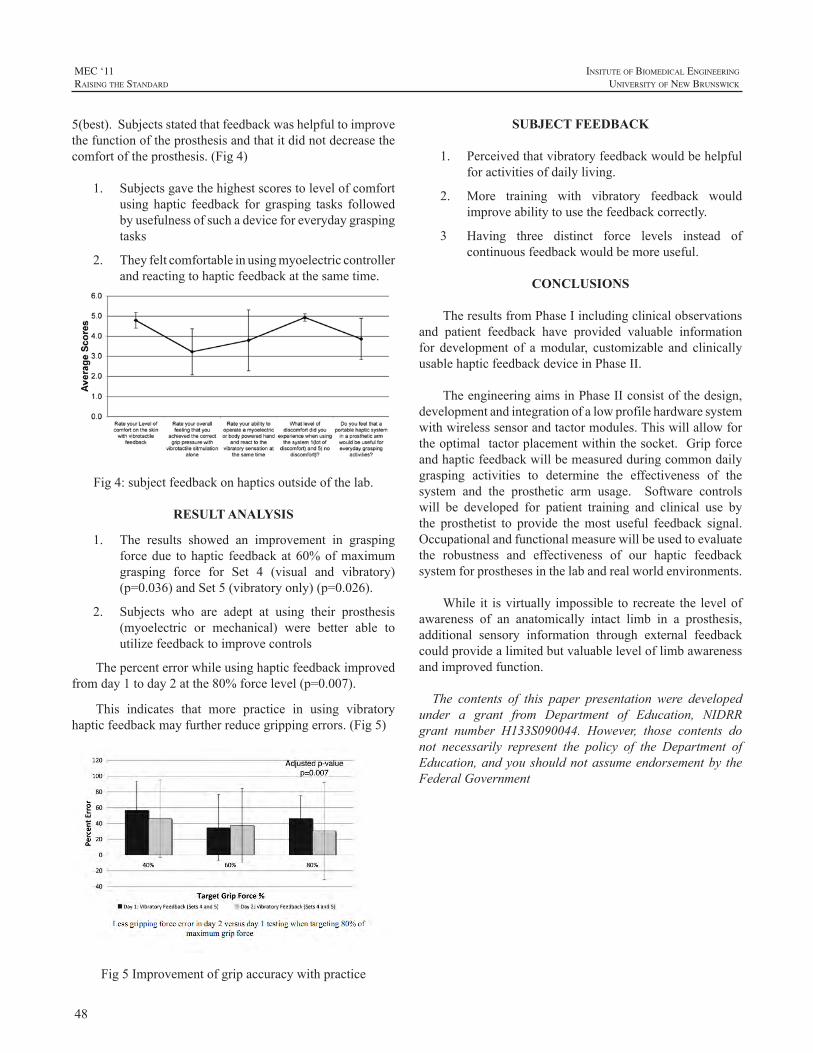
48
MEC ‘11raIsIng the standard
InsItute of BIomedIcal engIneerIng
unIversIty of new BrunswIck
5(best).Subjectsstatedthatfeedbackwashelpfultoimprovethefunctionoftheprosthesisandthatitdidnotdecreasethecomfortoftheprosthesis.(Fig4)
1. Subjectsgavethehighestscorestolevelofcomfortusing haptic feedback for grasping tasks followedbyusefulnessofsuchadeviceforeverydaygraspingtasks
2. Theyfeltcomfortableinusingmyoelectriccontrollerandreactingtohapticfeedbackatthesametime.
Fig4:subjectfeedbackonhapticsoutsideofthelab.
RESULT ANALYSIS
1. The results showed an improvement in graspingforcedue tohaptic feedbackat60%ofmaximumgrasping force for Set 4 (visual and vibratory)(p=0.036)andSet5(vibratoryonly)(p=0.026).
2. Subjects who are adept at using their prosthesis(myoelectric or mechanical) were better able toutilizefeedbacktoimprovecontrols
Thepercenterrorwhileusinghapticfeedbackimprovedfromday1today2atthe80%forcelevel(p=0.007).
This indicates that more practice in using vibratoryhapticfeedbackmayfurtherreducegrippingerrors.(Fig5)
Fig5Improvementofgripaccuracywithpractice
SUBJECT FEEDBACK
1. Perceivedthatvibratoryfeedbackwouldbehelpfulforactivitiesofdailyliving.
2. More training with vibratory feedback wouldimproveabilitytousethefeedbackcorrectly.
3 Having three distinct force levels instead of continuousfeedbackwouldbemoreuseful.
CONCLUSIONS
TheresultsfromPhaseIincludingclinicalobservationsand patient feedback have provided valuable informationfor development of amodular, customizable and clinicallyusablehapticfeedbackdeviceinPhaseII.
TheengineeringaimsinPhaseIIconsistofthedesign,developmentandintegrationofalowprofilehardwaresystemwithwirelesssensorandtactormodules.Thiswillallowfortheoptimaltactorplacementwithinthesocket.Gripforceandhapticfeedbackwillbemeasuredduringcommondailygrasping activities to determine the effectiveness of thesystem and the prosthetic arm usage. Software controlswill be developed for patient training and clinical use bythe prosthetist to provide themost useful feedback signal.Occupationalandfunctionalmeasurewillbeusedtoevaluatethe robustness and effectiveness of our haptic feedbacksystemforprosthesesinthelabandrealworldenvironments.
While it isvirtually impossible to recreate the levelofawareness of an anatomically intact limb in a prosthesis,additional sensory information through external feedbackcouldprovidealimitedbutvaluableleveloflimbawarenessandimprovedfunction.
The contents of this paper presentation were developedunder a grant from Department of Education, NIDRRgrant number H133S090044. However, those contents donot necessarily represent the policy of the Department ofEducation,andyoushouldnotassumeendorsementby theFederalGovernment
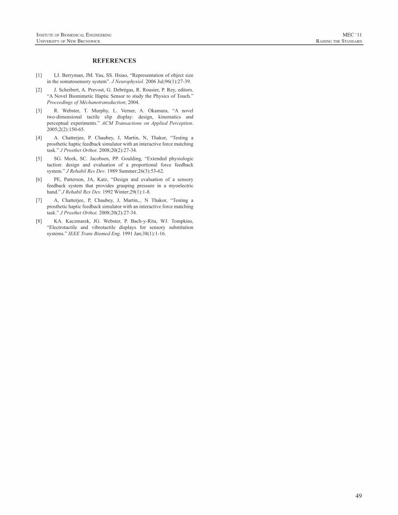
49
InsItute of BIomedIcal engIneerIng
unIversIty of new BrunswIck
MEC ‘11raIsIng the standard
REFERENCES
[1] LJ.Berryman,JM.Yau,SS.Hsiao,“Representationofobjectsizeinthesomatosensorysystem”.JNeurophysiol.2006Jul;96(1):27-39.
[2] J.Scheibert,A.Prevost,G.Debrègas,R.Rousier,P.Rey,editors.“ANovelBiomimeticHapticSensortostudythePhysicsofTouch.”ProceedingsofMéchanotransduction;2004.
[3] R. Webster, T. Murphy, L. Verner, A. Okamura, “A noveltwo-dimensional tactile slip display: design, kinematics andperceptual experiments.”ACMTransactions onApplied Perception.2005;2(2):150-65.
[4] A. Chatterjee, P. Chaubey, J, Martin, N, Thakor, “Testing aprosthetichapticfeedbacksimulatorwithaninteractiveforcematchingtask.”JProsthetOrthot.2008;20(2):27-34.
[5] SG. Meek, SC. Jacobsen, PP. Goulding, “Extended physiologictaction: design and evaluation of a proportional force feedbacksystem.”JRehabilResDev.1989Summer;26(3):53-62.
[6] PE, Patterson, JA, Katz, “Design and evaluation of a sensoryfeedback system that provides grasping pressure in a myoelectrichand.”JRehabilResDev.1992Winter;29(1):1-8.
[7] A, Chatterjee, P, Chaubey, J, Martin,., N Thakor, “Testing aprosthetichapticfeedbacksimulatorwithaninteractiveforcematchingtask.”JProsthetOrthot.2008;20(2):27-34.
[8] KA. Kaczmarek, JG. Webster, P. Bach-y-Rita, WJ. Tompkins,“Electrotactile and vibrotactile displays for sensory substitutionsystems.”IEEETransBiomedEng.1991Jan;38(1):1-16.
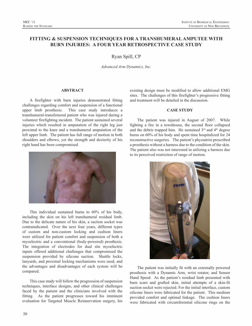
50
MEC ‘11raIsIng the standard
InsItute of BIomedIcal engIneerIng
unIversIty of new BrunswIck
ABSTRACT
A firefighter with burn injuries demonstrated fittingchallengesregardingcomfortandsuspensionofafunctionalupper limb prosthesis. This case study introduces atranshumeral-transfemoralpatientwhowasinjuredduringavolunteerfirefightingincident.Thepatientsustainedseveralinjuries which resulted in amputation of the right leg justproximal to thekneeanda transhumeralamputationof theleftupperlimb.Thepatienthasfullrangeofmotioninbothshouldersandelbows,yet the strengthanddexterityofhisrighthandhasbeencompromised.
This individual sustained burns to 60% of his body,including the skin on his left transhumeral residual limb.Duetothedelicatenatureofhisskin,asuctionsocketwascontraindicated. Over the next four years, different typesof custom and non-custom locking and cushion linerswere utilized for patient comfort and suspension of both amyoelectric anda conventional (body-powered)prosthesis.The integration of electrodes for dual site myoelectricinputs offered additional challenges that compromised thesuspension provided by silicone suction. Shuttle locks,lanyards,andproximallockingmechanismswereused,andthe advantages and disadvantages of each system will becompared.
Thiscasestudywillfollowtheprogressionofsuspensiontechniques, interface designs, and other clinical challengesfaced by the patient and the clinicians involved with thefitting. As the patient progresses toward his imminentevaluation for TargetedMuscle Reinnervation surgery, his
existingdesignmustbemodified toallowadditionalEMGsites.Thechallengesofthisfirefighter’sprogressivefittingandtreatmentwillbedetailedinthediscussion.
CASE STUDY
The patient was injured in August of 2007. Whilefighting a fire in a townhouse, the second floor collapsedandthedebristrappedhim.Hesustained3rdand4thdegreeburnson60%ofhisbodyandspenttimehospitalizedfor24reconstructivesurgeries.Thepatient’sphysiatristprescribedaprosthesiswithoutaharnessduetotheconditionoftheskin.Thepatientalsowasnotinterestedinutilizingaharnessduetoitsperceivedrestrictionofrangeofmotion.
Thepatientwasinitiallyfitwithanexternallypoweredprosthesis with a DynamicArm, wrist rotator, and SensorHandSpeed. As thepatient’s residual limbpresentedwithburn scars and grafted skin, initial attempts of a skin-fitsuctionsocketwererejected.Fortheinitialinterface,customsiliconelinerswerefabricatedforthepatient.Thismediumprovided comfort andoptimal linkage. The cushion linerswere fabricated with circumferential silicone rings on the
FITTING & SUSPENSION TECHNIQUES FOR A TRANSHUMERAL AMPUTEE WITH BURN INJURIES: A FOUR YEAR RETROSPECTIVE CASE STUDY
RyanSpill,CP
AdvancedArmDynamics,Inc.
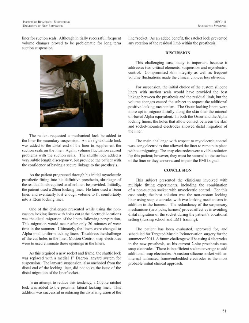
51
InsItute of BIomedIcal engIneerIng
unIversIty of new BrunswIck
MEC ‘11raIsIng the standard
linerforsuctionseals.Althoughinitiallysuccessful,frequentvolume changes proved to be problematic for long termsuctionsuspension.
The patient requested a mechanical lock be added tothelinerforsecondarysuspension.Anairtightshuttlelockwas added to the distal end of the liner to supplement thesuctionsealsontheliner.Again,volumefluctuationcausedproblemswith the suction seals. The shuttle lock added averysubtlelengthdiscrepancy,butprovidedthepatientwiththeconfidenceofhavingasecurelinkagetotheprosthesis.
Asthepatientprogressedthroughhisinitialmyoelectricprostheticfittingintohisdefinitiveprosthesis,shrinkageoftheresiduallimbrequiredsmallerlinersbeprovided.Initially,thepatientuseda20cmlockingliner.Helateruseda16cmliner,andeventuallylostenoughvolumetofitcomfortablyintoa12cmlockingliner.
One of the challenges presentedwhile using the non-customlockinglinerswithholescutattheelectrodelocationswasthedistalmigrationofthelinersfollowingperspiration.Thismigrationwouldoccur after only20minutesofweartimeinthesummer.Ultimately,thelinerswerechangedtoAlphasmalluniformlockingliners.Toaddressthechallengeofthecutholesintheliner,MotionControlsnapelectrodesweretousedeliminatetheseopeningsintheliners.
Asthisrequiredanewsocketandframe,theshuttlelockwas replacedwith amedial 1”Dacron lanyard system forsuspension.Thelanyardsuspension,alsoanchoredfromthedistalendofthelockingliner,didnotsolvetheissueofthedistalmigrationoftheliner/socket.
Inanattempttoreducethistendency,aCoyoteratchetlockwas added to theproximal lateral locking liner. Thisadditionwassuccessfulinreducingthedistalmigrationofthe
liner/socket.Asanaddedbenefit,theratchetlockpreventedanyrotationoftheresiduallimbwithintheprosthesis.
DISCUSSION
This challenging case study is important because itaddressestwocriticalelements,suspensionandmyoelectriccontrol. Compromised skin integrity as well as frequentvolumefluctuationsmadetheclinicalchoiceslessobvious.
Forsuspension,theinitialchoiceofthecustomsiliconeliners with suction seals would have provided the bestlinkagebetweentheprosthesisandtheresiduallimb,butthevolumechangescausedthesubjecttorequesttheadditionalpositivelockingmechanism.TheOssurlockinglinersweremoreapttomigratedistallyalongtheskinthanthemineraloil-basedAlphaequivalent.InboththeOssurandtheAlphalockingliners,theholesthatallowcontactbetweentheskinand socket-mounted electrodes allowed distalmigration oftheliner.
Themainchallengewithrespecttomyoelectriccontrolwasusingelectrodesthatallowedthelinertoremaininplacewithoutmigrating.Thesnapelectrodeswereaviablesolutionforthispatient;however,theymustbesecuredtothesurfaceofthelinerortheyunscrewandimpairtheEMGsignal.
CONCLUSION
This subject presented the clinicians involved withmultiple fitting experiments, including the combinationof anon-suction socketwithmyoelectric control. For thiscase study, the best solution was the non-custom lockinglinerusingsnapelectrodeswithtwolockingmechanismsinadditionto theharness. Theredundancyof thesuspensorymechanisms(twolocks,harness)provedeffectiveinavoidingdistalmigrationofthesocketduringthepatient’svocationalsetting(nursingschoolandEMTtraining).
The patient has been evaluated, approved for, andscheduledforTargetedMuscleReinnervationsurgeryforthesummerof2011.Afuturechallengewillbeusing4electrodesin the new prosthesis, as his current 2-site prosthesis usessnapelectrodes.Thereisinsufficientsocketcoveragetoaddadditionalsnapelectrodes.Acustomsiliconesocketwithaninternal laminated frame/embedded electrodes is the mostprobableinitialclinicalapproach.
52
MEC ‘11raIsIng the standard
InsItute of BIomedIcal engIneerIng
unIversIty of new BrunswIck
REFERENCES
[1] ECT. Baars, JHB. Gertzen, “Literature review of the possibleadvantages of silicon liner socket use in trans-tibial prostheses.”JournalofProstheticsandOrthotics International,Vol. 29, Issue1,pp.27-37.2005.
[2] B.Berman,O.Perez,Konda,BS.Sailesh,BE.Kohut,MH.Viera,S.Delgado,D.Zell,andQ.Li,“Areviewofthebiologiceffects,clinicalefficacy,andsafetyofsiliconeelastomersheetingforhypertrophicandkeloidscartreatmentandmanagement.”Dermatologicsurgery2007;33:1291-1303.
[3] A.Colas,J.Curtis,“Siliconebiomaterials:Historyandchemistry&medical applications of silicones.”Biomaterials Science, SecondEdition:AnIntroductiontoMaterialsinMedicine.2004.
[4] L. deLinde, B. Knothe “Therapist’s management of the burnedhand.”InJM.Hunter,EJ.Mackin,AL.Callahan,eds.RehabilitationoftheHandandUpperExtremity.St.Louis:MosbyInc.:2002:1492–1526.
[5] K Farquhar, “Silicone gel and hypertrophic scar formation: aliterature review.” CanadianJournalofOccupationalTherapyVol.59,No.2,pp.78-86.1992.
[6] L. Haberman, “Silicone-only suspension (SOS) with socket-locandtheringforthelowerlimb.”JProsthetOrthot1995;7:2.
[7] KJ.Quinn,JH.Evans,JM.Courtney,JDS.Gaylor,andWH.Reid,“Non-pressuretreatmentofhypertrophicscars.”Burns,12,102-108.1985.
[8] KJ. Quinn, “Silicone based scar therapy.” Care, Science andPractice.4,7-9.1986.
53
InsItute of BIomedIcal engIneerIng
unIversIty of new BrunswIck
MEC ‘11raIsIng the standard
INTRODUCTION
AccordingtoDillinghamet.al.[1]thereareonaverage26childrenbornwithanupperlimbdeficiencyper100,000live births each year in theUnited States.TheDillinghamstudy does acknowledge that previous research from othercountries has indicated an upper limb deficiency rate of50-62.5 per 100,000 live births. Evidence and opinionsare conflicted regarding the functional effectiveness andnecessityoffittingyoung,unilateralamputeechildrenwithanupperlimbprosthesis,especiallyinregardtotheunilateralcongenital below elbow deficiency (UCBED)[2-13]. Thedifficulty in interpretingandcomparing the studies’ resultsisthattherearedifferentdefinitionsofsuccessfulupperlimbprostheticuse.
It is thisauthor’sassertion that, although these studieshavevalue,theentirepictureofachild’sneedsisnotaddressed.Not all previous studies assure that the subjects had earlyandproperfittingoftheprosthesis,activity-appropriateandup-to-date prosthetic devices, parental support, therapeutictraining,andconsistentwearingschedules.Inaddition,thesestudies don’t often address or evaluate symmetry of upperbodymuscledevelopment,spinalalignmentandproperbodymechanicswhilecompletingbimanualtasks.
BACKGROUND
This case study follows a female child with a rightUCBEDfrombirth to7yearsofage. Thechildwasbornwitha“normal”presentationexcept for thefact thatshe ismissingherrighthandand2/3ofherforearm.Sheutilizesmultipleprostheticdevices.
Atsixmonthsofage,thechildwasfittedwithapassiveprosthesis with a semi-flexible, passive hand attachment.This allowed her to become accustomed to wearing aprosthesisandtobegintoexplorerightupperlimbmovementsuchasbattingobjectswithanarmlengthequaltoherleftarm.Theprosthesiswasinstrumentalinhelpingtomaintain
sittingbalanceandtocrawlinatypicalmannerwithnormalbodymechanics.Later,aprosthetichandinthepinchgraspshapewasadded.The thumbcouldbeopenedmanually toallowthechildorherparentstoplaceobjectsinthedevicetoencouragerecognitionthattheprosthetichandcanholdandcarryobjects.
Theinitialplanwasforamyoelectricfittingtooccurat12monthsofage.Thiswouldallowthechildtolearnhowtograspwithherrightprosthetichandatthesametimethatshewasdevelopinggrasppatternswithherlefthand.At18monthsafterastrugglewiththemedicalinsurancecompany,she was fitted with a VASI myoelectric prosthesis witha fixedwrist.The prosthesiswas activatedwith a “cookiecrusher,” single site electrode on her residual forearmextensormuscles.Itperformederraticallyfor4months,anditwas unknownwhether the problemwaswith the deviceor with the child’s ability. Within 4 days of the device’sproblem being identified and corrected, the child began tovoluntarily control the prosthesis at the age of 22months.Through therapy and parental encouragement, the childbegantousetheelectronicallycontrolledprosthetichandtoreachforand tograspobjects. However,shedidnothaveproportionalcontrolofthegraspuntilshebegantouseadualsite, proportional control program at age 3. With the newsetup, shewas able to demonstrate control over the speedand thegrip forceof theprosthetic handduring functionalactivities.This led to improved finemotor control.At age6,hermyoelectricprosthesiswasswitchedtoanOttoBockSystem 2000 hand with a manual, rotating, friction wristwhichallowedhertoprepositionherhandforactivitiesand,asaresult,useimprovedbodymechanics.
Althoughthemyoelectricprosthesiswaswornfulltime(10-12 hours a day), it could not be used during sportingactivities, sandbox play and other activities that mightdamageitssensitiveelectronicequipmentandmotor.At3½yearsthechildwasfittedwithapassivesportsprosthesiswithaFree-Flexhand. Thisallowedhertobegintoplaysportssuchassoccerort-ball.Asneeded,thehandwasremoved
THE PROSTHETIC HABILITATION OF A CONGENITAL, TRANSRADIAL LIMB DEFICIENT CHILD: A CASE STUDY ANALYZING THE FUNCTIONAL EFFECTIVENESS AND THE BENEFITS OF EARLY PROSTHETIC FITTING, APPROPRIATE PROSTHETIC
EQUIPMENT, AND CONSISTENT CAREGIVER FOLLOW UP
JenniferPeterson,MAPT
AdvancedArmDynamics11671FountainsDrive,Suite220
MapleGrove,MN5536
54
MEC ‘11raIsIng the standard
InsItute of BIomedIcal engIneerIng
unIversIty of new BrunswIck
and easily replacedbyother terminal ends such as a fixedhookfordoingthe“monkeybars”orpullups,atumblerforgymnastics,amodifiedPinchHitterforbatting,andaSlapShotHockeydeviceforplayinghockey.Thesedeviceshaveallowed participation in extracurricular activitieswith age-typicalform.
Toallow the child toplay theviolin at age3, anotheractivityspecificprosthesiswascreatedtoholdthebow.Thecustommadedevice has a spring to allow“wrist”motion,whichisextremelyimportanttothemechanicsofplayingtheviolin. With this feature, she isable tomaintaina relaxedshoulderonthebowingsidetohelppreventfutureshoulderinjury.Recently,theviolinterminaldevicewasswitchedtoaTRSViolin2bowadaptor.Violin2issimilartothepreviousdevice but replaces the “wrist” spring with rubber bands,thusmakingthewristfrictionmoreeasilyadjustableforthemusician.
Recently,avoluntaryclosingbodypoweredprosthesiswithafigureof9harnesswasprovidedforactivegripduringactivities that are potentially harmful for a myoelectricprosthesis,suchasadirtyorwetenvironment.Thechildhasfoundthebodypoweredprosthesistobedifficulttouseduetotheshoulderandscapularmovementsthatarerequiredtocontrol theprosthesis. Inorder tomaintaincableexcursionforconsistentgrasppressurewhilethelimbismovedtowardthebody,abnormalshoulderandscapularpositionsmustbeused.Asaresult,shehasnotusedtheprosthesisunlesshermyoelectricprosthesishasbeensentawayforaglovechangeorrepairs.
RESULTS
Thischildhasdevelopedinatypicalmannerascomparedto her peers during her 7 years and has no significantmedical issues. She is of average sizewith good posture,symmetricalupperbodymusculatureandnonotedabnormalspinal curvature. Motor coordination and developmentappearnormalincomparisontoherpeers.Thechildappearssomewhatshyinnewsurroundingsandwithnewpeople,butonce sheperceives acceptance, she is at ease, friendly andparticipateswholly.Thischildhasmanyfriendsandappearsconfident.Otherchildrenandadultsseemtoperceiveherasa typical7yearoldchildoncetheybecomeaccustomedtoherlimbdifference.
FunctionWearingupperlimbprostheticdeviceshasallowedthe
childtodothingsthatshewouldotherwisenotbeabletodosuchasnegotiatethemonkeybars(withassistance),playtheviolin,andparticipateingymnastics. Shehasbeenabletodevelopbimanualupperlimbskillsandfinemotorskillswithreducedcompensatorymovements.Itisanticipatedthatbody
mechanicsduringfunctionaltaskswillbeimprovedfurtheronceshereceivesanelectricwristrotatorforhermyoelectricprosthesis.
SymmetricaldevelopmentofupperbodymusculatureByusingherrightprosthesisaswellashersoundlimb
foractivitiesandbeingabletoperformactivitieswithproperbody mechanics, upper body musculature has developedsymmetrically. Inaddition, therearenosignsof scoliosis.Addedweightmaybeanegative towearingamyoelectricprosthesis, but for this child, the added weight may havecontributedtothestrengtheningofherrightshoulder,upperarm,andresiduallimbmusculatureaswellascontributedtothemaintenanceofastraightspine.
PossiblepreventionofoverusesyndromesThechild’sdevelopmentofbimanualupperlimbskills
with reduced compensatory movements has potentiallyminimizedtheeffectsoforthopedicchangesandsofttissuedamage that may lead to Cumulative Trauma Syndromes(CTS)inthefuture.
SelfesteemMeasurement of self esteem is difficult because of
themanyvariables that affect it. However, it appears thatwearing amyoelectric prosthesis has had a positive effecton this child’s self esteem. She likes the function andcosmesisitoffersandisproudofherprosthesis.Havingtheopportunity tousemultipleprostheticdeviceswhichallowhertoparticipateinageappropriateactivitieswithherpeershas also helped boost her self esteem. She knows she isdifferent,butshefeelsspecial,insteadoffeelingbadlyaboutbeinglimbdeficient.
DISCUSSION
No objective outcome/standardized measures wereperformed on this child. Objective tests would be ofinterestforthesakeofcomparison. However,thefactthatfitting this childwithmultiple prosthetic devices has beenof benefit in terms of function, symmetricalmuscular andspinaldevelopment,possiblepreventionof futureCTSanddevelopment of positive self esteem denotes success tothis particular child and the child’s parents, therapists, andteachers.
The successful prosthetic outcome for this child wasachievedthroughthefollowing:
• Early fitting: One of the main prosthetic goals forthe childwas tohaveherfitted earlywith an activeterminal device especially since several researchstudieshaveconcluded that rejectionof aprosthesisislesslikelyifachildisfittedbefore2yearsofage
55
InsItute of BIomedIcal engIneerIng
unIversIty of new BrunswIck
MEC ‘11raIsIng the standard
[3,4,6,9]. Theearlyfittingofapassiveprosthesisat6monthsofageallowedher tobecomeaccustomedto wearing a prosthesis during most waking hours.She was able to incorporate the prosthesis into hermovementstrategiesasshewasdevelopingtheabilitytoreachout,batanobject,rollover,situpandcrawl.Thismade the transition to amyoelectric prosthesisan easy one. Fitting the child with a functionalmyoelectric prosthesis at 18 months allowed her todevelopapinchgraspontherightaswellastobeginbimanualactivitiesatagenerallyageappropriatetimeinherdevelopment.
• Properlyfittingandup-to-dateprostheticequipment:This childwas fortunate tohavewellfitting socketsandaccessibilitytoprostheticcarewhenadjustmentswererequired.Shealsowasabletoreceivethemostup-to-dateprostheticcomponentsthatwereavailableforchildren.Thisincludedlightweightmaterialsandsmall,lightweightmyoelectricbatteries.Shedidhaveoneexperienceofbeingfittedwithasportsprosthesisthatwouldnot stayon. When she attempted touseit for anything functional, it would loosen and falloff.Itwasofnobenefittoher.Onceshewasfittedwithaproperlyfittingsuspensionsystem,shequicklyincorporatedtheprosthesisintothedesiredactivities.
• Therapeutic training: Early childhood specialeducation for Occupational Therapy (OT) servicesbeganinhomeat2½yearsofageandprogressedtoOTinthepreschoolsettingat½yearsofage.Thistherapy taught the child to use her prosthesis morespontaneously, to develop a consistent prostheticfinger tip grasp, to learn to use vision in place ofsensory feedback, to incorporate the prosthesis intobimanualactivities,todevelopfinemotorcontrolandselfhelpabilities,todevelopproperbodymechanics,andtodevelopproblemsolvingskills.CurrentlyshereceivesOTatleastonceduringeachschoolquartertoassesshowsheisprogressingwithfinemotortasks,typing, body mechanics, and prepositioning of hermyoelectric hand. Recommendations are made tothe teacher and parents so that therapy concepts arereinforcedintheclassroomandathome.
• Full time wearing schedule: The child’s prostheticdevices, especially her myoelectric prosthesis, havebeentreatedlikeapieceofclothing.Theprosthesisisputoninthemorningandtakenoffatnight.Assuringconsistent wearing of a prosthesis and encouraginghertousetheprosthesesinfunctionalwayshasbeenextremelyvaluable.
• Opportunitytotrymultipledevices:Oneupperlimbprosthesis cannot replicate what a natural hand cando. Multiple devices are necessary to accomplish
differing tasks. Crandall and Tomhave [12] suggestthat providing children with multiple prostheticdevices appears to encourage children to wearprosthetic devices for longer periods.This child hasbeenfortunatetohavetheopportunitytotrydifferentprosthetic devices and as a result has been able toparticipate in all age-appropriate activities like herpeers.Ifachildisnotallowedtotrymultipleprostheticdevices,greatopportunitiesmaybelost.
Mostunilateralupperlimbamputeeswillchoosetodoaone-handedtaskwiththeintactupperlimbjustasapersonwith two natural hands will prefer his dominant hand tocompleteaone-handedtask.However,whenitcomestoabimanual task, the one-handed person is at a disadvantageandwillneed tousecompensatorymovement strategies tocompletethetaskifnotwearingaprosthesis.Thetaskwillbecompleted,butatwhatcost? Compensatorymovementstrategieswhichleadtoimproperbodymechanicshavethepotential to create futureCTSor spinal abnormalities suchas scoliosis.Oneof the benefits ofwearing an upper limbprostheticdeviceistheabilitytoperformbilateraltaskswithproperbodymechanicsandthushelptopreventorthopedicchangesorsofttissueinjury.
Thisauthorwassurprisedtofindthatlittleresearchhasaddressedoverusesyndromesinupperextremityamputees.Jones and Davidson [14] found that 50% of upper limbamputeesintheirstudyreportedthattheyhadCTSsymptoms.Extrapolating from literature on overuse syndromes in thegeneral population [15] Gambrell suggests that overusesyndromes can occur from compensatory movements andpoorbodymechanicsassociatedwithunilateralupper limbdeficiency. In addition, Powers, Haher, Devlin, Spencer,andMillar[16]foundanincreasedincidenceofscoliosis inpeoplewithcongenitalupperlimbdeficienciesincomparisontothegeneralpopulation.Asymmetricalupperbodymuscledevelopment, less limb weight on the affected side, andcompensatory movements may contribute to the increasedprevalenceofscoliosisandCTSinUCBED.
An important question is: Does wearing an upperlimbprosthesis full time reduce the likelihoodofCTSandscoliosis?Furtherresearchisnecessarytodirectlycorrelateunilateral, upper limb amputation to CTS and to comparetheincidenceofinjurybetweenthosegroupsofupperlimbamputees who choose not to wear a prosthesis with thosewhochoosetowearaprosthesis.Itwouldalsobeinterestingto determine which type of prosthesis results in the leastoveruseinjuries.
Itappearstothisauthorthatifthechildinthiscasestudyhasbeen successfulwithprostheticdevices,otherUCBEDchildren shouldbe able to attain similar success. A child
56
MEC ‘11raIsIng the standard
InsItute of BIomedIcal engIneerIng
unIversIty of new BrunswIck
would need to have committed parents or caregivers whowillreinforceafulltimewearingscheduleandencouragethechildtoincorporatetheprosthesisintoactivities.Therapeutictrainingshouldbeprovidedbyatherapistwhohasexperiencewithupperlimbprosthetictraining.Thechildshouldbefittedearly with a comfortable, lightweight, passive prosthesisto prepare the child for future active grasp prostheses andactivity specific prostheses. Assessing which child andparentsarecommittedtomakingaprostheticfitsuccessfulisdifficult,butallchildrenshouldbegiventheopportunity.
CONCLUSION
Thiscasestudydemonstratesthatachildwithaunilateralcongenital below elbow deficiency can be successful atincorporatingprosthesesintoherdailyactivitiesifprovidedwith multiple, properly fitting and up-to-date prostheticoptions. Fitting a child early and enforcing a consistentwearing schedule with caregiver and therapeutic followthrough also contributes to functional prosthetic success.Alongwith functional prosthetic success comes the abilityfor a child to participate in age appropriate activities thatmayleadtopositiveselfesteem.Inaddition,usinganupperlimbprostheticdevicemayhelpawearertouseproperbodymechanics during activities. Proper body mechanics mayreduceorthopedicchangesinthespineandupperbodyjointsandreducethepotentialforsofttissueoveruseinjuriesinthefuture.
REFERENCES
[1] T.Dillingham,L.PezzinandE.MacKenzie,“Limbamputationandlimbdeficiency:epidemiologyandrecenttrendsintheUnitedStates,”SouthernMedicalJournal,Vol.95(8),pp.875-883,2002.
[2] M.James,A.Bagley,K.Brasington,C.Lutz,S.McConnell,andF.Molitor,“ImpactofProsthesesonFunctionandQualityofLifeforChildren with Unilateral Congenital Below-the-Elbow Deficiency,”TheJournalofBoneandJointSurgery(American),vol.88,pp.2356-2365,2006.
[3] ]T.ScotlandandH.Galway“Along-termreviewofchildrenwithcongenitalandacquiredupperlimbdeficiency,”JBoneJointSurgBr,vol.65(3),pp.346–349,1983.
[4] M.BrooksandJ.Shaperman,“Infantprostheticfitting.Astudyoftheresults,”AmJOccupThe,rvol.19(6),pp.329–334,1965.
[5] J.Shida-Tokeshi,A.Bagley,F.Molitor,W.Tomhave,J.Liberatore,K.Brasington,K.Montpetit,“Predictorsofcontinuedprostheticwearinchildrenwithupperextremityprostheses,”JournalofProstheticsandOrthotics,Vol17(4),pp119-124,2005.
[6] K. Postema, V. Van der Donk, J. Van Limbeek , R. Rijken,M.Poelma,“Prosthesisrejectioninchildrenwithaunilateralcongenitalarmdefect,”ClinRehabil,vol.13(3),pp.243–249,1999.
[7] K. Huizing, H. Reinders-Messelink, C. Maathuis, M Hadders-Algra, C.K. van der Sluis, “Age at first prosthetic fitting and laterfunctional outcome in children and young adults with unilateralcongenitalbelow-elbowdeficiency:across-sectionalstudy,”ProsthetOrthotInt, vol.34(2),pp.166-174, 2010.
[8] V. Wright, S. Hubbard, J. Jutai, S. Naumann, “The prostheticupperextremityfunctionalindex:developmentandreliabilitytestingof anew functional statusquestionnaire for childrenwhouseupperextremityprosthesis,”JHandTher,vol.14,pp.91–104,2001.
[9] M.Kuyper,M.Breedijk,A.Mulders,M.Post,A.Prevo,“Prostheticmanagement of children in The Netherlands with upper limbdeficiencies.”ProsthetOrthotInt,vol.25,pp.228–234,2001.
[10] L.Buffart,M.Roebroeck,V.vanHeijningen,J.Pesch-Batenburg,H. Stam, “Evaluation of arm and prosthetic functioning in childrenwithacongenitaltransversereductiondeficiencyoftheupperlimb.”JournalRehabilMed,vol.39,pp.379–386,2007.
[11] F. Routhier, C. Vincent , M-J. Morissette, and L. Desaulniers,“Clinical results of an investigation of paediatric upper limbmyoelectricprosthesisfittingat theQuebecRehabilitationInstitute,”ProsthetOrthotInt,vol.25(2),pp.119–131,2001.
[12] R.Crandall, andW.Tomhave, “Pediatric unilateral below-elbowamputees: retrospective analysis of 34 patients given multipleprostheticoptions,”JournalofPediatricOrthopedics,vol.22(3),pp.380-383,2002.
[13] M. James, “Unilateral upper extremity transverse deficiencies:prosthetic use and function,” Journal of Pediatric Orthopaedics,Volume30,Supplement,pp.S40-S44,2010.
[14] L.E.JonesandJ.H.Davidson,“Savethatarm:astudyofproblemsintheremainingarmofunilateralupperlimbamputees,”ProstheticsandOrthoticsInternational,vol.23,pp.55-58,1999.
[15] C. Gambrell, “Overuse syndrome and the unilateral upper limbamputee: consequences and prevention,” Journal ofProsthetics andOrthotics,vol.20(3),pp.126-131,2008.
[16] T.Powers,T.Haher,V.Devlin,D.Spencer,E.Millar,“Abnormalitiesofthespineinrelationtocongenitalupperlimbdeficiencies,”JPediatrOrthop,vol.3(4),pp.471-4,1983.
57
InsItute of BIomedIcal engIneerIng
unIversIty of new BrunswIck
MEC ‘11raIsIng the standard
INTRODUCTION
Healthcareprofessionalsworkingwithupperlimb(UL)amputeesmoreoftenthannot,havetheprivilegeofworkingwith a generally healthy patient population. Traumaticloss of the upper limb in previously active and productivepersons does not remove their intrinsic motivation foractiveparticipationinlife.Astheyrecoverfromtheabruptchange in their functional status, this innate drivemay besomewhatdiminishedforatime.However,withasupportiveenvironmentforrecovery,itispossibletoreturntoahealthyandproductivelifestyle.Itisincumbentuponrehabilitationprofessionalstocreateoptimalconditionsforpatientsuccess.Meetingthischallengerequiresthecoordinatedeffortsofarehabilitationteamfocusedonthedynamicfunctionaluseofaprosthesisbytheprimaryteammember-thepatient.
PartialortotallossoftheULandtheassociatedharmfulimpact to motor, sensory, perceptual and biomechanicalsystems coalesce to influence the amputee’s rehabilitationprocess.Of these, research suggests the potential sequelaeof conditions status post UL amputation include lateralcurvatureofthethoracicspine.Thisorthopaedicabnormalityin conjunctionwith deficits inmotor systems,may have anegative influence on the dynamic function of the upperquadrant.Occupational therapists experienced in treatmentof UL amputation patients utilize evidence-basedmethodsof treatment to mitigate the physical deficits impactingfunctional UL prosthesis use. A review of literature toexaminetheeffectsofULamputationtotheupperquadrantand a broad view of the applicable therapeutic modalitiesto address resultant deficits will be presented. SpecificemphasiswillbegiventotherehabilitationteamapproachtodynamicposturalcontrolforULprosthesisuseinfunctionalactivity.
THORACIC LATERAL SCOLIOSIS
Anon-profitorganization,TheWarAmps,statesonitspatient information page for amputee health and medicalissues,“Theremaybeatendency,duetotheweightimbalancefortheamputee’sspinetocurve(scoliosis).”[1]ThisstatementissupportedbyresearchspecifictoULamputation.A1996
studybyGreitmann, et al, finds, “Upper limbamputationscause, in correlation toweight loss, a shift of the trunk tothesideoftheamputation,ascoliosiswithabowingtothesideof theamputation,anelevationof theshoulderon theamputationsideandatorsionofthetrunk.”[2]Likewise,a1965studyof72FinnishsoldierswithULamputationandtherelatedlatesequelaereported,“Scoliosisofthethoracicspinemustbeconsideredacharacteristicdeformityinupperlimbamputees,basedon the investigators’ findings inwhich92percentoftheabove-elbowamputeesand67percentofthebelowelbowamputeespresented this condition clinically.”This author goes on to say, “radiologically, the frequencyofthoracicscoliosiswassignificantlygreaterinupper-limbamputees than inothergroups (P,0.05). Inall above-elbowamputees,thethoraciccurvewasconvextowardthesideofthestump.”[3]
Changesincurvatureofthespinehavealsobeennotedin the pediatric limb loss population. “Scoliosis is not anuncommon finding in childrenwith amputation, nomatterwhattheetiology.Thereisneedforcarefulexaminationoftheentirechildonbothinitialandfollow-upvisits,withfurtherevaluationsandprompt institutionof appropriate treatmentmeasureswheneverindicated.”[4]
THERAPEUTIC INTERVENTION CONSIDERATIONS
Smurr,etal,succinctlysummarizethefactorsinfluencingthe amputee’s physical performance when operating a ULprosthesis. Of these, gross motor effects are highlighted.“Grossmotorreferstorangeofmotionandbodysymmetry.After limb loss, the client frequently compensates withshoulderelevationontheaffectedside.”[5]
Changes in curvature of the spine and subsequentshoulder elevation stand to have a negative effect on thefunctionoftheupperquadrantandutilizationofaprosthesisviamusculoskeletalchangeswhenengagingthescapulaforULactivity.Additionally,asquotedinRehabilitationoftheHandandUpperExtremity,“...earlyelevationofthescapulais a sign of scapular compensation for aweak rotator cuffand/or a stiff glenohumeral joint capsule. This shrugging
OCCUPATIONAL THERAPY: TRAINING POSTURAL CONTROL FOR FUNCTIONAL UPPER LIMB PROSTHESIS USE
TiffanyRyan,MOT,OTR,CSCS
AdvancedArmDynamics3501NorthMacArthurBoulevard,Suite650
Irving,Texas75062
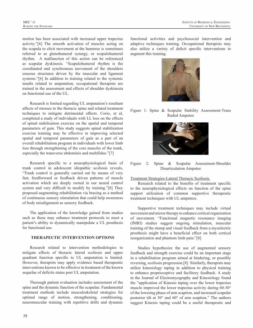
58
MEC ‘11raIsIng the standard
InsItute of BIomedIcal engIneerIng
unIversIty of new BrunswIck
motion has been associatedwith increased upper trapeziusactivity.”[6] The smooth activation of muscles acting onthescapulatoelicitmovementatthehumerusissometimesreferred to as glenohumeral synergy, or scapulohumeralrhythm. A malfunction of this action can be referencedas scapular dyskinesis. “Scapulohumeral rhythm is thecoordinated and synchronous movement of the shouldersosseous structures driven by the muscular and ligamentsystems.”[6] In addition to training related to the systemicinsults related to amputation, occupational therapists aretrainedintheassessmentandeffectsofshoulderdyskinesiaonfunctionaluseoftheUL.
ResearchislimitedregardingULamputation’sresultantaffectsofstressestothethoracicspineandrelatedtreatmenttechniques to mitigate detrimental effects. Corio, et al,completedastudyofindividualswithLLlossontheeffectsof spinal stabilization exercise on the spatial and temporalparametersofgain.This studysuggests spinal stabilizationexercise training may be effective in improving selectedspatial and temporal parameters of gain as a part of anoverallrehabilitationprograminindividualswithlowerlimblossthroughstrengtheningofthecoremusclesofthetrunk,especiallythetransverseabdominisandmultifidus.”[7]
Research specific to a neurophysiological basis oftrunk control in adolescent idiopathic scoliosis reveals,“Trunk control is generally carried out by means of veryfast, feedforward or feedback driven patterns of muscleactivation which are deeply rooted in our neural controlsystem and very difficult to modify by training.”[8] Theyproposedaugmentingrehabilitationviabracingasamethodofcontinuoussensorystimulationthatcouldhelpawarenessofbodymisalignmentassensoryfeedback.
The application of the knowledge gained from studiessuch as these may enhance treatment protocols to meet apatient’sability todynamicallymanipulateaULprosthesisforfunctionaluse.
THERAPEUTIC INTERVENTION OPTIONS
Research related to intervention methodologies tomitigate effects of thoracic lateral scoliosis and upperquadrant function specific to UL amputation is limited.However, therapistsmay apply evidence based therapeuticinterventionsknowntobeeffectiveintreatmentoftheknownsequelaeofdeficitsstatuspostULamputation.
Thoroughpatientevaluationincludesassessmentofthespineandthedynamicfunctionofthescapulae.Fundamentaltreatment methods include musculoskeletal strategies foroptimal range of motion, strengthening, conditioning,neuromuscular training with repetitive drills and dynamic
functional activities and psychosocial intervention andadaptive techniques training. Occupational therapists mayalso utilize a variety of deficit specific interventions toaugmentthistraining.
Figure 1: Spine & Scapular Stability Assessment-TransRadialAmputee
Figure 2: Spine & Scapular Assessment-ShoulderDisarticulationAmputee
TreatmentStrategies-LateralThoracicScoliosisResearch related to the benefits of treatment specific
to the neurophysiological effects on function of the spinesupport utilization of common supportive therapeutictreatmenttechniqueswithULamputees.
Supportive treatment techniques may include virtualmovementandmirrortherapytoenhancecorticalorganizationof movement. “Functional magnetic resonance imaging(fMRI) studies suggest ongoing stimulation, musculartrainingofthestumpandvisualfeedbackfromamyoelectricprosthesis might have a beneficial effect on both corticalreorganizationandphantomlimbpain.”[8]
Studies hypothesize the use of augmented sensoryfeedbackandstrengthexercisecouldbeanimportantstagein a rehabilitationprogramaimedathindering,orpossiblyreversing,scoliosisprogression.[8]Similarly,therapistsmayutilize kinesiology taping in addition to physical trainingto enhance proprioceptive and facilitory feedback.A studyin theJournalofElectromyographyandKinesiologyfoundthe“applicationofKinesio tapingover the lower trapeziusmuscleimprovedthelowertrapeziusactivityduring60-30°oftheloweringphaseofarmscaption,andincreasedscapularposterior tilt at 30° and60° of arm scaption.”The authorssuggest Kinesio taping could be a useful therapeutic and
59
InsItute of BIomedIcal engIneerIng
unIversIty of new BrunswIck
MEC ‘11raIsIng the standard
prophylacticassistanceboth in the rehabilitationclinicandinthefield.[9]TheconceptsforutilizationofthistreatmenttechniquemayproveusefulforULamputeetrainingforbodyawarenesstraining.
Therapeutic intervention for pain mediation related toperipheralnerve insult isalsoavaluable tool for treatmentof theUL amputee. Therapist attention to neural tension,neuromuscular conditioning, posture with activity andeducation for optimal musculoskeletal tissue healing isnecessary.
ULamputeesareoftenplacedinthepositionofmappingnew motor learning outside of their years of physicaldevelopment.Assuch,learningnewmotorskillscanbeanexceptional challenge. Progressive repetitive training forhighleveldynamicprosthesisfunctionisrequiredforoptimalmotormapping. A treatmentmindset similar to that usedwhen training athletes ormusiciansmay be advantageous.Internationallyrecognizedathletictrainingandconditioningexpert,VernGambettaexplainsfunctionaltrainingthisway,“Function employs an integrated (as opposed to isolated)approach.Itinvolvesmovementofmultiplebodyparts,andthemovementinvolvesmultipleplanes.Itisnotamatteroffunctionalornon-functional;ratheritisanunderstandingofhowfunctionalaparticularmovementorexerciseisrelativetothetrainingobjective.”[9]
REHABILITATION COLLABORATION
Asmembersoftherehabilitationteam,itisimperativetobeawareof the trainingand research resultsother teammembers bring to this topic.According toDonatelli, “Oneof themost direct relationships between the spine and theshoulder girdle is through muscle, tendon and fascialattachments.”[10]Smurr,etalreports,“Coordinatingtherapyeffortstoaddresstheoverallphysicaldeficitsassociatedwithamputation are imperative.”[5] She goes on to address theimportanceofpartneringwithphysicaltherapiststoaddresspostural symmetry and training. “Use of a combination ofmethods to train for optimal dynamics performance of theupperquadrantisindispensable.”[5]
The research of Yancosek, et al, highlights theopportunities to learn from the research and training ofbothoccupationalandphysicaltherapistsskilledintreatingamputees.Their2009studyontheeffectsofULprosthesisuse during gain in patients with concomitant LL losshighlightstheeffectsofupperquadrantfunctionongait.Thisreport surmises, “Trunk rotation and associated arm swingarecriticalcomponents tohumangait.Armswinghasalsobeenpurportedasthemotionthatisusefulincounteractingthetrunkrotationingait.Further,ithasbeensuggestedthatabnormaltrunkmotioninanyplanemayresultindecreased
stabilizationandpoorer locomotorcontrol.”[11]This studyalsofoundthatthedifferencebetweenthegaitpatternoftheuninjuredcontrolgroupversustheUL/LLamputationgroupwere fewer when the subjects wore their prostheses. Thisresultisanexampleofmeaningfulinformationavailableforthe UL amputation rehabilitation team. Patients generallyperform functional tasks in a dynamic fashion such asstanding,walking, bending and reaching.Theuse of aULprosthesis to perform these tasks calls for an overarchingteamapproachtorehabilitation.
CONCLUSION
It is essential todevelopacomprehensiveapproach torehabilitation within the context of occupational therapyandlikewisetherehabilitationteam.Thefoundationforthisapproachbeginswiththehealthcareprofessionalsworkinginpartnershipwiththepatient.Successfulfunctionaloperationof an UL prosthesis is comprised of the coordination ofinterventiontoaddressthemanyphysicalsystemsaffected.
Further research is required to definitively ascertainthefunctionalresultofthesephysicalinsultsspecifictoULamputation. Longitudinal studies to ascertain the effectsof UL amputation on the thoracic spine and presence ofsubsequentscapuladyskinesiawithcomparisonofeffectsbyamputationlevelmaybeofbenefit.Subsequentresearchtoidentify the therapeutic treatment techniques best suited topreventordiminish thenegative impactof theseeffectsondynamic functional prosthesis usewill enhanceULpatientrehabilitationandsuccess.
REFERENCES
[1] TheWarAmps,Health&medicalissues,Posture&BackProblems”,Retrieved2/22/2011,www.waramps.ca/nac/health.html.
[2] B.Greitemann,V.Güth,R.Baumgartner,“Asymmetryofpostureandtruncalmusculaturefollowingunilateralarmamputation-aclinicalelectromyographic,postureanalyticalandphotogrammetricstudy.”ZOrthopIhreGrenzgeb.Nov-Dec;134(6):498-510,1996.
[3] K.A. Solonen, H.J. Rinne, M. Viikeri, and E. Karvinen, “Latesequelae of amputation, a summary.” Annates Chirurgiae etGynaecologiaeFenniae,vol.54,Supplementum138,1965.
[4] C.Lambert,J.Sciora,“Theincidenceofscoliosis in the juvenileamputeepopulation,”ICIB,vol.11,num.2,1971.
[5] L.Smurr,K.Gulick,KYancosek,O.Ganz,“Managingtheupperextremityamputee:aprotocolforsuccess,treatingthewarcasualty,”JournalofHandTherapy,April-June,p.160-175,2008.
[6] T.Skirven,A.Osterman,J.Federoczyk,P.Amadio,RehabilitationoftheHandandUpperExtremity,sixthedition,p.1211-1212,2011.
[7] F.Corio,R.Troiano,J.Magel,“Theeffectsofspinalstabilizationexercisesonthespatialandtemporalparametersofgaininindividualswith lower limb loss,” Journal of Prosthetics&Orthotics, Issue 4,pp230-236,October,2010.
[8] N.Smania,A.Picelli,M.Romano,S.Negrini,“Neurophysicologicalbasisofrehabilitationofadolescentidiopathicscoliosis,”Disability&Rehabilitation,vol.20,num.10,pp.763-771,2008.
60
MEC ‘11raIsIng the standard
InsItute of BIomedIcal engIneerIng
unIversIty of new BrunswIck
[9] YH.Hsu,WY.ChenHC.Lin,W.Wang,YF. Shih, “The effectsof training on scapular kinematics and muscle performance inbaseball players with shoulder impingement syndrome,” Journal ofElectromyographyandKinesiology,vol.19,pp.1092-1099,2009.
[10] F.E.Roux,D,Ibarrola,Y.Lazorthes,I.Berry,“Virtualmovementsactivate primary sensorimotor areas in amputees: report of threecases,”Neurosurgery,vol.49,issue3,pp.736-742,September,2001.
[11] V. Gambetta, “Athletic Development”, The Art & Science ofFunctionalSportsConditioning,p.3,2007.
[12] R.Donatelli,PhysicalTherapyoftheShoulder,fourthedition,pp.179-180,2004.
[13] K.Yancosek,B.Schnall,B.Baum,“Impactofupperlimbprosthesisongait:acasestudy,”JournalofProsthetics&Orthotics:,October,Volume,20,Issue4,pp.163-166,2008.
61
InsItute of BIomedIcal engIneerIng
unIversIty of new BrunswIck
MEC ‘11raIsIng the standard
ABSTRACT
Thepotentialforpatternrecognitiontoimprovepoweredprosthesis control has beendiscussed formanyyears.Oneremainingbarriertoat-homeuseofthesetechniquesisthatpracticalmethodsofuserpromptingduringsystemtrainingare lacking. Most research and development of patternrecognitionsystemsforprosthesiscontrolhasreliedonon-screen cues to prompt the prosthesis wearer during signalcollection; thereforemost systems require connection to acomputerorexternaldevice.Wehavedevelopedamethodcalled Prosthesis-Guided Training (PGT) to address thisissue. In PGT, the prosthesis itself moves through a pre-programmed sequence ofmotions to prompt thewearer toelicit theappropriatemusclecontractions.PGTrequiresnoextra hardware and allows wearers to retrain, refresh, orrecalibrate the controller inmany locations and situations.Training via PGT is self-initiated and requires only about1minuteof thewearer’s time.Furthermore,PGTprovidesa practical mechanism for overcoming malfunctioning orchanging inputs, addresses differences in routine donning,andresultsinacquisitionofmyoelectricsignalsrepresentativeof those elicited during functional use. Qualitative andquantitativedataacquiredtoinvestigatetheefficacyofPGTsuggestthatitisanintuitive,effective,andclinicallyviablemethodoftrainingpatternrecognition–controlledprostheses.
BACKGROUND
The end goal of myoelectric pattern recognition forcontrol of upper-extremity prostheses has been successfuluse for a prosthesiswearer in their home and community.Previously, the use of pattern recognition for real-timecontrol of take-home myoelectric prostheses was notpossiblebecauseofthelimitedspeedandcomputingpowerofavailablemicrocontrollers.Inrecentyears,technologicaladvancementshaveeliminatedthisconstraint.
Manyadditionaladvancementshavealsobeenmadetovarious elements of myoelectric signal pattern recognitionsystems.Theseincluderefinementofclassificationalgorithms[1-7],improvedrecordingelectrodes[8],improvementstothestabilityoftheelectrode-skininterface[9],anddevelopmentof advanced prosthetic components [10-12]. In addition,conditioningofinputandoutputsignalshasbeenshownto
significantlyenhancethefunctionalityofpatternrecognitioncontrol[7,13].
Despite the progress that has been made, there isa remaining barrier to the clinical feasibility of patternrecognition prosthesis control.This barrier stems from thefactthatwearersarerequiredtotrainthepatternrecognitionsystembyprovidingtheprosthesiscontrollerwithexamplepatterns of myoelectric signals for each desired motion.Thesesignalsareusedtoconstructthepatternclassificationparametersusedby thecontrol algorithm.Frequent systemtraining is often required, as changes in environmentaltemperature,limbsweating,slightlimbvolumefluctuations,muscle fatigue, changes to socket alignment or loading,andelectrodeorwirefailurecanallcause theperformanceofthesystemtodegradesignificantly,resultinginalossoffunction.Without a simple and intuitivemethodof systemretraining,patternrecognitioncontrolmaynot findclinicalacceptance[14].
SCREEN-GUIDED TRAINING
Pattern recognition systems for prosthesis control arecommonlytrainedusingvisualprompts(stillpictures, text,videos, etc.) displayed on a computer screen to guide thewearerthroughasequenceofdesiredmovements[2,6,7,13](Figure 1a).This iswhatwe termScreen-GuidedTraining(SGT). The visual cues presented during SGT provide thetimesequenceforrecordingthemyoelectricsignalsforeachmotion class. Because of the long-standing popularity ofSGT,itisoftentheonlytechniqueconsideredforpromptingthewearerduringthesystemtrainingofmyoelectricpatternrecognition systems. Successful use of pattern recognitionprosthesiscontrolintheclinicalorhomesettingrequiresanapproachtosystemtrainingthatisintuitiveandrequireslittletonoadditionalhardwareortechnologicalcapability.
PROSTHESIS-GUIDED TRAINING
OverviewProsthesis-GuidedTraining (PGT) is aneasy, intuitive
method of user prompting for training and calibration ofpatternrecognition-controlledprostheses.Theconceptitselfis simple: to train, refresh, or recalibrate the controller,wearers press and hold a button (a 2s hold is used in the
PROSTHESIS-GUIDED TRAINING FOR PRACTICAL USE OF PATTERN RECOGNITION CONTROL OF PROSTHESES
BlairA.Lock1,AnnM.Simon1,KathyStubblefield1,andLeviJ.Hargrove1,2
1CenterforBionicMedicine,RehabilitationInstituteofChicago,Chicago,Illinois,USA2DepartmentofPhysicalMedicineandRehabilitation,NorthwesternUniversity,Chicago,Illinois,USA
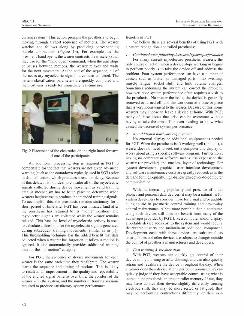
62
MEC ‘11raIsIng the standard
InsItute of BIomedIcal engIneerIng
unIversIty of new BrunswIck
currentsystem).Thisactionpromptstheprosthesistobeginmoving through a short sequence of motions. The wearerwatches and follows along by producing correspondingmuscle contractions (Figure 1b). For example, as theprosthetichandopens,thewearercontractsthemuscle(s)thattheyuseforthe“handopen”command;whenthearmstopsor pauses between motions, the wearer relaxes and waitsfor the nextmovement.At the end of the sequence, all ofthenecessarymyoelectric signalshavebeencollected.Thepattern classificationparameters are quickly computed andtheprosthesisisreadyforimmediatereal-timeuse.
Fig.2Placementoftheelectrodesontherighthandforearmofoneoftheparticipants.
An additional processing step is required in PGT tocompensateforthefactthatwearersarenotgivenadvancedwarning(suchasthecountdowntypicallyusedinSGT)priortodatacollection,whichproducesareactiondelay.Becauseofthisdelay,itisnotidealtoconsiderallofthemyoelectricsignalscollectedduringdevicemovementasvalid trainingdata.A mechanism has to be in place to determine whenwearersbegin/ceasetoproducetheintendedtrainingsignals.To accomplish this, the prosthesis remains stationary for ashortperiodoftimeafterPGThasbeeninitiated(andafterthe prosthesis has returned to its “home” position) andmyoelectric signals are collectedwhile thewearer remainsrelaxed.This baseline level ofmyoelectric activity is usedtocalculateathresholdforthemyoelectricsignalsgeneratedduring subsequent training movements (similar as in [1]).This thresholdingtechniquehas theaddedbenefit thatdatacollectedwhenawearerhasforgottentofollowamotionisignored. It also automatically provides additional trainingdataforthe“no-motion”category.
For PGT, the sequence of devicemovements for eachwearer is the same each time they recalibrate.Thewearerlearns the sequence and timing of motions. This is likelytoresult inanimprovementinthequalityandrepeatabilityof theelicitedsignalpatternsover time, thecomfortof thewearerwiththesystem,andthenumberoftrainingsessionsrequiredtoproducesatisfactorysystemperformance.
BenefitsofPGTWebelievethereareseveralbenefitsofusingPGTwith
apatternrecognition–controlledprosthesis:
1. ContinuedwearfollowingdecreasedsystemperformanceFor many current myoelectric prosthesis wearers, the
onlycourseofactionwhenadevicestopsworkingorbeginstoperformpoorly is to take thedeviceoffandaddress theproblem. Poor system performance can have a number ofcauses, such as broken or damaged parts, limb sweating,muscle fatigue, socket shift, and limb volume changes.Sometimes redonning the system can correct the problem;however,poorsystemperformanceoftenrequiresavisit totheprosthetist.Nomatter the issue, thedevice isgenerallyremovedorturnedoff,andthiscanoccuratatimeorplacethatisveryinconvenienttothewearer.Becauseofthis,somewearersmaychoose to leaveadeviceathome.WithPGT,many of these issues that arise can be overcome withouthaving to take the arm off or even needing to knowwhatcausedthedecreasedsystemperformance.
2. NoadditionalhardwarerequirementNoexternal displayor additional equipment is needed
forPGT.Whentheprosthesisisn’tworkingwell(oratall),awearerdoesnotneedtoseekoutacomputeranddisplayorworryaboutusingaspecificsoftwareprogram.Furthermore,havingnocomputeror softwaremeans lessexpense to thewearer (or provider) and one less layer of technology. Forsystem developers, graphical user interface developmentandsoftwaremaintenancecostsaregreatlyreduced,asisthedemandforhigh-quality,high-bandwidthdevice-to-computercommunication.
With the increasing popularity and presence of smartphonesandpersonaldatadevices,itmaybeanaturalfitforsystemdeveloperstoconsiderthoseforvisualand/oraudiblecuing to aid in prosthetic control training and day-to-daycontrolmaintenance.Albeitmoreportablethanacomputer,using suchdevices still doesnotbenefit frommanyof theadvantagesprovidedbyPGT.Likeacomputerand/ordisplay,aportabledeviceaddscosttothesystemandwouldrequirethewearer to carry andmaintain anadditional component.Development costs with these devices are substantial, assmartphonesandotherdevicesaresubjecttochangesoutsidethecontrolofprosthesismanufacturersanddevelopers.
3. Fasttraining&recalibrationWith PGT, wearers can quickly get control of their
deviceinthemorningorafterdonning,andcanalsoquicklyretrainandrecalibratethedevicethroughouttheday. Whenawearerdonstheirdeviceafteraperiodofnon-use,theycanquicklyjudgeif theyhaveacceptablecontrolusingwhatisstoredintheprosthesis’microcontrollermemory.Ifnot,theymay have donned their device slightly differently causingelectrode shift, theymay bemore rested or fatigued, theymay be performing contractions differently, or their skin
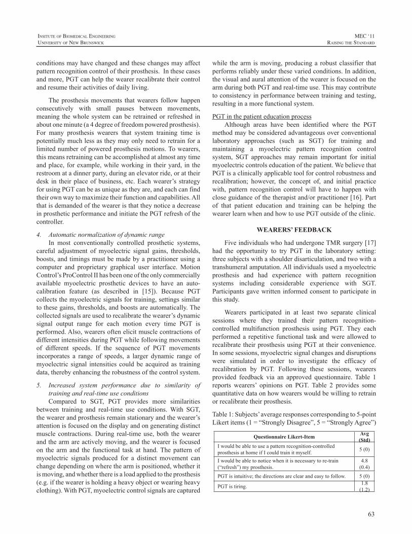
63
InsItute of BIomedIcal engIneerIng
unIversIty of new BrunswIck
MEC ‘11raIsIng the standard
conditionsmayhavechangedandthesechangesmayaffectpatternrecognitioncontroloftheirprosthesis.Inthesecasesandmore,PGTcanhelpthewearerrecalibratetheircontrolandresumetheiractivitiesofdailyliving.
Theprosthesismovements thatwearers followhappenconsecutively with small pauses between movements,meaning thewholesystemcanbe retrainedor refreshed inaboutoneminute(a4degreeoffreedompoweredprosthesis).For many prosthesis wearers that system training time ispotentiallymuchlessastheymayonlyneedtoretrainforalimitednumberofpoweredprosthesismotions.Towearers,thismeansretrainingcanbeaccomplishedatalmostanytimeandplace, forexample,whileworking in theiryard, in therestroomatadinnerparty,duringanelevatorride,orattheirdesk in theirplaceofbusiness, etc.Eachwearer’s strategyforusingPGTcanbeasuniqueastheyare,andeachcanfindtheirownwaytomaximizetheirfunctionandcapabilities.AllthatisdemandedoftheweareristhattheynoticeadecreaseinprostheticperformanceandinitiatethePGTrefreshofthecontroller.
4. AutomaticnormalizationofdynamicrangeIn most conventionally controlled prosthetic systems,
careful adjustment ofmyoelectric signal gains, thresholds,boosts,andtimingsmustbemadebyapractitionerusingacomputer and proprietary graphical user interface.MotionControl’sProControlIIhasbeenoneoftheonlycommerciallyavailable myoelectric prosthetic devices to have an auto-calibration feature (as described in [15]). Because PGTcollectsthemyoelectricsignalsfortraining,settingssimilartothesegains,thresholds,andboostsareautomatically.Thecollectedsignalsareusedtorecalibratethewearer’sdynamicsignal output range for each motion every time PGT isperformed.Also,wearersoftenelicitmusclecontractionsofdifferentintensitiesduringPGTwhilefollowingmovementsof different speeds. If the sequence of PGT movementsincorporates a range of speeds, a larger dynamic range ofmyoelectric signal intensities couldbe acquiredas trainingdata,therebyenhancingtherobustnessofthecontrolsystem.
5. Increased system performance due to similarity oftrainingandreal-timeuseconditionsCompared to SGT, PGT provides more similarities
between training and real-time use conditions.With SGT,thewearerandprosthesisremainstationaryandthewearer’sattentionisfocusedonthedisplayandongeneratingdistinctmuscle contractions.During real-timeuse,both thewearerandthearmareactivelymoving,andthewearerisfocusedon the armand the functional task at hand.Thepatternofmyoelectric signals produced for a distinct movement canchangedependingonwherethearmispositioned,whetheritismoving,andwhetherthereisaloadappliedtotheprosthesis(e.g.ifthewearerisholdingaheavyobjectorwearingheavyclothing).WithPGT,myoelectriccontrolsignalsarecaptured
while thearm ismoving,producinga robustclassifier thatperformsreliablyunderthesevariedconditions.Inaddition,thevisualandauralattentionofthewearerisfocusedonthearmduringbothPGTandreal-timeuse.Thismaycontributetoconsistencyinperformancebetweentrainingandtesting,resultinginamorefunctionalsystem.
PGTinthepatienteducationprocessAlthough areas have been identified where the PGT
methodmaybeconsideredadvantageousoverconventionallaboratory approaches (such as SGT) for training andmaintaining a myoelectric pattern recognition controlsystem, SGT approaches may remain important for initialmyoelectriccontrolseducationofthepatient.WebelievethatPGTisaclinicallyapplicabletoolforcontrolrobustnessandrecalibration; however, the concept of, and initial practicewith, pattern recognition controlwill have to happenwithcloseguidanceofthetherapistand/orpractitioner[16].Partof that patient education and training can be helping thewearerlearnwhenandhowtousePGToutsideoftheclinic.
WEARERS’ FEEDBACK
FiveindividualswhohadundergoneTMRsurgery[17]had the opportunity to try PGT in the laboratory setting:threesubjectswithashoulderdisarticulation,andtwowithatranshumeralamputation.Allindividualsusedamyoelectricprosthesis and had experience with pattern recognitionsystems including considerable experience with SGT.Participantsgavewritteninformedconsenttoparticipateinthisstudy.
Wearers participated in at least two separate clinicalsessions where they trained their pattern recognition-controlled multifunction prosthesis using PGT. They eachperformeda repetitive functional taskandwereallowed torecalibrate theirprosthesisusingPGTat theirconvenience.Insomesessions,myoelectricsignalchangesanddisruptionswere simulated in order to investigate the efficacy ofrecalibration by PGT. Following these sessions, wearersprovided feedback via an approved questionnaire. Table 1reports wearers’ opinions on PGT. Table 2 provides somequantitativedataonhowwearerswouldbewillingtoretrainorrecalibratetheirprosthesis.
Table1:Subjects’averageresponsescorrespondingto5-pointLikertitems(1=“StronglyDisagree”,5=“StronglyAgree”)
Questionnaire Likert-Item Avg (Std)
Iwouldbeabletouseapatternrecognition-controlledprosthesisathomeifIcouldtrainitmyself. 5(0)
Iwouldbeabletonoticewhenitisnecessarytore-train(“refresh”)myprosthesis.
4.8(0.4)
PGTisintuitive;thedirectionsareclearandeasytofollow. 5(0)
PGTistiring. 1.8(1.2)
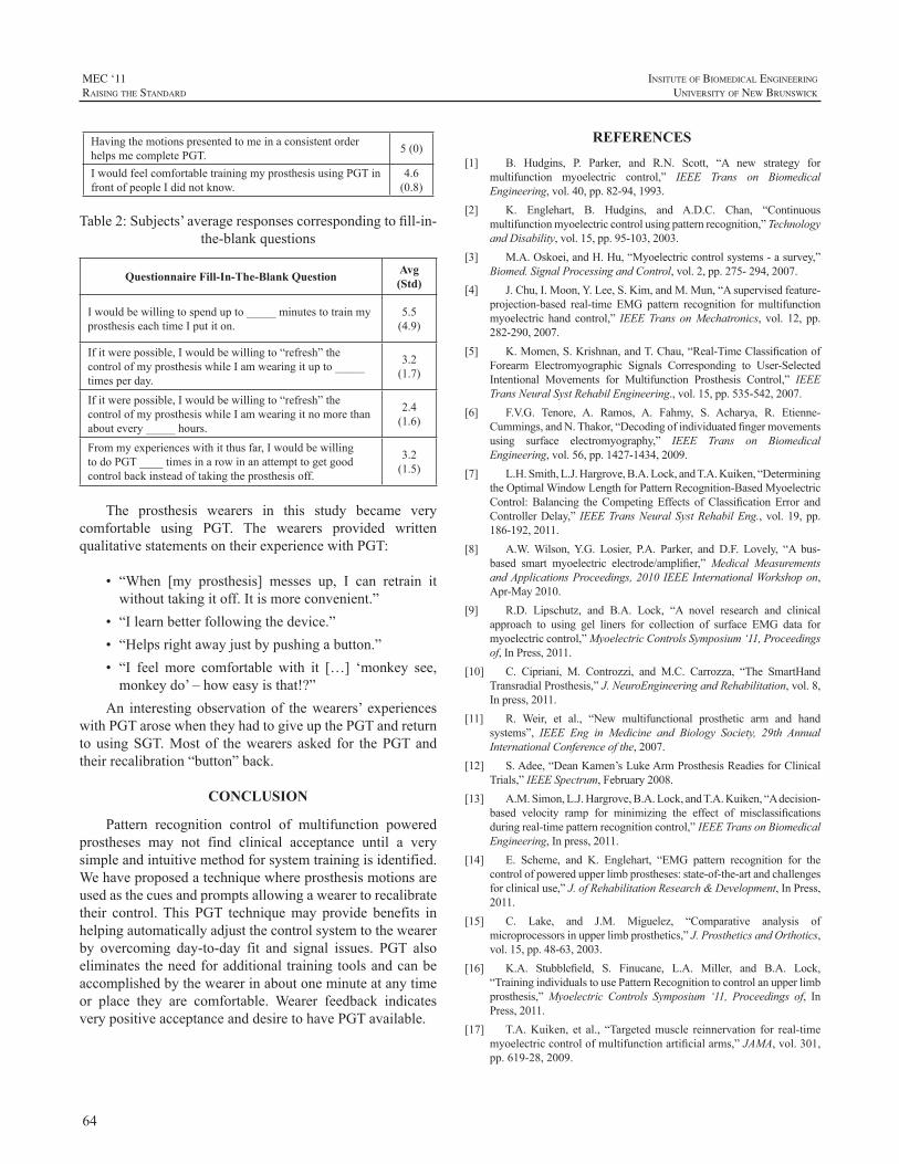
64
MEC ‘11raIsIng the standard
InsItute of BIomedIcal engIneerIng
unIversIty of new BrunswIck
HavingthemotionspresentedtomeinaconsistentorderhelpsmecompletePGT. 5(0)
IwouldfeelcomfortabletrainingmyprosthesisusingPGTinfrontofpeopleIdidnotknow.
4.6(0.8)
Table2:Subjects’averageresponsescorrespondingtofill-in-the-blankquestions
Questionnaire Fill-In-The-Blank Question Avg (Std)
Iwouldbewillingtospendupto_____minutestotrainmyprosthesiseachtimeIputiton.
5.5(4.9)
Ifitwerepossible,Iwouldbewillingto“refresh”thecontrolofmyprosthesiswhileIamwearingitupto_____timesperday.
3.2(1.7)
Ifitwerepossible,Iwouldbewillingto“refresh”thecontrolofmyprosthesiswhileIamwearingitnomorethanaboutevery_____hours.
2.4(1.6)
Frommyexperienceswithitthusfar,IwouldbewillingtodoPGT____timesinarowinanattempttogetgoodcontrolbackinsteadoftakingtheprosthesisoff.
3.2(1.5)
The prosthesis wearers in this study became verycomfortable using PGT. The wearers provided writtenqualitativestatementsontheirexperiencewithPGT:
• “When [my prosthesis] messes up, I can retrain itwithouttakingitoff.Itismoreconvenient.”
• “Ilearnbetterfollowingthedevice.”• “Helpsrightawayjustbypushingabutton.”• “I feel more comfortable with it […] ‘monkey see,monkeydo’–howeasyisthat!?”
An interestingobservationof thewearers’ experienceswithPGTarosewhentheyhadtogiveupthePGTandreturntousingSGT.Most of thewearers asked for thePGTandtheirrecalibration“button”back.
CONCLUSION
Pattern recognition control of multifunction poweredprostheses may not find clinical acceptance until a verysimpleandintuitivemethodforsystemtrainingisidentified.Wehaveproposedatechniquewhereprosthesismotionsareusedasthecuesandpromptsallowingawearertorecalibratetheir control.This PGT techniquemay provide benefits inhelpingautomaticallyadjustthecontrolsystemtothewearerby overcoming day-to-day fit and signal issues. PGT alsoeliminates theneedforadditional trainingtoolsandcanbeaccomplishedbythewearerinaboutoneminuteatanytimeor place they are comfortable. Wearer feedback indicatesverypositiveacceptanceanddesiretohavePGTavailable.
REFERENCES
[1] B. Hudgins, P. Parker, and R.N. Scott, “A new strategy formultifunction myoelectric control,” IEEE Trans on BiomedicalEngineering,vol.40,pp.82-94,1993.
[2] K. Englehart, B. Hudgins, and A.D.C. Chan, “Continuousmultifunctionmyoelectriccontrolusingpatternrecognition,”TechnologyandDisability,vol.15,pp.95-103,2003.
[3] M.A.Oskoei,andH.Hu,“Myoelectriccontrolsystems-asurvey,”Biomed.SignalProcessingandControl,vol.2,pp.275-294,2007.
[4] J.Chu,I.Moon,Y.Lee,S.Kim,andM.Mun,“Asupervisedfeature-projection-based real-time EMG pattern recognition formultifunctionmyoelectric hand control,” IEEETrans onMechatronics, vol. 12, pp.282-290,2007.
[5] K.Momen,S.Krishnan,andT.Chau,“Real-TimeClassificationofForearm Electromyographic Signals Corresponding to User-SelectedIntentional Movements for Multifunction Prosthesis Control,” IEEETransNeuralSystRehabilEngineering.,vol.15,pp.535-542,2007.
[6] F.V.G. Tenore, A. Ramos, A. Fahmy, S. Acharya, R. Etienne-Cummings,andN.Thakor,“Decodingofindividuatedfingermovementsusing surface electromyography,” IEEE Trans on BiomedicalEngineering,vol.56,pp.1427-1434,2009.
[7] L.H.Smith,L.J.Hargrove,B.A.Lock,andT.A.Kuiken,“DeterminingtheOptimalWindowLengthforPatternRecognition-BasedMyoelectricControl:Balancing theCompetingEffects ofClassificationError andControllerDelay,” IEEETransNeuralSystRehabilEng.,vol.19,pp.186-192,2011.
[8] A.W.Wilson,Y.G. Losier, P.A. Parker, and D.F. Lovely, “A bus-based smart myoelectric electrode/amplifier,”Medical MeasurementsandApplicationsProceedings,2010IEEEInternationalWorkshopon,Apr-May2010.
[9] R.D. Lipschutz, and B.A. Lock, “A novel research and clinicalapproach to using gel liners for collection of surface EMG data formyoelectriccontrol,”MyoelectricControlsSymposium‘11,Proceedingsof,InPress,2011.
[10] C. Cipriani, M. Controzzi, and M.C. Carrozza, “The SmartHandTransradialProsthesis,”J.NeuroEngineeringandRehabilitation,vol.8,Inpress,2011.
[11] R. Weir, et al., “New multifunctional prosthetic arm and handsystems”, IEEE Eng in Medicine and Biology Society, 29th AnnualInternationalConferenceofthe,2007.
[12] S.Adee,“DeanKamen’sLukeArmProsthesisReadiesforClinicalTrials,”IEEESpectrum,February2008.
[13] A.M.Simon,L.J.Hargrove,B.A.Lock,andT.A.Kuiken,“Adecision-based velocity ramp for minimizing the effect of misclassificationsduringreal-timepatternrecognitioncontrol,” IEEETransonBiomedicalEngineering,Inpress,2011.
[14] E. Scheme, and K. Englehart, “EMG pattern recognition for thecontrolofpoweredupperlimbprostheses:state-of-the-artandchallengesforclinicaluse,”J.ofRehabilitationResearch&Development,InPress,2011.
[15] C. Lake, and J.M. Miguelez, “Comparative analysis ofmicroprocessorsinupperlimbprosthetics,”J.ProstheticsandOrthotics,vol.15,pp.48-63,2003.
[16] K.A. Stubblefield, S. Finucane, L.A. Miller, and B.A. Lock,“TrainingindividualstousePatternRecognitiontocontrolanupperlimbprosthesis,”Myoelectric Controls Symposium ‘11, Proceedings of, InPress,2011.
[17] T.A.Kuiken, et al., “Targetedmuscle reinnervation for real-timemyoelectriccontrolofmultifunctionartificialarms,”JAMA,vol.301,pp.619-28,2009.
65
InsItute of BIomedIcal engIneerIng
unIversIty of new BrunswIck
MEC ‘11raIsIng the standard
ABSTRACT
Aremainingbarriertotheclinicalaccessibilityofpatternrecognition systems is the lack of practical methods toacquirethemyoelectricsignalsrequiredtotrainthesystem.Manycurrentmethodsinvolvescreen-guidedtraining(SGT),wherewearers connected to an external computer performmusclecontractionssynchronizedwithasequenceofvisualcues. The system complexity prevents easy retrainingwhen signal conditions change. We have developed amethod called prosthesis-guided training (PGT), wheretheprosthesisitselfprovidesthecuesbymovingthroughasequenceofpreprogrammedmotions;screenpromptingandexternalconnectionsareeliminated.Fiveprosthesiswearersperformed a repetitive clothespin placement task usingpattern recognition control. Wearers demonstrated similarbaselinefunctionalitybetweensystemstrainedwithPGT(10± 4 clothespins) andSGT (12± 7 clothespins) (p= 0.56).To investigate the efficacy of PGT retraining, real-worldissues (e.g. broken wires, external noise) were simulatedto accelerate control degradation. Sessions ended whenwearers indicated loss of functional control. On average,wearers maintained function through two malfunctioninginputs,placing48±17clothespins in31.6±16.2minuteswhenallowedtoretrainusingPGT.TheseresultssuggestthatPGTacquiresadequatetrainingdataandmayenablelonger-lastingfunctionaluse,potentiallyincreasingprosthesisweartimeandreducingdevicerejection.
INTRODUCTION
Pattern recognition–based control has shown promisefor myoelectric control of upper limb prostheses but hashadlimitedclinicalimplementation.Forpatternrecognitionsystemstoprogressandmoveoutsidethelaboratory,afewremainingbarriersneedtobeaddressed.Thispaperfocusesondevelopingapracticalwayforprosthesiswearerstotrainthesystem.
Existingmethods of acquiring themyoelectric signalsnecessarytotrainthesystemhavegenerallyreliedonvisual
or auditory cues. During a screen-guided training (SGT)session,wearersconnecttoanexternalcomputerandperformmusclecontractionssynchronizedwithasequenceofvisualcues[1].Thismethodhasseenwide-spreadimplementationinthelaboratorybutmaynotbepracticalforhomeuse.Therequirementforanexternaldisplayaddstosystemcomplexityandpreventseasyretrainingwhensignalconditionschange.Auditorycuescaneliminatetheneedforanexternaldisplaybut rely on the wearer to remember a preprogrammedsequenceofmovements.
Prosthesis-guided training(PGT) isanewmethod thateliminatestheneedforanexternalconnection.DuringPGT,theprosthesisprovidesthecuesforthewearer.WearersinitiatePGTbysimplypushingabutton.Theprosthesisthenmovesitselfthroughasequenceofpreprogrammedmotions.Wearersfollowalongwiththeprosthesismotionsbyperformingthenecessary muscle contractions and relaxing each time theprosthesispausesbetweenmotions.Themyoelectricsignalsthatarecollectedduringthissequenceareimmediatelyusedtotrainandrecalibratethepatternrecognitioncontrolsystem.
The goal of this studywas to investigate the efficacyof retraining a pattern recognition prosthesis system usingPGT,Wearerscanencounterseveraldifferenttypesofissuesintheirhomeandcommunitythatcancausetheirprosthesiscontrol todegrade.Faultyelectrodesandchanges insignalquality are twomajor problems that can occur during use.Wesimulatedthesereal-worldissuesatregular intervals inthelaboratorytotestwearerperformanceduringperiodsofaccelerated control degradation.Providingwearerswith aneasymethodof retrainingandrecalibrating theirprosthesisif andwhen these issues arise can increasewear time andreducedevicerejection.
METHODS
Five individuals who had undergone TMR surgeryparticipatedinthisstudy:twomaleparticipantswitharightshoulder-disarticulation(S1andS2),onefemaleparticipantwithaleftshoulder-disarticulation(S3),onemaleparticipant
PROSTHESIS-GUIDED TRAINING INCREASES FUNCTIONAL WEAR TIME AND IMPROVES TOLERANCE TO MALFUNCTIONING INPUTS OF PATTERN RECOGNITION–
CONTROLLED PROSTHESES
AnnM.Simon1*,BlairA.Lock1,KathyA.Stubblefield1,andLeviJ.Hargrove1,2
1CenterforBionicMedicine,RehabilitationInstituteofChicago,Chicago,Illinois,USA2DepartmentofPhysicalMedicineandRehabilitation,NorthwesternUniversity,Chicago,Illinois,USA
*CorrespondingAuthor:[email protected]
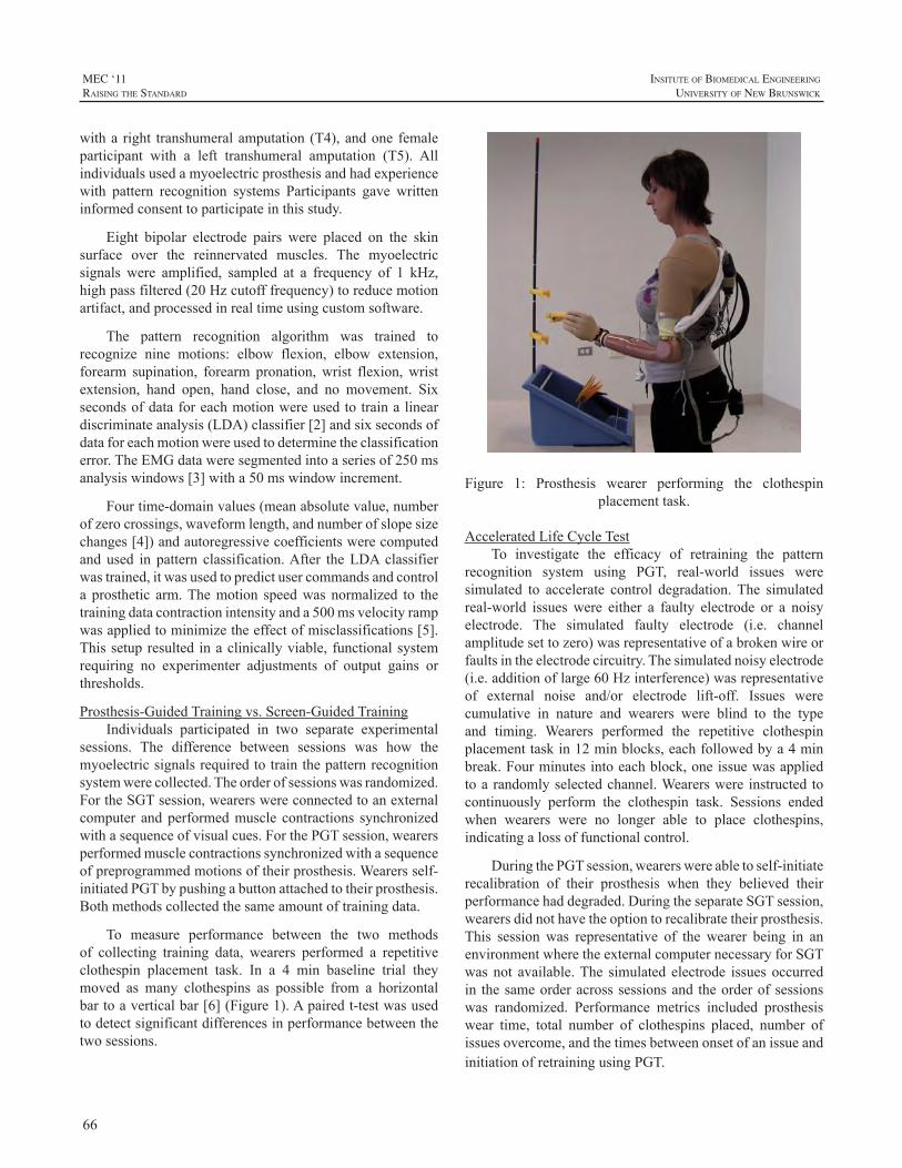
66
MEC ‘11raIsIng the standard
InsItute of BIomedIcal engIneerIng
unIversIty of new BrunswIck
witha right transhumeralamputation (T4),andone femaleparticipant with a left transhumeral amputation (T5). Allindividualsusedamyoelectricprosthesisandhadexperiencewith pattern recognition systems Participants gave writteninformedconsenttoparticipateinthisstudy.
Eight bipolar electrode pairs were placed on the skinsurface over the reinnervated muscles. The myoelectricsignals were amplified, sampled at a frequency of 1 kHz,highpassfiltered(20Hzcutofffrequency)toreducemotionartifact,andprocessedinrealtimeusingcustomsoftware.
The pattern recognition algorithm was trained torecognize nine motions: elbow flexion, elbow extension,forearm supination, forearm pronation,wrist flexion,wristextension, hand open, hand close, and no movement. Sixsecondsofdataforeachmotionwereusedtotrainalineardiscriminateanalysis(LDA)classifier[2]andsixsecondsofdataforeachmotionwereusedtodeterminetheclassificationerror.TheEMGdataweresegmentedintoaseriesof250msanalysiswindows[3]witha50mswindowincrement.
Fourtime-domainvalues(meanabsolutevalue,numberofzerocrossings,waveformlength,andnumberofslopesizechanges[4])andautoregressivecoefficientswerecomputedand used in pattern classification.After theLDAclassifierwastrained,itwasusedtopredictusercommandsandcontrola prosthetic arm.Themotion speedwas normalized to thetrainingdatacontractionintensityanda500msvelocityrampwasappliedtominimizetheeffectofmisclassifications[5].Thissetupresulted inaclinicallyviable, functionalsystemrequiring no experimenter adjustments of output gains orthresholds.
Prosthesis-GuidedTrainingvs.Screen-GuidedTrainingIndividuals participated in two separate experimental
sessions. The difference between sessions was how themyoelectricsignalsrequiredtotrainthepatternrecognitionsystemwerecollected.Theorderofsessionswasrandomized.FortheSGTsession,wearerswereconnectedtoanexternalcomputer andperformedmuscle contractions synchronizedwithasequenceofvisualcues.ForthePGTsession,wearersperformedmusclecontractionssynchronizedwithasequenceofpreprogrammedmotionsoftheirprosthesis.Wearersself-initiatedPGTbypushingabuttonattachedtotheirprosthesis.Bothmethodscollectedthesameamountoftrainingdata.
To measure performance between the two methodsof collecting training data, wearers performed a repetitiveclothespin placement task. In a 4 min baseline trial theymoved as many clothespins as possible from a horizontalbartoaverticalbar[6](Figure1).Apairedt-testwasusedtodetectsignificantdifferencesinperformancebetweenthetwosessions.
Figure 1: Prosthesis wearer performing the clothespinplacementtask.
AcceleratedLifeCycleTestTo investigate the efficacy of retraining the pattern
recognition system using PGT, real-world issues weresimulated to accelerate control degradation.The simulatedreal-world issueswere either a faulty electrode or a noisyelectrode. The simulated faulty electrode (i.e. channelamplitudesettozero)wasrepresentativeofabrokenwireorfaultsintheelectrodecircuitry.Thesimulatednoisyelectrode(i.e.additionoflarge60Hzinterference)wasrepresentativeof external noise and/or electrode lift-off. Issues werecumulative in nature and wearers were blind to the typeand timing. Wearers performed the repetitive clothespinplacementtaskin12minblocks,eachfollowedbya4minbreak.Fourminutesintoeachblock,oneissuewasappliedtoarandomlyselectedchannel.Wearerswere instructed tocontinuously perform the clothespin task. Sessions endedwhen wearers were no longer able to place clothespins,indicatingalossoffunctionalcontrol.
DuringthePGTsession,wearerswereabletoself-initiaterecalibration of their prosthesis when they believed theirperformancehaddegraded.DuringtheseparateSGTsession,wearersdidnothavetheoptiontorecalibratetheirprosthesis.This session was representative of the wearer being in anenvironmentwheretheexternalcomputernecessaryforSGTwasnot available.The simulated electrode issues occurredin thesameorderacrosssessionsand theorderofsessionswas randomized. Performance metrics included prosthesiswear time, total number of clothespins placed, number ofissuesovercome,andthetimesbetweenonsetofanissueandinitiationofretrainingusingPGT.
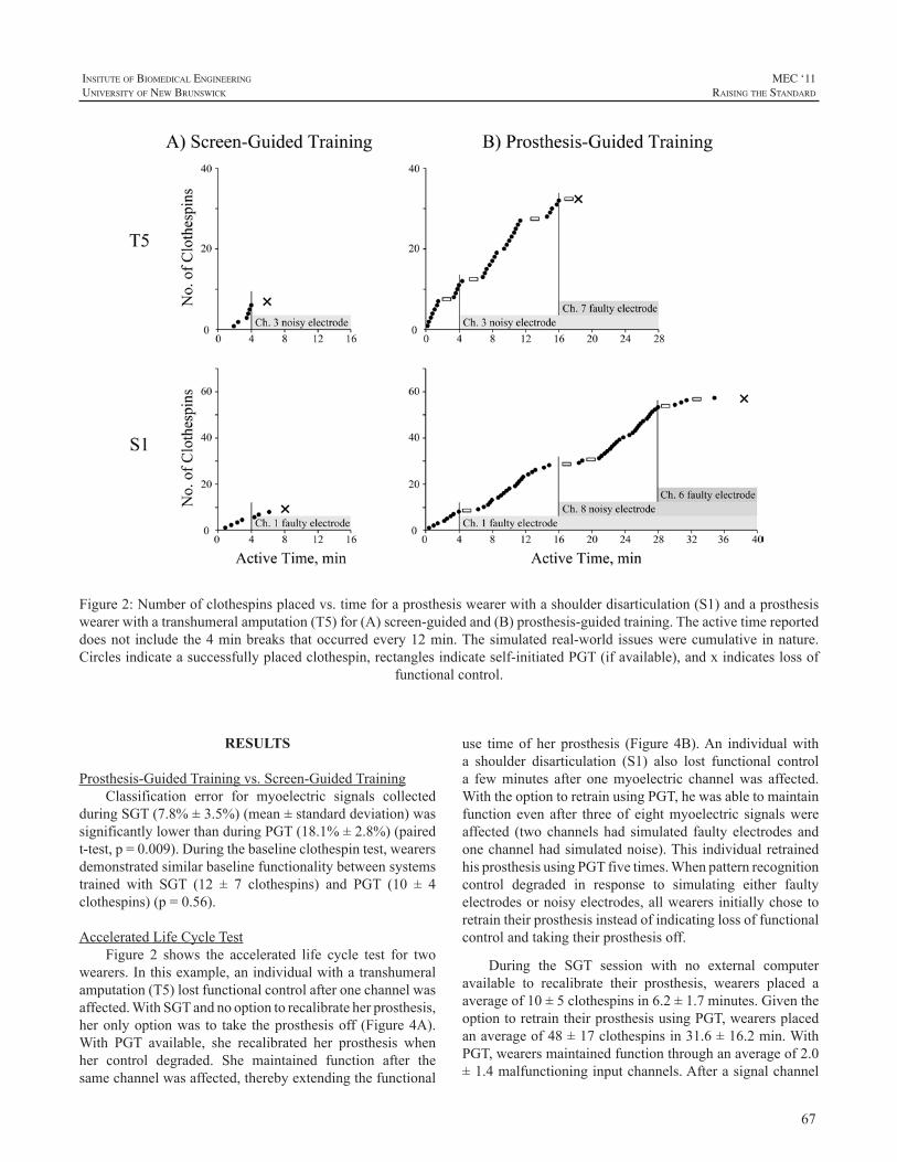
67
InsItute of BIomedIcal engIneerIng
unIversIty of new BrunswIck
MEC ‘11raIsIng the standard
RESULTS
Prosthesis-GuidedTrainingvs.Screen-GuidedTrainingClassification error for myoelectric signals collected
duringSGT(7.8%±3.5%)(mean±standarddeviation)wassignificantlylowerthanduringPGT(18.1%±2.8%)(pairedt-test,p=0.009).Duringthebaselineclothespintest,wearersdemonstratedsimilarbaselinefunctionalitybetweensystemstrained with SGT (12 ± 7 clothespins) and PGT (10 ± 4clothespins)(p=0.56).
AcceleratedLifeCycleTestFigure 2 shows the accelerated life cycle test for two
wearers.Inthisexample,anindividualwithatranshumeralamputation(T5)lostfunctionalcontrolafteronechannelwasaffected.WithSGTandnooptiontorecalibrateherprosthesis,heronlyoptionwas to take theprosthesisoff (Figure4A).With PGT available, she recalibrated her prosthesis whenher control degraded. She maintained function after thesamechannelwasaffected,therebyextendingthefunctional
Figure2:Numberofclothespinsplacedvs.timeforaprosthesiswearerwithashoulderdisarticulation(S1)andaprosthesiswearerwithatranshumeralamputation(T5)for(A)screen-guidedand(B)prosthesis-guidedtraining.Theactivetimereporteddoesnot includethe4minbreaks thatoccurredevery12min.Thesimulatedreal-world issueswerecumulative innature.Circlesindicateasuccessfullyplacedclothespin,rectanglesindicateself-initiatedPGT(ifavailable),andxindicateslossof
functionalcontrol.
use timeof her prosthesis (Figure 4B).An individualwitha shoulder disarticulation (S1) also lost functional controla fewminutes after onemyoelectric channelwas affected.WiththeoptiontoretrainusingPGT,hewasabletomaintainfunction even after threeof eightmyoelectric signalswereaffected (twochannelshad simulated faulty electrodes andonechannelhadsimulatednoise).ThisindividualretrainedhisprosthesisusingPGTfivetimes.Whenpatternrecognitioncontrol degraded in response to simulating either faultyelectrodesornoisyelectrodes,allwearersinitiallychosetoretraintheirprosthesisinsteadofindicatinglossoffunctionalcontrolandtakingtheirprosthesisoff.
During the SGT session with no external computeravailable to recalibrate their prosthesis, wearers placed aaverageof10±5clothespinsin6.2±1.7minutes.GiventheoptiontoretraintheirprosthesisusingPGT,wearersplacedanaverageof48±17clothespinsin31.6±16.2min.WithPGT,wearersmaintainedfunctionthroughanaverageof2.0±1.4malfunctioninginputchannels.Afterasignalchannel
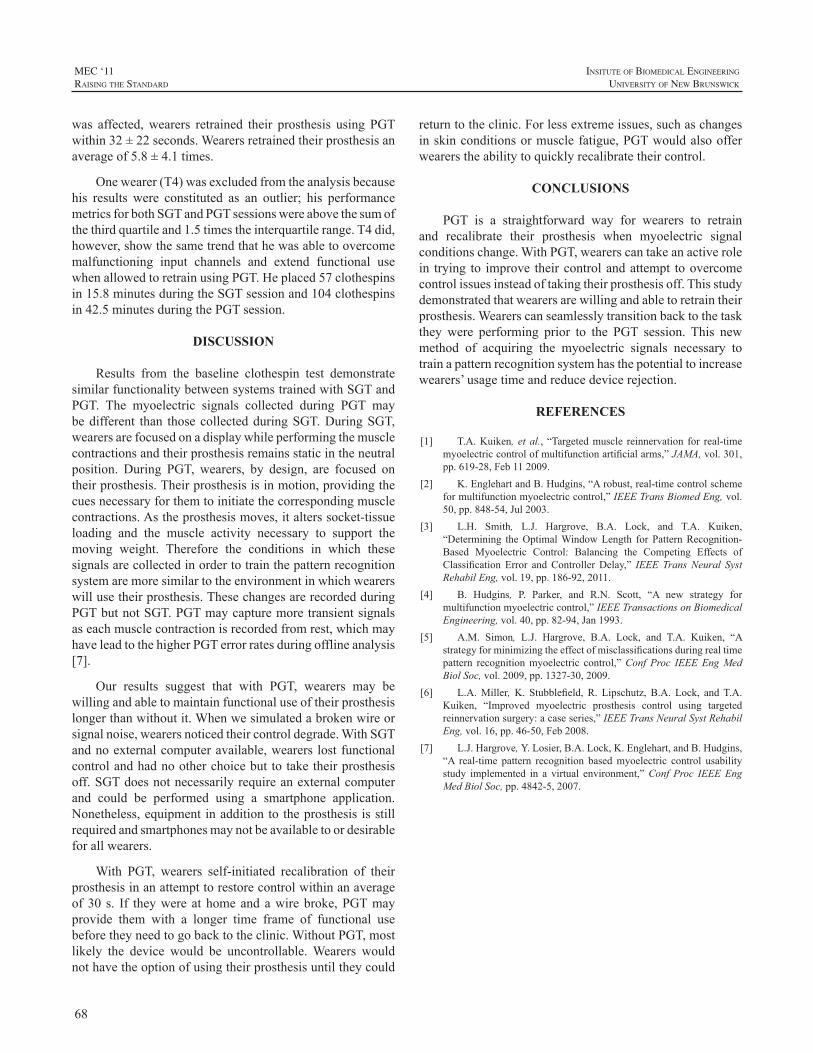
68
MEC ‘11raIsIng the standard
InsItute of BIomedIcal engIneerIng
unIversIty of new BrunswIck
was affected,wearers retrained their prosthesis using PGTwithin32±22seconds.Wearersretrainedtheirprosthesisanaverageof5.8±4.1times.
Onewearer(T4)wasexcludedfromtheanalysisbecausehis results were constituted as an outlier; his performancemetricsforbothSGTandPGTsessionswereabovethesumofthethirdquartileand1.5timestheinterquartilerange.T4did,however,showthesametrendthathewasabletoovercomemalfunctioning input channels and extend functional usewhenallowedtoretrainusingPGT.Heplaced57clothespinsin15.8minutesduringtheSGTsessionand104clothespinsin42.5minutesduringthePGTsession.
DISCUSSION
Results from the baseline clothespin test demonstratesimilarfunctionalitybetweensystemstrainedwithSGTandPGT. The myoelectric signals collected during PGT maybedifferent than thosecollectedduringSGT.DuringSGT,wearersarefocusedonadisplaywhileperformingthemusclecontractionsandtheirprosthesisremainsstaticintheneutralposition. During PGT, wearers, by design, are focused ontheirprosthesis.Theirprosthesisisinmotion,providingthecuesnecessaryforthemtoinitiatethecorrespondingmusclecontractions.Astheprosthesismoves,italterssocket-tissueloading and the muscle activity necessary to support themoving weight. Therefore the conditions in which thesesignalsarecollectedinordertotrainthepatternrecognitionsystemaremoresimilartotheenvironmentinwhichwearerswillusetheirprosthesis.ThesechangesarerecordedduringPGTbutnotSGT.PGTmaycapturemoretransientsignalsaseachmusclecontractionisrecordedfromrest,whichmayhaveleadtothehigherPGTerrorratesduringofflineanalysis[7].
Our results suggest that with PGT, wearers may bewillingandabletomaintainfunctionaluseoftheirprosthesislongerthanwithoutit.Whenwesimulatedabrokenwireorsignalnoise,wearersnoticedtheircontroldegrade.WithSGTandnoexternalcomputeravailable,wearers lostfunctionalcontrolandhadnootherchoicebuttotaketheirprosthesisoff.SGTdoesnotnecessarilyrequireanexternalcomputerand could be performed using a smartphone application.Nonetheless,equipmentinadditiontotheprosthesis isstillrequiredandsmartphonesmaynotbeavailabletoordesirableforallwearers.
With PGT, wearers self-initiated recalibration of theirprosthesisinanattempttorestorecontrolwithinanaverageof30 s. If theywereathomeandawirebroke,PGTmayprovide them with a longer time frame of functional usebeforetheyneedtogobacktotheclinic.WithoutPGT,mostlikely the device would be uncontrollable.Wearers wouldnothavetheoptionofusingtheirprosthesisuntiltheycould
returntotheclinic.Forlessextremeissues,suchaschangesinskinconditionsormusclefatigue,PGTwouldalsoofferwearerstheabilitytoquicklyrecalibratetheircontrol.
CONCLUSIONS
PGT is a straightforward way for wearers to retrainand recalibrate their prosthesis when myoelectric signalconditionschange.WithPGT,wearerscantakeanactiverolein trying to improve theircontrolandattempt toovercomecontrolissuesinsteadoftakingtheirprosthesisoff.Thisstudydemonstratedthatwearersarewillingandabletoretraintheirprosthesis.Wearerscanseamlesslytransitionbacktothetaskthey were performing prior to the PGT session. This newmethod of acquiring the myoelectric signals necessary totrainapatternrecognitionsystemhasthepotentialtoincreasewearers’usagetimeandreducedevicerejection.
REFERENCES
[1] T.A.Kuiken, et al., “Targetedmuscle reinnervation for real-timemyoelectriccontrolofmultifunctionartificialarms,”JAMA,vol.301,pp.619-28,Feb112009.
[2] K.EnglehartandB.Hudgins,“Arobust,real-timecontrolschemeformultifunctionmyoelectriccontrol,”IEEETransBiomedEng,vol.50,pp.848-54,Jul2003.
[3] L.H. Smith, L.J. Hargrove, B.A. Lock, and T.A. Kuiken,“Determining theOptimalWindowLength for PatternRecognition-Based Myoelectric Control: Balancing the Competing Effects ofClassification Error andControllerDelay,” IEEETransNeural SystRehabilEng,vol.19,pp.186-92,2011.
[4] B. Hudgins, P. Parker, and R.N. Scott, “A new strategy formultifunctionmyoelectriccontrol,”IEEETransactionsonBiomedicalEngineering,vol.40,pp.82-94,Jan1993.
[5] A.M. Simon, L.J. Hargrove, B.A. Lock, and T.A. Kuiken, “Astrategyforminimizingtheeffectofmisclassificationsduringrealtimepattern recognitionmyoelectric control,”Conf Proc IEEEEngMedBiolSoc,vol.2009,pp.1327-30,2009.
[6] L.A.Miller,K. Stubblefield, R. Lipschutz, B.A. Lock, andT.A.Kuiken, “Improved myoelectric prosthesis control using targetedreinnervationsurgery:acaseseries,”IEEETransNeuralSystRehabilEng,vol.16,pp.46-50,Feb2008.
[7] L.J.Hargrove,Y.Losier,B.A.Lock,K.Englehart,andB.Hudgins,“A real-time pattern recognition basedmyoelectric control usabilitystudy implemented in a virtual environment,”Conf Proc IEEEEngMedBiolSoc,pp.4842-5,2007.
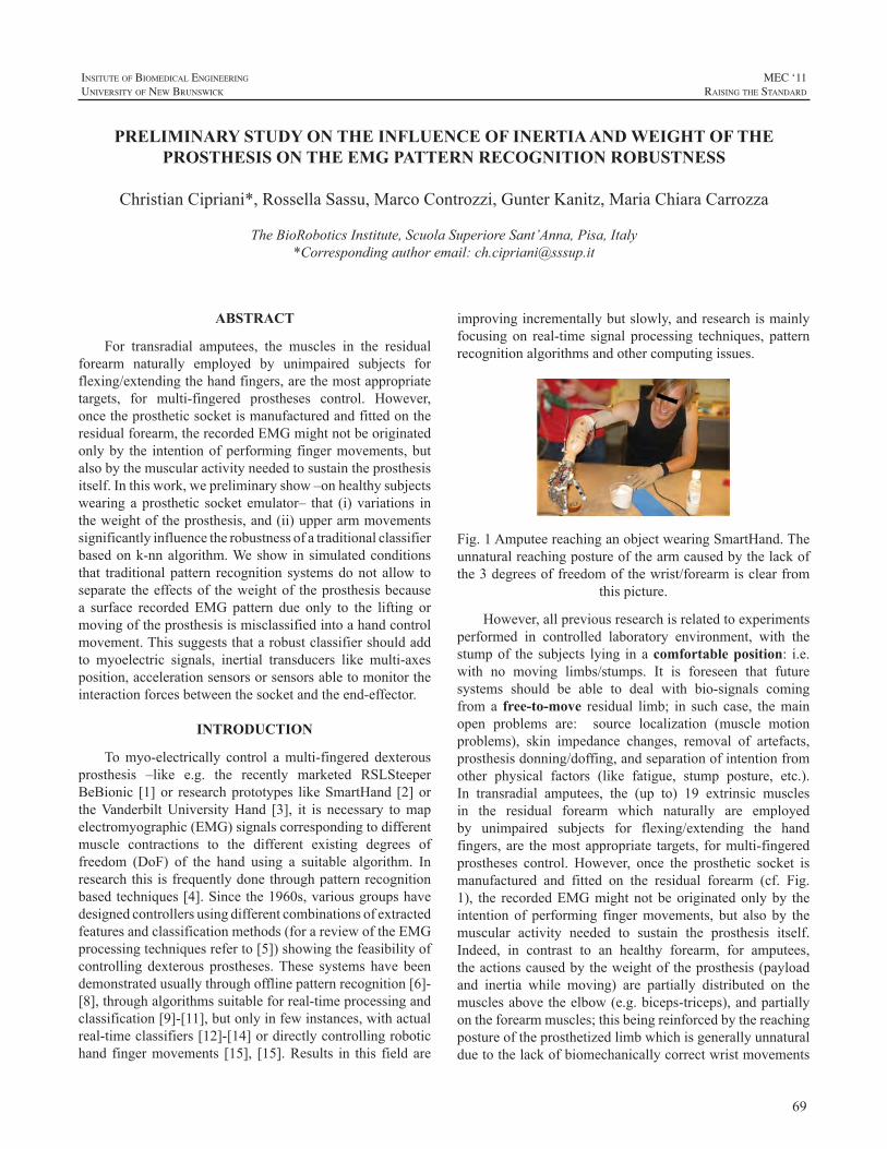
69
InsItute of BIomedIcal engIneerIng
unIversIty of new BrunswIck
MEC ‘11raIsIng the standard
ABSTRACT
For transradial amputees, the muscles in the residualforearm naturally employed by unimpaired subjects forflexing/extendingthehandfingers,arethemostappropriatetargets, for multi-fingered prostheses control. However,oncetheprostheticsocketismanufacturedandfittedontheresidualforearm,therecordedEMGmightnotbeoriginatedonlyby the intentionofperforming fingermovements,butalsobythemuscularactivityneededtosustaintheprosthesisitself.Inthiswork,wepreliminaryshow–onhealthysubjectswearingaprosthetic socket emulator– that (i)variations intheweightoftheprosthesis,and(ii)upperarmmovementssignificantlyinfluencetherobustnessofatraditionalclassifierbasedonk-nnalgorithm.Weshowinsimulatedconditionsthat traditionalpattern recognition systemsdonot allow toseparate theeffectsof theweightof theprosthesisbecausea surface recorded EMG pattern due only to the lifting ormovingoftheprosthesisismisclassifiedintoahandcontrolmovement.Thissuggeststhatarobustclassifiershouldaddto myoelectric signals, inertial transducers like multi-axesposition,accelerationsensorsorsensorsabletomonitortheinteractionforcesbetweenthesocketandtheend-effector.
INTRODUCTION
Tomyo-electrically control amulti-fingered dexterousprosthesis –like e.g. the recently marketed RSLSteeperBeBionic [1]or researchprototypes likeSmartHand [2]ortheVanderbiltUniversityHand [3], it is necessary tomapelectromyographic(EMG)signalscorrespondingtodifferentmuscle contractions to the different existing degrees offreedom (DoF) of the hand using a suitable algorithm. Inresearchthisisfrequentlydonethroughpatternrecognitionbasedtechniques[4].Sincethe1960s,variousgroupshavedesignedcontrollersusingdifferentcombinationsofextractedfeaturesandclassificationmethods(forareviewoftheEMGprocessingtechniquesreferto[5])showingthefeasibilityofcontrolling dexterous prostheses.These systems have beendemonstratedusuallythroughofflinepatternrecognition[6]-[8],throughalgorithmssuitableforreal-timeprocessingandclassification[9]-[11],butonlyinfewinstances,withactualreal-timeclassifiers[12]-[14]ordirectlycontrollingrobotichand fingermovements [15], [15].Results in this field are
improvingincrementallybutslowly,andresearchismainlyfocusing on real-time signal processing techniques, patternrecognitionalgorithmsandothercomputingissues.
Fig.1AmputeereachinganobjectwearingSmartHand.Theunnaturalreachingpostureofthearmcausedbythelackofthe3degreesoffreedomofthewrist/forearmisclearfrom
thispicture.
However,allpreviousresearchisrelatedtoexperimentsperformed in controlled laboratory environment, with thestumpof the subjects lying inacomfortable position: i.e.with no moving limbs/stumps. It is foreseen that futuresystems should be able to deal with bio-signals comingfroma free-to-move residual limb; in such case, themainopen problems are: source localization (muscle motionproblems), skin impedance changes, removal of artefacts,prosthesisdonning/doffing,andseparationofintentionfromother physical factors (like fatigue, stump posture, etc.).In transradial amputees, the (up to) 19 extrinsic musclesin the residual forearm which naturally are employedby unimpaired subjects for flexing/extending the handfingers,are themostappropriate targets, formulti-fingeredprostheses control. However, once the prosthetic socket ismanufactured and fitted on the residual forearm (cf. Fig.1), the recordedEMGmightnotbeoriginatedonlyby theintention of performing fingermovements, but also by themuscular activity needed to sustain the prosthesis itself.Indeed, in contrast to an healthy forearm, for amputees,theactionscausedbytheweightoftheprosthesis(payloadand inertia while moving) are partially distributed on themusclesabovetheelbow(e.g.biceps-triceps),andpartiallyontheforearmmuscles;thisbeingreinforcedbythereachingpostureoftheprosthetizedlimbwhichisgenerallyunnaturalduetothelackofbiomechanicallycorrectwristmovements
PRELIMINARY STUDY ON THE INFLUENCE OF INERTIA AND WEIGHT OF THE PROSTHESIS ON THE EMG PATTERN RECOGNITION ROBUSTNESS
ChristianCipriani*,RossellaSassu,MarcoControzzi,GunterKanitz,MariaChiaraCarrozza
TheBioRoboticsInstitute,ScuolaSuperioreSant’Anna,Pisa,Italy*Correspondingauthoremail:[email protected]
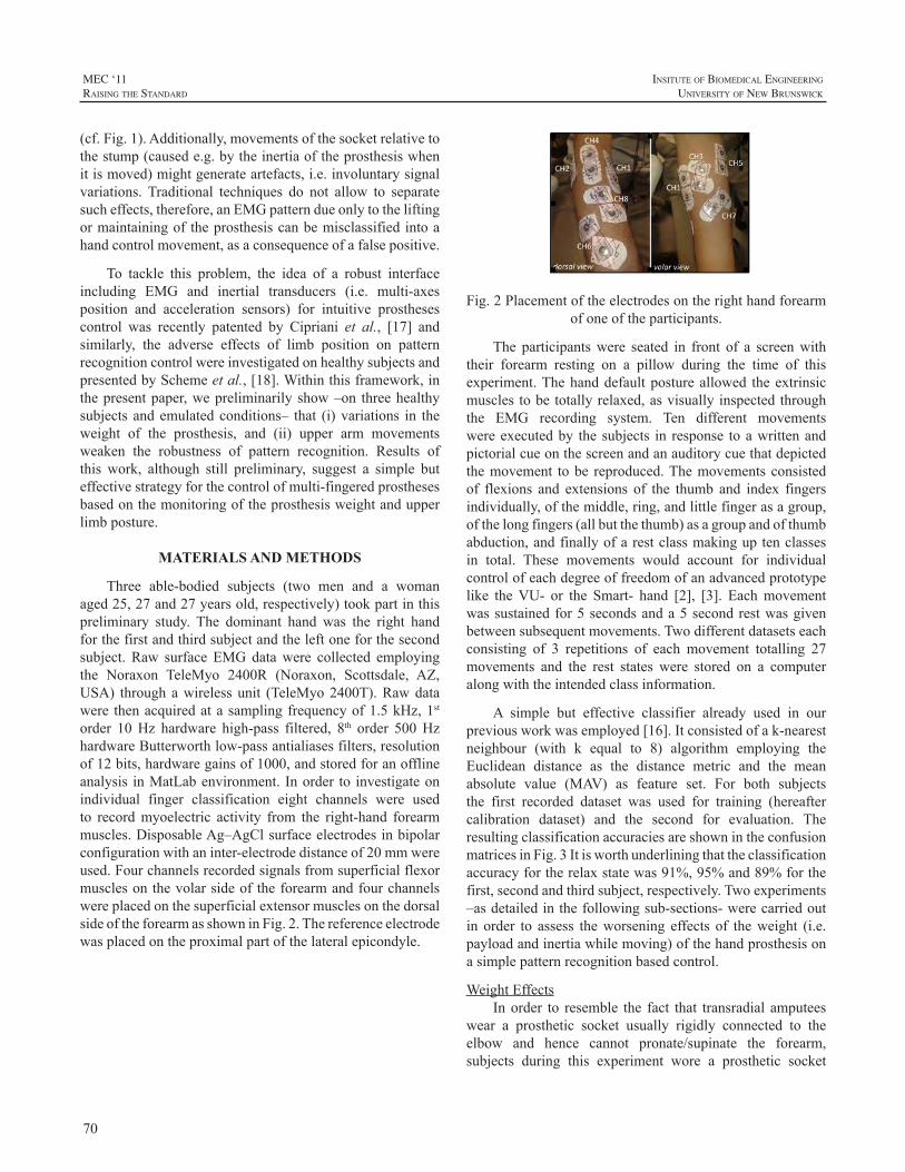
70
MEC ‘11raIsIng the standard
InsItute of BIomedIcal engIneerIng
unIversIty of new BrunswIck
(cf.Fig.1).Additionally,movementsofthesocketrelativetothestump(causede.g.bytheinertiaoftheprosthesiswhenitismoved)mightgenerateartefacts,i.e.involuntarysignalvariations. Traditional techniques do not allow to separatesucheffects,therefore,anEMGpatterndueonlytotheliftingormaintainingof theprosthesiscanbemisclassifiedintoahandcontrolmovement,asaconsequenceofafalsepositive.
To tackle this problem, the idea of a robust interfaceincluding EMG and inertial transducers (i.e. multi-axesposition and acceleration sensors) for intuitive prosthesescontrol was recently patented by Cipriani et al., [17] andsimilarly, the adverse effects of limb position on patternrecognitioncontrolwereinvestigatedonhealthysubjectsandpresentedbySchemeetal.,[18].Withinthisframework,inthepresentpaper,wepreliminarilyshow–on threehealthysubjects andemulatedconditions– that (i)variations in theweight of the prosthesis, and (ii) upper arm movementsweaken the robustness of pattern recognition. Results ofthis work, although still preliminary, suggest a simple buteffectivestrategyforthecontrolofmulti-fingeredprosthesesbasedonthemonitoringoftheprosthesisweightandupperlimbposture.
MATERIALS AND METHODS
Three able-bodied subjects (two men and a womanaged25,27and27yearsold,respectively)tookpartinthispreliminary study. The dominant hand was the right handforthefirstandthirdsubjectandtheleftoneforthesecondsubject. Raw surface EMG datawere collected employingthe Noraxon TeleMyo 2400R (Noraxon, Scottsdale, AZ,USA) throughawirelessunit (TeleMyo2400T).Rawdatawere thenacquiredatasamplingfrequencyof1.5kHz,1storder 10Hz hardware high-pass filtered, 8th order 500HzhardwareButterworthlow-passantialiasesfilters,resolutionof12bits,hardwaregainsof1000,andstoredforanofflineanalysis inMatLabenvironment. Inorder to investigateonindividual finger classification eight channels were usedto recordmyoelectric activity from the right-hand forearmmuscles.DisposableAg–AgClsurfaceelectrodesinbipolarconfigurationwithaninter-electrodedistanceof20mmwereused.FourchannelsrecordedsignalsfromsuperficialflexormusclesonthevolarsideoftheforearmandfourchannelswereplacedonthesuperficialextensormusclesonthedorsalsideoftheforearmasshowninFig.2.Thereferenceelectrodewasplacedontheproximalpartofthelateralepicondyle.
Fig.2Placementoftheelectrodesontherighthandforearmofoneoftheparticipants.
The participantswere seated in front of a screenwiththeir forearm resting on a pillow during the time of thisexperiment.Thehanddefaultpostureallowed theextrinsicmusclestobetotallyrelaxed,asvisuallyinspectedthroughthe EMG recording system. Ten different movementswereexecutedby thesubjects in response toawrittenandpictorialcueonthescreenandanauditorycuethatdepictedthemovement tobe reproduced.Themovementsconsistedof flexions and extensions of the thumb and index fingersindividually,ofthemiddle,ring,andlittlefingerasagroup,ofthelongfingers(allbutthethumb)asagroupandofthumbabduction,andfinallyofarestclassmakinguptenclassesin total. These movements would account for individualcontrolofeachdegreeoffreedomofanadvancedprototypelike theVU- or the Smart- hand [2], [3]. Eachmovementwassustainedfor5secondsanda5secondrestwasgivenbetweensubsequentmovements.Twodifferentdatasetseachconsisting of 3 repetitions of each movement totalling 27movements and the rest states were stored on a computeralongwiththeintendedclassinformation.
A simple but effective classifier already used in ourpreviousworkwasemployed[16].Itconsistedofak-nearestneighbour (with k equal to 8) algorithm employing theEuclidean distance as the distance metric and the meanabsolute value (MAV) as feature set. For both subjectsthe first recorded dataset was used for training (hereaftercalibration dataset) and the second for evaluation. TheresultingclassificationaccuraciesareshownintheconfusionmatricesinFig.3Itisworthunderliningthattheclassificationaccuracyfortherelaxstatewas91%,95%and89%forthefirst,secondandthirdsubject,respectively.Twoexperiments–asdetailedinthefollowingsub-sections-werecarriedoutin order to assess theworsening effects of theweight (i.e.payloadandinertiawhilemoving)ofthehandprosthesisonasimplepatternrecognitionbasedcontrol.
WeightEffectsInorder to resemble the fact that transradial amputees
wear a prosthetic socket usually rigidly connected to theelbow and hence cannot pronate/supinate the forearm,subjects during this experiment wore a prosthetic socket
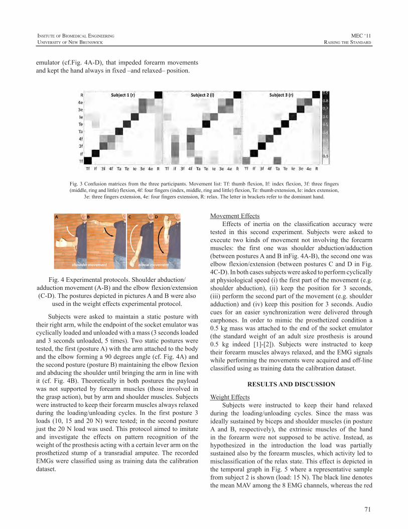
71
InsItute of BIomedIcal engIneerIng
unIversIty of new BrunswIck
MEC ‘11raIsIng the standard
emulator (cf.Fig. 4A-D), that impeded forearmmovementsandkeptthehandalwaysinfixed–andrelaxed–position.
Fig.4Experimentalprotocols.Shoulderabduction/adductionmovement(A-B)andtheelbowflexion/extension(C-D).TheposturesdepictedinpicturesAandBwerealso
usedintheweighteffectsexperimentalprotocol.
Subjects were asked to maintain a static posture withtheirrightarm,whiletheendpointofthesocketemulatorwascyclicallyloadedandunloadedwithamass(3secondsloadedand3secondsunloaded,5times).Twostaticposturesweretested,thefirst(postureA)withthearmattachedtothebodyandtheelbowforminga90degreesangle(cf.Fig.4A)andthesecondposture(postureB)maintainingtheelbowflexionandabducingtheshoulderuntilbringingthearminlinewithit (cf. Fig. 4B).Theoretically in both postures the payloadwas not supported by forearmmuscles (those involved inthegraspaction),butbyarmandshouldermuscles.Subjectswereinstructedtokeeptheirforearmmusclesalwaysrelaxedduring the loading/unloading cycles. In the first posture 3loads(10,15and20N)were tested; in thesecondposturejustthe20Nloadwasused.Thisprotocolaimedtoimitateand investigate the effects on pattern recognition of theweightoftheprosthesisactingwithacertainleverarmontheprosthetized stump of a transradial amputee.The recordedEMGswereclassifiedusingastrainingdatathecalibrationdataset.
Fig.3Confusionmatricesfromthethreeparticipants.Movementlist:Tf:thumbflexion,If:indexflexion,3f:threefingers(middle,ringandlittle)flexion,4f:fourfingers(index,middle,ringandlittle)flexion,Te:thumbextension,Ie:indexextension,
3e:threefingersextension,4e:fourfingersextension,R:relax.Theletterinbracketsrefertothedominanthand.
MovementEffectsEffects of inertia on the classification accuracy were
tested in this second experiment. Subjects were asked toexecute twokinds ofmovement not involving the forearmmuscles: the first one was shoulder abduction/adduction(betweenposturesAandBinFig.4A-B),thesecondonewaselbowflexion/extension(betweenposturesCandDinFig.4C-D).Inbothcasessubjectswereaskedtoperformcyclicallyatphysiologicalspeed(i)thefirstpartofthemovement(e.g.shoulder abduction), (ii) keep the position for 3 seconds,(iii)performthesecondpartofthemovement(e.g.shoulderadduction)and(iv)keepthispositionfor3seconds.Audiocues for an easier synchronization were delivered throughearphones. In order to mimic the prosthetized condition a0.5kgmasswasattachedtotheendofthesocketemulator(the standard weight of an adult size prosthesis is around0.5 kg indeed [1]-[2]). Subjects were instructed to keeptheirforearmmusclesalwaysrelaxed,andtheEMGsignalswhileperformingthemovementswereacquiredandoff-lineclassifiedusingastrainingdatathecalibrationdataset.
RESULTS AND DISCUSSION
WeightEffectsSubjects were instructed to keep their hand relaxed
during the loading/unloading cycles. Since the mass wasideallysustainedbybicepsandshouldermuscles(inpostureA and B, respectively), the extrinsic muscles of the handin the forearmwere not supposed to be active. Instead, ashypothesized in the introduction the load was partiallysustainedalsobytheforearmmuscles,whichactivityledtomisclassificationoftherelaxstate.ThiseffectisdepictedinthetemporalgraphinFig.5wherearepresentativesamplefromsubject2isshown(load:15N).TheblacklinedenotesthemeanMAVamongthe8EMGchannels,whereasthered
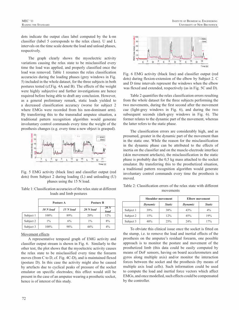
72
MEC ‘11raIsIng the standard
InsItute of BIomedIcal engIneerIng
unIversIty of new BrunswIck
dots indicate the output class label computed by the k-nnclassifier (label 5 corresponds to the relax class).U andLintervalsonthetimescaledenotetheloadandunloadphases,respectively.
The graph clearly shows the myoelectric activityvariations causing the relax state to bemisclassified everytimethe loadwasapplied,andproperlyclassifiedonce theloadwas removed.Table1 resumes the relaxclassificationaccuraciesduringtheloadingphases(greywindowsinFig.5)includedinthewholedataset,forthethreesubjectsinbothposturestested(cf.Fig.4AandB).Theeffectsoftheweightwerehighlysubjectiveandfurther investigationsarehencerequiredbeforebeingabletodraftanyconclusion.However,as a general preliminary remark, static loads yielded toa decreased classification accuracy (worse for subject 2where EMGs were recorded from his non-dominant arm).By transferring this to the transradial amputee situation, atraditional pattern recognition algorithm would generateinvoluntarycontrolcommandseverytimetheweightoftheprosthesischanges(e.g.everytimeanewobjectisgrasped).
Fig. 5EMGactivity (black line) and classifier output (reddots) fromSubject2during loading(L)andunloading(U)
phasesusingthe15Nload.
Table1:Classificationaccuraciesoftherelaxstateatdifferentloadsandlimbpostures
Posture A Posture B
10 N load 15 N load 20 N load 20 N load
Subject1 100% 89% 20% 12%
Subject2 1% 6% 1% 8%
Subject3 100% 98% 44% 4%
MovementeffectsA representative temporal graph of EMG activity and
classifieroutputstreamisshowninFig.6.Similarlytotheothertest,theplotshowsthatthemyoelectricactivitycausesthe relax state to be misclassified every time the forearmmoves(fromCtoD,cf.Fig.4C-D),andismaintainedflexed(postureD). In this case the activitymight also be causedbyartefactsdue tocyclicalpeaksofpressureof thesocketemulator on specific electrodes; this effect would still bepresentinthecaseofanamputeewearingaprostheticsocket,henceisofinterestofthisstudy.
Fig. 6EMGactivity (black line) and classifier output (reddots)duringflexion-extensionoftheelbowbySubject2.CandDtimeintervalsrepresentthewindowswhentheelbowwasflexedandextended,respectively(asinFig.5CandD).
Table2quantifiestherelaxclassificationerrorsresultingfromthewholedatasetforthethreesubjectsperformingthetwomovements,duringthefirstsecondafterthemovementcue (light-grey windows in Fig. 6), and during the twosubsequent seconds (dark-grey windows in Fig. 6). Theformerrelatestothedynamicpartofthemovement,whereasthelatterreferstothestaticphase.
The classification errors are considerably high, and aspresumed,greaterinthedynamicpartofthemovementthanin thestaticone.While thereasonfor themisclassificationin the dynamic phase can be attributed to the effects ofinertiaontheclassifierandonthemuscle-electrodeinterface(skinmovementartefacts),themisclassificationinthestaticphaseisprobablyduethe0,5kgmassattachedtothesocketemulator.By transferring this to the prosthetized situation,a traditional pattern recognition algorithm would generateinvoluntary control commands every time the prosthesis ismoved.
Table2:Classificationerrorsoftherelaxstatewithdifferentmovements
Shoulder movement Elbow movement
Dynamic Static Dynamic Static
Subject1 39% 38% 43% 4%
Subject2 15% 12% 45% 19%
Subject3 40% 25% 24% 17%
Toobviatethisclinicalissueoncethesocketisfittedonthestump,i.e.toremovetheloadandinertialeffectsoftheprosthesis on the amputee’s residual forearm, one possibleapproach is to monitor the posture and movement of theprosthetized limb (this data could be easily computed bymeansofDoFsensors,havingonboardaccelerometersandgyros along multiple axis) and/or monitor the interactionforcesbetween the socket and theprosthesis (bymeansofmultiple axis load cells). Such information could be usedtocompute the loadand inertial forcevectorswhichaffectEMGs,andoncemodelled,sucheffectscouldbecompensatedbythecontroller.
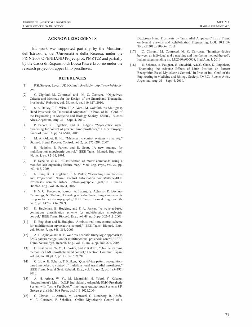
73
InsItute of BIomedIcal engIneerIng
unIversIty of new BrunswIck
MEC ‘11raIsIng the standard
Dexterous Hand Prosthesis by TransradialAmputees,” IEEE Trans.on Neural Systems and Rehabilitation Engineering, DOI: 10.1109/TNSRE.2011.2108667,2011.
[17] C. Cipriani, M. Controzzi, M. C. Carrozza, “Interface devicebetweenanindividualandamachineandinterfacingmethodthereof”,Italianpatentpendingno.LU2010A000008,filedAug.3,2010.
[18] E.Scheme,A.Fougner,Ø.Stavdahl,A.D.C.Chan,K.Englehart,“Examining the Adverse Effects of Limb Position on PatternRecognitionBasedMyoelectricControl,”InProc.ofIntl.Conf.oftheEngineeringinMedicineandBiologySociety,EMBC,BuenosAires,Argentina,Aug.31–Sept.4,2010.
ACKNOWLEDGEMENTS
This work was supported partially by the Ministerodell’Istruzione, dell’Università e della Ricerca, under thePRIN2008OPENHANDProjectprot.PMZT2ZandpartiallybytheCassadiRisparmiodiLuccaPisaeLivornoundertheresearchprojectonupperlimbprostheses.
REFERENCES
[1] RSLSteeper,Leeds,UK[Online].Available:http://www.bebionic.com
[2] C. Cipriani, M. Controzzi, and M. C. Carrozza, “Objectives,Criteria andMethods for the Design of the SmartHand TransradialProsthesis,”Robotica,vol.28,no.6,pp.919-927,2010.
[3] S.A.Dalley,T.E.Wiste,H.A.Varol,M.Goldfarb,“AMultigraspHandProsthesisforTransradialAmputees”,InProc.ofIntl.Conf.ofthe Engineering inMedicine andBiology Society, EMBC, BuenosAires,Argentina,Aug.31–Sept.4,2010.
[4] P. Parker, K. Englehart, and B. Hudgins, “Myoelectric signalprocessingforcontrolofpoweredlimbprostheses,”J.Electromyogr.Kinesiol.,vol.16,pp.541-548,2006.
[5] M.A.Oskoei,H.Hu, “Myoelectric control systems - a survey,”Biomed.SignalProcess.Control,vol.2,pp.275-294,2007.
[6] B. Hudgins, P. Parker, and R. Scott, “A new strategy formultifunctionmyoelectric control,” IEEETrans.Biomed. Eng., vol.40,no.1,pp.82–94,1993.
[7] F. Sebelius et al., “Classification of motor commands using amodifiedself-organisingfeaturemap,”Med.Eng.Phys.,vol.27,pp.403–413,2005.
[8] N.Jiang,K.B.Englehart,P.A.Parker,“ExtractingSimultaneousand Proportional Neural Control Information for Multiple-DOFProsthesesFromtheSurfaceElectromyographicSignal,”IEEETrans.Biomed.Eng.,vol.56,no.4,2009.
[9] F. V. G. Tenore,A. Ramos,A. Fahmy, S.Acharya, R. Etienne-Cummings,N.Thakor,”Decodingofindividuatedfingermovementsusingsurfaceelectromyography,”IEEETrans.Biomed.Eng.,vol.56,no.5,pp.1427–1434,2009.
[10] K. Englehart, B. Hudgins, and P. A. Parker, “A wavelet-basedcontinuous classification scheme for multifunction myoelectriccontrol,”IEEETrans.Biomed.Eng.,vol.48,no.3,pp.302–311,2001.
[11] K.EnglehartandB.Hudgins,“Arobust,real-timecontrolschemefor multifunction myoelectric control,” IEEE Trans. Biomed. Eng.,vol.50,no.7,pp.848–854,2003.
[12] A.B.AjiboyeandR.F.Weir,“AheuristicfuzzylogicapproachtoEMGpatternrecognitionformultifunctionalprosthesiscontrol,”IEEETrans.NeuralSyst.Rehabil.Eng.,vol.13,no.3,pp.280–291,2005.
[13] D.Nishikawa,W.Yu,H.Yokoi,andY.Kakazu,“On-linelearningmethodforEMGprosthetichandcontrol,”Electron.Commun.Japan,vol.84,no.10,pt.3,pp.1510–1519,2001.
[14] G.Li,A.E.Schultz,T.Kuiken,“Quantifyingpatternrecognition-basedmyoelectric controlofmultifunctional transradialprostheses,”IEEETrans.NeuralSyst.Rehabil.Eng.,vol.18,no.2,pp.185–192,2010.
[15] A. H. Arieta, W. Yu, M. Maaruishi, H. Yokoi, Y. Kakazu,“IntegrationofaMulti-D.O.F.IndividuallyAdaptableEMGProstheticSystemwithTactileFeedback,”IntelligentAutonomousSystems8F.Grorenetal.(Eds.)IOSPress,pp.1013-1021,2004
[16] C. Cipriani, C.Antfolk, M. Controzzi, G. Lundborg, B. Rosén,M. C. Carrozza, F. Sebelius, “Online Myoelectric Control of a
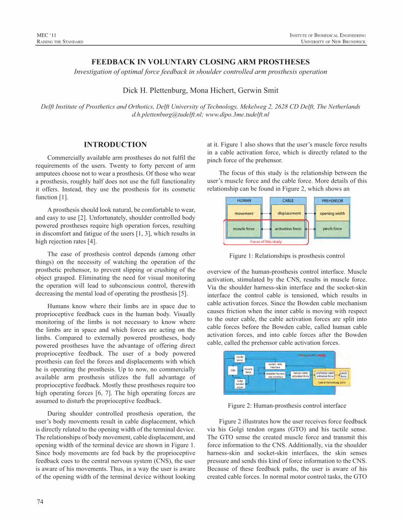
74
MEC ‘11raIsIng the standard
InsItute of BIomedIcal engIneerIng
unIversIty of new BrunswIck
INTRODUCTIONCommerciallyavailablearmprosthesesdonotfulfilthe
requirements of the users. Twenty to forty percent of armamputeeschoosenottowearaprosthesis.Ofthosewhowearaprosthesis,roughlyhalfdoesnotusethefullfunctionalityit offers. Instead, they use the prosthesis for its cosmeticfunction[1].
Aprosthesisshouldlooknatural,becomfortabletowear,andeasytouse[2].Unfortunately,shouldercontrolledbodypoweredprostheses requirehighoperationforces, resultingindiscomfortandfatigueoftheusers[1,3],whichresultsinhighrejectionrates[4].
The ease of prosthesis control depends (among otherthings) on the necessity of watching the operation of theprostheticprehensor, toprevent slippingorcrushingof theobject grasped.Eliminating the need for visualmonitoringthe operation will lead to subconscious control, therewithdecreasingthementalloadofoperatingtheprosthesis[5].
Humans know where their limbs are in space due toproprioceptive feedback cues in the human body.Visuallymonitoring of the limbs is not necessary to know wherethe limbs are in space andwhich forces are acting on thelimbs. Compared to externally powered prostheses, bodypowered prostheses have the advantage of offering directproprioceptive feedback. The user of a body poweredprosthesiscanfeeltheforcesanddisplacementswithwhichheisoperatingtheprosthesis.Uptonow,nocommerciallyavailable arm prosthesis utilizes the full advantage ofproprioceptivefeedback.Mostlytheseprosthesesrequiretoohighoperating forces [6, 7].Thehighoperating forces areassumedtodisturbtheproprioceptivefeedback.
During shoulder controlled prosthesis operation, theuser’sbodymovementsresultincabledisplacement,whichisdirectlyrelatedtotheopeningwidthoftheterminaldevice.Therelationshipsofbodymovement,cabledisplacement,andopeningwidthoftheterminaldeviceareshowninFigure1.Since bodymovements are fed backby the proprioceptivefeedbackcuestothecentralnervoussystem(CNS),theuserisawareofhismovements.Thus,inawaytheuserisawareoftheopeningwidthoftheterminaldevicewithoutlooking
atit.Figure1alsoshowsthattheuser’smuscleforceresultsin a cable activation force,which is directly related to thepinchforceoftheprehensor.
Thefocusof thisstudy is the relationshipbetween theuser’smuscleforceandthecableforce.MoredetailsofthisrelationshipcanbefoundinFigure2,whichshowsan
Figure1:Relationshipsisprosthesiscontrol
overviewofthehuman-prosthesiscontrolinterface.Muscleactivation, stimulatedby theCNS, results inmuscle force.Via the shoulderharness-skin interfaceand the socket-skininterface the control cable is tensioned, which results incableactivationforces.SincetheBowdencablemechanismcausesfrictionwhentheinnercableismovingwithrespectto theouter cable, the cable activation forces are split intocable forces before theBowden cable, called human cableactivation forces, and into cable forces after the Bowdencable,calledtheprehensorcableactivationforces.
Figure2:Human-prosthesiscontrolinterface
Figure2illustrateshowtheuserreceivesforcefeedbackvia his Golgi tendon organs (GTO) and his tactile sense.TheGTO sense the createdmuscle force and transmit thisforceinformationtotheCNS.Additionally,viatheshoulderharness-skin and socket-skin interfaces, the skin sensespressureandsendsthiskindofforceinformationtotheCNS.Because of these feedback paths, the user is aware of hiscreatedcableforces.Innormalmotorcontroltasks,theGTO
FEEDBACK IN VOLUNTARY CLOSING ARM PROSTHESES Investigationofoptimalforcefeedbackinshouldercontrolledarmprosthesisoperation
DickH.Plettenburg,MonaHichert,GerwinSmit
DelftInstituteofProstheticsandOrthotics,DelftUniversityofTechnology,Mekelweg2,2628CDDelft,[email protected];www.dipo.3me.tudelft.nl
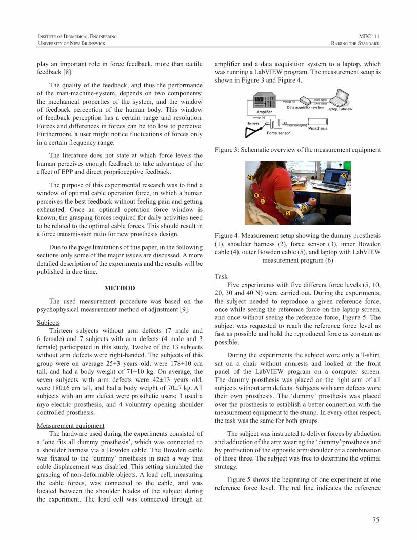
75
InsItute of BIomedIcal engIneerIng
unIversIty of new BrunswIck
MEC ‘11raIsIng the standard
playan important role in force feedback,more than tactilefeedback[8].
Thequalityof the feedback,and thus theperformanceof the man-machine-system, depends on two components:the mechanical properties of the system, and the windowof feedback perception of the human body. This windowof feedback perception has a certain range and resolution.Forcesanddifferencesinforcescanbetoolowtoperceive.Furthermore,ausermightnoticefluctuationsofforcesonlyinacertainfrequencyrange.
The literature does not state at which force levels thehumanperceivesenoughfeedbacktotakeadvantageoftheeffectofEPPanddirectproprioceptivefeedback.
Thepurposeofthisexperimentalresearchwastofindawindowofoptimalcableoperationforce,inwhichahumanperceivesthebestfeedbackwithoutfeelingpainandgettingexhausted. Once an optimal operation force window isknown,thegraspingforcesrequiredfordailyactivitiesneedtoberelatedtotheoptimalcableforces.Thisshouldresultinaforcetransmissionratiofornewprosthesisdesign.
Duetothepagelimitationsofthispaper,inthefollowingsectionsonlysomeofthemajorissuesarediscussed.Amoredetaileddescriptionoftheexperimentsandtheresultswillbepublishedinduetime.
METHOD
The used measurement procedure was based on thepsychophysicalmeasurementmethodofadjustment[9].
SubjectsThirteen subjects without arm defects (7 male and
6 female) and 7 subjects with arm defects (4 male and 3female)participatedinthisstudy.Twelveofthe13subjectswithoutarmdefectswereright-handed.Thesubjectsofthisgroup were on average 25±3 years old, were 178±10 cmtall, and had a bodyweight of 71±10 kg.On average, theseven subjects with arm defects were 42±13 years old,were180±6cmtall,andhadabodyweightof70±7kg.Allsubjectswithanarmdefectwereprostheticusers;3usedamyo-electric prosthesis, and 4 voluntary opening shouldercontrolledprosthesis.
MeasurementequipmentThehardwareusedduringtheexperimentsconsistedof
a ‘one fits all dummyprosthesis’,whichwas connected toashoulderharnessviaaBowdencable.TheBowdencablewas fixated to the ‘dummy’ prosthesis in such a way thatcabledisplacementwasdisabled.Thissettingsimulatedthegraspingofnon-deformableobjects.Aloadcell,measuringthe cable forces, was connected to the cable, and waslocated between the shoulder blades of the subject duringthe experiment. The load cell was connected through an
amplifier and a data acquisition system to a laptop,whichwasrunningaLabVIEWprogram.ThemeasurementsetupisshowninFigure3andFigure4.
Figure3:Schematicoverviewofthemeasurementequipment
Figure4:Measurementsetupshowingthedummyprosthesis(1), shoulder harness (2), force sensor (3), inner Bowdencable(4),outerBowdencable(5),andlaptopwithLabVIEW
measurementprogram(6)
TaskFiveexperimentswithfivedifferentforcelevels(5,10,
20,30and40N)werecarriedout.Duringtheexperiments,the subject needed to reproduce a given reference force,oncewhileseeing thereferenceforceon the laptopscreen,andoncewithout seeing the reference force,Figure5.Thesubjectwas requested to reach the reference force level asfastaspossibleandholdthereproducedforceasconstantaspossible.
DuringtheexperimentsthesubjectworeonlyaT-shirt,sat on a chair without armrests and looked at the frontpanel of the LabVIEW program on a computer screen.The dummy prosthesiswas placed on the right arm of allsubjectswithoutarmdefects.Subjectswitharmdefectsworetheir own prosthesis. The ‘dummy’ prosthesis was placedovertheprosthesistoestablishabetterconnectionwiththemeasurementequipmenttothestump.Ineveryotherrespect,thetaskwasthesameforbothgroups.
Thesubjectwasinstructedtodeliverforcesbyabductionandadductionofthearmwearingthe‘dummy’prosthesisandbyprotractionoftheoppositearm/shoulderoracombinationofthosethree.Thesubjectwasfreetodeterminetheoptimalstrategy.
Figure5showsthebeginningofoneexperimentatonereference force level. The red line indicates the reference
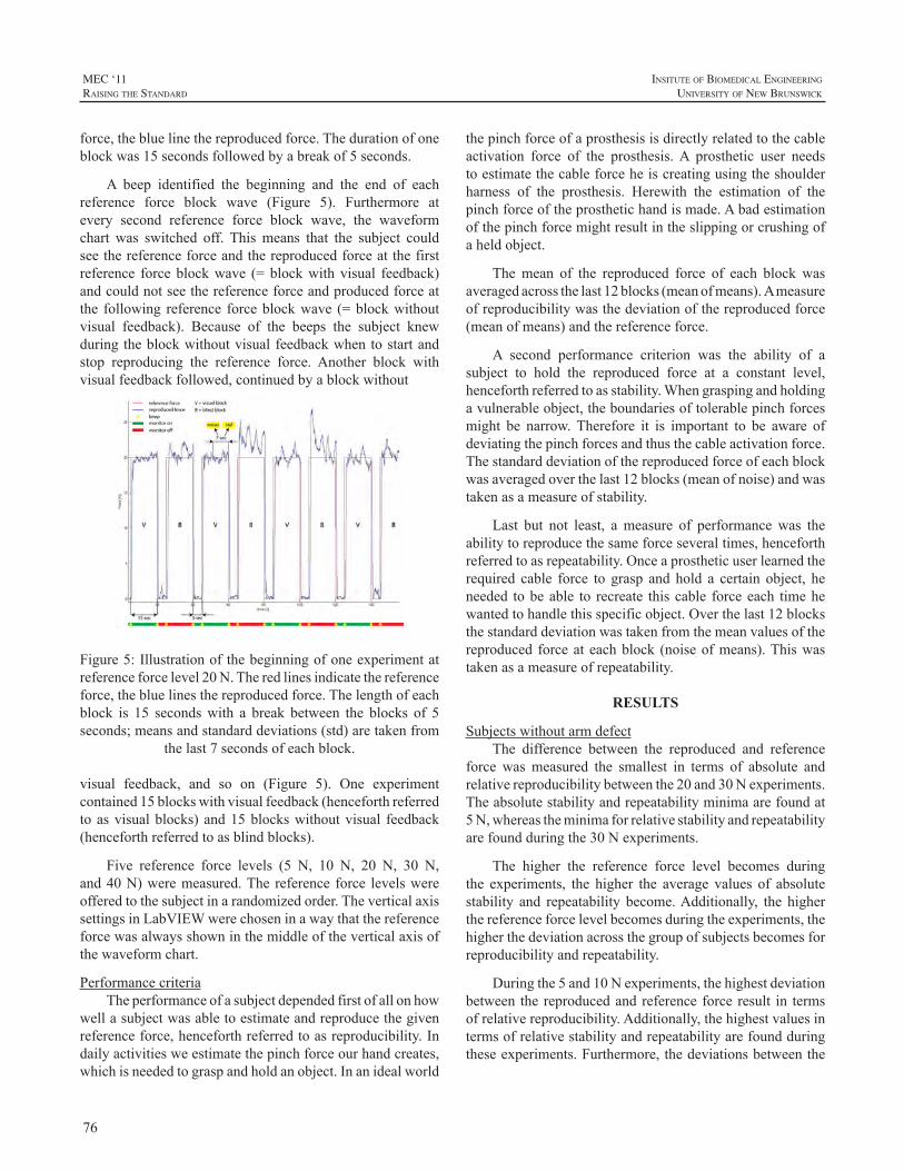
76
MEC ‘11raIsIng the standard
InsItute of BIomedIcal engIneerIng
unIversIty of new BrunswIck
force,thebluelinethereproducedforce.Thedurationofoneblockwas15secondsfollowedbyabreakof5seconds.
A beep identified the beginning and the end of eachreference force block wave (Figure 5). Furthermore atevery second reference force block wave, the waveformchart was switched off. Thismeans that the subject couldseethereferenceforceandthereproducedforceatthefirstreference forceblockwave (=blockwithvisual feedback)andcouldnotseethereferenceforceandproducedforceatthe following reference forceblockwave (=blockwithoutvisual feedback). Because of the beeps the subject knewduringtheblockwithoutvisualfeedbackwhentostartandstop reproducing the reference force. Another block withvisualfeedbackfollowed,continuedbyablockwithout
Figure5:Illustrationofthebeginningofoneexperimentatreferenceforcelevel20N.Theredlinesindicatethereferenceforce,thebluelinesthereproducedforce.Thelengthofeachblock is 15 secondswith a break between the blocks of 5seconds;meansandstandarddeviations(std)aretakenfrom
thelast7secondsofeachblock.
visual feedback, and so on (Figure 5). One experimentcontained15blockswithvisualfeedback(henceforthreferredtoasvisualblocks)and15blockswithoutvisual feedback(henceforthreferredtoasblindblocks).
Five reference force levels (5 N, 10 N, 20 N, 30 N,and40N)weremeasured.The reference force levelswereofferedtothesubjectinarandomizedorder.TheverticalaxissettingsinLabVIEWwerechoseninawaythatthereferenceforcewasalwaysshowninthemiddleoftheverticalaxisofthewaveformchart.
PerformancecriteriaTheperformanceofasubjectdependedfirstofallonhow
wellasubjectwasabletoestimateandreproducethegivenreferenceforce,henceforthreferredtoasreproducibility.Indailyactivitiesweestimatethepinchforceourhandcreates,whichisneededtograspandholdanobject.Inanidealworld
thepinchforceofaprosthesisisdirectlyrelatedtothecableactivation force of the prosthesis.A prosthetic user needstoestimatethecableforceheiscreatingusingtheshoulderharness of the prosthesis. Herewith the estimation of thepinchforceoftheprosthetichandismade.Abadestimationofthepinchforcemightresultintheslippingorcrushingofaheldobject.
Themean of the reproduced force of each block wasaveragedacrossthelast12blocks(meanofmeans).Ameasureofreproducibilitywasthedeviationofthereproducedforce(meanofmeans)andthereferenceforce.
A second performance criterion was the ability of asubject to hold the reproduced force at a constant level,henceforthreferredtoasstability.Whengraspingandholdingavulnerableobject,theboundariesoftolerablepinchforcesmight be narrow.Therefore it is important to be aware ofdeviatingthepinchforcesandthusthecableactivationforce.Thestandarddeviationofthereproducedforceofeachblockwasaveragedoverthelast12blocks(meanofnoise)andwastakenasameasureofstability.
Last but not least, ameasure of performancewas theabilitytoreproducethesameforceseveraltimes,henceforthreferredtoasrepeatability.Onceaprostheticuserlearnedtherequired cable force to grasp and hold a certain object, heneeded tobeable to recreate thiscable forceeach timehewantedtohandlethisspecificobject.Overthelast12blocksthestandarddeviationwastakenfromthemeanvaluesofthereproduced forceateachblock (noiseofmeans).Thiswastakenasameasureofrepeatability.
RESULTS
SubjectswithoutarmdefectThe difference between the reproduced and reference
force wasmeasured the smallest in terms of absolute andrelativereproducibilitybetweenthe20and30Nexperiments.Theabsolutestabilityandrepeatabilityminimaarefoundat5N,whereastheminimaforrelativestabilityandrepeatabilityarefoundduringthe30Nexperiments.
The higher the reference force level becomes duringthe experiments, the higher the average values of absolutestability and repeatability become.Additionally, the higherthereferenceforcelevelbecomesduringtheexperiments,thehigherthedeviationacrossthegroupofsubjectsbecomesforreproducibilityandrepeatability.
Duringthe5and10Nexperiments,thehighestdeviationbetween the reproducedandreferenceforce result in termsofrelativereproducibility.Additionally,thehighestvaluesintermsofrelativestabilityandrepeatabilityarefoundduringtheseexperiments.Furthermore,thedeviationsbetweenthe
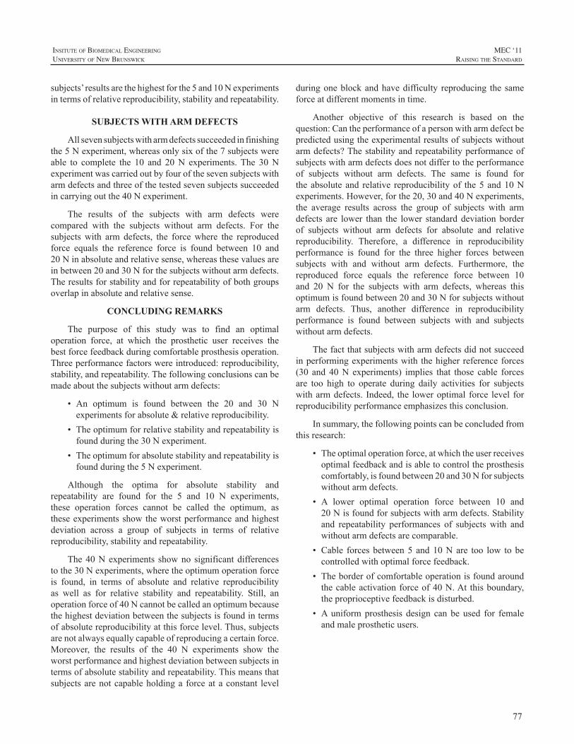
77
InsItute of BIomedIcal engIneerIng
unIversIty of new BrunswIck
MEC ‘11raIsIng the standard
subjects’resultsarethehighestforthe5and10Nexperimentsintermsofrelativereproducibility,stabilityandrepeatability.
SUBJECTS WITH ARM DEFECTS
Allsevensubjectswitharmdefectssucceededinfinishingthe5Nexperiment,whereasonlysixofthe7subjectswereable to complete the 10 and 20 N experiments.The 30Nexperimentwascarriedoutbyfourofthesevensubjectswitharmdefectsandthreeofthetestedsevensubjectssucceededincarryingoutthe40Nexperiment.
The results of the subjects with arm defects werecompared with the subjects without arm defects. For thesubjectswith arm defects, the forcewhere the reproducedforce equals the reference force is found between 10 and20Ninabsoluteandrelativesense,whereasthesevaluesareinbetween20and30Nforthesubjectswithoutarmdefects.Theresultsforstabilityandforrepeatabilityofbothgroupsoverlapinabsoluteandrelativesense.
CONCLUDING REMARKS
The purpose of this study was to find an optimaloperation force, at which the prosthetic user receives thebestforcefeedbackduringcomfortableprosthesisoperation.Threeperformancefactorswereintroduced:reproducibility,stability,andrepeatability.Thefollowingconclusionscanbemadeaboutthesubjectswithoutarmdefects:
• An optimum is found between the 20 and 30 Nexperimentsforabsolute&relativereproducibility.
• Theoptimumforrelativestabilityandrepeatabilityisfoundduringthe30Nexperiment.
• Theoptimumforabsolutestabilityandrepeatabilityisfoundduringthe5Nexperiment.
Although the optima for absolute stability andrepeatability are found for the 5 and 10 N experiments,these operation forces cannot be called the optimum, astheseexperimentsshowtheworstperformanceandhighestdeviation across a group of subjects in terms of relativereproducibility,stabilityandrepeatability.
The40Nexperiments showno significantdifferencestothe30Nexperiments,wheretheoptimumoperationforceis found, in terms of absolute and relative reproducibilityas well as for relative stability and repeatability. Still, anoperationforceof40Ncannotbecalledanoptimumbecausethehighestdeviationbetweenthesubjectsisfoundintermsofabsolutereproducibilityatthisforcelevel.Thus,subjectsarenotalwaysequallycapableofreproducingacertainforce.Moreover, the results of the 40 N experiments show theworstperformanceandhighestdeviationbetweensubjectsintermsofabsolutestabilityandrepeatability.Thismeansthatsubjectsarenotcapableholdinga forceataconstant level
duringoneblockandhavedifficulty reproducing the sameforceatdifferentmomentsintime.
Another objective of this research is based on thequestion:Cantheperformanceofapersonwitharmdefectbepredictedusingtheexperimentalresultsofsubjectswithoutarmdefects?Thestabilityandrepeatabilityperformanceofsubjectswitharmdefectsdoesnotdiffertotheperformanceof subjects without arm defects. The same is found fortheabsoluteand relative reproducibilityof the5and10Nexperiments.However,forthe20,30and40Nexperiments,the average results across the group of subjects with armdefects are lower than the lower standard deviation borderof subjects without arm defects for absolute and relativereproducibility. Therefore, a difference in reproducibilityperformance is found for the three higher forces betweensubjects with and without arm defects. Furthermore, thereproduced force equals the reference force between 10and 20 N for the subjects with arm defects, whereas thisoptimumisfoundbetween20and30Nforsubjectswithoutarm defects. Thus, another difference in reproducibilityperformance is found between subjects with and subjectswithoutarmdefects.
Thefactthatsubjectswitharmdefectsdidnotsucceedinperformingexperimentswith thehigherreferenceforces(30 and 40N experiments) implies that those cable forcesare too high to operate during daily activities for subjectswitharmdefects. Indeed, the loweroptimal force level forreproducibilityperformanceemphasizesthisconclusion.
Insummary,thefollowingpointscanbeconcludedfromthisresearch:
• Theoptimaloperationforce,atwhichtheuserreceivesoptimalfeedbackandisabletocontroltheprosthesiscomfortably,isfoundbetween20and30Nforsubjectswithoutarmdefects.
• A lower optimal operation force between 10 and20Nisfoundforsubjectswitharmdefects.Stabilityand repeatability performances of subjects with andwithoutarmdefectsarecomparable.
• Cable forcesbetween5 and10Nare too low tobecontrolledwithoptimalforcefeedback.
• Theborderofcomfortableoperationisfoundaroundthecableactivationforceof40N.At thisboundary,theproprioceptivefeedbackisdisturbed.
• Auniformprosthesis design can be used for femaleandmaleprostheticusers.
78
MEC ‘11raIsIng the standard
InsItute of BIomedIcal engIneerIng
unIversIty of new BrunswIck
REFERENCES
[1] D.H.Plettenburg,“Upperextremityprosthetics.Currentstatusandevaluation”VSSD,Delft,ISBN9789071301759,2006
[2] D.H. Plettenburg, “Basic requirements for upper extremityprostheses:TheWilmerapproach.”In:Proceedingsofthe20thAnnualInternationalConference of the IEEEEngineering inMedicine andBiologySociety.HongKong,China:pp.2276–2281,1998
[3] E.A.Biddiss,.T.Chau,“Electroactivepolymeric sensors inhandprostheses:bendingresponseofan ionicpolymermetalcomposite.”MedicalEngineering&Physics,Vol.28,pp.568-78,2006
[4] E.A.Biddiss,T.Chau,“Upperlimbprosthesisuseandabandonment:Asurveyofthelast25years.”ProstheticsandOrthoticsInternational,Vol.31,pp.236-257,2007
[5] D.C.Simpson,“Thechoiceofcontrolsystemformultimovementprosthesis: extended physiological proprioception (e.p.p.).” In:Herberts .P. (ed.) The control of upper extremity prostheses andorthoses.Thomas,Springfield,Ill.pp.146-150,1974
[6] G.Smit, D.H. Plettenburg, “Efficiency of voluntary closing handandhookprostheses”ProstheticsandOrthoticsInternational,Vol.34,No.4,pp411-427,2010
[7] G. Smit, R.M. Bongers, C.K. van der Sluis, D.H. Plettenburg,“Efficiencyofvoluntaryopeninghandandhookprostheses,24yearsofdevelopment?”submittedtoProstheticsandOrthoticsInternational,2011
[8] W.Mugge,D.A.Abbink,A.C.Schouten,J.P.A.Dewald,F.C.T.vanderHelm,“Arigorousmodelofreflexfunctionindicatesthatpositionand force feedback are flexibly tuned to position and force tasks.”ExperimentalBrainResearch,Vol.200,pp.325-340,2010
[9] G.A. Gescheider. “Psychophysics - Method and theory”, JohnWiley&Sons,NewYork,1976
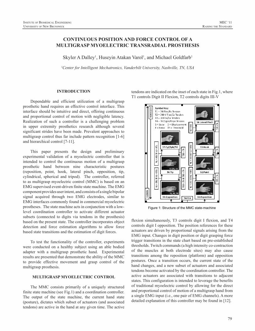
79
InsItute of BIomedIcal engIneerIng
unIversIty of new BrunswIck
MEC ‘11raIsIng the standard
INTRODUCTION
Dependable and efficient utilization of a multigraspprosthetichandrequiresaneffectivecontrol interface.Thisinterfaceshouldbeintuitiveanddirect,offeringcontinuousandproportional controlofmotionwithnegligible latency.Realization of such a controller is a challenging problemin upper extremity prosthetics research although severalsignificantstrideshavebeenmade.Prevalentapproachestomultigraspcontrolthusfarincludepatternrecognition[1-6]andhierarchicalcontrol[7-11].
This paper presents the design and preliminaryexperimental validation of a myoelectric controller that isintended to control the continuousmotion of amultigraspprosthetic hand between nine characteristic postures(reposition, point, hook, lateral pinch, opposition, tip,cylindrical, spherical and tripod). The controller, referredtoasmultigraspmyoelectriccontrol(MMC)isbasedonanEMGsupervisedevent-drivenfinitestatemachine.TheEMGcomponentprovidesuserintent,andconsistsofasinglebipolarsignal acquired through two EMG electrodes, similar toEMGinterfacescommonlyfoundincommercialmyoelectricprostheses.Thestatemachineactsinconjunctionwithalow-level coordination controller to activate different actuatorsubsets (connected to digits via tendons in the prosthesis)basedonthepresentstate.Thecontrollerincorporatesobjectdetection and force estimation algorithms to allow forcebasedstatetransitionsandtheestimationofdigitforces.
To test the functionality of the controller, experimentswere conducted on a healthy subject using an able bodiedadapter with a multigrasp prosthetic hand. ExperimentalresultsarepresentedthatdemonstratetheabilityoftheMMCto provide effective movement and grasp control of themultigraspprosthesis.
MULTIGRASP MYOELECTRIC CONTROL
TheMMC consists primarily of a uniquely structuredfinitestatemachine(seeFig.1)andacoordinationcontroller.The output of the state machine, the current hand state(posture),dictateswhichsubsetofactuators(andassociatedtendons)areactiveinthehandatanygiventime.Theactive
tendonsareindicatedontheinsetofeachstateinFig.1,whereT1controlsDigitIIFlexion,T2controlsdigitsIII-V
Figure 1: Structure of the MMC state-machine
flexion simultaneously,T3 controls digit I flexion, andT4controlsdigitIopposition.ThepositionreferencesfortheseactuatorsaredrivenbyproportionalsignalsarisingfromtheEMGinput.Changesindigitpositionordigitgraspingforcetriggertransitionsinthestatechartbasedonpre-establishedthresholds.Twitchcommands(ahighintensityco-contractionof the muscles at both electrode sites) may also causetransitions among the reposition (platform) and oppositionpostures.Once a transition occurs, the current state of thehandchanges,andanewsubsetofactuatorsandassociatedtendonsbecomeactivatedbythecoordinationcontroller.Theactive actuators are associated with transitions to adjacentstates.ThisconfigurationisintendedtoleveragethebenefitsoftraditionalmyoelectriccontrolbyallowingforthedirectandproportionalcontrolofmotionofamultigrasphandfromasingleEMGinput(i.e.,onepairofEMGchannels).Amoredetailedexplanationofthiscontrollermaybefoundin[12].
CONTINUOUS POSITION AND FORCE CONTROL OF A MULTIGRASP MYOELECTRIC TRANSRADIAL PROSTHESIS
SkylerADalley1,HuseyinAtakanVarol1,andMichaelGoldfarb1
1CenterforIntelligentMechatronics,VanderbiltUniversity,Nashville,TN,USA
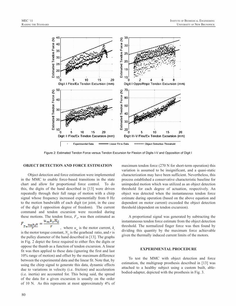
80
MEC ‘11raIsIng the standard
InsItute of BIomedIcal engIneerIng
unIversIty of new BrunswIck
Figure 2: Estimated Tendon Force versus Tendon Excursion for Flexion of Digits I-V and Opposition of Digit I
OBJECT DETECTION AND FORCE ESTIMATION
Objectdetectionandforceestimationwereimplementedin theMMC to enable force-based transitions in the statechart and allow for proportional force control. To dothis, the digits of the hand described in [13] were drivenrepeatedly through their full range ofmotionwith a chirpsignalwhose frequency increasedexponentially from0Hzto themotionbandwidthofeachdigit (or joint, in thecaseof the digit I opposition degree of freedom). The currentcommand and tendon excursion were recorded duringthesemotions.Thetendonforce,FT,was thenestimatedas
, whereumisthemotorcurrent,ktisthemotortorqueconstant,NGisthegearheadratio,andristhepulleydiameterofthehanddescribedin[13].ThegraphsinFig.2depicttheforcerequiredtoeitherflexthedigitsoropposethethumbasafunctionoftendonexcursion.Alinearfitwasthenappliedtothesedata(ignoringthefirstandlast10%rangeofmotion)andoffsetbythemaximumdifferencebetweentheexperimentaldataandthelinearfit.Notethat,byusingthechirpsignaltogeneratethisdata,dynamiceffectsdue to variations in velocity (i.e. friction) and acceleration(i.e. inertia) are accounted for.This being said, the spreadof the data for a given excursion is usually on the orderof 10N. As this represents atmost approximately 4% of
maximumtendonforce(270Nforshort-termoperation)thisvariation is assumed to be insignificant, and a quasi-staticcharacterizationmayhavebeensufficient.Nevertheless,thisprocessestablishedaconservativecharacteristicbaselineforunimpededmotionwhichwasutilizedasanobjectdetectionthreshold for each degree of actuation, respectively. Anobject was detected when the instantaneous tendon forceestimateduringoperation(basedontheaboveequationanddependentonmotor current) exceeded theobjectdetectionthreshold(dependentontendonexcursion).
Aproportionalsignalwasgeneratedbysubtractingtheinstantaneoustendonforceestimatefromtheobjectdetectionthreshold. The normalized finger forcewas then found bydividing this quantity by the maximum force achievablegiventhethermallyinducedcurrentlimitsofthemotors.
EXPERIMENTAL PROCEDURE
To test the MMC with object detection and forceestimation, themultigraspprosthesisdescribed in [13]wasattached to a healthy subject using a custom built, able-bodied-adapter,depictedwiththeprosthesisinFig.3.
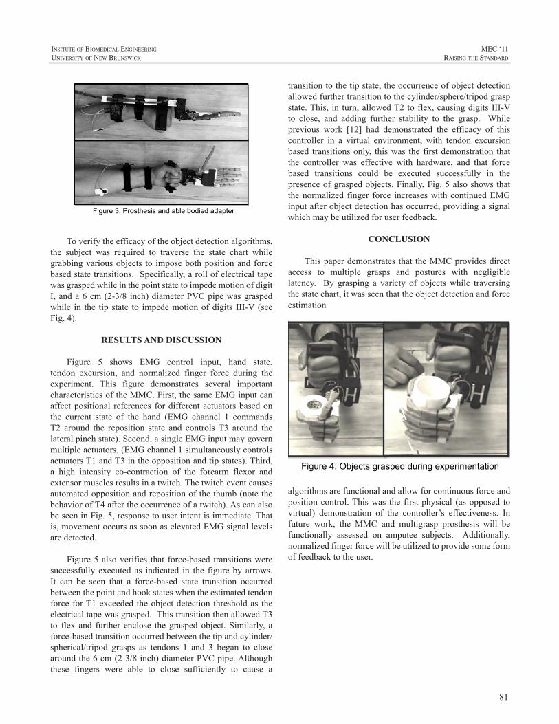
81
InsItute of BIomedIcal engIneerIng
unIversIty of new BrunswIck
MEC ‘11raIsIng the standard
Figure 3: Prosthesis and able bodied adapter
Toverifytheefficacyoftheobjectdetectionalgorithms,the subject was required to traverse the state chart whilegrabbingvariousobjects to imposebothpositionandforcebasedstatetransitions.Specifically,arollofelectricaltapewasgraspedwhileinthepointstatetoimpedemotionofdigitI,anda6cm(2-3/8 inch)diameterPVCpipewasgraspedwhile in the tip state to impedemotionofdigits III-V(seeFig.4).
RESULTS AND DISCUSSION
Figure 5 shows EMG control input, hand state,tendon excursion, and normalized finger force during theexperiment. This figure demonstrates several importantcharacteristicsoftheMMC.First,thesameEMGinputcanaffectpositional references fordifferentactuatorsbasedonthe current state of the hand (EMG channel 1 commandsT2 around the reposition state and controlsT3 around thelateralpinchstate).Second,asingleEMGinputmaygovernmultipleactuators,(EMGchannel1simultaneouslycontrolsactuatorsT1andT3intheoppositionandtipstates).Third,a high intensity co-contraction of the forearm flexor andextensormusclesresultsinatwitch.Thetwitcheventcausesautomatedoppositionandrepositionofthethumb(notethebehaviorofT4aftertheoccurrenceofatwitch).AscanalsobeseeninFig.5,responsetouserintentisimmediate.Thatis,movementoccursassoonaselevatedEMGsignallevelsaredetected.
Figure5alsoverifies that force-based transitionsweresuccessfully executed as indicated in the figureby arrows.It can be seen that a force-based state transition occurredbetweenthepointandhookstateswhentheestimatedtendonforce forT1exceeded theobjectdetection thresholdas theelectricaltapewasgrasped.ThistransitionthenallowedT3to flex and further enclose the grasped object. Similarly, aforce-basedtransitionoccurredbetweenthetipandcylinder/spherical/tripod grasps as tendons 1 and 3 began to closearoundthe6cm(2-3/8inch)diameterPVCpipe.Althoughthese fingers were able to close sufficiently to cause a
transitiontothetipstate,theoccurrenceofobjectdetectionallowedfurthertransitiontothecylinder/sphere/tripodgraspstate.This, in turn,allowedT2toflex,causingdigitsIII-Vto close, and adding further stability to the grasp. Whileprevious work [12] had demonstrated the efficacy of thiscontroller in a virtual environment, with tendon excursionbased transitionsonly, thiswas the firstdemonstration thatthe controller was effective with hardware, and that forcebased transitions could be executed successfully in thepresenceofgraspedobjects.Finally,Fig.5alsoshowsthatthenormalized finger force increaseswithcontinuedEMGinputafterobjectdetectionhasoccurred,providingasignalwhichmaybeutilizedforuserfeedback.
CONCLUSION
ThispaperdemonstratesthattheMMCprovidesdirectaccess to multiple grasps and postures with negligiblelatency. By grasping a variety of objectswhile traversingthestatechart,itwasseenthattheobjectdetectionandforceestimation
Figure 4: Objects grasped during experimentation
algorithmsarefunctionalandallowforcontinuousforceandpositioncontrol.Thiswas the firstphysical (asopposed tovirtual) demonstration of the controller’s effectiveness. Infuture work, the MMC and multigrasp prosthesis will befunctionally assessed on amputee subjects. Additionally,normalizedfingerforcewillbeutilizedtoprovidesomeformoffeedbacktotheuser.
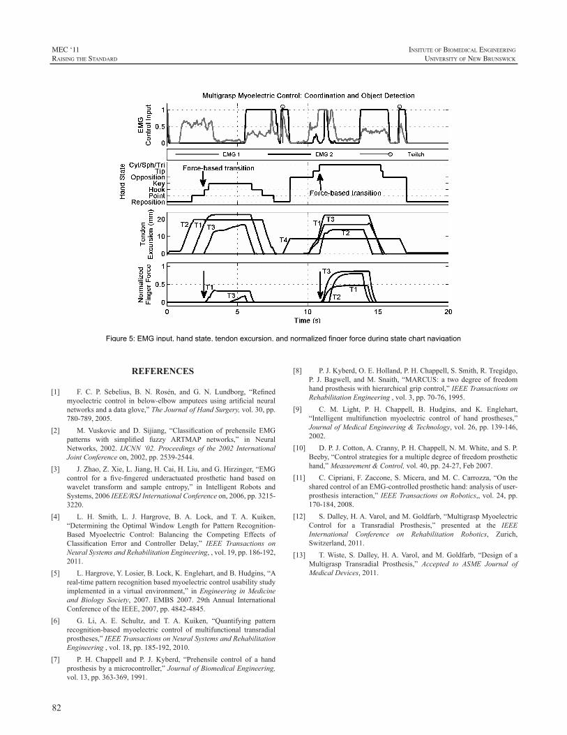
82
MEC ‘11raIsIng the standard
InsItute of BIomedIcal engIneerIng
unIversIty of new BrunswIck
Figure 5: EMG input, hand state, tendon excursion, and normalized finger force during state chart navigation
REFERENCES
[1] F. C. P. Sebelius, B. N. Rosén, and G. N. Lundborg, “Refinedmyoelectric control in below-elbow amputees using artificial neuralnetworksandadataglove,”TheJournalofHandSurgery,vol.30,pp.780-789,2005.
[2] M.Vuskovic and D. Sijiang, “Classification of prehensile EMGpatterns with simplified fuzzy ARTMAP networks,” in NeuralNetworks, 2002. IJCNN ‘02. Proceedings of the 2002 InternationalJointConferenceon,2002,pp.2539-2544.
[3] J.Zhao,Z.Xie,L.Jiang,H.Cai,H.Liu,andG.Hirzinger,“EMGcontrol for a five-fingered underactuated prosthetic hand based onwavelet transform and sample entropy,” in Intelligent Robots andSystems,2006IEEE/RSJInternationalConferenceon,2006,pp.3215-3220.
[4] L. H. Smith, L. J. Hargrove, B. A. Lock, and T. A. Kuiken,“Determining theOptimalWindowLength for PatternRecognition-Based Myoelectric Control: Balancing the Competing Effects ofClassification Error and Controller Delay,” IEEE Transactions onNeuralSystemsandRehabilitationEngineering,,vol.19,pp.186-192,2011.
[5] L.Hargrove,Y.Losier,B.Lock,K.Englehart,andB.Hudgins,“Areal-timepatternrecognitionbasedmyoelectriccontrolusabilitystudyimplemented in a virtual environment,” inEngineering inMedicineand Biology Society, 2007. EMBS 2007. 29thAnnual InternationalConferenceoftheIEEE,2007,pp.4842-4845.
[6] G. Li, A. E. Schultz, and T. A. Kuiken, “Quantifying patternrecognition-based myoelectric control of multifunctional transradialprostheses,”IEEETransactionsonNeuralSystemsandRehabilitationEngineering,vol.18,pp.185-192,2010.
[7] P. H. Chappell and P. J. Kyberd, “Prehensile control of a handprosthesisbyamicrocontroller,”JournalofBiomedicalEngineering,vol.13,pp.363-369,1991.
[8] P.J.Kyberd,O.E.Holland,P.H.Chappell,S.Smith,R.Tregidgo,P. J.Bagwell, andM.Snaith, “MARCUS: a twodegreeof freedomhandprosthesiswithhierarchicalgripcontrol,”IEEETransactionsonRehabilitationEngineering,vol.3,pp.70-76,1995.
[9] C. M. Light, P. H. Chappell, B. Hudgins, and K. Englehart,“Intelligent multifunction myoelectric control of hand prostheses,”JournalofMedicalEngineering&Technology,vol.26,pp.139-146,2002.
[10] D.P.J.Cotton,A.Cranny,P.H.Chappell,N.M.White,andS.P.Beeby,“Controlstrategiesforamultipledegreeoffreedomprosthetichand,”Measurement&Control,vol.40,pp.24-27,Feb2007.
[11] C.Cipriani,F.Zaccone,S.Micera,andM.C.Carrozza,“OnthesharedcontrolofanEMG-controlledprosthetichand:analysisofuser-prosthesis interaction,”IEEETransactionsonRobotics,,vol.24,pp.170-184,2008.
[12] S.Dalley,H.A.Varol,andM.Goldfarb,“MultigraspMyoelectricControl for a Transradial Prosthesis,” presented at the IEEEInternational Conference on Rehabilitation Robotics, Zurich,Switzerland,2011.
[13] T.Wiste,S.Dalley,H.A.Varol, andM.Goldfarb, “Designof aMultigrasp Transradial Prosthesis,” Accepted to ASME Journal ofMedicalDevices,2011.
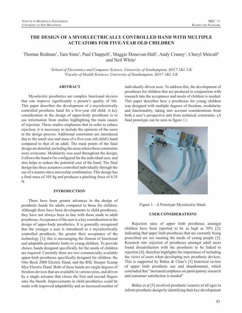
83
InsItute of BIomedIcal engIneerIng
unIversIty of new BrunswIck
MEC ‘11raIsIng the standard
ABSTRACT
Myoelectricprostheticsarecomplexfunctionaldevicesthat can improve significantly a person’s quality of life.This paper describes the development of amyoelectricallycontrolled prosthetic hand for a five-year old child.A keyconsideration in the design of upper-body prostheses is touse information from studies highlighting themain causesofrejection.Thesestudiesemphasizethatinordertoreducerejection,itisnecessarytoincludetheopinionsoftheusersin thedesignprocess.Additionalconstraintsare introducedduetothesmallsizeandmassofafive-yearoldchild’shandcompared to that of an adult.Themain points of the finaldesignaredetailed,includingtheareaswheretheseconstraintswereovercome.Modularitywasusedthroughoutthedesign;itallowsthehandtobeconfiguredfortheindividualuser,andalsohelpstoreducethepotentialcostofthehand.Thefinaldesignhasthreeactuatorscontrolledindividuallythroughtheuseofamaster-slavemicrochipcombination.Thisdesignhasafinalmassof105.8gandproducesapinchingforceof4.35N.
INTRODUCTION
There have been greater advances in the design ofprosthetichands for adults compared to those for children.Althoughtherehavebeendevelopmentstochildprostheses,theyhavenotalwaysbeeninlinewiththosemadetoadultprostheses.Acceptanceoftheuserisakeyconsiderationinthedesignofupper-bodyprosthetics.It isgenerallyrecognisedthat the younger a user is introduced to a myoelectricallycontrolled prosthesis, the greater their acceptance of thetechnology[1];thisisencouragingthefitmentoffunctionalandadaptableprostheticlimbstoyoungchildren.Toprovidechoice,handsdesignedspecificallyfortheneedsofchildrenarerequired.Currentlytherearetwocommerciallyavailableupper-limbprosthesesspecificallydesignedforchildren:theOttoBock2000ElectricHand,andtheRSLSteeperScampMyoElectricHand.Bothofthesehandsaresingledegreesoffreedomdevicesthatareavailableinvarioussizes,anddrivenbyasingleactuator thatcloses thefirstandsecondfingersontothethumb.Improvementsinchildprostheticscouldbemadewithimprovedadaptabilityandanincreasednumberof
individuallydrivenaxes.Toaddressthis,thedevelopmentofprosthesesforchildrenthatareproducedinconjunctionwithresearchintotheacceptanceandneedsofchildrenisneeded.This paper describes how a prostheses for young childrenwasdesignedwithmultipledegreesoffreedom,modularityand functionality, taking into account considerations frombothauser’sperspectiveandfromtechnicalconstraints.(Afinalprototypecanbeseeninfigure1.)
Figure1–APrototypeMyoelectricHand.
USER CONSIDERATIONS
Rejection rates of upper limb prostheses amongstchildren have been reported to be as high as 50% [2];indicatingthatupperlimbprosthesesthatarecurrentlybeingprescribed are notmeeting the needs of young people [3].Research into rejection of prostheses amongst adult usersfound dissatisfaction with the prosthesis to be linked torejection[4],thereforehighlightstheimportanceofincludingtheviewsofuserswhendevelopingnewprostheticdevices.This is supportedbyBidiss&Chau’s [3]historical reviewof upper limb prosthetic use and abandonment, whichconcludedthat“increasedemphasisonparticipatoryresearchandconsumersatisfactionisneeded”
Bidissetal[5]involvedprostheticwearersofallagestoinformprostheticdesignbyidentifyingtheirkeydevelopment
THE DESIGN OF A MYOELECTRICALLY CONTROLLED HAND WITH MULTIPLE ACTUATORS FOR FIVE-YEAR OLD CHILDREN
ThomasRedman1,TaraSims2,PaulChappell1,MaggieDonovan-Hall2,AndyCranny1,CherylMetcalf2andNeilWhite1
1SchoolofElectronicsandComputerScience,UniversityofSouthampton,SO171BJ,UK2FacultyofHealthSciences,UniversityofSouthampton,SO171BJ,UK
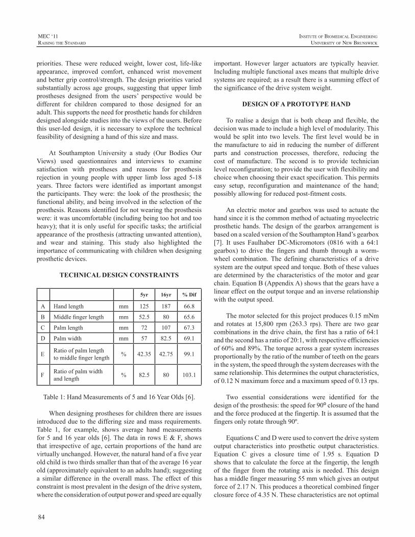
84
MEC ‘11raIsIng the standard
InsItute of BIomedIcal engIneerIng
unIversIty of new BrunswIck
priorities.Thesewere reducedweight, lower cost, life-likeappearance, improved comfort, enhanced wrist movementandbettergripcontrol/strength.Thedesignprioritiesvariedsubstantiallyacrossagegroups, suggesting thatupper limbprostheses designed from the users’ perspective would bedifferent for children compared to those designed for anadult.Thissupportstheneedforprosthetichandsforchildrendesignedalongsidestudiesintotheviewsoftheusers.Beforethisuser-leddesign, it isnecessarytoexplorethetechnicalfeasibilityofdesigningahandofthissizeandmass.
At Southampton University a study (Our Bodies OurViews) used questionnaires and interviews to examinesatisfaction with prostheses and reasons for prosthesisrejection in young people with upper limb loss aged 5-18years. Three factors were identified as important amongsttheparticipants.Theywere: the lookof theprosthesis; thefunctionalability,andbeinginvolvedintheselectionoftheprosthesis.Reasonsidentifiedfornotwearingtheprosthesiswere:itwasuncomfortable(includingbeingtoohotandtooheavy);thatitisonlyusefulforspecifictasks;theartificialappearanceoftheprosthesis(attractingunwantedattention),and wear and staining. This study also highlighted theimportanceofcommunicatingwithchildrenwhendesigningprostheticdevices.
TECHNICAL DESIGN CONSTRAINTS
5yr 16yr % Dif
A Handlength mm 125 187 66.8
B Middlefingerlength mm 52.5 80 65.6
C Palmlength mm 72 107 67.3
D Palmwidth mm 57 82.5 69.1
E Ratioofpalmlengthtomiddlefingerlength % 42.35 42.75 99.1
F Ratioofpalmwidthandlength % 82.5 80 103.1
Table1:HandMeasurementsof5and16YearOlds[6].
Whendesigningprosthesesforchildrenthereareissuesintroducedduetothedifferingsizeandmassrequirements.Table 1, for example, shows average hand measurementsfor5and16yearolds[6].Thedata inrowsE&F,showsthat irrespectiveofage,certainproportionsof thehandarevirtuallyunchanged.However,thenaturalhandofafiveyearoldchildistwothirdssmallerthanthatoftheaverage16yearold(approximatelyequivalenttoanadultshand);suggestinga similar difference in the overallmass.The effect of thisconstraintismostprevalentinthedesignofthedrivesystem,wheretheconsiderationofoutputpowerandspeedareequally
important. However larger actuators are typically heavier.Includingmultiplefunctionalaxesmeansthatmultipledrivesystemsarerequired;asaresultthereisasummingeffectofthesignificanceofthedrivesystemweight.
DESIGN OF A PROTOTYPE HAND
Torealiseadesign that isbothcheapand flexible, thedecisionwasmadetoincludeahighlevelofmodularity.Thiswould be split into two levels.The first levelwould be inthemanufacture toaid in reducing thenumberofdifferentparts and construction processes, therefore, reducing thecost of manufacture. The second is to provide technicianlevelreconfiguration;toprovidetheuserwithflexibilityandchoicewhenchoosingtheirexactspecification.Thispermitseasy setup, reconfiguration and maintenance of the hand;possiblyallowingforreducedpost-fitmentcosts.
Anelectricmotorandgearboxwasusedtoactuatethehandsinceitisthecommonmethodofactuatingmyoelectricprosthetichands.ThedesignofthegearboxarrangementisbasedonascaledversionoftheSouthamptonHand’sgearbox[7]. It uses Faulhaber DC-Micromotors (0816with a 64:1gearbox) to drive the fingers and thumb through a worm-wheel combination.The defining characteristics of a drivesystemaretheoutputspeedandtorque.Bothofthesevaluesaredeterminedbythecharacteristicsofthemotorandgearchain.EquationB(AppendixA)showsthatthegearshavealineareffectontheoutputtorqueandaninverserelationshipwiththeoutputspeed.
Themotorselectedforthisprojectproduces0.15mNmand rotates at 15,800 rpm (263.3 rps).There are two gearcombinationsinthedrivechain,thefirsthasaratioof64:1andthesecondhasaratioof20:1,withrespectiveefficienciesof60%and89%.Thetorqueacrossagearsystemincreasesproportionallybytheratioofthenumberofteethonthegearsinthesystem,thespeedthroughthesystemdecreaseswiththesamerelationship.Thisdeterminestheoutputcharacteristics,of0.12Nmaximumforceandamaximumspeedof0.13rps.
Two essential considerations were identified for thedesignoftheprosthesis:thespeedfor90⁰closureofthehandandtheforceproducedatthefingertip.Itisassumedthatthefingersonlyrotatethrough90º.
EquationsCandDwereusedtoconvertthedrivesystemoutput characteristics into prosthetic output characteristics.Equation C gives a closure time of 1.95 s. Equation Dshowsthattocalculatetheforceatthefingertip,thelengthof the finger from the rotating axis is needed.This designhasamiddlefingermeasuring55mmwhichgivesanoutputforceof2.17N.Thisproducesatheoreticalcombinedfingerclosureforceof4.35N.Thesecharacteristicsarenotoptimal
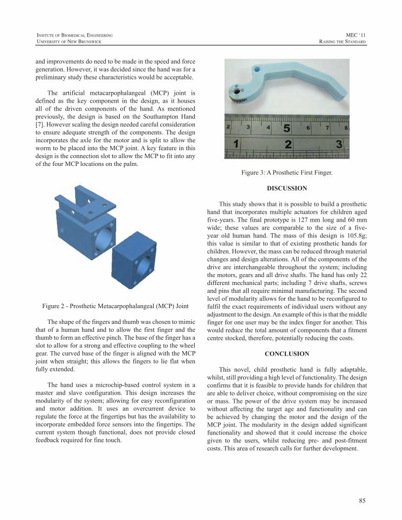
85
InsItute of BIomedIcal engIneerIng
unIversIty of new BrunswIck
MEC ‘11raIsIng the standard
andimprovementsdoneedtobemadeinthespeedandforcegeneration.However,itwasdecidedsincethehandwasforapreliminarystudythesecharacteristicswouldbeacceptable.
The artificial metacarpophalangeal (MCP) joint isdefined as the key component in the design, as it housesall of the driven components of the hand. As mentionedpreviously, the design is based on the Southampton Hand[7].Howeverscalingthedesignneededcarefulconsiderationtoensureadequatestrengthof thecomponents.ThedesignincorporatestheaxleforthemotorandissplittoallowthewormtobeplacedintotheMCPjoint.AkeyfeatureinthisdesignistheconnectionslottoallowtheMCPtofitintoanyofthefourMCPlocationsonthepalm.
Figure2-ProstheticMetacarpophalangeal(MCP)Joint
Theshapeofthefingersandthumbwaschosentomimicthat of a humanhand and to allow the first finger and thethumbtoformaneffectivepinch.Thebaseofthefingerhasaslottoallowforastrongandeffectivecouplingtothewheelgear.ThecurvedbaseofthefingerisalignedwiththeMCPjointwhen straight; this allows the fingers to lie flatwhenfullyextended.
The hand uses a microchip-based control system in amaster and slave configuration. This design increases themodularityofthesystem;allowingforeasyreconfigurationand motor addition. It uses an overcurrent device toregulatetheforceatthefingertipsbuthastheavailabilitytoincorporateembeddedforcesensorsintothefingertips.Thecurrent system though functional, does not provide closedfeedbackrequiredforfinetouch.
Figure3:AProstheticFirstFinger.
DISCUSSION
Thisstudyshowsthatitispossibletobuildaprosthetichand that incorporatesmultiple actuators for children agedfive-years.Thefinalprototypeis127mmlongand60mmwide; these values are comparable to the size of a five-year old human hand. The mass of this design is 105.8g;thisvalue issimilar to thatofexistingprosthetichands forchildren.However,themasscanbereducedthroughmaterialchangesanddesignalterations.Allofthecomponentsofthedrive are interchangeable throughout the system; includingthemotors,gearsandalldriveshafts.Thehandhasonly22differentmechanicalparts; including7driveshafts, screwsandpinsthatallrequireminimalmanufacturing.Thesecondlevelofmodularityallowsforthehandtobereconfiguredtofulfiltheexactrequirementsofindividualuserswithoutanyadjustmenttothedesign.Anexampleofthisisthatthemiddlefingerforoneusermaybetheindexfingerforanother.Thiswouldreducethetotalamountofcomponentsthatafitmentcentrestocked,therefore,potentiallyreducingthecosts.
CONCLUSION
This novel, child prosthetic hand is fully adaptable,whilst,stillprovidingahighleveloffunctionality.Thedesignconfirmsthatitisfeasibletoprovidehandsforchildrenthatareabletodeliverchoice,withoutcompromisingonthesizeormass.The power of the drive systemmay be increasedwithout affecting the target age and functionality and canbe achieved by changing the motor and the design of theMCP joint.Themodularity in thedesign added significantfunctionality and showed that it could increase the choicegiven to the users, whilst reducing pre- and post-fitmentcosts.Thisareaofresearchcallsforfurtherdevelopment.
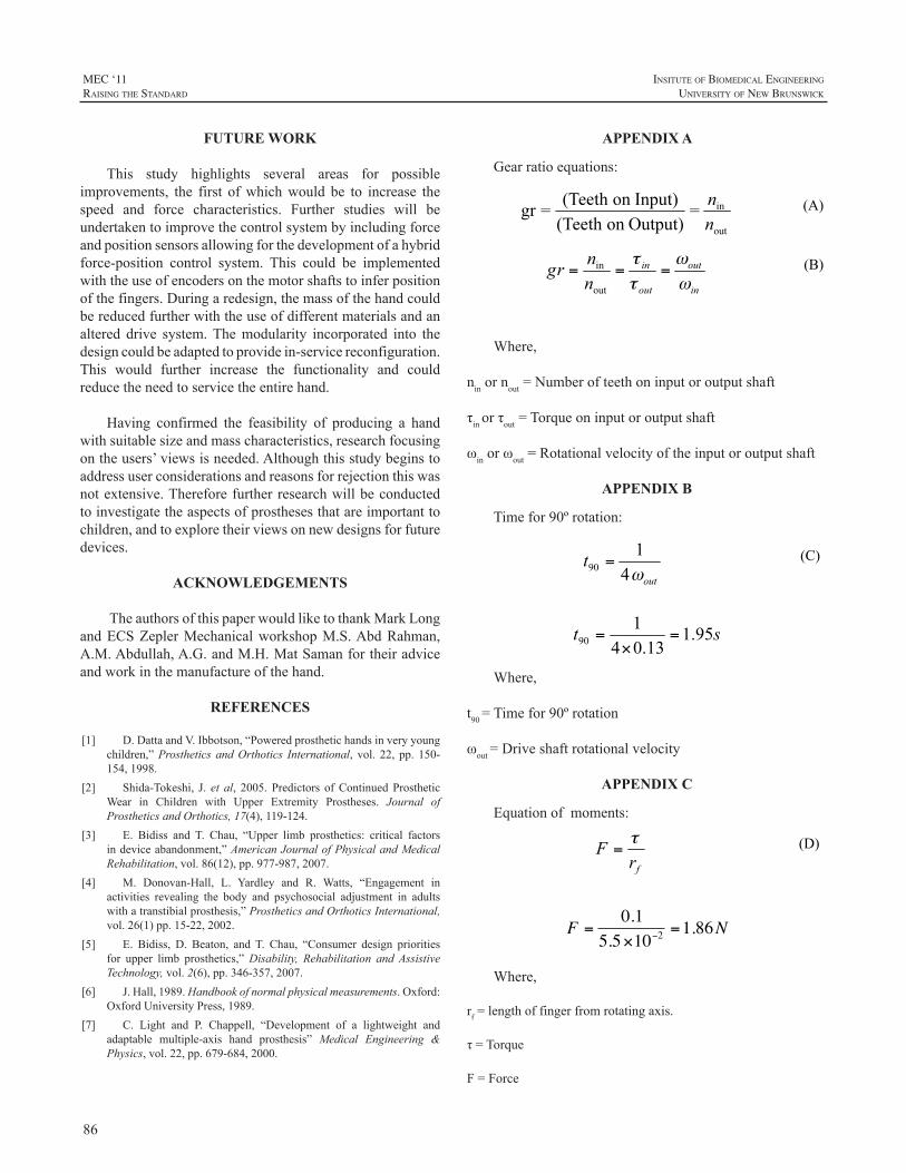
86
MEC ‘11raIsIng the standard
InsItute of BIomedIcal engIneerIng
unIversIty of new BrunswIck
FUTURE WORK
This study highlights several areas for possibleimprovements, the first ofwhichwould be to increase thespeed and force characteristics. Further studies will beundertakentoimprovethecontrolsystembyincludingforceandpositionsensorsallowingforthedevelopmentofahybridforce-position control system. This could be implementedwiththeuseofencodersonthemotorshaftstoinferpositionofthefingers.Duringaredesign,themassofthehandcouldbereducedfurtherwiththeuseofdifferentmaterialsandanaltered drive system.Themodularity incorporated into thedesigncouldbeadaptedtoprovidein-servicereconfiguration.This would further increase the functionality and couldreducetheneedtoservicetheentirehand.
Having confirmed the feasibility of producing a handwithsuitablesizeandmasscharacteristics,researchfocusingontheusers’viewsisneeded.Althoughthisstudybeginstoaddressuserconsiderationsandreasonsforrejectionthiswasnotextensive.Thereforefurtherresearchwillbeconductedtoinvestigatetheaspectsofprosthesesthatareimportanttochildren,andtoexploretheirviewsonnewdesignsforfuturedevices.
ACKNOWLEDGEMENTS
TheauthorsofthispaperwouldliketothankMarkLongandECSZeplerMechanicalworkshopM.S.AbdRahman,A.M.Abdullah,A.G.andM.H.MatSamanfortheiradviceandworkinthemanufactureofthehand.
REFERENCES
[1] D.DattaandV.Ibbotson,“Poweredprosthetichandsinveryyoungchildren,”Prosthetics andOrthotics International, vol. 22, pp. 150-154,1998.
[2] Shida-Tokeshi, J. et al, 2005. Predictors ofContinuedProstheticWear in Children with Upper Extremity Prostheses. Journal ofProstheticsandOrthotics,17(4),119-124.
[3] E. Bidiss and T. Chau, “Upper limb prosthetics: critical factorsindeviceabandonment,”AmericanJournalofPhysicalandMedicalRehabilitation,vol.86(12),pp.977-987,2007.
[4] M. Donovan-Hall, L. Yardley and R. Watts, “Engagement inactivities revealing the body and psychosocial adjustment in adultswithatranstibialprosthesis,”ProstheticsandOrthoticsInternational,vol.26(1)pp.15-22,2002.
[5] E. Bidiss, D. Beaton, and T. Chau, “Consumer design prioritiesfor upper limb prosthetics,”Disability, Rehabilitation and AssistiveTechnology,vol.2(6),pp.346-357,2007.
[6] J.Hall,1989.Handbookofnormalphysicalmeasurements.Oxford:OxfordUniversityPress,1989.
[7] C. Light and P. Chappell, “Development of a lightweight andadaptable multiple-axis hand prosthesis” Medical Engineering &Physics,vol.22,pp.679-684,2000.
APPENDIX A
Gearratioequations:
(A)
(B)
Where,
ninornout=Numberofteethoninputoroutputshaft
τinorτout=Torqueoninputoroutputshaft
ωinorωout=Rotationalvelocityoftheinputoroutputshaft
APPENDIX B
Timefor90ºrotation:
(C)
Where,
t90=Timefor90ºrotation
ωout=Driveshaftrotationalvelocity
APPENDIX C
Equationofmoments:
(D)
€
F =0.1
5.5×10−2=1.86N
Where,
rf=lengthoffingerfromrotatingaxis.
τ=Torque
F=Force
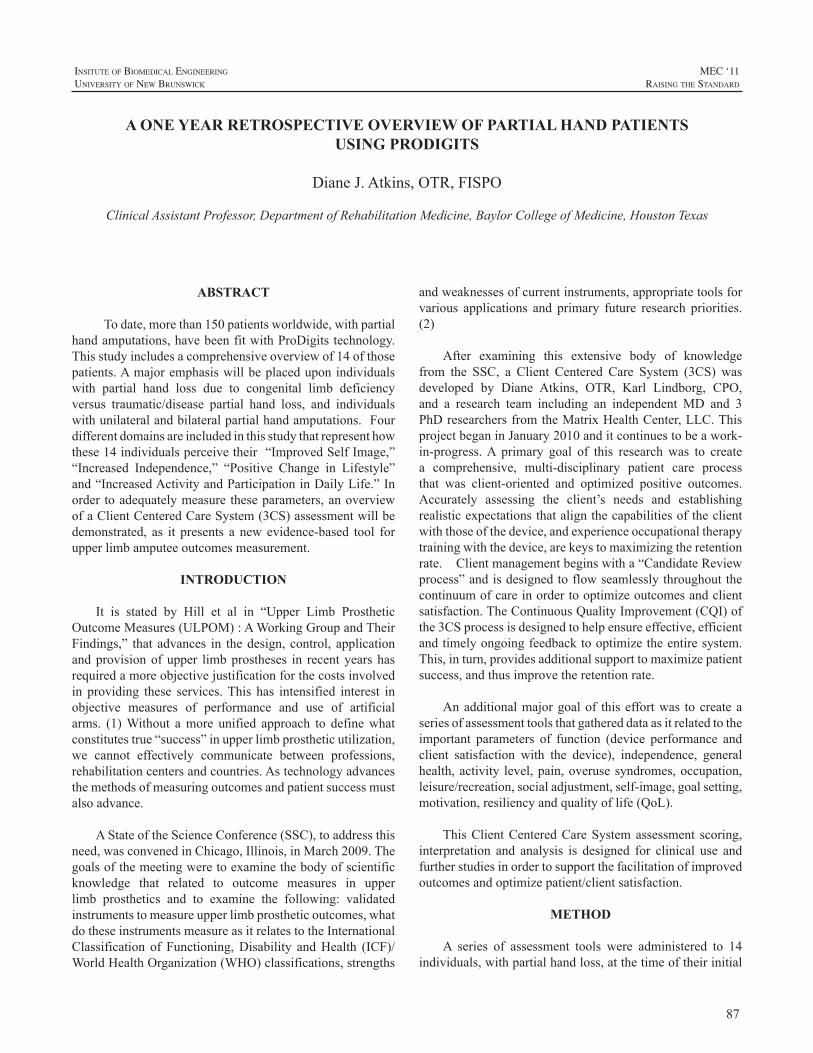
87
InsItute of BIomedIcal engIneerIng
unIversIty of new BrunswIck
MEC ‘11raIsIng the standard
ABSTRACT
Todate,morethan150patientsworldwide,withpartialhandamputations,havebeenfitwithProDigitstechnology.Thisstudyincludesacomprehensiveoverviewof14ofthosepatients.Amajoremphasiswillbeplaceduponindividualswith partial hand loss due to congenital limb deficiencyversus traumatic/disease partial hand loss, and individualswithunilateralandbilateralpartialhandamputations.Fourdifferentdomainsareincludedinthisstudythatrepresenthowthese14individualsperceivetheir“ImprovedSelfImage,”“Increased Independence,” “Positive Change in Lifestyle”and“IncreasedActivityandParticipationinDailyLife.”Inorder toadequatelymeasuretheseparameters,anoverviewofaClientCenteredCareSystem(3CS)assessmentwillbedemonstrated, as it presents a newevidence-based tool forupperlimbamputeeoutcomesmeasurement.
INTRODUCTION
It is stated by Hill et al in “Upper Limb ProstheticOutcomeMeasures(ULPOM):AWorkingGroupandTheirFindings,” that advances in thedesign, control, applicationandprovisionofupper limbprostheses in recentyearshasrequiredamoreobjectivejustificationforthecostsinvolvedin providing these services.This has intensified interest inobjective measures of performance and use of artificialarms. (1)Without amore unified approach to definewhatconstitutestrue“success”inupperlimbprostheticutilization,we cannot effectively communicate between professions,rehabilitationcentersandcountries.Astechnologyadvancesthemethodsofmeasuringoutcomesandpatientsuccessmustalsoadvance.
AStateoftheScienceConference(SSC),toaddressthisneed,wasconvenedinChicago,Illinois,inMarch2009.Thegoalsofthemeetingweretoexaminethebodyofscientificknowledge that related to outcome measures in upperlimb prosthetics and to examine the following: validatedinstrumentstomeasureupperlimbprostheticoutcomes,whatdotheseinstrumentsmeasureasitrelatestotheInternationalClassification of Functioning,Disability andHealth (ICF)/WorldHealthOrganization(WHO)classifications,strengths
andweaknessesofcurrentinstruments,appropriatetoolsforvarious applications and primary future research priorities.(2)
After examining this extensive body of knowledgefrom the SSC, a Client Centered Care System (3CS) wasdeveloped by Diane Atkins, OTR, Karl Lindborg, CPO,and a research team including an independent MD and 3PhDresearchersfromtheMatrixHealthCenter,LLC.ThisprojectbeganinJanuary2010anditcontinuestobeawork-in-progress.A primary goal of this research was to createa comprehensive, multi-disciplinary patient care processthat was client-oriented and optimized positive outcomes.Accurately assessing the client’s needs and establishingrealisticexpectationsthatalignthecapabilitiesoftheclientwiththoseofthedevice,andexperienceoccupationaltherapytrainingwiththedevice,arekeystomaximizingtheretentionrate.Clientmanagementbeginswitha“CandidateReviewprocess”andisdesignedtoflowseamlesslythroughoutthecontinuumofcareinordertooptimizeoutcomesandclientsatisfaction.TheContinuousQualityImprovement(CQI)ofthe3CSprocessisdesignedtohelpensureeffective,efficientandtimelyongoingfeedbacktooptimizetheentiresystem.This,inturn,providesadditionalsupporttomaximizepatientsuccess,andthusimprovetheretentionrate.
Anadditionalmajorgoalof thiseffortwas tocreateaseriesofassessmenttoolsthatgathereddataasitrelatedtotheimportant parameters of function (device performance andclient satisfaction with the device), independence, generalhealth,activity level,pain,overusesyndromes,occupation,leisure/recreation,socialadjustment,self-image,goalsetting,motivation,resiliencyandqualityoflife(QoL).
ThisClientCenteredCareSystemassessment scoring,interpretation and analysis is designed for clinical use andfurtherstudiesinordertosupportthefacilitationofimprovedoutcomesandoptimizepatient/clientsatisfaction.
METHOD
A series of assessment tools were administered to 14individuals,withpartialhandloss,atthetimeoftheirinitial
A ONE YEAR RETROSPECTIVE OVERVIEW OF PARTIAL HAND PATIENTS USING PRODIGITS
DianeJ.Atkins,OTR,FISPO
ClinicalAssistantProfessor,DepartmentofRehabilitationMedicine,BaylorCollegeofMedicine,HoustonTexas
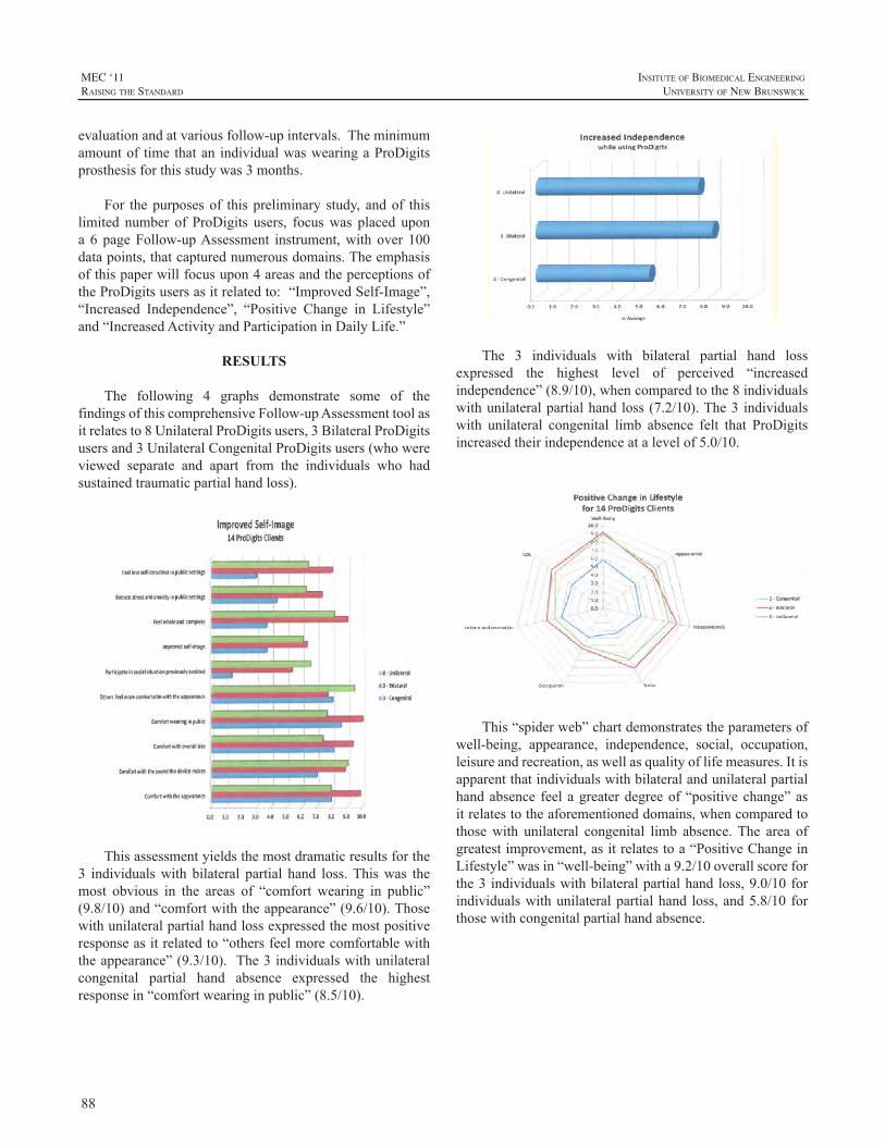
88
MEC ‘11raIsIng the standard
InsItute of BIomedIcal engIneerIng
unIversIty of new BrunswIck
evaluationandatvariousfollow-upintervals.Theminimumamountof time thatan individualwaswearingaProDigitsprosthesisforthisstudywas3months.
For thepurposesof thispreliminary study, andof thislimited number of ProDigits users, focuswas placed upona 6 pageFollow-upAssessment instrument,with over 100datapoints,thatcapturednumerousdomains.Theemphasisofthispaperwillfocusupon4areasandtheperceptionsoftheProDigitsusersasitrelatedto:“ImprovedSelf-Image”,“Increased Independence”, “Positive Change in Lifestyle”and“IncreasedActivityandParticipationinDailyLife.”
RESULTS
The following 4 graphs demonstrate some of thefindingsofthiscomprehensiveFollow-upAssessmenttoolasitrelatesto8UnilateralProDigitsusers,3BilateralProDigitsusersand3UnilateralCongenitalProDigitsusers(whowereviewed separate and apart from the individuals who hadsustainedtraumaticpartialhandloss).
Thisassessmentyieldsthemostdramaticresultsforthe3 individualswith bilateral partial hand loss.Thiswas themost obvious in the areas of “comfort wearing in public”(9.8/10)and“comfortwiththeappearance”(9.6/10).Thosewithunilateralpartialhandlossexpressedthemostpositiveresponseasitrelatedto“othersfeelmorecomfortablewiththeappearance”(9.3/10). The3individualswithunilateralcongenital partial hand absence expressed the highestresponsein“comfortwearinginpublic”(8.5/10).
The 3 individuals with bilateral partial hand lossexpressed the highest level of perceived “increasedindependence”(8.9/10),whencomparedtothe8individualswithunilateralpartialhandloss(7.2/10).The3 individualswith unilateral congenital limb absence felt that ProDigitsincreasedtheirindependenceatalevelof5.0/10.
This“spiderweb”chartdemonstratestheparametersofwell-being, appearance, independence, social, occupation,leisureandrecreation,aswellasqualityoflifemeasures.Itisapparentthatindividualswithbilateralandunilateralpartialhandabsence feelagreaterdegreeof“positivechange”asitrelatestotheaforementioneddomains,whencomparedtothosewith unilateral congenital limb absence.The area ofgreatestimprovement,asitrelatestoa“PositiveChangeinLifestyle”wasin“well-being”witha9.2/10overallscoreforthe3 individualswithbilateralpartialhandloss,9.0/10forindividualswithunilateralpartialhand loss,and5.8/10 forthosewithcongenitalpartialhandabsence.
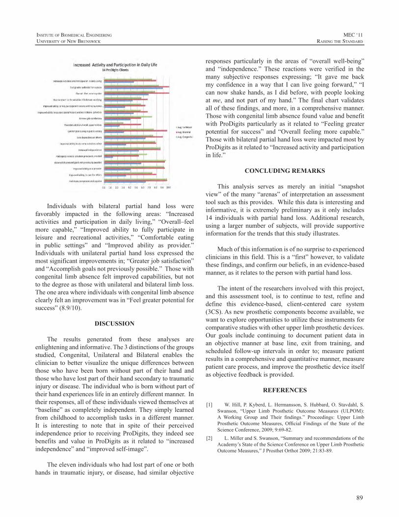
89
InsItute of BIomedIcal engIneerIng
unIversIty of new BrunswIck
MEC ‘11raIsIng the standard
Individuals with bilateral partial hand loss werefavorably impacted in the following areas: “Increasedactivities and participation in daily living,” “Overall–feelmore capable,” “Improved ability to fully participate inleisure and recreational activities,” “Comfortable eatingin public settings” and “Improved ability as provider.”Individuals with unilateral partial hand loss expressed themostsignificantimprovementsin;“Greaterjobsatisfaction”and“Accomplishgoalsnotpreviouslypossible.”Thosewithcongenital limbabsence felt improved capabilities, but nottothedegreeasthosewithunilateralandbilaterallimbloss.Theoneareawhereindividualswithcongenitallimbabsenceclearlyfeltanimprovementwasin“Feelgreaterpotentialforsuccess”(8.9/10).
DISCUSSION
The results generated from these analyses areenlighteningandinformative.The3distinctionsofthegroupsstudied, Congenital, Unilateral and Bilateral enables theclinician tobettervisualize theuniquedifferencesbetweenthose who have been born without part of their hand andthosewhohavelostpartoftheirhandsecondarytotraumaticinjuryordisease.Theindividualwhoisbornwithoutpartoftheirhandexperienceslifeinanentirelydifferentmanner.Intheirresponses,alloftheseindividualsviewedthemselvesat“baseline”ascompletelyindependent.Theysimplylearnedfrom childhood to accomplish tasks in a differentmanner.It is interesting to note that in spite of their perceivedindependenceprior to receivingProDigits, they indeed seebenefits and value in ProDigits as it related to “increasedindependence”and“improvedself-image”.
Theelevenindividualswhohadlostpartofoneorbothhands in traumatic injury, or disease, had similar objective
responses particularly in the areas of “overall well-being”and “independence.” These reactions were verified in themany subjective responses expressing; “It gave me backmyconfidence in away that I can livegoing forward,” “Icannowshakehands,as Ididbefore,withpeople lookingatme, and not part ofmy hand.”The final chart validatesallofthesefindings,andmore,inacomprehensivemanner.ThosewithcongenitallimbabsencefoundvalueandbenefitwithProDigits particularly as it related to “Feelinggreaterpotential for success” and “Overall feelingmore capable.”ThosewithbilateralpartialhandlosswereimpactedmostbyProDigitsasitrelatedto“Increasedactivityandparticipationinlife.”
CONCLUDING REMARKS
This analysis serves as merely an initial “snapshotview”ofthemany“arenas”ofinterpretationanassessmenttoolsuchasthisprovides.Whilethisdataisinterestingandinformative, it is extremelypreliminary as it only includes14 individuals with partial hand loss.Additional research,using a larger number of subjects,will provide supportiveinformationforthetrendsthatthisstudyillustrates.
Muchofthisinformationisofnosurprisetoexperiencedcliniciansinthisfield.Thisisa“first”however,tovalidatethesefindings,andconfirmourbeliefs,inanevidence-basedmanner,asitrelatestothepersonwithpartialhandloss.
Theintentoftheresearchersinvolvedwiththisproject,and this assessment tool, is to continue to test, refine anddefine this evidence-based, client-centered care system(3CS).Asnewprostheticcomponentsbecomeavailable,wewanttoexploreopportunitiestoutilizetheseinstrumentsforcomparativestudieswithotherupperlimbprostheticdevices.Our goals include continuing to document patient data inan objective manner at base line, exit from training, andscheduled follow-up intervals in order to; measure patientresultsinacomprehensiveandquantitativemanner,measurepatientcareprocess,andimprovetheprostheticdeviceitselfasobjectivefeedbackisprovided.
REFERENCES
[1] W.Hill,P.Kyberd,L.Hermansson,S.Hubbard,O.Stavdahl,S.Swanson, “Upper Limb Prosthetic Outcome Measures (ULPOM):A Working Group and Their findings.” Proceedings: Upper LimbProsthetic OutcomeMeasures, Official Findings of the State of theScienceConference,2009;9:69-82.
[2] L.MillerandS.Swanson,“SummaryandrecommendationsoftheAcademy’sStateoftheScienceConferenceonUpperLimbProstheticOutcomeMeasures,”JProsthetOrthot2009;21:83-89.

90
MEC ‘11raIsIng the standard
InsItute of BIomedIcal engIneerIng
unIversIty of new BrunswIck
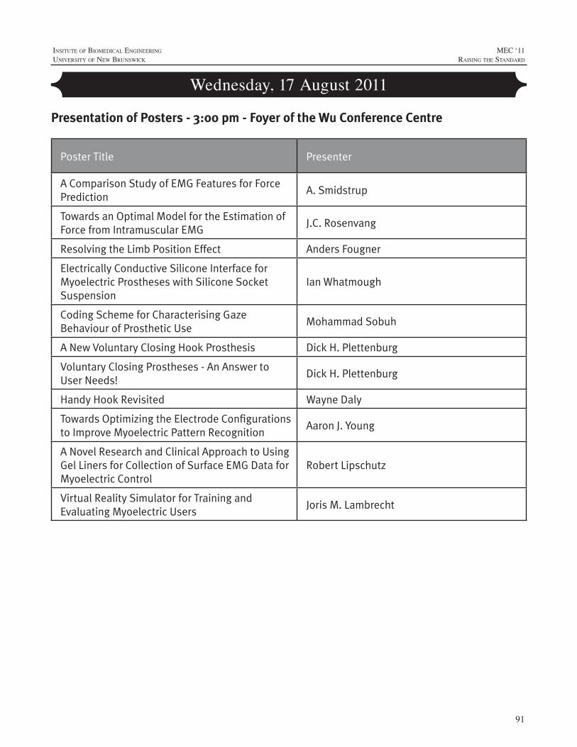
91
InsItute of BIomedIcal engIneerIng
unIversIty of new BrunswIck
MEC ‘11raIsIng the standard
Wednesday, 17 August 2011
Poster Title Presenter
A Comparison Study of EMG Features for Force Prediction
A. Smidstrup
Towards an Optimal Model for the Estimation of Force from Intramuscular EMG
J.C. Rosenvang
Resolving the Limb Position Effect Anders Fougner
Electrically Conductive Silicone Interface for Myoelectric Prostheses with Silicone Socket Suspension
Ian Whatmough
Coding Scheme for Characterising Gaze Behaviour of Prosthetic Use
Mohammad Sobuh
A New Voluntary Closing Hook Prosthesis Dick H. Plettenburg
Voluntary Closing Prostheses - An Answer to User Needs!
Dick H. Plettenburg
Handy Hook Revisited Wayne Daly
Towards Optimizing the Electrode Configurations to Improve Myoelectric Pattern Recognition
Aaron J. Young
A Novel Research and Clinical Approach to Using Gel Liners for Collection of Surface EMG Data for Myoelectric Control
Robert Lipschutz
Virtual Reality Simulator for Training and Evaluating Myoelectric Users
Joris M. Lambrecht
Presentation of Posters - 3:00 pm - Foyer of the Wu Conference Centre

92
MEC ‘11raIsIng the standard
InsItute of BIomedIcal engIneerIng
unIversIty of new BrunswIck
93
InsItute of BIomedIcal engIneerIng
unIversIty of new BrunswIck
MEC ‘11raIsIng the standard
ABSTRACT
Myoelectric prosthetic devices can be controlled by use ofsurfaceelectromyography(sEMG).However, intramuscularEMG(iEMG)hasbeenproposedasanalternative,sinceitmayprovidemorestableandselectiverecordingswithseveraladvantages.Thepurpose of this studywas to assess the predictive capabilities of14 featuresof iEMGand sEMGfor force ranging from0 to100% maximum voluntary contraction (MVC). Intramuscular EMGand surface EMG were recorded concurrently from the muscleflexor digitorum profundus from 11 subjects who exerted fourforceprofilesduringpowergrasping.ThepredictivecapabilityofeachfeaturewasassessedusingthemeanR2-valuewitha1storderpolynomial(linearprediction).WilsonAmplitudeshowedthebestresultsforbothsEMG(R2=0.952±0.007)andiEMG(R2=0.948± 0.008), with no significant difference (P = 0.658).Applicationof an advancedmodel based on artificial neural network did notimprove the performance (P = 0.895).We have concluded that alinearmodelissufficientforforceprediction(0-100%MVC),andthat iEMG is potentially suitable for proportional control in thesamemanneraswhenusingamoreglobalmeasureofintensity.
INTRODUCTION
Formanyamputees,theonlypossibilityforrestorationof movement is through the use of prosthetic devices.SurfaceEMG(sEMG)isalreadybeingusedforthecontrolofmyoelectricprostheticdevices,wheretheappliedforceisestimated proportionally to features extracted from sEMG.[1,2,3]Despite good results, the use of sEMG has a numberofdisadvantages:(1)it is limitedtooneortwoDegreesofFreedom(DoF),(2)itcanonlybemeasuredfromsuperficialmuscles,(3)itissensitivetocrosstalk,and(4)itcancauseirritationoftheskinduringrepeateduse.[1,4]
Use of intramuscular EMG (iEMG) for prostheticdeviceshasbeenproposedbecauseiEMGmayprovidemorestableandselectiverecordingscomparedtosEMG,andmayalloweffectivecontrolofmultipleDoFs.Furthermore,iEMGelectrodesmaybechronicallyimplanted.[1]Becauseoftheirhighselectivity,iEMGmaybelessrepresentativeoftheglobalmuscleactivityandtherebycontainlessinformationabouttheforceproducedbytheentiremuscle.Toourbestknowledge,very few features of iEMGhave been explored in relationtoforcee.g.integratedEMG,[5]globaldischargerate,[1]root
meanabsolutevaluesandconstraintsampleentropy(CSE).[6] Furthermore, no studies have shown whether the usedfeaturesproposedforsEMGcanbeappliedforiEMGintheentire rangeof force from0 to100%MaximumVoluntaryContraction(MVC).
Therefore, the aim of this study was to assess thepredictive capabilities of 14EMG features for both iEMGandsEMGusingtheentireforcerangefrom0to100%MVC.Thiswas based on a linear relationship and a relationshipfoundbyanArtificialNeuralNetwork(ANN).
METHODS
ExperimentSubjects: The study included 11 right-handed healthy
subjects(4w/7m)intheageof22to26years(mean23.8yrs).TheexperimentwasapprovedbytheDanishlocalethicalcommittee(approvalno:N-20080045).Allsubjectsreceivedbothwrittenandoralinformationabouttheexperimentandgavewrittenconsentpriortotheexperiment.
Procedure:Thesubjectsperformedpowergraspingonaforcedynamometer(Noraxon)withtheirrighthand,whileseatedinachairwiththeirarmplacedinanarmrest(Figure1).TheMVCforceofeachsubjectwasrecordedthreetimeswith a 3 min rest after each trial. The subjects were thenaskedtofollowfourdifferentforceprofiles:
1.Astepprofileof9secwithforceincreasingin6steps.
2.Adoublerampprofileof9sec.
3. Abellprofileof9sec.
4. A freevaryingprofileof9secwhere100%MVChadtobereachedatleastonce.
The order of the profiles was randomized. The step,doublerampandbellprofilewererecordedtwotimeseachandthelevelofforcespannedfrom0to100%MVC.Thefreevaryingprofilewasonlyrecordedonce.Theforcewasshownonanoscilloscopeinordertoprovidethesubjectwithvisualfeedbackduringeachprofile.Eachtrialwasfollowedbya3
A COMPARISON STUDY OF EMG FEATURES FOR FORCE PREDICTION
A.Smidstrup,E.Erkocevic,M.J.Niemeier,M.F.Bøg,J.C.RosenvangandE.N.Kamavuako*
DepartmentofHealthScienceandTechnology,AalborgUniversity,9220Aalborg,Denmark*ErnestNKamavuako,AalborgUniversity,Fredrikbajersvej7D3,9220Aalborg,Denmark,[email protected]
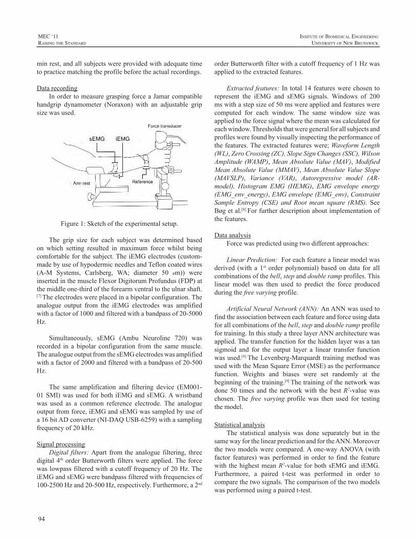
94
MEC ‘11raIsIng the standard
InsItute of BIomedIcal engIneerIng
unIversIty of new BrunswIck
minrest,andallsubjectswereprovidedwithadequatetimetopracticematchingtheprofilebeforetheactualrecordings.
DatarecordingInordertomeasuregraspingforceaJamarcompatible
handgrip dynamometer (Noraxon) with an adjustable gripsizewasused.
Figure1:Sketchoftheexperimentalsetup.
The grip size for each subject was determined basedon which setting resulted in maximum force whilst beingcomfortableforthesubject.TheiEMGelectrodes(custom-madebyuseofhypodermicneedlesandTefloncoatedwires(A-M Systems, Carlsberg, WA; diameter 50 µm)) wereinsertedinthemuscleFlexorDigitorumProfundus(FDP)atthemiddleone-thirdoftheforearmventraltotheulnarshaft.[7]Theelectrodeswereplacedinabipolarconfiguration.Theanalogue output from the iEMG electrodes was amplifiedwithafactorof1000andfilteredwithabandpassof20-5000Hz.
Simultaneously, sEMG (Ambu Neuroline 720) wasrecorded in a bipolar configuration from the samemuscle.TheanalogueoutputfromthesEMGelectrodeswasamplifiedwithafactorof2000andfilteredwithabandpassof20-500Hz.
The same amplification and filtering device (EM001-01SMI)wasusedforboth iEMGandsEMG.Awristbandwas used as a common reference electrode. The analogueoutputfromforce,iEMGandsEMGwassampledbyuseofa16bitADconverter(NI-DAQUSB-6259)withasamplingfrequencyof20kHz.
SignalprocessingDigital filters:Apart fromtheanaloguefiltering, three
digital4thorderButterworthfilterswereapplied.Theforcewaslowpassfilteredwithacutofffrequencyof20Hz.TheiEMGandsEMGwerebandpassfilteredwithfrequenciesof100-2500Hzand20-500Hz,respectively.Furthermore,a2nd
orderButterworthfilterwithacutofffrequencyof1Hzwasappliedtotheextractedfeatures.
Extracted features: In total14 featureswerechosen torepresent the iEMG and sEMG signals. Windows of 200mswithastepsizeof50mswereappliedandfeatureswerecomputed for each window. The same window size wasappliedtotheforcesignalwherethemeanwascalculatedforeachwindow.Thresholdsthatweregeneralforallsubjectsandprofileswerefoundbyvisuallyinspectingtheperformanceofthefeatures.Theextractedfeatureswere;WaveformLength(WL),ZeroCrossing(ZC),SlopeSignChanges(SSC),WilsonAmplitude(WAMP),MeanAbsoluteValue(MAV),ModifiedMeanAbsoluteValue(MMAV),MeanAbsoluteValueSlope(MAVSLP), Variance (VAR), Autoregressive model (AR-model), Histogram EMG (HEMG), EMG envelope energy(EMG_env_energy),EMGenvelope(EMG_env),ConstraintSample Entropy (CSE) and Rootmean square (RMS). SeeBøgetal.[8]Forfurtherdescriptionaboutimplementationofthefeatures.
DataanalysisForcewaspredictedusingtwodifferentapproaches:
LinearPrediction:Foreachfeaturealinearmodelwasderived (with a 1st order polynomial) basedondata for allcombinationsofthebell,stepanddoublerampprofiles.Thislinear model was then used to predict the force producedduringthefreevaryingprofile.
ArtificialNeuralNetwork(ANN):AnANNwasusedtofindtheassociationbetweeneachfeatureandforceusingdataforallcombinationsofthebell,stepanddoublerampprofilefortraining.InthisstudyathreelayerANNarchitecturewasapplied.Thetransferfunctionforthehiddenlayerwasatansigmoid and for the output layer a linear transfer functionwasused.[9]TheLevenberg-Marquardt trainingmethodwasusedwiththeMeanSquareError(MSE)astheperformancefunction. Weights and biases were set randomly at thebeginningofthetraining.[9]Thetrainingofthenetworkwasdone50 timesand thenetworkwith thebestR2-valuewaschosen.The free varyingprofilewas then used for testingthemodel.
StatisticalanalysisThe statistical analysiswas done separately but in the
samewayforthelinearpredictionandfortheANN.Moreoverthe twomodelswere compared.Aone-wayANOVA (withfactor features)was performed in order to find the featurewith thehighestmeanR2-valueforbothsEMGandiEMG.Furthermore, a paired t-test was performed in order tocomparethetwosignals.Thecomparisonofthetwomodelswasperformedusingapairedt-test.
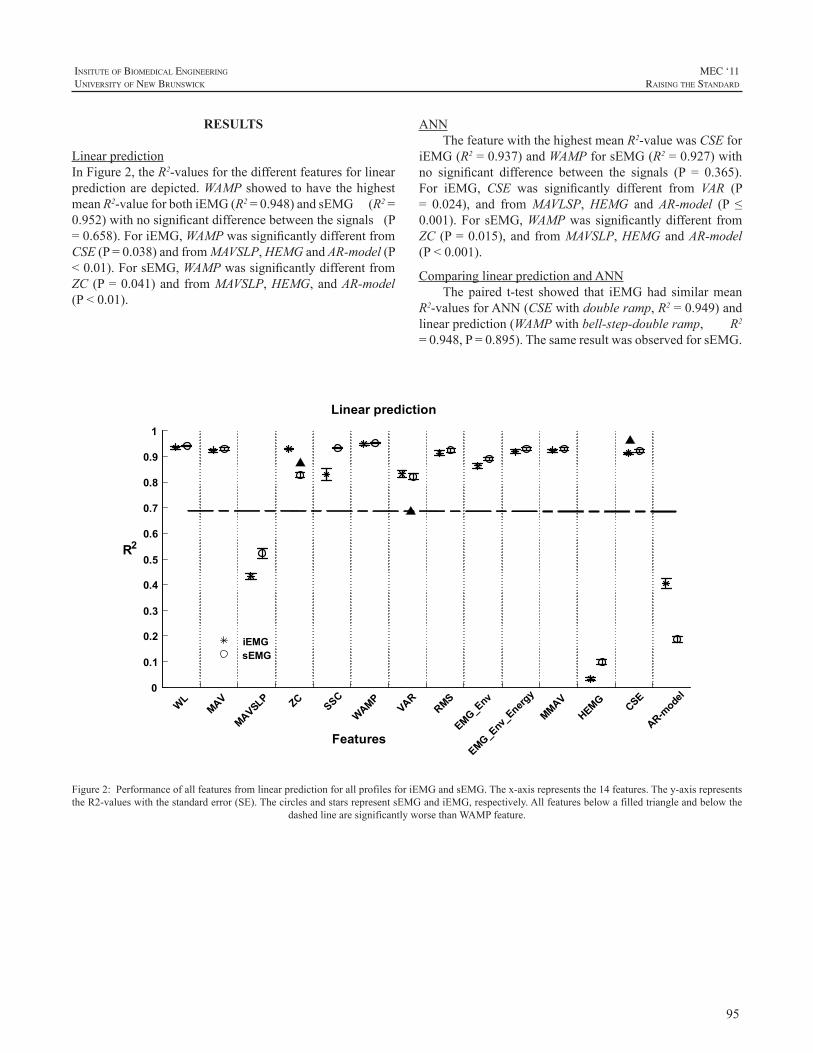
95
InsItute of BIomedIcal engIneerIng
unIversIty of new BrunswIck
MEC ‘11raIsIng the standard
RESULTS
LinearpredictionInFigure2,theR2-valuesforthedifferentfeaturesforlinearpredictionaredepicted.WAMPshowedtohavethehighestmeanR2-valueforbothiEMG(R2=0.948)andsEMG(R2=0.952)withnosignificantdifferencebetweenthesignals(P=0.658).ForiEMG,WAMPwassignificantlydifferentfromCSE(P=0.038)andfromMAVSLP,HEMGandAR-model(P<0.01).ForsEMG,WAMPwassignificantlydifferentfromZC (P=0.041)andfromMAVSLP,HEMG,andAR-model(P<0.01).
EMG_Env
_Energ
y0
0.1
0.2
0.3
0.4
0.5
0.6
0.7
0.8
0.9
1
R2
Linear prediction
WLMAV
MAVSLP ZCSSC
WAMPVAR
RMS
EMG_Env
MMAVHEMG CSE
AR-mode
l
iEMGsEMG
Features
Figure2:PerformanceofallfeaturesfromlinearpredictionforallprofilesforiEMGandsEMG.Thex-axisrepresentsthe14features.They-axisrepresentstheR2-valueswiththestandarderror(SE).ThecirclesandstarsrepresentsEMGandiEMG,respectively.Allfeaturesbelowafilledtriangleandbelowthe
dashedlinearesignificantlyworsethanWAMPfeature.
ANNThefeaturewiththehighestmeanR2-valuewasCSEfor
iEMG(R2=0.937)andWAMPforsEMG(R2=0.927)withno significant difference between the signals (P = 0.365).For iEMG, CSE was significantly different from VAR (P= 0.024), and fromMAVLSP,HEMG andAR-model (P ≤0.001).For sEMG,WAMPwas significantlydifferent fromZC (P=0.015),and fromMAVSLP,HEMGandAR-model(P<0.001).
ComparinglinearpredictionandANNThepaired t-test showed that iEMGhad similarmean
R2-valuesforANN(CSEwithdoubleramp,R2=0.949)andlinearprediction(WAMPwithbell-step-doubleramp,R2=0.948,P=0.895).ThesameresultwasobservedforsEMG.
96
MEC ‘11raIsIng the standard
InsItute of BIomedIcal engIneerIng
unIversIty of new BrunswIck
ACKNOWLEDGEMENTS
This study was supported by a grant from the TheDanishCouncilforIndependentResearch|TechnologyandProductionSciences(FTP).
REFERENCES
[1] E.N.Kamavuako,D.Farina,K.Yoshida,W.Jensen,”Relationshipbetweengrasping forceand featuresof single-channel intramuscularemg signals”, Journal ofNeuroscienceMethods, vol. 185, pp. 143–150,2009
[2] C. Disselhorst-Klug, T. Schmitz-Rode, G. Rau, “Surfaceelectromyographyandmuscleforce:Limitsinsemg–forcerelationshipandnewapproachesforapplications”,ClinicalBiomechanics,vol.24,pp.225–2352009
[3] M.J.Hoozemans,J.H.vanDieën,“Predictionofhandgripforcesusingsurfaceemgofforearmmuscles”,Journalofelectromyographyandkinesiology,vol.15,pp.358–366,2005
[4] J.W.Clark,M.R.Neuman,W.H.Olson,R.A.Peura,F.P.Primiano,M.P. Siedband, et al. “Medical Instrumentation - Application andDesign”,3rdEdition,Wiley,1998
[5] H. Onishi, R.Yagi , K.Akasaka , K. Momose , K. Ihashi , Y.Handa,”RelationshipbetweenEMGsignalsandforceinhumanvastuslateralis muscle using multiple bipolar wire electrodes”, Journal ofElectromyographyandKinesiology,vol.10,pp.59–67,2000
[6] E.N.Kamavuako,“Intramuscularandintrafascicularrecordingsforproportionalcontrolofprostheses”,SMI-PhDThesis2010
[7] S.R. Geiringer, “Anatomic localization for needleelectromyography”,2ndEdition,Hanley&Belfus,1999
[8] M.F. Bøg, E. Erkocevic, M.J. Niemeier, J.R. Mathiesen, A.Smidstrup,E.N.Kamavuako,“InvestigationoftheLinearrelationshipbetweengraspingforceandfeaturesofintramuscularEMG”,acceptedtoNBC,2011
[9] M.H. Beale, M.T. Hagan, H.B. Demuth, “Neural NetworkToolboxTM7-User’sGuide”,TheMathWorks,7thEdition,Inc,2010
[10] A.Phinyomark,S.Hirunviriya,C.Limsakul,P.Phukpattaranont,“Evaluationofemgfeatureextractionforhandmovementrecognitionbased on Euclidean distance and standard deviation”, ElectricalEngineering/Electronics Computer Telecommunications andInformationTechnology(ECTI-CON),InternationalConference,vol.1,pp.856–860,2010
DISCUSSION
The results showed that it is possible to predict forcebased on a linear relationship between force and featuresextractedfromeithersEMGoriEMG.Therelationshipandthe prediction performancewere dependent on the type offeature.Further,resultsforsEMGandiEMGweresimilarforboththelinearpredictionandANNwithR2>0.9.
ForcepredictionInastudybyPhinyomarketal.[10]theWLfeatureshowed
thebestperformanceforclassificationofhandmovements;however, WAMP also had a good performance. This issimilartotheresultsfromthepresentstudy,whichshowedthatWL had a good performance for force prediction, notsignificantlydifferent from thebest feature forboth iEMGand sEMG (WAMP). This shows that theWL andWAMPfeatures have an overall good performance and provide agood representation of themuscle activation, regardless oftheirapplication.Furthermore,Phinyomarketal.[10]showedthat MAVSLP had the worst performance compared tootherfeatures,whichisalsovalidforthepresentstudy,andtherefore theMAVSLP in general provides an insufficientrepresentationof themuscleactivation.However, it shouldbe noted, that Phinyomark et al.[10]only evaluated featuresextractedfromsEMG,wherethepresentstudyinvestigatedbothiEMGandsEMG.
Inordertoclarifywhetherthereexistabetterpredictionmodelthanthelinear,anANNwasused.TheANNpredictionshowed results similar to linear prediction for both sEMGand iEMGwith no significant difference between the twoprediction models. The same conclusion was obtained byKamavuako.[6]Thus, thechoiceofmodel (linearpredictionor ANN) does not play a significant role when the bestfeatureisselected.However,forourstudytheperformanceoftheANNingeneralseemedtovary,whichimpliesthatthepossibilityofotherrelationshipsperformingbettershouldbeinvestigatedfurther.
ModelselectionEventhoughthelinearpredictioningeneralshowedgood
performance it was not taken into consideration that theremightbeadifference in thepropertiesof theEMGsignalsfor increasing and decreasing force. Thus, the model wasbasedononlyonelinearrelationshipinsteadofarelationshipfor increasing force and for decreasing force, respectively.FutureworkshouldinvestigateifthereisadifferenceintheincreasinganddecreasingEMG-signals,andifnecessary,anewmodelshouldbedefinedinordertoprovidebetterforcepredictions.
97
InsItute of BIomedIcal engIneerIng
unIversIty of new BrunswIck
MEC ‘11raIsIng the standard
ABSTRACT
In this studywe have investigated a potential optimalmodel for the relationship between muscle force andelectromyogram (EMG) that includes both increasing anddecreasingforcepaths(hysteresis).
Intramuscular(iEMG)andsurface(sEMG)EMGwererecorded concurrently from the muscle flexor digitorumprofundus (0-100% MVC) in 11 subjects. Three features,MeanAbsolute Value (MAV), WilsonAmplitude (WAMP)andConstraintSampleEntropy(CSE)werecomputedfromtheEMGsignals.Twomodels,first(poly1)andthird(poly3)orderpolynomial,wereinvestigatedintwocases:1)Takingthehysteresisintoaccountforascending(contraction:cont)anddescending(relaxation:relax)forceand2)Disregardingthehysteresis(overall).
ForiEMGtheresultsforpoly1showedthathysteresis-basedmodels(cont:0.944±0.010,relax:0.939±0.008)hadsignificantly (P<0.01)higherR2-values (mean±SE) thantheoverallmodel (0.889 ± 0.016). Forpoly3 a significantdifference (P < 0.01) was also found between hysteresis-basedmodels (cont: 0.963± 0.010, relax: 0.985± 0.002),andtheoverallmodel(0.926±0.013).Similarresultswereobtained for sEMG.These results imply theexistenceof apathdependentmodel,whichmayimprovetheaccuracyofforceestimation.
INTRODUCTION
Myoelectric prosthetic devices controlled by surfaceEMG (sEMG) is clinically used to restore some of thelost functions for patients with upper limb amputations.[1,2,3] Intramuscular EMG (iEMG) has been suggested as apotential solution for increasing the number of degrees-of-freedom (DoFs).Apart from the possibility ofmoreDoFs,iEMGalsohasotheradvantagessuchaslimitedcrosstalkandchronic implantation of the electrodes.[1,2] One of usabilityrequirements foraprostheticdevice is tomake thecontrolasintuitiveaspossiblefortheuser.Thisimpliesforexample,providing better proportional control where the level ofactivation corresponds to the level of muscle activity.[3]Severalstudieshaveinvestigatedproportionalcontrolwhere
forcehasbeen estimatedbasedon features from theEMGsignals(See [6] forareview).Commonforall thesestudiesisthattheproposedmodel(linearornonlinear)iscomputedbasedontheoverallforce/featurerelationship.[4]Thus,toourbest knowledge, none of these studies have investigated ifthedegreeofassociationbetweenforceandfeaturesofEMGwasdependentonthepathoftheforceprofilei.e.onemodelforincreasingforceandanothermodelfordecreasingforce.DeepknowledgeofEMGforcehysteresisisstillmissingintheliterature.
Ridgway et al.[5] investigated the relationship betweenforceandcalciumconcentration.Itwasfoundthattheforcewashigherwhenthecalciumconcentrationwasdecreasingthanwhenincreasing,thushysteresiswasfoundintheforce-calcium relationship. Since calcium is needed in musclecontractions,hysteresismightalsobepresentinthefeature/forcerelationship.Therefore,theaimofthepresentstudywastoinvestigateifthefeature/forcerelationshipwasdependenton thecontractionpathforboth iEMGandsEMGinordertoinvestigateapotentialoptimalmodelforfutureprostheticdevices.
METHOD
ExperimentDataobtainedfromapreviousstudy[4]wasusedinthis
study.Elevenhealthyright-handedsubjectswereincluded(4w/7m, age range 22 - 26 years,mean = 23.8 years).TheprotocolwasapprovedbytheDanishlocalethicalcommittee(approval no.: N-20080045). All subjects received bothwrittenandoralinformationabouttheexperimentandgavewrittenconsentpriortotheexperiment.
Procedure:Thesubjectsexertedforcewhileseatedinachairwiththeirrightarmplacedinanarmrest(Fig.1).First,thesubjectsexertedMVCforcethreetimeswitha3minutesrestbetween the trials.Afterwards the subjectswere askedtofollowabell-shapedforceprofileof9swithforcelevelsrangingfrom0to100%MVC.Subjectswereprovidedwithadequate time to practice matching the profile before theactual recording.Theprofilewasmeasured twicewith a 3minutesrestinbetween.[4]
TOWARDS AN OPTIMAL MODEL FOR THE ESTIMATION OF FORCE FROM INTRAMUSCULAR EMG
J.C.Rosenvang, M.J.Niemeier,E.Erkocevic, M.F.Bøg, A.SmidstrupandE.N.Kamavuako*
1DepartmentofHealthScienceandTechnology,AalborgUniversity,9220Aalborg,Denmark*ErnestNKamavuako,AalborgUniversity,FredrikbajersVej7D3,9220Aalborg,Denmark,[email protected]
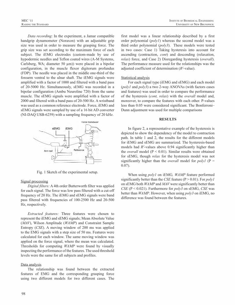
98
MEC ‘11raIsIng the standard
InsItute of BIomedIcal engIneerIng
unIversIty of new BrunswIck
Datarecording:Intheexperiment,aJamarcompatiblehandgrip dynamometer (Noraxon) with an adjustable gripsizewas used in order tomeasure the grasping force.Thegrip sizewas set according to themaximum forceof eachsubject. The iEMG electrodes (custom-made by use ofhypodermicneedlesandTefloncoatedwires(A-MSystems,Carlsberg,WA;diameter50µm))wereplaced inabipolarconfiguration, in the muscle flexor digitorum profundus(FDP).Theneedlewasplacedinthemiddleone-thirdoftheforearmventral to theulnar shaft.The iEMGsignalswereamplifiedwithafactorof1000andfilteredwithabandpassof 20-5000 Hz. Simultaneously, sEMGwas recorded in abipolarconfiguration(AmbuNeuroline720)fromthesamemuscle.ThesEMGsignalswereamplifiedwitha factorof2000andfilteredwithabandpassof20-500Hz.Awristbandwasusedasacommonreferenceelectrode.Force,iEMGandsEMGsignalsweresampledbyuseofa16bitADconverter(NI-DAQUSB-6259)withasamplingfrequencyof20kHz.
Fig.1Sketchoftheexperimentalsetup.
SignalprocessingDigitalfilters:A4thorderButterworthfilterwasapplied
foreachsignal.Theforcewaslowpassfilteredwithacut-offfrequencyof20Hz.TheiEMGandsEMGsignalswerebandpass filteredwith frequencies of 100-2500Hz and 20-500Hz,respectively.
Extracted features: Three features were chosen torepresenttheiEMGandsEMGsignals;MeanAbsoluteValue(MAV),WilsonAmplitude (WAMP) andConstraintSampleEntropy (CSE).Amovingwindowof 200mswas appliedtotheEMGsignalswithastepsizeof50ms.Featureswerecalculatedforeachwindow.Thesamemovingwindowwasappliedontheforcesignal,wherethemeanwascalculated.Thresholds for computingWAMP were found by visuallyinspectingtheperformanceofthefeatures.Theusedthresholdlevelswerethesameforallsubjectsandprofiles.
DataanalysisThe relationship was found between the extracted
features of EMG and the corresponding grasping forceusing two different models for two different cases. The
first model was a linear relationship described by a firstorderpolynomial (poly1)whereas the secondmodelwas athird order polynomial (poly3). Thesemodelswere testedin two cases: Case 1) Taking hysteresis into account forascending (contraction, cont) and descending (relaxation,relax) force,andCase2)Disregardinghysteresis (overall).Theperformancemeasureusedfortherelationshipswastheadjustedcoefficientofdetermination(R2-value).
StatisticalanalysisForeachsignaltype(iEMGandsEMG)andeachmodel
(poly1andpoly3)atwo2-wayANOVAs(withfactorscasesandfeatures)wasusedinordertocomparetheperformanceof the hysteresis (cont, relax)with the overallmodel and,moreover,tocomparethefeatureswitheachother.P-valueslessthan0.05wereconsideredsignificant.TheBonferroni–Dunnadjustmentwasusedformultiplecomparisons
RESULTS
Infigure2,arepresentativeexampleofthehysteresisisdepictedtoshowthedependencyofthemodeltocontractionpath. In table 1 and 2, the results for the differentmodelsforiEMGandsEMGaresummarized.Thehysteresis-basedmodels hadR2-values above 0.94 significantly higher thantheoverallmodel(P<0.01).Similarresultswereobtainedfor sEMG, though relax for the hysteresis model was notsignificantly higher than the overall model for poly1 (P =0.07).
Whenusingpoly1oniEMG,WAMPfeatureperformedsignificantlybetterthantheCSEfeature(P>0.01).Forpoly1onsEMGbothWAMPandMAVweresignificantlybetterthanCSE(P<0.021).Furthermoreforpoly3onsEMG,CSEwasbetterthanWAMP.However,whenusingpoly3oniEMG,nodifferencewasfoundbetweenthefeatures.
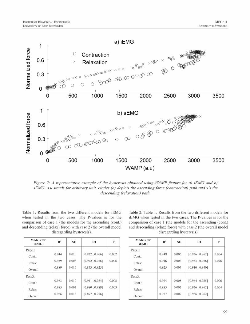
99
InsItute of BIomedIcal engIneerIng
unIversIty of new BrunswIck
MEC ‘11raIsIng the standard
Table 1: Results from the two different models for iEMGwhen tested in the two cases. The P-values is for thecomparisonofcase1(themodelsfor theascending(cont.)anddescending(relax)force)withcase2(theoverallmodel
disregardinghysteresis).
Models for iEMG R2 SE CI P
Poly1:
Cont.:0.944 0.010 [0.922,0.966] 0.002
Relax:0.939 0.008 [0.922,0.956] 0.006
Overall 0.889 0.016 [0.853,0.925]
Poly3:
Cont.:0.963 0.010 [0.941,0.984] 0.008
Relax:0.985 0.002 [0.980,0.989] 0.003
Overall 0.926 0.013 [0.897,0.956]
Figure 2:A representative example of the hysteresis obtained usingWAMP feature for a) iEMGand b)sEMG.a.ustandsforarbitraryunit,circles(o)depictstheascendingforce(contraction)pathandx’sthe
descending(relaxation)path.
Table2:Table1:ResultsfromthetwodifferentmodelsforiEMGwhentestedinthetwocases.TheP-valuesisforthecomparisonofcase1(themodelsfor theascending(cont.)anddescending(relax)force)withcase2(theoverallmodel
disregardinghysteresis).
Models for sEMG R2 SE CI P
Poly1:
Cont.:0.949 0.006 [0.936,0.962] 0.004
Relax:0.946 0.006 [0.933,0.958] 0.076
Overall 0.925 0.007 [0.910,0.940]
Poly3:
Cont.:0.974 0.005 [0.964,0.985] 0.006
Relax:0.985 0.002 [0.936,0.962] 0.004
Overall 0.957 0.007 [0.936,0.962]
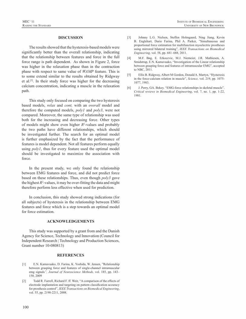
100
MEC ‘11raIsIng the standard
InsItute of BIomedIcal engIneerIng
unIversIty of new BrunswIck
DISCUSSION
Theresultsshowedthatthehysteresis-basedmodelsweresignificantly better than the overall relationship, indicatingthat the relationship between features and force in the fullforcerangeispathdependent.AsshowninFigure2,forcewas higher in the relaxation phase than in the contractionphasewithrespecttosamevalueofWAMPfeature.Thisisto someextend similar to the resultsobtainedbyRidgwayet al.[5]. In their study forcewas higher for the decreasingcalciumconcentration,indicatingamuscleintherelaxationpath.
Thisstudyonlyfocusedoncomparingthetwohysteresisbased models, relax and cont, with an overall model andtherefore the computedmodels,poly1 andpoly3,were notcompared.Moreover,thesametypeofrelationshipwasusedboth for the increasing and decreasing force. Other typesofmodelsmight showevenhigherR2-valuesandprobablythe two paths have different relationships, which shouldbe investigated further. The search for an optimal modelis further emphasized by the fact that the performance offeaturesismodeldependent.Notallfeaturesperformequallyusingpoly1, thus forevery featureused theoptimalmodelshould be investigated to maximize the association withforce.
In the present study, we only found the relationshipbetweenEMGfeaturesandforce,anddidnotpredictforcebasedontheserelationships.Thus,eventhoughpoly3gavethehighestR2-values,itmaybeover-fittingthedataandmightthereforeperformlesseffectivewhenusedforprediction.
Inconclusion,thisstudyshowedstrongindications(forallsubjects)ofhysteresisintherelationshipbetweenEMGfeaturesandforcewhichisasteptowardsanoptimalmodelforforceestimation.
ACKNOWLEDGEMENTS
ThisstudywassupportedbyagrantfromandtheDanishAgencyforScience,TechnologyandInnovation(CouncilforIndependentResearch|TechnologyandProductionSciences,Grantnumber10-080813)
REFERENCES
[1] E.N.Kamavuako,D.Farina,K.Yoshida,W.Jensen,”Relationshipbetweengrasping forceand featuresof single-channel intramuscularemgsignals”, JournalofNeuroscienceMethods, vol. 185,pp.143–150,2009
[2] ToddR.Farrell,RichardF.ff.Weir,“Acomparisonoftheeffectsofelectrodeimplantationandtargetingonpatternclassificationaccuracyforprosthesiscontrol”,IEEETransactionsonBiomedicalEngineering,vol.55,pp.2198-2211,2008.
[3] Johnny L.G. Nielsen, Steffen Holmgaard, Ning Jiang, KevinB. Englehart, Dario Farina, Phil A. Parker, ”Simultaneous andproportionalforceestimationformultifunctionmyoelectricprosthesesusingmirroredbilateral training”, IEEETransactionsonBiomedicalEngineering,vol.58,pp.681–688,2011.
[4] M.F. Bøg, E. Erkocevic, M.J. Niemeier, J.R. Mathiesen, A.Smidstrup,E.N.Kamavuako,“InvestigationoftheLinearrelationshipbetweengraspingforceandfeaturesofintramuscularEMG”,acceptedtoNBC,2011.
[5] EllisB.Ridgway,AlbertMGordon,DonaldA.Martyn,“Hysteresisintheforce-calciumrelationinmuscle”,Science,vol.219,pp.1075-1077,1983.
[6] J.Perry,GA.Bekey.“EMG-forcerelationshipsinskeletalmuscle”.Critical reviews inBiomedicalEngineering, vol. 7, no. 1, pp. 1-22,1981.
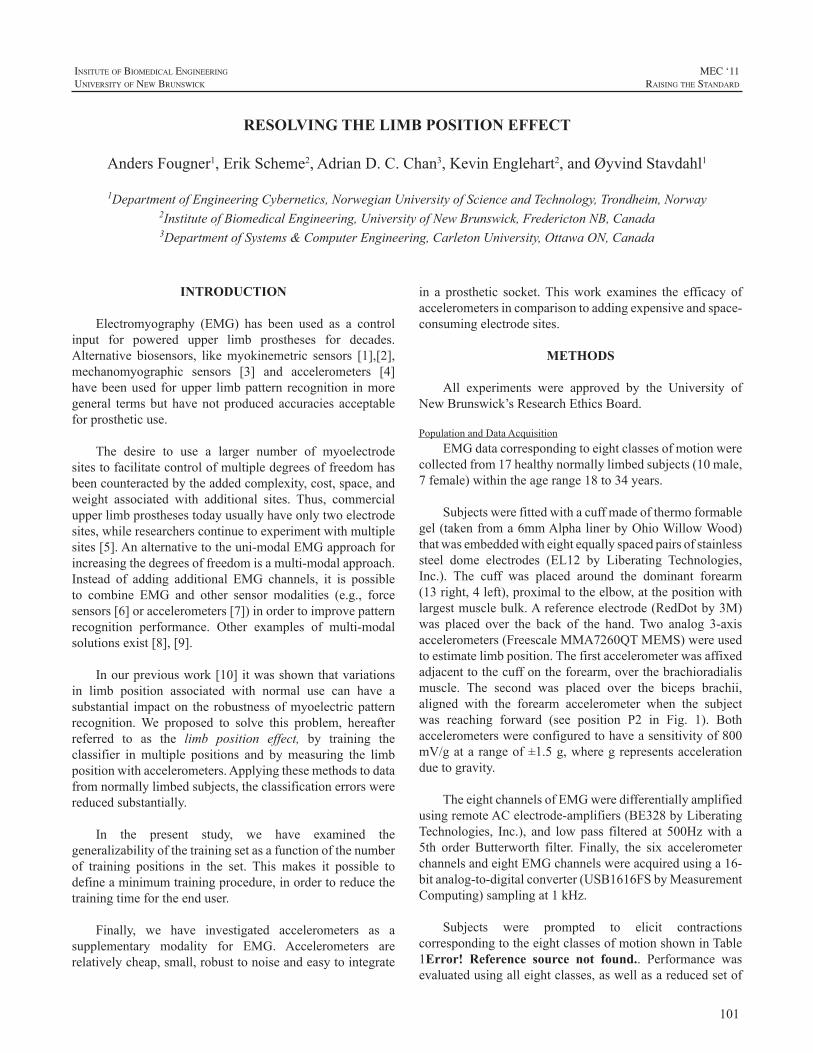
101
InsItute of BIomedIcal engIneerIng
unIversIty of new BrunswIck
MEC ‘11raIsIng the standard
INTRODUCTION
Electromyography (EMG) has been used as a controlinput for powered upper limb prostheses for decades.Alternative biosensors, likemyokinemetric sensors [1],[2],mechanomyographic sensors [3] and accelerometers [4]havebeenused forupper limbpattern recognition inmoregeneral termsbuthavenotproducedaccuracies acceptableforprostheticuse.
The desire to use a larger number of myoelectrodesitestofacilitatecontrolofmultipledegreesoffreedomhasbeencounteractedbytheaddedcomplexity,cost,space,andweight associated with additional sites. Thus, commercialupperlimbprosthesestodayusuallyhaveonlytwoelectrodesites,whileresearcherscontinuetoexperimentwithmultiplesites[5].Analternativetotheuni-modalEMGapproachforincreasingthedegreesoffreedomisamulti-modalapproach.Instead of adding additional EMG channels, it is possibleto combine EMG and other sensor modalities (e.g., forcesensors[6]oraccelerometers[7])inordertoimprovepatternrecognition performance. Other examples of multi-modalsolutionsexist[8],[9].
Inourpreviouswork[10]itwasshownthatvariationsin limb position associated with normal use can have asubstantial impacton the robustnessofmyoelectricpatternrecognition.We proposed to solve this problem, hereafterreferred to as the limb position effect, by training theclassifier inmultiple positions and bymeasuring the limbpositionwithaccelerometers.Applyingthesemethodstodatafromnormallylimbedsubjects,theclassificationerrorswerereducedsubstantially.
In the present study, we have examined thegeneralizabilityofthetrainingsetasafunctionofthenumberof training positions in the set. This makes it possible todefineaminimumtrainingprocedure,inordertoreducethetrainingtimefortheenduser.
Finally, we have investigated accelerometers as asupplementary modality for EMG. Accelerometers arerelativelycheap,small,robusttonoiseandeasytointegrate
in a prosthetic socket.Thiswork examines the efficacy ofaccelerometersincomparisontoaddingexpensiveandspace-consumingelectrodesites.
METHODS
All experiments were approved by the University ofNewBrunswick’sResearchEthicsBoard.
PopulationandDataAcquisitionEMGdatacorrespondingtoeightclassesofmotionwere
collectedfrom17healthynormallylimbedsubjects(10male,7female)withintheagerange18to34years.
Subjectswerefittedwithacuffmadeofthermoformablegel(takenfroma6mmAlphalinerbyOhioWillowWood)thatwasembeddedwitheightequallyspacedpairsofstainlesssteel dome electrodes (EL12 by Liberating Technologies,Inc.). The cuff was placed around the dominant forearm(13right,4left),proximaltotheelbow,atthepositionwithlargestmusclebulk.Areferenceelectrode(RedDotby3M)was placed over the back of the hand. Two analog 3-axisaccelerometers(FreescaleMMA7260QTMEMS)wereusedtoestimatelimbposition.Thefirstaccelerometerwasaffixedadjacenttothecuffontheforearm,overthebrachioradialismuscle. The second was placed over the biceps brachii,aligned with the forearm accelerometer when the subjectwas reaching forward (see position P2 in Fig. 1). Bothaccelerometerswereconfiguredtohaveasensitivityof800mV/gatarangeof±1.5g,wheregrepresentsaccelerationduetogravity.
TheeightchannelsofEMGweredifferentiallyamplifiedusingremoteACelectrode-amplifiers(BE328byLiberatingTechnologies, Inc.), and lowpass filtered at 500Hzwith a5th order Butterworth filter. Finally, the six accelerometerchannelsandeightEMGchannelswereacquiredusinga16-bitanalog-to-digitalconverter(USB1616FSbyMeasurementComputing)samplingat1kHz.
Subjects were prompted to elicit contractionscorrespondingtotheeightclassesofmotionshowninTable1Error! Reference source not found.. Performance wasevaluatedusingalleightclasses,aswellasareducedsetof
RESOLVING THE LIMB POSITION EFFECT
AndersFougner1,ErikScheme2,AdrianD.C.Chan3,KevinEnglehart2,andØyvindStavdahl1
1DepartmentofEngineeringCybernetics,NorwegianUniversityofScienceandTechnology,Trondheim,Norway2InstituteofBiomedicalEngineering,UniversityofNewBrunswick,FrederictonNB,Canada3DepartmentofSystems&ComputerEngineering,CarletonUniversity,OttawaON,Canada
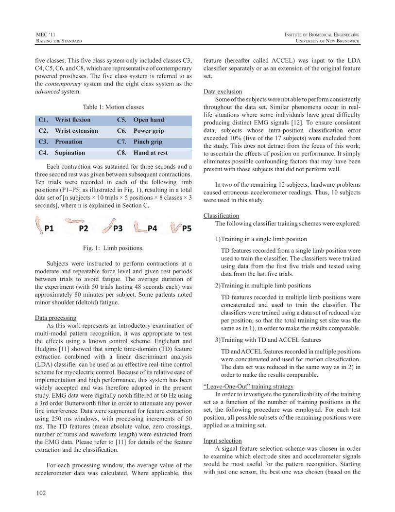
102
MEC ‘11raIsIng the standard
InsItute of BIomedIcal engIneerIng
unIversIty of new BrunswIck
fiveclasses.ThisfiveclasssystemonlyincludedclassesC3,C4,C5,C6,andC8,whicharerepresentativeofcontemporarypoweredprostheses.The fiveclasssystemis referred toasthecontemporary systemand theeightclass systemas theadvancedsystem.
Table1:Motionclasses
C1. Wrist flexion C5. Open hand
C2. Wrist extension C6. Power grip
C3. Pronation C7. Pinch grip
C4. Supination C8. Hand at rest
Eachcontractionwassustainedforthreesecondsandathreesecondrestwasgivenbetweensubsequentcontractions.Ten trials were recorded in each of the following limbpositions(P1–P5;asillustratedinFig.1),resultinginatotaldatasetof[nsubjects×10trials×5positions×8classes×3seconds],wherenisexplainedinSectionC.
Fig.1:Limbpositions.
Subjects were instructed to perform contractions at amoderate and repeatable force level andgiven rest periodsbetween trials to avoid fatigue. The average duration oftheexperiment(with50trialslasting48secondseach)wasapproximately80minutespersubject.Somepatientsnotedminorshoulder(deltoid)fatigue.
DataprocessingAsthisworkrepresentsanintroductoryexaminationof
multi-modal pattern recognition, it was appropriate to testthe effects using a known control scheme. Englehart andHudgins[11]showedthatsimpletime-domain(TD)featureextraction combined with a linear discriminant analysis(LDA)classifiercanbeusedasaneffectivereal-timecontrolschemeformyoelectriccontrol.Becauseofitsrelativeeaseofimplementationandhighperformance,thissystemhasbeenwidely accepted and was therefore adopted in the presentstudy.EMGdataweredigitallynotchfilteredat60Hzusinga3rdorderButterworthfilterinordertoattenuateanypowerlineinterference.Dataweresegmentedforfeatureextractionusing 250ms windows, with processing increments of 50ms.TheTD features (meanabsolutevalue, zerocrossings,numberofturnsandwaveformlength)wereextractedfromtheEMGdata.Pleasereferto[11]fordetailsofthefeatureextractionandtheclassification.
For each processingwindow, the average value of theaccelerometer data was calculated.Where applicable, this
feature (hereafter called ACCEL) was input to the LDAclassifierseparatelyorasanextensionoftheoriginalfeatureset.
DataexclusionSomeofthesubjectswerenotabletoperformconsistently
throughout the data set. Similar phenomena occur in real-life situationswhere some individualshavegreatdifficultyproducing distinct EMG signals [12].To ensure consistentdata, subjects whose intra-position classification errorexceeded10%(fiveofthe17subjects)wereexcludedfromthestudy.Thisdoesnotdetractfromthefocusofthiswork;toascertaintheeffectsofpositiononperformance.Itsimplyeliminatespossibleconfoundingfactorsthatmayhavebeenpresentwiththosesubjectsthatdidnotperformwell.
Intwooftheremaining12subjects,hardwareproblemscausederroneousaccelerometerreadings.Thus,10subjectswereusedinthisstudy.
ClassificationThefollowingclassifiertrainingschemeswereexplored:
1)Traininginasinglelimbposition
TDfeaturesrecordedfromasinglelimbpositionwereusedtotraintheclassifier.Theclassifiersweretrainedusing data from the first five trials and tested usingdatafromthelastfivetrials.
2)Traininginmultiplelimbpositions
TDfeaturesrecordedinmultiplelimbpositionswereconcatenated and used to train the classifier. Theclassifiersweretrainedusingadatasetofreducedsizeperposition,sothatthetotaltrainingsetsizewasthesameasin1),inordertomaketheresultscomparable.
3)TrainingwithTDandACCELfeatures
TDandACCELfeaturesrecordedinmultiplepositionswereconcatenatedandusedformotionclassification.Thedatasetwasreducedinthesamewayasin2)inordertomaketheresultscomparable.
“Leave-One-Out”trainingstrategyInordertoinvestigatethegeneralizabilityofthetraining
setasa functionof thenumberof trainingpositions in theset, the following procedure was employed. For each testposition,allpossiblesubsetsoftheremainingpositionswereappliedasatrainingset.
InputselectionAsignal feature selectionschemewaschosen inorder
toexaminewhichelectrodesitesandaccelerometersignalswould bemost useful for the pattern recognition. Startingwithjustonesensor,thebestonewaschosen(basedonthe
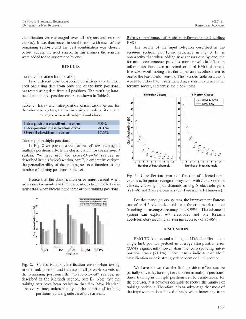
103
InsItute of BIomedIcal engIneerIng
unIversIty of new BrunswIck
MEC ‘11raIsIng the standard
classification error averaged over all subjects and motionclasses).Itwasthentestedincombinationwitheachoftheremaining sensors, and the best combination was chosenbefore adding the next sensor. In this manner the sensorswereaddedtothesystemonebyone.
RESULTS
TraininginasinglelimbpositionFivedifferentposition-specificclassifiersweretrained;
each one using data from only one of the limb positions,buttestedusingdatafromallpositions.Theresultingintra-positionandinter-positionerrorsareshowninTable2.
Table 2: Intra- and inter-position classification errors fortheadvancedsystem, trained inasingle limbposition,and
averagedacrossallsubjectsandclasse
Intra-position classification error 3.8%Inter-position classification error 21.1%Overall classification error 17.6%
TraininginmultiplepositionsIn Fig. 2we present a comparison of how training in
multiplepositionsaffectstheclassification,fortheadvancedsystem. We have used the Leave-One-Out strategy asdescribedintheMethodssection,partE,inordertoinvestigatethe generalizability of the training set as a function of thenumberoftrainingpositionsintheset.
Notice that the classification error improvementwhenincreasingthenumberoftrainingpositionsfromonetotwoislargerthanwhenincreasingtothreeorfourtrainingpositions.
Fig. 2: Comparison of classification errors when testinginone limbpositionand training in all possible subsetsofthe remaining positions (the “Leave-one-out” strategy, asdescribed in the Methods section, part E). Note that thetraining sets have been scaled so that they have identicalsize every time; independently of the number of training
positions,byusingsubsetsofthetentrials.
Relative importance of position information and surfaceEMG
The results of the input selection described in theMethods section, part F, are presented in Fig. 3. It isnoteworthy thatwhen addingnew sensors onebyone, theforearm accelerometer provides more novel classificationinformation than even a second or third EMG electrode.It is alsoworthnoting that theupper armaccelerometer isoneoftheleastusefulsensors.Thisisadesirableresultasitwouldbedifficulttojustifyincludingasensorexternaltotheforearmsocket,andacrosstheelbowjoint.
Fig. 3: Classification error as a functionof selected inputchannels,forpatternrecognitionsystemswith5and8motionclasses, choosing input channels among 8 electrode pairs(e1–e8)and2accelerometers(aF–Forearm,aH–Humerus).
Forthecontemporarysystem,theimprovementflattensout after 4-5 electrodes and one forearm accelerometer(reaching an average accuracy of 98-99%). The advancedsystem can exploit 6-7 electrodes and one forearmaccelerometer(reachinganaverageaccuracyof95-96%).
DISCUSSION
EMGTDfeaturesandtraininganLDAclassifierininasingle limbpositionyieldedanaverage intra-positionerror(3.8%) significantly lower than the corresponding inter-position errors (21.1%). These results indicate that EMGclassificationerrorisstronglydependentonlimbposition.
We have shown that the limb position effect can bepartiallysolvedbytrainingtheclassifierinmultiplepositions.Sincetraininginmultiplepositionscanbecumbersomefortheenduser,itishoweverdesirabletoreducethenumberoftrainingpositions.Thereforeitisanadvantagethatmostoftheimprovementisachievedalreadywhenincreasingfrom
104
MEC ‘11raIsIng the standard
InsItute of BIomedIcal engIneerIng
unIversIty of new BrunswIck
onetotwotrainingpositions(reducingtheaverageerrorfrom18.7%to13.6%).Previouslywehavealsoshown[10]thatitis importanttohaveatrainingsetcontainingavariationofelbowangle.
Theaccelerometerlendsitselftobeingusedinhuman-machineinterfacesduetoitssmallsize,lowcost,andsimplemechanical and electrical interfaces.The absence ofmanyof thedisturbancesoftenencountered inEMGsensors andsimilar devices makes it interesting as a supplementarysensorinhandmotionclassificationsystems,includingupperlimbprostheses.
The accelerometer does not provide an estimate ofmuscle force, but we have shown that it provides usefulinformationthatcansupplementEMGsignals.IfonewantstoimproveasystemoriginallyhavingtwoEMGelectrodes,amulti-modalapproachcanbetaken.Theresultsdemonstratethatitismoreadvantageoustoaddanaccelerometeraffixedto the forearm(multi-modalapproach) rather than increasethenumberofEMGchannels(uni-modalapproach).
Eventhoughthelimbpositioneffectwasdiscoveredandobserved in users in the clinic [7], [10], andwas resolvedforthenormallylimbedsubjectsinourstudy,itneedstobeexamined specifically for the end users. Gravitational andbiomechanicaleffectsof limbpositionwillbedifferent forprostheticuserscomparedtothenormallylimbedsubjectsofthisstudy.Assuch,weareplanningtoextendthisstudytoincludeprosthesisusers.
This work is part of a larger investigation aimed atimproving the practical robustness of myoelectric control.Thepresentresultsindicatethatfacilitatingpositioninvariantmyoelectric control through methods such as featureselection,dataprojection,multi-sensorsystems,orbyothermeanscouldbeanimportantpartofthislargerwork.
ACKNOWLEDGEMENTS
TheauthorswouldliketothankP.J.Kyberdforimportantinput concerning the experimental protocol and invaluablepracticalassistanceinconjunctionwiththeaccelerometers.
TheworkwassupportedinpartbyNSERCDiscoveryGrant 217354-10, NIH Grant 5R01HD058000-03, theAtlanticInnovationFund,StrategicAreaMedicalTechnologyat NTNU and The Research Council of Norway (Grant192546).
REFERENCES
[1] L.P.J.Kenney,I.Lisitsa,P.Bowker,G.H.Heath,andD.Howard,“Dimensional Change in Muscle as a Control Signal for PoweredUpperLimbProstheses:aPilotStudy”,Med.Eng.Phys.,21(8):589–597,Oct.1999.
[2] J. Canderle, L. P. J. Kenney, A. Bowen, D. Howard, and H.Chatterton, “A Dual-task Approach to the Evaluation of theMyokinemetricSignalasanAlternativetoEMG”,Conf.Proc.IEEEEng.Med.Biol.Soc.2004,26:4548–4551,Sep.2004.
[3] E.M.Scheeren,E.Krueger-Beck,G.Nogueira-Neto,P.Nohama,and V. L. S. N. Button, “Wrist Movement Characterization byMechanomyographyTechnique”,J.Med.Biol.Eng.,30(6):373–380,Dec.2010.
[4] M. E. Harrington, R.W.Daniel, P. J. Kyberd, “AMeasurementSystemfortheRecognitionofArmGesturesusingAccelerometers”,Proc.Inst.Mech.Eng.PartH:J.Eng.Med.,209(H2):129–134,1995.
[5] L. J. Hargrove, K. Englehart, B. Hudgins, “A Comparison ofSurface and IntramuscularMyoelectric Signal Classification”, IEEETrans.Biomed.Eng.,54(5):847–853,May2007.
[6] A. Fougner, M. Sæther, Ø. Stavdahl, J. Blum, P. J. Kyberd,“CancellationofForceInducedArtifactsinSurfaceEMGUsingFSRMeasurements”, Proc. of Myoelectric Controls Symposium (MEC)2008,pp.146–149,Aug.2008.
[7] E.Scheme,A.Fougner,Ø.Stavdahl,A.D.C.Chan,K.Englehart,“Examining the Adverse Effects of Limb Position on PatternRecognitionBasedMyoelectricControl”,Conf.Proc.IEEEEng.Med.Biol.Soc.2010,32:6337–40,Sep.2010.
[8] A.D.C.Chan,K.Englehart,B.Hudgins,andD.F.Lovely,“Multi-expert automatic speech recognition using acoustic andmyoelectricsignals”,IEEETrans.Biomed.Eng.,53(4):676–685,Apr.2006.
[9] B.Duc,E.S.Bigun,J.Bigun,G.Maitre,andS.Fischer,“FusionofAudioandVideoInformationforMulti-ModalPersonAuthentication,”PatternRecognit.Lett.,18(9):835–843,Sep.1997.
[10] A. Fougner, E. Scheme, A. D. C. Chan, K. Englehart, and Ø.Stavdahl,“ResolvingtheLimbPositionEffectinMyoelectricPatternRecognition”,IEEETrans.NeuralSyst.Rehabil.Eng.,submittedforpublication.
[11] K.EnglehartandB.Hudgins,“ARobustReal-timeControlSchemeForMultifunctionMyoelectricControl”,IEEETrans.Biomed.Eng.,50(7):848–854,Jul.2003.
[12] H.Bouwsema,C.K.vanderSluis,andR.M.Bongers,“Learningto Control Opening and Closing a Myoelectric Hand”, Archives ofPhysicalMedicineandRehabilitation,91(9):1442–1446,Sep.2010.
105
InsItute of BIomedIcal engIneerIng
unIversIty of new BrunswIck
MEC ‘11raIsIng the standard
ABSTRACT
Silicone socket suspension technology for the upperextremity amputee has been proven to provide increasedsuspension and range of motion over conventional selfsuspendingsockets.Applicationofsiliconesocketsuspensionhasgreatlybenefittedclientswithveryshortresiduallimbsanddisarticulation levelamputations. However, theuseofsilicone suspension sockets with myoelectric control haspresented someproblems, namely relating to thewear andtearonelectricalcontrolcablesandconnections.Managingtheinterfacebetweensiliconesocketandhardsocketwithoutcompromise to signal loss via an electrical-mechanicalinterface about the pin lock has been investigated, andalthough function was acceptable, this approach wastechnically complex. An alternate and potentially simplesolution is the use of an electrically conductive siliconeinterface within the silicone socket and localized at theelectrodesite.Toinvestigatethefeasibilityofthisapproach,a prosthetic socket and silicon sleeveusing the conductivematerial was fabricated and evaluated on a single subject.Signalqualitywasfoundtobeacceptablebutfurtherworkisneededtoassessthefactorsthatcanbetargetedtofurtherimprove the signal-to-noise ratio. This approach has thepotential to reduce the technical requirements in achievingusableEMGsignalcapture.
ELECTRICALLY CONDUCTIVE SILICONE INTERFACE FOR MYOELECTRIC PROSTHESES WITH SILICONE SOCKET SUSPENSION
IanWhatmoughR.T.P.(c),ShaneGlasfordC.P.(c),TonyLiangBASc,JanAndrysekPhD,PEng
HollandBloorviewKidsRehabilitationHospital,150KilgourRoad,Toronto,Ontario,M4G1R8
106
MEC ‘11raIsIng the standard
InsItute of BIomedIcal engIneerIng
unIversIty of new BrunswIck
INTRODUCTION
During the performance of a task in which detailedvisualinformationiscentraltoitssuccessthecentreofthevisual field (located at the fovea) is continuously focusedonkeyvisualcueswithinthescene[1].Studiessuggestthatthevisualbehaviourduringtheperformanceofanovelandchallenging upper limb task changes as subjects becomeskilled1[3].Forexample,duringtheearlystagesoflearningtouseahand-operated tool,gazecloselymonitors the toolmovement towards the target, toobtainvisual feedbackonits location. With training, the relationships between armmovements and tool location are established and thus toollocationcanbepredictedfromproprioceptivefeedback.Thisleadstoachangeingazebehaviour,withfixationincreasinglymovingtothetarget,ratherthanfollowingthetool.
Thechangestogazebehaviouroverthecourseofskillacquisitionhaveanumberofpotentialclinicalapplications.Forexample,comparinggazebehaviouroftraineeswithgazebehaviourofexpertsmayprovideusefulinsightintotrainees’performance[4].Gazemightalsobeusedasatrainingtoolinitself.Forexample,astudyofnovicebasketballplayersshowed that improvements in performance resulted fromobservinggazebehavioursofexpertplayers[5].
Instudiesofgazebehaviour, thelocationofthefovealfocusistypicallyestimatedfromdatacollectedfromahead-mountedcameramonitoringtheeye.Thesedataareusedtoprojectasymbol(typicallyacross-hair)ontoascenevideo,whichiscollectedfromasecondhead-mountedcamera.Inordertointerpretgazedataamethodisrequiredfordescribingandsummarizingthetrajectoryofthefovealgazewithinthescenevideo.
Inpreviousworkongazebehaviourintheperformanceof everyday tasks (i.e. in unstructured environments), gazehas been described in terms of periods spent focusing onAreas of Interest (AOI). Areas of Interests (AOIs) in thescenevideotypicallyconsistedofasetofobjectsthattheeyewasfocusedonduringthetaskperformance.Althoughmorerecentworkhasbeguntoconsiderthefunctionalimplications
[1] We define skilled motor behaviour as the ability to predict theconsequencesofphysicalactions[2]
offocusingondifferentpartsofobjects,thereareveryfewexamplesintheliteratureofclearlydescribedcodingschemesthatallowforsuchbehaviourtobeunambiguouslydescribed.Describinggazedatawithoutapredefinedcodingschemeislikelytomaketheprocessopentopersonalinterpretationoftherater.
The gaze location is projected on to a 2D video ofthe scene containing no information about the depth. Thisdiscrepancyinthedimensionalitymightmakealsothegazelocationopentomisinterpretationandhencepoorinter-raterreliability.Forinstance,iftwoAOIsoverlapwitheachotherin the lineofsight,acommonoccurrence inmanual tasks,thecursorwouldbeprojectedontotheobjectthatisclosertothesubject.However,thereisambiguityinsomecases.Forexample,incaseswheregazeisfocusedononeobjectand,asecondobjectismovedtopartlyobscurevisionofthefirstobject, it is difficult to judgewhether the subject is takinginformationfromthenear,orfarobject.
In a related paper [6], we report on a study of gazebehaviour during the performance of a functional task(pouringwaterfromacartontoacup)inanatomicallyintactsubjectslearningtocontrolamyoelectricprosthesis.Inthispaper we describe the development and validation of anobjective gaze coding scheme for characterization of gazebehaviourduringperformanceofthecartonpouringtaskBydescribingtheprocessbywhichtheschemewasdevelopedweprovidethepotentialtogeneralisetheapproachtoothersimilartasks.AOIsinthescenearestrictlydefined,basedonafunctionalinterpretation.Amethodisproposedfordealingwith uncertainty in AOIs arising from the dimensionalitydiscrepancybetweenthe3Dsceneand2Dgazevideodata.Finally,wereportaninter-raterreliabilitystudydemonstratingthereliabilityoftheproposedcodingscheme.
METHODS
SubjectsFollowing ethical approval from the University of
Salford’s Research Ethics Committee, 2 right-handedanatomicallyintactmalesubjects(28and30years)whohadnormal-to-correctedacuityandcolourvisionwererecruited
CODING SCHEME FOR CHARACTERISING GAZE BEHAVIOUR OF PROSTHETIC USE
M.Sobuh1*,L.Kenney1,A.Galpin2,S.Thies1,P.Kyberd3,R.Raffi2
1CHSRSR,UniversityofSalford,UK,2SchoolofSocialWork,Psychology&PublicHealth,UniversityofSalford,UK,3InstituteofBiomedicalEngineering,UniversityofNewBrunswick,Canada
*CentreforHealth,SportandRehabilitationSciences(CHSRSR),BrianBlatchfordbuilding,UniversityofSalford,SalfordM66PU.E-mail:[email protected]
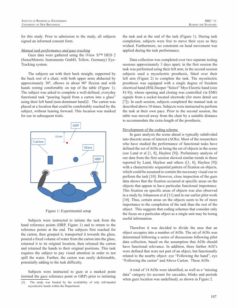
107
InsItute of BIomedIcal engIneerIng
unIversIty of new BrunswIck
MEC ‘11raIsIng the standard
for this study. Prior to admission to the study, all subjectssignedaninformedconsentform.
ManualtaskperformanceandgazetrackingGazedataweregatheredusing the iViewX™HED2
(SenseMotoric InstrumentsGmbH,Tellow,Germany)Eye-Trackingsystem.
The subjects satwith theirback straight, supportedbythebackrestofachair,withbothupperarmsabductedbyapproximately 30º, elbows in about 90º flexion and withhands resting comfortably on top of the table (Figure 1).Thesubjectwasaskedtocompleteawell-defined,everydayfunctional task “pouring liquid froma carton into a glass”usingtheirlefthand(non-dominanthand)2.Thecartonwasplacedatalocationthatcouldbecomfortablyreachedbythesubject,withoutleaningforward.Thislocationwasmarkedforuseinsubsequenttrials.
Figure1:Experimentalsetup
Subjects were instructed to initiate the task from thehand referencepoints (HRP,Figure1) and to return to thereference points at the end. The subjects first reached forthecarton,thengraspedit, transportedit towardstheglass,pouredafixedvolumeofwaterfromthecartonintotheglass,returned it to its original location, then released the cartonandreturnedthehandstotheiroriginalpositions.Thistaskrequires the subject to pay visual attention in order to notspill the water. Further, the carton was easily deformable,potentiallyaddingtothetaskdifficulty.
Subjects were instructed to gaze at a marked point(termedthegazereferencepointorGRP)priortoinitiating[2] The study was limited by the availability of only left-handed
myoelectrichandswithintheDepartment
the task and at the endof the task (Figure1).During taskcompletion, subjects were free tomove their eyes as theywished.Furthermore,noconstraintonheadmovementwasappliedduringthetaskperformance.
Datacollectionwascompletedovertwoseparatetestingsessionsapproximately3daysapart;inthefirstsessionthetaskwasperformedusingtheirleftarm;inthesecondsessionsubjects used a myoelectric prosthesis, fitted over theirleft arm (Figure 2) to complete the task. The myoelectricprosthesis was equipped with a single degree of freedomelectricalhand(RSLSteeper“Select”MyoElectrichand(size81/4)),whoseopeningandclosingwascontrolledviaEMGsignalsfromasocket-locatedelectrode(formoredetailsee[7]).Ineachsession,subjectscompletedthemanualtaskasdescribedabove10times.Subjectswereinstructedtoperformthe taskat theirownpace.Prior to the secondsession, thetablewasmovedawayfromthechairbyasuitabledistancetoaccommodatetheextra-lengthoftheprosthesis.
DevelopmentofthecodingschemeIngazeanalysisthesceneaheadistypicallysubdivided
intodiscreteareasofinterest(AOIs).Mostoftheresearcherswhohavestudiedtheperformanceoffunctional taskshavedefinedthesetofAOIsasbeingthesetofobjectsinthescene(seeLandetal[1,8],Hayhoe[9]).Preliminaryanalysisofourdatafromthefirstsessionshowedsimilartrendstothosereported byLand,Hayhoe and others ([1, 8],Hayhoe [9])withacharacteristicsequentialpatternoffixationonobjects,whichcouldbeassumedtocontainthenecessaryvisualcuetoperformthetask[10].However,closeinspectionofthegazedatashowsthatthefixationoccurredatspecificareasontheobjectsthatappeartohaveparticularfunctionalimportance.ThisfixationonspecificareasofobjectswasalsoobservedinastudybyJohanssonetal[11]andinourearlierpilotwork[10].Thus,certainareasontheobjectsseemtobeofmoreimportancetothecompletionofthetaskthantherestoftheobject.Thissuggeststhatcodingschemesthatconsideronlythefocusonaparticularobjectasasingleunitmaybelosingusefulinformation.
Therefore it was decided to divide the area that anobjectoccupiesintoanumberofAOIs.ThesetofAOIswasdeterminedfollowingaseriesofdiscussionsfollowingpilotdata collection, based on the assumption thatAOIs shouldhave functional relevance. In addition, three furtherAOI’sweredefinedthatwerenotpartofanobject,butfunctionallyrelatedtothenearbyobject:eye“Followingthehand”,eye“Followingthecarton”andAboveCarton.TheseAOIs
Atotalof14AOIswereidentified,aswellasa“missingdata”category(toaccountforsaccades,blinksandperiodswhengazelocationwasundefined),asshowninFigure2.
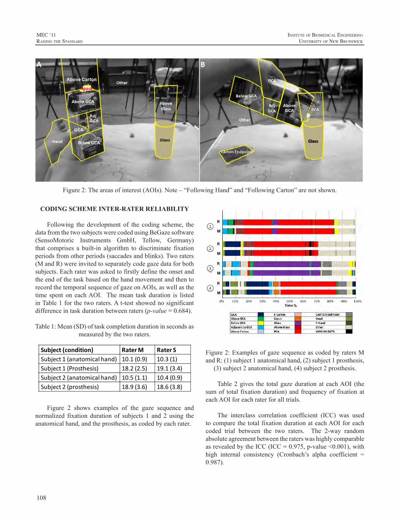
108
MEC ‘11raIsIng the standard
InsItute of BIomedIcal engIneerIng
unIversIty of new BrunswIck
Due to space limitations, it is not possible to describeeachAOIand itsderivation indetail.However, it isworthhighlighting two functional areas: Grasping Critical Area(GCA) is the area on the carton atwhich the handmakescontact. This definition accounts for between trials andbetweensubjectsvariations.Whenthecartonisgraspedbythehand, theGCAextends to include “Hand”AOI, as thefunctionalpurposeofbothAOIsmaybeassumedtobethesame.PouringCriticalArea(PCA)isnotasubsetofanobjectAOI, but rather a functional area that emerges during thepouringaction.
Toreduceambiguityintheinterpretationofthevideo,aconfusionmatrixshowingallpossible interactionsbetweenAOIswasdeveloped.IntheeventoftwoAOIsoverlapping,oneoftheAOIsisprioritised.
CODING SCHEME INTER-RATER RELIABILITY
Following the development of the coding scheme, thedatafromthetwosubjectswerecodedusingBeGazesoftware(SensoMotoric Instruments GmbH, Tellow, Germany)that comprises a built-in algorithm to discriminate fixationperiodsfromotherperiods(saccadesandblinks).Tworaters(MandR)wereinvitedtoseparatelycodegazedataforbothsubjects.EachraterwasaskedtofirstlydefinetheonsetandtheendofthetaskbasedonthehandmovementandthentorecordthetemporalsequenceofgazeonAOIs,aswellasthetime spent on eachAOI. Themean taskduration is listedinTable1forthetworaters.At-testshowednosignificantdifferenceintaskdurationbetweenraters(p-value=0.684).
Table1:Mean(SD)oftaskcompletiondurationinsecondsasmeasuredbythetworaters.
Subject (condition) Rater M Rater SSubject 1 (anatomical hand) 10.1 (0.9) 10.3 (1)Subject 1 (Prosthesis) 18.2 (2.5) 19.1 (3.4)Subject 2 (anatomical hand) 10.5 (1.1) 10.4 (0.9)Subject 2 (prosthesis) 18.9 (3.6) 18.6 (3.8)
Figure 2 shows examples of the gaze sequence andnormalized fixation duration of subjects 1 and 2 using theanatomicalhand,andtheprosthesis,ascodedbyeachrater.
Figure2:Theareasofinterest(AOIs).Note–“FollowingHand”and“FollowingCarton”arenotshown.
Figure2:ExamplesofgazesequenceascodedbyratersMandR:(1)subject1anatomicalhand,(2)subject1prosthesis,
(3)subject2anatomicalhand,(4)subject2prosthesis.
Table2gives the totalgazedurationat eachAOI (thesumof total fixationduration)andfrequencyof fixationateachAOIforeachraterforalltrials.
The interclass correlation coefficient (ICC) was usedtocomparethetotalfixationdurationateachAOIforeachcoded trial between the two raters. The 2-way randomabsoluteagreementbetweentheraterswashighlycomparableasrevealedbytheICC(ICC=0.975,p-value<0.001),withhigh internal consistency (Cronbach’s alpha coefficient =0.987).
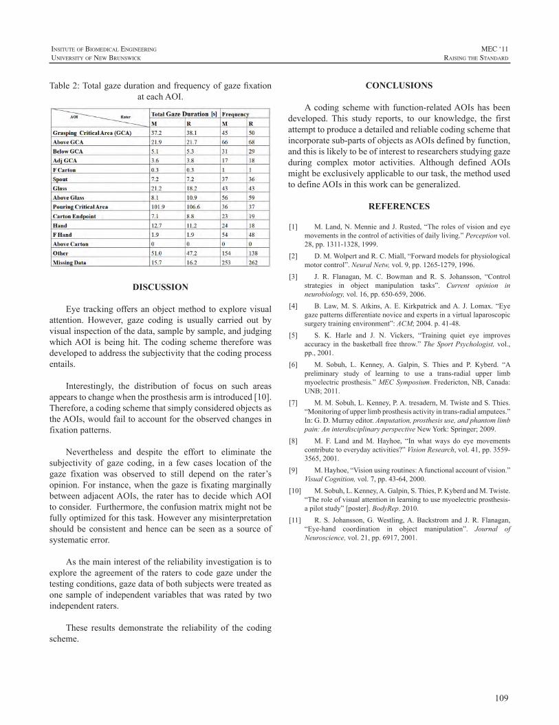
109
InsItute of BIomedIcal engIneerIng
unIversIty of new BrunswIck
MEC ‘11raIsIng the standard
Table2:TotalgazedurationandfrequencyofgazefixationateachAOI.
DISCUSSION
Eye trackingoffersanobjectmethod toexplorevisualattention. However, gaze coding is usually carried out byvisualinspectionofthedata,samplebysample,andjudgingwhichAOI is being hit.The coding scheme thereforewasdevelopedtoaddressthesubjectivitythatthecodingprocessentails.
Interestingly, the distribution of focus on such areasappearstochangewhentheprosthesisarmisintroduced[10].Therefore,acodingschemethatsimplyconsideredobjectsastheAOIs,wouldfailtoaccountfortheobservedchangesinfixationpatterns.
Nevertheless and despite the effort to eliminate thesubjectivity of gaze coding, in a few cases location of thegaze fixation was observed to still depend on the rater’sopinion.For instance,whenthegaze is fixatingmarginallybetweenadjacentAOIs, the rater has todecidewhichAOItoconsider.Furthermore,theconfusionmatrixmightnotbefullyoptimizedforthistask.Howeveranymisinterpretationshouldbe consistent andhence canbe seen as a sourceofsystematicerror.
Asthemaininterestofthereliabilityinvestigationistoexplore theagreementof the raters tocodegazeunder thetestingconditions,gazedataofbothsubjectsweretreatedasonesampleof independentvariables thatwasratedby twoindependentraters.
These results demonstrate the reliability of the codingscheme.
CONCLUSIONS
Acoding schemewith function-relatedAOIshasbeendeveloped. This study reports, to our knowledge, the firstattempttoproduceadetailedandreliablecodingschemethatincorporatesub-partsofobjectsasAOIsdefinedbyfunction,andthisislikelytobeofinteresttoresearchersstudyinggazeduring complex motor activities. Although defined AOIsmightbeexclusivelyapplicabletoourtask,themethodusedtodefineAOIsinthisworkcanbegeneralized.
REFERENCES
[1] M.Land,N.MennieandJ.Rusted,“Therolesofvisionandeyemovementsinthecontrolofactivitiesofdailyliving.”Perceptionvol.28,pp.1311-1328,1999.
[2] D.M.WolpertandR.C.Miall,“Forwardmodelsforphysiologicalmotorcontrol”.NeuralNetw,vol.9,pp.1265-1279,1996.
[3] J. R. Flanagan, M. C. Bowman and R. S. Johansson, “Controlstrategies in object manipulation tasks”. Current opinion inneurobiology,vol.16,pp.650-659,2006.
[4] B.Law,M. S.Atkins,A.E.Kirkpatrick andA. J. Lomax. “Eyegazepatternsdifferentiatenoviceandexpertsinavirtuallaparoscopicsurgerytrainingenvironment”:ACM;2004.p.41-48.
[5] S. K. Harle and J. N. Vickers, “Training quiet eye improvesaccuracy in thebasketball free throw.”TheSportPsychologist,vol.,pp.,2001.
[6] M. Sobuh, L. Kenney, A. Galpin, S. Thies and P. Kyberd. “Apreliminary study of learning to use a trans-radial upper limbmyoelectricprosthesis.”MECSymposium.Fredericton,NB,Canada:UNB;2011.
[7] M.M.Sobuh,L.Kenney,P.A.tresadern,M.TwisteandS.Thies.“Monitoringofupperlimbprosthesisactivityintrans-radialamputees.”In:G.D.Murrayeditor.Amputation,prosthesisuse,andphantomlimbpain:AninterdisciplinaryperspectiveNewYork:Springer;2009.
[8] M. F. Land andM. Hayhoe, “In what ways do eye movementscontributetoeverydayactivities?”VisionResearch,vol.41,pp.3559-3565,2001.
[9] M.Hayhoe,“Visionusingroutines:Afunctionalaccountofvision.”VisualCognition,vol.7,pp.43-64,2000.
[10] M.Sobuh,L.Kenney,A.Galpin,S.Thies,P.KyberdandM.Twiste.“Theroleofvisualattentioninlearningtousemyoelectricprosthesis-apilotstudy”[poster].BodyRep.2010.
[11] R.S. Johansson,G.Westling,A.Backstromand J.R.Flanagan,“Eye-hand coordination in object manipulation”. Journal ofNeuroscience,vol.21,pp.6917,2001.
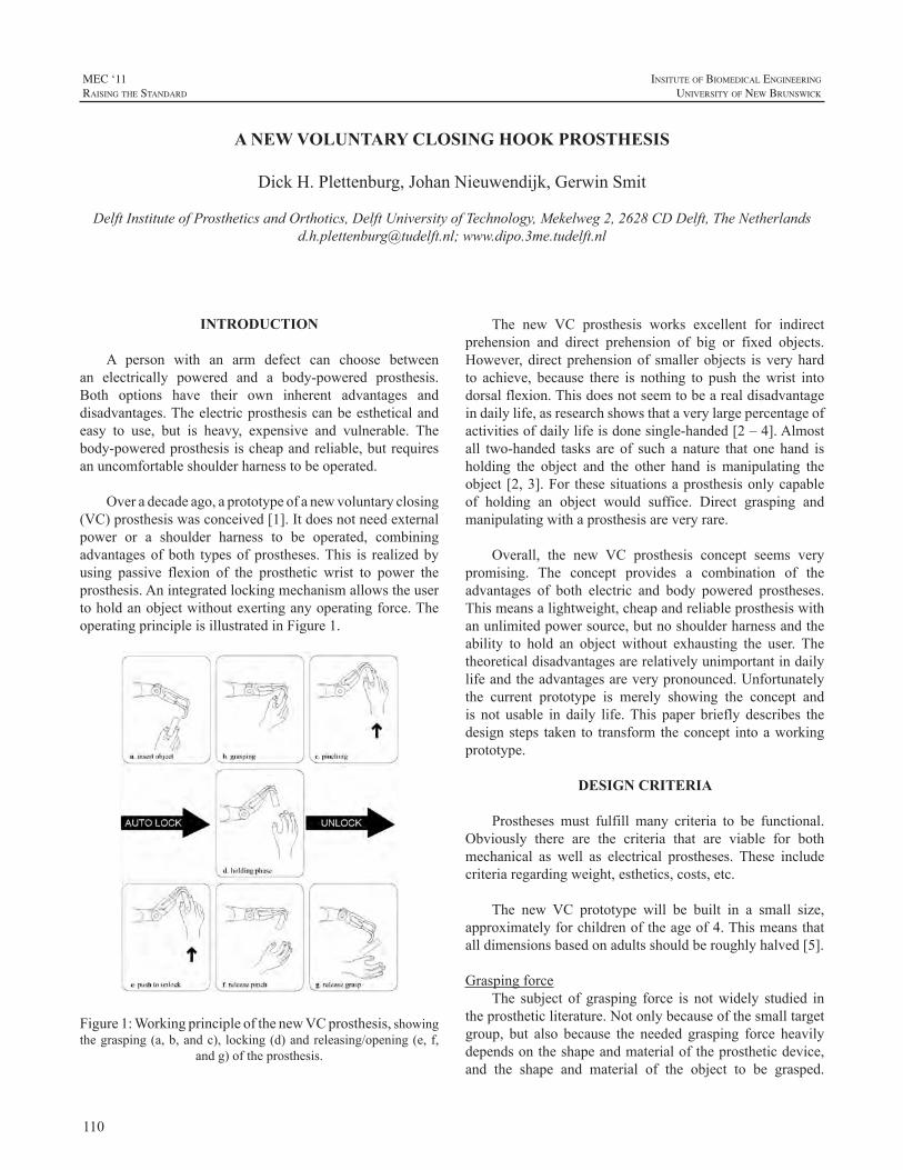
110
MEC ‘11raIsIng the standard
InsItute of BIomedIcal engIneerIng
unIversIty of new BrunswIck
INTRODUCTION
A person with an arm defect can choose betweenan electrically powered and a body-powered prosthesis.Both options have their own inherent advantages anddisadvantages.Theelectricprosthesiscanbeestheticalandeasy to use, but is heavy, expensive and vulnerable. Thebody-poweredprosthesisischeapandreliable,butrequiresanuncomfortableshoulderharnesstobeoperated.
Overadecadeago,aprototypeofanewvoluntaryclosing(VC)prosthesiswasconceived[1].Itdoesnotneedexternalpower or a shoulder harness to be operated, combiningadvantagesofboth typesofprostheses.This is realizedbyusing passive flexion of the prosthetic wrist to power theprosthesis.Anintegratedlockingmechanismallowstheusertoholdanobjectwithoutexertinganyoperatingforce.TheoperatingprincipleisillustratedinFigure1.
Figure1:WorkingprincipleofthenewVCprosthesis,showingthegrasping(a,b,andc), locking(d)andreleasing/opening(e,f,
andg)oftheprosthesis.
The new VC prosthesis works excellent for indirectprehension and direct prehension of big or fixed objects.However,directprehensionof smallerobjects isveryhardto achieve, because there is nothing to push thewrist intodorsalflexion.Thisdoesnotseemtobearealdisadvantageindailylife,asresearchshowsthataverylargepercentageofactivitiesofdailylifeisdonesingle-handed[2–4].Almostall two-handed tasks are of such a nature that one hand isholding the object and the other hand is manipulating theobject [2,3].For thesesituationsaprosthesisonlycapableof holding an object would suffice. Direct grasping andmanipulatingwithaprosthesisareveryrare.
Overall, the new VC prosthesis concept seems verypromising. The concept provides a combination of theadvantages of both electric and body powered prostheses.Thismeansalightweight,cheapandreliableprosthesiswithanunlimitedpowersource,butnoshoulderharnessandtheability to hold an object without exhausting the user. Thetheoreticaldisadvantagesarerelativelyunimportantindailylifeandtheadvantagesareverypronounced.Unfortunatelythe current prototype is merely showing the concept andis not usable in daily life.This paper briefly describes thedesignsteps taken to transform theconcept intoaworkingprototype.
DESIGN CRITERIA
Prostheses must fulfill many criteria to be functional.Obviously there are the criteria that are viable for bothmechanical as well as electrical prostheses. These includecriteriaregardingweight,esthetics,costs,etc.
The new VC prototype will be built in a small size,approximatelyforchildrenoftheageof4.Thismeansthatalldimensionsbasedonadultsshouldberoughlyhalved[5].
GraspingforceThe subject of grasping force is notwidely studied in
theprostheticliterature.Notonlybecauseofthesmalltargetgroup, but also because the needed grasping force heavilydependsontheshapeandmaterialoftheprostheticdevice,and the shape and material of the object to be grasped.
A NEW VOLUNTARY CLOSING HOOK PROSTHESIS
DickH.Plettenburg,JohanNieuwendijk,GerwinSmit
DelftInstituteofProstheticsandOrthotics,DelftUniversityofTechnology,Mekelweg2,2628CDDelft,[email protected];www.dipo.3me.tudelft.nl
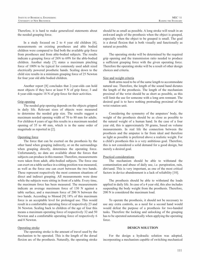
111
InsItute of BIomedIcal engIneerIng
unIversIty of new BrunswIck
MEC ‘11raIsIng the standard
Therefore, it is hard tomake generalized statements abouttheneededgraspingforce.
In a study focused on 2 to 4 year old children [6],measurements on existing prostheses and able bodiedchildrenwerecomparedtofindboththeavailablegripforcefromprosthesesandfromable-bodiedsubjects.Theresultsindicateagraspingforceof26Nto69Nfortheable-bodiedchildren. Another study [7] states a maximum pinchingforceof100Ntobetypicalforcommonlyusedadultsizedelectrically powered prosthetic hands. Scaling down to thechildsizeresultsinaminimumgraspingforceof25Newtonforfouryearoldablebodiedchildren.
Another report [8]concludes that2-year-oldscanholdmostobjects if theyhaveat least9Nofgrip force;3 and4-year-oldsrequire18Nofgripforcefortheiractivities.
GripopeningTheneededgripopeningdependsontheobjectsgripped
in daily life. Relevant sizes of objects were measuredto determine the needed grip size. The results suggest amaximumneededopeningwidthof70to80mmforadults.Forchildren4yearsofagethisresultsinamaximumneededopening of 35 to 40 mm, which is in the same order ofmagnitudeasreportedin[2].
OperatingforceThe force that canbeexertedon theprosthesisby the
otherhandwhengraspingindirectly,oronthesurroundingswhen grasping directly, determines the operating force.Unfortunately, no data are available about the forces thatsubjectscanproduceinthismanner.Therefore,measurementswere takenfromadult,able-bodiedsubjects.Theforceonecanexertonatablesurfaceinasittingpositionwasmeasured,aswell as the force one can exert between the twohands.Theserepresentrespectivelythemostcommonsituationsofdirect and indirect grasping.All measurements were donewhilethesubjectsweresittinginfrontofatable.Everytime,themaximumforcehasbeenmeasured.Themeasurementsindicate an average maximum force of 130 N against atable surface, andamaximumforceof200Nbetween thetwohands.AccordingtoMonod[9]18%ofthismaximumforce is an acceptable level for prolongeduse.Thiswouldresultinacomfortableoperatingforceofrespectively23and36Newton.Scalingbacktochildrenoftheageoffourthismeansamaximumoperatingforceofrespectively32and50Newtonandacomfortableoperatingforceofrespectively6and8Newton.
OperatingstrokeTheoperatingstrokeistheamountoftravelusedbythe
mechanism tobeoperated.This is the lengthof thedorsalflexionarcoftheprosthesis.Naturally,theoperatingstroke
shouldbeassmallaspossible.Alongstrokewillresultinanawkwardangleoftheprosthesiswhentheobjectisgrasped,especiallywhentheobjecttobegraspedissmall.Thegoalis adorsal flexion that isbothvisually and functionally asnaturalaspossible.
Theoperatingstrokewillbedeterminedbytherequiredgrip opening and the transmission ratio needed to producea sufficient grasping force with the given operating force.Thereforetheoperatingstrokewillbearesultofotherdesignchoicesandcriteria.
SizeandweightcriteriaBotharmsneedtobeofthesamelengthtoaccommodate
naturaluse.Therefore,thelengthofthesoundhanddictatesthe length of the prosthesis. The length of themechanismproximalofthewristshouldbeasshortaspossible,asthiswilllimittheuseforsomeonewithalongarmremnant.Thedesired goal is to have nothing protruding proximal of thewristrotationunit.
Considering the symmetry of the amputees’ body, theweight of the prosthesis should be as close as possible tothe naturalweight of a human hand. In the case of a fouryearold, this isapproximately50grams,basedonvolumemeasurements. In real life the connection between theprosthesis and the amputee is far from ideal and thereforeaslightaspossibleispreferredabovearealisticweight.Forachild’sprosthesisthisisaveryambitiousgoal.Therefore,thisisnotconsideredasoliddemandforagooddesign,butmerelyadesiredgoal.
PracticalconsiderationsThe mechanism should be able to withstand the
contaminationandabuseofdailyuse,i.e.perspiration,rain,dirt/sand.Thisisveryimportant,asoneofthemostcriticalfactorsindeviceabandonmentisalackofreliability[10].
The prosthesis should be able to withstand the loadsappliedindailylife.Incaseofa4yearold,thisalsoincludessuspendingthebodyweightfromtheprosthesis.Therefore,200Nisconsideredthemaximumload.
Tooperatetheprosthesis,itshouldnotbenecessarytouse anyextra controls, as aneed for a secondhandwouldwould defeat the purpose of a prosthesis for two-handedtasks.Therefore the lockingandunlockingof thegraspinghastobeoperatedautomaticallywhenapplyingtheoperatingforce.
DESIGN SOLUTION
For the design a hydraulic solution was adopted,incorporatingamechanismcapableofswitchingmechanical
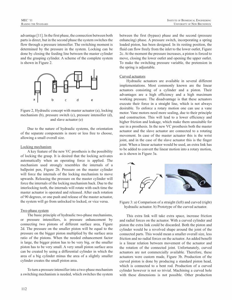
112
MEC ‘11raIsIng the standard
InsItute of BIomedIcal engIneerIng
unIversIty of new BrunswIck
advantage[11].Inthefirstphase,theconnectionbetweenbothpartsisdirect,butinthesecondphasethesystemswitchestheflowthroughapressureintensifier.Theswitchingmomentisdetermined by the pressure in the system. Locking can bedonebyclosingthefeedinglinebetweenthemastercylinderandthegraspingcylinder.AschemeofthecompletesystemisshowninFigure2.
Figure2,Hydraulicconceptwithmasteractuator(a),lockingmechanism(b),pressureswitch(c),pressureintensifier(d),
andslaveactuator(e)
Dueto thenatureofhydraulicsystems, theorientationof the separate components ismoreor less free to choose,allowingasmalloverallsize.
LockingmechanismAkeyfeatureofthenewVCprosthesisisthepossibility
of lockingthegrasp. It isdesired that the lockingactivatesautomatically when an operating force is applied. Themechanism used strongly resembles the internals of aballpoint pen, Figure 2b. Pressure on the master cylinderwill force the internals of the lockingmechanism tomoveupwards.Releasingthepressureonthemastercylinderwillforcetheinternalsofthelockingmechanismback.Duetotheinterlockingteeth,theinternalswillrotatewitheachtimethemasteractuatorisoperatedandreleased.Aftereachrotationof90degrees,oronepushandreleaseofthemasteractuator,thesystemwillgofromunlockedtolocked,orviceversa.
Two-phasesystemThebasicprincipleofhydraulictwo-phasemechanisms,
or pressure intensifiers, is pressure enhancement byconnecting two pistons of different surface area, Figure2d.Thepressureon thesmallerpistonwillbeequal to thepressureonthebiggerpistonmultipliedbythesurfacearearatio of the pistons.When the needed enhancement factorislarge,thebiggerpistonhastobeverybig,orthesmallerpistonhastobeverysmall.Averysmallpistonsurfaceareacanbecreatedbyusingadifferentialcylinderinwhichthearea of a big cylinderminus the area of a slightly smallercylindercreatesthesmallpistonarea.
Toturnapressureintensifierintoatwo-phasemechanismaswitchingmechanismisneeded,whichswitchesthesystem
between the first (bypass) phase and the second (pressureenhancing)phase.Apressureswitch,incorporatingaspringloadedpiston,hasbeendesigned.Initsrestingposition,thefluidcanflowfreelyfromtheinlettotheloweroutlet,Figure2c.Atthemomentthepressureincreases,apistonisforcedtomove,closingtheloweroutletandopeningtheupperoutlet.Tomake the switchingpressure variable, the pretension inthespringisadjustable.
CurvedactuatorsHydraulic actuators are available in several different
implementations. Most commonly known are the linearactuators consisting of a cylinder and a piston. Theiradvantages are a high efficiency and a high maximumworking pressure.The disadvantage is that these actuatorsexecute their force in a straight line, which is not alwaysdesirable. To enforce a rotary motion one can use a vanemotor.Vanemotorsneedmoresealing,duetotheirprincipleand construction. This will lead to a lower efficiency andhigherfrictionandleakage,whichmakethemunsuitableforuseinaprosthesis.InthenewVCprosthesisboththemasteractuator and the slave actuator are connected to a rotatingmovement. In case of themaster actuator this is thewristjoint,andinthecaseoftheslaveactuatorthisisthefingerjoint.Whenalinearactuatorwouldbeused,anextralinkhastobeaddedtoconvertthelinearmotionintoarotarymotion,asisshowninFigure3a.
Figure3:a)Comparisonofastraight(left)andcurved(right)hydraulicactuator.b)Prototypeofthecurvedactuator.
This extra linkwill take extra space, increase frictionandradialforcesontheactuator.Withacurvedcylinderandpistontheextralinkcouldbediscarded.Boththepistonandcylinderwouldbearevolvedshapearoundthe jointof theconnectedparts.Thiswouldmeanasmalleroverallsize,lessfrictionandnoradialforcesontheactuator.Anaddedbenefitis a linear relation betweenmovement of the actuator andthe rotation of the connected joint. Unfortunately, curvedactuators are not commercially available. Therefore, theseactuatorswere custommade, Figure 3b. Production of thecurvedpistonisdonebyproducingastandardpistonhead,which is connected to a bent rod. Production of a curvedcylinderhoweverisnotsotrivial.Machiningacurvedholewith these dimensions is not possible. Other production
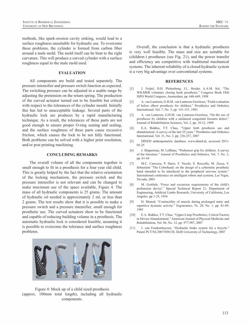
113
InsItute of BIomedIcal engIneerIng
unIversIty of new BrunswIck
MEC ‘11raIsIng the standard
methods,likespark-erosioncavitysinking,wouldleadtoasurfaceroughnessunsuitableforhydraulicuse.Toovercomethese problems, the cylinder is formed from carbon fiberaroundamalemold.Themolditselfcanbebenttotherightcurvature.Thiswillproduceacurvedcylinderwithasurfaceroughnessequaltothemalemoldused.
EVALUATION
All components are build and tested separately. Thepressureintensifierandpressureswitchfunctionasexpected.Theswitchingpressurecanbeadjustedinausablerangebyadjustingthepretensiononthereturnspring.Theproductionof thecurvedactuator turnedout tobe feasiblebutcriticalwithrespecttothetolerancesofthecylindermould.Initiallythis has led to unacceptable leakage. Several parts of thehydraulic lock are produces by a rapid manufacturingtechnique.Asa result, the tolerancesof thesepartsarenotgood enough to ensure proper O-ring seating and sealing,and the surface roughness of these parts cause excessivefriction, which causes the lock to be not fully functional.Bothproblemscanbesolvedwithahigherprintresolution,and/orpostprintingmachining.
CONCLUDING REMARKS
The overall volume of all the components together issmallenoughtofitinaprosthesisforafouryearoldchild.Thisisgreatlyhelpedbythefactthattherelativeorientationof the locking mechanism, the pressure switch and thepressure intensifier is not relevant and can be changed tomakemaximum use of the space available, Figure 4. Themassofallhydrauliccomponentsis25grams.Theamountofhydraulicoilneeded isapproximately2ml,or less than2grams.Thetestresultsshowthat it ispossibletomakeapressureswitchandapressureintensifier,smallenoughforprosthetic use.The curved actuators show to be functionalandcapableofreducingbuildingvolumeinaprosthesis.Theautomatichydrauliclockisconsideredfeasible,assumingitispossibletoovercomethetoleranceandsurfaceroughnessproblems.
Figure4:Mockupofachildsizedprosthesis(approx. 100mm total length), including all hydraulic
components.
Overall, the conclusion is that a hydraulic prosthesisis very well feasible. The mass and size are suitable for(children-)prostheses (seeFig.21),and thepower transferand efficiency are competitive with traditional mechanicalsystems.Theinherentreliabilityofaclosedhydraulicsystemisaverybigadvantageoverconventionalsystems.
REFERENCES
[1] J. Feijtel, D.H. Plettenburg, J.L. Herder, A.A.M. Sol, “TheWILMER voluntary closing hook prosthesis.” Congress Book IXthISPOWorldCongress,Amsterdam,pp.648-649,1998
[2] A.vanLunteren,G.H.M.vanLunteren-Gerritsen,“Fieldevaluationof below elbow prosthesis for children.” Prosthetics and OrthoticsInternational,Vol.7,No.3,pp.141-151,1983
[3] A.vanLunteren,G.H.M.vanLunteren-Gerritsen,“Ontheuseofprostheses by childrenwith a unilateral congenital forearm defect.”JournalofRehabilitationSciences,Vol.2,pp.10-12,1989
[4] E.A. Biddiss, T.T. Chau, “Upper limb prosthesis use andabandonment:Asurveyofthelast25years.”ProstheticsandOrthoticsInternational,Vol.31,No.3,pp.236-257,2007
[5] DINED anthropometric database, www.dined.nl, accessed 2011-05-25
[6] J.Shaperman,M.LeBlanc,“Prehensorgripforchildren.Asurveyoftheliterature.”JournalofProstheticsandOrthotics,Vol.7,No.2,pp.61-64
[7] M.C. Carrozza, P. Dario, F. Vecchi, S. Roccella, M. Zecca, F.Sebastiani“TheCyberhand:on thedesignofacyberneticprosthetichand intended to be interfaced to the peripheral nervous system.”Internationalconferenceonintelligentrobotsandsystems,LasVegas,Nevada,2003
[8] M. Gottlieb, “Force and excursion requirements of the child’sprehension device.” Special Technical Report 21, Department ofEngineering,ArtificialLimbsResearch,UniversityofCalifornia,LosAngeles.pp1-25,1954
[9] H.Monod, “Contractility ofmuscle during prolonged static andrepetitive dynamic activity.” Ergonomics,Vo. 28,No. 1, pp. 81-89,1985
[10] E.A.Biddiss,T.T.Chau,“Upper-LimpProsthetics;CriticalFactorsinDeviceAbandonment.”AmericanJournalofPhysicalMedicineandRehabilitation,Vol.86,No.12,pp.977-987,2007
[11] J. van Frankenhuyzen, “Hydraulic brake system for a bicycle.”PatentPCT/NL2007/050130,DelftUniversityofTechnology,2007
114
MEC ‘11raIsIng the standard
InsItute of BIomedIcal engIneerIng
unIversIty of new BrunswIck
INTRODUCTION
In order to meet the needs of a person with an armdefect,many,sometimesconflicting,requirementshavetobefulfilled.These requirementscanbesummarized into threebasicdemands:cosmetics,comfort,andcontrol[1,2].Inthecontrol domain natural, intuitive, subconscious control isstrivedfor.Toachievethis typeofcontrolproperfeedbackneeds to be present [3]. This implies control according tothe voluntary closing principle. In body-powered, body-controlled prostheses voluntary closing control enablesproprioceptive feedback of position, velocity, and forceto the user through the bodies own proprioceptive system,comparabletothewayweuseatool,e.g.atennisracket[4,5].
TheDelftInstituteofProstheticsandOrthotics(DIPO)has started several projects to develop body-powered,body-controlledvoluntaryclosinghandprostheses.Currentprojectsincludeavoluntaryclosinghandfortoddlers,wherethereductionofgloveforcesactingisthemainchallenge;avoluntary closingprehensor similar in looks to the alreadyexisting and successful appealing prehensor [6],where themainchallengeisavariableadvantagemechanismtopromotefast sizing of powerful grasps; a wrist-operated voluntaryclosingprehensor,wherethechallengeistoincorporatenovelhydraulics;andastudyintothepsychophysicalpropertiesofshoulderharnesses,wherethemainchallengeis toidentifythe optimal force and excursion windows. Ultimately,we aim at voluntary closing hands that provide adaptivegrasp patterns.Adaptivity enhances the natural appearance[cosmetics],andatthesametimereducestheneedforhighpinchforces[comfort,control].
Eachoftheabovementionedprojectsisbrieflydescribedbelow.
VC HAND FOR TODDLERS
In active, toddler sized hand prostheses the cosmeticglove introduces a stiffness which causes the requiredoperationforcestobetoohightobegeneratedbytoddlers.Measurements on several cosmetic gloves of identical size
and brand, showed different glove stiffness characteristics.The goal of this project is to design a voluntary closingtoddler sized hand prosthesis using an adjustable glovecompensation mechanism. A prototype of the glovecompensated hand prosthesis was designed. The designis based upon the WILMER passive hand prosthesis fortoddlers [7] andutilizesa springmechanismwithnegativestiffnesstocompensateforthegloveforces[8].Futureworkshoulddeterminethefeasibilityofthedesign.
VC PREHENSOR
A relatively new project aims to convert the alreadyexisting and successful appealing prehensor [6], whichoperates in a voluntary opening fashion, into a voluntaryclosing device. Most likely, the design will incorporate avariable advantage mechanism to promote fast sizing ofpowerful grasps, similar to previous designs made withinDIPO[9].
WRIST-OPERATED VC PREHENSOR
Currently, a person with an arm defect can choosebetween an electrically powered or a body-poweredprosthesis.Bothoptionshavetheirowninherentadvantagesanddisadvantages.Theelectronicprosthesiscanbeestheticalandeasytouse,butisheavy,expensiveandvulnerable.Thebody-poweredprosthesisischeapandreliable,butrequiresanuncomfortableshoulderharnesstobeoperated.
Overadecadeago,aprototypeofanewvoluntaryclosingprosthesiswasconceived[10].Itdoesnotneedexternalpowerorashoulderharnesstobeoperated,combiningadvantagesofbothtypesofprostheses.Thisisrealizedbyusingpassiveflexion of the prostheticwrist to power the prosthesis.Anintegrated locking mechanism allows the user to hold anobjectwithoutexertinganyoperatingforce.
A recent study [11] showed the feasibility of wristflexion operation. Subsequently, a prototype of the newvoluntary closing prosthesis was designed. It comprises ahydraulic system containing a pressure controlled pressureintensifier, an automatic locking system, and some novel
VOLUNTARY CLOSING PROSTHESES Ananswertouserneeds!
DickH.Plettenburg,GerwinSmit
DelftInstituteofProstheticsandOrthotics,DelftUniversityofTechnology,Mekelweg2,2628CDDelft,[email protected];www.dipo.3me.tudelft.nl
115
InsItute of BIomedIcal engIneerIng
unIversIty of new BrunswIck
MEC ‘11raIsIng the standard
hydraulicactuators.Allcomponentsarebuiltandtested.Theresultsshowtheviabilityofthenewconcept[12].
PSYCHOPHYSICAL PROPERTIES OF SHOULDER HARNESSES
High rejection rates indicate users are not satisfiedwiththeperformanceoftheirarmprostheses.Intheory,theadvantageofshouldercontrolledprosthesesis thattheuserreceives direct proprioceptive feedback about the openingwidthandpinchforceoftheterminaldevice.However,theoperatingforcesofcommerciallyavailablevoluntaryclosingprosthesesarehigh,leadingtodiscomfortanddisturbingthedirectproprioceptivefeedback.
As a start, a pilot study was performed to find theoptimaloperationforce,atwhichtheuserreceivesoptimumforce feedback during comfortable prosthesis operation[13, 14]. During experimental research, subjects wereasked to reproduce a reference force, with and withoutvisual representation of the forces produced.The subject’sperformances of blind generated forces regarding thereproducibility, stability and repeatability were evaluatedto find an optimal cable force. The performances of maleand female subjects, with and without arm defects werecompared.
The optimal operation force level is between 20 and30Nformaleandfemalesubjectswithoutarmdefects.Nodifferences in stability and repeatability performance arefound between subjects with and without an arm defect.Subjects with arm defects the reproducibility optimumis found between 10 and 20N as they have difficultiesreproducinghighforcelevels(>30N).
Future work will extend the force measurements andcombine them with measurements for the optimal cableexcursion feedback. Hence, a proper understanding ofthe proprioceptive feedback capabilities of a prostheticuser is gained. From here, the optimal control forces anddisplacements can be determined. These will serve as thebasisforthedesignofanewphysiologicalcontrolsystem.
VC HAND WITH ADAPTIVE FINGERS
Whenitcomestobodypoweredprostheses,mostusersprefer a hook over a hand. Body powered hands requirean uncomfortable high activation force [15, 16], producearelativelylowpinchforce(<15N)andhavestifffingers.Despiteallitsdrawbacks,thedesignofbodypoweredhandprosthesesalmosthasnotchangedsincethe1950’s.
Thegoalofthisstudywastodesignanewbody-powered,voluntary closing hand prosthesis, which has articulating
fingers.Thishandshouldrequireanoperationforcewithinacomfortablelevel.
A new hand was designed and prototyped [17]. Thehand uses hydraulics, to enable an efficient transmissionand to avoid the use of an inefficient Bowden-cable. ThefingershavearticulatingMCP-andPIP-joints,enablingbothprecision and cylinder grasp. The fingers are actuated byindividualhydraulic cylinders,which fit inside the fingers.Thecylinderscanbeoperatedatahighpressure(>50bar),whichenablesahighpinchload(>30N).Theusercanoperatethehandbyactivatingahydraulicmastercylinder,attachedtoashoulderstrap.Thehydraulichandisfastandreliable,duetotheuseofbodycontrol.Thehandprovidesfeedbacktotheuser,whichenablesaccurateforceandpositioncontrol.
REFERENCES
[1] D.H. Plettenburg, “Basic requirements for upper extremityprostheses: the WILMER approach.” In: Proceedings of the 20thAnnualInternationalConferenceoftheIEEEEngineeringinMedicineand Biology Society, Hong Kong SAR, China. Vol.5/6, pp. 2276 –2281,1998
[2] D.H.Plettenburg,Upperextremityprosthetics.Currentstatusandevaluation.VSSD,TheNetherlands,2006
[3] N. Wiener, Cybernetics, or control and communication in theanimalandthemachine.JohnWiley&Sons,Inc.,NewYork,USA,1948
[4] D.Simpson,“Thechoiceofcontrolsystemforthemultimovementprosthesis: extended physiological proprioception.” In: The controlof upper-extremity prostheses and orthoses. Charles C. Thomas,Springfield,Illinois,pp.146–150,1974
[5] J.A. Doubler, D.S. Childress, “An analysis of extendedphysiological proprioception as a prosthesis-control technique.”JournalofRehabilitationResearchandDevelopment,Vol.21,No.1.BPR10-38,pp.5–18,1984
[6] D.H.Plettenburg,“TheWILMERAppealingPrehensor”JournalofProstheticsandOrthotics,Vol.18,No.2,pp.43–45,2006
[7] D.H. Plettenburg, “The WILMER passive hand prosthesis fortoddlers”JournalofProstheticsandOrthotics,Vol.21,No.2,pp.97-99,2009
[8] D.H. Plettenburg, “A sizzling hand prosthesis. On the designand development of a pneumatically powered hand prosthesis forchildren.”PhD-thesisDelftUniversityofTechnology,2002
[9] J. Kruit, J.C. Cool, “Body-powered hand prosthesis with lowoperating power for children.” Journal of Medical Engineering &Technology,Vol.13,No.1/2,pp.129-133,1989
[10] J. Feijtel, D.H. Plettenburg, J.L. Herder, A.A.M. Sol, “TheWILMER voluntary closing hook prosthesis.”Congress Book IXthISPOWorldCongress,Amsterdam,pp.648-649,1998
[11] J.Nieuwendijk,“A new type of body-powered prosthesis.Usingwrist flexion instead of shoulder movement.” MSc-Thesis DelftUniversityofTechnology,2010
[12] D.H. Plettenburg, J. Nieuwendijk, G. Smit, “A new voluntaryclosinghookprosthesis.”,Accepted toMECSymposiumConferenceProceedings,2011
[13] M. Hichert, “Feedback in voluntary closing arm prostheses.Investigation of optimal force feedback in shoulder controlled arm
116
MEC ‘11raIsIng the standard
InsItute of BIomedIcal engIneerIng
unIversIty of new BrunswIck
prosthesis operation.”, MSc-thesis Delft University of Technology,2010
[14] D.H. Plettenburg, M. Hichert, G. Smit, “Feedback in voluntaryclosing arm prostheses. Investigation of optimal force feedback inshoulder controlled arm prosthesis operation.”, Accepted to MECSymposiumConferenceProceedings,2011
[15] G.Smit,D.H.Plettenburg,“Efficiencyofvoluntaryclosinghandandhookprostheses.”ProstheticsandOrthoticsInternational,Vol.34,No.4,pp411-427,2010
[16] G. Smit, R.A. Bongers, C.K. van der Sluis, D.H. Plettenburg,“Efficiencyofvoluntaryopeninghandandhookprostheses,24yearsofdevelopment?”SubmittedtoProstheticsandOrthoticsInternational,2011
[17] G.Smit,D.H.Plettenburg,“Designofahydraulichandprosthesis,with articulatingfingers.”Accepted toMECSymposiumConferenceProceedings,2011
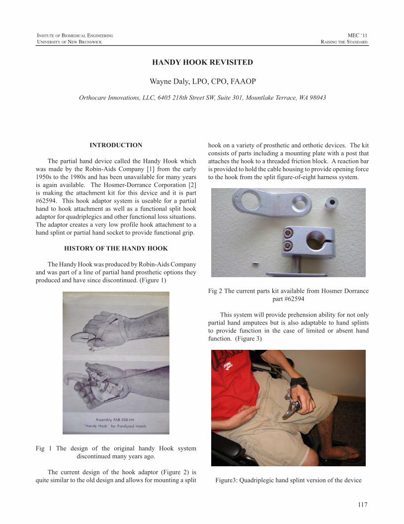
117
InsItute of BIomedIcal engIneerIng
unIversIty of new BrunswIck
MEC ‘11raIsIng the standard
INTRODUCTION
Thepartialhanddevicecalled theHandyHookwhichwasmade by theRobin-AidsCompany [1] from the early1950stothe1980sandhasbeenunavailableformanyyearsis again available. TheHosmer-Dorrance Corporation [2]is making the attachment kit for this device and it is part#62594. Thishookadaptor system isuseable for apartialhand tohookattachmentaswellasa functional splithookadaptorforquadriplegicsandotherfunctionallosssituations.Theadaptorcreatesaverylowprofilehookattachmenttoahandsplintorpartialhandsockettoprovidefunctionalgrip.
HISTORY OF THE HANDY HOOK
TheHandyHookwasproducedbyRobin-AidsCompanyandwaspartofalineofpartialhandprostheticoptionstheyproducedandhavesincediscontinued.(Figure1)
Fig 1 The design of the original handy Hook systemdiscontinuedmanyyearsago.
The current design of the hook adaptor (Figure 2) isquitesimilartotheolddesignandallowsformountingasplit
hookonavarietyofprostheticandorthoticdevices.Thekitconsistsofpartsincludingamountingplatewithapostthatattachesthehooktoathreadedfrictionblock.Areactionbarisprovidedtoholdthecablehousingtoprovideopeningforcetothehookfromthesplitfigure-of-eightharnesssystem.
Fig2ThecurrentpartskitavailablefromHosmerDorrancepart#62594
Thissystemwillprovideprehensionabilityfornotonlypartialhandamputeesbut is alsoadaptable tohand splintsto provide function in the case of limited or absent handfunction.(Figure3)
Figure3:Quadriplegichandsplintversionofthedevice
HANDY HOOK REVISITED
WayneDaly,LPO,CPO,FAAOP
OrthocareInnovations,LLC,6405218thStreetSW,Suite301,MountlakeTerrace,WA98043
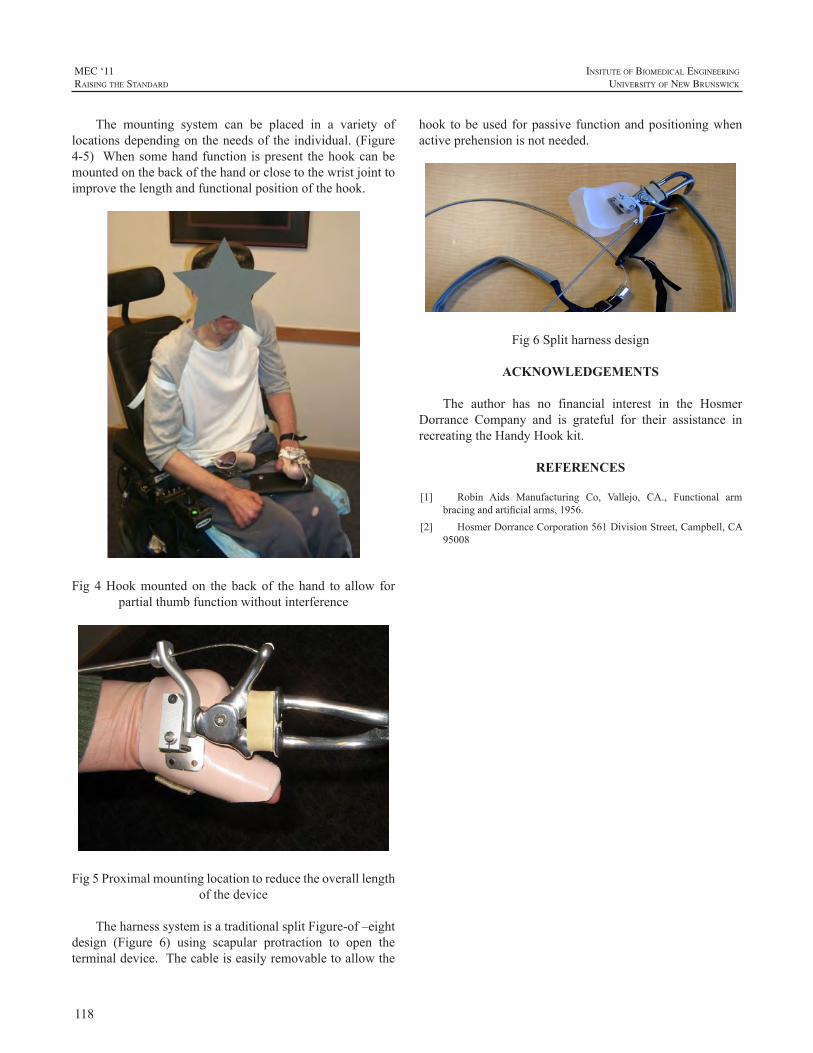
118
MEC ‘11raIsIng the standard
InsItute of BIomedIcal engIneerIng
unIversIty of new BrunswIck
The mounting system can be placed in a variety oflocationsdependingontheneedsof theindividual.(Figure4-5) Whensomehandfunctionispresent thehookcanbemountedonthebackofthehandorclosetothewristjointtoimprovethelengthandfunctionalpositionofthehook.
Fig4Hookmountedon thebackof thehand to allow forpartialthumbfunctionwithoutinterference
Fig5Proximalmountinglocationtoreducetheoveralllengthofthedevice
TheharnesssystemisatraditionalsplitFigure-of–eightdesign (Figure 6) using scapular protraction to open theterminaldevice.Thecableiseasilyremovabletoallowthe
hook tobeused forpassive functionandpositioningwhenactiveprehensionisnotneeded.
Fig6Splitharnessdesign
ACKNOWLEDGEMENTS
The author has no financial interest in the HosmerDorrance Company and is grateful for their assistance inrecreatingtheHandyHookkit.
REFERENCES
[1] Robin Aids Manufacturing Co, Vallejo, CA., Functional armbracingandartificialarms,1956.
[2] HosmerDorranceCorporation561DivisionStreet,Campbell,CA95008
119
InsItute of BIomedIcal engIneerIng
unIversIty of new BrunswIck
MEC ‘11raIsIng the standard
ABSTRACT
Standardmyoelectriccontrolsystemsusecarefullyplacedbipolar electrode pairs to provide independentmyoelectricsignals (MESs) forprosthesiscontrol.Becausemyoelectricpattern recognition systems do not require isolatedMESs,thetwoelectrodepolesusedforeachMESchannelmaybeplacedlongitudinallyalongindividualmusclesortransverselyacross multiple muscles. In addition, each electrode polecan be combined with a number of additional poles toformmultiplechannels.However,practical issues limit thenumberofpolesthatcanbeusedinclinicalsettings.Inthisstudy, we investigated classification error reduction andcontrollability improvementsprovidedbyacombinationoftransverseandlongitudinalMESchannelsintwoconditions:(1)aconstantnumberofelectrodepoles,and(2)aconstantnumberofMESchannels.Inbothcases,wealsoinvestigatedperformancewhentheelectrodeswereslightlyshiftedfromtheir original positions to evaluate sensitivity to electrodeshift.We found that a combination of two transverse andtwo longitudinal electrode channels constructed from fourpolessignificantlyoutperformedtheindividualperformancesof either two transverse or two longitudinal channels eachconstructedfromfourpoles(p<0.01).Usingeightpoles,wefoundthatthebestchannelsubsetwasalwayscomprisedofacombinationoftransverseandlongitudinalchannels.Theseresultsareimportantbecausethenumberandarrangementofpolesandchannelsisapracticalconsiderationforsuccessfulclinical implementation of myoelectric pattern recognitioncontrol.
INTRODUCTION
Myoelectricpattern recognition systems showpromisefor intuitive control ofprostheseswithmultipledegreesoffreedom[1].Despitetwodecadesofextensiveresearch,thesesystems have yet to be clinically implemented. Typically,studiesofpatternrecognitionsystemshavefocusedonsignalprocessing aspects including data windowing [2], featureextraction [3], classification [4], and post-processing [5].However, akeycomponentof the system is theplacementand configuration of the electrode poles. This is true intwo contexts: first, the information content of each MESchannelisaffectedbytheconfigurationofthetwoelectrode
poles,andsecond,useofmoreelectrodechannelsincreasescomputationalandfinancialcostsanduseofmoreelectrodepoles poses technical difficulties in embedding electrodesintoprostheticsockets.
The information content of anMES is determined bytheelectrodedetectionvolume,whichdefinestheselectivityof the electrode.Theprimary factor affecting selectivity isthe interelectrode distance: a rough estimate of detectionvolume is given by a sphere with radius equal to theinterelectrode distance [6]. Most experiments have beenconductedwith interelectrodedistancesofapproximately2cm, resulting in selective recordings. However, in patternrecognition systems, nonselective MES recordings mayprovideadifferentsetofinformationthatiscomplementaryto theselective information.Inaddition,nonselectiveMESrecordingsmaybe lesssensitive tochanges in the locationoftherecordingelectrodes[7],suchasthosethatresultfromdonninganddoffingtheprosthesisorsocketshiftduringuse.Electrodeshiftisapotentialprobleminclinicalapplicationsbecausedatapresentedtotheclassifierwhenelectrodesareshiftedaredifferentfromtrainingdata[8].
ThenumberofchannelsusedforclassificationofMESsvaries between studies based on the classification problemandavailablerecordingequipment.Fourchannelsareoftenused in studies of myoelectric pattern recognition controlby transradialamputees [9].Onestudy[4]showed that fora myoelectric control of 10 motion classes using forearmmuscles, four channels provided a sufficient amount ofinformation for classification, and additional channels didnotincreaseclassificationaccuracy.Infact,thestudyshowedasmalldecreaseinaccuracyasthenumberofchannelswasincreased to16.Other studieshaveshownsimilar findingswithaplateaueffectinclassificationaccuracywithincreasingnumbers of channels [10, 11]. The number of channels isan important property of the MES detection system, andthis studyexamines thisproperty in termsof robustness toelectrodeshift.
We compared pattern recognition system performancewhen using combinations of selective and nonselectiverecordingsbymeasuringclassificationerrorandcontrollabilitytesting. Selective recordings were obtained from bipolarelectrode pairs with small interelectrode distances aligned
TOWARD OPTIMIZING ELECTRODE CONFIGURATIONS TO IMPROVE MYOELECTRIC PATTERN RECOGNITION
AaronYoung1,2,LeviHargrove2,3
1.Dept.ofBiomedicalEngineering,NorthwesternUniversity,Evanston,IL,USA2.CenterforBionicMedicine,RehabilitationInstituteofChicago,Chicago,IL,USA
3.Dept.ofPhysicalMedicineandRehabilitation,NorthwesternUniversity,Chicago,IL,USA
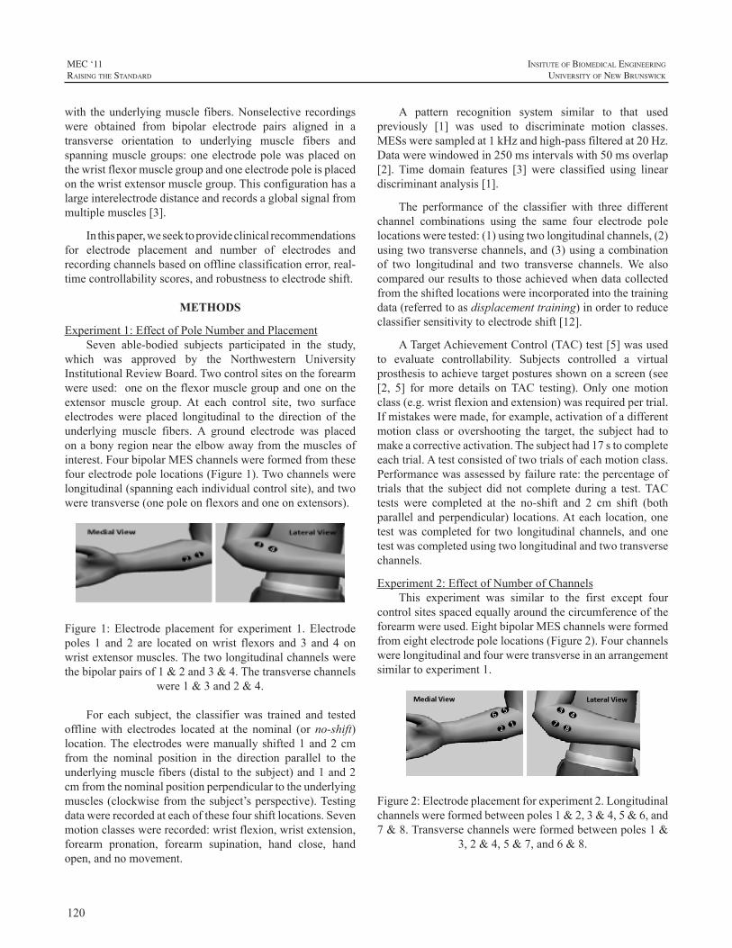
120
MEC ‘11raIsIng the standard
InsItute of BIomedIcal engIneerIng
unIversIty of new BrunswIck
with theunderlyingmuscle fibers.Nonselective recordingswere obtained from bipolar electrode pairs aligned in atransverse orientation to underlying muscle fibers andspanningmusclegroups:oneelectrodepolewasplacedonthewristflexormusclegroupandoneelectrodepoleisplacedonthewristextensormusclegroup.Thisconfigurationhasalargeinterelectrodedistanceandrecordsaglobalsignalfrommultiplemuscles[3].
Inthispaper,weseektoprovideclinicalrecommendationsfor electrode placement and number of electrodes andrecordingchannelsbasedonofflineclassificationerror,real-timecontrollabilityscores,androbustnesstoelectrodeshift.
METHODS
Experiment1:EffectofPoleNumberandPlacementSeven able-bodied subjects participated in the study,
which was approved by the Northwestern UniversityInstitutionalReviewBoard.Twocontrolsitesontheforearmwereused:oneontheflexormusclegroupandoneontheextensor muscle group. At each control site, two surfaceelectrodeswere placed longitudinal to the direction of theunderlying muscle fibers. A ground electrode was placedonabonyregionneartheelbowawayfromthemusclesofinterest.FourbipolarMESchannelswereformedfromthesefourelectrodepolelocations(Figure1).Twochannelswerelongitudinal(spanningeachindividualcontrolsite),andtwoweretransverse(onepoleonflexorsandoneonextensors).
Figure 1: Electrode placement for experiment 1. Electrodepoles 1 and 2 are located onwrist flexors and 3 and 4 onwristextensormuscles.Thetwolongitudinalchannelswerethebipolarpairsof1&2and3&4.Thetransversechannels
were1&3and2&4.
For each subject, the classifier was trained and testedofflinewith electrodes located at the nominal (orno-shift)location.Theelectrodesweremanuallyshifted1and2cmfrom the nominal position in the direction parallel to theunderlyingmusclefibers(distaltothesubject)and1and2cmfromthenominalpositionperpendiculartotheunderlyingmuscles(clockwisefromthesubject’sperspective).Testingdatawererecordedateachofthesefourshiftlocations.Sevenmotionclasseswererecorded:wristflexion,wristextension,forearm pronation, forearm supination, hand close, handopen,andnomovement.
A pattern recognition system similar to that usedpreviously [1] was used to discriminate motion classes.MESsweresampledat1kHzandhigh-passfilteredat20Hz.Datawerewindowedin250msintervalswith50msoverlap[2]. Time domain features [3] were classified using lineardiscriminantanalysis[1].
The performance of the classifier with three differentchannel combinations using the same four electrode polelocationsweretested:(1)usingtwolongitudinalchannels,(2)usingtwotransversechannels,and(3)usingacombinationof two longitudinal and two transverse channels.We alsocomparedourresultstothoseachievedwhendatacollectedfromtheshiftedlocationswereincorporatedintothetrainingdata(referredtoasdisplacementtraining)inordertoreduceclassifiersensitivitytoelectrodeshift[12].
ATargetAchievementControl(TAC)test[5]wasusedto evaluate controllability. Subjects controlled a virtualprosthesistoachievetargetposturesshownonascreen(see[2, 5] formore details onTAC testing). Only onemotionclass(e.g.wristflexionandextension)wasrequiredpertrial.Ifmistakesweremade,forexample,activationofadifferentmotion class or overshooting the target, the subject had tomakeacorrectiveactivation.Thesubjecthad17stocompleteeachtrial.Atestconsistedoftwotrialsofeachmotionclass.Performancewasassessedbyfailurerate:thepercentageoftrials that the subject did not complete during a test.TACtests were completed at the no-shift and 2 cm shift (bothparallelandperpendicular) locations.Ateach location,onetestwas completed for two longitudinal channels, and onetestwascompletedusingtwolongitudinalandtwotransversechannels.
Experiment2:EffectofNumberofChannelsThis experiment was similar to the first except four
controlsitesspacedequallyaroundthecircumferenceoftheforearmwereused.EightbipolarMESchannelswereformedfromeightelectrodepolelocations(Figure2).Fourchannelswerelongitudinalandfourweretransverseinanarrangementsimilartoexperiment1.
Figure2:Electrodeplacementforexperiment2.Longitudinalchannelswereformedbetweenpoles1&2,3&4,5&6,and7&8.Transversechannelswereformedbetweenpoles1&
3,2&4,5&7,and6&8.
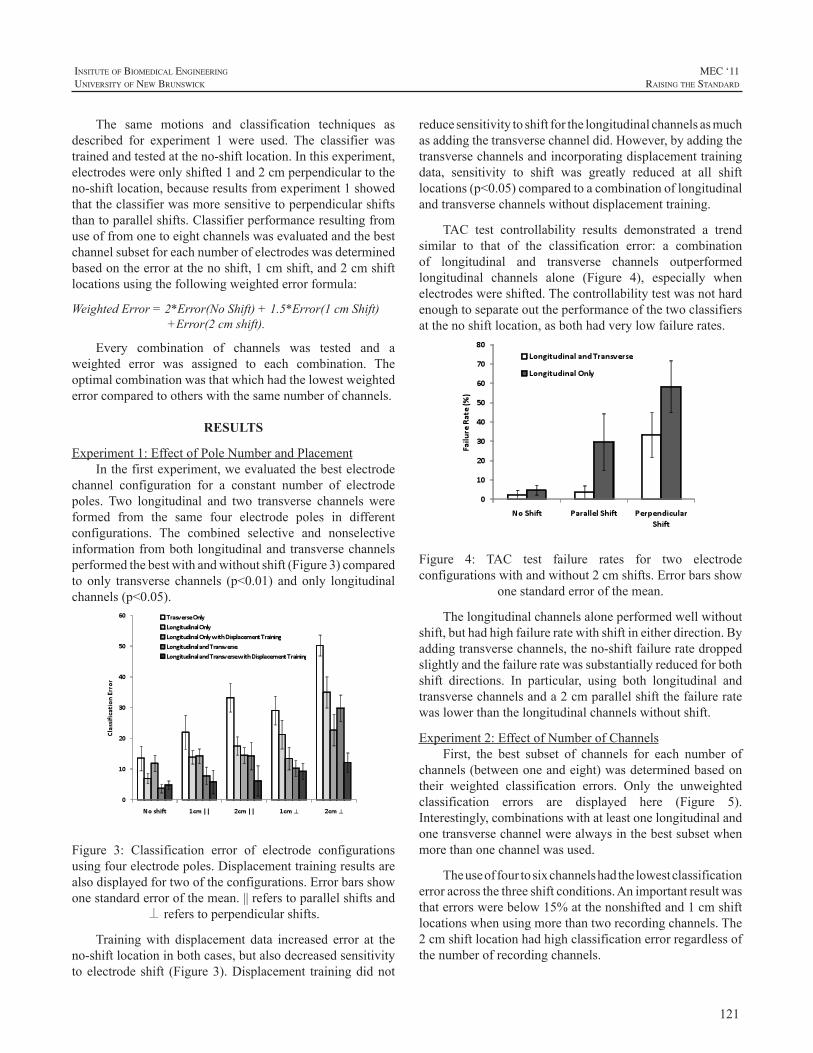
121
InsItute of BIomedIcal engIneerIng
unIversIty of new BrunswIck
MEC ‘11raIsIng the standard
The same motions and classification techniques asdescribed for experiment 1 were used. The classifier wastrainedandtestedattheno-shiftlocation.Inthisexperiment,electrodeswereonlyshifted1and2cmperpendiculartotheno-shiftlocation,becauseresultsfromexperiment1showedthattheclassifierwasmoresensitivetoperpendicularshiftsthantoparallelshifts.Classifierperformanceresultingfromuseoffromonetoeightchannelswasevaluatedandthebestchannelsubsetforeachnumberofelectrodeswasdeterminedbasedontheerroratthenoshift,1cmshift,and2cmshiftlocationsusingthefollowingweightederrorformula:
WeightedError=2*Error(NoShift)+1.5*Error(1cmShift)+Error(2cmshift).
Every combination of channels was tested and aweighted error was assigned to each combination. Theoptimalcombinationwasthatwhichhadthelowestweightederrorcomparedtootherswiththesamenumberofchannels.
RESULTS
Experiment1:EffectofPoleNumberandPlacementInthefirstexperiment,weevaluatedthebestelectrode
channel configuration for a constant number of electrodepoles. Two longitudinal and two transverse channels wereformed from the same four electrode poles in differentconfigurations. The combined selective and nonselectiveinformationfrombothlongitudinalandtransversechannelsperformedthebestwithandwithoutshift(Figure3)comparedto only transverse channels (p<0.01) andonly longitudinalchannels(p<0.05).
Figure 3: Classification error of electrode configurationsusingfourelectrodepoles.Displacementtrainingresultsarealsodisplayedfortwooftheconfigurations.Errorbarsshowonestandarderrorofthemean.||referstoparallelshiftsand
⊥referstoperpendicularshifts.
Trainingwith displacement data increased error at theno-shiftlocationinbothcases,butalsodecreasedsensitivitytoelectrodeshift (Figure3).Displacement trainingdidnot
reducesensitivitytoshiftforthelongitudinalchannelsasmuchasaddingthetransversechanneldid.However,byaddingthetransversechannelsandincorporatingdisplacementtrainingdata, sensitivity to shift was greatly reduced at all shiftlocations(p<0.05)comparedtoacombinationoflongitudinalandtransversechannelswithoutdisplacementtraining.
TAC test controllability results demonstrated a trendsimilar to that of the classification error: a combinationof longitudinal and transverse channels outperformedlongitudinal channels alone (Figure 4), especially whenelectrodeswereshifted.Thecontrollabilitytestwasnothardenoughtoseparateouttheperformanceofthetwoclassifiersatthenoshiftlocation,asbothhadverylowfailurerates.
Figure 4: TAC test failure rates for two electrodeconfigurationswithandwithout2cmshifts.Errorbarsshow
onestandarderrorofthemean.
Thelongitudinalchannelsaloneperformedwellwithoutshift,buthadhighfailureratewithshiftineitherdirection.Byaddingtransversechannels,theno-shiftfailureratedroppedslightlyandthefailureratewassubstantiallyreducedforbothshift directions. In particular, using both longitudinal andtransversechannelsanda2cmparallelshiftthefailureratewaslowerthanthelongitudinalchannelswithoutshift.
Experiment2:EffectofNumberofChannelsFirst, the best subset of channels for each number of
channels(betweenoneandeight)wasdeterminedbasedontheir weighted classification errors. Only the unweightedclassification errors are displayed here (Figure 5).Interestingly,combinationswithatleastonelongitudinalandonetransversechannelwerealwaysinthebestsubsetwhenmorethanonechannelwasused.
Theuseoffourtosixchannelshadthelowestclassificationerroracrossthethreeshiftconditions.Animportantresultwasthaterrorswerebelow15%atthenonshiftedand1cmshiftlocationswhenusingmorethantworecordingchannels.The2cmshiftlocationhadhighclassificationerrorregardlessofthenumberofrecordingchannels.
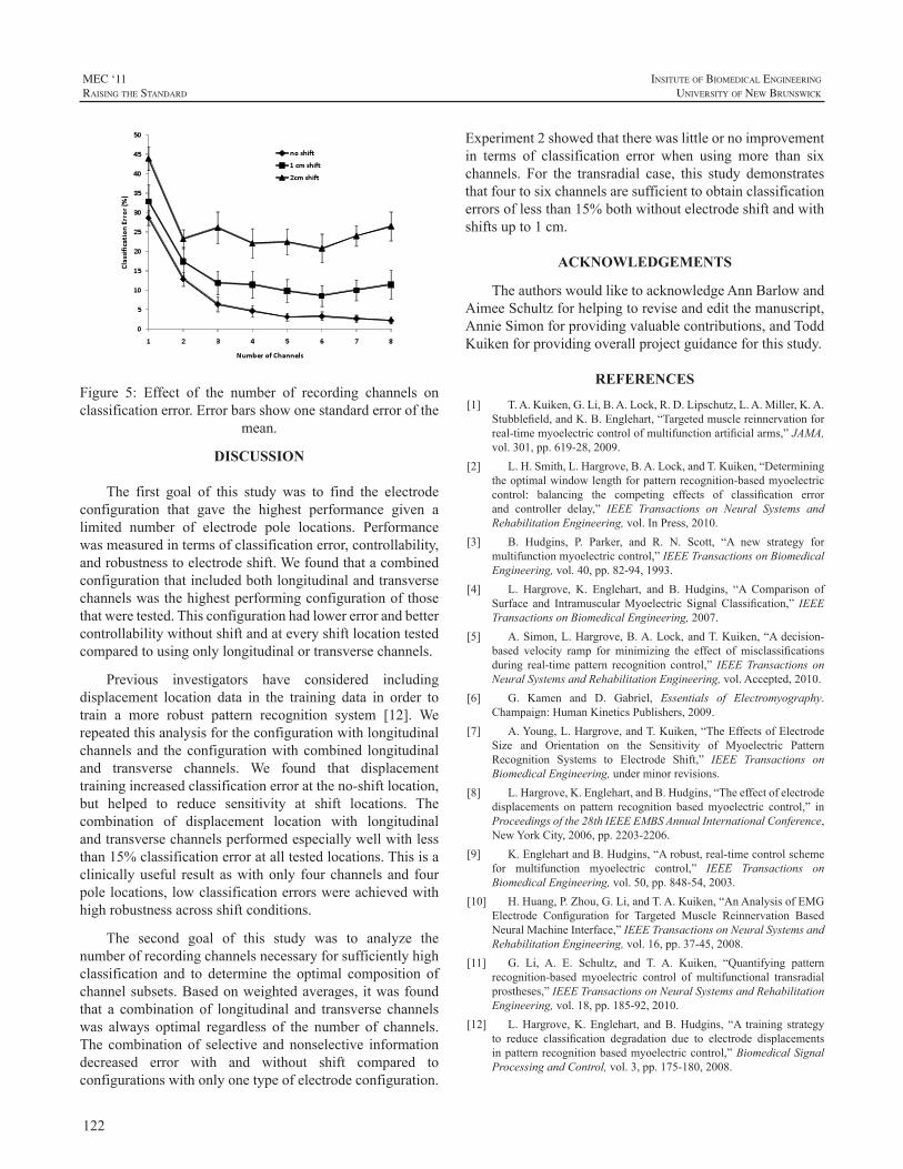
122
MEC ‘11raIsIng the standard
InsItute of BIomedIcal engIneerIng
unIversIty of new BrunswIck
Figure 5: Effect of the number of recording channels onclassificationerror.Errorbarsshowonestandarderrorofthe
mean.
DISCUSSION
The first goal of this study was to find the electrodeconfiguration that gave the highest performance given alimited number of electrode pole locations. Performancewasmeasuredintermsofclassificationerror,controllability,androbustnesstoelectrodeshift.Wefoundthatacombinedconfigurationthatincludedbothlongitudinalandtransversechannelswasthehighestperformingconfigurationofthosethatweretested.Thisconfigurationhadlowererrorandbettercontrollabilitywithoutshiftandateveryshiftlocationtestedcomparedtousingonlylongitudinalortransversechannels.
Previous investigators have considered includingdisplacement location data in the training data in order totrain a more robust pattern recognition system [12]. Werepeatedthisanalysisfortheconfigurationwithlongitudinalchannels and theconfigurationwithcombined longitudinaland transverse channels. We found that displacementtrainingincreasedclassificationerrorattheno-shiftlocation,but helped to reduce sensitivity at shift locations. Thecombination of displacement location with longitudinalandtransversechannelsperformedespeciallywellwithlessthan15%classificationerroratalltestedlocations.Thisisaclinicallyuseful result aswithonly fourchannelsand fourpolelocations,lowclassificationerrorswereachievedwithhighrobustnessacrossshiftconditions.
The second goal of this study was to analyze thenumberofrecordingchannelsnecessaryforsufficientlyhighclassification and to determine the optimal composition ofchannelsubsets.Basedonweightedaverages, itwasfoundthat a combination of longitudinal and transverse channelswas always optimal regardless of the number of channels.The combinationof selective andnonselective informationdecreased error with and without shift compared toconfigurationswithonlyonetypeofelectrodeconfiguration.
Experiment2showedthattherewaslittleornoimprovementin terms of classification error when using more than sixchannels. For the transradial case, this study demonstratesthatfourtosixchannelsaresufficienttoobtainclassificationerrorsoflessthan15%bothwithoutelectrodeshiftandwithshiftsupto1cm.
ACKNOWLEDGEMENTS
TheauthorswouldliketoacknowledgeAnnBarlowandAimeeSchultzforhelpingtoreviseandeditthemanuscript,AnnieSimonforprovidingvaluablecontributions,andToddKuikenforprovidingoverallprojectguidanceforthisstudy.
REFERENCES
[1] T.A.Kuiken,G.Li,B.A.Lock,R.D.Lipschutz,L.A.Miller,K.A.Stubblefield,andK.B.Englehart,“Targetedmusclereinnervationforreal-timemyoelectriccontrolofmultifunctionartificialarms,”JAMA,vol.301,pp.619-28,2009.
[2] L.H.Smith,L.Hargrove,B.A.Lock,andT.Kuiken,“Determiningtheoptimalwindowlengthforpatternrecognition-basedmyoelectriccontrol: balancing the competing effects of classification errorand controller delay,” IEEE Transactions on Neural Systems andRehabilitationEngineering,vol.InPress,2010.
[3] B. Hudgins, P. Parker, and R. N. Scott, “A new strategy formultifunctionmyoelectriccontrol,”IEEETransactionsonBiomedicalEngineering,vol.40,pp.82-94,1993.
[4] L. Hargrove, K. Englehart, and B. Hudgins, “A Comparison ofSurface and IntramuscularMyoelectric Signal Classification,” IEEETransactionsonBiomedicalEngineering,2007.
[5] A.Simon,L.Hargrove,B.A.Lock,andT.Kuiken,“Adecision-based velocity ramp for minimizing the effect of misclassificationsduring real-time pattern recognition control,” IEEETransactions onNeuralSystemsandRehabilitationEngineering,vol.Accepted,2010.
[6] G. Kamen and D. Gabriel, Essentials of Electromyography.Champaign:HumanKineticsPublishers,2009.
[7] A.Young,L.Hargrove,andT.Kuiken,“TheEffectsofElectrodeSize and Orientation on the Sensitivity of Myoelectric PatternRecognition Systems to Electrode Shift,” IEEE Transactions onBiomedicalEngineering,underminorrevisions.
[8] L.Hargrove,K.Englehart,andB.Hudgins,“Theeffectofelectrodedisplacements on pattern recognition basedmyoelectric control,” inProceedingsofthe28thIEEEEMBSAnnualInternationalConference,NewYorkCity,2006,pp.2203-2206.
[9] K.EnglehartandB.Hudgins,“Arobust,real-timecontrolschemefor multifunction myoelectric control,” IEEE Transactions onBiomedicalEngineering,vol.50,pp.848-54,2003.
[10] H.Huang,P.Zhou,G.Li,andT.A.Kuiken,“AnAnalysisofEMGElectrode Configuration for Targeted Muscle Reinnervation BasedNeuralMachineInterface,”IEEETransactionsonNeuralSystemsandRehabilitationEngineering,vol.16,pp.37-45,2008.
[11] G. Li, A. E. Schultz, and T. A. Kuiken, “Quantifying patternrecognition-based myoelectric control of multifunctional transradialprostheses,”IEEETransactionsonNeuralSystemsandRehabilitationEngineering,vol.18,pp.185-92,2010.
[12] L.Hargrove,K.Englehart, andB.Hudgins, “A training strategyto reduce classification degradation due to electrode displacementsinpatternrecognitionbasedmyoelectriccontrol,”BiomedicalSignalProcessingandControl,vol.3,pp.175-180,2008.
123
InsItute of BIomedIcal engIneerIng
unIversIty of new BrunswIck
MEC ‘11raIsIng the standard
ABSTRACT
For more than two decades, individuals with lowerlimb amputations have been successfully fitted with gelliners constructed from a variety of materials. Prosthetistshave also reported moderate success with gel liners fit toindividualswithupperlimbamputationswhouseexternallypoweredprostheses.AttheCenterforBionicMedicine,wehave explored a novel approach to collecting myoelectricsignals from individuals with lower limb or upper limbamputations—using electrodes embedded in gel liners.Initialdesignshaveprovenmorecomfortableandeasier todonthantraditionalsuctionsocketsandhaveallowedustoeliminatetheneedforseparateconnectionofpre-amplifiers.Webelievethistechnologywillbeofbenefittoindividualswith upper or lower limb amputations and eliminate someoftheclinicalchallengesandreporteddrawbacksofcurrentmyoelectricfittings.Thenextstepistocombinethenewlinertechnology with advanced electronics to control actuateddrive units in both upper limb and lower limb prostheses.In this contributionwe describe the evolution of this linertechnologyfrominitialexperiencesthroughcurrentstatustofuturedirections.
INTRODUCTION
SuctionSocketsMany prosthetists have used suction suspension as
the primary or sole means of suspending transhumeral ortransradialprostheses.Traditionalsuctionsockets,wherethelimbisindirectcontactwithanundersizedsocket,havebeenwidely used, particularly in the transhumeral population.Muchofthetheorybehindthedesignofthesesocketscomesfrom experiences fitting individuals with transfemoralamputations. Traditional suction sockets provide all of thebenefits of total contact sockets, including distribution offorces over larger surface areas to decrease concentratedareas of pressure, decreased edema, increased control oftheprosthesis,andenhancedproprioceptionoftheterminalend of the prosthesis [1, 2]. Additional benefits to upperlimb–prosthesisusersmaybeanincreasedabductionrangeof motion (ROM) and better cosmesis, both due to lowerlateraltrimlines.Eliminationoftheharnessisalsopossible
dependinguponwhichinputdevicesareusedandwhetherornotahybridsystemincorporatingbody-poweredcomponentsis used.At aminimum, adding suction to the total contactsocketconcepthasenabledmanyindividualstotoleratetheuse of transhumeral prostheses by decreasing the amountof pressure in the contralateral axilla [3], thus preventingneuropathiesofthecontralateralarmandhand[4].Inacasestudy,Vacek[5]reportedthateliminationoftightharnessingprevented tingling or sensation loss, and concluded thatprosthesiscomfortdirectlyaffectsan individual’s toleranceof,anddesiretocontinuetowear,thedevice.
Quasi-HydrostaticFittingsIf the socket is appropriately undersized, it offers
the ability to achieve a semi- or quasi-hydrostatic socketenvironment. Stokosa [6] coined the phrase Total SurfaceBearing (TSB) for transtibial socket design in which “theentire surface of the residual limb is in total contact with(the) socketwhile every unit area is under compression toits proportionate tolerable level,” andpoints out that thereisadifferencebetweenTSBandhydrostaticconcepts.Kahle[7],comparingtranstibialdesigns,defineshydrostaticdesignbased on themechanical properties of fluids andLong [8]statesthatutilizingthehydrostaticinterfacedesignpromotestissue elongation, increasing distal padding and producinga residual limb with a firmer tissue consistency. This isespecially important for control of the prosthetic socketin levels of amputation where the soft tissue is less moremobile, which occurswhenonlyoneboneispresent in thesoft tissue—for example in transhumeral or transfemoralamputations.Kahle[7]contendsthataproximalsealwiththehumeralepicondylesisessentialforachievingahydrostaticfitwhenutilizing roll-ongel liner technology in transtibialsockets. Miguelez [9] asserts that a secondary benefit ofhydrostaticfit—thelackofmovementoftransradialsocketsduring loading—can be attributed tomuscle contouring asopposedtosofttissuecompressionalone.Iftrue,theselattertwostatementssuggestthatlinersmustbedesignedsoasto(i)createasealattheproximalsocket(gleno-humeraljointorhumeralepicondylesfortranshumeralortransradiallimbs,respectively)and(ii)capturemoremusclecontours.
A NOVEL RESEARCH AND CLINICAL APPROACH TO USING GEL LINERS FOR COLLECTION OF SURFACE MYOELECTRIC SIGNALS FOR PROSTHETIC CONTROL
RobertD.Lipschutz,1,2,BlairA.Lock,1
1CenterforBionicMedicine,RehabilitationInstituteofChicago,345EastSuperiorStreet,Chicago,IL606112NorthwesternUniversityProsthetics-OrthoticsCenter,680NorthLakeShoreDrive,Chicago,IL,60611
124
MEC ‘11raIsIng the standard
InsItute of BIomedIcal engIneerIng
unIversIty of new BrunswIck
Themethodusedtodonthesocketwillaffecttheabilityto achieve a hydrostatic fit. In traditional suction sockets,hydrostaticfithasbeenachievedwiththeuseofadonningaid. This donning method is challenging for individualswith unilateral and bilateral amputations as they need tobalance their prosthesis while simultaneously donning thedevice.Additionally, the inner socket is customarilymadeof a semi-rigid or rigid thermoplastic, whichmay becomeuncomfortableastheuserattemptstoattaintheendrangesofshouldermotion (i.e.glenohumeral flexionandabduction).Thisisduetotheweightofthedevicecreatingaforcecouplethatplacesanintolerablepressureonthedistalaspectofthehumerus.
Thefirstfourindividualswithtranshumeralamputationswhounderwent targetedmuscle reinnervation (TMR)werefit with traditional suction sockets and cited the donningmethodasoneofthemajordeterrentstowearingthedevice:anadditionaldifficultyforTMRsubjectsisthenecessityofprecisely orienting their limbwith respect to the electrodecontacts within the prosthesis in order to achieve optimalalignmentformyoelectriccontrol.
GelLinersEarlydesignsofgellinerswerecustom-fabricatedover
amodifiedpositivemodel.OssurKristinssonfirstdevelopedthistechnology,whichevolvedintoviableoff-the-shelfliners.Amajorityofresiduallimbscanbefitwellwithappropriatelysizedoff-the-shelf liners, althoughcustom-fabricated linersare still utilized for limbs requiring special attention.Mostgellinersarefittoindividualswithlowerlimbamputationsforreasonsofcomfort,suspension,andbecausetheincreasedshearforcebetweenthelimbandliner(anddecreasedshearbetweenthelinerandsocket)protectsskinontheresiduallimbfromfrictioncausedbyrelativemovementoflimbandsocketinterface.Anadditionalbenefitistheoptionofapplyingsub-atmosphericpressuretothelimb-socketinterface.Somegel-linermanufacturersusetermssuchasTSBandhydrostaticintheirproductinformation,however,thesevariedfittinggoalsare achieved in many different ways and, although someare based on published specifications, are quite generic intheirproductapplications.Attentionshouldbepaidtousingthese liners as hydrostatic fittings as this requires a distaldistractionoftheresiduallimb,whichcreateselongationandareductionincross-sectionalarea.Onemethodofemployingthischangeinsofttissuegeometryiswiththeuseofalanyardaddedtotheendofthelinertopullthelimbintothesocket.Another technique,moreeasily implementedinlowerlimbprostheses, is using a linerwith an addeddistal pin:whilethe pin is engaged in the locking mechanism, repetitiveloading (weight bearing) and unloading will elongate andcircumferentially reduce the limb in size and the pin willfurtherengageintothelockingmechanism.
Althoughroll-ongellinershavebeenhistoricallyusedinlowerlimbfittings,therehasbeensomeprevioususeofthistechnologywith upper limb prostheses. Radocy [10], whohasatransradialamputation,presentedsomeoftheearliestinformation on, and evaluation of efficacy of, roll-on gellinerswithupperlimbprostheses.Earlyinthedevelopmentofsiliconesuctionsocket(3S)technology,itwasreportedthatthis fit prevents pistoning of the prosthesis and reduces oreliminatesperspirationbecausethereisnoairlayerbetweentheskinandthesocketwall[10].Radocy[10]reportedthatthecombinationofasupracondylarsocketandsiliconelinerprovidedsuperiorsuspension,improvedperformanceduringrigorousactivities,andreducedoreliminatedresiduallimb–to–socket rotation.The reduction in pistoning and rotationis beneficial for both suspension andmaintenance of skinintegrity;however,lackofperspirationmaydecreasesurfacemyoelectricsignals.
Daly[11]andSalam[12]utilizedroll-ongellinersforboth transhumeral and transradial fittings using differenttechniquesformyoelectricsignaldetection.
In each study, when using roll-on gel liners intranshumeralortransradialsockets,individualswereabletoachieve increasedROM.Inaddition, lower trimlineswerepossible. For transradial subjects, Daly [11] reported anaverageincreaseinROMof22.33ºandanincreaseofpullforce(beforelosingsuspension)of30lbf.Daly[11]reportedanaverageROMfrom8.57ºto120ºandapullforceof37lbf(withtwoofthetrialsexceeding50lbf)forhistranshumeralsubjects.Sincenocomparisonsweremadebetweenhighertrim lines and roll-ongel liners, it isdifficult todeterminewhether the lower trim lines or the gel liners caused theincreaseinROM.Miguelez[9]mightarguethatneitheristhedeterminingfactor,duetothefactthathistransradialsocketdesignhasneitherlowertrimlinesthanconventionalfittingsnordoesitnecessarilyutilizegelliners,yethereportsgreaterrangeROM.
Salam[12]cutholesingellinerstoallowskintoprotrudeand make contact with the electrodes, and Bill Hansen(LiberatingTechnologies,Inc.)hasproposedusinggellinerswith conductive patches. Both approaches have similardrawbacks: the hole/patch locationmust be exactly placedand cannot be moved. However, both have the potentialbenefit that allwires are self-contained.Daly provided forthetransmissionofmyoelectricsignalsthroughthegellinersvia snap electrodes—amethodwe commonly employ in aresearchsetting.Thistechniquepermitstheindividualtodonthe liner (withcontacts incorporated)and thensnapawireharness to the electrodesbefore inserting the liner into thesocket.Onemajordrawbackwiththisapproachistheneedtoprotectthewireharness.BothDalyandSalamclaimthatusersareable todon the liner so that theelectrodesconsistently
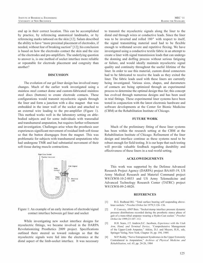
125
InsItute of BIomedIcal engIneerIng
unIversIty of new BrunswIck
MEC ‘11raIsIng the standard
endup in their correct location.This can be accomplishedby practice, by referencing anatomical landmarks, or byreferencingmarkstattooedontheskin[12].Salamdescribedtheabilitytohave“moreproximalplacementofelectrodes,ifneeded,withoutfearofbreakingsuction”[12];hisconclusionisbasedonhowtheelectrodescontacttheskinandthesizeoftheelectrodesandpre-amplifiers.Theunderlyingquestiontoansweris,isonemethodofsocketinterfacemorereliableor repeatable for electrode placement and congruity thananother?
DISCUSSION
Theevolutionofourgellinerdesignhasinvolvedmanychanges. Much of the earlier work investigated using astainlesssteelcontactdomeandcustom-fabricatedstainlesssteel discs (buttons) to create electrode contacts. Theseconfigurations would transmit myoelectric signals throughthe linerand forma junctionwithadiscmagnet thatwasembedded in the inner wall of the socket and attached toan external wire leading to the pre-amplifier (Figure 1).Thismethodworkswell in the laboratory setting on able-bodied subjects and for some individuals with transradialandtranshumeralamputation,butrequiresfurtherrefinementandinvestigation.Challengesarisewhentheprosthesisuserexperiencessignificantmovementofresiduallimbsofttissueso that the button disengages from the magnet. This wasproblematicforsubjectswithtranshumeralamputationswhohadundergoneTMRandhadsubstantialmovementoftheirsofttissueduringmusclecontractions.
Figure1:Anexampleofanearlyiterationofelectrode/signalcontactinterfacebetweengellinerandsocket
While investigating new socket interface designs formyoelectric fittings, we became involved in the DARPARevolutionizing Prosthetics 2009 project. Specificationsoutlined there steered us toward redesign so that themyoelectric signals were fed into the electronics at thedistalaspectof thelimb-socket interface. Itwasnecessary
to transmit the myoelectric signals along the liner to thedistalendthroughwiresorconductiveleads.Sincethelinerwas to be inverted and rolled 180° with respect to itself,the signal transmitting material used had to be flexibleenoughtowithstandsevereandrepetitiveflexing.Wehaveinvestigatedusingaconductivetextilefabricinanattempttocreatealinerwithsignaltransmissionleadsthatcanundergothe donning and doffing process without serious fatiguingor failure, and would ideally maintain myoelectric signalqualityandcontinuity throughout theuseful lifetimeof theliner.Inordertousethismaterial,customdistalconnectorshad tobe fabricated to receive the leadsas theyexited theliner. The fabric leads usedwith these liners are currentlybeing investigated. Various sizes, shapes, and durometersof contacts are being optimized through an experimentalprocesstodeterminetheoptimaldesignthusfar;thisconcepthas evolved through numerous designs and has been usedintrialfittings.Theseexperimentallinersystemshavebeentestedinconjunctionwiththelatestelectronichardwareandsoftware developments at the Center for Bionic Medicine(CBM)attheRehabilitationInstituteofChicago.
FUTURE WORK
Much of the preliminary fitting of these liner systemshas been within the research setting at the CBM at theRehabilitationInstituteofChicago.Refinementof thelinerdesign and interface continue as these systems need to berobustenoughforfieldtesting.Itisourhopethatsuchtestingwill provide valuable feedback regarding durability andeffectivenessoftheselinersinareal-worldsetting.
ACKLOWEDGEMENTS
This work was supported by the Defense AdvancedResearchProjectAgency(DARPA)projectBAA05-19,USArmy Medical Research and Materiel Command projectW81XWH-10-2-0033 and US Army Telemedicine andAdvanced Technology Research Center (TATRC) projectW81XWH-09-2-0020.
REFERENCES
[1] R.G.RedheadRG.“Totalsurfacebearingselfsuspendingabove-kneesockets.”ProsthetOrthotInt1979;3:126–136.
[2] P.Convery,AWPBuis.“Socket/stumpinterfacepressuredynamicpressuredistributions recordedduring theprosthetic stancephaseofgaitofatrans-tibialamputeewearingaHydro-Castsocket.”ProsthetOrthotInt1999;23:107–112.
[3] H.H.Sears,J.T.Andrew,S.C.Jacobsen,ExperiencewiththeUtahArm, Hand, and Terminal Device, “Comprehensive Managementof the Upper-LimbAmputee,”Atkins, D.J. andMeyers, R.H., eds,SpringerVerlag,NewYork,Chapter18,pp.194,1989.
[4] M.P.Reddy,“NerveEntrapmentSyndromesintheUpperExtremityContralateral to Amputation,” Archives of Physical Medicine andRehabilitation,vol.65,pp.24-26,1984
126
MEC ‘11raIsIng the standard
InsItute of BIomedIcal engIneerIng
unIversIty of new BrunswIck
[5] K.M.Vacek,“TransitiontoaSwitch-Activated,3-S,TranshumeralProsthesis:ATeamApproach,”JournalofProstheticsandOrthotics,vol.10(3),pp.56-60,1998.
[6] J.Stokosa,O&PListServeresponse,01/13/06[7] J. Kahle, “Conventional and Hydrostatic Transtibial Interface
Comparison”,JournalofProstheticsandOrthotics,vol.11(4),pp.85-91,1999.
[8] I.A.Long, “Normal Shape Normal Alignment (NSNA), AboveKneeProsthesis,”ClinicalProsthetics&Orthotics,19859(4):9-14
[9] J.M.Miguelez,C.Lake,D.Conyers,andJ.Zenie,“TheTransradialAnatomically Contoured (TRAC) Interface: Design Principles andMethodology”,JournalofProstheticsandOrthotics,2003,15(4),p.148
[10] R.Radocy,andW.D.Beiswinger, “TechnicalForum—AHigh-Performance, Variable Suspension, Transradial (Below-Elbow)Prosthesis”,JournalofProstheticsandOrthotics,vol.7(2),pp.65–67,1995.
[11] W. Daly, “Clinical Applications of Roll-on Sleeves forMyoelectricallyControlledTransradialandTranshumeralProstheses,”JournalofProstheticsandOrthotics,vol.12(3),pp.88–91,2000.
[12] Y. Salam, “Technical Forum—The Use of Silicone SuspensionSleeves with Myoelectric Fittings,” Journal of Prosthetics andOrthotics,vol.6(4),pp.119–120,1994.

127
InsItute of BIomedIcal engIneerIng
unIversIty of new BrunswIck
MEC ‘11raIsIng the standard
ABSTRACT
Controllingmultipledegreesoffreedomintuitivelyandefficientlyisamajorgoalinthefieldofupperlimbprosthetics.Manynovelalgorithmshavebeenconceivedtomeetthisgoal,butfewhavebeentestedinafunctionallyrelevantmanner.Wehave developed a virtual realitymyoelectric prosthesissimulator for testing novel control algorithms and devices.The system acquires EMG commands and residual limbkinematics,simulatestheprosthesisdynamics,anddisplaysthecombinedresiduallimbandvirtualprosthesismovementsin a virtual reality environment that includes force-basedinteractionswith virtual objects. Both a transhumeral andtransradialsimulatorhavebeendeveloped. Thetransradialsimulatorincludesadexteroushandandhapticfeedbacktotheresiduallimb.Thevirtualrealityprosthesissimulatorisapromisingtoolforevaluatingcontrolmethods,prototypingnovelprostheses,andtrainingamputees.Duetoitsrelativelyinexpensiveandportablecomponents(excludingthehapticdevice), the simulator can be used in the lab, clinic, or athome.
INTRODUCTION
Researchers have sought to improve control ofmyoelectric prostheses for several decades. Amajor goalis to achieve simultaneous, or at least seamless, controlof several degrees of freedom. Many promising controlalgorithms have been developed using pattern recognitiontechniques. However, few of these algorithms have beentested in a closed-loopmanner, and even fewer have beentested in a functionally relevant way. Virtual reality hasbeensuggestedasamethodtoquicklydevelopandevaluatecontrolstrategies,prototypedevices,andtrainsubjects.[1-3]
Previous myoelectric prosthesis simulators haveincluded costly or complicated components making themimpractical for widespread use in clinical settings [1,2].Also, only recently have advances in computer hardwareanddevelopmentofreal-timephysicssimulationsoftware—driven by widespread use in commercial video games—made real-time simulation ofmany physical interactions apossibility.
Werecentlydevelopedatranshumeralsimulator[3]anddemonstratedastandardclinicalassessmentwithinthevirtualreality environment, using a force-based physics engine.We have now developed a dextrous hand for transradialsimulations and added the capability for haptic (i.e. force/touch)feedbacktosimulatecollisionsandinertialaffectsoftheprosthesis.
METHODS
The simulator user, with or without upper limb loss,viewsananimationofhisorherresiduallimbmovementandthesimulatedprosthesismovementinavirtualenvironment.Thesystemincludesseveralcomponents:kinematictracking,EMG or command acquisition, data analysis and control,physics simulation, visualization, and haptic feedback.ThesecomponentsareillustratedinFigure1anddescribedindetailbelow.
1.KinematicTrackingKinematictrackingoftheresiduallimbcanbeachievedin
multipleways.Foraportablesystem,oneormoreorientationsensors(e.g.,3DM-GX1,MicroStrainInc.,Williston,VT)areusedtoaccuratelymeasuretheorientationoflimbsegmentsby fusing signals from triaxial accelerometers, gyroscopes,andmagnetometers.SincethesensoralwaysoutputsheadingrelativetomagneticNorth,thesubjectshouldkeephisorherbodyorientedinthesamedirectionduringtrials.Sincethesubjectshouldalwaysfacethecomputermonitor,hisorherdirection with respect to North can be calibrated quicklyusingthesamesensor.Ifmotionsoftwolimbsegments(e.g.upper and fore arm) need to be recorded, two sensors arerequired.Otherwiseonesensorissufficient.
In a lab setting, the HapticMaster[4] (Moog FCS,Netherlands) can be used to record the 3D position andthe3Dorientationoftheresiduallimbsegmentviaa3-dofinstrumented gimbal. Since the position returned by theHapticMasteristheproximalattachmentpointofthegimbal,some simple forward kinematic calculations based on thesegmentlengthsofthegimbalarerequiredtogetthepositionoftheendoftheresiduallimbsegment.
VIRTUAL REALITY SIMULATOR FOR TRAINING AND EVALUATING MYOELECTRIC USERS
JorisM.Lambrecht,ChrisL.Pulliam,andRobertF.Kirsch
DepartmentofBiomedicalEngineering,CaseWesternReserveUniversityWickendenBuilding311,2071MartinLutherKingJr.Drive,ClevelandOH44106,USA
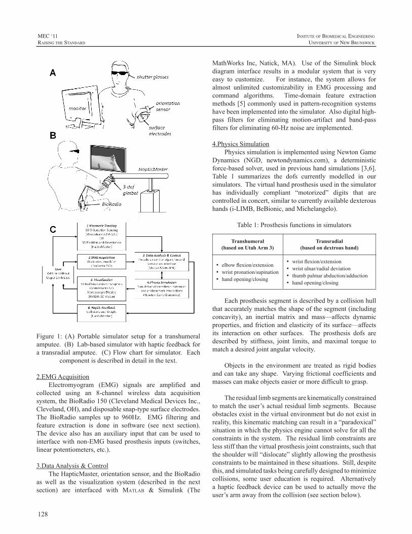
128
MEC ‘11raIsIng the standard
InsItute of BIomedIcal engIneerIng
unIversIty of new BrunswIck
Figure 1: (A) Portable simulator setup for a transhumeralamputee.(B)Lab-basedsimulatorwithhapticfeedbackfora transradialamputee. (C)Flowchart forsimulator. Each
componentisdescribedindetailinthetext.
2.EMGAcquisitionElectromyogram (EMG) signals are amplified and
collected using an 8-channel wireless data acquisitionsystem,theBioRadio150(ClevelandMedicalDevicesInc.,Cleveland,OH),anddisposablesnap-typesurfaceelectrodes.The BioRadio samples up to 960Hz. EMG filtering andfeature extraction is done in software (see next section).The device also has an auxiliary input that can be used tointerfacewithnon-EMGbasedprosthesis inputs (switches,linearpotentiometers,etc.).
3.DataAnalysis&ControlTheHapticMaster,orientationsensor,andtheBioRadio
as well as the visualization system (described in the nextsection) are interfaced with Matlab & Simulink (The
MathWorks Inc,Natick,MA). Use of the Simulink blockdiagram interface results in amodular system that is veryeasy to customize. For instance, the system allows foralmost unlimited customizability in EMG processing andcommand algorithms. Time-domain feature extractionmethods[5]commonlyusedinpattern-recognitionsystemshavebeenimplementedintothesimulator.Alsodigitalhigh-pass filters for eliminating motion-artifact and band-passfiltersforeliminating60-Hznoiseareimplemented.
4.PhysicsSimulationPhysicssimulationisimplementedusingNewtonGame
Dynamics (NGD, newtondynamics.com), a deterministicforce-basedsolver,usedinprevioushandsimulations[3,6].Table 1 summarizes the dofs currently modelled in oursimulators.Thevirtualhandprosthesisusedinthesimulatorhas individually compliant “motorized” digits that arecontrolledinconcert,similartocurrentlyavailabledexteroushands(i-LIMB,BeBionic,andMichelangelo).
Table1:Prosthesisfunctionsinsimulators
Transhumeral(based on Utah Arm 3)
Transradial(based on dextrous hand)
• elbowflexion/extension• wristpronation/supination• handopening/closing
• wristflexion/extension• wristulnar/radialdeviation• thumbpalmarabduction/adduction• handopening/closing
Eachprosthesissegmentisdescribedbyacollisionhullthataccuratelymatchestheshapeofthesegment(includingconcavity), an inertial matrix and mass—affects dynamicproperties,andfrictionandelasticityofitssurface—affectsits interaction on other surfaces. The prosthesis dofs aredescribed by stiffness, joint limits, andmaximal torque tomatchadesiredjointangularvelocity.
Objects in the environment are treated as rigid bodiesandcantakeanyshape.Varyingfrictionalcoefficientsandmassescanmakeobjectseasierormoredifficulttograsp.
Theresiduallimbsegmentsarekinematicallyconstrainedtomatchtheuser’sactualresiduallimbsegments.Becauseobstaclesexistinthevirtualenvironmentbutdonotexistinreality,thiskinematicmatchingcanresultina“paradoxical”situationinwhichthephysicsenginecannotsolveforalltheconstraintsinthesystem.Theresiduallimbconstraintsarelessstiffthanthevirtualprosthesisjointconstraints,suchthattheshoulderwill“dislocate”slightlyallowingtheprosthesisconstraintstobemaintainedinthesesituations.Still,despitethis,andsimulatedtasksbeingcarefullydesignedtominimizecollisions, some user education is required. Alternativelyahaptic feedbackdevicecanbeused toactuallymove theuser’sarmawayfromthecollision(seesectionbelow).
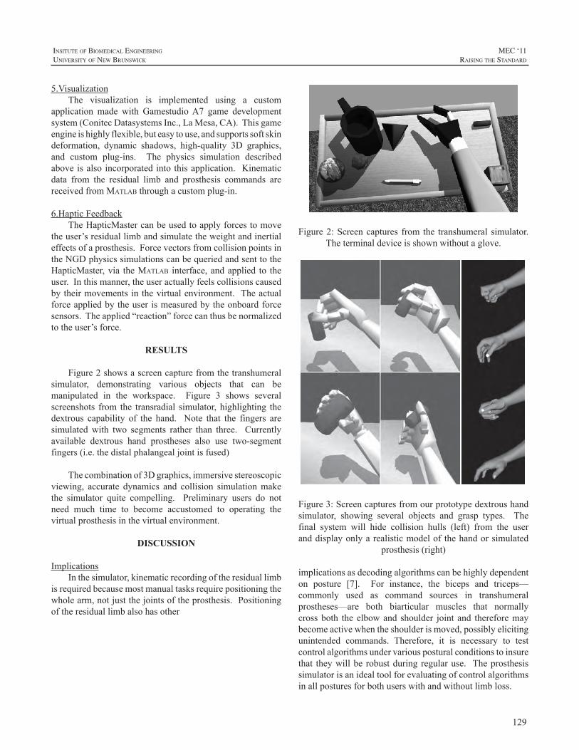
129
InsItute of BIomedIcal engIneerIng
unIversIty of new BrunswIck
MEC ‘11raIsIng the standard
5.VisualizationThe visualization is implemented using a custom
application made with GamestudioA7 game developmentsystem(ConitecDatasystemsInc.,LaMesa,CA).Thisgameengineishighlyflexible,buteasytouse,andsupportssoftskindeformation, dynamic shadows, high-quality 3D graphics,and custom plug-ins. The physics simulation describedaboveisalsoincorporatedintothisapplication. Kinematicdata from the residual limb and prosthesis commands arereceivedfromMatlabthroughacustomplug-in.
6.HapticFeedbackTheHapticMastercanbeusedtoapplyforcestomove
theuser’sresiduallimbandsimulatetheweightandinertialeffectsofaprosthesis.ForcevectorsfromcollisionpointsintheNGDphysicssimulationscanbequeriedandsenttotheHapticMaster,via theMatlab interface,andapplied to theuser.Inthismanner,theuseractuallyfeelscollisionscausedbytheirmovementsinthevirtualenvironment. Theactualforceappliedbytheuserismeasuredbytheonboardforcesensors.Theapplied“reaction”forcecanthusbenormalizedtotheuser’sforce.
RESULTS
Figure2showsascreencapturefromthetranshumeralsimulator, demonstrating various objects that can bemanipulated in the workspace. Figure 3 shows severalscreenshots from the transradial simulator, highlighting thedextrous capability of the hand. Note that the fingers aresimulatedwith two segments rather than three. Currentlyavailable dextrous hand prostheses also use two-segmentfingers(i.e.thedistalphalangealjointisfused)
Thecombinationof3Dgraphics,immersivestereoscopicviewing, accurate dynamics and collision simulationmakethe simulator quite compelling. Preliminary users do notneed much time to become accustomed to operating thevirtualprosthesisinthevirtualenvironment.
DISCUSSION
ImplicationsInthesimulator,kinematicrecordingoftheresiduallimb
isrequiredbecausemostmanualtasksrequirepositioningthewholearm,notjustthejointsoftheprosthesis.Positioningoftheresiduallimbalsohasother
Figure2:Screencaptures from the transhumeral simulator.Theterminaldeviceisshownwithoutaglove.
Figure3:Screencapturesfromourprototypedextroushandsimulator, showing several objects and grasp types. Thefinal system will hide collision hulls (left) from the useranddisplayonlyarealisticmodelofthehandorsimulated
prosthesis(right)
implicationsasdecodingalgorithmscanbehighlydependenton posture [7]. For instance, the biceps and triceps—commonly used as command sources in transhumeralprostheses—are both biarticular muscles that normallycrossboth theelbowand shoulder joint and thereforemaybecomeactivewhentheshoulderismoved,possiblyelicitingunintended commands. Therefore, it is necessary to testcontrolalgorithmsundervariousposturalconditionstoinsurethat theywillbe robustduringregularuse. Theprosthesissimulatorisanidealtoolforevaluatingofcontrolalgorithmsinallposturesforbothuserswithandwithoutlimbloss.
130
MEC ‘11raIsIng the standard
InsItute of BIomedIcal engIneerIng
unIversIty of new BrunswIck
The simulator can also be used to test novel devicesbefore they aremanufactured. For, instanceour simulateddextrous hand includes active flexion/extension and ulnar/radial deviation,which is not available in any commercialprosthesis system. Furthermore, maximum speeds,friction,massescanallbeadjustedtotesttheirinfluenceonperformance. The simulator is a cost effectivemethod fortryingnewdeviceconcepts.
Finally, the simulator can be used for myoelectrictrainingandevaluation. Wehavepreviouslydemonstrateda“BoxandBlockTest”[8]withthetranshumeralsimulator.Inthestudytwocommandmethodswereevaluated.Usinga more traditional command method, normally-limbedsubjectsmoved,onaverage, thesamenumberofblocksasrealamputeesperformingthesame,butnon-virtualtask[3].
LimitationsandFutureWorkThe HapticMaster can only apply forces from one
locationandcannotgeneratetorquesonthegimbals. Thusthe resulting movement of the real and virtual arm maynotmatchupona collision. However, thehaptic feedbackwas still found useful for avoiding paradoxical situationsdescribedabove.
Orientation sensors are dependent on a constant“recordedNorth”directionintheworkspace.Largeferrousobjects (e.g., filing cabinets, lab equipment) can affect thelocalmagneticfieldquitedrastically,resultingininaccurateorientationmeasurements.Caremustbetakenwhensettingupthesimulator to insure that theseobjectsarefarenoughaway.
Wehavedemonstratedtheabilitytograbandmanipulatevariedrigidbodiesinthevirtualenvironment,anddevelopeda virtual Box andBlockTest. Futurework could includedevelopingadditionalclinicaltestsofhand/armdexterityandfunction.
CONCLUSION
Wehavedevelopedvirtualrealitysimulatorsfortrainingand evaluatingmyoelectric users in a functionally relevantmanner. Virtual prosthesis dynamics and interactionswithobjects in the environment are simulated using a real-timephysicsengine. Thesimulatorallows forcustomizationofthe prosthesis properties, EMGprocessing techniques, andthecommandandcontrolmethods.Hapticfeedbackisusefulformorerealisticallysimulatingthetask.However,withouthapticfeedback,thesimulatorisportable,easytosetup,andrelativelyinexpensive,allowingforwidespreadclinicaluse.
ACKNOWLEDGEMENTS
FundingsupportfromTATRCW81XWH-07-2-0044.
REFERENCES
[1] M. Hauschild, R. Davoodi, and G. Loeb. “A virtual realityenvironmentfordesigningandfittingneuralprostheticlimbs.”IEEETNSRE,vol.15,pp.9-15,2007.
[2] G. Jimenez, O. Ryuhei, K. Akazaea. “Upper limb-hand 3Ddisplaysystem for biomimetic myoelectric hand simulator,” In:Proceedings of the 23rd Annual EMBS International Conference,Istanbul,Turkey,October25–28,2001.
[3] J. Lambrecht, C. Pulliam, and R. Kirsch. “Virtual realityenvironment for simulating tasks with a myoelectric prosthesis: anassessmentandtrainingtool,”JPO,vol.23,pp.89-94,2011.
[4] R. Van der Linde, P. Lammertse, E. Frederiksen and B. Ruiter.“The HapticMaster, a new high-performance haptic interface,” in:ProceedingsofEurohaptics,Edinburgh,UK,July,2002
[5] B. Hudgins, P. Parker, and R. Scott. “A New Strategy forMultifunctionMyoelectricControl,”IEEETBME,vol.40,pp.82-94,1993.
[6] G.Massera,A.Cangelosi,andS.Nolfi.“Evolutionofprehensionabilityinananthropomorphicneuroroboticarm,”FrontNeurorobotics,vol.1,pp.1–9,2007
[7] S.Micera,J.Carpaneto,S.Raspopovic.“Controlofhandprosthesesusingperipheralinformation,”IEEERBMEvol.3,pp.48-68,2011.
[8] V.Mathiowetz, G.Volland, N. Kashman, andK.Weber. “AdultnormsfortheBoxandBlockTestofmanualdexterity”.AmJOccupTher,vol.39,pp.386-391,1985.

131
InsItute of BIomedIcal engIneerIng
unIversIty of new BrunswIck
MEC ‘11raIsIng the standard
Thursday, 17 August 2011
8:30 am KEYNOTE - Jonathan Wolpaw
Presentation of Papers
Time Paper Title Presenter
9:30 amForequarter Amputee and Mirror Therapy; A Case Report on Adapting the Mirror Box Design
Vera G. van Heijningen
9:45 am Long Term Results of Early Myoelectric Fittings Liselotte Norling Hermansson
10:00 am REFRESHMENT BREAK / EXHIBITOR SHOWCASE
10:30 amContinuous and Simultaneous EMG-Based Neural Network Control of Transradial Prostheses
Christopher Pulliam
10:45 amSensor Options and Control Strategies for Multi-articulating Hand and Partial-hand-prostheses
Stefan Schulz
11:00 am
Unique Situations in Prosthetic Design when Applying Targeted Muscle Reinnervation in Transhumeral and Shoulder Disarticulation Levels of Limb Loss
Pat Prigge
11:15 amMethods for Collecting EMG from Individuals with Lower Limb Amputations
Robert Lipschutz
11:30 amReal-Time Recognition of User Intent for Neural Control of Artificial Legs
Fan Zhang
11:45 amMyoelectric Control of a Powered Transfemoral Prosthesis during Non-weight Bearing Activities
Levi Hargrove
12:00 pm LUNCH BREAK
1:00 pmMotor Control Processes when Learning to use a Prosthetic Device
Raoul Bongers
1:30 pmThe Effect of Visual Biofeedback Forms of Myoelectric Signal on Syoelectric Signal Separation Training
Kengo Ohnishi
Wu Conference Centre Auditorium

132
MEC ‘11raIsIng the standard
InsItute of BIomedIcal engIneerIng
unIversIty of new BrunswIck
Thursday, 17 August 2011
Time Paper Title Presenter
1:45 pmTraining Individuals to use Pattern Recognition to Control an Upper Limb Prosthesis
Kathy Stubblefield
2:00 pmFunctioning of Children with Unilateral Congenital Below Elbow Deficiency: An Online Gocus Group Study
Corry K. van der Sluis
2:15 pmUpper Limb Prosthetics Services Post Haiti Earthquake
Colleen O’Connell
2:30 pmDesigning for Affordability, Application and Performance: The International Trans-radial Adjustable Limb (ITAL) Prosthesis
Alwyn Johnson
2:45 pmOccupational Therapy for a Multiple Limb Loss Military Patient, a Case Study
Joseph Butkus
3:00 pm REFRESHMENT BREAK / POSTER EXHIBITION
3:30 pmUsing Multiple Outcome Measures to Determine Skill Level in Myoelectric Prosthesis Use
Hanneke Bouwsema
3:45 pmOutcome Measure Results of a Pattern Recognition Control of Multi-function Hand Wrist System: A Case Study
Laura Miller
4:00 pmA Preliminary Study of Learning to Use a Trans-radial Upper Limb Myoelectric Prosthesis
Mohammad Sobuh
4:15 pmMotion Analysis to Measure Outcomes following Targeted Muscle Reinnervation Surgery
Jacqueline S. Hebert
4:30 pmUsing Motion Analysis to Augment Upper-limb Prosthetics Outcome Measures
Craig Heckathorne
4:45 pmUse of a Dynamic Load Strap in Adjustable Anatomical Suspension in Transradial Amputee
Sam L. Phillips
5:00 pmComprehensive Arm Prosthesis and Rehabilitation Outcomes Questionnaire (CAPROQ)
Shawn Swanson Johnson
Presentation of Papers (Continued)
133
InsItute of BIomedIcal engIneerIng
unIversIty of new BrunswIck
MEC ‘11raIsIng the standard
ABSTRACT
BCIs have a promising future, with researchers inlaboratories all over the world using many different brainsignals,recordingmethods,andsignalprocessingapproachestorealizeincreasinglycapablesystems.TheseBCIsystemscancontrol avarietyof externaldevices, fromcursors andavatarsoncomputerscreens,totelevisionsandwheelchairs,toroboticarmsandneuroprostheses.Peoplewithandwithoutdisabilitieshavetestedthesesystems,andafewarealreadyusingthemforimportantpurposesintheirdailylives.Thus,BCIsarepoisedtobecomeamajornewtechnologyforpeoplewith disabilities, and possibly for the general populationas well. Nevertheless, the realization of this bright futuredependsonadvances in fourcriticalareas.First,bothnon-invasive and invasive BCIs need better signal-acquisitionhardware. Second, the real-life usefulness of BCI systemsfor people with disabilities requires convincing clinicalvalidation.Third,effectivestrategiesforBCIdisseminationand ongoing support must be developed. Fourth, andperhaps most important, if non-invasive or invasive BCIsaretobewidelyusedforanythingmorethanthemostbasiccommunication functions, their reliability must be greatlyimproved. The difficult problem of reliabilitymay requireBCIdesignstrategiesbasedontheprinciplesunderlyingtheexcellentreliabilityofnaturalneuromuscularactions.Thesestrategies include: effective engagement of brain adaptivecapacities; task-appropriate distribution of control betweenthebrainandtheBCI;andBCIuseofsignalsfrommultiplebrainareas.
REPRESENTATIVE REFERENCES
[1] J.R.Wolpaw, “Brain-Computer Interface.” In: Squire, L.R. (ed.)EncyclopaediaofNeuroscience,Vol2,pp429-437,Oxford:AcademicPress,2009.
[2] D.J. McFarland, W.A. Sarnacki, and J.R.Wolpaw,“Electroencephalographic (EEG) control of three-dimensionalmovement.”JournalofNeuralEngineering,11;7(3):036007,2010.
[3] D.J. McFarland, and J.R. Wolpaw, “Brain-computer interfacesfor the operation of robotic and prosthetic devices.” Advances inComputers,79:169-187,2010.
[4] J.R.Wolpaw, “Brain-computer interface research comes of age:traditional assumptions meet emerging realities.” Journal of MotorBehaviour,42:351-353,2010.
KEYNOTE:
THE FUTURE OF BRAIN-COMPUTER INTERFACES: MEETING THE EXPECTATIONS
JonathanR.Wolpaw
WadsworthCenter,Albany,NewYork
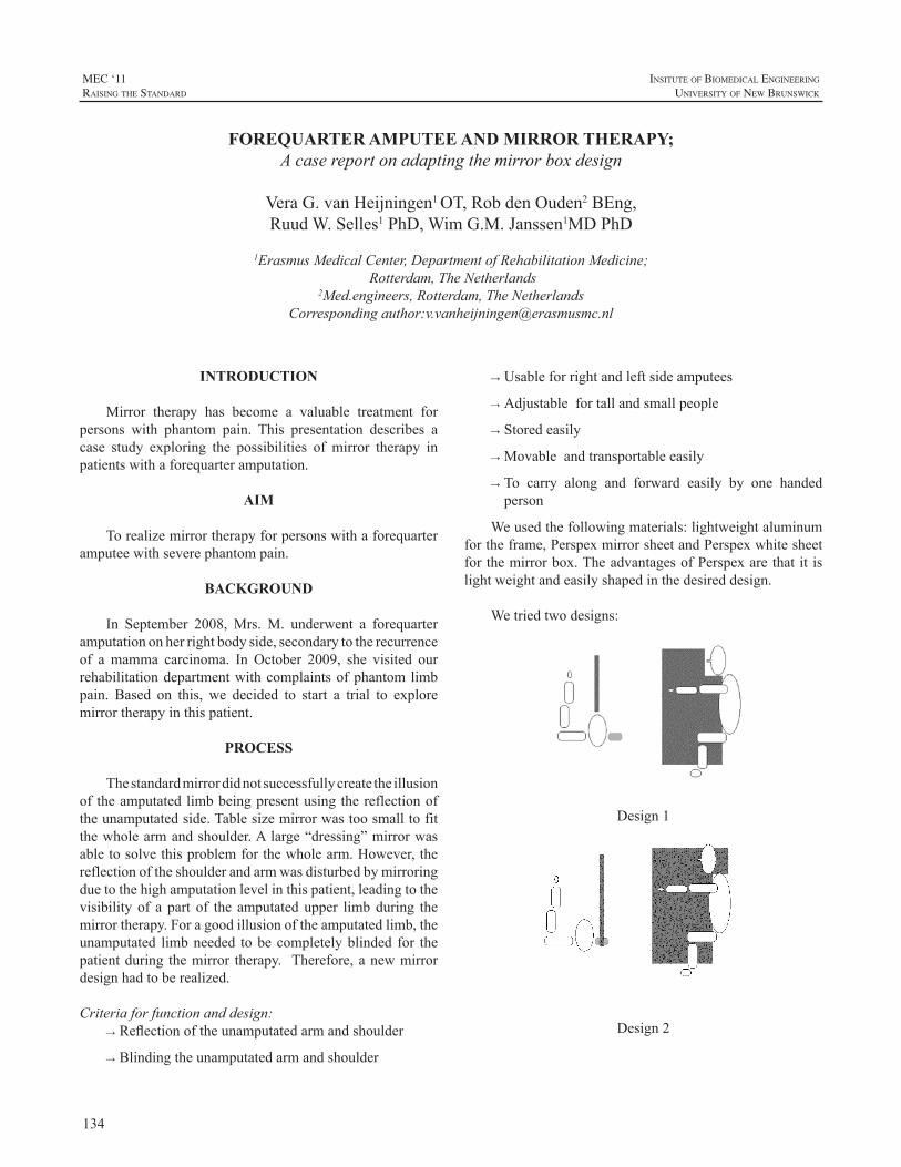
134
MEC ‘11raIsIng the standard
InsItute of BIomedIcal engIneerIng
unIversIty of new BrunswIck
INTRODUCTION
Mirror therapy has become a valuable treatment forpersons with phantom pain. This presentation describes acase study exploring the possibilities of mirror therapy inpatientswithaforequarteramputation.
AIM
Torealizemirrortherapyforpersonswithaforequarteramputeewithseverephantompain.
BACKGROUND
In September 2008, Mrs. M. underwent a forequarteramputationonherrightbodyside,secondarytotherecurrenceof a mamma carcinoma. In October 2009, she visited ourrehabilitationdepartmentwithcomplaintsofphantomlimbpain. Based on this, we decided to start a trial to exploremirrortherapyinthispatient.
PROCESS
Thestandardmirrordidnotsuccessfullycreatetheillusionof theamputatedlimbbeingpresentusingthereflectionoftheunamputatedside.Tablesizemirrorwastoosmalltofitthewholearmandshoulder.Alarge“dressing”mirrorwasabletosolvethisproblemforthewholearm.However,thereflectionoftheshoulderandarmwasdisturbedbymirroringduetothehighamputationlevelinthispatient,leadingtothevisibility of a part of the amputatedupper limbduring themirrortherapy.Foragoodillusionoftheamputatedlimb,theunamputated limbneeded tobecompletelyblinded for thepatientduring themirror therapy. Therefore,anewmirrordesignhadtoberealized.
Criteriaforfunctionanddesign:→Reflectionoftheunamputatedarmandshoulder
→Blindingtheunamputatedarmandshoulder
→Usableforrightandleftsideamputees
→Adjustablefortallandsmallpeople
→Storedeasily
→Movableandtransportableeasily
→To carry along and forward easily by one handedperson
Weusedthefollowingmaterials:lightweightaluminumfortheframe,PerspexmirrorsheetandPerspexwhitesheetforthemirrorbox.TheadvantagesofPerspexarethatit islightweightandeasilyshapedinthedesireddesign.
Wetriedtwodesigns:
Design1
Design2
FOREQUARTER AMPUTEE AND MIRROR THERAPY;Acasereportonadaptingthemirrorboxdesign
VeraG.vanHeijningen1OT,RobdenOuden2BEng,RuudW.Selles1PhD,WimG.M.Janssen1MDPhD
1ErasmusMedicalCenter,DepartmentofRehabilitationMedicine;Rotterdam,TheNetherlands
2Med.engineers,Rotterdam,TheNetherlandsCorrespondingauthor:[email protected]
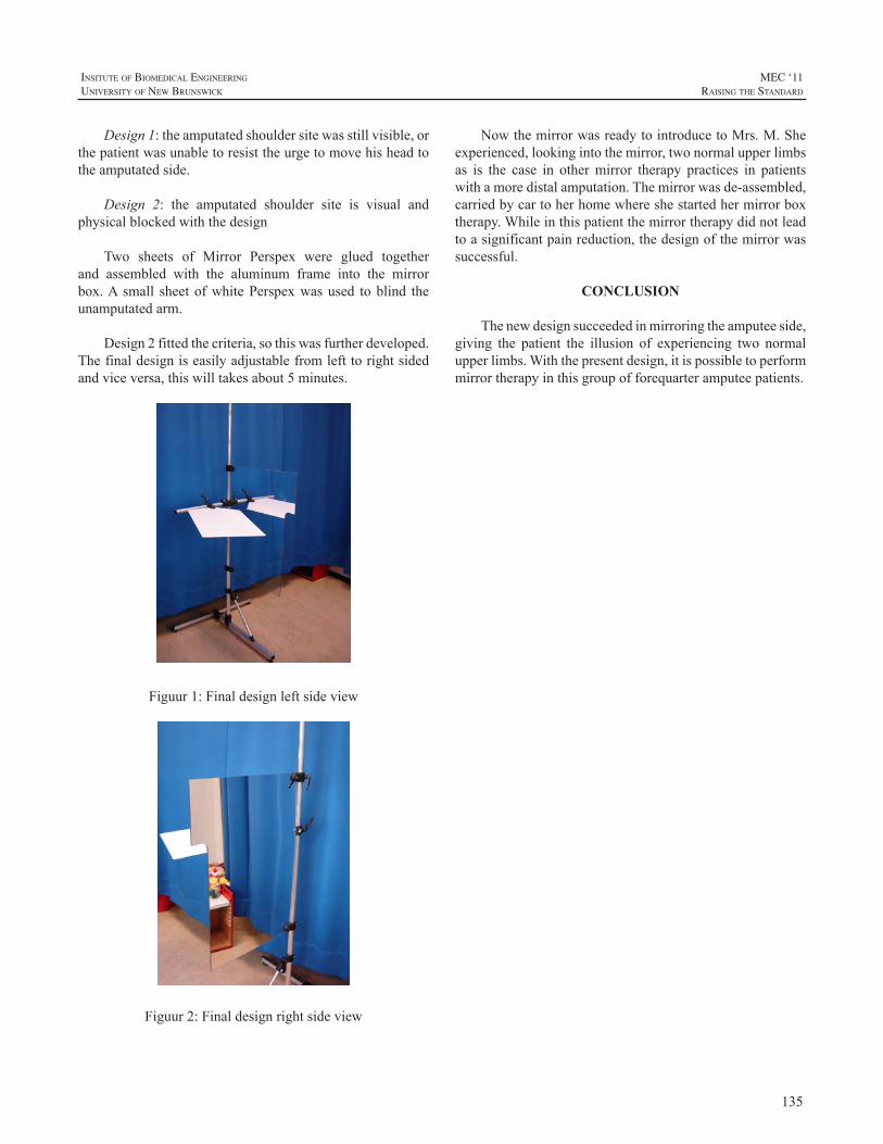
135
InsItute of BIomedIcal engIneerIng
unIversIty of new BrunswIck
MEC ‘11raIsIng the standard
Design1:theamputatedshouldersitewasstillvisible,orthepatientwasunabletoresisttheurgetomovehisheadtotheamputatedside.
Design 2: the amputated shoulder site is visual andphysicalblockedwiththedesign
Two sheets of Mirror Perspex were glued togetherand assembled with the aluminum frame into the mirrorbox.A small sheetofwhitePerspexwasused toblind theunamputatedarm.
Design2fittedthecriteria,sothiswasfurtherdeveloped.Thefinaldesigniseasilyadjustablefromlefttorightsidedandviceversa,thiswilltakesabout5minutes.
Figuur1:Finaldesignleftsideview
Figuur2:Finaldesignrightsideview
NowthemirrorwasreadytointroducetoMrs.M.Sheexperienced,lookingintothemirror,twonormalupperlimbsas is the case in othermirror therapy practices in patientswithamoredistalamputation.Themirrorwasde-assembled,carriedbycartoherhomewhereshestartedhermirrorboxtherapy.Whileinthispatientthemirrortherapydidnotleadtoasignificantpainreduction,thedesignofthemirrorwassuccessful.
CONCLUSION
Thenewdesignsucceededinmirroringtheamputeeside,giving the patient the illusion of experiencing two normalupperlimbs.Withthepresentdesign,itispossibletoperformmirrortherapyinthisgroupofforequarteramputeepatients.
136
MEC ‘11raIsIng the standard
InsItute of BIomedIcal engIneerIng
unIversIty of new BrunswIck
INTRODUCTION
Thereisanongoingdebateconcerningtheoptimalagefor first-time fitting of myoelectric prostheses to children.Sörbyeadvocates2½-4yearsofageasthebesttime[1] whereascentersinNorthAmericarecommendfittingasearlyas10-15monthsofage[2].Therationalefortheearlyfittingsisthatthesechildrenwillbemoreabletousethehand.But,atwhatagecanchildrenlearntooperateamyoelectrichand?Whichageformyoelectricfittingisthebestconsideringtheoutcomeinbothshort-andlongtime?
Theaimsof this studywere to compare the age for i)voluntary operation of amyoelectric hand, ii) unrestrictedoperationofamyoelectrichand,and,iii)tocomparetheuseofprosthesesatdifferentagesinchildrenfittedbefore2andafter2½yearsofage.
Table1:Sampledemographicsandage(inmonths)atfittingoffirstmyoelectricprosthetichand
Gender Laterality Prostheses side
Level of deficiency*
First myo
Case1/Control1 Girl/Boy Bilateral Right/Right BElower/
CAtot 18/36
Case2/Control2 Boy/Boy Bilateral Right/Right CApart/
CAtot 17/37
Case3/Control3 Boy/Boy Unilateral Right/Right BEmid/
BEmid 13/37
Case4/Control4 Girl/Girl Unilateral Right/Right BEupper/
BEupper 17/36
Case5/Control5 Girl/Girl Unilateral Right/Right BEmid/
BEmid 8/41
Case6/Control6 Boy/Boy Unilateral Left/Left BEupper/
BEupper 15/38
Case7/Control7 Boy/Boy Unilateral Left/Left BEupper/
BEupper 19/33
Case8/Control8 Girl/Girl Unilateral Left/Left BEmid/
BEmid 11/32
Case9/Control9 Boy/Boy Unilateral Left/Left BEmid/
BEmid 21/36
*BE=below the elbow; upper=upper third; mid=middlethird;lower=lowerthird;CA=carpal;part=partialabsenceof
carpals;tot=totalabsenceofcarpalbones
METHODS
A prospective longitudinal case-control design waschosen for the study. The data-collection started in June1995andendedwhenthelastchildin thestudygrouphadreachedtheageof12(March2011).Beforeinitiationofthestudy,informedconsentwasobtainedfromtheparents,and,becauseofthepossibleincreaseincostsrelatedtotheearlyfittinginthestudygroup,fromtheirhealthcareprovider.Forthecontrolgroup, informedconsentwasobtainedfromtheparents.
Nine childrenwere selected for early fittings andninechildren were matched to the study-group with regards togender, side and level of deficiency (Table 1). CaseswerebornbetweenJanuary1994andMarch1999.Inclusioncriteriawere:
· transversalreductiondeficiencybelowtheelbow
· livingin,orinthevicinityofthefittingcentre
· youngerthan2yearsattimeoffitting
· passiveprosthesesat6monthsofage
· familystructurestabileandparentsusedtoprosthetics
InstrumentationMain outcome variable was the Skills Index Ranking
Scale (SIRS), an observational based method used tocategorizeapersonsabilitytooperateamyoelectrichand[3].Thescalerangesfrom1 to14whereeachstepdescribesanincreasing ability to operate the hand (Figure 1). Based onthe observations of the child during play or performance ofotherdailytasks,theoccupationaltherapistdecidesatwhichlevel the child performs.Thevalidity of theSIRShas beentestedandtheorderofthestepsconfirmedbyRasch-analysis(unpublisheddata1997).
LONG TERM RESULTS OF EARLY MYOELECTRIC FITTINGS
LiselotteNorlingHermansson1,2andLisSjöberg1
1LimbDeficiencyandArmProsthesesCentre,ÖrebroUniversityHospital,Sweden2CentreforRehabilitationResearch,Box1613,Sweden
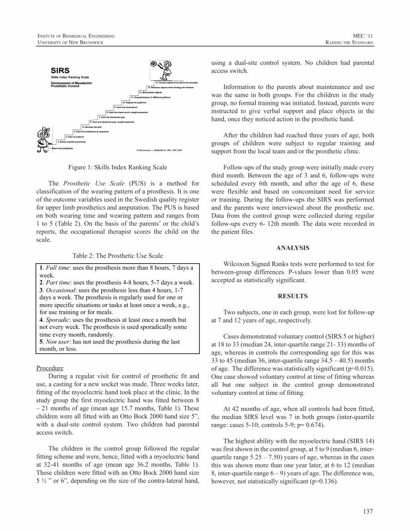
137
InsItute of BIomedIcal engIneerIng
unIversIty of new BrunswIck
MEC ‘11raIsIng the standard
Figure1:SkillsIndexRankingScale
The Prosthetic Use Scale (PUS) is a method forclassificationofthewearingpatternofaprosthesis.ItisoneoftheoutcomevariablesusedintheSwedishqualityregisterforupperlimbprostheticsandamputation.ThePUSisbasedonbothwearingtimeandwearingpatternandrangesfrom1 to5(Table2).On thebasisof theparents’or thechild’sreports, the occupational therapist scores the child on thescale.
Table2:TheProstheticUseScale
1. Full time: uses the prosthesis more than 8 hours, 7 days a week. 2. Part time: uses the prosthesis 4-8 hours, 5-7 days a week. 3. Occasional: uses the prosthesis less than 4 hours, 1-7 days a week. The prosthesis is regularly used for one or more specific situations or tasks at least once a week, e.g., for use training or for meals. 4. Sporadic: uses the prosthesis at least once a month but not every week. The prosthesis is used sporadically some time every month, randomly. 5. Non user: has not used the prosthesis during the last month, or less.
ProcedureDuring a regular visit for control of prosthetic fit and
use,acastingforanewsocketwasmade.Threeweekslater,fittingofthemyoelectrichandtookplaceattheclinic.Inthestudygroup the firstmyoelectrichandwas fittedbetween8–21monthsofage(meanage15.7months,Table1).ThesechildrenwereallfittedwithanOttoBock2000handsize5”,with a dual-site control system. Two children had parentalaccessswitch.
The children in the control group followed the regularfittingschemeandwere,hence,fittedwithamyoelectrichandat 32-41 months of age (mean age 36.2 months, Table 1).ThesechildrenwerefittedwithanOttoBock2000handsize5½”or6”,dependingonthesizeofthecontra-lateralhand,
using a dual-site control system. No children had parentalaccessswitch.
Information to the parents aboutmaintenance and usewas thesame inbothgroups.For thechildren in thestudygroup,noformaltrainingwasinitiated.Instead,parentswereinstructed to give verbal support and place objects in thehand,oncetheynoticedactionintheprosthetichand.
Afterthechildrenhadreachedthreeyearsofage,bothgroups of children were subject to regular training andsupportfromthelocalteamand/ortheprostheticclinic.
Follow-upsofthestudygroupwereinitiallymadeeverythirdmonth.Between the ageof3 and6, follow-upswerescheduled every 6th month, and after the age of 6, thesewere flexible and based on concomitant need for serviceortraining.Duringthefollow-upstheSIRSwasperformedand the parentswere interviewed about the prosthetic use.Data from the control groupwere collected during regularfollow-upsevery6-12thmonth.Thedatawererecordedinthepatientfiles.
ANALYSIS
WilcoxonSignedRankstestswereperformedtotestforbetween-group differences. P-values lower than 0.05 wereacceptedasstatisticallysignificant.
RESULTS
Twosubjects,oneineachgroup,werelostforfollow-upat7and12yearsofage,respectively.
Casesdemonstratedvoluntarycontrol(SIRS5orhigher)at18to33(median24,inter-quartilerange21-33)monthsofage,whereasincontrolsthecorrespondingageforthiswas33to45(median36,inter-quartilerange34.5–40.5)monthsofage.Thedifferencewasstatisticallysignificant(p=0.015).Onecaseshowedvoluntarycontrolattimeoffittingwhereasall but one subject in the control group demonstratedvoluntarycontrolattimeoffitting.
At42monthsofage,whenallcontrolshadbeenfitted,themedianSIRS levelwas7 inbothgroups (inter-quartilerange:cases5-10;controls5-9;p=0.674).
Thehighestabilitywiththemyoelectrichand(SIRS14)wasfirstshowninthecontrolgroup,at5to9(median6,inter-quartilerange5.25–7.50)yearsofage,whereasinthecasesthiswasshownmorethanoneyearlater,at6to12(median8,inter-quartilerange6–9)yearsofage.Thedifferencewas,however,notstatisticallysignificant(p=0.136).
138
MEC ‘11raIsIng the standard
InsItute of BIomedIcal engIneerIng
unIversIty of new BrunswIck
Theuseofprosthesesvariedovertheyearsandbetweenthe groups. However, although the median value wassomewhat different, there were no statistically significantdifferencesbetweenthegroups(Table3).
Table 3: Prosthetic use at different ages (median; inter-quartilerange)
Age(years)
Cases(n=8-9)
Prostheticuse*
Controls(n=8-9)
Prostheticuse*p
3½ 1.00;1.00-1.50 1.00;1.00-1.00 0.157
6 1.00;1.00-2.50 1.00;1.00-3.00 0.579
9 2.50;1.00-3.75 1.00;1.00-2.00 0.146
12 2.00;1.00-4.75 1.00;1.00-3.50 0.450
*1=Full time; 2=Part time; 3=Occasional; 4=Sporadic;5=Nonuser
DISCUSSION
Theresultsfromthisstudyshowthatchildrencanlearntooperateamyoelectricprosthetichandasearlyas24to36monthsofage.Earlierfittingsresultinearlierabilitytoreachthefirstlevelofcontrol,butchildrenfittedattheaverageageof36monthsdofasterprogressionthantheearlierfittings,resultinginacatchingupat42monthsofage.Thiscatchingupispartlyexplainedbythefactthatallbutoneofthechildrenfittedbetween32-41monthsofagewereimmediatelyabletooperatethehand!Thisstronglysupportsfittingsataround3yearsofage.
One interesting finding in this studywas that the agerangefordevelopmentofabilitytooperatethemyoelectrichand varied between the two groups of children. Whenlooking at the inter-quartile range, the difference is sixmonthsforvoluntarycontroland9monthsforunrestrictedcontrol.Inbothcases,theearlyfittingshavethelargerspanfor reaching the developmental stages. There are severalplausible explanations for this.Clinically,wehave noticedthat children who are fitted before they have passed the“terrible two’s”, theagewhenmostchildrendemonstrateastrongintegrityandwill,oftenusetheattentionfortheirarmandprosthesestodemonstratetheirwill.Hence,theydonotwant towear the prostheses and do not attempt to operatethehandinordertouseitforanypurpose.Thismayresultinadelay inability tooperateanduse theprosthetichandand could be one reason for the large variation in age fordevelopmentofcontrol.Otherfactorsthatprobablyhaveanimpactondevelopmentofcontrolarefamilyclimateandtheparents’influenceontraining,routinesineverydaylifeetc,andalsothechild’spersonalityandlearningpattern.
Afactorthatmayinfluencethedevelopmentofcontrolis wearing time/pattern. High wearing time is expected toindicatehighoperationalskill.Fromourexperience,besidestheparents’influence,wearingtimeisdependingonserviceandsupport.Hence,technicalproblemswiththeprosthesesmayhaveanegativeimpactonthedevelopment.Inthisstudywefoundnostatisticalsignificantdifferenceinwearingtimebetweenthegroups.Therewas,however,agreatertendencytowards decreasing use of prostheses in the study group.Further studies with larger samples are needed to confirmthis.
Themajordifferencebetweenthetwogroupsofchildrenwas,besidestheage,thetraining.Inourcentretrainingforchildrenwithamyoelectricprosthetichandisbasedonthenormaldevelopmentofchildren.Oncetheyreachtheageof3,mostchildrenarereadytocooperateandplaywithothers.Thisformsagoodbasisfor the training.Thechildrenwhowere fitted early did not receive any formal training untilthey reached the same age as in regular fittings. Despitethat,althoughwitha largeagespanwithin thegroup, theymanagedtolearntooperatethehandearlierthanthechildrenwith regular fittings.However,when lookingat the resultsfromwhenthechildrenreachedthehighestabilitytooperatethehandaccordingtoSIRS,thereisatendencytowardsthattheearlyfittingsreachthislaterthantheregularfittings.Thisindicatesthatthemajorimpactoftrainingisthatithelpsthechilddevelophigherskillswiththeprosthesisanduseitfordaily activities.To understand the significance of training,studiesonthistopicisrecommended.
Thereareseveralnegativeaspectstoconsiderwithearlymyoelectricfittings.Oneistheextraloadthatthisputsontheparentsatausuallyweredemandingtime.Earlymyoelectricprostheticfittingleadstoanincreaseofvisitstothehealthcareprovider.Furthermore,bytheearlyfitting,muchattentionisgiventothedevelopmentofcontrolinsteadoftothechild.Thequestionis,iftheresultingabilitytovoluntarilyoperatethehandisworthit?Dochildrenwhohavebeenfittedearlyhavebetteruseoftheirhandthanthosewhohavebeenfittedatasomewhatolderage?
Themajorlimitationofthisstudyisthesamplesize.Thenumberofcasesislimitedand,thus,requiresalongperiodfordata-collection.Byincreasingthenumberofcontrols,thestudywillgainpower.
CONCLUSION
In conclusion, the best age for fitting of myoelectricprosthetic hands in children is around 3 years, withfurther consideration taken to the individual psychosocialdevelopment.Studiesoverthebenefitfromearlyfittingsindailylifeareneeded.
139
InsItute of BIomedIcal engIneerIng
unIversIty of new BrunswIck
MEC ‘11raIsIng the standard
ACKNOWLEDGEMENTS
We are indebted to the families who participated inthis study.We also thankKristinaWaldenlöv, reg.OT andMalin Jansson, reg. OT, both at the Limb Deficiency andArmProsthesesCentre,ÖrebroUniversityHospital,Örebro,Sweden,forcontributingtothedata-collection.
REFERENCES
[1]. R. Sörbye, L. Hermansson “Which is the best age for thefirst application of myoelectrically controlled hand prostheses incongenitally amputated children.” In: Myoelectric Prostheses forInfants. Scott RN. Fredericton: Institute of Biomedical Engineering1992,pp47-50.
[2]. S. Hubbard, “HughMacmillan Rehabilitation Centre Pre-SchoolMyoelectricExperience.”In:MyoelectricProsthesesforInfants.ScottRN.Fredericton.:InstituteofBiomedicalEngineering.1992,pp21-30.
[3]. LM. Hermansson “Structured training of children fitted withmyoelectricprostheses.”ProsthetOrthotInt1991;15:88-92.
140
MEC ‘11raIsIng the standard
InsItute of BIomedIcal engIneerIng
unIversIty of new BrunswIck
ABSTRACT
As the development of dexterous prosthetic hand andwristunitscontinues,thereisaneedforcommandinterfacesthatwillenableausertooperatethesemulti-jointdevicesinanatural,coordinatedmanner.Inthisstudy,myoelectricsignalsand hand kinematics were recorded as three able-bodiedsubjectsperformedavarietyofindividuatedmovementsandsimulated functional tasks. Time-delayed artificial neuralnetworks (TDANNs) were designed to simultaneouslydecodethemovementtrajectoriesforsevendistaldegreesoffreedom(pronation-supination,wristulnar-radialdeviation,wrist flexion-extension, thumb rotation, thumb abduction-adduction, finger MCP flexion-extension, and fingerPIP flexion-extension). Performance was quantified bycalculatingthevarianceaccountedfor(VAF)andnormalizedroot-mean-square error (NRMSE) between the decodedandactualmovements.Accuratepredictionswereachieved(VAF:0.57-0.80,NRMSE:0.04-0.11),suggestingthatitmaybepossibletoprovideanintuitiveEMG-basedschemethatprovidescontinuousandsimultaneousmulti-jointcontrolforindividualswithbelow-elbowamputations.
INTRODUCTION
While upper extremity amputations can cause agreat deal of functional impairment, electrically-poweredprostheseshaveproventobeeffectivetoolsforperformingmanydailytasks.Whiletherehasbeenagreatdealofrecentdevelopmentinthemechanicaldesignofprostheticarms[1],ahighlyarticulatedlimbisoflittleuseifitsmovementsarenotwellcoordinated.
AnumberofdifferentapproacheshavebeentakentomapEMGsignalstothedesiredmovements.Discretemovementtypesareoftenidentifiedusingpatternrecognitionapproachessuchaslineardiscriminantanalysis,fuzzylogic,andartificialneural networks. Rather than classifying discrete states,the continuous prediction of trajectories has the potentialadvantageofenablingcoordinatedandsimultaneouscontrolof multiple joints. Reddy and Gupta [2] showed a directrelationshipbetweensurfaceEMGsignalsand jointanglesduring isolated single finger movements. This principle
has also been used [3,4] to predict continuous movementtrajectoriesfor individualfingerandwrist joints. Thegoalof the current studywas to further investigatemethods fordecoding of continuous finger and wrist movements fromelectromyographic (EMG) activity of muscles located inthe forearm using time-delayed artificial neural networksanddevelop amethod to reduce thenoise present in thesedecodedmovements.
METHODS
SubjectInformation3 male able-bodied subjects between the ages of 25
and 27 took part in these experiments. No subjects had aknownhistoryofanyneuromusculardisorders.AllsubjectsgaveinformedconsenttotheproceduresasapprovedbytheMetroHealthMedicalCenterInstitutionalReviewBoard.
EXPERIMENTAL PROTOCOL
AnOptotrakCertusMotionCaptureSystem(NorthernDigitalInc.,Waterloo,Ontario)wasusedtorecordthethree-dimensionalmotionsofthearm.Additionally,aCyberGloveII (CyberGlove Systems LLC, San Jose, CA)was used tomeasure the kinematics of the hand,wrist, and fingers viaresistivebend-sensors.SurfaceEMGsignalswererecordedfromanarrayofeightequallyspacedelectrodesaroundthecircumferenceoftheforearm.Asin[5],themarkingsfortheelectrodearraywerepositionedat40%ofthedistancefromthemedialepicondyleofthehumerustothestyloidprocessoftheulna.
Trials were collected while the subjects performed avarietyofmovements.Isolatedmovementsinvolvedmovingasingledegreeoffreedomatatime(e.g.flexingandextendingthe wrist or the metacarpophalangeal joint of the indexfinger). Whilemotion of an individual digit is frequentlyaccompanied by mechanically-coupled movements ofadjacentfingers,subjectswereinstructedtonotopposethesemovements.Coupledmovementsinvolvedmovingmultiplejoints inconcert, suchas flexingandextending the fingerstogether or forming palmar, lateral, and power grasps. Ina separate set of tasks, the subjectswere presentedwith a
CONTINUOUS AND SIMULTANEOUS EMG-BASED NEURAL NETWORK CONTROL OF TRANSRADIAL PROSTHESES
ChristopherL.Pulliam,JorisM.Lambrecht,andRobertF.Kirsch
DepartmentofBiomedicalEngineering,CaseWesternReserveUniversityWickendenBuilding311,2071MartinLutherKingJr.Drive,ClevelandOH44106,USA
141
InsItute of BIomedIcal engIneerIng
unIversIty of new BrunswIck
MEC ‘11raIsIng the standard
numberofobjectsofvaryinggeometry arranged randomlyona lapheight table. Subjectswere instructed toconformtheir hand to the objects without exerting much graspforce. During all trials, kinematic and EMG data weresimultaneouslyrecorded.
DataProcessingThedigitizedEMGdatasetswerethenprocessedoffline
byfiltering,windowing,andextractingsignalfeatures.Thedatawerefirsthighpassfilteredtoremovemovementartifacts.Severalfeatureswerethenextractedfrom128msrectangularwindowsofthesesignalswith50%overlapbetweenadjacentsegments.ThetimedomainstatisticsdescribedbyHudgins,Parker, andScott [6] wereused, generating a four-elementfeaturesetforeachEMGchannel.
Asapracticalconsideration,severalofthedigitizedjointanglesobtainedfromtheCyberGloveIIwereexcludedfromsubsequentanalyses. Alistofthesensorsusedisprovidedin Table 1. The locations of the various bony landmarksmeasuredbytheOptotraksystemwereprocessedtoobtainthe pronosupination joint angle. Themotion analysis data(fromboththeCyberGloveIIandtheOptotraksystem)wasthenre-sampledandbinnedusinga128mswindowwith50%overlap.Theaveragejointanglevaluesduringeachwindowwere used so that the sample time of the motion analysisdatamatchedthatoftheEMGfeatures.Allkinematicswerenormalized such that 0 to 1 represented the full range ofmotionofeachrespectivejoint.
Table 1.Movements predicted in this study and how theywererecorded
Table 1. Movements predicted in this study and how they were recorded.
MOVEMENT MOTION CAPTURE METHOD
Pronosupination Optotrak Wrist Flexion-Extension CyberGlove
Wrist Ulnar-Radial Deviation
CyberGlove
Thumb Adduction-Abduction
CyberGlove
Thumb Rotation CyberGlove Middle Finger MCP Flexion-Extension
CyberGlove
Middle Finger PIP Flexion-Extension
CyberGlove
NeuralNetworkTrainingWe investigated the use of a time-delayed artificial
neuralnetworkwith20hiddenlayerneuronsand5inputtimedelaystopredicthandandwristjointangletrajectoriesbasedonEMGinformationobtainedfrommusclesthatshouldbeintactandavailableforrecordingintransradialamputees.A
two-layer feed forward structurewith a nonlinear tangent-sigmoidalactivationfunctionforthehiddenlayerandalinearoutputlayerwasutilized.AllTDANNsweretrainedusingbackpropagation as implemented in MATLAB’s NeuralNetworkToolbox(TheMathworksInc.,Natick,MA).
TheperformanceoftheTDANNwasquantifiedbythenormalizedrootmeansquareerror(NRMSE)andthevarianceaccounted for (VAF) between the experimentally recordedjoint angle trajectories and the corresponding trajectoriespredicted by the TDANN. A 5-fold cross validation wasperformed, and all results represent the average across thefivefolds.
An“Adaptive”FilterforImprovingDecoderRobustnessTo regulate the neural network predictions, we
implemented an “adaptive”moving average filter for eachjoint. When the probability of movement intent is high,the filter speeds up (reduces the width of the window) totrackpredictedrapidchangesinthejointangletrajectories.Alternatively,whentheprobabilityofmovementintentislow,thefilterslowsdown(increasesthewidthofthewindow)toreducenoiseandincreasesmoothness.
A Bayesian approach was adopted for estimation oftheprobabilityofmovementonsetandoffset.Wedefinedatwo class problem for each joint inwhich the two classesaredeterminedbywhetherornot the joint is “active” (i.e.the jointvelocityexceedsapredetermined threshold). Theposterior probability calculated from Bayes’ theorem wasthen used to gate the number of samples averaged by thefilter.Inadditiontothegoodnessoffitmeasurespreviouslydiscussed(NRMSEandVAF),thesmoothnessofmovementswasquantifiedasthenumberofpeaksinthevelocityprofile.Fewerpeaksinspeedrepresentfewerperiodsofaccelerationand deceleration, making a smoother movement. In thisstudy, the number of velocity peaks (NVP)was calculatedby counting the number of local maxima in the velocityprofilethatweregreaterthantheirrespectiveprecedinglocalminimumbyat least10%of themaximumvelocityacrossalltrials.
RESULTS
Figure 1 shows the average (± standard deviation)cross-validated TDANN prediction performance for eachofthejointsconsideredinthisstudy.Showninwhiteisthemean performance for the unadjusted predictions, whilethe performance after applying the filter is shown in gray.Inmostcases, t. here isnosignificantdifference ineitherVAF orNRMSEwhen applying the filter. Figure 2 showstheaverage(±standarddeviation)NVPforeachjoint.Again,whitebarsrepresentthemeanperformancefortheunadjustedpredictions,whilegraybarsrepresenttheperformanceafter
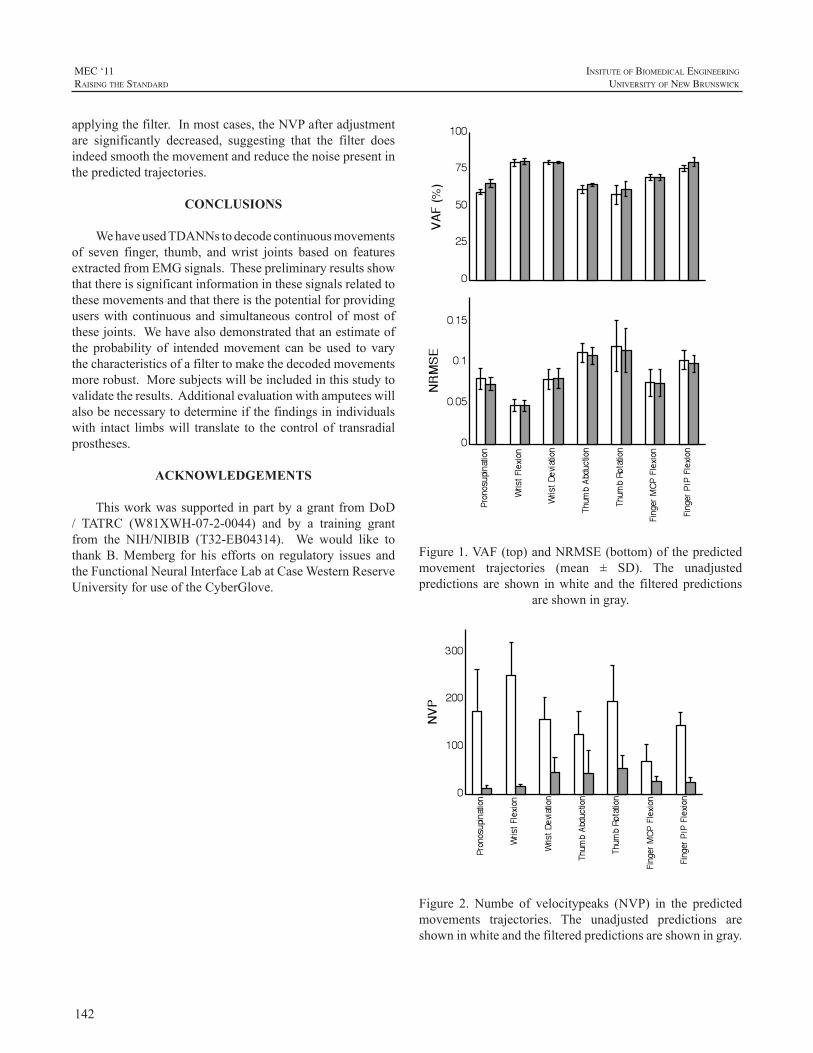
142
MEC ‘11raIsIng the standard
InsItute of BIomedIcal engIneerIng
unIversIty of new BrunswIck
applyingthefilter.Inmostcases,theNVPafteradjustmentare significantly decreased, suggesting that the filter doesindeedsmooththemovementandreducethenoisepresentinthepredictedtrajectories.
CONCLUSIONS
WehaveusedTDANNstodecodecontinuousmovementsof seven finger, thumb, andwrist joints based on featuresextractedfromEMGsignals.Thesepreliminaryresultsshowthatthereissignificantinformationinthesesignalsrelatedtothesemovementsandthatthereisthepotentialforprovidinguserswithcontinuousand simultaneouscontrolofmostofthesejoints.Wehavealsodemonstratedthatanestimateofthe probability of intendedmovement can be used to varythecharacteristicsofafiltertomakethedecodedmovementsmorerobust.Moresubjectswillbeincludedinthisstudytovalidatetheresults.Additionalevaluationwithamputeeswillalsobenecessarytodetermineifthefindingsinindividualswith intact limbswill translate to thecontrolof transradialprostheses.
ACKNOWLEDGEMENTS
Thisworkwassupported inpartbyagrantfromDoD/ TATRC (W81XWH-07-2-0044) and by a training grantfrom the NIH/NIBIB (T32-EB04314). We would like tothankB.Memberg for his efforts on regulatory issues andtheFunctionalNeuralInterfaceLabatCaseWesternReserveUniversityforuseoftheCyberGlove.
Figure 1. VAF (top) and NRMSE (bottom) of the predicted
movement trajectories (mean ± SD). The unadjusted predictions are shown in white and the filtered predictions
are shown in gray.
Figure1.VAF(top)andNRMSE(bottom)ofthepredictedmovement trajectories (mean ± SD). The unadjustedpredictions are shown inwhite and the filtered predictions
areshowningray.
Figure 2. Number of velocity peaks (NVP) in the predicted
movement trajectories. The unadjusted predictions are shown in white and the filtered predictions are shown in
gray.
Figure 2. Numbe of velocitypeaks (NVP) in the predictedmovements trajectories. The unadjusted predictions areshowninwhiteandthefilteredpredictionsareshowningray.
143
InsItute of BIomedIcal engIneerIng
unIversIty of new BrunswIck
MEC ‘11raIsIng the standard
REFERENCES
[1] S. Adee, “The Revolution Will Be Prosthetized: DARPA’sProstheticArmGivesAmputeesNewHope,”IEEESpectrum,vol.46,pp.44-48,2009.
[2] N.ReddyandV.Gupta,“TowardDirectBiocontrolUsingSurfaceEMGSignals:ControlofFingerandWristJointModels,”Med.Eng.Phys.,vol.29,pp.398-403,2007.
[3] F.Sebelius,L.Eriksson,C.Balkenius,andT.Laurell,“MyoelectricControlofaComputerAnimatedHand:ANewConceptBasedontheCombinedUseofaTree-StructuredArtificialNeuralNetworkandaDataGlove,”J.Med.Eng.Tech.,vol.30,pp.2-10,2006.
[4] R.Smith,F.Tenore,D.Huberdeau,R.Etienne-Cummings,andN.Thakor,“ContinuousDecodingofFingerPositionfromSurfaceEMGSignals for the Control of Powered Prostheses,” Proc. 30th AnnualInternationalIEEEEMBSConf.,2008Aug.20-24,Vancouver,BritishColumbia,Canada,pp.197-200,2008.
[5] T.FarrellandR.Weir,“AComparisonoftheEffectsofElectrodeImplantation and Targeting on Pattern Classification Accuracy forProsthesis Control,” IEEE Trans. Biomed. Eng., vol. 55, pp. 2198-2211,2008.
[6] B.Hudgins,PParker,andRScott,“ANewStrategyforMyoelectricControl,”IEEETrans.Biomed.Eng.,vol.40,pp.82-94,1993.
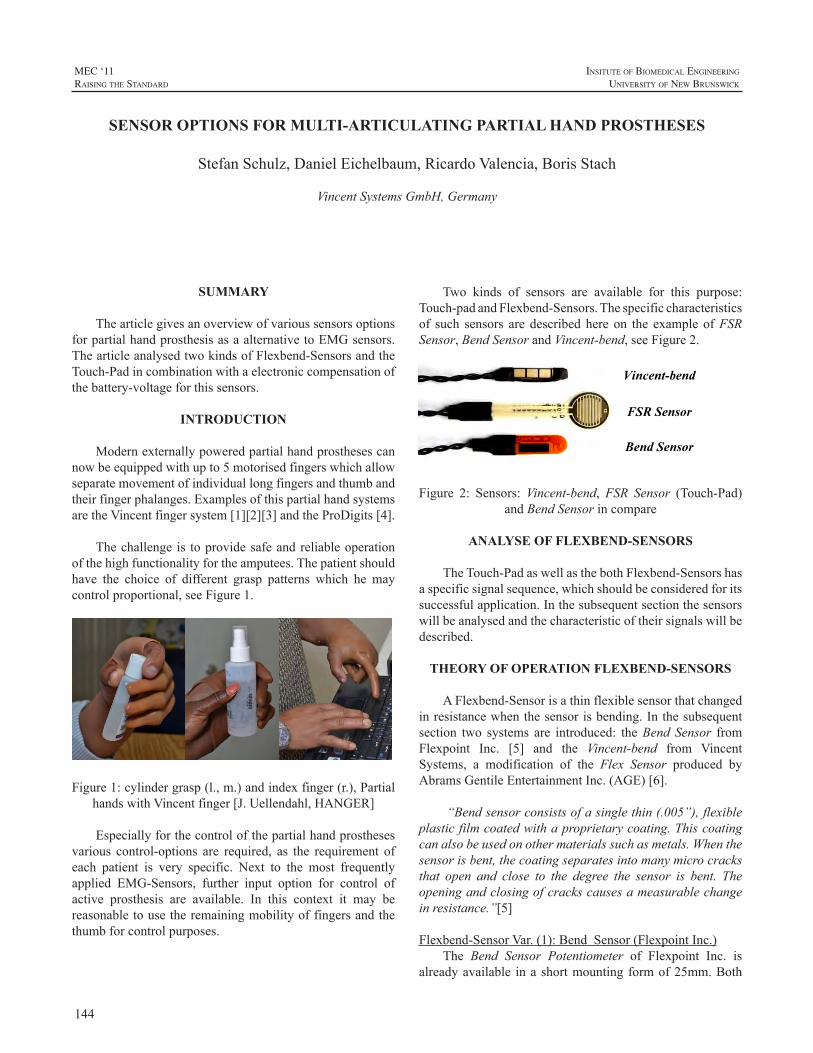
144
MEC ‘11raIsIng the standard
InsItute of BIomedIcal engIneerIng
unIversIty of new BrunswIck
SUMMARY
ThearticlegivesanoverviewofvarioussensorsoptionsforpartialhandprosthesisasaalternativetoEMGsensors.ThearticleanalysedtwokindsofFlexbend-SensorsandtheTouch-Padincombinationwithaelectroniccompensationofthebattery-voltageforthissensors.
INTRODUCTION
Modernexternallypoweredpartialhandprosthesescannowbeequippedwithupto5motorisedfingerswhichallowseparatemovementofindividuallongfingersandthumbandtheirfingerphalanges.ExamplesofthispartialhandsystemsaretheVincentfingersystem[1][2][3]andtheProDigits[4].
Thechallenge is toprovidesafeandreliableoperationofthehighfunctionalityfortheamputees.Thepatientshouldhave the choice of different grasp patterns which he maycontrolproportional,seeFigure1.
Figure1:cylindergrasp(l.,m.)andindexfinger(r.),PartialhandswithVincentfinger[J.Uellendahl,HANGER]
Especiallyforthecontrolofthepartialhandprosthesesvarious control-options are required, as the requirement ofeach patient is very specific. Next to the most frequentlyapplied EMG-Sensors, further input option for control ofactive prosthesis are available. In this context it may bereasonabletousetheremainingmobilityoffingersandthethumbforcontrolpurposes.
Two kinds of sensors are available for this purpose:Touch-padandFlexbend-Sensors.Thespecificcharacteristicsof such sensors are describedhere on the exampleofFSRSensor,BendSensorandVincent-bend,seeFigure2.
Vincent-bend
FSR Sensor
Bend Sensor
Figure 2: Sensors:Vincent-bend,FSR Sensor (Touch-Pad)andBendSensorincompare
ANALYSE OF FLEXBEND-SENSORS
TheTouch-PadaswellasthebothFlexbend-Sensorshasaspecificsignalsequence,whichshouldbeconsideredforitssuccessfulapplication.Inthesubsequentsectionthesensorswillbeanalysedandthecharacteristicoftheirsignalswillbedescribed.
THEORY OF OPERATION FLEXBEND-SENSORS
AFlexbend-Sensorisathinflexiblesensorthatchangedinresistancewhenthesensorisbending.Inthesubsequentsection two systems are introduced: theBend Sensor fromFlexpoint Inc. [5] and the Vincent-bend from VincentSystems, a modification of the Flex Sensor produced byAbramsGentileEntertainmentInc.(AGE)[6].
“Bendsensorconsistsofasinglethin(.005”),flexibleplasticfilmcoatedwithaproprietarycoating.Thiscoatingcanalsobeusedonothermaterialssuchasmetals.Whenthesensorisbent,thecoatingseparatesintomanymicrocracksthat open and close to the degree the sensor is bent. Theopeningandclosingofcrackscausesameasurablechangeinresistance.”[5]
Flexbend-SensorVar.(1):BendSensor(FlexpointInc.)The Bend Sensor Potentiometer of Flexpoint Inc. is
alreadyavailable inashortmountingformof25mm.Both
SENSOR OPTIONS FOR MULTI-ARTICULATING PARTIAL HAND PROSTHESES
StefanSchulz,DanielEichelbaum,RicardoValencia,BorisStach
VincentSystemsGmbH,Germany
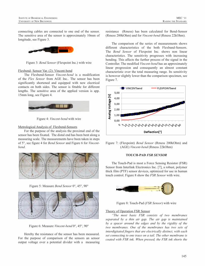
145
InsItute of BIomedIcal engIneerIng
unIversIty of new BrunswIck
MEC ‘11raIsIng the standard
connecting cables are connected to one end of the sensor.Thesensitiveareaof thesensor isapproximately10mmoflongitude,seeFigure3.
Figure3:BendSensor(FlexpointInc.)withwire
Flexbend-SensorVar.(2):Vincent-bendThe Flexbend-Sensor Vincent-bend is a modification
of the Flex Sensor fromAGE Inc.. The sensor has beensignificantly shortened and equipped with new electricalcontacts on both sides. The sensor is fittable for differentlengths. The sensitive area of the applied version is app.15mmlong,seeFigure4.
Figure4:Vincent-bendwithwire
MetrologicalAnalysisofFlexbend-SensorsForthepurposeoftheanalysistheproximalendofthe
sensorhasbeenfixated.Thedistalendhasbeenbentalongameasuringscale.Themeasurementshavebeentakeninstepsof5°,seefigure4forBendSensorandFigure6forVincent-bend.
Figure5:MeasureBendSensor0°,45°,90°
Figure6:MeasureVincent-bend0°,45°,90°
Herebytheresistanceofthesensorhasbeenmeasured.For the purpose of comparison of the sensors an sensoroutput voltage over a potential divider with a measuring
resistance (Rmess) has been calculated for Bend-Sensor(Rmess200kOhm)andforVincent-bend(Rmess22kOhm).
The comparison of the series of measurements showsdifferent characteristics of the both Flexband-Sensors.The Bend Sensor of Flexpoint Inc. shows non linearcharacteristics. The sensitivity progresses with increasingbending.ThisaffectsthefurtherprocessofthesignalintheController.ThemodifiedVincent-bendhasanapproximatelylinear progression and consequently an almost constantcharacteristicover the totalmeasuringrange. Itssensitivityishoweverslightlylowerthanthecomparisonspecimen,seeFigure7.
Figure 7: (Flexpoint)Bend Sensor (Rmess 200kOhm) and(AGE)Vincent-bend(Rmess22kOhm)
TOUCH-PAD FSR SENSOR
TheTouch-PadismostaForceSensingResistor(FSR)SensorfromInterlinkElectronicsInc.[7],arobust,polymerthickfilm(PTF)sensordevices,optimizedforuseinhumantouchcontrol.Figure8showtheFSRSensorwithwire.
Figure8:Touch-Pad(FSRSensor)withwire
TheoryofOperationFSRSensor“The most basic FSR consists of two membranes
separated by a thin air gap. The air gap is maintainedby a spacer around the edges and by the rigidity of thetwo membranes. One of the membranes has two sets ofinterdigitatedfingersthatareelectricallydistinct,witheachsetconnectingtoonetraceonatail.TheothermembraneiscoatedwithFSRink.Whenpressed,theFSRinkshortsthe
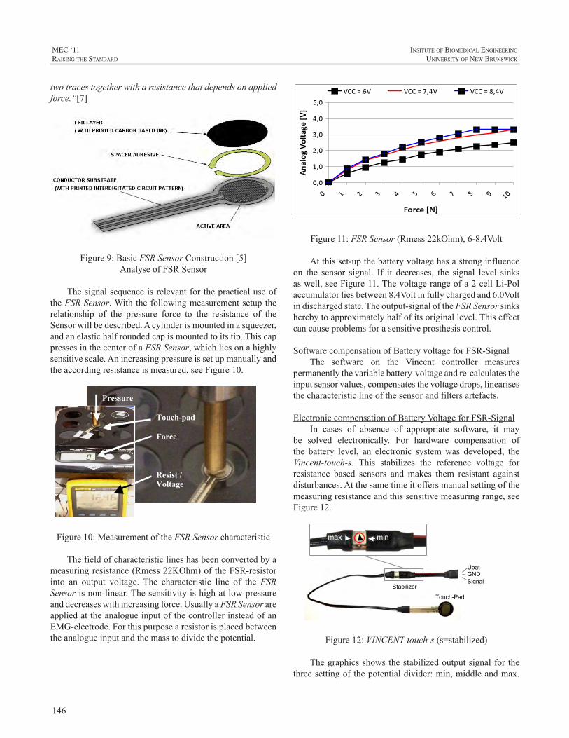
146
MEC ‘11raIsIng the standard
InsItute of BIomedIcal engIneerIng
unIversIty of new BrunswIck
twotracestogetherwitharesistancethatdependsonappliedforce.“[7]
Figure9:BasicFSRSensorConstruction[5]AnalyseofFSRSensor
ThesignalsequenceisrelevantforthepracticaluseoftheFSRSensor.Withthefollowingmeasurementsetuptherelationship of the pressure force to the resistance of theSensorwillbedescribed.Acylinderismountedinasqueezer,andanelastichalfroundedcapismountedtoitstip.ThiscappressesinthecenterofaFSRSensor,whichliesonahighlysensitivescale.Anincreasingpressureissetupmanuallyandtheaccordingresistanceismeasured,seeFigure10.
Pressure Touch-pad
Force Resist / Voltage
Figure10:MeasurementoftheFSRSensorcharacteristic
Thefieldofcharacteristiclineshasbeenconvertedbyameasuringresistance(Rmess22KOhm)oftheFSR-resistorinto an output voltage. The characteristic line of the FSRSensorisnon-linear.Thesensitivityishighatlowpressureanddecreaseswithincreasingforce.UsuallyaFSRSensorareappliedattheanalogueinputofthecontrollerinsteadofanEMG-electrode.Forthispurposearesistorisplacedbetweentheanalogueinputandthemasstodividethepotential.
Figure11:FSRSensor(Rmess22kOhm),6-8.4Volt
Atthisset-upthebatteryvoltagehasastronginfluenceon the sensor signal. If it decreases, the signal level sinksaswell,seeFigure11.Thevoltagerangeofa2cellLi-Polaccumulatorliesbetween8.4Voltinfullychargedand6.0Voltindischargedstate.Theoutput-signaloftheFSRSensorsinksherebytoapproximatelyhalfofitsoriginallevel.Thiseffectcancauseproblemsforasensitiveprosthesiscontrol.
SoftwarecompensationofBatteryvoltageforFSR-SignalThe software on the Vincent controller measures
permanentlythevariablebattery-voltageandre-calculatestheinputsensorvalues,compensatesthevoltagedrops,linearisesthecharacteristiclineofthesensorandfiltersartefacts.
ElectroniccompensationofBatteryVoltageforFSR-SignalIn cases of absence of appropriate software, it may
be solved electronically. For hardware compensation ofthe battery level, an electronic systemwas developed, theVincent-touch-s. This stabilizes the reference voltage forresistance based sensors and makes them resistant againstdisturbances.Atthesametimeitoffersmanualsettingofthemeasuringresistanceandthissensitivemeasuringrange,seeFigure12.
max min
Ubat GND SignalA
Touch-Pad
Stabilizer
Figure12:VINCENT-touch-s(s=stabilized)
Thegraphicsshowsthestabilizedoutputsignalforthethreesettingofthepotentialdivider:min,middleandmax.
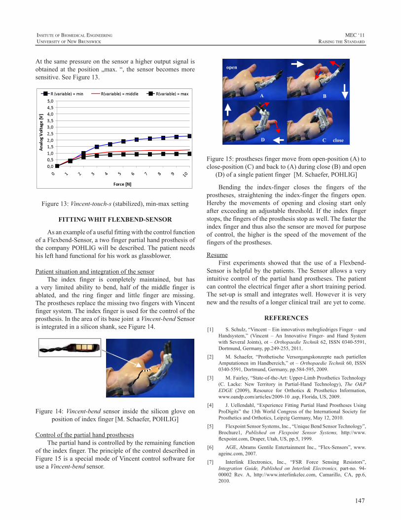
147
InsItute of BIomedIcal engIneerIng
unIversIty of new BrunswIck
MEC ‘11raIsIng the standard
Atthesamepressureonthesensorahigheroutputsignalisobtainedat theposition„max.“, the sensorbecomesmoresensitive.SeeFigure13.
Figure13:Vincent-touch-s(stabilized),min-maxsetting
FITTING WHIT FLEXBEND-SENSOR
AsanexampleofausefulfittingwiththecontrolfunctionofaFlexbend-Sensor,atwofingerpartialhandprosthesisofthecompanyPOHLIGwillbedescribed.Thepatientneedshislefthandfunctionalforhisworkasglassblower.
PatientsituationandintegrationofthesensorThe index finger is completely maintained, but has
a very limited ability to bend, half of themiddle finger isablated, and the ring finger and little finger are missing.TheprosthesesreplacethemissingtwofingerswithVincentfingersystem.Theindexfingerisusedforthecontroloftheprosthesis.IntheareaofitsbasejointaVincent-bendSensorisintegratedinasiliconshank,seeFigure14.
Figure 14:Vincent-bend sensor inside the silicon glove onpositionofindexfinger[M.Schaefer,POHLIG]
ControlofthepartialhandprosthesesThepartialhandiscontrolledbytheremainingfunction
oftheindexfinger.TheprincipleofthecontroldescribedinFigure15isaspecialmodeofVincentcontrolsoftwareforuseaVincent-bendsensor.
open
close
B
D
A
C
Figure15:prosthesesfingermovefromopen-position(A)toclose-position(C)andbackto(A)duringclose(B)andopen
(D)ofasinglepatientfinger[M.Schaefer,POHLIG]
Bending the index-finger closes the fingers of theprostheses, straightening the index-finger the fingers open.Hereby the movements of opening and closing start onlyafter exceedinganadjustable threshold. If the index fingerstops,thefingersoftheprosthesisstopaswell.Thefastertheindexfingerandthusalsothesensoraremovedforpurposeof control, thehigher is the speedof themovementof thefingersoftheprostheses.
ResumeFirst experiments showed that the use of a Flexbend-
Sensor ishelpfulbythepatients.TheSensorallowsaveryintuitivecontrolof thepartialhandprostheses.Thepatientcancontroltheelectricalfingerafterashorttrainingperiod.Theset-up issmalland integrateswell.However it isverynewandtheresultsofalongerclinicaltrailareyettocome.
REFERENCES
[1] S.Schulz,“Vincent–EininnovativesmehrgliedrigesFinger–undHandsystem,” (Vincent –An Innovative Finger- and Hand SystemwithSeveralJoints),ot–OrthopaedieTechnik62,ISSN0340-5591,Dortmund,Germany,pp.249-255,2011.
[2] M. Schaefer, “Prothetische Versorgungskonzepte nach partiellenAmputationenimHandbereich,”ot–OrthopaedieTechnik60,ISSN0340-5591,Dortmund,Germany,pp.584-595,2009.
[3] M.Fairley,“State-of-the-Art:Upper-LimbProstheticsTechnology(C. Lacke: New Territory in Partial-Hand Technology), The O&PEDGE (2009), Resource for Orthotics & Prosthetics Information,www.oandp.com/articles/2009-10.asp,Florida,US,2009.
[4] J.Uellendahl,“ExperienceFittingPartialHandProsthesesUsingProDigits” the13thWorldCongressof the InternationalSociety forProstheticsandOrthotics,LeipzigGermany,May12,2010.
[5] FlexpointSensorSystems,Inc.,“UniqueBendSensorTechnology”,Brochure1, Published on Flexpoint Sensor Systems, http://www.flexpoint.com,Draper,Utah,US,pp.5,1999.
[6] AGE,AbramsGentileEntertainment Inc., “Flex-Sensors”,www.ageinc.com,2007.
[7] Interlink Electronics, Inc., “FSR Force Sensing Resistors”,Integration Guide, Published on Interlink Electronics, part-no. 94-00002 Rev. A, http://www.interlinkelec.com, Camarillo, CA, pp.6,2010.
148
MEC ‘11raIsIng the standard
InsItute of BIomedIcal engIneerIng
unIversIty of new BrunswIck
INTRODUCTION
AfterseveralcasesutilizingTMRasthefoundationforcontrol it becomes apparent that even the most advancedcommercially available systems lack all the necessaryvariability to accommodate a wide array of clinicalpresentations. Some patients present with multiple sitesforcontrolbutmaywant,inadditiontoafullymyoelectricprosthesis,ahybriddevice;givingthemtheflexibilitytouseallavailabletypesofprostheses.Somepatientspresentwithmusclethatishyper-mobile;makingthejobofsecuringtheprosthesis andproviding agood interface for the electrodeanextremechallenge.Asaresultthereisaneedforfurtherdevelopmentofcomponentsmadeavailablesoastoprovidedevicesthatmeetthesedemands.
HYBRID TMR PROTHESIS WITH THREE SIMULTANEOUS DEGREES OF FREEDOM
Transhumeral hybrid prostheses have been usedsuccessfullybyupperextremityamputeesformanyyearstoincreasefunctionwhileallowing2degreesofsimultaneousfreedom;controllingtheelbowwhileoperatingtheterminaldevice.Manypatientspreferthisprostheticcontrolstrategytothestrictbodypoweredormyoelectricdesigns.WiththeadventofrecentTMRTargetedMusclereinnervationsurgicaltechniques,wehavebeenabletoincreasefunctionofhybridprostheses.
Targeted Muscle Reinnervation has given Prosthetistsadditional myoelectric locations to capture EMG signals.WiththeincreaseinthenumberofEMGsitestheProsthetistcan increase function for thepatient.Todatemostpatientswho underwent TMR surgery were fit with purely myoelectricsystem(myoelectricelbow,wristandhandorotherterminaldevice).Inmostcasesthisgivestheuser2degreesofsimultaneouscontrolofthemyoelectricprosthesis.
Using existing hybrid transhumeral prostheticcomponents we are able to increase simultaneous controloftheprosthesisfromtwotothreedegreesofsimultaneouscontrol. This allows the patient the ability to activelycontroltheelbowflexionandextension,wristpronationand
supination, and hand opening and closing simultaneouslygivingthepatientamorenaturalwayofmovingtheprosthesisinspacewhiledoingactivitiesofdaily livingmorecloselyresemblinganaturalhumanarm.
Advantages of the three degrees of simultaneousmovement should allow the patient faster response timewhenmanipulatingobjects,greaterwearingtimeduetothedecreasedweightofthebodypoweredelbowandincreasedproprioceptionandspeedofelbowflexioninspacethroughtheBowdencablesystem.
ExtensiveOccupationalandPhysicaltherapywillneedto take place to improve the patient’s control and functionwithadevicethatallowstheuserthreesimultaneousdegreesoffreedom.
Overall,patientsthathavebeenfitwiththeHybridTMRprosthesisreporttheyprefertowearthisprosthesisovertheirbodypoweredorTMRmyoelectricprosthesis.
FurthertrialswillneedtooccurtoinfutureTMRpatientstogaintheunderstandingofwhatcanbeaccomplish.
THE SOCKET AND ELECTRODE INTERRELATIONSHIP IN TMR SHOULDER
DISARTICULATION CASES
ThegoalbehindTMRsurgeryistosurgicallytreatthenerveinamoreappropriatemanner,toproducemoreelectrodesites and to create sites that aremore intuitive resulting inless switching andhigher simultaneous control ofmultipledegreesoffreedom.Alongwiththecreationofmoreelectrodesitesthereareissuesthatmayrequirethetypicalapproachesto socketdesignandelectrodeplacement andmanagementto bemodified. Sometimes the surgery produces amusclethatishyper-mobile.Thismaybecauseddirectlybyhyper-reinnervation,surgicallyremovingtheoriginorinsertionofthemuscleorbyremovingthesub-cutaneoustissueresultingin amore adherent skin tomuscle connection. Regardlessof thecause, theresult is thatmanagingtheplacementandconstantcontactbetweentheelectrodeandtheskincanbeachallengingproblem.
UNIQUE SITUATIONS IN PROSTHETIC DESIGN WHEN APPLYING TARGETED MUSCLE REINNERVATION IN TRANSHUMERAL AND SHOULDER DISARTICULATION LEVELS
PatrickCPrigge,CP,JamieVandersea,CPO
AdvancedArmDynamics,Inc.,11671FountainsDr.Suite220,MapleGrove,MN55369
149
InsItute of BIomedIcal engIneerIng
unIversIty of new BrunswIck
MEC ‘11raIsIng the standard
The problems of tissue sliding and pulling away fromthe socket have been previously reported.1 In Shoulderdisarticulation cases this problem of hyper-mobility ismoreofanissuebecauseframetypesocketdesignsdonotencapsulate the musculature and restrict movement as itwouldinaTranshumeralsituation.Thisgivestheskinoverthemusclefreedomtomoveandmakesthejobofkeepingtheelectrode inplacemoreofachallenge. If theelectrodeisheldinpositionintheframe,wetypicallyexpecttheskinto stay relatively in the same position under the electrode.Ifanyslidingoccurs,amotionartifactisproducedresultinginunpredictablebehavioroftheprosthesis.Itiscommontoallow for some flexibility outwardwith the electrodewithflexible mounts but it has not been a problem to controllateralshiftingofthemusculaturebysimplesocketdesigns.In theseTMRcases, expansion, change in topography andlateralshiftofthemuscleisverycommon.
Initially efforts were made to modify the socket forthe final resting position of the electrode upon completecontraction. When not contracting, the muscle and thesurrounding soft tissue would find a home inside thestrangelyshapedinterioroftheframe.Thisworkedwelltoapointbutseveralsideissuesarose.Thepatientswouldreportsignificant pressure over their electrode sites, they woulddescribenumbfeelingsintheir“transferred”limbsensationand often themusclewould not fire as strong resulting inthe need for higher than needed amplification through theelectronics.Anotherproblemwithhavingsomanyelectrodesinonearea,likeoverthepectoralismuscle,wasthatthesocketsurfacehadtobequitelargetoaccommodatetheelectrodes.Thismadethesocketlarger,hotterandmoresusceptibletocomingoffofthechestwheninaseatedpositionfromcounterpressure to theposterior inferiormemberof thesupportingsocket frame.These issues spawned the thought that ifwecoulddevelopanindividualelectrodeholdingapplianceandconnectitflexiblyandremotelytotheframethatwecouldcontrolindividuallythetensionoverthesiteandindependentofanyotherelectrodes,keepthemseparatelyflexiblewheneachmusclefired.
The first generation of flexible connector involveda spring steel arm and a fixed connector at the electrodethat would pivot over the length of the spring steel. OttoBocksuctionsocketelectrodeswereutilizedtoprovidetheconnection point to the fixed connector. If the only needwas to accommodate substantial outwardmovementof theskin, more than a typical flexible electrode mount wouldaccommodatethisworkedfine.Itdidnotworkhoweverinasituation that the topographychangedwhere theangleoftheelectrodeneededtochangetomaintaincontact.Tiltingofmorethan30degreeswasnecessaryinthiscase.
Anothergenerationofdevicewasmadewithapivotingattachmentovertheelectrode.Itaccommodatedthenecessarytiltoftheelectrodebutlackedtheabilitytocontrolrotationof theelectrode. Itwasalsonoted that thisdesignallowedforsomeaccommodationof theshearmovementunder theelectrodebycompressingthesofttissueoverthemuscleasit expanded.This isn’t a perfect solutionwhen the skin issignificantly sweaty as there is less coefficient of frictionbetweentheelectrodeandtheskinso the tiltwouldnotbeenoughtostabilizetheelectrode.
The third generation under development willaccommodatethefollowingcriteria
1.Springsteelattachmentarmforadjustabletensionandflexibleattachingtothesocketframe
2Rotatablelockingelectrodeholder
3.Pivotinghead
4.Gainadjustmentaccess
5.Shearaccommodation
6.Protectionforelectrodewire
With the above listed modifications the device willbe able to be used on even themost challenging ofTMRpresentations and maintain independence of the electrodefromtheanchorandnecessarilystablestructureofthesocket.
CONCLUSION
TMR surgery has expanded the functional capacity ofmodernupperlimbprostheticdevicesandasweexplorethesecasesandtrytomaximizethepotentialofeachpatientitisclearthatthereisagreatneedforfinetuningourapproaches.Asaresulttherewillbeaspill-overeffectofthesetechniquesincorporated for both the TMR population and non-TMRpopulationtobenefit..
REFERENCES
[1] TA. Kuiken, LA. Miller, RD. Lipschutz, KA. Stubblefield, BA.Lock,H.Huang,TW.Williams,Rff.Weir,“ControlofaSixDegreeof Freedom Prosthetic Arm After Targeted Muscle ReinnervationSurgery,”ArchPhysMedRehabil,Vol89,November2008
[2] TW.Williams,“Controlofpoweredupperextremityprostheses,”inFunctionalRestorationofAdultsandChildrenwithUpperExtremityAmputation,R.H.MeierandD.J.Atkins,Eds.NewYork,:Demos,2004,pp.207–224.
[3] TA. Kuiken, MM. Lowery, and NS. Stoykov, “The effect ofsubcutaneous fat on myoelectric signal amplitude and crosstalk,”Prosthet.Orthot.Int.,vol.27,pp.48–54,Apr.2003.
[4] TA.Kuiken,LA.Miller,RD.Lipschutz,BA.Lock,K.Stubblefield,PD.Marasco,P.Zhou,andGA.Dumanian,“TargetedReinnervationfor enhanced prosthetic arm function in a woman with a proximalamputation:Acasestudy,”Lancet,vol.369,pp.371–380,2007.
150
MEC ‘11raIsIng the standard
InsItute of BIomedIcal engIneerIng
unIversIty of new BrunswIck
[5] RD. Lipschutz, TA. Kuiken, LA. Miller, GA. Dumanian, andKA. Stubblefield, “Shoulder disarticulation externally poweredprostheticfittingfollowingtargetedmusclereinnervationforimprovedmyoelectriccontrol,”J.Prosthet.Orthot.,vol.18,pp.28–34,2006.
[6] JB. Hijjawi, TA. Kuiken, RD. Lipschutz, LA. Miller, KA.Stubblefield and GA. Dumanian, “Improved myoelectric prosthesiscontrol accomplished using multiple nerve transfers.” Plast andReconsteSurg,118(7):1573-78,2006.
[7] KD.O’Shaughnessy,GA.Dumanian,RD.Lipschutz,LA.Miller,KA. Stubblefield, TA. Kuiken. “Targeted reinnervation to improveprosthesiscontrolintranshumeralamputees:areportofthreecases.”JBoneJointSurgAm2008;90:393-400.
[8] LA.Miller,RD.Lipschutz,Rff.Weir,etal.“Shoulderdisarticulationfitting with 6 independently controlledmotors after targeted hyper-reinnervation nerve transfer surgery.” In: Proceedings of MECSymposium.2005;NewBrunswick(Canada).
151
InsItute of BIomedIcal engIneerIng
unIversIty of new BrunswIck
MEC ‘11raIsIng the standard
ABSTRACT
Technological advancements in lower limb prostheseshave resulted inactuatedmotors inbothkneesandankles.Currently, these components are controlled by informationmeasuredfromvariouselectromechanicalsensorsattachedtotheprosthesis.Ouraimistoenhancethecontrolinformationprovided to powered prosthetic components by includinginput from the user via interpreted myoelectric signals(MESs).Toextractusefulcontrolinformation,itisimperativethatconsistent,high-qualityMESsbecollectedfrompatientseach time they don the socket. In this work, we presentapproaches to maintaining consistent electrode placementsonindividualswithtransfemoralandtranstibialamputationsduring static non-weight-bearing conditions and dynamicweight-bearingactivities.Ourresultsshowthatavarietyofmethods, similar to those used in upper limb fittings,maybe used to collect high-quality MESs during static non-weight-bearingconditions.MEScollectionduringdynamicweight-bearingactivitiesismorechallenging.Thetype,size,shape,andplacementofelectrodesmustbecarefullychosento maintain contact with the skin without compromisingcomfortduringweight-bearingactivity.
INTRODUCTION
ThereareanestimatedthreemillionindividualsinNorthAmericawithmajoramputations[1],withanestimated90%to97%beinglowerlimbamputations[2].Mostlowerlimbprosthetic components are passive, reacting to the externalforces applied to them. Powered lower limb componentsconsistprimarilyofmicroprocessorknees,whichuse inputfromelectromechanicalsensorstoaltertheresistanceofthekneeunittocompensatefordifferentphasesofthegaitcycleorvariationsincadence.Untilrecently,theonlycomponentsthatcontainedamotor-actuatedjointforpositioningweretheOssurPowerKneeTMandProprioFootTMandthePowerKneewas theonly commercially available prosthetic componentthatactuallygeneratedpositivepower,whichmayreducetheuser’senergyexpenditureandimprovegaitmechanics[3].
Powered lower limbcomponentswithactuatedmotorshave been developed and tested clinically and are highlyvisible in the research community, with the PowerFootBiOMTMbyiWalkrecentlybecomingcommerciallyavailable.Eachmodeofoperationofthesecomponents(e.g.stairascent)hasakinematicprofilethatdeterminestheoperationsofthejoint.Althoughhighlysophisticated,thisvarietyofpoweredcomponentstillreliesonelectromechanicalsensorstotriggera particular mode. Switching between modes can also bedonemanually.Suchmethods for control arenot intuitive,donotprovidesmoothtransitioningbetweenmodes,andcanbecumbersomeastheymayinvolveuseofthecontra-laterallimbandmayrequiredonningadditionalhardware.
In order to enhance the performance of these lowerlimbprostheses,itisourgoaltoaugmentthecurrentsensorinformation with user intent information. Our approach tothismergerof technology is touseMESsfromthesurfaceof the individual’s residual limb to provide data that willimprove component responsiveness.A study by Huang etal. [4] investigated the use of advanced signal processingas a control strategy for powered lower limb prostheses.TheresultsindicatedthatthecombinationofsurfaceMESsand pattern recognition can provide accurate informationregarding the user’s intent for prosthetic control. In ordertoutilizeuserintentinformation,it isessentialtocreateaninterfacethatcapturesconsistent,reliable,high-qualityMESsfromresidual limbmusclesduringbothstaticanddynamicsituations[4].
Therearestandardpracticesregardingtheincorporationof electrodes into upper extremity prostheses. Two mainmethods are identified; first being thepackaged electrode,whichisacombinationofcontactsandpre-amplifiers.Theseare typically rectangular-shapedpackages thataremountedtotheinnersocket(orinterface)thatisindirectcontactwiththeskin.Appropriateplacementofthesepackagedelectrodesiscrucialwhenfabricatingtheinterface,asthesecannotbereadily repositioned without creating a void in the socketand remounting the package. Remote electrodes are thoseinwhich the electrode contacts are separate from the pre-
METHODS FOR COLLECTING MYOELECTRIC SIGNALS FROM INDIVIDUALS WITH LOWER LIMB AMPUTATIONS
RobertD.Lipschutz1,2,HeatherDaley
1CenterforBionicMedicine,RehabilitationInstituteofChicago345EastSuperiorStreet,Chicago,IL60611
2NorthwesternUniversityProsthetics-OrthoticsCenter680NorthLakeShoreDrive,Chicago,IL60611
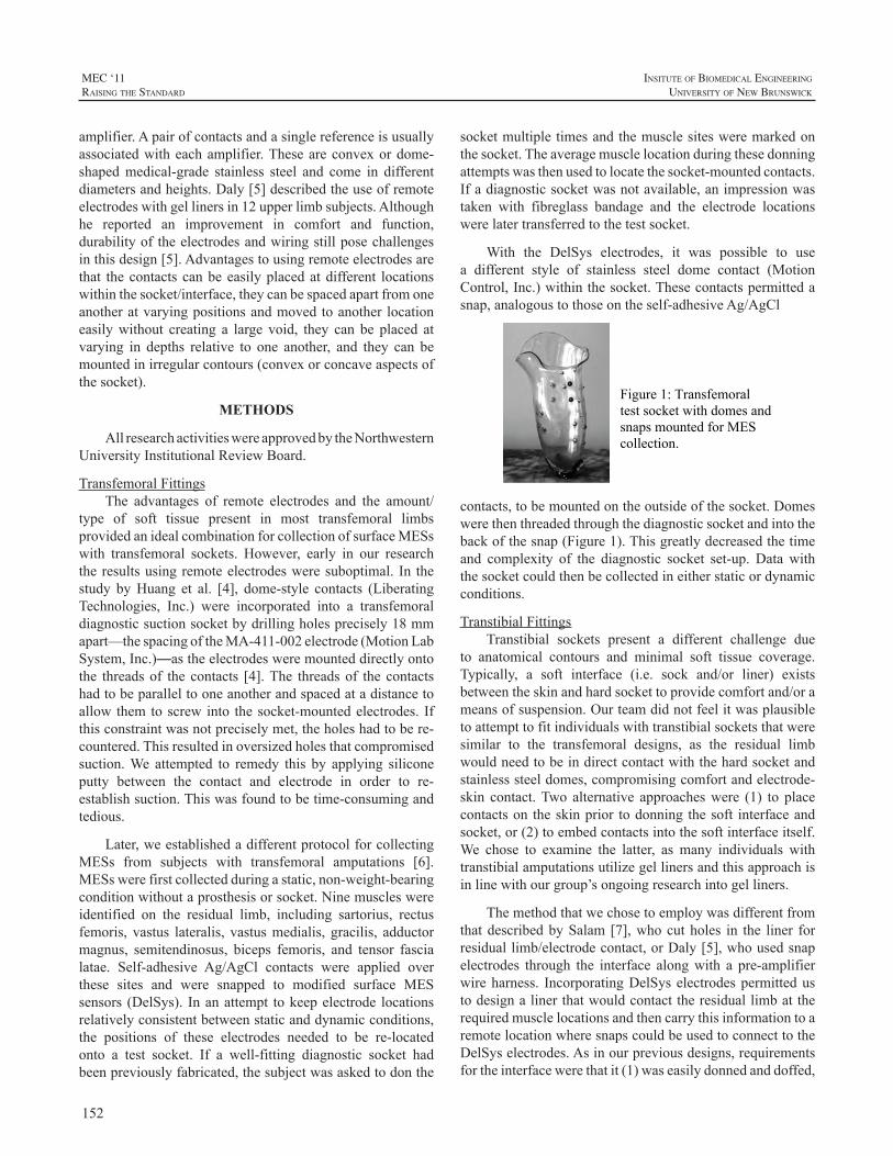
152
MEC ‘11raIsIng the standard
InsItute of BIomedIcal engIneerIng
unIversIty of new BrunswIck
amplifier.Apairofcontactsandasinglereferenceisusuallyassociatedwitheachamplifier.Theseareconvexordome-shapedmedical-grade stainless steel and come in differentdiametersandheights.Daly[5]describedtheuseofremoteelectrodeswithgellinersin12upperlimbsubjects.Althoughhe reported an improvement in comfort and function,durabilityoftheelectrodesandwiringstillposechallengesinthisdesign[5].Advantagestousingremoteelectrodesarethat thecontactscanbeeasilyplacedatdifferent locationswithinthesocket/interface,theycanbespacedapartfromoneanotheratvaryingpositionsandmovedtoanother locationeasilywithout creating a large void, they can be placed atvarying in depths relative to one another, and they can bemountedinirregularcontours(convexorconcaveaspectsofthesocket).
METHODS
AllresearchactivitieswereapprovedbytheNorthwesternUniversityInstitutionalReviewBoard.
TransfemoralFittingsThe advantages of remote electrodes and the amount/
type of soft tissue present in most transfemoral limbsprovidedanidealcombinationforcollectionofsurfaceMESswith transfemoral sockets. However, early in our researchtheresultsusingremoteelectrodesweresuboptimal. In thestudy byHuang et al. [4], dome-style contacts (LiberatingTechnologies, Inc.) were incorporated into a transfemoraldiagnosticsuctionsocketbydrillingholesprecisely18mmapart—thespacingoftheMA-411-002electrode(MotionLabSystem,Inc.)—astheelectrodesweremounteddirectlyontothe threadsof the contacts [4].The threadsof the contactshadtobeparalleltooneanotherandspacedatadistancetoallow themtoscrew into thesocket-mountedelectrodes. Ifthisconstraintwasnotpreciselymet,theholeshadtobere-countered.Thisresultedinoversizedholesthatcompromisedsuction.We attempted to remedy this by applying siliconeputty between the contact and electrode in order to re-establishsuction.Thiswasfoundtobetime-consumingandtedious.
Later,weestablishedadifferentprotocolforcollectingMESs from subjects with transfemoral amputations [6].MESswerefirstcollectedduringastatic,non-weight-bearingconditionwithoutaprosthesisorsocket.Ninemuscleswereidentified on the residual limb, including sartorius, rectusfemoris, vastus lateralis, vastusmedialis, gracilis, adductormagnus, semitendinosus, biceps femoris, and tensor fascialatae. Self-adhesive Ag/AgCl contacts were applied overthese sites and were snapped to modified surface MESsensors (DelSys). Inanattempt tokeepelectrode locationsrelativelyconsistentbetweenstaticanddynamicconditions,the positions of these electrodes needed to be re-locatedonto a test socket. If a well-fitting diagnostic socket hadbeenpreviouslyfabricated,thesubjectwasaskedtodonthe
socketmultipletimesandthemusclesitesweremarkedonthesocket.Theaveragemusclelocationduringthesedonningattemptswasthenusedtolocatethesocket-mountedcontacts.Ifadiagnosticsocketwasnotavailable,animpressionwastaken with fibreglass bandage and the electrode locationswerelatertransferredtothetestsocket.
With the DelSys electrodes, it was possible to usea different style of stainless steel dome contact (MotionControl,Inc.)withinthesocket.Thesecontactspermittedasnap,analogoustothoseontheself-adhesiveAg/AgCl
Figure 1: Transfemoral test socket with domes and snaps mounted for MES collection.
contacts,tobemountedontheoutsideofthesocket.Domeswerethenthreadedthroughthediagnosticsocketandintothebackofthesnap(Figure1).Thisgreatlydecreasedthetimeand complexity of the diagnostic socket set-up. Data withthesocketcouldthenbecollectedineitherstaticordynamicconditions.
TranstibialFittingsTranstibial sockets present a different challenge due
to anatomical contours and minimal soft tissue coverage.Typically, a soft interface (i.e. sock and/or liner) existsbetweentheskinandhardsockettoprovidecomfortand/orameansofsuspension.Ourteamdidnotfeelitwasplausibletoattempttofitindividualswithtranstibialsocketsthatweresimilar to the transfemoral designs, as the residual limbwouldneedtobeindirectcontactwiththehardsocketandstainlesssteeldomes,compromisingcomfortandelectrode-skin contact.Two alternative approacheswere (1) to placecontactson theskinprior todonning thesoft interfaceandsocket,or(2)toembedcontactsintothesoftinterfaceitself.We chose to examine the latter, as many individuals withtranstibialamputationsutilizegellinersandthisapproachisinlinewithourgroup’songoingresearchintogelliners.
ThemethodthatwechosetoemploywasdifferentfromthatdescribedbySalam[7],whocutholes in the liner forresiduallimb/electrodecontact,orDaly[5],whousedsnapelectrodes through the interface alongwith a pre-amplifierwireharness. IncorporatingDelSyselectrodespermittedustodesignalinerthatwouldcontacttheresiduallimbattherequiredmusclelocationsandthencarrythisinformationtoaremotelocationwheresnapscouldbeusedtoconnecttotheDelSyselectrodes.Asinourpreviousdesigns,requirementsfortheinterfacewerethatit(1)waseasilydonnedanddoffed,
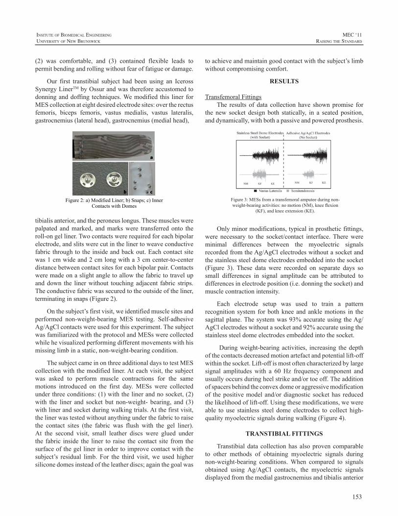
153
InsItute of BIomedIcal engIneerIng
unIversIty of new BrunswIck
MEC ‘11raIsIng the standard
(2) was comfortable, and (3) contained flexible leads topermitbendingandrollingwithoutfearoffatigueordamage.
Our first transtibial subject had been using an IcerossSynergyLinerTMbyOssurandwasthereforeaccustomedtodonninganddoffing techniques.Wemodified this liner forMEScollectionateightdesiredelectrodesites:overtherectusfemoris, biceps femoris, vastus medialis, vastus lateralis,gastrocnemius(lateralhead),gastrocnemius(medialhead),
Figure 2: a) Modified Liner; b) Snaps; c) Inner
Contacts with Domes
tibialisanterior,andtheperoneuslongus.Thesemuscleswerepalpated andmarked, andmarkswere transferred onto theroll-ongelliner.Twocontactswererequiredforeachbipolarelectrode,andslitswerecutinthelinertoweaveconductivefabricthroughtotheinsideandbackout.Eachcontactsitewas1cmwideand2cmlongwitha3cmcenter-to-centerdistancebetweencontactsitesforeachbipolarpair.Contactsweremadeonaslightangletoallowthefabrictotravelupanddown the linerwithout touchingadjacent fabric strips.Theconductivefabricwassecuredtotheoutsideoftheliner,terminatinginsnaps(Figure2).
Onthesubject’sfirstvisit,weidentifiedmusclesitesandperformed non-weight-bearing MES testing. Self-adhesiveAg/AgClcontactswereusedforthisexperiment.ThesubjectwasfamiliarizedwiththeprotocolandMESswerecollectedwhilehevisualizedperformingdifferentmovementswithhismissinglimbinastatic,non-weight-bearingcondition.
ThesubjectcameinonthreeadditionaldaystotestMEScollectionwiththemodifiedliner.Ateachvisit,thesubjectwas asked to perform muscle contractions for the samemotions introduced on the first day.MESs were collectedunderthreeconditions:(1)withthelinerandnosocket,(2)with the liner and socket but non-weight- bearing, and (3)withlinerandsocketduringwalkingtrials.Atthefirstvisit,thelinerwastestedwithoutanythingunderthefabrictoraisethe contact sites (the fabric was flush with the gel liner).At the second visit, small leather discs were glued underthe fabric inside the liner to raise thecontact site from thesurfaceofthegellinerinordertoimprovecontactwiththesubject’s residual limb. For the third visit,we used highersiliconedomesinsteadoftheleatherdiscs;againthegoalwas
toachieveandmaintaingoodcontactwiththesubject’slimbwithoutcompromisingcomfort.
RESULTS
TransfemoralFittingsThe results of data collectionhave shownpromise for
the new socket design both statically, in a seated position,anddynamically,withbothapassiveandpoweredprosthesis.
Figure3:MESsfromatransfemoralamputeeduringnon-weight-bearingactivities:nomotion(NM),kneeflexion
(KF),andkneeextension(KE).
Onlyminormodifications,typicalinprostheticfittings,were necessary to the socket/contact interface.Therewereminimal differences between the myoelectric signalsrecordedfromtheAg/AgClelectrodeswithoutasocketandthestainlesssteeldomeelectrodesembeddedintothesocket(Figure 3). These data were recorded on separate days sosmall differences in signal amplitude can be attributed todifferencesinelectrodeposition(i.e.donningthesocket)andmusclecontractionintensity.
Each electrode setup was used to train a patternrecognition system forbothkneeandanklemotions in thesagittalplane.Thesystemwas93%accurateusing theAg/AgClelectrodeswithoutasocketand92%accurateusingthestainlesssteeldomeelectrodesembeddedintothesocket.
Duringweight-bearingactivities, increasing thedepthofthecontactsdecreasedmotionartefactandpotentiallift-offwithinthesocket.Lift-offismostoftencharacterizedbylargesignal amplitudeswith a 60Hz frequency component andusuallyoccursduringheelstrikeand/ortoeoff.Theadditionofspacersbehindtheconvexdomeoraggressivemodificationof thepositivemodeland/ordiagnostic sockethas reducedthelikelihoodoflift-off.Usingthesemodifications,wewereable to use stainless steel dome electrodes to collect high-qualitymyoelectricsignalsduringwalking(Figure4).
TRANSTIBIAL FITTINGS
Transtibialdata collectionhas alsoprovencomparableto other methods of obtaining myoelectric signals duringnon-weight-bearing conditions.When compared to signalsobtained using Ag/AgCl contacts, the myoelectric signalsdisplayedfromthemedialgastrocnemiusandtibialisanterior
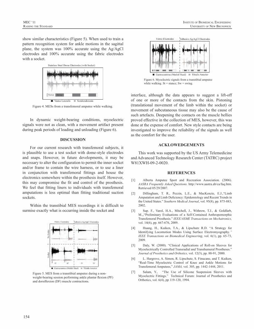
154
MEC ‘11raIsIng the standard
InsItute of BIomedIcal engIneerIng
unIversIty of new BrunswIck
showsimilarcharacteristics(Figure5).Whenusedtotrainapatternrecognitionsystemforanklemotions in thesagittalplane, the system was 100% accurate using theAg/AgClelectrodes and 100% accurate using the fabric electrodeswithasocket.
Figure4.MESsfromatransfemoralamputeewhilewalking.
In dynamic weight-bearing conditions, myoelectricsignalswerenotasclean,withamovementartifactpresentduringpeakperiodsofloadingandunloading(Figure6).
DISCUSSION
For our current researchwith transfemoral subjects, itisplausible tousea test socketwithdome-styleelectrodesand snaps. However, in future developments, it may benecessarytoaltertheconfigurationtopermittheinnersocketand/or frame to contain thewire harness, or to use a linerin conjunction with transfemoral fittings and house theelectronicssomewherewithintheprosthesisitself.However,thismay compromise the fit and control of the prosthesis.We feel that fitting liners to individuals with transfemoralamputations is less optimal than fitting traditional suctionsockets.
Within the transtibialMES recordings it is difficult tosurmiseexactlywhatisoccurringinsidethesocketand
Figure5.MESfromatranstibialamputeeduringanon-weight-bearingsessionperformingankleplantarflexion(PF)anddorsiflexion(DF)musclecontractions.
Figure6.Myoelectricsignalsfromatranstibialamputeewhilewalking.St=stance;Sw=swing.
interface, although the data appears to suggest a lift-offof one or more of the contacts from the skin. Pistoning(translational movement of the limb within the socket) ormovementofsubcutaneoustissuemayalsobethecauseofsuchartefacts.DeepeningthecontactsonthemusclebelliesprovedeffectiveinthecollectionofMES,however,thiswasdoneattheexpenseofcomfort.Newstylecontactsarebeinginvestigatedtoimprovethereliabilityofthesignalsaswellasthecomfortfortheuser.
ACKLOWEDGEMENTS
ThisworkwassupportedbytheUSArmyTelemedicineandAdvancedTechnologyResearchCenter(TATRC)projectW81XWH-09-2-0020.
REFERENCES
[1] Alberta Amputee Sport and Recreation Association. (2006).AASRAFrequentlyAskedQuestions.http://www.aastra.ab/ca/faq.htm.Retrieved05/29/2007.
[2] Dillingham, T. R., Pezzin, L.E., & MacKenzie, E.J.,“LimbAmputationandLimbDeficiency:EpidemiologyandRecentTrendsintheUnitedStates.”SouthernMedicalJournal,vol.95(8),pp.875-883,2002.
[3] Sup. F., Varol, H.A., Mitchell, J., Withrow, T.J., & Goldfarb,M.,,“Preliminary Evaluations of a Self-ContainedAnthropomorphicTransfemoralProsthesis.”IEEE/ASMETransactionsonMechatronics,vol.14(6),pp.667-676,2009.
[4] Huang, H., Kuiken, T.A., & Lipschutz R.D. “A Strategy forIdentifying Locomotion Modes Using Surface Electromyography.”IEEETransactionsonBiomedicalEngineering,vol.6(1),pp.65-73,2009.
[5] Daly, W. (2000). “Clinical Applications of Roll-on Sleeves forMyoelectricallyControlledTransradialandTranshumeralProstheses.”JournalofProstheticsandOrthotics,vol.12(3),pp.88-91,2000.
[6] L.Hargrove,A.Simon,R.Lipschutz,S.Finucane,andT.Kuiken,“Real-Time Myoelectric Control of Knee and Ankle Motions forTransfemoralAmputees,”JAMA,vol.305,pp.1442-1444,2011.
[7] Salam, Y., “The Use of Silicone Suspension Sleeves withMyoelectric Fittings.” Technical Forum: Journal of Prosthetics andOrthotics,vol.6(4),pp119-120,1994.
155
InsItute of BIomedIcal engIneerIng
unIversIty of new BrunswIck
MEC ‘11raIsIng the standard
INTRODUCTION
Lowerlimbamputationsignificantlyaffectsthequalityof the leg amputee’s daily life. Recent advancements inembeddedelectronicsandelectromechanicalactuatorshavepropelled therecentdevelopmentofpoweredartificial legs[1-3].Usually, finite-statemachine(FSM)isutilizedin thedesignofpoweredprosthetic legs to control theknee jointimpedance or knee position in each gait phase [2, 4].Theimpedanceadjustmentofthepoweredkneedependsonthelocomotionmodes[2-3],sincethedynamicsandkinematicsof theknee jointvariesacrossdifferent locomotionmodes.Thus,inordertoallowtheprostheticlegappropriatelyselecttheprostheticcontrolmodeandsmoothlytransittheactivitiesfromonetoanotherintime,theusermust“tell”theprostheticlegthelocomotionintentbeforeexecutionofthetransitions.Currently,theartificiallegsaremanuallycontrolledbyusingexaggeratedhipandtrunkmotion[4],whichiscumbersomeand sometimes unreliable. Accurately recognizing the legamputee’s locomotion intent is required in order to realizethesmoothandseamlesscontrolofprostheticlegs.
Anintentrecognitionapproachforthereal-timecontrolof a powered lower limb prosthesis, which utilized themechanicalsensorinformation,hasbeenreportedinarecentstudy [5]. One patient with transfemoral (TF) amputationperforming level-groundwalking,sitting,andstandingwastested. The study reported 100% accuracy of recognizingthe mode transitions and only 3 misclassifications duringa 570s testing period. However, over 500ms system delaywasreported,whichmaybeinadequateforuserstoperformsafe and smooth locomotion transitions. In addition, gaitinitiations and terminations were the only locomotiontransitions tested.Only usingmechanical informationmaynot be able to promptly recognize the transitions betweendifferentlocomotionmodesbecausethistypeofinformationmay not necessarily correspond with the user’s intent.Alternatively,utilizingtheneuralcontrolsignalmayenablethetrueintuitivecontroloftheartificiallimbs.
As one of the major neural control sources for thepowered prosthesis, surface electromyographic (EMG)signals have been successfully applied in the control of
upper limb prosthesis [6-9]. However, the EMG patternrecognitionmethods used in upper limb control cannot bedirectlyappliedonthelowerlimbprostheses,duetothenon-stationarycharacteristicofEMGsignalsmeasuredfromthelowerlimbmusclesduringdynamiclocomotionmovement.Inordertoaddressthischallenge,aphase-dependentEMGpattern recognition strategywasdeveloped inourpreviousstudy [10].This approachwas tested on eight able-bodiedsubjects and two subjectswithTFamputation.About90%accuracywasobtainedwhenrecognizingsevenlocomotionmodes.Inaddition,theuserintentrecognitionaccuracywasfurther improved by a neuromuscular-mechanical fusionalgorithm [11], which fused EMG signals measured fromthe residual thighmuscles and the ground reaction forces/momentscollectedfromtheprostheticpylon.Thealgorithmwastestedinreal-timetorecognizethreelocomotionmodes(levelwalking,stairascent,andstairdescent)ononeable-bodiedsubjectwith99.73%accuracy.
Althoughtheexperimentontheable-bodiedsubjecthasdemonstratedpromisingresults,whetherornotthedesignedintent recognitionsystemcanbeused forneuralcontrolofartificiallegsisunclear.Thisisbecausetheremightnotbeenough EMG recording sites available for neuromuscularinformation extraction due to the muscle loss in patientswithlegamputations,whichmaycausetheaccuracyofuserintent recognition to be inadequate for robust prostheticscontrol.Therefore, inorder toevaluate thepotentialof theintent recognition system for prosthetic legs, the designedsystemwasevaluatedononeTFamputee subjectvia real-time testing. In addition, besides the previous tested tasks,anothertwotasks:sittingandstanding,werealsoincludedinthisstudy.Itishopedthattheresultsofthisstudycouldaidthefurtherdevelopmentofneural-controlledartificiallegs.
METHODS
StructureofUserIntentRecognitionSystemThewholestructureoftheintentrecognitionsystemis
demonstrated inFig.1.ThemultichannelEMGsignals andmechanicalmeasurementsaresimultaneouslystreamedintothesystemandthensegmentedintocontinuous,overlappedanalysiswindows.EMGfeaturesfromeachchannelandthe
REAL-TIME RECOGNITION OF USER INTENT FOR NEURAL CONTROL OF ARTIFICIAL LEGS
FanZhang,He(Helen)Huang
DepartmentofElectrical,Computer,andBiomedicalEngineering,UniversityofRhodeIsland,Kingston,RI,USA,02881
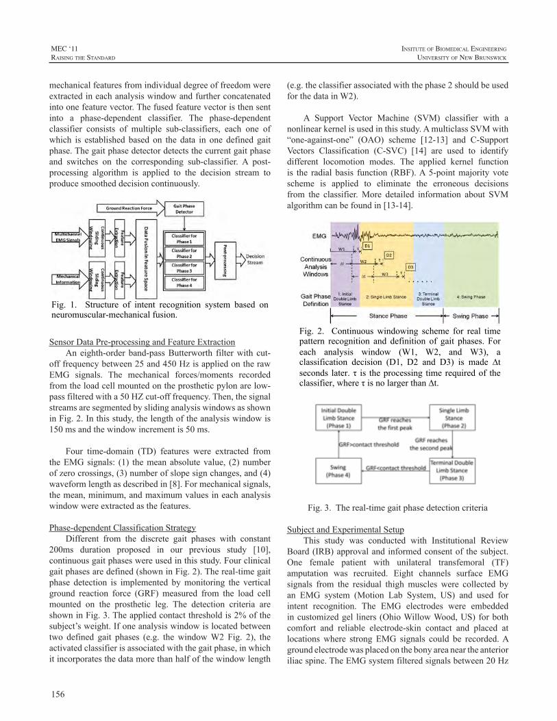
156
MEC ‘11raIsIng the standard
InsItute of BIomedIcal engIneerIng
unIversIty of new BrunswIck
(e.g.theclassifierassociatedwiththephase2shouldbeusedforthedatainW2).
A Support Vector Machine (SVM) classifier with anonlinearkernelisusedinthisstudy.AmulticlassSVMwith“one-against-one” (OAO) scheme [12-13] and C-SupportVectors Classification (C-SVC) [14] are used to identifydifferent locomotion modes. The applied kernel functionis the radial basis function (RBF).A5-pointmajority votescheme is applied to eliminate the erroneous decisionsfrom the classifier.More detailed information about SVMalgorithmcanbefoundin[13-14].
Fig. 2. Continuous windowing scheme for real time pattern recognition and definition of gait phases. For each analysis window (W1, W2, and W3), a classification decision (D1, D2 and D3) is made ∆t seconds later. τ is the processing time required of the classifier, where τ is no larger than ∆t.
Fig.3.Thereal-timegaitphasedetectioncriteria
SubjectandExperimentalSetupThis study was conducted with Institutional Review
Board(IRB)approvalandinformedconsentof thesubject.One female patient with unilateral transfemoral (TF)amputation was recruited. Eight channels surface EMGsignals from the residual thigh muscles were collected byan EMG system (Motion Lab System, US) and used forintent recognition. The EMG electrodes were embeddedincustomizedgel liners(OhioWillowWood,US)forbothcomfort and reliable electrode-skin contact and placed atlocationswhere strong EMG signals could be recorded.Agroundelectrodewasplacedonthebonyareaneartheanterioriliacspine.TheEMGsystemfilteredsignalsbetween20Hz
mechanicalfeaturesfromindividualdegreeoffreedomwereextractedineachanalysiswindowandfurtherconcatenatedintoonefeaturevector.Thefusedfeaturevectoristhensentinto a phase-dependent classifier. The phase-dependentclassifier consists of multiple sub-classifiers, each one ofwhich is established based on the data in one defined gaitphase.Thegaitphasedetectordetectsthecurrentgaitphaseand switches on the corresponding sub-classifier. A post-processing algorithm is applied to the decision stream toproducesmootheddecisioncontinuously.
Fig. 1. Structure of intent recognition system based on neuromuscular-mechanical fusion.
SensorDataPre-processingandFeatureExtraction
Aneighth-orderband-passButterworth filterwith cut-offfrequencybetween25and450HzisappliedontherawEMG signals. The mechanical forces/moments recordedfromtheloadcellmountedontheprostheticpylonarelow-passfilteredwitha50HZcut-offfrequency.Then,thesignalstreamsaresegmentedbyslidinganalysiswindowsasshowninFig.2.Inthisstudy,thelengthoftheanalysiswindowis150msandthewindowincrementis50ms.
Four time-domain (TD) features were extracted fromtheEMGsignals: (1) themeanabsolutevalue, (2)numberofzerocrossings,(3)numberofslopesignchanges,and(4)waveformlengthasdescribedin[8].Formechanicalsignals,themean,minimum,andmaximumvaluesineachanalysiswindowwereextractedasthefeatures.
Phase-dependentClassificationStrategyDifferent from the discrete gait phases with constant
200ms duration proposed in our previous study [10],continuousgaitphaseswereusedinthisstudy.Fourclinicalgaitphasesaredefined(showninFig.2).Thereal-timegaitphase detection is implemented bymonitoring the verticalground reaction force (GRF) measured from the load cellmounted on the prosthetic leg. The detection criteria areshowninFig.3.Theappliedcontactthresholdis2%ofthesubject’sweight.Ifoneanalysiswindowislocatedbetweentwo defined gait phases (e.g. the windowW2 Fig. 2), theactivatedclassifierisassociatedwiththegaitphase,inwhichitincorporatesthedatamorethanhalfofthewindowlength
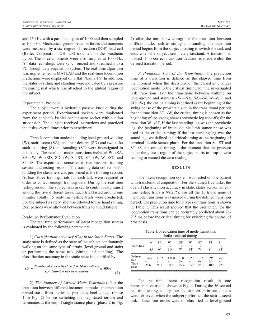
157
InsItute of BIomedIcal engIneerIng
unIversIty of new BrunswIck
MEC ‘11raIsIng the standard
and450Hzwithapass-bandgainof1000andthensampledat1000Hz.Mechanicalgroundreactionforcesandmomentsweremeasuredbyasix–degreeoffreedom(DOF)loadcell(Bertec Corporation, OH, US) mounted on the prostheticpylon.Theforces/momentswerealsosampledat1000Hz.Alldata recordingsweresynchronizedandstreamed intoaPCthroughdataacquisitionsystem.Thereal-timealgorithmwasimplementedinMATLABandthereal-timelocomotionpredictionsweredisplayedonaflatPlasmaTV.Inaddition,thestatesofsittingandstandingwereindicatedbyapressuremeasuringmatwhichwasattached to thegluteal regionofthesubject.
ExperimentalProtocolThe subjectwore a hydraulic passive knee during the
experiment period. Experimental sockets were duplicatedfrom the subject’s ischial containment socket with suctionsuspension.Thesubject received instructionsandpracticedthetasksseveraltimespriortoexperiment.
Threelocomotionmodesincludinglevel-groundwalking(W),stairascent(SA),andstairdescent(SD)andtwotaskssuch as sitting (S) and standing (ST) were investigated inthisstudy.TheresultantmodetransitionsincludedW→SA,SA→W, W→SD, SD→W, S→ST, ST→W, W→ST, andST→S.Theexperiment consistedof two sessions: trainingsessionandtestingsession.Thetrainingdatacollectionforbuildingtheclassifierswasperformedinthetrainingsession.At least three training trials for each taskwere required inorder to collect enough training data.During the real-timetestingsession,thesubjectwasaskedtocontinuouslytransitamongthefivedifferenttasks.Eachtriallastedaroundoneminute. Totally 15 real-time testing trials were conducted.Forthesubject’ssafety,shewasallowedtousehandrailing.Restperiodswereallowedbetweentrialstoavoidfatigue.
Real-timePerformanceEvaluationTherealtimeperformanceofintentrecognitionsystem
isevaluatedbythefollowingparameters.
1)ClassificationAccuracy(CA)intheStaticStates:Thestaticstateisdefinedasthestateofthesubjectcontinuouslywalkingonthesametypeofterrain(levelgroundandstair)or performing the same task (sitting and standing). Theclassificationaccuracyinthestaticstateisquantifiedby
(1)
2) The Number of Missed Mode Transitions: For thetransitionbetweendifferentlocomotionmodes,thetransitionperiod starts from the initial prosthetic heel contact (phase1 in Fig. 2) before switching the negotiated terrain andterminatesattheendofsinglestancephase(phase2inFig.
2) after the terrain switching; for the transition betweendifferent tasks such as sitting and standing, the transitionperiodbeginsfromthesubjectstartingtoswitchthetaskandendswhen the subject completely sit/stand.A transition ismissed if no correct transition decision ismadewithin thedefinedtransitionperiod.
3) Prediction Time of the Transitions: The predictiontime of a transition is defined as the elapsed time fromthe moment when the decisions of the classifier changeslocomotionmode to thecritical timing for the investigatedtask transitions. For the transitions between walking onlevel-groundand staircase (W→SA,SA→W,W→SD,andSD→W),thecriticaltimingisdefinedasthebeginningoftheswingphaseoftheprostheticsideinthetransitionalperiod;forthetransitionST→W,thecriticaltimingischosenasthebeginningoftheswingphase(prostheticlegtoe-off);forthetransitionW→ST,ifthelaststandinglegwastheprostheticleg, the beginning of initial double limb stance phasewasused as the critical timing; if the last standing legwas thesoundleg,wedefinedthecriticaltimingatthebeginningofterminaldoublestancephase.ForthetransitionS→STandST→S, the critical timing is themoment that the pressureundertheglutealregionofthesubjectstartstodroptozeroreadingorexceedthezeroreading.
RESULTS
Theintentrecognitionsystemwastestedononepatientwithtransfemoralamputation.Forthestudiedfivetasks,theoverallclassificationaccuracyinstaticstatesacross15real-time testing trials is 98.25%.For all the 15 trials, none ofthemodetransitionswasmissedduringthedefinedtransitionperiod.Thepredictiontimefor8typesoftransitionsisshowninTable 1. This result showed that the user intent for thelocomotiontransitionscanbeaccuratelypredictedabout76-295msbeforethecriticaltimingforswitchingthecontrolofprosthesis.
Table 1. Predication time of mode transitions before critical timing
Transition W→SA
SA→ W
W → SD
SD→W
W→ ST
ST→ W
ST→ S
S → ST
Estima-tion Time (ms)
126.7± 28.6
136.5± 25.7
138.8± 30.5
108.3± 27.4
92.8± 35.6
127.6± 25.3
295.6± 40.8
76.2± 22.8
The real-time intent recognition result in onerepresentativetrialisshowninFig.4.Duringthe56secondreal-timetesting, totallyfourdecisionerrors instaticstateswereobservedwhenthesubjectperformedthestairdescenttask. These four errors were misclassified as level-ground
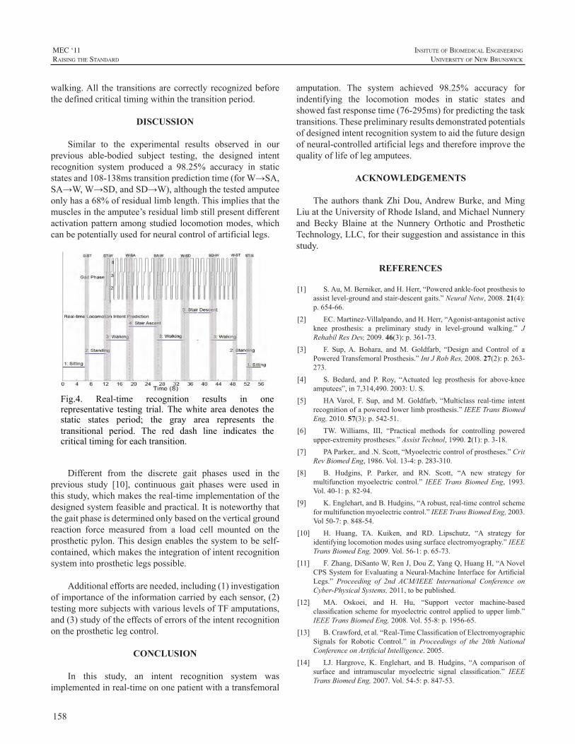
158
MEC ‘11raIsIng the standard
InsItute of BIomedIcal engIneerIng
unIversIty of new BrunswIck
walking.All the transitionsarecorrectly recognizedbeforethedefinedcriticaltimingwithinthetransitionperiod.
DISCUSSION
Similar to the experimental results observed in ourprevious able-bodied subject testing, the designed intentrecognition system produced a 98.25% accuracy in staticstatesand108-138mstransitionpredictiontime(forW→SA,SA→W,W→SD,andSD→W),althoughthetestedamputeeonlyhasa68%ofresiduallimblength.Thisimpliesthatthemusclesintheamputee’sresiduallimbstillpresentdifferentactivationpatternamongstudied locomotionmodes,whichcanbepotentiallyusedforneuralcontrolofartificiallegs.
Fig.4. Real-time recognition results in one representative testing trial. The white area denotes the static states period; the gray area represents the transitional period. The red dash line indicates the critical timing for each transition.
Different from the discrete gait phases used in theprevious study [10], continuous gait phases were used inthisstudy,whichmakesthereal-timeimplementationofthedesignedsystemfeasibleandpractical.Itisnoteworthythatthegaitphaseisdeterminedonlybasedontheverticalgroundreaction force measured from a load cell mounted on theprostheticpylon.Thisdesignenablesthesystemtobeself-contained,whichmakestheintegrationofintentrecognitionsystemintoprostheticlegspossible.
Additionaleffortsareneeded,including(1)investigationofimportanceoftheinformationcarriedbyeachsensor,(2)testingmoresubjectswithvariouslevelsofTFamputations,and(3)studyoftheeffectsoferrorsoftheintentrecognitionontheprostheticlegcontrol.
CONCLUSION
In this study, an intent recognition system wasimplementedinreal-timeononepatientwithatransfemoral
amputation. The system achieved 98.25% accuracy forindentifying the locomotion modes in static states andshowedfastresponsetime(76-295ms)forpredictingthetasktransitions.Thesepreliminaryresultsdemonstratedpotentialsofdesignedintentrecognitionsystemtoaidthefuturedesignofneural-controlledartificiallegsandthereforeimprovethequalityoflifeoflegamputees.
ACKNOWLEDGEMENTS
Theauthors thankZhiDou,AndrewBurke, andMingLiuattheUniversityofRhodeIsland,andMichaelNunneryand Becky Blaine at the Nunnery Orthotic and ProstheticTechnology,LLC,fortheirsuggestionandassistanceinthisstudy.
REFERENCES
[1] S.Au,M.Berniker,andH.Herr,“Poweredankle-footprosthesistoassistlevel-groundandstair-descentgaits.”NeuralNetw,2008.21(4):p.654-66.
[2] EC.Martinez-Villalpando,andH.Herr,“Agonist-antagonistactiveknee prosthesis: a preliminary study in level-ground walking.” JRehabilResDev,2009.46(3):p.361-73.
[3] F. Sup,A. Bohara, andM. Goldfarb, “Design and Control of aPoweredTransfemoralProsthesis.”IntJRobRes,2008.27(2):p.263-273.
[4] S. Bedard, and P. Roy, “Actuated leg prosthesis for above-kneeamputees”,in7,314,490.2003:U.S.
[5] HAVarol, F. Sup, andM.Goldfarb, “Multiclass real-time intentrecognitionofapoweredlowerlimbprosthesis.”IEEETransBiomedEng,2010.57(3):p.542-51.
[6] TW. Williams, III, “Practical methods for controlling poweredupper-extremityprostheses.”AssistTechnol,1990.2(1):p.3-18.
[7] PAParker,.and.N.Scott,“Myoelectriccontrolofprostheses.”CritRevBiomedEng,1986.Vol.13-4:p.283-310.
[8] B. Hudgins, P. Parker, and RN. Scott, “A new strategy formultifunctionmyoelectric control.” IEEE Trans Biomed Eng, 1993.Vol.40-1:p.82-94.
[9] K.Englehart,andB.Hudgins,“Arobust,real-timecontrolschemeformultifunctionmyoelectriccontrol.”IEEETransBiomedEng,2003.Vol50-7:p.848-54.
[10] H. Huang, TA. Kuiken, and RD. Lipschutz, “A strategy foridentifyinglocomotionmodesusingsurfaceelectromyography.”IEEETransBiomedEng,2009.Vol.56-1:p.65-73.
[11] F.Zhang,DiSantoW,RenJ,DouZ,YangQ,HuangH,“ANovelCPSSystemforEvaluatingaNeural-MachineInterfaceforArtificialLegs.” Proceeding of 2nd ACM/IEEE International Conference onCyber-PhysicalSystems,2011,tobepublished.
[12] MA. Oskoei, and H. Hu, “Support vector machine-basedclassificationschemeformyoelectriccontrolappliedtoupperlimb.”IEEETransBiomedEng,2008.Vol.55-8:p.1956-65.
[13] B.Crawford,etal.“Real-TimeClassificationofElectromyographicSignals for Robotic Control.” in Proceedings of the 20th NationalConferenceonArtificialIntelligence.2005.
[14] LJ. Hargrove, K. Englehart, and B. Hudgins, “A comparison ofsurface and intramuscular myoelectric signal classification.” IEEETransBiomedEng,2007.Vol.54-5:p.847-53.
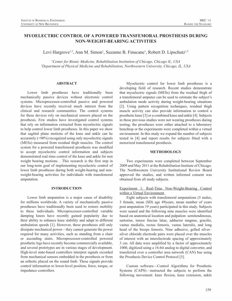
159
InsItute of BIomedIcal engIneerIng
unIversIty of new BrunswIck
MEC ‘11raIsIng the standard
ABSTRACT
Lower limb prostheses have traditionally beenmechanically passive devices without electronic controlsystems. Microprocessor-controlled passive and powereddevices have recently received much interest from theclinical and research communities. The control systemsfor thesedevices relyonmechanical sensorsplacedon theprosthesis. Few studies have investigated control systemsthatrelyon informationextractedfrommyoelectricsignalstohelpcontrollowerlimbprostheses.Inthispaperweshowthat sagittal plane motions of the knee and ankle can beaccurately(>90%)recognizedusingonlymyoelectricsignals(MESs)measuredfromresidualthighmuscles.Thecontrolsystemforapoweredtransfemoralprosthesiswasmodifiedto accept myoelectric control information and subjectsdemonstratedreal-timecontrolofthekneeandanklefornonweight bearingmotions. .This research is the first step inour long-termgoalof implementingmyoelectriccontroloflowerlimbprosthesesduringbothweight-bearingandnon-weight-bearing activities for individuals with transfemoralamputation.
INTRODUCTION
Lower limb amputation is a major cause of disabilityformillionsworldwide.A variety ofmechanically passiveprostheses have traditionally been used to restoremobilityto these individuals. Microprocessor-controlled variabledamping knees have recently gained popularity due totheirabilitytoenhancekneestabilityandadapttodifferentambulationspeeds[1].However,theseprosthesesstillonlydissipatemechanicalpower—theycannotgeneratethepowerrequired formanyactivities, suchas standing fromachairor ascending stairs. Microprocessor-controlled poweredprostheticlegshaverecentlybecomecommerciallyavailable,andseveralprototypesareinvariousstagesofdevelopment.High-levelstate-basedcontrollersinterpretsignalsrecordedfrommechanicalsensorsembeddedintheprosthesisorfromanorthoticplacedonthesoundlimb.Thesesignalsprovidecontrolinformationtolower-levelposition,force,torque,orimpedancecontrollers.
Myoelectric control for lower limb prostheses is adeveloping field of research. Recent studies demonstratethatmyoelectric signals (MESs) from the residual thighofatransfemoralamputeecanbeusedtoestimatethesubject’sambulationmode activity during weight-bearing situations[2]. Using pattern recognition techniques, residual thighmuscle activity can also provide information to control aprostheticknee[3]oracombinedkneeandankle[4].Subjectsinthesepreviousstudieswerenotwearingprosthesesduringtesting; the prostheseswere either attached to a laboratorybenchtoportheexperimentswerecompletedwithinavirtualenvironment.Inthisstudyweexpandthenumberofsubjectstested in [4] and report results for subjects fitted with amotorizedtransfemoralprosthesis.
METHODOLOGY
Two experiments were completed between September2009andMay2011attheRehabilitationInstituteofChicago.The Northwestern University Institutional Review Boardapproved the studies, and written informed consent wasobtainedfromallstudysubjects.
Experiment 1: Real-Time Non-Weight-Bearing ControlwithinaVirtualEnvironment
Eightsubjectswithtransfemoralamputations(5males,3 female, mean (SD) age 49years, mean number of yearspostamputation19years)participatedinthisstudy.Subjectswereseatedandthefollowingninemuscleswereidentifiedbasedonanatomicallocationandpalpation:semitendinosus,sartorius, tensor fasciae latae, adductor magnus, gracilis,vastus medialis, rectus femoris, vastus lateralis, and longhead of the biceps femoris. Nine adhesive, gelled silver–silverchlorideelectrodepairswereplacedoverthemusclesof interestwith an interelectrode spacingof approximately3cm.Alldatawereamplifiedbyafactorofapproximately1000,digitizedusinga16-bitanalogtodigitalconverter,andtransferredoveracontrollerareanetwork(CAN)bususingtheProsthesisDeviceControlProtocol[5].
Custom software—Control Algorithms for ProstheticSystems (CAPS)—instructed the subjects to perform thefollowing movement: knee flexion, knee extension, ankle
MYOELECTRIC CONTROL OF A POWERED TRANSFEMORAL PROSTHESIS DURING NON-WEIGHT-BEARING ACTIVITIES
LeviHargrove1,2,AnnM.Simon1,SuzanneB.Finucane1,RobertD.Lipschutz1,2
1CenterforBionicMedicine,RehabilitationInstitutionofChicago,ChicagoIL,USA2DepartmentofPhysicalMedicineandRehabilitation,NorthwesternUniversity,Chicago,IL,USA
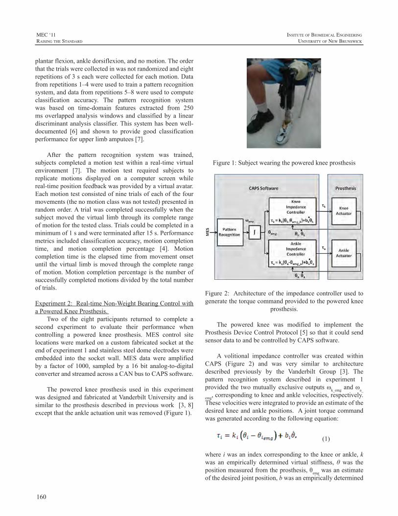
160
MEC ‘11raIsIng the standard
InsItute of BIomedIcal engIneerIng
unIversIty of new BrunswIck
plantarflexion,ankledorsiflexion,andnomotion.Theorderthatthetrialswerecollectedinwasnotrandomizedandeightrepetitionsof3seachwerecollectedforeachmotion.Datafromrepetitions1–4wereusedtotrainapatternrecognitionsystem,anddatafromrepetitions5–8wereusedtocomputeclassification accuracy. The pattern recognition systemwas based on time-domain features extracted from 250msoverlappedanalysiswindowsandclassifiedbya lineardiscriminantanalysisclassifier.Thissystemhasbeenwell-documented [6] and shown to provide good classificationperformanceforupperlimbamputees[7].
After the pattern recognition system was trained,subjects completed amotion testwithin a real-timevirtualenvironment [7]. The motion test required subjects toreplicate motions displayed on a computer screen whilereal-timepositionfeedbackwasprovidedbyavirtualavatar.Eachmotiontestconsistedofninetrialsofeachofthefourmovements(thenomotionclasswasnottested)presentedinrandomorder.Atrialwascompletedsuccessfullywhenthesubjectmoved the virtual limb through its complete rangeofmotionforthetestedclass.Trialscouldbecompletedinaminimumof1sandwereterminatedafter15s.Performancemetricsincludedclassificationaccuracy,motioncompletiontime, and motion completion percentage [4]. Motioncompletion time is the elapsed time frommovement onsetuntil thevirtual limb ismoved through thecomplete rangeofmotion.Motioncompletionpercentage is thenumberofsuccessfullycompletedmotionsdividedbythetotalnumberoftrials.
Experiment2:Real-timeNon-WeightBearingControlwithaPoweredKneeProsthesis.
Two of the eight participants returned to complete asecond experiment to evaluate their performance whencontrolling a powered knee prosthesis. MES control sitelocationsweremarkedonacustomfabricatedsocketattheendofexperiment1andstainlesssteeldomeelectrodeswereembedded into the socket wall.MES data were amplifiedby a factor of 1000, sampled by a 16 bit analog-to-digitalconverterandstreamedacrossaCANbustoCAPSsoftware.
The powered knee prosthesis used in this experimentwasdesignedandfabricatedatVanderbiltUniversityandissimilar to theprosthesisdescribed inpreviouswork [3,8]exceptthattheankleactuationunitwasremoved(Figure1).
Figure1:Subjectwearingthepoweredkneeprosthesis
Figure2: Architectureof the impedancecontrollerusedtogeneratethetorquecommandprovidedtothepoweredknee
prosthesis.
The powered knee was modified to implement theProsthesisDeviceControlProtocol[5]sothatitcouldsendsensordatatoandbecontrolledbyCAPSsoftware.
A volitional impedance controller was created withinCAPS (Figure 2) and was very similar to architecturedescribed previously by the Vanderbilt Group [3]. Thepattern recognition system described in experiment 1provided the twomutuallyexclusiveoutputsωk_emgandωa_
emg,correspondingtokneeandanklevelocities,respectively.Thesevelocitieswereintegratedtoprovideanestimateofthedesiredkneeandanklepositions. Ajoint torquecommandwasgeneratedaccordingtothefollowingequation:
(1)
whereiwasanindexcorrespondingtothekneeorankle,kwas an empirically determined virtual stiffness, θ was thepositionmeasuredfromtheprosthesis,θemgwasanestimateofthedesiredjointposition,bwasanempiricallydetermined
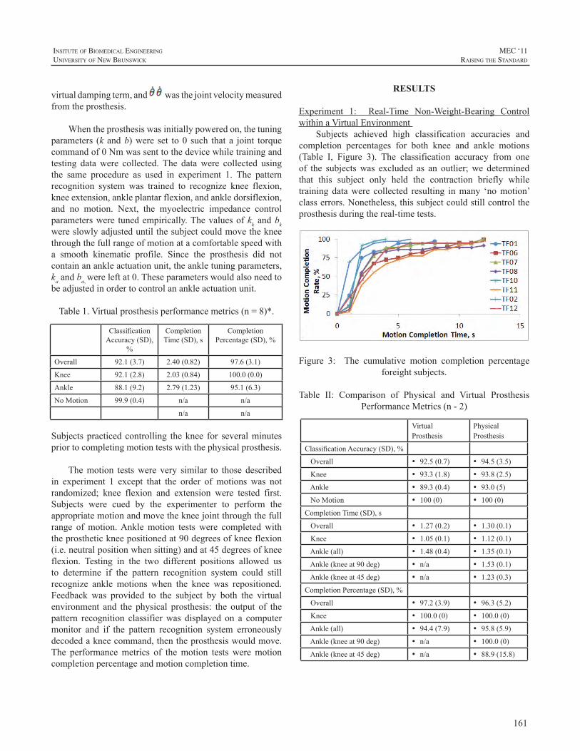
161
InsItute of BIomedIcal engIneerIng
unIversIty of new BrunswIck
MEC ‘11raIsIng the standard
virtualdampingterm,and wasthejointvelocitymeasuredfromtheprosthesis.
Whentheprosthesiswasinitiallypoweredon,thetuningparameters (k andb)were set to0 such that a joint torquecommandof0Nmwassenttothedevicewhiletrainingandtesting datawere collected.The datawere collected usingthe same procedure as used in experiment 1. The patternrecognition system was trained to recognize knee flexion,kneeextension,ankleplantarflexion,andankledorsiflexion,and no motion. Next, the myoelectric impedance controlparameterswere tunedempirically.Thevaluesofkkandbkwereslowlyadjusteduntilthesubjectcouldmovethekneethroughthefullrangeofmotionatacomfortablespeedwitha smooth kinematic profile. Since the prosthesis did notcontainanankleactuationunit,theankletuningparameters,kaandba,wereleftat0.Theseparameterswouldalsoneedtobeadjustedinordertocontrolanankleactuationunit.
Table1.Virtualprosthesisperformancemetrics(n=8)*.
ClassificationAccuracy(SD),
%
CompletionTime(SD),s
CompletionPercentage(SD),%
Overall 92.1(3.7) 2.40(0.82) 97.6(3.1)
Knee 92.1(2.8) 2.03(0.84) 100.0(0.0)
Ankle 88.1(9.2) 2.79(1.23) 95.1(6.3)
NoMotion 99.9(0.4) n/a n/a
n/a n/a
Subjectspracticedcontrolling theknee for severalminutespriortocompletingmotiontestswiththephysicalprosthesis.
Themotion testswere very similar to those describedin experiment 1 except that the order of motions was notrandomized; knee flexion and extension were tested first.Subjects were cued by the experimenter to perform theappropriatemotionandmovethekneejointthroughthefullrange ofmotion.Anklemotion tests were completedwiththeprosthetickneepositionedat90degreesofkneeflexion(i.e.neutralpositionwhensitting)andat45degreesofkneeflexion. Testing in the two different positions allowed usto determine if the pattern recognition system could stillrecognize ankle motions when the knee was repositioned.Feedback was provided to the subject by both the virtualenvironment and the physical prosthesis: the output of thepattern recognition classifierwas displayed on a computermonitor and if the pattern recognition system erroneouslydecodedakneecommand,thentheprosthesiswouldmove.The performancemetrics of themotion tests weremotioncompletionpercentageandmotioncompletiontime.
RESULTS
Experiment 1: Real-Time Non-Weight-Bearing ControlwithinaVirtualEnvironment
Subjects achieved high classification accuracies andcompletion percentages for both knee and ankle motions(Table I, Figure 3). The classification accuracy from oneof the subjectswas excluded as an outlier;we determinedthat this subject only held the contraction briefly whiletraining datawere collected resulting inmany ‘nomotion’classerrors.Nonetheless,thissubjectcouldstillcontroltheprosthesisduringthereal-timetests.
Figure 3: The cumulative motion completion percentageforeightsubjects.
Table II: Comparison of Physical and Virtual ProsthesisPerformanceMetrics(n-2)
VirtualProsthesis
PhysicalProsthesis
ClassificationAccuracy(SD),%
Overall • 92.5(0.7) • 94.5(3.5)
Knee • 93.3(1.8) • 93.8(2.5)
Ankle • 89.3(0.4) • 93.0(5)
NoMotion • 100(0) • 100(0)
CompletionTime(SD),s
Overall • 1.27(0.2) • 1.30(0.1)
Knee • 1.05(0.1) • 1.12(0.1)
Ankle(all) • 1.48(0.4) • 1.35(0.1)
Ankle(kneeat90deg) • n/a • 1.53(0.1)
Ankle(kneeat45deg) • n/a • 1.23(0.3)
CompletionPercentage(SD),%
Overall • 97.2(3.9) • 96.3(5.2)
Knee • 100.0(0) • 100.0(0)
Ankle(all) • 94.4(7.9) • 95.8(5.9)
Ankle(kneeat90deg) • n/a • 100.0(0)
Ankle(kneeat45deg) • n/a • 88.9(15.8)
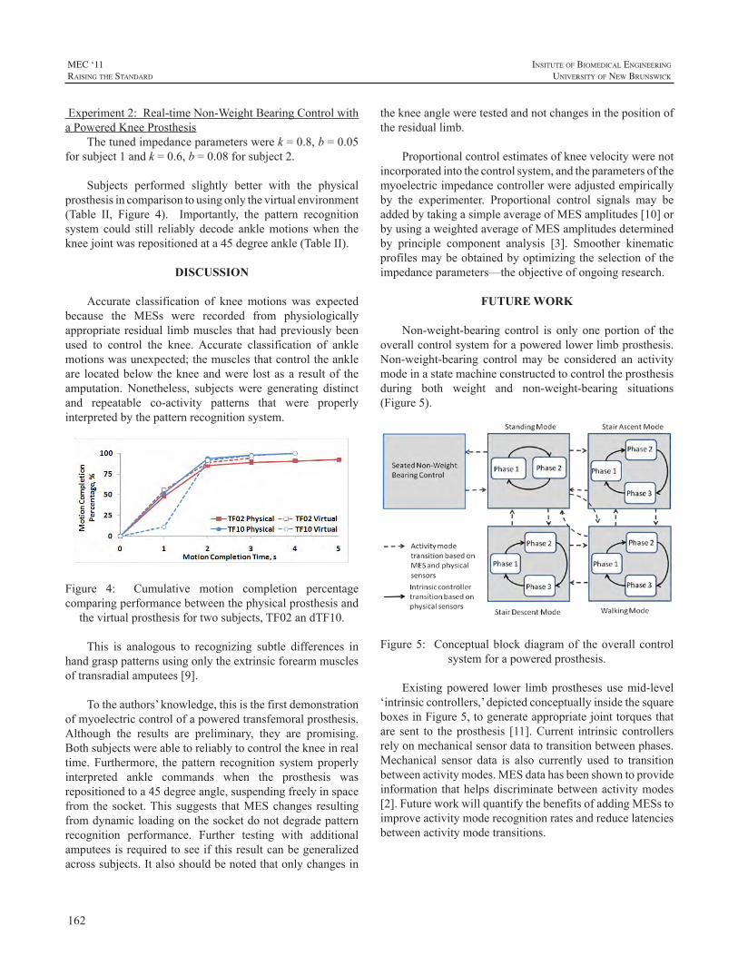
162
MEC ‘11raIsIng the standard
InsItute of BIomedIcal engIneerIng
unIversIty of new BrunswIck
Experiment2:Real-timeNon-WeightBearingControlwithaPoweredKneeProsthesis
Thetunedimpedanceparameterswerek=0.8,b=0.05forsubject1andk=0.6,b=0.08forsubject2.
Subjects performed slightly better with the physicalprosthesisincomparisontousingonlythevirtualenvironment(Table II, Figure 4). Importantly, the pattern recognitionsystem could still reliably decode anklemotionswhen thekneejointwasrepositionedata45degreeankle(TableII).
DISCUSSION
Accurate classification of knee motions was expectedbecause the MESs were recorded from physiologicallyappropriate residual limbmuscles thathadpreviouslybeenused to control the knee.Accurate classification of anklemotionswasunexpected;themusclesthatcontroltheankleare locatedbelow thekneeandwere lostasa resultof theamputation. Nonetheless, subjects were generating distinctand repeatable co-activity patterns that were properlyinterpretedbythepatternrecognitionsystem.
Figure 4: Cumulative motion completion percentagecomparingperformancebetweenthephysicalprosthesisand
thevirtualprosthesisfortwosubjects,TF02andTF10.
This is analogous to recognizing subtle differences inhandgrasppatternsusingonlytheextrinsicforearmmusclesoftransradialamputees[9].
Totheauthors’knowledge,thisisthefirstdemonstrationofmyoelectriccontrolofapoweredtransfemoralprosthesis.Although the results are preliminary, they are promising.Bothsubjectswereabletoreliablytocontrolthekneeinrealtime. Furthermore, the pattern recognition systemproperlyinterpreted ankle commands when the prosthesis wasrepositionedtoa45degreeangle,suspendingfreelyinspacefrom the socket.This suggests thatMESchanges resultingfromdynamicloadingonthesocketdonotdegradepatternrecognition performance. Further testing with additionalamputeesisrequiredtoseeifthisresultcanbegeneralizedacrosssubjects.Italsoshouldbenotedthatonlychangesin
thekneeangleweretestedandnotchangesinthepositionoftheresiduallimb.
Proportionalcontrolestimatesofkneevelocitywerenotincorporatedintothecontrolsystem,andtheparametersofthemyoelectricimpedancecontrollerwereadjustedempiricallyby the experimenter. Proportional control signals may beaddedbytakingasimpleaverageofMESamplitudes[10]orbyusingaweightedaverageofMESamplitudesdeterminedby principle component analysis [3]. Smoother kinematicprofilesmaybeobtainedbyoptimizingtheselectionoftheimpedanceparameters—theobjectiveofongoingresearch.
FUTURE WORK
Non-weight-bearing control is only one portion of theoverallcontrolsystemforapoweredlowerlimbprosthesis.Non-weight-bearing controlmay be considered an activitymodeinastatemachineconstructedtocontroltheprosthesisduring both weight and non-weight-bearing situations(Figure5).
Figure5: Conceptualblockdiagramof theoverallcontrolsystemforapoweredprosthesis.
Existing powered lower limbprostheses usemid-level‘intrinsiccontrollers,’depictedconceptuallyinsidethesquareboxesinFigure5,togenerateappropriatejointtorquesthatare sent to theprosthesis [11].Current intrinsic controllersrelyonmechanicalsensordatatotransitionbetweenphases.Mechanical sensor data is also currently used to transitionbetweenactivitymodes.MESdatahasbeenshowntoprovideinformation thathelpsdiscriminatebetweenactivitymodes[2].FutureworkwillquantifythebenefitsofaddingMESstoimproveactivitymoderecognitionratesandreducelatenciesbetweenactivitymodetransitions.
163
InsItute of BIomedIcal engIneerIng
unIversIty of new BrunswIck
MEC ‘11raIsIng the standard
ACKNOWLEDGEMENTS
ThisworkwassupportedbytheUSArmyTelemedicineandAdvancedTechnologyResearchCenter(TATRC)projectW81XWH-09-2-0020. The authors acknowledge AnnBarlow andAimee Schultz for editing themanuscript andToddKuikenforprojectguidance.
REFERENCES
[1] J.L.Johansson,D.M.Sherrill,P.O.Riley,P.Bonato,andH.Herr,“Aclinicalcomparisonofvariable-dampingandmechanicallypassiveprosthetickneedevices,”Am.J.Phys.Med.Rehabil.,vol.84,pp.563-75,2005.
[2] H.Huang,T.Kuiken,andR.Lipschutz,“AStrategyforIdentifyingLocomotionModes usingSurfaceElectromyography,” IEEE.Trans.Biomed.Eng.,vol.56,pp.65-73,2009.
[3] K. Ha, H.A. Varol, and M. Goldfarb, “Volitional Control of aProsthetic Knee Using Surface Electromyography,” IEEE Trans.Biomed.Eng.,vol.58,pp.144-151,,2011.
[4] L.Hargrove,A.Simon,R.Lipschutz,S.Finucane,andT.Kuiken,“Real-Time Myoelectric Control of Knee and Ankle Motions forTransfemoralAmputees,”JAMA,vol.305,pp.1442-1444,2011.
[5] Y. Losier andA.Wilson, “Moving Towards an Open Standard:TheUNBProstheticDeviceCommunicationProtocol,”InternationalSocietyforProsthetics&Orthotics(ISPO)WorldCongress,Leipzig,Germany,2010.
[6] K.EnglehartandB.Hudgins,“Arobust,real-timecontrolschemeformultifunctionmyoelectriccontrol,”IEEETrans.Biomed.Eng.,vol.50,pp.848-54,2003.
[7] T.A.Kuiken,G.Li,B.A.Lock,R.D.Lipschutz,L.A.Miller,K.A.Stubblefield,andK.B.Englehart,“Targetedmusclereinnervationforreal-timemyoelectriccontrolofmultifunctionartificialarms,”JAMA,vol.301,pp.619-28,2009.
[8] F. Sup, H.A. Varol, J. Mitchell, T.Withrow, andM. Goldfarb,“DesignandControlofanActiveElectricalKneeandAnkleProsthesis,”ProcIEEERASEMBSIntConfBiomedRobotBiomechatron.,pp.523-5282008.
[9] G. Li, A. E. Schultz, and T. A. Kuiken, “Quantifying patternrecognition-based myoelectric control of multifunctional transradialprostheses,”IEEETransactionsonNeuralSystemsandRehabilitationEngineering,vol.18,pp.185-92,2009.
[10] L.Hargrove,P.Zhou,K.Englehart,andT.Kuiken,“TheEffectofECGInterferenceonPatternRecognitionBasedMyoelectricControlFor TargetedMuscle Reinnervated Patients,” IEEE. Trans. Biomed.Eng.,vol.56,pp.2197-2201,2009.
[11] H.A.Varol,F.Sup,andM.Goldfarb,“MulticlassReal-TimeIntentRecognition of a Powered Lower Limb Prosthesis,” IEEE Trans.Biomed.Eng.,vol.57,pp.542-551,2010.
164
MEC ‘11raIsIng the standard
InsItute of BIomedIcal engIneerIng
unIversIty of new BrunswIck
INTRODUCTION
Prosthetic devices are designed to increase the actionpossibilitiesofanamputee.Appropriateactionswithupper-extremityprosthesesareonlypossiblewhenthesedevicescanbecontrolleddexterously.Importantly,thecontrolsignalsoftheneuromotorsystemnecessarytoperformagoal-directedactionwithaprosthesisdifferfromthosecontrolsignalsusedtoperformanactionwithanintactlimb.Todiscusswhatitmeansfortheneuromotorsystemtolearntocontrolanupperlimb prosthetic device, the current presentation will startfromBernstein’s(Russianoriginalfrom1940,publishedinEnglishin1996)insightfultreatiseonthehierarchicallevelsforthecontrolofmovement.Fromthisoverviewweaimtomakerecommendationsregardingtheissuesthatresearchonlearningtocontrolaprostheticdevicefortheupperextremityshouldfocuson.
LEVELS OF CONSTRUCTION OF MOVEMENT
Bernstein was a neurophysiologist with a primaryinterestinmotorcontrol.Basedontheevolutionofthebrainhedistinguishedfourlevelsofcontrolofhumanmovementthat each controlled a different class ofmovements.Theselevelswerehierarchicallyorganizedwitheachlevelemergingon top of the existing levels. Each new level emergedbased on evolutionary pressure requiring a new class ofmovement.More specifically, based on new challenges inthe environment, new actions had to evolve tomeet thesechallenges.Thesenewlyevolvedactionswereaccompaniedwith new sensory correction mechanisms. Based on theinterplay between the newly emerged actions and theaccompanying sensory corrections, new neural structuresevolved.Thesenewneuralstructuresrepresentedanewlevelofconstructionofmovementandaccountedforanewclassofmovements.Importantly,inevolution,and,thus,presumablyinmotorlearning,motorfunctioningandsensoryfunctioningdevelopedmutually.
The four levels Bernstein (1996) distinguished inmotorcontrolwere:theleveloftone,thelevelofsynergies,the levelofspaceand the levelofaction.The lowest levelofmotor control, and also the oldest, is that of tone.This
levelcontrols thebackgroundmuscular force thatprovidespostural stability underlying all acts. The next level is theone that emerged when extremities evolved; it controlsthe linking together ofmuscle-articular groups so that thenumerousmusclesbecomecontrollabletoperformstableandreproduciblemovements.Notethatsensorycorrectionswereprimarilybasedonproprioceptionattheleveloftoneandthatofsynergies.Thesensorycorrectionsattheothertwolevelsareprimarilyvisuallybased.Thelevelofspaceregulatesthatmovements reach theirgoals in theworkspacesurroundingthebody;distancesandorientationsofobjectsareperceivedforreachingmovementstobegoal-directed.Thehighestlevelofcontrolisthatofaction,inwhichsequencesofmovementsare controlled.This level of control takes care of adaptivesolutions to new situations.The levels of tone and that ofsynergiesarethesupportivelevelswhereasthelevelofspaceandactiontaketheleadingrole.
LEVELS AND PROSTHETIC USE
LeveloftoneThis level ofmotor control is easily overlooked since
it functions in thebackground indailyactivities.However,for prosthetic control it is important to take this level intoaccount.Note that thedistributionof themassof thebodychanges after an amputation. This affects the harmonicityof the walking pattern of an unilateral amputee. Wearinga prosthesis partly reduces such disturbances of walkingpatterns(Bertelsetal.,2010).However,themassandmassdistributionofanupperlimbprosthesisisdifferentfromthatof a sound arm.This implies that themoments and forcesaroundtheproximaljoints,suchastheshoulderjointdifferwithaprosthesiscomparedtothatofasoundarm.Thiswilldisturb postural control. Hence, optimizing a prosthesisshould take such issues into account. Moreover, trainingprogramsmayhavetofocusonhowtoincorporatetheuseofpreparatorymuscleactivitythatcounteractstheforcesthattheprosthesisproduces.
LevelofsynergiesTogetherwiththelevelofspace,thelevelofsynergies
is most important to consider when learning to use aprothesis.Activeupperextremityprosthesescanbebroadly
MOTOR CONTROL PROCESSES WHEN LEARNING TO USE A PROSTHETIC DEVICE
RaoulM.Bongers1,HannekeBouwsema1,andCorryK.vanderSluis2
1CenterforHumanMovementSciences,UniversityMedicalCenterGroningen,UniversityofGroningen,Groningen,TheNetherlands,2CenterforRehabilitation,UniversityMedicalCenterGroningen,Groningen,TheNetherlands
165
InsItute of BIomedIcal engIneerIng
unIversIty of new BrunswIck
MEC ‘11raIsIng the standard
distinguishedintothosethatarecontrolledwithmyo-signalsand those that arebody-powered,usingaharness.Theuseofbothtypesofprosthesesimpliesthelearningofdifferentsynergies.
The definition of synergies employed in the currentpaperistheoneproposedbyBizziandd’Avella(Bizzietal.,2008;d’Avellaetal.,2006).Musclesynergiesaredefinedasadistinctpatternofactivityovertimeofagroupofmuscles.Toproduceamovementasetofsynergiesiscombined.Toexecute differentmovements the onset time and amplitudescalingofeachindividualsynergyareadapted.
Formyo-electricallycontrolledprosthesesitisimportantto understand that the myo-signals picked up by theprostheses’ electrodes are essentially themuscle activationpatternsthatresultfromtheactivationofsynergies.Hence,learningtocontrolamyo-electricprosthesisimplieslearningtoactivatetheappropriatesetofsynergiesandscaletheonsettimingandamplitudeinanappropriateway.Note that inamyo-electricprosthesisusuallytheflexorsandextensorsofthewristareactivatedtocontrolclosingandopeningoftheprosthetichand.Thesearedifferentmusclesthanareusedinthesoundhand,hence, learning touseaprosthesis implieslearningnewscalingparametersofthesynergiescomprisingthesemuscles.
Thesameistrueforlearningtocontrolabody-poweredprosthesis. However, now different synergies have to belearned.Usuallythecontra-lateralshoulderisusedtocontrolthehandopeningoftheprosthetichand,hence,itisobviousthatthemusclesinvolvedfortheprosthetichandcontrolaredifferentfromthosethatareusedinasoundhand.Thus,inthis case the synergies around the contra-lateral shoulderneedtobescaledtoproducetheappropriatemuscleforcethatcontrols prosthetic hand opening. Importantly, the sensorycorrections of the body-powered prosthesis differs fromthatofthemyo-electricallycontrolledprosthesis.Thebody-powered prostheses can be controlled with proprioceptionsignals because of the forces required to control them.Thismight result ina relativelyeasier learningof thenewsynergiescontrollingtheprosthesisbecausethesesynergiesareregulatedmainlybyproprioception.
Surprisingly,at themomentnostudiesareavailable intheliteratureaddressingthechangeinactivationofsynergieswhenlearninganewmotortask.Moreover,theideathatthemyo-signals picked up by myo-electric prosthetic devicesresultfromsynergiesisinlinewithrecentdevelopmentsinthedesignofpick-upmechanismsinthatmultipleelectrodesareusedandthatpatternrecognitionalgorithmsareusedtodetect a larger ranges of choices to controlmore complexprosthetichands.
LevelofspaceGoal-directedreachingandgraspingarecontrolledatthe
levelofspace.Reachingandgraspingisdonedifferentlywithaprosthesisthanwithasoundhand:(i)thegrasptakeslongerand has a relatively long decelerative phase, (ii) the graspstarts after the reach has been initiated, and (iii) the graspprofileshowsaplateauphase(Bouwsema,etal.,2010;Wingand Fraser, 1983).One of the reasons for these deviationsin thegraspingprofilemight be the lackof proprioceptivefeedbackabouttheprosthetichand.Thismakesthatprosthesisusers have to rely solelyonvisual feedback for aspects ofmotor functioningwhile in the sound hand proprioceptionisaprimarysourceoffeedback.Trainingofprosthesis’useshould focus on making the grasp with a prosthesis morefluent.Moreover,technicaldevelopmentsshouldconcentrateonprovidingmoreandappropriatesensory feedbackabouttheprosthesisinuse.
LevelofactionThe highest level of control ofmovement regards the
controlofsequencesofactions.Twoissueswillbediscussed.First, in sound behaviour the gaze usually precedes themanipulative actions of the hand, that is,whenpicking upan object the gaze usually arrives at the object before thehandandthegazeneverchecksthehand.Thepresentationof Bouwsema et al. (2011) will address how this is donewithprostheses.Second,tomanipulateanobject,thatobjectneeds to be oriented relative to the hand in an appropriateway.Thismeansthatactionsneedtobeplannedinadvance,sothattheobjectisgraspedinsuchawaythatisappropriatefor the upcoming action. This implies that during objectmanipulationswitchesbetweengraspshavetobemade.Thisrequiresprosthesisthatallowforaswiftalterationbetweenhandposture,whichrequirelowattentionalcosts.
Thislatteraspectisespeciallyimportantfortherecentlydevelopedmulti-articulatedprosthetichands.Becausemoregrip patterns are availablewith these hands, the grips canbe adjusted to details of the function of the hand at eachparticularmomentinataskperformance.
CONCLUSIONS
We presented a view on motor control that allows toframetheproblemsofresearchintotheuseofupperextremityprostheticdevicesinoneframework.Thisframeworkallowsforahierarchicalapproachoftheproblemsofprostheticuse.From this view the change between different grip patternsshould be made easy, the feedback about the prosthesisshould improve, the reachingandgraspingshouldbemorefluent, trainingshouldtakeintoaccountthatnewsynergieshavetobelearned,andtheposturaldisturbancesfollowingprosthetic use should be considered in training and indevelopingprostheticdevices.
166
MEC ‘11raIsIng the standard
InsItute of BIomedIcal engIneerIng
unIversIty of new BrunswIck
REFERENCES
[1] N.A.Bernstein,“Ondexterityanditsdevelopment,”inM.L.Latash&M.T.Turvey(Eds.),Dexterityanditsdevelopment,pp.3-244,1996,LawrenceErlbaumAssociates,Hillsdale,NJ.
[2] T.Bertels,T.Schmalz,andE.Ludwigs,“Biomechanicalevaluationof a free-swinging shoulder prosthesis for shoulder amputeeswhilewalkingandstanding,”Abstracts,ISPO-13WorldCongress,Leipzig,Germany,pp.257-258,2010.
[3] H.Bouwsema,C.K.vanderSluis,andR.M.Bongers,“Movementcharacteristicsofupperextremityprosthesesduringbasicgoal-directedtasks,”Clin.Biom.,vol.25,pp.523-529,2010.
[4] H.Bouwsema,P.J.Kyberd,W.Hill,C.K.vanderSluis,andR.M.Bongers,“Usingmultipleoutcomemeasurestodetermineskilllevelinmyoelectricprosthesisuse,”MECproceedings,2011.
[5] E.Bizzi,V.C.K.Cheung,A.d’Avella,andM.Tresch,“Combiningmodulesformovement,”BrainRes.Rev.,vol.57,pp.125-133,2008.
[6] A.d’Avella,A.Portone,L.Fernandez,andF.Lacquaniti,“Controlof fast-reaching movements by muscle synergy combinations,” J.Neurosc.,vol.26,pp.7791-7810,2006.
[7] A.M. Wing, and C. Fraser, “The contribution of the thumb toreaching movements,”Q. J. Exp. Psychol., vol. 35A, pp. 297-307,1983.
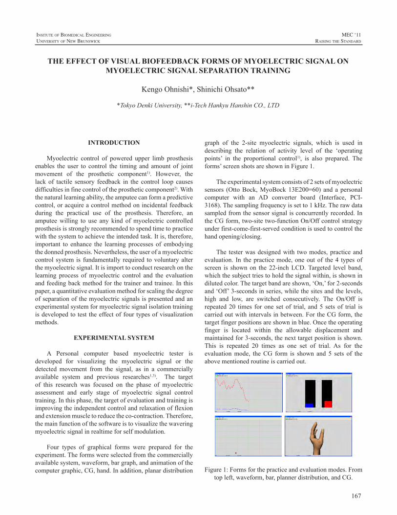
167
InsItute of BIomedIcal engIneerIng
unIversIty of new BrunswIck
MEC ‘11raIsIng the standard
INTRODUCTION
Myoelectric control of powered upper limb prosthesisenables the user to control the timing and amount of jointmovement of the prosthetic component1). However, thelack of tactile sensory feedback in the control loop causesdifficultiesinfinecontroloftheprostheticcomponent2).Withthenaturallearningability,theamputeecanformapredictivecontrol,oracquireacontrolmethodonincidentalfeedbackduring the practical use of the prosthesis. Therefore, anamputeewilling to use any kind ofmyoelectric controlledprosthesisisstronglyrecommendedtospendtimetopracticewiththesystemtoachievetheintendedtask.Itis,therefore,important to enhance the learning processes of embodyingthedonnedprosthesis.Nevertheless,theuserofamyoelectriccontrol system is fundamentally required tovoluntaryalterthemyoelectricsignal.Itisimporttoconductresearchonthelearning process ofmyoelectric control and the evaluationandfeedingbackmethodforthetrainerandtrainee.Inthispaper,aquantitativeevaluationmethodforscalingthedegreeofseparationofthemyoelectricsignalsispresentedandanexperimentalsystemformyoelectricsignalisolationtrainingisdevelopedtotesttheeffectoffourtypesofvisualizationmethods.
EXPERIMENTAL SYSTEM
A Personal computer based myoelectric tester isdeveloped for visualizing the myoelectric signal or thedetected movement from the signal, as in a commerciallyavailable system and previous researches1,3). The targetof this research was focused on the phase of myoelectricassessment and early stage of myoelectric signal controltraining.Inthisphase,thetargetofevaluationandtrainingisimprovingtheindependentcontrolandrelaxationofflexionandextensionmuscletoreducetheco-contraction.Therefore,themainfunctionofthesoftwareistovisualizethewaveringmyoelectricsignalinrealtimeforselfmodulation.
Four types of graphical forms were prepared for theexperiment.Theformswereselectedfromthecommerciallyavailablesystem,waveform,bargraph,andanimationofthecomputergraphic,CG,hand.Inaddition,planardistribution
graph of the 2-site myoelectric signals, which is used indescribing the relation of activity level of the ‘operatingpoints’ in the proportional control1), is also prepared. Theforms’screenshotsareshowninFigure1.
Theexperimentalsystemconsistsof2setsofmyoelectricsensors (OttoBock,MyoBock13E200=60) and apersonalcomputer with an AD converter board (Interface, PCI-3168).Thesamplingfrequencyissetto1kHz.Therawdatasampledfromthesensorsignalisconcurrentlyrecorded.IntheCGform,two-sitetwo-functionOn/Offcontrolstrategyunderfirst-come-first-servedconditionisusedtocontrolthehandopening/closing.
The testerwasdesignedwith twomodes,practiceandevaluation. In thepracticemode,oneoutof the4 typesofscreen is shownon the22-inchLCD.Targeted level band,whichthesubjecttriestoholdthesignalwithin,isshownindilutedcolor.Thetargetbandareshown,‘On,’for2-secondsand‘Off’3-secondsinseries,whilethesitesandthelevels,high and low, are switched consecutively. The On/Off isrepeated20 times forone setof trial, and5 setsof trial iscarriedoutwithintervalsinbetween.FortheCGform,thetargetfingerpositionsareshowninblue.Oncetheoperatingfinger is located within the allowable displacement andmaintainedfor3-seconds,thenexttargetpositionisshown.This is repeated 20 times as one set of trial. As for theevaluationmode, theCG form is shown and 5 sets of theabovementionedroutineiscarriedout.
Figure1:Formsforthepracticeandevaluationmodes.Fromtopleft,waveform,bar,plannerdistribution,andCG.
THE EFFECT OF VISUAL BIOFEEDBACK FORMS OF MYOELECTRIC SIGNAL ON MYOELECTRIC SIGNAL SEPARATION TRAINING
KengoOhnishi*,ShinichiOhsato**
*TokyoDenkiUniversity,**i-TechHankyuHanshinCO.,LTD
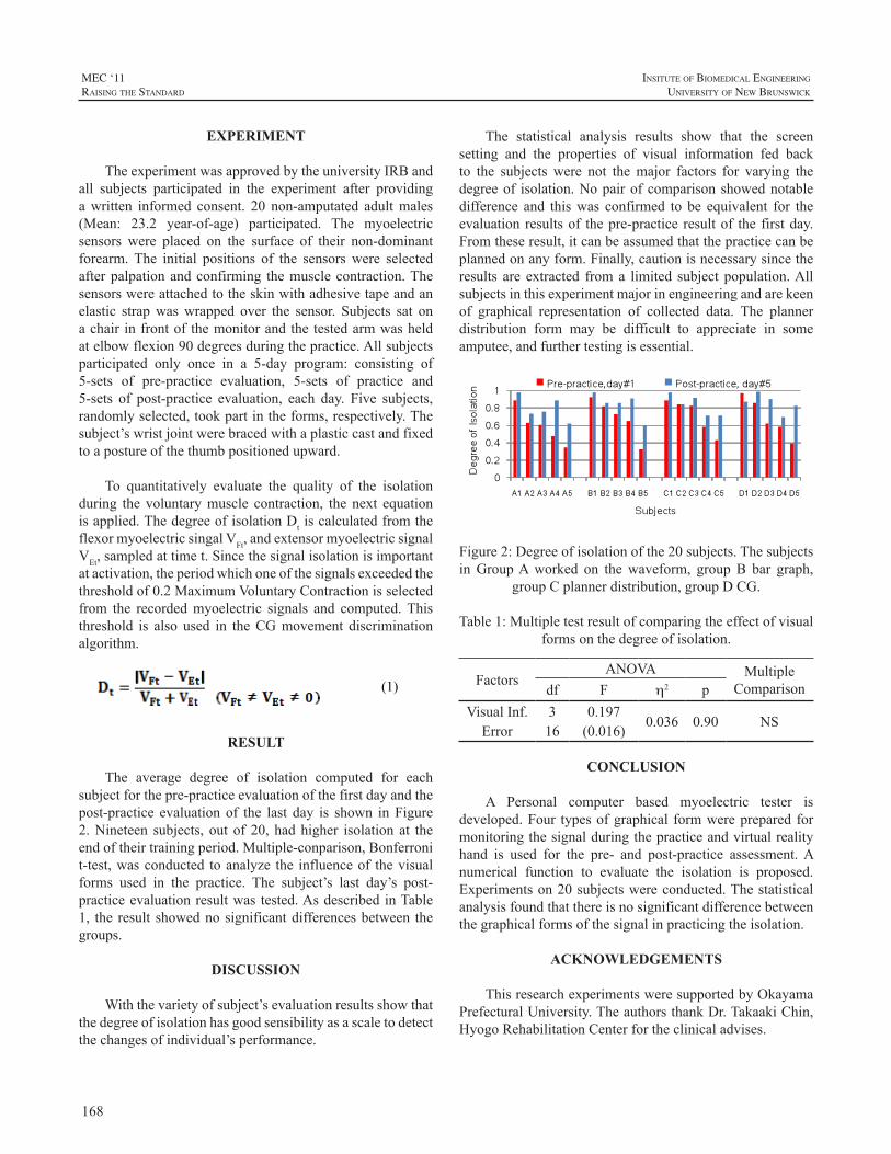
168
MEC ‘11raIsIng the standard
InsItute of BIomedIcal engIneerIng
unIversIty of new BrunswIck
EXPERIMENT
TheexperimentwasapprovedbytheuniversityIRBandall subjects participated in the experiment after providingawritten informed consent. 20 non-amputated adultmales(Mean: 23.2 year-of-age) participated. The myoelectricsensors were placed on the surface of their non-dominantforearm.The initial positions of the sensorswere selectedafterpalpationandconfirming themusclecontraction.Thesensorswereattachedtotheskinwithadhesivetapeandanelastic strapwaswrapped over the sensor. Subjects sat onachair infrontof themonitorandthetestedarmwasheldatelbowflexion90degreesduringthepractice.Allsubjectsparticipated only once in a 5-day program: consisting of5-sets of pre-practice evaluation, 5-sets of practice and5-sets of post-practice evaluation, each day. Five subjects,randomlyselected,tookpartintheforms,respectively.Thesubject’swristjointwerebracedwithaplasticcastandfixedtoapostureofthethumbpositionedupward.
To quantitatively evaluate the quality of the isolationduring the voluntarymuscle contraction, the next equationisapplied.ThedegreeofisolationDtiscalculatedfromtheflexormyoelectricsingalVFt,andextensormyoelectricsignalVEt,sampledattimet.Sincethesignalisolationisimportantatactivation,theperiodwhichoneofthesignalsexceededthethresholdof0.2MaximumVoluntaryContractionisselectedfrom the recordedmyoelectric signals and computed.Thisthreshold is also used in theCGmovement discriminationalgorithm.
(1)
RESULT
The average degree of isolation computed for eachsubjectforthepre-practiceevaluationofthefirstdayandthepost-practice evaluation of the last day is shown inFigure2.Nineteen subjects, out of 20, hadhigher isolation at theendoftheirtrainingperiod.Multiple-conparison,Bonferronit-test,wasconducted toanalyze the influenceof thevisualforms used in the practice. The subject’s last day’s post-practiceevaluationresultwas tested.AsdescribedinTable1, the result showednosignificantdifferencesbetween thegroups.
DISCUSSION
Withthevarietyofsubject’sevaluationresultsshowthatthedegreeofisolationhasgoodsensibilityasascaletodetectthechangesofindividual’sperformance.
The statistical analysis results show that the screensetting and the properties of visual information fed backto the subjects were not themajor factors for varying thedegreeof isolation.Nopairofcomparisonshowednotabledifference and thiswas confirmed to be equivalent for theevaluationresultsof thepre-practice resultof the firstday.Fromtheseresult,itcanbeassumedthatthepracticecanbeplannedonanyform.Finally,cautionisnecessarysincetheresults are extracted froma limited subject population.Allsubjectsinthisexperimentmajorinengineeringandarekeenof graphical representation of collected data. The plannerdistribution form may be difficult to appreciate in someamputee,andfurthertestingisessential.
Figure2:Degreeofisolationofthe20subjects.ThesubjectsinGroupAworked on thewaveform, groupB bar graph,
groupCplannerdistribution,groupDCG.
Table1:Multipletestresultofcomparingtheeffectofvisualformsonthedegreeofisolation.
FactorsANOVA Multiple
Comparisondf F h2 pVisualInf. 3 0.197
0.036 0.90 NSError 16 (0.016)
CONCLUSION
A Personal computer based myoelectric tester isdeveloped.Four typesofgraphical formwereprepared formonitoringthesignalduringthepracticeandvirtualrealityhand is used for the pre- and post-practice assessment.Anumerical function to evaluate the isolation is proposed.Experimentson20subjectswereconducted.Thestatisticalanalysisfoundthatthereisnosignificantdifferencebetweenthegraphicalformsofthesignalinpracticingtheisolation.
ACKNOWLEDGEMENTS
ThisresearchexperimentsweresupportedbyOkayamaPrefecturalUniversity.TheauthorsthankDr.TakaakiChin,HyogoRehabilitationCenterfortheclinicaladvises.
169
InsItute of BIomedIcal engIneerIng
unIversIty of new BrunswIck
MEC ‘11raIsIng the standard
REFERENCES
[1] A.Muzumdar(Ed.),“PoweredUpperLimbProsthesis”,Springer-Verlag,BerlinHeidelberg,2004
[2] D.Childress,R.Weir,“Chapter12ControlofLimbProstheses,”D.Smith,J.Michael,J.Bowker(Ed.).AtlasofAmputationsandLimbDeficiencies:Surgical,Prosthetic,andRehabilitationPrinciples.3rdEd.,AAOS,Rosemont,IL,2004
[3] AC Dupont, E. Morin “A Myoelectric Control Evaluation andTrainer System,” IEEE Trans. Rehabil. Engineering, Vol.2, No.2,pp.100-107,1994
170
MEC ‘11raIsIng the standard
InsItute of BIomedIcal engIneerIng
unIversIty of new BrunswIck
INTRODUCTION
Pattern recognition has been used in the laboratoryfor control of advanced prosthetic limbs. However,recentworkhas shown that ithas thepotential to improvecontrol of existing clinical prostheses [1].Targetedmusclereinnervation (TMR) makes it possible to access neuralinformationfromresidualperipheralnerves thatpreviouslyinnervated themissing limb[2].Pattern recognitionallowsthis information to be extracted and used by individualswithhigh-levelamputationsforeffectiveprosthesiscontrol.TMRisnotnecessaryforpatternrecognitioncontrolat thetransradialamputationlevel[3].Here,weoutlineasequencefortrainingindividualstousepatternrecognitioncontrolofelbowmovement,wristrotation,wristflexion/extension,andhandgrasps.Wehighlight thedifferencesbetween trainingfordirectcontrolandtrainingforpatternrecognitioncontrol.Wealsorecommendatrainingprotocoltofacilitatemasteryof pattern recognition control before and after being fittedwithaprosthesis.
TRAINING PROGRESSION
TeachingtheconceptofpatternrecognitioncontrolUnderstanding pattern recognition control is the first
challengeforindividualswithanamputationWebeginwithverbalexplanationsofpatternrecognition,includingthefactthateachelectrodelocationnolongercorrespondstoaspecificmovement(asindirectcontrol),andthatconsistentpatternsofmuscle activations are required for eachmovement.Weencourage the individual to activelyparticipate in training.Theprocessofselectingsharedvocabularysuchas“channel,”“signal,”“degreeoffreedom,”“supination,”or“keypinch,”engagestheindividualasapartnerintheprocessandinvitestheir active participation. Agreed-upon terminology alsoensuresclearcommunicationbetweentheindividualandtheclinician.
Once electrode sites are located (typically 6 for thetransradiallevelandupto12fortheshoulderdisarticulationlevel),weuseamyoelectricsignalviewerthatshowspatternsofmyoelectricactivitycorrespondingtomovementattempts.Thisillustratestotheindividualhowtheyareabletoproduce
identifiablepatternsofmuscleactivityforagivenmovement.We are also able to use virtual reality software to providefeedbacktotheindividualastheyattemptcontrol.
Weexplain the importanceofperforming the intendedmovementswithamoderatelevelofefforttoavoidfatigue,andthenecessityofduplicatingthe levelofeffort foreachmovement,asasignificantchangeineffortmayconfusetheclassifier.Frequent retrainingof theclassifier isperformedininitialtrainingsessionsbecauseofphysiologicalchanges,suchasalteredskinconduction,oralterationsinmovementattempts that occur as the individual adapts to the trainingprocess. It is explained to the individual that retraining isexpected and will be part of the routine, although it maybecomelessfrequentastheygainexperienceinusingpatternrecognitioncontrol.
PhantomlimbconsiderationsItisappropriateearlyinthetrainingprocesstodiscuss
the role of the phantom limb in pattern recognition. It isnecessary to determine if the phantom limbwill be usefulduring training.Users should be instructed to try tomovetheirphantomlimb in thedesireddirection,even if it feelsimmobile. Some individuals experience pain or crampingwhenattemptingtomovethephantomlimb;thisdiscomfortmayinterferewithsuccessfulcontrol.Inthiscase,weinstructthe individual to use a moderate level of effort, to focusmirroringthedesiredmovementwiththeintactlimb,andtoallowtimeforrelaxationofthephantomlimb.Photographsof exercises to be performed with the phantom limb areuseful and canbe included in a homeexercise program inpreparationforthenexttrainingsession(Figure1).
Pattern recognition training for individualswith transradialamputation
Initialtrainingsessionsutilizeavirtualarmwithwhichthe individual first experiences pattern recognition control.We begin pattern recognition classifier training with thedegrees of freedom easiest for the individual to control—handopenandcloseforthetransradiallevel.Individualswithtransradialamputationmustlearnnewmotorcommands:inpattern recognition control, the individual is being askedto perform a movement that he or she is not accustomed
TRAINING INDIVIDUALS TO USE PATTERN RECOGNITION TO CONTROL AN UPPER LIMB PROSTHESIS
KathyStubblefield1,SuzanneB.Finucane1, Laura A. Miller1,2, Blair A. Lock1
1CenterforBionicMedicine,RehabilitationInstituteofChicago,Chicago,Il,USA2FeinbergSchoolofMedicine,NorthwesternUniversity,Chicago,Il,USA
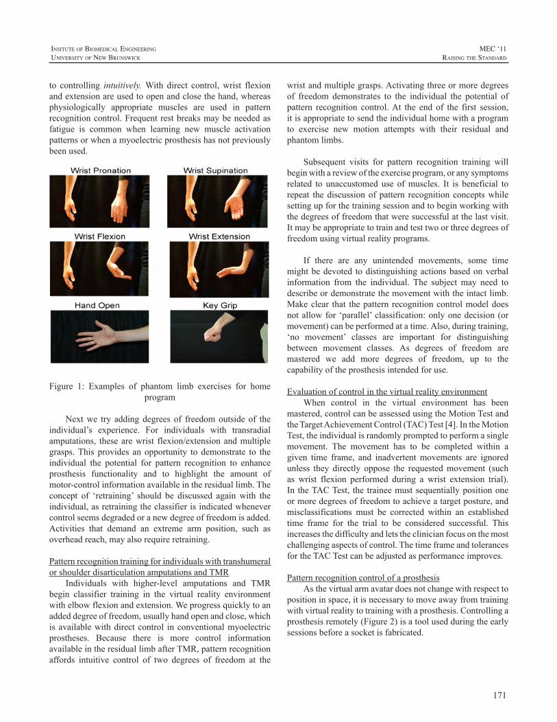
171
InsItute of BIomedIcal engIneerIng
unIversIty of new BrunswIck
MEC ‘11raIsIng the standard
to controlling intuitively.With direct control,wrist flexionandextensionareusedtoopenandclosethehand,whereasphysiologically appropriate muscles are used in patternrecognitioncontrol.Frequentrestbreaksmaybeneededasfatigue is common when learning new muscle activationpatternsorwhenamyoelectricprosthesishasnotpreviouslybeenused.
Figure 1: Examples of phantom limb exercises for homeprogram
Nextwe try addingdegrees of freedomoutside of theindividual’s experience. For individuals with transradialamputations, thesearewrist flexion/extensionandmultiplegrasps.This provides anopportunity to demonstrate to theindividual the potential for pattern recognition to enhanceprosthesis functionality and to highlight the amount ofmotor-controlinformationavailableintheresiduallimb.Theconcept of ‘retraining’ should be discussed againwith theindividual,asretrainingtheclassifierisindicatedwhenevercontrolseemsdegradedoranewdegreeoffreedomisadded.Activities that demand an extreme arm position, such asoverheadreach,mayalsorequireretraining.
PatternrecognitiontrainingforindividualswithtranshumeralorshoulderdisarticulationamputationsandTMR
Individuals with higher-level amputations and TMRbegin classifier training in the virtual reality environmentwithelbowflexionandextension.Weprogressquicklytoanaddeddegreeoffreedom,usuallyhandopenandclose,whichisavailablewithdirectcontrol inconventionalmyoelectricprostheses. Because there is more control informationavailableintheresiduallimbafterTMR,patternrecognitionaffords intuitive control of two degrees of freedom at the
wristandmultiplegrasps.Activatingthreeormoredegreesof freedom demonstrates to the individual the potential ofpattern recognition control.At the end of the first session,itisappropriatetosendtheindividualhomewithaprogramto exercise new motion attempts with their residual andphantomlimbs.
Subsequent visits for pattern recognition training willbeginwithareviewoftheexerciseprogram,oranysymptomsrelated to unaccustomed use ofmuscles. It is beneficial torepeat thediscussionofpattern recognitionconceptswhilesettingupforthetrainingsessionandtobeginworkingwiththedegreesoffreedomthatweresuccessfulatthelastvisit.Itmaybeappropriatetotrainandtesttwoorthreedegreesoffreedomusingvirtualrealityprograms.
If there are any unintended movements, some timemightbedevoted todistinguishingactionsbasedonverbalinformation from the individual. The subject may need todescribeordemonstratethemovementwiththeintactlimb.Makeclear that thepattern recognitioncontrolmodeldoesnotallowfor‘parallel’classification:onlyonedecision(ormovement)canbeperformedatatime. Also,duringtraining,‘no movement’ classes are important for distinguishingbetween movement classes. As degrees of freedom aremastered we add more degrees of freedom, up to thecapabilityoftheprosthesisintendedforuse.
EvaluationofcontrolinthevirtualrealityenvironmentWhen control in the virtual environment has been
mastered,controlcanbeassessedusingtheMotionTestandtheTargetAchievementControl(TAC)Test[4]. IntheMotionTest,theindividualisrandomlypromptedtoperformasinglemovement. The movement has to be completed within agiven time frame, and inadvertentmovements are ignoredunless they directly oppose the requestedmovement (suchas wrist flexion performed during a wrist extension trial).In theTACTest, thetraineemustsequentiallypositiononeormoredegreesoffreedomtoachieveatargetposture,andmisclassifications must be corrected within an establishedtime frame for the trial to be considered successful. Thisincreasesthedifficultyandletstheclinicianfocusonthemostchallengingaspectsofcontrol.ThetimeframeandtolerancesfortheTACTestcanbeadjustedasperformanceimproves.
PatternrecognitioncontrolofaprosthesisAsthevirtualarmavatardoesnotchangewithrespectto
positioninspace,itisnecessarytomoveawayfromtrainingwithvirtualrealitytotrainingwithaprosthesis.Controllingaprosthesisremotely(Figure2) isatoolusedduringtheearlysessionsbeforeasocketisfabricated.
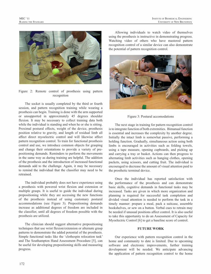
172
MEC ‘11raIsIng the standard
InsItute of BIomedIcal engIneerIng
unIversIty of new BrunswIck
Figure 2: Remote control of prosthesis using patternrecognition
The socket isusuallycompletedby the thirdor fourthsession, and pattern recognition training while wearing aprosthesiscanbegin.Trainingisdonewiththearmsupportedor unsupported in approximately 45 degrees shoulderflexion. It may be necessary to collect training data bothwhiletheindividualisstandingandwhenheorsheissitting.Proximal postural effects, weight of the device, prosthesisposition relative to gravity, and length of residual limb allaffect direct myoelectric control and will likewise affectpatternrecognitioncontrol.Totrainforfunctionalprosthesiscontrolanduse,weintroducecommonobjectsforgraspingand change their orientations to provide a variety of pre-positioningdemands.Reminderstoperformthemovementsinthesamewayasduringtrainingarehelpful.Theadditionoftheprosthesisandtheintroductionofincreasedfunctionaldemands add to the challenge.Again, itmay be necessaryto remind the individual that the classifiermayneed to beretrained.
Theindividualprobablydoesnothaveexperienceusinga prosthesis with powered wrist flexion and extension ormultiple grasps. It is useful to guide the individual duringprepositioning while they are accessing the new functionsof the prosthesis instead of using customary posturalaccommodations (see Figure 3). Prepositioning demandsincrease as additional degrees of freedom are included intheclassifier,untilalldegreesoffreedompossiblewiththeprosthesisareutilized.
Theclinician should suggest alternativeprepositioningtechniquesthatusewristflexion/extensionoralternategrasppatternstodemonstratetheaddedpotentialoftheprosthesis.Simplefunctional taskslikethe‘clothespinrelocationtask’andTheSouthamptonHandAssessmentProcedure[5],canbeusefulfordevelopingprepositioningskillsandmeasuringprogress.
Allowing individuals to watch video of themselvesusingtheprosthesisisinstructiveindemonstratingprogress.Watching video of others who have mastered patternrecognitioncontrolofasimilardevicecanalsodemonstratethepotentialofpatternrecognitioncontrol.
Figure3:Posturalaccomodations
Thenextstageintrainingforpatternrecognitioncontrolistointegratefunctionofbothextremities.Bimanualfunctionisessentialandincreasesthecomplexitybyanotherdegree.Initially the intact limb is somewhat passive, performing aholdingfunction.Gradually,simultaneousactionusingbothlimbs is encouraged in activities such as folding towels,using a tape measure, opening cupboards, and picking upandcarryinga trayorbasket.Actionscan thenprogress toalternatinglimbactivitiessuchashangingclothes,openingpackets, using scissors, and cutting fruit.The individual isencouragedtodecreasetheamountofvisualattentionpaidtotheprostheticterminaldevice.
Once the individual has reported satisfaction withthe performance of the prosthesis and can demonstratebasic skills, cognitive demands in functional tasksmay beincreased.Tasksaregiven inwhichmoreorganizationandplanning is required for successful task completion anddivided visual attention is needed to perform the task in atimely manner: prepare a meal, pack a suitcase, assemblebookshelves,orsewonabutton.Verbalcuestoretrainmaybeneededifunusualpositionsaffectcontrol.ItisalsousefultotakethisopportunitytodoanAssessmentofCapacityforMyoelectricControl[6]togetabaselinescoreofcontrol.
FUTURE WORK
Our experiencewith pattern recognition control in thehome and community to date is limited.Due to upcomingsoftware and electronic improvements, further trainingdevelopment will be needed. We anticipate advancingthe application of pattern recognition control to the home
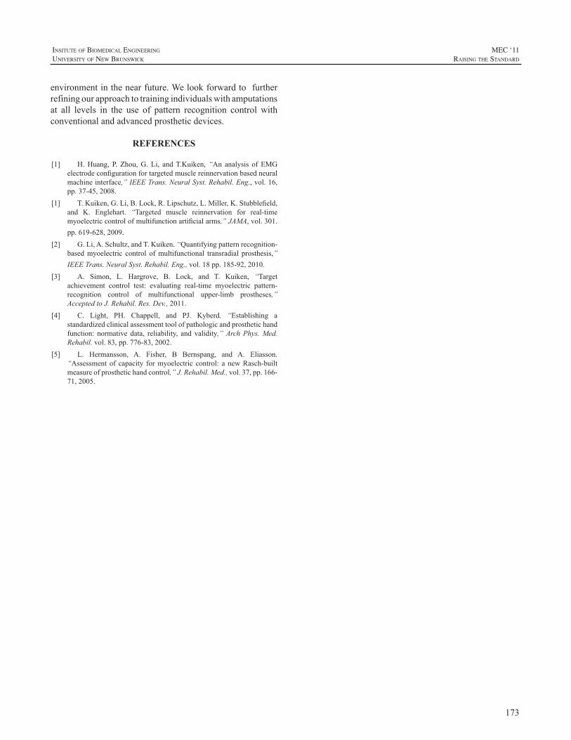
173
InsItute of BIomedIcal engIneerIng
unIversIty of new BrunswIck
MEC ‘11raIsIng the standard
environmentinthenearfuture.Welookforwardtofurtherrefiningourapproachtotrainingindividualswithamputationsat all levels in the use of pattern recognition control withconventionalandadvancedprostheticdevices.
REFERENCES
[1] H.Huang, P. Zhou,G.Li, andT.Kuiken,“An analysis ofEMGelectrodeconfigurationfortargetedmusclereinnervationbasedneuralmachineinterface,”IEEETrans.NeuralSyst.Rehabil.Eng.,vol.16,pp.37-45,2008.
[1] T.Kuiken,G.Li,B.Lock,R.Lipschutz,L.Miller,K.Stubblefield,and K. Englehart. “Targeted muscle reinnervation for real-timemyoelectriccontrolofmultifunctionartificialarms,”JAMA,vol.301.pp.619-628,2009.
[2] G.Li,A.Schultz,andT.Kuiken.“Quantifyingpatternrecognition-basedmyoelectric control ofmultifunctional transradial prosthesis,”IEEETrans.NeuralSyst.Rehabil.Eng.,vol.18pp.185-92,2010.
[3] A. Simon, L. Hargrove, B. Lock, and T. Kuiken, “Targetachievement control test: evaluating real-time myoelectric pattern-recognition control of multifunctional upper-limb prostheses,”AcceptedtoJ.Rehabil.Res.Dev.,2011.
[4] C. Light, PH. Chappell, and PJ. Kyberd. “Establishing astandardizedclinicalassessmenttoolofpathologicandprosthetichandfunction: normative data, reliability, and validity,”ArchPhys.Med.Rehabil.vol.83,pp.776-83,2002.
[5] L. Hermansson, A. Fisher, B Bernspang, and A. Eliasson.“Assessmentof capacity formyoelectric control: a newRasch-builtmeasureofprosthetichandcontrol,”J.Rehabil.Med.,vol.37,pp.166-71,2005.
174
MEC ‘11raIsIng the standard
InsItute of BIomedIcal engIneerIng
unIversIty of new BrunswIck
INTRODUCTION
Children and adolescents with unilateral congenitalbelow elbow deficiency (UCBED) seem to function quitewellindailylife1-3.However,currentliteraturedoesnotgiveinsightintoactualfunctioningofthesechildren.Furthermore,itisunknownhowthechildrenandadolescentsthemselvesthink about their functioning. Functioning encompassesactivityandparticipationaccording to theChildandYouthVersion of the International Classification of Functioning(ICF-CY)4.Activitylimitationsaredifficultiesanindividualmayhaveinexecutingactivities.Participationrestrictionsareproblemsanindividualmayexperienceintheinvolvementinlifesituations.AccordingtotheICF-CY,bothenvironmentalandpersonalfactorscanaffectactivityandparticipation,andthussomeone’sfunctioning.
Aimofthestudy:The first aim was to evaluate whether children and
adolescents with UCBED experience activity limitationsandparticipation restrictionsand if theydo,how theydealwith those limitations and restrictions. Secondary aimswere to examine differences in activities and participationfordifferentagegroupsandtocomparetheperspectivesofchildren,theirparentsandhealthprofessionals.
PatientsChildren with UCBED aged 8-12, 13-16, and 17-20
years, parents and professionals participated in the study.Participants were recruited from several rehabilitationcenters in the Netherlands. Furthermore, participants wereinvitedtotakepartinthestudythroughwebsitesofpatientorganizations.
METHODS
AqualitativestudydesignwasappliedbyusingOnlineFocus Group interviews5. The interviews were held inthe asynchronous form, meaning that participants coulddecidethemselveswhentologinandtakepartintheonline
discussionswithin a time frameof sevendays.Theonlinefocus group interviews were held on a secured websitecontaining five separate forums,one forum for eachgroupofparticipants.Duringthefirstfivedaysoftheweek,atthebeginningofeachday,aquestionwaspostedontheforums.Discussion topics were activities, participation, prosthesisuse, emotional functioning and rehabilitation care. Duringthelasttwodays,theparticipantshadtheopportunitytobringintheirowndiscussiontopics.Theframeworkapproachwasusedfordataanalysis.
RESULTS
878postingswerereceivedfrom17childrenof8-12yearsofage,13teenagersof13-16yearsofage,12adolescentsof17-20yearsofage,17parentsand19professionals.Havingashortarmdidnotprohibitexecutionofanyactivity,butnotallchildrenwereabletoperformallactivities.Thechildrenen parents mentioned numerous creative strategies to dealwith a short arm.Although people in the direct (internal)environment of the child, such as parents and friends, canbe supportive, it was remarkable how often people in theindirect(external)environmentofthechildwerementionedasareasonforalimitedfunctioningofachildwithUCBED.Peopleintheexternalenvironmentjudgeachild’scapacitywithout having sufficient knowledge about their abilities.Environmentalfactorswereespeciallydecisiveintransitionalphases,likegoingtoanewschoolorapplyingforanewjob.
Personal factors also influenced the children’s andadolescent’s functioning. Not all children had the samecognitiveormotorabilities,reactinthesamewayemotionallyorbehaveinthesamewayinsocialsituations.Parentswerepositive about the functioning of their children. Overall,parentsdidnotthinktheirchildexperiencedmanylimitations.Healthprofessionalsdescribedfewerstrategiestodealwithlimitationsandemphasizedbenefitsofprosthesesmorethanotherparticipants.
FUNCTIONING OF CHILDREN WITH UNILATERAL CONGENITAL BELOW ELBOW DEFICIENCY: AN ONLINE FOCUS GROUP STUDY
CorryK.vanderSluis1,IngridG.M.deJong1,KiekTates2,WimG.M.Janssen3,MargrietJ.Poelma4,IrisvanWijk5,HeleenA.Reinders-Messelink1
1DepartmentofRehabilitationMedicine,UniversityMedicalCenterGroningen,Groningen,2DepartmentofCommunicationandInformationSciences,UniversityofTilburg,Tilburg,3DepartmentofRehabilitationMedicine,ErasmusMedical
Center,Rotterdam,4RehabilitationCenterSintMaartenskliniek,Nijmegen,5RehabilitationCenterDeHoogstraat,Utrecht,theNetherlands.
Email:[email protected]
175
InsItute of BIomedIcal engIneerIng
unIversIty of new BrunswIck
MEC ‘11raIsIng the standard
CONCLUSIONS
Children with UCBED don’t feel disabled, butenvironment can make them feel that way, especially intransitional phases.They have numerous strategies to dealwith their deficiency. Prostheses are a minor solution toovercomelimitations.
REFERENCES
[1] C.A.vanDijk-Koot, I.vanderHam,L.M.Buffart,C.K. vanderSluis,H.J.Stam,J.M.F.B.Pesch-Batenburg,M.E.Roebroeck.Currentexperienceswith the prosthetiic upper extremity functional index infollow-upchildrernwithupper limbreductiondeficiency.JProsthetOrthot2009;21:110-4.
[2] L.M.Buffart,M.E.Roebroeck,V.G. vanHeijningen,J.M. Pesch-Batenburg,H.J.Stam.Evalutationofarmandprostheticfunctioninginchildrenwithacongenitaltransversereductiondeficiencyoftheupperlimb.JRehabilMed2007;39:379-86.
[3] M.A.James,A.M.Bagley,K.Brasington,C.Lutz,S.McConnell,F.Molitor. Impact of prosthesis on function and quality of life forchildrenwithunilateralcongenitalbelow-the-elbowdeficiency.JBoneJointSurg2006;88-A(11):2356-65.
[4] World Health Organization. International Classification ofFunctioning,DisabilityandHealth:Children&YouthVersion: ICF-CY.Geneva:WHO;2007.
[5] K. Tates, M. Zwaanswijk,R. Otten, S. van Dulmen, P.M.Hoogerbrugge,W.A.Kamps, J.M. Bensing.Online focus groups asa tool to collect data in hard-to-include populations: examples frompaediatriconcology.BMCMedResMethodol2009;9:15.
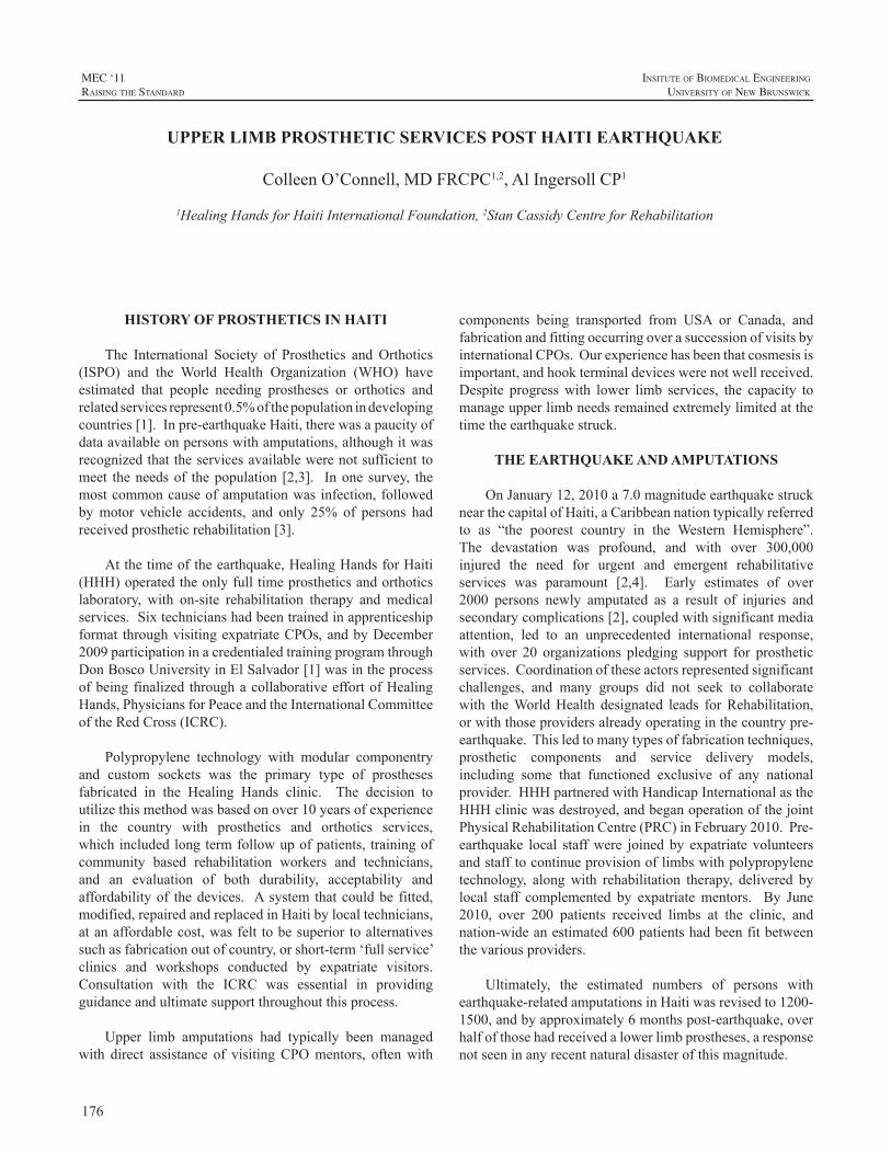
176
MEC ‘11raIsIng the standard
InsItute of BIomedIcal engIneerIng
unIversIty of new BrunswIck
HISTORY OF PROSTHETICS IN HAITI
The International Society of Prosthetics andOrthotics(ISPO) and the World Health Organization (WHO) haveestimated that people needing prostheses or orthotics andrelatedservicesrepresent0.5%ofthepopulationindevelopingcountries[1].Inpre-earthquakeHaiti,therewasapaucityofdataavailableonpersonswithamputations,althoughitwasrecognizedthattheservicesavailablewerenotsufficienttomeet theneedsof thepopulation [2,3]. Inone survey, themostcommoncauseofamputationwasinfection,followedbymotor vehicle accidents, and only 25% of persons hadreceivedprostheticrehabilitation[3].
Atthetimeoftheearthquake,HealingHandsforHaiti(HHH)operatedtheonlyfulltimeprostheticsandorthoticslaboratory, with on-site rehabilitation therapy and medicalservices.Sixtechnicianshadbeentrainedinapprenticeshipformat throughvisitingexpatriateCPOs,andbyDecember2009participationinacredentialedtrainingprogramthroughDonBoscoUniversityinElSalvador[1]wasintheprocessofbeingfinalized throughacollaborativeeffortofHealingHands,PhysiciansforPeaceandtheInternationalCommitteeoftheRedCross(ICRC).
Polypropylene technology with modular componentryand custom sockets was the primary type of prosthesesfabricated in the Healing Hands clinic. The decision toutilizethismethodwasbasedonover10yearsofexperiencein the country with prosthetics and orthotics services,whichincludedlongtermfollowupofpatients, trainingofcommunity based rehabilitation workers and technicians,and an evaluation of both durability, acceptability andaffordabilityof thedevices. Asystem thatcouldbe fitted,modified,repairedandreplacedinHaitibylocaltechnicians,atanaffordablecost,wasfelt tobesuperior toalternativessuchasfabricationoutofcountry,orshort-term‘fullservice’clinics and workshops conducted by expatriate visitors.Consultation with the ICRC was essential in providingguidanceandultimatesupportthroughoutthisprocess.
Upper limb amputations had typically been managedwith direct assistance of visitingCPOmentors, oftenwith
components being transported from USA or Canada, andfabricationandfittingoccurringoverasuccessionofvisitsbyinternationalCPOs.Ourexperiencehasbeenthatcosmesisisimportant,andhookterminaldeviceswerenotwellreceived.Despite progresswith lower limb services, the capacity tomanageupperlimbneedsremainedextremelylimitedatthetimetheearthquakestruck.
THE EARTHQUAKE AND AMPUTATIONS
OnJanuary12,2010a7.0magnitudeearthquakestrucknearthecapitalofHaiti,aCaribbeannationtypicallyreferredto as “the poorest country in the Western Hemisphere”.The devastation was profound, and with over 300,000injured the need for urgent and emergent rehabilitativeservices was paramount [2,4]. Early estimates of over2000 persons newly amputated as a result of injuries andsecondarycomplications[2],coupledwithsignificantmediaattention, led to an unprecedented international response,with over 20 organizations pledging support for prostheticservices.Coordinationoftheseactorsrepresentedsignificantchallenges, and many groups did not seek to collaboratewith theWorldHealth designated leads forRehabilitation,orwiththoseprovidersalreadyoperatinginthecountrypre-earthquake.Thisledtomanytypesoffabricationtechniques,prosthetic components and service delivery models,including some that functioned exclusive of any nationalprovider.HHHpartneredwithHandicapInternationalastheHHHclinicwasdestroyed,andbeganoperationofthejointPhysicalRehabilitationCentre(PRC)inFebruary2010.Pre-earthquake local staffwere joined by expatriate volunteersandstafftocontinueprovisionoflimbswithpolypropylenetechnology, alongwith rehabilitation therapy, delivered bylocal staff complemented by expatriatementors. By June2010, over 200 patients received limbs at the clinic, andnation-wideanestimated600patientshadbeenfitbetweenthevariousproviders.
Ultimately, the estimated numbers of persons withearthquake-relatedamputationsinHaitiwasrevisedto1200-1500,andbyapproximately6monthspost-earthquake,overhalfofthosehadreceivedalowerlimbprostheses,aresponsenotseeninanyrecentnaturaldisasterofthismagnitude.
UPPER LIMB PROSTHETIC SERVICES POST HAITI EARTHQUAKE
ColleenO’Connell,MDFRCPC1,2,AlIngersollCP1
1HealingHandsforHaitiInternationalFoundation,2StanCassidyCentreforRehabilitation
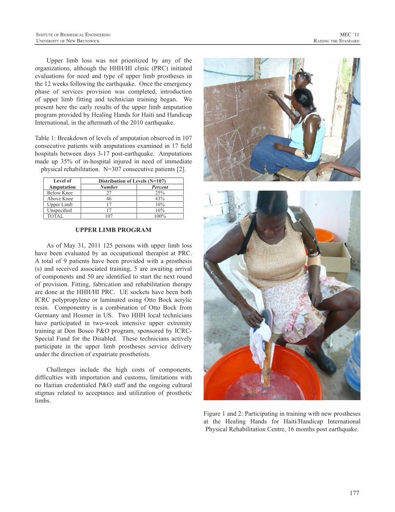
177
InsItute of BIomedIcal engIneerIng
unIversIty of new BrunswIck
MEC ‘11raIsIng the standard
Upper limb loss was not prioritized by any of theorganizations, although theHHH/HI clinic (PRC) initiatedevaluations for need and type of upper limb prostheses inthe12weeksfollowingtheearthquake.Oncetheemergencyphase of services provision was completed, introductionof upper limb fitting and technician training began. Wepresenthere theearly resultsof theupper limbamputationprogramprovidedbyHealingHandsforHaitiandHandicapInternational,intheaftermathofthe2010earthquake.
Table1:Breakdownoflevelsofamputationobservedin107consecutivepatientswithamputationsexaminedin17fieldhospitalsbetweendays3-17post-earthquake.Amputationsmade up 35% of in-hospital injured in need of immediatephysicalrehabilitation.N=307consecutivepatients[2].
Level of Amputation
Distribution of Levels (N=107)Number Percent
BelowKnee 27 25%AboveKnee 46 43%UpperLimb 17 16%Unspecified 17 16%TOTAL 107 100%
UPPER LIMB PROGRAM
AsofMay31,2011125personswithupper limb losshave been evaluated by an occupational therapist at PRC.A total of 9 patients have been providedwith a prosthesis(s) and received associated training, 5 are awaiting arrivalofcomponentsand50areidentifiedtostart thenextroundof provision. Fitting, fabrication and rehabilitation therapyaredoneat theHHH/HIPRC.UEsocketshavebeenbothICRCpolypropyleneor laminatedusingOttoBock acrylicresin. Componentry is a combination of Otto Bock fromGermanyandHosmer inUS. TwoHHH local technicianshave participated in two-week intensive upper extremitytrainingatDonBoscoP&Oprogram,sponsoredby ICRC-Special Fund for theDisabled. These technicians activelyparticipate in the upper limb prostheses service deliveryunderthedirectionofexpatriateprosthetists.
Challenges include the high costs of components,difficulties with importation and customs, limitations withnoHaitiancredentialedP&Ostaffandtheongoingculturalstigmas related to acceptance and utilization of prostheticlimbs.
Figure1and2:Participatingintrainingwithnewprosthesesat the Healing Hands for Haiti/Handicap InternationalPhysicalRehabilitationCentre,16monthspostearthquake.
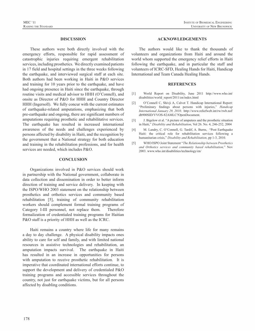
178
MEC ‘11raIsIng the standard
InsItute of BIomedIcal engIneerIng
unIversIty of new BrunswIck
DISCUSSION
These authors were both directly involved with theemergency efforts, responsible for rapid assessment ofcatastrophic injuries requiring emergent rehabilitationservices,includingprosthetics.Wedirectlyexaminedpatientsin17fieldandhospitalsettingsinthethreeweeksfollowingthe earthquake, and interviewed surgical staff at each site.Both authors had been working in Haiti in P&O servicesand training for10yearsprior to theearthquake,andhavehadongoingpresenceinHaitisincetheearthquake,throughroutinevisitsandmedicaladvisortoHHH(O’Connell),andonsite asDirector of P&O forHHH andCountryDirectorHHH(Ingersoll).Wefullyconcurwiththecurrentestimatesof earthquake-related amputations, emphasizing that bothpre-earthquakeandongoing,therearesignificantnumbersofamputationsrequiringprostheticandrehabilitativeservices.The earthquake has resulted in increased internationalawareness of the needs and challenges experienced bypersonsaffectedbydisabilityinHaiti,andtherecognitionbythegovernment that aNational strategy forbotheducationandtrainingintherehabilitationprofessions,andforhealthservicesareneeded,whichincludesP&O.
CONCLUSION
Organizations involved in P&O services should workinpartnershipwiththeNationalgovernment,collaborateindata collection anddissemination in order to better informdirectionof trainingand servicedelivery. InkeepingwiththeISPO/WHO2003statementontherelationshipbetweenprosthetics and orthotics services and community basedrehabilitation [5], training of community rehabilitationworkers should complement formal training programs ofCategory I-III personnel, not replace them. Thereforeformalizationof credentialed trainingprograms forHaitianP&OstaffisapriorityofHHHaswellastheICRC.
Haiti remains a country where life for many remainsaday todaychallenge. Aphysicaldisability impactsonesabilitytocareforselfandfamily,andwithlimitednationalresources in assistive technologies and rehabilitation, anamputation impacts survival. The earthquake in Haitihas resulted in an increase in opportunities for personswith amputation to receive prosthetic rehabilitation. It isimperativethatcoordinatedinternationaleffortscontinue,tosupport thedevelopmentanddeliveryofcredentialedP&Otraining programs and accessible services throughout thecountry,not justforearthquakevictims,butforallpersonsaffectedbydisablingconditions.
ACKNOWLEDGEMENTS
The authors would like to thank the thousands ofvolunteers and organizations from Haiti and around theworldwhomsupportedtheemergencyreliefeffortsinHaitifollowing the earthquake, and in particular the staff andvolunteersofICRC-SFD,HealingHandsforHaiti,HandicapInternationalandTeamCanadaHealingHands.
REFERENCES
[1] World Report on Disability, June 2011 http://www.who.int/disabilities/world_report/2011/en/index.html
[2] O’ConnellC,ShivjiA,CalvotT.Handicap InternationalReport:“Preliminary findings about persons with injuries,” HandicapInternationalJanuary29,2010.http://www.reliefweb.int/rw/rwb.nsf/db900SID/VVOS-82AMLC?OpenDocument.
[3] J.Bigelowetal.“ApictureofamputeesandtheprostheticsituationinHaiti,”DisabilityandRehabilitation,Vol26.No.4,246-252,2004
[4] M.Landry,C.O’Connell,G.Tardif,A.Burns,“PostEarthquakeHaiti: the critical role for rehabilitation services following ahumanitariancrisis,”DisabilityandRehabilitation,pp1-3,2010.
[5] WHO/ISPOJointStatement“TheRelationshipbetweenProstheticsand Orthotics services and community based rehabilitation,” Nov2003.www.who.int/disabilities/technology/en/
179
InsItute of BIomedIcal engIneerIng
unIversIty of new BrunswIck
MEC ‘11raIsIng the standard
ABSTRACT
A multi-disciplined team of engineers, prosthetists,physicians,andamputeeshasdevelopedanew trans-radialprosthesis currently completing second-year validationtesting. The International Trans-radial Adjustable Limb,or ITAL, comprises an innovative variable-compression,variable-geometryinterface,anewbody-poweredprehensorwith adjustable pinch force, control harness, and cable.Globally,prostheticoptionsareincreasinglylimitedbycostandlackofinfrastructurerequiredtofitandmaintainthem.TheITALwaspurposefullydesignedtoovercomethesebarriers,providing a new option for economically disadvantagedamputeesintheUSAanddevelopingcountries.Designedtowithstandharshenvironments,ITALsarerelativelylow-costandrestorebimanualcapacitytoperformstrenuousphysicallabor,enablingamputeestoearnalivingandbeself-reliant.
Packagedinkits,unitscanbetakendirectlytoamputeesand fit or serviced inside approximately one hour usingsimple hand tools, without requiring amputees visit or betransported to a central facility. Amputees in Jamaica, theUSA,andThailandhaveshowntheITALtobeanappropriatesolution, and now use it for daily activities. Users ratethe ITAL’s comfort at approximately 75% that of custom-fabricatedprosthesesbutequivalentinutility. Futureworkaimstofurtherincreasecomfortwhilerefiningtheaestheticstoaddressculturalneeds.
INTRODUCTION
Trans-radial amputation largely occurs due to trauma,disease or illness and is not generally the preferred optionifhealthyrestorationandrehabilitationofafunctionallimbispossible. Incidence ratesofupper-extremityamputationin nation states around the world are currently unknown;there are, however, general estimates thatmore than thirty(30) million people need orthotic and prosthetic services.Murdoch [1] estimates that potentially one hundredthousand (100,000) prosthetists would be necessary tomeetthedevelopingworld’sneedsusingcurrentfittingandfabrication methods. Approximately 80% of the world’spopulationmakes less thanUS$2.00 a day, a figure ofteninferredasdirectlyproportionaltotheresourcesofpersonswithamputationwhorequireP&Oservices[2, 3].
Consequently,thecostofprosthesesisalimitingfactorinprovidingaccesstothevastmajorityofamputees[4].Inordertoprovideprosthetictoolstoamputeeswholiveinremote,rural, and difficult-to-access areas, the logistics necessitatea design paradigm based on the operating environment,affordability, and performance. A selected approach willonly be successful if it correctly accommodates availableresources and requirements of users. Clinical experts haveurgentlyencouragedresearchersandmanufacturersto“strivefor developments that ultimately culminate in clinicallypractical, integrated,andaffordable techniques”, [5]and todevelopaffordabledevicesfortargetedapplicationssuchasfarming[6].Severalgroupshaveheededthiscalltoaction;thisresearchanddevelopmenteffortwasinitiatedspecificallyto create a low-cost, biomechanically appropriate upper-extremityprosthesisforbelow-elbowamputees.
METHODOLOGY
Toinitiatethedevelopmentprocess,designspecificationswere obtained from peer-reviewed articles, and a multi-national surveyof prosthetists, doctors, and amputeeswhoowned their own devices, and individualswho had accessto none. The main measures of UE prosthesis acceptanceidentified were the comfort, suspension, and aesthetics.Specifically, among many users surveyed, minimumrequired suspension ranged from 20-25 lbs. Comfortwas equally important, with users wanting to be able toperformmanual tasks for aminimumof three hours daily.Comfortrankedparticularlyimportantformanyindividualswho depend upon manual labor as their only means ofemployment. Based upon published literature, it is clearthat despite relative simplicity andmore limited dexterity,bodypowered(BP)prostheticsystemsremainverypopular;themajority ofUE amputees either uses them exclusivelyorkeeps themasbackup formyoelectricdevices [7,8,9].Theprimary reasons for theirpopularityarecomparativelylowercost,lowweight,mechanicalrobustness,preservationof proprioceptive feedback, and ease of maintenance incomparisontomyoelectricdevices.
Invariably,evenamputeeswhohadnoaccesstodeviceswanted aesthetic options; function, however, was equallyimportant for many individuals. Passive cooling was
DESIGNING FOR AFFORDABILITY, APPLICATION AND PERFORMANCE: THE INTERNATIONAL TRANS-RADIAL ADJUSTABLE LIMB (ITAL) PROSTHESIS
AlwynJohnson,BradleyVeatch
ToughWareProsthetics,Westminster,ColoradoUSA
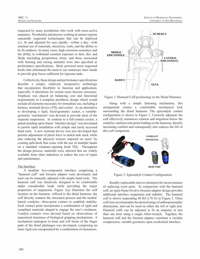
180
MEC ‘11raIsIng the standard
InsItute of BIomedIcal engIneerIng
unIversIty of new BrunswIck
requestedbymanyprosthetistswhoworkwithmore-activeamputees.Prosthetistsanddoctorsworkinginremoteregionsrepeatedly requested technologies that can be deployed(i.e. fit and adjusted for use) rapidly—within a day—withminimaluseofmaterials,electricity,tools,andtheabilitytobefitoutdoors.Inmanycases,highcorrosionresistanceandtheability towithstandconstantexposure todust,dirt,andfluids (including perspiration, brine, and those associatedwith farming and raising animals) were also specified asperformancespecifications. Bodypoweredusersrequestedhooksthateliminatedtheneedtousenumerouslatexbandstoprovidegripforcessufficientforrigoroustasks.
Collectively,thesedesignandperformancespecificationsdescribe a simple, relatively inexpensive technologythat incorporates flexibility in function and application;especially ifalterationsforcertainusersbecomenecessary.Emphasis was placed on balancing cost and functionalrequirements in a complete prosthesis designwhichwouldincludeallelementsnecessaryforimmediateuse,includingaharness,terminaldevice(TD),andsocket.Asanalternativeto developing a rigid, fixed-geometry socket, a variable-geometry ‘mechanism’wasdevised toprovidemostof therequisitesuspension. Incontrast toa full-contactsocket,apatent-pendingopen-frame“interfacedesign”wasdevelopedtopermitrapidinstallationwithsimpleandeasilyaccessedhandtools.Anewterminaldevicewasalsodevelopedthatpermitsadjustmentofpinchforcetomatchtaskneed,whilealso reducing the physical stresses imposed on users’ byexistingsplit-hookthatcomewiththeuseofmultiplebandson a standard voluntary-opening hook TDs. Throughoutthedesignprocess,materialswere selected that arewidelyavailable fromother industries to reduce the cost of repairandmaintenance.
TheInterfaceA modular two-component interface comprising a
“humeral cuff” and forearm adaptor were developed, andeachcanbemanuallyadjustedwithsimplehandtools.Thehumeral cuff was iteratively designed to be comfortableunder considerable loads while providing the majorproportion of suspension. Figure 1(a) illustrates the cufflocationonthehumerus.Affixedtothedistalhumerus, thecuffdirectlycontactstheolecranonprocessandthemedial/lateral condyles—three-point contact to establish stability.Eachcontactpoint incorporatesacombinationof rigidandcompliantmaterials shaped to engage the user’s residuum.Condyle contacts were devised based on observations ofanatomicalstructuresofbiologicalgrippingmechanisms.Amechanismanalogous toboneand soft tissueof the fingerpadsof thedistalphalangeswasdeveloped,comprisinganinnerrigidcoreencapsulatedbyacombinationofelastomers.
Figure1:HumeralCuffpositioningontheDistalHumerus
Along with a simple fastening mechanism, thisarrangement creates a comfortable mechanical locksurrounding the distal humerus. The epicondyle contactconfiguration is shown inFigure2.Correctlyadjusted, thecuffeffectivelyminimizesrotationandmigrationbelowthecondyles,andpreventspointloadingonthehumerus,therebyincreasingcomfortandconsequentlyalsoreducesthelifeofthiscuffcomponent.
Figure2:EpicondyleContactConfiguration
Readilyreplaceablesleevesminimizetheinconvenienceof replacingworn parts. In conjunctionwith the humeralcuff,anopen-framebivalveforearmadaptordesignprovidesadditional interface suspension and stability. The humeralcuffisshownsuspending40lbf(178N)inFigure3.Threecuffsizesaccommodatethedesiredrangeofanthropomorphicdimensions,andcanbeusedoneithertheleftorrightarm.Humeral cuffs can be adjusted to fit an amputee in lessthan one hour using a singleAllen-wrench. Together, thehumeral cuff and the forearm adaptor constitute a variablecompression,variable-geometryopenexoskeletalinterface.
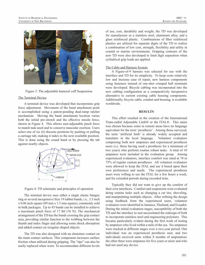
181
InsItute of BIomedIcal engIneerIng
unIversIty of new BrunswIck
MEC ‘11raIsIng the standard
Figure3:TheadjustablehumeralcuffSuspension
TheTerminalDevice
Aterminaldevicewasdevelopedthatincorporatesgripforceadjustment. Movementof thebandattachmentpointis accomplished using a patent-pending dual-ramp ratchetmechanism. Moving the band attachment location variesboth the initial pre-stretch and the effective tensile force,showninFigure4.Thisallowsuser-adjustablepinchforcetomatchtaskneedandtoconservemuscularexertion.Usersselectoneofsix(6)discretepositionsbypushingorpullingacarriagetab,makingitindextothenextavailableposition.This is done using the sound hand or by pressing the tabagainstnearbyobjects.
Figure4:TDschematicandprinciplesofoperation
TheterminaldeviceuseseitherasingleelasticbungeeringorseveralinexpensiveSize19rubberbands,i.e.,3.5inchx0.06inchsquare(89mmx1.5mmsquare),commonlysoldinbulkpackages.Upto45bandscanbeinstalledtoachieveamaximumpinch force of 17 lbf (76N).ThemechanicalarrangementoftheTDhasthebandscrossingthegripcontactarea,providingsimilarfunctiontothewebbingbetweenthethumbandindexfingerandallowingsomeshockabsorptionandaddedcontactonirregularshapedobjects.
TheTDwasalsodesignedwithanelastomercontactonthemaincontactsurfaces.Thiscomponentincreasessurfacefrictionwhenutilizedduringgripping.The“tips”canalsobeeasilyreplacedwhenworn.Toaccommodatedifferentlevels
of use, cost, durability andweight, theTDwas developedformanufactureasa stainless steel, aluminumalloy, andaglass reinforced plastic. Combinations of fiber reinforcedplasticsareutilized for separatedigitsof theTD to realizeacombinationoflowcost,strength,flexibilityandutilityincoastal or marine environments. Gripping contours of thenewTDwerealsodevelopedtolimitdigitseparationwhencylindricalgriploadsareapplied.
TheCableandHarnessSystemA Figure-of-9 harness was selected for use with the
interfaceandTDforitssimplicity.Tokeepcostsrelativelylow and increase ease of repair, new harness componentsusing fasteners instead of one-shot crimped ball terminalsweredeveloped.Bicycle cablingwas incorporated into thenew cabling configuration as a comparatively inexpensivealternative to current existing cable housing components.Additionally,bicyclecable,conduitandhousing,isavailableworldwide.
RESULTS
This effort resulted in the creationof the InternationalTrans-radialAdjustableLimb®or the ITAL®. This namewaschosenbecausesomeinremoteareashavenolanguageequivalentfortheterm‘prosthesis’.Amongthosesurveyed,the term ‘artificial limb’ is already widely accepted andtranslates in the local language. Volunteer evaluatorscomprising both new amputees and experienced prosthesisusers(i.e.thosehavingusedaprosthesisforaminimumoftwoyears)whoperformroutinerobusttasks.Atotalof10amputees were included in the evaluation group. Amongexperiencedevaluators,interfacecomfortwasratedat70to75%ofregularcustomprostheses.AllvolunteerevaluatorswereallowedtokeeptheITALanduseitbasedupontheirown preferences and needs. The experienced prosthesisuserswerewillingtousetheITALforafewhoursaweek,andforextendedperiodsduringrecordedtests.
Typically they did notwant to give up the comfort oftheirowninterfaces.Comfortandsuspensionwereevaluateddoing routine tasks such as changing a car tire, shoveling,andmanipulatingmultipleobjects.Afterrefiningthedesignusing feedback from the experienced users, volunteerevaluatorswereidentifiedinJamaica,Thailand,andEcuador.Duringtheinitialevaluationstages,susceptibilityofboththeTDandtheinterfacetorustnecessitatedtheredesignofbothtoincorporatestainlesssteelandengineeringpolymers.Thisbecameparticularlyevidentduringthefirstweekoftestingbyamputeeswholivedwithinamileofthesea.Sixamputeesweretrackedatdifferentstagesoveratwo-yearperiod.Oneindividual was an experienced prosthesis user, and twoindividuals received units within 8months of amputation;theotherthreewereamputeesforfiveyearsormoreandwhohadnotusedanydevice.
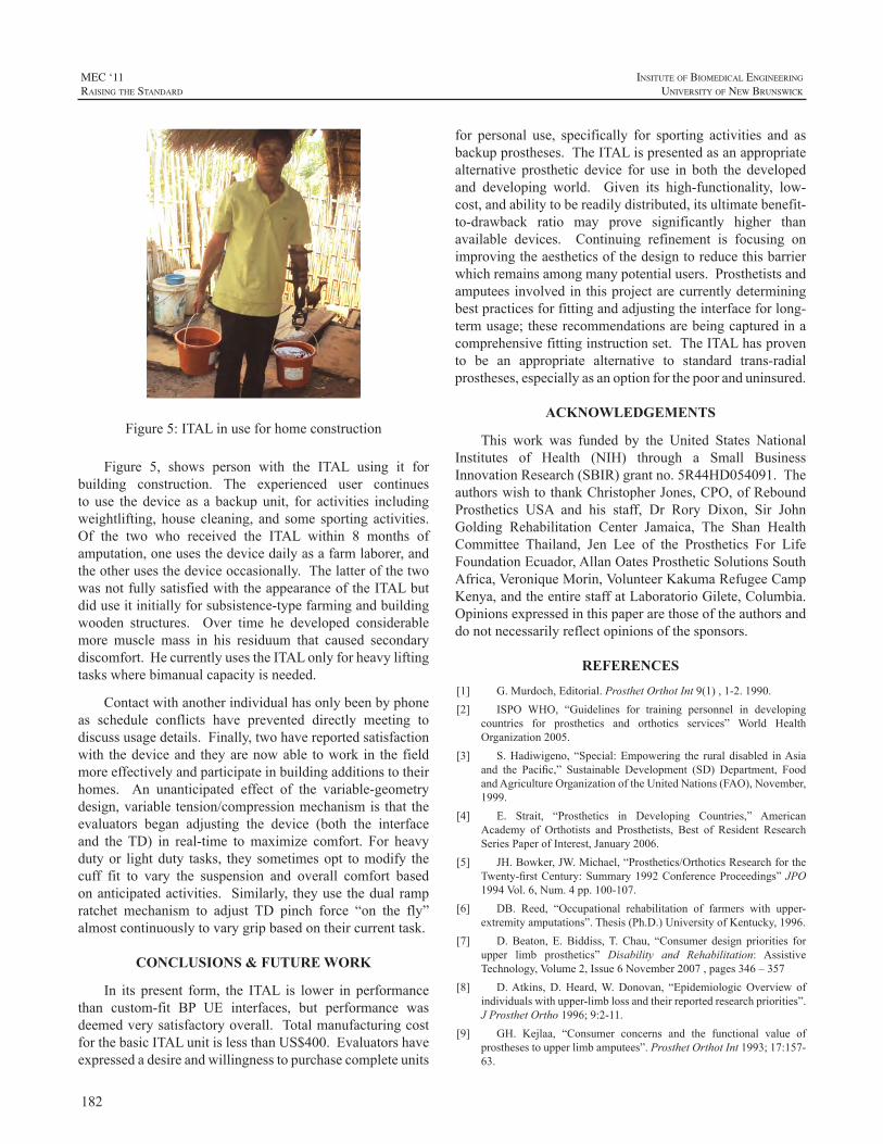
182
MEC ‘11raIsIng the standard
InsItute of BIomedIcal engIneerIng
unIversIty of new BrunswIck
Figure5:ITALinuseforhomeconstruction
Figure 5, shows person with the ITAL using it forbuilding construction. The experienced user continuesto use the device as a backup unit, for activities includingweightlifting,house cleaning, and some sporting activities.Of the two who received the ITAL within 8 months ofamputation,oneusesthedevicedailyasafarmlaborer,andtheotherusesthedeviceoccasionally.ThelatterofthetwowasnotfullysatisfiedwiththeappearanceoftheITALbutdiduseitinitiallyforsubsistence-typefarmingandbuildingwooden structures. Over time he developed considerablemore muscle mass in his residuum that caused secondarydiscomfort.HecurrentlyusestheITALonlyforheavyliftingtaskswherebimanualcapacityisneeded.
Contactwithanotherindividualhasonlybeenbyphoneas schedule conflicts have prevented directly meeting todiscussusagedetails.Finally,twohavereportedsatisfactionwith thedeviceand theyarenowable towork in the fieldmoreeffectivelyandparticipateinbuildingadditionstotheirhomes. An unanticipated effect of the variable-geometrydesign,variable tension/compressionmechanismis that theevaluators began adjusting the device (both the interfaceand theTD) in real-time tomaximize comfort. For heavydutyor lightduty tasks, they sometimesopt tomodify thecuff fit to vary the suspension and overall comfort basedonanticipatedactivities. Similarly, theyuse thedualrampratchet mechanism to adjust TD pinch force “on the fly”almostcontinuouslytovarygripbasedontheircurrenttask.
CONCLUSIONS & FUTURE WORK
In its present form, the ITAL is lower in performancethan custom-fit BP UE interfaces, but performance wasdeemedverysatisfactoryoverall. TotalmanufacturingcostforthebasicITALunitislessthanUS$400.Evaluatorshaveexpressedadesireandwillingnesstopurchasecompleteunits
for personal use, specifically for sporting activities and asbackupprostheses.TheITALispresentedasanappropriatealternative prosthetic device for use in both the developedand developing world. Given its high-functionality, low-cost,andabilitytobereadilydistributed,itsultimatebenefit-to-drawback ratio may prove significantly higher thanavailable devices. Continuing refinement is focusing onimprovingtheaestheticsofthedesigntoreducethisbarrierwhichremainsamongmanypotentialusers.Prosthetistsandamputeesinvolvedinthisprojectarecurrentlydeterminingbestpracticesforfittingandadjustingtheinterfaceforlong-termusage;theserecommendationsarebeingcapturedinacomprehensivefittinginstructionset.TheITALhasprovento be an appropriate alternative to standard trans-radialprostheses,especiallyasanoptionforthepooranduninsured.
ACKNOWLEDGEMENTS
This work was funded by the United States NationalInstitutes of Health (NIH) through a Small BusinessInnovationResearch(SBIR)grantno.5R44HD054091.TheauthorswishtothankChristopherJones,CPO,ofReboundProsthetics USA and his staff, Dr Rory Dixon, Sir JohnGolding Rehabilitation Center Jamaica, The Shan HealthCommittee Thailand, Jen Lee of the Prosthetics For LifeFoundationEcuador,AllanOatesProstheticSolutionsSouthAfrica,VeroniqueMorin,VolunteerKakumaRefugeeCampKenya,andtheentirestaffatLaboratorioGilete,Columbia.Opinionsexpressedinthispaperarethoseoftheauthorsanddonotnecessarilyreflectopinionsofthesponsors.
REFERENCES
[1] G.Murdoch,Editorial.ProsthetOrthotInt9(1),1-2.1990.[2] ISPO WHO, “Guidelines for training personnel in developing
countries for prosthetics and orthotics services” World HealthOrganization2005.
[3] S.Hadiwigeno, “Special:Empowering the rural disabled inAsiaand the Pacific,” Sustainable Development (SD) Department, FoodandAgricultureOrganizationoftheUnitedNations(FAO),November,1999.
[4] E. Strait, “Prosthetics in Developing Countries,” AmericanAcademy of Orthotists and Prosthetists, Best of Resident ResearchSeriesPaperofInterest,January2006.
[5] JH.Bowker,JW.Michael,“Prosthetics/OrthoticsResearchfortheTwenty-firstCentury:Summary1992ConferenceProceedings”JPO1994Vol.6,Num.4pp.100-107.
[6] DB. Reed, “Occupational rehabilitation of farmers with upper-extremityamputations”.Thesis(Ph.D.)UniversityofKentucky,1996.
[7] D.Beaton, E.Biddiss,T.Chau, “Consumer design priorities forupper limb prosthetics” Disability and Rehabilitation: AssistiveTechnology,Volume2,Issue6November2007,pages346–357
[8] D.Atkins,D.Heard,W.Donovan, “EpidemiologicOverview ofindividualswithupper-limblossandtheirreportedresearchpriorities”.JProsthetOrtho1996;9:2-11.
[9] GH. Kejlaa, “Consumer concerns and the functional value ofprosthesestoupperlimbamputees”.ProsthetOrthotInt1993;17:157-63.
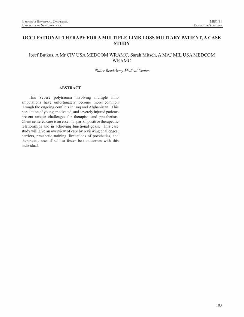
183
InsItute of BIomedIcal engIneerIng
unIversIty of new BrunswIck
MEC ‘11raIsIng the standard
ABSTRACT
This Severe polytrauma involving multiple limbamputations have unfortunately become more commonthroughtheongoingconflictsinIraqandAfghanistan.Thispopulationofyoung,motivated,andseverelyinjuredpatientspresent unique challenges for therapists and prosthetists.Clientcenteredcareisanessentialpartofpositivetherapeuticrelationships and in achieving functional goals. This casestudywillgiveanoverviewofcarebyreviewingchallenges,barriers, prosthetic training, limitations of prosthetics, andtherapeutic use of self to foster best outcomes with thisindividual.
OCCUPATIONAL THERAPY FOR A MULTIPLE LIMB LOSS MILITARY PATIENT, A CASE STUDY
JosefButkus,AMrCIVUSAMEDCOMWRAMC,SarahMitsch,AMAJMILUSAMEDCOMWRAMC
WalterReedArmyMedicalCenter
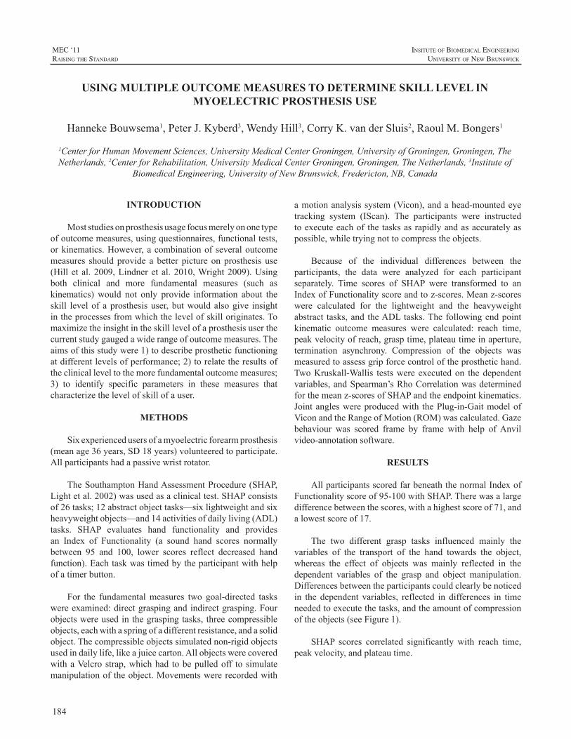
184
MEC ‘11raIsIng the standard
InsItute of BIomedIcal engIneerIng
unIversIty of new BrunswIck
INTRODUCTION
Moststudiesonprosthesisusagefocusmerelyononetypeofoutcomemeasures,usingquestionnaires,functionaltests,orkinematics.However,acombinationofseveraloutcomemeasures should provide a better picture on prosthesis use(Hill et al.2009,Lindneret al.2010,Wright2009).Usingboth clinical and more fundamental measures (such askinematics) would not only provide information about theskill levelof aprosthesisuser,butwouldalsogive insightintheprocessesfromwhichthelevelofskilloriginates.Tomaximizetheinsightintheskilllevelofaprosthesisuserthecurrentstudygaugedawiderangeofoutcomemeasures.Theaimsofthisstudywere1)todescribeprostheticfunctioningatdifferentlevelsofperformance;2)torelatetheresultsoftheclinicalleveltothemorefundamentaloutcomemeasures;3) to identify specific parameters in these measures thatcharacterizethelevelofskillofauser.
METHODS
Sixexperiencedusersofamyoelectricforearmprosthesis(meanage36years,SD18years)volunteeredtoparticipate.Allparticipantshadapassivewristrotator.
TheSouthamptonHandAssessmentProcedure(SHAP,Lightetal.2002)wasusedasaclinicaltest.SHAPconsistsof26tasks;12abstractobjecttasks—sixlightweightandsixheavyweightobjects—and14activitiesofdailyliving(ADL)tasks. SHAP evaluates hand functionality and providesan Index of Functionality (a sound hand scores normallybetween 95 and 100, lower scores reflect decreased handfunction).Eachtaskwastimedbytheparticipantwithhelpofatimerbutton.
For the fundamentalmeasures two goal-directed taskswereexamined:directgraspingandindirectgrasping.Fourobjectswereusedinthegraspingtasks, threecompressibleobjects,eachwithaspringofadifferentresistance,andasolidobject.Thecompressibleobjectssimulatednon-rigidobjectsusedindailylife,likeajuicecarton.AllobjectswerecoveredwithaVelcrostrap,whichhad tobepulledoff tosimulatemanipulationoftheobject.Movementswererecordedwith
amotionanalysissystem(Vicon),andahead-mountedeyetracking system (IScan). The participants were instructedtoexecuteeachofthetasksasrapidlyandasaccuratelyaspossible,whiletryingnottocompresstheobjects.
Because of the individual differences between theparticipants, the data were analyzed for each participantseparately. Time scores of SHAP were transformed to anIndexofFunctionalityscoreandtoz-scores.Meanz-scoreswere calculated for the lightweight and the heavyweightabstract tasks,and theADLtasks.Thefollowingendpointkinematic outcome measures were calculated: reach time,peakvelocityofreach,grasptime,plateautimeinaperture,termination asynchrony. Compression of the objects wasmeasuredtoassessgripforcecontroloftheprosthetichand.TwoKruskall-Wallis testswere executedon thedependentvariables,andSpearman’sRhoCorrelationwasdeterminedforthemeanz-scoresofSHAPandtheendpointkinematics.Jointangleswereproducedwith thePlug-in-GaitmodelofViconandtheRangeofMotion(ROM)wascalculated.Gazebehaviour was scored frame by frame with help ofAnvilvideo-annotationsoftware.
RESULTS
AllparticipantsscoredfarbeneaththenormalIndexofFunctionalityscoreof95-100withSHAP.Therewasalargedifferencebetweenthescores,withahighestscoreof71,andalowestscoreof17.
The two different grasp tasks influenced mainly thevariables of the transport of the hand towards the object,whereas the effect of objects was mainly reflected in thedependent variables of the grasp and object manipulation.Differencesbetweentheparticipantscouldclearlybenoticedin the dependent variables, reflected in differences in timeneededtoexecutethetasks,andtheamountofcompressionoftheobjects(seeFigure1).
SHAP scores correlated significantly with reach time,peakvelocity,andplateautime.
USING MULTIPLE OUTCOME MEASURES TO DETERMINE SKILL LEVEL IN MYOELECTRIC PROSTHESIS USE
HannekeBouwsema1,PeterJ.Kyberd3,WendyHill3,CorryK.vanderSluis2,RaoulM.Bongers1
1CenterforHumanMovementSciences,UniversityMedicalCenterGroningen,UniversityofGroningen,Groningen,TheNetherlands,2CenterforRehabilitation,UniversityMedicalCenterGroningen,Groningen,TheNetherlands,3Instituteof
BiomedicalEngineering,UniversityofNewBrunswick,Fredericton,NB,Canada
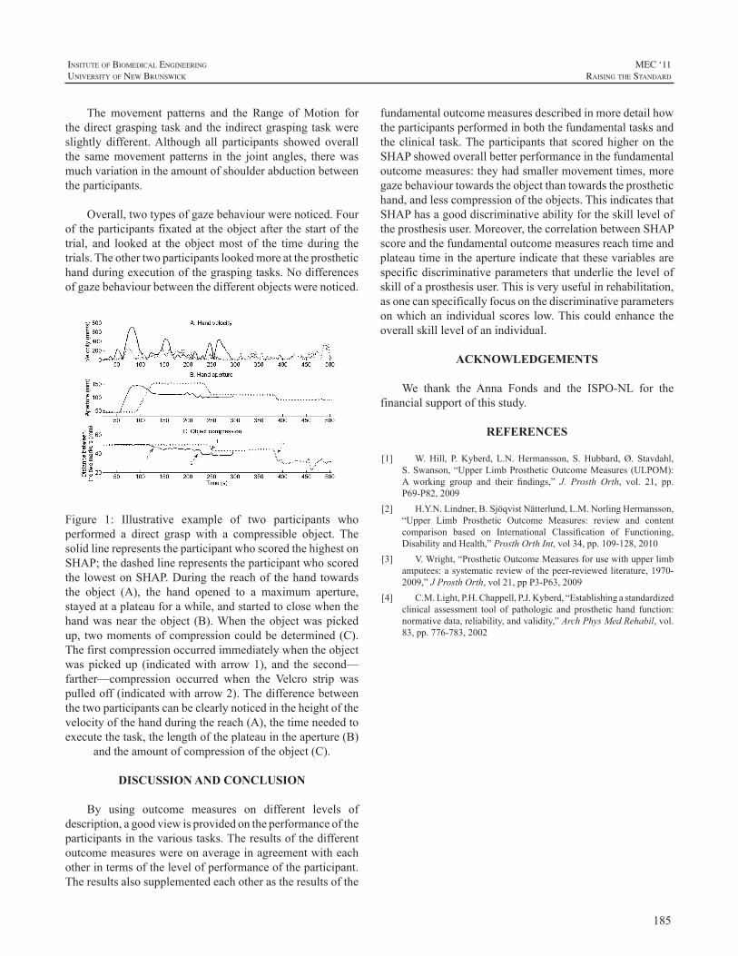
185
InsItute of BIomedIcal engIneerIng
unIversIty of new BrunswIck
MEC ‘11raIsIng the standard
The movement patterns and the Range ofMotion forthedirectgraspingtaskandtheindirectgraspingtaskwereslightly different.Although all participants showed overallthe samemovement patterns in the joint angles, therewasmuchvariationintheamountofshoulderabductionbetweentheparticipants.
Overall,twotypesofgazebehaviourwerenoticed.Fouroftheparticipantsfixatedattheobjectafterthestartofthetrial, and looked at the objectmost of the time during thetrials.Theothertwoparticipantslookedmoreattheprosthetichandduringexecutionofthegraspingtasks.Nodifferencesofgazebehaviourbetweenthedifferentobjectswerenoticed.
Figure 1: Illustrative example of two participants whoperformed a direct grasp with a compressible object. ThesolidlinerepresentstheparticipantwhoscoredthehighestonSHAP;thedashedlinerepresentstheparticipantwhoscoredthelowestonSHAP.Duringthereachofthehandtowardsthe object (A), the hand opened to a maximum aperture,stayedataplateauforawhile,andstartedtoclosewhenthehandwasnear theobject (B).When theobjectwaspickedup, twomomentsofcompressioncouldbedetermined(C).Thefirstcompressionoccurredimmediatelywhentheobjectwas picked up (indicatedwith arrow1), and the second—farther—compression occurred when the Velcro strip waspulledoff(indicatedwitharrow2).Thedifferencebetweenthetwoparticipantscanbeclearlynoticedintheheightofthevelocityofthehandduringthereach(A),thetimeneededtoexecutethetask,thelengthoftheplateauintheaperture(B)
andtheamountofcompressionoftheobject(C).
DISCUSSION AND CONCLUSION
By using outcome measures on different levels ofdescription,agoodviewisprovidedontheperformanceoftheparticipantsinthevarioustasks.Theresultsofthedifferentoutcomemeasureswereonaverageinagreementwitheachotherintermsofthelevelofperformanceoftheparticipant.Theresultsalsosupplementedeachotherastheresultsofthe
fundamentaloutcomemeasuresdescribedinmoredetailhowtheparticipantsperformedinboththefundamentaltasksandtheclinical task.Theparticipants that scoredhigheron theSHAPshowedoverallbetterperformanceinthefundamentaloutcomemeasures:theyhadsmallermovementtimes,moregazebehaviourtowardstheobjectthantowardstheprosthetichand,andlesscompressionoftheobjects.ThisindicatesthatSHAPhasagooddiscriminativeabilityfortheskillleveloftheprosthesisuser.Moreover,thecorrelationbetweenSHAPscoreandthefundamentaloutcomemeasuresreachtimeandplateautimeintheapertureindicatethatthesevariablesarespecificdiscriminativeparametersthatunderliethelevelofskillofaprosthesisuser.Thisisveryusefulinrehabilitation,asonecanspecificallyfocusonthediscriminativeparametersonwhichan individualscores low.Thiscouldenhance theoverallskilllevelofanindividual.
ACKNOWLEDGEMENTS
We thank the Anna Fonds and the ISPO-NL for thefinancialsupportofthisstudy.
REFERENCES
[1] W.Hill, P.Kyberd, L.N.Hermansson, S.Hubbard,Ø. Stavdahl,S.Swanson,“UpperLimbProstheticOutcomeMeasures(ULPOM):A working group and their findings,” J. Prosth Orth, vol. 21, pp.P69-P82,2009
[2] H.Y.N.Lindner,B.SjöqvistNätterlund,L.M.NorlingHermansson,“Upper Limb Prosthetic Outcome Measures: review and contentcomparison based on International Classification of Functioning,DisabilityandHealth,”ProsthOrthInt,vol34,pp.109-128,2010
[3] V.Wright,“ProstheticOutcomeMeasuresforusewithupperlimbamputees:asystematicreviewof thepeer-reviewedliterature,1970-2009,”JProsthOrth,vol21,ppP3-P63,2009
[4] C.M.Light,P.H.Chappell,P.J.Kyberd,“Establishingastandardizedclinical assessment tool of pathologic and prosthetic hand function:normativedata,reliability,andvalidity,”ArchPhysMedRehabil,vol.83,pp.776-783,2002
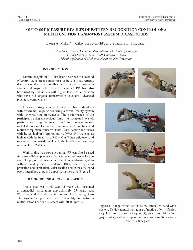
186
MEC ‘11raIsIng the standard
InsItute of BIomedIcal engIneerIng
unIversIty of new BrunswIck
INTRODUCTION
Patternrecognition(PR)hasbeendescribedasamethodofcontrollingalargernumberofprostheticarmmovementsthan those that are possible with currently availablecommercial myoelectric control devices.1 PR has alsobeen used by individualswith higher levels of amputationwho have had targeted reinnervation to control advancedprostheticcomponents.2
Previous testing was performed on five individualswith transradial amputations using a virtual reality systemwith 10 wrist/hand movements. The performance of theparticipants using the residual limbwas compared to theirperformance using the intact arm.3 Performance metricsincludedmotionselectiontime,motioncompletiontime,andmotioncompletion(“success”)rate.Classificationaccuracieswiththeresiduallimb(approximately79%±11%)werenotashighaswiththeintactarm(94%±3%).Whenonlyonehandmovementwas tested, residual limbclassificationaccuracyincreasedto93%±4%.
WorktodatehasnowshownthatPRcanalsobeusedfor transradialamputees (without targetedreinnervation) tocontrolaphysicaldevice:amultifunctionhand-wristsystemwith seven degrees of freedom (DOFs), including wristpronationandsupination,wristflexionandextension,handopen,lateral/keygrip,andopposition/pinchgrip(Figure1).
BACKGROUND & CONFIGURATION
The subject was a 62-year-old male who sustaineda transradial amputation approximately 25 years ago.We compared his ability to control his existing two-site myoelectric prosthesis with his ability to control amultifunctionhand-wristsystemwithPR(Figure1).
Figure1:Rangeofmotionof themultifunctionhand-wristsystem.Deviceatmaximumrangeofmotionofwristflexion(top left) and extension (top right), pinch and lateral/keygrip(center),andhandopen(bottom).Wristrotationmoves
through360degrees.
OUTCOME MEASURE RESULTS OF PATTERN RECOGNITION CONTROL OF A MULTIFUNCTION HAND-WRIST SYSTEM: A CASE STUDY
LauraA.Miller1,2,KathyStubblefield1,andSuzanneB.Finucane.1
1CenterforBionicMedicine,RehabilitationInstituteofChicago345EastSuperior,Suite1309,Chicago,IL60611
2FeinbergSchoolofMedicine,NorthwesternUniversity
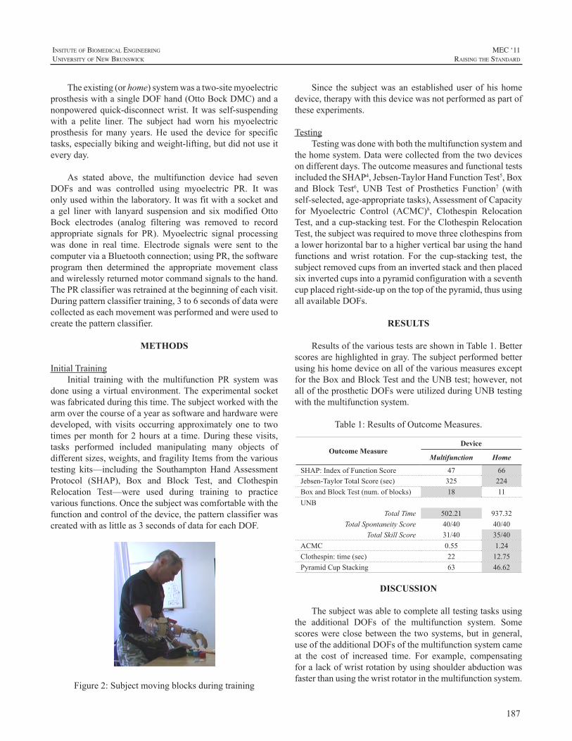
187
InsItute of BIomedIcal engIneerIng
unIversIty of new BrunswIck
MEC ‘11raIsIng the standard
Theexisting(orhome)systemwasatwo-sitemyoelectricprosthesiswithasingleDOFhand(OttoBockDMC)andanonpoweredquick-disconnectwrist. Itwas self-suspendingwith a pelite liner. The subject had worn his myoelectricprosthesis formany years.He used the device for specifictasks,especiallybikingandweight-lifting,butdidnotuseiteveryday.
As stated above, the multifunction device had sevenDOFs and was controlled using myoelectric PR. It wasonlyusedwithinthelaboratory.Itwasfitwithasocketanda gel linerwith lanyard suspension and sixmodifiedOttoBock electrodes (analog filtering was removed to recordappropriate signals for PR).Myoelectric signal processingwas done in real time. Electrode signals were sent to thecomputerviaaBluetoothconnection; usingPR,thesoftwareprogram then determined the appropriate movement classandwirelesslyreturnedmotorcommandsignalstothehand.ThePRclassifierwasretrainedatthebeginningofeachvisit.Duringpatternclassifiertraining,3to6secondsofdatawerecollectedaseachmovementwasperformedandwereusedtocreatethepatternclassifier.
METHODS
InitialTrainingInitial training with the multifunction PR system was
doneusingavirtualenvironment.Theexperimental socketwasfabricatedduringthistime.Thesubjectworkedwiththearmoverthecourseofayearassoftwareandhardwareweredeveloped,with visits occurring approximately one to twotimespermonth for2hoursat a time.During thesevisits,tasks performed included manipulating many objects ofdifferentsizes,weights,andfragilityItemsfromthevarioustesting kits—including the SouthamptonHandAssessmentProtocol (SHAP), Box and Block Test, and ClothespinRelocation Test—were used during training to practicevariousfunctions.Oncethesubjectwascomfortablewiththefunctionandcontrolofthedevice,thepatternclassifierwascreatedwithaslittleas3secondsofdataforeachDOF.
Figure2:Subjectmovingblocksduringtraining
Since the subjectwas an establisheduser of his homedevice,therapywiththisdevicewasnotperformedaspartoftheseexperiments.
TestingTestingwasdonewithboththemultifunctionsystemand
thehomesystem.Datawerecollectedfromthetwodevicesondifferentdays.TheoutcomemeasuresandfunctionaltestsincludedtheSHAP4,Jebsen-TaylorHandFunctionTest5,Boxand Block Test6, UNBTest of Prosthetics Function7 (withself-selected,age-appropriatetasks),AssessmentofCapacityfor Myoelectric Control (ACMC)8, Clothespin RelocationTest,andacup-stackingtest.FortheClothespinRelocationTest,thesubjectwasrequiredtomovethreeclothespinsfromalowerhorizontalbartoahigherverticalbarusingthehandfunctions andwrist rotation. For the cup-stacking test, thesubjectremovedcupsfromaninvertedstackandthenplacedsixinvertedcupsintoapyramidconfigurationwithaseventhcupplacedright-side-uponthetopofthepyramid,thususingallavailableDOFs.
RESULTS
ResultsofthevarioustestsareshowninTable1.Betterscoresarehighlightedingray.ThesubjectperformedbetterusinghishomedeviceonallofthevariousmeasuresexceptfortheBoxandBlockTestandtheUNBtest;however,notalloftheprostheticDOFswereutilizedduringUNBtestingwiththemultifunctionsystem.
Table1:ResultsofOutcomeMeasures.
Outcome MeasureDevice
Multifunction Home
SHAP:IndexofFunctionScore 47 66Jebsen-TaylorTotalScore(sec) 325 224BoxandBlockTest(num.ofblocks) 18 11UNB
TotalTime 502.21 937.32TotalSpontaneityScore 40/40 40/40
TotalSkillScore 31/40 35/40ACMC 0.55 1.24Clothespin:time(sec) 22 12.75PyramidCupStacking 63 46.62
DISCUSSION
Thesubjectwasabletocompletealltestingtasksusingthe additional DOFs of the multifunction system. Somescoreswereclosebetweenthetwosystems,but ingeneral,useoftheadditionalDOFsofthemultifunctionsystemcameat the cost of increased time. For example, compensatingforalackofwristrotationbyusingshoulderabductionwasfasterthanusingthewristrotatorinthemultifunctionsystem.
188
MEC ‘11raIsIng the standard
InsItute of BIomedIcal engIneerIng
unIversIty of new BrunswIck
Asa result, thehomedevice scoredmore favorablyon alltimedtestsexcepttheBoxandBlockandUNB.Theabilitytopositionthehandintoflexionmayhaveimprovedthescoreon the Box and Block Test. The multifunction prosthesisdemonstratedafastertimeonUNBtasks.Thiswasbecausethe subject had difficulty opening the hand of his two-sitesystem.Theskilllevelwashigherwiththisdevice,however,because when using the multifunction system, we foundthat despite asking him to do the task inwhatwe thoughtwould be an appropriate way (as the nondominant hand),heoftenwasinsistentthathewould“showuswhatitcoulddo”andthereforedid the tasks ina lessnaturalway,usingtheprosthetichandasthedominantextremity.Forexample,when removing money from a wallet, he stabilized thewalletwiththeintacthandandremovedthemoneywiththeprosthesis;whenusingadustpan,heheldthewhiskbroomwiththeprosthesis;and,whentearingtinfoil,heheldtheboxwiththeintacthandandtorethefoilwiththeprosthesis.
Oneof thereasonsthesubjectdidnotperformaswellwiththemultifunctionsysteminthestandardizedtestsisthathewaslessfamiliarwithit.Ournextgoalistohaveahometrialtoallowthesubjecttobecomebetteratcontrollingandincorporatingthedeviceintodailytasksasanassistivedevice.Aspreviouslymentioned,fortaskswherehewasallowedtochoosehowthedevicewasused(UNBandACMC),heofteninappropriatelychose touse theprosthesisas thedominanthand.
FUTURE WORK
AlthoughwehaveshownthatitispossibletocontrolatwoDOFhandand twoDOFwristwithPR, thereare stillmanyfactorsthatneedtoberesolvedbeforethissystemcanbe viable as a home system. For example, the processingthatisdoneonanexternalcomputerneedstobetransferredtoanembeddedsystem.Additionally,asystemthatdetectswhenanelectrodestopsprovidingdependablesignals(e.g..loses contact with the skin) may provide more reliablecontrol. Also, six electrodes can be difficult to integrateintoa transradial systemdue tosocket sizeconstraintsandthe difficulty in keeping six electrodes in contactwith theskinthroughallmovementsoftheresiduallimb.Effortsareunderway to improve the socket function and comfort forhometrials
Oncehardware issues have been resolved, home trialsareplanned.Thesetrialsareexpectedtobeginthisyear.
ACKNOWLEDGEMENTS
Wewould like to acknowledge Robert Parks and DatTran for software support, and Aimee Schultz and AnnBarlowforeditorialsupport.
REFERENCES
[1] K.EnglehartandB.Hudgins,“Arobust,real-timecontrolschemefor multifunction myoelectric control,” IEEE Trans Biomed Eng,vol.50,pp.848-54,2003.
[2] T.A.Kuiken,G.Li,B.A.Lock,R.D.Lipschutz,L.A.Miller,K.A.Stubblefield, andK. Englehart, “TargetedMuscle Reinnervation forReal-time Myoelectric Control of Multifunction Artificial Arms,”JAMA,vol301,pp.619-28,2009.
[3] G. Li, A.E. Schultz, and T.A. Kuiken, “Quantifying PatternRecognitionBasedMyoelectricControlofMultifunctionalTransradialProstheses,”IEEETransNeuralSysRehabEng,vol18,pp.185-192,2010.
[4] C.M. Light, P. H. Chappell, and P.J. Kyberd, “Establishing astandardizedclinicalassessmenttoolofpathologicandprosthetichandfunction: normative data, reliability, and validity.” Arch Phys MedRehabil,vol.83,pp.776-783,2002.
[5] R.H.Jebsen,N.Taylor,R.B.Trieeschmann,M.J.Trotter,andL.A.Howard,“Anobjectiveandstandardizedtestofhandfunction.”ArchPhysMedRehabil,vol.50,pp.311-319,1969.
[6] V.Mathiowetz, G.Volland, N. Kashman, andK.Weber, “Adultnorms for the box and blocks test of manual dexterity.” Am JOccupationalTher,vol.39,pp.386-391,1985
[7] E.R.Sanderson,andR.N.Scott,UNBtestofprostheticsfunction,atestforunilateralupperextremityamputees,Ages2-13,UniversityofNewBrunswick,Bio-engineeringInstitute: 1-9,1985
[8] L.M.Hermansson,A.G.Fisher,B.Bernspang,andA.C.Eliasson,“Assessment of capacity formyoelectric control: a newRasch-builtmeasureofprosthetichandcontrol.”JRehabilMed,vol.37,pp.166-171,2005
189
InsItute of BIomedIcal engIneerIng
unIversIty of new BrunswIck
MEC ‘11raIsIng the standard
INTRODUCTION
Tools to evaluate the effectiveness of upper limbprostheses generally measure user’s performance onfunctionaltasksorusequestionnairestoexaminetheeffectofamputationandprosthesisuseoneverydaylifeactivities[1].Therehavebeenfewstudiesdescribingthecharacteristicchanges in motor behaviour associated with learning touse a prosthesis [2, 3]. Such studies potentially provideuseful insight into the characteristics that are reflective ofskillacquisitionandhencemayleadtothedevelopmentofimprovedoutcomemeasures.
Nevertheless, most of these studies only investigatedplanar pointing tasks, in which no active involvement ofthe hand is required and relatively small differences inperformance between amputees and anatomically intactcontrols were observed. In contrast, previous studies ofactivities of daily living (ADL) performance have shownclear differences in joint kinematics and task completiontimebetweenhealthysubjectsandamputees[4].Moreover,despite thewidespreadagreement regarding the roleof thevisioninprostheticuse[3,5-8],andtheextensiveliteratureontheroleofvisioninlearningtouseatool(e.g.[9,10])andintheperformanceofADLs[11],gazebehaviourinupperlimbprosthesisusershasreceivedlimitedattention[3].
Inthisstudy,weevaluatedthechangestokinematicsandgazebehaviourassociatedwithlearningtouseamyoelectricprosthesisfortheperformanceofanADLtask.Wechosetostudy anatomically intact subjects to allow for comparisonoftaskperformancewiththeprosthesisagainstperformanceusingtheanatomicalupperlimb.Thestudyfirstlyaimedtodescribecharacteristicfactorswhichdifferentiateupperlimbtaskperformancewiththeanatomicalhandfromperformancewithamyoelectricprosthesis.Thesecondaimwastoidentifythose factors which changed with skill acquisition whilelearningtousetheprosthesis.Duetospacelimitations,inthispaperwedescribe themethodsandpresentdetailed resultsfromthegazebehaviourpartofthestudy.However,afullsetofresults,includingthekinematics,willbepresentedattheconference.
METHODS
The studywas approved by the University of SalfordResearchEthicscommittee.Followingwrittenconsent,fiveanatomically intact, right-handed individuals, (3males and2females)withameanageof30years(rangedfrom26-41)wererecruited.Allsubjectswereingoodphysicalconditionandhadwithin-normalvisualacuity.Alldataweregatheredin theMovement Science Laboratory at the University ofSalford,Salford,UK.
The experimental setup is discussed inmore detail in[12] and hence only brief details are provided here. Thestudywasa cross-overdesign (Table1).Participants’gazebehaviourandupperlimbkinematicsduringtheperformanceof anADL taskwere evaluated twice in separate sessions(E1andE2)whichformedabaselinephase.Followingthistheywerefittedwithamyoelectricprosthesissimulator(see[12]).Subjectswerethenevaluated3furthertimesoverthecourseofapproximately2weeks,whenperformingthetaskwith their prosthesis (E3-E5).Wealsoprovided6 separatepracticesessions(P).Duringeachofthesesessions,subjectsperformed the Southampton Hand Assessment Procedure(SHAP)once[13].TheSHAPsessionswereperformedondifferentdaystotheevaluationsessions,toavoidfatigue.TheSHAPtestnotonlyprovidedanopportunityforparticipantstopractice,butalsoallowedforanevaluationofhandfunctionoverthecourseofthestudy.
TheADLtaskcarriedoutineachoftheevaluation(E)sessions involved reaching for a carton and pouringwaterfrom the carton into a glass, then replacing the carton onto the table.The taskwas challenging toperformwith theprosthesis and had a cost (water spillage) associated withpoorperformance. Ateachevaluationsession (E)subjectsrepeatedthetask12timesandthefirst10repeatsinwhichgooddatawerecollectedwereconsideredforanalysis.
At thestartofeachevaluationsession thesubjectwasseateduprightinachairwithhis/herbackrestingonthechairback, the upper arm in a neutral position and both handsrestingcomfortablyon the table.The locationof thehandswhenrestedonthetablewerethenmarked(termedreference
A PRELIMINARY STUDY OF GAZE BEHAVIOUR AND UPPER LIMB KINEMATICS IN TRANS-RADIAL USERS
M.Sobuh1,L.Kenney1,A.Galpin2,S.Thies1,P.Kyberd3
1CHSRSR,UniversityofSalford,UK,2SchoolofSocialWork,Psychology&PublicHealth,UniversityofSalford,UK,3InstituteofBiomedicalEngineering,UniversityofNewBrunswick,Canada
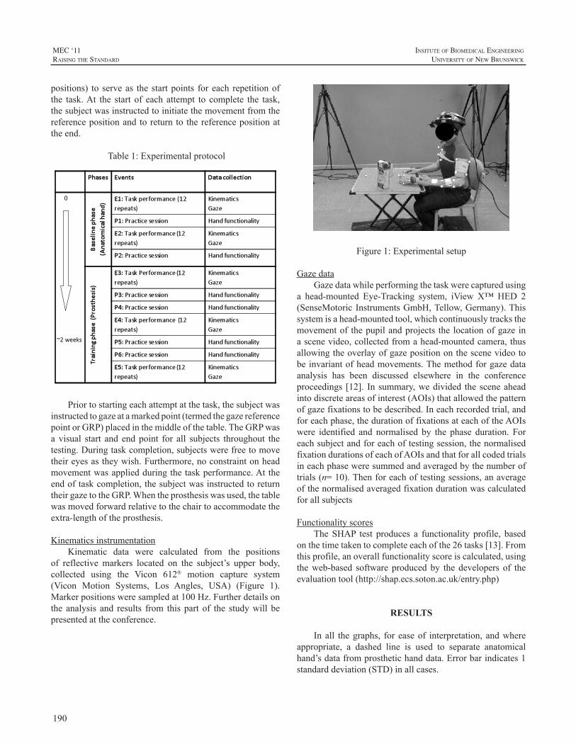
190
MEC ‘11raIsIng the standard
InsItute of BIomedIcal engIneerIng
unIversIty of new BrunswIck
positions) to serveas thestartpoints foreach repetitionofthe task.At the start of each attempt to complete the task,thesubjectwasinstructedtoinitiatethemovementfromthereferencepositionandtoreturnto thereferencepositionattheend.
Table1:Experimentalprotocol
Priortostartingeachattemptatthetask,thesubjectwasinstructedtogazeatamarkedpoint(termedthegazereferencepointorGRP)placedinthemiddleofthetable.TheGRPwasa visual start and end point for all subjects throughout thetesting.Duringtaskcompletion,subjectswerefreetomovetheireyesastheywish.Furthermore,noconstraintonheadmovementwasappliedduringthetaskperformance.Attheendoftaskcompletion,thesubjectwasinstructedtoreturntheirgazetotheGRP.Whentheprosthesiswasused,thetablewasmovedforwardrelativetothechairtoaccommodatetheextra-lengthoftheprosthesis.
KinematicsinstrumentationKinematic data were calculated from the positions
of reflective markers located on the subject’s upper body,collected using the Vicon 612® motion capture system(Vicon Motion Systems, Los Angles, USA) (Figure 1).Markerpositionsweresampledat100Hz.Furtherdetailsonthe analysis and results from this part of the studywill bepresentedattheconference.
Figure1:Experimentalsetup
GazedataGazedatawhileperformingthetaskwerecapturedusing
a head-mounted Eye-Tracking system, iView X™HED 2(SenseMotoricInstrumentsGmbH,Tellow,Germany).Thissystemisahead-mountedtool,whichcontinuouslytracksthemovementof thepupilandprojects the locationofgaze inascenevideo,collectedfromahead-mountedcamera,thusallowingtheoverlayofgazepositiononthescenevideotobeinvariantofheadmovements.Themethodforgazedataanalysis has been discussed elsewhere in the conferenceproceedings [12]. In summary,wedivided thesceneaheadintodiscreteareasofinterest(AOIs)thatallowedthepatternofgazefixationstobedescribed.Ineachrecordedtrial,andforeachphase,thedurationoffixationsateachoftheAOIswere identified and normalised by the phase duration. Foreachsubjectandforeachoftestingsession,thenormalisedfixationdurationsofeachofAOIsandthatforallcodedtrialsineachphaseweresummedandaveragedbythenumberoftrials(n=10).Thenforeachoftestingsessions,anaverageofthenormalisedaveragedfixationdurationwascalculatedforallsubjects
FunctionalityscoresTheSHAP test produces a functionality profile, based
onthetimetakentocompleteeachofthe26tasks[13].Fromthisprofile,anoverallfunctionalityscoreiscalculated,usingtheweb-based software producedby the developers of theevaluationtool(http://shap.ecs.soton.ac.uk/entry.php)
RESULTS
Inall thegraphs, for easeof interpretation, andwhereappropriate, a dashed line is used to separate anatomicalhand’sdatafromprosthetichanddata.Errorbarindicates1standarddeviation(STD)inallcases.
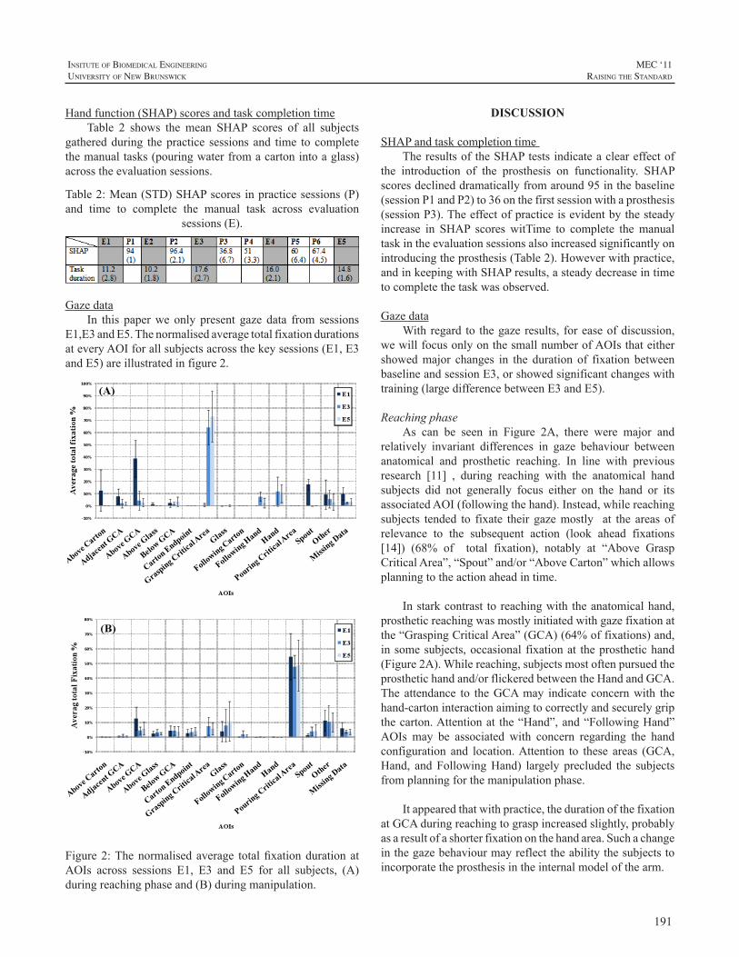
191
InsItute of BIomedIcal engIneerIng
unIversIty of new BrunswIck
MEC ‘11raIsIng the standard
Handfunction(SHAP)scoresandtaskcompletiontimeTable 2 shows the mean SHAP scores of all subjects
gatheredduring thepractice sessionsand time tocompletethemanualtasks(pouringwaterfromacartonintoaglass)acrosstheevaluationsessions.
Table2:Mean(STD)SHAPscoresinpracticesessions(P)and time to complete the manual task across evaluation
sessions(E).
Gazedata
In this paperwe only present gaze data from sessionsE1,E3andE5.ThenormalisedaveragetotalfixationdurationsateveryAOIforallsubjectsacrossthekeysessions(E1,E3andE5)areillustratedinfigure2.
Figure2:Thenormalisedaverage totalfixationdurationatAOIs across sessions E1, E3 and E5 for all subjects, (A)duringreachingphaseand(B)duringmanipulation.
DISCUSSION
SHAPandtaskcompletiontimeTheresultsoftheSHAPtestsindicateacleareffectof
the introduction of the prosthesis on functionality. SHAPscoresdeclineddramaticallyfromaround95inthebaseline(sessionP1andP2)to36onthefirstsessionwithaprosthesis(sessionP3).Theeffectofpracticeisevidentbythesteadyincrease in SHAP scores witTime to complete themanualtaskintheevaluationsessionsalsoincreasedsignificantlyonintroducingtheprosthesis(Table2).Howeverwithpractice,andinkeepingwithSHAPresults,asteadydecreaseintimetocompletethetaskwasobserved.
GazedataWithregard to thegazeresults, foreaseofdiscussion,
wewillfocusonlyonthesmallnumberofAOIsthateithershowedmajor changes in the duration of fixation betweenbaselineandsessionE3,orshowedsignificantchangeswithtraining(largedifferencebetweenE3andE5).
ReachingphaseAs can be seen in Figure 2A, there were major and
relatively invariant differences in gaze behaviour betweenanatomical and prosthetic reaching. In line with previousresearch [11] , during reaching with the anatomical handsubjects did not generally focus either on the hand or itsassociatedAOI(followingthehand).Instead,whilereachingsubjects tended to fixate their gazemostly at the areas ofrelevance to the subsequent action (look ahead fixations[14]) (68% of total fixation), notably at “Above GraspCriticalArea”,“Spout”and/or“AboveCarton”whichallowsplanningtotheactionaheadintime.
Instarkcontrast toreachingwith theanatomicalhand,prostheticreachingwasmostlyinitiatedwithgazefixationatthe“GraspingCriticalArea”(GCA)(64%offixations)and,insomesubjects,occasional fixationat theprosthetichand(Figure2A).Whilereaching,subjectsmostoftenpursuedtheprosthetichandand/orflickeredbetweentheHandandGCA.The attendance to theGCAmay indicate concernwith thehand-cartoninteractionaimingtocorrectlyandsecurelygripthecarton.Attentionat the“Hand”,and“FollowingHand”AOIs may be associated with concern regarding the handconfiguration and location.Attention to these areas (GCA,Hand, andFollowingHand) largely precluded the subjectsfromplanningforthemanipulationphase.
Itappearedthatwithpractice,thedurationofthefixationatGCAduringreachingtograspincreasedslightly,probablyasaresultofashorterfixationonthehandarea.Suchachangeinthegazebehaviourmayreflecttheabilitythesubjectstoincorporatetheprosthesisintheinternalmodelofthearm.
192
MEC ‘11raIsIng the standard
InsItute of BIomedIcal engIneerIng
unIversIty of new BrunswIck
ManipulationphaseIn contrast to the reaching phase, changes in gaze
behaviour during themanipulation phase between baselineand prosthetic sessions were not as clearly differentiated(Figure2B).Nevertheless,unlikewhenusingtheanatomicalhand,usingtheprosthesisrequirednoticeableattentiontotheGCAduring themanipulationphase (8%of total fixation).This may reflect the lack of the reliable feedback fromprosthesisregardingthehandstate.
Whileusingtheprosthesis,itisnoticeablethatsubjectsfixatedmoreonthe“Glass”(from7%to11%oftotalfixation)andlessatPouringCriticalArea(from55%to48%)whichisprobablyduetothepoorsensoryfeedbackviatheprosthesistoestimatetheremainingamountofwaterinthecarton.
CONCLUSIONS
Despite the dramatic improvement in prosthetictechnology, the extent to which amputees make use oftheirprosthesisineverydaylifetoperformfunctionaltasksstill appears to be low. This study has shown that gazebehavioursclearlychangewhencomparedwiththoseduringperformanceofaneverydaytaskwiththeanatomical limb.Smaller,butstillnoticeablechangesingazebehaviourwereobservedwithlearningtousetheprosthesis.Afuturestudyinanupperlimbamputeepopulationwillinvestigatewhetherthischaracteristicmayhelptoexplainobserveddifferencesinprostheticusage.
REFERENCES
[1] H. Lindner, S. Nätterlund and L. Hermansson, “Upper limbprostheticoutcomemeasures:Reviewandcontentcomparisonbasedon international classification of functioning, disability and health.”Prostheticsandorthoticsinternational,vol.34,pp.109-128,2010.
[2] CN.Schabowsky,AW.Dromerick,RJ.Holley,B.MonroeandPS.Lum,“Trans-radialupperextremityamputeesarecapableofadaptingtoanoveldynamicenvironment.”ExperimentalBrainResearch,vol.188,pp.589-601,2008.
[3] AJ. Metzger,AW. Dromerick, CN. Schabowsky, RJ. Holley, B.MonroeandPS.Lum,“Feedforwardcontrolstrategiesofsubjectswithtransradialamputationinplanarreaching.”JournalofRehabilitationResearchandDevelopment,vol.47,pp.,2010.
[4] SL. Carey, M. Jason Highsmith, ME.Maitland and RV. Dubey,“Compensatory movements of transradial prosthesis users duringcommontasks.”ClinicalBiomechanics,vol.23,pp.1128-1135,2008.
[5] DJ. Atkins, DCY. Heard and WH. Donovan, “Epidemiologicoverview of individuals with upper-limb loss and their reportedresearchpriorities.”JournalofProstheticsandOrthotics,vol.8,pp.2,1996.
[6] H. Bouwsema, CK. v. der Sluis and RM. Bongers, “Movementcharacteristicsofupperextremityprosthesesduringbasicgoal-directedtasks.”ClinicalBiomechanics,vol.25,pp.523-529.
[7] C. Fraser andAW.Wing, “A case study of reaching by a userof a manually-operated artificial hand.” Prosthetics and orthoticsinternational,vol.5,pp.151-156,1981.
[8] RB.Gillespie,JL.Contreras-Vidal,PA.Shewokis,MK.O’Malley,JD.Brown,H.Agashe,R.Gentili andA.Davis, “Toward improvedsensorimotor integration and learning using upper-limb prostheticdevices.” Engineering in Medicine and Biology Society (EMBC),AnnualInternationalConferenceoftheIEEE,pp.5077-5080,2010.
[9] C.Takahashi,J.r.DiedrichsenandSJ.Watt,“Integrationofvisionandhapticsduringtooluse.”JournalofVision,vol.9,pp.,2009.
[10] B.Law,MS.Atkins,AE.KirkpatrickandAJ.Lomax.“Eyegazepatterns differentiate novice and experts in a virtual laparoscopicsurgerytrainingenvironment.”ACM;2004.p.41-48.
[11] M.Land,N.MennieandJ.Rusted,“Therolesofvisionandeyemovementsinthecontrolofactivitiesofdailyliving.”Perceptionvol.28,pp.1311-1328,1999.
[12] M.Sobuh,L.Kenney,A.Galpin,S.Thies,P.KyberdandR.Raffi.“Codingschemeforcharacterisinggazebehaviourofprostheticuse.”MECSymposium.Fredericton,NB,Canada:UNB;2011.
[13] CM. Light, PH. Chappell and PJ. Kyberd, “Establishing astandardized clinical assessment tool of pathologic and prosthetichand function:Normativedata, reliability, andvalidity.”Archivesofphysicalmedicineandrehabilitation,vol.83,pp.776-783,2002.
[14] N.Mennie,M. Hayhoe and B. Sullivan, “Look-ahead fixations:Anticipatory eye movements in natural tasks.” Experimental BrainResearch,vol.179,pp.427-442,2007.
193
InsItute of BIomedIcal engIneerIng
unIversIty of new BrunswIck
MEC ‘11raIsIng the standard
INTRODUCTION
The‘BoxandBlocks’task(BB)isacomponentspecifictaskofperformancewhichteststhegrossmanualdexterityoftheupperlimb(UL)1andisawidelyusedoutcomemeasureforUL function in several populations.2-4TheBB taskhasalsobeenusedtoexamineULprostheticfunctionfollowingamputation, and specifically used to examine myoelectriccontrolafterTargetedMuscleReinnervationsurgery(TMR).5-7TheBBtaskmeasuresspeedandquantitywithrespecttothenumberofblocksmovedinaspecifictimeperiod,1regardlessofqualityofmovementorcompensatorystrategiesusedbytheindividualtoaccomplishthetask.
However, restoring “normal” UL function afteramputation reliesnotonlyonquantitativeperformancebutalsoonqualitativeobservationofthesmoothnessofpatternofmotionandtheabilitytotargetandcontrolexcursionofthegrasp.8-9Inaddition,itisimportantforprostheticuserstominimizecompensatorymotionsofthebodywhenadaptingtothelimitationsofaprostheticdevice.WithadvancesinULmanagement, such asTMRsurgery, theneed to accuratelyquantify the advantages of such procedures is even moreessential, as subjective interpretation by the patient andobservations on the quality of movement can be moreimpressivethantimedtasksortraditionaloutcomemeasuresofupperlimbfunction.10Withaspecificrepetitivetasksuchas the BB task, the arc and smoothness of motion of theprostheticlimbcanberepeatedlyobservedandrecorded;andisamenabletomotioncaptureforthepurposeofquantifyingthis component of performance.Our goalwas to establishamethodtoquantifythisimprovedqualityofmovementofTMRpatientsusingmyoelectricprostheses.
The purpose of this report is to describe a methodof quantitative motion analysis, in combination with amodificationof theBBtask,used toquantify theobservedimprovementsincompensatorymovementsandcontrolinasubjectpre-andpost-TMRsurgery.
METHODS
SubjectThesubjectwasa28-year-oldmalewithtraumaticleft
transhumeral amputationon July4, 2006.The subjectwasinitiallyfitwithconventionalbodypoweredprosthesiswithmechanical voluntary opening terminal device, and wasa successful daily prosthetic user. The subject underwenttranshumeral TMR surgery2 20 months post amputationand8monthspost surgery,hewas fitwithaTMRcontrolmyoelectric prosthesis. The motion analysis testing of thesubjectoccurredpriortoTMRsurgeryusingtheconventionalprosthesis, and 3months after fittingwith themyoelectricTMRprosthesis.
MotionAnalysisA total of 6 markers were applied to the subject,
includingsternum,C7,acromion(bilaterally),lateralelbowhinge,andwrist.Therewerethreemarkersplacedontheboxanddividertoidentifythelocationofboxandblocksinthevirtual labspaceaswellas thesubject’s locationrelative tothebox(Figure1).MotionwascapturedusingeightMotionAnalysisCorporationcameraswithasamplefrequencyof60hertz(Hz).
ModificationtotheBBtaskRather than a random assignment of blocks, the
placementandorderofblocksinthetraytobemovedwasstandardizedto16blocksplacedin4rows.Thesubjectwasinstructedtoproceedfromlowerleftcornerblock,acrosstherowthenproceedtothenextrow.Itwasfeltthatthissetupwould require specific targetingof the terminaldeviceanddemandforconsistentactivationandarcofmovement thatwould require precise control and be amenable to motionanalysis.Inadditiontothekinematicsoftheprostheticandtrunkmotion,thetimetocompletemovingall16blockswasrecorded or the number of blocksmovedwithin 1minute,whicheverthesubjectaccomplishedfirst.
MOTION ANALYSIS TO MEASURE OUTCOMES FOLLOWING TARGETED MUSCLE REINNERVATION SURGERY
JacquelineS.HebertMD,FRCPC1,JustinLewickeMBA,B.Sc2
1DivisionofPhysicalMedicine&Rehabilitation,UniversityofAlberta2SyncrudeCentreforMotionandBalance,GlenroseRehabilitationHospital
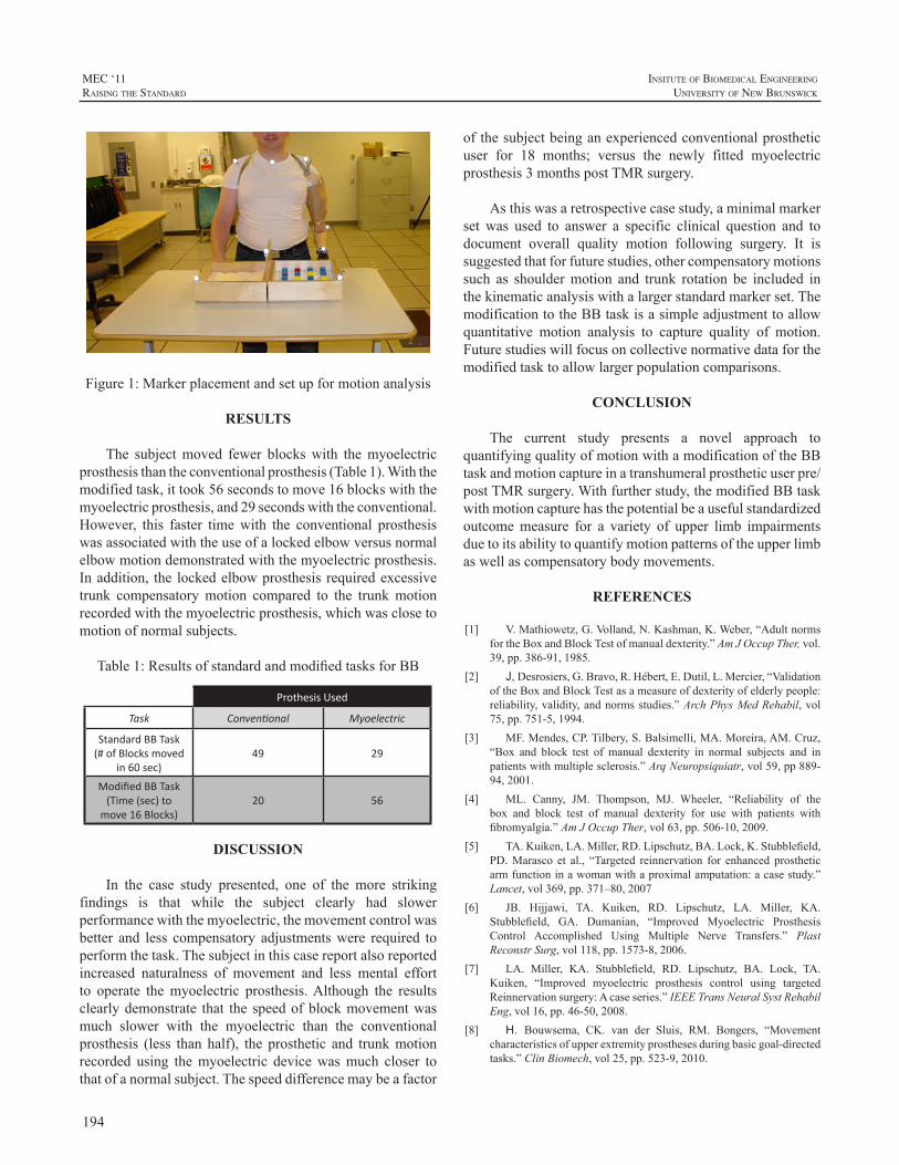
194
MEC ‘11raIsIng the standard
InsItute of BIomedIcal engIneerIng
unIversIty of new BrunswIck
Figure1:Markerplacementandsetupformotionanalysis
RESULTS
The subjectmoved fewer blockswith themyoelectricprosthesisthantheconventionalprosthesis(Table1).Withthemodifiedtask,ittook56secondstomove16blockswiththemyoelectricprosthesis,and29secondswiththeconventional.However, this faster timewith the conventional prosthesiswasassociatedwiththeuseofalockedelbowversusnormalelbowmotiondemonstratedwiththemyoelectricprosthesis.Inaddition, the lockedelbowprosthesis requiredexcessivetrunk compensatorymotion compared to the trunkmotionrecordedwiththemyoelectricprosthesis,whichwasclosetomotionofnormalsubjects.
Table1:ResultsofstandardandmodifiedtasksforBB
Prothesis Used
Task Conventional Myoelectric
Standard BB Task (# of Blocks moved
in 60 sec)49 29
Modified BB Task (Time (sec) to
move 16 Blocks)20 56
DISCUSSION
In the case study presented, one of the more strikingfindings is that while the subject clearly had slowerperformancewiththemyoelectric,themovementcontrolwasbetter and less compensatory adjustmentswere required toperformthetask.Thesubjectinthiscasereportalsoreportedincreased naturalness of movement and less mental effortto operate themyoelectric prosthesis.Although the resultsclearlydemonstrate that thespeedofblockmovementwasmuch slower with the myoelectric than the conventionalprosthesis (less than half), the prosthetic and trunkmotionrecorded using themyoelectric devicewasmuch closer tothatofanormalsubject.Thespeeddifferencemaybeafactor
ofthesubjectbeinganexperiencedconventionalprostheticuser for 18 months; versus the newly fitted myoelectricprosthesis3monthspostTMRsurgery.
Asthiswasaretrospectivecasestudy,aminimalmarkerset was used to answer a specific clinical question and todocument overall quality motion following surgery. It issuggestedthatforfuturestudies,othercompensatorymotionssuch as shouldermotion and trunk rotation be included inthekinematicanalysiswithalargerstandardmarkerset.ThemodificationtotheBBtaskisasimpleadjustmenttoallowquantitative motion analysis to capture quality of motion.Futurestudieswillfocusoncollectivenormativedataforthemodifiedtasktoallowlargerpopulationcomparisons.
CONCLUSION
The current study presents a novel approach toquantifyingqualityofmotionwithamodificationoftheBBtaskandmotioncaptureinatranshumeralprostheticuserpre/postTMRsurgery.Withfurtherstudy,themodifiedBBtaskwithmotioncapturehasthepotentialbeausefulstandardizedoutcomemeasure for a variety of upper limb impairmentsduetoitsabilitytoquantifymotionpatternsoftheupperlimbaswellascompensatorybodymovements.
REFERENCES
[1] V.Mathiowetz,G.Volland,N.Kashman,K.Weber,“AdultnormsfortheBoxandBlockTestofmanualdexterity.”AmJOccupTher,vol.39,pp.386-91,1985.
[2] J, Desrosiers,G.Bravo,R.Hébert,E.Dutil,L.Mercier,“ValidationoftheBoxandBlockTestasameasureofdexterityofelderlypeople:reliability,validity,andnormsstudies.”ArchPhysMedRehabil,vol75,pp.751-5,1994.
[3] MF.Mendes,CP.Tilbery,S.Balsimelli,MA.Moreira,AM.Cruz,“Box and block test of manual dexterity in normal subjects and inpatientswithmultiplesclerosis.”ArqNeuropsiquiatr,vol59,pp889-94,2001.
[4] ML. Canny, JM. Thompson, MJ. Wheeler, “Reliability of thebox and block test of manual dexterity for use with patients withfibromyalgia.”AmJOccupTher,vol63,pp.506-10,2009.
[5] TA.Kuiken,LA.Miller,RD.Lipschutz,BA.Lock,K.Stubblefield,PD.Marasco et al., “Targeted reinnervation for enhanced prostheticarmfunctioninawomanwithaproximalamputation:acasestudy.”Lancet,vol369,pp.371–80,2007
[6] JB. Hijjawi, TA. Kuiken, RD. Lipschutz, LA. Miller, KA.Stubblefield, GA. Dumanian, “Improved Myoelectric ProsthesisControl Accomplished Using Multiple Nerve Transfers.” PlastReconstrSurg,vol118,pp.1573-8,2006.
[7] LA. Miller, KA. Stubblefield, RD. Lipschutz, BA. Lock, TA.Kuiken, “Improved myoelectric prosthesis control using targetedReinnervationsurgery:Acaseseries.”IEEETransNeuralSystRehabilEng,vol16,pp.46-50,2008.
[8] H. Bouwsema, CK. van der Sluis, RM. Bongers, “Movementcharacteristicsofupperextremityprosthesesduringbasicgoal-directedtasks.”ClinBiomech,vol25,pp.523-9,2010.

195
InsItute of BIomedIcal engIneerIng
unIversIty of new BrunswIck
MEC ‘11raIsIng the standard
[9] JA. Doeringer, N. Hogan, “Performance of above elbow body-powered prostheses in visually guided unconstrainedmotion tasks.”IEEETransBiomedEng,vol42,pp.621-31,1995.
[10] LA.Miller,RD.Lipschutz,KA.Stubblefield,BA.Lock,H.Huang,TW.WilliamsIII,R.ff.Weir,TA.Kuiken,“Controlofasixdegreeoffreedomprostheticarmafter targetedmuscle reinnervationsurgery.”ArchPhysMedRehabil,vol89,pp.2057-65,2008.
196
MEC ‘11raIsIng the standard
InsItute of BIomedIcal engIneerIng
unIversIty of new BrunswIck
INTRODUCTION
As upper-limb prosthetic systems have become moresophisticated in terms of actuation and control, greaterimportanceisbeingplacedonproducingmovementsofboththeprosthesisandtheuserthathaveamorephysiologicallynormative appearance. Reducing the degree or range ofcompensatorymotionsandimprovingthetrajectorytraversedin themovementofmulti-joint prostheses are examplesofdesignobjectivestobringaboutbetterdynamicappearance.Standardized outcome measures in upper-limb prostheticsresearchandassessmentgenerallydonotprovideobjectiveinformation on the quality of movements performed bythe prosthesis user. Without this type of information, it isdifficult to evaluate different prosthesis designs for theirimpactonkinematics.
Earlyeffortstostudythekinematicsofhumanmovementandapplytheresultstothedesignorunderstandingofarmprostheseswerebasedoncinematography[1],[2].However,digitizing sequences of individualmovie frames to extractjointanglesandtrajectorieswasexactingandtimeconsumingworkandprovedsufficientlydauntingtolimititsapplication.Thereplacementof filmwithmagneticvideotapeprovidedalmost instantaneousaccesstotherecordedimage,buthadlittleimpactontheprocessofdigitizingtheindividualimagesto extract themovement data. Itwas not until the adventof automatic motion capture with multi-camera systemsrecording the position of passive or activemarkers on thebodythatkinematicstudiesbecamewidelyattractive.
The point has been reached where motion data is,relatively speaking, easy to obtain and the problem ofacquiringthedatahasbeensupplantedbyquestionsofhowcan kinematic studies help our understanding, how muchconfidence can we have that the acquired data representswhatwe think it represents, and how best can the data berepresentedtoprovideinsightintotheimportantfeaturesofthemovementunderstudy.
ROLE OF KINEMATIC ANALYSIS
In 2009, the American Academy of Orthotists andProsthetists convened a State-of-the-Science Conferenceon Upper Limb Prosthetic Outcome Measures [3]. Theconferenceparticipantsreviewedavarietyofmeasuresandassessment tools in use at the time and ranked the toolswith regard to their methodological strength and field ofapplication. Noneof the recommendedoutcomemeasuresincludedmotion-capture kinematic analysis. Furthermore,noneofthemeasuresrankedas“emerging”,“promising”,or“potential”incorporatedmotion-capturekinematicanalysis.What,therefore,istheroleforkinematicanalysis?
Motion-capture kinematic analysis is not an outcomemeasure. It can be a measurement that when used inconjunctionwith a standardizedoutcomemeasure helps toclarify and enhance the understanding of results obtainedfrom an outcome measure. Kinematic analysis providesobjective information about the specific actions performedbyanindividualincarryingoutatask.
Althoughkinematicanalysishasthepotentialtoaidourunderstandingofupper-limbprosthesisuseandutilization,itisnotwithout itscaveats. Motioncapturesystems,widelyused,requiremarkersthatareplacedonthebody.Fromthelocationofthesemarkers,itispossibletoapproximatejointcentersandsegmentlengths.
Ideally, markers should be anchored to the skeleton,butthatisrarelyfeasible.Instead,markersareattachedbyadhesivetosofttissueoverlyingpalpableskeletalstructures.Skinmovementthatchangesthelocationofthemarkercanaltertheapparentlocationofajointaxisand/orchangetheapparentlengthofalimbsegment.
There are several standardizedmarker sets that definewhere on the bodymarkers should be placed for differentkinematicanalyses[4].Therearenot,however,standardizedsets that include prostheses, and investigators or clinicians
USING MOTION ANALYSIS TO AUGMENTUPPER-LIMB PROSTHETICS OUTCOME MEASURES
CraigW.Heckathorne1andRebeccaStine2
1NorthwesternUniversityProsthetics-OrthoticsCenterforEducationandResearchDept.ofPhysicalMedicine&Rehabilitation,FeinbergSchoolofMedicine
680N.LakeShoreDr.,Suite1100,Chicago,IL606112JesseBrownVAMedicalCenter,Dept.ofVeteransAffairs,Chicago,IL
197
InsItute of BIomedIcal engIneerIng
unIversIty of new BrunswIck
MEC ‘11raIsIng the standard
arelefttotheirownjudgmentastowheretoplacemarkerson prosthetic devices. Not only could different markerplacements potentially alter results and confound inter-study comparisons, movement of the prosthesis on theresidual limbcouldaffect theapparent locationofmarkersplaced on a prosthesis. Pistoning or angular displacementof thesocket,especiallynear theextremesof jointmotion,could create a pseudo-arthrosis, reducing the accuracy ofthe location of markers on the prosthesis with respect tomarkers on thebody. For example, one study involving asubjectwithatranshumeralamputationwhousedalockingmechanicalelbowwasfoundtohavearangeofabout13°ofelbowflexionwhentheelbowwaslocked[5].Theauthorsofthatstudyattributedthisfindingtopossiblerelativemotionbetweenthesocketandtheresiduallimb.
In addition to artifacts that affect apparent markerlocation, the subject may also behave differently whilewearing markers and produce movements that are notrepresentative of how the subjectwouldmovewithout themarkers. Markers placed on the upper limb are readilyvisible. Their presencemay distract the user ormake theuserguardedsoasnottodislodgeorbumpamarkerwhileperformingatask.
REPRESENTING MOTION DATA
Motion-capture data—the sequential series of jointanglesandlimbandbodysegmentpositionssampledduringanactivity—canbefurtherprocessedandreducedinvariousways.Onemethodistocalculatetheangularrangeofmotionduringtheactivityforeachjointofinterest[5],[6],[7],[8].Theranges,alongwiththeirminimumandmaximumvalues,couldbe comparedbetween subjectswith intact limbs andsubjectswith impaired or prosthetic limbs doing the sametask,orbetweensubjectusingdifferenttypesofprostheses.Differences in angular range of motion may revealcompensatory actions or effects of varying components orsocketdesigns.
Ratios of angular ranges have been used to defineasymmetrybetweenrightandleftlimbsusedinasymmetricalbimanualtask,suchaspickingupabox[7].Ratiosofangularrangeshavealsobeenusedtohighlightlimitationsofmotionandcompensation[8].
Data obtained during cyclic or repeated activities canbenormalizedwithrespecttowheretheyoccurinthecycleoratwhatpercentageoftimeoverthecourseoftheactivitythey occur. [5], [7], [8], [9]. Normalization eliminatesabsolute time, enabling averaging of repeated data thatoccurredduring shorteror longerperiods for an individualsubjectandcomparisonofaverageddatabetweensubjects.Normalization can be used to compare angular profiles,
trajectories,velocityprofiles,andrelativetimingofcoupledoruncoupledactions.
CONCLUSIONS
Kinematic data obtained from marker-based motion-capture systems has been used to reveal and highlightdifferencesbetweenactionsperformedbypersonswithintactupperlimbsandpersonswithimpairedupperlimbsorwithpersons using arm prostheses. Although not an outcomemeasure in itself, kinematic analysis might be a powerfulcomplement to standardized outcome measures, providingdetails about the movements used during functional tasksthat individual outcome measures alone cannot convey.Attention to methodology and awareness of errors thatprosthetic systemsmight introduce into kinematic analysisareimportantaspectsforsuccessfulapplication.
ACKNOWLEDGEMENT
This work was funded by the National Institute onDisability and Rehabilitation Research (NIDRR) of theDepartmentofEducationundergrantnumberH133E080009andissupportedinpartbytheJesseBrownVAMedicalCenterthrough use of the Jesse Brown VAMC Motion AnalysisResearchLab.TheopinionscontainedinthispublicationarethoseofthegranteeanddonotnecessarilyreflectthoseoftheDepartmentofEducationnordotheynecessarilyreflecttheopinionsoftheDepartmentofVeteransAffairs.
REFERENCES
[1] C.L. Taylor, “The Biomechanics of the Normal and of theAmputated Upper Extremity”,Chapter 7 in Klopsteg andWilson’sHumanLimbsandTheirSubstitutes,McGraw-Hill,NewYork,1954.
[2] T.J. Engen, andW.A. Spencer, “Method of Kinematic Study ofNormalUpperExtremityMovements,”ArchivesofPhysicalMedicineandRehabilitation,vol.49,pp.9-12,1968.
[3] OfficialFindingsoftheState-of-the-ScienceConferenceonUpperLimb Prosthetic Outcome Measures, Proceedings of the AAOP,Number9,2009.
[4] G.Wu,F.C.TvanderHelm,H.E.J.Veeger,M.Makhsous,P.VanRoy,C.Anglin,etal.,“ISBRecommendationonDefinitionsofJointCoordinate Systems of Various Joints for the Reporting of HumanJoint Motion—Part II: Shoulder, Elbow, Wrist and Hand,” J. ofBiomechanics,vol.38,pp.981-992,2005.
[5] M.J.Highsmith,S.L.Carey,K.W.Koelsch,C.P.Lusk, andM.E.Maitland, “KinematicEvaluationofTerminalDevices forKayakingwithUpperExtremityAmputation,”J. ofProstheticsandOrthotics,vol.19(3),pp.84-90,2007.
[6] S.L. Carey,M.J. Highsmith, and R.V. Dubey, “MotionAnalysisof Transradial Prostheses While Lifting a Box for Developmentof a Biomechanical Model,” Proc. of the ASME 2008 SummerBioengineeringConference,MarcoIsland,FL,June25-29,2008.
[7] S.L. Carey, M.J. Highsmith, M.E. Maitland, and R.V. Dubey,“Compensatory Movements of Transradial Prosthesis Users DuringCommonTasks,”ClinicalBiomechanics, vol. 23(9), pp. 1128-1135,2008.

198
MEC ‘11raIsIng the standard
InsItute of BIomedIcal engIneerIng
unIversIty of new BrunswIck
[8] A. Murgia, P. Kyberd, and T. Barnhill, “The Use of Kinematicand Parametric Information to Highlight Lack of Movement andCompensation in the Upper Extremities DuringActivities of DailyLiving,”GaitandPosture,vol.31(3),pp.300-306,2010.
[9] H.Bouwsema,C.K.vanderSluis,andR.M.Bongers,“MovementCharacteristics of Upper Extremity Prostheses During Basic Goal-directedTasks,”ClinicalBiomechanics,vol.25(6),pp.523-529,2010.
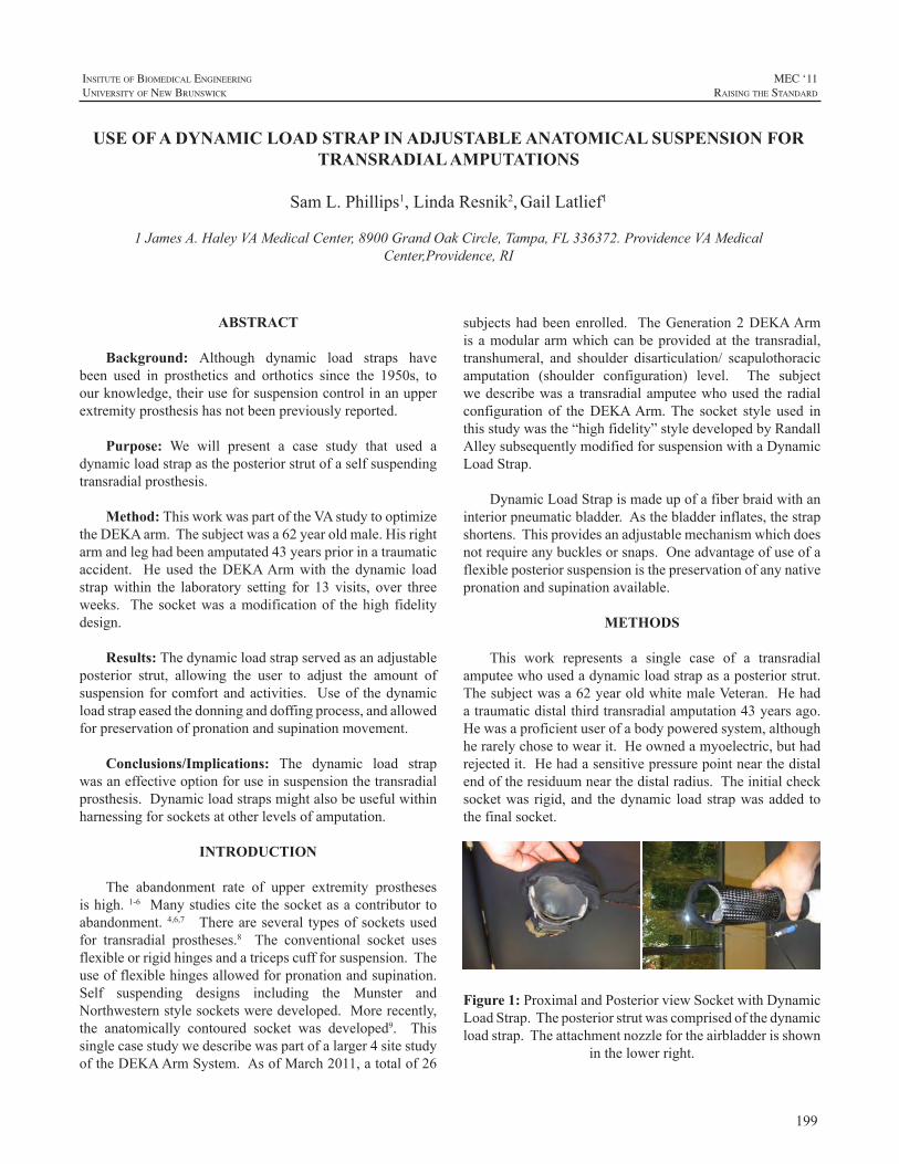
199
InsItute of BIomedIcal engIneerIng
unIversIty of new BrunswIck
MEC ‘11raIsIng the standard
ABSTRACT
Background: Although dynamic load straps havebeen used in prosthetics and orthotics since the 1950s, toourknowledge,theiruseforsuspensioncontrolinanupperextremityprosthesishasnotbeenpreviouslyreported.
Purpose: We will present a case study that used adynamicloadstrapastheposteriorstrutofaselfsuspendingtransradialprosthesis.
Method: ThisworkwaspartoftheVAstudytooptimizetheDEKAarm.Thesubjectwasa62yearoldmale.Hisrightarmandleghadbeenamputated43yearspriorinatraumaticaccident. He used theDEKAArmwith the dynamic loadstrapwithin the laboratory setting for 13 visits, over threeweeks. The socketwasamodificationof thehigh fidelitydesign.
Results: Thedynamicloadstrapservedasanadjustableposterior strut, allowing the user to adjust the amount ofsuspension forcomfortandactivities. Useof thedynamicloadstrapeasedthedonninganddoffingprocess,andallowedforpreservationofpronationandsupinationmovement.
Conclusions/Implications: The dynamic load strapwasaneffectiveoptionforuseinsuspensionthetransradialprosthesis.Dynamicloadstrapsmightalsobeusefulwithinharnessingforsocketsatotherlevelsofamputation.
INTRODUCTION
The abandonment rate of upper extremity prosthesesishigh.1-6 Manystudiescitethesocketasacontributortoabandonment. 4,6,7 Thereareseveral typesofsocketsusedfor transradial prostheses.8 The conventional socket usesflexibleorrigidhingesandatricepscuffforsuspension.Theuseofflexiblehingesallowedforpronationandsupination.Self suspending designs including the Munster andNorthwesternstylesocketsweredeveloped.Morerecently,the anatomically contoured socket was developed9. Thissinglecasestudywedescribewaspartofalarger4sitestudyoftheDEKAArmSystem.AsofMarch2011,atotalof26
subjectshadbeenenrolled. TheGeneration2DEKAArmisamodulararmwhichcanbeprovidedat the transradial,transhumeral, and shoulder disarticulation/ scapulothoracicamputation (shoulder configuration) level. The subjectwedescribewasa transradialamputeewhoused theradialconfiguration of theDEKAArm.The socket style used inthisstudywasthe“highfidelity”styledevelopedbyRandallAlleysubsequentlymodifiedforsuspensionwithaDynamicLoadStrap.
DynamicLoadStrapismadeupofafiberbraidwithaninteriorpneumaticbladder.Asthebladderinflates,thestrapshortens.Thisprovidesanadjustablemechanismwhichdoesnotrequireanybucklesorsnaps.Oneadvantageofuseofaflexibleposteriorsuspensionisthepreservationofanynativepronationandsupinationavailable.
METHODS
This work represents a single case of a transradialamputeewhousedadynamicloadstrapasaposteriorstrut.Thesubjectwasa62yearoldwhitemaleVeteran.Hehadatraumaticdistalthirdtransradialamputation43yearsago.Hewasaproficientuserofabodypoweredsystem,althoughherarelychosetowearit.Heownedamyoelectric,buthadrejectedit.Hehadasensitivepressurepointnearthedistalendoftheresiduumnearthedistalradius.Theinitialchecksocketwas rigid,and thedynamic loadstrapwasadded tothefinalsocket.
Figure 1: Proximaland PosteriorviewSocketwithDynamicLoadStrap.Theposteriorstrutwascomprisedofthedynamicloadstrap.Theattachmentnozzlefortheairbladderisshown
inthelowerright.
USE OF A DYNAMIC LOAD STRAP IN ADJUSTABLE ANATOMICAL SUSPENSION FOR TRANSRADIAL AMPUTATIONS
SamL.Phillips1,LindaResnik2,GailLatlief1
1JamesA.HaleyVAMedicalCenter,8900GrandOakCircle,Tampa,FL336372.ProvidenceVAMedicalCenter,Providence,RI
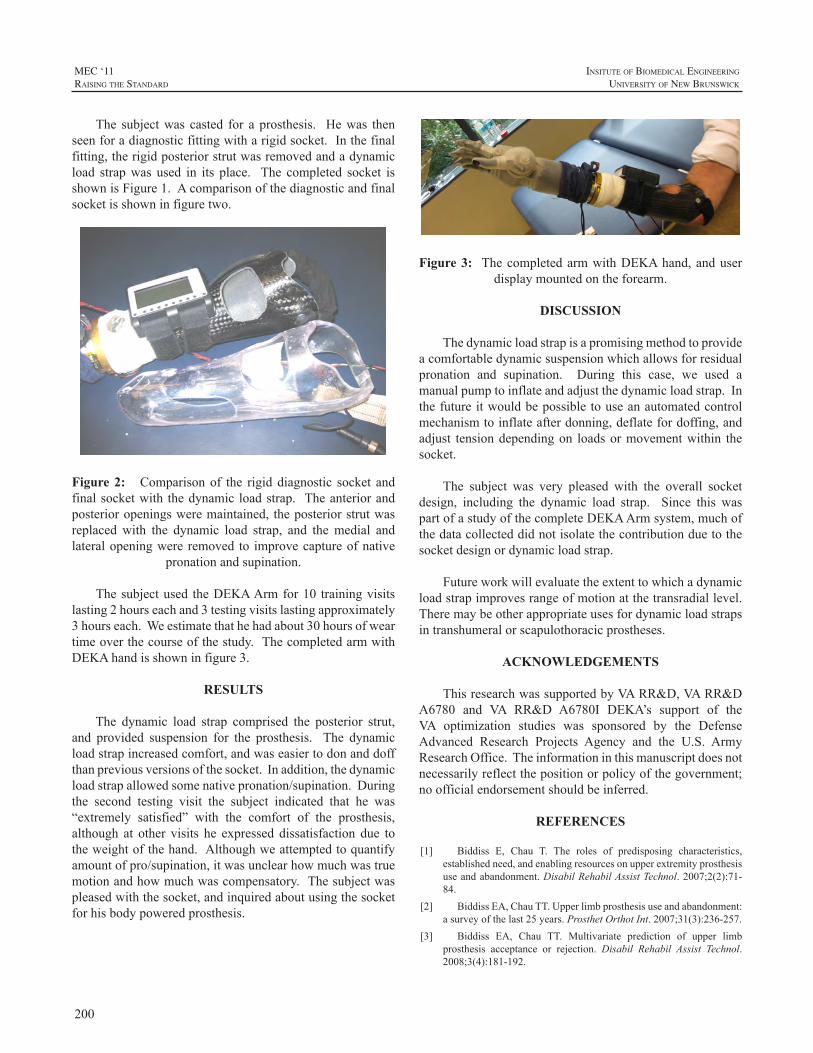
200
MEC ‘11raIsIng the standard
InsItute of BIomedIcal engIneerIng
unIversIty of new BrunswIck
The subjectwas casted for a prosthesis. Hewas thenseenforadiagnosticfittingwitharigidsocket.Inthefinalfitting,therigidposteriorstrutwasremovedandadynamicload strapwas used in its place. The completed socket isshownisFigure1.Acomparisonofthediagnosticandfinalsocketisshowninfiguretwo.
Figure 2: Comparisonof the rigiddiagnostic socket andfinalsocketwith thedynamic loadstrap. Theanteriorandposterioropeningsweremaintained, theposteriorstrutwasreplaced with the dynamic load strap, and themedial andlateralopeningwere removed to improvecaptureofnative
pronationandsupination.
Thesubjectused theDEKAArmfor10 trainingvisitslasting2hourseachand3testingvisitslastingapproximately3hourseach.Weestimatethathehadabout30hoursofweartimeoverthecourseofthestudy.ThecompletedarmwithDEKAhandisshowninfigure3.
RESULTS
The dynamic load strap comprised the posterior strut,and provided suspension for the prosthesis. The dynamicloadstrapincreasedcomfort,andwaseasiertodonanddoffthanpreviousversionsofthesocket.Inaddition,thedynamicloadstrapallowedsomenativepronation/supination.Duringthe second testing visit the subject indicated that he was“extremely satisfied” with the comfort of the prosthesis,although at other visits he expressed dissatisfaction due totheweightofthehand.Althoughweattemptedtoquantifyamountofpro/supination,itwasunclearhowmuchwastruemotionandhowmuchwascompensatory.Thesubjectwaspleasedwiththesocket,andinquiredaboutusingthesocketforhisbodypoweredprosthesis.
Dynamic Load Strap
Figure 3: ThecompletedarmwithDEKAhand,anduser
displaymountedontheforearm.
DISCUSSION
Thedynamicloadstrapisapromisingmethodtoprovideacomfortabledynamicsuspensionwhichallowsforresidualpronation and supination. During this case, we used amanualpumptoinflateandadjustthedynamicloadstrap.Inthefutureitwouldbepossibletouseanautomatedcontrolmechanismtoinflateafterdonning,deflatefordoffing,andadjust tensiondependingon loadsormovementwithin thesocket.
The subject was very pleased with the overall socketdesign, including the dynamic load strap. Since this waspartofastudyofthecompleteDEKAArmsystem,muchofthedatacollecteddidnotisolatethecontributionduetothesocketdesignordynamicloadstrap.
Futureworkwillevaluatetheextenttowhichadynamicloadstrapimprovesrangeofmotionatthetransradiallevel.Theremaybeotherappropriateusesfordynamicloadstrapsintranshumeralorscapulothoracicprostheses.
ACKNOWLEDGEMENTS
ThisresearchwassupportedbyVARR&D,VARR&DA6780 and VA RR&D A6780I DEKA’s support of theVA optimization studies was sponsored by the DefenseAdvanced Research Projects Agency and the U.S. ArmyResearchOffice.Theinformationinthismanuscriptdoesnotnecessarilyreflectthepositionorpolicyofthegovernment;noofficialendorsementshouldbeinferred.
REFERENCES
[1] Biddiss E, Chau T. The roles of predisposing characteristics,establishedneed,andenablingresourcesonupperextremityprosthesisuseandabandonment.DisabilRehabilAssistTechnol.2007;2(2):71-84.
[2] BiddissEA,ChauTT.Upperlimbprosthesisuseandabandonment:asurveyofthelast25years.ProsthetOrthotInt.2007;31(3):236-257.
[3] Biddiss EA, Chau TT. Multivariate prediction of upper limbprosthesis acceptance or rejection. Disabil Rehabil Assist Technol.2008;3(4):181-192.
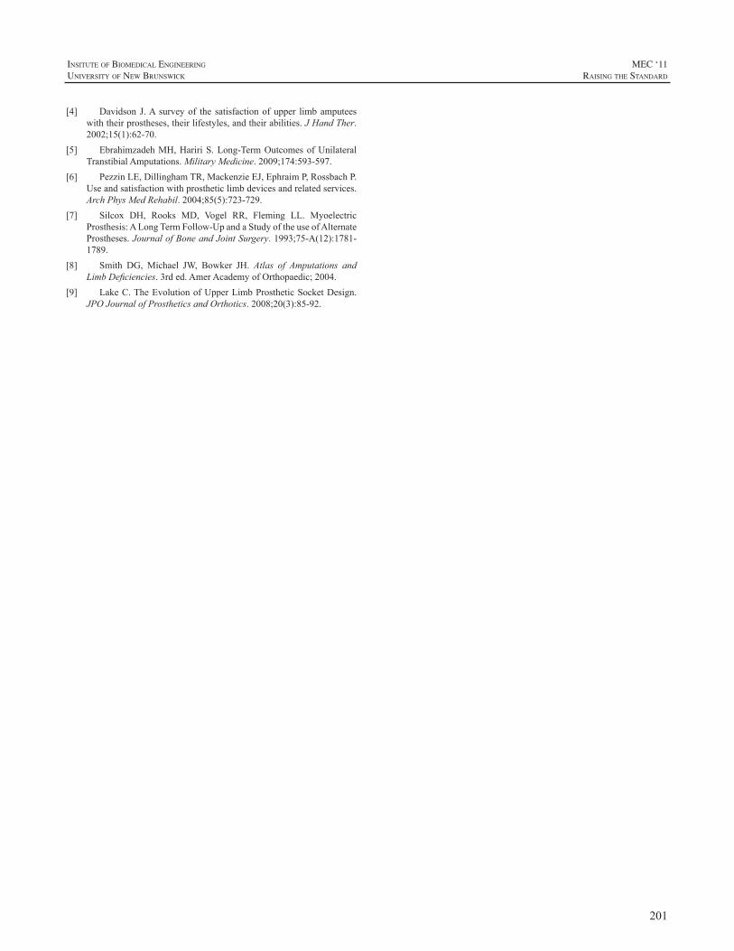
201
InsItute of BIomedIcal engIneerIng
unIversIty of new BrunswIck
MEC ‘11raIsIng the standard
[4] Davidson J.A surveyof the satisfactionofupper limbamputeeswiththeirprostheses,theirlifestyles,andtheirabilities.JHandTher.2002;15(1):62-70.
[5] EbrahimzadehMH,HaririS.Long-TermOutcomesofUnilateralTranstibialAmputations.MilitaryMedicine.2009;174:593-597.
[6] PezzinLE,DillinghamTR,MackenzieEJ,EphraimP,RossbachP.Useandsatisfactionwithprostheticlimbdevicesandrelatedservices.ArchPhysMedRehabil.2004;85(5):723-729.
[7] Silcox DH, Rooks MD, Vogel RR, Fleming LL. MyoelectricProsthesis:ALongTermFollow-UpandaStudyoftheuseofAlternateProstheses.JournalofBoneandJointSurgery.1993;75-A(12):1781-1789.
[8] Smith DG, Michael JW, Bowker JH. Atlas of Amputations andLimbDeficiencies.3rded.AmerAcademyofOrthopaedic;2004.
[9] LakeC.TheEvolutionofUpperLimbProstheticSocketDesign.JPOJournalofProstheticsandOrthotics.2008;20(3):85-92.
202
MEC ‘11raIsIng the standard
InsItute of BIomedIcal engIneerIng
unIversIty of new BrunswIck
ABSTRACT
Comprehensive Arm Prosthesis and RehabilitationOutcomesQuestionnaire(CAPROQ)isaquestionnairethatisadministeredtoAdvancedArmDynamic(AAD)patientsatvariousintervalsduringtheirprostheticfittingexperienceand rehabilitationprocess. TheCAPROQquestionnaire isintendedtoserveasanopportunityforthepatienttoprovideinformationand feedback regarding theoverall satisfactionthey have with their prosthesis and rehabilitation, as wellas the function of their prosthesis. The feedback providedis intended to help improve care forAAD patients, assistfuture prosthetic users and potentially provide feedback toprostheticmanufacturers.
The CAPROQ questionnaire takes anywhere from30 minutes to one hour to complete and is divided intoseven sections which include the following: backgroundand demographics, prosthetic history, primary prosthesissatisfactionandcomfort,pain,rehabilitationservices,ADL/IADL completion, and satisfaction with AAD staff. AhistoricaloverviewofCAPROQwillbediscussed,aswellas how the administrative processworks. A general viewofthesevensectionsandresultsofover100questionnairescompletedwillalsobeprovided.
COMPREHENSIVE ARM PROSTHESIS AND REHABILITATION OUTCOMES QUESTIONNAIRE (CAPROQ)
ShawnSwansonJohnson,OTR/L
AdvancedArmDynamics,Inc.,1230BoulderwoodsDrive,Houston,TX77062
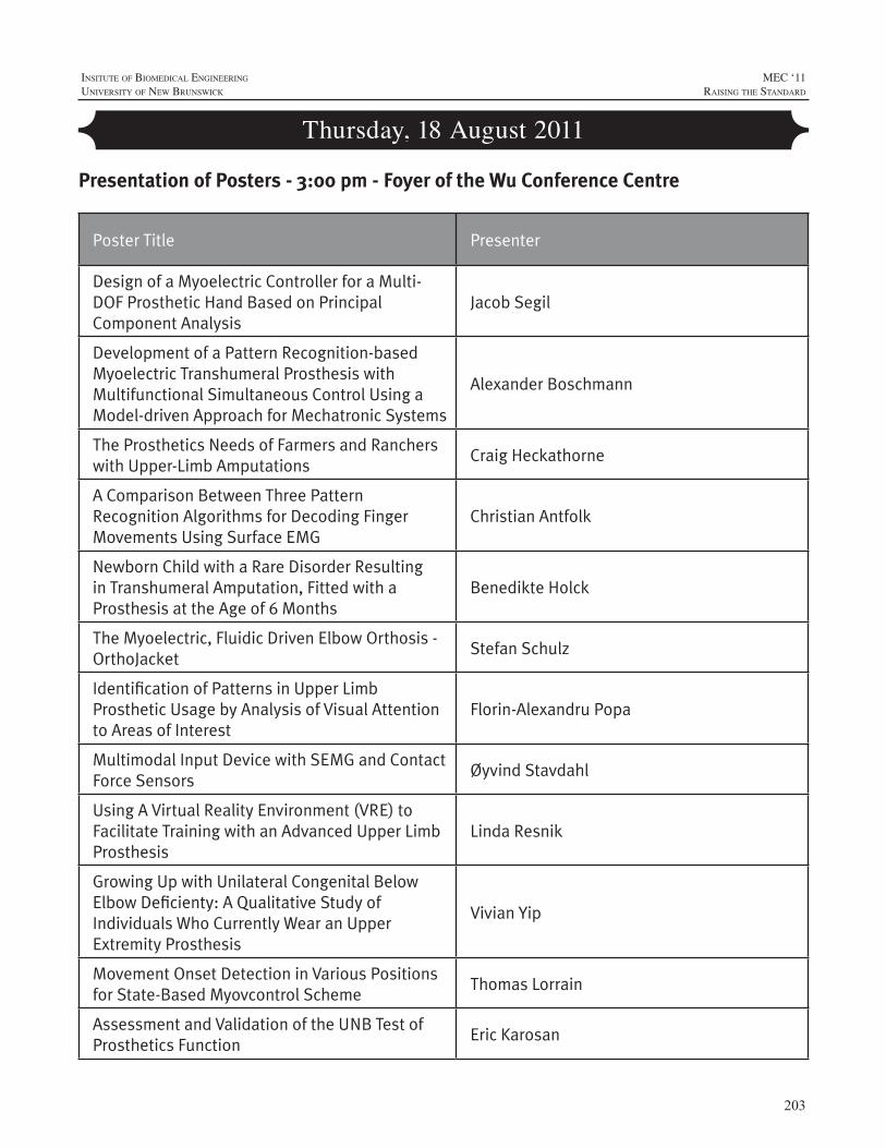
203
InsItute of BIomedIcal engIneerIng
unIversIty of new BrunswIck
MEC ‘11raIsIng the standard
Thursday, 18 August 2011
Poster Title Presenter
Design of a Myoelectric Controller for a Multi-DOF Prosthetic Hand Based on Principal Component Analysis
Jacob Segil
Development of a Pattern Recognition-based Myoelectric Transhumeral Prosthesis with Multifunctional Simultaneous Control Using a Model-driven Approach for Mechatronic Systems
Alexander Boschmann
The Prosthetics Needs of Farmers and Ranchers with Upper-Limb Amputations
Craig Heckathorne
A Comparison Between Three Pattern Recognition Algorithms for Decoding Finger Movements Using Surface EMG
Christian Antfolk
Newborn Child with a Rare Disorder Resulting in Transhumeral Amputation, Fitted with a Prosthesis at the Age of 6 Months
Benedikte Holck
The Myoelectric, Fluidic Driven Elbow Orthosis - OrthoJacket
Stefan Schulz
Identification of Patterns in Upper Limb Prosthetic Usage by Analysis of Visual Attention to Areas of Interest
Florin-Alexandru Popa
Multimodal Input Device with SEMG and Contact Force Sensors
Øyvind Stavdahl
Using A Virtual Reality Environment (VRE) to Facilitate Training with an Advanced Upper Limb Prosthesis
Linda Resnik
Growing Up with Unilateral Congenital Below Elbow Deficienty: A Qualitative Study of Individuals Who Currently Wear an Upper Extremity Prosthesis
Vivian Yip
Movement Onset Detection in Various Positions for State-Based Myovcontrol Scheme
Thomas Lorrain
Assessment and Validation of the UNB Test of Prosthetics Function
Eric Karosan
Presentation of Posters - 3:00 pm - Foyer of the Wu Conference Centre
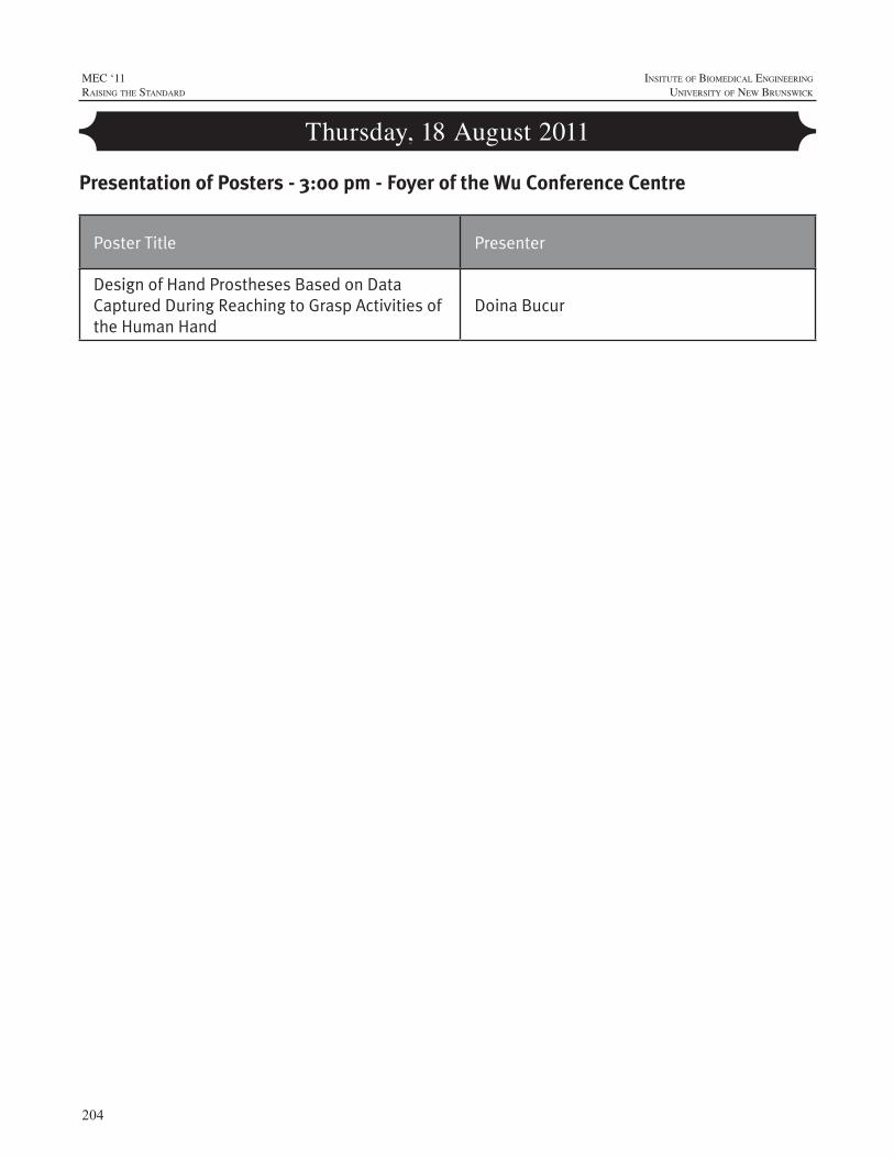
204
MEC ‘11raIsIng the standard
InsItute of BIomedIcal engIneerIng
unIversIty of new BrunswIck
Thursday, 18 August 2011
Presentation of Posters - 3:00 pm - Foyer of the Wu Conference Centre
Poster Title Presenter
Design of Hand Prostheses Based on Data Captured During Reaching to Grasp Activities of the Human Hand
Doina Bucur
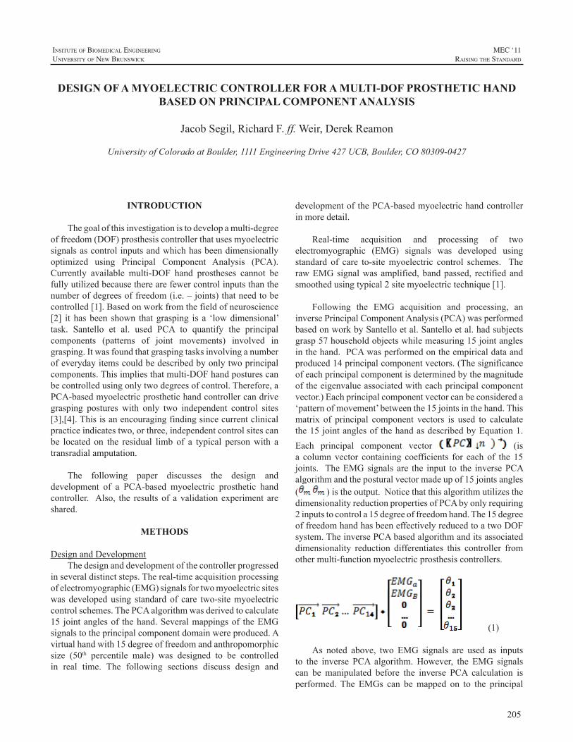
205
InsItute of BIomedIcal engIneerIng
unIversIty of new BrunswIck
MEC ‘11raIsIng the standard
INTRODUCTION
Thegoalofthisinvestigationistodevelopamulti-degreeoffreedom(DOF)prosthesiscontrollerthatusesmyoelectricsignalsascontrolinputsandwhichhasbeendimensionallyoptimized using Principal Component Analysis (PCA).Currently available multi-DOF hand prostheses cannot befullyutilizedbecausetherearefewercontrolinputsthanthenumberofdegreesoffreedom(i.e.–joints)thatneedtobecontrolled[1].Basedonworkfromthefieldofneuroscience[2] it hasbeen shown that grasping is a ‘lowdimensional’task. Santello et al. used PCA to quantify the principalcomponents (patterns of joint movements) involved ingrasping.Itwasfoundthatgraspingtasksinvolvinganumberofeverydayitemscouldbedescribedbyonlytwoprincipalcomponents.Thisimpliesthatmulti-DOFhandposturescanbecontrolledusingonlytwodegreesofcontrol.Therefore,aPCA-basedmyoelectricprosthetichandcontrollercandrivegrasping postures with only two independent control sites[3],[4].Thisisanencouragingfindingsincecurrentclinicalpracticeindicatestwo,orthree,independentcontrolsitescanbe located on the residual limb of a typical personwith atransradialamputation.
The following paper discusses the design anddevelopment of a PCA-based myoelectric prosthetic handcontroller. Also, the resultsof avalidationexperiment areshared.
METHODS
DesignandDevelopmentThedesignanddevelopmentofthecontrollerprogressed
inseveraldistinctsteps.Thereal-timeacquisitionprocessingofelectromyographic(EMG)signalsfortwomyoelectricsiteswas developedusing standardof care two-sitemyoelectriccontrolschemes.ThePCAalgorithmwasderivedtocalculate15 jointanglesof thehand.Severalmappingsof theEMGsignalstotheprincipalcomponentdomainwereproduced.Avirtualhandwith15degreeoffreedomandanthropomorphicsize (50th percentile male) was designed to be controlledin real time. The following sections discuss design and
developmentofthePCA-basedmyoelectrichandcontrollerinmoredetail.
Real-time acquisition and processing of twoelectromyographic (EMG) signals was developed usingstandard of care to-sitemyoelectric control schemes. TherawEMGsignalwasamplified,bandpassed, rectifiedandsmoothedusingtypical2sitemyoelectrictechnique[1].
Following the EMG acquisition and processing, aninversePrincipalComponentAnalysis(PCA)wasperformedbasedonworkbySantelloetal.Santelloetal.hadsubjectsgrasp57householdobjectswhilemeasuring15jointanglesinthehand.PCAwasperformedontheempiricaldataandproduced14principalcomponentvectors.(Thesignificanceofeachprincipalcomponentisdeterminedbythemagnitudeoftheeigenvalueassociatedwitheachprincipalcomponentvector.)Eachprincipalcomponentvectorcanbeconsidereda‘patternofmovement’betweenthe15jointsinthehand.Thismatrix of principal component vectors is used to calculatethe15jointanglesofthehandasdescribedbyEquation1.Each principal component vector (isa columnvector containing coefficients for each of the 15joints. TheEMGsignals are the input to the inversePCAalgorithmandtheposturalvectormadeupof15jointsangles( )istheoutput.NoticethatthisalgorithmutilizesthedimensionalityreductionpropertiesofPCAbyonlyrequiring2inputstocontrola15degreeoffreedomhand.The15degreeoffreedomhandhasbeeneffectivelyreducedtoatwoDOFsystem.TheinversePCAbasedalgorithmanditsassociateddimensionality reduction differentiates this controller fromothermulti-functionmyoelectricprosthesiscontrollers.
(1)
As noted above, two EMG signals are used as inputsto the inverse PCA algorithm. However, the EMG signalscan be manipulated before the inverse PCA calculation isperformed. The EMGs can bemapped on to the principal
DESIGN OF A MYOELECTRIC CONTROLLER FOR A MULTI-DOF PROSTHETIC HAND BASED ON PRINCIPAL COMPONENT ANALYSIS
JacobSegil,RichardF.ff.Weir,DerekReamon
UniversityofColoradoatBoulder,1111EngineeringDrive427UCB,Boulder,CO80309-0427
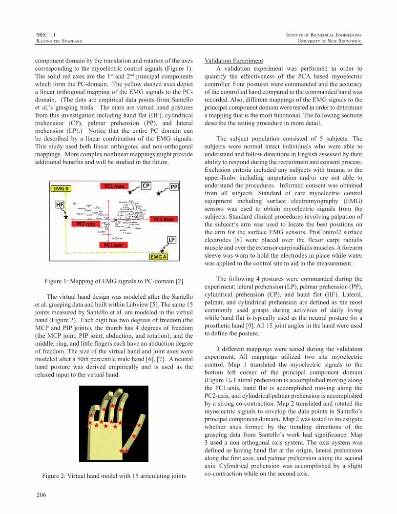
206
MEC ‘11raIsIng the standard
InsItute of BIomedIcal engIneerIng
unIversIty of new BrunswIck
componentdomainbythetranslationandrotationoftheaxescorrespondingtothemyoelectriccontrolsignals(Figure1). Thesolid redaxesare the1stand2ndprincipalcomponentswhichformthePC-domain.TheyellowdashedaxesdepictalinearorthogonalmappingoftheEMGsignalstothePC-domain. (Thedotsareempiricaldatapoints fromSantelloet al.’s grasping trials. The stars are virtual handposturesfromthisinvestigationincludinghandflat(HF),cylindricalprehension (CP), palmar prehension (PP), and lateralprehension (LP).) Notice that the entire PC domain canbe described by a linear combination of theEMG signals.This studyusedboth linearorthogonalandnon-orthogonalmappings.Morecomplexnonlinearmappingsmightprovideadditionalbenefitsandwillbestudiedinthefuture.
Figure1:MappingofEMGsignalstoPC-domain[2]
ThevirtualhanddesignwasmodeledaftertheSantelloetal.graspingdataandbuiltwithinLabview[5].Thesame15jointsmeasuredbySantelloetal.aremodeledinthevirtualhand(Figure2).Eachdigithastwodegreesoffreedom(theMCPandPIP joints), the thumbhas4degreesof freedom(theMCPjoint,PIPjoint,abduction,androtation),andthemiddle,ring,andlittlefingerseachhaveanabductiondegreeoffreedom.Thesizeofthevirtualhandandjointaxesweremodeledaftera50thpercentilemalehand[6],[7].Aneutralhand posture was derived empirically and is used as therelaxedinputtothevirtualhand.
Figure2:Virtualhandmodelwith15articulatingjoints
ValidationExperimentA validation experiment was performed in order to
quantify the effectiveness of the PCA based myoelectriccontroller.Fourpostureswerecommandedandtheaccuracyofthecontrolledhandcomparedtothecommandedhandwasrecorded.Also,differentmappingsoftheEMGsignalstotheprincipalcomponentdomainweretestedinordertodetermineamappingthatisthemostfunctional.Thefollowingsectionsdescribethetestingprocedureinmoredetail.
The subject population consisted of 5 subjects. Thesubjects were normal intact individuals who were able tounderstandandfollowdirectionsinEnglishassessedbytheirabilitytorespondduringtherecruitmentandconsentprocess.Exclusioncriteria includedanysubjectswith trauma to theupper-limbs including amputation and/or are not able tounderstandtheprocedures.Informedconsentwasobtainedfrom all subjects. Standard of care myoelectric controlequipment including surface electromyography (EMG)sensors was used to obtain myoelectric signals from thesubjects.Standardclinicalproceduresinvolvingpalpationofthe subject‘s armwas used to locate the best positions onthe arm for the surfaceEMGsensors.ProControl2 surfaceelectrodes [8] were placed over the flexor carpi radialismuscleandovertheextensorcarpiradialismuscles.Aforearmsleevewasworntoholdtheelectrodesinplacewhilewaterwasappliedtothecontrolsitetoaidinthemeasurement.
The following4postureswerecommandedduring theexperiment:lateralprehension(LP),palmarprehension(PP),cylindrical prehension (CP), and hand flat (HF). Lateral,palmar, and cylindrical prehension aredefined as themostcommonly used grasps during activities of daily livingwhilehandflatistypicallyusedastheneutralpostureforaprosthetichand[9].All15jointanglesinthehandwereusedtodefinetheposture.
3differentmappingswere testedduring thevalidationexperiment. All mappings utilized two site myoelectriccontrol. Map 1 translated the myoelectric signals to thebottom left corner of the principal component domain(Figure1). Lateralprehensionisaccomplishedmovingalongthe PC1-axis, hand flat is accomplishedmoving along thePC2-axis,andcylindrical/palmarprehensionisaccomplishedbyastrongco-contraction.Map2translatedandrotatedthemyoelectricsignals toenvelop thedatapoints inSantello’sprincipalcomponentdomain. Map2wastestedtoinvestigatewhether axes formed by the trending directions of thegrasping data from Santello’s work had significance.Map3usedanon-orthogonalaxis system.Theaxis systemwasdefinedashavinghandflatattheorigin,lateralprehensionalongthefirstaxis,andpalmarprehensionalongthesecondaxis. Cylindrical prehensionwas accomplished by a slightco-contractionwhileonthesecondaxis.
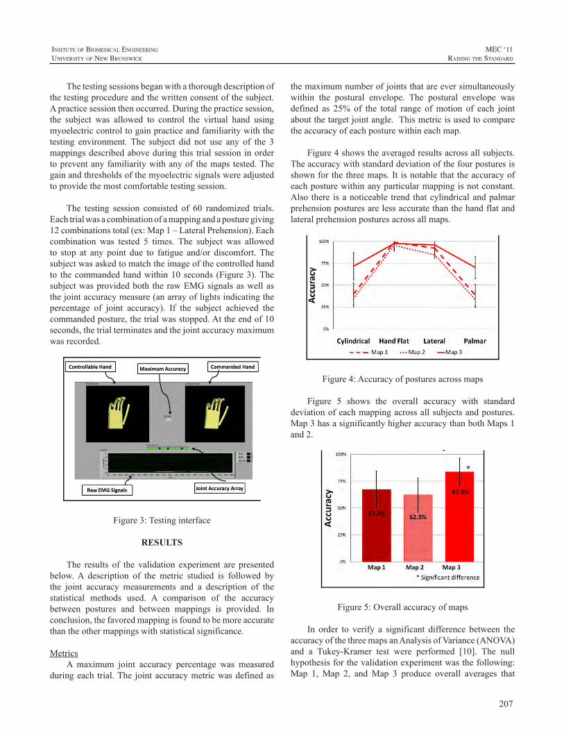
207
InsItute of BIomedIcal engIneerIng
unIversIty of new BrunswIck
MEC ‘11raIsIng the standard
Thetestingsessionsbeganwithathoroughdescriptionofthetestingprocedureandthewrittenconsentofthesubject.Apracticesessionthenoccurred.Duringthepracticesession,the subject was allowed to control the virtual hand usingmyoelectriccontroltogainpracticeandfamiliaritywiththetesting environment. The subject did not use any of the 3mappingsdescribedaboveduringthis trialsessioninordertopreventanyfamiliaritywithanyofthemapstested.Thegainandthresholdsofthemyoelectricsignalswereadjustedtoprovidethemostcomfortabletestingsession.
The testing session consisted of 60 randomized trials.Eachtrialwasacombinationofamappingandaposturegiving12combinationstotal(ex:Map1–LateralPrehension).Eachcombination was tested 5 times. The subject was allowedto stop at any point due to fatigue and/or discomfort.Thesubjectwasaskedtomatchtheimageofthecontrolledhandto thecommandedhandwithin10seconds (Figure3).Thesubjectwasprovidedboth therawEMGsignalsaswellasthejointaccuracymeasure(anarrayoflightsindicatingthepercentage of joint accuracy). If the subject achieved thecommandedposture,thetrialwasstopped.Attheendof10seconds,thetrialterminatesandthejointaccuracymaximumwasrecorded.
Figure3:Testinginterface
RESULTS
The results of the validation experiment are presentedbelow.A description of the metric studied is followed bythe joint accuracy measurements and a description of thestatistical methods used. A comparison of the accuracybetween postures and between mappings is provided. Inconclusion,thefavoredmappingisfoundtobemoreaccuratethantheothermappingswithstatisticalsignificance.
MetricsA maximum joint accuracy percentage was measured
duringeach trial.The jointaccuracymetricwasdefinedas
themaximumnumberofjointsthatareeversimultaneouslywithin the postural envelope. The postural envelope wasdefined as 25% of the total range ofmotion of each jointaboutthetargetjointangle.Thismetricisusedtocomparetheaccuracyofeachposturewithineachmap.
Figure4showstheaveragedresultsacrossallsubjects.Theaccuracywithstandarddeviationofthefourposturesisshownforthethreemaps.Itisnotablethattheaccuracyofeachposturewithinanyparticularmappingisnotconstant.Also there isanoticeable trend thatcylindricalandpalmarprehensionposturesarelessaccuratethanthehandflatandlateralprehensionposturesacrossallmaps.
Figure4:Accuracyofposturesacrossmaps
Figure 5 shows the overall accuracy with standarddeviationofeachmappingacrossallsubjectsandpostures.Map3hasasignificantlyhigheraccuracythanbothMaps1and2.
Figure5:Overallaccuracyofmaps
In order to verify a significant difference between theaccuracyofthethreemapsanAnalysisofVariance(ANOVA)and a Tukey-Kramer test were performed [10]. The nullhypothesisforthevalidationexperimentwasthefollowing:Map 1, Map 2, andMap 3 produce overall averages that
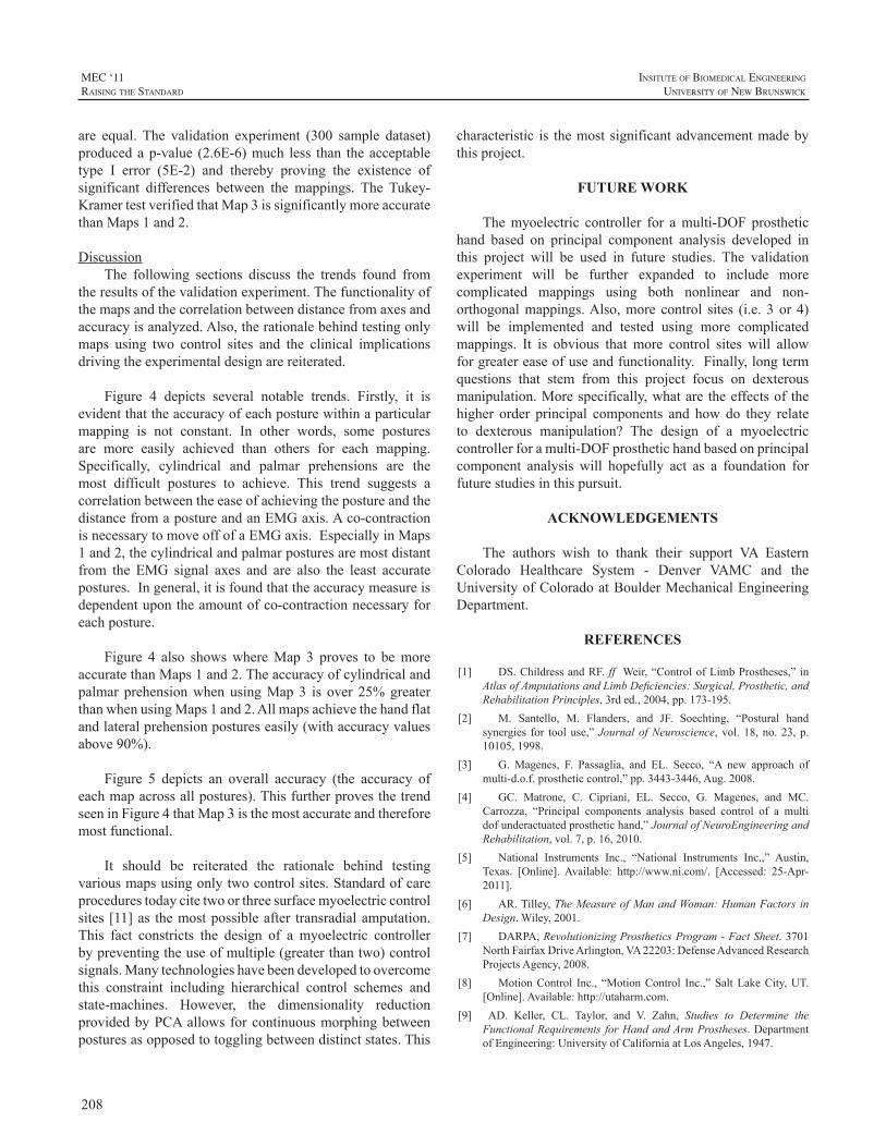
208
MEC ‘11raIsIng the standard
InsItute of BIomedIcal engIneerIng
unIversIty of new BrunswIck
are equal. The validation experiment (300 sample dataset)producedap-value (2.6E-6)much less than theacceptabletype I error (5E-2) and thereby proving the existence ofsignificant differences between the mappings. The Tukey-KramertestverifiedthatMap3issignificantlymoreaccuratethanMaps1and2.
DiscussionThe following sections discuss the trends found from
theresultsofthevalidationexperiment.Thefunctionalityofthemapsandthecorrelationbetweendistancefromaxesandaccuracyisanalyzed.Also,therationalebehindtestingonlymaps using two control sites and the clinical implicationsdrivingtheexperimentaldesignarereiterated.
Figure 4 depicts several notable trends. Firstly, it isevidentthattheaccuracyofeachposturewithinaparticularmapping is not constant. In other words, some posturesare more easily achieved than others for each mapping.Specifically, cylindrical and palmar prehensions are themost difficult postures to achieve. This trend suggests acorrelationbetweentheeaseofachievingthepostureandthedistancefromapostureandanEMGaxis.Aco-contractionisnecessarytomoveoffofaEMGaxis.EspeciallyinMaps1and2,thecylindricalandpalmarposturesaremostdistantfrom the EMG signal axes and are also the least accuratepostures.Ingeneral,itisfoundthattheaccuracymeasureisdependentupontheamountofco-contractionnecessaryforeachposture.
Figure 4 also showswhereMap 3 proves to bemoreaccuratethanMaps1and2.Theaccuracyofcylindricalandpalmar prehensionwhenusingMap3 is over 25%greaterthanwhenusingMaps1and2.Allmapsachievethehandflatandlateralprehensionpostureseasily(withaccuracyvaluesabove90%).
Figure 5 depicts an overall accuracy (the accuracy ofeachmapacrossallpostures).ThisfurtherprovesthetrendseeninFigure4thatMap3isthemostaccurateandthereforemostfunctional.
It should be reiterated the rationale behind testingvariousmapsusingonlytwocontrolsites.Standardofcareprocedurestodaycitetwoorthreesurfacemyoelectriccontrolsites [11]as themostpossibleafter transradialamputation.This fact constricts the design of a myoelectric controllerbypreventingtheuseofmultiple(greaterthantwo)controlsignals.Manytechnologieshavebeendevelopedtoovercomethis constraint including hierarchical control schemes andstate-machines. However, the dimensionality reductionprovidedbyPCAallowsforcontinuousmorphingbetweenposturesasopposedtotogglingbetweendistinctstates.This
characteristic is themostsignificantadvancementmadebythisproject.
FUTURE WORK
Themyoelectric controller for amulti-DOF prosthetichand based on principal component analysis developed inthis project will be used in future studies. The validationexperiment will be further expanded to include morecomplicated mappings using both nonlinear and non-orthogonalmappings.Also,more control sites (i.e. 3 or 4)will be implemented and tested using more complicatedmappings. It is obvious that more control sites will allowforgreatereaseofuseandfunctionality.Finally,longtermquestions that stem from this project focus on dexterousmanipulation.Morespecifically,whataretheeffectsof thehigher order principal components and how do they relateto dexterous manipulation? The design of a myoelectriccontrollerforamulti-DOFprosthetichandbasedonprincipalcomponent analysis will hopefully act as a foundation forfuturestudiesinthispursuit.
ACKNOWLEDGEMENTS
The authors wish to thank their support VA EasternColorado Healthcare System - Denver VAMC and theUniversityofColoradoatBoulderMechanicalEngineeringDepartment.
REFERENCES
[1] DS.ChildressandRF. ff Weir,“ControlofLimbProstheses,” inAtlasofAmputationsandLimbDeficiencies:Surgical,Prosthetic,andRehabilitationPrinciples,3rded.,2004,pp.173-195.
[2] M. Santello, M. Flanders, and JF. Soechting, “Postural handsynergies for tooluse,”JournalofNeuroscience, vol. 18,no.23,p.10105,1998.
[3] G. Magenes, F. Passaglia, and EL. Secco, “A new approach ofmulti-d.o.f.prostheticcontrol,”pp.3443-3446,Aug.2008.
[4] GC. Matrone, C. Cipriani, EL. Secco, G. Magenes, and MC.Carrozza, “Principal components analysis based control of a multidofunderactuatedprosthetichand,”JournalofNeuroEngineeringandRehabilitation,vol.7,p.16,2010.
[5] National Instruments Inc., “National Instruments Inc.,” Austin,Texas. [Online].Available: http://www.ni.com/. [Accessed: 25-Apr-2011].
[6] AR.Tilley,TheMeasureofManandWoman:HumanFactors inDesign.Wiley,2001.
[7] DARPA,RevolutionizingProstheticsProgram-FactSheet.3701NorthFairfaxDriveArlington,VA22203:DefenseAdvancedResearchProjectsAgency,2008.
[8] MotionControl Inc., “MotionControl Inc.,”SaltLakeCity,UT.[Online].Available:http://utaharm.com.
[9] AD. Keller, CL. Taylor, and V. Zahn, Studies to Determine theFunctionalRequirements forHandandArmProstheses.DepartmentofEngineering:UniversityofCaliforniaatLosAngeles,1947.

209
InsItute of BIomedIcal engIneerIng
unIversIty of new BrunswIck
MEC ‘11raIsIng the standard
[10] W.Navidi,StatisticsforEngineersandScientists,3rded.McGraw-Hill,2011.
[11] AB.Ajiboye andRF. ffWeir, “A heuristic fuzzy logic approachto EMG pattern recognition for multifunctional prosthesis control,”Neural Systems and Rehabilitation Engineering, IEEE Transactionson,vol.13,no.3,pp.280-291,2005.
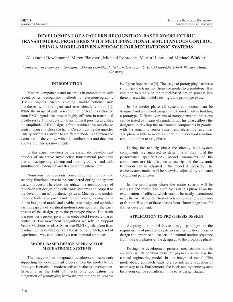
210
MEC ‘11raIsIng the standard
InsItute of BIomedIcal engIneerIng
unIversIty of new BrunswIck
INTRODUCTION
Moderncomponentsandmaterialsincombinationwithrecent pattern recognition methods for electromyographic(EMG) signals enable creating multi-functional armprostheses with intelligent and user-friendly control [1].WhiletheusageofpatternrecognitionoffeaturesextractedfromEMGsignalshasprovenhighlyefficientintransradialprostheses[2,3],mostcurrenttranshumeralprosthesesutilizetheamplitudeofEMGsignalsfromresidualarmmusclestocontrolopenandclosethehand.Co-contractingthemusclesusuallyperformsaswitchtoadifferentmodelikeflexionandextensionoftheelbow,whichiscumbersomeanddoesnotallowsimultaneousmovements.
In this paper we describe the systematic developmentprocess of an active myoelectric transhumeral prosthesisthat allows opening, closing and rotating of the handwithsimultaneousextensionandflexionoftheelbowjoint.
Numerous requirements concerning the motion- andsecurity functionshave tobeconsideredduring thesystemdesign process. Therefore we utilize the methodology ofmodel-drivendesignofmechatronicsystemsandadaptittothedevelopmentofprostheticsystems.Mechatronicmodelsdescribeboththephysical-andthecontrol-engineeringmodelinoneintegratedmodelandenableustodesignandoptimizevariousaspectsofanaturalmotionsequencefromtheearlyphases of the design up to the prototype phase.The resultisaprosthesisprototypewithanembeddedFreescale-basedcontroller. For movement recognition we rely on SupportVectorMachinestoclassifysurfaceEMGsignalstakenfromresidualhumeralmuscles.Tovalidateourapproach,asetofexperimentswasconductedbyatranshumeralamputee.
MODEL-BASED DESIGN APPROACH OF MECHATRONIC SYSTEMS
The usage of an integrated development frameworksupporting thedevelopmentprocess from themodel to theprototypeiscrucialinmodernactiveprosthesisdevelopment.Especially in the field of mechatronic application theintegrationofprototypinghardwareintothedesignprocess
isofgreatimportance[4].Theusageofprototypinghardwaresimplifiesthetransitionfromthemodeltoaprototype.Itiscommon to subdivide themodel-baseddesignprocess intothreephases:themodel-,testrig-,andprototypephase.
In the model phase all system components can bedesignedandoptimizedusingavirtualmodelbeforebuildingaprototype.Differentvariantsofcomponentsandfunctionscanbetestedbymeansofsimulations.Thisphaseallowsthedesignerstodevelopthemechanicalcomponentsinparallelwith the actuators, sensor system and electronic functions.Thephaseresultsinmodelsabletorununderhardrealtimeconditioninthetestrigphase.
During the test rig phase the already built systemcomponents are analysed to determine if they fulfil theperformance specifications. Model parameters of thecomponents are identified on a test rig and the dynamicbehaviour can be adjusted in the model if necessary. Theentiresystemmodelwillbestepwiseadjustedbyvalidatedcomponentparameters.
In the prototyping phase the entire system will beanalysedandtested.Themainfocusinthisphaseisontheexamination of effects,which cannot be easily determinedusingthevirtualmodel.Theseeffectsareforexampleabrasionorfriction.Resultsofthesephasesformaknowledgebaseforfurtherdevelopment.
APPLICATION TO PROSTHESIS DESIGN
Adapting the model-driven design paradigm to therequirementsofprostheticsystemsenablesthedeveloperstodesignandoptimizeallaspectsofanaturalmotionsequencefromtheearlyphasesofthedesignuptotheprototypephase.
During the development process, mechatronic modelsare usedwhich combine both the physical- as well as thecontrol engineering models in one integrated model. Thismodel-basedapproach leads to a considerable reductionofnecessarytests.Furthermore,feedbackanddynamicsystembehaviourcanbeconsideredintheearlydesignstages.
DEVELOPMENT OF A PATTERN RECOGNITION-BASED MYOELECTRIC TRANSHUMERAL PROSTHESIS WITH MULTIFUNCTIONAL SIMULTANEOUS CONTROL
USING A MODEL-DRIVEN APPROACH FOR MECHATRONIC SYSTEMS
AlexanderBoschmann1,MarcoPlatzner1,MichaelRobrecht2,MartinHahn2,andMichaelWinkler3
1UniversityofPaderborn,Germany,2iXtronicsGmbH,Paderborn,Germany,3O.T.W.OrthopädietechnikWinkler,Minden,Germany
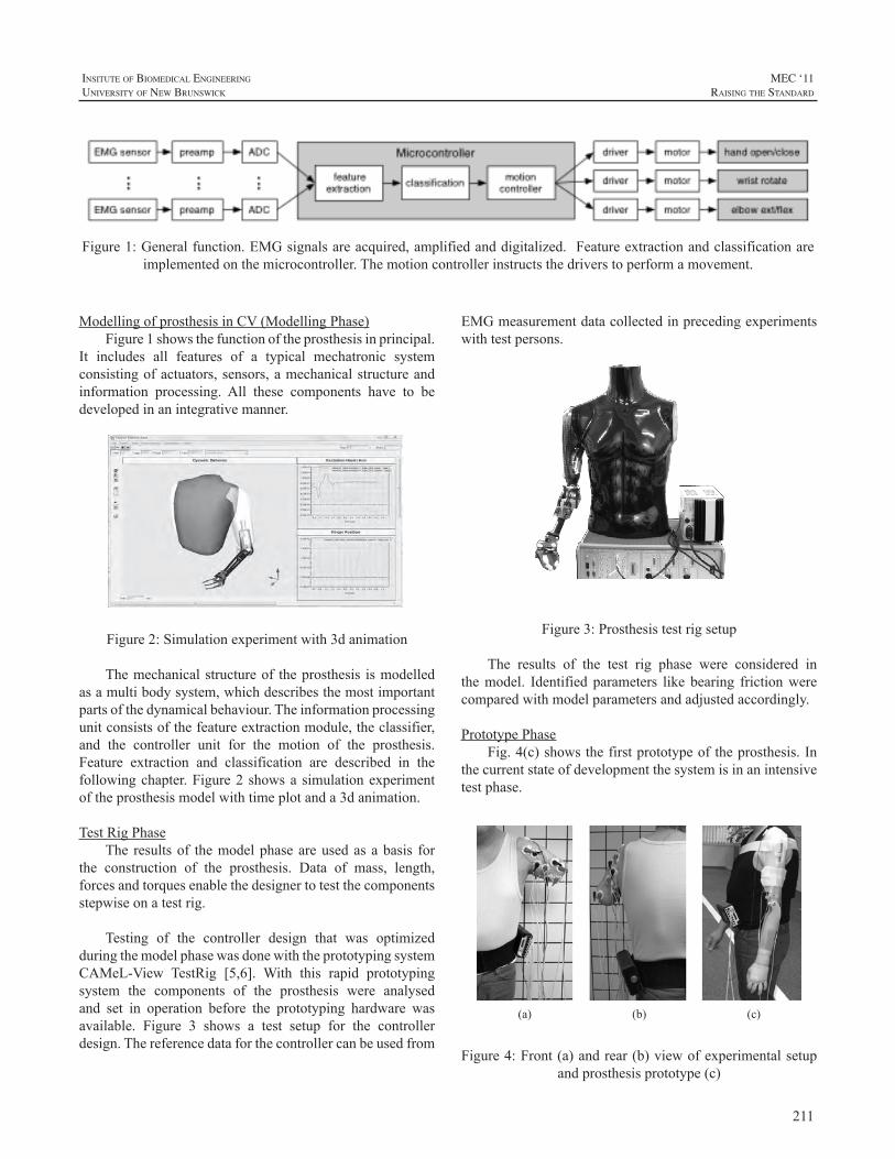
211
InsItute of BIomedIcal engIneerIng
unIversIty of new BrunswIck
MEC ‘11raIsIng the standard
ModellingofprosthesisinCV(ModellingPhase)Figure1showsthefunctionoftheprosthesisinprincipal.
It includes all features of a typical mechatronic systemconsistingofactuators,sensors,amechanicalstructureandinformation processing. All these components have to bedevelopedinanintegrativemanner.
Figure 2: Simulation experiment with 3d animation
Figure2:Simulationexperimentwith3danimation
Themechanicalstructureof theprosthesis ismodelledasamultibodysystem,whichdescribesthemostimportantpartsofthedynamicalbehaviour.Theinformationprocessingunitconsistsofthefeatureextractionmodule,theclassifier,and the controller unit for the motion of the prosthesis.Feature extraction and classification are described in thefollowingchapter.Figure2showsasimulationexperimentoftheprosthesismodelwithtimeplotanda3danimation.
TestRigPhaseThe resultsof themodelphaseareusedasabasis for
the construction of the prosthesis. Data of mass, length,forcesandtorquesenablethedesignertotestthecomponentsstepwiseonatestrig.
Testing of the controller design that was optimizedduringthemodelphasewasdonewiththeprototypingsystemCAMeL-View TestRig [5,6]. With this rapid prototypingsystem the components of the prosthesis were analysedand set in operation before the prototyping hardware wasavailable. Figure 3 shows a test setup for the controllerdesign.Thereferencedataforthecontrollercanbeusedfrom
EMGmeasurementdatacollectedinprecedingexperimentswithtestpersons.
Figure 3: Prosthesis test rig setup Figure3:Prosthesistestrigsetup
The results of the test rig phase were considered inthemodel. Identified parameters like bearing frictionwerecomparedwithmodelparametersandadjustedaccordingly.
PrototypePhaseFig.4(c)showsthefirstprototypeoftheprosthesis.In
thecurrentstateofdevelopmentthesystemisinanintensivetestphase.
(a) (b) (c)
Figure 4: Front (a) and rear (b) view of experimental setup and prosthesis prototype (c)
Figure4:Front(a)andrear(b)viewofexperimentalsetupandprosthesisprototype(c)
Figure1:Generalfunction.EMGsignalsareacquired,amplifiedanddigitalized.Featureextractionandclassificationareimplementedonthemicrocontroller.Themotioncontrollerinstructsthedriverstoperformamovement.
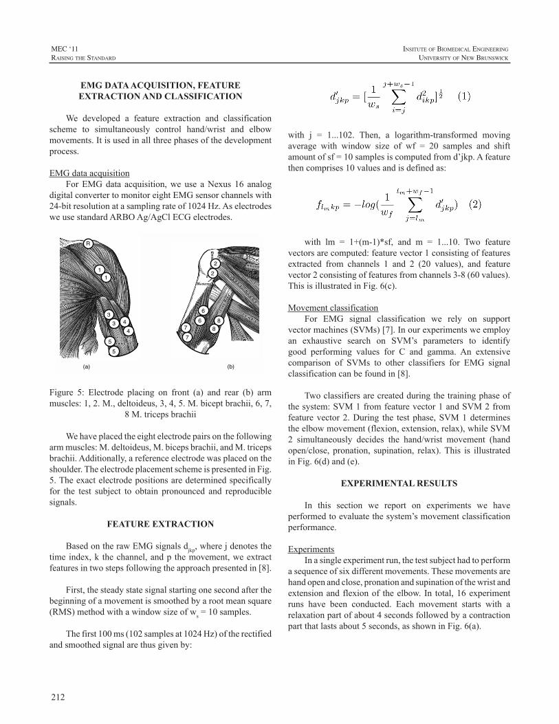
212
MEC ‘11raIsIng the standard
InsItute of BIomedIcal engIneerIng
unIversIty of new BrunswIck
EMG DATA ACQUISITION, FEATURE EXTRACTION AND CLASSIFICATION
We developed a feature extraction and classificationscheme to simultaneously control hand/wrist and elbowmovements.Itisusedinallthreephasesofthedevelopmentprocess.
EMGdataacquisitionForEMGdata acquisition,we use aNexus 16 analog
digitalconvertertomonitoreightEMGsensorchannelswith24-bitresolutionatasamplingrateof1024Hz.AselectrodesweusestandardARBOAg/AgClECGelectrodes.
44
11
33
5
57
78
8
6
6
R
2
2
(a) (b) Figure 5: Electrode placing on front (a) and rear (b) arm
muscles: 1, 2. M. deltoideus, 3, 4, 5. M. biceps brachii, 6, 7, 8 M. triceps brachii
Figure 5: Electrode placing on front (a) and rear (b) armmuscles:1,2.M.,deltoideus,3,4,5.M.biceptbrachii,6,7,
8M.tricepsbrachii
Wehaveplacedtheeightelectrodepairsonthefollowingarmmuscles:M.deltoideus,M.bicepsbrachii,andM.tricepsbrachii.Additionally,areferenceelectrodewasplacedontheshoulder.TheelectrodeplacementschemeispresentedinFig.5.Theexactelectrodepositionsaredeterminedspecificallyfor the test subject to obtain pronounced and reproduciblesignals.
FEATURE EXTRACTION
BasedontherawEMGsignalsdjkp,wherejdenotesthetimeindex,k thechannel,andp themovement,weextractfeaturesintwostepsfollowingtheapproachpresentedin[8].
First,thesteadystatesignalstartingonesecondafterthebeginningofamovementissmoothedbyarootmeansquare(RMS)methodwithawindowsizeofws=10samples.
Thefirst100ms(102samplesat1024Hz) oftherectifiedandsmoothedsignalarethusgivenby:
with j = 1...102. Then, a logarithm-transformed movingaverage with window size of wf = 20 samples and shiftamountofsf=10samplesiscomputedfromd’jkp.Afeaturethencomprises10valuesandisdefinedas:
with lm = 1+(m-1)*sf, and m = 1...10. Two featurevectorsarecomputed:featurevector1consistingoffeaturesextracted from channels 1 and 2 (20 values), and featurevector2consistingoffeaturesfromchannels3-8(60values).ThisisillustratedinFig.6(c).
MovementclassificationFor EMG signal classification we rely on support
vectormachines(SVMs)[7].Inourexperimentsweemployan exhaustive search on SVM’s parameters to identifygood performing values for C and gamma. An extensivecomparison of SVMs to other classifiers for EMG signalclassificationcanbefoundin[8].
Twoclassifiersarecreatedduringthetrainingphaseofthesystem:SVM1fromfeaturevector1andSVM2fromfeaturevector2.During the testphase,SVM1determinestheelbowmovement(flexion,extension,relax),whileSVM2 simultaneously decides the hand/wrist movement (handopen/close, pronation, supination, relax).This is illustratedinFig.6(d)and(e).
EXPERIMENTAL RESULTS
In this section we report on experiments we haveperformedtoevaluatethesystem’smovementclassificationperformance.
ExperimentsInasingleexperimentrun,thetestsubjecthadtoperform
asequenceofsixdifferentmovements.Thesemovementsarehandopenandclose,pronationandsupinationofthewristandextensionandflexionof theelbow.In total,16experimentruns have been conducted. Each movement starts with arelaxationpartofabout4secondsfollowedbyacontractionpartthatlastsabout5seconds,asshowninFig.6(a).
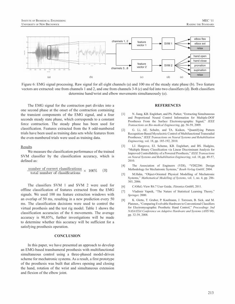
213
InsItute of BIomedIcal engIneerIng
unIversIty of new BrunswIck
MEC ‘11raIsIng the standard
TheEMGsignalforthecontractionpartdividesintoaonesecondphaseattheonsetofthecontractioncontainingthe transient components of the EMG signal, and a foursecondssteadystatephase,whichcorrespondstoaconstantforce contraction. The steady phase has been used forclassification.Features extracted from the8odd-numberedtrialshavebeenusedastrainingdatasetswhilefeaturesfromtheeven-numberedtrialswereusedastrainingdata.
ResultsWemeasuretheclassificationperformanceofthetrained
SVM classifier by the classification accuracy, which isdefinedas:
The classifiers SVM 1 and SVM 2 were used foroffline classification of features extracted from the EMGsignals.We used 100ms feature extraction windows withanoverlapof50ms,resultinginanewpredictionevery50ms. The classification decisions were used to control thevirtualprosthesisandthetestrigmodel.Table1showstheclassification accuracies of the 6movements.The averageaccuracy is 90,85%, further investigations will be madeto determinewhether this accuracywill be sufficient for asatisfyingprosthesisoperation.
CONCLUSION
Inthispaper,wehavepresentedanapproachtodevelopanEMG-basedtranshumeralprosthesiswithmultifunctionalsimultaneous control using a three-phased model-drivenschemeformechatronicsystems.Asaresult,afirstprototypeof theprosthesiswasbuilt thatallowsopeningandclosingthe hand, rotation of thewrist and simultaneous extensionandflexionoftheelbowjoint.
REFERENCES
[1] N.Jiang,KB.Englehart,andPA.Parker,“ExtractingSimultaneousand Proportional Neural Control Information for Multiple-DOFProstheses From the Surface Electromyographic Signal,” IEEETransactionsonBio-medicalEngineering,pp.56-59,2009.
[2] G. Li, AE. Schultz, and TA. Kuiken, “Quantifying PatternRecognition-BasedMyoelectricControlofMultifunctionalTransradialProstheses,”IEEETransactionsonNeuralSystemsandRehabilitationEngineering,vol.18,pp.185-192,2010.
[3] LJ. Hargrove, EJ. Scheme, KB. Englehart, and BS. Hudgins,“MultipleBinaryClassificationviaLinearDiscriminantAnalysisforImprovedControllabilityofaPoweredProsthesis,”IEEETransactionsonNeuralSystemsandRehabilitationEngineering,vol.18,pp.49-57,2010.
[4] The Association of Engineers (VDI), “VDI2206: DesignMethodologyforMechatronicSystems,”BeuthVerlagGmbH,2004.
[5] M.Hahn, “Object-Oriented Physical Modelling of MechatronicSystems,”MathematicalModellingofSystems,vol.1,no.4,pp.286-303,2006.
[6] CAMeL-ViewR6.7UserGuide,iXtronicsGmbH,2011.[7] Vladimir Vapnik, “The Nature of Statistical Learning Theory,”
Springer,2000.[8] K.Glette,T.Gruber, P.Kaufmann, J.Torresen,B. Sick, andM.
Platzner,,“ComparingEvolvableHardwaretoConventionalClassifiersfor Electromyographic Prosthetic Hand Control,” Proceedings 3ndNASA/ESAConferenceonAdaptiveHardwareandSystems(AHS’08),pp.32-39,2008.
(a) (b) (c) (d)
feature vector 1
feature vector 2
SVM 1
SVM 2
elbox flexelbox ext
relax
hand openhand closepronationsupination
relax(e)
channels 1, 2
channels 3...8
Figure 6: EMG signal processing. Raw signal for all eight channels (a) and 100 ms of the steady state phase (b). Two
feature vectors are extracted: one from channels 1 and 2, and one from channels 3-8 (c) and fed into two classifiers (d). Both classifiers determine hand/wrist and elbow movements simultaneously (e).
Figure6:EMGsignalprocessing.Rawsignalforalleightchannels(a)and100msofthesteadystatephase(b).Twofeaturevectorsareextracted:onefromchannels1and2,andonefromchannels3-8(c)andfedintotwoclassifiers(d).Bothclassifiers
determinehand/wristandelbowmovementssimultaneously(e).
214
MEC ‘11raIsIng the standard
InsItute of BIomedIcal engIneerIng
unIversIty of new BrunswIck
INTRODUCTION
Farming and ranching are among the most hazardousoccupations in the United States with many non-fatalaccidentsresultinginamputation[1],[2].Inaddition,thosewhocontinuetofarmusingprosthesesareatriskofsecondaryinjuriesrelatedtotheprosthesis,suchasfalls,entanglement,andoveruseinjuriestotheintactlimb[3].Furthermore,thehazardsofthefarmenvironmentarenotlimitedtoaffectingthe adult farmer, but also lead to a higher incidence ofamputationamongchildrenoffarmersthanisexperiencedinchildrenofthegeneralpopulation[4].
Many advances have been made in prostheticstechnology since the 1970s, especially with regard tolower-limb prostheses and electric-powered upper-limbprostheses. However, in 2008, the National Institute onDisability andRehabilitationResearch (NIDRR) identifiedfarmers as an underserved population with respect toassistivetechnologyincludingprosthetics[5]. Inresponse,the Northwestern University Prosthetics-Orthotics Center(NUPOC),astheNIDRR-fundedRehabilitationEngineeringResearch Center in Prosthetics and Orthotics, partneredwith theNationalAgrAbilityProject [6], a programof theU.S. Dept. of Agriculture that provides support servicesto farmers and ranchers with disabilities, to improveprostheticsoptions available to farmers and ranchers. Thegoals of this collaborative project include identification ofactivities supported by or hindered by use of a prosthesis,provideprosthetics-relatededucationalmaterials to farmersandranchersandtotheprosthetistswhoservethem,andtoimprove prosthetics technology through analysis of failedcomponents and engineering development projects. Theprojecthascompletedthefirstphaseofatwo-partsurveyoffarmers,ranchers,andprosthetists.
METHOD
The first part of the two-part survey was a series ofinterviews, by phone and in person, to determine specificproblems encountered by farmers and ranchers withamputations who were either using prostheses or wantingto use prostheses to enhance their work. Interviews
were conducted with 23 individuals with lower-limbamputations, 17 individuals with upper-limb amputations,and 25 prosthetists (across 14 states) who serve farmersand ranchers with amputations. Questions asked of thefarmers and ranchers included information about the typeand cause of the amputation, type of prosthesis currentlybeingusedandhistoryofprosthesisuse,typesofprosthesisfailures or problems experienced, other medical problemsandsecondaryinjuries,resourcesforpurchaseofprostheses,typesofimprovementsdesired,andcommentsonprostheticsservice.
RESULTS
Ofthe17farmerswithupper-limbamputations,onehada partial hand amputation, one had a wrist disarticulation,ten had transradial amputations (two bilateral), four hadtranshumeral amputations (one bilateral), and two hadshoulder disarticulations. Thirteen of the farmers hadamputations resulting from accidents involving farmequipment.
Allofthefarmerswithamputationsdistaltotheelbowwereusingaprosthesisatthetimeoftheintervieworusedaprosthesisforfarmingbeforeretiring.Onlyone(transhumerallevel) of the six farmerswith amputations proximal to theelbowwas using a prosthesis at the time of the interviewalthoughmosthadbrieflytriedusingaprosthesisintheearlyyearsaftertheiramputation.Allofthefarmerswhouseorusedaprosthesisintheirfarmworkusecable-actuatedbody-powereddevices.Sevenofthefarmershadexperiencewithmyoelectrically-controlledelectric-powereddevicesbutdidnotutilizethemintheirfarmingactivities.
THE PROSTHETICS NEEDS OF FARMERS AND RANCHERS WITH UPPER-LIMB AMPUTATIONS
CraigW.HeckathorneandKathyWaldera
NorthwesternUniversityProsthetics-OrthoticsCenterforEducationandResearch,Dept.ofPhysicalMedicine&Rehabilitation,FeinbergSchoolofMedicine,680N.LakeShoreDr.,Suite1100,Chicago,IL60611
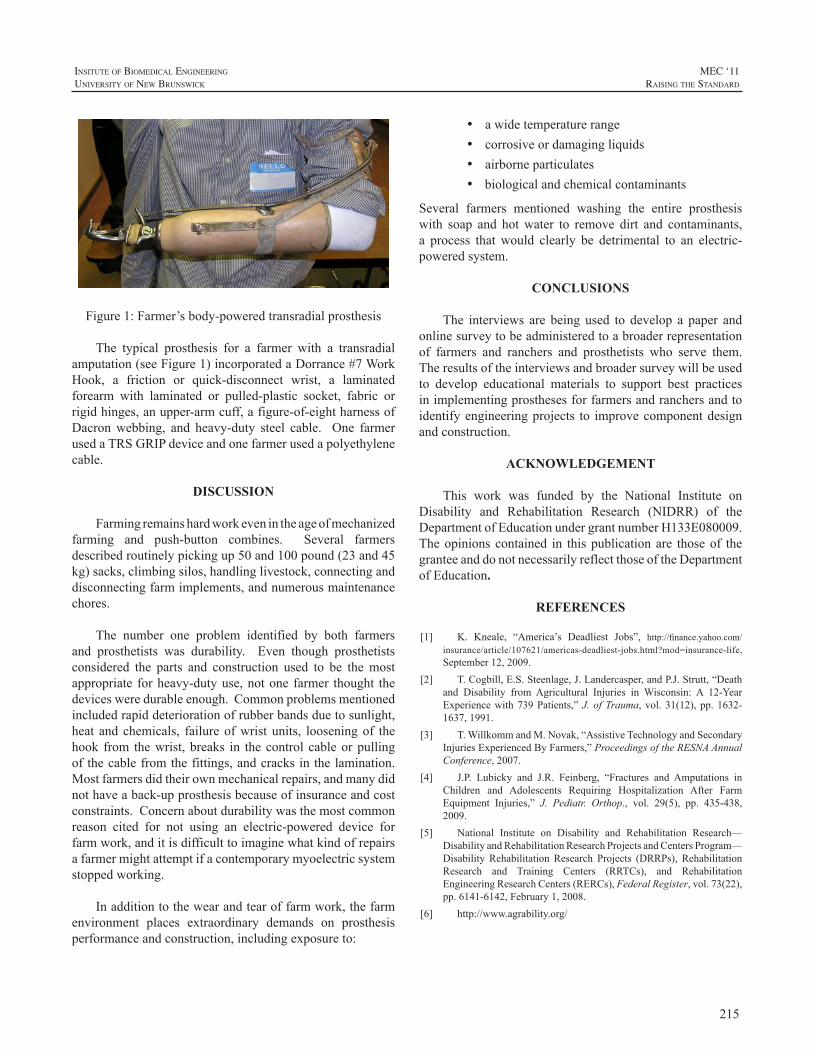
215
InsItute of BIomedIcal engIneerIng
unIversIty of new BrunswIck
MEC ‘11raIsIng the standard
Figure1:Farmer’sbody-poweredtransradialprosthesis
The typical prosthesis for a farmer with a transradialamputation(seeFigure1)incorporatedaDorrance#7WorkHook, a friction or quick-disconnect wrist, a laminatedforearm with laminated or pulled-plastic socket, fabric orrigidhinges,anupper-armcuff,afigure-of-eightharnessofDacronwebbing, and heavy-duty steel cable. One farmerusedaTRSGRIPdeviceandonefarmerusedapolyethylenecable.
DISCUSSION
Farmingremainshardworkevenintheageofmechanizedfarming and push-button combines. Several farmersdescribedroutinelypickingup50and100pound(23and45kg)sacks,climbingsilos,handlinglivestock,connectinganddisconnectingfarmimplements,andnumerousmaintenancechores.
The number one problem identified by both farmersand prosthetists was durability. Even though prosthetistsconsidered the parts and construction used to be themostappropriate forheavy-dutyuse,notone farmer thought thedevicesweredurableenough.Commonproblemsmentionedincludedrapiddeteriorationofrubberbandsduetosunlight,heat and chemicals, failureofwrist units, looseningof thehook from thewrist, breaks in thecontrol cableorpullingofthecablefromthefittings,andcracksinthelamination.Mostfarmersdidtheirownmechanicalrepairs,andmanydidnothaveaback-upprosthesisbecauseofinsuranceandcostconstraints.Concernaboutdurabilitywasthemostcommonreason cited for not using an electric-powered device forfarmwork,anditisdifficulttoimaginewhatkindofrepairsafarmermightattemptifacontemporarymyoelectricsystemstoppedworking.
Inadditiontothewearandtearoffarmwork,thefarmenvironment places extraordinary demands on prosthesisperformanceandconstruction,includingexposureto:
• awidetemperaturerange• corrosiveordamagingliquids• airborneparticulates• biologicalandchemicalcontaminants
Several farmers mentioned washing the entire prosthesiswith soap and hotwater to remove dirt and contaminants,a process that would clearly be detrimental to an electric-poweredsystem.
CONCLUSIONS
The interviews are being used to develop a paper andonlinesurveytobeadministeredtoabroaderrepresentationof farmers and ranchers and prosthetists who serve them.Theresultsoftheinterviewsandbroadersurveywillbeusedto develop educational materials to support best practicesinimplementingprosthesesforfarmersandranchersandtoidentifyengineeringprojects to improvecomponentdesignandconstruction.
ACKNOWLEDGEMENT
This work was funded by the National Institute onDisability and Rehabilitation Research (NIDRR) of theDepartmentofEducationundergrantnumberH133E080009.Theopinionscontained in thispublicationare thoseof thegranteeanddonotnecessarilyreflectthoseoftheDepartmentofEducation.
REFERENCES
[1] K. Kneale, “America’s Deadliest Jobs”, http://finance.yahoo.com/insurance/article/107621/americas-deadliest-jobs.html?mod=insurance-life,September12,2009.
[2] T.Cogbill,E.S.Steenlage,J.Landercasper,andP.J.Strutt,“Deathand Disability from Agricultural Injuries in Wisconsin: A 12-YearExperiencewith739Patients,”J.ofTrauma, vol.31(12),pp.1632-1637,1991.
[3] T.WillkommandM.Novak,“AssistiveTechnologyandSecondaryInjuriesExperiencedByFarmers,”ProceedingsoftheRESNAAnnualConference,2007.
[4] J.P. Lubicky and J.R. Feinberg, “Fractures and Amputations inChildren and Adolescents Requiring Hospitalization After FarmEquipment Injuries,” J. Pediatr. Orthop., vol. 29(5), pp. 435-438,2009.
[5] National Institute on Disability and Rehabilitation Research—DisabilityandRehabilitationResearchProjectsandCentersProgram—Disability Rehabilitation Research Projects (DRRPs), RehabilitationResearch and Training Centers (RRTCs), and RehabilitationEngineeringResearchCenters(RERCs),FederalRegister,vol.73(22),pp.6141-6142,February1,2008.
[6] http://www.agrability.org/
216
MEC ‘11raIsIng the standard
InsItute of BIomedIcal engIneerIng
unIversIty of new BrunswIck
INTRODUCTION
Classifying surface EMG into different movementtypesusingdifferentpatternrecognitionalgorithmsisoftenusedinresearchinupperlimbprosthetics.Severaldifferentclassifiers have been explored in the literature, howevernoneof themhavemade it tomarket forprosthetichands.Commerciallyavailablemyoelectrichandsarestillcontrolledinafairlysimpleopen/closemanner.Asthetherearemoredexteroushandsavailableforamputeessuchasthei-LimbbyTouchbionics[1],thebebionicbyRSLSteeper[2]andsoontobeavailablehandssuchastheMichelangelohandbyOttoBock[3],theVincenthand[4]andtheContineobyOrtocareInnovations [5] the need for robust control algorithms areevident.Therehasbeenmuchresearchintocontrolofhandsusing a vast amount of different techniques. Some of theearliestattemptsatcontrollingprosthetichandsusingpatternrecognitionapproachesdatesbacktothe1970’s[6].
UsingsupportvectormachinesandtencommercialOttoBockelectrodes,Bitzeretal.[7]wereabletodistinguishsixclassesofmovementstocontroltheDLRhandII.Sebeliusetal.[8]usedavirtualrealityhandfortrainingtheamputees.Pons et al [9] used virtual hands for training amputeesto control the MANUS hand prosthesis using a three bitsequential commands based on EMG. Another methodproposed byNan et al.[10] used five EMG-electrodes andacombinationofBayesianandneuralnetworks toclassifyboth locationandmotion inacooking task,classifyingsixmotions and six locations. Xinpu et al. [11] used a newmethodcalledSLEX(smoothlocalisedcomplexexponential)to detect EMG features and a LDA (Linear DiscriminantAnalysis) to reduce the data set and a MLP (Multi-layerperceptron) network to classify eight wrist motions usingsixelectrodesplacedontheforearmofhealthyparticipants.UsingfourchannelsofEMGsignalsJun-Uketal.[12]usedawaveletpacket transformtoextractafeaturevector.ThisvectorwassubsequentlydimensionallyreducedusingLDAandamultilayerperceptronnetworkwasusedtoclassifytheoutputstoninehandmotions.Ningetal.[13]usedasignalprocessing algorithm for extracting proportional controlinformationformultipleDOFcontrolfromEMGsignals.Anonnegativematrixfactorization(NMF)wasusedtoestimate
neural control information from theEMGsignals.Ciprianiet al. [14]used a four command EMG-classifier and statemachines to test different control strategies to commandtheCyberhandwith14able-bodiedparticipantsandaknn-classifiertocontroltheCyberhandin[15].Tenoreetal.[16]decodedindividualfingermovements(extension/flexion)ofeachfinger(10movements)using19electrodesforaamputeeusing traditional time-domain features and a multilayerperceptron as a classifier with an accuracy greater than90%.Shenoyetal.[17]performedanonlineandanofflinestudyusingwindowedRMSoftheEMG-signalasafeaturevectorandaSupportVectorMachine(SVM)asaclassifierto control a 4-DOF robotic arm. Castellini et al [18] usedtwoconditions;stillarm(SA)andfreearm(FA)toevaluatethree different grasps using seven electrodes and ten able-bodied participants using SVMs. User-selected intentionalmovementsweredecodedinrealtimeusingEMGcollectedfromtwositesbyMomenetal[18].Featureswereextractedusing thenatural logarithmofRMSvalues and the featurespace was segmented using a fuzzy C-means clusteringalgorithm.Englehartetal[20]usingfourchannelsofEMGcomparedLDAandMLPapproachesusingdifferentfeaturesinasixclasstask.Hargroveetal[21]comparedclassifiersandfeaturesusingbothsurfaceandintramuscularEMG.Theprecedingworkhasmostlyusedsurfaceelectromyography.ForsomeindepthreviewsonpatternrecognitiontechniquesusingEMGforcontrolofprosthetichandssee[23],[24].
Inthisworkacomparisonbetweenthreedifferentpatternrecognitionalgorithmsusingperhapsthemostsimplefeatureset,theMeanAbsoluteValue,ismade.
MATERIAL & METHODS
Ten able-bodied subjects (eightmen and twowomen,aged 25-34) took part in the study. Surface EMG-signalswere acquired using an in-house built amplification anddataacquisitionsystem.Thesystemacquires16channelsofEMG,sampledat2kHzperchannelandwithabandpassfilterbetween0.5Hzand800Hzwith16-bitresolutionperchanneland againof 56dBper channel.A custom-builtLabViewapplication (see frontend in Fig. 1) was used to store thedata on a PC. A written and visual cue was given as to
A COMPARISON BETWEEN THREE PATTERN RECOGNITION ALGORITHMS FOR DECODING FINGER MOVEMENTS USING SURFACE EMG
ChristianAntfolk,FredrikSebelius
LundUniversity,Dept.ofMeasurementTechnologyandIndustrialElectricalEngineering,P.O.Box118,22100Lund,Sweden
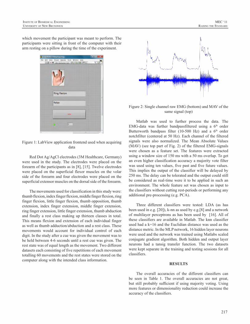
217
InsItute of BIomedIcal engIneerIng
unIversIty of new BrunswIck
MEC ‘11raIsIng the standard
whichmovementtheparticipantwasmeanttoperform.Theparticipantsweresittinginfrontofthecomputerwiththeirarmrestingonapillowduringthetimeoftheexperiment.
Figure1:LabViewapplicationfrontendusedwhenacquiringdata
RedDotAg/AgClelectrodes(3MHealthcare,Germany)were used in the study.The electrodeswere placed on theforearmoftheparticipantsasin[8],[15].Twelveelectrodeswere placed on the superficial flexormuscles on the volarsideof the forearmandfourelectrodeswereplacedon thesuperficialextensormusclesonthedorsalsideoftheforearm.
Themovementsusedforclassificationinthisstudywere:thumbflexion,indexfingerflexion,middlefingerflexion,ringfingerflexion,littlefingerflexion,thumbopposition,thumbextension, index finger extension,middle finger extension,ringfingerextension,littlefingerextension,thumbabductionand finally a rest classmakingup thirteen classes in total.Thismeansflexionandextensionofeachindividualfingeraswellasthumbadduction/abductionandarestclass.Thesemovements would account for individual control of eachdigit.Inthestudyafteracuewasgiventhemovementwastobeheldbetween4-6secondsuntilarestcuewasgiven.Thereststatewasofequallengthasthemovement.Twodifferentdatasetseachconsistingoffiverepetitionsofeachmovementtotalling60movementsandthereststateswerestoredonthecomputeralongwiththeintendedclassinformation.
Figure2:SinglechannelrawEMG(bottom)andMAVofthesamesignal(top)
Matlab was used to further process the data. TheEMG-data was further bandpassfiltered using a 6th orderButterworth bandpass filter (10-500 Hz) and a 6th ordernotchfilter(centeredat50Hz).Eachchannelofthefilteredsignals were also normalized. The MeanAbsolute Values(MAV)(see toppartofFig.2)of thefilteredEMG-signalswere chosen as a feature set. The features were extractedusingawindowsizeof150mswitha50msoverlap.Togetanevenhigherclassificationaccuracyamajorityvotefilterwasusedusingtenvalues,fivepastandfivefuturevalues.This implies theoutputof theclassifierwillbedelayedby250ms.Thedelaycanbetoleratedandtheoutputcouldstillbeconsideredas real-timewere it tobeapplied insuchanenvironment.Thewholefeaturesetwaschosenas input totheclassifierswithoutcuttingrest-periodsorperforminganyadditionalpre-processing(e.g.PCA).
Three different classifiers were tested: LDA (as hasbeenusedine.g.[20]),k-nnasusedbye.g.[8]andanetworkofmultilayerperceptronsashasbeenusedby [16].Alloftheseclassifiersareavailable inMatlab.Theknnclassifierusedhadak=16andtheEuclidiandistancewasusedasthedistancemetric.IntheMLPnetwork,16hiddenlayerneuronswereusedandthenetworkwastrainedusingMatlabsscaledconjugategradientalgorithm.Bothhiddenandoutputlayerneurons had a tansig transfer function. The two datasetswerekeptseparateinthetrainingandtestingsessionsforallclassifiers.
RESULTS
The overall accuracies of the different classifiers canbe seen in Table 1. The overall accuracies are not great,but stillprobablysufficient ifusingmajorityvoting.Usingmorefeaturesordimensionalityreductioncouldincreasetheaccuracyoftheclassifiers.
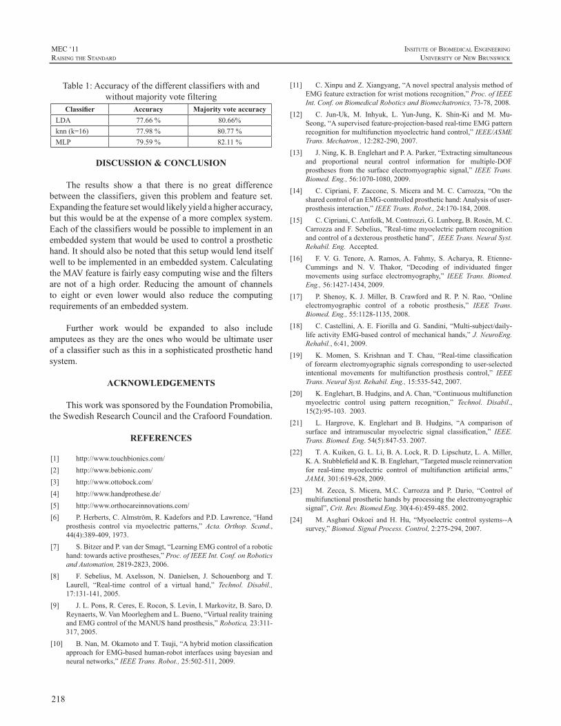
218
MEC ‘11raIsIng the standard
InsItute of BIomedIcal engIneerIng
unIversIty of new BrunswIck
Table1:Accuracyofthedifferentclassifierswithandwithoutmajorityvotefiltering
Classifier Accuracy Majority vote accuracyLDA 77.66% 80.66%knn(k=16) 77.98% 80.77%MLP 79.59% 82.11%
DISCUSSION & CONCLUSION
The results show a that there is no great differencebetween theclassifiers,given thisproblemand feature set.Expandingthefeaturesetwouldlikelyyieldahigheraccuracy,butthiswouldbeattheexpenseofamorecomplexsystem.Eachoftheclassifierswouldbepossibletoimplementinanembeddedsystemthatwouldbeusedtocontrolaprosthetichand.Itshouldalsobenotedthatthissetupwouldlenditselfwelltobeimplementedinanembeddedsystem.CalculatingtheMAVfeatureisfairlyeasycomputingwiseandthefiltersare not of a high order. Reducing the amount of channelsto eight or even lower would also reduce the computingrequirementsofanembeddedsystem.
Further work would be expanded to also includeamputeesas theyare theoneswhowouldbeultimateuserofaclassifiersuchasthisinasophisticatedprosthetichandsystem.
ACKNOWLEDGEMENTS
ThisworkwassponsoredbytheFoundationPromobilia,theSwedishResearchCouncilandtheCrafoordFoundation.
REFERENCES
[1] http://www.touchbionics.com/[2] http://www.bebionic.com/[3] http://www.ottobock.com/[4] http://www.handprothese.de/[5] http://www.orthocareinnovations.com/[6] P.Herberts,C.Almström,R.KadeforsandP.D.Lawrence,“Hand
prosthesis control via myoelectric patterns,” Acta. Orthop. Scand.,44(4):389-409,1973.
[7] S.BitzerandP.vanderSmagt,“LearningEMGcontrolofarobotichand:towardsactiveprostheses,”Proc.ofIEEEInt.Conf.onRoboticsandAutomation,2819-2823,2006.
[8] F. Sebelius, M.Axelsson, N. Danielsen, J. Schouenborg and T.Laurell, “Real-time control of a virtual hand,” Technol. Disabil.,17:131-141,2005.
[9] J.L.Pons,R.Ceres,E.Rocon,S.Levin,I.Markovitz,B.Saro,D.Reynaerts,W.VanMoorleghemandL.Bueno,“VirtualrealitytrainingandEMGcontroloftheMANUShandprosthesis,”Robotica,23:311-317,2005.
[10] B.Nan,M.OkamotoandT.Tsuji,“AhybridmotionclassificationapproachforEMG-basedhuman-robotinterfacesusingbayesianandneuralnetworks,”IEEETrans.Robot.,25:502-511,2009.
[11] C.XinpuandZ.Xiangyang,“AnovelspectralanalysismethodofEMGfeatureextractionforwristmotionsrecognition,”Proc.ofIEEEInt.Conf.onBiomedicalRoboticsandBiomechatronics,73-78,2008.
[12] C. Jun-Uk, M. Inhyuk, L. Yun-Jung, K. Shin-Ki and M. Mu-Seong,“Asupervisedfeature-projection-basedreal-timeEMGpatternrecognitionformultifunctionmyoelectrichandcontrol,”IEEE/ASMETrans.Mechatron.,12:282-290,2007.
[13] J.Ning,K.B.EnglehartandP.A.Parker,“Extractingsimultaneousand proportional neural control information for multiple-DOFprostheses from the surface electromyographic signal,” IEEETrans.Biomed.Eng.,56:1070-1080,2009.
[14] C.Cipriani,F.Zaccone,S.Micera andM.C.Carrozza, “On thesharedcontrolofanEMG-controlledprosthetichand:Analysisofuser-prosthesisinteraction,”IEEETrans.Robot.,24:170-184,2008.
[15] C.Cipriani,C.Antfolk,M.Controzzi,G.Lunborg,B.Rosén,M.C.CarrozzaandF.Sebelius,”Real-timemyoelectricpatternrecognitionandcontrolofadexterousprosthetichand”,IEEETrans.NeuralSyst.Rehabil.Eng.Accepted.
[16] F. V. G. Tenore,A. Ramos,A. Fahmy, S.Acharya, R. Etienne-Cummings and N. V. Thakor, “Decoding of individuated fingermovements using surface electromyography,” IEEE Trans. Biomed.Eng.,56:1427-1434,2009.
[17] P. Shenoy,K. J.Miller, B. Crawford andR. P.N. Rao, “Onlineelectromyographic control of a robotic prosthesis,” IEEE Trans.Biomed.Eng.,55:1128-1135,2008.
[18] C.Castellini,A.E.FiorillaandG.Sandini, “Multi-subject/daily-lifeactivityEMG-basedcontrolofmechanicalhands,”J.NeuroEng.Rehabil.,6:41,2009.
[19] K. Momen, S. Krishnan and T. Chau, “Real-time classificationof forearmelectromyographic signalscorresponding touser-selectedintentional movements for multifunction prosthesis control,” IEEETrans.NeuralSyst.Rehabil.Eng.,15:535-542,2007.
[20] K.Englehart,B.Hudgins,andA.Chan,“Continuousmultifunctionmyoelectric control using pattern recognition,” Technol. Disabil.,15(2):95-103.2003.
[21] L. Hargrove, K. Englehart and B. Hudgins, “A comparison ofsurface and intramuscular myoelectric signal classification,” IEEE.Trans.Biomed.Eng.54(5):847-53.2007.
[22] T.A.Kuiken,G.L.Li,B.A.Lock,R.D.Lipschutz,L.A.Miller,K.A.StubblefieldandK.B.Englehart,“Targetedmusclereinnervationfor real-time myoelectric control of multifunction artificial arms,”JAMA,301:619-628,2009.
[23] M. Zecca, S. Micera, M.C. Carrozza and P. Dario, “Control ofmultifunctionalprosthetichandsbyprocessingtheelectromyographicsignal”,Crit.Rev.Biomed.Eng.30(4-6):459-485.2002.
[24] M.AsghariOskoei andH.Hu, “Myoelectric control systems--Asurvey,”Biomed.SignalProcess.Control,2:275-294,2007.
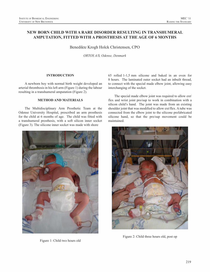
219
InsItute of BIomedIcal engIneerIng
unIversIty of new BrunswIck
MEC ‘11raIsIng the standard
INTRODUCTION
Anewbornboywithnormalbirthweightdevelopedanarterialthrombosisinhisleftarm(Figure1)duringthelabourresultinginatranshumeralamputation(Figure2).
METHOD AND MATERIALS
The Multidisciplinary Arm Prosthetic Team at theOdense University Hospital, prescribed an arm prosthesisforthechildat6monthsofage.Thechildwasfittedwitha transhumeral prosthesis, with a soft silicon inner socket(Figure3).Thesiliconeinnersocketwasmadewithshore
Figure1:Childtwohoursold
65rolled1-1,5mmsiliconeandbakedinanovenfor8hours. The laminatedoutersockethadan inbuilt thread,toconnectwiththespecialmadeelbowjoint,allowingeasyinterchangingofthesocket.
Thespecialmadeelbowjointwasrequiredtoallowext/flexandwrist jointpro/sup towork incombinationwithasiliconchild’shand. The jointwasmade fromanexistingshoulderjointthatwasmodifiedtoallowext/flex.Atubewasconnectedfromtheelbowjointtothesiliconeprefabricatedsilicone hand, so that the pro/sup movement could bemaintained.
Figure2:Childthreehoursold,postop
NEW BORN CHILD WITH A RARE DISORDER RESULTING IN TRANSHUMERAL AMPUTATION, FITTED WITH A PROSTHESIS AT THE AGE OF 6 MONTHS
BenedikteKroghHolckChristensen,CPO
ORTOSA/S,Odense,Denmark
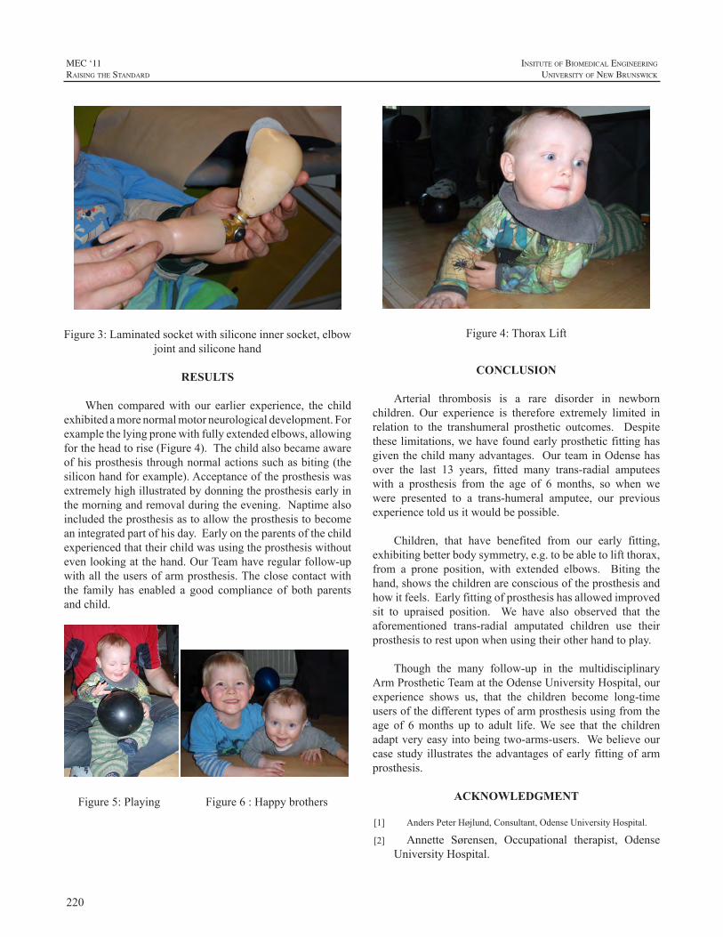
220
MEC ‘11raIsIng the standard
InsItute of BIomedIcal engIneerIng
unIversIty of new BrunswIck
Figure3:Laminatedsocketwithsiliconeinnersocket,elbowjointandsiliconehand
RESULTS
When comparedwith our earlier experience, the childexhibitedamorenormalmotorneurologicaldevelopment.Forexamplethelyingpronewithfullyextendedelbows,allowingfortheheadtorise(Figure4).Thechildalsobecameawareofhisprosthesisthroughnormalactionssuchasbiting(thesiliconhandforexample).Acceptanceoftheprosthesiswasextremelyhighillustratedbydonningtheprosthesisearlyinthemorningandremovalduringtheevening.Naptimealsoincludedtheprosthesisastoallowtheprosthesistobecomeanintegratedpartofhisday.Earlyontheparentsofthechildexperiencedthattheirchildwasusingtheprosthesiswithoutevenlookingatthehand.OurTeamhaveregularfollow-upwithall theusersofarmprosthesis.Theclosecontactwiththe family has enabled a good compliance of both parentsandchild.
Figure5:Playing Figure6:Happybrothers
Figure4:ThoraxLift
CONCLUSION
Arterial thrombosis is a rare disorder in newbornchildren. Our experience is therefore extremely limited inrelation to the transhumeral prosthetic outcomes. Despitetheselimitations,wehavefoundearlyprostheticfittinghasgiventhechildmanyadvantages. OurteaminOdensehasover the last 13 years, fitted many trans-radial amputeeswith a prosthesis from the age of 6 months, so when wewere presented to a trans-humeral amputee, our previousexperiencetoldusitwouldbepossible.
Children, that have benefited from our early fitting,exhibitingbetterbodysymmetry,e.g.tobeabletoliftthorax,from a prone position, with extended elbows. Biting thehand,showsthechildrenareconsciousoftheprosthesisandhowitfeels.Earlyfittingofprosthesishasallowedimprovedsit to upraised position. We have also observed that theaforementioned trans-radial amputated children use theirprosthesistorestuponwhenusingtheirotherhandtoplay.
Though the many follow-up in the multidisciplinaryArmProstheticTeamattheOdenseUniversityHospital,ourexperience shows us, that the children become long-timeusersofthedifferenttypesofarmprosthesisusingfromtheage of 6months up to adult life.We see that the childrenadaptveryeasyintobeingtwo-arms-users.Webelieveourcasestudy illustrates theadvantagesofearly fittingofarmprosthesis.
ACKNOWLEDGMENT
[1] AndersPeterHøjlund,Consultant,OdenseUniversityHospital.
[2] Annette Sørensen, Occupational therapist, OdenseUniversityHospital.
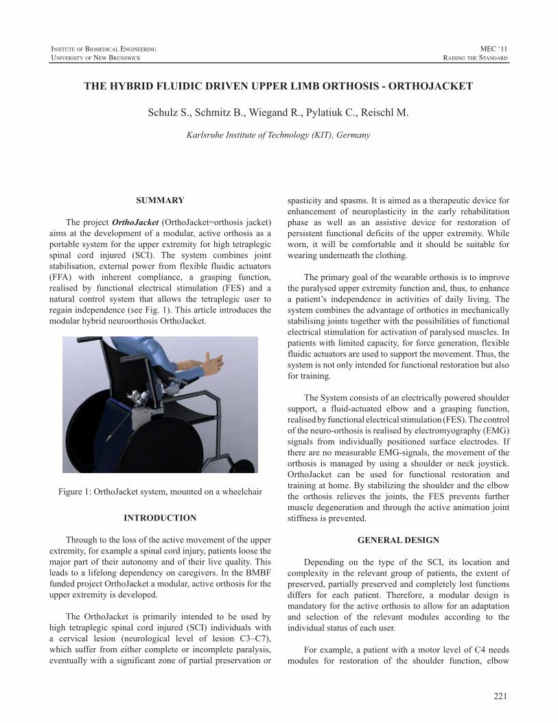
221
InsItute of BIomedIcal engIneerIng
unIversIty of new BrunswIck
MEC ‘11raIsIng the standard
SUMMARY
TheprojectOrthoJacket (OrthoJacket=orthosis jacket)aimsat thedevelopmentof amodular, activeorthosis as aportablesystemfortheupperextremityforhightetraplegicspinal cord injured (SCI). The system combines jointstabilisation, external power from flexible fluidic actuators(FFA) with inherent compliance, a grasping function,realised by functional electrical stimulation (FES) and anatural control system that allows the tetraplegic user toregainindependence(seeFig.1).ThisarticleintroducesthemodularhybridneuroorthosisOrthoJacket.
Figure1:OrthoJacketsystem,mountedonawheelchair
INTRODUCTION
Throughtothelossoftheactivemovementoftheupperextremity,forexampleaspinalcordinjury,patientsloosethemajorpartof theirautonomyandof their livequality.Thisleadstoalifelongdependencyoncaregivers.IntheBMBFfundedprojectOrthoJacketamodular,activeorthosisfortheupperextremityisdeveloped.
The OrthoJacket is primarily intended to be used byhigh tetraplegic spinal cord injured (SCI) individuals witha cervical lesion (neurological level of lesion C3–C7),which suffer fromeither completeor incompleteparalysis,eventuallywithasignificantzoneofpartialpreservationor
spasticityandspasms.Itisaimedasatherapeuticdeviceforenhancement of neuroplasticity in the early rehabilitationphase as well as an assistive device for restoration ofpersistent functional deficits of the upper extremity.Whileworn, it will be comfortable and it should be suitable forwearingunderneaththeclothing.
Theprimarygoalofthewearableorthosisistoimprovetheparalysedupperextremityfunctionand,thus,toenhancea patient’s independence in activities of daily living. Thesystemcombinestheadvantageoforthoticsinmechanicallystabilisingjointstogetherwiththepossibilitiesoffunctionalelectricalstimulationforactivationofparalysedmuscles.Inpatientswithlimitedcapacity,forforcegeneration,flexiblefluidicactuatorsareusedtosupportthemovement.Thus,thesystemisnotonlyintendedforfunctionalrestorationbutalsofortraining.
TheSystemconsistsofanelectricallypoweredshouldersupport, a fluid-actuated elbow and a grasping function,realisedbyfunctionalelectricalstimulation(FES).Thecontroloftheneuro-orthosisisrealisedbyelectromyography(EMG)signals from individually positioned surface electrodes. IftherearenomeasurableEMG-signals,themovementoftheorthosis ismanaged by using a shoulder or neck joystick.OrthoJacket can be used for functional restoration andtrainingathome.Bystabilizingtheshoulderandtheelbowthe orthosis relieves the joints, the FES prevents furthermuscledegenerationandthroughtheactiveanimationjointstiffnessisprevented.
GENERAL DESIGN
Depending on the type of the SCI, its location andcomplexity in the relevant group of patients, the extent ofpreserved,partiallypreservedandcompletelylostfunctionsdiffers for each patient. Therefore, a modular design ismandatoryfortheactiveorthosistoallowforanadaptationand selection of the relevant modules according to theindividualstatusofeachuser.
Forexample,apatientwithamotor levelofC4needsmodules for restoration of the shoulder function, elbow
THE HYBRID FLUIDIC DRIVEN UPPER LIMB ORTHOSIS - ORTHOJACKET
SchulzS.,SchmitzB.,WiegandR.,PylatiukC.,ReischlM.
KarlsruheInstituteofTechnology(KIT),Germany
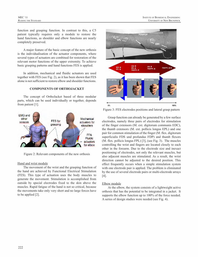
222
MEC ‘11raIsIng the standard
InsItute of BIomedIcal engIneerIng
unIversIty of new BrunswIck
function and grasping function. In contrast to this, a C5patient typically requires only a module to restore thehandfunctions,asshoulderandelbowfunctionsarenearlycompletelypreserved.
Amajorfeatureofthebasicconceptoftheneworthosisis the individualisation of the actuator components, whereseveraltypesofactuatorsarecombinedforrestorationoftherelevantmotorfunctionsoftheupperextremity.ToachievebasicgraspingpatternsandhandfunctionsFESisapplied.
In addition,mechanical and fluidic actuators are usedtogetherwithFES(seeFig.2),asithasbeenshownthatFESaloneisnotsufficienttorestoreelbowandshoulderfunctions.
COMPONENTS OF ORTHOJACKET
The concept of OrthoJacket based of three modularparts,which can be used individually or together, dependsfrompatient[1].
Figure2:Relevantcomponentsoftheneworthosis
HandandwristmoduleThemovementofthewristandthegraspingfunctionof
thehandare achievedbyFunctionalElectricalStimulation(FES). This type of actuation uses the body muscles togenerate themovement. Stimulation is accomplished fromoutside by special electrodes fixed to the skin above themuscles.Rapidfatigueofthehandisnotsocritical,becausethemovementstakeonlyveryshortandnolargeforceshavetobeapplied[2].
Figure3:FESelectrodespositionsandlateralgrasppattern
Graspfunctioncanalreadybegeneratedbyafewsurfaceelectrodes,namely threepairsof electrodes for stimulationofthefingerextensors(M.ext.digitorumcommunisEDC),the thumbextensors (M.ext.pollicis longusEPL)andonepairforcommonstimulationofthefinger(M.flex.digitorumsuperficialis FDS und profundus FDP) and thumb flexors(M.flex.pollicislongusFPL)[3],(seeFig.3).Themusclescontrollingthewristandfingersarelocatedcloselytoeachother in the forearm.Due to theelectrodesizeand inexactpositioningofelectrodes,notonlytherelevantmuscles,butalsoadjacentmuscles are stimulated.Asa result, thewristdirection cannot be adjusted to the desired position. Thiseffect frequently occurswhen a simple stimulation systemwithoneelectrodepairisapplied.Theproblemiseliminatedbytheuseofseveralelectrodepairsormulti-electrodearrays[4].
ElbowmoduleAttheelbow,thesystemconsistsofalightweightactive
orthosisthathasthepotentialtobeintegratedinajacket.Itsupportstheelbowfunctionupto100%oftheforceneeded.Aseriesofdesignstudieswereneeded(seeFig.4).
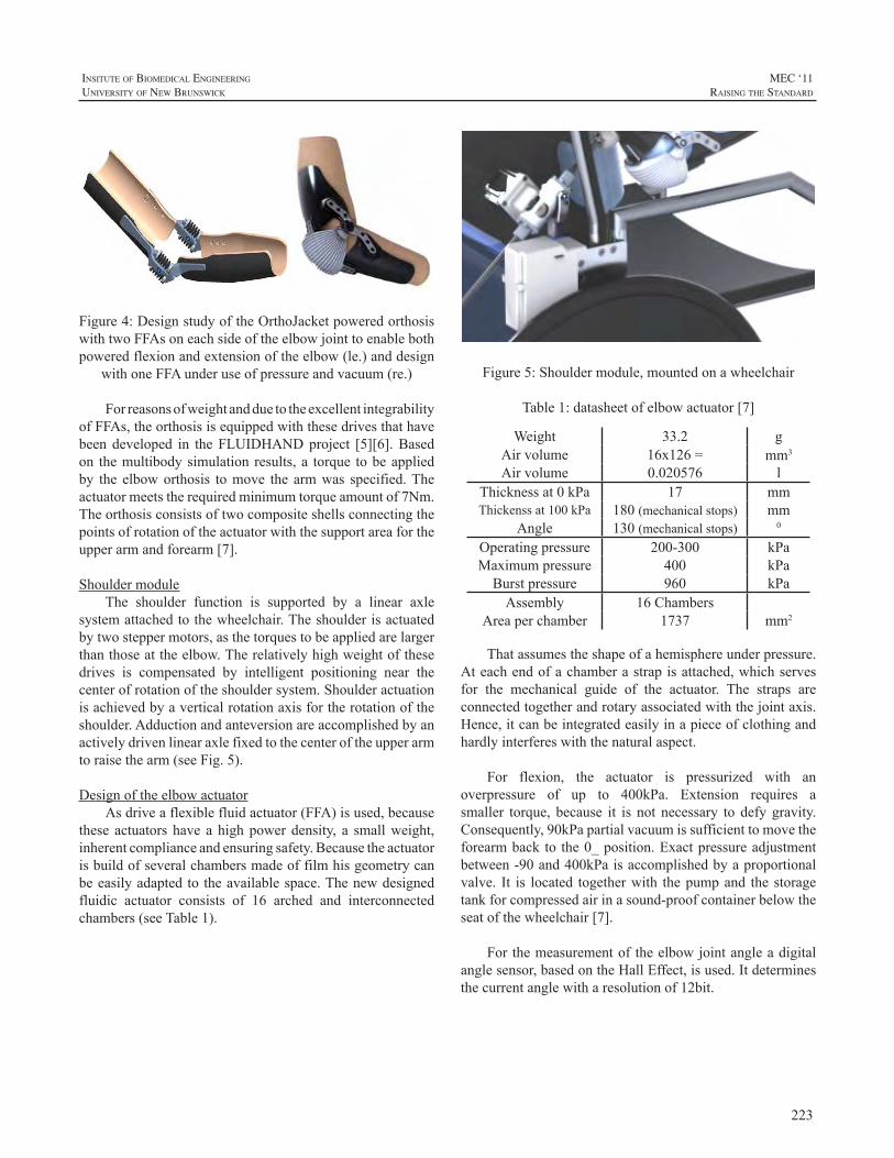
223
InsItute of BIomedIcal engIneerIng
unIversIty of new BrunswIck
MEC ‘11raIsIng the standard
Figure4:DesignstudyoftheOrthoJacketpoweredorthosiswithtwoFFAsoneachsideoftheelbowjointtoenablebothpoweredflexionandextensionoftheelbow(le.)anddesign
withoneFFAunderuseofpressureandvacuum(re.)
ForreasonsofweightandduetotheexcellentintegrabilityofFFAs,theorthosisisequippedwiththesedrivesthathavebeen developed in theFLUIDHANDproject [5][6].Basedon themultibodysimulation results,a torque tobeappliedby the elboworthosis tomove the armwas specified.Theactuatormeetstherequiredminimumtorqueamountof7Nm.Theorthosisconsistsoftwocompositeshellsconnectingthepointsofrotationoftheactuatorwiththesupportareafortheupperarmandforearm[7].
ShouldermoduleThe shoulder function is supported by a linear axle
systemattachedtothewheelchair.Theshoulderisactuatedbytwosteppermotors,asthetorquestobeappliedarelargerthanthoseattheelbow.Therelativelyhighweightofthesedrives is compensated by intelligent positioning near thecenterofrotationoftheshouldersystem.Shoulderactuationisachievedbyaverticalrotationaxisfortherotationoftheshoulder.Adductionandanteversionareaccomplishedbyanactivelydrivenlinearaxlefixedtothecenteroftheupperarmtoraisethearm(seeFig.5).
DesignoftheelbowactuatorAsdriveaflexiblefluidactuator(FFA)isused,because
these actuators have a highpowerdensity, a smallweight,inherentcomplianceandensuringsafety.Becausetheactuatorisbuildofseveralchambersmadeoffilmhisgeometrycanbeeasilyadaptedto theavailablespace.Thenewdesignedfluidic actuator consists of 16 arched and interconnectedchambers(seeTable1).
Figure5:Shouldermodule,mountedonawheelchair
Table1:datasheetofelbowactuator[7]
Weight 33.2 gAirvolume 16x126= mm3
Airvolume 0.020576 lThicknessat0kPa 17 mmThickenssat100kPa 180(mechanicalstops) mm
Angle 130(mechanicalstops) 0
Operatingpressure 200-300 kPaMaximumpressure 400 kPaBurstpressure 960 kPaAssembly 16Chambers
Areaperchamber 1737 mm2
Thatassumestheshapeofahemisphereunderpressure.Ateachendofachamberastrapisattached,whichservesfor the mechanical guide of the actuator. The straps areconnectedtogetherandrotaryassociatedwiththejointaxis.Hence,itcanbeintegratedeasilyinapieceofclothingandhardlyinterfereswiththenaturalaspect.
For flexion, the actuator is pressurized with anoverpressure of up to 400kPa. Extension requires asmaller torque, because it is not necessary to defy gravity.Consequently,90kPapartialvacuumissufficienttomovetheforearmback to the0_position.Exactpressureadjustmentbetween-90and400kPaisaccomplishedbyaproportionalvalve. It is located togetherwith thepumpand the storagetankforcompressedairinasound-proofcontainerbelowtheseatofthewheelchair[7].
Forthemeasurementof theelbowjointangleadigitalanglesensor,basedontheHallEffect,isused.Itdeterminesthecurrentanglewitharesolutionof12bit.
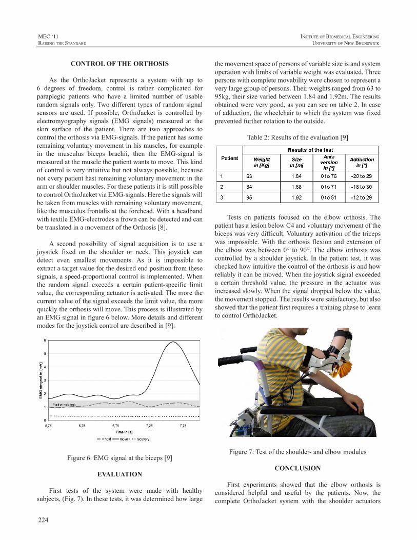
224
MEC ‘11raIsIng the standard
InsItute of BIomedIcal engIneerIng
unIversIty of new BrunswIck
CONTROL OF THE ORTHOSIS
As the OrthoJacket represents a system with up to6 degrees of freedom, control is rather complicated forparaplegic patients who have a limited number of usablerandomsignalsonly.Twodifferent typesof randomsignalsensors are used. If possible, OrthoJacket is controlled byelectromyography signals (EMG signals) measured at theskin surface of the patient. There are two approaches tocontroltheorthosisviaEMG-signals.Ifthepatienthassomeremainingvoluntarymovementinhismuscles,forexamplein the musculus biceps brachii, then the EMG-signal ismeasuredatthemusclethepatientwantstomove.Thiskindofcontrolisveryintuitivebutnotalwayspossible,becausenoteverypatienthastremainingvoluntarymovementinthearmorshouldermuscles.ForthesepatientsitisstillpossibletocontrolOrthoJacketviaEMG-signals.Herethesignalswillbetakenfrommuscleswithremainingvoluntarymovement,likethemusculusfrontalisattheforehead.WithaheadbandwithtextileEMG-electrodesafrowncanbedetectedandcanbetranslatedinamovementoftheOrthosis[8].
A second possibility of signal acquisition is to use ajoystick fixed on the shoulder or neck. This joystick candetect even smallest movements. As it is impossible toextractatargetvalueforthedesiredendpositionfromthesesignals,aspeed-proportionalcontrolisimplemented.Whenthe random signal exceeds a certain patient-specific limitvalue,thecorrespondingactuatorisactivated.Themorethecurrentvalueofthesignalexceedsthelimitvalue,themorequicklytheorthosiswillmove.ThisprocessisillustratedbyanEMGsignalinfigure6below.Moredetailsanddifferentmodesforthejoystickcontrolaredescribedin[9].
Figure6:EMGsignalatthebiceps[9]
EVALUATION
First tests of the system were made with healthysubjects,(Fig.7).Inthesetests,itwasdeterminedhowlarge
themovementspaceofpersonsofvariablesizeisandsystemoperationwithlimbsofvariableweightwasevaluated.Threepersonswithcompletemovabilitywerechosentorepresentaverylargegroupofpersons.Theirweightsrangedfrom63to95kg,theirsizevariedbetween1.84and1.92m.Theresultsobtainedwereverygood,asyoucanseeontable2.Incaseofadduction,thewheelchairtowhichthesystemwasfixedpreventedfurtherrotationtotheoutside.
Table2:Resultsoftheevaluation[9]
Tests on patients focused on the elbow orthosis. ThepatienthasalesionbelowC4andvoluntarymovementofthebicepswasverydifficult.Voluntaryactivationofthetricepswas impossible.With theorthosis flexionandextensionofthe elbowwasbetween0° to90°.The elboworthosiswascontrolledbyashoulder joystick.In thepatient test, itwascheckedhowintuitivethecontroloftheorthosisisandhowreliablyitcanbemoved.Whenthejoysticksignalexceededa certain threshold value, the pressure in the actuator wasincreasedslowly.Whenthesignaldroppedbelowthevalue,themovementstopped.Theresultsweresatisfactory,butalsoshowedthatthepatientfirstrequiresatrainingphasetolearntocontrolOrthoJacket.
Figure7:Testoftheshoulder-andelbowmodules
CONCLUSION
First experiments showed that the elbow orthosis isconsidered helpful and useful by the patients. Now, thecomplete OrthoJacket system with the shoulder actuators
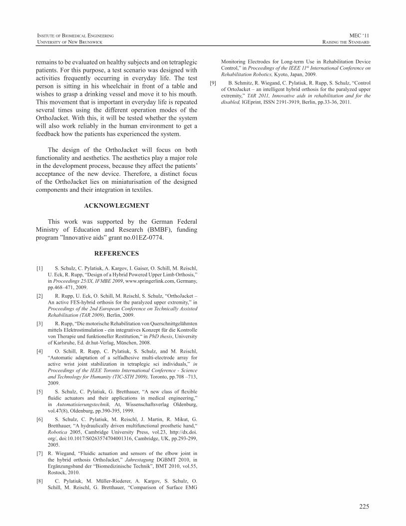
225
InsItute of BIomedIcal engIneerIng
unIversIty of new BrunswIck
MEC ‘11raIsIng the standard
remainstobeevaluatedonhealthysubjectsandontetraplegicpatients.Forthispurpose,atestscenariowasdesignedwithactivities frequently occurring in everyday life. The testperson is sitting in his wheelchair in front of a table andwishestograspadrinkingvesselandmoveittohismouth.Thismovementthatisimportantineverydaylifeisrepeatedseveral times using the different operation modes of theOrthoJacket.Withthis,itwillbetestedwhetherthesystemwill alsowork reliably in the human environment to get afeedbackhowthepatientshasexperiencedthesystem.
The design of the OrthoJacket will focus on bothfunctionalityandaesthetics.Theaestheticsplayamajorroleinthedevelopmentprocess,becausetheyaffectthepatients’acceptance of the new device. Therefore, a distinct focusof the OrthoJacket lies on miniaturisation of the designedcomponentsandtheirintegrationintextiles.
ACKNOWLEGMENT
This work was supported by the German FederalMinistry of Education and Research (BMBF), fundingprogram”Innovativeaids”grantno.01EZ-0774.
REFERENCES
[1] S.Schulz,C.Pylatiuk,A.Kargov,I.Gaiser,O.Schill,M.Reischl,U.Eck,R.Rupp,“DesignofaHybridPoweredUpperLimbOrthosis,”inProceedings25/IX,IFMBE2009,www.springerlink.com,Germany,pp.468–471,2009.
[2] R.Rupp,U.Eck,O.Schill,M.Reischl,S.Schulz,“OrthoJacket–AnactiveFES-hybridorthosisfortheparalyzedupperextremity,”inProceedingsofthe2ndEuropeanConferenceonTechnicallyAssistedRehabilitation(TAR2009),Berlin,2009.
[3] R.Rupp,“DiemotorischeRehabilitationvonQuerschnittgelähmtenmittelsElektrostimulation-einintegrativesKonzeptfürdieKontrollevonTherapieundfunktionellerRestitution,“inPhDthesis,UniversityofKarlsruhe,Ed.dr.hut-Verlag,München,2008.
[4] O. Schill, R. Rupp, C. Pylatiuk, S. Schulz, and M. Reischl,“Automatic adaptation of a selfadhesive multi-electrode array foractive wrist joint stabilization in tetraplegic sci individuals,” inProceedingsoftheIEEETorontoInternationalConference-ScienceandTechnologyforHumanity(TIC-STH2009),Toronto,pp.708–713,2009.
[5] S. Schulz, C. Pylatiuk, G. Bretthauer, “A new class of flexiblefluidic actuators and their applications in medical engineering,”in Automatisierungstechnik, At, Wissenschaftsverlag Oldenburg,vol.47(8),Oldenburg,pp.390-395,1999.
[6] S. Schulz, C. Pylatiuk, M. Reischl, J. Martin, R. Mikut, G.Bretthauer,“Ahydraulicallydrivenmultifunctionalprosthetichand,“Robotica 2005, Cambridge University Press, vol.23, http://dx.doi.org/,doi:10.1017/S0263574704001316,Cambridge,UK,pp.293-299,2005.
[7] R. Wiegand, “Fluidic actuation and sensors of the elbow joint inthe hybrid orthosis OrthoJacket,” Jahrestagung DGBMT 2010, inErgänzungsbandder“BiomedizinischeTechnik”,BMT2010,vol.55,Rostock,2010.
[8] C. Pylatiuk, M. Müller-Riederer, A. Kargov, S. Schulz, O.Schill, M. Reischl, G. Bretthauer, “Comparison of Surface EMG
Monitoring Electrodes for Long-term Use in Rehabilitation DeviceControl,”inProceedingsoftheIEEE11thInternationalConferenceonRehabilitationRobotics,Kyoto,Japan,2009.
[9] B.Schmitz,R.Wiegand,C.Pylatiuk,R.Rupp,S.Schulz,“ControlofOrtoJacket–anintelligenthybridorthosisfortheparalyzedupperextremity,” TAR 2011, Innovative aids in rehabilitation and for thedisabled,IGEprint,ISSN2191-3919,Berlin,pp.33-36,2011.
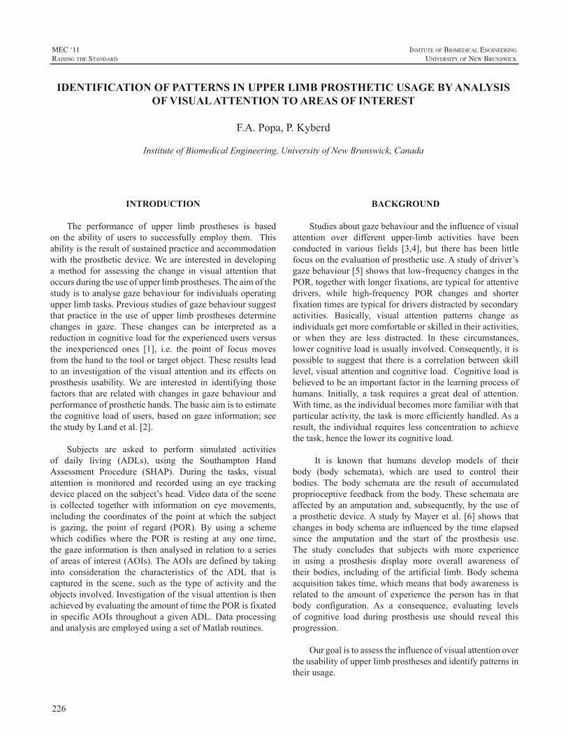
226
MEC ‘11raIsIng the standard
InsItute of BIomedIcal engIneerIng
unIversIty of new BrunswIck
INTRODUCTION
The performance of upper limb prostheses is basedon the ability of users to successfully employ them. Thisabilityistheresultofsustainedpracticeandaccommodationwith theprostheticdevice.Weare interested indevelopinga method for assessing the change in visual attention thatoccursduringtheuseofupperlimbprostheses.Theaimofthestudyistoanalysegazebehaviourforindividualsoperatingupperlimbtasks.Previousstudiesofgazebehavioursuggestthatpractice in theuseofupper limbprosthesesdeterminechanges in gaze. These changes can be interpreted as areductionincognitiveloadfortheexperiencedusersversusthe inexperienced ones [1], i.e. the point of focus movesfromthehandtothetoolortargetobject.Theseresultsleadtoaninvestigationof thevisualattentionanditseffectsonprosthesis usability.We are interested in identifying thosefactors thatarerelatedwithchanges ingazebehaviourandperformanceofprosthetichands.Thebasicaimistoestimatethecognitive loadofusers,basedongaze information;seethestudybyLandetal.[2].
Subjects are asked to perform simulated activitiesof daily living (ADLs), using the Southampton HandAssessment Procedure (SHAP). During the tasks, visualattention is monitored and recorded using an eye trackingdeviceplacedonthesubject’shead.Videodataofthesceneis collected together with information on eye movements,including the coordinatesof thepoint atwhich the subjectis gazing, the point of regard (POR). By using a schemewhich codifieswhere the POR is resting at any one time,thegazeinformationisthenanalysedinrelationtoaseriesofareasofinterest(AOIs).TheAOIsaredefinedbytakinginto consideration the characteristics of the ADL that iscaptured in the scene, such as the type of activity and theobjectsinvolved.InvestigationofthevisualattentionisthenachievedbyevaluatingtheamountoftimethePORisfixatedinspecificAOIs throughoutagivenADL.DataprocessingandanalysisareemployedusingasetofMatlabroutines.
BACKGROUND
Studiesaboutgazebehaviourandtheinfluenceofvisualattention over different upper-limb activities have beenconducted in various fields [3,4], but there has been littlefocusontheevaluationofprostheticuse.Astudyofdriver’sgazebehaviour[5]showsthatlow-frequencychangesinthePOR,togetherwithlongerfixations,aretypicalforattentivedrivers, while high-frequency POR changes and shorterfixationtimesaretypicalfordriversdistractedbysecondaryactivities. Basically, visual attention patterns change asindividualsgetmorecomfortableorskilledintheiractivities,or when they are less distracted. In these circumstances,lowercognitiveloadisusuallyinvolved.Consequently,itispossible to suggest that there isacorrelationbetweenskilllevel,visualattentionandcognitiveload.Cognitiveloadisbelievedtobeanimportantfactorinthelearningprocessofhumans. Initially, a task requires a great deal of attention.Withtime,astheindividualbecomesmorefamiliarwiththatparticularactivity,thetaskismoreefficientlyhandled.Asaresult, the individual requires less concentration toachievethetask,hencetheloweritscognitiveload.
It is known that humans develop models of theirbody (body schemata), which are used to control theirbodies. The body schemata are the result of accumulatedproprioceptivefeedbackfromthebody.Theseschemataareaffectedbyanamputationand,subsequently,by theuseofaprostheticdevice.AstudybyMayeretal. [6]showsthatchangesinbodyschemaareinfluencedbythetimeelapsedsince the amputation and the start of the prosthesis use.The study concludes that subjects with more experiencein using a prosthesis display more overall awareness oftheir bodies, including of the artificial limb.Body schemaacquisitiontakestime,whichmeansthatbodyawarenessisrelated to the amount of experience the person has in thatbody configuration. As a consequence, evaluating levelsof cognitive load during prosthesis use should reveal thisprogression.
Ourgoalistoassesstheinfluenceofvisualattentionovertheusabilityofupperlimbprosthesesandidentifypatternsintheirusage.
IDENTIFICATION OF PATTERNS IN UPPER LIMB PROSTHETIC USAGE BY ANALYSIS OF VISUAL ATTENTION TO AREAS OF INTEREST
F.A.Popa,P.Kyberd
InstituteofBiomedicalEngineering,UniversityofNewBrunswick,Canada
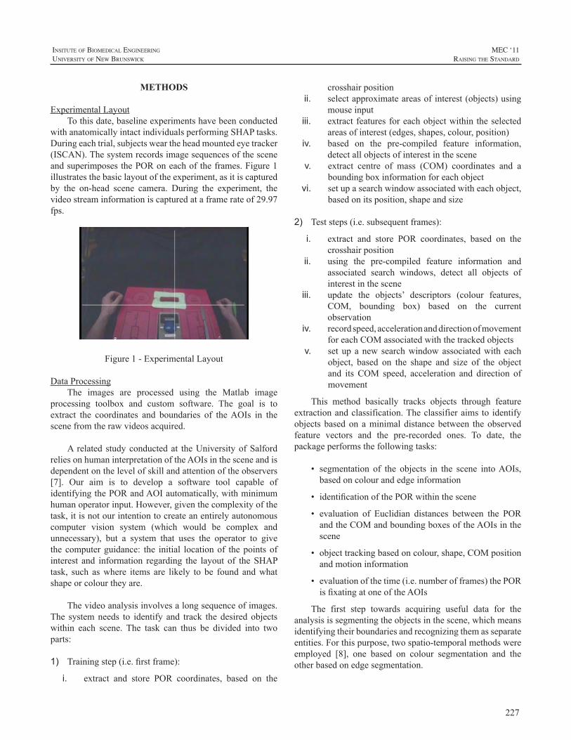
227
InsItute of BIomedIcal engIneerIng
unIversIty of new BrunswIck
MEC ‘11raIsIng the standard
METHODS
ExperimentalLayoutTothisdate,baselineexperimentshavebeenconducted
withanatomicallyintactindividualsperformingSHAPtasks.Duringeachtrial,subjectsweartheheadmountedeyetracker(ISCAN).ThesystemrecordsimagesequencesofthesceneandsuperimposesthePORoneachoftheframes.Figure1illustratesthebasiclayoutoftheexperiment,asitiscapturedby the on-head scene camera. During the experiment, thevideostreaminformationiscapturedataframerateof29.97fps.
Figure1-ExperimentalLayout
DataProcessingThe images are processed using the Matlab image
processing toolbox and custom software. The goal is toextract the coordinates and boundaries of theAOIs in thescenefromtherawvideosacquired.
A related studyconductedat theUniversityofSalfordreliesonhumaninterpretationoftheAOIsinthesceneandisdependentonthelevelofskillandattentionoftheobservers[7]. Our aim is to develop a software tool capable ofidentifyingthePORandAOIautomatically,withminimumhumanoperatorinput.However,giventhecomplexityofthetask,itisnotourintentiontocreateanentirelyautonomouscomputer vision system (which would be complex andunnecessary), but a system that uses the operator to givethecomputerguidance: the initial locationof thepointsofinterest and information regarding the layout of theSHAPtask, such aswhere items are likely to be found andwhatshapeorcolourtheyare.
Thevideoanalysisinvolvesalongsequenceofimages.The systemneeds to identify and track the desired objectswithin each scene. The task can thus be divided into twoparts:
1) Trainingstep(i.e.firstframe):
i. extract and store POR coordinates, based on the
crosshairpositionii. selectapproximateareasofinterest(objects)using
mouseinputiii. extractfeaturesforeachobjectwithin theselected
areasofinterest(edges,shapes,colour,position)iv. based on the pre-compiled feature information,
detectallobjectsofinterestinthescenev. extract centre of mass (COM) coordinates and a
boundingboxinformationforeachobjectvi. setupasearchwindowassociatedwitheachobject,
basedonitsposition,shapeandsize
2) Teststeps(i.e.subsequentframes):
i. extract and store POR coordinates, based on thecrosshairposition
ii. using the pre-compiled feature information andassociated search windows, detect all objects ofinterestinthescene
iii. update the objects’ descriptors (colour features,COM, bounding box) based on the currentobservation
iv. recordspeed,accelerationanddirectionofmovementforeachCOMassociatedwiththetrackedobjects
v. set up anew searchwindowassociatedwith eachobject, based on the shape and size of the objectand its COM speed, acceleration and direction ofmovement
This method basically tracks objects through featureextractionandclassification.Theclassifieraimsto identifyobjectsbasedon aminimaldistancebetween theobservedfeature vectors and the pre-recorded ones. To date, thepackageperformsthefollowingtasks:
• segmentation of the objects in the scene intoAOIs,basedoncolourandedgeinformation
• identificationofthePORwithinthescene
• evaluation of Euclidian distances between the PORandtheCOMandboundingboxesoftheAOIsinthescene
• objecttrackingbasedoncolour,shape,COMpositionandmotioninformation
• evaluationofthetime(i.e.numberofframes)thePORisfixatingatoneoftheAOIs
The first step towards acquiring useful data for theanalysisissegmentingtheobjectsinthescene,whichmeansidentifyingtheirboundariesandrecognizingthemasseparateentities.Forthispurpose,twospatio-temporalmethodswereemployed [8], one based on colour segmentation and theotherbasedonedgesegmentation.
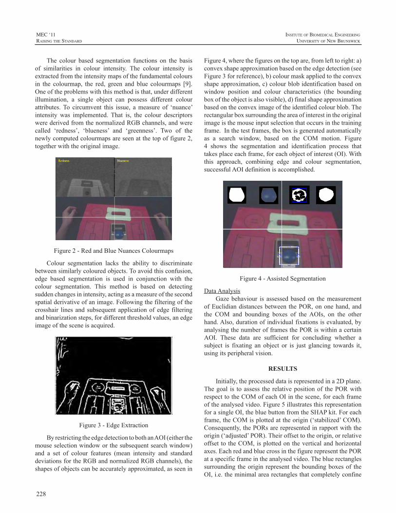
228
MEC ‘11raIsIng the standard
InsItute of BIomedIcal engIneerIng
unIversIty of new BrunswIck
The colour based segmentation functions on the basisof similarities in colour intensity. The colour intensity isextractedfromtheintensitymapsofthefundamentalcoloursin the colourmap, the red, green and blue colourmaps [9].Oneoftheproblemswiththismethodisthat,underdifferentillumination, a single object can possess different colourattributes.To circumvent this issue, ameasure of ‘nuance’intensity was implemented. That is, the colour descriptorswerederivedfromthenormalizedRGBchannels,andwerecalled ‘redness’, ‘blueness’ and ‘greenness’. Two of thenewlycomputedcolourmapsareseenatthetopoffigure2,togetherwiththeoriginalimage.
Figure2-RedandBlueNuancesColourmaps
Colour segmentation lacks the ability to discriminatebetweensimilarlycolouredobjects.Toavoidthisconfusion,edge based segmentation is used in conjunction with thecolour segmentation. This method is based on detectingsuddenchangesinintensity,actingasameasureofthesecondspatialderivativeofanimage.Followingthefilteringofthecrosshair linesandsubsequentapplicationofedge filteringandbinarizationsteps,fordifferentthresholdvalues,anedgeimageofthesceneisacquired.
Figure3-EdgeExtraction
ByrestrictingtheedgedetectiontobothanAOI(eitherthemouseselectionwindoworthesubsequentsearchwindow)and a set of colour features (mean intensity and standarddeviationsfortheRGBandnormalizedRGBchannels),theshapesofobjectscanbeaccuratelyapproximated,asseenin
Figure4,wherethefiguresonthetopare,fromlefttoright:a)convexshapeapproximationbasedontheedgedetection(seeFigure3forreference),b)colourmaskappliedtotheconvexshapeapproximation,c)colourblobidentificationbasedonwindow position and colour characteristics (the boundingboxoftheobjectisalsovisible),d)finalshapeapproximationbasedontheconveximageoftheidentifiedcolourblob.Therectangularboxsurroundingtheareaofinterestintheoriginalimageisthemouseinputselectionthatoccursinthetrainingframe.Inthetestframes,theboxisgeneratedautomaticallyas a search window, based on the COM motion. Figure4 shows the segmentation and identification process thattakesplaceeachframe,foreachobjectofinterest(OI).Withthis approach, combining edge and colour segmentation,successfulAOIdefinitionisaccomplished.
Figure4-AssistedSegmentation
DataAnalysisGazebehaviour is assessedbasedon themeasurement
ofEuclidiandistancesbetween thePOR,ononehand,andthe COM and bounding boxes of theAOIs, on the otherhand.Also,durationofindividualfixationsisevaluated,byanalysingthenumberofframesthePORiswithinacertainAOI. These data are sufficient for concluding whether asubject is fixating an object or is just glancing towards it,usingitsperipheralvision.
RESULTS
Initially,theprocesseddataisrepresentedina2Dplane.Thegoal is toassess the relativepositionof thePORwithrespecttotheCOMofeachOIinthescene,foreachframeoftheanalysedvideo.Figure5illustratesthisrepresentationforasingleOI,thebluebuttonfromtheSHAPkit.Foreachframe,theCOMisplottedattheorigin(‘stabilized’COM).Consequently,thePORsarerepresentedinrapportwiththeorigin(‘adjusted’POR).Theiroffsettotheorigin,orrelativeoffsettotheCOM,isplottedontheverticalandhorizontalaxes.EachredandbluecrossinthefigurerepresentthePORataspecificframeintheanalysedvideo.Thebluerectanglessurrounding theoriginrepresent theboundingboxesof theOI,i.e.theminimalarearectanglesthatcompletelyconfine
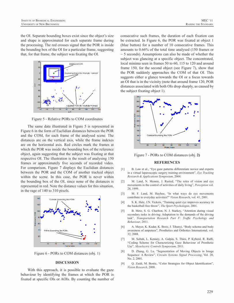
229
InsItute of BIomedIcal engIneerIng
unIversIty of new BrunswIck
MEC ‘11raIsIng the standard
theOI.Separateboundingboxesexistsincetheobject’ssizeand shape is approximated for each separate frame duringtheprocessing.TheredcrossessignalthatthePORisinsidetheboundingboxoftheOIforaparticularframe,suggestingthat,forthatframe,thesubjectwasfixatingtheOI.
Figure5-RelativePORstoCOMcoordinates
The samedata illustrated inFigure5 is represented inFigure6intheformofEuclidiandistancesbetweenthePORand the COM, for each frame of the analysed scene. Thedistances are on the vertical axis,while the frame indexesare on the horizontal axis. Red circlesmark the frames atwhichthePORwasinsidetheboundingboxofthereferenceobject,againsuggestingthatthesubjectwasfixatingatthatrespectiveOI.Theillustrationistheresultofanalysing150frames or approximately five seconds of recorded video.For comparison, Figure 7 displays the Euclidian distancesbetween the POR and the COM of another tracked objectwithin the scene. In this case, the POR is never withintheboundingboxof theOI, sincenoneof thedistances isrepresentedinred.Notethedistancevaluesforthissituation,intherageof140to310pixels.
Figure6-PORstoCOMdistances(obj.1)
DISCUSSION
With this approach, it is possible to evaluate the gazebehaviour by identifying the frames at which the POR isfixatedatspecificOIsorAOIs.Bycountingthenumberof
consecutive such frames, the duration of each fixation canbe extracted. InFigure6, thePORwas fixated at object 1(blue button) for a number of 10 consecutive frames.Thisamountsto0.66%ofthetotaltimeanalysed(150framesor~5seconds).Assumptionscanalsobemadeofwhetherthesubjectwasglancingataspecificobject.Theconcentrated,localminimaseeninframes50to60,115to120andaroundframe150, for the secondobject (seeFigure7), show thatthe POR suddenly approaches the COM of that OI. Thissuggestseitheraglance towards theOIora focus towardsanOIthatisinthevicinity(notethataroundframe120,PORdistancesassociatedwithbothOIsdropsharply,ascausedbythesubjectfixatingobject1).
Figure7-PORstoCOMdistances(obj. 2)
REFERENCES
[1] B.Lawetal.,“Eyegazepatternsdifferentiatenoviceandexpertsinavirtuallaparoscopicsurgerytrainingenvironment”,EyeTrackingResearch&ApplicationsSymposium,2004.
[2] M. Land, N. Mennie, J. Rusted, “The roles of vision and eyemovementsinthecontrolofactivitiesofdailyliving”,Perceptionvol.28,1999.
[3] M. F. Land, M. Hayhoe, “In what ways do eye movementscontributetoeverydayactivities?”VisionResearch,vol.41,2001.
[4] S.K.Hale,J.N.Vickers,“Trainingquieteyeimprovesaccuracyinthebasketballfreethrow”,TheSportPsychologist,2001.
[5] B.Metz, S.G.Charlton,N. J. Starkey, “Attention during visualsecondarytasksindriving:Adaptationtothedemandsofthedrivingtask”, Transportation Research Part F: Traffic Psychology andBehaviour,2011.
[6] A.Mayer,K.Kudar,K.Bretz,J.Tihanyi,“Bodyschemaandbodyawarenessofamputees”,ProstheticsandOrthoticsInternational,vol.32,2008.
[7] M. Sobuh, L.Kenney,A.Galpin, S.Thies, P.Kyberd, R. Raffi,“Coding Scheme for Characterizing Gaze Behaviour of ProstheticUse”,MyoelectricControlsSymposium,2011.
[8] D. Zhang, G. Lu, “Segmentation of Moving Objects in ImageSequence:AReview”,Circuits Systems Signal Processing,Vol. 20,No.2,2001.
[9] Q.Zaidi,M.Bostic, “ColorStrategies forObject Identification”,VisionResearch,2008.
230
MEC ‘11raIsIng the standard
InsItute of BIomedIcal engIneerIng
unIversIty of new BrunswIck
ABSTRACT
Inmyoelectricprostheses,movementartifactsareknowntoimpaircontrolperformance.Thisstudyrelatestoanovelsensor which measures surface electromyograms (SEMG)aswell as contact force at the electrode-skin interface. Itspurpose is to explore the in-socketmechanical realities ofmovement artifacts in order to produce control algorithmsthataremorerobusttosaidartifacts.
ThenewsensorincludesacommercialSEMGelectrodeand four surface-mounted force sensors, stacked within aplastichousing.Preliminaryexperiments inanexperiencedtransradialusershowedthatsuddenlackofcontrolwasoftencaused by electrode lift-off or re-connection. Future workwillincludealgorithmsforalleviatingtheseproblems.
INTRODUCTION
In myoelectric prostheses, surface electromyogram(SEMG)sensorsarelocatedat theverysameinterfacethattransfers mechanical load between the prosthesis and theresiduallimb.Variationsinthismechanicalloadareinevitableduringnormaluseofthedevice.Theaccompanyingvariationsincontactforceandpositionbetweenelectrodesandresidualcausedisturbances(artifacts)intheSEMGsignalsthatyieldunpredictable electrode output, obscuring the user’smotorintent and impairing prosthesis control performance. Thisisknown tobea seriousproblem to someusersofcurrentmyoelectricprostheses,totheextentthattheychoosetoturnthe prosthesis off in certain situations to avoid unsolicitedmovementsthatmaycauseharmtohumansorobjects.
The removal of artifacts from EMG signals has beenresearched extensively. When utilizing SEMG sites on ornear the torso, electrocardiogram (ECG) artifacts are ofparticularinterest;seei.e.[1]forabriefreview.
When it comes to movement artifacts in prosthesisapplications,theliteratureisconsiderablyscarcer.Lovelyetal. pointed out the problem, and suggested an implantableelectrode as part of the solution [2]. In prosthesis controlsystems based on SEMG, movement artifacts are usuallyattenuatedbyhigh-passfilteringtherawSEMGsignalwithacut-offfrequencyofapproximately20Hz,assuggestedin[3].
Thisfilterremovesthetransientnoiseinducedbymostnormalupper-limb movements. However, electrode displacementand contact force changes may also induce multiplicativedisturbancesofrelativelylowfrequencies;thismayhappene.g.when a heavy object is being lifted or in certain limbpositions,causingthesocket,andthustheelectrodes,tobepressedharderagainst theresidual,pulledawayfromit,orsimplydisplacedsideways.Similareffectscanbeobservedifthelimbismovedtoanewworkingposition,aphenomenonknown as the limb position effect [4]. This causes theamplitudeoftheSEMGsignaltochange,aformofmotionartifact thatcannotberemovedthroughlinearfiltering.Wepropose to include explicit contact forcemeasurements asasupplementarymodalityinordertoidentifyandattenuatetheseunwantedphenomena.Theresultingdeviceisreferredtoasamultimodalmyoelectricunit(MMU).
MATERIALS AND METHODS
TheMMUEach unit comprises a 13E200 electrode (Otto Bock),
which has a built-in preamplifier and produces an outputwhichisroughlyproportionaltotheamplitudeoftheSEMG.Four FS1500 force sensors (Honeywell), each connectedtooneoffourINA122UAinstrumentationamplifiers(BurrBrownCorp.),areemployedforcontactforcemeasurements.The electrode is coupled to the force sensorswith a layerofelasticfoamrubber,sandwichedbetweentwosemi-rigidplastic sheets, and all parts are eventually stacked withina plastic housing (Figures 1-3; the figures depict an olderelectrodethantheoneactuallyused).Thefoamrubberactsas a spring that allows the electrode an excursionofup to3 mm when exposed to contact forces, similar to that ofthe electrode when mounted the traditional way. Table 1summarizestheMMU’smaincharacteristics.
The rationale for including four force sensors is asfollows. Little is known about the in-socket mechanicalrealitiesofmovementartifacts.Whileasingleforcesensormightenabledetectionofsuchstatesasglobalelectrodelift-offorexcessivecontactforce,withseparatesensorsineachcorner of the devicewe achieve a joy stick-effect throughwhich we can detect both magnitude and direction of thecontact force, and thereby even sideways displacement.
MULTIMODAL INPUT DEVICE WITH SEMG AND CONTACT FORCE SENSORS
ØyvindStavdahl1,PeterJ.Kyberd2,TordisMagne3,MariaV.Ottermo4andTerjeMugaas4
1Dept.ofEngineeringCybernetics,NorwegianUniv.ofScienceandTechnology,Trondheim,Norway2InstituteofBiomedicalEngineering,UniversityofNewBrunswick,Fredericton,NB,Canada
3Orthopaedic-technicalDepartment,St.Olav’sHospital,UniversityHospitalofTrondheim,Norway4DepartmentofAppliedCybernetics,SINTEFICT,Trondheim,Norway
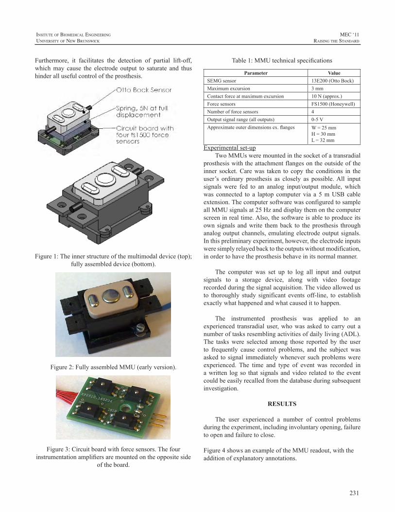
231
InsItute of BIomedIcal engIneerIng
unIversIty of new BrunswIck
MEC ‘11raIsIng the standard
Furthermore, it facilitates the detection of partial lift-off,whichmay cause the electrode output to saturate and thushinderallusefulcontroloftheprosthesis.
Figure1:Theinnerstructureofthemultimodaldevice(top);fullyassembleddevice(bottom).
Figure2:FullyassembledMMU(earlyversion).
Figure3:Circuitboardwithforcesensors.Thefourinstrumentationamplifiersaremountedontheoppositeside
oftheboard.
Table1:MMUtechnicalspecifications
Parameter ValueSEMGsensor 13E200(OttoBock)Maximumexcursion 3mmContactforceatmaximumexcursion 10N(approx.)Forcesensors FS1500(Honeywell)Numberofforcesensors 4Outputsignalrange(alloutputs) 0-5VApproximateouterdimensionsex.flanges W=25mm
H=30mmL=32mm
Experimentalset-upTwoMMUsweremountedinthesocketofatransradial
prosthesiswiththeattachmentflangesontheoutsideoftheinner socket.Carewas taken to copy the conditions in theuser’s ordinary prosthesis as closely as possible.All inputsignals were fed to an analog input/output module, whichwas connected to a laptop computer via a 5mUSB cableextension.ThecomputersoftwarewasconfiguredtosampleallMMUsignalsat25Hzanddisplaythemonthecomputerscreeninrealtime.Also,thesoftwareisabletoproduceitsown signals andwrite themback to theprosthesis throughanalogoutputchannels,emulatingelectrodeoutputsignals.Inthispreliminaryexperiment,however,theelectrodeinputsweresimplyrelayedbacktotheoutputswithoutmodification,inordertohavetheprosthesisbehaveinitsnormalmanner.
The computer was set up to log all input and outputsignals to a storage device, along with video footagerecordedduringthesignalacquisition.Thevideoallowedusto thoroughly study significant events off-line, to establishexactlywhathappenedandwhatcausedittohappen.
The instrumented prosthesis was applied to anexperienced transradialuser,whowasasked tocarryoutanumberoftasksresemblingactivitiesofdailyliving(ADL).The taskswere selected among those reported by the userto frequently cause control problems, and the subject wasasked tosignal immediatelywheneversuchproblemswereexperienced. The time and type of event was recorded inawritten log so that signals andvideo related to theeventcouldbeeasilyrecalledfromthedatabaseduringsubsequentinvestigation.
RESULTS
The user experienced a number of control problemsduringtheexperiment,includinginvoluntaryopening,failuretoopenandfailuretoclose.
Figure4showsanexampleoftheMMUreadout,withtheadditionofexplanatoryannotations.
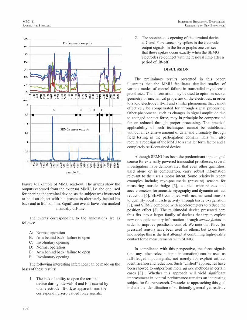
232
MEC ‘11raIsIng the standard
InsItute of BIomedIcal engIneerIng
unIversIty of new BrunswIck
Sample No.
Force sensor outputs
SEMG sensor outputs
A B C D E F
Figure4:ExampleofMMUread-out.ThegraphsshowtheoutputscapturedfromtheextensorMMU,i.e.theoneusedforopeningtheterminaldevice,asthesubjectwasinstructedtoholdanobjectwithhisprosthesis alternatelybehindhisbackandinfrontofhim.Significanteventshavebeenmarked
manuallyoff-line.
The events corresponding to the annotations are asfollows:
A: NormaloperationB: Armbehindback;failuretoopenC: InvoluntaryopeningD: NormaloperationE: Armbehindback;failuretoopenF: Involuntaryopening
Thefollowinginterestinginferencescanbemadeonthebasisoftheseresults:
1. ThelackofabilitytoopentheterminaldeviceduringintervalsBandEiscausedbytotalelectrodelift-off,asapparentfromthecorrespondingzerovaluedforcesignals.
2. ThespontaneousopeningoftheterminaldeviceatCandFarecausedbyspikesintheelectrodeoutputsignals.IntheforcegraphsonecanseethatthesespikesoccurexactlywhentheSEMGelectrodesre-connectwiththeresiduallimbafteraperiodoflift-off.
DISCUSSION
The preliminary results presented in this paper,illustrates that the MMU facilitates detailed studies ofvariousmodes of control failure in transradialmyoelectricprostheses.Thisinformationmaybeusedtooptimizesocketgeometryormechanicalpropertiesoftheelectrodes,inordertoavoidelectrodelift-offandsimilarphenomenathatcannoteffectively be compensated for through signal processing.Otherphenomena,suchaschangesinsignalamplitudeduetochangedcontact force,mayinprinciplebecompensatedfor or reduced through proper processing. The practicalapplicability of such techniques cannot be establishedwithoutanextensiveamountofdata,andultimatelythroughfield testing in the participation domain. This will alsorequirearedesignoftheMMUtoasmallerformfactorandacompletelyself-containeddevice.
AlthoughSEMGhasbeenthepredominantinputsignalsourceforexternallypoweredtransradialprostheses,severalinvestigators have demonstrated that even other quantities,used alone or in combination, carry robust informationrelevant to the user’smotor intent. Some relatively recentexamples include; myo-pneumatic (pressure) sensors formeasuring muscle bulge [5], coupled microphones andaccelerometersforacousticmyographyanddynamicartifactreduction [6], SEMG combinedwith near-infrared sensorstoquantifylocalmuscleactivitythroughtissueoxygenation[7],andSEMGcombinedwithaccelerometerstoreducetheposition effect [8]. The multimodal device presented herethus fits into a larger family of devices that try to exploitneworsupplementaryinformationthroughsensorfusioninorder to improveprosthesis control.Wenote that force (orpressure)sensorshavebeenusedbyothers,but toourbestknowledgethisisthefirstattemptatcombininghigh-qualitycontactforcemeasurementswithSEMG.
In compliance with this perspective, the force signals(and any other relevant input information) can be used asfull-fledged input signals, not merely for explicit artifactidentificationandreduction.Such“unified”approacheshavebeenshowedtooutperformmoreadhocmethodsincertaincases [8] . Whether this approach will yield significantimprovementincontrolperformanceremainsaninterestingsubjectforfutureresearch.Obstaclestoapproachingthisgoalincludetheidentificationofsufficientlygeneralyetrealistic
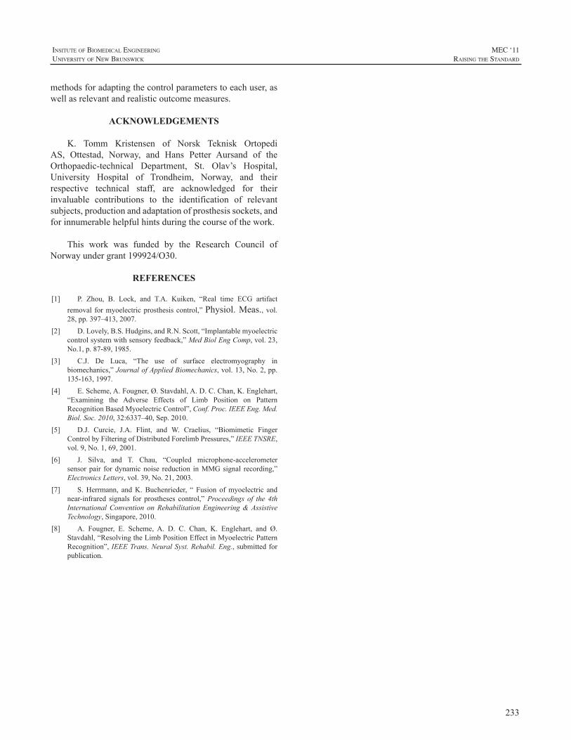
233
InsItute of BIomedIcal engIneerIng
unIversIty of new BrunswIck
MEC ‘11raIsIng the standard
methodsforadaptingthecontrolparameterstoeachuser,aswellasrelevantandrealisticoutcomemeasures.
ACKNOWLEDGEMENTS
K. Tomm Kristensen of Norsk Teknisk OrtopediAS, Ottestad, Norway, and Hans Petter Aursand of theOrthopaedic-technical Department, St. Olav’s Hospital,University Hospital of Trondheim, Norway, and theirrespective technical staff, are acknowledged for theirinvaluable contributions to the identification of relevantsubjects,productionandadaptationofprosthesissockets,andforinnumerablehelpfulhintsduringthecourseofthework.
This work was funded by the Research Council ofNorwayundergrant199924/O30.
REFERENCES
[1] P. Zhou, B. Lock, and T.A. Kuiken, “Real time ECG artifactremoval formyoelectricprosthesiscontrol,”Physiol.Meas.,vol.28,pp.397–413,2007.
[2] D.Lovely,B.S.Hudgins,andR.N.Scott,“Implantablemyoelectriccontrolsystemwithsensoryfeedback,”MedBiolEngComp,vol.23,No.1,p.87-89,1985.
[3] C.J. De Luca, “The use of surface electromyography inbiomechanics,”JournalofAppliedBiomechanics,vol.13,No.2,pp.135-163,1997.
[4] E.Scheme,A.Fougner,Ø.Stavdahl,A.D.C.Chan,K.Englehart,“Examining the Adverse Effects of Limb Position on PatternRecognitionBasedMyoelectricControl”,Conf.Proc.IEEEEng.Med.Biol.Soc.2010,32:6337–40,Sep.2010.
[5] D.J. Curcie, J.A. Flint, and W. Craelius, “Biomimetic FingerControlbyFilteringofDistributedForelimbPressures,”IEEETNSRE,vol.9,No.1,69,2001.
[6] J. Silva, and T. Chau, “Coupled microphone-accelerometersensorpair fordynamicnoise reduction inMMGsignal recording,”ElectronicsLetters,vol.39,No.21,2003.
[7] S.Herrmann, andK.Buchenrieder, “ Fusion ofmyoelectric andnear-infrared signals for prostheses control,”Proceedings of the 4thInternationalConvention onRehabilitationEngineering&AssistiveTechnology,Singapore,2010.
[8] A. Fougner, E. Scheme, A. D. C. Chan, K. Englehart, and Ø.Stavdahl,“ResolvingtheLimbPositionEffectinMyoelectricPatternRecognition”,IEEETrans.NeuralSyst.Rehabil.Eng.,submittedforpublication.
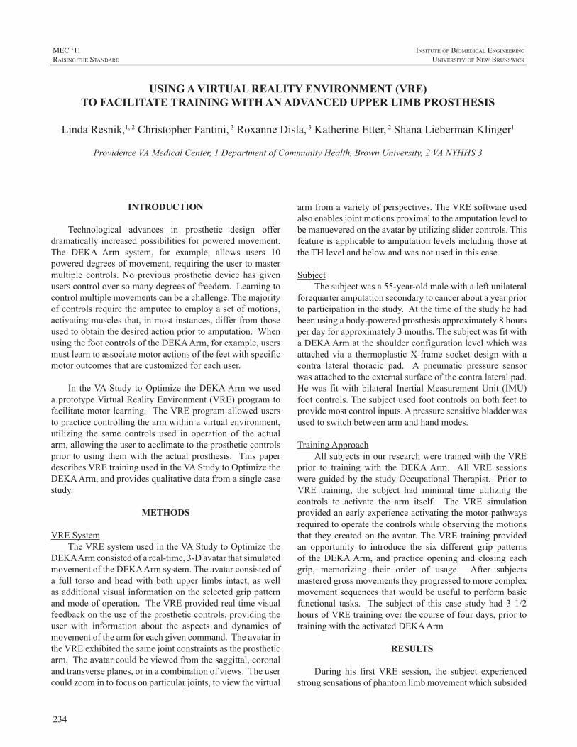
234
MEC ‘11raIsIng the standard
InsItute of BIomedIcal engIneerIng
unIversIty of new BrunswIck
INTRODUCTION
Technological advances in prosthetic design offerdramaticallyincreasedpossibilitiesforpoweredmovement.The DEKA Arm system, for example, allows users 10powereddegreesofmovement,requiringtheusertomastermultiple controls.No previous prosthetic device has givenuserscontroloversomanydegreesoffreedom.Learningtocontrolmultiplemovementscanbeachallenge.Themajorityofcontrolsrequiretheamputeetoemployasetofmotions,activatingmusclesthat,inmostinstances,differfromthoseusedtoobtainthedesiredactionpriortoamputation.WhenusingthefootcontrolsoftheDEKAArm,forexample,usersmustlearntoassociatemotoractionsofthefeetwithspecificmotoroutcomesthatarecustomizedforeachuser.
In theVAStudy toOptimize theDEKAArmweusedaprototypeVirtualRealityEnvironment(VRE)programtofacilitatemotor learning. TheVREprogramalloweduserstopracticecontrollingthearmwithinavirtualenvironment,utilizing the same controls used in operation of the actualarm,allowingtheusertoacclimatetotheprostheticcontrolsprior to using themwith the actual prosthesis. This paperdescribesVREtrainingusedintheVAStudytoOptimizetheDEKAArm,andprovidesqualitativedatafromasinglecasestudy.
METHODS
VRESystemTheVREsystemusedintheVAStudytoOptimizethe
DEKAArmconsistedofareal-time,3-DavatarthatsimulatedmovementoftheDEKAArmsystem.Theavatarconsistedofa full torso andheadwithbothupper limbs intact, aswellasadditionalvisualinformationontheselectedgrippatternandmodeofoperation.TheVREprovidedrealtimevisualfeedbackontheuseoftheprostheticcontrols,providingtheuser with information about the aspects and dynamics ofmovementofthearmforeachgivencommand.TheavatarintheVREexhibitedthesamejointconstraintsastheprostheticarm.Theavatarcouldbeviewedfromthesaggittal,coronalandtransverseplanes,orinacombinationofviews.Theusercouldzoomintofocusonparticularjoints,toviewthevirtual
armfromavarietyofperspectives.TheVREsoftwareusedalsoenablesjointmotionsproximaltotheamputationleveltobemanueveredontheavatarbyutilizingslidercontrols.ThisfeatureisapplicabletoamputationlevelsincludingthoseattheTHlevelandbelowandwasnotusedinthiscase.
SubjectThesubjectwasa55-year-oldmalewithaleftunilateral
forequarteramputationsecondarytocanceraboutayearpriortoparticipationinthestudy.Atthetimeofthestudyhehadbeenusingabody-poweredprosthesisapproximately8hoursperdayforapproximately3months.ThesubjectwasfitwithaDEKAArmattheshoulderconfigurationlevelwhichwasattached via a thermoplasticX-frame socket designwith acontra lateral thoracic pad. A pneumatic pressure sensorwasattachedtotheexternalsurfaceofthecontralateralpad.Hewas fitwithbilateral InertialMeasurementUnit (IMU)footcontrols.Thesubjectusedfootcontrolsonbothfeettoprovidemostcontrolinputs.Apressuresensitivebladderwasusedtoswitchbetweenarmandhandmodes.
TrainingApproachAllsubjectsinourresearchweretrainedwiththeVRE
prior to training with the DEKAArm. All VRE sessionswereguidedby thestudyOccupationalTherapist. Prior toVRE training, the subject had minimal time utilizing thecontrols to activate the arm itself. The VRE simulationprovidedanearlyexperienceactivatingthemotorpathwaysrequiredtooperatethecontrolswhileobservingthemotionsthat theycreatedon theavatar.TheVREtrainingprovidedan opportunity to introduce the six different grip patternsof theDEKAArm, and practice opening and closing eachgrip, memorizing their order of usage. After subjectsmasteredgrossmovementstheyprogressedtomorecomplexmovementsequencesthatwouldbeusefultoperformbasicfunctional tasks. The subject of this case study had 3 1/2hoursofVREtrainingoverthecourseoffourdays,priortotrainingwiththeactivatedDEKAArm
RESULTS
During his firstVRE session, the subject experiencedstrongsensationsofphantomlimbmovementwhichsubsided
USING A VIRTUAL REALITY ENVIRONMENT (VRE) TO FACILITATE TRAINING WITH AN ADVANCED UPPER LIMB PROSTHESIS
LindaResnik,1,2ChristopherFantini,3RoxanneDisla,3KatherineEtter,2ShanaLiebermanKlinger1
ProvidenceVAMedicalCenter,1DepartmentofCommunityHealth,BrownUniversity,2VANYHHS3
235
InsItute of BIomedIcal engIneerIng
unIversIty of new BrunswIck
MEC ‘11raIsIng the standard
insubsequentsessions.Becauseoftheprototypedatatransferapproaches used in the version of theDEKAArm thatweweretesting,smallvariationsinmovementandtimingexistedbetweenresponsivenessoftheavatarandtheactualDEKAArmwhichwerenoticeabletothesubject.Nevertheless,theVREsimulationprovidedanearlyexperienceofactivatingthemotorpathwaysrequiredtooperatethecontrolsandtheopportunity to see resultantmovements of the virtual arm.Bytheendofstudy,thesubjectwasacompetentuseroftheDEKAArmandperformedmanyfunctionalandrecreationalactivities.ThestudystaffandsubjectbelievedthattheVREwasavaluabletoolinlearningtousetheDEKAArmcontrols.
IMPLICATIONS/CONCLUSION
WeconcludedthattrainingwiththeVREmadelearningtouseacomplexsetofprostheticcontrolseasier,howeverwehadnowaytotestthishypothesisgivenourstudydesigns.Futurestudiesareneeded toevaluate thespeedof learningto use complex controlswith andwithout the use ofVREsoftware.
ACKNOWLEDGEMENTS
ThisresearchwassupportedbyVARR&D,VARR&DA6780 and VA RR&D A6780I. DEKA’s support of theVA optimization studies was sponsored by the DefenseAdvanced Research Projects Agency and the U.S. ArmyResearchOffice.Theinformationinthismanuscriptdoesnotnecessarilyreflectthepositionorpolicyofthegovernment;noofficialendorsementshouldbeinferred.
The authors acknowledge the valuable work of studycoordinatorKateBarnabe,andmembersoftheresearchteamattheVANYHHS:NicoleSasson,sitePrincipalInvestigator,KenBreuer, prosthetist, andMaryanneGarbarini, researchassistant.
236
MEC ‘11raIsIng the standard
InsItute of BIomedIcal engIneerIng
unIversIty of new BrunswIck
ABSTRACT
With many pieces of literature that debate whetherchildren with upper extremity limb deficiencies should befittedwithupperextremityprostheses(Biddis&Chau,2007;Biddis&Chau,2008; Jameset al., 2006;Wagner,Bagley,James,2007),itremainsuncertainwhyadultswithcongenitalupperextremity limb losscontinue towearprostheses intoadulthood.Ourchildhoodstoriescontaindetailsofhowwehavebecomethepersonswearetoday(Clark,1993).Whatchildhoodexperienceshaveinfluencedadultswithunilateralcongenital below elbow deficiency (UCBED) to continueto wear a prosthesis? This study used qualitativemethodsto capture childhood experiences that have impacted thelivesofadultswhocurrentlywearabelowelbowprosthesis.A phenomenological approach using in-depth narrativeinterviewsofthreeadultswithUCBEDtargeted1)positiveandnegativestories rememberedfromchildhood2)storiesrelated to use and non-use of the prosthesis, 3) perceivedquality of life and identity, and 4) influences to wear aprosthesis.Analysesof these interviews resulted in themesconsistingoftheparticipants’backgrounds,growingupandcopingwith“factsoflife”,howtheindividualscontinuetocopeasadults,theinfluencestowearaprosthesis,andeachindividual’s personal recommendations for families with achildwithUCBED.
GROWING UP WITH UNILATERAL CONGENITAL BELOW ELBOW DEFICIENCY: A QUALITATIVE STUDY OF INDIVIDUALS WHO CURRENTLY WEAR A PROSTHESIS
VivianJ.YipOTD,MA,OTR/L
ChildAmputeeProstheticsProject,Shriner’sHospitalsforChildren-LosAngelesDepartmentofOccupationalScienceandOccupationalTherapy,UniversityofSouthernCalifornia
237
InsItute of BIomedIcal engIneerIng
unIversIty of new BrunswIck
MEC ‘11raIsIng the standard
ABSTRACT
Myoelectric prostheses offer great potential ofrehabilitation for amputees. However, a main drawbacktowardthisachievementliesinthecontrolalgorithms,whichare unable to reliably translate the user’s intention to thearticulators(prosthesismotors)inanintuitivefashion.Thisstudyispartofanon-goingproject,todevelopanalternativeapproach for myoelectric control, by de-correlating thepattern recognition classes and the actual position of thehand.Itfocusesonmovementonsetdetectionoftwodegreesof freedom from the hand and wrist complex, in variouspositions. With 6 channels of surface electromyogram(sEMG)mounted on the forearm, 4 healthy subjects wereinstructed to perform random sequences of movementswith low level of contractions without returning to therest position. A detection method was developed using areferencebufferandtheenergyvariationsinthesEMG.Theresultsshowthataccuratedetectionofthemovementonsetcanbeachievedregardlessoftheactualpositionofthehandwithinareasonabledelay.Thisonsetdetectionmethodisthefirststeptowardastate-basedcontrolschemeformyoelectriccontrol. Further work will use this detection method totriggeraclassificationalgorithmanddeterminethetargetofthemovement.
INTRODUCTION
The surface electromyograms (sEMG) can be non-invasivelyrecordedfromtheskinsurface,andrepresenttheactivityofthemusclefibresinthesurroundingarea.Theyareeasytoacquire,andsincetheyhaveshowntobeanefficientway tocontrolpoweredprostheses [1], theyattractedgreatinterest in the past decades.The state of the art formulti-functionprosthesesismainlybasedonthepatternrecognitionapproach. A large variety of algorithms [2-3] have beeninvestigatedforbothmovementclassificationandhand/wristanglesestimation,bothshowingverypromisingperformance[4-5].However,thepatternrecognitionapproachassumesthatdifferenttypesofmotioncanbeassociatedtodistinguishable
and consistent signal patterns in the surface EMG. Thisassumption,whichcanbetrueinverycontrolledlaboratorysettings, could be challenged in more realistic conditions.Thisisoneofthemaingapsbetweentheacademiastate-of-the-artandindustrialstate-of-the-art.
Various commercial powered prostheses are actuallyavailable for upper limb amputees; however their controlscheme is rather basic due to the lack of reliability of themoreadvancedmethods.Theymainlyallowcontrollingtwodegreesoffreedoms,withanunintuitiveswitchingmethod,forexampleco-contraction,toswitchbetweenthearticulateddegreesoffreedom(DOF).
Theaimof this study is to reproduce theperformanceof such switchbased algorithm,without the limitation andrestrictions of the co-contractions.A state-based algorithmis being developed providing the control of one degree offreedomatatime,butofferingamorenaturalapproachwhenswitchingbetweenthedifferentarticulatedDOFs.Thisstate-based control scheme relies on two main algorithms: theswitchdetectionandthetargetdecision.
The following of this paper introduces the switchdetectionalgorithmandreportsitsperformanceonmovementonsetdetectioninvariouspositionsofthehandandwrist.
METHODS
SubjectsFour healthy subjects (3males, 1 female) participated
intheexperiment.Allsubjectsgavetheirinformedconsentprior participation to the experiment, and the procedureswereapprovedbythelocalethicscommittee.
ProceduresTheexperimentfocusedon2degreesoffreedom(DoF)
ofthehandandwrist:Supination/Pronationoftheforearm,andClosing/Openingofthehand,asthesearethearticulatedDOFs of the commercial prosthesis the project isworking
MOVEMENT ONSET DETECTION IN VARIOUS POSITIONS FOR STATE-BASED MYO-CONTROL SCHEME
T.Lorrain1,I.K.Niazi1,N.Jiang2,3,D.Farina3
1CenterforSensory-MotorInteraction,DepartmentofHealthScienceandTechnology,AalborgUniversity,Aalborg,Denmark.
2OttoBockHealthCareGmbH,StrategicTechnologyManagement,Max-Näder-Str.15,D-37115Duderstadt,Germany3DepartmentofNeurorehabilitationEngineering,BernsteinCenterforComputationalNeuroscience,UniversityMedical
CenterGöttingen
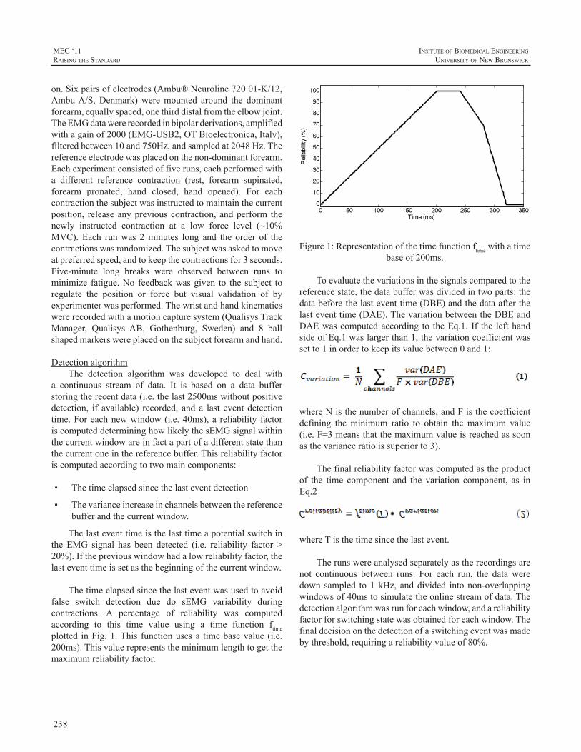
238
MEC ‘11raIsIng the standard
InsItute of BIomedIcal engIneerIng
unIversIty of new BrunswIck
on.Sixpairsofelectrodes(Ambu®Neuroline72001-K/12,AmbuA/S,Denmark)weremounted around the dominantforearm,equallyspaced,onethirddistalfromtheelbowjoint.TheEMGdatawererecordedinbipolarderivations,amplifiedwithagainof2000(EMG-USB2,OTBioelectronica,Italy),filteredbetween10and750Hz,andsampledat2048Hz.Thereferenceelectrodewasplacedonthenon-dominantforearm.Eachexperimentconsistedoffiveruns,eachperformedwitha different reference contraction (rest, forearm supinated,forearm pronated, hand closed, hand opened). For eachcontractionthesubjectwasinstructedtomaintainthecurrentposition, releaseanypreviouscontraction,andperform thenewly instructed contraction at a low force level (~10%MVC). Each runwas 2minutes long and the order of thecontractionswasrandomized.Thesubjectwasaskedtomoveatpreferredspeed,andtokeepthecontractionsfor3seconds.Five-minute long breaks were observed between runs tominimize fatigue.No feedbackwasgiven to the subject toregulate the position or force but visual validation of byexperimenterwasperformed.Thewristandhandkinematicswererecordedwithamotioncapturesystem(QualisysTrackManager, Qualisys AB, Gothenburg, Sweden) and 8 ballshapedmarkerswereplacedonthesubjectforearmandhand.
DetectionalgorithmThe detection algorithm was developed to deal with
a continuous stream of data. It is based on a data bufferstoringtherecentdata(i.e.thelast2500mswithoutpositivedetection, if available) recorded, and a last event detectiontime.Foreachnewwindow(i.e.40ms),a reliability factoriscomputeddetermininghowlikelythesEMGsignalwithinthecurrentwindowareinfactapartofadifferentstatethanthecurrentoneinthereferencebuffer.Thisreliabilityfactoriscomputedaccordingtotwomaincomponents:
• Thetimeelapsedsincethelasteventdetection
• Thevarianceincreaseinchannelsbetweenthereferencebufferandthecurrentwindow.
Thelasteventtimeisthelasttimeapotentialswitchinthe EMG signal has been detected (i.e. reliability factor >20%).Ifthepreviouswindowhadalowreliabilityfactor,thelasteventtimeissetasthebeginningofthecurrentwindow.
Thetimeelapsedsincethelasteventwasusedtoavoidfalse switch detection due do sEMG variability duringcontractions. A percentage of reliability was computedaccording to this time value using a time function ftimeplotted inFig.1.This functionusesa timebasevalue (i.e.200ms).Thisvaluerepresentstheminimumlengthtogetthemaximumreliabilityfactor.
Figure1:Representationofthetimefunctionftimewithatimebaseof200ms.
Toevaluatethevariationsinthesignalscomparedtothereferencestate,thedatabufferwasdividedintwoparts:thedatabeforethelasteventtime(DBE)andthedataafterthelasteventtime(DAE).ThevariationbetweentheDBEandDAEwascomputedaccording to theEq.1. If the lefthandsideofEq.1waslargerthan1,thevariationcoefficientwassetto1inordertokeepitsvaluebetween0and1:
whereNisthenumberofchannels,andFisthecoefficientdefining theminimum ratio to obtain themaximum value(i.e.F=3meansthatthemaximumvalueisreachedassoonasthevarianceratioissuperiorto3).
Thefinalreliabilityfactorwascomputedastheproductof the time component and the variation component, as inEq.2
whereTisthetimesincethelastevent.
Therunswereanalysedseparatelyastherecordingsarenot continuous between runs. For each run, the data weredownsampled to1kHz, anddivided intonon-overlappingwindowsof40mstosimulatetheonlinestreamofdata.Thedetectionalgorithmwasrunforeachwindow,andareliabilityfactorforswitchingstatewasobtainedforeachwindow.Thefinaldecisiononthedetectionofaswitchingeventwasmadebythreshold,requiringareliabilityvalueof80%.
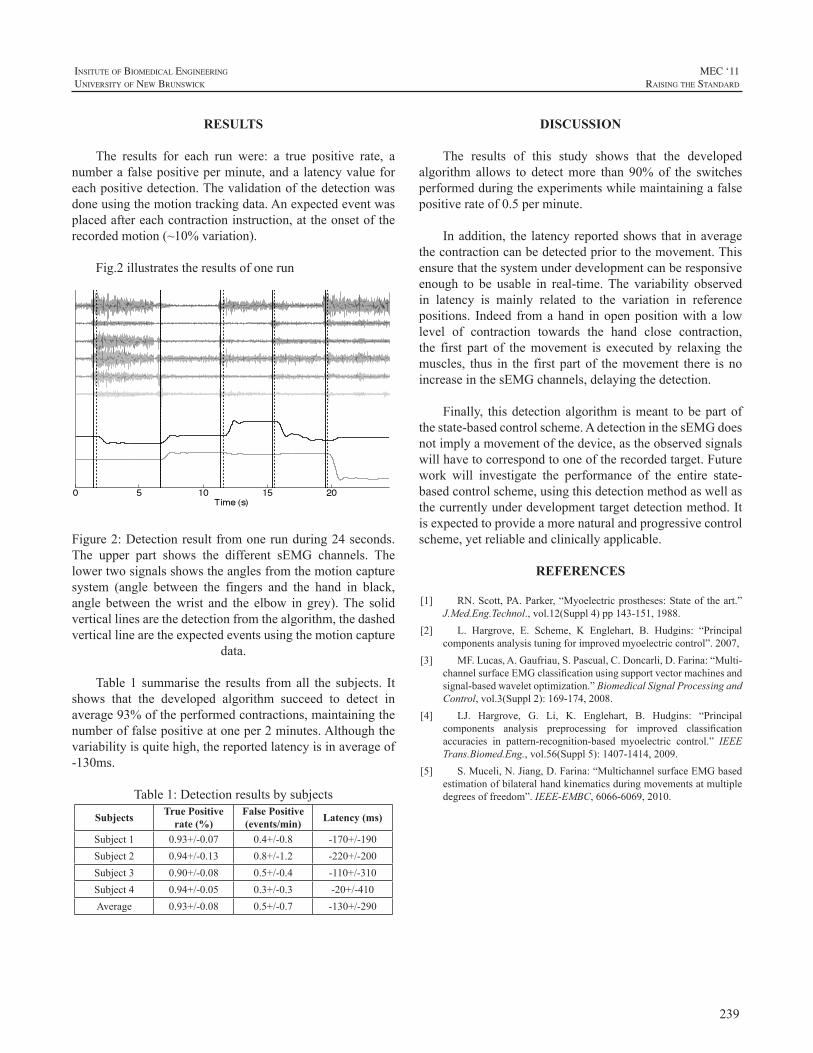
239
InsItute of BIomedIcal engIneerIng
unIversIty of new BrunswIck
MEC ‘11raIsIng the standard
RESULTS
The results for each run were: a true positive rate, anumberafalsepositiveperminute,andalatencyvalueforeachpositivedetection.Thevalidationofthedetectionwasdoneusingthemotiontrackingdata.Anexpectedeventwasplacedaftereachcontractioninstruction,attheonsetoftherecordedmotion(~10%variation).
Fig.2illustratestheresultsofonerun
Figure2:Detectionresultfromonerunduring24seconds.The upper part shows the different sEMG channels. Thelowertwosignalsshowstheanglesfromthemotioncapturesystem (angle between the fingers and the hand in black,angle between thewrist and the elbow in grey).The solidverticallinesarethedetectionfromthealgorithm,thedashedverticallinearetheexpectedeventsusingthemotioncapture
data.
Table 1 summarise the results fromall the subjects. Itshows that the developed algorithm succeed to detect inaverage93%oftheperformedcontractions,maintainingthenumberoffalsepositiveatoneper2minutes.Althoughthevariabilityisquitehigh,thereportedlatencyisinaverageof-130ms.
Table1:Detectionresultsbysubjects
Subjects True Positive rate (%)
False Positive (events/min) Latency (ms)
Subject1 0.93+/-0.07 0.4+/-0.8 -170+/-190Subject2 0.94+/-0.13 0.8+/-1.2 -220+/-200Subject3 0.90+/-0.08 0.5+/-0.4 -110+/-310Subject4 0.94+/-0.05 0.3+/-0.3 -20+/-410Average 0.93+/-0.08 0.5+/-0.7 -130+/-290
DISCUSSION
The results of this study shows that the developedalgorithm allows to detectmore than 90%of the switchesperformedduringtheexperimentswhilemaintainingafalsepositiverateof0.5perminute.
Inaddition, the latencyreportedshows that inaveragethecontractioncanbedetectedpriortothemovement.Thisensurethatthesystemunderdevelopmentcanberesponsiveenough to be usable in real-time.The variability observedin latency is mainly related to the variation in referencepositions. Indeed fromahand inopenpositionwith a lowlevel of contraction towards the hand close contraction,the first part of themovement is executed by relaxing themuscles, thus in the first partof themovement there isnoincreaseinthesEMGchannels,delayingthedetection.
Finally, thisdetectionalgorithm ismeant tobepartofthestate-basedcontrolscheme.AdetectioninthesEMGdoesnotimplyamovementofthedevice,astheobservedsignalswillhavetocorrespondtooneoftherecordedtarget.Futurework will investigate the performance of the entire state-basedcontrolscheme,usingthisdetectionmethodaswellasthecurrentlyunderdevelopmenttargetdetectionmethod.Itisexpectedtoprovideamorenaturalandprogressivecontrolscheme,yetreliableandclinicallyapplicable.
REFERENCES
[1] RN.Scott,PA.Parker,“Myoelectricprostheses:Stateof theart.”J.Med.Eng.Technol.,vol.12(Suppl4)pp143-151,1988.
[2] L. Hargrove, E. Scheme, K Englehart, B. Hudgins: “Principalcomponentsanalysistuningforimprovedmyoelectriccontrol”.2007,
[3] MF.Lucas,A.Gaufriau,S.Pascual,C.Doncarli,D.Farina:“Multi-channelsurfaceEMGclassificationusingsupportvectormachinesandsignal-basedwaveletoptimization.”BiomedicalSignalProcessingandControl,vol.3(Suppl2):169-174,2008.
[4] LJ. Hargrove, G. Li, K. Englehart, B. Hudgins: “Principalcomponents analysis preprocessing for improved classificationaccuracies in pattern-recognition-based myoelectric control.” IEEETrans.Biomed.Eng.,vol.56(Suppl5):1407-1414,2009.
[5] S.Muceli,N.Jiang,D.Farina:“MultichannelsurfaceEMGbasedestimationofbilateralhandkinematicsduringmovementsatmultipledegreesoffreedom”.IEEE-EMBC,6066-6069,2010.
240
MEC ‘11raIsIng the standard
InsItute of BIomedIcal engIneerIng
unIversIty of new BrunswIck
INTRODUCTION
This paper focuses on the assessment and validationoftheUNBtestofprostheticsfunction.Thereisaconstantneedtostayuptodatewithformsofassessment,asassistivedevices become more intuitive and precise enablingbetter control and movement. Due to these advancementsin therapy, technology, and education, the UNB test ofprostheticsfunctionissubjecttoredesigninordertobetterevaluatetheusage,function,andtrainingofpresentdayusersofprostheticarms.Theaimofthisstudyistore-evaluatethecurrentprotocoltodetermineanymodificationsthatmaybenecessarytocomplywithcurrentstandardsofpractice.Therevisedtestwillthenbevalidatedthroughtheuseofvariousclinicsandusers.
THE UNB TEST
The UNB test assesses function with upper limbprosthesesandwasdesignedtobesimple,quicktoadminister,takingapproximately30-45minutestosetup,completeandscoreasubtest.Therearethreesubtestsof10tasksallowingtestretestwhichremovesconcernsoverlearningeffects.Thetestallowsthechildtoperformhis/hertaskatanunhurriedpace.TheUNBtestiswellknownclinicallyandmakesanassessmentusing10developmentallybased,age-appropriateactivitiesforchildrenagedfrom2-13years.Itmeasuresthespontaneityandskillofusewitheitherconventional(body-powered, passive) or myoelectric prostheses, by a trainedobserver.This particular testwas created in 1985, and hasbeenemployedbycliniciansandresearchers,andusedasastandardofcomparisontonewlycreatedevaluationsofupperlimbprosthetic use [1].Upper limbprosthetic assessmentsare integral to the rehabilitation process where maximalfunctionalabilityandindependenceathome,inschool,andinthecommunityaretheprimaryconcerns.
ThenewanalysisoftheUNBtestwillbebrokendowntoreviewingsinglecomponentsincluding;culturebias,genderbias, types of grasps, task classification and distribution,progressionofchilddevelopmentbetweenagegroups,andceiling effects within age groups. These are variables thatinfluencethefunctionaloutcomesofatest.Oneofthemain
criticisms of outcomemeasures that classify categories offunction, assessed by clinicians’ observed reports, is thatcategoriesmaynothavespecificrelevancetotheindividuals’lifestylesordailyroutines[2].Someactivitiesofdailylivinghavechangedover the last twodecades,andsoshould themethodsofassessingtheseactivitiesbealteredaswell.
Choosing the most appropriate outcome measure(s),and having a clear understanding of their strengths andlimitations,isimportantinbothclinicalandresearchterms[3]Thescoringmethodwillmost likely remainasevaluationsofskillandspontaneity.Anoutcomeofsuccessfulprostheticuseisdefinedasapersonwhodisplaysexcellentproficiency(skill=4)andwillingness(spontaneity=4)whenusingtheirprostheticlimb.Apooroutcomeofprostheticuseisdefinedasapersonwhodisplaysseveredifficultywhenattemptingtoperformthetaskathand(skill=0)and/orrefusaltoengage(spontaneity=0)theprostheticlimbtocompletetherequiredtask.
In the period before 6 years of age there is rapiddevelopment and practice of many new skills, whereasafter this age the focus tends to be on perfection of skills[4].Thornby et al [5] also found delay in development ofbimanual skills in children with below elbow amputation.Once themodifiedage rangeshavebeenestablished, therewill be the need to identify any discrepancies in transitionphasesfromoneagegrouptothenext.Aceilingeffectshouldbe included in each subtest to decrease the likelihoodof ayoungerchildperformingtasksfoundinanolderagegroupwithease.
Afterfeedbackfromclinicalpractitioners,modificationsto the activities for each age-specific subtestwill bemadewhilemaintainingequality in taskdistributionbetween thethree subtests of the corresponding age groups. Differentpatternsofprehensilemotionwillbeclassified;
1.Passiveuseofthehand
2.Maintainedgraspofanobject
3.Maintenanceofthegraspwhilethepersonisinmotion
ASSESSMENT AND VALIDATION OF THE UNB TEST OF PROSTHETICS FUNCTION
EricKarosan1,UshaKuruganti1,WendyHill1-2,PeterKyberd2
1FacultyofKinesiology,UniversityofNewBrunswick,Fredericton,NB,Canada2InstituteofBiomedicalEngineering,UniversityofNewBrunswick,Fredericton,NB,Canada
241
InsItute of BIomedIcal engIneerIng
unIversIty of new BrunswIck
MEC ‘11raIsIng the standard
4.Repetitive grasp and release of an object duringactivities
5.Performing grasp and release of the object in anyposition
6.Theabilitytograspandreleasedelicateobject
7.Thegraspandreleaseofheavyobjects
Theaimisanevendistributionoftheseactivitieswithinandbetweensubtests.Thetestswillbemodified,ifnecessary,toensurethisdistribution.Followingthisitwillbecheckedforvalidity.Alterationstotheagerangesmaybeconsidered,alongwiththepossiblebroadeningofthescopeofevaluationthroughtoteensandadults.
CONCLUSION
Accurateandappropriatetestsarecriticalinenablingthecorrectdesignofprosthesestobematchedtotheuserorfordevelopmentofnewdesigns.Itsuseinprostheticpracticeandresearchenablesstakeholderstounderstandmorefullytheirchoicesfortrainingandprescription.ThereforeinvestigatingthevalidityofamodifiedUNBtestofprostheticfunctionaloutcomesisnecessary.
REFERENCES
[1] E.R.SandersonandR.N.Scott,(1985).“UNBtestofprostheticsfunction: a test for unilateral amputees” [test manual]. Fredericton,NB,Bio-EngineeringInstitute,UniversityofNewBrunwsick
[2] V.Wylde, S. Hewlett, I.D. Learmouth, V.J. Cavendish, (2006).“Personal impact of disability in osteoarthritis: Patient, professionalandpublicvalues.”MusculoskeletalCare.4(3):152-66
[3] A.Long,,D.Scott,(1994).“Measuringhealthstatusandoutcomesin rheumatoid arthritis within routine clinical practice.” Brit. J.Rheumatology.33(7):682-85
[4] K.S. Holt, (1991). “Child Development: Diagnosis andAssessment.”LondonButterworth-Heinemann.
[5] M.A.Thornby,D.E.Krebs,(1992).“Bimanualskilldevelopmentinpaediatricbelow-elbowamputation:Amulticenter,cross-sectionalstudy.”Archives of PhysicalMedicine and Rehabilitation. 73: 697-702.
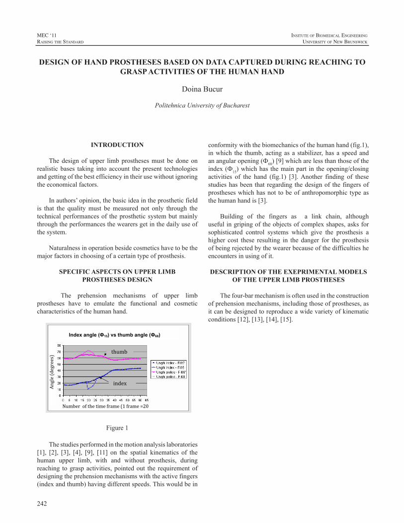
242
MEC ‘11raIsIng the standard
InsItute of BIomedIcal engIneerIng
unIversIty of new BrunswIck
INTRODUCTION
Thedesignof upper limbprosthesesmust be doneonrealistic bases taking into account the present technologiesandgettingofthebestefficiencyintheirusewithoutignoringtheeconomicalfactors.
Inauthors’opinion,thebasicideaintheprostheticfieldis that the qualitymust bemeasured not only through thetechnicalperformancesof theprostheticsystembutmainlythroughtheperformancesthewearersgetinthedailyuseofthesystem.
Naturalnessinoperationbesidecosmeticshavetobethemajorfactorsinchoosingofacertaintypeofprosthesis.
SPECIFIC ASPECTS ON UPPER LIMB PROSTHESES DESIGN
The prehension mechanisms of upper limbprostheses have to emulate the functional and cosmeticcharacteristicsofthehumanhand.
Figure 1
thumb
index
Angle (degrees)
Number of the time frame (1 frame =20 ms)
Index angle (Ф15) vs thumb angle (Ф68)
Figure1
Thestudiesperformedinthemotionanalysislaboratories[1], [2], [3], [4], [9], [11] on the spatial kinematics of thehuman upper limb, with and without prosthesis, duringreaching tograspactivities,pointedout the requirementofdesigningtheprehensionmechanismswiththeactivefingers(indexandthumb)havingdifferentspeeds.Thiswouldbein
thumbindex
conformitywiththebiomechanicsofthehumanhand(fig.1),inwhich the thumb,actingasa stabilizer,hasa speedandanangularopening(Ф68)[9]whicharelessthanthoseoftheindex(Ф15)whichhas themainpart in theopening/closingactivities of the hand (fig.1) [3].Another finding of thesestudieshasbeen that regarding thedesignof thefingersofprostheseswhichhasnot tobeofanthropomorphic typeasthehumanhandis[3].
Building of the fingers as a link chain, althoughusefulingripingoftheobjectsofcomplexshapes,asksforsophisticated control systems which give the prosthesis ahigher cost these resulting in the danger for the prosthesisofbeingrejectedbythewearerbecauseofthedifficultiesheencountersinusingofit.
DESCRIPTION OF THE EXEPRIMENTAL MODELS OF THE UPPER LIMB PROSTHESES
Thefour-barmechanismisoftenusedintheconstructionofprehensionmechanisms,includingthoseofprostheses,asitcanbedesignedtoreproduceawidevarietyofkinematicconditions[12],[13],[14],[15].
DESIGN OF HAND PROSTHESES BASED ON DATA CAPTURED DURING REACHING TO GRASP ACTIVITIES OF THE HUMAN HAND
DoinaBucur
PolitehnicaUniversityofBucharest
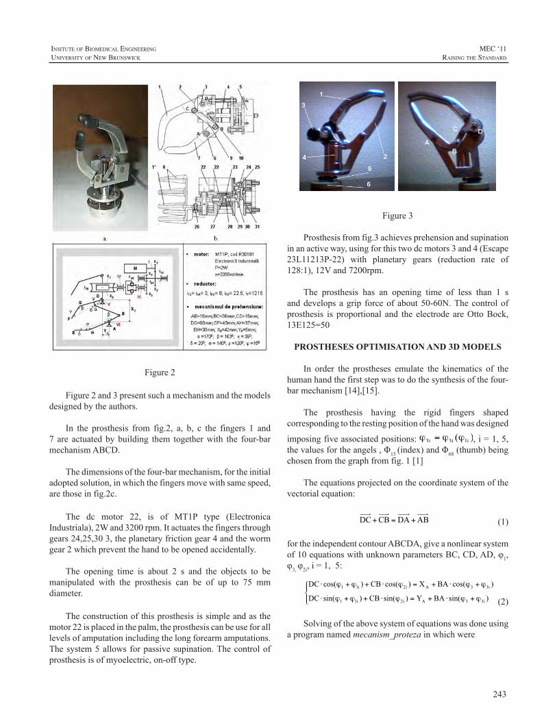
243
InsItute of BIomedIcal engIneerIng
unIversIty of new BrunswIck
MEC ‘11raIsIng the standard
Figure 2 Figure2
Figure2and3presentsuchamechanismandthemodelsdesignedbytheauthors.
In the prosthesis from fig.2, a, b, c the fingers 1 and7 are actuatedbybuilding them togetherwith the four-barmechanismABCD.
Thedimensionsofthefour-barmechanism,fortheinitialadoptedsolution,inwhichthefingersmovewithsamespeed,arethoseinfig.2c.
The dc motor 22, is of MT1P type (ElectronicaIndustriala),2Wand3200rpm.Itactuatesthefingersthroughgears24,25,303,theplanetaryfrictiongear4andthewormgear2whichpreventthehandtobeopenedaccidentally.
The opening time is about 2 s and the objects to bemanipulated with the prosthesis can be of up to 75 mmdiameter.
Theconstructionofthisprosthesisissimpleandasthemotor22isplacedinthepalm,theprosthesiscanbeuseforalllevelsofamputationincludingthelongforearmamputations.Thesystem5allowsforpassivesupination.Thecontrolofprosthesisisofmyoelectric,on-offtype.
Figure2 Figure4Figure3
Figure 3 Figure3
Prosthesisfromfig.3achievesprehensionandsupinationinanactiveway,usingforthistwodcmotors3and4(Escape23L11213P-22) with planetary gears (reduction rate of128:1),12Vand7200rpm.
The prosthesis has an opening time of less than 1 sanddevelopsagrip forceofabout50-60N.Thecontrolofprosthesis is proportional and the electrode areOttoBock,13E125=50
PROSTHESES OPTIMISATION AND 3D MODELS
In order the prostheses emulate the kinematics of thehumanhandthefirststepwastodothesynthesisofthefour-barmechanism[14],[15].
The prosthesis having the rigid fingers shapedcorrespondingtotherestingpositionofthehandwasdesigned
imposingfiveassociatedpositions: ,i=1,5,thevaluesfortheangels,Φ15(index)andΦ68(thumb)beingchosenfromthegraphfromfig.1[1]
Theequationsprojectedonthecoordinatesystemofthevectorialequation:
(1)
fortheindependentcontourABCDA,giveanonlinearsystemof10equationswithunknownparametersBC,CD,AD,φ1,φ3,φ2i,i=1,5:
(2)
Solvingoftheabovesystemofequationswasdoneusingaprogramnamedmecanism_protezainwhichwere
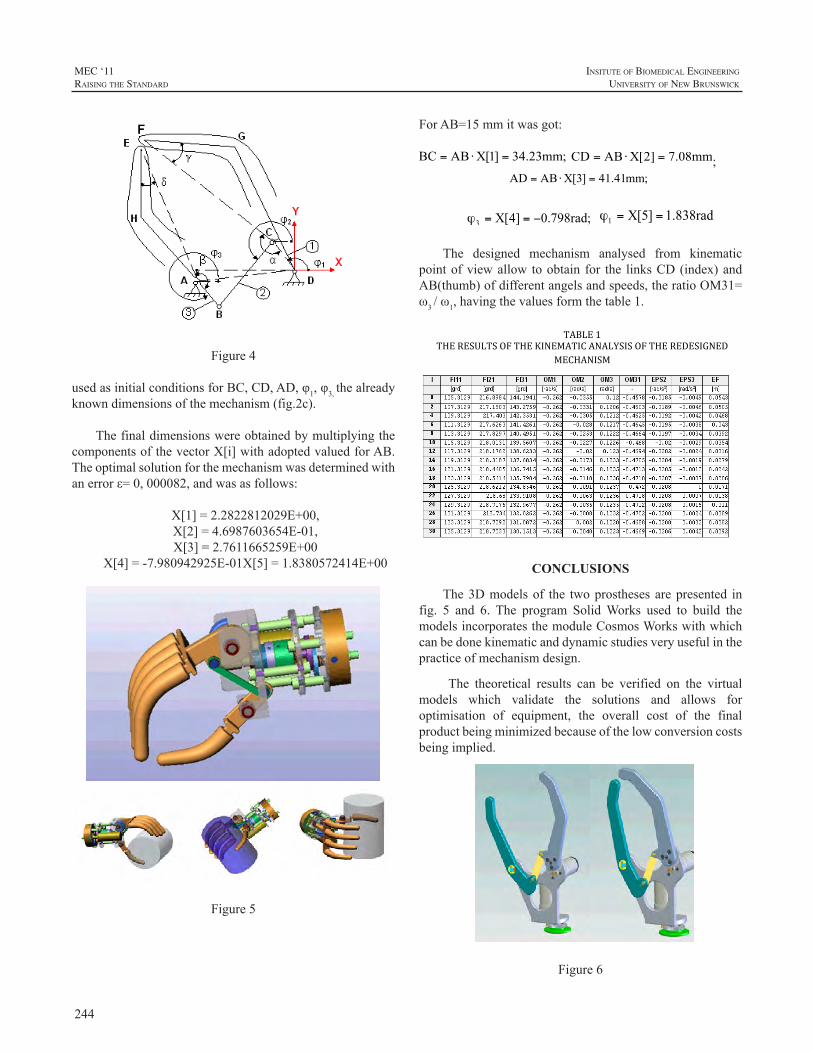
244
MEC ‘11raIsIng the standard
InsItute of BIomedIcal engIneerIng
unIversIty of new BrunswIck
Figure 4
Figure4
usedasinitialconditionsforBC,CD,AD,φ1,φ3,thealreadyknowndimensionsofthemechanism(fig.2c).
ThefinaldimensionswereobtainedbymultiplyingthecomponentsofthevectorX[i]withadoptedvaluedforAB.Theoptimalsolutionforthemechanismwasdeterminedwithanerrorε=0,000082,andwasasfollows:
X[1]=2.2822812029E+00,X[2]=4.6987603654E-01,X[3]=2.7611665259E+00
X[4]=-7.980942925E-01X[5]=1.8380572414E+00
Figure5
ForAB=15mmitwasgot:
;
The designed mechanism analysed from kinematicpointofviewallow toobtain for the linksCD(index)andAB(thumb)ofdifferentangelsandspeeds,theratioOM31=ω3/ω1,havingthevaluesformthetable1.
TABLE 1 THE RESULTS OF THE KINEMATIC ANALYSIS OF THE REDESIGNED
MECHANISM
CONCLUSIONS
The3Dmodelsof the twoprosthesesarepresented infig. 5 and 6. The program SolidWorks used to build themodelsincorporatesthemoduleCosmosWorkswithwhichcanbedonekinematicanddynamicstudiesveryusefulinthepracticeofmechanismdesign.
The theoretical results can be verified on the virtualmodels which validate the solutions and allows foroptimisation of equipment, the overall cost of the finalproductbeingminimizedbecauseofthelowconversioncostsbeingimplied.
Figure 6
Figure6
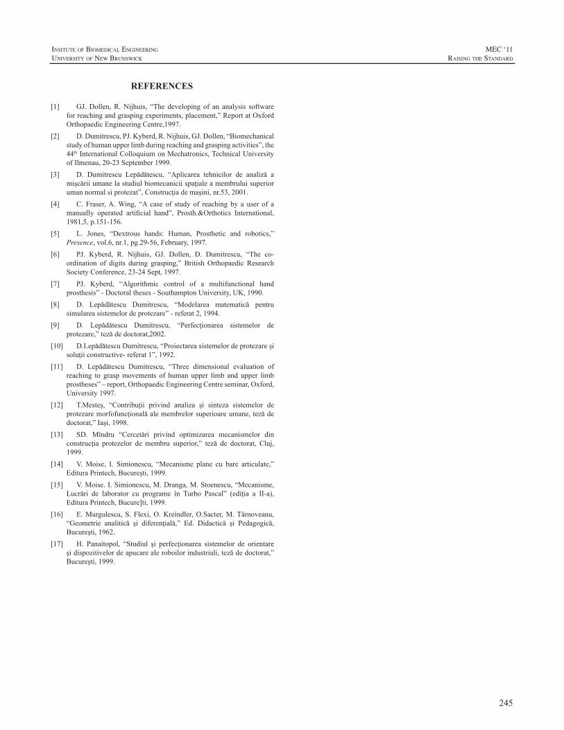
245
InsItute of BIomedIcal engIneerIng
unIversIty of new BrunswIck
MEC ‘11raIsIng the standard
REFERENCES
[1] GJ.Dollen,R.Nijhuis, “The developing of an analysis softwareforreachingandgraspingexperiments,placement,”ReportatOxfordOrthopaedicEngineeringCentre,1997.
[2] D.Dumitrescu,PJ.Kyberd,R.Nijhuis,GJ.Dollen,“Biomechanicalstudyofhumanupperlimbduringreachingandgraspingactivities”,the44thInternationalColloquiumonMechatronics,TechnicalUniversityofIlmenau,20-23September1999.
[3] D. Dumitrescu Lepădătescu, “Aplicarea tehnicilor de analiză amişcăriiumanelastudiulbiomecaniciispaţialeamembruluisuperiorumannormalsiprotezat”,Construcţiademaşini,nr.53,2001.
[4] C. Fraser,A.Wing, “A case of study of reaching by a user of amanually operated artificial hand”, Prosth.&Orthotics International,1981,5,p.151-156.
[5] L. Jones, “Dextrous hands: Human, Prosthetic and robotics,”Presence,vol.6,nr.1,pg.29-56,February,1997.
[6] PJ. Kyberd, R. Nijhuis, GJ. Dollen, D. Dumitrescu, “The co-ordination of digits during grasping,” British Orthopaedic ResearchSocietyConference,23-24Sept,1997.
[7] PJ. Kyberd, “Algorithmic control of a multifunctional handprosthesis”-Doctoraltheses-SouthamptonUniversity,UK,1990.
[8] D. Lepădătescu Dumitrescu, “Modelarea matematică pentrusimulareasistemelordeprotezare”-referat2,1994.
[9] D. Lepădătescu Dumitrescu, “Perfecţionarea sistemelor deprotezare,”tezădedoctorat,2002.
[10] D.LepădătescuDumitrescu,“Proiectareasistemelordeprotezareşisoluţiiconstructive-referat1”,1992.
[11] D. Lepădătescu Dumitrescu, “Three dimensional evaluation ofreaching to graspmovements of human upper limb and upper limbprostheses”–report,OrthopaedicEngineeringCentreseminar,Oxford,University1997.
[12] T.Mesteş, “Contribuţii privind analiza şi sinteza sistemelor deprotezaremorfofuncţionalăalemembrelorsuperioareumane,tezădedoctorat,”Iaşi,1998.
[13] SD. Mîndru “Cercetări privind optimizarea mecanismelor dinconstrucţia protezelor de membru superior,” teză de doctorat, Cluj,1999.
[14] V.Moise, I. Simionescu, “Mecanisme plane cu bare articulate,”EdituraPrintech,Bucureşti,1999.
[15] V.Moise.I.Simionescu,M.Dranga,M.Stoenescu,“Mecanisme,Lucrări de laborator cu programe în Turbo Pascal” (ediţia a II-a),EdituraPrintech,Bucure]ti,1999.
[16] E.Murgulescu,S.Flexi,O.Kreindler,O.Sacter,M.Târnoveanu,“Geometrie analitică şi diferenţială,” Ed. Didactică şi Pedagogică,Bucureşti,1962.
[17] H. Panaitopol, “Studiul şi perfecţionarea sistemelor de orientareşidispozitivelordeapucarealeroboilorindustriali,tezădedoctorat,”Bucureşti,1999.

246
MEC ‘11raIsIng the standard
InsItute of BIomedIcal engIneerIng
unIversIty of new BrunswIck
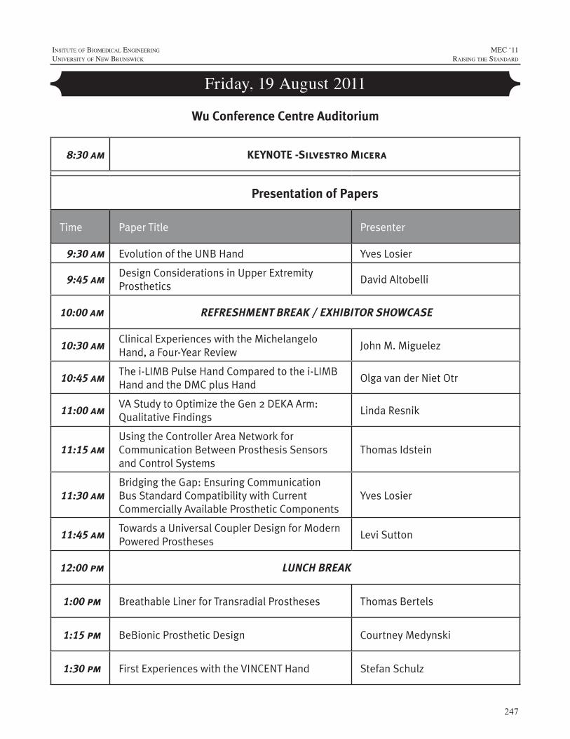
247
InsItute of BIomedIcal engIneerIng
unIversIty of new BrunswIck
MEC ‘11raIsIng the standard
Friday, 19 August 2011
Wu Conference Centre Auditorium
8:30 am KEYNOTE -Silvestro Micera
Presentation of Papers
Time Paper Title Presenter
9:30 am Evolution of the UNB Hand Yves Losier
9:45 am Design Considerations in Upper Extremity Prosthetics
David Altobelli
10:00 am REFRESHMENT BREAK / EXHIBITOR SHOWCASE
10:30 amClinical Experiences with the Michelangelo Hand, a Four-Year Review
John M. Miguelez
10:45 amThe i-LIMB Pulse Hand Compared to the i-LIMB Hand and the DMC plus Hand
Olga van der Niet Otr
11:00 amVA Study to Optimize the Gen 2 DEKA Arm: Qualitative Findings
Linda Resnik
11:15 amUsing the Controller Area Network for Communication Between Prosthesis Sensors and Control Systems
Thomas Idstein
11:30 amBridging the Gap: Ensuring Communication Bus Standard Compatibility with Current Commercially Available Prosthetic Components
Yves Losier
11:45 amTowards a Universal Coupler Design for Modern Powered Prostheses
Levi Sutton
12:00 pm LUNCH BREAK
1:00 pm Breathable Liner for Transradial Prostheses Thomas Bertels
1:15 pm BeBionic Prosthetic Design Courtney Medynski
1:30 pm First Experiences with the VINCENT Hand Stefan Schulz
248
MEC ‘11raIsIng the standard
InsItute of BIomedIcal engIneerIng
unIversIty of new BrunswIck
Friday, 19 August 2011
Time Paper Title Presenter
1:45 pmThe Electric Terminal Device (ETD) - Case Studies and Evolution
Harold Sears
2:00 pmHybridizing body Power & Batteries: Development of the Electromechanical Sure-Lok Cable Control System
Bradley Veatch
2:15 pmCreative Solutions to Bilateral Upper Extremity Involvement
Debra Latour
2:30 pm RAISING THE STANDARD - PANEL DISCUSSION
3:00 pm CLOSING
Presentation of Papers (Continued)
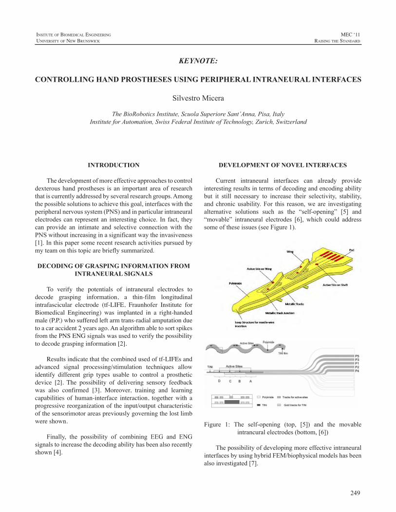
249
InsItute of BIomedIcal engIneerIng
unIversIty of new BrunswIck
MEC ‘11raIsIng the standard
INTRODUCTION
Thedevelopmentofmoreeffectiveapproachestocontroldexteroushandprostheses is an important areaof researchthatiscurrentlyaddressedbyseveralresearchgroups.Amongthepossiblesolutionstoachievethisgoal,interfaceswiththeperipheralnervoussystem(PNS)andinparticularintraneuralelectrodescan representan interestingchoice. In fact, theycan provide an intimate and selective connection with thePNSwithoutincreasinginasignificantwaytheinvasiveness[1].Inthispapersomerecentresearchactivitiespursuedbymyteamonthistopicarebrieflysummarized.
DECODING OF GRASPING INFORMATION FROM INTRANEURAL SIGNALS
To verify the potentials of intraneural electrodes to decode grasping information, a thin-film longitudinal intrafascicular electrode (tf-LIFE, Fraunhofer Institute for Biomedical Engineering) was implanted in a right-handed male (P.P.) who suffered left arm trans-radial amputation due to a car accident 2 years ago. An algorithm able to sort spikes from the PNS ENG signals was used to verify the possibility to decode grasping information [2].
Results indicate that the combined used of tf-LIFEs and advanced signal processing/stimulation techniques allow identify different grip types usable to control a prosthetic device [2]. The possibility of delivering sensory feedback was also confirmed [3]. Moreover, training and learning capabilities of human-interface interaction, together with a progressive reorganization of the input/output characteristic of the sensorimotor areas previously governing the lost limb were shown.
Finally, the possibility of combining EEG and ENGsignalstoincreasethedecodingabilityhasbeenalsorecentlyshown[4].
DEVELOPMENT OF NOVEL INTERFACES
Current intraneural interfaces can already provideinterestingresultsintermsofdecodingandencodingabilitybut it still necessary to increase their selectivity, stability,and chronicusability.For this reason,we are investigatingalternative solutions such as the “self-opening” [5] and“movable” intraneural electrodes [6], which could addresssomeoftheseissues(seeFigure1).
Figure 1: The self-opening (top, [5]) and the movableintrancuralelectrodes(bottom,[6])
ThepossibilityofdevelopingmoreeffectiveintraneuralinterfacesbyusinghybridFEM/biophysicalmodelshasbeenalsoinvestigated[7].
KEYNOTE:
CONTROLLING HAND PROSTHESES USING PERIPHERAL INTRANEURAL INTERFACES
SilvestroMicera
TheBioRoboticsInstitute,ScuolaSuperioreSant’Anna,Pisa,ItalyInstituteforAutomation,SwissFederalInstituteofTechnology,Zurich,Switzerland
250
MEC ‘11raIsIng the standard
InsItute of BIomedIcal engIneerIng
unIversIty of new BrunswIck
DISCUSSION AND CONCLUSIONS
Intraneural interfaces with the PNS can represent asuitable way to create a natural and bi-directional linkbetweenthenervoussystemandartificiallimbs.
However,additionaleffortsarenecessarytocompletelycharacterizethepotentialsandlimitsofthisapproachanditsclinicalchronicusability.Wearecurrentlypursuingseveralapproachesinordertoaddresstheseissues.
ACKNOWLEDGEMENTS
ThisworkwassupportedinpartbytheEuropeanUnion(EU) within the TIME Project (FP7-ICT – 2007-224012,Transverse, Intrafascicular Multichannel Electrode systemfor induction of sensation and treatment of phantom limbpaininamputees).
Thisworkwascarriedoutbyseveralstudentsandpost-docwhoarecurrentlyworkingorworkedwithme(L.Citi,J.Rigosa, J.Carpaneto,S.Raspopovic,M.Capogrosso,S.Bossi,A.Cutrone,P.N.Sergi).Theimplantationwascarriedout by the group of Prof. Paolo Maria Rossini (CampusBiomedicoUniversity,Rome,Italy).
REFERENCES
[1] S. Micera, X. Navarro, et al. “On the use of longitudinalintrafascicularperipheralinterfacesforthecontrolofcybernetichandprosthesesinamputees”.IEEETransNeuralSystRehabilEng2008,16:453-47.
[2] S.Micera,L.Citi, J.Rigosaet al., “Decoding InformationFromNeural Signals Recorded Using Intraneural Electrodes: Toward theDevelopmentofaNeurocontrolledHandProsthesis”,ProcIEEE,vol.98,no.3,pp.407-417,2010.
[3] P.M. Rossini, S. Micera , et al. “Double nerve intraneuralinterfaceimplantonahumanamputeeforrobotichandcontrol”.ClinNeurophysiol2010,121:777-783.
[4] M. Tombini et al., “CombinedAnalysis of Cortical (EEG) andNerveStumpSignalsImprovesRoboticHandControl,”NeuralRehabNeuralRepair,2011inpress.
[5] A. Cutrone, S. Bossi, P.N. Sergi, S.Micera, “Modelization of aself-openingperipheralneuralinterface:afeasibilitystudy”,MedEngPhys,2011,inpress.
[6] S.Bossi,56.S. Bossi, S. Kammer, T. Dorge, A. Menciassi,K.P.,Hoffmann, S. Micera, “An Implantable MicroactuatedIntrafascicularElectrodeforPeripheralNerves”,IEEETransBiomedEng,vol.56,no.11,pp.2701-2706,2009.
[7] S. Raspopovic, M. Capogrosso, S. Micera, “A ComputationalModel for the Stimulation ofRat SciaticNerveUsing aTransverseIntrafascicular Multichannel Electrode”, IEEE Trans Neural SysRehabEng,2011,inpress.
251
InsItute of BIomedIcal engIneerIng
unIversIty of new BrunswIck
MEC ‘11raIsIng the standard
INTRODUCTION
In 2007, the University of New Brunswick’s (UNB)Institute of Biomedical Engineering (IBME) receivedfundingfromtheCanadiangovernment’sAtlanticInnovationFund program to develop a commercially viable andtechnologically advanced prosthetic hand system. The5-year project includes several collaborators namely, theRehabilitationInstituteofChicago’s(RIC)BioMechatronicsDevelopment Laboratory, the Université de Moncton’s(UdeM)ThinFilmsandPhotonicsResearchGroup,UNB’sAppliedNanotechnologyLaboratory(ANL),andLiberatingTechnologiesInc.
Thedesignof thisnewsystem, termed theUNBHandSystem,aimsatproducingacompact,life-likeandaffordablehandwithanovelcosmeticgloveandsensors.ThesystemutilizesapatternrecognitioncontrolsystembasedonIBME’sprevious and ongoing research in the myoelectric controlfield.Thispaperprovidesageneraloverviewofthemajorcomponentsandcharacteristicsofthesystem.
DESIGN CONSIDERATIONS
Severaldesignfactorswereoutlinedattheonsetofthisproject that has helped guide the design and developmentefforts.
OverallCost/AffordabilityAnewprostheticsystemwillprovidebenefittoamputees
onlyifitimprovesthefunctionalityoftheprostheticlimbandthatitremainsaffordable.Thecostofthesystemshouldnotbebarriertotheacquisitionofthesystemforauser.
DegreesofFreedom(DOF)A more dextrous hand requires at least two DOF in
ordertoproducevariousgrasps.ItwasalsorecognizedthatincreasingthenumberofDOFwithinthedesignwouldhavedrawbacks both in terms of weight and fabrication costs.TherewasthereforeastrongmotivationtolimithowmanyDOFwouldbeincorporatedwithinthedesign.
ControllabilityMost prosthetic limb users have a limited number of
inputsourcesavailabletocontroltheirprosthesis.Althoughsurgical techniques, such as targeted muscle reinnervation[1],canincreasethenumberofavailableinputsources,thisprocedurewill not be available, suitable, or evendesirablefor many amputees. Pattern recognition control strategiescanhelpmaximizetheuseofavailableinputs[2]butthereare limitations on how much controllability improvementuserscangainfromsuchcontrolschemes. Inlightofthis,itwas emphasized that themechanical design of theUNBHand should only incorporate as many grasps/movementsasdeemedrealisticallycontrollablebymostamputees.ThiscriterionalsoreinforcedtheargumentoflimitingthenumberofDOFusedwithinthemechanicaldesignofthehand.
Modular/FlexibleDesignGiventhateveryuserhasuniquerequirements(fitting,
control,etc),thesystemmustbemodulartobeeasilyadaptableto meet the needs of the user. This modular approach isnecessary for both the electro-mechanical components andthecontroloptions.
SYSTEM OVERVIEW
Thesystemdesigncanbeclassifiedaseitherpertainingtothehandmechanism,cosmeticglove/sensorenhancements,electronichardware,orcontrolsystem.
MechanicalHandDesignThemajordesignconsiderations includedthetypeand
layoutofthedrivetrain,thenumberofDOFandthehand’sformfactor.
DrivetrainConfigurationThe hand uses three DC motors, with independent
actuationoftheindexfinger,linkedactuationofmiddle,ringandlittlefingers,andathirdmotordrivingthethumb.TheBioMechatronicsDevelopmentLaboratoryatRICdesignedacustomgearheadable toprovide thenecessary force,butbasingthedesignonanoff-the-shelfsolutiontoreducecosts.
AN OVERVIEW OF THE UNB HAND SYSTEM
YvesLosier1,2,AdamClawson1,AdamWilson1,ErikScheme1,KevinEnglehart1,2,PeterKyberd1,2,andBernardHudgins1,2
1InstituteofBiomedicalEngineering,UniversityofNewBrunswick,Canada2DepartmentofElectricalandComputerEngineering,UniversityofNewBrunswick,Canada
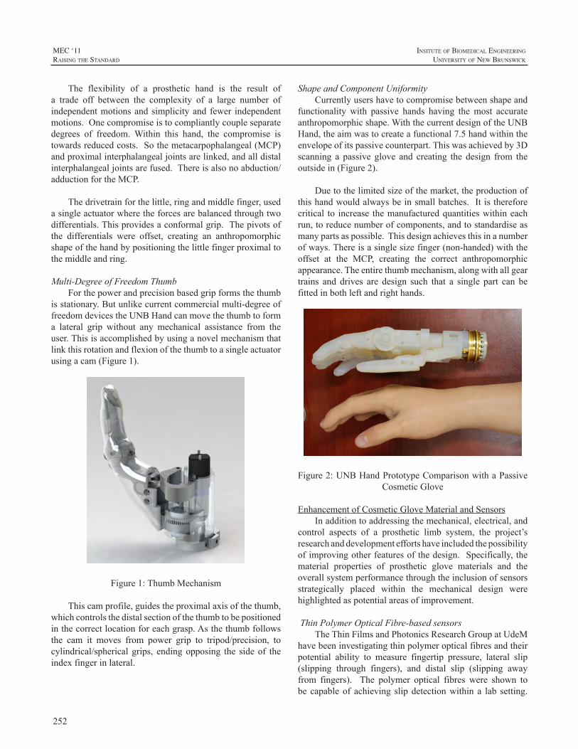
252
MEC ‘11raIsIng the standard
InsItute of BIomedIcal engIneerIng
unIversIty of new BrunswIck
The flexibility of a prosthetic hand is the result ofa trade off between the complexity of a large number ofindependentmotionsandsimplicityand fewer independentmotions.Onecompromiseistocompliantlycoupleseparatedegrees of freedom.Within this hand, the compromise istowardsreducedcosts.Sothemetacarpophalangeal(MCP)andproximalinterphalangealjointsarelinked,andalldistalinterphalangealjointsarefused.Thereisalsonoabduction/adductionfortheMCP.
Thedrivetrainforthelittle,ringandmiddlefinger,usedasingleactuatorwheretheforcesarebalancedthroughtwodifferentials.Thisprovidesaconformalgrip.Thepivotsofthe differentials were offset, creating an anthropomorphicshapeofthehandbypositioningthelittlefingerproximaltothemiddleandring.
Multi-DegreeofFreedomThumbForthepowerandprecisionbasedgripformsthethumb
isstationary.Butunlikecurrentcommercialmulti-degreeoffreedomdevicestheUNBHandcanmovethethumbtoforma lateral grip without any mechanical assistance from theuser.Thisisaccomplishedbyusinganovelmechanismthatlinkthisrotationandflexionofthethumbtoasingleactuatorusingacam(Figure1).
Figure1:ThumbMechanism
Thiscamprofile,guidestheproximalaxisofthethumb,whichcontrolsthedistalsectionofthethumbtobepositionedinthecorrectlocationforeachgrasp.Asthethumbfollowsthe cam it moves from power grip to tripod/precision, tocylindrical/spherical grips, endingopposing the sideof theindexfingerinlateral.
ShapeandComponentUniformityCurrentlyusershavetocompromisebetweenshapeand
functionality with passive hands having themost accurateanthropomorphicshape.WiththecurrentdesignoftheUNBHand,theaimwastocreateafunctional7.5handwithintheenvelopeofitspassivecounterpart.Thiswasachievedby3Dscanning a passive glove and creating the design from theoutsidein(Figure2).
Duetothelimitedsizeofthemarket,theproductionofthishandwouldalwaysbeinsmallbatches.Itisthereforecritical to increase themanufacturedquantitieswithineachrun,toreducenumberofcomponents,andtostandardiseasmanypartsaspossible.Thisdesignachievesthisinanumberofways.Thereisasinglesizefinger(non-handed)withtheoffset at the MCP, creating the correct anthropomorphicappearance.Theentirethumbmechanism,alongwithallgeartrains and drives are design such that a single part can befittedinbothleftandrighthands.
Figure2:UNBHandPrototypeComparisonwithaPassiveCosmeticGlove
EnhancementofCosmeticGloveMaterialandSensorsInadditiontoaddressingthemechanical,electrical,and
control aspects of a prosthetic limb system, the project’sresearchanddevelopmenteffortshaveincludedthepossibilityofimprovingotherfeaturesofthedesign.Specifically,thematerial properties of prosthetic glove materials and theoverallsystemperformancethroughtheinclusionofsensorsstrategically placed within the mechanical design werehighlightedaspotentialareasofimprovement.
ThinPolymerOpticalFibre-basedsensorsTheThinFilmsandPhotonicsResearchGroupatUdeM
havebeeninvestigatingthinpolymeropticalfibresandtheirpotential ability to measure fingertip pressure, lateral slip(slipping through fingers), and distal slip (slipping awayfrom fingers). The polymer optical fibres were shown tobe capableof achieving slipdetectionwithin a lab setting.
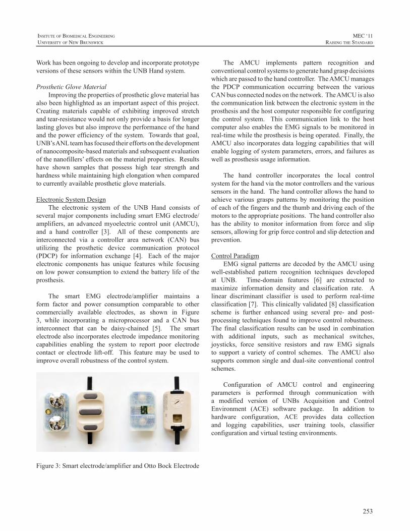
253
InsItute of BIomedIcal engIneerIng
unIversIty of new BrunswIck
MEC ‘11raIsIng the standard
WorkhasbeenongoingtodevelopandincorporateprototypeversionsofthesesensorswithintheUNBHandsystem.
ProstheticGloveMaterialImprovingthepropertiesofprostheticglovematerialhas
alsobeenhighlightedasanimportantaspectofthisproject.Creating materials capable of exhibiting improved stretchandtear-resistancewouldnotonlyprovideabasisforlongerlastingglovesbutalsoimprovetheperformanceofthehandandthepowerefficiencyofthesystem.Towardsthatgoal,UNB’sANLteamhasfocusedtheireffortsonthedevelopmentofnanocomposite-basedmaterialsandsubsequentevaluationofthenanofillers’effectsonthematerialproperties.Resultshave shown samples that possess high tear strength andhardnesswhilemaintaininghighelongationwhencomparedtocurrentlyavailableprostheticglovematerials.
ElectronicSystemDesignThe electronic system of the UNB Hand consists of
severalmajorcomponents includingsmartEMGelectrode/amplifiers, an advancedmyoelectric control unit (AMCU),and a hand controller [3]. All of these components areinterconnected via a controller area network (CAN) busutilizing the prosthetic device communication protocol(PDCP) for information exchange [4]. Each of themajorelectronic components has unique features while focusingonlowpowerconsumptiontoextendthebatterylifeoftheprosthesis.
The smart EMG electrode/amplifier maintains aform factor and power consumption comparable to othercommercially available electrodes, as shown in Figure3, while incorporating a microprocessor and a CAN businterconnect that can be daisy-chained [5]. The smartelectrodealsoincorporateselectrodeimpedancemonitoringcapabilities enabling the system to report poor electrodecontact or electrode lift-off. This feature may be used toimproveoverallrobustnessofthecontrolsystem.
Figure3:Smartelectrode/amplifierandOttoBockElectrode
The AMCU implements pattern recognition andconventionalcontrolsystemstogeneratehandgraspdecisionswhicharepassedtothehandcontroller.TheAMCUmanagesthe PDCP communication occurring between the variousCANbusconnectednodesonthenetwork.TheAMCUisalsothecommunicationlinkbetweentheelectronicsystemintheprosthesisandthehostcomputerresponsibleforconfiguringthe control system. This communication link to the hostcomputeralsoenables theEMGsignals tobemonitoredinreal-timewhiletheprosthesisisbeingoperated.Finally,theAMCUalso incorporatesdata loggingcapabilities thatwillenableloggingofsystemparameters,errors,andfailuresaswellasprosthesisusageinformation.
The hand controller incorporates the local controlsystemforthehandviathemotorcontrollersandthevarioussensorsinthehand.Thehandcontrollerallowsthehandtoachieve various grasps patterns bymonitoring the positionofeachofthefingersandthethumbanddrivingeachofthemotorstotheappropriatepositions.Thehandcontrolleralsohas the ability tomonitor information from force and slipsensors,allowingforgripforcecontrolandslipdetectionandprevention.
ControlParadigmEMGsignalpatternsaredecodedby theAMCUusing
well-established pattern recognition techniques developedat UNB. Time-domain features [6] are extracted tomaximize information density and classification rate. Alinear discriminant classifier is used to perform real-timeclassification[7].Thisclinicallyvalidated[8]classificationscheme is further enhanced using several pre- and post-processingtechniquesfoundtoimprovecontrolrobustness.The final classification results can be used in combinationwith additional inputs, such as mechanical switches,joysticks, force sensitive resistors and raw EMG signalsto support a variety of control schemes. TheAMCU alsosupportscommonsingleanddual-siteconventionalcontrolschemes.
Configuration of AMCU control and engineeringparameters is performed through communication witha modified version of UNBs Acquisition and ControlEnvironment (ACE) software package. In addition tohardware configuration, ACE provides data collectionand logging capabilities, user training tools, classifierconfigurationandvirtualtestingenvironments.
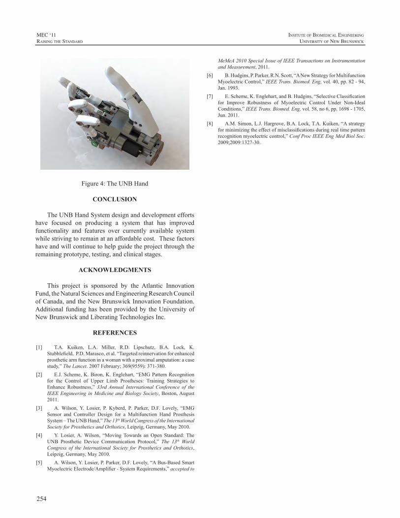
254
MEC ‘11raIsIng the standard
InsItute of BIomedIcal engIneerIng
unIversIty of new BrunswIck
Figure4:TheUNBHand
CONCLUSION
TheUNBHandSystemdesignanddevelopmenteffortshave focused on producing a system that has improvedfunctionality and features over currently available systemwhilestrivingtoremainatanaffordablecost.Thesefactorshaveandwillcontinuetohelpguidetheprojectthroughtheremainingprototype,testing,andclinicalstages.
ACKNOWLEDGMENTS
This project is sponsored by the Atlantic InnovationFund,theNaturalSciencesandEngineeringResearchCouncilofCanada,andtheNewBrunswickInnovationFoundation.Additional fundinghasbeenprovidedby theUniversityofNewBrunswickandLiberatingTechnologiesInc.
REFERENCES
[1] T.A. Kuiken, L.A. Miller, R.D. Lipschutz, B.A. Lock, K.Stubblefield,P.D.Marasco,etal.“Targetedreinnervationforenhancedprostheticarmfunctioninawomanwithaproximalamputation:acasestudy,”TheLancet.2007February;369(9559):371-380.
[2] E.J.Scheme,K.Biron,K.Englehart,“EMGPatternRecognitionfor the Control of Upper Limb Prostheses: Training Strategies toEnhance Robustness,” 33rdAnnual International Conference of theIEEEEngineering inMedicineandBiologySociety,Boston,August2011.
[3] A.Wilson,Y. Losier, P. Kyberd, P. Parker, D.F. Lovely, “EMGSensor and Controller Design for a Multifunction Hand ProsthesisSystem–TheUNBHand,”The13thWorldCongressoftheInternationalSocietyforProstheticsandOrthotics,Leipzig,Germany,May2010.
[4] Y. Losier,A.Wilson, “MovingTowards anOpen Standard: TheUNB Prosthetic Device Communication Protocol,” The 13th WorldCongress of the International Society forProsthetics andOrthotics,Leipzig,Germany,May2010.
[5] A.Wilson,Y.Losier,P.Parker,D.F.Lovely,“ABus-BasedSmartMyoelectricElectrode/Amplifier-SystemRequirements,”acceptedto
MeMeA2010SpecialIssueofIEEETransactionsonInstrumentationandMeasurement,2011.
[6] B.Hudgins,P.Parker,R.N.Scott,“ANewStrategyforMultifunctionMyoelectricControl,”IEEETrans.Biomed.Eng,vol.40,pp.82-94,Jan.1993.
[7] E.Scheme,K.Englehart,andB.Hudgins,“SelectiveClassificationfor Improve Robustness of Myoelectric Control Under Non-IdealConditions,”IEEETrans.Biomed.Eng,vol.58,no6,pp.1698-1705,Jun.2011.
[8] A.M.Simon,L.J.Hargrove,B.A.Lock,T.A.Kuiken,“Astrategyforminimizingtheeffectofmisclassificationsduringrealtimepatternrecognitionmyoelectriccontrol,”ConfProcIEEEEngMedBiolSoc.2009;2009:1327-30.
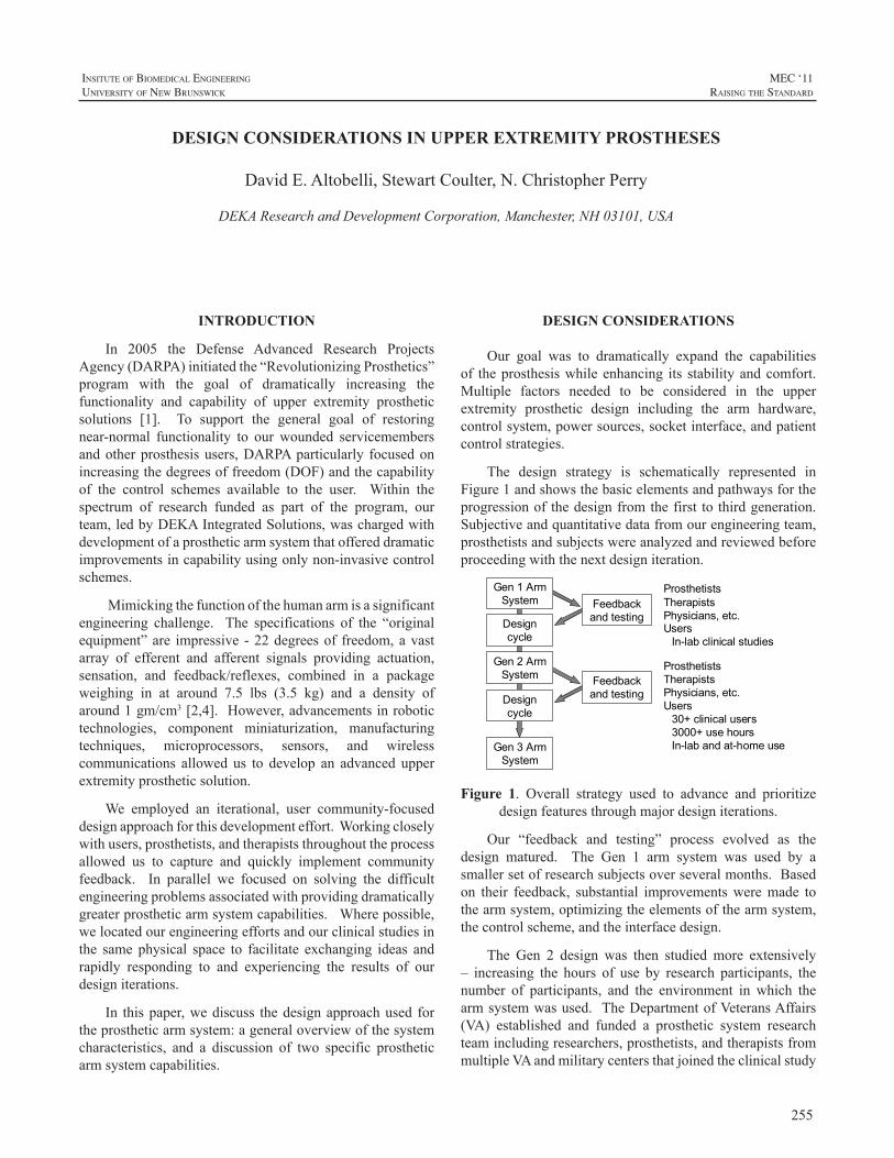
255
InsItute of BIomedIcal engIneerIng
unIversIty of new BrunswIck
MEC ‘11raIsIng the standard
INTRODUCTION
In 2005 the Defense Advanced Research ProjectsAgency(DARPA)initiatedthe“RevolutionizingProsthetics”program with the goal of dramatically increasing thefunctionality and capability of upper extremity prostheticsolutions [1]. To support the general goal of restoringnear-normal functionality to our wounded servicemembersandotherprosthesisusers,DARPAparticularly focusedonincreasingthedegreesoffreedom(DOF)andthecapabilityof the control schemes available to the user. Within thespectrum of research funded as part of the program, ourteam,ledbyDEKAIntegratedSolutions,waschargedwithdevelopmentofaprostheticarmsystemthatoffereddramaticimprovementsincapabilityusingonlynon-invasivecontrolschemes.
Mimickingthefunctionofthehumanarmisasignificantengineering challenge. The specifications of the “originalequipment”are impressive -22degreesof freedom,avastarray of efferent and afferent signals providing actuation,sensation, and feedback/reflexes, combined in a packageweighing in at around 7.5 lbs (3.5 kg) and a density ofaround1gm/cm3[2,4]. However,advancementsinrobotictechnologies, component miniaturization, manufacturingtechniques, microprocessors, sensors, and wirelesscommunications allowed us to develop an advanced upperextremityprostheticsolution.
We employed an iterational, user community-focuseddesignapproachforthisdevelopmenteffort.Workingcloselywithusers,prosthetists,andtherapiststhroughouttheprocessallowed us to capture and quickly implement communityfeedback. In parallel we focused on solving the difficultengineeringproblemsassociatedwithprovidingdramaticallygreaterprostheticarmsystemcapabilities.Wherepossible,welocatedourengineeringeffortsandourclinicalstudiesinthe same physical space to facilitate exchanging ideas andrapidly responding to and experiencing the results of ourdesigniterations.
In thispaper,wediscuss thedesignapproachused fortheprostheticarmsystem:ageneraloverviewofthesystemcharacteristics, and a discussion of two specific prostheticarmsystemcapabilities.
DESIGN CONSIDERATIONS
Our goal was to dramatically expand the capabilitiesof theprosthesiswhileenhancing its stabilityandcomfort.Multiple factors needed to be considered in the upperextremity prosthetic design including the arm hardware,controlsystem,powersources,socketinterface,andpatientcontrolstrategies.
The design strategy is schematically represented inFigure1andshowsthebasicelementsandpathwaysfortheprogressionof thedesignfromthefirst tothirdgeneration.Subjectiveandquantitativedatafromourengineeringteam,prosthetistsandsubjectswereanalyzedandreviewedbeforeproceedingwiththenextdesigniteration.
ProsthetistsTherapistsPhysicians, etc.Users
In-lab clinical studies
Gen 1 Arm System
Gen 2 Arm System
Gen 3 Arm System
Feedback and testingDesign
cycle
Designcycle
Feedback and testing
ProsthetistsTherapistsPhysicians, etc.Users
30+ clinical users3000+ use hoursIn-lab and at-home use
Figure 1. Overall strategy used to advance and prioritizedesignfeaturesthroughmajordesigniterations.
Our “feedback and testing” process evolved as thedesign matured. The Gen 1 arm system was used by asmallersetofresearchsubjectsoverseveralmonths.Basedon their feedback, substantial improvementsweremade tothearmsystem,optimizingtheelementsofthearmsystem,thecontrolscheme,andtheinterfacedesign.
The Gen 2 design was then studied more extensively– increasing the hours of use by research participants, thenumber of participants, and the environment in which thearmsystemwasused. TheDepartmentofVeteransAffairs(VA) established and funded a prosthetic system researchteamincludingresearchers,prosthetists,andtherapistsfrommultipleVAandmilitarycentersthatjoinedtheclinicalstudy
DESIGN CONSIDERATIONS IN UPPER EXTREMITY PROSTHESES
DavidE.Altobelli,StewartCoulter,N.ChristopherPerry
DEKAResearchandDevelopmentCorporation,Manchester,NH03101,USA
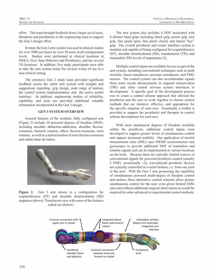
256
MEC ‘11raIsIng the standard
InsItute of BIomedIcal engIneerIng
unIversIty of new BrunswIck
effort.Thisteambroughtfeedbackfromalargersetofusers,therapistsandprosthetiststotheengineeringteamtosupporttheGen3designeffort.
Intotal,theGen2armsystemwasusedinclinicalstudiesforover3000usehoursbyover30usersatallconfigurationlevels. Studies were performed at clinical locations atDEKA,NextStepOrthoticsandProsthetics,andtheseveralVAlocations.Inaddition,fivestudyparticipantswereableto take thearmsystemhomeforseveralweeksofuse inanon-clinicalsetting.
The extensive Gen 2 study team provided significantfeedback across the entire arm system with insights andsuggestions regarding: grip design, joint range of motion;the control system implementation; and the active socketinterface. In addition, engineering studies of reliability,capability, and joint use provided additional valuableinformationincorporatedintheGen3design.
GEN 3 SYSTEM OVERVIEW
General features of themodular, fully configured arm(Figure2) include10powereddegrees of freedom (DOF),including shoulder abduction-adduction, shoulder flexion-extension, humeral rotation, elbow flexion-extension,wristrotation,aswellasahybridmotionofwristflexion-extensionandradial-ulnardeviation.
Figure 2. Gen 3 arm shown in a configuration forscapulothoracic (ST) and shoulder disarticulation (SD) amputees(above).Translucentviewwithsomeofthefeatures
calledout(below).
The arm system also includes 4 DOF associatedwith6distincthandgripsincludingchuckgrip,powergrip,toolgrip, fine pinch open, fine pinch closed, and lateral “key”grip. Theoverallprosthesisandsocket interfacesystemismodularandcapableofbeingconfiguredforscapulothoracic(ST),shoulderdisarticulation(SD),transhumeral(TH),andtransradial(TR)levelsofamputation[3].
Multiplecontrolinputsareavailableforuseaspartofthearmsystem,includingconventionaltechniquessuchaspushswitches,lineartransducers,pressuretransducers,andEMGsensors.Thecontrolsystemcanalsoaccommodatesignalsfrom more recent advancements in targeted reinnervation(TRI) and other central nervous system interfaces indevelopment. A specific goal of the development processwas to create a control scheme approach that allowed theprosthetist and theuser towork together to choosecontrolmethods that are intuitive, effective, and appropriate forthe specific situationof eachuser. Essentially, a toolkit isprovided to support the prosthetist and therapist in controlschemedevelopmentforeachuser.
With more mechanical degrees of freedom availablewithin the prosthesis, additional control inputs weredevelopedtosupportgreaterlevelsofsimultaneouscontrolandsupport increasedusability. Ourapplicationof inertialmeasurement units (IMU) usesMEMS accelerometers andgyroscopes to provide additional DOF of translation androtationsignalsandcanbeimplementedatvariouslocationsonthebody.Becausetherearetypicallylimitedsourcesofconventionalsignalsforpoweredprosthesiscontrol(usually2 EMG, occasionally >2), conventional prosthetic devicesaretypicallycontrolledinaserialfashion,i.e.fromonejointto thenext. With theGen3armpossessing thecapabilityof simultaneous powered multi-degree of freedom controlandmotion,thesealternativecontrolschemesallowgreatersimultaneouscontrolfor theuser,evengivenlimitedEMGsitesandwithoutadditionalsurgicalinterventionaswouldberequiredforotheradvancedorexperimentalcontrolmethods.
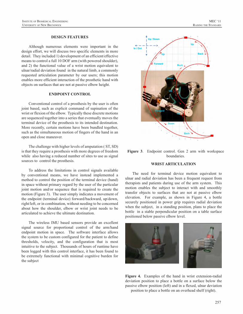
257
InsItute of BIomedIcal engIneerIng
unIversIty of new BrunswIck
MEC ‘11raIsIng the standard
DESIGN FEATURES
Although numerous elements were important in thedesigneffort,wewilldiscusstwospecificelementsinmoredetail.Theyincluded1)developmentofanefficient/effectivemeanstocontrolafull10DOFarm(withpoweredshoulder),and2) the functionalvalueofawristmotionequivalent toulnar/radialdeviationfoundinthenaturallimb,acommonlyrequested articulation parameter by our users; this motionenablesmoreefficientinteractionoftheprosthetichandwithobjectsonsurfacesthatarenotatpassiveelbowheight.
ENDPOINT CONTROL
Conventionalcontrolofaprosthesisbytheuserisoftenjointbased, suchasexplicit commandof supinationof thewristorflexionoftheelbow.Typicallythesediscretemotionsaresequencedtogetherintoaseriesthateventuallymovestheterminaldeviceoftheprosthesistoitsintendeddestination.Morerecently,certainmotionshavebeenbundledtogether,suchasthesimultaneousmotionoffingersofthehandinanopenandclosemaneuver.
Thechallengewithhigherlevelsofamputation(ST,SD)isthattheyrequireaprosthesiswithmoredegreesoffreedomwhilealsohavingareducednumberofsitestouseassignalsourcestocontroltheprosthesis.
To address the limitations in control signals availableby conventional means, we have instead implemented amethodtocontrolthepositionoftheterminaldevice(hand)inspacewithoutprimaryregardbytheuseroftheparticularjointmotion and/or sequence that is required to create themotion(Figure3).Theusersimplyindicatesamovementoftheendpoint(terminaldevice)forward/backward,up/down,right/left,orincombination,withoutneedingtobeconcernedabout how the shoulder, elbow or wrist joint needs to bearticulatedtoachievetheultimatedestination.
The wireless IMU based sensors provide an excellentsignal source for proportional control of the arm/handendpoint motion in space. The software interface allowsthesystemtobecustomconfiguredforthepatienttodefinethresholds, velocity, and the configuration that is mostintuitivetothesubject.Thousandsofhoursofruntimehavebeenloggedwiththiscontrolinterface,ithasbeenfoundtobeextremely functionalwithminimalcognitiveburden forthesubject
Figure 3. Endpoint control. Gen 2 arm with workspaceboundaries.
WRIST ARTICULATION
The need for terminal device motion equivalent toulnarandradialdeviationhasbeenafrequentrequestfromtherapistsandpatientsduringuseof thearmsystem. Thismotion enables the subject to interact with and smoothlytransfer objects to surfaces that are not at passive elbowelevation. For example, as shown in Figure 4, a bottlesecurely positioned in power grip requires radial deviationwhenthesubject,inastandingposition,planstoplacethebottle inastableperpendicularpositionona tablesurfacepositionedbelowpassiveelbowlevel.
Figure 4. Examples of the hand inwrist extension-radialdeviationposition to place a bottle on a surfacebelow thepassiveelbowposition(left)andinaflexed,ulnardeviation
positiontoplaceabottleonanoverheadshelf(right).
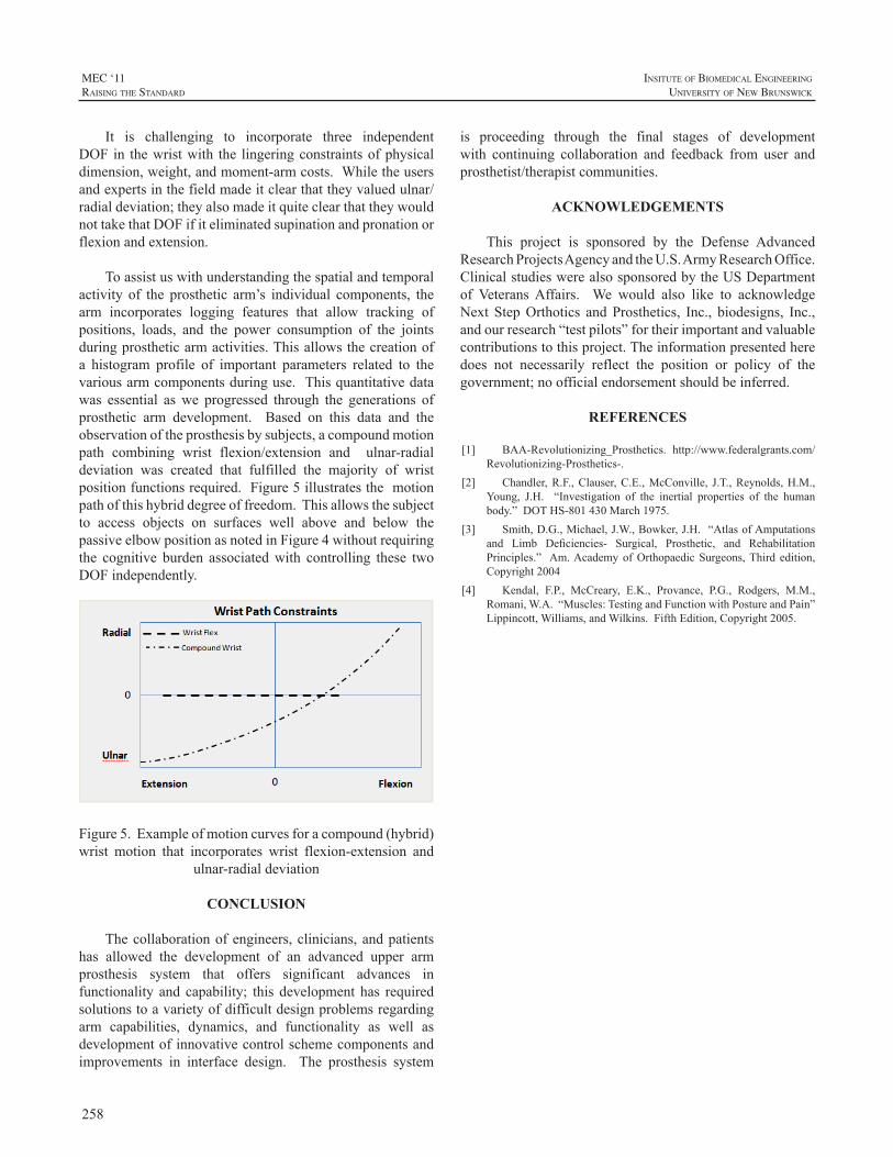
258
MEC ‘11raIsIng the standard
InsItute of BIomedIcal engIneerIng
unIversIty of new BrunswIck
It is challenging to incorporate three independentDOF in thewristwith the lingeringconstraintsofphysicaldimension,weight,andmoment-armcosts.Whiletheusersandexpertsinthefieldmadeitclearthattheyvaluedulnar/radialdeviation;theyalsomadeitquiteclearthattheywouldnottakethatDOFifiteliminatedsupinationandpronationorflexionandextension.
Toassistuswithunderstandingthespatialandtemporalactivity of the prosthetic arm’s individual components, thearm incorporates logging features that allow tracking ofpositions, loads, and the power consumption of the jointsduringprostheticarmactivities.Thisallowsthecreationofa histogram profile of important parameters related to thevariousarmcomponentsduringuse.Thisquantitativedatawas essential aswe progressed through the generations ofprosthetic arm development. Based on this data and theobservationoftheprosthesisbysubjects,acompoundmotionpath combining wrist flexion/extension and ulnar-radialdeviation was created that fulfilled the majority of wristpositionfunctionsrequired.Figure5illustratesthemotionpathofthishybriddegreeoffreedom.Thisallowsthesubjectto access objects on surfaces well above and below thepassiveelbowpositionasnotedinFigure4withoutrequiringthe cognitive burden associatedwith controlling these twoDOFindependently.
Figure5.Exampleofmotioncurvesforacompound(hybrid)wrist motion that incorporates wrist flexion-extension and
ulnar-radialdeviation
CONCLUSION
Thecollaborationofengineers,clinicians,andpatientshas allowed the development of an advanced upper armprosthesis system that offers significant advances infunctionality and capability; this development has requiredsolutionstoavarietyofdifficultdesignproblemsregardingarm capabilities, dynamics, and functionality as well asdevelopmentofinnovativecontrolschemecomponentsandimprovements in interface design. The prosthesis system
is proceeding through the final stages of developmentwith continuing collaboration and feedback from user andprosthetist/therapistcommunities.
ACKNOWLEDGEMENTS
This project is sponsored by the Defense AdvancedResearchProjectsAgencyandtheU.S.ArmyResearchOffice.ClinicalstudieswerealsosponsoredbytheUSDepartmentof VeteransAffairs. We would also like to acknowledgeNext StepOrthotics andProsthetics, Inc., biodesigns, Inc.,andourresearch“testpilots”fortheirimportantandvaluablecontributionstothisproject.Theinformationpresentedheredoes not necessarily reflect the position or policy of thegovernment;noofficialendorsementshouldbeinferred.
REFERENCES
[1] BAA-Revolutionizing_Prosthetics. http://www.federalgrants.com/Revolutionizing-Prosthetics-.
[2] Chandler,R.F.,Clauser,C.E.,McConville, J.T.,Reynolds,H.M.,Young, J.H. “Investigation of the inertial properties of the humanbody.”DOTHS-801430March1975.
[3] Smith,D.G.,Michael,J.W.,Bowker,J.H.“AtlasofAmputationsand Limb Deficiencies- Surgical, Prosthetic, and RehabilitationPrinciples.” Am.AcademyofOrthopaedicSurgeons,Third edition,Copyright2004
[4] Kendal, F.P., McCreary, E.K., Provance, P.G., Rodgers, M.M.,Romani,W.A.“Muscles:TestingandFunctionwithPostureandPain”Lippincott,Williams,andWilkins.FifthEdition,Copyright2005.
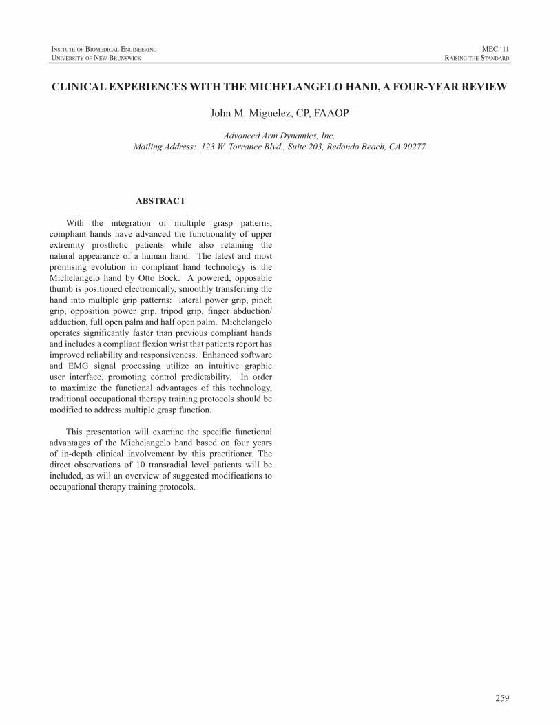
259
InsItute of BIomedIcal engIneerIng
unIversIty of new BrunswIck
MEC ‘11raIsIng the standard
ABSTRACT
With the integration of multiple grasp patterns,compliant hands have advanced the functionality of upperextremity prosthetic patients while also retaining thenatural appearance of a humanhand. The latest andmostpromising evolution in compliant hand technology is theMichelangelo hand by Otto Bock. A powered, opposablethumbispositionedelectronically,smoothlytransferringthehand intomultiplegrippatterns: lateralpowergrip, pinchgrip, opposition power grip, tripod grip, finger abduction/adduction,fullopenpalmandhalfopenpalm.Michelangelooperates significantly faster thanprevious compliant handsandincludesacompliantflexionwristthatpatientsreporthasimprovedreliabilityandresponsiveness.Enhancedsoftwareand EMG signal processing utilize an intuitive graphicuser interface, promoting control predictability. In orderto maximize the functional advantages of this technology,traditionaloccupationaltherapytrainingprotocolsshouldbemodifiedtoaddressmultiplegraspfunction.
This presentation will examine the specific functionaladvantages of theMichelangelo hand based on four yearsof in-depth clinical involvement by this practitioner. Thedirect observations of 10 transradial level patients will beincluded,aswillanoverviewofsuggestedmodificationstooccupationaltherapytrainingprotocols.
CLINICAL EXPERIENCES WITH THE MICHELANGELO HAND, A FOUR-YEAR REVIEW
JohnM.Miguelez,CP,FAAOP
AdvancedArmDynamics,Inc.MailingAddress:123W.TorranceBlvd.,Suite203,RedondoBeach,CA90277
260
MEC ‘11raIsIng the standard
InsItute of BIomedIcal engIneerIng
unIversIty of new BrunswIck
INTRODUCTION
The new generation of multi articulating myoelectricprosthetic hands claims to be more functional than a onejointprosthetichand.TheaimofthestudyistoestablishandcomparethefunctionalityofthemyoelectricDMCplus,thei-LIMBandthei-LIMBPulsehand.
CASE REPORT
In 2006, a 43-year-old man suffered from a wristdisarticulationathisdominantleftsideduringwork.Initiallyhewasprovidedwitha2electrodesmyoelectricprosthesiswith DynamicMode Control (DMC plus, OttoBock©). InDecember2008thepatientreceivedani-LIMBhand(TouchBionics©)witharidgedwristandfromDecember2010tillMay2011heusedthei-LIMBPulsewithafrictionwrist.
METHOD
ThepatientuseddifferenthandsinatestprocedurethatcoveredallfunctionallevelsoftheICF.FirstwetestedtheDMCplushandandafter fourweeksofusage the i-LIMBhand¹.Thei-LIMBwasmeasuredagainafteroneyear.Thei-LIMB Pulse was tested after one month of training anddailyuseandagainafterthreemonths.
GripandpinchstrengthweremeasuredusingtheJamardynamometerandPinchmeterofthee-LINKsystem.
Prehensilepatternsandgrippostureswereassessedbythe Southampton HandAssessment Procedure (SHAP). Ascoreof98,rangingform0-100,isproperforanunimpairedpopulation.
The assessment of Capacity for Myoelectric control(ACMC 2.0) gauges myoelectric control in an everydayactivity,packingasuitcase.Ascoreofzerologitsreferstoanaveragecontrolability.
Satisfaction with the prosthesis was measured withthe Trinity Amputation and Prosthesis Experience Scales(TAPES).
The functional status ofTheOrthotics andProstheticsUsers’ Survey (OPUS) was established from a 19 itemquestionnaire. A score of 27 reflects zero logits and amoderatelevelofupperextremityfunction.
Visual Analogue Scale (VAS) scores were used todetermine the patient’s subjective opinion on strength,appearance, sound, precision grip, power grip, robustnessandgrip variety of the prosthetic hand.Thepatient scoredalsotherelevanceofthesecharacteristics.
Finally inasemistructuredinterview, thepatient toldabouthisexperienceswiththeprostheses.
RESULTS
Gripstrengthofthei-LIMBPulseisalmostequaltothestrengthof theDMCplushand, andmuchhigher than thegrippowerof the i-LIMB.The tripodgripstrength isverymuchinfavoroftheDMCplus.
TheIndexofFunctionScoreintheSHAPhasimprovedforthei-LIMBfrom52afteramonthtoasorecomparabletotheDMCplusscore[1].ThePulsehasthehighestscores.
In theACMC thepatienthas thehighest score for thei-LIMBPulse,andlowestforthei-LIMB.
The prosthesis satisfaction in the Trinity AmputationandProsthesisExperienceScalesisfortheDMClowestandhighestforthePulse.Theadjustmenttopatientslimitationsisinfavorofthei-LIMBPulse.
TheFunctionalStatusintheOPUSisalmostequalforthethreetestedhands.
AccordingtotheVASscoresthePulseishighlyvaluedforitsvariabilityingrippatterns,whichisimportanttothispatient.TheDMCplushandandi-LIMBPulsebothhaveagoodgrippowerandareequallyrobust.Thei-LIMBisthemostvulnerableaccordingtothepatient’sopinion.
THE I-LIMB PULSE HAND COMPARED TO THE I-LIMB AND DMC PLUS HAND
OlgavanderNietOtr¹,HeleenA.Reinders-MesselinkMScPhD¹,HannekeBouwsemaMSc²,RaoulM.BongersMScPhD²,CorryK.vanderSluisMDPhD¹
¹DepartmentofRehabilitationMedicine,UniversityMedicalCenterGroningen,²CenterofHumanMovementSciences,UniversityofGroningen,Groningen,TheNetherlands.
e-mail:[email protected]
261
InsItute of BIomedIcal engIneerIng
unIversIty of new BrunswIck
MEC ‘11raIsIng the standard
In the interview the patient stated that what he likedbest about the i-LIMB and i-LIMBPulse compared to theDMCplushand,wasthatheneednotbeveryparticularinpositioningthei-LIMBhandsbeforepickingupeverydayobjectssuchasapen,aglassoraT-shirt,due to theirfineprecisiongrip.
DISCUSSION
ThiscasereportcomparesthefunctionalityoftheDMCplus,thei-LIMBandthei-LIMBPulsehand.
InthefirstpartofthestudyinwhichwecomparedtheDMCplus and the i-LIMB [1],we suggested that the lowscoresforthei-LIMBhandintheSHAPmightbeduetothelimited training, theextra time the thumbpositioning took,therigidwristandthelimitedgripstrength.TheSHAPscoresfor the i-LIMBafteroneyear improved to the levelof theDMChand.Thesesuggestthatmoreexperienceinusingthei-LIMBhandimprovedthecontrolofthehandandthereforetook less time in performing the tasks. The i-LIMB Pulsehashighest scores in theSHAP.Thepreset features of thePulseincombinationwiththeintensivedailytrainingandthefrictionwristseemtohavecontributedtothescores.
IntheTAPES,theadjustmenttolimitationishighestforthei-LIMBPulse.Anexplanationmightbethatthepatienttoldthataftertheaccidenthehadmetnewpeople,foundnewactivitiesandgoalsinlifewhichweredirectlyrelatedtohisonehandedness.Hefelteventuallythathehadgainedmoreinhislifethanhehadlost.Theadjustmenttolimitationmightalsoberelatedtothelapseoftime.
The high tripod grip force and power grip strength oftheDMC plus, require high control abilitywhen handlingdelicateobjects.ThePulsehasacomparablepowergrip,buta low tripodgrip.Thismakeshandlingheavy anddelicateobjectspossible.
CONCLUSION
Within the limitationsof this casereport,we conclude,that the i-LIMBPulse has a functional advantage over thei-LIMBhand.Ithasmorepower,islessvulnerable,andthefunctionalityseemshigher.TheDMChandisvaluedforitsforceand robustness, as is the i-LIMBPulse.Trainingandeverydayuseforat leastfourmonthsisneededtobeableto fit in a multi articulating myo electric prosthetic handindailyactivities.Thepreset featuresof the i-LIMBPulsehandrequireintensiveadditionaltrainingtoanexperiencedi-LIMBuser.
REFERENCES
[1] O.vanderNiet,H.A.Reinders-Messelink,R.M.Bongers, H.Bouwsema,C.K.vanderSluis.“Thei-LIMBhandand DMCplushandcompared:acasereport”,Prostheticsand OrthoticsInternational,vol34,pp216-220,June2010.
262
MEC ‘11raIsIng the standard
InsItute of BIomedIcal engIneerIng
unIversIty of new BrunswIck
INTRODUCTION
In 2005 DARPA announced its “RevolutionizingProsthetics” program and funded the development of theDEKAprostheticarm.WhentheGen2prototypeDEKAArmSystem became available for clinical research and testing,DARPA signed a Memorandum of Agreement with theDepartmentofVeteransAffairs(VA)andprovidedadditionalfunds toDEKAtosupportaVAOptimizationStudyof theDEKAArmsystem.Thepurposeofthisstudywastoobtainuserfeedbacktoinformdesignofthenextprototype,theGen3Arm.
TheDEKAArmisdesignedforuserswithamputationsat the forequarter, shoulder disarticulation, transhumeral ortransradiallevel.Therearethreeversionsavailable:shoulderconfiguration (SC), humeral configuration (HC) and radialconfiguration (RC).TheGen 2Arms thatwe tested had 6handgrips(power,chuck, lateralpinch,openpinch,closedpinch and tool grip), and used a variety of control inputsincluding EMGs, air bladders, and foot controls (ForceSensitiveResistors [FSR]) and InertialMeasurementUnits[IMUs]).
STUDY DESIGN AND PURPOSE
TheVAstudywasaniterativeusabilityandoptimizationstudyemployingamultiplecasestudydesignwithamixed-methodologyapproach.Concurrentquantitativemetricsandqualitativedatawerecollectedtoprovidericher,morevalid,andmorereliablefindingsthanadesignbasedoneitherthequalitative or the quantitative method alone. The purposeofthispaperistodescribeourVAsubjects’perspectivesonusingtheGen2DEKAArm.
METHODS
SubjectsTwenty-six subjects were fit with the DEKA Arm
(22men and 4women ), ages 19 to 82 years. Fivewereon active duty in the U.S.military, 13 were veterans (notonactiveduty),and8hadneverserved in theU.S.ArmedForces.Twenty-threesubjectshadunilateralupperarmloss
and 3 had bilateral upper limb loss. Ten subjectswere fitwithSCDEKAArms,8werefitwithanRC,and8werefitwithanHC.Fourofthe10subjectsfitwithaSChadshorttranshumeralamputations.Subjectswereseenatoneoffourparticipating sites,VANYHHS (Manhattan), James HaleyVA(Tampa),LongBeachVA(LongBeach),andtheCenterfortheIntrepid(CFI).
DataCollectionSubjectsweretoldthattheprimaryobjectiveofthestudy
wastoobtainfeedbackontheDEKAArmprototypeinorderto inform thedesigneffortsof thenextprototype, theGen3Arm.Theiropinionsaboutallaspectsof theDEKAArmwere solicited throughout the study through surveys, semi-guided interviews, audio memos, and videotaped trainingandtestingsessions.Subjectshadapproximately20hoursoftrainingintheuseoftheDEKAArm(somesubjectswithSCconfigurationhadupto30hoursoftraining)andparticipatedinmultipletestingsessions.
DataAnalysisQualitative data analysis involved open coding of
transcriptsfromaudiotapes,memosfromvideotapedsessions,andparticipants’responsestoopen-endedsurveyquestions.Opencodingwasusedtoreducethedatatoasetofimportantthemesorcategories.Thedatawassynthesizedinacross-group analysis to compare similarities and differences inexperienceand recommendationsofparticipantsbyDEKAArm level.At each stage of data collection and analysis,members of the research teamdiscussed key case findingsandinterpretations.
RESULTS
MainImpressionsAt theendof the study subjectswereasked, “What is
yourimpressionoftheDEKAArm?”Amajorityofsubjects(21/25, 84%) had favorable impressions; 14 of these asunequivocally favorable and7were favorablewith criticalfeedback.AhigherpercentageofsubjectsusingtheSCArmwereclassifiedasunequivocallyfavorable(70%ofSCs;43%TC;50%RC).The7subjectswhohadgenerallyfavorableimpressionsbuthadcriticalfeedbackcommentedonissues,
VA STUDY TO OPTIMIZE THE GEN 2 DEKA ARM: QUALITATIVE FINDINGS
LindaResnik
ProvidenceVAMedicalCenter;DepartmentofCommunityHealth,BrownUniversity
263
InsItute of BIomedIcal engIneerIng
unIversIty of new BrunswIck
MEC ‘11raIsIng the standard
includingweight,reliability,ROMofthewrist,andtheneedtoputthearminstandbymodewhilewalking.Foursubjects(16%),includingonesubjectateachlevel,hadunfavorableimpressionsoftheDEKAArmattheendofthestudy.Weightwasthemostcommonlycitedcriticism,butitwasonlyoneamongavarietyofissuesmentioned.
FunctionwiththeDEKAArmTwenty-one of the 22 subjects who used a prosthesis
priortothestudygaveexamplesofnewactivitiestheyhadbeenabletoperformwiththeDEKAArmduringthetrainingprotocol that they had not been able to performwith theircurrent prostheses. The most frequently mentioned typesof new functional activities were self-care and everydayhousehold/office tasks. At the end of the study subjectswere asked if there were any activities they could not dowith the DEKAArm that they were able to do with theircurrent prostheses. Among the 22 subjectswho answeredthis question, 77% said “no” while 23% answered “yes.”Examples of activities from those who answered “yes”included:washmyself,driveacar,rideabike.SomeofthesetaskswereobviouslyrelatedtolimitationsofthefootcontrolsandthelevelofwaterresistanceoftheGen2prototype.
DesiretoReceiveaDEKAArmintheFutureAt the end of the study subjects were asked if they
would want to receive a DEKAArm in the future and toexplainwhyorwhynot.Nineteenoutof25subjects(76%)answered“Yes.”ManysubjectsexplainedthattheywantedaDEKAArmbecauseofincreasedoverallfunction,saying,forexample,“willmakeeverydayactivitiesbetter”,“wouldopenupawholenewworldofindependenceandqualityoflife.”EightypercentofthoseusinganSCArm,86%ofHCArms,and63%ofRCArmsclearlywantedaDEKAArminthefuture.TwosubjectsstateddefinitivelytheydidnotwanttheArminthefuture(1SC,1HC),while4said“Maybe”(3RC,1SC).Amongthesubjectswhosaid“Maybe”,allthatwereusersoftheRClistedweightasareasontheymaynotwanttheArmsystem.
FeedbackonGripsAt the end of the study subjectswere askedwhich, if
any, of the hand grips they found most useful. Open andclosed pinches were most frequently mentioned as mostuseful,followedbylateralpinchandchuck.Atthesametimesubjectswerealsoaskediftherewereanygripstheywouldnotuse:64%statedtherewerenogripstheywouldnotuseand36%thought therewereoneormoregrips theywouldnotuse.Toolgripwasmostlistedmostfrequently,followedbychuckgrip.
ConcernsabouttakingtheDEKAArmhomeSubjectswereaskedtolisttheirconcernsaboutusinga
Gen2DEKAArmathome.Twenty-oneoutof25subjects
who responded to this question (84%) expressed at leastoneconcernaboutusingtheprototypeDEKAArmathome,largely relating to repairs, water resistance, and weight.Despiteconcerns,76%saidtheywantedtoreceiveaDEKAArminthefuture.Subjectsprovidedfeedbackonfeaturesofthearmsystemsuchascosmesis,weight,controls,donninganddoffing.
RecommendedImprovementsSubjects were asked, “How do you think the DEKA
Armsystemcouldbeimprovedtomakeiteasiertouseandmore acceptable to other persons with upper limb loss?”The most frequently mentioned improvements were 1) tomake it lighter inweight and2) to improvecontrols. Thenext three most frequently mentioned categories relatedto 1) making the Arm system smaller/wireless/with lessexternalcomponents;2)improvingthewristmotionsand3)improvingthesocketfitand/oreaseofdonninganddoffingtheArm system. Six subjects suggested improvements incosmesis. Other less frequently mentioned improvementsrelatedtoreducingnoise,andimprovementstotheinflatablebladdersorinflationprocessforsocketbladders,madeby3HCsubjects.
CONCLUSION
Our subject’soverall impressionsof theGen2DEKAArmwerefavorable. Themajorityofsubjectsexpressedadesire toobtainDEKAArms in the future. Manyof thesesame subjects also expressed critical feedback about theArm,butthisfactalonedidnotequatewithdesiretoreceiveaDEKAArminthefuture.AllsubjectfeedbackwassharedwithDEKAandmany suggested improvements have beenaddressedintheGen3design.ClinicalstudiesoftheGen3Armarenowunderway.
ACKNOWLEDGEMENTS
ThisresearchwassupportedbyVARR&D,VARR&DA6780 and VA RR&D A6780I. DEKA’s support of theVA optimization studies was sponsored by the DefenseAdvanced Research Projects Agency and the U.S. ArmyResearchOffice.Theinformationinthismanuscriptdoesnotnecessarilyreflectthepositionorpolicyofthegovernment;noofficialendorsementshouldbeinferred.
The authors acknowledge the valuable work of studyanalystShanaLiebermanKlingerandstudycoordinatorKateBarnabe.
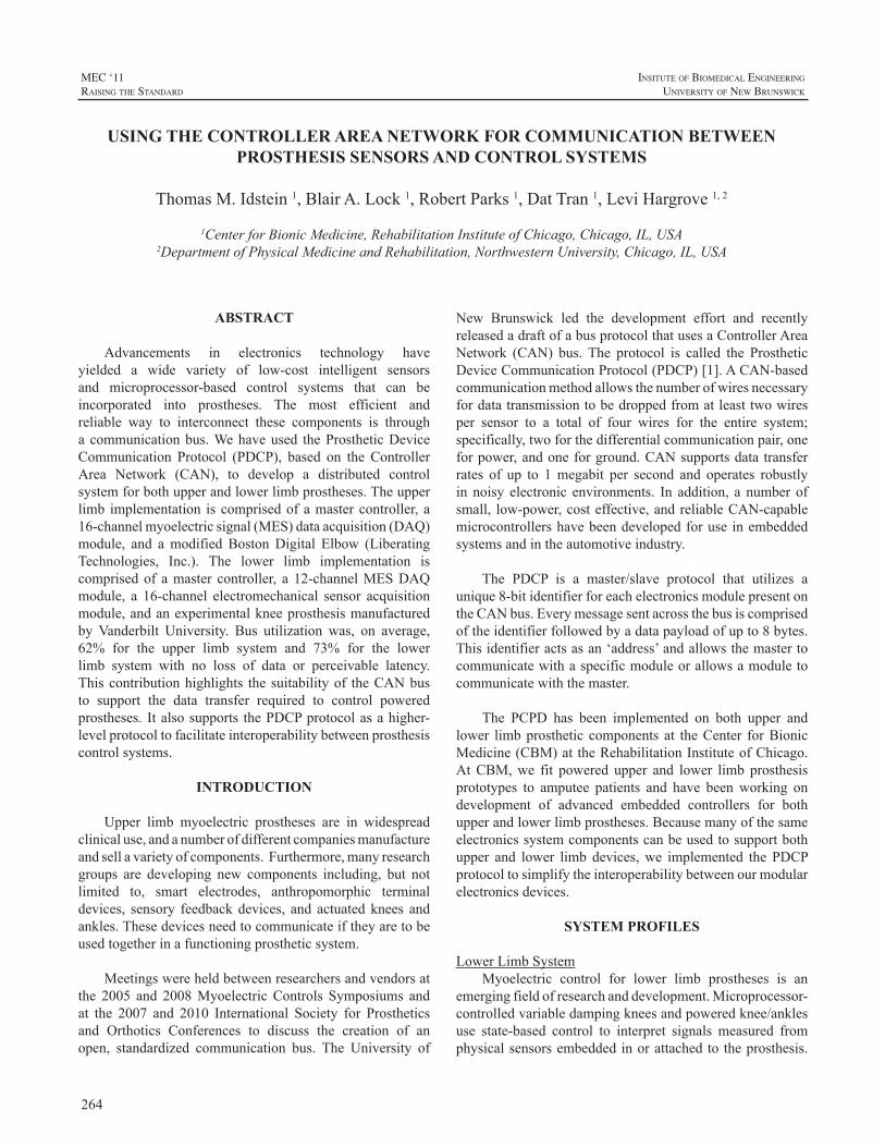
264
MEC ‘11raIsIng the standard
InsItute of BIomedIcal engIneerIng
unIversIty of new BrunswIck
ABSTRACT
Advancements in electronics technology haveyielded a wide variety of low-cost intelligent sensorsand microprocessor-based control systems that can beincorporated into prostheses. The most efficient andreliable way to interconnect these components is througha communicationbus.Wehaveused theProstheticDeviceCommunication Protocol (PDCP), based on the ControllerArea Network (CAN), to develop a distributed controlsystemforbothupperandlowerlimbprostheses.Theupperlimb implementation iscomprisedofamastercontroller, a16-channelmyoelectricsignal(MES)dataacquisition(DAQ)module, and amodified BostonDigital Elbow (LiberatingTechnologies, Inc.). The lower limb implementation iscomprisedof amaster controller, a 12-channelMESDAQmodule, a 16-channel electromechanical sensor acquisitionmodule,andanexperimentalkneeprosthesismanufacturedbyVanderbilt University. Bus utilization was, on average,62% for the upper limb system and 73% for the lowerlimb system with no loss of data or perceivable latency.Thiscontributionhighlights thesuitabilityof theCANbusto support the data transfer required to control poweredprostheses. Italsosupports thePDCPprotocolasahigher-levelprotocoltofacilitateinteroperabilitybetweenprosthesiscontrolsystems.
INTRODUCTION
Upper limb myoelectric prostheses are in widespreadclinicaluse,andanumberofdifferentcompaniesmanufactureandsellavarietyofcomponents.Furthermore,manyresearchgroups are developing new components including, but notlimited to, smart electrodes, anthropomorphic terminaldevices, sensory feedbackdevices, and actuatedknees andankles.Thesedevicesneedtocommunicateiftheyaretobeusedtogetherinafunctioningprostheticsystem.
Meetingswereheldbetweenresearchersandvendorsatthe 2005 and 2008MyoelectricControls Symposiums andat the 2007 and 2010 International Society for Prostheticsand Orthotics Conferences to discuss the creation of anopen, standardized communication bus. The University of
New Brunswick led the development effort and recentlyreleasedadraftofabusprotocolthatusesaControllerAreaNetwork (CAN) bus. The protocol is called the ProstheticDeviceCommunicationProtocol(PDCP)[1].ACAN-basedcommunicationmethodallowsthenumberofwiresnecessaryfordatatransmissiontobedroppedfromatleasttwowiresper sensor to a total of four wires for the entire system;specifically,twoforthedifferentialcommunicationpair,oneforpower,andoneforground.CANsupportsdatatransferrates of up to 1megabit per second and operates robustlyin noisy electronic environments. In addition, a number ofsmall, low-power,costeffective,andreliableCAN-capablemicrocontrollershavebeendevelopedforuse inembeddedsystemsandintheautomotiveindustry.
The PDCP is a master/slave protocol that utilizes aunique8-bitidentifierforeachelectronicsmodulepresentontheCANbus.Everymessagesentacrossthebusiscomprisedoftheidentifierfollowedbyadatapayloadofupto8bytes.Thisidentifieractsasan‘address’andallowsthemastertocommunicatewithaspecificmoduleorallowsamoduletocommunicatewiththemaster.
The PCPD has been implemented on both upper andlower limbprosthetic components at theCenter forBionicMedicine(CBM)attheRehabilitationInstituteofChicago.AtCBM,we fit powered upper and lower limb prosthesisprototypes to amputee patients and have beenworking ondevelopment of advanced embedded controllers for bothupperandlowerlimbprostheses.Becausemanyofthesameelectronicssystemcomponentscanbeusedtosupportbothupper and lower limb devices,we implemented the PDCPprotocoltosimplifytheinteroperabilitybetweenourmodularelectronicsdevices.
SYSTEM PROFILES
LowerLimbSystemMyoelectric control for lower limb prostheses is an
emergingfieldofresearchanddevelopment.Microprocessor-controlledvariabledampingkneesandpoweredknee/anklesuse state-based control to interpret signals measured fromphysicalsensorsembeddedinorattachedtotheprosthesis.
USING THE CONTROLLER AREA NETWORK FOR COMMUNICATION BETWEEN PROSTHESIS SENSORS AND CONTROL SYSTEMS
ThomasM.Idstein1,BlairA.Lock1,RobertParks1,DatTran1,LeviHargrove1,2
1CenterforBionicMedicine,RehabilitationInstituteofChicago,Chicago,IL,USA2DepartmentofPhysicalMedicineandRehabilitation,NorthwesternUniversity,Chicago,IL,USA
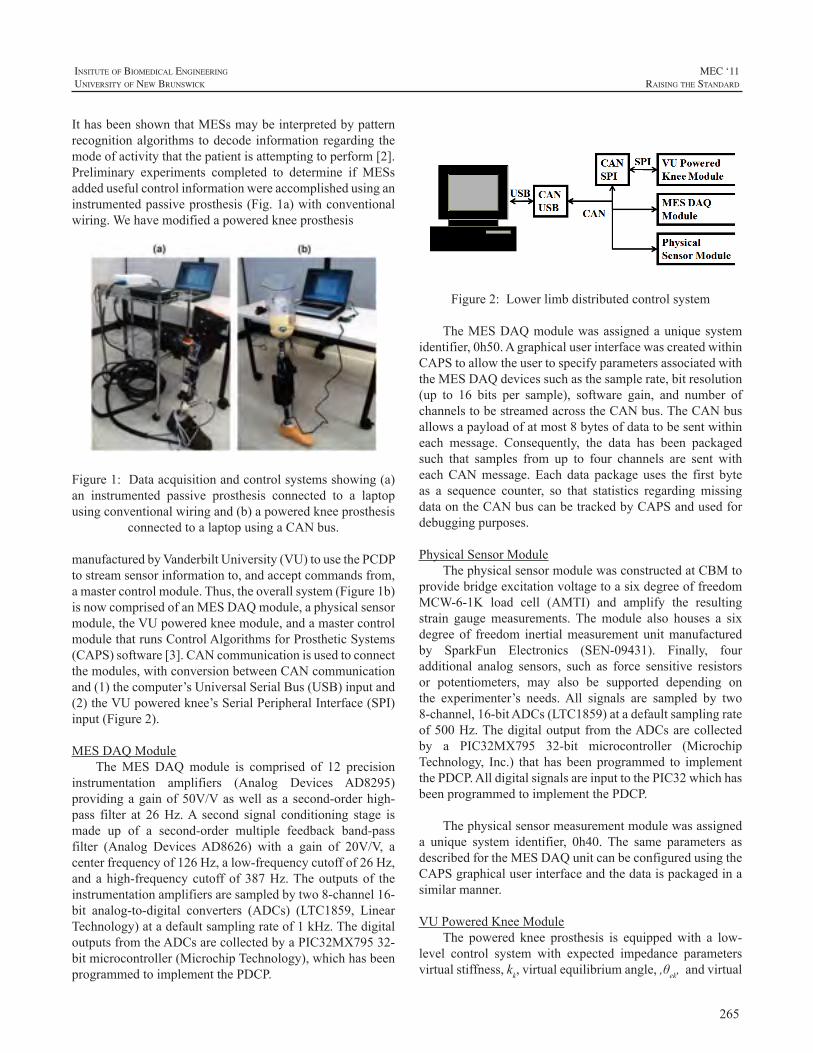
265
InsItute of BIomedIcal engIneerIng
unIversIty of new BrunswIck
MEC ‘11raIsIng the standard
IthasbeenshownthatMESsmaybeinterpretedbypatternrecognitionalgorithmstodecode informationregarding themodeofactivitythatthepatientisattemptingtoperform[2].Preliminary experiments completed to determine if MESsaddedusefulcontrolinformationwereaccomplishedusinganinstrumentedpassiveprosthesis(Fig.1a)withconventionalwiring.Wehavemodifiedapoweredkneeprosthesis
Figure1:Dataacquisitionandcontrolsystemsshowing(a)an instrumented passive prosthesis connected to a laptopusingconventionalwiringand(b)apoweredkneeprosthesis
connectedtoalaptopusingaCANbus.
manufacturedbyVanderbiltUniversity(VU)tousethePCDPtostreamsensorinformationto,andacceptcommandsfrom,amastercontrolmodule.Thus,theoverallsystem(Figure1b)isnowcomprisedofanMESDAQmodule,aphysicalsensormodule,theVUpoweredkneemodule,andamastercontrolmodulethatrunsControlAlgorithmsforProstheticSystems(CAPS)software[3].CANcommunicationisusedtoconnectthemodules,withconversionbetweenCANcommunicationand(1)thecomputer’sUniversalSerialBus(USB)inputand(2)theVUpoweredknee’sSerialPeripheralInterface(SPI)input(Figure2).
MESDAQModuleTheMES DAQmodule is comprised of 12 precision
instrumentation amplifiers (Analog Devices AD8295)providingagainof50V/Vaswellasasecond-orderhigh-pass filter at 26Hz.A second signal conditioning stage ismade up of a second-order multiple feedback band-passfilter (Analog DevicesAD8626) with a gain of 20V/V, acenterfrequencyof126Hz,alow-frequencycutoffof26Hz,andahigh-frequencycutoffof387Hz.Theoutputsof theinstrumentationamplifiersaresampledbytwo8-channel16-bit analog-to-digital converters (ADCs) (LTC1859, LinearTechnology)atadefaultsamplingrateof1kHz.ThedigitaloutputsfromtheADCsarecollectedbyaPIC32MX79532-bitmicrocontroller(MicrochipTechnology),whichhasbeenprogrammedtoimplementthePDCP.
Figure 2: Lower limb distributed control system.
Figure2:Lowerlimbdistributedcontrolsystem
TheMESDAQmodulewasassignedauniquesystemidentifier,0h50.AgraphicaluserinterfacewascreatedwithinCAPStoallowtheusertospecifyparametersassociatedwiththeMESDAQdevicessuchasthesamplerate,bitresolution(up to 16 bits per sample), software gain, and number ofchannelstobestreamedacrosstheCANbus.TheCANbusallowsapayloadofatmost8bytesofdatatobesentwithineach message. Consequently, the data has been packagedsuch that samples from up to four channels are sent witheachCANmessage. Each data package uses the first byteas a sequence counter, so that statistics regarding missingdataontheCANbuscanbetrackedbyCAPSandusedfordebuggingpurposes.
PhysicalSensorModuleThephysicalsensormodulewasconstructedatCBMto
providebridgeexcitationvoltagetoasixdegreeoffreedomMCW-6-1K load cell (AMTI) and amplify the resultingstrain gaugemeasurements. Themodule also houses a sixdegreeof freedom inertialmeasurement unitmanufacturedby SparkFun Electronics (SEN-09431). Finally, fouradditional analog sensors, such as force sensitive resistorsor potentiometers, may also be supported depending onthe experimenter’s needs.All signals are sampled by two8-channel,16-bitADCs(LTC1859)atadefaultsamplingrateof500Hz.ThedigitaloutputfromtheADCsarecollectedby a PIC32MX795 32-bit microcontroller (MicrochipTechnology, Inc.) that has been programmed to implementthePDCP.AlldigitalsignalsareinputtothePIC32whichhasbeenprogrammedtoimplementthePDCP.
Thephysicalsensormeasurementmodulewasassigneda unique system identifier, 0h40. The same parameters asdescribedfortheMESDAQunitcanbeconfiguredusingtheCAPSgraphicaluserinterfaceandthedataispackagedinasimilarmanner.
VUPoweredKneeModuleThe powered knee prosthesis is equippedwith a low-
level control system with expected impedance parametersvirtualstiffness,kk,virtualequilibriumangle,,θek,andvirtual
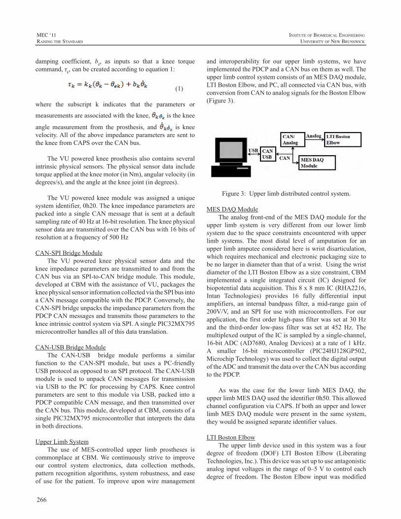
266
MEC ‘11raIsIng the standard
InsItute of BIomedIcal engIneerIng
unIversIty of new BrunswIck
damping coefficient, bk, as inputs so that a knee torquecommand,τk,canbecreatedaccordingtoequation1:
(1)
(1)
where the subscript k indicates that the parameters or
measurementsareassociatedwiththeknee, istheknee
angle measurement from the prosthesis, and is kneevelocity.AlloftheaboveimpedanceparametersaresenttothekneefromCAPSovertheCANbus.
TheVUpoweredkneeprosthesisalsocontainsseveralintrinsicphysicalsensors.Thephysicalsensordata includetorqueappliedatthekneemotor(inNm),angularvelocity(indegrees/s),andtheangleatthekneejoint(indegrees).
TheVUpoweredkneemodulewas assigned a uniquesystemidentifier,0h20.Thekneeimpedanceparametersarepacked intoasingleCANmessage that issentatadefaultsamplingrateof40Hzat16-bitresolution.ThekneephysicalsensordataaretransmittedovertheCANbuswith16bitsofresolutionatafrequencyof500Hz
CAN-SPIBridgeModuleThe VU powered knee physical sensor data and the
kneeimpedanceparametersaretransmittedtoandfromtheCANbusviaanSPI-to-CANbridgemodule.Thismodule,developedatCBMwiththeassistanceofVU,packagesthekneephysicalsensorinformationcollectedviatheSPIbusintoaCANmessagecompatiblewiththePDCP.Conversely,theCAN-SPIbridgeunpackstheimpedanceparametersfromthePDCPCANmessagesandtransmitsthoseparameterstothekneeintrinsiccontrolsystemviaSPI.AsinglePIC32MX795microcontrollerhandlesallofthisdatatranslation.
CAN-USBBridgeModuleThe CAN-USB bridge module performs a similar
function to the CAN-SPI module, but uses a PC-friendlyUSBprotocolasopposedtoanSPIprotocol.TheCAN-USBmodule is used to unpackCANmessages for transmissionviaUSB to thePC for processingbyCAPS.Knee controlparametersare sent to thismoduleviaUSB,packed intoaPDCPcompatibleCANmessage,andthentransmittedovertheCANbus.Thismodule,developedatCBM,consistsofasinglePIC32MX795microcontrollerthatinterpretsthedatainbothdirections.
UpperLimbSystemThe use of MES-controlled upper limb prostheses is
commonplace atCBM.We continuously strive to improveour control system electronics, data collection methods,patternrecognitionalgorithms,systemrobustness,andeaseof use for the patient.To improve uponwiremanagement
and interoperability for our upper limb systems, we haveimplementedthePDCPandaCANbusonthemaswell.TheupperlimbcontrolsystemconsistsofanMESDAQmodule,LTIBostonElbow,andPC,allconnectedviaCANbus,withconversionfromCANtoanalogsignalsfortheBostonElbow(Figure3).
Figure 3: Upper limb distributed control system.
Figure3:Upperlimbdistributedcontrolsystem.
MESDAQModuleTheanalogfront-endoftheMESDAQmoduleforthe
upper limb system is very different from our lower limbsystemduetothespaceconstraintsencounteredwithupperlimb systems. The most distal level of amputation for anupperlimbamputeeconsideredhereiswristdisarticulation,whichrequiresmechanicalandelectronicpackagingsizetobenolargerindiameterthanthatofawrist.UsingthewristdiameteroftheLTIBostonElbowasasizeconstraint,CBMimplemented a single integrated circuit (IC) designed forbiopotentialdataacquisition.This8x8mmIC(RHA2216,Intan Technologies) provides 16 fully differential inputamplifiers, an internal bandpass filter, amid-range gain of200V/V,andanSPI forusewithmicrocontrollers.Forourapplication,thefirstorderhigh-passfilterwassetat30Hzand the third-order low-pass filterwas set at 452Hz.ThemultiplexedoutputoftheICissampledbyasingle-channel,16-bitADC(AD7680,AnalogDevices)ata rateof1kHz.A smaller 16-bit microcontroller (PIC24HJ128GP502,MicrochipTechnology)wasusedtocollectthedigitaloutputoftheADCandtransmitthedataovertheCANbusaccordingtothePDCP.
As was the case for the lower limb MES DAQ, theupperlimbMESDAQusedtheidentifier0h50.ThisallowedchannelconfigurationviaCAPS.IfbothanupperandlowerlimbMESDAQmodulewerepresent in the same system,theywouldbeassignedseparateidentifiervalues.
LTIBostonElbowTheupper limbdeviceused in this systemwas a four
degree of freedom (DOF) LTI Boston Elbow (LiberatingTechnologies,Inc.).Thisdevicewassetuptouseantagonisticanaloginputvoltagesintherangeof0–5Vtocontroleachdegree of freedom.TheBostonElbow inputwasmodified
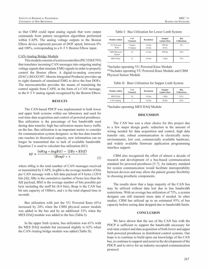
267
InsItute of BIomedIcal engIneerIng
unIversIty of new BrunswIck
MEC ‘11raIsIng the standard
so that CBM could input analog signals that were outputcommands from pattern recognition algorithms performedwithin CAPS. The analog voltage outputs to the BostonElbowdevicerepresentpercentofDOFspeed,between0%and100%,correspondingtoa0–5VBostonElbowinput.
CAN-AnalogBridgeModuleThismoduleconsistsofamicrocontroller(PIC32MX795)
thattranslatesincomingCANmessagesintooutgoinganalogvoltagesignalsthatsimulateEMGsignalsinordertoproperlycontrol the Boston elbow. A digital-to-analog converter(DAC)(MAX5307,MaximIntegratedProducts)providesuptoeightchannelsofsimulatedEMGtodrivethefourDOFs.The microcontroller provides the means of translating thecontrolsignalsfromCAPS,intheformofaCANmessage,tothe0–5VanalogsignalsrecognizedbytheBostonElbow.
RESULTS
TheCAN-basedPDCPwasimplementedinbothlowerandupper limbsystemswithinour laboratoryandusedforreal-timedataacquisitionandcontrolofpoweredprostheses.Bus utilization is the percentage of bus bandwidth usedduringdatatransfer;highbusutilizationmeansheavytrafficonthebus.Busutilizationisanimportantmetrictoconsiderforcommunicationsystemdesigners:asthebusdatatransferratereachesitstheoreticalcapacity,newinformationcannolonger be transmitted due to lack of available bandwidth.Equation2isusedtocalculatebusutilization(bU):
(2)
wherenMsgisthetotalnumberofCANmessagesreceivedortransmittedbyCAPS,AvgBitistheaveragenumberofbitsperCANmessagewithafulldatapayloadof8bytes(120.8bits[4]),SByisthecumulativenumberofbyteslessthanthefullpayload,BStfistheaveragenumberofbitspossibleperbyteincludingthestuffbit(8.8bits),BcapistheCANbusbitratecapacityof1Mbit/s,andτisthetotalelapsedtimeinseconds.
Bus utilization with just theVU Powered Knee (6%)increased by 24%when theCBMphysical sensormodulewas added to the bus and by an additional 33%when theMESDAQmodulewasaddedtothebus(TableI).
Intheupperlimbsystem,busutilizationwas61%withtheMESDAQmodulebutincreasedslightlyto62%whentheCAN-Analogbridgemodulewasadded(TableII).
TableI:BusUtilizationforLowerLimbSystem
Module Added # ofChannels Resolution Sample/
Update RateBus
Utilizations
VUPoweredKnee
3Inputs3Outputs
16bits16bits
500Hz40Hz
6%
CBMPhysicalSensor
16 12bits 500Hz 30%
MESDAQ 12 16bits 1kHz 73%
*IncludesoperatingVUPoweredKneeModule**IncludesoperatingVUPoweredKneeModuleandCBMPhysicalSensorModule
TableII:BussUtilizationforSupperLimbSystem
Module Added # ofChannels Resolution Sample/
Update RateBus
Utilizations
MESDAQ 16 16bits 1kHz 61%
CANAnalog 1 16bits 40Hz 62%
*IncludesoperatingMESDAQModule
DISCUSSION
TheCAN buswas a clear choice for this project dueto a few major design goals: reduction in the amount ofwiring needed for data acquisition and control, high datatransfer rate, robust communication in electrically noisyenvironments, low cost, commercially available hardware,and widely available firmware application programminginterfacesupport.
CBMalso recognized theeffortof almost adecadeofresearch and development of a bus-based communicationstandardforpoweredprostheses[5-7].Anindustrystandardfor system communicationwould facilitate interoperabilitybetweendevicesandmayallowthepatientgreaterflexibilityinchoosingprostheticcomponents.
TheresultsshowthatalargemajorityoftheCANbusmay be utilized without data lost due to bus bandwidthrestrictions.Withanaveragebusutilizationof73%,asystemdesigner can still transmit more data if needed. In otherstudies, CBM has utilized up to an estimated 93% of buscapacitybeforeseeingdatadroppedduetobandwidthlimits.
CONCLUSION
Wehave shown that theuseof theCANbuswith thePDCP is sufficient to support the bandwidth necessary forreal-timecontrolanddataacquisitionofbothlowerandupperlimbpoweredprosthesesindistributedcontrolsystems.OurhopeistocontinuetobuilduponourknowledgeoftheCANbus,tocontinuetosupportandassistinthedevelopmentofthePDCP,andtostriveforanindustry-acceptedcommunicationprotocol.
268
MEC ‘11raIsIng the standard
InsItute of BIomedIcal engIneerIng
unIversIty of new BrunswIck
REFERENCES
[1] Y.Losier,“ProstheticdevicecommunicationprotocolfortheAIFUNB hand project,” http://groups.google.ca/group/scip-forum/2009.
[2] H. Huang, T.A. Kuiken, R.D. Lipschutz, “A strategy foridentifyinglocomotionmodesusingsurfaceelectromyography,”IEEETransactionsonBiomedicalEngineering,vol.56,pp.65-73,2009.
[3] T.A.Kuiken,G.Li,B.A.Lock,etal,“Targetedmusclereinnervationfor real-time myoelectric control of multifunction artificial arms,”Journal of theAmericanMedicalAssociation, vol. 301(6), pp. 619-628,2009.
[4] R. Bosch GmbH, “CAN Specification Version 2.0,” Stuttgart,Germany,September1991.
[5] A.S. Poulton, P.J. Kyberd, S. Jonsson, D. Gow and L. Sandsjo,”Experience with the intelligent hybrid arm systems,” Proceedingsof theMEC ‘02MyoelectricControls Symposium, Fredericton,NB,Canada,2002.
[6] O.StavdahlandG.Mathisen,“Abusprotocolforintercomponentcommunication in advanced upper-limb prosthesis,” Proceedingsof theMEC‘05MyoelectricControlsSymposium, Fredericton,NB,Canada,2005.
[7] S.Banzi,E.MainardiandA.Davalli,“ACAN-baseddistributedcontrolsystemforupperlimbmyoelectricprosthesis,”Proceedingsofthe2005ICSCCongressonComputationalIntelligenceMethodsandApplications,Istanbul,Turkey,2005.
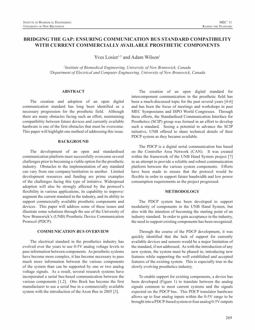
269
InsItute of BIomedIcal engIneerIng
unIversIty of new BrunswIck
MEC ‘11raIsIng the standard
ABSTRACT
The creation and adoption of an open digitalcommunication standard has long been identified as anecessary progression for the prosthetic field. Althoughtherearemanyobstaclesfacingsuchaneffort,maintainingcompatibilitybetweenfuturedevicesandcurrentlyavailablehardwareisoneofthefirstobstaclesthatmustbeovercome.Thispaperwillhighlightonemethodofaddressingthisissue.
BACKGROUND
The development of an open and standardisedcommunicationplatformmustsuccessfullyovercomeseveralchallengespriortobecomingaviableoptionfortheprostheticindustry. Obstacles to the implementationof any standardcanvaryfromonecompany/institutiontoanother.Limiteddevelopment resources and funding are prime examplesof the challenges facing this typeof initiative.Widespreadadoption will also be strongly affected by the protocol’sflexibilityinvariousapplications,itscapabilitytoimprove/augmentthecurrentstandardintheindustry,anditsabilitytosupport commercially available prosthetic components anddevices. Thispaperwill address someof these issues andillustratesomesolutionsthroughtheuseoftheUniversityofNewBrunswick’s(UNB)ProstheticDeviceCommunicationProtocol(PDCP).
COMMUNICATION BUS OVERVIEW
The electrical standard in the prosthetics industry hasevolvedovertheyearstouse0-5Vanalogvoltagelevelstopassinformationbetweencomponents.Asprostheticsystemshavebecomemorecomplex,ithasbecomenecessarytopassmuch more information between the various componentsof the system thancanbe supportedbyoneor twoanalogvoltagesignals. Asa result, several researchsystemshaveincorporatedaserialbus-basedcommunicationbetweenthevariouscomponents [1,2]. OttoBockhasbecome the firstmanufacturertouseaserialbusinacommerciallyavailablesystemwiththeintroductionoftheAxonBusin2005[3].
The creation of an open digital standard forintercomponent communication in the prosthetic field hasbeenamuch-discussedtopicforthepastseveralyears[4-6]andhasbeen the focusofmeetingsandworkshops inpastMECSymposiums and ISPOWorldCongresses. Throughtheseefforts,theStandardisedCommunicationInterfaceforProsthetics(SCIP)groupwasformedinanefforttodevelopsuch a standard. Seeing a potential to advance the SCIPinitiative, UNB offered to share technical details of theirPDCPsystemastheybecameavailable.
ThePDCPisadigitalserialcommunicationbusbasedon the Controller Area Network (CAN). It was createdwithintheframeworkoftheUNBHandSystemproject[7]inanattempttoprovideareliableandrobustcommunicationplatform between the various system components. Effortshave been made to ensure that the protocol would beflexibleinordertosupportfuturebandwidthandlowpowerconsumptionrequirementsastheprojectprogressed.
METHODOLOGY
The PDCP system has been developed to supportmodularity of components in the UNB Hand System, butalsowiththeintentionofbecomingthestartingpointofanindustrystandard.Inordertogainacceptanceintheindustry,theneedtosupportexistingcomponentshasbeenrecognized.
Through the course of the PDCP development, itwasquickly identified that the lack of support for currentlyavailabledevicesandsensorswouldbeamajorlimitationofthestandard,ifnotaddressed.Aswiththeintroductionofanynewsystem,thesystemmustbephasedin;introducingnewfeatureswhilesupportingthewellestablishedandacceptedfeaturesoftheexistingsystem.Thisisespeciallytrueintheslowlyevolvingprostheticsindustry.
Toenablesupportforexistingcomponents,adevicehasbeen developed (Figure 1) to translate between the analogsignals common to most current systems and the signalsexpectedonthePDCPbus.ThisPDCPtranslatorhardwareallowsuptofouranaloginputswithinthe0-5VrangetobebroughtintoaPDCP-basedsystemorfouranalog0-5Voutputs
BRIDGING THE GAP: ENSURING COMMUNICATION BUS STANDARD COMPATIBILITY WITH CURRENT COMMERCIALLY AVAILABLE PROSTHETIC COMPONENTS
YvesLosier1,2andAdamWilson1
1InstituteofBiomedicalEngineering,UniversityofNewBrunswick,Canada2DepartmentofElectricalandComputerEngineering,UniversityofNewBrunswick,Canada
270
MEC ‘11raIsIng the standard
InsItute of BIomedIcal engIneerIng
unIversIty of new BrunswIck
tobegeneratedfromaPDCP-basedsystem.Therefore,anycombinationsofupto4sensorscanbeconnectedtoaPDCP-basedsystemwiththeuseofasinglePDCPtranslatorcircuitboard. These sensorsmay include:EMGelectrodes, forcesensitive resistors (FSR), linear potentiometers, switches,etc.Inaddition,anycombinationsofupto4actuatorscanalsobeconnectedtoaPDCPbasedsystemwiththeuseofasinglePDCP translatorcircuitboard. Theseactuatorsmayinclude:hands,wrists,elbows,etc.Ifmorethan4sensorsormorethan4actuatoroutputsarerequired,additionalPDCPtranslatorboardsmaysimplybeaddedtothesystem.
Figure1:PDCPTranslatorBoard
This approach allows new prosthetic systems toimplement and take advantage of the PDCP bus whilesupporting existing sensors and actuators. As such, acompletesystemcouldconsistofpurelyanalogsensorsandactuatorsfromexistingcommerciallyavailablecomponentsbut use a serial bus based interconnect incorporating thePDCP. One benefit of such an implementation would bethereducednumberofwiresrunningthroughtheprostheticsystem.TheinterconnectionofallthesensorsandactuatorswouldbereducedtothefourwiresneededforthePDCPbusasillustratedinFigure2.
Figure 2: Example Using Existing Components within aPDCP-BasedSystem
CONCLUSION
The development of an open communication standardmust include amechanism to support existing componentsthatarecurrentlyusedintheprostheticindustry.IntermsofthePDCPstandard,thedevelopmentandimplementationofthePDCPtranslatorhardwarehassatisfiedthisrequirementby allowing the integration of commercially availableprosthetic components with no modifications required totheseoff-the-shelfdevices.
ACKNOWLEDGMENTS
This project is sponsored by the Atlantic InnovationFund,theNaturalSciencesandEngineeringResearchCouncilofCanada,andtheNewBrunswickInnovationFoundation.Additional fundinghasbeenprovidedby theUniversityofNewBrunswickandLiberatingTechnologiesInc.
REFERENCES
[1] P.Kyberd,A.Poulton,L.Sandsjö,S.Jönsson,B.Jones,D.Gow,“TheToMPAWModularProsthesis:APlatformforResearchinUpper-LimbProsthetics”,JournalofProstheticsandOrthotics,vol.19(1),pp.15-21,2007.
[2] S. Banzi, E. Mainardi, A. Davalli, “A CAN-based distributedcontrol system for upper limb myoelectric prosthesis”, 2005 ICSCCongress on Computational IntelligenceMethods andApplications,Istanbul,Turkey,pp.6,2005.
[3] P.Prigge,“NewConceptsinExternalPoweredArmComponents”,Proceedings of the MEC ’05 Myoelectric Controls Symposium,Fredericton,Canada,pp.227-230,2005.
[4] Ø. Stavdahl, G. Mathisen, “A Bus Protocol for IntercomponentCommunication in Advanced Upper-limb Prostheses”, ProceedingsoftheMyoelectricControlsSymposium‘05,Fredericton,Canada,pp.258-261,2005.
[5] Ø. Stavdahl, P. Kyberd, “SCIP:A Standardised CommunicationInterfaceforProsthetics”,The12thWorldCongressoftheInternationalSocietyforProsthetics&Orthotics,Vancouver,Canada,2007.
[6] Y. Losier,A.Wilson, “MovingTowards anOpen Standard: TheUNB Prosthetic Device Communication Protocol”, The 13th WorldCongress of the International Society forProsthetics andOrthotics,Leipzig,Germany,May2010.
[7] Y.Losier,A.Clawson,A.Wilson,E.Scheme,K.Englehart,P.Kyberd,B.Hudgins,“AnOverviewoftheUNBHandSystem”ProceedingsoftheMyoelectricControlsSymposium‘11,2011.
271
InsItute of BIomedIcal engIneerIng
unIversIty of new BrunswIck
MEC ‘11raIsIng the standard
INTRODUCTION
Universalcoupler standardshaveplayedacritical rolein allowing prosthetists to choose the best terminal devicefortheirpatient’sparticularneeds.Theconventionalquick-disconnect coupler allows users to passively rotate theirprosthesisortouseaweakmotorizedrotator.However,thecurrentstandardprecludesuseofthestrongmotorizedwristrotatorsintroducedbyseveralcompaniesanduniversities,asthesedeviceswoulddecouplethecurrentuniversalcoupler.A new universal coupler standard is required to allowinterchangeability of these new devices. An open sourceuniversal coupler standard that meets necessary designrequirementswouldbetterserveprosthesisusers.
DESIGN REQUIREMENTS
We have identified the following eight majorconsiderations that thedesignofan idealuniversalcouplershould meet in order to accommodate the needs of theprosthesisuserandprosthetist:
1. Sizeconstraints:a. Axiallengthshouldbe12mmorlessb. Outerdiametershouldbe25mmorless
2. Easeofconnectionanddisconnection:a. Ifmultipleactionsarerequired,theyshouldbe
sequentialb. Shouldallowprosthesistobedonnedand
doffedwithcosmesiscoveringinplace
3. Rotationconstraint:a. Deviceshouldlocktopreventunwanted
rotationb. Numberofmechanicallockingorientations
shouldequalthenumberofpermissibleelectricalconnectionorientations
4. Strengthconstraint:a. Deviceshouldwithstand45Nmofbending
torque(70Nmdesired)b. Deviceshouldwithstandupto15Nmofaxial
torque
5. Interfacewithadjacentsegment:Adjacentsegmentmaybelargerthancouplerdiameter
a. Contactwithanadjacentsegmentlargerthanthecouplermayincreaseconnectionstrength
6. Manufacturingconstraints:a. Proximalcomponentmaybeastand-alonepart
ormadeintegralwithalaminationcollarb. Distalcomponentmaybeastand-alonepartor
madeintegralwiththedistaldevicec. Maybemanufacturedfromdifferentmetals
dependingonstrengthrequirementsofuser
7. Location:a. Maybeusedatthewristb. Maybeplacednear,butslightlydistalto,the
elbowformodularforearms
8. Electronicconstraints:a. Maleandfemaleconnectorsforsixconductorsb. Shouldprohibitimproperelectricalconnectionc. Shouldprecludethepossibilityofelectrode
shortsduringconnectionordisconnection
SizeconstraintsThesizeofthecouplerisimportantforbothuserfunction
andcosmeticappearance.Patientswith longresidual limbswill benefit from a coupler with a short axial profile, 12mmorless,asitwillnotaddsignificantlengthtothelimb.Thecouplerdiametermustbeno larger than theminimumdimensionofasmallwrist,25mm,sothatwithacosmesiscovering, itwillhave theappearanceofananatomicwrist.The current conventional quick-disconnect coupler has alengthofapproximately18mmanda40mmdiameter.
EaseofconnectionanddisconnectionConnectinganddisconnectingthecouplershouldrequire
minimal dexterity so that it is manageable for all users,includingbilateralamputees.Forthisreason,connectinganddisconnectingthecouplershouldrequireasfewuseractionsaspossible,andifmultipleactionsarerequired,theyshouldbe sequential rather than simultaneous. Many cosmeticcoverings extend from the hand to the elbow and wouldtherefore prevent direct access to the coupler.The couplermust be easy to connect and disconnect without visualfeedback and without requiring removal of the cosmeticcovering.
TOWARDS A UNIVERSAL COUPLER DESIGN FOR MODERN POWERED PROSTHESES
LeviG.Sutton1,AdamClawson2,T.WalleyWilliamsIII3,JamesH.Lipsey1,JonathonW.Sensinger1,4
1RehabilitationInstituteofChicago,345EastSuperiorSt.,Chicago,ILUSA.2UniversityofNewBrunswick,25DineenDr.,Fredericton,NewBrunswick,Canada.
3LiberatingTechnologies,325HoppingBrookRd.,Holliston,MA,USA.4NorthwesternUniversity,345EastSuperiorSt.,Chicago,IL,USA.
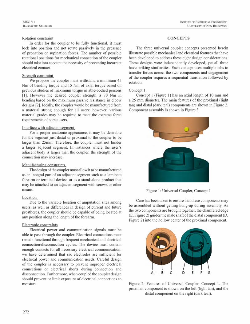
272
MEC ‘11raIsIng the standard
InsItute of BIomedIcal engIneerIng
unIversIty of new BrunswIck
RotationconstraintIn order for the coupler to be fully functional, itmust
lock into position and not rotate passively in the presenceof pronation or supination forces. The number of possiblerotationalpositionsformechanicalconnectionofthecouplershouldtakeintoaccountthenecessityofpreventingincorrectelectricalcontact.
StrengthconstraintWeproposethecouplermustwithstandaminimum45
Nmofbendingtorqueand15Nmofaxialtorquebasedonpreviousstudiesofmaximumtorqueinable-bodiedpersons[1]. However the desired coupler strength is 70 Nm inbendingbasedonthemaximumpassiveresistanceinelbowdesigns[2].Ideally,thecouplerwouldbemanufacturedfroma material strong enough for all users; however, variousmaterialgradesmaybe required tomeet theextremeforcerequirementsofsomeusers.
Interfacewithadjacentsegment Foraproperanatomicappearance, itmaybedesirable
for thesegment justdistalorproximal to thecoupler tobelarger than 25mm.Therefore, the couplermust not hindera larger adjacent segment. In instances where the user’sadjacentbodyislargerthanthecoupler, thestrengthoftheconnectionmayincrease.
Manufacturingconstraints Thedesignofthecouplermustallowittobemanufactured
asanintegralpartofanadjacentsegmentsuchasalaminateforearmorterminaldevice,orasastand-aloneproductthatmaybeattachedtoanadjacentsegmentwithscrewsorothermeans.
Location Duetothevariablelocationofamputationsitesamong
users,aswellasdifferencesindesignofcurrentandfutureprostheses,thecouplershouldbecapableofbeinglocatedatanypositionalongthelengthoftheforearm.
ElectronicconstraintsElectrical power and communication signals must be
abletopassthroughthecoupler.Electricalconnectionsmustremainfunctionalthroughfrequentmechanicalandelectricalconnection/disconnection cycles. The device must containenoughcontactsforallnecessaryelectricalcommunication:we have determined that six electrodes are sufficient forelectrical power and communication needs.Careful designof the coupler is necessary to prevent improper electricalconnections or electrical shorts during connection anddisconnection.Furthermore,whencoupledthecouplerdesignshouldpreventorlimitexposureofelectricalconnectionstomoisture.
CONCEPTS
The three universal coupler concepts presented hereinillustratepossiblemechanicalandelectricalfeaturesthathavebeendevelopedtoaddresstheseeightdesignconsiderations.These designswere independently developed, yet all threehavestrikingsimilarities.Eachconceptusesmultipletabstotransfer forcesacross the twocomponentsandengagementof thecouplerrequiresasequential translationfollowedbyrotation.
Concept1Concept1(Figure1)hasanaxiallengthof10mmand
a25mmdiameter.Themainfeaturesoftheproximal(lighttan)anddistal(darkteal)componentsareshowninFigure2.ComponentassemblyisshowninFigure3.
Figure1:UniversalCoupler,Concept1
Carehasbeentakentoensurethatthesecomponentsmaybeassembledwithoutgettinghung-upduringassembly.Asthetwocomponentsarebroughttogether,thechamferededge(E,Figure2)guidesthemaleshaftofthedistalcomponent(D,Figure2)intothehollowcenteroftheproximalcomponent.
Figure 2: Features of Universal Coupler, Concept 1. Theproximalcomponentisshownontheleft(lighttan),andthe
distalcomponentontheright(darkteal).
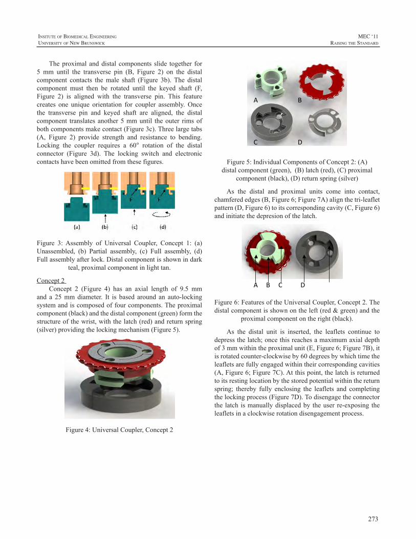
273
InsItute of BIomedIcal engIneerIng
unIversIty of new BrunswIck
MEC ‘11raIsIng the standard
Theproximal anddistal components slide together for5 mm until the transverse pin (B, Figure 2) on the distalcomponent contacts themale shaft (Figure 3b). The distalcomponent must then be rotated until the keyed shaft (F,Figure 2) is aligned with the transverse pin. This featurecreates one unique orientation for coupler assembly. Oncethe transverse pin and keyed shaft are aligned, the distalcomponent translates another5mmuntil theouter rimsofbothcomponentsmakecontact(Figure3c).Threelargetabs(A, Figure 2) provide strength and resistance to bending.Locking the coupler requires a 60° rotation of the distalconnector (Figure 3d). The locking switch and electroniccontactshavebeenomittedfromthesefigures.
Figure 3:Assembly of Universal Coupler, Concept 1: (a)Unassembled, (b) Partial assembly, (c) Full assembly, (d)Fullassemblyafterlock.Distalcomponentisshownindark
teal,proximalcomponentinlighttan.
Concept2Concept 2 (Figure 4) has an axial length of 9.5 mm
and a 25mmdiameter. It is based around an auto-lockingsystemandiscomposedoffourcomponents.Theproximalcomponent(black)andthedistalcomponent(green)formthestructureofthewrist,withthelatch(red)andreturnspring(silver)providingthelockingmechanism(Figure5).
Figure4:UniversalCoupler,Concept2
A B
C D
Figure5:IndividualComponentsofConcept2:(A)distalcomponent(green),(B)latch(red),(C)proximal
component(black),(D)returnspring(silver)
As the distal and proximal units come into contact,chamferededges(B,Figure6;Figure7A)alignthetri-leafletpattern(D,Figure6)toitscorrespondingcavity(C,Figure6)andinitiatethedepresionofthelatch.
A B C D E
Figure6:FeaturesoftheUniversalCoupler,Concept2.Thedistalcomponentisshownontheleft(red&green)andthe
proximalcomponentontheright(black).
As the distal unit is inserted, the leaflets continue todepressthelatch;oncethisreachesamaximumaxialdepthof3mmwithintheproximalunit(E,Figure6;Figure7B),itisrotatedcounter-clockwiseby60degreesbywhichtimetheleafletsarefullyengagedwithintheircorrespondingcavities(A,Figure6;Figure7C).Atthispoint,thelatchisreturnedtoitsrestinglocationbythestoredpotentialwithinthereturnspring; thereby fully enclosing the leaflets and completingthelockingprocess(Figure7D).Todisengagetheconnectorthe latch ismanuallydisplacedby theuser re-exposing theleafletsinaclockwiserotationdisengagementprocess.
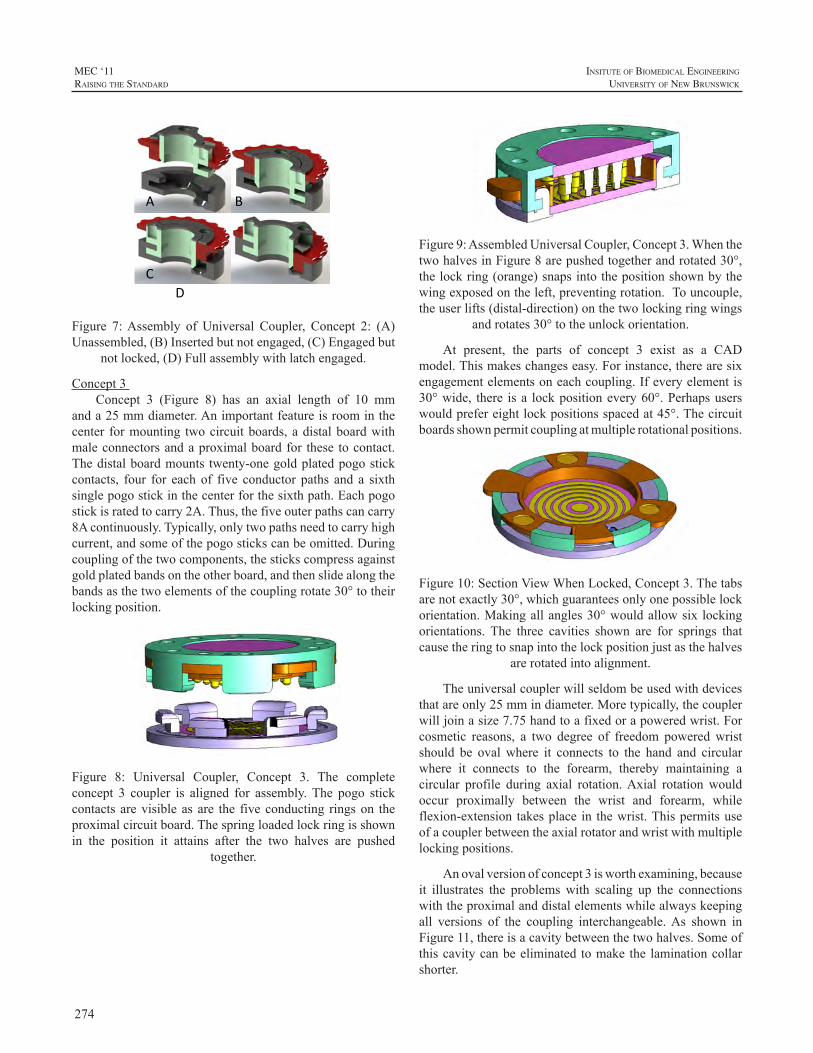
274
MEC ‘11raIsIng the standard
InsItute of BIomedIcal engIneerIng
unIversIty of new BrunswIck
A B C D
Figure 7:Assembly of Universal Coupler, Concept 2: (A)Unassembled,(B)Insertedbutnotengaged,(C)Engagedbut
notlocked,(D)Fullassemblywithlatchengaged.
Concept3Concept 3 (Figure 8) has an axial length of 10 mm
anda25mmdiameter.Animportantfeatureisroominthecenter formounting twocircuitboards,adistalboardwithmaleconnectorsandaproximalboardfor these tocontact.Thedistalboardmounts twenty-onegoldplatedpogostickcontacts, four for eachof five conductor paths and a sixthsinglepogostickinthecenterforthesixthpath.Eachpogostickisratedtocarry2A.Thus,thefiveouterpathscancarry8Acontinuously.Typically,onlytwopathsneedtocarryhighcurrent,andsomeofthepogostickscanbeomitted.Duringcouplingofthetwocomponents,thestickscompressagainstgoldplatedbandsontheotherboard,andthenslidealongthebandsasthetwoelementsofthecouplingrotate30°totheirlockingposition.
Figure 8: Universal Coupler, Concept 3. The completeconcept 3 coupler is aligned for assembly.The pogo stickcontacts arevisibleasare the fiveconducting ringson theproximalcircuitboard.Thespringloadedlockringisshownin the position it attains after the two halves are pushed
together.
Figure9:AssembledUniversalCoupler,Concept3.WhenthetwohalvesinFigure8arepushedtogetherandrotated30°,thelockring(orange)snapsintothepositionshownbythewingexposedontheleft,preventingrotation.Touncouple,theuserlifts(distal-direction)onthetwolockingringwings
androtates30°totheunlockorientation.
At present, the parts of concept 3 exist as a CADmodel.Thismakeschangeseasy.Forinstance,therearesixengagementelementsoneachcoupling.Ifeveryelementis30°wide, there isa lockpositionevery60°.Perhapsuserswouldprefereightlockpositionsspacedat45°.Thecircuitboardsshownpermitcouplingatmultiplerotationalpositions.
Figure10:SectionViewWhenLocked,Concept3.Thetabsarenotexactly30°,whichguaranteesonlyonepossiblelockorientation.Makingallangles30°wouldallowsix lockingorientations. The three cavities shown are for springs thatcausetheringtosnapintothelockpositionjustasthehalves
arerotatedintoalignment.
Theuniversalcouplerwillseldombeusedwithdevicesthatareonly25mmindiameter.Moretypically,thecouplerwilljoinasize7.75handtoafixedorapoweredwrist.Forcosmetic reasons, a two degree of freedom poweredwristshould be ovalwhere it connects to the hand and circularwhere it connects to the forearm, thereby maintaining acircular profile during axial rotation.Axial rotation wouldoccur proximally between the wrist and forearm, whileflexion-extension takesplace in thewrist.Thispermitsuseofacouplerbetweentheaxialrotatorandwristwithmultiplelockingpositions.
Anovalversionofconcept3isworthexamining,becauseit illustrates the problemswith scaling up the connectionswiththeproximalanddistalelementswhilealwayskeepingall versions of the coupling interchangeable.As shown inFigure11,thereisacavitybetweenthetwohalves.Someofthiscavitycanbeeliminated tomake the laminationcollarshorter.
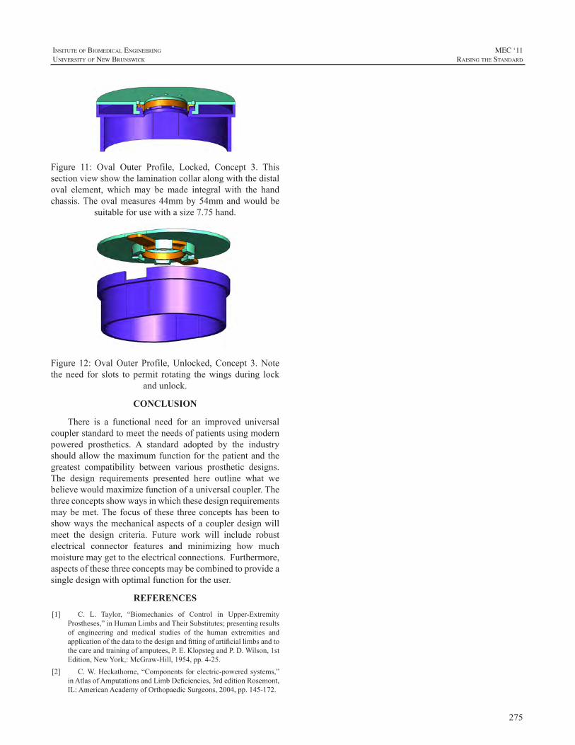
275
InsItute of BIomedIcal engIneerIng
unIversIty of new BrunswIck
MEC ‘11raIsIng the standard
Figure 11: Oval Outer Profile, Locked, Concept 3. Thissectionviewshowthelaminationcollaralongwiththedistaloval element, which may be made integral with the handchassis.Theovalmeasures44mmby54mmandwouldbe
suitableforusewithasize7.75hand.
Figure 12:OvalOuter Profile,Unlocked,Concept 3.Notetheneed for slots to permit rotating thewingsduring lock
andunlock.
CONCLUSION
There is a functional need for an improved universalcouplerstandardtomeettheneedsofpatientsusingmodernpowered prosthetics. A standard adopted by the industryshouldallowthemaximumfunctionforthepatientandthegreatest compatibility between various prosthetic designs.The design requirements presented here outline what webelievewouldmaximizefunctionofauniversalcoupler.Thethreeconceptsshowwaysinwhichthesedesignrequirementsmaybemet.Thefocusof these threeconceptshasbeentoshowwaysthemechanicalaspectsofacouplerdesignwillmeet the design criteria. Future work will include robustelectrical connector features and minimizing how muchmoisturemaygettotheelectricalconnections.Furthermore,aspectsofthesethreeconceptsmaybecombinedtoprovideasingledesignwithoptimalfunctionfortheuser.
REFERENCES
[1] C. L. Taylor, “Biomechanics of Control in Upper-ExtremityProstheses,”inHumanLimbsandTheirSubstitutes;presentingresultsof engineering and medical studies of the human extremities andapplicationofthedatatothedesignandfittingofartificiallimbsandtothecareandtrainingofamputees,P.E.KlopstegandP.D.Wilson,1stEdition,NewYork,:McGraw-Hill,1954,pp.4-25.
[2] C.W.Heckathorne,“Components forelectric-poweredsystems,”inAtlasofAmputationsandLimbDeficiencies,3rdeditionRosemont,IL:AmericanAcademyofOrthopaedicSurgeons,2004,pp.145-172.
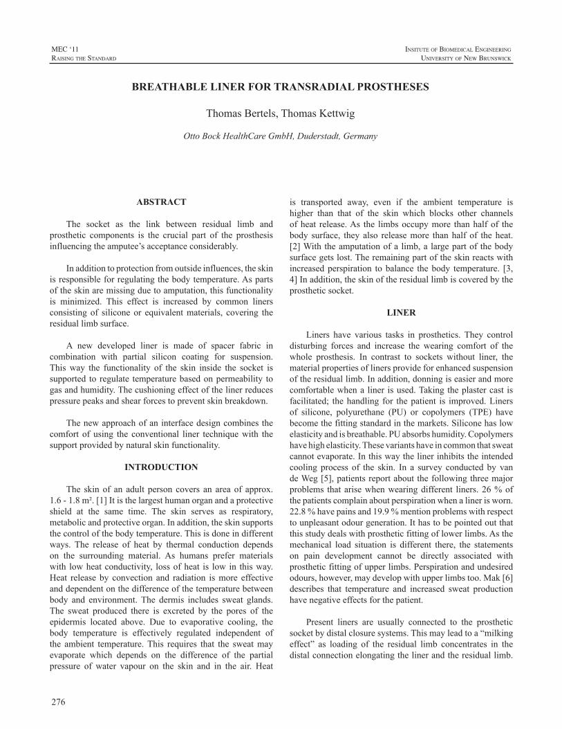
276
MEC ‘11raIsIng the standard
InsItute of BIomedIcal engIneerIng
unIversIty of new BrunswIck
ABSTRACT
The socket as the link between residual limb andprosthetic components is the crucial part of the prosthesisinfluencingtheamputee’sacceptanceconsiderably.
Inadditiontoprotectionfromoutsideinfluences,theskinisresponsibleforregulatingthebodytemperature.Aspartsoftheskinaremissingduetoamputation,thisfunctionalityis minimized. This effect is increased by common linersconsisting of silicone or equivalentmaterials, covering theresiduallimbsurface.
A new developed liner is made of spacer fabric incombination with partial silicon coating for suspension.Thisway the functionality of the skin inside the socket issupported to regulate temperaturebasedonpermeability togasandhumidity.Thecushioningeffectofthelinerreducespressurepeaksandshearforcestopreventskinbreakdown.
Thenewapproachofaninterfacedesigncombinesthecomfort of using the conventional liner techniquewith thesupportprovidedbynaturalskinfunctionality.
INTRODUCTION
The skin of an adult person covers an areaof approx.1.6-1.8m².[1]Itisthelargesthumanorganandaprotectiveshield at the same time. The skin serves as respiratory,metabolicandprotectiveorgan.Inaddition,theskinsupportsthecontrolofthebodytemperature.Thisisdoneindifferentways. The release of heat by thermal conduction dependson the surrounding material. As humans prefer materialswith lowheatconductivity, lossofheat is lowin thisway.Heat release by convection and radiation ismore effectiveanddependentonthedifferenceofthetemperaturebetweenbody and environment.The dermis includes sweat glands.The sweat produced there is excreted by the pores of theepidermis located above. Due to evaporative cooling, thebody temperature is effectively regulated independent ofthe ambient temperature.This requires that the sweatmayevaporate which depends on the difference of the partialpressure of water vapour on the skin and in the air. Heat
is transported away, even if the ambient temperature ishigher than that of the skin which blocks other channelsofheat release.As the limbsoccupymore thanhalfof thebody surface, they also releasemore thanhalf of theheat.[2]Withtheamputationofa limb,a largepartof thebodysurfacegetslost.Theremainingpartoftheskinreactswithincreasedperspiration tobalance thebody temperature. [3,4]Inaddition,theskinoftheresiduallimbiscoveredbytheprostheticsocket.
LINER
Liners have various tasks in prosthetics. They controldisturbing forces and increase the wearing comfort of thewhole prosthesis. In contrast to sockets without liner, thematerialpropertiesoflinersprovideforenhancedsuspensionoftheresiduallimb.Inaddition,donningiseasierandmorecomfortablewhena liner isused.Takingtheplastercast isfacilitated; thehandling for thepatient is improved.Linersof silicone, polyurethane (PU) or copolymers (TPE) havebecomethefittingstandardinthemarkets.Siliconehaslowelasticityandisbreathable.PUabsorbshumidity.Copolymershavehighelasticity.Thesevariantshaveincommonthatsweatcannotevaporate.Inthiswaythelinerinhibitstheintendedcooling process of the skin. In a survey conducted by vandeWeg[5],patientsreportaboutthefollowingthreemajorproblems thatarisewhenwearingdifferent liners.26%ofthepatientscomplainaboutperspirationwhenalinerisworn.22.8%havepainsand19.9%mentionproblemswithrespecttounpleasantodourgeneration.Ithastobepointedoutthatthisstudydealswithprostheticfittingoflowerlimbs.Asthemechanical load situation is different there, the statementson pain development cannot be directly associated withprostheticfittingofupperlimbs.Perspirationandundesiredodours,however,maydevelopwithupperlimbstoo.Mak[6]describes that temperature and increased sweat productionhavenegativeeffectsforthepatient.
Present liners are usually connected to the prostheticsocketbydistalclosuresystems.Thismayleadtoa“milkingeffect” as loading of the residual limb concentrates in thedistalconnectionelongatingthelinerandtheresiduallimb.
BREATHABLE LINER FOR TRANSRADIAL PROSTHESES
ThomasBertels,ThomasKettwig
OttoBockHealthCareGmbH,Duderstadt,Germany
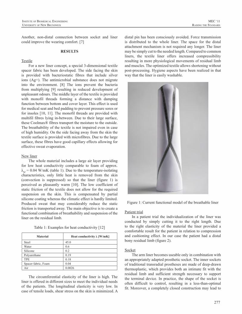
277
InsItute of BIomedIcal engIneerIng
unIversIty of new BrunswIck
MEC ‘11raIsIng the standard
Another, non-distal connection between socket and linercouldimprovethewearingcomfort.[7]
RESULTS
TextileForanewlinerconcept,aspecial3-dimensionaltextile
spacer fabrichasbeendeveloped.The side facing the skinis provided with bacteriostatic fibres that include silverions (Ag+). The antimicrobial substance does not migrateinto the environment. [8] The ions prevent the bacteriafrom multiplying [9] resulting in reduced development ofunpleasantodours.Themiddlelayerofthetextileisprovidedwith monofil threads forming a distance with dampingfunctionbetweenbottomandcoverlayer.Thiseffectisusedformedicalseatandbedpaddingtopreventpressuresoresorfor insoles[10,11].Themonofil threadsareprovidedwithmultifil fibres lying in-between.Due to their large surface,theseCoolmax®fibrestransportthemoisturetotheoutside.Thebreathabilityofthetextileisnotimpairedevenincaseofhighhumidity.Onthesidefacingawayfromtheskinthetextilesurfaceisprovidedwithmicrofibres.Duetothelargesurface,thesefibreshavegoodcapillaryeffectsallowingforeffectivesweatevaporation.
NewlinerThewholematerialincludesalargeairlayerproviding
for low heat conductivity comparable to foam of approx.λSf=0.04W/mK(table1).Duetothetemperature-isolatingcharacteristics, only little heat is removed from the skin(convection is suppressed) so that the liner (figure 1) isperceived as pleasantlywarm [10].The low coefficient ofstatic frictionof the textiledoesnot allow for the requiredsuspension on the skin. This is compensated by partialsiliconecoatingwhereastheclimaticeffectishardlylimited.Produced sweat that may considerably reduce the staticfrictionistransportedaway.Themainobjectiveistocreateafunctionalcombinationofbreathabilityandsuspensionofthelinerontheresiduallimb.
Table1:Examplesforheatconductivity[12]
Material Heat conductivity λ [W/mK]
Steel 45.0Water 0.6Silicone 0.2Polyurethane 0.19TPE 0.18Spacerfabric,Foam 0.04Air 0.0026
The circumferential elasticity of the liner is high.Thelinerisofferedindifferentsizestomeettheindividualneedsof the patients. The longitudinal elasticity is very low. Incaseoftensileloads,shearstressontheskinisminimized.A
distalpinhasbeenconsciouslyavoided.Forcetransmissionis distributed to the whole liner. The space for the distalattachmentmechanismisnotrequiredanylonger.Thelinermaybesimplycuttotheneededlength.Comparedtocommonliners, the textile liner offers increased compressibilityresultinginmorephysiologicalmovementsofresiduallimbandmuscles.Theoptimizedtextileallowsshorteningwithoutpost-processing.Hygieneaspectshavebeenrealizedinthatwaythatthelineriseasilywashable.
Figure1:Currentfunctionalmodelofthebreathableliner
PatienttrialIn a patient trial the individualization of the linerwas
conducted by simply cutting it to the right length. Dueto the right elasticity of the material the liner provided acomfortableresultforthepatientinrelationtocompressionand cushioning effect. In our case the patient had a distalbonyresiduallimb(figure2).
SocketThearmlinerbecomesuseableonlyincombinationwith
anappropriatelyadaptedprostheticsocket.Theinnersocketsoftraditionaltransradialprosthesesaremadeofdeep-drawnthermoplastic,whichprovidesbothan intimate fitwith theresidual limb and sufficient strength necessary to supportthe terminal device. In practice, the shape of the socket isoften difficult to control, resulting in a less-than-optimalfit.Moreover,acompletelyclosedconstructionmayleadto
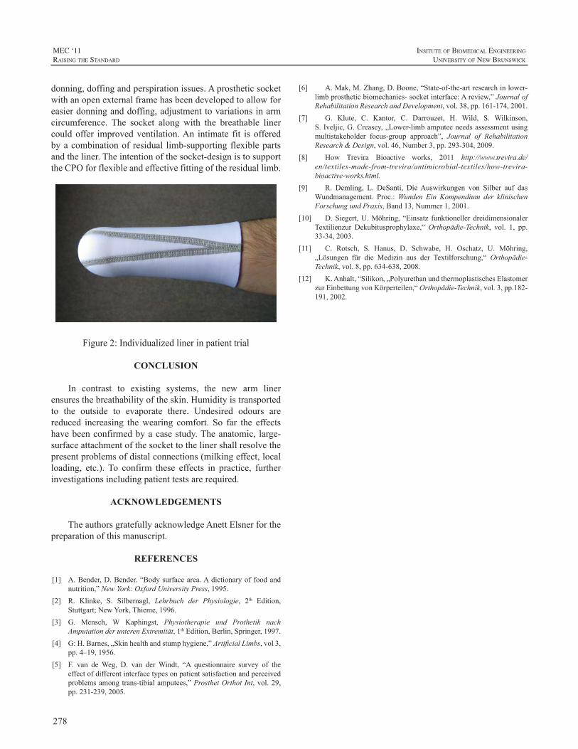
278
MEC ‘11raIsIng the standard
InsItute of BIomedIcal engIneerIng
unIversIty of new BrunswIck
donning,doffingandperspirationissues.Aprostheticsocketwithanopenexternalframehasbeendevelopedtoallowforeasierdonninganddoffing,adjustmenttovariationsinarmcircumference. The socket along with the breathable linercouldoffer improvedventilation.An intimate fit isofferedbyacombinationofresidual limb-supportingflexiblepartsandtheliner.Theintentionofthesocket-designistosupporttheCPOforflexibleandeffectivefittingoftheresiduallimb.
Figure2:Individualizedlinerinpatienttrial
CONCLUSION
In contrast to existing systems, the new arm linerensuresthebreathabilityoftheskin.Humidityistransportedto the outside to evaporate there. Undesired odours arereduced increasing thewearing comfort. So far the effectshavebeenconfirmedbyacasestudy.Theanatomic, large-surfaceattachmentofthesockettothelinershallresolvethepresentproblemsofdistalconnections(milkingeffect,localloading, etc.). To confirm these effects in practice, furtherinvestigationsincludingpatienttestsarerequired.
ACKNOWLEDGEMENTS
TheauthorsgratefullyacknowledgeAnettElsnerforthepreparationofthismanuscript.
REFERENCES
[1] A.Bender,D.Bender.“Bodysurfacearea.Adictionaryoffoodandnutrition,”NewYork:OxfordUniversityPress,1995.
[2] R. Klinke, S. Silbernagl, Lehrbuch der Physiologie, 2th Edition,Stuttgart;NewYork,Thieme,1996.
[3] G. Mensch, W Kaphingst, Physiotherapie und Prothetik nachAmputationderunterenExtremität,1thEdition,Berlin,Springer,1997.
[4] G:H.Barnes,„Skinhealthandstumphygiene,”ArtificialLimbs,vol3,pp.4–19,1956.
[5] F. van deWeg, D. van derWindt, “A questionnaire survey of theeffectofdifferentinterfacetypesonpatientsatisfactionandperceivedproblemsamongtrans-tibialamputees,”ProsthetOrthotInt,vol.29,pp.231-239,2005.
[6] A.Mak,M.Zhang,D.Boone,“State-of-the-artresearchinlower-limbprostheticbiomechanics-socketinterface:Areview,”JournalofRehabilitationResearchandDevelopment,vol.38,pp.161-174,2001.
[7] G. Klute, C. Kantor, C. Darrouzet, H. Wild, S. Wilkinson,S.Iveljic,G.Creasey,„Lower-limbamputeeneedsassessmentusingmultistakeholder focus-group approach”, Journal of RehabilitationResearch&Design,vol.46,Number3,pp.293-304,2009.
[8] How Trevira Bioactive works, 2011 http://www.trevira.de/en/textiles-made-from-trevira/antimicrobial-textiles/how-trevira-bioactive-works.html.
[9] R. Demling, L. DeSanti, DieAuswirkungen von Silber auf dasWundmanagement. Proc.:Wunden Ein Kompendium der klinischenForschungundPraxis,Band13,Nummer1,2001.
[10] D.Siegert,U.Möhring, “Einsatz funktionellerdreidimensionalerTextilienzur Dekubitusprophylaxe,“Orthopädie-Technik, vol. 1, pp.33-34,2003.
[11] C. Rotsch, S. Hanus, D. Schwabe, H. Oschatz, U. Möhring,„Lösungen für die Medizin aus der Textilforschung,“ Orthopädie-Technik,vol.8,pp.634-638,2008.
[12] K.Anhalt,“Silikon,„PolyurethanundthermoplastischesElastomerzurEinbettungvonKörperteilen,“Orthopädie-Technik,vol.3,pp.182-191,2002.
279
InsItute of BIomedIcal engIneerIng
unIversIty of new BrunswIck
MEC ‘11raIsIng the standard
INTRODUCTION
ThebebionichandbyRSLSteeperisafullyarticulatingmyo-electric hand with multiple pre-programmed grippositions. Increased function and hand flexibility providesdesignengineerswithchallengesinmaintainingreliabilityandmeetingincreasinguserdemands.Thispaperwilldiscussthetechnicalattributes,keydesignelementsandthephilosophyoftheirselectionandevolution,aswellas thoughtsfor thefuture. Special attention will be paid to thumb and digitdesign,feedbackloop,materialandhardwareselection.
Thehand is controlled in a similarway toothermyo-electrichandsbycontrolledmusclecontraction.Electrodesmeasureelectricalchangesontheskincoveringthecontrolmuscles,andinstructthefiveindividualactuatorswithinthehandtoprovidethedesiredmovements.
The hand incorporates five high speed/force motorsand isdesigned for lowpower consumption.Thenaturallycompliant fingers and thumbof the bebionic handprovideasecureplatformtoperformeverydaytasksusingcommongrippatterns.
TECHNICAL INFORMATION
PrincipalDimensionsTable1:PrincipalDimensionsofbebionicHands
Principal Dimensions Large Hand Medium Hand
A MiddleFingerTiptoHandBase 200mm 190mm
B ThumbTiptoHandBase 125mm 121mm
C MaxChassisWidth(noglove) 92mm 84mm
D DiameterofChassisatWrist 50mm 50mm
PalmCircumference(noglove) 220mm 204mm
MaximumOpeningwidthTripodGrip
105mmwithglove
105mmwithglove
ThumbSwingThroughAngle 68° 68°
X EQDonly 5mm 5mm
Figure1:bebionicv2Hand
PerformanceSpecificationTable2:PerformanceSpecificationsofbebionicHand
Large Hand Medium Hand
MaximumPowerGrip 16.8ftlbs(75N)
16.8ftlbs(75N)
MaximumTripodGrip 7.6ftlbs(34N)
7.6ftlbs(34N)
MinimumTimetoClose–TripodGrip 0.4Seconds 0.4Seconds
MinimumTimetoClose–PowerGrip 0.9Seconds 0.9Seconds
MinimumTimetoClose–KeyGrip 0.9Seconds 0.9Seconds
MaximumStaticLoad–HookGrip 70.5lbs(32kg) 70.5lbs(32kg)
MaximumLoadIndividualFinger–HookGrip 35.2lbs(16kg) 35.2lbs(16kg)
FingerTipExtensionLoad 13.2lbs(6kg) 13.2lbs(6kg)
Maximumsafeverticalloadtakenthroughknuckles
198.4lbs(90kg)
198.4lbs(90kg)
KEY DESIGN FEATURES
The bebionic hand has many sophisticated designfeaturesprovidingflexibilityforbothuserandpractitioner.
BEBIONIC PROSTHETIC DESIGN
CourtneyMedynskiBEngEIT,BruceRattrayBScP/O
RSLSteeperUnit7,HunsletTradingEstate,SevernRoad,WestYorkshire,LS101BL,UK
280
MEC ‘11raIsIng the standard
InsItute of BIomedIcal engIneerIng
unIversIty of new BrunswIck
FingerDesignThe bebionic hand features individually powered,
articulated digits each driven by and linked to its own 6Vactuator. The actuators are positioned within the palm toprovideabeneficialsolutionforweightdistribution.
Theactuatorsareassembledwith individualseparatelyprogrammed PCB’s with onboard microprocessors. Thesearecodedtoconstantlytracktheplacementofeachdigitandprovideprecisecontrol.Thisensuresaccurategripsequencesand digits performing synchronized movements togethereverytime.
An aluminum lead screw nut attaches the actuator toits individual finger proximal through carefully designedfoldaway links. Made of nylon (TechnylA218V30) thesefoldaway finger links allow the fingers to flex freely andnaturally,aswellasallowtheusertopushupto90kgthroughthehandtoaidinstandingfromaseatedposition,afeatureespeciallyusefulforthebilateralamputee.
In the event ofmechanical overload it is important toprotect theunit.Thedesignaccomplishes thiswithashearpinfittedaspartofthefingerlinkage.Theshearpinismadefrompeekandisdesignedtofractureunderapredeterminedextension load, thus preventing damage to the finger andmotor.Theshearpincanbereplacedlocallybytheclinicalteam.
The finger proximal moulds are shared between theindex,middleandringfingerandareofanextremelyrobustconstructionutilisinghighimpactthermoplastic,HostaformC9021 GV3/20 (POM). All joint connections are lockedwith titanium fixed fasteners and square extension returnsprings.Thesematerialsmaintainahighdegreeofstrengthanddurabilitywhilstreducingweight.Eachfingeralsohastip mounted soft pads made from silicone. The palps aremoulded in halves and shared between the index and ringfinger.
Fieldreplacementsof individualdigitscanbedonebycarefully removing the shear pin, closing thehand slightlytolowertheleadscrewnutandthenremovingthehexscrewfromtheknucklebase.
ThumbDesignThe thumb also utilizes its own actuator and can be
manually placed in one of two positions, opposed or non-opposedtothefingers.Locatedatthebaseofthethumbmotorisanylon(DerlinAF)trunnionnutwhichfitsdirectlyintothealuminum (AL-LM25TF) thumbbracket.Awishbone link,madefromsiliconebrass,attachesthebackofthebrackettotheactuatortoprovidestabilityandallowmovementtowardsandawayfromthepalm.
Thethumbbracketisattachedtothechassisbasethroughafittedlowercam,mountingboltandspringassembly.Thisrobust assemblyallows for continualmanualmovementofthe thumbwitha68degree rangeofbaselineadjustability.Thecamdesignallowsthethumbtolockintoanopposingor non-opposing position. This prevents the patient fromwastingtimealigningthethumbandallowsforfastselectionof grip patterns through the feedback loop (read switch).Also,whenthethumbis lockeditcannotbackawayunderload,forexampleifthefinger-objectishittingoffcenter.
Areadswitchislocatedontherearchassisneartheoutersideof the thumbbracketandworks inconjunctionwithasmall magnet located in the same vicinity on the bracket.Whenthethumbisinanon-opposingpositionthemagnetisincloseenoughproximitytoenablethereadswitchcausingthenon-opposedhandgripstobefacilitated.Withthethumbinopposedposition,themagnetcannotenablethereadswitchandthereforetheopposedsetofgripsareused.
Thumb alignment adjustment has been added to thedesign to allow clinical staff to reposition the thumb foradditional grips or realign strike points as required bypatientneed.Thethumbincludesamedial-lateraladjustertorepositioncontactwitheithertheindexandmiddlefingersorwiththeindexfingeralone.Aslottedscrewisfittedwithinthethumbpivotassemblyandactstoadjustthefrictionontheinternalclamp.Toloosenrequiresturningtwocompleteturnsthenpushingthescrewinward.Withtheclampslackenedthethumbpositioncanbemanuallyre-positioned.Theassemblymustberetightenedbeforeelectricallydrivingthethumb.
Another adjuster, located under the thumb base, isintegrated to alter the baseline position of the thumb.Thismovesthethumbeithertowardsthepalmorawayfromthepalminordertooptimizethecontactpointofthethumbtipagainsttheopposingfinger(s).Usingaflatbladedscrewdrivertheadjustershouldbeturnedclockwisetomovethethumbtowardsthepalmandcounter-clockwisetomovethethumbawayfromthepalm.Theeffectwillonlybeobservedafterresetting the hand (turning the battery switch off/on), notwhilstmakingtheadjustment.
ChassisArchitectureThe rear chassis provides attachment of the thumb
through the bracket, lower cam,mounting bolt and springassembly.TheselectedbebionicwristtypeisattachedtothebaseoftherearchassisandheldinplacewiththreeM3x8SKTcapscrews.Thechassisisuniquelydesignedtoconformto the shapeof thepalmPCBwhich is slid in andheld inplacewithanM2x6PANPOZIthreadformingscrew.
The front chassis design conformably houses the fourfingeractuatorsandagearcover,whileprovidingattachment
281
InsItute of BIomedIcal engIneerIng
unIversIty of new BrunswIck
MEC ‘11raIsIng the standard
and placement for the knuckles. The gear cover (ABSmaterial) protects the finger actuators from dust particleswhilealsoprovidingashieldforthepalmPCBandwiring.Attachmentofthefrontchassistotherearchassisisdoneinthree places.AnM3 16PANPOZI thread forming screwlocated in the outer palm of the front chassis attaches itdirectlytotherearchassis.AnM3x16SKTheadcapscrewbelowthefirstfingeronthefrontchassisattachesitthroughtherearchassisthumbbolt.Thisalsoholdsthethumbbolt/bracket assembly in place. The third connection point islocatedonthebackofthehandandincludesachassislink,T-boltandM3x12SKTheadcapscrewassemblythatalsocontributestofurtherstabilizingthepalmPCB.
Thetopchassis,orbackcover,providesfinalenclosureandeasyaccesstothefingeractuatorsandpalmPBC.AnRFID tag isplacedon the insideof thecover toprovideeasyidentificationofeachhand.Atthetopofthecoverarethreepinsdesignedtoslideintoadjacentholeslocatedonthefrontchassis beneath the back of the knuckles.The base of thecover issecureddirectlyto therearchassiswithtwoM2x10mmtrimetthreadformingscrew.
ProgramSwitchLocatedonthebackofthehandisamembraneswitch
that utilises flexible PCB tracks to connect directly to thepalmPCB.Thetactiledesignallowstheusedtoeasilylocateit beneath a glove. The switch has four functions and isintegratedwithselectablebleepandvibrateswitchindicators,whichcanbeactivatedthroughthebebalancesoftware.
GripPatternsThe bebionic v2 hand can provide 14 selectable grip
patterns/handpositions.
Thethumbhastwouserselectablepositions–opposedandnon-opposed–withtwogrippatternsavailableineachposition,thusprovidingfourprimarygrippatterns.Theusercansequencebetweenthedefaultandalternativegrippatternfor each thumb position by applying an OPEN OPEN orco-contraction signal (dependingonwhat setting is chosenwithin the bebalance software). To gain access to fourfurthergrippatterns,theusercanalternatefromtheprimarygrippatterns,tothesecondarygrippatternsbypressingtheprogramswitch.
Several grip patterns – Hook Grip, FingerAdductionandFlatHand–areachievedaspartialgripsofanothergrippatternandthereforedonotneedtobeactivelyselected.Forinstance,apartialcloseinPowerGripprovidesHookGrip.Amaximumof10outof the14grippatternsare thereforeavailabletotheuseratanyonetime.Individualfingerscanalso be stalled manually by applying resistance, allowingfurtherhandpositions.
To achieve certain grip patterns it is necessary for thepractitionertoadjustthethumbalignmentsothatthecontactposition between the finger(s) and thumb is changed. Forinstance,thethumbcontactsontheindexfingerforPrecisionandPinchGriprather thantheindexandthemiddlefingerforTripodGrip.
This represents an increase of grip patterns comparedwiththeversion1bebionichand,anddemonstrateshownewunique hand patterns such asMOUSE gripmay easily becreated.
ElectronicMonitoringofDigitPositionThe code sets a starting point for the counter when
hand is first powered up. The number of revolutions ofeach actuator is counted in order tomonitor placement ofindividualmotors.Thisprovidesaccurateandrepeatablegrippatterns.
AutoGripFeatureAuto Grip is a selectable electronic feature that can
be enabled or disabled through the bebalance software.It functionsonlywith the thumbopposedand inTripodorPinchGrips.OnceenabledautoGripisactivatedbytheuserproviding three consecutive close signals and de-activatedwhenthehandisopened.
Therotationof thefingeractuators ismonitoredevery50ms.Movementorslippageofaheldobjectisdetectedbymotorrotation.Theappropriatemotorsaredriventopreventthismovementoccurringbychangingfingerposition/gripforce and therefore automatically providing amore securegrip.
BEBALANCE SOFTWARE
The hand is programmed using Bebalance softwaredeveloped by RSLSteeper. Information is transmittedwirelessly to and from the system. A radio frequencytransmitter/receivermoduleisincorporatedwithinthehand.Thesoftwareallowscontrolparameterssuchashandspeed,grip force and grip selection to be individually optimized,set and stored. It alsoprovides a rangeof controlmethodsusing one or two electrodes, or other inputs.The softwareprovides real time analysis including adjustment of usersignalandallowstheusertopracticeusingvisualfeedback.Thesoftwarealsoallowsahandtobe‘read’todetermineitsexistingprogramsettings.
FUTURE THOUGHTS
The bebionic wrist allows the patient to performrotation, flexion and extension for either a left or righthand. It uses a singlemotor to accommodateboth actions.
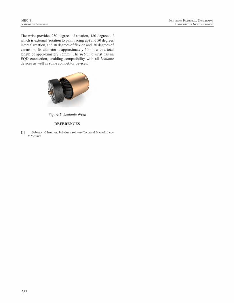
282
MEC ‘11raIsIng the standard
InsItute of BIomedIcal engIneerIng
unIversIty of new BrunswIck
Thewristprovides230degreesof rotation,180degreesofwhichisexternal(rotationtopalmfacingup)and50degreesinternalrotation,and30degreesofflexionand30degreesofextension.Itsdiameter isapproximately50mmwitha totallengthofapproximately75mm..ThebebionicwristhasanEQD connection, enabling compatibility with all bebionicdevicesaswellassomecompetitordevices.
Figure2:bebionicWrist
REFERENCES
[1] Bebionicv2handandbebalancesoftwareTechnicalManual.Large&Medium
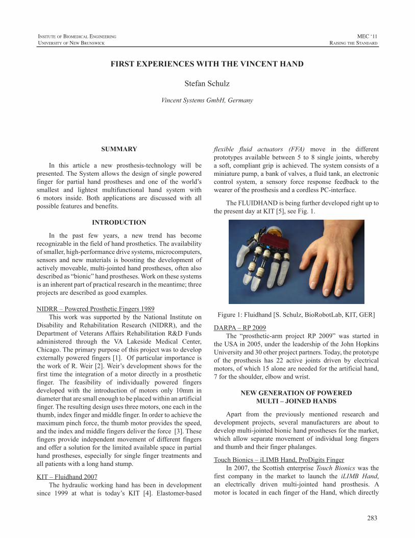
283
InsItute of BIomedIcal engIneerIng
unIversIty of new BrunswIck
MEC ‘11raIsIng the standard
SUMMARY
In this article a new prosthesis-technology will bepresented.TheSystemallowsthedesignofsinglepoweredfinger for partial hand prostheses and one of the world’ssmallest and lightest multifunctional hand system with6 motors inside. Both applications are discussed with allpossiblefeaturesandbenefits.
INTRODUCTION
In the past few years, a new trend has becomerecognizableinthefieldofhandprosthetics.Theavailabilityofsmaller,high-performancedrivesystems,microcomputers,sensors and newmaterials is boosting the development ofactivelymoveable,multi-jointedhandprostheses,oftenalsodescribedas“bionic”handprostheses.Workonthesesystemsisaninherentpartofpracticalresearchinthemeantime;threeprojectsaredescribedasgoodexamples.
NIDRR–PoweredProstheticFingers1989Thisworkwas supported by theNational Institute on
Disability and Rehabilitation Research (NIDRR), and theDepartment ofVeteransAffairsRehabilitationR&DFundsadministered through the VA Lakeside Medical Center,Chicago.Theprimarypurposeofthisprojectwastodevelopexternallypoweredfingers[1].OfparticularimportanceistheworkofR.Weir[2].Weir’sdevelopmentshowsforthefirst time the integrationofamotordirectly inaprostheticfinger. The feasibility of individually powered fingersdeveloped with the introduction of motors only 10mm indiameterthataresmallenoughtobeplacedwithinanartificialfinger.Theresultingdesignusesthreemotors,oneeachinthethumb,indexfingerandmiddlefinger.Inordertoachievethemaximumpinchforce,thethumbmotorprovidesthespeed,andtheindexandmiddlefingersdelivertheforce[3].Thesefingers provide independentmovement of different fingersandofferasolutionforthelimitedavailablespaceinpartialhandprostheses,especiallyforsinglefinger treatmentsandallpatientswithalonghandstump.
KIT–Fluidhand2007The hydraulicworking hand has been in development
since 1999 at what is today’s KIT [4]. Elastomer-based
flexible fluid actuators (FFA) move in the differentprototypes available between 5 to 8 single joints,wherebyasoft,compliantgripisachieved.Thesystemconsistsofaminiaturepump,abankofvalves,afluidtank,anelectroniccontrol system, a sensory force response feedback to theweareroftheprosthesisandacordlessPC-interface.
TheFLUIDHANDisbeingfurtherdevelopedrightuptothepresentdayatKIT[5],seeFig.1.
Figure1:Fluidhand[S.Schulz,BioRobotLab,KIT,GER]
DARPA–RP2009The “prosthetic-arm project RP 2009” was started in
theUSAin2005,undertheleadershipoftheJohnHopkinsUniversityand30otherprojectpartners.Today,theprototypeof the prosthesis has 22 active joints driven by electricalmotors,ofwhich15aloneareneededfortheartificialhand,7fortheshoulder,elbowandwrist.
NEW GENERATION OF POWERED MULTI – JOINED HANDS
Apart from the previously mentioned research anddevelopment projects, several manufacturers are about todevelopmulti-jointedbionichandprosthesesforthemarket,which allow separatemovement of individual long fingersandthumbandtheirfingerphalanges.
TouchBionics–iLIMBHand,ProDigitsFingerIn2007, theScottishenterpriseTouchBionicswas the
first company in the market to launch the iLIMB Hand,an electrically driven multi-jointed hand prosthesis. Amotoris locatedineachfingerof theHand,whichdirectly
FIRST EXPERIENCES WITH THE VINCENT HAND
StefanSchulz
VincentSystemsGmbH,Germany
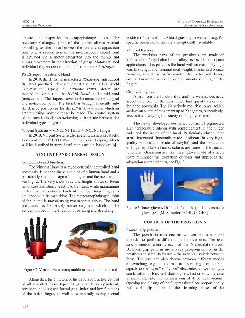
284
MEC ‘11raIsIng the standard
InsItute of BIomedIcal engIneerIng
unIversIty of new BrunswIck
actuates the respective metacarpophalangeal joint. Themetacarpophalangeal joint of the thumb allows manualswivelling to takeplacebetween the lateralandoppositionpositions.A second axis of the metacarpophalangeal jointis actuated via a motor integrated into the thumb andallowsmovement in thedirectionofgrasp.Motor-actuatedindividualfingersareavailableunderthenameProDigits.
RSLSteeper–BeBionicHandIn2010,theBritishmanufacturerRSLSteeperintroduced
its latest prosthetic development at the 13th ICPO WorldCongress in Leipzig, the BeBionic Hand. Motors arelocated in contrast to the iLIMB Hand in the mid-hand(metacarpus).Thefingersmovesinthemetacarpophalangealandmetacarpal joint. The thumb is broughtmanually intothedesiredpositionasforthe iLIMBHand,fromwhichanactiveclosingmovementcanbemade.Thecontrol systemof theprosthesis allows switching tobemadebetween theindividualtypesofgrasp.
VincentSystems–VINCENTHand,VINCENTFingerIn2010,VincentSystemsalsopresentedanewprosthetic
systemat the13th ICPOWorldCongress inLeipzig,whichwillbedescribedinmoredetailinthisarticle,basedon[6].
VINCENT HAND GENERAL DESIGN
ComponentsandfunctionsTheVincentHandisamyoelectricallycontrolledhand
prosthesis.Ithastheshapeandsizeofahumanhandandaparticularlyslenderdesignofthefingersandthemetacarpus,seeFig.2.Theveryshortstructuralheightallowsdifferenthandsizesandstumplengthstobefitted,whilemaintaininganatomical proportions. Each of the four long fingers isequippedwithitsowndrive.Themetacarpophalangealjointofthethumbismovedusingtwoseparatedrives.Thehandprosthesis has 10 actively moveable joints, which can beactivelymovedinthedirectionofbendingandstretching.
Figure2:VincentHandcomparableinsizetohumanhand
Altogether,the6motorsofthehandallowactivecontrolof all essential basic types of grip, such as cylindrical,precision,hookingandlateralgrip,indexandkeyfunctionsof the index finger, as well as a naturally acting normal
positionofthehand.Individualgraspingmovementse.g.forspecificprofessionaluse,arealsooptionallyavailable.
MaterialfeaturesThe precision parts of the prosthesis are made of
high-tensile forged aluminium alloy, as used in aerospaceapplications.Thisprovidesthehandwithanextremelyhightensilestrengthandminimaltotalweight.Plasticandbronzebearings, as well as surface-coated steel axles and drives,ensure low-wear in operation and smooth running of thefingers.
Cosmetic–gloveApart from the functionality and theweight, cosmetic
aspects are one of the most important quality criteria ofthehandprosthesis.The10activelymovable joints,whichachieveanextentofmovementupto90degrees,respectively,necessitateaveryhighelasticityoftheglovematerial.
The newly developed cosmetics consist of pigmentedhigh temperature silicon with reinforcement in the fingerpads and the inside of the hand. Particularly elastic jointareas, integrated fingernailsmade of silicon (in very high-quality models also made of acrylic), and the simulationof finger tip-like surface structuresare someof the specialfunctional characteristics.An inner glove made of siliconfoam minimises the formation of folds and improves theadaptationcharacteristics,seeFig.3.
Figure3:Innerglovewithsiliconfoam(le.),siliconcosmeticglove(re.)[M.Schaefer,POHLIG,GER]
CONTROL OF THE PROSTHESIS
ControlgrippatternsThe prosthesis uses one or two sensors as standard
in order to perform different hand movements. The usersubconsciously controls each of the 6 articulation axes.Different grip patterns are already pre-programmed in theprosthesistosimplifyitsuse–theusermayswitchbetweenthese. The user can also choose between different modesof switching, e.g., co-contraction, short single or double-signals to the“open”or“close”electrodes,aswellasbyacombinationoflongandshortsignals,fastorslowincreaseinsignalintensityandcombinationsofalloftheseoptions.Openingandclosingofthefingerstakesplaceproportionallywith each grip pattern. In the “learning phase” of the
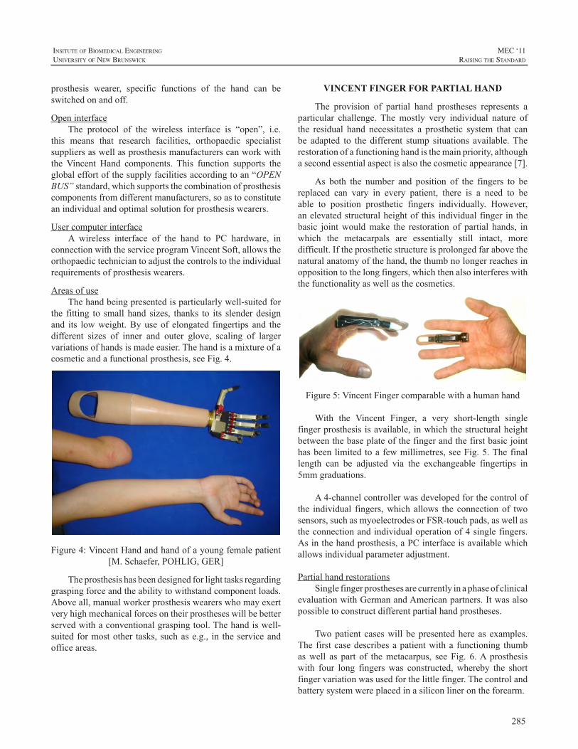
285
InsItute of BIomedIcal engIneerIng
unIversIty of new BrunswIck
MEC ‘11raIsIng the standard
prosthesis wearer, specific functions of the hand can beswitchedonandoff.
OpeninterfaceThe protocol of the wireless interface is “open”, i.e.
this means that research facilities, orthopaedic specialistsuppliersaswellasprosthesismanufacturerscanworkwiththe Vincent Hand components. This function supports theglobaleffortofthesupplyfacilitiesaccordingtoan“OPENBUS”standard,whichsupportsthecombinationofprosthesiscomponentsfromdifferentmanufacturers,soastoconstituteanindividualandoptimalsolutionforprosthesiswearers.
UsercomputerinterfaceA wireless interface of the hand to PC hardware, in
connectionwiththeserviceprogramVincentSoft,allowstheorthopaedictechniciantoadjustthecontrolstotheindividualrequirementsofprosthesiswearers.
AreasofuseThehandbeingpresentedisparticularlywell-suitedfor
the fitting to small hand sizes, thanks to its slenderdesignand its lowweight.Byuseof elongated fingertips and thedifferent sizes of inner and outer glove, scaling of largervariationsofhandsismadeeasier.Thehandisamixtureofacosmeticandafunctionalprosthesis,seeFig.4.
Figure4:VincentHandandhandofayoungfemalepatient[M.Schaefer,POHLIG,GER]
Theprosthesishasbeendesignedforlighttasksregardinggraspingforceandtheabilitytowithstandcomponentloads.Aboveall,manualworkerprosthesiswearerswhomayexertveryhighmechanicalforcesontheirprostheseswillbebetterservedwithaconventionalgraspingtool.Thehandiswell-suitedformostother tasks,suchase.g., in theserviceandofficeareas.
VINCENT FINGER FOR PARTIAL HAND
The provision of partial hand prostheses represents aparticular challenge. The mostly very individual nature ofthe residual hand necessitates a prosthetic system that canbe adapted to the different stump situations available.Therestorationofafunctioninghandisthemainpriority,althoughasecondessentialaspectisalsothecosmeticappearance[7].
As both the number and position of the fingers to bereplaced can vary in every patient, there is a need to beable to position prosthetic fingers individually. However,anelevatedstructuralheightofthisindividualfingerinthebasic jointwouldmake the restoration of partial hands, inwhich the metacarpals are essentially still intact, moredifficult.Iftheprostheticstructureisprolongedfarabovethenaturalanatomyofthehand,thethumbnolongerreachesinoppositiontothelongfingers,whichthenalsointerfereswiththefunctionalityaswellasthecosmetics.
Figure5:VincentFingercomparablewithahumanhand
With the Vincent Finger, a very short-length singlefingerprosthesisisavailable,inwhichthestructuralheightbetweenthebaseplateofthefingerandthefirstbasicjointhasbeenlimitedtoafewmillimetres,seeFig.5.Thefinallength can be adjusted via the exchangeable fingertips in5mmgraduations.
A4-channelcontrollerwasdevelopedforthecontrolofthe individual fingers,which allows the connectionof twosensors,suchasmyoelectrodesorFSR-touchpads,aswellastheconnectionandindividualoperationof4singlefingers.Asinthehandprosthesis,aPCinterfaceisavailablewhichallowsindividualparameteradjustment.
PartialhandrestorationsSinglefingerprosthesesarecurrentlyinaphaseofclinical
evaluationwithGermanandAmericanpartners.Itwasalsopossibletoconstructdifferentpartialhandprostheses.
Twopatient caseswill bepresentedhere as examples.Thefirstcasedescribesapatientwitha functioning thumbaswell as part of themetacarpus, see Fig. 6.A prosthesiswith four long fingerswas constructed,whereby the shortfingervariationwasusedforthelittlefinger.Thecontrolandbatterysystemwereplacedinasiliconlinerontheforearm.
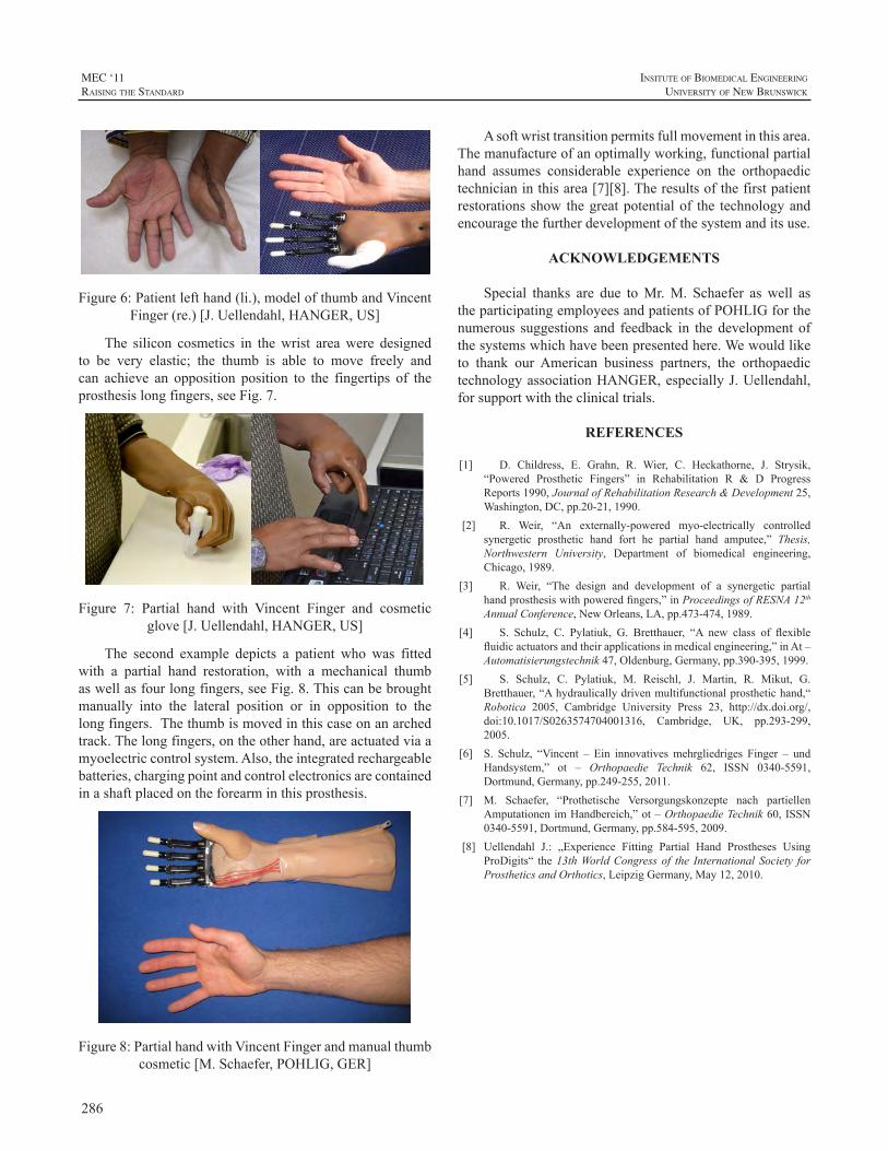
286
MEC ‘11raIsIng the standard
InsItute of BIomedIcal engIneerIng
unIversIty of new BrunswIck
Figure6:Patientlefthand(li.),modelofthumbandVincentFinger(re.)[J.Uellendahl,HANGER,US]
The silicon cosmetics in thewrist areawere designedto be very elastic; the thumb is able to move freely andcan achieve an opposition position to the fingertips of theprosthesislongfingers,seeFig.7.
Figure 7: Partial hand with Vincent Finger and cosmeticglove[J.Uellendahl,HANGER,US]
The second example depicts a patient who was fittedwith a partial hand restoration, with a mechanical thumbaswellasfourlongfingers,seeFig.8.Thiscanbebroughtmanually into the lateral position or in opposition to thelongfingers.Thethumbismovedinthiscaseonanarchedtrack.Thelongfingers,ontheotherhand,areactuatedviaamyoelectriccontrolsystem.Also,theintegratedrechargeablebatteries,chargingpointandcontrolelectronicsarecontainedinashaftplacedontheforearminthisprosthesis.
Figure8:PartialhandwithVincentFingerandmanualthumbcosmetic[M.Schaefer,POHLIG,GER]
Asoftwristtransitionpermitsfullmovementinthisarea.Themanufactureofanoptimallyworking,functionalpartialhand assumes considerable experience on the orthopaedictechnicianinthisarea[7][8].Theresultsofthefirstpatientrestorationsshow thegreatpotentialof the technologyandencouragethefurtherdevelopmentofthesystemanditsuse.
ACKNOWLEDGEMENTS
Special thanks are due toMr.M. Schaefer as well astheparticipatingemployeesandpatientsofPOHLIGforthenumerous suggestions and feedback in the development ofthesystemswhichhavebeenpresentedhere.Wewouldliketo thank our American business partners, the orthopaedictechnologyassociationHANGER,especiallyJ.Uellendahl,forsupportwiththeclinicaltrials.
REFERENCES
[1] D. Childress, E. Grahn, R. Wier, C. Heckathorne, J. Strysik,“Powered Prosthetic Fingers” in Rehabilitation R & D ProgressReports1990,JournalofRehabilitationResearch&Development25,Washington,DC,pp.20-21,1990.
[2] R. Weir, “An externally-powered myo-electrically controlledsynergetic prosthetic hand fort he partial hand amputee,” Thesis,Northwestern University, Department of biomedical engineering,Chicago,1989.
[3] R. Weir, “The design and development of a synergetic partialhandprosthesiswithpoweredfingers,”inProceedingsofRESNA12thAnnualConference,NewOrleans,LA,pp.473-474,1989.
[4] S. Schulz, C. Pylatiuk, G. Bretthauer, “A new class of flexiblefluidicactuatorsandtheirapplicationsinmedicalengineering,”inAt–Automatisierungstechnik47,Oldenburg,Germany,pp.390-395,1999.
[5] S. Schulz, C. Pylatiuk, M. Reischl, J. Martin, R. Mikut, G.Bretthauer,“Ahydraulicallydrivenmultifunctionalprosthetichand,“Robotica 2005, Cambridge University Press 23, http://dx.doi.org/,doi:10.1017/S0263574704001316, Cambridge, UK, pp.293-299,2005.
[6] S. Schulz, “Vincent – Ein innovativesmehrgliedriges Finger – undHandsystem,” ot – Orthopaedie Technik 62, ISSN 0340-5591,Dortmund,Germany,pp.249-255,2011.
[7] M. Schaefer, “Prothetische Versorgungskonzepte nach partiellenAmputationenimHandbereich,”ot–OrthopaedieTechnik60,ISSN0340-5591,Dortmund,Germany,pp.584-595,2009.
[8] Uellendahl J.: „Experience Fitting Partial Hand Prostheses UsingProDigits“ the13thWorldCongress of the International Society forProstheticsandOrthotics,LeipzigGermany,May12,2010.
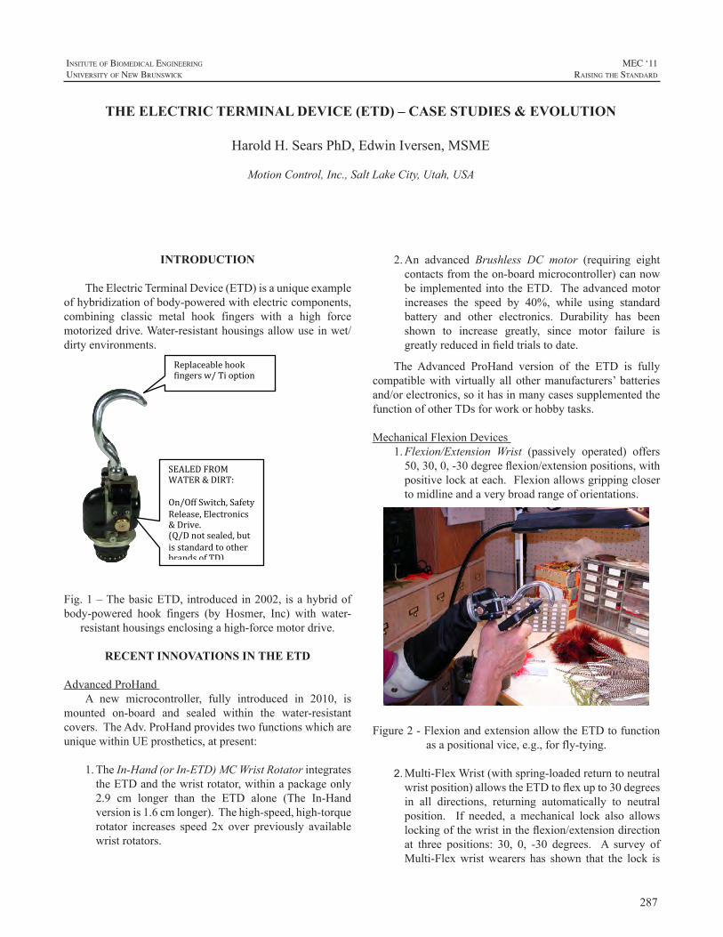
287
InsItute of BIomedIcal engIneerIng
unIversIty of new BrunswIck
MEC ‘11raIsIng the standard
2.An advanced Brushless DC motor (requiring eightcontactsfromtheon-boardmicrocontroller)cannowbe implementedinto theETD. Theadvancedmotorincreases the speed by 40%, while using standardbattery and other electronics. Durability has beenshown to increase greatly, since motor failure isgreatlyreducedinfieldtrialstodate.
The Advanced ProHand version of the ETD is fullycompatiblewith virtually all othermanufacturers’ batteriesand/orelectronics,soithasinmanycasessupplementedthefunctionofotherTDsforworkorhobbytasks.
MechanicalFlexionDevices1. Flexion/Extension Wrist (passively operated) offers50,30,0,-30degreeflexion/extensionpositions,withpositivelockateach.Flexionallowsgrippingclosertomidlineandaverybroadrangeoforientations.
Figure2-FlexionandextensionallowtheETDtofunctionasapositionalvice,e.g.,forfly-tying.
2. Multi-FlexWrist(withspring-loadedreturntoneutralwristposition)allowstheETDtoflexupto30degreesin all directions, returning automatically to neutralposition. If needed, a mechanical lock also allowslockingofthewristintheflexion/extensiondirectionat three positions: 30, 0, -30 degrees. A survey ofMulti-Flexwristwearers has shown that the lock is
INTRODUCTION
TheElectricTerminalDevice(ETD)isauniqueexampleofhybridizationofbody-poweredwithelectriccomponents,combining classic metal hook fingers with a high forcemotorizeddrive.Water-resistanthousingsallowuseinwet/dirtyenvironments.
Fig.1–ThebasicETD,introducedin2002, isahybridofbody-powered hook fingers (by Hosmer, Inc) with water-
resistanthousingsenclosingahigh-forcemotordrive.
RECENT INNOVATIONS IN THE ETD
AdvancedProHandA new microcontroller, fully introduced in 2010, is
mounted on-board and sealed within the water-resistantcovers.TheAdv.ProHandprovidestwofunctionswhichareuniquewithinUEprosthetics,atpresent:
1.TheIn-Hand(orIn-ETD)MCWristRotatorintegratestheETDandthewristrotator,withinapackageonly2.9 cm longer than the ETD alone (The In-Handversionis1.6cmlonger).Thehigh-speed,high-torquerotator increases speed 2x over previously availablewristrotators.
THE ELECTRIC TERMINAL DEVICE (ETD) – CASE STUDIES & EVOLUTION
HaroldH.SearsPhD,EdwinIversen,MSME
MotionControl,Inc.,SaltLakeCity,Utah,USA
Replaceable hook fingers w/ Ti option
SEALED FROM WATER & DIRT: On/Off Switch, Safety Release, Electronics & Drive. (Q/D not sealed, but is standard to other brands of TD).
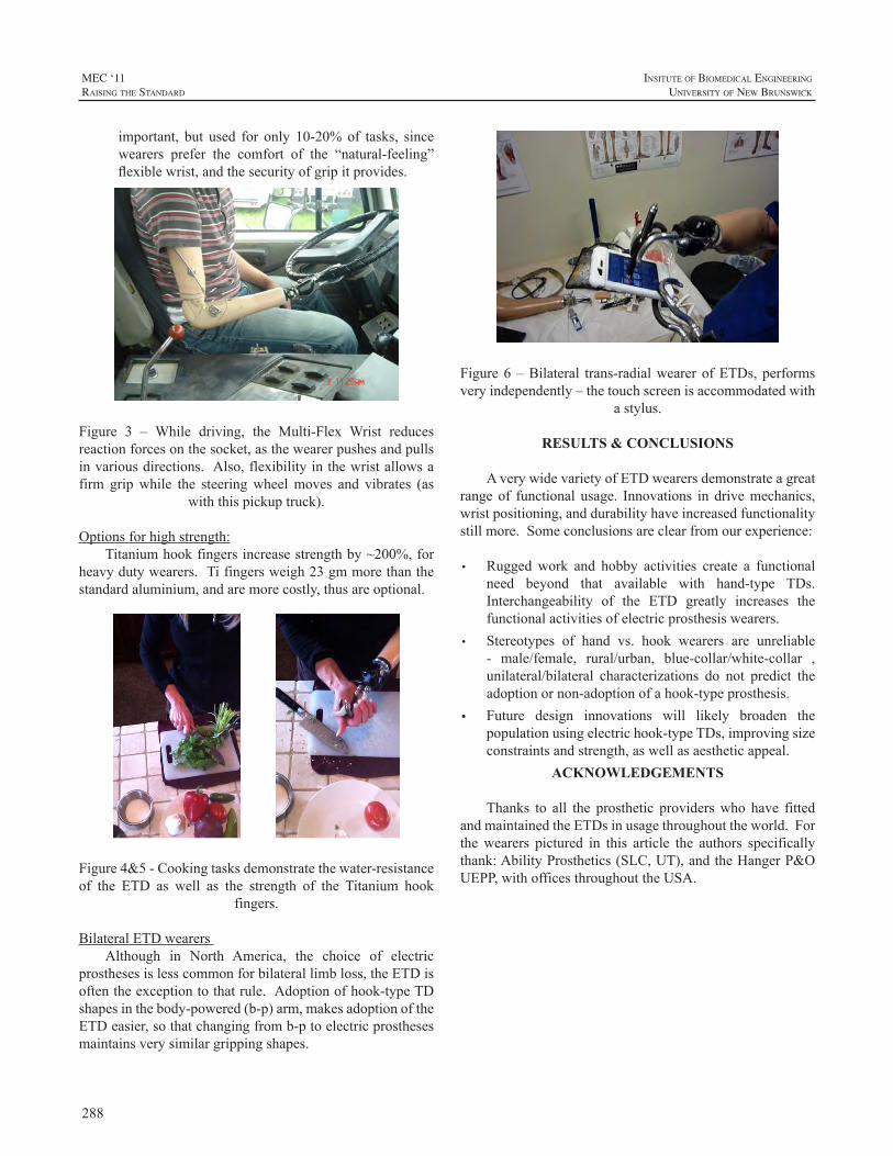
288
MEC ‘11raIsIng the standard
InsItute of BIomedIcal engIneerIng
unIversIty of new BrunswIck
important, but used for only 10-20%of tasks, sincewearers prefer the comfort of the “natural-feeling”flexiblewrist,andthesecurityofgripitprovides.
Figure 3 – While driving, the Multi-Flex Wrist reducesreactionforcesonthesocket,asthewearerpushesandpullsinvariousdirections.Also,flexibilityinthewristallowsafirm gripwhile the steeringwheelmoves and vibrates (as
withthispickuptruck).
Optionsforhighstrength:Titaniumhookfingersincreasestrengthby~200%,for
heavydutywearers.Tifingersweigh23gmmorethanthestandardaluminium,andaremorecostly,thusareoptional.
Figure4&5-Cookingtasksdemonstratethewater-resistanceof the ETD as well as the strength of the Titanium hook
fingers.
BilateralETDwearersAlthough in North America, the choice of electric
prosthesesislesscommonforbilaterallimbloss,theETDisoftentheexceptiontothatrule.Adoptionofhook-typeTDshapesinthebody-powered(b-p)arm,makesadoptionoftheETDeasier,sothatchangingfromb-ptoelectricprosthesesmaintainsverysimilargrippingshapes.
Figure6–Bilateral trans-radialwearerofETDs,performsveryindependently–thetouchscreenisaccommodatedwith
astylus.
RESULTS & CONCLUSIONS
AverywidevarietyofETDwearersdemonstrateagreatrangeof functional usage. Innovations in drivemechanics,wristpositioning,anddurabilityhaveincreasedfunctionalitystillmore.Someconclusionsareclearfromourexperience:
• Rugged work and hobby activities create a functionalneed beyond that available with hand-type TDs.Interchangeability of the ETD greatly increases thefunctionalactivitiesofelectricprosthesiswearers.
• Stereotypes of hand vs. hook wearers are unreliable- male/female, rural/urban, blue-collar/white-collar ,unilateral/bilateral characterizations do not predict theadoptionornon-adoptionofahook-typeprosthesis.
• Future design innovations will likely broaden thepopulationusingelectrichook-typeTDs,improvingsizeconstraintsandstrength,aswellasaestheticappeal.
ACKNOWLEDGEMENTS
Thanks to all the prosthetic providerswho have fittedandmaintainedtheETDsinusagethroughouttheworld.Forthewearers pictured in this article the authors specificallythank:AbilityProsthetics(SLC,UT),andtheHangerP&OUEPP,withofficesthroughouttheUSA.
289
InsItute of BIomedIcal engIneerIng
unIversIty of new BrunswIck
MEC ‘11raIsIng the standard
ABSTRACT
Withinthefieldofupper-limbprosthetics,motivepowerforvariouscomponentsistypicallyprovidedbytheuser’sownmuscularexertion(bodypower,orBP)ordrawnfromexternalsources such as batteries. While prostheses “combining”these power sources are not unusual—myoelectric elbowswith BP terminal devices (TD) for example—each systemtypically remains separate, operating independently of theother. Anelectromechanicalversionof theSure-Lokcablecontrolisindevelopmenttopurposefullyenablecrossoverortruehybridization.Meldingtheprecisionandversatilityofelectroniccontrolswiththeefficiencyandreadyavailabilityofbodypowerwillmakepossiblenewprosthesesofferingmaximizedefficiencyandfunctionalutility.Inoperation,thenewElectro-Lok uses existing, familiar electronic controls(e.g.myoelectric,bumpswitch,FSR,etc.)togoverncable-actuated BP components. Potential applications includeelectrically (un)locking cable-actuated elbows, modulatinggripforceinvoluntary-opening(VO)TDs,sustaininggraspwith voluntary-closing (VC) TDs, and improving controlofmulti-functionwristunits,amongothers. Newpediatricoptions are also envisioned. TheElectro-Lok represents anew class of mechanisms intended to enable practitionersto hybridize and blend various prosthetic components inpracticalandintuitivewaysforthebenefitandenjoymentoftheirpatients.
INTRODUCTION
Many amputees prefer the relatively lower cost,simplicity, and robustness of cable-operated prostheses forroutine chores and engaging in recreational activities andhobbies [1-4]. Design inefficiencies in these cable-drivensystems, however, often cause additionalwear and tear ofanatomicalstructuresalreadycompromised[4-6].
The pathomechanics underlying upper-limb amputees’overuse and repetitive stress injuries are notmysterious inorigin.Viewedasanorganicmachine,anatomicalstructuresof the body—such as the shoulder girdle—begin to wearout under repetitive, abusive loads. The supraspinatus,infraspinatus, teresminor,andsubscapularis tendonsof the
rotator cuff, as well as the coracoacromial, trapezoid, andconoidligamentsofupper-limbamputees’contralateralsidesareoftenfounduponsurgicalexplorationtobefrayed,wornthin,or torn [4,6]. Inaddition to thismechanicaldamage,blood flow to muscle tissues—primarily the trapezius—is impeded by sustained harness pressure and inadequatemusclerelaxationandrecoverytime.Musclebiopsiestakenfromamputeeswithchronictrapeziusmyalgiafindcoarsenedfibers and changes in capillary vessel structure; undermicroscopicexamination, investigators report thesemusclefibers appear visibly “ragged” [7,8]. Finally, harness looppressureontheaxillanerveandarteryoftencausesaxillarynervedysfunction,impairingmovementandsensationintheuser’ssoundshoulder[9].
Unchecked,theseeffectsarecumulative,incrementallydegradingfunctionalityandultimatelyrobbingamputeesoftheirabilitytoeffectivelyusetheirprostheses,withbilateralamputeesparticularlyatrisk[1].Inthesecases,theoutcomeis a diminishing quality of life as users progress along aspectrumrangingfromminorneckpainandstiffnesstowardsdebilitating, irreversible rotator cuff and shoulder girdledamage [7,8]. Myoelectricdevices also load the shoulder,andarenotapanacea[5,6].
Paradoxically, conventional prostheses’ most desirablecharacteristics—intuitive and self-contained operation,extreme robustness, and preservation of physiologicalproprioception—are possible precisely because of thecableandharness[10].Cabletensionandharnesspressureare inherent in thedevice’s operation and cannot be easilyeliminated.Theirdeleteriouseffectsontheuser’sanatomy,however, can be partly mitigated by shielding users fromhavingtosustaintensionforprolongedperiods.
Asa first step towards thisgoal, themechanicalSure-Lokwasdeveloped. Effectivelyaone-waycable lock, thedevicemaintains cable tensionwhile the user relaxes theirmuscles with an attendant reduction in harness pressure.Amputees using the device report markedly diminishedfatigue andpain, and clinical practitioners are increasinglyincorporatingtheSure-Lokintonewprostheses.
HYBRIDIZING BODY POWER & BATTERIES: DEVELOPMENT OF THE ELECTROMECHANICAL SURE-LOK CABLE CONTROL SYSTEM
BradleyD.Veatch1,PE,RobertRadocy2
1ToughWareProsthetics,Westminster,ColoradoUSA,2TRSInc.,Boulder,ColoradoUSA
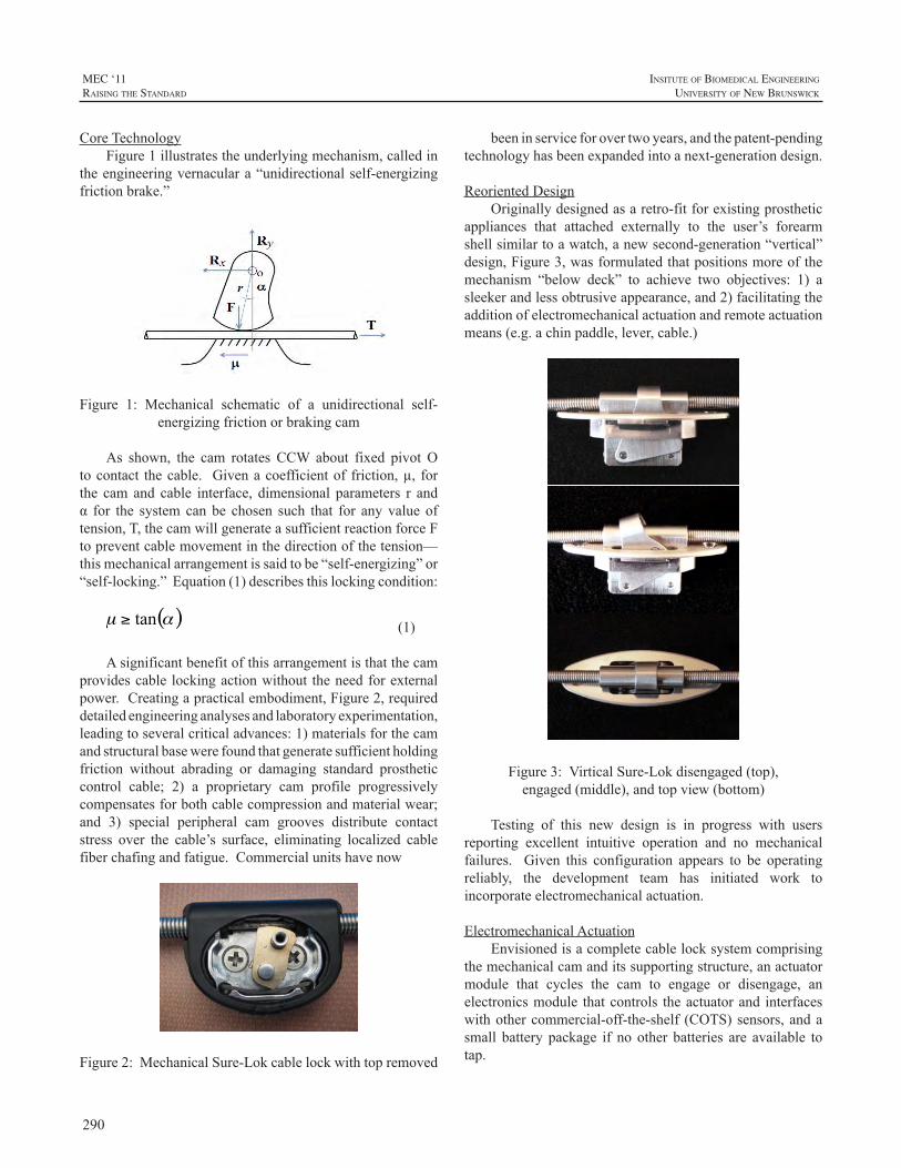
290
MEC ‘11raIsIng the standard
InsItute of BIomedIcal engIneerIng
unIversIty of new BrunswIck
CoreTechnologyFigure1illustratestheunderlyingmechanism,calledin
theengineeringvernaculara“unidirectionalself-energizingfrictionbrake.”
Figure 1: Mechanical schematic of a unidirectional self-energizingfrictionorbrakingcam
As shown, the cam rotates CCW about fixed pivot Otocontact thecable. Givenacoefficientof friction,µ, forthe cam and cable interface, dimensional parameters r andα for the system can be chosen such that for any value oftension,T,thecamwillgenerateasufficientreactionforceFtopreventcablemovementinthedirectionofthetension—thismechanicalarrangementissaidtobe“self-energizing”or“self-locking.”Equation(1)describesthislockingcondition:
(1)
Asignificantbenefitofthisarrangementisthatthecamprovidescable lockingactionwithout theneedforexternalpower.Creatingapracticalembodiment,Figure2,requireddetailedengineeringanalysesandlaboratoryexperimentation,leadingtoseveralcriticaladvances:1)materialsforthecamandstructuralbasewerefoundthatgeneratesufficientholdingfriction without abrading or damaging standard prostheticcontrol cable; 2) a proprietary cam profile progressivelycompensatesforbothcablecompressionandmaterialwear;and 3) special peripheral cam grooves distribute contactstress over the cable’s surface, eliminating localized cablefiberchafingandfatigue.Commercialunitshavenow
Figure2:MechanicalSure-Lokcablelockwithtopremoved
beeninserviceforovertwoyears,andthepatent-pendingtechnologyhasbeenexpandedintoanext-generationdesign.
ReorientedDesignOriginallydesignedasaretro-fitforexistingprosthetic
appliances that attached externally to the user’s forearmshellsimilartoawatch,anewsecond-generation“vertical”design,Figure3,wasformulatedthatpositionsmoreofthemechanism “below deck” to achieve two objectives: 1) asleekerandlessobtrusiveappearance,and2)facilitatingtheadditionofelectromechanicalactuationandremoteactuationmeans(e.g.achinpaddle,lever,cable.)
Figure3:VirticalSure-Lokdisengaged(top),engaged(middle),andtopview(bottom)
Testing of this new design is in progress with usersreporting excellent intuitive operation and no mechanicalfailures. Given this configuration appears to be operatingreliably, the development team has initiated work toincorporateelectromechanicalactuation.
ElectromechanicalActuationEnvisionedisacompletecablelocksystemcomprising
themechanicalcamanditssupportingstructure,anactuatormodule that cycles the cam to engage or disengage, anelectronicsmodule thatcontrols theactuatorand interfaceswithothercommercial-off-the-shelf (COTS)sensors,andasmall battery package if no other batteries are available totap.
291
InsItute of BIomedIcal engIneerIng
unIversIty of new BrunswIck
MEC ‘11raIsIng the standard
Twomethodsof actuating thecamarecurrentlybeingexplored.Thefirstemploysamicromotorservounit,whilethe second uses electromagetic elements arranged into abi-stable flip-flop configuration. Both designs, to ensuresafety,lettheuseroveridetheactuationsystemtomanuallydisengagethelock.
The design of myoelectric control circuits, locatingelectrode sites on amputees’ residual limbs, and selectingmuscle contraction/co-contraction actuation schemes forprostheticdevicesareestablishedpracticeswithintheO&Pfield.CircuitrytocontroltheElectro-Lokwillbedesignedto accept standard control signals. Moreover, prosthetistsworking with the development team are providingconsiderable clinical guidance to ensure the engineeringdesignproperlytakesintoaccountpragmaticclinicalfactors.The objective is to create a robust, modular commercialproduct thatworkswellwithexistingstandardcomponentsandthatprosthetistscanuseintuitivelywithlittledifficulty.
PhilosophyofHybridizationBecauseenergy isonlyconsumedchangingstates (i.e.
engaged todisengagedorviceversa), energy requirementsfor the cable lock are very low, and a small rechargeablebatterycanprovidesufficientpower tocycle the lockoveran extended period. This a key aspect of hybridization:generally using external energy sources (that is, energythatcomesatapremium) tocontrolanddirect the flowoftheuser’smuscularenergy (moreabundant) indrivingandpositioningtheirprostheticcomponents.Eachenergysourceisusedmoreefficientlyandeffectivelytobenefittheamputeeoveralongerserviceperiod.
Adevice thatmechanically locks users’ control cablesin response tomyoelectric signals as contemplated here isjustthefirstofseveralcomponentsbeingdevelopedthatareanticipated toopenup thefieldofprosthetichybridization.Others include control cable multiplexers that selectively“connect”oneofseveralpossiblecontrolcablestoauser’sharness, and a system for storing mechanical energy andreturningitunderelectroniccontrol.
Historically, both cable operated BP systems andexternallypowereddeviceshavedemonstrated their abilityto improve the quality of life and well being of amputeeusers.Itisreasonabletobelievethatnewhybriddesignsthatcapitalizeuponandmakeavailablethebestaspectsofthesetwo systemswill substantially benefit amputees stillmore.Thepossibilitiesareunlimitedandbeguiling.
ACKNOWLEDGEMENTS
This work was funded by the United States NationalInstitutes of Health (NIH) through a Small BusinessInnovationResearch(SBIR)grantno.1R43HD047039.TheauthorswishtothankRandallAlley,CPOofbiodesigns,inc.,alongwithBillHansenandT.WalleyWilliamsofLiberatingTechnologies,Inc.(LTI)fortheircontributionstothiseffort.Opinionsexpressedinthispaperarethoseoftheauthorsanddonotnecessarilyreflectopinionsofthesponsors.
REFERENCES
[1] Otto Bock Healthcare USA, “Skills for Life II: Bilateral UpperExtremity Limb Loss Workshop”, October 9-12, 2008, DenverRenaissanceHotel,Denver,Colorado.
[2] PezzinLE,DillinghamTR,MackenzieEJ,EphraimP,RossbackP., “Use and satisfaction with prosthetic limb devices and relatedservices,”ArchPhysMedRehabil.2004May;85(5):723-9.
[3] DillinghamTR,PezzinLE,MacKenzieEJ.,“LimbamputationandlimbdeficiencyepidemiologyandrecenttrendsintheUnitedStates,”SouthMedJ.2002Aug;95(8):875-83.
[4] Gambrell, Christina R., “Overuse syndrome and the unilateralupperlimbamputee:consequencesandprevention,”JProsthetOrthot2008;20:126–132.
[5] DattaD,SelvarajahK,DaveyN.,“Functionaloutcomeofpatientswith proximal upper limb deficiency-acquired and congenital,”ClinRehabil.2004Mar;18(2):172-7.
[6] JonesLE,DavidsonJH,“Savethatarm:astudyofproblemsintheremainingarmofunilateralupperlimbamputees,”ProsthetOrthotInt.1999Apr;23(1):55-8.
[7] Kadi F., K.Waling, C.Ahlgren, G. Sundelin, S. Holmner, G.S.Butler-Browne,L.E.Thornell, “Pathologicalmechanisms implicatedinlocalizedfemaletrapeziusmyalgia,”Pain1998;78(3):191-6.
[8] LarssonS.E.,L.Bodegård,K.G.Henriksson,P.A.Oberg,“Chronictrapeziusmyalgia.Morphologyandbloodflowstudiedin17patients,”ActaOrthopScand.1990Oct;61(5):394-8.
[9] Collier, M., M. LeBlanc, “Technical forum-- axilla bypass ringforshoulderharnessesforupper-limbprostheses,”JPO,1996,Vol.8,Num.4,pp.130-131.
[10] R.Meier,D.Atkins,“FunctionalRestorationofAdultsandChildrenwithUpperExtremityAmputation”,Chapter30,ResearchTrendsfortheTwenty-FirstCentury,byR.Weir,D.Childress,DemosMedicalPublishing,LLC,NewYork,2004,pp.353-360.

292
MEC ‘11raIsIng the standard
InsItute of BIomedIcal engIneerIng
unIversIty of new BrunswIck
INTRODUCTION
Individuals with acquired limb deficiency oftenexperience difficulties with prosthetic fitting and use dueto anatomical presentations that may affect both upperextremities. The non-amputated side may be affected bynerve damage, scar tissue or brachial plexus involvement.These problems may impact the potential user’s abilityto access power from available bodymovements. Signalsfromthenervesmostcommonlyusedtocontrolutilityoftheprosthesismayalsobeimpeded.Theseproblemsare likelytoaffectthecapabilityoftheconsumertocomfortablywearand/ortoaccesspowerorcontrolfromtheprosthesis.Suchproblems directly result in challenges to use the affectednon-amputatedupperextremity,theprostheticextremityandin difficulty to complete bilateral activities necessary forfunctionalindependence.
The Anchor technology was initially used to accessscapularpoweronthesamesideofthetrans-radialdeficiencyin order to operate the terminal device of a prosthesis.Byaccessing power ipsilaterally, lesser harnessing is utilizedresulting in increased comfort, improved cosmesis anddecreased axillary impingement. Other benefits includemore symmetricalbilateralmuscledevelopment,decreasedrepetitive contralateral shoulder motion, and increasedfunctionparticularlyduringbilateralupperextremity tasks.Consumers report the importance that intuitive movementrather than strategicmotor planning is used to operate theprosthetic terminaldevice.For these reasons theprosthesiscanthenbecomeamorenaturalextensionofthebody.Thissimpletechnologymayalsobeappliedtoaccesspowerfromotheranatomicalsources.Thesesitesmayincludetheforearmtoactivateahandprosthesisorthetrunktostabilizealineartransducer.ThecutaneousAnchormayprovetobeaviableresource for suspension, stabilization or power of variousprosthetic technology.This technologyis inpatent-pendingstatuswiththeUnitedStatesPatentOffice.Ithasbeenusedin patient treatment sinceAugust 2006. Patients appear toderivebenefitandimprovedfunctionoftheirprosthesiswiththeuseofthisdevice.
This paper addresses case solutions for problemsassociated with accessing power/control of the prosthesisusingsimpletechnologyadvancestocomplementthemorecomplextechnologyusedinthedesignoftheprosthesis.Twocasestudiesarediscussedwhichincludeinitialpresentationwith consumer-stated problems and concerns, solutionsofferedandtrainingprovidedtotheuserfromtheperspectiveoftheoccupationaltherapist.Occupationaltherapistssuchasmyselfareconcernedwiththeabilitiesofourclientstoattainthe skills necessary for maximal functional independenceduring the necessary tasks of life that include self-care,vocationandleisuretimeactivities.Proficiencyintheseareasfostersenjoyablequalityoflife.
METHOD
SubjectsTwo subjects are identified for the purpose of this
reflection.
(A) is a male aged 45 years who experienced blunttrauma to his dominant right upper extremity atthe trans-humeral level 4+ years ago involvingthebrachialplexusandresultinginamputation.Heuses a trans-humeral prosthesiswith a chest strapstyled suspension, VariGrip hand and Otto Bocklineartransducersandcables.Averticalstraptohisbeltisusedtocontrolthetransducerwhichoperatesthehand.Atransducerplacedposteriorlyconnectstothecheststrapandcontrolstheelbowfunctions.(A)experiencedlossofRsidedvisionaswellfromthistrauma.Heisaformersemi-professionalboxerandworksasafitness/boxing instructorat agym.He was referred due to problems associated withaccessing control of the prosthesis from availableneuro-anatomy.
(B) Is a female aged12years from ElSalvadorwhoexperienced electrical trauma to both upperextremitiesapproximately1yearago.Shesustainedextensive burns and brachial plexus injury to herdominant right upper extremity as well as trans-humeral burn and amputation of her left upperextremity.Shehasresidualscartissueacrossmostof
CREATIVE SOLUTIONS TO BILATERAL UPPER EXTREMITY INVOLVEMENT
DebraLatour1,M.Ed.,OTR/LGreigP.Martino2,CP
1SeniorOccupationalTherapist,ShrinersHospitalsforChildren,Co-Owner,Single-HandedSolutions,LLC,2UnitedProsthetics,Inc.
293
InsItute of BIomedIcal engIneerIng
unIversIty of new BrunswIck
MEC ‘11raIsIng the standard
hervolaranddorsaltrunkaswellasherrightarm.Her rightupper extremityhas sustaineddecreasedmusculatureaswellassensitivity.Shepresentedforconsiderationofprosthetictechnology.Althoughherleft upper extremityappearedcapableof enduringprosthetic componentry, her right upper extremitycouldnotenduretraditionalharnessingattheaxillaorat thechest.Higher technologyofelectronicormyo-electroniccapacitywasnotconsideredduetotheresourcesavailableinhernaturalenvironment.Sheattendsschool,playssoccerandenjoysreadingandhelpinginthefamilyhome.Shewasfittedwithaprosthesis featuringaTRSLite-Touchhandanda mechanical elbow. She was referred due to thechallengesofaccessingbody-poweredcontrol.
ApparatusVariationsofthecutaneousAnchor,utilizingtechnology
for individuals with trans-humeral limb deficiency: (A) tostabilizelineartransducersinvolaranddorsalaspectsofthetrunk;and(B)toaccessipsilateralbodypowerforelbowandhandcontrols.
ProceduresEach client was fit with Anchor technology to suit
individual needs: (A) 2 standard uni-button cutaneousAnchorpadspositionedstrategicallytoaccessscapularandlowerserratusanteriorcontrol;(B)1double-buttonAnchorcutaneous Anchor pad positioned strategically to accessscapular control. These controls activate both prostheticelbow and prosthetic hand movement however throughdifferentmechanisms:bodyvselectronic.Theprosthetistandtheoccupational therapist fit the clientwith theAnchor(s).Prosthetic training is provided which includes application,skin hygiene, use and care of the Anchor. Baselineobservations are completed includingclinicalobservations,video-graphed functional tasks. Follow-up videos of bothclientsarepending.
DataAnalysesData is anecdotal via both therapist and client report
including photograph and video-graph display. It appearsto represent client satisfaction and ability towardmaximalfunctional independence and ultimately toward positivequalityoflife.
RESULTS
Initial observations and results include activeparticipationtowardindependenceinself-applicationofbothAnchor applications aswell as prosthetic donning/doffing,success with prosthetic ability particularly as increasedactive spontaneoususe, approved cosmesis andhigh clientsatisfaction.Consumerreportreflectstheintuitivenatureof
themovementrequiredtoeffectivelyutilizetheprostheses.This is important considering that both clients haveexperiencedhistoricaluseofbilateralupperextremitiesandhavealsoexperiencedabsolutelossofoneupperextremityandhaveexperience impacted lossofsomefunction in theotherremainingupperextremity.
DISCUSSION
ThecutaneousAnchorissimplisticindesign.Thepartsare durable, easily available and affordable. The potentialbenefits of this technology appear to result in increasedprosthetic wear and use (relative to frequency, tolerance,spontaneity)asitallowsforimprovedcomfort,cosmesisandeaseofuseduringfunctionalactivityandparticularlyduringbilateral activity The previously mentioned implicationsareproventobebeneficialforsomeindividualswithtrans-humeral deficiency, whether congenital (past proven) ornewlyacquired.Itisclearthatthetechnologyiscapableofactivating both prosthetic hand and elbow; and is useableby populations of both limb deficiency and brachialplexus injury. Implications continue to project use towarddynamizingorthoticsinclientswithlossinfunctionbutnotnecessarilylossoflimb.Itishopedthatstudyoffutureworkwillprovethistobetrue.
ACKNOWLEDGEMENTS
Gratitude is extended to the clientswho permitted thesharing of their stories, Shriners Hospitals for Children-Springfield, MA; Shriners Hospitals for ChildrenInternational,HQ; andMichaelLatour,Co-Owner, Single-HandedSolutionsforcontinuedsupportandencouragement.Itisimportanttonotethepastbeneficenceandencouragementfrom Bob Radocy, TRS and Bill Hanson, LiberatingTechnologies,Inc.
REFERENCES
[1] R. C. Crandall, and W. Tomhave, “Pediatric unilateral below-elbowamputees:retrospectiveanalysisof34patientsgivenmultipleprostheticoptions.”J.PediatricOrthopedics,vol.22(3),pp.380-383,2002.
[2] D.DattaandV.Ibbotson,“Poweredprosthetichandsinveryyoungchildren.”ProstheticsOrthoticsInternational,vol22(2)pp.150-154,1998.
[3] G. H. Kejlaa, “Consumer concerns and the functional value ofprosthesestoupperlimbamputees”ProstheticsOrthoticsInternational,vol17(3)pp.157-163,1993.
[4] G.H.Kejlaa,“Thesocialandeconomicoutcomeafterupperlimbamputation.”ProstheticsOrthoticsInternational,vol16(1)pp25-31.
[5] C. Murray, “The social meanings of prosthesis use.” J. HealthPsychology,vol10(3),pp.425-441,2005.
[6] M. Dragas, et al, “Upper extremity arterial injuries: factorsinfluencingtreatmentoutcome.”Injury,vol40(8),pp.815-819,2009.
294
MEC ‘11raIsIng the standard
InsItute of BIomedIcal engIneerIng
unIversIty of new BrunswIck
List of Conference Presenters and Contributors
Name PageNo.
a
Alley, Randall ................................31Altobelli, David E. ........................ 255Andrysek, Jan ............................. 105Antfolk, Christian ......................... 216Atkins, Diane ................................87
B
Bertels, Thomas .......................... 276Blunn, Gordon W. ..........................37Bøg, M.F. ................................ 93, 97Bongers, Raoul M. .........164, 184, 260Boone, David ................................47Boschmann, Alexander ................. 210Bouwsema, Hanneke ......164, 184, 260Brånemark, Richard .......................44Bucur, Doina ............................... 242Burger, Helena ................................5Butkus, Josef .............................. 183
C
Caine-Winterberger, Kerstin ............44Carrozza, Maria Chiara ...................69Chan, Adrian D.C. ........................ 101Chappell, Paul ...............................83Chaubey, Pravin ............................47Cheng, Jonathan ...........................40Cipriani, Christian ..........................69Clawson, Adam ....................251, 271Controzzi, Marco ...........................69Coulter, Stewart .......................... 255Cranny, Andy ................................83
D
Daley, Heather ............................ 151Dalley, Skylar A. ............................79
Name PageNo.
Daly, Wayne K. .......................47, 117de Jong, Ingrid G.M. .................... 174den Ouden, Rob .......................... 134Disla, Roxanne ............................ 234Dodson, Robert .............................40Donovan-Hall, Maggie ....................83
E
Eichelbaum, Daniel ...................... 144Englehart, Kevin ...................101, 251Erkocevic, E. ........................... 93, 97Etter, Katherine ........................... 234
F
Fantini, Christopher ..................... 234Farina, D. ................................... 237Finucane, Suzanne B. .....159, 170, 186Fougner, Anders .......................... 101
G
Galpin, A. ............................106, 189Glasford, Shane .......................... 105Goldfarb, Michael ...........................79
HHahn, Martin ............................... 210Hargrove, Levi ...61, 65, 119, 159, 264Harris, Melani S. ............................27Hebert, Jacqueline S. ................... 193Heckathorne, Craig ...............196, 214Hermansson, L.M. Norling ......... 8, 136Hichert, Mona ...............................74Hill, Wendy ..........................184, 240Holck, Benedikte ......................... 219
295
InsItute of BIomedIcal engIneerIng
unIversIty of new BrunswIck
MEC ‘11raIsIng the standard
Name PageNo.
Huang, He (Helen) ....................... 155Hudgins, Bernard ........................ 251
I
Idstein, Thomas M. ...................... 264Ingersoll, A. ................................ 176Iversen, Edwin ............................ 287
J
Janssen, Wim G.M. ...............134, 174Jiang, N. .................................... 237Johnson, Alwyn ........................... 179Johnson, Shawn Swanson, ............ 202Jönsson, Stewe .............................44
K
Kajitani, Isamu .............................12Kamavuako, E.N. ..................... 93, 97Kanitz, Gunter ...............................69Karosan, Eric .............................. 240Kenney, L. ...........................106, 189Kettwig, Thomas ......................... 276Kirsch, Robert F. ...................127, 140Koss, Laurel B. ..............................27Kuruganti, Usha .......................... 240Kyberd, Peter ........ 106, 184, 189,226,...................................230, 240, 251
L
Lambrecht, Joris M. ..............127, 140Lang, MacJulian .............................16Latlief, Gail A. ........................27, 199Latour, Debra .............................. 292Lewicke, Justin ............................ 193Liang, Tony ................................. 105Lieberman Klinger, Shana ............. 234Lindner, Helen .................................8Lipschutz, Robert ...........123, 151, 159
Name PageNo.
Lipsey, James ............................. 271Lock, Blair A. .....61, 65, 123, 170, 264Lorrain, T. ................................... 237Losier, Yves..........................251, 269
M
Magne, Tordis ............................. 230Martino, Greig P. .......................... 292Medynski, Courtney ..................... 279Metcalf, Cheryl ..............................83Micera, Silvestro .......................... 249Miguelez, John M. ........................ 259Miller, Laura .........................170, 186Mita, Tomoki .................................12Mitsch, Sarah .............................. 183Mugaas, Terje ............................. 230
N
Nakamura, Takashi ........................12Niazi, I.K. ................................... 237Niemeier, M.J. ......................... 93, 97Nieuwendijk, Johan ...................... 110
O
O’Connell, Colleen ....................... 176Ohnishi, Kengo ............................ 167Ohsato, Shinichi .......................... 167Ottermo, Maria V. ........................ 230
P
Parks, Robert .............................. 264Pendergrass, Catherine J. ...............37Perry, N. Christopher .................... 255Peterson, Jennifer ..........................53Phillips, Sam L. ......................27, 199Platzner, Marco ............................ 210Plettenburg, Dick H. ...24, 74, 110, 114Poelma, Margriet J. ...................... 174Popa, F.A. ................................... 226
296
MEC ‘11raIsIng the standard
InsItute of BIomedIcal engIneerIng
unIversIty of new BrunswIck
Name PageNo.
Prigge, Patrick C. ......................... 148Pulliam, Chris .......................127, 140Pylatiuk, C. ................................. 221
R
Radocy, Robert ............................ 289Raffi, R. ..................................... 106Rattray, Bruce ............................. 279Reamon, Derek ........................... 205Redman, Thomas ..........................83Reinders-Messelink, Heleen ...174, 260Reischl, M. .................................. 221Resnik, Linda ................199, 234, 262Robrecht, Michael ........................ 210Rosenbaum-Chou, Teri ...................47Rosenvang, J.D. ...................... 93, 97Ryan, Tiffany .......................... 40, 57
S
Sassu, Rossella .............................69Scheme, Erik .......................101, 251Schmitz, B. ................................. 221Schulz, Stefan ...............144, 221, 283Sears, Harold H. .......................... 287Sebelius, Fredrik ......................... 216Segil, Jacob ................................ 205Selles, Ruud W. ........................... 134Sensinger, Johathon W. ................ 271Simon, Ann ..................... 61, 65, 159Sims, Tara ....................................83Sjöberg, Lis ................................ 136Smidstrup, A. .......................... 93, 97Smit, Gerwin ............24, 74, 110, 114Sobuh, M.............................106, 189Spill, Ryan ....................................50Stach, Boris ................................ 144Stavdahl, Øyvind ..................101, 230Stine, Rebecca ............................ 196Stubblefield, Kathy ....61, 65, 170, 186Sutton, Levi ................................ 271
Name PageNo.
T
Tates, Kiek ................................. 174Thies, S. .............................106, 189Tran, Dat .................................... 264
V
Valencia, Ricardo ......................... 144van der Niet Otr, Olga .................. 260van der Sluis, Corry K. ..164, 174, 184, ................................................. 260van Heijningen, Vera G. ................ 134van Wijk, Iris .............................. 174Vandersea, Jamie ........................ 148Varol, Huseyin Atakan ....................79Veatch, Bradley ....................179, 289
W
Waldera, Kathy ............................ 214Waryck, Brian ...............................20Weir, Richard F. ff. ....................... 205Whatmough, Ian ......................... 105White, Neil ...................................83Wiegand, R. ................................ 221Williams III, T. Walley .............34, 271Wilson, Adam .......................251, 269Winkler, Michael .......................... 210Wolpaw, Jonathan R. .................... 133
Y
Yip, Vivian .................................. 236Young, Aaron .............................. 119
Z
Zhang, Fan ................................. 155
