radiative and non-radiative decay of a single molecule close to a metallic nanoparticle
TRANSCRIPT
www.elsevier.com/locate/optcom
Optics Communications 261 (2006) 368–375
Radiative and non-radiative decay of a single moleculeclose to a metallic nanoparticle
R. Carminati a,*, J.-J. Greffet a, C. Henkel b, J.M. Vigoureux c
a Laboratoire d’Energetique Moleculaire et Macroscopique, Combustion, Ecole Centrale Paris, Centre National de la Recherche Scientifique, Grande
Voie des Vignes, 92295 Chatenay-Malabry Cedex, Franceb Institut fur Physik, Universitat Potsdam, Am Neuen Palais 10, 14469 Potsdam, Germany
c Laboratoire de Physique Moleculaire, Universite de Franche-Comte, Centre National de la Recherche Scientifique, 25030 Besancon Cedex, France
Received 27 September 2005; received in revised form 5 December 2005; accepted 6 December 2005
Abstract
We study the spontaneous emission of a single emitter close to a metallic nanoparticle, with the aim to clarify the distance dependenceof the radiative and non-radiative decay rates. We derive analytical formulas based on a dipole–dipole model, and show that the non-radiative decay rate follows a R�6 dependence at short distance, where R is the distance between the emitter and the center of the nano-particle, as in Forster’s energy transfer. The distance dependence of the radiative decay rate is more subtle. It is chiefly dominated by aR�3 dependence, a R�6 dependence being visible at plasmon resonance. The latter is a consequence of radiative damping in the effectivedipole polarizability of the nanoparticle. The different distance behavior of the radiative and non-radiative decay rates implies that theapparent quantum yield always vanishes at short distance. Moreover, non-radiative decay is strongly enhanced when the emitter radiatesat the plasmon-resonance frequency of the nanoparticle.� 2005 Elsevier B.V. All rights reserved.
PACS: 33.50.�j; 32.50.�d; 42.50.ct
Keywords: Fluorescence; Single molecule; Nanoparticle; Quenching
1. Introduction
Since the pioneering work of Purcell [1], it has beendemonstrated in many different situations that the sponta-neous emission rate of a single emitter (e.g., atom, mole-cule, quantum dot) depends on the environment.Modifications of the spontaneous decay rate of moleculesclose to metallic surfaces [2,3] or atoms in simple cavities[4] have become textbook examples. Analytical theoreticalstudies of spontaneous emission close to surfaces or mul-tilayer structures [5–8], or spheres [9,10] have beendeveloped.
0030-4018/$ - see front matter � 2005 Elsevier B.V. All rights reserved.doi:10.1016/j.optcom.2005.12.009
* Corresponding author. Tel.: +33 1 41 13 10 66; fax: +33 1 47 02 80 35.E-mail address: [email protected] (R. Carminati).
The advent of near-field optics techniques has made pos-sible the detection and spectroscopy of single molecules incomplex environments, with a lateral resolution below100 nm [11]. Single emitters have been used to image localelectromagnetic fields at the nanometer scale [11–13] and toprobe nanostructures [14]. These results stimulated theoret-ical studies of single-molecule emission close to structuredsurfaces [15–18] or in the vicinity of nanoscopic particlesor tips [19–24].
Near-field optics also stimulated the use of sharp metal-lic tips, producing highly localized and bright fields, tomodify the lifetime [25] and to enhance the fluorescenceof single molecules [26]. In the context of fluorescence,the role of metallic tips, nanoparticles or surface nano-structures is twofold: an enhancement of the exciting localintensity, and a modification of the radiative emission rate,
R. Carminati et al. / Optics Communications 261 (2006) 368–375 369
both in amplitude (Purcell effect) and angular dependence.These objects thus behave as nanoantennas, a conceptwhose relevance for single-emitter fluorescence modifica-tion has been demonstrated experimentally [27–30]. Adrawback when using metallic objects is the presence ofabsorption, which creates additional non-radiative chan-nels. Understanding and modelling the trade-off betweenradiative and non-radiative processes is a key issue for boththe fundamental and practical aspects of fluorescenceenhancement [23,31–35].
In this paper, we study the spontaneous decay rate of asingle dipole emitter close to a metallic nanoparticle. Thisissue has already been addressed numerically in variousconfigurations, involving particles, tips and/or surfaces(see, e.g., Refs. [20,23,24]), or using analytical models [32].We focus here on the distance dependence of the radiativeand non-radiative rates. Our objective here is not to discussthe fluorescence enhancement factor, but to get a betterunderstanding of the interplay between radiative andnon-radiative decay channels. We have chosen to workwith the simplest situation, in which the nanoparticle isdescribed by its polarizability so that the emitter and nano-particle interact through dipole–dipole coupling only. Thischoice is motivated by the need of deriving simple analyti-cal formulas from which the distance dependence of theradiative and non-radiative rates can be explicitly identi-fied. An important result of our approach is that thenon-radiative decay rate follows a R�6 dependence at shortrange, where R is the distance between the emitter and thecenter of the nanoparticle, whereas the distance depen-dence of the radiative decay rate is more subtle. It is chieflydominated by a R�3 dependence, a R�6 dependence beingvisible at plasmon resonance. To our knowledge, this resultwas not explicitly put forward in previous studies availablein the literature. Moreover, as we shall show, obtainingthe correct distance dependence requires a proper treat-ment of radiative damping in the electrodynamics of thenanoparticle.
The paper is organized as follows. In Section 2, we pres-ent the derivation of the expression of the decay rate. InSection 3, we identify the radiative and non-radiative con-tributions. Based on these results, we discuss in Section 4the distance dependence of both rates and the role of radi-ative damping at the nanoparticle. In Section 5, we presentnumerical calculations in a specific situation: an emitterclose to a silver nanoparticle, emitting either at the plas-mon-resonance frequency, or far from resonance. Section6 summarizes our conclusions.
2. Calculation of the spontaneous decay rate
We consider a single emitter (e.g., atom, molecule, quan-tum dot) located at short distance from a metallic nanopar-ticle. We denote by x the emission frequency and by r theposition of the emitter. The nanoparticle is assumed to be asphere of radius a, located at position rp. We choose thecoordinate system with rp at the origin and the emitter
on the z-axis (the distance between the emitter and the par-ticle is z = |r�rp|).
2.1. General expression
For electric-dipole transitions and in the weak-couplingregime, the normalized spontaneous decay rate C (or thefluorescence lifetime s = 1/C) can be calculated from theelectric-field susceptibility (or electric Green function)which describes the electromagnetic response of the envi-ronment [2,7]. It takes the form
CC0
¼ 1þ 6p�0
k3Im½u � Sðr; r;xÞ � u� ð1Þ
where k = x/c and u is the direction of the transitiondipole, C0 is the decay rate in free space. The dyadic S
describes the modification of the free-space dyadic Greenfunction (or electric-field susceptibility) due to the presenceof the nanoparticle.
2.2. Green function in the presence of a nanoparticle
The (dyadic) Green function connects an electric-dipolesource p at a position r 0 to the electric field at a position r
through the relation E(r) = G(r,r 0,x) Æ p. In the presence ofthe nanoparticle, described itself in the dipole approxima-tion, it can be written as
Gðr; r0;xÞ ¼ G0ðr; r0;xÞ þG0ðr; rp;xÞ � aðxÞ�0G0ðrp; r0;xÞð2Þ
where G0 is the free-space Green function and a(x) is thepolarizability of the nanoparticle. The dyadic S in Eq. (1)is defined by G(r,r 0,x) = G0(r,r 0,x) + S(r,r 0,x), and can beidentified from Eq. (2)
Sðr; r0;xÞ ¼ G0ðr; rp;xÞ � aðxÞ�0G0ðrp; r0;xÞ. ð3Þ
The free-space Green function G0 is given by [36,37]
G0ðr; r0;xÞ ¼ PV k2Iþrr� � expðikRÞ
4p�0R� I
3�0
dðr� r0Þ ð4Þ
where I is the unit dyadic and PV denotes the principalvalue.
2.3. Expression of the polarizability
The expression of the polarizability of the nanoparticle,accounting for radiation damping, is (see Refs. [38,39] andthe derivation in Appendix A)
aðxÞ ¼ a0ðxÞ1� iðk3=6pÞa0ðxÞ
ð5Þ
where a0 is the quasi-static polarizability.
a0ðxÞ ¼ 4pa3 �ðxÞ � 1
�ðxÞ þ 2ð6Þ
with �(x) the dielectric constant of the particle.
370 R. Carminati et al. / Optics Communications 261 (2006) 368–375
For example, for a metallic nanoparticle described by aDrude model, one has
�ðxÞ ¼ 1�x2
p
x2 þ ixcð7Þ
where xp is the plasma frequency and c accounts forabsorption losses. Inserting (7) into (5) yields
aðxÞ ¼ 4pa3x20
x20 � x2 � ixc� ið2=3Þk3a3x2
0
ð8Þ
where x20 ¼ x2
p=3. The term �ixc accounts for damping byabsorption, whereas the term �ið2=3Þk3a3x2
0 accounts forradiative damping.
Let us stress that expression (5) of the polarizability is con-sistent with energy conservation (or, equivalently, the opticaltheorem) [38,39]. Using this form of the polarizability is a keypoint when one separates the radiative and the non-radiativecontributions to the decay rate, based on energy conserva-tion arguments. We will come back to this point in Section 4.
2.4. Explicit expressions of the decay rate
The expression of the decay rate is obtained by insertingEq. (3) into Eq. (1), and using Eq. (4). We will consider twoorientations of the transition dipole: a transition dipolealong the z-direction (the dipole points towards the nano-particle), and a transition dipole along the x-direction(the transition dipole is perpendicular to the emitter-parti-cle axis).
For a transition dipole oriented along the z-direction,one obtains
Cz
C0
¼ 1þ 3k3
2pIm aðxÞ expð2ikzÞ �1
ðkzÞ4þ 2
iðkzÞ5þ 1
ðkzÞ6
!" #.
ð9ÞFor a transition dipole along the x-direction
Cx
C0
¼ 1þ 3k3
8pIm
"aðxÞ expð2ikzÞ
� 1
ðkzÞ2� 2
iðkzÞ3� 3
ðkzÞ4þ 2
iðkzÞ5þ 1
ðkzÞ6
!#. ð10Þ
These expressions are derived without any approximation,in the limit of validity of the description of the nanoparticleby a dipolar polarizability. This assumption requires thedistance z to remain larger than a few radii of the nanopar-ticle. For a discussion of the limits of the dipole approxi-mation in the near field, see Ref. [40].
2.5. Short-distance limit
We will now concentrate on the distance dependence ofthe decay rates at short distance, namely, in the regimeka < kz� 1. In this regime, approximate simplificationsof Eqs. (9) and (10) can be derived. To proceed, one needsto expand the exponential term exp(2ikz) to third order in
kz to calculate properly all terms of orders (kz)�3 to (kz)�6.This leads to
Cz
C0
¼ 1þ 3k3
2pIm aðxÞ 1
ðkzÞ6þ 1
ðkzÞ4þ 2i
3ðkzÞ3
!" #ð11Þ
for the z-orientation and to
Cx
C0
¼ 1þ 3k3
8pIm aðxÞ 1
ðkzÞ6� 1
ðkzÞ4� 4i
3ðkzÞ3
!" #ð12Þ
for the x-orientation.
3. Radiative and non-radiative rates
The expression of the normalized decay rate (1) canbe obtained by treating the emitter as a classical har-monic damped dipole oscillating at frequency x [2]. In thisapproach, the normalized spontaneous decay rate is equiv-alent to the normalized power emitted by the classicaldipole. One writes C/C0 = P/P0, where P is the power emit-ted in the presence of the environment and P0 is the poweremitted by the same dipole in free-space. In the presence ofabsorption, this classical approach allows to calculate sep-arately the radiative decay rate CR (proportional to the far-field radiated power) and the non-radiative decay rate CNR
(proportional to the power absorbed by the environment)[25,32]. Energy conservation requires that C = CR + CNR,so that only two quantities need to be calculated. Havingalready the expressions of the full decay rate C, we cancompute the non-radiative decay rate, and then deducethe radiative rate by subtraction.
3.1. Expression of non-radiative rates
The non-radiative rate is derived from the powerabsorbed inside the particle. It reads (the derivation isgiven in Appendix B)
P abs ¼x�0
2Im½aðxÞ� � k3
6pjaðxÞj2
� �jEexcðrpÞj2 ð13Þ
where Eexc(rp) = G0(rp, r,x) Æ p is the field exciting the par-ticle. Note that both Im(a) and |a|2 enter this expression.This is necessary in order to satisfy energy conservation(or the optical theorem) [38]. Indeed, the imaginary partof the polarizability Im(a) describes the extinction due toboth absorption and scattering. In particular, Im(a) doesnot vanish for a non-absorbing particle. The net absorptionis given by the term in brackets in Eq. (13).
Recalling that z = |r�rp| and inserting the expression (4)of the dyadic G0 into Eq. (13), one can calculate explicitlythe non-radiative rates for the two orientations of the tran-sition dipole. For a dipole oriented along the z-direction,the absorbed power is
P abs ¼xk6
8p2�0
Im½aðxÞ� � k3
6pjaðxÞj2
� �1
ðkzÞ6þ 1
ðkzÞ4
" #jpj2.
ð14Þ
R. Carminati et al. / Optics Communications 261 (2006) 368–375 371
Normalizing this expression by the power emitted in freespace P0, one obtains the normalized non-radiative rateCNR
z =C0 ¼ P abs=P 0
CNRz
C0
¼ 3k3
2pIm½aðxÞ� � k3
6pjaðxÞj2
� �1
ðkzÞ6þ 1
ðkzÞ4
" #. ð15Þ
The non-radiative rate corresponding to a transition dipoleoriented along the x-direction is obtained in a similar way
CNRx
C0
¼ 3k3
8pIm½aðxÞ� � k3
6pjaðxÞj2
� �1
ðkzÞ6� 1
ðkzÞ4þ 1
ðkzÞ2
" #.
ð16Þ
3.2. Expressions of radiative rates
From Eqs. (11), (12) and (15), (16), it is possible toderive the normalized radiative rate using the relationshipCR = C � CNR. The results given here are valid in the shortdistance limit, up to order 1/(kz)3. For a transition dipolealong the z-direction, one obtains
CRz
C0
¼ 1þ k6
4p2jaðxÞj2 1
ðkzÞ6þ 1
ðkzÞ4
" #þ k3
pRe½aðxÞ� 1
ðkzÞ3.
ð17ÞFor a transition dipole along the x-direction, the resultwrites
CRx
C0
¼ 1þ k6
16p2jaðxÞj2 1
ðkzÞ6� 1
ðkzÞ4
" #� k3
2pRe½aðxÞ� 1
ðkzÞ3.
ð18ÞThe radiative rates can also be calculated from the far-fieldpower emitted by the system of emitter and scatterer.We have checked that to the order 1/(kz)3, the results areidentical.
4. Discussion
4.1. Distance dependence of CR and CNR
Eqs. (15) and (16) show that at short distance (kz� 1),the leading term in the non-radiative rate is proportional toz�6. This is the usual dependence found in non-radiativeenergy transfer due to dipole–dipole interaction, as in For-ster’s theory [41].
In the expressions of the radiative rates Eqs. (17) and(18), a term proportional to z�3 survives. A term propor-tional to z�6 still contributes, together with a z�4 termwhich ensures a crossover between the z�3 and z�6 regimes.The relative weight of the z�6 and z�3 terms can be evalu-ated. The ratio between them is |a|2/[4pRe(a)z3], whichcan be simplified using Eqs. (5) and (6) to give (a/z)3-(Re(C)2 + Im(C)2)/Re(C), where C = (� � 1)/(� + 2). Thissimple expression shows qualitatively that for a very smallparticle, the ratio should be very small so that the z�3 term
should dominate the behavior of the radiative decay rate.Note that the situation can be different at plasmon reso-nance (i.e., at a frequency such that |C|� 1). In this case,the ratio may become larger than unity so that the z�6 con-tribution may still contribute. One can expect the ratiobetween CR and CNR to be substantially different in a non-resonant and a resonant situation. This will be illustratedquantitatively using an example in Section 5.
The physical origin of the existence of the z�3 term in theexpression of the radiative rate can be understood using theclassical radiation picture. The power radiated by the emit-ter-particle system is proportional to |E1 + E2|2, where E1 isthe far field radiated by the emitter (proportional to thedipole moment p of the emitter) and E2 is the far field radi-ated by the induced dipole in the nanoparticle (propor-tional to the polarizability and to z�3). The radiative ratethus contains three contributions: the power directly radi-ated by the emitter (C0 / |E1|2), the power radiated by theinduced dipole in the nanoparticle (/ |E2|2 / z�6) and aninterference term ð/ E1 � E�2 / z�3Þ. The existence of thez�3 term in the radiative rate is hence a direct consequenceof the coherence which exists between the transition dipoleof the emitter and the induced dipole in the nanoparticle.This situation is different from fluorescence resonantenergy transfer (FRET) between a donor and an acceptor[41]. In FRET, the emission transition dipole of the accep-tor is uncorrelated with that of the donor, so that no cross-term survives and only a z�6 dependence is observed.
4.2. Role of radiation damping at the nanoparticle
Including radiation damping in the description of theelectrodynamics of the nanoparticle is necessary in orderto fulfill energy conservation. This is done by using expres-sion (5) for the polarizability, and expression (13) for theabsorbed power. This is essential in order to obtain the cor-rect form of the decay rates. Indeed, if we had neglectedradiation damping [by using the quasi-static polarizabilitya0(x) and the expression Pabs = (x�0/2)Im[a0(x)]|Eexc(rp)|2
instead of Eq. (13)], we would have obtained a normalizedradiative rate containing a z�3 term only. This shows thatthe presence of the terms proportional to z�6 and z�4 inEqs. (17) and (18) is due to the inclusion of radiative damp-ing at the particle. Although the preceding qualitative dis-cussion has shown that this should be negligible for a verysmall particle, the effect of the z�6 term could become sig-nificant at plasmon resonance. A radiative rate that devi-ates from a z�3 dependence would thus be a signature ofthe influence of radiation damping in the interactionbetween the dipole emitter and the nanoparticle.
5. Example: decay rates close to a silver nanoparticle
In this section, we compute the decay rates in a specificsituation. We consider a silver nanoparticle with radiusa = 5 nm, and an emitter with emission wavelengthk = 612 nm or k = 354 nm (the second value corresponding
372 R. Carminati et al. / Optics Communications 261 (2006) 368–375
to the plasmon resonance of the nanoparticle). The dielec-tric constant of the particle is taken from [42] (bulk value):�(612 nm) = �15.04 + 1.02i and �(354 nm) = �2.03 + 0.6i.Size corrections would only change slightly the imaginarypart. Note that microscopic corrections (spatial dispersion)should be taken into account at very short distance [33,43].In the case of the nanoparticle, this regime is beyondthe validity of the dipole–dipole approach, and is notaddressed in the present study.
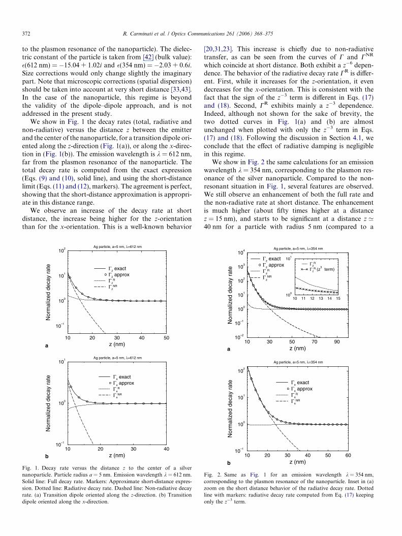
We show in Fig. 1 the decay rates (total, radiative andnon-radiative) versus the distance z between the emitterand the center of the nanoparticle, for a transition dipole ori-ented along the z-direction (Fig. 1(a)), or along the x-direc-tion in (Fig. 1(b)). The emission wavelength is k = 612 nm,far from the plasmon resonance of the nanoparticle. Thetotal decay rate is computed from the exact expression(Eqs. (9) and (10), solid line), and using the short-distancelimit (Eqs. (11) and (12), markers). The agreement is perfect,showing that the short-distance approximation is appropri-ate in this distance range.
We observe an increase of the decay rate at shortdistance, the increase being higher for the z-orientationthan for the x-orientation. This is a well-known behavior
10 20 30 40 50z (nm)
10–1
100
101
102
Nor
mal
ized
dec
ay r
ate
Ag particle, a=5 nm, λ=612 nm
Γz exactΓz approxΓz
R
ΓzNR
10 20 30 40z (nm)
10–1
100
101
Nor
mal
ized
dec
ay r
ate
Ag particle, a=5 nm, λ=612 nm
Γx exactΓx approxΓx
R
ΓxNR
a
b
Fig. 1. Decay rate versus the distance z to the center of a silvernanoparticle. Particle radius a = 5 nm. Emission wavelength k = 612 nm.Solid line: Full decay rate. Markers: Approximate short-distance expres-sion. Dotted line: Radiative decay rate. Dashed line: Non-radiative decayrate. (a) Transition dipole oriented along the z-direction. (b) Transitiondipole oriented along the x-direction.
[20,31,23]. This increase is chiefly due to non-radiativetransfer, as can be seen from the curves of C and CNR
which coincide at short distance. Both exhibit a z�6 depen-dence. The behavior of the radiative decay rate CR is differ-ent. First, while it increases for the z-orientation, it evendecreases for the x-orientation. This is consistent with thefact that the sign of the z�3 term is different in Eqs. (17)and (18). Second, CR exhibits mainly a z�3 dependence.Indeed, although not shown for the sake of brevity, thetwo dotted curves in Fig. 1(a) and (b) are almostunchanged when plotted with only the z�3 term in Eqs.(17) and (18). Following the discussion in Section 4.1, weconclude that the effect of radiative damping is negligiblein this regime.
We show in Fig. 2 the same calculations for an emissionwavelength k = 354 nm, corresponding to the plasmon res-onance of the silver nanoparticle. Compared to the non-resonant situation in Fig. 1, several features are observed.We still observe an enhancement of both the full rate andthe non-radiative rate at short distance. The enhancementis much higher (about fifty times higher at a distancez = 15 nm), and starts to be significant at a distance z ’40 nm for a particle with radius 5 nm (compared to a
10 30 50 70 90z (nm)
10–2
10–1
100
101
102
103
104
Nor
mal
ized
dec
ay r
ate
Ag particle, a=5 nm, λ=354 nm
Γz exactΓz approxΓz
R
ΓzNR
10 11 12 13 14 1510
0
101
ΓzR
ΓzR (z
3 term)
a
b10 20 30 40 50 60
z (nm)
10–1
100
101
102
Nor
mal
ized
dec
ay r
ate
Ag particle, a=5 nm, λ=354 nm
Γx exactΓx approxΓx
R
ΓxNR
Fig. 2. Same as Fig. 1 for an emission wavelength k = 354 nm,corresponding to the plasmon resonance of the nanoparticle. Inset in (a)zoom on the short distance behavior of the radiative decay rate. Dottedline with markers: radiative decay rate computed from Eq. (17) keepingonly the z�3 term.
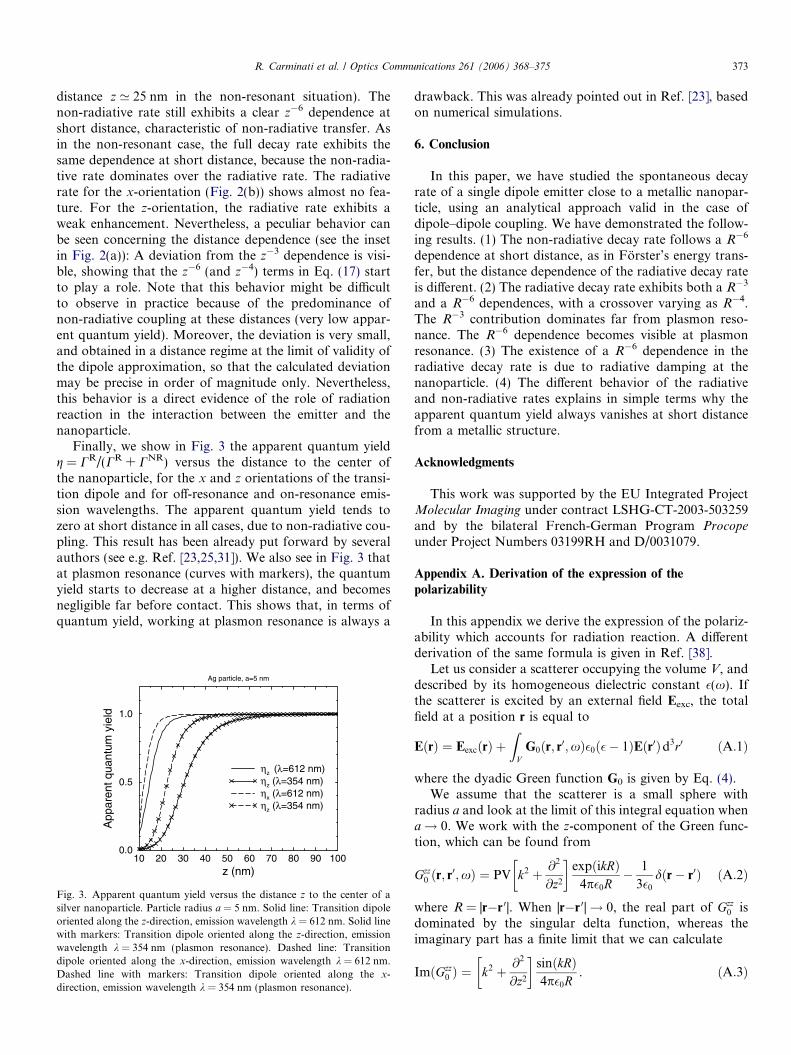
R. Carminati et al. / Optics Communications 261 (2006) 368–375 373
distance z ’ 25 nm in the non-resonant situation). Thenon-radiative rate still exhibits a clear z�6 dependence atshort distance, characteristic of non-radiative transfer. Asin the non-resonant case, the full decay rate exhibits thesame dependence at short distance, because the non-radia-tive rate dominates over the radiative rate. The radiativerate for the x-orientation (Fig. 2(b)) shows almost no fea-ture. For the z-orientation, the radiative rate exhibits aweak enhancement. Nevertheless, a peculiar behavior canbe seen concerning the distance dependence (see the insetin Fig. 2(a)): A deviation from the z�3 dependence is visi-ble, showing that the z�6 (and z�4) terms in Eq. (17) startto play a role. Note that this behavior might be difficultto observe in practice because of the predominance ofnon-radiative coupling at these distances (very low appar-ent quantum yield). Moreover, the deviation is very small,and obtained in a distance regime at the limit of validity ofthe dipole approximation, so that the calculated deviationmay be precise in order of magnitude only. Nevertheless,this behavior is a direct evidence of the role of radiationreaction in the interaction between the emitter and thenanoparticle.
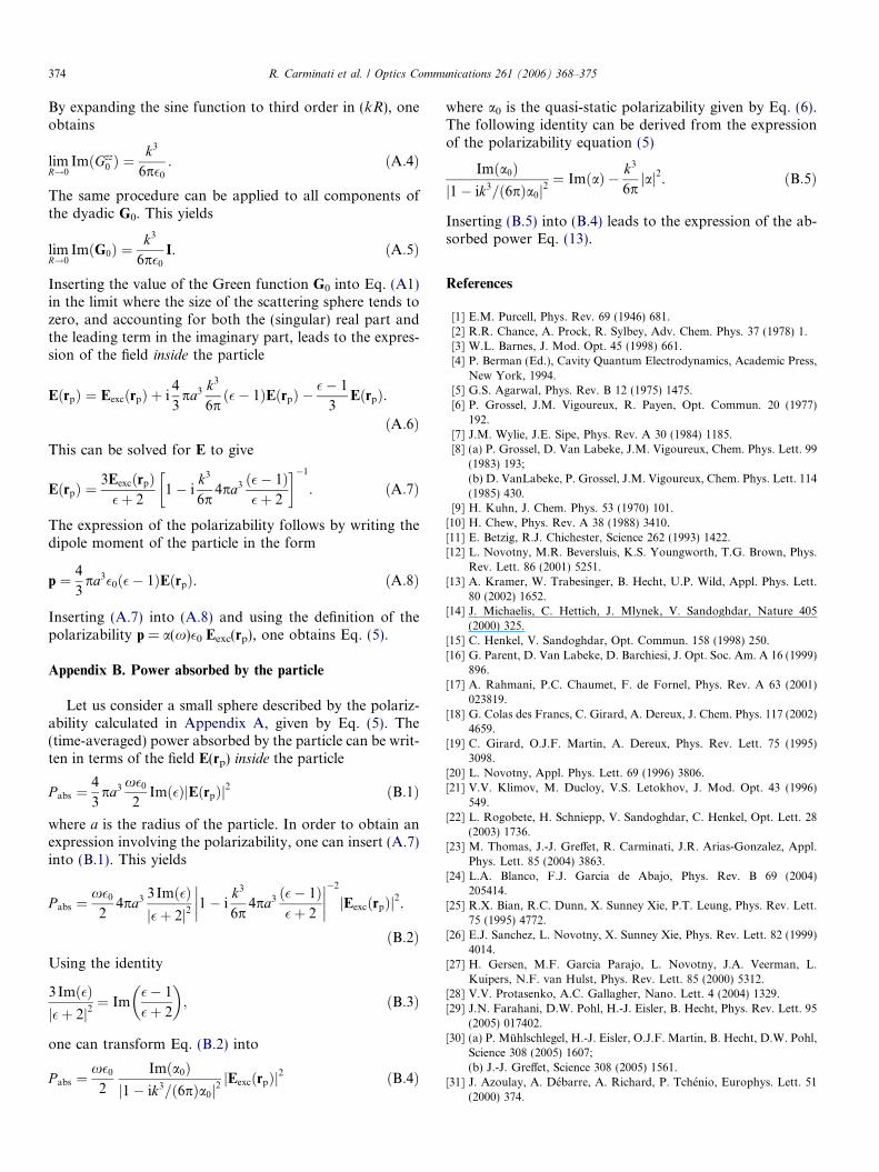
Finally, we show in Fig. 3 the apparent quantum yieldg = CR/(CR + CNR) versus the distance to the center ofthe nanoparticle, for the x and z orientations of the transi-tion dipole and for off-resonance and on-resonance emis-sion wavelengths. The apparent quantum yield tends tozero at short distance in all cases, due to non-radiative cou-pling. This result has been already put forward by severalauthors (see e.g. Ref. [23,25,31]). We also see in Fig. 3 thatat plasmon resonance (curves with markers), the quantumyield starts to decrease at a higher distance, and becomesnegligible far before contact. This shows that, in terms ofquantum yield, working at plasmon resonance is always a
10 20 30 40 50 60 70 80 90 100z (nm)
0.0
0.5
1.0
App
aren
t qua
ntum
yie
ld
Ag particle, a=5 nm
ηz (λ=612 nm)ηz (λ=354 nm)ηx (λ=612 nm)ηz (λ=354 nm)
Fig. 3. Apparent quantum yield versus the distance z to the center of asilver nanoparticle. Particle radius a = 5 nm. Solid line: Transition dipoleoriented along the z-direction, emission wavelength k = 612 nm. Solid linewith markers: Transition dipole oriented along the z-direction, emissionwavelength k = 354 nm (plasmon resonance). Dashed line: Transitiondipole oriented along the x-direction, emission wavelength k = 612 nm.Dashed line with markers: Transition dipole oriented along the x-direction, emission wavelength k = 354 nm (plasmon resonance).
drawback. This was already pointed out in Ref. [23], basedon numerical simulations.
6. Conclusion
In this paper, we have studied the spontaneous decayrate of a single dipole emitter close to a metallic nanopar-ticle, using an analytical approach valid in the case ofdipole–dipole coupling. We have demonstrated the follow-ing results. (1) The non-radiative decay rate follows a R�6
dependence at short distance, as in Forster’s energy trans-fer, but the distance dependence of the radiative decay rateis different. (2) The radiative decay rate exhibits both a R�3
and a R�6 dependences, with a crossover varying as R�4.The R�3 contribution dominates far from plasmon reso-nance. The R�6 dependence becomes visible at plasmonresonance. (3) The existence of a R�6 dependence in theradiative decay rate is due to radiative damping at thenanoparticle. (4) The different behavior of the radiativeand non-radiative rates explains in simple terms why theapparent quantum yield always vanishes at short distancefrom a metallic structure.
Acknowledgments
This work was supported by the EU Integrated ProjectMolecular Imaging under contract LSHG-CT-2003-503259and by the bilateral French-German Program Procope
under Project Numbers 03199RH and D/0031079.
Appendix A. Derivation of the expression of the
polarizability
In this appendix we derive the expression of the polariz-ability which accounts for radiation reaction. A differentderivation of the same formula is given in Ref. [38].
Let us consider a scatterer occupying the volume V, anddescribed by its homogeneous dielectric constant �(x). Ifthe scatterer is excited by an external field Eexc, the totalfield at a position r is equal to
EðrÞ ¼ EexcðrÞ þZ
VG0ðr; r0;xÞ�0ð�� 1ÞEðr0Þd3r0 ðA:1Þ
where the dyadic Green function G0 is given by Eq. (4).We assume that the scatterer is a small sphere with
radius a and look at the limit of this integral equation whena! 0. We work with the z-component of the Green func-tion, which can be found from
Gzz0 ðr; r0;xÞ ¼ PV k2 þ @2
@z2
� �expðikRÞ
4p�0R� 1
3�0
dðr� r0Þ ðA:2Þ
where R = |r�r 0|. When |r�r 0|! 0, the real part of Gzz0 is
dominated by the singular delta function, whereas theimaginary part has a finite limit that we can calculate
ImðGzz0 Þ ¼ k2 þ @2
@z2
� �sinðkRÞ4p�0R
. ðA:3Þ
374 R. Carminati et al. / Optics Communications 261 (2006) 368–375
By expanding the sine function to third order in (kR), oneobtains
limR!0
ImðGzz0 Þ ¼
k3
6p�0
. ðA:4Þ
The same procedure can be applied to all components ofthe dyadic G0. This yields
limR!0
ImðG0Þ ¼k3
6p�0
I. ðA:5Þ
Inserting the value of the Green function G0 into Eq. (A1)in the limit where the size of the scattering sphere tends tozero, and accounting for both the (singular) real part andthe leading term in the imaginary part, leads to the expres-sion of the field inside the particle
EðrpÞ ¼ EexcðrpÞ þ i4
3pa3 k3
6pð�� 1ÞEðrpÞ �
�� 1
3EðrpÞ.
ðA:6ÞThis can be solved for E to give
EðrpÞ ¼3EexcðrpÞ�þ 2
1� ik3
6p4pa3 ð�� 1Þ
�þ 2
� ��1
. ðA:7Þ
The expression of the polarizability follows by writing thedipole moment of the particle in the form
p ¼ 4
3pa3�0ð�� 1ÞEðrpÞ. ðA:8Þ
Inserting (A.7) into (A.8) and using the definition of thepolarizability p = a(x)�0 Eexc(rp), one obtains Eq. (5).
Appendix B. Power absorbed by the particle
Let us consider a small sphere described by the polariz-ability calculated in Appendix A, given by Eq. (5). The(time-averaged) power absorbed by the particle can be writ-ten in terms of the field E(rp) inside the particle
P abs ¼4
3pa3 x�0
2Imð�ÞjEðrpÞj2 ðB:1Þ
where a is the radius of the particle. In order to obtain anexpression involving the polarizability, one can insert (A.7)into (B.1). This yields
P abs ¼x�0
24pa3 3 Imð�Þ
j�þ 2j21� i
k3
6p4pa3 ð�� 1Þ
�þ 2
���������2
jEexcðrpÞj2.
ðB:2ÞUsing the identity
3Imð�Þj�þ 2j2
¼ Im�� 1
�þ 2
� �; ðB:3Þ
one can transform Eq. (B.2) into
P abs ¼x�0
2
Imða0Þj1� ik3=ð6pÞa0j2
jEexcðrpÞj2 ðB:4Þ
where a0 is the quasi-static polarizability given by Eq. (6).The following identity can be derived from the expressionof the polarizability equation (5)
Imða0Þj1� ik3=ð6pÞa0j2
¼ ImðaÞ � k3
6pjaj2. ðB:5Þ
Inserting (B.5) into (B.4) leads to the expression of the ab-sorbed power Eq. (13).
References
[1] E.M. Purcell, Phys. Rev. 69 (1946) 681.[2] R.R. Chance, A. Prock, R. Sylbey, Adv. Chem. Phys. 37 (1978) 1.[3] W.L. Barnes, J. Mod. Opt. 45 (1998) 661.[4] P. Berman (Ed.), Cavity Quantum Electrodynamics, Academic Press,
New York, 1994.[5] G.S. Agarwal, Phys. Rev. B 12 (1975) 1475.[6] P. Grossel, J.M. Vigoureux, R. Payen, Opt. Commun. 20 (1977)
192.[7] J.M. Wylie, J.E. Sipe, Phys. Rev. A 30 (1984) 1185.[8] (a) P. Grossel, D. Van Labeke, J.M. Vigoureux, Chem. Phys. Lett. 99
(1983) 193;(b) D. VanLabeke, P. Grossel, J.M. Vigoureux, Chem. Phys. Lett. 114(1985) 430.
[9] H. Kuhn, J. Chem. Phys. 53 (1970) 101.[10] H. Chew, Phys. Rev. A 38 (1988) 3410.[11] E. Betzig, R.J. Chichester, Science 262 (1993) 1422.[12] L. Novotny, M.R. Beversluis, K.S. Youngworth, T.G. Brown, Phys.
Rev. Lett. 86 (2001) 5251.[13] A. Kramer, W. Trabesinger, B. Hecht, U.P. Wild, Appl. Phys. Lett.
80 (2002) 1652.[14] J. Michaelis, C. Hettich, J. Mlynek, V. Sandoghdar, Nature 405
(2000) 325.[15] C. Henkel, V. Sandoghdar, Opt. Commun. 158 (1998) 250.[16] G. Parent, D. Van Labeke, D. Barchiesi, J. Opt. Soc. Am. A 16 (1999)
896.[17] A. Rahmani, P.C. Chaumet, F. de Fornel, Phys. Rev. A 63 (2001)
023819.[18] G. Colas des Francs, C. Girard, A. Dereux, J. Chem. Phys. 117 (2002)
4659.[19] C. Girard, O.J.F. Martin, A. Dereux, Phys. Rev. Lett. 75 (1995)
3098.[20] L. Novotny, Appl. Phys. Lett. 69 (1996) 3806.[21] V.V. Klimov, M. Ducloy, V.S. Letokhov, J. Mod. Opt. 43 (1996)
549.[22] L. Rogobete, H. Schniepp, V. Sandoghdar, C. Henkel, Opt. Lett. 28
(2003) 1736.[23] M. Thomas, J.-J. Greffet, R. Carminati, J.R. Arias-Gonzalez, Appl.
Phys. Lett. 85 (2004) 3863.[24] L.A. Blanco, F.J. Garcia de Abajo, Phys. Rev. B 69 (2004)
205414.[25] R.X. Bian, R.C. Dunn, X. Sunney Xie, P.T. Leung, Phys. Rev. Lett.
75 (1995) 4772.[26] E.J. Sanchez, L. Novotny, X. Sunney Xie, Phys. Rev. Lett. 82 (1999)
4014.[27] H. Gersen, M.F. Garcia Parajo, L. Novotny, J.A. Veerman, L.
Kuipers, N.F. van Hulst, Phys. Rev. Lett. 85 (2000) 5312.[28] V.V. Protasenko, A.C. Gallagher, Nano. Lett. 4 (2004) 1329.[29] J.N. Farahani, D.W. Pohl, H.-J. Eisler, B. Hecht, Phys. Rev. Lett. 95
(2005) 017402.[30] (a) P. Muhlschlegel, H.-J. Eisler, O.J.F. Martin, B. Hecht, D.W. Pohl,
Science 308 (2005) 1607;(b) J.-J. Greffet, Science 308 (2005) 1561.
[31] J. Azoulay, A. Debarre, A. Richard, P. Tchenio, Europhys. Lett. 51(2000) 374.
R. Carminati et al. / Optics Communications 261 (2006) 368–375 375
[32] V.V. Klimov, M. Ducloy, V.S. Letokhov, Quant. Electr. 31 (2001) 569.[33] I.A. Larkin, M.I. Stockman, M. Achermann, V.I. Klimov, Phys. Rev.
B 69 (2004) 121403(R).[34] X. Brokmann, L. Coolen, M. Dahan, J.P. Hermier, Phys. Rev. Lett.
93 (2004) 107403.[35] J.T. Krug II, E.J. Sanchez, X. Sunney Xie, J. Chem. Phys. 116 (2002)
10895.[36] J. van Bladel, Singular Electromagnetic Fields and Sources, Claren-
don, Oxford, 1991.
[37] A.D. Yaghjian, Proc. IEEE 68 (1980) 248.[38] B.T. Draine, Astrophys. J. 333 (1988) 848.[39] A. Lakhtakia, Opt. Commun. 79 (1990) 1.[40] P.C. Chaumet, A. Rahmani, F. de Fornel, J.-P. Dufour, Phys. Rev. B
58 (1998) 2310.[41] T. Forster, Ann. Physik 6 (1948) 55.[42] E.W. Palik, Handbook of Optical Constants of Solids, Academic
Press, San Diego, 1985.[43] G.W. Ford, W.H. Weber, Phys. Rep. 113 (1984) 195.