quantitative risk assessment (qra) report for lpg mounded
TRANSCRIPT
Page | i
INDIAN OIL CORPORATION LIMITED
QUANTITATIVE RISK ASSESSMENT (QRA) REPORT
FOR
LPG MOUNDED STORAGE SYSTEM
(EXISTING &PROPOSED)
AT
VISAKHAPATNEM, ANDHRA PRADESH
VIMTA LABS LIMITED
461. 142, IDA Phase-II,Cherlapally
Hyderabad - 500051
REVISION – A2
JUNE 2019
Page | ii
QRA Report for Existing & New LPG Storage & Bottling Plant
of IOCL Visakhapatnam
CONTENTS Chapter Description Page No.
1. INTRODUCTION 4
2. FACILITYDESCRIPTION 5
3. SCOPE, OBJECTIVE &METHODOLOGY 9
4. QUANTITATIVE RISKANALYSIS 20
5. CONCLUSIONS & RECOMMENDATIONS Error! Bookmark not defined.
ANNEXURE – 1: PLANT LAYOUT DIAGRAM

Page | iii
QRA Report for Existing & New LPG Storage & Bottling Plant
of IOCL Visakhapatnam
ABBREVIATIONS
ALARP As Low As Reasonably Practicable
BLEVE Boiling Liquid Expanding Vapour Explosion
COMAH Control of Major Accident Hazards (UK)
DNV Det NorskeVeritas
EIV Emergency isolation valve
IOCL Indian Oil Corporation Limited
ISIR Individual-specific individual risk
kg Kilogramme
kW/m2 Kilowatt per square metre
LPG Liquefied Petroleum Gas
LSIR Location-specific individual risk
MoEF Ministry of Environment & Forests (Government of India)
MoP&NG Ministry of Petroleum & Natural Gas (Government of India)
MT Metric Tonne
OGP International Oil & Gas Producers Association
OISD Oil Industry Safety Directorate
psig Pounds per square inch gauge
QRA Quantitative Risk Assessment
ROV Remote operated valve
SH&E Safety, Health &Environment
UK-HSE United Kingdom – Health & safety Executive
VCE Vapour cloud explosion

QRA Report for Existing & New LPG Storage & Bottling Plant
of IOCL Visakhapatnam
1. INTRODUCTION
Indian Oil Corporation Limited (IOCL) is a Government of India Enterprise with a Navratna
Status, and a Fortune 500 and Forbes 2000 company. Incorporated as Indian Oil Corporation
Ltd. on 1st September, 1964 Indian Oil and its subsidiaries account for approximately 48%
petroleum products market share, 34% national refining capacity and 71% downstream sector
pipelines capacity in India. It is India‟s flagship national oil company and downstream petroleum major thus being India‟s largest commercial enterprise.
As the flagship national oil company in the downstream sector, Indian Oil reaches precious
petroleum products to millions of people every day through a countrywide network of about
35,000 sales points. They are backed for supplies by 167 bulk storage terminals and depots, 101
aviation fuel stations and 89 Indane (LPG) bottling plants.
IOCL plan to expand the LPG storage capacity in their existing LPG Bottling Plant at Parawada
near Visakhapatnam in Andhra Pradesh State by installing additional three mounded LPG bullets
each with 600 MT capacity.
Being an organization with commitment to high standards of safety, health and environmental
protection, IOCL wish to ensure that all hazards and risks due to the existing and the proposed
additional mounded LPG storage in their LPG Bottling Plant at Visakhapatnam are properly
identified and necessary risk reduction measures are implemented.
Accordingly, IOCL have engaged the services of Vimta Labs Limited, Hyderabad to carry out a
Quantitative Risk Assessment (QRA) Study for the LPG storage in the LPG Bottling Plant
including the existing and new facilities at Visakhapatnam.
Vimta Labs Limited, accredited by QCI/NABET have carried out similar risk analysis studies for
a large number of LPG, LNG, oil & gas and chemical installations. This report presents the
QRA study for the existing and additional LPG Storage & Bottling Plant of IOCL
Visakhapatnam Facility.

QRA Report for Existing & New LPG Storage & Bottling Plant
of IOCL Visakhapatnam
Existing Mounded LPG
Bullets (3 x 600 MT)
Proposed Mounded LPG
Bullets (3 x 600 MT)
2. FACILITYDESCRIPTION
IOCL LPG Storage & Bottling Plant, Visakhapatnam
IOCL „Indane‟ LPG Bottling Plant at Parawada is located in Visakhapatnam district of Andhra Pradesh. The plant covering an area of 58.09 acres is situated in an industrial
area about 35 km south-west of Visakhapatnam. The site is well connected by road
through NH-16.
Map indicating location of the plant is shown in the Figure 2.1 below.
Figure 2.1: IOCL Visakhapatnam Site Location Map
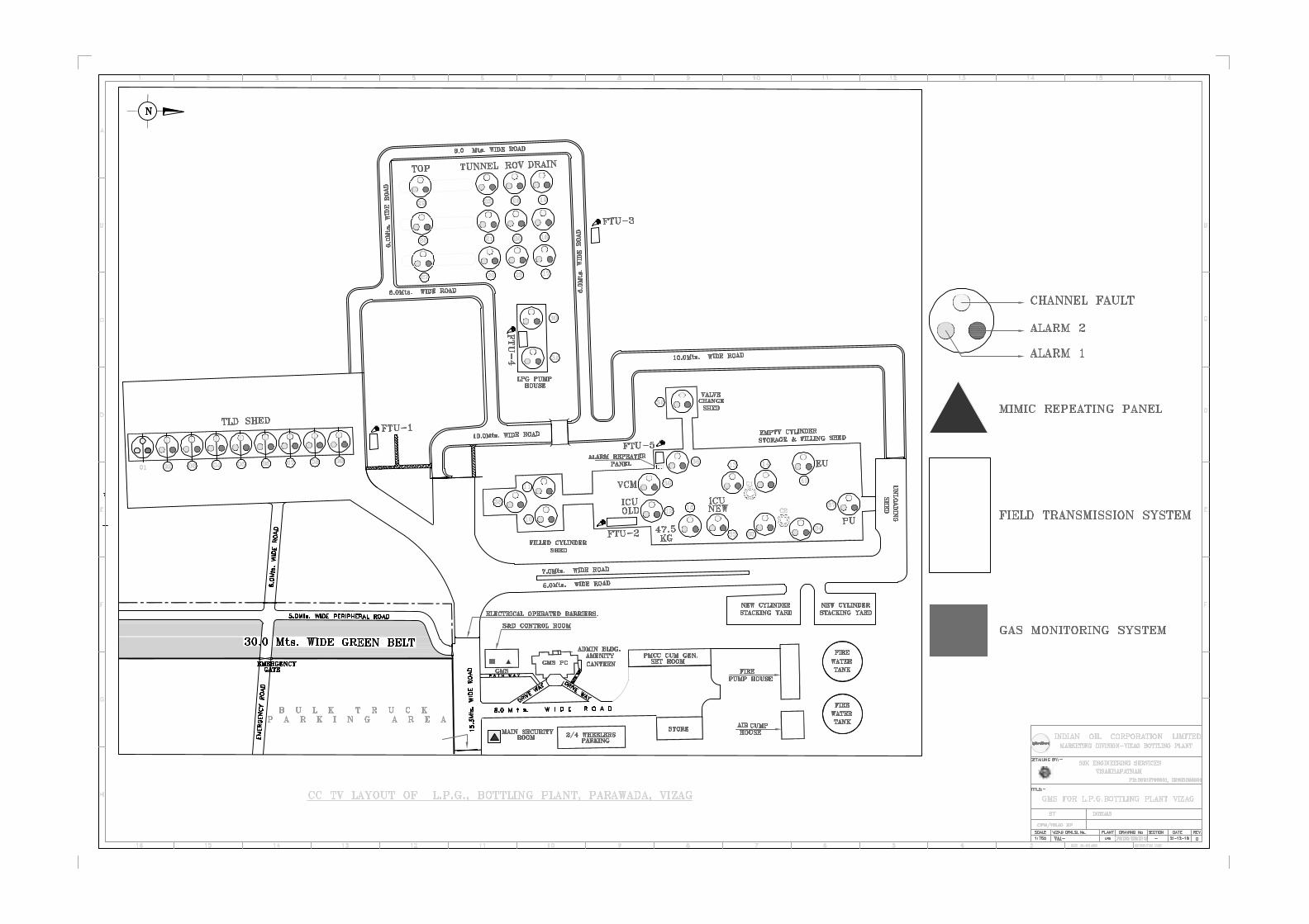
The layout drawing of IOCL Visakhapatnam LPG Plant is enclosed in Annexure – 1.
Page 6
QRA Report for Existing & New LPG Storage & Bottling Plant
of IOCL Visakhapatnam
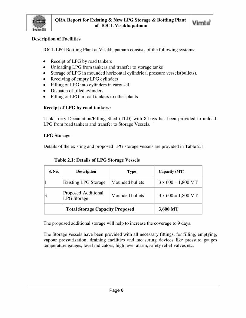
Description of Facilities
IOCL LPG Bottling Plant at Visakhapatnam consists of the following systems:
Receipt of LPG by road tankers
Unloading LPG from tankers and transfer to storage tanks
Storage of LPG in mounded horizontal cylindrical pressure vessels(bullets).
Receiving of empty LPG cylinders
Filling of LPG into cylinders in carousel
Dispatch of filled cylinders
Filling of LPG in road tankers to other plants
Receipt of LPG by road tankers:
Tank Lorry Decantation/Filling Shed (TLD) with 8 bays has been provided to unload
LPG from road tankers and transfer to Storage Vessels.
LPG Storage
Details of the existing and proposed LPG storage vessels are provided in Table 2.1.
Table 2.1: Details of LPG Storage Vessels
S. No. Description Type Capacity (MT)
1 Existing LPG Storage Mounded bullets 3 x 600 = 1,800 MT
3 Proposed Additional
LPG Storage
Mounded bullets
3 x 600 = 1,800 MT
Total Storage Capacity Proposed 3,600 MT
The proposed additional storage will help to increase the coverage to 9 days.
The Storage vessels have been provided with all necessary fittings, for filling, emptying,
vapour pressurization, draining facilities and measuring devices like pressure gauges
temperature gauges, level indicators, high level alarm, safety relief valves etc.

Page 7
QRA Report for Existing & New LPG Storage & Bottling Plant
of IOCL Visakhapatnam
Receipt of Empty LPG Cylinders
Four telescopic type unloading bays are provided for empty cylinders received in trucks.
All necessary inspections of the empty cylinders are carried out before going for filling.
The segregated cylinders are stacked separately and these are taken for testing/repair.
Filling of LPG in cylinders
Two electronic filling machines each with 24 points and cylinder conveyor have been
installed in filling shed for filling of 14.2 kg and 19 kg cylinders. Electronic check scales
are provided for checking weight of filled cylinders and weight correction unit machines,
Automatic valve testing machines, test bath for checking any leakage from cylinder bung
and body. The filling shed also contains hot air sealing machine for sealing of cylinders
prior to despatch and SQC machine for quality checks of cylinders. Processed cylinders
directly go to loading bays and the cylinders failing the test go are sent for repair.
Despatch of Filled Cylinders
After passing of all tests, the filled cylinders are loaded in trucks by using four telescopic
type loading bays.
LPG Pump and Compressor House
Three centrifugal pump have been installed to pump liquid LPG from storage vessels to
carousel. These pumps have been provided with pop-action valves on discharge lines and
are coupled to flame proof motors.
There are three LPG vapour compressors each coupled to a flame-proof motor for unloading of LPG tankers by differential pressure mechanism. The compressors have
maximum discharge pressure of 11.5 kg/cm2g. Details of LPG pumps and compressors are provided in Table2.2.
Table 2.2: Details of LPG Pumps & Compressors
Description Nos. Capacity
(M3/hr) Motor
(HP)
LPG Pump 1 85 60
LPG Pump 2 48 75
LPG Compressors 2 35 25
LPG Compressor 1 150 60

Page 8
QRA Report for Existing & New LPG Storage & Bottling Plant
of IOCL Visakhapatnam
Fire Protection & Safety Measures
Storage and handling of LPG involves the following hazards:
Fire hazard due to ignition of leaking LPG liquid/vapour
Explosion due to delayed ignition of vapour cloud in flammable range formed by
large quantity of LPG mixed with air
Cold burn due to contact with flashing liquid LPG at very low temperature
Fire protection measures provided in the Visakhapatnam LPG installation include the
following:
Fire water system
Fire water storage tanks – 2 Nos. each 3700 KL (total 7400 KL)capacity
Fire water pumps with diesel engine drives - 5 Nos. each 410 M3/hr capacity
Fire water jockey pumps with motor drive - 2 Nos. each 20 M3/hr capacity
Fire water distribution network
Fire hydrants.
Monitors.
Water spray systems with deluge valves.
LPG received in road tankers is odorized with ethyl mercaptan to alert the people in the
area in case of any leaks.
Gas detectors are provided in areas around bullets, pumps & tanker loading stations.
Ignition sources are strictly controlled by the following measures:
Use of flame-proof electrical equipment &fittings
Strict implementation of „No Smoking‟rule
The LPG installation and fire protection measures conform to relevant OISD standards.

Page 9
QRA Report for Existing & New LPG Storage & Bottling Plant
of IOCL Visakhapatnam
3. SCOPE, OBJECTIVE & METHODOLOGY
3,1 Scope of work
The scope of work of this study covers the Quantitative Risk Assessment (QRA) for the
complete IOCL LPG Bottling Plant near Visakhapatnam in Andhra Pradesh state
including the existing and proposed additional mounded LPG storage vessels.
Objective of the Study
The objectives of this study are as follows:
Identifying the potential failure scenarios for release of flammable/ toxic
material in the LPG storage installation.
Carrying out consequence analysis for significant accident scenarios.
Carrying out for Quantitative Risk Analysis
Estimating the individual risk and societal risk due to the installation.
Assessing the risk with respect to the risk tolerance criteria
Identifying risk reduction measures wherever warranted to ensure that the risk is as low as reasonably practicable.
Methodology
Risk arises from hazards. Risk is defined as the product of severity of consequence and
likelihood of occurrence. Risk may be to people, environment, assets or business
reputation. This study is specifically concerned with risk of serious injury or fatality to
people. The flow diagram of QRA is shown in Figure 2.1.
The following steps are involved in quantitative risk assessment (QRA):
Study of the plant facilities and systems.
Identification of the hazards.
Enumeration of the failure scenarios.
Estimation of the consequences for the selected failure incidents.
Risk analysis taking into account the failure frequency, extent of consequences and exposure of people to the hazards.
Risk assessment to compare the calculated risk with risk tolerability criteria and
review the risk management system to ensure that the risk is “As Low As Reasonably Practicable”(ALARP)

Page 10
QRA Report for Existing & New LPG Storage & Bottling Plant
of IOCL Visakhapatnam
Figure 3.1: Flow diagram of quantitative risk assessment (QRA)
Consequence Analysis
Consequence analysis for the selected failure scenarios is carried out using DNV Phast
software. Consequence analysis provides results for the following:
Dispersion of toxic clouds to defined concentrations
Heat radiation intensity due to jet fire and pool fire
Explosion overpressure
The renowned DNV Phast software package is used worldwide for consequence
modelling and quantitative risk analysis.
Phast is based on Unified Dispersion Modelling to calculate the results of the release of
material into the atmosphere. It can model both heavy gas dispersion and buoyant
dispersion of lighter-than-air gases. Phast has extensive material database and provides
for definition of mixtures.

Page 11
QRA Report for Existing & New LPG Storage & Bottling Plant
of IOCL Visakhapatnam
Quantitative Risk Analysis(QRA)
The quantitative risk analysis is carried out using the renowned software
package PHAST Risk Micro (also known as SAFETI Micro) version 6.6
developed and marketed by Det Norske Veritas (DNV) of Norway.
The following input data are required for the risk calculation:
Process data for release scenarios (material, inventory, pressure,
temperature, type of release, leak size, location, etc.)
Estimated frequency of each failure case
Distribution of people in the plant/ adjoining area during the day
and night time.
Distribution of wind speed and direction (wind rose data).
Ignition sources
Failure Frequency Estimation
For objective and comprehensive risk analysis, whole range of leak sizes is
considered in each section containing large inventory of hazardous material
Small leak (5 mm diameter)
Medium leak (25 mm diameter)
Large leak (100 mm diameter)
Full bore leak.
Theoretically, Fault Tree Analysis (FTA) can be used for estimation of
failure rates for loss of containment from equipment. Fault tree is
constructed to show how the Top Event (loss of containment) can develop
from basic failure events through intermediate events connected by logic
gates. The two most widely used logic gates are „OR‟ gate and „AND‟ gate.
In the case of „OR‟ logic gate, any one of the input events will lead to the output event.
In the case of „AND‟ logic gate with two input events, the output event
will occur only when both the input events occur.
Following are the symbols used for fault tree analysis:

Page 12
QRA Report for Existing & New LPG Storage & Bottling Plant
of IOCL Visakhapatnam
Figure 1.2: Symbols used in Fault Tree
Fault Trees for the hydrocarbon leakage scenario covering leak in Storage Tank, Pipelines and
Tank Lorry Decantation Shed are shown in figures below:

Page 13
QRA Report for Existing & New LPG Storage & Bottling Plant
of IOCL Visakhapatnam
Figure 3.3: Fault Tree for Hydrocarbon leak in Pipelines

Page 14
QRA Report for Existing & New LPG Storage & Bottling Plant
of IOCL Visakhapatnam
Figure 3.4: Fault Tree for Hydrocarbon leak in Storage Tank

Page 15
QRA Report for Existing & New LPG Storage & Bottling Plant
of IOCL Visakhapatnam
Figure 3.5: Fault Tree for LPG Release in Tank Lorry Decantation Shed Area
Page 16
QRA Report for Existing & New LPG Storage & Bottling Plant
of IOCL Visakhapatnam
In theory, fault tree analysis can be used to calculate the probability of the top event
based on the probabilities of all the basic events.
In the case of „OR‟ gate, the probability of occurrence of the output event is approximately the sum of the probabilities of occurrence of the input events.
Poutput Pinput1 + Pinput2
In the case of „AND‟ gate, the probability of occurrence of the output event is approximately the product of the probabilities of occurrence of the input events.
Poutput Pinput1 * Pinput2
In actual practice, calculation of failure rates using fault tree analysis is limited by non-
availability of failure rate data for many basic and external events involved.
The current practice in QRA is to estimate the failure rates required for failure scenarios
for different types of equipment using the historical failure frequency database published
by organizations such as International Oil & Gas Producers Association (OGP).
OGP Report No. 434-1 “Process Release Frequencies” for equipment &piping
OGP Report No. 434-3 “Storage Incident Frequencies”
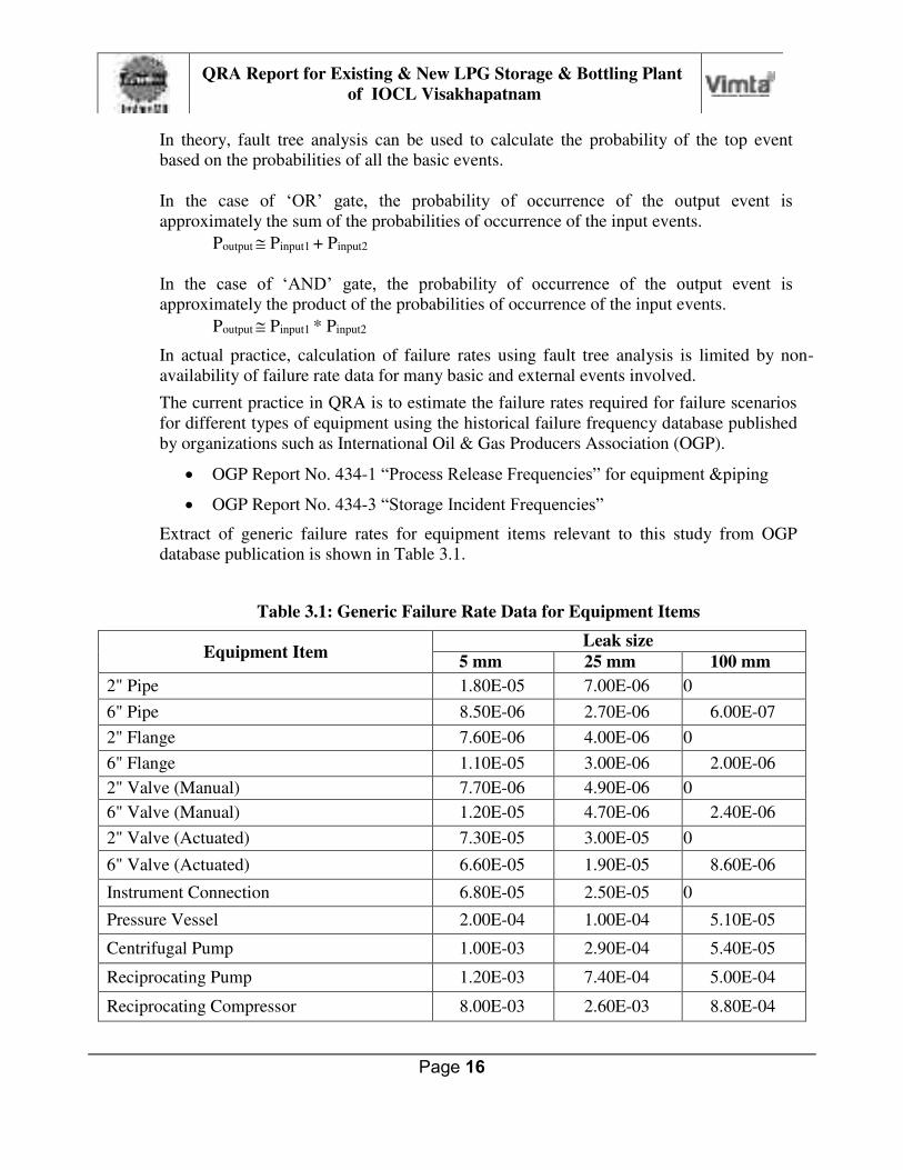
Extract of generic failure rates for equipment items relevant to this study from OGP
database publication is shown in Table 3.1.
Table 3.1: Generic Failure Rate Data for Equipment Items
Equipment Item Leak size
5 mm 25 mm 100 mm
2" Pipe 1.80E-05 7.00E-06 0
6" Pipe 8.50E-06 2.70E-06 6.00E-07
2" Flange 7.60E-06 4.00E-06 0
6" Flange 1.10E-05 3.00E-06 2.00E-06
2" Valve (Manual) 7.70E-06 4.90E-06 0
6" Valve (Manual) 1.20E-05 4.70E-06 2.40E-06
2" Valve (Actuated) 7.30E-05 3.00E-05 0
6" Valve (Actuated) 6.60E-05 1.90E-05 8.60E-06
Instrument Connection 6.80E-05 2.50E-05 0
Pressure Vessel 2.00E-04 1.00E-04 5.10E-05
Centrifugal Pump 1.00E-03 2.90E-04 5.40E-05
Reciprocating Pump 1.20E-03 7.40E-04 5.00E-04
Reciprocating Compressor 8.00E-03 2.60E-03 8.80E-04

Page 17
QRA Report for Existing & New LPG Storage & Bottling Plant
of IOCL Visakhapatnam
Note:
Failure rate notation: 1.0E-05 per year means 1.0 x 10⁻⁵ per year
The results of quantitative risk analysis are commonly represented by the following
parameters:
Individual Risk
Societal Risk
Individual risk is the risk that an individual remaining at a particular spot would face
from the plant facility. The calculation of individual risk at a geographical location in
and around a plant assumes that the contributions of all incident outcome cases are
additive. Thus, the total individual risk at each point is equal to the sum of the individual
risks, at that point, of all incident outcome cases associated with theplant.
The individual risk value is a frequency of fatality, usually chances per million per year,
and it is displayed as a two-dimensional plot over a locality plan as contours of equal risk
in the form of iso-risk contours as shown in the following Figure 3.3.
Figure 3.6: Iso-Risk Contours on Site Plan (Typical)
Risk tolerability criteria
For the purpose of effective risk assessment, it is necessary to have established criteria
for tolerable risk. The risk tolerability criteria defined by UK Health & Safety Executive
(UK-HSE) are normally used for risk assessment in the absence of specific guidelines by
Indian authorities.
UK-HSE has, in the publications “Reducing Risk and Protecting People” and “Guidance

Page 18
QRA Report for Existing & New LPG Storage & Bottling Plant
of IOCL Visakhapatnam
on ALARP decisions in control of major accident hazards (COMAH)” enunciated the tolerability criteria for individual risk.
The guidance on QRA also can be taken from MoEF, Gov. of India from their
publication “Technical EIA Guidance Manual for Offshore and Onshore Oil and Gas
Exploration Development and Production, September 2009.” and Bureau of Indian Standards Hazard Identification and Risk Analysis (IS15656:2006).
An individual risk of death of one in a million (1 x 10⁻⁶) per annum for both
workers and the public corresponds to a very low level of risk and should be
used as a guideline for the boundary between the risk acceptable and ALARP
regions.
An individual risk of death of one in a thousand (1 x 10⁻³) per annum should
on its own represent the dividing line between what could be just tolerable for any substantial category of workers for any large part of a working life, and
what is unacceptable. For members of the public who have a risk imposed on them „in the wider interest of society‟ this limit is judged to be an order of magnitude lower, at 1 in 10,000 (1 x 10⁻⁴) per annum.
The upper limit of tolerable risk to public, 1 x 10⁻⁴ per year is in the range of risk due to
transport accidents. The upper limit of acceptable risk, 1 x 10⁻⁶ per year, is in the range of risk due to natural hazard such as lightning.
The tolerability criteria for individual risk are shown in Figure 3.4.
Figure 3.7: Individual Risk Criteria
Page 19
QRA Report for Existing & New LPG Storage & Bottling Plant
of IOCL Visakhapatnam
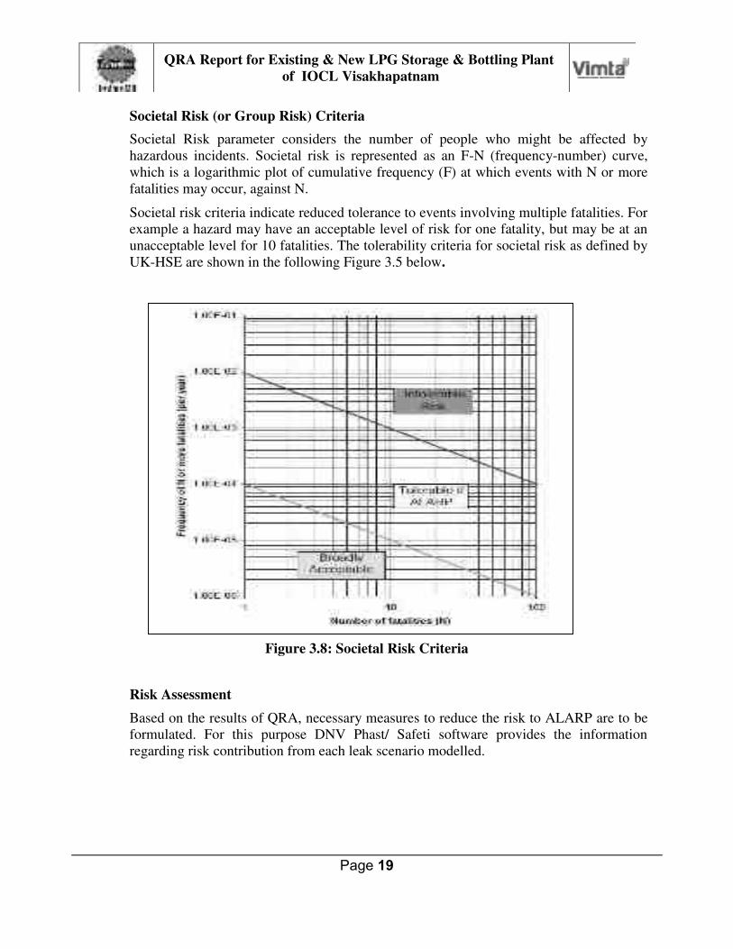
Societal Risk (or Group Risk) Criteria
Societal Risk parameter considers the number of people who might be affected by
hazardous incidents. Societal risk is represented as an F-N (frequency-number) curve,
which is a logarithmic plot of cumulative frequency (F) at which events with N or more
fatalities may occur, against N.
Societal risk criteria indicate reduced tolerance to events involving multiple fatalities. For
example a hazard may have an acceptable level of risk for one fatality, but may be at an
unacceptable level for 10 fatalities. The tolerability criteria for societal risk as defined by
UK-HSE are shown in the following Figure 3.5 below.
Figure 3.8: Societal Risk Criteria
Risk Assessment
Based on the results of QRA, necessary measures to reduce the risk to ALARP are to be
formulated. For this purpose DNV Phast/ Safeti software provides the information
regarding risk contribution from each leak scenario modelled.
Page 20
QRA Report for Existing & New LPG Storage & Bottling Plant
of IOCL Visakhapatnam
4. QUANTITATIVE RISKANALYSIS
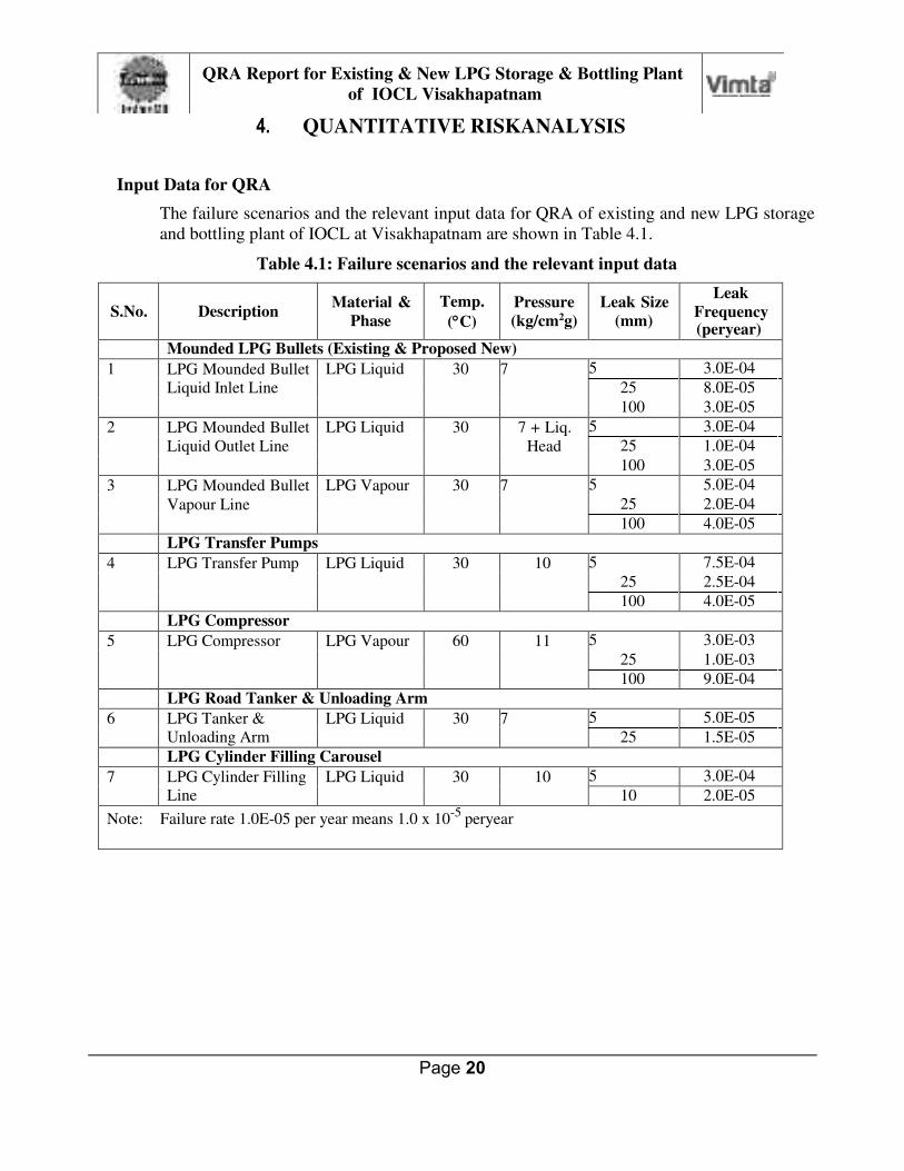
Input Data for QRA
The failure scenarios and the relevant input data for QRA of existing and new LPG storage
and bottling plant of IOCL at Visakhapatnam are shown in Table 4.1.
Table 4.1: Failure scenarios and the relevant input data
S.No.
Description Material &
Phase
Temp.
(C)
Pressure
(kg/cm2g)
Leak Size
(mm)
Leak
Frequency (peryear)
Mounded LPG Bullets (Existing & Proposed New)
1 LPG Mounded Bullet
Liquid Inlet Line
LPG Liquid 30 7 5 3.0E-04
25 8.0E-05
100 3.0E-05
2 LPG Mounded Bullet
Liquid Outlet Line
LPG Liquid 30 7 + Liq.
Head
5 3.0E-04
25 1.0E-04
100 3.0E-05
3 LPG Mounded Bullet
Vapour Line
LPG Vapour 30 7 5 5.0E-04
25 2.0E-04
100 4.0E-05 LPG Transfer Pumps
4 LPG Transfer Pump LPG Liquid 30 10 5 7.5E-04
25 2.5E-04
100 4.0E-05 LPG Compressor
5 LPG Compressor LPG Vapour 60 11 5 3.0E-03
25 1.0E-03
100 9.0E-04 LPG Road Tanker & Unloading Arm
6 LPG Tanker &
Unloading Arm
LPG Liquid 30 7 5 5.0E-05
25 1.5E-05 LPG Cylinder Filling Carousel
7 LPG Cylinder Filling Line
LPG Liquid 30 10 5 3.0E-04
10 2.0E-05
Note: Failure rate 1.0E-05 per year means 1.0 x 10⁻⁵
peryear
Page 21
QRA Report for Existing & New LPG Storage & Bottling Plant
of IOCL Visakhapatnam
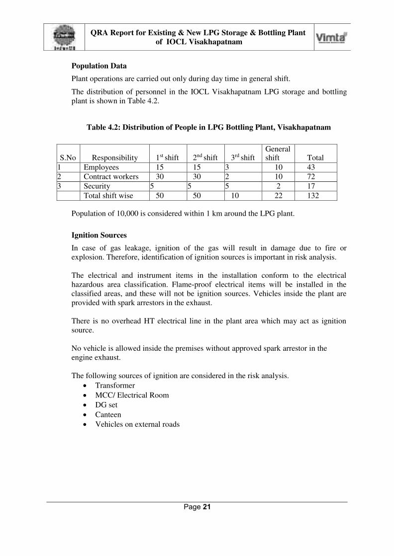
Population Data
Plant operations are carried out only during day time in general shift.
The distribution of personnel in the IOCL Visakhapatnam LPG storage and bottling
plant is shown in Table 4.2.
Table 4.2: Distribution of People in LPG Bottling Plant, Visakhapatnam
S.No
Responsibility
1st shift
2nd shift
3rd shift General shift
Total
1 Employees 15 15 3 10 43
2 Contract workers 30 30 2 10 72
3 Security 5 5 5 2 17 Total shift wise 50 50 10 22 132
Population of 10,000 is considered within 1 km around the LPG plant.
Ignition Sources
In case of gas leakage, ignition of the gas will result in damage due to fire or
explosion. Therefore, identification of ignition sources is important in risk analysis.
The electrical and instrument items in the installation conform to the electrical
hazardous area classification. Flame-proof electrical items will be installed in the
classified areas, and these will not be ignition sources. Vehicles inside the plant are
provided with spark arrestors in the exhaust.
There is no overhead HT electrical line in the plant area which may act as ignition
source.
No vehicle is allowed inside the premises without approved spark arrestor in the
engine exhaust.
The following sources of ignition are considered in the risk analysis.
Transformer
MCC/ Electrical Room
DG set
Canteen
Vehicles on external roads

Page 22
QRA Report for Existing & New LPG Storage & Bottling Plant
of IOCL Visakhapatnam
Weather parameters
Weather parameters play a significant role in dispersion analysis. The notable
parameters for assessing the atmosphere are wind speed, atmospheric stability,
ambient temperature, humidity and topographic parameters.
Atmospheric stability represents the vertical turbulence in the air due to temperature
differentials caused by heating of the earth by solar radiation. Atmospheric stability
effects are represented through Pasquill parameters as follows shown in Table 4.3.
Table 4.3: Pasquill parameters
Stability Class Atmospheric Condition
A
B
C
D
E F
Very Unstable
Unstable
Slightly Unstable
Neutral
Stable
Very Stable
The relationship between wind speed and atmospheric stability is shown in
Table 4.4.
Table 4.4: Relationship between wind speed and atmospheric stability
Wind speed
Day-Time: Solar Radiation
Night-Time Cloud Cover
(m/s) Strong Medium Slight Thin <3/8
Medium >3/8
Overcast >4/5
<2 A A-B B - - D
2-3 A-B B C E F D
3-5 B B-C C D E D
5-6 C C-D D D D D
>6 C D D D D D
Category D (neutral) is the most probable at sites in moderate climates and may occur
for up to 80 % of the time at relevant sites. Stability F (very stable) represents the
most adverse condition in which dispersion extends over longer distances
horizontally. Normally, stability F occurs for short periods in the year, mainly during
winternights.
Weather data (monthly average maximum & minimum temperature and rain fall) for
Vijayawada are indicated in Table 4.5.

Page 23
QRA Report for Existing & New LPG Storage & Bottling Plant
of IOCL Visakhapatnam
Table 4.5: Weather Data for Visakhapatnam
Month Temperature (oC) Relative Humidity (%)
Rainfall
(mm) Max Min 08:30 17:30
January 31.6 14.4 76 65 7.4
February 34.3 16.8 75 65 13.8
March 37.3 19.5 71 66 6.6
April 37.8 22.2 68 70 24.2
May 40.1 23.1 68 69 45.3
June 40.4 23.9 72 69 117.7
July 37.0 23.7 78 73 128.2
August 36.2 23.8 78 74 161.4
September 35.5 23.3 79 77 171.9
October 34.6 21.5 75 73 194.7
November 32.7 17.5 69 68 73.5
December 31.1 14.8 69 64 6.0
Total 950.7
Wind rose diagram for distribution of wind direction and wind speed is shown in
Figure 4.1.
Figure 4.1: Wind Rose Diagram for Visakhapatnam

Page 24
QRA Report for Existing & New LPG Storage & Bottling Plant
of IOCL Visakhapatnam
The representative combinations of weather parameters for the site considered in this
study are shown in Table 4.6.
Table 4.6: Weather Parameters for Risk Analysis
Description #1 #2
Temperature (C) 35 20
Wind speed (m/s) 5 3
Atmospheric Stability D D
Hazardous Properties of LPG
The flammable consequences of LPG release from equipment are mainly the
following:
Jet fire/ pool fire/ flash fire
Vapour cloud explosion
Properties of LPG relevant to this QRA study are as follows.
Composition: Mixture of Propane and Butane
Normal Boiling Point: (-)6 C Lower Flammable Limit(LFL): 1.8 % (vol)
Upper Flammable Limit(UFL): 9.5 %(vol)
Auto ignition temperature: 410-580 C (approx.)
LPG is stored as liquid under pressure. LPG vapours are heavier than air and
disperse close to ground level. LPG odorized with Ethyl Mercaptan is received in
the plant so as to provide warning in case of leakage.
Consequence Analysis
Jet/ Pool Fire Radiation
The effect from jet fire and pool fire is thermal radiation intensity on the receptor
surface as shown in Table 4.7.
Table 4.7: Damage Effects due to Jet/ Pool Fire Radiation
Heat
Radiation
Intensity
(kW/m2)
Observed Effect
4 Sufficient to cause pain to personnel if unable to reach cover
within 20 seconds; however blistering of the skin (second- degree burn) is likely; 0% lethality.
12.5 Minimum energy required for piloted ignition of wood, melting of plastic tubing.
37.5 Sufficient to cause damage to process equipment.

Page 25
QRA Report for Existing & New LPG Storage & Bottling Plant
of IOCL Visakhapatnam
Thermal radiation intensity exceeding 37.5 kW/m² may cause escalation due to
damage of other equipment.
Thermal radiation intensity exceeding 12.5 kW/m² may cause ignition of
combustibles on buildings and impairment of escape route.
Thermal radiation intensity exceeding 4 kW/m² may cause burn injury on personnel
injury.
Vapour cloud explosion (VCE)
When a large quantity of flammable vapour or gas is released, mixes with air to
produce sufficient mass in the flammable range and is then ignited, the result is a
vapour cloud explosion (VCE). In the LPG installation large release of LPG from
equipment or piping has potential for vapour cloud explosion. The damage effect of
vapour cloud explosion is due to overpressure as shown in Table 4.8.
Table 4.8: VCE over pressure limit and Observed Effect
Over-pressure Effect Observed Damage bar(g) psig
0.021 0.3 “Safe distance” (probability 0.95 of no serious damage below this value); projectile limit; some damage to
house ceilings; 10% of window glass broken.
0.069 1 Repairable damage; partial demolition of houses; steel
frame of clad building slightly distorted.
0.138 2 Partial collapse of walls of houses.
0.207 3 Heavy machines in industrial buildings suffered little
damage; steel frame building distorted and pulled away
from foundations.
Consequence Analysis Results for Maximum Credible Scenarios
The whole range of leak sizes (small, medium & large) with the appropriate failure
frequencies are taken into account for QRA using DNV Phast/ Safeti software.
Consequence analysis modelling for all the scenarios is carried out by Phast which is a
part of Safeti software. Results of the consequence analysis is further processed
internally by Safeti software to derive the results for QRA.
It is necessary to display the results of consequence analysis for selected cases
representing maximum credible scenarios.
In the case of equipment and associated piping, sources of release of hazardous
materials normally encountered are the following:
Seal leak in pumps and valves
Leaks from tanker unloading arms
Leaks from corrosion damage
Leaks from flange joints
Leaks from damaged small-bore connections for instruments, drains &vents.
Pumps used in LPG plants are normally provided with advanced type of mechanical
seals. Any leak from such seals will be from a small clearance around the shaft. The
Page 26
QRA Report for Existing & New LPG Storage & Bottling Plant
of IOCL Visakhapatnam
leak size is conservatively estimated as equivalent to 5 mm diameter hole with cross
sectional area of about 20 sq. mm.
In the case of LPG tanker unloading arms, leaks from articulated joints or coupling
are estimated to be equivalent to 5 mm diameter hole. In order to prevent release of
LPG in case of damage of the unloading arm by accidental movement of tanker the
following safety features are provided:
Break-away coupling
Excess flow check valve (EFCV) installed inside the tanker.
Corrosion damage in equipment or piping usually starts as small pinhole leak or
crack. The leak size is estimated as equivalent to 5 mm diameter hole. If the leak is
allowed to continue it will become larger in size.
Flange joints in LPG plant equipment and piping are normally raised face or ring type
(RTJ). The raised face flanges are provided with spiral wound metallic gaskets which
are not expected to rupture catastrophically. Leak from such flange joint will be from
small gap due to the following causes:
Excess strain due to thermal expansion or improper supports
Weakening of one or more bolts in the flange joint
The flow area for leakage from flange joint will be the length of opening along inner
circumference multiplied by the gap. For 8” (200 mm) size pipe, flow area covering
25% of flange joint and 2 mm gap is 320 sq.mm. which is equivalent to 20 mm
diameter hole.
Small bore connections for instrument tapping are normally ¾ inch size. Vent and
drain connections are normally 1 inch (25 mm) size.
Taking into account all the above points, leak size equivalent to 25 mm diameter hole
is considered for represent, on a conservative basis, the maximum credible release
scenario in this facility.
Results of consequence analysis by Phast software for the maximum credible leak
scenarios relevant to IOCL Vizag LPG bottling plant are shown in the Table 4.9.
Graphical results plotted on the site map drawings are shown in Figure 4.2 to 4.17.
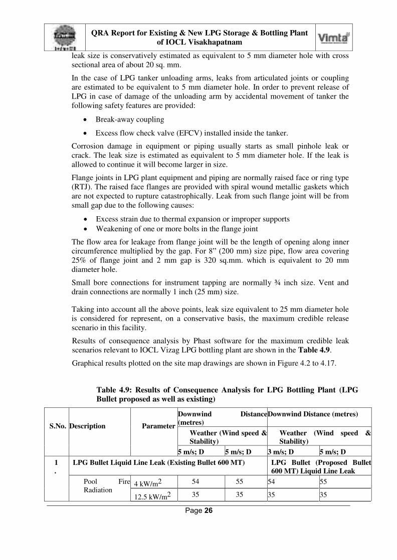
Table 4.9: Results of Consequence Analysis for LPG Bottling Plant (LPG
Bullet proposed as well as existing)
S.No.
Description
Parameter
Downwind Distance
(metres)
Downwind Distance (metres)
Weather (Wind speed &
Stability)
Weather (Wind speed &
Stability)
5 m/s; D 5 m/s; D 3 m/s; D 5 m/s; D
1
.
LPG Bullet Liquid Line Leak (Existing Bullet 600 MT) LPG Bullet (Proposed Bullet
600 MT) Liquid Line Leak
Pool Fire
Radiation 4 kW/m2 54 55 54 55
12.5 kW/m2 35 35 35 35

Page 27
QRA Report for Existing & New LPG Storage & Bottling Plant
of IOCL Visakhapatnam
Intensity 37.5 kW/m2 19 18 19 18
Flash Fire
Envelope
LFL (1.7%) 57 64 57 64
VCE
Overpressure
0.02 bar 172 226 172 226
0.07 bar 86 110 86 110
0.2 bar Not
reached
Not
reached Not reached Not reached

Page 28
QRA Report for Existing & New LPG Storage & Bottling Plant
of IOCL Visakhapatnam
Table 4.10: Results of Consequence Analysis for LPG Bottling Plant
S.No.
Description
Parameter
Downwind Distance (metres)
Weather (Wind speed & Stability)
5 m/s; D 3 m/s; D
2. LPG Pump Discharge Line Leak
Pool Fire Radiation Intensity 4 kW/m2 48 48
12.5 kW/m2 31 30
37.5 kW/m2 17 15
Flash Fire Envelope LFL (1.7%) 59 67
VCE Overpressure 0.02 bar 184 226
0.07 bar 90 109
0.2 bar Not reached Not reached
3. LPG Vapour Compressor Discharge Line Leak
Jet Fire Radiation Intensity 4 kW/m2 20 20
12.5 kW/m2 17 16
37.5 kW/m2 10 12
Flash Fire Envelope LFL (1.7%) 8 9
44
LPG Road Tanker Liquid Unloading Arm Leak
Pool Fire Radiation Intensity 4 kW/m2 26 26
12.5 kW/m2 17 17
37.5 kW/m2 8 7
Flash Fire Envelope LFL (1.7%) 31 33
VCE Overpressure 0.02 bar 98 102
0.07 bar 50 52
0.2 bar Not reached Not reached
5. LPG Cylinder Filling Carousel Line Leak
Pool Fire Radiation Intensity 4 kW/m2 8 8
12.5 kW/m2 5 5
37.5 kW/m2 2 2
Flash Fire Envelope LFL (1.7%) 13 14
VCE Overpressure 0.02 bar 33 36
0.07 bar 17 18
0.2 bar Not reached Not reached

Page 29
QRA Report for Existing & New LPG Storage & Bottling Plant
of IOCL Visakhapatnam
Note: After expansion, the existing facilities like pumps, compressors and carousel will be
used. So, the table 4.9 shows comparison of consequence analysis for release from bullet
liquid line (proposed as well as existing).
Legend for Consequence Analysis Graphs

Page 30
QRA Report for Existing & New LPG Storage & Bottling Plant
of IOCL Visakhapatnam
1(a). Existing Mounded LPG Bullet Liquid Line Leak
Figure 4.2: Existing Mounded Bullet Liquid Line Leak - Pool Fire Radiation Intensity
Figure 4.3: Existing Mounded Bullet Liquid Line Leak – Flash Fire Envelope

Page 31
QRA Report for Existing & New LPG Storage & Bottling Plant
of IOCL Visakhapatnam
1(a). Existing Mounded LPG Bullet Liquid Line Leak (continued)
Figure 4.4: Existing Mounded Bullet Liquid Line Leak – VCE Overpressure

Page 32
QRA Report for Existing & New LPG Storage & Bottling Plant
of IOCL Visakhapatnam
1(b) New Mounded LPG Bullet Liquid Line Leak
Figure 4.5: New Mounded LPG Bullet Liquid Line Leak - Pool Fire Radiation Intensity
Figure 4.6: New Mounded LPG Bullet Liquid Line Leak – Flash Fire Envelope

Page 33
QRA Report for Existing & New LPG Storage & Bottling Plant
of IOCL Visakhapatnam
1(b). New Mounded LPG Bullet Liquid Line Leak (continued)
Figure 4.7: New Mounded LPG Bullet Liquid Line Leak – VCE Overpressure

Page 34
QRA Report for Existing & New LPG Storage & Bottling Plant
of IOCL Visakhapatnam
2. LPG Pump Discharge Line Leak
Figure 4.8: LPG Pump Discharge Line Leak - Pool Fire Radiation Intensity
Figure 4.9: LPG Pump Discharge Line Leak – Flash Fire Envelope

Page 35
QRA Report for Existing & New LPG Storage & Bottling Plant
of IOCL Visakhapatnam
2. LPG Pump Discharge Line Leak (continued)
Figure 4.10: LPG Pump Discharge Line Leak – VCE Overpressure

Page 36
QRA Report for Existing & New LPG Storage & Bottling Plant
of IOCL Visakhapatnam
3. LPG Vapour Compressor Discharge Line Leak
Figure 4.11: LPG Compressor Discharge Line Leak – Jet Fire Radiation Intensity

Page 37
QRA Report for Existing & New LPG Storage & Bottling Plant
of IOCL Visakhapatnam
4. LPG Road Tanker Liquid Unloading Arm Leak
Figure 4.12: Road Tanker Liquid Arm Leak – Pool Fire Radiation Intensity
Figure 4.13: Road Tanker Liquid Arm Leak – Flash Fire Envelope
Page 38
QRA Report for Existing & New LPG Storage & Bottling Plant
of IOCL Visakhapatnam
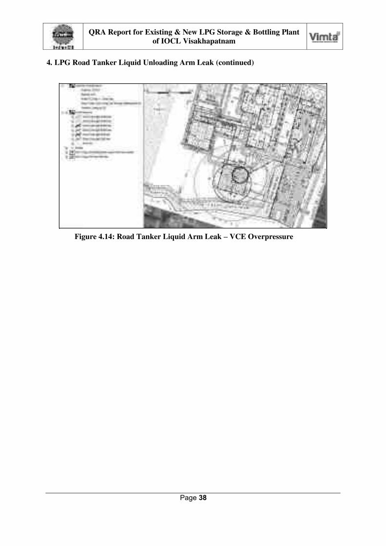
4. LPG Road Tanker Liquid Unloading Arm Leak (continued)
Figure 4.14: Road Tanker Liquid Arm Leak – VCE Overpressure
Page 39
QRA Report for Existing & New LPG Storage & Bottling Plant
of IOCL Visakhapatnam
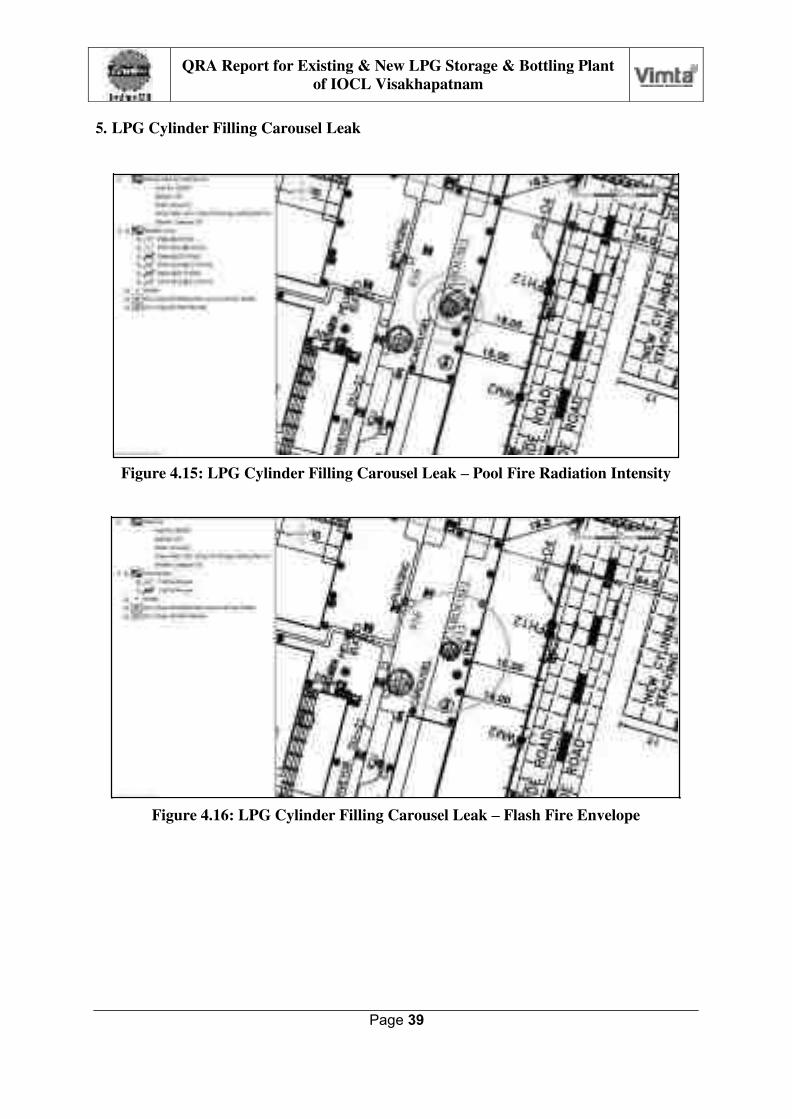
5. LPG Cylinder Filling Carousel Leak
Figure 4.15: LPG Cylinder Filling Carousel Leak – Pool Fire Radiation Intensity
Figure 4.16: LPG Cylinder Filling Carousel Leak – Flash Fire Envelope

Page 40
QRA Report for Existing & New LPG Storage & Bottling Plant
of IOCL Visakhapatnam
5. LPG Cylinder Filling Carousel Leak(continued)
o
Figure 4.17: LPG Cylinder Filling Carousel Leak – VCE Overpressure
Review of Consequence Analysis Results for LPG Storage & Bottling Plant
Based on the results of consequence analysis, the following observations are made:
In case of maximum credible scenario represented by 25 mm leak in liquid and
vapour lines connected to mounded LPG bullets, pumps and compressor, the
significant effect distances for pool/ jet fire radiation intensity and flash fire envelope
are contained within the plant boundary.
In case of vapour cloud explosion due to delayed ignition of the flammable cloud
formed by LPG leak from mounded bullet outlet line, 0.02 bar overpressure effect
may extend slightly outside the north boundary of the plant. However, this level of
overpressure effect will not cause any serious damage..
Mounded LPG bullets are not susceptible to catastrophic failure and BLEVE/ fire ball
hazard by prolonged exposure to external jet fire or pool fire.

Page 41
QRA Report for Existing & New LPG Storage & Bottling Plant
of IOCL Visakhapatnam
QRA Results for LPG Storage & Handling
As seen in the previous section, consequence analysis for failure scenario involving
large release of LPG may result in different outcomes, namely pool fire, jet fire, flash
fire and vapour cloud explosion.
Event Tree describes the development of these outcomes depending on the prevailing
conditions such as immediate ignition, delayed ignition and congestion. A typical
Event Tree for release of LPG from storage tank is shown in Figure 4.18.
Figure 4.18: Event Tree for LPG Leak from Storage System
As the LPG storage vessel is mounded type, fireball/ BLEVE hazard is not
considered.
DNV SAFETI software calculates the individual risk and societal risk based on the
Event Tree, wind rose data for probability of wind in each direction, location of
ignition sources and population density in different areas.
The detailed results of QRA for IOCL LPG bottling plant in Visakhapatnam provided
as outputs from Phast Risk software are presented in this section.

Page 42
QRA Report for Existing & New LPG Storage & Bottling Plant
of IOCL Visakhapatnam
1 x 10⁻⁵ per year
1 x 10⁻⁶ per year
Individual risk
The iso-risk contours for the complete LPG bottling plant including the existing and
new mounded storage vessels are shown in Figure 4.19.
Figure 4.19: Iso-Risk Contours for Individual Risk
Page 43
QRA Report for Existing & New LPG Storage & Bottling Plant
of IOCL Visakhapatnam
1 x 10⁻⁵ per year
1 x 10⁻⁶ per year
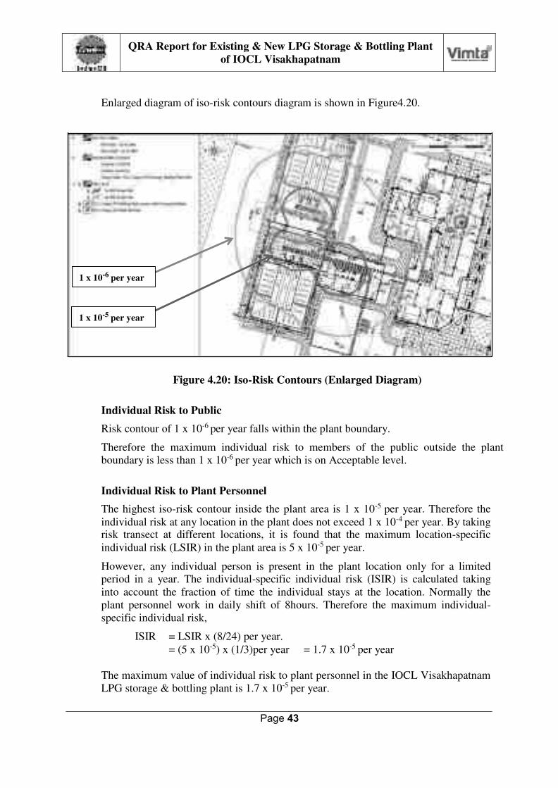
Enlarged diagram of iso-risk contours diagram is shown in Figure4.20.
Figure 4.20: Iso-Risk Contours (Enlarged Diagram)
Individual Risk to Public
Risk contour of 1 x 10⁻⁶ per year falls within the plant boundary.
Therefore the maximum individual risk to members of the public outside the plant
boundary is less than 1 x 10⁻⁶ per year which is on Acceptable level.
Individual Risk to Plant Personnel
The highest iso-risk contour inside the plant area is 1 x 10⁻⁵ per year. Therefore the
individual risk at any location in the plant does not exceed 1 x 10⁻⁴ per year. By taking risk transect at different locations, it is found that the maximum location-specific
individual risk (LSIR) in the plant area is 5 x 10⁻⁵ per year.
However, any individual person is present in the plant location only for a limited
period in a year. The individual-specific individual risk (ISIR) is calculated taking
into account the fraction of time the individual stays at the location. Normally the
plant personnel work in daily shift of 8hours. Therefore the maximum individual-
specific individual risk,
ISIR = LSIR x (8/24) per year.
= (5 x 10-5) x (1/3)per year = 1.7 x 10⁻⁵ per year
The maximum value of individual risk to plant personnel in the IOCL Visakhapatnam
LPG storage & bottling plant is 1.7 x 10⁻⁵ per year.

Page 44
QRA Report for Existing & New LPG Storage & Bottling Plant
of IOCL Visakhapatnam
Risk to
Personnel Risk to
Public
The values of maximum individual risk to public and plant personnel in IOCL
Visakhapatnam LPG storage & bottling plant in comparison with the risk tolerance
criteria are shown in Figure 4.21.
Intolerable
Risk
10-3 per year
10-4 per year
Max. Individual Risk toPersonnel:
1,7 x 10⁻⁵ peryear
10-6 per year
Risk Tolerable
if ALARP
Acceptable
Risk
Max. Individual Risk to Public:
1.0 x 10⁻⁶ per year
10-6 per year
Figure 4.21: Max. Individual Risk at IOCL Visakhapatnam LPG Plant

Page 45
QRA Report for Existing & New LPG Storage & Bottling Plant
of IOCL Visakhapatnam
Societal Risk
The FN Curves for societal risk due to existing & proposed new LPG storage &
bottling plant of IOCL at Visakhapatnam is shown in Figure 4.22.
Figure 4.22: Societal Risk due to IOCL Visakhapatnam LPG Plant,
It is seen that the societal risks due to existing and proposed new LPG mounded
storage & bottling plant of IOCL at Visakhapatnam is in the Acceptable (Negligible)
Risk region.
Page 46
QRA Report for Existing & New LPG Storage & Bottling Plant
of IOCL Visakhapatnam
5. CONCLUSIONS & RECOMMENDATIONS
Conclusions
The conclusions of QRA study for the IOCL Visakhapatnam LPG bottling plant
including the existing three mounded LPG storage vessels and the proposed additional
three mounded LPG storage vessels are as follows.
Individual risk to the public is 1.0E-06 per year which is in Acceptable level.
Maximum individual risk to personnel working in the LPG storage & bottling plant is 1.7E-05 per year, which is in the lower part of ALARP
region.
Societal risk due to LPG bottling plant is in Acceptable region.
Based on the above results it is concluded that the LPG storage & bottling plant of
IOCL at Visakhapatnam conform to the specified risk tolerance criteria.
In case of maximum credible scenario represented by 25 mm leak in liquid and
vapour lines connected to mounded LPG bullets, pumps and compressor, the
significant effect distances for pool/ jet fire radiation intensity and flash fire envelope
are contained within the plant boundary.
In case of vapour cloud explosion due to delayed ignition of the flammable cloud
formed by LPG leak from mounded bullet outlet line, 0.02 bar overpressure effect
may extend slightly outside the north boundary of the plant. However, this may cause
only light damage such as window glass breakage.
Mounded LPG bullets are not susceptible to catastrophic failure and BLEVE/ fire ball
hazard.
IOCL has responsibility to maintain the risk within the ALARP region by ensuring
effective safety management system and adopting the best industry practices
applicable to operation and maintenance of LPG storage and bottling plant.
The LPG storage & bottling plant of IOCL at Visakhapatnam conforms to the
requirements of OISD standards 144, 150 and 158.
It is significant to note that the existing three LPG bullets as well as the proposed
three additional bullets are mounded type which represents the industry best practice
with regard to safety.
Fire protection system has been provided conforming to the requirement of OISD
standards. This includes the following:
Fire/ gas detectors with alarms
Fire water storage and distribution system with hydrants monitors
Fixed water spray system for LPG storage, pumps, road tanker unloading,
cylinder filling and cylinder storage areas.

Page 47
QRA Report for Existing & New LPG Storage & Bottling Plant
of IOCL Visakhapatnam
Remote operated emergency isolation valves, non-return valves and excess flow
check valves have been provided as per the requirement of OISD standards.
Emergency response/ disaster management plan has been implemented for the
existing LPG storage and bottling plant. This will be updated for the proposed
additional LPG storage.
Recommendations
The following recommendations are made in order to ensure that the risks at IOCL
Visakhapatnam LPG storage & bottling plant are maintained at low level by control
and mitigation of the maximum credible accident scenarios.
1. Periodic preventive maintenance of pumps, compressors, valves, flanges,
nozzles, flame arrestors, breather valves, equipments at filling shed etc. must be
done.
2. A regular scheduled plant inspection shall be done for excess flow check valve
in the road tankers and the excess flow check valves on the liquid transfer line
to avoid escape LPG during loading/ unloading operations. OISD-135 on
“Inspection of Loading and Unloading Hoses” for petroleum products shall be followed for inspection and maintenance of loading/ unloading hoses.
3. Emergency push buttons to close the remote-operated isolation valves (EIVs)
and stop LPG pumps/ compressors are also to be provided in the plant area at
appropriate locations neat bullets, pumps and tanker loading bays.
4. Raised face flanges with metallic spiral wound gaskets or tongue & groove type
flanges should be used in LPG service.
5. Fire water system (hydrants, monitors and fixed water sprays) are to be
extended to cover the new mounded LPG bullets.
6. Gas detectors are to be provided near the openings for liquid and vapour lines
on top and bottom of LPG bullets, LPG pump house, tanker unloading bays and
cylinder filling areas.
7. Prevention of ignition
The flame-proof electrical equipment should be properly maintained by competent and trained personnel to ensure their integrity.
The spark arrestors used for vehicles should be maintained by regular checking.
Use of cell phones should not be allowed in the LPG installation.
8. It is to be ensured that all the employees are thoroughly trained in emergency
procedures. This will include recognition of alarm signals (initial alarm, emergency,
evacuation) and personal action on instruction to evacuate. Safety manual and Public
awareness manual needs to be prepared and distributed to all employees and nearby
public.

Page 48
QRA Report for Existing & New LPG Storage & Bottling Plant
of IOCL Visakhapatnam
9. Work permit system must be implemented mandatorily for hazardous work in the
plant.
10. Small leaks could occur frequently during routine operations like pump seal failure,
sample point valve or drain valve left open, flange leak etc. They should be attended
to immediately
11. Ensure proper working of Security circuit containing fusible plugs to detect heat/fire
and thereby closing ROVs in case of fire.
12. The DG sets must be periodically tested on load to ensure that it remains always in
operating condition.
13. Ensure selection of electrical/lighting equipment‟s based on HAC (hazardous area
classification).
14. In order to reduce the frequency of failures and consequent risk, codes, rules and
standards framed e.g. OISD 144/150, SMPV rules (Unfired), gas cylinder rules etc.
should be strictly followed with respect to construction of new facilities.
15. Cathodic protection should be provided for mounded storage vessels on the external
surface.
16. Ensure provision of a gas extraction system with suction points at critical places
where gas concentration is high like carousel, evacuation, valve change shed etc.
***************

Page 49
QRA Report for Existing & New LPG Storage & Bottling Plant
of IOCL Visakhapatnam
ANNEXURE – I
IOCL VISAKHAPATNAM LPG PLANT LAYOUT DRAWING