pv elite 2009 licensee: l&t chiyoda filename
TRANSCRIPT
PV Elite 2009 Licensee: L&T CHIYODA FileName : GOF_T10201-EMPTY(mks)1 ------------- ----------- Page 1 of 106 Input Echo : Step: 1 10:04a Feb 16,2010
PV Elite Vessel Analysis Program: Input Data
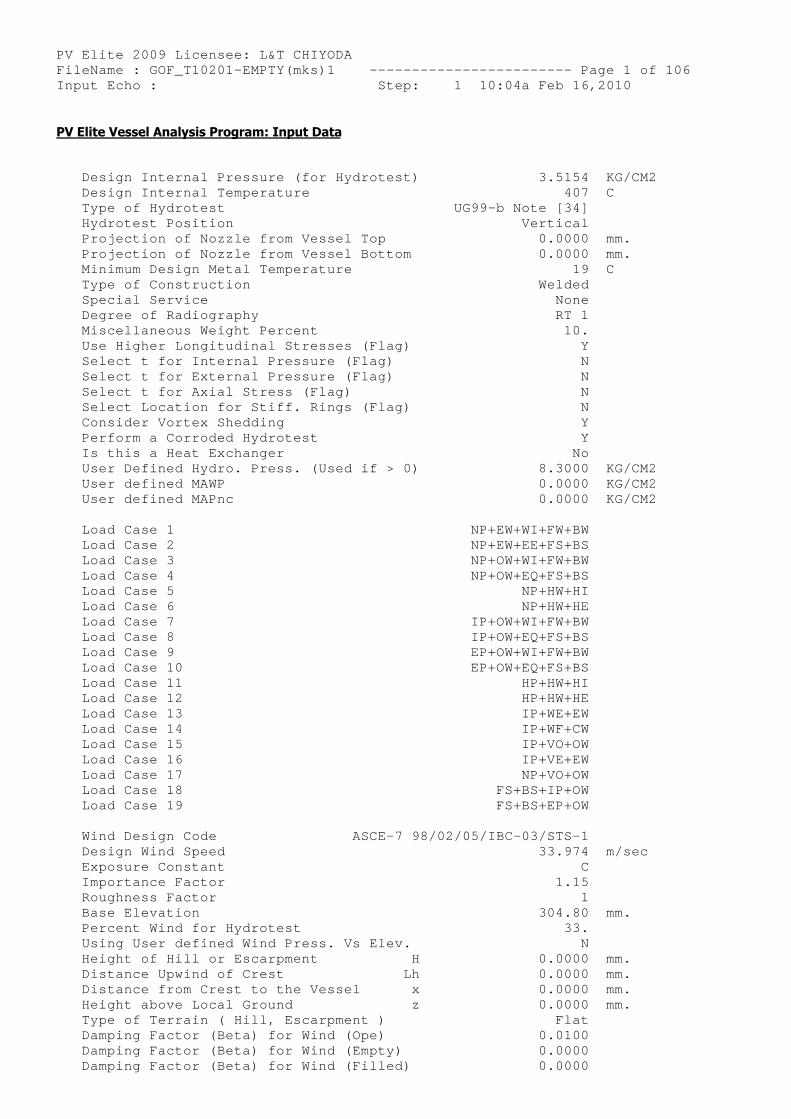
Design Internal Pressure (for Hydrotest) 3.5154 KG/CM2 Design Internal Temperature 407 C Type of Hydrotest UG9 9-b Note [34] Hydrotest Position Vertical Projection of Nozzle from Vessel Top 0.0000 mm. Projection of Nozzle from Vessel Bottom 0.0000 mm. Minimum Design Metal Temperature 19 C Type of Construction Welded Special Service None Degree of Radiography RT 1 Miscellaneous Weight Percent 10. Use Higher Longitudinal Stresses (Flag) Y Select t for Internal Pressure (Flag) N Select t for External Pressure (Flag) N Select t for Axial Stress (Flag) N Select Location for Stiff. Rings (Flag) N Consider Vortex Shedding Y Perform a Corroded Hydrotest Y Is this a Heat Exchanger No User Defined Hydro. Press. (Used if > 0) 8.3000 KG/CM2 User defined MAWP 0.0000 KG/CM2 User defined MAPnc 0.0000 KG/CM2
Load Case 1 N P+EW+WI+FW+BW Load Case 2 N P+EW+EE+FS+BS Load Case 3 N P+OW+WI+FW+BW Load Case 4 N P+OW+EQ+FS+BS Load Case 5 NP+HW+HI Load Case 6 NP+HW+HE Load Case 7 I P+OW+WI+FW+BW Load Case 8 I P+OW+EQ+FS+BS Load Case 9 E P+OW+WI+FW+BW Load Case 10 E P+OW+EQ+FS+BS Load Case 11 HP+HW+HI Load Case 12 HP+HW+HE Load Case 13 IP+WE+EW Load Case 14 IP+WF+CW Load Case 15 IP+VO+OW Load Case 16 IP+VE+EW Load Case 17 NP+VO+OW Load Case 18 FS+BS+IP+OW Load Case 19 FS+BS+EP+OW
Wind Design Code ASCE-7 98/02/05 /IBC-03/STS-1 Design Wind Speed 33.974 m/sec Exposure Constant C Importance Factor 1.15 Roughness Factor 1 Base Elevation 304.80 mm. Percent Wind for Hydrotest 33. Using User defined Wind Press. Vs Elev. N Height of Hill or Escarpment H 0.0000 mm. Distance Upwind of Crest Lh 0.0000 mm. Distance from Crest to the Vessel x 0.0000 mm. Height above Local Ground z 0.0000 mm. Type of Terrain ( Hill, Escarpment ) Flat Damping Factor (Beta) for Wind (Ope) 0.0100 Damping Factor (Beta) for Wind (Empty) 0.0000 Damping Factor (Beta) for Wind (Filled) 0.0000
PV Elite 2009 Licensee: L&T CHIYODA FileName : GOF_T10201-EMPTY(mks)1 ------------- ----------- Page 2 of 106 Input Echo : Step: 1 10:04a Feb 16,2010
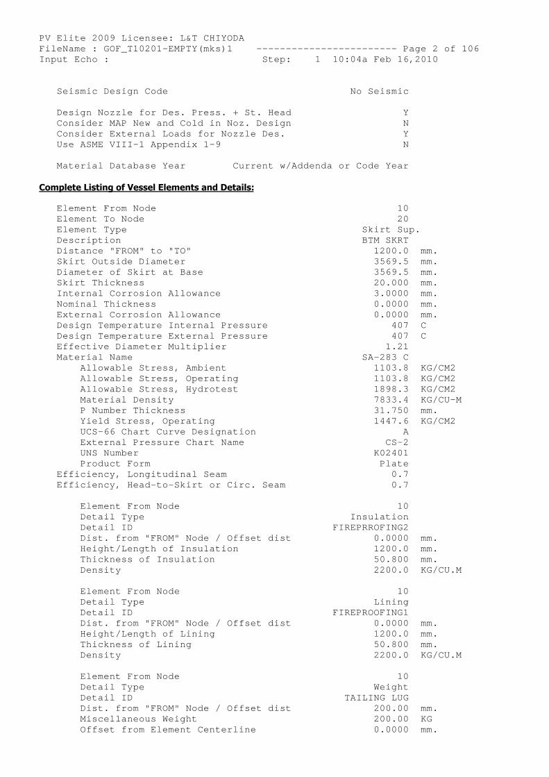
Seismic Design Code No Seismic
Design Nozzle for Des. Press. + St. Head Y Consider MAP New and Cold in Noz. Design N Consider External Loads for Nozzle Des. Y Use ASME VIII-1 Appendix 1-9 N
Material Database Year Current w/Addenda or Code Year
Complete Listing of Vessel Elements and Details:
Element From Node 10 Element To Node 20 Element Type Skirt Sup. Description BTM SKRT Distance "FROM" to "TO" 1200.0 mm. Skirt Outside Diameter 3569.5 mm. Diameter of Skirt at Base 3569.5 mm. Skirt Thickness 20.000 mm. Internal Corrosion Allowance 3.0000 mm. Nominal Thickness 0.0000 mm. External Corrosion Allowance 0.0000 mm. Design Temperature Internal Pressure 407 C Design Temperature External Pressure 407 C Effective Diameter Multiplier 1.21 Material Name SA-283 C Allowable Stress, Ambient 1103.8 KG/CM2 Allowable Stress, Operating 1103.8 KG/CM2 Allowable Stress, Hydrotest 1898.3 KG/CM2 Material Density 7833.4 KG/CU-M P Number Thickness 31.750 mm. Yield Stress, Operating 1447.6 KG/CM2 UCS-66 Chart Curve Designation A External Pressure Chart Name CS-2 UNS Number K02401 Product Form Plate Efficiency, Longitudinal Seam 0.7 Efficiency, Head-to-Skirt or Circ. Seam 0.7
Element From Node 10 Detail Type Insulation Detail ID FIREPRROFING2 Dist. from "FROM" Node / Offset dist 0.0000 mm. Height/Length of Insulation 1200.0 mm. Thickness of Insulation 50.800 mm. Density 2200.0 KG/CU.M
Element From Node 10 Detail Type Lining Detail ID FIREPROOFING1 Dist. from "FROM" Node / Offset dist 0.0000 mm. Height/Length of Lining 1200.0 mm. Thickness of Lining 50.800 mm. Density 2200.0 KG/CU.M
Element From Node 10 Detail Type Weight Detail ID TAILING LUG Dist. from "FROM" Node / Offset dist 200.00 mm. Miscellaneous Weight 200.00 KG Offset from Element Centerline 0.0000 mm.
PV Elite 2009 Licensee: L&T CHIYODA FileName : GOF_T10201-EMPTY(mks)1 ------------- ----------- Page 3 of 106 Input Echo : Step: 1 10:04a Feb 16,2010 ----------------------------------------------- ---------------------
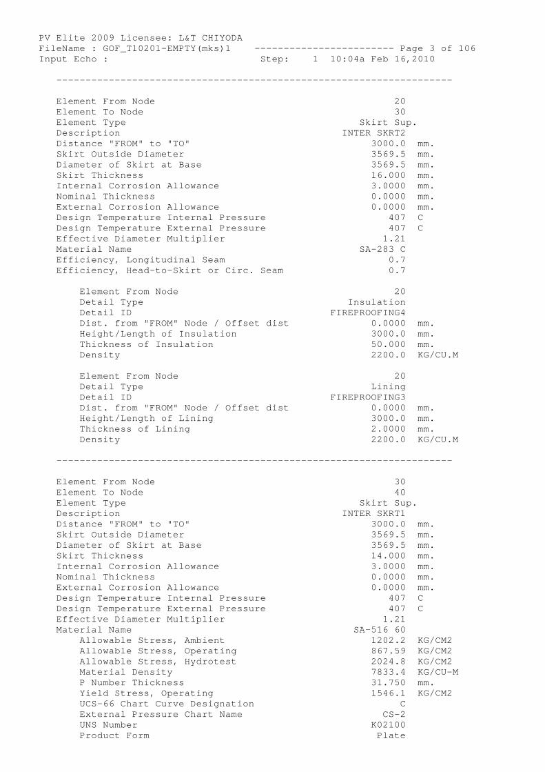
Element From Node 20 Element To Node 30 Element Type Skirt Sup. Description INTER SKRT2 Distance "FROM" to "TO" 3000.0 mm. Skirt Outside Diameter 3569.5 mm. Diameter of Skirt at Base 3569.5 mm. Skirt Thickness 16.000 mm. Internal Corrosion Allowance 3.0000 mm. Nominal Thickness 0.0000 mm. External Corrosion Allowance 0.0000 mm. Design Temperature Internal Pressure 407 C Design Temperature External Pressure 407 C Effective Diameter Multiplier 1.21 Material Name SA-283 C Efficiency, Longitudinal Seam 0.7 Efficiency, Head-to-Skirt or Circ. Seam 0.7
Element From Node 20 Detail Type Insulation Detail ID FIREPROOFING4 Dist. from "FROM" Node / Offset dist 0.0000 mm. Height/Length of Insulation 3000.0 mm. Thickness of Insulation 50.000 mm. Density 2200.0 KG/CU.M
Element From Node 20 Detail Type Lining Detail ID FIREPROOFING3 Dist. from "FROM" Node / Offset dist 0.0000 mm. Height/Length of Lining 3000.0 mm. Thickness of Lining 2.0000 mm. Density 2200.0 KG/CU.M
----------------------------------------------- ---------------------
Element From Node 30 Element To Node 40 Element Type Skirt Sup. Description INTER SKRT1 Distance "FROM" to "TO" 3000.0 mm. Skirt Outside Diameter 3569.5 mm. Diameter of Skirt at Base 3569.5 mm. Skirt Thickness 14.000 mm. Internal Corrosion Allowance 3.0000 mm. Nominal Thickness 0.0000 mm. External Corrosion Allowance 0.0000 mm. Design Temperature Internal Pressure 407 C Design Temperature External Pressure 407 C Effective Diameter Multiplier 1.21 Material Name SA-516 60 Allowable Stress, Ambient 1202.2 KG/CM2 Allowable Stress, Operating 867.59 KG/CM2 Allowable Stress, Hydrotest 2024.8 KG/CM2 Material Density 7833.4 KG/CU-M P Number Thickness 31.750 mm. Yield Stress, Operating 1546.1 KG/CM2 UCS-66 Chart Curve Designation C External Pressure Chart Name CS-2 UNS Number K02100 Product Form Plate
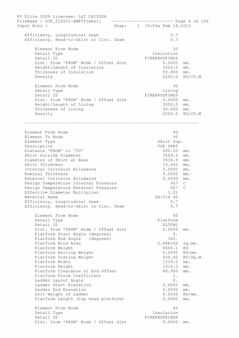
PV Elite 2009 Licensee: L&T CHIYODA FileName : GOF_T10201-EMPTY(mks)1 ------------- ----------- Page 4 of 106 Input Echo : Step: 1 10:04a Feb 16,2010 Efficiency, Longitudinal Seam 0.7 Efficiency, Head-to-Skirt or Circ. Seam 0.7
Element From Node 30 Detail Type Insulation Detail ID FIREPROOFING6 Dist. from "FROM" Node / Offset dist 0.0000 mm. Height/Length of Insulation 3000.0 mm. Thickness of Insulation 50.800 mm. Density 2200.0 KG/CU.M
Element From Node 30 Detail Type Lining Detail ID FIREPROOFING5 Dist. from "FROM" Node / Offset dist 0.0000 mm. Height/Length of Lining 3000.0 mm. Thickness of Lining 50.800 mm. Density 2200.0 KG/CU.M
----------------------------------------------- ---------------------
Element From Node 40 Element To Node 50 Element Type Skirt Sup. Description TOP SKRT Distance "FROM" to "TO" 600.00 mm. Skirt Outside Diameter 3569.5 mm. Diameter of Skirt at Base 3536.9 mm. Skirt Thickness 14.000 mm. Internal Corrosion Allowance 3.0000 mm. Nominal Thickness 0.0000 mm. External Corrosion Allowance 0.0000 mm. Design Temperature Internal Pressure 407 C Design Temperature External Pressure 407 C Effective Diameter Multiplier 1.21 Material Name SA-516 60 Efficiency, Longitudinal Seam 0.7 Efficiency, Head-to-Skirt or Circ. Seam 0.7
Element From Node 40 Detail Type Platform Detail ID PLTFM1 Dist. from "FROM" Node / Offset dist 0.0000 mm. Platform Start Angle (degrees) 0. Platform End Angle (degrees) 360. Platform Wind Area 2.48E+06 sq.mm. Platform Weight 8604.1 KG Platform Railing Weight 0.0000 KG/mm. Platform Grating Weight 450.00 KG/SQ.M. Platform Width 1219.2 mm. Platform Height 1016.0 mm. Platform Clearance or End Offset 88.900 mm. Platform Force Coefficient 1. Ladder Layout Angle 0. Ladder Start Elevation 0.0000 mm. Ladder End Elevation 0.0000 mm. Unit Weight of Ladder 0.0000 KG/mm. Platform Length (top head platform) 0.0000 mm.
Element From Node 40 Detail Type Insulation Detail ID FIREPROOFING8 Dist. from "FROM" Node / Offset dist 0.0000 mm.
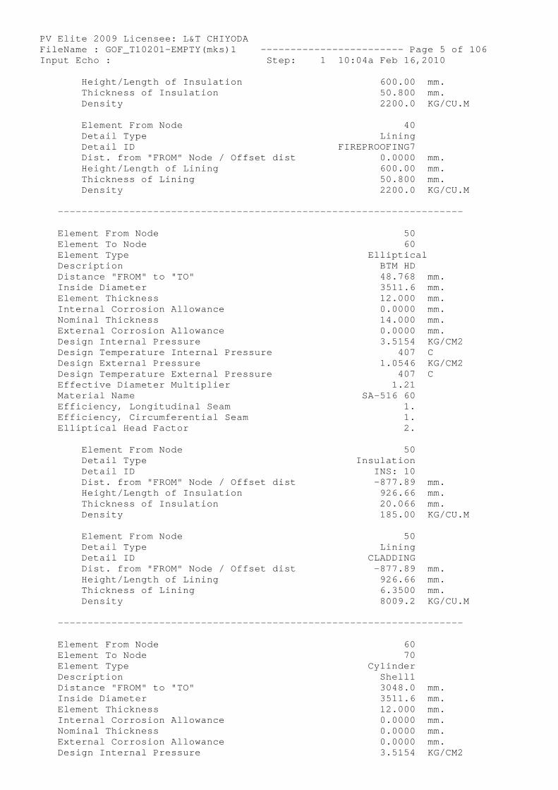
PV Elite 2009 Licensee: L&T CHIYODA FileName : GOF_T10201-EMPTY(mks)1 ------------- ----------- Page 5 of 106 Input Echo : Step: 1 10:04a Feb 16,2010 Height/Length of Insulation 600.00 mm. Thickness of Insulation 50.800 mm. Density 2200.0 KG/CU.M
Element From Node 40 Detail Type Lining Detail ID FIREPROOFING7 Dist. from "FROM" Node / Offset dist 0.0000 mm. Height/Length of Lining 600.00 mm. Thickness of Lining 50.800 mm. Density 2200.0 KG/CU.M
----------------------------------------------- ---------------------
Element From Node 50 Element To Node 60 Element Type Elliptical Description BTM HD Distance "FROM" to "TO" 48.768 mm. Inside Diameter 3511.6 mm. Element Thickness 12.000 mm. Internal Corrosion Allowance 0.0000 mm. Nominal Thickness 14.000 mm. External Corrosion Allowance 0.0000 mm. Design Internal Pressure 3.5154 KG/CM2 Design Temperature Internal Pressure 407 C Design External Pressure 1.0546 KG/CM2 Design Temperature External Pressure 407 C Effective Diameter Multiplier 1.21 Material Name SA-516 60 Efficiency, Longitudinal Seam 1. Efficiency, Circumferential Seam 1. Elliptical Head Factor 2.
Element From Node 50 Detail Type Insulation Detail ID INS: 10 Dist. from "FROM" Node / Offset dist -877.89 mm. Height/Length of Insulation 926.66 mm. Thickness of Insulation 20.066 mm. Density 185.00 KG/CU.M
Element From Node 50 Detail Type Lining Detail ID CLADDING Dist. from "FROM" Node / Offset dist -877.89 mm. Height/Length of Lining 926.66 mm. Thickness of Lining 6.3500 mm. Density 8009.2 KG/CU.M
----------------------------------------------- ---------------------
Element From Node 60 Element To Node 70 Element Type Cylinder Description Shell1 Distance "FROM" to "TO" 3048.0 mm. Inside Diameter 3511.6 mm. Element Thickness 12.000 mm. Internal Corrosion Allowance 0.0000 mm. Nominal Thickness 0.0000 mm. External Corrosion Allowance 0.0000 mm. Design Internal Pressure 3.5154 KG/CM2
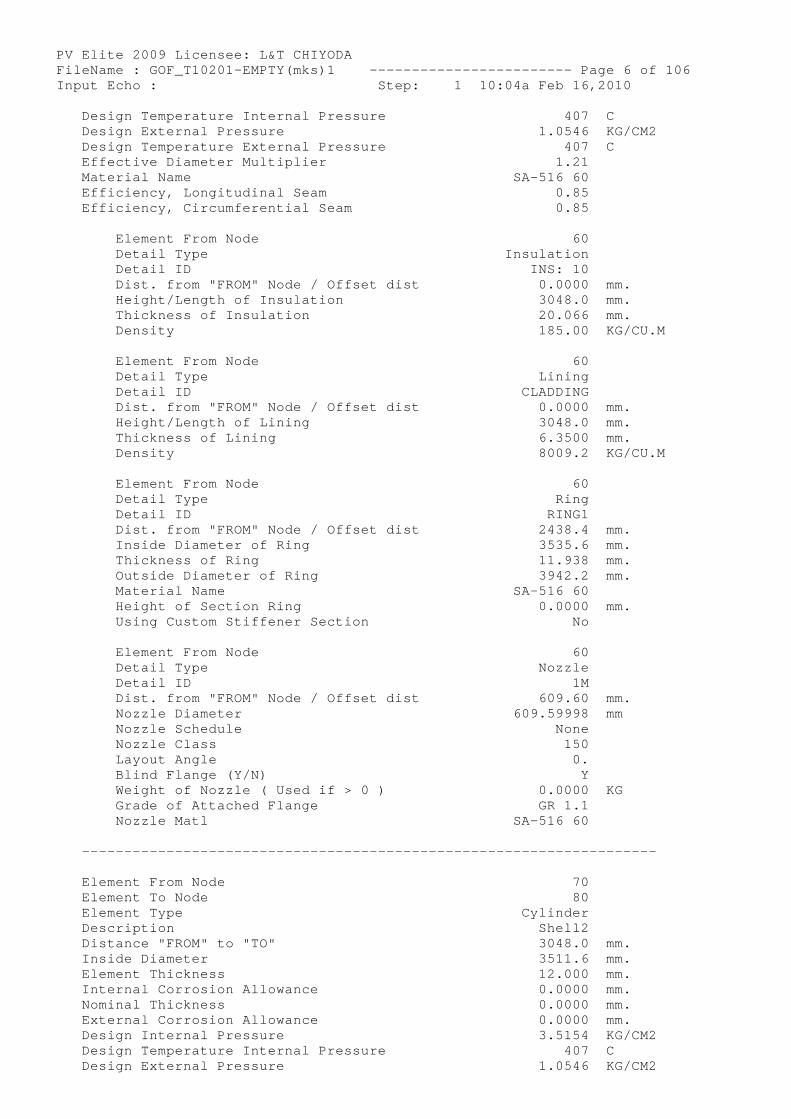
PV Elite 2009 Licensee: L&T CHIYODA FileName : GOF_T10201-EMPTY(mks)1 ------------- ----------- Page 6 of 106 Input Echo : Step: 1 10:04a Feb 16,2010 Design Temperature Internal Pressure 407 C Design External Pressure 1.0546 KG/CM2 Design Temperature External Pressure 407 C Effective Diameter Multiplier 1.21 Material Name SA-516 60 Efficiency, Longitudinal Seam 0.85 Efficiency, Circumferential Seam 0.85
Element From Node 60 Detail Type Insulation Detail ID INS: 10 Dist. from "FROM" Node / Offset dist 0.0000 mm. Height/Length of Insulation 3048.0 mm. Thickness of Insulation 20.066 mm. Density 185.00 KG/CU.M
Element From Node 60 Detail Type Lining Detail ID CLADDING Dist. from "FROM" Node / Offset dist 0.0000 mm. Height/Length of Lining 3048.0 mm. Thickness of Lining 6.3500 mm. Density 8009.2 KG/CU.M
Element From Node 60 Detail Type Ring Detail ID RING1 Dist. from "FROM" Node / Offset dist 2438.4 mm. Inside Diameter of Ring 3535.6 mm. Thickness of Ring 11.938 mm. Outside Diameter of Ring 3942.2 mm. Material Name SA-516 60 Height of Section Ring 0.0000 mm. Using Custom Stiffener Section No
Element From Node 60 Detail Type Nozzle Detail ID 1M Dist. from "FROM" Node / Offset dist 609.60 mm. Nozzle Diameter 609.59998 mm Nozzle Schedule None Nozzle Class 150 Layout Angle 0. Blind Flange (Y/N) Y Weight of Nozzle ( Used if > 0 ) 0.0000 KG Grade of Attached Flange GR 1.1 Nozzle Matl SA-516 60
----------------------------------------------- ---------------------
Element From Node 70 Element To Node 80 Element Type Cylinder Description Shell2 Distance "FROM" to "TO" 3048.0 mm. Inside Diameter 3511.6 mm. Element Thickness 12.000 mm. Internal Corrosion Allowance 0.0000 mm. Nominal Thickness 0.0000 mm. External Corrosion Allowance 0.0000 mm. Design Internal Pressure 3.5154 KG/CM2 Design Temperature Internal Pressure 407 C Design External Pressure 1.0546 KG/CM2
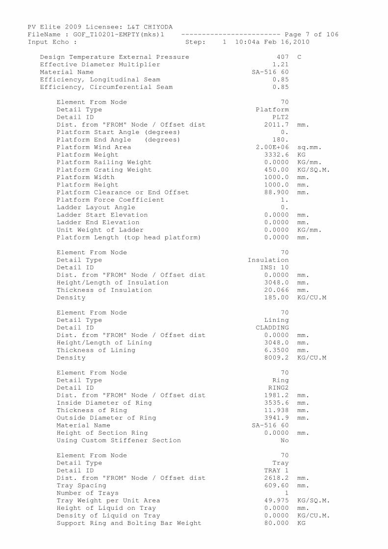
PV Elite 2009 Licensee: L&T CHIYODA FileName : GOF_T10201-EMPTY(mks)1 ------------- ----------- Page 7 of 106 Input Echo : Step: 1 10:04a Feb 16,2010 Design Temperature External Pressure 407 C Effective Diameter Multiplier 1.21 Material Name SA-516 60 Efficiency, Longitudinal Seam 0.85 Efficiency, Circumferential Seam 0.85
Element From Node 70 Detail Type Platform Detail ID PLT2 Dist. from "FROM" Node / Offset dist 2011.7 mm. Platform Start Angle (degrees) 0. Platform End Angle (degrees) 180. Platform Wind Area 2.00E+06 sq.mm. Platform Weight 3332.6 KG Platform Railing Weight 0.0000 KG/mm. Platform Grating Weight 450.00 KG/SQ.M. Platform Width 1000.0 mm. Platform Height 1000.0 mm. Platform Clearance or End Offset 88.900 mm. Platform Force Coefficient 1. Ladder Layout Angle 0. Ladder Start Elevation 0.0000 mm. Ladder End Elevation 0.0000 mm. Unit Weight of Ladder 0.0000 KG/mm. Platform Length (top head platform) 0.0000 mm.
Element From Node 70 Detail Type Insulation Detail ID INS: 10 Dist. from "FROM" Node / Offset dist 0.0000 mm. Height/Length of Insulation 3048.0 mm. Thickness of Insulation 20.066 mm. Density 185.00 KG/CU.M
Element From Node 70 Detail Type Lining Detail ID CLADDING Dist. from "FROM" Node / Offset dist 0.0000 mm. Height/Length of Lining 3048.0 mm. Thickness of Lining 6.3500 mm. Density 8009.2 KG/CU.M
Element From Node 70 Detail Type Ring Detail ID RING2 Dist. from "FROM" Node / Offset dist 1981.2 mm. Inside Diameter of Ring 3535.6 mm. Thickness of Ring 11.938 mm. Outside Diameter of Ring 3941.9 mm. Material Name SA-516 60 Height of Section Ring 0.0000 mm. Using Custom Stiffener Section No
Element From Node 70 Detail Type Tray Detail ID TRAY 1 Dist. from "FROM" Node / Offset dist 2618.2 mm. Tray Spacing 609.60 mm. Number of Trays 1 Tray Weight per Unit Area 49.975 KG/SQ.M. Height of Liquid on Tray 0.0000 mm. Density of Liquid on Tray 0.0000 KG/CU.M. Support Ring and Bolting Bar Weight 80.000 KG
PV Elite 2009 Licensee: L&T CHIYODA FileName : GOF_T10201-EMPTY(mks)1 ------------- ----------- Page 8 of 106 Input Echo : Step: 1 10:04a Feb 16,2010
----------------------------------------------- ---------------------
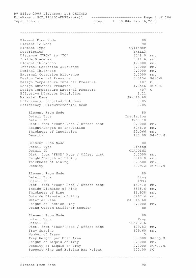
Element From Node 80 Element To Node 90 Element Type Cylinder Description SHELL3 Distance "FROM" to "TO" 3048.0 mm. Inside Diameter 3511.6 mm. Element Thickness 12.000 mm. Internal Corrosion Allowance 0.0000 mm. Nominal Thickness 0.0000 mm. External Corrosion Allowance 0.0000 mm. Design Internal Pressure 3.5154 KG/CM2 Design Temperature Internal Pressure 407 C Design External Pressure 1.0546 KG/CM2 Design Temperature External Pressure 407 C Effective Diameter Multiplier 1.21 Material Name SA-516 60 Efficiency, Longitudinal Seam 0.85 Efficiency, Circumferential Seam 0.85
Element From Node 80 Detail Type Insulation Detail ID INS: 10 Dist. from "FROM" Node / Offset dist 0.0000 mm. Height/Length of Insulation 3048.0 mm. Thickness of Insulation 20.066 mm. Density 185.00 KG/CU.M
Element From Node 80 Detail Type Lining Detail ID CLADDING Dist. from "FROM" Node / Offset dist 0.0000 mm. Height/Length of Lining 3048.0 mm. Thickness of Lining 6.3500 mm. Density 8009.2 KG/CU.M
Element From Node 80 Detail Type Ring Detail ID RING3 Dist. from "FROM" Node / Offset dist 1524.0 mm. Inside Diameter of Ring 3535.6 mm. Thickness of Ring 11.938 mm. Outside Diameter of Ring 3967.4 mm. Material Name SA-516 60 Height of Section Ring 0.0000 mm. Using Custom Stiffener Section No
Element From Node 80 Detail Type Tray Detail ID TRAY 2-6 Dist. from "FROM" Node / Offset dist 179.83 mm. Tray Spacing 609.60 mm. Number of Trays 5 Tray Weight per Unit Area 50.000 KG/SQ.M. Height of Liquid on Tray 0.0000 mm. Density of Liquid on Tray 0.0000 KG/CU.M. Support Ring and Bolting Bar Weight 400.00 KG
----------------------------------------------- ---------------------
Element From Node 90
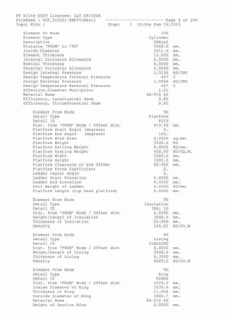
PV Elite 2009 Licensee: L&T CHIYODA FileName : GOF_T10201-EMPTY(mks)1 ------------- ----------- Page 9 of 106 Input Echo : Step: 1 10:04a Feb 16,2010 Element To Node 100 Element Type Cylinder Description SHELL4 Distance "FROM" to "TO" 3048.0 mm. Inside Diameter 3511.6 mm. Element Thickness 12.000 mm. Internal Corrosion Allowance 0.0000 mm. Nominal Thickness 0.0000 mm. External Corrosion Allowance 0.0000 mm. Design Internal Pressure 3.5154 KG/CM2 Design Temperature Internal Pressure 407 C Design External Pressure 1.0546 KG/CM2 Design Temperature External Pressure 407 C Effective Diameter Multiplier 1.21 Material Name SA-516 60 Efficiency, Longitudinal Seam 0.85 Efficiency, Circumferential Seam 0.85
Element From Node 90 Detail Type Platform Detail ID PLT3 Dist. from "FROM" Node / Offset dist 914.40 mm. Platform Start Angle (degrees) 0. Platform End Angle (degrees) 180. Platform Wind Area 0.0000 sq.mm. Platform Weight 3332.6 KG Platform Railing Weight 0.0000 KG/mm. Platform Grating Weight 450.00 KG/SQ.M. Platform Width 1000.0 mm. Platform Height 1000.0 mm. Platform Clearance or End Offset 88.900 mm. Platform Force Coefficient 0. Ladder Layout Angle 0. Ladder Start Elevation 0.0000 mm. Ladder End Elevation 0.0000 mm. Unit Weight of Ladder 0.0000 KG/mm. Platform Length (top head platform) 0.0000 mm.
Element From Node 90 Detail Type Insulation Detail ID INS: 10 Dist. from "FROM" Node / Offset dist 0.0000 mm. Height/Length of Insulation 3048.0 mm. Thickness of Insulation 20.066 mm. Density 185.00 KG/CU.M
Element From Node 90 Detail Type Lining Detail ID CLADDING Dist. from "FROM" Node / Offset dist 0.0000 mm. Height/Length of Lining 3048.0 mm. Thickness of Lining 6.3500 mm. Density 8009.2 KG/CU.M
Element From Node 90 Detail Type Ring Detail ID RING4 Dist. from "FROM" Node / Offset dist 1524.0 mm. Inside Diameter of Ring 3535.6 mm. Thickness of Ring 11.938 mm. Outside Diameter of Ring 3940.7 mm. Material Name SA-516 60 Height of Section Ring 0.0000 mm.
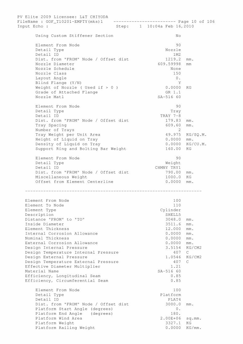
PV Elite 2009 Licensee: L&T CHIYODA FileName : GOF_T10201-EMPTY(mks)1 ------------- ----------- Page 10 of 106 Input Echo : Step: 1 10:04a Feb 16,2010 Using Custom Stiffener Section No
Element From Node 90 Detail Type Nozzle Detail ID 1M2 Dist. from "FROM" Node / Offset dist 1219.2 mm. Nozzle Diameter 609.59998 mm Nozzle Schedule None Nozzle Class 150 Layout Angle 0. Blind Flange (Y/N) Y Weight of Nozzle ( Used if > 0 ) 0.0000 KG Grade of Attached Flange GR 1.1 Nozzle Matl SA-516 60
Element From Node 90 Detail Type Tray Detail ID TRAY 7-8 Dist. from "FROM" Node / Offset dist 179.83 mm. Tray Spacing 609.60 mm. Number of Trays 2 Tray Weight per Unit Area 49.975 KG/SQ.M. Height of Liquid on Tray 0.0000 mm. Density of Liquid on Tray 0.0000 KG/CU.M. Support Ring and Bolting Bar Weight 160.00 KG
Element From Node 90 Detail Type Weight Detail ID CHMNY TRY1 Dist. from "FROM" Node / Offset dist 790.00 mm. Miscellaneous Weight 1000.0 KG Offset from Element Centerline 0.0000 mm.
----------------------------------------------- ---------------------
Element From Node 100 Element To Node 110 Element Type Cylinder Description SHELL5 Distance "FROM" to "TO" 3048.0 mm. Inside Diameter 3511.6 mm. Element Thickness 12.000 mm. Internal Corrosion Allowance 0.0000 mm. Nominal Thickness 0.0000 mm. External Corrosion Allowance 0.0000 mm. Design Internal Pressure 3.5154 KG/CM2 Design Temperature Internal Pressure 407 C Design External Pressure 1.0546 KG/CM2 Design Temperature External Pressure 407 C Effective Diameter Multiplier 1.21 Material Name SA-516 60 Efficiency, Longitudinal Seam 0.85 Efficiency, Circumferential Seam 0.85
Element From Node 100 Detail Type Platform Detail ID PLAT4 Dist. from "FROM" Node / Offset dist 3000.0 mm. Platform Start Angle (degrees) 0. Platform End Angle (degrees) 180. Platform Wind Area 2.00E+06 sq.mm. Platform Weight 3327.1 KG Platform Railing Weight 0.0000 KG/mm.
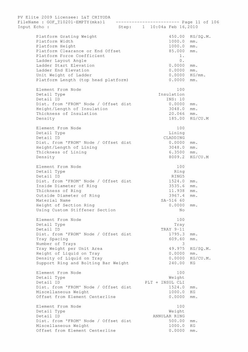
PV Elite 2009 Licensee: L&T CHIYODA FileName : GOF_T10201-EMPTY(mks)1 ------------- ----------- Page 11 of 106 Input Echo : Step: 1 10:04a Feb 16,2010 Platform Grating Weight 450.00 KG/SQ.M. Platform Width 1000.0 mm. Platform Height 1000.0 mm. Platform Clearance or End Offset 85.000 mm. Platform Force Coefficient 1. Ladder Layout Angle 0. Ladder Start Elevation 0.0000 mm. Ladder End Elevation 0.0000 mm. Unit Weight of Ladder 0.0000 KG/mm. Platform Length (top head platform) 0.0000 mm.
Element From Node 100 Detail Type Insulation Detail ID INS: 10 Dist. from "FROM" Node / Offset dist 0.0000 mm. Height/Length of Insulation 3048.0 mm. Thickness of Insulation 20.066 mm. Density 185.00 KG/CU.M
Element From Node 100 Detail Type Lining Detail ID CLADDING Dist. from "FROM" Node / Offset dist 0.0000 mm. Height/Length of Lining 3048.0 mm. Thickness of Lining 6.3500 mm. Density 8009.2 KG/CU.M
Element From Node 100 Detail Type Ring Detail ID RING5 Dist. from "FROM" Node / Offset dist 1524.0 mm. Inside Diameter of Ring 3535.6 mm. Thickness of Ring 11.938 mm. Outside Diameter of Ring 3967.4 mm. Material Name SA-516 60 Height of Section Ring 0.0000 mm. Using Custom Stiffener Section No
Element From Node 100 Detail Type Tray Detail ID TRAY 9-11 Dist. from "FROM" Node / Offset dist 1795.3 mm. Tray Spacing 609.60 mm. Number of Trays 3 Tray Weight per Unit Area 49.975 KG/SQ.M. Height of Liquid on Tray 0.0000 mm. Density of Liquid on Tray 0.0000 KG/CU.M. Support Ring and Bolting Bar Weight 240.00 KG
Element From Node 100 Detail Type Weight Detail ID PL T + INSUL CLI Dist. from "FROM" Node / Offset dist 1524.0 mm. Miscellaneous Weight 1000.0 KG Offset from Element Centerline 0.0000 mm.
Element From Node 100 Detail Type Weight Detail ID ANNULAR RING Dist. from "FROM" Node / Offset dist 500.00 mm. Miscellaneous Weight 1000.0 KG Offset from Element Centerline 0.0000 mm.
PV Elite 2009 Licensee: L&T CHIYODA FileName : GOF_T10201-EMPTY(mks)1 ------------- ----------- Page 12 of 106 Input Echo : Step: 1 10:04a Feb 16,2010 ----------------------------------------------- ---------------------
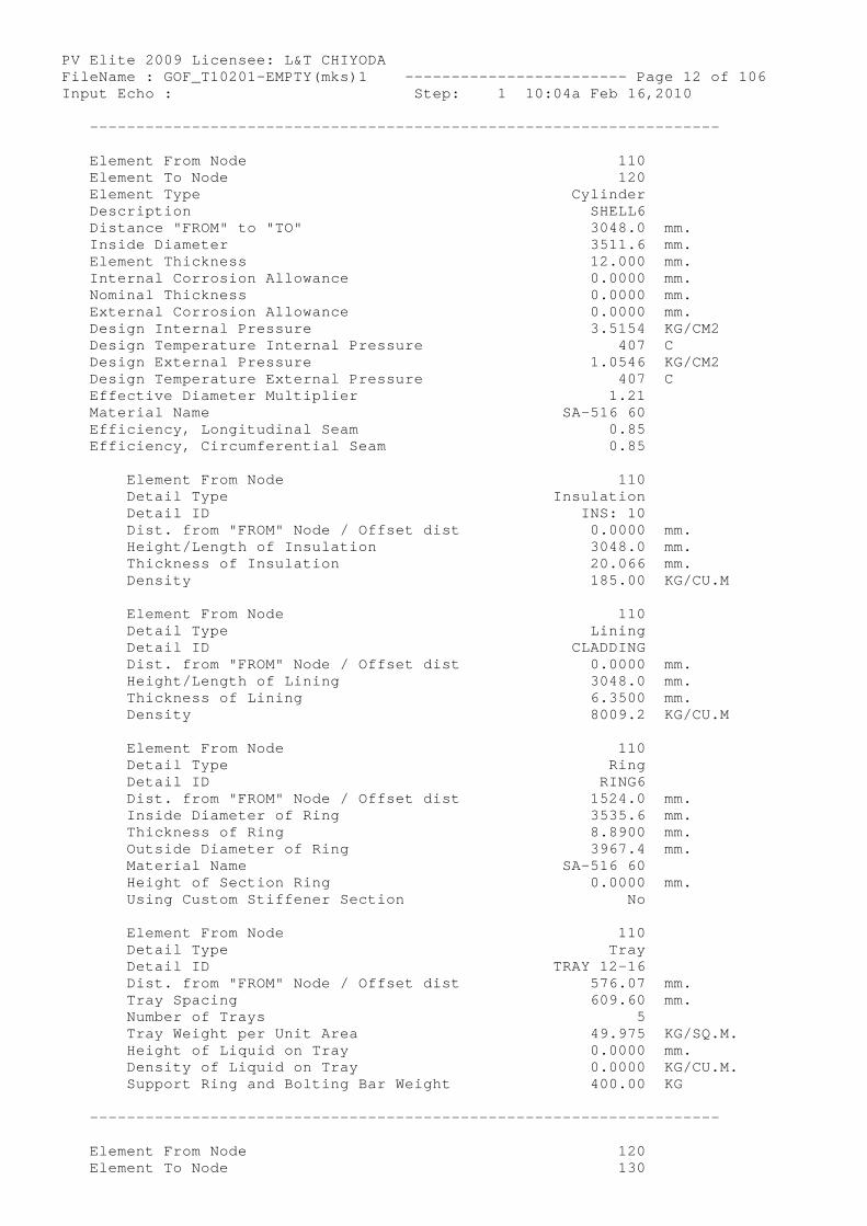
Element From Node 110 Element To Node 120 Element Type Cylinder Description SHELL6 Distance "FROM" to "TO" 3048.0 mm. Inside Diameter 3511.6 mm. Element Thickness 12.000 mm. Internal Corrosion Allowance 0.0000 mm. Nominal Thickness 0.0000 mm. External Corrosion Allowance 0.0000 mm. Design Internal Pressure 3.5154 KG/CM2 Design Temperature Internal Pressure 407 C Design External Pressure 1.0546 KG/CM2 Design Temperature External Pressure 407 C Effective Diameter Multiplier 1.21 Material Name SA-516 60 Efficiency, Longitudinal Seam 0.85 Efficiency, Circumferential Seam 0.85
Element From Node 110 Detail Type Insulation Detail ID INS: 10 Dist. from "FROM" Node / Offset dist 0.0000 mm. Height/Length of Insulation 3048.0 mm. Thickness of Insulation 20.066 mm. Density 185.00 KG/CU.M
Element From Node 110 Detail Type Lining Detail ID CLADDING Dist. from "FROM" Node / Offset dist 0.0000 mm. Height/Length of Lining 3048.0 mm. Thickness of Lining 6.3500 mm. Density 8009.2 KG/CU.M
Element From Node 110 Detail Type Ring Detail ID RING6 Dist. from "FROM" Node / Offset dist 1524.0 mm. Inside Diameter of Ring 3535.6 mm. Thickness of Ring 8.8900 mm. Outside Diameter of Ring 3967.4 mm. Material Name SA-516 60 Height of Section Ring 0.0000 mm. Using Custom Stiffener Section No
Element From Node 110 Detail Type Tray Detail ID TRAY 12-16 Dist. from "FROM" Node / Offset dist 576.07 mm. Tray Spacing 609.60 mm. Number of Trays 5 Tray Weight per Unit Area 49.975 KG/SQ.M. Height of Liquid on Tray 0.0000 mm. Density of Liquid on Tray 0.0000 KG/CU.M. Support Ring and Bolting Bar Weight 400.00 KG
----------------------------------------------- ---------------------
Element From Node 120 Element To Node 130
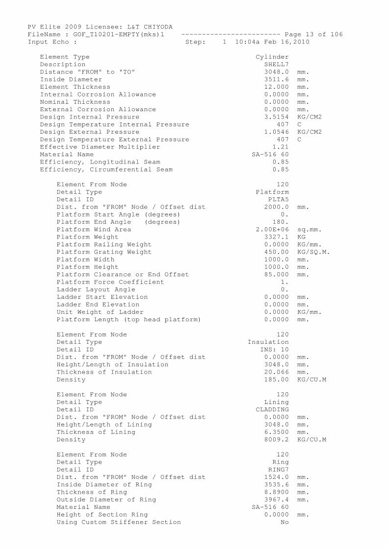
PV Elite 2009 Licensee: L&T CHIYODA FileName : GOF_T10201-EMPTY(mks)1 ------------- ----------- Page 13 of 106 Input Echo : Step: 1 10:04a Feb 16,2010 Element Type Cylinder Description SHELL7 Distance "FROM" to "TO" 3048.0 mm. Inside Diameter 3511.6 mm. Element Thickness 12.000 mm. Internal Corrosion Allowance 0.0000 mm. Nominal Thickness 0.0000 mm. External Corrosion Allowance 0.0000 mm. Design Internal Pressure 3.5154 KG/CM2 Design Temperature Internal Pressure 407 C Design External Pressure 1.0546 KG/CM2 Design Temperature External Pressure 407 C Effective Diameter Multiplier 1.21 Material Name SA-516 60 Efficiency, Longitudinal Seam 0.85 Efficiency, Circumferential Seam 0.85
Element From Node 120 Detail Type Platform Detail ID PLTA5 Dist. from "FROM" Node / Offset dist 2000.0 mm. Platform Start Angle (degrees) 0. Platform End Angle (degrees) 180. Platform Wind Area 2.00E+06 sq.mm. Platform Weight 3327.1 KG Platform Railing Weight 0.0000 KG/mm. Platform Grating Weight 450.00 KG/SQ.M. Platform Width 1000.0 mm. Platform Height 1000.0 mm. Platform Clearance or End Offset 85.000 mm. Platform Force Coefficient 1. Ladder Layout Angle 0. Ladder Start Elevation 0.0000 mm. Ladder End Elevation 0.0000 mm. Unit Weight of Ladder 0.0000 KG/mm. Platform Length (top head platform) 0.0000 mm.
Element From Node 120 Detail Type Insulation Detail ID INS: 10 Dist. from "FROM" Node / Offset dist 0.0000 mm. Height/Length of Insulation 3048.0 mm. Thickness of Insulation 20.066 mm. Density 185.00 KG/CU.M
Element From Node 120 Detail Type Lining Detail ID CLADDING Dist. from "FROM" Node / Offset dist 0.0000 mm. Height/Length of Lining 3048.0 mm. Thickness of Lining 6.3500 mm. Density 8009.2 KG/CU.M
Element From Node 120 Detail Type Ring Detail ID RING7 Dist. from "FROM" Node / Offset dist 1524.0 mm. Inside Diameter of Ring 3535.6 mm. Thickness of Ring 8.8900 mm. Outside Diameter of Ring 3967.4 mm. Material Name SA-516 60 Height of Section Ring 0.0000 mm. Using Custom Stiffener Section No
PV Elite 2009 Licensee: L&T CHIYODA FileName : GOF_T10201-EMPTY(mks)1 ------------- ----------- Page 14 of 106 Input Echo : Step: 1 10:04a Feb 16,2010
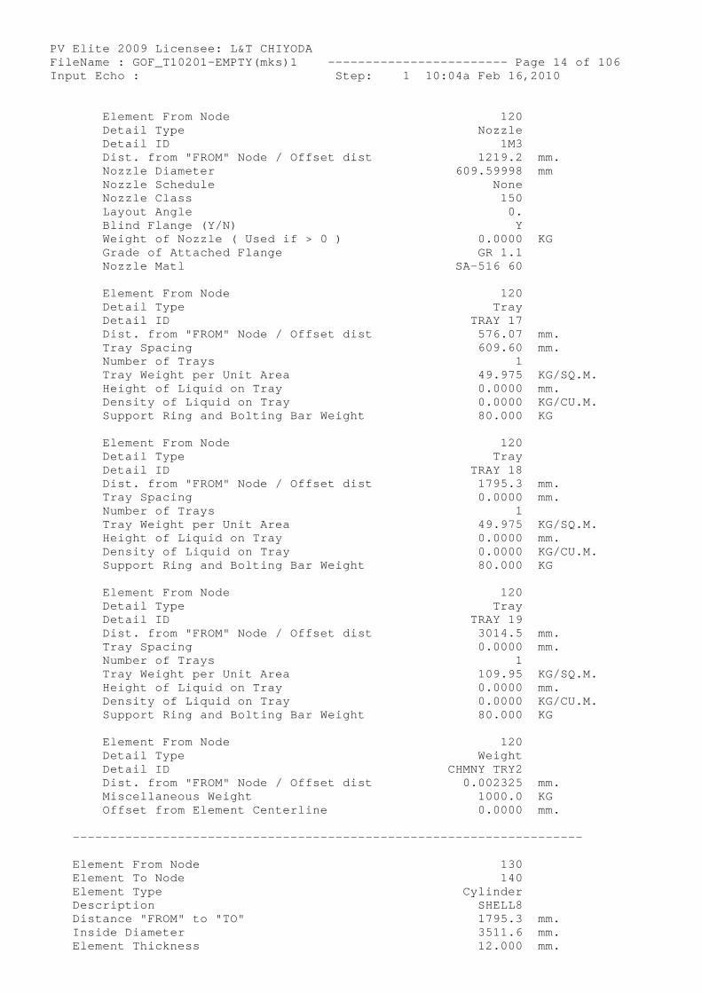
Element From Node 120 Detail Type Nozzle Detail ID 1M3 Dist. from "FROM" Node / Offset dist 1219.2 mm. Nozzle Diameter 609.59998 mm Nozzle Schedule None Nozzle Class 150 Layout Angle 0. Blind Flange (Y/N) Y Weight of Nozzle ( Used if > 0 ) 0.0000 KG Grade of Attached Flange GR 1.1 Nozzle Matl SA-516 60
Element From Node 120 Detail Type Tray Detail ID TRAY 17 Dist. from "FROM" Node / Offset dist 576.07 mm. Tray Spacing 609.60 mm. Number of Trays 1 Tray Weight per Unit Area 49.975 KG/SQ.M. Height of Liquid on Tray 0.0000 mm. Density of Liquid on Tray 0.0000 KG/CU.M. Support Ring and Bolting Bar Weight 80.000 KG
Element From Node 120 Detail Type Tray Detail ID TRAY 18 Dist. from "FROM" Node / Offset dist 1795.3 mm. Tray Spacing 0.0000 mm. Number of Trays 1 Tray Weight per Unit Area 49.975 KG/SQ.M. Height of Liquid on Tray 0.0000 mm. Density of Liquid on Tray 0.0000 KG/CU.M. Support Ring and Bolting Bar Weight 80.000 KG
Element From Node 120 Detail Type Tray Detail ID TRAY 19 Dist. from "FROM" Node / Offset dist 3014.5 mm. Tray Spacing 0.0000 mm. Number of Trays 1 Tray Weight per Unit Area 109.95 KG/SQ.M. Height of Liquid on Tray 0.0000 mm. Density of Liquid on Tray 0.0000 KG/CU.M. Support Ring and Bolting Bar Weight 80.000 KG
Element From Node 120 Detail Type Weight Detail ID CHMNY TRY2 Dist. from "FROM" Node / Offset dist 0.002325 mm. Miscellaneous Weight 1000.0 KG Offset from Element Centerline 0.0000 mm.
----------------------------------------------- ---------------------
Element From Node 130 Element To Node 140 Element Type Cylinder Description SHELL8 Distance "FROM" to "TO" 1795.3 mm. Inside Diameter 3511.6 mm. Element Thickness 12.000 mm.
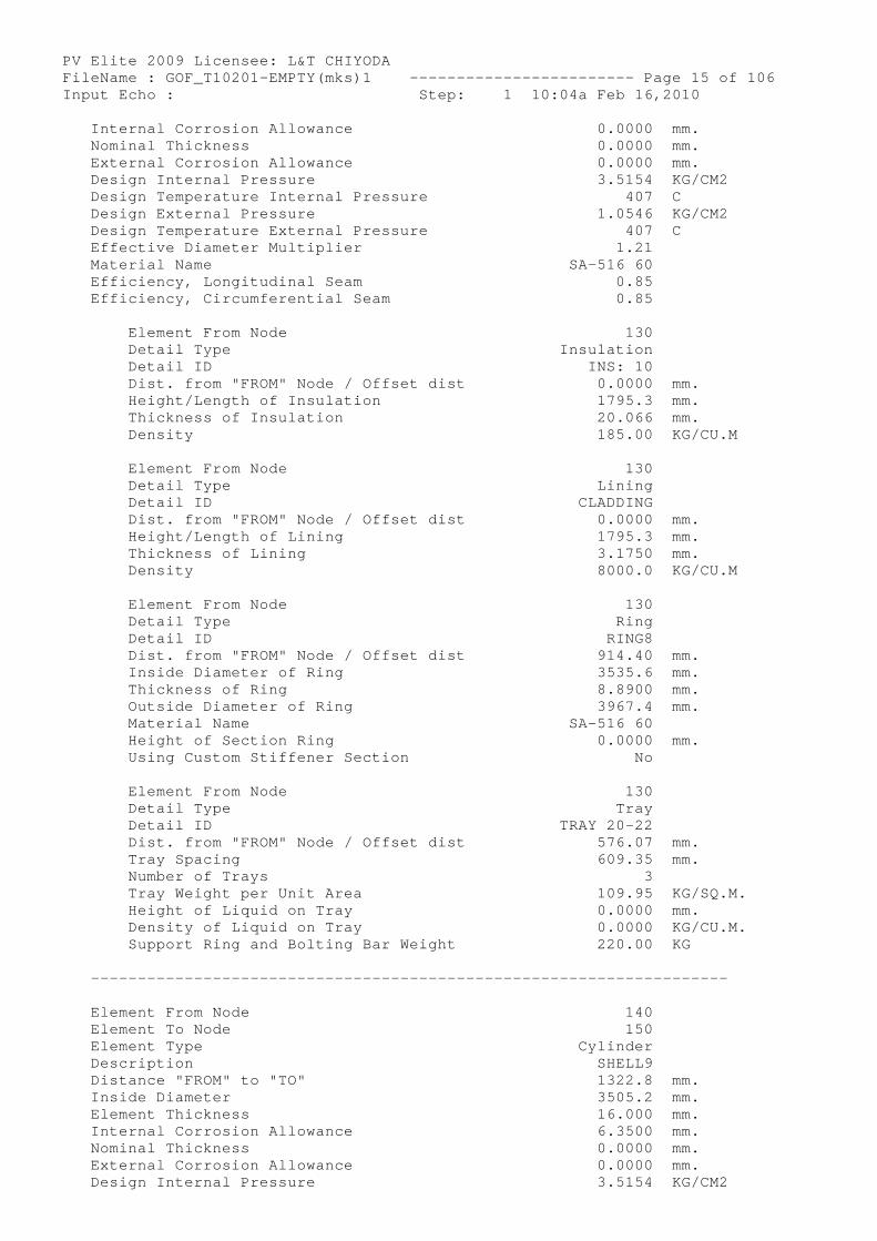
PV Elite 2009 Licensee: L&T CHIYODA FileName : GOF_T10201-EMPTY(mks)1 ------------- ----------- Page 15 of 106 Input Echo : Step: 1 10:04a Feb 16,2010 Internal Corrosion Allowance 0.0000 mm. Nominal Thickness 0.0000 mm. External Corrosion Allowance 0.0000 mm. Design Internal Pressure 3.5154 KG/CM2 Design Temperature Internal Pressure 407 C Design External Pressure 1.0546 KG/CM2 Design Temperature External Pressure 407 C Effective Diameter Multiplier 1.21 Material Name SA-516 60 Efficiency, Longitudinal Seam 0.85 Efficiency, Circumferential Seam 0.85
Element From Node 130 Detail Type Insulation Detail ID INS: 10 Dist. from "FROM" Node / Offset dist 0.0000 mm. Height/Length of Insulation 1795.3 mm. Thickness of Insulation 20.066 mm. Density 185.00 KG/CU.M
Element From Node 130 Detail Type Lining Detail ID CLADDING Dist. from "FROM" Node / Offset dist 0.0000 mm. Height/Length of Lining 1795.3 mm. Thickness of Lining 3.1750 mm. Density 8000.0 KG/CU.M
Element From Node 130 Detail Type Ring Detail ID RING8 Dist. from "FROM" Node / Offset dist 914.40 mm. Inside Diameter of Ring 3535.6 mm. Thickness of Ring 8.8900 mm. Outside Diameter of Ring 3967.4 mm. Material Name SA-516 60 Height of Section Ring 0.0000 mm. Using Custom Stiffener Section No
Element From Node 130 Detail Type Tray Detail ID TRAY 20-22 Dist. from "FROM" Node / Offset dist 576.07 mm. Tray Spacing 609.35 mm. Number of Trays 3 Tray Weight per Unit Area 109.95 KG/SQ.M. Height of Liquid on Tray 0.0000 mm. Density of Liquid on Tray 0.0000 KG/CU.M. Support Ring and Bolting Bar Weight 220.00 KG
----------------------------------------------- ---------------------
Element From Node 140 Element To Node 150 Element Type Cylinder Description SHELL9 Distance "FROM" to "TO" 1322.8 mm. Inside Diameter 3505.2 mm. Element Thickness 16.000 mm. Internal Corrosion Allowance 6.3500 mm. Nominal Thickness 0.0000 mm. External Corrosion Allowance 0.0000 mm. Design Internal Pressure 3.5154 KG/CM2
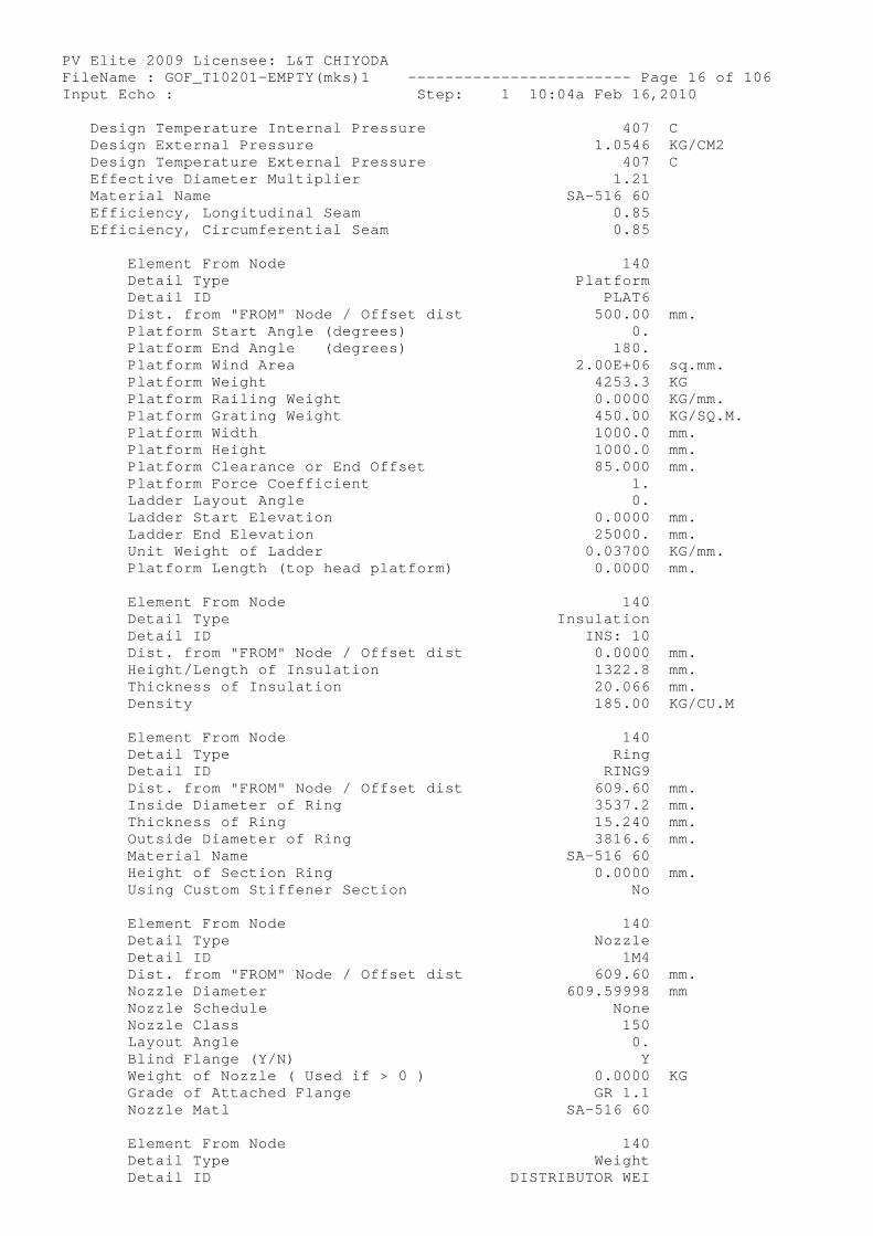
PV Elite 2009 Licensee: L&T CHIYODA FileName : GOF_T10201-EMPTY(mks)1 ------------- ----------- Page 16 of 106 Input Echo : Step: 1 10:04a Feb 16,2010 Design Temperature Internal Pressure 407 C Design External Pressure 1.0546 KG/CM2 Design Temperature External Pressure 407 C Effective Diameter Multiplier 1.21 Material Name SA-516 60 Efficiency, Longitudinal Seam 0.85 Efficiency, Circumferential Seam 0.85
Element From Node 140 Detail Type Platform Detail ID PLAT6 Dist. from "FROM" Node / Offset dist 500.00 mm. Platform Start Angle (degrees) 0. Platform End Angle (degrees) 180. Platform Wind Area 2.00E+06 sq.mm. Platform Weight 4253.3 KG Platform Railing Weight 0.0000 KG/mm. Platform Grating Weight 450.00 KG/SQ.M. Platform Width 1000.0 mm. Platform Height 1000.0 mm. Platform Clearance or End Offset 85.000 mm. Platform Force Coefficient 1. Ladder Layout Angle 0. Ladder Start Elevation 0.0000 mm. Ladder End Elevation 25000. mm. Unit Weight of Ladder 0.03700 KG/mm. Platform Length (top head platform) 0.0000 mm.
Element From Node 140 Detail Type Insulation Detail ID INS: 10 Dist. from "FROM" Node / Offset dist 0.0000 mm. Height/Length of Insulation 1322.8 mm. Thickness of Insulation 20.066 mm. Density 185.00 KG/CU.M
Element From Node 140 Detail Type Ring Detail ID RING9 Dist. from "FROM" Node / Offset dist 609.60 mm. Inside Diameter of Ring 3537.2 mm. Thickness of Ring 15.240 mm. Outside Diameter of Ring 3816.6 mm. Material Name SA-516 60 Height of Section Ring 0.0000 mm. Using Custom Stiffener Section No
Element From Node 140 Detail Type Nozzle Detail ID 1M4 Dist. from "FROM" Node / Offset dist 609.60 mm. Nozzle Diameter 609.59998 mm Nozzle Schedule None Nozzle Class 150 Layout Angle 0. Blind Flange (Y/N) Y Weight of Nozzle ( Used if > 0 ) 0.0000 KG Grade of Attached Flange GR 1.1 Nozzle Matl SA-516 60
Element From Node 140 Detail Type Weight Detail ID DI STRIBUTOR WEI
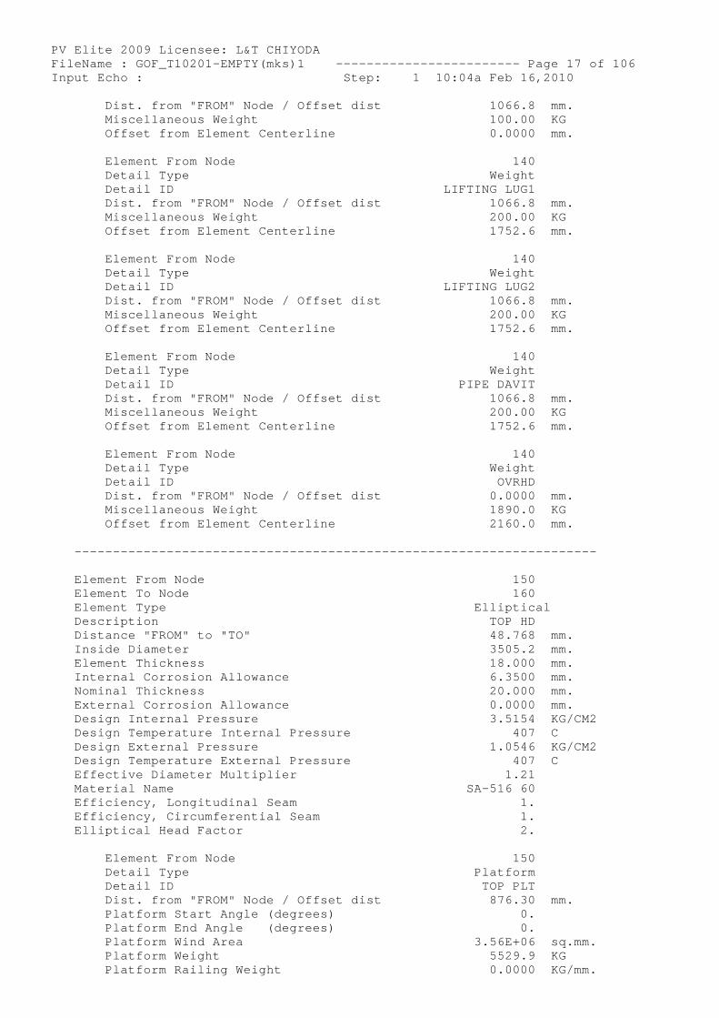
PV Elite 2009 Licensee: L&T CHIYODA FileName : GOF_T10201-EMPTY(mks)1 ------------- ----------- Page 17 of 106 Input Echo : Step: 1 10:04a Feb 16,2010 Dist. from "FROM" Node / Offset dist 1066.8 mm. Miscellaneous Weight 100.00 KG Offset from Element Centerline 0.0000 mm.
Element From Node 140 Detail Type Weight Detail ID LIFTING LUG1 Dist. from "FROM" Node / Offset dist 1066.8 mm. Miscellaneous Weight 200.00 KG Offset from Element Centerline 1752.6 mm.
Element From Node 140 Detail Type Weight Detail ID LIFTING LUG2 Dist. from "FROM" Node / Offset dist 1066.8 mm. Miscellaneous Weight 200.00 KG Offset from Element Centerline 1752.6 mm.
Element From Node 140 Detail Type Weight Detail ID PIPE DAVIT Dist. from "FROM" Node / Offset dist 1066.8 mm. Miscellaneous Weight 200.00 KG Offset from Element Centerline 1752.6 mm.
Element From Node 140 Detail Type Weight Detail ID OVRHD Dist. from "FROM" Node / Offset dist 0.0000 mm. Miscellaneous Weight 1890.0 KG Offset from Element Centerline 2160.0 mm.
----------------------------------------------- ---------------------
Element From Node 150 Element To Node 160 Element Type Elliptical Description TOP HD Distance "FROM" to "TO" 48.768 mm. Inside Diameter 3505.2 mm. Element Thickness 18.000 mm. Internal Corrosion Allowance 6.3500 mm. Nominal Thickness 20.000 mm. External Corrosion Allowance 0.0000 mm. Design Internal Pressure 3.5154 KG/CM2 Design Temperature Internal Pressure 407 C Design External Pressure 1.0546 KG/CM2 Design Temperature External Pressure 407 C Effective Diameter Multiplier 1.21 Material Name SA-516 60 Efficiency, Longitudinal Seam 1. Efficiency, Circumferential Seam 1. Elliptical Head Factor 2.
Element From Node 150 Detail Type Platform Detail ID TOP PLT Dist. from "FROM" Node / Offset dist 876.30 mm. Platform Start Angle (degrees) 0. Platform End Angle (degrees) 0. Platform Wind Area 3.56E+06 sq.mm. Platform Weight 5529.9 KG Platform Railing Weight 0.0000 KG/mm.
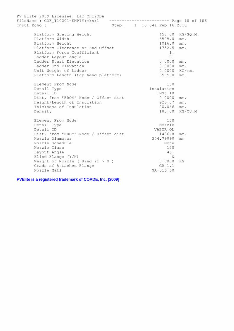
PV Elite 2009 Licensee: L&T CHIYODA FileName : GOF_T10201-EMPTY(mks)1 ------------- ----------- Page 18 of 106 Input Echo : Step: 1 10:04a Feb 16,2010 Platform Grating Weight 450.00 KG/SQ.M. Platform Width 3505.0 mm. Platform Height 1016.0 mm. Platform Clearance or End Offset 1752.5 mm. Platform Force Coefficient 1. Ladder Layout Angle 0. Ladder Start Elevation 0.0000 mm. Ladder End Elevation 0.0000 mm. Unit Weight of Ladder 0.0000 KG/mm. Platform Length (top head platform) 3505.0 mm.
Element From Node 150 Detail Type Insulation Detail ID INS: 10 Dist. from "FROM" Node / Offset dist 0.0000 mm. Height/Length of Insulation 925.07 mm. Thickness of Insulation 20.066 mm. Density 185.00 KG/CU.M
Element From Node 150 Detail Type Nozzle Detail ID VAPOR OL Dist. from "FROM" Node / Offset dist 1436.8 mm. Nozzle Diameter 304.79999 mm Nozzle Schedule None Nozzle Class 150 Layout Angle 45. Blind Flange (Y/N) N Weight of Nozzle ( Used if > 0 ) 0.0000 KG Grade of Attached Flange GR 1.1 Nozzle Matl SA-516 60
PVElite is a registered trademark of COADE, Inc. [2009]
PV Elite 2009 Licensee: L&T CHIYODA FileName : GOF_T10201-EMPTY(mks)1 ------------- ----------- Page 19 of 106 XY Coordinate Calculations : Step: 2 10:04a Feb 16,2010
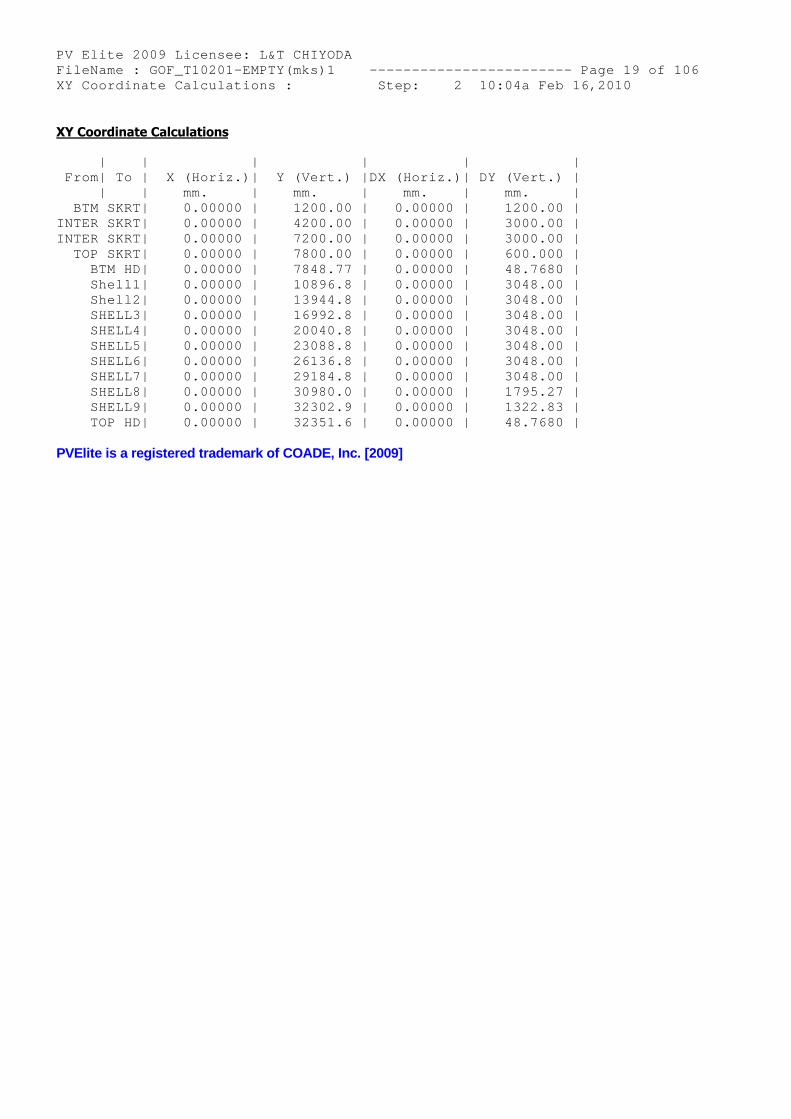
XY Coordinate Calculations
| | | | | | From| To | X (Horiz.)| Y (Vert.) |DX (Horiz.)| DY (Vert.) | | | mm. | mm. | mm. | mm. | BTM SKRT| 0.00000 | 1200.00 | 0.00000 | 1200.00 | INTER SKRT| 0.00000 | 4200.00 | 0.00000 | 3000.00 | INTER SKRT| 0.00000 | 7200.00 | 0.00000 | 3000.00 | TOP SKRT| 0.00000 | 7800.00 | 0.00000 | 600.000 | BTM HD| 0.00000 | 7848.77 | 0.00000 | 48.7680 | Shell1| 0.00000 | 10896.8 | 0.00000 | 3048.00 | Shell2| 0.00000 | 13944.8 | 0.00000 | 3048.00 | SHELL3| 0.00000 | 16992.8 | 0.00000 | 3048.00 | SHELL4| 0.00000 | 20040.8 | 0.00000 | 3048.00 | SHELL5| 0.00000 | 23088.8 | 0.00000 | 3048.00 | SHELL6| 0.00000 | 26136.8 | 0.00000 | 3048.00 | SHELL7| 0.00000 | 29184.8 | 0.00000 | 3048.00 | SHELL8| 0.00000 | 30980.0 | 0.00000 | 1795.27 | SHELL9| 0.00000 | 32302.9 | 0.00000 | 1322.83 | TOP HD| 0.00000 | 32351.6 | 0.00000 | 48.7680 |
PVElite is a registered trademark of COADE, Inc. [2009]
PV Elite 2009 Licensee: L&T CHIYODA FileName : GOF_T10201-EMPTY(mks)1 ------------- ----------- Page 20 of 106 Internal Pressure Calculations : Step: 3 10:04a Feb 16,2010
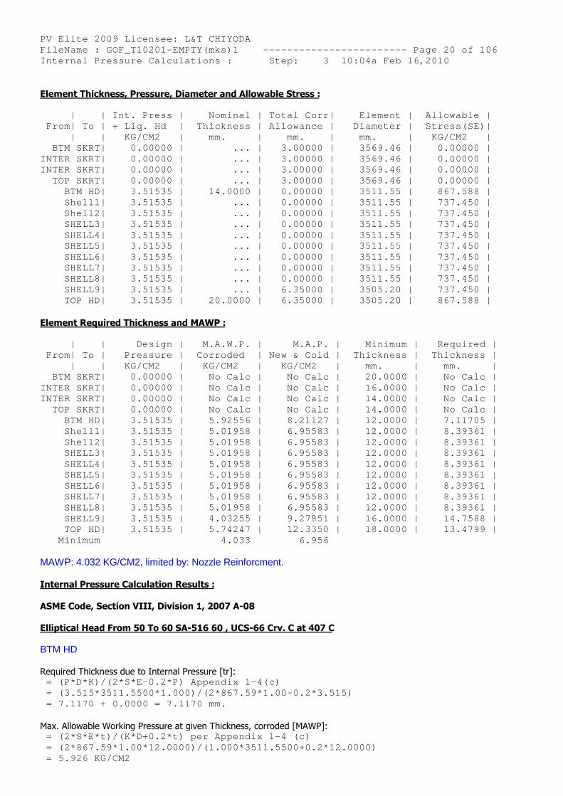
Element Thickness, Pressure, Diameter and Allowable Stress :
| | Int. Press | Nominal | Total Corr| Element | Allowable | From| To | + Liq. Hd | Thickness | Allowance | Diameter | Stress(SE)| | | KG/CM2 | mm. | mm. | mm. | KG/CM2 | BTM SKRT| 0.00000 | ... | 3.00000 | 3569.46 | 0.00000 | INTER SKRT| 0.00000 | ... | 3.00000 | 3569.46 | 0.00000 | INTER SKRT| 0.00000 | ... | 3.00000 | 3569.46 | 0.00000 | TOP SKRT| 0.00000 | ... | 3.00000 | 3569.46 | 0.00000 | BTM HD| 3.51535 | 14.0000 | 0.00000 | 3511.55 | 867.588 | Shell1| 3.51535 | ... | 0.00000 | 3511.55 | 737.450 | Shell2| 3.51535 | ... | 0.00000 | 3511.55 | 737.450 | SHELL3| 3.51535 | ... | 0.00000 | 3511.55 | 737.450 | SHELL4| 3.51535 | ... | 0.00000 | 3511.55 | 737.450 | SHELL5| 3.51535 | ... | 0.00000 | 3511.55 | 737.450 | SHELL6| 3.51535 | ... | 0.00000 | 3511.55 | 737.450 | SHELL7| 3.51535 | ... | 0.00000 | 3511.55 | 737.450 | SHELL8| 3.51535 | ... | 0.00000 | 3511.55 | 737.450 | SHELL9| 3.51535 | ... | 6.35000 | 3505.20 | 737.450 | TOP HD| 3.51535 | 20.0000 | 6.35000 | 3505.20 | 867.588 |
Element Required Thickness and MAWP :
| | Design | M.A.W.P. | M.A.P. | Minimum | Required | From| To | Pressure | Corroded | New & Cold | Thickness | Thickness | | | KG/CM2 | KG/CM2 | KG/CM2 | mm. | mm. | BTM SKRT| 0.00000 | No Calc | No Calc | 20.0000 | No Calc | INTER SKRT| 0.00000 | No Calc | No Calc | 16.0000 | No Calc | INTER SKRT| 0.00000 | No Calc | No Calc | 14.0000 | No Calc | TOP SKRT| 0.00000 | No Calc | No Calc | 14.0000 | No Calc | BTM HD| 3.51535 | 5.92556 | 8.21127 | 12.0000 | 7.11705 | Shell1| 3.51535 | 5.01958 | 6.95583 | 12.0000 | 8.39361 | Shell2| 3.51535 | 5.01958 | 6.95583 | 12.0000 | 8.39361 | SHELL3| 3.51535 | 5.01958 | 6.95583 | 12.0000 | 8.39361 | SHELL4| 3.51535 | 5.01958 | 6.95583 | 12.0000 | 8.39361 | SHELL5| 3.51535 | 5.01958 | 6.95583 | 12.0000 | 8.39361 | SHELL6| 3.51535 | 5.01958 | 6.95583 | 12.0000 | 8.39361 | SHELL7| 3.51535 | 5.01958 | 6.95583 | 12.0000 | 8.39361 | SHELL8| 3.51535 | 5.01958 | 6.95583 | 12.0000 | 8.39361 | SHELL9| 3.51535 | 4.03255 | 9.27851 | 16.0000 | 14.7588 | TOP HD| 3.51535 | 5.74247 | 12.3350 | 18.0000 | 13.4799 | Minimum 4.033 6.956
MAWP: 4.032 KG/CM2, limited by: Nozzle Reinforcment.
Internal Pressure Calculation Results :
ASME Code, Section VIII, Division 1, 2007 A-08
Elliptical Head From 50 To 60 SA-516 60 , UCS-66 Crv. C at 407 C
BTM HD
Required Thickness due to Internal Pressure [tr]: = (P*D*K)/(2*S*E-0.2*P) Appendix 1-4(c) = (3.515*3511.5500*1.000)/(2*867.59*1.00-0.2*3.51 5) = 7.1170 + 0.0000 = 7.1170 mm.
Max. Allowable Working Pressure at given Thickness, corroded [MAWP]: = (2*S*E*t)/(K*D+0.2*t) per Appendix 1-4 (c) = (2*867.59*1.00*12.0000)/(1.000*3511.5500+0.2*12 .0000) = 5.926 KG/CM2
PV Elite 2009 Licensee: L&T CHIYODA FileName : GOF_T10201-EMPTY(mks)1 ------------- ----------- Page 21 of 106 Internal Pressure Calculations : Step: 3 10:04a Feb 16,2010
Maximum Allowable Pressure, New and Cold [MAPNC]: = (2*S*E*t)/(K*D+0.2*t) per Appendix 1-4 (c) = (2*1202.25*1.00*12.0000)/(1.000*3511.5500+0.2*1 2.0000) = 8.211 KG/CM2
Actual stress at given pressure and thickness, corroded [Sact]: = (P*(K*D+0.2*t))/(2*E*t) = (3.515*(1.000*3511.5500+0.2*12.0000))/(2*1.00*1 2.0000) = 514.698 KG/CM2
Straight Flange Required Thickness: = (P*R)/(S*E-0.6*P) + c per UG-27 (c)(1) = (3.515*1755.7750)/(867.59*1.00-0.6*3.515)+0.000 = 7.131 mm.
Straight Flange Maximum Allowable Working Pressure: = (S*E*t)/(R+0.6*t) per UG-27 (c)(1) = (867.59 * 1.00 * 14.0000 ) / (1755.7750 + 0.6 * 14.0000 ) = 6.885 KG/CM2
Percent Elongation per UCS-79 (75*tnom/Rf)*(1-Rf/ Ro) 1.752 %
MDMT Calculations in the Knuckle Portion:
Govrn. thk, tg = 12.000 , tr = 5.891 , c = 0.0000 mm. , E* = 1.00Stress Ratio = tr * (E*) / (tg - c) = 0.491 , Temp. Reduction = 35 C
Min Metal Temp. w/o impact per UCS-66 -39 C Min Metal Temp per UCS-66 and UCS-68(c),PWHT credi t -56 C Min Metal Temp. at Required thickness (UCS 66.1) -65 C
MDMT Calculations in the Head Straight Flange:
Govrn. thk, tg = 14.000 , tr = 5.901 , c = 0.0000 mm. , E* = 1.00Stress Ratio = tr * (E*) / (tg - c) = 0.421 , Temp. Reduction = 52 C
Min Metal Temp. w/o impact per UCS-66 -36 C Min Metal Temp per UCS-66 and UCS-68(c),PWHT credi t -52 C Min Metal Temp. at Required thickness (UCS 66.1) -65 C
Cylindrical Shell From 60 To 70 SA-516 60 , UCS-66 Crv. C at 407 C
Shell1
Required Thickness due to Internal Pressure [tr]: = (P*R)/(S*E-0.6*P) per UG-27 (c)(1) = (3.515*1755.7750)/(867.59*0.85-0.6*3.515) = 8.3936 + 0.0000 = 8.3936 mm.
Max. Allowable Working Pressure at given Thickness, corroded [MAWP]: = (S*E*t)/(R+0.6*t) per UG-27 (c)(1) = (867.59*0.85*12.0000)/(1755.7750+0.6*12.0000) = 5.020 KG/CM2
Maximum Allowable Pressure, New and Cold [MAPNC]: = (S*E*t)/(R+0.6*t) per UG-27 (c)(1) = (1202.25*0.85*12.0000)/(1755.7750+0.6*12.0000) = 6.956 KG/CM2
Actual stress at given pressure and thickness, corroded [Sact]: = (P*(R+0.6*t))/(E*t) = (3.515*(1755.7750+0.6*12.0000))/(0.85*12.0000)
PV Elite 2009 Licensee: L&T CHIYODA FileName : GOF_T10201-EMPTY(mks)1 ------------- ----------- Page 22 of 106 Internal Pressure Calculations : Step: 3 10:04a Feb 16,2010 = 607.596 KG/CM2
Percent Elongation per UCS-79 (50*tnom/Rf)*(1-Rf/ Ro) 0.341 %
Minimum Design Metal Temperature Results:
Govrn. thk, tg = 12.000 , tr = 6.945 , c = 0.0000 mm. , E* = 0.85Stress Ratio = tr * (E*) / (tg - c) = 0.492 , Temp. Reduction = 35 C
Min Metal Temp. w/o impact per UCS-66 -39 C Min Metal Temp per UCS-66 and UCS-68(c),PWHT credi t -56 C Min Metal Temp. at Required thickness (UCS 66.1) -65 C
Cylindrical Shell From 70 To 80 SA-516 60 , UCS-66 Crv. C at 407 C
Shell2
Required Thickness due to Internal Pressure [tr]: = (P*R)/(S*E-0.6*P) per UG-27 (c)(1) = (3.515*1755.7750)/(867.59*0.85-0.6*3.515) = 8.3936 + 0.0000 = 8.3936 mm.
Max. Allowable Working Pressure at given Thickness, corroded [MAWP]: = (S*E*t)/(R+0.6*t) per UG-27 (c)(1) = (867.59*0.85*12.0000)/(1755.7750+0.6*12.0000) = 5.020 KG/CM2
Maximum Allowable Pressure, New and Cold [MAPNC]: = (S*E*t)/(R+0.6*t) per UG-27 (c)(1) = (1202.25*0.85*12.0000)/(1755.7750+0.6*12.0000) = 6.956 KG/CM2
Actual stress at given pressure and thickness, corroded [Sact]: = (P*(R+0.6*t))/(E*t) = (3.515*(1755.7750+0.6*12.0000))/(0.85*12.0000) = 607.596 KG/CM2
Percent Elongation per UCS-79 (50*tnom/Rf)*(1-Rf/ Ro) 0.341 %
Minimum Design Metal Temperature Results:
Govrn. thk, tg = 12.000 , tr = 6.945 , c = 0.0000 mm. , E* = 0.85Stress Ratio = tr * (E*) / (tg - c) = 0.492 , Temp. Reduction = 35 C
Min Metal Temp. w/o impact per UCS-66 -39 C Min Metal Temp per UCS-66 and UCS-68(c),PWHT credi t -56 C Min Metal Temp. at Required thickness (UCS 66.1) -65 C
Cylindrical Shell From 80 To 90 SA-516 60 , UCS-66 Crv. C at 407 C
SHELL3
Required Thickness due to Internal Pressure [tr]: = (P*R)/(S*E-0.6*P) per UG-27 (c)(1) = (3.515*1755.7750)/(867.59*0.85-0.6*3.515) = 8.3936 + 0.0000 = 8.3936 mm.
Max. Allowable Working Pressure at given Thickness, corroded [MAWP]: = (S*E*t)/(R+0.6*t) per UG-27 (c)(1) = (867.59*0.85*12.0000)/(1755.7750+0.6*12.0000) = 5.020 KG/CM2
Maximum Allowable Pressure, New and Cold [MAPNC]:
PV Elite 2009 Licensee: L&T CHIYODA FileName : GOF_T10201-EMPTY(mks)1 ------------- ----------- Page 23 of 106 Internal Pressure Calculations : Step: 3 10:04a Feb 16,2010 = (S*E*t)/(R+0.6*t) per UG-27 (c)(1) = (1202.25*0.85*12.0000)/(1755.7750+0.6*12.0000) = 6.956 KG/CM2
Actual stress at given pressure and thickness, corroded [Sact]: = (P*(R+0.6*t))/(E*t) = (3.515*(1755.7750+0.6*12.0000))/(0.85*12.0000) = 607.596 KG/CM2
Percent Elongation per UCS-79 (50*tnom/Rf)*(1-Rf/ Ro) 0.341 %
Minimum Design Metal Temperature Results:
Govrn. thk, tg = 12.000 , tr = 6.945 , c = 0.0000 mm. , E* = 0.85Stress Ratio = tr * (E*) / (tg - c) = 0.492 , Temp. Reduction = 35 C
Min Metal Temp. w/o impact per UCS-66 -39 C Min Metal Temp per UCS-66 and UCS-68(c),PWHT credi t -56 C Min Metal Temp. at Required thickness (UCS 66.1) -65 C
Cylindrical Shell From 90 To 100 SA-516 60 , UCS-66 Crv. C at 407 C
SHELL4
Required Thickness due to Internal Pressure [tr]: = (P*R)/(S*E-0.6*P) per UG-27 (c)(1) = (3.515*1755.7750)/(867.59*0.85-0.6*3.515) = 8.3936 + 0.0000 = 8.3936 mm.
Max. Allowable Working Pressure at given Thickness, corroded [MAWP]: = (S*E*t)/(R+0.6*t) per UG-27 (c)(1) = (867.59*0.85*12.0000)/(1755.7750+0.6*12.0000) = 5.020 KG/CM2
Maximum Allowable Pressure, New and Cold [MAPNC]: = (S*E*t)/(R+0.6*t) per UG-27 (c)(1) = (1202.25*0.85*12.0000)/(1755.7750+0.6*12.0000) = 6.956 KG/CM2
Actual stress at given pressure and thickness, corroded [Sact]: = (P*(R+0.6*t))/(E*t) = (3.515*(1755.7750+0.6*12.0000))/(0.85*12.0000) = 607.596 KG/CM2
Percent Elongation per UCS-79 (50*tnom/Rf)*(1-Rf/ Ro) 0.341 %
Minimum Design Metal Temperature Results:
Govrn. thk, tg = 12.000 , tr = 6.945 , c = 0.0000 mm. , E* = 0.85Stress Ratio = tr * (E*) / (tg - c) = 0.492 , Temp. Reduction = 35 C
Min Metal Temp. w/o impact per UCS-66 -39 C Min Metal Temp per UCS-66 and UCS-68(c),PWHT credi t -56 C Min Metal Temp. at Required thickness (UCS 66.1) -65 C
Cylindrical Shell From 100 To 110 SA-516 60 , UCS-66 Crv. C at 407 C
SHELL5
Required Thickness due to Internal Pressure [tr]: = (P*R)/(S*E-0.6*P) per UG-27 (c)(1) = (3.515*1755.7750)/(867.59*0.85-0.6*3.515) = 8.3936 + 0.0000 = 8.3936 mm.
PV Elite 2009 Licensee: L&T CHIYODA FileName : GOF_T10201-EMPTY(mks)1 ------------- ----------- Page 24 of 106 Internal Pressure Calculations : Step: 3 10:04a Feb 16,2010
Max. Allowable Working Pressure at given Thickness, corroded [MAWP]: = (S*E*t)/(R+0.6*t) per UG-27 (c)(1) = (867.59*0.85*12.0000)/(1755.7750+0.6*12.0000) = 5.020 KG/CM2
Maximum Allowable Pressure, New and Cold [MAPNC]: = (S*E*t)/(R+0.6*t) per UG-27 (c)(1) = (1202.25*0.85*12.0000)/(1755.7750+0.6*12.0000) = 6.956 KG/CM2
Actual stress at given pressure and thickness, corroded [Sact]: = (P*(R+0.6*t))/(E*t) = (3.515*(1755.7750+0.6*12.0000))/(0.85*12.0000) = 607.596 KG/CM2
Percent Elongation per UCS-79 (50*tnom/Rf)*(1-Rf/ Ro) 0.341 %
Minimum Design Metal Temperature Results:
Govrn. thk, tg = 12.000 , tr = 6.945 , c = 0.0000 mm. , E* = 0.85Stress Ratio = tr * (E*) / (tg - c) = 0.492 , Temp. Reduction = 35 C
Min Metal Temp. w/o impact per UCS-66 -39 C Min Metal Temp per UCS-66 and UCS-68(c),PWHT credi t -56 C Min Metal Temp. at Required thickness (UCS 66.1) -65 C
Cylindrical Shell From 110 To 120 SA-516 60 , UCS-66 Crv. C at 407 C
SHELL6
Required Thickness due to Internal Pressure [tr]: = (P*R)/(S*E-0.6*P) per UG-27 (c)(1) = (3.515*1755.7750)/(867.59*0.85-0.6*3.515) = 8.3936 + 0.0000 = 8.3936 mm.
Max. Allowable Working Pressure at given Thickness, corroded [MAWP]: = (S*E*t)/(R+0.6*t) per UG-27 (c)(1) = (867.59*0.85*12.0000)/(1755.7750+0.6*12.0000) = 5.020 KG/CM2
Maximum Allowable Pressure, New and Cold [MAPNC]: = (S*E*t)/(R+0.6*t) per UG-27 (c)(1) = (1202.25*0.85*12.0000)/(1755.7750+0.6*12.0000) = 6.956 KG/CM2
Actual stress at given pressure and thickness, corroded [Sact]: = (P*(R+0.6*t))/(E*t) = (3.515*(1755.7750+0.6*12.0000))/(0.85*12.0000) = 607.596 KG/CM2
Percent Elongation per UCS-79 (50*tnom/Rf)*(1-Rf/ Ro) 0.341 %
Minimum Design Metal Temperature Results:
Govrn. thk, tg = 12.000 , tr = 6.945 , c = 0.0000 mm. , E* = 0.85Stress Ratio = tr * (E*) / (tg - c) = 0.492 , Temp. Reduction = 35 C
Min Metal Temp. w/o impact per UCS-66 -39 C Min Metal Temp per UCS-66 and UCS-68(c),PWHT credi t -56 C Min Metal Temp. at Required thickness (UCS 66.1) -65 C
Cylindrical Shell From 120 To 130 SA-516 60 , UCS-66 Crv. C at 407 C
PV Elite 2009 Licensee: L&T CHIYODA FileName : GOF_T10201-EMPTY(mks)1 ------------- ----------- Page 25 of 106 Internal Pressure Calculations : Step: 3 10:04a Feb 16,2010
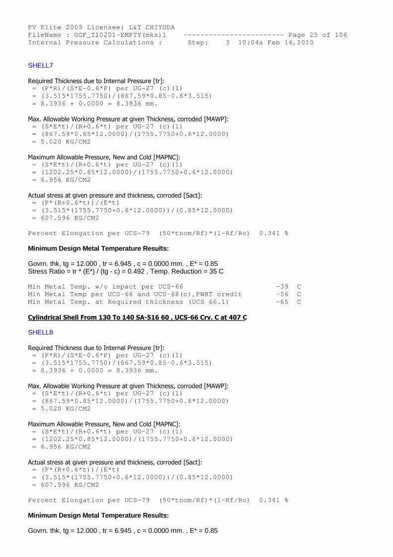
SHELL7
Required Thickness due to Internal Pressure [tr]: = (P*R)/(S*E-0.6*P) per UG-27 (c)(1) = (3.515*1755.7750)/(867.59*0.85-0.6*3.515) = 8.3936 + 0.0000 = 8.3936 mm.
Max. Allowable Working Pressure at given Thickness, corroded [MAWP]: = (S*E*t)/(R+0.6*t) per UG-27 (c)(1) = (867.59*0.85*12.0000)/(1755.7750+0.6*12.0000) = 5.020 KG/CM2
Maximum Allowable Pressure, New and Cold [MAPNC]: = (S*E*t)/(R+0.6*t) per UG-27 (c)(1) = (1202.25*0.85*12.0000)/(1755.7750+0.6*12.0000) = 6.956 KG/CM2
Actual stress at given pressure and thickness, corroded [Sact]: = (P*(R+0.6*t))/(E*t) = (3.515*(1755.7750+0.6*12.0000))/(0.85*12.0000) = 607.596 KG/CM2
Percent Elongation per UCS-79 (50*tnom/Rf)*(1-Rf/ Ro) 0.341 %
Minimum Design Metal Temperature Results:
Govrn. thk, tg = 12.000 , tr = 6.945 , c = 0.0000 mm. , E* = 0.85Stress Ratio = tr * (E*) / (tg - c) = 0.492 , Temp. Reduction = 35 C
Min Metal Temp. w/o impact per UCS-66 -39 C Min Metal Temp per UCS-66 and UCS-68(c),PWHT credi t -56 C Min Metal Temp. at Required thickness (UCS 66.1) -65 C
Cylindrical Shell From 130 To 140 SA-516 60 , UCS-66 Crv. C at 407 C
SHELL8
Required Thickness due to Internal Pressure [tr]: = (P*R)/(S*E-0.6*P) per UG-27 (c)(1) = (3.515*1755.7750)/(867.59*0.85-0.6*3.515) = 8.3936 + 0.0000 = 8.3936 mm.
Max. Allowable Working Pressure at given Thickness, corroded [MAWP]: = (S*E*t)/(R+0.6*t) per UG-27 (c)(1) = (867.59*0.85*12.0000)/(1755.7750+0.6*12.0000) = 5.020 KG/CM2
Maximum Allowable Pressure, New and Cold [MAPNC]: = (S*E*t)/(R+0.6*t) per UG-27 (c)(1) = (1202.25*0.85*12.0000)/(1755.7750+0.6*12.0000) = 6.956 KG/CM2
Actual stress at given pressure and thickness, corroded [Sact]: = (P*(R+0.6*t))/(E*t) = (3.515*(1755.7750+0.6*12.0000))/(0.85*12.0000) = 607.596 KG/CM2
Percent Elongation per UCS-79 (50*tnom/Rf)*(1-Rf/ Ro) 0.341 %
Minimum Design Metal Temperature Results:
Govrn. thk, tg = 12.000 , tr = 6.945 , c = 0.0000 mm. , E* = 0.85
PV Elite 2009 Licensee: L&T CHIYODA FileName : GOF_T10201-EMPTY(mks)1 ------------- ----------- Page 26 of 106 Internal Pressure Calculations : Step: 3 10:04a Feb 16,2010
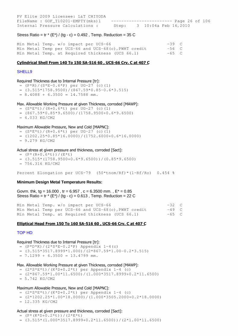
Stress Ratio = tr * (E*) / (tg - c) = 0.492 , Temp. Reduction = 35 C
Min Metal Temp. w/o impact per UCS-66 -39 C Min Metal Temp per UCS-66 and UCS-68(c),PWHT credi t -56 C Min Metal Temp. at Required thickness (UCS 66.1) -65 C
Cylindrical Shell From 140 To 150 SA-516 60 , UCS-66 Crv. C at 407 C
SHELL9
Required Thickness due to Internal Pressure [tr]: = (P*R)/(S*E-0.6*P) per UG-27 (c)(1) = (3.515*1758.9500)/(867.59*0.85-0.6*3.515) = 8.4088 + 6.3500 = 14.7588 mm.
Max. Allowable Working Pressure at given Thickness, corroded [MAWP]: = (S*E*t)/(R+0.6*t) per UG-27 (c)(1) = (867.59*0.85*9.6500)/(1758.9500+0.6*9.6500) = 4.033 KG/CM2
Maximum Allowable Pressure, New and Cold [MAPNC]: = (S*E*t)/(R+0.6*t) per UG-27 (c)(1) = (1202.25*0.85*16.0000)/(1752.6000+0.6*16.0000) = 9.279 KG/CM2
Actual stress at given pressure and thickness, corroded [Sact]: = (P*(R+0.6*t))/(E*t) = (3.515*(1758.9500+0.6*9.6500))/(0.85*9.6500) = 756.316 KG/CM2
Percent Elongation per UCS-79 (50*tnom/Rf)*(1-Rf/ Ro) 0.454 %
Minimum Design Metal Temperature Results:
Govrn. thk, tg = 16.000 , tr = 6.957 , c = 6.3500 mm. , E* = 0.85Stress Ratio = tr * (E*) / (tg - c) = 0.613 , Temp. Reduction = 22 C
Min Metal Temp. w/o impact per UCS-66 -32 C Min Metal Temp per UCS-66 and UCS-68(c),PWHT credi t -49 C Min Metal Temp. at Required thickness (UCS 66.1) -65 C
Elliptical Head From 150 To 160 SA-516 60 , UCS-66 Crv. C at 407 C
TOP HD
Required Thickness due to Internal Pressure [tr]: = (P*D*K)/(2*S*E-0.2*P) Appendix 1-4(c) = (3.515*3517.8999*1.000)/(2*867.59*1.00-0.2*3.51 5) = 7.1299 + 6.3500 = 13.4799 mm.
Max. Allowable Working Pressure at given Thickness, corroded [MAWP]: = (2*S*E*t)/(K*D+0.2*t) per Appendix 1-4 (c) = (2*867.59*1.00*11.6500)/(1.000*3517.8999+0.2*11 .6500) = 5.742 KG/CM2
Maximum Allowable Pressure, New and Cold [MAPNC]: = (2*S*E*t)/(K*D+0.2*t) per Appendix 1-4 (c) = (2*1202.25*1.00*18.0000)/(1.000*3505.2000+0.2*1 8.0000) = 12.335 KG/CM2
Actual stress at given pressure and thickness, corroded [Sact]: = (P*(K*D+0.2*t))/(2*E*t) = (3.515*(1.000*3517.8999+0.2*11.6500))/(2*1.00*1 1.6500)
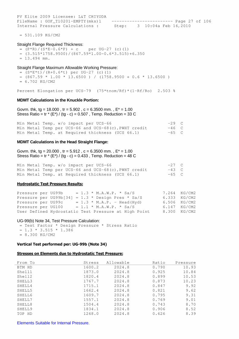
PV Elite 2009 Licensee: L&T CHIYODA FileName : GOF_T10201-EMPTY(mks)1 ------------- ----------- Page 27 of 106 Internal Pressure Calculations : Step: 3 10:04a Feb 16,2010 = 531.109 KG/CM2
Straight Flange Required Thickness: = (P*R)/(S*E-0.6*P) + c per UG-27 (c)(1) = (3.515*1758.9500)/(867.59*1.00-0.6*3.515)+6.350 = 13.494 mm.
Straight Flange Maximum Allowable Working Pressure: = (S*E*t)/(R+0.6*t) per UG-27 (c)(1) = (867.59 * 1.00 * 13.6500 ) / (1758.9500 + 0.6 * 13.6500 ) = 6.702 KG/CM2
Percent Elongation per UCS-79 (75*tnom/Rf)*(1-Rf/ Ro) 2.503 %
MDMT Calculations in the Knuckle Portion:
Govrn. thk, tg = 18.000 , tr = 5.902 , c = 6.3500 mm. , E* = 1.00Stress Ratio = tr * (E*) / (tg - c) = 0.507 , Temp. Reduction = 33 C
Min Metal Temp. w/o impact per UCS-66 -29 C Min Metal Temp per UCS-66 and UCS-68(c),PWHT credi t -46 C Min Metal Temp. at Required thickness (UCS 66.1) -65 C
MDMT Calculations in the Head Straight Flange:
Govrn. thk, tg = 20.000 , tr = 5.912 , c = 6.3500 mm. , E* = 1.00Stress Ratio = tr * (E*) / (tg - c) = 0.433 , Temp. Reduction = 48 C
Min Metal Temp. w/o impact per UCS-66 -27 C Min Metal Temp per UCS-66 and UCS-68(c),PWHT credi t -43 C Min Metal Temp. at Required thickness (UCS 66.1) -65 C
Hydrostatic Test Pressure Results:
Pressure per UG99b = 1.3 * M.A.W.P. * Sa/S 7.264 KG/CM2 Pressure per UG99b[34] = 1.3 * Design Pres * Sa/S 6.333 KG/CM2 Pressure per UG99c = 1.3 * M.A.P. - Head(Hyd) 6.506 KG/CM2 Pressure per UG100 = 1.1 * M.A.W.P. * Sa/S 6.147 KG/CM2 User Defined Hydrostatic Test Pressure at High Poi nt 8.300 KG/CM2
UG-99(b) Note 34, Test Pressure Calculation: = Test Factor * Design Pressure * Stress Ratio = 1.3 * 3.515 * 1.386 = 8.300 KG/CM2
Vertical Test performed per: UG-99b (Note 34)
Stresses on Elements due to Hydrostatic Test Pressure:
From To Stress Allowable Ratio Pressure BTM HD 1600.2 2024.8 0.790 10.93 Shell1 1873.0 2024.8 0.925 10.84 Shell2 1820.4 2024.8 0.899 10.53 SHELL3 1767.7 2024.8 0.873 10.23 SHELL4 1715.1 2024.8 0.847 9.92 SHELL5 1662.4 2024.8 0.821 9.62 SHELL6 1609.7 2024.8 0.795 9.31 SHELL7 1557.1 2024.8 0.769 9.01 SHELL8 1504.4 2024.8 0.743 8.70 SHELL9 1834.1 2024.8 0.906 8.52 TOP HD 1268.0 2024.8 0.626 8.39
Elements Suitable for Internal Pressure.
PV Elite 2009 Licensee: L&T CHIYODA FileName : GOF_T10201-EMPTY(mks)1 ------------- ----------- Page 28 of 106 Internal Pressure Calculations : Step: 3 10:04a Feb 16,2010
PVElite is a registered trademark of COADE, Inc. [2009]
PV Elite 2009 Licensee: L&T CHIYODA FileName : GOF_T10201-EMPTY(mks)1 ------------- ----------- Page 29 of 106 External Pressure Calculations : Step: 4 10:04a Feb 16,2010
External Pressure Calculation Results :
ASME Code, Section VIII, Division 1, 2007 A-08
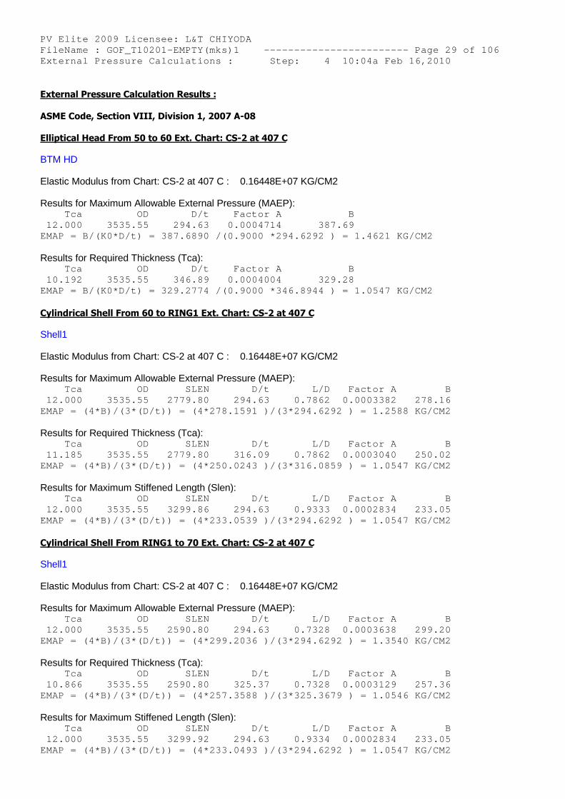
Elliptical Head From 50 to 60 Ext. Chart: CS-2 at 407 C
BTM HD
Elastic Modulus from Chart: CS-2 at 407 C : 0.16448E+07 KG/CM2
Results for Maximum Allowable External Pressure (MAEP): Tca OD D/t Factor A B 12.000 3535.55 294.63 0.0004714 387. 69 EMAP = B/(K0*D/t) = 387.6890 /(0.9000 *294.6292 ) = 1.4621 KG/CM2
Results for Required Thickness (Tca): Tca OD D/t Factor A B 10.192 3535.55 346.89 0.0004004 329. 28 EMAP = B/(K0*D/t) = 329.2774 /(0.9000 *346.8944 ) = 1.0547 KG/CM2
Cylindrical Shell From 60 to RING1 Ext. Chart: CS-2 at 407 C
Shell1
Elastic Modulus from Chart: CS-2 at 407 C : 0.16448E+07 KG/CM2
Results for Maximum Allowable External Pressure (MAEP): Tca OD SLEN D/t L/D Factor A B 12.000 3535.55 2779.80 294.63 0.7862 0.0003382 278.16 EMAP = (4*B)/(3*(D/t)) = (4*278.1591 )/(3*294.6292 ) = 1.2588 KG/CM2
Results for Required Thickness (Tca): Tca OD SLEN D/t L/D Factor A B 11.185 3535.55 2779.80 316.09 0.7862 0.0003040 250.02 EMAP = (4*B)/(3*(D/t)) = (4*250.0243 )/(3*316.0859 ) = 1.0547 KG/CM2
Results for Maximum Stiffened Length (Slen): Tca OD SLEN D/t L/D Factor A B 12.000 3535.55 3299.86 294.63 0.9333 0.0002834 233.05 EMAP = (4*B)/(3*(D/t)) = (4*233.0539 )/(3*294.6292 ) = 1.0547 KG/CM2
Cylindrical Shell From RING1 to 70 Ext. Chart: CS-2 at 407 C
Shell1
Elastic Modulus from Chart: CS-2 at 407 C : 0.16448E+07 KG/CM2
Results for Maximum Allowable External Pressure (MAEP): Tca OD SLEN D/t L/D Factor A B 12.000 3535.55 2590.80 294.63 0.7328 0.0003638 299.20 EMAP = (4*B)/(3*(D/t)) = (4*299.2036 )/(3*294.6292 ) = 1.3540 KG/CM2
Results for Required Thickness (Tca): Tca OD SLEN D/t L/D Factor A B 10.866 3535.55 2590.80 325.37 0.7328 0.0003129 257.36 EMAP = (4*B)/(3*(D/t)) = (4*257.3588 )/(3*325.3679 ) = 1.0546 KG/CM2
Results for Maximum Stiffened Length (Slen): Tca OD SLEN D/t L/D Factor A B 12.000 3535.55 3299.92 294.63 0.9334 0.0002834 233.05 EMAP = (4*B)/(3*(D/t)) = (4*233.0493 )/(3*294.6292 ) = 1.0547 KG/CM2
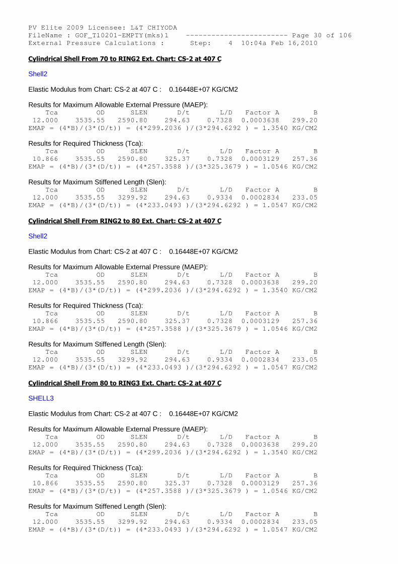
PV Elite 2009 Licensee: L&T CHIYODA FileName : GOF_T10201-EMPTY(mks)1 ------------- ----------- Page 30 of 106 External Pressure Calculations : Step: 4 10:04a Feb 16,2010 Cylindrical Shell From 70 to RING2 Ext. Chart: CS-2 at 407 C
Shell2
Elastic Modulus from Chart: CS-2 at 407 C : 0.16448E+07 KG/CM2
Results for Maximum Allowable External Pressure (MAEP): Tca OD SLEN D/t L/D Factor A B 12.000 3535.55 2590.80 294.63 0.7328 0.0003638 299.20 EMAP = (4*B)/(3*(D/t)) = (4*299.2036 )/(3*294.6292 ) = 1.3540 KG/CM2
Results for Required Thickness (Tca): Tca OD SLEN D/t L/D Factor A B 10.866 3535.55 2590.80 325.37 0.7328 0.0003129 257.36 EMAP = (4*B)/(3*(D/t)) = (4*257.3588 )/(3*325.3679 ) = 1.0546 KG/CM2
Results for Maximum Stiffened Length (Slen): Tca OD SLEN D/t L/D Factor A B 12.000 3535.55 3299.92 294.63 0.9334 0.0002834 233.05 EMAP = (4*B)/(3*(D/t)) = (4*233.0493 )/(3*294.6292 ) = 1.0547 KG/CM2
Cylindrical Shell From RING2 to 80 Ext. Chart: CS-2 at 407 C
Shell2
Elastic Modulus from Chart: CS-2 at 407 C : 0.16448E+07 KG/CM2
Results for Maximum Allowable External Pressure (MAEP): Tca OD SLEN D/t L/D Factor A B 12.000 3535.55 2590.80 294.63 0.7328 0.0003638 299.20 EMAP = (4*B)/(3*(D/t)) = (4*299.2036 )/(3*294.6292 ) = 1.3540 KG/CM2
Results for Required Thickness (Tca): Tca OD SLEN D/t L/D Factor A B 10.866 3535.55 2590.80 325.37 0.7328 0.0003129 257.36 EMAP = (4*B)/(3*(D/t)) = (4*257.3588 )/(3*325.3679 ) = 1.0546 KG/CM2
Results for Maximum Stiffened Length (Slen): Tca OD SLEN D/t L/D Factor A B 12.000 3535.55 3299.92 294.63 0.9334 0.0002834 233.05 EMAP = (4*B)/(3*(D/t)) = (4*233.0493 )/(3*294.6292 ) = 1.0547 KG/CM2
Cylindrical Shell From 80 to RING3 Ext. Chart: CS-2 at 407 C
SHELL3
Elastic Modulus from Chart: CS-2 at 407 C : 0.16448E+07 KG/CM2
Results for Maximum Allowable External Pressure (MAEP): Tca OD SLEN D/t L/D Factor A B 12.000 3535.55 2590.80 294.63 0.7328 0.0003638 299.20 EMAP = (4*B)/(3*(D/t)) = (4*299.2036 )/(3*294.6292 ) = 1.3540 KG/CM2
Results for Required Thickness (Tca): Tca OD SLEN D/t L/D Factor A B 10.866 3535.55 2590.80 325.37 0.7328 0.0003129 257.36 EMAP = (4*B)/(3*(D/t)) = (4*257.3588 )/(3*325.3679 ) = 1.0546 KG/CM2
Results for Maximum Stiffened Length (Slen): Tca OD SLEN D/t L/D Factor A B 12.000 3535.55 3299.92 294.63 0.9334 0.0002834 233.05 EMAP = (4*B)/(3*(D/t)) = (4*233.0493 )/(3*294.6292 ) = 1.0547 KG/CM2
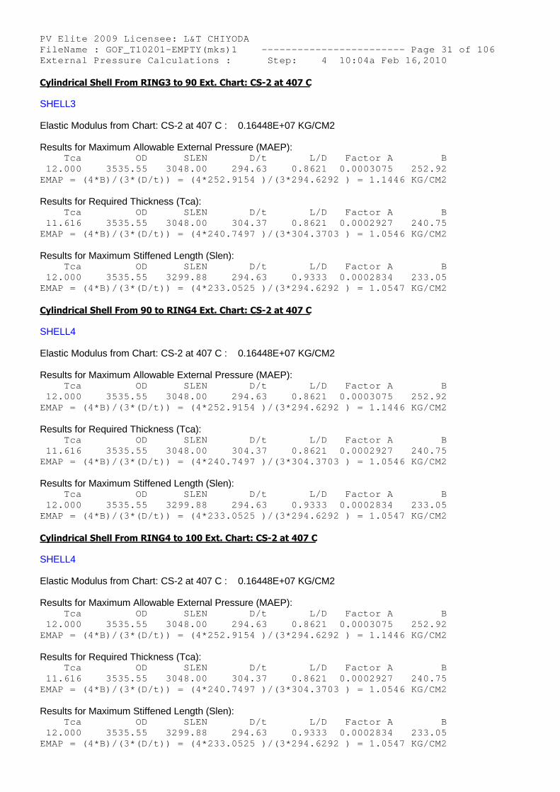
PV Elite 2009 Licensee: L&T CHIYODA FileName : GOF_T10201-EMPTY(mks)1 ------------- ----------- Page 31 of 106 External Pressure Calculations : Step: 4 10:04a Feb 16,2010 Cylindrical Shell From RING3 to 90 Ext. Chart: CS-2 at 407 C
SHELL3
Elastic Modulus from Chart: CS-2 at 407 C : 0.16448E+07 KG/CM2
Results for Maximum Allowable External Pressure (MAEP): Tca OD SLEN D/t L/D Factor A B 12.000 3535.55 3048.00 294.63 0.8621 0.0003075 252.92 EMAP = (4*B)/(3*(D/t)) = (4*252.9154 )/(3*294.6292 ) = 1.1446 KG/CM2
Results for Required Thickness (Tca): Tca OD SLEN D/t L/D Factor A B 11.616 3535.55 3048.00 304.37 0.8621 0.0002927 240.75 EMAP = (4*B)/(3*(D/t)) = (4*240.7497 )/(3*304.3703 ) = 1.0546 KG/CM2
Results for Maximum Stiffened Length (Slen): Tca OD SLEN D/t L/D Factor A B 12.000 3535.55 3299.88 294.63 0.9333 0.0002834 233.05 EMAP = (4*B)/(3*(D/t)) = (4*233.0525 )/(3*294.6292 ) = 1.0547 KG/CM2
Cylindrical Shell From 90 to RING4 Ext. Chart: CS-2 at 407 C
SHELL4
Elastic Modulus from Chart: CS-2 at 407 C : 0.16448E+07 KG/CM2
Results for Maximum Allowable External Pressure (MAEP): Tca OD SLEN D/t L/D Factor A B 12.000 3535.55 3048.00 294.63 0.8621 0.0003075 252.92 EMAP = (4*B)/(3*(D/t)) = (4*252.9154 )/(3*294.6292 ) = 1.1446 KG/CM2
Results for Required Thickness (Tca): Tca OD SLEN D/t L/D Factor A B 11.616 3535.55 3048.00 304.37 0.8621 0.0002927 240.75 EMAP = (4*B)/(3*(D/t)) = (4*240.7497 )/(3*304.3703 ) = 1.0546 KG/CM2
Results for Maximum Stiffened Length (Slen): Tca OD SLEN D/t L/D Factor A B 12.000 3535.55 3299.88 294.63 0.9333 0.0002834 233.05 EMAP = (4*B)/(3*(D/t)) = (4*233.0525 )/(3*294.6292 ) = 1.0547 KG/CM2
Cylindrical Shell From RING4 to 100 Ext. Chart: CS-2 at 407 C
SHELL4
Elastic Modulus from Chart: CS-2 at 407 C : 0.16448E+07 KG/CM2
Results for Maximum Allowable External Pressure (MAEP): Tca OD SLEN D/t L/D Factor A B 12.000 3535.55 3048.00 294.63 0.8621 0.0003075 252.92 EMAP = (4*B)/(3*(D/t)) = (4*252.9154 )/(3*294.6292 ) = 1.1446 KG/CM2
Results for Required Thickness (Tca): Tca OD SLEN D/t L/D Factor A B 11.616 3535.55 3048.00 304.37 0.8621 0.0002927 240.75 EMAP = (4*B)/(3*(D/t)) = (4*240.7497 )/(3*304.3703 ) = 1.0546 KG/CM2
Results for Maximum Stiffened Length (Slen): Tca OD SLEN D/t L/D Factor A B 12.000 3535.55 3299.88 294.63 0.9333 0.0002834 233.05 EMAP = (4*B)/(3*(D/t)) = (4*233.0525 )/(3*294.6292 ) = 1.0547 KG/CM2

PV Elite 2009 Licensee: L&T CHIYODA FileName : GOF_T10201-EMPTY(mks)1 ------------- ----------- Page 32 of 106 External Pressure Calculations : Step: 4 10:04a Feb 16,2010 Cylindrical Shell From 100 to RING5 Ext. Chart: CS-2 at 407 C
SHELL5
Elastic Modulus from Chart: CS-2 at 407 C : 0.16448E+07 KG/CM2
Results for Maximum Allowable External Pressure (MAEP): Tca OD SLEN D/t L/D Factor A B 12.000 3535.55 3048.00 294.63 0.8621 0.0003075 252.92 EMAP = (4*B)/(3*(D/t)) = (4*252.9154 )/(3*294.6292 ) = 1.1446 KG/CM2
Results for Required Thickness (Tca): Tca OD SLEN D/t L/D Factor A B 11.616 3535.55 3048.00 304.37 0.8621 0.0002927 240.75 EMAP = (4*B)/(3*(D/t)) = (4*240.7497 )/(3*304.3703 ) = 1.0546 KG/CM2
Results for Maximum Stiffened Length (Slen): Tca OD SLEN D/t L/D Factor A B 12.000 3535.55 3299.88 294.63 0.9333 0.0002834 233.05 EMAP = (4*B)/(3*(D/t)) = (4*233.0525 )/(3*294.6292 ) = 1.0547 KG/CM2
Cylindrical Shell From RING5 to 110 Ext. Chart: CS-2 at 407 C
SHELL5
Elastic Modulus from Chart: CS-2 at 407 C : 0.16448E+07 KG/CM2
Results for Maximum Allowable External Pressure (MAEP): Tca OD SLEN D/t L/D Factor A B 12.000 3535.55 3048.00 294.63 0.8621 0.0003075 252.92 EMAP = (4*B)/(3*(D/t)) = (4*252.9154 )/(3*294.6292 ) = 1.1446 KG/CM2
Results for Required Thickness (Tca): Tca OD SLEN D/t L/D Factor A B 11.616 3535.55 3048.00 304.37 0.8621 0.0002927 240.75 EMAP = (4*B)/(3*(D/t)) = (4*240.7497 )/(3*304.3703 ) = 1.0546 KG/CM2
Results for Maximum Stiffened Length (Slen): Tca OD SLEN D/t L/D Factor A B 12.000 3535.55 3299.88 294.63 0.9333 0.0002834 233.05 EMAP = (4*B)/(3*(D/t)) = (4*233.0525 )/(3*294.6292 ) = 1.0547 KG/CM2
Cylindrical Shell From 110 to RING6 Ext. Chart: CS-2 at 407 C
SHELL6
Elastic Modulus from Chart: CS-2 at 407 C : 0.16448E+07 KG/CM2
Results for Maximum Allowable External Pressure (MAEP): Tca OD SLEN D/t L/D Factor A B 12.000 3535.55 3048.00 294.63 0.8621 0.0003075 252.92 EMAP = (4*B)/(3*(D/t)) = (4*252.9154 )/(3*294.6292 ) = 1.1446 KG/CM2
Results for Required Thickness (Tca): Tca OD SLEN D/t L/D Factor A B 11.616 3535.55 3048.00 304.37 0.8621 0.0002927 240.75 EMAP = (4*B)/(3*(D/t)) = (4*240.7497 )/(3*304.3703 ) = 1.0546 KG/CM2
Results for Maximum Stiffened Length (Slen): Tca OD SLEN D/t L/D Factor A B 12.000 3535.55 3299.88 294.63 0.9333 0.0002834 233.05 EMAP = (4*B)/(3*(D/t)) = (4*233.0525 )/(3*294.6292 ) = 1.0547 KG/CM2
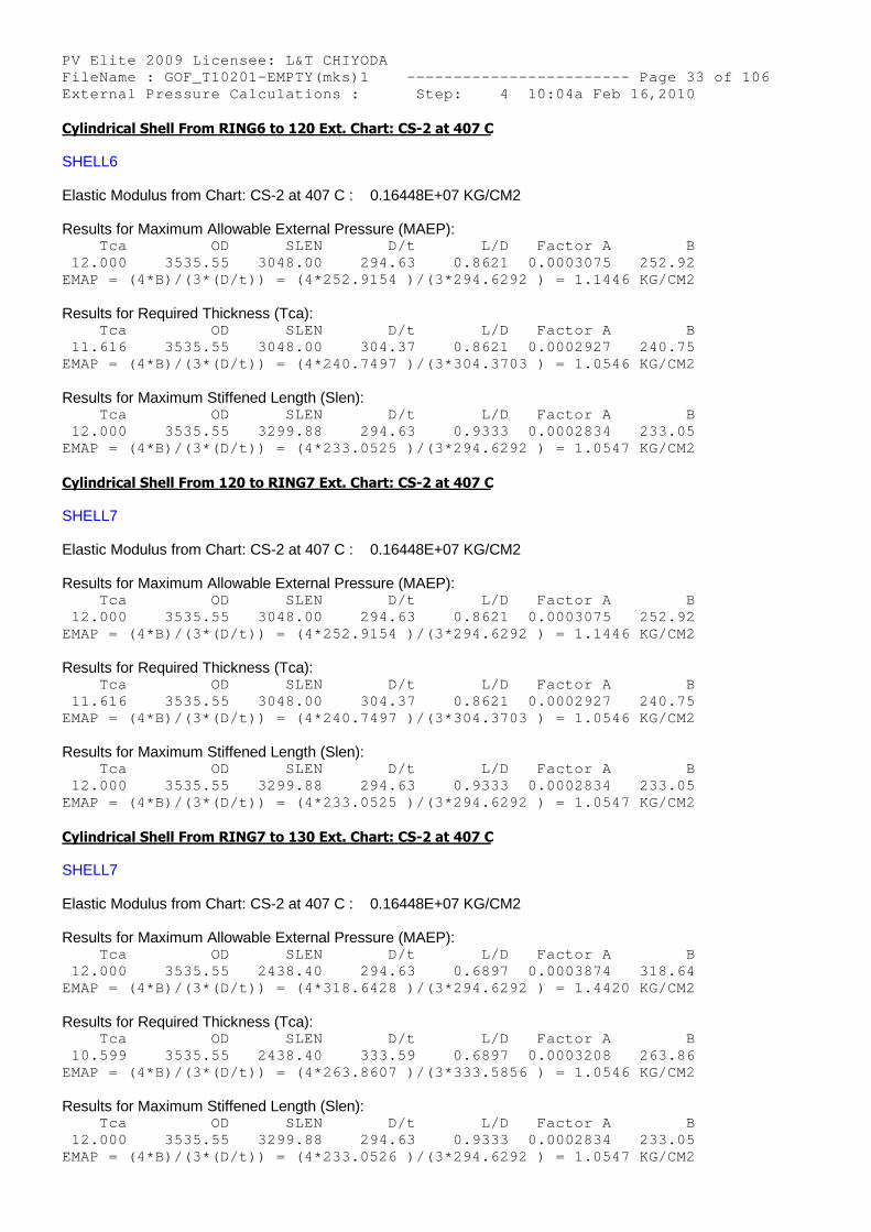
PV Elite 2009 Licensee: L&T CHIYODA FileName : GOF_T10201-EMPTY(mks)1 ------------- ----------- Page 33 of 106 External Pressure Calculations : Step: 4 10:04a Feb 16,2010 Cylindrical Shell From RING6 to 120 Ext. Chart: CS-2 at 407 C
SHELL6
Elastic Modulus from Chart: CS-2 at 407 C : 0.16448E+07 KG/CM2
Results for Maximum Allowable External Pressure (MAEP): Tca OD SLEN D/t L/D Factor A B 12.000 3535.55 3048.00 294.63 0.8621 0.0003075 252.92 EMAP = (4*B)/(3*(D/t)) = (4*252.9154 )/(3*294.6292 ) = 1.1446 KG/CM2
Results for Required Thickness (Tca): Tca OD SLEN D/t L/D Factor A B 11.616 3535.55 3048.00 304.37 0.8621 0.0002927 240.75 EMAP = (4*B)/(3*(D/t)) = (4*240.7497 )/(3*304.3703 ) = 1.0546 KG/CM2
Results for Maximum Stiffened Length (Slen): Tca OD SLEN D/t L/D Factor A B 12.000 3535.55 3299.88 294.63 0.9333 0.0002834 233.05 EMAP = (4*B)/(3*(D/t)) = (4*233.0525 )/(3*294.6292 ) = 1.0547 KG/CM2
Cylindrical Shell From 120 to RING7 Ext. Chart: CS-2 at 407 C
SHELL7
Elastic Modulus from Chart: CS-2 at 407 C : 0.16448E+07 KG/CM2
Results for Maximum Allowable External Pressure (MAEP): Tca OD SLEN D/t L/D Factor A B 12.000 3535.55 3048.00 294.63 0.8621 0.0003075 252.92 EMAP = (4*B)/(3*(D/t)) = (4*252.9154 )/(3*294.6292 ) = 1.1446 KG/CM2
Results for Required Thickness (Tca): Tca OD SLEN D/t L/D Factor A B 11.616 3535.55 3048.00 304.37 0.8621 0.0002927 240.75 EMAP = (4*B)/(3*(D/t)) = (4*240.7497 )/(3*304.3703 ) = 1.0546 KG/CM2
Results for Maximum Stiffened Length (Slen): Tca OD SLEN D/t L/D Factor A B 12.000 3535.55 3299.88 294.63 0.9333 0.0002834 233.05 EMAP = (4*B)/(3*(D/t)) = (4*233.0525 )/(3*294.6292 ) = 1.0547 KG/CM2
Cylindrical Shell From RING7 to 130 Ext. Chart: CS-2 at 407 C
SHELL7
Elastic Modulus from Chart: CS-2 at 407 C : 0.16448E+07 KG/CM2
Results for Maximum Allowable External Pressure (MAEP): Tca OD SLEN D/t L/D Factor A B 12.000 3535.55 2438.40 294.63 0.6897 0.0003874 318.64 EMAP = (4*B)/(3*(D/t)) = (4*318.6428 )/(3*294.6292 ) = 1.4420 KG/CM2
Results for Required Thickness (Tca): Tca OD SLEN D/t L/D Factor A B 10.599 3535.55 2438.40 333.59 0.6897 0.0003208 263.86 EMAP = (4*B)/(3*(D/t)) = (4*263.8607 )/(3*333.5856 ) = 1.0546 KG/CM2
Results for Maximum Stiffened Length (Slen): Tca OD SLEN D/t L/D Factor A B 12.000 3535.55 3299.88 294.63 0.9333 0.0002834 233.05 EMAP = (4*B)/(3*(D/t)) = (4*233.0526 )/(3*294.6292 ) = 1.0547 KG/CM2
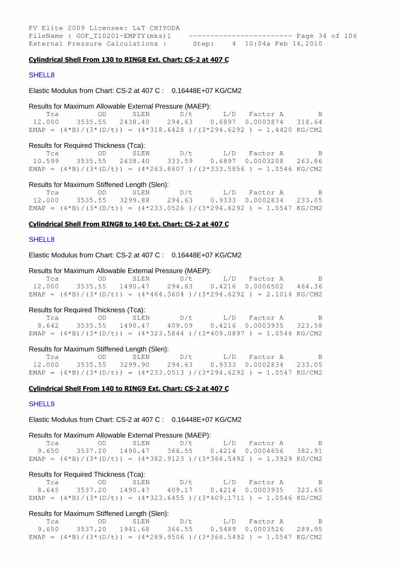
PV Elite 2009 Licensee: L&T CHIYODA FileName : GOF_T10201-EMPTY(mks)1 ------------- ----------- Page 34 of 106 External Pressure Calculations : Step: 4 10:04a Feb 16,2010 Cylindrical Shell From 130 to RING8 Ext. Chart: CS-2 at 407 C
SHELL8
Elastic Modulus from Chart: CS-2 at 407 C : 0.16448E+07 KG/CM2
Results for Maximum Allowable External Pressure (MAEP): Tca OD SLEN D/t L/D Factor A B 12.000 3535.55 2438.40 294.63 0.6897 0.0003874 318.64 EMAP = (4*B)/(3*(D/t)) = (4*318.6428 )/(3*294.6292 ) = 1.4420 KG/CM2
Results for Required Thickness (Tca): Tca OD SLEN D/t L/D Factor A B 10.599 3535.55 2438.40 333.59 0.6897 0.0003208 263.86 EMAP = (4*B)/(3*(D/t)) = (4*263.8607 )/(3*333.5856 ) = 1.0546 KG/CM2
Results for Maximum Stiffened Length (Slen): Tca OD SLEN D/t L/D Factor A B 12.000 3535.55 3299.88 294.63 0.9333 0.0002834 233.05 EMAP = (4*B)/(3*(D/t)) = (4*233.0526 )/(3*294.6292 ) = 1.0547 KG/CM2
Cylindrical Shell From RING8 to 140 Ext. Chart: CS-2 at 407 C
SHELL8
Elastic Modulus from Chart: CS-2 at 407 C : 0.16448E+07 KG/CM2
Results for Maximum Allowable External Pressure (MAEP): Tca OD SLEN D/t L/D Factor A B 12.000 3535.55 1490.47 294.63 0.4216 0.0006502 464.36 EMAP = (4*B)/(3*(D/t)) = (4*464.3604 )/(3*294.6292 ) = 2.1014 KG/CM2
Results for Required Thickness (Tca): Tca OD SLEN D/t L/D Factor A B 8.642 3535.55 1490.47 409.09 0.4216 0.0003935 323.58 EMAP = (4*B)/(3*(D/t)) = (4*323.5844 )/(3*409.0897 ) = 1.0546 KG/CM2
Results for Maximum Stiffened Length (Slen): Tca OD SLEN D/t L/D Factor A B 12.000 3535.55 3299.90 294.63 0.9333 0.0002834 233.05 EMAP = (4*B)/(3*(D/t)) = (4*233.0513 )/(3*294.6292 ) = 1.0547 KG/CM2
Cylindrical Shell From 140 to RING9 Ext. Chart: CS-2 at 407 C
SHELL9
Elastic Modulus from Chart: CS-2 at 407 C : 0.16448E+07 KG/CM2
Results for Maximum Allowable External Pressure (MAEP): Tca OD SLEN D/t L/D Factor A B 9.650 3537.20 1490.47 366.55 0.4214 0.0004656 382.91 EMAP = (4*B)/(3*(D/t)) = (4*382.9123 )/(3*366.5492 ) = 1.3929 KG/CM2
Results for Required Thickness (Tca): Tca OD SLEN D/t L/D Factor A B 8.645 3537.20 1490.47 409.17 0.4214 0.0003935 323.65 EMAP = (4*B)/(3*(D/t)) = (4*323.6455 )/(3*409.1711 ) = 1.0546 KG/CM2
Results for Maximum Stiffened Length (Slen): Tca OD SLEN D/t L/D Factor A B 9.650 3537.20 1941.68 366.55 0.5489 0.0003526 289.95 EMAP = (4*B)/(3*(D/t)) = (4*289.9506 )/(3*366.5492 ) = 1.0547 KG/CM2
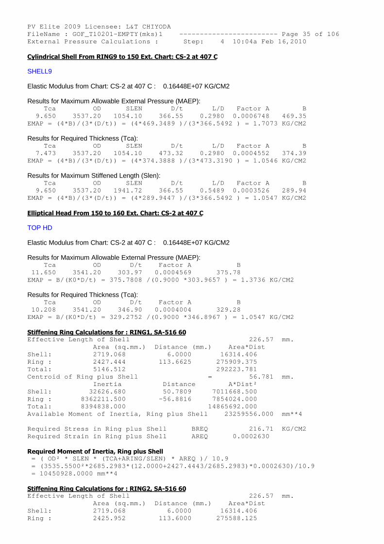
PV Elite 2009 Licensee: L&T CHIYODA FileName : GOF_T10201-EMPTY(mks)1 ------------- ----------- Page 35 of 106 External Pressure Calculations : Step: 4 10:04a Feb 16,2010 Cylindrical Shell From RING9 to 150 Ext. Chart: CS-2 at 407 C
SHELL9
Elastic Modulus from Chart: CS-2 at 407 C : 0.16448E+07 KG/CM2
Results for Maximum Allowable External Pressure (MAEP): Tca OD SLEN D/t L/D Factor A B 9.650 3537.20 1054.10 366.55 0.2980 0.0006748 469.35 EMAP = (4*B)/(3*(D/t)) = (4*469.3489 )/(3*366.5492 ) = 1.7073 KG/CM2
Results for Required Thickness (Tca): Tca OD SLEN D/t L/D Factor A B 7.473 3537.20 1054.10 473.32 0.2980 0.0004552 374.39 EMAP = (4*B)/(3*(D/t)) = (4*374.3888 )/(3*473.3190 ) = 1.0546 KG/CM2
Results for Maximum Stiffened Length (Slen): Tca OD SLEN D/t L/D Factor A B 9.650 3537.20 1941.72 366.55 0.5489 0.0003526 289.94 EMAP = (4*B)/(3*(D/t)) = (4*289.9447 )/(3*366.5492 ) = 1.0547 KG/CM2
Elliptical Head From 150 to 160 Ext. Chart: CS-2 at 407 C
TOP HD
Elastic Modulus from Chart: CS-2 at 407 C : 0.16448E+07 KG/CM2
Results for Maximum Allowable External Pressure (MAEP): Tca OD D/t Factor A B 11.650 3541.20 303.97 0.0004569 375. 78 EMAP = B/(K0*D/t) = 375.7808 /(0.9000 *303.9657 ) = 1.3736 KG/CM2
Results for Required Thickness (Tca): Tca OD D/t Factor A B 10.208 3541.20 346.90 0.0004004 329. 28 EMAP = B/(K0*D/t) = 329.2752 /(0.9000 *346.8967 ) = 1.0547 KG/CM2
Stiffening Ring Calculations for : RING1, SA-516 60 Effective Length of Shell 226.57 mm. Area (sq.mm.) Distance (mm.) A rea*Dist Shell: 2719.068 6.0000 163 14.406 Ring : 2427.444 113.6625 2759 09.375 Total: 5146.512 2922 23.781 Centroid of Ring plus Shell = 56.781 mm. Inertia Distance A *Dist² Shell: 32626.680 50.7809 70116 68.500 Ring : 8362211.500 -56.8816 78540 24.000 Total: 8394838.000 148656 92.000 Available Moment of Inertia, Ring plus Shell 23 259556.000 mm**4
Required Stress in Ring plus Shell BREQ 216.71 KG/CM2 Required Strain in Ring plus Shell AREQ 0.0002630
Required Moment of Inertia, Ring plus Shell = ( OD² * SLEN * (TCA+ARING/SLEN) * AREQ )/ 10.9 = (3535.5500²*2685.2983*(12.0000+2427.4443/2685.2 983)*0.0002630)/10.9 = 10450928.0000 mm**4
Stiffening Ring Calculations for : RING2, SA-516 60 Effective Length of Shell 226.57 mm. Area (sq.mm.) Distance (mm.) A rea*Dist Shell: 2719.068 6.0000 163 14.406 Ring : 2425.952 113.6000 2755 88.125
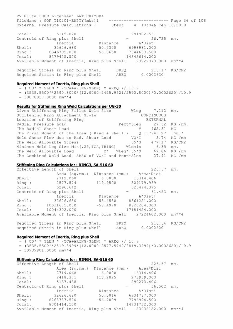
PV Elite 2009 Licensee: L&T CHIYODA FileName : GOF_T10201-EMPTY(mks)1 ------------- ----------- Page 36 of 106 External Pressure Calculations : Step: 4 10:04a Feb 16,2010 Total: 5145.020 2919 02.531 Centroid of Ring plus Shell = 56.735 mm. Inertia Distance A *Dist² Shell: 32626.680 50.7350 69989 81.000 Ring : 8346799.000 -56.8650 78446 33.500 Total: 8379425.500 148436 14.000 Available Moment of Inertia, Ring plus Shell 23 222070.000 mm**4
Required Stress in Ring plus Shell BREQ 216.17 KG/CM2 Required Strain in Ring plus Shell AREQ 0.0002620
Required Moment of Inertia, Ring plus Shell = ( OD² * SLEN * (TCA+ARING/SLEN) * AREQ )/ 10.9 = (3535.5500²*2590.8000*(12.0000+2425.9521/2590.8 000)*0.0002620)/10.9 = 10070027.0000 mm**4
Results for Stiffening Ring Weld Calculations per UG-30 Given Stiffening Ring Fillet Weld Size Wleg 7.112 mm. Stiffening Ring Attachment Style CONTINUOUS Location of Stiffening Ring EXTERNAL Radial Pressure Load Pext*Slen 27.32 KG /mm. The Radial Shear Load V 965.81 KG The First Moment of the Area ( Ring + Shell ) Q 137943.27 mm.³ Weld Shear Flow due to Rad. Shear Load VQ/I 5.74 KG /mm The Weld Allowable Stress .55*S 477.17 KG/CM2 Minimum Weld Leg Size Min(.25,TCA,TRING) Wldmin 6.35 mm. The Weld Allowable Load 2* WLeg*.55*S 67.86 KG /mm The Combined Weld Load SRSS of VQ/I and Pext*Slen 27.91 KG /mm
Stiffening Ring Calculations for : RING3, SA-516 60 Effective Length of Shell 226.57 mm. Area (sq.mm.) Distance (mm.) A rea*Dist Shell: 2719.068 6.0000 163 14.406 Ring : 2577.574 119.9500 3091 79.969 Total: 5296.642 3254 94.375 Centroid of Ring plus Shell = 61.453 mm. Inertia Distance A *Dist² Shell: 32626.680 55.4530 83612 21.000 Ring : 10011675.000 -58.4970 88202 04.000 Total: 10044302.000 171814 24.000 Available Moment of Inertia, Ring plus Shell 27 224602.000 mm**4
Required Stress in Ring plus Shell BREQ 216.54 KG/CM2 Required Strain in Ring plus Shell AREQ 0.0002620
Required Moment of Inertia, Ring plus Shell = ( OD² * SLEN * (TCA+ARING/SLEN) * AREQ )/ 10.9 = (3535.5500²*2819.3999*(12.0000+2577.5740/2819.3 999)*0.0002620)/10.9 = 10939801.0000 mm**4
Stiffening Ring Calculations for : RING4, SA-516 60 Effective Length of Shell 226.57 mm. Area (sq.mm.) Distance (mm.) A rea*Dist Shell: 2719.068 6.0000 163 14.406 Ring : 2418.371 113.2825 2739 59.000 Total: 5137.438 2902 73.406 Centroid of Ring plus Shell = 56.502 mm. Inertia Distance A *Dist² Shell: 32626.680 50.5016 69347 37.000 Ring : 8268787.500 -56.7809 77969 94.500 Total: 8301414.500 147317 32.000 Available Moment of Inertia, Ring plus Shell 23 032182.000 mm**4
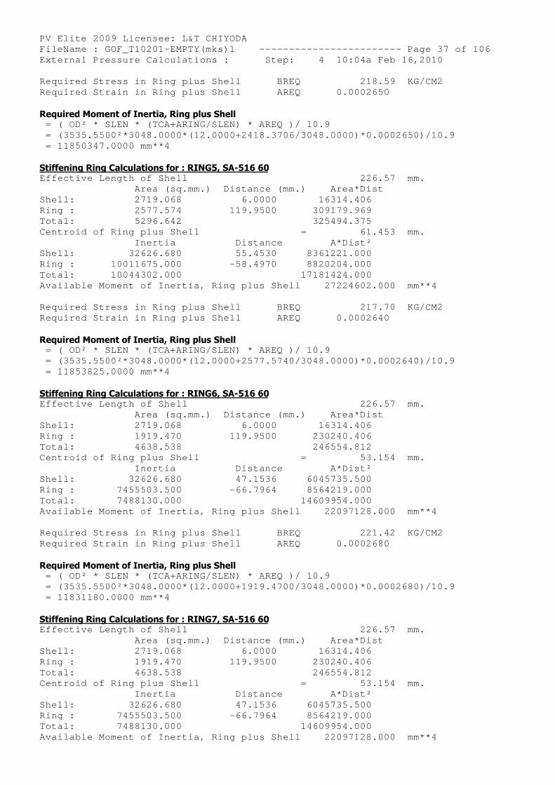
PV Elite 2009 Licensee: L&T CHIYODA FileName : GOF_T10201-EMPTY(mks)1 ------------- ----------- Page 37 of 106 External Pressure Calculations : Step: 4 10:04a Feb 16,2010 Required Stress in Ring plus Shell BREQ 218.59 KG/CM2 Required Strain in Ring plus Shell AREQ 0.0002650
Required Moment of Inertia, Ring plus Shell = ( OD² * SLEN * (TCA+ARING/SLEN) * AREQ )/ 10.9 = (3535.5500²*3048.0000*(12.0000+2418.3706/3048.0 000)*0.0002650)/10.9 = 11850347.0000 mm**4
Stiffening Ring Calculations for : RING5, SA-516 60 Effective Length of Shell 226.57 mm. Area (sq.mm.) Distance (mm.) A rea*Dist Shell: 2719.068 6.0000 163 14.406 Ring : 2577.574 119.9500 3091 79.969 Total: 5296.642 3254 94.375 Centroid of Ring plus Shell = 61.453 mm. Inertia Distance A *Dist² Shell: 32626.680 55.4530 83612 21.000 Ring : 10011675.000 -58.4970 88202 04.000 Total: 10044302.000 171814 24.000 Available Moment of Inertia, Ring plus Shell 27 224602.000 mm**4
Required Stress in Ring plus Shell BREQ 217.70 KG/CM2 Required Strain in Ring plus Shell AREQ 0.0002640
Required Moment of Inertia, Ring plus Shell = ( OD² * SLEN * (TCA+ARING/SLEN) * AREQ )/ 10.9 = (3535.5500²*3048.0000*(12.0000+2577.5740/3048.0 000)*0.0002640)/10.9 = 11853825.0000 mm**4
Stiffening Ring Calculations for : RING6, SA-516 60 Effective Length of Shell 226.57 mm. Area (sq.mm.) Distance (mm.) A rea*Dist Shell: 2719.068 6.0000 163 14.406 Ring : 1919.470 119.9500 2302 40.406 Total: 4638.538 2465 54.812 Centroid of Ring plus Shell = 53.154 mm. Inertia Distance A *Dist² Shell: 32626.680 47.1536 60457 35.500 Ring : 7455503.500 -66.7964 85642 19.000 Total: 7488130.000 146099 54.000 Available Moment of Inertia, Ring plus Shell 22 097128.000 mm**4
Required Stress in Ring plus Shell BREQ 221.42 KG/CM2 Required Strain in Ring plus Shell AREQ 0.0002680
Required Moment of Inertia, Ring plus Shell = ( OD² * SLEN * (TCA+ARING/SLEN) * AREQ )/ 10.9 = (3535.5500²*3048.0000*(12.0000+1919.4700/3048.0 000)*0.0002680)/10.9 = 11831180.0000 mm**4
Stiffening Ring Calculations for : RING7, SA-516 60 Effective Length of Shell 226.57 mm. Area (sq.mm.) Distance (mm.) A rea*Dist Shell: 2719.068 6.0000 163 14.406 Ring : 1919.470 119.9500 2302 40.406 Total: 4638.538 2465 54.812 Centroid of Ring plus Shell = 53.154 mm. Inertia Distance A *Dist² Shell: 32626.680 47.1536 60457 35.500 Ring : 7455503.500 -66.7964 85642 19.000 Total: 7488130.000 146099 54.000 Available Moment of Inertia, Ring plus Shell 22 097128.000 mm**4
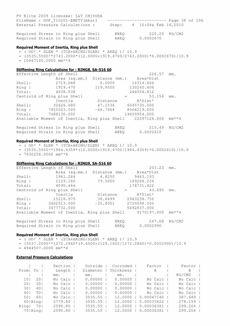
PV Elite 2009 Licensee: L&T CHIYODA FileName : GOF_T10201-EMPTY(mks)1 ------------- ----------- Page 38 of 106 External Pressure Calculations : Step: 4 10:04a Feb 16,2010 Required Stress in Ring plus Shell BREQ 220.20 KG/CM2 Required Strain in Ring plus Shell AREQ 0.0002670
Required Moment of Inertia, Ring plus Shell = ( OD² * SLEN * (TCA+ARING/SLEN) * AREQ )/ 10.9 = (3535.5500²*2743.2000*(12.0000+1919.4700/2743.2 000)*0.0002670)/10.9 = 10667100.0000 mm**4
Stiffening Ring Calculations for : RING8, SA-516 60 Effective Length of Shell 226.57 mm. Area (sq.mm.) Distance (mm.) A rea*Dist Shell: 2719.068 6.0000 163 14.406 Ring : 1919.470 119.9500 2302 40.406 Total: 4638.538 2465 54.812 Centroid of Ring plus Shell = 53.154 mm. Inertia Distance A *Dist² Shell: 32626.680 47.1536 60457 35.500 Ring : 7455503.500 -66.7964 85642 19.000 Total: 7488130.000 146099 54.000 Available Moment of Inertia, Ring plus Shell 22 097128.000 mm**4
Required Stress in Ring plus Shell BREQ 215.49 KG/CM2 Required Strain in Ring plus Shell AREQ 0.0002610
Required Moment of Inertia, Ring plus Shell = ( OD² * SLEN * (TCA+ARING/SLEN) * AREQ )/ 10.9 = (3535.5500²*1964.4359*(12.0000+1919.4700/1964.4 359)*0.0002610)/10.9 = 7630258.0000 mm**4
Stiffening Ring Calculations for : RING9, SA-516 60 Effective Length of Shell 203.23 mm. Area (sq.mm.) Distance (mm.) A rea*Dist Shell: 1961.284 4.8250 94 63.193 Ring : 2129.160 79.5000 1692 68.234 Total: 4090.444 1787 31.422 Centroid of Ring plus Shell = 43.695 mm. Inertia Distance A *Dist² Shell: 15218.975 38.8699 29632 38.750 Ring : 3462513.500 -35.8051 27295 98.500 Total: 3477732.500 56928 37.000 Available Moment of Inertia, Ring plus Shell 9 170197.000 mm**4
Required Stress in Ring plus Shell BREQ 247.08 KG/CM2 Required Strain in Ring plus Shell AREQ 0.0002990
Required Moment of Inertia, Ring plus Shell = ( OD² * SLEN * (TCA+ARING/SLEN) * AREQ )/ 10.9 = (3537.2000²*1272.2860*(9.6500+2129.1602/1272.28 60)*0.0002990)/10.9 = 4944507.0000 mm**4
External Pressure Calculations
| | Section | Outside | Corroded | Factor | Factor | From| To | Length | Diameter | Thickness | A | B | | | mm. | mm. | mm. | | KG/CM2 | 10| 20| No Calc | 0.00000 | 0.00000 | No Calc | No Calc | 20| 30| No Calc | 0.00000 | 0.00000 | No Calc | No Calc | 30| 40| No Calc | 0.00000 | 0.00000 | No Calc | No Calc | 40| 50| No Calc | 0.00000 | 0.00000 | No Calc | No Calc | 50| 60| No Calc | 3535.55 | 12.0000 | 0.00047140 | 387.689 | 60|Ring| 2779.80 | 3535.55 | 12.0000 | 0.00033822 | 278.159 | Ring| 70| 2590.80 | 3535.55 | 12.0000 | 0.00036381 | 299.204 | 70|Ring| 2590.80 | 3535.55 | 12.0000 | 0.00036381 | 299.204 |
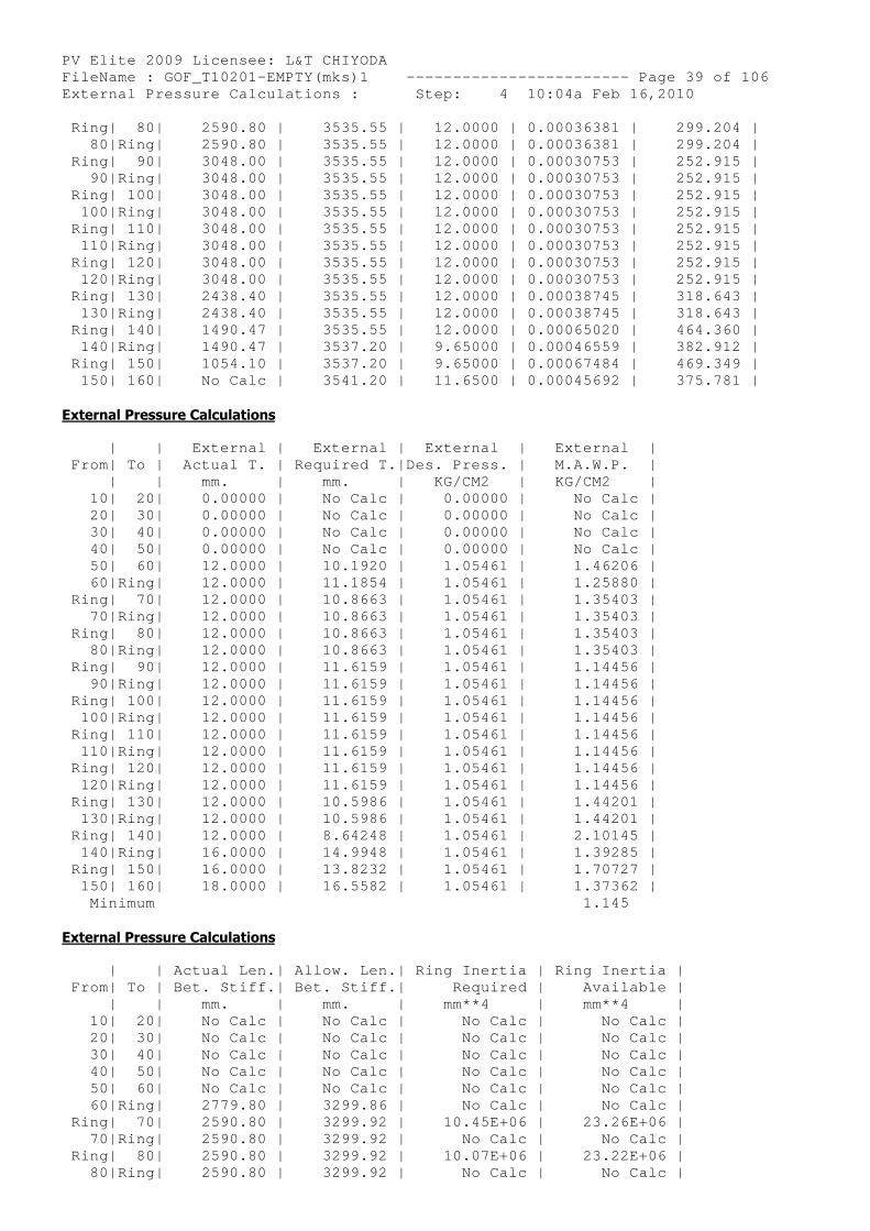
PV Elite 2009 Licensee: L&T CHIYODA FileName : GOF_T10201-EMPTY(mks)1 ------------- ----------- Page 39 of 106 External Pressure Calculations : Step: 4 10:04a Feb 16,2010 Ring| 80| 2590.80 | 3535.55 | 12.0000 | 0.00036381 | 299.204 | 80|Ring| 2590.80 | 3535.55 | 12.0000 | 0.00036381 | 299.204 | Ring| 90| 3048.00 | 3535.55 | 12.0000 | 0.00030753 | 252.915 | 90|Ring| 3048.00 | 3535.55 | 12.0000 | 0.00030753 | 252.915 | Ring| 100| 3048.00 | 3535.55 | 12.0000 | 0.00030753 | 252.915 | 100|Ring| 3048.00 | 3535.55 | 12.0000 | 0.00030753 | 252.915 | Ring| 110| 3048.00 | 3535.55 | 12.0000 | 0.00030753 | 252.915 | 110|Ring| 3048.00 | 3535.55 | 12.0000 | 0.00030753 | 252.915 | Ring| 120| 3048.00 | 3535.55 | 12.0000 | 0.00030753 | 252.915 | 120|Ring| 3048.00 | 3535.55 | 12.0000 | 0.00030753 | 252.915 | Ring| 130| 2438.40 | 3535.55 | 12.0000 | 0.00038745 | 318.643 | 130|Ring| 2438.40 | 3535.55 | 12.0000 | 0.00038745 | 318.643 | Ring| 140| 1490.47 | 3535.55 | 12.0000 | 0.00065020 | 464.360 | 140|Ring| 1490.47 | 3537.20 | 9.65000 | 0.00046559 | 382.912 | Ring| 150| 1054.10 | 3537.20 | 9.65000 | 0.00067484 | 469.349 | 150| 160| No Calc | 3541.20 | 11.6500 | 0.00045692 | 375.781 |
External Pressure Calculations
| | External | External | External | External | From| To | Actual T. | Required T.|Des. Press. | M.A.W.P. | | | mm. | mm. | KG/CM2 | KG/CM2 | 10| 20| 0.00000 | No Calc | 0.00000 | No Calc | 20| 30| 0.00000 | No Calc | 0.00000 | No Calc | 30| 40| 0.00000 | No Calc | 0.00000 | No Calc | 40| 50| 0.00000 | No Calc | 0.00000 | No Calc | 50| 60| 12.0000 | 10.1920 | 1.05461 | 1.46206 | 60|Ring| 12.0000 | 11.1854 | 1.05461 | 1.25880 | Ring| 70| 12.0000 | 10.8663 | 1.05461 | 1.35403 | 70|Ring| 12.0000 | 10.8663 | 1.05461 | 1.35403 | Ring| 80| 12.0000 | 10.8663 | 1.05461 | 1.35403 | 80|Ring| 12.0000 | 10.8663 | 1.05461 | 1.35403 | Ring| 90| 12.0000 | 11.6159 | 1.05461 | 1.14456 | 90|Ring| 12.0000 | 11.6159 | 1.05461 | 1.14456 | Ring| 100| 12.0000 | 11.6159 | 1.05461 | 1.14456 | 100|Ring| 12.0000 | 11.6159 | 1.05461 | 1.14456 | Ring| 110| 12.0000 | 11.6159 | 1.05461 | 1.14456 | 110|Ring| 12.0000 | 11.6159 | 1.05461 | 1.14456 | Ring| 120| 12.0000 | 11.6159 | 1.05461 | 1.14456 | 120|Ring| 12.0000 | 11.6159 | 1.05461 | 1.14456 | Ring| 130| 12.0000 | 10.5986 | 1.05461 | 1.44201 | 130|Ring| 12.0000 | 10.5986 | 1.05461 | 1.44201 | Ring| 140| 12.0000 | 8.64248 | 1.05461 | 2.10145 | 140|Ring| 16.0000 | 14.9948 | 1.05461 | 1.39285 | Ring| 150| 16.0000 | 13.8232 | 1.05461 | 1.70727 | 150| 160| 18.0000 | 16.5582 | 1.05461 | 1.37362 | Minimum 1.145
External Pressure Calculations
| | Actual Len.| Allow. Len.| Ring Inertia | Ring Inertia | From| To | Bet. Stiff.| Bet. Stiff.| Required | Available | | | mm. | mm. | mm**4 | mm**4 | 10| 20| No Calc | No Calc | No Calc | No Calc | 20| 30| No Calc | No Calc | No Calc | No Calc | 30| 40| No Calc | No Calc | No Calc | No Calc | 40| 50| No Calc | No Calc | No Calc | No Calc | 50| 60| No Calc | No Calc | No Calc | No Calc | 60|Ring| 2779.80 | 3299.86 | No Calc | No Calc | Ring| 70| 2590.80 | 3299.92 | 10.45E+06 | 23.26E+06 | 70|Ring| 2590.80 | 3299.92 | No Calc | No Calc | Ring| 80| 2590.80 | 3299.92 | 10.07E+06 | 23.22E+06 | 80|Ring| 2590.80 | 3299.92 | No Calc | No Calc |
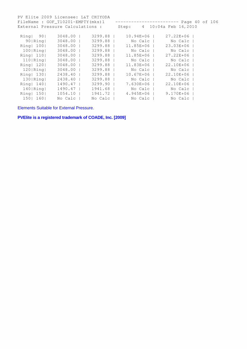
PV Elite 2009 Licensee: L&T CHIYODA FileName : GOF_T10201-EMPTY(mks)1 ------------- ----------- Page 40 of 106 External Pressure Calculations : Step: 4 10:04a Feb 16,2010 Ring| 90| 3048.00 | 3299.88 | 10.94E+06 | 27.22E+06 | 90|Ring| 3048.00 | 3299.88 | No Calc | No Calc | Ring| 100| 3048.00 | 3299.88 | 11.85E+06 | 23.03E+06 | 100|Ring| 3048.00 | 3299.88 | No Calc | No Calc | Ring| 110| 3048.00 | 3299.88 | 11.85E+06 | 27.22E+06 | 110|Ring| 3048.00 | 3299.88 | No Calc | No Calc | Ring| 120| 3048.00 | 3299.88 | 11.83E+06 | 22.10E+06 | 120|Ring| 3048.00 | 3299.88 | No Calc | No Calc | Ring| 130| 2438.40 | 3299.88 | 10.67E+06 | 22.10E+06 | 130|Ring| 2438.40 | 3299.88 | No Calc | No Calc | Ring| 140| 1490.47 | 3299.90 | 7.630E+06 | 22.10E+06 | 140|Ring| 1490.47 | 1941.68 | No Calc | No Calc | Ring| 150| 1054.10 | 1941.72 | 4.945E+06 | 9.170E+06 | 150| 160| No Calc | No Calc | No Calc | No Calc |
Elements Suitable for External Pressure.
PVElite is a registered trademark of COADE, Inc. [2009]
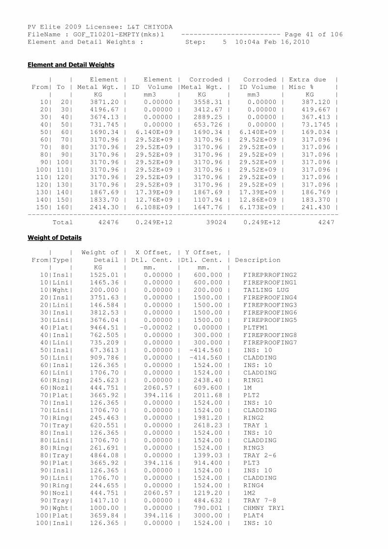
PV Elite 2009 Licensee: L&T CHIYODA FileName : GOF_T10201-EMPTY(mks)1 ------------- ----------- Page 41 of 106 Element and Detail Weights : Step: 5 10:04a Feb 16,2010
Element and Detail Weights
| | Element | Element | Corroded | Corroded | Extra due | From| To | Metal Wgt. | ID Volume |Metal Wgt. | ID Volume | Misc % | | | KG | mm3 | KG | mm3 | KG | 10| 20| 3871.20 | 0.00000 | 3558.31 | 0.00000 | 387.120 | 20| 30| 4196.67 | 0.00000 | 3412.67 | 0.00000 | 419.667 | 30| 40| 3674.13 | 0.00000 | 2889.25 | 0.00000 | 367.413 | 40| 50| 731.745 | 0.00000 | 653.726 | 0.00000 | 73.1745 | 50| 60| 1690.34 | 6.140E+09 | 1690.34 | 6.140E+09 | 169.034 | 60| 70| 3170.96 | 29.52E+09 | 3170.96 | 29.52E+09 | 317.096 | 70| 80| 3170.96 | 29.52E+09 | 3170.96 | 29.52E+09 | 317.096 | 80| 90| 3170.96 | 29.52E+09 | 3170.96 | 29.52E+09 | 317.096 | 90| 100| 3170.96 | 29.52E+09 | 3170.96 | 29.52E+09 | 317.096 | 100| 110| 3170.96 | 29.52E+09 | 3170.96 | 29.52E+09 | 317.096 | 110| 120| 3170.96 | 29.52E+09 | 3170.96 | 29.52E+09 | 317.096 | 120| 130| 3170.96 | 29.52E+09 | 3170.96 | 29.52E+09 | 317.096 | 130| 140| 1867.69 | 17.39E+09 | 1867.69 | 17.39E+09 | 186.769 | 140| 150| 1833.70 | 12.76E+09 | 1107.94 | 12.86E+09 | 183.370 | 150| 160| 2414.30 | 6.108E+09 | 1647.76 | 6.173E+09 | 241.430 | -------------------------------------------------- ------------------------- Total 42476 0.249E+12 39024 0.249E+12 4247
Weight of Details
| | Weight of | X Offset, | Y Offset, | From|Type| Detail | Dtl. Cent. |Dtl. Cent. | Description | | KG | mm. | mm. | 10|Insl| 1525.01 | 0.00000 | 600.000 | FIREPRROFING2 10|Lini| 1465.36 | 0.00000 | 600.000 | FIREPROOFING1 10|Wght| 200.000 | 0.00000 | 200.000 | TAILING LUG 20|Insl| 3751.63 | 0.00000 | 1500.00 | FIREPROOFING4 20|Lini| 146.584 | 0.00000 | 1500.00 | FIREPROOFING3 30|Insl| 3812.53 | 0.00000 | 1500.00 | FIREPROOFING6 30|Lini| 3676.04 | 0.00000 | 1500.00 | FIREPROOFING5 40|Plat| 9464.51 | -0.00002 | 0.00000 | PLTFM1 40|Insl| 762.505 | 0.00000 | 300.000 | FIREPROOFING8 40|Lini| 735.209 | 0.00000 | 300.000 | FIREPROOFING7 50|Insl| 67.3613 | 0.00000 | -414.560 | INS: 10 50|Lini| 909.786 | 0.00000 | -414.560 | CLADDING 60|Insl| 126.365 | 0.00000 | 1524.00 | INS: 10 60|Lini| 1706.70 | 0.00000 | 1524.00 | CLADDING 60|Ring| 245.623 | 0.00000 | 2438.40 | RING1 60|Nozl| 444.751 | 2060.57 | 609.600 | 1M 70|Plat| 3665.92 | 394.116 | 2011.68 | PLT2 70|Insl| 126.365 | 0.00000 | 1524.00 | INS: 10 70|Lini| 1706.70 | 0.00000 | 1524.00 | CLADDING 70|Ring| 245.463 | 0.00000 | 1981.20 | RING2 70|Tray| 620.551 | 0.00000 | 2618.23 | TRAY 1 80|Insl| 126.365 | 0.00000 | 1524.00 | INS: 10 80|Lini| 1706.70 | 0.00000 | 1524.00 | CLADDING 80|Ring| 261.691 | 0.00000 | 1524.00 | RING3 80|Tray| 4864.08 | 0.00000 | 1399.03 | TRAY 2-6 90|Plat| 3665.92 | 394.116 | 914.400 | PLT3 90|Insl| 126.365 | 0.00000 | 1524.00 | INS: 10 90|Lini| 1706.70 | 0.00000 | 1524.00 | CLADDING 90|Ring| 244.655 | 0.00000 | 1524.00 | RING4 90|Nozl| 444.751 | 2060.57 | 1219.20 | 1M2 90|Tray| 1417.10 | 0.00000 | 484.632 | TRAY 7-8 90|Wght| 1000.00 | 0.00000 | 790.001 | CHMNY TRY1 100|Plat| 3659.84 | 394.116 | 3000.00 | PLAT4 100|Insl| 126.365 | 0.00000 | 1524.00 | INS: 10
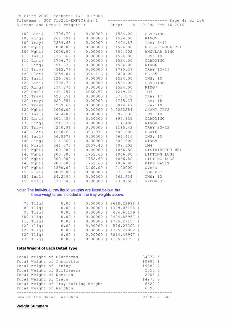
PV Elite 2009 Licensee: L&T CHIYODA FileName : GOF_T10201-EMPTY(mks)1 ------------- ----------- Page 42 of 106 Element and Detail Weights : Step: 5 10:04a Feb 16,2010 100|Lini| 1706.70 | 0.00000 | 1524.00 | CLADDING 100|Ring| 261.691 | 0.00000 | 1524.00 | RING5 100|Tray| 2389.65 | 0.00000 | 2404.87 | TRAY 9-11 100|Wght| 1000.00 | 0.00000 | 1524.00 | PLT + INSUL CLI 100|Wght| 1000.00 | 0.00000 | 500.002 | ANNULAR RING 110|Insl| 126.365 | 0.00000 | 1524.00 | INS: 10 110|Lini| 1706.70 | 0.00000 | 1524.00 | CLADDING 110|Ring| 194.876 | 0.00000 | 1524.00 | RING6 110|Tray| 4862.76 | 0.00000 | 1795.27 | TRAY 12-16 120|Plat| 3659.84 | 394.116 | 2000.00 | PLTA5 120|Insl| 126.365 | 0.00000 | 1524.00 | INS: 10 120|Lini| 1706.70 | 0.00000 | 1524.00 | CLADDING 120|Ring| 194.876 | 0.00000 | 1524.00 | RING7 120|Nozl| 444.751 | 2060.57 | 1219.20 | 1M3 120|Tray| 620.551 | 0.00000 | 576.072 | TRAY 17 120|Tray| 620.551 | 0.00000 | 1795.27 | TRAY 18 120|Tray| 1259.65 | 0.00000 | 3014.47 | TRAY 19 120|Wght| 1000.00 | 0.00000 | 0.0023254 | CHMNY TRY2 130|Insl| 74.4289 | 0.00000 | 897.636 | INS: 10 130|Lini| 502.487 | 0.00000 | 897.635 | CLADDING 130|Ring| 194.876 | 0.00000 | 914.400 | RING8 130|Tray| 4240.96 | 0.00000 | 1185.42 | TRAY 20-22 140|Plat| 4678.63 | 393.977 | 500.000 | PLAT6 140|Insl| 54.8678 | 0.00000 | 661.416 | INS: 10 140|Ring| 211.869 | 0.00000 | 609.600 | RING9 140|Nozl| 541.378 | 2057.40 | 609.602 | 1M4 140|Wght| 100.000 | 0.00000 | 1066.80 | DISTRIBUTOR WEI 140|Wght| 200.000 | 1752.60 | 1066.80 | LIFTING LUG1 140|Wght| 200.000 | 1752.60 | 1066.80 | LIFTING LUG2 140|Wght| 200.000 | 1752.60 | 1066.80 | PIPE DAVIT 140|Wght| 1890.00 | 2160.00 | 0.00000 | OVRHD 150|Plat| 6082.88 | 0.00000 | 876.300 | TOP PLT 150|Insl| 64.2494 | 0.00000 | 462.534 | INS: 10 150|Nozl| 133.040 | 0.00000 | 73.0250 | VAPOR OL
Note: The individual tray liquid weights are listed below, butthese weights are included in the tray weights above.
70|Tliq| 0.00 | 0.00000 | 2618.22998 | 80|Tliq| 0.00 | 0.00000 | 1399.03198 | 90|Tliq| 0.00 | 0.00000 | 484.63199 | 100|Tliq| 0.00 | 0.00000 | 2404.86987 | 110|Tliq| 0.00 | 0.00000 | 1795.27197 | 120|Tliq| 0.00 | 0.00000 | 576.07202 | 120|Tliq| 0.00 | 0.00000 | 1795.27002 | 120|Tliq| 0.00 | 0.00000 | 3014.46997 | 130|Tliq| 0.00 | 0.00000 | 1185.41797 |
Total Weight of Each Detail Type
Total Weight of Platforms 34877.5 Total Weight of Insulation 10997.1 Total Weight of Lining 19382.4 Total Weight of Stiffeners 2055.6 Total Weight of Nozzles 2008.7 Total Weight of Trays 14273.9 Total Weight of Tray Bolting Weight 6622.0 Total Weight of Weights 6790.0 -------------------------------------------------- ------------- Sum of the Detail Weights 97007.2 KG
Weight Summary
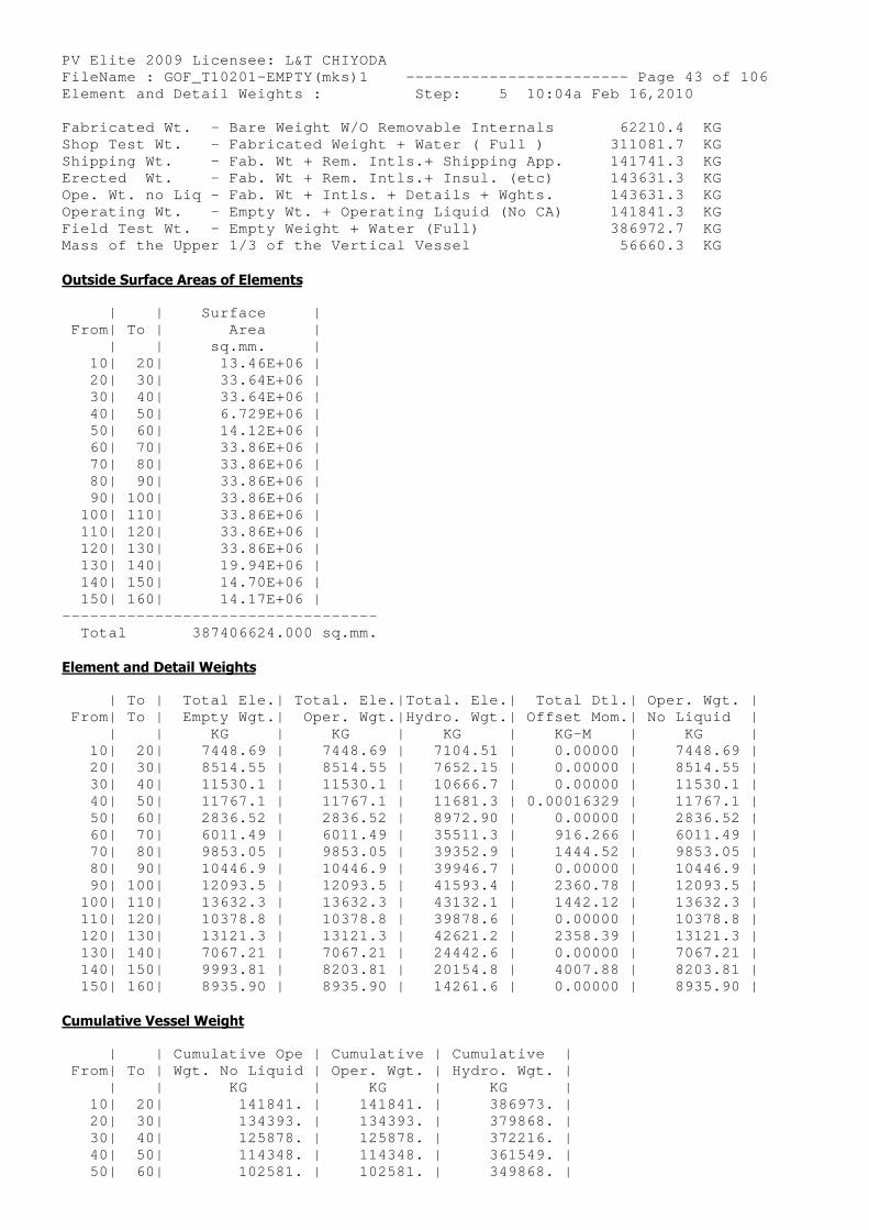
PV Elite 2009 Licensee: L&T CHIYODA FileName : GOF_T10201-EMPTY(mks)1 ------------- ----------- Page 43 of 106 Element and Detail Weights : Step: 5 10:04a Feb 16,2010 Fabricated Wt. - Bare Weight W/O Removable Intern als 62210.4 KG Shop Test Wt. - Fabricated Weight + Water ( Full ) 311081.7 KG Shipping Wt. - Fab. Wt + Rem. Intls.+ Shipping App. 141741.3 KG Erected Wt. - Fab. Wt + Rem. Intls.+ Insul. (e tc) 143631.3 KG Ope. Wt. no Liq - Fab. Wt + Intls. + Details + Wgh ts. 143631.3 KG Operating Wt. - Empty Wt. + Operating Liquid (No CA) 141841.3 KG Field Test Wt. - Empty Weight + Water (Full) 386972.7 KG Mass of the Upper 1/3 of the Vertical Vessel 56660.3 KG
Outside Surface Areas of Elements
| | Surface | From| To | Area | | | sq.mm. | 10| 20| 13.46E+06 | 20| 30| 33.64E+06 | 30| 40| 33.64E+06 | 40| 50| 6.729E+06 | 50| 60| 14.12E+06 | 60| 70| 33.86E+06 | 70| 80| 33.86E+06 | 80| 90| 33.86E+06 | 90| 100| 33.86E+06 | 100| 110| 33.86E+06 | 110| 120| 33.86E+06 | 120| 130| 33.86E+06 | 130| 140| 19.94E+06 | 140| 150| 14.70E+06 | 150| 160| 14.17E+06 | ---------------------------------- Total 387406624.000 sq.mm.
Element and Detail Weights
| To | Total Ele.| Total. Ele.|Total. Ele.| Total Dtl.| Oper. Wgt. | From| To | Empty Wgt.| Oper. Wgt.|Hydro. Wgt.| Offset Mom.| No Liquid | | | KG | KG | KG | KG-M | KG | 10| 20| 7448.69 | 7448.69 | 7104.51 | 0.00000 | 7448.69 | 20| 30| 8514.55 | 8514.55 | 7652.15 | 0.00000 | 8514.55 | 30| 40| 11530.1 | 11530.1 | 10666.7 | 0.00000 | 11530.1 | 40| 50| 11767.1 | 11767.1 | 11681.3 | 0.00016329 | 11767.1 | 50| 60| 2836.52 | 2836.52 | 8972.90 | 0.00000 | 2836.52 | 60| 70| 6011.49 | 6011.49 | 35511.3 | 916.266 | 6011.49 | 70| 80| 9853.05 | 9853.05 | 39352.9 | 1444.52 | 9853.05 | 80| 90| 10446.9 | 10446.9 | 39946.7 | 0.00000 | 10446.9 | 90| 100| 12093.5 | 12093.5 | 41593.4 | 2360.78 | 12093.5 | 100| 110| 13632.3 | 13632.3 | 43132.1 | 1442.12 | 13632.3 | 110| 120| 10378.8 | 10378.8 | 39878.6 | 0.00000 | 10378.8 | 120| 130| 13121.3 | 13121.3 | 42621.2 | 2358.39 | 13121.3 | 130| 140| 7067.21 | 7067.21 | 24442.6 | 0.00000 | 7067.21 | 140| 150| 9993.81 | 8203.81 | 20154.8 | 4007.88 | 8203.81 | 150| 160| 8935.90 | 8935.90 | 14261.6 | 0.00000 | 8935.90 |
Cumulative Vessel Weight
| | Cumulative Ope | Cumulative | Cumulati ve | From| To | Wgt. No Liquid | Oper. Wgt. | Hydro. W gt. | | | KG | KG | KG | 10| 20| 141841. | 141841. | 3869 73. | 20| 30| 134393. | 134393. | 3798 68. | 30| 40| 125878. | 125878. | 3722 16. | 40| 50| 114348. | 114348. | 3615 49. | 50| 60| 102581. | 102581. | 3498 68. |
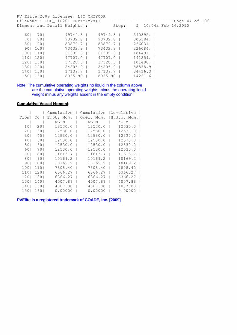
PV Elite 2009 Licensee: L&T CHIYODA FileName : GOF_T10201-EMPTY(mks)1 ------------- ----------- Page 44 of 106 Element and Detail Weights : Step: 5 10:04a Feb 16,2010 60| 70| 99744.3 | 99744.3 | 3408 95. | 70| 80| 93732.8 | 93732.8 | 3053 84. | 80| 90| 83879.7 | 83879.7 | 2660 31. | 90| 100| 73432.9 | 73432.9 | 2260 84. | 100| 110| 61339.3 | 61339.3 | 1844 91. | 110| 120| 47707.0 | 47707.0 | 1413 59. | 120| 130| 37328.3 | 37328.3 | 1014 80. | 130| 140| 24206.9 | 24206.9 | 5885 8.9 | 140| 150| 17139.7 | 17139.7 | 3441 6.3 | 150| 160| 8935.90 | 8935.90 | 1426 1.6 |
Note: The cumulative operating weights no liquid in the column aboveare the cumulative operating weights minus the operating liquidweight minus any weights absent in the empty condition.
Cumulative Vessel Moment
| | Cumulative | Cumulative |Cumulative | From| To | Empty Mom. | Oper. Mom. |Hydro. Mom.| | | KG-M | KG-M | KG-M | 10| 20| 12530.0 | 12530.0 | 12530.0 | 20| 30| 12530.0 | 12530.0 | 12530.0 | 30| 40| 12530.0 | 12530.0 | 12530.0 | 40| 50| 12530.0 | 12530.0 | 12530.0 | 50| 60| 12530.0 | 12530.0 | 12530.0 | 60| 70| 12530.0 | 12530.0 | 12530.0 | 70| 80| 11613.7 | 11613.7 | 11613.7 | 80| 90| 10169.2 | 10169.2 | 10169.2 | 90| 100| 10169.2 | 10169.2 | 10169.2 | 100| 110| 7808.40 | 7808.40 | 7808.40 | 110| 120| 6366.27 | 6366.27 | 6366.27 | 120| 130| 6366.27 | 6366.27 | 6366.27 | 130| 140| 4007.88 | 4007.88 | 4007.88 | 140| 150| 4007.88 | 4007.88 | 4007.88 | 150| 160| 0.00000 | 0.00000 | 0.00000 |
PVElite is a registered trademark of COADE, Inc. [2009]
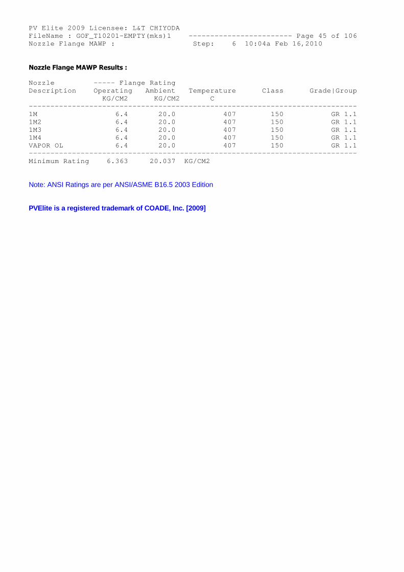
PV Elite 2009 Licensee: L&T CHIYODA FileName : GOF_T10201-EMPTY(mks)1 ------------- ----------- Page 45 of 106 Nozzle Flange MAWP : Step: 6 10:04a Feb 16,2010
Nozzle Flange MAWP Results :
Nozzle ----- Flange Rating Description Operating Ambient Temperature Class Grade|Group KG/CM2 KG/CM2 C -------------------------------------------------- -------------------------- 1M 6.4 20.0 407 150 GR 1.1 1M2 6.4 20.0 407 150 GR 1.1 1M3 6.4 20.0 407 150 GR 1.1 1M4 6.4 20.0 407 150 GR 1.1 VAPOR OL 6.4 20.0 407 150 GR 1.1 -------------------------------------------------- -------------------------- Minimum Rating 6.363 20.037 KG/CM2
Note: ANSI Ratings are per ANSI/ASME B16.5 2003 Edition
PVElite is a registered trademark of COADE, Inc. [2009]
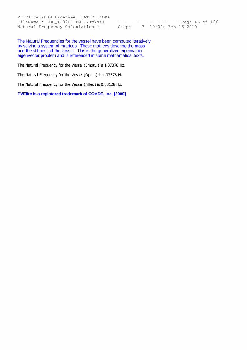
PV Elite 2009 Licensee: L&T CHIYODA FileName : GOF_T10201-EMPTY(mks)1 ------------- ----------- Page 46 of 106 Natural Frequency Calculation : Step: 7 10:04a Feb 16,2010
The Natural Frequencies for the vessel have been computed iterativelyby solving a system of matrices. These matrices describe the massand the stiffness of the vessel. This is the generalized eigenvalue/eigenvector problem and is referenced in some mathematical texts.
The Natural Frequency for the Vessel (Empty.) is 1.37378 Hz.
The Natural Frequency for the Vessel (Ope...) is 1.37378 Hz.
The Natural Frequency for the Vessel (Filled) is 0.88128 Hz.
PVElite is a registered trademark of COADE, Inc. [2009]
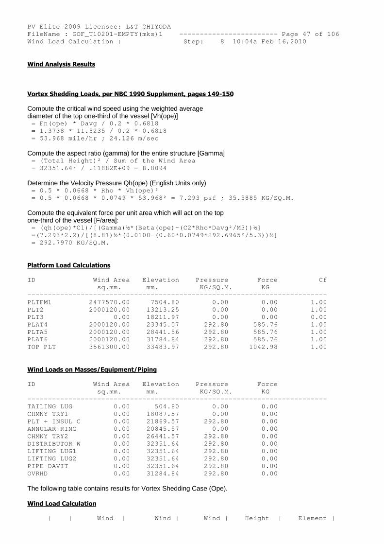
PV Elite 2009 Licensee: L&T CHIYODA FileName : GOF_T10201-EMPTY(mks)1 ------------- ----------- Page 47 of 106 Wind Load Calculation : Step: 8 10:04a Feb 16,2010
Wind Analysis Results
Vortex Shedding Loads, per NBC 1990 Supplement, pages 149-150
Compute the critical wind speed using the weighted averagediameter of the top one-third of the vessel [Vh(ope)]
= Fn(ope) * Davg / 0.2 * 0.6818 = 1.3738 * 11.5235 / 0.2 * 0.6818 = 53.968 mile/hr ; 24.126 m/sec
Compute the aspect ratio (gamma) for the entire structure [Gamma] = (Total Height)² / Sum of the Wind Area = 32351.64² / .11882E+09 = 8.8094
Determine the Velocity Pressure Qh(ope) (English Units only) = 0.5 * 0.0668 * Rho * Vh(ope)² = 0.5 * 0.0668 * 0.0749 * 53.968² = 7.293 psf ; 3 5.5885 KG/SQ.M.
Compute the equivalent force per unit area which will act on the topone-third of the vessel [F/area]:
= (qh(ope)*C1)/[(Gamma)½*(Beta(ope)-(C2*Rho*Davg² /M3))½] =(7.293*2.2)/[(8.81)½*(0.0100-(0.60*0.0749*292.69 65²/5.3))½] = 292.7970 KG/SQ.M.
Platform Load Calculations
ID Wind Area Elevation Pressure Force Cf sq.mm. mm. KG/SQ.M. KG -------------------------------------------------- ----------------------- PLTFM1 2477570.00 7504.80 0.00 0.00 1.00 PLT2 2000120.00 13213.25 0.00 0.00 1.00 PLT3 0.00 18211.97 0.00 0.00 0.00 PLAT4 2000120.00 23345.57 292.80 585.76 1.00 PLTA5 2000120.00 28441.56 292.80 585.76 1.00 PLAT6 2000120.00 31784.84 292.80 585.76 1.00 TOP PLT 3561300.00 33483.97 292.80 1042.98 1.00
Wind Loads on Masses/Equipment/Piping
ID Wind Area Elevation Pressure Force sq.mm. mm. KG/SQ.M. KG -------------------------------------------------- ----------------------- TAILING LUG 0.00 504.80 0.00 0.00 CHMNY TRY1 0.00 18087.57 0.00 0.00 PLT + INSUL C 0.00 21869.57 292.80 0.00 ANNULAR RING 0.00 20845.57 0.00 0.00 CHMNY TRY2 0.00 26441.57 292.80 0.00 DISTRIBUTOR W 0.00 32351.64 292.80 0.00 LIFTING LUG1 0.00 32351.64 292.80 0.00 LIFTING LUG2 0.00 32351.64 292.80 0.00 PIPE DAVIT 0.00 32351.64 292.80 0.00 OVRHD 0.00 31284.84 292.80 0.00
The following table contains results for Vortex Shedding Case (Ope).
Wind Load Calculation
| | Wind | Wind | Wind | Height | Element |
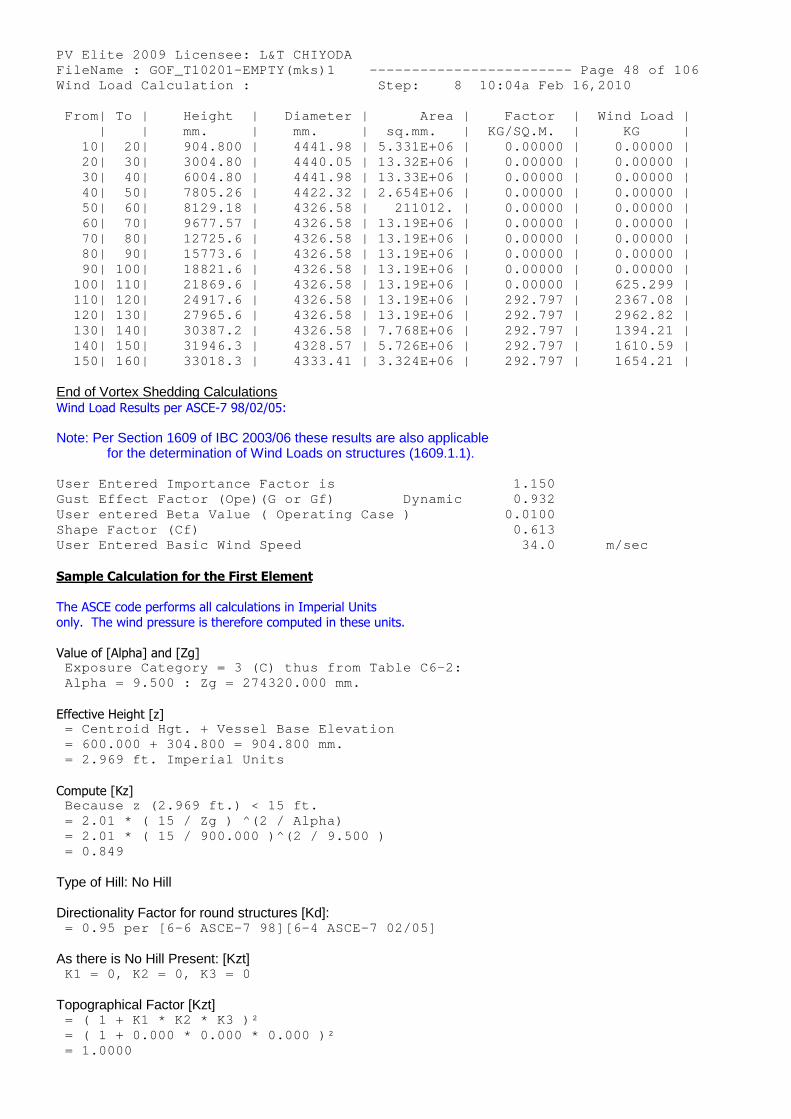
PV Elite 2009 Licensee: L&T CHIYODA FileName : GOF_T10201-EMPTY(mks)1 ------------- ----------- Page 48 of 106 Wind Load Calculation : Step: 8 10:04a Feb 16,2010 From| To | Height | Diameter | Area | Factor | Wind Load | | | mm. | mm. | sq.mm. | KG/SQ.M. | KG | 10| 20| 904.800 | 4441.98 | 5.331E+06 | 0.00000 | 0.00000 | 20| 30| 3004.80 | 4440.05 | 13.32E+06 | 0.00000 | 0.00000 | 30| 40| 6004.80 | 4441.98 | 13.33E+06 | 0.00000 | 0.00000 | 40| 50| 7805.26 | 4422.32 | 2.654E+06 | 0.00000 | 0.00000 | 50| 60| 8129.18 | 4326.58 | 211012. | 0.00000 | 0.00000 | 60| 70| 9677.57 | 4326.58 | 13.19E+06 | 0.00000 | 0.00000 | 70| 80| 12725.6 | 4326.58 | 13.19E+06 | 0.00000 | 0.00000 | 80| 90| 15773.6 | 4326.58 | 13.19E+06 | 0.00000 | 0.00000 | 90| 100| 18821.6 | 4326.58 | 13.19E+06 | 0.00000 | 0.00000 | 100| 110| 21869.6 | 4326.58 | 13.19E+06 | 0.00000 | 625.299 | 110| 120| 24917.6 | 4326.58 | 13.19E+06 | 292.797 | 2367.08 | 120| 130| 27965.6 | 4326.58 | 13.19E+06 | 292.797 | 2962.82 | 130| 140| 30387.2 | 4326.58 | 7.768E+06 | 292.797 | 1394.21 | 140| 150| 31946.3 | 4328.57 | 5.726E+06 | 292.797 | 1610.59 | 150| 160| 33018.3 | 4333.41 | 3.324E+06 | 292.797 | 1654.21 |
End of Vortex Shedding CalculationsWind Load Results per ASCE-7 98/02/05:
Note: Per Section 1609 of IBC 2003/06 these results are also applicablefor the determination of Wind Loads on structures (1609.1.1).
User Entered Importance Factor is 1.150 Gust Effect Factor (Ope)(G or Gf) Dynamic 0.932 User entered Beta Value ( Operating Case ) 0.0100 Shape Factor (Cf) 0.613 User Entered Basic Wind Speed 34.0 m/sec
Sample Calculation for the First Element
The ASCE code performs all calculations in Imperial Unitsonly. The wind pressure is therefore computed in these units.
Value of [Alpha] and [Zg] Exposure Category = 3 (C) thus from Table C6-2: Alpha = 9.500 : Zg = 274320.000 mm.
Effective Height [z] = Centroid Hgt. + Vessel Base Elevation = 600.000 + 304.800 = 904.800 mm. = 2.969 ft. Imperial Units
Compute [Kz] Because z (2.969 ft.) < 15 ft. = 2.01 * ( 15 / Zg ) ^(2 / Alpha) = 2.01 * ( 15 / 900.000 )^(2 / 9.500 ) = 0.849
Type of Hill: No Hill
Directionality Factor for round structures [Kd]: = 0.95 per [6-6 ASCE-7 98][6-4 ASCE-7 02/05]
As there is No Hill Present: [Kzt] K1 = 0, K2 = 0, K3 = 0
Topographical Factor [Kzt] = ( 1 + K1 * K2 * K3 )² = ( 1 + 0.000 * 0.000 * 0.000 )² = 1.0000
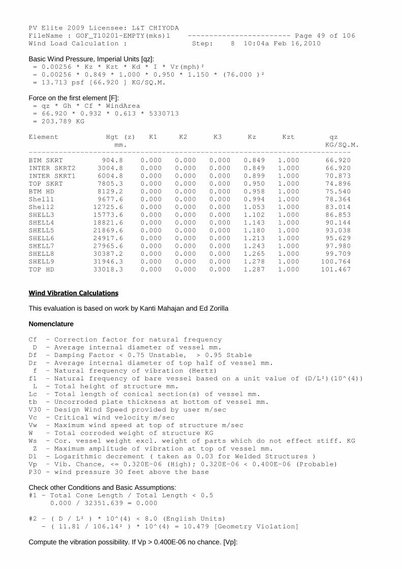
PV Elite 2009 Licensee: L&T CHIYODA FileName : GOF_T10201-EMPTY(mks)1 ------------- ----------- Page 49 of 106 Wind Load Calculation : Step: 8 10:04a Feb 16,2010
Basic Wind Pressure, Imperial Units [qz]: = 0.00256 * Kz * Kzt * Kd * I * Vr(mph)² = 0.00256 * 0.849 * 1.000 * 0.950 * 1.150 * (76.0 00 )² = 13.713 psf [66.920 ] KG/SQ.M.
Force on the first element [F]: = qz * Gh * Cf * WindArea = 66.920 * 0.932 * 0.613 * 5330713 = 203.789 KG
Element Hgt (z) K1 K2 K3 Kz Kzt qz mm. KG/SQ.M. -------------------------------------------------- ------------------------- BTM SKRT 904.8 0.000 0.000 0.000 0.849 1.000 66.920 INTER SKRT2 3004.8 0.000 0.000 0.000 0.849 1.000 66.920 INTER SKRT1 6004.8 0.000 0.000 0.000 0.899 1.000 70.873 TOP SKRT 7805.3 0.000 0.000 0.000 0.950 1.000 74.896 BTM HD 8129.2 0.000 0.000 0.000 0.958 1.000 75.540 Shell1 9677.6 0.000 0.000 0.000 0.994 1.000 78.364 Shell2 12725.6 0.000 0.000 0.000 1.053 1.000 83.014 SHELL3 15773.6 0.000 0.000 0.000 1.102 1.000 86.853 SHELL4 18821.6 0.000 0.000 0.000 1.143 1.000 90.144 SHELL5 21869.6 0.000 0.000 0.000 1.180 1.000 93.038 SHELL6 24917.6 0.000 0.000 0.000 1.213 1.000 95.629 SHELL7 27965.6 0.000 0.000 0.000 1.243 1.000 97.980 SHELL8 30387.2 0.000 0.000 0.000 1.265 1.000 99.709 SHELL9 31946.3 0.000 0.000 0.000 1.278 1.000 100.764 TOP HD 33018.3 0.000 0.000 0.000 1.287 1.000 101.467
Wind Vibration Calculations
This evaluation is based on work by Kanti Mahajan and Ed Zorilla
Nomenclature
Cf - Correction factor for natural frequency D - Average internal diameter of vessel mm. Df - Damping Factor < 0.75 Unstable, > 0.95 Stab le Dr - Average internal diameter of top half of ves sel mm. f - Natural frequency of vibration (Hertz) f1 - Natural frequency of bare vessel based on a unit value of (D/L²)(10^(4)) L - Total height of structure mm. Lc - Total length of conical section(s) of vessel mm. tb - Uncorroded plate thickness at bottom of vess el mm. V30 - Design Wind Speed provided by user m/sec Vc - Critical wind velocity m/sec Vw - Maximum wind speed at top of structure m/sec W - Total corroded weight of structure KG Ws - Cor. vessel weight excl. weight of parts whi ch do not effect stiff. KG Z - Maximum amplitude of vibration at top of ves sel mm. Dl - Logarithmic decrement ( taken as 0.03 for We lded Structures ) Vp - Vib. Chance, <= 0.320E-06 (High); 0.320E-06 < 0.400E-06 (Probable) P30 - wind pressure 30 feet above the base
Check other Conditions and Basic Assumptions: #1 - Total Cone Length / Total Length < 0.5 0.000 / 32351.639 = 0.000
#2 - ( D / L² ) * 10^(4) < 8.0 (English Units) - ( 11.81 / 106.14² ) * 10^(4) = 10.479 [Geomet ry Violation]
Compute the vibration possibility. If Vp > 0.400E-06 no chance. [Vp]:
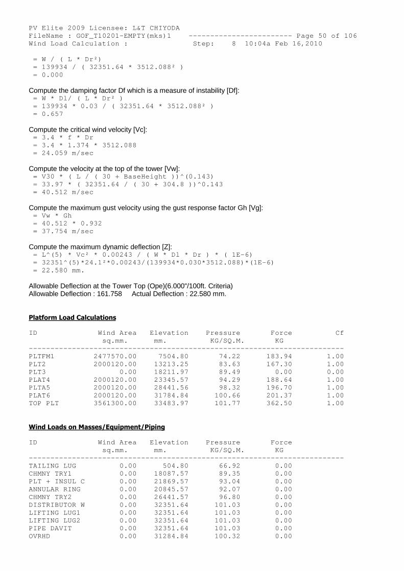
PV Elite 2009 Licensee: L&T CHIYODA FileName : GOF_T10201-EMPTY(mks)1 ------------- ----------- Page 50 of 106 Wind Load Calculation : Step: 8 10:04a Feb 16,2010 = W / ( L * Dr²) = 139934 / ( 32351.64 * 3512.088² ) = 0.000
Compute the damping factor Df which is a measure of instability [Df]: = W * Dl/ ( L * Dr² ) = 139934 * 0.03 / ( 32351.64 * 3512.088² ) = 0.657
Compute the critical wind velocity [Vc]: = 3.4 * f * Dr = 3.4 * 1.374 * 3512.088 = 24.059 m/sec
Compute the velocity at the top of the tower [Vw]: = V30 * ( L / ( 30 + BaseHeight ))^(0.143) = 33.97 * ( 32351.64 / ( 30 + 304.8 ))^0.143 = 40.512 m/sec
Compute the maximum gust velocity using the gust response factor Gh [Vg]: = Vw * Gh = 40.512 * 0.932 = 37.754 m/sec
Compute the maximum dynamic deflection [Z]: = L^(5) * Vc² * 0.00243 / ( W * Dl * Dr ) * ( 1E- 6) = 32351^(5)*24.1²*0.00243/(139934*0.030*3512.088) *(1E-6) = 22.580 mm.
Allowable Deflection at the Tower Top (Ope)(6.000"/100ft. Criteria)Allowable Deflection : 161.758 Actual Deflection : 22.580 mm.
Platform Load Calculations
ID Wind Area Elevation Pressure Force Cf sq.mm. mm. KG/SQ.M. KG -------------------------------------------------- ----------------------- PLTFM1 2477570.00 7504.80 74.22 183.94 1.00 PLT2 2000120.00 13213.25 83.63 167.30 1.00 PLT3 0.00 18211.97 89.49 0.00 0.00 PLAT4 2000120.00 23345.57 94.29 188.64 1.00 PLTA5 2000120.00 28441.56 98.32 196.70 1.00 PLAT6 2000120.00 31784.84 100.66 201.37 1.00 TOP PLT 3561300.00 33483.97 101.77 362.50 1.00
Wind Loads on Masses/Equipment/Piping
ID Wind Area Elevation Pressure Force sq.mm. mm. KG/SQ.M. KG -------------------------------------------------- ----------------------- TAILING LUG 0.00 504.80 66.92 0.00 CHMNY TRY1 0.00 18087.57 89.35 0.00 PLT + INSUL C 0.00 21869.57 93.04 0.00 ANNULAR RING 0.00 20845.57 92.07 0.00 CHMNY TRY2 0.00 26441.57 96.80 0.00 DISTRIBUTOR W 0.00 32351.64 101.03 0.00 LIFTING LUG1 0.00 32351.64 101.03 0.00 LIFTING LUG2 0.00 32351.64 101.03 0.00 PIPE DAVIT 0.00 32351.64 101.03 0.00 OVRHD 0.00 31284.84 100.32 0.00
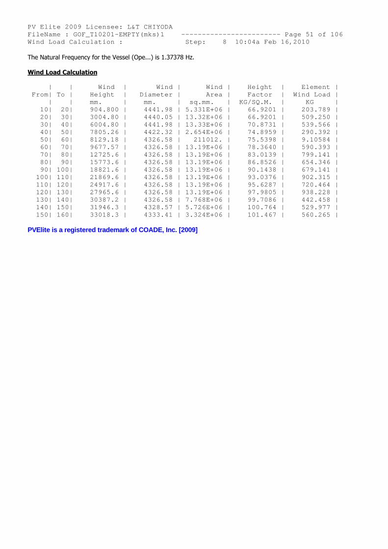
PV Elite 2009 Licensee: L&T CHIYODA FileName : GOF_T10201-EMPTY(mks)1 ------------- ----------- Page 51 of 106 Wind Load Calculation : Step: 8 10:04a Feb 16,2010 The Natural Frequency for the Vessel (Ope...) is 1.37378 Hz.
Wind Load Calculation
| | Wind | Wind | Wind | Height | Element | From| To | Height | Diameter | Area | Factor | Wind Load | | | mm. | mm. | sq.mm. | KG/SQ.M. | KG | 10| 20| 904.800 | 4441.98 | 5.331E+06 | 66.9201 | 203.789 | 20| 30| 3004.80 | 4440.05 | 13.32E+06 | 66.9201 | 509.250 | 30| 40| 6004.80 | 4441.98 | 13.33E+06 | 70.8731 | 539.566 | 40| 50| 7805.26 | 4422.32 | 2.654E+06 | 74.8959 | 290.392 | 50| 60| 8129.18 | 4326.58 | 211012. | 75.5398 | 9.10584 | 60| 70| 9677.57 | 4326.58 | 13.19E+06 | 78.3640 | 590.393 | 70| 80| 12725.6 | 4326.58 | 13.19E+06 | 83.0139 | 799.141 | 80| 90| 15773.6 | 4326.58 | 13.19E+06 | 86.8526 | 654.346 | 90| 100| 18821.6 | 4326.58 | 13.19E+06 | 90.1438 | 679.141 | 100| 110| 21869.6 | 4326.58 | 13.19E+06 | 93.0376 | 902.315 | 110| 120| 24917.6 | 4326.58 | 13.19E+06 | 95.6287 | 720.464 | 120| 130| 27965.6 | 4326.58 | 13.19E+06 | 97.9805 | 938.228 | 130| 140| 30387.2 | 4326.58 | 7.768E+06 | 99.7086 | 442.458 | 140| 150| 31946.3 | 4328.57 | 5.726E+06 | 100.764 | 529.977 | 150| 160| 33018.3 | 4333.41 | 3.324E+06 | 101.467 | 560.265 |
PVElite is a registered trademark of COADE, Inc. [2009]
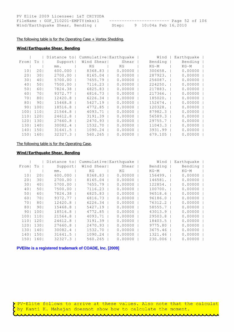
PV Elite 2009 Licensee: L&T CHIYODA FileName : GOF_T10201-EMPTY(mks)1 ------------- ----------- Page 52 of 106 Wind/Earthquake Shear, Bending : Step: 9 10:04a Feb 16,2010
The following table is for the Operating Case + Vortex Shedding.
Wind/Earthquake Shear, Bending
| | Distance to| Cummulative|Earthquake | Wind | Earthquake | From| To | Support| Wind Shear| Shear | Bending | Bending | | | mm. | KG | KG | KG-M | KG-M | 10| 20| 600.000 | 8368.83 | 0.00000 | 300658. | 0.00000 | 20| 30| 2700.00 | 8165.04 | 0.00000 | 287923. | 0.00000 | 30| 40| 5700.00 | 7655.79 | 0.00000 | 256087. | 0.00000 | 40| 50| 7500.00 | 7116.23 | 0.00000 | 224250. | 0.00000 | 50| 60| 7824.38 | 6825.83 | 0.00000 | 217883. | 0.00000 | 60| 70| 9372.77 | 6816.73 | 0.00000 | 217366. | 0.00000 | 70| 80| 12420.8 | 6226.34 | 0.00000 | 185020. | 0.00000 | 80| 90| 15468.8 | 5427.19 | 0.00000 | 152674. | 0.00000 | 90| 100| 18516.8 | 4772.85 | 0.00000 | 120328. | 0.00000 | 100| 110| 21564.8 | 4093.71 | 0.00000 | 87982.3 | 0.00000 | 110| 120| 24612.8 | 3191.39 | 0.00000 | 56589.3 | 0.00000 | 120| 130| 27660.8 | 2470.93 | 0.00000 | 29755.7 | 0.00000 | 130| 140| 30082.4 | 1532.70 | 0.00000 | 11043.3 | 0.00000 | 140| 150| 31641.5 | 1090.24 | 0.00000 | 3931.99 | 0.00000 | 150| 160| 32327.3 | 560.265 | 0.00000 | 679.105 | 0.00000 |
The following table is for the Operating Case.
Wind/Earthquake Shear, Bending
| | Distance to| Cummulative|Earthquake | Wind | Earthquake | From| To | Support| Wind Shear| Shear | Bending | Bending | | | mm. | KG | KG | KG-M | KG-M | 10| 20| 600.000 | 8368.83 | 0.00000 | 156499. | 0.00000 | 20| 30| 2700.00 | 8165.04 | 0.00000 | 146581. | 0.00000 | 30| 40| 5700.00 | 7655.79 | 0.00000 | 122854. | 0.00000 | 40| 50| 7500.00 | 7116.23 | 0.00000 | 100700. | 0.00000 | 50| 60| 7824.38 | 6825.83 | 0.00000 | 96518.6 | 0.00000 | 60| 70| 9372.77 | 6816.73 | 0.00000 | 96186.0 | 0.00000 | 70| 80| 12420.8 | 6226.34 | 0.00000 | 76312.2 | 0.00000 | 80| 90| 15468.8 | 5427.19 | 0.00000 | 58555.7 | 0.00000 | 90| 100| 18516.8 | 4772.85 | 0.00000 | 43013.9 | 0.00000 | 100| 110| 21564.8 | 4093.71 | 0.00000 | 29503.8 | 0.00000 | 110| 120| 24612.8 | 3191.39 | 0.00000 | 18403.5 | 0.00000 | 120| 130| 27660.8 | 2470.93 | 0.00000 | 9775.80 | 0.00000 | 130| 140| 30082.4 | 1532.70 | 0.00000 | 3675.46 | 0.00000 | 140| 150| 31641.5 | 1090.24 | 0.00000 | 1321.46 | 0.00000 | 150| 160| 32327.3 | 560.265 | 0.00000 | 230.006 | 0.00000 |
PVElite is a registered trademark of COADE, Inc. [2009]
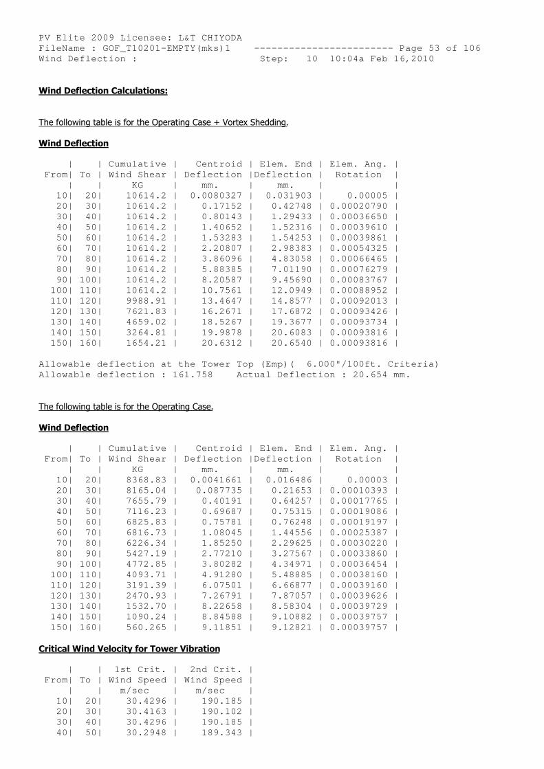
PV Elite 2009 Licensee: L&T CHIYODA FileName : GOF_T10201-EMPTY(mks)1 ------------- ----------- Page 53 of 106 Wind Deflection : Step: 10 10:04a Feb 16,2010
Wind Deflection Calculations:
The following table is for the Operating Case + Vortex Shedding.
Wind Deflection
| | Cumulative | Centroid | Elem. End | Elem. Ang. | From| To | Wind Shear | Deflection |Deflection | Rotation | | | KG | mm. | mm. | | 10| 20| 10614.2 | 0.0080327 | 0.031903 | 0.00005 | 20| 30| 10614.2 | 0.17152 | 0.42748 | 0.00020790 | 30| 40| 10614.2 | 0.80143 | 1.29433 | 0.00036650 | 40| 50| 10614.2 | 1.40652 | 1.52316 | 0.00039610 | 50| 60| 10614.2 | 1.53283 | 1.54253 | 0.00039861 | 60| 70| 10614.2 | 2.20807 | 2.98383 | 0.00054325 | 70| 80| 10614.2 | 3.86096 | 4.83058 | 0.00066465 | 80| 90| 10614.2 | 5.88385 | 7.01190 | 0.00076279 | 90| 100| 10614.2 | 8.20587 | 9.45690 | 0.00083767 | 100| 110| 10614.2 | 10.7561 | 12.0949 | 0.00088952 | 110| 120| 9988.91 | 13.4647 | 14.8577 | 0.00092013 | 120| 130| 7621.83 | 16.2671 | 17.6872 | 0.00093426 | 130| 140| 4659.02 | 18.5267 | 19.3677 | 0.00093734 | 140| 150| 3264.81 | 19.9878 | 20.6083 | 0.00093816 | 150| 160| 1654.21 | 20.6312 | 20.6540 | 0.00093816 |
Allowable deflection at the Tower Top (Emp)( 6.00 0"/100ft. Criteria) Allowable deflection : 161.758 Actual Deflectio n : 20.654 mm.
The following table is for the Operating Case.
Wind Deflection
| | Cumulative | Centroid | Elem. End | Elem. Ang. | From| To | Wind Shear | Deflection |Deflection | Rotation | | | KG | mm. | mm. | | 10| 20| 8368.83 | 0.0041661 | 0.016486 | 0.00003 | 20| 30| 8165.04 | 0.087735 | 0.21653 | 0.00010393 | 30| 40| 7655.79 | 0.40191 | 0.64257 | 0.00017765 | 40| 50| 7116.23 | 0.69687 | 0.75315 | 0.00019086 | 50| 60| 6825.83 | 0.75781 | 0.76248 | 0.00019197 | 60| 70| 6816.73 | 1.08045 | 1.44556 | 0.00025387 | 70| 80| 6226.34 | 1.85250 | 2.29625 | 0.00030220 | 80| 90| 5427.19 | 2.77210 | 3.27567 | 0.00033860 | 90| 100| 4772.85 | 3.80282 | 4.34971 | 0.00036454 | 100| 110| 4093.71 | 4.91280 | 5.48885 | 0.00038160 | 110| 120| 3191.39 | 6.07501 | 6.66877 | 0.00039160 | 120| 130| 2470.93 | 7.26791 | 7.87057 | 0.00039626 | 130| 140| 1532.70 | 8.22658 | 8.58304 | 0.00039729 | 140| 150| 1090.24 | 8.84588 | 9.10882 | 0.00039757 | 150| 160| 560.265 | 9.11851 | 9.12821 | 0.00039757 |
Critical Wind Velocity for Tower Vibration
| | 1st Crit. | 2nd Crit. | From| To | Wind Speed | Wind Speed | | | m/sec | m/sec | 10| 20| 30.4296 | 190.185 | 20| 30| 30.4163 | 190.102 | 30| 40| 30.4296 | 190.185 | 40| 50| 30.2948 | 189.343 |
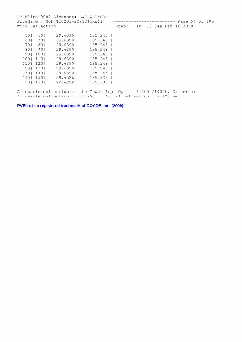
PV Elite 2009 Licensee: L&T CHIYODA FileName : GOF_T10201-EMPTY(mks)1 ------------- ----------- Page 54 of 106 Wind Deflection : Step: 10 10:04a Feb 16,2010 50| 60| 29.6390 | 185.243 | 60| 70| 29.6390 | 185.243 | 70| 80| 29.6390 | 185.243 | 80| 90| 29.6390 | 185.243 | 90| 100| 29.6390 | 185.243 | 100| 110| 29.6390 | 185.243 | 110| 120| 29.6390 | 185.243 | 120| 130| 29.6390 | 185.243 | 130| 140| 29.6390 | 185.243 | 140| 150| 29.6526 | 185.329 | 150| 160| 29.6858 | 185.536 |
Allowable deflection at the Tower Top (Ope)( 6.00 0"/100ft. Criteria) Allowable deflection : 161.758 Actual Deflectio n : 9.128 mm.
PVElite is a registered trademark of COADE, Inc. [2009]
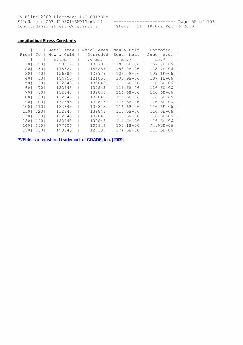
PV Elite 2009 Licensee: L&T CHIYODA FileName : GOF_T10201-EMPTY(mks)1 ------------- ----------- Page 55 of 106 Longitudinal Stress Constants : Step: 11 10:04a Feb 16,2010
Longitudinal Stress Constants
| | Metal Area | Metal Area |New & Cold | Corroded | From| To | New & Cold | Corroded |Sect. Mod. | Sect. Mod. | | | sq.mm. | sq.mm. | mm.³ | mm.³ | 10| 20| 223032. | 189738. | 196.8E+06 | 167.7E+06 | 20| 30| 178627. | 145257. | 158.0E+06 | 128.7E+06 | 30| 40| 156386. | 122978. | 138.5E+06 | 109.1E+06 | 40| 50| 154956. | 121855. | 135.9E+06 | 107.1E+06 | 50| 60| 132843. | 132843. | 116.6E+06 | 116.6E+06 | 60| 70| 132843. | 132843. | 116.6E+06 | 116.6E+06 | 70| 80| 132843. | 132843. | 116.6E+06 | 116.6E+06 | 80| 90| 132843. | 132843. | 116.6E+06 | 116.6E+06 | 90| 100| 132843. | 132843. | 116.6E+06 | 116.6E+06 | 100| 110| 132843. | 132843. | 116.6E+06 | 116.6E+06 | 110| 120| 132843. | 132843. | 116.6E+06 | 116.6E+06 | 120| 130| 132843. | 132843. | 116.6E+06 | 116.6E+06 | 130| 140| 132843. | 132843. | 116.6E+06 | 116.6E+06 | 140| 150| 177006. | 106949. | 155.1E+06 | 94.05E+06 | 150| 160| 199245. | 129189. | 174.6E+06 | 113.6E+06 |
PVElite is a registered trademark of COADE, Inc. [2009]
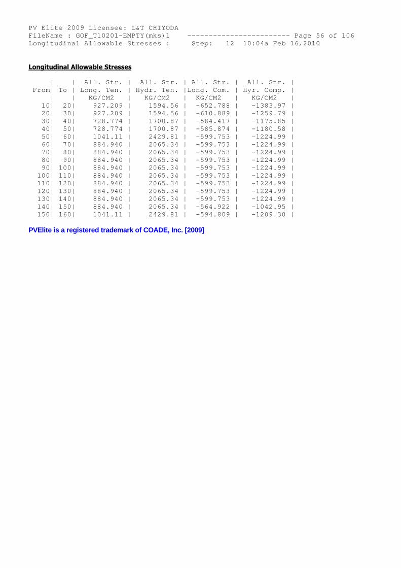
PV Elite 2009 Licensee: L&T CHIYODA FileName : GOF_T10201-EMPTY(mks)1 ------------- ----------- Page 56 of 106 Longitudinal Allowable Stresses : Step: 12 10:04a Feb 16,2010
Longitudinal Allowable Stresses
| | All. Str. | All. Str. | All. Str. | All. Str. | From| To | Long. Ten. | Hydr. Ten. |Long. Com. | Hyr. Comp. | | | KG/CM2 | KG/CM2 | KG/CM2 | KG/CM2 | 10| 20| 927.209 | 1594.56 | -652.788 | -1383.97 | 20| 30| 927.209 | 1594.56 | -610.889 | -1259.79 | 30| 40| 728.774 | 1700.87 | -584.417 | -1175.85 | 40| 50| 728.774 | 1700.87 | -585.874 | -1180.58 | 50| 60| 1041.11 | 2429.81 | -599.753 | -1224.99 | 60| 70| 884.940 | 2065.34 | -599.753 | -1224.99 | 70| 80| 884.940 | 2065.34 | -599.753 | -1224.99 | 80| 90| 884.940 | 2065.34 | -599.753 | -1224.99 | 90| 100| 884.940 | 2065.34 | -599.753 | -1224.99 | 100| 110| 884.940 | 2065.34 | -599.753 | -1224.99 | 110| 120| 884.940 | 2065.34 | -599.753 | -1224.99 | 120| 130| 884.940 | 2065.34 | -599.753 | -1224.99 | 130| 140| 884.940 | 2065.34 | -599.753 | -1224.99 | 140| 150| 884.940 | 2065.34 | -564.922 | -1042.95 | 150| 160| 1041.11 | 2429.81 | -594.809 | -1209.30 |
PVElite is a registered trademark of COADE, Inc. [2009]
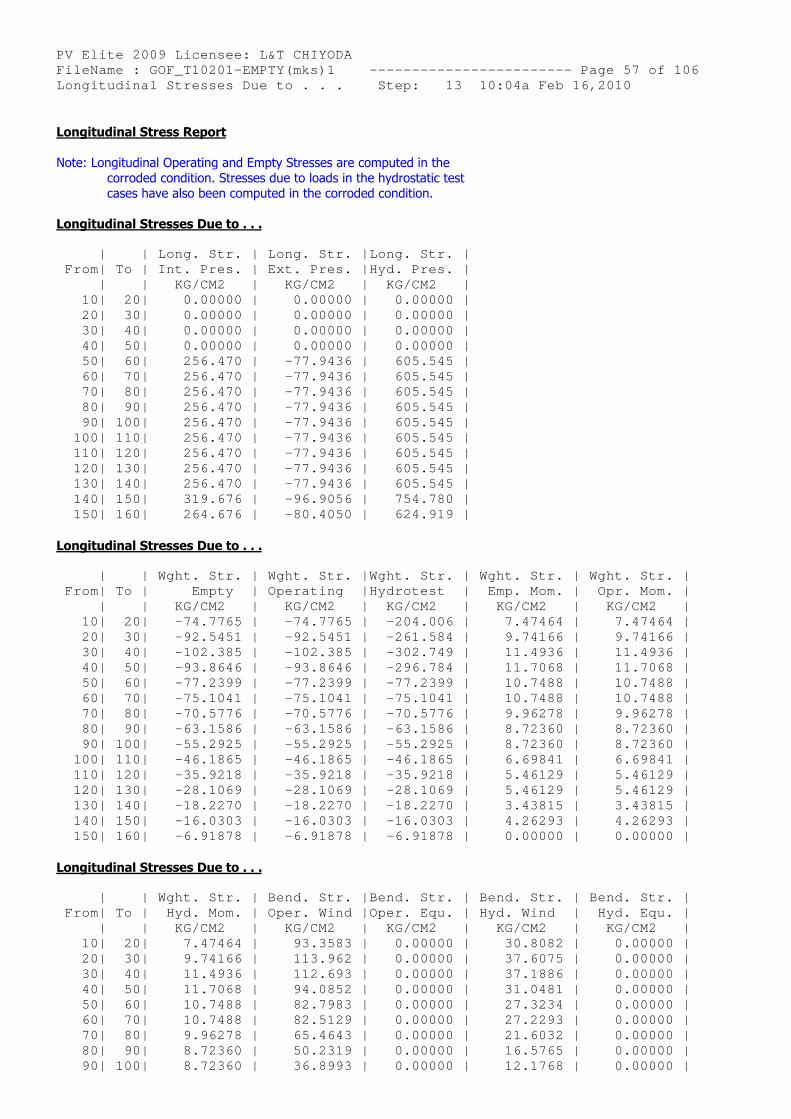
PV Elite 2009 Licensee: L&T CHIYODA FileName : GOF_T10201-EMPTY(mks)1 ------------- ----------- Page 57 of 106 Longitudinal Stresses Due to . . . Step: 13 10:04a Feb 16,2010
Longitudinal Stress Report
Note: Longitudinal Operating and Empty Stresses are computed in thecorroded condition. Stresses due to loads in the hydrostatic testcases have also been computed in the corroded condition.
Longitudinal Stresses Due to . . .
| | Long. Str. | Long. Str. |Long. Str. | From| To | Int. Pres. | Ext. Pres. |Hyd. Pres. | | | KG/CM2 | KG/CM2 | KG/CM2 | 10| 20| 0.00000 | 0.00000 | 0.00000 | 20| 30| 0.00000 | 0.00000 | 0.00000 | 30| 40| 0.00000 | 0.00000 | 0.00000 | 40| 50| 0.00000 | 0.00000 | 0.00000 | 50| 60| 256.470 | -77.9436 | 605.545 | 60| 70| 256.470 | -77.9436 | 605.545 | 70| 80| 256.470 | -77.9436 | 605.545 | 80| 90| 256.470 | -77.9436 | 605.545 | 90| 100| 256.470 | -77.9436 | 605.545 | 100| 110| 256.470 | -77.9436 | 605.545 | 110| 120| 256.470 | -77.9436 | 605.545 | 120| 130| 256.470 | -77.9436 | 605.545 | 130| 140| 256.470 | -77.9436 | 605.545 | 140| 150| 319.676 | -96.9056 | 754.780 | 150| 160| 264.676 | -80.4050 | 624.919 |
Longitudinal Stresses Due to . . .
| | Wght. Str. | Wght. Str. |Wght. Str. | Wght. Str. | Wght. Str. | From| To | Empty | Operating |Hydrotest | Emp. Mom. | Opr. Mom. | | | KG/CM2 | KG/CM2 | KG/CM2 | KG/CM2 | KG/CM2 | 10| 20| -74.7765 | -74.7765 | -204.006 | 7.47464 | 7.47464 | 20| 30| -92.5451 | -92.5451 | -261.584 | 9.74166 | 9.74166 | 30| 40| -102.385 | -102.385 | -302.749 | 11.4936 | 11.4936 | 40| 50| -93.8646 | -93.8646 | -296.784 | 11.7068 | 11.7068 | 50| 60| -77.2399 | -77.2399 | -77.2399 | 10.7488 | 10.7488 | 60| 70| -75.1041 | -75.1041 | -75.1041 | 10.7488 | 10.7488 | 70| 80| -70.5776 | -70.5776 | -70.5776 | 9.96278 | 9.96278 | 80| 90| -63.1586 | -63.1586 | -63.1586 | 8.72360 | 8.72360 | 90| 100| -55.2925 | -55.2925 | -55.2925 | 8.72360 | 8.72360 | 100| 110| -46.1865 | -46.1865 | -46.1865 | 6.69841 | 6.69841 | 110| 120| -35.9218 | -35.9218 | -35.9218 | 5.46129 | 5.46129 | 120| 130| -28.1069 | -28.1069 | -28.1069 | 5.46129 | 5.46129 | 130| 140| -18.2270 | -18.2270 | -18.2270 | 3.43815 | 3.43815 | 140| 150| -16.0303 | -16.0303 | -16.0303 | 4.26293 | 4.26293 | 150| 160| -6.91878 | -6.91878 | -6.91878 | 0.00000 | 0.00000 |
Longitudinal Stresses Due to . . .
| | Wght. Str. | Bend. Str. |Bend. Str. | Bend. Str. | Bend. Str. | From| To | Hyd. Mom. | Oper. Wind |Oper. Equ. | Hyd. Wind | Hyd. Equ. | | | KG/CM2 | KG/CM2 | KG/CM2 | KG/CM2 | KG/CM2 | 10| 20| 7.47464 | 93.3583 | 0.00000 | 30.8082 | 0.00000 | 20| 30| 9.74166 | 113.962 | 0.00000 | 37.6075 | 0.00000 | 30| 40| 11.4936 | 112.693 | 0.00000 | 37.1886 | 0.00000 | 40| 50| 11.7068 | 94.0852 | 0.00000 | 31.0481 | 0.00000 | 50| 60| 10.7488 | 82.7983 | 0.00000 | 27.3234 | 0.00000 | 60| 70| 10.7488 | 82.5129 | 0.00000 | 27.2293 | 0.00000 | 70| 80| 9.96278 | 65.4643 | 0.00000 | 21.6032 | 0.00000 | 80| 90| 8.72360 | 50.2319 | 0.00000 | 16.5765 | 0.00000 | 90| 100| 8.72360 | 36.8993 | 0.00000 | 12.1768 | 0.00000 |
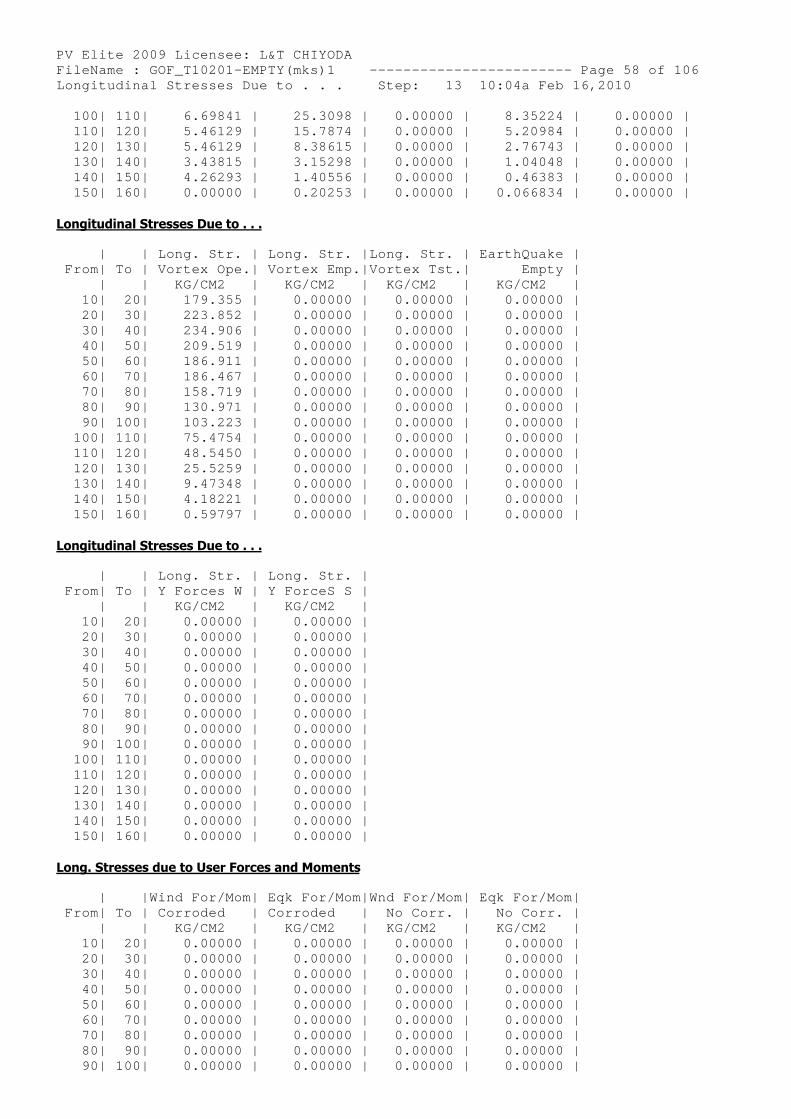
PV Elite 2009 Licensee: L&T CHIYODA FileName : GOF_T10201-EMPTY(mks)1 ------------- ----------- Page 58 of 106 Longitudinal Stresses Due to . . . Step: 13 10:04a Feb 16,2010 100| 110| 6.69841 | 25.3098 | 0.00000 | 8.35224 | 0.00000 | 110| 120| 5.46129 | 15.7874 | 0.00000 | 5.20984 | 0.00000 | 120| 130| 5.46129 | 8.38615 | 0.00000 | 2.76743 | 0.00000 | 130| 140| 3.43815 | 3.15298 | 0.00000 | 1.04048 | 0.00000 | 140| 150| 4.26293 | 1.40556 | 0.00000 | 0.46383 | 0.00000 | 150| 160| 0.00000 | 0.20253 | 0.00000 | 0.066834 | 0.00000 |
Longitudinal Stresses Due to . . .
| | Long. Str. | Long. Str. |Long. Str. | EarthQuake | From| To | Vortex Ope.| Vortex Emp.|Vortex Tst.| Empty | | | KG/CM2 | KG/CM2 | KG/CM2 | KG/CM2 | 10| 20| 179.355 | 0.00000 | 0.00000 | 0.00000 | 20| 30| 223.852 | 0.00000 | 0.00000 | 0.00000 | 30| 40| 234.906 | 0.00000 | 0.00000 | 0.00000 | 40| 50| 209.519 | 0.00000 | 0.00000 | 0.00000 | 50| 60| 186.911 | 0.00000 | 0.00000 | 0.00000 | 60| 70| 186.467 | 0.00000 | 0.00000 | 0.00000 | 70| 80| 158.719 | 0.00000 | 0.00000 | 0.00000 | 80| 90| 130.971 | 0.00000 | 0.00000 | 0.00000 | 90| 100| 103.223 | 0.00000 | 0.00000 | 0.00000 | 100| 110| 75.4754 | 0.00000 | 0.00000 | 0.00000 | 110| 120| 48.5450 | 0.00000 | 0.00000 | 0.00000 | 120| 130| 25.5259 | 0.00000 | 0.00000 | 0.00000 | 130| 140| 9.47348 | 0.00000 | 0.00000 | 0.00000 | 140| 150| 4.18221 | 0.00000 | 0.00000 | 0.00000 | 150| 160| 0.59797 | 0.00000 | 0.00000 | 0.00000 |
Longitudinal Stresses Due to . . .
| | Long. Str. | Long. Str. | From| To | Y Forces W | Y ForceS S | | | KG/CM2 | KG/CM2 | 10| 20| 0.00000 | 0.00000 | 20| 30| 0.00000 | 0.00000 | 30| 40| 0.00000 | 0.00000 | 40| 50| 0.00000 | 0.00000 | 50| 60| 0.00000 | 0.00000 | 60| 70| 0.00000 | 0.00000 | 70| 80| 0.00000 | 0.00000 | 80| 90| 0.00000 | 0.00000 | 90| 100| 0.00000 | 0.00000 | 100| 110| 0.00000 | 0.00000 | 110| 120| 0.00000 | 0.00000 | 120| 130| 0.00000 | 0.00000 | 130| 140| 0.00000 | 0.00000 | 140| 150| 0.00000 | 0.00000 | 150| 160| 0.00000 | 0.00000 |
Long. Stresses due to User Forces and Moments
| |Wind For/Mom| Eqk For/Mom|Wnd For/Mom| Eqk For/Mom| From| To | Corroded | Corroded | No Corr. | No Corr. | | | KG/CM2 | KG/CM2 | KG/CM2 | KG/CM2 | 10| 20| 0.00000 | 0.00000 | 0.00000 | 0.00000 | 20| 30| 0.00000 | 0.00000 | 0.00000 | 0.00000 | 30| 40| 0.00000 | 0.00000 | 0.00000 | 0.00000 | 40| 50| 0.00000 | 0.00000 | 0.00000 | 0.00000 | 50| 60| 0.00000 | 0.00000 | 0.00000 | 0.00000 | 60| 70| 0.00000 | 0.00000 | 0.00000 | 0.00000 | 70| 80| 0.00000 | 0.00000 | 0.00000 | 0.00000 | 80| 90| 0.00000 | 0.00000 | 0.00000 | 0.00000 | 90| 100| 0.00000 | 0.00000 | 0.00000 | 0.00000 |
PV Elite 2009 Licensee: L&T CHIYODA FileName : GOF_T10201-EMPTY(mks)1 ------------- ----------- Page 59 of 106 Longitudinal Stresses Due to . . . Step: 13 10:04a Feb 16,2010 100| 110| 0.00000 | 0.00000 | 0.00000 | 0.00000 | 110| 120| 0.00000 | 0.00000 | 0.00000 | 0.00000 | 120| 130| 0.00000 | 0.00000 | 0.00000 | 0.00000 | 130| 140| 0.00000 | 0.00000 | 0.00000 | 0.00000 | 140| 150| 0.00000 | 0.00000 | 0.00000 | 0.00000 | 150| 160| 0.00000 | 0.00000 | 0.00000 | 0.00000 |
PVElite is a registered trademark of COADE, Inc. [2009]
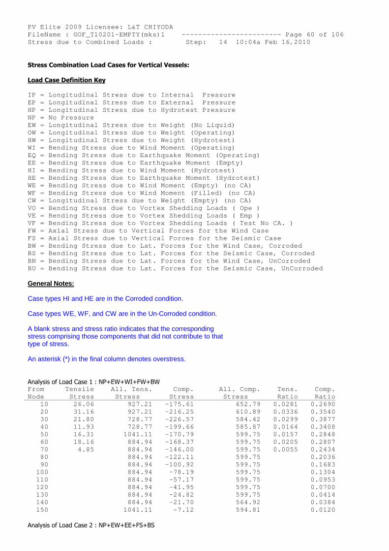
PV Elite 2009 Licensee: L&T CHIYODA FileName : GOF_T10201-EMPTY(mks)1 ------------- ----------- Page 60 of 106 Stress due to Combined Loads : Step: 14 10:04a Feb 16,2010
Stress Combination Load Cases for Vertical Vessels:
Load Case Definition Key
IP = Longitudinal Stress due to Internal Pressure EP = Longitudinal Stress due to External Pressure HP = Longitudinal Stress due to Hydrotest Pressure NP = No Pressure EW = Longitudinal Stress due to Weight (No Liquid) OW = Longitudinal Stress due to Weight (Operating) HW = Longitudinal Stress due to Weight (Hydrotest) WI = Bending Stress due to Wind Moment (Operating) EQ = Bending Stress due to Earthquake Moment (Oper ating) EE = Bending Stress due to Earthquake Moment (Empt y) HI = Bending Stress due to Wind Moment (Hydrotest) HE = Bending Stress due to Earthquake Moment (Hydr otest) WE = Bending Stress due to Wind Moment (Empty) (no CA) WF = Bending Stress due to Wind Moment (Filled) (n o CA) CW = Longitudinal Stress due to Weight (Empty) (no CA) VO = Bending Stress due to Vortex Shedding Loads ( Ope ) VE = Bending Stress due to Vortex Shedding Loads ( Emp ) VF = Bending Stress due to Vortex Shedding Loads ( Test No CA. ) FW = Axial Stress due to Vertical Forces for the W ind Case FS = Axial Stress due to Vertical Forces for the S eismic Case BW = Bending Stress due to Lat. Forces for the Win d Case, Corroded BS = Bending Stress due to Lat. Forces for the Sei smic Case, Corroded BN = Bending Stress due to Lat. Forces for the Win d Case, UnCorroded BU = Bending Stress due to Lat. Forces for the Sei smic Case, UnCorroded
General Notes:
Case types HI and HE are in the Corroded condition.
Case types WE, WF, and CW are in the Un-Corroded condition.
A blank stress and stress ratio indicates that the correspondingstress comprising those components that did not contribute to thattype of stress.
An asterisk (*) in the final column denotes overstress.
Analysis of Load Case 1 : NP+EW+WI+FW+BW From Tensile All. Tens. Comp. All. Comp. Tens. Comp. Node Stress Stress Stress Str ess Ratio Ratio 10 26.06 927.21 -175.61 652.79 0.0281 0.2690 20 31.16 927.21 -216.25 610.89 0.0336 0.3540 30 21.80 728.77 -226.57 584.42 0.0299 0.3877 40 11.93 728.77 -199.66 585.87 0.0164 0.3408 50 16.31 1041.11 -170.79 599.75 0.0157 0.2848 60 18.16 884.94 -168.37 599.75 0.0205 0.2807 70 4.85 884.94 -146.00 599.75 0.0055 0.2434 80 884.94 -122.11 599.75 0.2036 90 884.94 -100.92 599.75 0.1683 100 884.94 -78.19 599.75 0.1304 110 884.94 -57.17 599.75 0.0953 120 884.94 -41.95 599.75 0.0700 130 884.94 -24.82 599.75 0.0414 140 884.94 -21.70 564.92 0.0384 150 1041.11 -7.12 594.81 0.0120
Analysis of Load Case 2 : NP+EW+EE+FS+BS
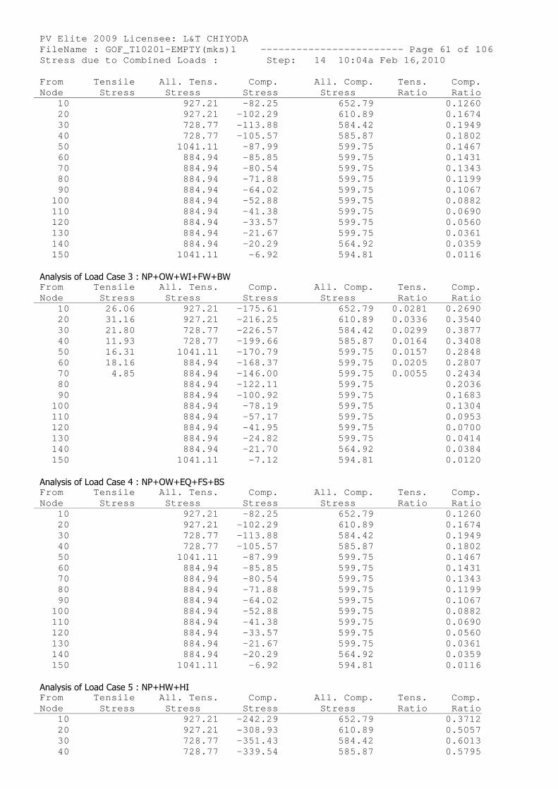
PV Elite 2009 Licensee: L&T CHIYODA FileName : GOF_T10201-EMPTY(mks)1 ------------- ----------- Page 61 of 106 Stress due to Combined Loads : Step: 14 10:04a Feb 16,2010 From Tensile All. Tens. Comp. All. Comp. Tens. Comp. Node Stress Stress Stress Str ess Ratio Ratio 10 927.21 -82.25 652.79 0.1260 20 927.21 -102.29 610.89 0.1674 30 728.77 -113.88 584.42 0.1949 40 728.77 -105.57 585.87 0.1802 50 1041.11 -87.99 599.75 0.1467 60 884.94 -85.85 599.75 0.1431 70 884.94 -80.54 599.75 0.1343 80 884.94 -71.88 599.75 0.1199 90 884.94 -64.02 599.75 0.1067 100 884.94 -52.88 599.75 0.0882 110 884.94 -41.38 599.75 0.0690 120 884.94 -33.57 599.75 0.0560 130 884.94 -21.67 599.75 0.0361 140 884.94 -20.29 564.92 0.0359 150 1041.11 -6.92 594.81 0.0116
Analysis of Load Case 3 : NP+OW+WI+FW+BW From Tensile All. Tens. Comp. All. Comp. Tens. Comp. Node Stress Stress Stress Str ess Ratio Ratio 10 26.06 927.21 -175.61 652.79 0.0281 0.2690 20 31.16 927.21 -216.25 610.89 0.0336 0.3540 30 21.80 728.77 -226.57 584.42 0.0299 0.3877 40 11.93 728.77 -199.66 585.87 0.0164 0.3408 50 16.31 1041.11 -170.79 599.75 0.0157 0.2848 60 18.16 884.94 -168.37 599.75 0.0205 0.2807 70 4.85 884.94 -146.00 599.75 0.0055 0.2434 80 884.94 -122.11 599.75 0.2036 90 884.94 -100.92 599.75 0.1683 100 884.94 -78.19 599.75 0.1304 110 884.94 -57.17 599.75 0.0953 120 884.94 -41.95 599.75 0.0700 130 884.94 -24.82 599.75 0.0414 140 884.94 -21.70 564.92 0.0384 150 1041.11 -7.12 594.81 0.0120
Analysis of Load Case 4 : NP+OW+EQ+FS+BS From Tensile All. Tens. Comp. All. Comp. Tens. Comp. Node Stress Stress Stress Str ess Ratio Ratio 10 927.21 -82.25 652.79 0.1260 20 927.21 -102.29 610.89 0.1674 30 728.77 -113.88 584.42 0.1949 40 728.77 -105.57 585.87 0.1802 50 1041.11 -87.99 599.75 0.1467 60 884.94 -85.85 599.75 0.1431 70 884.94 -80.54 599.75 0.1343 80 884.94 -71.88 599.75 0.1199 90 884.94 -64.02 599.75 0.1067 100 884.94 -52.88 599.75 0.0882 110 884.94 -41.38 599.75 0.0690 120 884.94 -33.57 599.75 0.0560 130 884.94 -21.67 599.75 0.0361 140 884.94 -20.29 564.92 0.0359 150 1041.11 -6.92 594.81 0.0116
Analysis of Load Case 5 : NP+HW+HI From Tensile All. Tens. Comp. All. Comp. Tens. Comp. Node Stress Stress Stress Str ess Ratio Ratio 10 927.21 -242.29 652.79 0.3712 20 927.21 -308.93 610.89 0.5057 30 728.77 -351.43 584.42 0.6013 40 728.77 -339.54 585.87 0.5795
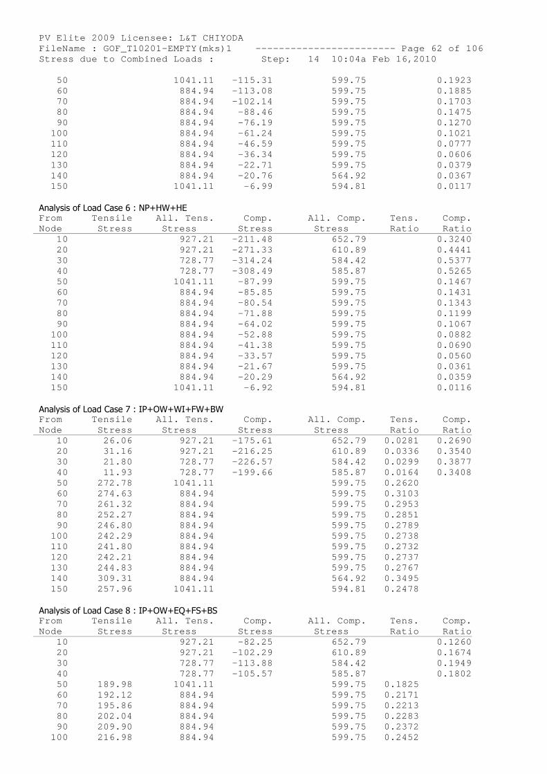
PV Elite 2009 Licensee: L&T CHIYODA FileName : GOF_T10201-EMPTY(mks)1 ------------- ----------- Page 62 of 106 Stress due to Combined Loads : Step: 14 10:04a Feb 16,2010 50 1041.11 -115.31 599.75 0.1923 60 884.94 -113.08 599.75 0.1885 70 884.94 -102.14 599.75 0.1703 80 884.94 -88.46 599.75 0.1475 90 884.94 -76.19 599.75 0.1270 100 884.94 -61.24 599.75 0.1021 110 884.94 -46.59 599.75 0.0777 120 884.94 -36.34 599.75 0.0606 130 884.94 -22.71 599.75 0.0379 140 884.94 -20.76 564.92 0.0367 150 1041.11 -6.99 594.81 0.0117
Analysis of Load Case 6 : NP+HW+HE From Tensile All. Tens. Comp. All. Comp. Tens. Comp. Node Stress Stress Stress Str ess Ratio Ratio 10 927.21 -211.48 652.79 0.3240 20 927.21 -271.33 610.89 0.4441 30 728.77 -314.24 584.42 0.5377 40 728.77 -308.49 585.87 0.5265 50 1041.11 -87.99 599.75 0.1467 60 884.94 -85.85 599.75 0.1431 70 884.94 -80.54 599.75 0.1343 80 884.94 -71.88 599.75 0.1199 90 884.94 -64.02 599.75 0.1067 100 884.94 -52.88 599.75 0.0882 110 884.94 -41.38 599.75 0.0690 120 884.94 -33.57 599.75 0.0560 130 884.94 -21.67 599.75 0.0361 140 884.94 -20.29 564.92 0.0359 150 1041.11 -6.92 594.81 0.0116
Analysis of Load Case 7 : IP+OW+WI+FW+BW From Tensile All. Tens. Comp. All. Comp. Tens. Comp. Node Stress Stress Stress Str ess Ratio Ratio 10 26.06 927.21 -175.61 652.79 0.0281 0.2690 20 31.16 927.21 -216.25 610.89 0.0336 0.3540 30 21.80 728.77 -226.57 584.42 0.0299 0.3877 40 11.93 728.77 -199.66 585.87 0.0164 0.3408 50 272.78 1041.11 599.75 0.2620 60 274.63 884.94 599.75 0.3103 70 261.32 884.94 599.75 0.2953 80 252.27 884.94 599.75 0.2851 90 246.80 884.94 599.75 0.2789 100 242.29 884.94 599.75 0.2738 110 241.80 884.94 599.75 0.2732 120 242.21 884.94 599.75 0.2737 130 244.83 884.94 599.75 0.2767 140 309.31 884.94 564.92 0.3495 150 257.96 1041.11 594.81 0.2478
Analysis of Load Case 8 : IP+OW+EQ+FS+BS From Tensile All. Tens. Comp. All. Comp. Tens. Comp. Node Stress Stress Stress Str ess Ratio Ratio 10 927.21 -82.25 652.79 0.1260 20 927.21 -102.29 610.89 0.1674 30 728.77 -113.88 584.42 0.1949 40 728.77 -105.57 585.87 0.1802 50 189.98 1041.11 599.75 0.1825 60 192.12 884.94 599.75 0.2171 70 195.86 884.94 599.75 0.2213 80 202.04 884.94 599.75 0.2283 90 209.90 884.94 599.75 0.2372 100 216.98 884.94 599.75 0.2452
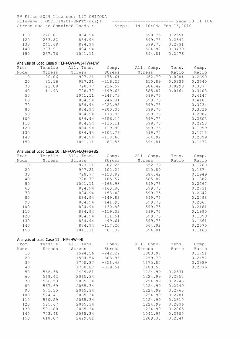
PV Elite 2009 Licensee: L&T CHIYODA FileName : GOF_T10201-EMPTY(mks)1 ------------- ----------- Page 63 of 106 Stress due to Combined Loads : Step: 14 10:04a Feb 16,2010 110 226.01 884.94 599.75 0.2554 120 233.82 884.94 599.75 0.2642 130 241.68 884.94 599.75 0.2731 140 307.91 884.94 564.92 0.3479 150 257.76 1041.11 594.81 0.2476
Analysis of Load Case 9 : EP+OW+WI+FW+BW From Tensile All. Tens. Comp. All. Comp. Tens. Comp. Node Stress Stress Stress Str ess Ratio Ratio 10 26.06 927.21 -175.61 652.79 0.0281 0.2690 20 31.16 927.21 -216.25 610.89 0.0336 0.3540 30 21.80 728.77 -226.57 584.42 0.0299 0.3877 40 11.93 728.77 -199.66 585.87 0.0164 0.3408 50 1041.11 -248.73 599.75 0.4147 60 884.94 -246.31 599.75 0.4107 70 884.94 -223.95 599.75 0.3734 80 884.94 -200.06 599.75 0.3336 90 884.94 -178.86 599.75 0.2982 100 884.94 -156.14 599.75 0.2603 110 884.94 -135.11 599.75 0.2253 120 884.94 -119.90 599.75 0.1999 130 884.94 -102.76 599.75 0.1713 140 884.94 -118.60 564.92 0.2099 150 1041.11 -87.53 594.81 0.1472
Analysis of Load Case 10 : EP+OW+EQ+FS+BS From Tensile All. Tens. Comp. All. Comp. Tens. Comp. Node Stress Stress Stress Str ess Ratio Ratio 10 927.21 -82.25 652.79 0.1260 20 927.21 -102.29 610.89 0.1674 30 728.77 -113.88 584.42 0.1949 40 728.77 -105.57 585.87 0.1802 50 1041.11 -165.93 599.75 0.2767 60 884.94 -163.80 599.75 0.2731 70 884.94 -158.48 599.75 0.2642 80 884.94 -149.83 599.75 0.2498 90 884.94 -141.96 599.75 0.2367 100 884.94 -130.83 599.75 0.2181 110 884.94 -119.33 599.75 0.1990 120 884.94 -111.51 599.75 0.1859 130 884.94 -99.61 599.75 0.1661 140 884.94 -117.20 564.92 0.2075 150 1041.11 -87.32 594.81 0.1468
Analysis of Load Case 11 : HP+HW+HI From Tensile All. Tens. Comp. All. Comp. Tens. Comp. Node Stress Stress Stress Str ess Ratio Ratio 10 1594.56 -242.29 1 383.97 0.1751 20 1594.56 -308.93 1 259.79 0.2452 30 1700.87 -351.43 1 175.85 0.2989 40 1700.87 -339.54 1 180.58 0.2876 50 566.38 2429.81 1 224.99 0.2331 60 568.42 2065.34 1 224.99 0.2752 70 566.53 2065.34 1 224.99 0.2743 80 567.69 2065.34 1 224.99 0.2749 90 571.15 2065.34 1 224.99 0.2765 100 574.41 2065.34 1 224.99 0.2781 110 580.29 2065.34 1 224.99 0.2810 120 585.67 2065.34 1 224.99 0.2836 130 591.80 2065.34 1 224.99 0.2865 140 743.48 2065.34 1 042.95 0.3600 150 618.07 2429.81 1 209.30 0.2544
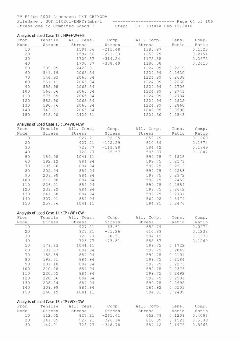
PV Elite 2009 Licensee: L&T CHIYODA FileName : GOF_T10201-EMPTY(mks)1 ------------- ----------- Page 64 of 106 Stress due to Combined Loads : Step: 14 10:04a Feb 16,2010 Analysis of Load Case 12 : HP+HW+HE
From Tensile All. Tens. Comp. All. Comp. Tens. Comp. Node Stress Stress Stress Str ess Ratio Ratio 10 1594.56 -211.48 1 383.97 0.1528 20 1594.56 -271.33 1 259.79 0.2154 30 1700.87 -314.24 1 175.85 0.2672 40 1700.87 -308.49 1 180.58 0.2613 50 539.05 2429.81 1 224.99 0.2219 60 541.19 2065.34 1 224.99 0.2620 70 544.93 2065.34 1 224.99 0.2638 80 551.11 2065.34 1 224.99 0.2668 90 558.98 2065.34 1 224.99 0.2706 100 566.06 2065.34 1 224.99 0.2741 110 575.09 2065.34 1 224.99 0.2784 120 582.90 2065.34 1 224.99 0.2822 130 590.76 2065.34 1 224.99 0.2860 140 743.01 2065.34 1 042.95 0.3598 150 618.00 2429.81 1 209.30 0.2543
Analysis of Load Case 13 : IP+WE+EW From Tensile All. Tens. Comp. All. Comp. Tens. Comp. Node Stress Stress Stress Str ess Ratio Ratio 10 927.21 -82.25 652.79 0.1260 20 927.21 -102.29 610.89 0.1674 30 728.77 -113.88 584.42 0.1949 40 728.77 -105.57 585.87 0.1802 50 189.98 1041.11 599.75 0.1825 60 192.12 884.94 599.75 0.2171 70 195.86 884.94 599.75 0.2213 80 202.04 884.94 599.75 0.2283 90 209.90 884.94 599.75 0.2372 100 216.98 884.94 599.75 0.2452 110 226.01 884.94 599.75 0.2554 120 233.82 884.94 599.75 0.2642 130 241.68 884.94 599.75 0.2731 140 307.91 884.94 564.92 0.3479 150 257.76 1041.11 594.81 0.2476
Analysis of Load Case 14 : IP+WF+CW From Tensile All. Tens. Comp. All. Comp. Tens. Comp. Node Stress Stress Stress Str ess Ratio Ratio 10 927.21 -63.61 652.79 0.0974 20 927.21 -75.26 610.89 0.1232 30 728.77 -80.51 584.42 0.1378 40 728.77 -73.81 585.87 0.1260 50 179.23 1041.11 599.75 0.1722 60 181.37 884.94 599.75 0.2049 70 185.89 884.94 599.75 0.2101 80 193.31 884.94 599.75 0.2184 90 201.18 884.94 599.75 0.2273 100 210.28 884.94 599.75 0.2376 110 220.55 884.94 599.75 0.2492 120 228.36 884.94 599.75 0.2581 130 238.24 884.94 599.75 0.2692 140 309.99 884.94 564.92 0.3503 150 260.19 1041.11 594.81 0.2499
Analysis of Load Case 15 : IP+VO+OW From Tensile All. Tens. Comp. All. Comp. Tens. Comp. Node Stress Stress Stress Str ess Ratio Ratio 10 112.05 927.21 -261.61 652.79 0.1209 0.4008 20 141.05 927.21 -326.14 610.89 0.1521 0.5339 30 144.01 728.77 -348.78 584.42 0.1976 0.5968
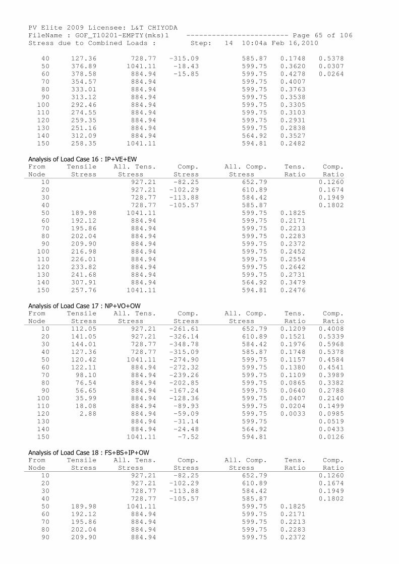
PV Elite 2009 Licensee: L&T CHIYODA FileName : GOF_T10201-EMPTY(mks)1 ------------- ----------- Page 65 of 106 Stress due to Combined Loads : Step: 14 10:04a Feb 16,2010 40 127.36 728.77 -315.09 585.87 0.1748 0.5378 50 376.89 1041.11 -18.43 599.75 0.3620 0.0307 60 378.58 884.94 -15.85 599.75 0.4278 0.0264 70 354.57 884.94 599.75 0.4007 80 333.01 884.94 599.75 0.3763 90 313.12 884.94 599.75 0.3538 100 292.46 884.94 599.75 0.3305 110 274.55 884.94 599.75 0.3103 120 259.35 884.94 599.75 0.2931 130 251.16 884.94 599.75 0.2838 140 312.09 884.94 564.92 0.3527 150 258.35 1041.11 594.81 0.2482
Analysis of Load Case 16 : IP+VE+EW From Tensile All. Tens. Comp. All. Comp. Tens. Comp. Node Stress Stress Stress Str ess Ratio Ratio 10 927.21 -82.25 652.79 0.1260 20 927.21 -102.29 610.89 0.1674 30 728.77 -113.88 584.42 0.1949 40 728.77 -105.57 585.87 0.1802 50 189.98 1041.11 599.75 0.1825 60 192.12 884.94 599.75 0.2171 70 195.86 884.94 599.75 0.2213 80 202.04 884.94 599.75 0.2283 90 209.90 884.94 599.75 0.2372 100 216.98 884.94 599.75 0.2452 110 226.01 884.94 599.75 0.2554 120 233.82 884.94 599.75 0.2642 130 241.68 884.94 599.75 0.2731 140 307.91 884.94 564.92 0.3479 150 257.76 1041.11 594.81 0.2476
Analysis of Load Case 17 : NP+VO+OW From Tensile All. Tens. Comp. All. Comp. Tens. Comp. Node Stress Stress Stress Str ess Ratio Ratio 10 112.05 927.21 -261.61 652.79 0.1209 0.4008 20 141.05 927.21 -326.14 610.89 0.1521 0.5339 30 144.01 728.77 -348.78 584.42 0.1976 0.5968 40 127.36 728.77 -315.09 585.87 0.1748 0.5378 50 120.42 1041.11 -274.90 599.75 0.1157 0.4584 60 122.11 884.94 -272.32 599.75 0.1380 0.4541 70 98.10 884.94 -239.26 599.75 0.1109 0.3989 80 76.54 884.94 -202.85 599.75 0.0865 0.3382 90 56.65 884.94 -167.24 599.75 0.0640 0.2788 100 35.99 884.94 -128.36 599.75 0.0407 0.2140 110 18.08 884.94 -89.93 599.75 0.0204 0.1499 120 2.88 884.94 -59.09 599.75 0.0033 0.0985 130 884.94 -31.14 599.75 0.0519 140 884.94 -24.48 564.92 0.0433 150 1041.11 -7.52 594.81 0.0126
Analysis of Load Case 18 : FS+BS+IP+OW From Tensile All. Tens. Comp. All. Comp. Tens. Comp. Node Stress Stress Stress Str ess Ratio Ratio 10 927.21 -82.25 652.79 0.1260 20 927.21 -102.29 610.89 0.1674 30 728.77 -113.88 584.42 0.1949 40 728.77 -105.57 585.87 0.1802 50 189.98 1041.11 599.75 0.1825 60 192.12 884.94 599.75 0.2171 70 195.86 884.94 599.75 0.2213 80 202.04 884.94 599.75 0.2283 90 209.90 884.94 599.75 0.2372
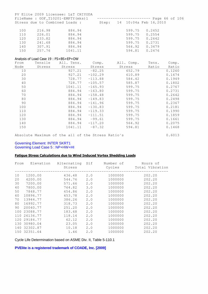
PV Elite 2009 Licensee: L&T CHIYODA FileName : GOF_T10201-EMPTY(mks)1 ------------- ----------- Page 66 of 106 Stress due to Combined Loads : Step: 14 10:04a Feb 16,2010 100 216.98 884.94 599.75 0.2452 110 226.01 884.94 599.75 0.2554 120 233.82 884.94 599.75 0.2642 130 241.68 884.94 599.75 0.2731 140 307.91 884.94 564.92 0.3479 150 257.76 1041.11 594.81 0.2476
Analysis of Load Case 19 : FS+BS+EP+OW From Tensile All. Tens. Comp. All. Comp. Tens. Comp. Node Stress Stress Stress Str ess Ratio Ratio 10 927.21 -82.25 652.79 0.1260 20 927.21 -102.29 610.89 0.1674 30 728.77 -113.88 584.42 0.1949 40 728.77 -105.57 585.87 0.1802 50 1041.11 -165.93 599.75 0.2767 60 884.94 -163.80 599.75 0.2731 70 884.94 -158.48 599.75 0.2642 80 884.94 -149.83 599.75 0.2498 90 884.94 -141.96 599.75 0.2367 100 884.94 -130.83 599.75 0.2181 110 884.94 -119.33 599.75 0.1990 120 884.94 -111.51 599.75 0.1859 130 884.94 -99.61 599.75 0.1661 140 884.94 -117.20 564.92 0.2075 150 1041.11 -87.32 594.81 0.1468
Absolute Maximum of the all of the Stress Ratio's 0.6013
Governing Element: INTER SKRT1Governing Load Case 5 : NP+HW+HI
Fatigue Stress Calculations due to Wind Induced Vortex Shedding Loads
From Elevation Alternating Sif Number of Hours of Stress Cycles Total Vibration -------------------------------------------------- ------------------- 10 1200.00 436.48 2.0 1000000 202.20 20 4200.00 544.76 2.0 1000000 202.20 30 7200.00 571.66 2.0 1000000 202.20 40 7800.00 764.82 3.0 1000000 202.20 50 7848.77 454.86 2.0 1000000 202.20 60 10896.77 453.78 2.0 1000000 202.20 70 13944.77 386.26 2.0 1000000 202.20 80 16992.77 318.73 2.0 1000000 202.20 90 20040.77 251.20 2.0 1000000 202.20 100 23088.77 183.68 2.0 1000000 202.20 110 26136.77 118.14 2.0 1000000 202.20 120 29184.77 62.12 2.0 1000000 202.20 130 30980.04 23.05 2.0 1000000 202.20 140 32302.87 10.18 2.0 1000000 202.20 150 32351.64 1.46 2.0 1000000 202.20
Cycle Life Determination based on ASME Div. II, Table 5-110.1
PVElite is a registered trademark of COADE, Inc. [2009]
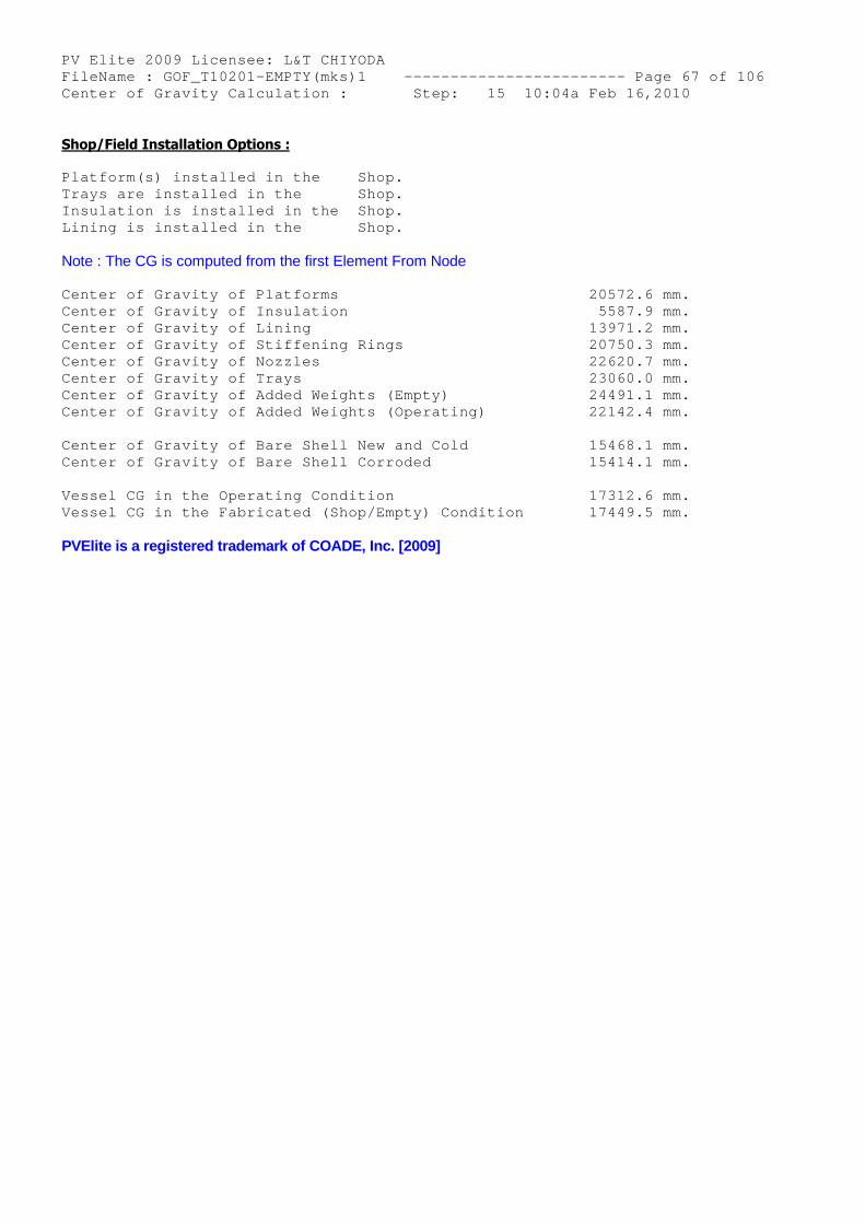
PV Elite 2009 Licensee: L&T CHIYODA FileName : GOF_T10201-EMPTY(mks)1 ------------- ----------- Page 67 of 106 Center of Gravity Calculation : Step: 15 10:04a Feb 16,2010
Shop/Field Installation Options :
Platform(s) installed in the Shop. Trays are installed in the Shop. Insulation is installed in the Shop. Lining is installed in the Shop.
Note : The CG is computed from the first Element From Node
Center of Gravity of Platforms 20572.6 mm. Center of Gravity of Insulation 5587.9 mm. Center of Gravity of Lining 13971.2 mm. Center of Gravity of Stiffening Rings 20750.3 mm. Center of Gravity of Nozzles 22620.7 mm. Center of Gravity of Trays 23060.0 mm. Center of Gravity of Added Weights (Empty) 24491.1 mm. Center of Gravity of Added Weights (Operating) 22142.4 mm.
Center of Gravity of Bare Shell New and Cold 15468.1 mm. Center of Gravity of Bare Shell Corroded 15414.1 mm.
Vessel CG in the Operating Condition 17312.6 mm. Vessel CG in the Fabricated (Shop/Empty) Condition 17449.5 mm.
PVElite is a registered trademark of COADE, Inc. [2009]
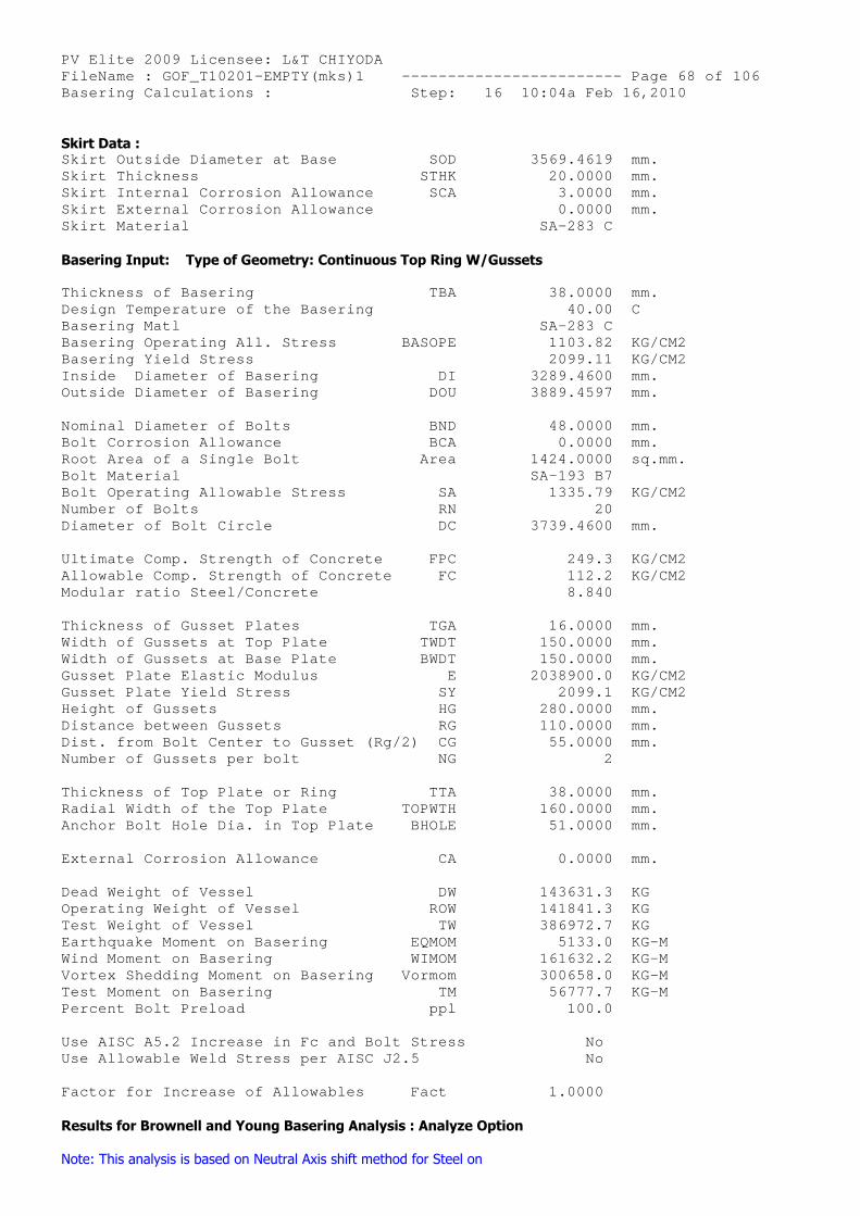
PV Elite 2009 Licensee: L&T CHIYODA FileName : GOF_T10201-EMPTY(mks)1 ------------- ----------- Page 68 of 106 Basering Calculations : Step: 16 10:04a Feb 16,2010
Skirt Data : Skirt Outside Diameter at Base SOD 3569.4619 mm. Skirt Thickness STHK 20.0000 mm. Skirt Internal Corrosion Allowance SCA 3.0000 mm. Skirt External Corrosion Allowance 0.0000 mm. Skirt Material SA-283 C
Basering Input: Type of Geometry: Continuous Top Ring W/Gussets
Thickness of Basering TBA 38.0000 mm. Design Temperature of the Basering 40.00 C Basering Matl SA-283 C Basering Operating All. Stress BASOPE 1103.82 KG/CM2 Basering Yield Stress 2099.11 KG/CM2 Inside Diameter of Basering DI 3289.4600 mm. Outside Diameter of Basering DOU 3889.4597 mm.
Nominal Diameter of Bolts BND 48.0000 mm. Bolt Corrosion Allowance BCA 0.0000 mm. Root Area of a Single Bolt Area 1424.0000 sq.mm. Bolt Material SA-193 B7 Bolt Operating Allowable Stress SA 1335.79 KG/CM2 Number of Bolts RN 20 Diameter of Bolt Circle DC 3739.4600 mm.
Ultimate Comp. Strength of Concrete FPC 249.3 KG/CM2 Allowable Comp. Strength of Concrete FC 112.2 KG/CM2 Modular ratio Steel/Concrete 8.840
Thickness of Gusset Plates TGA 16.0000 mm. Width of Gussets at Top Plate TWDT 150.0000 mm. Width of Gussets at Base Plate BWDT 150.0000 mm. Gusset Plate Elastic Modulus E 2038900.0 KG/CM2 Gusset Plate Yield Stress SY 2099.1 KG/CM2 Height of Gussets HG 280.0000 mm. Distance between Gussets RG 110.0000 mm. Dist. from Bolt Center to Gusset (Rg/2) CG 55.0000 mm. Number of Gussets per bolt NG 2
Thickness of Top Plate or Ring TTA 38.0000 mm. Radial Width of the Top Plate TOPWTH 160.0000 mm. Anchor Bolt Hole Dia. in Top Plate BHOLE 51.0000 mm.
External Corrosion Allowance CA 0.0000 mm.
Dead Weight of Vessel DW 143631.3 KG Operating Weight of Vessel ROW 141841.3 KG Test Weight of Vessel TW 386972.7 KG Earthquake Moment on Basering EQMOM 5133.0 KG-M Wind Moment on Basering WIMOM 161632.2 KG-M Vortex Shedding Moment on Basering Vormom 300658.0 KG-M Test Moment on Basering TM 56777.7 KG-M Percent Bolt Preload ppl 100.0
Use AISC A5.2 Increase in Fc and Bolt Stress No Use Allowable Weld Stress per AISC J2.5 No
Factor for Increase of Allowables Fact 1.0000
Results for Brownell and Young Basering Analysis : Analyze Option
Note: This analysis is based on Neutral Axis shift method for Steel on
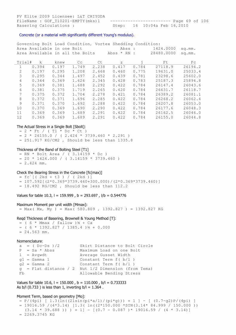
PV Elite 2009 Licensee: L&T CHIYODA FileName : GOF_T10201-EMPTY(mks)1 ------------- ----------- Page 69 of 106 Basering Calculations : Step: 16 10:04a Feb 16,2010
Concrete (or a material with significantly different Young's modulus).
Governing Bolt Load Condition, Vortex Shedding Con dition: Area Available in one Bolt Abss : 1424.0000 sq.mm. Area Available in all the Bolts Abss * RN : 28480.0000 sq.mm.
Trial# k knew Cc Ct z j Ft Fc 1 0.394 0.197 1.749 2.238 0.417 0.78 4 27118.9 26194.2 2 0.197 0.295 1.208 2.668 0.460 0.77 5 19631.0 25033.4 3 0.295 0.344 1.497 2.452 0.439 0.78 1 23298.6 25602.0 4 0.344 0.369 1.626 2.345 0.428 0.78 3 25187.3 25894.8 5 0.369 0.381 1.688 2.292 0.422 0.78 4 26147.4 26043.6 6 0.381 0.375 1.719 2.265 0.420 0.78 4 26631.7 26118.7 7 0.375 0.372 1.704 2.278 0.421 0.78 4 26389.2 26081.1 8 0.372 0.371 1.696 2.285 0.422 0.78 4 26268.2 26062.4 9 0.371 0.370 1.692 2.288 0.422 0.78 4 26207.8 26053.0 10 0.370 0.369 1.690 2.290 0.422 0.78 4 26177.6 26048.3 11 0.369 0.369 1.689 2.291 0.422 0.78 4 26162.5 26046.0 12 0.369 0.369 1.689 2.291 0.422 0.78 4 26155.0 26044.8
The Actual Stress in a Single Bolt [Sbolt]: = 2 * Ft / ( T1 * Dc * Ct ) = 2 * 26155.0 / ( 2.424 * 3739.460 * 2.291 ) = 251.917 KG/CM2 , Should be less than 1335.8
Thickness of the Band of Bolting Steel [T1] = RN * Bolt Area / ( 3.14159 * Dc ) = 20 * 1424.000 / ( 3.14159 * 3739.460 ) = 2.424 mm.
Check the Bearing Stress in the Concrete [fc(max)] = fc`[( 2kd + t3 ) / ( 2kd )] = 107.592[(2*0.369*3739.460+300.000)/(2*0.369*373 9.460)] = 18.492 KG/CM2 , Should be less than 112.2
Values for table 10.3, l = 159.999 , b = 293.697 , l/b = 0.544776
Maximum Moment per unit width [Mmax]: = Max( Mx, My ) = Max( 580.809 , 1392.827 ) = 139 2.827 KG
Reqd Thickness of Basering, Brownell & Young Method [T]: = ( 6 * Mmax / fallow )½ + Ca = ( 6 * 1392.827 / 1385.4 )½ + 0.000 = 24.563 mm.
Nomenclature: a = ( Dc-Ds )/2 Skirt Distance to Bolt Ci rcle P = Sa * Abss Maximum Load on one Bolt l = Avgwdt Average Gusset Width g1 = Gamma 1 Constant Term f( b/l ) g2 = Gamma 2 Constant Term f( b/l ) g = Flat distance / 2 Nut 1/2 Dimension (from T ema) Fb Allowable Bending Stress
Values for table 10.6, l = 150.000 , b = 110.000 , b/l = 0.733333As b/l (0.733 ) is less than 1, inverting b/l = 1.364 .
Moment Term, based on geometry [Mo]: = P/(4pi) [ 1.3(ln((2lsin(pi*a/l)/(pi*g))) + 1 ] - [ (0.7-g2)P/(4pi) ] = 19016.59 /(4*3.14) [1.3( ln((2*150.000 *SIN(3.1 4* 84.999 / 150.000 )) (3.14 * 39.688 )) ) + 1] - [(0.7 - 0.087 )* 190 16.59 / (4 * 3.14)] = 2269.3745 KG
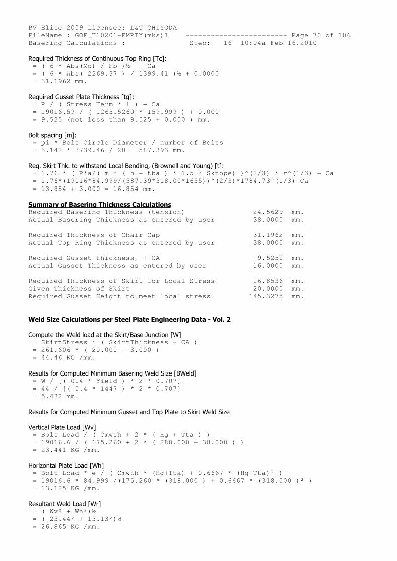
PV Elite 2009 Licensee: L&T CHIYODA FileName : GOF_T10201-EMPTY(mks)1 ------------- ----------- Page 70 of 106 Basering Calculations : Step: 16 10:04a Feb 16,2010 Required Thickness of Continuous Top Ring [Tc]:
= ( 6 * Abs(Mo) / Fb )½ + Ca = ( 6 * Abs( 2269.37 ) / 1399.41 )½ + 0.0000 = 31.1962 mm.
Required Gusset Plate Thickness [tg]: = P / ( Stress Term * l ) + Ca = 19016.59 / ( 1265.5260 * 159.999 ) + 0.000 = 9.525 (not less than 9.525 + 0.000 ) mm.
Bolt spacing [m]: = pi * Bolt Circle Diameter / number of Bolts = 3.142 * 3739.46 / 20 = 587.393 mm.
Req. Skirt Thk. to withstand Local Bending, (Brownell and Young) [t]: = 1.76 * ( P*a/( m * ( h + tba ) * 1.5 * Sktope) )^(2/3) * r^(1/3) + Ca = 1.76*(19016*84.999/(587.39*318.00*1655))^(2/3)* 1784.73^(1/3)+Ca = 13.854 + 3.000 = 16.854 mm.
Summary of Basering Thickness Calculations Required Basering Thickness (tension) 24.5629 mm. Actual Basering Thickness as entered by user 38.0000 mm.
Required Thickness of Chair Cap 31.1962 mm. Actual Top Ring Thickness as entered by user 38.0000 mm.
Required Gusset thickness, + CA 9.5250 mm. Actual Gusset Thickness as entered by user 16.0000 mm.
Required Thickness of Skirt for Local Stress 16.8536 mm. Given Thickness of Skirt 20.0000 mm. Required Gusset Height to meet local stress 145.3275 mm.
Weld Size Calculations per Steel Plate Engineering Data - Vol. 2
Compute the Weld load at the Skirt/Base Junction [W] = SkirtStress * ( SkirtThickness - CA ) = 261.606 * ( 20.000 - 3.000 ) = 44.46 KG /mm.
Results for Computed Minimum Basering Weld Size [BWeld] = W / [( 0.4 * Yield ) * 2 * 0.707] = 44 / [( 0.4 * 1447 ) * 2 * 0.707] = 5.432 mm.
Results for Computed Minimum Gusset and Top Plate to Skirt Weld Size
Vertical Plate Load [Wv] = Bolt Load / ( Cmwth + 2 * ( Hg + Tta ) ) = 19016.6 / ( 175.260 + 2 * ( 280.000 + 38.000 ) ) = 23.441 KG /mm.
Horizontal Plate Load [Wh] = Bolt Load * e / ( Cmwth * (Hg+Tta) + 0.6667 * ( Hg+Tta)² ) = 19016.6 * 84.999 /(175.260 * (318.000 ) + 0.666 7 * (318.000 )² ) = 13.125 KG /mm.
Resultant Weld Load [Wr] = ( Wv² + Wh²)½ = ( 23.44² + 13.13²)½ = 26.865 KG /mm.
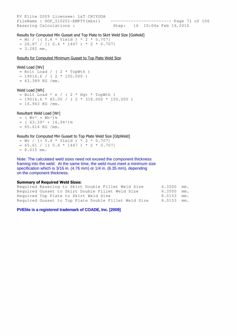
PV Elite 2009 Licensee: L&T CHIYODA FileName : GOF_T10201-EMPTY(mks)1 ------------- ----------- Page 71 of 106 Basering Calculations : Step: 16 10:04a Feb 16,2010 Results for Computed Min Gusset and Top Plate to Skirt Weld Size [GsWeld]
= Wr / [( 0.4 * Yield ) * 2 * 0.707] = 26.87 / [( 0.4 * 1447 ) * 2 * 0.707] = 3.282 mm.
Results for Computed Minimum Gusset to Top Plate Weld Size
Weld Load [Wv] = Bolt Load / ( 2 * TopWth ) = 19016.6 / ( 2 * 150.000 ) = 63.389 KG /mm.
Weld Load [Wh] = Bolt Load * e / ( 2 * Hgt * TopWth ) = 19016.6 * 85.00 / ( 2 * 318.000 * 150.000 ) = 16.943 KG /mm.
Resultant Weld Load [Wr] = ( Wv² + Wh²)½ = ( 63.39² + 16.94²)½ = 65.614 KG /mm.
Results for Computed Min Gusset to Top Plate Weld Size [GtpWeld] = Wr / [( 0.4 * Yield ) * 2 * 0.707] = 65.61 / [( 0.4 * 1447 ) * 2 * 0.707] = 8.015 mm.
Note: The calculated weld sizes need not exceed the component thicknessframing into the weld. At the same time, the weld must meet a minimum sizespecification which is 3/16 in. (4.76 mm) or 1/4 in. (6.35 mm), dependingon the component thickness.
Summary of Required Weld Sizes: Required Basering to Skirt Double Fillet Weld Size 6.3500 mm. Required Gusset to Skirt Double Fillet Weld Size 6.3500 mm. Required Top Plate to Skirt Weld Size 8.0153 mm. Required Gusset to Top Plate Double Fillet Weld Si ze 8.0153 mm.
PVElite is a registered trademark of COADE, Inc. [2009]
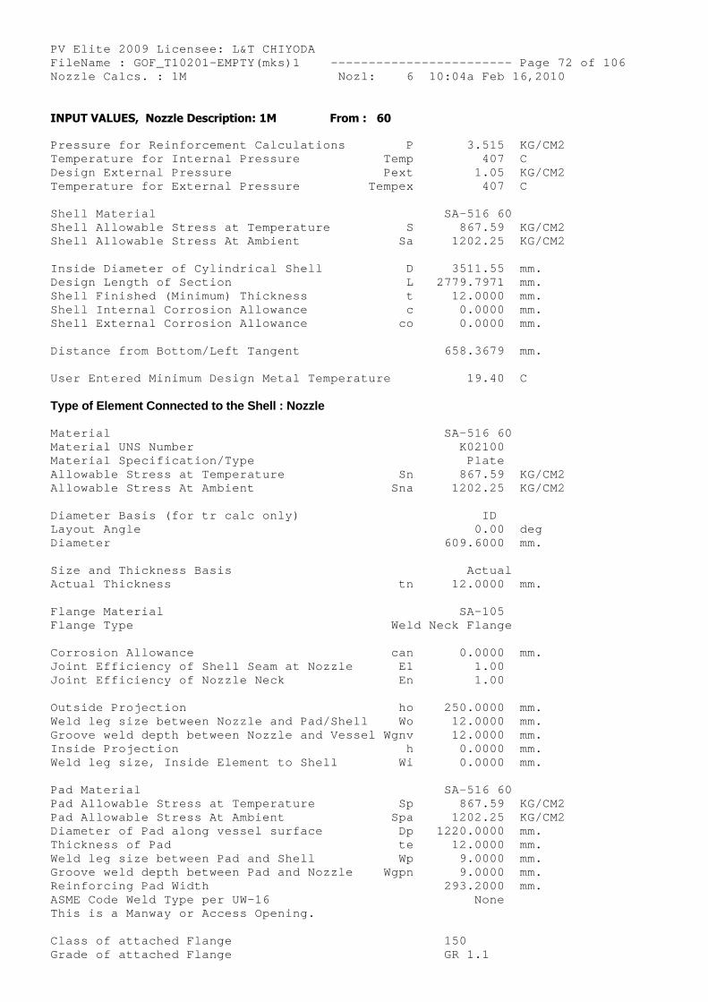
PV Elite 2009 Licensee: L&T CHIYODA FileName : GOF_T10201-EMPTY(mks)1 ------------- ----------- Page 72 of 106 Nozzle Calcs. : 1M Nozl: 6 10:04a Feb 16,2010
INPUT VALUES, Nozzle Description: 1M From : 60
Pressure for Reinforcement Calculations P 3.515 KG/CM2 Temperature for Internal Pressure Temp 407 C Design External Pressure Pext 1.05 KG/CM2 Temperature for External Pressure Tempex 407 C
Shell Material SA-516 60 Shell Allowable Stress at Temperature S 867.59 KG/CM2 Shell Allowable Stress At Ambient Sa 1202.25 KG/CM2
Inside Diameter of Cylindrical Shell D 3511.55 mm. Design Length of Section L 2779.7971 mm. Shell Finished (Minimum) Thickness t 12.0000 mm. Shell Internal Corrosion Allowance c 0.0000 mm. Shell External Corrosion Allowance co 0.0000 mm.
Distance from Bottom/Left Tangent 658.3679 mm.
User Entered Minimum Design Metal Temperature 19.40 C
Type of Element Connected to the Shell : Nozzle
Material SA-516 60 Material UNS Number K02100 Material Specification/Type Plate Allowable Stress at Temperature Sn 867.59 KG/CM2 Allowable Stress At Ambient Sna 1202.25 KG/CM2
Diameter Basis (for tr calc only) ID Layout Angle 0.00 deg Diameter 609.6000 mm.
Size and Thickness Basis Actual Actual Thickness tn 12.0000 mm.
Flange Material SA-105 Flange Type Weld Neck Flange
Corrosion Allowance can 0.0000 mm. Joint Efficiency of Shell Seam at Nozzle E1 1.00 Joint Efficiency of Nozzle Neck En 1.00
Outside Projection ho 250.0000 mm. Weld leg size between Nozzle and Pad/Shell Wo 12.0000 mm. Groove weld depth between Nozzle and Vessel Wgnv 12.0000 mm. Inside Projection h 0.0000 mm. Weld leg size, Inside Element to Shell Wi 0.0000 mm.
Pad Material SA-516 60 Pad Allowable Stress at Temperature Sp 867.59 KG/CM2 Pad Allowable Stress At Ambient Spa 1202.25 KG/CM2 Diameter of Pad along vessel surface Dp 1220.0000 mm. Thickness of Pad te 12.0000 mm. Weld leg size between Pad and Shell Wp 9.0000 mm. Groove weld depth between Pad and Nozzle Wgpn 9.0000 mm. Reinforcing Pad Width 293.2000 mm. ASME Code Weld Type per UW-16 None This is a Manway or Access Opening.
Class of attached Flange 150 Grade of attached Flange GR 1.1

PV Elite 2009 Licensee: L&T CHIYODA FileName : GOF_T10201-EMPTY(mks)1 ------------- ----------- Page 73 of 106 Nozzle Calcs. : 1M Nozl: 6 10:04a Feb 16,2010
The Pressure Design option was Design Pressure + static head.
Nozzle Sketch | | | | | | | | __________/| | ____/|__________\| | | \ | | | \ | | |________________\|__|
Insert Nozzle With Pad, no Inside projection
Reinforcement CALCULATION, Description: 1M
ASME Code, Section VIII, Division 1, 2007, A-08 UG-37 to UG-45
Actual Inside Diameter Used in Calculation 609.600 mm. Actual Thickness Used in Calculation 12.000 mm.
Nozzle input data check completed without errors.
Reqd thk per UG-37(a)of Cylindrical Shell, Tr [Int. Press] = (P*R)/(S*E-0.6*P) per UG-27 (c)(1) = (3.52*1755.7750)/(867*1.00-0.6*3.52) = 7.1315 mm.
Reqd thk per UG-37(a)of Nozzle Wall, Trn [Int. Press] = (P*R)/(S*E-0.6*P) per UG-27 (c)(1) = (3.52*304.80)/(867*1.00-0.6*3.52) = 1.2380 mm.
Required Nozzle thickness under External Pressure per UG-28 : 1.5065 mm.
UG-40, Limits of Reinforcement : [Int. Press] Parallel to Vessel Wall (Diameter Limit) Dl 1219.2000 mm. Parallel to Vessel Wall d 609.6000 mm. Normal to Vessel Wall (Thickness Limit), pad side Tlwp 30.0000 mm.
Note : The Pad diameter is greater than the Diameter Limit, theexcess will not be considered .
Weld Strength Reduction Factor [fr1]: = min( 1, Sn/S ) = min( 1, 867.6 /867.6 ) = 1.000
Weld Strength Reduction Factor [fr2]: = min( 1, Sn/S ) = min( 1, 867.6 /867.6 ) = 1.000
Weld Strength Reduction Factor [fr4]: = min( 1, Sp/S ) = min( 1, 867.6 /867.6 ) = 1.000
Weld Strength Reduction Factor [fr3]: = min( fr2, fr4 ) = min( 1.0 , 1.0 )

PV Elite 2009 Licensee: L&T CHIYODA FileName : GOF_T10201-EMPTY(mks)1 ------------- ----------- Page 74 of 106 Nozzle Calcs. : 1M Nozl: 6 10:04a Feb 16,2010 = 1.000
Results of Nozzle Reinforcement Area Calculations: AREA AVAILABLE, A1 to A5 Design External Mapnc Area Required Ar 4347.631 3409.524 NA sq.mm. Area in Shell A1 2968.022 496.606 NA sq.mm. Area in Nozzle Wall A2 645.759 629.647 NA sq.mm. Area in Inward Nozzle A3 0.000 0.000 NA sq.mm. Area in Welds A41+A42+A43 144.009 144.009 NA sq.mm. Area in Element A5 7027.636 7027.636 NA sq.mm. TOTAL AREA AVAILABLE Atot 10785.427 8297.897 NA sq.mm.
The External Pressure Case Governs the Analysis.
Nozzle Angle Used in Area Calculations 90.00 Degs.
The area available without a pad is Insufficient.The area available with the given pad is Sufficient.
SELECTION OF POSSIBLE REINFORCING PADS: Diameter Thickness Based on given Pad Thickness: 811.8608 12.0000 mm. Based on given Pad Diameter: 1220.0000 3.6529 mm. Based on Shell or Nozzle Thickness: 811.8608 12.0000 mm.
Area Required [A]: = 0.5( d * tr*F + 2 * tn * tr*F * (1-fr1) ) per U G-37(d) or UG-39 = 0.5(609.6000*11.1854*1+2*12.0000*11.1854*1*(1-1 .00)) = 3409.524 sq.mm.
Reinforcement Areas per Figure UG-37.1
Area Available in Shell [A1]: = d( E1*t - F*tr ) - 2 * tn( E1*t - F*tr ) * ( 1 - fr1 ) = 609.600 ( 1.00 * 12.0000 - 1.0 * 11.185 ) - 2 * 12.000 ( 1.00 * 12.0000 - 1.0 * 11.1854 ) * ( 1 - 1.00 0 ) = 496.606 sq.mm.
Area Available in Nozzle Wall Projecting Outward [A2]: = ( 2 * Tlwp ) * ( tn - trn ) * fr2 = ( 2 * 30.00 ) * ( 12.00 - 1.51 ) * 1.0000 ) = 629.647 sq.mm.
Area Available in Welds [A41 + A42 + A43]: = Wo²*fr3+(Wi-can/0.707)²*fr2+Wp²*fr4 = 12.0000² *1.00 + (0.0000 )² *1.00 + 0.0000² * 1 .00 = 144.009 sq.mm.
Area Available in Element [A5]: = (min(Dp,DL)-(Nozzle OD))*(min(tp,Tlwp,te))*fr4 = ( 1219.2000 - 633.6000 ) * 12.0000 * 1.0000 = 7027.636 sq.mm.
Nozzle Junction Minimum Design Metal Temperature (MDMT) Calculations:
MDMT of the Nozzle Neck to Flange Weld, Curve: C -------------------------------------------------- --------------------
Govrn. thk, tg = 12.000 , tr = 0.893 , c = 0.0000 mm. , E* = 1.00Stress Ratio = tr * (E*) / (tg - c) = 0.074 , Temp. Reduction = 78 C
Min Metal Temp. w/o impact per UCS-66 -39 C Min Metal Temp per UCS-66 and UCS-68(c),PWHT credi t -56 C Min Metal Temp. at Required thickness (UCS 66.1) -104 C
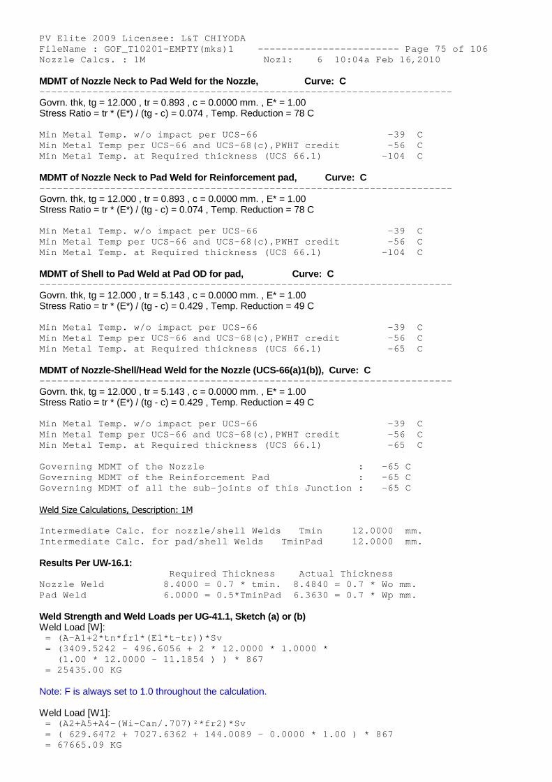
PV Elite 2009 Licensee: L&T CHIYODA FileName : GOF_T10201-EMPTY(mks)1 ------------- ----------- Page 75 of 106 Nozzle Calcs. : 1M Nozl: 6 10:04a Feb 16,2010
MDMT of Nozzle Neck to Pad Weld for the Nozzle, Curve: C -------------------------------------------------- --------------------
Govrn. thk, tg = 12.000 , tr = 0.893 , c = 0.0000 mm. , E* = 1.00Stress Ratio = tr * (E*) / (tg - c) = 0.074 , Temp. Reduction = 78 C
Min Metal Temp. w/o impact per UCS-66 -39 C Min Metal Temp per UCS-66 and UCS-68(c),PWHT credi t -56 C Min Metal Temp. at Required thickness (UCS 66.1) -104 C
MDMT of Nozzle Neck to Pad Weld for Reinforcement pad, Curve: C -------------------------------------------------- --------------------
Govrn. thk, tg = 12.000 , tr = 0.893 , c = 0.0000 mm. , E* = 1.00Stress Ratio = tr * (E*) / (tg - c) = 0.074 , Temp. Reduction = 78 C
Min Metal Temp. w/o impact per UCS-66 -39 C Min Metal Temp per UCS-66 and UCS-68(c),PWHT credi t -56 C Min Metal Temp. at Required thickness (UCS 66.1) -104 C
MDMT of Shell to Pad Weld at Pad OD for pad, Curve: C -------------------------------------------------- --------------------
Govrn. thk, tg = 12.000 , tr = 5.143 , c = 0.0000 mm. , E* = 1.00Stress Ratio = tr * (E*) / (tg - c) = 0.429 , Temp. Reduction = 49 C
Min Metal Temp. w/o impact per UCS-66 -39 C Min Metal Temp per UCS-66 and UCS-68(c),PWHT credi t -56 C Min Metal Temp. at Required thickness (UCS 66.1) -65 C
MDMT of Nozzle-Shell/Head Weld for the Nozzle (UCS-66(a)1(b)), Curve: C -------------------------------------------------- --------------------
Govrn. thk, tg = 12.000 , tr = 5.143 , c = 0.0000 mm. , E* = 1.00Stress Ratio = tr * (E*) / (tg - c) = 0.429 , Temp. Reduction = 49 C
Min Metal Temp. w/o impact per UCS-66 -39 C Min Metal Temp per UCS-66 and UCS-68(c),PWHT credi t -56 C Min Metal Temp. at Required thickness (UCS 66.1) -65 C
Governing MDMT of the Nozzle : -65 C Governing MDMT of the Reinforcement Pad : -65 C Governing MDMT of all the sub-joints of this Junct ion : -65 C
Weld Size Calculations, Description: 1M
Intermediate Calc. for nozzle/shell Welds Tmin 12.0000 mm. Intermediate Calc. for pad/shell Welds TminPad 12.0000 mm.
Results Per UW-16.1: Required Thickness Actual Thickness Nozzle Weld 8.4000 = 0.7 * tmin. 8.4840 = 0.7 * Wo mm. Pad Weld 6.0000 = 0.5*TminPad 6.3630 = 0.7 * Wp mm.
Weld Strength and Weld Loads per UG-41.1, Sketch (a) or (b)Weld Load [W]:
= (A-A1+2*tn*fr1*(E1*t-tr))*Sv = (3409.5242 - 496.6056 + 2 * 12.0000 * 1.0000 * (1.00 * 12.0000 - 11.1854 ) ) * 867 = 25435.00 KG
Note: F is always set to 1.0 throughout the calculation.
Weld Load [W1]: = (A2+A5+A4-(Wi-Can/.707)²*fr2)*Sv = ( 629.6472 + 7027.6362 + 144.0089 - 0.0000 * 1. 00 ) * 867 = 67665.09 KG
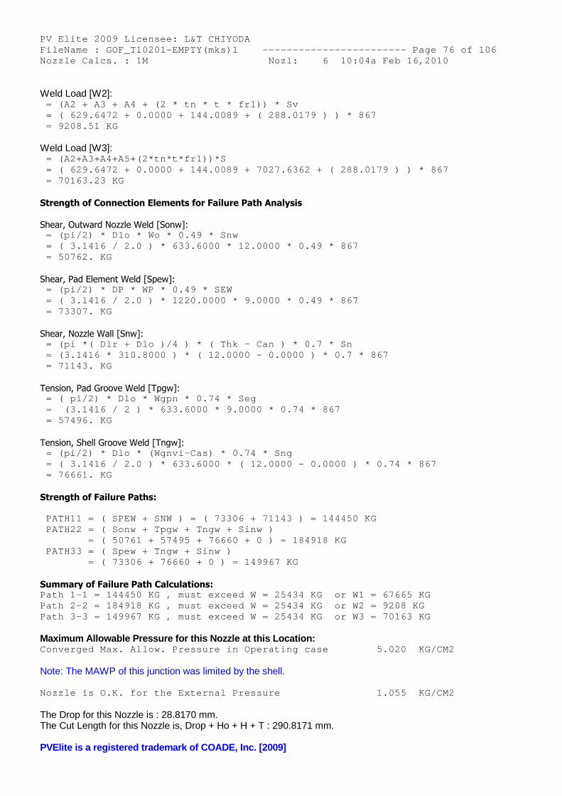
PV Elite 2009 Licensee: L&T CHIYODA FileName : GOF_T10201-EMPTY(mks)1 ------------- ----------- Page 76 of 106 Nozzle Calcs. : 1M Nozl: 6 10:04a Feb 16,2010
Weld Load [W2]: = (A2 + A3 + A4 + (2 * tn * t * fr1)) * Sv = ( 629.6472 + 0.0000 + 144.0089 + ( 288.0179 ) ) * 867 = 9208.51 KG
Weld Load [W3]: = (A2+A3+A4+A5+(2*tn*t*fr1))*S = ( 629.6472 + 0.0000 + 144.0089 + 7027.6362 + ( 288.0179 ) ) * 867 = 70163.23 KG
Strength of Connection Elements for Failure Path Analysis
Shear, Outward Nozzle Weld [Sonw]: = (pi/2) * Dlo * Wo * 0.49 * Snw = ( 3.1416 / 2.0 ) * 633.6000 * 12.0000 * 0.49 * 867 = 50762. KG
Shear, Pad Element Weld [Spew]: = (pi/2) * DP * WP * 0.49 * SEW = ( 3.1416 / 2.0 ) * 1220.0000 * 9.0000 * 0.49 * 867 = 73307. KG
Shear, Nozzle Wall [Snw]: = (pi *( Dlr + Dlo )/4 ) * ( Thk - Can ) * 0.7 * Sn = (3.1416 * 310.8000 ) * ( 12.0000 - 0.0000 ) * 0 .7 * 867 = 71143. KG
Tension, Pad Groove Weld [Tpgw]: = ( pi/2) * Dlo * Wgpn * 0.74 * Seg = (3.1416 / 2 ) * 633.6000 * 9.0000 * 0.74 * 867 = 57496. KG
Tension, Shell Groove Weld [Tngw]: = (pi/2) * Dlo * (Wgnvi-Cas) * 0.74 * Sng = ( 3.1416 / 2.0 ) * 633.6000 * ( 12.0000 - 0.000 0 ) * 0.74 * 867 = 76661. KG
Strength of Failure Paths:
PATH11 = ( SPEW + SNW ) = ( 73306 + 71143 ) = 144 450 KG PATH22 = ( Sonw + Tpgw + Tngw + Sinw ) = ( 50761 + 57495 + 76660 + 0 ) = 184918 K G PATH33 = ( Spew + Tngw + Sinw ) = ( 73306 + 76660 + 0 ) = 149967 KG
Summary of Failure Path Calculations: Path 1-1 = 144450 KG , must exceed W = 25434 KG o r W1 = 67665 KG Path 2-2 = 184918 KG , must exceed W = 25434 KG o r W2 = 9208 KG Path 3-3 = 149967 KG , must exceed W = 25434 KG o r W3 = 70163 KG
Maximum Allowable Pressure for this Nozzle at this Location: Converged Max. Allow. Pressure in Operating case 5.020 KG/CM2
Note: The MAWP of this junction was limited by the shell.
Nozzle is O.K. for the External Pressure 1.055 KG/CM2
The Drop for this Nozzle is : 28.8170 mm.The Cut Length for this Nozzle is, Drop + Ho + H + T : 290.8171 mm.
PVElite is a registered trademark of COADE, Inc. [2009]

PV Elite 2009 Licensee: L&T CHIYODA FileName : GOF_T10201-EMPTY(mks)1 ------------- ----------- Page 77 of 106 Nozzle Calcs. : 1M2 Nozl: 7 10:04a Feb 16,2010
INPUT VALUES, Nozzle Description: 1M2 From : 90
Pressure for Reinforcement Calculations P 3.515 KG/CM2 Temperature for Internal Pressure Temp 407 C Design External Pressure Pext 1.05 KG/CM2 Temperature for External Pressure Tempex 407 C
Shell Material SA-516 60 Shell Allowable Stress at Temperature S 867.59 KG/CM2 Shell Allowable Stress At Ambient Sa 1202.25 KG/CM2
Inside Diameter of Cylindrical Shell D 3511.55 mm. Design Length of Section L 3048.0000 mm. Shell Finished (Minimum) Thickness t 12.0000 mm. Shell Internal Corrosion Allowance c 0.0000 mm. Shell External Corrosion Allowance co 0.0000 mm.
Distance from Bottom/Left Tangent 10411.9688 mm.
User Entered Minimum Design Metal Temperature 19.40 C
Type of Element Connected to the Shell : Nozzle
Material SA-516 60 Material UNS Number K02100 Material Specification/Type Plate Allowable Stress at Temperature Sn 867.59 KG/CM2 Allowable Stress At Ambient Sna 1202.25 KG/CM2
Diameter Basis (for tr calc only) ID Layout Angle 0.00 deg Diameter 609.6000 mm.
Size and Thickness Basis Actual Actual Thickness tn 12.0000 mm.
Flange Material SA-105 Flange Type Weld Neck Flange
Corrosion Allowance can 0.0000 mm. Joint Efficiency of Shell Seam at Nozzle E1 1.00 Joint Efficiency of Nozzle Neck En 1.00
Outside Projection ho 250.0000 mm. Weld leg size between Nozzle and Pad/Shell Wo 12.0000 mm. Groove weld depth between Nozzle and Vessel Wgnv 12.0000 mm. Inside Projection h 0.0000 mm. Weld leg size, Inside Element to Shell Wi 0.0000 mm.
Pad Material SA-516 60 Pad Allowable Stress at Temperature Sp 867.59 KG/CM2 Pad Allowable Stress At Ambient Spa 1202.25 KG/CM2 Diameter of Pad along vessel surface Dp 1220.0000 mm. Thickness of Pad te 12.0000 mm. Weld leg size between Pad and Shell Wp 9.0000 mm. Groove weld depth between Pad and Nozzle Wgpn 9.0000 mm. Reinforcing Pad Width 293.2000 mm. ASME Code Weld Type per UW-16 None This is a Manway or Access Opening.
Class of attached Flange 150 Grade of attached Flange GR 1.1

PV Elite 2009 Licensee: L&T CHIYODA FileName : GOF_T10201-EMPTY(mks)1 ------------- ----------- Page 78 of 106 Nozzle Calcs. : 1M2 Nozl: 7 10:04a Feb 16,2010
The Pressure Design option was Design Pressure + static head.
Nozzle Sketch | | | | | | | | __________/| | ____/|__________\| | | \ | | | \ | | |________________\|__|
Insert Nozzle With Pad, no Inside projection
Reinforcement CALCULATION, Description: 1M2
ASME Code, Section VIII, Division 1, 2007, A-08 UG-37 to UG-45
Actual Inside Diameter Used in Calculation 609.600 mm. Actual Thickness Used in Calculation 12.000 mm.
Nozzle input data check completed without errors.
Reqd thk per UG-37(a)of Cylindrical Shell, Tr [Int. Press] = (P*R)/(S*E-0.6*P) per UG-27 (c)(1) = (3.52*1755.7750)/(867*1.00-0.6*3.52) = 7.1315 mm.
Reqd thk per UG-37(a)of Nozzle Wall, Trn [Int. Press] = (P*R)/(S*E-0.6*P) per UG-27 (c)(1) = (3.52*304.80)/(867*1.00-0.6*3.52) = 1.2380 mm.
Required Nozzle thickness under External Pressure per UG-28 : 1.5065 mm.
UG-40, Limits of Reinforcement : [Int. Press] Parallel to Vessel Wall (Diameter Limit) Dl 1219.2000 mm. Parallel to Vessel Wall d 609.6000 mm. Normal to Vessel Wall (Thickness Limit), pad side Tlwp 30.0000 mm.
Note : The Pad diameter is greater than the Diameter Limit, theexcess will not be considered .
Weld Strength Reduction Factor [fr1]: = min( 1, Sn/S ) = min( 1, 867.6 /867.6 ) = 1.000
Weld Strength Reduction Factor [fr2]: = min( 1, Sn/S ) = min( 1, 867.6 /867.6 ) = 1.000
Weld Strength Reduction Factor [fr4]: = min( 1, Sp/S ) = min( 1, 867.6 /867.6 ) = 1.000
Weld Strength Reduction Factor [fr3]: = min( fr2, fr4 ) = min( 1.0 , 1.0 )
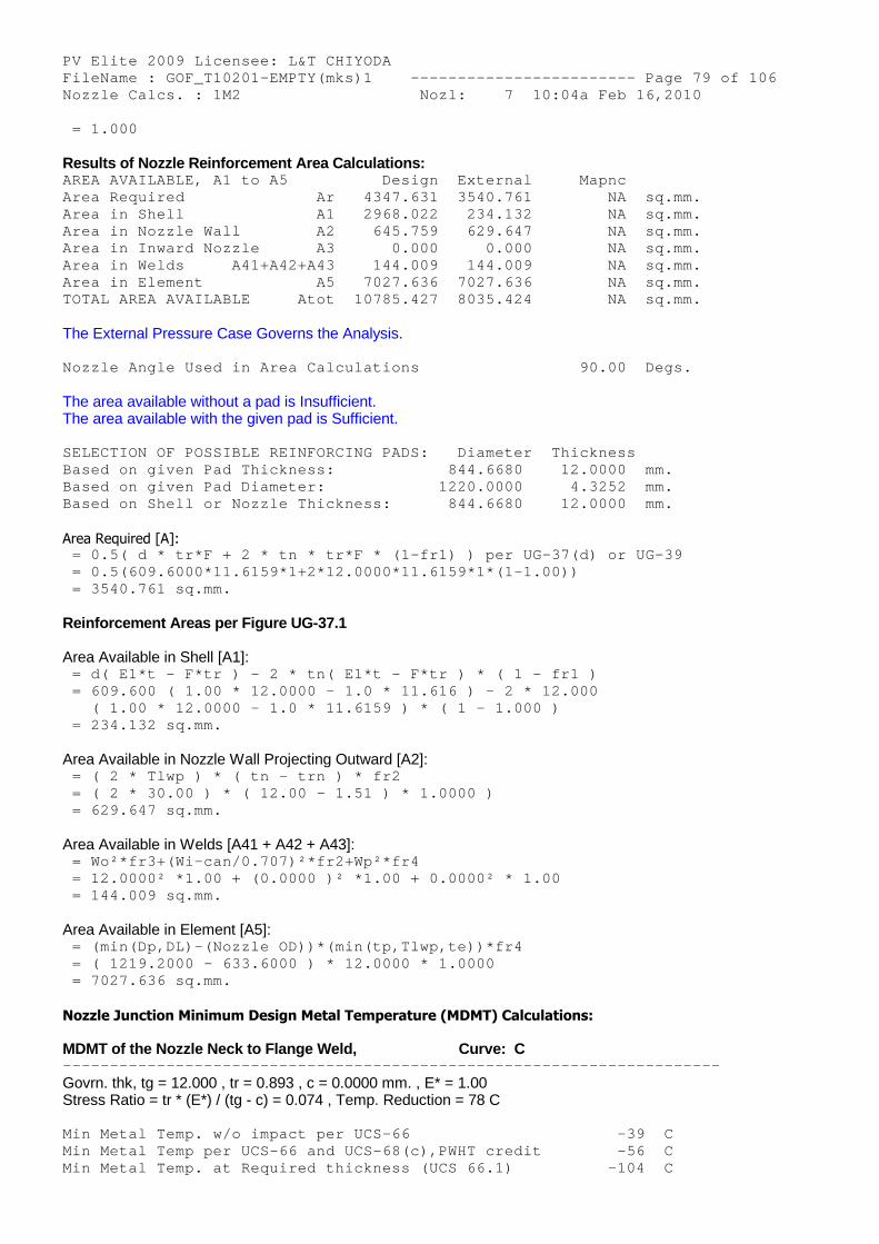
PV Elite 2009 Licensee: L&T CHIYODA FileName : GOF_T10201-EMPTY(mks)1 ------------- ----------- Page 79 of 106 Nozzle Calcs. : 1M2 Nozl: 7 10:04a Feb 16,2010 = 1.000
Results of Nozzle Reinforcement Area Calculations: AREA AVAILABLE, A1 to A5 Design External Mapnc Area Required Ar 4347.631 3540.761 NA sq.mm. Area in Shell A1 2968.022 234.132 NA sq.mm. Area in Nozzle Wall A2 645.759 629.647 NA sq.mm. Area in Inward Nozzle A3 0.000 0.000 NA sq.mm. Area in Welds A41+A42+A43 144.009 144.009 NA sq.mm. Area in Element A5 7027.636 7027.636 NA sq.mm. TOTAL AREA AVAILABLE Atot 10785.427 8035.424 NA sq.mm.
The External Pressure Case Governs the Analysis.
Nozzle Angle Used in Area Calculations 90.00 Degs.
The area available without a pad is Insufficient.The area available with the given pad is Sufficient.
SELECTION OF POSSIBLE REINFORCING PADS: Diameter Thickness Based on given Pad Thickness: 844.6680 12.0000 mm. Based on given Pad Diameter: 1220.0000 4.3252 mm. Based on Shell or Nozzle Thickness: 844.6680 12.0000 mm.
Area Required [A]: = 0.5( d * tr*F + 2 * tn * tr*F * (1-fr1) ) per U G-37(d) or UG-39 = 0.5(609.6000*11.6159*1+2*12.0000*11.6159*1*(1-1 .00)) = 3540.761 sq.mm.
Reinforcement Areas per Figure UG-37.1
Area Available in Shell [A1]: = d( E1*t - F*tr ) - 2 * tn( E1*t - F*tr ) * ( 1 - fr1 ) = 609.600 ( 1.00 * 12.0000 - 1.0 * 11.616 ) - 2 * 12.000 ( 1.00 * 12.0000 - 1.0 * 11.6159 ) * ( 1 - 1.00 0 ) = 234.132 sq.mm.
Area Available in Nozzle Wall Projecting Outward [A2]: = ( 2 * Tlwp ) * ( tn - trn ) * fr2 = ( 2 * 30.00 ) * ( 12.00 - 1.51 ) * 1.0000 ) = 629.647 sq.mm.
Area Available in Welds [A41 + A42 + A43]: = Wo²*fr3+(Wi-can/0.707)²*fr2+Wp²*fr4 = 12.0000² *1.00 + (0.0000 )² *1.00 + 0.0000² * 1 .00 = 144.009 sq.mm.
Area Available in Element [A5]: = (min(Dp,DL)-(Nozzle OD))*(min(tp,Tlwp,te))*fr4 = ( 1219.2000 - 633.6000 ) * 12.0000 * 1.0000 = 7027.636 sq.mm.
Nozzle Junction Minimum Design Metal Temperature (MDMT) Calculations:
MDMT of the Nozzle Neck to Flange Weld, Curve: C -------------------------------------------------- --------------------
Govrn. thk, tg = 12.000 , tr = 0.893 , c = 0.0000 mm. , E* = 1.00Stress Ratio = tr * (E*) / (tg - c) = 0.074 , Temp. Reduction = 78 C
Min Metal Temp. w/o impact per UCS-66 -39 C Min Metal Temp per UCS-66 and UCS-68(c),PWHT credi t -56 C Min Metal Temp. at Required thickness (UCS 66.1) -104 C

PV Elite 2009 Licensee: L&T CHIYODA FileName : GOF_T10201-EMPTY(mks)1 ------------- ----------- Page 80 of 106 Nozzle Calcs. : 1M2 Nozl: 7 10:04a Feb 16,2010
MDMT of Nozzle Neck to Pad Weld for the Nozzle, Curve: C -------------------------------------------------- --------------------
Govrn. thk, tg = 12.000 , tr = 0.893 , c = 0.0000 mm. , E* = 1.00Stress Ratio = tr * (E*) / (tg - c) = 0.074 , Temp. Reduction = 78 C
Min Metal Temp. w/o impact per UCS-66 -39 C Min Metal Temp per UCS-66 and UCS-68(c),PWHT credi t -56 C Min Metal Temp. at Required thickness (UCS 66.1) -104 C
MDMT of Nozzle Neck to Pad Weld for Reinforcement pad, Curve: C -------------------------------------------------- --------------------
Govrn. thk, tg = 12.000 , tr = 0.893 , c = 0.0000 mm. , E* = 1.00Stress Ratio = tr * (E*) / (tg - c) = 0.074 , Temp. Reduction = 78 C
Min Metal Temp. w/o impact per UCS-66 -39 C Min Metal Temp per UCS-66 and UCS-68(c),PWHT credi t -56 C Min Metal Temp. at Required thickness (UCS 66.1) -104 C
MDMT of Shell to Pad Weld at Pad OD for pad, Curve: C -------------------------------------------------- --------------------
Govrn. thk, tg = 12.000 , tr = 5.143 , c = 0.0000 mm. , E* = 1.00Stress Ratio = tr * (E*) / (tg - c) = 0.429 , Temp. Reduction = 49 C
Min Metal Temp. w/o impact per UCS-66 -39 C Min Metal Temp per UCS-66 and UCS-68(c),PWHT credi t -56 C Min Metal Temp. at Required thickness (UCS 66.1) -65 C
MDMT of Nozzle-Shell/Head Weld for the Nozzle (UCS-66(a)1(b)), Curve: C -------------------------------------------------- --------------------
Govrn. thk, tg = 12.000 , tr = 5.143 , c = 0.0000 mm. , E* = 1.00Stress Ratio = tr * (E*) / (tg - c) = 0.429 , Temp. Reduction = 49 C
Min Metal Temp. w/o impact per UCS-66 -39 C Min Metal Temp per UCS-66 and UCS-68(c),PWHT credi t -56 C Min Metal Temp. at Required thickness (UCS 66.1) -65 C
Governing MDMT of the Nozzle : -65 C Governing MDMT of the Reinforcement Pad : -65 C Governing MDMT of all the sub-joints of this Junct ion : -65 C
Weld Size Calculations, Description: 1M2
Intermediate Calc. for nozzle/shell Welds Tmin 12.0000 mm. Intermediate Calc. for pad/shell Welds TminPad 12.0000 mm.
Results Per UW-16.1: Required Thickness Actual Thickness Nozzle Weld 8.4000 = 0.7 * tmin. 8.4840 = 0.7 * Wo mm. Pad Weld 6.0000 = 0.5*TminPad 6.3630 = 0.7 * Wp mm.
Weld Strength and Weld Loads per UG-41.1, Sketch (a) or (b)Weld Load [W]:
= (A-A1+2*tn*fr1*(E1*t-tr))*Sv = (3540.7610 - 234.1316 + 2 * 12.0000 * 1.0000 * (1.00 * 12.0000 - 11.6159 ) ) * 867 = 28760.25 KG
Note: F is always set to 1.0 throughout the calculation.
Weld Load [W1]: = (A2+A5+A4-(Wi-Can/.707)²*fr2)*Sv = ( 629.6472 + 7027.6362 + 144.0089 - 0.0000 * 1. 00 ) * 867 = 67665.09 KG

PV Elite 2009 Licensee: L&T CHIYODA FileName : GOF_T10201-EMPTY(mks)1 ------------- ----------- Page 81 of 106 Nozzle Calcs. : 1M2 Nozl: 7 10:04a Feb 16,2010
Weld Load [W2]: = (A2 + A3 + A4 + (2 * tn * t * fr1)) * Sv = ( 629.6472 + 0.0000 + 144.0089 + ( 288.0179 ) ) * 867 = 9208.51 KG
Weld Load [W3]: = (A2+A3+A4+A5+(2*tn*t*fr1))*S = ( 629.6472 + 0.0000 + 144.0089 + 7027.6362 + ( 288.0179 ) ) * 867 = 70163.23 KG
Strength of Connection Elements for Failure Path Analysis
Shear, Outward Nozzle Weld [Sonw]: = (pi/2) * Dlo * Wo * 0.49 * Snw = ( 3.1416 / 2.0 ) * 633.6000 * 12.0000 * 0.49 * 867 = 50762. KG
Shear, Pad Element Weld [Spew]: = (pi/2) * DP * WP * 0.49 * SEW = ( 3.1416 / 2.0 ) * 1220.0000 * 9.0000 * 0.49 * 867 = 73307. KG
Shear, Nozzle Wall [Snw]: = (pi *( Dlr + Dlo )/4 ) * ( Thk - Can ) * 0.7 * Sn = (3.1416 * 310.8000 ) * ( 12.0000 - 0.0000 ) * 0 .7 * 867 = 71143. KG
Tension, Pad Groove Weld [Tpgw]: = ( pi/2) * Dlo * Wgpn * 0.74 * Seg = (3.1416 / 2 ) * 633.6000 * 9.0000 * 0.74 * 867 = 57496. KG
Tension, Shell Groove Weld [Tngw]: = (pi/2) * Dlo * (Wgnvi-Cas) * 0.74 * Sng = ( 3.1416 / 2.0 ) * 633.6000 * ( 12.0000 - 0.000 0 ) * 0.74 * 867 = 76661. KG
Strength of Failure Paths:
PATH11 = ( SPEW + SNW ) = ( 73306 + 71143 ) = 144 450 KG PATH22 = ( Sonw + Tpgw + Tngw + Sinw ) = ( 50761 + 57495 + 76660 + 0 ) = 184918 K G PATH33 = ( Spew + Tngw + Sinw ) = ( 73306 + 76660 + 0 ) = 149967 KG
Summary of Failure Path Calculations: Path 1-1 = 144450 KG , must exceed W = 28760 KG o r W1 = 67665 KG Path 2-2 = 184918 KG , must exceed W = 28760 KG o r W2 = 9208 KG Path 3-3 = 149967 KG , must exceed W = 28760 KG o r W3 = 70163 KG
Maximum Allowable Pressure for this Nozzle at this Location: Converged Max. Allow. Pressure in Operating case 5.020 KG/CM2
Note: The MAWP of this junction was limited by the shell.
Nozzle is O.K. for the External Pressure 1.055 KG/CM2
The Drop for this Nozzle is : 28.8170 mm.The Cut Length for this Nozzle is, Drop + Ho + H + T : 290.8171 mm.
PVElite is a registered trademark of COADE, Inc. [2009]

PV Elite 2009 Licensee: L&T CHIYODA FileName : GOF_T10201-EMPTY(mks)1 ------------- ----------- Page 82 of 106 Nozzle Calcs. : 1M3 Nozl: 8 10:04a Feb 16,2010
INPUT VALUES, Nozzle Description: 1M3 From : 120
Pressure for Reinforcement Calculations P 3.515 KG/CM2 Temperature for Internal Pressure Temp 407 C Design External Pressure Pext 1.05 KG/CM2 Temperature for External Pressure Tempex 407 C
Shell Material SA-516 60 Shell Allowable Stress at Temperature S 867.59 KG/CM2 Shell Allowable Stress At Ambient Sa 1202.25 KG/CM2
Inside Diameter of Cylindrical Shell D 3511.55 mm. Design Length of Section L 3048.0000 mm. Shell Finished (Minimum) Thickness t 12.0000 mm. Shell Internal Corrosion Allowance c 0.0000 mm. Shell External Corrosion Allowance co 0.0000 mm.
Distance from Bottom/Left Tangent 19555.9668 mm.
User Entered Minimum Design Metal Temperature 19.40 C
Type of Element Connected to the Shell : Nozzle
Material SA-516 60 Material UNS Number K02100 Material Specification/Type Plate Allowable Stress at Temperature Sn 867.59 KG/CM2 Allowable Stress At Ambient Sna 1202.25 KG/CM2
Diameter Basis (for tr calc only) ID Layout Angle 0.00 deg Diameter 609.6000 mm.
Size and Thickness Basis Actual Actual Thickness tn 12.0000 mm.
Flange Material SA-105 Flange Type Weld Neck Flange
Corrosion Allowance can 0.0000 mm. Joint Efficiency of Shell Seam at Nozzle E1 1.00 Joint Efficiency of Nozzle Neck En 1.00
Outside Projection ho 250.0000 mm. Weld leg size between Nozzle and Pad/Shell Wo 12.0000 mm. Groove weld depth between Nozzle and Vessel Wgnv 9.0000 mm. Inside Projection h 0.0000 mm. Weld leg size, Inside Element to Shell Wi 0.0000 mm.
Pad Material SA-516 60 Pad Allowable Stress at Temperature Sp 867.59 KG/CM2 Pad Allowable Stress At Ambient Spa 1202.25 KG/CM2 Diameter of Pad along vessel surface Dp 1220.0000 mm. Thickness of Pad te 12.0000 mm. Weld leg size between Pad and Shell Wp 9.0000 mm. Groove weld depth between Pad and Nozzle Wgpn 9.0000 mm. Reinforcing Pad Width 293.2000 mm. ASME Code Weld Type per UW-16 None This is a Manway or Access Opening.
Class of attached Flange 150 Grade of attached Flange GR 1.1

PV Elite 2009 Licensee: L&T CHIYODA FileName : GOF_T10201-EMPTY(mks)1 ------------- ----------- Page 83 of 106 Nozzle Calcs. : 1M3 Nozl: 8 10:04a Feb 16,2010
The Pressure Design option was Design Pressure + static head.
Nozzle Sketch | | | | | | | | __________/| | ____/|__________\| | | \ | | | \ | | |________________\|__|
Insert Nozzle With Pad, no Inside projection
Reinforcement CALCULATION, Description: 1M3
ASME Code, Section VIII, Division 1, 2007, A-08 UG-37 to UG-45
Actual Inside Diameter Used in Calculation 609.600 mm. Actual Thickness Used in Calculation 12.000 mm.
Nozzle input data check completed without errors.
Reqd thk per UG-37(a)of Cylindrical Shell, Tr [Int. Press] = (P*R)/(S*E-0.6*P) per UG-27 (c)(1) = (3.52*1755.7750)/(867*1.00-0.6*3.52) = 7.1315 mm.
Reqd thk per UG-37(a)of Nozzle Wall, Trn [Int. Press] = (P*R)/(S*E-0.6*P) per UG-27 (c)(1) = (3.52*304.80)/(867*1.00-0.6*3.52) = 1.2380 mm.
Required Nozzle thickness under External Pressure per UG-28 : 1.5065 mm.
UG-40, Limits of Reinforcement : [Int. Press] Parallel to Vessel Wall (Diameter Limit) Dl 1219.2000 mm. Parallel to Vessel Wall d 609.6000 mm. Normal to Vessel Wall (Thickness Limit), pad side Tlwp 30.0000 mm.
Note : The Pad diameter is greater than the Diameter Limit, theexcess will not be considered .
Weld Strength Reduction Factor [fr1]: = min( 1, Sn/S ) = min( 1, 867.6 /867.6 ) = 1.000
Weld Strength Reduction Factor [fr2]: = min( 1, Sn/S ) = min( 1, 867.6 /867.6 ) = 1.000
Weld Strength Reduction Factor [fr4]: = min( 1, Sp/S ) = min( 1, 867.6 /867.6 ) = 1.000
Weld Strength Reduction Factor [fr3]: = min( fr2, fr4 ) = min( 1.0 , 1.0 )

PV Elite 2009 Licensee: L&T CHIYODA FileName : GOF_T10201-EMPTY(mks)1 ------------- ----------- Page 84 of 106 Nozzle Calcs. : 1M3 Nozl: 8 10:04a Feb 16,2010 = 1.000
Results of Nozzle Reinforcement Area Calculations: AREA AVAILABLE, A1 to A5 Design External Mapnc Area Required Ar 4347.631 3540.761 NA sq.mm. Area in Shell A1 2968.022 234.132 NA sq.mm. Area in Nozzle Wall A2 645.759 629.647 NA sq.mm. Area in Inward Nozzle A3 0.000 0.000 NA sq.mm. Area in Welds A41+A42+A43 144.009 144.009 NA sq.mm. Area in Element A5 7027.636 7027.636 NA sq.mm. TOTAL AREA AVAILABLE Atot 10785.427 8035.424 NA sq.mm.
The External Pressure Case Governs the Analysis.
Nozzle Angle Used in Area Calculations 90.00 Degs.
The area available without a pad is Insufficient.The area available with the given pad is Sufficient.
SELECTION OF POSSIBLE REINFORCING PADS: Diameter Thickness Based on given Pad Thickness: 844.6680 12.0000 mm. Based on given Pad Diameter: 1220.0000 4.3252 mm. Based on Shell or Nozzle Thickness: 844.6680 12.0000 mm.
Area Required [A]: = 0.5( d * tr*F + 2 * tn * tr*F * (1-fr1) ) per U G-37(d) or UG-39 = 0.5(609.6000*11.6159*1+2*12.0000*11.6159*1*(1-1 .00)) = 3540.761 sq.mm.
Reinforcement Areas per Figure UG-37.1
Area Available in Shell [A1]: = d( E1*t - F*tr ) - 2 * tn( E1*t - F*tr ) * ( 1 - fr1 ) = 609.600 ( 1.00 * 12.0000 - 1.0 * 11.616 ) - 2 * 12.000 ( 1.00 * 12.0000 - 1.0 * 11.6159 ) * ( 1 - 1.00 0 ) = 234.132 sq.mm.
Area Available in Nozzle Wall Projecting Outward [A2]: = ( 2 * Tlwp ) * ( tn - trn ) * fr2 = ( 2 * 30.00 ) * ( 12.00 - 1.51 ) * 1.0000 ) = 629.647 sq.mm.
Area Available in Welds [A41 + A42 + A43]: = Wo²*fr3+(Wi-can/0.707)²*fr2+Wp²*fr4 = 12.0000² *1.00 + (0.0000 )² *1.00 + 0.0000² * 1 .00 = 144.009 sq.mm.
Area Available in Element [A5]: = (min(Dp,DL)-(Nozzle OD))*(min(tp,Tlwp,te))*fr4 = ( 1219.2000 - 633.6000 ) * 12.0000 * 1.0000 = 7027.636 sq.mm.
Nozzle Junction Minimum Design Metal Temperature (MDMT) Calculations:
MDMT of the Nozzle Neck to Flange Weld, Curve: C -------------------------------------------------- --------------------
Govrn. thk, tg = 12.000 , tr = 0.893 , c = 0.0000 mm. , E* = 1.00Stress Ratio = tr * (E*) / (tg - c) = 0.074 , Temp. Reduction = 78 C
Min Metal Temp. w/o impact per UCS-66 -39 C Min Metal Temp per UCS-66 and UCS-68(c),PWHT credi t -56 C Min Metal Temp. at Required thickness (UCS 66.1) -104 C
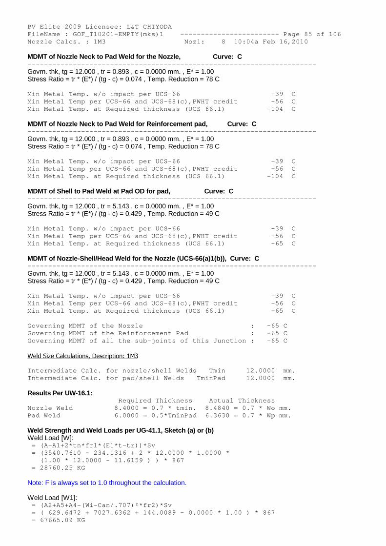
PV Elite 2009 Licensee: L&T CHIYODA FileName : GOF_T10201-EMPTY(mks)1 ------------- ----------- Page 85 of 106 Nozzle Calcs. : 1M3 Nozl: 8 10:04a Feb 16,2010
MDMT of Nozzle Neck to Pad Weld for the Nozzle, Curve: C -------------------------------------------------- --------------------
Govrn. thk, tg = 12.000 , tr = 0.893 , c = 0.0000 mm. , E* = 1.00Stress Ratio = tr * (E*) / (tg - c) = 0.074 , Temp. Reduction = 78 C
Min Metal Temp. w/o impact per UCS-66 -39 C Min Metal Temp per UCS-66 and UCS-68(c),PWHT credi t -56 C Min Metal Temp. at Required thickness (UCS 66.1) -104 C
MDMT of Nozzle Neck to Pad Weld for Reinforcement pad, Curve: C -------------------------------------------------- --------------------
Govrn. thk, tg = 12.000 , tr = 0.893 , c = 0.0000 mm. , E* = 1.00Stress Ratio = tr * (E*) / (tg - c) = 0.074 , Temp. Reduction = 78 C
Min Metal Temp. w/o impact per UCS-66 -39 C Min Metal Temp per UCS-66 and UCS-68(c),PWHT credi t -56 C Min Metal Temp. at Required thickness (UCS 66.1) -104 C
MDMT of Shell to Pad Weld at Pad OD for pad, Curve: C -------------------------------------------------- --------------------
Govrn. thk, tg = 12.000 , tr = 5.143 , c = 0.0000 mm. , E* = 1.00Stress Ratio = tr * (E*) / (tg - c) = 0.429 , Temp. Reduction = 49 C
Min Metal Temp. w/o impact per UCS-66 -39 C Min Metal Temp per UCS-66 and UCS-68(c),PWHT credi t -56 C Min Metal Temp. at Required thickness (UCS 66.1) -65 C
MDMT of Nozzle-Shell/Head Weld for the Nozzle (UCS-66(a)1(b)), Curve: C -------------------------------------------------- --------------------
Govrn. thk, tg = 12.000 , tr = 5.143 , c = 0.0000 mm. , E* = 1.00Stress Ratio = tr * (E*) / (tg - c) = 0.429 , Temp. Reduction = 49 C
Min Metal Temp. w/o impact per UCS-66 -39 C Min Metal Temp per UCS-66 and UCS-68(c),PWHT credi t -56 C Min Metal Temp. at Required thickness (UCS 66.1) -65 C
Governing MDMT of the Nozzle : -65 C Governing MDMT of the Reinforcement Pad : -65 C Governing MDMT of all the sub-joints of this Junct ion : -65 C
Weld Size Calculations, Description: 1M3
Intermediate Calc. for nozzle/shell Welds Tmin 12.0000 mm. Intermediate Calc. for pad/shell Welds TminPad 12.0000 mm.
Results Per UW-16.1: Required Thickness Actual Thickness Nozzle Weld 8.4000 = 0.7 * tmin. 8.4840 = 0.7 * Wo mm. Pad Weld 6.0000 = 0.5*TminPad 6.3630 = 0.7 * Wp mm.
Weld Strength and Weld Loads per UG-41.1, Sketch (a) or (b)Weld Load [W]:
= (A-A1+2*tn*fr1*(E1*t-tr))*Sv = (3540.7610 - 234.1316 + 2 * 12.0000 * 1.0000 * (1.00 * 12.0000 - 11.6159 ) ) * 867 = 28760.25 KG
Note: F is always set to 1.0 throughout the calculation.
Weld Load [W1]: = (A2+A5+A4-(Wi-Can/.707)²*fr2)*Sv = ( 629.6472 + 7027.6362 + 144.0089 - 0.0000 * 1. 00 ) * 867 = 67665.09 KG

PV Elite 2009 Licensee: L&T CHIYODA FileName : GOF_T10201-EMPTY(mks)1 ------------- ----------- Page 86 of 106 Nozzle Calcs. : 1M3 Nozl: 8 10:04a Feb 16,2010
Weld Load [W2]: = (A2 + A3 + A4 + (2 * tn * t * fr1)) * Sv = ( 629.6472 + 0.0000 + 144.0089 + ( 288.0179 ) ) * 867 = 9208.51 KG
Weld Load [W3]: = (A2+A3+A4+A5+(2*tn*t*fr1))*S = ( 629.6472 + 0.0000 + 144.0089 + 7027.6362 + ( 288.0179 ) ) * 867 = 70163.23 KG
Strength of Connection Elements for Failure Path Analysis
Shear, Outward Nozzle Weld [Sonw]: = (pi/2) * Dlo * Wo * 0.49 * Snw = ( 3.1416 / 2.0 ) * 633.6000 * 12.0000 * 0.49 * 867 = 50762. KG
Shear, Pad Element Weld [Spew]: = (pi/2) * DP * WP * 0.49 * SEW = ( 3.1416 / 2.0 ) * 1220.0000 * 9.0000 * 0.49 * 867 = 73307. KG
Shear, Nozzle Wall [Snw]: = (pi *( Dlr + Dlo )/4 ) * ( Thk - Can ) * 0.7 * Sn = (3.1416 * 310.8000 ) * ( 12.0000 - 0.0000 ) * 0 .7 * 867 = 71143. KG
Tension, Pad Groove Weld [Tpgw]: = ( pi/2) * Dlo * Wgpn * 0.74 * Seg = (3.1416 / 2 ) * 633.6000 * 9.0000 * 0.74 * 867 = 57496. KG
Tension, Shell Groove Weld [Tngw]: = (pi/2) * Dlo * (Wgnvi-Cas) * 0.74 * Sng = ( 3.1416 / 2.0 ) * 633.6000 * ( 9.0000 - 0.0000 ) * 0.74 * 867 = 57496. KG
Strength of Failure Paths:
PATH11 = ( SPEW + SNW ) = ( 73306 + 71143 ) = 144 450 KG PATH22 = ( Sonw + Tpgw + Tngw + Sinw ) = ( 50761 + 57495 + 57495 + 0 ) = 165752 K G PATH33 = ( Spew + Tngw + Sinw ) = ( 73306 + 57495 + 0 ) = 130802 KG
Summary of Failure Path Calculations: Path 1-1 = 144450 KG , must exceed W = 28760 KG o r W1 = 67665 KG Path 2-2 = 165752 KG , must exceed W = 28760 KG o r W2 = 9208 KG Path 3-3 = 130802 KG , must exceed W = 28760 KG o r W3 = 70163 KG
Maximum Allowable Pressure for this Nozzle at this Location: Converged Max. Allow. Pressure in Operating case 5.020 KG/CM2
Note: The MAWP of this junction was limited by the shell.
Nozzle is O.K. for the External Pressure 1.055 KG/CM2
The Drop for this Nozzle is : 28.8170 mm.The Cut Length for this Nozzle is, Drop + Ho + H + T : 290.8171 mm.
PVElite is a registered trademark of COADE, Inc. [2009]

PV Elite 2009 Licensee: L&T CHIYODA FileName : GOF_T10201-EMPTY(mks)1 ------------- ----------- Page 87 of 106 Nozzle Calcs. : 1M4 Nozl: 9 10:04a Feb 16,2010
INPUT VALUES, Nozzle Description: 1M4 From : 140
Pressure for Reinforcement Calculations P 3.515 KG/CM2 Temperature for Internal Pressure Temp 407 C Design External Pressure Pext 1.05 KG/CM2 Temperature for External Pressure Tempex 407 C
Shell Material SA-516 60 Shell Allowable Stress at Temperature S 867.59 KG/CM2 Shell Allowable Stress At Ambient Sa 1202.25 KG/CM2
Inside Diameter of Cylindrical Shell D 3505.20 mm. Design Length of Section L 1054.1000 mm. Shell Finished (Minimum) Thickness t 16.0000 mm. Shell Internal Corrosion Allowance c 6.3500 mm. Shell External Corrosion Allowance co 0.0000 mm.
Distance from Bottom/Left Tangent 23789.6406 mm.
User Entered Minimum Design Metal Temperature 19.40 C
Type of Element Connected to the Shell : Nozzle
Material SA-516 60 Material UNS Number K02100 Material Specification/Type Plate Allowable Stress at Temperature Sn 867.59 KG/CM2 Allowable Stress At Ambient Sna 1202.25 KG/CM2
Diameter Basis (for tr calc only) ID Layout Angle 0.00 deg Diameter 609.6000 mm.
Size and Thickness Basis Actual Actual Thickness tn 16.0000 mm.
Flange Material SA-105 Flange Type Weld Neck Flange
Corrosion Allowance can 6.3500 mm. Joint Efficiency of Shell Seam at Nozzle E1 1.00 Joint Efficiency of Nozzle Neck En 1.00
Outside Projection ho 250.0000 mm. Weld leg size between Nozzle and Pad/Shell Wo 16.0000 mm. Groove weld depth between Nozzle and Vessel Wgnv 16.0000 mm. Inside Projection h 0.0000 mm. Weld leg size, Inside Element to Shell Wi 0.0000 mm.
Pad Material SA-516 60 Pad Allowable Stress at Temperature Sp 867.59 KG/CM2 Pad Allowable Stress At Ambient Spa 1202.25 KG/CM2 Diameter of Pad along vessel surface Dp 1400.0000 mm. Thickness of Pad te 16.0000 mm. Weld leg size between Pad and Shell Wp 8.0000 mm. Groove weld depth between Pad and Nozzle Wgpn 8.0000 mm. Reinforcing Pad Width 379.2000 mm. ASME Code Weld Type per UW-16 None This is a Manway or Access Opening.
Class of attached Flange 150 Grade of attached Flange GR 1.1
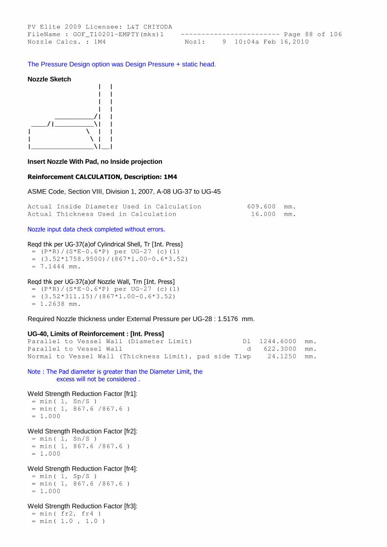
PV Elite 2009 Licensee: L&T CHIYODA FileName : GOF_T10201-EMPTY(mks)1 ------------- ----------- Page 88 of 106 Nozzle Calcs. : 1M4 Nozl: 9 10:04a Feb 16,2010
The Pressure Design option was Design Pressure + static head.
Nozzle Sketch | | | | | | | | __________/| | ____/|__________\| | | \ | | | \ | | |________________\|__|
Insert Nozzle With Pad, no Inside projection
Reinforcement CALCULATION, Description: 1M4
ASME Code, Section VIII, Division 1, 2007, A-08 UG-37 to UG-45
Actual Inside Diameter Used in Calculation 609.600 mm. Actual Thickness Used in Calculation 16.000 mm.
Nozzle input data check completed without errors.
Reqd thk per UG-37(a)of Cylindrical Shell, Tr [Int. Press] = (P*R)/(S*E-0.6*P) per UG-27 (c)(1) = (3.52*1758.9500)/(867*1.00-0.6*3.52) = 7.1444 mm.
Reqd thk per UG-37(a)of Nozzle Wall, Trn [Int. Press] = (P*R)/(S*E-0.6*P) per UG-27 (c)(1) = (3.52*311.15)/(867*1.00-0.6*3.52) = 1.2638 mm.
Required Nozzle thickness under External Pressure per UG-28 : 1.5176 mm.
UG-40, Limits of Reinforcement : [Int. Press] Parallel to Vessel Wall (Diameter Limit) Dl 1244.6000 mm. Parallel to Vessel Wall d 622.3000 mm. Normal to Vessel Wall (Thickness Limit), pad side Tlwp 24.1250 mm.
Note : The Pad diameter is greater than the Diameter Limit, theexcess will not be considered .
Weld Strength Reduction Factor [fr1]: = min( 1, Sn/S ) = min( 1, 867.6 /867.6 ) = 1.000
Weld Strength Reduction Factor [fr2]: = min( 1, Sn/S ) = min( 1, 867.6 /867.6 ) = 1.000
Weld Strength Reduction Factor [fr4]: = min( 1, Sp/S ) = min( 1, 867.6 /867.6 ) = 1.000
Weld Strength Reduction Factor [fr3]: = min( fr2, fr4 ) = min( 1.0 , 1.0 )
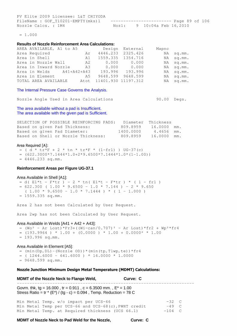
PV Elite 2009 Licensee: L&T CHIYODA FileName : GOF_T10201-EMPTY(mks)1 ------------- ----------- Page 89 of 106 Nozzle Calcs. : 1M4 Nozl: 9 10:04a Feb 16,2010 = 1.000
Results of Nozzle Reinforcement Area Calculations: AREA AVAILABLE, A1 to A5 Design External Mapnc Area Required Ar 4446.233 2325.426 NA sq.mm. Area in Shell A1 1559.335 1354.716 NA sq.mm. Area in Nozzle Wall A2 0.000 0.000 NA sq.mm. Area in Inward Nozzle A3 0.000 0.000 NA sq.mm. Area in Welds A41+A42+A43 193.996 193.996 NA sq.mm. Area in Element A5 9648.599 9648.599 NA sq.mm. TOTAL AREA AVAILABLE Atot 11401.930 11197.312 NA sq.mm.
The Internal Pressure Case Governs the Analysis.
Nozzle Angle Used in Area Calculations 90.00 Degs.
The area available without a pad is Insufficient.The area available with the given pad is Sufficient.
SELECTION OF POSSIBLE REINFORCING PADS: Diameter Thickness Based on given Pad Thickness: 809.8959 16.0000 mm. Based on given Pad Diameter: 1400.0000 4.4656 mm. Based on Shell or Nozzle Thickness: 809.8959 16.0000 mm.
Area Required [A]: = ( d * tr*F + 2 * tn * tr*F * (1-fr1) ) UG-37(c) = (622.3000*7.1444*1.0+2*9.6500*7.1444*1.0*(1-1.0 0)) = 4446.233 sq.mm.
Reinforcement Areas per Figure UG-37.1
Area Available in Shell [A1]: = d( E1*t - F*tr ) - 2 * tn( E1*t - F*tr ) * ( 1 - fr1 ) = 622.300 ( 1.00 * 9.6500 - 1.0 * 7.144 ) - 2 * 9 .650 ( 1.00 * 9.6500 - 1.0 * 7.1444 ) * ( 1 - 1.000 ) = 1559.335 sq.mm.
Area 2 has not been Calculated by User Request.
Area 2wp has not been Calculated by User Request.
Area Available in Welds [A41 + A42 + A43]: = (Wo² - Ar Lost)*Fr3+((Wi-can/0.707)² - Ar Lost) *fr2 + Wp²*fr4 = (193.9964 ) * 1.00 + (0.0000 ) * 1.00 + 0.0000² * 1.00 = 193.996 sq.mm.
Area Available in Element [A5]: = (min(Dp,DL)-(Nozzle OD))*(min(tp,Tlwp,te))*fr4 = ( 1244.6000 - 641.6000 ) * 16.0000 * 1.0000 = 9648.599 sq.mm.
Nozzle Junction Minimum Design Metal Temperature (MDMT) Calculations:
MDMT of the Nozzle Neck to Flange Weld, Curve: C -------------------------------------------------- --------------------
Govrn. thk, tg = 16.000 , tr = 0.911 , c = 6.3500 mm. , E* = 1.00Stress Ratio = tr * (E*) / (tg - c) = 0.094 , Temp. Reduction = 78 C
Min Metal Temp. w/o impact per UCS-66 -32 C Min Metal Temp per UCS-66 and UCS-68(c),PWHT credi t -49 C Min Metal Temp. at Required thickness (UCS 66.1) -104 C
MDMT of Nozzle Neck to Pad Weld for the Nozzle, Curve: C
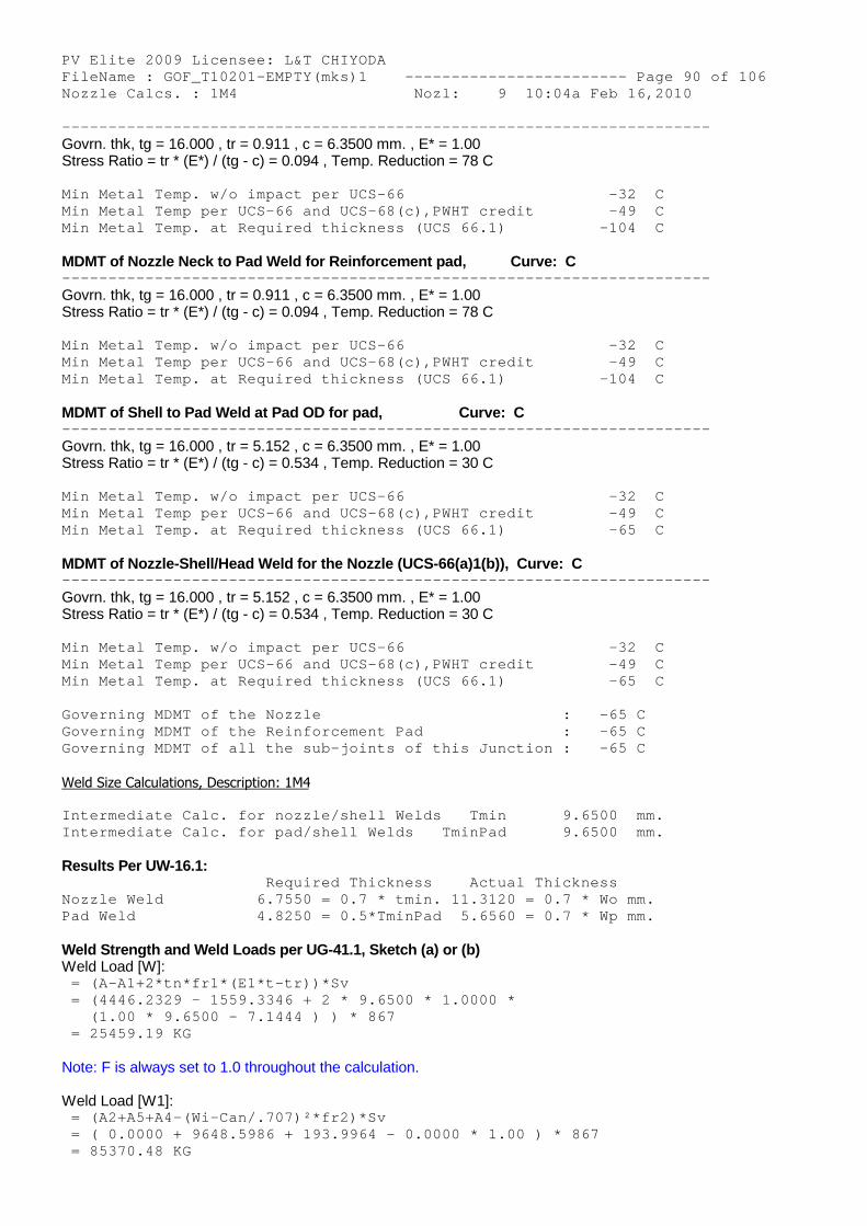
PV Elite 2009 Licensee: L&T CHIYODA FileName : GOF_T10201-EMPTY(mks)1 ------------- ----------- Page 90 of 106 Nozzle Calcs. : 1M4 Nozl: 9 10:04a Feb 16,2010 -------------------------------------------------- --------------------
Govrn. thk, tg = 16.000 , tr = 0.911 , c = 6.3500 mm. , E* = 1.00Stress Ratio = tr * (E*) / (tg - c) = 0.094 , Temp. Reduction = 78 C
Min Metal Temp. w/o impact per UCS-66 -32 C Min Metal Temp per UCS-66 and UCS-68(c),PWHT credi t -49 C Min Metal Temp. at Required thickness (UCS 66.1) -104 C
MDMT of Nozzle Neck to Pad Weld for Reinforcement pad, Curve: C -------------------------------------------------- --------------------
Govrn. thk, tg = 16.000 , tr = 0.911 , c = 6.3500 mm. , E* = 1.00Stress Ratio = tr * (E*) / (tg - c) = 0.094 , Temp. Reduction = 78 C
Min Metal Temp. w/o impact per UCS-66 -32 C Min Metal Temp per UCS-66 and UCS-68(c),PWHT credi t -49 C Min Metal Temp. at Required thickness (UCS 66.1) -104 C
MDMT of Shell to Pad Weld at Pad OD for pad, Curve: C -------------------------------------------------- --------------------
Govrn. thk, tg = 16.000 , tr = 5.152 , c = 6.3500 mm. , E* = 1.00Stress Ratio = tr * (E*) / (tg - c) = 0.534 , Temp. Reduction = 30 C
Min Metal Temp. w/o impact per UCS-66 -32 C Min Metal Temp per UCS-66 and UCS-68(c),PWHT credi t -49 C Min Metal Temp. at Required thickness (UCS 66.1) -65 C
MDMT of Nozzle-Shell/Head Weld for the Nozzle (UCS-66(a)1(b)), Curve: C -------------------------------------------------- --------------------
Govrn. thk, tg = 16.000 , tr = 5.152 , c = 6.3500 mm. , E* = 1.00Stress Ratio = tr * (E*) / (tg - c) = 0.534 , Temp. Reduction = 30 C
Min Metal Temp. w/o impact per UCS-66 -32 C Min Metal Temp per UCS-66 and UCS-68(c),PWHT credi t -49 C Min Metal Temp. at Required thickness (UCS 66.1) -65 C
Governing MDMT of the Nozzle : -65 C Governing MDMT of the Reinforcement Pad : -65 C Governing MDMT of all the sub-joints of this Junct ion : -65 C
Weld Size Calculations, Description: 1M4
Intermediate Calc. for nozzle/shell Welds Tmin 9.6500 mm. Intermediate Calc. for pad/shell Welds TminPad 9.6500 mm.
Results Per UW-16.1: Required Thickness Actual Thickness Nozzle Weld 6.7550 = 0.7 * tmin. 11.3120 = 0.7 * Wo mm. Pad Weld 4.8250 = 0.5*TminPad 5.6560 = 0.7 * Wp mm.
Weld Strength and Weld Loads per UG-41.1, Sketch (a) or (b)Weld Load [W]:
= (A-A1+2*tn*fr1*(E1*t-tr))*Sv = (4446.2329 - 1559.3346 + 2 * 9.6500 * 1.0000 * (1.00 * 9.6500 - 7.1444 ) ) * 867 = 25459.19 KG
Note: F is always set to 1.0 throughout the calculation.
Weld Load [W1]: = (A2+A5+A4-(Wi-Can/.707)²*fr2)*Sv = ( 0.0000 + 9648.5986 + 193.9964 - 0.0000 * 1.00 ) * 867 = 85370.48 KG
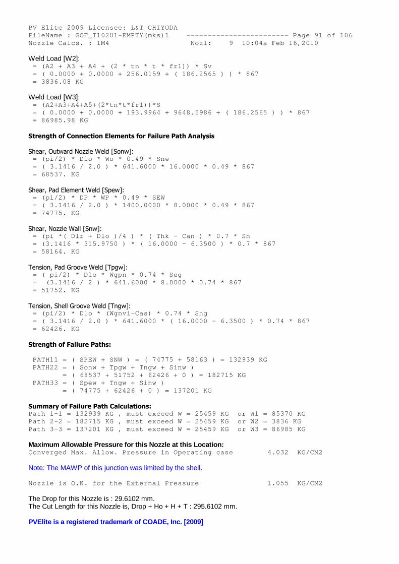
PV Elite 2009 Licensee: L&T CHIYODA FileName : GOF_T10201-EMPTY(mks)1 ------------- ----------- Page 91 of 106 Nozzle Calcs. : 1M4 Nozl: 9 10:04a Feb 16,2010
Weld Load [W2]: = (A2 + A3 + A4 + (2 * tn * t * fr1)) * Sv = ( 0.0000 + 0.0000 + 256.0159 + ( 186.2565 ) ) * 867 = 3836.08 KG
Weld Load [W3]: = (A2+A3+A4+A5+(2*tn*t*fr1))*S = ( 0.0000 + 0.0000 + 193.9964 + 9648.5986 + ( 18 6.2565 ) ) * 867 = 86985.98 KG
Strength of Connection Elements for Failure Path Analysis
Shear, Outward Nozzle Weld [Sonw]: = (pi/2) * Dlo * Wo * 0.49 * Snw = ( 3.1416 / 2.0 ) * 641.6000 * 16.0000 * 0.49 * 867 = 68537. KG
Shear, Pad Element Weld [Spew]: = (pi/2) * DP * WP * 0.49 * SEW = ( 3.1416 / 2.0 ) * 1400.0000 * 8.0000 * 0.49 * 867 = 74775. KG
Shear, Nozzle Wall [Snw]: = (pi *( Dlr + Dlo )/4 ) * ( Thk - Can ) * 0.7 * Sn = (3.1416 * 315.9750 ) * ( 16.0000 - 6.3500 ) * 0 .7 * 867 = 58164. KG
Tension, Pad Groove Weld [Tpgw]: = ( pi/2) * Dlo * Wgpn * 0.74 * Seg = (3.1416 / 2 ) * 641.6000 * 8.0000 * 0.74 * 867 = 51752. KG
Tension, Shell Groove Weld [Tngw]: = (pi/2) * Dlo * (Wgnvi-Cas) * 0.74 * Sng = ( 3.1416 / 2.0 ) * 641.6000 * ( 16.0000 - 6.350 0 ) * 0.74 * 867 = 62426. KG
Strength of Failure Paths:
PATH11 = ( SPEW + SNW ) = ( 74775 + 58163 ) = 132 939 KG PATH22 = ( Sonw + Tpgw + Tngw + Sinw ) = ( 68537 + 51752 + 62426 + 0 ) = 182715 K G PATH33 = ( Spew + Tngw + Sinw ) = ( 74775 + 62426 + 0 ) = 137201 KG
Summary of Failure Path Calculations: Path 1-1 = 132939 KG , must exceed W = 25459 KG o r W1 = 85370 KG Path 2-2 = 182715 KG , must exceed W = 25459 KG o r W2 = 3836 KG Path 3-3 = 137201 KG , must exceed W = 25459 KG o r W3 = 86985 KG
Maximum Allowable Pressure for this Nozzle at this Location: Converged Max. Allow. Pressure in Operating case 4.032 KG/CM2
Note: The MAWP of this junction was limited by the shell.
Nozzle is O.K. for the External Pressure 1.055 KG/CM2
The Drop for this Nozzle is : 29.6102 mm.The Cut Length for this Nozzle is, Drop + Ho + H + T : 295.6102 mm.
PVElite is a registered trademark of COADE, Inc. [2009]
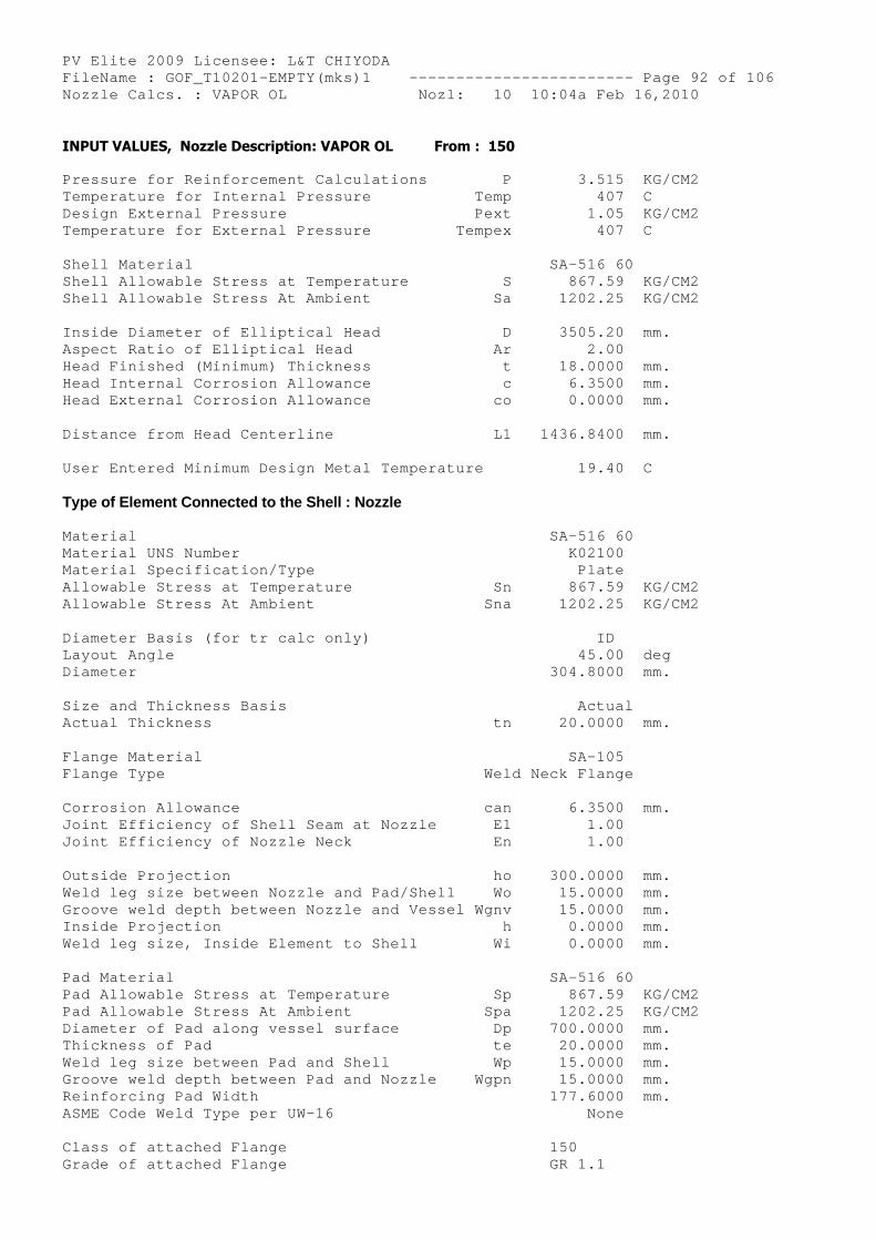
PV Elite 2009 Licensee: L&T CHIYODA FileName : GOF_T10201-EMPTY(mks)1 ------------- ----------- Page 92 of 106 Nozzle Calcs. : VAPOR OL Nozl: 10 10:04a Feb 16,2010
INPUT VALUES, Nozzle Description: VAPOR OL From : 150
Pressure for Reinforcement Calculations P 3.515 KG/CM2 Temperature for Internal Pressure Temp 407 C Design External Pressure Pext 1.05 KG/CM2 Temperature for External Pressure Tempex 407 C
Shell Material SA-516 60 Shell Allowable Stress at Temperature S 867.59 KG/CM2 Shell Allowable Stress At Ambient Sa 1202.25 KG/CM2
Inside Diameter of Elliptical Head D 3505.20 mm. Aspect Ratio of Elliptical Head Ar 2.00 Head Finished (Minimum) Thickness t 18.0000 mm. Head Internal Corrosion Allowance c 6.3500 mm. Head External Corrosion Allowance co 0.0000 mm.
Distance from Head Centerline L1 1436.8400 mm.
User Entered Minimum Design Metal Temperature 19.40 C
Type of Element Connected to the Shell : Nozzle
Material SA-516 60 Material UNS Number K02100 Material Specification/Type Plate Allowable Stress at Temperature Sn 867.59 KG/CM2 Allowable Stress At Ambient Sna 1202.25 KG/CM2
Diameter Basis (for tr calc only) ID Layout Angle 45.00 deg Diameter 304.8000 mm.
Size and Thickness Basis Actual Actual Thickness tn 20.0000 mm.
Flange Material SA-105 Flange Type Weld Neck Flange
Corrosion Allowance can 6.3500 mm. Joint Efficiency of Shell Seam at Nozzle E1 1.00 Joint Efficiency of Nozzle Neck En 1.00
Outside Projection ho 300.0000 mm. Weld leg size between Nozzle and Pad/Shell Wo 15.0000 mm. Groove weld depth between Nozzle and Vessel Wgnv 15.0000 mm. Inside Projection h 0.0000 mm. Weld leg size, Inside Element to Shell Wi 0.0000 mm.
Pad Material SA-516 60 Pad Allowable Stress at Temperature Sp 867.59 KG/CM2 Pad Allowable Stress At Ambient Spa 1202.25 KG/CM2 Diameter of Pad along vessel surface Dp 700.0000 mm. Thickness of Pad te 20.0000 mm. Weld leg size between Pad and Shell Wp 15.0000 mm. Groove weld depth between Pad and Nozzle Wgpn 15.0000 mm. Reinforcing Pad Width 177.6000 mm. ASME Code Weld Type per UW-16 None
Class of attached Flange 150 Grade of attached Flange GR 1.1
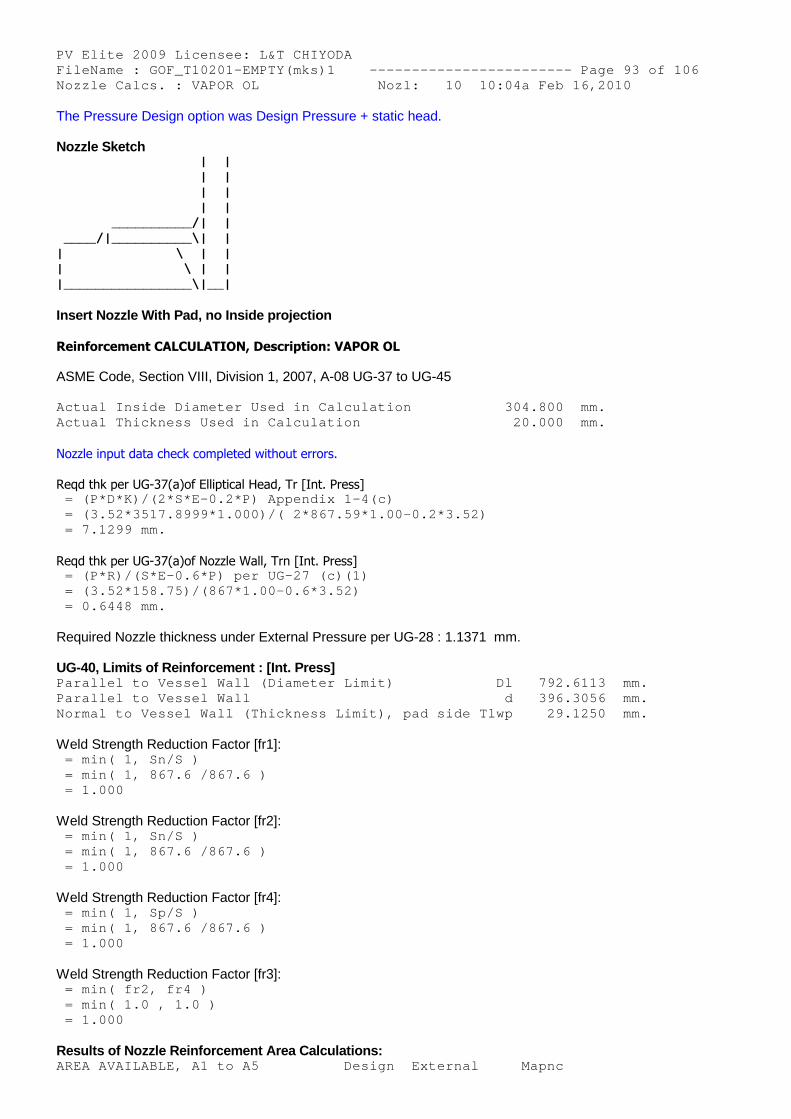
PV Elite 2009 Licensee: L&T CHIYODA FileName : GOF_T10201-EMPTY(mks)1 ------------- ----------- Page 93 of 106 Nozzle Calcs. : VAPOR OL Nozl: 10 10:04a Feb 16,2010
The Pressure Design option was Design Pressure + static head.
Nozzle Sketch | | | | | | | | __________/| | ____/|__________\| | | \ | | | \ | | |________________\|__|
Insert Nozzle With Pad, no Inside projection
Reinforcement CALCULATION, Description: VAPOR OL
ASME Code, Section VIII, Division 1, 2007, A-08 UG-37 to UG-45
Actual Inside Diameter Used in Calculation 304.800 mm. Actual Thickness Used in Calculation 20.000 mm.
Nozzle input data check completed without errors.
Reqd thk per UG-37(a)of Elliptical Head, Tr [Int. Press] = (P*D*K)/(2*S*E-0.2*P) Appendix 1-4(c) = (3.52*3517.8999*1.000)/( 2*867.59*1.00-0.2*3.52 ) = 7.1299 mm.
Reqd thk per UG-37(a)of Nozzle Wall, Trn [Int. Press] = (P*R)/(S*E-0.6*P) per UG-27 (c)(1) = (3.52*158.75)/(867*1.00-0.6*3.52) = 0.6448 mm.
Required Nozzle thickness under External Pressure per UG-28 : 1.1371 mm.
UG-40, Limits of Reinforcement : [Int. Press] Parallel to Vessel Wall (Diameter Limit) Dl 792.6113 mm. Parallel to Vessel Wall d 396.3056 mm. Normal to Vessel Wall (Thickness Limit), pad side Tlwp 29.1250 mm.
Weld Strength Reduction Factor [fr1]: = min( 1, Sn/S ) = min( 1, 867.6 /867.6 ) = 1.000
Weld Strength Reduction Factor [fr2]: = min( 1, Sn/S ) = min( 1, 867.6 /867.6 ) = 1.000
Weld Strength Reduction Factor [fr4]: = min( 1, Sp/S ) = min( 1, 867.6 /867.6 ) = 1.000
Weld Strength Reduction Factor [fr3]: = min( fr2, fr4 ) = min( 1.0 , 1.0 ) = 1.000
Results of Nozzle Reinforcement Area Calculations: AREA AVAILABLE, A1 to A5 Design External Mapnc
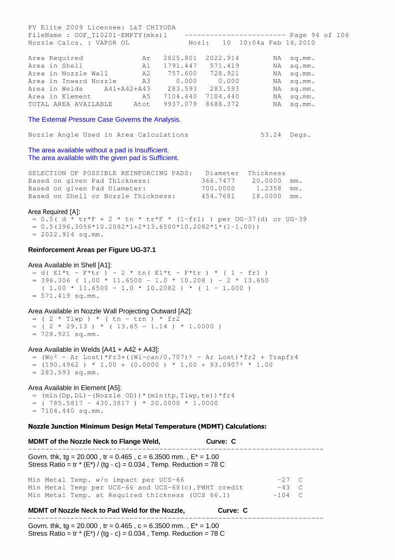
PV Elite 2009 Licensee: L&T CHIYODA FileName : GOF_T10201-EMPTY(mks)1 ------------- ----------- Page 94 of 106 Nozzle Calcs. : VAPOR OL Nozl: 10 10:04a Feb 16,2010 Area Required Ar 2825.801 2022.914 NA sq.mm. Area in Shell A1 1791.447 571.419 NA sq.mm. Area in Nozzle Wall A2 757.600 728.921 NA sq.mm. Area in Inward Nozzle A3 0.000 0.000 NA sq.mm. Area in Welds A41+A42+A43 283.593 283.593 NA sq.mm. Area in Element A5 7104.440 7104.440 NA sq.mm. TOTAL AREA AVAILABLE Atot 9937.079 8688.372 NA sq.mm.
The External Pressure Case Governs the Analysis.
Nozzle Angle Used in Area Calculations 53.24 Degs.
The area available without a pad is Insufficient.The area available with the given pad is Sufficient.
SELECTION OF POSSIBLE REINFORCING PADS: Diameter Thickness Based on given Pad Thickness: 366.7477 20.0000 mm. Based on given Pad Diameter: 700.0000 1.2358 mm. Based on Shell or Nozzle Thickness: 454.7681 18.0000 mm.
Area Required [A]: = 0.5( d * tr*F + 2 * tn * tr*F * (1-fr1) ) per U G-37(d) or UG-39 = 0.5(396.3056*10.2082*1+2*13.6500*10.2082*1*(1-1 .00)) = 2022.914 sq.mm.
Reinforcement Areas per Figure UG-37.1
Area Available in Shell [A1]: = d( E1*t - F*tr ) - 2 * tn( E1*t - F*tr ) * ( 1 - fr1 ) = 396.306 ( 1.00 * 11.6500 - 1.0 * 10.208 ) - 2 * 13.650 ( 1.00 * 11.6500 - 1.0 * 10.2082 ) * ( 1 - 1.00 0 ) = 571.419 sq.mm.
Area Available in Nozzle Wall Projecting Outward [A2]: = ( 2 * Tlwp ) * ( tn - trn ) * fr2 = ( 2 * 29.13 ) * ( 13.65 - 1.14 ) * 1.0000 ) = 728.921 sq.mm.
Area Available in Welds [A41 + A42 + A43]: = (Wo² - Ar Lost)*Fr3+((Wi-can/0.707)² - Ar Lost) *fr2 + Trapfr4 = (190.4962 ) * 1.00 + (0.0000 ) * 1.00 + 93.0907 ² * 1.00 = 283.593 sq.mm.
Area Available in Element [A5]: = (min(Dp,DL)-(Nozzle OD))*(min(tp,Tlwp,te))*fr4 = ( 785.5817 - 430.3817 ) * 20.0000 * 1.0000 = 7104.440 sq.mm.
Nozzle Junction Minimum Design Metal Temperature (MDMT) Calculations:
MDMT of the Nozzle Neck to Flange Weld, Curve: C -------------------------------------------------- --------------------
Govrn. thk, tg = 20.000 , tr = 0.465 , c = 6.3500 mm. , E* = 1.00Stress Ratio = tr * (E*) / (tg - c) = 0.034 , Temp. Reduction = 78 C
Min Metal Temp. w/o impact per UCS-66 -27 C Min Metal Temp per UCS-66 and UCS-68(c),PWHT credi t -43 C Min Metal Temp. at Required thickness (UCS 66.1) -104 C
MDMT of Nozzle Neck to Pad Weld for the Nozzle, Curve: C -------------------------------------------------- --------------------
Govrn. thk, tg = 20.000 , tr = 0.465 , c = 6.3500 mm. , E* = 1.00Stress Ratio = tr * (E*) / (tg - c) = 0.034 , Temp. Reduction = 78 C
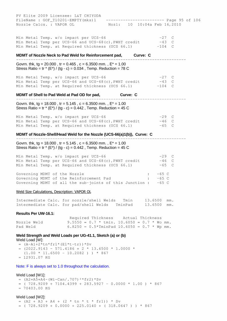
PV Elite 2009 Licensee: L&T CHIYODA FileName : GOF_T10201-EMPTY(mks)1 ------------- ----------- Page 95 of 106 Nozzle Calcs. : VAPOR OL Nozl: 10 10:04a Feb 16,2010
Min Metal Temp. w/o impact per UCS-66 -27 C Min Metal Temp per UCS-66 and UCS-68(c),PWHT credi t -43 C Min Metal Temp. at Required thickness (UCS 66.1) -104 C
MDMT of Nozzle Neck to Pad Weld for Reinforcement pad, Curve: C -------------------------------------------------- --------------------
Govrn. thk, tg = 20.000 , tr = 0.465 , c = 6.3500 mm. , E* = 1.00Stress Ratio = tr * (E*) / (tg - c) = 0.034 , Temp. Reduction = 78 C
Min Metal Temp. w/o impact per UCS-66 -27 C Min Metal Temp per UCS-66 and UCS-68(c),PWHT credi t -43 C Min Metal Temp. at Required thickness (UCS 66.1) -104 C
MDMT of Shell to Pad Weld at Pad OD for pad, Curve: C -------------------------------------------------- --------------------
Govrn. thk, tg = 18.000 , tr = 5.145 , c = 6.3500 mm. , E* = 1.00Stress Ratio = tr * (E*) / (tg - c) = 0.442 , Temp. Reduction = 45 C
Min Metal Temp. w/o impact per UCS-66 -29 C Min Metal Temp per UCS-66 and UCS-68(c),PWHT credi t -46 C Min Metal Temp. at Required thickness (UCS 66.1) -65 C
MDMT of Nozzle-Shell/Head Weld for the Nozzle (UCS-66(a)1(b)), Curve: C -------------------------------------------------- --------------------
Govrn. thk, tg = 18.000 , tr = 5.145 , c = 6.3500 mm. , E* = 1.00Stress Ratio = tr * (E*) / (tg - c) = 0.442 , Temp. Reduction = 45 C
Min Metal Temp. w/o impact per UCS-66 -29 C Min Metal Temp per UCS-66 and UCS-68(c),PWHT credi t -46 C Min Metal Temp. at Required thickness (UCS 66.1) -65 C
Governing MDMT of the Nozzle : -65 C Governing MDMT of the Reinforcement Pad : -65 C Governing MDMT of all the sub-joints of this Junct ion : -65 C
Weld Size Calculations, Description: VAPOR OL
Intermediate Calc. for nozzle/shell Welds Tmin 13.6500 mm. Intermediate Calc. for pad/shell Welds TminPad 13.6500 mm.
Results Per UW-16.1: Required Thickness Actual Thickness Nozzle Weld 9.5550 = 0.7 * tmin. 10.6050 = 0.7 * Wo mm. Pad Weld 6.8250 = 0.5*TminPad 10.6050 = 0.7 * Wp mm.
Weld Strength and Weld Loads per UG-41.1, Sketch (a) or (b)Weld Load [W]:
= (A-A1+2*tn*fr1*(E1*t-tr))*Sv = (2022.9143 - 571.4186 + 2 * 13.6500 * 1.0000 * (1.00 * 11.6500 - 10.2082 ) ) * 867 = 12931.07 KG
Note: F is always set to 1.0 throughout the calculation.
Weld Load [W1]: = (A2+A5+A4-(Wi-Can/.707)²*fr2)*Sv = ( 728.9209 + 7104.4399 + 283.5927 - 0.0000 * 1. 00 ) * 867 = 70403.00 KG
Weld Load [W2]: = (A2 + A3 + A4 + (2 * tn * t * fr1)) * Sv = ( 728.9209 + 0.0000 + 225.0140 + ( 318.0647 ) ) * 867
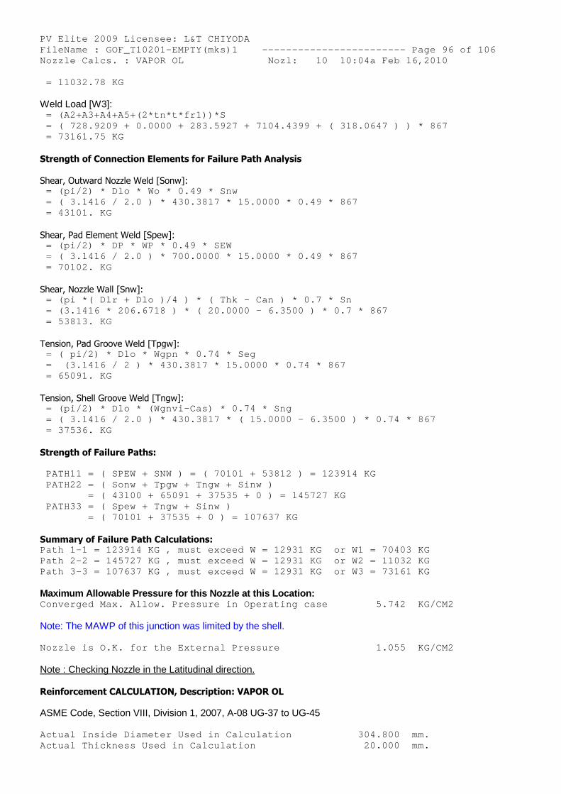
PV Elite 2009 Licensee: L&T CHIYODA FileName : GOF_T10201-EMPTY(mks)1 ------------- ----------- Page 96 of 106 Nozzle Calcs. : VAPOR OL Nozl: 10 10:04a Feb 16,2010 = 11032.78 KG
Weld Load [W3]: = (A2+A3+A4+A5+(2*tn*t*fr1))*S = ( 728.9209 + 0.0000 + 283.5927 + 7104.4399 + ( 318.0647 ) ) * 867 = 73161.75 KG
Strength of Connection Elements for Failure Path Analysis
Shear, Outward Nozzle Weld [Sonw]: = (pi/2) * Dlo * Wo * 0.49 * Snw = ( 3.1416 / 2.0 ) * 430.3817 * 15.0000 * 0.49 * 867 = 43101. KG
Shear, Pad Element Weld [Spew]: = (pi/2) * DP * WP * 0.49 * SEW = ( 3.1416 / 2.0 ) * 700.0000 * 15.0000 * 0.49 * 867 = 70102. KG
Shear, Nozzle Wall [Snw]: = (pi *( Dlr + Dlo )/4 ) * ( Thk - Can ) * 0.7 * Sn = (3.1416 * 206.6718 ) * ( 20.0000 - 6.3500 ) * 0 .7 * 867 = 53813. KG
Tension, Pad Groove Weld [Tpgw]: = ( pi/2) * Dlo * Wgpn * 0.74 * Seg = (3.1416 / 2 ) * 430.3817 * 15.0000 * 0.74 * 86 7 = 65091. KG
Tension, Shell Groove Weld [Tngw]: = (pi/2) * Dlo * (Wgnvi-Cas) * 0.74 * Sng = ( 3.1416 / 2.0 ) * 430.3817 * ( 15.0000 - 6.350 0 ) * 0.74 * 867 = 37536. KG
Strength of Failure Paths:
PATH11 = ( SPEW + SNW ) = ( 70101 + 53812 ) = 123 914 KG PATH22 = ( Sonw + Tpgw + Tngw + Sinw ) = ( 43100 + 65091 + 37535 + 0 ) = 145727 K G PATH33 = ( Spew + Tngw + Sinw ) = ( 70101 + 37535 + 0 ) = 107637 KG
Summary of Failure Path Calculations: Path 1-1 = 123914 KG , must exceed W = 12931 KG o r W1 = 70403 KG Path 2-2 = 145727 KG , must exceed W = 12931 KG o r W2 = 11032 KG Path 3-3 = 107637 KG , must exceed W = 12931 KG o r W3 = 73161 KG
Maximum Allowable Pressure for this Nozzle at this Location: Converged Max. Allow. Pressure in Operating case 5.742 KG/CM2
Note: The MAWP of this junction was limited by the shell.
Nozzle is O.K. for the External Pressure 1.055 KG/CM2
Note : Checking Nozzle in the Latitudinal direction.
Reinforcement CALCULATION, Description: VAPOR OL
ASME Code, Section VIII, Division 1, 2007, A-08 UG-37 to UG-45
Actual Inside Diameter Used in Calculation 304.800 mm. Actual Thickness Used in Calculation 20.000 mm.
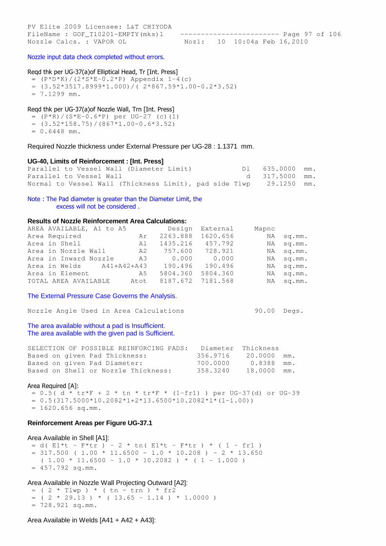
PV Elite 2009 Licensee: L&T CHIYODA FileName : GOF_T10201-EMPTY(mks)1 ------------- ----------- Page 97 of 106 Nozzle Calcs. : VAPOR OL Nozl: 10 10:04a Feb 16,2010 Nozzle input data check completed without errors.
Reqd thk per UG-37(a)of Elliptical Head, Tr [Int. Press] = (P*D*K)/(2*S*E-0.2*P) Appendix 1-4(c) = (3.52*3517.8999*1.000)/( 2*867.59*1.00-0.2*3.52 ) = 7.1299 mm.
Reqd thk per UG-37(a)of Nozzle Wall, Trn [Int. Press] = (P*R)/(S*E-0.6*P) per UG-27 (c)(1) = (3.52*158.75)/(867*1.00-0.6*3.52) = 0.6448 mm.
Required Nozzle thickness under External Pressure per UG-28 : 1.1371 mm.
UG-40, Limits of Reinforcement : [Int. Press] Parallel to Vessel Wall (Diameter Limit) Dl 635.0000 mm. Parallel to Vessel Wall d 317.5000 mm. Normal to Vessel Wall (Thickness Limit), pad side Tlwp 29.1250 mm.
Note : The Pad diameter is greater than the Diameter Limit, theexcess will not be considered .
Results of Nozzle Reinforcement Area Calculations: AREA AVAILABLE, A1 to A5 Design External Mapnc Area Required Ar 2263.888 1620.656 NA sq.mm. Area in Shell A1 1435.216 457.792 NA sq.mm. Area in Nozzle Wall A2 757.600 728.921 NA sq.mm. Area in Inward Nozzle A3 0.000 0.000 NA sq.mm. Area in Welds A41+A42+A43 190.496 190.496 NA sq.mm. Area in Element A5 5804.360 5804.360 NA sq.mm. TOTAL AREA AVAILABLE Atot 8187.672 7181.568 NA sq.mm.
The External Pressure Case Governs the Analysis.
Nozzle Angle Used in Area Calculations 90.00 Degs.
The area available without a pad is Insufficient.The area available with the given pad is Sufficient.
SELECTION OF POSSIBLE REINFORCING PADS: Diameter Thickness Based on given Pad Thickness: 356.9716 20.0000 mm. Based on given Pad Diameter: 700.0000 0.8388 mm. Based on Shell or Nozzle Thickness: 358.3240 18.0000 mm.
Area Required [A]: = 0.5( d * tr*F + 2 * tn * tr*F * (1-fr1) ) per U G-37(d) or UG-39 = 0.5(317.5000*10.2082*1+2*13.6500*10.2082*1*(1-1 .00)) = 1620.656 sq.mm.
Reinforcement Areas per Figure UG-37.1
Area Available in Shell [A1]: = d( E1*t - F*tr ) - 2 * tn( E1*t - F*tr ) * ( 1 - fr1 ) = 317.500 ( 1.00 * 11.6500 - 1.0 * 10.208 ) - 2 * 13.650 ( 1.00 * 11.6500 - 1.0 * 10.2082 ) * ( 1 - 1.00 0 ) = 457.792 sq.mm.
Area Available in Nozzle Wall Projecting Outward [A2]: = ( 2 * Tlwp ) * ( tn - trn ) * fr2 = ( 2 * 29.13 ) * ( 13.65 - 1.14 ) * 1.0000 ) = 728.921 sq.mm.
Area Available in Welds [A41 + A42 + A43]:
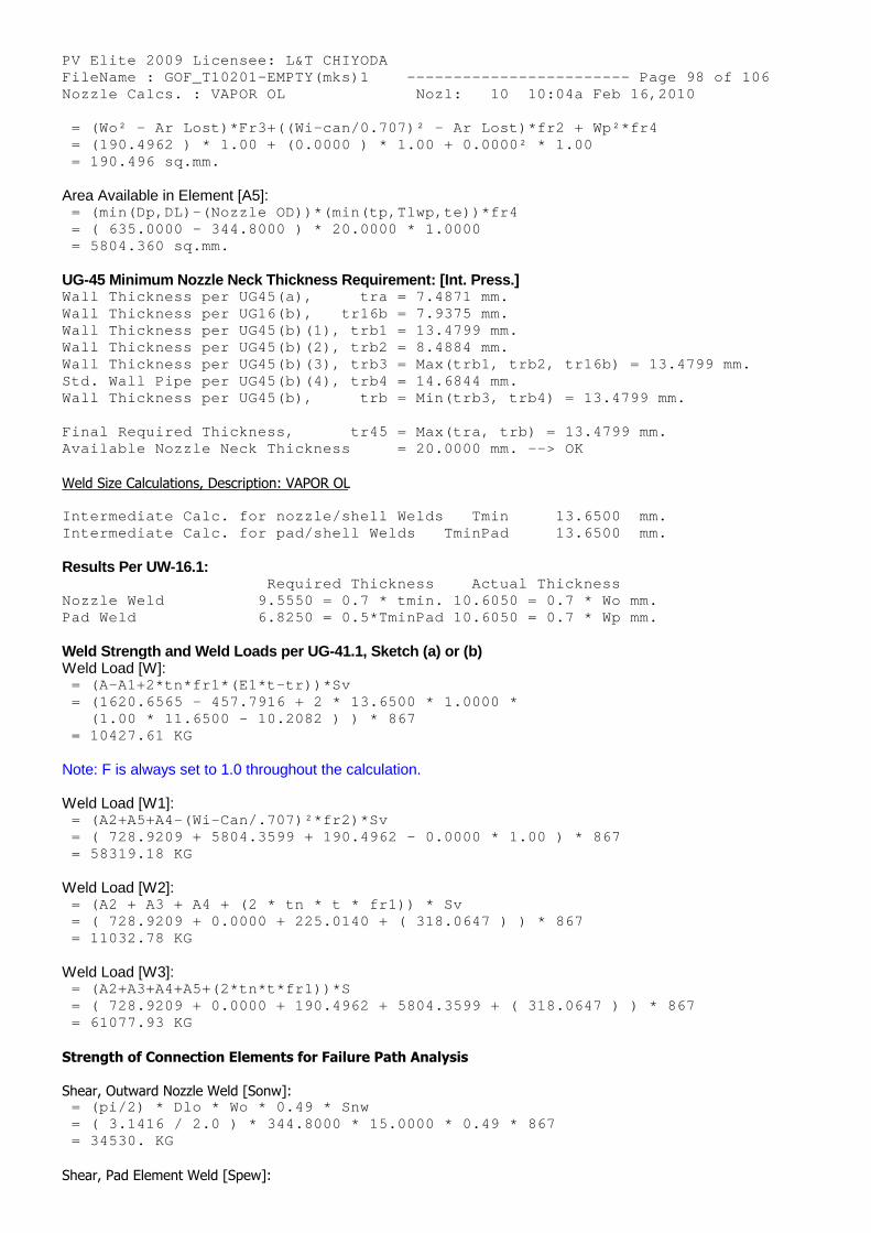
PV Elite 2009 Licensee: L&T CHIYODA FileName : GOF_T10201-EMPTY(mks)1 ------------- ----------- Page 98 of 106 Nozzle Calcs. : VAPOR OL Nozl: 10 10:04a Feb 16,2010 = (Wo² - Ar Lost)*Fr3+((Wi-can/0.707)² - Ar Lost) *fr2 + Wp²*fr4 = (190.4962 ) * 1.00 + (0.0000 ) * 1.00 + 0.0000² * 1.00 = 190.496 sq.mm.
Area Available in Element [A5]: = (min(Dp,DL)-(Nozzle OD))*(min(tp,Tlwp,te))*fr4 = ( 635.0000 - 344.8000 ) * 20.0000 * 1.0000 = 5804.360 sq.mm.
UG-45 Minimum Nozzle Neck Thickness Requirement: [Int. Press.] Wall Thickness per UG45(a), tra = 7.4871 mm. Wall Thickness per UG16(b), tr16b = 7.9375 mm. Wall Thickness per UG45(b)(1), trb1 = 13.4799 mm. Wall Thickness per UG45(b)(2), trb2 = 8.4884 mm. Wall Thickness per UG45(b)(3), trb3 = Max(trb1, tr b2, tr16b) = 13.4799 mm. Std. Wall Pipe per UG45(b)(4), trb4 = 14.6844 mm. Wall Thickness per UG45(b), trb = Min(trb3, tr b4) = 13.4799 mm.
Final Required Thickness, tr45 = Max(tra, trb ) = 13.4799 mm. Available Nozzle Neck Thickness = 20.0000 mm. --> OK
Weld Size Calculations, Description: VAPOR OL
Intermediate Calc. for nozzle/shell Welds Tmin 13.6500 mm. Intermediate Calc. for pad/shell Welds TminPad 13.6500 mm.
Results Per UW-16.1: Required Thickness Actual Thickness Nozzle Weld 9.5550 = 0.7 * tmin. 10.6050 = 0.7 * Wo mm. Pad Weld 6.8250 = 0.5*TminPad 10.6050 = 0.7 * Wp mm.
Weld Strength and Weld Loads per UG-41.1, Sketch (a) or (b)Weld Load [W]:
= (A-A1+2*tn*fr1*(E1*t-tr))*Sv = (1620.6565 - 457.7916 + 2 * 13.6500 * 1.0000 * (1.00 * 11.6500 - 10.2082 ) ) * 867 = 10427.61 KG
Note: F is always set to 1.0 throughout the calculation.
Weld Load [W1]: = (A2+A5+A4-(Wi-Can/.707)²*fr2)*Sv = ( 728.9209 + 5804.3599 + 190.4962 - 0.0000 * 1. 00 ) * 867 = 58319.18 KG
Weld Load [W2]: = (A2 + A3 + A4 + (2 * tn * t * fr1)) * Sv = ( 728.9209 + 0.0000 + 225.0140 + ( 318.0647 ) ) * 867 = 11032.78 KG
Weld Load [W3]: = (A2+A3+A4+A5+(2*tn*t*fr1))*S = ( 728.9209 + 0.0000 + 190.4962 + 5804.3599 + ( 318.0647 ) ) * 867 = 61077.93 KG
Strength of Connection Elements for Failure Path Analysis
Shear, Outward Nozzle Weld [Sonw]: = (pi/2) * Dlo * Wo * 0.49 * Snw = ( 3.1416 / 2.0 ) * 344.8000 * 15.0000 * 0.49 * 867 = 34530. KG
Shear, Pad Element Weld [Spew]:
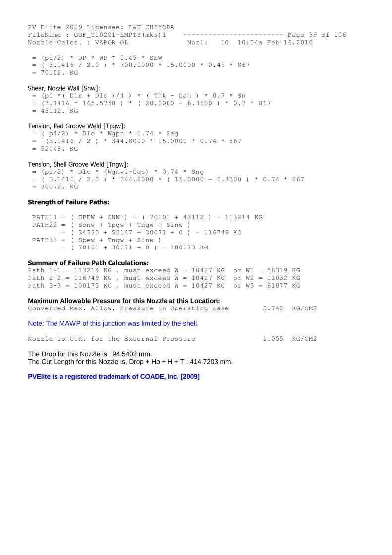
PV Elite 2009 Licensee: L&T CHIYODA FileName : GOF_T10201-EMPTY(mks)1 ------------- ----------- Page 99 of 106 Nozzle Calcs. : VAPOR OL Nozl: 10 10:04a Feb 16,2010 = (pi/2) * DP * WP * 0.49 * SEW = ( 3.1416 / 2.0 ) * 700.0000 * 15.0000 * 0.49 * 867 = 70102. KG
Shear, Nozzle Wall [Snw]: = (pi *( Dlr + Dlo )/4 ) * ( Thk - Can ) * 0.7 * Sn = (3.1416 * 165.5750 ) * ( 20.0000 - 6.3500 ) * 0 .7 * 867 = 43112. KG
Tension, Pad Groove Weld [Tpgw]: = ( pi/2) * Dlo * Wgpn * 0.74 * Seg = (3.1416 / 2 ) * 344.8000 * 15.0000 * 0.74 * 86 7 = 52148. KG
Tension, Shell Groove Weld [Tngw]: = (pi/2) * Dlo * (Wgnvi-Cas) * 0.74 * Sng = ( 3.1416 / 2.0 ) * 344.8000 * ( 15.0000 - 6.350 0 ) * 0.74 * 867 = 30072. KG
Strength of Failure Paths:
PATH11 = ( SPEW + SNW ) = ( 70101 + 43112 ) = 113 214 KG PATH22 = ( Sonw + Tpgw + Tngw + Sinw ) = ( 34530 + 52147 + 30071 + 0 ) = 116749 K G PATH33 = ( Spew + Tngw + Sinw ) = ( 70101 + 30071 + 0 ) = 100173 KG
Summary of Failure Path Calculations: Path 1-1 = 113214 KG , must exceed W = 10427 KG o r W1 = 58319 KG Path 2-2 = 116749 KG , must exceed W = 10427 KG o r W2 = 11032 KG Path 3-3 = 100173 KG , must exceed W = 10427 KG o r W3 = 61077 KG
Maximum Allowable Pressure for this Nozzle at this Location: Converged Max. Allow. Pressure in Operating case 5.742 KG/CM2
Note: The MAWP of this junction was limited by the shell.
Nozzle is O.K. for the External Pressure 1.055 KG/CM2
The Drop for this Nozzle is : 94.5402 mm.The Cut Length for this Nozzle is, Drop + Ho + H + T : 414.7203 mm.
PVElite is a registered trademark of COADE, Inc. [2009]
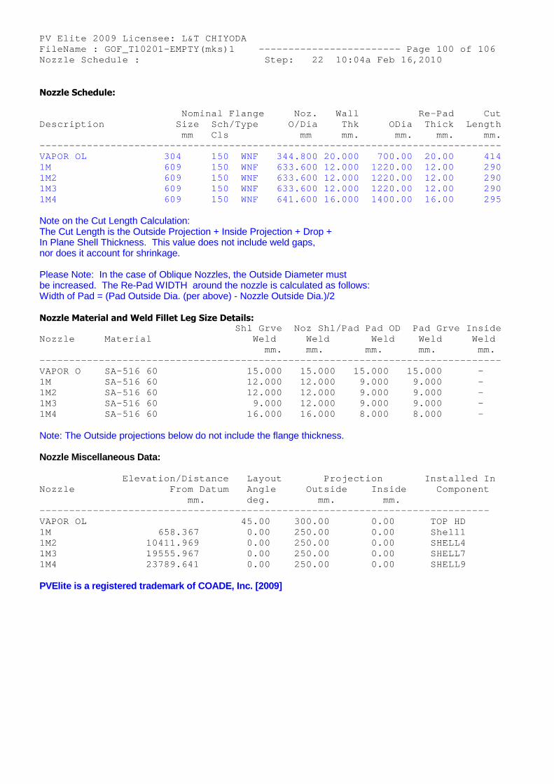
PV Elite 2009 Licensee: L&T CHIYODA FileName : GOF_T10201-EMPTY(mks)1 ------------- ----------- Page 100 of 106 Nozzle Schedule : Step: 22 10:04a Feb 16,2010
Nozzle Schedule:
Nominal Flange Noz. Wall Re-Pad Cut Description Size Sch/Type O/Dia Thk ODia Thick Length mm Cls mm mm. mm. mm. mm. -------------------------------------------------- ---------------------------- VAPOR OL 304 150 WNF 344.800 20 .000 700.00 20.00 414 1M 609 150 WNF 633.600 12 .000 1220.00 12.00 290 1M2 609 150 WNF 633.600 12 .000 1220.00 12.00 290 1M3 609 150 WNF 633.600 12 .000 1220.00 12.00 290 1M4 609 150 WNF 641.600 16 .000 1400.00 16.00 295
Note on the Cut Length Calculation:The Cut Length is the Outside Projection + Inside Projection + Drop +In Plane Shell Thickness. This value does not include weld gaps,nor does it account for shrinkage.
Please Note: In the case of Oblique Nozzles, the Outside Diameter mustbe increased. The Re-Pad WIDTH around the nozzle is calculated as follows:Width of Pad = (Pad Outside Dia. (per above) - Nozzle Outside Dia.)/2
Nozzle Material and Weld Fillet Leg Size Details: Shl Grve Noz Shl /Pad Pad OD Pad Grve Inside Nozzle Material Weld Weld Weld Weld Weld mm. mm. mm. mm. mm. -------------------------------------------------- ---------------------------- VAPOR O SA-516 60 15.000 15.000 15.000 15.000 - 1M SA-516 60 12.000 12.000 9.000 9.000 - 1M2 SA-516 60 12.000 12.000 9.000 9.000 - 1M3 SA-516 60 9.000 12.000 9.000 9.000 - 1M4 SA-516 60 16.000 16.000 8.000 8.000 -
Note: The Outside projections below do not include the flange thickness.
Nozzle Miscellaneous Data:
Elevation/Distance Layout Pr ojection Installed In Nozzle From Datum Angle Outsi de Inside Component mm. deg. mm. mm. -------------------------------------------------- -------------------------- VAPOR OL 45.00 300.00 0.00 TOP HD 1M 658.367 0.00 250.00 0.00 Shell1 1M2 10411.969 0.00 250.00 0.00 SHELL4 1M3 19555.967 0.00 250.00 0.00 SHELL7 1M4 23789.641 0.00 250.00 0.00 SHELL9
PVElite is a registered trademark of COADE, Inc. [2009]
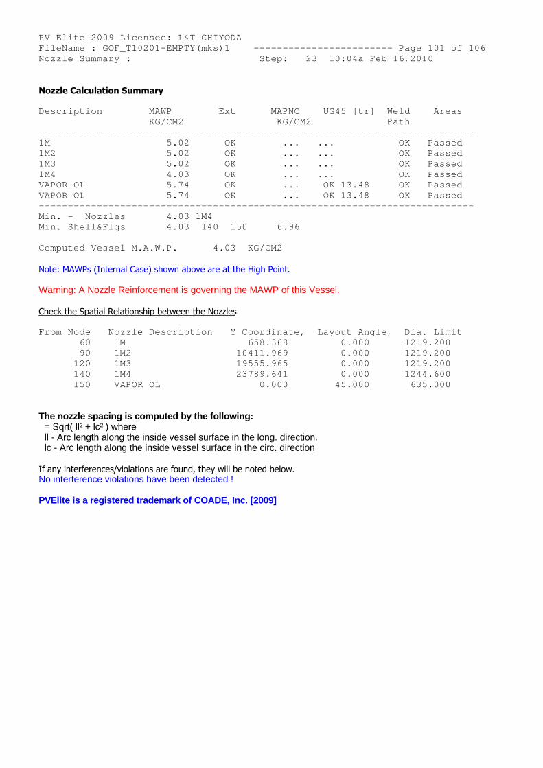
PV Elite 2009 Licensee: L&T CHIYODA FileName : GOF_T10201-EMPTY(mks)1 ------------- ----------- Page 101 of 106 Nozzle Summary : Step: 23 10:04a Feb 16,2010
Nozzle Calculation Summary
Description MAWP Ext MAPNC U G45 [tr] Weld Areas KG/CM2 KG/CM2 Path -------------------------------------------------- ------------------------- 1M 5.02 OK ... .. . OK Passed 1M2 5.02 OK ... .. . OK Passed 1M3 5.02 OK ... .. . OK Passed 1M4 4.03 OK ... .. . OK Passed VAPOR OL 5.74 OK ... O K 13.48 OK Passed VAPOR OL 5.74 OK ... O K 13.48 OK Passed -------------------------------------------------- ------------------------- Min. - Nozzles 4.03 1M4 Min. Shell&Flgs 4.03 140 150 6.96
Computed Vessel M.A.W.P. 4.03 KG/CM2
Note: MAWPs (Internal Case) shown above are at the High Point.
Warning: A Nozzle Reinforcement is governing the MAWP of this Vessel.
Check the Spatial Relationship between the Nozzles
From Node Nozzle Description Y Coordinate, La yout Angle, Dia. Limit 60 1M 658.368 0.000 1219.200 90 1M2 10411.969 0.000 1219.200 120 1M3 19555.965 0.000 1219.200 140 1M4 23789.641 0.000 1244.600 150 VAPOR OL 0.000 45.000 635.000
The nozzle spacing is computed by the following:= Sqrt( ll² + lc² ) wherell - Arc length along the inside vessel surface in the long. direction.lc - Arc length along the inside vessel surface in the circ. direction
If any interferences/violations are found, they will be noted below.No interference violations have been detected !
PVElite is a registered trademark of COADE, Inc. [2009]
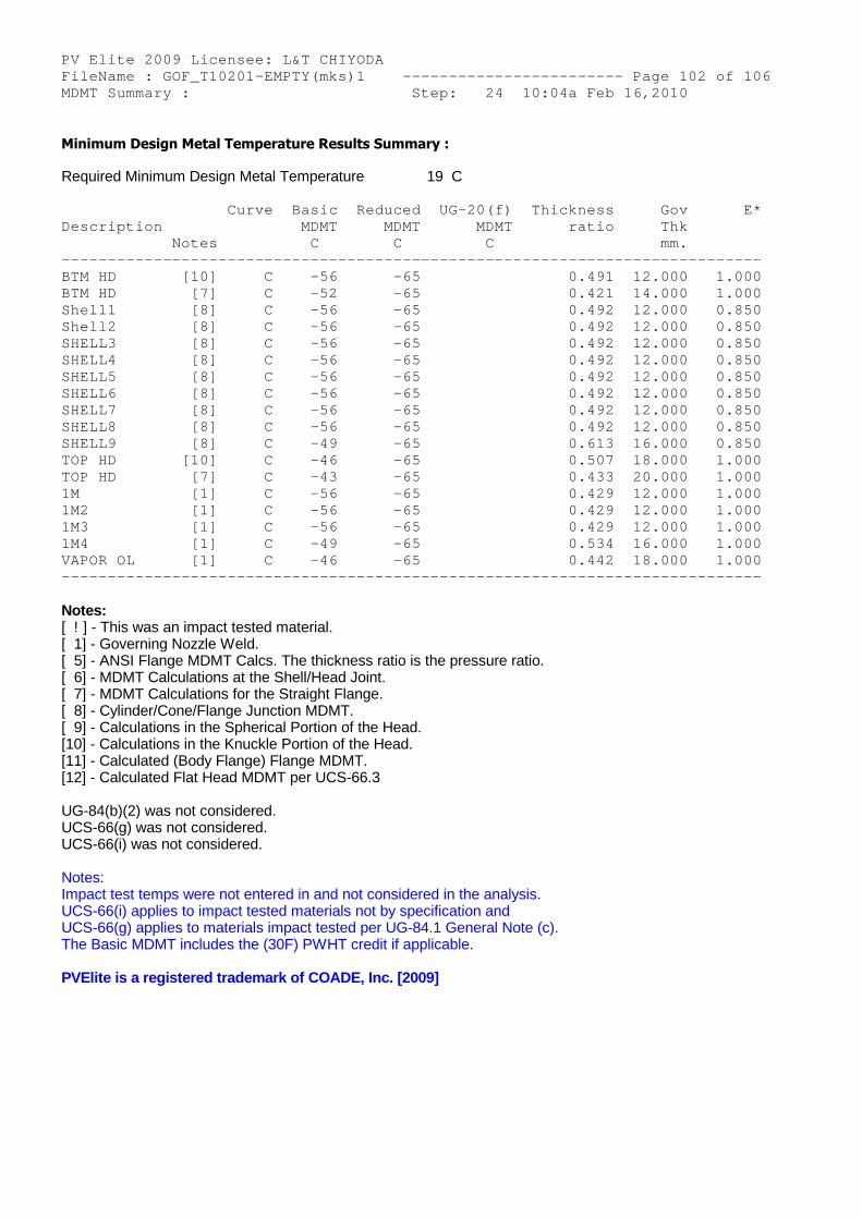
PV Elite 2009 Licensee: L&T CHIYODA FileName : GOF_T10201-EMPTY(mks)1 ------------- ----------- Page 102 of 106 MDMT Summary : Step: 24 10:04a Feb 16,2010
Minimum Design Metal Temperature Results Summary :
Required Minimum Design Metal Temperature 19 C
Curve Basic Reduced UG-20(f) Thickness Gov E* Description MDMT MDMT MDMT ratio Thk Notes C C C mm. -------------------------------------------------- -------------------------- BTM HD [10] C -56 -65 0.491 12.000 1.000 BTM HD [7] C -52 -65 0.421 14.000 1.000 Shell1 [8] C -56 -65 0.492 12.000 0.850 Shell2 [8] C -56 -65 0.492 12.000 0.850 SHELL3 [8] C -56 -65 0.492 12.000 0.850 SHELL4 [8] C -56 -65 0.492 12.000 0.850 SHELL5 [8] C -56 -65 0.492 12.000 0.850 SHELL6 [8] C -56 -65 0.492 12.000 0.850 SHELL7 [8] C -56 -65 0.492 12.000 0.850 SHELL8 [8] C -56 -65 0.492 12.000 0.850 SHELL9 [8] C -49 -65 0.613 16.000 0.850 TOP HD [10] C -46 -65 0.507 18.000 1.000 TOP HD [7] C -43 -65 0.433 20.000 1.000 1M [1] C -56 -65 0.429 12.000 1.000 1M2 [1] C -56 -65 0.429 12.000 1.000 1M3 [1] C -56 -65 0.429 12.000 1.000 1M4 [1] C -49 -65 0.534 16.000 1.000 VAPOR OL [1] C -46 -65 0.442 18.000 1.000 -------------------------------------------------- --------------------------
Notes:[ ! ] - This was an impact tested material.[ 1] - Governing Nozzle Weld.[ 5] - ANSI Flange MDMT Calcs. The thickness ratio is the pressure ratio.[ 6] - MDMT Calculations at the Shell/Head Joint.[ 7] - MDMT Calculations for the Straight Flange.[ 8] - Cylinder/Cone/Flange Junction MDMT.[ 9] - Calculations in the Spherical Portion of the Head.[10] - Calculations in the Knuckle Portion of the Head.[11] - Calculated (Body Flange) Flange MDMT.[12] - Calculated Flat Head MDMT per UCS-66.3
UG-84(b)(2) was not considered.UCS-66(g) was not considered.UCS-66(i) was not considered.
Notes:Impact test temps were not entered in and not considered in the analysis.UCS-66(i) applies to impact tested materials not by specification andUCS-66(g) applies to materials impact tested per UG-84.1 General Note (c).The Basic MDMT includes the (30F) PWHT credit if applicable.
PVElite is a registered trademark of COADE, Inc. [2009]
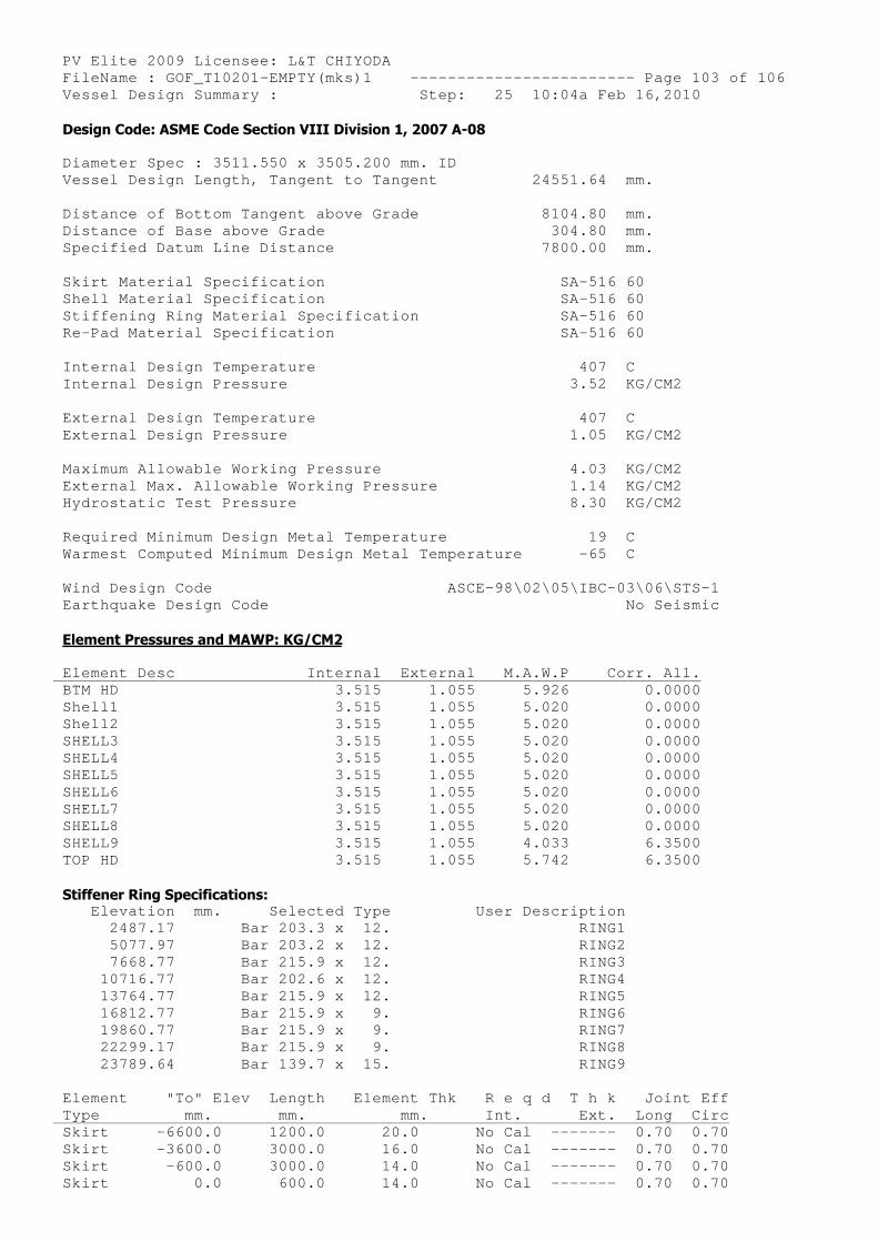
PV Elite 2009 Licensee: L&T CHIYODA FileName : GOF_T10201-EMPTY(mks)1 ------------- ----------- Page 103 of 106 Vessel Design Summary : Step: 25 10:04a Feb 16,2010 Design Code: ASME Code Section VIII Division 1, 2007 A-08
Diameter Spec : 3511.550 x 3505.200 mm. ID Vessel Design Length, Tangent to Tangent 24551.64 mm.
Distance of Bottom Tangent above Grade 8104.80 mm. Distance of Base above Grade 304.80 mm. Specified Datum Line Distance 7800.00 mm.
Skirt Material Specification SA-516 60 Shell Material Specification SA-516 60 Stiffening Ring Material Specification SA-516 60 Re-Pad Material Specification SA-516 60
Internal Design Temperature 407 C Internal Design Pressure 3.52 KG/CM2
External Design Temperature 407 C External Design Pressure 1.05 KG/CM2
Maximum Allowable Working Pressure 4.03 KG/CM2 External Max. Allowable Working Pressure 1.14 KG/CM2 Hydrostatic Test Pressure 8.30 KG/CM2
Required Minimum Design Metal Temperature 19 C Warmest Computed Minimum Design Metal Temperature -65 C
Wind Design Code ASCE-98\0 2\05\IBC-03\06\STS-1 Earthquake Design Code No Seismic
Element Pressures and MAWP: KG/CM2
Element Desc Internal External M.A .W.P Corr. All. BTM HD 3.515 1.055 5 .926 0.0000 Shell1 3.515 1.055 5 .020 0.0000 Shell2 3.515 1.055 5 .020 0.0000 SHELL3 3.515 1.055 5 .020 0.0000 SHELL4 3.515 1.055 5 .020 0.0000 SHELL5 3.515 1.055 5 .020 0.0000 SHELL6 3.515 1.055 5 .020 0.0000 SHELL7 3.515 1.055 5 .020 0.0000 SHELL8 3.515 1.055 5 .020 0.0000 SHELL9 3.515 1.055 4 .033 6.3500 TOP HD 3.515 1.055 5 .742 6.3500
Stiffener Ring Specifications: Elevation mm. Selected Type User D escription 2487.17 Bar 203.3 x 12. RING1 5077.97 Bar 203.2 x 12. RING2 7668.77 Bar 215.9 x 12. RING3 10716.77 Bar 202.6 x 12. RING4 13764.77 Bar 215.9 x 12. RING5 16812.77 Bar 215.9 x 9. RING6 19860.77 Bar 215.9 x 9. RING7 22299.17 Bar 215.9 x 9. RING8 23789.64 Bar 139.7 x 15. RING9
Element "To" Elev Length Element Thk R e q d T h k Joint Eff Type mm. mm. mm. Int. Ext. Long Circ Skirt -6600.0 1200.0 20.0 No Cal ------- 0.70 0.70 Skirt -3600.0 3000.0 16.0 No Cal ------- 0.70 0.70 Skirt -600.0 3000.0 14.0 No Cal ------- 0.70 0.70 Skirt 0.0 600.0 14.0 No Cal ------- 0.70 0.70
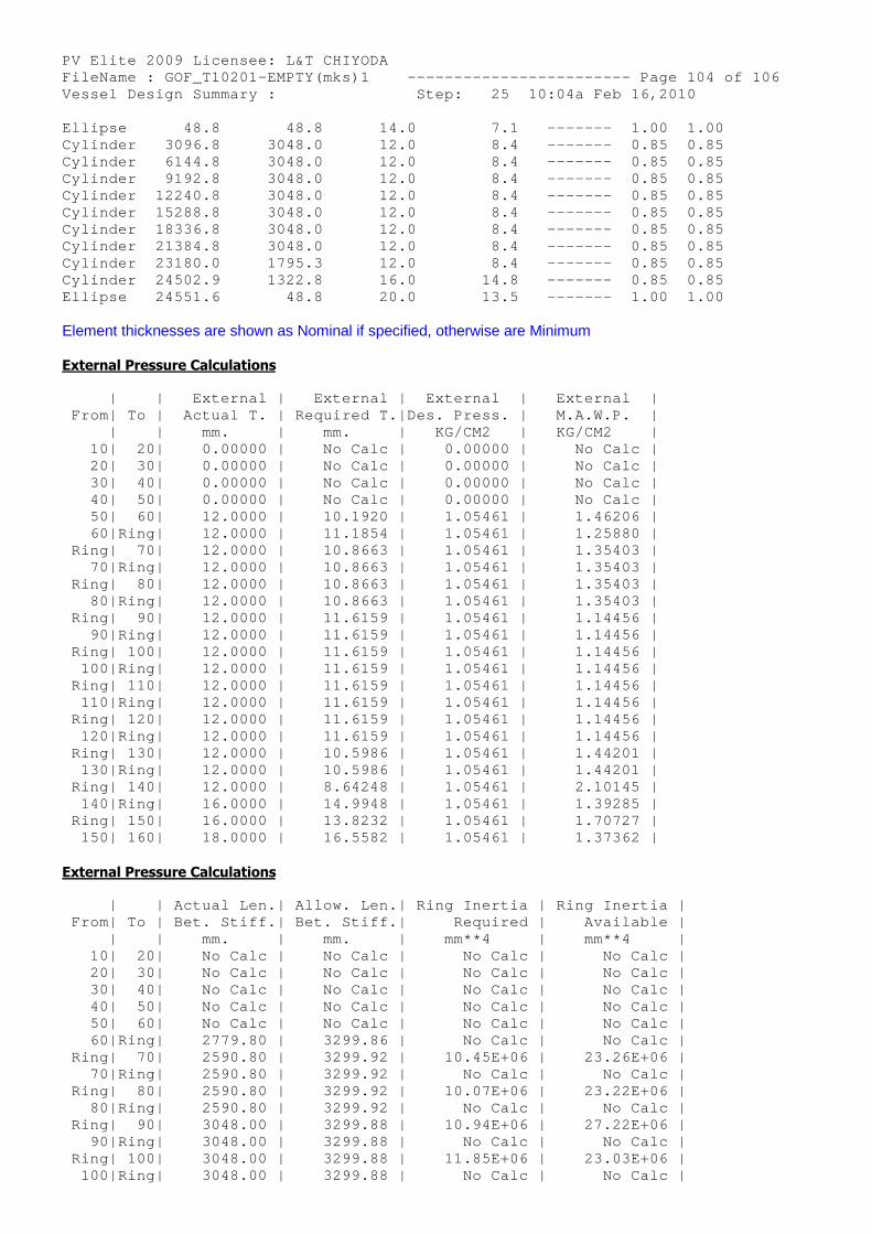
PV Elite 2009 Licensee: L&T CHIYODA FileName : GOF_T10201-EMPTY(mks)1 ------------- ----------- Page 104 of 106 Vessel Design Summary : Step: 25 10:04a Feb 16,2010 Ellipse 48.8 48.8 14.0 7.1 ------- 1.00 1.00 Cylinder 3096.8 3048.0 12.0 8.4 ------- 0.85 0.85 Cylinder 6144.8 3048.0 12.0 8.4 ------- 0.85 0.85 Cylinder 9192.8 3048.0 12.0 8.4 ------- 0.85 0.85 Cylinder 12240.8 3048.0 12.0 8.4 ------- 0.85 0.85 Cylinder 15288.8 3048.0 12.0 8.4 ------- 0.85 0.85 Cylinder 18336.8 3048.0 12.0 8.4 ------- 0.85 0.85 Cylinder 21384.8 3048.0 12.0 8.4 ------- 0.85 0.85 Cylinder 23180.0 1795.3 12.0 8.4 ------- 0.85 0.85 Cylinder 24502.9 1322.8 16.0 14.8 ------- 0.85 0.85 Ellipse 24551.6 48.8 20.0 13.5 ------- 1.00 1.00
Element thicknesses are shown as Nominal if specified, otherwise are Minimum
External Pressure Calculations
| | External | External | External | External | From| To | Actual T. | Required T.|Des. Press. | M.A.W.P. | | | mm. | mm. | KG/CM2 | KG/CM2 | 10| 20| 0.00000 | No Calc | 0.00000 | No Calc | 20| 30| 0.00000 | No Calc | 0.00000 | No Calc | 30| 40| 0.00000 | No Calc | 0.00000 | No Calc | 40| 50| 0.00000 | No Calc | 0.00000 | No Calc | 50| 60| 12.0000 | 10.1920 | 1.05461 | 1.46206 | 60|Ring| 12.0000 | 11.1854 | 1.05461 | 1.25880 | Ring| 70| 12.0000 | 10.8663 | 1.05461 | 1.35403 | 70|Ring| 12.0000 | 10.8663 | 1.05461 | 1.35403 | Ring| 80| 12.0000 | 10.8663 | 1.05461 | 1.35403 | 80|Ring| 12.0000 | 10.8663 | 1.05461 | 1.35403 | Ring| 90| 12.0000 | 11.6159 | 1.05461 | 1.14456 | 90|Ring| 12.0000 | 11.6159 | 1.05461 | 1.14456 | Ring| 100| 12.0000 | 11.6159 | 1.05461 | 1.14456 | 100|Ring| 12.0000 | 11.6159 | 1.05461 | 1.14456 | Ring| 110| 12.0000 | 11.6159 | 1.05461 | 1.14456 | 110|Ring| 12.0000 | 11.6159 | 1.05461 | 1.14456 | Ring| 120| 12.0000 | 11.6159 | 1.05461 | 1.14456 | 120|Ring| 12.0000 | 11.6159 | 1.05461 | 1.14456 | Ring| 130| 12.0000 | 10.5986 | 1.05461 | 1.44201 | 130|Ring| 12.0000 | 10.5986 | 1.05461 | 1.44201 | Ring| 140| 12.0000 | 8.64248 | 1.05461 | 2.10145 | 140|Ring| 16.0000 | 14.9948 | 1.05461 | 1.39285 | Ring| 150| 16.0000 | 13.8232 | 1.05461 | 1.70727 | 150| 160| 18.0000 | 16.5582 | 1.05461 | 1.37362 |
External Pressure Calculations
| | Actual Len.| Allow. Len.| Ring Inertia | Ring Inertia | From| To | Bet. Stiff.| Bet. Stiff.| Required | Available | | | mm. | mm. | mm**4 | mm**4 | 10| 20| No Calc | No Calc | No Calc | No Calc | 20| 30| No Calc | No Calc | No Calc | No Calc | 30| 40| No Calc | No Calc | No Calc | No Calc | 40| 50| No Calc | No Calc | No Calc | No Calc | 50| 60| No Calc | No Calc | No Calc | No Calc | 60|Ring| 2779.80 | 3299.86 | No Calc | No Calc | Ring| 70| 2590.80 | 3299.92 | 10.45E+06 | 23.26E+06 | 70|Ring| 2590.80 | 3299.92 | No Calc | No Calc | Ring| 80| 2590.80 | 3299.92 | 10.07E+06 | 23.22E+06 | 80|Ring| 2590.80 | 3299.92 | No Calc | No Calc | Ring| 90| 3048.00 | 3299.88 | 10.94E+06 | 27.22E+06 | 90|Ring| 3048.00 | 3299.88 | No Calc | No Calc | Ring| 100| 3048.00 | 3299.88 | 11.85E+06 | 23.03E+06 | 100|Ring| 3048.00 | 3299.88 | No Calc | No Calc |
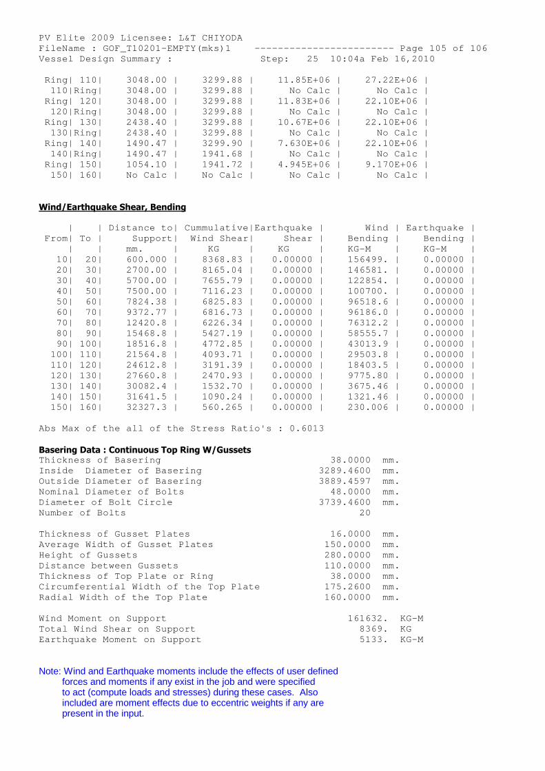
PV Elite 2009 Licensee: L&T CHIYODA FileName : GOF_T10201-EMPTY(mks)1 ------------- ----------- Page 105 of 106 Vessel Design Summary : Step: 25 10:04a Feb 16,2010 Ring| 110| 3048.00 | 3299.88 | 11.85E+06 | 27.22E+06 | 110|Ring| 3048.00 | 3299.88 | No Calc | No Calc | Ring| 120| 3048.00 | 3299.88 | 11.83E+06 | 22.10E+06 | 120|Ring| 3048.00 | 3299.88 | No Calc | No Calc | Ring| 130| 2438.40 | 3299.88 | 10.67E+06 | 22.10E+06 | 130|Ring| 2438.40 | 3299.88 | No Calc | No Calc | Ring| 140| 1490.47 | 3299.90 | 7.630E+06 | 22.10E+06 | 140|Ring| 1490.47 | 1941.68 | No Calc | No Calc | Ring| 150| 1054.10 | 1941.72 | 4.945E+06 | 9.170E+06 | 150| 160| No Calc | No Calc | No Calc | No Calc |
Wind/Earthquake Shear, Bending
| | Distance to| Cummulative|Earthquake | Wind | Earthquake | From| To | Support| Wind Shear| Shear | Bending | Bending | | | mm. | KG | KG | KG-M | KG-M | 10| 20| 600.000 | 8368.83 | 0.00000 | 156499. | 0.00000 | 20| 30| 2700.00 | 8165.04 | 0.00000 | 146581. | 0.00000 | 30| 40| 5700.00 | 7655.79 | 0.00000 | 122854. | 0.00000 | 40| 50| 7500.00 | 7116.23 | 0.00000 | 100700. | 0.00000 | 50| 60| 7824.38 | 6825.83 | 0.00000 | 96518.6 | 0.00000 | 60| 70| 9372.77 | 6816.73 | 0.00000 | 96186.0 | 0.00000 | 70| 80| 12420.8 | 6226.34 | 0.00000 | 76312.2 | 0.00000 | 80| 90| 15468.8 | 5427.19 | 0.00000 | 58555.7 | 0.00000 | 90| 100| 18516.8 | 4772.85 | 0.00000 | 43013.9 | 0.00000 | 100| 110| 21564.8 | 4093.71 | 0.00000 | 29503.8 | 0.00000 | 110| 120| 24612.8 | 3191.39 | 0.00000 | 18403.5 | 0.00000 | 120| 130| 27660.8 | 2470.93 | 0.00000 | 9775.80 | 0.00000 | 130| 140| 30082.4 | 1532.70 | 0.00000 | 3675.46 | 0.00000 | 140| 150| 31641.5 | 1090.24 | 0.00000 | 1321.46 | 0.00000 | 150| 160| 32327.3 | 560.265 | 0.00000 | 230.006 | 0.00000 |
Abs Max of the all of the Stress Ratio's : 0.6013
Basering Data : Continuous Top Ring W/Gussets Thickness of Basering 38.0000 mm. Inside Diameter of Basering 32 89.4600 mm. Outside Diameter of Basering 38 89.4597 mm. Nominal Diameter of Bolts 48.0000 mm. Diameter of Bolt Circle 37 39.4600 mm. Number of Bolts 20
Thickness of Gusset Plates 16.0000 mm. Average Width of Gusset Plates 1 50.0000 mm. Height of Gussets 2 80.0000 mm. Distance between Gussets 1 10.0000 mm. Thickness of Top Plate or Ring 38.0000 mm. Circumferential Width of the Top Plate 1 75.2600 mm. Radial Width of the Top Plate 1 60.0000 mm.
Wind Moment on Support 161632. KG-M Total Wind Shear on Support 8369. KG Earthquake Moment on Support 5133. KG-M
Note: Wind and Earthquake moments include the effects of user definedforces and moments if any exist in the job and were specifiedto act (compute loads and stresses) during these cases. Alsoincluded are moment effects due to eccentric weights if any arepresent in the input.
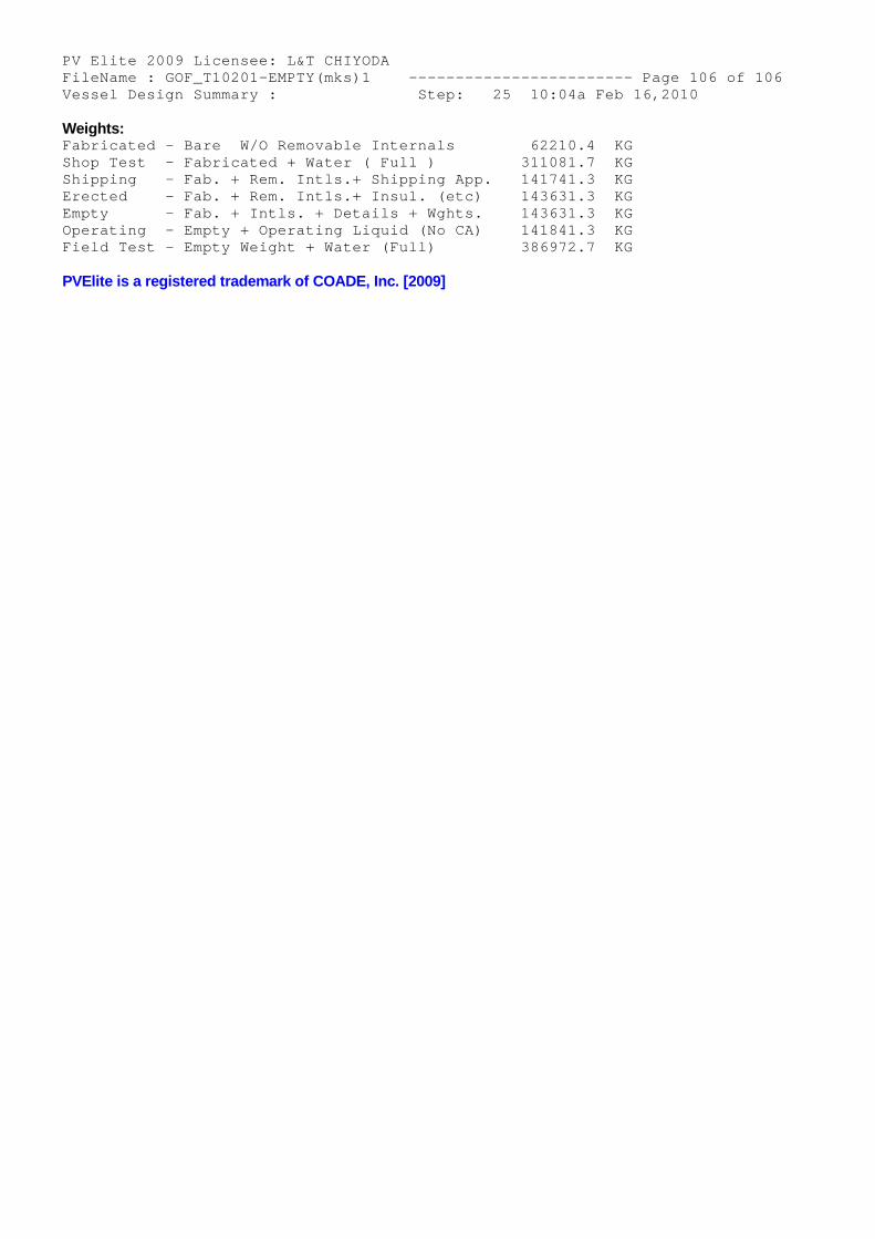
PV Elite 2009 Licensee: L&T CHIYODA FileName : GOF_T10201-EMPTY(mks)1 ------------- ----------- Page 106 of 106 Vessel Design Summary : Step: 25 10:04a Feb 16,2010
Weights: Fabricated - Bare W/O Removable Internals 62210.4 KG Shop Test - Fabricated + Water ( Full ) 3 11081.7 KG Shipping - Fab. + Rem. Intls.+ Shipping App. 1 41741.3 KG Erected - Fab. + Rem. Intls.+ Insul. (etc) 1 43631.3 KG Empty - Fab. + Intls. + Details + Wghts. 1 43631.3 KG Operating - Empty + Operating Liquid (No CA) 1 41841.3 KG Field Test - Empty Weight + Water (Full) 3 86972.7 KG
PVElite is a registered trademark of COADE, Inc. [2009]