public utilities-electric division 2019 specifications & contract
TRANSCRIPT
1
Public Utilities-Electric Division
2019
Specifications & Contract Documents
SUBSTATION POWER TRANSFORMERS DESIGN, MANUFACTURE, AND DELIVERY
2
CITY OF GARDEN CITY, KANSAS
INVITATION TO BID
BID TITLE SUBSTATION POWER TRANSFORMERS
ISSUE DATE November 15, 2019
BID OPENING December 13, 2019
BID AWARD January 24, 2020
IMPORTANT NOTE: Indicate company name and Bid Title on the front of the sealed bid envelope.
The City of Garden City, Kansas (City of Garden City or City), is seeking competitive sealed bids on two (2) new 115 kV-34.5 kV 40 MVA Substation Power Transformers.
The City of Garden City desires to engage in the manufacturing and delivery of the two (2) new 115 kV-34.5 kV 40 MVA Substation Power Transformers.
The process of responding to the Bid should involve interested companies reviewing and analyzing the information provided herein and responding in writing to any and all items where a response is requested.
Sealed bids will be received by the City of Garden City, Electric Division, until 2:00 p.m. CT December 13, 2019, at which time they will be publicly opened and read aloud. The bid opening will begin promptly at the appointed time at the Utilities Service Center located at 140 Harvest St., Garden City, KS 67846. No bids may be submitted after the bid opening begins. The bidder is solely responsible for the timely submission of this bid.
Address bids to the City of Garden City, Electric Division ATTN: Tyler Patterson, Warehouse Manager
Substation Power Transformers-UE2019-14 Bid 140 Harvest St.-P.O. Box 998
Garden City, KS 67846, on or before December 13, 2019, at 2:00 p.m. CT
No bid may be withdrawn for a period of sixty (60) calendar days after the bid opening. The City of Garden City reserves the right to evaluate bids to determine the lowest responsible bidder according to City policies, to reject any and all proposals, to waive formalities within the scope of authority, and further, the City reserves the right to make an award of bid that is in the best interest of the City of Garden City. Direct all questions on bidding procedure to: Kent Pottorf, Electrical Engineering/SCADA Mgr. [email protected] 140 Harvest St. P.O. Box 998 Garden City, KS 67846 (620) 276-1290
3
Introduction
The intent and purpose of this Invitation to Bid is to establish a contract with a qualified Manufacturer who can provide supervision, labor, material, and incidentals necessary to perform the manufacturing and delivery of the 115 kV-34.5 kV 40 MVA Substation Power Transformers.
Scope of Services and Standards of Work
Manufacturer obligations:
To supply the materials, manufacturing, and delivery of substation power transformers per specifications.
Safety
Job site activities shall at all times be conducted in accordance with applicable Federal, State and Local laws, regulations and requirements.
Damage to Facilities / Insurance Requirements
The Manufacturer shall be responsible for damages by its employees, agents or subcontractors to any City of Garden City utility facilities or customer-owned facilities during the delivery of the substation power transformers. Furthermore, any damages to utility facilities not owned by the City of Garden City shall be the responsibility of the Manufacturer. The Manufacturer shall submit proof of comprehensive General Liability Insurance carried in the minimum amount of $1,000,000 for bodily injury or death, and $1,000,000 for property damage. Workers compensation and motor vehicle liability insurance are also required. Proof of insurance must be submitted to the City of Garden City prior to execution of the contract for services. Risk of loss and/or damages shall be upon Manufacturer until goods are physically delivered as indicated, field work completed, and accepted by the City of Garden City.
Supervision / Customer Notification
The Manufacturer shall remain in close communication with the City of Garden City’s designated representative. No manufacturing or delivery of the substation power transformers shall commence that has not been directed by the City of Garden City’s designated representative.
Manufacturer Employees
All employees of the Manufacturer, while working or performing the substation power transformers delivery activity for the City of Garden City, will be required to wear some form of identification and proper PPE to perform the substation power transformers delivery. Employees will maintain a professional attitude toward the work being performed and toward any and all contacts with the City of Garden City.
Payment
Invoices may be submitted by the Manufacturer for payment at the Manufacturer’s discretion, but submissions shall be made at least monthly, with payment within thirty (30) days. Retainage of 10% will be withheld until final acceptance and payment.
4
Assignment
No assignment, subcontracting, subletting, or transferring of the Manufacturer’s obligations or the Manufacturer's right to receive payment hereunder shall be permitted without written approval of the City of Garden City. Manufacturer who submits a bid shall provide on the bid form the name of any delivery and transportation sub-contractors proposed to perform project work, along with the nature of the work to be performed by the subcontractor, and the subcontractor’s address, phone number, and email address. If manufacture and/or final assembly of the substation power transformers is performed by an entity other than Manufacturer, they shall also be identified as a subcontractor. Product manufacturing or assembly of components of the substation power transformers which are affixed to the substation power transformers shall not be considered subcontractors. If City or its Engineer, after due investigation, has reasonable objection to any proposed subcontractor, supplier, individual, or entity, City may, before the Notice of Award is given, request apparent successful bidder to submit an acceptable substitute, in which case apparent successful bidder shall submit a substitute bidder’s bid price, increased (or decreased) by the difference in cost occasioned by such substitution, and City may consider such price adjustment in evaluating bids and making the contract award.
Term / Limitation of Time to Complete Work
The Manufacturer is expected to start work promptly after the authorization to proceed is issued. Work shall begin within thirty (30) days of the execution date of authorization to proceed.
Indemnification
The Manufacturer agrees to and shall indemnify and hold the City of Garden City harmless from and against all liability, loss, damage or injury, and all costs and expenses (including attorney’s fees and costs of any suit related thereto), suffered or incurred by the City, arising from or related to Manufacturer’s negligent performance under the contract, or the negligence of Manufacturer’s employees, agents or subcontractors.
References
The Manufacturer shall supply, with its bid, professional references of companies or organizations for which it (and any subcontractors) has performed similar substation power transformer manufacturing and delivery within the last twenty-four (24) months. At least three (3) references shall be included with a contact name and telephone number.
Permits
Manufacturer will be responsible for securing any and all transportation or other permits necessary to deliver product as set forth herein. Costs of all permits shall be included in bid.
Equal Opportunity and Nondiscrimination
Equal Employment Opportunity. The Manufacturer and subcontractors will be required to comply with the President’s Executive Order 11246 (Equal Employment Opportunity), as amended, which prohibits discrimination in employment regarding race, color, creed, sex, or national origin. The Manufacturer must certify that they do not or will not maintain or provide for their employees any facilities that are segregated on the basis of race, color, creed or national origin. The documents within Section 00201 (Equal Employment Opportunity) are made a condition of the bid. (See attachment). Nondiscrimination Clauses. Bidders on this work, including subcontractors or vendors, will be required to comply with regulations as outlined within the documents included within Section 00202 (Non-Discrimination Clauses 0708). (See attachment).
5
Special Provisions. The Manufacturer and subcontractors will be required to comply with the Civil Rights Act of 1964, Rehabilitation Act of 1973, Americans with Disabilities Act of 1990, Age Discrimination Act of 1975, Executive Order 12898, Federal Actions to Address Environmental Justice in Minority Populations and Low-Income Populations of 1994 and 49 C.F.R. Part 26.1 (DBE Program), along with any amendments thereto.
CITY LOAD LOSS EVALUATION FORMULA
SUBSTATION POWER TRANSFORMERS DESIGN, MANFACTURE, AND DELIVERY
Two (2) 115 kV-34.5 kV, 40 MVA Substation Power Transformers (Technical Specifications Enclosed)
TC =TB + LLB (LLV) + NLLB (NLLV) Where: TC = Evaluated Transformer Cost TB = Transformer bid Price ($) LLB = Load Loss @ Max. KVA Bid (W) NLLB = No Load Loss Bid (W) LLV = LoadLoss Value $/W = $2.05 NLLV = No Load Loss Value $/W = $6.80
6
INSTRUCTIONS AND CONDITIONS
These conditions are an integral part of this bid, and the bidder must comply with them.
1. Bidder must bid on the Bid Sheet & Certification (page) and submit references on the Bidder
References Form (page), as requested.
2. Bidder must complete Fill-In Data sheets and provide the information specified on FD-1 as provided
in the Specifications.
3. Bidder should make a copy of bid for his/her file.
4. All costs for the service must be included in the total bid price as stated on the Bid Sheet &
Certification (page).
5. The City of Garden City reserves the right to accept or reject any or all bids, reserves all rights
granted by law, reserves the right to waive formalities and to take such action as it deems necessary
in the best interest of the City of Garden City.
6. Each bidder must sign the bid with his/her signature and shall give his/her business address on the
form provided in this bid.
7. The City of Garden City operates on an equal opportunity basis in its bidding policy. Bidding is open
to all interested parties, in compliance with national, state and local laws.
8. No late bids will be opened.
9. Bids will be opened and read publicly at the Utilities Service Center, 140 Harvest St., Garden City,
KS 67846, on December 13, 2019 at 2 pm CT.
10. No bid award will be made at the time of the opening. The successful bidder will be contacted
immediately following bid approval by the Governing Body of the City of Garden City, Kansas.
Bidders may contact the City of Garden City Electric Division at (620) 276-1290 to find out the
results of the bid award.
11. Exceptions. The Bidder shall furnish a statement on company letterhead giving a complete
description of all exceptions to the terms, conditions, and specifications. Failure to furnish the
statement will mean that the bidder agrees to meet all requirements of the terms, conditions, and
specifications.
7
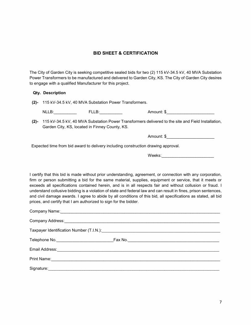
BID SHEET & CERTIFICATION
The City of Garden City is seeking competitive sealed bids for two (2) 115 kV-34.5 kV, 40 MVA Substation Power Transformers to be manufactured and delivered to Garden City, KS. The City of Garden City desires to engage with a qualified Manufacturer for this project.
Qty. Description
(2)- 115 kV-34.5 kV, 40 MVA Substation Power Transformers.
NLLB:__________ FLLB:__________ Amount: $_____________________
(2)- 115 kV-34.5 kV, 40 MVA Substation Power Transformers delivered to the site and Field Installation, Garden City, KS, located in Finney County, KS.
Amount: $_____________________
Expected time from bid award to delivery including construction drawing approval.
Weeks:_______________________
I certify that this bid is made without prior understanding, agreement, or connection with any corporation, firm or person submitting a bid for the same material, supplies, equipment or service, that it meets or exceeds all specifications contained herein, and is in all respects fair and without collusion or fraud. I understand collusive bidding is a violation of state and federal law and can result in fines, prison sentences, and civil damage awards. I agree to abide by all conditions of this bid, all specifications as stated, all bid prices, and certify that I am authorized to sign for the bidder.
Company Name:______________________________________________________________________
Company Address:____________________________________________________________________
Taxpayer Identification Number (T.I.N.):____________________________________________________
Telephone No._________________________Fax No.________________________________________
Email Address:_______________________________________________________________________
Print Name:__________________________________________________________________________
Signature:___________________________________________________________________________
8
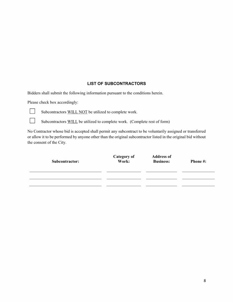
LIST OF SUBCONTRACTORS
Bidders shall submit the following information pursuant to the conditions herein.
Please check box accordingly: Subcontractors WILL NOT be utilized to complete work. Subcontractors WILL be utilized to complete work. (Complete rest of form) No Contractor whose bid is accepted shall permit any subcontract to be voluntarily assigned or transferred or allow it to be performed by anyone other than the original subcontractor listed in the original bid without the consent of the City.
Subcontractor: Category of
Work: Address of Business: Phone #:
9
BIDDER REFERENCE FORM
The Contractor shall supply, with its bid, professional references of companies or organizations for which it has performed similar manufacturing of Substation Power Transformer(s) within the last twenty-four (24) months. At least three (3) references shall be included with a contact name and telephone number.
1. Company Name:________________________________________________________________
Contact Name:____________________________________________________________________
Contact Phone:________________Contact Email:________________________________________
Date(s) of Services Rendered:________________________________________________________
Brief Description of Specific Services Rendered:__________________________________________
2. Company Name:________________________________________________________________
Contact Name:____________________________________________________________________
Contact Phone:________________Contact Email:________________________________________
Date(s) of Services Rendered:________________________________________________________
Brief Description of Specific Services Rendered:__________________________________________
________________________________________________________________________________
________________________________________________________________________________
3. Company Name:________________________________________________________________
Contact Name:____________________________________________________________________
Contact Phone:________________Contact Email:________________________________________
Date(s) of Services Rendered:________________________________________________________
Brief Description of Specific Services Rendered:__________________________________________
________________________________________________________________________________
ADVERTISEMENT
NOTICE TO BIDDERS
Bids for the 2019 Substation Power Transformers Design, Manufacture, and Delivery (UE2019-14), for the City of Garden City, Kansas will be received at the Utilities Service Center, 140 Harvest Street, Garden City, Kansas, until 2:00 p.m. CT, December 13th, 2019 at which time the bids will be opened publicly and read aloud. All bids shall be made on printed forms, which may be obtained from the Utilities Service Center or online at https://www.garden-city.org/services/advanced-components/misc-pages/bids-rfps/-fsiteid-1 . No bidder may withdraw his bid for at least sixty (60) calendar days after the scheduled closing time for the receipt of bids. The City reserves the right to reject any or all bids and to waive informalities, and to accept the bid deemed to be in the best interest of the public. Tyler Patterson Warehouse Manager
__________________________________________________________________________________________ 17-100-063-12 Equal Employment Opportunity 00201-1
EQUAL EMPLOYMENT OPPORTUNITY
During the performance of this contract the Contractor agrees as follows: 1. The Contractor will not discriminate against any employee or applicant for employment because of race, color, religion, sex or national origin. The Contractor will take affirmative action to ensure that applicants are employed and that employees are treated during employment without regard to their race, color, religion, sex or national origin. Such action shall include, but not be limited to the following: Employment upgrading, demotion or transfer, recruitment advertising, layoff or termination, rates of pay or other forms of compensation and selection for training, including apprenticeship. The Contractor agrees to post in conspicuous places, available to employees and applicants for employment, notices to be provided by the Contracting Officer, setting forth the provisions of this nondiscrimination clause. 2. The Contractor will, in all solicitations or advertisements for employees placed by or on behalf of the Contractor, state that all qualified applicants will receive consideration for employment without regard to race, color, religion, sex or national origin. 3. The Contractor will send to each labor union or representative of workers with which he has a collective bargaining agreement or other contract or understanding, a notice to be provided by the Contract Compliance Officer advising the said labor union or worker’s representatives of the Contractors commitment under this section and shall post copies of the notice in conspicuous places available to employees and applicants for employment. 4. The Contractor will comply with all provisions of Executive Order 11246 of September 24, 1965, and of the rules, regulations and relevant orders of the Secretary of Labor.
5. The Contractor will furnish all information and reports required by Executive Order 11246 of September 24, 1965, and by the rules, regulations and orders of the Secretary of Labor, or pursuant thereto and will permit access to his books, records and accounts by the Department and the Secretary of Labor for purposes of investigation to ascertain compliance with such rules, regulations and orders. 6. In the event of the Contractors noncompliance with the nondiscrimination clauses of this contract or with any of such rules, regulations or orders, this contract may be canceled, terminated or suspended in whole or in part and the Contractor may be declared ineligible for further Government contracts or federally assisted construction contract procedures authorized in Executive Order 11246 of September 24, 1965, or by rule, regulation or order of the Secretary of Labor, or as otherwise provided by law. 7. The Contractor will include the portion of the sentence immediately preceding paragraph (1) and the provisions of paragraphs (1) through (7) in every subcontract or purchase order unless exempted by rules, regulations or orders of the Secretary of Labor issued pursuant to Section 204, provisions will be binding upon each subcontractor or vendor. The Contractor will take such action with respect to any subcontract or purchase order as the Department may direct as a means of enforcing such provisions, including sanctions for noncompliance. Provided, however, that in the event a Contractor becomes involved in, or is threatened with, litigation with a subcontractor or vendor as a result of such direction by the Department the Contractor may request the United States to enter into such litigation to protect the interest of the United States. 8. The Contractor will, prior to the approval of any construction contract, submit an acceptable Affirmative Action Plan to the City for review and approval.
______________________________________________________________________________ 17-100-063-12 Nondiscrimination Clauses (Garden City 0708) 00202-2
NONDISCRIMINATION CLAUSES
During the performance of this Contract, the Contractor or Consultant, for itself, its assignees and successors in interest (hereinafter referred to as the "Contractor"), agrees as follows: (1) COMPLIANCE WITH REGULATIONS: The Contractor will comply with the Regulations of the United States Department of Transportation relative to nondiscrimination in federally assisted programs of the United States Department of Transportation (Title 49, Code of Federal Regulations, Parts 21, 23 and 27), hereinafter incorporated by reference and made a part of this contract. (2) NONDISCRIMINATION: The Contractor, with regard to the work performed by it after award and prior to completion of the Contract work, will not discriminate on the grounds of race, religion, color, gender, age, disability, national origin or minority populations and low income populations in the selection and retention of subcontractors, including procurements of materials and leases of equipment. The Contractor will not participate either directly or indirectly in the discrimination prohibited by Section 21.5 of the Regulations, including employment practices when the Contract covers a program set forth in Appendix "A", "B", and "C" of the Regulations. (3) SOLICITATIONS FOR SUBCONTRACTS, INCLUDING PROCUREMENTS OF MATERIALS AND EQUIPMENT: In all solicitations, either by competitive bidding or negotiation made by the Contractor for work to be performed under a subcontract, including procurements of materials or equipment, each potential subcontractor or supplier shall be notified by the Contractor of the Contractor's obligations under this Contract and the Regulations relative to nondiscrimination on the grounds of race, religion, color, gender, age, disability, national origin or minority populations and low income populations. (4) INFORMATION AND REPORTS: The Contractor will provide all information and reports required by the Regulations, or orders and instructions issued pursuant thereto, and the City or the Secretary of Transportation of the State of Kansas, will be permitted access to its books, records, accounts, other sources of information and its facilities as may be determined by the City, Secretary of Transportation of the State of Kansas to be pertinent to ascertain compliance with such regulations, orders and instructions. Where any information required of a Contractor is in the exclusive possession of another who fails or refuses to furnish this information, the Contractor shall so certify to the City, Secretary of Transportation of the State of Kansas as appropriate; and shall set forth what efforts it has made to obtain information. (5) EMPLOYMENT: The Contractor will not discriminate against any employee or applicant for employment because of race, religion, color, gender, age, disability, or national origin. (6) SANCTIONS FOR NONCOMPLIANCE: In the event of the Contractor’s noncompliance with the nondiscrimination provisions of this Contract, the City shall impose such Contract sanctions as it, or the Secretary of Transportation of the State of Kansas, may determine to be appropriate, including, but not limited to, (a) withholding of payments to the Contractor under the Contract until the Contractor complies, and/or (b) cancellation, termination or suspension of the Contract, in whole or in part.
______________________________________________________________________________ 17-100-063-12 Nondiscrimination Clauses (Garden City 0708) 00202-2
(7) DISADVANTAGED BUSINESS OBLIGATION: (a) Disadvantaged Businesses as defined in the Regulations, shall have a level playing field to compete fairly for contracts financed in whole or in part with Federal funds under this contract. (b) All necessary and reasonable steps shall be taken in accordance with the Regulations to ensure that Disadvantaged Businesses have equal opportunity to compete for and perform contracts. No person(s) shall be discriminated against on the basis of race, color, gender, or national origin in the award and performance of federally‐assisted contracts. (c) The Contractor, sub recipient or subcontractor shall not discriminate on the basis of race, color, national origin, or sex in the performance of this contract. The contractor shall carry out applicable requirements of 49 CFR Part 26 in the award and administration of Federally‐assisted contracts. Failure by the contractor to carry out these requirements is a material breach of contract, which may result in the termination of this contract or such other remedy, as the recipient deems appropriate. (8) EXECUTIVE ORDER 12898: (a) To the extent permitted by existing law, and whenever practical and appropriate, all necessary and reasonable steps shall be taken in accordance with Executive Order 12898 to collect, maintain, and analyze information on the race, color, national origin and income level of persons affected by programs, polices and activities of the Secretary of Transportation and use of such information in complying with this Order. (9) INCORPORATION OF PROVISIONS: The Contractor will include the provisions of paragraph (1) through (8) in every subcontract, including procurements of materials and leases of equipment, unless exempt by the regulations, orders of instructions issued pursuant thereto. The Contractor will take such action with respect to any subcontract or procurement as the City or the Federal Highway Administration may direct as a means of enforcing such provisions including sanctions for noncompliance; provided, however, that in the event a Contractor becomes involved in, or is threatened with, litigation with a subconsultant or supplier as a result of such direction, the Contractor may request the State to enter into such litigation to protect the interests of the State.
NONDISCRIMINATION UNDER TITLE VI OF THE CIVIL RIGHTS ACT OF 1964
The Contractor will comply with the Title VI of the Civil Rights Act of 1964 (P.L. 88‐352) and the regulations pursuant thereto (25 CFR Part 1), which provides that no person in the United States shall on the ground of race, color or national origin, be excluded from participation in, be denied the benefits of, or be otherwise subjected to discrimination under any program or activity undertaken with Federal financial assistance.
No. 22-05-2019-01THIS AGREEMENT made and entered into this day of ,2019,by and between the City of Garden City, Kansas, hereinafter called "CITY" and
hereinafter called "CONTRACTOR".
WITNESSETH:
ARTICLE 1: The CONTRACTOR will commence and complete the project known as
ARTICLE 2: It is hereby mutually agreed, that for and in consideration of the sum or sums tobe paid the CONTRACTOR by the CITY as set forth in the Proposal, the CONTRACTOR shallfurnish all labor, equipment, accessories and material (except materials salvaged or otherwisefurnished as specified) and shall perform all work necessary to construct and complete theimprovement in a good, substantial and workmanlike manner, ready for use, and in strictaccordance with the contract documents, as set forth below, as approved and filed pursuantto law in the office of the legal representative of the CITY.
ARTICLE 3: It is hereby further agreed, that the CONTRACTOR will perform all of the workdescribed in the contract documents and comply with the terms therein for the sum or sums setforth in the Proposal as accepted by the CITY.
ARTICLE 4: It is hereby further agreed that in consideration of the faithful performance of thework by the CONTRACTOR, the CITY shall pay the CONTRACTOR the sum or sums due himat stated intervals and in amounts certified by the Engineer, in accordance with the provisions ofthe Contract Documents and as set forth in the Proposal as accepted by the CITY.
ARTICLE 5: It is further agreed, that at the completion of the work and its acceptance by the CITY, all sums due the CONTRACTOR by reason of his faithful completion of the work, takinginto consideration additions to, or deductions from, the contract price by reason of alterations ormodifications of the original Contract Documents or by Change Order or Force Account workauthorized under the Contract in accordance with the Contract Documents, will be paid to theCONTRACTOR by the CITY within thirty (30) days after said completion and acceptance.
ARTICLE 6: It is hereby further agreed, that the term "Contract Documents" means and includesthe Notice to Bidders, Information to Bidders, Nondiscrimination Clauses, Special Attachment,Equal Employment Opportunity Clauses, General Conditions of the Specifications, General Provisions, Technical Provisions, Technical Specifications, General Specifications, SpecialProvisions, Certification of Nonsegregated Facilities, Plans and/or Drawings, Proposal, Contract,Contract and Maintenance Bond, Statutory Bond, as applicable to the project, and are herebymade part of this agreement as fully as if set out at length herein.
ARTICLE 7: It is hereby further agreed that the words "he", "him", or "it" whenever used herein asreferring to the CONTRACTOR shall be deemed to refer to the CONTACTOR, whether a person, partnership, or corporation, and that this contract and all covenants and agreements thereofshall be binding and for the benefit of the heirs, executors, administrators, successors and assigns of the CONTRACTOR.
CONTRACT
C-2000 Page 1
ARTICLE 8: It is hereby further agreed, that the CONTRACTOR will commence the workrequired by the Contract Documents, within ten (10) calendar days after the date of the Noticeto Proceed and will complete the same within the time provided in the Contract Documents,unless the period for such completion is otherwise extended pursuant to the Contract Documents.
ARTICLE 9: It is hereby further agreed, that should the CONTRACTOR fail to complete all workwithin the time provided, the CONTRACTOR shall be liable to the CITY for liquidated damagesat the rate as specified in the Contract Documents.
IN WITNESS WHEREOF, the Parties hereto have executed, or caused to be executed by theirduly authorized officials, this Contract on the date first above written, in triplicate, each of whichshall be considered as the original.
CITY OF GARDEN CITY, KANSAS CONTRACTOR
Mayor Title:
ATTEST: ATTEST:
City Clerk Title
C-2000 Page 2
KNOW ALL MEN BY THESE PRESENTS, that the undersigned Contractor, as Principal and theundersigned, as Surety, a Corporation organized under the laws of the State of withgeneral offices in and authorized to transact business in the state of Kansas, are held and firmly bound unto the City of Garden City, Kansas, (City) in the sum of $lawful money of the United States, for the Payment of which sum, well and truly to be made, thePrincipal and Surety bind themselves, their heirs, administrators, executors and assigns, jointly and severally, firmly by these presents.
THE CONDITION OF THE FOREGOING OBLIGATION IS SUCH THAT WHEREAS,Principal has entered into a written Contract with the City dated , 2019,for the furnishing of materials and labor and doing of all work of whatever kind necessary to constructcertain improvements entitled
for the City all in accordance with the detailed Contract documents for such work, a copy of which isattached hereto and which is by reference made a part hereof.
NOW THEREFORE, if Principal shall well and truly perform all of the covenants, conditions andobligations of the Contract on the part of the Principal to be performed, and shall hold the City harmless against all claims, loss or damage which it may sustain or suffer by reason of any injury to persons or property by the action of the Principal or its employees, and if Principal shall maintain the improvements to be constructed by it as provided in the manner and for the time provided for in the Contract above referred to, then this obligation shall be void; otherwise to remain in full force and effect.
If Principal shall fail or neglect to pay any person, firm or corporation for labor bills, including the hire,rental or lease of equipment or machinery and the operators thereof, used on the work, or materials employed or used in carrying forward, performing and completing the Contract, or other expenses essential to the completion of the Contract within thirty (30) days after the same becomes due and payable, such persons, firms or corporations entitled to such pay may sue on this bond to recover from Principal and Surety or either of them, the amount so due and unpaid.
The Surety, for value received, hereby stipulates and agrees that no change, extension of time,alteration or addition to the terms of the Contract or to the work to be performed thereunder, shall in any way affect its obligations on this bond, and it does hereby waive notice of any such change,extension of time, alteration or addition to the terms of the Contract, or to the work, or to the GeneralConditions of the Specifications.
IN TESTIMONY WHEREOF, Principal has duly executed this document and Surety has caused thisdocument to be executed in its name and its corporate seal to be hereunto affixed, by its duly authorized agent or agents, all as of the day of , 2019.
Principal: Surety:
By:Attorney-in-fact
(A certified copy of the power-of-attorney must be attached hereto.)
CMB-2000
CONTRACT AND MAINTENANCE BOND

KNOW ALL MEN BY THESE PRESENTS, that the undersigned Contractor, as Principal and theundersigned, as Surety, a Corporation organized under the laws of the State of withgeneral offices in and authorized to transact business in the state of Kansas, are held and firmly bound unto the City of Garden City, Kansas, (City) in the sum of $lawful money of the United States, for the Payment of which sum, well and truly to be made, thePrincipal and Surety bind themselves, their heirs, administrators, executors and assigns, jointly and severally, firmly by these presents.
THE CONDITION OF THE FOREGOING OBLIGATION IS SUCH THAT WHEREAS,Principal has entered into a written Contract with the City dated , 2019,for the furnishing of materials and labor and doing of all work of whatever kind necessary to constructcertain improvements entitled
for the City all in accordance with the detailed Contract documents for such work, a copy of which isattached hereto and which is by reference made a part hereof.
NOW THEREFORE, if Principal or any subcontractor of Principal shall payall indebtednessincurred for supplies, materials or labor furnished, used or consumed in connection with or in or about theconstruction or making ot the above described improvements including: gasoline, lubrication oils, fuel oils,greases, coal and similar items used or consumed directly in furtherance of such improvement, this obligation shall be void, otherwise it shall remain in full force and effect.
If Principal shall fail or neglect to pay any person, firm or corporation for labor bills, including the hire,rental or lease of equipment or machinery and the operators thereof, used on the work, or materials employed or used in carrying forward, performing and completing the Contract, or other expenses essential to the completion of the Contract within thirty (30) days after the same becomes due and payable, such persons, firms or corporations entitled to such pay may sue on this bond to recover from Principal and Surety or either of them, the amount so due and unpaid.
The Surety, for value received, hereby stipulates and agrees that no change, extension of time,alteration or addition to the terms of the Contract or to the work to be performed thereunder, shall in any way affect its obligations on this bond, and it does hereby waive notice of any such change,extension of time, alteration or addition to the terms of the Contract, or to the work, or to the GeneralConditions of the Specifications.
IN TESTIMONY WHEREOF, Principal has duly executed this document and Surety has caused thisdocument to be executed in its name and its corporate seal to be hereunto affixed, by its duly authorized agent or agents, all as of the day of , 2019.
Principal: Surety:
By:Attorney-in-fact
(A certified copy of the power-of-attorney must be attached hereto.)
SB-2000
STATUTORY BOND
KIEWIT
9401 Renner Blvd., Lenexa, KS 66219
913-928-7000 913-689-4000 fax
SPECIFICATIONS FOR
SUBSTATION POWER TRANSFORMERS
94.03.26.550
GARDEN CITY SUBSTATION TRANSFORMERS
GARDEN CITY, FINNEY COUNTY, KS
KIEWIT PROJECT NO. 20031123
ISSUED: March 19, 2019
REVISION B – Issued for Proposal
Garden City Substation Transformers
Kiewit Project No. 20031123 TOC-1 94.03.26.550/B/Issued for Proposal
TECHNICAL SPECIFICATIONS
TABLE OF CONTENTS
TITLE Pages Revision
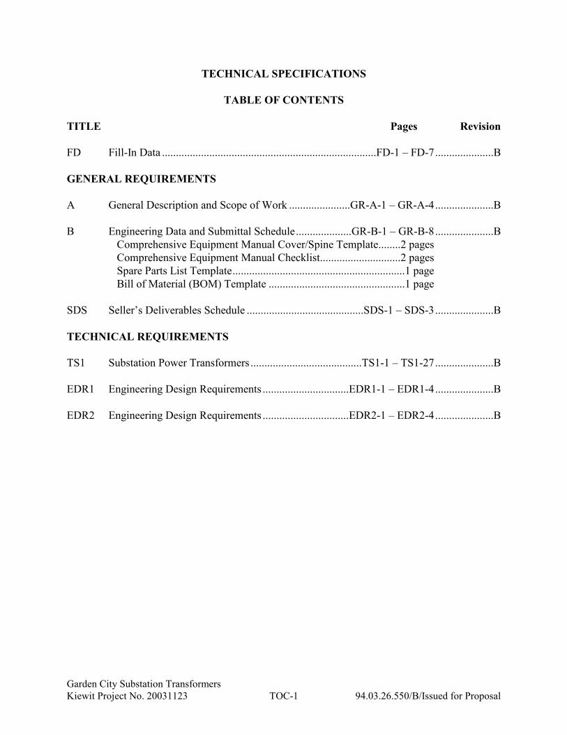
FD Fill-In Data .............................................................................FD-1 – FD-7.....................B
GENERAL REQUIREMENTS
A General Description and Scope of Work ......................GR-A-1 – GR-A-4.....................B
B Engineering Data and Submittal Schedule....................GR-B-1 – GR-B-8.....................B
Comprehensive Equipment Manual Cover/Spine Template........2 pages
Comprehensive Equipment Manual Checklist.............................2 pages
Spare Parts List Template..............................................................1 page
Bill of Material (BOM) Template .................................................1 page
SDS Seller’s Deliverables Schedule ..........................................SDS-1 – SDS-3.....................B
TECHNICAL REQUIREMENTS
TS1 Substation Power Transformers ........................................TS1-1 – TS1-27.....................B
EDR1 Engineering Design Requirements ...............................EDR1-1 – EDR1-4.....................B
EDR2 Engineering Design Requirements ...............................EDR2-1 – EDR2-4.....................B
SUBSTATION POWER TRANSFORMERS
FILL-IN DATA
Garden City Substation Transformers
KED Project No. 20031123 FD-1 94.03.26.550/B/Issued for Proposal
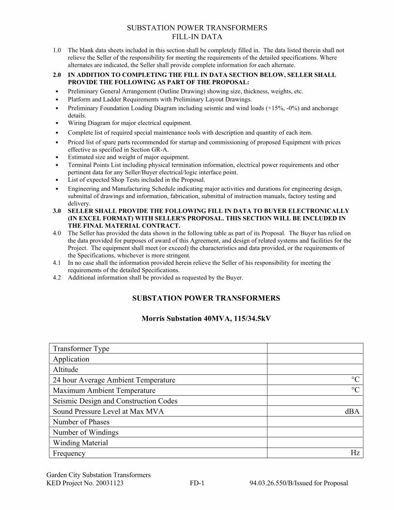
1.0 The blank data sheets included in this section shall be completely filled in. The data listed therein shall not
relieve the Seller of the responsibility for meeting the requirements of the detailed specifications. Where
alternates are indicated, the Seller shall provide complete information for each alternate.
2.0 IN ADDITION TO COMPLETING THE FILL IN DATA SECTION BELOW, SELLER SHALL
PROVIDE THE FOLLOWING AS PART OF THE PROPOSAL:
Preliminary General Arrangement (Outline Drawing) showing size, thickness, weights, etc.
Platform and Ladder Requirements with Preliminary Layout Drawings.
Preliminary Foundation Loading Diagram including seismic and wind loads (+15%, -0%) and anchorage
details.
Wiring Diagram for major electrical equipment.
Complete list of required special maintenance tools with description and quantity of each item.
Priced list of spare parts recommended for startup and commissioning of proposed Equipment with prices
effective as specified in Section GR-A.
Estimated size and weight of major equipment.
Terminal Points List including physical termination information, electrical power requirements and other
pertinent data for any Seller/Buyer electrical/logic interface point.
List of expected Shop Tests included in the Proposal.
Engineering and Manufacturing Schedule indicating major activities and durations for engineering design,
submittal of drawings and information, fabrication, submittal of instruction manuals, factory testing and
delivery.
3.0 SELLER SHALL PROVIDE THE FOLLOWING FILL IN DATA TO BUYER ELECTRONICALLY
(IN EXCEL FORMAT) WITH SELLER'S PROPOSAL. THIS SECTION WILL BE INCLUDED IN
THE FINAL MATERIAL CONTRACT.
4.0 The Seller has provided the data shown in the following table as part of its Proposal. The Buyer has relied on
the data provided for purposes of award of this Agreement, and design of related systems and facilities for the
Project. The equipment shall meet (or exceed) the characteristics and data provided, or the requirements of
the Specifications, whichever is more stringent.
4.1 In no case shall the information provided herein relieve the Seller of his responsibility for meeting the
requirements of the detailed Specifications.
4.2 Additional information shall be provided as requested by the Buyer.
SUBSTATION POWER TRANSFORMERS
Morris Substation 40MVA, 115/34.5kV
Transformer Type
Application
Altitude
24 hour Average Ambient Temperature °C
Maximum Ambient Temperature °C
Seismic Design and Construction Codes
Sound Pressure Level at Max MVA dBA
Number of Phases
Number of Windings
Winding Material
Frequency Hz
SUBSTATION POWER TRANSFORMERS
FILL-IN DATA
Garden City Substation Transformers
KED Project No. 20031123 FD-2 94.03.26.550/B/Issued for Proposal
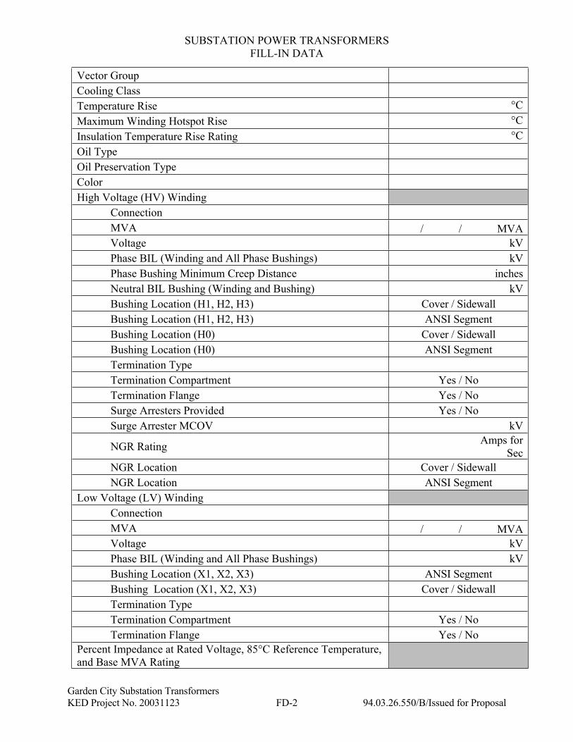
Vector Group
Cooling Class
Temperature Rise °C
Maximum Winding Hotspot Rise °C
Insulation Temperature Rise Rating °C
Oil Type
Oil Preservation Type
Color
High Voltage (HV) Winding
Connection
MVA / / MVA
Voltage kV
Phase BIL (Winding and All Phase Bushings) kV
Phase Bushing Minimum Creep Distance inches
Neutral BIL Bushing (Winding and Bushing) kV
Bushing Location (H1, H2, H3) Cover / Sidewall
Bushing Location (H1, H2, H3) ANSI Segment
Bushing Location (H0) Cover / Sidewall
Bushing Location (H0) ANSI Segment
Termination Type
Termination Compartment Yes / No
Termination Flange Yes / No
Surge Arresters Provided Yes / No
Surge Arrester MCOV kV
NGR Rating Amps for
Sec
NGR Location Cover / Sidewall
NGR Location ANSI Segment
Low Voltage (LV) Winding
Connection
MVA / / MVA
Voltage kV
Phase BIL (Winding and All Phase Bushings) kV
Bushing Location (X1, X2, X3) ANSI Segment
Bushing Location (X1, X2, X3) Cover / Sidewall
Termination Type
Termination Compartment Yes / No
Termination Flange Yes / No
Percent Impedance at Rated Voltage, 85°C Reference Temperature,
and Base MVA Rating
SUBSTATION POWER TRANSFORMERS
FILL-IN DATA
Garden City Substation Transformers
KED Project No. 20031123 FD-3 94.03.26.550/B/Issued for Proposal
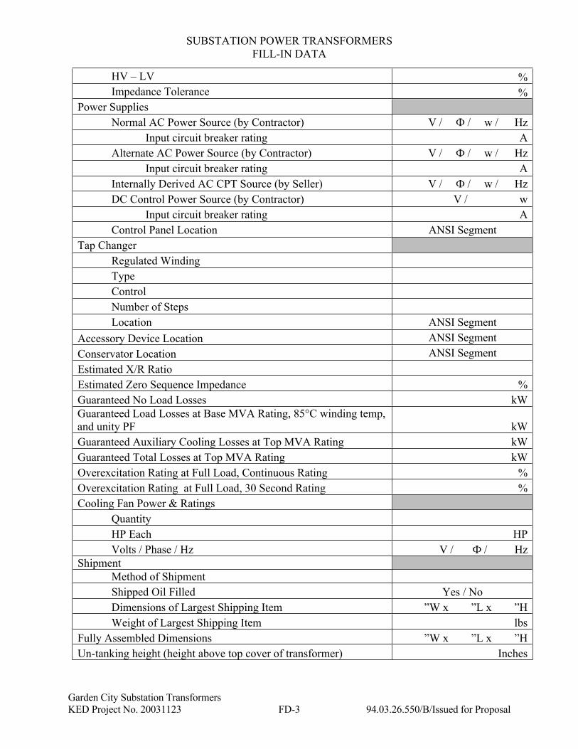
HV – LV %
Impedance Tolerance %
Power Supplies
Normal AC Power Source (by Contractor) V / Ф / w / Hz
Input circuit breaker rating A
Alternate AC Power Source (by Contractor) V / Ф / w / Hz
Input circuit breaker rating A
Internally Derived AC CPT Source (by Seller) V / Ф / w / Hz
DC Control Power Source (by Contractor) V / w
Input circuit breaker rating A
Control Panel Location ANSI Segment
Tap Changer
Regulated Winding
Type
Control
Number of Steps
Location ANSI Segment
Accessory Device Location ANSI Segment
Conservator Location ANSI Segment
Estimated X/R Ratio
Estimated Zero Sequence Impedance %
Guaranteed No Load Losses kW
Guaranteed Load Losses at Base MVA Rating, 85°C winding temp,
and unity PF kW
Guaranteed Auxiliary Cooling Losses at Top MVA Rating kW
Guaranteed Total Losses at Top MVA Rating kW
Overexcitation Rating at Full Load, Continuous Rating %
Overexcitation Rating at Full Load, 30 Second Rating %
Cooling Fan Power & Ratings
Quantity
HP Each HP
Volts / Phase / Hz V / Ф / Hz
Shipment
Method of Shipment
Shipped Oil Filled Yes / No
Dimensions of Largest Shipping Item ”W x ”L x ”H
Weight of Largest Shipping Item lbs
Fully Assembled Dimensions ”W x ”L x ”H
Un-tanking height (height above top cover of transformer) Inches
SUBSTATION POWER TRANSFORMERS
FILL-IN DATA
Garden City Substation Transformers
KED Project No. 20031123 FD-4 94.03.26.550/B/Issued for Proposal
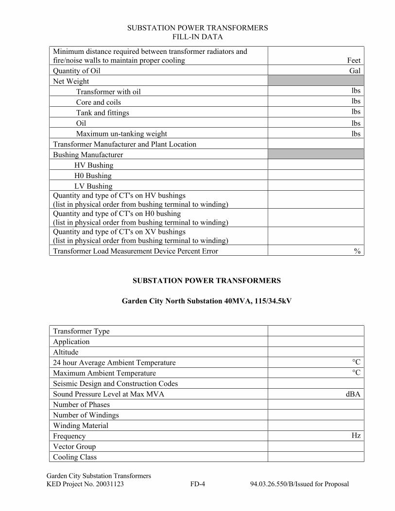
Minimum distance required between transformer radiators and
fire/noise walls to maintain proper cooling Feet
Quantity of Oil Gal
Net Weight
Transformer with oil lbs
Core and coils lbs
Tank and fittings lbs
Oil lbs
Maximum un-tanking weight lbs
Transformer Manufacturer and Plant Location
Bushing Manufacturer
HV Bushing
H0 Bushing
LV Bushing
Quantity and type of CT's on HV bushings
(list in physical order from bushing terminal to winding)
Quantity and type of CT's on H0 bushing
(list in physical order from bushing terminal to winding)
Quantity and type of CT's on XV bushings
(list in physical order from bushing terminal to winding)
Transformer Load Measurement Device Percent Error %
SUBSTATION POWER TRANSFORMERS
Garden City North Substation 40MVA, 115/34.5kV
Transformer Type
Application
Altitude
24 hour Average Ambient Temperature °C
Maximum Ambient Temperature °C
Seismic Design and Construction Codes
Sound Pressure Level at Max MVA dBA
Number of Phases
Number of Windings
Winding Material
Frequency Hz
Vector Group
Cooling Class
SUBSTATION POWER TRANSFORMERS
FILL-IN DATA
Garden City Substation Transformers
KED Project No. 20031123 FD-5 94.03.26.550/B/Issued for Proposal
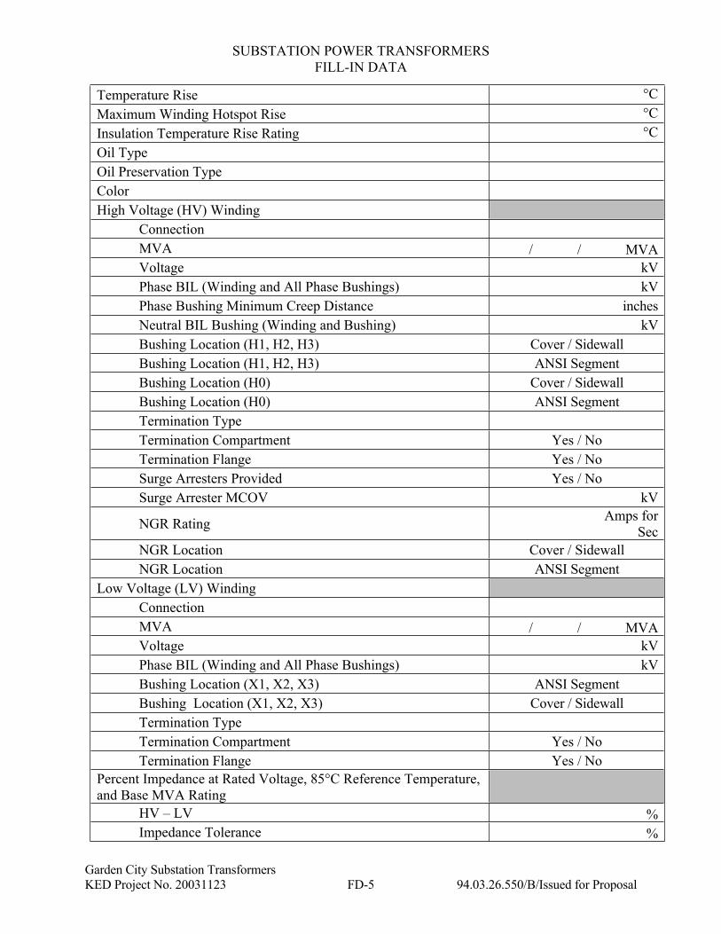
Temperature Rise °C
Maximum Winding Hotspot Rise °C
Insulation Temperature Rise Rating °C
Oil Type
Oil Preservation Type
Color
High Voltage (HV) Winding
Connection
MVA / / MVA
Voltage kV
Phase BIL (Winding and All Phase Bushings) kV
Phase Bushing Minimum Creep Distance inches
Neutral BIL Bushing (Winding and Bushing) kV
Bushing Location (H1, H2, H3) Cover / Sidewall
Bushing Location (H1, H2, H3) ANSI Segment
Bushing Location (H0) Cover / Sidewall
Bushing Location (H0) ANSI Segment
Termination Type
Termination Compartment Yes / No
Termination Flange Yes / No
Surge Arresters Provided Yes / No
Surge Arrester MCOV kV
NGR Rating Amps for
Sec
NGR Location Cover / Sidewall
NGR Location ANSI Segment
Low Voltage (LV) Winding
Connection
MVA / / MVA
Voltage kV
Phase BIL (Winding and All Phase Bushings) kV
Bushing Location (X1, X2, X3) ANSI Segment
Bushing Location (X1, X2, X3) Cover / Sidewall
Termination Type
Termination Compartment Yes / No
Termination Flange Yes / No
Percent Impedance at Rated Voltage, 85°C Reference Temperature,
and Base MVA Rating
HV – LV %
Impedance Tolerance %
SUBSTATION POWER TRANSFORMERS
FILL-IN DATA
Garden City Substation Transformers
KED Project No. 20031123 FD-6 94.03.26.550/B/Issued for Proposal
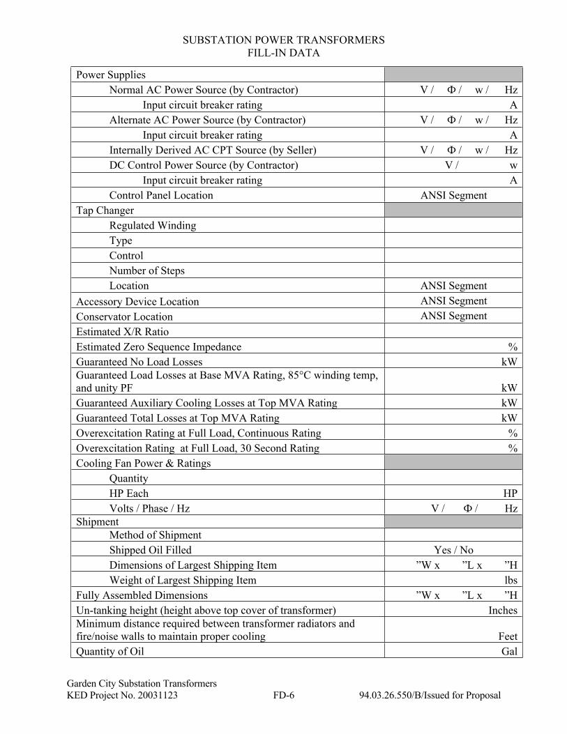
Power Supplies
Normal AC Power Source (by Contractor) V / Ф / w / Hz
Input circuit breaker rating A
Alternate AC Power Source (by Contractor) V / Ф / w / Hz
Input circuit breaker rating A
Internally Derived AC CPT Source (by Seller) V / Ф / w / Hz
DC Control Power Source (by Contractor) V / w
Input circuit breaker rating A
Control Panel Location ANSI Segment
Tap Changer
Regulated Winding
Type
Control
Number of Steps
Location ANSI Segment
Accessory Device Location ANSI Segment
Conservator Location ANSI Segment
Estimated X/R Ratio
Estimated Zero Sequence Impedance %
Guaranteed No Load Losses kW
Guaranteed Load Losses at Base MVA Rating, 85°C winding temp,
and unity PF kW
Guaranteed Auxiliary Cooling Losses at Top MVA Rating kW
Guaranteed Total Losses at Top MVA Rating kW
Overexcitation Rating at Full Load, Continuous Rating %
Overexcitation Rating at Full Load, 30 Second Rating %
Cooling Fan Power & Ratings
Quantity
HP Each HP
Volts / Phase / Hz V / Ф / Hz
Shipment
Method of Shipment
Shipped Oil Filled Yes / No
Dimensions of Largest Shipping Item ”W x ”L x ”H
Weight of Largest Shipping Item lbs
Fully Assembled Dimensions ”W x ”L x ”H
Un-tanking height (height above top cover of transformer) Inches
Minimum distance required between transformer radiators and
fire/noise walls to maintain proper cooling Feet
Quantity of Oil Gal
SUBSTATION POWER TRANSFORMERS
FILL-IN DATA
Garden City Substation Transformers
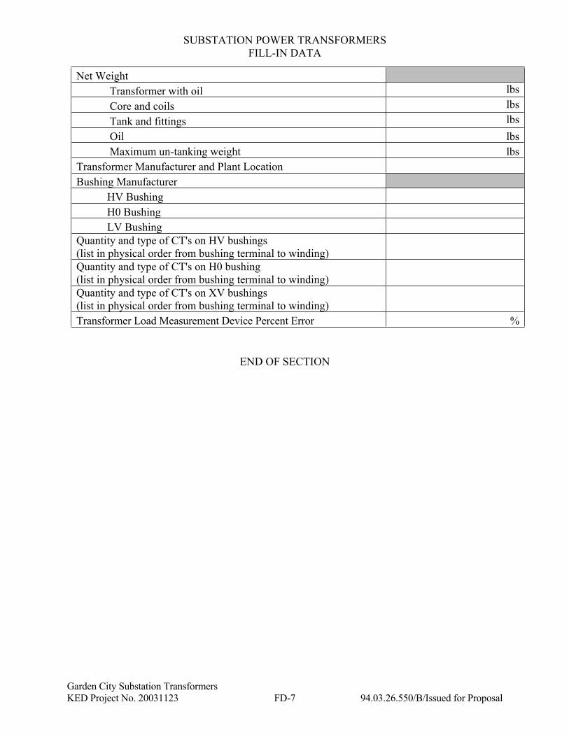
KED Project No. 20031123 FD-7 94.03.26.550/B/Issued for Proposal
Net Weight
Transformer with oil lbs
Core and coils lbs
Tank and fittings lbs
Oil lbs
Maximum un-tanking weight lbs
Transformer Manufacturer and Plant Location
Bushing Manufacturer
HV Bushing
H0 Bushing
LV Bushing
Quantity and type of CT's on HV bushings
(list in physical order from bushing terminal to winding)
Quantity and type of CT's on H0 bushing
(list in physical order from bushing terminal to winding)
Quantity and type of CT's on XV bushings
(list in physical order from bushing terminal to winding)
Transformer Load Measurement Device Percent Error %
END OF SECTION
Garden City Substation Transformers
Kiewit Project No. 20031123 GR-A-1 94.03.26.550/B/Issued for Proposal
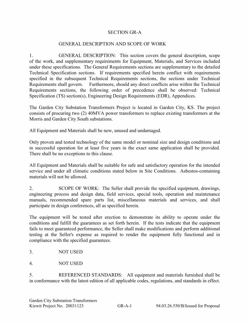
SECTION GR-A
GENERAL DESCRIPTION AND SCOPE OF WORK
1. GENERAL DESCRIPTION: This section covers the general description, scope
of the work, and supplementary requirements for Equipment, Materials, and Services included
under these specifications. The General Requirements sections are supplementary to the detailed
Technical Specification sections. If requirements specified herein conflict with requirements
specified in the subsequent Technical Requirements sections, the sections under Technical
Requirements shall govern. Furthermore, should any direct conflicts arise within the Technical
Requirements sections, the following order of precedence shall be observed: Technical
Specification (TS) section(s), Engineering Design Requirements (EDR), Appendices.
The Garden City Substation Transformers Project is located in Garden City, KS. The project
consists of procuring two (2) 40MVA power transformers to replace existing transformers at the
Morris and Garden City South substations.
All Equipment and Materials shall be new, unused and undamaged.
Only proven and tested technology of the same model or nominal size and design conditions and
in successful operation for at least five years in the exact same application shall be provided.
There shall be no exceptions to this clause.
All Equipment and Materials shall be suitable for safe and satisfactory operation for the intended
service and under all climatic conditions stated below in Site Conditions. Asbestos-containing
materials will not be allowed.
2. SCOPE OF WORK: The Seller shall provide the specified equipment, drawings,
engineering process and design data, field services, special tools, operation and maintenance
manuals, recommended spare parts list, miscellaneous materials and services, and shall
participate in design conferences, all as specified herein.
The equipment will be tested after erection to demonstrate its ability to operate under the
conditions and fulfill the guarantees as set forth herein. If the tests indicate that the equipment
fails to meet guaranteed performance, the Seller shall make modifications and perform additional
testing at the Seller's expense as required to render the equipment fully functional and in
compliance with the specified guarantees.
3. NOT USED
4. NOT USED
5. REFERENCED STANDARDS: All equipment and materials furnished shall be
in conformance with the latest edition of all applicable codes, regulations, and standards in effect.
Garden City Substation Transformers
Kiewit Project No. 20031123 GR-A-2 94.03.26.550/B/Issued for Proposal
Seller shall obtain Buyer approval for any deviation to these standards or alternative standards.
Request for deviation or alternative shall include an explanation why such change is necessary
and how compliance is to be achieved. Buyer reserves the right to reject any such request for any
reason. If the Seller discovers any conflict between any code, standard, or regulation, the Seller
shall notify the Buyer of the conflict. The Buyer in its sole discretion shall then choose which
provision shall take precedence over the conflicting provision. Unless specific exceptions are
indicated in the Agreement, all specifications will be considered applying to all phases of the
Work.
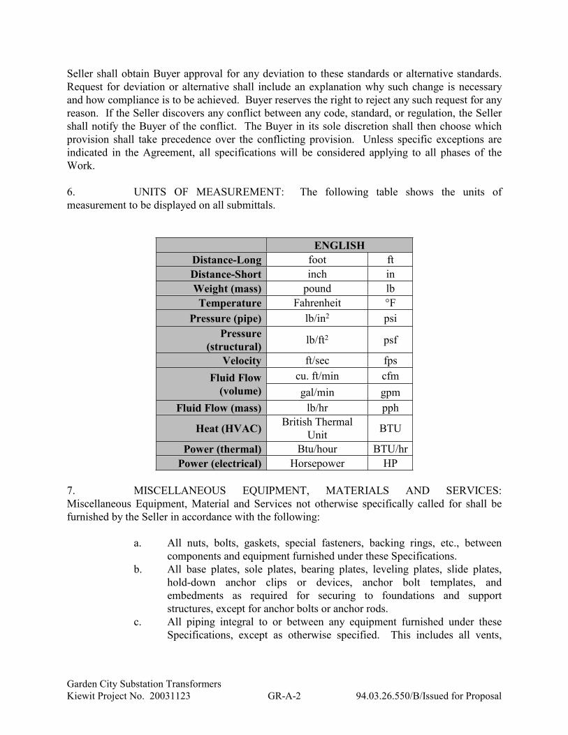
6. UNITS OF MEASUREMENT: The following table shows the units of
measurement to be displayed on all submittals.
ENGLISH
Distance-Long foot ft
Distance-Short inch in
Weight (mass) pound lb
Temperature Fahrenheit °F
Pressure (pipe) lb/in2 psi
Pressure
(structural)lb/ft2 psf
Velocity ft/sec fps
cu. ft/min cfmFluid Flow
(volume) gal/min gpm
Fluid Flow (mass) lb/hr pph
Heat (HVAC)British Thermal
UnitBTU
Power (thermal) Btu/hour BTU/hr
Power (electrical) Horsepower HP
7. MISCELLANEOUS EQUIPMENT, MATERIALS AND SERVICES:
Miscellaneous Equipment, Material and Services not otherwise specifically called for shall be
furnished by the Seller in accordance with the following:
a. All nuts, bolts, gaskets, special fasteners, backing rings, etc., between
components and equipment furnished under these Specifications.
b. All base plates, sole plates, bearing plates, leveling plates, slide plates,
hold-down anchor clips or devices, anchor bolt templates, and
embedments as required for securing to foundations and support
structures, except for anchor bolts or anchor rods.
c. All piping integral to or between any equipment furnished under these
Specifications, except as otherwise specified. This includes all vents,
Garden City Substation Transformers
Kiewit Project No. 20031123 GR-A-3 94.03.26.550/B/Issued for Proposal
drains, instrument piping, and other piping Work required for a complete
unit.
d. All necessary instrument, power and control wiring and raceways integral
to any equipment furnished under these Specifications. This shall include
terminal blocks and internal wiring to these terminal blocks for Equipment
requiring external connection.
e. Leveling blocks, sole plates, thrust blocks, matching blocks, and shims.
f. One complete set of start-up and commissioning consumable spare parts.
g. Detailed erection drawings, prints, information, instructions, and other
data for use by the Buyer.
h. Finish painting of all equipment except as specified herein
i. Finish touch-up paint
j. Detailed storage requirements and lubrication requirements (including
quantities and lubrication and rotation frequencies) for use by the Buyer.
k. Supply all special tools or lifting beams and lugs for offloading
l. Initial fill of lubricants, fluids and media
m. All special tools required for erection of the equipment. Erection tools
shall remain the property of the Seller and all shipping costs to and from
the Job Site shall be at the Seller's expense.
n. All special tools required for dismantling and maintenance of the
equipment. All special tools shall be new and unused and shall become
the property of the Buyer for transfer to the Owner.
8. WORK NOT INCLUDED UNDER THESE SPECIFICATIONS: The following
items of Work will be furnished by others:
Receiving, unloading, storing, and field erection of all Equipment and Materials
(unless specifically identified in the Technical Specifications)
Foundations and foundation anchor bolts
Grouting materials and the placing thereof
Permanent electric wiring to connect equipment terminal boxes to the electrical
equipment supplied by others.
Fuels for operation
Solvents and cleaning materials
Operating personnel for startup and tests
9. NOT USED
Garden City Substation Transformers
Kiewit Project No. 20031123 GR-A-4 94.03.26.550/B/Issued for Proposal
10. DESIGN CONFERENCE: The Seller's design engineers shall participate in a
design conference at a time selected by the Buyer to discuss matters relative to the execution of
this Contract. The Seller's design engineers shall participate in additional design conferences as
required by the Buyer thereafter to expedite the Work.
11. NOT USED
12. NOT USED
13. NOT USED
14. CONSTRUCTION MANAGEMENT SYSTEM: The Seller and subcontractors
shall provide, to the Buyer, engineering, procurement, production, scheduling, and shipping
information for the equipment, including sub-suppliers equipment. Such information shall be
provided in the detail and format and at the frequency required by the Buyer. The information
shall be submitted by the first of each month or more frequently as determined by the Buyer. The
information will be used by the Buyer for schedule monitoring purposes, to ensure that schedule
interfaces with other suppliers and subcontractors are met, and to monitor overall Project
performance.
15. FACTORY WITNESS TESTS: Supplementing the provisions of the equipment
specifications concerning factory witness tests, the Seller shall notify the Buyer not less than 30
days prior to the date of each Factory Witness Test (FWT). The Seller shall be fully prepared to
conduct a successful FWT upon Buyer’s arrival. If there is any doubt at all, the Seller shall
conduct a full test prior to the official FWT and shall be responsible for any expenses incurred by
the Buyer or Owner if the equipment fails any part of the FWT and re-testing is necessary.
END OF SECTION
Garden City Substation Transformers
Kiewit Project No. 20031123 GR-B-1 94.03.26.550/B/Issued for Proposal
SECTION GR-B
ENGINEERING DATA AND SUBMITTAL SCHEDULE
1. ENGINEERING DATA: Compliance with the Schedule and the Seller’s
Deliverables Schedule (SDS) for engineering data submittal is essential to the scheduled progress
and timely completion of the Project and is of the essence of this Contract.
1.1 Document Index: A document index listing all drawings and data to be submitted
shall be included with the initial submittal. The document index shall be resubmitted as required
to indicate revisions to the list. The list shall include the document number and title, if known, or
the general document category (e.g., wiring diagrams) for each document.
1.2 Numbering System: The Seller will utilize their standard tagging format for all
equipment, instruments, etc. within their scope of supply and documentation. Buyer retains the
right to review and provide comments with regard to the tagging scheme to prevent duplication or
confusion when reviewed with the Buyer engineering documentation
1.3 Kick-Off and Contract Review: The Seller shall participate in a kick-off meeting.
As part of this kick-off meeting, a specification page turn with the Buyer’s Responsible Engineer
and the Seller’s operations personnel shall be conducted. The walk through of each contract
section is intended to confirm that there are no misunderstandings of the contractual technical
requirements and both parties are in agreement on the interpretation of the language.
2. SUBMITTALS AND CORRESPONDENCE: All correspondence, technical and
commercial, including all documents, data, and drawings shall be provided in the English
language. The following two articles describe in detail the minimum expectations for technical
submittals; the third article describes the expectations for commercial correspondence, which
follows a separate procedure.
2.1 General Submittal Format: All Engineering Drawings and Engineering Data shall
be submitted to Buyer in electronic format (excluding vendor manuals). Electronic documents
shall be submitted as noted below:
a. Project Records Information Management System (RIMS) shall be utilized
for both document submittal and document return. Separate instructions
will be provided for site access. Seller shall provide a list of personnel
requiring access, including name, title, address, phone number and email
address.
1. Electronic Documents uploaded shall not exceed 500 MB for a
single upload.
b. Information Management Lead shall provide log-in information and
instructions to Seller’s Document Control and Project Management team
for posting documents to RIMS.
c. Seller shall enter the following Metadata for each document uploaded
(instructions provided later):
Garden City Substation Transformers
Kiewit Project No. 20031123 GR-B-2 94.03.26.550/B/Issued for Proposal
1. File name (match Vendor Drawing Number)
2. Title
3. Vendor Drawing Number (VDN)
4. Vendor Drawing Revision (VDN Rev)
5. SDS Line Item
2.2 Transmittals: Letters of transmittal shall accompany all submittals of engineering
data and shall include a list of the data included in the transmittal as identified below. All
correspondence shall be identified with the Project name, Specification number, Buyer's Project
number, and Seller's order number.
a. Seller's Name
b. Contract Number
c. Kiewit Purchase Order Number
d. Drawing Title
e. Drawing Number
f. Drawing Revision
g. Quantity Sent
h. SDS Item Number to which the submittal applies
i. Return Address, Name of Recipient and E-mail address of Recipient
j. Date of Submission
Submittals will be considered received when posted to RIMS. Submittals that arrive later than 5
PM Central Time will be documented as received at the beginning of the next business day.
ELECTRONIC COPY
Kent Pottorf [email protected]
Mike Muirhead [email protected]
Effort should be made to provide all submittals in electronic PDF format. Submittals such as large
binders, where requested, paint samples, product samples, or other submittals that cannot be
submitted electronically shall be submitted in hard copy to the following address:
HARD COPY
City of Garden City Kansas
Attn: Kent Pottorf
PO Box 998, 140 Harvest St.
Garden City, KS 67846
One (1) copy of the transmittal including the transmittal letter, the list of the data included in the
transmittal, and one (1) prints of the Engineering Drawings and Engineering Data shall be sent by
express mail to the Buyer’s address above.
Garden City Substation Transformers
Kiewit Project No. 20031123 GR-B-3 94.03.26.550/B/Issued for Proposal
2.3 Commercial Correspondence: All commercial documentation, including but not
limited to, any correspondence regarding adjustments to cost or schedule shall be addressed to the
Buyer as follows:
HARD COPY
City of Garden City Kansas
Attn: Kent Pottorf
PO Box 998, 140 Harvest St.
Garden City, KS 67846
ELECTRONIC COPY
Kent Pottorf [email protected]
Mike Muirhead [email protected]
All commercial correspondence shall be identified with the Project name, Specification number,
Buyer's Project number, and Seller's order number.
3. REVIEW OF ENGINEERING DATA: The Buyer's review of engineering data
will cover only general conformity of the data to the Specifications and Documents, external
connections, interfaces with equipment and materials furnished under separate specifications, and
dimensions which affect plant arrangements. The Buyer's review including any indication or
drawing approval, does not indicate a thorough review of all dimensions, quantities, and details of
the Equipment, material, device, or item indicated or the accuracy of the information submitted;
nor shall review by the Buyer be construed as relieving the Seller from any responsibility for errors
or deviations from the requirements of the Contract.
All engineering data submitted, after final processing and acceptance by the Buyer shall become a
part of the Contract. Work shall be performed in accordance with the accepted engineering data.
4. TEST AND INSPECTION DATA: Certified copies of specified test and
inspection reports shall be provided by the Seller for all tests and inspections conducted on the
specified equipment or material.
5. DRAWINGS: All drawings necessary for design, installation and operation shall
be submitted. Drawings shall be fully completed, checked, and certified by the Seller to verify
that the information on the submittal is complete with the requirements of these Specifications.
Drawings shall have title block entries clearly indicating the drawing is certified.
Each drawing submitted shall have a title block clearly marked with the name of the Project, the
unit designation, the Specification title, the Specification number, the equipment or structure
nomenclature, the equipment tag number, and the Seller's name, address, date of approval, drawing
revision number, and responsible person. If standard drawings or catalog pages are submitted, the
applicable Equipment and devices furnished shall be clearly marked. Any drawing with detail or
Garden City Substation Transformers
Kiewit Project No. 20031123 GR-B-4 94.03.26.550/B/Issued for Proposal
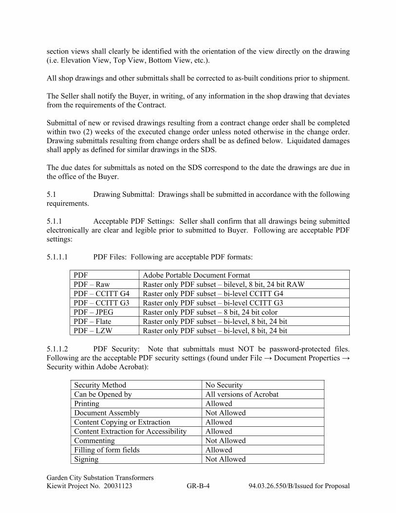
section views shall clearly be identified with the orientation of the view directly on the drawing
(i.e. Elevation View, Top View, Bottom View, etc.).
All shop drawings and other submittals shall be corrected to as-built conditions prior to shipment.
The Seller shall notify the Buyer, in writing, of any information in the shop drawing that deviates
from the requirements of the Contract.
Submittal of new or revised drawings resulting from a contract change order shall be completed
within two (2) weeks of the executed change order unless noted otherwise in the change order.
Drawing submittals resulting from change orders shall be as defined below. Liquidated damages
shall apply as defined for similar drawings in the SDS.
The due dates for submittals as noted on the SDS correspond to the date the drawings are due in
the office of the Buyer.
5.1 Drawing Submittal: Drawings shall be submitted in accordance with the following
requirements.
5.1.1 Acceptable PDF Settings: Seller shall confirm that all drawings being submitted
electronically are clear and legible prior to submitted to Buyer. Following are acceptable PDF
settings:
5.1.1.1 PDF Files: Following are acceptable PDF formats:
PDF Adobe Portable Document Format
PDF – Raw Raster only PDF subset – bilevel, 8 bit, 24 bit RAW
PDF – CCITT G4 Raster only PDF subset – bi-level CCITT G4
PDF – CCITT G3 Raster only PDF subset – bi-level CCITT G3
PDF – JPEG Raster only PDF subset – 8 bit, 24 bit color
PDF – Flate Raster only PDF subset – bi-level, 8 bit, 24 bit
PDF – LZW Raster only PDF subset – bi-level, 8 bit, 24 bit
5.1.1.2 PDF Security: Note that submittals must NOT be password-protected files.
Following are the acceptable PDF security settings (found under File → Document Properties →
Security within Adobe Acrobat):
Security Method No Security
Can be Opened by All versions of Acrobat
Printing Allowed
Document Assembly Not Allowed
Content Copying or Extraction Allowed
Content Extraction for Accessibility Allowed
Commenting Not Allowed
Filling of form fields Allowed
Signing Not Allowed

Garden City Substation Transformers
Kiewit Project No. 20031123 GR-B-5 94.03.26.550/B/Issued for Proposal
Creation of Template Pages Not Allowed
Submitting Forms Not Allowed
5.2 NOT USED
5.3 Drawing Processing: Effort will be made to review and return all submittals to the
Seller within 15 business days as stipulated herein, except that drawings with “SUPERCEDED or
SUPERCEDED BEFORE FULLY REVIEWED” (SSR) status will not be returned. The status
“SSR” is assigned when the Seller submits the document before the already submitted document
is not returned/still under review by the Buyer. Drawings returned to the Seller will be in Adobe
Acrobat (pdf) format with the Buyer's comments and Action Stamp.
When drawings and data are returned marked APPROVED AS NOTED (AAN), the changes shall
be made as noted thereon, and the drawing shall be resubmitted for final approval. If a drawing(s)
is returned to the Seller with a status of RETURNED FOR RECORD (RFR), comments made to
the drawing(s) (such as addition of tag numbers) shall be noted by the Seller but the Seller is not
required to pick up the comment immediately and resubmit unless requested by the Buyer.
However, if the Seller does re-submit the drawing(s) for other reasons, the comment shall be
picked up within the new revision.
Drawings and data that do not meet the minimum requirements of the Contract will be returned
marked “RETURNED FOR CORRECTION” (RFC), and will be regarded as not submitted. When
the drawings and data are returned marked “RFC”, the corrections shall be made as noted thereon
and as instructed by the Buyer, and the drawing shall be resubmitted for final approval as soon as
possible, but no later than ten (10) business days.
Additionally, drawings may receive a status of VOID if the drawings are no longer applicable to
the project due to changes in project scope.
When a drawing is revised and resubmitted, the Seller shall include an issue number and revision
description in the drawing revision block. All revisions pertaining to that particular drawing issue
shall be back circled or otherwise clearly noted on the drawing. Seller shall resubmit drawings
within ten (10) business days of receipt. Seller will be responsible for costs associated with
engineering and construction costs caused from drawings information that was changed and not
back circled and clearly identified as changed from the previous submittal.
Drawings marked FOR INFORMATION ONLY (INF) have been filed, but have not been
reviewed.
Where comments are made that result in a Change to the Contract, the quantification and
qualification of the Change shall be recorded, in writing, in a form acceptable to Buyer and
submitted to Buyer within five (5) working days of receipt of the returned document.
No work shall be performed in connection with the fabrication or manufacture of Equipment and
materials until the drawings and data therein have been reviewed by the Buyer, except at the
Seller's own risk and responsibility. Work may proceed on Equipment and materials when the
Garden City Substation Transformers
Kiewit Project No. 20031123 GR-B-6 94.03.26.550/B/Issued for Proposal
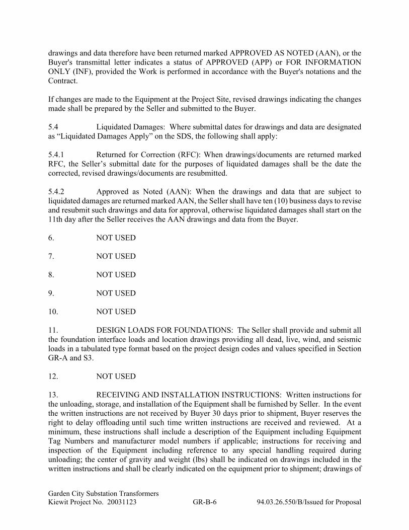
drawings and data therefore have been returned marked APPROVED AS NOTED (AAN), or the
Buyer's transmittal letter indicates a status of APPROVED (APP) or FOR INFORMATION
ONLY (INF), provided the Work is performed in accordance with the Buyer's notations and the
Contract.
If changes are made to the Equipment at the Project Site, revised drawings indicating the changes
made shall be prepared by the Seller and submitted to the Buyer.
5.4 Liquidated Damages: Where submittal dates for drawings and data are designated
as “Liquidated Damages Apply” on the SDS, the following shall apply:
5.4.1 Returned for Correction (RFC): When drawings/documents are returned marked
RFC, the Seller’s submittal date for the purposes of liquidated damages shall be the date the
corrected, revised drawings/documents are resubmitted.
5.4.2 Approved as Noted (AAN): When the drawings and data that are subject to
liquidated damages are returned marked AAN, the Seller shall have ten (10) business days to revise
and resubmit such drawings and data for approval, otherwise liquidated damages shall start on the
11th day after the Seller receives the AAN drawings and data from the Buyer.
6. NOT USED
7. NOT USED
8. NOT USED
9. NOT USED
10. NOT USED
11. DESIGN LOADS FOR FOUNDATIONS: The Seller shall provide and submit all
the foundation interface loads and location drawings providing all dead, live, wind, and seismic
loads in a tabulated type format based on the project design codes and values specified in Section
GR-A and S3.
12. NOT USED
13. RECEIVING AND INSTALLATION INSTRUCTIONS: Written instructions for
the unloading, storage, and installation of the Equipment shall be furnished by Seller. In the event
the written instructions are not received by Buyer 30 days prior to shipment, Buyer reserves the
right to delay offloading until such time written instructions are received and reviewed. At a
minimum, these instructions shall include a description of the Equipment including Equipment
Tag Numbers and manufacturer model numbers if applicable; instructions for receiving and
inspection of the Equipment including reference to any special handling required during
unloading; the center of gravity and weight (lbs) shall be indicated on drawings included in the
written instructions and shall be clearly indicated on the equipment prior to shipment; drawings of
Garden City Substation Transformers
Kiewit Project No. 20031123 GR-B-7 94.03.26.550/B/Issued for Proposal
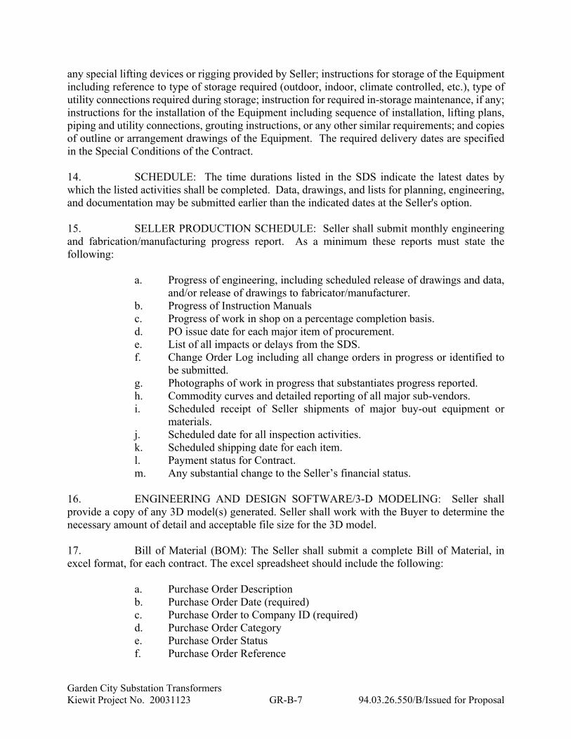
any special lifting devices or rigging provided by Seller; instructions for storage of the Equipment
including reference to type of storage required (outdoor, indoor, climate controlled, etc.), type of
utility connections required during storage; instruction for required in-storage maintenance, if any;
instructions for the installation of the Equipment including sequence of installation, lifting plans,
piping and utility connections, grouting instructions, or any other similar requirements; and copies
of outline or arrangement drawings of the Equipment. The required delivery dates are specified
in the Special Conditions of the Contract.
14. SCHEDULE: The time durations listed in the SDS indicate the latest dates by
which the listed activities shall be completed. Data, drawings, and lists for planning, engineering,
and documentation may be submitted earlier than the indicated dates at the Seller's option.
15. SELLER PRODUCTION SCHEDULE: Seller shall submit monthly engineering
and fabrication/manufacturing progress report. As a minimum these reports must state the
following:
a. Progress of engineering, including scheduled release of drawings and data,
and/or release of drawings to fabricator/manufacturer.
b. Progress of Instruction Manuals
c. Progress of work in shop on a percentage completion basis.
d. PO issue date for each major item of procurement.
e. List of all impacts or delays from the SDS.
f. Change Order Log including all change orders in progress or identified to
be submitted.
g. Photographs of work in progress that substantiates progress reported.
h. Commodity curves and detailed reporting of all major sub-vendors.
i. Scheduled receipt of Seller shipments of major buy-out equipment or
materials.
j. Scheduled date for all inspection activities.
k. Scheduled shipping date for each item.
l. Payment status for Contract.
m. Any substantial change to the Seller’s financial status.
16. ENGINEERING AND DESIGN SOFTWARE/3-D MODELING: Seller shall
provide a copy of any 3D model(s) generated. Seller shall work with the Buyer to determine the
necessary amount of detail and acceptable file size for the 3D model.
17. Bill of Material (BOM): The Seller shall submit a complete Bill of Material, in
excel format, for each contract. The excel spreadsheet should include the following:
a. Purchase Order Description
b. Purchase Order Date (required)
c. Purchase Order to Company ID (required)
d. Purchase Order Category
e. Purchase Order Status
f. Purchase Order Reference
Garden City Substation Transformers
Kiewit Project No. 20031123 GR-B-8 94.03.26.550/B/Issued for Proposal
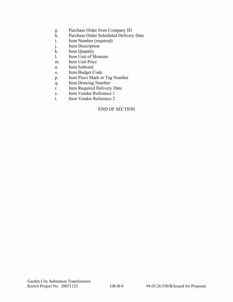
g. Purchase Order from Company ID
h. Purchase Order Scheduled Delivery Date
i. Item Number (required)
j. Item Description
k. Item Quantity
l. Item Unit of Measure
m. Item Unit Price
n. Item Subtotal
o. Item Budget Code
p. Item Piece Mark or Tag Number
q. Item Drawing Number
r. Item Required Delivery Date
s. Item Vendor Reference 1
t. Item Vendor Reference 2
END OF SECTION

COMPREHENSIVE EQUIPMENT MANUAL
Morris and Garden City North SubstationsSubstation Power Transformers
Specification #94.03.26.550
Equipment Supplier NameEquipment Supplier Address
Ph Supplier Phone #Fax Supplier Fax #
EQUIPMENT DESCRIPTIONEquipment Tag
Order #
VOLUME 1 OF1
Morris and Garden City North Substations
Substation Power Transformers
Specification #94.03.26.550
Equip Supplier Name
Equipment SupplierAddress
Ph Phone NumberFax Fax Number
EquipmentDescription
Equipment TagOrder #
COMPREHENSIVE EQUIPMENT
MANUAL
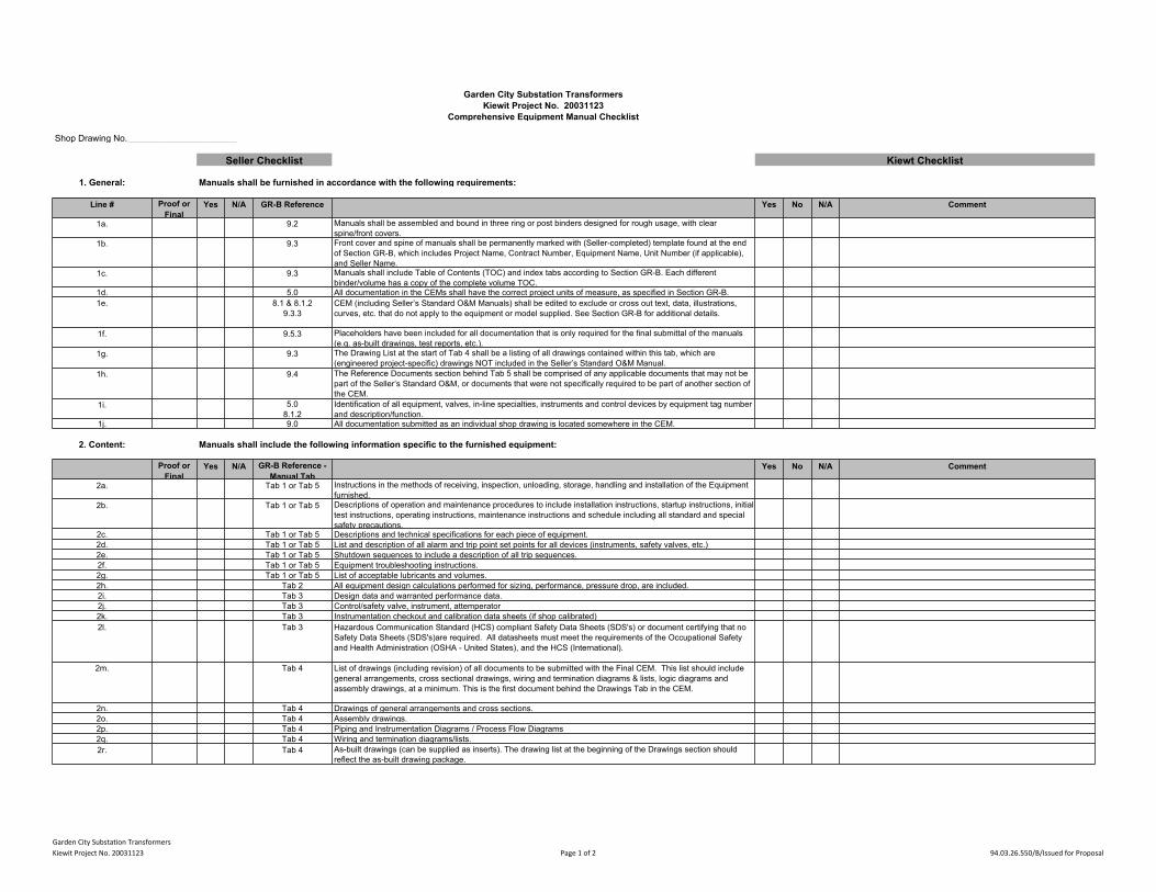
Garden City Substation TransformersKiewit Project No. 20031123 Page 1 of 2 94.03.26.550/B/Issued for Proposal
Garden City Substation TransformersKiewit Project No. 20031123
Comprehensive Equipment Manual Checklist
Shop Drawing No.______________________
Seller Checklist Kiewt Checklist
1. General: Manuals shall be furnished in accordance with the following requirements:
Line # Proof orFinal
Yes N/A GR-B Reference Yes No N/A Comment
1a. 9.2 Manuals shall be assembled and bound in three ring or post binders designed for rough usage, with clearspine/front covers.
1b. 9.3 Front cover and spine of manuals shall be permanently marked with (Seller-completed) template found at the endof Section GR-B, which includes Project Name, Contract Number, Equipment Name, Unit Number (if applicable),and Seller Name.
1c. 9.3 Manuals shall include Table of Contents (TOC) and index tabs according to Section GR-B. Each differentbinder/volume has a copy of the complete volume TOC.
1d. 5.0 All documentation in the CEMs shall have the correct project units of measure, as specified in Section GR-B.1e. 8.1 & 8.1.2
9.3.3CEM (including Seller’s Standard O&M Manuals) shall be edited to exclude or cross out text, data, illustrations,curves, etc. that do not apply to the equipment or model supplied. See Section GR-B for additional details.
1f. 9.5.3 Placeholders have been included for all documentation that is only required for the final submittal of the manuals(e.g. as-built drawings, test reports, etc.).
1g. 9.3 The Drawing List at the start of Tab 4 shall be a listing of all drawings contained within this tab, which are(engineered project-specific) drawings NOT included in the Seller’s Standard O&M Manual.
1h. 9.4 The Reference Documents section behind Tab 5 shall be comprised of any applicable documents that may not bepart of the Seller’s Standard O&M, or documents that were not specifically required to be part of another section ofthe CEM.
1i. 5.08.1.2
Identification of all equipment, valves, in-line specialties, instruments and control devices by equipment tag numberand description/function.
1j. 9.0 All documentation submitted as an individual shop drawing is located somewhere in the CEM.
2. Content: Manuals shall include the following information specific to the furnished equipment:
Proof orFinal
Yes N/A GR-B Reference -Manual Tab
Yes No N/A Comment
2a. Tab 1 or Tab 5 Instructions in the methods of receiving, inspection, unloading, storage, handling and installation of the Equipmentfurnished.
2b. Tab 1 or Tab 5 Descriptions of operation and maintenance procedures to include installation instructions, startup instructions, initialtest instructions, operating instructions, maintenance instructions and schedule including all standard and specialsafety precautions.
2c. Tab 1 or Tab 5 Descriptions and technical specifications for each piece of equipment.2d. Tab 1 or Tab 5 List and description of all alarm and trip point set points for all devices (instruments, safety valves, etc.)2e. Tab 1 or Tab 5 Shutdown sequences to include a description of all trip sequences.2f. Tab 1 or Tab 5 Equipment troubleshooting instructions.2g. Tab 1 or Tab 5 List of acceptable lubricants and volumes.2h. Tab 2 All equipment design calculations performed for sizing, performance, pressure drop, are included.2i. Tab 3 Design data and warranted performance data.2j. Tab 3 Control/safety valve, instrument, attemperator2k. Tab 3 Instrumentation checkout and calibration data sheets (if shop calibrated)2l. Tab 3 Hazardous Communication Standard (HCS) compliant Safety Data Sheets (SDS's) or document certifying that no
Safety Data Sheets (SDS's)are required. All datasheets must meet the requirements of the Occupational Safetyand Health Administration (OSHA - United States), and the HCS (International).
2m. Tab 4 List of drawings (including revision) of all documents to be submitted with the Final CEM. This list should includegeneral arrangements, cross sectional drawings, wiring and termination diagrams & lists, logic diagrams andassembly drawings, at a minimum. This is the first document behind the Drawings Tab in the CEM.
2n. Tab 4 Drawings of general arrangements and cross sections.2o. Tab 4 Assembly drawings.2p. Tab 4 Piping and Instrumentation Diagrams / Process Flow Diagrams2q. Tab 4 Wiring and termination diagrams/lists.2r. Tab 4 As-built drawings (can be supplied as inserts). The drawing list at the beginning of the Drawings section should
reflect the as-built drawing package.
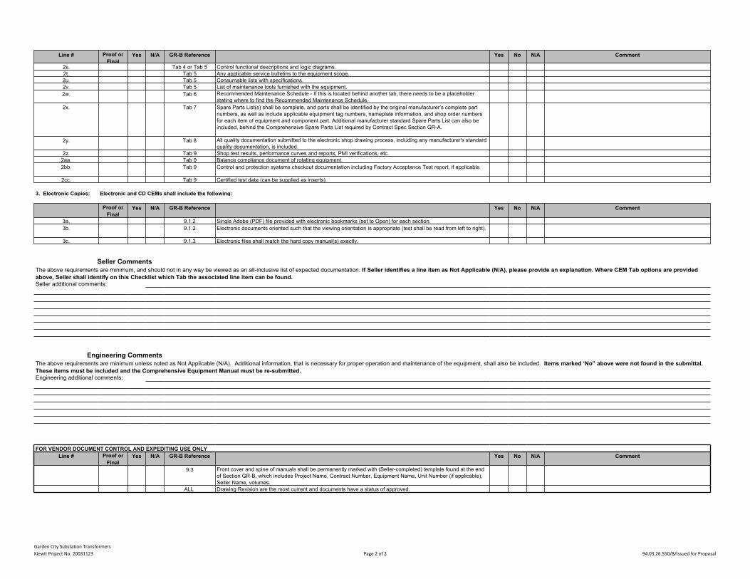
Garden City Substation TransformersKiewit Project No. 20031123 Page 2 of 2 94.03.26.550/B/Issued for Proposal
2s. Tab 4 or Tab 5 Control functional descriptions and logic diagrams.2t. Tab 5 Any applicable service bulletins to the equipment scope.2u. Tab 5 Consumable lists with specifications.2v. Tab 5 List of maintenance tools furnished with the equipment.2w. Tab 6 Recommended Maintenance Schedule - If this is located behind another tab, there needs to be a placeholder
stating where to find the Recommended Maintenance Schedule.2x. Tab 7 Spare Parts List(s) shall be complete, and parts shall be identified by the original manufacturer’s complete part
numbers, as well as include applicable equipment tag numbers, nameplate information, and shop order numbersfor each item of equipment and component part. Additional manufacturer standard Spare Parts List can also beincluded, behind the Comprehensive Spare Parts List required by Contract Spec Section GR-A.
2y. Tab 8 All quality documentation submitted to the electronic shop drawing process, including any manufacturer's standardquality documentation, is included.
2z. Tab 9 Shop test results, performance curves and reports, PMI verifications, etc.2aa. Tab 9 Balance compliance document of rotating equipment.2bb. Tab 9 Control and protection systems checkout documentation including Factory Acceptance Test report, if applicable
2cc. Tab 9 Certified test data (can be supplied as inserts).
3. Electronic Copies: Electronic and CD CEMs shall include the following:
Proof orFinal
Yes N/A GR-B Reference Yes No N/A Comment
3a. 9.1.2 Single Adobe (PDF) file provided with electronic bookmarks (set to Open) for each section.3b. 9.1.2 Electronic documents oriented such that the viewing orientation is appropriate (test shall be read from left to right).
3c. 9.1.3 Electronic files shall match the hard copy manual(s) exactly.
Seller CommentsThe above requirements are minimum, and should not in any way be viewed as an all-inclusive list of expected documentation. If Seller identifies a line item as Not Applicable (N/A), please provide an explanation. Where CEM Tab options are providedabove, Seller shall identify on this Checklist which Tab the associated line item can be found.Seller additional comments:
Engineering CommentsThe above requirements are minimum unless noted as Not Applicable (N/A). Additional information, that is necessary for proper operation and maintenance of the equipment, shall also be included. Items marked ‘No” above were not found in the submittal.These items must be included and the Comprehensive Equipment Manual must be re-submitted.Engineering additional comments:
FOR VENDOR DOCUMENT CONTROL AND EXPEDITING USE ONLY Line # Proof or
FinalYes N/A GR-B Reference Yes No N/A Comment
9.3 Front cover and spine of manuals shall be permanently marked with (Seller-completed) template found at the endof Section GR-B, which includes Project Name, Contract Number, Equipment Name, Unit Number (if applicable),Seller Name, volumes.
ALL Drawing Revision are the most current and documents have a status of approved.
Line # Proof orFinal
Yes N/A GR-B Reference Yes No N/A Comment
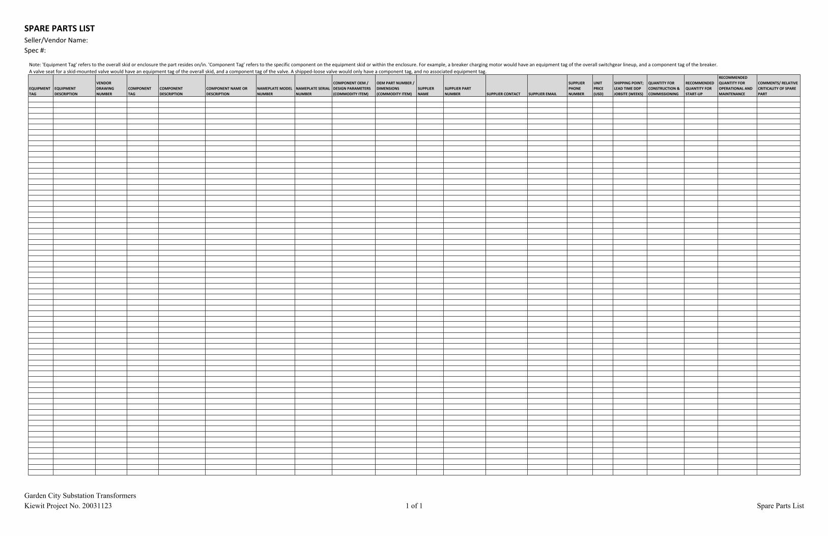
SPARE PARTS LISTSeller/Vendor Name:Spec #:
Garden City Substation TransformersKiewit Project No. 20031123 1 of 1 Spare Parts List
Note: 'Equipment Tag' refers to the overall skid or enclosure the part resides on/in. 'Component Tag' refers to the specific component on the equipment skid or within the enclosure. For example, a breaker charging motor would have an equipment tag of the overall switchgear lineup, and a component tag of the breaker. A valve seat for a skid-mounted valve would have an equipment tag of the overall skid, and a component tag of the valve. A shipped-loose valve would only have a component tag, and no associated equipment tag.
EQUIPMENTTAG
EQUIPMENTDESCRIPTION
VENDORDRAWINGNUMBER
COMPONENTTAG
COMPONENTDESCRIPTION
COMPONENT NAME ORDESCRIPTION
NAMEPLATE MODELNUMBER
NAMEPLATE SERIALNUMBER
COMPONENT OEM /DESIGN PARAMETERS(COMMODITY ITEM)
OEM PART NUMBER /DIMENSIONS(COMMODITY ITEM)
SUPPLIERNAME
SUPPLIER PARTNUMBER SUPPLIER CONTACT SUPPLIER EMAIL
SUPPLIERPHONENUMBER
UNITPRICE(USD)
SHIPPING POINT;LEAD TIME DDPJOBSITE (WEEKS)
QUANTITY FORCONSTRUCTION &COMMISSIONING
RECOMMENDEDQUANTITY FORSTART-UP
RECOMMENDEDQUANTITY FOROPERATIONAL ANDMAINTENANCE
COMMENTS/ RELATIVECRITICALITY OF SPAREPART
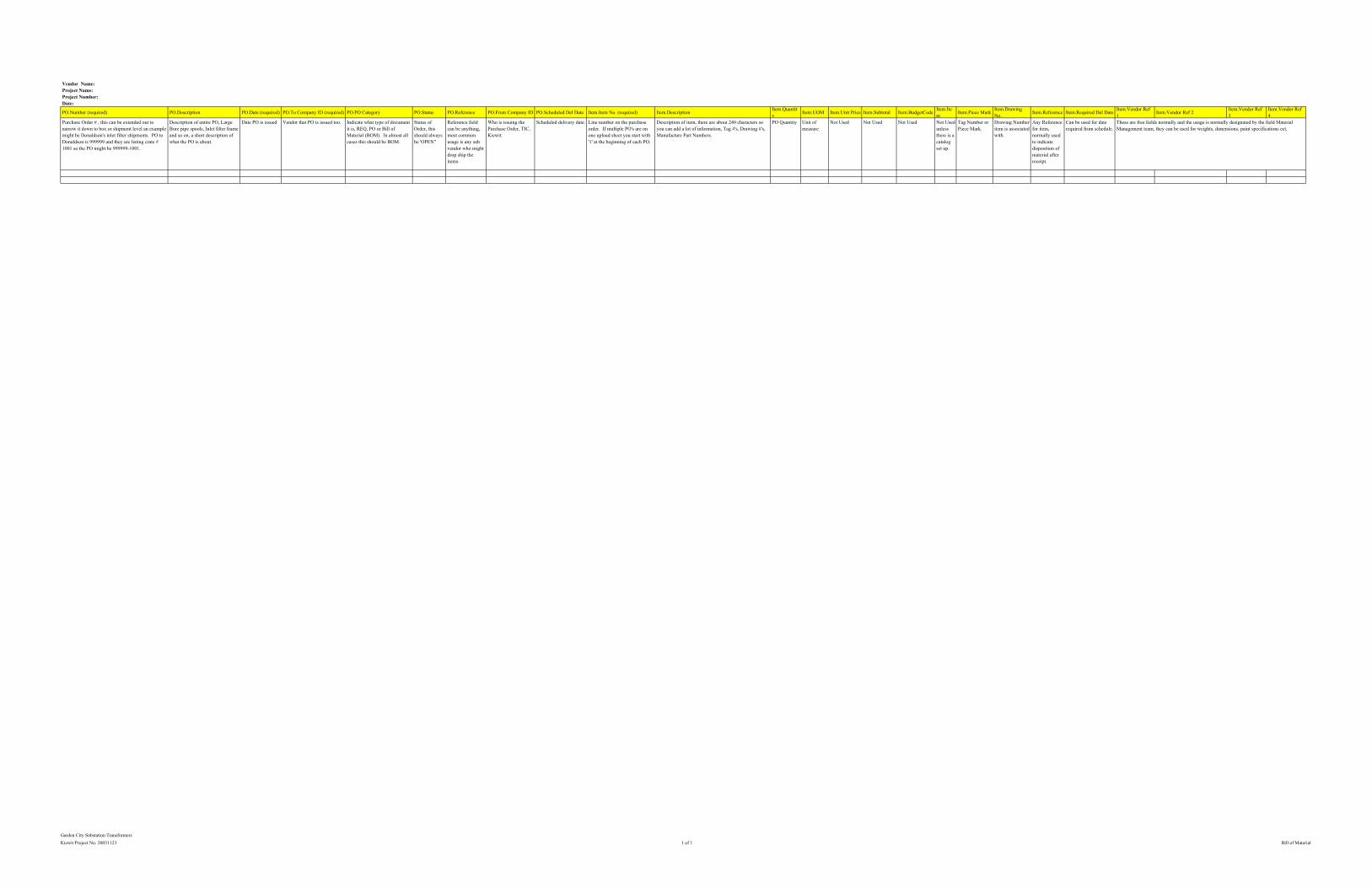
Garden City Substation TransformersKiewit Project No. 20031123 1 of 1 Bill of Material
Vendor Name:Project Name:Project Number:Date:
PO.Number (required) PO.Description PO.Date (required) PO.To Company ID (required) PO.PO Category PO.Status PO.Reference PO.From Company ID PO.Scheduled Del Date Item.Item No. (required) Item.Description Item.Quantity Item.UOM Item.Unit Price Item.Subtotal Item.BudgetCode Item.Ite
m Item.Piece Mark Item.DrawingNo. Item.Reference Item.Required Del Date Item.Vendor Ref
1 Item.Vendor Ref 2 Item.Vendor Ref3
Item.Vendor Ref4
Purchase Order # , this can be extended out tonarrow it down to box or shipment level an examplemight be Donaldson's inlet filter shipments. PO toDonaldson is 999999 and they are listing crate #1001 so the PO might be 999999-1001.
Description of entire PO, LargeBore pipe spools, Inlet filter frameand so on, a short description ofwhat the PO is about.
Date PO is issued Vendor that PO is issued too. Indicate what type of documentit is, REQ, PO or Bill ofMaterial (BOM). In almost allcases this should be BOM.
Status ofOrder, thisshould alwaysbe 'OPEN"
Reference fieldcan be anything,most commonusage is any subvendor who mightdrop ship theitems.
Who is issuing thePurchase Order, TIC,Kiewit.
Scheduled delivery date. Line number on the purchaseorder. If multiple PO's are onone upload sheet you start with'1' at the beginning of each PO.
Description of item, there are about 240 characters soyou can add a lot of information, Tag #'s, Drawing #'s,Manufacture Part Numbers.
PO Quantity Unit ofmeasure
Not Used Not Used Not Used Not Usedunlessthere is acatalogset up.
Tag Number orPiece Mark.
Drawing Numberitem is associatedwith.
Any Referencefor item,normally usedto indicatedisposition ofmaterial afterreceipt.
Can be used for daterequired from schedule.
These are free fields normally and the usage is normally designated by the field MaterialManagement team, they can be used for weights, dimensions, paint specifications ect.
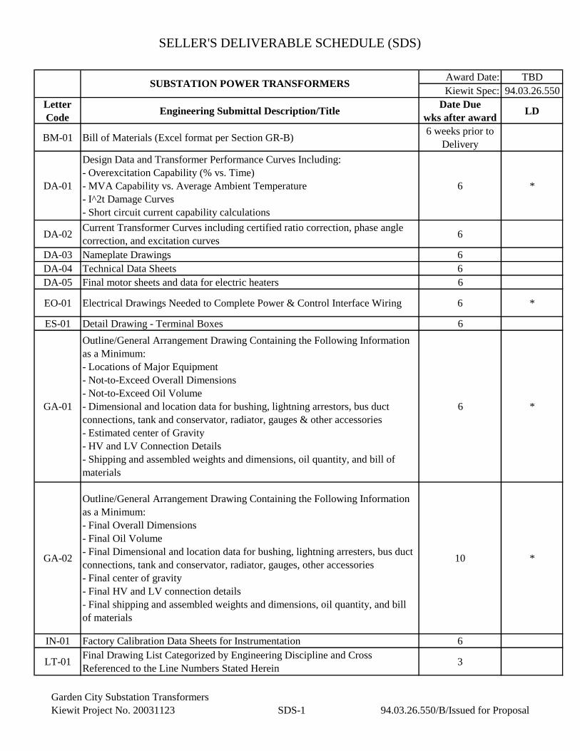
SELLER'S DELIVERABLE SCHEDULE (SDS)
Award Date: TBD
Kiewit Spec: 94.03.26.550
Letter
CodeEngineering Submittal Description/Title
Date Due
wks after awardLD
BM-01 Bill of Materials (Excel format per Section GR-B)6 weeks prior to
Delivery
DA-01
Design Data and Transformer Performance Curves Including:
- Overexcitation Capability (% vs. Time)
- MVA Capability vs. Average Ambient Temperature
- I^2t Damage Curves
- Short circuit current capability calculations
6 *
DA-02Current Transformer Curves including certified ratio correction, phase angle
correction, and excitation curves6
DA-03 Nameplate Drawings 6
DA-04 Technical Data Sheets 6
DA-05 Final motor sheets and data for electric heaters 6
EO-01 Electrical Drawings Needed to Complete Power & Control Interface Wiring 6 *
ES-01 Detail Drawing - Terminal Boxes 6
GA-01
Outline/General Arrangement Drawing Containing the Following Information
as a Minimum:
- Locations of Major Equipment
- Not-to-Exceed Overall Dimensions
- Not-to-Exceed Oil Volume
- Dimensional and location data for bushing, lightning arrestors, bus duct
connections, tank and conservator, radiator, gauges & other accessories
- Estimated center of Gravity
- HV and LV Connection Details
- Shipping and assembled weights and dimensions, oil quantity, and bill of
materials
6 *
GA-02
Outline/General Arrangement Drawing Containing the Following Information
as a Minimum:
- Final Overall Dimensions
- Final Oil Volume
- Final Dimensional and location data for bushing, lightning arresters, bus duct
connections, tank and conservator, radiator, gauges, other accessories
- Final center of gravity
- Final HV and LV connection details
- Final shipping and assembled weights and dimensions, oil quantity, and bill
of materials
10 *
IN-01 Factory Calibration Data Sheets for Instrumentation 6
LT-01Final Drawing List Categorized by Engineering Discipline and Cross
Referenced to the Line Numbers Stated Herein3
SUBSTATION POWER TRANSFORMERS
Garden City Substation Transformers
Kiewit Project No. 20031123 SDS-1 94.03.26.550/B/Issued for Proposal
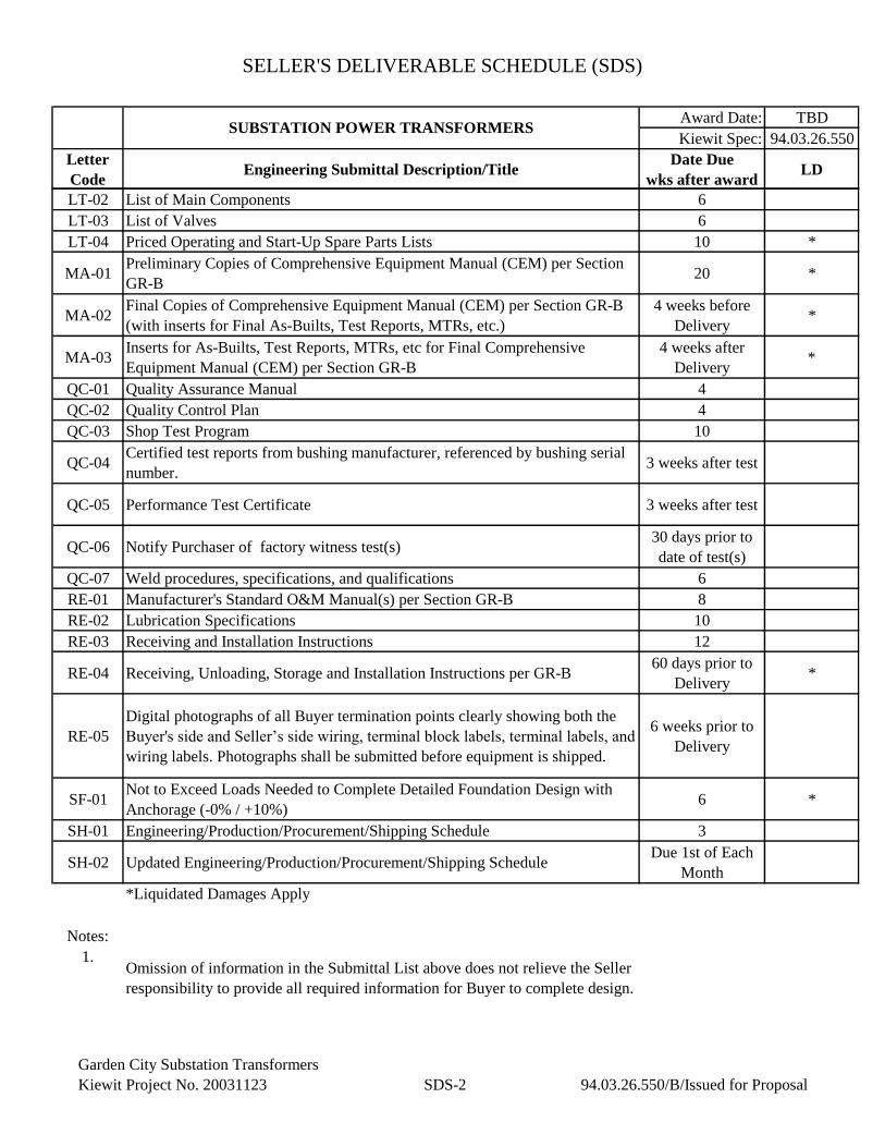
SELLER'S DELIVERABLE SCHEDULE (SDS)
Award Date: TBD
Kiewit Spec: 94.03.26.550
Letter
CodeEngineering Submittal Description/Title
Date Due
wks after awardLD
SUBSTATION POWER TRANSFORMERS
LT-02 List of Main Components 6
LT-03 List of Valves 6
LT-04 Priced Operating and Start-Up Spare Parts Lists 10 *
MA-01Preliminary Copies of Comprehensive Equipment Manual (CEM) per Section
GR-B20 *
MA-02Final Copies of Comprehensive Equipment Manual (CEM) per Section GR-B
(with inserts for Final As-Builts, Test Reports, MTRs, etc.)
4 weeks before
Delivery*
MA-03Inserts for As-Builts, Test Reports, MTRs, etc for Final Comprehensive
Equipment Manual (CEM) per Section GR-B
4 weeks after
Delivery*
QC-01 Quality Assurance Manual 4
QC-02 Quality Control Plan 4
QC-03 Shop Test Program 10
QC-04Certified test reports from bushing manufacturer, referenced by bushing serial
number.3 weeks after test
QC-05 Performance Test Certificate 3 weeks after test
QC-06 Notify Purchaser of factory witness test(s)30 days prior to
date of test(s)
QC-07 Weld procedures, specifications, and qualifications 6
RE-01 Manufacturer's Standard O&M Manual(s) per Section GR-B 8
RE-02 Lubrication Specifications 10
RE-03 Receiving and Installation Instructions 12
RE-04 Receiving, Unloading, Storage and Installation Instructions per GR-B60 days prior to
Delivery*
RE-05
Digital photographs of all Buyer termination points clearly showing both the
Buyer's side and Seller’s side wiring, terminal block labels, terminal labels, and
wiring labels. Photographs shall be submitted before equipment is shipped.
6 weeks prior to
Delivery
SF-01Not to Exceed Loads Needed to Complete Detailed Foundation Design with
Anchorage (-0% / +10%)6 *
SH-01 Engineering/Production/Procurement/Shipping Schedule 3
SH-02 Updated Engineering/Production/Procurement/Shipping ScheduleDue 1st of Each
Month
*Liquidated Damages Apply
Notes:
1.Omission of information in the Submittal List above does not relieve the Seller
responsibility to provide all required information for Buyer to complete design.
Garden City Substation Transformers
Kiewit Project No. 20031123 SDS-2 94.03.26.550/B/Issued for Proposal
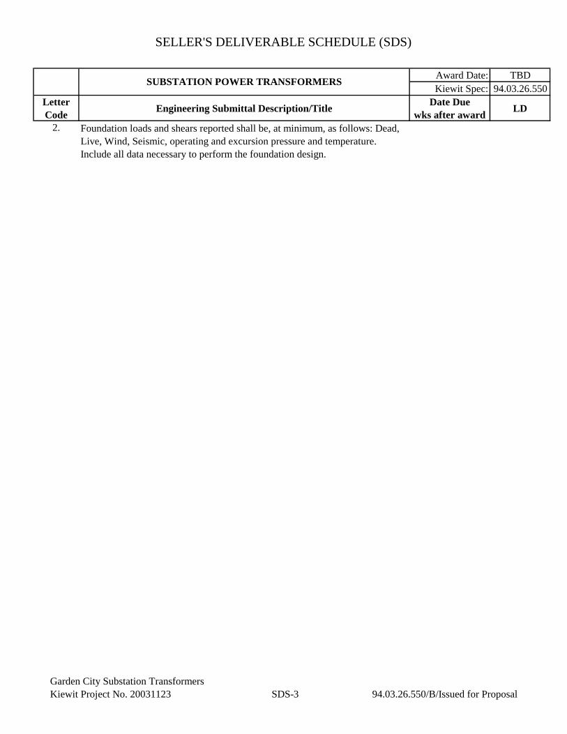
SELLER'S DELIVERABLE SCHEDULE (SDS)
Award Date: TBD
Kiewit Spec: 94.03.26.550
Letter
CodeEngineering Submittal Description/Title
Date Due
wks after awardLD
SUBSTATION POWER TRANSFORMERS
2. Foundation loads and shears reported shall be, at minimum, as follows: Dead,
Live, Wind, Seismic, operating and excursion pressure and temperature.
Include all data necessary to perform the foundation design.
Garden City Substation Transformers
Kiewit Project No. 20031123 SDS-3 94.03.26.550/B/Issued for Proposal
Garden City Substation Transformers
Kiewit Project No. 20031123 TS1-1 94.03.26.550/B/Issued for Proposal
TECHNICAL SPECIFICATION 94.03.26.550
SUBSTATION POWER TRANSFORMERS
1. GENERAL:
1.1 APPLICABLE PUBLICATIONS: The transformers shall be designed,
manufactured, and tested in accordance with the applicable current Standards to the extent
indicated by the references herein and in Section GR-A
1.2 American National Standards Institute/Institute of Electrical and Electronic
Engineers (ANSI/IEEE) publications.
C32 Standard Requirements, Terminology, and Test Procedures for
Neutral Grounding Devices
C37.23 Standard for Metal-Enclosed Bus
C57.12.00 General Requirements for Liquid-Immersed Distribution, Power,
and Regulating Transformers
C57.12.10 Standard Requirements for Liquid-Immersed Power Transformers
C57.12.70 Standard Terminal Markings and Connections for Distribution and
Power Transformers
C57.12.90 Test Code for Liquid-Immersed Distribution, Power, and
Regulating Transformers
C57.13 Requirements for Instrument Transformers
C57.13.2 Conformance Test Procedures for Instrument Transformers”
C57.19.00 General Requirements and Test Procedure for Outdoor Power
Apparatus Bushings
C57.19.01 Performance Characteristics and Dimensions for Outdoor Power
Apparatus Bushings
C57.19.100 Guide for Application of Power Apparatus Bushings
C57.32 Requirements, Terminology, and Test Procedures for Neutral
Grounding Devices
C57.91 Guide for Loading Mineral-Oil-Immersed Transformers
Garden City Substation Transformers
Kiewit Project No. 20031123 TS1-2 94.03.26.550/B/Issued for Proposal
C57.104 Guide for the Interpretation of Gases Generated in Oil-Immersed
Transformers
C57.106 Guide for Acceptance and Maintenance of Insulating Oil in
Equipment
C57.109 Guide for Liquid Immersed Transformer Through-Fault-Current
Duration
C57.116 Guide for Transformers Directly Connected to Generators
C57.120 Loss Evaluation Guide for Power Transformers and Reactors
C57.148 Control Cabinets for Power Transformers
C57.149 Guide for the Application and Interpretation of Frequency
Response Analysis for Oil Immersed Transformers
C57.152 Guide for Diagnostic Field Testing of Fluid-Filled Power
Transformers, Regulators, and Reactors
C62.11 Standard for Metal-Oxide Surge Arresters for AC Power Circuits
(>1kV)
C62.22 Guide for the Application of Metal-Oxide Surge Arresters for
Alternating-Current Systems
1.2.1 If Engineering Design Requirements indicate transformer to be filled with Less
Flammable Hydrocarbon (LFH) fluid:
C57.121 Guide for Acceptance and Maintenance of Less Flammable
Hydrocarbon Fluid in Transformers
1.3 National Electrical Manufacturers Association (NEMA) publications.
107 Methods of Measurement of Radio Influence Voltage (RIV) of High
Voltage Apparatus
C84.1 Standard for Electric Power Systems and Equipment – Voltage
Ratings (60 Hertz)
ICS1 Industrial Control and Systems – General Requirements
ICS2 Industrial Control and Systems; Controllers, Contactors, and
Garden City Substation Transformers
Kiewit Project No. 20031123 TS1-3 94.03.26.550/B/Issued for Proposal
Overload Relays Rated 600 Volts
SG-6 Power Switching Equipment
TR1 Transformers, Step Voltage Regulators, and Reactors
TR98 Guide for Loading Oil-Immersed Power
1.4 Underwriters Laboratories (UL) publications:
489 UL Standard for Safety Molded-Case Circuit Breakers, Molded-
Case Switches and Circuit-Breaker Enclosures
1.5 American Society of Testing and Materials (ASTM) publications.
D877 Standard Test Method for Dielectric Breakdown Voltage of
Insulating Liquids Using Disk Electrodes
D923 Standard Practice for Sampling Electric Insulating Liquids
D924 Standard Test Method for Dissipation Factor (or Power Factor) and
Relative Permittivity (Dielectric Constant) of Electrical Insulating
Liquids
D971 Standard Test Method for Interfacial Tension of Oil Against Water
by the Ring Method
D974 Standard Test Method for Acid and Base Number by Color-
Indicator Titration
D1275 Standard Test Method for Corrosive Sulfur in Electrical Insulating
Liquids
D1500 Standard Test Method for ASTM Color of Petroleum Products
(ASTM Color Scale)
D1524 Standard Test Method for Visual Examination of Used Electrical
Insulating Liquids in the Field
D1533 Standard Test Method for Water in Insulating Liquids by
Coulometric Karl Fischer Titration
D1816 Standard Test Method for Dielectric Breakdown Voltage of
Insulating Liquids Using VDE Electrodes
Garden City Substation Transformers
Kiewit Project No. 20031123 TS1-4 94.03.26.550/B/Issued for Proposal
D3487 Standard Specification for Mineral Insulating Oil used in Electric
Equipment
D3612 Standard Test Method for Analysis of Gases Dissolved in
Electrical Insulating Oil by Gas Chromatography
2. GENERAL REQUIREMENTS: The Seller shall design, fabricate, test, and deliver
to the Job Site a total number of oil filled power transformers as indicated in the attached
Engineering Design Requirements (EDR). The transformers shall be designed, manufactured and
tested as per latest ANSI/IEEE Standards.
2.1 Each transformer shall meet the requirements of ANSI/IEEE C57.12.00 paragraph
7.1.5.5. Unless indicated otherwise in the attached EDR the low voltage delta winding will be
isophase bus duct connected direct to its generator or an SF6 generator circuit breaker. Unless
indicated otherwise in the attached EDR, the transformer high voltage solidly grounded wye
winding will be connected to a substation SF6 outdoor power circuit breaker and the transformer
shall be capable of power flow in both directions. Rating of each transformer shall be as detailed
in the attached EDR.
2.2 Noise Level: The noise level expressed in sound power shall not exceed noise
levels as specified in NEMA TR1 at the top cooled rating (all fans energized), "A" weighted when
measured in accordance with ANSI/IEEE C57.12.90 Article 13 “Audible Sound Tests,” or as listed
in Section GR-A, whichever is more stringent.
3. DESIGN: Each transformer shall be designed and fabricated in accordance with
the following:
3.1 Tanks: Each transformer tank, along with radiators, shall meet the applicable
sections of ANSI/IEEE C57.12.00. Each transformer tank/conservator system shall be of a
sealed design with welded on cover (cover to be welded to tank prior to beginning of FAT,
conservator tank used for FAT shall be the conservator tank that is designed for permanent
installation for the transformer) and general welded plate construction. The tank/conservator
system shall be absolutely oil tight and gas tight with all fittings in place. The tank and
attachments that are subjected to operating pressures or installation vacuums shall be designed to
withstand, without permanent deformation, pressures 25 percent greater than the maximum
operating pressures resulting from inert gas type oil preservation system, or from the vacuum
expected during oil filling. Each tank and tank mounted accessories shall be designed for the
seismic criteria as defined in Section S1 of this Specification. All hardware for fall protection shall
also be provided and installed. The tank shall be designed so that all current transformers (CTs)
can be removed easily without removing the main transformer tank cover.
3.1.1 Tank Manhole/Handhole Covers: Suitable manhole openings (18” minimum
diameter) and hand holes with gasketed, bolted covers shall be provided in the cover of the tank to
allow access to the inside of the tank for inspection. Manholes and hand holes shall be provided to
allow easy access to the lower ends of bushings, terminals, upper portions of the coils, and to
permit replacement of CTs and other auxiliaries without removing the tank cover. Access openings
shall have a 1/2" raised flange to prevent submersion of gaskets in water. The transformer cover
Garden City Substation Transformers
Kiewit Project No. 20031123 TS1-5 94.03.26.550/B/Issued for Proposal
shall have a non-skid surface. Access covers in the sidewalls of the tank shall be minimized. A
minimum of 18” clearance is required between the manhole or hand hole cover and any radiator or
other accessory.
3.1.1 Fall Prevention System: One (1) base plate shall be provided and welded on the top
cover for a transformer fall arrest system. If the tank dimension exceeds 15 feet in width or length,
two (2) plates shall be provided and appropriately spaced. Plates shall be provided in a manner
with no obstruction vertically perpendicular to the transformer cover. Provisions shall be provided
to install a safety barricade along the entire edge of the transformer cover.
3.1.2 Ladder: The transformer shall be provided with a permanent ladder to access the
top of the transformer to perform maintenance to the accessories installed on the top cover of the
transformer. The location of the ladder on the wall of transformer shall not have any restrictions
while climbing on to the top of the transformer. A cover/door shall be attached to the ladder with
provisions to padlock; design shall accommodate to restrict unauthorized personnel access to the
top of the transformer. Rung to rung distance and rung to top of transformer distance shall comply
with OSHA limits.
3.1.3 Base: The transformer and its base shall be designed to permit rolling, skidding,
and pulling in either parallel or perpendicular direction to transformer main axis. Suitable lugs and
jack points shall be provided for this purpose. Jacking lugs shall be a minimum 14” above the
transformer base. The base shall be fabricated from structural members and arranged such that the
transformer tank bottom is exposed above the bottom of base members to allow ventilation and
prevent accumulation of moisture. The base shall be designed to permit lifting, rolling, jacking, or
pulling of the entire assembled transformer filled with oil with no damage to base coils or tank.
The tank base shall include provisions for anchoring the transformer to its structural foundation.
3.1.4 Finish: Each transformer tank and radiator assemblies shall be cleaned and
degreased prior to receiving the Seller’s standard primer coat. A finish coat shall be applied to the
exterior of each tank. The exterior color shall be as indicated on the EDR. A final finish coat of
high gloss paint shall be applied to the tank and radiator exterior surface immediately prior to
shipment. One (1) gallon of paint shall be shipped with each transformer for final touch-up after
assembly.
3.1.5 Ground Pads: Grounding pads shall consist of copper or stainless steel, NEMA 4-
hole pads drilled and tapped with ½”-13 UNC threads. The minimum threaded depth of holes
shall be 1”. Thread protectors shall be furnished.
3.1.5.1 Tank Ground Pads: Four (4) ground pads shall be welded to the tank wall near
the base, one (1) at each corner. Pads shall be located as required to not interfered with jacking
facilities or be obstructed by other transformer accessory devices (e.g. control panels).
3.1.5.2 Tank Cover Ground Pads: Two (2) ground pads shall be located on the tank cover.
One ground pad is near the HO bushing and the second ground is pad near the LV bushing
isophase bus flanges.
Garden City Substation Transformers
Kiewit Project No. 20031123 TS1-6 94.03.26.550/B/Issued for Proposal
3.1.5.3 A ¼” x 2” copper ground bus shall be provided and supported on insulated
standoffs between one (1) of the tank ground pads and the cover mounted ground pad next to the
HO bushing.
3.1.5.4 If Surge arrestors are provided, they shall be grounded as required in Article 3.10.3
of this Section. All connectors and stainless-steel hardware shall be supplied and installed by the
Seller
3.1.6 Ground Lead Clips: Ground clips shall be provided on the transformer tank
between the top cover isophase, non-segregated bus flanges, and/or overhead cable connection
ground pad(s) and one tank ground pad to secure a 4/0 stranded bare copper conductor. The
conductor is provided by others.
3.2 Core: Each transformer core shall be fabricated from high grade, non-aging, cold-
rolled, grain oriented, highly permeable, electrical silicon alloy steel with low hysteresis loss
characteristics. The laminations shall be free of burrs and sharp projections. Mitered and stacked
laminations shall be rigidly clamped to prevent noise and distortion under normal operation, under
short circuit stresses, and during handling. Provisions shall be made for lifting the core and coil
assembly out of or into the tank. Nuts and bolts in the core assembly shall have positive locking
devices to prevent loosening.
3.2.1 The transformer internal core ground connection shall be located at the top of the
coil near a manhole cover. The core ground shall be brought out of the tank and terminated on a
5kV bushing mounted on the tank cover. The core ground bushing shall be totally enclosed by a
weatherproof enclosure to prevent accidental contact and be removable to allow access to the
bushing for core ground testing. The enclosure shall be clearly labeled with “EXTERNAL
CORE GROUND CONNECTION”.
3.3 Windings: Windings shall be fabricated from high conductivity electrical grade
copper and shall be self-supporting. Joints in windings or at bushings or tap changer shall be
brazed or clamped with suitable locking devices to prevent loosening of connections. Soldering
shall not be permitted. The assembled core and coil shall be rigidly braced and clamped to
withstand short circuit forces in accordance with ANSI C57.12.00. All clamps shall have suitable
locking devices to prevent loosening. Provisions shall be made for lifting the core and coil
assembly out of or into the tank. Winding insulation BIL characteristics shall be as specified in the
EDR. Internal surge arresters are not allowed. Internal current limiting reactors are not allowed
without Purchaser approval. Guide tubes shall be used where possible. Transformer windings shall
be designed to be free-buckling and shall not rely on winding tubes for their short circuit strength.
3.4 Insulation: When indicated in the EDR, the hottest spot temperature rise for 65⁰C
average temperature rise ratings shall not exceed 80⁰C. Unless specified otherwise in the attached
EDR, temperature ratings shall be based on a 24-hour average ambient temperature of 30⁰C and a
maximum ambient of 40⁰C in accordance with ANSI C57.12.00. High temperature insulation
shall be added between the tie plate and core.
Garden City Substation Transformers
Kiewit Project No. 20031123 TS1-7 94.03.26.550/B/Issued for Proposal
3.5 Impedance: The transformer impedance shall meet the ratings specified in the EDR
based on self-cooled primary MVA ratings, rated voltage, and rated temperature rise. The
impedance shall be within +/- 10% for three-winding units and +/- 7.5% for two-winding units
manufacturing tolerance, per IEEE C57.12.00, of the nominal impedance specified in the EDR.
The Seller shall furnish design calculations indicating the short circuit current values at the design
impedance for Purchaser review and approval prior to the start of any manufacturing.
3.6 On-load tap changer: Each transformer shall be provided with an on-load tap
changer. The transformer(s) shall be furnished with arcing contact housed in a separate
compartment designed to prevent any interchange of oil between the compartment and the main
tank. Removable bolted covers shall be provided for access to the switch compartment without
opening the main tank or lowering the oil in the main tank. A drain valve with sampling device
shall be located in the bottom of each oil-filled compartment to provide complete oil drainage. A
magnetic liquid level gauge with a vertical face shall be mounted on the top of the oil-filled
compartment. A mechanical pressure relief device shall be mounted on the top of the oil-filled
compartment. The tap changer shall provide full rated kVA on taps above and below rated
voltage. The tap changer shall be designed to provide at least 500,000 operations at the maximum
nameplate current rating before contact replacement. If a current limiting series transformer is
provided, it shall have circular windings and meet the same criteria as the main core and coil.
Equipment for the automatic and manual control of the load tap changer shall be furnished in a
weatherproof compartment mounted adjacent to the tap changer compartment. Access and
operation shall be accessible from grade level at the transformer (5’-0” above bottom of tank). The
following equipment shall be furnished, as required, to provide the specified controls:
Manual Control
a. Operating mechanism with motor drive
b. Weatherproof control compartment with convenience outlet, anti-
condensation heater, and light with switches
c. Mechanically operated limit switches and stops to prevent over-travel of the
drive mechanism beyond the maximum raise and lower positions
d. Local position indicator
e. Operations counter
f. RAISE-LOWER selector switch for manual control
Automatic Control
a. AUTOMATIC-OFF-MANUAL selector switch
b. Voltage testing terminals
c. Line drop compensator with adjustable resistance and reactive elements
d. Current transformers for line drop compensation
e. Voltage regulating relay
f. Time-delay relays for first step of a tap position change
g. A hand crank for manual operation, with electrical interlock to prevent
operation of the motor while the hand crank is being used
Remote control
Garden City Substation Transformers
Kiewit Project No. 20031123 TS1-8 94.03.26.550/B/Issued for Proposal
a. REMOTE-LOCAL selector switch
b. Remote tap position indicator for mounting on a remote-control panel
provided by others
c. Additional equipment needed for remote/local or automatic/manual control
3.7 NOT USED
3.8 Vacuum and resistive LTC switches shall have a fault pressure relay on the LTC
compartment wired to the control cabinet. The fault pressure relay must be watertight when
mounted below the flood level or below the level of the bottom of the control cabinet. The fault
pressure relay will be equipped with one set of form “C” contacts. These will be tripping contacts
operated directly by the fault pressure relay for external protection.
3.9 Assembled Transformer: Each transformer shall be adequately sized, insulated, and
braced to meet the short circuit requirements of ANSI / IEEE Standard C57.12.00 and to withstand
the short circuit test code as defined in ANSI / IEEE Standard C57.12.90. Each transformer shall
be capable of withstanding, without injury, the mechanical and thermal stresses caused by faults
with 110% rated voltage maintained across the terminals HV winding and zero external
transformer impedance used in calculating the short circuit current; the transformer impedance
used shall be the minimum within tolerances. The thermal time duration shall be in accordance
with ANSI / IEEE Standard C57.12.00 Sections 7.1.1 and 7.4. The center of gravity of the
assembled transformer shall be low and as near the vertical center line as practicable. The
transformer shall be stable with or without oil. If the center of gravity is off center relative to the
base, either with or without oil, its location shall be shown on the outline drawing.
3.10 Transformer Terminations: All terminations shall be silver plated.
3.10.1 HV Bushing Termination: The HV bushings shall be provided with provisions
for overhead line connections. HV bushings shall be rated and located as specified in the EDR.
Bushing terminals shall be provided with NEMA 4-hole terminal pads.
3.10.2 HV Surge Arresters: Surge arresters shall be supplied as specified in the EDR for
overhead connections.
3.10.2.1 The maximum continuous operating voltage (MCOV) of the arresters shall be as
specified in the attached EDR sheets. Surge arrester tests shall be performed by the original
manufacturer. Quality control test data documented by the arrester manufacturer shall be
provided with the transformer test data.
3.10.3 The arresters shall be metal top type with a NEMA 4-hole terminal pad. The
ground terminal of all three (3) arresters shall be connected to two (2) separated tank ground
pads by one (1) continuous unbroken run of #4/0 AWG bare copper cable to allow two (2) paths
to ground from each arrester. The cable shall be adequately supported along the transformer at
least every 3’.
Garden City Substation Transformers
Kiewit Project No. 20031123 TS1-9 94.03.26.550/B/Issued for Proposal
3.10.4 LV Bushing Termination: LV bushing terminals shall be provided with multiple
holes with NEMA 2-hole spacing for connection of flexible links. The LV bushings shall have a
raised circular flange around the bushings for connection to IPBD. Flanges shall be provided
with an equal number of holes equally spaced and centered on the transformer main axis.
Sufficient space shall be provided under the raised circular flange to allow nut installation. If
sufficient space cannot be provided, Seller shall weld captive nuts with UNC threads to the
bottom side of the flange. The IPBD terminal enclosure and flexible links will be provided by
Others.
3.10.5 ANSI C57.12.00 Table 10 clearances or the Seller’s required strike distances shall
be maintained between live parts of the bushings and other grounded surfaces on the transformer,
whichever is greater. Clearances shall take into consideration the installation of the LV bushing
isolated phase bus duct (IPBD) terminations enclosure provided by Others, which will consist of
an enclosure extending vertically from the LV bushing flange plus an additional 3” margin
between the LV and HV bushings. Bushings shall be spaced or angled as required to meet this
clearance requirement. Clearance spheres around the bushings live parts and surge arresters shall
be clearly shown for all three (3) phases on both the Seller’s 3D model files and shop drawings.
3.11 Bushings: Each transformer shall have HV and LV bushings located as in the
attached EDR sheets. Bushings shall be wet process, non-porous, free from cavities or other flaws,
gray bulk porcelain capable of meeting the requirements of ANSI/IEEE C57.19.01. Minimum
bushing ampacity requirements for both the HV and LV bushings shall be based upon the
maximum currents at the extreme tap position, maximum transformer cooling classification (top.
ONAF rating), and maximum rated temperature rise specified in the attached EDR sheets. The
bushing rating shall not limit the transformer rating under any circumstances.
3.12 ANSI Segment Drawing: Unless specified otherwise in the attached EDR sheets,
all bushing and accessories shall be located on the transformer in accordance with ANSI/IEEE
C27.12.10. The physical arrangement and terminal identification shall be X1-X2-X3, from left-to-
right when facing the LV bushing and H1-H2-H3 from right-to-left when facing the HV bushings.
3.12.1 HV phase bushings shall be oil filled, condenser, drawn lead type with static
shields.
3.12.2 HO bushing shall be located on the tank cover and be grounded per the attached
EDR sheets.
3.12.3 LV bushing selection shall also take into account the bus enclosures around the
bushing and the elevated ambient temperature around the bushings. The LV bushing shall be
suitable for connection to IPBD operating at 105⁰C. IEEE standard C57.23 shall be followed for
bushing connecting to IPBD. Viton gaskets shall be used. Current rating for LV bushings shall
be compatible with the top transformer cooling rating at rated temperature rise and not be less
than 110% rated amps for each transformer.
3.13 Current Transformers (CTs): Current transformers shall be provided with the
ratings, quantity, and location as indicated on the EDR. CTs shall be designed and installed in
Garden City Substation Transformers
Kiewit Project No. 20031123 TS1-10 94.03.26.550/B/Issued for Proposal
accordance with all applicable standards, including ANSI/IEEE Standard C57.13. CTs shall be
multi-ratio, metering class, relaying class, or dual rated in accordance with ANSI/IEEE C57.13
and as specified in the EDR. Multi-ratio CTs shall be five (5) lead type with fully distributed
windings and single - ratio CTs shall be two lead type. All taps shall be wired out to terminal
blocks with 600 volt, 90°C, insulated copper cables, #10 AWG minimum size. Terminal blocks
located in the transformer control cabinet shall be as specified in Section E2 and be General
Electric Model EB-27, Marathon 1500 Series or Purchaser approved equal. Wiring shall be
terminated with ring tongue (fully closed) preinsulated lugs. Six (6) points shall be assigned for
each CT with CT polarity being connected to point 1 and point 6 the CT neutral. The grounded
terminal shall be the CT neutral or as indicated during shop drawing review. Seller shall design
the equipment to prevent the unintentional opening of the CT secondary circuits at all terminal
blocks and similar locations. CT wiring shall be complete from CTs to the control cabinet prior
to the Factory Acceptance Test (FAT).
3.14 Oil Preservation Equipment: The oil preservation system shall be per the EDR. The
tank and oil conservator (if required) shall be sized for operation without vacuum or pressure relief
over an oil operating temperature range from the minimum site temperature listed in Section GR-A
to 120⁰C.
3.14.1 If a sealed tank system is provided, the system shall include a pressure vacuum
gauge and a pressure relief device designed to seal the interior of the transformer from the
atmosphere and hold the gas and oil volume constant within the range of 10 psi positive to 8 psi
negative.
3.14.2 If a conservator system is provided, the conservator shall be inflatable cell type.
The system shall prevent air and moisture from contacting the oil using a flexible rubber air cell in
the conservator tank. Transformer cover, raised flanges, and other oil containing devices above
the tank cover shall be designed to ensure no gases can be trapped at the high point of the
extension. This design and installation shall include all necessary high point gas vent ports and
sloped piping to direct all gases to the conservator piping, through the inline gas monitor, and
finally to the conservator tank. The following items shall be accounted for in the design:
3.14.2.1 Necessary piping, valves, and vents to allow flushing, purging, and sampling.
Sampling valves and parts shall be accessible from grade.
3.14.2.2 Oil conservator tank shall be bracket mounted from the tank and be located t to
exceed the required clearance between the grounded parts and live parts of the HV bushings and
sure arresters. The conservator tank shall have manhole access plates.
3.14.2.3 Oil conservator tank shall be bracket mounted from the tank and be located to
exceed the required clearances between the grounded parts and live parts of the HV bushings.
Conservator tank shall have manhole access plates.
3.14.2.4 Dehydrating air breather: The flexible bag shall be connected to an external auto-
recharging dehydrating breather. The breather shall be supplied with indication dehydrating
material and be equipped with an oil cup to prolong the life of this material. The breather is to
Garden City Substation Transformers
Kiewit Project No. 20031123 TS1-11 94.03.26.550/B/Issued for Proposal
be located on the control panel side of the transformer and be accessible for maintenance at
ground level.
3.14.3 A nitrogen blanket system shall be provided. The system shall include an alarm
device with isolated contacts for remote indication of low gas supply. Valves shall be provided to
permit purging the gas space and testing the seal on the tank by admitting dry nitrogen under
pressure. The gas control equipment, including adequate space for nitrogen bottles, shall be
protected by an easily accessible weatherproof enclosure mounted on the transformer. Sufficient
nitrogen gas shall be furnished for the initial flushing, filling and operation.
3.14.4 The system shall include the following equipment:
a. Necessary piping and valves to provide for tank purging and sampling
b. High and low-level alarm contacts
c. Oil conservator tank shall be bracket mounted from the tank and maintain
required clearances from live parts of high voltage bushings. Conservator
tank shall have manhole access plates
The nitrogen blanket system shall include the following:
a. One or more cylinders, as required, of dry nitrogen conforming to Section
6.6.3 of ANSI/IEEE C57.12.00
b. A high-pressure valve and gauge to indicate cylinder pressure
c. A compound pressure gauge to indicate internal tank pressure or vacuum
d. Pressure reducing valve and regulator to maintain a pressure in the tank
(throughout a top oil temperature range of 100°C) and an internal pressure
not exceeding 8 psi
e. Pressure/Vacuum bleeder device which operates to pass nitrogen or air if the
internal pressure exceeds (positive or negative) tank design limits
f. One (1) spare full cylinder of inert gas located with each transformer
3.15 Insulating Oil: Insulating oil shall be furnished by the Seller in sufficient quantity
for complete filling to the recommended operating level. Insulation oil shall be as required herein
and as specified in the EDR.
3.15.1 The insulating oil shall be in accordance with ANSI/ASTM D3487-82A and ANSI
C57.106 or C57.121 standards, shall be free from corrosive ingredients or acids, shall have no
detectable PCB (polychlorinated biphenyl) contamination, shall be chemically stable, and shall
possess a dielectric strength suitable for the transformer design. The Seller shall certify that any oil
used in the production or testing of the equipment, and any oil delivered to the site for use in filling
the equipment is classified as “PCB free” with contamination of less than 1 part per million (PPM)
per EPA publication 40 DFR Part 761. The same certification is required for all tankers used to
deliver the oil to the site. The following statement shall be added to the nameplates of any
equipment containing insulating oil: “PCB at time of manufacture <1PPM”.
Garden City Substation Transformers
Kiewit Project No. 20031123 TS1-12 94.03.26.550/B/Issued for Proposal
3.15.2 Insulating oil shall be factory tested for quality and dielectric strength in accordance
with the applicable standards of ASTM. A sample of insulating oil shall be taken by the Seller
after delivery to the Job Site and prior to oil filling of the transformer. The field sample shall be
laboratory tested for quality and dielectric strength in accordance with the applicable standards of
ASTM D-923. When FR3 or other subsequent insulating fluid is specified applicable insulating
fluid testing standards such as, but not limited to ASTM D 3612 shall be used over traditional
mineral oil testing standards. As a minimum, oil testing will include the following tests (these tests
shall be taken prior to beginning FAT and also after concluding FAT, results shall be provided to
Purchaser prior to Purchaser departing the Seller’s FAT facility):
a. Dielectric strength (ASTM D-877 and ASTM D-1816)
b. Acid neutralization number (ASTM D-974)
c. Interface tension (ASTM D-971)
d. Color (ASTM D-1500)
e. Visual condition (ASTM D-1524)
f. Moisture PPM (ASTM D-1533)
g. Power factor (ASTM D-924)
h. Dissolved Gas Analysis (ASTM D-3612 or ANSI C57.104)
i. Corrosive Sulfur (ASTM D1275)
Acceptance of oil at the site is conditional upon the samples taken upon delivery passing the
laboratory testing. Filling of each transformer with oil shall be performed only after the field test
results indicate the insulating oil is acceptable. Seller shall coordinate closely with Purchaser
regarding the delivery of oil to Site, therefore avoiding demurrage charges as much as possible. The
“PCB free” certification must be received by the Purchaser before delivery of the oil is accepted. Oil
shall be provided on an as needed basis.
3.16 Cooling System: Transformer cooling shall be as specified in the EDR. Forced
cooling shall be accomplished by groups of fans and controls. All fans and fan motors shall be
completely interchangeable. Transformers may be enclosed on multiple sides for fire/noise walls
installed by the Purchaser on site. The Seller shall specify the minimum required distance in
between the transformer radiators and the fire/noise walls to maintain proper cooling in the
proposal and indicated the distance on the outline drawings per Article 8.1 of this Section.
3.16.1 Each radiator shall be connected to the main tank through flanged isolating valves,
with top vents and bottom drain valves. The design shall permit removal of each radiator without
draining oil from the transformer or header. Valves shall clearly indicate open or closed position.
Valves shall be padlockable in either the open or closed position.
3.16.2 The cooling control equipment including selector switches, contactors, combination
motor starters and control power transformers (CPTs) shall be located in a tank mounted control
cabinet. Each device shall be identified by engraved nameplates as shown on the Seller's wiring
and elementary diagrams.
3.16.3 Provisions shall be made at each transformer cabinet for two (2) 120/240VAC, 1-
phase, 3-wire power sources with equipment ground wire, unless indicated otherwise in the EDR
sheets. The 120/240VAC power sources will be field wired to the cabinet by the Purchaser. The
Garden City Substation Transformers
Kiewit Project No. 20031123 TS1-13 94.03.26.550/B/Issued for Proposal
fans shall be separated into two (2) circuits, one (1) for each cooling stage. The 120/240VAC
motor power circuits shall be arranged to provide a normal power source and an alternate power
source. Automatic transfer from the normal source to the alternate source upon loss of the normal
source shall be incorporated into the control system design. The control system shall automatically
transfer from the alternate source back to the normal source upon re-energization of the normal
source. Closed transfer switching shall be prevented via hardwired interlock. The automatic
transfer equipment shall be located in same tank mounted control cabinet as the cooling control
equipment.
3.16.4 All monitoring or protective equipment shall be operable on 120VAC power. No
DC power source will be provided.
3.16.5 Fans shall be 240VAC 1-phase, 60 hertz and controlled through starters with
overload protection. A separate, fused disconnect switch or circuit breaker shall be provided to
protect and to facilitate disconnecting each group of fans if more than one (1) radiator is used.
Thermal overload protection shall be furnished for each fan motor if fans do not have integral
overload protection.
3.16.6 Fans shall be totally enclosed, non-ventilated (TENV) with sealed, pre-lubricated
ball bearings, and rated for outdoor operation. Motors shall be designed, manufactured, and tested
in accordance with the latest applicable NEMA and ANSI standards. The continuous horsepower
nameplate rating of the motor shall exceed the maximum brake horsepower required by the fan
when operating at its maximum load condition. Motors shall be provided with fan guards.
3.16.7 The cooling control scheme shall have terminal points for incorporating a series
connection of a total of three (3) separate normally closed contacts provided by Others that will be
wired in the field by the Purchaser. These terminal points shall be factory wired together with
jumpers (to permit cooling equipment operation without the external contacts connected) by the
Seller. The series wired contacts will open under abnormal operating conditions. The open status
of any of these contacts shall stop the operation of all cooling equipment. The control cooling
scheme shall provide for changing the sequence of cooler groups.
3.16.8 The cooling control scheme shall be provided with two (2) HAND–OFF–AUTO
(HOA) selector switches, one (1) for each cooling stage providing for the following operation:
3.16.8.1 With the selector switch in "HAND" position, all banks of the cooling system stage
shall be energized.
3.16.8.2 With the selector switch in the "OFF" position, all banks of the cooling system stage
shall be de-energized. If already running, the fans shall be de-energized; if not running, all starting
interlocks shall be blocked. The switch “OFF” position shall have an electrically isolated contact
wired out to terminal blocks. The Contact shall be closed when in the “OFF” position.
3.16.9 With the selector switches in the "AUTO" position, one (1) bank of the cooling
system shall be energized by an oil temperature switch. The second fan bank shall be energized by
top oil temperature or the winding temperature detector.
Garden City Substation Transformers
Kiewit Project No. 20031123 TS1-14 94.03.26.550/B/Issued for Proposal
3.17 Control Cabinets: Each transformer shall be furnished with a control cabinet for
cooling equipment controls, current transformer connections, and auxiliary equipment wiring. The
control cabinet shall be mounted on the transformer tank on the wall in ANSI segment 1 unless
specified otherwise in the EDR and shall be accessible from grade. The cabinet shall have a
NEMA rating in accordance with Section E2 for an outdoor location, weatherproof design with
vertical hinged doors, 3-point closing latches with padlock provisions, and drip shields. Doors shall
open wide giving full access to interiors. Doors and swing panels shall have stops to prevent
accidental closing. A print pocket shall be included on the interior of the cabinet door for storage
of an instruction manual and related drawings. If the cabinet width exceeds 30”, gasketed double
center closing doors with vertical hinges and a vertical center brace shall be incorporated into the
cabinet design. Fully opened door swings shall clearly be indicated on the Seller’s shop drawings
to facilitate in platform and handrail design by the Purchaser.
3.17.1 Purchaser's conduits will enter from the bottom. Bottom of cabinet shall have a
removable panel to facilitate field punching. The bottom plate shall be the same size as the bottom
of the control cabinet. The bottom removable panel shall be gasketed and bolted to the bottom of
the panel. The control cabinet shall have a 1” flange for bolting the removable panel to the control
cabinet.
3.17.2 Cabinet arrangement shall allow unobstructed access to all equipment without the
interference with any other equipment or field wiring connections.
3.17.3 All relays, switches, contactors, and other devices shall be identified by engraved
nameplates. The engraved nameplates shall be black lettering with white background.
3.17.4 Thermostatically controlled electric heaters with auto / off / manual control
switches shall be furnished in the cabinets to prevent condensation. The heaters shall be rated at
240 Volts, 1-phase AC but sized and wired to operate at 120 Volts, 1-phase AC from the cabinet
transformer. The heaters shall be provided with circuit breaker or fused protection. Heaters shall
be shielded to prevent direct contact. Heaters shall not be mounted near any thermal magnetic
circuit breakers to prevent inadvertent tripping.
3.17.5 Internal LED lighting shall be provided for the cabinets and shall be controlled
from a switch mounted in the cabinet set to activate upon opening the cabinet door.
3.17.6 A 120 volt, 60 Hz, 15 amp duplex GFCI receptacle shall be provided in each
control cabinet, wired to the cabinet control transformer.
3.17.7 A monitoring/under-voltage relay shall be furnished with two (2) sets of form ‘C’
contacts for local and remote annunciations. The monitoring relay shall be installed down stream
of all control fuses or breakers in the transformer control cabinet.
3.17.8 All wiring external to the control cabinet shall be run in rigid metal raceways except
for short runs of flexible liquidtight metallic conduit (maximum length of 6’) or plug in type
equipment connections which shall be made with suitable weather resistant multi-conductor cable
cord provided with weather resistant jackets, fittings, and terminators. If used Plug-in type
Garden City Substation Transformers
Kiewit Project No. 20031123 TS1-15 94.03.26.550/B/Issued for Proposal
equipment shall not be draped to devices. If plug-in type equipment cables are used, they shall be
fastened frequently, ran in straight lines, and supported in cable tray or approved equal as required
to provide a neat appearance. Metal clamps used on cables shall be provided with a rubber sleeve
to prevent damage to the cable.
3.17.9 All terminal blocks shall be industrial duty, barriered, and shall be furnished with
white marking strips and, where permitted by the safety codes and standards, shall be without
covers. All terminal blocks for external control wiring shall be rated for 600 V, 20 A minimum
and shall have strap screw terminals suitable for #10 AWG and smaller 600 V insulated
conductors. CT terminal blocks shall be as specified in Article 3.13 All terminal blocks shall be
identified. Wiring shall be terminated with ring tongue (fully closed) pre-insulated lugs. Wiring
shall be 600 V, 90°C, minimum #14AWG stranded copper with SIS insulation. Hinge type
wiring shall be supplied for wiring crossing hinges to swing panels or door mounted devices. All
alarm points for customer use shall be wired to a dedicated continuous terminal block row.
Provide 15% spare 12-point terminal blocks for end user. Each terminal block, terminal,
conductor, relay, breaker, fuse block, and other auxiliary device shall be permanently labeled to
coincide with the identification indicated on the drawings. All terminals provided for termination
of external circuits shall be identified by inscribing circuit designations acceptable to the
Engineer on the terminal block marking strips with indelible black ink.
3.17.10 Control cabinet shall be provided with an internal copper ground bar with
provisions for grounding the incoming power supplies, CT circuits, devices, etc. Ground bus shall
be equipped with a compression connector or NEMA 2-hole pad for connection of up to a
#4/0AWG copper ground cable.
3.18 Neutral Grounding Equipment: The transformer H0 bushing shall be solidly
grounded. A flexible braided jumper with NEMA 2-hole or 4-hole pads shall be provided between
the H0 bushing terminal pad and the respective ground pad. All terminations shall be silver plated.
All connectors and stainless-steel hardware shall be supplied and installed by the Seller.
3.19 Valves, Piping, Fittings, and Wells: All valves, piping, and fittings shall be in
accordance with Section M1. Each transformer shall be provided with ball or globe valves with
screwed ends for external piping associated with oil filling/sampling/and draining. Oil sampling
points shall be located at grade level on the control panel side Valves shall be capable of holding
hot oil without leaking and be capable of passing an air pressure test of 75 psi or an oil pressure
test of 50 psi. All valves shall be furnished with pipe plugs to protect threads and prevent rain
from entering valves. Valves opening to inside of tank shall be baffled to prevent splashing and
aeration of oil inside tank. Minimum valves required are:
3.19.1 Drain/Lower Filter Valve: A 2” valve suitable for use as a tank drain and lower
filter valve connection shall be located to completely drain the tank. A ¼” sample valve shall be
located on the discharge side of the drain valve and a drain plug shall be provided. Drain plugs
shall be provided
3.19.2 Filling Valve: A valve suitable for filling the transformer shall be located on upper
tank sidewall, below normal oil level.
Garden City Substation Transformers
Kiewit Project No. 20031123 TS1-16 94.03.26.550/B/Issued for Proposal
3.19.3 Vacuum Valve: A valve suitable for use to pull a tank vacuum shall be located on
the upper tank sidewall above normal oil level. If a conservator is provided, the vacuum shall be
located as required by the Seller for proper oil filling.
3.19.4 Radiators shall be provided with upper and lower flanged valves, a top vent, and a
bottom drain as required in Article 3.16.1 of this section.
3.19.5 For transformers equipped with a conservator tank, isolation valves shall be
furnished on each side of the Buchholz relay for maintenance. Provisions shall be provided for
obtaining gas samples from the relay at grade level on the control panel side.
3.19.6 For transformers equipped with a sudden pressure monitor, an isolation valve shall
be furnished in between the flanged tank connection and the sudden pressure monitoring probe(s).
The probe side of the valve shall include a port for injecting pressure to allow field testing of the
pressure devices. The injection port shall face downward to allow draining of oil downstream of
the valve if needed for future probe replacement.
3.19.7 Transformer tank shall be equipped with isolation valves necessary to install a
condition monitoring system.
3.19.8 Transformer shall be provided with sufficient valves to isolate the gas monitoring
device (if required).
3.19.9 Drywells for all temperature indicating devices shall be standard size and placed in
the sides of the transformer to permit removal of the sensing devices without removing the
transformer from service.
3.20 Accessories: All accessories shall be located or have access provided per the
requirements in Section GR-C. Dial gauges shall have an oversized face, angled to allow viewing
from grade. No special tools shall be required for installation and servicing. When special tools
are necessary the Seller shall furnish one (1) complete set. Each instrument shall be furnished with
Form “C” contacts for alarms and trips, as required. Contacts for alarm and trip levels shall be
factory set. All contacts shall be wired to the control cabinet. Where sufficient contacts cannot be
provided on the equipment, auxiliary relays shall be furnished to provide the required contacts.
Accessories shall be located as indicated on the attached EDR Sheets. The following accessory
equipment shall be provided for control and protection of the transformer:
3.20.1 A winding temperature indicator (hot spot) relay shall be provided with contacts to
operate fans for high temperature alarm process. Indicator shall be furnished with maximum
temperature indicating pointer, resettable from ground level without tools. Resetting by means of
permanent magnet attached to the indicator by chain or otherwise will be acceptable. Load sensing
C.T., balancing transformer, and thermowell heater coil shall be provided if required for operation
of the winding temperature indicator.
3.20.2 Dial type oil temperature indicator shall be provided with dial markings covering a
range of 0°C to 120°C. Indicator shall be furnished with contacts for fan operation, high
temperature alarm contacts (factory preset), and a maximum indicating pointer, resettable from
Garden City Substation Transformers
Kiewit Project No. 20031123 TS1-17 94.03.26.550/B/Issued for Proposal
ground level without tools. Resetting by means of a permanent magnet permanently attached to the
indicator by a chain or otherwise will be acceptable.
3.20.3 A magnetically coupled oil level indicator, with dial markings showing the
minimum level, the 25°C level, and the maximum level.
3.20.4 A Buchholz relay shall be provided and installed in accordance with the
manufacturer’s recommendations. Relay equipment shall be Qualitrol or Purchaser approved
equal, furnished complete with a lockout and seal-in relay with reset button mounted in the control
cabinet. The seal-in relay shall have two (2) isolated alarm and two (2) isolated trip contacts and
shall be wired to the oil surge contact of the Buchholz relay.
3.20.5 A sudden pressure rise relay shall be provided and installed in accordance with the
manufacturer’s recommendations with contacts wired to the control cabinet. The relay shall be
Qualitrol or Purchaser approved equal. The relay shall be mounted on a rubber shock system. The
relay shall be furnished with an indication shutoff valve, which can be fastened in either the open or
closed position. The location shall be accessible from the transformer base. Contacts shall be
connected to a Qualitrol or Contactor approved equal seal-in relay with reset button located in the
control cabinet. The seal-in relay shall have two (2) isolated alarm and two (2) isolated trip
contacts.
3.20.6 A tank mechanical pressure relief device(s) shall be provided with self-resealing
alarm contacts and resettable mechanical target viewable from grade. The device shall operate at
pressures equal to or below the test pressures for the tanks, radiators, and attached accessories. The
device shall be rainproof after a pressure relief event. The relief device(s) shall include contacts
for pressure relief position.
3.20.7 A tank pressure-vacuum gauge shall be provided with maximum pressure reading
between 60% and 100% of the full vacuum scale displayed.
3.20.8 Gas Monitor: A gas detection system shall be permanently mounted on the
transformer and shall continuously monitor the composite gases in the transformer. Both visual
indication and alarm contacts shall be provided. Gas monitor oil inlet system (valve or supply line)
shall be next to the radiator oil inlet valve. Monitor shall be at a visible and accessible location not
to exceed 5 feet above transformer base and a minimum of 3 feet above the transformer base.
3.21 Nameplates: All nameplates and identification markers on the tank shall be made
of etched stainless steel. A nameplate and connection diagram shall be attached to the transformer
control cabinet door with stainless steel fasteners. Nameplates and connection diagrams shall be in
English, designed and inscribed with information in accordance with the current issue of ANSI
Standard C57.12.00. Nameplate shall state the winding material and shall make reference to this
Specification. In addition, the nameplate and connection diagram shall include the ratios and
accuracy designation adjacent to each current transformer on the connection diagram, and the
design maximum withstand operating pressure (positive and negative). The change in top oil level
per 10ºC change in temperature shall be indicated on the nameplate.
Garden City Substation Transformers
Kiewit Project No. 20031123 TS1-18 94.03.26.550/B/Issued for Proposal
3.22 Alarms: Unless indicated otherwise, two (2) electrically isolated form “C” contacts
shall be provided for each alarm or trip listed below. Alarm points shall be identified on the wiring
diagrams according to the shelf and normal operation states (i.e. alarm contact open in normal
operation, non-alarm state and closed in the abnormal operation, alarm state). Seller shall provide
a detailed schematic drawing(s) for all alarms.
a. Winding Temperature – High
b. Winding Temperature – High-High
c. Oil Temperature – High
d. Oil Temperature – High-High
e. Oil Level – Low
f. Oil Level – High
g. Buchholz Relay – Alarm (Gas Accumulation)
h. Buchholz Relay – Trip (Sudden Pressure Oil Flow)
i. Sudden Pressure Relay – Alarm
j. Sudden Pressure Relay – Tripped
k. Mechanical Pressure Relief – Operated
l. Normal 120/240VAC Power Source – Loss of Source (failsafe mode, energized
under normal operation)
m. Alternate 120/240VAC Power Source – Loss of Source (failsafe mode, energized
under normal operation)
n. 120VAC Control Power Source – Loss of Source (failsafe mode, energized under
normal operation)
o. Stage 1 Cooling – Any motor overload tripped
p. Stage 2 Cooling – Any motor overload tripped
q. Gas Monitor (Gas Detected) – High
r. Gas Monitor (Gas Detected) – High-High
Gas Monitor – Common Alarm
4. Design Review: Purchaser and/or a Purchaser designated representative reserves the
right to review the transformer design in depth. The Seller shall schedule the transformer design
engineer to attend the meeting at the Purchaser’s office or mutually agreed upon location. The
Seller shall provide short circuit test reports performed on similar units during design review.
Design review document shall include but is not limited to details such as bushing layout, core and
coil design, rating, location of tap changer, short circuit strength and tolerance, insulation clearance
table, stress in radial oil ducts, impulse stress calculation, losses and impedance, cooling and sound
level, stray flux control, and physical dimension & limitations and accessories. Design review shall
be completed prior to release of design for the production. Seller shall provide all information
required for comprehensive design review. Responses and clarifications shall be submitted to the
Purchaser no later than two (2) business days after the Purchaser and/or representative sends the
request to the Seller.
5. TESTS: Purchaser and/or a Purchaser designated representative reserves the right
to witness any and all factory and field tests. The following tests shall be performed on each
transformer in accordance with the latest revisions of ANSI Standards C57.12.00 and C57.12.90.
Each transformer shall be tested with the bushings that are to be shipped with the unit.
Garden City Substation Transformers
Kiewit Project No. 20031123 TS1-19 94.03.26.550/B/Issued for Proposal
5.1 In preparation of Factory Acceptance Test (FAT), Seller shall provide sufficient
photos to Purchaser 3 weeks, 2 weeks and 1 week prior to the FAT start date to ensure
transformers are on target. The transformer(s) shall be completely dress-out with the permanent
accessories prior to starting the FAT.
5.2 Testing shall be performed with the insulating fluid specified herein. Using mineral
oil for testing when FR3 or other subsequent insulating fluid is specified is unacceptable and test
results shall not be considered for approval.
5.3 Resistance measurements on all windings and on all tap positions. The test report
shall indicate how the windings were connected (e.g. series or parallel).
5.4 Core ground insulation test performed at 2000VDC and a minimum of 1000 Mega-
ohms.
5.5 Ratio tests on the rated voltage connection and all tap connections.
5.6 Polarity and phase relation tests on the rated voltage connection.
5.7 Excitation (no load) loss at rated voltage and rated frequency and 90%, 100%, and
110% of rated voltage measured by the average voltage method.
5.7.1 The test report shall contain the following calculated worst-case values:
5.7.1.1 Peak Inrush current during energization in amps
5.7.1.2 Maximum fundamental component of inrush current during energization in amps
5.7.2 Maximum 2nd and 4th harmonic components of inrush currents during energization
in amps and in percent of the fundamental component
5.8 Excitation current at rated frequency and at 90%, 100%, and 110% of rated voltage.
5.9 Impedance volts and load loss at rated current and rated frequency on the rated
voltage connection and on the tap extremes. Impedance and load losses shall be measured by
circulating rated current in the windings. Measurements and testing shall be performed at 60Hz.
Utilizing 50Hz for measurements and testing will only be allowed when 60Hz is not available.
5.9.1 Load losses may be measured at 60Hz or 50Hz between each pair of windings by
applying a primary voltage sufficient to produce rated current in the windings with the secondary
winding short circuited. If the test is made at 50Hz, the load losses shall be adjusted to 60Hz by
the following formula:
60Hz adjusted losses = 1.05 * (I2R + 1.44 * stray 50Hz load losses)
5.9.2 The impedance between windings shall be measured and stated in the test report.
Each transformer shall be tested, and the test report shall give the impedance and the serial number
Garden City Substation Transformers
Kiewit Project No. 20031123 TS1-20 94.03.26.550/B/Issued for Proposal
of each transformer. The impedances may be measured at either 60Hz or 50Hz. If impedances are
measured at 50Hz, they shall be corrected to 60Hz by multiplying the 50Hz measured value by 1.2.
5.10 Zero Phase Sequence Test:
5.11 Impulse Test: A quality control impulse test shall be made. Testing shall be in
accordance with the current ANSI C57.12.90 requirements on each high voltage terminal and each
low voltage terminal with the neutral solidly grounded and also on the neutral terminal
5.12 Temperature Test. A temperature rise test in accordance with ANSI C57.12.90
shall be made on one (1) unit of each rating design at the self-cooled (ONAN) MVA rating and
rated current at nominal tap setting to verify rating capacity and design. A thermal scan shall be
performed on the tank during the temperature rise test to search for hotspots.
5.13 Applied potential tests
5.14 Induced potential tests, neutral to be grounded as if transformer were in operation:
5.15 Tank and radiator pressure tests: Any oil or pressure containing device shall be
tested for leaks and strength by applying a pressure not less than 10psi for a minimum of 24 hours.
The transformer and devices shall all be filled with oil to the normal operating level before
applying pressure.
5.16 Bushing Power Factor Tests and capacitance measurements shall be performed, and
the results shall be compared to the manufacturer’s test data).
5.17 Lightning arrester tests shall be done by the original manufacturer.
5.18 Dew Point Test: Measurements will be tested at the factory, when transformer
arrives on site, and after complete installation. Dew point shall be less than 0.5% for each
measurement. If the moisture content is not less than 0.5%, the Seller shall be responsible for
performing the necessary drying operations to return the insulation to less than 0.5%.
5.19 CTs shall be tested by the original manufacturer with ratio saturation. Polarity tests
shall be conducted on each tap and provided as part of the Seller’s certified test reports.
5.19.1 The CT wiring shall be tested by injecting current into CTs and reading output
current of the CTs.
5.20 All protection wiring shall be checked against the Seller’s latest wiring diagrams.
A functional test and wiring check shall be completed for all protective devices installed on the
transformer.
5.21 Sweep Frequency Response Analysis Test:
5.21.1 Two (2) tests shall be performed at the factory using Doble’s M5x00 SFRA test
instrument. The test shall range from 20Hz to 2MHz frequency as a minimum. Additional results
Garden City Substation Transformers
Kiewit Project No. 20031123 TS1-21 94.03.26.550/B/Issued for Proposal
low or high frequencies may also be recorded. These two tests performed at the factory shall be
considered as baseline to compare with the tests performed at the site.
5.21.1.1 One (1) test shall be made when the transformer is on the test pad fully installed, oil
filled, with normal in service-bushings installed, and the core is de-magnetized.
5.21.1.2 One (1) test shall be performed when the unit is ready for shipping without oil and
bushing; it may be tested on the truck with manufacture standard procedures. This test shall be
performed using spark plug bushings.
5.21.2 In order to perform the SFRA test at the site without being fully assembled, the
Seller shall provide spark plug bushings installed on the transformer. These spark plug bushings
shall be easily accessible to the inspector at the site to perform the test as soon as the unit arrives at
the site.
5.21.3 The results shall be presented as a plot of the admittance (current divided by voltage)
including both the magnitude and phase angle versus frequency. Current measurements shall be
made by grounding the terminal through a 50Ω resistance and measuring either the voltage across
the resistor or the current directly.
5.21.4 The test setup shall be completely documented so that the same test can be done in
the same manner at a future date in the field. This documentation shall include the test equipment
used and the instrument settings, the type of leads and lengths of leads used, the points of
connections for the terminal connections and for the ground connections for the applied voltage,
measured current, and for the grounding connections of the untested terminals. Photographic
documentation is also required. The data shall be stored in a readable digital format (such as
ASCII) that can be archived and retrieved for 50 years or the life of the transformer. The 50-year
archiving requirement may be met by providing the Purchaser with a compact disk with the FRA
data stored in ASCII format with the frequency, admittance magnitude, and phase angle. The units
of the magnitude and phase angle must be specified in the file.
5.22 Sound level tests shall be performed on one (1) transformer of each size and type in
accordance with NEMA TR1 and the results shall be included in the test report.
5.23 Core insulation measurements shall be made with a 1kV megger with the results
included in the test report.
5.24 Oil Testing: The levels of dissolved gases in oil shall be measured and recorded
before and after final testing of the transformers. Seller shall analyze the levels and determine if
the increases in levels are acceptable.
5.24.1 Insulating oil shall be factory tested for quality and dielectric strength in accordance
with the applicable standards of ASTM. A sample of insulating oil shall be taken by the Seller
after delivery to the Job Site and prior to oil filling of the transformer. The field sample shall be
laboratory tested for quality and dielectric strength in accordance with the applicable standards of
ASTM D-923. When FR3 or other subsequent insulating fluid is specified, applicable insulating
Garden City Substation Transformers
Kiewit Project No. 20031123 TS1-22 94.03.26.550/B/Issued for Proposal
fluid testing standards such as, but not limited to, ASTM D 3612 shall be used over traditional
mineral oil testing standards. As a minimum, oil testing will include the following tests:
a. Dielectric strength (ASTM D-877 and ASTM D-1816)
b. Acid neutralization number (ASTM D-974)
c. Interface tension (ASTM D-971)
d. Color (ASTM D-1500)
e. Visual condition (ASTM D-1524)
f. Moisture PPM (ASTM D-1533)
g. Power factor (ASTM D-924)
h. Dissolved Gas Analysis (ASTM D-3612 or ANSI C57.104)
i. Corrosive Sulfur (ASTM D1275)
5.25 Acceptance of oil at the site is conditional upon the samples taken upon delivery
passing the laboratory testing. Filling of each transformer with oil shall be performed only after the
field test results indicate the insulating oil is acceptable. Seller shall coordinate closely with
Purchaser regarding the delivery of oil to Site, therefore avoiding demurrage charges as much as
possible. The “PCB free” certification must be received by the Purchaser before delivery of the oil
is accepted. Oil shall be provided on an as needed basis.
5.26 The Seller shall provide copy of FAT results/values for each transformer to the
Purchaser prior to the Purchaser departing the Seller’s FAT facility.
6. TRANSFORMER LOSSES:
6.1 IEEE C57.120 will be used to evaluate each type of transformer loss (no-load, load,
and auxiliary) at the time of bid evaluation and select the transformer representing the best value.
6.2 The following are guarantees: No load loss, load loss on nominal tap, max MVA
losses, impedance, and temperature rise. Seller’s test procedure shall utilize the three (3) wattmeter
method to establish loss levels. Seller’s Multi-Amp polyphase HV metering equipment shall have
the following accuracy for loss measurement.
Current: 0.3%
Voltage: 0.3%
Power: 0.3% at 1.0 power factor
6.3 Guaranteed losses for each transformer shall be filled out by the Seller under the
Fill-In-Data Section of this Specification. Guaranteed losses shall target what is listed in the
attached EDR and will be evaluated at the rate given in Special Conditions for any losses over the
guaranteed values.
6.4 Any transformer which, upon factory test, is found to have losses greater than the
guaranteed losses stated shall have a portion of its selling price returned to the Purchaser. The
Garden City Substation Transformers
Kiewit Project No. 20031123 TS1-23 94.03.26.550/B/Issued for Proposal
price return shall be the difference between the guaranteed losses and the actual losses, as
determined by the tests, multiplied by the appropriate dollar value given in the Special Conditions.
6.5 The precision measuring system shall be calibrated regularly by the original
equipment manufacturer. The reference calibration equipment used shall be traceable to
International Standards or National Bureau of Standards. The measurement error possible with the
loss measurement equipment shall be as stated in the Equipment and Performance Data Section
GR-B.
7. SHIPPING: The transformer(s) shall be shipped in accordance with the Special
Conditions.
7.1 The transformer shipment shall be fitted with at least three (3) impact recorders for
recording all excessive impacts during the shipment of the transformer from the manufacturer’s
facility to the project site. Impact recorders shall be digital, with real-time tracker, and shall have
batteries capable of powering the impact recorders throughout the duration of shipment. The
recorder shall record date, time, and magnitude of each impact during shipment. The recorders
shall measure impacts in all three (3) axes (X, Y, and Z). Maximum shipment impact levels shall
be specified by the transformer manufacturer and approved by Purchaser prior to shipment of the
transformers. After the transformers are off loaded at the project site, the impact recorder data will
be inspected and recorded by the Seller with the Purchaser present to witness the values. The
Seller shall submit the impact recorder data with the final site testing documentation. Seller shall
provide any necessary software and instructions for gathering data off the impact recorders. If the
Purchaser determines excessive impacts have occurred, the Seller shall perform an SFRA test,
open each transformer, and examine all components for possible damage. A report detailing the
investigative findings shall be furnished by the Seller for review by the Purchaser. Based on
recommendations from the Purchaser review, corrective action shall be taken by the Seller.
7.2 If transformers are shipped to the site oil filled, the oil level shall be such that oil
removal will not be required during assembly, and the only oil necessary to complete oil filling, will
be for radiator fill and conservator tank (if equipped) filling.
7.3 If the transformers are shipped without oil, they shall be shipped pressurized with
dry air or nitrogen. The pressurized gas shall be at ambient temperature during the time of filling.
The Seller shall record the ambient temperature at the time of filling and the final as-filled pressure.
The pressure shall be great enough to ensure the pressure will never reach 0psi during the shipment
accounting for all temperature variations. Necessary equipment shall be included with the dry air or
nitrogen system to allow the transformer tank to maintain a constant predetermined pressure
automatically.
7.4 A pressure gauge with mechanical flag or other indicator shall be provided to
monitor dry air or nitrogen pressure during shipment from the manufacturer’s facility to the project
site. The mechanical flag or other indicator shall indicate if the pressure reaches 0psi throughout
the duration of shipment (indicating a leak). After the transformers are off loaded at the project
site, the ambient temperature, pressure, and mechanical flag or other indicator status will be
inspected and recorded by the Seller with the Purchaser present to witness the values. The Seller
shall submit these values and the status with the final site testing documentation. If the status
Garden City Substation Transformers
Kiewit Project No. 20031123 TS1-24 94.03.26.550/B/Issued for Proposal
indicator indicates the pressure reached 0psi, the Seller shall perform an additional pressure test to
find and repair the leak. The Seller shall dry the transformer immediately after repairing the leak
and perform a dew point test. A report detailing the investigative findings and repairs shall be
furnished by the Seller for review by the Purchaser.
8. DRAWINGS: After award of Contract, the Seller shall furnish the required copies
of the following drawings for review and approval prior to manufacture. See Section GR-B and
the Seller’s Deliverable Schedule for additional drawing submittal requirements.
8.1 Outline drawings showing exact HV, LV, and neutral bushing terminal locations
(included required strike distances), bushing details including IPBD flanges, connection details,
tank and conservator (if equipped) dimensions, radiator locations and dimensions (including
clearance distances required), accessory equipment locations, shipping weights and dimensions,
assembled weights and dimensions, oil quantity, tank base details and bill of material.
8.2 Certified ratio correction, phase angle correction and excitation curves of all
bushing CTs.
8.3 Certified test reports from the bushing manufacturer, referenced by bushing serial
number, shall be supplied for each bushing. Seller shall add tags to all bushing drawings to clearly
indicate which transformer the bushing is used on.
8.4 Standard engineering information, including dimensional data and information for
bushings, lightning arresters, fans, gauges, pressure relief devices, and all other accessories.
8.5 Transformer nameplate drawing.
8.6 Wiring diagrams, schematics, and interconnects of transformer accessories, oil
preservation system, and cooling system.
8.7 All transformer accessories such as but not limited to temperature, level and
pressure gauges shall include instrument calibration sheets and shall be part of instruction manual.
8.8 Design calculations indicating sizing of transformer components to meet the
specified ratings.
9. O&M MANUALS AND CEMs: O&M Manuals and CEMs shall be provided in
accordance with Section GR-B. Manuals shall include exact information of all auxiliary
equipment, such as bushings, thermometers, gauges, relays and alarm set-points, supplied on the
transformer. It is not acceptable to only include "typical" device catalog cut-sheets. Manuals shall
include a complete parts list with pricing and the original manufacturer’s parts numbers. Spare
parts list format shall be per the Purchaser’s template. Manuals shall include copies of all final “as
shipped” drawings. The final drawings may be shipped separate for insertion into the manuals if
the final drawings are finished after the final manuals are shipped.
9.1 One (1) copy of the curves specified in this Section and all certified test reports
shall be incorporated in each copy of the O&M manuals. Quality control test data documented by
the arrester manufacturer shall be provided with transformer test data. The certified test reports
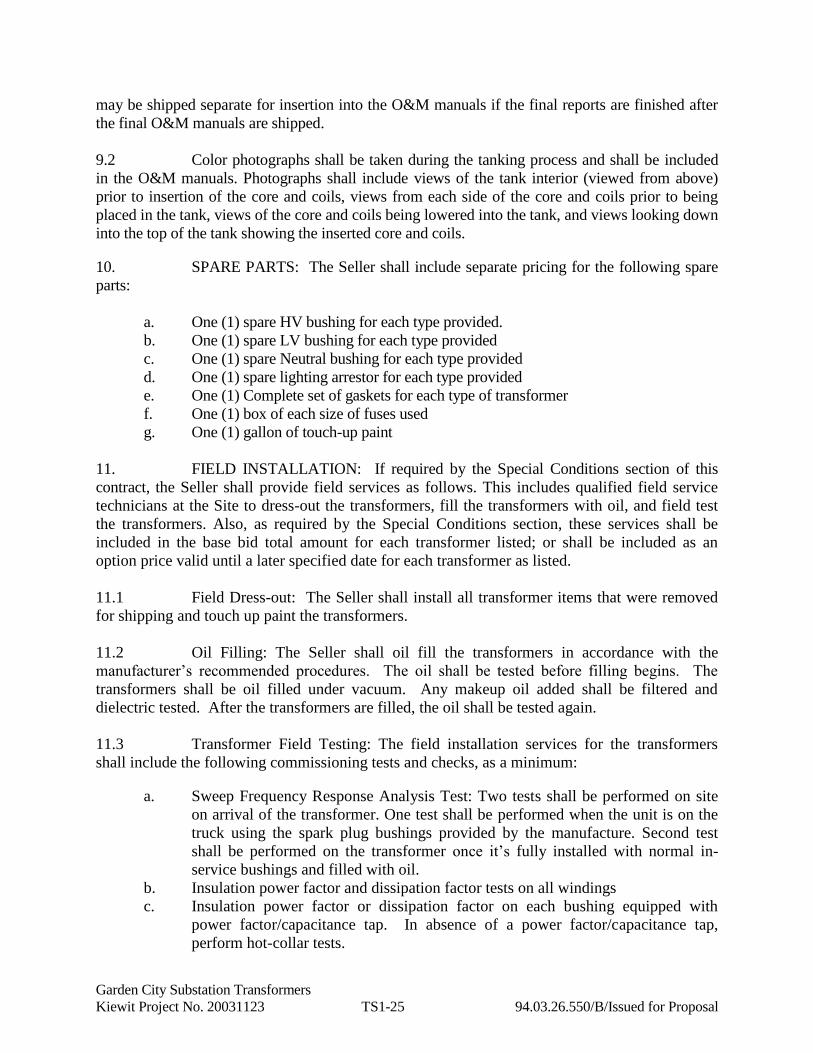
Garden City Substation Transformers
Kiewit Project No. 20031123 TS1-25 94.03.26.550/B/Issued for Proposal
may be shipped separate for insertion into the O&M manuals if the final reports are finished after
the final O&M manuals are shipped.
9.2 Color photographs shall be taken during the tanking process and shall be included
in the O&M manuals. Photographs shall include views of the tank interior (viewed from above)
prior to insertion of the core and coils, views from each side of the core and coils prior to being
placed in the tank, views of the core and coils being lowered into the tank, and views looking down
into the top of the tank showing the inserted core and coils.
10. SPARE PARTS: The Seller shall include separate pricing for the following spare
parts:
a. One (1) spare HV bushing for each type provided.
b. One (1) spare LV bushing for each type provided
c. One (1) spare Neutral bushing for each type provided
d. One (1) spare lighting arrestor for each type provided
e. One (1) Complete set of gaskets for each type of transformer
f. One (1) box of each size of fuses used
g. One (1) gallon of touch-up paint
One (1) radiator fan
11. FIELD INSTALLATION: If required by the Special Conditions section of this
contract, the Seller shall provide field services as follows. This includes qualified field service
technicians at the Site to dress-out the transformers, fill the transformers with oil, and field test
the transformers. Also, as required by the Special Conditions section, these services shall be
included in the base bid total amount for each transformer listed; or shall be included as an
option price valid until a later specified date for each transformer as listed.
11.1 Field Dress-out: The Seller shall install all transformer items that were removed
for shipping and touch up paint the transformers.
11.2 Oil Filling: The Seller shall oil fill the transformers in accordance with the
manufacturer’s recommended procedures. The oil shall be tested before filling begins. The
transformers shall be oil filled under vacuum. Any makeup oil added shall be filtered and
dielectric tested. After the transformers are filled, the oil shall be tested again.
11.3 Transformer Field Testing: The field installation services for the transformers
shall include the following commissioning tests and checks, as a minimum:
a. Sweep Frequency Response Analysis Test: Two tests shall be performed on site
on arrival of the transformer. One test shall be performed when the unit is on the
truck using the spark plug bushings provided by the manufacture. Second test
shall be performed on the transformer once it’s fully installed with normal in-
service bushings and filled with oil.
b. Insulation power factor and dissipation factor tests on all windings
c. Insulation power factor or dissipation factor on each bushing equipped with
power factor/capacitance tap. In absence of a power factor/capacitance tap,
perform hot-collar tests.
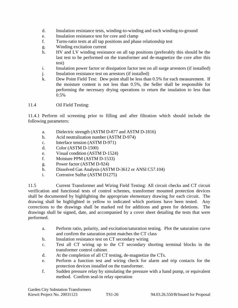
Garden City Substation Transformers
Kiewit Project No. 20031123 TS1-26 94.03.26.550/B/Issued for Proposal
d. Insulation resistance tests, winding-to-winding and each winding-to-ground
e. Insulation resistance test for core and clamp
f. Turns-ratio tests at all tap positions and phase relationship test
g. Winding excitation current
h. HV and LV winding resistance on all tap positions (preferably this should be the
last test to be performed on the transformer and de-magnetize the core after this
test)
i. Insulation power factor or dissipation factor test on all surge arrestors (if installed)
j. Insulation resistance test on arrestors (if installed)
k. Dew Point Field Test: Dew point shall be less than 0.5% for each measurement. If
the moisture content is not less than 0.5%, the Seller shall be responsible for
performing the necessary drying operations to return the insulation to less than
0.5%
11.4 Oil Field Testing:
11.4.1 Perform oil screening prior to filling and after filtration which should include the
following parameters:
a. Dielectric strength (ASTM D-877 and ASTM D-1816)
b. Acid neutralization number (ASTM D-974)
c. Interface tension (ASTM D-971)
d. Color (ASTM D-1500)
e. Visual condition (ASTM D-1524)
f. Moisture PPM (ASTM D-1533)
g. Power factor (ASTM D-924)
h. Dissolved Gas Analysis (ASTM D-3612 or ANSI C57.104)
i. Corrosive Sulfur (ASTM D1275)
11.5 Current Transformer and Wiring Field Testing: All circuit checks and CT circuit
verification and functional tests of control schemes, transformer mounted protection devices
shall be documented by highlighting the appropriate elementary drawing for each circuit. The
drawing shall be highlighted in yellow to indicated which portions have been tested. Any
corrections to the drawings shall be marked red for additions and green for deletions. The
drawings shall be signed, date, and accompanied by a cover sheet detailing the tests that were
performed.
a. Perform ratio, polarity, and excitation/saturation testing. Plot the saturation curve
and confirm the saturation point matches the CT class
b. Insulation resistance test on CT secondary wiring
c. Test all CT wiring up to the CT secondary shorting terminal blocks in the
transformer control cabinet.
d. At the completion of all CT testing, de-magnetize the CTs.
e. Perform a function test and wiring check for alarm and trip contacts for the
protection devices installed on the transformer.
f. Sudden pressure relay by simulating the pressure with a hand pump, or equivalent
method. Confirm seal-in relay operation
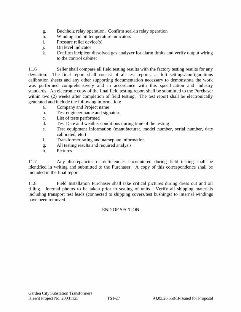
Garden City Substation Transformers
Kiewit Project No. 20031123 TS1-27 94.03.26.550/B/Issued for Proposal
g. Buchholz relay operation. Confirm seal-in relay operation
h. Winding and oil temperature indicators
i. Pressure relief device(s)
j. Oil level indicator
k. Confirm incipient dissolved gas analyzer for alarm limits and verify output wiring
to the control cabinet
11.6 Seller shall compare all field testing results with the factory testing results for any
deviation. The final report shall consist of all test reports, as left settings/configurations
calibration sheets and any other supporting documentation necessary to demonstrate the work
was performed comprehensively and in accordance with this specification and industry
standards. An electronic copy of the final field testing report shall be submitted to the Purchaser
within two (2) weeks after completion of field testing. The test report shall be electronically
generated and include the following information:
a. Company and Project name
b. Test engineer name and signature
c. List of tests performed
d. Test Date and weather conditions during time of the testing
e. Test equipment information (manufacturer, model number, serial number, date
calibrated, etc.)
f. Transformer rating and nameplate information
g. All testing results and required analysis
h. Pictures
11.7 Any discrepancies or deficiencies encountered during field testing shall be
identified in writing and submitted to the Purchaser. A copy of this correspondence shall be
included in the final report
11.8 Field Installation Purchaser shall take critical pictures during dress out and oil
filling. Internal photos to be taken prior to sealing of units. Verify all shipping materials
including transport test leads (connected to shipping covers/test bushings) to internal windings
have been removed.
END OF SECTION

Garden City Substation Transformers
Kiewit Project No. 20031123 EDR1-1 94.03.26.550/B/Issued for Proposal
ENGINEERING DESIGN REQUIREMENTS
Morris Substation Power Transformer
40MVA, 115/34.5kV
Applicable Standards
Including, but not limited to all
ANSI C57 Standards and all
Standards listed in Article 1 of
Section 94.03.26.550
Transformer Type Autotransformer
Application Outdoor
Altitude Per Section GR-A
24 hour Average Ambient Temperature 30˚CMaximum Ambient Temperature Per Section GR-A
Seismic Design and ConstructionPer Section S1 and Section
94.03.26.550
Sound Pressure Level at Max. MVA 85 dBA
Number of Phases 3
Number of Windings 1
Winding Material 100% Copper
Frequency 60Hz
Vector Group Yy0
Cooling Class ONAN/ONAF/ONAF
Temperature Rise 65˚CInsulation Temperature Rise Rating 65˚CMaximum Winding Hotspot Rise 80˚COil Type High Grade Mineral
Oil Preservation Type Conservator – Inflatable Cell Type
Color ANSI 61 Gray
High Voltage (HV) Winding
Connection Grounded Wye
MVA 40/53/66
Voltage 115 kV
Phase BIL (Winding and All Phase Bushings) 550 kV
Phase Bushing Minimum Creep DistanceDesigned for Light Contamination,
28mm/kV
Neutral BIL (Winding and Bushing) 150kV
Bushing Location (H1, H2, H3) Cover
Bushing Location (H1, H2, H3) ANSI segment per diagram below
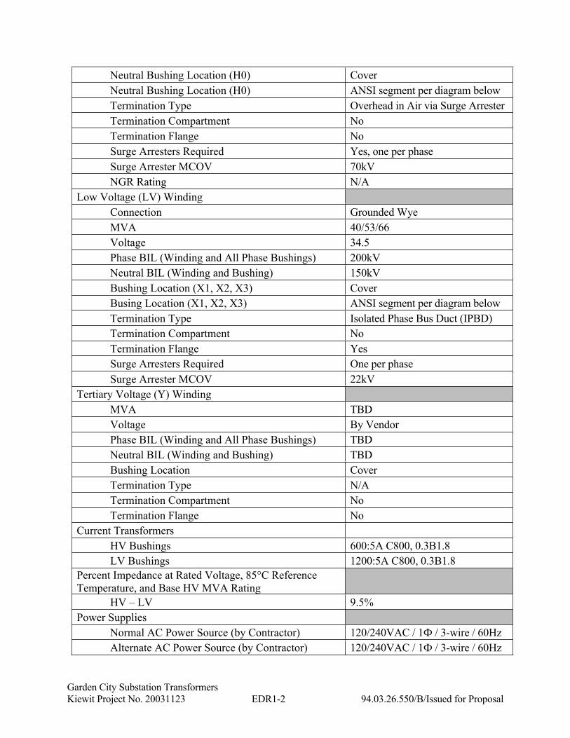
Garden City Substation Transformers
Kiewit Project No. 20031123 EDR1-2 94.03.26.550/B/Issued for Proposal
Neutral Bushing Location (H0) Cover
Neutral Bushing Location (H0) ANSI segment per diagram below
Termination Type Overhead in Air via Surge Arrester
Termination Compartment No
Termination Flange No
Surge Arresters Required Yes, one per phase
Surge Arrester MCOV 70kV
NGR Rating N/A
Low Voltage (LV) Winding
Connection Grounded Wye
MVA 40/53/66
Voltage 34.5
Phase BIL (Winding and All Phase Bushings) 200kV
Neutral BIL (Winding and Bushing) 150kV
Bushing Location (X1, X2, X3) Cover
Busing Location (X1, X2, X3) ANSI segment per diagram below
Termination Type Isolated Phase Bus Duct (IPBD)
Termination Compartment No
Termination Flange Yes
Surge Arresters Required One per phase
Surge Arrester MCOV 22kV
Tertiary Voltage (Y) Winding
MVA TBD
Voltage By Vendor
Phase BIL (Winding and All Phase Bushings) TBD
Neutral BIL (Winding and Bushing) TBD
Bushing Location Cover
Termination Type N/A
Termination Compartment No
Termination Flange No
Current Transformers
HV Bushings 600:5A C800, 0.3B1.8
LV Bushings 1200:5A C800, 0.3B1.8
Percent Impedance at Rated Voltage, 85°C Reference
Temperature, and Base HV MVA Rating
HV – LV 9.5%
Power Supplies
Normal AC Power Source (by Contractor) 120/240VAC / 1Ф / 3-wire / 60Hz
Alternate AC Power Source (by Contractor) 120/240VAC / 1Ф / 3-wire / 60Hz
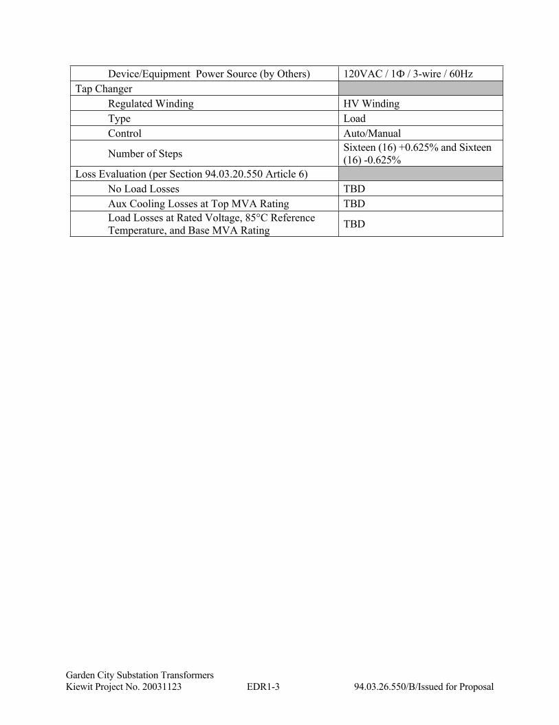
Garden City Substation Transformers
Kiewit Project No. 20031123 EDR1-3 94.03.26.550/B/Issued for Proposal
Device/Equipment Power Source (by Others) 120VAC / 1Ф / 3-wire / 60Hz
Tap Changer
Regulated Winding HV Winding
Type Load
Control Auto/Manual
Number of StepsSixteen (16) +0.625% and Sixteen
(16) -0.625%
Loss Evaluation (per Section 94.03.20.550 Article 6)
No Load Losses TBD
Aux Cooling Losses at Top MVA Rating TBD
Load Losses at Rated Voltage, 85°C Reference
Temperature, and Base MVA RatingTBD

Garden City Substation Transformers
Kiewit Project No. 20031123 EDR1-4 94.03.26.550/B/Issued for Proposal
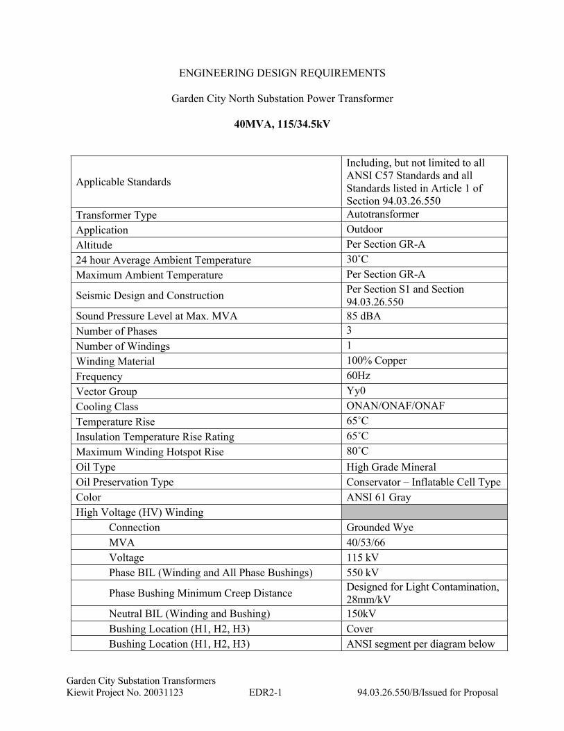
Garden City Substation Transformers
Kiewit Project No. 20031123 EDR2-1 94.03.26.550/B/Issued for Proposal
ENGINEERING DESIGN REQUIREMENTS
Garden City North Substation Power Transformer
40MVA, 115/34.5kV
Applicable Standards
Including, but not limited to all
ANSI C57 Standards and all
Standards listed in Article 1 of
Section 94.03.26.550
Transformer Type Autotransformer
Application Outdoor
Altitude Per Section GR-A
24 hour Average Ambient Temperature 30˚CMaximum Ambient Temperature Per Section GR-A
Seismic Design and ConstructionPer Section S1 and Section
94.03.26.550
Sound Pressure Level at Max. MVA 85 dBA
Number of Phases 3
Number of Windings 1
Winding Material 100% Copper
Frequency 60Hz
Vector Group Yy0
Cooling Class ONAN/ONAF/ONAF
Temperature Rise 65˚CInsulation Temperature Rise Rating 65˚CMaximum Winding Hotspot Rise 80˚COil Type High Grade Mineral
Oil Preservation Type Conservator – Inflatable Cell Type
Color ANSI 61 Gray
High Voltage (HV) Winding
Connection Grounded Wye
MVA 40/53/66
Voltage 115 kV
Phase BIL (Winding and All Phase Bushings) 550 kV
Phase Bushing Minimum Creep DistanceDesigned for Light Contamination,
28mm/kV
Neutral BIL (Winding and Bushing) 150kV
Bushing Location (H1, H2, H3) Cover
Bushing Location (H1, H2, H3) ANSI segment per diagram below

Garden City Substation Transformers
Kiewit Project No. 20031123 EDR2-2 94.03.26.550/B/Issued for Proposal
Neutral Bushing Location (H0) Cover
Neutral Bushing Location (H0) ANSI segment per diagram below
Termination Type Overhead in Air via Surge Arrester
Termination Compartment No
Termination Flange No
Surge Arresters Required One per phase
Surge Arrester MCOV 70kV
NGR Rating N/A
Low Voltage (LV) Winding
Connection Grounded Wye
MVA 40
Voltage 34.5
Phase BIL (Winding and All Phase Bushings) 200kV
Neutral BIL (Winding and Bushing) N/A
Bushing Location (X1, X2, X3) Cover
Busing Location (X1, X2, X3) ANSI segment per diagram below
Termination Type Isolated Phase Bus Duct (IPBD)
Termination Compartment No
Termination Flange No
Surge Arresters Required One per phase
Surge Arrester MCOV 22kV
Tertiary Voltage (Y) Winding
MVA TBD
Voltage By Vendor
Phase BIL (Winding and All Phase Bushings) TBD
Neutral BIL (Winding and Bushing) TBD
Bushing Location Cover
Termination Type N/A
Termination Compartment No
Termination Flange No
Current Transformers
HV Bushings 600:5A C800, 0.3B1.8
LV Bushings 1200:5A C800, 0.3B1.8
Percent Impedance at Rated Voltage, 85°C Reference
Temperature, and Base HV MVA Rating
HV – LV 9.5%
Power Supplies
Normal AC Power Source (by Contractor) 120/240VAC / 1Ф / 3-wire / 60Hz
Alternate AC Power Source (by Contractor) 120/240VAC / 1Ф / 3-wire / 60Hz

Garden City Substation Transformers
Kiewit Project No. 20031123 EDR2-3 94.03.26.550/B/Issued for Proposal
Device/Equipment Power Source (by Others) 120VAC / 1Ф / 3-wire / 60Hz
Tap Changer
Regulated Winding HV Winding
Type Load
Control Auto/Manual
Number of StepsSixteen (16) +0.625% and Sixteen
(16) -0.625%
Loss Evaluation (per Section 94.03.20.550 Article 6)
No Load Losses TBD
Aux Cooling Losses at Top MVA Rating TBD
Load Losses at Rated Voltage, 85°C Reference
Temperature, and Base MVA RatingTBD
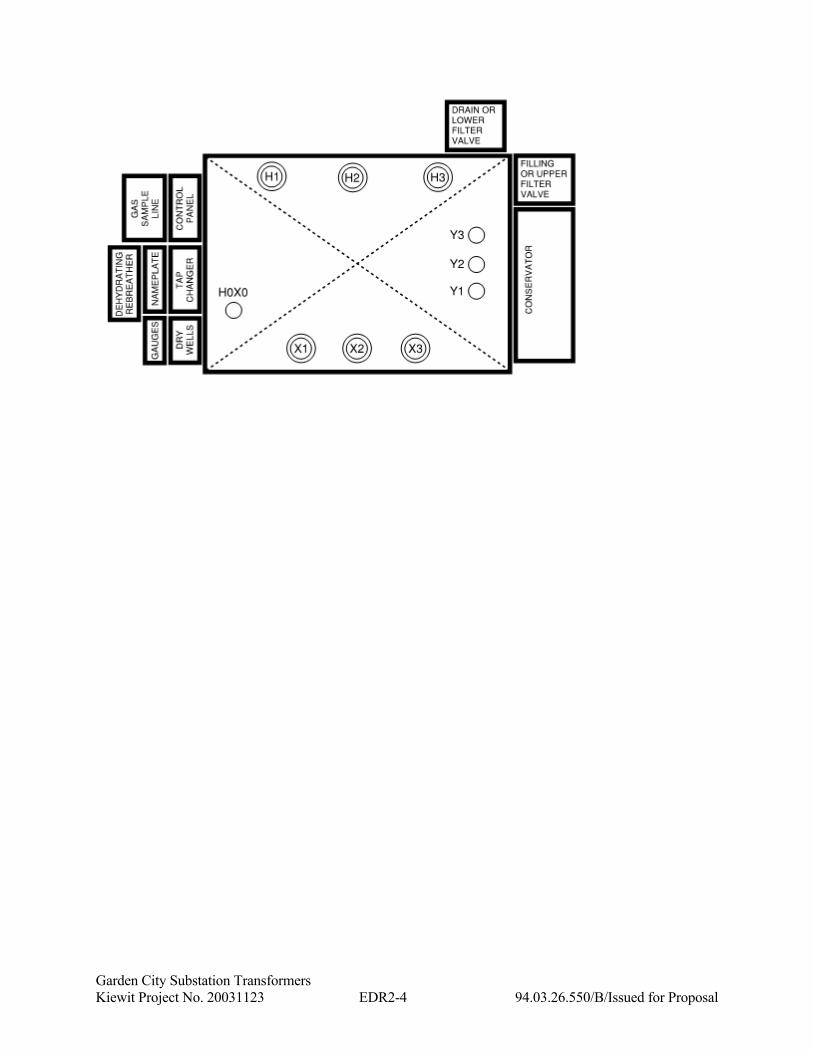
Garden City Substation Transformers
Kiewit Project No. 20031123 EDR2-4 94.03.26.550/B/Issued for Proposal