contract-documents-and-specifications-lakeshore-drive
TRANSCRIPT
PORT OF PORT ARTHUR NAVIGATION DISTRICT OF JEFFERSON COUNTY, TEXAS
CONTRACT DOCUMENTS AND TECHNICAL SPECIFICATIONS
FOR CONSTRUCTION OF
LAKESHORE DRIVE WIDENING
CSJ 0920-38-250
(BSCE JOB NO. PPA-054)
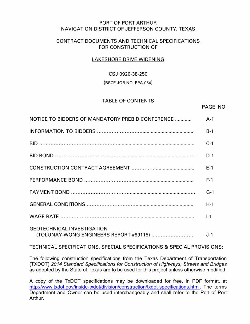
TABLE OF CONTENTS PAGE_NO.
NOTICE TO BIDDERS OF MANDATORY PREBID CONFERENCE ............ A-1 INFORMATION TO BIDDERS ………………………....................................... B-1 BID …………………………………………........................................................ C-1 BID BOND …………………………………….................................................… D-1 CONSTRUCTION CONTRACT AGREEMENT ……………............................ E-1 PERFORMANCE BOND …………………………............................................ F-1 PAYMENT BOND ………………………………...........................................…. G-1 GENERAL CONDITIONS …………………………........................................... H-1 WAGE RATE …………………………………................................................... I-1 GEOTECHNICAL INVESTIGATION (TOLUNAY-WONG ENGINEERS REPORT #89115) ..……………………. J-1 TECHNICAL SPECIFICATIONS, SPECIAL SPECIFICATIONS & SPECIAL PROVISIONS: The following construction specifications from the Texas Department of Transportation (TXDOT) 2014 Standard Specifications for Construction of Highways, Streets and Bridges as adopted by the State of Texas are to be used for this project unless otherwise modified. A copy of the TxDOT specifications may be downloaded for free, in PDF format, at http://www.txdot.gov/inside-txdot/division/construction/txdot-specifications.html. The terms Department and Owner can be used interchangeably and shall refer to the Port of Port Arthur.
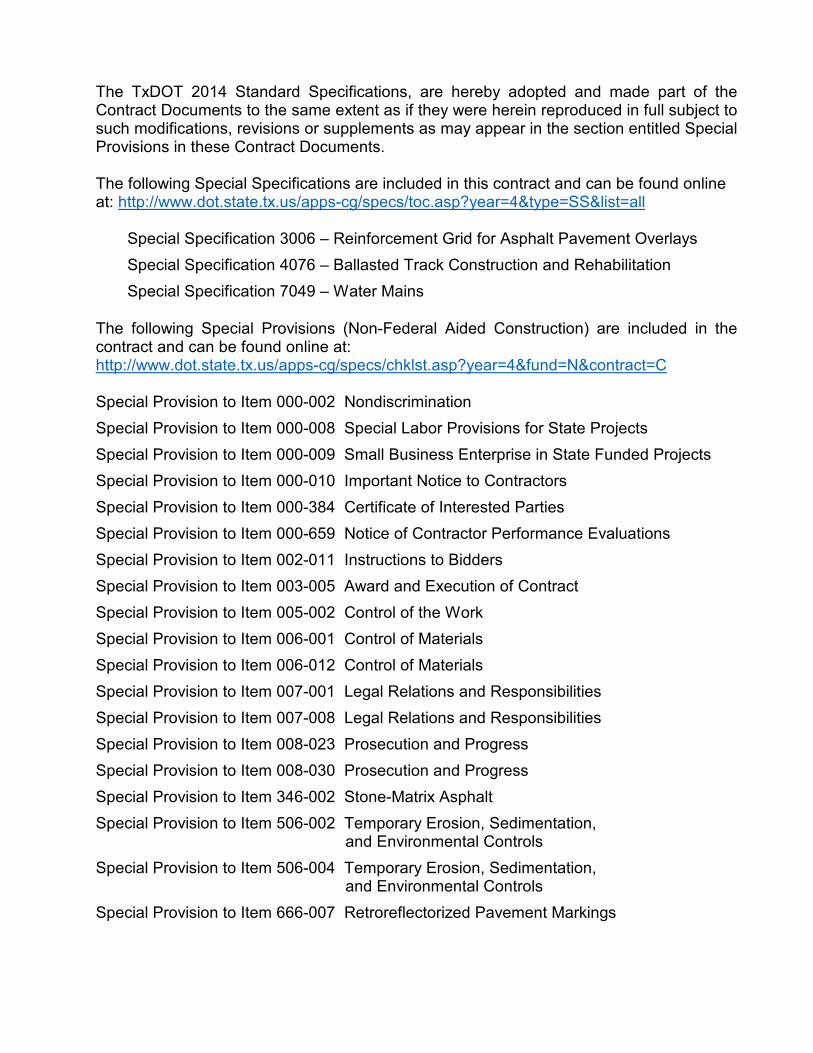
The TxDOT 2014 Standard Specifications, are hereby adopted and made part of the Contract Documents to the same extent as if they were herein reproduced in full subject to such modifications, revisions or supplements as may appear in the section entitled Special Provisions in these Contract Documents. The following Special Specifications are included in this contract and can be found online at: http://www.dot.state.tx.us/apps-cg/specs/toc.asp?year=4&type=SS&list=all
Special Specification 3006 – Reinforcement Grid for Asphalt Pavement Overlays Special Specification 4076 – Ballasted Track Construction and Rehabilitation Special Specification 7049 – Water Mains
The following Special Provisions (Non-Federal Aided Construction) are included in the contract and can be found online at: http://www.dot.state.tx.us/apps-cg/specs/chklst.asp?year=4&fund=N&contract=C Special Provision to Item 000-002 Nondiscrimination Special Provision to Item 000-008 Special Labor Provisions for State Projects Special Provision to Item 000-009 Small Business Enterprise in State Funded Projects Special Provision to Item 000-010 Important Notice to Contractors Special Provision to Item 000-384 Certificate of Interested Parties Special Provision to Item 000-659 Notice of Contractor Performance Evaluations Special Provision to Item 002-011 Instructions to Bidders Special Provision to Item 003-005 Award and Execution of Contract Special Provision to Item 005-002 Control of the Work Special Provision to Item 006-001 Control of Materials Special Provision to Item 006-012 Control of Materials Special Provision to Item 007-001 Legal Relations and Responsibilities Special Provision to Item 007-008 Legal Relations and Responsibilities Special Provision to Item 008-023 Prosecution and Progress Special Provision to Item 008-030 Prosecution and Progress Special Provision to Item 346-002 Stone-Matrix Asphalt Special Provision to Item 506-002 Temporary Erosion, Sedimentation, and Environmental Controls Special Provision to Item 506-004 Temporary Erosion, Sedimentation, and Environmental Controls Special Provision to Item 666-007 Retroreflectorized Pavement Markings

NOTICE TO BIDDERS OF MANDATORY PREBID CONFERENCE
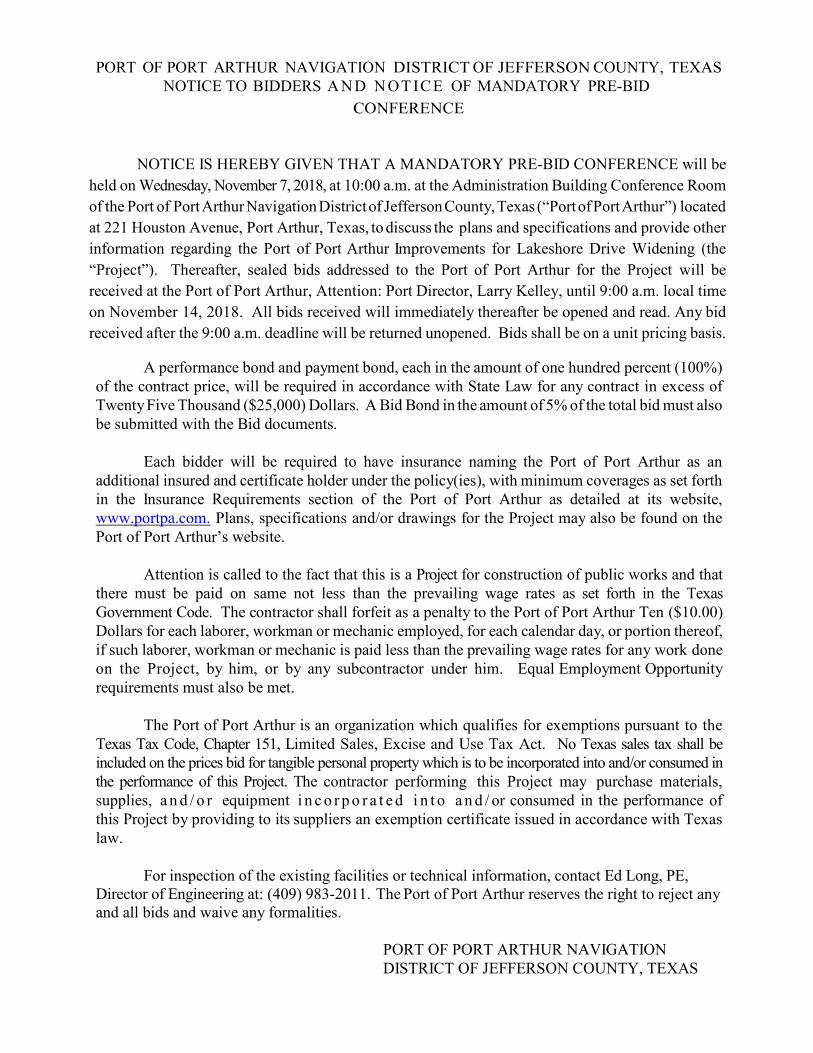
PORT OF PORT ARTHUR NAVIGATION DISTRICT OF JEFFERSON COUNTY, TEXAS NOTICE TO BIDDERS A N D N O T IC E OF MANDATORY PRE-BID
CONFERENCE
NOTICE IS HEREBY GIVEN THAT A MANDATORY PRE-BID CONFERENCE will be held on Wednesday, November 7, 2018, at 10:00 a.m. at the Administration Building Conference Room of the Port of Port Arthur Navigation District of Jefferson County, Texas (“Port of Port Arthur”) located at 221 Houston Avenue, Port Arthur, Texas, to discuss the plans and specifications and provide other information regarding the Port of Port Arthur Improvements for Lakeshore Drive Widening (the “Project”). Thereafter, sealed bids addressed to the Port of Port Arthur for the Project will be received at the Port of Port Arthur, Attention: Port Director, Larry Kelley, until 9:00 a.m. local time on November 14, 2018. All bids received will immediately thereafter be opened and read. Any bid received after the 9:00 a.m. deadline will be returned unopened. Bids shall be on a unit pricing basis.
A performance bond and payment bond, each in the amount of one hundred percent (100%) of the contract price, will be required in accordance with State Law for any contract in excess of Twenty Five Thousand ($25,000) Dollars. A Bid Bond in the amount of 5% of the total bid must also be submitted with the Bid documents.
Each bidder will be required to have insurance naming the Port of Port Arthur as an
additional insured and certificate holder under the policy(ies), with minimum coverages as set forth in the Insurance Requirements section of the Port of Port Arthur as detailed at its website, www.portpa.com. Plans, specifications and/or drawings for the Project may also be found on the Port of Port Arthur’s website.
Attention is called to the fact that this is a Project for construction of public works and that
there must be paid on same not less than the prevailing wage rates as set forth in the Texas Government Code. The contractor shall forfeit as a penalty to the Port of Port Arthur Ten ($10.00) Dollars for each laborer, workman or mechanic employed, for each calendar day, or portion thereof, if such laborer, workman or mechanic is paid less than the prevailing wage rates for any work done on the Project, by him, or by any subcontractor under him. Equal Employment Opportunity requirements must also be met.
The Port of Port Arthur is an organization which qualifies for exemptions pursuant to the
Texas Tax Code, Chapter 151, Limited Sales, Excise and Use Tax Act. No Texas sales tax shall be included on the prices bid for tangible personal property which is to be incorporated into and/or consumed in the performance of this Project. The contractor performing this Project may purchase materials, supplies, a n d / o r equipment i n c o r p o r a t e d i n t o a n d / or consumed in the performance of this Project by providing to its suppliers an exemption certificate issued in accordance with Texas law.
For inspection of the existing facilities or technical information, contact Ed Long, PE,
Director of Engineering at: (409) 983-2011. The Port of Port Arthur reserves the right to reject any and all bids and waive any formalities.
PORT OF PORT ARTHUR NAVIGATION DISTRICT OF JEFFERSON COUNTY, TEXAS

INFORMATION TO BIDDERS
B - 1
INFORMATION TO BIDDERS
The following instructions are applicable to the Contract in addition to the requirements set forth in the ADVERTISEMENT FOR BIDS. 1. Bid Procedure. Bids must be submitted in DUPLICATE upon the prescribed forms, or copies thereof, in sealed envelopes plainly marked IMPROVEMENTS FOR LAKESHORE DRIVE WIDENING, CSJ 0920-38-257. Bids shall be prepared in compliance with the requirements of the NOTICE TO BIDDERS OF MANDATORY PRE-BID CONFERENCE (Advertisement for Bids); these instructions and the instructions printed on the prescribed forms. All blank places on the Proposal form must be filled in as noted, in ink, in both words and figures, with amounts extended and totaled, and no changes shall be made in the phraseology of the forms or of the terms mentioned therein. In case of any discrepancy between the written amounts and the figures, the written amounts shall govern. If the Bidder does not bid on optional items (if shown in the Proposal form), "No Bid" shall be entered in the blank spaces therefor. Any bid may be deemed irregular which contains any omission, erasure, alteration, addition, or irregularity of any kind or item not called for, or which does not contain prices set opposite to each of the several items in the Proposal form, or in which any of the prices are obviously unbalanced, or which shall in any manner fail to conform to the conditions of the published ADVERTISEMENT FOR BID. The Bidder shall sign his Proposal in the blank area provided therefor. If the bid is made by a partnership or corporation, the name and address of the partnership or corporation shall be shown, together with the name and address of the partners or officers. If the bid is made by a partnership, it must be acknowledged by one of the partners; if made by a corporation, by one of the officers thereof accompanied by Corporate seal. In order to ensure consideration, the Proposal must be enclosed in a sealed envelope plainly identified by the name of the project and the Contract number, and addressed to the Owner as prescribed in the Invitation to Bidders. 2. Bid Security and Liquidated Damages. Bids shall be accompanied by a bid guarantee of not less than five percent (5%) of the amount of the total bid which shall be a Certified Check or Cashier's Check payable without recourse to the Port of Port Arthur, or a bid bond with corporate surety authorized to conduct business in Texas. Said security shall be submitted with the understanding that it shall guarantee that the Bidder will not withdraw his bid within sixty (60) days after the date of the opening of bids; that if a bid is accepted, the Bidder will enter into a formal contract with the Owner, furnish bonds and insurance as may be required and commence work at the specified time, and that in the event of the withdrawal of said bid within said period, or the failure to enter into said Contract, furnish said bonds and insurance and commence work within the time specified, the
B - 2
Bidder shall be liable to the Owner for the difference between the amount specified in the bid and the amount for which the Owner may otherwise procure the required work. Checks of all except the three lowest responsible Bidders will be returned when award is made; when the Contract is executed, the checks of the two remaining unsuccessful Bidders will be returned; that of the successful Bidder will be returned when formal Contract, bonds, and insurance are approved, and work has commenced within the time specified. The Bidder to whom the award is made shall execute and return the formal Contract with the Owner and furnish Performance and Payment Bonds and required insurance documents within ten (10) days after the prescribed forms are presented to him for signature. Said period will be extended only upon written presentation to the Owner, within said period, of reasons which, in the sole discretion of the Owner, justify an extension. If said Contract, bonds, and insurance documents are not received by the Owner within said period or if work has not been commenced within the time specified, the Owner may proceed to have the work required by the Plans and Specifications performed by any means at its command, and the Bidder shall be liable to the Port for any excess cost to the Owner over his bid amount. Further, the bid guarantee shall be forfeited to the Port as liquidated damages and Bidder shall be liable to the Port for an additional amount of five percent (5%) of the bid amount as liquidated damages without limitation. The Owner, within ten (10) days of receipt of acceptable Performance and Payment Bonds, insurance documents and Contract signed by Bidder to whom Contract was awarded, shall sign and return executed duplicate of the Contract to said party. Should Owner not execute the Contract within such period, the Bidder may, by written Notice to Owner, withdraw his signed Agreement. 3. Bonds. If the Contract exceeds Twenty-five Thousand Dollars ($25,000.00), Performance and Payment Bonds shall be furnished on prescribed forms in the amount of one hundred percent (100%) of the Contract price with corporate surety duly authorized to do business in the State of Texas. Attorneys-in-fact who sign Bonds must file with each Bond a certified and effective dated copy of their Power of Attorney. 4. Notice to Proceed. Notice to Proceed shall be issued within ten (10) days of the execution of the Contract by Owner. Should there be any reason why Notice to Proceed cannot be issued within such period, the time may be extended by mutual agreement between Owner and the Contractor. If Notice to Proceed has not been issued within the ten (10) day period or a period mutually agreed upon, Contractor may terminate the Contract without liability on the part of either party.
Port of Port Arthur Navigation District
CONTRACTOR INSURANCE REQUIREMENTS
A. In General
The Contractor shall purchase and continuously maintain in full force and effect for the
policy periods specified below the insurance policies specified in this Section. The
Contractor shall forward updated certificates of insurance and endorsement(s) when policies
are renewed or changed.
The insurance required hereunder shall not be interpreted to relieve the Contractor of any
obligations under the Contract. The Contractor shall remain fully liable for all deductibles
and amounts in excess for the coverage actually realized.
1. Commercial General Liability Insurance
The Contractor shall provide and maintain Commercial General Liability Insurance
insuring against claims for bodily injury, property damage, personal injury and
advertising injury that shall e no less comprehensive and no more restrictive than the
coverage provided by Insurance Services Office (ISO) form for Commercial General
Liability (CG 00-01-10-01). By its terms or appropriate endorsements such insurance
shall include the following coverage, to wit: Bodily Injury, Property Damage, Fire
Legal Liability (not less than the replacement value of the portion of the premises
occupied), Personal Injury, Blanket Contractual, Independent Contractors, Premises
Operations, Products and Completed Operations (for a minimum of two (2) years
following Final Completion of the Project). The policy cannot be endorsed to
exclude the perils of explosion (x), collapse (c) and underground (u) exposures
without the specific written approval of the Owner.
If Commercial General Liability Insurance o other form with a general aggregate
limit and products and completed operations aggregate limit is used, then the
aggregate limits shall apply separately to the project, or the Contractor may obtain
separate insurance to provide the required limit which shall not be subject to
depletion because of claims arising out of any other project or activity of the
Contractor. Any such excess insurance shall be at least as broad as the Contractor’s
primary insurance. The coverage shall be primary and non-contributory. General
Aggregate limit applies per Project for construction projects.
The Port of Port Arthur Navigation District shall be named as an Additional
Insurance under the Commercial General Liability policy of insurance per standard
ISO endorsement forms 2010 (07/04) for ongoing operations and 3027 (07/040) for
products/completed operations, or their equivalent.
B-3
5. Insurance
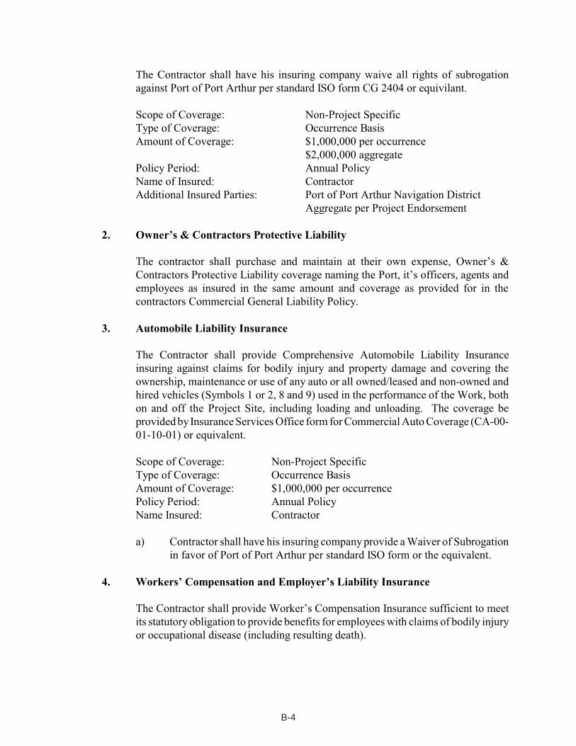
The Contractor shall have his insuring company waive all rights of subrogation
against Port of Port Arthur per standard ISO form CG 2404 or equivilant.
Scope of Coverage: Non-Project Specific
Type of Coverage: Occurrence Basis
Amount of Coverage: $1,000,000 per occurrence
$2,000,000 aggregate
Policy Period: Annual Policy
Name of Insured: Contractor
Additional Insured Parties: Port of Port Arthur Navigation District
Aggregate per Project Endorsement
2. Owner’s & Contractors Protective Liability
The contractor shall purchase and maintain at their own expense, Owner’s &
Contractors Protective Liability coverage naming the Port, it’s officers, agents and
employees as insured in the same amount and coverage as provided for in the
contractors Commercial General Liability Policy.
3. Automobile Liability Insurance
The Contractor shall provide Comprehensive Automobile Liability Insurance
insuring against claims for bodily injury and property damage and covering the
ownership, maintenance or use of any auto or all owned/leased and non-owned and
hired vehicles (Symbols 1 or 2, 8 and 9) used in the performance of the Work, both
on and off the Project Site, including loading and unloading. The coverage be
provided by Insurance Services Office form for Commercial Auto Coverage (CA-00-
01-10-01) or equivalent.
Scope of Coverage: Non-Project Specific
Type of Coverage: Occurrence Basis
Amount of Coverage: $1,000,000 per occurrence
Policy Period: Annual Policy
Name Insured: Contractor
a) Contractor shall have his insuring company provide a Waiver of Subrogation
in favor of Port of Port Arthur per standard ISO form or the equivalent.
4. Workers’ Compensation and Employer’s Liability Insurance
The Contractor shall provide Worker’s Compensation Insurance sufficient to meet
its statutory obligation to provide benefits for employees with claims of bodily injury
or occupational disease (including resulting death).
B-4
Policy Period: Annual Policy
Name Insured: Contractor
a) The Contractor shall provide Employer Liability Insurance covering its legal
obligation to pay damages because of bodily injury or occupational disease
(including resulting death) sustained by an employee.
Scope of Coverage: Non-Profit Specific
Type of Coverage: Occurrence Basis
Amount of Coverage: $1,000,000 bodily injury by accident
$1,000,000 bodily injury by disease
$1,000,000 policy limit
Policy Period: Annual Policy
Named Insured: Contractor
b) The Contractor shall provide Longshore & Harbor Workers coverage if any
employees are determined to be eligible benefits.
c) The Contractor shall have his insuring company waive all right of
subrogation against Port of Port Arthur per standard form WC 420304 A or
equivalent.
5. Marine Operations
If any operations involves the use of any form of watercraft, additional coverage may
be required of Contractors as follows:
a) In the even the User is required to provide coverage pursuant to this section
such insurance on waterborne vessels shall comply with the following
requirements.
1) If the User uses a chartered waterborne vessel in the operations
hereunder, the User shall provide Certificates of Insurance evidencing
that the User has procured Charter’s Legal Liability Insurance,
including full Maritime Employers Liability and Collision and
Tower’s Liability, covering bodily injury and property damage with
a combined single limit of at least $1,000,000 or the value of the
vessel, whichever is greater;
2) If the User uses an owned waterborne vessel in the operations
hereunder, the User shall provide Certificates of Insurance evidencing
that the User has procured Hull and Machinery Insurance, including
full Collision and Tower’s Liability and protection and Indemnity
Insurance (including crew) covering bodily injury and property
damage, each with a combined single limit of at least $1,000,000 or
B-5
the value of the vessel, whichever is greater.
3) Port of Port Arthur will be named additional insured and right of
subrogation will be waived in favor of Port of Port Arthur by
endorsement acceptable to the Port risk manager.
6. Umbrella/Excess Liability
The Contractor shall provide Umbrella/Excess Liability insurance limits as follows:
For contract amount under $5,000,000; At least $5,000,000 limit
For contract amount from $5,000,000 to $25,000,000; At least $10,000,000 limit
For contract amount from over $25,000,000 to $50,000,000; At least $50,000,000 limit
For contract amount over $50,000,000; At least $50,000,000 limit
a) Port of Port Arthur shall be named as additional insured and the
insuring carrier shall waive their rights of subrogation in favor of Port
of Port Arthur.
7. Port of Port Arthur Navigation District-Owned Property:
Unless otherwise provided in the Contract Documents, the Contractor shall purchase
and maintain property insurance (Builder’s Risk) upon the work at the site to the full
insurable value. The insurance shall include the interests of the Owner, Owner’s
Designated Representative, Contractor, and Subcontractors of any tier. Coverage shall
be written on forms to include fire, extended coverage and special form including theft.
Contractor is responsible for the deductible for any claim made against the policy. A
separate certificate of insurance evidencing the coverage required herein shall be
provided to the Owner.
8. Installation Floater Insurance
The Contractor shall provide and maintain Installation Floater Insurance insuring
against damage or destriction of the materials or equipment in transit to, or stored on
or off the Project Site which is to be used in the Work. A separate certificate of
insurance evidencing the coverage required herein shall be provided to the Owner.
Scope of Coverage: Non-Project Specific
Type of Coverage: Occurrence Basis
Amount of Coverage: TBD
Policy Period: Effective until final completion of the Project
Named Insured: Contractor
Additional Insured Parties: Port of Port Arthur
B-6
9. Pollution Liability Insurance
The Contractor shall provide and maintain first party cleanup and third party liability
for all pollutants involved in their operations. Limits will be specified by Port risk
management based on scope of the project. Port of Port Arthur is to be named
additional named insured to this coverage.
10. Professional Liability Insurance
The Contractor shall provide and maintain professional liability insurance for any
services that are deemed professional in nature. Limits will be specified by Port risk
management based on scope of the project. Port of Port Arthur is to be named
additional named insured to this coverage.
B. Acceptable Insurance Company
The insurance company providing any of the insurance coverage required herein shall have a
Best Key Rating of A, with a Financial Strength of VII or higher, (i.e., A VII, A VIII, A IX, A
X, etc.) and shall be subject to approval by the Owner. Each insurance company’s rating as
shown in the latest Best’s Key Rating Guide shall be fully disclosed and entered on the
required certificate of insurance.
C. Premiums, Deductibles and Self-Insured Retentions
The Contractor shall be responsible for payment of premiums for all of the insurance coverages
required. The Contractor further agrees that for each claim, suit or action made against
insurance provided hereunder, with respect to all matters for which the Contractor is
responsible hereunder, the Contractor shall be solely responsible for all deductibles and self-
insured retentions. Any deductibles or self-insured retentions over $25,000 in the Contractor
insurance must be declared and approved in writing by Port of Port Arthur risk management.
D. Certificate of Insurance
The Contractor will deliver to the Port of Port Arthur Navigation District. The required
certificates must be signed by the authorized representative of the insurance company shown
on the certificate with proof that such person is an authorized representative thereof, and is
authorized to bind the named underwriter(s) and their company to the coverage, limits and
termination provisions shown thereon. All endorsement shall be attached to the certificates
of insurance when submitted to the Port of Port Arthur.
E. Renewal Policies
The Contractor shall promptly deliver to the Pot of Port Arthur Navigation District a certificate
of insurance with respect to each renewal policy, as necessary to demonstrate the maintenance
of the required insurance coverage for the terms specified herein. Such certificate shall be
B-7

delivered to the Owner not less than 30 days prior to the expiration date of any policy and bear
a notation evidencing payment of the premium thereof.
F. Cancellation and Modification of Insurance Coverages
The Contractor shall be responsible to immediately notify the Owner in writing of any changes
or cancellations of its insurance, or may be found in breach of the contract and the contract
could be terminated. This notice requirement does not waive the insurance requirements
contained herein.
G. No Recourse
There shall be no recourse against Port of Port Arthur Navigation District for the payment of
premiums or other amounts with respect to the insurance required from the Contractor.
H. Endorsements and Waivers
All insurance policies required hereunder shall contain or be endorsed to contain the following
provisions:
1) For claims covered by the insurance specified herein, said insurance coverage shall be
primary insurance with respect to the insured, additional insured parties, and their
respective members, directors, officers, employees and agents and shall specify that
coverage continues notwithstanding the fact that the Contractor has left the Project site.
Any insurance or self-insurance beyond that specified in this Contract that is
maintained by an insured, additional insured, or their members, directors, officers,
employees and agents should be primary and non-contributory.
2) The insurance shall apply separately to each insured and additional insured party
against whom a claim is made or suit is brought, except with respect to the limits of the
insurer’s liability.
I. Failure to Provide or Maintain Insurance Coverages
The Contractor’s failure to provide or maintain any of the insurance coverage required herein
shall constitute a breach of the Contract. The Owner may take whatever action is necessary
to maintain the current policies in effect (including the payment of any premiums that may be
due and owing by the Contractor) or procure substitute insurance. The Contractor is
responsible for any costs incurred by the Owner in maintaining the current insurance coverage
in effect, or providing substitute insurance, and such costs may be deducted from any sums due
and owing the Contractor.
B-8
B - 9
6. Job Examination. Bidders should carefully examine the plans, specifications, and other documents, visit the site of the work, and fully inform themselves as to all conditions and matters which can in any way affect the work or the cost thereof. Should a Bidder find discrepancies in, or omissions from, the Plans, Specifications or other documents, or should a Bidder be in doubt as to their meaning, the Bidder should at once notify the Owner's Architect/Engineer and obtain clarification prior to submitting any bid. All Bidders are required to visit the job site before submitting their Proposal and to have read and be thoroughly familiar with the Plans and other Contract documents. Failure to do so will not relieve a successful Bidder of the obligation to furnish all material and labor necessary to carry out the provisions of the Contract documents and to complete the contemplated work for the considerations set forth in the bid. Any information shown in the specifications or on the plans in regard to subsurface data, test borings, and similar conditions is to be considered approximate and does not relieve the Bidder of the responsibility for its verification. In conformity with applicable statutes, the Owner has adopted a labor classification and a minimum wage scale, which is included in the following specifications. 7. Sales Tax. This Contract is issued by an organization which qualifies for exemption pursuant to the provisions of Section 151.209 of the Texas Limited Sales, Excise and Use Tax Act as codified in Chapter 151 of the Texas Tax Code.
The Contractor's attention is directed to the State of Texas Comptroller of Public Accounts Limited Sales, Excise and Use Tax rules and regulations, Rulings regarding Repairmen and Contractors - Reference: Section 151.056 Texas Tax Code which, upon compliance with certain conditions, provides for exemption from this tax of non-consumable materials and equipment permanently incorporated into work done for an exempt organization, and to House Bill 11 amendments to Section 151.311 of the Tax Code (Vernon Supp. 1992) as they relate to separated contracts/bids in order for non-consumable materials and equipment to qualify for resale to the Port and be exempt from sales tax.
Any Bidder may elect to exclude this sales tax from his bid. The bid and contract,
however, must separately identify the charges for (1)non-consumable materials and equipment that are permanently incorporated into the project and (2)charges for skill, labor and consumable materials, tools and equipment which are not permanently incorporated into the project. This statement shall be included in and made part of the Contract. Contractors are required to have a sales tax permit issued by the Comptroller of the State of Texas in order to quality under the exemption provisions and the separated Contract procedure.
B - 10
The Port will issue a specific exemption certificate for a separated Contract to the Contractor in order that he does not have to pay taxes on qualifying materials and equipment purchased for and permanently incorporated in the Port project. The Contractor performing this Contract must issue to his suppliers an exemption certificate in lieu of the tax, said exemption certificate complying with all applicable State Comptroller's rulings, along with a copy of the certificate issued to him by the Port.
The Owner will make no further allowance for and will make no price adjustment
above or below the originally bid unit prices on account of this tax. It shall be the Contractor's sole responsibility, if Contractor has elected to exclude the sales tax from the bid, to comply with the aforementioned Rulings and with any other applicable rules, regulations or laws pertaining to the Texas Limited Sales, Excise and Use Tax which may now or at any time during the performance of this Contract be in effect, and the Owner shall have no responsibility for any sales or use tax which the Contractor may be required to pay as a result of Contractor's failure or the Owner's failure to comply with said rules, regulations or laws, or as the result of the performance of the Contract or any part thereon by the Contractor.
Bidders are cautioned that materials which are not permanently incorporated into the work (Example: Fuel, lubricants, tools, forming materials, etc.) are not eligible for exemption and are not to be included in the statement as "Non-Consumable Materials and Equipment". 8. Financial Statement and Experience Record. The Bidder will, upon request by the Owner, furnish such information and data as Owner may request to determine ability of the Bidder to perform the work, including, without limitation, a list of all jobs completed in the last 24 months giving name of Owner, amount of Contract, description of the job, and name of Owner's representative who is familiar with the work performed by the Contractor. 9. Interpretation of Plans and Specifications. Bidder desiring further information, or further interpretation of the Plans and Specifications must make request for such information in writing to the Engineer, prior to 72 hours before the bid opening (9:00AM, November 11, 2018). Answers to all such requests will be given in writing to all Bidders, in Addendum form, and all addenda will be bound and made a part of the Contract Documents. No other explanation or interpretation will be considered official or binding. Should a Bidder find discrepancies in, or omissions from, the plans or other contract documents, or should he be in doubt as to their meaning, he should at once notify the Architect/Engineer in order that a written Addendum may be sent to all Bidders.
B - 11
10. Award of Contract. Unless it elects to reject all bids, the Owner will award the Contract as promptly as possible consistent with the time required for a thorough analysis of bid submitted. Award will be made on the basis of the greatest advantage to the Owner, considering all elements of the bid. The right is reserved to reject any or all Proposals and to waive technical defects, as the interest of the Owner may require. A Bidder may withdraw his Proposal before the expiration of the time during which a Proposal may be submitted, without prejudice to himself, by submitting a written request for its withdrawal to the officer who holds it. 11. Time of Completion. Attention is directed to the requirement that each Bidder specify in his Proposal the time in which he will agree to complete the work. The time required for completion of the work will be a consideration in the determination of the successful bidder. 12. Substitutions. Where materials or equipment are specified by a trade or brand name, it is not the intention of the Owner to discriminate against an equal product of another manufacturer, but rather to set a definite standard of quality or performance, and to establish an equal basis for the evaluation of bids. 13. Laws. All applicable laws, ordinances and the rules and regulations of all authorities having jurisdiction over construction of the project shall apply to the Contract throughout. 14. Equal Opportunity. Bidder agrees to abide by the requirement under Executive Order No. 11246, as amended. 15. Material Suppliers and Subcontractors. Low Bidder shall supply the names and addresses of major material suppliers and subcontractors when requested to do so by Owner.
B - 12
16. Retainage. Ten percent (10%) of the amount of each periodic progress payment shall be retained, by Owner, until final completion and acceptance of all work under the Contract. 17. Unit Prices. If the Contract is let on a unit price basis, the specifications furnished to Bidders shall contain approximate quantities estimated upon the best available information, but the compensation to be paid to the Contractor shall be based upon the actual quantities constructed or supplied. 18. Pre-Bid Conference. A Mandatory Pre-Bid Conference between the Engineer, Representatives of the Port of Port Arthur, and prospective bidders will be held at the Port of Port Arthur Navigation District of Jefferson County, Texas, 221 Houston Avenue, Port Arthur, Texas at 10:00 AM on Wednesday, November 7, 2018. The purpose of the Pre-Bid Conference is to make certain that the scope of work is fully understood, to answer any questions, to clarify the intent of the contract documents, and to resolve any problems that may affect the project construction. No addendum will be issued at this meeting, but subsequent thereto, the Engineer, if necessary, will issue an addendum to clarify the intent of the contract documents. Prospective bidders shall be required to attend the Mandatory Pre-Bid Conference. Bids received from firms or individuals not listed on the roll of attendees of the Mandatory Pre-Bid Conference will be rejected and returned unopened to the Bidder. Bidders are requested to fully review the material prior to the Mandatory Pre-Bid conference.
B - 13
WORKERS’ COMPENSATION REQUIREMENTS
I. MANDATORY LANGUAGE FROM TEXAS WORKERS’ COMPENSATION
COMMISSION REGULATIONS
28TAC 110.110
WORKER’S COMPENSATION – INSURANCE COVERAGE
A. Definitions:
Certificate of coverage (“certificate”) – A copy of a certificate of
insurance, a Certificate of authority to self-insure issued by the
commission, or a coverage agreement (TWCC-81, TWCC-82, TWCC-
83, or TWCC-84), showing statutory workers’ compensation
insurance coverage for the person’s or entity’s employees providing
services on a project, for the duration of the project.
Duration of the project – includes the time form the beginning of the
work on the project until the contractor’s/person’s work on the project
has been completed and accepted by the governmental entity.
Persons providing services on the project (“subcontractor” in
496.096) – includes all persons or entities performing all or part of the
services the contractor has undertaken to perform on the project,
regardless of whether that person contracted directly with the
contractor and regardless of whether that person has employees.
This includes, without limitation, independent contractors,
subcontractors, leasing companies, motor carriers, owner-operators,
employees of any such entity, or employees of any entity which
furnishes persons to provide services on the project. “Services”
include, without limitation, providing, hauling, or delivering
equipment or materials, or providing labor, transportation, or other
service related to a project. “Services” does not include activities
unrelated to the project, such as food/beverage vendors, office
supply deliveries, and delivery of portable toilets.
B. The contractor shall provide coverage, based on proper reporting of
classification codes and payroll amounts and filing of any coverage
agreements, which meets the statutory requirements of Texas Labor
Code, Section 401.011(44) for all employees of the contractor
providing services on the project, for the duration of the project.
B - 14
C. The Contractor must provide a Certificate of coverage to the
governmental entity prior to being awarded the contract.
D. If the coverage period shown of the contractor’s current certificate of
coverage ends during the duration of the project, the contractor must,
prior to the end of the coverage period, file a new Certificate of
coverage with the governmental entity showing that coverage has
been extended.
E. The contractor shall obtain from each person providing services on a
project, and provide to the governmental entity:
(1) a certificate of coverage, prior to that person beginning work on
the project, so the governmental entity will have on file
certificates of coverage showing coverage for all persons
providing services on the project; and
(2) no later than seven days after receipt by the contractor, a new
certificate of coverage showing extension of coverage, if the
coverage period shown on the current certificate of coverage
ends during the duration of the project.
F. The contractor shall retain all required certificates of coverage for the
duration of the project and one year thereafter.
G. The contractor shall notify the governmental entity in writing by
certified mail or personal delivery, within 10 days after the contractor
knew or should have known, of any change that materially affects the
provision of coverage of any person providing services on the
project.
H. The contractor shall post on each project site a notice, in the text,
form and manner prescribed by the Texas Workers’ Compensation
Commission, informing all person providing services on the project
that they are required to be covered, and stating how a person may
verify coverage and report lack of coverage.
I. The contractor shall contractually require each person with whom it
contracts to provide services on a project, to:
(1) provide coverage, based on proper reporting of classification
codes and payroll amounts and filing of any coverage
B - 15
agreements, which meets the statutory requirements of Texas
Labor Code, Section 401.011(44) for all of its employees
providing services on the project, for the duration of the project;
(2) provide to the contractor, prior to that person beginning work on
the project, a certificate of coverage showing that coverage is
being provided for all employees of the person providing
services on the project, for the duration of the project;
(3) provide the contractor, prior to the end of the coverage period, a
new certificate of coverage showing extension of coverage, if the
coverage period shown on the current certificate of coverage
ends during the duration of the project;
(4) obtain from each other person with whom it contracts, and
provide to the contractor:
(a) a certificate of coverage, prior to the other person
beginning work on the project; and
(b) a new certificate of coverage showing extension of
coverage, prior to the end of the coverage period, if the
coverage period shown on the current certificate of
coverage ends during the duration of the project;
(5) retain all certificates of coverage on file for the duration of the
project and for one year thereafter;
(6) notify the governmental entity in writing by certified mail or
personal delivery, within 10 days after the person knew or
should have known, of any change that materially affects the
provision of coverage of any person providing services on the
project; and
(7) contractually require each person with whom it contracts, to
perform as required by paragraphs (1) - (7), with the certificates
of coverage to be provided to the person for whom they are
providing services.
J. By signing this contract or providing or causing to be provided a
certificate of coverage, the contractor is representing to the
governmental entity that all employees of the contractor who will
provide services on the project will be covered by workers’
compensation coverage for the duration of the project, that the
B - 16
coverage will be based on proper reporting of classification codes
and payroll amounts, and that all coverage agreements will be filed
with the appropriate insurance carrier or, in the case of a self-insured,
with the commission’s Division of Self-Insurance Regulation.
Providing false or misleading information may subject the contractor
to administrative penalties, criminal penalties, civil penalties, or other
civil actions.
K. The contractor’s failure to comply with any of these provisions is a
breach of contract by the contractor which entitles the governmental
entity to declare the contract void if the contractor does not remedy
the breach within ten days after receipt of notice of breach from the
governmental entity.
II. OTHER EXCERPTS FROM 28 TAC 110.110
(d) A Contractor shall:
(1) provide coverage for its employees providing services on a project,
for the duration of the project based on proper reporting of
classification codes and payroll amounts and filing of any coverage
agreements;
(2) provide a certificate of coverage showing workers’ compensation
coverage to the governmental entity prior to beginning work on the
project;
(3) provide the governmental entity, prior to the end of the coverage
period, a new certificate of coverage showing extension of coverage,
if the coverage period shown on the contractor’s current certificate of
coverage ends during the duration of the project;
(4) obtain from each person providing services on a project, and provide
to the governmental entity:
(A) A certificate of coverage, prior to that person beginning work on
the project, so the governmental entity will have on file
certificates of coverage showing coverage for all persons
providing services on the project; and
B - 17
(B) no later than seven days after receipt by the contractor, a new
certificate of coverage showing extension of coverage, if the
coverage period shown on the current certificate of coverage
ends during the duration of the project;
(5) retain all required certificates of coverage on file for the duration of
the project and for one year thereafter;
(6) notify the governmental entity in writing by certified mail or personal
delivery, within 10 days after the contractor knew or should have
known, of any change that materially affects the provision of
coverage of any person providing services on the project;
(7) post a notice on each project site informing all persons providing
services on the project that they are required to be covered, and
stating how a person may verify current coverage and report failure
to provide coverage. This notice does not satisfy other posting
requirements imposed by the Act or other commission rules. This
notice must be printed with a title in at least 30 point bold type and
text in at least 19 point normal type, and shall be in both English and
Spanish and any other language common to the worker population.
REQUIRED WORKERS’ COMPENSATION COVERAGE
“The law requires that each person working on this site or providing
services related to this construction project must be covered by
workers’ compensation insurance. This includes persons providing, hauling, or delivering equipment or materials, or providing labor or
transportation or other service related to the project, regardless of
the identity of their employer or status as an employee.”
“Call the Texas Workers’ Compensation Commission at 512-440-3789
to receive information on the legal requirement for coverage, to
verify whether your employer has provided the required coverage, or
to report an employer’s failure to provide coverage.”
and
(8) contractually require each person with whom is contracts to provide
services on a project, to:
(A) provide coverage based on proper reporting of classification
codes and payroll amounts and filing of any coverage
B - 18
agreements for all of its employees providing services on the
project, for the duration of the project;
(B) provide a certificate of coverage to the contractor prior to that
person beginning work on the project;
(C) include in all contracts to provide services on the project the
language in subsection (e)(3) of this rule;
(D) provide the contractor, prior to the end of the coverage period, a
new certificate of coverage showing extension of coverage, if the
coverage period shown on the current certificate of coverage
ends during the duration of the project;
(E) obtain from each other person with whom is contracts, and
provide to the contractor;
(i) a certificate of coverage, prior to the other person beginning
work on the project; and
(ii) prior to the end of the coverage period, a new certificate of
coverage showing extension of the coverage period, if the
coverage period shown on the current certificate of coverage
ends during the duration of the project;
(F) retain all required certificates of coverage on file for duration of
the project and for one year thereafter;
(G) notify the governmental entity in writing by certified mail or
personal delivery, within 10 days after the person knew or
should have known, of any change that materially affects the
provision of coverage of any person providing services on the
project; and
(H) contractually require each other person with whom in contracts,
to perform as required by paragraphs (A) – (H), with the
certificate of coverage to be provided to the person for whom
they are providing services.
(e) A person providing services on a project, other than a contractor, shall:
(1) provide coverage for its employees providing services on a project,
for the duration of the project based on proper reporting of
B - 19
classification codes and payroll amounts and filing of any coverage
agreements;
(2) provide a certificate of coverage as required by its contract to provide
services on the project, prior to beginning work on the project;
(3) have the following language in its contract to provide services on the
project;
“By signing this contract or providing or causing to be provided a
certificate of coverage, the person signing this contract is
representing to the governmental entity that all employees of the
person signing this contract who will provide services on the project
will be covered by workers’ compensation coverage for the duration
of the project, that the coverage will be based on proper reporting of
classification codes and payroll amounts, and that all coverage
agreements will be filed with the appropriate insurance carrier or, in
the case of a self insured, with the commission’s Division of Self-
Insurance Regulation. Providing false or misleading information may
subject the contractor to administrative penalties, criminal penalties,
civil penalties, or other civil actions.”
(4) provide the person for whom it is providing services on the project,
prior to the end of the coverage period shown on its current
certificate of coverage, a new certificate showing extension of
coverage, if the coverage period shown on the certificate of coverage
ends during the duration of the project.
(5) obtain from each person providing services on a project under
contract to it, and provide as required by its contract:
(A) a certificate of coverage, prior to the other person beginning
work on the project; and
(B) prior to the end of the coverage period, a new certificate of
coverage showing extension of the coverage period, if the
coverage period shown on the current certificate of coverage
ends during the duration of the project;
(6) retail all required certificates of coverage on file for the duration of
the project and for one year thereafter;

B - 20
(7) notify the governmental entity by certified mail or personal delivery,
of any change that materially affects provision of coverage of any
person providing services on the project and send the notice within
10 days after the person knew or should have known of the change;
and
(8) contractually require each other person with whom it contracts to:
(A) provide coverage based on proper reporting of classification
codes and payroll amounts and filing of any coverage
agreements for all of its employees providing services on the
project, for the duration of the project;
(B) provide a certificate of coverage to it prior to that other person
beginning work on the project;
(C) include in all contracts to provide services on the project the
language in subsection (e)(3) of this rule:
(D) provide, prior to the end of the coverage period, a new
Certificate of coverage showing extension of the coverage
period, if the coverage period shown on the current certificate of
coverage ends during the duration of the project;
(E) obtain from each other person under contract to it to provide
services on the project, and provide as required by its contract:
(i) a certificate of coverage, prior to the other person beginning
work on the project; and
(ii) prior to the end of the coverage period, a new certificate of
coverage period, if the coverage period shown on the current
certificate of coverage ends during the duration of the
contract;
(F) retail all required certificates of coverage on file for the duration
of the project and for one year thereafter;
(G) notify the governmental entity in writing by certified mail or
personal delivery, within 10 days after the person knew or
should have known, or a change that materially affects the
provision of coverage of any person providing services on the
project; and
B - 21
(H) contractually require each person with whom it contracts, to
perform as required by paragraphs (A) – (H), with the certificate
of coverage to be provided to the person for whom they are
providing services.
(f) If any provision of this rule or its application to any person or
circumstance is held invalid, the invalidity does not affect other
provisions or applications of this rule that can be given effect without the
invalid provision or application, and to this end the provisions of this
rule are declared to be severable.
(g) This rule is applicable for building or construction contracts advertised
for bid by a governmental entity on or after September 1, 1994.

BID
C - 1
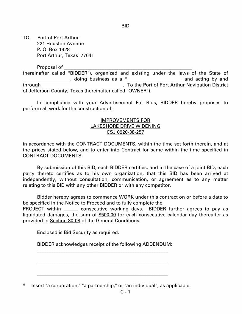
BID
TO: Port of Port Arthur 221 Houston Avenue P. O. Box 1428 Port Arthur, Texas 77641 Proposal of ______________________________________________________
(hereinafter called "BIDDER"), organized and existing under the laws of the State of ____________________, doing business as a *_______________________ and acting by and through __________________________________. To the Port of Port Arthur Navigation District of Jefferson County, Texas (hereinafter called "OWNER").
In compliance with your Advertisement For Bids, BIDDER hereby proposes to perform all work for the construction of:
IMPROVEMENTS FOR
LAKESHORE DRIVE WIDENING CSJ 0920-38-257
in accordance with the CONTRACT DOCUMENTS, within the time set forth therein, and at the prices stated below, and to enter into Contract for same within the time specified in CONTRACT DOCUMENTS.
By submission of this BID, each BIDDER certifies, and in the case of a joint BID, each party thereto certifies as to his own organization, that this BID has been arrived at independently, without consultation, communication, or agreement as to any matter relating to this BID with any other BIDDER or with any competitor.
Bidder hereby agrees to commence WORK under this contract on or before a date to
be specified in the Notice to Proceed and to fully complete the PROJECT within ______ consecutive working days. BIDDER further agrees to pay as liquidated damages, the sum of $500.00 for each consecutive calendar day thereafter as provided in Section 80-08 of the General Conditions.
Enclosed is Bid Security as required. BIDDER acknowledges receipt of the following ADDENDUM: _______________________________________________________ _______________________________________________________ _______________________________________________________
* Insert "a corporation," "a partnership," or "an individual", as applicable.
C - 2
BID SCHEDULE
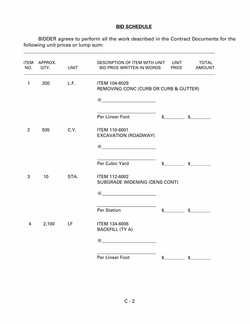
BIDDER agrees to perform all the work described in the Contract Documents for the following unit prices or lump sum: ITEM APPROX. DESCRIPTION OF ITEM WITH UNIT UNIT TOTAL NO. QTY. UNIT BID PRICE WRITTEN IN WORDS PRICE AMOUNT 1 200 L.F. ITEM 104-6029 REMOVING CONC (CURB OR CURB & GUTTER) @ Per Linear Foot $__________ $__________
2 935 C.Y. ITEM 110-6001 EXCAVATION (ROADWAY) @ Per Cubic Yard $__________ $__________
3 10 STA. ITEM 112-6002 SUBGRADE WIDENING (DENS CONT) @ Per Station $__________ $__________
4 2,100 LF ITEM 134-6006 BACKFILL (TY A) @ Per Linear Foot $__________ $__________
C - 3
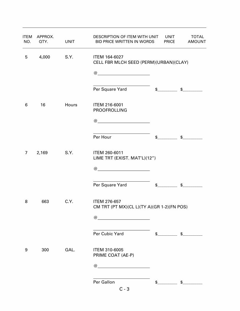
ITEM APPROX. DESCRIPTION OF ITEM WITH UNIT UNIT TOTAL NO. QTY. UNIT BID PRICE WRITTEN IN WORDS PRICE AMOUNT 5 4,000 S.Y. ITEM 164-6027
CELL FBR MLCH SEED (PERM)(URBAN)(CLAY) @ Per Square Yard $__________ $__________ 6 16 Hours ITEM 216-6001 PROOFROLLING @ Per Hour $__________ $__________ 7 2,169 S.Y. ITEM 260-6011 LIME TRT (EXIST. MAT’L)(12”) @ Per Square Yard $__________ $__________ 8 663 C.Y. ITEM 276-657 CM TRT (PT MX)(CL L)(TY A)(GR 1-2)(FN POS) @ Per Cubic Yard $__________ $__________ 9 300 GAL. ITEM 310-6005 PRIME COAT (AE-P) @ Per Gallon $__________ $__________
C - 4
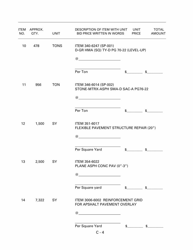
ITEM APPROX. DESCRIPTION OF ITEM WITH UNIT UNIT TOTAL NO. QTY. UNIT BID PRICE WRITTEN IN WORDS PRICE AMOUNT 10 478 TONS ITEM 340-6247 (SP-001) D-GR HMA (SQ) TY-D PG 70-22 (LEVEL-UP) @ Per Ton $__________ $__________ 11 956 TON ITEM 346-6014 (SP-002)
STONE-MTRX-ASPH SMA-D SAC-A PG76-22 @ Per Ton $__________ $__________ 12 1,500 SY ITEM 351-6017 FLEXIBLE PAVEMENT STRUCTURE REPAIR (20”) @ Per Square Yard $__________ $__________ 13 2,500 SY ITEM 354-6022 PLANE ASPH CONC PAV (0”-3”) @ Per Square yard $__________ $__________ 14 7,322 SY ITEM 3006-6002 REINFORCEMENT GRID
FOR APSHALT PAVEMENT OVERLAY @ Per Square Yard $__________ $__________
C - 5
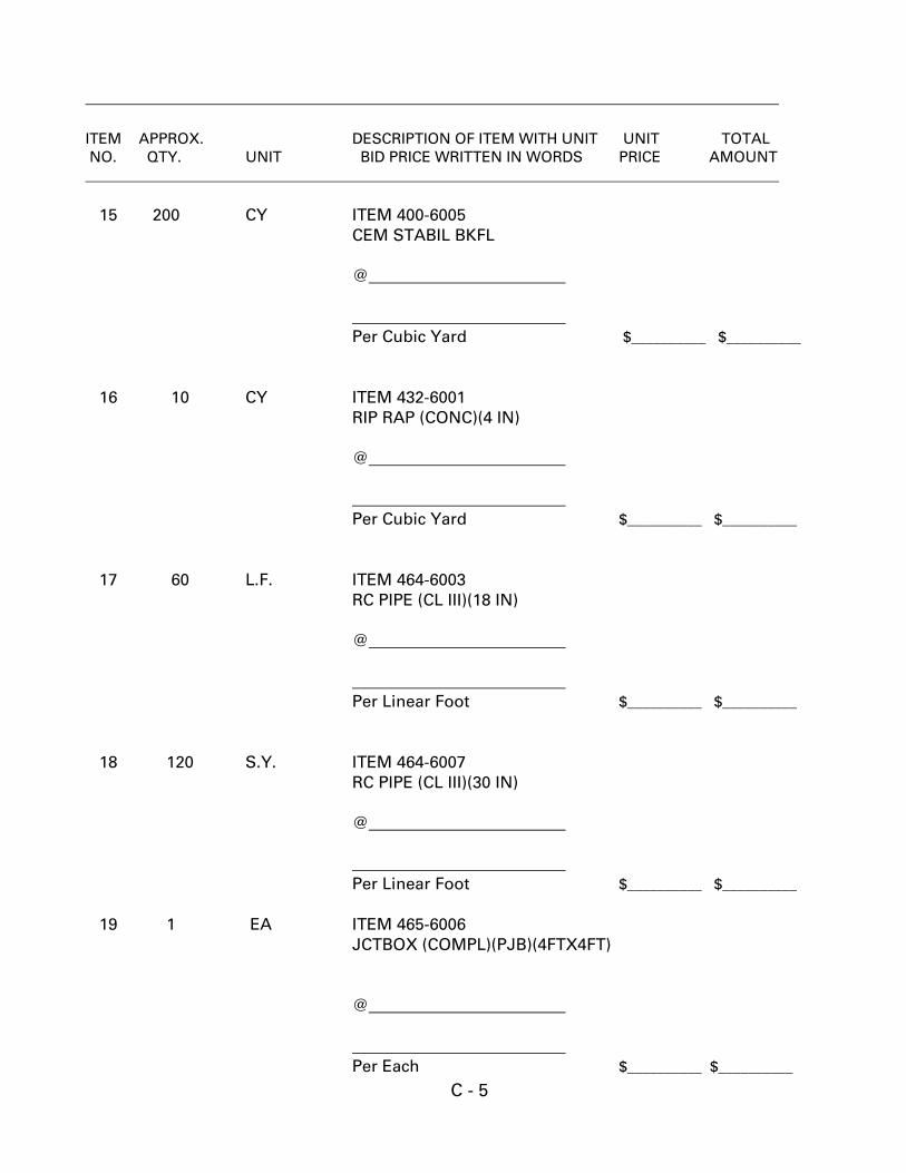
ITEM APPROX. DESCRIPTION OF ITEM WITH UNIT UNIT TOTAL NO. QTY. UNIT BID PRICE WRITTEN IN WORDS PRICE AMOUNT 15 200 CY ITEM 400-6005
CEM STABIL BKFL @ Per Cubic Yard $__________ $__________ 16 10 CY ITEM 432-6001
RIP RAP (CONC)(4 IN) @ Per Cubic Yard $__________ $__________ 17 60 L.F. ITEM 464-6003 RC PIPE (CL III)(18 IN) @ Per Linear Foot $__________ $__________ 18 120 S.Y. ITEM 464-6007 RC PIPE (CL III)(30 IN) @ Per Linear Foot $__________ $__________ 19 1 EA ITEM 465-6006 JCTBOX (COMPL)(PJB)(4FTX4FT) @ Per Each $__________ $__________
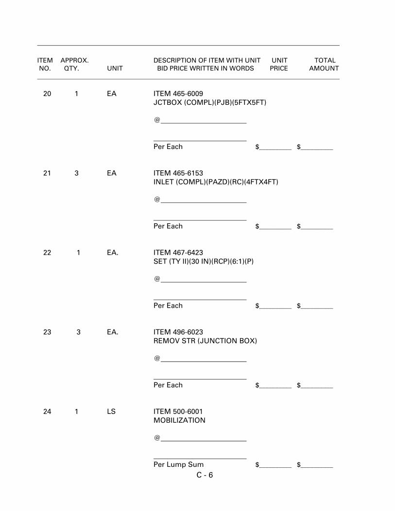
C - 6
ITEM APPROX. DESCRIPTION OF ITEM WITH UNIT UNIT TOTAL NO. QTY. UNIT BID PRICE WRITTEN IN WORDS PRICE AMOUNT 20 1 EA ITEM 465-6009 JCTBOX (COMPL)(PJB)(5FTX5FT) @ Per Each $__________ $__________ 21 3 EA ITEM 465-6153 INLET (COMPL)(PAZD)(RC)(4FTX4FT) @ Per Each $__________ $__________ 22 1 EA. ITEM 467-6423 SET (TY II)(30 IN)(RCP)(6:1)(P) @ Per Each $__________ $__________ 23 3 EA. ITEM 496-6023 REMOV STR (JUNCTION BOX) @ Per Each $__________ $__________ 24 1 LS ITEM 500-6001
MOBILIZATION @ Per Lump Sum $__________ $__________
C - 7
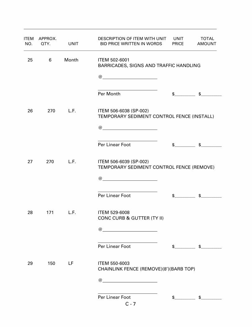
ITEM APPROX. DESCRIPTION OF ITEM WITH UNIT UNIT TOTAL NO. QTY. UNIT BID PRICE WRITTEN IN WORDS PRICE AMOUNT 25 6 Month ITEM 502-6001
BARRICADES, SIGNS AND TRAFFIC HANDLING @ Per Month $__________ $__________ 26 270 L.F. ITEM 506-6038 (SP-002) TEMPORARY SEDIMENT CONTROL FENCE (INSTALL) @ Per Linear Foot $__________ $__________ 27 270 L.F. ITEM 506-6039 (SP-002) TEMPORARY SEDIMENT CONTROL FENCE (REMOVE) @ Per Linear Foot $__________ $__________ 28 171 L.F. ITEM 529-6008
CONC CURB & GUTTER (TY II) @ Per Linear Foot $__________ $__________ 29 150 LF ITEM 550-6003
CHAINLINK FENCE (REMOVE)(8’)(BARB TOP) @ Per Linear Foot $__________ $__________
C - 8
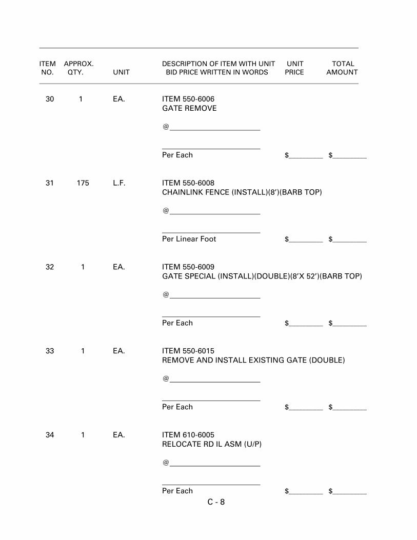
ITEM APPROX. DESCRIPTION OF ITEM WITH UNIT UNIT TOTAL NO. QTY. UNIT BID PRICE WRITTEN IN WORDS PRICE AMOUNT 30 1 EA. ITEM 550-6006 GATE REMOVE @ Per Each $__________ $__________ 31 175 L.F. ITEM 550-6008 CHAINLINK FENCE (INSTALL)(8’)(BARB TOP) @ Per Linear Foot $__________ $__________ 32 1 EA. ITEM 550-6009
GATE SPECIAL (INSTALL)(DOUBLE)(8’X 52’)(BARB TOP) @ Per Each $__________ $__________ 33 1 EA. ITEM 550-6015
REMOVE AND INSTALL EXISTING GATE (DOUBLE) @ Per Each $__________ $__________ 34 1 EA. ITEM 610-6005
RELOCATE RD IL ASM (U/P) @ Per Each $__________ $__________
C - 9
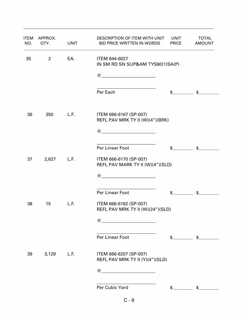
ITEM APPROX. DESCRIPTION OF ITEM WITH UNIT UNIT TOTAL NO. QTY. UNIT BID PRICE WRITTEN IN WORDS PRICE AMOUNT 35 2 EA. ITEM 644-6027 IN SM RD SN SUP&AM TYS80(1)SA(P) @ Per Each $__________ $__________ 36 350 L.F. ITEM 666-6167 (SP-007) REFL PAV MRK TY II (W)(4”)(BRK) @ Per Linear Foot $__________ $__________ 37 2,627 L.F. ITEM 666-6170 (SP-007) REFL PAV MARK TY II (W)(4”)(SLD) @ Per Linear Foot $__________ $__________ 38 15 L.F. ITEM 666-6182 (SP-007)
REFL PAV MRK TY II (W)(24”)(SLD) @ Per Linear Foot $__________ $__________ 39 3,129 L.F. ITEM 666-6207 (SP-007)
REFL PAV MRK TY II (Y)(4”)(SLD) @ Per Cubic Yard $__________ $__________
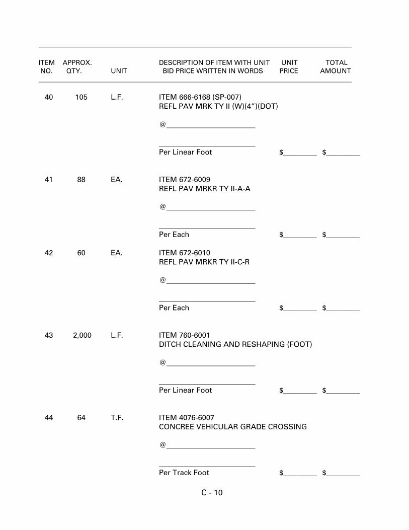
C - 10
ITEM APPROX. DESCRIPTION OF ITEM WITH UNIT UNIT TOTAL NO. QTY. UNIT BID PRICE WRITTEN IN WORDS PRICE AMOUNT 40 105 L.F. ITEM 666-6168 (SP-007) REFL PAV MRK TY II (W)(4”)(DOT) @ Per Linear Foot $__________ $__________ 41 88 EA. ITEM 672-6009 REFL PAV MRKR TY II-A-A @ Per Each $__________ $__________ 42 60 EA. ITEM 672-6010
REFL PAV MRKR TY II-C-R @ Per Each $__________ $__________ 43 2,000 L.F. ITEM 760-6001
DITCH CLEANING AND RESHAPING (FOOT) @ Per Linear Foot $__________ $__________ 44 64 T.F. ITEM 4076-6007 CONCREE VEHICULAR GRADE CROSSING @ Per Track Foot $__________ $__________
C - 11
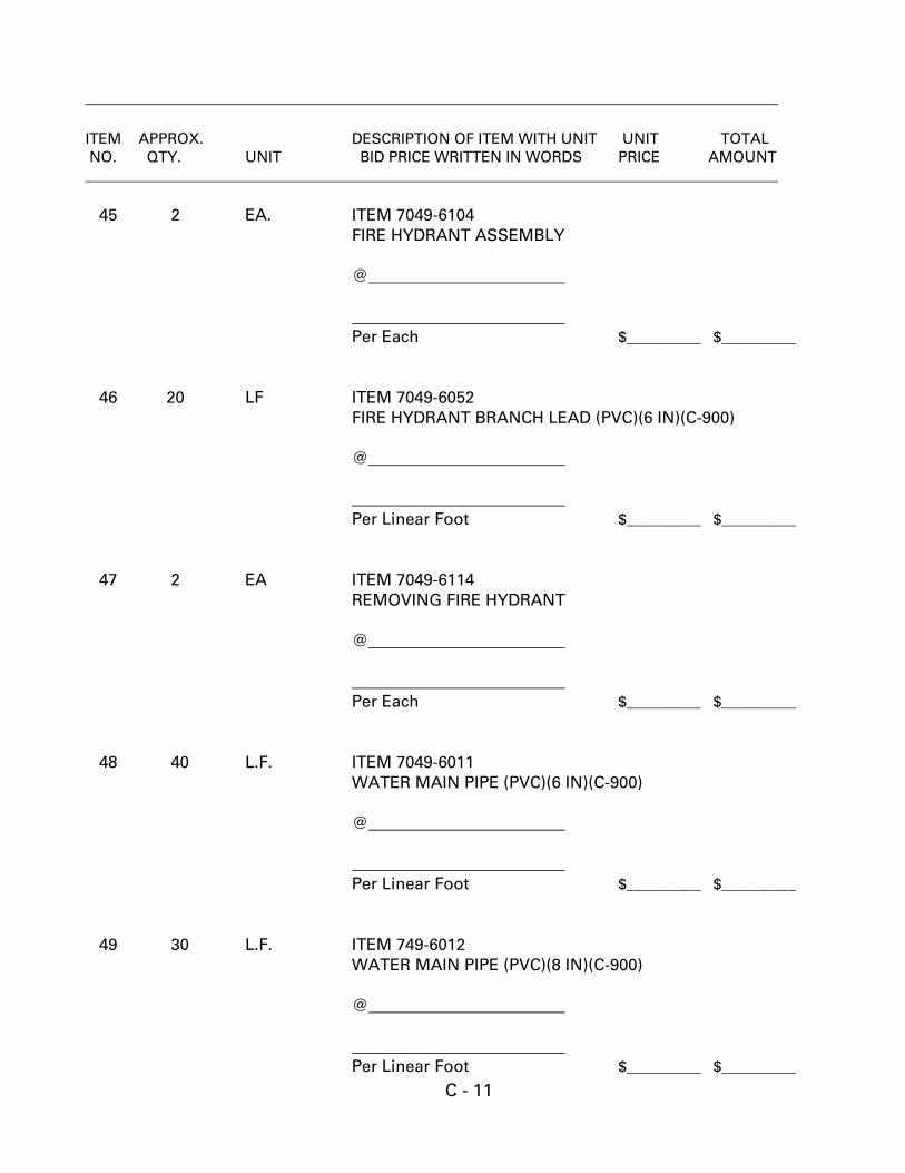
ITEM APPROX. DESCRIPTION OF ITEM WITH UNIT UNIT TOTAL NO. QTY. UNIT BID PRICE WRITTEN IN WORDS PRICE AMOUNT 45 2 EA. ITEM 7049-6104 FIRE HYDRANT ASSEMBLY @ Per Each $__________ $__________ 46 20 LF ITEM 7049-6052
FIRE HYDRANT BRANCH LEAD (PVC)(6 IN)(C-900) @ Per Linear Foot $__________ $__________ 47 2 EA ITEM 7049-6114
REMOVING FIRE HYDRANT @ Per Each $__________ $__________ 48 40 L.F. ITEM 7049-6011 WATER MAIN PIPE (PVC)(6 IN)(C-900) @ Per Linear Foot $__________ $__________ 49 30 L.F. ITEM 749-6012 WATER MAIN PIPE (PVC)(8 IN)(C-900) @ Per Linear Foot $__________ $__________
C - 12
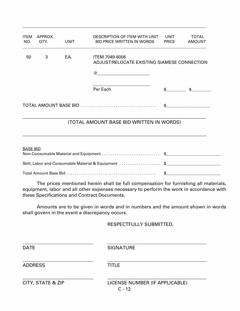
ITEM APPROX. DESCRIPTION OF ITEM WITH UNIT UNIT TOTAL NO. QTY. UNIT BID PRICE WRITTEN IN WORDS PRICE AMOUNT 50 3 EA. ITEM 7049-6006 ADJUST/RELOCATE EXISTING SIAMESE CONNECTION @ Per Each $__________ $__________ TOTAL AMOUNT BASE BID . . . . . . . . . . . . . . . . . . . . . . . . . . . . . . . . . . . $______________________
(TOTAL AMOUNT BASE BID WRITTEN IN WORDS) BASE BID Non-Consumable Material and Equipment . . . . . . . . . . . . . . . . . . . . . . . . . . . $ Skill, Labor and Consumable Material & Equipment . . . . . . . . . . . . . . . . . . . $ Total Amount Base Bid . . . . . . . . . . . . . . . . . . . . . . . . . . . . . . . . . . . . . . . . . . $ The prices mentioned herein shall be full compensation for furnishing all materials, equipment, labor and all other expenses necessary to perform the work in accordance with these Specifications and Contract Documents. Amounts are to be given in words and in numbers and the amount shown in words shall govern in the event a discrepancy occurs. RESPECTFULLY SUBMITTED, DATE SIGNATURE ADDRESS TITLE CITY, STATE & ZIP LICENSE NUMBER (IF APPLICABLE)

C - 13
(SEAL – if BID is by a Corporation) ATTEST:

BID BOND
D - 1
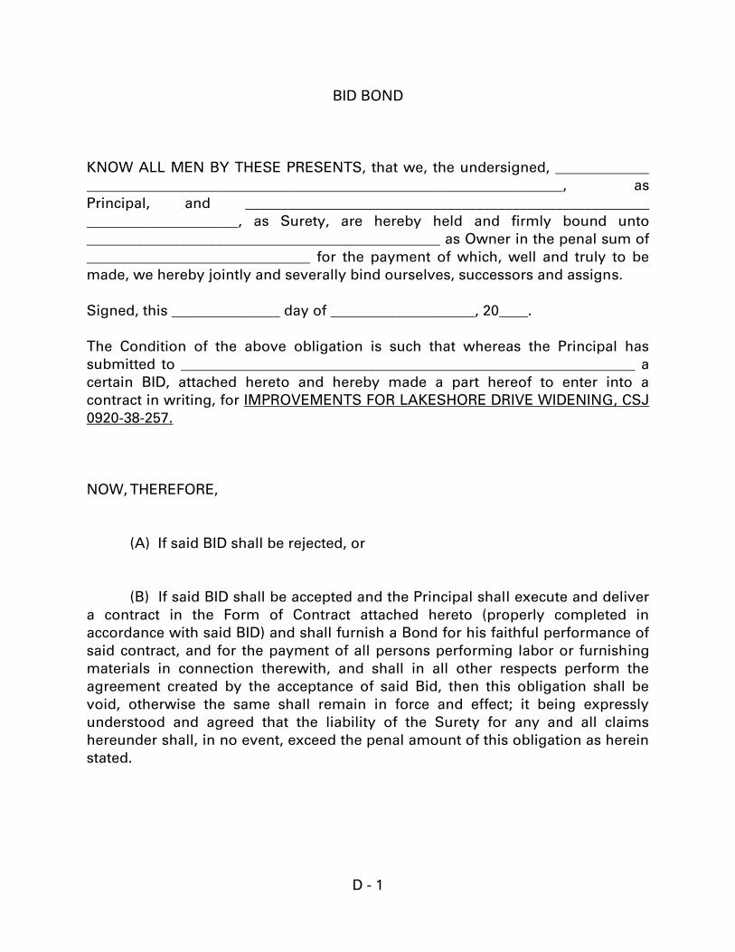
BID BOND
KNOW ALL MEN BY THESE PRESENTS, that we, the undersigned, _____________
__________________________________________________________________, as
Principal, and ________________________________________________________
_____________________, as Surety, are hereby held and firmly bound unto
_________________________________________________ as Owner in the penal sum of
_______________________________ for the payment of which, well and truly to be
made, we hereby jointly and severally bind ourselves, successors and assigns.
Signed, this _______________ day of ____________________, 20____.
The Condition of the above obligation is such that whereas the Principal has
submitted to _______________________________________________________________ a
certain BID, attached hereto and hereby made a part hereof to enter into a
contract in writing, for IMPROVEMENTS FOR LAKESHORE DRIVE WIDENING, CSJ
0920-38-257.
NOW, THEREFORE,
(A) If said BID shall be rejected, or
(B) If said BID shall be accepted and the Principal shall execute and deliver
a contract in the Form of Contract attached hereto (properly completed in
accordance with said BID) and shall furnish a Bond for his faithful performance of
said contract, and for the payment of all persons performing labor or furnishing
materials in connection therewith, and shall in all other respects perform the
agreement created by the acceptance of said Bid, then this obligation shall be
void, otherwise the same shall remain in force and effect; it being expressly
understood and agreed that the liability of the Surety for any and all claims
hereunder shall, in no event, exceed the penal amount of this obligation as herein
stated.
D - 2
The Surety, for value received, hereby stipulates and agrees that the obligations
of said Surety and its Bond shall be in no way impaired or affected by any
extension of the time within which the Owner may accept such Bid; and said
Surety does hereby waive notice of any such extension.
IN WITNESS WHEREOF, the Principal and the Surety have unto set their hands
and seals, and such of them as are corporations have caused their corporate seals
to be hereto affixed and these presents to be signed by their proper officers, the
day and year first set forth above.
______________________________(L.S.)
Principal
______________________________
Surety
By: __________________________
IMPORTANT: Surety companies executing Bonds must appear on the Treasury
Department’s most current list (Circular 570 as amended) and be authorized to
transact business in the state where the project is located.

CONSTRUCTION CONTRACT AGREEMENT
E-1
AGREEMENT between PORT OF PORT ARTHUR NAVIGATION DISTRICT OF JEFFERSON COUNTY, TEXAS (“OWNER”) and _______________________________________ (“CONTRACTOR”)
E-2
STANDARD FORM OF AGREEMENT BETWEEN OWNER AND CONTRACTOR ON THE BASIS OF A STIPULATED PRICE THIS AGREEMENT is dated as of the ____ day of ___________________, 2018 by and between the Port of Port Arthur Navigation District of Jefferson County, Texas (hereinafter called “OWNER”) and ____________________ (hereinafter called “CONTRACTOR”). OWNER and CONTRACTOR, in consideration of the mutual covenants hereinafter set forth, agree as follows: Article 1. WORK. CONTRACTOR shall complete all Work as specified or indicated in the Contract Documents. The Work is generally described as follows: 1.1 The Work of this project comprises the Port of Port Arthur improvements for the
Widening of Lakeshore Drive. The project generally consists of traffic control, storm water pollution prevention, asphalt planning, subgrade widening, lime stabilization, drainage, water line appurtenance relocation, fencing, full depth pavement repair, concrete gutter replacement, hot mix asphaltic concrete overlay and pavement striping (the “Project”).
Article 2. CONTRACT TIME.
2.1 The field Work will be substantially completed within _____ working days from the date when the Contract Time commences to run as provided in paragraph 80-02 of the General Conditions. OWNER desires the work to start as soon as practical with prior agreement from CONTRACTOR.
Article 3. CONTRACT PRICE.
3.1 CONTRACTOR and any Subcontractors shall pay prevailing wages according to the Davis Bacon Act.
3.2 OWNER shall pay CONTRACTOR for completion of the Work in accordance
with the Contract Documents in current funds as follows: Article 4. PAYMENT PROCEDURES. CONTRACTOR shall submit Applications for Payment in accordance with Section 90 of
E-3
the General Conditions. Applications for Payment will be processed by ENGINEER as provided in General Conditions.
4.1 Progress Payments. OWNER shall make progress payments on account of the Contract Price on the basis of CONTRACTOR’S Applications for Payment as recommended by ENGINEER, on or about seven (7) days following the third (3rd) Wednesday of each month during construction as provided below. All progress payments will be done on the basis of the progress of the Work in accordance with Paragraphs 90-06 and 90-07 of the General Conditions.
4.2 Retainage. OWNER shall retain 10% of all progress payments otherwise due and
payable under the terms of this Agreement. Retainage shall be paid as a part of the Final Payment, as defined in these Contract Documents.
4.3 Final Payment. Upon final completion and acceptance of the Work in accordance
with Paragraph 50-15 of the General Conditions, OWNER shall pay the remainder of the Contract Price as recommended by ENGINEER as provided in said paragraph 90-09.
4.4 Interest. All monies not paid when due as provided in Paragraph 50-15. of the
General Conditions shall bear interest at the maximum rate allowed by law. Retainage shall not be considered due until Final Payment is due, and shall not bear interest until Final Payment is due.
4.5 Affidavits Regarding Title. OWNER may require CONTRACTOR to sign an
affidavit attesting to CONTRACTOR’S title to work covered by each payment. Article 5. INSURANCE.
5.1 At all times during the performance of this Agreement, CONTRACTOR will, at its own expense, and CONTRACTOR’S subcontractors will, at their own or at CONTRACTOR’S expense, carry the insurance coverage as detailed on Exhibit 2, Insurance Requirements, as provided in Paragraph 5 of the Information to Bidders, which is attached hereto and incorporated by reference herein for all purposes. CONTRACTOR will, at its own expense, furnish to OWNER certificates attesting to the fact that such policies are in effect. All insurance shall be with an insurance company authorized to do business in the State of Texas. OWNER shall be additional insured on all policies, excluding Worker’s Compensation/Employer’s Liability. Insurance shall be made on an “occurrence form” rather than a “claims made form.”
5.2 Insurance policies covering CONTRACTOR and naming OWNER as additional insured and evidencing the required coverages shall be delivered to OWNER
E-4
prior to commencement of the Work under this Agreement. Such policies shall provide that any change restricting or reducing coverage or any cancellation shall not be valid as respects the OWNER’S interest therein until OWNER has received 30 days’ notice in writing of such change or cancellation.
5.3 Any and all deductibles in the above described insurance policies shall be
assumed by, for the account of and at CONTRACTOR’S sole risk.
5.4 Each policy shall be endorsed to provide waiver of subrogation rights in favor of OWNER, its subsidiaries and affiliates and all other parties owning an interest in the property on which Work covered by this Agreement is to be performed. CONTRACTOR agrees to waive and agrees to have its insurer waive any rights of subrogation as respects deductibles under such policies and as respects damages to equipment, including the loss of use thereof, whether insured or not.
5.5 Failure of CONTRACTOR to keep the required insurance policies in full force
and effective hereunder shall constitute a breach of this Agreement and OWNER shall have the right, in addition to any other rights, to immediately cancel and terminate this Agreement.
5.6 Nothing contained in these provisions relating to coverage and amounts set out
herein shall operate as a limitation of CONTRACTOR’S liability in tort or contracted for under the terms of this Agreement.
5.7 CONTRACTOR shall also file with the OWNER valid policies of Insurance on
like form for all consultants or subcontractors. Similar insurance shall be provided by or on behalf of all consultants or subcontractors to cover their operations under the Agreement. In the event a consultant or subcontractor is unable to furnish insurance as required under the Contract, then the available insurance limits and coverages may be reviewed by the OWNER and insurance requirements may be amended. Such review and amendment will not be unreasonably withheld.
5.8 CONTRACTOR shall promptly report to OWNER all accidents occurring to
CONTRACTOR employees or any other parties or property. Article 6. CONTRACTOR’S REPRESENTATIONS. In order to induce OWNER to enter into the Agreement CONTRACTOR makes the following representations:
6.1 CONTRACTOR has familiarized itself with the nature and extent of the Contract
E-5
Documents, Work, site locality, and all local conditions and Laws and Regulations that in any manner may affect cost, progress, performance of furnishing of Work.
6.2 CONTRACTOR has studied carefully all reports of explorations and tests of
subsurface conditions and drawings of physical conditions which are identified in these Contract Documents and the technical data contained in such reports and drawings, upon which CONTRACTOR is entitled to rely.
6.3 CONTRACTOR has reviewed and checked all information and data shown or
indicated on the Contract Documents with respect to existing Underground Facilities at or contiguous to the site and assumes responsibility for the site and assumes responsibility for the accurate location of said Underground Facilities. No additional examinations, investigations, explorations, tests, reports, studies or similar information or data in respect of said Underground Facilities are or will be required by CONTRACTOR in order to perform and furnish the Work at the Contract Price, within the Contract Time and in accordance with other terms and conditions of the Contract Documents.
6.4 CONTRACTOR has correlated the results of all such observations, examinations,
investigations, explorations, tests, reports and studies with the terms and conditions of the Contract Documents.
6.5 CONTRACTOR has given ENGINEER written notice of all conflicts, errors or
discrepancies that it has discovered in the Contract Documents and the written resolution thereof by ENGINEER is acceptable to CONTRACTOR.
Article 7. CONTRACT DOCUMENTS. The Contract Documents which comprise the entire agreement between OWNER and CONTRACTOR concerning the Work consist of the following: 7.1 This Agreement (pages 1 to 7, inclusive). 7.2 The Contractor’s accepted Bid and Bonds required by these Contract Documents,
attached hereto. 7.4 Construction Specifications manual entitled Port of Port Arthur Lakeshore Drive
Widening dated September, 2018, which includes the following: a) Notice to Bidders of Mandatory Prebid Conference
E-6
b) Information to Bidders c) Bid d) Bid Bond e) Construction Contract Agreement f) Performance Bond g) Payment Bond h) General Conditions i) Wage Rate j) Geotechnical Investigation k) Technical Specifications, Special Specifications, Special Provisions
7.5 Drawings bearing the following title: 7.5.1 “Plans of Proposed Lakeshore Drive Widening”
(Refer to the Project Index Sheet 2 for Detailed Drawing Index)
7.6 The following which may be delivered or issued after the Effective Date of the Agreement and are not attached hereto: All Written Amendments and other documents amending, modifying, or supplementing the Contract Documents pursuant to Section 40 of the General Conditions.
7.7 The documents listed in Article 7 above are attached to this Agreement (except as
expressly noted otherwise above). There are no Contract Documents other than those listed above in this Article 7. The Contract Documents may only be amended, modified or supplemented as provided for in the General Conditions. Article 8. MISCELLANEOUS. 8.1 Terms used in this Agreement which are defined in Section 10 of the General
Conditions will have the meanings indicated in the General Conditions. 8.2 No assignment by a party hereto of any rights under or interest in the Contract
Documents will be binding on another party hereto without the written consent of the party sought to be bound; and specifically but without limitation monies that may become due and monies that are due may not be assigned without such consent (except to the extent that the effect of this restriction may be limited by law), and unless specifically stated to the contrary in any written consent to an assignment no assignment will release or discharge the assignor from any duty or responsibility under the Contract Documents.
E-7
8.3 OWNER and CONTRACTOR each binds itself, its partners, successors, assigns and legal representatives to the other party hereto, its partners, successors, assigns and legal representative in respect of all covenants, agreements and obligations contained in the Contract Documents.
IN WITNESS WHEREOF, OWNER and CONTRACTOR have signed this Agreement in triplicate. One counterpart each has been delivered to OWNER, CONTRACTOR and ENGINEER. All portions of the Contract Documents have been signed or identified by OWNER and CONTRACTOR or by ENGINEER on their behalf. This Agreement will be effective on , 2018. OWNER Port of Port Arthur CONTRACTOR __________________ Navigation District of __________________ Jefferson County, Texas By: By: Address for giving notices: Address for giving notices: 221 Houston Avenue ____________________________________ PO Box 1428 ____________________________________ Port Arthur, TX 77641 License No. _________________________

PERFORMANCE BOND
F - 1
PERFORMANCE BOND
KNOW ALL MEN BY THESE PRESENTS: that _____________________________________________________________________
NAME OF CONTRACTOR
_____________________________________________________________________ ADDRESS OF CONTRACTOR
a ________________________________________, hereinafter called Principal, and CORPORATION, PARTNERSHIP, OR INDIVIDUAL _____________________________________________________________________
NAME OF SURETY _____________________________________________________________________
ADDRESS OF SURETY hereinafter called Surety, are held firmly bound unto: The Port of Port Arthur Navigation District of Jefferson County, Texas, P. O. Box 1428, Port Arthur, Texas 77641 hereinafter called OWNER, in the penal sum of __________________________________________________($__________) in lawful money of the United States, for the payment of which sum well and truly to be made, we bind ourselves, successors, and assigns, jointly and severally, firmly by these presents. THE CONDITION OF THIS OBLIGATION is such that whereas, the Principal entered into a certain contract with the OWNER, dated the _____________ day of ________, 20___, a copy of which is hereto attached and made a part hereof for the construction of: LAKESHORE DRIVE WIDENING, CSJ 0920-38-257. NOW, THEREFORE, if the Principal shall well, truly and faithfully perform its duties, all the undertakings, covenants, terms, conditions, and agreements of said contract during the original term thereof, and any extensions thereof which may be granted by the OWNER, with or without notice to the Surety and during the one-year guaranty period, and if he shall satisfy all claims and demands incurred under such contract, and shall fully indemnify and save harmless the OWNER from all costs and damages which it may suffer by reason of failure to do so, and shall reimburse and repay the OWNER all outlay and expense which the OWNER may incur in making good any default, then this obligation shall be void; otherwise to remain in full force and effect. Provided, that this bond is executed pursuant to Chapter 2253 of the Texas Government Code and all liabilities on this bond shall be determined in accordance with the provisions thereof to the same extent as if it were copied at length. PROVIDED, FURTHER, that the said surety, for value received hereby stipulates and agrees that no change, extension of time, alteration or addition to the terms of the contract or to WORK to be performed thereunder or the SPECIFICATIONS
F - 2
accompanying the same shall be any wise affect its obligation on this BOND, and it does hereby waive notice of any such change, extension of time, alteration or addition to the terms of the Contract or to the WORK or to the SPECIFICATIONS. PROVIDED, FURTHER, that no final settlement between the OWNER and the CONTRACTOR shall abridge the right of any beneficiary hereunder, whose claim may be unsatisfied. IN WITNESS WHEREOF, of this instrument is executed in __________ counterparts, each one of which shall be deemed an original, this the _______ day of __________________, 20____. ATTEST: _______________________________
PRINCIPAL _____________________________ BY_____________________________ (PRINCIPAL) SECRETARY (SEAL) _____________________________ ________________________________ WITNESS AS TO PRINCIPAL ADDRESS _____________________________ ________________________________ ADDRESS _____________________________ ________________ _______________ SURETY ATTEST: _____________________________ (SURETY) SECRETARY (SEAL) ______________________________ BY_____________________________ WITNESS AS TO SURETY ATTORNEY-IN-FACT ______________________________ _______________________________ ADDRESS ADDRESS _______________________________ _______________________________ NOTE: Date of BOND must not be prior to date of Contract. If CONTRACTOR is Partnership, all partners should execute BOND. IMPORTANT: Surety companies executing BONDS must appear on the Treasury Department's most current list (Circular 570 as amended) and be authorized to transact business in the state where the PROJECT is located.

PAYMENT BOND
G - 1
PAYMENT BOND
STATE OF TEXAS )
) ss. KNOW ALL MEN BY THESE PRESENTS:
COUNTY OF )
THAT we ______________________________________________________, of the
City of _____________________________, County of ____________________, and State
of _____________, as principal, and _________________________ ___________________,
as surety, authorized under the laws of the State of Texas to act as surety on
bonds for principals are held and firmly bound unto the Port of Port Arthur
Navigation District of Jefferson County, Texas, and to all subcontractors,
workmen, laborers, mechanics, and furnishers of material, and any other
claimant, as their interest may appear, all of whom shall have the right to sue
upon their bond, in the penal sum of:
_____________________________________________($__________), lawful currency of
the United States of America, for the payment of which, well and truly to be made,
we do hereby bind ourselves, our heirs, executors, administrators and successors,
jointly and severally and firmly by these presents:
The condition of this Bond is such that, whereas, the above bounden
Principal as prime contractor has on the __________day of _________________,
20____, entered into a formal contract with the Port of Port Arthur, Texas for
construction of: LAKESHORE DRIVE WIDENING, CSJ 0920-38-257 which is
hereby referred to and made part hereof as if fully written herein.
NOW, THEREFORE, if the above bounden Principal shall protect all
claimants supplying labor and material as provided for in Chapter 2253 of the
Texas Government Code and all liabilities on this bond shall be determined in
accordance with the provisions thereof to the same extent as if it were copied at
length. This bond being solely for the protection of all such claimants and being
for the use of each such claimant, then this obligation shall be null and void,
otherwise it shall remain in full force and effect.
It is stipulated and agreed that no change, extension of time, addition to or
modification of the Contract or work performed thereunder, shall in anywise affect
the obligation of this bond, and surety expressly waives notice of any such
change, extension of time, addition or modification.
G - 2
IN WITNESS WHEREOF, the said Principal has caused these presents to be
executed, and the said surety has caused these presents to be executed, each by
its duly authorized agent and officer, and its corporate seal to be affixed at
_________________________ on this the ______day of __________________, A. D.,
20_____.
_______________________________
CONTRACTOR
ATTEST:
_______________________________ BY:____________________________
TITLE:__________________________
_______________________________
SURETY
ATTEST: BY:____________________________
________________________________ TITLE:__________________________
NOTE: Date of Bond must not be prior to date of Contract. If Contractor is
Partnership, all partners shall execute Bond. Surety companies
executing bonds must appear on Treasury Department's most current list
(Circular 570 as amended) and be authorized to transact business in
Texas.
GENERAL CONDITIONS
H - 1
GENERAL_CONDITIONS
SECTION 10: DEFINITION OF TERMS …………………….........................................5
01 AASHTO 02 OMITTED 03 OMITTED 04 ADVERTISEMENT 05 OMITTED 06 OMITTED 07 ASTM 08 AWARD 09 BIDDER 10 OMITTED 11 CALENDAR DAY 12 CHANGE ORDER 13 CONTRACT 14 CONTRACT ITEM (PAY ITEM) 15 CONTRACT TIME 16 CONTRACTOR 17 DRAINAGE SYSTEM 18 ENGINEER 19 EQUIPMENT 20 EXTRA WORK 21 OMITTED 22 FEDERAL SPECIFICATIONS 23 RESIDENT PROJECT REPRESENTATIVE 24 INTENTION OF TERMS 25 LABORATORY 26 OMITTED 27 MAJOR AND MINOR CONTRACT ITEMS 28 MATERIALS 29 NOTICE TO PROCEED 30 OWNER (SPONSOR) 31 PAVEMENT 32 PAYMENT BOND 33 PERFORMANCE BOND 34 PLANS 35 PROJECT 36 PROPOSAL 37 PROPOSAL GUARANTY 38 OMITTED 39 SPECIFICATIONS 40 STRUCTURES 41 SUBGRADE 42 SUPERINTENDENT 43 SUPPLEMENTAL AGREEMENT
H - 2
44 SURETY 45 OMITTED 46 WORK 47 WORKING DAYS 48 THD
SECTION 20: PROPOSAL REQUIREMENTS AND CONDITIONS .....................……9
01 ADVERTISEMENT FOR BIDS 02 PRE-QUALIFICATION OF BIDDERS <<Omitted>> 03 CONTENTS OF PROPOSAL FORMS 04 ISSUANCE OF PROPOSAL FORMS 05 INTERPRETATION OF ESTIMATED PROPOSAL QUANTITIES 06 EXAMINATION OF PLANS, SPECIFICATIONS, AND SITE 07 PREPARATION OF PROPOSAL 08 IRREGULAR PROPOSALS 09 PROPOSAL GUARANTY 10 DELIVERY OF PROPOSAL 11 WITHDRAWAL OR REVISION OF PROPOSALS 12 PUBLIC OPENING OF PROPOSALS 13 DISQUALIFICATION OF BIDDERS
SECTION 30: AWARD AND EXECUTION OF CONTRACT ...........................……….13
01 CONSIDERATION OF PROPOSALS 02 AWARD OF CONTRACT 03 CANCELLATION OF AWARD 04 RETURN OF PROPOSAL GUARANTY 05 REQUIREMENTS OF CONTRACT BONDS 06 EXECUTION OF CONTRACT 07 APPROVAL OF CONTRACT 08 FAILURE TO EXECUTE CONTRACT
SECTION 40: SCOPE OF WORK .............................................………………………..15 01 INTENT OF CONTRACT
02 ALTERATION OF WORK AND QUANTITIES 03 OMITTED ITEMS 04 EXTRA WORK 05 MAINTENANCE OF TRAFFIC 06 REMOVAL OF EXISTING STRUCTURES 07 RIGHTS IN AND USE OF MATERIALS FOUND IN THE WORK 08 FINAL CLEANING UP
SECTION 50: CONTROL OF WORK ...........................................…………………….. 19
01 AUTHORITY OF THE ENGINEER 02 CONFORMITY WITH PLANS AND SPECIFICATIONS 03 COORDINATION OF CONTRACT, PLANS AND SPECIFICATIONS
H - 3
04 COOPERATION OF CONTRACTOR 05 COOPERATION BETWEEN CONTRACTORS 06 CONSTRUCTION LAYOUT AND STAKES 07 OMITTED 08 AUTHORITY AND DUTIES OF RESIDENT PROJECT REPRESENTATIVE 09 OBSERVATION OF THE WORK 10 REMOVAL OF UNACCEPTABLE AND UNAUTHORIZED WORK 11 LOAD RESTRICTIONS 12 MAINTENANCE DURING CONSTRUCTION 13 FAILURE TO MAINTAIN THE WORK 14 PARTIAL ACCEPTANCE 15 FINAL ACCEPTANCE 16 CLAIMS FOR ADJUSTMENT AND DISPUTES
SECTION 60: CONTROL OF MATERIALS ......................................…………………. 25
01 SOURCE OF SUPPLY AND QUALITY REQUIREMENTS 02 SAMPLES, TESTS, AND CITED SPECIFICATIONS 03 CERTIFICATION OF COMPLIANCE 04 PLANT INSPECTION 05 ENGINEER'S FIELD OFFICE AND LABORATORY 06 STORAGE OF MATERIALS 07 UNACCEPTABLE MATERIALS 08 OWNER-FURNISHED MATERIALS
SECTION 70: LEGAL RELATIONS AND RESPONSIBILITY TO PUBLIC .............. 28
01 LAWS TO BE OBSERVED 02 PERMITS, LICENSES, AND TAXES 03 PATENTED DEVICES, MATERIALS, AND PROGRESS 04 RESTORATION OF SURFACES DISTURBED BY OTHERS 05 OMITTED 06 SANITARY, HEALTH, AND SAFETY PROVISIONS 07 PUBLIC CONVENIENCE AND SAFETY 08 BARRICADES, WARNING SIGNS, AND HAZARD MARKINGS 09 OMITTED 10 PROTECTION AND RESTORATION OF PROPERTY AND LANDSCAPE 11 RESPONSIBILITY FOR DAMAGE CLAIMS 12 THIRD PARTY BENEFICIARY CLAUSE 13 OPENING SECTIONS OF THE WORK TO TRAFFIC 14 CONTRACTOR'S RESPONSIBILITY FOR WORK 15 CONTRACTOR'S RESPONSIBILITY FOR UTILITY SERVICE AND FACILITIES OF OTHERS 16 FURNISHING RIGHTS-OF-WAY 17 PERSONAL LIABILITY OF PUBLIC OFFICIALS 18 NO WAIVER OF LEGAL RIGHTS 19 ENVIRONMENTAL PROTECTION 20 ARCHAEOLOGICAL AND HISTORICAL FINDINGS
H - 4
SECTION 80: PROSECUTION AND PROGRESS ..................................……………. 36
01 SUBLETTING OF CONTRACT 02 NOTICE TO PROCEED 03 PROSECUTION AND PROGRESS 04 OMITTED 05 CHARACTER OF WORKERS, METHODS, AND EQUIPMENT 06 TEMPORARY SUSPENSION OF THE WORK 07 DETERMINATION AND EXTENSION OF CONTRACT TIME 08 FAILURE TO COMPLETE ON TIME 09 DEFAULT AND TERMINATION OF CONTRACT 10 TERMINATION
SECTION 90: MEASUREMENT AND PAYMENT ...................................……………. 42
01 MEASUREMENT OF QUANTITIES 02 SCOPE OF PAYMENT 03 COMPENSATION FOR ALTERED QUANTITIES 04 PAYMENT FOR OMITTED ITEMS 05 PAYMENT FOR EXTRA AND FORCE ACCOUNT WORK 06 PARTIAL PAYMENTS 07 PAYMENT FOR MATERIALS ON HAND 08 PAYMENT FOR WITHHELD FUNDS 09 ACCEPTANCE AND FINAL PAYMENT 10 GUARANTY OF WORK 11 MAINTENANCE OF WORK
H - 5
GENERAL CONDITIONS
SECTION 10
DEFINITION OF TERMS
Whenever the following terms are used in these specifications, in the contract, in any documents or other instruments pertaining to construction where these specifications govern, the intent and meaning shall be interpreted as follows: 10-01 AASHTO - The American Association of State Highway and Transportation officials, the successor association to AASHO. 10-02 OMITTED 10-03 OMITTED 10-04 ADVERTISEMENT - A public announcement, as required by local law, inviting bids for work to be performed and materials to be furnished. 10-05 OMITTED 10-06 OMITTED 10-07 ASTM - The American Society for Testing and Materials. 10-08 AWARD - The acceptance, by the owner, of the successful bidder's proposal. 10-09 BIDDER - Any individual, partnership, firm, or corporation, acting directly or through a duly authorized representative, who submits a proposal for the work contemplated. 10-10 OMITTED 10-11 CALENDAR DAY - Everyday shown on the calendar. 10-12 CHANGE ORDER - A written order to the contractor covering changes in the plans, specifications, or proposal quantities and establishing the basis of payment and contract time adjustment, if any, for the work affected by such changes. The work, covered by a change order, shall be within the scope of the contract. 10-13 CONTRACT - The written agreement covering the work to be performed. The awarded contract shall include, but is not limited to: The Advertisement; the Contract Form; The Proposal; The Performance Bond; The Payment Bond; any required insurance certificates; The specifications; The Plans; and any addenda issued to bidders. 10-14 CONTRACT ITEM (PAY ITEM) - A specific unit of work for which a price is provided in the contract.
H - 6
DEFINITION OF TERMS
10-15 CONTRACT TIME - The number of calendar days or working days, stated in the proposal, allowed for completion of the contract, including authorized time extensions. If a calendar date of completion is stated in the proposal, in lieu of a number of calendar or working days, the contract shall be completed by that date. 10-16 CONTRACTOR - The individual, partnership, firm, or corporation primarily liable for the acceptable performance of the work contracted and for the payment of all legal debts pertaining to the work who acts directly or through lawful agents or employees to complete the contract work. 10-17 DRAINAGE SYSTEM - The system of pipes, ditches, and structures by which surface or subsurface waters are collected and conducted from the project area. 10-18 ENGINEER - The individual, partnership, firm, or corporation duly authorized by the owner (sponsor) to be responsible for engineering supervision of the contract work and acting directly or through an authorized representative. 10-19 EQUIPMENT - All machinery, together with the necessary supplies for upkeep and maintenance, and also all tools and apparatus necessary for the proper construction and acceptable completion of the work. 10-20 EXTRA WORK - An item of work not provided for in the awarded contract as previously modified by change order or supplemental agreement, but which is found by the engineer to be necessary to complete the work within the intended scope of the contract as previously modified. 10-21 OMITTED 10-22 FEDERAL SPECIFICATIONS - The Federal Specifications and Standards, and supplements, amendments, and indices thereto are prepared and issued by the General Services Administration of the Federal Government. They may be obtained from the Specifications Activity, Printed Materials Supply Division, Building 197, Naval Weapons Plant, Washington, D. C. 20407. 10-23 RESIDENT PROJECT REPRESENTATIVE - An authorized representative of the engineer assigned to observe the work performed or being performed, or observe the tests of the materials furnished or being furnished by the contractor. 10-24 INTENTION OF TERMS - Whenever, in these specifications or on the plans, the words "directed", "required", "permitted", "ordered", "designated", "prescribed", or words of the like import are used, it shall be understood that the direction, requirement, permission, order, designation, or prescription of the engineer is intended; and similarly, the words "approved", "accepted", "satisfactory", or words of like import shall mean approved by, or acceptable to, or satisfactory to the engineer, subject in each case to the final determination of the owner.
H - 7
DEFINITION OF TERMS Any reference to a specific requirement of a numbered paragraph of the contract specifications or a cited standard shall be interpreted to include all general requirements of the entire section, specification item or cited standard that may be pertinent to such specific reference. 10-25 LABORATORY - The official testing laboratories of the owner or such other laboratories as may be designated by the engineer. 10-26 OMITTED 10-27 MAJOR AND MINOR CONTRACT ITEMS - A major contract item shall be any item that is listed in the proposal, the total cost of which is equal to or greater than 10 percent of the total amount of the awarded contract. All other items shall be considered minor contract items. 10-28 MATERIALS - Any substance specified for use in the construction of the contract work. 10-29 NOTICE TO PROCEED - A written notice to the contractor to begin the actual contract work on a previously agreed date. If applicable, the Notice to Proceed shall state the date on which the contract time begins. 10-30 OWNER (SPONSOR) - The term owner shall mean the party of the first part of the contracting agency signatory to the contract. 10-31 PAVEMENT - The combined surface course, base course, and sub-base course, if any, considered as a single unit. 10-32 PAYMENT BOND - The approved form of security furnished by the contractor and his surety as a guaranty that he will pay in full all bills and accounts for materials and labor used in the construction of the work. 10-33 PERFORMANCE BOND - The approved form of security furnished by the contractor and his surety as a guaranty that the contractor will complete the work in accordance with the terms of the contract. 10-34 PLANS - The official drawings or exact reproductions, approved by the engineer, which show the location, character, dimensions and details of the project and the work to be done and which are to be considered as a part of the contract, supplementary to the specifications. 10-35 PROJECT - The agreed scope of work for accomplishing specific improvements. 10-36 PROPOSAL - The written offer of the bidder (when submitted on the bid or proposal forms) to perform the contemplated work and furnish the necessary materials in accordance with the provisions of the plans and specifications.
H - 8
DEFINITION OF TERMS 10-37 PROPOSAL GUARANTY - The security furnished with a proposal to guarantee that the bidder will enter into a contract if his proposal is accepted by the owner. 10-38 OMITTED 10-39 SPECIFICATIONS - A part of the contract containing the written directions and requirements for completing the contract work. Standards for specifying materials or testing which are cited in the contract specifications by reference shall have the same force and effect as if included in the contract physically. 10-40 STRUCTURES - Facilities such as bridges, culverts, catch basins, inlets, retaining walls, cribbing, storm and sanitary sewer lines, water lines, underdrains, electrical ducts, manholes, handholes, lighting fixtures and bases, transformers, flexible and rigid pavements, buildings, vaults, and, other man made features that may be encountered in the work and not otherwise classified herein. 10-41 SUBGRADE - The soil which forms the pavement foundation. 10-42 SUPERINTENDENT - The contractor's executive representative who is present on the work during progress, authorized to receive and fulfill instructions from the engineer, and who shall supervise and direct the construction. 10-43 SUPPLEMENTAL AGREEMENT - A written agreement between the contractor and the owner covering: 1) work that would increase or decrease the total amount of the awarded contract, or any major contract item, by more than 25 percent, such increased or decreased work being within the scope of the originally awarded contract, or 2) work that is not within the scope of the originally awarded contract. 10-44 SURETY - The corporation, partnership, or individual, other than the contractor, executing payment or performance bonds which are furnished to the owner by the contractor. 10-45 OMITTED 10-46 WORK - The furnishing of all labor, materials, tools, equipment and incidentals necessary or convenient to the contractor's performance of all duties and obligations imposed by the contract, plans, and specifications. 10-47 WORKING DAY - A working day shall be any day other than a legal holiday, Saturday, or Sunday on which the normal working forces of the contractor may proceed with regular work for at least 6 hours toward completion of the contract. Unless work is suspended for causes beyond the contractor's control, Saturdays, Sundays and holidays on which the contractor's forces engage in regular work, requiring the presence of an inspector, will be considered as working days. 10-48 THD - Texas Department of Highways and Public Transportation.
H - 9
SECTION 20
PROPOSAL REQUIREMENTS AND CONDITIONS
20-01 ADVERTISEMENT FOR BIDS - The following instructions are applicable to the Contract in addition to the requirements set forth in the "NOTICE TO BIDDERS OF MANDATORY PRE-BID CONFERENCE" (Advertisement for Bids) and the "INFORMATION TO BIDDERS". It is the intent that where publications are cited for reference within these specifications, the latest edition of said publications shall be used. 20-02 PRE-QUALIFICATION OF BIDDERS - Each bidder shall furnish the owner satisfactory evidence of his competency to perform the proposed work. Such evidence of competency, unless otherwise specified, shall consist of statements covering the bidder's past experience on similar work, a list of equipment that would be available for the work, and a list of key personnel that would be available. In addition, each bidder shall furnish the owner satisfactory evidence of his financial responsibility. Such evidence of financial responsibility, unless otherwise specified, shall consist of a confidential statement or report of the bidder's financial resources and liabilities as of the last calendar year of the contractor's last fiscal year. Such statements or reports shall be certified by a public accountant. At the time of submitting each financial statements or reports, the bidder shall further certify whether his financial responsibility is approximately the same as stated or reported by the public accountant. If the bidder's financial responsibility has changed, the bidder shall qualify the public accountant's statement or report to reflect his (bidder's) true financial condition at the time such qualified statement or report is submitted to the owner. Unless otherwise specified, a bidder may submit evidence that he is pre-qualified with the State Highway Division and is on the current "bidder's list" of the State in which the proposed work is located. Such evidence of State Highway Division pre-qualification may be submitted as evidence of financial responsibility in lieu of the certified statements or reports hereinbefore specified. <<OMITTED>> 20-03 CONTENTS OF PROPOSAL FORMS - The owner shall furnish bidders with proposal forms. All papers bound with or attached to the proposal forms are necessary parts and must not be detached. The plans, specification, and other documents designated in the proposal form shall be considered a part of the proposal whether attached or not. 20-04 ISSUANCE OF PROPOSAL FORMS - The owner reserves the right to refuse to issue a proposal form to a prospective bidder should such bidder be in default for any of the following reasons:
(a) Failure to comply with any pre-qualification regulations of the owner, if such regulations are cited, or otherwise included, in the proposal as a requirement for bidding.
H - 10
PROPOSAL REQUIREMENTS AND CONDITIONS
(b) Failure to pay, or satisfactorily settle, all bills due for labor and materials on former contracts in force (with the owner) at the time the owner issues the proposal to a prospective bidder.
(c) Contractor default under previous contracts with the owner. (d) Unsatisfactory work on previous contracts with the owner.
20-05 INTERPRETATION OF ESTIMATED PROPOSAL QUANTITIES - An estimate of quantities of work to be done and materials to be furnished under these specifications is given in the proposal. It is the result of careful calculations and is believed to be correct. It is given only as a basis for comparison of proposals and the award of the contract. The owner does not expressly or by implication agree that the actual quantities involved will correspond exactly therewith; nor shall the bidder plead misunderstanding or deception because of such estimates of quantities, or of the character, location, or other conditions pertaining to the work. Payment to the contractors will be made only for the actual quantities of work performed or materials furnished in accordance with the plans and specifications. It is understood that the quantities may be increased or decreased as hereafter provided in the subsection titled ALTERATION OF WORK AND QUANTITIES of Section 40 without in any way invalidating the unit bid prices. 20-06 EXAMINATION OF PLANS, SPECIFICATIONS, AND SITE - The bidder is expected to carefully examine the site of the proposed work, the proposal, plans, specifications, and contract forms. He shall satisfy himself as to the character, quality, and quantities of work to be performed, materials to be furnished, and as to the requirements of the proposed contract. The submission of a proposal shall be prima facie evidence that the bidder has made such examination and is satisfied as to the conditions to be encounter- ed in performing the work and as to the requirements of the proposed contract, plans, and specifications. It is understood and agreed that any subsurface information, whether included in the Plans, Specifications, or otherwise made available to the Bidder, was obtained and is intended for the Owner's design and estimating purposes only. Such information has been made available for the convenience of all Bidders. It is further understood and agreed that each Bidder is solely responsible for all assumptions, deductions, or conclusions which he may make or obtain from his examination of the boring logs and other records of subsurface investigations and tests that are furnished by the Owner. 20-07 PREPARATION OF PROPOSAL - The bidder shall submit his proposal on the forms furnished by the owner. All blank spaces in the proposal form must be correctly filled in where indicated for each and every item for which a quantity is given. The bidder shall state the price (written in ink or typed) both in words and numerals for which he proposes to do each pay item furnished in the proposal. In case of conflict between words and numerals, the words, unless obviously incorrect, shall govern.
H - 11
PROPOSAL REQUIREMENTS AND CONDITIONS
The bidder shall sign his proposal correctly and in ink. If the proposal is made by an individual, his name and post office address must be shown. If made by a partnership, the name and post office address of each member of the partnership must be shown. If made by a corporation, the person signing the proposal shall give the name of the State under the laws of which the corporation was chartered and the name, titles, and business address of the president, secretary, and the treasurer. Anyone signing a proposal as an agent shall file evidence of his authority to do so and that the signature is binding upon the firm or corporation. 20-08 IRREGULAR PROPOSALS - Proposal shall be considered irregular for the following reasons:
(a) If the proposal is on a form other than that furnished by the owner, or if the owner's form is altered, or if any part of the proposal form is detached.
(b) If there are unauthorized additions, conditional or alternate pay items or
irregularities of any kind which make the proposal incomplete, indefinite, or otherwise ambiguous.
(c) If the proposal does not contain a unit price for each pay item listed in the
proposal, except in the case of authorized alternate pay items, for which the bidder is not required to furnish a unit price.
(d) If the proposal contains unit prices that are obviously unbalanced. (e) If the proposal is not accompanied by the proposal guaranty specified by the
owner. (f) If unit prices used in computing the base bid are not used in computing lump
sum deductive or additive alternates.
The owner reserves the right to reject any irregular proposal and the right to waive technicalities if such waiver is in the best interest of the owner and conforms to local laws and ordinances pertaining to the letting of construction contracts. 20-09 PROPOSAL GUARANTY - Each separate proposal shall be accompanied by a certified check, or other specified acceptable collateral, in the amount specified in the proposal form. Such check, or collateral, shall be made payable to the owner. 20-10 DELIVERY OF PROPOSAL - Each proposal submitted shall be placed in a sealed envelope plainly marked with the project number, name and location of the project and name and address of the bidder on the outside. When sent by mail, preferably registered, the sealed proposal, marked as indicated above should be enclosed in an additional envelope. No proposal will be considered unless received at the place specified in the advertisement before the time specified for opening of all bids. Proposals received after the bid opening time shall be returned to the bidder unopened.

H - 12
PROPOSAL REQUIREMENTS AND CONDITIONS
20-11 WITHDRAWAL OR REVISION OF PROPOSAL - A bidder may withdraw or revise (by withdrawal of one proposal and submission of another) a proposal provided that the bidder's request for withdrawal is received by the owner in writing or by telegram before the time specified for opening bids. Revised proposals must be received at the place specified in the advertisement before the time specified for opening all bids. 20-12 PUBLIC OPENING OF PROPOSALS - Proposals shall be opened, and read, publicly at the time and place specified in the advertisement. Bidders, their authorized agents, and other interested persons are invited to attend. Proposals that have been withdrawn (by written or telegraphic request) or received after the time specified for opening bids shall be returned to the bidder unopened. 20-13 DISQUALIFICATION OF BIDDERS - A bidder shall be considered disqualified for any of the following reasons:
a) Submitting more than one proposal from the same partnership, firm, or corporation under the same or different name.
b) Evidence of collusion among bidders. Bidder participating in such collusion
shall be disqualified as bidders for any future work of the owner until such participating bidder has been reinstated by the owner as a qualified bidder.
c) If the bidder is considered to be in "default" for any reason specified in the
subsection titled ISSUANCE OF PROPOSAL FORMS of this section. d) If the bidder failed to attend the compulsory pre-bid conference or the bidder's
company name does not appear on the role of attendees for the compulsory pre-bid conference.

H - 13
SECTION 30
AWARD AND EXECUTION OF CONTRACT
30-01 CONSIDERATION OF PROPOSALS - After the proposals are publicly opened and read, they will be compared on the basis of the summation of the products obtained by multiplying the estimated quantities shown in the proposal by the unit bid prices. If a bidder's proposal contains a discrepancy between unit bid prices written in words and unit bid prices written in numbers, the unit price written in words shall govern. Until the award of a contract is made, the owner reserves the right to reject a bidder's proposal for any of the following reasons:
a) If the proposal is irregular as specified in the subsection titled IRREGULAR PROPOSALS of Section 20.
b) If the bidder is disqualified for any of the reasons specified in the subsection
titled DISQUALIFICATION OF BIDDERS of Section 20.
In addition, until the award of a contract is made, the owner reserves the right to reject any or all proposals; waive technicalities, if such waiver is in the best interest of the owner and is in conformance with applicable state and local laws or regulations pertaining to the letting of construction contracts; advertise for new proposals; or proceed with the work otherwise. All such actions shall promote the owner's best interest. 30-02 AWARD OF CONTRACT - The award of a contract, if it is to be awarded, shall be made within 60 calendar days of the date specified for publicly opening proposals, unless otherwise specified herein. Award of the contract shall be made by the owner to the lowest, qualified bidder whose proposal conforms to the cited requirements of the owner. 30-03 CANCELLATION OF AWARD - The owner reserves the right to cancel the award without liability to the bidder, except return of proposal guaranty, at any time before a contract has been fully executed by all parties and is approved by the owner in accordance with the subsection titled APPROVAL OF CONTRACT of this section. 30-04 RETURN OF PROPOSAL GUARANTY - All proposal guaranties, except those of the three lowest bidders, will be returned immediately after the owner has make a comparison of bids as hereinbefore specified in the subsection titled CONSIDERATION OF PROPOSALS of this section. Proposal guaranties of the three lowest bidders will be retained by the owner until such time as an award is made, at which time, the unsuccessful bidder's proposal guaranty will be returned. The successful bidder's proposal guaranty will be returned as soon as the owner received the contract bonds as
H - 14
AWARD AND EXECUTION OF CONTRACT specified in the subsection titled REQUIREMENTS OF CONTRACT BONDS of this section.
30-05 REQUIREMENTS OF CONTRACT BONDS - At the time of the execution of the contract, the successful bidder shall furnish the owner a surety bond or bonds which have been fully executed by the bidder and his surety guaranteeing the performance of the work and the payment of all legal debts that may be incurred by reason of the contractor's performance of the work. The surety and the form of the bond or bonds shall be acceptable to the owner. Unless otherwise specified in this subsection, the surety bond or bonds shall be in a sum equal to the full amount of the contract. 30-06 EXECUTION OF CONTRACT - The successful bidder shall sign (execute) the necessary agreements for entering into the contract and return such signed contract to the owner, along with the fully executed surety bond or bonds specified in subsection titled REQUIREMENTS OF CONTRACT of this section, within 10 calendar days from the date mailed or otherwise delivered to the successful bidder. If the contract is mailed, special handling is recommended. 30-07 APPROVAL OF CONTRACT - Upon receipt of the contract and contract bond or bonds that have been executed by the successful bidder, the owner shall complete the execution of the contract in accordance with local laws or ordinances, and return the fully executed contract to the contractor. Delivery of the fully executed contract to the contractor shall constitute the owner's approval to be bound by the successful bidder's proposal and the terms of the contract. 30-08 FAILURE TO EXECUTE CONTRACT - Failure of the successful bidder to execute the contract and furnish an acceptable surety bond or bonds within the 10 calendar day period specified in the subsection titled REQUIREMENTS OF CONTRACT BONDS of this section shall be just cause for cancellation of the award and forfeiture of the proposal guaranty, not as a penalty, but as liquidation of damages to the owner.
H - 15
SECTION 40
SCOPE OF WORK
40-01 INTENT OF CONTRACT - The intent of the contract is to provide for construction and completion, in every detail, of the work described. It is further intended that the contractor shall furnish all labor, materials, equipment, tools, transportation, and supplies required to complete the work in accordance with the plans, specifications, and terms of the contract. 40-02 ALTERATION OF WORK AND QUANTITIES - The owner reserves and shall have the right to make such alterations in the work as may be necessary or desirable to complete the work originally intended in an acceptable manner. Unless otherwise specified herein, the engineer shall be and is hereby authorized to make such alterations in the work as may increase or decrease the originally awarded contract quantities, provided that the aggregate of such alterations does not change the total contract cost or the total cost of any major contract item by more than 25 percent limitation shall not invalidate the contract nor release the surety, and the contractor agrees to accept payment for such alterations as if the altered work had been a part of the original contract. These alterations which are for work within the general scope of the contract shall be covered by "Change Orders" issued by the engineer. Change Orders for altered work shall include extensions of contract time where, in the engineer's opinion, such extensions are commensurate with the amount and difficulty of added work. Should the aggregate amount of altered work exceed the 25 percent limitation hereinbefore specified, such excess altered work shall be covered by supplemental agreement. If the owner and the contractor are unable to agree on a unit adjustment for any contract item that requires a supplemental agreement, the owner reserves the right to terminate the contract with respect to the item and make other arrangements for its completion. 40-03 OMITTED ITEMS - The engineer may, in the owner's best interest, omit from the work any contract item, except major contract items. Major contract items may be omitted by a supplemental agreement. Such omission of contract items shall not invalidate any other contract provision or requirement. Should a contract item be omitted or otherwise ordered to be non-performed, the contractor shall be paid for all work performed toward completion of such item prior to the date of the order to omit such item. Payment for work performed shall be in accordance with the subsection titled PAYMENT FOR OMITTED ITEMS of Section 90. 40-04 EXTRA WORK - Should acceptable completion of the contract require the contractor to perform an item of work for which no basis of payment has been provided in the original contract or previously issued change orders or supplemental agreements, the same shall be called Extra Work. Extra Work that is within the general scope of the contract shall be covered by written change order. Change orders for such extra work shall contain agreed unit prices for performing the change order work in accordance
H - 16
SCOPE OF WORK
with the requirements specified in the order, and shall contain any adjustment to the contract time, in the engineer's opinion, is necessary for completion of such extra work. When determined by the engineer to be in the owner's best interest, he may order the contractor to proceed with extra work by force account as provided in the subsection titled PAYMENT FOR EXTRA AND FORCE ACCOUNT WORK of Section 90. Extra work that is necessary for acceptable completion of the project, but is not within the general scope of the work covered by the original contract shall be covered by a supplemental agreement as hereinbefore defined in the subsection titled SUPPLEMENTAL AGREEMENT of Section 10. Any claim for payment of extra work that is not covered by written agreement (change order or supplemental agreement) shall be rejected by the owner. 40-05 MAINTENANCE OF TRAFFIC - When the contract requires the maintenance of vehicular traffic on an existing road, street, or highway during the contractor's performance of work that is otherwise provided for in the contract, plans, and specifications, the contractor shall keep such road, street, or highway open to all traffic and shall provide such maintenance as may be required to accommodate traffic. The contractor shall furnish, erect, and maintain barricades, warning signs, flagmen, and other traffic control devices in reasonable conformity with the manual of Uniform Traffic Control Devices for Streets and Highways (published by the United States Government Printing Office), unless otherwise specified herein. The contractor shall also construct and maintain in a safe condition any temporary connections necessary for ingress to and egress from abutting property or intersecting roads, streets or highways. Unless otherwise specified herein, the contractor will not be required to furnish snow removal for such existing road, street, or highway. The contractor shall make his own estimate of all labor, materials, equipment, and incidentals necessary for providing the maintenance of vehicular traffic as specified in this subsection. The cost of maintaining the vehicular traffic specified in this subsection shall not be measured or paid for directly, but shall be included in the various contract items. 40-06 REMOVAL OF EXISTING STRUCTURES - All existing structures encountered within the established lines, grades, or grading sections shall be removed by the contractor, unless such existing structures are otherwise specified to be relocated, adjusted up or down, salvaged, abandoned in place, reused in the work or to remain in place. The cost of removing such existing structures shall not be measured or paid for directly, but shall be included in the various contract items. Should the contractor encounter an existing structure (above or below ground) in the work for which the disposition is not indicated on the plans, the engineer shall be

H - 17
SCOPE OF WORK notified prior to disturbing such structure. The disposition of existing structures so encountered shall be determined by the engineer in accordance with the provisions of the contract. Except as provided in the subsection titled RIGHTS IN AND USE OF MATERIALS FOUND IN THE WORK of this section, it is intended that all existing materials or structures that may be encountered (within the lines, grades, or grading sections established for completion of the work) shall be utilized in the work as otherwise provided for in the contract and shall remain the property of the owner when so utilized in the work. 40-07 RIGHTS IN AND USE OF MATERIALS FOUND IN THE WORK - Should the contractor encounter any material such as (but not restricted to) sand, stone, gravel, slag, or concrete slabs within the established lines, grades, or grading sections, the use of which is intended by the terms of the contract to be either embankment or waste, he may at his option either:
a) Use such material in another contract item, providing such use is approved by the engineer and is in conformance with the contract specifications applicable to such use; or,
b) Remove such material from the site, upon written approval of the engineer; or c) Use such material for his own temporary construction on site; or, d) Use such material as intended by the terms of the contract.
Should the contractor wish to exercise option a, b, or c he shall request the engineer's approval in advance of such use. Should the engineer approve the contractor's request to exercise option a, b, or c, the contractor shall be paid for the excavation or removal of such material at the applicable contract price. The contractor shall replace, at his own expense, such removed or excavated material with an agreed equal volume of material that is acceptable for use in constructing embankment, backfills, or otherwise to the extent that such replacement material is needed to complete the contract work. The contractor shall not be charged for his use of such material so used in the work or removed from the site. Should the engineer approve the contractor's exercise of option a, the contractor shall be paid, at the applicable contract price, for furnishing and installing such material in accordance with requirements of the contract item in which the material is used. It is understood and agreed that the contractor shall make no claims for delays by reason of his exercise of option a, b, or c.
H - 18
SCOPE OF WORK
The contractor shall not excavate, remove, or otherwise disturb any material, structure, or part of a structure which is located outside the lines, grades, or grading sections established for the work, except where such excavation or removal is provided for in the contract, plans, or specifications.
40-08 FINAL CLEANING UP - Upon completion of the work and before acceptance and final payment will be made, the contractor shall remove from the site all machinery, equipment, surplus and discarded materials, rubbish, temporary structures, and stumps or portions of trees. He shall cut all brush and woods within the limits indicated and shall leave the site in a neat and presentable condition. Material cleared from the site and deposited on adjacent property will not be considered as having been disposed of satisfactorily, unless the contractor has obtained the written permission of such property owner.
H - 19
SECTION 50
CONTROL OF WORK
50-01 AUTHORITY OF THE ENGINEER - The engineer shall decide any and all questions which may arise as to the quality and acceptability of materials furnished, work performed, and as to the manner of performance and rate of progress of the work. He shall decide all questions which may arise as to the interpretation of the specifications or plans relating to the work, the fulfillment of the contract on the part of the contractor, and the rights of different Contractors on the project. The engineer shall determine the amount and quality of the several kinds of work performed and materials furnished which are to be paid for under the contract. 50-02 CONFORMITY WITH PLANS AND SPECIFICATIONS - All work and all materials furnished shall be in reasonably close conformity with the lines, grades, grading sections, cross sections, dimensions, material requirements, and testing requirements that are specified (including specified tolerances) in the contract, plans, or specifications. If the engineer finds the materials furnished, work performed, or the finished product not within reasonably close conformity with the plans and specifications but that the portion of the work affected will, in his opinion, result in a finished product having a level of safety, economy, durability, and workmanship acceptable to the owner, he will advise the owner of his determination that the affected work be accepted and remain in place. In this event, the engineer will document his determination and recommend to the owner a basis of acceptance which will provide for an adjustment in the contract price for the affected portion of the work. The engineer's determination and recommended contract price adjustments will be based on good engineering judgement and such tests or re-tests of the affected work as are, in his opinion, needed. Changes in the contract price shall be covered by contract modifications (change order or supplemental agreement) as applicable. If the engineer finds the materials furnished, work performed, or the finished project are not in reasonably close conformity with the plans and specifications and have resulted in an unacceptable finished product, the affected work or materials shall be removed and replaced or otherwise corrected by and at the expense of the contractor in accordance with the engineer's written orders. For the purpose of this subsection, the term "reasonably close conformity" shall not be construed as waiving the contractor's responsibility to complete the work in accordance with the contract, plans, and specifications. The term shall not be construed as waiving the engineer's right to insist on strict compliance with the requirements of the contract, plans, and specifications during the contractor's prosecution of the work, when, in the engineer's opinion, such compliance is essential to provide an acceptable finished portion of the work.
H - 20
CONTROL OF WORK For the purpose of this subsection, the term "reasonably close conformity" is also intended to provide the engineer with the authority to use good engineering judgement in his determinations as to acceptance of work that is not in strict conformity but will provide a finished product equal to or better than that intended by the requirements of the contract, plans and specifications. 50-03 COORDINATION OF CONTRACT, PLANS AND SPECIFICATIONS - The contract, plans, specifications, and all referenced standards cited are essential parts of the contract requirements. A requirement occurring in one is as binding as though occurring in all. They are intended to be complementary and to describe and provide for a complete work. In case of discrepancy, calculated dimensions will govern over scaled dimensions; contract technical specifications shall govern over contract general provisions, plans, cited standards for materials or testing, contract general provisions shall govern over plans, cited standards for materials or testing, plans shall govern over cited standards for materials or testing. The contractor shall not take advantage of any apparent error or omission on the plans and specifications. In the event the contractor discovers any apparent error or discrepancy, he shall immediately call upon the engineer for his interpretation and decision, and such decision shall be final. 50-04 COOPERATION OF CONTRACTOR - The contractor will be supplied with two copies each of the plans and specifications. He shall have available on the work at all times one copy each of the plans and specifications. Additional copies of plans and specifications may be obtained by the contractor for the cost of reproduction. The contractor shall give constant attention to the work to facilitate the progress thereof, and he shall cooperate with the engineer and his inspectors and with other contractors in every way possible. The engineer shall allocate the work and designate the sequence of construction in case of controversy between contractors. The contractor shall have a competent superintendent on the work at all time who is fully authorized as his agent on the work. The superintendent shall be capable of reading and thoroughly understanding the plans and specifications and shall receive and fulfill instructions from the engineer or his authorized representative. 50-05 COOPERATION BETWEEN CONTRACTORS - The owner reserves the right to contract for and perform other or additional work on or near the work covered by this contract. When separate contracts are let within the limits of any one project, each contractor shall conduct his work so as not to interfere with or hinder the progress of completion of the work being performed by other contractors. Contractors working on the same project shall cooperate with each other as directed.
H - 21
CONTROL OF WORK
Each contractor involved shall assume all liability, financial or otherwise, in connection with his contract and shall protect and save harmless the owner from any and all damages or claims that may arise because of inconvenience, delays, or lossexperienced by him because of the presence and operations of other contractors working within the limits of the same project. The contractor shall arrange his work and shall place and dispose of the materials being used so as not to interfere with the operations of the other contractors within the limits of the same project. He shall join his work with that of the others in an acceptable manner and shall perform it in proper sequence to that of the others. 50-06 CONSTRUCTION LAYOUT AND STAKES - The engineer will establish base lines and bench marks at the site of the work. From the base lines and bench marks established by the engineer, the contractor shall complete the layout of the work and shall be responsible for all measurements that may be required for the execution of the work to the locations and limit marks prescribed in the specifications or on the contract drawings, subject to such modifications as the engineer may require to meet changed conditions or as a result of necessary modifications to the surveyor and such stakes, templates, platforms, equipment, tools and material, and all labor as may be required in laying out any part of the work from the base lines and bench marks established by the engineer. It shall be the responsibility of the contractor to maintain and preserve all stakes and other marks established by the engineer until authorized to remove them and if such marks are destroyed by the contractor or through negligence prior to their authorized removal, they may be replaced by the engineer, at his discretion, and the expense of replacement will be charged to the contractor. The engineer may require that work be suspended at any time when location and limit marks established by the contractor are not reasonably adequate to permit checking of the work. 50-07 OMITTED 50-08 AUTHORITY AND DUTIES OF RESIDENT PROJECT REPRESENTATIVE - Resident Project Representative employed by the Owner shall be authorized to observe all work done and materials furnished. Such observation may extend to all or any part of the work and to the preparation, fabrication, or manufacture of the materials to be used. Resident Project Representatives are not authorized to revoke, alter, or waive any provision of the Contract. Resident Project Representatives are not authorized to issue instructions contrary to the Plans and Specifications or to act as foreman for the Contractor. Resident Project Representatives employed by the Owner are authorized to notify the Contractor or his representative of any failure of the work or materials to conform to the requirements of the Contract, Plans, or Specifications and to reject such non-conforming materials in question until such issues can be referred to the Engineer for his decision.

H - 22
CONTROL OF WORK 50-09 OBSERVATION OF THE WORK - All materials and each part or detail of the work shall be subject to observation by the engineer. The engineer shall be allowed access to all parts of the work and shall be furnished with such information and assistance by the contractor as is required to make a complete and detailed observation. Representatives and/or agents of the Port of Port Arthur and/or the State of Texas will be afforded access to any and all portions of the work for purposes of observation of the work and/or materials employed. If the engineer requests it, the contractor, at any time before acceptance of the work, shall remove or uncover such portions of the finished work as may be directed. After examination, the contractor shall restore said portions of the work to the standard required by the specifications. Should the work thus exposed or examined prove acceptable, the uncovering, or removing, and the replacing of the covering or making good of the parts removed will be paid for as extra work; but should the work so exposed or examined prove unacceptable, the uncovering, ore removing, and the replacing of the covering or making good of the parts removed will be at the contractor's expense. Any work done or materials used without supervision or observation by an authorized representative of the owner may be ordered removed and replaced at the contractor's expense unless the owner's representative failed to examine said work after having been given reasonable notice in writing that the work was to be performed. Should the contract work include relocation, adjustment, or any other modification to existing facilities, not the property of the (contract) owner, authorized representatives of the owners of such facilities shall have the right to observe such work. Such observation shall in no sense make any facility owner a party to the contract, and shall in no way interfere with the rights of the parties to this contract. 50-10 REMOVAL OF UNACCEPTABLE AND UNAUTHORIZED WORK - All work which does not conform to the requirements of the contract, plans, and specifications will be considered unacceptable, unless otherwise determined acceptable by the engineer as provided in the subsection titled CONFORMITY WITH PLANS AND SPECIFICATIONS of this section. Unacceptable work, whether the result of poor workmanship, use of defective materials, damage through carelessness, or any other cause found to exist prior to the final acceptance of the work, shall be removed immediately and replaced in an acceptable manner in accordance with the provisions of the subsection titled CONTRACTOR'S RESPONSIBILITY FOR WORK of Section 70. No work shall be done without lines and grade having been given by the engineer. Work done contrary to the instructions of the engineer, work done beyond the lines shown on the plans or as given, except as herein specified, or any extra work done without authority, will be considered as unauthorized and will not be paid for under the
H - 23
CONTROL OF WORK provisions of the contract. Work so done may be ordered removed or replaced at the contractor's expense. Upon failure on the part of the contractor to comply forthwith with any order of the engineer made under the provisions of this subsection, the engineer will have authority to cause unacceptable work to be remedied or removed and replaced and unauthorized work to be removed and to deduct the costs (incurred by the owner) from any monies due or to become due the contractor. 50-11 LOAD RESTRICTIONS - The contractor shall comply with all legal load restrictions in the hauling of materials on public roads beyond the limits of the work. A special permit will not relieve the contractor of liability for damage which may result from the moving of material or equipment. The operation of equipment of such weight or so loaded as to cause damage to structures or to any other type of construction will not be permitted. Hauling of materials over the base course or surface course under construction shall be limited as directed. No loads will be permitted on a concrete pavement, base, or structure before the expiration of the curing period. The contractor shall be responsible for all damage done by his hauling equipment and shall correct such damage at his own expense. 50-12 MAINTENANCE DURING CONSTRUCTION - The contractor shall maintain the work during construction and until the work is accepted. The maintenance shall constitute continuous and effective work prosecuted day by day, with adequate equipment and forces so that the work is maintained in satisfactory condition at all times. In the case of a contract for the placing of a course upon a course or subgrade previously constructed, the contractor shall maintain the previous course or subgrade during all construction operations. All costs of maintenance work during construction and before the project is accepted shall be included in the unit price bid on the various contract items, and the contractor will not be paid an additional amount for such work. 50-13 FAILURE TO MAINTAIN THE WORK - Should the contractor at any time fail to maintain the work as provided in the subsection titled MAINTENANCE DURING CONSTRUCTION of this section, the engineer shall immediately notify the contractor of such noncompliance. Such notification shall specify a reasonable time within which the contractor shall be required to remedy such unsatisfactory maintenance condition. The time specified will give due consideration to the exigency that exists. Should the contractor fail to respond to the engineer's notification, the engineer may suspend any work necessary for the owner to correct such unsatisfactory maintenance
H - 24
CONTROL OF WORK
condition, depending of the exigency that exists. Any maintenance cost incurred by the owner, shall be deducted from monies due or to become due the contractor. 50-14 PARTIAL ACCEPTANCE - If at any time during the prosecution of the project the contractor substantially completes a usable unit or portion of the work, the occupancy of which will benefit the owner, he may request the engineer to make final inspection of that unit. If the engineer finds upon inspection that the unit has been satisfactorily completed in compliance with the contract, he may accept it as being completed, and the contractor may be relieved of further responsibility for that unit. Such partial acceptance and beneficial occupancy by the owner shall not void or alter any provision of the contract. 50-15 FINAL ACCEPTANCE - Upon due notice from the contractor of presumptive completion of the entire project, the engineer and owner will make an inspection. If all construction provided for and contemplated by the contract is found to be completed in accordance with the contract, plans, and specifications, such inspection shall constitute the final inspection. The engineer shall notify the contractor in writing of final acceptance as of the date of the final inspection. If, however, the inspection discloses any work, in whole or in part, as being unsatisfactory, the engineer will give the contractor the necessary instructions for correction of same, and the contractor shall immediately comply with and execute such instructions. Upon correction of the work, another inspection will be made which shall constitute the final inspection provided the work has been satisfactorily completed. In such event, the engineer will make the final acceptance and notify the contractor in writing of this acceptance as of the date of final inspection. 50-16 CLAIMS FOR ADJUSTMENT AND DISPUTES - If for any reason the contractor deems that additional compensation is due him for work or materials not clearly provided for in the contract, plans, or specifications or previously authorized as extra work, he shall notify the engineer in writing of his intention to claim such additional compensation before he begins the work on which he bases the claim. If such notification is not given or the engineer is not afforded proper opportunity by the contractor for keeping strict account of actual cost as required, then the contractor hereby agrees to waive any claim for such additional compensation. Such notice by the contractor and the fact that the engineer has kept account of the cost of the work shall not in any way be construed as proving or substantiating the validity of the claim. When the work on which the claim for additional compensation is based has been completed, the contractor shall, within 10 calendar days, submit his written claim to the engineer who will present it to the owner for consideration in accordance with local laws or ordinances. Nothing in this subsection shall be construed as a waiver of the contractor's right to dispute final payment based on differences in measurements or computations.
H - 25
SECTION 60
CONTROL OF MATERIALS
60-01 SOURCE OF SUPPLY AND QUALITY REQUIREMENTS - The materials used on the work shall conform to the requirements of the contract, plans and specifications. Unless otherwise specified, such materials that are manufactured or processed shall be new (as compared to used or reprocessed). In order to expedite the inspection and testing of materials, the contractor shall furnish complete statements to the engineer as to the origin, composition, and manufacture of all materials to be used in the work. Such statements shall be furnished promptly after execution of the contract but, in all cases, prior to delivery of such materials. At the engineer's option, materials may be approved at the source of supply before delivery is started. If it is found after trial that sources of supply for previously approved materials do not produce specified projects, the contractor shall furnish materials from other sources. 60-02 SAMPLES, TESTS, AND CITED SPECIFICATIONS - All materials used in the work shall be inspected, tested, and approved by the engineer before incorporation in the work. Any work in which untested materials are used without approval or written permission of the engineer shall be performed at the contractor's risk. Materials found to be unacceptable and unauthorized will not be paid for and, if directed by the engineer, shall be removed at the contractor's expense. Unless otherwise designated, tests in accordance with the cited standard methods of AASHTO or ASTM which are current on the date of advertisement for bids will be made by and at the expense of the owner. Samples will be taken by a qualified representative of the owner. All materials being used are subject to inspection, test, or rejection at any time prior to or during incorporation into the work. Copies of all tests will be furnished to the contractor's representative at his request. 60-03 CERTIFICATION OF COMPLIANCE - The engineer may permit the use, prior to sampling and testing, of certain materials or assemblies when accompanied by manufacturer's certificates of compliance stating that such materials or assemblies fully comply with the requirements of the contract. The certificate shall be signed by the manufacturer. Each lot of such materials or assemblies delivered to the work must be accompanied by a certificate of compliance in which the lot is clearly identified. Materials or assemblies used on the basis of certificates of compliance may be sampled and tested at any time and if found not to be in conformity with contract requirements will be subject to rejection whether in place or not. The form and distribution of certificates of compliance shall be as approved by the engineer.
H - 26
CONTROL OF MATERIALS
When a material or assembly is specified by "brand name or equal" and the
contractor elects to furnish the specified "brand name", the contractor shall be required to furnish the manufacturer's certificate of compliance for each lot of such material or assembly delivered to the work. Such certificate of compliance shall clearly identify each lot delivered and shall certify as to: a) Conformance to the specified performance, testing, quality or dimensional requirements; and b) Suitability of the material or assembly for the use intended in the contract work. Should the contractor propose to furnish an "or equal" material or assembly, he shall furnish the manufacturer's certificates of compliance as hereinbefore described for the specified brand name material or assembly. However, the engineer shall be the sole judge as to whether the proposed "or equal" is suitable for use in the work. The engineer reserves the right to refuse permission for use of materials or assemblies on the basis of certificates of compliance. 60-04 PLANT INSPECTION - The engineer or his authorized representative may inspect, at its source, any specified material or assembly to be used in the work. Manufacturing plans may be inspected from time to time for the purpose of determining compliance with specified manufacturing methods or materials to be used in the work and to obtain samples required for his acceptance of the material or assembly. Should the engineer conduct plant inspections, the following conditions shall exist: a) The engineer shall have the cooperation and assistance of the contractor and the producer with whom he has contracted for materials. b) The engineer shall have full entry at all reasonable times to such parts of the plant that concern the manufacture of production of the materials being furnished. c) If required by the engineer, the contractor shall arrange for adequate office or working space that may be reasonably needed for conducting plant inspections. Office or working space should be conveniently located with respect to the plant. It is understood and agreed that the owner shall have the right to retest any material which has been tested and approved at the source of supply after it has been delivered to the site. The engineer shall have the right to reject only material which, when retested, does not meet the requirements of the contract, plans or specifications.
H - 27
CONTROL OF MATERIALS
60-05 ENGINEER'S FIELD OFFICE AND LABORATORY - When specified and provided for as a contract item, the contractor shall furnish a building for the exclusive use of the engineer as a field office and field testing laboratory. The building shall be furnished and maintained by the contractor as specified herein and shall become property of the contractor when the contract work is completed. 60-06 STORAGE OF MATERIALS - Materials shall be so stored as to assure the preservation of their quality and fitness for the work. Stored materials, even though approved before storage, may again be inspected prior to their use in the work. Stored materials shall be located so as to facilitate their prompt inspection. The contractor shall coordinate the storage of all materials with the engineer. Materials to be stored at the project site shall not interfere with the free and unobstructed movement of traffic. Unless otherwise shown on the plans, the storage of materials and the location of the contractor's plant and parked equipment or vehicles shall be as directed by the engineer. Private property shall not be used for storage purposes without written permission of the owner or lessee of such property. The contractor shall make all arrangements and bear all expenses for the storage of materials on private property. Upon request, the contractor shall furnish the engineer a copy of the property owner's permission. All storage sites on private property shall be restored to their original condition by the contractor at his entire expense, except as otherwise agreed to (in writing) by the owner or lessee of the property. 60-07 UNACCEPTABLE MATERIALS - Any material or assembly that does not conform to the requirements of the contract, plans, or specifications shall be considered unacceptable and shall be rejected. The contractor shall remove any rejected material or assembly from the site of the work, unless otherwise instructed by the engineer. No rejected material or assembly, the defects of which have been corrected by the contractor, shall be returned to the site of the work until such time as the engineer has approved its use in the work. 60-08 OWNER-FURNISHED MATERIALS - The contractor shall furnish all materials required to complete the work, except those specified herein (if any) to be furnished by the owner. Owner-furnished materials shall be made available to the contractor at the location specified herein. All costs of handling, transportation from the specified location to the site of work, storage, and installing owner-furnished materials shall be included in the unit price bid for the contract item in which such owner- furnished material is used. After any owner-furnished material has been delivered to the location specified, the contractor shall be responsible for any damage, loss, or other deficiencies which may occur during the contractor's handling, storage, or use of such owner-furnished
H - 28
CONTROL OF MATERIALS material. The owner will deduct from any monies due or to become due the contractor any cost incurred by the owner in making good such loss due to the contractor's handling, storage, or use of owner-furnished materials.
SECTION 70
LEGAL RELATIONS AND RESPONSIBILITY TO PUBLIC 70-01 LAWS TO BE OBSERVED - The contractor shall keep fully informed of all Federal and State laws, all local laws, ordinances, and regulations and all orders and decrees of bodies or tribunals having any jurisdiction or authority, which in any manner affect those engaged or employed on the work, or which in any way affect the conduct of the work. He shall at all times observe and comply with all such laws, ordinances, regulations, orders, and decrees; and shall protect and indemnify the owner and all his officers, agents, or servants against any claim or liability arising from or based on the violation of any such law, ordinance, regulation, order, or decree, whether by himself or his employees. 70-02 PERMITS, LICENSES, AND TAXES - The contractor shall procure all permits and licenses, pay all charges, fees, and taxes, and give all notices necessary and incidental to the due and lawful prosecution of the work. 70-03 PATENTED DEVICES, MATERIALS, AND PROCESSES - If the contractor is required or desires to use any design, device, material, or process covered by letters of patent or copyright, he shall provide for such use by suitable legal agreement with the patentee or owner. The contractor and the surety shall indemnify and save harmless the owner, any third party, or political subdivision from any and all claims for infringement by reason of the use of any such patented design, device, material or process, or any trademark or copyright, and shall indemnify the owner for any costs, expenses, and damages which it may be obliged to pay by reason of an infringement, at any time during the prosecution or after the completion of the work. 70-04 RESTORATION OF SURFACES DISTURBED BY OTHERS - The owner reserves the right to authorize the construction, reconstruction, or maintenance of any public or private utility service, or a utility service of another government agency at any time during the progress of the work. To the extent that such construction, reconstruction, or maintenance has been coordinated with the owner, such authorized work (by others) is indicated as follows:
<< NONE AT THIS TIME>>
H - 29
LEGAL RELATIONS AND RESPONSIBILITY TO PUBLIC Except as listed above, the contractor shall not permit any individual, firm, or corporation to excavate or otherwise disturb such utility services or facilities located within the limits of the work without the written permission of the engineer. Should the owner of public or private utility service, or a utility service of another government agency be authorized to construct, reconstruct, or maintain such utility service or facility during the progress of the work, the contractor shall cooperate with such owners by arranging and performing the work in this contract so as to facilitate such construction, reconstruction or maintenance by others whether or not such work by others is listed above. When ordered as extra work by the engineer, the contractor shall make all necessary repairs to the work which are due to such authorized work by others, unless otherwise provided for in the contract, plans, or specifications. It is understood and agreed that the contractor shall not be entitled to make any claim for damages due to such authorization work by others or for any delay to the work resulting from such authorized work. 70-05 OMITTED 70-06 SANITARY, HEALTH, AND SAFETY PROVISIONS - The contractor shall provide and maintain in a neat, sanitary condition such accommodations for the use of his employees as may be necessary to comply with the requirements of the State and Local Board of Health, or of other bodies of tribunals having jurisdiction. Attention is directed to Federal, State, and local laws, rules and regulations concerning construction safety and health standards. The contractor shall not require any worker to work in surroundings or under conditions which are unsanitary, hazardous, or dangerous to his health or safety. 70-07 PUBLIC CONVENIENCE AND SAFETY - The contractor shall control his operations and those of his subcontractors and all suppliers, to assure the least inconvenience to the traveling public. Under all circumstances, safety shall be the most important consideration. The contractor shall maintain the free and unobstructed movement of vehicular traffic with respect to his own operations and those of his subcontractors and all suppliers in accordance with the subsection titled MAINTENANCE OF TRAFFIC of Section 40 hereinbefore specified and shall limit such operations for the convenience and safety of the traveling public as specified in the subsection titled LIMITATION OF OPERATIONS of Section 80 hereinafter. 70-08 BARRICADES, WARNING SIGNS, AND HAZARD MARKINGS - The contractor shall furnish, erect, and maintain all barricades, warning signs, and markings for hazards necessary to protect the public and the work. When used during period of darkness, such barricades, warning signs and hazard markings shall be suitably illuminated.
H - 30
LEGAL RELATIONS AND RESPONSIBILITY TO PUBLIC For vehicular and pedestrian traffic, the contractor shall furnish, erect, and maintain barricades, warning signs, lights and other traffic control devices in reasonable conformity with the Manual of Uniform Traffic Control Devices for Streets and Highways (published by the United States Government Printing Office). The contractor shall furnish, erect, and maintain markings and associated lighting of open trenches, excavations, temporary stock piles, and his parked construction equipment that may be hazardous. The contractor shall furnish and erect all barricades, warning signs, and markings for hazards prior to commencing work which requires such erection and shall maintain the barricades, warning signs, and markings for hazards until their dismantling is directed by the engineer. 70-09 OMITTED 70-10 PROTECTION AND RESTORATION OF PROPERTY AND LANDSCAPE - The contractor shall be responsible for the preservation of all public and private property, and shall protect carefully from disturbance or damage all land monuments and property marks until the engineer has witnessed or otherwise referenced their location and shall not move them until directed. The contractor shall be responsible for all damage or injury to property of any character, during the prosecution of the work, resulting from any act, omission, neglect, or misconduct in his manner or method of executing the work, or at any time due to defective work or materials, and said responsibility will not be released until the project shall have been completed and accepted. When or where any direct or indirect damage or injury is done to public or private property by or on account of any act, omission, neglect, or misconduct in the execution of the work, or in consequence of the non-execution thereof by the contractor, he shall restore, at his own expense, such property to a condition similar or equal to that existing before such damage or injury was done, by repairing, rebuilding, or otherwise restoring as may be directed, or he shall make good such damage or injury in an acceptable manner. 70-11 RESPONSIBILITY FOR DAMAGE CLAIMS - The contractor shall indemnify and save harmless the engineer and the owner and their officers, and employees from all suits, actions, or claims of any character brought because of any injuries or damage received or sustained by any person, persons, or property on account of the operations of the contractor; or on account of or in consequence of any neglect in safeguarding the work; or through use of unacceptable materials in constructing the work; or because of any act or omission, neglect, or misconduct of said contractor; or because of any claims
H - 31
LEGAL RELATIONS AND RESPONSIBILITY TO PUBLIC or amounts recovered from any infringements of patent, trademark, or copyright; or from any claims or amounts arising or recovered under the "Workmen's Compensation Act," or any other law, ordinance, order, or decree. Money due the contractor under and by virtue of his contract as may be considered necessary by the owner for such purpose may be retained for the use of the owner or, in case no money is due, his surety may be held until such suit or suits, action or actions, claim or claims for injuries or damages as aforesaid shall have been settled and suitable evidence to that effect furnished to the owner, except that money due the contractor will not be withheld when the contractor produces satisfactory evidence that he is adequately protected by public liability and property damage insurance. 70-12 THIRD PARTY BENEFICIARY CLAUSE - It is specifically agreed between the parties executing the contract that it is not intended by any of the provisions of any part of the contract to create the public or any member thereof a third party beneficiary or to authorize anyone not a party to the contract to maintain a suit for personal injuries or property damage pursuant to the terms or provisions of the contract. 70-13 OPENING SECTIONS OF THE WORK TO TRAFFIC - Should it be necessary for the contractor to complete portions of the contract work for the beneficial occupancy of the owner prior to completion of the entire contract, such "phasing" of the work shall be specified herein and indicated on the plans. When so specified, the contractor shall complete such portions of the work on or before the date specified or as otherwise specified. The contractor shall make his own estimate of the difficulties involved in arranging his work to permit such beneficial occupancy by the owner as described below: This is an operating port. The contractor will coordinate his work with the Owner or Owners designated representative to avoid conflict with daily port operations. Upon completion of any portion of the work listed above, such portion shall be accepted by the owner in accordance with the subsection titled PARTIAL ACCEPTANCE of Section 50. No portion of the work may be opened by the contractor for public use until ordered by the engineer in writing. Should it become necessary to open a portion of the work to public traffic on a temporary or intermittent bases, such openings shall be made when, in the opinion of the engineer, such portion of the work is in an acceptable condition to support the intended traffic. Temporary or intermittent openings are considered to be inherent in the work and shall not constitute either acceptance of the portion of the work so opened or a waiver of any provision of the contract. Any damage to the portion of the work so opened that is not attributable to traffic which is permitted by the owner shall be repaired by the contractor at his expense.
H - 32
LEGAL RELATIONS AND RESPONSIBILITY TO PUBLIC The contractor shall make his own estimate of the inherent difficulties involved in completing the work under the conditions herein described and shall not claim any added compensation by reason of delay or increased cost due to opening a portion of the contract work. 70-14 CONTRACTOR'S RESPONSIBILITY FOR WORK - Until the engineer's final written acceptance of the entire completed work, excepting only those portions of the work accepted in accordance with the subsection titled PARTIAL ACCEPTANCE of Section 50, the contractor shall have the charge and care thereof and shall take every precaution against injury or damage to any part due to the action of the elements of from any other cause, whether arising from the execution or from the non-execution of the work. The contractor shall rebuild, repair, restore, and make good all injuries or damages to any portion of the work occasioned by any of the above causes before final acceptance and shall bear the expense thereof except damage to the work due to unforeseeably causes beyond the control of and without the fault or negligence of the contractor, including but not restricted to acts of God such as earthquake, tidal wave, tornado, hurricane or other cataclysmic phenomenon of nature, or acts of the public enemy or of governmental authorities. If the work is suspended for any cause whatever, the contractor shall be responsible for the work and shall take such precautions necessary to prevent damage to the work. The contractor shall provide for normal drainage and shall erect necessary temporary structures, signs, or other facilities at his expense. During such period of suspension of work, the contractor shall properly and continuously maintain in an acceptable growing condition all living material in newly established plantings, seedings, and soddings furnished under his contract, and shall take adequate precautions to protect new tree growth and other important vegetative growth against injury. 70-15 CONTRACTOR'S RESPONSIBILITY FOR UTILITY SERVICE AND FACILITIES OF OTHERS - As provided in the subsection titled RESTORATION OF SURFACES DISTURBED BY OTHERS of this section, the contractor shall cooperate with the owner of any public or private utility service or a utility service of another government agency that may be authorized by the owner to construct, reconstruct or maintain such utility services or facilities during the progress of the work. In addition, the contractor shall control his operations to prevent the unscheduled interruption of such utility services and facilities. To the extent that such public or private utility services or utility services of another governmental agency are known to exist within the limits of the Contract Work, the approximate locations have been indicated on the plans and the Owners are indicated as follows:
H - 33
LEGAL RELATIONS AND RESPONSIBILITY TO PUBLIC Utility Service Person to Contact Owner's Emergency or Facility (Name, Title, Address, & Phone) Contact (Phone) CONTACT PERSONNEL FOR PRIVATE UTILITIES AND PUBLIC AGENCIES ARE AS FOLLOWS: A. PORT OF PORT ARTHUR MR. MIKE YOUNG DIRECTOR OF SAFETY, (409) 550-4335 SPECIAL PROJECTS AND EQUIPMENT B. DRAINAGE DISTRICT 7 MR. PHIL KELLEY (409) 985-4369 C. TEXAS GAS SERVICE MR. PATRICK SAM (409) 460-9236 IF NO ANSWER: MR. MICHAEL PEAVEY (409) 460-0531 D. ENTERGY MR. AL HARRINGTON (409) 785-2346 E. AT&T MR. EDDIE COOK (409) 839-6950 F. CITY OF PORT ARTHUR MR. DONALD STANTON WATER UTILITIES (409) 983-8556 G. CITY OF PORT ARTHUR MR. ARMANDO GUTIEREZ, PE PULIC WORKS (409) 983-8513 H. TEXAS ONE CALL SYSTEM WWW.TEXAS811.ORG DIAL 811 It is understood and agreed that the Owner does not guarantee the accuracy or the completeness of the location information relating to existing utility services, facilities, or structures that may be shown on the plans or encountered in the work. Any inaccuracy or omission in such information shall not relieve the Contractor of his responsibility to protect such existing features from damage or unscheduled interruption of service. It is further understood and agreed that the Contractor shall, upon execution of the contract, notify the owners of all utility services or other facilities of his plan of operations. Such notifications shall be in writing addressed to THE PERSON TO
H - 34
LEGAL RELATIONS AND RESPONSIBILITY TO PUBLIC CONTACT as provided hereinbefore in this subsection and the subsection titled RESTORATION OF SURFACES DISTURBED BY OTHERS of this section. A copy of each notification shall be given to the engineer. In addition to the general written notification hereinbefore provided, it shall be the responsibility of the contractor to keep such individual owners advised of changes in his plan of operations that would affect such owners. Prior to commencing the work in the general vicinity of an existing utility service or facility, the contractor shall again notify each such owner of his plan of operation. If, in the contractor's opinion, the owner's assistance is needed to locate the utility service or facility or the presence of a representative of the owner is desirable to observe the work, such advice should be included in the notification. Such notification shall be given by the most expeditious means to reach the utility owner's PERSON TO CONTACT no later than two normal business days prior to the contractor's commencement of operations in such general vicinity. The contractor shall furnish a written summary of the notification to the engineer. The contractor's failure to give the two-day’s notice hereinabove provided shall be cause for the engineer to suspend the contractor's operations in the general vicinity of a utility service or facility. Where the outside limits of an underground utility service have been located and staked on the ground, the contractor shall be required to use excavation methods acceptable to the engineer within 3 feet of such outside limits at such points as may be required to insure protection from damage due to the contractor's operations. Should the contractor damage or interrupt the operation of a utility service or facility by accident or otherwise, he shall immediately notify the proper authority and the engineer and shall take all reasonable measures to prevent further damage or interruption of service. The contractor, in such events, shall cooperate with the utility service of facility owner and the engineer continuously until such damage has been repaired and service restored to the satisfaction of the utility or facility owner. The contractor shall bear all costs of damage and restoration of service to any utility service or facility due to his operations whether or not due to negligence or accident. The contract owner reserves the right to deduct such costs from any monies due or which may become due the contractor, or his surety. 70-16 FURNISHING RIGHTS-OF-WAY - The owner will be responsible for furnishing all rights-of-way upon which the work is to be constructed in advance of the contractor's operations. 70-17 PERSONAL LIABILITY OF PUBLIC OFFICIALS - In carrying out any of the contract provisions or in exercising any power or authority granted to him by this contract, there shall be no liability upon the engineer, his authorized representatives, or
H - 35
LEGAL RELATIONS AND RESPONSIBILITY TO PUBLIC any official of the owner either personally or as an official of the owner. It is understood that in such matters they act solely as agents and representatives of the owner. 70-18 NO WAIVER OF LEGAL RIGHTS - Upon completion of the work, the owner will expeditiously make final inspection and notify the contractor of final acceptance. Such final acceptance, however, shall not preclude or estop the owner from correcting any measurement, estimate, or certificate made before or after completion of the work, nor shall the owner be precluded or estopped from recovering from the contractor or his surety, or both, such overpayment as may be sustained, or by failure on the part of the contractor to fulfill his obligations under the contract. A waiver on the part of the owner of any breach of any part of the contract shall not be held to be a waiver of any other or subsequent breach. The contractor, without prejudice to the terms of the contract, shall be liable to the owner for latent defects, fraud, or such gross mistakes as may amount to fraud, or as regards the owner's rights under any warranty or guaranty. 70-19 ENVIRONMENTAL PROTECTION - The contractor shall comply with all Federal, State, and local laws and regulations controlling pollution of the environment. He shall take necessary precautions to prevent pollution of streams, lakes, ponds, and reservoirs with fuels, oils, bitumens, chemicals, or other harmful materials and to prevent pollution of the atmosphere from particulate and gaseous matter. 70-20 ARCHAEOLOGICAL AND HISTORICAL FINDINGS - Unless otherwise specified in this subsection, the contractor is advised that the site of the work is not within any property, district, or site, and does not contain any building, structure, or object listed in the current National Register of Historic Places published by the United States Department of Interior. Should the contractor encounter, during his operations, any building, part of a building, structure, or object which is incongruous with its surroundings, he shall immediately cease operations in that location and notify the engineer. The engineer will immediately investigate the contractor's finding and will direct the contractor to either resume his operations or to suspend operations as directed. Should the engineer order suspension of the contractor's operations in order to protect an archaeological or historical finding, or order the contractor to perform extra work, such shall be covered by an appropriate contract modification (change order or supplemental agreement) as provided in the subsection titled EXTRA WORK of Section 40 and the subsection titled PAYMENT FOR EXTRA WORK AND FORCE ACCOUNT WORK of Section 90. If appropriate, the contract modification shall include an extension of contract time in accordance with the subsection titled DETERMINATION AND EXTENSION OF CONTRACT TIME of Section 80.
H - 36
SECTION 80
PROSECUTION AND PROGRESS 80-01 SUBLETTING OF CONTRACT - The owner will not recognize any subcontractor on the work. The contractor shall at all times when work is in progress be represented either in person, by a qualified superintendent, or by other designated, qualified representative who is duly authorized to receive and execute orders of the engineer. Should the contractor elect to assign his contract, said assignment shall be concurred in by the surety, shall be presented for the consideration and approval of the owner, and shall be consummated only on the written approval of the owner. In case of approval, the contractor shall file copies of all subcontracts with the engineer. 80-02 NOTICE TO PROCEED - The notice to proceed shall state the date on which it is expected the contractor will begin the construction and from which date contract time will be charged. The contractor shall begin the work to be performed under the contract within 10 days of the date set by the engineer in the written notice to proceed, but in any event, the contractor shall notify the engineer at least 24 hours in advance of the time actual construction operations will begin. 80-03 PROSECUTION AND PROGRESS - Unless otherwise specified, the contractor shall submit his progress schedule for the engineer's approval within 10 days after the effective date of the notice to proceed. The contractor's progress schedule, when approved by the engineer, may be used to establish major construction operations and to check on the progress of the work. The contractor shall provide sufficient materials, equipment, and labor to guarantee the completion of the project in accordance with the plans and specifications within the time set forth in the proposal. If the contractor falls significantly behind the submitted schedule, the contractor shall, upon the engineer's request, submit a revised schedule for completion of the work within the contract time and modify his operations to provide such additional materials, equipment, and labor necessary to meet the revised schedule. Should the prosecution of the work be discontinued for any reason, the contractor shall notify the engineer at least 24 hours in advance of resuming operations. The contractor shall not commence any actual construction prior to the date on which the notice to proceed is issued by the owner. 80-04 OMITTED 80-05 CHARACTER OF WORKERS, METHODS, AND EQUIPMENT - The contractor shall, at all times, employ sufficient labor and equipment for prosecuting the work to full completion in the manner and time required by the contract, plans, and specifications. All workers shall have sufficient skill and experience to perform properly the work assigned to them. Workers engaged in special work or skilled work shall have sufficient
H - 37
PROSECUTION AND PROGRESS experience in such work and in the operation of the equipment required to perform the work satisfactorily. Any person employed by the contractor or by any subcontractor who, in the opinion of the engineer, does not perform his work in a proper and skillful manner or is intemperate or disorderly shall, at the written request of the engineer, be removed forthwith by the contractor or subcontractor employing such person, and shall not be employed again in any portion of the work without the approval of the engineer. Should the contractor fail to remove such person or persons or fail to furnish suitable and sufficient personnel for the proper prosecution of the work, the engineer may suspend the work by written notice until compliance with such orders. All equipment which is proposed to be used on the work shall be of sufficient size and in such mechanical condition as to meet requirements of the work and to produce a satisfactory quality of work. Equipment used on any portion of the work shall be such that no injury to previously completed work, adjacent property, or existing facilities will result from its use. When the methods and equipment to be used by the contractor in accomplishing the work are not prescribed in the contract, the contractor is free to use any methods or equipment that will accomplish the work in conformity with the requirements of the contract, plans, and specifications. When the contract specifies the use of certain methods and equipment, such methods and equipment shall be used unless others are authorized by the engineer. If the contractor desires to use a method or type of equipment other than specified in the contract, he may request authority from the engineer to do so. The request shall be in writing and shall include a full description of the methods and equipment proposed and of the reasons for desiring to make the change. If approval is given, it will be on the condition that the contractor will be fully responsible for producing work in conformity with contract requirements. If, after trial use of the substituted methods or equipment, the engineer determines that the work produced does not meet contract requirements, the contractor shall discontinue the use of the substitute method or equipment and shall complete the remaining work with the specified methods and equipment. The contractor shall remove any deficient work and replace it with work of specified quality, or take such other correction action as the engineer may direct. No change will be made in basis of payment for the contract items involved nor in contract time as a result of authorizing a change in methods or equipment under this subsection. 80-06 TEMPORARY SUSPENSION OF THE WORK - The engineer shall have the authority to suspend the work wholly, or in part, for such period or periods as he may deem necessary, due to unsuitable weather, or such other conditions as are considered unfavorable for the prosecution of the work, or for such time as is necessary due to the
H - 38
PROSECUTION AND PROGRESS failure on the part of the contractor to carry out orders given or perform any or all provisions of the contract. In the event that the contractor is ordered by the engineer, in writing, to suspend work for some unforeseen cause not otherwise provided for in the contract and over which the contractor has no control, the contractor may be reimbursed for actual money expended on the work during the period of shutdown. No allowance will be made for anticipated profits. The period of shutdown shall be computed from the effective date of the engineer's order to suspend work to the effective date of the engineer's order to resume the work. Claims for such compensation shall be filed with the engineer within the time period stated in the engineer's order to resume work. The contractor shall submit with his claim information substantiating the amount shown on the claim. The engineer will forward the contractor's claim to the owner for consideration in accordance with local laws or ordinances. No provision of this article shall be construed as entitling the contractor to compensation for delays due to inclement weather, for suspensions made at the request of the contractor, or for any other delay provided for in the contract, plans, or specifications. If it should become necessary to suspend work for an indefinite period, the contractor shall store all materials in such manner that they will not become an obstruction nor become damaged in any way. He shall take every precaution to prevent damage or deterioration of the work performed and provide for normal drainage of the work. The contractor shall erect temporary structures where necessary to provide for traffic on, to, or from the project site. 80-07 DETERMINATION AND EXTENSION OF CONTRACT TIME - The number of calendar or working days allowed for completion of the work shall be stated in the proposal and contract and shall be known as the CONTRACT TIME. Should the contract time require extension for reasons beyond the contractor's control, it shall be adjusted as follows: (a) CONTRACT TIME based on WORKING DAYS shall be calculated weekly by the engineer. The engineer will furnish the contractor a copy of his weekly statement of the number of working days charged against the contract time during the week and the number of working days currently specified for completion of the contract (the original contract time plus the number of working days, if any, that have been included in approved CHANGE ORDERS or SUPPLEMENTAL AGREEMENTS covering EXTRA WORK). The engineer shall base his weekly statement of contract time charged on the following considerations: (1) No time shall be charged for days on which the contractor is unable to proceed with the principal item of work under construction at the time for at least 6
H - 39
PROSECUTION AND PROGRESS hours with the normal work force employed on such principal item. Should the normal work force be on a double-shift, 12 hours shall be used. Should the normal work force be on a triple-shift, 18 hours shall apply. Conditions beyond the contractor's control such as strikes, lockouts, unusual delays in transportation, temporary suspension of the principal items of work under construction or temporary suspension of the entire work which have been ordered by the engineer for reasons not the fault of the contractor, shall not be charged against the contract time. (2) The engineer will not make charges against the contract time prior to the effective date of the notice to proceed. (3) The engineer will begin charges against the contract time on the first working day after the effective date of the notice to proceed. (4) The engineer will not make charges against the contract time after the date of final acceptance as defined in subsection titled FINAL ACCEPTANCE of Section 50. (5) The contractor will be allowed one week in which to file a written protest setting forth his objections to the engineer's weekly statement. If no objection is filed within such specified time, the weekly statement shall be considered as acceptable to the contractor. The contract time (stated in the proposal) is based on the originally estimated quantities as described in the subsection titled INTERPRETATION OF ESTIMATED PROPOSAL QUANTITIES of Section 20. Should the satisfactory completion of the contract require performance of work in greater quantities than those estimated in the proposal, the contract time shall be increased in the same proportion as the cost of the actually completed quantities bears to the cost of the originally estimated quantities in the proposal. Such increase in contract time shall not consider either the cost of work or the extension of contract time that has been covered by change order or supplemental agreement and shall be made at the time of final payment. (b) CONTRACT TIME based on CALENDAR DAYS shall consist of the number of calendar days stated in the contract counting from the effective date of the notice to proceed and including all Saturdays, Sundays, holidays, and non-work days. All calendar days elapsing between the effective dates of the engineer's orders to suspend and resume all work, due to causes not the fault of the contractor, shall be excluded. At the time of final payment, the contract time shall be increased in the same proportion as the cost of the actually completed quantities bears to the cost of the originally estimated quantities in the proposal. Such increase in the contract time shall not consider either the cost of work or the extension of contract time that has been covered by a change order or supplemental agreement. Charges against the contract time will cease as of the date of final acceptance.
H - 40
PROSECUTION AND PROGRESS (c) When the contract time is a specified completion date, it shall be the date on
which all contract work shall be substantially completed. If the contractor finds it impossible for reasons beyond his control to complete the work within the contract time as specified, or as extended in accordance with the provisions of this subsection, he may, at any time prior to the expiration of the contract time as extended, make a written request to the engineer for an extension of time setting forth the reasons which he believes will justify the granting of his request. The contractor's plea that insufficient time was specified is not a valid reason for extension of time. If the engineer finds that the work was delayed because of conditions beyond the control and without the fault of the contractor, he may extend the time for completion in such amount as the conditions justify. The extended time for completion shall then be in full force and effect, the same as though it were the original time for completion. 80-08 FAILURE TO COMPLETE ON TIME - For each calendar day or working day, as specified in the contract, that any work remains uncompleted after the contract time (including all extensions and adjustments as provided in the subsection titled DETERMINATION AND EXTENSION OF CONTRACT TIME of this Section) the sum specified in the contract and proposal as liquidated damages will be deducted from any money due or to become due the contractor or his surety. Such deducted sums shall not be deducted as a penalty but shall be considered as liquidation of a reasonable portion of damages that will be incurred by the owner should the contractor fail to complete the work in the time provided in his contract. Permitting the contractor to continue and finish the work or any part of it after the time fixed for its completion, or after the date to which the time for completion may have been extended, will in no way operate as a waiver on the part of the owner of any of its rights under the contract. 80-09 DEFAULT AND TERMINATION OF CONTRACT - The contractor shall be considered in default of his contract and such default will be considered as cause for the owner to terminate the contract for any of the following reasons if the contractor: (a) fails to begin the work under the contract within the time specified in the "Notice to Proceed", or (b) fails to perform the work or fails to provide sufficient workers, equipment or materials to assure completion of work in accordance with the terms of the contract, or (c) performs the work unsuitably or neglects or refuses to remove materials or to perform anew such work as may be rejected as unacceptable and unsuitable, or (d) discontinues the prosecution of the work, or
H - 41
PROSECUTION AND PROGRESS
(e) fails to resume work which has been discontinued within a reasonable time after notice to do so, or (f) becomes insolvent or is declared bankrupt, or commits any act of bankruptcy or insolvency, or (g) allows any final judgement to stand against him unsatisfied for a period of 10 days, or (h) makes an assignment for the benefit of creditors, or (i) for any other cause whatsoever, fails to carry on the work in an acceptable manner. Should the engineer consider the contractor in default of the contract for any reason hereinbefore, he shall immediately give written notice to the contractor and the contractor's surety as to the reasons for considering the contractor in default and the owner's intentions to terminate the contract. If the contractor or surety, within a period of 10 days after such notice, does not proceed in accordance therewith, then the owner will, upon written notification from the engineer of the facts of such delay, neglect, or default and the contractor's failure to comply with such notice, have full power and authority without violating the contract, to take the prosecution of the work out of the hands of the contractor. The owner may appropriate or use any or all materials and equipment that have been mobilized for use in the work and are acceptable and may enter into an agreement for the completion of said contract according to the terms and provisions thereof, or use such other methods as in the opinion of the engineer will be required for the completion of said contract in an acceptable manner. All costs and charges incurred by the owner, together with the cost of completing the work under contract, will be deducted from any monies due or which may become due the contractor. If such expense exceeds the sum which would have been payable under the contract, then the contractor and the surety shall be liable and shall pay to the owner the amount of such excess. 80-10 TERMINATION - When the contract, or any portion thereof, is terminated before completion of all items of work in the contract, payment will be made for the actual number of units or items of work completed at the contract price or as mutually agreed for items of work partially completed or not started. No claims or loss of anticipated profits shall be considered. Reimbursement for organization of the work, and other overhead expenses, (when not otherwise included in the contract) and moving equipment and materials to and from
H - 42
PROSECUTION AND PROGRESS the job will be considered, the intent being that an equitable settlement will be made with the contractor. Acceptable materials, obtained or ordered by the contractor for the work and that are not incorporated in the work shall, at the option of the contractor, be purchased from the contractor at actual cost as shown by receipted bills and actual cost records at such points of delivery as may be designated by the engineer. Termination of the contract or a portion thereof shall neither relieve the contractor of his responsibilities for the completed work nor shall it relieve his surety of its obligation for and concerning any just claim arising out of the work performed.
SECTION 90
MEASUREMENT AND PAYMENT 90-01 MEASUREMENT OF QUANTITIES - All work completed under the contract will be measured by the engineer, or his authorized representatives, using United States Customary Units of Measurement. The methods of measurement and computations to be used in determination of quantities of material furnished and or work performed under the contract will be those methods generally recognized as conforming to good engineering practice. Unless otherwise specified, longitudinal measurements for area computations will be made horizontally, and no deductions will be made for individual fixtures (or leave-outs) having an area of 9 square feet or less. Unless otherwise specified, transverse measurements for area computations will be the neat dimensions shown on the plans or ordered in writing by the engineer. Structures will be measured according to neat lines shown on the plans or as altered to fit field conditions. Unless otherwise specified, all contract items which are measured by the linear foot such as electrical ducts, conduits, pipe culverts, underdrains, and similar items shall be measured parallel to the base or foundation upon which such items are placed. In computing volumes of excavation, the average end area method or other acceptable methods will be used.
H - 43
MEASUREMENT AND PAYMENT The thickness of plates and galvanized sheet used in the manufacture of corrugated metal pipe, metal plate pipe culverts and arches, and metal cribbing will be specified and measured in decimal fraction of inches. The term "ton" will mean the short ton consisting of 2000 pounds avoirdupois. All materials which are measured or proportioned by weights shall be weighed on accurate, approved scales by competent, qualified personnel at locations designated by the engineer. If material is shipped by rail, the car weight may be accepted that only the actual weight of material be paid for. However, car weights will not be acceptable for material to be passed through mixing plants. Trucks used to haul material being paid for by weight shall be weighed empty daily at such times as the engineer directs, and each truck shall bear a plainly legible identification mark. Materials to be measured by volume in the hauling vehicle shall be hauled in approved vehicles and measured therein at the point of delivery. Vehicles for this purpose may be of any size or type acceptable to the engineer, provided that the body is of such shape that the actual contents may be readily and accurately determined. All vehicles shall be loaded to at least their water level capacity and all loads shall be leveled when the vehicles arrive at the point of delivery. When requested by the contractor and approved by the engineer in writing, material specified to be measured by the cubic yard may be weighed and such weights will be converted to cubic yards for payment purposes. Factors for conversion from weight measurement to volume measurement will be determined by the engineer and shall be agreed to by the contractor before such method of measurement of pay quantities is used. Bituminous materials will be measured by the gallon or ton. When measured by volume, such volumes will be measured at 60 degrees F. or will be corrected to the volume at 60 degrees F. using ASTM D 1250 for asphalts or ASTM D 633 for tars. Net certified scale weights or weights based on certified volumes in the case of rail shipments will be used as a basis of measurement, subject to correction when bituminous material has been lost from the car or the distributor, wasted, or otherwise not incorporated in the work. When bituminous materials are shipped by truck or transport, net certified weights by volume, subject to correction for loss or foaming, may be used for computing quantities. Cement will be measured by the ton or hundredweight. Timber will be measured by the thousand feet board measure (M.F.B.M.) actually incorporated in the structure. Measurement will be based on nominal widths and thicknesses and the extreme length of each piece.
H - 44
MEASUREMENT AND PAYMENT The term "lump sum" when used as an item of payment will mean complete payment for the work described in the contract. When a complete structure or structural unit (in effect, "lump sum" work) is specified as the unit of measurement, the unit will be construed to include all necessary fittings and accessories. Rental of equipment will be measured by time in hours of actual working time and necessary traveling time of the equipment within the limits of the work. Special equipment ordered by the engineer in connection with force account work will be measured as agreed in the change order or supplemental agreement authorizing such force account work as provided in the subsection titled PAYMENT FOR EXTRA AND FORCE ACCOUNT WORK of this section. When standard manufactured items are specified such as fence, wire, plates, rolled shapes, pipe conduit, etc., and these items are identified by gage, unit weight, section dimensions, etc., such identification will be considered to be nominal weights or dimensions. Unless more stringently controlled by tolerances in cited specifications, manufacturing tolerances established by the industries involved will be accepted. Scales for weight materials which are required to be proportioned or measured and paid for by weight shall be furnished, erected, and maintained by the contractor, or be certified permanently installed commercial scales. Scales shall be accurate within one-half percent of the correct weight throughout the range of use. The contractor shall have the scales checked under the observation of the inspector before beginning work and at such other times as requested. The intervals shall be uniform in spacing throughout the graduated or marked length of the beam or dial and shall not exceed one-tenth of one percent of the nominal rated capacity of the scale, but not less than one pound. The use of spring balances will not be permitted. Beams, dials, platforms, and other scale equipment shall be so arranged that the operator and inspector can safely and conveniently view them. Scale installations shall have available, ten standard fifty-pound weights for testing the weighing equipment or suitable weights and devices for other approved equipment. Scales must be tested for accuracy and serviced before use at a new site. Platform scales shall be installed and maintained with the platform level and rigid bulkheads at each end. Scales "overweighing" (indicating more than correct weight) will not be permitted to operate and all materials received subsequent to the last previous correct weighing-
H - 45
MEASUREMENT AND PAYMENT accuracy-test will be reduced by the percentage of error in excess of one-half of one percent. In the event inspection reveals the scales have been "underweighing" (indicating less than correct weight) they shall be adjusted and no additional payment to the contractor will be allowed for materials previously weighed and recorded. All costs in connection with furnishing, installing, certifying, testing, and maintaining scales; for furnishing check weights and scale house; and for all other items specified in this subsection, for the weighing of materials for proportioning or payment, shall be included in the unit contract price for the various items of the project. When the estimated quantities for a specific portion of the work are designated as the pay quantities in the contract, they shall be the final quantities for which payment for such specific portion of the work will be made, unless the dimensions of said portions of the work shown on the plans are revised by the engineer. If revised dimensions result in an increase or decrease in the quantities of such work, the final quantities for payment will be revised in the amount represented by the authorized changes in the dimensions. 90-02 SCOPE OF PAYMENT - The contractor shall receive and accept compensation provided for in the contract as full payment for furnishing all materials, for performing all work under the contract in a complete and acceptable manner, and for all risk, loss, damage, or expense or whatever character arising out of the nature of the work or the prosecution thereof, subject to the provisions of the subsection titled NO WAIVER OF LEGAL RIGHTS in Section 70. When the "basis of payment" subsection of a technical specification requires that the contract price (price bid) include compensation for certain work or material essential to the item, the same work or material will not also be measured for payment under any other contract item which may appear elsewhere in the contract, plans, or specifications. 90-03 COMPENSATION FOR ALTERED QUANTITIES - When the accepted quantities of work vary from the quantities in the proposal, the contractor shall accept as payment in full, so far as contract items are concerned, payment at the original contract price for the accepted quantities of work actually completed and accepted. No allowance, except as provided for in the subsection titled ALTERATION OF WORK AND QUANTITIES of Section 40 will be made for any increased expense, loss of expected reimbursement, or loss of anticipated profits suffered or claimed by the contractor which results directly from such alterations or indirectly from his unbalanced allocation or overhead and profit among the contract items, or from any other cause.
H - 46
MEASUREMENT AND PAYMENT 90-04 PAYMENT FOR OMITTED ITEMS - As specified in the subsection titled OMITTED ITEMS of Section 40, the engineer shall have the right to omit from the work (order non-performance) any contract item, except major contract items, in the best interest of the owner. Should the engineer omit or order non-performance of a contract item or portion of such item from the work, the contractor shall accept payment in full at the contract prices for any work actually completed and acceptable prior to the engineer's order to omit or non-perform such contract item. Acceptable materials ordered by the contractor or delivered on the work prior to the date of the engineer's order will be paid for at the actual cost to the contractor and shall thereupon become the property of the owner. In addition to the reimbursement hereinbefore provided, the contractor shall be reimbursed for all actual costs incurred for the purpose of performing the omitted contract item prior to the date of the engineer's order. Such additional costs incurred by the contractor must be directly related to the deleted contract item and shall be supported by certified statements by the contractor as to the nature and amount of such costs. 90-05 PAYMENT FOR EXTRA AND FORCE ACCOUNT WORK - Extra work, performed in accordance with the subsection titled EXTRA WORK of Section 40, will be paid for at the contract prices or agreed prices specified in the change order of supplemental agreement authorizing such extra work. When the change order or supplemental agreement authorizing the extra work requires that it be done by force account, such force account shall be measured and paid for as follows: (a) Labor - For all labor (skilled and unskilled) and foreman in direct charge of a specific force account item, the contractor shall receive the rate of wage (or scale) for every hour that such labor or foreman is actually engaged in the specified force account work. Such wage (or scale) shall be agreed upon in writing before beginning the work. The contractor shall receive the actual costs paid to, or in behalf of, workers by reason of subsistence and travel allowances, health and welfare benefits, pension fund benefits or other benefits, when such amounts are required by collective bargaining agreement or other employment contract generally applicable to the classes of labor employed on the work. An amount equal to 15 percent of the sum of the above items will also be paid the contractor. (b) Insurance and Taxes - For property damage, liability, and workmen's compensation insurance premiums, unemployment insurance contributions, and social security taxes on the force account work the contractor shall receive the actual cost, to

H - 47
MEASUREMENT AND PAYMENT which cost (sum) 5 percent will be added. The contractor shall furnish satisfactory evidence of the rate or rates paid for such insurance and taxes. (c) Materials - For materials accepted by the engineer and used, the contractor shall receive the actual cost of such materials delivered on the work, including transportation charges paid by him (exclusive of machinery rentals as hereinafter set forth), to which cost (sum) 15 percent will be added. (d) Equipment - For any machinery or special equipment (other than small tools) including fuel and lubricants, plus transportation costs, the use of which has been authorized by the engineer, the contractor shall receive the rental rates agreed upon in writing before such work is begun for the actual time that such equipment is committed to the work, to which rental sum 15 percent will be added. (e) Miscellaneous - No additional allowance will be made for general superintendence, the use of small tools, or other costs for which no specific allowance is herein provided. (f) Comparison of Records - The contractor and the engineer shall compare records of the cost of force account work at the end of each day. Agreement shall be indicated by signature of the contractor and engineer or their duly authorized representatives. (g) Statements - No payment will be made for work performed on a force account basis until the contractor has furnished the engineer with duplicate itemized statements of the cost of such force account work detailed as follows: (1) Name, classification, date, daily hours, total hours, rate and extension for each laborer and foreman. (2) Designation, dates, daily hours, total hours, rental rate, and extension for each unit of machinery and equipment. (3) Quantities of materials, prices, and extensions. (4) Transportation of materials. (5) Cost of property damage, liability and workmen's compensation insurance premiums, unemployment insurance contributions, and social security tax. Statements shall be accompanied and supported by receipted invoice for all materials used and transportation charges. However, if materials used on the force account work are not specifically purchased for such work but are taken from the contractor's stock, then in lieu of the invoices the contractor shall furnish an affidavit certifying that such materials were taken from his stock, that the quantity claimed, was

H - 48
MEASUREMENT AND PAYMENT actually used, and that the price and transportation claimed represent the actual cost to the contractor. The additional payment, based on the percentages specified above, shall constitute full compensation for all items of expense not specifically provided for the force account work. The total payment made as provided above shall constitute full compensation for such work. 90-06 PARTIAL PAYMENTS - Partial payments will be made at least once each month as the work progresses. Said payments will be based upon estimates prepared by the engineer of the value of the work performed and materials completed in place in accordance with the contract, plans, and specifications. Such partial payments may also include the delivered actual cost of those materials stockpiled and stored in accordance with the subsection titled PAYMENT FOR MATERIALS ON HAND of this section. No partial payment will be made when the amount due the contractor since the last estimates amounts to less than five hundred dollars. From the total of the amount determined to be payable on a partial payment, 10 percent of such total amount will be deducted and retained by the owner until the final payment is made except, as may be provided (at the contractor's option) in the subsection titled PAYMENT OF WITHHELD FUNDS of this section. The balance (90 percent) of the amount payable, less all previous payments, shall be certified for payment. Should the contractor exercise his option, as provided in the subsection titled PAYMENT OF WITHHELD FUNDS of this section, no such 10 percent retainage shall be deducted. When not less than 95% of the work has been completed the engineer may, at his discretion and with the consent of the surety, prepare an estimate from which will be retained an amount not less than twice the contract value or estimated cost, which ever is greater, of the work remaining to be done. The remainder, less all previous payments and deductions, will then be certified for payment to the contractor. It is understood and agreed that the contractor shall not be entitled to demand or receive partial payment based on quantities of work in excess of those provided in the proposal or covered by approved change orders or supplemental agreements, except when such excess quantities have been determined by the engineer to be a part of the final quantity for the item of work in question. No partial payment shall bind the owner to the acceptance of any materials or work in place as to quality or quantity. All partial payments are subject to correction at the time of final payment as provided in the subsection titled ACCEPTANCE AND FINAL PAYMENT of this section.
H - 49
MEASUREMENT AND PAYMENT 90-07 PAYMENT FOR MATERIALS ON HAND - Partial payments may be made to the extent of the delivered cost of materials to be incorporated in the work, provided that such materials meet the requirements of the contract, plans, and specifications and are delivered to acceptable sites on the project site or at other sites in the vicinity that are acceptable to the owner. Such delivered costs of stored or stockpiled materials may be included in the next partial payment after the following conditions are met: (a) The material has been stored or stockpiled in a manner acceptable to the engineer at or on an approved site. (b) The contractor has furnished the engineer with acceptable evidence of the quantity and quality of such stored or stockpiled materials. (c) The contractor has furnished the engineer with satisfactory evidence that the material and transportation costs have been paid. (d) The contractor has furnished the owner legal title (free of liens or encumbrances of any kind) to the material so stored or stockpiled. (e) The contractor has furnished the owner evidence that the material so stored or stockpiled is insured against loss by damage to or disappearance of such materials at any time prior to use in the work. It is understood and agreed that the transfer of title and the owner's payment for such stored or stockpiled materials shall in no way relieve the contractor of his responsibility for furnishing and placing such materials in accordance with the requirements of the contract, plans and specifications. In no case will the amount of partial payments for materials on hand exceed the contract price for such materials or the contract price for the contract item in which the material is intended to be used. No partial payment will be made for stored or stockpiled living or perishable plant materials. The contractor shall bear all costs associated with the partial payment of stored or stockpiled materials in accordance with the provisions of this subsection. 90-08 PAYMENT FOR WITHHELD FUNDS - At the contractor's option, he may request that the owner accept (in lieu of the 10 percent retainage on partial payments described in the subsection titled PARTIAL PAYMENTS of this section) the contractor's deposits in escrow under the following conditions: (a) The contractor shall bear all expenses of establishing and maintaining an escrow account and escrow agreement acceptable to the owner.
H - 50
MEASUREMENT AND PAYMENT (b) The contractor shall deposit to and maintain in such escrow only those securities or bank certificates of deposit as are acceptable to the owner and having a value not less than the 10 percent retainage that would otherwise be withheld from partial payment. (c) The contractor shall enter into an escrow agreement satisfactory to the owner. (d) The contractor shall obtain the written consent of the surety to such agreement. 90-09 ACCEPTANCE AND FINAL PAYMENT - When the contract work has been accepted in accordance with the requirements of the subsection titled FINAL ACCEPTANCE of Section 50, the engineer will prepare the final estimate of the item of work actually performed. The contractor shall approve the engineer's final estimate which are based on disputes in measurements or computations of the final quantities to be paid under the contract as amended by change order or supplemental agreement. The contractor and engineer shall resolve all disputes (if any) in the measurement and computation of final quantities to be paid within 30 calendar days of the contractor's receipt of the engineer's final estimate. If, after such 30 day period, a dispute still exists, the contract may approve the engineer's estimate under protest of the quantities in dispute and such disputed quantities shall be considered by the owner as a claim in accordance with the subsection titled CLAIMS FOR ADJUSTMENT AND DISPUTES of Section 50. After the contractor has approved, or approved under protest, the engineer's final estimate, final payment will be processed based on the entire sum or the undisputed sum in case of approval under protest, determined to be due the contractor less all previous payments and all amounts to be deducted under the provisions of the contract. All prior partial estimates and payments shall be subject to correction in the final estimate and payment. If the contractor has filed a claim for additional compensation under the provisions of the subsection titled CLAIMS FOR ADJUSTMENTS AND DISPUTES of Section 50 or under the provisions of this subsection, such claims will be considered by the owner in accordance with local laws or ordinances. Upon final adjudication of such claims, any additional payment determined to be due the contractor will be paid pursuant to a supplemental, final, estimate. 90-10 GUARANTY OF WORK - Neither the final certificate of payment nor any provision in the contract documents nor partial or entire occupancy of the premises by the owner shall constitute an acceptance of work not done in accordance with the contract documents or relieve the contractor of liability in respect to any warranties or responsibility for faulty materials or workmanship. The contractor guarantees and
H - 51
MEASUREMENT AND PAYMENT warrants that all materials and equipment which are to become part of the work shall be new unless otherwise specified and that all work will be of good quality and free from faults or defects and in accordance with the contract documents and of any inspections, tests or approvals required by the contract documents, law, ordinance, rules, regulations or orders of any public authority having jurisdiction. The Owner will give notice of observed defects with reasonable promptness. Neither observation by architect or engineer nor inspections, tests or approval by persons other than contractor shall relieve contractor from his obligations to perform the work in accordance with the requirements of the contract. The provisions of this paragraph shall be cumulative of and not in limitation of the responsibility of contractor for defects in the work or materials or damages resulting therefrom as otherwise provided by the law of the State of Texas or this contract, including, without limitation, the implied warranty of fitness of the work and the implied obligation to perform the work in a good and workmanlike manner. 90-11 MAINTENANCE OF WORK - If, after approval of final payment and prior to expiration of one (1) year after date of substantial completion or such longer period as may be prescribed by law or by any applicable special guarantee required by the contract documents, any work is found to be defective, contractor shall promptly, without cost to owner and in accordance with owner's written instructions, correct such defective work. If contractor does not promptly comply with such instructions, owner may have such defective work corrected and all direct and indirect costs of such removal and replacement, including compensation for additional professional services, shall be paid by contractor. The provisions of this paragraph shall not limit the obligation of contractor under paragraph 90-10 GUARANTY OF WORK in any respect whatsoever, including the time period of such GUARANTY OF WORK provision in paragraph 90-10 as will arise under the laws of the State of Texas and such paragraph 90-10 and without regard to the provisions of this paragraph MAINTENANCE OF WORK, nor shall this paragraph, MAINTENANCE OF WORK, be construed to establish any period of limitation for any cause of action against contractor under the obligations of paragraph 90-10.
WAGE CLASSIFICATION AND MINIMUM WAGE RATE
I - 1
CONTRACTOR'S PAYMENT OF PREVAILING WAGE RATE
1. Prevailing Wage Rate
Contractor agrees that it, and its subcontractors, will pay the prevailing wage
rate which has been determined by the Owner. The prevailing wage rate
which Contractor and its subcontractors are required to pay is set forth on
page I-4 and following.
2. Penalty for Failure to Pay Prevailing Wage Rate
The Contractor will pay to the Owner, as penalty, $60.00 each calendar day for
each worker who is not paid the prevailing wage rate. The Owner shall use the
money collected under this paragraph to offset the cost incurred in the
administration of the prevailing wage rates.
3. Record Keeping
The Contractor must keep records of its employees to establish that it has paid
the prevailing wage rate.
4. Contractor May Pay Higher Than Prevailing Wage Rate
The Contractor may pay its employees, and its subcontractors may pay their
employees, a wage rate that is higher than the prevailing wage rate as
established herein.
5. Recognizing Complaints of Contractor/Subcontractor Employees
The Owner Shall Recognize Complaints of the Contractor's employees, and the
subcontractors' employees, about the Contractors and subcontractors failure
to pay prevailing wage rate. The Owner shall withhold from final payment
monies due the Contractor that should have been paid to the employees based
on the prevailing wage rate as set forth herein, except that the Owner may not
withhold money from any source other than the retainage without a
determination by the Owner that there is good cause to believe the Contractor,
or its subcontractors, have failed to pay the prevailing wage rate.
6. Initial Determination
On receipt of information, including a complaint by a worker, concerning the
Contractor's, or its subcontractors', failure to pay the prevailing wage rate, the
Owner shall make an initial determination as to whether good cause exist to
believe that the violation occurred. The Owner must make its initial
I - 2
determination as to whether good cause exists to believe that a violation
occurred before the thirty-first (31st) day after the date the Owner receives
information indicating a violation has occurred. The Owner shall notify the
Contractor, or its subcontractor, and any affected worker of its initial
determination.
7. Arbitration
If any dispute arises regarding the payment of prevailing wage rate, such
dispute shall be determined by arbitration. If an employee of the Contractor,
or its subcontractors, contends that they have not been paid the prevailing
wage rate as required herein, and such matter cannot be resolved by
agreement before the 15th day after the date the Owner makes its initial
determination, then any issue related to the Contractor's, or subcontractors',
failure to pay the prevailing wage rate, including the penalty owed to the
Owner, shall be submitted to binding arbitration in accordance with the Texas
General Arbitration Act. If the persons required to arbitrate do not agree on an
arbitrator before the 11th day after the date arbitration is required herein, a
district court shall appoint an arbitrator on the petition of any of the persons.
The Owner is not a party to the arbitration. If the arbitrator determines that the
Contractor, or its subcontractors, have failed to pay the prevailing wage rate,
the arbitrator shall assess an award against the Contractor or subcontractor,
penalties as provided herein, all amounts owed to the affected worker, and an
arbitrator shall assess an award of reasonable costs, including the arbitrator's
fee, against the party who does not prevail. Costs may be assessed against
the worker only if the arbitrator finds that the claim is frivolous. If the
arbitrator does not find that the claim is frivolous, and does not make an award
to the worker, costs shall be shared equally by the parties. The decision and
award of an arbitrator is final and binding on all parties and may be enforced
in any court of competent jurisdiction. The requirements for arbitration set
forth herein are for wage rate disputes only and do not apply to any other
dispute arising out of, or related to, this contract.
8. Applicable Law
The prevailing wage rate requirements set forth herein are intended to follow
Chapter 2258 et seq. of the Texas Government Code and, to the extent that the
provisions herein contravene or do not follow Section 2258 et seq. of the Texas
Government Code, the statute shall prevail.
9. Non-liability of Owner
The Owner, its officers, agents and employees are not liable in civil action for
any act or omission in implementing or enforcing this Chapter unless the
action was made in bad faith.
I - 3
10. Reliance on Certificate of Subcontractor
Contractor is entitled to rely on a certificate by a subcontractor regarding
the payment of all sums due those working for the subcontractor until the
contrary has been determined.
11. Determination of Prevailing Wage Rate
Owner's determination of the prevailing wage rate is final.
General Decision Number: TX180056 01/05/2018 TX56
Superseded General Decision Number: TX20170056
State: Texas
Construction Type: Highway
Counties: Austin, Brazoria, Chambers, Fort Bend, Galveston, Hardin, Harris,
Jefferson, Liberty, Montgomery, Orange, San Jacinto and Waller Counties in
Texas.
HIGHWAY CONSTRUCTION PROJECTS (excluding tunnels, building structures in
rest area projects & railroad construction; bascule, suspension & spandrel arch
bridges designed for commercial navigation, bridges involving marine
construction; and other major bridges).
Note: Under Executive Order (EO) 13658, an hourly minimum wage of $10.35 for
calendar year 2018 applies to all contracts subject to the Davis-Bacon Act for
which the contract is awarded (and any solicitation was issued) on or after
January 1, 2015. If this contract is covered by the EO, the contractor must pay all
workers in any classification listed on this wage determination at least $10.35 per
hour (or the applicable wage rate listed on this wage determination, if it is higher)
for all hours spent performing on the contract in calendar year 2018. The EO
minimum wage rate will be adjusted annually. Please note that this EO applies to
the above-mentioned types of contracts entered into by the federal government
that are subject to the Davis-Bacon Act itself, but it does not apply to contracts
subject only to the Davis-Bacon Related Acts, including those set forth at 29 CFR
5.1(a)(2)-(60). Additional information on contractor requirements and worker
protections under the EO is available at www.dol.gov/whd/govcontracts.
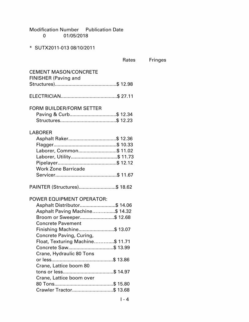
I - 4
Modification Number Publication Date
0 01/05/2018
* SUTX2011-013 08/10/2011
Rates Fringes
CEMENT MASON/CONCRETE
FINISHER (Paving and
Structures).............................................$ 12.98
ELECTRICIAN.........................................$ 27.11
FORM BUILDER/FORM SETTER
Paving & Curb..................................$ 12.34
Structures.........................................$ 12.23
LABORER
Asphalt Raker...................................$ 12.36
Flagger..............................................$ 10.33
Laborer, Common............................$ 11.02
Laborer, Utility..................................$ 11.73
Pipelayer...........................................$ 12.12
Work Zone Barricade
Servicer.............................................$ 11.67
PAINTER (Structures)...........................$ 18.62
POWER EQUIPMENT OPERATOR:
Asphalt Distributor..........................$ 14.06
Asphalt Paving Machine………......$ 14.32
Broom or Sweeper.........................$ 12.68
Concrete Pavement
Finishing Machine..........................$ 13.07
Concrete Paving, Curing,
Float, Texturing Machine………....$ 11.71
Concrete Saw.................................$ 13.99
Crane, Hydraulic 80 Tons
or less.............................................$ 13.86
Crane, Lattice boom 80
tons or less.....................................$ 14.97
Crane, Lattice boom over
80 Tons...........................................$ 15.80
Crawler Tractor..............................$ 13.68
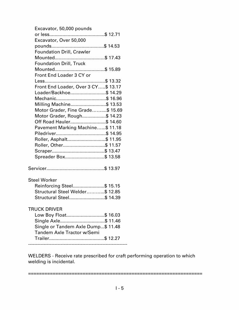
I - 5
Excavator, 50,000 pounds
or less..........................................$ 12.71
Excavator, Over 50,000
pounds........................................$ 14.53
Foundation Drill, Crawler
Mounted......................................$ 17.43
Foundation Drill, Truck
Mounted......................................$ 15.89
Front End Loader 3 CY or
Less..............................................$ 13.32
Front End Loader, Over 3 CY…..$ 13.17
Loader/Backhoe...........................$ 14.29
Mechanic......................................$ 16.96
Milling Machine...........................$ 13.53
Motor Grader, Fine Grade……....$ 15.69
Motor Grader, Rough..................$ 14.23
Off Road Hauler...........................$ 14.60
Pavement Marking Machine…...$ 11.18
Piledriver......................................$ 14.95
Roller, Asphalt.............................$ 11.95
Roller, Other................................$ 11.57
Scraper........................................$ 13.47
Spreader Box..............................$ 13.58
Servicer............................................$ 13.97
Steel Worker
Reinforcing Steel........................$ 15.15
Structural Steel Welder………...$ 12.85
Structural Steel...........................$ 14.39
TRUCK DRIVER
Low Boy Float.............................$ 16.03
Single Axle..................................$ 11.46
Single or Tandem Axle Dump...$ 11.48
Tandem Axle Tractor w/Semi
Trailer..........................................$ 12.27
----------------------------------------------------------------
WELDERS - Receive rate prescribed for craft performing operation to which
welding is incidental.
================================================================
I - 6
Note: Executive Order (EO) 13706, Establishing Paid Sick Leave for Federal
Contractors applies to all contracts subject to the Davis-Bacon Act for which the
contract is awarded (and any solicitation was issued) on or after January 1, 2017.
If this contract is covered by the EO, the contractor must provide employees with
1 hour of paid sick leave for every 30 hours they work, up to 56 hours of paid sick
leave each year. Employees must be permitted to use paid sick leave for their own
illness, injury or other health-related needs, including preventive care; to assist a
family member (or person who is like family to the employee) who is ill, injured,
or has other health-related needs, including preventive care; or for reasons
resulting from, or to assist a family member (or person who is like family to the
employee) who is a victim of, domestic violence, sexual assault, or stalking.
Additional information on contractor requirements and worker protections under
the EO is available at www.dol.gov/whd/govcontracts.
Unlisted classifications needed for work not included within the scope of the
classifications listed may be added after award only as provided in the labor
standards contract clauses (29CFR 5.5 (a) (1) (ii)).
----------------------------------------------------------------
The body of each wage determination lists the classification and wage rates that
have been found to be prevailing for the cited type(s) of construction in the area
covered by the wage determination. The classifications are listed in alphabetical
order of "identifiers" that indicate whether the particular rate is a union rate
(current union negotiated rate for local), a survey rate (weighted average rate) or a
union average rate (weighted union average rate).
Union Rate Identifiers
A four-letter classification abbreviation identifier enclosed in dotted lines
beginning with characters other than "SU" or "UAVG" denotes that the union
classification and rate were prevailing for that classification in the survey.
Example: PLUM0198-005 07/01/2014. PLUM is an abbreviation identifier of the
union which prevailed in the survey for this classification, which in this example
would be Plumbers. 0198 indicates the local union number or district council
number where applicable, i.e., Plumbers Local 0198. The next number, 005 in the
example, is an internal number used in processing the wage determination.
07/01/2014 is the effective date of the most current negotiated rate, which in this
example is July 1, 2014.
Union prevailing wage rates are updated to reflect all rate changes in the
collective bargaining agreement (CBA) governing this classification and rate.
I - 7
Survey Rate Identifiers
Classifications listed under the "SU" identifier indicate that no one rate prevailed
for this classification in the survey and the published rate is derived by computing
a weighted average rate based on all the rates reported in the survey for that
classification. As this weighted average rate includes all rates reported in the
survey, it may include both union and non-union rates. Example: SULA2012-007
5/13/2014. SU indicates the rates are survey rates based on a weighted average
calculation of rates and are not majority rates. LA indicates the State of Louisiana.
2012 is the year of survey on which these classifications and rates are based. The
next number, 007 in the example, is an internal number used in producing the
wage determination. 5/13/2014 indicates the survey completion date for the
classifications and rates under that identifier.
Survey wage rates are not updated and remain in effect until a new survey is
conducted.
Union Average Rate Identifiers
Classification(s) listed under the UAVG identifier indicate that no single majority
rate prevailed for those classifications; however, 100% of the data reported for the
classifications was union data. EXAMPLE: UAVG-OH-0010 08/29/2014. UAVG
indicates that the rate is a weighted union average rate. OH indicates the state.
The next number, 0010 in the example, is an internal number used in producing
the wage determination. 08/29/2014 indicates the survey completion date for the
classifications and rates under that identifier.
A UAVG rate will be updated once a year, usually in January of each year, to
reflect a weighted average of the current negotiated/CBA rate of the union locals
from which the rate is based.
----------------------------------------------------------------
WAGE DETERMINATION APPEALS PROCESS
1.) Has there been an initial decision in the matter? This can be:
* an existing published wage determination
* a survey underlying a wage determination
* a Wage and Hour Division letter setting forth a position on a wage
determination matter
* a conformance (additional classification and rate) ruling
I - 8
On survey related matters, initial contact, including requests for summaries of
surveys, should be with the Wage and Hour Regional Office for the area in which
the survey was conducted because those Regional Offices have responsibility for
the Davis-Bacon survey program. If the response from this initial contact is not
satisfactory, then the process described in 2.) and 3.) should be followed.
With regard to any other matter not yet ripe for the formal process described
here, initial contact should be with the Branch of Construction Wage
Determinations. Write to:
Branch of Construction Wage Determinations
Wage and Hour Division
U.S. Department of Labor
200 Constitution Avenue, N.W.
Washington, DC 20210
2.) If the answer to the question in 1.) is yes, then an interested party (those
affected by the action) can request review and reconsideration from the Wage and
Hour Administrator (See 29 CFR Part 1.8 and 29 CFR Part 7). Write to:
Wage and Hour Administrator
U.S. Department of Labor
200 Constitution Avenue, N.W.
Washington, DC 20210
The request should be accompanied by a full statement of the interested party's
position and by any information (wage payment data, project description, area
practice material, etc.) that the requestor considers relevant to the issue.
3.) If the decision of the Administrator is not favorable, an interested party may
appeal directly to the Administrative Review Board (formerly the Wage Appeals
Board). Write to:
Administrative Review Board
U.S. Department of Labor
200 Constitution Avenue, N.W.
Washington, DC 20210
4.) All decisions by the Administrative Review Board are final.
================================================================
END OF GENERAL DECISION
GEOTECHNICAL INVESTIGATIONS
FINAL REPORT OF GEOTECHNICAL SERVICES LAKESHORE DRIVE WIDENING
PORT OF PORT ARTHUR PORT ARTHUR, TEXAS
Prepared for:
Bob Shaw Consulting Engineers 4749 Twin City Highway, Suite 305
Port Arthur, Texas 77642
Prepared by:
Tolunay-Wong Engineers, Inc. 2455 West Cardinal Drive, Suite A
Beaumont, Texas 77705
November 10, 2017
Project No. 17.23.039 / Report No. 89115
2455 West Cardinal Drive, Suite A • Beaumont, Texas 77705 • Phone (409) 840-4214 • Fax (409) 840-4259
November 10, 2017
Bob Shaw Consulting Engineers 4749 Twin City Highway, Suite 305 Port Arthur, Texas 77642
Attn: Mr. Ed Long, P.E. [email protected]
Re: Final Report of Geotechnical Services Lakeshore Drive Widening Port of Port Arthur Port Arthur, Texas TWE Project No. 17.23.039 / Report No. 89115
Dear Mr. Long,
Tolunay-Wong Engineers, Inc. (TWE) is pleased to submit this final report of our geotechnical study for the above referenced project. This final report contains a detailed description of the field and laboratory services performed for our study as well as our geotechnical design and construction recommendations for the widening of Lakeshore Drive at the Port of Port Arthur in Port Arthur, Texas.
This final report and its contents supersede and replace all previous information, recommendations and transmittals provided by TWE for the referenced project. We appreciate the opportunity to work with you on this phase of the project and look forward to the opportunity to provide additional services as the project progresses. If you have any questions regarding this final report or if we can be of further assistance, please contact us.
Sincerely,
TOLUNAY-WONG ENGINEERS, INC. Texas Board of Professional Engineers Firm Registration No. F-000124
Armando Gomez Jr., E.I.T. Tyler G. Henneke, P.E. Geotechnical Department Manager Branch Manager Beaumont, Texas Beaumont, Texas
AG/TGH/ag/tgh
TWE Project No. 17.23.039 i Report No. 89115
TABLE OF CONTENTS
1 INTRODUCTION AND PROJECT DESCRIPTION 1-1 1.1 Introduction 1-1 1.2 Project Description 1-1
2 PURPOSE AND SCOPE OF SERVICES 2-1
3 FIELD PROGRAM 3-1 3.1 Test Borings 3-1
4 LABORATORY SERVICES 4-1
5 EXISTING SITE CONDITIONS 5-1 5.1 Existing Roadway Surface Conditions 5-1 5.2 Interior Pavement Sections 5-3 5.3 Exterior Pavement Shoulder Conditions 5-4
6 GEOTECHNICAL RECOMMENDATIONS 6-1 6.1 Discussion 6-1
6.2 Flexible Pavement Design 6-1
6.3 Flexible Pavement Construction 6-5
7 LIMITATIONS AND DESIGN REVIEW 7-1 7.1 Limitations 7-1 7.2 Design Review and Construction Monitoring 7-1 7.3 Closing Remarks 7-1
TWE Project No. 17.23.039 ii Report No. 89115
TABLES AND APPENDICES
TABLES
Table 4-1 Laboratory Testing Program 4-1
Table 6-1 Existing Pavement Section Structural Number 6-2 Test Boring PC-1 (Sta. 2+00)
Table 6-2 Existing Pavement Section Structural Number 6-2 Test Boring PC-2 (Sta. 8+00)
Table 6-3 Existing Pavement Section Structural Number 6-2 Test Boring PC-3 (Sta. 13+00)
Table 6-4 Design 18-kip ESALs 6-3
Table 6-5 Design Pavement Section Structural Number 6-3
Table 6-6 New Pavement Section - Existing Interior Roadway 6-4 Sta. 0+00 to Sta. 10+50
Table 6-7 New Pavement Section - Proposed Widening Areas 6-4 Sta. 0+00 to Sta. 10+50
Table 6-8 New Pavement Section - Existing Roadway 6-5 Sta. 10+50 to Sta. 14+09.13
APPENDICES
Appendix A: Preliminary Project Exhibits and Drawings Bob Shaw Consulting Engineers
Appendix B: Test Boring Location Plan TWE Drawing No. 17.23.039-1
Appendix C: TWE Logs of Borings and a Key to Terms and Symbols used on Boring Logs
Appendix D: Laboratory Moisture-Density Relations and CBR Test Results on Combined Bulk Samples
TWE Project No. 17.23.039 1-1 Report No. 89115
1 INTRODUCTION AND PROJECT DESCRIPTION
1.1 Introduction
This final report presents the results of our geotechnical engineering study performed for the widening of Lakeshore Drive at the Port of Port Arthur (PoPA) in Port Arthur, Texas. Our study was conducted in accordance with TWE Proposal No. P17-B271 (Revision 1) dated February 13, 2017 and authorized by Ed Long, P.E. of Bob Shaw Consulting Engineers on March 16, 2017.
1.2 Project Description
The project consists of widening approximately 1,400-ft of Lakeshore Drive at the PoPA in Port Arthur, Texas. The alignment runs from the PoPA entrance gate to Houston Avenue. Based on drawings provided by the Client, the existing roadway is currently 28-ft wide which will be widened to 44-ft from Sta. 0+00 (Inside Port Gate) to Sta. 10+50 (Railroad Crossing).
The new widened section will consist of three (3) 14-ft wide lanes to accommodate the increase of commercial and personal vehicle traffic to the PoPA. Within this widened section, new shoulders will be constructed on each side of the existing roadway which will consist of prepared subgrade, new subbase and new base materials to match elevation of the existing interior roadway. New monolithic leveling and surface courses with reinforcement grid will then be installed over the entire 44-ft width of the roadway encompassing both the existing interior section and new widened portions.
From Sta. 10+50 (Railroad Crossing) to Sta. 14+09.13 (Houston Avenue), the existing roadway will be milled in a tapered fashion to the extents of the existing concrete curb and gutter and then overlaid with new leveling and surface courses including reinforcement grid. Additional modifications to accommodate the widened roadway include extended railroad grade crossings, reshaping of roadside ditches and adding culverts for improved drainage. Project exhibits and drawings, provided by the Client, are provided in Appendix A of this final report.
TWE Project No. 17.23.039 2-1 Report No. 89115
2 PURPOSE AND SCOPE OF SERVICES
The purposes of our geotechnical engineering study were to investigate the existing roadway conditions and to provide geotechnical design and construction recommendations to support the proposed widening of the roadway. Our scope of services for the project consisted of:
1. Performing six (6) test borings to depths of 6-ft below existing grade within the roadway alignment to determine existing pavement section material types, thicknesses and subgrade soil conditions;
2. Performing geotechnical laboratory tests on recovered subgrade soil samples to evaluate the physical and engineering properties of the soils encountered;
3. Providing a discussion and conclusion of our findings from the field program and laboratory services; and,
4. Providing geotechnical design and construction recommendations for the proposed roadway widening including flexible pavement design parameters, approximate traffic loading estimates, suitable pavement material types and thicknesses, site and subgrade preparation, excavation considerations, pavement installation and quality control testing and inspection guidelines.
Our scope did not include any environmental assessments for the presence or absence of wetlands or of hazardous or toxic materials within or on the soil, air, or water within this project alignment. Any statements in this report or on the boring log regarding odors, colors, or unusual or suspicious items or conditions are strictly for the information of the Client. A geological fault study was also beyond the scope of our study.
TWE Project No. 17.23.039 3-1 Report No. 89115
3 FIELD PROGRAM
3.1 Test Borings
TWE conducted shallow subsurface explorations within the project alignment by performing six (6) test borings to depths of 6-ft below existing grade. Three (3) test borings, PC-1 through PC-3, were performed within existing pavement areas to determine type and thickness of existing pavement materials as well as subgrade soil conditions. The three (3) test borings performed outside of existing pavement areas, HA/BS-1 through HA/BS-3, were performed to determine native soil conditions in proposed widening areas. The test boring locations are provided on TWE Drawing No. 17.23.039-1 in Appendix B of this report.
3.1.1 Sampling Methods
Stand-mounted concrete coring equipment was used at test boring locations PC-1 through PC-3 to obtain measurements of each existing pavement layer. At all test boring locations, hand-auger boring equipment was used to obtain samples of the existing subgrade soils to depths of 6-ft. Subgrade soil samples were obtained using an open chamber bucket sampler or thin-walled tubes at 1-ft depth intervals. Dynamic Cone Penetrometer (DCP) tests were performed at every 1-ft depth interval. Bulk grab samples were also collected at each test boring location for laboratory testing purposes.
The soil samples were visually-classified by our Geotechnician prior to placing them in moisture-sealed bags and transporting them to our laboratory. The test boring locations were backfilled with soil cuttings and/or bentonite chips as well as appropriate pavement repair materials. The recovered soil sample depths and field strength measurements are presented on the boring logs in Appendix C.
3.1.2 Boring Logs
Our interpretations of general subsurface conditions at the test boring location are included on the project boring logs in Appendix C. The interpretations of material types throughout the boring depths and the locations of material changes were based on visual classifications during field sampling and laboratory testing using the Standard Practice for Classification of Soils for Engineering Purposes (Unified Soil Classification System) [ASTM D2487] and the Standard Practice for Description and Identification of Soils (Visual-Manual Procedure) [ASTM D2488]. The boring logs include the type and interval depth for each sample along with corresponding field strength measurements. The project boring logs and a key to the terms and symbols used on boring logs are presented in Appendix C.
3.1.3 Groundwater Measurements
Free water (perched) was encountered at a depth of 5-ft to 6-ft within the test borings during hand-augering. Static water levels were not obtained due to caving of the boreholes immediately after encountering the perched water levels. Groundwater or perched water levels within the project alignment could fluctuate with climatic and seasonal variations and should be verified before construction.
TWE Project No. 17.23.039 4-1 Report No. 89115
4 LABORATORY SERVICES
A laboratory testing program was conducted on selected samples to assist in classification and evaluation of the physical and engineering properties of the subgrade soils encountered within the test borings. Laboratory tests were performed in general accordance with ASTM International standards. The types and brief descriptions of the laboratory tests performed are presented below.
Table 4-1
Laboratory Testing Program
Type of Test Testing Method
Compaction Characteristics of Soil using Standard Effort (Proctor) ASTM D698
Amount of Materials in Soils Finer than Sieve No. 200 ASTM D1140
California Bearing Ratio (CBR) ASTM D1883
Natural Water Content of Soil ASTM D2216
Atterberg Limits ASTM D4318
Standard index classification test results from the laboratory are presented on the test boring logs in Appendix C of this final report. The results of moisture-density relation and CBR tests on a combined sample of native clay subgrade material are presented in Appendix D.
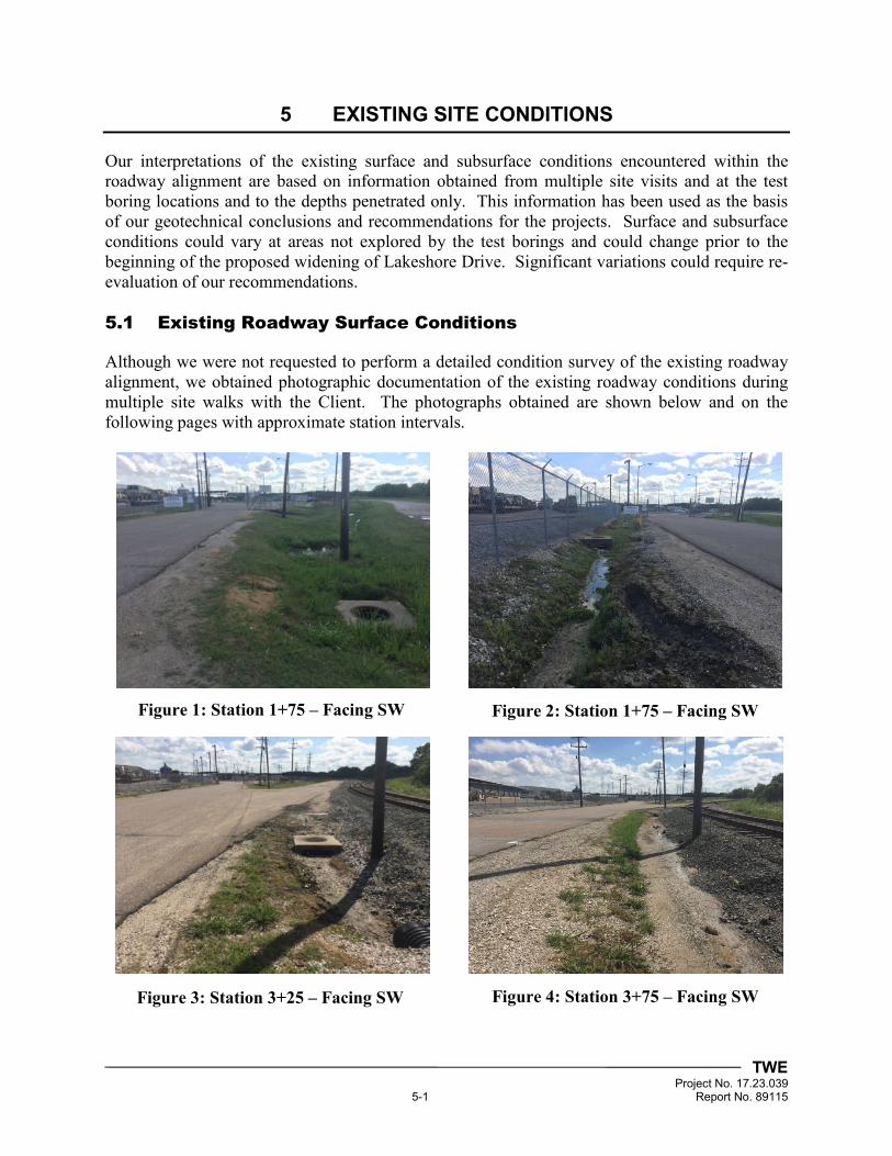
TWE Project No. 17.23.039 5-1 Report No. 89115
5 EXISTING SITE CONDITIONS
Our interpretations of the existing surface and subsurface conditions encountered within the roadway alignment are based on information obtained from multiple site visits and at the test boring locations and to the depths penetrated only. This information has been used as the basis of our geotechnical conclusions and recommendations for the projects. Surface and subsurface conditions could vary at areas not explored by the test borings and could change prior to the beginning of the proposed widening of Lakeshore Drive. Significant variations could require re-evaluation of our recommendations.
5.1 Existing Roadway Surface Conditions
Although we were not requested to perform a detailed condition survey of the existing roadway alignment, we obtained photographic documentation of the existing roadway conditions during multiple site walks with the Client. The photographs obtained are shown below and on the following pages with approximate station intervals.
Figure 1: Station 1+75 – Facing SW Figure 2: Station 1+75 – Facing SW
Figure 3: Station 3+25 – Facing SW Figure 4: Station 3+75 – Facing SW
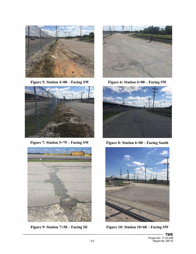
TWE Project No. 17.23.039 5-2 Report No. 89115
Figure 5: Station 4+00 – Facing SW Figure 6: Station 4+00 – Facing SW
Figure 7: Station 5+75 – Facing SW Figure 8: Station 6+00 – Facing South
Figure 9: Station 7+50 – Facing SE Figure 10: Station 10+60 – Facing SW
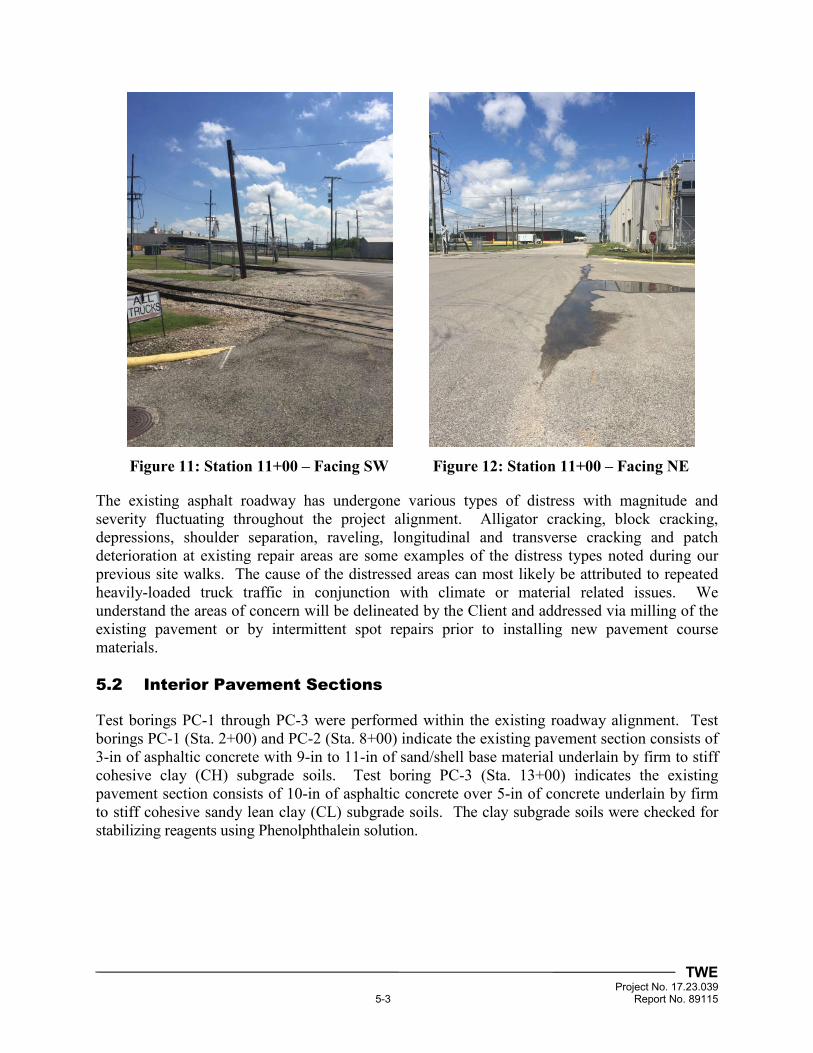
TWE Project No. 17.23.039 5-3 Report No. 89115
The existing asphalt roadway has undergone various types of distress with magnitude and severity fluctuating throughout the project alignment. Alligator cracking, block cracking, depressions, shoulder separation, raveling, longitudinal and transverse cracking and patch deterioration at existing repair areas are some examples of the distress types noted during our previous site walks. The cause of the distressed areas can most likely be attributed to repeated heavily-loaded truck traffic in conjunction with climate or material related issues. We understand the areas of concern will be delineated by the Client and addressed via milling of the existing pavement or by intermittent spot repairs prior to installing new pavement course materials.
5.2 Interior Pavement Sections
Test borings PC-1 through PC-3 were performed within the existing roadway alignment. Test borings PC-1 (Sta. 2+00) and PC-2 (Sta. 8+00) indicate the existing pavement section consists of 3-in of asphaltic concrete with 9-in to 11-in of sand/shell base material underlain by firm to stiff cohesive clay (CH) subgrade soils. Test boring PC-3 (Sta. 13+00) indicates the existing pavement section consists of 10-in of asphaltic concrete over 5-in of concrete underlain by firm to stiff cohesive sandy lean clay (CL) subgrade soils. The clay subgrade soils were checked for stabilizing reagents using Phenolphthalein solution.
Figure 11: Station 11+00 – Facing SW Figure 12: Station 11+00 – Facing NE
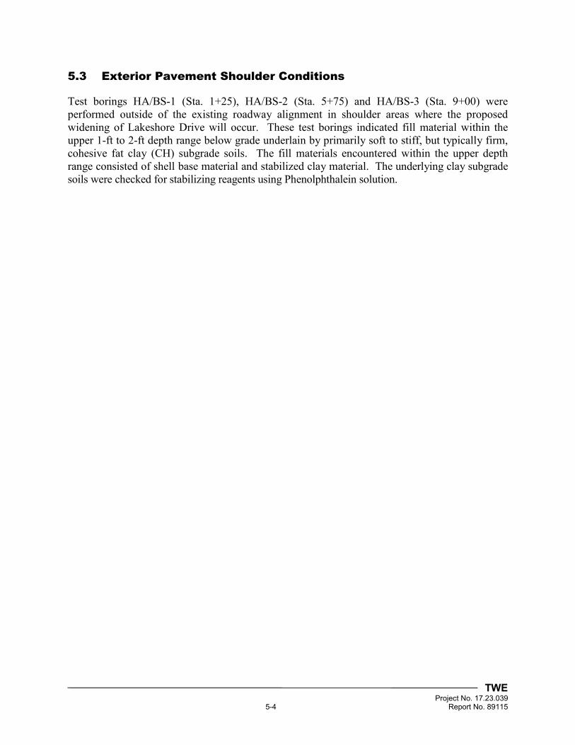
TWE Project No. 17.23.039 5-4 Report No. 89115
5.3 Exterior Pavement Shoulder Conditions
Test borings HA/BS-1 (Sta. 1+25), HA/BS-2 (Sta. 5+75) and HA/BS-3 (Sta. 9+00) were performed outside of the existing roadway alignment in shoulder areas where the proposed widening of Lakeshore Drive will occur. These test borings indicated fill material within the upper 1-ft to 2-ft depth range below grade underlain by primarily soft to stiff, but typically firm, cohesive fat clay (CH) subgrade soils. The fill materials encountered within the upper depth range consisted of shell base material and stabilized clay material. The underlying clay subgrade soils were checked for stabilizing reagents using Phenolphthalein solution.
TWE Project No. 17.23.039 6-1 Report No. 89115
6 GEOTECHNICAL RECOMMENDATIONS
6.1 Discussion
Lakeshore Drive is primarily used for ingress and egress to and from the PoPA. The proposed widening from Sta. 0+00 (Inside Port Gate) to Sta. 10+50 (Railroad Crossing) and resurfacing of Sta. 10+50 (Railroad Crossing) to Sta. 14+09.13 (Houston Avenue) will address existing and future Client demand of heavily-loaded daily truck traffic. The widening is also intended to enhance safety of the roadway and to reduce congestion for all PoPA users.
Based on the conditions encountered during our field program and the anticipated methods of construction, we developed recommendations for the roadway alignment based on the two (2) sections identified previously: Sta. 0+00 (Inside Port Gate) to Sta. 10+50 (Railroad Crossing) and Sta. 10+50 (Railroad Crossing) to Sta. 14+09.13 (Houston Avenue).
The new widened section from Sta. 0+00 (Inside Port Gate) to Sta. 10+50 (Railroad Crossing) will include new shoulders constructed on each side of the existing roadway which will consist of prepared subgrade, new subbase and new base materials to match elevation of the existing interior roadway. New monolithic leveling and surface courses with reinforcement grid will then be installed over the entire 44-ft width of the roadway encompassing both the existing interior section and new widened portions.
From Sta. 10+50 (Railroad Crossing) to Sta. 14+09.13 (Houston Avenue), the existing roadway will be milled in a tapered fashion to the extents of the existing concrete curb and gutter and then overlaid with new leveling and surface courses including reinforcement grid.
Project exhibits and drawings, provided by the Client, are provided in Appendix A of this final report. Using the available project information provided by the Client, the American Association of State Highway and Transportation Officials (AASHTO) Guide for Design of Pavement Structures and the Texas Department of Transportation (TxDOT) Standard Specifications for Construction and Maintenance of Highways, Streets and Bridges, our geotechnical design and construction recommendations for flexible pavement systems associated with the project are provided in the following report sections.
6.2 Flexible Pavement Design
6.2.1 Structural Numbers of Existing Pavement Sections
Based on test borings PC-1, PC-2 and PC-3, we estimated the Structural Numbers (SNs) of the existing pavement sections to be on the order of 3.82 to 6.40 as presented in Tables 6-1 through 6-3 on the following page. These structural numbers were used as a general guide for comparison with design structural numbers for new pavement sections associated with the project.
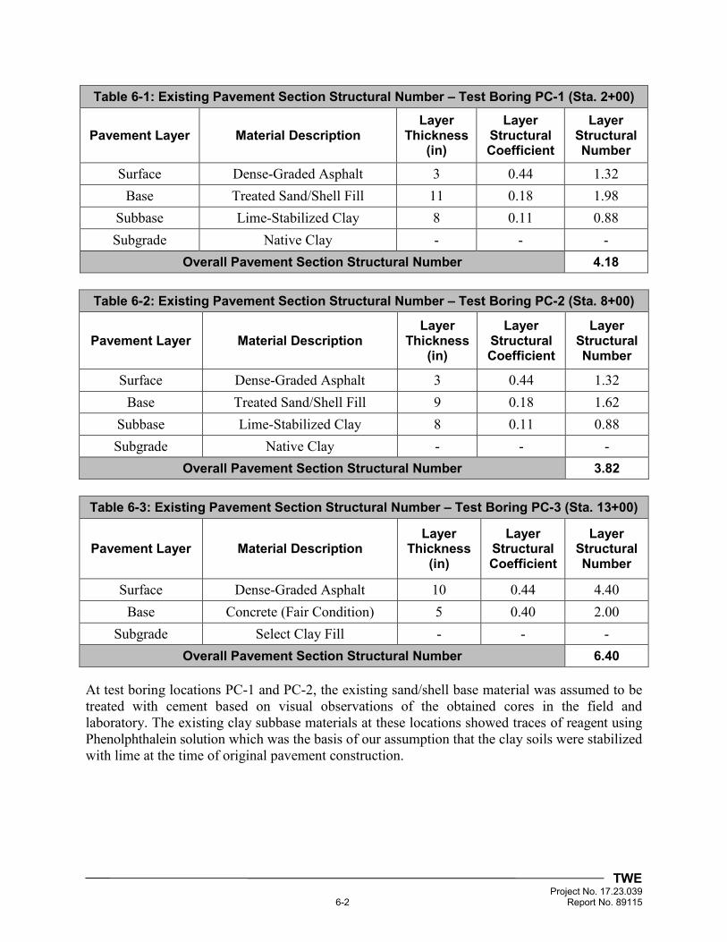
TWE Project No. 17.23.039 6-2 Report No. 89115
Table 6-1: Existing Pavement Section Structural Number – Test Boring PC-1 (Sta. 2+00)
Pavement Layer Material Description Layer
Thickness (in)
Layer Structural Coefficient
Layer Structural Number
Surface Dense-Graded Asphalt 3 0.44 1.32
Base Treated Sand/Shell Fill 11 0.18 1.98
Subbase Lime-Stabilized Clay 8 0.11 0.88
Subgrade Native Clay - - -
Overall Pavement Section Structural Number 4.18
Table 6-2: Existing Pavement Section Structural Number – Test Boring PC-2 (Sta. 8+00)
Pavement Layer Material Description Layer
Thickness (in)
Layer Structural Coefficient
Layer Structural Number
Surface Dense-Graded Asphalt 3 0.44 1.32
Base Treated Sand/Shell Fill 9 0.18 1.62
Subbase Lime-Stabilized Clay 8 0.11 0.88
Subgrade Native Clay - - -
Overall Pavement Section Structural Number 3.82
Table 6-3: Existing Pavement Section Structural Number – Test Boring PC-3 (Sta. 13+00)
Pavement Layer Material Description Layer
Thickness (in)
Layer Structural Coefficient
Layer Structural Number
Surface Dense-Graded Asphalt 10 0.44 4.40
Base Concrete (Fair Condition) 5 0.40 2.00
Subgrade Select Clay Fill - - -
Overall Pavement Section Structural Number 6.40
At test boring locations PC-1 and PC-2, the existing sand/shell base material was assumed to be treated with cement based on visual observations of the obtained cores in the field and laboratory. The existing clay subbase materials at these locations showed traces of reagent using Phenolphthalein solution which was the basis of our assumption that the clay soils were stabilized with lime at the time of original pavement construction.
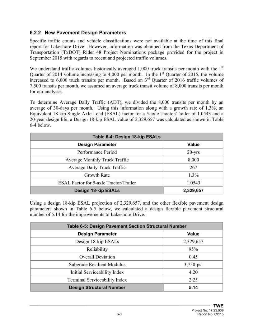
TWE Project No. 17.23.039 6-3 Report No. 89115
6.2.2 New Pavement Design Parameters
Specific traffic counts and vehicle classifications were not available at the time of this final report for Lakeshore Drive. However, information was obtained from the Texas Department of Transportation (TxDOT) Rider 48 Project Nominations package provided for the project in September 2015 with regards to recent and projected traffic volumes.
We understand traffic volumes historically averaged 1,000 truck transits per month with the 1st Quarter of 2014 volume increasing to 4,000 per month. In the 1st Quarter of 2015, the volume increased to 6,000 truck transits per month. Based on 3rd Quarter of 2016 traffic volumes of 7,500 transits per month, we assumed an average truck transit volume of 8,000 transits per month for our analyses.
To determine Average Daily Traffic (ADT), we divided the 8,000 transits per month by an average of 30-days per month. Using this information along with a growth rate of 1.3%, an Equivalent 18-kip Single Axle Load (ESAL) factor for a 5-axle Tractor/Trailer of 1.0543 and a 20-year design life, a Design 18-kip ESAL value of 2,329,657 was calculated as shown in Table 6-4 below.
Table 6-4: Design 18-kip ESALs
Design Parameter Value
Performance Period 20-yrs
Average Monthly Truck Traffic 8,000
Average Daily Truck Traffic 267
Growth Rate 1.3%
ESAL Factor for 5-axle Tractor/Trailer 1.0543
Design 18-kip ESALs 2,329,657
Using a design 18-kip ESAL projection of 2,329,657, and the other flexible pavement design parameters shown in Table 6-5 below, we calculated a design flexible pavement structural number of 5.14 for the improvements to Lakeshore Drive.
Table 6-5: Design Pavement Section Structural Number
Design Parameter Value
Design 18-kip ESALs 2,329,657
Reliability 95%
Overall Deviation 0.45
Subgrade Resilient Modulus 3,750-psi
Initial Serviceability Index 4.20
Terminal Serviceability Index 2.25
Design Structural Number 5.14
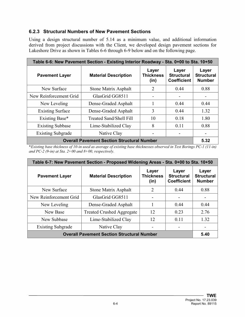
TWE Project No. 17.23.039 6-4 Report No. 89115
6.2.3 Structural Numbers of New Pavement Sections
Using a design structural number of 5.14 as a minimum value, and additional information derived from project discussions with the Client, we developed design pavement sections for Lakeshore Drive as shown in Tables 6-6 through 6-9 below and on the following page.
Table 6-6: New Pavement Section - Existing Interior Roadway - Sta. 0+00 to Sta. 10+50
Pavement Layer Material Description Layer
Thickness (in)
Layer Structural Coefficient
Layer Structural Number
New Surface Stone Matrix Asphalt 2 0.44 0.88
New Reinforcement Grid GlasGrid GG8511 - - -
New Leveling Dense-Graded Asphalt 1 0.44 0.44
Existing Surface Dense-Graded Asphalt 3 0.44 1.32
Existing Base* Treated Sand/Shell Fill 10 0.18 1.80
Existing Subbase Lime-Stabilized Clay 8 0.11 0.88
Existing Subgrade Native Clay - - -
Overall Pavement Section Structural Number 5.32
*Existing base thickness of 10-in used as average of existing base thicknesses observed in Test Borings PC-1 (11-in) and PC-2 (9-in) at Sta. 2+00 and 8+00, respectively.
Table 6-7: New Pavement Section - Proposed Widening Areas - Sta. 0+00 to Sta. 10+50
Pavement Layer Material Description Layer
Thickness (in)
Layer Structural Coefficient
Layer Structural Number
New Surface Stone Matrix Asphalt 2 0.44 0.88
New Reinforcement Grid GlasGrid GG8511 - - -
New Leveling Dense-Graded Asphalt 1 0.44 0.44
New Base Treated Crushed Aggregate 12 0.23 2.76
New Subbase Lime-Stabilized Clay 12 0.11 1.32
Existing Subgrade Native Clay - - -
Overall Pavement Section Structural Number 5.40
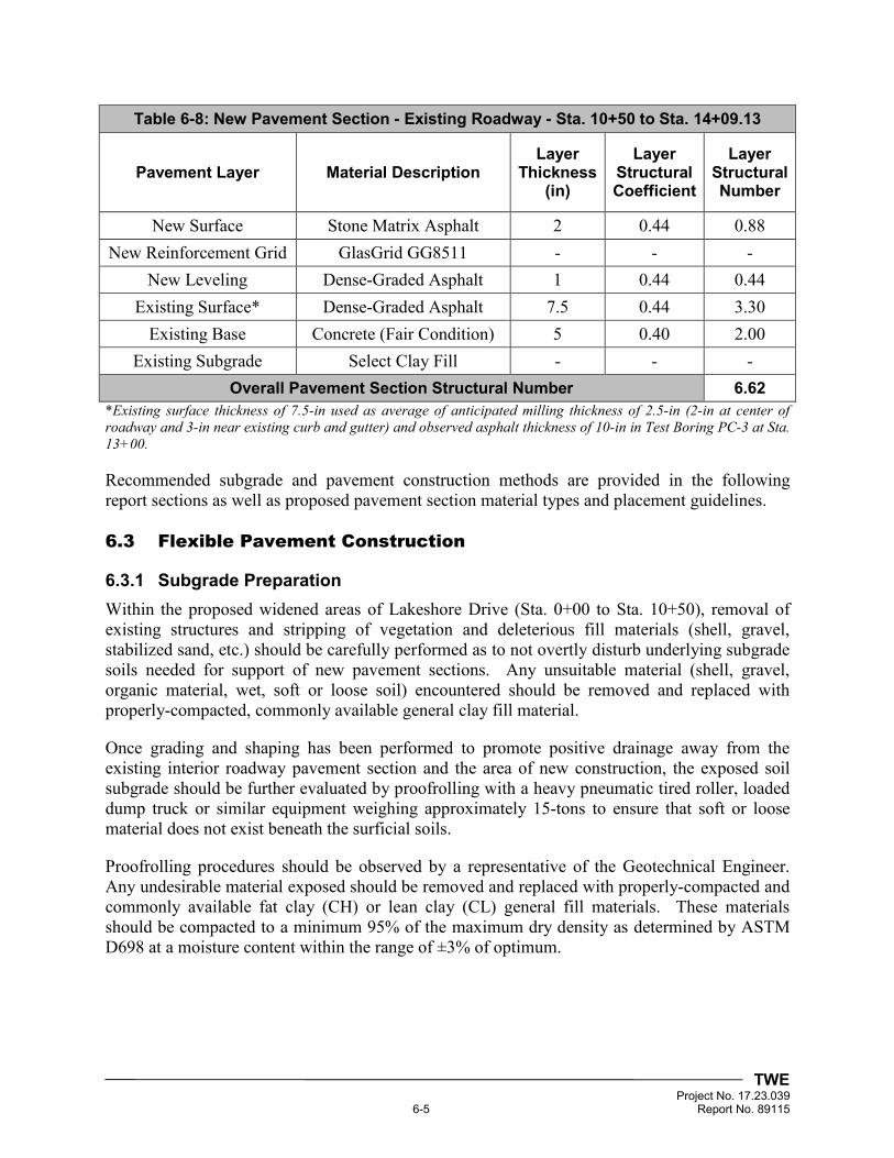
TWE Project No. 17.23.039 6-5 Report No. 89115
Table 6-8: New Pavement Section - Existing Roadway - Sta. 10+50 to Sta. 14+09.13
Pavement Layer Material Description Layer
Thickness (in)
Layer Structural Coefficient
Layer Structural Number
New Surface Stone Matrix Asphalt 2 0.44 0.88
New Reinforcement Grid GlasGrid GG8511 - - -
New Leveling Dense-Graded Asphalt 1 0.44 0.44
Existing Surface* Dense-Graded Asphalt 7.5 0.44 3.30
Existing Base Concrete (Fair Condition) 5 0.40 2.00
Existing Subgrade Select Clay Fill - - -
Overall Pavement Section Structural Number 6.62
*Existing surface thickness of 7.5-in used as average of anticipated milling thickness of 2.5-in (2-in at center of roadway and 3-in near existing curb and gutter) and observed asphalt thickness of 10-in in Test Boring PC-3 at Sta. 13+00.
Recommended subgrade and pavement construction methods are provided in the following report sections as well as proposed pavement section material types and placement guidelines.
6.3 Flexible Pavement Construction
6.3.1 Subgrade Preparation
Within the proposed widened areas of Lakeshore Drive (Sta. 0+00 to Sta. 10+50), removal of existing structures and stripping of vegetation and deleterious fill materials (shell, gravel, stabilized sand, etc.) should be carefully performed as to not overtly disturb underlying subgrade soils needed for support of new pavement sections. Any unsuitable material (shell, gravel, organic material, wet, soft or loose soil) encountered should be removed and replaced with properly-compacted, commonly available general clay fill material.
Once grading and shaping has been performed to promote positive drainage away from the existing interior roadway pavement section and the area of new construction, the exposed soil subgrade should be further evaluated by proofrolling with a heavy pneumatic tired roller, loaded dump truck or similar equipment weighing approximately 15-tons to ensure that soft or loose material does not exist beneath the surficial soils.
Proofrolling procedures should be observed by a representative of the Geotechnical Engineer. Any undesirable material exposed should be removed and replaced with properly-compacted and commonly available fat clay (CH) or lean clay (CL) general fill materials. These materials should be compacted to a minimum 95% of the maximum dry density as determined by ASTM D698 at a moisture content within the range of ±3% of optimum.
TWE Project No. 17.23.039 6-6 Report No. 89115
6.3.2 Lime-Stabilized Clay Subbase
Lime stabilization of clay subgrade soils is recommended for the proposed roadway widening areas (Sta. 0+00 to Sta. 10+50). Proper preparation and lime stabilization of the roadway subgrade soils will improve long-term pavement performance. However, due to space constraints within the project alignment and where the existing roadway will be widened, the Contractor should determine if lime-stabilized soils can be mixed-in-place or if imported lime-stabilized soils will be required.
Assuming lime-stabilized subbase soils will be road-mixed on-site, we recommend the exposed subgrade surface, at final subgrade elevation, be scarified and pulverized to a depth of 12-in and uniformly-mixed with hydrated lime in conformance with TxDOT 2014 Standard Specification Item 260 “Lime Treatment (Road-Mixed)”. For the native subgrade soils [fat clay (CH)] captured in Appendix D of this report, we estimate 8% hydrated lime by dry unit weight of soil will be required. Assuming an in-place dry unit weight of 100-pcf and a 12-in stabilization depth for the clay subgrade soils, 8% lime by dry unit weight equates to about 72-lbs of lime per square yard of treated subgrade. The actual quantity of lime required and optimum moisture content of the stabilized material should be determined after the roadway alignment is stripped and subgrade soils are exposed by use of a laboratory soil treatability study.
Dry hydrated lime or hydrated lime slurry used during chemical stabilization should meet the requirements of TxDOT Department Material Specification (DMS) 6350 “Lime and Lime Slurry.” Before applying lime in dry form, the prepared subgrade should be moisture-conditioned to approximately 2% above optimum moisture content. When necessary, sprinkling should be performed in accordance with TxDOT Standard Specification Item 204, “Sprinkling.” If the slurry placement method will be used, slurry should be free of objectionable materials and of uniform consistency during application. Slurry should be distributed uniformly by making successive passes over the prepared section of roadway until the specified lime content is reached.
Thorough initial mixing of the subgrade material and lime should be performed within 6-hr of application of lime using appropriate equipment. It is imperative that the moisture content of the material being treated is above the optimum moisture content to ensure adequate chemical reaction of the lime and subgrade materials. The treated mixture should be allowed to mellow for 1 to 4-days with sprinkling performed during both the mixing and mellowing operations to achieve adequate hydration and continuously moist conditions.
After mellowing, final mixing should be performed until a homogeneous, friable mixture is obtained prior to compaction. The lime-stabilized subbase materials should then be compacted (maximum 8-in loose measure lifts) to a minimum 95% of the maximum dry density as determined by ASTM D698 to within 1% below and 2% above optimum moisture content. A minimum of one (1) in-place density test should be performed per lift every 500-ft2 in accordance with ASTM D6938 at locations representative of the lime-stabilized subbase areas. Based on the PI of the native clay subgrade soils, a minimum curing time of 5-days is recommended unless proofrolling indicates adequate curing has been achieved.
TWE Project No. 17.23.039 6-7 Report No. 89115
Lime stabilization should extend at least 1-ft beyond the roadway edge to reduce effects of seasonal shrinking and swelling. Routine sampling and laboratory classification testing (moisture content and Atterberg limits) should be performed to verify the resulting plasticity indices (PI) of the stabilized materials is at/or below 25 or that maximum PI reduction has been achieved. Mechanical lime stabilization of the roadway subbase will not prevent normal seasonal movement of the underlying untreated clay subgrade materials. Therefore, good perimeter surface drainage with a minimum 2% slope away from the roadway is recommended.
6.3.3 Cement-Treated Crushed Aggregate
Cement-treated crushed aggregate base material will be utilized within the proposed widened areas of Lakeshore Drive (Sta. 0+00 to Sta. 10+50). Cement-treated base is also being considered for full-depth repair of existing pavement failures within the interior of Lakeshore Drive.
We anticipate cement-treated crushed aggregate for this project will be plant-mixed in accordance with TxDOT Item 276 “Cement Treatment (Plant-Mixed).” Hydraulic cement and crushed aggregate should be in accordance with TxDOT DMS-4600 “Hydraulic Cement” and TxDOT Item 247 “Flexible Base”, Type A, Grade 1-2, respectively. Mix designs should be provided for the target cement content necessary to produce a stabilized mixture meeting a compressive strength of 500-psi after 7-days (Class L).
If the plant-mixed method is utilized, the materials should be mixed thoroughly at the optimum moisture content of the mixture until homogeneity is achieved. The cement-treated base should be placed on properly-prepared and compacted lime-stabilized clay subbase. Cement-treated aggregate base material should only be placed in areas where compaction and finishing can be completed during the same working day. Vertical joints should be constructed between new cement-treated base and cement-treated base which has been in-place 4-hrs or longer by cutting back the face to approximately vertical.
Cement-treated aggregate base should be compacted in lifts (maximum 8-in loose measure) within 2-hr after plant-mixing water with dry material. Moisture content in the mixture at the plant should be adjusted so that it is within 2% of optimum during compaction as determined by ASTM D1557. The mixture should be compacted to at least 95% of the maximum dry density as determined by ASTM D1557. A minimum of one (1) in-place density test should be performed per lift every 500-ft2 in accordance with ASTM D6938 at locations representative of the cement-treated aggregate base areas. Once the cement-treated base is compacted and finished, curing by sprinkling should be performed for at least 3-days to maintain the moisture content no lower than 2% below optimum.
6.3.4 Dense-Graded Hot-Mix Asphalt
Type D dense-graded hot-mix asphaltic concrete (HMAC) is being considered for use as a leveling course across the entire roadway width for both project sections: Sta. 0+00 to 10+50 and Sta. 10+50 to 14+09.13. Prior to placing HMAC leveling courses, all base and pavement failures within the existing roadway interior should be repaired full depth with cement-treated aggregate base as described in Section 6.3.3 of this final report.
TWE Project No. 17.23.039 6-8 Report No. 89115
Type D HMAC should be a plant-mixed, hot-laid, dense-graded mixture of aggregate and asphalt binder having a fine surface meeting the requirements of TxDOT 2014 Standard Specifications Item 340 and specific criteria for the job mix formula. The Type D HMAC mix should be compacted uniformly to contain between 3% to 8% in-place air voids (92% to 97% of the maximum theoretical density) as measured by ASTM D2041. Pneumatic-tired rollers should be used to seal the surface unless excessive pickup of fines occurs.
On the first day of production, rolling patterns should be established which produce the desired in-place air voids. All compaction operations should be completed before the pavement temperature drops below 160°F unless otherwise directed by the project specifications. The compacted pavement should be allowed to cool to 160°F or lower before opening to traffic.
6.3.5 Reinforcement Grid
Based on the heavily-loaded truck traffic of Lakeshore Drive, we recommend a geosynthetic pavement interlayer be used to extend the service life of the proposed pavement systems and to mitigate the potential for migration of reflective cracks between new and existing pavement joints. We recommend a stress absorbing reinforcement grid such as the GlasGrid Pavement Reinforcement System, or approved equal, which is composed of a series of fiberglass strands coated with an elastomeric polymer and formed into a grid structure providing high tensile strength and high modulus of elasticity at low elongation.
Reinforcement grids used in asphalt pavements should be in accordance with TxDOT Special Specification 3006. We recommend GlasGrid GG8511, or approved equal, be used in between the Type D HMAC leveling course and the surficial Stone Matrix Asphalt (SMA) surface course. GlasGrid should be used full width from edge to edge of the widened or existing pavement structure and installed per Manufacturer recommendations. Transverse and longitudinal joint overlap should also be in accordance with Manufacturer recommendations.
A minimum 1-in thick leveling course of dense-graded HMAC is required prior to installing the reinforcement grid. The surface temperature of the pavement should be 70°F or higher before installing the grid. A non-tracking, polymer modified asphalt tack coat such as UltraFuse, or approved equal, should be used on clean and dry leveling course surfaces prior to placing reinforcement grid. The tack coat should not be placed on a wet or damp surface at any point during paving operations. All grid placed in a working day should be covered with asphalt surface course materials the same day.
6.3.6 Stone Matrix Asphalt
Stone Matrix Asphalt (SMA) is being considered for use as the surface course across the entire width of Lakeshore Drive. SMA should consist of a plant-mixed, hot-laid, compacted mixture of aggregate, asphalt binder and additives meeting the requirements of TxDOT Standard Specification Item 346 and specific criteria for the job mix formula developed for this project. Asphalt Suppliers and Contractors familiar with SMA job mix formulas should be contracted to produce and install SMA material.
TWE Project No. 17.23.039 6-9 Report No. 89115
SMA should be placed immediately after the non-tracking tack coat and reinforcement grid are installed. SMA should be placed in minimum 1.5-in thick compacted lifts and compacted uniformly to contain between 3% to 7% in-place air voids (93% to 97% of the maximum theoretical density) as measured by ASTM D2041. Pneumatic-tired rollers should be used to seal the surface unless excessive pickup of fines occurs.
On the first day of production, rolling patterns should be established which produce the desired in-place air voids. All compaction operations should be completed before the pavement temperature drops below 160°F unless otherwise directed by the project specifications. The compacted pavement should be allowed to cool to 160°F or lower before opening to traffic.
6.3.7 Pavement Maintenance and Drainage
Maintaining the improved roadway system to prevent infiltration of water into the pavement section is essential. Allowing water to enter the pavement section will result in high maintenance costs and premature pavement failure. Periodic maintenance should be performed on the roadway system to seal any surface cracks and to prevent infiltration of water. Many proprietary sealant materials are available to seal surface cracks.
Migration of water and moisture intrusion into pavement structures has long been recognized as a primary cause of distress. Appropriate longitudinal and transverse slopes can serve to propagate water off the roadway to minimize ponding. We recommend positive drainage be established away from the roadway so that perched or ponded water does not collect near the pavement section.
TWE Project No. 17.23.039 7-1 Report No. 89115
7 LIMITATIONS AND DESIGN REVIEW
7.1 Limitations
This final report has been prepared for the exclusive use of Bob Shaw Consulting Engineers and their project team for specific application to the Lakeshore Drive Widening Project at the Port of Port Arthur in Port Arthur, Texas. Our final report has been prepared in accordance with generally-accepted geotechnical engineering practice common to the local area. No other warranty, express or implied is made.
The analyses and recommendations contained in this final report are based on the data obtained from the referenced test borings within the existing alignment of Lakeshore Drive. The test borings indicate subsurface conditions only at the specific locations and times performed and only to the depths penetrated. The test borings do not necessarily reflect material variations that could exist at other locations within the roadway alignment. Such conditions can be confirmed only during the construction phase of the project or via additional geotechnical investigations. Our recommendations presented in this final report must be re-evaluated if conditions during construction are different from those described in this final report.
If any changes in the nature, design or location of the project are planned, the conclusions and recommendations contained in this final report should not be considered valid unless the changes are reviewed and the conclusions modified or verified in writing by TWE. TWE is not responsible for any claims, damages or liability associated with interpretation or reuse of the subsurface data or engineering analyses without the expressed written authorization of TWE.
7.2 Design Review and Construction Monitoring
Review of the project plans and specifications should be performed by TWE before release. The review is aimed at determining if the geotechnical recommendations contained in this final report have been properly-interpreted. Design review is not within our current authorized scope of work for this study.
Construction surveillance is recommended and has been assumed in preparing our geotechnical recommendations. These field services are required to check for changes in conditions that could result in modifications to our recommendations. The quality of the construction practices will affect roadway performance and should be monitored by the Geotechnical Engineer.
7.3 Closing Remarks
We appreciate the opportunity to be of service during this phase of the project and we look forward to continuing our services during the construction phase and on future projects.
TWE Project No. 17.23.039 Report No. 89115
APPENDIX A
PROJECT EXHIBITS AND DRAWINGS BOB SHAW CONSULTING ENGINEERS
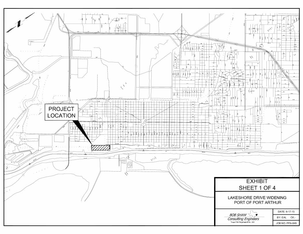
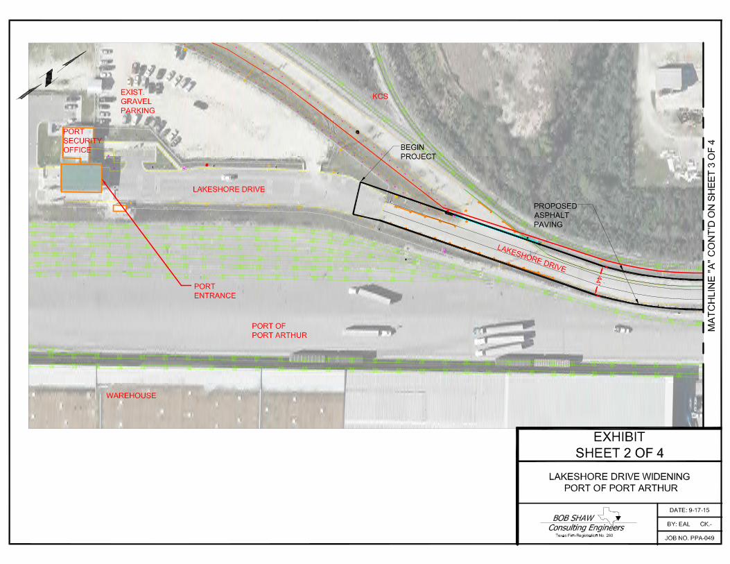
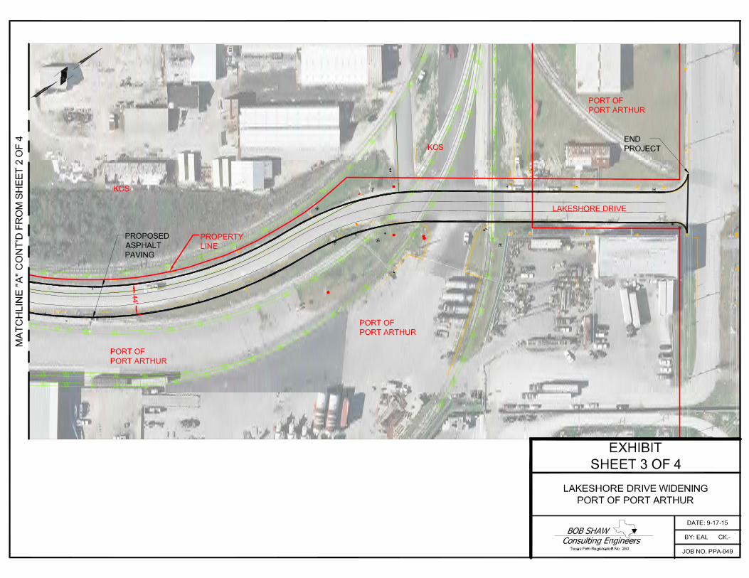
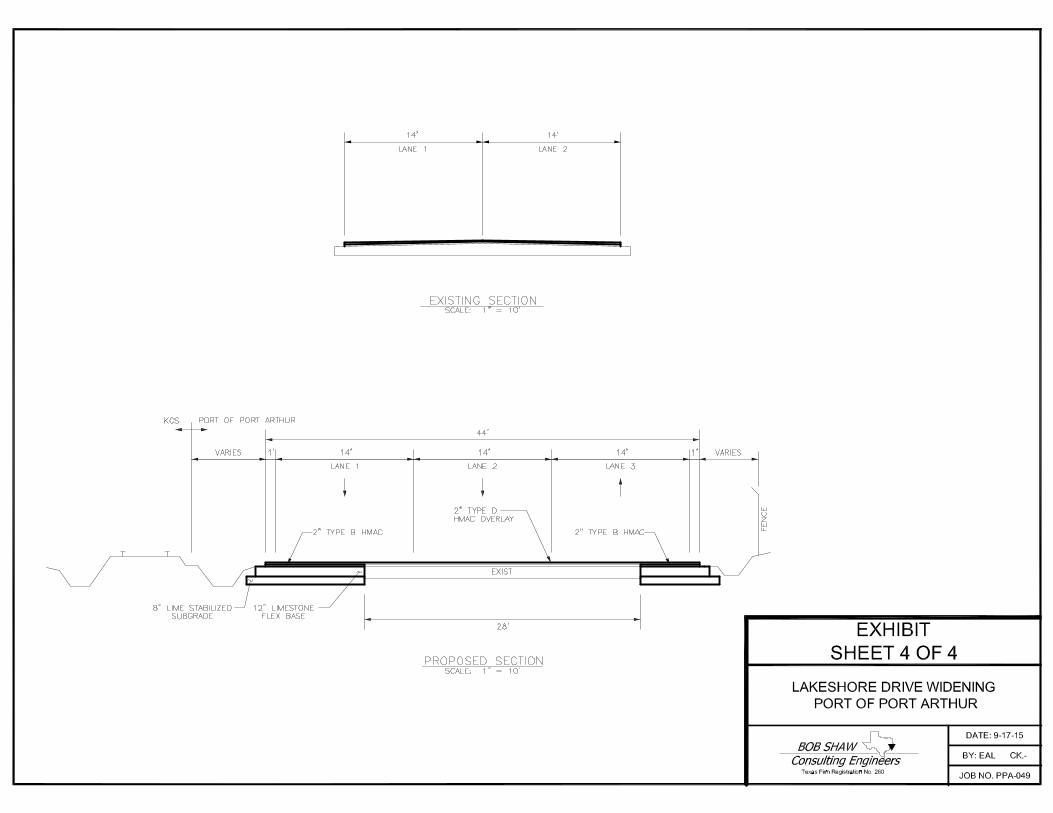
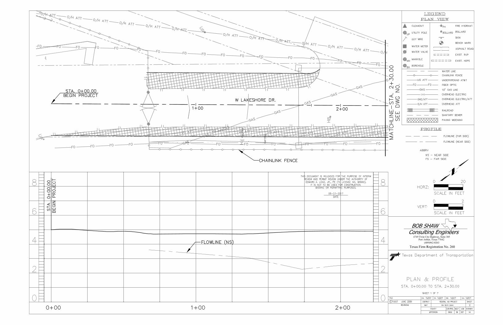

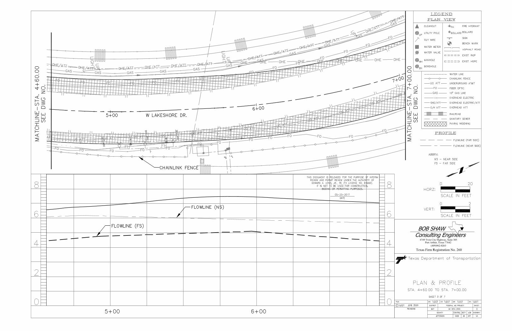
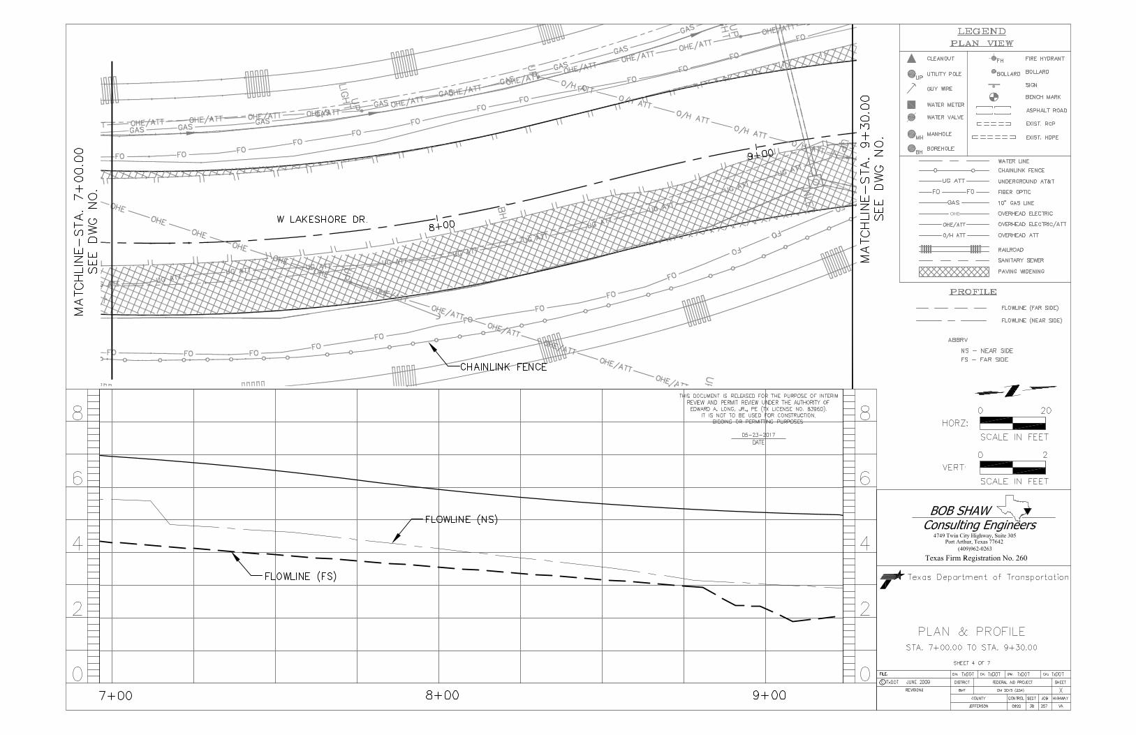
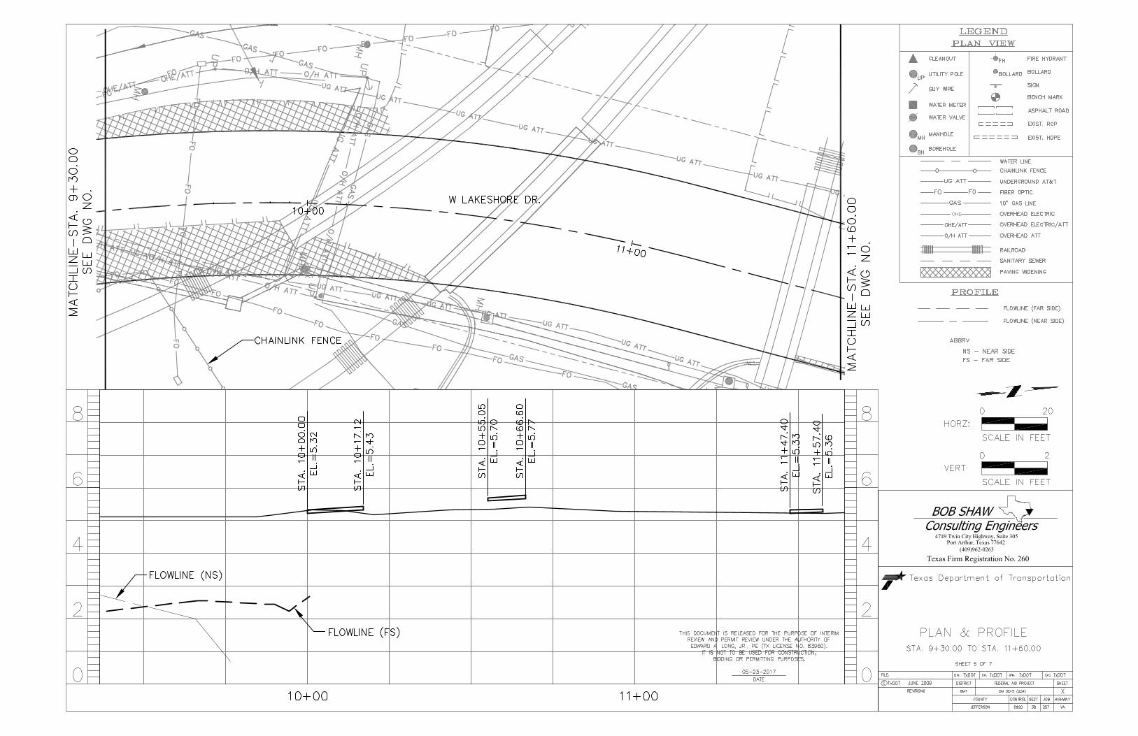
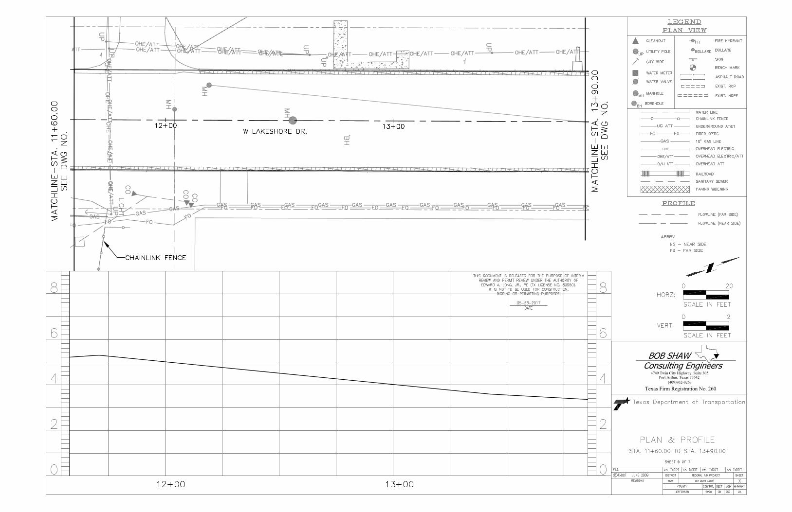

TWE Project No. 17.23.039 Report No. 89115
APPENDIX B
FIELD PROGRAM LOCATION PLAN TWE DRAWING NO. 17.23.039-1
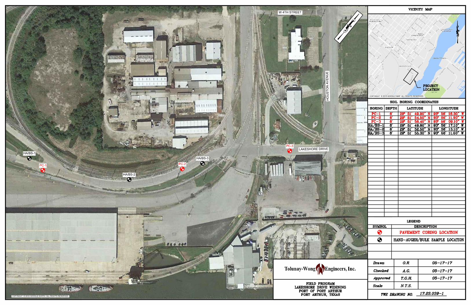
COPYRIGHT © 2015 GOOGLE EARTH. ALL RIGHTS RESERVED.
COPYRIGHT © 2015 GOOGLE MAP. ALL RIGHTS RESERVED.
PC-1
PC-2
PC-3
HA/BS-1
HA/BS-2
HA/BS-3
HO
US
TO
N A
VE
NU
E
LAKESHORE DRIVE
W 4TH STREET
TWE Project No. 17.23.039 Report No. 89115
APPENDIX C
TWE LOGS OF TEST BORINGS AND A KEY TO TERMS AND SYMBOLS USED ON BORING LOGS
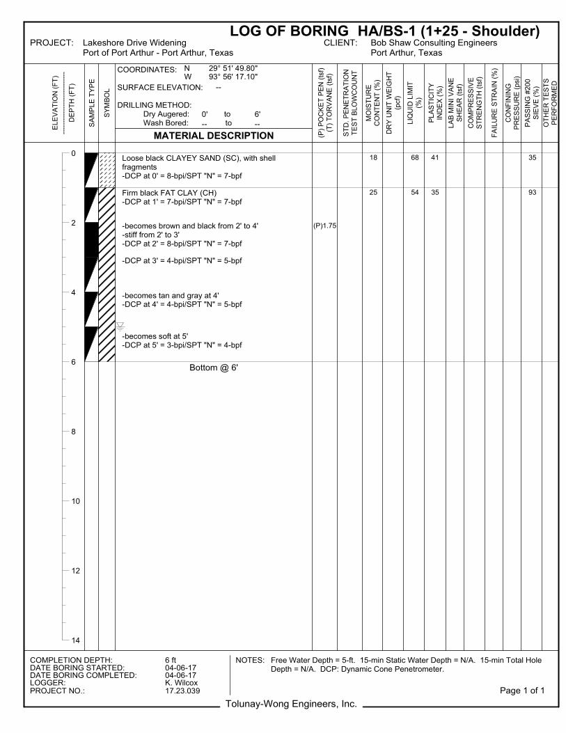
0
2
4
6
8
10
12
14
Loose black CLAYEY SAND (SC), with shellfragments-DCP at 0' = 8-bpi/SPT "N" = 7-bpf
Firm black FAT CLAY (CH)-DCP at 1' = 7-bpi/SPT "N" = 7-bpf
-becomes brown and black from 2' to 4'-stiff from 2' to 3'-DCP at 2' = 8-bpi/SPT "N" = 7-bpf
-DCP at 3' = 4-bpi/SPT "N" = 5-bpf
-becomes tan and gray at 4'-DCP at 4' = 4-bpi/SPT "N" = 5-bpf
-becomes soft at 5'-DCP at 5' = 3-bpi/SPT "N" = 4-bpf
Bottom @ 6'
(P)1.75
18
25
68
54
41
35
35
93
Tolunay-Wong Engineers, Inc.
LOG OF BORING HA/BS-1 (1+25 - Shoulder)PROJECT: Lakeshore Drive Widening
Port of Port Arthur - Port Arthur, TexasCLIENT: Bob Shaw Consulting Engineers
Port Arthur, Texas
COMPLETION DEPTH: 6 ft NOTES: Free Water Depth = 5-ft. 15-min Static Water Depth = N/A. 15-min Total HoleDepth = N/A. DCP: Dynamic Cone Penetrometer.DATE BORING STARTED: 04-06-17
DATE BORING COMPLETED: 04-06-17LOGGER: K. WilcoxPROJECT NO.: 17.23.039
ELE
VA
TIO
N (
FT
)--
----
----
----
----
----
----
-D
EP
TH
(F
T)
SA
MP
LE
TY
PE
SY
MB
OL
MATERIAL DESCRIPTION
COORDINATES:
SURFACE ELEVATION:
DRILLING METHOD: Dry Augered: to Wash Bored: to
(P)
PO
CK
ET
PE
N (
tsf)
(T)
TO
RV
AN
E (
tsf)
ST
D.
PE
NE
TR
AT
ION
TE
ST
BLO
WC
OU
NT
MO
IST
UR
EC
ON
TE
NT
(%
)
DR
Y U
NIT
WE
IGH
T(p
cf)
LIQ
UID
LIM
IT(%
)
PL
AS
TIC
ITY
IND
EX
(%
)
LA
B M
INI
VA
NE
SH
EA
R (
tsf)
CO
MP
RE
SS
IVE
ST
RE
NG
TH
(ts
f)
FA
ILU
RE
ST
RA
IN (
%)
CO
NF
ININ
GP
RE
SS
UR
E (
psi
)
PA
SS
ING
#200
SIE
VE
(%
)
OT
HE
R T
ES
TS
PE
RF
OR
ME
D
--
0' 6'
-- --
29° 51' 49.80"93° 56' 17.10"
NW
Page 1 of 1
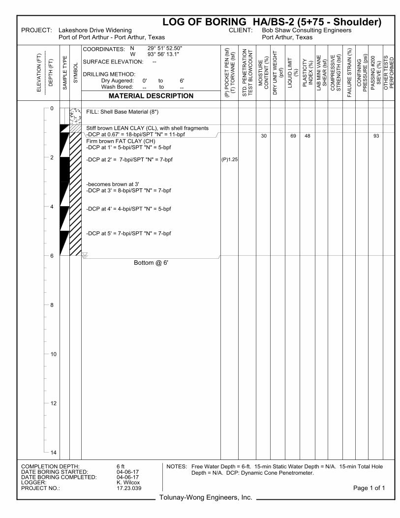
0
2
4
6
8
10
12
14
FILL: Shell Base Material (8")
Stiff brown LEAN CLAY (CL), with shell fragments-DCP at 0.67' = 18-bpi/SPT "N" = 11-bpfFirm brown FAT CLAY (CH)-DCP at 1' = 5-bpi/SPT "N" = 5-bpf
-DCP at 2' = 7-bpi/SPT "N" = 7-bpf
-becomes brown at 3'-DCP at 3' = 8-bpi/SPT "N" = 7-bpf
-DCP at 4' = 4-bpi/SPT "N" = 5-bpf
-DCP at 5' = 7-bpi/SPT "N" = 7-bpf
Bottom @ 6'
(P)1.25
30 69 48 93
Tolunay-Wong Engineers, Inc.
LOG OF BORING HA/BS-2 (5+75 - Shoulder)PROJECT: Lakeshore Drive Widening
Port of Port Arthur - Port Arthur, TexasCLIENT: Bob Shaw Consulting Engineers
Port Arthur, Texas
COMPLETION DEPTH: 6 ft NOTES: Free Water Depth = 6-ft. 15-min Static Water Depth = N/A. 15-min Total HoleDepth = N/A. DCP: Dynamic Cone Penetrometer.DATE BORING STARTED: 04-06-17
DATE BORING COMPLETED: 04-06-17LOGGER: K. WilcoxPROJECT NO.: 17.23.039
ELE
VA
TIO
N (
FT
)--
----
----
----
----
----
----
-D
EP
TH
(F
T)
SA
MP
LE
TY
PE
SY
MB
OL
MATERIAL DESCRIPTION
COORDINATES:
SURFACE ELEVATION:
DRILLING METHOD: Dry Augered: to Wash Bored: to
(P)
PO
CK
ET
PE
N (
tsf)
(T)
TO
RV
AN
E (
tsf)
ST
D.
PE
NE
TR
AT
ION
TE
ST
BLO
WC
OU
NT
MO
IST
UR
EC
ON
TE
NT
(%
)
DR
Y U
NIT
WE
IGH
T(p
cf)
LIQ
UID
LIM
IT(%
)
PL
AS
TIC
ITY
IND
EX
(%
)
LA
B M
INI
VA
NE
SH
EA
R (
tsf)
CO
MP
RE
SS
IVE
ST
RE
NG
TH
(ts
f)
FA
ILU
RE
ST
RA
IN (
%)
CO
NF
ININ
GP
RE
SS
UR
E (
psi
)
PA
SS
ING
#200
SIE
VE
(%
)
OT
HE
R T
ES
TS
PE
RF
OR
ME
D
--
0' 6'
-- --
29° 51' 52.50"93° 56' 13.1"
NW
Page 1 of 1
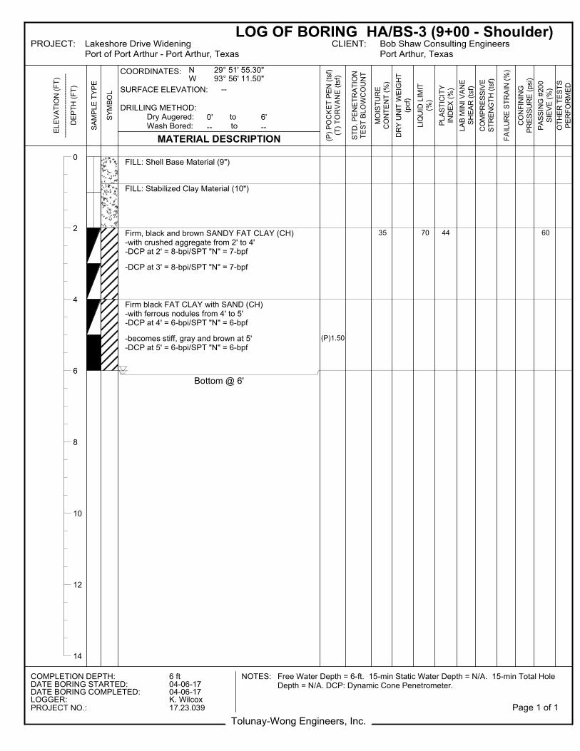
0
2
4
6
8
10
12
14
FILL: Shell Base Material (9")
FILL: Stabilized Clay Material (10")
Firm, black and brown SANDY FAT CLAY (CH)-with crushed aggregate from 2' to 4'-DCP at 2' = 8-bpi/SPT "N" = 7-bpf
-DCP at 3' = 8-bpi/SPT "N" = 7-bpf
Firm black FAT CLAY with SAND (CH)-with ferrous nodules from 4' to 5'-DCP at 4' = 6-bpi/SPT "N" = 6-bpf
-becomes stiff, gray and brown at 5'-DCP at 5' = 6-bpi/SPT "N" = 6-bpf
Bottom @ 6'
(P)1.50
35 70 44 60
Tolunay-Wong Engineers, Inc.
LOG OF BORING HA/BS-3 (9+00 - Shoulder)PROJECT: Lakeshore Drive Widening
Port of Port Arthur - Port Arthur, TexasCLIENT: Bob Shaw Consulting Engineers
Port Arthur, Texas
COMPLETION DEPTH: 6 ft NOTES: Free Water Depth = 6-ft. 15-min Static Water Depth = N/A. 15-min Total HoleDepth = N/A. DCP: Dynamic Cone Penetrometer.DATE BORING STARTED: 04-06-17
DATE BORING COMPLETED: 04-06-17LOGGER: K. WilcoxPROJECT NO.: 17.23.039
ELE
VA
TIO
N (
FT
)--
----
----
----
----
----
----
-D
EP
TH
(F
T)
SA
MP
LE
TY
PE
SY
MB
OL
MATERIAL DESCRIPTION
COORDINATES:
SURFACE ELEVATION:
DRILLING METHOD: Dry Augered: to Wash Bored: to
(P)
PO
CK
ET
PE
N (
tsf)
(T)
TO
RV
AN
E (
tsf)
ST
D.
PE
NE
TR
AT
ION
TE
ST
BLO
WC
OU
NT
MO
IST
UR
EC
ON
TE
NT
(%
)
DR
Y U
NIT
WE
IGH
T(p
cf)
LIQ
UID
LIM
IT(%
)
PL
AS
TIC
ITY
IND
EX
(%
)
LA
B M
INI
VA
NE
SH
EA
R (
tsf)
CO
MP
RE
SS
IVE
ST
RE
NG
TH
(ts
f)
FA
ILU
RE
ST
RA
IN (
%)
CO
NF
ININ
GP
RE
SS
UR
E (
psi
)
PA
SS
ING
#200
SIE
VE
(%
)
OT
HE
R T
ES
TS
PE
RF
OR
ME
D
--
0' 6'
-- --
29° 51' 55.30"93° 56' 11.50"
NW
Page 1 of 1
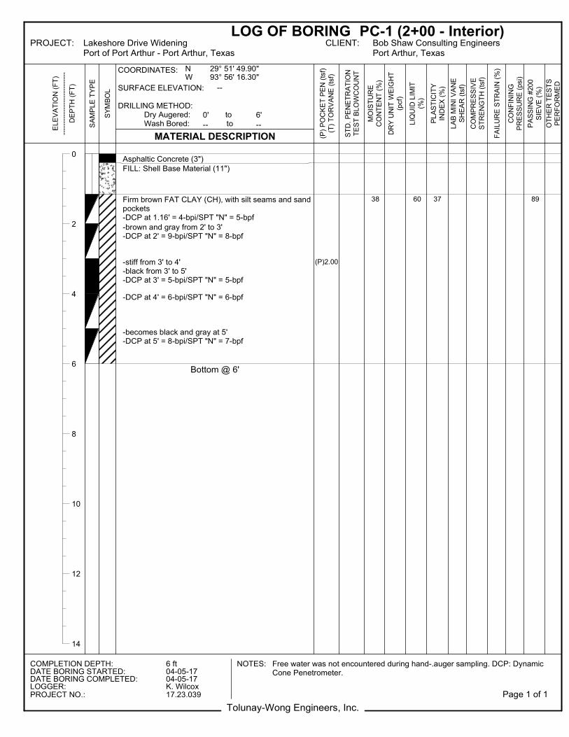
0
2
4
6
8
10
12
14
Asphaltic Concrete (3")FILL: Shell Base Material (11")
Firm brown FAT CLAY (CH), with silt seams and sandpockets-DCP at 1.16' = 4-bpi/SPT "N" = 5-bpf
-brown and gray from 2' to 3'-DCP at 2' = 9-bpi/SPT "N" = 8-bpf
-stiff from 3' to 4'-black from 3' to 5'-DCP at 3' = 5-bpi/SPT "N" = 5-bpf
-DCP at 4' = 6-bpi/SPT "N" = 6-bpf
-becomes black and gray at 5'-DCP at 5' = 8-bpi/SPT "N" = 7-bpf
Bottom @ 6'
(P)2.00
38 60 37 89
Tolunay-Wong Engineers, Inc.
LOG OF BORING PC-1 (2+00 - Interior)PROJECT: Lakeshore Drive Widening
Port of Port Arthur - Port Arthur, TexasCLIENT: Bob Shaw Consulting Engineers
Port Arthur, Texas
COMPLETION DEPTH: 6 ft NOTES: Free water was not encountered during hand-.auger sampling. DCP: DynamicCone Penetrometer.DATE BORING STARTED: 04-05-17
DATE BORING COMPLETED: 04-05-17LOGGER: K. WilcoxPROJECT NO.: 17.23.039
ELE
VA
TIO
N (
FT
)--
----
----
----
----
----
----
-D
EP
TH
(F
T)
SA
MP
LE
TY
PE
SY
MB
OL
MATERIAL DESCRIPTION
COORDINATES:
SURFACE ELEVATION:
DRILLING METHOD: Dry Augered: to Wash Bored: to
(P)
PO
CK
ET
PE
N (
tsf)
(T)
TO
RV
AN
E (
tsf)
ST
D.
PE
NE
TR
AT
ION
TE
ST
BLO
WC
OU
NT
MO
IST
UR
EC
ON
TE
NT
(%
)
DR
Y U
NIT
WE
IGH
T(p
cf)
LIQ
UID
LIM
IT(%
)
PL
AS
TIC
ITY
IND
EX
(%
)
LA
B M
INI
VA
NE
SH
EA
R (
tsf)
CO
MP
RE
SS
IVE
ST
RE
NG
TH
(ts
f)
FA
ILU
RE
ST
RA
IN (
%)
CO
NF
ININ
GP
RE
SS
UR
E (
psi
)
PA
SS
ING
#200
SIE
VE
(%
)
OT
HE
R T
ES
TS
PE
RF
OR
ME
D
--
0' 6'
-- --
29° 51' 49.90"93° 56' 16.30"
NW
Page 1 of 1
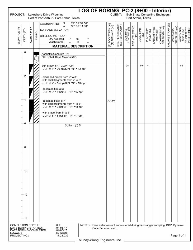
0
2
4
6
8
10
12
14
Asphaltic Concrete (3")FILL: Shell Base Material (9")
Stiff brown FAT CLAY (CH)-DCP at 1' = 20-bpi/SPT "N" = 12-bpf
-black and brown from 2' to 3'-with shell fragments from 2' to 3'-DCP at 2' = 15-bpi/SPT "N" = 10-bpf
-becomes firm at 3'-DCP at 3' = 5-bpi/SPT "N" = 5-bpf
-becomes black at 4'-with shell fragments from 4' to 6'-DCP at 4' = 9-bpi/SPT "N" = 8-bpf
-with gravel from 5' to 6'-DCP at 5' = 8-bpi/SPT "N" = 7-bpf
Bottom @ 6'
(P)1.50
28 59 41 86
Tolunay-Wong Engineers, Inc.
LOG OF BORING PC-2 (8+00 - Interior)PROJECT: Lakeshore Drive Widening
Port of Port Arthur - Port Arthur, TexasCLIENT: Bob Shaw Consulting Engineers
Port Arthur, Texas
COMPLETION DEPTH: 6 ft NOTES: Free water was not encountered during hand-auger sampling. DCP: DynamicCone Penetrometer.DATE BORING STARTED: 04-05-17
DATE BORING COMPLETED: 04-05-17LOGGER: K. WilcoxPROJECT NO.: 17.23.039
ELE
VA
TIO
N (
FT
)--
----
----
----
----
----
----
-D
EP
TH
(F
T)
SA
MP
LE
TY
PE
SY
MB
OL
MATERIAL DESCRIPTION
COORDINATES:
SURFACE ELEVATION:
DRILLING METHOD: Dry Augered: to Wash Bored: to
(P)
PO
CK
ET
PE
N (
tsf)
(T)
TO
RV
AN
E (
tsf)
ST
D.
PE
NE
TR
AT
ION
TE
ST
BLO
WC
OU
NT
MO
IST
UR
EC
ON
TE
NT
(%
)
DR
Y U
NIT
WE
IGH
T(p
cf)
LIQ
UID
LIM
IT(%
)
PL
AS
TIC
ITY
IND
EX
(%
)
LA
B M
INI
VA
NE
SH
EA
R (
tsf)
CO
MP
RE
SS
IVE
ST
RE
NG
TH
(ts
f)
FA
ILU
RE
ST
RA
IN (
%)
CO
NF
ININ
GP
RE
SS
UR
E (
psi
)
PA
SS
ING
#200
SIE
VE
(%
)
OT
HE
R T
ES
TS
PE
RF
OR
ME
D
--
0' 6'
-- --
29° 51' 54.50"93° 56' 11.90"
NW
Page 1 of 1
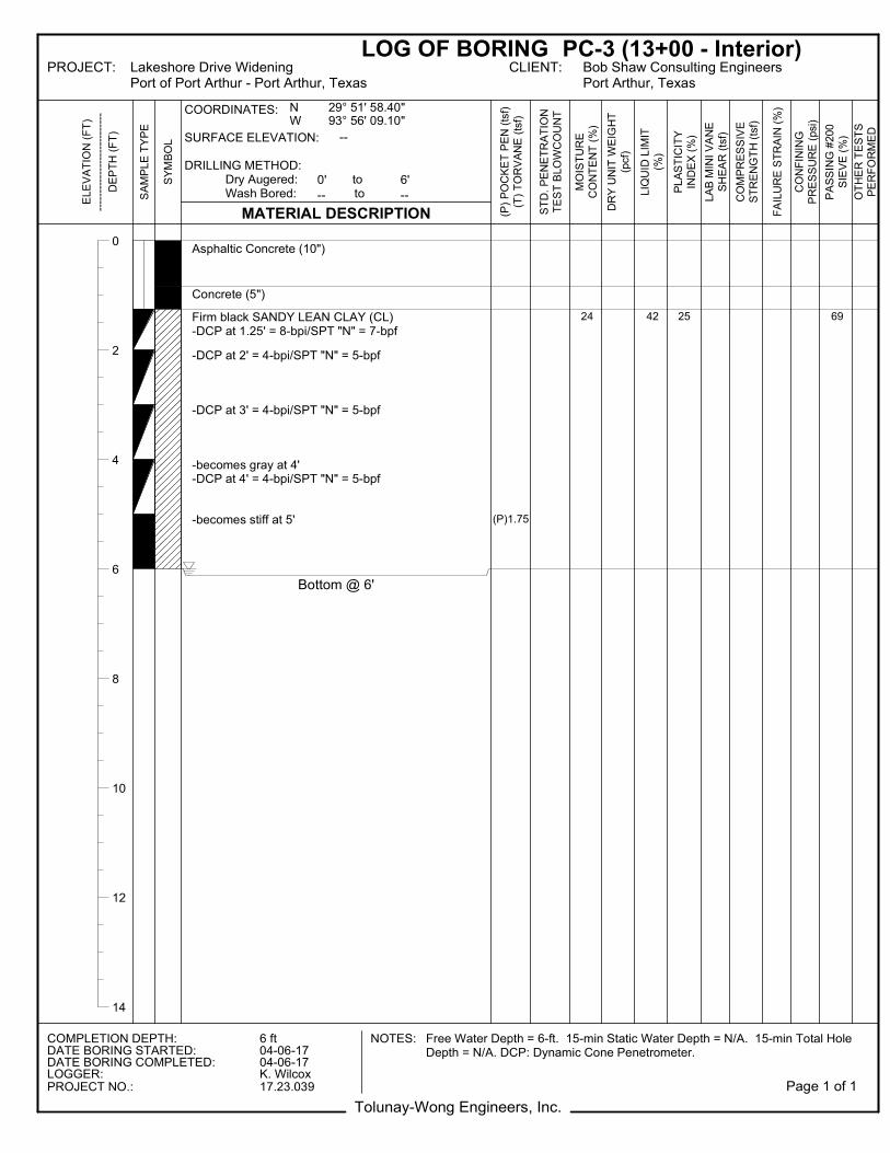
0
2
4
6
8
10
12
14
Asphaltic Concrete (10")
Concrete (5")
Firm black SANDY LEAN CLAY (CL)-DCP at 1.25' = 8-bpi/SPT "N" = 7-bpf
-DCP at 2' = 4-bpi/SPT "N" = 5-bpf
-DCP at 3' = 4-bpi/SPT "N" = 5-bpf
-becomes gray at 4'-DCP at 4' = 4-bpi/SPT "N" = 5-bpf
-becomes stiff at 5'
Bottom @ 6'
(P)1.75
24 42 25 69
Tolunay-Wong Engineers, Inc.
LOG OF BORING PC-3 (13+00 - Interior)PROJECT: Lakeshore Drive Widening
Port of Port Arthur - Port Arthur, TexasCLIENT: Bob Shaw Consulting Engineers
Port Arthur, Texas
COMPLETION DEPTH: 6 ft NOTES: Free Water Depth = 6-ft. 15-min Static Water Depth = N/A. 15-min Total HoleDepth = N/A. DCP: Dynamic Cone Penetrometer.DATE BORING STARTED: 04-06-17
DATE BORING COMPLETED: 04-06-17LOGGER: K. WilcoxPROJECT NO.: 17.23.039
ELE
VA
TIO
N (
FT
)--
----
----
----
----
----
----
-D
EP
TH
(F
T)
SA
MP
LE
TY
PE
SY
MB
OL
MATERIAL DESCRIPTION
COORDINATES:
SURFACE ELEVATION:
DRILLING METHOD: Dry Augered: to Wash Bored: to
(P)
PO
CK
ET
PE
N (
tsf)
(T)
TO
RV
AN
E (
tsf)
ST
D.
PE
NE
TR
AT
ION
TE
ST
BLO
WC
OU
NT
MO
IST
UR
EC
ON
TE
NT
(%
)
DR
Y U
NIT
WE
IGH
T(p
cf)
LIQ
UID
LIM
IT(%
)
PL
AS
TIC
ITY
IND
EX
(%
)
LA
B M
INI
VA
NE
SH
EA
R (
tsf)
CO
MP
RE
SS
IVE
ST
RE
NG
TH
(ts
f)
FA
ILU
RE
ST
RA
IN (
%)
CO
NF
ININ
GP
RE
SS
UR
E (
psi
)
PA
SS
ING
#200
SIE
VE
(%
)
OT
HE
R T
ES
TS
PE
RF
OR
ME
D
--
0' 6'
-- --
29° 51' 58.40"93° 56' 09.10"
NW
Page 1 of 1
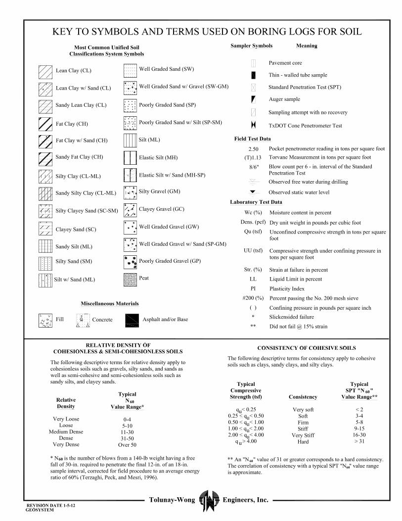
TWE Project No. 17.23.039 Report No. 89115
APPENDIX D
LABORATORY MOISTURE-DENSITY RELATIONS AND CBR TEST RESULTS ON COMBINED BULK SAMPLES
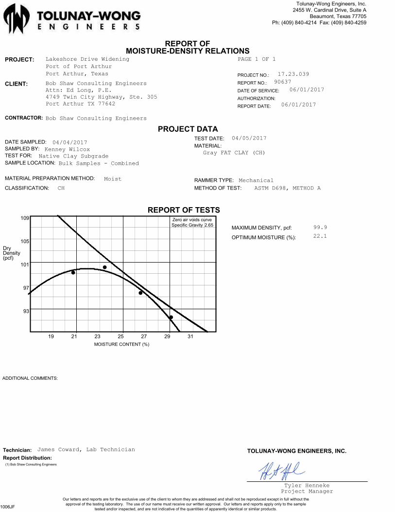
CLIENT: Bob Shaw Consulting Engineers
PAGE 1 OF 1
PROJECT NO.: 17.23.039
Attn: Ed Long, P.E.4749 Twin City Highway, Ste. 305Port Arthur TX 77642
PROJECT: Lakeshore Drive Widening
Port of Port Arthur
Port Arthur, Texas
REPORT NO.: 90637
DATE OF SERVICE: 06/01/2017
AUTHORIZATION:
REPORT DATE: 06/01/2017
REPORT OFMOISTURE-DENSITY RELATIONS
PROJECT DATA
REPORT OF TESTS
MAXIMUM DENSITY, pcf:
OPTIMUM MOISTURE (%):
CONTRACTOR: Bob Shaw Consulting Engineers
DATE SAMPLED: 04/04/2017SAMPLED BY: Kenney WilcoxTEST FOR: Native Clay SubgradeSAMPLE LOCATION: Bulk Samples - Combined
TEST DATE: 04/05/2017
MATERIAL:
Gray FAT CLAY (CH)
CLASSIFICATION: CH
MATERIAL PREPARATION METHOD: Moist RAMMER TYPE: Mechanical
ASTM D698, METHOD AMETHOD OF TEST:
99.9
22.1
Dry
109
105
101
97
93
19 21 23 25 27 29 31
Zero air voids curveSpecific Gravity 2.65
Density(pcf)
MOISTURE CONTENT (%)
Tolunay-Wong Engineers, Inc.2455 W. Cardinal Drive, Suite A
Beaumont, Texas 77705Ph: (409) 840-4214 Fax: (409) 840-4259
..
........................................................................................................
.
.
.
.
.
.
.
.
.
.
.
.
.
.
.
.
.
.
.
.
.
.
.
.
.
.
.
.
.
.
.
.
.
.
.
.
.
.
.
.
.
.
.
.
.
.
.
.
.
.
.
.
.
.
.
.
.
.
.
.
.
.
.
.
.
.
.
.
.
.
.
.
.
.
.
.
.
.
.
.
.
.
.
.
.
.
.
.
.
.
.
.
.
.
.
.
.
.
.
.
.
.
.
.
.
.
.
.
.
.
.
.
.
.
.
.
.
.
.
.
.
.
.
.
.
.
.
.
.
.
.
.
.
.
.
.
.
.
.
.
.
.
.
.
.
.
.
.
.
.
.
.
.
.
.
.
.
.
.
.
.
.
.
.
.
.
.
.
.
.
.
.
.
.
.
.
.
.
.
.
.
.
.
.
.
.
.
.
.
.
.
.
.
.
.
.
.
.
.
.
.
.
.
.
.
.
.
.
.
.
.
.
.
.
.
.
.
.
.
.
.
.
.
.
.
.
.
.
.
.
.
.
.
.
.
.
.
.
.
.
.
.
.
.
.
.
.
.
.
.
.
.
.
.
.
.
.
.
.
.
.
.
.
.
.
.
.
.
.
.
.
.
.
.
.
.
.
.
.
.
.
.
.
.
.
.
.
.
.
.
.
.
.
.
.
.
.
.
.
.
.
.
.
.
.
.
.
.
.
.
.
.
...
.
.
.
.
.
.
.
.........................................................................................................................................................................................................................................................................................................................................................................................................................
.
.
.
.
.
.
.
.
.
.
.
.
.
.
.
.
.
.
.
.
.
.
.
.
.
.
.
.
.
.
.
.
.
.
.
.
.
.
.
.
.
.
.
.
.
.
.
.
.
.
.
.
.
.
.
.
.
.
.
.
.
.
.
.
.
.
.
.
.
.
.
.
.
.
.
.
.
.
.
.
.
.
.
.
.
.
.
.
.
.
.
.
.
.
.
.
.
.
.
.
.
.
.
.
.
.
.
.
.
.
.
.
.
.
.
.
.
.
.
.
.
.
.
.
.
.
.
.
.
.
.
.
.
.
.
.
.
.
.
.
.
.
.
.
.
.
.
.
.
.
.
.
.
.
.
.
.
.
.
.
.
.
.
.
.
.
.
.
.
...................................................................................................................................................................................................................
ADDITIONAL COMMENTS:
Technician: James Coward, Lab Technician
Tyler HennekeProject Manager
TOLUNAY-WONG ENGINEERS, INC.
(1) Bob Shaw Consulting Engineers
Report Distribution:
Our letters and reports are for the exclusive use of the client to whom they are addressed and shall not be reproduced except in full without the
approval of the testing laboratory. The use of our name must receive our written approval. Our letters and reports apply only to the sample
tested and/or inspected, and are not indicative of the quantities of apparently identical or similar products.1006JF
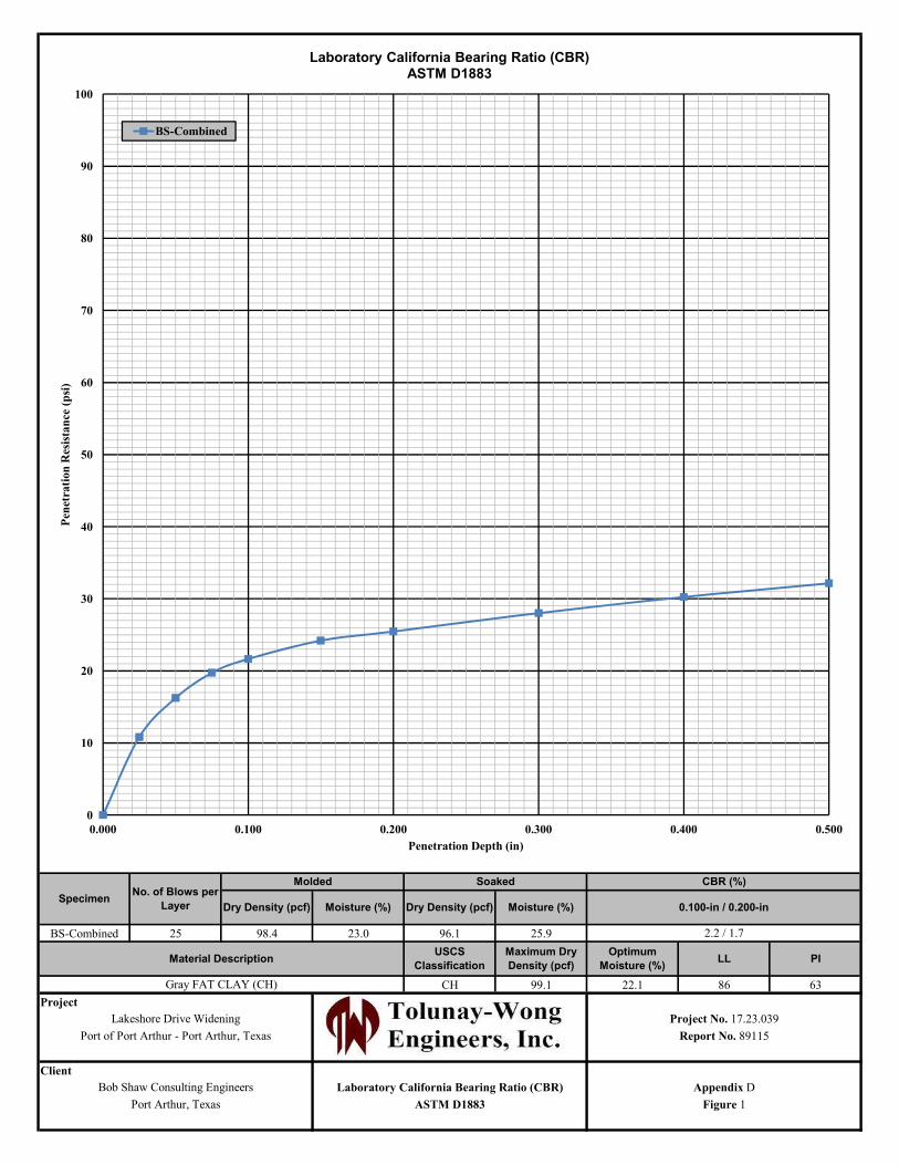
BS-Combined 25 98.4 23.0 96.1 25.9
CH 99.1 22.1 86 63
Project
Client
Laboratory California Bearing Ratio (CBR)
PILLOptimum
Moisture (%)
USCS
Classification
Maximum Dry
Density (pcf)
Gray FAT CLAY (CH)
Material Description
Port Arthur, Texas Figure 1
Lakeshore Drive Widening
Port of Port Arthur - Port Arthur, Texas Report No. 89115
Bob Shaw Consulting Engineers
SoakedMoldedNo. of Blows per
Layer
CBR (%)
SpecimenDry Density (pcf) 0.100-in / 0.200-in
2.2 / 1.7
ASTM D1883
Appendix D
Moisture (%)Dry Density (pcf)Moisture (%)
Project No. 17.23.039
0
10
20
30
40
50
60
70
80
90
100
0.000 0.100 0.200 0.300 0.400 0.500
Pen
etra
tion
Res
ista
nce
(p
si)
Penetration Depth (in)
Laboratory California Bearing Ratio (CBR)ASTM D1883
BS-Combined

TECHNICAL SPECIFICATIONS
SPECIAL SPECIFICATIONS &
SPECIAL PROVISIONS
3006
1 12-14 Districtwide
Special Specification 3006 Reinforcement Grid for Asphalt Pavement Overlays 1. DESCRIPTION
This Specification governs the sampling, testing, material requirements, and construction methods for reinforcement grid for asphalt pavement reinforcement in accordance with the details shown on the plans and the requirements of this specification.
2. MATERIAL DESCRIPTION
The reinforcement material is a uniform, glass-fiber strand grid coated with an elastomeric polymer with a self-adhesive backing. This material shall function as reinforcement for joints and as a retardant to reflective cracking when placed under an asphalt concrete overlay.
There are 2 types of reinforcement grid; the following describes each type. Type I is intended for placement and reinforcement of the entire surface of the overlay. With mesh
openings of 1” (center to center). Type II is intended for reinforcement in transverse and longitudinal joints and to retard reflective
cracking, and is placed directly over the joints as recommended by the Manufacturer. With mesh opening of 1” x ¾” (center to center).
3. SAMPLING AND TESTING
Sampling of reinforcement grid is performed in accordance with Texas Test Method Tex-735-I, “Sampling Construction Fabrics.” Testing is performed in accordance to the methods stated under Article 4, “Material Requirements.”
The Department will sample and test all materials; however, the Contractor shall be responsible for the costs of sampling and testing failing materials. Costs of sampling and testing failing materials will be assessed at the rate established by the Director of the Materials and Pavements Section of the Construction Division and in effect at the time of testing.
The Contractor shall submit a test report certifying that the proposed product meets all requirements of this specification.
4. MATERIAL REQUIREMENTS
4.1. General Requirements. The reinforcement grid shall have the following material properties: the grid shall resist damage during construction; the grid shall be certified to possess long-term resistance to chemical and biological degradation caused
by the materials being reinforced; and the grid structure shall maintain dimensional stability during placement and under normal construction
traffic.
4.2. Physical Requirements. The reinforcement grid shall conform to the following requirements when tested in accordance with the test methods specified. Specimen and ambient temperature shall be maintained at 77 ± 2ºF (25 ± 1ºC) during physical testing.
3006
2 12-14 Districtwide
Type I Type II Area Weight (ASTM D5261-92) 300 g/m2 (11 oz/sy) 500 g/m2 (16 oz/sy) % Open Area (Tex-621-J) 50% min 50% min Softening Point (ASTM C338) 537 C (1000 F min) 537 C (1000 F min) Loss on Ignition (ASTM D4963-89) 15% min 15% min
4.3. Packaging and Labeling. The reinforcement grid shall be packaged in a protective wrap to prevent damage under normal storage and handling, including ultraviolet degradation. The material shall be stored in dry covered conditions free from dust, and should be stocked vertically to avoid misshapen rolls. Misshapen rolls and rolls exposed to direct ultraviolet light shall not be used unless otherwise approved by the Engineer.
Each roll shall be identified with a tag or label securely affixed to the outside of the roll on or near one end. The following information shall be included on the label: unique roll number, serially designated; manufacturer's lot number or control numbers, if any; name of manufacturer; brand name of product; style or catalog designation of the product; and roll width and length.
4.4. Safety Precautions. Gloves are recommended to prevent direct contact with the material. Goggles or other eye protection may be needed to prevent loose fibers from irritating the eyes.
5. CONSTRUCTION
The area on which the grid is to be placed shall be clean of dirt, dust or other deleterious material. Sweeping or other approved methods of surface preparation may be required by the Engineer. A Manufacturer’s representative shall be present on the project for the duration of grid installation. This service will be subsidiary to this specification.
All base and pavement failures shall be repaired prior to placement of the grid. A level-up course of at least 0.75 in. hot-mix asphalt is required prior to installing the grid.
The surface temperature of the pavement before laying the grid shall be 70ºF or higher unless otherwise approved. The grid shall not be placed when the general weather conditions, in the opinion of the Engineer, are not suitable.
Tack coat will be applied prior to placing the grid, unless otherwise directed by the Engineer. The following tack coat requirements supersede those outlined in the Hot-Mix Asphalt specification.
Unless otherwise shown on the plans or approved by the Engineer, furnish Track Free Tack Coat –Hot Applied with a residual application rate of 0.15-0.22 gal/yd2, in accordance with Item 300, “Asphalts, Oils, and Emulsions.”
Do not dilute emulsified asphalts at the terminal, in the field, or at any other location before use.
The Engineer will obtain at least 1 sample of the tack coat binder per project and test it to verify compliance with Item 300. The Engineer will obtain the sample from the asphalt distributor immediately before use.
Clean the surface before placing the tack coat. Unless otherwise approved, apply coat uniformly at the rate directed by the Engineer. The Engineer will set the rate between 0.15 and 0.22 gal of residual asphalt per square yard of surface area. Apply a thin, uniform tack coat all contact surfaces of curbs, structures, and all joints. Prevent splattering of tack coat when placed adjacent to curb, gutter, and structures. Roll the tack coat with a pneumatic-tire roller when directed. The Engineer may use Tex-243-F to verify that the tack coat has
3006
3 12-14 Districtwide
adequate adhesive properties. The Engineer may suspend paving operations until there is adequate adhesion.
Grid shall be laid out either by hand or mechanical means under sufficient tension to eliminate ripples. Should ripples occur, these shall be removed by pulling the grid tight or in extreme cases, for example, in tight radius, by cutting and relaying flat. A sharp knife may be used for cutting.
Transverse joints shall be lapped in the direction of the paver by 3 in. minimum. Longitudinal joints shall be lapped by 1 in. minimum. The surface of the grid should be rolled with a rubber coated drum roller or pneumatic tire roller to form a secure bond. Tires shall be cleaned regularly with an approved asphalt cleaning agent.
All grid placed in a day shall be covered with asphalt concrete the same day, within permissible laying temperatures, and compacted in accordance with applicable asphalt concrete specifications.
6. MEASUREMENT
This Item will be measured by the foot of joint or crack repaired or by the square yard of the actual area complete in place. When measurement and payment is by the linear foot, a minimum width will be shown on the plans. No allowance will be made for overlapping at joints.
7. PAYMENT
The work performed and materials furnished in accordance with this Item and measured as provided under “Measurement” will be paid for at the unit price bid for “Reinforcement Grid for Asphalt Pavement Overlay” of the type specified and by the width for the foot measurement. This price should be full compensation for cleaning the existing pavement; for furnishing, preparing, hauling and placing all materials, including tack; for all manipulation, including rolling, and for all labor, tools, equipment and incidentals necessary to complete the work.
4076
1 - 23 03-17 OTU
Special Specification 4076
Ballasted Track Construction and Rehabilitation
1. DESCRIPTION
Furnish the construction of railroad track and the rehabilitation of existing track in accordance with this specification, project plans, and the American Railway Engineering and Maintenance of Way Association’s (AREMA) “Manual for Railway Engineering.” Track construction includes, but is not limited to, placing ballast, distributing and lining ties, installing and field welding running rail, installing jointed rail, installing turnouts and switches, rehabilitating existing ties and rail, raising and lining track, installing vehicular grade crossings and other incidentals as specified. Track on ballasted and open deck bridges is also included.
2. MATERIALS
2.1. General
2.1.1. Use new material conforming to this specification unless otherwise designated in the plans or as approved by the Engineer. New material must be free from defects, rust, or damage and conform to the requirements of AREMA standards unless otherwise shown on the plans, these specifications, or as required by the Engineer. Provide new material in an unblemished condition, free from defects, rust, or damage.
2.1.2. Where second hand material is permitted by the plans or approved by the Engineer, the second hand material must be in good condition and conform to AREMA Standards unless otherwise shown on the plans or approved by the Engineer. Second hand material must be straight and true, in good condition, and free from excess rust, pits, or wear. Test second hand rail for head wear, corrosion, base wear, sweeps, kinks, cracking, delamination, or any other defect including internal metal defects. Ensure the material meets the appropriate specifications indicated below.
2.2. Rail
2.2.1. Use Type RE 115, 119, 132, or 136 lb. Standard Strength Rail supplied by the Contractor and conforming to the requirements of AREMA Chapter 4 “Rail” for constructing track and replacing rail unless otherwise required as shown on the plans. Rail on curves greater than 1° 30’ must be head hardened rail. For jointed rail or field-welded rail, furnish rail as show on the plans or in lengths of 39 ft. with 11% shorts varying by 1 ft. increments from 38 ft. down to 25 ft. in length, if lengths are not otherwise specified.
2.2.2. The Contractor will furnish the necessary joint bars, anchors, spikes, bolts, nuts, securements, welding, and any other materials necessary for the rail installation. In the event any existing rail should break during tie removal, installation, surfacing, or any other portion of the project; the Engineer will determine whether the rail should be replaced or spliced by welding or the installation of joint bars. The Contractor will furnish the necessary joint bars, anchors, spikes, bolts, nuts, securements, welding, and any other materials necessary for the rail installation of the same rail section size as the break.
2.2.3. Submit to the Engineer five (5) copies of a layout showing the proposed rail types, continuous welded rail (CWR) lengths, and field welds for approval prior to track construction. Designate on the track layouts the size of transition rail, compromise rail, and compromise joints as shown on the plans or as necessary at locations where the proposed rail joins with existing rail. Field verify the sizes of required transition rail, compromise rail, and compromise joints then submit a detailed list of the sizes and locations to the Engineer before to beginning track construction.
2.2.4. Furnish reports of the chemical and mechanical test results to the Engineer. For continuously welded rail (CWR), provide continuous shop welded rail when specified by the plans and transport it, excluding rail for
4076
2 - 23 03-17 OTU
industry leads, in 80 ft., 400 ft., or longer than 400 ft. sections to the project site unless shorter sections are required due to curve length, or fit between switches. Meet the requirements of AREMA Manual, Chapter 4, “Specifications for Fabrication of Continuous Welded Rail” (electric flash butt welds) for shop welding. Joints must be field welded using the Thermite welding process between the sections.
2.3. Compromise Rail and Transition Rail.
2.3.1. Use Type RE 90, 112, 115, or 119 lb. Standard Strength Rail conforming to the requirements of AREMA Chapter 4 “Rail” “Class 1” unless otherwise required as shown on the plans for “compromise” or “transition” sections to connect replacement rail sections with existing rail sections of dissimilar size.
2.4. Switch Points.
2.4.1. Use Type RE 90, 112, 119, 115, or 136 lb. Standard Strength Rail conforming to the requirements of AREMA Chapter 4 “Rail” and matching the existing rail type unless otherwise required or as shown on the plans for installing or replacing switch points. Switch points must be replaced on both sides as shown on the plans and replaced as a set. The Contractor will furnish transportation of the switch points and the necessary plates, anchors, joint bars, bolts, clips, and other necessary materials of the same rail section size.
2.5. Turnouts.
2.5.1. Contractor must furnish turnout castings (frogs), switch stands, connecting rods, plates, switch ties, cross ties, welding, securements, and all other materials used in construction of turnouts and switch mechanisms in accordance with AREMA Specifications Chapter 4 and construct all new turnouts complete as shown on the plans. Turnouts must be constructed and placed as shown on the drawings. Contractor must install all new turnouts complete in place.
2.6. Track Crossties.
2.6.1. Track crossties must conform to the current AREMA Specifications, Chapter 30, “Ties.” The track crossties must be new Oak, Douglas Fir, or Mixed Hardwood Wood ties, 7 in. x 9 in. x 8 ft. 6 in. minimum AREMA-7 inch Grade or as shown on the plans.
2.6.2. Bridge crossties must conform to the current AREMA Specifications, Chapter 30, “Ties.” The bridge crossties must be new Oak, Douglas Fir, or Mixed Hardwood Wood ties, 7 in. x 9 in. x 9 ft. minimum AREMA-7 inch Grade or as shown on the plans.
2.6.3. Ties under grade crossing panels must be of new Oak, Douglas Fir, or Mixed Hardwood ties, 7 in. x 9 in. x 10 ft. minimum AREMA-7 inch Grade.
2.6.4. Crossties must be treated according to the American Wood Preservers Association Standards, based on 50% creosote and 50% coal tar solution with a minimum preservative retention of 8 pcf of Wood. Treatment must conform to AREMA Manual Chapter 3, Parts 6, 7, 8, and 9 for applicable timber species. Treat field cuts or drilled holes with a compatible preservative before installing, spiking, or bolting. No boultonizing of ties will be permitted.
2.6.5. Crossties must be seasoned, dimensioned and prebored prior to treatment and treated in accordance with AWPA Standard C6 “Crossties and Switch Ties - Preservative Treatment by Pressure Processes,” or ASTM D 1760 “Standard Specification for Pressure Treatment of Timber Products.” All ties must be fitted with anti- splitting devices, regardless of their tendency to split.
2.6.6. Ties must be inspected and certified by an approved commercial testing laboratory stating that the ties to be used meet the specifications in accordance with AWPA Standard M2 “Standard for Inspection of Treated Wood Products.” Results of test and inspections must be furnished to the Engineer. Ties may be rejected for excessive checking, warp, twist, or other defects as determined by the Engineer.
4076
3 - 23 03-17 OTU
2.7. Switch Ties.
2.7.1. Switch ties must conform to the current AREMA Specifications, Chapter 30, “Timber Switch Ties.” The track crossties must be new Oak, Douglas Fir, or Mixed Hardwood Wood ties, AREMA-7 inch Grade. Switch ties must be 7 in. x 9 in. x the length shown on the plans and necessary for installation at the location indicated by the Engineer.
2.7.2. Switch ties must be treated according to the American Wood Preservers Association Standards, based on 50% creosote and 50% coal tar solution with a minimum preservative retention of 8 pcf of Wood. No boultonizing of switch ties will be permitted.
2.7.3. Switch ties must be seasoned, dimensioned and prebored prior to treatment and treated in accordance with AWPA Standard C6 “Crossties and Switch Ties - Preservative Treatment by Pressure Processes,” or ASTM D 1760 “Standard Specification for Pressure Treatment of Timber Products.” All ties must be fitted with anti- splitting devices, regardless of their tendency to split.
2.7.4. Switch ties must be inspected and certified by an approved commercial testing laboratory stating that the ties to be used meet the specifications in accordance with AWPA Standard M2 “Standard for Inspection of Treated Wood Products.” Results of test and inspections must be furnished to the Engineer.
2.8. Tie Plates.
2.8.1. Hot worked, high carbon, double shoulder, flat bottom tie plates must conform to the AREMA specifications, Chapter 5, “Track,” with punched A-8 square spike holes. Where necessary on curves, use 16 in. tie plates in accordance with AREMA specifications, Chapter 5, “Track.”
2.9. Track Spikes and Coach Screws.
2.9.1. Supply new high carbon steel track spikes and coach screws conforming to the requirements of AREMA Chapter 5 “Track.” Deliver track spikes to the Job Site in Engineer-approved containers (kegs). Install in accordance with sections 4.2.7. through 4.2.14 of this Special Specification, and Federal Railroad Administration (FRA) Standards.
2.10. Joint Bars and Track Bolts.
2.10.1. Use joint bars, track bolts, nuts, and washers conforming to the requirements of AREMA Chapter 4, Part 2, Section 2.8, “Specifications for Quenched Carbon-Steel Joint Bars, Microalloyed Joint Bars, and Forged Compromise Joint Bars.” Compromise or transition rails must be used in lieu of compromise joint bars when joining rails of different sizes and/or sections as specified in section 4.4 of this specification.
2.11. Rail Anchors.
2.11.1. Use Grip type rail anchors conforming to the requirements of AREMA Chapter 5, Section 7 “Rail Anchors.”
2.12. Derails.
2.12.1. Supply left hand or right hand hinge derails as necessary of the appropriate size for the particular rail installation location shown on the plans.
2.13. Guard rails.
2.13.1. Install guard rails of the appropriate size for the particular rail installation location as shown on the plans.
2.14. Subballast.
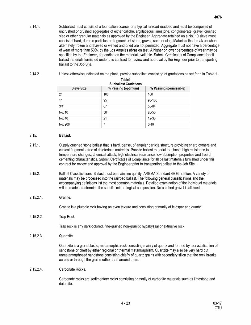
4076
4 - 23 03-17 OTU
2.14.1. Subballast must consist of a foundation coarse for a typical railroad roadbed and must be composed of uncrushed or crushed aggregates of either caliche, argillaceous limestone, conglomerate, gravel, crushed slag or other granular materials as approved by the Engineer. Aggregate retained on a No. 10 sieve must consist of hard, durable particles or fragments of stone, gravel, sand or slag. Materials that break up when alternately frozen and thawed or wetted and dried are not permitted. Aggregate must not have a percentage of wear of more than 50%, by the Los Angeles abrasion test. A higher or lower percentage of wear may be specified by the Engineer, depending on the material available. Submit Certificates of Compliance for all ballast materials furnished under this contract for review and approval by the Engineer prior to transporting ballast to the Job Site.
2.14.2. Unless otherwise indicated on the plans, provide subballast consisting of gradations as set forth in Table 1.
Table1 Subballast Gradations
Sieve Size % Passing (optimum) % Passing (permissible)
2” 100 100
1” 95 90-100
3/4” 67 50-84
No. 10 38 26-50
No. 40 21 12-30
No. 200 7 0-10
2.15. Ballast.
2.15.1. Supply crushed stone ballast that is hard, dense, of angular particle structure providing sharp corners and cubical fragments, free of deleterious materials. Provide ballast material that has a high resistance to temperature changes, chemical attack, high electrical resistance, low absorption properties and free of cementing characteristics. Submit Certificates of Compliance for all ballast materials furnished under this contract for review and approval by the Engineer prior to transporting ballast to the Job Site.
2.15.2. Ballast Classifications. Ballast must be main line quality, AREMA Standard 4A Gradation. A variety of materials may be processed into the railroad ballast. The following general classifications and the accompanying definitions list the most common materials. Detailed examination of the individual materials will be made to determine the specific mineralogical composition. No crushed gravel is allowed.
2.15.2.1. Granite.
Granite is a plutonic rock having an even texture and consisting primarily of feldspar and quartz.
2.15.2.2. Trap Rock.
Trap rock is any dark-colored, fine-grained non-granitic hypabyssal or extrusive rock.
2.15.2.3. Quartzite.
Quartzite is a granoblastic, metamorphic rock consisting mainly of quartz and formed by recrystallization of sandstone or chert by either regional or thermal metamorphism. Quartzite may also be very hard but unmetamorphosed sandstone consisting chiefly of quartz grains with secondary silica that the rock breaks across or through the grains rather than around them.
2.15.2.4. Carbonate Rocks.
Carbonate rocks are sedimentary rocks consisting primarily of carbonite materials such as limestone and dolomite.
4076
5 - 23 03-17 OTU
2.15.2.5. Slags.
Slags are materials formed during the metal-making process by fusion fluxstones, coke and other metallic particles.
2.15.3. Property Requirements.
2.15.3.1. Physical Analysis.
2.15.3.1.1. Method of Sampling. Secure field samples in accordance with ASTM D-75. Reduce test samples from field samples in accordance with ASTM C 702.
2.15.3.1.2. Sieve Analysis. Perform sieve analysis in accordance with ASTM C 136. All sieve analyses require wet sieving.
2.15.3.1.3. Material Finer than No. 200 Sieve. Test material finer than a No. 200 Sieve in accordance with ASTM C 117.
2.15.3.1.4. Bulk Specific Gravity and Absorption. Determine bulk specific gravity and percentage of absorption in accordance with ASTM C 127. Specific gravity must conform to AREMA standards at 2.6 minimum.
2.15.3.1.5. Percentage of Clay Lumps and Friable Particles. Determine percentage of clay lumps and friable particles in accordance with ASTM C 142.535 as follows: test materials having gradations containing particles retained on the 1 in. sieve by ASTM C 535, test materials having gradations of 100% passing the 1 in. sieve by ASTM C 131.
2.15.3.1.6. Sodium Sulfate Soundness. Sodium sulfate soundness tests must be made in accordance with ASTM C 88.
2.15.3.1.7. Unit Weight. The weight per cubic foot must be determined in accordance with ASTM C 29.
2.15.3.1.8. Percentage of Flat and/or Elongated Particles. Percent of flat and/or elongated particles must be determined in accordance with U.S. Army Corps of Engineers Test CRD-C-119.
2.15.3.1.9. Plasticity Index. The plastic limit, liquid limit and plasticity index must be determined in accordance with ASTM D 423 and D 424. Each sample must be tested in two ways; one test must test the fines generated by the Los Angeles Machine, and the other test must test the fines contained in the total sample. The portions of these samples generated by the Los Angeles Machine, and passing the #40 sieve must be non-plastic (NP). The portion of the total sample passing the #40 sieve must have a liquid limit of not more than 25, and plasticity index of not more than 6.
2.15.3.2. Chemical Analysis.
2.15.3.2.1. No specific chemical analysis is considered essential for the evaluation of granite, trap rocks, or quartzite type materials, provided the materials are defined by applicable method. For carbonate materials, dolomitic limestone is defined as having a magnesium carbonate content of 28% to 36%. Those carbonate materials indicating magnesium carbonate values above 36% must be defined dolomite. Carbonate material indicating magnesium carbonate values below 28% must be defined as limestone. Chemical analysis will be used in selecting or evaluating plant sites. Magnesium carbonate content of carbonate materials must be tested and defined in accordance with ASTM C 25.
2.15.3.2.2. The blending, stockpiling and other production handling operations must be managed by the producer to minimize segregation of the finished product. Stockpiling operations must minimize, as practical, breakage or excessive fall in stockpiling operations and movement of wheeled or tracked machines over stockpile material must be limited. Processed ballast must be washed and/or rescreened as necessary to remove fine particle contamination as defined by the specification.
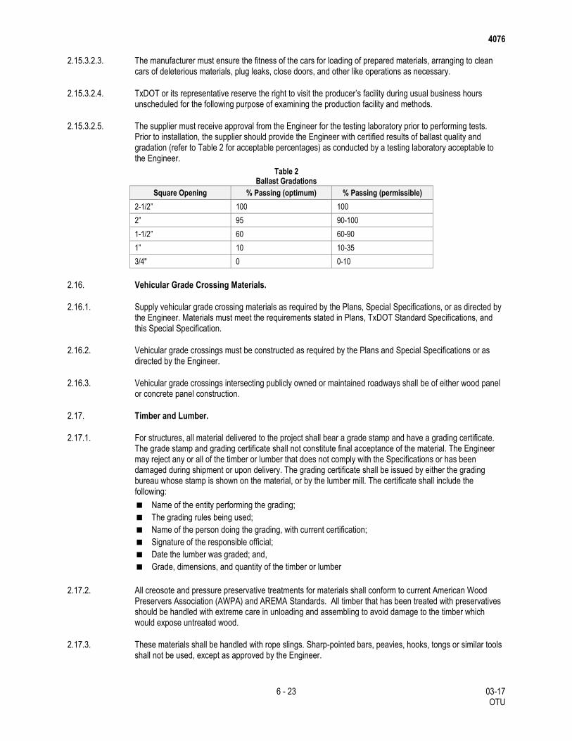
4076
6 - 23 03-17 OTU
2.15.3.2.3. The manufacturer must ensure the fitness of the cars for loading of prepared materials, arranging to clean cars of deleterious materials, plug leaks, close doors, and other like operations as necessary.
2.15.3.2.4. TxDOT or its representative reserve the right to visit the producer’s facility during usual business hours unscheduled for the following purpose of examining the production facility and methods.
2.15.3.2.5. The supplier must receive approval from the Engineer for the testing laboratory prior to performing tests. Prior to installation, the supplier should provide the Engineer with certified results of ballast quality and gradation (refer to Table 2 for acceptable percentages) as conducted by a testing laboratory acceptable to the Engineer.
Table 2 Ballast Gradations
Square Opening % Passing (optimum) % Passing (permissible)
2-1/2” 100 100
2” 95 90-100
1-1/2” 60 60-90
1” 10 10-35
3/4" 0 0-10
2.16. Vehicular Grade Crossing Materials.
2.16.1. Supply vehicular grade crossing materials as required by the Plans, Special Specifications, or as directed by the Engineer. Materials must meet the requirements stated in Plans, TxDOT Standard Specifications, and this Special Specification.
2.16.2. Vehicular grade crossings must be constructed as required by the Plans and Special Specifications or as directed by the Engineer.
2.16.3. Vehicular grade crossings intersecting publicly owned or maintained roadways shall be of either wood panel or concrete panel construction.
2.17. Timber and Lumber.
2.17.1. For structures, all material delivered to the project shall bear a grade stamp and have a grading certificate. The grade stamp and grading certificate shall not constitute final acceptance of the material. The Engineer may reject any or all of the timber or lumber that does not comply with the Specifications or has been damaged during shipment or upon delivery. The grading certificate shall be issued by either the grading bureau whose stamp is shown on the material, or by the lumber mill. The certificate shall include the following:
Name of the entity performing the grading;
The grading rules being used;
Name of the person doing the grading, with current certification;
Signature of the responsible official;
Date the lumber was graded; and,
Grade, dimensions, and quantity of the timber or lumber
2.17.2. All creosote and pressure preservative treatments for materials shall conform to current American Wood Preservers Association (AWPA) and AREMA Standards. All timber that has been treated with preservatives should be handled with extreme care in unloading and assembling to avoid damage to the timber which would expose untreated wood.
2.17.3. These materials shall be handled with rope slings. Sharp-pointed bars, peavies, hooks, tongs or similar tools shall not be used, except as approved by the Engineer.
4076
7 - 23 03-17 OTU
2.17.4. All cutting, framing, and boring of treated timbers shall be done before treatment insofar as is practicable.
2.17.5. All cuts and holes required in the field for treated piles or timbers, and all abrasions, after being carefully trimmed, shall be treated by means of CCA or ACA water-borne salt treatment. Unfilled holes, after being treated, shall be plugged with a filler approved by the Engineer. All countersunk recesses for bolts which would form pockets to retain water shall be treated as cuts and then filled with an approved filler after the bolt is placed.
2.17.6. Whenever forms or temporary braces are attached to treated timber with nails or spikes, the hole shall be filled by driving galvanized nails or spikes flush with the surface or plugging holes as required for cuts and holes, the adequacy of which shall be subject to approval by the Engineer.
2.17.7. Materials shall be stored in designated materials storage areas shown in the plans or at the job site where SW3P measures are in effect. Materials shall be stored in a neat manner at proper clearance from tracks.
2.17.8. Care should be exercised to prevent fires in material held in storage. The ground underneath and in the vicinity of piling and lumber should be cleared of all weeds, rubbish and combustible material.
2.17.9. Treated lumber should be close-stacked in a manner that will prevent long timbers or pre-framed material from sagging or becoming crooked.
2.17.10. Untreated lumber should be open-stacked on suitable skids at least 1 foot above the ground and above possible high water; it should be piled in a manner to shed water and to prevent warping.
2.17.11. When required, it shall be protected from the weather by suitable covering. Piling should be stacked in a manner to prevent excessive bending.
2.17.12. Hardware received at the job site should be protected from corrosion by storing under cover or by a protective coating.
2.17.13. Fasteners.
2.17.13.1. Bolts, dowels, washers, and other hardware, including nails, shall be black or galvanized as specified in the plans, but if not so specified shall be galvanized when used in treated timber structures.
2.17.13.2. Malleable Iron. Malleable iron castings shall conform to current ASTM Specifications, designation A47, Grade 35018, with minimum yield point of 35,000 psi.
2.17.13.3. Rolled Steel. Rolled steel plates, bars and shapes shall conform to current ASTM Specifications, designation A36.
2.17.13.4. Nails, Spikes and Drift Bolts. Nails, spikes and drift bolts shall be made of rolled steel, square or round, as called for on the plans. Where special heads are not specified, the manufacturer’s standard heads will be acceptable. Nails used for fastening timbers shall be of a type having grooved, barbed or otherwise deformed shanks for greater holding power.
2.17.13.5. Through Bolts. Through bolts shall be made of rolled steel with U.S. standard square or hexagon heads and nuts unless otherwise specified on the plans.
2.17.13.6. Washers. Round plate washers shall be made of rolled steel. Finish may be black or hot dip galvanized.
2.17.13.7. Lag Screws. Lag screws, including steel drive dowels and spikes with spirally grooved shanks, shall be made of rolled steel. Heads for lag screws shall be U.S. standard unless otherwise specified.
4076
8 - 23 03-17 OTU
2.17.13.8. Special Castings. Special castings, including such parts as gib plates, angle blocks, etc., shall be made of cast or malleable iron. They shall be true to pattern, free from wind, without injurious defects and of the size and shape specified on the plans.
3. EQUIPMENT
All on-track equipment used in connection with the project must comply with Federal Railroad Administration regulations contained in 49 CFR 214 Subpart D, Roadway Maintenance Machine Safety.
4. CONSTRUCTION
4.1. General Requirements.
4.1.1. Before starting work, the Contractor must fully inform the Engineer of the construction methods he proposes to use, the adequacy of which are subject to the approval of the Engineer.
4.1.2. Concurrence on the part of the Engineer of any proposed construction methods or approval of equipment does not relieve the Contractor of the responsibility for the safety or correctness of the methods, the adequacy of his equipment or from carrying out the work in full accordance with the contract.
4.1.3. The following codes, regulations, reference standards, and specifications apply to work included in this section:
AREMA, Manual for Railway Engineering, Chapter 1 “Roadway and Ballast,” Chapter 4 “Rail” and
Chapter 5 “Track”
American Welding Society (AWS): D1.1
Applicable referenced ASTM Specifications
Track Safety Standards of the Federal Railroad Administration (FRA).
Standard drawings provided by the Engineer
Any Items not covered specifically must be in accordance with AREMA Standards and recommended practices subject to the approval of the Engineer. Construction must adhere to all TxDOT Standard Specifications, Project Plans, and FRA requirements. Subballast construction methods must conform to Item 247, “Flexible Base.”
4.1.4. All workers employed in the project or supervising the project must have been certified according to Federal Railroad Administration (FRA) regulations contained in 49 CFR 213, “Track Safety Standards”; 49 CFR 214, “Railroad Workplace Safety”; 49 CFR 217, “Railroad Operating Rules”; 49 CFR 218, “Railroad Operating Practices”; 49 CFR 237, “Bridge Safety Standards”: and all other FRA regulations, rules, and orders as applicable. All workers employed in the project must comply with the workplace safety requirements of the operating railroad which may be subject to change. Changes to the operating railroad's safety requirements may impact training requirements and construction activities, and may result in extra costs for the contractor. All training requirements are subsidiary to the work and will not be reimbursed or considered for payment.
4.1.5. When the Contractor desires to occupy any space above the top of rail within the horizontal distance of 10 ft. either side of the centerline of any track, measured at right angles to the track centerline, it will be necessary that he obtain authority from the Railroad with at least 24 hr. advance notice. The authority will be requested and granted according to the Railroad operating rules, and the Contractor will fully comply with all instructions issued by the Railroad in regards to occupancy of the track. If, in the judgment of the Railroad, flagmen are required, they will be furnished at the Railroad’s expense.
4.1.6. The Contractor must require his employees, agents, or subcontractors to comply with any and all instructions or warnings of the Railroad’s flagmen as to clearance for the passage of trains.
4076
9 - 23 03-17 OTU
4.1.7. All scaffolding, materials, and equipment used in the Contractor’s operations must, at all times, be maintained at a clearance from the tracks as approved by the Engineer, except when working within the limits of authority granted to occupy the tracks.
4.1.8. TxDOT’s acceptance of trackage and its appurtenances which have been built must be based on the Engineer’s written statement that construction and construction materials have met TxDOT standards.
4.1.9. Unless otherwise shown on the plans or directed by the Engineer, all removed materials will become the property of the Contractor. All removed materials and debris must be removed from the railroad right of way and TxDOT property, and disposed of in a manner approved by the Engineer.
4.1.10. Milestones - The following milestones will be reviewed and approved during the project:
4.1.10.1. Grading - Review and approve prior to placement of subballast.
4.1.10.2. Ballasted Trackwork - Review, approve, and coordinate the track construction to assure compliance with TxDOT requirements.
4.1.10.3. Vehicular Grade Crossing - Review, approve, and coordinate the vehicular crossing to assure compliance with TxDOT requirements.
4.1.10.4. Welding - All welds, including compromise and transition welds must conform to the requirements of AREMA Chapter 4 “Rail,” Part 2.3 “Specification for the Quality Assurance of Electric-Flash Butt Welding of Rail” and/or Part 2.5 “Specification for the Quality Assurance of Thermite Welding of Rail.” Welds must be tested in accordance with AREMA standards and all test results provided to the Engineer.
4.2. Trackwork.
4.2.1. The replacement of railroad ties, ballast distribution, surfacing work, and associated mechanical operations will be performed using standard on-track equipment. All work must be performed using on-track equipment whenever possible.
4.2.2. Designated materials storage areas and mobilization areas must have SW3P plans implemented as shown on the plans before off-track equipment operates in those areas.
4.2.3. Ties must be placed as shown on the plans or as directed by the Engineer or his designee. Defective ties must be replaced as shown on the plans or as marked by the Engineer or his designee. The ties must be designated before the commencement of work. The Contractor will remove designated ties and replace them with new ties, laid with the heartwood face down.
4.2.4. Ties must be placed on 19.5 in. centers in main tracks and laid with the heart wood side down. Individually replaced ties must be centered in the gap and not skewed. All ties must be laid at right angles to the rail with the ends lined uniformly.
4.2.5. Ties must be placed and maintained square to the line of rail on straight track and radially on curves. The right-hand end of ties (direction determined by facing away from initial point of the line) must be lined parallel with the rail.
4.2.6. Tie hooks, tongs or tie crane must be used in handling ties, to avoid damage to the ties. New treated ties must not be adzed without authority from the Engineer. If adzing is authorized, an approved preservative must be applied to the adzed surface.
4.2.7. Tie plates must set squarely on the tie and must be of the dimensions to fit the base of rail used. All tracks must be fully tie plated and spiked in accordance with proper criteria. Tie plates must be centered and have full bearing on ties. Rail must be properly seated in the tie plates and not riding on the shoulder of the tie
4076
10 - 23 03-17 OTU
plate. Tie plates and rail must be cleaned before being laid. Tie plates must be placed with slope of plate towards center of track.
4.2.8. Tie plates that are removed from marked ties must be reapplied to the replacement tie, unless broken or replaced due to an increase in rail size. All broken tie plates will be replaced and held for the Engineer’s inspection.
4.2.9. All rail must be gauged when laid and when replacement ties are spiked. The standard gauge is 4 ft. 8-1/2 in. between points 5/8 in. below the top of rail on the two inside edges of the rail. All gauges used by the Contractor will be checked by the Engineer. If found to be more than 1/16 in. in variance from the master gauge, those gauges must immediately be removed from the job.
4.2.10. Track bolts, with nuts, which have wrench turn fittings, must be used where required. Spring washers must be the correct size to fit the bolt. All bolts will be tightened with an approved bolt machine or torque wrench to a torque of 650 ft.-lbs. Bolting must be started with the center bolts working toward the ends and all nuts must be turned up tight with bolt heads staggered inside and outside of the rail alternately.
4.2.11. Securement of ties to open deck bridge structures must be in accordance with the plans or as directed by the Engineer.
4.2.12. All track spikes are to be the proper size. Care must be taken to make sure that the base of rail is not riding on the shoulder of the tie plate when spikes are driven. Spikes must be started, driven vertically, and square when driven into the spike holes of the tie plate. Crooked or bent spikes must be removed and replaced. Straightening with maul of spikes started crooked will not be permitted. When spikes are pulled, the hole must be plugged with a standard treated tie plug. In driving the spikes, the last few blows of the hammers must be such that the spike head will not be bent or broken, and the hammer must not be permitted to strike directly upon the rail.
4.2.13. Ties must be spiked through the tie plates with three rail-holding spikes in each tie plate on curved track. The rail gauge side of the tie plate must be spiked through the tie plates with two rail-holding spikes on curved track. The rail field side of the tie plate must be spiked through the tie plates with one rail-holding spike on curved track.
4.2.14. All rail must be spiked to ties with not less than four spikes per tie, one spike in contact with gauge side and one in contact with field side of each rail. Spikes must be staggered so that the outside spikes must be on the same side of the tie and the inside spikes on the opposite side. Ties must be spiked through the tie plates with two rail holding spikes in each tie plate on tangent track; the rail gauge side and rail field side spikes in each tie plate being driven diagonally across from each other.
4.2.15. Rail must not be struck with maul or heavy tool when spiking, gauging or lining.
4.2.16. Immediately after completion of track surfacing, spikes must be settled in place with the underside of the head of the spike contacting the top of base of rail with a minimum of pressure.
4.2.17. Tie plugs, where required, must completely fill holes from which spikes are drawn. The plugs must conform to the current AREMA Specifications, Chapter 30, Part 3.1.5, “Specifications for Tie Plugs and Synthetic Tie Plugging Materials”. Tie Plugs must be made of either wood or synthetic materials. Wood plugs must be treated with Creosote or a similar preservative. Synthetic plug materials, including epoxies, must conform to the recommended manufacturer’s specifications for application, use, and disposal.
4.2.18. Grip type rail anchors must be applied in the approved manner for the particular type of anchor furnished and as directed by the Engineer. Rail anchors must be installed on every other tie, or as shown on the plans, after the ballast operation and the track is raised, lined and ties re-spaced or as directed by the Engineer. All ties must be fully box-anchored in the following areas:
Entire length of ballast deck bridges
Entire length of open deck bridges
4076
11 - 23 03-17 OTU
Within 200 ft. of a ballast or open deck bridge
Entire length of roadway crossings
Within 200 ft. of a roadway crossing
Entire length of turnouts
4.2.19. Track must be box anchored as shown on the plans and as required. Box anchoring is defined as installing opposing anchors to bear against each side of the tie on each rail for a total of four anchors per cross tie.
4.2.20. Under no circumstances must rail anchors be installed on ties under or immediately adjacent to rail joints, nor must anchors be installed on one side of the tie under one rail and on the opposite side of the tie under the other rail.
4.2.21. Care must be taken to avoid overdriving or damaging anchors. Anchors must not be driven along the rail. Sufficient rail anchors must be applied and maintained to effectively control longitudinal rail movement. Anchors must be installed on the same side(s) of the tie on both rails. Anchors must not be applied to one rail only, but must be applied to both rails in a uniform pattern. For CWR, anchors must not be applied on the opposite rail directly across from the joints or straps.
4.2.22. Rail anchors which are dislodged or removed during work, including surfacing, are to be replaced in box pattern. To avoid tie skewing, the anchors must be applied against the same tie on opposite rails. Rail anchors when applied must have full bearing against a sound tie.
4.2.23. Rail saws must be used when necessary to cut rail. The use of a torch or track chisel will not be permitted.
4.2.24. All necessary new bolt holes must be marked, using an approved rail drilling template and the drilling operation must be carefully performed. Both cutting and drilling must use proper lubrication. Cut rails must be drilled and fully bolted. There must be no extra holes in the rail. The burred edges on bolt holes drilled in the field must be carefully removed by grinding. When necessary to cut secondhand rail, the cut end must be beveled. When necessary to cut new standard carbon rail, the cut end must be end hardened and beveled in accordance with Railroad Specifications.
4.2.25. The Contractor must record the number of crossties replaced between each whole-number milepost and provide a report of that information to the Engineer or his designee daily. When crossties are replaced between multiple mileposts the Contractor must record the number of crossties replaced between each individual whole-number milepost and provide a report of that information to the Engineer or his designee daily.
4.2.26. The Contractor must record the number of crossties replaced on each bridge approach and each bridge and provide a report of that information to the Engineer or his designee daily. When crossties are replaced on multiple bridges and bridge approaches, the Contractor must record the number of crossties replaced on each bridge and bridge approach and provide a report of that information to the Engineer or his designee daily.
4.2.27. When laying rail in tangent track the right-hand rail (direction determined by facing away from initial point of line), must be laid first and lined to the staked track alignment. After each right-hand rail is lined and spiked, the left-hand rail must be laid to accurate gauge and spiked to gauge every third tie with gauge spikes fully driven (except through joint areas) before the track gauges are removed. The left hand rail must be laid into the track, and rail joint bolts installed (if used) before spiking to gauge, and before gauge spikes are driven. The left-hand rail must be held in place snugly against the track gauges with lining bars.
4.2.28. When laying up to existing track tie-in locations, a combination of rails less than standard length may be used to avoid cutting, if practicable. Rail saws must be used when necessary to cut rail. The use of a torch or track chisel will not be permitted. All necessary new bolt holes must be marked, using an approved rail drilling template and the drilling operation must be carefully performed. Both cutting and drilling must utilize proper lubrication.
4076
12 - 23 03-17 OTU
4.2.29. When working with rail deliveries, the Contractor must unload the materials as directed by the Engineer. The Contractor must provide for the handling and laying of rail in such a manner as to avoid damage to the roadbed, sub-ballast and rail. Care must be taken to avoid twisting or damaging the rail sections. In areas where new construction is adjacent to existing track, care must be taken to prevent damage to existing track from equipment operation and construction activities.
4.2.30. The Contractor must provide such equipment, tools and materials as necessary and in common practice for welded rail track construction. It may be necessary for the Contractor to move the welded rail strings to the exact location of installation. When unloading CWR, joint straps must be removed, rail ends by-passed when necessary and wooden blocks or shims must be placed between rail ends to accommodate thermal expansion of rail. CWR must not be unloaded where it would obstruct a grade crossing and must either be cut or buried through it.
4.2.31. The Contractor should apply all rail anchors immediately behind the laying of rail. Ballast must be unloaded and all cribs filled as soon as rail anchors have been applied. The track should be surfaced and tamped as soon as possible after the laying of the rail.
4.3. Rail Joints.
4.3.1. All rail joints must be welded unless shown otherwise on the plans or as directed by the Engineer. Rail not in CWR locations must be staggered according to the direction of the Engineer, except when balancing the joints for switch leads, grade crossings, bridge ends and signal circuits, as well as in secondary tracks where use of prefabricated track panels is authorized. To reduce the resonant reaction, rail joints must be staggered at 12 ft. from the nearest joint on the opposite rail. To avoid unnecessary rail cutting in providing staggered joints, a 2 ft. tolerance will be permitted in either direction. When laying rail, joints must not be located in grade crossings, bridge decks, or on ends of bridges.
4.3.2. At the time rail is being laid, joint bars must be applied as shown on the plans, placing one bolt at each end of rail in the joint bar. Before the bolts are tightened, and after the track has been surfaced and lined, the joint bars must be removed and the joint bars as well as the rail ends within the limits of the joint bar area must be thoroughly cleaned with a wire brush to remove all rust, dirt and mill scale. The contact surface of the joint bars must then be lubricated using a liberal amount of lubricant as approved by the Engineer. After application of lubricant, the joint bars are to be reapplied; taking care to see that no dirt, gravel or other foreign material is permitted to get into the lubricated area.
4.3.3. Rail expansion shims must be used to establish the proper opening between rails. Expansion shims must not be used at the ends of strings when laying CWR.
4.3.4. The desired laying temperature of the rail is determined by the Engineer. The Contractor must record the temperature of each rail laid. Rail temperature measurements must be taken on the base of rail on the side away from the sun.
4.3.5. When it is not possible to lay rail at the desired laying temperature, the Contractor must make the necessary adjustment at a later date. The exact procedure used to adjust the rail temperature must be approved by the Engineer.
4.3.6. Bond wires that are broken or damaged during rail replacement, tie replacement, surfacing, or other contractor operations will be replaced by the Contractor. Replacement will be subsidiary to the other track work and no separate payment will be made.
4.3.7. At joints, the opening between rail ends must be in accordance with Table 3:
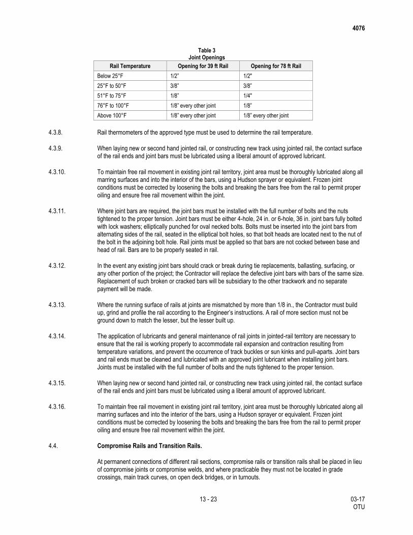
4076
13 - 23 03-17 OTU
Table 3
Joint Openings
Rail Temperature Opening for 39 ft Rail Opening for 78 ft Rail
Below 25°F 1/2” 1/2"
25°F to 50°F 3/8” 3/8”
51°F to 75°F 1/8” 1/4"
76°F to 100°F 1/8” every other joint 1/8”
Above 100°F 1/8” every other joint 1/8” every other joint
4.3.8. Rail thermometers of the approved type must be used to determine the rail temperature.
4.3.9. When laying new or second hand jointed rail, or constructing new track using jointed rail, the contact surface of the rail ends and joint bars must be lubricated using a liberal amount of approved lubricant.
4.3.10. To maintain free rail movement in existing joint rail territory, joint area must be thoroughly lubricated along all marring surfaces and into the interior of the bars, using a Hudson sprayer or equivalent. Frozen joint conditions must be corrected by loosening the bolts and breaking the bars free from the rail to permit proper oiling and ensure free rail movement within the joint.
4.3.11. Where joint bars are required, the joint bars must be installed with the full number of bolts and the nuts tightened to the proper tension. Joint bars must be either 4-hole, 24 in. or 6-hole, 36 in. joint bars fully bolted with lock washers; elliptically punched for oval necked bolts. Bolts must be inserted into the joint bars from alternating sides of the rail, seated in the elliptical bolt holes, so that bolt heads are located next to the nut of the bolt in the adjoining bolt hole. Rail joints must be applied so that bars are not cocked between base and head of rail. Bars are to be properly seated in rail.
4.3.12. In the event any existing joint bars should crack or break during tie replacements, ballasting, surfacing, or any other portion of the project; the Contractor will replace the defective joint bars with bars of the same size. Replacement of such broken or cracked bars will be subsidiary to the other trackwork and no separate payment will be made.
4.3.13. Where the running surface of rails at joints are mismatched by more than 1/8 in., the Contractor must build up, grind and profile the rail according to the Engineer’s instructions. A rail of more section must not be ground down to match the lesser, but the lesser built up.
4.3.14. The application of lubricants and general maintenance of rail joints in jointed-rail territory are necessary to ensure that the rail is working properly to accommodate rail expansion and contraction resulting from temperature variations, and prevent the occurrence of track buckles or sun kinks and pull-aparts. Joint bars and rail ends must be cleaned and lubricated with an approved joint lubricant when installing joint bars. Joints must be installed with the full number of bolts and the nuts tightened to the proper tension.
4.3.15. When laying new or second hand jointed rail, or constructing new track using jointed rail, the contact surface of the rail ends and joint bars must be lubricated using a liberal amount of approved lubricant.
4.3.16. To maintain free rail movement in existing joint rail territory, joint area must be thoroughly lubricated along all marring surfaces and into the interior of the bars, using a Hudson sprayer or equivalent. Frozen joint conditions must be corrected by loosening the bolts and breaking the bars free from the rail to permit proper oiling and ensure free rail movement within the joint.
4.4. Compromise Rails and Transition Rails.
At permanent connections of different rail sections, compromise rails or transition rails shall be placed in lieu of compromise joints or compromise welds, and where practicable they must not be located in grade crossings, main track curves, on open deck bridges, or in turnouts.
4076
14 - 23 03-17 OTU
Compromise rails or transition rails are required at all locations between the ends of rail of different weights or cross section. The Contractor must install all compromise rails and transition rails as directed by the Engineer. Compromise rails and transition rails must not be placed within the limits of turnouts.
4.5. Field Rail Welding.
Clean the rails to be free of grease, oil, dirt, loose scale, and moisture to a minimum of 6 in. back from the rail ends, including the rail end surfaces, by use of a wire brush. Align the faces of the rail ends. Rail ends to show no steel defects, dents, or porosity before welding.
If rail must be cut to length for any reason, cut it square and clean by means of rail saws or abrasive cutting wheels in accordance with AREMA, "Specifications for Steel Rails."
Straighten rail not meeting the requirements of AREMA, "Specifications For Fabrication of Continuous Welded Rail," to be within the specified tolerance. If any rail cannot be straightened, cut it back a sufficient distance to achieve the required alignment. Perform all straightening or cutting prior to welding.
Align and properly gap the ends of the rails to be welded to produce a weld which conforms to the alignment tolerances specified. Hold the rail gap and alignment during field welding without change during the complete welding cycle. Align rail on the head of the rail. Vertical alignment must provide for a flat running surface. Horizontal alignment must be in such a manner that any difference in the width of heads of rails occurs on the field side. Horizontal offsets must not exceed 0.040 in. in the head and 0.125 in. in the base.
4.5.1. Surface misalignment tolerance must conform to the following:
4.5.1.1. Combined Vertical Offset and Crown Camber. Not to exceed 0.080 in. per foot at 600°F or less. No dip camber will be allowed.
4.5.1.2. Gauge Misalignment Tolerance. Combined horizontal offset and horizontal kink camber not to exceed 0.080 in. per foot at 600°F or less.
4.5.2. All rails for electric-flash butt welds must have the scale removed down to the bright metal in the end zones on the top and bottom of the rails where the welding current-carrying electrodes contact on head and base of rail.
All electric-flash butt welds must be forged to point of refusal to further plastic deformation and have a minimum upset of 1/2 in., with 5/8 in. as standard. If flashing on electric-flash butt welds is interrupted because of malfunction or external reason, with less than 1/2 in. of flashing distance remaining before upsetting, rails must be reclamped in the machine and flashing initiated again.
4.5.3. Rails for preheated rail welds must be cleaned 2 in. on each side of the weld, to remove scale and rust using a power actuated grinder, with abrasive wheel. Rail ends must be preheated prior to welding to at least the temperature designed by the welding manufacturer and for a sufficient time to ensure full fusion of the weld metal to the rail ends without cracking of the rail or weld.
4.5.4. Inspect each weld using a 3 ft. straightedge along the centerline of the rail and 0.625 in. below top of rail on the gauge side of the rail head. Center the straightedge over the weld. The gap between the straightedge and the rail to comply with the requirements of AREMA, Chapter 4 Governing the Inspection, Grinding and Heat Treating of Track Components.
Bring rails and joints in the finished track to a true surface and alignment by means of an approved grinding machine. If end bolt hole is drilled in the rail to be welded, the minimum allowable distance from end of rail to edge of end bolt hole is 6 in.
4.5.5. Finish the completed weld by grinding to conform to the following requirements:
Rail head surface and sides must be finished ground to a smooth and uniform surface.
4076
15 - 23 03-17 OTU
The web zone (underside of head, web, top of base, both fillets each side) must be finished to not
greater than 1/8 in. of parent contour or closer, but must not be deeper than parent section. Finishing
must eliminate all cracks.
All notches created by offset conditions or twisted rails must be eliminated by grinding to blend the
variations.
All fins on the weld due to shearing drag must be removed prior to final inspection.
All heavy grinding must be performed on the hot metal, immediately following welding, by an approved
rail grinder, to prevent metallurgical damage. Finish grinding must be carried out in a cooled down
condition. Use a straightedge frequently while grinding to make sure that a good straight surface is
produced. If a hand grinder must be used, extra care must be taken to insure a smooth running surface
without low spots. Any grinding of the web and base of the weld should be done while the web is at least
450°F.
Jagged, notched or badly mismatched end faces must be preflashed to an even or mated condition
before setting up rails for preheating and final flashing to assure that the entire surfaces of the rail ends
are uniformly flashing immediately preceding upsetting.
4.5.6. Test all welds at the time of welding and ultrasonically test both the welds and the rail once the rails have been laid in final position. Ultrasonically inspect welds and rail in accordance with ASTM E164 and the AWS D1.1. Use ultrasonic test equipment capable of detecting a 3/64 in. discontinuity, 6-1/2 in. below the top of rail. Test results must be supplied to the Engineer for review and approval before the rail installation or replacement is accepted.
At a minimum, scan the weld from the top and both sides of the rail head and the base. Scan the weld from both sides on the face for longitudinal and transverse discontinuities using the applicable scanning pattern or patterns. Use equipment which has a distance amplitude correction feature. Calibrate the equipment daily using an 11W calibration block, also made of rail steel.
4.5.7. The Contractor’s rail distressing procedure must be presented to the Engineer for approval before welding can commence.
4.5.8. Inspection Personnel: Qualify all inspection personnel in accordance with AWS D1.1. Cut out and re-weld all welds giving fault indication in ultrasonic inspection.
4.6. Ballasting and Surfacing.
4.6.1. Ballast
4.6.1.1. Furnishing, delivery and unloading of ballast to project site is the Contractor’s responsibility. Care must be taken to insure that track and walkways are safe for movement.
4.6.1.2. Haul and place ballast material in such a way that damage to adjacent areas is avoided.
4.6.1.3. Ballast must be uniformly distributed and the track raised, lined, surfaced, and tamped, with the finished surface of the ballast dressed in accordance with the approved drawings or the Engineer’s instructions.
4.6.1.4. The track must be laid and connected before ballast is spread and raised. It will not be permissible to operate over long stretches of track before it has been raised and surfaced unless approved by the Engineer. Immediately prior to unloading ballast for the final raise, the track must be lined as close as practical to the stakes and all ties straightened and re-spaced as necessary. Ballast must then be spread evenly and leveled to the required section, taking care to assure that subgrade material is not intermixed with the ballast.
4.6.1.5. Ballast must be spread and the track raised in a series of lifts to the approved elevation. No single lift will be higher than 4 in. In raising track, if jacks or mechanical tampers are used they must be so regulated as to avoid the binding or straining of joints. Sufficient sets of track jacks, if used, must be simultaneously used
4076
16 - 23 03-17 OTU
and properly spaced to avoid sharp breaks or bends in the rail when the track is raised. Both rails must be raised simultaneously and to proper cross level by utilizing standard track level boards with each set of track raising jacks (minimum three insertions).
4.6.1.6. Ballast must be kept clean and free of segregation during handling and placing operations.
4.6.1.7. Ballast must be thoroughly regulated and level for the full length of each tie, end to end, and for the full length and width of the ballast section or bridge unless otherwise directed by the engineer. Centers are to be filled and regulated.
4.6.1.8. Ballast must be thoroughly tamped from each tie end to 15 in. outside and inside of the rail.
4.6.2. Tamping
4.6.2.1. Tamping is to be done by machines approved by the Engineer, in a manner that will produce uniform compaction. Tamping must not disturb subgrade/subballast. Thorough tamping under the rail set is required, and joint ties must be tamped especially firm.
4.6.2.2. Tamping will not be permitted at the middle of a tie. Both ends of a tie must be tamped simultaneously and tamping inside and outside the rail must be done at the same time. All ties that are pulled loose in the track raising operation must be placed in their proper position and properly tie-plated and fully spiked before tamping. The track must be true to line and grade as staked with tangent track level transversely.
4.6.2.3. During each track raise, the track is to be tamped in such a manner that it will be uniform. During the raising and tamping operations, sufficient spot boards, track level boards or other approved surfacing devices must be constantly used to insure the correct surface and cross level in the track after tamping work is completed.
4.6.2.4. Tamping tools must be inserted simultaneously on opposite sides of the same tie to prevent the tie from cocking, to insure that the ballast under the tie is completely compacted and that the rail is firmly seated on the tie plate.
4.6.2.5. When using power tampers in tandem, the machines should be of the same type and have identical tamping heads to produce uniform compaction.
4.6.3. Finishing and Surfacing
4.6.3.1. After ballasting is completed and the track is in correct gauge, surfaced and lined according to the stakes, the ballast must be trimmed neatly to the section shown on the drawings, and any surplus material must be spread evenly along the slopes of the ballast section. Dressing of the ballast by placing earth higher than the ballast toe and thus preventing proper drainage will not be permitted.
4.6.3.2. Bring the initial layer of compacted ballast to an elevation that will establish the track surface no higher than 2 in. below final base of rail grade. Refer to plans and cross sections for ballast depth and base of rail grades.
4.6.3.3. Ballast must be inserted under ties in minimum 2-1/2 in., maximum 4 in. lifts. Cribs must be filled with ballast to the top of tie.
4.6.3.4. Do not perform track surfacing unless the cribs are filled with ballast.
4.6.3.5. Special care must be taken when surfacing during hot weather in order to avoid track buckles.
4.6.3.6. Perform track surfacing by an approved method which prevents undue bending of the rail or straining of the joints.
4.6.3.7. Both rails must be raised at one time and as uniformly as possible.
4076
17 - 23 03-17 OTU
4.6.3.8. Ties that have been pulled loose must be replaced to proper position and must be fully tamped to proper elevation.
4.6.3.9. Track must be constructed to the alignment and grade prescribed by the approved plans or drawings.
4.6.3.10. Deviation from established gauge and cross level must not exceed 3/4 in. per 62 ft. cord; deviation from profile grade and horizontal alignment must not exceed 3/4 in. All work must be acceptable to the TXPF.
4.6.3.11. Tangent track must be cross level.
4.6.3.12. No humps or sags will be accepted nor will irregularities in alignment, either on tangent or curved track that exceed previously defined deviations. Top of track ballast must be dressed parallel with top of ties for the full length of each tie, end to end and for the full length and width of the ballast section or bridge.
4.6.3.13. Maximum allowable adjustment in line after final resurfacing is 2 in.
4.6.3.14. Top of track ballast must be dressed parallel with top of ties, extending a minimum 9 in. beyond the end of tie, then on three to one slope to subballast. Not less than three insertions of tamping tools must be made.
4.6.4. Acceptance
4.6.4.1. Before final acceptance, all track must be surfaced and accurately lined to remove all irregularities of cross level, surface or line caused by settlement or compaction of ballast following traffic loading. Any ties not giving full support to rails must be retamped. Bolts must be retightened, if necessary, to bring to full tension and spikes set down to full rail contact.
4.6.4.2. TxDOT’s acceptance of trackage and its appurtenances which have been built must be based on the Engineer’s written statement that construction and construction materials have met TxDOT standards, Special Specifications, and Plans.
4.7. Vehicular Grade Crossing.
4.7.1. Preparation
4.7.1.1. When preparing to work in vehicular grade crossings, the Contractor must notify the owner of a private crossing of the work to be done at least 24 hr. in advance of the proposed work. The Contractor must notify the city, county, or state road authority of crossing work to be done on publicly owned roads at least 24 hr. in advance of the proposed work. The Contractor must coordinate with the private crossing owner or the road authority regarding the type of work to be performed and the time the crossing will be blocked or closed. Private crossings must only be closed for one day. Public crossings may be closed for more than one day if appropriate detours are arranged with the responsible road authority. Barricades, signs, and traffic handling for closures and detours must be placed in accordance with TxDOT Standard Specification Item 502, “Barricades, Signs, and Traffic Handling”.
4.7.2. Approach subgrades and ditches shall be re-profiled as required by the plans or as directed by the Engineer.
4.7.3. Temporary crossing surfaces must be constructed where necessary as required by the plans or as directed by the Engineer.
4.7.4. The track must be properly lined, tamped, compacted, spiked, broomed and anchored before any crossing materials are installed.
4.7.5. Ballast, Subballast, and Subgrade
4.7.5.1. Existing ballast and subballast shall be excavated to the hard pan below the grade crossing and to a minimum of 12” below the bottom of the crossties. If full surface hard pan is not present or if the subgrade is
4076
18 - 23 03-17 OTU
not fully consolidated, install fully compacted granular fill as base material before placement of subballast, ballast, or crossing materials.
4.7.5.2. Install filter fabric and perforated pipe extending to the indicated limits shown in accordance with the manufacturer's instructions when required by the state or local road authority or when directed by the Engineer. Filter fabric must meet the requirements of DMS-6200 “Filter Fabric.” Protect filter fabrics from puncture throughout construction.
4.7.5.3. Fouled ballast materials must be removed for a minimum distance of 20 ft. from the ends of the crossing. The crossing and approaches must be raised within specifications to allow drainage away from the crossing.
4.7.6. Cross-ties
4.7.6.1. Verify that cross-ties are of correct length, position and spacing. Correct any track deficiencies before starting the installation of the vehicular grade crossing.
4.7.6.2. Each cross-tie in vehicular grade crossings must be plated and double-spiked with 4 rail holding spikes per tie plate.
4.7.6.3. Each cross-tie in vehicular grade crossings must be fully box-anchored.
4.7.6.4. Cross-ties shall be long enough to fully support the width of the panels in an even and uniform manner.
4.7.7. Rail
4.7.7.1. Rail must be replaced with new, unused rail within all vehicular grade crossings included in the project as shown on the plans.
4.7.7.2. Weld all rail joints within the limits of the crossing. Limits of the crossing include the full length of the crossing and an additional 15 feet on either side of the crossing as measured along the rail from the edge of the crossing panel furthest from the center of the crossing.
4.7.7.3. All welds within the crossing surface must be ground flush on all sides of the rail except on the bottom of the base.
4.7.8. Crossing panels
4.7.8.1. Panels shall be constructed of either prestressed concrete or treated wood, as specified by the plans or as directed by the Engineer.
4.7.8.2. Panels shall be supported by the ties in an even and uniform manner.
4.7.8.3. Panels shall be secured to the ties below the rail to prevent movement, maintain the grade line of the intersecting roadway, and to establish an even and uniform support for the panels.
4.7.8.4. Panels shall extend a minimum of 3 feet from the edge of the traveled way, including shoulders, of the intersecting roadway.
4.7.9. Finishing and Alignment
4.7.9.1. Finished crossings must be constructed to the lines and grades as shown on the plans or as directed by the Engineer. Grade crossing surfaces must be placed as shown on the plans or as directed by the Engineer.
4.7.9.2. Flangeways in crossings shall be filled. Filter fabric and asphalt shall be installed in the flangeways of timber crossings and rubber fillers shall be installed in concrete panel crossings.
4076
19 - 23 03-17 OTU
4.7.9.3. Where asphalt is specified on the plans or specifications, hot mix asphalt shall be used.
4.7.9.4. Verify that the track has been installed in accordance with the plans and specifications and approved for alignment and profile by the Engineer.
4.8. Turnouts.
4.8.1. Turnouts must be constructed in strict conformity with the shop drawings, plans, the Engineer’s instructions, and AREMA specifications, Chapter 4, Part 4, “Track Construction”.
4.8.2. The switch stands must be fastened securely to head blocks and must be square with the track. The targets must be lined parallel with the rails of the major track when the switch is lined for the major track. All switch ties must be fully tie plated.
4.8.3. Stock rails for turnouts must be bent accurately and must not be sprung into place. All frogs, with the exception of self-guarded frogs, must be protected by guardrails installed in accordance with the standard plans before any train is allowed to pass over them.
4.8.4. Turnouts must also include switchman walkways.
4.8.5. Turnouts must have all special switch plates, frog and guard rail plates fully spiked. Spiking standards must be per the approved shop drawings, as shown on the plans, Special Specification, and the Engineer’s instructions.
4.8.6. Panel turnouts must be constructed in conformity with the approved shop drawings, plans, the Engineer’s instructions, and these specifications. Care must be taken in unloading or moving the panel sections so as not to skew or bend the sections or cause damage to the prepared subgrade. The Contractor must adjust anchors, ties, spikes, switch plates, braces, etc., as necessary to conform to the standard plan.
4.8.7. Where required, derails must be installed in conformity with the plans, specifications, and/or instructions, and must be inspected and approved by the Engineer before final acceptance and operation over the track.
4.8.8. All rail within the turnout shall be head hardened.
4.8.9. Rail bound and solid steel frogs shall be made of manganese castings.
4.9. Removing Ballasted Track and Turnouts.
4.9.1. After designated sections of ballasted track and turnouts are no longer needed to carry traffic they must be disconnected from the rail line and all salvageable materials must be removed.
4.9.1.1. Fill in ditches, except as needed for drainage and scarify abandoned trackbed and/or plow so as to mix it with soil to the satisfaction of the Engineer. The entire area of the removed ballasted track and turnouts must be smoothed by blading or other methods.
4.9.1.2. Timber Curbs.
4.9.1.2.1. Timber curbs shall be of the size and length shown in the plans. Replacement timber curbing for damaged curbs shall be of the same size and length of the existing timber curb or as approved by the Engineer.
4.9.1.2.2. Timber curbs shall be connected to bridge cross ties by bolts that are 3/4-in. minimum diameter. Timber curb bolts shall extend completely through the timber curb and cross ties and be secured on the opposite end using flat washers, lock washers, and nuts.

4076
20 - 23 03-17 OTU
4.9.1.2.3. Timber curbs shall be secured to the bridge deck near every fourth cross tie using a 3/4-in. minimum diameter bolt wherever possible. Timber curb securement bolts shall extend completely through the timber curb and bridge deck and be secured on the opposite end using timber washers (malleable iron) and nuts.
4.10. Salvaging.
4.10.1. Unless otherwise specified, all removed materials will become the property of the Contractor.
4.11. Warranty.
4.11.1. The Contractor will warrant the rehabilitation of track construction and rehabilitation for a period of 12 months. The warranty period begins with the Engineer’s acceptance of the work.
4.11.2. Contractor Inspections. Conduct initial and semiannual inspections of the Track Construction and Rehabilitation. Conduct initial inspections within 7 days after work is completed. For Track Construction and Rehabilitation provide a written report of the existing conditions at the time of the inspection to the Department. Document each inspection with digital photography, and provide a copy of the written report and digital photographs to the Department. Provide sketches, written reports and digital photographs within 30 days after the inspection. Conduct warranty inspections according to 4.1., “General Requirements.”
4.11.3. Replace or repair work or materials that do not meet contract specifications. Notify the Engineer at least 72 hrs. prior to beginning any warranty work. If deficiencies are not corrected within 30 days of a semiannual inspection, the warranty period for the entire project will be extended on a daily basis starting on the 31st day until the deficiency is corrected.
4.11.4. A Department representative will be present for all semiannual inspections. Provide written notification to the Engineer no later than 15 days prior to any semiannual inspection.
4.11.5. Department Inspections. The Contractor will be provided a copy of any inspections. The Contractor will be notified in writing of any needed warranty work between semiannual inspections. Within 30 days of receipt of the written notification, replace or repair work or materials that do not meet the contract specifications. If deficiencies are not corrected within 30 days of receipt of the written notification, the warranty period for the entire project will be extended on a daily basis starting on the 31st day until the deficiency is corrected. If it is found that the requirements are met, provide documentation of the evaluation results to the Engineer for review and his decision per Item 5, “Control of the Work.”
4.11.6. The Department will conduct a final warranty inspection prior to the expiration of 1 yr. of the project completion date. The Contractor will be notified in writing of the final warranty inspection date at least 15 days prior to the inspection to allow the Contractor to be present. Absence or failure to witness the final inspection will not delay the final inspection. If the final warranty inspection identifies any work or materials that do not meet the contract specifications, replace or repair the work or materials to meet the contract specifications. Failure to repair or replace work or materials that do not meet the contract specifications, will result in the warranty period for the entire project being extended on a daily basis until all work or materials meet performance requirements and have passed an initial inspection.
4.11.7. The Contractor will be considered in default during the warranty period if:
any warranty work is not completed within 60 days of an initial, semiannual or final warranty inspection,
or receipt of written notice from the Engineer identifying an area of concern;
any warranty work from the initial inspection is not conducted within 7 days of when the work or
materials are installed;
fails to perform the semiannual inspection or provide the report documenting the inspection; or,
submits a false or misleading report regarding whether the work or materials meet the performance
requirements.
4076
21 - 23 03-17 OTU
4.11.8. The warranty bond will insure the proper and prompt completion of required warranty work following completion of the project, including payments for all labor performed, equipment and material used in accordance with the specifications.
5. MEASUREMENT
5.1. Tie Removal and Replacement will be measured jointly by each individual tie removed and replaced as one unit.
5.2. Open Deck Bridge Tie Removal and Replacement will be measured jointly by each individual tie removed and replaced as one unit.
5.3. Switch Tie Removal and Replacement will be measured jointly by each individual tie removed and replaced as one unit and specified by length.
5.4. Subballast will be measured by the cubic yard, complete in place.
5.5. Ballast Delivery and Regulating will be measured by the ton, complete in place.
5.6. Ballasted Track Surfacing and Alignment will be measured jointly by the mile.
5.7. Replacement Rail installed will be measured by the linear foot for installation and removal.
5.8. Compromise Rail will be measured by the linear foot for installation and removal.
5.9. Transition Rail will be measured by the linear foot for installation and removal.
5.10. Turnouts will be measured by the each for installation and removal.
5.11. Derails will be measured by the each for installation and removal.
5.12. Guardrails will be measured by the linear foot for installation and removal.
5.13. Welds will be measured by the each connecting two rails together.
5.14. Vehicular Grade Crossing will be measured by the track foot for installation and removal, including all ties, rail, panels, ballast, sub-ballast, spikes, joints, bolts, securement, filter fabrics, drains, temporary crossing materials, etc.
5.15. Timber Curbs will be measured by each timber curb removed and installed as one unit complete and in place.
6. PAYMENT
6.1. Payment for tie replacement will be made at the unit price bid for "Tie Removal and Replacement." This price is full compensation for transportation; storage; removal of defective ties, installation of all track work materials including replacement ties, securement, anchors, joint bars, all track work on ballast deck bridges, track work at vehicular grade crossings; and for the removal of all materials used in Track Construction & Rehabilitation and for all other materials, tools, equipment and incidentals necessary to complete the work.
6.2. Payment for open deck bridge tie replacement will be made at the unit price bid for "Open Deck Bridge Tie Removal and Replacement." This price is full compensation for transportation; storage; removal of defective ties, installation of all track work materials including replacement ties, securement, anchors, joint bars, all track work on open deck bridges; and for the removal of all materials used in tie removal and replacement and for all other materials, tools, equipment and incidentals necessary to complete the work.
4076
22 - 23 03-17 OTU
6.3. Payment for switch tie replacement will be made at the unit price bid for "Switch Tie Removal and Replacement" by specified length. This price is full compensation for transportation; storage; removal of defective switch ties, installation of all track work materials including replacement ties, securement, anchors, joint bars, all track work on bridges, track work at vehicular grade crossings; and for the removal of all materials used in Track Construction & Rehabilitation and for all other materials, tools, equipment and incidentals necessary to complete the work.
6.4. Payment for subballast will be at the unit price bid for “Subballast.” This price is full compensation for furnishing, hauling, placing, sprinkling, rolling the subballast and for all other materials, tools, equipment and incidentals necessary to complete the work.
6.5. Payment for Ballast Delivery and Regulating will be made at the unit price bid for "Ballast Delivery and Regulating.” This price is full compensation for transportation; storage; installation of materials including placing ballast; for regulating ballast to final grade and cross section; for the removal of all materials used in Ballast Delivery and for all other materials, tools, equipment and incidentals necessary to complete the work.
6.6. Payment for Ballasted Track Surfacing and Alignment will be made at the unit price bid for "Ballasted Track Surfacing and Alignment." This price is full compensation for transportation; storage; tamping and raising track to final grade and alignment, and for the removal of all materials used in Ballasted Track Surfacing and Alignment and for all other materials, tools, equipment and incidentals necessary to complete the work.
6.7. Payment for Rail Replacement will be made at the unit price bid for “Rail Replacement.” This price is full compensation for transportation; storage; all fasteners, plates, spikes, joints, bolts, welds; and for all other materials, tools equipment, labor and incidentals necessary to complete the work.
6.8. Payment for Compromise Rail will be made at the unit bid price for “Compromise Rail.” This price is full compensation for the removal of existing rails, bolts, nuts, spikes, and all other materials; furnishing, hauling, and installation of materials including compromise rail, welding materials, welds, joint bars, anchors, spikes, bolts, nuts, and all other materials, tools equipment, labor and incidentals necessary to complete the work.
6.9. Payment for Transition Rail will be made at the unit bid price for “Transition Rail.” This price is full compensation for the removal of existing rails, bolts, nuts, spikes, and all other materials; furnishing, hauling, and installation of materials including compromise rail, welding materials, welds, joint bars, anchors, spikes, bolts, nuts, and all other materials, tools equipment, labor and incidentals necessary to complete the work.
6.10. Payment for Turnouts will be made at the unit bid price for “Turnouts.” This price is full compensation for the removal of existing turnouts, rails, bolts, nuts, spikes, and all other materials; furnishing, hauling, and installation of materials including turnout castings (frogs), switch stands, connecting rods, plates, switch ties, cross ties, welding, securements, rail, switch mechanisms, and all other materials, tools equipment, labor and incidentals necessary to complete the work.
6.11. Payments for Derails will be made at the unit bid price for “Derails.” This price is full compensation for furnishing, hauling, and installation of materials including derails, hinges, plates, bolts, securement, signage, marking, locks, and all other materials, tools equipment, labor and incidentals necessary to complete the work.
6.12. Payments for Guardrails will be made at the unit bid price for “Guardrails.” This price is full compensation for furnishing, hauling, and installation of materials including guardrail, plates, spikes, bolts, securement, and all other materials, tools equipment, labor and incidentals necessary to complete the work.
6.13. Payments for Welds will be made at the unit bid price for “Welds.” This price is full compensation for joining two rails by thermite or electric arc induction, and for all materials, tools, equipment, labor and incidentals necessary to complete the work.
6.14. Payment for Vehicular Grade Crossing will be made at the unit price bid for "Vehicular Grade Crossing" by specified type. This price is full compensation for all temporary crossing materials, crossing materials, filter fabric, underdrains, fasteners; for the removal of the existing crossing materials, filter fabric, underdrains,
4076
23 - 23 03-17 OTU
fasteners; for all ties, rail, panels, ballast, sub-ballast, plates, spikes, joints, bolts, welding; and for all other materials, tools, equipment, labor and incidentals necessary to complete the work.
6.15. Payment for “Timber Curbs” will be made at the unit price bid for "Timber Curbs". This price shall be full compensation for furnishing and installing timber curbs; all transportation; storage; labor, equipment, tools, treating, removal of defective components, erecting, installation, fasteners and for all other materials, tools, equipment, and incidentals necessary to complete the work.
7049
1 - 52 07-15 OTU
Special Specification 7049
Water Mains
1. DESCRIPTION
Furnish labor, materials, and equipment necessary to provide a complete water main system in conformance with the plans and specifications, and in compliance with the Department’s Utility Accommodations Policy (Title 43, T.A.C., Sections 21.31-21.55). Construct water mains of the sizes, materials, and dimensions shown on the plans including pipe, joints, and connections to new and existing pipes, casing, valves, fittings, fire hydrants, meters, blocking, etc., as many as may be required to complete the work.
Furnish material and equipment for encasing existing water lines with split steel encasement pipes using the open cut method in accordance with this specification.
The abbreviations AWWA, ASA, ASTM, ANSI, AASHTO, NACE, NSF, SSPC, and TCEQ used in this specification refer to the following organizations or technical societies:
AWWA American Water Works Association
ASA American Standards Association
ASTM American Society for Testing and Materials
ANSI American National Standards Institute
AASHTO American Association of State Highway and Transportation Officials
NACE National Association of Corrosion Engineers
NSF National Sanitation Foundations
SSPC Steel Structural Painting Council
TCEQ Texas Commission on Environmental Quality
References to specifications of the above organizations mean the latest standard or tentative standard in effect on the date of the proposal.
2. MATERIALS
All materials must conform to the requirements of this Item, the plans and the following Items:
Item 421, “Hydraulic Cement Concrete”
Item 440, “Reinforcement for Concrete”
Item 441, “Steel Structures”
Item 465, “Junction Boxes, Manholes, and Inlets”
Item 471, “Frames, Grates, Rings, and Covers”
2.1. General. Provide new and unused materials for this project unless otherwise stated in the plans or proposal.
Pipe 6 in. or larger is acceptable to the Texas Fire Insurance Commission without penalty for use in water works distribution systems.
For water mains less than 24 in. in diameter, use casing insulators between the water main and casing unless otherwise shown on the plans. For water mains 4 in. through 14 in., use 8 in. wide casing insulators.
For water mains 16 in. through 20 in., use 12 in. wide insulators. For pipe materials up to 12 in., use Pipeline Seal and Insulator Model C8G-2 or approved equal. For water mains larger than 12 in. use Pipeline Seal and
7049
2 - 52 07-15 OTU
Insulator Model C12G-2 or approved equal. Casing end seals: Pipeline Seal and Insulator Model C or approved equal.
2.2. Steel Pipe and Fittings.
2.2.1. Steel Carrier Pipe. Provide steel pipe for use as carrier pipe in the distribution system, conforming to the requirements of AWWA Standard C200. Install steel pipe 20 in. and smaller as aerial crossings, above-ground piping, and for encasement sleeves only. Do not bury steel pipe that is 20 in. and smaller directly or within a casing.
For pipe 24 in. and greater, conform to the requirements of AWWA C200, C207, C208 and AWWA M11 except as modified in this specification. Furnish pipe and fittings that have manufacturer's certifications ensuring that they have been hydrostatically tested at the factory in accordance with AWWA C200, Section 3.4. Ensure pipe steel meets the requirements of ASTM A36, ASTM A570 Grade 36, ASTM A53 Grade B, ASTM A135 Grade B, or ASTM A139 Grade B as a minimum. Pipe is also subject to the requirements of Underwriters Laboratories, Inc. Specification for “Steel Pipelines for Underground Water Service.”
Provide pipe and fittings to withstand the most critical simultaneous application of external loads and internal pressures based on the minimum of AASHTO HS-20 loading, AREMA E-80 loads, depths of bury as indicated on the plans, and the most critical groundwater level condition. The pipe design conditions follow:
Working pressure = 100 psi.
Hydrostatic field test pressure = 150 psi.
For pipe design (24 in. and larger) conform to AWWA M11 with the following conditions:
Design stress due to working pressure: The maximum is 50% of the minimum yield strength or
16,500 psi maximum stress for mortar-coated pipe.
Design stress due to hydraulic test pressure: The maximum is 75% of the minimum yield strength or
24,750 psi maximum stress for mortar-coated pipe.
Modulus of soil reaction (E'), <1,500 psi.
Unit weight of fill (w) > 120 pcf.
Deflection lag factor (D1) = 1.2.
Bedding constant (K) = 0.1.
Fully saturated soil conditions: hw = h = depth of cover above top of pipe.
Maximum deflection from specified diameter = 3% for flexible coatings.
Provide pipe and fittings that have been designed by a licensed Engineer. Before manufacturing, submit these signed, sealed, and dated calculations for approval.
Supply pipe in double random lengths unless otherwise shown on the plans. Bevel the ends of the pipe for field butt welding as shown on the plans.
Provide a minimum of 3/8 in. inside joint recess between ends of pipe in straight pipe sections.
Provide a minimum allowable steel wall thickness in accordance with Tables 1 and 2 for HS-20 live loads and depths of bury up to 16 ft.
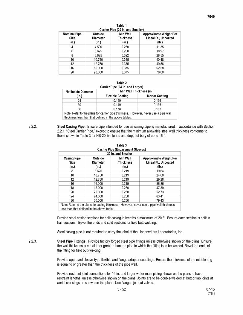
7049
3 - 52 07-15 OTU
Table 1 Carrier Pipe (20 in. and Smaller)
Nominal Pipe Size (in.)
Outside Diameter
(in.)
Min Wall Thickness
(in.)
Approximate Weight Per Lineal Ft., Uncoated
(lb.)
4 4.500 0.250 11.35
6 6.625 0.280 18.97
8 8.625 0.322 28.55
10 10.750 0.365 40.48
12 12.750 0.375 49.56
16 16.000 0.375 62.58
20 20.000 0.375 78.60
Table 2 Carrier Pipe (24 in. and Larger)
Net Inside Diameter (in.)
Min Wall Thickness (in.)
Flexible Coating Mortar Coating
24 0.149 0.136
30 0.149 0.136
36 0.178 0.163
Note: Refer to the plans for carrier pipe thickness. However, never use a pipe wall thickness less than that defined in the above tables.
2.2.2. Steel Casing Pipe. Ensure pipe intended for use as casing pipe is manufactured in accordance with Section 2.2.1, “Steel Carrier Pipe,” except to ensure that the minimum allowable steel wall thickness conforms to those shown in Table 3 for HS-20 live loads and depth of bury of up to 16 ft.
Table 3
Casing Pipe (Encasement Sleeves)
30 in. and Smaller
Casing Pipe Size (in.)
Outside Diameter
(in.)
Min Wall Thickness
(in.)
Approximate Weight Per Lineal Ft., Uncoated
(lb.)
8 8.625 0.219 19.64
10 10.750 0.219 24.60
12 12.750 0.219 29.28
16 16.000 0.219 36.86
18 18.000 0.250 47.39
20 20.000 0.250 52.73
24 24.000 0.250 63.41
30 30.000 0.250 79.43
Note: Refer to the plans for casing thickness. However, never use a pipe wall thickness less than that defined in the above table.
Provide steel casing sections for split casing in lengths a maximum of 20 ft. Ensure each section is split in half-sections. Bevel the ends and split sections for field butt-welding.
Steel casing pipe is not required to carry the label of the Underwriters Laboratories, Inc.
2.2.3. Steel Pipe Fittings. Provide factory forged steel pipe fittings unless otherwise shown on the plans. Ensure the wall thickness is equal to or greater than the pipe to which the fitting is to be welded. Bevel the ends of the fitting for field butt-welding.
Provide approved sleeve-type flexible and flange adaptor couplings. Ensure the thickness of the middle ring is equal to or greater than the thickness of the pipe wall.
Provide restraint joint connections for 16 in. and larger water main piping shown on the plans to have restraint lengths, unless otherwise shown on the plans. Joints are to be double-welded at butt or lap joints at aerial crossings as shown on the plans. Use flanged joint at valves.
7049
4 - 52 07-15 OTU
Elbows: Provide 2-piece for 0° to 22.5°; 3-piece for 23° to 45°; 4-piece for 46° to 67.5°; and 5-piece for 68° to 90°, unless otherwise shown on plans.
Outlets: Reinforced in accordance with AWWA M11, Sections 13.3-13.7, AWWA C200, and AWWA C208. Provide interior lining and exterior coating in accordance with paragraphs on coating and lining, and matching pipe to access inlets, service outlets, test inlets, and air-vacuum valve and other outlets, including riser pipes.
Radius: The minimum radius is 2.5 times pipe diameter.
2.2.4. Hydrostatic Test of Pipe. Ensure the pipe manufacturer performs hydrostatic testing in accordance with AWWA C200, Section 3.5.3, at the point of manufacture, conducts the test for a minimum of 2 min., and thoroughly inspects the pipe. Repair or reject pipe revealing leaks or cracks. Obtain from the manufacturer and submit to the Engineer, the manufacturer’s written certification that the pipe and fittings used on this project have passed the hydrostatic test.
Calibrate pressure gauges within 1 yr. before testing, as specified in AWWA C200, Section 1.04 L.
2.2.5. Butt Straps for Closure Piece. Provide a minimum 12 in. wide split butt strap; minimum plate thickness equal to the thinnest member being joined; fabricated from material equal in chemical and physical properties to the thinnest member being joined.
Provide a minimum lap of 4 in. between the member being joined and the edge of the butt strap, welded on both the inside and outside, unless otherwise approved.
Provide a minimum 6 in. welded outlet for inspecting each closure section, unless the access man way is within 40 ft. of the closure section. Provide forged steel threaded outlets of approved design, where required, for use in passing hose or lead wires into the pipe. Tap plugs with standard pipe threads and weld to the pipe in an approved manner, and use solid forged steel plugs for closure.
Provide full penetration butt or welded joints as shown on the plans. Use flanged joints at valves unless otherwise shown on the plans. Perform x-ray or ultrasonic testing of manual welds on special pipe and fittings.
Dished Head Plugs: Provide dished head plugs (test plugs) to withstand field hydrostatic test pressure from either side of the plug. Ensure the design stress due to hydrostatic pressure is at most 50% of minimum yield. Pipe on the opposite side of the hydrostatic test may or may not contain water. Ensure the manufacturer of the steel pipe hydrostatically tests the plugs at the factory.
Make curves and bends by deflecting joints, by using beveled joints, or by combining these methods, unless otherwise shown on the plans. Do not exceed the joint deflection angle recommended by the pipe manufacturer.
Make penetration of spigot into bell at all points of circumference at least equal to minimum required penetration shown on the plans. Provide beveled pipe sections used in curved alignment of standard length except when shorter sections are required to limit the radius of curvature. In this case, provide equal length sections throughout the curve. Do not allow the bevel to exceed 5°.
2.2.6. Steel Pipe Flanges. Ensure steel pipe flanges shown on the plans conform to AWWA Standard C207 for Class D Flanges (same diameter and drilling as Class 125 cast-iron flanges ASA B16.1).
Make cast-iron to steel pipe connections with 1 cast-iron bell flange and 1 steel slip-on flange, and ensure they are electrically isolated.
7049
5 - 52 07-15 OTU
The use of insulating gaskets, plastic bolt sleeves, and washers of insulating gasket material backed with zinc plated or hot-dip galvanized washers, or epoxy coated bolts, nuts, and washers used with an insulating gasket, are approved for this purpose.
For inline flange joints 12 in. in diameter and greater and for butterfly valve flanges, use Pyrex LineBacker Type E phenolic gaskets manufactured by Pipeline Seal and Insulator Inc., or approved equal.
Use full-face gaskets for other flanged joints not listed above. Provide cloth-inserted rubber gasket material, 1/8 in. thick in accordance with AWWA C207. Ensure gaskets are factory-cut to proper dimensions.
Maintain electrically isolated flanged joints between steel and cast-iron by using epoxy coated bolts, nuts, washers, and insulating type gaskets unless, otherwise approved.
Fabricate flanges with oversize bolt holes, with flanges drilled in pairs, to accommodate insulating sleeves.
2.2.7. Steel Pipe Protective Coatings.
2.2.7.1. General. Use shop-applied protective coatings except for field repairs and coatings of field welded joints. The Engineer may provide for witness of inspection and testing of shop-applied coatings, however, such witness does not relieve the Contractor of the responsibility to furnish material, perform work, and provide quality control in conformance with the applicable AWWA Standard and the requirements of these specifications.
The substrate surface profile and minimum and maximum individual and total dry film thickness (DFT) indicated in this specification apply. No requirement of this specification cancels or supersedes the specific written directions and recommendations of the specific coating manufacturer so as to jeopardize the integrity of the applied system. Measure the dry film thickness in accordance with SSPC PA2.
Field test shop coating and field repairs for holidays, pinholes, or discontinuities, at voltage levels required by the applicable AWWA Standard and in accordance with the applicable NACE procedure, i.e., PRO 188, RPO 274, TMD 384, etc. Submit the test procedure, including voltage levels to be used, before testing. Repair holidays in conformance with the applicable AWWA Standard.
Provide documentation by a NACE-certified inspector of compliance with the required tests.
Handle, store, and use field procedures for shop-coated pipe in conformance with the applicable AWWA Standards. Adequately seal and protect pipe ends from damage during handling and storage. Do not remove such protection until immediately before installing. Do not lift pipe using caliper clamps or hooks at ends of the pipe.
Repair damage to the pipe or the protective coating caused while installing the pipe and before final acceptance by the owner, as directed and in conformance with the applicable standards.
Keep the interior of the pipe and fittings clean of foreign matter before installing and until the work is accepted. Keep joint contact surfaces clean until jointing is complete.
Furnish an affidavit of compliance that all materials and work furnished comply with the requirements of the applicable AWWA Standard and these specifications.
2.2.7.2. Internal Lining for Steel. Ensure the material used for the internal coating of the steel carrier pipe is NSF61-listed as suitable for contact with potable water as required by Chapter 290, Rules & Regulations for Public Systems, Texas Commission on Environmental Quality (TCEQ).
Supply steel pipe with epoxy lining, capable of conveying water at temperatures not greater than 140°F. Provide linings conforming to American National Standards Institute/National Sanitation Foundation (ANSI/NFS) Standard 61, and certification from an organization accredited by ANSI. Unless otherwise noted,
7049
6 - 52 07-15 OTU
coat exposed (wetted) steel parts of flanges, blind flanges, bolts, and access manhole covers, with epoxy lining as specified.
2.2.7.2.1. Epoxy Lining. Use Liquid Epoxy meeting the requirements of AWWA C-210, “Liquid Epoxy Coating System for the Interior and Exterior of Steel Water Pipelines,” except as modified in this specification. Provide a Liquid Epoxy system consisting of three coats of polyamide epoxy (no coal tar material) as follows:
Prime Coat: 2-part, chemically cured, NSF certified epoxy, 4-6 mils dry film thickness (DFT).
Intermediate Coat: 2-part NSF certified epoxy, 4-6 mils (DFT).
Finish Coat: 2-part NSF certified epoxy, 4-6 mils (DFT).
Ensure the total system has a minimum DFT of 12 mils and a maximum DFT of 18 mils. Apply each coat in contrasting colors, using a buff prime and intermediate coat and a white finish coat. Use the same manufacturer to supply all material. Coal-tar epoxy material is not permitted. For surfaces to be coated, abrasive blast clean them to a near-white finish in accordance with SSPC-5(64) to establish an average anchor profile of 2.0 to 3.0 mils, with no individual reading greater than 4.0 mils or less than 1.5 mils. Before applying, inspect the prepared and cleaned surface for evidence of non-visible contaminants such as soluble salts or chlorides in accordance with NACE Technical Committee Report “Surface Preparation of Contaminated Steel Surfaces,” NACE Publication 6G 186.
Re-clean the surface as necessary, until it is free of such contaminants.
Perform an interior adhesion test on pipe 30 in. in diameter and larger in accordance with ASTM D 4541.
Minimum field adhesion: 700 psi. Perform this test on pipe for project at a frequency of one for every 1000 sq. ft. of epoxy lining. Perform a cure test in accordance with ASTM D 4752 (solvent rub test) and ASTM D 3363 (pencil hardness) for each section of pipe. Repair tested areas with approved procedures.
Provide Fusion Bonded Epoxy in accordance with AWWA C-213, “Fusion-Bonded Epoxy Coating for the Interior and Exterior of Steel Water Pipelines.”
2.2.7.3. External Coating.
2.2.7.3.1. Above Ground. Externally coat above ground steel piping and fittings with a 3-coat epoxy/epoxy/polyurethane system in accordance with AWWA C-218, “Coating the Exterior of Aboveground Steel Water Pipelines and Fittings,” Section 2.5, Coating System No. 4-91, except as modified in this specification.
Prime Coat: 2-component, inhibitive epoxy primer; DFT of 4-6 mils.
Intermediate Coat: 2-component, chemical resistant epoxy; DFT of 4-6 mils.
Finish Coat: 2-componant aliphatic polyurethane; DFT 1.5-2.5 mils.
Ensure the total system has a minimum DFT of 9.5 mils and a maximum DFT of 14.5 mils. Apply each coat in contrasting colors, using a buff prime coat and a blue finish coat, or as directed. Use the same manufacturer to supply all material. For surfaces to be coated, abrasive blast clean them to a near-white finish in accordance with SSPC-SP10 (NACE 2) to establish an average anchor profile of 2.0 to 3.0 mils, with no individual reading greater than 4.0 mils or less than 1.5 mils. Before coating, inspect the prepared and cleaned surface for evidence of non-visible contaminants such as soluble salts or chlorides in accordance with NACE Technical committee Report “Surface Preparation of Contaminated Steel Surfaces,” NACE Publication 6G 186. Re-clean the surface as necessary, until it is free of such contaminants.
Perform an interior adhesion test on pipe 30 in. in diameter and larger in accordance with ASTM D 4541. Minimum field adhesion: 700 psi. Perform this test on pipe for the project at a frequency of one for every 1000 sq. ft. of epoxy lining. Perform a cure test in accordance with ASTM D 4752 (solvent rub test) and ASTM D 3363 (pencil hardness) for each section of pipe. Repair tested areas with approved procedures.

7049
7 - 52 07-15 OTU
Provide Fusion Bonded Epoxy in accordance with AWWA C-213, “Fusion-Bonded Epoxy Coating for the Interior and Exterior of Steel Water Pipelines.”
2.2.7.3.2. Buried Steel Pipe, 24 Inch Diameter and Larger Only. Coat buried steel pipe and fittings (except tunneled, cased, or augered holes) with either of the following systems:
2.2.7.3.2.1. Tape Coating. Provide an approved tape for external tape coating. Apply in accordance with AWWA C214 and the requirements of this section; 80 mil shop-applied, Polyken YG-III, Tek-Rap Yard-Rap, or approved equal. Components: Primer, one 20 mil layer of inner-layer tape for corrosion protection and two 30 mil layers of outer-layer tape for mechanical protection. Bond coupling to adjacent pipes with bonding cables as shown on the plans.
Use approved filler putty, type Polyken 939 insulating putty, or approved equal, to fill in the gap and create a smooth sloped transition between the top of the reinforcing plate and the pipe, before applying the tape coating.
Primer: Compatible with the tape coating, supplied by the coating-system manufacturer.
Provide pipe with shop coatings cut back approximately 4 to 4-1/2 in. from the joint ends to facilitate joining and welding of pipe. Taper successive tape layers by 1 in. staggers to facilitate field wrapping and welding of joints. Inner and outer tape width: 12 in. or 18 in.
Do not expose tape coating to direct sunlight for more than 60 days.
Wrap specials and fittings that cannot be machine wrapped due to configuration, with primer layer and two layers of prefabricated tape, each 35 mils thick. Overlap machine applied tape with hand applied tape by minimum of 2 in. and bind to it.
Apply Polyken approved 30 mil filler tape 931, or approved equal, parallel to spiral weld seams if weld height measures greater than or equal to 1/8 in.
2.2.7.3.2.2. Polyurethane Coating. Refer to Section 2.2.7.3.1., “Above Ground.” Heat Shrink Joint Sleeves for Tape Coating: Aqua-shield, or approved equal. For repairs to heat shrink joint sleeves, use Aqua-shield Repair Patch Kit, or approved equal.
2.2.7.3.3. Steel Pipe in Tunneled, Cased, Bored, or Augered Holes.
2.2.7.3.3.1. 24 Inch and Larger: Prime steel pipe in tunneled or cased holes with 3.0 to 4.0 mils of a 2-part chemically cured rust inhibitive polyamide epoxy. Prepare the surface the same as for above ground external coating in accordance with Section 2.2.7.3.1., “Above Ground.” Fill the annular space between the tunnel or casing with the specified grout.
2.2.7.3.3.2. 20 Inch and Smaller: Coat steel pipe in bored or augered holes, or holes in a tunnel or casing, with Corropipe II-TX or Corroclad 2000 as manufactured by Madison Chemical Industries, Inc., or approved equal, and apply in strict conformance with the manufacturer's recommendations.
For external field welds and other field repairs, use Madison Chemical “GP” II or “TX” Touch Up, or approved equal, in conformance with the manufacturer's recommendations.
2.2.7.4. Inspections and Testing of Coatings. Perform electrical inspection on the inner layer of tape before applying the intermediate layer of tape. If holidays are detected, repair holidays immediately before applying the outer layer of tape. Clear the holiday area of material and re-prime if necessary. Re-coat the area with inner wrap tape. Overlap the inner wrap tape onto the surrounding inner wrap coating by at least 2 in. Perform an electrical re-test at the repaired area after repairing the holiday, and before continuing the outer wrap.
7049
8 - 52 07-15 OTU
Shrink Wrap: Perform an electrical inspection on the shrink wrap to check for holidays. Perform peel tests over the heat affected zone. Minimum acceptable result: 15 lbs. ft. per inch.
2.3. Ductile-Iron Pipe and Fittings.
2.3.1. Ductile-Iron Pipe. Provide ductile-iron pipe conforming to the requirements of AWWA Standard C151. Provide minimum lengths of 18 ft. and minimum thickness of Class 51 for water lines. Provide minimum thickness Class 53 for flanged pipe and minimum thickness Class 52 for areas with pipe offset sections. Use joints of the push-on type or flanged type unless otherwise shown on the plans. Use push-on joints conforming to the requirements of ASA Specification A21.11 (AWWA C111). Use flanged joints conforming to the requirements of AWWA C115 including a cloth inserted rubber gasket material 1/8 in. thick for flanged joints. Do not use threaded or grooved type joints which reduce the pipe wall thickness below the minimum required.
Provide polyethylene encasement material and install in accordance with AWWA C105, and backfill as specified. Apply a minimum of two complete wraps of 8 mil thick polyethylene. Use polyethylene encasement for open cut installations only. For augered sections or sections installed inside a tunnel or casing, provide polyurethane coating.
Ensure the pipe manufacturer performs hydrostatic testing in accordance with AWWA C 151, Section 5.2.1, at the point of manufacture, conducts the test for a minimum of 2 min. and thoroughly inspects the pipe. Repair or reject pipe revealing leaks or cracks. Obtain from the manufacturer and submit to the Engineer, the manufacturer’s written certification that the pipe and fittings used on this project have passed the hydrostatic test.
Prevent any lateral movement of thrust restraints throughout the pressure testing and operation. Passive resistance of soil will not be permitted in the calculation of thrust restraint.
Clearly mark the pipe section to show the location and thickness or pressure class color code.
Provide an exterior coating, in open cut excavations, consisting of a prime coat and an outside asphaltic coating conforming to AWWA C110, C115, or C151 for pipe and fittings. Encase the water line in a double wrap of polyethylene. Use polyethylene wrap conforming to the requirements of Section 2.13., “Polyethylene Film Wrap,” and Section 3.16., “Polyethylene Film Wrap.” Install bond wire as specified.
Coat Ductile-Iron pipe in augered holes with a polyurethane coating. Use a polyurethane coating conforming to the same requirements as those in Section 2.2.7.3.3., “Steel Pipe in Tunneled, Cased, Bored, or Augered Holes.”
2.3.2. Fittings for Ductile-Iron Pipe. Ensure fittings for use with ductile-iron pipe of nominal sizes 4 in. through 48 in. conform to AWWA Standard C110 or C153.
Use joints of the push-on type or flanged type unless otherwise shown on the plans. Use push-on joints conforming to the requirements of ANSI Specification A21.11 (AWWA C111), rated for a 250 psig working pressure or A21.53 (AWWA C153). Use flanged fittings conforming to AWWA C110, of cast or ductile iron and conforming to ANSI B16.1, class 125 rated at 250 psig working pressure. Screw flanged fittings on threaded pipe ends done in the shop in accordance AWWA C115 for attaching, aligning, and facing.
Coat the inside and outside surfaces of the fittings as specified for the regular lengths of ductile-iron pipe.
Regardless of the coating system, for flanged joints in buried service, provide a petrolatum wrapping system, Denso, or approved equal, for the complete joint and alloy steel fasteners. Alternatively, provide bolts made of Type 304 stainless steel.
Bond joints in accordance with Section 2.6., “Joint Bonding and Electrical Insulation.”
7049
9 - 52 07-15 OTU
2.3.3. Restrained Joints. For buried services, restrain ductile iron pipe 16 in. diameter and larger from movement, using special joints. Provide the following or approved equal:
Super-Lock Joint by Clow Corporation.
Flex-Ring or Lok-Ring by American Cast Iron Pipe Company.
TR-Flex or Field-Lok Joint by U.S. Pipe and Foundry Company.
Provide restrained joints with enough distance from each side of the bend, tee, plug, or other fitting to resist thrust developed at the design pressure for the pipe.
Use water main interior coatings conforming to AWWA C104 or ANSI A21.4, cement-lined with seal coat or ANSI A 21.16 fusion-bonded epoxy coating.
Ensure the material used for internal coating is NSF 61 and listed as suitable for contact with potable water as required by Chapter 290, Rules and Regulation for Public Water Systems, Texas Natural Resources Conservation Commission (TNRCC).
2.4. Polyvinyl Chloride Pipe (PVC) Pipe and Fittings.
2.4.1. Polyvinyl Chloride Pipe, 2 Inch through 20 Inch. Provide PVC pipe 4 in. and larger with integral bell type gasketed push-on joints or plain end pipe with twin-gasketed couplings conforming to the requirements of ASTM Designation D3139 for push-on-type joints. Use rubber gaskets conforming to the requirements of ASTM Designation D1869. Lubricate gaskets with a nontoxic water-soluble lubricant before joining pipe units. Fit pipe units together in such a manner to avoid twisting or damaging the rubber gasket.
Mark furnished PVC pipe on the spigot end for proper depth of makeup to the bell end of a joining length of pipe or fitting.
Provide valves for use with PVC pipe conforming to the requirements of Section 2.9., “Gate Valves, Tapping Valves, and Tapping Sleeves,” except provide valve ends of the push-on-joint type for use with PVC pipe. Provide self-extinguishing PVC pipe that bears Underwriters' Laboratories mark of approval and is acceptable without penalty to Texas State Fire Insurance Committee for use in fire protection lines. Ensure PVC pipe bears the National Sanitation Foundation Seal of Approval (NSF-PW).
Provide PVC meeting the following thickness when using restrained joints:
DR 18: For restrained joints where shown in the plans.
DR 14: For alternate to offset pipe sections shown on the plans. Do not use PVC pipe for offset
sections with depth cover greater than 20 ft. or less than 4 ft. Do not use PVC pipe in potentially
petroleum-contaminated areas.
Make curves and bends by deflecting joints. Do not exceed the maximum deflection recommended the by the pipe manufacturer. Submit details of other methods of providing curves and bends for review by the Engineer.
Gaskets: Use gaskets meeting the requirements of ASTM F 477. Use elastomeric factory-installed gaskets to make joints flexible and watertight. Flat Face Mating Flange: Full faces 1/8 in. thick ethylene propylene rubber (EPR). Raised Face Mating Flange: Flat ring 1/8 in. EPR, with filler gasket between the outside diameter (OD) of the raised face and the flange OD to protect the flange from the bolting moment. Lubricant for rubber-gasketed joints: Water- soluble, non-toxic, non-objectionable in taste and odor imparted to fluid, non-supporting of bacteria growth, and causing no deteriorating effect on PVC or rubber gaskets. Use one manufacturer to furnish PVC pipe. When an approved PVC system is used as alternate to offset pipe section, a second manufacturer may be used. Do not use PVC pipe in potentially or known contaminated areas. Do not use PVC pipe in areas exposed to direct sunlight.
Ensure the pipe manufacturer performs hydrostatic testing accordance with AWWA C 900, AWWA C 905, AWWA C 909, and ANSI A 21.10 (AWWA C 110) at the point of manufacture. Obtain from the manufacturer
7049
10 - 52 07-15 OTU
and submit to the Engineer, the manufacturer’s written certification that the pipe and fittings used on this project have passed the hydrostatic test.
2.4.2. Fittings for Polyvinyl Chloride Pipe, 2 Inch. Provide PVC pipe manufactured in accordance with the requirements of ASTM Designation D1784 for PVC 12454B (Type I, Grade 1) or PVC 12454C (Type I, Grade 1) and with a standard thermoplastic pipe dimension ratio (SDR) equal to 21.
Use fittings for 2 in. PVC pipe with a minimum pressure rating of 200 psi. Use fittings of the solvent-weld, socket type conforming to the requirements of ASTM D2466, or the gasketed push-on type conforming to the requirements of ASTM D2241. Use PVC solvent cements manufactured in accordance with ASTM D2564.
2.4.3. Polyvinyl Chloride Pipe, 4 Inch Through 20 Inch. PVC pipe 4 in. through 12 in.: AWWA C 900, AWWA C 909, Class 150, DR 18; AWWA C 900, Class 200, DR 14 as alternate to offset pipe sections; nominal 20 ft. lengths; cast-iron equivalent outside diameters. Pipe 14 in. through 20 in.: AWWA C 905; Class 235; DR 18; nominal 20 ft. lengths; cast-iron equivalent outside diameter.
Use joints conforming to the same requirements as those specified for 2 in. PVC pipe.
2.4.4. Bends and Fittings for PVC Pipe, 4 Inch through 20 Inch. Provide fittings conforming to the requirements of Section 2.3.2., “Fittings for Ductile-Iron Pipe.” Use polyethylene wrapped fittings as required by Section 2.13., “Polyethylene Film Wrap,” and Section 3.16., “Polyethylene Film Wrap.”
Provide restrained joints with enough distance from each side of the bend, tee, plug, or other fitting to resist thrust developed at the design pressure for the pipe.
Approved Certa-Lok PVC restrained joints, 200-250 psi, may be provided for up to 12 in. in diameter. Where preventing movements of 12 in. diameter or greater pipe due to thrusts is necessary, provide the following restrained joints, or approved equal:
2.4.4.1. Fittings. JCM 610 Sur-Grip Fitting Restrainer by JCM Industries, Inc. or Series 500 Fitting Restrainer by Ebba Iron, Inc., One Bolt by One Bolt, Inc., or approved equal.
2.4.4.2. Bell and Spigot. JCM 620 or 621 Sur-Grip Bell Joint Restrainer by JCM Industries, Inc. or Series 1500 or Series 1100HV Joint Restrainer by Ebba Iron, Inc., One Bolt by One Bolt, Inc., or approved equal.
2.4.5. Nonmetallic Pipe Detection. Where nonmetallic pipe is installed longitudinally underground, provide for a method of detecting the location of the nonmetallic pipe. The specific method is shown on the plans or will be approved. This system may involve some components to be installed in the trench around the pipe to be detected using a metal detector. Or the system may consist of locating equipment capable of creating a non-destructive pressure wave which can be detected above ground using a portable detection device with both audible and visual indicators. Ensure either system of detection is capable of accurately locating the pipe to a maximum depth of 3 ft. over the areas shown on the plans.
Either system must be capable of locating lines under earth, concrete, or asphaltic surfaces. Use equipment, materials, and installation as specified by the manufacturer.
2.5. Fiberglass Reinforced Plastic (FRP) Pipe for Casing.
2.5.1. FRP Casing Pipe. Ensure pipe used for casing is centrifugally cast fiberglass pipe conforming to the requirements of AWWA Standard C 950 and the requirements of this section.
Design fiberglass casing pipe wall thickness to withstand the most critical simultaneous application of external loads, including construction loads and internal pressures. Base the design on the minimum of AASHTO HS-20 loading, AREMA E-80 loads, and depths of bury as indicated on the plans. Design for the most critical groundwater level condition. The pipe design conditions follow:
Working Pressure = 100 psi
7049
11 - 52 07-15 OTU
Hydrostatic Field Test Pressure = 150 psi
Provide the pipe with pressure rated fiberglass sleeve couplings or O-ring bell-and-spigot joints that use elastomeric sealing gaskets to maintain joint water-tightness conforming to the requirements of ASTM D 4161. Provide the casing end treatments with rubber boot type seals capable of maintaining casing water-tightness. Provide casing pipe, gasketing and end treatments that have a very-low to zero corrosive reaction to the chemicals listed on the pipeline product lines shown in the plans. The pipeline products encountered at proposed water line crossings include, but are not limited to:
MTBE (Methyl Tertiary Butyl Ether)
TBA (tertiary butyl arsine)
Nitrogen
Benzene
Petroleum
Natural Gas
Ethane
Provide pipe manufactured with an epoxy vinyl ester resin with the physical and chemical properties of HETRON 970-35 by Ashland, or approved equal.
Provide fiberglass casing sections in nominal lengths of 20 ft. Provide a stiffness class of fiberglass pipe that satisfies design requirements, but not less than 46 psi, when used in direct bury operation. For tunneled and augered sections, use pipe and pipe joints designed to carry loads including but not limited to: Overburden and lateral earth pressures, subsurface soil, grouting, other conditions of service, thrust of jacks, and stress anticipated during handling and installation. Do not create grout holes with pipe.
Submit shop drawings signed and sealed by a Professional Engineer licensed in State of Texas showing following:
Manufacturer’s pipe design calculations including thrust restraint design.
Details of pictorial nature of critical features and specials indicating alignment and grade, laying
dimensions, fabrication, fitting, flange, and fully dimensioned details, with plan view detailing pipe invert
elevations, bends, and other critical features. Indicate station numbers for fittings corresponding to the
e plans. Do not start production of pipe and fittings before review and approval by Engineer. Provide
final approved lay schedule on CD-ROM in Adobe Portable Document Format (*.PDF).
Certification from manufacturer that design was performed for the project in accordance with the
requirements of this section. This Certification is to be signed and sealed by Professional Engineer
licensed in the State of Texas.
Gasket and resin selection for approval.
2.6. Joint Bonding and Electrical Insulation. For electrical bond wires, use a minimum No. 2 AWG, 7 strand, and copper cable, furnished with high molecular weight polyethylene insulation (HMWPE). Remove 1 in. of HMWPE insulation from each end of the bond wire. Provide 2 bond wires as shown on the plans.
Provide a flange adaptor with an insulating kit, as required, when connecting new piping to existing piping and piping of different materials. Provide electrical flange insulation through the installation of the following materials:
2.6.1. Insulating Gasket.
2.6.1.1. Piping Sized 30 Inches in Diameter and Greater. Provide Pyrox G-10 with nitrile seal, Type E LineBacker gasket as manufactured by Pipeline Seal and Insulator, Inc. or approved equal.
2.6.1.2. Piping Sized Between 12 Inches and 24 Inches in Diameter. Provide Phenolic PSI with nitrile seal, Type E LineBacker gasket as manufactured by Pipeline Seal and Insulator, Inc., or approved equal.
7049
12 - 52 07-15 OTU
The Contractor may provide a plain-faced phenolic gasket, as manufactured by Pipeline Seal and Insulator, Inc., or approved equal. Place the phenolic gasket between two full-faced gaskets. Provide cloth-inserted rubber gasket material, 1/8 in. thick in accordance with AWWA C207. Use gaskets that are factory cut to proper dimensions.
2.6.2. Sleeves and Washers.
2.6.2.1. Piping Sized 30 Inches in Diameter and Greater. Provide full length Mylar sleeves with Pyrox G-10 washers, double washer sets as manufactured by Pipeline Seal and Insulator Inc., or equal.
2.6.2.2. Piping Sized Between 12 Inches and 24 Inches in Diameter. Provide full length Mylar sleeves with phenolic washers, double washer sets as manufactured by Pipeline Seal and Insulator, Inc. or approved equal.
2.7. Copper Tubing for Copper Service Lines and Small Mains. For 3/4 in., 1 in., 1-1/2 in., and 2 in. diameter copper tubing for underground service, use Type “K” soft annealed and seamless with the proper bending temper and conforming to ASTM Designation B88 and Federal Specification WW-T-799 with the following exceptions:
Section 14 of ASTM Designation B88 is hereby modified to provide for the following number of samples for each size of tubing:
For each 7,500 ft. of tubing 1 sample
Items of less than 7,500 ft. of tubing 1 sample
Furnish 3/4 in. and 1 in. tubes in 60 ft. coils. Furnish 1-1/2 in. and 2 in. tubes in coils of minimum 40 ft. length. Use minimum joint spacing in multiples of 60 ft. or 40 ft. respectively
Provide flared or compression-type brass fittings for use with Type K annealed copper tubing in accordance with AWWA C800.
2.8. Brass Fittings for Underground Services Lines and Small Mains (Less Than 24 inch Diameter).
2.8.1. General. Unless otherwise provided in this specification, use brass fittings in underground installations of service lines and small mains in the water distribution system.
Use brass fittings composed of Copper Alloy No. C 83600 conforming to the requirements of ASTM Designation B62. Ensure the general pattern for each fitting conforms to that of standard brass fittings as manufactured by Mueller Company, Hays Manufacturing Company, or an approved equal.
Compression fittings may be used for unions except where they occur under existing or future paving. Use compression tube fittings with Buna-N beveled gaskets.
Ensure each fitting has the manufacturer’s name or trademark and size plainly stamped into or cast on the body. Provide straight pipe adjacent to fittings for at least 10 in.
Provide waterways no smaller in diameter than the nominal size of the stop and accurately finish to a watertight joint; face all nuts and washers to a true fit; and design them such that the joint remains watertight and reasonably easy to operate after repeated use over a number of years. Use external threads conforming to AWWA Standard C800 and, on corporation stops, protect them in shipment by using plastic coatings or an alternate approved method.
2.8.2. Corporation Stops. Provide inlet ends of one of the following types: Standard corporation stop threads as specified in Table 1, AWWA C800; iron pipe thread (permissible for use with service saddles only); or Hays 4200- 4202 or approved equal.
7049
13 - 52 07-15 OTU
Use one of the following types of valve body: Tapered plug type; O-ring seat ball type; or the rubber seat ball type.
Provide outlet ends with a flared-copper connection for use with Type-K soft copper or compression type fitting.
For PVC pipe, provide all brass corporation stops specifically designed for use with PVC pipe.
2.8.3. Curb Stops. Provide inlet ends with flared copper connections or compression type fittings.
Use a valve body with a straight through or angled meter stop design equipped with padlock wings and of the O-ring seal straight plug type or the rubber seat ball type.
Provide the outlet with female iron pipe threads or swivel nut meter spud threads, 3/4 in. and 1 in. stops, and with 2-hole flanges for 1-1/2 in. and 2 in. sizes.
2.8.4. Service Saddles. Provide service saddle with dual straps and one of the following types: Brass body and straps; ductile-iron body and straps, vinyl coated; ductile-iron body, vinyl coated with stainless steel straps.
Taps for PVC Water Mains: Use dual strap or single, wide band strap saddles which provide full support around the circumference of the pipe and a bearing area with enough width along the axis of the pipe, 2 in. minimum, to ensure that the pipe will not be distorted when the saddle is tightened. Use Romac Series 101N wide band, stainless-steel tapping saddle with AWWA standard thread (Mueller thread), or approved equal.
2.8.5. Angle Stops. Provide angle stops in accordance with AWWA C800; ground-key stop type with bronze lock-wing head stop cap; inlet and outlet threads conforming to the application tables of AWWA C800; and inlet side with a flared connection or Mueller 110 compression type, or an approved equal.
2.8.5.1. Outlet for 3/4 Inch and 1 Inch Size. Provide meter swivel nut with saddle support.
2.8.5.2. Outlet for 1-1/2 Inch through 2 Inch Size. Provide O-ring sealed meter flange, iron pipe threads.
2.8.6. Fittings. Provide fittings in accordance with AWWA C800 and as described below:
2.8.6.1. Castings. Smooth, free from burrs, scales, blister, sand holes, and defects which would make them unfit for their intended use.
2.8.6.2. Nuts. Smooth cast and with symmetrical hexagonal wrench flats.
2.8.6.3. Flare-joint Fittings. Smooth cast. Machine seating surfaces for metal-to-metal seal, to proper taper or curve, free from any pits or protrusions.
2.8.6.4. Thread Fittings. Use N.P.T. threads and protect male threaded ends in shipment by using plastic coatings or other equally satisfactory means.
2.8.6.5. Compression Tube Fittings. Provide with a Buna-N beveled gasket.
Brass fittings will require the following testing:
Submerge in water for 10 sec. at 85 psi with stops in both closed and open positions.
Reject any fittings that show air leakage. The Department may confirm tests locally. An entire lot from
which samples were taken will be rejected when random sampling discloses unsatisfactory fittings.
2.9. Gate Valves, Tapping Valves, and Tapping Sleeves.
2.9.1. Gate Valves. Use gate valves conforming to AWWA Standard C500, C509, C515, and the following supplemental specifications:
7049
14 - 52 07-15 OTU
Provide direct-bury valves and valves in subsurface vaults that open clockwise. Prove above-ground valves that open counter-clockwise.
If the type of valve is not indicated on the plans, use gate valves as line valves for sizes less than 20 in. If the type of valve is specified, no substitute will be allowed.
Use a valve body of straight-through or angled, meter-stop design equipped with the following:
O-Ring Seal – straight plug type.
Rubber Seat – ball type
Provide the outlet end with female, iron-pipe threads or swivel-nut, meter-spud threads on 3/4 in. and 1 in. stops; and with a 2-hole flange on 1-1/2 in. and 2 in. sizes.
Where installing at depths greater than 4 ft., provide gate valves with a non-rising, extension stem with a coupling able to attach securely to the operating nut of the valve. Terminate the upper end of the extension stem in a square wrench nut no deeper than 4 ft. from the finished grade. Support the extension stem with an arm attached to the wall of the manhole or structure that loosely holds the extension stem and allows rotation in the axial direction only.
Provide gate valves in factory mutual type meter installations conforming to the provisions of this specification with outside screw and yoke valves, and carrying the label of Underwriter’s Laboratories, Inc.
Provide coatings in accordance with AWWA C550; Indurall 3300 or approved equal, that are non-toxic; do not impart taste to water; function as a physical, chemical, and electrical barrier between base the metal and surroundings; and are a minimum 12 mil thick fusion-bonded epoxy. Before assembling the valve, apply the protective coating to the interior and exterior surfaces of the body.
Provide flange joints when the valve is connected to steel pipe.
Mount valves horizontally if the proper ground clearance cannot be achieved by a normal vertical installation. For horizontally mounted gate valves, provide bevel operation gear that is mounted vertically, for above ground operation.
2.9.1.1. Gate Valves 1-1/2 Inches in Diameter and Smaller. Use an operating pressure of 125 psi; bronze mounting; rising-stem; single-wedge; disc type; screwed ends; Crane No. 428, or approved equal.
2.9.1.2. Gate Valves 2 Inches in Diameter. Use an iron body; double gate; non-rising stem; 150 lb. test; 2 in. square nut operating clockwise to open.
2.9.1.3. Gate Valves 4 Inches to 12 Inches in Diameter. Non-directional; standard-wall resilient-seated in accordance with AWWA C509, parallel seat double disc in accordance with AWWA C500, or reduced-wall resilient-seated gate valves AWWA C515; operating pressure of 200 psi; pressure rating bronze mounting; push-on bell ends with rubber joint rings and nut-operated unless otherwise specified; resilient-seated provided by American Darling AFC-500, US Pipe Metro Seal 200, or approved equal; Reduced-wall resilient seated valves by American Flow Control Series 2500, or approved equal; double disc provided by American Darling 52, Clow F-6102, or approved equal; and comply with following unless otherwise shown on the plans:
2.9.1.3.1. Design. Fully encapsulated rubber wedge or rubber seat ring mechanically attached with minimum 304 stainless steel fasteners or screws; threaded connection isolated from water by compressed rubber around opening.
2.9.1.3.2. Body. Cast or ductile iron; flange bonnet and stuffing box together with ASTM A307 Grade B bolts. Cast the manufacturer’s initials, pressure rating, and year manufactured into the valve body.
7049
15 - 52 07-15 OTU
2.9.1.3.3. Bronze. Ensure that the valve components in the waterway contain at most 15% zinc and at most 2% aluminum.
2.9.1.3.4. Stems. ASTM B763 bronze, alloy number 995 minimum yield strength of 40,000 psi; minimum elongation in 2 in. of 12%; non-rising.
2.9.1.3.5. O-rings. For AWWA C509, Sections 2.2.6 and 4.8.2. For AWWA C500, Section 3.12.2. For AWWA C515, Section 4.2.2.5.
2.9.1.3.6. Stem Seals. Consist of 3 O-rings, 2 above and 1 below the thrust collar, with an anti-friction washer located above the thrust collar.
2.9.1.3.7. Stem Nut. Independent or integrally cast of ASTM B62 bronze.
2.9.1.3.8. Resilient Wedge. Molded; synthetic rubber; vulcanized and bonded to cast-iron or ductile-iron wedge tested to meet or exceed ASTM D429 Method B; or attached with 304 stainless steel screws; seat against epoxy-coated surface in the valve body.
2.9.1.3.9. Bolts. Furnish in accordance with AWWA C509 Section 2.2.5, AWWA C500 Section 3.4, or AWWA C515 Section 4.4.4 stainless steel; cadmium-plated, or zinc-coated.
2.9.1.4. Gate Valves 14 Inches and Larger in Diameter. AWWA C500; parallel seat double disc, or AWWA C515; reduced-wall, resilient-seated gate valves; flanged ends and nut-operated unless otherwise specified. Provide reduced-wall resilient-seated valves with 250 psig pressure rating and manufactured by American Flow Control Series 2500, or approved equal. Provide double disc valves with 150 psig pressure rating and manufactured by American Darling 52, Clow F-6102, or approved equal. Comply with following requirements unless otherwise shown on the plans.
2.9.1.4.1. Body. Cast iron or ductile iron; flange together bonnet and stuffing box with ASTM A 307 Grade B bolts. Cast the following into the valve body: manufacturer’s initials, pressure rating, and year manufactured. When mounting horizontally, equip valves greater in diameter than 12 in. with rollers, tracks, and scrapers.
2.9.1.4.2. O-rings. For AWWA C500, Section 3.12.2. For AWWA C515, Section 4.2.2.5.
2.9.1.4.3. Stems. ASTM B 763 bronze, alloy number 995 minimum yield strength of 40,000 psi; minimum elongation in 2 in. of 12%, non-rising.
2.9.1.4.4. Stem Nuts. Machined from ASTM B 62 bronze rod with integral forged thrust collar machined to size; non-rising.
2.9.1.4.5. Stem Seals. Consist of 3 O-rings, 2 above and 1 below the thrust collar, with an anti-friction washer located above the thrust collar for operating torque.
2.9.1.4.6. Bolts. AWWA C500 Section 3.4 or AWWA C515 Section 4.4.4; stainless steel: cadmium-plated, or zinc-coated.
2.9.1.4.7. Discs. Cast iron with bronze disc rings securely pinned into machined dovetailed grooves.
2.9.1.4.8. Wedging Device. Solid bronze or cast-iron, bronze-mounted wedges. Thin plates or shapes integrally cast into cast-iron surfaces are acceptable. Provide other moving surfaces integral to wedging action that are bronze monel or nickel alloy-to-iron.
2.9.1.4.9. Gear Cases. Cast iron; furnished on 18 in. and larger valves and of extended type with steel side plates; lubricated; gear case enclosed with oil seal or O-rings at shaft openings.
7049
16 - 52 07-15 OTU
2.9.1.4.10. Bronze Mounting. Built as integral unit mounted over, or supported on, cast-iron base and of sufficient dimensions to be structurally sound and adequate for imposed forces.
2.9.1.4.11. Stuffing Boxes. Located on the top of the bonnet and outside the gear case.
Provide a bypass for double-disc gate valves 24 in. and larger.
2.9.1.5. Gate Valves 14 Inches to 36 Inches in Diameter. Provide AWWA C515, reduce-wall, resilient-seated gate valves with 250 psi pressure rating. Furnish with spur or bevel gearings.
Mount valves horizontally if proper ground clearance cannot be achieved by normal vertical installation. For horizontally mounted gate valves, provide bevel operation gear mounted vertically for above ground operation.
Use valve body, bonnet, wedge, and operator nut constructed of ductile-iron.
Fully encapsulate the exterior of the ductile-iron wedge with rubber. Ensure the wedge is symmetrical and seals equally well with flow in either direction.
Bolts: AWWA C515, Section 4.4.4, stainless steel; cadmium-plated or zinc-coated.
Provide high-strength bronze stem and nut.
O-rings: AWWA C515, Section 4.2.2.5, pressure O-rings as gaskets. Provide stem sealed by 3 O-rings. The top 2 O-rings are to be replaceable with the valve fully open at the full rated working pressure. Provide thrust washers for the thrust collar for easy valve operation.
2.9.2. Tapping Valves. Provide double disc or resilient wedge type tapping valves meeting the requirements of gate valves, as listed above, except for the type of joints; inlet flanges meeting AWWA C110, Class 125 or meeting AWWA C110, Class 150 or higher and with a minimum eight-hole flange. Provide outlets with standard mechanical or push-on type joints that fit any standard tapping machine.
Provide a valve seat opening such that a full-size shell cutter for the nominal size tap may pass through the valve without any contact with the valve body.
Provide valve boxes conforming to the requirements of Section 2.11., “Valve Boxes.”
2.9.3. Tapping Sleeves. Provide tapping sleeve bodies in accordance with AWWA C110 ductile-iron; or AWWA C111 carbon steel; in 2 sections to be bolted together with high-strength, corrosion-resistant, low-alloy, steel bolts, and with mechanical joint ends.
Provide flanged branch outlets of tapping sleeves; machined recess in accordance AWWA C207 Class D, ANSI 150 lb. drilling. Ensure the gasket is affixed around the recess of the tap opening to preclude rolling or binding during installation.
Provide tapping sleeves with a 3/4 in. NPT test opening for testing before tapping. Provide a 3/4 in. bronze plug for the opening.
2.9.3.1. Steel Sleeves. Do not use steel sleeves for taps greater than 75% of the pipe diameter.
Use steel sleeves only on pipe diameters 6 in. and larger. No “size-on-size” sleeve will be permitted (i.e., 6 in. x 6 in., etc.). To accomplish size-on-size connections, the next smaller tap may be made and a LEB (large end bell) increaser used. Where fire service from a 6 in. main is approved, only a ductile-iron split sleeve is permitted.
7049
17 - 52 07-15 OTU
Provide a body of heavy welded steel construction. Groove the top half of the body to permanently retain a neoprene O-ring seal against the outside diameter of the pipe.
Provide fusion-bonded steel sleeves, epoxy-coated to a minimum 12 mil thickness. Ensure the finished epoxy coat is free of laminations and blisters; does not peel; remains pliant and resistant to impact. Ship steel sleeves in wooden crates that protect the epoxy coating during transport and storage.
Use bolts and nuts conforming to AWWA Standard C500, Section 3.5, and coated with a 100% vinyl resin (or made of corrosion resistant material).
Steel Tapping Sleeves: Use Smith Blair No. 622, Rockwell No. 623, JCM No. 412, or approved equal.
2.9.4. Air Release and Vacuum Relief Valves.
2.9.4.1. Combination Air Valves. Provide where combination air valves are designed to fulfill the functions of air release, permitting the air accumulated in the line at the high point of elevation to escape while the line is under pressure, and vacuum relief. Valve exterior: Paint with shop-applied primer suitable for contact with potable water. Provide Apco Model 145C or 147C, Val-matic Series 200, or approved equal valves as shown on the plans.
2.9.4.2. Air Release Valves. Provide with flanged inlet and outlet connections as specified on the plans. For 2 in. and 3 in. single body valves, size the orifice for a 100 psi working pressure. Fabricate the air relief valve of materials as follows: body and cover, ASTM A 48, Class 30 cast-iron; float and leverage mechanism, ASTM A 240 or A 276 stainless steel; orifice and seat, stainless steel against Buna-N or Viton mechanically retained with hex head nut and bolt. Other valve internals: stainless steel or bronze.
2.9.4.3. Air Release and Vacuum Valves. Provide single-body standard combination or duplex-body custom combination valves as shown on the plans.
2.9.4.3.1. 2 Inch and 3 Inch Single-body Valves. Provide inlet and outlet sizes as shown on the plans and an orifice sized for a 100 psi working pressure. Valve materials: Body, cover, and baffle, ASTM A48, Class 35, or ASTM A126, Grade B cast iron; plug or poppet, ASTM A276 stainless steel; float, ASTM A240 stainless steel; seat, Buna-N; other valve internals, stainless steel. Paint valve exterior with an epoxy shop-applied primer. Provide Apco Model 145C or 147C, Val-Matic Series 200, or approved equal.
2.9.4.3.2. 3 Inch and Larger Duplex-body Valves. As shown on the plans, provide an Apco Series 1700 with a No. 200 air release valve, GA Industries Fig. No. AR/GH-21K/280, or approved equal.
Air and vacuum valve materials: Body and cover, ASTM A48, Class 35, cast iron; float, ASTM A240 stainless steel; seat, Type-304, stainless steel and Buna-N; other valve internals, stainless steel or bronze. Air release valve: Construct as specified in Section 2.9.4.2., “Air Release Valves.”
2.9.5. External Coating Above Ground Valves. Coat valves with a polyurethane coating conforming to the same requirements under Section 2.2.7.3.2.2, “Polyurethane Coating.”
2.10. Butterfly Valves. Provide butterfly valves and operators conforming to the requirements of AWWA Standard C504 Class 150B, except as modified or supplemented in this specification. Provide short-body valves with a flanged design for closing against a flow velocity of 16 ft. per sec. at a normal working pressure of 150 psi and with a downstream pressure of 0 psi (Class 150B).
Provide direct-bury valves and valves in subsurface vaults that open clockwise. Provide above-ground and plant valves that open counter-clockwise.
Body: Cast iron, ASTM 126, Class B.
Discs for Butterfly Valves: Either cast-iron or ductile-iron.
7049
18 - 52 07-15 OTU
Provide valves with Buna-N or neoprene seats mounted either on the disc or in the body. Mechanically secure the seats, not relying solely on adhesive properties of epoxy or similar bonding agents to attach the seats to the body. Mechanically retain the seats on the disc by using stainless steel (18-8) retaining rings held in place by stainless steel (18-8) cap screws that pass through a rubber seat for added retention. When the seat is on the disc, retain the seat in position by using shoulders located on both the disc and the stainless-steel retaining ring. Provide mating surfaces for seats of Type 304 or Type 316 stainless steel, secured to the disc by mechanical means. Sprayed on or plated mating surfaces will not be allowed. Provide a cast-iron disc conforming to ASTM A126, Class B or ductile-iron conforming to AWWA C151. The seat must be replaceable in the field for valves greater than 30 in. in diameter. Valves with segmented retaining rings will not be accepted.
Coat interior wetted ferrous surfaces of the valve, including the disc, with epoxy suitable for potable water conditions. Furnish epoxy, perform surface preparation, and apply epoxy in accordance with AWWA C550 and the coating manufacturer’s recommendations. Provide 3 coats of 2-component, high-build epoxy with a minimum dry thickness of 12 mils. Use Indurall 3300, or approved equal, epoxy coating. Holiday test and measure the coatings for thickness.
Use Type 304 or Type 316 stainless steel for the valve shaft and keys, 24 in. in diameter and greater, that require a minimum of 2 in., or taper pins used for attaching the valve shaft to the valve disc. Do not use a torque plug to attach the valve shaft to the valve disc. All portions of shaft bearings: Stainless steel, bronze, nylon, or Teflon (supported by fiberglass mat or backing material with a proven record of preventing Teflon flow under load) in accordance with AWWA C504, stainless steel bearing material. Design the valve shaft to withstand 3 times amount of torque necessary to the open the valve.
Packing: Field-adjustable, split-V type, and replaceable without removing the operator assembly.
Retaining hardware for seats: Type 304 or Type 316 stainless steel. Nuts and screws used with clamps and discs for rubber seats: Securely held with lock tight, or other approved method, from loosening by vibration or cavitational effects.
Seat the valve disc in a position 90° to the pipe axis and ensure it rotates 90° between the fully-opened and tightly-closed position. Install valves with valve shafts horizontal and the convex side of the disc facing the anticipated direction of flow, except where shown otherwise on the plans.
Use push-on or flanged (flanged valves coupled to Bell-Flange adapters may be used) joint types for installation with cast-iron or ductile-iron pipe. Use flanges conforming in dimensions and drilling to ANSI B16.1 for cast-iron body valves, Class 125. Use bolts conforming to AWWA Standard C500, Section 9, in valve installations, including bolts for operators, housing, etc. Use flanged joints for steel or concrete steel cylinder pipes.
Provide properly sized gear type actuators for valves 8 in. and larger. Provide fully enclosed and traveling-nut type, rack and pinion type, or worm-gear type gear actuators. Equip direct-bury valves with a 2 in. square nut operating clockwise to open the valve. Completely enclose the space between the actuator housing and the valve body. Ensure that no moving parts are exposed to the soil or elements. Provide oil-tight and water-tight actuators, factory packed with suitable grease. Use operators conforming to the requirements of AWWA Standard C504 and equipped with adjustable limit stop devices.
Design worm-gear and traveling-nut operators so a torque of 150 ft.-lb. or less will operate the valve at the most adverse condition for which the valve is designed. Ensure the vertical axis of the operating nut does not move as the valve is opened or closed.
If the type of valve is not indicated on the plans, use butterfly valves for line valve sizes 24 in. and larger. For valves 24 in. and larger, provide valves manufactured by Pratt, Dezurik, or approved equal. Provide valves from an approved manufacturer. Provide valves and actuators from the same valve or actuator manufacturer. Ensure the shaft connecting the actuator to the valve body is fully enclosed. Provide a fully enclosed, watertight bonnet and extension
7049
19 - 52 07-15 OTU
2.11. Valve Boxes. Provide Type “A,” cast-iron or ductile-iron slide-type valve boxes as manufactured by Bass and Hays Foundry, Inc. or approved equal. Ensure the chemical composition of Casting “A” conforms to the requirements of AWWA Standard C110. Fabricate the base of each valve box from 6 in. cast-iron or ductile-iron pipe, conforming to the requirements of this specification except that the lining and coating will comply with this section.
Cast a letter “W” into the lid, 1/2 in. in height and raised 3/32 in., for valves serving potable water lines.
Coat boxes, bases, and lids by dipping them in hot bituminous varnish.
2.12. Fire Hydrants.
2.12.1. General. Provide fire hydrants, including 6 in. gate valve and box, conforming to the requirements of AWWA C502, except as modified or supplemented in this specification, and that are on the Utility Owner’s approved products list.
Provide fire hydrants in conformance with AWWA C 502, Standards for Dry Barrel Fire Hydrants (Latest Edition). Provide hydrants that are approved by the City of Houston. Only hydrants with a current Certification of Responsibility will be allowed. The hydrants shown in Table 4 are currently approved. Alternative hydrants will not be considered.
Table 4 Approved Hydrants
Hydrant City of Houston Engineering Control
Drawing
U.S. Pipe and Foundry Con. M-94 Metropolitan 5-1/4 in. A495
DWG 960324 Rev. dated 2/06/02
Mueller Company Super Construction 250 5-1/4 in. A423
DWG FH-70 Rev. B dated 7/02/08
American AVK Company AVK Series 2780 Nostalgic
DWG 2780-Houston-2Rev. AAD3, dated 3/24/04
Ensure they are of dry-barrel, tamper resistant, and collision-safety construction design. Provide hydrants from same manufacturer throughout the project.
Installation of used, salvaged, or reconditioned fire hydrants will not be permitted.
2.12.2. Hydrant Barrel. Fabricate the lower hydrant barrel as a ductile-iron single piece, and connect it to the upper hydrant barrel by means of a joint coupling that will provide a 360° rotation of the upper barrel. Clearly mark the finish grade on the barrel. Provide the specified bury length, equal to the distance from the bottom of the inlet to the ground line.
Provide the hydrant barrel with a non-tapped, non-corrodible drain or drip valve, completely made of bronze or bronze-lined. Ensure the drain valve operates, automatically and positively, to drain the barrel when the hydrant valve is in the fully-closed position, and to completely close the drain opening so as to prevent leaking when the hydrant valve is in the open position.
Equip each hydrant barrel with two 2-1/2 in. nominal inside diameter hose nozzles and a single 4 in. nominal inside diameter pumper nozzle conforming with National (American) Standard Fire Hose Coupling Screw Threads, bronze (minimum Grade D) (per NFPA No. 194 and ANSI B26-1925).
Security fasten field-replaceable nozzles into the upper barrel by mechanical means, install by turning counterclockwise, seal with O-rings, and mechanically lock in place with a security device. Provide nozzles with nozzle caps and neoprene gasket seals. Securely attach the caps to the hydrant barrel with chains of not less than 1/8 in. diameter. Situate the pumper nozzle to allow an unobstructed radius of 10 in. from the threaded surface of the nozzle throughout the path of travel of a wrench or other device used to fasten a hose to the nozzle.
7049
20 - 52 07-15 OTU
Orient the hydrant so that the pumper nozzle faces the curb or street nearest the hydrant.
Design the barrel joint connecting the upper and lower hydrant sections so that the hydrant shut-off valve will remain closed and reasonably tight against leakage in the event of an impact accident resulting in damage to or breaking of the hydrant above or near ground level. Provide the joint with a breakable bolt flange or breakable coupling including an adequate number of bolts, above finish grade.
Fabricate the operating and hold down nuts of stainless steel, cast-iron, or ductile-iron with bronze inserts. Provide a security device with each hydrant employing a bronze operating nut to protect this feature of the hydrant from malicious mischief or unauthorized removal. Ensure that such security devices do not require special tools for normal off/on operation of the hydrant. For the operating nut, use a tapered pentagon 1-1/2 in. point to face at the base, and 1-1/8 in. point to face at the top of the nut, opening left (counter-clockwise). Fabricate hold down assemblies of metallic materials suitable for the intended service.
Design the hydrant barrel to permit the use of one or more standard extensions, available from the hydrant manufacturer, in lengths from 6 in. to 60 in. in 6 in. increments.
2.12.3. Shut-off Valve and Inlet Shoe. Provide hydrants with circular, compression-type shut-off valves which close with the water pressure, with center stem construction and which remain closed and tight against leakage upon impact. Ensure each shut-off valve is circular and not less than 5-1/4 in. in diameter. Seal the bottom end of the stem threads from contact with water by using a cap nut. Provide a bronze valve seat ring, threaded into a bronze drain ring to provide an all-bronze drain way. Ensure the seat ring and main valve assembly is removable from above ground through the upper barrel by using a light-weight seat removal wrench.
Construct the valve seat facing of molded rubber with a Durometer rating of 90 ± 5, a minimum thickness of 1/2 in., and that is resistant to microbiological attack.
Unless otherwise shown on the plans, provide a hydrant inlet shoe that is an elbow with the AWWA standard bell designed for a nominal 6 in. mechanical joint hub end, or push-on assembly as specified. Provide a hydrant shoe of cast-iron or ductile-iron pipe that is flanged, swivel or slip joint with harnessing lugs for restrained joints. Coat the interior of the shoe with a minimum of 12 mils of fusion bonded epoxy conforming to NSF Standard 61. For underground flanging, incorporate a minimum of six 3/4 in. diameter electro-galvanized or cadmium-coated steel bolts or four 5/8 in. diameter stainless or cadmium-coated steel bolts.
2.12.4. Valve Stem. Where threads are located in the barrel or waterway, use Everdure operating stems, or other high-quality, non-correctible metal.
Use bronze-to-bronze working parts in the waterway; genuine wrought-iron or steel where threads are not located in the barrel or waterway, bronze bushed at the penetration of the stuffing box; seal the threads against contact with water regardless of the (open or closed) position of the main valve. Provide the valve stem with a breakable stem coupling opposite the barrel breakaway feature. Construct connecting pins and locking devices of bronze or other corrosion-resistant material. Provide the valve stem with a bronze sleeve, O-ring seals, and travel stop. Ensure the operating threads, working parts, and bearing surfaces are fully lubricated during normal operation of the fire hydrant. Ensure the lubricant is contained in a lubricating reservoir that is sealed at the top and bottom. Equip the operating assembly with a thrust bearing or lubricated thrust collar to minimize operating torque. Provide a lubricant meeting the requirements of FDA 21 CFR 178.3570 and manufactured with FDA-approved oxidation inhibitors.
Provide a valve stem that operates counterclockwise (turning to the left) to open.
2.12.5. Gaskets and Seals. Provide dynamic seals of O-ring type, oil-resistant material, which do not require adjustment for a watertight seal. Provide moving parts in contact with the seal made of bronze or other corrosion-resistant material.
Provide static seals of Buna “N” or other approved synthetic composition.
7049
21 - 52 07-15 OTU
2.12.6. Painting. Shop coat the fire hydrant's exterior with 1 coat of rust prohibitive primer. Ensure the top half of the hydrant from the traffic flange up, receives 1 coat of blue enamel before delivery to the jobsite as outlined by the following:
2.12.6.1. Exterior Above the Traffic Flange (Including Bolts and Nuts). Prepare the surface in accordance with SSPC-SP10 (NACE 2), near-white blast-cleaned surface.
Coat with a 3-coat alkyd/silicone/alkyd system with a total dry film thickness (DFT) of 6-9 mils as follows:
Prime Coat. Oil Modified Alkyd Primer, Acro Products No. 1104, Heavy Duty Tank & Steel Primer, or
approved equal, in general accordance with SSPC Paint Specification No. 25. Apply with a total dry film
thickness (DFT) of 2-3 mils.
Intermediate Coat. Heavy Duty Heavy Duty Industrial Alkyd Enamel, Acro Products No. 2214, or
approved equal, in general accordance with SSPC Paint Specification No. 104, and Federal Standard
TT-E-489. Apply with a total dry film thickness (DFT) of 2-3 mils.
Finish Coat. Silicone Alkyd Resin Enamel, Acro Products No. 2215, or approved equal, in general
accordance with SSPC Paint Specification No. 21. Total dry film thickness (DFT) of 2-3 mils. Except do
not finish shop coat the hydrant bonnet, only intermediate coat it. Field applies and color code the finish
coating when installed.
Colors. For primer, use the manufacturer’s standard color. For the finish coat of the hydrant body, use
blue (Acro 555 crystal blue or equivalent). Finish coat the hose connection caps white, and paint a white
band of finish coat 2 in. in width on the hydrant body approximately 6 in. above and parallel to the traffic
flange. For intermediate coat, use a contrasting color to the blue finish coat, such as white.
2.12.6.2. Exterior Below the Traffic Flange. Prepare the surface in accordance with SSPC-SP10 (NACE 2), near-white blast-cleaned surface.
Coat with a 3-coat system as follows:
Primer and intermediate coat - coal tar epoxy, Acro Products No. 4467, or approved equal, in general
accordance with SSPC Paint Specification No. 16. Apply 2 coats with a dry film thickness (DFT) of
8-10 mils each, for a total dry film thickness (DFT) of 16-20 mils.
Finish coat - water based vinyl acrylic mastic, Acro Products No. 7782, or approved equal. Apply 1 coat
with a dry film thickness (DFT) of 6-8 mils. For the color of the finish coat, use the same as for the finish
coat for the exterior above the traffic flange i.e., blue (Acro 555 crystal blue or equivalent).
2.12.6.3. Interior Surfaces Above and Below the Main Valve. Provide material used for internal coating of hydrant interior ferrous surfaces below the main valve that is NSF61 listed as suitable for contact with potable water, as required by Chapter 290, “Rules and Regulation for Public Water Systems,” Texas Commission on Environmental Quality (TCEQ).
Prepare the surface in accordance with SSPC-SP10 (NACE 2), near-white blast-cleaned surface.
Provide a liquid or powder epoxy system coating in accordance with AWWA Standard C-550. Apply the coating in 2 or 3 coats, according to the manufacturer’s recommendations, for a total dry film thickness of 12-18 mils.
2.12.6.4. General. Apply coatings in strict conformance with the manufacturer's recommendation. No requirement of this specification cancels or supersedes the written directions and recommendations of the specific coating manufacturer so as to jeopardize the integrity of the applied system.
Ensure the hydrant supplier furnishes an affidavit of compliance that the materials and work furnished comply with the requirements of this specification and referenced applicable standards.
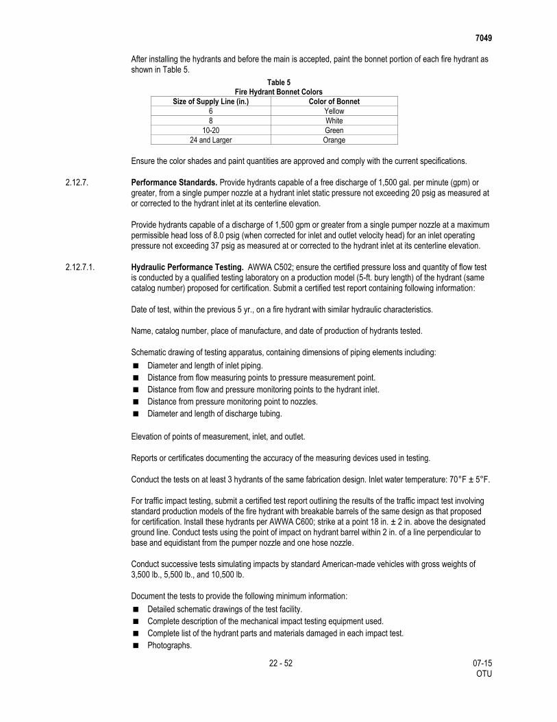
7049
22 - 52 07-15 OTU
After installing the hydrants and before the main is accepted, paint the bonnet portion of each fire hydrant as shown in Table 5.
Table 5 Fire Hydrant Bonnet Colors
Size of Supply Line (in.) Color of Bonnet
6 Yellow
8 White
10-20 Green
24 and Larger Orange
Ensure the color shades and paint quantities are approved and comply with the current specifications.
2.12.7. Performance Standards. Provide hydrants capable of a free discharge of 1,500 gal. per minute (gpm) or greater, from a single pumper nozzle at a hydrant inlet static pressure not exceeding 20 psig as measured at or corrected to the hydrant inlet at its centerline elevation.
Provide hydrants capable of a discharge of 1,500 gpm or greater from a single pumper nozzle at a maximum permissible head loss of 8.0 psig (when corrected for inlet and outlet velocity head) for an inlet operating pressure not exceeding 37 psig as measured at or corrected to the hydrant inlet at its centerline elevation.
2.12.7.1. Hydraulic Performance Testing. AWWA C502; ensure the certified pressure loss and quantity of flow test is conducted by a qualified testing laboratory on a production model (5-ft. bury length) of the hydrant (same catalog number) proposed for certification. Submit a certified test report containing following information:
Date of test, within the previous 5 yr., on a fire hydrant with similar hydraulic characteristics.
Name, catalog number, place of manufacture, and date of production of hydrants tested.
Schematic drawing of testing apparatus, containing dimensions of piping elements including:
Diameter and length of inlet piping.
Distance from flow measuring points to pressure measurement point.
Distance from flow and pressure monitoring points to the hydrant inlet.
Distance from pressure monitoring point to nozzles.
Diameter and length of discharge tubing.
Elevation of points of measurement, inlet, and outlet.
Reports or certificates documenting the accuracy of the measuring devices used in testing.
Conduct the tests on at least 3 hydrants of the same fabrication design. Inlet water temperature: 70°F ± 5°F.
For traffic impact testing, submit a certified test report outlining the results of the traffic impact test involving standard production models of the fire hydrant with breakable barrels of the same design as that proposed for certification. Install these hydrants per AWWA C600; strike at a point 18 in. ± 2 in. above the designated ground line. Conduct tests using the point of impact on hydrant barrel within 2 in. of a line perpendicular to base and equidistant from the pumper nozzle and one hose nozzle.
Conduct successive tests simulating impacts by standard American-made vehicles with gross weights of 3,500 lb., 5,500 lb., and 10,500 lb.
Document the tests to provide the following minimum information:
Detailed schematic drawings of the test facility.
Complete description of the mechanical impact testing equipment used.
Complete list of the hydrant parts and materials damaged in each impact test.
Photographs.

7049
23 - 52 07-15 OTU
Size and static pressure of the line to which the hydrant is attached.
Estimated of amount of water discharged, if any, from the hydrant within 30 min. immediately following
the collision.
2.12.8. Hydrant Leads. Provide hydrant branch leads conforming to the same requirements under Section 2.2.3., “Steel Pipe Fittings;” Section 2.3., “Ductile-Iron Pipe and Fittings;” or Section 2.4., “Polyvinyl Chloride Pipe (PVC) Pipe and Fittings.”
2.13. Polyethylene Film Wrap.
2.13.1. General. Except where noted on the plans, use polyethylene film as a wrap to protect cast-iron pipe, ductile-iron pipe, and fittings. Provide polyethylene film conforming to the requirements outlined in this specification and use only in open-cut construction.
2.13.2. Film. Provide polyethylene film in accordance with ASTM 1248 and AWWA C105, Type 1, Class C, Category 5, Grade J-3, 2.5% to 3% carbon black content. Unless otherwise shown on the plans, provide film 8 mils thick with a minimum tensile strength of 1,200 to 2,500 psi, elongation up to 600% and either in tubular or sheet form. Furnish film supplied in tubular form in the minimum widths shown in Table 6.
Table 6 Minimum Width of Film Tube (when laying flat)
Nominal Pipe Size (in.) Push-on Joint Flat Tube Width (in.)
4 14
6 17
8 21
10 25
12 29
14 33
16 37
18 41
20 45
24 53
For film in sheet form, furnish in widths equal to twice that shown for tube widths.
2.13.3. Polyethylene Tape. For taping film edges and overlays, use 3 in. wide plastic-backed adhesive tape. Use Polyken No. 900, Scotch Wrap No. 50, or approved equal.
2.14. Bedding Material. Unless otherwise shown on the plans, provide one of the following types of bedding for water mains:
2.14.1. Bank Run Sand. Furnish bank run sand bedding as called for in these specifications and consisting of soil classified as SP, SW, or SM by the Unified Soil Classification System (USCS). Provide sand with a plasticity index, when tested, of less than 7% and a liquid limit of 25 or less. Ensure the bank run sand gradation has a maximum of 15% passing the No. 200 sieve when tested, and is free of roots, organic material, trash, clay lumps, or other deleterious or objectionable material.
2.14.2. Concrete Sand. Furnish concrete sand bedding conforming to the specifications for Fine Aggregates specified in ASTM Standard C-33. Provide Fine Aggregates consisting of natural sand, manufactured sand, or a combination of the two, within the gradation limits shown in Table 7.
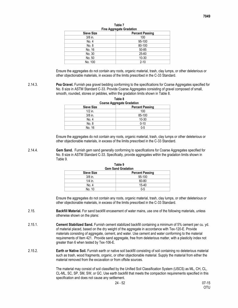
7049
24 - 52 07-15 OTU
Table 7 Fine Aggregate Gradation
Sieve Size Percent Passing
3/8 in. 100
No. 4 95-100
No. 8 80-100
No. 16 50-85
No. 30 25-60
No. 50 10-30
No. 100 2-10
Ensure the aggregates do not contain any roots, organic material, trash, clay lumps, or other deleterious or other objectionable materials, in excess of the limits prescribed in the C-33 Standard.
2.14.3. Pea Gravel. Furnish pea gravel bedding conforming to the specifications for Coarse Aggregates specified for No. 8 size in ASTM Standard C-33. Provide Coarse Aggregates consisting of gravel composed of small, smooth, rounded, stones or pebbles, within the gradation limits shown in Table 8.
Table 8 Coarse Aggregate Gradation
Sieve Size Percent Passing
1/2 in. 100
3/8 in. 85-100
No. 4 10-30
No. 8 0-10
No. 16 0-5
Ensure the aggregates do not contain any roots, organic material, trash, clay lumps or other deleterious or other objectionable materials, in excess of the limits prescribed in the C-33 Standard.
2.14.4. Gem Sand. Furnish gem sand generally conforming to specifications for Coarse Aggregates specified for No. 8 size in ASTM Standard C-33. Specifically, provide aggregates within the gradation limits shown in Table 9.
Table 9 Gem Sand Gradation
Sieve Size Percent Passing
3/8 in. 95-100
1/4 in. 60-80
No. 4 15-40
No. 10 0-5
Ensure the aggregates do not contain any roots, organic material, trash, clay lumps, or other deleterious or other objectionable materials, in excess of the limits prescribed in the C-33 Standard.
2.15. Backfill Material. For sand backfill encasement of water mains, use one of the following materials, unless otherwise shown on the plans:
2.15.1. Cement Stabilized Sand. Furnish cement stabilized backfill containing a minimum of 5% cement per cu. yd. of material placed, based on the dry weight of the aggregate in accordance with Tex-120-E. Provide materials consisting of aggregate, cement, and water. Use cement and water conforming to the material requirements of Item 421. Provide sand aggregate, free from deleterious matter, with a plasticity index not greater than 6 when tested by Tex-106-E.
2.15.2. Earth or Native Soil. Furnish earth or native soil backfill consisting of soil containing no deleterious material such as trash, wood fragments, organic, or other objectionable material. Supply the material from either the material removed from the excavation or from offsite sources.
The material may consist of soil classified by the Unified Soil Classification System (USCS) as ML, CH, CL, CL-ML, SC, SP, SM, SW, or GC. Use earth backfill that meets the compaction requirements specified in this specification and does not cause any settlement.
7049
25 - 52 07-15 OTU
2.15.3. Bank Run Sand. Furnish bank run sand backfill as called for in these specifications and conforming to the same requirements as those under Section 2.14.1., “Bank Run Sand.”
2.16. Concrete. Use Class “A” concrete in conformance to the requirements of Item 421, unless otherwise shown on the plans. Leave the forms in place unless directed to remove certain sections of the forms.
2.17. Water Meters, Meter Vaults, and Meter Boxes.
2.17.1. Water Meters. Provide meters of the type and size indicated on the plans.
2.17.1.1. Provide Bolted Split Casings. Main casings of meters and external fasteners: Copper alloy with minimum 75% copper for 5/8 in. to 2 in., bronze or cast-iron, hot-dipped galvanized or epoxy coating for coating for 3 in. and larger.
2.17.1.2. Straightening Vanes. Use non-corrosive material compatible with the case material.
2.17.1.3. Intermediate Gear Train. Do not allow the intermediate gear train to come in contact with water; operate in suitable lubricant.
Register: Automatic Meter Reading (AMR) type that provides pulse, contact closure, piezo switch, or encoder-generated output signal, compatible with Utility Owner’s radio and telephone AMR systems. Provide a minimum 12 ft. of wire when permanently connected to the register. Lens: impact resistant. Register box: tamper resistant by means of a tamper screw or plug: Register: permanently sealed, straight-reading, center-sweep test hand, magnetic driven, reading in U.S. gal. Digits: 6, black in color with the lowest registering three digits (below 1,000 gal. registration) in contrasting digit and background colors. Register capacity of meters: 9.99 million gal. for 5/8 in. to 2 in. and 999.999 million gal. for 3 in. and larger.
Connections: 5/8 in. to 1 in.: threads at each end; 1-1/2 in. to 2 in.: two-bolt oval flanges each end; 3 in. and larger: flange at each end.
Stamp the manufacturer’s meter serial number on the outer case. Stamp the manufacturer’s meter serial number on the outside of the register lid, when provided. Ensure the manufacturer’s serial numbers are individual and not duplicated.
Meters: Equip with AMR type register to connect to the Utility Owner’s AMR system. Compound Meter manufactured by: Badger, Hersey Products, Neptune, Sensus, or approved equal. Turbine Meters: manufactured by Badger, Hersey Products, Neptune, Sensus, or approved equal.
Fire Service Meters: manufactured by Hersey Products, Neptune, Sensus, or approved equal. Displacement Meters: manufactured by Badger, Neptune, Hershey, Kent, Sensus, or approved equal.
2.17.1.4. Manufacturing Quality Control. Permit successful interchangeability from one meter to another of same size; registers, measuring chambers and units, discs or pistons as units, change gears, bolts, nuts, and washers, without affecting the accuracy of the new meters.
2.17.1.5. Commercial Meter Valves for Meter Installations. Provide commercial meter valves identical to line valves except provide them with Class 125 flanges and equip them with hand wheels operating counterclockwise to open.
For pipe and fittings inside the meter box or meter vault, use ductile-iron conforming to Section 2.3., “Ductile-Iron Pipe and Fittings,” and as specified on the plans.
2.17.2. Meter Vaults.
2.17.2.1. General. Furnish meter vaults in either of the following designs: precast concrete vault, cast-in-place concrete vault, or solid masonry, unless a specific type of construction is required on plans. Ensure
7049
26 - 52 07-15 OTU
dimensions and reinforcement complies with the Utility Owner’s standard meter vault drawings for the type and size shown on the plans. Use Class “S” concrete conforming to the requirements of Item 421.
2.17.2.2. Precast Concrete Vaults. Construct precast concrete vaults as shown on the plans. Use reinforcing steel conforming to the requirements of Item 440.
Install precast vaults in conformance with the manufacturer recommendations. Set level and on a minimum 3 in. thick bed of sand conforming to the requirements of Section 2.15, “Backfill Material.” Seal lifting holes with cement mortar or non-shrink grout.
2.17.2.3. Meter Vault Floor Slab. Slope the floor 1/4 in. per foot toward the sump. Make the sump 12 in. in diameter, or 12 in. square, and 4 in. deep, unless other dimensions are shown on the plans. Install dowels at a maximum of 18 in., center-to-center, or install a mortar trench for keying the walls to the floor slab.
2.17.2.4. Cast-In-Place Concrete Vaults. Construct cast-in-place concrete vaults as shown on the plans. Use reinforcing steel conforming to the requirements of Item 440. Key the walls to the floor slab.
2.17.2.5. Frame and Cover. Use A-36 welded steel, or approved equal. Fabricate the cover plate with a 1/4 in. skid-resistant raised pattern floor plate. Fabricate the meter access door from the same material as the cover plate. Perform welding in accordance with the provisions of Item 441. Nondestructive testing will not be required.
Furnish castings for frames, grates, rings, and covers conforming to ASTM A48 Class 30. Provide locking covers if indicated on the plans. Use castings capable of withstanding the application of an AASHTO HS-20 loading, unless otherwise specified.
Provide covers and frames conforming to the shape dimensions, and with the wording or logos shown on the plans. The standard diameter dimension for manhole covers is 32 in. Furnish frames, grates, rings, and covers conforming to Item 471, except as noted above and except for measurement and payment..
2.17.3. Meter Boxes.
2.17.3.1. General. Furnish meter boxes for 5/8 in. through 1 in. meters of the following materials:
Non-traffic bearing locations: cast-iron, concrete, or plastic as specified on the plans.
Traffic bearing locations: cast iron.
Meter boxes for 1-1/2 in. and 2 in. meters: cast-iron. Provide meter box lids with a key-operated, spring type, locking device and a reading lid. Ensure the lids contain enough metals so that the meter box is easily located with metal a detector. If words are specified on the plans, cast them into lid with letters of 1/2 in. height and raised by 3/32 in. Ensure the size reads 5/8 in. to 1 in. or 1-1/2 in. to 2 in.
Furnish meter boxes conforming to the following approximate dimensions:
Length: At the top, 15-1/2 in.; at the bottom, 20 in.
Width: At the top, 12-1/2 in.; at the bottom, 14-3/4 in.
Height: 12 in.
Ensure that meter box extensions 3 in. and 6 in. in height are available from the manufacturer.
2.17.3.2. Cast-Iron Meter Boxes. Furnish cast-iron boxes that are clean and free from sand blow-holes or other defects, and conforming to the requirements of ASTM A48. Machine the bearing surfaces so that the covers seat evenly in the frames. Provide boxes and lids with a dipped, coal-tar-pitch, varnish finish. Provide lock-type meter boxes when shown on the plans. Ensure the lock mechanisms work with ease.
2.17.3.3. Concrete Meter Boxes. Furnish concrete meter boxes made of Class “A” concrete conforming to requirements of Item 421. Construct boxes as shown on the plans. Furnish castings that are free from
7049
27 - 52 07-15 OTU
fractures, large or deep cracks, blisters or surface roughness, or any other defects that may affect serviceability.
2.17.3.4. Plastic Meter Boxes. Furnish plastic meter boxes made of high-density polyethylene conforming to the ASTM Specifications shown in Table 10.
Table 10 ASTM Test Requirements for Plastic Meter Boxes
ASTM Test Requirement
D256 Impact Strength = 1.9 ft.-lb./in. (Izod, Notched)
D256 Impact Strength = 6.4 ft.-lb./in. (Izod, Un-Notched)
D638 Tensile Strength (2.0 Min) = 3,400 psi
D648 Deflection Temperature = 170°F
D790 Flexural Modulus = 90,000 psi
D676 Shore D Hardness, 55-65 Impact
Strength, Falling Dart Method, 100 in.-lb.
Provide meter boxes meeting the following test requirements:
Static Load: Not less than 2,500 lb. using a 6 in. disc with direct compression exerted at the center of
the top of the meter box with a solid plastic lid.
Deflection: Not less than 1,000 lb. load required to deflect the top edge of the meter ox 1/8 in.
Provide a meter box body, without lid, weighing approximately 7 lb.
2.18. Affidavit of Compliance. Unless otherwise directed, furnish a manufacturer's affidavit of compliance for each of the materials used in this project. Ensure the affidavit certifies that factory inspection and specified tests were performed and that the material furnished complies with the requirements outlined in this specification.
2.19. Pressure Reducing Station. Unless otherwise shown on the plans, furnish new and unused station piping, valves, and fittings, of the same type as specified on the plans.
Use Class “S” concrete in conformance with Item 421.
Provide reinforcing steel in conformance with Item 440.
Provide a Pressure Reducing Valve (PRV) with a strainer, in the location and arrangement shown on the plans. Provide a valve body made of ductile iron with Class 150 ANSI B16.1 flanges. Provide a valve cover made of ASTM A 48 cast iron. Use Buna-N rubber parts. No leather parts are allowed. Provide a resilient seat with a rectangular cross-section.
Valve internals: Provide a single moving disc and diaphragm assembly. Use a flexible nylon fabric-reinforced elastomer diaphragm integral with assembly. Provide valve internal trim (seat ring, disc guide, and cover bearing) made of stainless steel. Apply a heat fusion bonded epoxy coating to the internal and external surfaces of the valve body including the disc retainer and diaphragm washer. Holiday test the coating applied to the valve body to confirm a minimum even coating of 5-7 mils. Treat the stem with a penetrative salt nitride process. Use a Xylan-coated seat. Leather parts are not allowed. Prepare threaded connections by first using an approved pipe tape.
Furnish control tubing containing shutoff cocks with a “Y” strainer. Equip the valve to allow installing control tubing on either side of the valve. Equip the valve with a valve position indicator.
Ensure the valve and valve box are initially set in the field by an authorized manufacturer's representative. Set the downstream pressure at 60 psi unless otherwise specified. Ensure the PRV includes an adjustable and pressure sustaining pilot system. Use a diaphragm type or piston type valve for the main valve.
Provide Cla-Val Model 90-01BDSYKCKD, Watts ACV Model 115-3M, or approved equal.
7049
28 - 52 07-15 OTU
Provide a basket strainer upstream of the pressure reducing valve as shown on the plans. Furnish a quick-opening type strainer body, of fabricated steel construction with ANSI Class 150 flanges. Use Type 304 stainless steel for the basket.
Provide a Hayward Model 90, or equal, for PRV's 4 in. to 24 in. When there are space constraints, provide a Hayward Model 510, or equal, for PRV's 14 in. or greater.
2.20. Adjusting Manholes. Reuse removed manhole and inlet rings, plates, grates, covers, and brick if they are in good condition as determined by the Engineer. Provide additional materials in accordance with Item 465 at no cost to the Department. Single- or multiple-piece prefabricated metal extension rings may be used for the adjustment of manholes as approved. Provide concrete that conforms to the requirements of Item 421.
3. CONSTRUCTION
All construction must conform to the requirements of this Item, the plans and the following Items:
Item 100, “Preparing Right of Way”
Item 400, “Excavation and Backfill for Structures”
Item 402, “Trench Excavation Protection”
Item 403, “Temporary Special Shoring”
Item 421, “Hydraulic Cement Concrete”
Item 465, “Junction Boxes, Manholes, and Inlets”
Item 476, “Jacking, Boring, or Tunneling Pipe or Box”
Item 479, “Adjusting Manholes and Inlets”
3.1. Excavation.
3.1.1. Trenches. Construct water lines and fire hydrant branches (leads) in open cut trenches with vertical sides except in those locations where the pipe is tunneled, cased, or augered. Construct the trenches to the dimensions shown in the excavation and backfill details.
Sheath and brace the trenches to the extent necessary to maintain the sides of the trench in a vertical position throughout the construction period. Protect excavation greater than 5 ft. in depth as specified by Item 402, or Item 403.
Open and excavate the trenches to the finished grade. To allow for possible adjustment of the alignment and grade, locate the water mains to which the mains and fire hydrant branches (leads) under construction are to be connected, well in advance of making connections.
Construct water mains and fire hydrant branches (leads) in dry trenches. If necessary, employ well pointing or additional sheathing to accomplish this objective, at no additional cost to the Department.
For pipes less than 18 in. in diameter, the minimum trench width below the top of the pipe is the outside diameter of the pipe, plus 18 in. For pipes 18 in. and larger, the minimum trench width below the top of pipe is the outside diameter of pipe plus 24 in. Additional width will be required for unstable conditions. The Engineer will determine unstable conditions.
Where it is necessary to excavate trenches adjacent to improved property, take precautions to avoid damaging or impairing that property. Where it is necessary to disturb grass, shrubs, driveways, etc., restore such improvements to their original condition.
Use enough trench width or benches above the embedment zone when installing well point headers or manifolds and pumps, where the trench depth makes it uneconomical or impractical to pump from the surface elevation. Provide enough space between the shoring cross braces to permit equipment operations and handling the forms, pipe, embedment and backfill, and other materials.
7049
29 - 52 07-15 OTU
Before moving the supports, place and compact the embedment to enough depth to provide protection of the pipe and stability of the trench walls. As the supports are moved, finish placing and compacted the embedment.
Immediately before placing the embedment materials, ensure the bottoms and sidewalls of trenches are free of loose, sloughing, caving, or otherwise unsuitable soil.
Place and compact the embedment materials directly against the undisturbed soils in the trench sidewalls or against sheeting which will remain in place.
Do not place trench shields or shoring within the height of the embedment zone unless using some means to maintain the density of the compacted embedment material. If using moveable supports in embedment zone, lift the supports incrementally to allow placing and compacting of the material against undisturbed soil.
Place haunching material around the pipe and compact it to provide uniform bearing and side support.
Place trench dams in Class I embedments near the midpoint of line segments longer than 100 ft. between manholes.
Where damage to the completed pipe installation work is likely to result from withdrawal of the sheeting, leave the sheeting in place.
3.1.2. Existing Streets. Unless otherwise shown on the plans, open cut existing streets.
Where water line construction requires cutting through existing streets outside the limits of new street construction, replace those streets in kind in conformance with the appropriate specifications in the proposal or as directed. When cutting pavement outside the Department’s right of way, comply with the Utility Owner Street Cutting Ordinance.
Where, in the opinion of the Engineer, it is necessary to maintain traffic across a trench, construct temporary bridges as necessary to facilitate the movement of traffic.
At locations where the proposed water main parallels the edge of an existing permanent pavement (i.e., concrete pavement, concrete base with asphalt surface, etc.), and is 3 ft. or less from the edge of that pavement, protect the trench with timber sheathing and bracing. Leave the bracing in place at intervals of 5 ft. maximum.
Keep the street surface adjacent to the trench free of surplus spoil. Place construction materials at locations that minimize interference with the traveling public.
Do not close more than 2 street intersections at any one time unless authorized in writing..
3.2. Jacking, Tunneling, Boring, or Augering.
3.2.1. General. Perform jacking, tunneling, or augering for water mains and fire hydrant branches (leads) at the locations shown on the plans and at other locations specifically designated by the Engineer.
Unless otherwise shown on the plans, use casing pipe conforming to the requirements of Section 2.2.2., “Steel Casing Pipe.”
Excavate auger pits to a finished grade at least 6 in. lower than that indicated by the construction stakes or as approved, to ensure that a dry pit bottom is encountered.
Provide a minimum width of jacking, tunneling, or augering pits such that there is at least 6 in. of space between the pipe and the walls of the auger pit. The maximum allowable width of the pit is 5 ft., unless otherwise approved. Ensure the width of the pit at the surface is not less than at the bottom. The maximum
7049
30 - 52 07-15 OTU
allowable length of the pit is 5 ft. longer than 1 full joint of pipe of the type being used and does not exceed 25 ft., unless approved.
Grout in place tunnels for water lines with 36 in. diameters. When casing size is 48 in. in diameter or greater, or when using a tunnel liner plate, regardless of the water line diameter, grout in place unless otherwise directed. Provide an annular grout consisting of a sand-cement mortar mix with a 28 day compressive strength of at least 1,500 psi, when tested in accordance with ASTM C 942. The maximum allowable density is 130 pcf.
Use admixtures meeting ASTM C 494 and ASTM C 1017 as required, to improve pump ability, control the time of set, hold sand in suspension, and reduce segregation and bleeding. Fill the annular space in 3 lifts to prevent pipe floating. In addition, place appropriate blocking between the carrier pipe and the top of the liner to maintain position. Place a concrete invert to facilitate threading the carrier pipe.
Do not allow inadvertent metallic contact between the casing and the carrier pipe. Place spacers to ensure that the carrier pipe is adequately supported throughout its length, particularly at ends, to offset setting and possible electrical shorting, unless otherwise approved by Engineer. Ensure the end spacer is within 6 in. of the end of the casing pipe, regardless of the size of the casing and carrier pipe or the type of spacer used. Casing spacers are designed to withstand much greater loads than can be safely applied to most coatings. Therefore, the spacing between spacers depends largely on the load bearing capabilities of the pipe coating and the flexibility of the pipe.
Install casing spacers in conformance with the manufacturer’s instructions. Use special care to ensure that subcomponents are correctly assembled, evenly tightened, and that no damage occurs while tightening the insulators or inserting the carrier pipe.
Seal the annulus between the carrier pipe and casing with casing end seals at each end of the casing.
Insular Spacing:
Provide spacing as shown on the plans with a maximum distance between spacers of 10 ft. for pipe
sizes for pipe sizes 4 in. to 14 in. and 8 ft. for pipe sizes 16 in. to 30 in.
For ductile-iron pipe, flanged pipe, or bell-and-spigot pipe, install spacers within 1 ft. on each side of the
bell or flange, and one in the center of the joint when 18 ft. to 20 ft. long joints are used.
If the casing or carrier pipe is angled or bent, reduce the spacing. Provide the casing with a smooth,
continuous interior surface.
Perform bedding and backfilling of jacking, tunneling, boring, or augering pits in conformance with the details
on the plans and these specifications.
3.2.2. Jacking Steel Casing. Perform jacking of steel casing in accordance with the requirements of Item 476.
3.2.3. Tunneling. Perform tunneling in accordance with the tunneling requirements of Item 476.
3.2.4. Boring or Augering. Perform boring or augering in accordance with the requirements of Item 476.
Do not exceed 100 ft. for the length of the auger hole without a receiving pit.
Do not exceed 75 ft. for the length of the auger hole for PVC pipe 12 in. and less in diameter without a receiving pit.
Do not exceed 40 ft. for the length of the auger hole for PVC pipe 16 in. and greater in diameter without a receiving pit.
At locations where water pipes cross underneath driveways (of 16 ft. or less in width) or sidewalks, install the pipe in tight fitting augered holes.
7049
31 - 52 07-15 OTU
At locations where the centerline of the proposed water main is 10 ft. or less from the centerline of an 8 in. diameter or larger growing tree, place the pipe in a tight fitting augered hole. Extend the bored hole at least 4 ft. beyond each side of the tree.
Block the void space around the pipe in the augered hole with approximately 12 in. of packed clay or similar approved material, so that the bedding or backfill does not escape into the void around the pipe in the auger hole, when compacted.
Around the pipe, a use the minimum volume of the clay or similar acceptable material as shown in Table 11.
Table 11 Volume of Clay or Acceptable Material for Blocking Voids
Pipe Diameter (in.) Minimum Quantity (cu. Ft.)
4 through 8 0.5
12 through 16 0.75
3.2.5. Bedding for Trenches and for Jacking, Tunneling, Boring, or Augering Pits.
3.2.5.1. Pipe Bedding for Water Mains Less Than 24 Inches in Diameter.
3.2.5.1.1. Open Cut Trench Installation. Construct trenches with a minimum of 6 in. bedding. Remove the soil in the bottom of the trench, excavate to a minimum depth of 6 in. below the bottom of the pipe, and replace the soil with bedding material. Remove saturated material from the bottom of the pit before placing the bedding. Place the pipe in the bedding such that there is a 6 in. bedding below and up to the spring line of the pipe.
Compact the bedding material to within 95% of the standard density within 5% of the optimum moisture as determined by Tex-113-E. Mechanically compact the bedding material by using vibratory equipment or any other acceptable equipment.
3.2.5.1.2. Jacking, Tunneling, Boring or Augering Pits. Construct pits with a minimum of 6 in. bedding. Remove the soil in the pit, excavate to a minimum depth of 6 in. below the bottom of the pipe and replace the soil with bedding material.
If the bottom of the excavation becomes wet due to the presence of groundwater and a dewatering system is not required, and if directed, over excavate an additional 6 in. to a depth of 1 ft. below the bottom of the pipe. Place a non-woven geotextile fabric and then compact 12 in. of bank run sand or concrete sand in a single lift on top of the fabric. Compact the upper 6 in. to 90% of the standard maximum density as determined by Tex-113-E. The Engineer may require the Contractor to remove unstable or unsuitable material, even though the Contractor has not determined the material to be unsuitable.
Mechanically compact the bedding material by using vibratory equipment or any other acceptable equipment. Compact the bedding material to 95% of the standard density within 5% of the optimum moisture, as determined by Tex-113-E.
3.2.5.1.3. Bedding Materials. The following describes the acceptable materials for bedding:
Section 2.14.1., “Bank Run Sand”
Section 2.14.3., “Pea Gravel”
Bank run sand may be used as bedding material around the pipe only if, as determined by the Engineer, the trench bottom and sides are dry. If sand is used, place the pipe in the bedding so that there is at least 6 in. bedding around and on top of the pipe. Compact the sand as described in Section 3.2.5.1.1., “Open Cut Trench Installation.”
3.2.5.2. Pipe Bedding for Water Mains 24 Inches or Greater in Diameter.

7049
32 - 52 07-15 OTU
Open Cut: Provide pipe bedding as described in Section 3.2.5.1., “Pipe Bedding for Water Mains Less Than 24 Inches in Diameter,” with the following exceptions: Use bank run sand for the bedding material as described in Section 2.14, “Bedding Material.”
Compact cement stabilized sand used as backfill or as pipe bedding as specified on the plans, in 6 in. lifts to 95% of the standard maximum density as determined by Tex-113-E, at the optimum moisture content.
3.3. Handling Pipe and Accessories. During pipe construction operations, use caution to prevent injury to the pipe, protective linings, and coatings in conformance with the manufacturer's recommendations. Do not place debris, tools, or other materials in the pipe.
Repair any damage to the pipe or the protective lining and coating from any cause during the installation of the pipeline and before final acceptance by the purchaser. Perform this work as directed, in conformance with the applicable standards, and at no cost to the Department.
Unload pipe, fittings, valves, and accessories at the point of delivery and haul them to the project site. Distribute the material opposite or near the place where it will be laid in the trench such that storm water or runoff will not enter or pass through the pipe. Do not drop the materials. Do not allow pipe handled on skid ways to be skidded or rolled against pipe already on the ground.
Load, transport, unload, and otherwise handle pipe and fittings in a manner and by methods which prevent damage of any kind. Handle and transport pipe with equipment designed, constructed, and arranged to prevent damage to the pipe, lining, and coating. Do not allow bare chains, hooks, metal bars, or narrow skids or cradles to come in contact with the coatings. Provide pipe fittings with enough interior strutting or cross-bracing to prevent deflection under their own weight.
Hoist the pipe and fittings from the trench side into the trench by means of a sling of smooth steel cable, canvas, leather, nylon, or similar material. Do not lift pipe by using hooks at each end of the pipe. When stacking pipe, ensure it is packaged on timbers. Place protective pads place under the banding straps at the time of packaging.
When using fork trucks to relocate pipe, pad the forks using carpet or some other suitable type of material. When relocating pipe using a crane or backhoe, use nylon straps or smooth steel cable, do not use chains, around the pipe for lift.
3.4. Cutting Pipe. Cut pipe 12 in. in diameter and smaller in conformance with the manufacturer’s recommendations. Cut pipe larger than 12 in. in an approved manner. Perform each cut at right angles to the axis of the pipe and file or grind to remove sharp edges. Use a cutting machine unless otherwise approved by Engineer. Do not damage pipe or linings and coatings, while cutting.
3.5. Defective or Damaged Material. Inspect pipe and accessories for defects before lowering into the trench. Repair or replace any defective, damaged, or unsound material as directed.
If a damaged piece of pipe, furnished by the Contractor, is placed in the water main, furnish the labor and materials necessary to remove and replace the defective pipe and to restore the street to its original condition at no cost to the Department. If the Contractor damages the pipe after installation, the Engineer may permit the damaged section to be cut from the length, unless it is the opinion of the Engineer that the entire length was damaged. The cost of and replacement of broken pipe is at the expense of the Contractor.
3.6. Cleaning Pipe and Accessories. Remove lumps, blisters, and excess coating from the bell and spigot ends of steel pipe, ductile-iron pipe, valves, hydrants, and fittings. Wire brush the outside of the spigot and the inside of the bell and wipe clean, dry, and free from oil and grease before laying the pipe.
Remove foreign matter or dirt from the interior of water pipe, accessories, and from the mating surfaces of the joints, before lowering the material into the trench. Keep the pipe and accessories clean during and after laying by approved means.
7049
33 - 52 07-15 OTU
Use cleaning solutions, detergents, solvents, etc. with caution when cleaning PVC pipe.
Provide cleanup and restoration crews to work closely behind the pipe laying crews, and where necessary, during disinfection, testing, service transfers, abandonment of old mains, backfilling, and surface restoration.
Upon completely installing a section not exceeding 4,000 ft. per crew, immediately prepare to disinfect and pressure test between valves or plugs. No later than 3 days after completing disinfection preparatory work, submit to the Utility Owner an appropriate request for disinfection.
Begin transfer of services no later than 7 calendar days after successfully completing the disinfection and pressure testing.
Immediately after transfer of services, begin abandonment of the old mains, including re-sodding and placing sidewalks and pavements.
Do not begin construction of additional sections if the above conditions are not met.
For large diameter water mains, do not install more than 2,000 ft. of main, until the previous 2,000 ft. is cleaned up and the site is fully restored. Schedule paving crews so that the repaving work will not lag behind the pipe laying work by more than 1,000 ft.
Completely restore the site within 30 days from the date the water main is successfully disinfected and hydrostatically tested, unless extended in writing by the Engineer.
For projects involving multiple locations, limit water main installation to a maximum of 2 project site locations.
Remove construction debris or foreign material and thoroughly clean and flush piping systems as approved. Provide temporary connections, equipment, and labor for cleaning. The Engineer must inspect the water main for cleanliness before filling.
Disinfection of Water Lines: Conform to the requirements of Section 3.17., “Disinfecting Mains and Testing for Leakage.”
3.7. Laying Pipe. For the work of laying the pipe, employ only workers who are skilled and experienced in laying pipe of the type and joint configuration being furnished. Provide watertight pipe and pipe joints. Lay pipe with the bell ends facing in the direction of laying, unless otherwise directed.
Lay pipe to the lines and grades shown on the plans. To ensure proper placement, use adequate surveying methods and equipment, and employ personnel competent in using this equipment. Ensure the pipe does not deviate from the horizontal and vertical alignment indicated on the plans by more than 0.10 ft., without prior approval. Measure and record the “as-built” horizontal alignment and vertical grade at a maximum of every 50 ft. on the on-site recorded plans.
During pipe laying operations, keep pipe trenches free of water which might impair the laying operations. Ensure holes for bells are of ample size to prevent the bells from coming in contact with the subgrade. Carefully grade pipe trenches to provide uniform support along the bottom of the pipe.
Do not lay more than 50 ft. of pipe in the trench ahead of the backfilling operations. If pipe laying operations are interrupted overnight, cover the pipe laid in the trench simultaneously on each side of the pipe or completely backfill, to avoid lateral displacement of the pipe and damage to the joints. If adjustment of the position of a length of pipe is required after it is laid, remove and re-lay it in conformance with these specifications and at no expense to the Department. After pipe laying and joining operations are complete, clean the inside of the pipe and remove debris.
Use care to prevent damage to the coating when placing backfill. Backfill in accordance with Section 3.11, “Backfilling.”
7049
34 - 52 07-15 OTU
Lay pipe in a straight line unless otherwise shown or approved. Long radius curves, either horizontal or vertical, may be laid with standard pipe using deflections at the joints. If curved pipe is shown, needing no special fittings, the curves can be made by deflection of the joints with standard lengths of pipe as approved. If maximum pipe joint deflections are permitted, do not exceed the manufacturer’s recommendation for maximum pipe joint deflections. Joint the gasketed pipe in a straight alignment and then deflect it to the curved alignment.
If the vertical deflection exceeds the maximum recommended by the manufacturer, remove the entire portion of the deflected pipe section and install new pipe as directed. Perform this work at no expense to the Department. The Engineer may measure assessment of deflection at any location along the pipe. Arithmetical averages of the vertical deflection or similar average measurement methods will not be deemed as meeting the intent of the standard.
Where field conditions require horizontal deflection curves not shown on the plans, the Engineer will determine the methods to be used.
No additional payment will be made for laying pipe on curves as shown, or for change orders involving standard lengths of pipe deflected at the joints. Adjust the pipe, valves, hydrants, and fittings to be at their proper locations and prepare each joint as specified in Section 3.8., “Joining Pipe and Accessories.” As each joint of pipe is laid in the trench, center the spigot end in the bell of the previously laid pipe, then force home the pipe and bring it to the correct line and grade. Ensure each length of pipe rests on the bottom of the trench and is inspected for damage throughout its entire length.
When pipe lying is discontinued for the day or for an indefinite period, tightly place a cap or plug in the end of the last pipe laid to prevent the intrusion of water. When water is excluded from the interior of pipe, place enough backfill on the pipe to prevent floating. Schedule the work to prevent the possibility of floatation. Remove from the trench any pipe that has floated and re-lay as directed.
When assembling PVC pipe on top of the trench, allow it to cool to ground temperature before backfilling, to prevent pull-out due to thermal contraction.
Do not schedule night works or plant shut down to begin within 2 working days before or after Utility Owner-designated holidays.
For tie-ins to existing water mains, provide the necessary material on-hand to facilitate connection before shutting down the existing water main.
Ensure that separation from gravity sanitary sewers and manholes, or from force mains, is a minimum of 9 ft. clearance in all directions or as specified, unless a special design is shown on the plans.
Minimum Clearance of this specification:
Parallel water line and gravity sanitary sewer force main, or manhole with no leaks:
Minimum 4 ft. horizontal clearance from the outside wall of the water line to the outside wall of the
gravity sanitary sewer, force main, or manhole.
Water line crossing above gravity sanitary sewer or force main with no leaks:
Minimum 2 ft. vertical clearance.
Water line crossing below a sanitary sewer or force main with no leaks:
Minimum 2 ft. vertical clearance.
3.8. Joining Pipe and Accessories.
3.8.1. Ductile-Iron Pipe, Valves, Hydrants, and Fittings. After thoroughly cleaning the inside of the bell and the outside of the spigot, install members in conformance with the manufacturer's recommendation and AWWA C600, or as modified by these specifications.
7049
35 - 52 07-15 OTU
Mark pipe and accessories that are not furnished, with a depth mark before assembly to ensure that the spigot end is inserted to the full depth of the joint.
Brace the fittings on small mains with short pieces of 2 in. galvanized pipe as directed.
Brace each plug installed under this contract by a standard pipe clamp, a 3 ft. nipple of the same diameter pipe as the nearby sections of mains, and a block of concrete.
For 4 in. through 12 in. water mains, use pipe clamps that are Underwriters Lab-approved for underground water service piping. For water mains 16 in. and larger, use pipe clamps conforming to details shown on the plans.
For rubber-gasketed joints use lubrication that is water soluble, non-toxic, non-objectionable in taste and odor imparted to the fluid, non-supporting of bacteria growth, and has no deteriorating effect on coatings or rubber gaskets.
3.8.2. Polyvinyl Chloride Pipe and Accessories. Join plastic pipe in conformance with the instructions furnished by the manufacturer. To prevent weakening the joint, do not handle or install in the trench pipe joined using solvent cementing techniques, until the joints “cure.”
For rubber-gasketed joints, use lubrication that is water soluble, non-toxic, non-objectionable in taste and odor imparted to the fluid, non-supporting of bacteria growth, and has no deteriorating effect on PVC or rubber gaskets.
3.8.3. Welded Joints for Steel Pipe. Ensure the joints receive a full-penetration butt weld type double weld, in accordance with AWWA C206. It is the Contractor’s option to use either automatic or hand welders. Before starting the work, provide proof of certification of qualification for welders employed on the project for every type of work procedure and position involved. Ensure qualification is in accordance with AWWA C206. Ensure complete penetration of deposited metal with the base metal. Provide inside fittings and joints that are free from globules of weld metal that would restrict flow or become loose.
Miter end cuts of both ends of butt-welded joints may be used for joint deflections of up to 2.5°.
Set fittings and joints square and true, and preserve the alignment during welding operations. Align the butting ends to minimize the offset between surfaces. For pipe of the same nominal wall thickness, do not exceed 1/16 in. offset. Use line-up clamps for this purpose; however, exercise caution to avoid damaging to the linings and coatings.
Furnish each welder employed with a steel stencil for marking welds, so the work of each welder can be identified. Mark pipe with the assigned stencil adjacent to the weld. If a welder leaves the job, void that stencil and do not duplicate it. Welders making defective welds must discontinue work and leave the project site. Such welders may return to the project site only after recertification.
During welding, protect the lining by draping an 18 in. wide strip of heat-resistant material over the top half of the pipe on each side of the lining holdback to avoid damage to the lining by the hot splatter. Protect the tape coating similarly.
Provide welding rods of a type compatible with the metal being welded, to obtain the strongest bond, E-70XX.
Deposit the metal in successive layers so there will be at least 2 passes or beads for automatic welding and 3 passes or beads for manual welding in the completed weld.
On welds, do not deposit more than 1/4 in. of metal on each pass. Thoroughly clean the weld by wire brushing and hammering on each individual pass including the final one, to remove dirt, slag, or flux.
7049
36 - 52 07-15 OTU
Do not perform welding under any weather condition that would impair the strength of the weld, such as wet surface, rain or snow, dust or high winds, unless the work is properly protected.
If using tack welds, ensure they are of the same material and made by the same procedure as the completed weld. Otherwise, remove tack welds during the welding operation.
Remove dirt, scale, and other foreign matter from the inside of piping before tying in sections, fittings, or valves.
Provide a minimum overlap of 4 in. of butt strap over the adjacent piece on butt strap closures.
Employ an approved independent certified testing laboratory, to perform weld tests and associated work to accommodate testing on the entire job. Include the cost of such testing in the contract unit bid price for the water main. Furnish copies of test reports to the Engineer for review. Ensure testing is by X-ray methods for butt welds and is performed for every joint weld. If a defective weld is revealed, assume the cost of repairing and retesting the repaired weld. The Engineer has the full and final decision as to the suitability of welds tested. If any interior or exterior coating or lining is damaged during the welding process, repair it and return it to its original state as approved, in conformance with applicable AWWA standards.
Provide cylindrical corrosion barriers (CCBs) for epoxy-lined steel pipe smaller than 24 in. in diameter. Furnish CCBs manufactured by CCB International, Inc., or approved equal. CCBs are not required if the minimum wall thickness is 1/2 in. or greater.
In addition to the welding requirements contained in this specification, conform to the protection fitting manufacturer’s installation recommendations.
Provide the services of a technical representative of the manufacturer available on site at beginning of pipe laying operations. Ensure this representative is able to train welders and advise regarding installation and general construction methods. Employ only welders with at least 12 mo. experience installing protection fittings.
3.8.4. Flanged Joints for Steel Pipe. Before installing bolts, accurately center the flange joints and align them to prevent mechanical pre-stressing of flanges, pipe, and appurtenances. Align bolt holes to straddle the vertical, horizontal, or north-south, centerline. The maximum inclination of the flange face from the true alignment is 3/64 in. per foot.
Use full-face gaskets for flanged joints. Provide 1/8 in. thick cloth inserted rubber gasket material. Cut the gaskets at the factory to the proper dimensions.
Unless otherwise noted, provide insulation kits at connections to the existing water system or at locations to isolate one type of cathodic system from another type; between water line, access manhole piping, and other major openings in the water line; or as shown on the plans.
For isolating flange joints 30 in. in diameter and greater, and at butterfly valve flanges, provide a Pyrox G-10 with nitrite seal, Type E LineBacker gasket as manufactured by Pipeline Seal and Insulator, Inc., or approved equal, conforming to ANSI A 21.11 mechanical joint gaskets. For isolating flange joints 24 in. in diameter and smaller, provide a Phenolic PSI with nitrite seal, Type E LineBacker gasket as manufactured by Pipeline Seal and Insulator, Inc., or approved equal, conforming to ANSI A 21.11 mechanical joint gaskets.
Use galvanized or black nuts and bolts to match the flange material. Use cadmium-plated steel nuts and bolts underground. Tighten the bolts progressively to prevent unbalanced stress. Consistently maintain approximately same distance between the two flanges at all points around the flanges. Tighten the bolts alternately (180° apart) until they are evenly tight. Draw the bolts right to ensure properly seating the gaskets. Provide Denso, or approved equal, petroleum-based tape wrapping system for nuts and bolts.
7049
37 - 52 07-15 OTU
Pay particular attention to procedures used in tightening and torqueing flanged joints. Improper methods may result in leakage and require corrective measures. Follow recommended industry standards and guidelines as set forth by the various fabricators and manufacturers.
3.8.5. Flanged Joints For Use On Ductile-Iron Pipe. See the requirements of Section 3.8.4., “Flanged Joints for Steel Pipe.”
3.9. Thrust Restraint. Provide adequate temporary blocking of fittings when making connections to the distribution system and during hydrostatic tests. Provide enough anchorage and blocking to resist stresses and forces encountered while tapping the existing waterline. For new waterlines 16 in. in diameter and larger, provide restraining joints as specified in this section. Provide restrained joint lengths as shown on the plans or as directed. For existing waterlines and waterlines less than 16 in. in diameter, restrain pipe joints with concrete thrust blocks or provide joints as specified in this section.
The length of the restrained joints shown on the plans, assumes that hydrostatic testing will begin upstream and proceed downstream with respect to the normal flow of the water in the pipe. If installation or testing of the pipe differs from this assumption, submit for approval a revised method of restraining the pipe joints upstream and downstream of the device used to test against (i.e., block valve, blind flange, or dished head plug).
3.10. Electrical Continuity Bonds.
3.10.1. General. Attach the bond wires at the required locations using the Thermite welding process.
3.10.2. Thermite Welding Methods. Perform Thermite welding of bond wires to the piping in the following manner:
Ensure the pipe to which the wires will be attached is clean and dry. Use a grinding wheel to remove coating, mill scale, oxide, grease, and dirt from an area approximately 3 in. square. Grind the surface to bright metal.
Remove approximately 1 in. of insulation from each end of the wires to be Thermite welded to the structure, exposing clean, oxide-free copper for welding.
Select the proper size Thermite weld mold as recommended by the manufacturer. Place the wire between the graphite mold and the prepared metal surface. For No. 12 AWG size wires, use a copper sleeve crimped over the wire. Place the metal disk in the bottom of the mold. Place the Thermite weld charge in the mold. Squeeze the bottom of the cartridge to spread ignition powder over the charge.
Close the mold cover and ignite the starting powder with a flint gun. After the exothermic reaction, remove the Thermite weld mold and gently strike the weld with a hammer to remove the weld slag. Pull on the wire to assure a secure connection. If the weld is not secure or the wire breaks, repeat the procedure with a new wire. If the weld is secure, coat bare metal and weld metal with a coal-tar compound. If a polyurethane dielectric coating has been used, use a compatible polyurethane coating.
3.11. Backfilling.
3.11.1. General. Backfill trenches in accordance with the requirements of Item 400.
Begin backfilling and cleaning up each section of main, i.e., from valve to valve, immediately upon the completing the hydrostatic test, unless otherwise permitted by Engineer, and continue until obtaining a final and complete clean-up of the section. Any portion of the trench that is left open in excess of that required to facilitate hydrostatic testing may be ordered closed by the Engineer.
Use surplus excavated materials in the embankments or dispose of them as directed.
3.11.2. Backfilling Pipe for Water Mains.
7049
38 - 52 07-15 OTU
3.11.2.1. Open Cut. After the pipe joints are made up and inspected, backfill the trenches with excavated materials or any other backfill material covered by this specification, as approved. Backfill the portion from the spring line of the pipe (or from 6 in. on top of pipe if sand bedding is used) to the top of the trench in maximum lifts of 9 in. loose measurement (provided the trench is not located in sidewalks, roadways, roadway shoulders, driveways, etc. that are being used for automobile or pedestrian traffic). Mechanically compact the backfill material using vibratory equipment, or any other acceptable equipment, so that no settlement occurs. Compact to a density of at least 95% of the maximum dry density, as determined in accordance with Tex-114-E. The Engineer reserves the right to perform compaction tests on an as-needed basis. Compaction by water tamping is prohibited.
Do not allow dirt, clods, or trench sides to fall or rest against the pipe before completing the embedment or backfill.
The allowable materials for backfill are listed in Section 2.15, “Backfill Material.”
Continue backfilling and compacting in this manner to the minimum elevation shown in the excavation and backfill diagram.
3.11.2.2. Boring or Augering Pits. Backfill boring or augering pits with bank run sand up to 1 ft. from the top of the natural ground. For the final 12 in., use backfill consisting of 10 in. of native soil in the bottom and 2 in. of bank run sand just below the grass.
Backfill the portion from the spring line of the pipe to the top of the pit in lifts not exceeding 9 in. (loose measurement). Mechanically compact the backfill by using vibratory equipment, or any other acceptable equipment, so that no settlement occurs. Compact the material to a density of at least 95% of the maximum dry density at optimum moisture content as determined in accordance with Tex-113-E or Tex-114-E. The Utility Owner may perform compaction tests on an as-needed basis. Compaction by water tamping is prohibited.
Do not allow dirt, clods, or auger pit sides to fall or rest against the pipe before completing the embedment or backfill.
The only allowable material for backfill in boring or augering pits is bank run sand, described in Section 2.15, “Backfill Material.”
3.12. Valves and Fire Hydrants. Ensure each valve and fire hydrant is completely closed when placed in the pipe line.
Install valves and hydrants in accordance with AWWA C600, except where modified by this specification. Provide drainage at the base of the hydrant in accordance with AWWA C600.
Set each hydrant at the location and grade indicated by the stakes, and plumb, brace, and install in accordance with AWWA’s requirements for fire hydrant installation. If the barrel of a hydrant is to pass through a concrete slab, fit a piece of 1 in. thick pre formed bituminous expansion joint material closely around the section of the barrel passing through the concrete.
Locate the nozzle centerline a minimum of 18 in. above the finish grade.
Place 12 in. x 12 in. yellow indicators (plastic, sheet metal, plywood, or other approved material) on pumper nozzles of new or relocated fire hydrants installed on new mains not in service. Remove indicators after the new main is tested and approved.
3.13. Tapping Sleeves and Valves.
7049
39 - 52 07-15 OTU
3.13.1. General. Install tapping sleeves and valves at the locations and using the sizes shown on the plans. Thoroughly clean the tapping sleeve, tapping valve, and pipe in conformance with the manufacturer’s instructions before installing.
Hydrostatically test the installed tapping sleeve to 150 psig for a minimum of 15 minutes. Inspect the sleeve for leaks, and remedy any leaks before the tapping operation.
When tapping concrete pressure pipe, size on size, use a shell cutter one standard size smaller than that of the water line being tapped. Do not use Large End Bell (LEB) increases with a next size tap except for existing asbestos-cement pipe.
3.13.2. Installation. Verify the outside diameter of the pipe to be tapped before ordering the sleeve. Tighten the bolts in the proper sequence to avoid placing undue stress on the pipe. Align the tapping valve properly and attach it to the tapping sleeve. Insert the insulation sleeve into the flange holes of the tapping valve and pipe. Insert the sleeve on pipe side of tapping valve. Do not damage insulation sleeves during the bolt tightening process.
Make the tap with a sharp shell cutter using the following criteria: For 12 in. and smaller taps use a minimum cutter diameter 1/2 in. less than the nominal tap size. For 16 in. and larger taps, use the manufacturer’s recommended cutter diameter.
Withdraw the coupon and flush the cuttings from the newly-made tap. For 12 in. and smaller taps, wrap the completed tapping sleeve and valve in accordance with this specification.
For 16 in. and larger taps, apply Denso or approved equal, petroleum-based tape wrapping system around the completed tapping sleeve and valve. Place the concrete thrust block behind the tapping sleeve (not over the tapping sleeve and valve).
Arrange for the mandatory inspection of the installation before backfilling. Completion of the inspection is not required before backfilling. Backfill in accordance with this specification and as shown on the plans.
If Asbestos-Cement (AC) Pipe is encountered, follow the Safety Practice outlined in the Asbestos-Cement Pipe Producers Association publication, “Recommended Work Practices for A/C Pipe,” and make them “Mandatory Practices” for this project.
3.14. Boxes for Valves. Cut the cast-iron or ductile-iron pipe to the proper length, then assemble and brace the box as approved. Construct manholes over the operators of butterfly valves for sizes 30 in. and larger.
Concrete for valve box placement: For locations in new concrete pavement, use the same strength and mix design as that of new pavement. For other locations, use Class “A” Concrete, conforming to the requirements of Item 421.
Install valve box and riser piping plumbed in a vertical position. Provide 6 in. telescoping freeboard space between the riser pipe top butt end and the interior contact flange of the valve box, for vertical movement damping. Ensure the riser (bell end of pipe) rests on the valve flange, or provide a suitable foot piece to support the riser pipe.
Set, align, and adjust the valve box so that the lid is level with the final grade.
Paint the covers of new valve boxes in “Fluorescent Orange” when installed. After completion and approval by the Engineer, repaint the covers in “Black.”
3.15. Wet Connections. Make the wet connections, as directed, in such a manner and at such hours to minimize inconvenience to the public. When the existing mains have been cut or a plug removed for a connection, pursue the work of making the connection without interruption until complete.
7049
40 - 52 07-15 OTU
If the Contractor proceeds with a wet connection without a complete shut-off, there will be no extra compensation for damages or extra work resulting from the incomplete shut-off.
The Utility Owner will operate gate valves in the existing system and in sections of completed mains that have been placed in service. Notify the Utility Owner at least 48 hr. in advance of making connections.
Wet connections that are 2 in. or smaller are sometimes referred to on the plans as 2 in. standard connections or gooseneck connections.
Items that may be necessary to complete these types of wet connections include corporation cock, saddle, copper tubing, brass fittings, and 2 in. valves. Do not use these connections on or consider them as part of a 2 in. service line.
The Utility Owner will handle, at no cost to the Contractor, operations involving opening and closing valves for wet connections.
3.16. Polyethylene Film Wrap. Except as noted on the plans, wrap ductile-iron pipe (including fittings and other appurtenances), with a polyethylene film. Also wrap fire hydrant barrels.
Remove lumps of clay, mud, cinders, etc., on the pipe surface before installing the polyethylene encasement. Prevent soil or embedment material from becoming trapped between the pipe and the polyethylene. Fit the polyethylene film to the contour of the pipe to affect a snug, but not tight fit; encase with minimum space between the polyethylene and the pipe. Provide enough slack in contouring to prevent stretching the polyethylene where it bridges irregular surfaces, such as bell-spigot interfaces, bolted joints, or fittings, and to prevent damage to the polyethylene due backfilling operations. Secure overlaps and ends with adhesive tape to hold polyethylene encasement in place until backfilling operations are complete.
For installations below the water table and in areas subject to tidal actions, seal both ends of the polyethylene tube with adhesive tape at the joint overlap.
Repairs: Repair any cuts, tears, punctures, or damage to the polyethylene with adhesive tape or with a short length of polyethylene sheet or cut open tube, wrapped around the pipe to cover the damaged area, and secured in place.
Openings in Encasement: Provide openings for branches, service taps, blow offs, air valves, and similar appurtenances by making an X-shaped cut in the polyethylene and temporarily folding back the film. After the appurtenance is installed, tape the slack securely to the appurtenance and repair the cut, as well as other damaged areas in the polyethylene, with tape. Service taps may also be made directly through the polyethylene. Repair any resulting damaged areas as described above.
Junctions between Wrapped and Unwrapped Pipe: Where polyethylene-wrapped pipe joins an adjacent pipe that is not wrapped, extend polyethylene wrap to cover the adjacent pipe for distance of at least 3 ft. Secure the end with circumferential turns of tape. Wrap service lines of dissimilar metals with polyethylene or suitable dielectric tape for a minimum clear distance of 3 ft. away from cast-iron or ductile-iron pipe..
3.16.1. Tubular Type Wrap. When the polyethylene film is supplied in tubular form, install it on the pipe before placing the pipe in the trench and in the following manner:
Elevate the spigot end of the pipe, brush mud and debris from the pipe, and slip a length of film (approximately 2 ft. longer than the joint of pipe) over the joint of the pipe. Wrap the film tightly around the spigot end, leaving about 1 ft. extending beyond the end of the pipe, and tape the edge down lightly with polyethylene tape.
When lifting the joint of pipe for placing in the trench, remove any remaining mud, clay, or debris. Insert the spigot end into the bell end of the joint previously placed, push home, and release the pipe into the trench. Pick up the pipe joint at the bell, slide the film to a point back of the bell, and prepare a bell hole.
7049
41 - 52 07-15 OTU
When laying the next joint, pull the film beyond the bell to overlap the film attached to the spigot of the new pipe joint. Wrap the film by folding it longitudinally and tape it securely in place to prevent damage during backfill. Do not tape the end that is slipped over the last bell but bind it with twine or other approved material.
At each corporation, draw the loose material up around the corporation base and seal it with tape to insulate the 2 dissimilar metals.
Wrap fittings and fire hydrant leads, and tape or bind the wrap with heavy twine. Wrap fittings, such as bends and reducers, similarly to the method outlined above. Wrap specials, such as valves, tees, crosses, etc., by splitting, tucking, and overlapping the polyethylene tube, then closing the field-made splices with the required tape. Material to cover the valves may be acquired from excess overlapping polyethylene tubing on adjacent pipe joints. Draw the polyethylene tubing over the bell of the pipe on either side and insulate with field-made seams as described above. Completely wrap fittings and specials that require concrete blocking, before placing concrete.
3.16.2. Sheet Type Wrap. Apply sheet type wrap around the pipe either before or after positioning the pipe in the trench. Install “above ground” in a manner similar to that described above for tubular installation. Install “in trench” in a manner similar to that described below:
Cut the polyethylene sheet to a length approximately 2 ft. longer than the pipe section. Center the length to provide a 1 ft. overlap on each adjacent pipe section, bunching it until it clears the pipe ends. Wrap the polyethylene around the pipe so that it circumferentially overlaps the top quadrant of the pipe. Secure the cut edge of the polyethylene sheet at intervals of approximately 3 ft.
Lower the wrapped pipe into the trench and make up the pipe joint with the preceding section of pipe. Make shallow bell holes at joints to facilitate installation of the polyethylene. After completing the joint, make the overlap and secure the ends.
Repair cuts, tears, punctures, or other damage to the polyethylene. Proceed with installing the next section of pipe in the same manner.
3.16.3. Boring or Augering Section Installation. Use cast-iron or ductile-iron pipe with a polyurethane coating as specified in this Specification.
Provide a final seal against the intrusion of the backfill material by completely encasing the tapping sleeve with sheet vinyl of 8 mil thickness. Apply tape to secure this wrapping, using Polyken No. 900, Scotch Wrap No. 50, or approved equal, manufactured for this purpose.
3.17. Disinfecting Mains and Testing for Leakage.
3.17.1. Disinfecting Mains. The Utility Owner will furnish water for disinfecting and flushing without charge to the Contractor.
Furnish the necessary taps, risers, and jumpers of such sizes and materials as are specified by the Engineer, and install the subject material in the locations designated. Normally, each valve section of main will require two 3/4 in. taps; however, on larger mains the Engineer may order that 1-1/2 in. or 2 in. taps and risers be used.
Furnish and install the necessary temporary blind flanges, sleeves, plugs, etc., as required to disinfect and pressure test the new mains.
Use fire hydrants as blow-offs to flush newly constructed waterlines 8 in. diameter and above.
After laying and backfilling the pipe, disinfect the newly laid pipe. Unless otherwise shown on the plans, the Utility Owner will furnish and pay for the labor and materials necessary for the initial application of the disinfecting agent. Slowly fill each valves section of pipe with water and expel the air from the pipe. Furnish
7049
42 - 52 07-15 OTU
and install taps at the points of highest elevation, if required to accomplish this. After filling the main with water and expelling the air, charge the pipe with the disinfecting agent and allow it to stand for 24 hr. Unless otherwise shown on the plans, the Utility Owner will then flush the main with water. After flushing, draw samples from the main and test for 2 consecutive days at a valid, approved testing facility. After samples are drawn and the test results pass, proceed with the pressure test and any necessary repairs. If the samples do not pass, re-disinfect the pipe until the samples taken are passed by the certified and approved testing facility. Unless otherwise shown on the plans, in the event that more than one disinfection of the main (or portion of the main) is required, the additional disinfection will be charged to the Contractor at rates established by the Utility Owner.
After disinfecting and flushing water lines, bacteriological tests will be performed by the Utility Owner or testing laboratory.
When test results indicate a need for additional disinfection of water lines based on Texas Department of Health requirements, assist Utility Owner with additional disinfection operations.
3.17.2. Testing for Leakage. Following the first disinfection test, subject the newly laid pipes to a hydrostatic pressure of 125 psi, unless otherwise shown on the plans. Where practicable, test pipe lines in lengths between line valves or plugs, of at most 1,500 ft. unless otherwise approved. Perform the pressure test by means of a pump connected to the pipe in a manner satisfactory to the Engineer. Furnish, install, and operate the necessary connections, pump, meter, and gauges. Before running the pressure test, ensure the meter is tested, sealed, and approved (at the Contractor’s expense) by an approved, certified testing facility. Ensure the minimum duration of the test is 8 hr. If a large quantity of water is required to maintain pressure during the test, discontinue testing until the cause of the water loss is identified and corrected.
Observe the following general regulations during each leakage test for cast-iron, ductile-iron, and PVC pipe:
Except for welded steel pipe in which no leakage is permitted, ensure that pipe lines, when subjected to the specified pressure test, do not show leakage in excess of 3.19 gal. per inch of diameter, per mi., in 24 hrs.
Repair portions of the pipe showing visible leaks regardless of the total leakage shown by the pressure test. Remove and replace cracked or defective pipes, fittings, valves, or hydrants discovered by means of this pressure test with sound material. If the main is opened for any reason, re-disinfect it until satisfactory samples are obtained. Also, pressure tests it until the requirements of this specification are met.
Immediately upon completing disinfection and pressure testing, remove all taps, risers, and blow-offs, then backfill the remainder of the trench in accordance with the requirements of this specification.
Perform leakage testing at no additional cost to the Department.
3.18. Using Completed Sections of Mains. The Utility Owner may use and operate portions of the water mains that are disinfected and pass the leakage test. Unless otherwise shown on the plans, operate the valves in such completed sections only with the express permission of the Utility Owner.
The use of the mains is not construed as acceptance of them and does not relieve the Contractor’s responsibility for fulfilling the conditions of the contract, unless the mains are damaged due to negligence on the part of the Utility Owner.
3.19. Lowering Mains. When lowering a main, perform the initial excavation in such a manner to permit the mains to rest on a number of dirt benches. If soil conditions are unsatisfactory for dirt benches, use wooden blocks to support the mains. Then attach the pipe by using ropes, cable, or chains to overhead supports; remove the dirt benches or wooden blocks, and slowly and evenly lower the pipe into position. After lowering the mains, repair each damaged joint as directed.
3.20. Copper Service Line Construction. The use of Hays-Seal and Mueller Company catalog numbers to describe various fittings is not intended to be proprietary, but merely to indicate clearly the respective types of fittings to be furnished.
7049
43 - 52 07-15 OTU
3.20.1. Installing Service Lines. For curb and gutter streets, lay copper service lines with a minimum 30 in. of cover from top of curb to the top of the service line. For crowned streets with open ditches, lay copper service lines with a minimum 30 in. of cover at the crown and with a minimum 18 in. of cover from the flow line of the ditch to the top of the service line. Ensure service line locations are clear of proposed paving and underground work.
Exercise caution to keep the lines free of dirt and foreign matter at all times. Assemble copper lines in an entirely slack position and free of kinks. Use service lines consisting of one continuous run of copper tubing where possible. Do not use bends greater than that originally found in the coil of tubing as packaged.
For 1-1/2 in. and 2 in. copper tubing shipped in straight lengths, use the following bend criteria:
For 2 in. copper tubing, a maximum of one 45° bend may be accomplished in a 4 ft. section; for 1-1/2 in. copper tubing, a maximum of one 45° bend in a 3 ft. section. No kinks, dents, flats, or crimps will be permitted.
Locate meters, in general, 1 ft. into the street right of way. Where this is not applicable, locate meters approximately 1 ft. from the sidewalk on the curb side. If the present meter location conflicts with proposed driveway turnouts or other proposed street improvements, shift the meter to miss the obstruction and reconnect it to the customer’s service line. Reset meters at positions such that the top of the meter is 4 in. to 6 in. below the finished grade.
Where the plans call for salvaging and relocating the meter, meter box, and curb stop, remove these materials with care, thoroughly clean them, and submit them for inspection by the Engineer, before installing them in the new location. If the plans call for relocating the meter (other than at some point along the existing service line), a new service line will be required.
Where it is necessary to cross a paved street, push the service line under the paving through a pre-drilled and prepared opening. Use only full lengths of copper tubing, taking care not to damage the tubing when pulling it through the prepared hole.
A compression type union is only permitted when a full 40 ft. (60 ft. for 3/4 in. to 1 in.) length of tubing cannot completely span underneath the pavement. Do not use compression type unions under the paved street.
3.20.2. Installing Corporation Stops. Tap the main at a location such that a straight line passing through the meter and the corporation stop will be at 90° to the main. Locate taps in the upper portion of the main within 45° of the pipe spring line. Perform the cutting operation with an approved sharp shell cutter tool.
Install taps for service lines conforming to the requirements of Table 12. Space taps a minimum of 2 ft. apart.
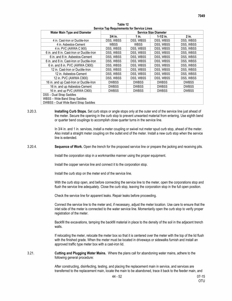
7049
44 - 52 07-15 OTU
Table 12 Service Tap Requirements for Service Lines
Water Main Type and Diameter Service Size Diameter
3/4 in. 1 in. 1-1/2 in. 2 in.
4 in. Cast-Iron or Ductile-Iron DSS, WBSS DSS, WBSS DSS, WBSS DSS, WBSS
4 in. Asbestos-Cement WBSS WBSS DSS, WBSS DSS, WBSS
4 in. PVC (AWWA C 900) DSS, WBSS DSS, WBSS DSS, WBSS DSS, WBSS
6 in. and 8 in. Cast-Iron or Ductile-Iron DSS, WBSS DSS, WBSS DSS, WBSS DSS, WBSS
6 in. and 8 in. Asbestos-Cement DSS, WBSS DSS, WBSS DSS, WBSS DSS, WBSS
6 in. and 8 in. Cast-Iron or Ductile-Iron DSS, WBSS DSS, WBSS DSS, WBSS DSS, WBSS
6 in. and 8 in. PVC (AWWA C900) DSS, WBSS DSS, WBSS DSS, WBSS DSS, WBSS
12 in. Cast-Iron or Ductile-Iron DSS, WBSS DSS, WBSS DSS, WBSS DSS, WBSS
12 in. Asbestos-Cement DSS, WBSS DSS, WBSS DSS, WBSS DSS, WBSS
12 in. PVC (AWWA C900) DSS, WBSS DSS, WBSS DSS, WBSS DSS, WBSS
16 in. and up Cast-Iron or Ductile-Iron DWBSS DWBSS DWBSS DWBSS
16 in. and up Asbestos-Cement DWBSS DWBSS DWBSS DWBSS
16 in. and up PVC (AWWA C900) DWBSS DWBSS DWBSS DWBSS
DSS – Dual Strap Saddles WBSS – Wide Band Strap Saddles DWBSS – Dual Wide Band Strap Saddles
3.20.3. Installing Curb Stops. Set curb stops or angle stops only at the outer end of the service line just ahead of the meter. Secure the opening in the curb stop to prevent unwanted material from entering. Use eighth bend or quarter bend couplings to accomplish close quarter turns in the service line.
In 3/4 in. and 1 in. services, install a meter coupling or swivel nut meter spud curb stop, ahead of the meter. Also install a straight meter coupling on the outlet end of the meter. Install a new curb stop when the service line is extended.
3.20.4. Sequence of Work. Open the trench for the proposed service line or prepare the jacking and receiving pits.
Install the corporation stop in a workmanlike manner using the proper equipment.
Install the copper service line and connect it to the corporation stop.
Install the curb stop on the meter end of the service line.
With the curb stop open, and before connecting the service line to the meter, open the corporations stop and flush the service line adequately. Close the curb stop, leaving the corporation stop in the full open position.
Check the service line for apparent leaks. Repair leaks before proceeding.
Connect the service line to the meter and, if necessary, adjust the meter location. Use care to ensure that the inlet side of the meter is connected to the water service line. Momentarily open the curb stop to verify proper registration of the meter.
Backfill the excavations, tamping the backfill material in place to the density of the soil in the adjacent trench walls.
If relocating the meter, relocate the meter box so that it is centered over the meter with the top of the lid flush with the finished grade. When the meter must be located in driveways or sidewalks furnish and install an approved traffic type meter box with a cast-iron lid.
3.21. Cutting and Plugging Water Mains. Where the plans call for abandoning water mains, adhere to the following general procedure:
After constructing, disinfecting, testing, and placing the replacement main in service, and services are transferred to the replacement main, locate the main to be abandoned, trace it back to the feeder main, and
7049
45 - 52 07-15 OTU
at this point cut and plug it at the tee. Normally, installing a plug, clamp, and a concrete thrust block does this. In cases of 1-1/2 in. or 2 in. corporation cock or tapping sleeve and valve (TS&V) connections, remove the valve and install a cap or plug at the tee. Ensure the line to be abandoned is not valves off at the nearest valve, nor cut and plugged other than at the supply main.
Adequately plug the ends or openings in abandoned mains or cap them in an approved manner and replace excavation, backfill, and any street surfaces, to the Engineer’s satisfaction. Perform this work in accordance with Sections 3.1., “Excavation,” and 3.11., “Backfilling.”
Remove surface identification, i.e., valve boxes and fire hydrants. Where valve boxes are in improved streets (other than shell), pouring valve boxes full of concrete with the cap permanently removed is permitted.
Do not remove plugs during the months of peak water demands, June, July, and August, unless otherwise approved
3.22. Service Lines of Public Utilities. Where any pipe or conduit of a public utility corporation crosses the water main trench, support such pipe or conduit in a manner satisfactory to the Engineer.
If the Contractor considers it necessary for a utility company to relocate their utility lines or other improvements, notify the Engineer in advance.
If the Engineer considers it imperative to make the change, the Engineer will make the necessary arrangements with the utility company.
3.23. Relocating Meter Vaults. Salvage existing valves, meters, and strainers from inside the vault and return them to the Utility Owner, or as designated on the plans.
Install pipe, valves, service lines, and other appurtenances in accordance with the sections of this specification or as directed.
In general, install the type of meter vault shown on the plans or as approved.
3.23.1. Precast Concrete Vault. Construct and furnish the precast concrete vault as shown on the plans.
Set the precast concrete vault level on a minimum 3 in. bed of sand in an excavation and bring it to grade. Then install piping and backfill with sand around the vault.
3.23.2. Cast-in-Place Concrete Vault. Construct the cast-in-place concrete vault as shown on the plans. Key the walls to the floor slab and form to the dimensions shown on the plans. Provide a minimum wall thickness of 4 in. Cast the walls monolithically. One cold joint is allowed when the vault depth exceeds 12 ft. Set the frame for the cover while the concrete is still green.
3.23.3. Frame and Cover. Construct the frame and cover as shown on the plans.
In grass areas, set the frame and cover 2 in. to 3 in. above the natural ground or finished grade and parallel to it (the maximum allowable angle from horizontal is 20°). Slope the backfill away from the meter.
In sidewalk areas, set the frame and cover 1/2 in. to 1 in. above the adjacent concrete and parallel to it. Slope the replacement concrete away from the meter to meet the adjacent concrete.
3.23.4. Inspections. The following inspections will be made jointly by the Engineer and representatives of the Utility Owner:
Site Location Inspection - to obtain the required approval of proposed meter location before
commencing work.
Final Inspection – conducted after the backfill is in place, the cover is installed, the cleanup is
completed, and the surface is restored.
7049
46 - 52 07-15 OTU
3.24. Adjusting Existing Surface Structures.
3.24.1. Valve Boxes. Salvage and reuse the valve box. Remove and replace the 6 in. ductile-iron riser pipe with a suitable length for the depth of cover required to establish the adjusted elevation to accommodate the actual finished grade.
Reinstall the valve box and riser piping plumbed in a vertical position. Provide a minimum of 6 in. telescoping freeboard space between the riser pipe top butt end and the interior contact flange of the valve box, for vertical movement damping.
After setting, aligning, and adjusting the valve box so that the top lid is level with the final grade, place a 24 in. by 24 in. by 8 in. thick concrete block around the valve box. Center the valve box horizontally within the concrete box.
3.24.2. Meter Boxes. Salvage and reuse meter boxes when possible. Reinstall them in conformance with the manufacturer’s recommendations. Repair any damage sustained by the meter box during relocation or service transfer, at no expense to the Department.
If the existing meter box requires replacement, the Contractor may obtain a new box from the Utility Owner by providing adequate documentation of the existing and proposed locations.
3.24.3. Meter Vaults. Adjust meter vaults in conformance with the details shown on the plans. Salvage and reuse access covers.
3.25. Relocating Water Meters and Boxes. Salvage, clean, inspect, and install existing curb stops, meters, unions, and meter boxes at the new locations in conformance with specifications in this section. When the meter and box is relocated, move it the minimum distance to enable access for new connections. Repair any damage sustained by the meter box during relocation or service transfer, at no expense to the Department.
If unable to salvage the existing boxes, the Contractor may obtain new boxes from the Utility Owner by providing proper documentation of the existing and proposed locations of the meter.
When approved, the Contractor may relocate meter boxes located adjacent to existing pavement, if this operation facilitates construction or decreases the costs. Obtain written approval of the Engineer and perform this work, including excavation, piping, meter box relocation, removal and replacement of paving, etc., at no cost to the Department.
3.26. Installing Split Casing. Notify the Utility Owner at least 48 hr. in advance of any work planned involving existing water lines. Do not, at any one time, expose more than 20 ft. of water lines to be encased.
Place 6 in. x 6 in. x 1-1/4 in. neoprene pads between the split casing sections and the top and bottom of the water lines spacing them at approximately 6 ft. or as directed.
Ensure the completed and shaped trench to receive the casing is of wide enough to provide free working space for satisfactorily installing the casing and backfilling under and around the casing.
Hold the split casing in place for welding by using hinges, coupling bands, or any other acceptable method.
Use a casing diameter not less that the outside dimension of the pipe at is longest dimension plus 4 in.
Perform welds conforming to the requirements of AWWA Standard C 206. Provide welds capable of developing the full strength of the pipe throughout the joint and casing split.
Seal the ends of the encasement pipe with casing and seals in accordance with Section 2.2.1., “Steel Carrier Pipe,” to prevent the entrance of the excessive ground water.
7049
47 - 52 07-15 OTU
3.27. Modifications for Cathodic Protection.
3.27.1. General. Provide cathodic protection systems as shown on the plans.
References to steel pipe apply to tape-coated welded steel pipe. If damage occurs to the pipe coatings during the welding process, refurbish the affected area to its original condition.
3.27.2. Bonded Joints. Where rubber gasket bell and spigots are provided, provide for bonded joints by either welding a strap or clip between the bell and the spigot of each joint, or by providing a Thermite-welded cable between the bell and the spigot of each joint. Provide pipes, whether installed in a tunnel or open cut, with bonded joints, except where providing insulating flanges. Where welding joints for thrust restraint, no additional bonding is required.
Bonding Strap or Clip: Provide a strap or clip for bonding the bell to the spigot, that is free of foreign material that could increase the contact resistance between the wire and the strap or clip.
Unless otherwise noted, provide insulation kits at connections to the existing water system, at locations to isolate one type of cathodic system from another type, between the water main and extra piping, or as shown on the plans.
3.28. Removing and Salvaging Fire Hydrants and Water Meters. Deliver removed and salvaged fire hydrants and water meters to the Utility Owner at the location shown on the plans, or as directed.
3.29. Installing the Nonmetallic Pipe Detection System. Install the nonmetallic pipe detection system concurrently with placing the proposed pipe. Install as specified by the manufacturer and as approved.
3.30. Removing Water Mains and Removing Water Mains with Casing. Remove water mains and water mains with casing in accordance with Item 100, or as shown on the plans. This includes removing and disposing of pipe and appurtenances as shown on the plans or as directed. Perform related excavation and backfilling, as required, at no additional cost the Department.
3.31. Adjusting Manholes. Perform work in accordance with Item 465. Excavate and backfill in accordance with Item 400. Carefully remove and temporarily store as directed, manhole and inlet rings, covers, plates, and grates to be reused. Clean mortar and grease from the contact areas of reused items. Dispose of unused removed material as directed. Use construction methods described in Sections 479.3.1, “Lowering the Top of a Manhole or Inlet,” and 479.3.2, “Raising the Top of a Manhole or Inlet,” unless otherwise shown on the plans.
3.31.1. Lowering the Top of a Manhole or Inlet. Remove a sufficient depth of brick courses or concrete to permit reconstruction on a batter not exceeding 1 in. horizontal to 2 in. vertical. Where brickwork is present, clean the mortar from the top course of brick. Rebuild the manhole or inlet to the original top dimensions or to the dimensions shown in the plans. Install the manhole or inlet ring and the cover, plate, or grate to conform to the proposed new surface contour.
3.31.2. Raising the Top of a Manhole or Inlet. Clean the top surface of brick or concrete. Construct to the proper new elevation using new brick, brick salvaged from other manholes or inlets, prefabricated metal extension rings, concrete rings, or Class A concrete. Install the manhole or inlet ring and the cover, plate, or grate to conform to the proposed new surface contour. Install prefabricated extension rings in accordance with manufacturer’s instructions.
4. MEASUREMENT
4.1. Water Main Pipe and Steel Casing. Measured by the foot, of the various sizes and types specified. Water mains and casing will be measured along the axis of the pipe and no deductions will be made for valves or fittings. Reducers will be classed as pipe of the size of the larger end.
7049
48 - 52 07-15 OTU
Unless otherwise shown on the plans, Fire Hydrant Branches (Leads) will be measured by the foot, of the various types and installation methods specified, along the axis of each branch (lead) from the hydrant to the end of the branch (lead). No deductions will be made for valves or fittings.
4.2. Split Steel Casing. Measured by the foot, of the various sizes shown on the plans.
4.3. Fiberglass Reinforced Plastic (FRP) Pipe for Casing. Measured by the foot, of the various sizes shown on the plans.
4.4. Jacking, Tunneling, Boring, or Augering. Jacking, Tunneling, Boring, or Augering for water mains and steel casing will be measured by the foot, of the sizes, types, and wall thickness (applicable only for casing) specified.
Jacking, Tunneling, Boring, or Augering for fire hydrant branches (leads) will be measured by the foot, of the various types specified.
4.5. New Copper Service Lines. Measured by each service line installed.
Short Side service line refers to service connections made to meters located on the same side of the street as the supply main is located. Long Side service line refers to service connections made to meters located on the opposite side of the street from the supply main, or from the center of the street, where the supply main is located in the center of the street.
4.6. Gate Valves, Tapping Sleeves and Valves, and Butterfly Valves. Measured by each assembly installed, of the various sizes specified, except that gate valves 20 in. in diameter and smaller, are subsidiary to the water lines.
4.7. Fire Hydrants. Measured by each assembly installed, including a 6-in. gate valve and box, regardless of depth. It is the Contractor’s responsibility to install the fire hydrant assembly such that it meets the standard installation requirements of this specification and the manufacturer’s specifications.
Fire Hydrant Branches (Leads) will be measured as indicated in Sections 4.1., “Water Main Pipe and Steel Casing” and 4.4., “Jacking, Tunneling, Boring, or Augering.”
4.8. Meters and Vaults. Measured by each assembly constructed.
4.9. Air Release and Vacuum Relief Valves. Measured by each assembly, of the various sizes, with the valve box installed.
4.10. Pressure Reducing Stations. Measured by the lump sum unit constructed.
4.11. Blow Off Valves. Measured by each assembly, of the various sizes and types, with the valve box installed.
4.12. Removing Fire Hydrants. Measured by each assembly removed and disposed of properly.
4.13. Removing Water Valves and Boxes. Measured by each assembly removed and disposed of properly.
4.14. Removing and Relocating Meters and Boxes. Measured by each assembly removed, cleaned, and installed at the new location.
4.15. Removing Meters and Vaults. Measured by each assembly removed and disposed of properly.
4.16. Removing and Salvaging Water Meters. Measured by each assembly removed and salvaged.
4.17. Removing and Salvaging Fire Hydrants. Measured by each assembly removed and salvaged.
7049
49 - 52 07-15 OTU
4.18. Removing and Relocating Water Meters and Meter Vaults. Measured by each assembly removed and relocated.
4.19. Adjusting Meter Vaults. Measured by each assembly adjusted.
4.20. Adjusting Meter Boxes. Measured by each assembly adjusted.
4.21. Adjust or Relocate Water Meter. Measured by each assembly adjusted or relocated.
4.22. Lowering Water Mains. Measured by the foot, of the sizes and types of pipe lowered.
4.23. Cutting and Plugging Water Mains. Measured by each location a water main is cut and plugged, of the sizes indicated.
4.24. Removing Pressure Reducing Stations. Measured by each complete pressure reducing station removed.
4.25. Wet Connections. Measured by each connection, of the sizes specified.
4.26. Extra Hand Excavation or Extra Machine Excavation. Measured by the cubic yard in its original position. Excavation performed by manual labor at the locations specifically designated by the Engineer, and which is not included under or subsidiary to other bid items contained in this specification, is considered Extra Hand Excavation or Extra Machine Excavation.
4.27. Adjusting Manholes. Adjusted manholes will be measured as each manhole adjusted.
5. PAYMENT
The work performed and materials furnished in accordance with this Item and measured as provided under “Measurement” will be paid for at the unit prices bid for the items of work described below. These prices are full compensation for furnishing, hauling, placing, and installing the materials; for inspecting and testing; and for other materials, labor, equipment, tools, and incidentals.
5.1. Water Main Pipe and Steel Casing. Payment for water main pipe, and steel casing will be made at the unit prices bid for “Water Main Pipe (Cast-Iron),” “Water Main Pipe (Steel),” “Water Main Pipe (Ductile Iron),” “Water Main Pipe (Copper),” “Water Main Pipe (Polyvinyl Chloride)(PVC),” and “Casing (Steel),” of the various sizes and types specified, installed by the open-cut method.
Unless otherwise shown on the plans or specifications, excavating, disposing of unsuitable excavated material, backfilling, and the material for backfill, for the complete installation of the water main system, are subsidiary to this bid Item.
5.2. Split Steel Casing. Payment for split steel casing will be made at the unit price bid for “Split Steel Casing,” of the various sizes specified, installed by the open cut method.
5.3. Fiberglass Reinforced Plastic (FRP) Pipe for Casing. Payment for Fiberglass Reinforced Plastic (FRP) Pipe for Casing will be made at the unit price bit for “Fiberglass Reinforced Plastic (FRP) Pipe for Casing” of the various sizes specified.
5.4. Jacking, Tunneling, Boring, or Augering. Payment for jacking, tunneling, boring, or augering water main will be made at the unit price bid for “Jacking, Tunneling, Boring, or Augering (Water Main),” of the sizes and types specified. This price includes furnishing the pipe.
Payment for jacking, tunneling, boring, or augering fire hydrant branches (leads) will be made at the unit price bid for “Jacking, Tunneling, Boring, or Augering Fire Hydrant Branch (Lead)(6 in.),” of the types and installation method specified. This price includes furnishing the pipe.
7049
50 - 52 07-15 OTU
Payment for jacking, tunneling, boring, or augering steel casing will be made at the unit price bid for “Jacking, Tunneling, Boring, or Augering Casing (Steel),” of the sizes, types, and wall thickness (applicable only if exceeding minimum thickness, shown in Section 2.2.2, “Steel Casing Pipe”) specified. This price includes the casing. Water mains and fire hydrant branches (leads) placed in the casing will be paid for by the appropriate bid item.
Excavating, backfilling, backfill material, and disposing of unsuitable excavated material for jacking, tunneling, boring, or augering pits are subsidiary to these bid items.
5.5. New Copper Service Lines. Payment for copper service lines will be made at the unit price bid for “Service Line (Short Side 5/8 in. to 1 in.),” “Service Line (Long Side 5/8 in. to 1 in.),” “Service Line (Short Side 1-1/2 in. to 2 in.)” and “Service Line (Long Side 1-1/2 in. to 2 in.),” installed. This price is full compensation for labor, materials, excavation, and backfill required to install the facility, including connection to the customer’s service line.
5.6. Gate Valves, Tapping Sleeves and Valves, and Butterfly Valves. Payment for gate valves (larger than 20 in. in diameter), tapping sleeves and valves, and butterfly valves will be made at the unit price bid for “Gate Valve,” “Tapping Sleeve and Valve,” and “Butterfly Valve,” of the various sizes specified, with the valve box installed.
5.7. Fire Hydrants. Payment for fire hydrants will be made at the unit price bid for “Fire Hydrant Assembly,” including 6 in. gate valve and box, installed regardless of barrel depth.
Payment for fire hydrant branches (leads) will be made at the unit price bid for “Fire Hydrant Branch (Lead) (6 in.)” installed by the open-cut method.
Any adjustment required either in the flow line of the water main or to the barrel length of the fire hydrant is subsidiary to this bid Item.
5.8. Meters and Vaults. Payment for meters and vaults will be made at the unit price bid for “Meter and Vault” constructed.
5.9. Air Release and Vacuum Relief Valves. Payment for air release and vacuum relief valves will be made at the unit price bid for “Air Release and Vacuum Relief Valve,” of the various sizes specified, with the valve box installed.
5.10. Pressure Reducing Stations. Payment for pressure reducing stations will be made at the unit price bid for “Pressure Reducing Station.” This price is full compensation for performing the necessary excavation, backfill, finish grading, constructing the concrete structure, and furnishing and installing station appurtenances addressed under Article 2, “Materials,” of this specification.
5.11. Blow Off Valves. Payment for blow off valves with boxes will be made at the unit price bid for “Blow Off Valve” of the various sizes and types specified, with the valve box installed.
5.12. Removing Fire Hydrants. Payment for removing fire hydrants will be made at the unit price bid for “Removing Fire Hydrant.” This price includes removing valves from the existing location, disposing of the valves, and plugging at the tee. Excavation and backfill required for removing fire hydrants are subsidiary to this bid Item.
5.13. Removing Water Valves and Boxes. Payment for removing water valves and boxes will be made at the unit price bid for “Removing Water Valve and Box.” Excavation and backfill required for removing water valves and boxes are subsidiary to this bid Item.
5.14. Removing and Relocating Meters and Boxes. Payment for removing and relocating meters and boxes will be made at the unit price bid for “Removing and Relocating Meter and Box.”
7049
51 - 52 07-15 OTU
5.15. Removing Meters and Vaults. Payment for removing meters and vaults will be made at the unit price bid for “Removing Meter and Vault.” This includes salvaging the meter strainers and valves and delivering them to their owner at the location shown on the plans or as directed.
5.16. Removing and Salvaging Water Meters. Payment for removing and salvaging water meters will be made at the unit price bid for “Removing and Salvaging Water Meter.” This price includes removing salvaged water meters from the existing locations and delivering them to the owner. Excavation, backfill, and finish grading required for removing the water meters are subsidiary to this bid Item.
5.17. Removing and Salvaging Fire Hydrants. Payment for removing and salvaging fire hydrants will be made at the unit price bid for “Removing and Salvaging Fire Hydrant.” The salvaging of fire hydrants will be a cash reimbursement to the owner by the Contractor where the fire hydrants will become the property of the Contractor or the Contractor will deliver the fire hydrants to the Utility Owner at the location shown on the plans. Excavation, backfill, and finish grading required for removing fire hydrants are subsidiary to this bid Item.
5.18. Removing and Relocating Water Meters and Meter Vaults. Payment for removing and relocating water meters and meter vaults will be made at the unit price for “Removing and Relocating Water Meter and Meter Vault.”
5.19. Adjusting Meter Vaults. Payment for adjusting meter vaults will be made at the unit price bid for “Adjusting Meter Vault.” This price is full compensation for furnishing the required materials, including backfill as required, excavation, tools, labor, equipment, and incidentals.
5.20. Adjusting Meter Boxes. Payment for adjusting meter boxes will be made at the unit price for “Adjusting Meter Box.”
5.21. Adjust or Relocate Water Meter. Payment for adjusting or relocating water meters will be made at the unit price for “Adjusting or Relocating Water Meters.” This price is full compensation for adjusting or relocating water meters. Miscellaneous fittings required to complete the work will not be paid for directly, but will be subsidiary to this Item unless otherwise shown on the plans. Water line sterilization and testing of the completed water main system is considered subsidiary to this Item.
5.22. Lowering Water Mains. Payment for lowering water mains will be made at the unit price bid for “Lowering Water Mains,” of the sizes and types of pipe lowered. This price is full compensation for lowering and adjusting pipes, as well as any connected valves, boxes, and service lines. Excavation and backfill required for lowering water mains are subsidiary to this bid Item.
5.23. Cutting and Plugging Water Mains. Payment for cutting and plugging water mains will be made at the unit price bid for “Cut and Plug Water Main,” of the sizes indicated. This price is full compensation for performing excavation, backfill, finish grading, and other incidental items required to abandon or cut and plug the water main as set forth this specification. Where grout is required, as shown on the plans, it is subsidiary to this bid Item.
5.24. Removing Pressure Reducing Stations. Payment for removing pressure reducing stations will be made at the unit price bid for “Removing Pressure Reducing Station.” This price is full compensation for performing the necessary excavation, backfill, finish grading, pipe removal, structure removal, and for tools, equipment, and incidentals.
5.25. Wet Connections. Payment for wet connections will be made at the unit price bid for “Wet Connections,” of the sizes specified.
5.26. Extra Hand Excavation or Extra Machine Excavation. Payment for extra hand excavation or extra machine excavation will be made at the unit price bid for “Extra Hand Excavation” or “Extra Machine Excavation.” This price is full compensation for labor, hand tools, machines, dewatering, and handling and properly disposing of any excess excavated material not suitable for bedding or backfill for this project.
7049
52 - 52 07-15 OTU
5.27. Adjusting Manholes. The work performed and materials furnished in accordance with this Item and measured as provided under “Measurement” will be paid for at the unit price bid for “Water Main (Adj Exist Manhole).” This price is full compensation for replacement of Air Release / Vacuum Release Valve and installation of the Standard Bollards as shown on the plans; for materials including backfill as required, and for excavation, tools, equipment, labor, and incidentals.
Trench excavation protection or temporary special shoring for trenches greater than 5 ft. in depth, or sloping the sides of these trenches to preclude collapse, will be measured and paid for as required by Item 402, “Trench Excavation Protection,” or Item 403, “Temporary Special Shoring.”
Furnishing and placing bedding material is subsidiary to the various bid items.
Providing fittings, including necessary concrete thrust blocking, pipe clamps, nipples, pipe coatings, and lubricants, etc. is subsidiary to the water mains in which they are installed.
In addition, providing fittings required due to plan changes or alterations in line and grade, is subsidiary to the water mains in which they are installed.
Furnishing and installing taps, risers, jumpers, blind flanges, cast-iron sleeves, plugs, reducers etc., as required to disinfect and pressure test the new mains is subsidiary to the various bid items. In addition, necessary excavation and backfill, site grading, and maintenance until completion of pressure testing are subsidiary to the various bid items.
Unless otherwise shown on the plans, the work performed and materials furnished to support the pipes or conduits of public utilities are subsidiary to the various bid items.
Furnishing and installing the nonmetallic pipe detection system, as well as the labor and materials necessary for the system, is subsidiary to the various bid items. In addition, ensure that the detection system is complete, operational, and satisfactory to the Utility Owner.
Adjusting valve boxes is subsidiary to the various bid items.
000-002
1 - 3 07-15 Statewide
Special Provision to Item 000
Nondiscrimination
1. DESCRIPTION
All recipients of federal financial assistance are required to comply with various nondiscrimination laws including Title VI of the Civil Rights Act of 1964, as amended, (Title VI). Title VI forbids discrimination against anyone in the United States on the grounds of race, color, or national origin by any agency receiving federal funds.
Texas Department of Transportation, as a recipient of Federal financial assistance, and under Title VI and related statutes, ensures that no person shall on the grounds of race, religion (where the primary objective of the financial assistance is to provide employment per 42 U.S.C. § 2000d-3), color, national origin, sex, age or disability be excluded from participation in, be denied the benefits of, or otherwise be subjected to discrimination under any Department programs or activities.
2. DEFINITION OF TERMS
Where the term “Contractor” appears in the following six nondiscrimination clauses, the term “Contractor” is understood to include all parties to Contracts or agreements with the Texas Department of Transportation.
3. NONDISCRIMINATION PROVISIONS
During the performance of this Contract, the Contractor, for itself, its assignees, and successors in interest (hereinafter referred to as the "Contractor") agrees as follows:
3.1. Compliance with Regulations. The Contractor (hereinafter includes consultants) will comply with the Acts and the Regulations relative to Nondiscrimination in Federally-assisted programs of the U.S. Department of Transportation, the Federal Highway Administration, as they may be amended from time to time, which are herein incorporated by reference and made a part of this Contract.
3.2. Nondiscrimination. The Contractor, with regard to the work performed by it during the Contract, will not discriminate on the grounds of race, color, or national origin in the selection and retention of subcontractors, including procurements of materials and leases of equipment. The Contractor will not participate directly or indirectly in the discrimination prohibited by the Acts and the Regulations, including employment practices when the Contract covers any activity, project, or program set forth in Appendix B of 49 CFR Part 21.
3.3. Solicitations for Subcontracts, Including Procurements of Materials and Equipment: In all solicitations, either by competitive bidding, or negotiation made by the Contractor for work to be performed under a subcontract, including procurements of materials, or leases of equipment, each potential subcontractor or supplier will be notified by the Contractor of the Contractor's obligations under this Contract and the Acts and the Regulations relative to Nondiscrimination on the grounds of race, color, or national origin.
3.4. Information and Reports: The Contractor will provide all information and reports required by the Acts, the Regulations, and directives issued pursuant thereto and will permit access to its books, records, accounts, other sources of information, and its facilities as may be determined by the Recipient or the Federal Highway Administration to be pertinent to ascertain compliance with such Acts, Regulations, and instructions. Where any information required of a Contractor is in the exclusive possession of another who fails or refuses to furnish the information, the Contractor will so certify to the Recipient or the Federal Highway Administration, as appropriate, and will set forth what efforts it has made to obtain the information.
000-002
2 - 3 07-15 Statewide
3.5. Sanctions for Noncompliance. In the event of a Contractor's noncompliance with the Nondiscrimination provisions of this Contract, the Recipient will impose such Contract sanctions as it or the Federal Highway Administration may determine to be appropriate, including, but not limited to:
withholding payments to the Contractor under the Contract until the Contractor complies, and/or
cancelling, terminating, or suspending a Contract, in whole or in part.
3.6. Incorporation of Provisions. The Contractor will include the provisions of paragraphs (3.1) through (3.6) in every subcontract, including procurements of materials and leases of equipment, unless exempt by the Acts, the Regulations, and directives issued pursuant thereto. The Contractor will take action with respect to any subcontract or procurement as the Recipient or the Federal Highway Administration may direct as a means of enforcing such provisions including sanctions for noncompliance. Provided, that if the Contractor becomes involved in, or is threatened with litigation by a subcontractor, or supplier because of such direction, the Contractor may request the Recipient to enter into any litigation to protect the interests of the Recipient. In addition, the Contractor may request the United States to enter into the litigation to protect the interests of the United States.
4. PERTINENT NONDISCRIMINATION AUTHORITIES:
During the performance of this Contract, the Contractor, for itself, its assignees, and successors in interest (hereinafter referred to as the "Contractor") agrees to comply with the following nondiscrimination statutes and authorities; including but not limited to:
4.1. Title VI of the Civil Rights Act of 1964 (42 U.S.C. § 2000d et seq., 78 stat. 252), (prohibits discrimination on the basis of race, color, national origin); and 49 CFR Part 21.
4.2. The Uniform Relocation Assistance and Real Property Acquisition Policies Act of 1970, (42 U.S.C. § 4601), (prohibits unfair treatment of persons displaced or whose property has been acquired because of Federal or Federal-aid programs and projects);
4.3. Federal-Aid Highway Act of 1973, (23 U.S.C. § 324 et seq.), (prohibits discrimination on the basis of sex);
4.4. Section 504 of the Rehabilitation Act of 1973, (29 U.S.C. § 794 et seq.), as amended, (prohibits discrimination on the basis of disability); and 49 CFR Part 27;
4.5. The Age Discrimination Act of 1975, as amended, (42 U.S.C. § 6101 et seq.), (prohibits discrimination on the basis of age);
4.6. Airport and Airway Improvement Act of 1982, (49 U.S.C. § 4 71, Section 4 7123), as amended, (prohibits discrimination based on race, creed, color, national origin, or sex);
4.7. The Civil Rights Restoration Act of 1987, (PL 100-209), (Broadened the scope, coverage and applicability of Title VI of the Civil Rights Act of 1964, The Age Discrimination Act of 1975 and Section 504 of the Rehabilitation Act of 1973, by expanding the definition of the terms "programs or activities" to include all of the programs or activities of the Federal-aid recipients, subrecipients and Contractors, whether such programs or activities are Federally funded or not);
4.8. Titles II and III of the Americans with Disabilities Act, which prohibit discrimination on the basis of disability in the operation of public entities, public and private transportation systems, places of public accommodation, and certain testing entities (42 U.S.C. §§ 12131-12189) as implemented by Department of Transportation regulations at 49 C.F.R. parts 37 and 38;
4.9. The Federal Aviation Administration's Nondiscrimination statute (49 U.S.C. § 47123) (prohibits discrimination on the basis of race, color, national origin, and sex);
000-002
3 - 3 07-15 Statewide
4.10. Executive Order 12898, Federal Actions to Address Environmental Justice in Minority Populations and Low-Income Populations, which ensures discrimination against minority populations by discouraging programs, policies, and activities with disproportionately high and adverse human health or environmental effects on minority and low-income populations;
4.11. Executive Order 13166, Improving Access to Services for Persons with Limited English Proficiency, and resulting agency guidance, national origin discrimination includes discrimination because of limited English proficiency (LEP). To ensure compliance with Title VI, you must take reasonable steps to ensure that LEP persons have meaningful access to your programs (70 Fed. Reg. at 74087 to 74100);
4.12. Title IX of the Education Amendments of 1972, as amended, which prohibits you from discriminating because of sex in education programs or activities (20 U .S.C. 1681 et seq).
000-008
1 09-14 Statewide
Special Provision to Item 000
Special Labor Provisions for State Projects
1. GENERAL
This is a “Public Works” Project, as provided under Government Code Title 10, Chapter 2258, “Prevailing Wage Rates,” and is subject to the provisions of the Statute. No provisions in the Contract are intended to be in conflict with the provisions of the Statute.
The Texas Transportation Commission has ascertained and indicated in the special provisions the regular rate of per diem wages prevailing in each locality for each craft or type of worker. Apply the wage rates contained in the specifications as minimum wage rates for the Contract.
2. MINIMUM WAGES, HOURS AND CONDITIONS OF EMPLOYMENT
All workers necessary for the satisfactory completion of the work are within the purview of the Contract.
Whenever and wherever practical, give local citizens preference in the selection of labor.
Do not require any worker to lodge, board or trade at a particular place, or with a particular person as a condition of employment.
Do not charge or accept a fee of any from any person who obtains work on the project. Do not require any person who obtains work on the project to pay any fee to any other person or agency obtaining employment for the person on the project.
Do not charge for tools or equipment used in connection with the duties performed, except for loss or damage of property. Do not charge for necessary camp water.
Do not charge for any transportation furnished to any person employed on the project.
The provisions apply where work is performed by piece work, station work, etc. The minimum wage paid will be exclusive of equipment rental on any shipment which the worker or subcontractor may furnish in connection with his work.
Take responsibility for carrying out the requirements of this specification and ensure that each subcontractor working on the project complies with its provisions.
Any form of subterfuge, coercion or deduction designated to evade, reduce or discount the established minimum wage scales will be considered a violation of the Contract.
The Fair Labor Standards Acts (FLSA) established one and one-half (1-1/2) pay for overtime in excess of 40 hours worked in 1 week. Do not consider time consumed by the worker in going to and returning from the place of work as part of the hours of work. Do not require or permit any worker to work in excess of 40 hours in 1 week, unless the worker receives compensation at a rate not less than 1-1/2 times the basic rate of pay for all hours worked in excess of 40 hours in the workweek.
The general rates of per diem wages prevailing in this locality for each class and type of workers whose services are considered necessary to fulfill the Contract are indicated in the special provisions, and these rates govern as minimum wage rates on this Contract. A penalty of $60.00 per calendar day or portion of a calendar day for each worker that is paid less than the stipulated general rates of per diem wages for any work done under the Contract will be deducted. The Department, upon receipt of a complaint by a worker,
000-008
2 09-14 Statewide
will determine within 30 days whether good cause exists to believe that the Contractor or a subcontractor has violated wage rate requirements and notify the parties involved of the findings. Make every effort to resolve the alleged violation within 14 days after notification. The next alternative is submittal to binding arbitration in accordance with the provisions of the Texas General Arbitration Act (Art. 224 et seq., Revised Statutes).
Notwithstanding any other provision of the Contract, covenant and agree that the Contractor and its subcontractors will pay each of their employees and contract labor engaged in any way in work under the Contract, a wage not less than what is generally known as the “federal minimum wage” as set out in 29 U.S.C. 206 as that Statute may be amended from time to time.
Pay any worker employed whose position is not listed in the Contract, a wage not less than the per diem wage rate established in the Contract for a worker whose duties are most nearly comparable.
3. RECORD AND INSPECTIONS
Keep copies of weekly payrolls for review. Require subcontractors to keep copies of weekly payrolls for review. Show the name, occupation, number of hours worked each day and per diem wage paid each worker together with a complete record of all deductions made from such wages. Keep records for a period of 3 years from the date of completion of the Contract.
Where the piece-work method is used, indicate on the payroll for each person involved:
Quantity of piece work performed.
Price paid per piece-work unit.
Total hours employed.
The Engineer may require the Contractor to file an affidavit for each payroll certifying that payroll is a true and accurate report of the full wages due and paid to each person employed.
Post or make available to employees the prevailing wage rates from the Contract. Require subcontractors to post or make available to employees the prevailing wage rates from the Contract.
000-009
1 09-14 Statewide
Special Provision to Item 000
Small Business Enterprise in State Funded Projects
1. DESCRIPTION
The purpose of this Special Provision is to carry out the Texas Department of Transportation’s policy of ensuring that Small Business Enterprise (SBE) has an opportunity to participate in the performance of contracts. If the SBE goal is greater than zero, Article A of this Special Provision shall apply to this Contract; otherwise, Article B of this Special Provision applies. The percentage goal for SBE participation in the work to be performed under this contract will be shown in the proposal.
2. DEFINITIONS
Small Business Enterprise (SBE) is a firm (including affiliates) certified by the Department whose annual gross receipts do not exceed the U.S. Small Business Administration’s size standards for 4 consecutive years. Firms certified as Historically Underutilized Businesses (HUBs) by the Texas Comptroller of Public Accounts and as Disadvantaged Business Enterprises (DBEs) by the Texas Uniform Certification Program automatically qualify as SBEs.
2.1. Article A - SBE Goal is Greater than Zero.
2.1.1. Policy. The Department is committed to providing contracting opportunities for small businesses. In this regard, it is the Department’s policy to develop and maintain a program in order to facilitate contracting opportunities for small businesses. Consequently, the requirements of the Department’s Small Business Enterprise Program apply to this contract as follows:
2.1.1.1. The Contractor shall make a good faith effort to meet the SBE goal for this contract.
2.1.1.2. The Contractor and any Subcontractors shall not discriminate on the basis of race, color, national origin, age, disability or sex in the award and performance of this contract. These nondiscrimination requirements shall be incorporated into any subcontract and purchase order.
2.1.1.3. After a conditional award is made to the low bidder, the Department will determine the adequacy of a Contractor’s efforts to meet the contract goal, as is outlined under Section 2, “Contractor’s Responsibilities.” If the requirements of Section 2 are met, the contract will be forwarded to the Contractor for execution.
The Contractor’s performance, during the construction period of the contract in meeting the SBE goal, will be monitored by the Department.
2.1.2. Contractor's Responsibilities. These requirements must be satisfied by the Contractor. A SBE Contractor may satisfy the SBE requirements by performing at least 25% of the contract work with its own organization as defined elsewhere in the contract.
2.1.2.1. The Contractor shall submit a completed SBE Commitment Agreement Form for each SBE they intend to use to satisfy the SBE goal so as to arrive in the Department’s Office of Civil Rights (OCR) in Austin, Texas not later than 5:00 p.m. on the 10th business day, excluding national holidays, after the conditional award of the contract. When requested, additional time, not to exceed 7 business days, excluding national holidays, may be granted based on documentation submitted by the Contractor.
2.1.2.2. A Contractor who cannot meet the contract goal, in whole or in part, shall document the good faith efforts taken to meet the SBE goal. The Department will consider as good faith efforts all documented explanations
000-009
2 09-14 Statewide
that are submitted and that describe a Contractor’s failure to meet a SBE goal or obtain SBE participation, including:
2.1.2.2.1. Advertising in general circulation, trade association, and/or minority/women focus media concerning subcontracting opportunities,
2.1.2.2.2. Dividing the contract work into reasonable portions in accordance with standard industry practices,
2.1.2.2.3. Documenting reasons for rejection or meeting with the rejected SBE to discuss the rejection,
2.1.2.2.4. Providing qualified SBEs with adequate information about bonding, insurance, plans, specifications, scope of work, and the requirements of the contract,
2.1.2.2.5. Negotiating in good faith with qualified SBEs, not rejecting qualified SBEs who are also the lowest responsive bidder, and;
2.1.2.2.6. Using the services of available minorities and women, community organizations, contractor groups, local, state and federal business assistance offices, and other organizations that provide support services to SBEs.
2.1.2.3. The good faith effort documentation is due at the time and place specified in Subarticle 2.(a). of this Special Provision. The Director of the DBE & SBE Programs Section will evaluate the Contractor’s documentation. If it is determined that the Contractor has failed to meet the good faith effort requirements, the Contractor will be given an opportunity for reconsideration by the Department.
2.1.2.4. Should the bidder to whom the contract is conditionally awarded refuse, neglect or fail to meet the SBE goal and/or demonstrate to the Department’s satisfaction sufficient efforts to obtain SBE participation, the proposal guaranty filed with the bid shall become the property of the State, not as a penalty, but as liquidated damages to the Department.
2.1.2.5. The Contractor must not terminate a SBE subcontractor submitted on a commitment agreement for a contract with an assigned goal without the prior written consent of the Department.
2.1.2.6. The Contractor shall designate a SBE contact person who will administer the Contractor’s SBE program and who will be responsible for submitting reports, maintaining records, and documenting good faith efforts to use SBEs.
2.1.2.7. The Contractor must inform the Department of the representative's name, title and telephone number within 10 days of beginning work.
2.1.3. Eligibility of SBEs.
2.1.3.1. The Department certifies the eligibility of SBEs.
2.1.3.2. The Department maintains and makes available to interested parties a directory of certified SBEs.
2.1.3.3. Only firms certified at the time of letting or at the time the commitments are submitted are eligible to be used in the information furnished by the Contractor required under Section 2.(a) above.
2.1.3.4. Certified HUBs and DBEs are eligible as SBEs.
2.1.3.5. Small Business Size Regulations and Eligibility is referenced on e-CFR (Code of Federal Regulations), Title 13 – Business Credit and Assistance, Chapter 1 – Small Business Administration, Part 121 – Small Business Size Regulations, Subpart A – Size Eligibility Provisions and Standards.
2.1.4. Determination of SBE Participation. SBE participation shall be counted toward meeting the SBE goal in this contract in accordance with the following:
000-009
3 09-14 Statewide
2.1.4.1. A Contractor will receive credit for all payments actually made to a SBE for work performed and costs incurred in accordance with the contract, including all subcontracted work.
2.1.4.2. A SBE Contractor or subcontractor may not subcontract more than 75% of a contract. The SBE shall perform not less than 25% of the value of the contract work with its own organization.
2.1.4.3. A SBE may lease equipment consistent with standard industry practice. A SBE may lease equipment from the prime contractor if a rental agreement, separate from the subcontract specifying the terms of the lease arrangement, is approved by the Department prior to the SBE starting the work in accordance with the following:
2.1.4.3.1. If the equipment is of a specialized nature, the lease may include the operator. If the practice is generally acceptable with the industry, the operator may remain on the lessor's payroll. The operator of the equipment shall be subject to the full control of the SBE, for a short term, and involve a specialized piece of heavy equipment readily available at the job site.
2.1.4.3.2. For equipment that is not specialized, the SBE shall provide the operator and be responsible for all payroll and labor compliance requirements.
2.1.5. Records and Reports.
2.1.5.1. The Contractor shall submit monthly reports, after work begins, on SBE payments, (including payments to HUBs and DBEs). The monthly reports are to be sent to the Area Engineer’s office. These reports will be due within 15 days after the end of a calendar month.
These reports will be required until all SBE subcontracting or supply activity is completed. The “SBE Progress Report” is to be used for monthly reporting. Upon completion of the contract and prior to receiving the final payment, the Contractor shall submit the “SBE Final Report” to the Office of Civil Rights and a copy to the Area Engineer. These forms may be obtained from the Office of Civil Rights and reproduced as necessary. The Department may verify the amounts being reported as paid to SBEs by requesting, on a random basis, copies of invoices and cancelled checks paid to SBEs. When the SBE goal requirement is not met, documentation supporting Good Faith Efforts, as outlined in Section 2.(b) of this Special Provision, must be submitted with the Final Report.
2.1.5.2. SBE subcontractors and/or suppliers should be identified on the monthly report by SBE certification number, name and the amount of actual payment made to each during the monthly period. These reports are required regardless of whether or not SBE activity has occurred in the monthly reporting period.
2.1.5.3. All such records must be retained for a period of 3 years following completion of the contract work and shall be available at reasonable times and places for inspection by authorized representatives of the Department.
2.1.6. Compliance of Contractor. To ensure that SBE requirements of this contract are complied with, the Department will monitor the Contractor’s efforts to involve SBEs during the performance of this contract. This will be accomplished by a review of monthly reports submitted by the Contractor indicating his progress in achieving the SBE contract goal and by compliance reviews conducted by the Department.
A Contractor’s failure to comply with the requirements of this Special Provision shall constitute a material breach of this contract. In such a case, the Department reserves the right to employ remedies as the Department deems appropriate in the terms of the contract.
2.2. Article B - No SBE Goal.
2.2.1. Policy. It is the policy of the Department that SBEs shall have an opportunity to participate in the performance of contracts. Consequently, the requirements of the Department’s Small Business Enterprise Program apply to this contract as specified in Section 2-5 of this Article.
000-009
4 09-14 Statewide
2.2.2. Contractor's Responsibilities. If there is no SBE goal, the Contractor will offer SBEs an opportunity to participate in the performance of contracts and subcontracts.
2.2.3. Prohibit Discrimination. The Contractor and any subcontractor shall not discriminate on the basis of race, color, national origin, religion, age, disability or sex in the award and performance of contracts. These nondiscrimination requirements shall be incorporated into any subcontract and purchase order.
2.2.4. Records and Reports.
2.2.4.1. The Contractor shall submit reports on SBE (including HUB and DBE) payments. The reports are to be sent to the Area Engineer’s office. These reports will be due annually by the 31st of August or at project completion, whichever comes first.
These reports will be required until all SBE subcontracting or supply activity is completed. The “SBE Progress Report” is to be used for reporting. Upon completion of the contract and prior to receiving the final payment, the Contractor shall submit the “SBE Final Report” to the Office of Civil Rights and a copy to the Area Engineer. These forms may be obtained from the Office of Civil Rights and reproduced as necessary. The Department may verify the amounts being reported as paid to SBEs by requesting copies of invoices and cancelled checks paid to SBEs on a random basis.
2.2.4.2. SBE subcontractors and/or suppliers should be identified on the report by SBE Certification Number, name and the amount of actual payment made.
2.2.4.3. All such records must be retained for a period of 3 years following completion of the contract work and shall be available at reasonable times and places for inspection by authorized representatives of the Department.
000-010
1 09-14 Statewide
Special Provision to Item 000
Important Notice to Contractors
By the 20th day of each month, report to the Engineer the number of incidents and injuries that occurred on the project the previous month. Report:
the total number of incidents and injuries for the Contractor and all subcontractors, and
the number of Contractor and subcontractor-related incidents and injuries that involved a third party.
An “incident” is defined as any work-related occurrence that caused damage only to vehicles, equipment, materials, etc.
An “injury” is defined as an OSHA recordable injury.
Acquire an Electronic Project Records System (EPRS) account to report incidents and injuries. Submit an EPRS User Access Request Form (Form 2451) to request an account. This form can be found at http://www.txdot.gov/business/resources/doing-business/prequalification.html.
Report injuries and incidents using the EPRS website located at https://apps.dot.state.tx.us/apps/eprs/InjuryIncident/InjryIncdt.aspx.
Failure to submit this information to the Engineers by the 20th day of each month will result in the Department taking actions including, but not limited to withholding estimates and suspending the work. This report will not be paid for directly, but will be considered subsidiary to Items of the contract.
000-384
1 - 1 12-16 Statewide
Special Provision 000
Certificate of Interested Parties (Form 1295)
Submit a notarized Form 1295, “Certificate of Interested Parties,” in the following instances:
at contract execution for contracts awarded by the Commission;
at contract execution for contracts awarded by the District Engineer with an award amount of $1,000,000 or more;
at any time an existing contract awarded by the District Engineer increases in value to $1,000,000 or more due to changes
in the contract;
at any time there is an increase of $1,000,000 or more to an existing contract (change orders, extensions, and renewals); or
at any time there is a change to the information in Form 1295, when the form was filed for an existing contract.
Form 1295 and instructions on completing and filing the form are available on the Texas Ethics Commission website.
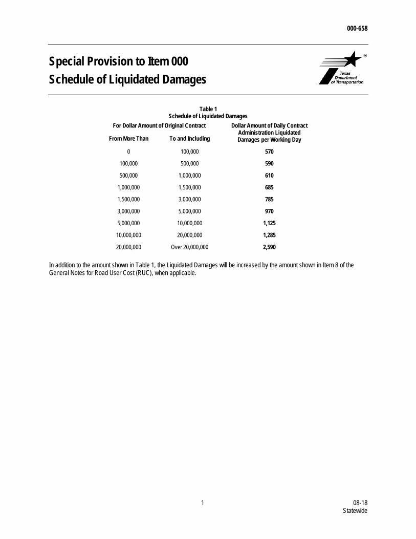
000-658
1 08-18 Statewide
Special Provision to Item 000 Schedule of Liquidated Damages
Table 1 Schedule of Liquidated Damages
For Dollar Amount of Original Contract Dollar Amount of Daily Contract Administration Liquidated Damages per Working Day From More Than To and Including
0 100,000 570
100,000 500,000 590
500,000 1,000,000 610
1,000,000 1,500,000 685
1,500,000 3,000,000 785
3,000,000 5,000,000 970
5,000,000 10,000,000 1,125
10,000,000 20,000,000 1,285
20,000,000 Over 20,000,000 2,590
In addition to the amount shown in Table 1, the Liquidated Damages will be increased by the amount shown in Item 8 of the General Notes for Road User Cost (RUC), when applicable.
000-659
1 08-18 Statewide
Special Provision 000 Notice of Contractor Performance Evaluations 1. GENERAL
In accordance with Texas Transportation Code §223.012, the Engineer will evaluate Contractor performance based on quality, safety, and timeliness of the project.
2. DEFINITIONS
2.1. Project Recovery Plan (PRP)—a formal, enforceable plan developed by the Contractor, in consultation with the District, that documents the cause of noted quality, safety, and timeliness issues and specifies how the Contractor proposes to correct project-specific performance deficiencies.
In accordance with Title 43, Texas Administrative Code (TAC), §9.23, the District will request a PRP if the Contractor’s performance on a project is below the Department’s acceptable standards and will monitor the Contractor’s compliance with the established plan.
2.2. Corrective Action Plan (CAP)—a formal, enforceable plan developed by the Contractor, and proposed for adoption by the Construction or Maintenance Division, that documents the cause of noted quality, safety, and timeliness issues and specifies how the Contractor proposes to correct statewide performance deficiencies.
In accordance with 43 TAC §9.23, the Division will request a CAP if the average of the Contractor’s statewide final evaluation scores falls below the Department’s acceptable standards for the review period and will monitor the Contractor’s compliance with the established plan.
3. CONTRACTOR EVALUATIONS
In accordance with Title 43, Texas Administrative Code (TAC) §9.23, the Engineer will schedule evaluations at the following intervals, at minimum: Interim evaluations—at or within 30 days after the anniversary of the notice to proceed, for Contracts
extending beyond 1 yr., and Final evaluation—upon project closeout.
In case of a takeover agreement, the Engineer will evaluate the Surety as the prime Contractor.
In addition to regularly scheduled evaluations, the Engineer may schedule an interim evaluation at any time to formally communicate issues with quality, safety, or timeliness. Upon request, work with the Engineer to develop a PRP to document expectations for correcting deficiencies.
Comply with the PRP as directed. Failure to comply with the PRP may result in additional remedial actions available to the Engineer under Item 5, “Control of the Work.” Failure to meet a PRP to the Engineer’s satisfaction may result in immediate referral to the Performance Review Committee for consideration of further action against the Contractor.
The Engineer will consider and document any events outside the Contractor’s control that contributed to the failure to meet performance standards or comply with a PRP, including consideration of sufficient time.
Follow the escalation ladder if there is a disagreement regarding an evaluation or disposition of a PRP. The Contractor may submit additional documentation pertaining to the dispute. The District Engineer’s decision
000-659
2 08-18 Statewide
on a Contractor’s evaluation score and recommendation of action required in a PRP or follow up for non-compliance is final.
4. DIVISION OVERSIGHT
Upon request of the Construction or Maintenance Division, develop and submit for Division approval a proposed CAP to document expectations for correcting deficiencies in the performance of projects statewide.
Comply with the CAP as directed. The CAP may be modified at any time up to completion or resolution after written approval of the premise of change from the Division. Failure to meet an adopted or revised adopted CAP to the Division’s satisfaction within 120 days will result in immediate referral to the Performance Review Committee for consideration of further action against the Contractor.
The Division will consider and document any events outside the Contractor’s control that contributed to the failure to meet performance standards or comply with a CAP, including consideration of sufficient time and associated costs as appropriate.
5. PERFORMANCE REVIEW COMMITTEE
The Performance Review Committee, in accordance with 43 TAC §9.24, will review at minimum all final evaluations, history of compliance with PRPs, any adopted CAPs including agreed modifications, any information about events outside a Contractor’s control contributing to the Contractor’s performance, and any documentation submitted by the Contractor and may recommend one or more of the following actions: take no action, reduce the Contractor’s bidding capacity, prohibit the Contractor from bidding on one or more projects, immediately suspend the Contractor from bidding for a specified period of time, by reducing the
Contractor’s bidding capacity to zero, or prohibit the Contractor from being awarded a Contract on which they are the apparent low bidder.
A Surety acting as a prime may be found in non-compliance through the contractor evaluation process.
The Deputy Executive Director will determine any further action against the Contractor.
6. APPEALS PROCESS
In accordance with 43 TAC §9.25, the Contractor may appeal remedial actions determined by the Deputy Executive Director.
002-011
1 - 1 02-18 Statewide
Special Provision to Item 2
Instructions to Bidders
Item 2, “Instructions to Bidders,” of the Standard Specifications is amended with respect to the clauses cited below. No other clauses or requirements of this Item are waived or changed.
Article 2.3., “Issuing Proposal Forms,” is supplemented by the following:
the Bidder or affiliate of the Bidder that was originally determined as the apparent low Bidder on a project, but was deemed
nonresponsive for failure to register or participate in the Department of Homeland Security’s (DHS) E-Verify system as
specified in Article 2.15., “Department of Homeland Security (DHS) E-Verify System,” is prohibited from rebidding that
specific project.
Article 2.7., “Nonresponsive Bid,” is supplemented by the following:
the Bidder failed to participate in the Department of Homeland Security’s (DHS) as specified in Article 2.15., “Department of
Homeland Security (DHS) E-Verify System.”
Article 2.15., “Department of Homeland Security (DHS) E-Verify System,” is added.
The Department will not award a Contract to a Contractor that is not registered in the DHS E-Verify system. Remain active in E=Verify throughout the life of the contract. In addition, in accordance with paragraph six of Article 8.2, “Subcontracting,” include this requirement in all subcontracts and require that subcontractors remain active in E-Verify until their work is completed.
If the apparent low Bidder does not appear on the DHS E-Verify system prior to award, the Department will notify the Contractor that they must submit documentation showing that they are compliant within 5-business days after the date the notification was sent. A Contractor who fails to comply or respond within the deadline will be declared non-responsive and the Department will execute the proposal guaranty. The proposal guaranty will become the property of the State, not as a penalty, but as liquidated damages. The Bidder forfeiting the proposal guaranty will not be considered in future proposals for the same work unless there has been a substantial change in the scope of the work.
The Department may recommend that the Commission:
reject all bids, or
award the Contract to the new apparent low Bidder, if the Department is able to verify the Bidder’s participation in the DHS
E-verify system. For the Bidder who is not registered in E-Verify, the Department will allow for one business day after
notification to provide proof of registration.
If the Department is unable to verify the new apparent low Bidder’s participation in the DHS E-Verify system within one calendar day:
the new apparent low Bidder will not be deemed nonresponsive,
the new apparent low Bidder’s guaranty will not be forfeited,
the Department will reject all bids, and
the new apparent low Bidder will remain eligible to receive future proposals for the same project.
003-005
1 - 1 04-15 Statewide
Special Provision to Item 3
Award and Execution of Contract
Item 3, “Award and Execution of Contract” of the Standard Specifications is amended with respect to the clauses cited below. No other clauses or requirements of this Item are waived or changed.
Section 4.2., “Bonds,” is supplemented by the following:
On the Department’s form, provide a warranty bond executed by either the manufacturer of the warranted items or the Contractor, and a U. S. Treasury listed surety with attached powers of attorney and notification information. The warranty bond will be for the total amount of the items that are warranted and furnished as a guarantee for the protection of the Department for all labor, materials, equipment and other incidentals for the replacement of defective work. The party providing the warranty bond is responsible for meeting the warranty requirements.
005-002
1 - 1 09-18 Statewide
Special Provision to Item 5 Control of the Work
Item 5, “Control of the Work,” of the Standard Specifications is amended with respect to the clauses cited below. No other clauses or requirements of this Item are waived or changed.
Article 5.1, “Authority of Engineer,” is voided and replaced by the following.
The Engineer has the authority to observe, test, inspect, approve, and accept the work. The Engineer decides all questions about the quality and acceptability of materials, work performed, work progress, Contract interpretations, and acceptable Contract fulfillment. The Engineer has the authority to enforce and make effective these decisions.
The Engineer acts as a referee in all questions arising under the terms of the Contract. The Engineer’s decisions will be final and binding.
The Engineer will pursue and document actions against the Contractor as warranted to address Contract performance issues. Contract remedies include, but are not limited to, the following: conducting interim performance evaluations requiring a Project Recovery Plan, in accordance with Title 43,
Texas Administrative Code (TAC) §9.23, requiring the Contractor to remove and replace defective work, or reducing payment for defective work, removing an individual from the project, suspending the work without suspending working day charges, assessing standard liquidated damages to recover the Department’s administrative costs, including additional project-
specific liquidated damages when specified in the Contract in accordance with 43 TAC §9.22, withholding estimates, declaring the Contractor to be in default of the Contract, and in case of a Contractor’s failure to meet a Project Recovery Plan, referring the issue directly to the Performance Review
Committee for consideration of further action against the Contractor in accordance with 43 TAC §9.24.
The Engineer will consider and document any events outside the Contractor’s control that contributed to the failure to meet performance standards, including consideration of sufficient time.
Follow the issue escalation ladder if there is disagreement regarding the application of Contract remedies.
006-001
1 09-14 Statewide
Special Provision to Item 6
Control of Materials
For this project, Item 6, “Control of Materials,” of the Standard Specifications, is hereby amended with respect to the clauses cited below, and no other clauses or requirements of this Item are waived or changed hereby.
Article 4., “Sampling, Testing, and Inspection,” is supplemented by the following:
Meet with the Engineer and choose either the Department or a Department-selected Commercial Lab (CL) for conducting the subset of project-level sampling and testing shown in Table 1, “Select Guide Schedule Sampling and Testing.” Selection may be made on a test by test basis. CLs will meet the testing turnaround times shown (includes test time and time for travel/sampling and reporting) and in all cases issue test reports as soon as possible.
If the Contractor chooses a Department-selected CL for any Table 1 sampling and testing:
notify the Engineer, District Lab, and the CL of project scheduling that may require CL testing; provide the Engineer, District Lab, and CL at least 24 hours’ notice by phone and e-mail; reimburse the Department for CL Table 1 testing using the contract fee schedule for the CL (including
mileage and travel/standby time) at the minimum guide schedule testing frequencies; reimburse the Department for CL Table 1 testing above the minimum guide schedule frequencies for
retesting when minimum frequency testing results in failures to meet specification limits; agree with the Engineer and CL upon a policy regarding notification for testing services; give any cancellation notice to the Engineer, District Lab, and CL by phone and e-mail; reimburse the Department a $150 cancellation fee to cover technician time and mileage charges for
previously scheduled work cancelled without adequate notice, which resulted in mobilization of technician and/or equipment by the CL; and
all CL charges will be reimbursed to the Department by a deduction from the Contractor's monthly pay estimate.
If the CL does not meet the Table 1 turnaround times, testing charge to the Contractor will be reduced by 50% for the first late day and an additional 5% for each succeeding late day.
Approved CL project testing above the minimum testing frequencies in the Guide Schedule of Sampling and Testing, and not as the result of failing tests, will be paid by the Department.
Other project-level Guide Schedule sampling and testing not shown on Table 1 will be the responsibility of the Department.
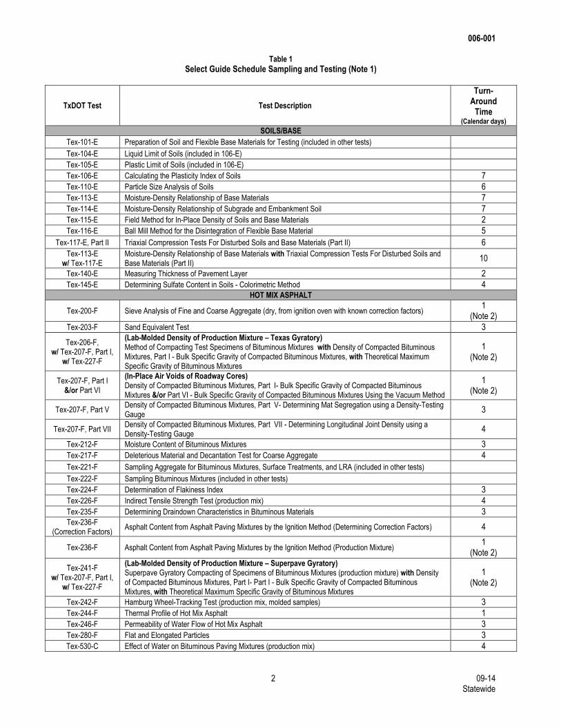
006-001
2 09-14 Statewide
Table 1 Select Guide Schedule Sampling and Testing (Note 1)
TxDOT Test Test Description
Turn- Around
Time (Calendar days)
SOILS/BASE
Tex-101-E Preparation of Soil and Flexible Base Materials for Testing (included in other tests)
Tex-104-E Liquid Limit of Soils (included in 106-E)
Tex-105-E Plastic Limit of Soils (included in 106-E)
Tex-106-E Calculating the Plasticity Index of Soils 7
Tex-110-E Particle Size Analysis of Soils 6
Tex-113-E Moisture-Density Relationship of Base Materials 7
Tex-114-E Moisture-Density Relationship of Subgrade and Embankment Soil 7
Tex-115-E Field Method for In-Place Density of Soils and Base Materials 2
Tex-116-E Ball Mill Method for the Disintegration of Flexible Base Material 5
Tex-117-E, Part II Triaxial Compression Tests For Disturbed Soils and Base Materials (Part II) 6
Tex-113-E w/ Tex-117-E
Moisture-Density Relationship of Base Materials with Triaxial Compression Tests For Disturbed Soils and Base Materials (Part II)
10
Tex-140-E Measuring Thickness of Pavement Layer 2
Tex-145-E Determining Sulfate Content in Soils - Colorimetric Method 4 HOT MIX ASPHALT
Tex-200-F Sieve Analysis of Fine and Coarse Aggregate (dry, from ignition oven with known correction factors) 1
(Note 2)
Tex-203-F Sand Equivalent Test 3
Tex-206-F, w/ Tex-207-F, Part I,
w/ Tex-227-F
(Lab-Molded Density of Production Mixture – Texas Gyratory) Method of Compacting Test Specimens of Bituminous Mixtures with Density of Compacted Bituminous Mixtures, Part I - Bulk Specific Gravity of Compacted Bituminous Mixtures, with Theoretical Maximum Specific Gravity of Bituminous Mixtures
1 (Note 2)
Tex-207-F, Part I &/or Part VI
(In-Place Air Voids of Roadway Cores) Density of Compacted Bituminous Mixtures, Part I- Bulk Specific Gravity of Compacted Bituminous Mixtures &/or Part VI - Bulk Specific Gravity of Compacted Bituminous Mixtures Using the Vacuum Method
1 (Note 2)
Tex-207-F, Part V Density of Compacted Bituminous Mixtures, Part V- Determining Mat Segregation using a Density-Testing Gauge
3
Tex-207-F, Part VII Density of Compacted Bituminous Mixtures, Part VII - Determining Longitudinal Joint Density using a Density-Testing Gauge
4
Tex-212-F Moisture Content of Bituminous Mixtures 3
Tex-217-F Deleterious Material and Decantation Test for Coarse Aggregate 4
Tex-221-F Sampling Aggregate for Bituminous Mixtures, Surface Treatments, and LRA (included in other tests)
Tex-222-F Sampling Bituminous Mixtures (included in other tests)
Tex-224-F Determination of Flakiness Index 3
Tex-226-F Indirect Tensile Strength Test (production mix) 4
Tex-235-F Determining Draindown Characteristics in Bituminous Materials 3 Tex-236-F
(Correction Factors) Asphalt Content from Asphalt Paving Mixtures by the Ignition Method (Determining Correction Factors) 4
Tex-236-F Asphalt Content from Asphalt Paving Mixtures by the Ignition Method (Production Mixture) 1
(Note 2)
Tex-241-F w/ Tex-207-F, Part I,
w/ Tex-227-F
(Lab-Molded Density of Production Mixture – Superpave Gyratory) Superpave Gyratory Compacting of Specimens of Bituminous Mixtures (production mixture) with Density of Compacted Bituminous Mixtures, Part I- Part I - Bulk Specific Gravity of Compacted Bituminous Mixtures, with Theoretical Maximum Specific Gravity of Bituminous Mixtures
1 (Note 2)
Tex-242-F Hamburg Wheel-Tracking Test (production mix, molded samples) 3
Tex-244-F Thermal Profile of Hot Mix Asphalt 1
Tex-246-F Permeability of Water Flow of Hot Mix Asphalt 3
Tex-280-F Flat and Elongated Particles 3
Tex-530-C Effect of Water on Bituminous Paving Mixtures (production mix) 4
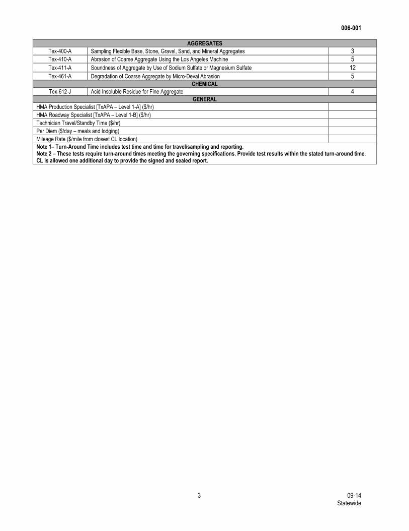
006-001
3 09-14 Statewide
AGGREGATES
Tex-400-A Sampling Flexible Base, Stone, Gravel, Sand, and Mineral Aggregates 3
Tex-410-A Abrasion of Coarse Aggregate Using the Los Angeles Machine 5
Tex-411-A Soundness of Aggregate by Use of Sodium Sulfate or Magnesium Sulfate 12
Tex-461-A Degradation of Coarse Aggregate by Micro-Deval Abrasion 5 CHEMICAL
Tex-612-J Acid Insoluble Residue for Fine Aggregate 4 GENERAL
HMA Production Specialist [TxAPA – Level 1-A] ($/hr)
HMA Roadway Specialist [TxAPA – Level 1-B] ($/hr)
Technician Travel/Standby Time ($/hr)
Per Diem ($/day – meals and lodging)
Mileage Rate ($/mile from closest CL location) Note 1– Turn-Around Time includes test time and time for travel/sampling and reporting. Note 2 – These tests require turn-around times meeting the governing specifications. Provide test results within the stated turn-around time. CL is allowed one additional day to provide the signed and sealed report.
006-012
1 - 2 02-18 Statewide
Special Provision to Item 6 Control of Materials
Item 6, “Control of Materials” of the Standard Specifications is amended with respect to the clauses cited below. No other clauses or requirements of this Item are waived or changed.
Article 6.10., “Hazardous Materials,” is voided and replaced by the following:
Comply with the requirements of Article 7.12., “Responsibility for Hazardous Materials.”
Notify the Engineer immediately when a visual observation or odor indicates that materials on sites owned or controlled by the Department may contain hazardous materials. Except as noted herein, the Department is responsible for testing, removing, and disposing of hazardous materials not introduced by the Contractor. The Engineer may suspend work wholly or in part during the testing, removing, or disposing of hazardous materials, except in the case where hazardous materials are introduced by the Contractor.
Use materials that are free of hazardous materials. Notify the Engineer immediately if materials are suspected to contain hazardous materials. If materials delivered to the project by the Contractor are suspected to contain hazardous materials, have an approved commercial laboratory test the materials for the presence of hazardous materials as approved. Remove, remediate, and dispose of any of these materials found to contain hazardous materials. The work required to comply with this section will be at the Contractor’s expense if materials are found to contain hazardous materials. Working day charges will not be suspended and extensions of working days will not be granted for activities related to handling hazardous material introduced by the Contractor. If suspected materials are not found to contain hazardous materials, the Department will reimburse the Contractor for hazardous materials testing and will adjust working day charges if the Contractor can show that this work impacted the critical path.
10.1. Painted Steel Requirements. Coatings on existing steel contain hazardous materials unless otherwise shown on the plans. Remove paint and dispose of steel coated with paint containing hazardous materials is in accordance with the following:
10.1.1. Removing Paint From Steel For contracts that are specifically for painting steel, Item 446, “Field Cleaning and Painting Steel” will be included as a pay item. Perform work in accordance with that item.
For projects where paint must be removed to allow for the dismantling of steel or to perform other work, the Department will provide for a separate contractor (third party) to remove paint containing hazardous materials prior to or during the Contract. Remove paint covering existing steel shown not to contain hazardous materials in accordance with Item 446, “Field Cleaning and Painting Steel.”
10.1.2. Removal and Disposal of Painted Steel. For steel able to be dismantled by unbolting, paint removal will not be performed by the Department. The Department will remove paint, at locations shown on the plans or as agreed, for the Contractor’s cutting and dismantling purposes. Utilize Department cleaned locations for dismantling when provided or provide own means of dismantling at other locations.
Painted steel to be retained by the Department will be shown on the plans. For painted steel that contains hazardous materials, dispose of the painted steel at a steel recycling or smelting facility unless otherwise shown on the plans. Maintain and make available to the Engineer invoices and other records obtained from the facility showing the received weight of the steel and the facility name. Dispose of steel that does not contain hazardous material coatings in accordance with federal, state and local regulations.
006-012
2 - 2 02-18 Statewide
10.2. Asbestos Requirements. The plans will indicate locations or elements where asbestos containing materials (ACM) are known to be present. Where ACM is known to exist or where previously unknown ACM has been found, the Department will arrange for abatement by a separate contractor prior to or during the Contract. Notify the Engineer of proposed dates of demolition or removal of structural elements with ACM at least 60 days before beginning work to allow the Department sufficient time for abatement.
The Department of State Health Services (DSHS), Asbestos Programs Branch, is responsible for administering the requirements of the National Emissions Standards for Hazardous Air Pollutants, 40 CFR Part 61, Subpart M and the Texas Asbestos Health Protection Rules (TAHPR). Based on EPA guidance and regulatory background information, bridges are considered to be a regulated “facility” under NESHAP. Therefore, federal standards for demolition and renovation apply.
The Department is required to notify the DSHS at least 10 working days (by postmarked date) before initiating demolition or renovation of each structure or load bearing member shown on the plans. If the actual demolition or renovation date is changed or delayed, notify the Engineer in writing of the revised dates in sufficient time to allow for the Department’s notification to DSHS to be postmarked at least 10 days in advance of the actual work.
Failure to provide the above information may require the temporary suspension of work under Article 8.4., “Temporary Suspension of Work or Working Day Charges,” due to reasons under the control of the Contractor. The Department retains the right to determine the actual advance notice needed for the change in date to address post office business days and staff availability.
10.3. Lead Abatement. Provide traffic control as shown on the plans, and coordinate and cooperate with the third party and the Department for managing or removing hazardous materials. Work for the traffic control shown on the plans and coordination work will not be paid for directly but will be subsidiary to pertinent Items.
007-001
1-3 07-15 Statewide
Special Provision to Item 7
Legal Relations and Responsibilities
Item 7, “Legal Relations and Responsibilities,” of the Standard Specifications is amended with respect to the clauses cited below. No other clauses or requirements of this Item are waived or changed.
Section 7.2.6.5, “Training,” is supplemented by the following:
Coordinate enrollment, pay associated fees, and successfully complete Department-approved Training or Contractor-developed Training. Training is valid for the period prescribed by the provider. If no training period is prescribed by the provider, then training is valid for 3 yrs. from the date of completion. The Engineer may require training at a frequency in lieu of the period prescribed based on the Department’s needs. Training and associated fees will not be measured or paid for directly but are considered subsidiary to pertinent Items.
2.6.5.1. Department-approved Training. Department-approved training is listed below. For Section 7.2.6.5.1.4.,
“Other Work Zone Personnel”, the Contractor may use Contractor-developed Training in lieu of Department-approved Training.
2.6.5.1.1 Contractor Responsible Person and Alternate.
Provider Course Title
American Traffic Safety Services Association Traffic Control Supervisor
National Highway Institute1 Design and Operation of Work Zone Traffic
Control, Work Zone Traffic Control for
Maintenance Operations
Texas Engineering Extension Service Work Zone Traffic Control for CRPs
University of Texas Arlington,
Division for Enterprise Development
Traffic Control Supervisor
1. Both classes are required in order to equal the level of training taught in a single class by other providers.
2.6.5.1.2. Flagger Instructor Training.
Provider Course Title
American Traffic Safety Services Association Flagging Instructor Training
Texas Engineering Extension Service Train-the-Trainer Flaggers
National Safety Council Flagger Instructor Training
University of Texas at Arlington,
Division for Enterprise Development
Certified Instructor: Qualified Flagger Training
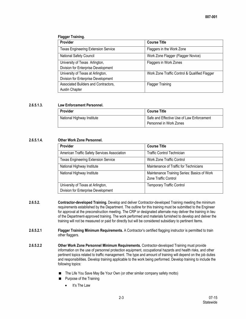
007-001
2-3 07-15 Statewide
Flagger Training.
Provider Course Title
Texas Engineering Extension Service Flaggers in the Work Zone
National Safety Council Work Zone Flagger (Flagger Novice)
University of Texas Arlington,
Division for Enterprise Development
Flaggers in Work Zones
University of Texas at Arlington,
Division for Enterprise Development
Work Zone Traffic Control & Qualified Flagger
Associated Builders and Contractors,
Austin Chapter
Flagger Training
2.6.5.1.3. Law Enforcement Personnel.
Provider Course Title
National Highway Institute Safe and Effective Use of Law Enforcement
Personnel in Work Zones
2.6.5.1.4. Other Work Zone Personnel.
Provider Course Title
American Traffic Safety Services Association Traffic Control Technician
Texas Engineering Extension Service Work Zone Traffic Control
National Highway Institute Maintenance of Traffic for Technicians
National Highway Institute Maintenance Training Series: Basics of Work
Zone Traffic Control
University of Texas at Arlington,
Division for Enterprise Development
Temporary Traffic Control
2.6.5.2. Contractor-developed Training. Develop and deliver Contractor-developed Training meeting the minimum requirements established by the Department. The outline for this training must be submitted to the Engineer for approval at the preconstruction meeting. The CRP or designated alternate may deliver the training in lieu of the Department-approved training. The work performed and materials furnished to develop and deliver the training will not be measured or paid for directly but will be considered subsidiary to pertinent Items.
2.6.5.2.1 Flagger Training Minimum Requirements. A Contractor’s certified flagging instructor is permitted to train other flaggers.
2.6.5.2.2 Other Work Zone Personnel Minimum Requirements. Contractor-developed Training must provide
information on the use of personnel protection equipment, occupational hazards and health risks, and other pertinent topics related to traffic management. The type and amount of training will depend on the job duties and responsibilities. Develop training applicable to the work being performed. Develop training to include the following topics:
The Life You Save May Be Your Own (or other similar company safety motto)
Purpose of the Training
It’s The Law
007-001
3-3 07-15 Statewide
To make work zones safer for workers and motorist
To understand what is needed for traffic control
To save lives including your own
Personal and Co-Worker Safety
High Visibility Safety Apparel: Discuss compliant requirements; Inspect regularly for fading and
reduced reflective properties; If night operations are required, discuss the additional and
appropriate required apparel in addition to special night work risks; If moving operations are
underway, discuss appropriate safety measures specific to the situation and traffic control plan.
Blind Areas: A blind area is the area around a vehicle or piece of construction equipment not visible
to the operators, either by line of sight or indirectly by mirrors. Discuss the “Circle of Safety” around
equipment and vehicles; Use of spotters; Maintain eye contact with equipment operators; Use of
hand signals.
Runovers and Backovers: Remain alert at all times; Keep a safe distance from traffic; Avoid turning
your back to traffic and if you must then use a spotter; Stay behind protective barriers, whenever
possible. Note: It is not safe to sit on or lean against a concrete barrier, these barriers can deflect
4+ feet when struck by a vehicle.
Look out for each other, warn co-workers
Be courteous to motorists
Do not run across active roadways
Workers must obey traffic laws and drive courteously while operating vehicles in the work zones.
Workers must be made aware of company distracted driving policies
Night Time Operations: Focus should be placed on projects with a nighttime element.
Traffic Control Training: Basics of Traffic Control.
Identify Work Zone Traffic Control Supervisor and other appropriate persons to report issues to
when they arise.
Work Zone Traffic Control Devices must be in clean and in undamaged condition. If devices have
been hit but not damaged, put back in their correct place and report to traffic control supervisor. If
devices have been damaged, replace with new one and report to traffic control supervisor. If
devices are dirty, faded or have missing or damaged reflective tape clean or replace and report to
traffic control supervisor. Show examples of non-acceptable device conditions. Discussion on
various types of traffic control devices to be used and where spacing requirements can be found.
Channelizing Devices and Barricades with slanted stripes: Stripes are to slant in the direction you
want traffic to stay or move to; Demonstrate this with a device.
Traffic Queuing: Workers must be made aware of traffic queuing and the dangers created by it.
Workers must be instructed to immediately notify the traffic control supervisor and other
supervisory personnel if traffic is queuing beyond advance warning sign and devices or
construction limits.
Signs: Signs must be straight and not leaning. Report problems to the traffic control supervisor or
other as designated for immediate repair. Covered signs must be fully covered. If covers are
damaged or out of place, report to traffic control supervisor or other as designated.
007-008
1 - 1 07-17 Statewide
Special Provision to Item 7
Legal Relations and Responsibilities
Item 7, “Legal Relations and Responsibilities” of the Standard Specifications is amended with respect to the clauses cited below. No other clauses or requirements of this Item are waived or changed.
Section 19.1., Minimum Wage Requirements for Federally Funded Contracts. The second paragraph is voided and replaced by the following:
Submit electronic payroll records to the Engineer using the Department’s payroll system.
Section 19.2., Minimum Wage Requirements for State Funded Contracts. The second paragraph is voided and replaced by the following:
Submit electronic payroll records to the Engineer using the Department’s payroll system.
008-023
1 - 1 12-16 Statewide
Special Provision to Item 8
Prosecution and Progress
Item 8, “Prosecution and Progress” of the Standard Specifications is amended with respect to the clauses cited below. No other clauses or requirements of this Item are waived or changed.
Article 8.7.2., Wrongful Default,” is voided and not replaced.
008-030
02-18 Statewide
Special Provision to Item 8 Prosecution and Progress Item 8, “Prosecution and Progress” of the Standard Specification is amended with respect to the clauses cited below. No other clauses or requirements of this Item are waived or changed. Article 8.2., “Subcontracting,” is supplemented by the following paragraph, which is added as paragraph six to this article: The Contractor certifies by signing the Contract that the Contractor will not enter into any subcontract with a subcontractor that is not registered in the Department of Homeland Security’s (DHS) E-Verify system. Require that all subcontractors working on the project register and require that all subcontractors remain active in the DHS E-Verify system until their work is complete on the project.
340-001
1 - 1 08-18 Districtwide
Special Provision to Item 340
Dense-Graded Hot-Mix Asphalt (Small Quantity)
Item 340, “Dense-Graded Hot-Mix Asphalt (Small Quantity)” of the Standard Specifications is amended with respect to the clauses cited below. No other clauses or requirements of this Item are waived or changed.
Article 5. “Measurement.” is voided and replaced by the following:
Hot mix will be measured by the square yard or ton of composite hot-mix, which includes asphalt, aggregate, and additives. Measurement by the square yard must be in its final position at the depth shown in the plans. Measurement by ton must measure the weight on scales in accordance with Item 520, “Weighing and Measuring Equipment.”
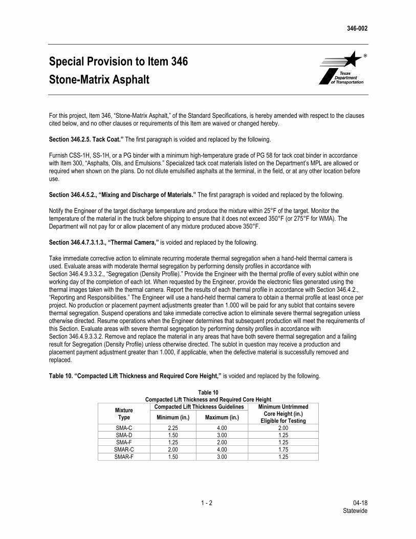
346-002
1 - 2 04-18 Statewide
Special Provision to Item 346
Stone-Matrix Asphalt
For this project, Item 346, “Stone-Matrix Asphalt,” of the Standard Specifications, is hereby amended with respect to the clauses cited below, and no other clauses or requirements of this Item are waived or changed hereby.
Section 346.2.5. Tack Coat.” The first paragraph is voided and replaced by the following.
Furnish CSS-1H, SS-1H, or a PG binder with a minimum high-temperature grade of PG 58 for tack coat binder in accordance with Item 300, “Asphalts, Oils, and Emulsions.” Specialized tack coat materials listed on the Department’s MPL are allowed or required when shown on the plans. Do not dilute emulsified asphalts at the terminal, in the field, or at any other location before use.
Section 346.4.5.2., “Mixing and Discharge of Materials.” The first paragraph is voided and replaced by the following.
Notify the Engineer of the target discharge temperature and produce the mixture within 25°F of the target. Monitor the temperature of the material in the truck before shipping to ensure that it does not exceed 350°F (or 275°F for WMA). The Department will not pay for or allow placement of any mixture produced above 350°F.
Section 346.4.7.3.1.3., “Thermal Camera,” is voided and replaced by the following.
Take immediate corrective action to eliminate recurring moderate thermal segregation when a hand-held thermal camera is used. Evaluate areas with moderate thermal segregation by performing density profiles in accordance with Section 346.4.9.3.3.2., “Segregation (Density Profile).” Provide the Engineer with the thermal profile of every sublot within one working day of the completion of each lot. When requested by the Engineer, provide the electronic files generated using the thermal images taken with the thermal camera. Report the results of each thermal profile in accordance with Section 346.4.2., “Reporting and Responsibilities.” The Engineer will use a hand-held thermal camera to obtain a thermal profile at least once per project. No production or placement payment adjustments greater than 1.000 will be paid for any sublot that contains severe thermal segregation. Suspend operations and take immediate corrective action to eliminate severe thermal segregation unless otherwise directed. Resume operations when the Engineer determines that subsequent production will meet the requirements of this Section. Evaluate areas with severe thermal segregation by performing density profiles in accordance with Section 346.4.9.3.3.2. Remove and replace the material in any areas that have both severe thermal segregation and a failing result for Segregation (Density Profile) unless otherwise directed. The sublot in question may receive a production and placement payment adjustment greater than 1.000, if applicable, when the defective material is successfully removed and replaced.
Table 10. “Compacted Lift Thickness and Required Core Height,” is voided and replaced by the following.
Table 10
Compacted Lift Thickness and Required Core Height
Mixture Type
Compacted Lift Thickness Guidelines Minimum Untrimmed Core Height (in.)
Eligible for Testing Minimum (in.) Maximum (in.)
SMA-C 2.25 4.00 2.00
SMA-D 1.50 3.00 1.25
SMA-F 1.25 2.00 1.25
SMAR-C 2.00 4.00 1.75
SMAR-F 1.50 3.00 1.25
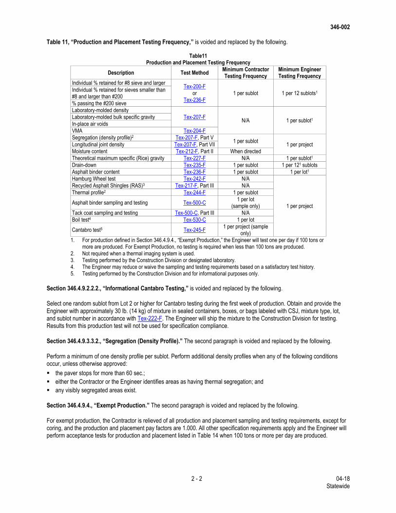
346-002
2 - 2 04-18 Statewide
Table 11, “Production and Placement Testing Frequency,” is voided and replaced by the following.
Table11 Production and Placement Testing Frequency
Description Test Method Minimum Contractor Testing Frequency
Minimum Engineer Testing Frequency
Individual % retained for #8 sieve and larger Tex-200-F
or Tex-236-F
1 per sublot 1 per 12 sublots1 Individual % retained for sieves smaller than #8 and larger than #200
% passing the #200 sieve
Laboratory-molded density
Tex-207-F N/A 1 per sublot1 Laboratory-molded bulk specific gravity
In-place air voids
VMA Tex-204-F
Segregation (density profile)2 Tex-207-F, Part V 1 per sublot
1 per project Longitudinal joint density Tex-207-F, Part VII
Moisture content Tex-212-F, Part II When directed
Theoretical maximum specific (Rice) gravity Tex-227-F N/A 1 per sublot1
Drain-down Tex-235-F 1 per sublot 1 per 121 sublots
Asphalt binder content Tex-236-F 1 per sublot 1 per lot1
Hamburg Wheel test Tex-242-F N/A
1 per project
Recycled Asphalt Shingles (RAS)3 Tex-217-F, Part III N/A
Thermal profile2 Tex-244-F 1 per sublot
Asphalt binder sampling and testing Tex-500-C 1 per lot
(sample only)
Tack coat sampling and testing Tex-500-C, Part III N/A
Boil test4 Tex-530-C 1 per lot
Cantabro test5 Tex-245-F 1 per project (sample
only)
1. For production defined in Section 346.4.9.4., “Exempt Production,” the Engineer will test one per day if 100 tons or more are produced. For Exempt Production, no testing is required when less than 100 tons are produced.
2. Not required when a thermal imaging system is used. 3. Testing performed by the Construction Division or designated laboratory. 4. The Engineer may reduce or waive the sampling and testing requirements based on a satisfactory test history. 5. Testing performed by the Construction Division and for informational purposes only.
Section 346.4.9.2.2.2., “Informational Cantabro Testing,” is voided and replaced by the following.
Select one random sublot from Lot 2 or higher for Cantabro testing during the first week of production. Obtain and provide the Engineer with approximately 30 lb. (14 kg) of mixture in sealed containers, boxes, or bags labeled with CSJ, mixture type, lot, and sublot number in accordance with Tex-222-F. The Engineer will ship the mixture to the Construction Division for testing. Results from this production test will not be used for specification compliance.
Section 346.4.9.3.3.2., “Segregation (Density Profile).” The second paragraph is voided and replaced by the following.
Perform a minimum of one density profile per sublot. Perform additional density profiles when any of the following conditions occur, unless otherwise approved:
the paver stops for more than 60 sec.;
either the Contractor or the Engineer identifies areas as having thermal segregation; and
any visibly segregated areas exist.
Section 346.4.9.4., “Exempt Production.” The second paragraph is voided and replaced by the following.
For exempt production, the Contractor is relieved of all production and placement sampling and testing requirements, except for coring, and the production and placement pay factors are 1.000. All other specification requirements apply and the Engineer will perform acceptance tests for production and placement listed in Table 14 when 100 tons or more per day are produced.
346-002
3 - 2 04-18 Statewide
Section 346.6.2.2.,” Placement Sublots Subject to Removal and Replacement.” The first paragraph is voided and replaced by the following.
If after referee testing, the placement payment adjustment factor for any sublot results in a “remove and replace” condition as listed in Table 14, the Engineer will choose the location of 2 cores to be taken within 3 ft. of the original failing core location. The Contractor will obtain the cores in the presence of the Engineer. The Engineer will take immediate possession of the untrimmed cores and submit the untrimmed cores to the Construction Division, where they will be trimmed if necessary and tested for bulk specific gravity within 10 working days of receipt.
The bulk specific gravity of each core will be divided by the Engineer’s average maximum theoretical specific gravity for that lot to determine the new payment adjustment factor of the sublot in question. If the new payment adjustment factor is 0.700 or greater, the new payment adjustment factor will apply to that sublot. If the new payment adjustment factor is less than 0.700, no payment will be made for the sublot. Remove and replace the failing sublot, or the Engineer may allow the sublot to be left in place without payment. The Engineer may also accept the sublot in accordance with Section 5.3.1., “Acceptance of Defective or Unauthorized Work.” Replacement material meeting the requirements of this Item will be paid for in accordance with this Section.
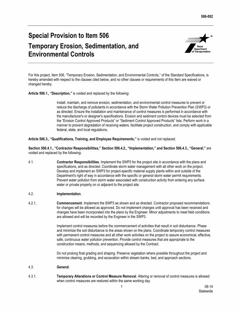
506-002
1 08-14 Statewide
Special Provision to Item 506
Temporary Erosion, Sedimentation, and Environmental Controls
For this project, Item 506, “Temporary Erosion, Sedimentation, and Environmental Controls,” of the Standard Specifications, is hereby amended with respect to the clauses cited below, and no other clauses or requirements of this Item are waived or changed hereby.
Article 506.1., “Description,” is voided and replaced by the following:
Install, maintain, and remove erosion, sedimentation, and environmental control measures to prevent or reduce the discharge of pollutants in accordance with the Storm Water Pollution Prevention Plan (SWP3) or as directed. Ensure the installation and maintenance of control measures is performed in accordance with the manufacturer's or designer's specifications. Erosion and sediment control devices must be selected from the “Erosion Control Approved Products” or “Sediment Control Approved Products” lists. Perform work in a manner to prevent degradation of receiving waters, facilitate project construction, and comply with applicable federal, state, and local regulations.
Article 506.3., “Qualifications, Training, and Employee Requirements,” is voided and not replaced.
Section 506.4.1., “Contractor Responsibilities,” Section 506.4.2., “Implementation,” and Section 506.4.3., “General,” are voided and replaced by the following:
4.1. Contractor Responsibilities. Implement the SWP3 for the project site in accordance with the plans and specifications, and as directed. Coordinate storm water management with all other work on the project. Develop and implement an SWP3 for project-specific material supply plants within and outside of the Department's right of way in accordance with the specific or general storm water permit requirements. Prevent water pollution from storm water associated with construction activity from entering any surface water or private property on or adjacent to the project site.
4.2. Implementation.
4.2.1. Commencement. Implement the SWP3 as shown and as directed. Contractor proposed recommendations for changes will be allowed as approved. Do not implement changes until approval has been received and changes have been incorporated into the plans by the Engineer. Minor adjustments to meet field conditions are allowed and will be recorded by the Engineer in the SWP3.
Implement control measures before the commencement of activities that result in soil disturbance. Phase and minimize the soil disturbance to the areas shown on the plans. Coordinate temporary control measures with permanent control measures and all other work activities on the project to assure economical, effective, safe, continuous water pollution prevention. Provide control measures that are appropriate to the construction means, methods, and sequencing allowed by the Contract.
Do not prolong final grading and shaping. Preserve vegetation where possible throughout the project and minimize clearing, grubbing, and excavation within stream banks, bed, and approach sections.
4.3. General.
4.3.1. Temporary Alterations or Control Measure Removal. Altering or removal of control measures is allowed when control measures are restored within the same working day.
506-002
2 08-14 Statewide
4.3.2. Stabilization. Initiate stabilization for disturbed areas no more than 14 days after the construction activities in that portion of the site has temporarily or permanently ceased. Establish a uniform vegetative cover or use another stabilization practice as approved.
4.3.3. Finished Work. Upon the Engineer's acceptance of vegetative cover or other stabilization practice, remove and dispose of all temporary control measures unless otherwise directed. Complete soil disturbing activities and establish a uniform perennial vegetative cover. A project will not be considered for acceptance until a vegetative cover of 70% density of existing adjacent undisturbed areas is obtained or equivalent permanent stabilization is obtained as approved.
4.3.4. Restricted Activities and Required Precautions. Do not discharge onto the ground or surface waters any pollutants such as chemicals, raw sewage, fuels, lubricants, coolants, hydraulic fluids, bitumens, or any other petroleum product. Operate and maintain equipment on site in a manner as to prevent actual or potential water pollution. Manage, control, and dispose of litter on site such that no adverse impacts to water quality occur. Prevent dust from creating a potential or actual unsafe condition, public nuisance, or condition endangering the value, utility, or appearance of any property. Wash out concrete trucks only in approved contained areas. Use appropriate controls to minimize the offsite transport of suspended sediments and other pollutants if it is necessary to pump or channel standing water (i.e. dewatering). Prevent discharges that would contribute to a violation of Edwards Aquifer Rules, water quality standards, the impairment of a listed water body, or other state or federal law.
Section 506.4.4., “Installation, Maintenance, and Removal Work.” The first paragraph is voided and replaced by the following.
Perform work in accordance with the SWP3, and according to the manufacturers’ guidelines. Install and maintain the integrity of temporary erosion and sedimentation control devices to accumulate silt and debris until soil disturbing activities are completed and permanent erosion control features are in place or the disturbed area has been adequately stabilized as determined by the Engineer.
Section 506.4.5., “Monitoring and Documentation,” is voided and not replaced.
Section 506.6.5.2., “Maintenance Earthwork for Erosion and Sediment Control for Cleaning and/or Restoring Control Measures,” is voided and replaced by the following:
Earthwork needed to remove and obliterate of erosion-control features will not be paid for directly but is subsidiary to pertinent Items unless otherwise shown on the plans.
Sprinkling and rolling required by this Item will not be paid for directly but will be subsidiary to this Item.
506-004
1 - 2 04-18 Statewide
Special Provision to Item 506
Temporary Erosion, Sedimentation, and Environmental Controls
Item 506, “Temporary Erosion, Sedimentation, and Environmental Controls,” of the Standard Specifications is amended with respect to the clauses cited below. No other clauses or requirements of this Item are waived or changed.
Article 506.1., “Description.” The second paragraph is voided and replaced by the following.
Contractor is considered primary operator to have day-to-day operational control as defined in TPDES GP TXR150000.
1.1. For projects with soil disturbance of less than 1 acre, no submittal to TCEQ will be required but Contractor will follow SWP3. For projects with soil disturbance of 1 acre to less than 5 acres a small site notice will be posted at the site. For projects with soil disturbance of 5 acres or more a notice of intent (NOI) is required and a large site notice posted at site. Postings will be in accordance with TPDES GP TXR150000. Postings not associated with project specific locations will be in same location as Department’s postings.
1.2. Notice of Intent (NOI). Submit a NOI, if applicable, with the TCEQ under the TPDES GP TXR150000 at least 7 days prior to commencement of construction activities at the project site. Provide a signed copy to the Engineer and any other MS4 operators at the time of submittal. The Department will submit their NOI prior to contractor submission and will provide a copy for Contractor’s use in completing the Contractor’s NOI form.
1.3. Notice of Change (NOC). Upon concurrence of the Engineer, submit a NOC, if applicable, to the TCEQ within 14 days of discovery of a change or revision to the NOI as required by the TPDES GP TXR150000. Provide a signed copy of the NOC to the Engineer and any other MS4 operators at the time of submittal.
1.4. Notice of Termination (NOT). Upon concurrence of the Engineer, submit a NOT, if applicable, to the TCEQ within 30 days of the Engineer’s approval that 70% native background vegetative cover is met or equivalent permanent stabilization have been employed in accordance with the TPDES GP TXR 150000. Provide a signed copy of the NOT to the Engineer and any other MS4 operators at the time of submittal.
Section 506.3.3., “Training,” is supplemented by the following:
Training is provided by the Department at no cost to the Contractor and is valid for 3 yr. from the date of completion. The Engineer may require the following training at a frequency less than 3 yr. based on environmental needs:
“Environmental Management System: Awareness Training for the Contractor” (English and Spanish) (Approximate
running time 20 min.), and
“Storm Water: Environmental Requirements During Construction” (English and Spanish) (Approximate running time 20
min.).
The contractor responsible person environmental (CRPE), alternate CRPE designated for emergencies, Contractor’s superintendent, Contractor, and subcontractor lead personnel involved in soil disturbing or SWP3 activities must enroll in and complete the training listed below and provide the certificate of completion to the Engineer before performing soil disturbing or SWP3 activities on the project. Training is provided by a third party and is valid for 3 years from the date shown on the Certificate of Completion. Coordinate enrollment as prescribed by the Department and pay associated fees for the following training:
“Revegetation During Construction”
“Construction General Permit Compliance,” and
506-004
2 - 2 04-18 Statewide
“Construction Stage Gate Checklist (CSGC).”
Training and associated fee will not be measured or paid for directly but are subsidiary to this Item.
666-007
1 - 2 02-18 Statewide
Special Provision to Item 666 Retroreflectorized Pavement Markings
Item 666, “Retroreflectorized Pavement Markings,” of the Standard Specifications is amended with respect to the clauses cited below. No other clauses or requirements of this Item are waived or changed.
Section 2.3., “Glass Traffic Beads.” The first paragraph is voided and replaced by the following:
Furnish drop-on glass beads in accordance with DMS-8290, “Glass Traffic Beads,” or as approved. Furnish a double-drop of Type II and Type III drop-on glass beads for longitudinal pavement markings where each type bead is applied separately in equal portions (by weight), unless otherwise approved. Apply the Type III beads before applying the Type II beads. Furnish Type II beads for work zone pavement markings and transverse markings or symbols.
Section 4.3.1., “Type I Markings.,” is supplemented by the following:
4.3.1.3. Spot Striping. Perform spot striping on a callout basis with a minimum callout quantity as shown on the plans.
Section 4.3.2., “Type II Markings.,” is supplemented by the following:
4.3.2.1. Spot Striping. Perform spot striping on a callout basis with a minimum callout quantity as shown on the plans.
Section 4.4., “Retroreflectivity Requirements.,” is voided and replaced by the following.
Type I markings for Contracts totaling more than 20,000 ft. of pavement markings must meet the following minimum retroreflectivity values for all longitudinal edgeline, centerline or no passing barrier-line, and lane line markings when measured any time after 3 days, but not later than 10 days after application.
White markings: 250 millicandelas per square meter per lux (mcd/m2/lx)
Yellow markings: 175 mcd/m2/lx
Retroreflectivity requirements for Type I markings are not required for Contracts with less than 20,000 ft. of pavement markings or Contracts with callout work, unless otherwise shown on the plans.
Section 4.5., “Retroreflectivity Measurements.,” is voided and replaced by the following:
Use a mobile retroreflectometer to measure retroreflectivity for Contracts totaling more than 50,000 ft. of pavement markings, unless otherwise shown on the plans. For Contracts with less than 50,000 ft. of pavement markings, mobile or portable retroreflectometers may be used at the Contractor’s discretion. Coordinate with and obtain authorization from the Engineer before starting any retroreflectivity data collection.
Section 4.5.1., “Mobile Retroreflectometer Measurements.” The last paragraph is voided and replaced by the following.
Restripe again at the Contractor's expense with a minimum of 0.060 in. (60 mils) of Type I marking material if the average of these measurements falls below the minimum retroreflectivity requirements. Take measurements every 0.1 miles a minimum of 10 days after this third application within that mile segment for that series of markings. If the markings do not meet minimum retroreflectivity after this third application, the Engineer may require removal of all existing markings, a new application as initially specified, and a repeat of the application process until minimum retroreflectivity requirements are met.
666-007
2 - 2 02-18 Statewide
Section 4.5.2., “Portable Retroreflectometer Measurements.” The first and second paragraphs are voided and replaced by the following.
Provide portable measurement averages for every 1.0 mile unless otherwise specified or approved. Take a minimum of 20 measurements for each 1-mi. section of roadway for each series of markings (e.g., edgeline, center skip line, each line of a double line) and direction of traffic flow when using a portable reflectometer. Measure each line in both directions for centerlines on two-way roadways (i.e., measure both double solid lines in both directions and measure all center skip lines in both directions). The spacing between each measurement must be at least 100 ft. The Engineer may decrease the mileage frequency for measurements if the previous measurements provide satisfactory results. The Engineer may require the original number of measurements if concerns arise.
Restripe at the Contractor's expense with a minimum of 0.060 in. (60 mils) of Type I marking material if the averages of these measurements fail. Take a minimum of 10 more measurements after 10 days of this second application within that mile segment for that series of markings. Restripe again at the Contractor's expense with a minimum of 0.060 in. (60 mils) of Type I marking material if the average of these measurements falls below the minimum retroreflectivity requirements. If the markings do not meet minimum retroreflectivity after this third application, the Engineer may require removal of all existing markings, a new application as initially specified, and a repeat of the application process until minimum retroreflectivity requirements are met.
Section 4.6. “Performance Period.” The first sentence is voided and replaced by the following:
All longitudinal markings must meet the minimum retroreflectivity requirements within the time frame specified. All markings must meet all other performance requirements of this specification for at least 30 calendar days after installation.
Article 6. “Payment.” The first two paragraphs are voided and replaced by the following.
The work performed and materials furnished in accordance with this Item and measured as provided under “Measurement” will be paid for at the unit price bid for “Pavement Sealer” of the size specified; “Retroreflectorized Pavement Markings” of the type and color specified and the shape, width, size, and thickness (Type I markings only) specified, as applicable; “Retroreflectorized Pavement Markings with Retroreflective Requirements” of the types, colors, sizes, widths, and thicknesses specified; “Retroreflectorized Profile Pavement Markings” of the various types, colors, shapes, sizes, and widths specified; or “Reflectorized Pavement Marking (Call Out)” of the shape, width, size, and thickness (Type I markings only) specified, as applicable; or “Pavement Sealer (Call Out)” of the size specified.
This price is full compensation for materials, application of pavement markings, equipment, labor, tools, and incidentals.