standard specifications - utilities commission
TRANSCRIPT
Utilities Commission City of New Smyrna Beach Smyrna Substation October, 2018 Substation Expansion Project New Smyrna Beach, FL
SUBMITTAL PROCEDURES 01330-1
SPECIFICATION SECTION 01330
SUBMITTAL PROCEDURES PART 1 GENERAL 1.1 SUMMARY
A. Section includes general requirements and procedures related to preparation and transmittal of Submittals to include Schedules, Packager’s Drawings, Samples, Manuals, Methods of Construction, and Record Drawings to Engineer demonstrating performance of Work. 1. Other requirements for submittals are specified under applicable sections of the
Specifications.
1.2 SUBMITTAL REQUIREMENTS
A. General. 1. Submit each under separate cover or transmittal.
2. Furnish neat, legible, and sufficiently explicit detail to enable proper review for
Contract compliance.
3. Show complete and detailed fabrication; assembly and installation details; wiring and control diagrams; catalog data; pamphlets; descriptive literature; and performance and test data.
4. Include calculations or other information sufficient to show comprehensive description of structure, machine, or system provided and its intended manner of use. a. With each submission, furnish Engineer specific written notation and
justification of each variation in Contractor's Submittals from requirements of Contract Documents.
b. Fabrication, purchase or delivery of materials to the site, and installation of materials or Work performed before approval, or not conforming to approved submittals, shall be at Contractor's risk.
5. Engineer’s review and approval of submittals shall not relieve Contractor from responsibility for fulfillment of terms of Contract, unless Engineer has received specific written notice of each variation and has given specific written approval.
6. Contractor assumes all risks of error and omission.
7. Contract Work, Materials, Fabrication, and Installation: Following approved submittals.
B. Process and Requirements.
Utilities Commission City of New Smyrna Beach Smyrna Substation October, 2018
SUBMITTAL PROCEDURES 01330-2
1. Not later than 30 days after Notice to Proceed, submit written list of materials and equipment to be purchased, giving name, address, and telephone number of Supplier, Manufacturer, or processor. a. Submit updated material and equipment list when changes are made.
2. Coordinate and schedule submittals with construction schedule and Engineer.
3. With the first submittal, but not later than 30 days after Notice to Proceed, submit a
complete submittal schedule, listing as near as practicable and by Specification Section number, submittals required and approximate date submittal will be forwarded. a. Arrange submittals schedule so that related equipment items are submitted
concurrently. b. Engineer may require changes to submittal schedule to permit concurrent
review of related equipment.
4. To each submittal affix the following signed Certification Statement. a. "Certification Statement: By this submittal, we hereby represent that we have
determined and verified all field measurements, field construction criteria, materials, dimensions, catalog numbers and pertinent data and we have checked and coordinated each item with other applicable approved drawings and all Contract requirements."
5. Identification a. Submit identification data, as applicable, contained thereon or permanently
adhered thereto: 1) The Contract Number. 2) Contract name and location. 3) Submittal Numbers:
a) Number by specification section followed by sequential number. Number format example is 12345-01.
b) Resubmittals shall bear original submittal number and be sequentially lettered (Example 12345-01A).
4) Product identification. 5) Drawing title, drawing number, revision number, and date of
drawing and revision. 6) Applicable Contract Drawing Numbers and Specification Section
and Paragraph Numbers. 7) Subcontractor's, Vendor's and/or Manufacturer's name, address and
phone number. 8) Contractor's Certification Statement.
b. Identify on exterior, catalog product data or brochures submitted in packages of multiple items. Include page and catalog item numbers for items submitted. 1) Highlight catalog, product data, or brochures containing various
products, sizes, and materials to show particular item submitted. 2) Mark items not applicable to Contract "not applicable" or cross out.
Utilities Commission City of New Smyrna Beach Smyrna Substation October, 2018
SUBMITTAL PROCEDURES 01330-3
6. Stamp Space: Blank space of approximately 2-1/2 inches high by 4 inches wide adjacent to the identification data to receive Engineer's status stamp.
7. Number of Copies: See requirements in Submittals specified herein.
8. Approval Process. a. Follow submittal schedule provided to Engineer. Engineer will return
submittal within 15 days. b. Submittals will be returned, marked with one of following classifications:
1) APPROVED: Requires no corrections, no marks. 2) APPROVED AS NOTED: Requires minor corrections. Items may
be fabricated as marked without further resubmission. Resubmit 2 corrected copies to the Engineer for record.
3) APPROVED AS NOTED - RESUBMIT: Requires corrections. Items not marked may be fabricated. Resubmit entire submittal following original submission with corrections noted. Allow 30 days for checking and Engineer’s appropriate action.
4) REJECTED: Requires major corrections or is otherwise not following Contract Documents. No items shall be fabricated. Resubmit entire submittal following original submission with corrections noted. Allow 30 days for checking and Engineer’s appropriate action.
5) INFORMATION ONLY: Items specified by Contract Documents. c. The Contractor shall be allowed up to three submissions (initial plus two
resubmittals) of the same submittals for review. The Contractor shall bear all costs for reviews beyond three submissions
C. Electronic Submittals: PDF Format, as approved by Engineer.
1.3 SUBMITTALS
A. Schedules: Submit project schedule, showing the following major milestones, to the Owner
within seven (7) days of receiving Notice to Proceed (NTP). 1. Initial Design Completed
2. Shop Drawing Submittal
3. Owner’s Shop Drawing Review Period 4. Order Materials
5. Start of Construction
6. Factory Testing
7. Construction Complete
8. Equipment Ship Date
Utilities Commission City of New Smyrna Beach Smyrna Substation October, 2018
SUBMITTAL PROCEDURES 01330-4
9. Equipment Date of Arrival at Owner’s Site
B. Equipment Warranty and Certification Form 1. Submit “EQUIPMENT WARRANTY AND CERTIFICATION FORM” with the
first submittal for all equipment and systems listed below. Submittals that do not include the required form(s) will not be accepted.
2. The form shall be duly executed by an authorized principal of the manufacturer.
3. The principal shall warrant and certify that the equipment, component, or system proposed meets or exceeds contract specifications, is suitable for its intended purpose and installation, and will provide satisfactory performance at the design criteria specified. a. In the event that the manufacturer is not the supplier, an authorized principal
of the supplier shall also execute the Equipment Warranty and Certification Form.
4. Provide Certificates for the items listed below:
Section Equipment
16147 Panelboards
16290 Relay Panels
C. Shop Drawings. 1. For original submittal and each subsequent re-submittal required, submit both
electronic (via FTP site or email) and 2 hard copies of catalog data. Engineer will return 1 copy or electronic file at his/her discretion.
2. Show types, sizes, accessories, and layouts, including plans, elevations, and sectional views; component, assembly, and installation details; and all other information required to illustrate how applicable portions of Contract requirements will be fabricated and/or installed.
3. In case of fixed mechanical and electrical equipment, submit layout drawings drawn to scale, to show required clearances for operation, maintenance, and replacement of parts. Include manufacturer's certified performance curves, catalog cuts, pamphlets, descriptive literature, installation, and application recommendations, as required. Submit together shop drawings for closely related items. Additional shop drawings and information required for electrical and mechanical equipment are listed in appropriate Specification Sections.
4. Manufacturer shall have on file certified drawing(s) containing above information approved by the Owner, and items furnished shall be as described on certified drawing(s). If Standard Details or Specifications change after certified drawings are approved, new submittals are required.
Utilities Commission City of New Smyrna Beach Smyrna Substation October, 2018
SUBMITTAL PROCEDURES 01330-5
D. Catalog Data.
1. For original submittal and each subsequent re-submittal required, submit both
electronic (via FTP site or email) and 2 hard copies of catalog data. Engineer will return 1 copy or electronic file at his/her discretion.
2. Manufacturer's Catalog, Product, and Equipment Data: Certified and include material type, performance characteristics, voltage, phase, capacity, and similar data. a. Furnish wiring diagrams when applicable. b. Indicate catalog, model, and serial numbers representing specified
equipment. c. Submit complete component information to verify specified required items.
E. Working Drawings.
1. For original submittal and each subsequent re-submittal required, submit both
electronic (via FTP site or email) and 2 hard copies of catalog data. Engineer will return 1 copy or electronic file at his/her discretion.
2. Submit working drawings as required for changes, substitutions, Contractor design items, and Contractor designed methods of construction. Requirements for working drawings are listed in appropriate Specification Sections or in Special Provisions.
3. Include with drawings calculations or other information to completely explain structure, machine, or system described and its intended use. Review or approval of drawings by Engineer shall not relieve Contractor from responsibility for fulfillment of terms of Contract. Contractor assumes risks of error, and Engineer shall have no responsibility.
4. Submit any required structural drawings and calculations sealed, dated, and signed by Professional Engineer registered in State of Florida and experienced in the work or discipline involved.
F. Method of Construction.
1. For original submittal and each subsequent re-submittal required, submit both
electronic (via FTP site or email) and 2 hard copies of catalog data. Engineer will return 1 copy or electronic file at his/her discretion.
2. When Engineer specifies or directs, submit proposed method of construction for specific portions of Work. a. Include detailed written description of phases of construction operation to
fully explain to Engineer proposed method of construction. b. If required by Specifications, submit working drawings to supplement
description.
3. Engineer review will follow the process herein and shall not relieve Contractor from responsibility for fulfillment of terms of Contract. Contractor assumes risks associated with proposed method.

Utilities Commission City of New Smyrna Beach Smyrna Substation October, 2018
SUBMITTAL PROCEDURES 01330-6
4. After review, submit requests for modifications in detail, including justification for
them. Do not implement modifications prior to Engineer’s review.
G. Manufacturer's Installation Recommendations. 1. For original submittal and each subsequent re-submittal required, submit both
electronic (via FTP site or email) and 2 hard copies of catalog data. Engineer will return 1 copy or electronic file at his/her discretion.
2. Furnish written detail for step by step preparation and installation of the materials and products, including recommended tolerances and space for maintenance and operation.
H. Record Drawings (As-builts).
1. Prepare and maintain record drawings for work performed.
a. Before preliminary inspection, furnish record drawings to the Engineer. At completion of Contract and before final payment is made, furnish Engineer one (1) set of finally approved record drawings. Furnish Engineer record drawing data on disk or CD, in format compatible with the Owner’s software.
I. Operation and Maintenance Manuals.
1. Furnish Operation and Maintenance Manuals for various types of equipment and
systems, as required by Contract Documents.
2. Unless otherwise indicated, furnish a separate manual for each piece of equipment and system. If a manual contains other items or equipment, indicate where specified items are located in manual. Include in manual complete information necessary to operate, maintain, and repair specific equipment and system furnished under this Contract, and include the following specific requirements; a. Contents.
1) Table of Contents and Index. 2) Brief description of equipment/system and principal components. 3) Starting and stopping procedures, both normal and emergency. 4) Installation, maintenance, and overhaul instructions including
detailed assembly drawings with parts list and numbers, and recommended spare parts list with recommended quantity, manufacturer's price, supplier's address, and telephone number.
5) Recommended schedule for servicing, including technical data sheets that indicate weights and types of oil, grease, or other lubricants recommended for use and their application procedures.
6) One copy of each component wiring diagram and system wiring diagram showing wire size and identification.
7) One approved copy of each submittal with changes made during construction properly noted, including test certificates, characteristic curves, factory and field test results.
Utilities Commission City of New Smyrna Beach Smyrna Substation October, 2018
SUBMITTAL PROCEDURES 01330-7
8) For electrical systems, include dimensioned installation drawings, single line diagrams, control diagrams, wiring and connection diagrams, list of material for contactors, relays and controls, outline drawings showing relays, meters, controls and indication equipment mounted on equipment or inside cubicles, control and protective schematics, and recommended relay settings.
b. Material: 1) Covers: Oil, moisture, and wear resistant 9 inches by 11-1/2 inches
size. 2) Pages: 60 pound paper 8-1/2 inches by 11 inches size with
minimum of 2 punched holes 8-1/2 inches apart reinforced with plastic, cloth, or metal.
3) Fasteners: Metal screw post or Acco metal strap type. 4) Diagrams and Illustrations: Attach foldouts, as required. 5) Legible Original Quality: Reproduced by dry copy method.
3. Copies:
a. Submit preliminary electronic copies of manuals (via FTP site or email) for review and approval no later than date of shipment of equipment. Installation shall not begin until manuals are accepted by Engineer. Include in preliminary copies all items required under “Contents” above. Three copies will be marked and returned to Contractor.
b. Deliver 3 copies of finally approved manuals to Engineer before Engineer's inspections and tests.
PART 2 PRODUCTS (Not Used)
PART 3 EXECUTION
(Not Used) PART 4 MEASUREMENT AND PAYMENT
4.1 Providing for and complying with requirements in this Section will not be measured for payment, but
cost will be considered incidental to Contract.
END OF SECTION
Utilities Commission City of New Smyrna Beach Smyrna Substation October, 2018 Substation Expansion Project New Smyrna Beach, FL
MATERIAL DELIVERY, STORAGE & HANDLING 01600-1
SPECIFICATIONS SECTION 01600
MATERIAL DELIVERY STORAGE & HANDLING
PART 1 GENERAL
1.1 SUMMARY
A. Provide, transport, handle, store and protect material and equipment used on this project as specified herein.
B. Conform to applicable technical specifications, codes, and standards.
1.2 GENERAL REQUIREMENTS
A. Comply with size, make, type, and quality specified, or as approved subject to the additional requirements of Section 01630.
B. Manufactured and fabricated products 1. Design, fabricate and assemble in accordance with the best engineering and shop
practices.
2. Manufacture like parts to be interchangeable, with standard sizes and gauges.
3. Two or more items of the same kind shall be identical and by the same manufacturer.
4. Provide products which are suitable for the service conditions in which they are installed.
5. Adhere to equipment capacities, sizes, and dimensions shown or specified unless variations are specifically approved by the Engineer.
6. Do not use material or equipment for any purpose other than that for which it is designed or is specified.
1.3 APPROVAL OF MATERIALS
A. Incorporate only new materials and equipment into the Work. 1. The Engineer shall inspect and approve all materials and equipment incorporated
into the Work.
2. Do not deliver material to the site or incorporate it into the Work without prior approval of Engineer.
B. Provide the Engineer with a list of proposed materials and equipment to be used as
described in Section 01330.
Utilities Commission City of New Smyrna Beach Smyrna Substation October, 2018
MATERIAL DELIVERY, STORAGE & HANDLING 01600-2
C. Provide all facilities and labor for handling and inspecting materials and equipment for the project.
D. Submit data sufficiently early to permit their review and approval. 1. Approval is required before the items are incorporated into the Work.
2. Failure to submit data in a timely manner shall not be an acceptable basis of claim
for additional costs or time.
E. Use materials and equipment in the work that corresponds to approved samples or other data.
1.4 MANUFACTURER’S INSTALLATION INSTRUCTIONS
A. Provide manufacturer’s written installation instructions to all parties involved. 1. Submit in accordance with Section 01330.
1.5 TRANSPORTATION AND HANDLING
A. Arrange product deliveries in accordance with the approved delivery schedule. Coordinate to avoid conflict with work and conditions at the project site. 1. Deliver products in undamaged condition and in the manufacturer’s original
containers or packaging with identifying labels intact and legible.
2. Inspect shipments immediately upon delivery. a. Ensure compliance with requirements of Contract Documents and
approved submittals, b. Ensure that products are properly protected and undamaged.
B. Handle products and packaging using methods designed to prevent soiling or damage.
C. The successful Bidder (Contractor) shall ship all materials “FOB Destination” to the designated substation site as defined below, New Smyrna Beach, Florida area, freight prepaid and allowed.
D. The Contractor shall assume responsibility for safe arrival of the items and shall handle
all claims, if damaged in transit. E. The Contractor shall offload all items at the delivery sites. Ownership will only be
transferred once the items are installed and accepted by Owner. F. All equipment furnished which requires packaging shall be labeled with the following
information: City P.O. Number Packager’s Job/Order Number Substation Name Item Number per Packager’s Bill of Material Content Description
Utilities Commission City of New Smyrna Beach Smyrna Substation October, 2018
MATERIAL DELIVERY, STORAGE & HANDLING 01600-3
G. With shipment the Contractor shall furnish any special tools required for assembly and
installation, and shall furnish touch-up paint to match any painted surfaces. These items shall be packed separately and marked with descriptive information and the City P.O. number.
H. Packages of any supplemental parts or materials shall be shipped either on pallets or
bundled in an acceptable manner for off-loading. Packing shall be such as to adequately protect the contents from any damage that might reasonably encountered during transportation and handling. Packing crates shall be sturdy enough to withstand up to one (1) year of outdoor storage without deterioration of crates or damage to the contents. Any packages that require indoor storage shall be clearly marked to that effect.
1.6 PROTECTION DURING STORAGE
A. Provide covered, weather-protected structures to store products and equipment. Examples of suitable enclosures include buildings or trailers which have a concrete or wooden floor, a roof, and fully closed walls on all sides. 1. Provide a clean, dry, non-corrosive environment for all electrical equipment,
architectural items, instrumentation equipment, and special equipment. a. Protect mechanical and electrical equipment from contamination by dust,
dirt, water, atmosphere moisture, chemicals, insects, animals, vandals, or other sources of damage.
b. Store equipment in strict accordance with the manufacturer’s instructions and also in temperature and humidity controlled storage area. 1) Include heating and moisture control when required. Maintain
temperature and humidity within the ranges recommended in manufacturers’ instructions.
c. Equipment designed and rated for outdoor installation may be stored outdoors subject to Owner’s approval.
2. Replace corroded, damaged, or deteriorated equipment and parts before project
acceptance.
3. Do not include improperly stored equipment and materials in payment estimates.
4. Ensure that all seals and labels remain intact and legible during storage.
5. Store fabricated products above the ground or floor and on blocking or skids. a. Prevent soiling or staining. b. Cover products which are subject to deterioration with impervious sheet
coverings. c. Provide adequate ventilation to avoid condensation.
6. Provide heated storage for materials subject to damage by freezing or low
temperatures.
7. Store loose granular materials in a well-drained area on solid surfaces to prevent mixing with foreign matter. a. Store cement, sand, and lime under roof and off the ground.
Utilities Commission City of New Smyrna Beach Smyrna Substation October, 2018
MATERIAL DELIVERY, STORAGE & HANDLING 01600-4
b. Keep material completely dry at all times.
B. Handle and store all material and equipment in a manner to prevent warping, twisting, bending, breaking, cracking chipping, spalling, rusting, staining, and any injury, theft, dampness, corrosion or damage of any kind whatsoever.
C. Remove all material which, in the sole opinion of Engineer, is damaged from the project site. The Contractor shall receive no compensation for either the damaged material or its removal.
D. Arrange stored items in a manner to provide easy access for inspection. 1. Make periodic inspections of stored products 2. Ensure that products are maintained under specified conditions, and free from
damage or deterioration.
E. Protect installed products from damage due to traffic, fallen objects, incidental contact by equipment or other materials during placement, and any other subsequent construction operations. Include temporary electrical connections to motor and cabinet heaters if required by the manufacturer. Remove protection prior to testing.
F. Correct storage and handling issues that do not conform to these specifications within seven days after receiving written notice to do so. 1. If the Contractor fails to act within the specified length of time, the Owner may
correct all deficiencies identified in the written notice and deduct the costs associated with these corrections from Contractor’s payments.
2. The Owner’s costs shall include labor, equipment usage, administration, clerical, engineering, and any other costs associated with making the necessary corrections.
1.7 EQUIPMENT DELIVERY, STORAGE, AND HANDLING ON SITE
A. Deliver equipment to the project site at the date and time agreed upon. Delivery dates shall be agreed upon by both the Contractor and the Owner in writing.
B. Handle all material and equipment in a manner to prevent warping, twisting, bending, breaking, cracking chipping, spalling, rusting, staining, and any injury, theft, dampness, corrosion or damage of any kind whatsoever.
C. Deliveries will be accepted only on normal business days between 8:00am and 3:00pm. D. Deliveries shall be coordinated with the Owner to assure accessibility to site and
availability of manpower and equipment. E. Deliver materials with manufacturer's tags and labels and UL labels intact. Deliver
packaged material in manufacturer's original, unopened containers bearing manufacturer's name, brand and UL Label. All materials delivered shall be packaged suitably for outdoor storage prior to being installed.
F. Contractor shall perform an independent inspection of all Owner furnished materials and
equipment when they are turned over to his control by the Owner. Any damage shall be noted at this time, and the Owner shall be immediately informed in writing. Subsequent
Utilities Commission City of New Smyrna Beach Smyrna Substation October, 2018
MATERIAL DELIVERY, STORAGE & HANDLING 01600-5
damage to Owner furnished items shall be the responsibility of the Contractor to repair or replace.
G. Contractor’s employees or subcontractors for shipping and off-load shall be trained and
insured to operate heavy machinery within an energized substation. H. The Contractor shall coordinate with Utilities Commission of New Smyrna Beach
(UCNSB) for site access and for receipt and offloading of supplemental packages. Notice of at least 48 hours (not counting weekends and holidays) must be given prior to delivery to enable UCNSB to make necessary arrangements. Notice will be given to:
Tad Moon Electrical Engineer Utilities Commission of New Smyrna Beach 200 Canal Streeet New Smyrna Beach, FL 32168 (386) 424-3029
PART 2 PRODUCTS (Not Used)
PART 3 EXECUTION (Not Used)
END OF SECTION
Utilities Commission City of New Smyrna Beach Smyrna Substation October, 2018 Substation Expansion Project New Smyrna Beach, FL
SPECIFICATION SECTION 01700
EXECUTION
PART 1 GENERAL
1.1 SUMMARY
A. This Section includes general procedural requirements governing execution of the Work including, but not limited to, the following: 1. Construction layout. 2. Field engineering and surveying. 3. General installation of products. 4. Correction of the Work.
B. Project Record Documents: Submit a record of Work performed (materials tests, inspections, acceptance tests, etc.) and record data as required under provisions in Division 1 Sections "Submittal Procedures" and "Contract Closeout."
PART 2 PRODUCTS (Not Used)
PART 3 EXECUTION
3.1 EXAMINATION
A. Acceptance of Conditions: Examine substrates, areas, and conditions, with Installer or Applicator present where indicated, for compliance with requirements for installation tolerances and other conditions affecting performance. Record observations.
B. Space Requirements: Verify space requirements and dimensions of items shown diagrammatically on Drawings.
C. Review of Contract Documents and Field Conditions: Immediately on discovery of the need for clarification of the Contract Documents, submit a request for information (RFI) to Owner. Include a detailed description of problem encountered, together with recommendations for changing the Contract Documents.
3.2 INSTALLATION
A. General: Locate the Work and components of the Work accurately, in correct alignment and elevation, as indicated. 1. Make vertical work plumb and make horizontal work level. 2. Where space is limited, install components to maximize space available for
maintenance and ease of removal for replacement.
Utilities Commission City of New Smyrna Beach Smyrna Substation October, 2018
EXECUTION 01700 - 2
B. Comply with manufacturer's written instructions and recommendations for installing products in applications indicated.
C. Maintain conditions required for product performance until Substantial Completion.
D. Anchors and Fasteners: Provide anchors and fasteners as required to anchor each component securely in place, accurately located and aligned with other portions of the Work. 1. Mounting Heights: Where mounting heights are not indicated, mount
components at heights directed by Owner.
E. During handling and installation, clean and protect construction in progress and adjoining materials already in place. Apply protective covering where required to ensure protection from damage or deterioration at Substantial Completion.
F. Clean and provide maintenance on completed construction as frequently as necessary through the remainder of the construction period. Adjust and lubricate operable components to ensure operability without damaging effects.
G. Limiting Exposures: Supervise construction operations to ensure that no part of the construction completed or in progress, is subject to harmful, dangerous, damaging, or otherwise deleterious exposure during the construction period.
3.3 CORRECTION OF THE WORK
A. Repair or remove and replace defective construction. 1. Repairing includes replacing defective parts, and properly adjusting operating
equipment.
B. Restore permanent facilities used during construction to their specified condition.
C. Repair components that do not operate properly. Remove and replace operating components that cannot be repaired.
END OF SECTION
Utilities Commission City of New Smyrna Beach Smyrna Substation October 2018 Substation Expansion Project New Smyrna Beach, FL
SPECIFICATION SECTION 02300 EARTHWORK
PART 1 GENERAL
1.1 SUMMARY
A. This Section includes the following: 1. Preparing subgrades for slabs-on-grade, walks, pavements, lawns, and plantings.
2. Excavating and backfilling for buildings and structures.
3. Drainage course for slabs-on-grade.
4. Base course for asphalt paving.
1.2 DEFINITIONS
A. Backfill: Soil materials used to fill an excavation. 1. Initial Backfill: Backfill placed beside and over utility in a trench, including
haunches to support sides of utility.
2. Final Backfill: Backfill placed over initial backfill to fill a trench.
B. Base Course: Layer placed between the subgrade and asphalt paving.
C. Bedding Course: Layer placed over the excavated subgrade in a trench before placing utility.
D. Borrow: Satisfactory soil imported from off-site for use as fill or backfill.
E. Drainage Course: Layer supporting slab-on-grade used to minimize capillary flow of pore water and serve as under slab subdrainage.
F. Excavation: Removal of material encountered above subgrade elevations. 1. Additional Excavation: Excavation below subgrade elevations as directed.
Additional excavation and replacement material will be paid for according to Contract provisions for changes in the Work.
2. Bulk Excavation: Excavations more than 10 feet in width and pits more than 30 feet in either length or width.
Utilities Commission City of New Smyrna Beach Smyrna Substation October 2018
EARTHWORK 02300 - 2
3. /Unauthorized Excavation: Excavation below subgrade elevations or beyond indicated dimensions without direction by Owner. Unauthorized excavation, as well as remedial work directed by Owner, shall be without additional compensation.
G. Fill: Soil materials used to raise existing grades.
H. Natural soil or existing fill soil: all naturally occurring soils or fill soils occurring above rock, or weathered rock materials that do not meet the definition of “rock” below.
I. Rock: Rock material in beds, ledges, unstratified masses, and conglomerate deposits and boulders of rock material 3/4 cu. yd. or more in volume confirmed visually by an independent geotechnical testing agency. Visual examination of rock requires removal of soil and weathered rock overburden.
J. Structures: Buildings, footings, foundations, retaining walls, slabs, tanks, curbs, mechanical and electrical appurtenances, or other man-made stationary features constructed above or below the ground surface.
K. Subgrade: Surface or elevation remaining after completing excavation, or top surface of a fill or backfill immediately below subbase, drainage fill, or topsoil materials.
L. Utilities include on-site underground pipes, conduits, ducts, and cables, as well as underground services within buildings.
1.3 SUBMITTALS
A. Product Data: For the following: 1. Each type of plastic warning tape.
2. Drainage fabric.
3. Separation fabric.
B. Material Test Reports: From a qualified testing agency indicating and interpreting test results for compliance of the following with requirements indicated: 1. Laboratory compaction curve according to ASTM D 698 for each on-site or
borrow soil material proposed for fill and backfill.
2. Field reports; in-place soil density tests.
3. One optimum moisture-maximum density curve for each type of soil encountered.
4. Report of actual unconfined compressive strength and/or results of bearing tests of each strata tested.
5. Test reports must be submitted to the Owner and Engineer
Utilities Commission City of New Smyrna Beach Smyrna Substation October 2018
EARTHWORK 02300 - 3
1.4 QUALITY ASSURANCE
A. Field Requirements 1. The contractor shall furnish a guarantee that filled areas will not suffer from
ponding or settlement in excess of the following limitations for a period of one year from the date of final acceptance. a. Type I: (paved areas and areas within five feet of structures) 0.05 foot.
b. Type II: (unimproved areas) 0.50 foot, sloped to provide positive drainage.
c. Type III: (all other areas) 0.10 foot.
2. Fill material which settles in excess of the above limitations shall be removed and
replaced with suitable material at no cost to the Owner. Structures, paving, landscaping and other site improvements damaged by settlement, shall be removed and replaced at no cost to the Owner.
3. Inspection and testing: Placing fill material and performing earthwork will be subject to continuous inspection. Contractor will make field density tests as necessary to provide the guarantee against ponding or settlement. Submit test reports the next work day after conducting tests to the engineer for review.
1.5 PROJECT CONDITIONS
A. Site Information: Contractor shall locate all underground utilities prior to digging.
PART 2 PRODUCTS
2.1 FILL MATERIAL
A. General Requirements 1. Fill material shall be free of organic or frozen material, waste metal products,
unsightly debris, toxic material or other deleterious materials. In non-tidal wetlands and non-tidal wetlands buffers fill material from 6 inches over the pipe up to the surface shall consist of previously excavated material which can include organic matter.
2. All soil for fill shall be of a quality acceptable to the Engineer, and adhere to the July 2017 FDOT Section 902 of the Standard Specifications for Road and Bridge Construction.
a. The fill material shall be free from roots, rubbish or other extraneous
material. b. The fill material for areas outside the rock yard to be compacted shall be
sand similar to materials classified in the A-3 group as shown in AASHTO M145.
Utilities Commission City of New Smyrna Beach Smyrna Substation October 2018
EARTHWORK 02300 - 4
c. The fill material for rocked areas shall be sand with less than 5% fines
similar to materials classified in the A-3 group as shown in AASHTO M145 and Section 902 of the FDOT Specs.
d. Where fill is added, at least the top underlying twelve (12) inches of the
rock yard site shall be compacted to 98% of maximum density as per ASTM D-1557. All fill areas outside the rock yard shall be compacted to 95% of the maximum density as per ASTM D-1557.
e. Borrow, where necessary, shall be provided from sources off the site in
areas provided by the Contractor. The borrow pit shall be available for inspection by the Engineer. Geotechnical testing will be performed on the station yard fill before the fill will be accepted for the building structures or anything that would interfere with the Geotechnical Borings needed to verify the fill is acceptable.
3. Excavated materials meeting requirements stipulated herein shall be used, when
approved by the engineer. Otherwise the contractor shall excavate, haul and place material from other approved sources.
a. Fill material shall be at a moisture content which will permit compaction
to the density specified.
b. Soils material that is within the unified soil classification system, types OL, OH, CH and PT, ASTM D2488, shall not be used as fill material. Material classified as types CL and ML may be used if the liquid limit does not exceed 30 and the plasticity index does not exceed 6.
c. Fill material in type I areas, under future paving and within five feet of a
structure, and type III areas shall meet requirements of 2.a. Except from three feet over the top of the pipe up to the top twelve inches below the proposed pavement base course or finished grade no rocks larger than eight inches in their greatest dimension will be permitted and no rocks or gravel larger than three inches will be permitted in the top twelve inches.
d. Prior notification of at least twenty four hours shall be given by the
contractor as to the source and quantity of borrow material to be used. Acceptance of the material from any location shall not be construed as approval of entire location but only insofar as the material continues to meet the specification requirements.
B. Structural Fill, Embankment Fill and Other Fill Areas 1. Soils material for these fills shall meet requirements of ASTM D2488, material
classification types GW, GP, GM, GC, SW, SP, SM and SC. Soil classification CL-ML may be used provided it has a liquid limit not exceeding 30 and plasticity
Utilities Commission City of New Smyrna Beach Smyrna Substation October 2018
EARTHWORK 02300 - 5
index not exceeding 6. Soils material shall not contain stones larger than three inches in the greatest dimension
2. Gravel Backfill Below Subgrade
a. Gravel backfill below subgrade, replacement for unsuitable material shall be ASTM C33, coarse aggregate, size number 4 or 3, or surge stone as specified in accordance with standard industry practice and as directed by the engineer. Gravel backfill below subgrade in non-tidal wetlands and non-tidal wetlands buffers shall be bank run gravel.
3. Gravel Base for On Grade Slabs (Porous Fill) a. Gravel base for on grade slabs, where indicated, shall be ASTM C33,
coarse aggregate, size number 4.
C. Placement 1. Embankments shall be constructed true to lines, grades and cross sections shown
on the plans. Fill shall be placed in successive layers of not more than twelve (12) inches in thickness, loose measure. Each layer shall be compacted to a density of at least 95% of the maximum density as determined by AASHTO T99 except that the final 9 inches of stabilized fill shall be compacted to maximum density as per AASHTO T99. Elevations after final grading shall be within 0.1 foot above or below plan dimensions.
2. No fill material for the rock yard shall be placed until receipt of a Letter of
Certification from an independent testing company stating that the fill material is in compliance with the A-3 group of AASHTO M145 containing less than 5% fines.
D. Sheeting, Shoring and Bracing 1. Sheeting, shoring and bracing materials shall be timber, steel or aluminum, or a
combination thereof, designed as required, to retain the earth around structures, prevent cave in and settlements, and to fulfill all safety requirements. a. Timber shall be structural grade with minimum working stress of 1,100
psi.
b. Steel sheet piling shall conform to requirements of ASTM A328, continuous interlocking type. Struts, bracing and all other accessories required for the sheet piling system shall meet requirements of ASTM A36.
E. Trench Erosion Check
Utilities Commission City of New Smyrna Beach Smyrna Substation October 2018
EARTHWORK 02300 - 6
1. Wood for trench erosion checks shall be pine treated with chromated copper arsenate in accordance with AWPA C2.
F. Dewatering Material 1. Material used for dewatering within non-tidal wetlands and non-tidal wetlands
buffers in areas from bottom of pipe to bottom of trench shall be coarse aggregate meeting requirements of ASTM C33, size number 67 and size number 3 or number 4 for areas below subgrade. Dewatering material shall be limited to three linear feet for every twenty linear feet of trench.
2.2 ACCESSORIES
A. Drainage Fabric: Nonwoven geotextile, specifically manufactured as a drainage geotextile; made from polyolefins, polyesters, or polyamides; and with the following minimum properties determined according to ASTM D 4759 and referenced standard test methods: 1. Grab Tensile Strength: 110 lbf; ASTM D 4632.
2. Tear Strength: 40 lbf; ASTM D 4533.
3. Puncture Resistance: 50 lbf; ASTM D 4833.
4. Water Flow Rate: 150 gpm per sq. ft.; ASTM D 4491.
5. Apparent Opening Size: No. 50; ASTM D 4751.
PART 3 EXECUTION
3.1 PREPARATION
A. Protect structures, utilities, sidewalks, pavements, and other facilities from damage caused by settlement, lateral movement, undermining, washout, and other hazards created by earthwork operations.
B. Protect subgrades and foundation soils against freezing temperatures or frost. Provide protective insulating materials as necessary.
C. Provide erosion-control measures to prevent erosion or displacement of soils and discharge of soil-bearing water runoff or airborne dust to adjacent properties and walkways.
3.2 DEWATERING
A. Should ground water be encountered, Contractor shall be responsible for utilizing a dewatering system(s) to remove water from the excavations. The Contractor will obtain any necessary FDEP Dewatering Permit for the project. Contractor shall ensure that permit is onsite and comply with all monitoring requirements with documentation listed in FDEP Dewatering Permit for the entire time dewatering occurs on this project site. Additionally, prior to any dewatering.
Utilities Commission City of New Smyrna Beach Smyrna Substation October 2018
EARTHWORK 02300 - 7
B. Prevent surface water and ground water from entering excavations, from ponding on prepared subgrades, and from flooding Project site and surrounding area. Requirements for dewatering should be coordinated with the qualified independent testing agency.
C. Protect subgrades from softening, undermining, washout, and damage by rain or water accumulation.
1. Reroute surface water runoff away from excavated areas. Do not allow water to accumulate in excavations. Do not use excavated trenches as temporary drainage ditches.
2. Install a dewatering system to keep subgrades dry and convey ground water away from excavations. Maintain until dewatering is no longer required.
3.3 BLASTING
A. Blasting shall not be performed.
3.4 EXCAVATION, GENERAL
A. Perform excavation of every type of material encountered within the limits of the work to the lines, grades and elevations indicated on the plans, and/or as required for foundation or other subsurface construction. Compact excavated area to 95% of maximum density per AASHTO T99 before filling operations are commenced.
B. Unclassified Excavation: Excavation to subgrade elevations regardless of the character of surface and subsurface conditions encountered, including rock, soil materials, and obstructions.
1. If excavated materials intended for fill and backfill include unsatisfactory soil materials and rock, replace with satisfactory soil materials.
3.5 EXCAVATION PRECAUTIONS
A. Depressions: Where depressions result from, or have resulted from, the removal of surface or subsurface obstructions, remove all debris and soft material as directed by the Field Representative.
B. Overexcavation: Backfill and compact all overexcavated areas as specified at no additional cost to the Owner.
C. Shoring: Shoring, sheeting and bracing shall be provided as may be required to properly accomplish the work.
D. Protection of In-Place Structures: Excavation likely to misalign, damage or impair the strength of structures already in place shall be made only after adequate protection has been provided. The Contractor shall repair any damage that occurs as a result of insufficient protection at no cost to the Owner. It is the responsibility of the Contractor to coordinate with the utility owners to adjust any utilities conflicting with the work under this contract
Utilities Commission City of New Smyrna Beach Smyrna Substation October 2018
EARTHWORK 02300 - 8
at no additional cost to the Owner. It is the Contractor’s responsibility to locate all underground utilities prior to digging.
E. Underground Utilities: The Contractor shall determine the location of all underground utilities before proceeding with the work. Should any utilities be encountered that were not expected, work in the area shall be halted and the Engineer notified immediately.
F. Classification: All material shall be unclassified and considered as excavation regardless of the material encountered and no additional compensation will be allowed because of difficulties met in removing such materials.
G. Dewatering: Provide and maintain at all times during construction, ample means and devices with which to remove promptly and dispose of all water from every source entering the excavations or other parts of the work. The Contractor shall utilize quiet pumps and socks, with noise deflectors installed around the pumps, to comply with all allowable night time local noise ordinances. Dewater by means which will ensure dry excavations and the preservation of the final lines and grades of bottoms of excavations. If dewatering is performed by use of a sock system, Contractor shall completely grout fill the abandoned sock(s) upon completion of dewatering activities. Locations of all abandoned socks shall be indicated on Contractor submitted “as-built’ drawings.
H. Muck Removal: Where muck or other soft material occurs, the Contractor shall excavate such material to suitable foundation soil or to a depth designated by the Engineer and backfill in accordance with Civil Site Work Technical Specifications, paragraph 1.7. The Contractor is responsible for removal of a maximum of one (2) foot of the muck. Where the Engineer directs the removal of such material to a depth in excess of one (2) foot, an adjustment in the contract price will be allowed.
3.6 EXCAVATION FOR STRUCTURES
A. Excavate to indicated elevations and dimensions within a tolerance of plus or minus 1 inch. Extend excavations a sufficient distance from structures for placing and removing concrete formwork, for installing services and other construction, and for inspections. 1. Excavations for Footings and Foundations: Do not disturb bottom of excavation.
Excavate by hand to final grade just before placing concrete reinforcement. Trim bottoms to required lines and grades to leave solid base to receive other work. All overblasted or loose rock fragment materials shall be removed from the bottom of footing excavations. Over-excavations to remove loose rock materials below foundation subgrades shall be replaced by lean mixed concrete (2,000 psi at 28 days) up to design footing subgrades. Do not lower footing subgrades to meet excavation limits if over excavation or unauthorized excavation occurs.
B. Shafts for piers shall be either drilled or augured by the use of a combination of power driven rotary type rig and bits or augers of a size and type to excavate the required diameter and depth as specified on the drawings.
C. Removal of materials from the shaft shall be by the use of the auger or a drilling mud slurry re-circulated from a sump through the hollow drill stem back up the open shaft and into the
Utilities Commission City of New Smyrna Beach Smyrna Substation October 2018
EARTHWORK 02300 - 9
sump. Excavated material shall be disposed of in a manner subject to the approval of the Owner.
3.7 APPROVAL OF SUBGRADE
A. Notify Owner when excavations have reached required subgrade.
B. If approved testing agency determines that unsatisfactory soil or rock material is present, continue excavation and replace with lean mixed concrete (2,000 psi at 28 days).
1. Additional excavation and replacement material will be paid for according to Contract provisions for changes in the Work.
C. Proof roll subgrade with heavy pneumatic-tired equipment to identify soft pockets and areas of excess yielding. Do not proof roll wet or saturated subgrades.
D. Reconstruct subgrades damaged by freezing temperatures, frost, rain, accumulated water, or construction activities, as directed by the Geotechnical Engineer.
3.8 UNAUTHORIZED EXCAVATION
A. Fill unauthorized excavation under foundations or wall footings by placing lean mixed concrete (2,000 psi at 28 days) without altering bottom of foundation subgrade. Lean concrete fill may be used when approved by the independent testing agency. 1. Fill unauthorized excavations under other construction or utility pipe as directed.
3.9 STORAGE OF SOIL MATERIALS
A. Stockpile borrowed materials and satisfactory excavated soil materials. Stockpile soil materials without intermixing. Place, grade, and shape stockpiles to drain surface water. Cover to prevent windblown dust. 1. Stockpile soil materials away from edge of excavations. Do not store within drip
line of remaining trees.
3.10 BACKFILL
A. Place and compact backfill in excavations promptly, but not before completing the following: 1. Construction below finish grade including, where applicable, damp proofing,
waterproofing, and perimeter insulation.
2. Surveying locations of underground utilities for record documents.
3. Removing concrete formwork.
4. Removing trash and debris.
Utilities Commission City of New Smyrna Beach Smyrna Substation October 2018
EARTHWORK 02300 - 10
5. Removing temporary shoring and bracing, and sheeting.
6. Installing permanent or temporary horizontal bracing on horizontally supported
walls.
3.11 FILL
A. Preparation: Remove vegetation, topsoil, debris, unsatisfactory soil materials, obstructions, and deleterious materials from ground surface before placing fills.
B. Plow, scarify, bench, or break up sloped surfaces steeper than 1 vertical to 4 horizontal so fill material will bond with existing material.
C. Place and compact fill material in layers to required elevations as follows: 1. Under grass and planted areas, use satisfactory soil material.
2. Under walks and pavements, use satisfactory soil material.
3. Under steps and ramps, use structural backfill.
4. Under slabs, use drainage fills.
5. Under footings and foundations, use structural backfill.
3.12 TESTING FOR SOILS
A. The Contractor shall employ an approved independent laboratory to do all testing. Two copies of test reports shall be submitted to the Engineer.
B. Soil Properties: The Contractor shall submit an analysis of borrow material proposed for site fill including the following tests: Particle Size Analysis of Soils (per AASHTO T88) and Permeability of Granular Soils - Constant Head (per AASHTO T215). 1. Three (3) additional Particle Size and Permeability tests shall be performed on
truck loads of fill material randomly selected by the Field Representative. If any of the truck loads tested does not comply with the A-3 group of AASHTO M145 containing less than 5% fines, the material shall be rejected, and the Contractor shall perform six (6) additional sets of tests on material in place. Any material in place that does not comply with the A-3 group of AASHTO M145 containing less than 5% fines shall be removed and replaced with acceptable material at no additional cost to the Owner. The Contractor shall pay for all of the above testing.
C. Compaction: In-place density tests shall be made in accordance with AASHTO T191-61, ASTM D1556-74, ASTM D2167-77, or ASTM D2922-78 at the following locations: 1. Ten (10) tests per layer of site fill at locations determined by the Field
Representative for site compaction.
Utilities Commission City of New Smyrna Beach Smyrna Substation October 2018
EARTHWORK 02300 - 11
2. One (1) test under each of ten (10) foundations as selected by the Field
Representative. Compaction tests shall be made no sooner than one day before the placing of a succeeding layer of fill or the pouring of a foundation, as the case may be. The intent of the time stipulation is to minimize the loss of compaction due to moisture loss after the compaction test has been made.
D. Utilities Commission of New Smyrna Beach (UCNSB) Provided Soils Tests 1. UCNSB has obtained a representative number of core borings; the boring logs are
included in Appendix “A”. Investigations conducted by the UCNSB of subsurface conditions are for the purpose of study and design only. The UCNSB does not assume any responsibility with respect to the sufficiency or accuracy of the borings, or of the interpretations made thereof. There is no warranty or guarantee, either expressed or implied, that the conditions indicated by such investigations are representative of those existing throughout the site, or any part thereof, or that unforeseen developments may not occur. After the contract has been awarded, the Contractor shall make an inspection of the site to determine the conditions under which the work is to be performed and may obtain additional core borings, if deemed necessary.
3.13 MOISTURE CONTROL
A. Uniformly moisten or aerate subgrade and each subsequent fill or backfill layer before compaction to within 2 percent of optimum moisture content. 1. Do not place backfill or fill material on surfaces that are muddy, frozen, or contain
frost or ice.
2. Remove and replace, or scarify and air-dry, otherwise satisfactory soil material that exceeds optimum moisture content by 2 percent and is too wet to compact to specified density.
3.14 COMPACTION OF BACKFILLS AND FILLS
A. Place backfill and fill materials in layers not more than 6 inches in loose depth for material compacted by heavy compaction equipment, and not more than 4 inches in loose depth for material compacted by hand-operated tampers.
B. Place backfill and fill materials evenly on all sides of structures to required elevations, and uniformly along the full length of each structure.
C. Compact soil to not less than the following percentages of maximum dry density according to ASTM D 698: 1. Under structures, building slabs, steps, and pavements, scarify and recompact top
12 inches of existing subgrade and each layer of backfill or fill material at 95 percent.
Utilities Commission City of New Smyrna Beach Smyrna Substation October 2018
EARTHWORK 02300 - 12
2. Under walkways, scarify and recompact top 6 inches below subgrade and compact each layer of backfill or fill material at 95 percent.
3. Under lawn or unpaved areas, scarify and recompact top 6 inches below subgrade and compact each layer of backfill or fill material at 85 percent.
3.15 GRADING
A. General: Uniformly grade areas to a smooth surface, free from irregular surface changes. Comply with compaction requirements and grade to cross sections, lines, and elevations indicated. 1. Provide a smooth transition between adjacent existing grades and new grades.
2. Cut out soft spots, fill low spots, and trim high spots to comply with required
surface tolerances.
B. Site Grading: Slope grades to direct water away from buildings and to prevent ponding.
3.16 DRAINAGE COURSE
A. Under slabs-on-grade, install drainage fabric on prepared subgrade according to manufacturer's written instructions, overlapping sides and ends. Place drainage course on drainage fabric and as follows:
B. Under slabs-on-grade, place drainage course on prepared subgrade and as follows: 1. When compacted thickness of drainage course is 6 inches or less, place materials
in a single layer.
2. When compacted thickness of drainage course exceeds 6 inches, place materials in equal layers, with no layer more than 6 inches thick or less than 3 inches thick when compacted.
3.17 PROTECTION
A. Protecting Graded Areas: Protect newly graded areas from traffic, freezing, and erosion. Keep free of trash and debris.
B. Repair and reestablish grades to specified tolerances where completed or partially completed surfaces become eroded, rutted, settled, or where they lose compaction due to subsequent construction operations or weather conditions. 1. Scarify or remove and replace soil material to depth as directed by the testing
agency; reshape and recompact.
C. Where settling occurs before Project correction period elapses, remove finished surfacing, backfill with additional soil material, compact, and reconstruct surfacing.
Utilities Commission City of New Smyrna Beach Smyrna Substation October 2018
EARTHWORK 02300 - 13
1. Restore appearance, quality, and condition of finished surfacing to match adjacent work, and eliminate evidence of restoration to the greatest extent possible.
3.18 DISPOSAL OF SURPLUS AND WASTE MATERIALS
A. Disposal: Remove surplus satisfactory soil and waste material, including unsatisfactory soil, trash, and debris, and legally dispose of it off Owner's property.
END OF SECTION
Utilities Commission City of New Smyrna Beach Smyrna Substation October 2018 Substation Expansion Project New Smyrna Beach, FL
SITE IMPROVEMENTS 02301 - 1
SPECIFICATION SECTION 02301
SITE IMPROVEMENTS
PART 1 GENERAL
1.1 SUMMARY
A. This is a general specification that covers the civil work requirements for substation construction. Any equipment, material or methods listed which does not apply to this particular project shall be disregarded. The Drawings shall be used to determine the type of work, along with these associated specifications intended for use on this project. These specifications sometime refer to the FDOT Standard Specifications which the most current July 2018 version can be found online at the following website: http://www.fdot.gov/programmanagement/Implemented/SpecBooks/July2018/Files/718eBook.pdf
1.2 SCOPE
A. This Section shall govern site preparation required to accomplish the work of this contract. 1. The Contractor shall erect silt fences around the entire substation site in accordance
with the applicable DEP requirements and the construction drawing requirements.
2. The Contractor shall develop a Maintenance of Traffic (MOT) plan where entrance/access from public roads and sidewalks occur.
1.3 FAMILIARIZATION
A. Prior to all work of this Section, Contractor shall become thoroughly familiar with the site, the site conditions and all portions of the work falling within this section. The address of the substation is 3019 SR-44, New Smyrna Beach, FL 32168. The name of the electric substation is Smyrna Substation. The work of this contract is detailed in the construction drawings and these Civil Site Work Technical Specifications.
B. Contractor shall locate all underground utilities prior to digging.
1.4 SURVEYING
A. The Contractor SHALL engage the services of a State of Florida Registered Land Surveyor to perform the limits of construction, total clearing, and the structure staking. The accuracy of this operation is critical to the success of this project. Therefore, prior to any clearing on this project, the Contractors’ Construction Superintendent Chief shall be prepared to meet on the job site with the Utilities Commission of New Smyrna Beach (UCNSB) Project Engineer and a Consulting Engineer from Fred Wilson & Associates (FW&A) to discuss and exchange data for the staking operation and thereby ensure effective communication
Utilities Commission City of New Smyrna Beach Smyrna Substation October 2018
SITE IMPROVEMENTS 02301 - 2
has occurred. Note: All Boundary Survey Data and Topographical Survey for the Construction Drawings was provided by Daniel W. Cory Surveyor, LLC whose contact is Jeff Cory – Phone No. 386-427-9575 ext. 3. 1. As-Builts: The Contractor shall provide coordinates and elevations on As Built
Drawings in the appropriate State Plane Coordinate System (SPCS) and Zone (latest adjustment), for all new structures. The Contractor shall also provide ground rod resistance measurements for each structure.
2. Survey Datum: The horizontal and vertical datum(s) shall be the North American Datum (NAD) 1983 and North American Vertical Datum (NAVD) 1988 respectively. Any exceptions must be approved by UCNSB prior to the commencement of work. All work will be required to adhere to the following standards.
a. Vertical: Work shall be Third Order, as outlined in the Federal Geographic Data Committee (FGDC) Geospatial Positioning Accuracy Standards, Part 4: Standards for Architecture, Engineering, Construction (A/E/C) and Facility Management.
b. Horizontal: Work shall be done using either standard surveying techniques or Global Positioning Satellite (GPS) system. If standard surveying techniques are used, all horizontal work shall comply with Third Order Class II, as outlined in the Federal Geographic Data Committee (FGDC) Geospatial Positioning Accuracy Standards, Part 4: Standards for Architecture, Engineering, Construction (A/E/C) and Facility Management. If GPS is used, the relative horizontal accuracy shall conform to the Federal Geographic Data Committee (FGDC) Geospatial Positioning Accuracy Standards, Part 2: National Standard for Spatial Data Accuracy.
1.5 PERMITS
A. Contractor shall comply with all permit requirements accompanying these specifications and shall obtain additional permits, if required, at no additional cost to the UCNSB.
PART 2 PRODUCTS
2.1 AGGREGATE FILL
A. Aggregate fill (rock) shall be blue/gray limestone (natural) or granite. All rock shall be a gradation equal to Size #5, as shown in AASHTO M43 or ASTM D448 (Note: Size #57 will not be acceptable). The Contractor shall submit a sample and sieve analysis of the aggregate for approval before proceeding with the rocking. Before placement of the aggregate, the subgrade shall be dressed and compacted.
B. Install rock and required geogrid materials per the civil design drawings and specifications.
Utilities Commission City of New Smyrna Beach Smyrna Substation October 2018
SITE IMPROVEMENTS 02301 - 3
1. Additionally, replace all gravel located in the east portion of the existing substation yard. Replace all gravel that is east of the existing Transformer No.1 high side circuit switcher as described above.
C. Cover an area five (5) feet outside the perimeter of the substation fence with #5 rock as shown and specified on the contract drawings.
D. Asphalt covered surfaces do not require gravel cover, and can be exempted from the above.
2.2 HERBICIDE (GROUND STERILIZATION)
A. Prior to spreading aggregate in the substation area, the Contractor shall have the area treated with DuPont Krovar I DF for selective control of weeds. Substation area shall be defined as the structure area inside the fence and the five feet rocked area outside the fence. Areas outside of the fence where rock is not to be installed shall not be treated. Application shall be by a licensed pesticide applicator in accordance with the manufacturer's instructions and precautionary statements. Personal protective equipment recommendations on the MSDS shall be strictly followed. Federal, State and local regulations regarding handling, transportation and spills shall be observed by the applicator.
2.3 TRIAX GEOGRID AND NON WOVEN GEOTEXTILES
A. Tensar TriAx TX140 geogrid shall be placed over Mirafi 140 N on all areas to be rocked and SHALL develop the structural support previously attained with limerock stabilization which is now only allowed under impervious surfaces.
B. Mirafi 140 N and TriAx TX140 Geogrid: The exposed subgrade soils shall be lined with a soil stabilization Mirafi 140 N geotextile nonwoven filter fabric. The filter fabric shall be Mirafi 140N, which shall be installed as per manufacturer's instructions and precautionary statements. Once the filter fabric is in place on all areas to be rocked, Tensar TriAx TX140 Geogrid shall be placed on top of the filter fabric as detailed in the plan drawings. After the filter fabric and TX140 geogrid are in place and secured per manufacturer requirements, then the rock can be placed as directed in the plan drawings.
2.4 DRAINAGE FACILITIES
A. All drainage facilities shall be constructed in accordance with the plans or FDOT Design Standards of the most current year for any index number referenced. The UCNSB will obtain the Stormwater Management Permit from the Florida Department of Environmental Protection (FDEP). All drainage facilities are to be placed to the nearest tenth of a foot.
Utilities Commission City of New Smyrna Beach Smyrna Substation October 2018
SITE IMPROVEMENTS 02301 - 4
PART 3 EXECUTION
3.1 EROSION CONTROL PLAN
A. Contractor shall provide erosion and sediment control measures conforming to current Land Development Procedures of Volusia County, Florida, for all land-disturbing construction activities.
3.2 CLEARING AND GRUBBING
A. Description of Services: 1. Contractor shall remove all timber by logging and/or chipping.
2. Contractor may employ any practical means for performing the work, including
such equipment as tractors and chains, bulldozers with brush hooks and rakes, or axe and chain saw, such that the specified requirements for clearing and grubbing are accomplished to the satisfaction of the Field Representative.
3. In areas to be cleared and grubbed that are accessible to bulldozers, Contractor shall, wherever possible, push or pull trees extracting roots all in one piece, and push out with the bulldozer blade the stumps of trees cut by others.
B. Total Clearing and Grubbing: Total clearing and grubbing shall consist of: 1. Complete removal and disposal in accordance with the provisions of this
specification and associated construction drawings, of all standing trees including their root systems along with all brush, bushes, shrubs, stumps, vines and their associated root systems, as well as other logs, trees cut by others, wood fencing, wood structures, debris, rubbish and all other obstructions to the work. In accordance with the project drawings, the Contractor shall stake every 50’ along the boundary of the areas to be cleared. The Contractor shall obtain UCNSB approval of the stake out prior to the removal of any trees or shrubs.
2. If trees within the property are designated to remain: Protect these trees by providing a fence or barricade around each tree of sufficient distance away and of sufficient height to prevent damage to the tree in any way as part of this work; see Clearing Plan Drawings. The Contractor shall obtain UCNSB approval prior to the proposed removal of any trees or shrubs located on a boundary between areas to be cleared and those that are to remain. The UCNSB project representative may make adjustments to the tree and shrub locations depicted on the construction drawings depending on actual site conditions at the time.
3. Total clearing and grubbing shall be accomplished within the areas designated on the plans and other areas, if/as required for construction or landscaping.
4. All rubbish such as tires, roofing materials, concrete, etc., resulting from clearing shall be considered to be property of the Contractor and shall be removed from the
Utilities Commission City of New Smyrna Beach Smyrna Substation October 2018
SITE IMPROVEMENTS 02301 - 5
job site for proper disposal. All fees for disposal of rubbish and/or other items related to clearing shall be paid by the Contractor.
a. The Contractor shall dispose of the following solid wastes if found on the
property: anti-freeze containers, aerosol lubricant and solvent cans, rusted 55 gallon drums, automobile gasoline tanks and batteries, domestic trash, oil filters and containers, appliances, demolition debris, tires, concrete, roofing materials, boards, metal, soil piles, etc.
b. All solid wastes shall be disposed in accordance with FAC 62-701 (Solid Waste/Construction and Demolition Debris), 62-710 (Used Oil and Used Oil Filters), 62-711 (Tires) and 62-730 (Hazardous Waste). Several of these materials (whole tires, appliances, batteries, oil filters, non-empty containers) are prohibited from disposal in permitted, non-hazardous solid waste landfills.
c. Any liquids discovered on-site must be properly screened (sampled and
analyzed) before developing a disposal plan. Containers may be required to be crushed or cut open to demonstrate that they are empty.
d. If asbestos is determined to be present, proper precautions shall be
followed when removing and transporting the material (wet material, use Type C respirators, and transport in covered vehicle). Hazardous materials shall be disposed of in approved landfills only.
C. Stump Removal: All stumps and roots larger than 2 inches in diameter shall be removed to a depth at least 2 feet below the existing ground surface, or new final grade, whichever is lower.
3.3 DISPOSAL OF MATERIALS
A. Clearing and Grubbing: Disposal of materials resulting from clearing and grubbing shall consist of: 1. All trees, stumps, roots, root mat, branches, brush, shrubs, logs, vines, wood
fencing, wood structures and other debris or obstructions that are the products of the clearing and grubbing work shall be completely removed from Owner's property.
2. No Burning will be permitted on the site.
B. Excavation: Any surplus excavated materials shall become the property of the Contractor and are to be disposed of by him to the satisfaction of the Field Representative and in compliance with the requirements for solid waste disposal for Volusia County.
END OF SECTION
Utilities Commission City of New Smyrna Beach Smyrna Substation October 2018 Substation Expansion Project New Smyrna Beach, FL
PAVING AND DRAINAGE 02302 - 1
SPECIFICATION SECTION 02302
PAVING AND DRAINAGE
PART 1 GENERAL
1.1 SCOPE
A. The work specified in this Subsection consists of constructing substation driveways with 1-1/2 inch asphaltic concrete surface on a 6 inch limerock base and stabilized subgrade. The work also includes installation of drainage facilities.
B. These specifications sometime refer to the FDOT Standard Specifications which the most current July 2018 version can be found online at the following website:
C. http://www.fdot.gov/programmanagement/Implemented/SpecBooks/July2018/Files/718eBook.pdf
1.2 FAMILIARIZATION
A. Prior to bidding the work of this Subsection, the Contractor shall become thoroughly familiar with the site conditions and all portions of the work falling within this Subsection.
PART 2 PRODUCTS (Not Used)
PART 3 EXECUTION
3.1 PAVING
A. All workmanship, materials, equipment and plant shall be in accordance with the applicable sections of the Florida DOT Standard Specifications for Road and Bridge Construction, Latest Edition, and referred to hereinafter as Standard Specifications. The sections of the above mentioned specifications which are applicable are listed below. Additional compensation for adjustment of quantities due to extra thickness of base construction or extra application of materials will not be made.
B. Muck Removal: Muck or other unsuitable material shall be removed and the excavated area backfilled in accordance with the applicable requirements of Civil Site Work Technical Specifications, Subsection 1.
C. Stabilization: The top 12 inches of the subgrade shall be stabilized (Type B) to a Limerock Bearing Ratio (LBR) of 40 in accordance with Section 160 of the Standard Specifications. The stabilized area shall be compacted to 98% of the maximum density as determined by FM 1-T 180, Method D from the FDOT Standard Specifications Section 200.
Utilities Commission City of New Smyrna Beach Smyrna Substation October 2018
PAVING AND DRAINAGE 02302 - 2
D. Base Course: A limerock base course shall be constructed in accordance with Section 200 of the Standard Specifications and shall be compacted to 98 percent of maximum density as determined by FM 1-T 180, Method D from the FDOT Standard Specifications.
E. Prime Coat: Materials and method of application for the prime coat shall conform to Section 300 of the FDOT Standard Specifications.
F. Asphaltic Concrete Surface: The surface course shall be FDOT Type S-P-12.5 asphaltic concrete structural course for Traffic Level A in accordance with Section 320,330 and 334 of the FDOT Standard Specifications.
G. Plant, Methods and Equipment: The plant and methods of operations for preparing all plant-mixed hot bituminous mixtures for surface courses and bases, and the requirements for the equipment to be used in the construction of the pavements and bases shall be in accordance with Section 320 of the FDOT Standard Specifications.
H. General Construction Requirements: The general construction requirements for all plant-mixed hot bituminous pavements and bases shall be in accordance with Section 330 of the FDOT Standard Specifications.
3.2 TESTING
A. The stabilized subgrade shall be tested for density and LBR, and the base course tested for density at approximately 100 foot intervals. Density tests may be performed using AASHTO T191-61 or ASTM D2922. The Contractor shall employ, at his expense, an independent testing laboratory to do all testing for pavement.
B. Two (2) copies of all test reports shall be submitted to the Engineer.
3.3 DRAINAGE FACILITIES
A. All drainage facilities shall be constructed in accordance with the plans or FDOT Design Standards of the most current year for any index number referenced. The Utilities Commission of New Smyrna Beach will obtain the Stormwater Management Permit from the Florida Department of Environmental Protection (FDEP). All drainage facilities are to be placed to the nearest tenth of a foot. The Bio Retention Planting Swales are to be approximately one foot deep with no pipes or outlets. They are designed to hold approximately one foot of water to provide water for the Landscape Plantings and infiltrate down into the ground.
END OF SECTION
Utilities Commission City of New Smyrna Beach Smyrna Substation October 2018 Substation Expansion Project New Smyrna Beach, FL
GRASSING 02303 - 1
SPECIFICATION SECTION 02303
GRASSING
PART 1 GENERAL
1.1 SCOPE
A. A stand of grass shall be established on all areas as shown on the drawings plus any other areas where the existing grass is disturbed by construction activity exclusive of paved or rocked areas. Grass shall be established by seeding, seeding and mulching or by sodding of all slopes as noted on the drawings. The work shall include maintaining the grassed areas until final acceptance of the project.
PART 2 PRODUCTS (Not Used)
PART 3 EXECUTION
3.1 MATERIALS AND CONSTRUCTION METHODS
A. The following section of the 2018 edition of Florida DOT Standard Specifications shall govern the materials and construction methods used by the Contractor for Grassing. These specs can be downloaded for free from the FDOT website at: http://www.fdot.gov/programmanagement/Implemented/SpecBooks/July2018/Files/718eBook.pdf
1. Section 570: Performance Turf
3.2 RESTORATION
A. The Contractor shall, at his expense, restore any vegetative areas damaged during construction to conditions that existed prior to the project. The Contractor will be required to restore area to proper grade, properly amend soil and install vegetation that matches surrounding and/or pre-existing conditions. Contractor shall water area as necessary to permanently establish new vegetation.
PART 4 MAINTENANCE
4.1 The Contractor shall, at his expense, maintain the grassed areas in a satisfactory condition until final acceptance of the project.
A. Work Included:
Utilities Commission City of New Smyrna Beach Smyrna Substation October 2018
GRASSING 02303 - 2
1. Watering, weeding, cultivating, spraying and mowing necessary to keep the grassed areas in a healthy growing condition and to keep these areas neat and attractive throughout the maintenance period.
2. Provide equipment and means for proper application of water to those areas not equipped with an irrigation system.
3. Filling, leveling and repairing of any washed or eroded areas, as may be necessary.
B. Replacements: 1. At the end of the maintenance period, all grassed areas shall be in a healthy
growing condition.
2. During the maintenance period, should the appearance of any grass indicate weakness and probability of dying, immediately replace that area of grass without additional cost to the Owner.
3. Replacements required because of vandalism or other causes beyond control of the Contractor shall be paid for by the Owner.
END OF SECTION
Utilities Commission City of New Smyrna Beach Smyrna Substation October 2018 Substation Expansion Project New Smyrna Beach, FL
DRILLED PIERS 02466 - 1
SPECIFICATION SECTION 02466 DRILLED PIERS
PART 1 - GENERAL
1.1 RELATED DOCUMENTS
A. Drawings and general provisions of the Contract, including General and Supplementary Conditions and Division 1 Specification Sections, apply to this Section.
1.2 SUMMARY
A. This Section includes the following:
1. Drilled piers.
B. Related Sections include the following:
1. Section 03300 "Cast-in-Place Concrete" for general structural and building applications of concrete.
1.3 UNIT PRICES
A. Basis of Bids: Base bids on indicated number of drilled piers; design length from top elevation to bottom of shaft, extended through the bell, if applicable; and diameter of shaft and bell.
B. Basis for Payment: Payment for drilled piers will be made on actual net volume of drilled piers in place and approved.
1. Unit prices include labor, materials, tools, equipment, and incidentals required for excavation, trimming, shoring, casings, dewatering, reinforcement, concrete fill, and other items for complete drilled-pier installation.
2. Provide unit prices for special excavation and obstruction removal as established in Part 3 of this Section.
1.4 SUBMITTALS
A. Product Data: For each type of product indicated.
B. Shop Drawings: For concrete reinforcement detailing fabricating, bending, and placing.
C. Design Mixes: For each class of concrete. Include revised mix proportions when characteristics of materials, Project conditions, weather, test results, or other circumstances warrant adjustments.
1. Laboratory Test Reports: For evaluation of concrete materials and mix design.
Utilities Commission City of New Smyrna Beach Smyrna Substation October 2018
DRILLED PIERS 02466 - 2
2. General mix design requirements are specified in Section 03300 “Cast-in-Place Concrete.”
D. Welding certificates.
E. Qualification Data: For Installer.
F. Project Record Documents:
1. Provide written reports which outline amount and nature of work accomplished each day.
2. Include driven pier location, diameter, length, elevation of bottom and top of driven pier, quantity of grout material actually pumped for each 5-foot pile increment and corresponding grout factor, documentation of reinforcing steel installation, and explanation of anything unusual related to pile installation or operation of equipment.
3. Submit written reports to Job Superintendent daily.
4. Submit formal weekly reports to Engineer weekly.
5. Submit final cumulative report to Engineer within 30 days of completion of installation.
1.5 QUALITY ASSURANCE
A. Applicable Standards: Comply with provisions in ACI 336.1, "Specification for the Construction of Drilled Piers," unless modified in this Section or on Drawings.
B. Survey Work: The Contractor SHALL engage the services of a State of Florida Registered Land Surveyor, to perform surveys, layouts, and measurements for drilled piers. Before excavating, lay out each drilled pier to lines and levels required. Record actual measurements of each drilled pier's location, shaft diameter, bottom and top elevations, deviations from specified tolerances, and other specified data.
1. Record and maintain information pertinent to each drilled pier and cooperate with testing and inspecting agency to provide data for required reports.
C. Testing Agency Qualifications: Qualified according to ASTM C 1077 and ASTM E 329 to perform material evaluation tests and to design concrete mixes, as documented according to ASTM E 548.
D. Welding Standards: Qualify procedures and personnel according to the following:
1. AWS D1.1, "Structural Welding Code--Steel."
E. Preinstallation Conference: Conduct conference at Project site
1.6 PROJECT CONDITIONS
A. Existing Utilities: Locate existing underground utilities before excavating drilled piers. If utilities are to remain in place, provide protection from damage during drilled-pier operations.
Utilities Commission City of New Smyrna Beach Smyrna Substation October 2018
DRILLED PIERS 02466 - 3
1. Should uncharted or incorrectly charted piping or other utilities be encountered during excavation, adapt drilling procedure if necessary to prevent damage to utilities. Cooperate with Owner and utility companies in keeping services and facilities in operation without interruption. Repair damaged utilities to satisfaction of utility owner.
B. Site Information: A geotechnical report has been prepared for this Project and is referenced elsewhere in the Project Manual for information only.
PART 2 - PRODUCTS
2.1 STEEL REINFORCEMENT
A. See Section 03300: Cast-in-Place Concrete.
2.2 CONCRETE MATERIALS
A. See Section 03300: Cast-in-Place Concrete.
2.3 CONCRETE MIX
A. Prepare design mixes according to ACI 211.1 and ACI 301 for each type and strength of concrete determined by either laboratory trial mix or field test data bases.
1. Use a qualified testing agency for preparing and reporting proposed mix designs for laboratory trial mix basis.
B. Proportion mixes according to ACI 211.1 and ACI 301 to provide normal-weight concrete with the following properties:
1. Compressive Strength (28 Days): As indicated on drawings. 2. Minimum Slump: Capable of maintaining the slump as specified in ACI 336.1 until
completion of placement.
3. Do not air entrain concrete for drilled piers.
C. Cementitious Materials: Limit percentage, by weight, of cementitious materials other than portland cement according to ACI 301 limits as if concrete were exposed to deicing chemicals.
D. Limit water-soluble, chloride-ion content in hardened concrete to [0.30] percent by weight of cement.
E. Concrete-mix design adjustments may be considered if characteristics of materials, Project conditions, weather, test results, or other circumstances warrant. Resubmit and obtain approval of proposed changes to concrete-mix proportions.
2.4 CONCRETE MIXING
A. Ready-Mixed Concrete: Measure, batch, mix, and deliver concrete according to ASTM C 94/C 94M, and furnish batch ticket information.
1. Do not add water to concrete mix after mixing.
Utilities Commission City of New Smyrna Beach Smyrna Substation October 2018
DRILLED PIERS 02466 - 4
2. Maintain concrete temperature to not exceed 90 deg F (32 deg C).
PART 3 - EXECUTION
3.1 PREPARATION
A. Protect structures, utilities, sidewalks, pavements, and other facilities from damage caused by settlement, lateral movement, vibration, and other hazards created by drilled-pier operations.
3.2 EXCAVATION
A. Unclassified Excavation: Excavation is unclassified and includes excavation to bearing elevations regardless of character of materials or obstructions encountered.
1. Obstructions: Unclassified excavation includes removal of unanticipated boulders, concrete, masonry, or other subsurface obstructions.
B. Prevent surface water from entering excavated shafts. Conduct water to site drainage facilities.
C. Excavate shafts for drilled piers to indicated elevations. Remove loose material from bottom of excavation.
1. Excavate bottom of drilled piers to level plane within 1:12 tolerance.
2. Remove water from excavated shafts before concreting.
D. Notify testing and inspecting agency to test and inspect bottom of excavation. If unsuitable bearing stratum is encountered, make adjustments to drilled piers as determined by Engineer.
1. Do not excavate shafts deeper than elevations indicated, unless approved by Engineer.
2. Additional authorized excavation will be paid according to Contract provisions for changes in the Work.
E. Excavate shafts for closely spaced drilled piers and those occurring in fragile or sand strata, only after adjacent drilled piers are filled with concrete and allowed to set.
F. Temporary Casings: Install watertight steel casings of sufficient length and thickness to prevent water seepage into shaft; to withstand compressive, displacement, and withdrawal stresses; and to maintain stability of shaft walls.
1. Remove temporary casings, maintained in plumb position, during concrete placement and before initial set of concrete.
G. Tolerances: Construct drilled piers to remain within ACI 336.1 tolerances.
1. If location or out-of-plumb tolerances are exceeded, provide corrective construction. Submit design and construction proposals to Engineer for review before proceeding.
H. Inspection: Each drilled pier must be inspected and tested before placing concrete.
Utilities Commission City of New Smyrna Beach Smyrna Substation October 2018
DRILLED PIERS 02466 - 5
1. Provide and maintain facilities with equipment required for testing and inspecting excavations. Cooperate with testing and inspecting personnel to expedite the Work.
2. Notify Engineer and testing agency at least six hours before excavations are ready for tests and inspections.
3.3 STEEL REINFORCEMENT
A. Comply with recommendations in CRSI's "Manual of Standard Practice" for fabricating, placing, and supporting reinforcement.
B. Clean reinforcement of loose rust and mill scale, earth, and other materials that reduce or destroy bond with concrete.
C. Fabricate and install reinforcing cages symmetrically about axis of shafts in a single unit.
D. Accurately position, support, and secure reinforcement against displacement during concreting. Maintain minimum cover to reinforcement.
E. Use templates to set anchor bolts, leveling plates, and other accessories furnished in work of other Sections. Provide blocking and holding devices to maintain required position during final concrete placement.
F. Protect exposed ends of extended reinforcement, dowels, or anchor bolts from mechanical damage and exposure to weather.
3.4 CONCRETE PLACEMENT
A. Place concrete in continuous operation and without segregation immediately after inspection and approval of shaft by Owner's independent testing and inspecting agency.
B. Means and methods of concrete placement shall be determined by the contractor after review of site, soil, and groundwater conditions and shall be in accordance with ACI 336.1. 1. Provide mechanical vibration for top 60 inches (1500 mm) of concrete.
C. Coordinate withdrawal of temporary casings with concrete placement to maintain at least a 60-inch (1500-mm) head of concrete above bottom of casing.
1. Vibrate top 60 inches (1500 mm) of concrete after withdrawal of temporary casing.
D. When hot-weather conditions exist that would seriously impair quality and strength of concrete, place concrete according to ACI 301 to maintain delivered temperature of concrete at no greater than 90 deg F (32 deg C).
1. Place concrete immediately on delivery. Keep exposed concrete surfaces and formed shaft extensions moist by fog sprays, wet burlap, or other effective means for a minimum of seven days.
Utilities Commission City of New Smyrna Beach Smyrna Substation October 2018
DRILLED PIERS 02466 - 6
3.5 FIELD QUALITY CONTROL
A. Testing Agency: Engage a qualified independent testing and inspecting agency to sample materials, perform tests, and submit reports during excavation and concrete placement for drilled piers.
B. A drilled-pier report will be prepared by testing and inspecting agency for each drilled pier as follows:
1. Actual top and bottom elevations.
2. Description of soil materials.
3. Description, location, and dimensions of obstructions.
4. Final top centerline location and deviations from requirements.
5. Variation of shaft from plumb.
6. Shaft excavating method.
7. Design and tested bearing capacity of bottom.
8. Depth of rock socket.
9. Levelness of bottom and adequacy of cleanout.
10. Ground-water conditions and water-infiltration rate, depth, and pumping.
11. Description, diameter, and top and bottom elevations of temporary casings.
12. Description of soil or water movement, sidewall stability, loss of ground, and means of control.
13. Date and time of starting and completing excavation.
14. Inspection report.
15. Position of reinforcing steel.
16. Concrete placing method, including elevation of consolidation and delays.
17. Elevation of concrete during removal of casings.
18. Remarks, unusual conditions encountered, and deviations from requirements.
19. Concrete testing results.
C. Concrete: Sampling and testing of concrete for quality control may include the following:
1. Sampling Fresh Concrete: ASTM C 172, except modified for slump to comply with ASTM C 94/C 94M.
Utilities Commission City of New Smyrna Beach Smyrna Substation October 2018
DRILLED PIERS 02466 - 7
a. Slump: ASTM C 143/C 143M; one test at point of placement for each compressive-strength test, but no fewer than one test for each concrete load.
b. Concrete Temperature: ASTM C 1064; one test hourly when air temperature is 40 deg F (4.4 deg C) and below and when 80 deg F (27 deg C) and above, and one test for each set of compressive-strength specimens.
c. Compression Test Specimens: ASTM C 31/C 31M; one set of four standard cylinders for each compressive-strength test, unless otherwise indicated. Mold and store cylinders for laboratory-cured test specimens, unless field-cured test specimens are required.
d. Compressive-Strength Tests: ASTM C 39; one set per 50 cubic yards. One specimen will be tested at 7 days, 2 specimens will be tested at 28 days, and one specimen will be retained in reserve for later testing if required.
2. When frequency of testing will provide fewer than five strength tests for a given class of concrete, testing will be conducted from at least five randomly selected batches or from each batch if fewer than five are used.
3. When strength of field-cured cylinders is less than 85 percent of companion laboratory-cured cylinders, evaluate current operations and provide corrective procedures for protecting and curing in-place concrete.
4. Strength level of concrete will be considered satisfactory if averages of sets of 3 consecutive strength test results equal or exceed specified compressive strength and no individual strength test result falls below specified compressive strength by more than 500 psi (3.45 MPa).
5. Test results will be reported in writing to Engineer, concrete manufacturer, and Contractor within 24 hours of testing. Reports of compressive-strength tests will contain Project identification name and number, date of concrete placement, name of concrete testing and inspecting agency, concrete type and class, location of concrete batch in drilled pier, design compressive strength at 28 days, concrete-mix proportions and materials, compressive breaking strength, and type of break for both 7- and 28-day tests.
6. Nondestructive Testing: Impact hammer, sonoscope, or other nondestructive device may be permitted but shall not be used as sole basis for acceptance or rejection.
7. Additional Tests: Testing and inspecting agency will make additional tests of concrete when test results indicate concrete strengths or other requirements have not been met.
a. Continuous coring of drilled piers may be required, at Contractor's expense, when temporary casings have not been withdrawn within specified time limits or where observations of placement operations indicate deficient concrete quality, presence of voids, segregation, or other possible defects.
3.6 DISPOSAL OF MATERIALS
A. Remove surplus excavated material and slurry and legally dispose of it off Owner's property.
Utilities Commission City of New Smyrna Beach Smyrna Substation October 2018
DRILLED PIERS 02466 - 8
END OF SECTION
Utilities Commission City of New Smyrna Beach Smyrna Substation October 2018 Substation Expansion Project New Smyrna Beach, FL
PRE-STRESSED CENTRIFUGAL-CAST CONCRETE UTILITY POLES 02582 - 1
SPECIFICATION SECTION 02582
PRE-STRESSED CENTRIFUGAL-CAST CONCRETE UTILITY POLES
PART 1 GENERAL
1.01 SCOPE AND QUALIFICATIONS
A. Design, fabricate, and deliver pre-stressed centrifugal-cast (spun-cast) Concrete Poles for transmission line.
1. Pole quantity: Three for transmission line
2. Two for substation line terminal structure
3. Three for substation lightning masts.
B. The Manufacturer must be an established company which within the last two years has produced poles of similar height, strength, and application for delivery to a Florida utility. The Manufacturer shall be responsible for the means, methods, techniques, sequences and procedures of fabrication.
1.02 SECTION INCLUDES
A. This Section is a purchase specification which includes general requirements of the Manufacturer, and covers the minimum requirements for the design, materials, fabrication, and delivery of Concrete Poles.
B. Concrete Poles furnished under this Section shall be complete including pole shafts, through-holes, grounding conductors and connections, and provisions for handling and lifting.
C. This Section is supplemented by Load Case Tables and by Drilling Detail Drawings contained in the Bidding Documents.
1.03 RELATED SECTIONS
A. The requirements of the Bidding Documents apply to work in this Section as if incorporated herein.
1.04 REFERENCES
Utilities Commission City of New Smyrna Beach Smyrna Substation October 2018
PRE-STRESSED CENTRIFUGAL-CAST CONCRETE UTILITY POLES 02582 - 2
The design, materials, fabrication and testing of the Concrete Poles furnished under this Specification shall be in accordance with applicable portions of the requirements and/or recommendations of the following standards, codes and guidelines, latest revision.
A. ACI 318, Building Code Requirements for Structural Concrete and Commentary
B. IEEE C2, “National Electric Safety Code” (NESC)
C. ASCE “Guide for the Design and Use of Concrete Poles”
D. ASTM A416/A416M, Specification for Low-Relaxation Seven-Wire Steel Strand for Prestressed Concrete
E. ASTM C39/C39M, Standard Test Method for Compressive Strength of Cylindrical Concrete Specimens
F. PCI JR257, Guide Specification for Prestressed Concrete Poles
G. PCI JR412, Guide for Design of Prestressed Concrete Poles
H. PCI MNL116, Manual for Quality Control for Plants and Production of Precast and Prestressed Concrete Products
1.05 DEFINITIONS
Owner Utilities Commission, City of New Smyrna Beach 200 Canal Street New Smyrna Beach, FL 32168 Phone: (386) 424-3029 Tad Moon e-mail: [email protected]
Engineer Fred Wilson & Associates, Inc. 3970 Hendricks Avenue Jacksonville, FL 32207-5398 Phone: (904) 398-8636 Ed Wisser, P.E. e-mail: [email protected]
Manufacturer The Concrete Pole fabricator
ACI American Concrete Institute
ANSI American National Standards Institute
ASCE American Society of Civil Engineers
ASTM American Society for Testing and Materials
IEEE Institute of Electrical and Electronics Engineers
PCI Prestressed Concrete Institute
Utilities Commission City of New Smyrna Beach Smyrna Substation October 2018
PRE-STRESSED CENTRIFUGAL-CAST CONCRETE UTILITY POLES 02582 - 3
butt Synonymous with “base” when referring to the large end of a tapered pole shaft
First-Crack The moment at which the concrete just begins to crack due to exceeding the tensile strength of the concrete on the tension face of the pole
p-delta The effect of the vertical loads causing secondary moments due to their deflected position under transverse load
taper The total increase of pole shaft diameter measured in inches per foot of length
tip Synonymous with “top” when referring to the small end of a tapered pole shaft
Ultimate The loads (moment, shear, vertical force, torsion) corresponding to the point at which the pole fails
Zero-Tension The moment at which a crack resulting from First Crack load re-opens (second crack)
1.06 SUBMITTALS
A. Any proposed exceptions or deviations from this Section and the reasons therefor. No exceptions to this Section will be permitted without written approval of the Owner.
B. After award, the Manufacturer shall provide copies of the following documents for each different pole type and height to Owner for review and evaluation in accordance with the Contract Documents. Use US standard units of measurement and English language for text.
1. Design Calculations
2. Detailed and dimensioned Fabrication Drawings (Shop Drawings)
The Manufacturer shall submit Adobe PDF copy of the required Submittals by e-mail for review and approval by the Owner. Review by the Owner or their representative is for determining conformance with this Section and its Attachments. It does not relieve the Manufacturer of responsibility for the accuracy of dimensions and structural detailing.
Submittals will be marked with any comments and returned to the Manufacturer by e-mail within ten business days after receipt, if possible. Poles shall not be fabricated until the required Design Calculations and Shop Drawings are reviewed and approved with “No exceptions noted” or “Approved as noted”.
C. Design Calculations: Design and structural calculations showing that the design requirements have been met shall be prepared, signed and sealed by a Registered Professional Engineer, preferably in the State of Florida, experienced in pre-stressed concrete design. Submittal shall include, in addition to the previously stipulated items:
1. Minimum test concrete compressive strength at 7 days and at 28 days;
Utilities Commission City of New Smyrna Beach Smyrna Substation October 2018
PRE-STRESSED CENTRIFUGAL-CAST CONCRETE UTILITY POLES 02582 - 4
2. Ultimate concrete compressive strength used in the design, and basis for correlation between cylinder test values and the design value;
3. Moments, section modulus, and stresses at the ground line, and in 5-foot increments along the pole shaft;
4. First-Crack, Zero-Tension, and Ultimate moment ratings;
5. Maximum pole-top deflection resulting from each load case, including foundation rotation;
D. Fabrication Drawings: Fabrication drawings shall include:
1. Dimensions and details of pole shaft, including tip and butt diameters, inside and outside tapers;
2. Location and size of through-holes;
3. Quantity and size of reinforcing steel;
4. Ground conductor details;
5. Identification plate details;
6. Fabrication tolerances;
7. Pole weight and center of gravity;
8. The location of the dunnage supports to be used when the pole is stored horizontally;
9. The single pickup point for use in raising the pole to a vertical position and for handling in setting operations;
10. The double pickup point for lifting and handling the pole in the horizontal position.
1.07 PROJECT RECORD DOCUMENTS
A. Final Design Calculations and final Fabrication Drawings shall be provided to the Owner, reflecting submittal review comments and any corrections made during the fabrication process.
1. Provide drawings in DXF format or in Adobe PDF format suitable for printing on 11x17 paper.
1.08 DELIVERY, STORAGE, AND HANDLING
Utilities Commission City of New Smyrna Beach Smyrna Substation October 2018
PRE-STRESSED CENTRIFUGAL-CAST CONCRETE UTILITY POLES 02582 - 5
A. The Concrete Poles shall be delivered no later than the date required by the Contractor for installation.
B. Delivery of all Concrete Poles will be to job sites within the Owner’s service area.
1. Smyrna Substation, 3019 SR-44, west of I-95, Volusia County
C. Specific directions for delivery will be provided by the Owner. The unloading will be done by a Contractor representing the Owner. The Owner also reserves the right to allow a Contractor representing the Owner to coordinate delivery with the Manufacturer. The Manufacturer shall allow four hours “turn around” time for unloading each Concrete Pole.
D. Untimely delivery, either ahead of or behind agreed upon delivery schedules, shall not be a cause for a claim to the Owner for any costs incurred by the Manufacturer.
PART 2 PRODUCTS
2.01 DESIGN DATA
A. The Engineer has prepared Load Case Tables and Drilling Detail Drawings that contain design load case information and that depict the intended pole application and configuration. The Design Data is included in the Bidding Documents.
1. For the substation lightning masts, the Engineer has specified the required pole strength as a nominal ultimate rating of a 7.5-kip load applied at 2-feet from the tip of the pole with the embedded portion held fixed.
B. Soil Borings were performed at certain locations along the pole line. The Engineer has used the soil parameters to determine the required pole embedment depth based on a preliminary computation of the ground-line reactions.
2.02 DESIGN CRITERIA
A. Concrete Pole designs shall be prepared on the basis of the Design Data and the limitations contained in this Section. Poles shall be capable of withstanding the loads of all specified load cases, including secondary stresses induced from foundation movement and pole shaft rotation, plus the effect of vertical loads acting on the deflected pole shaft (the p-delta effect). In addition to the dead load of the wires, the deflected structure weight, applied at its centroid above ground, shall be included in the secondary moment calculation. These calculations shall be used to establish the Ultimate moment rating. The transverse, longitudinal and axial wire loads shown in the load cases include overload capacity factors (OCF). Transverse loads shown in the load cases include the wind load acting on the wires; however it is the responsibility of the Manufacturer to include the appropriate wind force applied to the pole shaft and components. New Smyrna Beach is in the 125-mph zone for NESC Extreme Wind.
Utilities Commission City of New Smyrna Beach Smyrna Substation October 2018
PRE-STRESSED CENTRIFUGAL-CAST CONCRETE UTILITY POLES 02582 - 6
Substation structures are designed for 130-mph.
B. Concrete Poles shall be designed for direct-embedment, in self-supporting or guyed applications. Two degrees shall be assumed as the rotation at the ground-line under the controlling load case. Unless otherwise specified, the total pole deflection shall not exceed 10% of the height above ground, including the rotation of the foundation.
C. The pole analysis shall assume the maximum moment (point of fixity) to occur at a point 1/3 of the distance below the ground line. The reinforcing steel required at the point of fixity shall continue to within two feet of the butt.
D. Elastic methods of analysis shall be used.
E. Unless otherwise specified, poles shall be designed so that the First-Crack moment of the pole exceeds 40 percent of the Ultimate moment, and the Zero-Tension moment of the pole exceeds 28 percent of the Ultimate moment.
F. Hauling and handling stresses shall be designed to be less than stresses corresponding to the First-Crack load.
2.03 DESIGN DETAILS
A. The pole shaft shall be circular in cross section and shall have a uniform exterior taper of 0.216 inches per foot from the tip to the butt.
1. Poles shall have a minimum pole top diameter as specified on the Drilling Details or in the Load Case Tables, and a maximum pole top diameter of 18 inches.
2. Poles shall have a minimum nominal wall thickness of 2.5 inches at any point along the shaft. The pole shall have sufficient wall thickness to withstand the forces induced by any connecting bolts.
B. Poles shall be designed with a void in the center of the pole, consistent with strength requirements and weight reduction. Not less than the top and bottom 12 inches of each pole shall be solid and without voids, with the exception of a 1-1/2 inch diameter weep hole through the solid bottom.
C. The Manufacturer shall provide preformed holes through each pole for each structure type as indicated on the Drilling Detail Drawings. Holes shall be cast using cast-in-place PVC pipe, and shall be perpendicular to the centerline of the pole, unless specified otherwise on the Drawings.
1. The Manufacturer shall provide “cant” holes for handling. The Manufacturer shall provide lifting holes, or suitable flush inserts with removable lifting attachments may be cast into the pole.
2. The Owner or their Contractor may furnish additional hole requirements to the Manufacturer during the Submittal process.
Utilities Commission City of New Smyrna Beach Smyrna Substation October 2018
PRE-STRESSED CENTRIFUGAL-CAST CONCRETE UTILITY POLES 02582 - 7
D. Reinforcing Steel
1. Poles shall have reinforcing steel tendons for pre-stressing and spiral reinforcing steel throughout the entire pole length, as required to develop the pole strength.
2. The minimum concrete cover between reinforcement and surfaces of the pole shall be 1.0 inch for pre-stressing steel and 0.75 inch for spirals.
3. The minimum concrete cover between the spiral reinforcing steel and the holes cast at the time of manufacture shall be 1.0 inch.
4. Except for spiral reinforcing steel and fabrication devices, both the transverse and longitudinal axes shall be clear of embedded steel for 1.5 inches on either side of the axes for the full length of the pole so that additional holes may be field drilled without interference. The value above may be reduced to 1 inch clear on either side of the axes for the top 10 feet of the pole if it would otherwise require an increase in the tip size.
5. The end of each reinforcing steel tendons in both the top and butt shall be burned back a minimum of 1.0 inch. The resulting holes shall be thoroughly cleaned of any loose residue and completely filled with a non-shrink epoxy grout.
E. A #4 AWG soft-drawn bare stranded copper ground conductor shall be imbedded in the concrete from the tip of the pole to below the ground line. This conductor shall be in continuous length, without splices or sleeves, and shall be connected to the reinforcing steel at both ends with an appropriate mechanical connector.
1. Bronze ground couplings to accommodate a ½”-13 threaded bronze grounding connector shall be provided on the face of the pole at locations as indicated on the Drawings. Suitable connectors and length of conductor shall be used to connect the internal ground conductor to the required ground couplings.
2.04 MATERIALS
A. Materials used shall be in accordance with ASTM standards as referenced in the PCI Guide Specification.
B. The Manufacturer shall maintain a system, including records, which allows verification that the concrete and reinforcing steel furnished meet the requirements specified. Certified mill test reports for steel shall constitute sufficient evidence of conformity when purchased. This information shall be provided to the Owner upon request.
C. Concrete
1. The Chloride content of the concrete mix, considering all ingredients, shall be 0.4 pounds per cubic yard or less.
Utilities Commission City of New Smyrna Beach Smyrna Substation October 2018
PRE-STRESSED CENTRIFUGAL-CAST CONCRETE UTILITY POLES 02582 - 8
2. Four representative pairs of cylinders from each day’s concrete pour shall be taken and tested per ASTM C39 as follows: 1 at 3 days; 1 at 7 days; 1 at 28 days; and 1 spare. A copy of the test reports shall be furnished to the Owner upon request. Concrete shall have a 7-day compressive strength of not less than 5,000 psi and a 28-day compressive strength of not less than 8,500 psi.
D. Pre-stressing steel tendons shall conform to ASTM A416, Grade 270.
E. The minimum diameter of the spiral reinforcing steel shall be 3/16-inch and the maximum design stress at ultimate load shall not exceed 60 kips per square inch. Spacing shall conform to the following:
1. For a distance of three feet from the tip and butt of the pole, spirals shall have a maximum center to center spacing (pitch) of 1.75 inches but no less than 1.25 inches.
2. If torsional loads are encountered, the pitch shall be adjusted, if necessary, to provide sufficient reinforcing in accordance with Section 11.6 of ACI 318.
3. Closer pitch may also be required in the region below the ground-line to adequately resist the increased shear encountered in developing the resisting soil pressure.
4. The maximum pitch throughout the remainder of the pole shall not exceed four inches.
F. All inserts or attachments, if required, shall be non-corroding material.
2.05 BIRTHMARK
A. A non-corroding identification plate (birthmark) shall be permanently affixed to an in-line face of each Concrete Pole, approximately 5 feet above the ground line.
B. The plate shall be approximately 4 inches square with letters at least 0.25-inch high. Lettering may be stamped, engraved, or embossed on the plate and must be clearly legible.
C. The birthmark shall contain as a minimum: the acronym “UCNSB”, the Manufacturer’s name or trademark, the month and year of manufacture, total pole length in feet, pole weight, and the ultimate ground-line moment capacity of the pole in foot-kips.
PART 3 EXECUTION
3.01 FABRICATION
Utilities Commission City of New Smyrna Beach Smyrna Substation October 2018
PRE-STRESSED CENTRIFUGAL-CAST CONCRETE UTILITY POLES 02582 - 9
A. Fabrication shall be performed in strict compliance with the Shop Drawing details. Material substitutions or deviations from the approved drawings shall not be made without written approval by the Owner.
B. The pole shall have a smooth, uncolored finish with no cracks. Sharp edges shall be tooled to smooth. The outside surface along the length of the structure shall be troweled until all projections, depressions and irregularities have been removed and the entire surface has a smooth texture with neat lines.
C. All small cavities and voids caused by air bubbles, honeycomb spots, etc., shall be cleaned, saturated with water and then carefully pointed with mortar. A small cavity is defined as one not larger than 1/2 inch in diameter or deeper than 1/4 inch. Larger non-structural cavities not exceeded 2 inches long shall be repaired by opening the damaged area on a 1 to 1 slope using a mechanical grinder, cleaning thoroughly and filling with a high-strength non-shrink concrete repair material. Poles with larger cavities shall be rejected.
D. The manufacturer shall take necessary measures to prevent mold seam leaks that may occur during the spinning process. If excessive seam leaks are detected, the pole will be further inspected to ascertain whether sufficient quantity of cement paste has escaped to cause honeycombing or other damage to the wall. Poles exhibiting signs of honeycombing shall be rejected.
3.02 MANUFACTURING TOLERANCES
A. Product tolerances shall be limited to the following:
1. Overall length: + / - 2.0 inches
2. Pole Diameter: + / - 0.25 inch
3. Wall Thickness: Allowable variation along the pole shaft shall be not greater than +20%, with a maximum reduction in wall thickness of 0.25 inch, provided that minimum coverage over steel is maintained. Each pole shall be inspected for uniformity of inside appearance and wall thickness. Actual wall thickness measurements shall be taken on each pole and recorded. Wall thickness measurements shall be done by drilling pilot holes through the wall beginning two feet below the tip and continuing at ten-foot intervals on the longitudinal axis of the pole opposite the “bottom face” of the pole. The “bottom face” of the pole is defined as the face where the slurry settles after spinning of the pole is completed. Pilot hole locations may be adjusted to avoid cast in place items.
4. Sweep: Sweep (the deviation of a pole shaft from straightness) will be allowed in one plane and one direction only. A straight line joining the edges of the pole at both the tip and the butt shall not be distant from the pole shaft surface at any point more than 0.375 inch for each ten feet of length between these two points.
Utilities Commission City of New Smyrna Beach Smyrna Substation October 2018
PRE-STRESSED CENTRIFUGAL-CAST CONCRETE UTILITY POLES 02582 - 10
5. Reinforcement: Longitudinal: +0.25 inch for individual strands and + / - 0.125 inch for the centroid of a group of strands Spiral: + / - 25% spacing variance, with total quantity per foot maintained
6. Holes: Location of a group of bolt holes from pole tip: + / - 1.0 inches Distance between groups of bolt holes: + / - 1.0 inch Location of bolt holes within a group: + / - 0.125 inch Alignment with respect to centerline of pole: + / - 0.125 inch Bolt hole diameter: +0.125 / -0 inches of specified hole diameter
3.03 INSPECTION AND QUALITY ASSURANCE
A. The Manufacturer shall have an active in-plant quality assurance program and perform regular checks and tests on the products made. The program shall cover the entire production process including the delivery of the product. Copies of test and inspection records shall be provided to the Owner upon request.
B. The Owners’ representative or authorized representative shall have access to the work at all times for inspection wherever the Concrete Poles are in preparation or progress. The Manufacturer shall make reasonable provision for such access and inspection without additional cost to the Owner.
3.04 PROOF TESTING
A. No strength proof tests will be required.
3.05 PACKING AND SHIPPING
A. Plug all holes with removable plastic plugs.
B. Poles and accessories to be stored temporarily in outdoor areas shall be raised above ground level and separated with spacers to allow free circulation of air to all surfaces. Blocking and spacers shall be of materials that are not harmful to the surfaces, shall span the full width of each bearing point, and shall be spaced such that there are no undue stresses imposed on the poles.
C. All poles shall be carefully loaded for protection during shipment.
D. Each shipment shall include a packing list identifying the poles in the shipment.
E. The following information shall be marked on the pole shaft in legible, durable ink or paint, or may be cast into the pole. These marks shall be kept small but conspicuous.
1. Dunnage points
2. Single and double pickup points
Utilities Commission City of New Smyrna Beach Smyrna Substation October 2018
PRE-STRESSED CENTRIFUGAL-CAST CONCRETE UTILITY POLES 02582 - 11
3. Support points to be used when the pole is transported
4. Pole structure number. This marking shall be placed on the butt and on the shaft within eight feet of the butt.
3.06 DELIVERY INSPECTION
A. All materials will be subject to "Job Site Inspection". Poles and accessories shall be protected from damage during storage, shipping, and handling. Members that arrive damaged shall be repaired or replaced as determined by the Owner. Large cavities, superficial damage to the surface (including spalling due to holes drilled after casting), and abrasions shall be repaired to the satisfaction of the Owner’s Representative.
B. Material may be rejected at the time of the first inspection or at any time defects are found during the progress of the erection or installation. Inspection by the Owner or waiving of inspection shall not relieve the Manufacturer from the responsibility for furnishing products that conform to the requirements of this Section, nor invalidate any claim of the Owner because of defective or unsatisfactory material or workmanship.
END OF SECTION
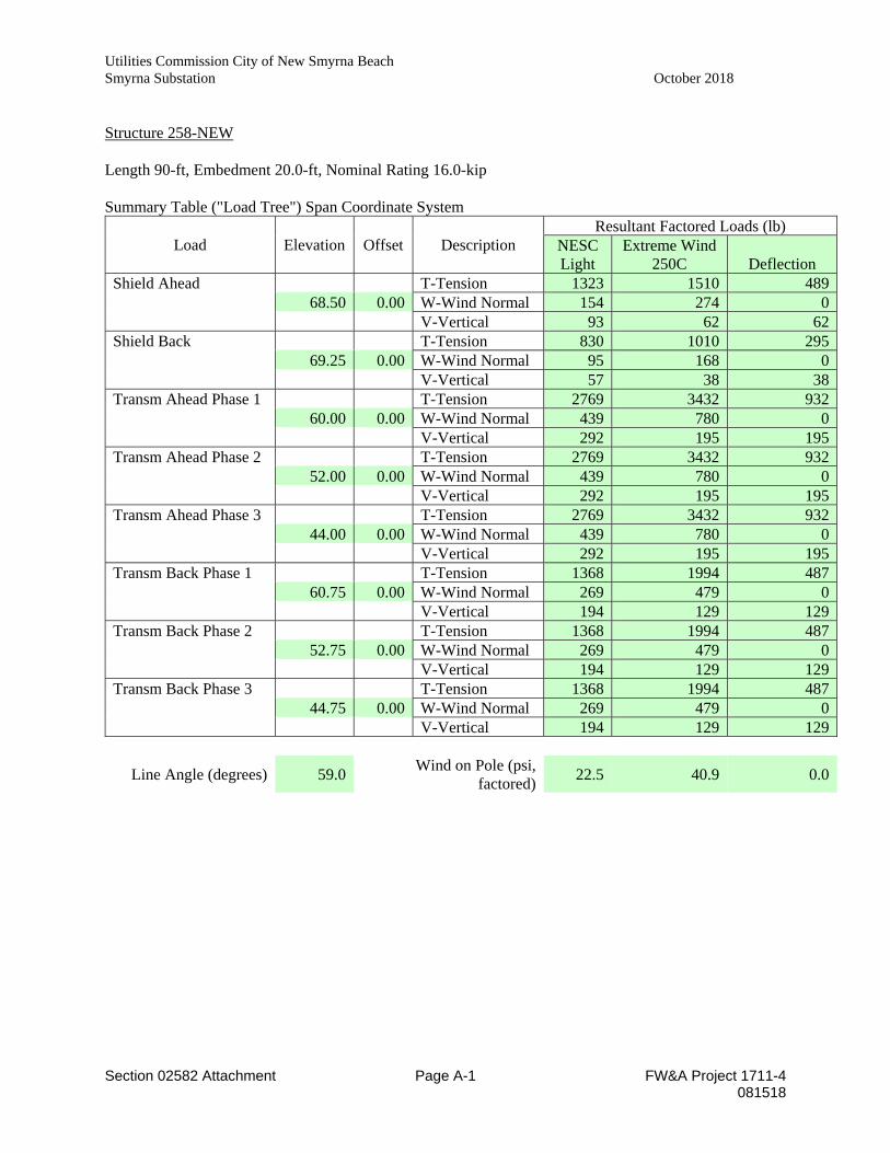
Utilities Commission City of New Smyrna Beach Smyrna Substation October 2018
Section 02582 Attachment Page A-1 FW&A Project 1711-4 081518
Structure 258-NEW Length 90-ft, Embedment 20.0-ft, Nominal Rating 16.0-kip Summary Table ("Load Tree") Span Coordinate System
Load Elevation Offset Description Resultant Factored Loads (lb)
NESC Light
Extreme Wind 250C Deflection
Shield Ahead T-Tension 1323 1510 489 68.50 0.00 W-Wind Normal 154 274 0 V-Vertical 93 62 62Shield Back T-Tension 830 1010 295 69.25 0.00 W-Wind Normal 95 168 0 V-Vertical 57 38 38Transm Ahead Phase 1 T-Tension 2769 3432 932 60.00 0.00 W-Wind Normal 439 780 0 V-Vertical 292 195 195Transm Ahead Phase 2 T-Tension 2769 3432 932 52.00 0.00 W-Wind Normal 439 780 0 V-Vertical 292 195 195Transm Ahead Phase 3 T-Tension 2769 3432 932 44.00 0.00 W-Wind Normal 439 780 0 V-Vertical 292 195 195Transm Back Phase 1 T-Tension 1368 1994 487 60.75 0.00 W-Wind Normal 269 479 0 V-Vertical 194 129 129Transm Back Phase 2 T-Tension 1368 1994 487 52.75 0.00 W-Wind Normal 269 479 0 V-Vertical 194 129 129Transm Back Phase 3 T-Tension 1368 1994 487 44.75 0.00 W-Wind Normal 269 479 0 V-Vertical 194 129 129
Line Angle (degrees) 59.0 Wind on Pole (psi, factored) 22.5 40.9 0.0
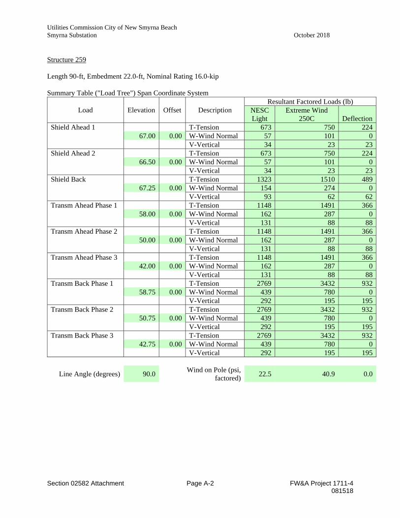
Utilities Commission City of New Smyrna Beach Smyrna Substation October 2018
Section 02582 Attachment Page A-2 FW&A Project 1711-4 081518
Structure 259 Length 90-ft, Embedment 22.0-ft, Nominal Rating 16.0-kip Summary Table ("Load Tree") Span Coordinate System
Load Elevation Offset Description Resultant Factored Loads (lb)
NESC Light
Extreme Wind 250C Deflection
Shield Ahead 1 T-Tension 673 750 224 67.00 0.00 W-Wind Normal 57 101 0 V-Vertical 34 23 23Shield Ahead 2 T-Tension 673 750 224 66.50 0.00 W-Wind Normal 57 101 0 V-Vertical 34 23 23Shield Back T-Tension 1323 1510 489 67.25 0.00 W-Wind Normal 154 274 0 V-Vertical 93 62 62Transm Ahead Phase 1 T-Tension 1148 1491 366 58.00 0.00 W-Wind Normal 162 287 0 V-Vertical 131 88 88Transm Ahead Phase 2 T-Tension 1148 1491 366 50.00 0.00 W-Wind Normal 162 287 0 V-Vertical 131 88 88Transm Ahead Phase 3 T-Tension 1148 1491 366 42.00 0.00 W-Wind Normal 162 287 0 V-Vertical 131 88 88Transm Back Phase 1 T-Tension 2769 3432 932 58.75 0.00 W-Wind Normal 439 780 0 V-Vertical 292 195 195Transm Back Phase 2 T-Tension 2769 3432 932 50.75 0.00 W-Wind Normal 439 780 0 V-Vertical 292 195 195Transm Back Phase 3 T-Tension 2769 3432 932 42.75 0.00 W-Wind Normal 439 780 0 V-Vertical 292 195 195
Line Angle (degrees) 90.0 Wind on Pole (psi, factored) 22.5 40.9 0.0
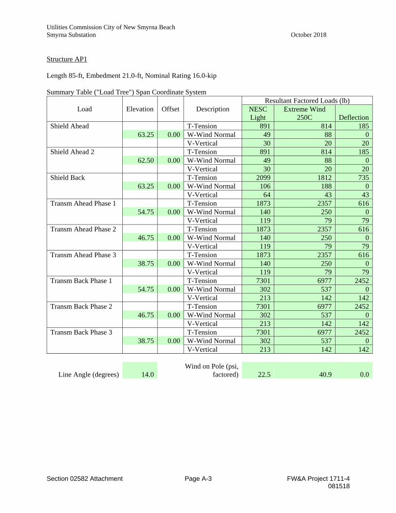
Utilities Commission City of New Smyrna Beach Smyrna Substation October 2018
Section 02582 Attachment Page A-3 FW&A Project 1711-4 081518
Structure AP1 Length 85-ft, Embedment 21.0-ft, Nominal Rating 16.0-kip Summary Table ("Load Tree") Span Coordinate System
Load Elevation Offset Description Resultant Factored Loads (lb)
NESC Light
Extreme Wind 250C Deflection
Shield Ahead T-Tension 891 814 185 63.25 0.00 W-Wind Normal 49 88 0 V-Vertical 30 20 20Shield Ahead 2 T-Tension 891 814 185 62.50 0.00 W-Wind Normal 49 88 0 V-Vertical 30 20 20Shield Back T-Tension 2099 1812 735 63.25 0.00 W-Wind Normal 106 188 0 V-Vertical 64 43 43Transm Ahead Phase 1 T-Tension 1873 2357 616 54.75 0.00 W-Wind Normal 140 250 0 V-Vertical 119 79 79Transm Ahead Phase 2 T-Tension 1873 2357 616 46.75 0.00 W-Wind Normal 140 250 0 V-Vertical 119 79 79Transm Ahead Phase 3 T-Tension 1873 2357 616 38.75 0.00 W-Wind Normal 140 250 0 V-Vertical 119 79 79Transm Back Phase 1 T-Tension 7301 6977 2452 54.75 0.00 W-Wind Normal 302 537 0 V-Vertical 213 142 142Transm Back Phase 2 T-Tension 7301 6977 2452 46.75 0.00 W-Wind Normal 302 537 0 V-Vertical 213 142 142Transm Back Phase 3 T-Tension 7301 6977 2452 38.75 0.00 W-Wind Normal 302 537 0 V-Vertical 213 142 142
Line Angle (degrees) 14.0 Wind on Pole (psi,
factored) 22.5 40.9 0.0
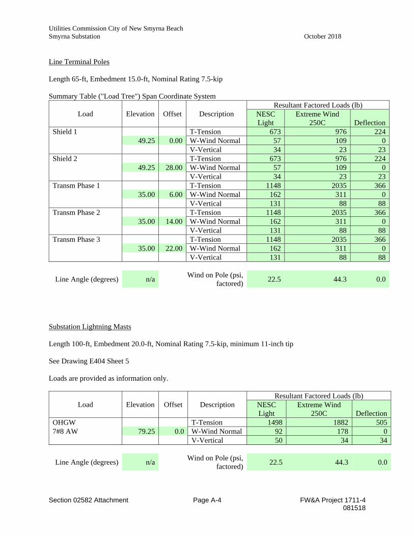
Utilities Commission City of New Smyrna Beach Smyrna Substation October 2018
Section 02582 Attachment Page A-4 FW&A Project 1711-4 081518
Line Terminal Poles Length 65-ft, Embedment 15.0-ft, Nominal Rating 7.5-kip Summary Table ("Load Tree") Span Coordinate System
Load Elevation Offset Description Resultant Factored Loads (lb)
NESC Light
Extreme Wind 250C Deflection
Shield 1 T-Tension 673 976 224 49.25 0.00 W-Wind Normal 57 109 0 V-Vertical 34 23 23Shield 2 T-Tension 673 976 224 49.25 28.00 W-Wind Normal 57 109 0 V-Vertical 34 23 23Transm Phase 1 T-Tension 1148 2035 366 35.00 6.00 W-Wind Normal 162 311 0 V-Vertical 131 88 88Transm Phase 2 T-Tension 1148 2035 366 35.00 14.00 W-Wind Normal 162 311 0 V-Vertical 131 88 88Transm Phase 3 T-Tension 1148 2035 366 35.00 22.00 W-Wind Normal 162 311 0 V-Vertical 131 88 88
Line Angle (degrees) n/a Wind on Pole (psi, factored) 22.5 44.3 0.0
Substation Lightning Masts Length 100-ft, Embedment 20.0-ft, Nominal Rating 7.5-kip, minimum 11-inch tip See Drawing E404 Sheet 5 Loads are provided as information only.
Load Elevation Offset Description Resultant Factored Loads (lb)
NESC Light
Extreme Wind 250C Deflection
OHGW T-Tension 1498 1882 5057#8 AW 79.25 0.0 W-Wind Normal 92 178 0 V-Vertical 50 34 34
Line Angle (degrees) n/a Wind on Pole (psi, factored) 22.5 44.3 0.0
Utilities Commission City of New Smyrna Beach Smyrna Substation October 2018 Substation Expansion Project New Smyrna Beach, FL
CHAIN LINK FENCE 02830 - 1
SPECIFICATIONS SECTION 02830
CHAIN LINK FENCE AND GATES
PART 1 GENERAL 1.1 SUMMARY
A. Provide chain link fencing, gates and accessories as specified and as shown on the
Contract Documents.
1.2 QUALITY ASSURANCE A. Provide components that are the standard product of a manufacturer regularly engaged in
the production of the required materials and equipment. 1. A single manufacturer shall provide all fencing, gates and appurtenances.
2. The manufacturer shall be responsible for the design, construction and proper
operation of all components.
B. Comply with referenced standards as applicable.
1.3 REFERENCES A. ASTM A121 Specification for Metallic-Coated Carbon Steel Barbed Wire
B. ASTM A392 Specification for Zinc-Coated Steel Chain-Link Fence Fabric
C. ASTM A491 Specification for Aluminum-Coated Steel Chain-Link Fabric
D. ASTM A780 Standard Practice for Repair of Damaged and Uncoated Areas of Hot-Dip
Galvanized Coatings
E. ASTM A817 Specification for Metallic-Coated Steel Wire for Chain Link Fence Fabric and Marcelled Tension Wire
F. F. ASTM A824 Specification for Metallic-Coated Steel Marcelled Tension Wire for Use With Chain Link
G. ASTM F552 Standard Terminology Relating to Chain Link Fencing
H. ASTM F567 Standard Practice for Installation of Chain Link Fence
I. ASTM F626 Specification for Fence Fittings
J. ASTM F668 Specification for Polymer Coated Chain Link Fence Fabric
Utilities Commission City of New Smyrna Beach Smyrna Substation October 2018
CHAIN LINK FENCE 02830 - 2
K. ASTM F900 Specification for Industrial and Commercial Swing Gates
L. ASTM F934 Specification for Standard Colors for Polymer-Coated Chain Link
M. ASTM F1043 Specification for Strength and Protective Coatings of Steel Industrial Chain Link Fence Framework
N. ASTM F1083 Specification for Pipe, Steel, Hot-Dipped Zinc-Coated (Galvanized) Welded, for Fence Structures
O. ASTM F1184 Specification for Industrial and Commercial Horizontal Slide Gates
P. ASTM F1345 Specification for Zinc-5% Aluminum-Mischmetal Alloy-Coated Steel Chain-Link Fence Fabric
Q. ASTM F1664 Specification for Poly (Vinyl Chloride) (PVC) and Other Conforming Organic Polymer-Coated Steel Tension Wire Used with Chain-Link Fence
R. ASTM F1665 Specification for Poly (Vinyl Chloride) (PVC) and Other Conforming Organic Polymer-Coated Steel Barbed Wire Used with Chain-Link Fence
S. ASTM F1910 Specification for Long Barbed Tape Obstacles
T. ASTM F1911 Standard Practice for Installation of Barbed Tape
U. ASTM F2200 Specification for Automated Vehicular Gate Construction
V. ASTM F3000 / F3000M Standard Specification for Polymer Privacy Insert Slats for Chain Link Fabric and Privacy Chain Link Fabric Manufactured Containing Pre-Installed Privacy Slats
W. UL325 Automatic operators: Door, Drapery, Gate, Louver and Window 1.4 SUBMITTALS
A. Comply with Section 01330. Include the following information:
1. Shop Drawings showing:
a. Site plan showing layout of fence location with dimensions, location of
gates and opening size, cleared area, elevation of fence, gates, footings and details of attachments.
b. Cross sectional dimensions of posts, braces, rails, fittings, accessories, and gate frames, design of gates and details of gate hardware.
c. Spacing of posts and location of gates, abrupt changes in grade, and corner, gate, anchor, end, and pull posts.
2. Manufacturer’s catalog information that describes each fencing system component provided. Include
Utilities Commission City of New Smyrna Beach Smyrna Substation October 2018
CHAIN LINK FENCE 02830 - 3
a. Specifications, manufacturer’s information and cut sheets.
b. A complete bill of materials that identifies all materials of construction.
3. Manufacturer’s installation instructions.
1.5 QUALITY ASSURANCE
A. Manufacturer: Company headquartered in the United States having U.S. manufacturing
facility/facilities specializing in manufacturing chain link fence products with at least 5 years experience.
B. Fence contractor: Company with demonstrated successful experience installing similar
projects and products in accordance with ASTM F567 and have at least 5 years experience.
C. Tolerances: Current published edition of ASTM specifications tolerances apply. ASTM
specification tolerances supersede any conflicting tolerance.
1.6 PRODUCT DELIVERY, STORAGE AND HANDLING A. Deliver, handle, and store the equipment in accordance with Section 01600.
B. Deliver materials to the project site undamaged.
1. Attach tags to every roll of fabric.
2. Indicate mesh size, coating weight and wire gauge.
C. Store off of the ground to protect against oxidation caused by ground contact.
PART 2 PRODUCTS 2.1 MATERIALS
A. Conform to applicable parts of FS RR-F-191 K/GEN as modified herein.
B. Use Type I zinc coated steel, with weight of zinc coating not less than1.2 oz. per square
foot
C. Fabric: Fabricated from minimum 9-gage, 0.148 inch diameter wire, helically wound and interwoven to provide continuous 2-inch nominal mesh without knots or ties except selvages. 1. Attach tags to every roll, indicating mesh size and wire gage.
2. Height: See Drawings.
3. Selvage: Twisted and barbed at top and bottom except top selvage may be
knuckled when top rail is provided.
Utilities Commission City of New Smyrna Beach Smyrna Substation October 2018
CHAIN LINK FENCE 02830 - 4
4. Individual Fabric Ties: Same material as fabric for attaching fabric to line posts
and top and bottom tension wires or rails.
5. Gate Fabric: Same material as fabric for fencing.
D. Posts and Accessories. 1. Posts: Tubular with appropriate caps driven to fit over outside section to exclude
moisture.
2. Top Rails, Braces, Tie Rods, Stretcher Bars, and Accessories: Shape, dimensions, and weights following Contract Documents.
3. All corner, pull and line posts shall have barbed wire support arms at 45 degree angles oriented towards the outside of the fence. Arms shall be provided to support three runs of barbed wire, evenly spaced to a vertical height of 1’-0”.
4. All posts without barbed wire extension arms shall be capped with galvanized malleable iron, outside fit, dome shaped post tops.
E. Swing Gates
1. Swing Gates: Galvanized steel pipe welded fabrication in compliance with ASTM
F900. Gate frame members 1.900 in. OD (48.3 mm) ASTM F 1083 schedule 40 galvanized steel. Frame members spaced no greater than 8 ft. (2440 mm) apart vertically and horizontally. Welded joints protected by applying zinc-rich paint in accordance with ASTM Practice A780. Positive locking gate latch, pressed steel galvanized after fabrication. Galvanized malleable iron or heavy gauge pressed steel post and frame hinges. Provide lockable drop bar and gate holdbacks with double gates. Match gate fabric to that of the fence system. Gateposts per ASTM F1083 schedule 40 galvanized steel pipe. Gatepost diameter as shown on the drawings. Electrically operated gates must comply with ASTM F2200 and UL325
2. Frames: Round tubular members made of 1.625” Nominal OD (1-1/4” NPS) steel pipe. Top and bottom framing shall be welded between two vertical pipes.
3. Bracing: Round tubular members made of 1.375” Nominal OD (1” NPS) steel pipe.
4. One vertical brace is required every 8’.
5. One horizontal brace is required between each vertical brace and frame member.
6. Barbed Wire: Extend top of gate frame members at least 1 foot above top horizontal member and attach 3 strands of barbed wire, uniformly spaced, by means of bands, clips, or hook bolts.
7. Fabric: Shop-attach gate fabric to gate frame at intervals of not more than 15
inches.
Utilities Commission City of New Smyrna Beach Smyrna Substation October 2018
CHAIN LINK FENCE 02830 - 5
8. Accessories: Fittings and accessories, including locking and padlocking device required making complete installation.
9. Hinges:
a. 180° offset type, with a bolt and self-locking nut (or approved equivalent means) to prohibit removal. Arrange so closed gate cannot be lifted off its hinges.
b. Sufficient size and number to prevent twist or turn under action of gate.
c. The maximum permissible gap between the gate post and frame is 1-3/4” when the gate is closed.
10. Opening: Full with minimum 180 degree swing.
11. Gates shall be inward swinging from closed to 180 degrees unless otherwise noted
on the contract drawings. Gates shall be physically prevented from swinging outward.
12. Swing gates with an overall width greater than 24’ shall include wheels for support on each swinging edge.
13. Gate Keeper: A galvanized iron or cast aluminum gate keeper shall be provided to hold gate at maximum open position. Anchor pipe shall be approximately 2” Nominal OD and set in concrete to a minimum depth of 1’-6”. Double gates shall be provided with two gate keepers.
F. Horizontal Slide Gates
1. Cantilever Slide Gates: In compliance with ASTM F1184 Type II.
2. Class 2-Internal Roller Design: Galvanized Steel or Aluminum Gate frame
fabricated by welding, vertical and horizontal members installed no greater than 8 ft. (2440 mm) apart. Class 2 cantilever slide gates to comply with the performance deflection criteria listed in ASTM F1184. Gates designed to open or close by applying an initial pull force no greater than 40 lbs. (18.14 kg). Internal truck assemblies designed to handle the forces required for gate size opening and height. Match chain link fabric to that of the fence system. Gateposts, 4.000 in. O.D. (106.1 mm) schedule 40 pipe per ASTM F1083.
3. Electrically operated horizontal slide gates must be manufactured and installed to
comply with the safety requirements of ASTM F2200 and UL 325
G. Type I, Zinc Coated Steel Fencing. 1. Fabric: FS RR-F-191/1D, Type I, with minimum zinc coating of 1.2 ounces per
square foot. a. Color: Match existing unless otherwise indicated.
Utilities Commission City of New Smyrna Beach Smyrna Substation October 2018
CHAIN LINK FENCE 02830 - 6
2. Posts, Top Rail, and Braces: FS RR-F-191/3D with zinc coating of 2.0 ounces per square foot.
a. End, corner and pull post:
(1) 4.5” Nominal OD (4” NPS) hot-dip galvanized schedule 40 steel
pipe with a minimum of 2.0 ounces of zinc per square foot.
b. Line and intermediate posts: (1) 2.375” Nominal OD (2-1/2” NPS) hot-dip galvanized schedule
40 steel pipe with a minimum of 2.0 ounces of zinc per square foot.
c. Gate posts: (1) Double gates with total opening of 12 feet and under (individual
panels 6 feet and under): 4.5” Nominal OD (4” NPS) hot-dip galvanized schedule 40 steel pipe with a minimum of 2.0 ounces of zinc per square foot.
(2) Double gates with total opening between 12 feet and 20 feet (individual panels between 6 feet and 10 feet): 4.5” Nominal OD (4” NPS) hot-dip galvanized schedule 40 steel pipe with a minimum of 2.0 ounces of zinc per square foot.
d. Top Rail:
(1) A top rail consisting of 1.625” Nominal O.D. (1-1/4” NPS)
schedule 40 galvanized steel pipe with 2.0 ounces of zinc per square foot shall be installed at the top of the fence fabric.
(2) Provide top rail couplings every 20’-0”.
e. Tension Wire:
(1) A tension wire consisting of No.7 AWG, extra galvanized, high carbon, coiled steel shall be installed at the bottom of the fence fabric.
(2) Tension wire shall be continuous between fabric terminations.
3. Accessories: FS RR-F-191/4D with galvanized zinc coating
4. Gates:
a. FS RR-F-191/2D with fabric same as used for fence.
b. Dimensions: Same as required for Type I fencing.
Utilities Commission City of New Smyrna Beach Smyrna Substation October 2018
CHAIN LINK FENCE 02830 - 7
c. Gates frames shall be hot-dip galvanized after fabrication with a minimum of 2.0 ounces of zinc per square foot.
5. Barbed Wire: ASTM F1665-01, using 12-1/2 gauge wire with 4-point 14 gauge barbs, round, spaced at maximum of 4 inches on center and zinc coating of 0.8 ounces per square foot
H. Padlocks: Provided by Owner.
I. Touch-Up Paint: Zinc-rich paint. See ASTM A780
J. Concrete 1. Comply with Section 03300
2. Use 3,000 psi concrete.
K. Grout
1. Mix regular grout using one part cement to three parts concrete sand.
2. Add minimum amount of water to produce a workable mix.
PART 3 EXECUTION 3.1 INSTALLATION
A. Perform the necessary clearing, excavation, backfilling and grading to provide clear
line-of-fence runs.
B. Encasement. 1. Post:
a. Extend concrete at least 4 inches below bottom of posts.
b. Extend concrete to 1 inch above ground line at posts and slope to drain
away from posts.
c. Encase minimum 10 inch diameter for line posts and 12 inch diameter for end, corner, pull, and gate posts.
2. Fence Encasement: a. 5 feet and less in height: Minimum of 2.5 feet deep.
b. Over 5 feet in height: Minimum of 3.0 feet deep.
3. Gate Post Encasement:
a. For gates with swing of 6 feet and less: Minimum of 3.0 feet deep.
Utilities Commission City of New Smyrna Beach Smyrna Substation October 2018
CHAIN LINK FENCE 02830 - 8
b. For gates with swing over 6 feet: Minimum of 3.0 feet deep and at least 16
inch diameter.
C. Post Placement. 1. Evenly space posts at not more than 10 feet or less than 8 feet on centers. Place
additional posts at each change in line and abrupt change in grade.
2. Posts on rock: Drill holes 2 inches deeper than depth shown or specified.
a. Drill holes 2 inches greater all around than outside diameter of post or square section.
b. Fill rock portion of hole with grout.
3. Posts on Concrete Structure: Cast section of steel pipe at least 12 inches long in concrete at correct location for fence posts. a. Steel pipe sleeve: Inside diameter not more than 3/8 inch larger all
around than post to be inserted.
b. Grout fence posts into steel pipe with non-shrink grout.
4. Set corner or pull posts at each horizontal or vertical angle point of 15 or more degrees and at no more than 75-foot intervals.
5. Set corner, end, and pull posts with horizontal or diagonal brace rail and tie rod to nearest line post.
D. Rails, Tension Wire, and Braces.
1. After posts are installed and concrete has set firmly, place top rail or tension
wire, and bottom tension wire approximately 4 inches above grade. a. Anchor and brace end, corner, and pull posts before hanging fabric.
b. Brace gate posts for fabric 6 feet or more in height.
E. Fabric Placement.
1. Secure ends of fabric using tension bars threaded through loops in fabric, and
secure to posts by means of bands with bolts and nuts.
2. Splice fabric lengths together by reweaving without breaking continuity of knuckled or twisted and barbed selvage.
3. Place fabric by securing 1 end and applying sufficient tension by means of mechanical fence stretchers to remove slack before making attachments.
Utilities Commission City of New Smyrna Beach Smyrna Substation October 2018
CHAIN LINK FENCE 02830 - 9
4. Fasten fabric with appropriate tie wires to top rails and bottom tension wire at 18 inches on center maximum, and to posts at 12 inches on center maximum.
5. Hold bottom of fabric uniformly as possible to not more than 2 inches above finished grade.
F. Barbed Wire: Where indicated, provide 3 strands of barbed wire above fence fabric.
1. Stretch strands to remove sag and anchor firmly to extension arms.
2. Incline extension arms on line posts pointing away from the substation property
at approximately 45 degree angle.
G. Gates: 1. Install fence gates, gate stops, and fan guards as shown.
2. Locate gate stops set in concrete accurately so that gate stop or latch can be fully
engaged.
H. Line Post Anchorage: Acceptable Alternate Method. 1. Drive post into ground and hold rigidly in position by means of 2 steel angle
anchors driven diagonally and attached to post on opposite sides.
2. Anchors, attachments, and methods: Follow MSHA Standard Details.
3.2 DEFECTIVE WORK A. Remove and replace fencing improperly located, not true to line and grade, and not
plumb posts.
B. Repair damaged polyvinyl chloride by following fence manufacturer's recommendations.
3.3 EXISTING CHAIN LINK FENCE
A. When required to remove chain link fence to permit construction, remove and store fence to prevent damage. 1. Restore fence to original location following applicable requirements herein or
relocate as shown.
2. Repair damaged chain link fence or when directed, replace with applicable in-kind material following requirements specified herein.
B. When connecting to existing chain link fence, connect as shown on Drawings, or as directed, following requirements specified herein.
3.4 TEMPORARY CHAIN LINK FENCE
A. Provide temporary chain link fence and gates where required for protection of work.
Utilities Commission City of New Smyrna Beach Smyrna Substation October 2018
CHAIN LINK FENCE 02830 - 10
END OF SECTION
Utilities Commission City of New Smyrna Beach Smyrna Substation October 2018 Substation Expansion Project New Smyrna Beach, FL
CAST IN PLACE CONCRETE 03300 - 1
SPECIFICATION SECTION 03300
CAST-IN-PLACE CONCRETE
PART 1 GENERAL
1.1 SUMMARY
A. Section includes cast-in-place concrete, including formwork, reinforcement, concrete materials, mixture design, placement procedures, and finishes.
B. Related Sections: 1. Section 02300 "Earthwork" for drainage fill under slabs-on-grade.
1.2 REFERENCES
A. American Society for Testing and Materials (ASTM) 1. A36/A36M Carbon Structural Steel
2. A82/A82M Steel Wire, Plain, for Concrete Reinforcement
3. A153/A153M Zinc Coating (Hot-Dip) on Iron and Steel Hardware
4. A307 Carbon Steel Bolts, Studs, and Threaded Rod
5. A615/A615M Deformed and Plain Carbon-Steel Bars for Concrete Reinforcement
6. A1064/A1064M Carbon-Steel Wire and Welded Wire Reinforcement, Plain and
Deformed, for Concrete
7. C31/C31M Making and Curing Concrete Test Specimens in the Field
8. C33/C33M Concrete Aggregates
9. C39/C39M Test Method for Compressive Strength of Cylindrical Concrete Specimens
10. C94/C94M Ready-Mixed Concrete
11. C109/C109M Test Method for Compressive Strength of Hydraulic Cement Mortars
12. C143/C143M Test Method for Slump of Hydraulic-Cement Concrete
13. C150/C150M Portland Cement
14. C231/C231M Test Method for Air Content of Freshly Mixed Concrete by the Pressure Method
Utilities Commission City of New Smyrna Beach Smyrna Substation October 2018
CAST IN PLACE CONCRETE 03300 - 2
15. C260/C260M Air-Entraining Admixtures for Concrete
16. C494/C494M Chemical Admixtures for Concrete
17. C579 Test Methods for Compressive Strength of Chemical-Resistant Mortars, Grouts,
Monolithic Surfacings, and Polymer Concretes
18. C595/C595M Blended Hydraulic Cements
19. C618 Coal Fly Ash and Raw or Calcined Natural Pozzolan for Use in Concrete
20. C827/C827M Test Methods for Change in Height at Early Ages of Cylindrical Specimens of Cementitious Mixtures
21. D1752 Preformed Sponge Rubber Cork and Recycled PVC Expansion Joint Fillers for Concrete Paving and Structural Construction
22. F1554 Anchor Bolts, Steel
B. American Concrete Institute (ACI) 1. 117 Tolerances for Concrete Construction and Materials
2. 301 Specifications for Structural Concrete
3. 304R Guide for Measuring, Mixing, Transporting and Placing Concrete
4. 305R Guide to Hot Weather Concreting
5. 306R Guide to Cold Weather Concreting
6. 318 Building Code Requirements for Structural Concrete
7. 347R Guide to Formwork for Concrete
8. SP-66 ACI Detailing Manual
C. Florida Department of Transportation (FDOT) Standard Specifications for Road and Bridge Construction 1. Section 901 Coarse Aggregate
2. Section 902 Fine Aggregate
D. American Plywood Association (APA) 1. PS1 Structural Plywood
E. American Lumber Standards Committee (ALSC)
Utilities Commission City of New Smyrna Beach Smyrna Substation October 2018
CAST IN PLACE CONCRETE 03300 - 3
1. PS20 American Softwood Lumber Standard
F. US Army Corps of Engineers (COE) 1. CRD-C 621 Spec for Non-Shrink Grout
1.3 SUBMITTALS
A. Product Data: For each type of product indicated.
B. Design Mixtures: For each concrete mixture submit copies of proposed concrete design mixes for each class of concrete, at the appropriate slump, expected to be used in the job. The Contractor shall submit complete reports of concrete materials and mix proportions of the design mixes to the Owner for approval at least 14 days before any concrete is required on the project. Results of concrete cylinder tests for unproven design mixes shall be submitted to the Owner with the proposed mixes. Approval of such mixes tests will be only a check to assist the Contractor in his compliance with specification requirements and will be contingent upon acceptance of final tests for the concrete used in the project.
C. Steel Reinforcement Shop Drawings: Placing drawings that detail fabrication, bending, and placement.
D. Formwork Shop Drawings: Prepared by or under the supervision of a qualified professional engineer detailing fabrication, assembly, and support of formwork.
E. Material certificates.
F. Material test reports.
G. Floor surface flatness and levelness measurements.
1.4 QUALITY ASSURANCE
A. Manufacturer Qualifications: A firm experienced in manufacturing ready-mixed concrete
products and that complies with ASTM C 94/C 94M requirements for production facilities and equipment. 1. Manufacturer certified according to NRMCA's "Certification of Ready Mixed
Concrete Production Facilities."
B. Survey Work: The Contractor SHALL engage the services of a State of Florida Registered Land Surveyor, to perform surveys, layouts, and measurements for all concrete foundations. Before excavating, lay out each foundation to lines and levels required. Record actual measurements of each foundation’s location, major dimensions, bottom and top elevations, deviations from specified tolerances, and other specified data. 1. Record and maintain information pertinent to each foundation and cooperate with
testing and inspecting agency to provide data for required reports.
Utilities Commission City of New Smyrna Beach Smyrna Substation October 2018
CAST IN PLACE CONCRETE 03300 - 4
C. Testing Agency Qualifications: An independent agency, acceptable to authorities having jurisdiction, qualified according to ASTM C 1077 and ASTM E 329 for testing indicated.
D. Welding Qualifications: Qualify procedures and personnel according to AWS D1.4/D 1.4M, "Structural Welding Code - Reinforcing Steel."
E. ACI Publications: Comply with the following unless modified by requirements in the Contract Documents: 1. ACI 301, "Specifications for Structural Concrete"
2. ACI 117, "Specifications for Tolerances for Concrete Construction and
Materials"
F. Concrete Testing Service: Engage a qualified independent testing agency to perform material evaluation tests and to design concrete mixtures.
G. Preinstallation Conference: Conduct conference at project site.
PART 2 PRODUCTS
2.1 FORM-FACING MATERIALS
A. Smooth-Formed Finished Concrete: Form-facing panels that will provide continuous, true, and smooth concrete surfaces. Furnish in largest practicable sizes to minimize number of joints.
2.2 STEEL REINFORCEMENT
A. Recycled Content of Steel Products: Postconsumer recycled content plus one-half of
preconsumer recycled content not less than 25 percent.
B. Reinforcing Bars: ASTM A 615, Grade 60, deformed.
C. Wire: Plain cold-drawn wire, ASTM A82/A82M, deformed steel wire.
D. Deformed-Steel Welded Wire Reinforcement: ASTM A 497/A 497M, flat sheet.
E. Bar Supports: Bolsters, chairs, spacers, and other devices for spacing, supporting, and fastening reinforcing bars and welded wire reinforcement in place. Manufacture bar supports from steel wire, plastic, or precast concrete according to CRSI's "Manual of Standard Practice.
F. Anchor Rods: Anchor rods shall conform to ASTM F1554 and be furnished in the grade and length as shown in the Anchor Rod Schedule on the Foundation Detail Drawings. Anchor rods shall be Hot Dipped galvanized full length.
2.3 CONCRETE MATERIALS
A. Cementitious Material: Use the following cementitious materials, of the same type,
brand, and source, throughout Project:
Utilities Commission City of New Smyrna Beach Smyrna Substation October 2018
CAST IN PLACE CONCRETE 03300 - 5
1. Portland Cement: ASTM C 150, Type I, gray
a. Fly Ash: ASTM C 618, Class F
b. Ground Granulated Blast-Furnace Slag: ASTM C 989, Grade 100 or 120.
B. Normal-Weight Aggregates: ASTM C 33, graded.
1. Maximum Coarse-Aggregate Size: 3/4 inch nominal.
C. Fine Aggregate: 1. Free of materials with deleterious reactivity to alkali in cement. Sand or rock
screenings conforming to Section 902 of the FDOT Standard Specifications for Road and Bridge Construction.
D. Water: ASTM C 94 and potable
2.4 ADMIXTURES
A. Air-Entraining Admixture: ASTM C 260.
B. Chemical Admixtures: Provide admixtures certified by manufacturer to be compatible with other admixtures and that will not contribute water-soluble chloride ions exceeding those permitted in hardened concrete. Do not use calcium chloride or admixtures containing calcium chloride.
2.5 FIBER REINFORCEMENT
A. Synthetic Micro-Fiber: fibrillated polypropylene micro-fibers engineered and designed
for use in concrete, complying with ASTM C 1116, Type III, 1/2 to 1-1/2 inches long.
2.6 CURING MATERIALS
A. Evaporation Retarder: Waterborne, monomolecular film forming, manufactured for application to fresh concrete.
B. Clear, Waterborne, Membrane-Forming Curing Compound: ASTM C 309, Type 1, Class B, nondissipating, certified by curing compound manufacturer to not interfere with bonding of floor covering.
C. Clear, Waterborne, Membrane-Forming Curing and Sealing Compound: ASTM C 1315, Type 1, Class A.
2.7 BONDING AGENT
A. The material shall be a two-component epoxy-polysulphide resin system, with strong adhesion to both wet and dry concrete either the hardened or the plastic state markings.
Utilities Commission City of New Smyrna Beach Smyrna Substation October 2018
CAST IN PLACE CONCRETE 03300 - 6
2.8 GROUT
A. Cementitious Grout: Grout shall be cement-based, nonmetallic, non-shrink type specially formulated for hot weather, high sulfate and salt water resistance. Plastic form shall have 0% shrinkage in accordance with ASTM C827/C827M and 0% shrinkage and expansion in the hardened form in accordance with CRD-C621. Grout shall have a compressive strength of 5,000 psi at 7 days in accordance with ASTM C109/C109M. Grout shall be Five Star Special Grout 550 or equal.
B. Epoxy Grout: Grout shall be non-shrink type, 100% solids, three-component system consisting of resin, hardener and aggregate. Grout shall have 0% shrinkage in the plastic form and 0% expansion in the hardened form in accordance with ASTM C827/C827M. Compressive strength shall be 5,000 psi in 24 hours and 12,000 psi in 7 days, in accordance with ASTM C579, Method B. Grout shall be Five Star Epoxy Grout or equal.
2.9 RELATED MATERIALS
A. Expansion- and Isolation-Joint-Filler Strips: ASTM D 1751, asphalt-saturated cellulosic fiber.
2.10 CONCRETE MIXTURES
A. Prepare design mixtures for each type and strength of concrete, proportioned on the basis
of laboratory trial mixture or field test data, or both, according to ACI 301.
B. Cementitious Materials: Use fly ash, pozzolan, ground granulated blast-furnace slag, and silica fume as needed to reduce the total amount of portland cement, which would otherwise be used, by not less than 40 percent.
C. Admixtures: Use admixtures according to manufacturer's written instructions.
D. Proportion normal-weight concrete mixture as follows:
E. Coordinate compressive strength with water-cementitious materials ratio if concrete will be subject to special exposure conditions or sulfate exposure as identified in ACI 318 (ACI 318M). 1. Design Strength, 5,000 PSI Concrete: Use for pre-stressed concrete and where
indicated on the drawings or specified herein.
2. Design Strength 4,000 PSI Concrete: Use unless otherwise indicated on the drawings, for all structures, buildings, manhole concrete, concrete driveways, and paving.
3. Design Strength 3,000 PSI Concrete: Unless otherwise noted, may be used for concrete foundations, sidewalks, curbs and gutters, splash blocks, pipe encasements, pipe supports, electrical conduit ducts, and where indicated on the drawings.
4. Design Strength 2,500 PSI Concrete: May be used only for thrust blocks and anchors, fill concrete and where indicated on the drawings.
Utilities Commission City of New Smyrna Beach Smyrna Substation October 2018
CAST IN PLACE CONCRETE 03300 - 7
5. Maximum Water-Cementitious Materials Ratio: 0.45
6. Slump Limit: 4 inches for concrete with verified slump of 2 to 4 inches before
adding high-range water-reducing admixture or plasticizing admixture, plus or minus 1 inch.
7. Air Content: 6 percent, plus or minus 1.5 percent at point of delivery for 3/4-inch nominal maximum aggregate size.
8. Air Content: Do not allow air content of trowel-finished floors to exceed 3 percent.
9. Synthetic Micro-Fiber: Uniformly disperse in concrete mixture at manufacturer's recommended rate, but not less than 1.5 lb/cu. yd.
2.11 FABRICATING REINFORCEMENT
A. Fabricate steel reinforcement according to CRSI's "Manual of Standard Practice."
2.12 CONCRETE MIXING
A. Ready-Mixed Concrete: Measure, batch, mix, and deliver concrete according to ASTM C 94 and ASTM C 1116, and furnish batch ticket information. 1. When air temperature is between 85 and 90 deg F, reduce mixing and delivery
time from 1-1/2 hours to 75 minutes; when air temperature is above 90 deg F, reduce mixing and delivery time to 60 minutes.
PART 3 EXECUTION
3.1 FORMWORK
A. Design, erect, shore, brace, and maintain formwork, according to ACI 301, to support vertical, lateral, static, and dynamic loads, and construction loads that might be applied, until structure can support such loads.
B. Construct formwork so concrete members and structures are of size, shape, alignment, elevation, and position indicated, within tolerance limits of ACI 117.
C. Chamfer exterior corners and edges of permanently exposed concrete.
3.2 EMBEDDED ITEMS
A. Place and secure anchorage devices and other embedded items required for adjoining work that is attached to or supported by cast-in-place concrete. Use setting drawings, templates, diagrams, instructions, and directions furnished with items to be embedded.
3.3 STEEL REINFORCEMENT
A. General: Comply with CRSI's "Manual of Standard Practice" for placing reinforcement.
Utilities Commission City of New Smyrna Beach Smyrna Substation October 2018
CAST IN PLACE CONCRETE 03300 - 8
1. Do not cut or puncture vapor retarder. Repair damage and reseal vapor retarder
before placing concrete.
B. Space chairs and bolsters in accordance with ACI 318 and SP-66 using height to furnish cover over reinforcing required. Chairs with plastic feet shall be used in all beams and elevated slabs. Chairs for other concrete adjacent to or on the ground may be pieces of concrete brick pressed into the sub-grade, or chairs set on pre-cast concrete pads pressed into the sub-grade.
C. When placed in the forms, reinforcement shall be clean and free of all loose rust, scale, dust, paint, oil, or other foreign material, and shall be accurately and securely positioned both laterally and vertically before placing concrete.
D. The rebars shall be fastened together at every intersection or at intervals not greater than 24 bar diameters by wire ties or by some alternate method acceptable to the Owner. In areas where large bars are closer together, the wire ties may be spaced not more than 30 bar diameters apart.
E. Reinforcement splices shall be held to a minimum number and shall be located at points of minimum stress. Splice lengths shall be shown on the approved shop drawings.
F. Install wire fabric in the longest practicable length. Lap adjoining pieces one full mesh minimum and tie slices with tie wire. Do not make end laps midway between supporting beams, or directly over beams of continuous structures. Offset end laps in adjacent widths to prevent continuous laps.
G. Accessories: Install as indicated on the drawings and manufacturer’s written instructions.
3.4 JOINTS
A. General: Construct joints true to line with faces perpendicular to surface plane of concrete.
B. Construction Joints: Install so strength and appearance of concrete are not impaired, at locations indicated or as approved by Engineer.
3.5 CONCRETE PLACEMENT
A. Before placing concrete, verify that installation of formwork, reinforcement, and
embedded items is complete and that required inspections have been performed.
B. Deposit concrete continuously in one layer or in horizontal layers of such thickness that no new concrete will be placed on concrete that has hardened enough to cause seams or planes of weakness. If a section cannot be placed continuously, provide construction joints as indicated. Deposit concrete to avoid segregation. 1. Consolidate placed concrete with mechanical vibrating equipment according to
ACI 301.
C. Cold-Weather Placement: Comply with ACI 306R.
Utilities Commission City of New Smyrna Beach Smyrna Substation October 2018
CAST IN PLACE CONCRETE 03300 - 9
D. Hot-Weather Placement: Comply with ACI 305R.
3.6 FINISHING FORMED SURFACES
A. Smooth-Formed Finish: As-cast concrete texture imparted by form-facing material, arranged in an orderly and symmetrical manner with a minimum of seams. Repair and patch tie holes and defects. Remove fins and other projections that exceed specified limits on formed-surface irregularities. 1. Apply to concrete surfaces exposed to public view, to receive a rubbed finish, to
be covered with a coating or covering material applied directly to concrete.
B. Rubbed Finish: Apply the following to smooth-formed finished as-cast concrete where indicated: 1. Smooth-Rubbed Finish: Not later than one day after form removal, moisten
concrete surfaces and rub with carborundum brick or another abrasive until producing a uniform color and texture. Do not apply cement grout other than that created by the rubbing process.
C. Related Unformed Surfaces: At tops of walls, horizontal offsets, and similar unformed
surfaces adjacent to formed surfaces, strike off smooth and finish with a texture matching adjacent formed surfaces. Continue final surface treatment of formed surfaces uniformly across adjacent unformed surfaces unless otherwise indicated.
3.7 FINISHING FLOORS AND SLABS
A. General: Comply with ACI 302.1R recommendations for screeding, re-straightening, and finishing operations for concrete surfaces. Do not wet concrete surfaces.
B. Float Finish: Consolidate surface with power-driven floats or by hand floating if area is small or inaccessible to power driven floats. Re-straighten, cut down high spots, and fill low spots. Repeat float passes and re-straightening until surface is left with a uniform, smooth, granular texture.
C. Trowel Finish: After applying float finish, apply first troweling and consolidate concrete by hand or power-driven trowel. Continue troweling passes and re-straighten until surface is free of trowel marks and uniform in texture and appearance. Grind smooth any surface defects that would telegraph through applied coatings or floor coverings.
1. Finish and measure surface so gap at any point between concrete surface and an
unleveled, freestanding, 10-ft. long straightedge resting on two high spots and placed anywhere on the surface does not exceed 1/8 inch.
D. Broom Finish: Apply a broom finish to exterior concrete platforms, steps, ramps, and
elsewhere as indicated.
3.8 CONCRETE PROTECTING AND CURING
Utilities Commission City of New Smyrna Beach Smyrna Substation October 2018
CAST IN PLACE CONCRETE 03300 - 10
A. General: Protect freshly placed concrete from premature drying and excessive cold or hot temperatures. Comply with ACI 306.1 for cold-weather protection and ACI 301 for hot-weather protection during curing.
B. Evaporation Retarder: Apply evaporation retarder to unformed concrete surfaces if hot, dry, or windy conditions cause moisture loss approaching 0.2 lb/sq. ft. x h before and during finishing operations. Apply according to manufacturer's written instructions after placing, screeding, and bull floating or darbying concrete, but before float finishing.
C. Cure concrete according to ACI 308.1, by one or a combination of the following methods: 1. Curing Compound: Apply uniformly in continuous operation by power spray or
roller according to manufacturer's written instructions. Recoat areas subjected to heavy rainfall within three hours after initial application. Maintain continuity of coating and repair damage during curing period.
2. Curing and Sealing Compound: Apply uniformly to floors and slabs indicated in a continuous operation by power spray or roller according to manufacturer's written instructions. Recoat areas subjected to heavy rainfall within three hours after initial application. Repeat process 24 hours later and apply a second coat. Maintain continuity of coating and repair damage during curing period.
3. Flat Surface: Generally, all flat or nearly-flat surfaces, including foundations and floor slabs, shall be wet-cured by covering with burlap or equal, lapped 3 inches at joints, and by wetting this covering at least twice daily to keep it wet at all times for six days.
4. Form Tie Holes and Formed Surfaces: Form ties shall be removed immediately after form removal and the concrete surface shall be given a “rough” or “regular” finish as specified under “Concrete Finishes”, immediately after form ties have been removed.
5. The surrounding surfaces shall be kept damp during these operations by spraying with water at least once each hour, and the finished surfaces shall be sprayed with an approved curing compound within four hours after removal of forms. Only as much form work shall be removed in any one day as can be finished and sprayed with curing compound during that day.
6. Unfinished Surfaces: If forms are removed from an area, and for some acceptable reason, that particular area cannot be finished as specified during that day, the concrete curing operation shall be continued by wrapping the exposed concrete surface with burlap. The burlap shall be kept wet or the concrete surfaces shall be continuously sprinkled with a soaker hose or rotary sprinkler until the finishing operation has been complete and the curing compound applied, or until the six-day curing period is over.
7. Application of Curing Compound: The membrane curing compound shall be applied in two coats by spraying in accordance with the manufacturer’s printed instructions. The second coat shall be applied in a direction which will be at right angles to the application of the first coat. Spraying equipment shall be
Utilities Commission City of New Smyrna Beach Smyrna Substation October 2018
CAST IN PLACE CONCRETE 03300 - 11
equipped with a wind guard on the nozzle. Runs or puddling of curing compound shall be avoided. The curing compound shall contain a contrasting, non-permanent, coloring agent which shall make its presence obvious. a. Curing Smooth-Rubbed Finish: All concrete to receive stucco, paint, or
other similar coatings and concrete that is to receive a “smooth-rubbed finish”, as herein specified, shall be damp cured for at least six days and shall not receive curing compound.
b. Alternate Curing Method: In lieu of damp curing, except for concrete that is to receive a “smooth-rubbed finish”, the forms may be left in place for five days and thoroughly wetted at least once a day.
3.9 CONCRETE SURFACE REPAIRS
A. Defective Concrete: Repair and patch defective areas when approved by Owner.
Remove and replace concrete that cannot be repaired and patched to Owner approval.
PART 4 CONTRACTOR QUALITY CONTROL
A. Testing and Inspecting: Engage a qualified testing and inspecting agency to perform field tests and inspections and prepare test reports.
B. The quality of the concrete is entirely the responsibility of the Contractor until accepted in place in the structure and verified by the final cylinder test.
C. Compression Test Cylinders: Standard laboratory compression test cylinders shall be made by the testing laboratory’s representative, unless otherwise approved by the Owner for each class of concrete as the concrete is discharged from the mixer. A minimum of one set of three test cylinders shall be taken each day from one representative batch of each class of the concrete furnished. Additional sets of cylinders may be taken wherever directed by the Owner. One cylinder shall be tested in seven days, one in 28 days and one held as a spare. The laboratory will keep an accurate record of the locations where the concrete was placed from which samples were taken. Slump tests will be made each time cylinders are taken, and as directed by the Owner. Test cylinders shall be made and cured in accordance with ASTM C31/C31M. Test shall be performed in accordance with ASTM C39/C39M. The laboratory will furnish copies of all test results to the Owner and Contractor.
D. Air-Entrainment Test: For air-entrained concrete, the Laboratory will make tests for the amount of air in the concrete each time cylinders are taken; except that if placements requiring cylinders are small, this may be extended to every other time. Tests will be conducted in accordance with ASTM C231/C231M.
E. Load Tests, or other special tests not covered above, if required by the Owner for any section of the structure that is compromised by quality or workmanship, shall be made by the Contractor at his own expense. Such tests shall be conducted in accordance with detailed instructions approved by the Owner.
F. Batch Truck Tickets: Accompanying each batch of concrete delivered to the site shall be a truck ticket that shall indicate the following information: (1) time mix was batched, (2) brand and type of cement (3) pounds of cement per cubic yard of concrete, (4) planned
Utilities Commission City of New Smyrna Beach Smyrna Substation October 2018
CAST IN PLACE CONCRETE 03300 - 12
slump, (5) water available to be added upon arrival onsite, (6) admixture, and (7) name of supplier. These tickets shall be readily available for inspection when the truck arrives on the job; they shall be kept on the job and the information on them shall be made available to the testing laboratory’s representative for inclusion in his report.
G. Tolerances: 1. Form-work: Tolerances shall conform to the permissible variations from line,
grades, or dimensions as specified in ACI 347R.
2. Reinforcement: Tolerances shall conform to the tolerances as specified in ACI 301 and 304R.
3. Slabs: Floors and exterior slabs on grade shall have surfaces that are straight within a tolerance of plus or minus 1/8 inch in 10 feet. For exterior concrete slabs where slope is specified to provide for water drainage, a 1/16 inch minimum per foot uniform slope shall be provided.
END OF SECTION
Utilities Commission City of New Smyrna Beach Smyrna Substation October 2018 Substation Equipment Package New Smyrna Beach, FL
BASIC METAL MATERIALS AND METHODS 05050-1
SPECIFICATION SECTION 05050
BASIC METAL MATERIALS AND METHODS
PART 1 GENERAL 1.1 SUMMARY
A. This section supplements the General Requirements for Substation Structural Steel Package.
The technical requirements for design and fabrication of outdoor electrical substation structures, equipment, materials and necessary incidentals, are outlined herein and indicated on the Contract Drawings.
B. The Substation Structural Steel Package shall include, but not be limited to, required steel designs and furnishing fabricated hot-dipped galvanized steel structures, anchor rods, bus conductor, bus connectors, bus support insulators, switches and switch supports, complete, with switch operator’s grounding pads, fasteners and assembly material as indicated and specified.
C. The Smyrna Substation design requires the fabrication of galvanized structures and other items of equipment in accordance with the attached Contract Drawings. It is the project intent to provide new structures that conform to the existing substation structures to the greatest extent possible. Where details of the existing structures were available, they are provided as reference drawings. Where connections between existing and new structures are made all dimensions and top-of-member elevations shall match the existing structures. Different member sizes will be permitted only where required to meet the loading and deflection requirements. The use of different member types will not be permitted.
D. The Smyrna Substation package requires design and fabrication of one (1) 115kV dead end switch supported by round spun concrete poles, six (6) low profile 23kV feeder bays, seven (7) 115kV 19’ three-phase bus support structures, six (6) 115kV 25’ three-phase bus support structures, one (1) 115kV 13’ three-phase bus support structures, three (3) 115kV 25’ bus three-phase switches, and one (1) 115kV three-phase CCVT stand, all as shown on the Contract Drawings. In addition to the structural steel, the Packager shall also provide all other associated appurtenances, and the equipment and materials as listed on the Contract Drawing Bill of Materials, including but not limited to CCVT’s, PT’s, switches, switch grounding platforms, tubular bus, cable bus, bus connectors, station post insulators, surge arresters, hardware, etc., as required for a complete installation.
E. The Substation Structural Steel Package does not include field installation of structural steel structures, concrete foundation construction, installation of equipment, installation of conduits and control cables, installation of the substation ground grid, or providing equipment and material as listed as being “Owner Furnished”.
1.2 REFERENCES
Utilities Commission City of New Smyrna Beach Smyrna Substation October 2018
BASIC METAL MATERIALS AND METHODS 05050-2
A. The work shall conform to the applicable requirements of all Federal, State and local agencies and applicable provisions of the latest edition or revision of the following standards, except as modified herein. 1. Aluminum Association (AA)
TH56 Aluminum Electrical Conductor Handbook
2. American Concrete Institute (ACI) 318 Building Code Requirements for Structural Concrete
3. Institute of Electrical and Electronics Engineers (IEEE) C2 National Electrical Safety Code (NESC) C37.30 Requirements for High-Voltage Switches C37.35 High-Voltage Air Disconnecting and Load Interrupter Switches,
Guide for Application, Installation, Operation and Maintenance 80 Guide for Safety in AC Substation Grounding 142 Recommended Practice for Grounding of Industrial and
Commercial Power Systems 605 Guide for Bus Design in Air Insulated Substations 837 Qualifying Permanent Connections Used in Substation Grounding
4. American Society for Testing and Materials (ASTM) A36/A36M Carbon Structural Steel A123/A123M Zinc (Hot-Dip Galvanized) Coatings on Iron and Steel
Products A153/A153M Zinc Coating (Hot-Dip) on Iron and Steel Hardware A307 Carbon Steel Bolts, Studs, and Threaded Rod A325M Structural Bolts, Steel, Heat Treated A394 Steel Transmission Tower Bolts, Zinc-Coated and Bare A563 Carbon and Alloy Steel Nuts A595/A595M Steel Tubes, Low-Carbon or High-Strength Low-Alloy,
Tapered for Structural Use A992/A992M Structural Steel Shapes B8 Concentric-Lay-Stranded Copper Conductors; Hard,
Medium-Hard, or Soft B584 Copper Alloy Sand Castings for General Applications F1554 Anchor Bolts, Steel F2329/F2329M Zinc Coating, Hot-Dip, Requirements for Application to
Carbon and Alloy Steel Bolts, Screws, Washers, Nuts, and Special Threaded Fasteners
5. Federal Specifications and Standards (FSS)
TT-P-645C Paint, Alkyd Type, Formula Number 84
6. National Fire Protection Association (NFPA)
Utilities Commission City of New Smyrna Beach Smyrna Substation October 2018
BASIC METAL MATERIALS AND METHODS 05050-3
-- Handbook of Fire Protection Engineering 70 National Electrical Code (NEC)
7. American Society of Civil Engineers (ASCE) MOP 113 Substation Structure Design Guide SEI 48 Design of Steel Transmission Pole Structures
8. American Institute of Steel Construction (AISC) 360 Structural Steel Buildings
PART 2 PRODUCTS 2.1 STRUCTURAL STEEL DESIGN
A. The Substation shall be designed for nominal voltages of 115kV with 550kV BIL and 23kV
with 150kV BIL insulation level.
B. Steel structures shall be designed to be supported on anchor rods only. No grouting under the structure baseplate will be allowed.
C. Structures and anchor rods shall be designed to withstand the following loadings: 1. 115kV structures shall be designed to withstand the forces on conductors from a
symmetrical short circuit of 42,000 amperes, minimum for 0.5 seconds.
2. 23kV structures shall be designed to withstand the forces on conductors from a symmetrical short circuit of 20,000 amperes, minimum for 0.5 seconds.
3. The structures shall be designed to withstand wind loadings in accordance with the
NESC or the ASCE MOP 113, whichever is more restrictive.
4. The structures shall be designed to withstand apparatus loads, dead loads, equipment operating dynamic loads, temporary construction loads, specified loads, and normal service conditions for the installation location.
5. Ice Loading: Allowance for ice loading will not be required in the structure design.
D. Configuration, unless noted otherwise, shall be as specified herein and indicated on the drawings. 1. The Contractor shall furnish the necessary structures, switches, switch operating
handles and inter-phase operating rods, switch operator’s grounding pads, adapter plates, and other related devices necessary for complete installations as specified herein and indicated on the drawings.
2. The Contract Drawings indicate the general arrangement of the structures and components, and are furnished to serve as a guide in establishing the basic design to
Utilities Commission City of New Smyrna Beach Smyrna Substation October 2018
BASIC METAL MATERIALS AND METHODS 05050-4
be followed. Details shown for the sizes of members, details of connection, location of holes, etc., are representative only. The Contractor is responsible for determining, and verifying, all final detailed designs. The structures provided shall meet the loading design requirements of the applicable standards for the area of service.
3. The design shall provide adequate capacity and space, including space required for operation and maintenance, and shall be satisfactory for the use intended. The design shall provide electrical and mechanical clearances necessary to prevent interference with operating mechanisms or door opening on control cabinets.
E. Steel structure design and fabrication shall conform to ASCE SEI 48, ASCE MOP 113, and AISC 360. Steel structures shall meet the current design and loading requirements of the NESC. 1. For purposes of design analysis, the combinations of attachments, wind loading and
unbalanced forces that provides the maximum loading on the structures shall be used.
2. Allowable stresses shall be in accordance with the NESC, AISC or local building codes, whichever are the most restrictive.
3. Deflection shall be limited to the following values on Class "A" structures and Class
"B" Structures.
a. Class "A" structures are those intended for the support of high voltage equipment (i.e. air switches, interrupter switches and circuit interrupting devices).
1) Horizontal deflection of vertical members shall be limited to 1/100 of the vertical height of the structures.
2) Vertical and horizontal deflection of horizontal members shall be limited to 1/200 of the span.
b. Class "B" structures are those on which the deflections, within limits, do not
affect the performance of the supported equipment (i.e. bus supports and miscellaneous equipment supports).
1) Horizontal deflection of vertical members shall be limited to 1/50 of the vertical height of the structure.
2) Vertical deflection of horizontal members shall be limited to 1/200 of the span.
3) Horizontal deflection of horizontal members shall be limited to 1/100 of the span.
4. The recommended minimum clearance between conductors and grounded metal parts, conductors of different phases, vertical clearance of unguarded parts and horizontal clearance of unguarded parts shall be as follows:
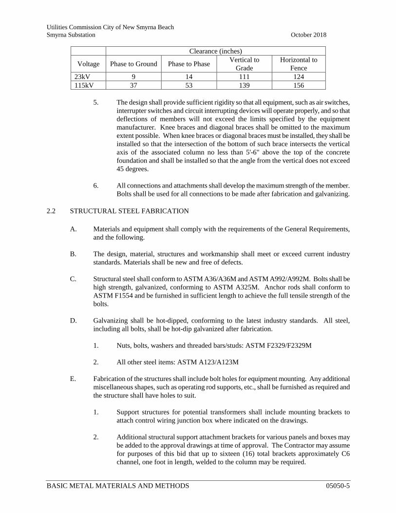
Utilities Commission City of New Smyrna Beach Smyrna Substation October 2018
BASIC METAL MATERIALS AND METHODS 05050-5
Clearance (inches)
Voltage Phase to Ground Phase to Phase Vertical to Grade
Horizontal to Fence
23kV 9 14 111 124 115kV 37 53 139 156
5. The design shall provide sufficient rigidity so that all equipment, such as air switches,
interrupter switches and circuit interrupting devices will operate properly, and so that deflections of members will not exceed the limits specified by the equipment manufacturer. Knee braces and diagonal braces shall be omitted to the maximum extent possible. When knee braces or diagonal braces must be installed, they shall be installed so that the intersection of the bottom of such brace intersects the vertical axis of the associated column no less than 5'-6" above the top of the concrete foundation and shall be installed so that the angle from the vertical does not exceed 45 degrees.
6. All connections and attachments shall develop the maximum strength of the member.
Bolts shall be used for all connections to be made after fabrication and galvanizing.
2.2 STRUCTURAL STEEL FABRICATION A. Materials and equipment shall comply with the requirements of the General Requirements,
and the following. B. The design, material, structures and workmanship shall meet or exceed current industry
standards. Materials shall be new and free of defects. C. Structural steel shall conform to ASTM A36/A36M and ASTM A992/A992M. Bolts shall be
high strength, galvanized, conforming to ASTM A325M. Anchor rods shall conform to ASTM F1554 and be furnished in sufficient length to achieve the full tensile strength of the bolts.
D. Galvanizing shall be hot-dipped, conforming to the latest industry standards. All steel,
including all bolts, shall be hot-dip galvanized after fabrication.
1. Nuts, bolts, washers and threaded bars/studs: ASTM F2329/F2329M
2. All other steel items: ASTM A123/A123M E. Fabrication of the structures shall include bolt holes for equipment mounting. Any additional
miscellaneous shapes, such as operating rod supports, etc., shall be furnished as required and the structure shall have holes to suit.
1. Support structures for potential transformers shall include mounting brackets to
attach control wiring junction box where indicated on the drawings.
2. Additional structural support attachment brackets for various panels and boxes may be added to the approval drawings at time of approval. The Contractor may assume for purposes of this bid that up to sixteen (16) total brackets approximately C6 channel, one foot in length, welded to the column may be required.
Utilities Commission City of New Smyrna Beach Smyrna Substation October 2018
BASIC METAL MATERIALS AND METHODS 05050-6
F. All laced or trussed members shall be shop assembled and provided with suitable connections
for field erection. All pieces shall be clearly marked to facilitate field erection, and Shop Drawings shall indicate markings.
G. Each member shall be assigned a mark number and shall have this number stamped or
imprinted in characters at least 1/2-inch high. All lettering or imprint painted on a member after galvanizing shall be applied with material which cannot be removed by natural washing action.
2.3 OWNER FURNISHED MATERIALS A. The Owner has established a list of items by description, which the Owner intends to furnish
for the project. Reference numbers are provided for identification on Contract Drawings. The Packager shall coordinate the listed Owner Furnished Materials into all Structural Steel designs where indicated. The Contractor will be furnished one electronic copy of Manufacturer's Drawings, where available, illustrating terminal arrangements and physical properties of equipment furnished by Owner.
2.4 CONTRACTOR FURNISHED MATERIALS A. The Owner has established a list of items by description, which the Contractor is to furnish for
the project. Reference numbers are provided for identification on Contract Drawings. For some items, manufacturer name and catalog number are provided to establish a standard of reference. The list of Contractor Furnished Materials is not intended to be comprehensive or complete, and shall be supplemented with accessory and incidental materials as necessary for a complete installation, including anchor bolts. The Contractor shall verify quantities.
B. All material shall be new, approved and labeled, where required, by UL. Only products by manufacturers regularly engaged in production of specified units will be acceptable.
C. Provide materials of suitable composition to perform satisfactorily when exposed to corrosive conditions of project site.
D. Protection from contact of dissimilar materials 1. All metal surfaces to be in contact with mortar, concrete or other masonry materials
shall be painted with alkali-resistant coatings such as heavy-bodied bituminous paint. 2. Aluminum surfaces placed in contact with steel shall be given one coat of zinc
chromate primer complying with FSS TT-P-645C, or equivalent. Aluminum surfaces in contact with stainless, aluminized, hot-dip galvanized or electro-galvanized steel need not be treated.
E. Structure Grounding
1. Grounding pads shall be welded, or grounding points shall be incorporated, near the
base of each low profile type column leg.
Utilities Commission City of New Smyrna Beach Smyrna Substation October 2018
BASIC METAL MATERIALS AND METHODS 05050-7
2. For steel elements, provide grounding attachment points for vertical runs up, and horizontal runs across, the complete lengths of columns or trusses. Ground cable attachments shall be provided at maximum spacing of 4’-0”.
F. Miscellaneous Items
1. Switch Operator Platforms: All group operated switches shall be supplied with an
operator platform. The platform shall be designed in accordance with the recommendations of IEEE-80 pertaining to touch potentials.
2. Anchor Rods: Supply all anchor rods required to install Packager supplied
structures.
3. Terminal Pads: All connector and switch terminal pads shall be finished on the top surface to provide a smooth connection point for terminal connectors to transfer rated current. The pads on switches shall be tin plated, 4-hole NEMA pads suitable for bolted aluminum or copper connectors with standard hole spacing of 1-¾ inches x 1-¾ inches.
4. All necessary connectors shall be provided to terminate or couple bus, cable,
equipment, switches, etc. 5. All terminal pad connections shall be made using a suitable number of stainless steel
hex bolts, hex nuts, 2 stainless steel flat washers and 1 stainless steel compression washer provided per bolt. This hardware shall be provided by the Contractor. Bolt lengths shall be sized to provide minimal projection beyond hex nut to prevent excessive noise due to corona, but the entire hex nut shall be engaged.
6. Grease: All grease shall be high temperature synthetic grease. 7. Aeolian vibration damping cable shall be provided for all horizontal bus runs of
tubing with diameter of 2 inches or larger. 8. Provide electrical joint compound for all aluminum-to-aluminum and aluminum-to-
copper connections. Furnish a sufficient quantity of AFL “Alnox” Electrical Joint Compound, or approved equal, for aluminum connections.
9. All copper bus connectors shall be mechanical. 10. Provide a bi-metal transition plate for any planned copper/bronze to aluminum
connections. Transition plate is not required when one or both sides of the connection are tin plated.
PART 3 EXECUTION 3.1 SUBMITTALS
A. The Contractor shall submit lists of equipment and material supplemented by shop drawings,
descriptive bulletins, and/or other information necessary to completely describe the equipment and material proposed. Provide submittals within 30 days from the date of Notice of Award,
Utilities Commission City of New Smyrna Beach Smyrna Substation October 2018
BASIC METAL MATERIALS AND METHODS 05050-8
for review by the Owner. Submittals shall be complete and shall include, but not necessarily be limited to, the following:
B. Structural Steel
1. Steel structure design calculations, including complete foundation load reactions.
a. Calculations shall be signed and sealed by a Structural Engineer with a Florida Professional Engineering License.
2. Plan, elevations and section views necessary to fully illustrate the structure layout and
their assembly.
3. Complete structural steel details, including member sizes, welding requirements, fabrication and erection instructions. Include all necessary details without limitation of connections to structures.
4. Itemized Bills of Material, complete with identifying mark indications and quantities.
5. Installation and erection instructions, including weights of all preassembled
components.
6. Foundation bolt (anchor rod) details and templates for structures to be furnished. C. Equipment, Materials, and Incidentals
1. Complete switch manufacturer shop drawings including ratings, dimensions, mounting and terminal details, manual or motor operator details, and maintenance manuals.
2. Complete surge arrester manufacturer shop drawings including ratings, dimensions,
mounting and terminal details, and performance characteristics.
3. Complete CCVT and PT manufacturer shop drawings including ratings, dimensions, mounting and terminal details, and performance characteristics.
4. Completely itemized Bill of Material including item Description, Manufacturer,
Catalog Number, and Quantity, cross referenced to the Owner’s reference numbers.
5. Manufacturer’s literature and data as necessary to establish “Approved Equal” equivalence for any items substituted.
3.2 Shop Drawings
A. All shop drawing submittals required to be delivered to the Utilities Commission of New
Smyrna Beach shall be mailed (three copies) and sent by e-mail to:
Utilities Commission City of New Smyrna Beach Smyrna Substation October 2018
BASIC METAL MATERIALS AND METHODS 05050-9
Tad Moon Electrical Engineer Utilities Commission of New Smyrna Beach 200 Canal Street New Smyrna Beach, FL 32168 [email protected]
B. Certified physical copies of drawings (24” X 36” prints), instruction books, and operations &
maintenance manuals shall be provided for each category of equipment furnished. Manufacturer descriptive bulletins and/or other information shall be complete for all components. Electronic files of drawings compatible with AutoCAD Release 2010 shall also be furnished to the Owner for record.
C. Submit test data to the Owner for review, for any applicable items.
D. Where spare parts are included in the Structural Steel Package award, submittals shall include
a list of spare parts items to be furnished under the contract. The spare parts list shall provide the name and identification number of both the Packager and the original manufacturer of the components. The parts list shall provide the list price for each item, effective as of the date of conditional Notice of Award of Contract and conditional notice to proceed.
3.3 SHOP DRAWING REVIEW
A. Failure by the Owner for reasons other than actions or omissions on the part of the Contractor
to return shop drawings within 15 business days from date of receipt thereof shall constitute the basis for a day-for-day extension in the proposed delivery schedule. Failure by the Owner to return shop drawings within 15 business days due to actions or omissions on the part of the Contractor shall not constitute grounds for extension of delivery time proposed.
B. A maximum of two reviews for each submittal to establish conformance with the
Specifications will be allowed. In the event an item has been determined by Owner not to be in conformance with the contract requirements after two reviews, the Contractor shall pay Owner an amount equal to the cost incurred by UCNSB to perform additional submittal reviews required to establish conformance with the Specifications. These costs will be deducted from the Contractor’s retainage prior to final payment.
C. Both the owner and the supplier shall make a good-faith effort to be available for
teleconferencing upon the call of either party, and shall attempt to do so within the 15 business day approval period. All such teleconferencing shall be performed at the supplier’s expense and shall be arranged by the supplier.
END OF SECTION
Utilities Commission City of New Smyrna Beach Smyrna Substation October 2018 Substation Expansion Project New Smyrna Beach, FL
BASIC ELECTRICAL MATERIALS AND METHODS 16050 - 1
SPECIFICATION SECTION 16050
BASIC ELECTRICAL MATERIALS AND METHODS
PART 1 GENERAL 1.1 SUMMARY
A. Section includes requirements for basic electrical materials and methods applicable to sections with electrical equipment requirements except when in these individual sections requirements are otherwise specified.
1.2 QUALITY ASSURANCE
A. Electrical Work and Materials: Follow the latest edition of the National Electrical Code
(NEC), which is minimum requirement for electrical work and if there is a conflict between requirements specified in Contract Documents and code, the more stringent will apply as determined and approved by Engineer.
B. Unless otherwise indicated, provide electrical materials and equipment which are the standard products of manufacturers regularly engaged in production of such materials and equipment. Except where otherwise shown on Drawings.
1. Provide the manufacturer's latest standard design that conforms to these
Specifications.
2. When 2 or more units of same class of material and equipment are required, these units shall be products of same manufacturer.
1.3 SUBMITTALS
A. Comply with Section 01330. Include the following information:
1. Complete list of electrical materials to be furnished, indicating manufacturer.
2. Complete schedule and listing of system and equipment identification labels with
legends.
3. Test plan and schedule.
1.4 PROJECT CONDITIONS
A. General: Drawings indicate extent and general arrangement of principal electrical elements, outlets, and circuit layouts.
Utilities Commission City of New Smyrna Beach Smyrna Substation October 2018
BASIC ELECTRICAL MATERIALS AND METHODS 16050 - 2
B. Connections: Properly connect electrical elements and devices provided under this and other sections, in accordance with NEC, to form workable system following Contract Documents, whether connections and interconnections are specifically specified or shown on Drawings.
C. Additional Circuits: Install where required by furnished equipment and for proper installation of work, without additional cost to the Owner.
1.5 IDENTIFICATION FOR SYSTEM AND EQUIPMENT
A. General
1. Identification: Identify and label each raceway, piece of equipment, and conductor.
2. Label Schedule: Develop schedule from legend shown on Drawings, schedules, and
derived from nature of system.
a. Lacking specific data, develop legends from nature of service or system and submit for Engineer’s approval.
b. Arrange schedule to produce legible comprehensive identification system.
B. Raceway Identification 1. Exposed Raceways: Identify at each end within 12 inches of termination.
2. Identifying Labels: Factory manufactured with colored paper, machine printed, with
identifying legend laminated between 2 sheets of vinylite plastic formed to completely encircle raceway.
a. Sizes: Match raceway to which applied.
b. Installation: Following manufacturer's instructions.
3. Legends for Use in Labels:
a. Indicate system voltage and what it serves or type of service.
b. Letter colors and minimum sizes.
1) Raceways 2-1/2 inch and smaller: 1 inch high white letters on black
background.
2) Raceways larger than 2-1/2-inch diameter: 2 inch high letters with same colors as above.
C. Equipment Identification
1. Nameplate: Attach to inside surfaces with adhesive and to outside surface with round
head, self-tapping metal screws.
Utilities Commission City of New Smyrna Beach Smyrna Substation October 2018
BASIC ELECTRICAL MATERIALS AND METHODS 16050 - 3
a. Letter Colors and Minimum Sizes: Two-color laminated plastic not less than 1/16 inch thick, machine engraved to show white letters not less than 1/4 inch high on black background.
2. Legend: Identify enclosure or piece of equipment.
D. Conductor Identification 1. Location:
a. Identify power conductors terminating in panelboards, cabinets, switchgear,
and switchboards at each end and in intervening junction and pull boxes.
b. Where feeder conductors pass through cable tray, tag feeder every 15 feet to indicate electrical characteristics, circuit number, and panelboard designation.
c. Locate labels near conductor ends for terminals and on exposed portions of
conductor within pull and junction boxes.
2. Labels: Plastic slip-on ferrule type with durable machine printed letters, numerals, and other identifying characters.
PART 2 PRODUCTS
2.1 SUBSTATION POWER TRANSFORMERS
A. General: The new substation power transformers designated Transformer No.1 and
Transformer No.2 will be supplied by the Owner. Owner will arrange for procurement of transformer as well as shipment to project site, placement on the foundations, assembly, and oil filling.
B. Contractor shall be responsible for protecting the transformers during the work, and commissioning of the new Transformer No. 1 and Transformer No.2.
2.2 POWER CIRCUIT BREAKERS & CIRCUIT SWITCHERS A. Two (2) 121kV, 1200A SF6 power circuit switchers will be supplied by the Owner. Owner
will arrange for procurement of the circuit switchers as well as shipment to project site.
B. Nine (9) 23kV 1200A vacuum power circuit breakers will be supplied by the Owner. Owner will arrange for procurement of the circuit breakers as well as shipment to project site.
C. Contractor shall be responsible for offload, temporary storage, installation, testing and commissioning of the new circuit breakers and circuit switchers.
2.3 SUBSTATION PACKAGE A. Substation bus, structures, connectors, disconnect switches, insulators and all miscellaneous
equipment will be provided by the Contractor.
Utilities Commission City of New Smyrna Beach Smyrna Substation October 2018
BASIC ELECTRICAL MATERIALS AND METHODS 16050 - 4
1. See Substation Bill of Material for Items that will be furnished by the Owner.
2. If Bill of Material lists material quantities, these should be assumed to be
approximate. Contractor is responsible for providing his own material take offs and quantities.
B. Bus Fittings and Connections will be provided by the Contractor. Bus fittings and
connections shall be either welded or compression as indicated by the Bill of Material. 1. Substitution of swaged type connectors for welded and/or compression connectors
will be allowed. Approved vendors for swaged connectors are AFL and DMC Power. Contractor will be responsible for acquiring all tooling required for installation.
C. Insulators
1. Contractor shall furnish an additional three (3) of each size insulator to the job site
as a part of the substation package. These insulators shall be maintained on site during construction and used in the event of a broken or damaged insulator so that the work is not delayed. Broken or damaged insulators shall then be replaced by the Contractor, and three (3) spares of each type shall be turned over to the Owner at the completion of the project.
D. Bolted Terminal Pad and Bus Connections: 1. Contractor shall provide hardware for bus connections.
2. Use 1/2” UNC-13 stainless steel hex head bolts and nuts, grade 316
3. Under both bolt head and nut, provide one 1-1/4” 316 stainless steel flat washer and
one 1-1/8”, 2500-3500lb rated 301 stainless steel Belleville compression washer.
2.4 PROTECTIVE RELAYS A. Contractor shall provide relay panels, protective relays, and control devices per the
Contract Drawings and Specification Section 16290.
2.5 WIRE AND CABLE - 600 VOLTS AND BELOW A. Low voltage wire and cable shall be in accordance with Section 16120, Low Voltage
Conductors and Cables.
B. Wire Cable Identification: Printed at regular intervals throughout entire length. 1. Manufacture or trade name.
2. Size of conductor.
3. Type of insulation.
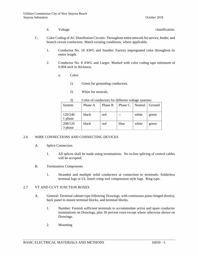
Utilities Commission City of New Smyrna Beach Smyrna Substation October 2018
BASIC ELECTRICAL MATERIALS AND METHODS 16050 - 5
4. Voltage classification.
C. Color Coding of AC Distribution Circuits: Throughout entire network for service, feeder, and
branch circuit conductors. Match existing conditions, where applicable. 1. Conductor No. 10 AWG and Smaller: Factory impregnated color throughout its
entire length.
2. Conductor No. 8 AWG and Larger: Marked with color coding tape minimum of 0.004 inch in thickness.
a. Color:
1) Green for grounding conductors.
2) White for neutrals.
3) Color of conductors for different voltage systems:
System Phase A Phase B Phase C Neutral Ground
120/240 1 phase
black red -- white green
208/120 3 phase
black red blue white green
2.6 WIRE CONNECTIONS AND CONNECTING DEVICES
A. Splice Connectors
1. All splices shall be made using terminations. No in-line splicing of control cables
will be accepted.
B. Termination Components 1. Stranded and multiple solid conductors at connection to terminals: Solderless
terminal lugs or UL listed crimp tool compression style lugs. Ring type. 2.7 VT AND CCVT JUNCTION BOXES
A. General: Terminal cabinet type following Drawings, with continuous piano hinged door(s),
back panel to mount terminal blocks, and terminal blocks. 1. Number: Furnish sufficient terminals to accommodate active and spare conductor
terminations on Drawings, plus 30 percent extra except where otherwise shown on Drawings.
2. Mounting
Utilities Commission City of New Smyrna Beach Smyrna Substation October 2018
BASIC ELECTRICAL MATERIALS AND METHODS 16050 - 6
a. Mount terminals and back panels from cabinet front.
b. Do not mount with fasteners extending through cabinet back.
B. Materials 1. Cabinets shall be Stainless Steel.
2. NEMA 4 and 4X Cabinets: Quick release latches, padlockable.
3. Terminal Strips: Standoff mounted and channel mounting type with marking strips.
4. Boxes shall be sized to accommodate all wiring, devices and terminations.
Contractor to verify box size prior to ordering, based upon actual devices supplied. 5. Low voltage fused disconnects shall be interlocked to allow removal of the fuses
only after the disconnect switch has been opened. a. Fused disconnects shall be either fully enclosed UL98 listed, or protected
by removable clear plastic barriers to prevent accidental contact with live circuits.
C. Locations
1. Panels for Damp, Wet, or Corrosive Areas: NEMA-4X, minimum 16 gauge 316
stainless steel with stainless steel accessories and hardware unless otherwise indicated
2.8 LOW VOLTAGE CIRCUIT BREAKERS
A. Applications: UL489, with interrupting capacity following Drawings and UL listed for conductor type used. 1. Type: Molded case, quick-make, quick-break, thermal magnetic trip type, trip
indicating and bolted in type.
2. Rating on each breaker: Visible trip.
3. Single pole breakers: Full module size.
4. Two and Multiple pole Circuits: Common trip type having single operating handle.
a. Single pole circuit breakers with handle ties for multiple pole breakers: Not accepted.
B. For circuit breakers to be installed in existing equipment, Contractor shall provide devices
that match the ratings and manufacture of the in-place equipment.
C. Used for Service Disconnect: Same as for enclosed applications, except suitable for service entrance.
2.9 PHASE IDENTIFICATION
Utilities Commission City of New Smyrna Beach Smyrna Substation October 2018
BASIC ELECTRICAL MATERIALS AND METHODS 16050 - 7
A. Provide phase identification on all new 115kV and 23kV busses.
1. Provide phase identification at each 115kV disconnect switch structure and line
termination structure, at the base of the appropriate phase insulator.
2. Provide phase identification at the end of each 23kV bus, at the base of the appropriate phase insulator.
B. Phase identification lettering shall be a minimum of 4” high. The lettering shall withstand
weathering and UV exposure without fading or discoloring. Phase coloring shall be as follows: 1. Aθ = White text on Red background
2. Bθ = White text on Black background
3. Cθ = White text on Blue background
2.10 DEVICE NUMBERS
A. Provide device numbers on all new circuit breakers and disconnecting switches.
1. Circuit breaker numbers shall be installed on the exterior of the circuit breaker.
2. Hookstick switch numbering shall be installed as close as possible to the center phase of each three phase group of switches.
3. Gang operated switch numbers shall be installed at the switch operating handle.
B. Device numbers and letters shall be a minimum of 4” high. The lettering shall be yellow on a black background, and withstand weathering and UV exposure without fading or discoloring.
PART 3 EXECUTION
3.1 GENERAL
A. Install electrical equipment and material of size, type, and general routing following Drawings or approved Contractor's Drawings.
B. Install metallic raceway, fittings, boxes, and cabinets free from direct contact with reinforcing steel.
C. Install fasteners, anchor bolts, anchorage items, and supports as required to insure proper and rigid alignment. 1. Attach equipment with fasteners sized according to size and weight of equipment and
thickness of supporting surface.
Utilities Commission City of New Smyrna Beach Smyrna Substation October 2018
BASIC ELECTRICAL MATERIALS AND METHODS 16050 - 8
D. Where aluminum is placed in contact with dissimilar metal or concrete, separate contact surfaces with gasket, non-absorptive tape, or coating to prevent corrosion.
E. Ground and make metallic conduit, raceways, and cable trays electrically and mechanically continuous. 1. Conduits: Continuous between outlets, boxes, cabinets, and panels, and secured to
each box.
2. Ground Conductor: For each conduit run.
3.2 TESTING
A. Contractor shall engage an independent third party testing agency to perform the required testing of the substation equipment and materials. 1. The testing agency shall demonstrate a minimum of 5 years’ experience with utility
substation equipment acceptance testing.
2. Qualifications of the testing agency shall be submitted to the Owner for review.
B. Submit a testing plan and schedule to the Owner.
C. Contractor shall perform all final testing and commissioning of the equipment supplied in the Substation package. Testing shall be per the NETA Acceptance Testing Standard (ANSI/NETA ATS-2013) and per manufacturer’s recommendations. The equipment to be tested includes: 1. Power Transformer No.1
a. Transformer No.1 Load Tap Changer
2. Power Transformer No. 2
a. Transformer No. 2 Load Tap Changer
3. 121kV SF6 Circuit Switchers
4. 115kV Motor Operated Switches
5. 23kV Vacuum Circuit Breakers
6. Cables, Low Voltage, 600V
7. Cutout Switches
8. Protective Relays
9. CCVTs
Utilities Commission City of New Smyrna Beach Smyrna Substation October 2018
BASIC ELECTRICAL MATERIALS AND METHODS 16050 - 9
10. CTs
11. PTs
12. Arrestors
13. Air Break Disconnect Switches
14. Surge Arresters
15. Outdoor Bus Structures
16. System Functional Testing
D. Equipment shall be put into service only after receiving Owner’s written approval of the test report.
3.3 SUBSTATION POWER TRANSFORMERS
A. Contractor is responsible for final testing and commissioning of the transformers.
B. Contractor shall make all connections to high voltage bushings, low voltage bushings,
lightning arrestors, ground grid and controls circuits.
C. Contractor shall perform all final testing and commissioning of the transformers. 1. Testing shall be per the NETA Acceptance Testing Standard (ANSI/NETA ATS-
2013), including all testing listed as “Optional”. 2. Record the results of all testing and provide a final report to the Owner for review.
3. Equipment shall be put into service only after receiving Owner’s written approval of
the test report.
3.4 POWER CIRCUIT BREAKERS & CIRCUIT SWITCHERS A. Owner will furnish, two (2) 121kV SF6 circuit switchers and nine (9) 23kV vacuum circuit
breakers at the project site. Coordinate with Owner for the delivery of the circuit breakers and circuit switchers. All preliminary work to prepare for the installation shall be completed by the Contractor prior to agreed upon delivery date.
B. Contractor shall be responsible for receiving, rigging and offloading the circuit breakers and
circuit switchers. Contractor shall be responsible for supervising the placement of circuit breakers and circuit switcher structures on the foundations. Equipment not immediately installed shall be stored in accordance with Specification 01600, Material Delivery, Storage and Handling, as well as the manufacturer’s instructions.
C. Install the circuit breakers and circuit switchers per the manufacturer’s written instructions. Secure the circuit breakers to the anchor bolts, and make all connections to circuit breaker
Utilities Commission City of New Smyrna Beach Smyrna Substation October 2018
BASIC ELECTRICAL MATERIALS AND METHODS 16050 - 10
bushings, ground grid, and controls circuits. Install the circuit switcher support structures and control cabinets per the manufacturer’s written instructions. 1. Pressurize the 115kV circuit switchers with SF6 gas per the manufacturer’s
instructions. Gas to be provided by Contractor.
D. Contractor shall perform all final testing and commissioning of the circuit breakers and circuit switchers. 1. Testing shall be per the NETA Acceptance Testing Standard (ANSI/NETA ATS-
2013), including all testing listed as “Optional”. 2. Record the results of all testing and provide a final report to the Owner for review.
3. Equipment shall be put into service only after receiving Owner’s written approval of
the test report.
3.5 SUBSTATION BUS
A. General: Install substation bus such that it is secure and braced against magnetic forces due to
short circuit currents.
B. Tube Bus: 1. Install as shown on Contract Drawings
2. Al Tube bus runs over nine (9) feet in length shall have a vibration damper installed.
a. Install a length of 4/0 ACSR cable within the aluminum tube prior to
installing the end fittings. The weight of the cable damper shall be 15%-25% of the weight of the associated tube bus segment.
3. Support tube bus as shown with insulator support clamps at the support insulators.
4. Rigid tube bus shall have expansion fittings as shown on the Contract Drawings.
5. Drill a 5/16” weep hole at the low point of all bus runs.
C. Bare Cable Bus 1. Install flexible cable bus as shown on the Contract Drawings.
2. Cable shall be routed, as nearly as is possible, directly from one termination pad to
the next.
3. Cable shall be installed considering possible expansion and contraction due to temperature variations, but shall not excessively bow or sag.
Utilities Commission City of New Smyrna Beach Smyrna Substation October 2018
BASIC ELECTRICAL MATERIALS AND METHODS 16050 - 11
4. Installation shall conform to NESC required phase to phase and phase to ground clearances.
D. Fittings and Connections
1. Install connectors per the manufacturer’s recommendations.
2. Apply oxide inhibiting, electrical joint compound before installing conductor into standard compression connectors. .
a. Use Alcoa AFC grit compound for installing cable fittings.
b. Use non-gritted Alcoa #2 EJC for all others.
E. Bolted Connections: 1. Clean surfaces with emery cloth and wire brush to remove oxide layer
2. Use non-grit oxide inhibitor between the two surfaces (Alcoa #2 EJC or equal)
3.6 PROTECTIVE RELAYS
A. Install new relay panels as shown on the Contract Drawings and defined in the Specifications.
B. Contractor shall install new control cable from the substation to the control panel
terminations.
C. Contractor shall connect the panel wiring to the control devices.
D. When all other work is complete, Contractor shall identify and remove all existing control wiring made obsolete by this project.
E. Contractor shall perform all final testing and commissioning of the protective relays. 1. Testing shall be per the NETA Acceptance Testing Standard (ANSI/NETA ATS-
2013), including all testing listed as “Optional”. 2. Record the results of all testing and provide a final report to the Owner for review.
3. Equipment shall be put into service only after receiving Owner’s written approval of
the test report.
3.7 CABLE AND CONDUCTORS A. Install complete raceway system and clear debris and moisture before conductor installation.
B. Install conductors in raceways with no splices between boxes following Drawings.
C. Pull conductors using proper equipment without exceeding manufacturer's recommendation
for maximum pulling tension.
Utilities Commission City of New Smyrna Beach Smyrna Substation October 2018
BASIC ELECTRICAL MATERIALS AND METHODS 16050 - 12
D. Protect conductor insulation jacket at all times from kinks, scrapes, punctures, and other
damage. 1. Replace damaged conductors.
2. Use UL listed lubricating compound compatible with conductor insulated jacket and
with raceway to reduce pulling force.
E. Support conductors in vertical risers with woven grips to prevent loading on conductor connectors.
F. For conduits entering buildings or from areas where temperature change may cause condensation or moisture, seal between conductors and conduit after conductors are in place.
G. When using color coding tape, apply with overlapping turns for minimum length of 2 inches starting 2 inches back from termination point.
H. Connect circuit conductors of same color to same phase throughout installation.
I. Contractor shall perform all final testing and commissioning of the control cable. 1. Testing shall be per the NETA Acceptance Testing Standard (ANSI/NETA ATS-
2013), including all testing listed as “Optional”. 2. Record the results of all testing and provide a final report to the Owner for review.
3. Equipment shall be put into service only after receiving Owner’s written approval of
the test report. 3.8 CABINETS AND ENCLOSURES
A. Mount cabinets and enclosures with minimum of 1-1/2 inch air space all around.
B. Arrange conductors in cabinets, panels, and enclosures neatly, cut to proper length and with
surplus conductor removed.
C. Identify each circuit in enclosure.
D. Provide terminals and connectors for type of material used. 3.9 GROUNDING
A. Ground exposed noncurrent carrying metallic parts of electrical equipment, raceway systems,
and neutral of all wiring systems following NESC, NEC and other applicable codes.
B. Bond all substation structures and equipment to station ground grid using 4/0 stranded bare copper conductor.
Utilities Commission City of New Smyrna Beach Smyrna Substation October 2018
BASIC ELECTRICAL MATERIALS AND METHODS 16050 - 13
1. All transformers, circuit breakers, and multi-leg steel structures shall be bonded to ground using two independent grounds.
2. All lightning arrestors, voltage transformers, and single leg structures shall be bonded to the ground grid using one ground.
3. All switch operators (swing handle or motor operators) shall be bonded to the switch structure, ground conductor, and the switch operator platform.
C. Contractor shall perform all final testing and of the substation ground system. 3.10 FIELD QUALITY CONTROL
A. Contractor shall retain the services of a NETA certified independent testing agency to perform all final testing per the NETA Acceptance Testing Standard (ANSI/NETA ATS-2013). Record the results of all testing and provide a report to the Owner for review. 1. Correct defects and failures to Engineer’s acceptance.
END OF SECTION
Utilities Commission City of New Smyrna Beach Smyrna Substation October 2018 Substation Equipment Package New Smyrna Beach, FL
BILL OF MATERIAL 16050.1-1
SPECIFICATIONS SECTION 16050.1
BILL OF MATERIAL
PART 1 GENERAL
1.1 SUMMARY
A. Provide, transport, handle, store and protect material and equipment used on this project as specified in Specification Section 01600 – Material Delivery, Storage, and Handling.
B. Conform to the Contract Specifications and all applicable technical specifications, codes, and standards.
C. Quantities provided in the Bill of Material are estimated quantities only. Contractor’s materialman shall review the contract documents and create their own counts of the materials required for purposes of bidding and ordering. Notify the Owner of any discrepancies between the below Bill of Material and the materialman’s count prior to ordering.
UTILITIES COMMISSION CITY OF NEW SMYRNA BEACH
PRELIMINARY BILL OF MATERIAL
SMYRNA SUBSTATION 115/23 KV INSTALLATION
NOTES:
1. MANUFACTURERS AND PART NUMBERS LISTED ARE THE BASIS OF
DESIGN ONLY. CONTRACTOR SHALL PROCURE MATERIALS THE CONFORM TO THE SPECIFICATIONS AND THE DESIGN DRAWINGS. IF NO SPECIFICATION EXISTS FOR A MATERIAL, PROVIDE THE LISTED EQUIPMENT OR AN APPROVED EQUAL BASED ON THE ITEM DESCRIPTION.
2. MATERIAL QUANTITIES ARE APPROXIMATE. CONTRACTOR SHALL PERFORM
THEIR OWN TAKEOFF (MATERIAL COUNT) PRIOR TO BIDDING.
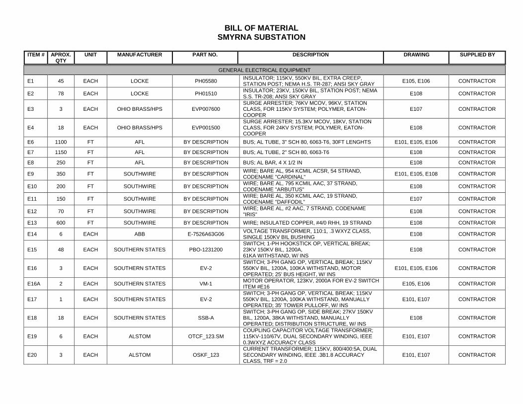
BILL OF MATERIAL SMYRNA SUBSTATION
ITEM # APROX.
QTY UNIT MANUFACTURER PART NO. DESCRIPTION DRAWING SUPPLIED BY
GENERAL ELECTRICAL EQUIPMENT
E1 45 EACH LOCKE PH05580 INSULATOR; 115KV, 550KV BIL, EXTRA CREEP, STATION POST; NEMA H.S. TR-287; ANSI SKY GRAY E105, E106 CONTRACTOR
E2 78 EACH LOCKE PH01510 INSULATOR; 23KV, 150KV BIL, STATION POST; NEMA S.S. TR-208; ANSI SKY GRAY E108 CONTRACTOR
E3 3 EACH OHIO BRASS/HPS EVP007600 SURGE ARRESTER; 76KV MCOV, 96KV, STATION CLASS, FOR 115KV SYSTEM; POLYMER, EATON-COOPER
E107 CONTRACTOR
E4 18 EACH OHIO BRASS/HPS EVP001500 SURGE ARRESTER; 15.3KV MCOV, 18KV, STATION CLASS, FOR 24KV SYSTEM; POLYMER, EATON-COOPER
E108 CONTRACTOR
E6 1100 FT AFL BY DESCRIPTION BUS; AL TUBE, 3" SCH 80, 6063-T6, 30FT LENGHTS E101, E105, E106 CONTRACTOR
E7 1150 FT AFL BY DESCRIPTION BUS; AL TUBE, 2" SCH 80, 6063-T6 E108 CONTRACTOR
E8 250 FT AFL BY DESCRIPTION BUS; AL BAR, 4 X 1/2 IN E108 CONTRACTOR
E9 350 FT SOUTHWIRE BY DESCRIPTION WIRE; BARE AL, 954 KCMIL ACSR, 54 STRAND, CODENAME "CARDINAL" E101, E105, E108 CONTRACTOR
E10 200 FT SOUTHWIRE BY DESCRIPTION WIRE; BARE AL, 795 KCMIL AAC, 37 STRAND, CODENAME "ARBUTUS" E108 CONTRACTOR
E11 150 FT SOUTHWIRE BY DESCRIPTION WIRE; BARE AL, 350 KCMIL AAC, 19 STRAND, CODENAME "DAFFODIL" E107 CONTRACTOR
E12 70 FT SOUTHWIRE BY DESCRIPTION WIRE; BARE AL, #2 AAC, 7 STRAND, CODENAME "IRIS" E108 CONTRACTOR
E13 600 FT SOUTHWIRE BY DESCRIPTION WIRE; INSULATED COPPER, #4/0 RHH, 19 STRAND E108 CONTRACTOR
E14 6 EACH ABB E-7526A63G06 VOLTAGE TRANSFORMER, 110:1, .3 WXYZ CLASS, SINGLE 150KV BIL BUSHING E108 CONTRACTOR
E15 48 EACH SOUTHERN STATES PBO-1231200 SWITCH; 1-PH HOOKSTICK OP, VERTICAL BREAK; 23KV 150KV BIL, 1200A, 61KA WITHSTAND, W/ INS
E108 CONTRACTOR
E16 3 EACH SOUTHERN STATES EV-2 SWITCH; 3-PH GANG OP, VERTICAL BREAK; 115KV 550KV BIL, 1200A, 100KA WITHSTAND, MOTOR OPERATED; 25' BUS HEIGHT, W/ INS
E101, E105, E106 CONTRACTOR
E16A 2 EACH SOUTHERN STATES VM-1 MOTOR OPERATOR, 123KV, 2000A FOR EV-2 SWITCH ITEM #E16 E105, E106 CONTRACTOR
E17 1 EACH SOUTHERN STATES EV-2 SWITCH; 3-PH GANG OP, VERTICAL BREAK; 115KV 550KV BIL, 1200A, 100KA WITHSTAND, MANUALLY OPERATED; 35' TOWER PULLOFF, W/ INS
E101, E107 CONTRACTOR
E18 18 EACH SOUTHERN STATES SSB-A SWITCH; 3-PH GANG OP, SIDE BREAK; 27KV 150KV BIL, 1200A, 38KA WITHSTAND, MANUALLY OPERATED; DISTRIBUTION STRUCTURE, W/ INS
E108 CONTRACTOR
E19 6 EACH ALSTOM OTCF_123.SM COUPLING CAPACITOR VOLTAGE TRANSFORMER; 115KV-110/67V, DUAL SECONDARY WINDING, IEEE 0.3WXYZ ACCURACY CLASS
E101, E107 CONTRACTOR
E20 3 EACH ALSTOM OSKF_123 CURRENT TRANSFORMER; 115KV, 800/400:5A, DUAL SECONDARY WINDING, IEEE .3B1.8 ACCURACY CLASS, TRF = 2.0
E101, E107 CONTRACTOR
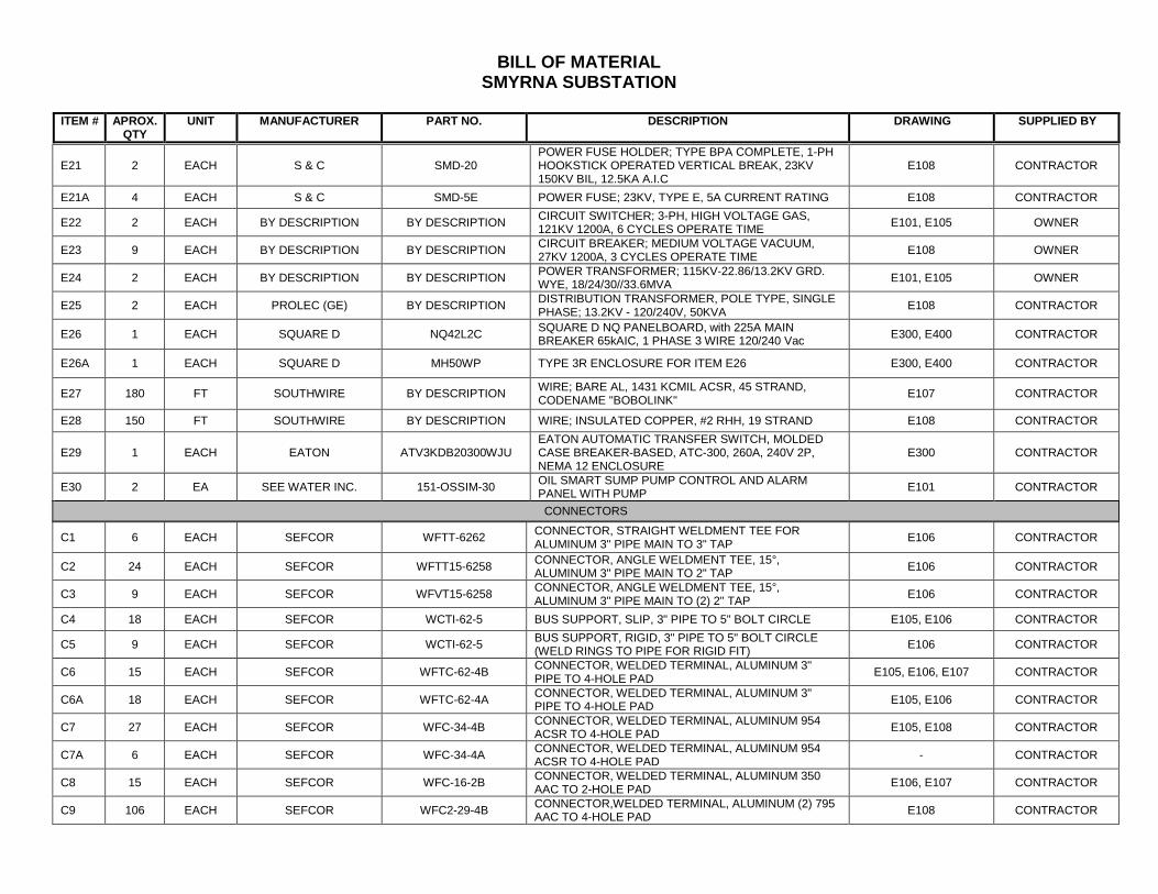
BILL OF MATERIAL SMYRNA SUBSTATION
ITEM # APROX.
QTY UNIT MANUFACTURER PART NO. DESCRIPTION DRAWING SUPPLIED BY
E21 2 EACH S & C SMD-20
POWER FUSE HOLDER; TYPE BPA COMPLETE, 1-PH HOOKSTICK OPERATED VERTICAL BREAK, 23KV 150KV BIL, 12.5KA A.I.C
E108 CONTRACTOR
E21A 4 EACH S & C SMD-5E POWER FUSE; 23KV, TYPE E, 5A CURRENT RATING E108 CONTRACTOR
E22 2 EACH BY DESCRIPTION BY DESCRIPTION CIRCUIT SWITCHER; 3-PH, HIGH VOLTAGE GAS, 121KV 1200A, 6 CYCLES OPERATE TIME E101, E105 OWNER
E23 9 EACH BY DESCRIPTION BY DESCRIPTION CIRCUIT BREAKER; MEDIUM VOLTAGE VACUUM, 27KV 1200A, 3 CYCLES OPERATE TIME E108 OWNER
E24 2 EACH BY DESCRIPTION BY DESCRIPTION POWER TRANSFORMER; 115KV-22.86/13.2KV GRD. WYE, 18/24/30//33.6MVA E101, E105 OWNER
E25 2 EACH PROLEC (GE) BY DESCRIPTION DISTRIBUTION TRANSFORMER, POLE TYPE, SINGLE PHASE; 13.2KV - 120/240V, 50KVA E108 CONTRACTOR
E26 1 EACH SQUARE D NQ42L2C SQUARE D NQ PANELBOARD, with 225A MAIN BREAKER 65kAIC, 1 PHASE 3 WIRE 120/240 Vac E300, E400 CONTRACTOR
E26A 1 EACH SQUARE D MH50WP TYPE 3R ENCLOSURE FOR ITEM E26 E300, E400 CONTRACTOR
E27 180 FT SOUTHWIRE BY DESCRIPTION WIRE; BARE AL, 1431 KCMIL ACSR, 45 STRAND, CODENAME "BOBOLINK" E107 CONTRACTOR
E28 150 FT SOUTHWIRE BY DESCRIPTION WIRE; INSULATED COPPER, #2 RHH, 19 STRAND E108 CONTRACTOR
E29 1 EACH EATON ATV3KDB20300WJU EATON AUTOMATIC TRANSFER SWITCH, MOLDED CASE BREAKER-BASED, ATC-300, 260A, 240V 2P, NEMA 12 ENCLOSURE
E300 CONTRACTOR
E30 2 EA SEE WATER INC. 151-OSSIM-30 OIL SMART SUMP PUMP CONTROL AND ALARM PANEL WITH PUMP E101 CONTRACTOR
CONNECTORS
C1 6 EACH SEFCOR WFTT-6262 CONNECTOR, STRAIGHT WELDMENT TEE FOR ALUMINUM 3" PIPE MAIN TO 3" TAP E106 CONTRACTOR
C2 24 EACH SEFCOR WFTT15-6258 CONNECTOR, ANGLE WELDMENT TEE, 15°, ALUMINUM 3" PIPE MAIN TO 2" TAP E106 CONTRACTOR
C3 9 EACH SEFCOR WFVT15-6258 CONNECTOR, ANGLE WELDMENT TEE, 15°, ALUMINUM 3" PIPE MAIN TO (2) 2" TAP E106 CONTRACTOR
C4 18 EACH SEFCOR WCTI-62-5 BUS SUPPORT, SLIP, 3" PIPE TO 5" BOLT CIRCLE E105, E106 CONTRACTOR
C5 9 EACH SEFCOR WCTI-62-5 BUS SUPPORT, RIGID, 3" PIPE TO 5" BOLT CIRCLE (WELD RINGS TO PIPE FOR RIGID FIT) E106 CONTRACTOR
C6 15 EACH SEFCOR WFTC-62-4B CONNECTOR, WELDED TERMINAL, ALUMINUM 3" PIPE TO 4-HOLE PAD E105, E106, E107 CONTRACTOR
C6A 18 EACH SEFCOR WFTC-62-4A CONNECTOR, WELDED TERMINAL, ALUMINUM 3" PIPE TO 4-HOLE PAD E105, E106 CONTRACTOR
C7 27 EACH SEFCOR WFC-34-4B CONNECTOR, WELDED TERMINAL, ALUMINUM 954 ACSR TO 4-HOLE PAD E105, E108 CONTRACTOR
C7A 6 EACH SEFCOR WFC-34-4A CONNECTOR, WELDED TERMINAL, ALUMINUM 954 ACSR TO 4-HOLE PAD - CONTRACTOR
C8 15 EACH SEFCOR WFC-16-2B CONNECTOR, WELDED TERMINAL, ALUMINUM 350 AAC TO 2-HOLE PAD E106, E107 CONTRACTOR
C9 106 EACH SEFCOR WFC2-29-4B CONNECTOR,WELDED TERMINAL, ALUMINUM (2) 795 AAC TO 4-HOLE PAD E108 CONTRACTOR
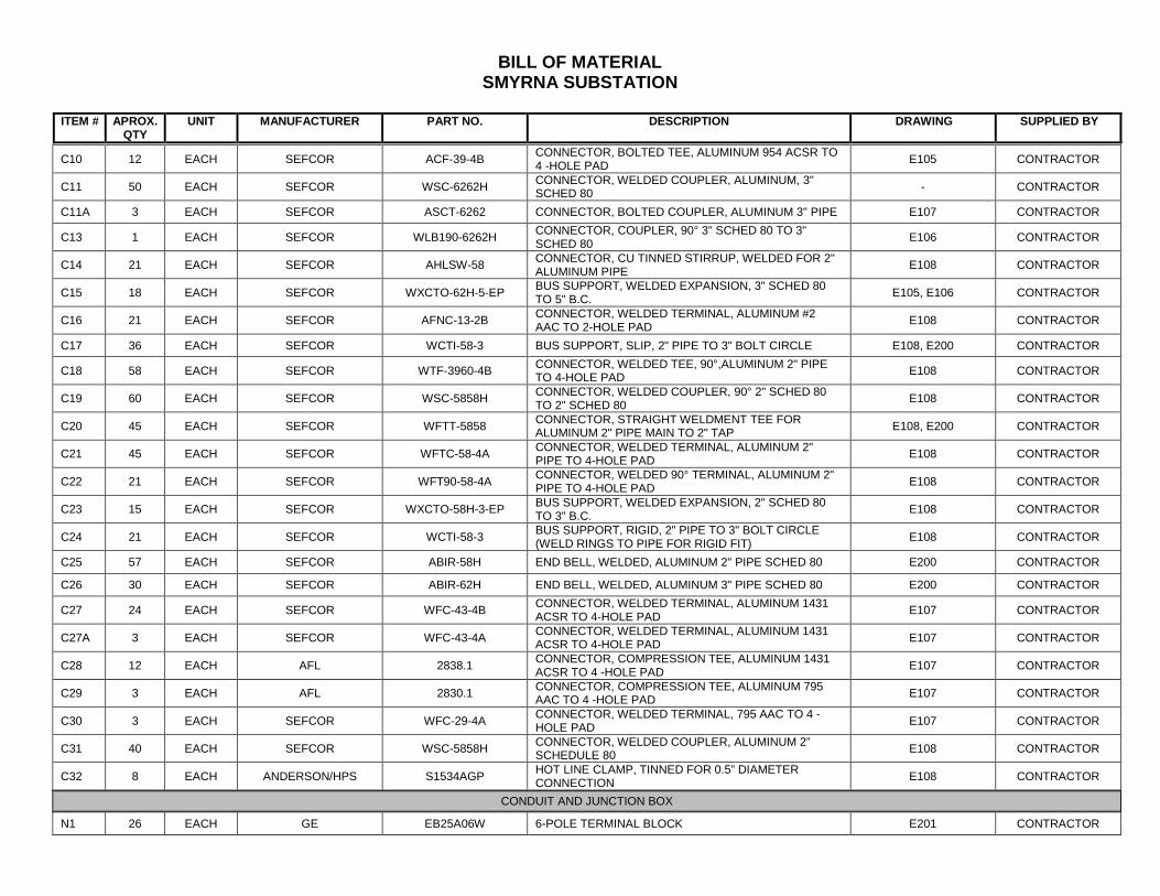
BILL OF MATERIAL SMYRNA SUBSTATION
ITEM # APROX.
QTY UNIT MANUFACTURER PART NO. DESCRIPTION DRAWING SUPPLIED BY
C10 12 EACH SEFCOR ACF-39-4B CONNECTOR, BOLTED TEE, ALUMINUM 954 ACSR TO
4 -HOLE PAD E105 CONTRACTOR
C11 50 EACH SEFCOR WSC-6262H CONNECTOR, WELDED COUPLER, ALUMINUM, 3" SCHED 80 - CONTRACTOR
C11A 3 EACH SEFCOR ASCT-6262 CONNECTOR, BOLTED COUPLER, ALUMINUM 3" PIPE E107 CONTRACTOR
C13 1 EACH SEFCOR WLB190-6262H CONNECTOR, COUPLER, 90° 3" SCHED 80 TO 3" SCHED 80 E106 CONTRACTOR
C14 21 EACH SEFCOR AHLSW-58 CONNECTOR, CU TINNED STIRRUP, WELDED FOR 2" ALUMINUM PIPE E108 CONTRACTOR
C15 18 EACH SEFCOR WXCTO-62H-5-EP BUS SUPPORT, WELDED EXPANSION, 3" SCHED 80 TO 5" B.C. E105, E106 CONTRACTOR
C16 21 EACH SEFCOR AFNC-13-2B CONNECTOR, WELDED TERMINAL, ALUMINUM #2 AAC TO 2-HOLE PAD E108 CONTRACTOR
C17 36 EACH SEFCOR WCTI-58-3 BUS SUPPORT, SLIP, 2" PIPE TO 3" BOLT CIRCLE E108, E200 CONTRACTOR
C18 58 EACH SEFCOR WTF-3960-4B CONNECTOR, WELDED TEE, 90°,ALUMINUM 2" PIPE TO 4-HOLE PAD E108 CONTRACTOR
C19 60 EACH SEFCOR WSC-5858H CONNECTOR, WELDED COUPLER, 90° 2" SCHED 80 TO 2" SCHED 80 E108 CONTRACTOR
C20 45 EACH SEFCOR WFTT-5858 CONNECTOR, STRAIGHT WELDMENT TEE FOR ALUMINUM 2" PIPE MAIN TO 2" TAP E108, E200 CONTRACTOR
C21 45 EACH SEFCOR WFTC-58-4A CONNECTOR, WELDED TERMINAL, ALUMINUM 2" PIPE TO 4-HOLE PAD E108 CONTRACTOR
C22 21 EACH SEFCOR WFT90-58-4A CONNECTOR, WELDED 90° TERMINAL, ALUMINUM 2" PIPE TO 4-HOLE PAD E108 CONTRACTOR
C23 15 EACH SEFCOR WXCTO-58H-3-EP BUS SUPPORT, WELDED EXPANSION, 2" SCHED 80 TO 3" B.C. E108 CONTRACTOR
C24 21 EACH SEFCOR WCTI-58-3 BUS SUPPORT, RIGID, 2" PIPE TO 3" BOLT CIRCLE (WELD RINGS TO PIPE FOR RIGID FIT) E108 CONTRACTOR
C25 57 EACH SEFCOR ABIR-58H END BELL, WELDED, ALUMINUM 2" PIPE SCHED 80 E200 CONTRACTOR
C26 30 EACH SEFCOR ABIR-62H END BELL, WELDED, ALUMINUM 3" PIPE SCHED 80 E200 CONTRACTOR
C27 24 EACH SEFCOR WFC-43-4B CONNECTOR, WELDED TERMINAL, ALUMINUM 1431 ACSR TO 4-HOLE PAD E107 CONTRACTOR
C27A 3 EACH SEFCOR WFC-43-4A CONNECTOR, WELDED TERMINAL, ALUMINUM 1431 ACSR TO 4-HOLE PAD E107 CONTRACTOR
C28 12 EACH AFL 2838.1 CONNECTOR, COMPRESSION TEE, ALUMINUM 1431 ACSR TO 4 -HOLE PAD E107 CONTRACTOR
C29 3 EACH AFL 2830.1 CONNECTOR, COMPRESSION TEE, ALUMINUM 795 AAC TO 4 -HOLE PAD E107 CONTRACTOR
C30 3 EACH SEFCOR WFC-29-4A CONNECTOR, WELDED TERMINAL, 795 AAC TO 4 -HOLE PAD E107 CONTRACTOR
C31 40 EACH SEFCOR WSC-5858H CONNECTOR, WELDED COUPLER, ALUMINUM 2” SCHEDULE 80 E108 CONTRACTOR
C32 8 EACH ANDERSON/HPS S1534AGP HOT LINE CLAMP, TINNED FOR 0.5” DIAMETER CONNECTION E108 CONTRACTOR
CONDUIT AND JUNCTION BOX
N1 26 EACH GE EB25A06W 6-POLE TERMINAL BLOCK E201 CONTRACTOR
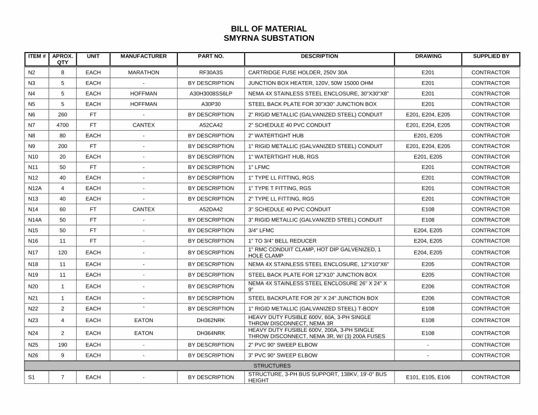
BILL OF MATERIAL SMYRNA SUBSTATION
ITEM # APROX.
QTY UNIT MANUFACTURER PART NO. DESCRIPTION DRAWING SUPPLIED BY
N2 8 EACH MARATHON RF30A3S CARTRIDGE FUSE HOLDER, 250V 30A E201 CONTRACTOR
N3 5 EACH - BY DESCRIPTION JUNCTION BOX HEATER, 120V, 50W 15000 OHM E201 CONTRACTOR
N4 5 EACH HOFFMAN A30H3008SS6LP NEMA 4X STAINLESS STEEL ENCLOSURE, 30"X30"X8" E201 CONTRACTOR
N5 5 EACH HOFFMAN A30P30 STEEL BACK PLATE FOR 30"X30" JUNCTION BOX E201 CONTRACTOR
N6 260 FT - BY DESCRIPTION 2" RIGID METALLIC (GALVANIZED STEEL) CONDUIT E201, E204, E205 CONTRACTOR
N7 4700 FT CANTEX A52CA42 2" SCHEDULE 40 PVC CONDUIT E201, E204, E205 CONTRACTOR
N8 80 EACH - BY DESCRIPTION 2" WATERTIGHT HUB E201, E205 CONTRACTOR
N9 200 FT - BY DESCRIPTION 1" RIGID METALLIC (GALVANIZED STEEL) CONDUIT E201, E204, E205 CONTRACTOR
N10 20 EACH - BY DESCRIPTION 1" WATERTIGHT HUB, RGS E201, E205 CONTRACTOR
N11 50 FT - BY DESCRIPTION 1" LFMC E201 CONTRACTOR
N12 40 EACH - BY DESCRIPTION 1" TYPE LL FITTING, RGS E201 CONTRACTOR
N12A 4 EACH - BY DESCRIPTION 1” TYPE T FITTING, RGS E201 CONTRACTOR
N13 40 EACH - BY DESCRIPTION 2" TYPE LL FITTING, RGS E201 CONTRACTOR
N14 60 FT CANTEX A52DA42 3" SCHEDULE 40 PVC CONDUIT E108 CONTRACTOR
N14A 50 FT - BY DESCRIPTION 3” RIGID METALLIC (GALVANIZED STEEL) CONDUIT E108 CONTRACTOR
N15 50 FT - BY DESCRIPTION 3/4" LFMC E204, E205 CONTRACTOR
N16 11 FT - BY DESCRIPTION 1" TO 3/4" BELL REDUCER E204, E205 CONTRACTOR
N17 120 EACH - BY DESCRIPTION 1" RMC CONDUIT CLAMP, HOT DIP GALVENIZED, 1 HOLE CLAMP E204, E205 CONTRACTOR
N18 11 EACH - BY DESCRIPTION NEMA 4X STAINLESS STEEL ENCLOSURE, 12"X10"X6" E205 CONTRACTOR
N19 11 EACH - BY DESCRIPTION STEEL BACK PLATE FOR 12"X10" JUNCTION BOX E205 CONTRACTOR
N20 1 EACH - BY DESCRIPTION NEMA 4X STAINLESS STEEL ENCLOSURE 26" X 24" X 9" E206 CONTRACTOR
N21 1 EACH - BY DESCRIPTION STEEL BACKPLATE FOR 26" X 24" JUNCTION BOX E206 CONTRACTOR
N22 2 EACH - BY DESCRIPTION 1" RIGID METALLIC (GALVANIZED STEEL) T-BODY E108 CONTRACTOR
N23 4 EACH EATON DH362NRK HEAVY DUTY FUSIBLE 600V, 60A, 3-PH SINGLE THROW DISCONNECT, NEMA 3R E108 CONTRACTOR
N24 2 EACH EATON DH364NRK HEAVY DUTY FUSIBLE 600V, 200A, 3-PH SINGLE THROW DISCONNECT, NEMA 3R, W/ (3) 200A FUSES E108 CONTRACTOR
N25 190 EACH - BY DESCRIPTION 2” PVC 90° SWEEP ELBOW - CONTRACTOR
N26 9 EACH - BY DESCRIPTION 3” PVC 90° SWEEP ELBOW - CONTRACTOR
STRUCTURES
S1 7 EACH - BY DESCRIPTION STRUCTURE, 3-PH BUS SUPPORT, 138KV, 19'-0" BUS HEIGHT E101, E105, E106 CONTRACTOR
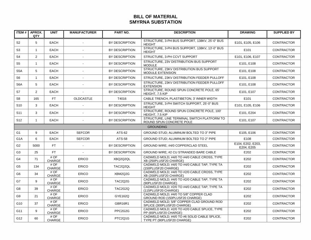
BILL OF MATERIAL SMYRNA SUBSTATION
ITEM # APROX.
QTY UNIT MANUFACTURER PART NO. DESCRIPTION DRAWING SUPPLIED BY
S2 5 EACH - BY DESCRIPTION STRUCTURE, 3-PH BUS SUPPORT, 138KV, 25'-0" BUS
HEIGHT E101, E105, E106 CONTRACTOR
S3 1 EACH - BY DESCRIPTION STRUCTURE, 3-PH BUS SUPPORT, 138KV, 13'-0" BUS HEIGHT E101 CONTRACTOR
S4 2 EACH - BY DESCRIPTION STRUCTURE, 3-PH CCVT SUPPORT E101, E106, E107 CONTRACTOR
S5 1 EACH - BY DESCRIPTION STRUCTURE, 23V DISTRIBUTION BUS SUPPORT MODULE E101, E108 CONTRACTOR
S5A 5 EACH - BY DESCRIPTION STRUCTURE, 23KV DISTRIBUTION BUS SUPPORT MODULE EXTENSION E101, E108 CONTRACTOR
S6 1 EACH - BY DESCRIPTION STRUCTURE, 23KV DISTRIBUTION FEEDER PULLOFF E101, E108 CONTRACTOR
S6A 5 EACH - BY DESCRIPTION STRUCTURE, 23KV DISTRIBUTION FEEDER PULLOFF EXTENSION E101, E108 CONTRACTOR
S7 2 EACH - BY DESCRIPTION STRUCTURE, ROUND SPUN CONCRETE POLE, 65' HEIGHT, 7.5 KIP E101, E107 CONTRACTOR
S8 165 FT OLDCASTLE T4016 CABLE TRENCH, PLASTIBETON, 3' INNER WIDTH E101 CONTRACTOR
S10 3 EACH - BY DESCRIPTION STRUCTURE, 3-PH SWITCH SUPPORT, 25'-0" BUS HEIGHT E101, E105, E106 CONTRACTOR
S11 3 EACH - BY DESCRIPTION STRUCTURE, ROUND SPUN CONCRETE POLE, 100' HEIGHT, 7.5 KIP E101, E204 CONTRACTOR
S12 1 EACH - BY DESCRIPTION STRUCTURE, LINE TERMINAL SWITCH PLATFORM TO ROUND SPUN CONCRETE POLE E101, E107 CONTRACTOR
GROUNDING
G1 9 EACH SEFCOR ATS-62 GROUND STUD; ALUMINUM BOLTED TO 3" PIPE E105, E106 CONTRACTOR
G1A 6 EACH SEFCOR ATS-58 GROUND STUD; ALUMINUM BOLTED TO 2" PIPE E108 CONTRACTOR
G2 5000 FT - BY DESCRIPTION GROUND WIRE; #4/0 COPPERCLAD STEEL E104, E202, E203, E204, E205 CONTRACTOR
G3 25 FT - BY DESCRIPTION GROUND WIRE; #2 CU STRANDED BARE CABLE E202 CONTRACTOR
G4 71 # OF CHARGE ERICO XBQ2Q2QL CADWELD MOLD; #4/0 TO #4/0 CABLE CROSS, TYPE
XB (250PLUSF20 CHARGE) E202 CONTRACTOR
G5 134 # OF CHARGE ERICO TAC2Q2QL CADWELD MOLD; #4/0 TO #4/0 CABLE TAP, TYPE TA
(150PLUSF20 CHARGE) E202 CONTRACTOR
G6 34 # OF CHARGE ERICO XBM2Q2G CADWELD MOLD; #4/0 TO #2/0 CABLE CROSS, TYPE
XB (200PLUSF20 CHARGE) E202 CONTRACTOR
G7 9 # OF CHARGE ERICO TAC2Q2G CADWELD MOLD; #4/0 TO #2/0 CABLE TAP, TYPE TA
(90PLUSF20 CHARGE) E202 CONTRACTOR
G8 39 # OF CHARGE ERICO TAC2G2Q CADWELD MOLD; #2/0 TO #4/0 CABLE TAP, TYPE TA
(115PLUSF20 CHARGE) E202 CONTRACTOR
G9 21 # OF CHARGE ERICO GYE162Q CADWELD MOLD; #4/0 TO 5/8" COPPER CLAD
GROUND ROD (150PLUSF20 CHARGE) E202 CONTRACTOR
G10 37 # OF CHARGE ERICO GBR16R1 CADWELD MOLD; 5/8" COPPER CLAD GROUND ROD
SPLICE (300PLUSF20 CHARGE) E202 CONTRACTOR
G11 9 # OF CHARGE ERICO PPC2G2G CADWELD MOLD; #2/0 TO #2/0 CABLE SPLICE, TYPE
PP (65PLUSF20 CHARGE) E202 CONTRACTOR
G12 60 # OF CHARGE ERICO PTC2Q1G CADWELD MOLD; #4/0 TO #6 SOLID CABLE SPLICE,
TYPE PT (90PLUSF20 CHARGE) E202 CONTRACTOR
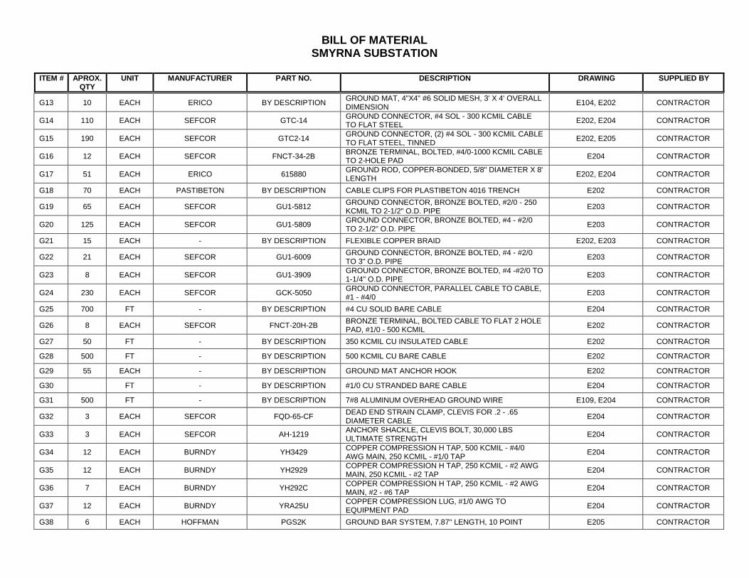
BILL OF MATERIAL SMYRNA SUBSTATION
ITEM # APROX.
QTY UNIT MANUFACTURER PART NO. DESCRIPTION DRAWING SUPPLIED BY
G13 10 EACH ERICO BY DESCRIPTION GROUND MAT, 4"X4" #6 SOLID MESH, 3' X 4' OVERALL
DIMENSION E104, E202 CONTRACTOR
G14 110 EACH SEFCOR GTC-14 GROUND CONNECTOR, #4 SOL - 300 KCMIL CABLE TO FLAT STEEL E202, E204 CONTRACTOR
G15 190 EACH SEFCOR GTC2-14 GROUND CONNECTOR, (2) #4 SOL - 300 KCMIL CABLE TO FLAT STEEL, TINNED E202, E205 CONTRACTOR
G16 12 EACH SEFCOR FNCT-34-2B BRONZE TERMINAL, BOLTED, #4/0-1000 KCMIL CABLE TO 2-HOLE PAD E204 CONTRACTOR
G17 51 EACH ERICO 615880 GROUND ROD, COPPER-BONDED, 5/8" DIAMETER X 8' LENGTH E202, E204 CONTRACTOR
G18 70 EACH PASTIBETON BY DESCRIPTION CABLE CLIPS FOR PLASTIBETON 4016 TRENCH E202 CONTRACTOR
G19 65 EACH SEFCOR GU1-5812 GROUND CONNECTOR, BRONZE BOLTED, #2/0 - 250 KCMIL TO 2-1/2" O.D. PIPE E203 CONTRACTOR
G20 125 EACH SEFCOR GU1-5809 GROUND CONNECTOR, BRONZE BOLTED, #4 - #2/0 TO 2-1/2" O.D. PIPE E203 CONTRACTOR
G21 15 EACH - BY DESCRIPTION FLEXIBLE COPPER BRAID E202, E203 CONTRACTOR
G22 21 EACH SEFCOR GU1-6009 GROUND CONNECTOR, BRONZE BOLTED, #4 - #2/0 TO 3" O.D. PIPE E203 CONTRACTOR
G23 8 EACH SEFCOR GU1-3909 GROUND CONNECTOR, BRONZE BOLTED, #4 -#2/0 TO 1-1/4" O.D. PIPE E203 CONTRACTOR
G24 230 EACH SEFCOR GCK-5050 GROUND CONNECTOR, PARALLEL CABLE TO CABLE, #1 - #4/0 E203 CONTRACTOR
G25 700 FT - BY DESCRIPTION #4 CU SOLID BARE CABLE E204 CONTRACTOR
G26 8 EACH SEFCOR FNCT-20H-2B BRONZE TERMINAL, BOLTED CABLE TO FLAT 2 HOLE PAD, #1/0 - 500 KCMIL E202 CONTRACTOR
G27 50 FT - BY DESCRIPTION 350 KCMIL CU INSULATED CABLE E202 CONTRACTOR
G28 500 FT - BY DESCRIPTION 500 KCMIL CU BARE CABLE E202 CONTRACTOR
G29 55 EACH - BY DESCRIPTION GROUND MAT ANCHOR HOOK E202 CONTRACTOR
G30 FT - BY DESCRIPTION #1/0 CU STRANDED BARE CABLE E204 CONTRACTOR
G31 500 FT - BY DESCRIPTION 7#8 ALUMINUM OVERHEAD GROUND WIRE E109, E204 CONTRACTOR
G32 3 EACH SEFCOR FQD-65-CF DEAD END STRAIN CLAMP, CLEVIS FOR .2 - .65 DIAMETER CABLE E204 CONTRACTOR
G33 3 EACH SEFCOR AH-1219 ANCHOR SHACKLE, CLEVIS BOLT, 30,000 LBS ULTIMATE STRENGTH E204 CONTRACTOR
G34 12 EACH BURNDY YH3429 COPPER COMPRESSION H TAP, 500 KCMIL - #4/0 AWG MAIN, 250 KCMIL - #1/0 TAP E204 CONTRACTOR
G35 12 EACH BURNDY YH2929 COPPER COMPRESSION H TAP, 250 KCMIL - #2 AWG MAIN, 250 KCMIL - #2 TAP E204 CONTRACTOR
G36 7 EACH BURNDY YH292C COPPER COMPRESSION H TAP, 250 KCMIL - #2 AWG MAIN, #2 - #6 TAP E204 CONTRACTOR
G37 12 EACH BURNDY YRA25U COPPER COMPRESSION LUG, #1/0 AWG TO EQUIPMENT PAD E204 CONTRACTOR
G38 6 EACH HOFFMAN PGS2K GROUND BAR SYSTEM, 7.87" LENGTH, 10 POINT E205 CONTRACTOR
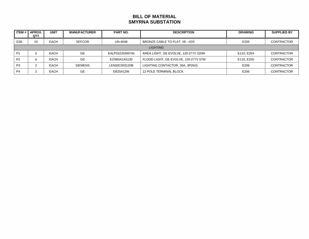
BILL OF MATERIAL SMYRNA SUBSTATION
ITEM # APROX.
QTY UNIT MANUFACTURER PART NO. DESCRIPTION DRAWING SUPPLIED BY
G39 10 EACH SEFCOR UN-4048 BRONZE CABLE TO FLAT, #8 - #2/0 E205 CONTRACTOR
LIGHTING
P1 5 EACH GE EALP010J5SM740 AREA LIGHT, GE EVOLVE, 120-277V 220W E110, E204 CONTRACTOR
P2 6 EACH GE E2SB0A1A5130 FLOOD LIGHT, GE EVOLVE, 120-277V 57W E110, E205 CONTRACTOR
P3 2 EACH SIEMENS LEN00C003120B LIGHTING CONTACTOR, 30A, 3P(NO) E206 CONTRACTOR
P4 2 EACH GE EB25A12W 12 POLE TERMINAL BLOCK E206 CONTRACTOR
Utilities Commission City of New Smyrna Beach Smyrna Substation October 2018
MATERIAL DELIVERY, STORAGE & HANDLING 16050.1-2
END OF SECTION
Utilities Commission City of New Smyrna Beach Smyrna Substation October 2018 Substation Expansion Project New Smyrna Beach, FL
GROUNDING AND BONDING 16060 - 1
SPECIFICATION SECTION 16060
GROUNDING AND BONDING
PART 1 GENERAL
1.1 SUMMARY
A. Provide a single, complete, electrically continuous grounding system. 1. Provide grounding system to provide ground resistance less than 5 ohms.
2. Provide appurtenances as specified and as shown on the contract documents.
1.2 QUALITY ASSURANCE
A. Provide components that are the standard product of a manufacturer regularly engaged in the production of the required materials and equipment. 1. The manufacturer shall be responsible for the design, construction, and proper
operation of all components.
B. Comply with applicable standards including, but not limited to the most recent edition of the following: 1. American National Standards Institute (ANSI): C2, National Electric Safety
Code.
2. National Fire Protection Association (NFPA): 70, National Electrical Code (NEC).
C. Design to provide satisfactory performance under the specified operating conditions.
1.3 SUBMITTALS
A. Submit the following in accordance with Section 01330, Submittal Procedures. 1. Product data.
2. Conductor routing and connection diagrams.
PART 2 PRODUCTS
2.1 MANUFACTURERS
A. Ground Rods:
Utilities Commission City of New Smyrna Beach Smyrna Substation October 2018
GROUNDING AND BONDING 16060 - 2
1. Erico Products Inc.
2. Copperweld Corporation.
3. ITT Blackburn Company.
4. Or equal.
B. Exothermic Welding: 1. Erico Products Inc.
2. American Brass Mfg. Co.
3. Burndy Corporation; Therm-O-Weld.
4. Or equal.
C. Swaged 1. AFL
2. DMC Power
D. Connecting Hardware: 1. American Brass Mfg. Co.
2. Anderson Electric Corp.
3. Burndy Corporation.
4. O.Z./Gedney, Division of General Signal Corporation.
5. Sefcor.
6. Or equal.
2.2 CONDUCTORS
A. Provide grounding conductors to comply with the following: 1. Cables or Wire:
a. Class A bare or insulated copper.
b. Sizes as indicated on the drawings and specified herein or as required by the NEC, whichever is larger.
Utilities Commission City of New Smyrna Beach Smyrna Substation October 2018
GROUNDING AND BONDING 16060 - 3
c. All conductors protected from physical damage resulting from exposure.
2. Main grounding conductors, grounding electrode conductors and main bonding jumpers: a. No smaller than No. 4/0 stranded copperclad cable. b. Use copperclad steel cable
c. With no less 19 strands in the cable unless otherwise stated on drawings.
3. Furnish bare conductors where buried in earth or where embedded in concrete.
4. In buildings run insulated grounding conductors with green insulation only.
5. Insulated grounding conductors having insulation rated at 600 volts.
6. Furnish grounding conductors for installation in all non-metallic raceway in
addition to, and not to be considered as, the neutral wire of the systems.
2.3 CONNECTIONS
A. Provide grounding connections as follows: 1. Make all buried and concealed ground connections by exothermic welding or
swaged compression. Standard compression connections are NOT allowed.
2. Make accessible connections to structural members by bolted connections to structure grounding plates.
3. For connections to equipment or ground bus, use acceptable bolted connectors suitable for and matching with grounding provisions furnished.
4. Use all clamps, connectors, lugs of copper alloy.
5. Ground Clamps: Multi-bolt type, saddle clamp on compression type, assembled with Everdur silicon bronze.
6. Apply grounding bushings on both ends of conduit run and intermediate enclosures.
2.4 GROUND RODS
A. Provide ground rods as below: 1. Copper clad steel.
2. 5/8-inch in diameter.
Utilities Commission City of New Smyrna Beach Smyrna Substation October 2018
GROUNDING AND BONDING 16060 - 4
3. 8 feet long - made up of three 8-foot lengths coupled together with bronze couplings, as required to provide ground resistance of 5 ohms or less.
B. Provide rolled scar-resisting surface, with both ends of the rod receiving the same heavy coating of copper as the body of the rod.
C. The end of the driving rod chamfered and the point machined smooth to aid in driving.
PART 3 EXECUTION
3.1 INSTALLATION
A. Install grounding conductors as follows: 1. Prevent from exposure to physical damage.
a. Install connections firm and tight.
b. Arrange conductors and connectors to avoid strain on connections.
2. Bury equipment grounding conductors 18 inches deep.
a. Bring loops or taps up for connections to equipment or other items to be
grounded.
3. Install all grounding conductors in conduit except the grounding electrode conductor or where shown otherwise.
4. Connect building steel to the station ground system using bonding cable with exothermic welds.
5. Comply with following: a. Install loop type, low impedance, grounding system.
b. Interconnect all components to provide at least two ground connections
for each major item of electrical equipment.
c. Ensure that severing of any single grounding conductors in this system does not remove grounding protection on any major item.
6. Perform exothermic welding with properly sized molds in good conditions.
B. Install ground rods as follows: 1. Provide ground rods as shown on the Substation Grounding Plan.
Utilities Commission City of New Smyrna Beach Smyrna Substation October 2018
GROUNDING AND BONDING 16060 - 5
2. Provide ground rods at manholes, substations and buildings whether indicated on drawings or not.
3. Make connection to overall grounding system as indicated.
4. Ensure that final resistance of interconnected ground system is 5 ohms, or less. Measure ground resistance in normally dry conditions and not less than 48 hours after rainfall.
C. Equipment Grounding 1. Ground all low voltage electrical equipment by means of a grounding conductor
installed in raceway feeding that equipment.
2. Use copper wire sized in accordance with NEC.
3. Grounding conductors installed in conduit, having green, 600-volt insulation.
a. Connect transformer cases and neutrals to grounding system.
b. Connect neutral ground connection at transformer terminal as shown on drawings.
c. Provide two separate, independent, diagonally opposite, connections for
power transformers so removal of one connection will not impair continuity of other unless otherwise stated.
4. Provide connections as follows: a. Connect two separate ground connections from ground grid to ground
bus of switchgear spot network assemblies and all outdoors substation equipment.
b. Each connection for item of equipment, from different section of ground grid.
5. Scrape bolted surfaces clean and coat with oxide-resistant conductive compound.
6. Ground all conduit and armored cables leaving the service equipment, spot network and/or motor control centers, to the service equipment spot network and/or motor control center ground bus.
7. Provide grounding for lighting standard as follows:
a. Drive a ground rod near base of standard, in accordance with requirements of National Electrical Safety Code.
Utilities Commission City of New Smyrna Beach Smyrna Substation October 2018
GROUNDING AND BONDING 16060 - 6
b. Connect ground rods to grounding conductor brought with street lighting feeder cable.
8. Ensure that suitable separate ground conductor connects lightning arresters with system ground. Where lightning arresters are furnished with electrical equipment and ground connections are not inherently provided.
9. Ground wire fences when used to enclose electrical equipment.
a. Unless otherwise indicated, provide grounding at a minimum. 1) Buried outside peripheral ground loop.
2) Connections from each corner fence post and pull post to nearby
ground conductor/rod.
3) Flexible connections to each gate.
4) Connections from ground grid to fence fabric and each strand of barbed wire every 50 linear feet along fence line.
5) At least two connections to grounding system from approximately opposite positions of fence.
6) Attach each pull post to ground grid.
10. Also connect the ground rods to the grounding conductor run with the direct burial cable.
D. Instrumentation Grounding 1. Install separate main ground conductors for all dc and instrumentation panels and
instruments.
2. Connect dc and instrumentation grounds to the main station grounding system at a properly selected point as shown on the Drawings or as recommended by the instrumentation supplier.
3. Provide ground connection for shielded cable at one location only, in accordance with the recommendation of the instrumentation manufacturer/supplier.
3.2 FIELD QUALIY CONTROL AND TESTING
A. Contractor shall retain the services of a NETA certified independent testing agency to perform all final testing per the NETA Acceptance Testing Standard (ANSI/NETA ATS-2013). Record the results of all testing and provide a final report to the Owner for review. 1. Correct defects and failures to Engineer’s acceptance.
Utilities Commission City of New Smyrna Beach Smyrna Substation October 2018
GROUNDING AND BONDING 16060 - 7
B. Inspect exposed Connections for: 1. Proper lug type for conductor material.
2. Proper lug installation.
3. Proper Exothermic welds installation.
C. Before underground or embedded connections are covered, they shall be physically inspected to insure tightness and continuity.
D. Perform a substation ground grid resistance to remote earth test using the three-point method. 1. Submit a report to the Engineer including a description of the test setup and the
test results.
2. Measure ground resistance no fewer than two full days after last trace of precipitation and without soil being moistened by any means other than natural drainage or seepage and without chemical treatment or other artificial means of reducing natural ground resistance.
E. Utilizing the two-point method, measure between each piece of equipment and a known low impedance ground grid node. 1. Any ground connection exhibiting greater than 0.02 ohms to the grid shall be
reworked. All other exposed metal items such as handrails shall measure less than 0.05 ohms to ground.
F. Perform continuity test of ground conductors
G. Repair and correct any deficiencies found during testing or at the direction of the Engineer.
END OF SECTION
Utilities Commission City of New Smyrna Beach Smyrna Substation October 2018 Substation Expansion Project New Smyrna Beach, FL
HANGERS AND SUPPORTS 16070 - 1
SPECIFICATION SECTION 16070
HANGERS AND SUPPORTS
PART 1 GENERAL
1.1 SUMMARY
A. This Section includes the following: 1. Hangers and supports for electrical equipment and systems.
2. Construction requirements for concrete bases.
1.2 DEFINITIONS
A. EMT: Electrical metallic tubing.
B. IMC: Intermediate metal conduit.
C. RMC: Rigid metal conduit.
1.3 PERFORMANCE REQUIREMENTS
A. Design supports for multiple raceways capable of supporting combined weight of supported systems and its contents.
B. Design equipment supports capable of supporting combined operating weight of supported equipment and connected systems and components.
C. Rated Strength: Adequate in tension, shear, and pullout force to resist maximum loads calculated or imposed for this Project, with a minimum structural safety factor of 5 times the applied force.
1.4 SUBMITTALS
A. Product Data: For the following: 1. Steel slotted support systems.
2. Nonmetallic slotted support systems.
B. Shop Drawings: Show fabrication and installation details and include calculations for the following: 1. Trapeze hangers. Include Product Data for components.
Utilities Commission City of New Smyrna Beach Smyrna Substation October 2018
HANGERS AND SUPPORTS 16070 - 2
2. Steel slotted channel systems. Include Product Data for components.
3. Nonmetallic slotted channel systems. Include Product Data for components.
4. Equipment supports.
1.5 QUALITY ASSURANCE
A. Welding: Qualify procedures and personnel according to AWS D1.1/D1.1M, "Structural Welding Code - Steel."
B. Comply with NFPA 70.
1.6 COORDINATION
A. Coordinate size and location of concrete bases. Cast anchor-bolt inserts into bases. Concrete, reinforcement, and formwork requirements are specified together with concrete Specifications.
PART 2 PRODUCTS
2.1 SUPPORT, ANCHORAGE, AND ATTACHMENT COMPONENTS
A. Steel Slotted Support Systems: Comply with MFMA-4, factory-fabricated components for field assembly. 1. Available Manufacturers: Subject to compliance with requirements,
manufacturers offering products that may be incorporated into the Work include, but are not limited to, the following: a. Allied Tube & Conduit.
b. Cooper B-Line, Inc.; a division of Cooper Industries.
c. ERICO International Corporation.
d. GS Metals Corp.
e. Thomas & Betts Corporation.
f. Unistrut; Tyco International, Ltd.
2. Metallic Coatings: Hot-dip galvanized after fabrication and applied according to
MFMA-4.
3. Painted Coatings: Manufacturer's standard painted coating applied according to MFMA-4.
4. Channel Dimensions: Selected for applicable load criteria.
Utilities Commission City of New Smyrna Beach Smyrna Substation October 2018
HANGERS AND SUPPORTS 16070 - 3
B. Raceway and Cable Supports: As described in NECA 1 and NECA 101.
C. Conduit and Cable Support Devices: Steel and malleable-iron hangers, clamps, and associated fittings, designed for types and sizes of raceway or cable to be supported.
D. Structural Steel for Fabricated Supports and Restraints: ASTM A 36/A 36M, steel plates, shapes, and bars; black and galvanized.
E. Mounting, Anchoring, and Attachment Components: Items for fastening electrical items or their supports to building surfaces include the following: 1. Powder-Actuated Fasteners: Threaded-steel stud, for use in hardened portland
cement concrete, steel, or wood, with tension, shear, and pullout capacities appropriate for supported loads and building materials where used. a. Available Manufacturers: Subject to compliance with requirements,
manufacturers offering products that may be incorporated into the Work include, but are not limited to, the following: 1) Hilti Inc.
2) ITW Ramset/Red Head; a division of Illinois Tool Works, Inc.
3) MKT Fastening, LLC.
4) Simpson Strong-Tie Co., Inc.; Masterset Fastening Systems
Unit.
2. Mechanical-Expansion Anchors: Insert-wedge-type, zinc-coated steel, for use in hardened portland cement concrete with tension, shear, and pullout capacities appropriate for supported loads and building materials in which used. a. Available Manufacturers: Subject to compliance with requirements,
manufacturers offering products that may be incorporated into the Work include, but are not limited to, the following: 1) Cooper B-Line, Inc.; a division of Cooper Industries.
2) Empire Tool and Manufacturing Co., Inc.
3) Hilti Inc.
4) ITW Ramset/Red Head; a division of Illinois Tool Works, Inc.
5) MKT Fastening, LLC.
3. Concrete Inserts: Steel or malleable-iron, slotted support system units similar to
MSS Type 18; complying with MFMA-4 or MSS SP-58.
Utilities Commission City of New Smyrna Beach Smyrna Substation October 2018
HANGERS AND SUPPORTS 16070 - 4
4. Clamps for Attachment to Steel Structural Elements: MSS SP-58, type suitable
for attached structural element.
5. Through Bolts: Structural type, hex head, and high strength. Comply with ASTM A 325.
6. Toggle Bolts: All-steel springhead type.
7. Hanger Rods: Threaded steel.
2.2 FABRICATED METAL EQUIPMENT SUPPORT ASSEMBLIES
A. Description: Welded or bolted, structural-steel shapes, shop or field fabricated to fit dimensions of supported equipment.
PART 3 EXECUTION
3.1 APPLICATION
A. Comply with NECA 1 and NECA 101 for application of hangers and supports for electrical equipment and systems except if requirements in this Section are stricter.
B. Maximum Support Spacing and Minimum Hanger Rod Size for Raceway: Space supports for EMT, IMC, and RMC as scheduled in NECA 1, where its Table 1 lists maximum spacings less than stated in NFPA 70. Minimum rod size shall be 1/4 inch in diameter.
C. Multiple Raceways or Cables: Install trapeze-type supports fabricated with steel slotted support system, sized so capacity can be increased by at least 25 percent in future without exceeding specified design load limits.
3.2 SUPPORT INSTALLATION
A. Comply with NECA 1 and NECA 101 for installation requirements except as specified in this Article.
B. Raceway Support Methods: In addition to methods described in NECA 1, conduits may be supported by openings through structure members, as permitted in NFPA 70.
C. Strength of Support Assemblies: Where not indicated, select sizes of components so strength will be adequate to carry present and future static loads within specified loading limits. Minimum static design load used for strength determination shall be weight of supported components plus 200 lb.
D. Mounting and Anchorage of Surface-Mounted Equipment and Components: Anchor and fasten electrical items and their supports to building structural elements by the following methods unless otherwise indicated by code:
Utilities Commission City of New Smyrna Beach Smyrna Substation October 2018
HANGERS AND SUPPORTS 16070 - 5
1. To Wood: Fasten with lag screws or through bolts.
2. To New Concrete: Bolt to concrete inserts.
3. To Masonry: Approved toggle-type bolts on hollow masonry units and expansion anchor fasteners on solid masonry units.
4. To Existing Concrete: Expansion anchor fasteners.
5. Instead of expansion anchors, powder-actuated driven threaded studs provided with lock washers and nuts may be used in existing standard-weight concrete 4 inches thick or greater. Do not use for anchorage to lightweight-aggregate concrete or for slabs less than 4 inches thick.
6. To Steel: Beam clamps (MSS Type 19, 21, 23, 25, or 27) complying with MSS SP-69.
7. To Light Steel: Sheet metal screws.
8. Items Mounted on Hollow Walls and Nonstructural Building Surfaces: Mount cabinets, panelboards, disconnect switches, control enclosures, pull and junction boxes, transformers, and other devices on slotted-channel racks attached to substrate by means that meet seismic-restraint strength and anchorage requirements.
E. Drill holes for expansion anchors in concrete at locations and to depths that avoid reinforcing bars.
3.3 INSTALLATION OF FABRICATED METAL SUPPORTS
A. Cut, fit, and place miscellaneous metal supports accurately in location, alignment, and elevation to support and anchor electrical materials and equipment.
B. Field Welding: Comply with AWS D1.1/D1.1M.
3.4 CONCRETE BASES
A. Construct concrete bases of dimensions indicated but not less than 4 inches larger in both directions than supported unit, and so anchors will be a minimum of 10 bolt diameters from edge of the base.
B. Use 4000-psi 28-day compressive-strength concrete. Concrete materials, reinforcement, and placement requirements are specified in Section 03300 "Cast-in-Place Concrete". Anchor equipment to concrete base. 1. Place and secure anchorage devices. Use supported equipment manufacturer's
setting drawings, templates, diagrams, instructions, and directions furnished with items to be embedded.
Utilities Commission City of New Smyrna Beach Smyrna Substation October 2018
HANGERS AND SUPPORTS 16070 - 6
2. Install anchor bolts to elevations required for proper attachment to supported equipment.
3. Install anchor bolts according to anchor-bolt manufacturer's written instructions.
3.5 PAINTING
A. Touchup: Clean field welds and abraded areas of shop paint. Paint exposed areas immediately after erecting hangers and supports. Use same materials as used for shop painting. Comply with SSPC-PA 1 requirements for touching up field-painted surfaces. 1. Apply paint by brush or spray to provide minimum dry film thickness of 2.0 mils.
B. Galvanized Surfaces: Clean welds, bolted connections, and abraded areas and apply galvanizing-repair paint to comply with ASTM A 780.
3.6 CONTRACTOR QUALITY CONTROL
A. General: Components and installation shall comply with NFPA 70 "National Electrical Code."
B. Inspections: Perform the following inspections: 1. Verify that all hangers and supports are properly applied in accordance with this
specification section.
2. Verify the all hangers and supports are properly installed in accordance with this specification section.
3. Verify that hangers and supports are properly cleaned and that finishes are painted or repaired in accordance with this specification section.
C. Reports: Maintain a written record of observations, report defective materials and workmanship, and reinspect corrected defective items. Submit written reports to the Owner.
END OF SECTION
Utilities Commission City of New Smyrna Beach Smyrna Substation October 2018 Substation Expansion Project New Smyrna Beach, FL
ELECTRICAL IDENTIFICATION 16075 - 1
SPECIFICATION SECTION 16075
ELECTRICAL IDENTIFICATION
PART 1 GENERAL
1.1 SUMMARY
A. Provide electrical identification products and components for identification of electrical materials, equipment and installation, including but not limited to the following: 1. Buried electrical line warnings.
2. Conduits, raceways, cables, and conductors.
3. Electrical manhole and handhole covers.
4. Operational instruction signs.
5. Warning and caution signs.
6. Equipment labels and signs.
1.2 QUALITY ASSURANCE
A. Comply with applicable portions of Section 16050, Basic Electrical Materials and Methods.
B. Provide components that are the standard product of a manufacturer regularly engaged in the product of the required materials and equipment.
C. Comply with applicable codes and standards including, but not limited to the most recent edition of the following. 1. American National Standards Institute (ANSI): A13.1, Scheme for the
Identification of Piping Systems, with regard to type and size of lettering for raceway and cable labels.
2. National Fire Protection Association (NFPA): 70, National Electrical Code (NEC).
D. Design to provide satisfactory performance under the specified operating conditions.
1.3 SUBMITTALS
A. Submit the following in accordance with Section 01330, Submittal Procedures. 1. Product data.
Utilities Commission City of New Smyrna Beach Smyrna Substation October 2018
ELECTRICAL IDENTIFICATION 16075 - 2
2. Schedule of identification nomenclature to be used for identification signs and labels.
3. Samples of each color, lettering style, and other graphic representation required
for identification materials; samples of labels and signs.
PART 2 PRODUCTS
2.1 ELECTRICAL IDENTIFICATION PRODUCTS
A. Provide Adhesive Marking Labels for Raceway and Metal-Clad Cable: 1. Pre-printed.
2. Flexible.
3. Self-adhesive labels with legend indicating voltage and service (emergency,
lighting, power, light, power dc, air conditioning, communications, control, and fire).
B. Colored Adhesive Marking Tape for Raceways, Wires, and Cables: Provide self-adhesive vinyl tape not less than 3 mils thick by 1 inch to 2 inches in width.
C. Pre-tensioned Flexible Wraparound Colored Plastic Sleeves for Raceway and Cable Identification: Provide flexible acrylic band, sized to suit the raceway diameter and arranged to stay in place by pre-tensioned gripping action when coiled around the raceway or cable.
D. Underground Line Marking Tape: 1. Provide permanent, bright-colored, continuous-printed, plastic tape compounded
for direct-burial service not less than 6 inches wide by 4 mils thick.
2. Provide printed legend, indicative of general type of underground line below.
E. Wire/Cable Designation Tape Markers: Provide vinyl or vinyl-cloth, self-adhesive, wraparound, cable/conductor markers with preprinted numbers and letters.
F. Aluminum, Wraparound, Cable Marker Bands: 1. Provide bands cut from 0.014-inch thick, aluminum sheet, fitted with slots or ears
for securing permanently around wire or cable jacks or around groups of conductors.
2. Make arrangement for applying legend with stamped letters or numbers.
G. Plasticized Card Stock Tags:
Utilities Commission City of New Smyrna Beach Smyrna Substation October 2018
ELECTRICAL IDENTIFICATION 16075 - 3
1. Provide vinyl cloth with preprinted and field-printed legends to suit the application.
2. Use orange background, except as otherwise indicated, with eyelet for fastener.
H. Brass or Stainless Steel Tags: 1. Provide metal tags with stamped legend punched for fastener.
2. Dimensions: 2 inches by 2 inches by 19 gauge.
I. Engraved, Plastic-Laminated Labels, Signs, and Instruction Plates: 1. Provide engraving stock melamine plastic laminate, 1/16-inch minimum thick for
signs up to 20 square inches, or 8 inches in length; 1/8-inch thick for larger sizes.
2. Provide engraved legend in white letters on black face and punched for mechanical fasteners.
J. Baked-Enamel Warning and Caution Signs for Interior Use: Provide preprinted aluminum signs, punched for fasteners, with colors, legend, and size appropriate to the location.
K. Fasteners for Plastic-Laminated and Metal Signs: Provide self-tapping stainless steel screws or number 10/32 stainless steel machine screws with nuts and flat and lock washers.
L. Cable Ties: 1. Provide fungus-inert, self-extinguishing, one-piece, self-locking nylon cable ties,
0.18-inch minimum width, 50-pound minimum tensile strength, and suitable for a temperature range from minus 50 to 350 degrees F.
2. Provide ties of specified colors when used for color coding.
PART 3 EXECUTION
3.1 INSTALLATION
A. Lettering and Graphics: 1. Coordinate names, abbreviations, colors, and other designations used in electrical
identification work with corresponding designations specified or indicated.
2. Install numbers, lettering, and colors as approved in submittals and as required by code and according to applicable portions of Section 16050 Basic Electrical requirements
B. Install identification devices in accordance with manufacturer’s written instructions and requirements of NEC.
Utilities Commission City of New Smyrna Beach Smyrna Substation October 2018
ELECTRICAL IDENTIFICATION 16075 - 4
C. Sequence of Work: Where identification is to be applied to surfaces that require finish, install identification after completion of finish work.
D. Conduit Identification. 1. Identify Raceways of Certain Systems with Color Banding:
a. Provide bands for exposed or accessible raceways for identification.
b. Provide pre-tensioned bands, snap-around colored plastic sleeves,
colored adhesive marking tape, or a combination of the two.
c. Make each color band 2 inches wide, completely encircling conduit, and place adjacent bands of two-color markings in contact, side by side.
d. Install bands at changes in direction, at penetrations of walls and floors,
and at 40-foot maximum intervals in straight runs.
E. Identify Junction, Pull, and Connection Boxes 1. Provide code-required caution sign for boxes, with pressure-sensitive, self-
adhesive type label, indicating system voltage in black, preprinted on orange background. a. Install label on outside of box cover.
b. Label box covers with identity of contained circuits.
c. Use pressure-sensitive plastic labels at exposed locations.
d. Provide similar labels or plasticized card stock tags at concealed boxes.
F. Underground Electrical Line Identification: 1. During trench backfilling, for exterior underground power, signal, and
communications lines, install continuous underground plastic line marker, located directly above line at 6 to 8 inches below finished grade.
2. Where multiple lines are installed in a common trench or concrete envelope, do not exceed an overall width of 16 inches; install a single line marker.
G. Electrical Manholes and Handholes: 1. Provide identification on all new electrical manhole and handhole covers.
2. Identification shall consist of metal tags with stamped legend punched for
fastener. Dimensions shall be 2 inches by 2 inches by 19 gauge.
H. High Voltage Overhead Bus:
Utilities Commission City of New Smyrna Beach Smyrna Substation October 2018
ELECTRICAL IDENTIFICATION 16075 - 5
1. Provide phase identification at each disconnect switch and support structure.
Identification shall be mounted to the grounded steel structure directly underneath the high voltage bus being identified.
2. Identification shall consist of 4”x4” non-reflective, non-corrosive phase markers.
a. Markers shall denote A, B or C phase and clearly legible from ground level.
b. Markers shall attach to the structures using solid mounting hardware or wire ties. Adhesive attachment is not acceptable.
I. Install line marker for underground wiring, both direct-buried and in raceways.
J. Use conductors with factory-applied color on the entire length of the conductors except as follows: 1. Use following field-applied color-coding methods in lieu of factory-coded wire
for sizes larger than No. 10 AWG. a. Apply colored, pressure-sensitive plastic tape.
1) Provide half-lapped turns for a distance of 6 inches from
terminal points and in boxes where splices or taps are made.
2) Apply the last two laps of tape with no tension to prevent possible unwinding.
3) Use 1-inch-wide tape in colors as specified.
4) Do not obliterate cable identification markings by taping.
5) Adjust tape locations slightly to prevent obliteration.
b. Use of colored cable ties in lieu of pressure-sensitive tape.
1) Apply three ties of specified color to each wire at each terminal
or splice point starting 3 inches from the terminal and spaced 3 inches apart.
2) Apply with a special tool or pliers, tighten for snug fit, and cut off excess length.
2. Power Circuit Identification:
Utilities Commission City of New Smyrna Beach Smyrna Substation October 2018
ELECTRICAL IDENTIFICATION 16075 - 6
a. Securely fasten identifying metal tags or aluminum wraparound marker bands to cables, feeders, and power circuits in vaults, pull boxes, junction boxes, manholes, and switchboard rooms.
b. Use 1/4-inch steel letter and number stamps with legend to correspond with designations on drawings.
c. Where metal tags are provided, attach them with approximately
55-pound test monofilament line or one-piece self-locking nylon cable ties.
K. Tag or label conductors as follows. 1. Future connections: Indicate cable for future connection or connection under
another contract, with identification indicating source and circuit numbers.
2. Multiple Circuits: Where multiple branch circuits or control wiring or communications/signal conductors are present in the same box or enclosure (except for three-circuit, four-wire home runs):
a. Label each conductor or cable.
b. Provide legend indicating source, voltage, circuit number, and phase for
branch circuit wiring.
c. Indicate phase and voltage of branch circuit wiring by means of coded color of conductor insulation.
d. For control and communications/signal wiring, use color coding or wire/
cable marking tape at terminations and at intermediate locations where conductors appear in wiring boxes, troughs, and control cabinets.
e. Use consistent letter/ number conductor designations throughout on wire/
cable marking tapes.
3. Match identification markings with designation used in panelboards shop drawings, Contract Documents, and similar previously established identification schemes for the facility’s electrical installations.
L. Apply warning, caution, and instruction signs and stencils as follows: 1. Install warning, caution, or instruction signs where required by NEC, where
indicated, or where reasonably required to assure safe operation and maintenance of electrical systems and of the items to which they connect.
2. Install engraved plastic-laminated instruction signs with approved legend where instructions or explanations are needed for system or equipment operation.
Utilities Commission City of New Smyrna Beach Smyrna Substation October 2018
ELECTRICAL IDENTIFICATION 16075 - 7
3. Install butyrate signs with metal backing for outdoor items.
4. Emergency Operating Signs: Install engraved laminate signs with white legend on red background with minimum 3/8-inch high lettering for emergency instructions on power transfer, load shedding, or other emergency operations.
M. Install equipment/system circuit/device identification as follows: 1. Apply equipment identification labels of engraved plastic-laminate on each major
unit of electrical equipment in building, including central or master unit of each electrical system. This includes communication/signal/alarm systems, unless unit is specified with its own self-explanatory identification.
2. Except as otherwise indicated, provide single line of text, with 1/2-inch-high lettering on 1-1/2-inch-high label (1-inch-high where two lines are required), white lettering in black field.
3. Text shall match terminology and numbering of the Contract Documents and shop drawings.
4. Apply labels for each unit of the following categories of electrical equipment.
a. Panelboards, electrical cabinets, and enclosures. b. Access doors and panels for concealed electrical items.
c. Circuit Breakers.
d. Circuit Switchers
e. High voltage disconnect switches.
f. Control devices.
g. Transformers.
N. Apply circuit/control/item designation labels of engraved plastic laminate for disconnect switches, breakers, pushbuttons, pilot lights, motor control centers, and similar items for power distribution and control components above, except panelboards and alarm/signal components, where labeling is specified elsewhere.
O. For panelboards, provide framed, typed circuit schedules with explicit description and identification of items controlled by each individual breaker.
P. Install labels at locations indicated and at locations for best convenience of viewing without interference with operation and maintenance of equipment.
Utilities Commission City of New Smyrna Beach Smyrna Substation October 2018
ELECTRICAL IDENTIFICATION 16075 - 8
END OF SECTION
Utilities Commission City of New Smyrna Beach Smyrna Substation October 2018 Substation Expansion Project New Smyrna Beach, FL
SPECIFICATION SECTION 16120
LOW VOLTAGE CONDUCTORS AND CABLES
PART 1 GENERAL
1.1 SUMMARY
A. Provide all wires and cables as indicated on drawings and as specified herein, for a complete electrical system.
1.2 QUALITY ASSURANCE
A. Comply with applicable portions of Section 16050 Basic Electrical Materials and Methods.
B. Provide components that are the standard product of a manufacturer regularly engaged in the production of the required materials and equipment. 1. The manufacturer shall be responsible for the design, construction and proper
operation of all components.
C. Comply with applicable standards, codes and regulations including but not limited to the most recent edition of the following: 1. Association of Edison Illuminating Companies (AEIC).
2. ASTM International (ASTM):
a. B3, Soft or Annealed Copper Wire.
b. B8, Concentric-Lay-Stranded Copper Conductors, Hard, Medium-Hard
or Soft.
c. B29, Refined Lead.
d. B33, Tinned Soft or Annealed Copper Wire for Electrical Purposes.
3. Insulated Cable Engineers Association, Inc. (ICEA):
a. S-19-81, Rubber-Insulated Wire and Cable.
b. S-61-402, Thermoplastic-Insulated Wire and Cable.
c. S-66-524, Cross-linked Thermosetting Polyethylene-Insulated Wire and Cable.
Utilities Commission City of New Smyrna Beach Smyrna Substation October 2018
LOW VOLTAGE CONDUCTORS AND CABLES 16120 - 2
d. S-68-516, Ethylene-Propylene-Rubber Insulated Wire and Cable.
4. National Electrical Manufacturer’s Association (NEMA):
a. W 3, Rubber Insulated Wire and Cable.
b. WC 5, Thermoplastic Insulated Wire and Cable.
c. WC 7, Cross-Linked-Thermosetting Polyethylene-Insulated Wire and
Cable.
d. WC 30, Color Coding of Wires and Cable.
5. National Fire Protection Association (NFPA) 70, National Electrical Code (NEC).
6. Underwriters Laboratory Inc. (UL):
a. UL 44, Wires and Cables Rubber/Thermoset Insulated.
b. UL 83, Wires Thermoplastic Insulated.
c. UL 854, Cables, Service Entrance.
d. UL 1277, Tray Cable.
e. UL 1581/IEEE 383, Vertical Tray 70,000 BTU Flame Test.
7. National Electrical Safety Code.
1.3 SUBMITTALS
A. Submit the following in accordance with Section 01330, Submittal Procedures. 1. Product data.
2. Drawings.
PART 2 PRODUCTS
2.1 MATERIALS
A. 600V Cable for Low Voltage Power Circuits: 1. Southwire Company.
2. Belden Corporation.
Utilities Commission City of New Smyrna Beach Smyrna Substation October 2018
LOW VOLTAGE CONDUCTORS AND CABLES 16120 - 3
3. Prysmian Cable Systems.
B. Control and Metering Wire: 1. Southwire Company.
2. Houston Wire and Cable.
3. Belden Corporation.
C. Instrumentation Cable: 1. Belden Company.
2. Okonite Corporation.
3. Houston Wire and Cable.
D. Ethernet Cable: 1. Houston Wire and Cable.
2. Belden Corporation.
3. Belkin International, Inc.
2.2 WIRES AND CABLES
A. Provide copper conductors unless otherwise indicated. Material and stranding of conductors shall conform to ASTM B33, ASTM B3, and to ASTM B8, for the appropriate class No. 12 AWG minimum wire size unless otherwise noted.
B. Tinned Wire used with Natural Rubber Insulation: Conforms to ASTM B33. Uncoated, soft or annealed copper wire conforms to ASTM B3.
C. All wire and cable shall be UL listed.
D. Conductor color coding shall be provided per the contract drawings.
E. Wires and Cables for Maximum 600-Volt Power Circuits: Type XHHW/XHHW-2 rated 600-volt, single conductor, stranded copper with XLP insulation and PVC or CPE jacket or equivalent.
F. Wires and Cables for panel interior control wiring and control wiring between panels: Type SIS, rated 600-volt single conductor.
G. Wires and Cables for Control, Indication, Signal and Alarm Circuits: Single and multi-conductor control cable, Class B or C stranding.
Utilities Commission City of New Smyrna Beach Smyrna Substation October 2018
LOW VOLTAGE CONDUCTORS AND CABLES 16120 - 4
1. Use Type XHHW/XHHW-2 insulation, 600-volt, abrasion, moisture, and heat resistant thermoset cross-linked polyethylene (XLP) insulation with PVC or CPE conductor jacket.
2. Multi-conductor cable to have sunlight resistant PVC jacket, rated flame retardant type TC for use in cable trays.
H. Analog wiring shall be shielded single pair, instrumentation cable designed for noise rejection for process control, computer, or data log applications and meeting NEMA WC 55 requirements. 1. Outer jacket shall be 45 mil nominal thickness.
2. Individual pair shield shall be 1.35 mil, double-faced aluminum/synthetic
polymer overlapped to provide 100 percent coverage.
3. Dimension shall be 0.31-inch nominal OD.
4. Conductors shall be:
a. Bare soft annealed copper, Class B, seven-strand concentric, meeting requirements of ASTM B8.
b. No. 20 AWG, 7-strand tinned copper drain wire
c. Insulation of 15 mil nominal PVC.
d. Jacket of 4 mil nominal nylon.
e. Pair conductors, color-code black and red.
5. Cables: Rated 600 volts and 90˚C. Flame retardant type TC rated for cable trays.
I. Copper Ethernet Cable for communication shall be CAT 6. Conductor shall be 23 AWG solid bare copper, color coded, to form 4-pair UTP.
PART 3 EXECUTION
3.1 INSTALLATION
A. Install wiring in accordance with applicable provisions of NEC, and as indicated.
B. Wire and cable sizes are indicated; however, in no case use smaller cable sizes than required by the NEC.
C. Unless otherwise indicated, use no conductor smaller than No. 12 AWG for power.
D. Use minimum size No. 12 AWG stranded wire for interior panel control wiring and control wiring between panels.
Utilities Commission City of New Smyrna Beach Smyrna Substation October 2018
LOW VOLTAGE CONDUCTORS AND CABLES 16120 - 5
E. Use minimum size No. 10 AWG stranded wire for control wiring to remote locations (circuit breakers, CCVTs, etc.).
F. Conductors for Branch Lighting Circuits: Install conductors of sizes such that greatest voltage drop between lighting panel and center of load will not exceed 2 percent at rated load.
G. Number and sizes of wires and conduits indicated are based upon selected standard components of electrical equipment. 1. Modifications approved by the Engineer may be made by the Contractor at his
expense to accommodate equipment actually purchased.
2. The basic sequence and method of control must be maintained as indicated on the drawings and specifications.
H. Install conductors continuous from outlet to outlet and make no splices except within outlet, junction, or terminal boxes.
I. Draw all conductors contained within single conduit at same time. Cut-off section subject to mechanical pulling means, provide maximum slack at all connection, pull, and terminal points.
J. Apply wire pulling compound as recommended by the cable manufacturer to conductors, if required.
K. Use no cable bend with radius of less than eight times its diameter.
L. Wires and cables installed without prior submittal review and Engineer’s approval are subject to removal at no additional expense to the Owner.
M. Support cables in riser raceways at intervals as required by NEC.
3.2 CONDUCTOR IDENTIFICATION
A. Label each wire at all termination points. Label to denote the terminal block designation of the remote end of the cable.
B. Identify each wire in junction boxes, cabinets, and terminal boxes where total number of control, indicating, and metering wires is three or more and no terminal board is provided, including all power wires, by means of plastic split-sleeve, no adhesive, wire marker.
C. In cases similar to above where terminal boards are provided for the control, indicating, and metering wires, identify all wires including motor leads and other power wires too large for connection to terminal boards, by wire markers as specified above.
D. Provide cable and wire identification in accordance 16075, Electrical Identification.
Utilities Commission City of New Smyrna Beach Smyrna Substation October 2018
LOW VOLTAGE CONDUCTORS AND CABLES 16120 - 6
3.3 CONNECTORS, TERMINAL LUGS AND BOARDS
A. Terminate all wires connected to terminal boards, terminal blocks, or to other similar terminals by means of ring tongue, nylon self-insulated, tin-plated copper pressure terminals.
B. Fabricated terminal boards, installed where indicated, of type 600 volts, 30 amperes, screw terminals, with white marking strips for wire identification, of the 4-, 6-, 8-, or 12-hole type, as necessary.
C. Clearly and permanently mark terminal strips with ink or indelible pencil. Mark each wire consistently throughout entire system, using notation of wires given on manufacturer’s wiring diagrams wherever possible.
3.4 FIELD QUALITY CONTROL
A. Contractor shall retain the services of a NETA certified independent testing agency to perform all final testing per the NETA Acceptance Testing Standard (ANSI/NETA ATS-2013). Record the results of all testing and provide a final report to the Owner for review. 1. Contractor shall correct all deficiencies found.
END OF SECTION
Utilities Commission City of New Smyrna Beach Smyrna Substation October 2018 Substation Expansion Project New Smyrna Beach, FL
RACEWAYS AND BOXES 16130 - 1
SPECIFICATION SECTION 16130
RACEWAYS AND BOXES
PART 1 GENERAL
1.1 SUMMARY
A. Provide junction boxes, pull boxes, metal wireways, covers and miscellaneous hardware as indicated, in accordance with the Contract Documents.
1.2 QUALITY ASSURANCE
A. Comply with applicable portions of Section 16050, Basic Electrical Materials and Methods
B. Provide components that are the standard product of a manufacturer regularly engaged in the production of the required materials and equipment. 1. The manufacturer shall be responsible for the design, construction and proper
operation of all components.
C. Comply with applicable codes and standards including, but not limited to the most recent edition of the following: 1. National Electrical Manufacturer’s Association (NEMA).
2. UL 886.
3. UL 698.
4. UL 508.
5. National Electrical Code (NEC).
6. National Electrical Safety Code (NESC)
D. Design to provide satisfactory performance under the specified operating conditions.
1.3 DEFINITIONS
A. GRC – Galvanized Rigid Conduit
1.4 SUBMITTALS
A. Submit the following in accordance with Section 01330, Submittal Procedures.
Utilities Commission City of New Smyrna Beach Smyrna Substation October 2018
RACEWAYS AND BOXES 16130 - 2
1. Product data.
2. Shop drawings.
3. Special shipping, storage, protection and handling instructions, if any.
4. Manufacturer’s installation instructions.
PART 2 PRODUCTS
2.1 MANUFACTURERS
A. Metal Conduits, Tubing and Fittings 1. AFL
2. Allied Tube & Conduit; a Tyco International Ltd. Co.
3. Anamet Electrical, Inc.
4. Electri-Flex Company.
5. O-Z/Gedney; a brand of EGS Electrical Group.
6. Or equal.
B. Outlet Boxes: 1. Steel City.
2. Appleton Electric Co.
3. Raco.
4. Carlon.
5. Or equal.
C. Pull and Junction Boxes: 1. JM Gillin Electrical Enclosures
2. Crouse-Hinds Co.
3. OZ Electrical Manufacturing Co.
4. Hoffman; a Pentair company.
5. Or equal.
Utilities Commission City of New Smyrna Beach Smyrna Substation October 2018
RACEWAYS AND BOXES 16130 - 3
D. Fittings: 1. Crouse-Hinds Co’
2. Appleton Electric Co.
3. Robroy Industries.
4. OZ Electrical Manufacturing Co.
5. Carlon.
6. Or equal.
E. Non-Metallic Conduit 1. Cantex
2. Or Equal
2.2 RACEWAY AND FITTINGS
A. General: 1. Minimum Size: 1 inch.
2. Fittings: Match material and design of raceway.
B. Raceways: 1. Rigid Steel, Heavy Wall, and Hot Dip Galvanized: UL-6 and ANSI C80.1.
a. PVC coated Rigid Steel: UL-6 and ANSI C80.1 steel and 40 mil bonded PVC jacket meeting requirements of NEMA RN-1 type A-40.
2. Electrical Metallic Tubing (EMT): UL-797 and ANSI C80.3.
3. Rigid Aluminum: UL-6 and ANSI C80.5.
4. Rigid Non-metallic: Schedule 40 PVC meeting requirements of UL-651 with solvent cement joints.
C. Fittings: 1. Material: Same material and finish as raceways and meeting requirements of
UL-514 and ANSI C80.4.
a. Use threaded connectors for rigid metal conduits.
Utilities Commission City of New Smyrna Beach Smyrna Substation October 2018
RACEWAYS AND BOXES 16130 - 4
2. Dry Areas: For enclosures, cabinets, and boxes, use nylon insulated bushing and lock nut.
3. Wet Areas: For enclosures, cabinets and boxes, use watertight hub fitting with gasket.
D. Raceway Supports: 1. Support raceway at intervals and at locations required by NEC.
a. Do not use perforated straps or plumber’s tape for conduit supports.
b. Independently support raceways from structure unless otherwise directed by Engineer.
c. Supports and hangers: Steel, hot dip galvanized after fabrication except for:
1) PVC coated supports: For PVC and PVC coated raceways.
2) Aluminum Supports: For use on aluminum raceways.
2. Fasteners for Concrete: Expansion bolts or inserts, toggle bolts for hollow masonry or frame construction, and preset inserts for prestressed concrete.
3. Surface supported Raceways: Use straps with holes for 1 or 2 fasteners and shaped to fit raceway size.
4. Supports at Structural Steel Members:
a. Hot dip galvanized beam clamps.
b. Drilling or welding: Following Drawings or with Engineer’s approval.
5. Suspended Raceways: Use galvanized hanger rods threaded minimum of 1-1/2 inches on each end to permit adjustment and of following sizes:
a. Raceways up to 2 inch diameter: Not less than 3/8 inch diameter.
b. Raceways larger than 2 inch diameter: 1/2 inch diameter rods.
6. Multiple Suspended Raceways: Horizontal channel not be less than 1-1/2 inches square by 12 gage
a. Weld 2 or more together when greater strength is required to limit deflection to 1/2000 of span.
b. Hanger for horizontal channel: Number and size of raceways supported following Drawings or if not shown, at Engineer’s direction.
Utilities Commission City of New Smyrna Beach Smyrna Substation October 2018
RACEWAYS AND BOXES 16130 - 5
E. Raceways Exposed: For walls below grade, in damp, wet, or corrosive locations use standoff brackets with minimum of 1/4 inch air space between raceway and mounting surface.
2.3 METAL CONDUITS, TUBING, AND FITTINGS
A. Listing and Labeling: Metal conduits, tubing, and fittings shall be listed and labeled as defined in NFPA 70, by a qualified testing agency, and marked for intended location and application.
B. GRC: Comply with ANSI C80.1 and UL 6.
C. Fittings for Metal Conduit: Comply with NEMA FB 1 and UL 514B.
D. Joint Compound for GRC: Approved, as defined in NFPA 70, by authorities having jurisdiction for use in conduit assemblies, and compounded for use to lubricate and protect threaded conduit joints from corrosion and to enhance their conductivity.
2.4 BOXES
A. Dry Areas: 1. Boxes meeting requirements of NEMA 12, steel. 1 piece boxes, galvanized sheet
steel knock-out type, minimum 4 inches square or octagonal and 1-1/2 inches deep with cover plates compatible for each box.
B. Damp and Wet Areas: 1. Boxes meeting requirements of NEMA 3R with threaded external hubs for
conduit entrance, same minimum size as boxes in dry areas.
2. Cover plates: Gasketed PVC coated with stainless steel hardware.
2.5 OUTLET BOXES
A. Provide outlet boxes for use with metal raceway as follows. 1. Galvanized case metal type.
2. With tapped hubs for conduit entrance.
3. Having galvanized cast metal covers with rubber gasket.
B. Provide non-metallic outlet boxes for use with concealed PVC raceway. Procure from same manufacturer as raceway.
C. Provide non-metallic single- and two-gang outlet boxes with integral mounting feet, for use with PVC raceway. Provide non-metallic blank covers with stainless steel mounting screws. Carlon FS or FD, or equal.
Utilities Commission City of New Smyrna Beach Smyrna Substation October 2018
RACEWAYS AND BOXES 16130 - 6
D. Provide PVC coated cast outlet boxes in hazardous areas (as defined by NEC), as follows
1. Suitable for Class, Division and Group location as indicated.
2. Conform to UL 886.
3. Bearing UL label as suitable for intended application.
2.6 PULL AND JUNCTION BOXES
A. Provide junction or pull boxes where indicated, and where required to facilitate wire pulling and connection.
B. Provide pull and junction boxes less than 100 cubic inches as specified for outlet boxes: 1. Flush NEMA 3R junction boxes – watertight outside flanged with recessed cover
type “YR” as manufactured by OZ/Gedney, or equal.
C. Provide pull and junction boxes 100 cubic inches and larger for use with PVC raceway, fabricated from PVC, or equal non-metallic product, and: 1. Equipped with screw cover unless otherwise noted.
2. Adequately support the boxes to maintain shape.
3. Provide NEMA 3R boxes with watertight gasketed covers and external mounting
feet.
D. Pull and junction boxes 100 cubic inches and larger installed in hazardous areas, as defined by NEC, shall be suitable for Class, Division and Group as indicated and comply with following: 1. Provide neoprene gasket.
2. Provide stainless steel hinges and natural stainless steel finish.
3. Confirming to UL 886 and bearing UL label as suitable for intended application.
E. Boxes shall be supported to maintain shape. Larger boxes shall be formed of structural bracing into rigid assembly to maintain alignment in shipment and installation
F. Provide drain fittings in NEMA 3R boxes. Crouse-Hinds, Type ECD 11, Killark No. KDB-1, or equal.
2.7 PAINTING
A. Clean and shop prime all non-galvanized, non-stainless steel metal surfaces in accordance with standard industry practice.
Utilities Commission City of New Smyrna Beach Smyrna Substation October 2018
RACEWAYS AND BOXES 16130 - 7
B. Use ANSI 61 light gray as the final exterior color for the pull boxes.
PART 3 EXECUTION
3.1 GENERAL
A. Size boxes in accordance with NEC, or as indicated.
B. Provide suitable box at outlets especially designed to receive type of fixtures and devices to be mounted thereon, except where otherwise noted for recessed fluorescent fixtures.
C. Provide fixture outlets with fixture supports of size and type required for fixture to be hung. Fixture studs, generally, shall be 3/8-inch.
D. Provide boxes of type approved for particular purpose intended.
E. Recessed wall outlet boxes shall be at least 4-inches square.
F. In finished areas, provide box covers to fit outlet box installed of required depth so that the edge of ring is flush with finished material.
3.2 INSTALLATION
A. Comply with NECA 1 and NECA 101 for installation requirements except where requirements on Drawings or in this article are stricter. Comply with NFPA 70 limitations for types of raceways allowed in specific occupancies and number of floors.
B. Keep raceways at least 6 inches away from parallel runs of flues and steam or hot-water pipes. Install horizontal raceway runs above water and steam piping.
C. Complete raceway installation before starting conductor installation.
D. Comply with requirements in Section 16070 “Hangers and Supports" for hangers and supports.
E. Arrange stub-ups so curved portions of bends are not visible above finished slab.
F. Install no more than the equivalent of three 90-degree bends in any conduit run except for control wiring conduits, for which fewer bends are allowed. Support within 12 inches of changes in direction.
G. Install conduits parallel or perpendicular to building lines.
H. Support conduit within 12 inches of enclosures to which attached.
I. Threaded Conduit Joints, Exposed to Wet, Damp, Corrosive, or Outdoor Conditions: Apply listed compound to threads of raceway and fittings before making up joints. Follow compound manufacturer's written instructions.
Utilities Commission City of New Smyrna Beach Smyrna Substation October 2018
RACEWAYS AND BOXES 16130 - 8
J. Raceway Terminations at Locations Subject to Moisture or Vibration: Use insulating bushings to protect conductors including conductors smaller than No. 4 AWG.
K. Terminate threaded conduits into threaded hubs or with locknuts on inside and outside of boxes or cabinets. Install bushings on conduits up to 1-1/4-inch trade size and insulated throat metal bushings on 1-1/2-inch trade size and larger conduits terminated with locknuts. Install insulated throat metal grounding bushings on service conduits.
L. Install raceways square to the enclosure and terminate at enclosures with locknuts. Install locknuts hand tight plus 1/4 turn more.
M. Do not rely on locknuts to penetrate nonconductive coatings on enclosures. Remove coatings in the locknut area prior to assembling conduit to enclosure to assure a continuous ground path.
N. Cut conduit perpendicular to the length. For conduits 2-inch trade size and larger, use roll cutter or a guide to make cut straight and perpendicular to the length.
O. Install pull wires in empty raceways. Use polypropylene or monofilament plastic line with not less than 800-lb tensile strength. Leave at least 12 inches of slack at each end of pull wire. Cap underground raceways designated as spare above grade alongside raceways in use.
P. Install devices to seal raceway interiors at accessible locations. Locate seals so no fittings or boxes are between the seal and the following changes of environments. Seal the interior of all raceways at the following points: 1. Where conduits pass from warm to cold locations, such as boundaries of
refrigerated spaces.
2. Where an underground raceway enters a building or structure.
3. Where otherwise required by NFPA 70.
Q. Fasten junction and pull boxes to or support from building structure. Do not support boxes by conduits.
R. Securely support each box at two or more points and two or more sides to prevent movement in all directions.
S. Use boxes to support devices and face plates. Do not use face plates and devices to support boxes.
T. Where box is concealed in stud wall, securely attach it to full depth stud (or section of stud) on each side of box.
U. Provide labels in accordance with Section 16075, Electrical Identification.
Utilities Commission City of New Smyrna Beach Smyrna Substation October 2018
RACEWAYS AND BOXES 16130 - 9
3.3 RACEWAY APPLICATION
A. Outdoors: Apply raceway products as specified below unless otherwise indicated: 1. Exposed Conduit: GRC
2. Concealed Conduit, Above ground: PVC (Cantex)
3. Concealed Conduit, Below ground: PVC (Cantex)
4. Boxes and Enclosures, Aboveground: NEMA 250, Type 4X, 316 stainless steel.
B. Indoors: Apply raceway products as specified below unless otherwise indicated: 1. Exposed Conduit: Aluminum
2. Boxes and Enclosures: NEMA 250, Type 1, except use NEMA 250, Type 4X in
damp or wet locations.
C. Minimum Raceway Size: 1 inch trade size.
D. Raceway Fittings: Compatible with raceways and suitable for use and location. 1. Rigid Steel Conduit: Use threaded rigid steel conduit fittings unless otherwise
indicated. Comply with NEMA FB 2.10.
2. Flexible Conduit: Use only fittings listed for use with flexible conduit. Comply with NEMA FB 2.20.
E. Do not install aluminum conduits, boxes, or fittings in direct contact with concrete or earth. Mounting on Concrete and Masonry Surfaces: Minimum of 1/4 inch standoff support. 1. Support and fasten conduit to building structural members using pipe straps, wall
brackets, hangers, or ceiling trapeze spaced following electrical codes.
2. Support conduit minimum 8 feet and within 3 feet of every box, panel, and enclosure.
F. Earth Buried Conduits: 1. Cover: Minimum 30 inches of cover and minimum 1 foot clearance between
other utility crossings and parallel runs for Low Voltage conduits.
2. Grade: Maintain grade of minimum 4 inches per 100 feet From 1 manhole or pull box to next or from high point between them.
3. Drain conduits away from building, or, if not possible, install watertight seal at building.
Utilities Commission City of New Smyrna Beach Smyrna Substation October 2018
RACEWAYS AND BOXES 16130 - 10
4. Detectable Warning Tape: Placed approximately 18 inches above and directly
over centerline of buried conduit.
G. Concrete Encased Conduits: 1. Maintain minimum of 1 inch between conduits and extend conduit minimum of
2 inches beyond concrete encasement.
2. After concrete is set, pull mandrel of not less than 1/4 inch inside diameter of conduit and bristle brush through each conduit.
H. Conduit Penetrations: 1. Concealed Penetrations for Conduits: Not more than 1/4 inch larger than
diameter of conduit.
2. Exposed Penetrations through Walls, Ceiling, and Floors Other than Concrete: Exposed conduits not more than 1/4 inch larger than diameter of conduit and void around conduit filled with caulking compound and surface finished same as wall, ceiling, or floor.
3. Concrete Roof or Membrane Waterproofed Wall:
a. Install watertight sealing sleeve that can be tightened from 1 or both sides.
b. If sealing sleeve is not placed with concrete, core drill proper size hole to
provide mechanically watertight installation.
4. Non-waterproofed Wall, Floor, or Ceiling: a. Install galvanized steel sleeve, Schedule 40, and fill space between
conduit and sleeve with plastic expandable compound or oakum and lead joint.
b. If sleeve is not placed with concrete, drill hole not less than 1/2-inch or more than 1 inch larger than sleeve, center sleeve and grout sleeve total depth of penetrated concrete with non-shrink grout, polyurethane, or silicone sealant.
I. Spare Conduits: 1. Install for future use following Drawings.
2. Minimum 200-pound strength nylon pull line in each spare conduit and identify
at each end origin and termination of conduit.
Utilities Commission City of New Smyrna Beach Smyrna Substation October 2018
RACEWAYS AND BOXES 16130 - 11
3. Terminate spare conduits in equipment, boxes, or by couplings plugged flush with building surfaces.
J. Conduit Damage Correction: Repair cuts, nicks, and abrasions, or replace damaged conduit as directed.
3.4 BOXES
A. General. 1. Size and securely install boxes for number of conductors enclosed in box.
2. Mounting on Steel, Concrete, and Masonry Surfaces: Minimum 1/4-inch spacer
to hold box away from surface or provide non-corrosive coating between surfaces.
3. Expansion Anchors, Toggle Bolts, or Appropriate Screws: Use to support boxes separately and bolt units to building.
4. Lighting Fixture Outlet Boxes: Use supports adequate to support weight of fixture to be mounted on box.
5. Remove debris including dust, dirt, wire clippings, and insulation from interior of boxes.
6. Replace boxes with open conduit holes at no cost to the Owner, and repair or replace damaged boxes at Engineer’s direction.
7. Do not mount boxes shown on each side of common walls back-to-back, but offset horizontally minimum of 6 inches.
B. Outlet Boxes 1. Mount boxes flush with finished wall or ceiling and with long axis vertical
except where otherwise shown on Drawings.
2. Measure mounting heights from finished floor to centerline of outlet box as follows, except when otherwise shown on Drawings:
a. Switches: 4 feet and mount lighting switches on strike side of door.
b. Duplex convenience outlets: 24 inches.
c. Fixtures and equipment: Follow Drawings.
C. Junction and Pull Boxes 1. Install pull boxes where required to facilitate conductor installation and to limit
conduit runs to less than 150 feet.
Utilities Commission City of New Smyrna Beach Smyrna Substation October 2018
RACEWAYS AND BOXES 16130 - 12
2. Install pull and junction boxes in accessible locations with working space in front
of and around installation.
3. Do not install boxes in finished areas without Engineer’s approval.
D. Terminal Panels: Install following Drawings and in accessible locations with working space in front of and around installation.
3.5 FIRE STOPPING
A. Install fire stopping at penetrations of fire-rated floor and wall assemblies.
3.6 FIELD QUALITY CONTROL
A. Perform field inspection and testing in accordance with NETA standards.
B. Adjusting and Cleaning: Clean surfaces after installation.
C. Grounding: 1. Provide grounding in accordance with Section 16060, Grounding and Bonding.
2. Tighten connections to comply with tightening torques specified by the
manufacturers and UL Standard 486A to assure permanent and effective grounding.
END OF SECTION
Utilities Commission City of New Smyrna Beach Smyrna Substation October 2018 Substation Expansion Project New Smyrna Beach, FL
CABLE TRAYS FOR ELECTRICAL SYSTEMS 16131-1
SPECIFICATION SECTION 16131
CABLE TRAYS FOR ELECTRICAL SYSTEMS
PART 1 GENERAL
1.1 SUMMARY
A. Section Includes specifications for ladder cable trays.
1.2 SUBMITTALS
A. Product Data: For each type of product.
B. Shop Drawings: For each type of cable tray.
C. Delegated-Design Submittal: For seismic restraints. 1. Design Calculations: Calculate requirements for selecting seismic restraints.
2. Detail fabrication, including anchorages and attachments to structure and to
supported cable trays.
D. Field quality-control reports.
PART 2 PRODUCTS
2.1 GENERAL REQUIREMENTS FOR CABLE TRAYS
A. Cable Trays and Accessories: Identified as defined in NFPA 70 and marked for intended location, application, and grounding.
B. Sizes and Configurations: See the Cable Tray Schedule on Drawings for specific requirements for types, materials, sizes, and configurations.
C. Structural Performance: See articles on individual cable tray types for specific values for uniform load distribution, concentrated load, and load and safety factor parameters.
2.2 LADDER CABLE TRAYS
A. Subject to compliance with requirements, provide product indicated on Drawings or
comparable product by one of the following: 1. Allied Tube & Conduit; a Tyco International Ltd. Co.
2. Chalfant Manufacturing Company.
3. Cooper B-Line, Inc.
Utilities Commission City of New Smyrna Beach Smyrna Substation October 2018
CABLE TRAYS FOR ELECTRICAL SYSTEMS 16131 - 2
4. Mono-Systems, Inc.
5. Or equal
B. Description: 1. Configuration: Two I-beam side rails with transverse rungs welded to side rails.
2. Rung Spacing: 12 inches on center
3. Radius-Fitting Rung Spacing: 9 inches at center of tray's width.
4. Minimum Cable-Bearing Surface for Rungs: 7/8-inch width with radius edges.
5. No portion of the rungs shall protrude below the bottom plane of side rails.
6. Structural Performance of Each Rung: Capable of supporting a maximum cable
load, with a safety factor of 1.5, plus a 200-lb concentrated load, when tested according to NEMA VE 1.
7. Minimum Usable Load Depth: 4 inches
8. Straight Section Lengths: 20 feet, except where shorter lengths are required to facilitate tray assembly.
9. Width: 18 inches unless otherwise indicated on Drawings.
10. Fitting Minimum Radius: 12 inches
11. Class Designation: Comply with NEMA VE 1, Class 20B Splicing Assemblies: Bolted type using serrated flange locknuts.
12. Hardware and Fasteners: ASTM F 593 and ASTM F 594 stainless steel, Type 316
13. Splice Plate Capacity: Splices located within support span shall not diminish rated loading capacity of cable tray.
2.3 MATERIALS AND FINISHES
A. Aluminum:
1. Materials: Alloy 6063-T6 according to ANSI H35.1/H 35.1M for extruded
components, and Alloy 6061-T6 according to ANSI H35.1/H 35.1M for fabricated parts.
2. Hardware: Stainless steel, Type 316, ASTM F 593 and ASTM F 594.
3. Hardware for Aluminum Cable Tray Used Outdoors: Stainless steel, Type 316, ASTM F 593 and ASTM F 594.
Utilities Commission City of New Smyrna Beach Smyrna Substation October 2018
CABLE TRAYS FOR ELECTRICAL SYSTEMS 16131 - 3
2.4 CABLE TRAY ACCESSORIES
A. Fittings: Tees, crosses, risers, elbows, and other fittings as indicated, of same materials
and finishes as cable tray.
B. Barrier Strips: Same materials and finishes as for cable tray.
C. Cable tray supports and connectors, including bonding jumpers, as recommended by cable tray manufacturer.
2.5 WARNING SIGNS
A. Lettering: 1-1/2 inch high, black letters on yellow background with legend "Warning!
Not To Be Used as Walkway, Ladder, or Support for Ladders or Personnel."
B. Comply with requirements of Section 16075 Electrical Identification.
2.6 SOURCE QUALITY CONTROL
A. Testing: Test and inspect cable trays according to NEMA VE 1.
PART 3 EXECUTION
3.1 CABLE TRAY INSTALLATION
A. Install cable trays according to NEMA VE 2.
B. Install cable trays as a complete system, including fasteners, hold-down clips, support systems, barrier strips, adjustable horizontal and vertical splice plates, elbows, reducers, tees, crosses, cable dropouts, adapters, covers, and bonding.
C. Fasten cable tray supports to building structure and install seismic restraints.
D. Design fasteners and supports to carry cable tray, the cables, and a concentrated load of 200 lb. Comply with requirements in Section 16070, Hangers and Supports.
E. Make connections to equipment with flanged fittings fastened to cable trays and to equipment. Support cable trays independent of fittings. Do not carry weight of cable trays on equipment enclosure.
F. Install expansion connectors where cable trays cross building expansion joints and in cable tray runs that exceed dimensions recommended in NEMA VE 2. Space connectors and set gaps according to applicable standard.
G. Seal penetrations through fire and smoke barriers.
H. Install barriers to separate cables of different systems, such as power, communications, and data processing; or of different insulation levels, such as 600, 5000, and 15 000 V.
Utilities Commission City of New Smyrna Beach Smyrna Substation October 2018
CABLE TRAYS FOR ELECTRICAL SYSTEMS 16131 - 4
I. Install permanent covers, if used, after installing cable. Install cover clamps according to NEMA VE 2.
J. Install warning signs in visible locations on or near cable trays after cable tray installation.
3.2 CABLE TRAY GROUNDING
A. Ground cable trays according to NFPA 70 unless additional grounding is specified. Comply with requirements in Section 16060, Grounding and Bonding.
B. Cable trays shall be bonded together with splice plates listed for grounding purposes or with listed bonding jumpers.
C. Bond cable trays to power source for cables contained within with bonding conductors sized according to NFPA 70, Article 250.122, "Size of Equipment Grounding Conductors."
D. Install a single continuous 2/0 bare copper ground conductor inside the cable tray that is connected to the substation ground grid. Connect this conductor to each section of tray using approved mechanical clamp connectors.
3.3 CABLE INSTALLATION
A. Install cables only when each cable tray run has been completed and inspected.
B. Fasten cables on horizontal runs with cable clamps or cable ties according to
NEMA VE 2. Tighten clamps only enough to secure the cable, without indenting the cable jacket.
C. Fasten cables on vertical runs to cable trays every 18 inches.
D. Fasten and support cables that pass from one cable tray to another or drop from cable trays to equipment enclosures. Fasten cables to the cable tray at the point of exit and support cables independent of the enclosure. The cable length between cable trays or between cable tray and enclosure shall be no more than 72 inches.
3.4 CONNECTIONS
A. Connect raceways to cable trays according to requirements in NEMA VE 2.
3.5 FIELD QUALITY CONTROL
A. Perform the following tests and inspections: 1. After installing cable trays and after electrical circuitry has been energized,
survey for compliance with requirements.
2. Visually inspect cable insulation for damage. Correct sharp corners, protuberances in cable trays, vibrations, and thermal expansion and contraction conditions, which may cause or have caused damage.
Utilities Commission City of New Smyrna Beach Smyrna Substation October 2018
CABLE TRAYS FOR ELECTRICAL SYSTEMS 16131 - 5
3. Verify that the number, size, and voltage of cables in cable trays do not exceed
that permitted by NFPA 70. Verify that communications or data-processing circuits are separated from power circuits by barriers or are installed in separate cable trays.
4. Verify that there are no intruding items such as pipes, hangers, or other equipment in the cable tray.
5. Remove dust deposits, industrial process materials, trash of any description, and any blockage of tray ventilation.
6. Visually inspect each cable tray joint and each ground connection for mechanical continuity. Check bolted connections between sections for corrosion. Clean and retorque in suspect areas.
7. Check for missing, incorrect, or damaged bolts, bolt heads, or nuts. When found, replace with specified hardware.
8. Perform visual and mechanical checks for adequacy of cable tray grounding; verify that all takeoff raceways are bonded to cable trays. Test entire cable tray system for continuity. Maximum allowable resistance is 1 ohm.
B. Prepare test and inspection reports.
3.6 PROTECTION
A. Protect installed cable trays and cables.
END OF SECTION
Utilities Commission City of New Smyrna Beach Smyrna Substation October 2018 Substation Expansion Project New Smyrna Beach, FL
CABLE TRENCH FOR ELECTRICAL SYSTEMS 16132-1
SPECIFICATION SECTION 16132
PRE-FABRICATED CABLE TRENCH SYSTEMS
PART 1 GENERAL
1.1 SUMMARY
A. Section Includes: 1. Pre-fabricated cable trench systems
1.2 SUBMITTALS
A. Product Data: For each type of product.
B. Shop Drawings: For each type of cable trench and cover.
1.3 PERFORMANCE AND DESIGN
A. The Contractor shall provide drawings for engineering approval and field installation. Final drawings will include individual details, the layout, a complete BOM (Bill of Materials), and installation guidelines. Electronic individual component drawings in PDF format are available upon request. Standard part drawings shall be included in all submittals.
B. Course and fine aggregates shall conform to ASTM C33 "Specification for Concrete Aggregates".
C. With equipment installed; the trench system shall be capable of withstanding temperature variations of -40° Fahrenheit to 149° Fahrenheit without cracking, splitting, or otherwise deforming. Material shall be have been tested and conform to ASTM C666/C666M-03.
PART 2 PRODUCTS
2.1 MANUFACTURERS
A. Approved manufacturers of utility cable trench systems 1. Oldcastle Enclosure Solutions
2. Concast, Inc.
3. Or Equal
B. Approved manufacturers for cable tray riser 1. MP Husky
Utilities Commission City of New Smyrna Beach Smyrna Substation October 2018
CABLE TRENCH FOR ELECTRICAL SYSTEMS 16132 - 2
2. Cooper B-Line, Inc.
3. Concast, Inc.
4. Or equal
2.2 GENERAL REQUIREMENTS FOR CABLE TRENCH
A. Sizes and Configurations: See the Contract Drawings for specific requirements for types,
materials, sizes, and configurations.
B. Material for cable trough and cover shall be a dielectric material, High Density Polymer Concrete.
C. The contractor shall furnish lightweight composite polymer body / high density polymer concrete cover precast cable trench suitable for indoor and outdoor use. 1. The Contractor shall furnish H-20 Traffic Rated trench where indicated on the
Contract Drawings.
D. The trench unit must provide a minimum of 500 psf live loading on cover and equivalent lateral load for trench body side wall.
E. The material used in the fabrication of the covers shall be polymer concrete reinforced with sheet molding compound (SMC) per the material specifications detailed below. 1. The lightweight high density polymer concrete covers shall be made from
materials that are low-smoke, zero-halogen, and are in compliance with Type I and Type II-approved noncombustible construction as defined in NFPA 220, as specified in 2-2, Construction and 2-4.2, Materials, which states that materials shall be capable of being subjected to temperatures up to 932°F (500°C) for 1 hour (NFPA 130).
2. The cable trench cover material shall be of a dielectric characteristic, non-metallic, and shall be reinforced with SMC for impact resistance.
F. Material for cable trench and covers shall be totally nonporous (closed cell) and shall resist water absorption in accordance with ASTM D-750. The material shall be unaffected by grease, oil, salt and the degrading action of freeze/thaw cycles
G. Material for cable trench covers shall be Ultra Violet stabilized and tested in accordance with ASTM G154-06.
H. The pedestrian rated cable trench covers shall be provided with means of manually lifting. Any special tools required for manual lifting of cable trench and covers are to be provided by the contractor.
I. The cover shall sit inside the trench to allow flush to grade installation.
Utilities Commission City of New Smyrna Beach Smyrna Substation October 2018
CABLE TRENCH FOR ELECTRICAL SYSTEMS 16132 - 3
1. Covers that are pedestrian rated may be allowed to sit on top of the trench provided that the lid includes a mechanism to prevent the lid from sliding.
J. The cable trough system shall include the channel, covers and all necessary fittings.
K. The cable trough shall be of the self supporting type with easy access covers.
2.3 CABLE TRENCH ACCESSORIES
A. Fittings: Tees, crosses, risers, elbows, and other fittings shall be of same construction,
rating and manufacture as the overall cable trench system.
B. The cable trench shall be provided with 2 integral dividers installed as per manufacturer’s recommendations. Dividers shall be designed to support lateral loads from cables without any structural warping or deflections.
C. Installation hardware shall be stainless bolts, round head and countersunk to prevent any damage to cables.
2.4 CABLE TRAY RISER
A. Provide aluminum cable riser and cable riser cover for each entrance point into control
building.
B. Cable tray risers shall be eighteen (18) inches wide with a five (5) inch loading depth.
C. Include all required mounting hardware, brackets, bolts and fittings.
PART 3 EXECUTION
3.1 CABLE TRENCH INSTALLATION
A. Install cable trench as a complete system, including fasteners, barrier strips, reducers, tees, crosses, adapters, covers, and bonding.
B. Install trench such that the top of the trench walls and the trench covers are approximately 2 inches above the top of the final finished rock layer of the substation as shown on the Contract Drawings.
C. Seal penetrations through fire and smoke barriers.
D. Install barriers to separate cables of different systems, such as power, communications, and data processing; or of different insulation levels, such as 600, 5000, and 15 000 V.
E. Provide six (6) inches of coarse sand, fine gravel, or other suitable material on all three sides of the cable trench. A four (4) inch corrugated drain pipe shall be run parallel to the trench on both sides to allow for proper drainage.
F. When the bottom of the excavation is soft, or where in the opinion of the Engineer unsatisfactory foundation conditions exist, the contractor shall over excavate to a depth to ensure a proper foundation as directed by the soils engineer.
Utilities Commission City of New Smyrna Beach Smyrna Substation October 2018
CABLE TRENCH FOR ELECTRICAL SYSTEMS 16132 - 4
G. In the case of unintentional over excavation, or if the Contractor is required to remove
unsuitable soils below the planned excavation, the trench shall be backfilled to the proper grade with coarse sand, fine gravel, or other suitable material.
3.2 CABLE TRAY RISER
A. Install cable tray risers and riser cover following the written instructions of the
manufacturer.
B. Coordinate installation of the cable risers with the location of the overhead cable tray system.
C. Install weatherproofing around cable riser entrance to control building.
3.3 CABLE TRENCH GROUNDING
A. Ground conductor shall be run inside all cable trench as shown on the Contract Drawings. The ground conductor shall be run the entire length of the trough.
B. Include ground clip brackets to support ground cable spaced every four (4) feet.
C. Ground shall be connected to the substation subsurface ground grid where the grid intersects the cable trough.
D. Cable trough ground shall be made continuous with the cable tray system inside the substation control house.
3.4 CABLE INSTALLATION
A. Install cables only when each cable trench run has been completed and inspected.
B. Fasten cables on horizontal runs with cable clamps or cable ties according to
NEMA VE 2. Tighten clamps only enough to secure the cable, without indenting the cable jacket.
C. Fasten cables on vertical runs to cable riser every 18 inches.
3.5 FIELD QUALITY CONTROL
A. Perform the following tests and inspections. 1. Visually inspect cable insulation for damage. Correct sharp corners,
protuberances in cable trench, which may cause or have caused damage.
2. Verify that the number, size, and voltage of cables in cable trench do not exceed that permitted by NFPA 70. Verify that communications or data-processing circuits are separated from power circuits by barriers or are installed in separate cable trays.
3. Remove dust deposits, industrial process materials, and trash of any description.
Utilities Commission City of New Smyrna Beach Smyrna Substation October 2018
CABLE TRENCH FOR ELECTRICAL SYSTEMS 16132 - 5
4. Visually inspect each cable trench joint and each ground connection for
mechanical continuity.
5. Check for missing, incorrect, or damaged bolts, bolt heads, or nuts. When found, replace with specified hardware.
6. Perform visual and mechanical checks for adequacy of cable trench grounding; verify that all metallic takeoff raceways and cable risers are bonded to cable trench grounding.
B. Prepare test and inspection reports.
END OF SECTION
Utilities Commission City of New Smyrna Beach Smyrna Substation October 2018 Substation Expansion Project New Smyrna Beach, FL
PANELBOARDS 16147 - 1
SPECIFICATION SECTION 16147 PANELBOARDS
PART 1 GENERAL
1.1 SCOPE
A. The Contractor shall furnish and install the panelboards as specified and as shown on the contract drawings
1.2 REFERENCES
A. The panelboards and all components shall be designed, manufactured and tested in accordance with the latest applicable standards of NEMA and UL as follows: 1. UL 67 – Panelboards
2. UL 50 – Cabinets and boxes
3. NEMA PB1
4. Fed. Spec. W-P-115C
5. UL98 – Fusible Switches
1.3 SUBMITTALS – FOR REVIEW/APPROVAL
A. The following information shall be submitted to the Engineer: 1. Breaker layout drawing with dimensions indicated and nameplate designation
2. Component list
3. Conduit entry/exit locations
4. Assembly ratings including:
a. Short-circuit rating
b. Voltage
c. Continuous current
5. Cable terminal sizes
Utilities Commission City of New Smyrna Beach Smyrna Substation October 2018
PANELBOARDS 16147 - 2
6. Product data sheets
1.4 SUBMITTALS – FOR CONSTRUCTION
A. The following information shall be submitted for record purposes: 1. Final as-built drawings and information for items listed in Paragraph 1.4, and shall
incorporate all changes made during the manufacturing process
2. Installation information
3. Equipment anchorage details
1.5 QUALIFICATIONS
A. The manufacturer of the assembly shall be the manufacturer of the major components within the assembly.
B. For the equipment specified herein, the manufacturer shall be ISO 9001 or 9002 certified.
C. The manufacturer of this equipment shall have produced similar electrical equipment for a minimum period of five (5) years. When requested by the Engineer, an acceptable list of installations with similar equipment shall be provided demonstrating compliance with this requirement.
1.6 REGULATORY REQUIREMENTS
A. Panelboard overcurrent protective devices shall be selectively coordinated with all supply side overcurrent protective devices as required for this project by the National Electrical Code/NFPA 70 Articles 645.27, 700.27, 701.27 and 708.54.
B. The panelboards shall be UL labeled.
1.7 DELIVERY, STORAGE AND HANDLING
A. Equipment shall be handled and stored in accordance with manufacturer’s instructions. One (1) copy of these instructions shall be included with the equipment at time of shipment.
1.8 OPERATION AND MAINTENANCE MANUALS
A. Equipment operation and maintenance manuals shall be provided with each assembly shipped and shall include instruction leaflets, instruction bulletins and renewal parts lists where applicable, for the complete assembly and each major component.
Utilities Commission City of New Smyrna Beach Smyrna Substation October 2018
PANELBOARDS 16147 - 3
PART 2 PRODUCTS
2.1 MANUFACTURERS
A. Eaton
B. Schneider Electric
C. Or equal
D. The listing of specific manufacturers above does not imply acceptance of their products that do not meet the specified ratings, features and functions. Manufacturers listed above are not relieved from meeting these specifications in their entirety. Products in compliance with the specification and manufactured by others not named will be considered only if pre-approved by the Engineer ten (10) days prior to bid date.
2.2 RATINGS
A. Panelboards rated 240 Vac or less shall have short-circuit ratings as shown on the drawings or panelboard schedules, but not less than 10,000 amperes RMS symmetrical.
B. Panelboards rated 480 Vac shall have short-circuit ratings as shown on the drawings or panelboard schedules, but not less than 14,000 amperes RMS symmetrical.
C. Panelboards shall be labeled with a UL short-circuit rating. Series rated panelboards shall be provided with a label or manual stating the conditions of the UL series ratings. Information in the manual shall include, at minimum: 1. Size and type of upstream device
2. Branch devices that can be used
3. UL tested and listed series short-circuit rating
2.3 CONSTRUCTION
A. Interiors shall be completely factory assembled. They shall be designed such that switching and protective devices can be replaced without disturbing adjacent units and without removing the main bus connectors.
B. Trims for branch circuit panelboards shall be supplied with a hinged door over all circuit breaker handles. Doors in panelboard trims shall not uncover any live parts. Doors shall have a semi flush cylinder lock and catch assembly. Door-in-door trim shall be provided. Both hinged trim and trim door shall utilize three point latching. No tools shall be required to install or remove trim. Trim shall be equipped with a door-actuated trim locking tab. Equip locking tab with provision for a screw such that removal of trim requires a tool, at the owner’s option. Installation shall be tamper resistant with no exposed hardware on the panelboard trim.
Utilities Commission City of New Smyrna Beach Smyrna Substation October 2018
PANELBOARDS 16147 - 4
C. Distribution panelboard trims shall cover all live parts. Switching device handles shall be accessible.
D. Surface trims shall be same height and width as box. Flush trims shall overlap the box by 3/4 of an inch on all sides.
E. A directory card with a clear plastic cover shall be supplied and mounted on the inside of each door.
F. All locks shall be keyed alike.
2.4 BUS
A. Main bus bars shall be tin-plated copper, sized in accordance with UL standards to limit temperature rise on any current carrying part to a maximum of 65 degrees C above an ambient of 40 degrees C maximum.
B. A system ground bus shall be included in all panels.
C. Full-size (100%-rated) insulated stand-off neutral bars shall be included for panelboards shown with neutral. Bus bar taps for panels with single-pole branches shall be arranged for sequence phasing of the branch circuit devices. Neutral busing shall have a suitable lug for each outgoing feeder requiring a neutral connection. 200%-rated neutrals shall be supplied for panels designated on drawings with oversized neutral conductors.
2.5 BRANCH CIRCUIT PANELBOARDS – CIRCUIT BREAKER
A. The minimum short-circuit rating for branch circuit panelboards shall be 10,000 amperes symmetrical at 240 volts, and 14,000 amperes symmetrical at 480 volts, or as indicated on the drawings. Panelboards shall be fully rated.
B. Bolt-on type, heavy-duty, quick-make, quick-break, single- and multi-pole circuit breakers of the types specified herein, shall be provided for each circuit with toggle handles that indicate when unit has tripped.
C. All circuit breakers shall be thermal-magnetic type with common handle for all multiple pole circuit breakers. Circuit breakers shall be minimum 100-ampere frame. Ratings through 100-ampere trip shall take up the same pole spacing. Circuit breakers shall be UL listed as type SWD for lighting circuits. 1. Circuit breaker handle locks (ON position) shall be provided for all circuits that
supply exit signs, emergency lights, energy management, and control system (EMCS) panels and fire alarm panels.
2.6 ENCLOSURE
A. Enclosures shall be at least 20 inches wide made from galvanized steel. Provide minimum gutter space in accordance with the National Electrical Code. Where feeder cables supplying the mains of a panel are carried through its box to supply other electrical
Utilities Commission City of New Smyrna Beach Smyrna Substation October 2018
PANELBOARDS 16147 - 5
equipment, the box shall be sized to include the additional required wiring space. At least four interior mounting studs with adjustable nuts shall be provided.
B. Enclosures shall be provided with blank ends.
C. Where indicated on the drawings, branch circuit panelboards shall be column width type.
2.7 NAMEPLATES
A. Provide an engraved nameplate for each panel section.
2.8 FINISH
A. Surfaces of the trim assembly shall be properly cleaned, primed, and a finish coat of gray ANSI 61 paint applied.
PART 3 EXECUTION
3.1 FACTORY TESTING
A. The following standard factory tests shall be performed on the equipment provided under this section. All tests shall be in accordance with the latest version of NEMA and UL standards.
3.2 INSTALLATION
A. The Contractors shall install all equipment per the manufacturer’s recommendations and the contract drawings.
B. Contractor shall retain the services of a NETA certified independent testing agency to perform all final testing per the NETA Acceptance Testing Standard (ANSI/NETA ATS-2013). Record the results of all testing and provide a final report to the Owner for review. 1. Correct defects and failures to Engineer’s acceptance.
C. Equipment shall be put into service only after receiving Owner’s written approval of the test report.
END OF SECTION
Utilities Commission City of New Smyrna Beach Smyrna Substation October 2018 Substation Expansion Project New Smyrna Beach, FL
PANELBOARDS 16290 - 1
SPECIFICATION SECTION 16290
PROTECTIVE RELAY PANELS
PART 1 GENERAL
1.1 SCOPE
A. This specification includes the minimum design requirements for indoor protective relay panels. The proposal shall include freight on board final destination. The relay panels shall be furnished with all accessories as indicated in the drawings, Technical Data Sheet and in this specification.
1.2 STANDARDS
A. The equipment shall be designed, manufactured and tested in accordance with the latest applicable standards to include, but not be limited to: 1. ANSI – American National Standards Institutes
2. NEMA – National Electrical Manufacturers Association
3. NETA-ATS – International Electrical Testing Association – Acceptance Testing
Specifications
4. NEC – National Electric Code
5. NFPA – National Fire Protection Association
6. ASTM – American Society of Testing and Materials
1.3 SERVICE USE
A. The protective relay panels will be installed inside a control building in an existing substation owned by the Utilities Commission City of New Smyrna Beach, FL (UCNSB; a.k.a. OWNER). The location is in the City of New Smyrna Beach, located in Volusia County, Florida. The address of the substation is 3019 State Rd 44, New Smyrna Beach, FL 32168.
1.4 GENERAL REQUIREMENTS
A. The CONTRACTOR shall determine required materials and quantities from the drawings, the Technical Data Sheet and this specification.
Utilities Commission City of New Smyrna Beach Smyrna Substation October 2018
PANELBOARDS 16290 - 2
1.5 SUBMITTALS
A. All submittals shall be sent to the OWNER and ENGINEER for review and approval. Electronic copies of material submittals and preliminary drawings for approval are accepted, distribution shall be as follows (see below for requirements of the Operations and Maintenance Manuals and the Record Drawings submittals):
B. Review of shop drawings by Engineer does not relieve the CONTRACTOR of responsibility for errors, correctness of details or conformance with the specifications.
C. Provide a Drawing List with the drawing submissions.
D. Shop drawings: Indicate outline dimensions, weight, materials and anchoring details. Include the following drawings as a minimum:
1. Equipment outline plan and elevation drawings.
2. Panel wiring diagrams with all internal wiring completed by the MANUFACTURER. The drawings will be modified by the owner at a later date to include external wiring to field devices, power, SCADA, etc. Wiring diagrams shall be of the point-to-point type; terminal point tabulations are not acceptable.
3. The panel wiring diagrams shall locate each piece of equipment and terminal
blocks mounted thereon and indicate the individual wiring between each item.
4. Interconnection wiring diagrams as required.
E. Bill of materials with manufacturer, model/type, description and catalog number for standard components and accessories.
F. Technical Data Sheet: completed Technical Data Sheets must be submitted with the proposal. Blank spaces or “unknown” responses are not acceptable. MANUFACTURER’s engineer’s best estimates may be acceptable for some responses for the proposal. If that is the case, accurately completed Technical Data Sheets must be resubmitted with correct data after award of contract.
G. Schedule for the manufacture and delivery of equipment furnished under this specification.
H. MANUFACTURER’s standard method for finishing, including surface preparation and type of finish applied.
I. MANUFACTURER’s recommended methods for handling and storage.
J. Test Reports:
The MANUFACTURER shall perform the following tests:
Utilities Commission City of New Smyrna Beach Smyrna Substation October 2018
PANELBOARDS 16290 - 3
1. The panels shall be connected to the appropriate control voltage and all equipment shall be verified for proper operation. Relays and meters shall be checked to insure they power up.
2. All wiring shall be verified and functionally tested to be correct per the drawings.
3. A report showing verification of these tests will be submitted for approval prior to
shipment and will be included in the O&M Manuals.
K. Record Drawings: Submit two (2) hard copies to the OWNER and one (1) hard copy to the ENGINEER
L. Operation and Maintenance Manuals: submit five (5) copies to the OWNER and one (1) copy to the ENGINEER of the following information in book form before shipment of the equipment, with one additional copy accompanying the relay panels:
1. Parts illustrations, including parts lists adequate for the purpose of identifying and ordering replacement parts and designation of the number required per component.
2. Complete drawing set.
3. Test reports
4. Material Data Sheets for hazardous materials.
5. AutoCAD™ R2010 DWG or DXF formatted files for all project drawings. Provide files on DVD or CD.
1.6 WARRANTY
A. The MANUFACTURER shall guarantee the equipment furnished under this contract to be free from material and manufacturing defects for the MANUFACTURER’s standard warranty period, which shall be not less than five (5) years. The CONTRACTOR shall include warranty information with the bid proposal.
1.7 DELIVERY, STORAGE AND HANDLING
A. The equipment shall be handled and stored in accordance with the MANUFACTURER’s recommendations until received by the OWNER.
B. Prior to shipping the panels, remove all temporary wiring installed in the factory for equipment testing.
C. Block and support the equipment mounted on the panels as required to avoid damage during shipping.
Utilities Commission City of New Smyrna Beach Smyrna Substation October 2018
PANELBOARDS 16290 - 4
D. The relay panels shall be shipped fully assembled. The crate/bracing shall be clearly labeled with the MANUFACTURER’s control number, project name, purchase order number and equipment destination.
E. The MANUFACTURER shall provide detailed instructions for checking for shipping damage and unloading the equipment.
F. The CONTRACTOR shall be responsible for receiving and storing.
PART 2 PRODUCTS
2.1 PROTECTIVE RELAY PANELS
A. The equipment to be furnished is protective relay panels. The protective relay panels shall be of high commercial quality in material, workmanship and design. The material and design shall be such as has been proved to be satisfactory for the application by past experience of the MANUFACTURER. The CONTRACTOR shall show, in his bid proposal, that the MANUFACTURER has previously made equipment of the same type and that it is providing satisfactory service under similar conditions.
B. All incoming and outgoing cables shall enter the equipment from above by means of a cable tray above the equipment.
C. Protective Relay Panel Wiring
1. Wiring shall be performed with switchboard type stranded wire with gray SIS insulation rated for 600-volt service and which passes the VW-1 vertical flame test. The stranding for general switchboard wiring shall be Class K stranded.
2. Current transformer circuits shall use No. 10 AWG copper conductor.
3. All other circuits shall use No. 12 AWG copper conductor.
4. All terminations of wire shall be made with pre-insulated pressure-crimp type ring-tongue terminal connectors, applied with a compression tool that requires full compression before relieving.
5. Crimped pin terminals shall be used on all control wiring to the SEL-700 series relays.
6. To insure positive electrical connections and avoid damage to the ferrule, it is mandatory that the proper crimping tool be used in accordance with the instructions for its use. The proper terminal and crimping tool shall be used for each wire size.
7. Destination style labeling shall be used.
8. Ring-tongue terminal connectors shall equal to the pre-insulated PLASTI-GRIP terminal, as manufactured by AMP Incorporated, Harrisburg, PA or equal.
Utilities Commission City of New Smyrna Beach Smyrna Substation October 2018
PANELBOARDS 16290 - 5
9. The crimping tool used to apply these terminal connectors shall be equal to the TETRA-CRIMP Tooling as manufactured by AMP Incorporated, and as recommended by the manufacturer of the ring-tongue terminal connectors being furnished and installed by the MANUFACTURER.
10. A wireway duct system, consisting of overhead horizontal wireways and vertical wireways, with removable covers shall be provided for the wiring within the panel. These wireways shall allow cabling from panel to panel and vertically from the top to the floor of each protective relay panel section.
11. All wiring within the wireways shall be completely accessible for operations, maintenance, removal, and replacement. The wireway system shall be designed with capacity for wire for all devices, present and future, that can practicably be mounted on the panel.
12. The removable covers shall be completely accessible for removal and replacement. No wiring within or external to the wire-ways shall be attached to the covers.
13. Exposed wiring shall be kept to a minimum. Where used, exposed wiring shall be formed into compact groups bound together and firmly supported. Exposed wiring shall be run straight, horizontally, or vertically with short-radius right-angle bends.
14. Hinge wiring shall be twisted around the longitudinal axis of the wire, wherever possible, instead of being bent laterally.
15. Each wire shall be protected from abrasion where it leaves a channel or wireway. Grommets shall be provided at all holes and all elliptical slots furnished for wires and cables, including holes provided for OWNER-furnished wires and cables.
16. Splices are not permitted in the wiring.
17. All connections shall be made at device studs or terminal blocks. A maximum of two connections per terminal stud will be used where possible. All wiring between various devices shall be performed by the most direct method rather than looping back and forth across the protective relay panel.
18. Wiring from the protective relay panel(s) to outdoor equipment shall be made using multi-conductor control cables per Specification Section 16120
19. The MANUFACTURER shall provide labeled and pre-terminated jumpers for the connections between protective relay panels as required.
20. Circuit/conductor designations as shown on the schematic and wiring diagrams shall be machine lettered, stamped, engraved, or neatly marked with permanent black ink on a white heat shrink marking sleeve at every wire termination.
21. The heat shrink sleeves shall be suitable for being slipped onto each conductor, over solderless-type lugs or connectors which have already been applied to the conductor, and heat shrunk to fit the conductor using a heat gun.
Utilities Commission City of New Smyrna Beach Smyrna Substation October 2018
PANELBOARDS 16290 - 6
22. After shrinking, the marker sleeve shall be tight enough to stay in place regardless of conductor position and loose enough to permit the marker to be slid and twisted so it can be read after the conductor is terminated.
23. The lettering shall be machine printed or neatly hand printed with indelible ink, black on white background, and shall be in accordance with the designations shown on the wiring diagrams.
24. The heat shrink tubing shall be suitable for being "printed" in a typewriter or printer with a multiple strike inked textile ribbon.
25. The heat shrink marking sleeves shall be equivalent to:
1) Critchley, E-Z Mark Type I HS.
2) Raychem RNF-100 heat shrink tubing.
D. Terminal Blocks
1. The MANUFACTURER shall be responsible for designation of terminal blocks and panel designators.
2. The MANUFACTURER shall be responsible for development of the panel wiring diagrams.
3. Arrangement and location of the blocks shall be such that incoming and outgoing cables can be supported and all wiring to the blocks shall be completely accessible without having to remove other devices for accessibility. The terminal blocks shall be mounted on angled spacers or some other device such that they are oriented at approximately 45° towards the rear of the protective relay panel. Adjacent rows of terminal blocks shall be separated at least six inches edge to edge.
4. Terminal blocks shall be provided for each protective relay panel section to facilitate interconnections of wiring between adjacent protective relay panel sections, power sources, SCADA connections, and field equipment. These blocks shall be mounted on the side sheets and be grouped according to the interconnecting cable destination.
5. Circuit/conductor designations as shown on the schematic and wiring diagrams shall be machine lettered, stamped, engraved, or neatly marked with permanent black ink on the white marking strip on the terminal block.
6. The terminals shall be arranged so that the conductors in each cable are grouped together to the fullest extent possible. Terminals for common circuits shall be jumpered and one conductor run to adjacent protective relay panels to reduce the number of conductors. Adjacent terminals on the same terminal block shall be used for the three-phase leads and neutral from each set of current transformers.
Utilities Commission City of New Smyrna Beach Smyrna Substation October 2018
PANELBOARDS 16290 - 7
7. Each set of current transformer cables shall be terminated on 4-point shorting terminal blocks.
8. The terminal blocks shall be Marathon Special Products 1700 series terminal blocks or approved equal.
E. Nameplates
1. Nameplates shall be furnished per the included nameplate schedule and details.
2. The protective relay panel designation shall also be placed on the inside of each protective relay panel, using a nameplate identical to that located at top of the exterior side of the panel.
3. Nameplates, stencils, KRPY-type labels, or neat lettering giving the device function number and wiring diagram location designation shall also be placed on the back of the panels adjacent to each device.
4. Nameplates shall meet the following requirements:
a. All engraving shall be centered, unless otherwise specified.
b. Nameplate material shall be laminated phenolic resin sheet either 1/16 or 3/32 inch thick (as specified or required) cut to size with square edges.
c. Nameplate material shall have semi-matte, buffed, or satin finish black surfaces, except for nameplates specified to have red surfaces.
d. All nameplate material shall be suitable for exposure to direct sunlight without fading.
e. Nameplate material shall have a white center.
f. All lettering shall be flat groove type cut through the black surface to military specification MIL-P-78A and Federal Specification L-P-509A.
g. The Contractor shall use gothic lettering.
h. All mounting holes shall be 1/8 inch diameter.
i. All edges shall be beveled.
F. Protective Relay Panel Construction
1. General
2. The protective relay panels shall be numbered per the drawings.
Utilities Commission City of New Smyrna Beach Smyrna Substation October 2018
PANELBOARDS 16290 - 8
3. The protective relay panels shall have the following structural and mechanical features:
1) Rigid, self-supporting, sheet-steel enclosed.
2) Top closure and necessary framing, bracing, and brackets. The individual panels shall have an overall height of 7 feet 6 inches (90 inches) not including the base. Panel widths shall be 30 inches and depth shall be 24 inches as specified in the drawings.
3) Refer to the panel arrangement and layout as shown on the drawings.
4) Panels shall be of especially leveled sheet steel no lighter than No. 11 United States Standard Gage.
4. Electrical Features
5. One fixture with two 20-watt fluorescent lamps controlled by a two-way switch per panel for rear lighting. The lamp assemblies shall be furnished with removable, translucent, durable covers.
6. One ground-type, with Ground Fault Circuit Interrupter (GFCI), convenience outlet for each protective relay panel. The outlets shall be 2-pole, 3-wire, 20 amperes, 125 volts (NEMA type 5-20R). Separate 120-volt, single-phase, alternating-current (AC) circuits shall be provided for interior lighting and convenience outlets located within the panel. These circuits shall be wired to outgoing terminal block points.
7. Ground bus shall be copper and in accordance with Paragraph 6.1.2 of ANSI C37.20. The ground bus, complete with solderless lugs or terminals for connecting a No. 4/0 AWG grounding cable, shall be located at the bottom rear of each protective relay panel. A minimum of 24 drilled and tapped holes with 10-32 screws shall be provided in the ground bus for each panel. Refer to the wiring diagrams for the actual number used. Copper jumper straps shall be provided for connecting the ground bus to the ground bus on adjacent protective relay panels.
G. Panel Devices
1. Provide each panel with the devices as shown on the Drawings and described herein with nameplates on both the front and back of the panels. The equipment shall be mounted in the positions shown. The panel layout drawings are diagrammatic and are intended to convey the desired device layout. Should physical constraints or device dimensions require a layout that differs from that shown on the Contract Drawings, indicate an alternate arrangement in the shop drawings and state reasons for the alternate arrangement.
2. Refer to the drawings for name of manufacturer and catalog number of the major metering, control, and relay equipment to be furnished and installed in each
Utilities Commission City of New Smyrna Beach Smyrna Substation October 2018
PANELBOARDS 16290 - 9
protective relay panel. Quote protective relays and meters on a "no substitute" basis.
3. All relays and meters mounted on the front of the panels shall be flush or semi-flush mounted.
H. Small Parts
1. Provide assorted equipment, such as fuses, test blocks, nameplates, or other identification means as shown on the Contract Drawings or specified herein.
2.2 MISCELLANEOUS
A. Furnish 100% spare bulbs and fuses.
PART 3 EXECUTION
3.1 INSTALLATION
A. The CONTRACTOR shall be responsible for final placement of the panels in the existing control building.
B. The CONTRACTOR shall be responsible for all external connections, to include power, control power, and field devices.
C. The CONTRACTOR shall provide the services of an independent, approved relay testing agency to test and provide testing certification stickers for all relays during substation commissioning. 1. CONTRACTOR’s testing agency shall test for proper relay operation as well as
proper operation of all programmed protective functions and logic. 2. CONTRACTOR shall submit a test plan for approval by the Owner 2 weeks in
advance of testing.
D. The CONTRACTOR shall perform final checkout and commissioning of panels after installation.
END OF SECTION
Utilities Commission City of New Smyrna Beach Smyrna Substation October 2018 Substation Expansion Project New Smyrna Beach, FL
GROUNDING AND BONDING 16300 - 1
SPECIFICATION SECTION 16300
OVERHEAD TYPE DISTRIBUTION TRANSFORMERS
PART 1 GENERAL
1.1 Scope
A. This specification covers the electrical and mechanical characteristics of Eaton’s Cooper Power series 5–167 kVA Single-Phase Overhead Type Distribution Transformers.
1.2 Applicable Standards
A. All characteristics, definitions, and terminology, except as specifically covered in this specification, shall be in accordance with the latest revision of the following ANSI®, IEEE, Department of Energy, and NEMA standards.
IEEE Std C57.12.00–IEEE Standard for General Requirements for Liquid-Immersed
Distribution, Power, and Regulating Transformers
IEEE Std C57.12.20–IEEE Standard for Overhead-Type Distribution Transformers 500kVA and Smaller: High Voltage, 34500V and Below; Low Voltage, 7970/13800Y V and below
IEEE Std C57.12.31–IEEE Standard for Pole Mounted Equipment–Enclosure
Integrity
IEEE Std C57.12.35–IEEE Standard Bar Coding for Distribution Transformers and Step-Voltage Regulators
IEEE Std C57.12.90–IEEE Standard Test Code for Liquid-Immersed Distribution,
Power, and Regulating Transformers
IEEE Std C57. 91–IEEE Guide for Loading Mineral-Oil-Immersed Transformers and Step-Voltage Regulators
IEEE Std C57.154 IEEE Standard for the Design, Testing, and Application of Liquid-
Immersed Distribution, Power, and Regulating Transformers using High-Temperature Insulation Systems and Operating at Elevated Temperatures
Utilities Commission City of New Smyrna Beach Smyrna Substation October 2018
GROUNDING AND BONDING 16300 - 2
NEMA TR 1 (R2000)–Transformers, Regulators and Reactors, Audible Sound Levels
10 CFR Part 431–Department of Energy–Energy Conservation Program: Energy Conservation Standards for Distribution Transformers; Final Rule.
1.3 SUBMITTALS
A. Submit the following in accordance with Section 01330, Submittal Procedures. 1. Product data.
2. Core losses
3. Winding losses
4. Percent Impedance
PART 2 PRODUCTS
2.1 MANUFACTURERS
A. Eaton/Cooper Power Systems
B. Howard Transformer
C. ABB
D. Or Equal
2.2 Ratings
A. The transformer shall be designed in accordance with this specification and shall have an Average Winding Rise (AWR) of 55/65°C.
B. The transformer shall be designed in accordance with this specification and shall have a kVA rating as specified on the Drawings.
C. The primary bushing shall have a 95kV BIL.
D. The secondary bushings shall have a 30kV BIL.
2.3 Construction
A. The core and coil shall be vacuum processed to ensure maximum penetration of insulating fluid into the coil insulation system. While under vacuum, the transformer will be filled with preheated filtered degassed insulating fluid. The core shall be
Utilities Commission City of New Smyrna Beach Smyrna Substation October 2018
GROUNDING AND BONDING 16300 - 3
manufactured from burr-free, grain-oriented silicon steel and shall be precisely stacked to eliminate gaps in the corner joints. The coil shall be insulated with B-stage, epoxy coated, diamond pattern insulating paper, which shall be thermally cured under pressure to ensure proper bonding of conductor and paper.
B. Transformers 75kVA and below shall be manufactured with interlaced windings in order to provide superior surge suppression (Interlaced windings above 75kVA are not required for superior surge suppression due to greater volts/turn at the higher kVA’s)
C. The tank shall include a pressure relief device as a means to relieve pressure in excess of pressure resulting from normal operation. The venting and sealing characteristics shall be as follows:
Cracking pressure: 10psig ± 2 psig Resealing pressure: 6 psig minimum Zero leakage from reseal pressure to -8 psig Flow at 15 psig: 35 SCFM minimum
D. The tank provided shall have a recessed tank bottom which offers protection when sliding over rough surfaces.
E. The tank shall have an internal mark, which indicates the proper oil level per - IEEE Std C57.12.20.
F. The tank shall be provided with a mild steel cover ring with stainless steel cover ring loops and a stainless steel bolt. A bronze nut shall also be provided to eliminate corrosion problems and avoid galling.
G. The tanks shall be complete with an anodized aluminum laser engraved nameplate. Nameplate shall conform to IEEE Std C57.12.00™, nameplate A.
H. The tank shall include arrester mounting pads, grounding provisions, ANSI® support lugs (hanger brackets) and lift lugs.
I. The tank shall have two hanger brackets.
2.4 High Voltage Bushings and Terminals
A. The bushing terminals provided shall be tin plated to accommodate both aluminum and copper conductors.
B. The bushing shall have a NEMA 4 hole terminal pad
C. The color of the bushings shall match Light Gray Number 70.
2.5 Low Voltage Bushings and Terminals
A. The low-voltage bushings provided shall be in accordance with Table 5.
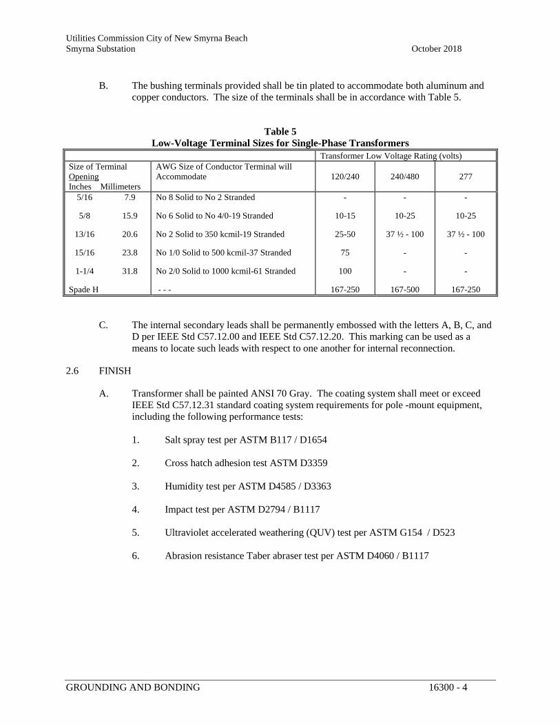
Utilities Commission City of New Smyrna Beach Smyrna Substation October 2018
GROUNDING AND BONDING 16300 - 4
B. The bushing terminals provided shall be tin plated to accommodate both aluminum and copper conductors. The size of the terminals shall be in accordance with Table 5.
Table 5
Low-Voltage Terminal Sizes for Single-Phase Transformers Transformer Low Voltage Rating (volts) Size of Terminal Opening Inches Millimeters
AWG Size of Conductor Terminal will Accommodate
120/240
240/480
277
5/16 7.9 5/8 15.9 13/16 20.6 15/16 23.8 1-1/4 31.8 Spade H
No 8 Solid to No 2 Stranded No 6 Solid to No 4/0-19 Stranded No 2 Solid to 350 kcmil-19 Stranded No 1/0 Solid to 500 kcmil-37 Stranded No 2/0 Solid to 1000 kcmil-61 Stranded - - -
-
10-15
25-50
75
100
167-250
-
10-25
37 ½ - 100 - -
167-500
-
10-25
37 ½ - 100 - -
167-250
C. The internal secondary leads shall be permanently embossed with the letters A, B, C, and D per IEEE Std C57.12.00 and IEEE Std C57.12.20. This marking can be used as a means to locate such leads with respect to one another for internal reconnection.
2.6 FINISH
A. Transformer shall be painted ANSI 70 Gray. The coating system shall meet or exceed IEEE Std C57.12.31 standard coating system requirements for pole -mount equipment, including the following performance tests: 1. Salt spray test per ASTM B117 / D1654
2. Cross hatch adhesion test ASTM D3359
3. Humidity test per ASTM D4585 / D3363
4. Impact test per ASTM D2794 / B1117
5. Ultraviolet accelerated weathering (QUV) test per ASTM G154 / D523
6. Abrasion resistance Taber abraser test per ASTM D4060 / B1117
Utilities Commission City of New Smyrna Beach Smyrna Substation October 2018
GROUNDING AND BONDING 16300 - 5
PART 3 EXECUTION
3.1 TESTING
A. All units shall be tested for the following: 1. No-Load losses at rated current
2. Total losses at rated current
3. Percent Impedance at rated current
4. Excitation current (100% voltage) test
5. Ratio tests using all tap settings
6. Polarity and phase relation tests
7. Induced potential tests
8. Full wave and reduced wave impulse test
B. The manufacturer shall provide the guaranteed average no-load and load losses.d.
1. The maximum no-load loss shall be 10% 2. The maximum total losses shall be 6%.
END OF SECTION
Utilities Commission City of New Smyrna Beach Smyrna Substation October 2018 Substation Expansion Project New Smyrna Beach, FL
OVERHEAD TRANSMISSION & DISTRIBUTION 16301 - 1
SPECIFICATION SECTION 16301
OVERHEAD TRANSMISSION AND DISTRIBUTION
PART 1 GENERAL
1.01 SCOPE OF WORK
A. Intent: The Contractor shall provide all management, administration, tools, construction equipment, labor and supervision to accomplish the work as specified herein and on the Construction Drawings. The source of materials to accomplish the work of this project is specified herein and on the Construction Drawings. The materials, equipment, methods of framing and construction practices must conform to the latest and best current practices of the electric utility industry. The system shall be complete with all components necessary for proper operation.
B. Project Scope and Purpose: See Article 1.06 for detailed project description. See Construction Drawings and Specifications for detailed project requirements. Replace Airport line Structure 1, and relocate a portion of the 115 kV Cassadaga transmission line to a new line terminal position in the Smyrna Substation, and out of the way of other proposed substation construction. No fiber optic or distribution work is involved in this project. The work of this project is described in the following three steps.
1. Stage One, Airport: With clearance outage on the Airport 115 kV transmission line, replace guyed double-dead-end structure 1 of the Airport 115 kV transmission line with a new self-supporting spun concrete structure, at 15-feet south of the existing structure. Note- If permanent materials cannot be procured in a timely manner to meet the Stage One Substantial Completion date, temporary construction may be required.
2. Cassadaga Step One: Construct an extension of the Cassadaga 115 kV transmission line. Modify existing wood structure 257 as specified. Install two new self-supporting spun concrete structures, 258(NEW) and 259. Install three new spans (450 circuit feet) of 3-phase transmission conductors and shield wire(s). Assume a brief clearance outage will be granted to drill structure 257 and attach new conductors. Leave jumpers at structure 257 not connected.
3. Cassadaga Step Two: With clearance outage on the Cassadaga 115 kV transmission line, remove two spans (260 circuit feet) of 3-phase transmission conductors with two shield wires between the Cassadaga line terminal structure in Smyrna Substation and existing structure 257. Remove existing fiberglass pole structure 258, complete. Drill wood structure 257, add jumper post insulator assemblies, and connect jumpers to the new line section installed in Step One.
C. Location of Project: A project Location Map appears on the cover of the Construction Drawings.
Utilities Commission City of New Smyrna Beach Smyrna Substation October 2018
OVERHEAD TRANSMISSION & DISTRIBUTION 16301 - 2
1. The work will take place both outside and inside the fenced area of the Smyrna Substation in Volusia County, Florida, 3019 SR-44, west of I-95.
D. Pre-Bid Conference and Site Visit: There will be a formal Pre-bid Conference meeting. The Contractor is expected to be thoroughly familiar with the project requirements prior to submitting a bid. The Owner will accommodate a pre-bid project site visit upon request.
1.02 SECTION INCLUDES
A. This Section includes a general description of the project, general requirements of the Contractor, a description of Owner-furnished and Contractor-furnished materials, an anticipated sequence of work, staking requirements, clearing requirements, temporary construction requirements, installation requirements for transmission materials, requirements for substantial completion, and related information and requirements.
B. This Section also includes information to establish standards for dimensions, composition, manufacture and quality testing of Contractor-furnished materials to be used for the project. Standards are established either by reference to industry standard publications, by descriptions herein of key characteristics, by specific catalog numbers, or by reference to specific Stock Numbers representing the material standards of the Owner.
1. Material Stock Numbers that satisfy the intent of the design are contained in the Material List included on the Construction Drawings. Additional approved manufacturer and catalog number information for these Stock Numbers is maintained at www.aursi.com.
2. Minor, incidental, temporary, or disposable Contractor-furnished materials are not necessarily identified on the Construction Drawings or within the technical specifications, but they shall meet or exceed the quality and requirements of applicable industry standards and codes. See Article 2.02 for additional details.
1.03 RELATED SECTIONS
The requirements of the Contract, Bidding Documents, and other technical specification Sections apply to work in this Section as if incorporated herein.
Section 02582 (33 71 16.13) Pre-Stressed Centrifugal-Cast Concrete Utility Poles
1.04 REFERENCES
Part 2 Products and Part 3 Execution shall conform to latest revision of the following standards and regulations, and to other applicable industry standards of the organizations listed below (unless otherwise noted):
A. Standards and Regulations
Utilities Commission City of New Smyrna Beach Smyrna Substation October 2018
OVERHEAD TRANSMISSION & DISTRIBUTION 16301 - 3
1. Occupational Safety and Health Act of 1970 (OSHA)
2. National Electric Safety Code (NESC)
3. National Electrical Code (NEC)
B. Industry Organizations
1. American Association of State Highway & Transportation Officials (AASHTO)
2. American Institute of Steel Construction (AISC)
3. American National Standards Institute (ANSI)
4. American Society for Testing and Materials (ASTM)
5. American Wood Preservers’ Association (AWPA)
6. Associated General Contractors of America (AGC)
7. Florida Department of Environmental Protection (FDEP)
8. Florida Department of Transportation (FDOT)
9. Institute of Electrical and Electronics Engineers (IEEE)
10. National Electrical Manufacturers Association (NEMA)
11. Underwriters Laboratories (UL)
12. United States Department of Agriculture / Rural Utilities Service (USDA/RUS)
1.05 DEFINITIONS
A. Owner for this work is: Utilities Commission, City of New Smyrna Beach 200 Canal Street New Smyrna Beach, FL 32168 Phone: (386) 424-3029 Tad Moon e-mail: [email protected]
B. Engineer Consultant for this work is:
Utilities Commission City of New Smyrna Beach Smyrna Substation October 2018
OVERHEAD TRANSMISSION & DISTRIBUTION 16301 - 4
Fred Wilson & Associates, Inc. 3970 Hendricks Avenue Jacksonville, FL 32207-5398 Phone: (904) 398-8636 Ed Wisser, P.E. e-mail: [email protected]
C. Contractor shall mean the construction contractor with whom the Owner enters into a Contract based on their bid furnished in response to the Bidding Documents, Construction Drawings and technical specifications for the work of this project.
D. Unless otherwise specified or indicated, electrical terms used in the technical specifications and on the Construction Drawings shall be as defined in IEEE Standard 100.
1.06 DETAILED PROJECT DESCRIPTION
Stage One, Airport:
A. Install:
At 15-ft south of Structure 1 of the Airport 115 kV transmission line, install one 85-ft 16-kip spun concrete self-supporting pole set 21-ft deep. Transfer and double dead-end the existing 3#9 AW shield wires and 795 AAC phase conductors. Maintain the existing line tensions east. Maintain the existing phase relationship and see Stringing Chart information for the span into Smyrna Substation.
Assume a transmission clearance outage will be granted to perform this work on the Airport transmission line.
1. Note- If permanent materials cannot be procured in a timely manner to meet the Stage One Substantial Completion date, temporary construction may be required. Temporary construction would consist of installing a 45-ft wood class 3 or better guy stub pole near the outer existing anchor west and set 9-ft deep, two 3/8” EHS down guys to a multi-helix anchor, and transferring existing Structure 1 down guys west as span guys. Take precautions to avoid underground 23kV cables in the area. Remove the temporary materials when permanent materials are installed.
B. Remove:
At existing Structure 1, remove the 75-ft 10-kip spun concrete pole, six 15-bell porcelain strain insulator assemblies, three polymer jumper post insulator assemblies, three shield wire dead-end assemblies, and five 9/16-in down guys. Cut four guy anchors at 2-ft below grade.
Dispose of or return removed materials as designated by the Owner.
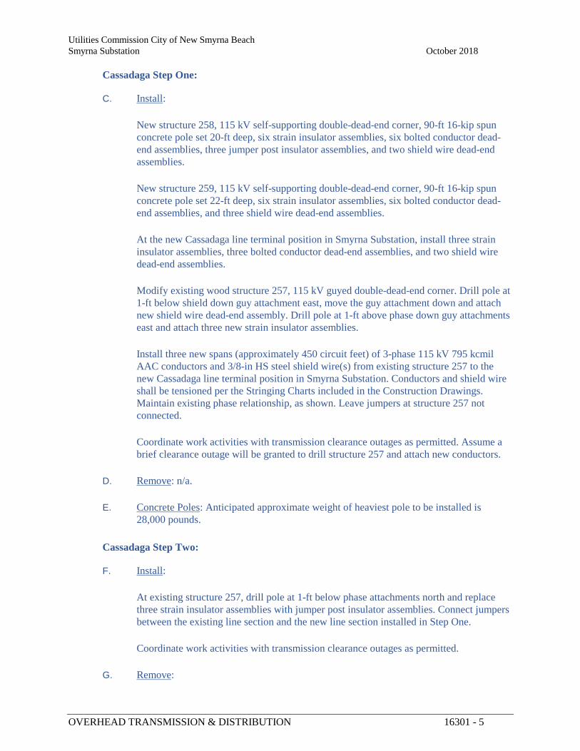
Utilities Commission City of New Smyrna Beach Smyrna Substation October 2018
OVERHEAD TRANSMISSION & DISTRIBUTION 16301 - 5
Cassadaga Step One:
C. Install:
New structure 258, 115 kV self-supporting double-dead-end corner, 90-ft 16-kip spun concrete pole set 20-ft deep, six strain insulator assemblies, six bolted conductor dead-end assemblies, three jumper post insulator assemblies, and two shield wire dead-end assemblies.
New structure 259, 115 kV self-supporting double-dead-end corner, 90-ft 16-kip spun concrete pole set 22-ft deep, six strain insulator assemblies, six bolted conductor dead-end assemblies, and three shield wire dead-end assemblies.
At the new Cassadaga line terminal position in Smyrna Substation, install three strain insulator assemblies, three bolted conductor dead-end assemblies, and two shield wire dead-end assemblies.
Modify existing wood structure 257, 115 kV guyed double-dead-end corner. Drill pole at 1-ft below shield down guy attachment east, move the guy attachment down and attach new shield wire dead-end assembly. Drill pole at 1-ft above phase down guy attachments east and attach three new strain insulator assemblies.
Install three new spans (approximately 450 circuit feet) of 3-phase 115 kV 795 kcmil AAC conductors and 3/8-in HS steel shield wire(s) from existing structure 257 to the new Cassadaga line terminal position in Smyrna Substation. Conductors and shield wire shall be tensioned per the Stringing Charts included in the Construction Drawings. Maintain existing phase relationship, as shown. Leave jumpers at structure 257 not connected.
Coordinate work activities with transmission clearance outages as permitted. Assume a brief clearance outage will be granted to drill structure 257 and attach new conductors.
D. Remove: n/a.
E. Concrete Poles: Anticipated approximate weight of heaviest pole to be installed is 28,000 pounds.
Cassadaga Step Two:
F. Install:
At existing structure 257, drill pole at 1-ft below phase attachments north and replace three strain insulator assemblies with jumper post insulator assemblies. Connect jumpers between the existing line section and the new line section installed in Step One.
Coordinate work activities with transmission clearance outages as permitted.
G. Remove:
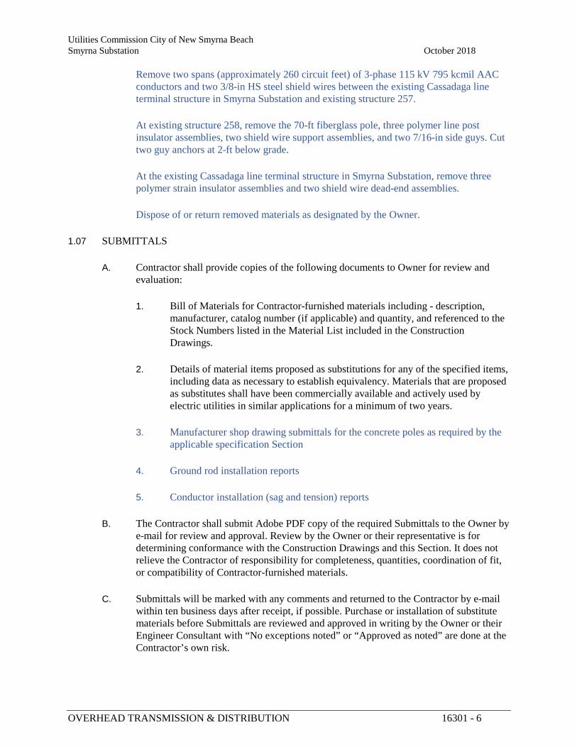
Utilities Commission City of New Smyrna Beach Smyrna Substation October 2018
OVERHEAD TRANSMISSION & DISTRIBUTION 16301 - 6
Remove two spans (approximately 260 circuit feet) of 3-phase 115 kV 795 kcmil AAC conductors and two 3/8-in HS steel shield wires between the existing Cassadaga line terminal structure in Smyrna Substation and existing structure 257.
At existing structure 258, remove the 70-ft fiberglass pole, three polymer line post insulator assemblies, two shield wire support assemblies, and two 7/16-in side guys. Cut two guy anchors at 2-ft below grade.
At the existing Cassadaga line terminal structure in Smyrna Substation, remove three polymer strain insulator assemblies and two shield wire dead-end assemblies.
Dispose of or return removed materials as designated by the Owner.
1.07 SUBMITTALS
A. Contractor shall provide copies of the following documents to Owner for review and evaluation:
1. Bill of Materials for Contractor-furnished materials including - description, manufacturer, catalog number (if applicable) and quantity, and referenced to the Stock Numbers listed in the Material List included in the Construction Drawings.
2. Details of material items proposed as substitutions for any of the specified items, including data as necessary to establish equivalency. Materials that are proposed as substitutes shall have been commercially available and actively used by electric utilities in similar applications for a minimum of two years.
3. Manufacturer shop drawing submittals for the concrete poles as required by the applicable specification Section
4. Ground rod installation reports
5. Conductor installation (sag and tension) reports
B. The Contractor shall submit Adobe PDF copy of the required Submittals to the Owner by e-mail for review and approval. Review by the Owner or their representative is for determining conformance with the Construction Drawings and this Section. It does not relieve the Contractor of responsibility for completeness, quantities, coordination of fit, or compatibility of Contractor-furnished materials.
C. Submittals will be marked with any comments and returned to the Contractor by e-mail within ten business days after receipt, if possible. Purchase or installation of substitute materials before Submittals are reviewed and approved in writing by the Owner or their Engineer Consultant with “No exceptions noted” or “Approved as noted” are done at the Contractor’s own risk.
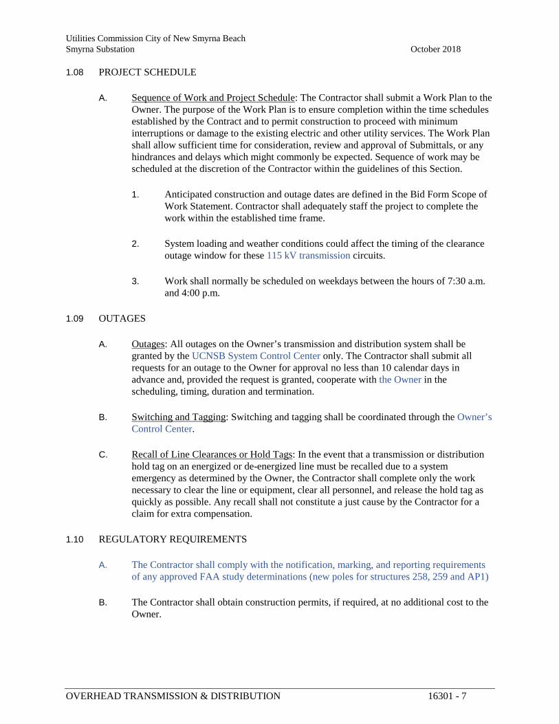
Utilities Commission City of New Smyrna Beach Smyrna Substation October 2018
OVERHEAD TRANSMISSION & DISTRIBUTION 16301 - 7
1.08 PROJECT SCHEDULE
A. Sequence of Work and Project Schedule: The Contractor shall submit a Work Plan to the Owner. The purpose of the Work Plan is to ensure completion within the time schedules established by the Contract and to permit construction to proceed with minimum interruptions or damage to the existing electric and other utility services. The Work Plan shall allow sufficient time for consideration, review and approval of Submittals, or any hindrances and delays which might commonly be expected. Sequence of work may be scheduled at the discretion of the Contractor within the guidelines of this Section.
1. Anticipated construction and outage dates are defined in the Bid Form Scope of Work Statement. Contractor shall adequately staff the project to complete the work within the established time frame.
2. System loading and weather conditions could affect the timing of the clearance outage window for these 115 kV transmission circuits.
3. Work shall normally be scheduled on weekdays between the hours of 7:30 a.m. and 4:00 p.m.
1.09 OUTAGES
A. Outages: All outages on the Owner’s transmission and distribution system shall be granted by the UCNSB System Control Center only. The Contractor shall submit all requests for an outage to the Owner for approval no less than 10 calendar days in advance and, provided the request is granted, cooperate with the Owner in the scheduling, timing, duration and termination.
B. Switching and Tagging: Switching and tagging shall be coordinated through the Owner’s Control Center.
C. Recall of Line Clearances or Hold Tags: In the event that a transmission or distribution hold tag on an energized or de-energized line must be recalled due to a system emergency as determined by the Owner, the Contractor shall complete only the work necessary to clear the line or equipment, clear all personnel, and release the hold tag as quickly as possible. Any recall shall not constitute a just cause by the Contractor for a claim for extra compensation.
1.10 REGULATORY REQUIREMENTS
A. The Contractor shall comply with the notification, marking, and reporting requirements of any approved FAA study determinations (new poles for structures 258, 259 and AP1)
B. The Contractor shall obtain construction permits, if required, at no additional cost to the Owner.
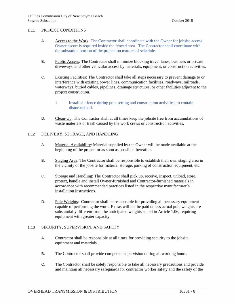
Utilities Commission City of New Smyrna Beach Smyrna Substation October 2018
OVERHEAD TRANSMISSION & DISTRIBUTION 16301 - 8
1.11 PROJECT CONDITIONS
A. Access to the Work: The Contractor shall coordinate with the Owner for jobsite access. Owner escort is required inside the fenced area. The Contractor shall coordinate with the substation portion of the project on matters of schedule.
B. Public Access: The Contractor shall minimize blocking travel lanes, business or private driveways, and other vehicular access by materials, equipment, or construction activities.
C. Existing Facilities: The Contractor shall take all steps necessary to prevent damage to or interference with existing power lines, communication facilities, roadways, railroads, waterways, buried cables, pipelines, drainage structures, or other facilities adjacent to the project construction.
1. Install silt fence during pole setting and construction activities, to contain disturbed soil.
D. Clean-Up: The Contractor shall at all times keep the jobsite free from accumulations of waste materials or trash caused by the work crews or construction activities.
1.12 DELIVERY, STORAGE, AND HANDLING
A. Material Availability: Material supplied by the Owner will be made available at the beginning of the project or as soon as possible thereafter.
B. Staging Area: The Contractor shall be responsible to establish their own staging area in the vicinity of the jobsite for material storage, parking of construction equipment, etc.
C. Storage and Handling: The Contractor shall pick up, receive, inspect, unload, store, protect, handle and install Owner-furnished and Contractor-furnished materials in accordance with recommended practices listed in the respective manufacturer’s installation instructions.
D. Pole Weights: Contractor shall be responsible for providing all necessary equipment capable of performing the work. Extras will not be paid unless actual pole weights are substantially different from the anticipated weights stated in Article 1.06, requiring equipment with greater capacity.
1.13 SECURITY, SUPERVISION, AND SAFETY
A. Contractor shall be responsible at all times for providing security to the jobsite, equipment and materials.
B. The Contractor shall provide competent supervision during all working hours.
C. The Contractor shall be solely responsible to take all necessary precautions and provide and maintain all necessary safeguards for contractor worker safety and the safety of the
Utilities Commission City of New Smyrna Beach Smyrna Substation October 2018
OVERHEAD TRANSMISSION & DISTRIBUTION 16301 - 9
general public in accordance with OSHA regulations, provisions of the NESC, and other applicable utility industry and governmental codes and regulations.
1.14 CHANGES
A. Changes and material substitutions shall be permitted only if so directed or authorized by the Owner. Changes will be governed by the Contract documents.
B. The Owner shall have the right to make changes in the Contract Drawings or technical specifications. The Contractor may request major changes through a written Request for Information to the Owner, and may request minor changes by the same method.
C. All major changes will be provided to the Contractor in writing by Proposed Change Order documents prepared by the Engineer Consultant and issued by the Owner. The Contractor shall reply in writing, detailing the addition or reduction in cost or time for the proposed change, and shall not proceed with the work until notified of acceptance of the change by the Owner (except where emergency system conditions or public safety are involved).
D. Minor changes may be authorized verbally by the Owner and will be observed and documented. The Contractor shall document claims for additional cost or time due to verbal changes before or along with the next Application for Payment for consideration of the Owner.
1.15 PROJECT RECORD DOCUMENTS
A. Contractor shall maintain an up-to-date “as-built” set of Construction Drawings and Contract documents, clearly marked with any and all revisions and deviations that are made during the course of the project.
B. Field record drawings may be established as a condition for approval of any Application for Payment, and shall be submitted to the Owner at the completion of the project along with the final Application for Payment.
1.16 WARRANTY
Installation warranty shall be for a period of one year after substantial completion. Material warranty shall be the warranties of the respective manufacturers.
PART 2 PRODUCTS
2.01 OWNER-FURNISHED MATERIALS
A. Material Provided by the Owner: There will be no Owner-furnished materials.
Utilities Commission City of New Smyrna Beach Smyrna Substation October 2018
OVERHEAD TRANSMISSION & DISTRIBUTION 16301 - 10
2.02 CONTRACTOR-FURNISHED MATERIALS
A. Material Provided by Contractor: The Contractor shall furnish all materials that are not otherwise defined as Owner-furnished, including those listed on the Material List which is part of the Construction Drawings. Contractor-furnished materials shall satisfy the dimensions, composition and quality established by any manufacturer or catalog number referenced in the Material List. Materials provided by the Contractor shall meet or exceed the quality and requirements of applicable industry standards and codes. Material documentation shall be submitted to the Owner for approval as described in Article 1.07. Used materials or products manufactured more than three years prior to delivery to the project site shall not be acceptable.
1. The Contractor shall furnish poles per Section 02582 and the Construction Drawings.
2. The Contractor shall furnish all backfill materials. Backfill for concrete pole installation shall be AASHTO #57 crushed stone.
3. The Contractor shall furnish any materials required to stabilize, maintain and repair the project area.
4. The Contractor shall furnish all materials required for temporary protection and construction, and the cost of such material shall be included in the base Bid.
5. Incidental and disposable material such as inhibitors, joining and cleaning solvents, grout, paint, rope, etc., required for construction shall be supplied by the Contractor and the cost of such material shall be included in the base Bid.
2.03 INSULATORS
A. Suspension: 115 kV suspension (dead-end strain) insulators shall have polymer weathersheds of proven design and UV-resistance, over a 25-kip SML 5/8” fiberglass rod, with chain eye tower-end fitting, ANSI 52-5 ball line-end fitting, and the following minimum characteristics.
1. Section Length = 73 inches
2. Leakage Distance = 180 inches.
B. Line Post: 115 kV jumper post insulators shall have polymer weathersheds of proven design and UV-resistance, over a 2.5-inch fiberglass rod, with bendable gain base and drop eye tongue end fitting, and the following minimum characteristics.
1. Section Length = 64 inches
2. Leakage Distance = 148 inches.

Utilities Commission City of New Smyrna Beach Smyrna Substation October 2018
OVERHEAD TRANSMISSION & DISTRIBUTION 16301 - 11
2.04 POLE-LINE HARDWARE
A. Hardware: The specified and required pole-line hardware shall be hot-dip galvanized steel, conforming to applicable ASTM, IEEE, and NEMA standards.
B. Tees: Dead-end tees for attaching dead-ends and guys shall be of the specified strength, shall attach to poles with a minimum of two 3/4” bolts, and mounting surface shall be suitable for the shape of the pole.
C. Bolts: Contractor shall be responsible for determining that bolts for attachment of all equipment are of sufficient length (see 3.09B.1) to permit attachment of the equipment. The transmission pole information provided by the supplier can be used to make this check, and no claim for extras will be granted for failure to make this check and order properly sized bolts prior to start of work.
D. Washers: Washers shall be provided for installation under bolt heads and under nuts on all bolted attachments. Flat or curved washers shall be of size and thickness as specified. The diameter of holes in washers shall be the correct standard size for the bolt on which a washer is used.
E. Locknuts: Provide M-F style locknuts (not palnuts) on all bolted attachments.
2.05 CONDUCTORS, HARDWARE AND CONNECTORS
A. Conductors: Transmission conductors shall be 795 kcmil “Arbutus” 37 strand AAC, per industry standards. Shield wire shall be 3/8-inch 7 strand high-strength (HS) grade galvanized “C”-coat steel cable, per industry standards.
B. Connectors: Connectors and splices shall be of copper alloy for copper conductors, aluminum alloy for aluminum-composition conductors, and a type designed to minimize galvanic corrosion for copper to aluminum connections or for copper to steel connections. Compression fittings shall be of the type recommended by the conductor manufacturer for the particular size and type of conductor.
2.06 GUY MATERIALS [Not in Contract]
2.07 ANCHORS [Not in Contract]
2.08 GROUNDING AND BONDING
A. Grounding Conductors: Furnish #4 AWG solid soft-drawn copper conductor for external pole ground, and for hardware bonding, per ASTM B8.
B. Ground Rods: Provide 13-mil copper-clad steel ground rods conforming to UL 467. Ground rods shall be threadless type, 5/8-inch diameter by 10 feet long. Couplings shall be threadless type made of high-strength silicon bronze.
Utilities Commission City of New Smyrna Beach Smyrna Substation October 2018
OVERHEAD TRANSMISSION & DISTRIBUTION 16301 - 12
C. Grounding Connections: Connection to ground rod shall be by compression connector conforming to IEEE 837 for underground application. Above-ground bonding connections shall use bolted connectors as specified.
2.09 RETURN OF MATERIALS
A. Return of Removal Material: Contractor shall disassemble, clean, sort, and return all removed materials to the location designated by the Owner, if applicable.
PART 3 EXECUTION
3.01 ANTICIPATED SEQUENCE OF WORK
A. Mobilize.
B. Receive and store Contractor-furnished materials.
C. Stage One, Airport: Obtain clearance outage, set new pole and transfer conductors and shield wires. Remove existing pole with down guys and anchors.
D. Cassadaga Step One: Set two poles and install grounding and bonding materials.
Obtain clearance outage, drill holes and install strain insulators. Install new structure framing materials. Install three spans of conductors and shield wire.
E. Cassadaga Step Two: Obtain clearance outage and remove two spans of conductors, shield wires, and related materials.
Remove one pole, complete.
Drill holes and install jumper support insulators. Install jumpers.
F. Cleanup and complete punch list items.
G. Demobilize.
3.02 SURVEY / STAKING
A. Structure Locations: Structure coordinates X and Y (Easting and Northing) are shown on the Construction Drawings. The Contractor shall engage the services of a State of Florida Registered Land Surveyor to perform the structure staking. The accuracy of this operation is critical to the success of this project. Therefore, prior to setting the poles on this project, the Owner shall be given opportunity to have their representative and/or the Consulting Engineer review the staked locations. Any work accomplished by the Contractor prior to this review shall be subject to change at no expense to the Owner.
Utilities Commission City of New Smyrna Beach Smyrna Substation October 2018
OVERHEAD TRANSMISSION & DISTRIBUTION 16301 - 13
1. Survey data for the Construction Drawings was provided by Daniel W. Cory Surveyor, LLC, New Smyrna Beach, whose contact is Jeff Cory, (386) 427-9575.
B. Underground Utility Locates: Underground 23kV cables are known to cross the project area. No other underground facilities were identified during design; however, there is no guarantee that this is correct. The Contractor shall call Sunshine State One-Call to locate all underground utilities a minimum of three business days prior to any excavation.
C. Underground Utility Conflicts: Where the underground utility markings indicate a potential conflict, excavation shall be accomplished by non-destructive methods to determine the exact location of the other utility.
1. Where an underground utility is determined to be in conflict with the proposed construction, the situation shall be reported immediately to the Owner.
2. Where an underground utility must be relocated to resolve the conflict, the Owner will make arrangements for relocation with the utility owner.
3. Changes in design to resolve the conflict will be handled per Article 1.14.
3.03 CLEARING
A. Clearing is required to be performed by the Contractor as part of the site work specified elsewhere in the Bidding Documents.
3.04 TEMPORARY CONSTRUCTION
A. Temporary Protection: The Contractor shall be responsible for all labor, poles, material and equipment for guard structures and any other temporary protection of existing distribution lines and other improvements or utilities above or below ground which may be affected by the work, to avoid damage, inconvenience, impairment, or interruption in service.
B. Temporary Construction: The Contractor shall be responsible for all labor, poles, material and equipment for installation and removal of temporary structures, and shall avoid damage to the wires and connectors. Temporary work shall meet all the safety requirements of OSHA and the NESC.
3.05 POLES
A. Pole Deliveries: Contractor shall be responsible for coordinating with the concrete pole supplier regarding the date, time and location for delivery of poles. Contractor shall be responsible for delivery of each pole to its final location for installation. Untimely delivery, either ahead of or behind agreed upon delivery schedules, shall not be a cause for a claim to the Owner for any costs incurred by the Contractor.
Utilities Commission City of New Smyrna Beach Smyrna Substation October 2018
OVERHEAD TRANSMISSION & DISTRIBUTION 16301 - 14
1. The Contractor shall notify the Owner immediately if poles appear to be damaged upon their arrival to the jobsite from the supplier.
B. Pole Assembly, Handling, and Drilling:
1. Contractor shall use proper equipment, slings, and lagging to handle the poles without causing damage. Any damage caused shall be repaired to the satisfaction of the Owner at the expense of the Contractor.
2. Poles shall be lifted only at appropriate pick-up points.
3. Concrete poles will have pre-cast holes to the extent practical. Any field drilling of concrete poles shall be performed per standard industry practices, and any resulting damage to the pole surface shall be repaired to the satisfaction of the Owner at the expense of the Contractor.
C. Pole Installation: Poles shall be oriented properly (within 1.0 degree) with respect to pre-cast holes.
1. Direct-embedded poles shall be installed by use of a power-driven rotary rig having an auger with minimum diameter as specified on the Construction Drawings. See the Soil Boring Reports included as an Appendix to this Section for anticipated below-ground conditions. The Contractor shall dewater each pole location (if necessary). The Contractor shall stabilize the sides of the excavation holes (if necessary) using synthetic polymer slurry drilling fluid, mixed and installed per the manufacturer’s instructions. Bentonite clay is not acceptable. Residual water and/or drilling fluid shall be captured by a pumping tanker truck as the pole is set and as the backfill material is added. The Contractor shall dispose of the collected water and/or drilling fluid that is not re-used, in accordance with all Local, State and Federal requirements.
a. The Owner shall be given opportunity to witness pole installation to verify proper setting depth and integrity of adjacent utilities.
b. The setting depth of the poles shall be as indicated on the Construction Drawings, with a tolerance of 3 inches deeper or shallower. On sloping ground, always measure depth from the lowest side of the hole. The pole shall be marked for the required setting depth, placed in the hole, and made plumb. The tolerance for plumbness shall be 1/2 inch per 10 feet of height.
c. The stability of existing structures and facilities shall not be impaired or endangered by excavation work. Sheeting and shoring shall be provided by the Contractor as required to protect and maintain the stability of existing structures and facilities and the sides of excavations and trenches until they are backfilled. Sheeting, bracing and shoring shall be designed and built to withstand all loads caused by earth movement or
Utilities Commission City of New Smyrna Beach Smyrna Substation October 2018
OVERHEAD TRANSMISSION & DISTRIBUTION 16301 - 15
pressure, and shall maintain the shape of the excavation under all circumstances.
d. Contractor shall remove from the jobsite and properly dispose of excess excavated material. When approved by the Owner, surplus excavated soil may be carefully spread on the surface of the ground near structures in upland areas, in a manner to minimize damage to the surrounding environment.
D. Backfill Around Poles: Contractor shall add the specified backfill material in one cubic yard lifts, and the fill material shall be continuously compacted through each lift from the bottom of the hole to 18-inches below the ground line using a minimum of two long-stemmed vibrators. Fill the remaining 18 inches with clean, coarse sand. Disturbed earth around the embedment hole shall be placed in a conical shape and tightly packed to drain water away from the pole.
E. Pole Removal: Poles designated to be removed shall be removed prior to substantial completion and returned to the Owner.
1. Where poles are removed the Contractor shall be responsible for backfilling the remaining hole with a suitable clean fill material acceptable to the Owner. The fill material shall be continuously compacted from the bottom of the hole to the ground line using long-stemmed vibrators.
3.06 ANCHORS AND GUYS
A. Anchor Installation: [Not in Contract]
B. Anchor Removal: The down guy anchors designated to be removed shall be cut at approximately two feet below the ground line.
C. Guy Installation: [Not in Contract]
3.07 INSULATOR AND HARDWARE INSTALLATION
A. Insulators: Insulators shall be carefully handled to avoid damage to the sheds, fiberglass rods, bases, and end fittings. Insulators shall be thoroughly cleaned before being installed on the structures.
B. Pins and Bolts:
1. Through-bolts shall extend a minimum of 1-inch and a maximum of 2-1/2 inches past the last nut.
2. Orient the head of a pin through a hole at the higher side of the hole.
3. Orient the head of a cotter key toward the structure.
Utilities Commission City of New Smyrna Beach Smyrna Substation October 2018
OVERHEAD TRANSMISSION & DISTRIBUTION 16301 - 16
C. Hardware: Install in accordance with any manufacturer’s instructions. Where possible, orient hardware to shed water from any depressions or pockets.
3.08 CONDUCTOR INSTALLATION
A. General: Conductors shall be installed by controlled tension method in accordance with the latest revision of IEEE Standard 524, “Guide to the Installation of Overhead Transmission Line Conductors”.
1. Contractor shall be responsible for installing and removing temporary guard structures, guys and anchors that may be necessary for conductor stringing operations. Contractor shall provide all labor, material and equipment required for such temporary work.
B. Handling: Conductors shall be handled so as to prevent damage of any kind. The Contractor shall follow the conductor manufacturer’s recommendations for special installation precautions and for types of grips and come-alongs. Particular care shall be observed at all times to prevent kinking, twisting, nicking, scoring, or other damage to the conductor strands.
C. Stringing:
1. The Contractor shall furnish all equipment and supplies necessary for the conductor stringing operation.
2. Positive grounding devices shall be used during stringing operations on all transmission lines, and shall be attached in accordance with OSHA regulations.
D. Sagging:
1. Use the Stringing Charts included in the Construction Drawings as the basis for selecting tension or sag values to use.
a. Sagging temperature shall be the temperature of the conductor as measured by an accurate conductor thermometer hung at the proper elevation for a minimum of 15 minutes.
b. Sagging new conductor by the dynamometer method is acceptable for this project application, provided the dynamometer is of proper precision and has been recently calibrated.
2. Conductors shall be sagged on the same day if possible. Sagging shall be accomplished within 72 hours after the conductors are pulled into the stringing blocks.
Utilities Commission City of New Smyrna Beach Smyrna Substation October 2018
OVERHEAD TRANSMISSION & DISTRIBUTION 16301 - 17
3. After sagging, all conductors shall be accurately plumb-marked for clipping-in at all structures on the same day. Conductors shall be clipped in within 72 hours after they are loaded to the initial sagging tension.
E. Connectors: All conductors and materials used in a splice, tap, or connection shall be thoroughly cleaned, dried and burnished with a wire brush prior to make-up to ensure proper electrical and mechanical connections. Approved inhibitor compounds shall be used to minimize oxidation. The Contractor shall follow the manufacturer’s installation instructions for suspension units, clamps, armor rods, vibration dampers, compression dead-ends, terminal connectors, and splices.
1. For any aluminum to copper connections, the aluminum shall be installed above the copper.
F. Conductor Installation Reports: The Owner shall be given opportunity to witness conductor stringing and sagging activities. The Contractor shall keep a careful record of conductor sagging, including: limits of the pull (from structure, to structure), measured sagging temperature, method of sagging, calculated tension or sag value, date of stringing, date of sagging, date of clipping, and any other pertinent information. This information shall be submitted to the Owner in report form along with the associated Application for Payment.
3.09 GROUNDING
A. Pole Grounds:
1. Concrete transmission poles will be furnished with threaded inserts to accept grounding lugs near areas where grounds are required. A continuous #4 AWG copper external pole ground shall be installed from the ground insert at the lowest phase position up to a connection at the shield wire. It shall pass through connectors at each ground insert, and shall be secured to the pole between inserts at intervals of approximately 3-feet using tube straps and concrete screws.
B. Bonding of Hardware: Transmission hardware and guys shall be electrically bonded by extending a #4 AWG copper wire to a bolted connection at the external pole ground.
C. Ground Rod Installation: Ground rods are required at every transmission pole.
Ground rods shall be installed immediately after the structure is erected. The top of the completed ground rod installation shall be at least six inches below final grade, and shall be at least 2 feet from the nearest face of the transmission pole.
1. The Contractor shall install a minimum of two 5/8” x 10’ ground rod sections at each structure location by conventional methods using an air compressor and air hammer. Contractor shall install and test the two ground rod sections and if a ground resistance reading of 15 ohms or less is not obtained, the Contractor shall contact the Owner to witness installation of two additional ground rod sections followed by ground resistance testing. If four ground rod sections have been
Utilities Commission City of New Smyrna Beach Smyrna Substation October 2018
OVERHEAD TRANSMISSION & DISTRIBUTION 16301 - 18
installed and a ground resistance of 15 ohms or less is still not obtained, the Owner can accept the installation or may direct the Contractor to install additional ground rod sections until a satisfactory reading is obtained. The Contractor shall supply the materials, labor and equipment for installation of additional ground rod sections. Additional ground rod sections (above the two) will be paid for at the unit bid prices included in the Contract.
2. The ground connection between the structure and the ground rod shall be installed immediately after satisfactory testing.
D. Ground Rod Installation Reports: The Owner shall be given opportunity to witness ground rod installation and testing. The ground rod resistance measurements shall be made with a “ground megger”. The tests shall be performed as recommended by the manufacturer of the instrument used. The Contractor shall keep a record of the number of rods driven and the resistance readings. This information shall be submitted to the Owner in report form along with the associated Application for Payment.
3.10 SUBSTANTIAL COMPLETION AND CLEAN-UP
A. Materials or workmanship discovered or determined during construction to be defective or otherwise not in compliance with the Construction Drawings or technical specifications shall be promptly repaired or replaced to the satisfaction of the Owner at the expense of the Contractor.
B. The Contractor shall notify the Owner when, in their opinion, the construction is ready to be declared substantially complete and to be turned over to the Owner. The Owner and/or their designated representative will perform a final field review to determine general conformance with the Construction Drawings and technical specifications and to document any shortcomings in the form of a Punch List.
C. The Contractor shall address the items contained in the Punch List, submit required installation reports (Article 1.07), and submit as-built project record documents (Article 1.15). The Owner will determine when sufficient Punch List items have been addressed to declare the project substantially complete. All Punch List items shall be addressed to the satisfaction of the Owner before final Application for Payment can be processed.
D. The Contractor shall remove waste materials and trash from the jobsite and shall repair (or cause to be repaired) any damage to paved and unpaved areas, survey markers, fences, mailboxes, and other improvements or utilities located within rights-of-way or on properties adjacent to the jobsite, as directed by and to the satisfaction of the Owner and any permitting agencies. Clean-up and repairs must be completed before final Application for Payment can be processed.
E. Construction observation and final field review by the Owner or waiving of inspections shall not relieve the Contractor from performing their obligations under the Contract, nor shall it invalidate any claim of the Owner at a later date because of defective or unsatisfactory materials or workmanship.
Utilities Commission City of New Smyrna Beach Smyrna Substation October 2018
OVERHEAD TRANSMISSION & DISTRIBUTION 16301 - 19
END OF SECTION
Utilities Commission City of New Smyrna Beach Smyrna Substation October 2018 Substation Equipment Package New Smyrna Beach, FL
HIGH VOLTAGE DISCONNECT SWITCHES 16310 - 1
SPECIFICATION SECTION 16310
DISCONNECT SWITCHES
PART 1 GENERAL
1.1 SUMMARY
A. This specification covers group operated air break outdoor disconnect switches, ground switches and motor operators for outdoor substation use.
B. Contractor shall coordinate the height of switches and structures based on the actual equipment to be ordered. Structures shall not be ordered until after shop drawings are received for the switches and the final height is set to accommodate the bus height.
1.2 QUALITY ASSURANCE
A. Comply with applicable portions of Section 16050, Basic Electrical Materials and Methods
B. Provide components that are the standard product of a manufacturer regularly engaged in the production of the required materials and equipment.
1. The manufacturer shall be responsible for the design, construction and proper operation of all components.
C. Comply with applicable codes and standards including, but not limited to the most recent edition of the following: 1. National Electrical Manufacturer’s Association (NEMA).
2. National Electrical Code (NEC).
3. National Electrical Safety Code (NESC)
4. ANSI C37.30
5. ANSI C37.32
6. ANSI C37.34
D. Design to provide satisfactory performance under the following operating conditions: 1. Suitable for outdoor, unsheltered service and the service conditions per ANSI
C37.30
2. Switches will be operated very infrequently.
Utilities Commission City of New Smyrna Beach Smyrna Substation October 2018
HIGH VOLTAGE DISCONNECT SWITCHES 16310 - 2
3. Switches shall require minimal or no maintenance through their expected life.
4. Switches shall operate properly in winds of 60 miles per hour, with possible gusts
up to 125 miles per hour. Switches shall be designed not to be blown closed by high winds.
1.3 SUBMITTALS
A. Submit the following in accordance with Section 01330, Submittal Procedures. 1. Product data.
2. Shop drawings shall include the following at a minimum:
a. Outline of the switch showing overall dimensions in both the open and closed positions.
b. Individual weights of switch poles, insulators, bases, and ground switches.
c. Weight of three phase assembly not including operating mechanism. Include ground switch weight if applicable.
d. Operating mechanism design and assembly details. Include details of all components including structural steel, bearing supports, guide bearings, and operating shafts.
e. Switch base dimensions and mounting details.
3. Certified test reports.
4. Special shipping, storage, protection and handling instructions, if any.
5. Manufacturer’s installation instructions.
B. Furnish operation, installation and maintenance manuals.
PART 2 PRODUCTS
2.1 GENERAL
A. All components furnished shall have a minimum design life of 40 years.
B. All terminal pads shall be drilled according to NEMA standard dimensions.
C. All steel components shall be stainless steel or hot dip galvanized after fabrication in accordance with ASTM-A123.
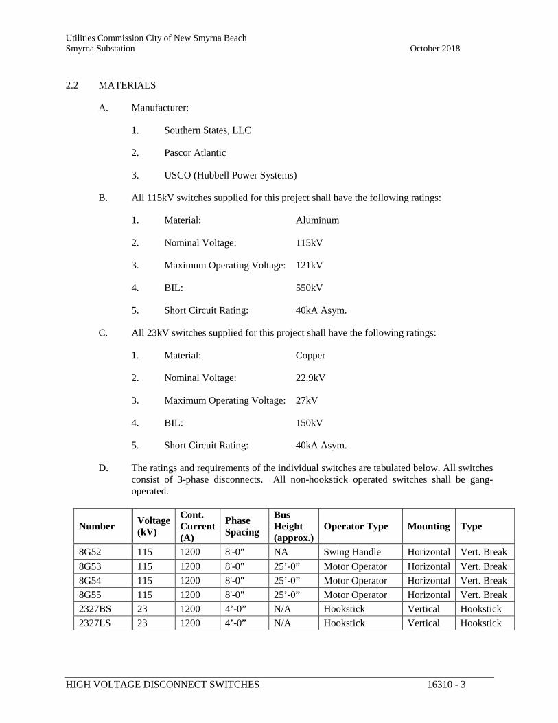
Utilities Commission City of New Smyrna Beach Smyrna Substation October 2018
HIGH VOLTAGE DISCONNECT SWITCHES 16310 - 3
2.2 MATERIALS
A. Manufacturer:
1. Southern States, LLC
2. Pascor Atlantic
3. USCO (Hubbell Power Systems)
B. All 115kV switches supplied for this project shall have the following ratings:
1. Material: Aluminum
2. Nominal Voltage: 115kV
3. Maximum Operating Voltage: 121kV
4. BIL: 550kV
5. Short Circuit Rating: 40kA Asym.
C. All 23kV switches supplied for this project shall have the following ratings:
1. Material: Copper
2. Nominal Voltage: 22.9kV
3. Maximum Operating Voltage: 27kV
4. BIL: 150kV
5. Short Circuit Rating: 40kA Asym.
D. The ratings and requirements of the individual switches are tabulated below. All switches consist of 3-phase disconnects. All non-hookstick operated switches shall be gang-operated.
Number Voltage (kV)
Cont. Current (A)
Phase Spacing
Bus Height (approx.)
Operator Type Mounting Type
8G52 115 1200 8'-0" NA Swing Handle Horizontal Vert. Break 8G53 115 1200 8'-0" 25’-0” Motor Operator Horizontal Vert. Break 8G54 115 1200 8'-0" 25’-0” Motor Operator Horizontal Vert. Break 8G55 115 1200 8'-0" 25’-0” Motor Operator Horizontal Vert. Break 2327BS 23 1200 4’-0” N/A Hookstick Vertical Hookstick 2327LS 23 1200 4’-0” N/A Hookstick Vertical Hookstick
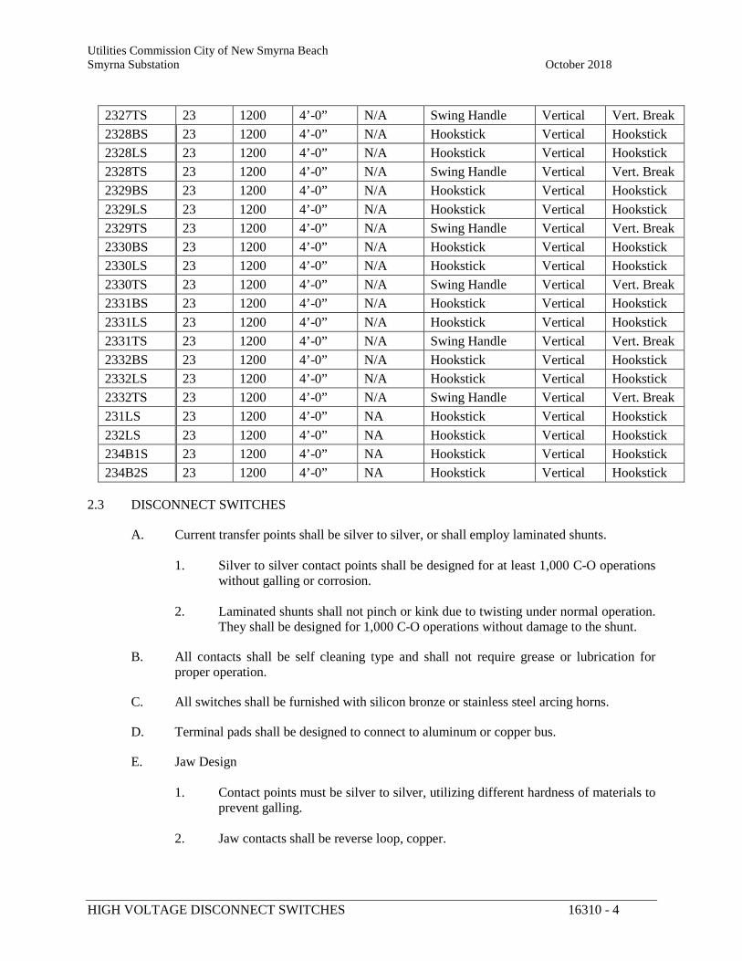
Utilities Commission City of New Smyrna Beach Smyrna Substation October 2018
HIGH VOLTAGE DISCONNECT SWITCHES 16310 - 4
2327TS 23 1200 4’-0” N/A Swing Handle Vertical Vert. Break 2328BS 23 1200 4’-0” N/A Hookstick Vertical Hookstick 2328LS 23 1200 4’-0” N/A Hookstick Vertical Hookstick 2328TS 23 1200 4’-0” N/A Swing Handle Vertical Vert. Break 2329BS 23 1200 4’-0” N/A Hookstick Vertical Hookstick 2329LS 23 1200 4’-0” N/A Hookstick Vertical Hookstick 2329TS 23 1200 4’-0” N/A Swing Handle Vertical Vert. Break 2330BS 23 1200 4’-0” N/A Hookstick Vertical Hookstick 2330LS 23 1200 4’-0” N/A Hookstick Vertical Hookstick 2330TS 23 1200 4’-0” N/A Swing Handle Vertical Vert. Break 2331BS 23 1200 4’-0” N/A Hookstick Vertical Hookstick 2331LS 23 1200 4’-0” N/A Hookstick Vertical Hookstick 2331TS 23 1200 4’-0” N/A Swing Handle Vertical Vert. Break 2332BS 23 1200 4’-0” N/A Hookstick Vertical Hookstick 2332LS 23 1200 4’-0” N/A Hookstick Vertical Hookstick 2332TS 23 1200 4’-0” N/A Swing Handle Vertical Vert. Break 231LS 23 1200 4’-0” NA Hookstick Vertical Hookstick 232LS 23 1200 4’-0” NA Hookstick Vertical Hookstick 234B1S 23 1200 4’-0” NA Hookstick Vertical Hookstick 234B2S 23 1200 4’-0” NA Hookstick Vertical Hookstick
2.3 DISCONNECT SWITCHES
A. Current transfer points shall be silver to silver, or shall employ laminated shunts. 1. Silver to silver contact points shall be designed for at least 1,000 C-O operations
without galling or corrosion.
2. Laminated shunts shall not pinch or kink due to twisting under normal operation. They shall be designed for 1,000 C-O operations without damage to the shunt.
B. All contacts shall be self cleaning type and shall not require grease or lubrication for proper operation.
C. All switches shall be furnished with silicon bronze or stainless steel arcing horns.
D. Terminal pads shall be designed to connect to aluminum or copper bus.
E. Jaw Design 1. Contact points must be silver to silver, utilizing different hardness of materials to
prevent galling.
2. Jaw contacts shall be reverse loop, copper.
Utilities Commission City of New Smyrna Beach Smyrna Substation October 2018
HIGH VOLTAGE DISCONNECT SWITCHES 16310 - 5
3. All copper components of aluminum switches shall be hot tin dip plated.
4. Stainless steel (316) hardware shall be used to assemble copper components to
aluminum.
a. 301 Stainless steel compression washers (3,000 lb) and 316 stainless steel flat washers shall be used under both the bolt and the nut.
b. Mate surfaces using an oxide inhibiting compound with a maximum temperature rating of at least 150°C
F. Hinge Design 1. Hinge joints shall be by-passed using high pressure contacts or an aluminum
laminated strip jumper.
2. Braided shunts are not acceptable as a normal current carrying component of the switch.
3. Hinge joints shall not require grease or lubrication for proper operation except in the case of threaded joints that are completely sealed using o-rings or other acceptable methods. All hinge joints shall remain maintenance free.
G. Counterbalance Springs 1. Springs located in the current path shall be stainless steel or non-ferrous. They
shall be arranged such that they do not carry current.
2. Springs located outside the current path may be ferrous material provided they are protected from corrosion.
3. Springs shall be shielded in all directions from ice buildup.
2.4 SWITCH OPERATORS
A. All operators shall have a means to decouple the operator from the switch operating pipe. 1. Provide for padlocking of the decoupling mechanism
B. Provide “Open” and “Closed” indication on the operating pipe.
C. Provide one (1) adjustable auxiliary position switches attached to the operating pipe of switch 520-2. Provide one (1) additional auxiliary position switch to be attached to an existing switch.
D. Provide the motor operators for switches 8G53, 8G54, and 8G55 with provisions for electrical interlocking and key interlocking with a Southern States CSV circuit switcher. Coordinate controls with Engineer. Provide key interlock hardware.
Utilities Commission City of New Smyrna Beach Smyrna Substation October 2018
HIGH VOLTAGE DISCONNECT SWITCHES 16310 - 6
2.5 BASE AND OPERATING MECHANISMS
A. Switch bases and operating mechanisms shall be designed by the manufacturer based on the Contract Drawings. The design shall take into consideration the location of the switch, type of operator identified, operating requirements of the switch, arrangement of the mounting structure, and location of the operating mechanism relative to the switch.
B. Furnish operating mechanism complete with all mounting steel, operating pipes, clevises, guide bearings and other appurtenances required for complete field assembly.
C. Switch bases, mechanisms and mounting components shall be galvanized structural steel and be designed to withstand all forces encountered based on the operating conditions described above.
D. All control fittings for pipe attachments shall have self piercing set screw. Set screws shall be of corrosion resistant material.
E. Each switch phase shall have adjustable, self locking stops for open and close position.
F. All gang operated switches shall include a flexible braided copper grounding strap for attachment to the mechanism downpipe at the operating handle. Strap shall have the equivalent area of a #4/0 conductor with tinned copper ferrules. 1. Provide one ferrule with a 9/16” bolt hole for attachment to the structure and one
formed to attach to the switch operating pipe.
2. Provide clamp connector to attach ground strap to operating pipe.
G. Bearings 1. Switch bearings shall be tapered roller bearings (Timken or equal) manufactured
domestically or ball bearings.
a. Ball bearings shall have stainless steel or non-ferrous races, unless the bearings are adequately sealed and greased to prevent corrosion.
b. Galvanized iron or steel races are not acceptable (except in the case of tapered roller bearings)
c. Aluminum races are not acceptable
2. Tapered roller bearings shall be lubricated. All lubricated bearings shall be packed with fluro-silicon grease and have standard grease fittings.
3. Dry type bearings shall be composed of stainless steel or non-ferrous material.
4. Bearing housing shall be sealed to prevent water entry into the rolling elements.
H. All required mounting and assembly hardware shall be furnished along with the switch.
Utilities Commission City of New Smyrna Beach Smyrna Substation October 2018
HIGH VOLTAGE DISCONNECT SWITCHES 16310 - 7
1. Bolts and nuts shall be standard hex head
2. All mounting hardware shall be hot dip galvanized per the latest revision of
ASTM-A153.
2.6 INSULATORS
A. Switches shall be furnished from the manufacturer with the following porcelain station post insulators. 1. 115kV Switches: TR287 High Strength, Extra Creep
2. 23kV Switches: TR208 Standard Strength
B. Insulators shall be installed on the switches at the factory, and all leveling nuts fully adjusted prior to shipment.
PART 3 EXECUTION
3.1 SHIPPING
A. Ship each switch complete with all disassembled items, to include base, operating mechanism, operator, and quick break device as applicable.
B. Include with the shipment a parts list of all disassembled components. Include assembly instructions cross-referenced with the parts list.
3.2 INSTALLATION
A. Installation will be completed by the Contractor.
END OF SECTION
Utilities Commission City of New Smyrna Beach Smyrna Substation October 2018 Substation Equipment Package New Smyrna Beach, FL
CCVTs 16312 - 1
SPECIFICATION SECTION 16312
INSTRUMENT TRANSFORMERS
PART 1 GENERAL
1.1 SUMMARY
A. This specification covers the design, engineering, manufacture and testing of high voltage induction coupling capacitor voltage transformers.
1.2 QUALITY ASSURANCE
A. Comply with applicable portions of Section 16050, Basic Electrical Materials and Methods
B. Provide components that are the standard product of a manufacturer regularly engaged in the production of the required materials and equipment. 1. The manufacturer shall be responsible for the design, construction, and proper
operation of all components.
C. Comply with applicable standards including, but not limited to the most recent edition of the following: 1. ANSI C2, National Electrical Safety Code.
2. ANSI/IEEE C57.13.
D. Design to provide satisfactory performance under the specified operating conditions. 1. Suitable for outdoor unsheltered service and standard service conditions
1.3 SUBMITTALS
A. Submit the following in accordance with Section 01330, Submittal Procedures. 1. Approval documentation shall include the following:
a. Outline drawing, showing dimensions and base drilling details; valves and other auxiliary devices clearly identified with catalog numbers and purpose
b. Nameplate drawing
c. Schematic and wiring diagram
d. Drawings (Outline, Nameplate, Schematic, Wiring Diagram)
Utilities Commission City of New Smyrna Beach Smyrna Substation October 2018
CCVTs 16312 - 2
2. One bound instruction book shall be furnished with the equipment, containing the following information:
a. List of all equipment furnished
b. Storage and handling instructions
c. Installation instructions
d. Operation and Maintenance instructions
3. Final documentation shall include above items, plus
a. Instruction book
b. Test report
PART 2 PRODUCTS
2.1 COUPLING CAPACITOR VOLTAGE TRANSFORMERS
A. MANUFACTURERS
1. Provide CCVT’s from one of the following:
a. GE/Alstom
b. ABB
c. Trench
B. COUPLING CAPACITOR VOLTAGE TRANSFORMERS 1. Provide voltage transformers meeting the following requirements:
a. Nominal System Voltage: 115kV line-to-line
b. Maximum System Voltage: 121kV line-to-line
c. System Frequency: 60Hz
d. Dual-Wound Secondaries
e. Secondary Voltage: 120V with 67V tap.
f. Connection: Single phase, line-to-ground.
g. Burden: WXYZ-burden at 0.6 accuracy.
Utilities Commission City of New Smyrna Beach Smyrna Substation October 2018
CCVTs 16312 - 3
h. BIL: 550kV
C. WINDINGS
1. The transformer windings shall be high conductivity electrolytic copper.
2. The high voltage capacitive divider shall be connected phase to ground.
3. The CCVT shall have secondary windings as shown on the Contract Drawings for independent metering and synchronization circuits.
4. Each coupling capacitor voltage transformer shall have two electrically separate secondaries, each capable of supplying voltage at both marked ratios.
2.2 MEDIUM VOLTAGE POTENTIAL TRANSFORMERS
A. MANUFACTURERS
1. Provide voltage transformers from one of the following.
a. ABB
b. Kuhlman
c. Alstom
d. Trench
e. Or equal.
B. VOLTAGE TRANSFORMERS
1. Provide voltage transformers meeting the following requirements:
a. Nominal System Voltage: 22.9kV line-to-line
b. Maximum System Voltage: 27kV line-to-line
c. System Frequency: 60Hz
d. PT Voltage: 13.2kV-120V.
e. Type: Wire wound induction type.
f. Connection: Single phase, line-to-ground.
g. Burden: WXY-burden at 0.3 accuracy.
h. Voltage Factor: 1.9 for 30 seconds.
Utilities Commission City of New Smyrna Beach Smyrna Substation October 2018
CCVTs 16312 - 4
i. BIL: 150kV
C. WINDINGS
1. The transformer windings shall be high conductivity electrolytic copper.
2. The primary winding shall be connected phase to ground.
3. The PT shall have secondary windings as shown on the Contract Drawings for independent metering circuits.
2.3 CURRENT TRANSFORMERS
A. MANUFACTURERS
1. Provide voltage transformers from one of the following:
a. GE/Alstom
b. ABB
c. Trench
B. CURRENT TRANSFORMERS
1. Provide metering accuracy current transformers meeting the following requirements.
a. Nominal System Voltage: 115kV line-to-line
b. Maximum System Voltage: 121kV line-to-line
c. System Frequency: 60Hz
d. Current Ratio: Dual Ratio 800/400:5A.
e. Accuracy: 0.3B1.8
f. Thermal Rating Factor: 2.0.
g. Voltage Factor: 1.9 for 30 seconds.
h. BIL: 150kV
2.4 VOLTAGE TRANSFORMER LINE TERMINAL
A. The line terminal shall be located at the top of the transformer. This terminal shall consist of a NEMA four-hole connection, with a minimum of 3” x 3” surface area.
Utilities Commission City of New Smyrna Beach Smyrna Substation October 2018
CCVTs 16312 - 5
B. The terminal pad shall be oriented to allow the high voltage connection to be made either in line with the transformer axis or perpendicular to it.
2.5 CURRENT TRANSFORMER LINE TERMINALS
A. The line terminals shall be located at the top of the transformer perpendicular to the transformer post and on opposite sides. These terminals shall consist of a NEMA four-hole connection, with a minimum of 3” x 3” surface area.
B. The terminal pad shall be oriented to allow the high voltage connection to be made perpendicular to the transformer axis as shown on the contract drawings.
2.6 BASE HOUSING
A. The base housing of the transformer shall be made of cast aluminum or painted steel.
B. The oil-filled part of oil-filled type CCVT’s shall be completely factory sealed to prevent breathing and absorption of moisture. The base housing shall be of weatherproof construction.
C. The base shall contain insulating mineral oil that is free of PCB contamination.
D. Provide a ground pad welded to the base housing. Pad shall be drilled and tapped to accept a NEMA standard terminal pad, with two ½” diameter stainless steel bolts.
E. If the base requires painting, the color shall be ANSI #70 – Sky Gray.
F. Provide a potential grounding switch between the capacitor divider intermediate voltage circuit and ground. The switch shall be operable by a hook stick from ground elevation without opening the base housing of the coupling capacitor voltage transformer.
G. Provide on the base of the CCVT’s a ground terminal, suitable for mounting a NEMA 2-hole terminal pad.
2.7 SECONDARY TERMINAL BOX
A. The CCVT and Current Transformer terminal boxes shall be weatherproof design to keep moisture out and have a minimum of two 1 ½-inch NPT conduit hubs to allow installation of conduit to a junction box.
B. The 23kV Potential Transformer terminal box shall be weatherproof design to keep moisture out and have a minimum of two 1-inch NPT conduit hubs to allow installation of conduit to a junction box or adjacent transformer.
2.8 INSULATING OIL
A. The insulating oil shall be certified free of PCBs.
1. The transformer nameplate shall include a statement that the oil is PCB free.
Utilities Commission City of New Smyrna Beach Smyrna Substation October 2018
CCVTs 16312 - 6
2.9 PORCELAIN HOUSING
A. The transformer line to ground insulation shall be porcelain, with the dimensions and characteristics required to meet the above ratings.
B. The porcelain exterior shall be glazed and ANSI #70 - Sky Gray in color.
2.10 NAMEPLATE
A. Nameplate shall be stainless steel with engraved lettering.
B. Shall be permanently attached using non-corrosive hardware.
PART 3 EXECUTION
3.1 TESTING
A. The manufacturer’s standard design and production tests shall be performed to verify conformance with ANSI C57.13 and the herein specified ratings.
B. The Contractor shall employ an independent testing agency to perform acceptance testing of all new instrument transformers prior to energization.
3.2 INSTALLATION
A. Installation shall be completed by the Contractor.
END OF SECTION
Utilities Commission City of New Smyrna Beach Smyrna Substation October 2018 Substation Equipment Package New Smyrna Beach, FL
LIGHTNING ARRESTERS 16313 - 1
SPECIFICATION SECTION 16313
LIGHTNING ARRESTERS
PART 1 GENERAL
1.1 SUMMARY
A. This specification covers the design, engineering, manufacture and testing of high voltage station class metal oxide lightning arresters.
1.2 QUALITY ASSURANCE
A. Comply with applicable portions of Section 16050, Basic Electrical Materials and Methods
B. Provide components that are the standard product of a manufacturer regularly engaged in the production of the required materials and equipment. 1. The manufacturer shall be responsible for the design, construction, and proper
operation of all components.
C. Comply with applicable standards including, but not limited to the most recent edition of the following: 1. ANSI C2, National Electrical Safety Code.
2. ANSI/IEEE C62.11
3. ANSI/IEEE C62.22
4. NEMA LA1
D. Design to provide satisfactory performance under the specified operating conditions. 1. Suitable for outdoor unsheltered service and standard service conditions per
IEEE C62.11.
2. Suitable for grounded wye system configuration.
1.3 SUBMITTALS
A. Submit the following in accordance with Section 01330, Submittal Procedures. 1. Approval documentation shall include the following:
a. Product datasheet including all ratings
Utilities Commission City of New Smyrna Beach Smyrna Substation October 2018
LIGHTNING ARRESTERS 16313 - 2
b. Outline drawing, showing dimensions and base drilling details. c. Nameplate drawing
2. One bound instruction book shall be furnished with the equipment, containing
the following information:
a. List of all equipment furnished
b. Storage and handling instructions
c. Installation instructions
d. Operation and Maintenance instructions
3. Final documentation shall include above items, plus
a. Instruction book
b. Test reports
PART 2 PRODUCTS
2.1 MANUFACTURERS
A. Provide arresters from one of the following: 1. Ohio Brass (Hubbell Power Systems)
2. MacLean Power Systems
3. ABB
2.2 GENERAL REQUIREMENTS
A. Provide 115kV station class surge arresters as follows: 1. Nominal System Voltage: 115kV line-to-line
2. Maximum System Voltage: 121kV line-to-line
3. System Frequency: 60Hz
4. Energy Rating: 10 kJ/kV of MCOV, minimum
5. MCOV: 76kV
6. Duty Cycle: 96kV
Utilities Commission City of New Smyrna Beach Smyrna Substation October 2018
LIGHTNING ARRESTERS 16313 - 3
B. Provide 27kV station class surge arresters as follows: 1. Nominal System Voltage: 23kV line-to-line
2. Maximum System Voltage: 27kV line-to-line
3. System Frequency: 60Hz
4. MCOV: 15.3kV
5. Duty Cycle: 18kV
C. Provide polymer type arresters. There shall be no polymer to polymer joints.
D. Minimum cantilever strength shall be 6,000 in-lbs (for polymer arresters).
E. Arresters shall be furnished with a 4-hole NEMA terminal pad on the line side for mounting of a standard terminal connector.
F. Arresters shall have a ground clamp at the base to accept a 4/0 stranded copper ground riser.
G. Provide for vertical installation, surface mounting. Arrester shall have a 3 hole mounting base using a bolt circle diameter between 8.75” and 10.0”. Mounting bolts shall be ½” diameter, stainless steel.
H. All hardware shall be stainless steel.
I. Color shall be ANSI #70 – Sky Gray.
2.3 NAMEPLATE
A. Nameplate shall be stainless steel with engraved lettering.
B. Shall be permanently attached using non-corrosive hardware.
PART 3 EXECUTION
3.1 TESTING
A. The manufacturer’s standard design and production tests shall be performed to verify conformance with ANSI standards and the herein specified ratings.
3.2 INSTALLATION
A. Installation shall be by the Contractor.
Utilities Commission City of New Smyrna Beach Smyrna Substation October 2018
LIGHTNING ARRESTERS 16313 - 4
END OF SECTION
Utilities Commission City of New Smyrna Beach Smyrna Substation October 2018 Substation Expansion Project New Smyrna Beach, FL
AUTOMATIC TRANSFER SWITCH MOLDED CASE 16496 - 1
SPECIFICATION SECTION 16496
AUTOMATIC TRANSFER SWITCH MOLDED CASE
PART 1 GENERAL
1.1 SCOPE
A. Furnish and install the low voltage automatic transfer switches having the ratings, features/accessories and enclosures as specified herein and as shown on the contract drawings.
1.2 REFERENCES
A. The automatic transfer switches and all components shall be designed, manufactured and tested in accordance with the latest applicable standards of UL and NEMA as follows: 1. UL 1008 – Transfer Switches
2. UL 991 - Tests for Safety-Related Controls Employing Solid-State Devices
3. NFPA 70 – National Electrical Code
4. NFPA 99 – Essential Electrical Systems of Health Care Facilities
5. NFPA 110 – Emergency and Standby Power Systems
6. NEMA ICS 10 – AC Transfer Switch Equipment
7. IEEE 446 – Recommended Practice for Emergency and Standby Power Systems
1.3 SUBMITTALS
A. The following information shall be submitted to the Engineer: 1. Front view and plan view of the assembly
2. Schematic diagram
3. Conduit space locations within the assembly.
4. Assembly ratings including:
a. Withstand and Closing rating
b. Voltage
Utilities Commission City of New Smyrna Beach Smyrna Substation October 2018
AUTOMATIC TRANSFER SWITCH MOLDED CASE 16496 - 2
c. Continuous current rating
d. Short-Time rating if applicable
e. Short-circuit rating if ordered with integral protection
5. Cable terminal sizes
6. Product Data Sheets.
B. Where applicable, the following additional information shall be submitted to the Engineer: 1. Busway connection
2. Connection details between close-coupled assemblies
3. Composite front view and plan view of close-coupled assemblies
C. The following information shall be submitted for record purposes: 1. Final as-built drawings and information for items listed in section 1.04
2. Wiring diagrams
3. Certified production test reports
4. Installation information
D. The final (as-built) drawings shall include the same drawings as the construction drawings and shall incorporate all changes made during the manufacturing process.
1.4 QUALIFICATIONS
A. The manufacturer of the assembly shall be the manufacturer of the major components within the assembly.
B. For the equipment specified herein, the manufacturer shall be ISO 9001 or 9002 certified.
C. The manufacturer of this equipment shall have produced similar electrical equipment for a minimum period of five (5) years. When requested by the Engineer, an acceptable list of installations with similar equipment shall be provided demonstrating compliance with this requirement.
1.5 REGULATORY REQUIREMENTS
A. Provide a certificate of compliance with UL 1008 for the transfer switches furnished under this section.
Utilities Commission City of New Smyrna Beach Smyrna Substation October 2018
AUTOMATIC TRANSFER SWITCH MOLDED CASE 16496 - 3
1.6 DELIVERY, STORAGE AND HANDLING
A. Equipment shall be handled and stored in accordance with manufacturer’s instructions.
B. One (1) copy of these instructions shall be included with the equipment at time of shipment.
1.7 OPERATION AND MAINTENANCE MANUALS
A. Equipment operation and maintenance manuals shall be provided with each assembly shipped, and shall include instruction leaflets and instruction bulletins for the complete assembly and each major component.
PART 2 PRODUCTS
2.1 MANUFACTURERS
A. ASCO
B. Eaton
C. Or Equal
D. The listing of specific manufacturers above does not imply acceptance of their products that do not meet the specified ratings, features and functions. Manufacturers listed above are not relieved from meeting these specifications in their entirety. Products in compliance with the specification and manufactured by others not named will be considered only if pre-approved by the engineer ten (10) days prior to bid date.
2.2 CONSTRUCTION
A. Switching devices for 30 Amp through 1000 Amp transfer switches shall be molded case breaker type. All breaker transfer switches shall be UL listed for application in their intended enclosures for 100% of their continuous ampere rating.
B. The automatic transfer switch shall be of double throw construction operated by a reliable electrical mechanism momentarily energized.
C. Each transfer switch shall be positively interlocked both mechanically and electrically to prevent simultaneous closing of both sources under either automatic or manual operation.
D. Main contacts shall be silver composition and mechanically held in both normal and emergency positions.
E. Switches shall operate delayed transition, with a time delay in the neutral position adjustable from 0 to120 or greater seconds
F. The switching panel shall consist of completely enclosed contact assemblies and a separate control or transformer panel. Control power for all transfer operations shall be derived from
Utilities Commission City of New Smyrna Beach Smyrna Substation October 2018
AUTOMATIC TRANSFER SWITCH MOLDED CASE 16496 - 4
the line side of the source to which the load is being transferred. The transformer shall be multi-tap for ease of voltage adjustment in the field.
G. Transfer switches shall be capable of being operated manually under full rated load conditions. Manual operation shall be accomplished by a permanently attached manual operator, or by integrally mounted pushbuttons. Removable manual operating handles, and handles that may move in the event of an electrical operation during the manual operation, are not acceptable. Manual operators requiring source or load disconnection prior to manual operation are not acceptable.
H. On transfer switches requiring a fourth pole for switching the neutral, the neutral shall be identical to the other power poles. Switched neutral poles which are add-on or overlap, or that are not capable of breaking full rated load current are not acceptable.
I. On transfer switches requiring a solid neutral, the neutral shall be fully rated.
J. Where shown on drawings, transfer switches applied as service entrance equipment shall include molded case circuit breakers with thermal magnetic trip units on source 1 and 2. Ground fault protection shall be provided for all switches rated 1000 amperes or more applied on 480Y/277 Vac systems.
2.3 MICROPROCESSOR LOGIC
A. The transfer switch shall be equal to an Eaton ATC-600 type microprocessor-based controller. The controller shall be hardened against potential problems from transients and surges. Operation of the transfer switch and monitoring of both sources shall be managed by the controller.
B. The automatic transfer switch controllers shall meet or exceed the following standards in addition to the basic switch standards: 1. IEC 61000-4-2 - EMC Testing and Measurement Techniques - Electrostatic
Discharge Immunity Test
2. IEC 61000-4-3 - EMC Testing and Measurement Techniques - Radio-frequency, Electromagnetic Field Immunity Test
3. IEC 61000-4-4 - EMC Testing and Measurement Techniques - Electrical Fast Transient/Burst Immunity Test
4. IEC 61000-4-5 - EMC Testing and Measurement Techniques - Surge Immunity Test
5. IEC 61000-4-6 - EMC Testing and Measurement Techniques - Immunity to Conducted Disturbances, Induced by Radio-frequency Fields
6. IEC 61000-4-11 - EMC Testing and Measurement Techniques - Voltage Dips, Short Interrupts and Voltage Variations Immunity Tests
Utilities Commission City of New Smyrna Beach Smyrna Substation October 2018
AUTOMATIC TRANSFER SWITCH MOLDED CASE 16496 - 5
7. CISPR11, Class B - Industrial, Scientific and Medical Radio-frequency Equipment - Electromagnetic Disturbance Characteristics - Limits and Methods of Measurement
8. FCC Part 15, Subpart B, Class B
2.4 ENCLOSURE
A. Each transfer switch shall be provided in a NEMA 12 enclosure suitable for use in environments indicated in the drawings.
B. NEMA 1, 12 or 3R enclosures shall be painted with the manufacturer’s standard light gray ANSI 61paint. Nema 4X shall be 316 stainless steel.
2.5 CONTROLLER DISPLAY AND KEYPAD
A. The microprocessor-based controller display shall be UV resistant and include a backlit display. The controller shall be capable of displaying transfer switch status, parameters, and diagnostic data. All set point parameters shall be password protected and programmable using the controller keypad, USB port, or remotely using serial port access.
B. The microprocessor-based controller shall include a mimic bus display consisting of a minimum of four (4) individual LED’s for indicating the following: 1. Availability status of source 1
2. Availability status of source 2
3. Connection status of source 1
4. Connection status of source 2
2.6 VOLTAGE AND FREQUENCY SENSING
A. The controller shall have a voltage range of 0-790 volts (50/60 Hz) with an accuracy of +/- 1% of the reading and a frequency range of 40-70 Hz with an accuracy of +/- .3 Hz.
B. Voltage and frequency dropout and pickup parameters are set as a percentage of the nominal voltage as indicated in the table below.
Setpoint Sources Dropout Pickup Undervoltage Source1 and 2 70 – 97% (DO + 2%) - 99% Overvoltage Source 1 and 2 105 – 110% 103% - (DO – 2%) Underfrequency Source 1 and 2 90 – 97% (DO + 1Hz) – 99% Overfrequency Source 1 and 2 103 – 105% 101% - (DO – 1Hz) Voltage Unbalance Source 1 and 2 5 – 20% (UNBAL DO% - 2)
– 3%
Utilities Commission City of New Smyrna Beach Smyrna Substation October 2018
AUTOMATIC TRANSFER SWITCH MOLDED CASE 16496 - 6
C. The normal and emergency sources shall include phase reversal protection. The preferred rotation is programmable as ABC or CBA.
2.7 TIME DELAYS
A. A time delay shall be provided to override a momentary power outage or voltage fluctuation, adjustable from 0 to 120 seconds.
B. A time delay shall be provided on transfer to source 2, adjustable from 0 to 166 minutes.
C. A time delay shall be provided for engine failure to start, adjustable 0- 6 seconds.
D. A time delay shall be provided on retransfer from source 2 to source 1, adjustable from 0 to 166 minutes.
E. A time delay shall be provided after retransfer that allows the generator to run unloaded prior to shutdown, adjustable form 0 to 166 minutes.
F. All delays shall be field adjustable from the microprocessor-based controller without the use of special tools.
2.8 ADDITIONAL FEATURES
A. The controller shall include a keypad pushbutton to initiate a system test.
B. The controller shall include 4 user configurable inputs. Each input can be user configured to one of the following features: 1. Input to accept a remote contact which closes to initiate a transfer to source 2. This
feature shall be failsafe and an automatic retransfer shall occur in the event that source 2 power is lost.
2. Input to accept a remote contact which closes to initiate a transfer to source 2. This feature shall be failsafe and an automatic retransfer shall occur in the event that source 2 power is lost.
3. Input to accept a remote contact which opens to inhibit transfer to source 2.
4. Input to enable lockout feature to disable automatic operations of the transfer switch following an overcurrent trip of an integral circuit breaker.
5. Input to enable or disable manual retransfer to source 1.
6. Input to initiate manual retransfer to source 1.
7. Input to select source 1 or source 2 as the preferred source.
8. Input to initiate a remote load test.
Utilities Commission City of New Smyrna Beach Smyrna Substation October 2018
AUTOMATIC TRANSFER SWITCH MOLDED CASE 16496 - 7
C. The controller shall include 4 user configurable outputs rated for 10-Amp at 250-Vac. Each output can be user configured to one of the following features: 1. Source 1 connected
2. Source 2 connected
3. ATS in test
4. ATS not in automatic mode (Monitor Mode)
5. General Alarm indication for failure to transfer, mechanical fault, or electrical
fault.
6. Emergency inhibit on
7. Load sequence – Output used to signal select loads to disconnect prior to transfer and reconnect 0-120 seconds after. Loads are reconnected sequentially.
8. Pre and/or post transfer signal - A pre and or post transfer time delay output adjustable from 0-120 seconds.
D. One Form C auxiliary contact to indicate Source 1 position and one Form C contact to indicate source 2 position. The contacts shall be rated for 10-Amp, 1/3-Horsepower at 250-Vac and 10-Amp at 30-Vdc.
E. One Form C contact for Source 1 Available. The contacts shall be rated for 10-Amp, 1/3-Horsepower at 250-Vac and 10-Amp at 30-Vdc.
F. One Form C contact for Source 2 Available. The contacts shall be rated for 10-Amp, 1/3-Horsepower at 250-Vac and 10-Amp at 30-Vdc.
2.9 ACCESSORIES
A. Communications Interface to be Modbus RTU
B. Space heater with thermostat rated for 100 watts.
PART 3 ADDITIONAL REQUIREMENTS
3.1 WITHSTAND AND CLOSING RATINGS
A. The transfer switch shall have a minimum specific breaker withstand and closing rating of 50 KA at 240 volts.
Utilities Commission City of New Smyrna Beach Smyrna Substation October 2018
AUTOMATIC TRANSFER SWITCH MOLDED CASE 16496 - 8
PART 4 EXECUTION
4.1 FACTORY TESTING
A. The following standard factory tests shall be performed on the equipment provided under this section. All tests shall be in accordance with the latest version of UL and NEMA standards. 1. Insulation check to ensure the integrity of insulation and continuity of the entire
system.
2. Visual inspection to ensure that the switch matches the specification requirements and to verify that the fit and finish meet quality standards.
3. Mechanical tests to verify that the switch's power sections are free of mechanical hindrances.
4. Electrical tests to verify the complete electrical operation of the switch and to set up time delays and voltage sensing settings of the logic.
B. The manufacturer shall provide a certified copy of factory test reports.
C. Transfer switch shall include a label indicating order number, catalog number and date
4.2 INSTALLATION
A. The Contractor shall install all equipment per the manufacturer’s recommendations and the contract drawings.
B. All necessary hardware to secure the assembly in place shall be provided by the contractor
C. Contractor shall retain the services of a NETA certified independent testing agency to perform all final testing per the NETA Acceptance Testing Standard (ANSI/NETA ATS-2013). Record the results of all testing and provide a final report to the Owner for review. 1. Correct defects and failures to Engineer’s acceptance.
D. Equipment shall be put into service only after receiving Owner’s written approval of the test report.
4.3 TRAINING
A. A Manufacturer’s qualified representative shall conduct a training session for up to five (5) owner’s representatives for 1 normal workday at a jobsite location determined by the owner. The training program shall consist of the instruction on the operation of the transfer switch and the major components within the assembly. 1. The training shall be at the Contractor’s expense.
Utilities Commission City of New Smyrna Beach Smyrna Substation October 2018
AUTOMATIC TRANSFER SWITCH MOLDED CASE 16496 - 9
END OF SECTION