programmable control unit pcu–100 - dinel, sro
TRANSCRIPT
Before the first use of the unit, read the instructions in this manual and keep itcarefully. The manufacturer reserves the right to do alteration without prior notice.
industrial electronics
Programmable Control Unit PCU–100
USER MANUAL
1. Basic description ......................................................................................................................3
2. Application areas .......................................................................................................................4
3. Unit's variants ............................................................................................................................4
4. Dimensional drawing .................................................................................................................4
5. The front panel and terminal block ............................................................................................5
6. Installation instructions ..............................................................................................................5
7. Mechanical mounting.................................................................................................................5
8. Electrical connection..................................................................................................................6
9. Settings......................................................................................................................................8
9.1.Configurationofthemeasuremententryoftheunit ...........................................................9
9.2.Displayconfiguration ..........................................................................................................10
9.3. Conversion Rules ...............................................................................................................13
9.4.OutputRelay ......................................................................................................................19
9.5.Thearchivinganddataexportconfiguration ......................................................................21
9.6.Otherconfiguration.............................................................................................................22
9.7. Menu Structure...................................................................................................................25
10. Functions of the equipment .....................................................................................................28
10.1. Description of the front panel ...........................................................................................28
10.2. Signalling functions ..........................................................................................................29
10.3. Export of data ...................................................................................................................29
10.4.DisplayingFunctionsoftheUserMenu ...........................................................................30
11. Order code ...............................................................................................................................32
12. Correctspecificationexamples................................................................................................32
13. Safety,protections,compatibilityandexplosionproof .............................................................32
14. Use,manipulationandmaintenance .......................................................................................32
15. General,conditionsandwarranty ............................................................................................33
16. Marking of labels .....................................................................................................................33
17. Technicalspecifications ...........................................................................................................34
18. Packing,shippingandstorage ................................................................................................35
CONTENTS
PCU–100 © Dinel, s.r.o.3
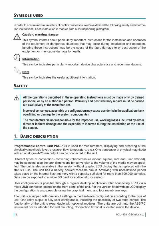
Programmable control unit PCU–100isusedformeasurement,displayingandarchivingofthephysicalvalue(liquidlevel,pressure,flow,temperature,etc.).Onetransducerofphysicalmagnitudewith an analogue 4-20 mA output can be connected to the unit.
Different typesof conversion (converting)characteristics (linear, square, rootanduserdefined),maybeselected,alsothetankdimensionsforconversiontothevolumeofthemediamaybespeci-fied.TheunitisalsoavailableintheversionwithoutgraphicLCDdisplaythatisreplacedwiththestatusLEDs.Theunit hasabatterybacked real-timecircuit.Archivingwithuser-definedperiodtakesplaceontheinternalflashmemorywithacapacitysufficientformorethan500,000samples.Data can be exported to a micro SD card for additional processing.
Userconfiguration ispossible througharegulardesktopapplicationafterconnectingaPCviaamicroUSBconnectorlocatedonthefrontpaneloftheunit.FortheversionfittedwithanLCDdisplaytheconfigurationisalsopossibleusingthegraphicalmenuandfourmembranekeys.
Theunitisequippedwithoneinputsettingsinthehardwareconfigurationaccordingtothetypeofunit.Onerelayoutput isfullyuser-configurable, includingthepossibilityoftwo-statecontrol.Thefunctionalityoftheunit isexpandablewithoptionalmodules.Theunitsarebuilt intotheABS/PCinstrument boxes intended for wall mounting. Connection terminal is located inside the device.
All the operations described in these operating instructions must be made only by trained personnel or by an authorised person. Warranty and post-warranty repairs must be carried out exclusively at the manufacturer.Incorrect sensor use, assembly or configuration may cause accidents in the application (tank overfilling or damage to the system components).The manufacturer is not responsible for the improper use, working losses incurred by either direct or indirect damage and the expenditure incurred during the installation or the use of the sensor.
Inordertoensuremaximumsafetyofcontrolprocesses,wehavedefinedthefollowingsafetyandinforma-tion instructions. Each instruction is marked with a corresponding pictogram.
Caution, warning, danger
Thissymbolinformsaboutparticularlyimportantinstructionsfortheinstallationandoperationoftheequipmentordangeroussituationsthatmayoccurduringinstallationandoperation.Ignoringthese instructionsmaybethecauseof thefault,damagetoordestructionof theequipmentormaycausedamagetohealth.
Information
Thissymbolindicatesparticularlyimportantdevicecharacteristicsandrecommendations.
Note
Thissymbolindicatestheusefuladditionalinformation.
Symbols used
Safety
1. Basic description
4© Dinel, s.r.o. PCU–100
Programmable control unit can be used as a universal industrial data logger for monitoring of a measuredvalue.Thankstoarelayoutput,itisalsopossibletousetheunitforthecontroloftheprocess of measured value using two-state control.
2. Application areas
3. Unit's variants
• PCU–100–D Front panel with a graphic LCD display and a membrane keypad. The entrydependingonconfiguration(forconnectingonesensor),onerelayout-put.
The unit is available in two versions. Themakes are different by the front panel appearance.BothversionshaveamicroUSBconnector toconnectacomputer toconfigure theunitvia theconfigurationapplicationandmicroSDcardslotforthepurposesofexportsoftherecordeddata.
• PCU–100–L The front panel without an LCD display with status LEDs. The entrydependingonconfiguration(forconnectingonesensor),onerelayoutput
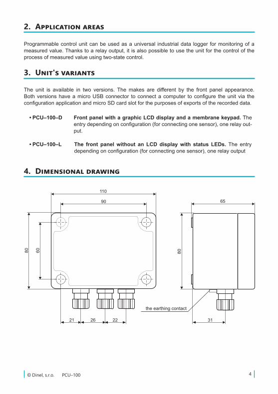
4. Dimensional drawing
the earthing contact
PCU–100 © Dinel, s.r.o.5
• A number of evaluation units PCU-100-X is designed to be installed on a wall using four mountingscrewsorbolts(hereinafterreferredtoas“thescrews”).
• When installing the device, it is first necessary to withdraw the transparent polycarbonatehousingofthefrontpanelthatisheldinplaceby4plasticscrews.Themountingholesdesignedforscrewsforattachingtothewallarelocatedundertheplasticscrews.Usingthescrews,theunitisfixedintherequiredpositiononthewall.Now,itispossibletoconnectthecablestotheterminals.
• Then,returnthetransparentcover to theplaceonthefrontpaneland itsplasticscrewsaresufficientlytightenedtoachievefullcoverage.
• Theprescribedtighteningtorqueis3Nm.
6. Installation instructions
7. Mechanical mounting
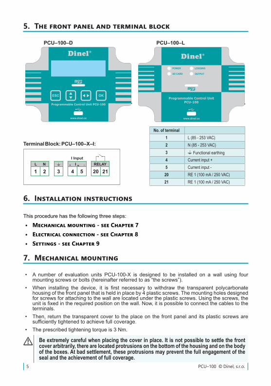
No. of terminal1 L (85 - 253 VAC)2 N (85 - 253 VAC)3 Functional earthing4 Current input +5 Current input -
20 RE 1 (100 mA / 250 VAC)21 RE 1 (100 mA / 250 VAC)
5. The front panel and terminal block
SCHÉMA ŠTÍTKU (ČERVENĚ JSOU VYZNAČENY OTVORY)
Poznámka: šedé orámování tlačítek bude ještě v rovině fólie
www.dinel.cz
Programmable Control Unit PCU-100
ESC OK
1 2 3 4
PIN 1PIN 1
1 2 3 4
MAR SR 191
TransparentPANT 320vývod
z rubovéstrany
PIN 1
14,5
15
SCHÉMA ŠTÍTKU (ČERVENĚ JSOU VYZNAČENY OTVORY)
MAR SR 191PANT 320
www.dinel.cz
Programmable Control Unit
PCU-100
POWER
POWER
SD CARD
LOGGING
OUTPUT
POWER
PCU–100–D PCU–100–L
Terminal Block: PCU–100–X–I:
This procedure has the following three steps:
• Mechanical mounting - see Chapter 7• Electrical connection - see Chapter 8• Settings - see Chapter 9
Be extremely careful when placing the cover in place. It is not possible to settle the front cover arbitrarily, there are located protrusions on the bottom of the housing and on the body of the boxes. At bad settlement, these protrusions may prevent the full engagement of the seal and the achievement of full coverage.
6© Dinel, s.r.o. PCU–100
8. Electrical connection
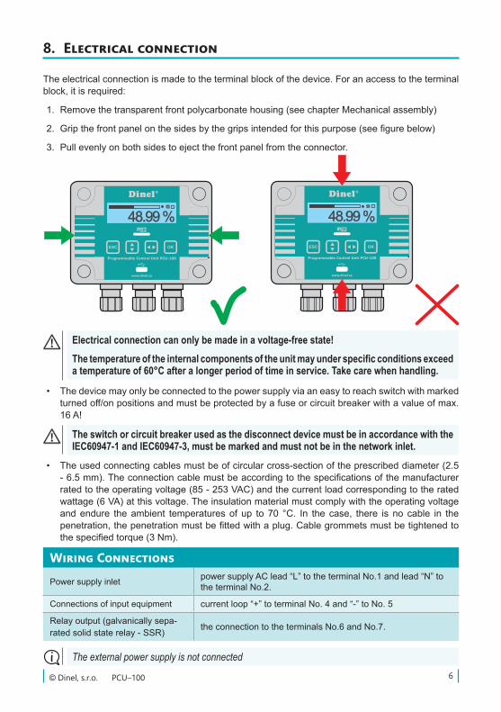
Electrical connection can only be made in a voltage-free state!The temperature of the internal components of the unit may under specific conditions exceed a temperature of 60°C after a longer period of time in service. Take care when handling.
• Thedevicemayonlybeconnectedtothepowersupplyviaaneasytoreachswitchwithmarkedturnedoff/onpositionsandmustbeprotectedbyafuseorcircuitbreakerwithavalueofmax.16 A!
• Theusedconnectingcablesmustbeofcircularcross-sectionoftheprescribeddiameter(2.5-6.5mm).Theconnectioncablemustbeaccordingtothespecificationsofthemanufacturerratedtotheoperatingvoltage(85-253VAC)andthecurrentloadcorrespondingtotheratedwattage(6VA)atthisvoltage.Theinsulationmaterialmustcomplywiththeoperatingvoltageandendure theambient temperaturesof up to70 °C. In the case, there is no cable in thepenetration,thepenetrationmustbefittedwithaplug.Cablegrommetsmustbetightenedtothespecifiedtorque(3Nm).
The switch or circuit breaker used as the disconnect device must be in accordance with the IEC60947-1 and IEC60947-3, must be marked and must not be in the network inlet.
The external power supply is not connected
Wiring Connections
Powersupplyinlet powersupplyAClead“L”totheterminalNo.1andlead“N”totheterminalNo.2.
Connections of input equipment currentloop“+”toterminalNo.4and“-”toNo.5
Relayoutput(galvanicallysepa-ratedsolidstaterelay-SSR) theconnectiontotheterminalsNo.6andNo.7.
The electrical connection is made to the terminal block of the device. For an access to the terminal block,itisrequired:
1. Removethetransparentfrontpolycarbonatehousing(seechapterMechanicalassembly)
2. Gripthefrontpanelonthesidesbythegripsintendedforthispurpose(seefigurebelow)
3. Pullevenlyonbothsidestoejectthefrontpanelfromtheconnector.
PCU–100 © Dinel, s.r.o.7
The grounding wire is always attached only in one place by using the method 1 or 2. It is never attached in both places at the same time.
• Grounding wire connected to the unit serves always as the functional ground to improvetheassembly resistanceagainstEM interferenceanddoesnot fulfil theprotective function.Connectionofa functionalearth to theunit ispossible inoneof the twowayswhilewearechoosingthewaythatallowsconnectionthegroundwireonashorterroute:
1. We will connect the grounding wire inside the unit to the terminal number three where it is assumed to bring the earthing wire to the unit within the power cable.
2. Thegroundingwirewillbeconnectedtotheexternalearthterminalofthedevice,whichis located on the bottom of the box together with outlets.
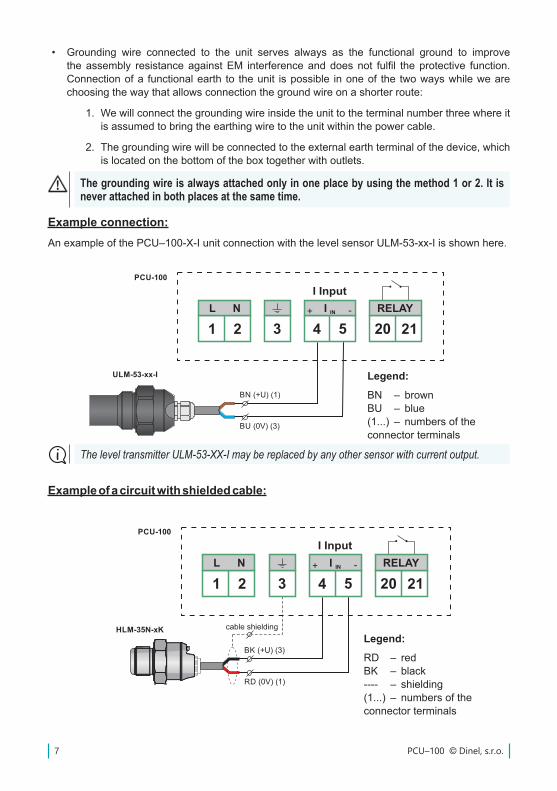
Example connection:AnexampleofthePCU–100-X-IunitconnectionwiththelevelsensorULM-53-xx-Iisshownhere.
Legend:BN – brownBU – blue(1...) – numbersoftheconnector terminals
The level transmitter ULM-53-XX-I may be replaced by any other sensor with current output.
Legend:RD – redBK – black---- – shielding(1...) – numbersoftheconnector terminals
Example of a circuit with shielded cable:
8© Dinel, s.r.o. PCU–100
9. Settings
Be extremely careful when placing the cover back in place. It is not possible to settle the front cover arbitrarily, there are located protrusions on the bottom of the housing and on the body of the boxes. At bad settlement, these protrusions may prevent the full engagement of the seal and the achievement of full coverage.
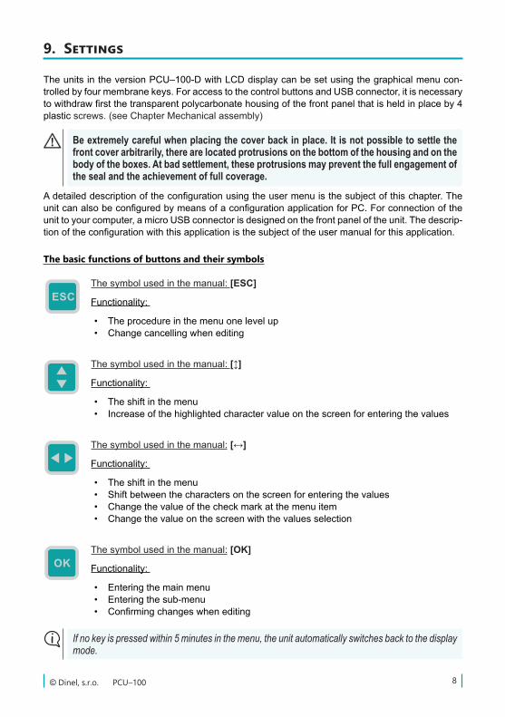
Thesymbolusedinthemanual:[ESC]
Functionality:
• The procedure in the menu one level up• Change cancelling when editing
Thesymbolusedinthemanual:[]
Functionality:
• The shift in the menu• Increase of the highlighted character value on the screen for entering the values
Thesymbolusedinthemanual: [↔]
Functionality:
• The shift in the menu• Shift between the characters on the screen for entering the values• Change the value of the check mark at the menu item• Change the value on the screen with the values selection
Thesymbolusedinthemanual: [OK]
Functionality:
• Entering the main menu • Entering the sub-menu• Confirmingchangeswhenediting
If no key is pressed within 5 minutes in the menu, the unit automatically switches back to the display mode.
The basic functions of buttons and their symbols
TheunitsintheversionPCU–100-DwithLCDdisplaycanbesetusingthegraphicalmenucon-trolledbyfourmembranekeys.ForaccesstothecontrolbuttonsandUSBconnector,itisnecessarytowithdrawfirstthetransparentpolycarbonatehousingofthefrontpanelthatisheldinplaceby4plasticscrews.(seeChapterMechanicalassembly)
Adetaileddescriptionoftheconfigurationusingtheusermenuisthesubjectofthischapter.TheunitcanalsobeconfiguredbymeansofaconfigurationapplicationforPC.Forconnectionoftheunittoyourcomputer,amicroUSBconnectorisdesignedonthefrontpaneloftheunit.Thedescrip-tionoftheconfigurationwiththisapplicationisthesubjectoftheusermanualforthisapplication.
PCU–100 © Dinel, s.r.o.9
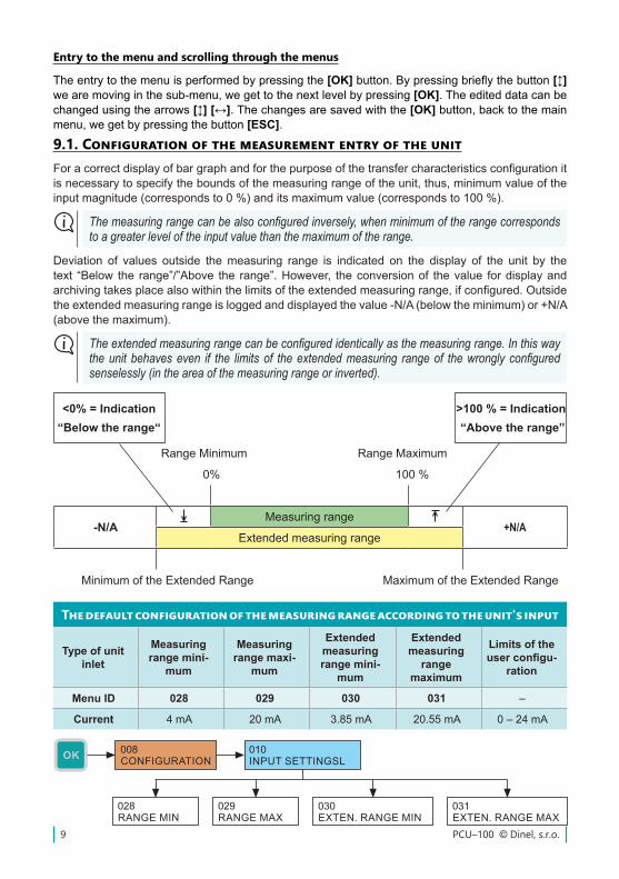
9.1. Configuration of the measurement entry of the unitForacorrectdisplayofbargraphandforthepurposeofthetransfercharacteristicsconfigurationitisnecessarytospecifytheboundsofthemeasuringrangeoftheunit,thus,minimumvalueoftheinputmagnitude(correspondsto0%)anditsmaximumvalue(correspondsto100%).
The default configuration of the measuring range according to the unit's input
Type of unit inlet
Measuring range mini-
mum
Measuring range maxi-
mum
Extended measuring range mini-
mum
Extended measuring
rangemaximum
Limits of the user configu-
ration
Menu ID 028 029 030 031 –
Current 4 mA 20 mA 3.85 mA 20.55 mA 0 – 24 mA
The measuring range can be also configured inversely, when minimum of the range corresponds to a greater level of the input value than the maximum of the range.
Deviation of values outside themeasuring range is indicated on the display of the unit by thetext “Below the range”/”Above the range”.However, theconversionof thevalue fordisplayandarchivingtakesplacealsowithinthelimitsoftheextendedmeasuringrange,ifconfigured.Outsidetheextendedmeasuringrangeisloggedanddisplayedthevalue-N/A(belowtheminimum)or+N/A(abovethemaximum).
The extended measuring range can be configured identically as the measuring range. In this way the unit behaves even if the limits of the extended measuring range of the wrongly configured senselessly (in the area of the measuring range or inverted).
Range Minimum Range Maximum
0% 100%
-N/AMeasuring range
+N/AExtended measuring range
Minimum of the Extended Range Maximum of the Extended Range
<0% = Indication “Below the range“
>100 % = Indication “Above the range”
Entry to the menu and scrolling through the menus
Theentrytothemenuisperformedbypressingthe[OK]button.Bypressingbrieflythebutton[] wearemovinginthesub-menu,wegettothenextlevelbypressing[OK]. The edited data can be changed using the arrows [] [↔]. The changes are saved with the [OK]button,backtothemainmenu,wegetbypressingthebutton[ESC].
10© Dinel, s.r.o. PCU–100
9.1.1. Filtration of the input value
Itissuitabletousethefiltrationfunctionforsuppressionofthefluctuationsinviewatfastorjumpchanges of the input value. The subsequent speed of change of the input value will be dependent onanexponentialcourse.Filtrationwithdefineddelayinsecondsindicatesthetimethattheexpo-nentialcurvereaches2/3ofitsmaximumvalue.
To turn off the filtration, it is necessary to configure the value to 0 seconds.
9.2. Display configuration
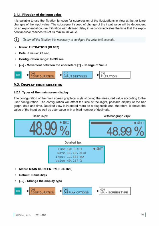
9.2.1. Types of the main screen display
Theconfigurationofthemainscreengraphicalstyleshowingthemeasuredvalueaccordingtotheuserconfiguration.Theconfigurationwillaffect thesizeof thedigits,possibledisplayof thebargraph,dateandtime.Detailedviewisintendedmoreasadiagnosticand,therefore,itshowsthevalueoftheinputaswellasuservaluewithafixednumberofdecimals.
• Menu: MAIN SCREEN TYPE (ID 020)
• Default: Basic 32px
• [↔] - Change the display type
Basic 32px With bar graph 24px
Detailed 8px
• Menu: FILTRATION (ID 032)
• Default value: 20 sec
• Configuration range: 0-999 sec
• [↔] - Movement between the characters [] - Change of Value
PCU–100 © Dinel, s.r.o.11
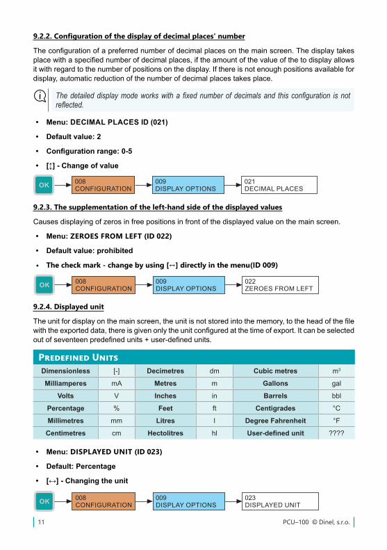
9.2.4. Displayed unit
Theunitfordisplayonthemainscreen,theunitisnotstoredintothememory,totheheadofthefilewiththeexporteddata,thereisgivenonlytheunitconfiguredatthetimeofexport.Itcanbeselectedoutofseventeenpredefinedunits+user-definedunits.
Predefined UnitsDimensionless [-] Decimetres dm Cubic metres m3
Milliamperes mA Metres m Gallons gal
Volts V Inches in Barrels bbl
Percentage % Feet ft Centigrades °C
Millimetres mm Litres l Degree Fahrenheit °F
Centimetres cm Hectolitres hl User-defined unit ????
9.2.3. The supplementation of the left-hand side of the displayed values
Causesdisplayingofzerosinfreepositionsinfrontofthedisplayedvalueonthemainscreen.
• Menu: ZEROES FROM LEFT (ID 022)
• Default value: prohibited
• The check mark - change by using [↔] directly in the menu(ID 009)
9.2.2. Configuration of the display of decimal places' number
Theconfigurationofapreferrednumberofdecimalplacesonthemainscreen.Thedisplaytakesplacewithaspecifiednumberofdecimalplaces,iftheamountofthevalueofthetodisplayallowsitwithregardtothenumberofpositionsonthedisplay.Ifthereisnotenoughpositionsavailablefordisplay,automaticreductionofthenumberofdecimalplacestakesplace.
The detailed display mode works with a fixed number of decimals and this configuration is not reflected.
• Menu: DECIMAL PLACES ID (021)
• Default value: 2
• Configuration range: 0-5
• [] - Change of value
• Menu: DISPLAYED UNIT (ID 023)
• Default: Percentage
• [↔] - Changing the unit
12© Dinel, s.r.o. PCU–100
9.2.5. Defining the user unit
Itispossibletoenterany4characters.Theheredefinedunitisthenofferedtheselectionofunits.
• Menu: USER UNIT ID (024)
• [↔] - Movement between characters [] - Change of the character
9.2.6. The menu language
Theunitallowstoselectalanguagemutationsandcurrency.CzechorEnglishareavailable.
• Menu: MENU LANGUAGE (ID 025)
• Default: English
• [↔] - Change of value
9.2.7. Backlight level of the LCD display
ConfigurationoftheLCDbacklightlevel.Itispossibletoselectfromninelevelsbacklightanditsfullturn-off(0value).
• Menu: BACKLIGHT LEVEL (ID 026)
• Default value: 3
• Configuration range: 0 - 9
• [] - Change of value
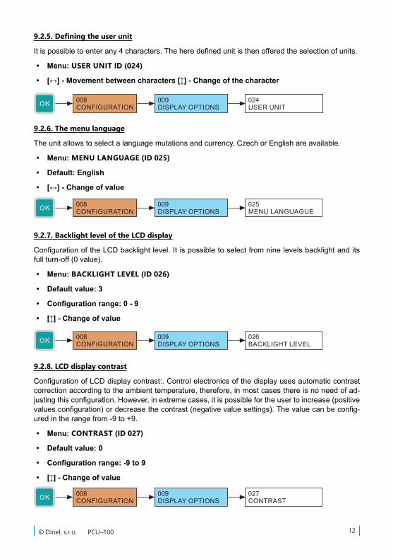
9.2.8. LCD display contrast
ConfigurationofLCDdisplaycontrast:.Controlelectronicsofthedisplayusesautomaticcontrastcorrectionaccordingtotheambienttemperature,therefore,inmostcasesthereisnoneedofad-justingthisconfiguration.However,inextremecases,itispossiblefortheusertoincrease(positivevaluesconfiguration)ordecreasethecontrast(negativevaluesettings).Thevaluecanbeconfig-uredintherangefrom-9to+9.
• Menu: CONTRAST (ID 027)
• Default value: 0
• Configuration range: -9 to 9
• [] - Change of value
PCU–100 © Dinel, s.r.o.13
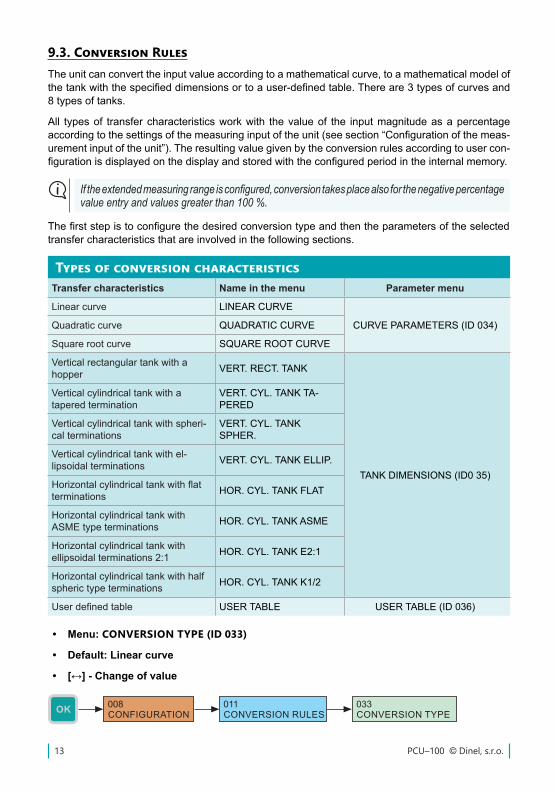
9.3. Conversion RulesTheunitcanconverttheinputvalueaccordingtoamathematicalcurve,toamathematicalmodelofthetankwiththespecifieddimensionsortoauser-definedtable.Thereare3typesofcurvesand8typesoftanks.
All typesof transfercharacteristicsworkwith thevalueof the inputmagnitudeasapercentageaccordingtothesettingsofthemeasuringinputoftheunit(seesection“Configurationofthemeas-urementinputoftheunit”).Theresultingvaluegivenbytheconversionrulesaccordingtousercon-figurationisdisplayedonthedisplayandstoredwiththeconfiguredperiodintheinternalmemory.
Types of conversion characteristicsTransfer characteristics Name in the menu Parameter menu
Linearcurve LINEARCURVE
CURVEPARAMETERS(ID034)Quadratic curve QUADRATICCURVE
Square root curve SQUAREROOTCURVE
Verticalrectangulartankwithahopper VERT.RECT.TANK
TANKDIMENSIONS(ID035)
Verticalcylindricaltankwithatapered termination
VERT.CYL.TANKTA-PERED
Verticalcylindricaltankwithspheri-cal terminations
VERT.CYL.TANKSPHER.
Verticalcylindricaltankwithel-lipsoidal terminations VERT.CYL.TANKELLIP.
Horizontalcylindricaltankwithflatterminations HOR.CYL.TANKFLAT
HorizontalcylindricaltankwithASMEtypeterminations HOR.CYL.TANKASME
Horizontalcylindricaltankwithellipsoidal terminations 2:1 HOR.CYL.TANKE2:1
Horizontalcylindricaltankwithhalfspherictypeterminations HOR.CYL.TANKK1/2
Userdefinedtable USERTABLE USERTABLE(ID036)
If the extended measuring range is configured, conversion takes place also for the negative percentage value entry and values greater than 100 %.
Thefirststepistoconfigurethedesiredconversiontypeandthentheparametersoftheselectedtransfer characteristics that are involved in the following sections.
• Menu: CONVERSION TYPE (ID 033)
• Default: Linear curve
• [↔] - Change of value
14© Dinel, s.r.o. PCU–100
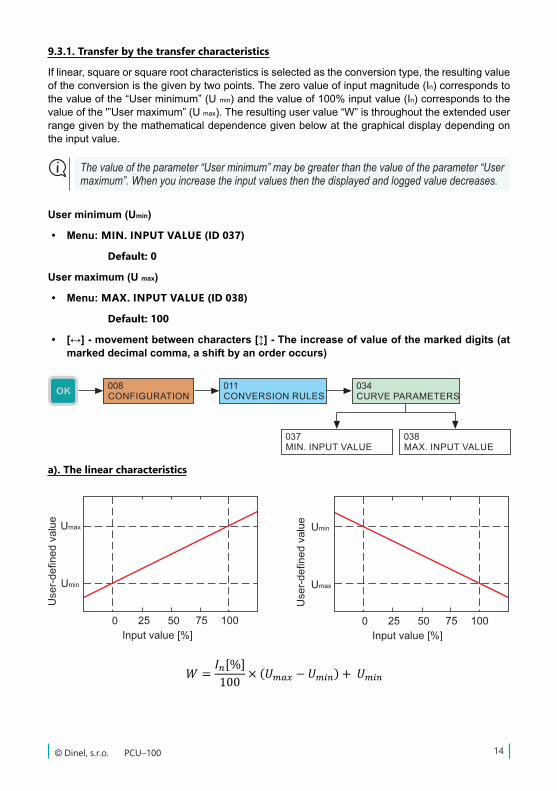
9.3.1. Transfer by the transfer characteristics
Iflinear,squareorsquarerootcharacteristicsisselectedastheconversiontype,theresultingvalueoftheconversionisthegivenbytwopoints.Thezerovalueofinputmagnitude(In)correspondstothevalueofthe“Userminimum”(Umin)andthevalueof100%inputvalue(In)correspondstothevalueofthe'”Usermaximum”(Umax).Theresultinguservalue“W”isthroughouttheextendeduserrangegivenbythemathematicaldependencegivenbelowatthegraphicaldisplaydependingonthe input value.
The value of the parameter “User minimum” may be greater than the value of the parameter “User maximum”. When you increase the input values then the displayed and logged value decreases.
User minimum (Umin)
• Menu: MIN. INPUT VALUE (ID 037)
Default: 0
User maximum (U max)
• Menu: MAX. INPUT VALUE (ID 038)
Default: 100
• [↔] - movement between characters [] - The increase of value of the marked digits (at marked decimal comma, a shift by an order occurs)
ℎ =𝐼𝐼𝐼𝐼𝑛𝑛𝑛𝑛[%]100
× 𝑉𝑉𝑉𝑉ýš𝑘𝑘𝑘𝑘𝑘𝑘𝑘𝑘 𝑛𝑛𝑛𝑛á𝑑𝑑𝑑𝑑𝑑𝑑𝑑𝑑ž𝑒𝑒𝑒𝑒
𝑊𝑊𝑊𝑊 =𝐼𝐼𝐼𝐼𝑛𝑛𝑛𝑛[%]100
× (𝑈𝑈𝑈𝑈𝑚𝑚𝑚𝑚𝑚𝑚𝑚𝑚𝑚𝑚𝑚𝑚 − 𝑈𝑈𝑈𝑈𝑚𝑚𝑚𝑚𝑚𝑚𝑚𝑚𝑛𝑛𝑛𝑛) + 𝑈𝑈𝑈𝑈𝑚𝑚𝑚𝑚𝑚𝑚𝑚𝑚𝑛𝑛𝑛𝑛
𝑊𝑊𝑊𝑊 = 𝐼𝐼𝐼𝐼𝑛𝑛𝑛𝑛[%]100
2
× (𝑈𝑈𝑈𝑈𝑚𝑚𝑚𝑚𝑚𝑚𝑚𝑚𝑚𝑚𝑚𝑚 − 𝑈𝑈𝑈𝑈𝑚𝑚𝑚𝑚𝑚𝑚𝑚𝑚𝑛𝑛𝑛𝑛) + 𝑈𝑈𝑈𝑈𝑚𝑚𝑚𝑚𝑚𝑚𝑚𝑚𝑛𝑛𝑛𝑛
𝑊𝑊𝑊𝑊 = 𝐼𝐼𝐼𝐼𝑛𝑛𝑛𝑛[%]100
× (𝑈𝑈𝑈𝑈𝑚𝑚𝑚𝑚𝑚𝑚𝑚𝑚𝑚𝑚𝑚𝑚 − 𝑈𝑈𝑈𝑈𝑚𝑚𝑚𝑚𝑚𝑚𝑚𝑚𝑛𝑛𝑛𝑛) + 𝑈𝑈𝑈𝑈𝑚𝑚𝑚𝑚𝑚𝑚𝑚𝑚𝑛𝑛𝑛𝑛
𝑊𝑊𝑊𝑊 =𝐼𝐼𝐼𝐼𝑛𝑛𝑛𝑛[%] − 𝑋𝑋𝑋𝑋(𝑃𝑃𝑃𝑃𝑃𝑃𝑃𝑃)𝑋𝑋𝑋𝑋(𝑃𝑃𝑃𝑃𝑃𝑃𝑃𝑃) − 𝑋𝑋𝑋𝑋(𝑃𝑃𝑃𝑃𝑃𝑃𝑃𝑃)
× [𝑌𝑌𝑌𝑌(𝑃𝑃𝑃𝑃𝑃𝑃𝑃𝑃)− 𝑌𝑌𝑌𝑌(𝑃𝑃𝑃𝑃𝑃𝑃𝑃𝑃)] + 𝑌𝑌𝑌𝑌(𝑃𝑃𝑃𝑃𝑃𝑃𝑃𝑃)
ℎ =𝐼𝐼𝐼𝐼𝑛𝑛𝑛𝑛[%]100
× 𝑇𝑇𝑇𝑇𝑘𝑘𝑘𝑘𝑛𝑛𝑛𝑛𝑘𝑘𝑘𝑘 ℎ𝑒𝑒𝑒𝑒𝑒𝑒𝑒𝑒𝑒𝑒𝑒𝑒ℎ𝑡𝑡𝑡𝑡
a). The linear characteristics
PCU–100 © Dinel, s.r.o.15
ℎ =𝐼𝐼𝐼𝐼𝑛𝑛𝑛𝑛[%]100
× 𝑉𝑉𝑉𝑉ýš𝑘𝑘𝑘𝑘𝑘𝑘𝑘𝑘 𝑛𝑛𝑛𝑛á𝑑𝑑𝑑𝑑𝑑𝑑𝑑𝑑ž𝑒𝑒𝑒𝑒
𝑊𝑊𝑊𝑊 =𝐼𝐼𝐼𝐼𝑛𝑛𝑛𝑛[%]100
× (𝑈𝑈𝑈𝑈𝑚𝑚𝑚𝑚𝑚𝑚𝑚𝑚𝑚𝑚𝑚𝑚 − 𝑈𝑈𝑈𝑈𝑚𝑚𝑚𝑚𝑚𝑚𝑚𝑚𝑛𝑛𝑛𝑛) + 𝑈𝑈𝑈𝑈𝑚𝑚𝑚𝑚𝑚𝑚𝑚𝑚𝑛𝑛𝑛𝑛
𝑊𝑊𝑊𝑊 = 𝐼𝐼𝐼𝐼𝑛𝑛𝑛𝑛[%]100
2
× (𝑈𝑈𝑈𝑈𝑚𝑚𝑚𝑚𝑚𝑚𝑚𝑚𝑚𝑚𝑚𝑚 − 𝑈𝑈𝑈𝑈𝑚𝑚𝑚𝑚𝑚𝑚𝑚𝑚𝑛𝑛𝑛𝑛) + 𝑈𝑈𝑈𝑈𝑚𝑚𝑚𝑚𝑚𝑚𝑚𝑚𝑛𝑛𝑛𝑛
𝑊𝑊𝑊𝑊 = 𝐼𝐼𝐼𝐼𝑛𝑛𝑛𝑛[%]100
× (𝑈𝑈𝑈𝑈𝑚𝑚𝑚𝑚𝑚𝑚𝑚𝑚𝑚𝑚𝑚𝑚 − 𝑈𝑈𝑈𝑈𝑚𝑚𝑚𝑚𝑚𝑚𝑚𝑚𝑛𝑛𝑛𝑛) + 𝑈𝑈𝑈𝑈𝑚𝑚𝑚𝑚𝑚𝑚𝑚𝑚𝑛𝑛𝑛𝑛
𝑊𝑊𝑊𝑊 =𝐼𝐼𝐼𝐼𝑛𝑛𝑛𝑛[%] − 𝑋𝑋𝑋𝑋(𝑃𝑃𝑃𝑃𝑃𝑃𝑃𝑃)𝑋𝑋𝑋𝑋(𝑃𝑃𝑃𝑃𝑃𝑃𝑃𝑃) − 𝑋𝑋𝑋𝑋(𝑃𝑃𝑃𝑃𝑃𝑃𝑃𝑃)
× [𝑌𝑌𝑌𝑌(𝑃𝑃𝑃𝑃𝑃𝑃𝑃𝑃)− 𝑌𝑌𝑌𝑌(𝑃𝑃𝑃𝑃𝑃𝑃𝑃𝑃)] + 𝑌𝑌𝑌𝑌(𝑃𝑃𝑃𝑃𝑃𝑃𝑃𝑃)
ℎ =𝐼𝐼𝐼𝐼𝑛𝑛𝑛𝑛[%]100
× 𝑇𝑇𝑇𝑇𝑘𝑘𝑘𝑘𝑛𝑛𝑛𝑛𝑘𝑘𝑘𝑘 ℎ𝑒𝑒𝑒𝑒𝑒𝑒𝑒𝑒𝑒𝑒𝑒𝑒ℎ𝑡𝑡𝑡𝑡
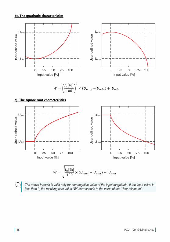
b). The quadratic characteristics
c). The square root characteristics
The above formula is valid only for non negative value of the input magnitude. If the input value is less than 0, the resulting user value “W” corresponds to the value of the “User minimum”.
ℎ =𝐼𝐼𝐼𝐼𝑛𝑛𝑛𝑛[%]100
× 𝑉𝑉𝑉𝑉ýš𝑘𝑘𝑘𝑘𝑘𝑘𝑘𝑘 𝑛𝑛𝑛𝑛á𝑑𝑑𝑑𝑑𝑑𝑑𝑑𝑑ž𝑒𝑒𝑒𝑒
𝑊𝑊𝑊𝑊 =𝐼𝐼𝐼𝐼𝑛𝑛𝑛𝑛[%]100
× (𝑈𝑈𝑈𝑈𝑚𝑚𝑚𝑚𝑚𝑚𝑚𝑚𝑚𝑚𝑚𝑚 − 𝑈𝑈𝑈𝑈𝑚𝑚𝑚𝑚𝑚𝑚𝑚𝑚𝑛𝑛𝑛𝑛) + 𝑈𝑈𝑈𝑈𝑚𝑚𝑚𝑚𝑚𝑚𝑚𝑚𝑛𝑛𝑛𝑛
𝑊𝑊𝑊𝑊 = 𝐼𝐼𝐼𝐼𝑛𝑛𝑛𝑛[%]100
2
× (𝑈𝑈𝑈𝑈𝑚𝑚𝑚𝑚𝑚𝑚𝑚𝑚𝑚𝑚𝑚𝑚 − 𝑈𝑈𝑈𝑈𝑚𝑚𝑚𝑚𝑚𝑚𝑚𝑚𝑛𝑛𝑛𝑛) + 𝑈𝑈𝑈𝑈𝑚𝑚𝑚𝑚𝑚𝑚𝑚𝑚𝑛𝑛𝑛𝑛
𝑊𝑊𝑊𝑊 = 𝐼𝐼𝐼𝐼𝑛𝑛𝑛𝑛[%]100
× (𝑈𝑈𝑈𝑈𝑚𝑚𝑚𝑚𝑚𝑚𝑚𝑚𝑚𝑚𝑚𝑚 − 𝑈𝑈𝑈𝑈𝑚𝑚𝑚𝑚𝑚𝑚𝑚𝑚𝑛𝑛𝑛𝑛) + 𝑈𝑈𝑈𝑈𝑚𝑚𝑚𝑚𝑚𝑚𝑚𝑚𝑛𝑛𝑛𝑛
𝑊𝑊𝑊𝑊 =𝐼𝐼𝐼𝐼𝑛𝑛𝑛𝑛[%] − 𝑋𝑋𝑋𝑋(𝑃𝑃𝑃𝑃𝑃𝑃𝑃𝑃)𝑋𝑋𝑋𝑋(𝑃𝑃𝑃𝑃𝑃𝑃𝑃𝑃) − 𝑋𝑋𝑋𝑋(𝑃𝑃𝑃𝑃𝑃𝑃𝑃𝑃)
× [𝑌𝑌𝑌𝑌(𝑃𝑃𝑃𝑃𝑃𝑃𝑃𝑃)− 𝑌𝑌𝑌𝑌(𝑃𝑃𝑃𝑃𝑃𝑃𝑃𝑃)] + 𝑌𝑌𝑌𝑌(𝑃𝑃𝑃𝑃𝑃𝑃𝑃𝑃)
ℎ =𝐼𝐼𝐼𝐼𝑛𝑛𝑛𝑛[%]100
× 𝑇𝑇𝑇𝑇𝑘𝑘𝑘𝑘𝑛𝑛𝑛𝑛𝑘𝑘𝑘𝑘 ℎ𝑒𝑒𝑒𝑒𝑒𝑒𝑒𝑒𝑒𝑒𝑒𝑒ℎ𝑡𝑡𝑡𝑡
16© Dinel, s.r.o. PCU–100
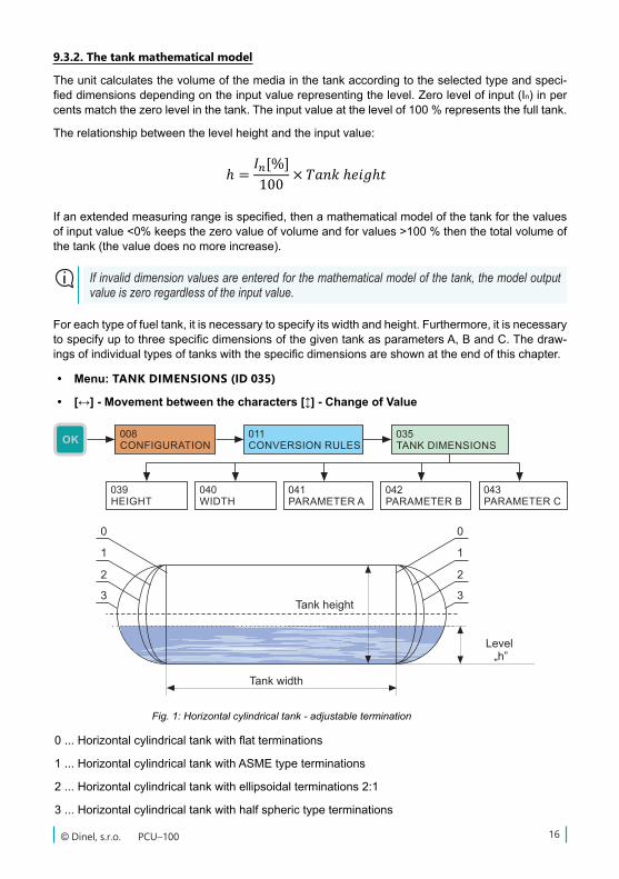
Fig. 1: Horizontal cylindrical tank - adjustable termination
0...Horizontalcylindricaltankwithflatterminations
1...HorizontalcylindricaltankwithASMEtypeterminations
2...Horizontalcylindricaltankwithellipsoidalterminations2:1
3...Horizontalcylindricaltankwithhalfspherictypeterminations
9.3.2. The tank mathematical model
Theunitcalculatesthevolumeofthemediainthetankaccordingtotheselectedtypeandspeci-fieddimensionsdependingontheinputvaluerepresentingthelevel.Zerolevelofinput(In)inpercentsmatchthezerolevelinthetank.Theinputvalueatthelevelof100%representsthefulltank.
The relationship between the level height and the input value:
• Menu: TANK DIMENSIONS (ID 035)
• [↔] - Movement between the characters [] - Change of Value
ℎ =𝐼𝐼𝐼𝐼𝑛𝑛𝑛𝑛[%]100
× 𝑉𝑉𝑉𝑉ýš𝑘𝑘𝑘𝑘𝑘𝑘𝑘𝑘 𝑛𝑛𝑛𝑛á𝑑𝑑𝑑𝑑𝑑𝑑𝑑𝑑ž𝑒𝑒𝑒𝑒
𝑊𝑊𝑊𝑊 =𝐼𝐼𝐼𝐼𝑛𝑛𝑛𝑛[%]100
× (𝑈𝑈𝑈𝑈𝑚𝑚𝑚𝑚𝑚𝑚𝑚𝑚𝑚𝑚𝑚𝑚 − 𝑈𝑈𝑈𝑈𝑚𝑚𝑚𝑚𝑚𝑚𝑚𝑚𝑛𝑛𝑛𝑛) + 𝑈𝑈𝑈𝑈𝑚𝑚𝑚𝑚𝑚𝑚𝑚𝑚𝑛𝑛𝑛𝑛
𝑊𝑊𝑊𝑊 = 𝐼𝐼𝐼𝐼𝑛𝑛𝑛𝑛[%]100
2
× (𝑈𝑈𝑈𝑈𝑚𝑚𝑚𝑚𝑚𝑚𝑚𝑚𝑚𝑚𝑚𝑚 − 𝑈𝑈𝑈𝑈𝑚𝑚𝑚𝑚𝑚𝑚𝑚𝑚𝑛𝑛𝑛𝑛) + 𝑈𝑈𝑈𝑈𝑚𝑚𝑚𝑚𝑚𝑚𝑚𝑚𝑛𝑛𝑛𝑛
𝑊𝑊𝑊𝑊 = 𝐼𝐼𝐼𝐼𝑛𝑛𝑛𝑛[%]100
× (𝑈𝑈𝑈𝑈𝑚𝑚𝑚𝑚𝑚𝑚𝑚𝑚𝑚𝑚𝑚𝑚 − 𝑈𝑈𝑈𝑈𝑚𝑚𝑚𝑚𝑚𝑚𝑚𝑚𝑛𝑛𝑛𝑛) + 𝑈𝑈𝑈𝑈𝑚𝑚𝑚𝑚𝑚𝑚𝑚𝑚𝑛𝑛𝑛𝑛
𝑊𝑊𝑊𝑊 =𝐼𝐼𝐼𝐼𝑛𝑛𝑛𝑛[%] − 𝑋𝑋𝑋𝑋(𝑃𝑃𝑃𝑃𝑃𝑃𝑃𝑃)𝑋𝑋𝑋𝑋(𝑃𝑃𝑃𝑃𝑃𝑃𝑃𝑃) − 𝑋𝑋𝑋𝑋(𝑃𝑃𝑃𝑃𝑃𝑃𝑃𝑃)
× [𝑌𝑌𝑌𝑌(𝑃𝑃𝑃𝑃𝑃𝑃𝑃𝑃)− 𝑌𝑌𝑌𝑌(𝑃𝑃𝑃𝑃𝑃𝑃𝑃𝑃)] + 𝑌𝑌𝑌𝑌(𝑃𝑃𝑃𝑃𝑃𝑃𝑃𝑃)
ℎ =𝐼𝐼𝐼𝐼𝑛𝑛𝑛𝑛[%]100
× 𝑇𝑇𝑇𝑇𝑘𝑘𝑘𝑘𝑛𝑛𝑛𝑛𝑘𝑘𝑘𝑘 ℎ𝑒𝑒𝑒𝑒𝑒𝑒𝑒𝑒𝑒𝑒𝑒𝑒ℎ𝑡𝑡𝑡𝑡
Ifanextendedmeasuringrangeisspecified,thenamathematicalmodelofthetankforthevaluesofinputvalue<0%keepsthezerovalueofvolumeandforvalues>100%thenthetotalvolumeofthetank(thevaluedoesnomoreincrease).
If invalid dimension values are entered for the mathematical model of the tank, the model output value is zero regardless of the input value.
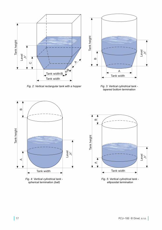
Foreachtypeoffueltank,itisnecessarytospecifyitswidthandheight.Furthermore,itisnecessarytospecifyuptothreespecificdimensionsofthegiventankasparametersA,BandC.Thedraw-ingsofindividualtypesoftankswiththespecificdimensionsareshownattheendofthischapter.
PCU–100 © Dinel, s.r.o.17
Fig. 4: Vertical cylindrical tank - spherical termination (ball)
Fig. 5: Vertical cylindrical tank - ellipsoidal termination
Fig. 2: Vertical rectangular tank with a hopper Fig. 3: Vertical cylindrical tank - tapered bottom termination
18© Dinel, s.r.o. PCU–100
ℎ =𝐼𝐼𝐼𝐼𝑛𝑛𝑛𝑛[%]100
× 𝑉𝑉𝑉𝑉ýš𝑘𝑘𝑘𝑘𝑘𝑘𝑘𝑘 𝑛𝑛𝑛𝑛á𝑑𝑑𝑑𝑑𝑑𝑑𝑑𝑑ž𝑒𝑒𝑒𝑒
𝑊𝑊𝑊𝑊 =𝐼𝐼𝐼𝐼𝑛𝑛𝑛𝑛[%]100
× (𝑈𝑈𝑈𝑈𝑚𝑚𝑚𝑚𝑚𝑚𝑚𝑚𝑚𝑚𝑚𝑚 − 𝑈𝑈𝑈𝑈𝑚𝑚𝑚𝑚𝑚𝑚𝑚𝑚𝑛𝑛𝑛𝑛) + 𝑈𝑈𝑈𝑈𝑚𝑚𝑚𝑚𝑚𝑚𝑚𝑚𝑛𝑛𝑛𝑛
𝑊𝑊𝑊𝑊 = 𝐼𝐼𝐼𝐼𝑛𝑛𝑛𝑛[%]100
2
× (𝑈𝑈𝑈𝑈𝑚𝑚𝑚𝑚𝑚𝑚𝑚𝑚𝑚𝑚𝑚𝑚 − 𝑈𝑈𝑈𝑈𝑚𝑚𝑚𝑚𝑚𝑚𝑚𝑚𝑛𝑛𝑛𝑛) + 𝑈𝑈𝑈𝑈𝑚𝑚𝑚𝑚𝑚𝑚𝑚𝑚𝑛𝑛𝑛𝑛
𝑊𝑊𝑊𝑊 = 𝐼𝐼𝐼𝐼𝑛𝑛𝑛𝑛[%]100
× (𝑈𝑈𝑈𝑈𝑚𝑚𝑚𝑚𝑚𝑚𝑚𝑚𝑚𝑚𝑚𝑚 − 𝑈𝑈𝑈𝑈𝑚𝑚𝑚𝑚𝑚𝑚𝑚𝑚𝑛𝑛𝑛𝑛) + 𝑈𝑈𝑈𝑈𝑚𝑚𝑚𝑚𝑚𝑚𝑚𝑚𝑛𝑛𝑛𝑛
𝑊𝑊𝑊𝑊 =𝐼𝐼𝐼𝐼𝑛𝑛𝑛𝑛[%] − 𝑋𝑋𝑋𝑋(𝑃𝑃𝑃𝑃𝑃𝑃𝑃𝑃)𝑋𝑋𝑋𝑋(𝑃𝑃𝑃𝑃𝑃𝑃𝑃𝑃) − 𝑋𝑋𝑋𝑋(𝑃𝑃𝑃𝑃𝑃𝑃𝑃𝑃)
× [𝑌𝑌𝑌𝑌(𝑃𝑃𝑃𝑃𝑃𝑃𝑃𝑃)− 𝑌𝑌𝑌𝑌(𝑃𝑃𝑃𝑃𝑃𝑃𝑃𝑃)] + 𝑌𝑌𝑌𝑌(𝑃𝑃𝑃𝑃𝑃𝑃𝑃𝑃)
ℎ =𝐼𝐼𝐼𝐼𝑛𝑛𝑛𝑛[%]100
× 𝑇𝑇𝑇𝑇𝑘𝑘𝑘𝑘𝑛𝑛𝑛𝑛𝑘𝑘𝑘𝑘 ℎ𝑒𝑒𝑒𝑒𝑒𝑒𝑒𝑒𝑒𝑒𝑒𝑒ℎ𝑡𝑡𝑡𝑡
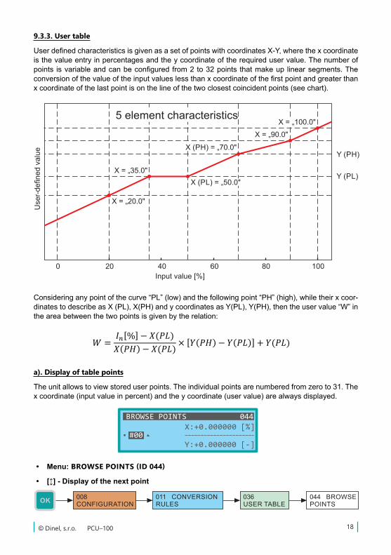
9.3.3. User table
UserdefinedcharacteristicsisgivenasasetofpointswithcoordinatesX-Y,wherethexcoordinateisthevalueentryinpercentagesandtheycoordinateoftherequireduservalue.Thenumberofpoints isvariableandcanbeconfiguredfrom2to32pointsthatmakeup linearsegments.Theconversionofthevalueoftheinputvalueslessthanxcoordinateofthefirstpointandgreaterthanxcoordinateofthelastpointisonthelineofthetwoclosestcoincidentpoints(seechart).
Consideringanypointofthecurve“PL”(low)andthefollowingpoint“PH”(high),whiletheirxcoor-dinatestodescribeasX(PL),X(PH)andycoordinatesasY(PL),Y(PH),thentheuservalue“W”intheareabetweenthetwopointsisgivenbytherelation:
a). Display of table points
Theunitallowstoviewstoreduserpoints.Theindividualpointsarenumberedfromzeroto31.Thexcoordinate(inputvalueinpercent)andtheycoordinate(uservalue)arealwaysdisplayed.
• Menu: BROWSE POINTS (ID 044)
• [] - Display of the next point
PCU–100 © Dinel, s.r.o.19
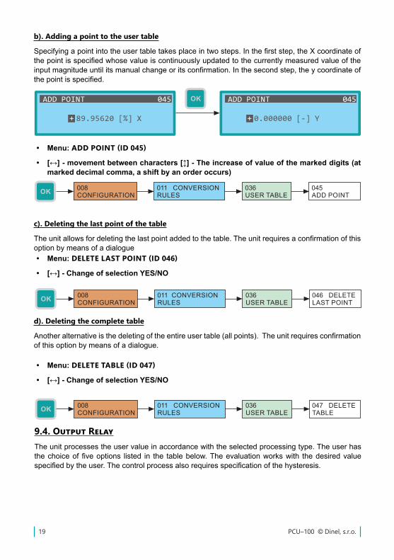
b). Adding a point to the user table
Specifyingapointintotheusertabletakesplaceintwosteps.Inthefirststep,theXcoordinateofthepointisspecifiedwhosevalueiscontinuouslyupdatedtothecurrentlymeasuredvalueoftheinputmagnitudeuntilitsmanualchangeoritsconfirmation.Inthesecondstep,theycoordinateofthepointisspecified.
• Menu: ADD POINT (ID 045)
• [↔] - movement between characters [] - The increase of value of the marked digits (at marked decimal comma, a shift by an order occurs)
c). Deleting the last point of the table
Theunitallowsfordeletingthelastpointaddedtothetable.Theunitrequiresaconfirmationofthisoptionbymeansofadialogue• Menu: DELETE LAST POINT (ID 046)
• [↔] - Change of selection YES/NO
d). Deleting the complete table
Anotheralternativeisthedeletingoftheentireusertable(allpoints).Theunitrequiresconfirmationofthisoptionbymeansofadialogue.
• Menu: DELETE TABLE (ID 047)
• [↔] - Change of selection YES/NO
9.4. Output RelayTheunitprocessestheuservalueinaccordancewiththeselectedprocessingtype.Theuserhasthechoiceoffiveoptions listed in the tablebelow.Theevaluationworkswith thedesiredvaluespecifiedbytheuser.Thecontrolprocessalsorequiresspecificationofthehysteresis.
20© Dinel, s.r.o. PCU–100
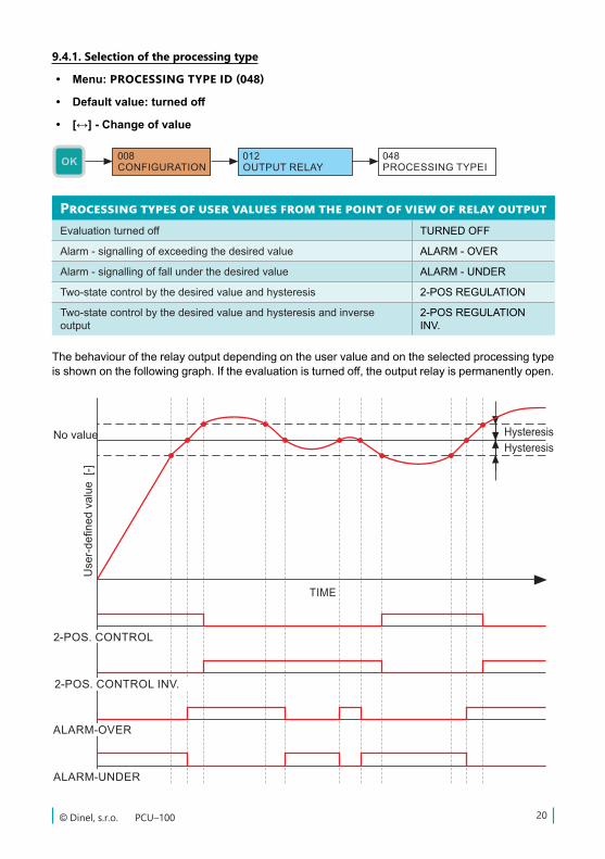
9.4.1. Selection of the processing type
• Menu: PROCESSING TYPE ID (048)
• Default value: turned off
• [↔] - Change of value
Processing types of user values from the point of view of relay outputEvaluationturnedoff TURNEDOFF
Alarm - signalling of exceeding the desired value ALARM-OVER
Alarm - signalling of fall under the desired value ALARM-UNDER
Two-statecontrolbythedesiredvalueandhysteresis 2-POSREGULATION
Two-statecontrolbythedesiredvalueandhysteresisandinverseoutput
2-POSREGULATIONINV.
Thebehaviouroftherelayoutputdependingontheuservalueandontheselectedprocessingtypeisshownonthefollowinggraph.Iftheevaluationisturnedoff,theoutputrelayispermanentlyopen.
PCU–100 © Dinel, s.r.o.21
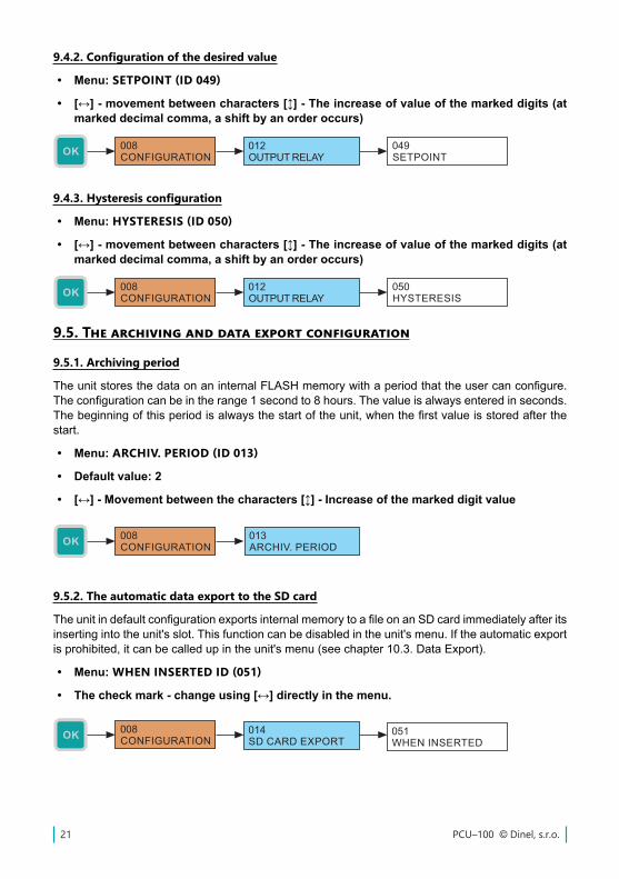
9.4.2. Configuration of the desired value
• Menu: SETPOINT (ID 049)
• [↔] - movement between characters [] - The increase of value of the marked digits (at marked decimal comma, a shift by an order occurs)
9.4.3. Hysteresis configuration
• Menu: HYSTERESIS (ID 050)
• [↔] - movement between characters [] - The increase of value of the marked digits (at marked decimal comma, a shift by an order occurs)
9.5. The archiving and data export configuration
9.5.1. Archiving period
TheunitstoresthedataonaninternalFLASHmemorywithaperiodthattheusercanconfigure.Theconfigurationcanbeintherange1secondto8hours.Thevalueisalwaysenteredinseconds.Thebeginningofthisperiodisalwaysthestartoftheunit,whenthefirstvalueisstoredafterthestart.
• Menu: ARCHIV. PERIOD (ID 013)
• Default value: 2
• [↔] - Movement between the characters [] - Increase of the marked digit value
9.5.2. The automatic data export to the SD card
TheunitindefaultconfigurationexportsinternalmemorytoafileonanSDcardimmediatelyafteritsinserting into the unit's slot. This function can be disabled in the unit's menu. If the automatic export isprohibited,itcanbecalledupintheunit'smenu(seechapter10.3.DataExport).
• Menu: WHEN INSERTED ID (051)
• The check mark - change using [↔] directly in the menu.
22© Dinel, s.r.o. PCU–100
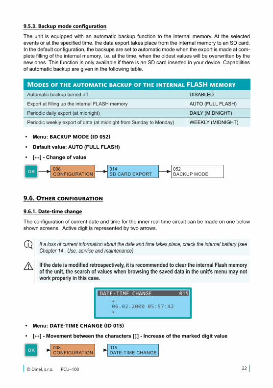
Modes of the automatic backup of the internal FLASH memoryAutomaticbackupturnedoff DISABLED
ExportatfillinguptheinternalFLASHmemory AUTO(FULLFLASH)
Periodicdailyexport(atmidnight) DAILY(MIDNIGHT)
Periodicweeklyexportofdata(atmidnightfromSundaytoMonday) WEEKLY(MIDNIGHT)
• Menu: BACKUP MODE (ID 052)
• Default value: AUTO (FULL FLASH)
• [↔] - Change of value
9.6. Other configuration
9.6.1. Date-time change
Theconfigurationofcurrentdateandtimefortheinnerrealtimecircuitcanbemadeononebelowshownscreens.Activedigitisrepresentedbytwoarrows.
9.5.3. Backup mode configuration
Theunit isequippedwithanautomaticbackup function to the internalmemory.At theselectedeventsoratthespecifiedtime,thedataexporttakesplacefromtheinternalmemorytoanSDcard.Inthedefaultconfiguration,thebackupsaresettoautomaticmodewhentheexportismadeatcom-pletefillingoftheinternalmemory,i.e.atthetime,whentheoldestvalueswillbeoverwrittenbythenewones.ThisfunctionisonlyavailableifthereisanSDcardinsertedinyourdevice.Capabilitiesof automatic backup are given in the following table.
If a loss of current information about the date and time takes place, check the internal battery (see Chapter 14 . Use, service and maintenance)
If the date is modified retrospectively, it is recommended to clear the internal Flash memory of the unit, the search of values when browsing the saved data in the unit's menu may not work properly in this case.
• Menu: DATE-TIME CHANGE (ID 015)
• [↔] - Movement between the characters [] - Increase of the marked digit value
PCU–100 © Dinel, s.r.o.23
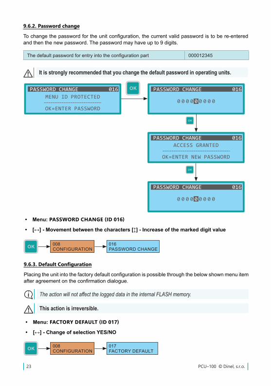
9.6.2. Password change
Tochangethepasswordfortheunitconfiguration,thecurrentvalidpasswordistobere-enteredandthenthenewpassword.Thepasswordmayhaveupto9digits.
Thedefaultpasswordforentryintotheconfigurationpart 000012345
It is strongly recommended that you change the default password in operating units.
• Menu: PASSWORD CHANGE (ID 016)
• [↔] - Movement between the characters [] - Increase of the marked digit value
9.6.3. Default Configuration
Placingtheunitintothefactorydefaultconfigurationispossiblethroughthebelowshownmenuitemafteragreementontheconfirmationdialogue.
The action will not affect the logged data in the internal FLASH memory.
This action is irreversible.
• Menu: FACTORY DEFAULT (ID 017)
• [↔] - Change of selection YES/NO
24© Dinel, s.r.o. PCU–100
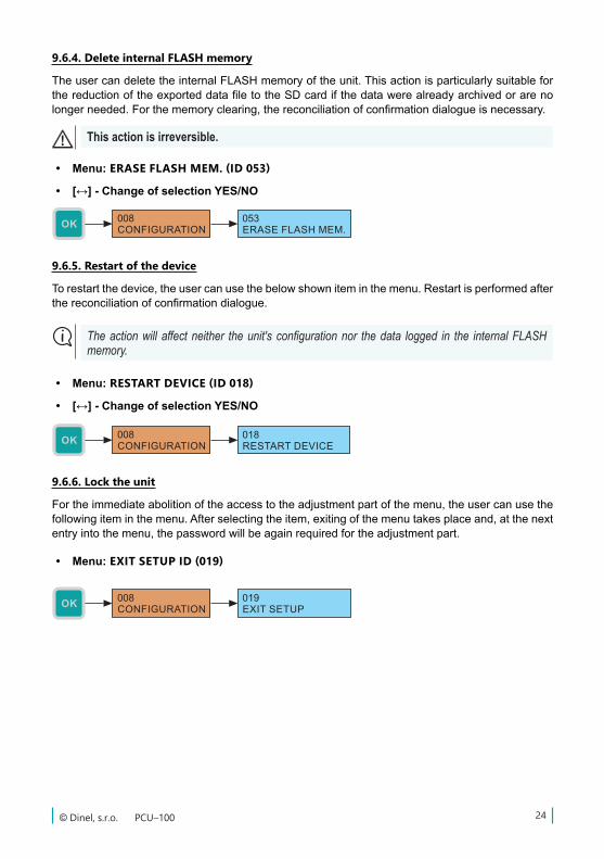
9.6.5. Restart of the device
Torestartthedevice,theusercanusethebelowshowniteminthemenu.Restartisperformedafterthereconciliationofconfirmationdialogue.
The action will affect neither the unit's configuration nor the data logged in the internal FLASH memory.
• Menu: RESTART DEVICE (ID 018)
• [↔] - Change of selection YES/NO
9.6.6. Lock the unit
Fortheimmediateabolitionoftheaccesstotheadjustmentpartofthemenu,theusercanusethefollowingiteminthemenu.Afterselectingtheitem,exitingofthemenutakesplaceand,atthenextentryintothemenu,thepasswordwillbeagainrequiredfortheadjustmentpart.
• Menu: EXIT SETUP ID (019)
9.6.4. Delete internal FLASH memory
TheusercandeletetheinternalFLASHmemoryoftheunit.ThisactionisparticularlysuitableforthereductionoftheexporteddatafiletotheSDcardifthedatawerealreadyarchivedorarenolongerneeded.Forthememoryclearing,thereconciliationofconfirmationdialogueisnecessary.
This action is irreversible.
• Menu: ERASE FLASH MEM. (ID 053)
• [↔] - Change of selection YES/NO
PCU–100 © Dinel, s.r.o.25
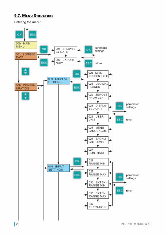
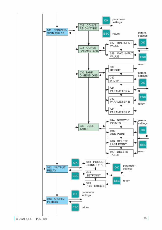
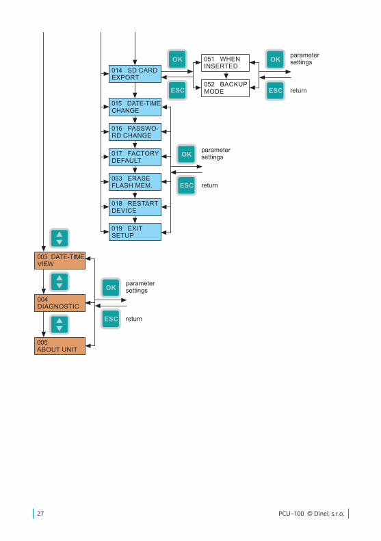
9.7. Menu StructureEntering the menu:
26© Dinel, s.r.o. PCU–100
PCU–100 © Dinel, s.r.o.27
28© Dinel, s.r.o. PCU–100
10. Functions of the equipment
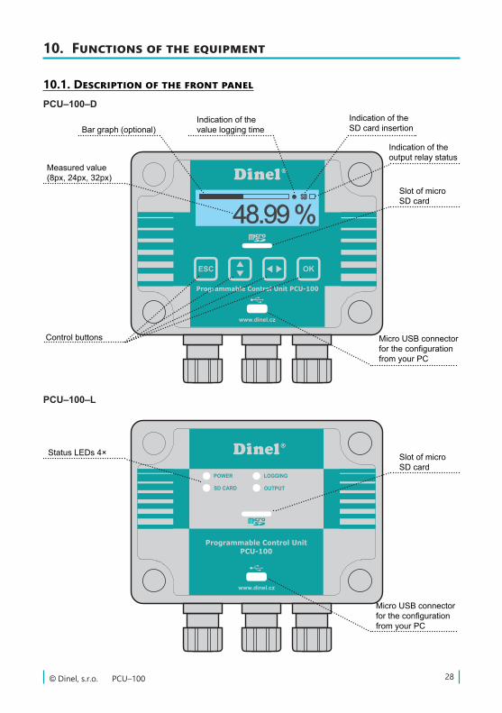
10.1. Description of the front panelPCU–100–D
Indication of the outputrelaystatus
Indication of the SD card insertion
Indication of the value logging timeBargraph(optional)
Measured value (8px,24px,32px)
Control buttons Micro USB connector fortheconfigurationfromyourPC
Slot of micro SD card
PCU–100–L
StatusLEDs4×
Micro USB connector fortheconfigurationfromyourPC
Slot of micro SD card
PCU–100 © Dinel, s.r.o.29
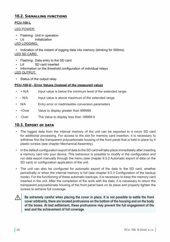
10.2. Signalling functionsPCU-100-L
LEDPOWER:
• Flashing: Unit in operation• Lit: InitializationLEDLOGGING:
• Indicationoftheinstantofloggingdataintomemory(blinkingfor500ms)LEDSD CARD:
• Flashing:DataentrytotheSDcard• Lit: SDcardinserted• InformationonthethresholdconfigurationofindividualrelaysLEDOUTPUT:
• Statusoftheoutputrelay
10.3. Export of data• The loggeddata from the internalmemoryof theunit canbeexported to amicroSDcard
foradditionalprocessing.Foraccesstotheslotformemorycardinsertion,it isnecessarytowithdrawfirstthetransparentpolycarbonatehousingofthefrontpanelthatisheldinplaceby4plasticscrews(seechapterMechanicalAssembly).
• InthedefaultconfigurationexportofdatatotheSDcardwilltakeplaceimmediatelyafterinsertingamemorycardintoyourdevice.Thisbehaviourispossibletomodifyintheconfigurationandrundataexportmanuallythroughthemenu(seechapter9.5.2AutomaticexportofdataontheSDcard)orconfigurationapplicationoftheunit.
• The unit can also be configured for automatic export of the data to the SD card, whetherperiodicallyorwhentheinternalmemoryisfull(seechapter9.5.3Configurationofthebackupmode).Forthefunctioningoftheseautomaticbackups,itisnecessarytokeepthememorycardinsertedintheunit.Afterthecompletionoftheworkwiththedata,itisnecessarytoreturnthetransparentpolycarbonatehousingofthefrontpanelbackonitsplaceandproperlytightenthescrews to achieve full coverage.
Be extremely careful when placing the cover in place. It is not possible to settle the front cover arbitrarily, there are located protrusions on the bottom of the housing and on the body of the boxes. At bad settlement, these protrusions may prevent the full engagement of the seal and the achievement of full coverage.
PCU-100-D - Error Values (instead of the measured value)
• +N/A Inputvalueisbelowtheminimumleveloftheextendedrange.
• -N/A Inputvalueisabovemaximumoftheextendedrange.
• N/A Entryerrororinadmissibleconversionparameters
• +Over Valuetodisplaygreaterthan999999
• -Over TheValuetodisplaylessthan-99999.9
30© Dinel, s.r.o. PCU–100
• ThedataarestoredonamemorycardinCSVformat.Pathtothestoredfilewillbeasfollows:/PCU-100/SNXXXXXX/DATA_YYY.CSV,whereXXXXXXis theserialnumberof theunitandYYYsequencenumberofthefile.Upto999fileswithexporteddatacanbesavedforeachunitofthePCU-100withoutoverwritingthepreviousfile.
The delimiter in a CSV file is dependent on the selected menu language. EN: “,” CZ: “;”
10.4. Displaying Functions of the User MenuThefunctionoftheusermenuintheversionwiththedisplay(PCU-100-D)arenotrestrictedonlyto the configuration of the unit.Additional functions for data management and diagnostics aredescribed in this chapter.
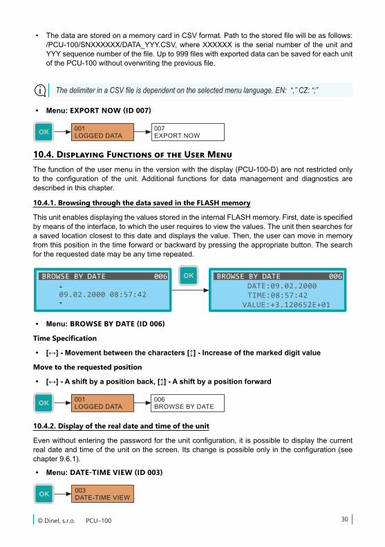
10.4.1. Browsing through the data saved in the FLASH memory
ThisunitenablesdisplayingthevaluesstoredintheinternalFLASHmemory.First,dateisspecifiedbymeansoftheinterface,towhichtheuserrequirestoviewthevalues.Theunitthensearchesforasavedlocationclosesttothisdateanddisplaysthevalue.Then,theusercanmoveinmemoryfromthispositioninthetimeforwardorbackwardbypressingtheappropriatebutton.Thesearchfortherequesteddatemaybeanytimerepeated.
• Menu: BROWSE BY DATE (ID 006)
Time Specification
• [↔] - Movement between the characters [] - Increase of the marked digit value
Move to the requested position
• [↔] - A shift by a position back, [] - A shift by a position forward
10.4.2. Display of the real date and time of the unit
Evenwithoutenteringthepasswordfortheunitconfiguration,itispossibletodisplaythecurrentrealdateandtimeoftheunitonthescreen.Itschangeispossibleonlyintheconfiguration(seechapter9.6.1).
• Menu: DATE-TIME VIEW (ID 003)
• Menu: EXPORT NOW (ID 007)
PCU–100 © Dinel, s.r.o.31
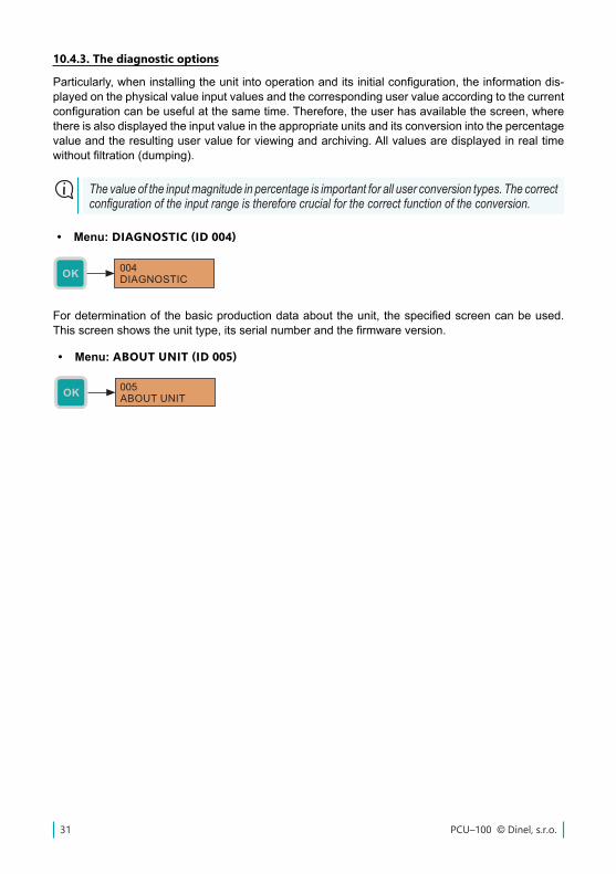
10.4.3. The diagnostic options
Particularly,wheninstallingtheunitintooperationanditsinitialconfiguration,theinformationdis-playedonthephysicalvalueinputvaluesandthecorrespondinguservalueaccordingtothecurrentconfigurationcanbeusefulatthesametime.Therefore,theuserhasavailablethescreen,wherethereisalsodisplayedtheinputvalueintheappropriateunitsanditsconversionintothepercentagevalueandtheresultinguservalueforviewingandarchiving.Allvaluesaredisplayedinrealtimewithoutfiltration(dumping).
• Menu: DIAGNOSTIC (ID 004)
The value of the input magnitude in percentage is important for all user conversion types. The correct configuration of the input range is therefore crucial for the correct function of the conversion.
Fordeterminationofthebasicproductiondataabouttheunit,thespecifiedscreencanbeused.Thisscreenshowstheunittype,itsserialnumberandthefirmwareversion.
• Menu: ABOUT UNIT (ID 005)
32© Dinel, s.r.o. PCU–100
Theoperatorcando thecontrolof theunit function(displayeddata)andof thedeviceoperatorthroughtheMENUthatisnotprotectedbypasswordand,also,copythearchiveddatatotheMicroSD card.
Theequipmentcontainstheuser-replaceablebatteryforbackupoftherealtimecircuitinthebrack-etonthebottomsideoftheunit'sfrontpanel.Fortheaccesstoit,itisnecessarytoremovethefrontpanel(seesection8.Electricalconnection).Then,wemovethebatteryoutofthebrackettothesideandreplaceitwithanewone.Thebatterymustbereplacediftheunitisnotabletostoretheconfiguredrealtimewithoutaconnectedpowersupply.
14. Use, manipulation and maintenance
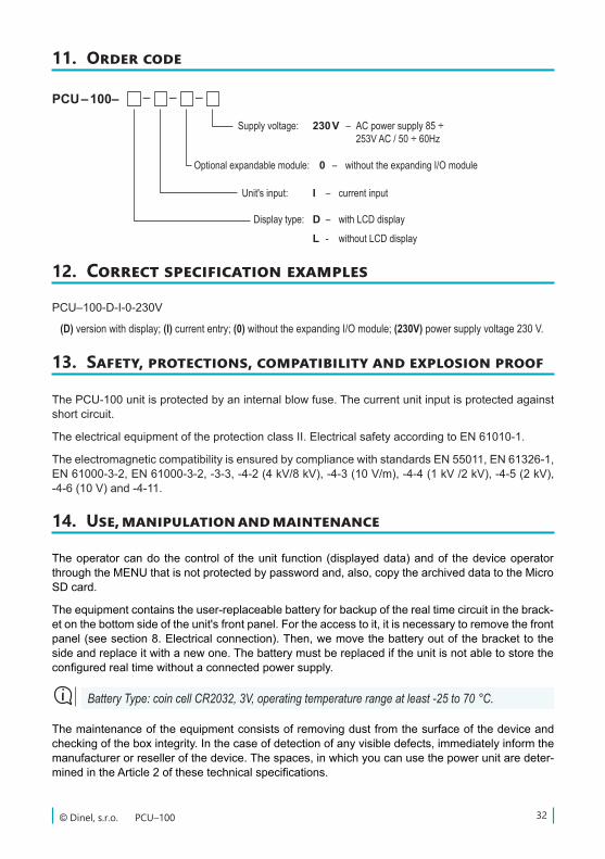
11. Order code
PCU – 100– – – –
Optional expandable module:
Unit's input: I – current input
Supply voltage: 230 V – AC power supply 85 ÷ 253V AC / 50 ÷ 60Hz
0 – without the expanding I/O module
Display type: D – with LCD display
L - without LCD display
12. Correct specification examples
PCU–100-D-I-0-230V
(D) version with display; (I) current entry; (0) without the expanding I/O module; (230V) power supply voltage 230 V.
ThePCU-100unitisprotectedbyaninternalblowfuse.Thecurrentunitinputisprotectedagainstshort circuit.
TheelectricalequipmentoftheprotectionclassII.ElectricalsafetyaccordingtoEN61010-1.
TheelectromagneticcompatibilityisensuredbycompliancewithstandardsEN55011,EN61326-1,EN61000-3-2,EN61000-3-2,-3-3,-4-2(4kV/8kV),-4-3(10V/m),-4-4(1kV/2kV),-4-5(2kV),-4-6(10V)and-4-11.
13. Safety, protections, compatibility and explosion proof
The maintenance of the equipment consists of removing dust from the surface of the device and checkingoftheboxintegrity.Inthecaseofdetectionofanyvisibledefects,immediatelyinformthemanufacturerorresellerofthedevice.Thespaces,inwhichyoucanusethepowerunitaredeter-minedintheArticle2ofthesetechnicalspecifications.
Battery Type: coin cell CR2032, 3V, operating temperature range at least -25 to 70 °C.
PCU–100 © Dinel, s.r.o.33
Any changes or interventions without the permission of the manufacturer are forbidden to be performed on the PCU-100. Any repairs must be carried out only at the manufacturer or by his authorized service organization.The assembly, installation, commissioning, operation and maintenance of the PCU-100 must be carried out in accordance with this manual and must comply with the provisions of the standards in force for the installation of electrical equipment.
15. General, conditions and warranty
Themanufacturerguarantees from thesupply that thisproductwill haveestablishedpropertiesgiveninthetechnicalconditionsforaperiodof3years.
Themanufacturerisresponsibleforthefaultsthathavebeenidentifiedduringthewarrantyperiodand were claimed in writing.
Thewarrantydoesnotapplytodefectsresultingfromimproperhandlingorfailuretocomplywiththetechnicalspecifications.
Thewarrantyshallexpireifthecustomerorathirdpartycarriesoutchangesormodificationsoftheproduct,iftheproductismechanicallyorchemicallydamaged,oriftheproductionnumberisnot legible.
Fortheapplicationofaclaim,itisnecessarytosubmitthecertificateofwarranty.
Intheeventofjustifiedcomplaint,werepairthedefectiveproduct,orreplaceitwithanewone.Inbothcases,thewarrantyperiodshallbeextendedbythetimeoftherepair.
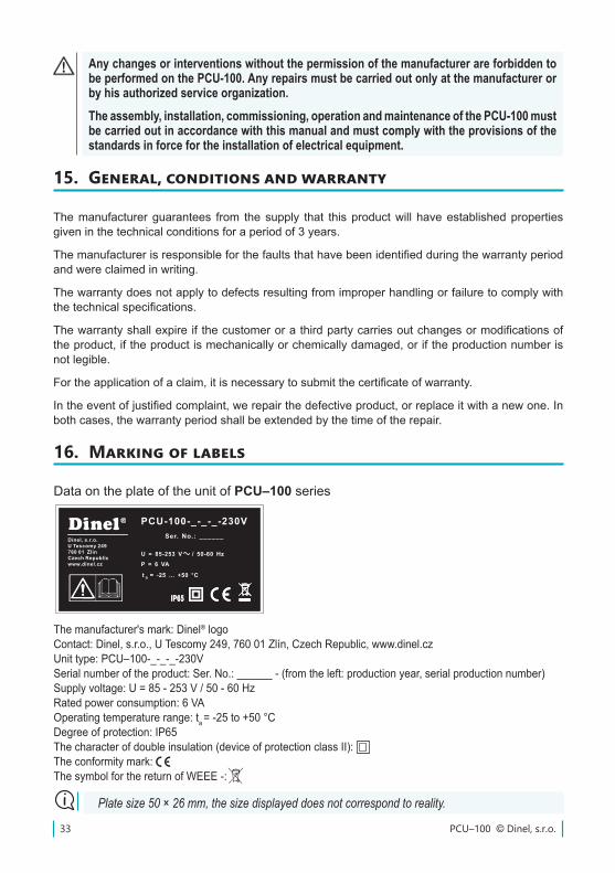
Data on the plate of the unit of PCU–100 series
16. Marking of labels
The manufacturer's mark: Dinel® logoContact:Dinel,s.r.o.,UTescomy249,76001Zlín,CzechRepublic,www.dinel.czUnittype:PCU–100-_-_-_-230VSerialnumberoftheproduct:Ser.No.:______-(fromtheleft:productionyear,serialproductionnumber)Supplyvoltage:U=85-253V/50-60HzRatedpowerconsumption:6VAOperating temperature range: ta=-25to+50°CDegree of protection: IP65Thecharacterofdoubleinsulation(deviceofprotectionclassII):Theconformitymark:ThesymbolforthereturnofWEEE-:
Plate size 50 × 26 mm, the size displayed does not correspond to reality.
Štítek PCU-100 verze 230 V AC
M1:1 50x26 mm
P = 6 VA
t = -25 ... +50 °Ca
U = 85-253 V / 50-60 Hz
PCU-100-_-_-_-230VSer. No.: ______
Dinel, s.r.o.U Tescomy 249760 01 ZlínCzech Republicwww.dinel.cz P = 6 VA
t = -25 ... +50 °Ca
U = 85-253 V / 50-60 Hz
PCU-100-_-_-_-230VSer. No.: ______
Dinel, s.r.o.U Tescomy 249760 01 ZlínCzech Republicwww.dinel.cz
34© Dinel, s.r.o. PCU–100
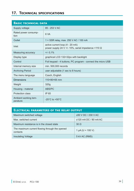
17. Technical specifications
Basic technical dataSupplyvoltage 85-253VAC
Rated power consump-tion 6VA
Outlet 1×SSRrelay,max.250VAC/100mA
Inlet activecurrentloop(4-20mA)powersupply24V+/-10%,serialimpedance<110Ω
Measuringaccuracy +/-0,1%
Displaytype graphicalLCD132×32pxwithbacklight
Control Foilkeypad-4buttons,PCprogram-connectthemicroUSB
Internalmemorysize min.500,000records
Archiving Period useradjustable(1secto8hours)
The menu language Czech,English
Dimensions 110×80×65mm
Weight 320g
Housing-material ABS/PC
Protection class IP 65
Ambient working tem-perature -25°Cto+50°C
Electrical parameters of the relay outputMaximum switched voltage ±50VDC/230VAC
Max. switched current ±120mADC/80mAAC
Maximum resistance is in the closed state 30Ω
Themaximumcurrentflowingthroughtheopenedcontacts 1µA(U=100V)
InsulatingVoltage 5kVAC(RMS)
PCU–100 © Dinel, s.r.o.35
18. Packing, shipping and storage
ThePCU–100iswrappedinapolyethylenebagandthewholeconsignment isplacedinacardbox.Inthecartonbox,appropriatepaddingisusedtopreventmechanicaldamageduringtransport.
Removethedevicefromthepackagingjustbeforeitsuse,youmayavoidpossibledamage.
Thetransporttothecustomerisrealizedbymeansofaforwardingcompany.Afteraprioragreement,personaltakingoftheorderedgoodsfromheadquartersisalsopossible.Whentakingover,pleasemakesurethattheconsignmentiscompleteandcorrespondstotheextentoftheorder,andthatnodamageoccurredtotheequipmentwhentransporting.Donotuseadeviceobviouslydamagedduringtransport,butcontactthemanufacturerinordertoaddressthesituation.
Ifthedeviceistobetransportedfurther,thenonlywrappedintheoriginalpackagingandprotectedagainst shocks and weather conditions.
Storethedeviceintheoriginalpackagingindryareascoveredfromtheweatherconditions,withamoistureupto85%withoutanyeffectsofChemicallyactivesubstances.Storagetemperaturerangeis-10°Cto+50°C.
Dinel, s.r.o.U Tescomy 249
760 01 ZlínCzech Republic
Phone: +420 577 002 002Fax: +420 577 002 007
E-mail: [email protected]
www.dinel.cz
The current version of the manual can be found on www.dinel.czVersion: 08/2017
industrial electronics
11/2018