pico - part 08 - programmable io
TRANSCRIPT
Part 08-
Programmable IO
Version: 2021-01-30

Programmable I/O on Pico
Like many microcontrollers, RP2040 has hardware support for some digital communications protocols such as I2C, SPI, and UART. This means that if you want to communicate with something via I2C, you can simply send the raw data to the I2C peripheral and it will control the pins to handle the specific timing requirements for this protocol. However, what happens if you need something a little unusual such as WS2812B LEDs, or more I2C or SPI buses than are available? Pico (and RP2040) has a little trick up its sleeve: Programmable I/O.On most microcontrollers, you have to ‘bit-bang’, which means using the main processing core to turn the pins on and off directly. This can work, but it can cause timing problems (especially if you use interrupts), and can take a lot of processing resources that you may need for other things.
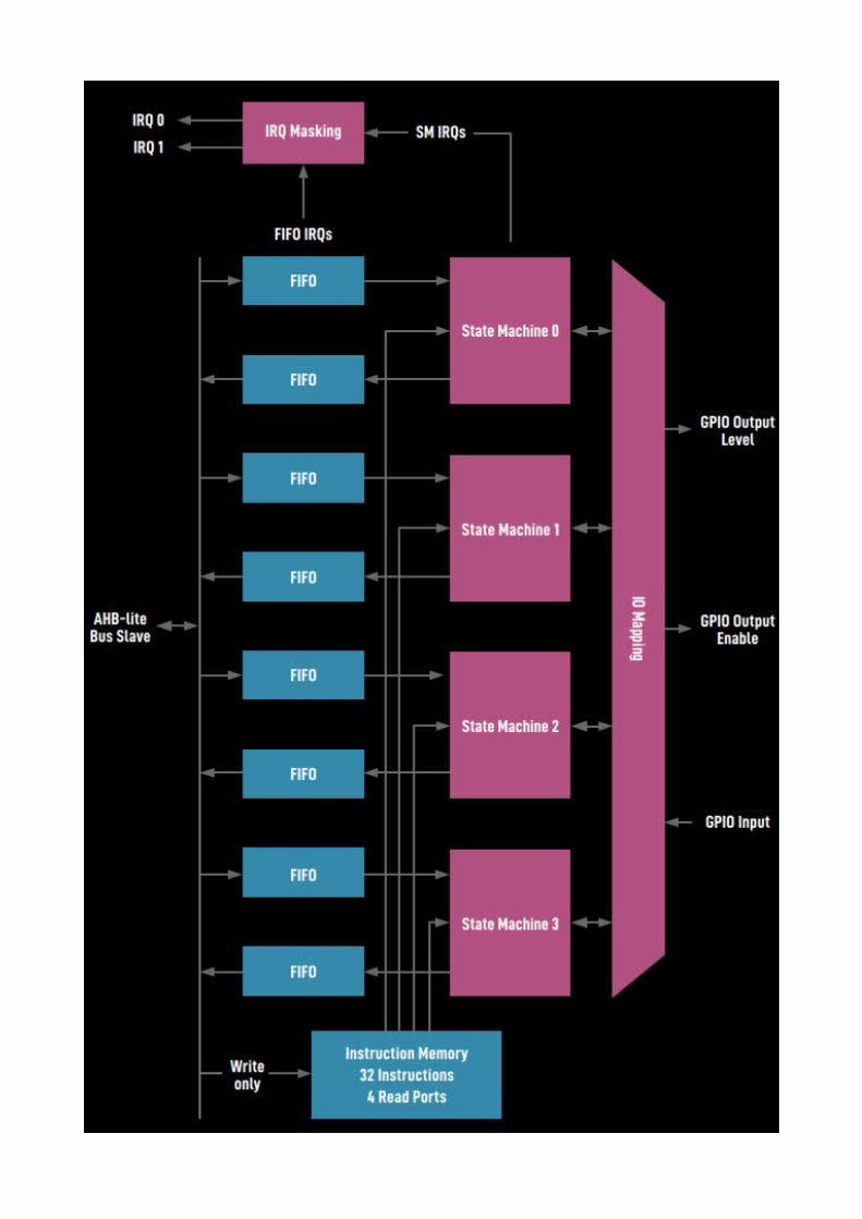
Pico has Programmable I/O (PIO). As well as the two main Cortex-M0+ processing cores, there are two PIO blocks that each have four state machines. These are really stripped-down processing cores that can be used to handle data coming in or out of the microcontroller, and offload some of the processing requirement for implementing communications protocols.
For each simple processor (called a state machine), there are two First-In-First-Out (FIFO) structures: one for data coming in and one for data going out. These are used to link the state machine to everything else. Essentially, they are just a type of memory where the data is read out in the same order it’s written in – for this reason, they’re often called queues because they work in the same way as a queue of people. The first piece of data in (or first person in the queue) is the first to get out the other end. When you need to send data via a PIO state machine, you push it to the FIFO, and when your state machine is ready for the next chunk of data, it pulls it. This way, your PIO state machine and program running on the main core don’t have to be perfectly in-sync. The FIFOs are only four words (of 32 bits) long, but you can link these with direct memory access (DMA) to send larger amounts of data to the PIO state machine without needing to constantly write it from your main program. The FIFOs link to the PIO state machine via the input shift register and the output shift register. There are also two scratch registers called X and Y. These are for storing temporary data. The processor cores are simple state machines that have nine instructions:
• IN shifts 1–32 bits at a time into the input shift register from somewhere (such as a set of pins or a scratch register)
• OUT shifts 1–32 bits from the output shift register to somewhere• PUSH sends data to the RX FIFO• PULL gets data from the TX FIFO• MOV moves data from a source to destination• IRQ sets or clears the interrupt flag• SET writes data to destination• WAIT pauses until a particular action happens• JMP moves to a different point in the code
Within these, there are options to change the behaviour and locations of the data. Take a look at the data sheet for a full overview. In addition, there are a couple of features to make life a little easier:
• Side-setting is where you can set one or more pins at the same time that another instruction runs
• Delays can be added to any instruction (the number of clock cycle delays in square brackets)

Simple Square Wave outputLet’s have a look at a really simple example, a square wave:
.program squarewave_wrap
.wrap_target set pins, 1 [1] set pins, 0 [1].wrap
This uses an outer wrap loop. The wrap_target label is a special case because we don’t need to do an explicit jump to it: we can use .wrap to jump straight to .wrap_target. Unlike an explicit jump instruction, this doesn’t take a clock cycle, so in this case we’re producing a perfect 50% square wave. The .wrap and .wrap_target labels can be omitted. Each instruction also has a delay of a single clock cycle.The value of pins is set when we create the PIO program, so this can create a square wave on any I/O.
SPI OutputLet’s take a look at a more useful example, an SPI transmitter. This just controls the data-sending line for SPI:
.program spi_tx_fast
.side_set 1
loop: out pins, 1 side 0 jmp loop side 1
This shows the power of the side-set. In this case, the side-set pin is the SCL (clock) line of SPI, and the out pin is the SDA. The out instruction takes a value from the FIFO and sets the pin to that value (either 1 or 0). The next instruction triggers the side-set on the clock pin, which causes the receiver to read the data line. Notice that the second instruction is a jump, not the wrap as in the previous example, so it does take a clock cycle to complete.The out instruction gets a bit of data from the output shift register, and this program would quickly empty this register without a pull instruction to get data into it. However, the pull instruction would take one cycle which would complicate the timings. Fortunately, we can enable autopull when we create a PIO program, and this will continuously refill the output shift register as needed as long as data is available in the FIFO. Should the FIFO be empty, the PIO state machine will stall and wait for more data.The speed of this SPI transmit is set up the clock speed of the PIO state machine, and this is configurable when you start the PIO.
Programmable I/O and MicroPython
NOTE: Make sure you have at least version 20210207-v1.14 of the MircoPython firmware installed. There is a problem in earlier firmwares whereas “array” is not defined in rp2. Hence running the code below is not possible and produces the error “ImportError: no module named 'array'”
Simple flashing lights Sometimes a blinking LED is needed to let the user know what's going on with your project. That's easy enough to do, but it's not always visually appealing. A slow fade in can be a better look. While this isn't hard to program on its own, if you've got other processing to do, it can be hard to juggle CPU time to make sure the fade remains smooth. Let's take a look at how to do this with Programmable I/O in MicroPython.
from rp2 import PIO, StateMachine, asm_piofrom machine import Pinimport time
@asm_pio(set_init=PIO.OUT_LOW)def led_off(): set(pins, 0)
@asm_pio(set_init=PIO.OUT_LOW)def led_on(): set(pins, 1)
sm1 = StateMachine(1, led_off, freq=20000, set_base=Pin(25))sm2 = StateMachine(2, led_on, freq=20002, set_base=Pin(25))
sm1.active(1)sm2.active(1)
As you can see, we use the @asm_pio decorator to let MicroPython know that a method is written in PIO assembly. We need to pass a parameter to the PIO assembler to let it know the initial state of the pin. We've set it low in both progams. In this setup, each state machine does one thing: turns an LED on (with a 1) or off (with a 0). These programs automatically loop, so they'll continue turning the LED on and off. We need to load the programs into state machines before we can use them. The StateMachine class takes a range of parameters, but we only need the most basic ones
• the state machine number• the program we want it to run• the frequency we want to run it at• the pin we want the set instruction to operate on
As you can see, we've set them running at slightly different frequencies, so the programs get a little out of sync over time. This means that the proportion of time the LED will be on or off will vary, leading to a rhythmical fading in then turning off. Finally we need to activate the state machines. This will set them running in the background and leave the main MicroPython program to get on doing whatever you want to do. If you want to disable them, you just need to run
sm2.active(0)
to stop the state machine turning the led on.That's the very basics of using PIO, creating a state machine and setting it running.

PWMPico does have a PWM peripheral but we're going to implement our own PWM using PIO.PWM stands for Pulse Width Modulation and is a way of setting the brightness of an LED (amoung other things) by flicking it on or off very quickly. The larger the proportion of the time it's on, the brighter it is.
from machine import Pinfrom rp2 import PIO, StateMachine, asm_piofrom time import sleep
max_count = 500
@asm_pio(sideset_init=PIO.OUT_LOW)def pwm_prog(): pull(noblock) .side(0) # Keep most recent pull data stashed in X, for recycling by noblock mov(x, osr) # ISR must be preloaded with PWM count max mov(y, isr) label("pwmloop") jmp(x_not_y, "skip") nop() .side(1) label("skip") jmp(y_dec, "pwmloop")
pwm_sm = StateMachine(0, pwm_prog, freq=10000000, sideset_base=Pin(25))
pwm_sm.put(max_count)pwm_sm.exec("pull()")pwm_sm.exec("mov(isr, osr)")pwm_sm.active(1)
while True: for i in range(500): pwm_sm.put(i) sleep(0.001)
First we need to import some things, create a program and load it into a state machine.
from machine import Pinfrom rp2 import PIO, StateMachine, asm_piofrom time import sleep
max_count = 500
@asm_pio(sideset_init=PIO.OUT_LOW)def pwm_prog(): pull(noblock) .side(0) mov(x, osr) mov(y, isr) label("pwmloop") jmp(x_not_y, "skip") nop() .side(1) label("skip") jmp(y_dec, "pwmloop")
pwm_sm = StateMachine(0, pwm_prog, freq=10000000, sideset_base=Pin(25))
We are doing things a little differently here in a few ways. Firstly, we aren't turning pins on and off using set, we're using .side(). This is known as side setting and it runs concurrently with other instructions. Note that we define the pin with sideset_base rather than set_base. This means that you can use set and sideset on different pins. There's also out, so you can use three independent groups of pins from a individual PIO program.

Let's go through this line-by-line as there are a few unfamiliar bits here.
• pull(noblock) .side(0)The pull command takes data from the output FIFO and places it in the Output Shift Register. The noblock option means that if there is no data in the output FIFO, then it will continue running. If noblock is omitted, it will pause here and wait for data. .side(0) will turn the sideset pin (25 in this case) off. FIFOs or First In First Outs are data structures that do exactly this. The first bit of data you put in will be the first bit out the other end. They're sometimes known as queues and they perform a similar function of queueing up data before an input is ready to accept it.
• mov(x, osr)
Move data from the Ouput Shift Register in the x (one of two scratch registers we can use -- the other being y. You can think of these a little like variables).
• mov(y, isr) Move data from the Input Shift Register into y. Usually the ISR is used to store data read in from input pins, but in this case it's being uses a bit like a temporary variable. We'll see later how we load data into the ISR.
• label("pwmloop"). We can place markers at certain points in our code that allows us to 'jump' to them.
• jmp(x_not_y, "skip"). This performs a test between x and y. If they are different, then the program jumps to the label "skip" and doesn't execute any of the code in between.
• nop() .side(1). The program will only reach this line if x is equal to y (if they are not, then the jump in the previous line will happen. nop means nothing happens in the main instruction, but the side(1) will turn the side set pin on.
• jmp(y_dec, "pwmloop"). This jumps to the label pwmloop. As this is above this line, it will create a loop (as the label suggests). Each time it jumps, it will decrease the value of y by one, and if it gets to 0, it will not do the jump. As such, this performs a little like a for loop in Python with numbers counting down.
• If the program gets to the end, it automatically loops back to the start.
A key to the way this program works is that we pre-load the ISR with the number of loops we want our pwm cycle to take. In our example, we've used 500, but it can be any 32-bit number.The pull line will see if there is a new value to use, but if there isn't it will continue using the current value of the OSR (setting the PWM pin to 0 in the process), and load this into the x register. The program then loads the number of loops from the ISR into the y register. The PWM loop (between the label and the final jump) will continue to run until y reaches 0. When y reaches the value of x, it will turn on the sideset pin.

Let's take a look how to pre-load the ISR with data
pwm_sm.put(max_count)pwm_sm.exec("pull()")pwm_sm.exec("mov(isr, osr)")pwm_sm.active(1)
First we use the put method to put data in the state machine's output FIFO. Then we use the exec method (which can run arbitrary commands in the state machine) to load the value into the ISR. Finally we activate the state machine so it's ready to start accepting values.To set the brightness of the LED, then, we just have to feed a value between 0 (completely off) and 500 (almost fully on) into the output FIFO.
while True: for i in range(500): pwm_sm.put(i) sleep(0.001)
Again, we use the put method to feed data into the output FIFO of the state machine.
Programmable I/O and C-SDK
Note: Not tested yet – I am a bit reluctant to C/C++ eventhough I used to program in C and C++ a long time ago.
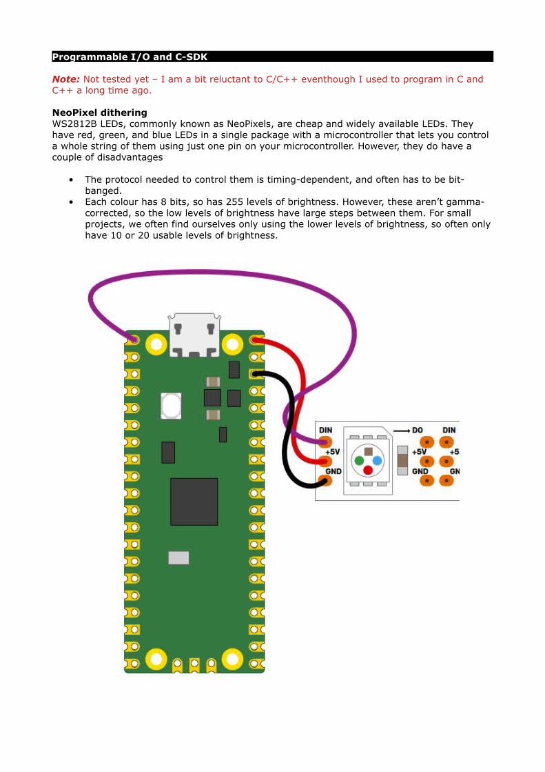
NeoPixel ditheringWS2812B LEDs, commonly known as NeoPixels, are cheap and widely available LEDs. They have red, green, and blue LEDs in a single package with a microcontroller that lets you control a whole string of them using just one pin on your microcontroller. However, they do have a couple of disadvantages
• The protocol needed to control them is timing-dependent, and often has to be bit-banged.
• Each colour has 8 bits, so has 255 levels of brightness. However, these aren’t gamma-corrected, so the low levels of brightness have large steps between them. For small projects, we often find ourselves only using the lower levels of brightness, so often only have 10 or 20 usable levels of brightness.

Setting up the C-SDKIn order to compile this code, you need to set up the C-SDK. Follow the steps as listed in the document “Pico - Part 04 - C-C++ SDK”. Once you’ve got that set up, you can use CMake to build the project. So, if you have two directories at the same level, one called PicoLights and one called PicoLights-build, you can build the project with the following run in the PicoLights-build directory
cmake ../PicoLights -G "Nmake Makefiles" nmake
This is for Windows. You’ll need to alter the -G parameter of CMake if you’re using macOS or Linux. See “Pico - Part 04 - C-C++ SDK” for details.
Basic codeWe’re going to look at how two features of Pico help solve these problems. Firstly, Programmable IO (PIO) lets us implement the control protocol on a state machine rather than the main processing cores. This means that we don’t have to dedicate any processor time to sending the data out. Secondly, having two cores means we can use one of the processing cores to dither the NeoPixels. This means shift them rapidly between different brightness levels to make pseudo-levels of brightness. For example, if we wanted a brightness level halfway between levels 3 and 4, we’d flick the brightness back and forth between 3 and 4. If we can do this fast enough, our eyes blur this into a single brightness level and we don’t see the flicker. By varying the amount of time at levels 3 and 4, we can make many virtual levels of brightness. While one core is doing this, we still have a processing core completely free to manipulate the data we want to display.First, we’ll need a PIO program to communicate with the WS2812B LEDs. The Pico development team have provided an example PIO program to work with – you can see the full details at the end of this document, but we’ll cover the essentials here. The PIO code is:
.program ws2812
.side_set 1
.define public T1 2
.define public T2 5
.define public T3 3 bitloop: out x, 1 side 0 [T3 - 1] jmp !x do_zero side 1 [T1 - 1] do_one: jmp bitloop side 1 [T2 - 1] do_zero: nop side 0 [T2 – 1]
We looked at the PIO syntax above, but it’s basically an assembly language for the PIO state machine. The WS2812B protocol uses pulses at a rate of 800kHz, but the length of the pulse determines if a 1 or a 0 is being sent. This code uses jumps to move through the loop to set the timings depending on whether the bit (stored in the register x) is 0 or 1. The T1, T2, and T3 variables hold the timings, so are used to calculate the delays (with 1 taken off as the instruction itself takes one clock cycle). There’s also a section in the pio file that links the PIO code and the C code:
% c-sdk { #include "hardware/clocks.h" static inline void ws2812_program_init(PIO pio, uint sm, uint offset, uint pin, float freq, bool rgbw) { pio_gpio_select(pio, pin); pio_sm_set_consecutive_pindirs(pio, sm, pin, 1, true); pio_sm_config c = ws2812_program_get_default_
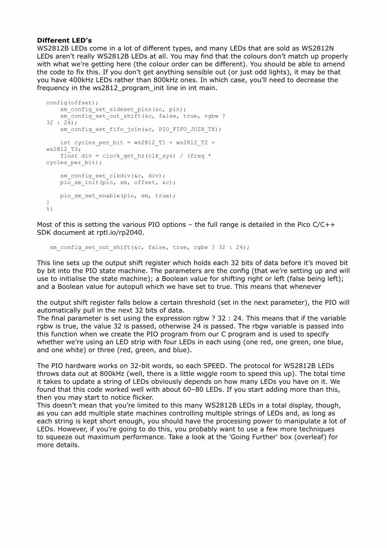
Different LED’sWS2812B LEDs come in a lot of different types, and many LEDs that are sold as WS2812N LEDs aren’t really WS2812B LEDs at all. You may find that the colours don’t match up properly with what we’re getting here (the colour order can be different). You should be able to amend the code to fix this. If you don’t get anything sensible out (or just odd lights), it may be that you have 400kHz LEDs rather than 800kHz ones. In which case, you’ll need to decrease the frequency in the ws2812_program_init line in int main.
config(offset); sm_config_set_sideset_pins(&c, pin); sm_config_set_out_shift(&c, false, true, rgbw ? 32 : 24); sm_config_set_fifo_join(&c, PIO_FIFO_JOIN_TX); int cycles_per_bit = ws2812_T1 + ws2812_T2 + ws2812_T3; float div = clock_get_hz(clk_sys) / (freq * cycles_per_bit); sm_config_set_clkdiv(&c, div); pio_sm_init(pio, sm, offset, &c); pio_sm_set_enable(pio, sm, true); } %}
Most of this is setting the various PIO options – the full range is detailed in the Pico C/C++ SDK document at rptl.io/rp2040.
sm_config_set_out_shift(&c, false, true, rgbw ? 32 : 24);
This line sets up the output shift register which holds each 32 bits of data before it’s moved bit by bit into the PIO state machine. The parameters are the config (that we’re setting up and will use to initialise the state machine); a Boolean value for shifting right or left (false being left); and a Boolean value for autopull which we have set to true. This means that whenever
the output shift register falls below a certain threshold (set in the next parameter), the PIO will automatically pull in the next 32 bits of data.The final parameter is set using the expression rgbw ? 32 : 24. This means that if the variable rgbw is true, the value 32 is passed, otherwise 24 is passed. The rbgw variable is passed into this function when we create the PIO program from our C program and is used to specify whether we’re using an LED strip with four LEDs in each using (one red, one green, one blue, and one white) or three (red, green, and blue).
The PIO hardware works on 32-bit words, so each SPEED. The protocol for WS2812B LEDs throws data out at 800kHz (well, there is a little wiggle room to speed this up). The total time it takes to update a string of LEDs obviously depends on how many LEDs you have on it. We found that this code worked well with about 60–80 LEDs. If you start adding more than this, then you may start to notice flicker.This doesn’t mean that you’re limited to this many WS2812B LEDs in a total display, though, as you can add multiple state machines controlling multiple strings of LEDs and, as long as each string is kept short enough, you should have the processing power to manipulate a lot of LEDs. However, if you’re going to do this, you probably want to use a few more techniques to squeeze out maximum performance. Take a look at the 'Going Further' box (overleaf) for more details.

Forgechunk of data we write with the values we want to send to the LEDs has to be 32 bits long. However, if we’re using RGB LED strips, we actually want to work in 24-bit lengths. By setting autopull to 24, we still pull in 32 bits each time, but once 24 bits have been read, another 32 bits are pulled in which overwrite the remaining 8 bits.
sm_config_set_fifo_join(&c, PIO_FIFO_JOIN_TX);
Each state machine has two four-word FIFOs attached to it. These can be used for one going in and one coming out. However, as we only have data going into our state machine, we can join them together to form a single eight-word FIFO using the above line. This gives us a small buffer of time to write data to in order to avoid the state machine running out of data and execution stalling.The following three lines are used to set the speed the state machine runs at:
int cycles_per_bit = ws2812_T1 + ws2812_T2 + ws2812_T3; float div = clock_get_hz(clk_sys) / (freq * cycles_per_bit); sm_config_clkdiv(&c, div);
The WS2812B protocol demands that data is sent out at a rate of 800kHz. However, each bit of data requires a number of state machine cycles. In this case, they’re defined in the variables T1, T2, and T3. If you look back at the original PIO program, you’ll see that these are used in the delays (always with 1 taken off the value because the initial instruction takes one cycle before the delay kicks in). Every loop of the PIO program will take T1 + T2 + T3 cycles. We use these values to calculate the speed we want the state machine to run at, and from there we can work out the divider we need to slow the system clock down to the right speed for the state machine.
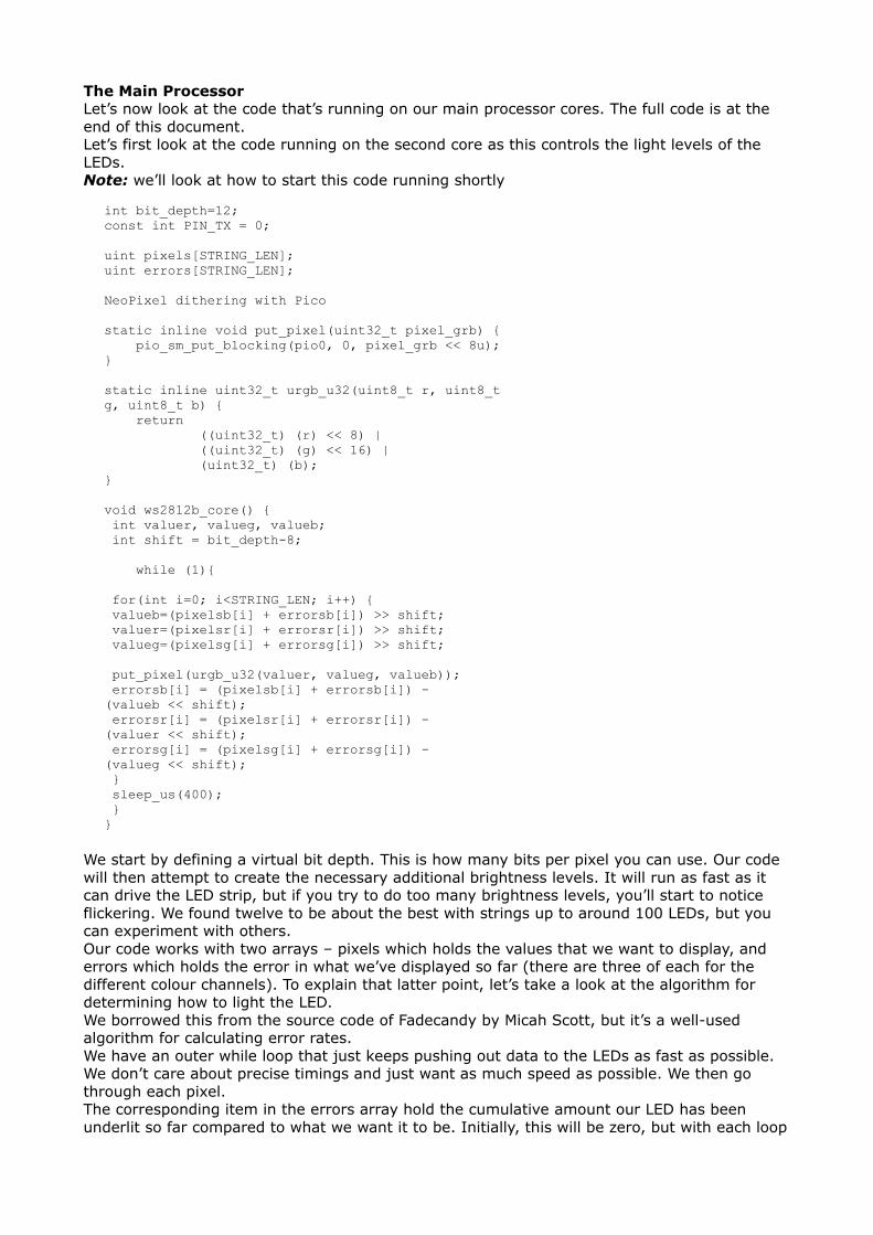
The Main ProcessorLet’s now look at the code that’s running on our main processor cores. The full code is at the end of this document.Let’s first look at the code running on the second core as this controls the light levels of the LEDs.Note: we’ll look at how to start this code running shortly
int bit_depth=12; const int PIN_TX = 0; uint pixels[STRING_LEN]; uint errors[STRING_LEN]; NeoPixel dithering with Pico
static inline void put_pixel(uint32_t pixel_grb) { pio_sm_put_blocking(pio0, 0, pixel_grb << 8u); } static inline uint32_t urgb_u32(uint8_t r, uint8_t g, uint8_t b) { return ((uint32_t) (r) << 8) | ((uint32_t) (g) << 16) | (uint32_t) (b); } void ws2812b_core() { int valuer, valueg, valueb; int shift = bit_depth-8; while (1){ for(int i=0; i<STRING_LEN; i++) { valueb=(pixelsb[i] + errorsb[i]) >> shift; valuer=(pixelsr[i] + errorsr[i]) >> shift; valueg=(pixelsg[i] + errorsg[i]) >> shift;
put_pixel(urgb_u32(valuer, valueg, valueb)); errorsb[i] = (pixelsb[i] + errorsb[i]) - (valueb << shift); errorsr[i] = (pixelsr[i] + errorsr[i]) - (valuer << shift); errorsg[i] = (pixelsg[i] + errorsg[i]) - (valueg << shift); } sleep_us(400); } }
We start by defining a virtual bit depth. This is how many bits per pixel you can use. Our code will then attempt to create the necessary additional brightness levels. It will run as fast as it can drive the LED strip, but if you try to do too many brightness levels, you’ll start to notice flickering. We found twelve to be about the best with strings up to around 100 LEDs, but you can experiment with others. Our code works with two arrays – pixels which holds the values that we want to display, and errors which holds the error in what we’ve displayed so far (there are three of each for the different colour channels). To explain that latter point, let’s take a look at the algorithm for determining how to light the LED. We borrowed this from the source code of Fadecandy by Micah Scott, but it’s a well-used algorithm for calculating error rates.We have an outer while loop that just keeps pushing out data to the LEDs as fast as possible. We don’t care about precise timings and just want as much speed as possible. We then go through each pixel. The corresponding item in the errors array hold the cumulative amount our LED has been underlit so far compared to what we want it to be. Initially, this will be zero, but with each loop

(if there’s a difference between what we want to light the LED and what we can light the LED) this error value will increase.These two numbers (the closest light level and the error) added together give the brightness at the pseudo-level, so we need to bit-shift this by the difference between our virtual level and the 8-bit brightness levels that are available. This gives us the value for this pixel which we write out. We then need to calculate the new error level.Let’s take a look at what this means in practice. Suppose we want a brightness level halfway between 1 and 2 in the 8-bit levels. To simplify things, we’ll use nine virtual bits. 1 and 2 in 8-bit is 2 and 4 in 9 bits (adding an extra 0 to the end multiplies everything by a power of 2), so halfway between these two is a 9-bit value of 3 (or 11 in binary, which we’ll use from now on).
In the first iteration of our loop, pixels is 11, errors is 0, and shift is 1.
value = 11 >> 1 = 1 errors = 11 – 10 = 1
So this time, the brightness level of 1 is written out.The second iteration, we have:
value = 100 >> 1 = 10 errors = 100 – 100 = 0
So this time, the brightness level of 10 (in binary, or 2 in base 10) is written out. This time, the errors go back to 0, so we’re in the same position as at the start of the first loop. In this case, the LED will flick between the two brightness levels each loop so you'll have a brightness half way between the two.Using this simple algorithm, we can experiment with different virtual bit-depths. The algorithm will always handle the calculations for us, but we just have to see what creates the most pleasing visual effect for the eye. The larger the virtual bit depth, the more potential iterations you have to go through before the error accumulates enough to create a correction, so the more likely you are to see flicker.The biggest blocker to increasing the virtual bit depth is the sleep_us(400). This is needed to reset the LED strip. Essentially, we throw out bits at 800kHz, and each block of 24 bits is sent, in turn, to the next LED. However, once there’s a long enough pause, everything resets and it goes back to the first LED. How big that pause is can vary. The truth is that a huge proportion of WS2812B LEDs are clones rather than official parts – and even for official parts, the length of the pause needed to reset has changed over the years. 400 microseconds is conservative and should work, but you may be able to get away with less (possibly even as low as 50 microseconds for some LEDs).The urgb_u32 method simply amalgamates the red, blue, and green values into a single 32-bit string (well, a 24-bit string that’s held inside a 32-bit string), and put_pixel sends this to the state machine. The bit shift there is to make sure the data is in the right place so the state machine reads the correct 24 bits from the output shift register.
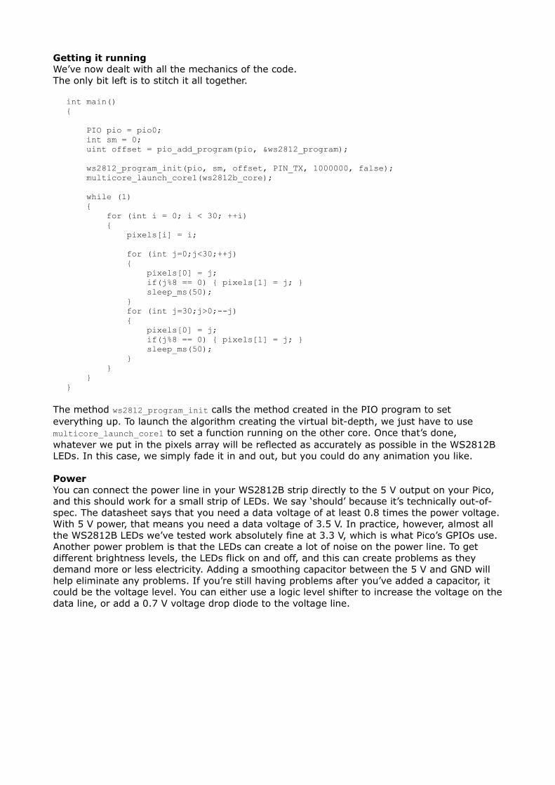
Getting it runningWe’ve now dealt with all the mechanics of the code. The only bit left is to stitch it all together.
int main() { PIO pio = pio0; int sm = 0; uint offset = pio_add_program(pio, &ws2812_program); ws2812_program_init(pio, sm, offset, PIN_TX, 1000000, false); multicore_launch_core1(ws2812b_core); while (1) { for (int i = 0; i < 30; ++i) { pixels[i] = i; for (int j=0;j<30;++j) { pixels[0] = j; if(j%8 == 0) { pixels[1] = j; } sleep_ms(50); } for (int j=30;j>0;--j) { pixels[0] = j; if(j%8 == 0) { pixels[1] = j; } sleep_ms(50); } } } }
The method ws2812_program_init calls the method created in the PIO program to set everything up. To launch the algorithm creating the virtual bit-depth, we just have to use multicore_launch_core1 to set a function running on the other core. Once that’s done, whatever we put in the pixels array will be reflected as accurately as possible in the WS2812B LEDs. In this case, we simply fade it in and out, but you could do any animation you like.
PowerYou can connect the power line in your WS2812B strip directly to the 5 V output on your Pico, and this should work for a small strip of LEDs. We say ‘should’ because it’s technically out-of-spec. The datasheet says that you need a data voltage of at least 0.8 times the power voltage. With 5 V power, that means you need a data voltage of 3.5 V. In practice, however, almost all the WS2812B LEDs we’ve tested work absolutely fine at 3.3 V, which is what Pico’s GPIOs use.Another power problem is that the LEDs can create a lot of noise on the power line. To get different brightness levels, the LEDs flick on and off, and this can create problems as they demand more or less electricity. Adding a smoothing capacitor between the 5 V and GND will help eliminate any problems. If you’re still having problems after you’ve added a capacitor, it could be the voltage level. You can either use a logic level shifter to increase the voltage on the data line, or add a 0.7 V voltage drop diode to the voltage line.
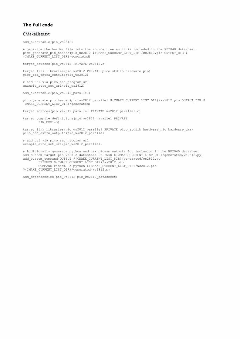
The Full code
CMakeLists.txt
add_executable(pio_ws2812)
# generate the header file into the source tree as it is included in the RP2040 datasheetpico_generate_pio_header(pio_ws2812 ${CMAKE_CURRENT_LIST_DIR}/ws2812.pio OUTPUT_DIR ${CMAKE_CURRENT_LIST_DIR}/generated)
target_sources(pio_ws2812 PRIVATE ws2812.c)
target_link_libraries(pio_ws2812 PRIVATE pico_stdlib hardware_pio)pico_add_extra_outputs(pio_ws2812)
# add url via pico_set_program_urlexample_auto_set_url(pio_ws2812)
add_executable(pio_ws2812_parallel)
pico_generate_pio_header(pio_ws2812_parallel ${CMAKE_CURRENT_LIST_DIR}/ws2812.pio OUTPUT_DIR ${CMAKE_CURRENT_LIST_DIR}/generated)
target_sources(pio_ws2812_parallel PRIVATE ws2812_parallel.c)
target_compile_definitions(pio_ws2812_parallel PRIVATE PIN_DBG1=3)
target_link_libraries(pio_ws2812_parallel PRIVATE pico_stdlib hardware_pio hardware_dma)pico_add_extra_outputs(pio_ws2812_parallel)
# add url via pico_set_program_urlexample_auto_set_url(pio_ws2812_parallel)
# Additionally generate python and hex pioasm outputs for inclusion in the RP2040 datasheetadd_custom_target(pio_ws2812_datasheet DEPENDS ${CMAKE_CURRENT_LIST_DIR}/generated/ws2812.py)add_custom_command(OUTPUT ${CMAKE_CURRENT_LIST_DIR}/generated/ws2812.py DEPENDS ${CMAKE_CURRENT_LIST_DIR}/ws2812.pio COMMAND Pioasm -o python ${CMAKE_CURRENT_LIST_DIR}/ws2812.pio ${CMAKE_CURRENT_LIST_DIR}/generated/ws2812.py )add_dependencies(pio_ws2812 pio_ws2812_datasheet)
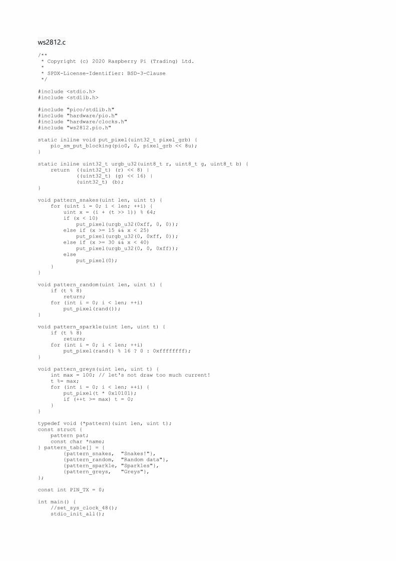
ws2812.c
/** * Copyright (c) 2020 Raspberry Pi (Trading) Ltd. * * SPDX-License-Identifier: BSD-3-Clause */
#include <stdio.h>#include <stdlib.h>
#include "pico/stdlib.h"#include "hardware/pio.h"#include "hardware/clocks.h"#include "ws2812.pio.h"
static inline void put_pixel(uint32_t pixel_grb) { pio_sm_put_blocking(pio0, 0, pixel_grb << 8u);}
static inline uint32_t urgb_u32(uint8_t r, uint8_t g, uint8_t b) { return ((uint32_t) (r) << 8) | ((uint32_t) (g) << 16) | (uint32_t) (b);}
void pattern_snakes(uint len, uint t) { for (uint i = 0; i < len; ++i) { uint x = (i + (t >> 1)) % 64; if (x < 10) put_pixel(urgb_u32(0xff, 0, 0)); else if (x >= 15 && x < 25) put_pixel(urgb_u32(0, 0xff, 0)); else if (x >= 30 && x < 40) put_pixel(urgb_u32(0, 0, 0xff)); else put_pixel(0); }}
void pattern_random(uint len, uint t) { if (t % 8) return; for (int i = 0; i < len; ++i) put_pixel(rand());}
void pattern_sparkle(uint len, uint t) { if (t % 8) return; for (int i = 0; i < len; ++i) put_pixel(rand() % 16 ? 0 : 0xffffffff);}
void pattern_greys(uint len, uint t) { int max = 100; // let's not draw too much current! t %= max; for (int i = 0; i < len; ++i) { put_pixel(t * 0x10101); if (++t >= max) t = 0; }}
typedef void (*pattern)(uint len, uint t);const struct { pattern pat; const char *name;} pattern_table[] = { {pattern_snakes, "Snakes!"}, {pattern_random, "Random data"}, {pattern_sparkle, "Sparkles"}, {pattern_greys, "Greys"},};
const int PIN_TX = 0;
int main() { //set_sys_clock_48(); stdio_init_all();

puts("WS2812 Smoke Test");
// todo get free sm PIO pio = pio0; int sm = 0; uint offset = pio_add_program(pio, &ws2812_program);
ws2812_program_init(pio, sm, offset, PIN_TX, 800000, true);
int t = 0; while (1) { int pat = rand() % count_of(pattern_table); int dir = (rand() >> 30) & 1 ? 1 : -1; puts(pattern_table[pat].name); puts(dir == 1 ? "(forward)" : "(backward)"); for (int i = 0; i < 1000; ++i) { pattern_table[pat].pat(150, t); sleep_ms(10); t += dir; } }}
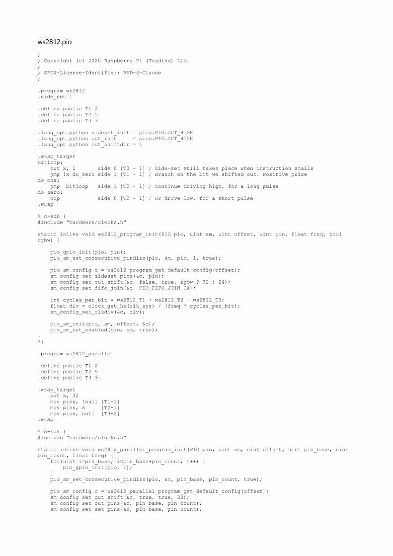
ws2812.pio
;; Copyright (c) 2020 Raspberry Pi (Trading) Ltd.;; SPDX-License-Identifier: BSD-3-Clause;
.program ws2812
.side_set 1
.define public T1 2
.define public T2 5
.define public T3 3
.lang_opt python sideset_init = pico.PIO.OUT_HIGH
.lang_opt python out_init = pico.PIO.OUT_HIGH
.lang_opt python out_shiftdir = 1
.wrap_targetbitloop: out x, 1 side 0 [T3 - 1] ; Side-set still takes place when instruction stalls jmp !x do_zero side 1 [T1 - 1] ; Branch on the bit we shifted out. Positive pulsedo_one: jmp bitloop side 1 [T2 - 1] ; Continue driving high, for a long pulsedo_zero: nop side 0 [T2 - 1] ; Or drive low, for a short pulse.wrap
% c-sdk {#include "hardware/clocks.h"
static inline void ws2812_program_init(PIO pio, uint sm, uint offset, uint pin, float freq, bool rgbw) {
pio_gpio_init(pio, pin); pio_sm_set_consecutive_pindirs(pio, sm, pin, 1, true);
pio_sm_config c = ws2812_program_get_default_config(offset); sm_config_set_sideset_pins(&c, pin); sm_config_set_out_shift(&c, false, true, rgbw ? 32 : 24); sm_config_set_fifo_join(&c, PIO_FIFO_JOIN_TX);
int cycles_per_bit = ws2812_T1 + ws2812_T2 + ws2812_T3; float div = clock_get_hz(clk_sys) / (freq * cycles_per_bit); sm_config_set_clkdiv(&c, div);
pio_sm_init(pio, sm, offset, &c); pio_sm_set_enabled(pio, sm, true);}%}
.program ws2812_parallel
.define public T1 2
.define public T2 5
.define public T3 3
.wrap_target out x, 32 mov pins, !null [T1-1] mov pins, x [T2-1] mov pins, null [T3-2].wrap
% c-sdk {#include "hardware/clocks.h"
static inline void ws2812_parallel_program_init(PIO pio, uint sm, uint offset, uint pin_base, uint pin_count, float freq) { for(uint i=pin_base; i<pin_base+pin_count; i++) { pio_gpio_init(pio, i); } pio_sm_set_consecutive_pindirs(pio, sm, pin_base, pin_count, true);
pio_sm_config c = ws2812_parallel_program_get_default_config(offset); sm_config_set_out_shift(&c, true, true, 32); sm_config_set_out_pins(&c, pin_base, pin_count); sm_config_set_set_pins(&c, pin_base, pin_count);

sm_config_set_fifo_join(&c, PIO_FIFO_JOIN_TX);
int cycles_per_bit = ws2812_parallel_T1 + ws2812_parallel_T2 + ws2812_parallel_T3; float div = clock_get_hz(clk_sys) / (freq * cycles_per_bit); sm_config_set_clkdiv(&c, div);
pio_sm_init(pio, sm, offset, &c); pio_sm_set_enabled(pio, sm, true);}%}
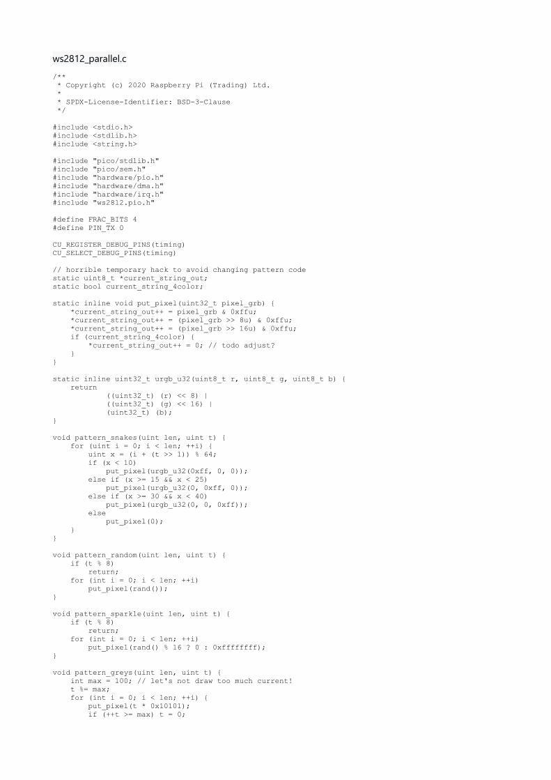
ws2812_parallel.c
/** * Copyright (c) 2020 Raspberry Pi (Trading) Ltd. * * SPDX-License-Identifier: BSD-3-Clause */
#include <stdio.h>#include <stdlib.h>#include <string.h>
#include "pico/stdlib.h"#include "pico/sem.h"#include "hardware/pio.h"#include "hardware/dma.h"#include "hardware/irq.h"#include "ws2812.pio.h"
#define FRAC_BITS 4#define PIN_TX 0
CU_REGISTER_DEBUG_PINS(timing)CU_SELECT_DEBUG_PINS(timing)
// horrible temporary hack to avoid changing pattern codestatic uint8_t *current_string_out;static bool current_string_4color;
static inline void put_pixel(uint32_t pixel_grb) { *current_string_out++ = pixel_grb & 0xffu; *current_string_out++ = (pixel_grb >> 8u) & 0xffu; *current_string_out++ = (pixel_grb >> 16u) & 0xffu; if (current_string_4color) { *current_string_out++ = 0; // todo adjust? }}
static inline uint32_t urgb_u32(uint8_t r, uint8_t g, uint8_t b) { return ((uint32_t) (r) << 8) | ((uint32_t) (g) << 16) | (uint32_t) (b);}
void pattern_snakes(uint len, uint t) { for (uint i = 0; i < len; ++i) { uint x = (i + (t >> 1)) % 64; if (x < 10) put_pixel(urgb_u32(0xff, 0, 0)); else if (x >= 15 && x < 25) put_pixel(urgb_u32(0, 0xff, 0)); else if (x >= 30 && x < 40) put_pixel(urgb_u32(0, 0, 0xff)); else put_pixel(0); }}
void pattern_random(uint len, uint t) { if (t % 8) return; for (int i = 0; i < len; ++i) put_pixel(rand());}
void pattern_sparkle(uint len, uint t) { if (t % 8) return; for (int i = 0; i < len; ++i) put_pixel(rand() % 16 ? 0 : 0xffffffff);}
void pattern_greys(uint len, uint t) { int max = 100; // let's not draw too much current! t %= max; for (int i = 0; i < len; ++i) { put_pixel(t * 0x10101); if (++t >= max) t = 0;
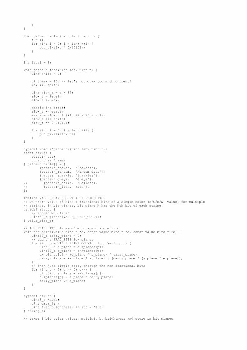
}}
void pattern_solid(uint len, uint t) { t = 1; for (int i = 0; i < len; ++i) { put_pixel(t * 0x10101); }}
int level = 8;
void pattern_fade(uint len, uint t) { uint shift = 4;
uint max = 16; // let's not draw too much current! max <<= shift;
uint slow_t = t / 32; slow_t = level; slow_t %= max;
static int error; slow_t += error; error = slow_t & ((1u << shift) - 1); slow_t >>= shift; slow_t *= 0x010101;
for (int i = 0; i < len; ++i) { put_pixel(slow_t); }}
typedef void (*pattern)(uint len, uint t);const struct { pattern pat; const char *name;} pattern_table[] = { {pattern_snakes, "Snakes!"}, {pattern_random, "Random data"}, {pattern_sparkle, "Sparkles"}, {pattern_greys, "Greys"},// {pattern_solid, "Solid!"},// {pattern_fade, "Fade"},};
#define VALUE_PLANE_COUNT (8 + FRAC_BITS)// we store value (8 bits + fractional bits of a single color (R/G/B/W) value) for multiple// strings, in bit planes. bit plane N has the Nth bit of each string.typedef struct { // stored MSB first uint32_t planes[VALUE_PLANE_COUNT];} value_bits_t;
// Add FRAC_BITS planes of e to s and store in dvoid add_error(value_bits_t *d, const value_bits_t *s, const value_bits_t *e) { uint32_t carry_plane = 0; // add the FRAC_BITS low planes for (int p = VALUE_PLANE_COUNT - 1; p >= 8; p--) { uint32_t e_plane = e->planes[p]; uint32_t s_plane = s->planes[p]; d->planes[p] = (e_plane ^ s_plane) ^ carry_plane; carry_plane = (e_plane & s_plane) | (carry_plane & (s_plane ^ e_plane)); } // then just ripple carry through the non fractional bits for (int p = 7; p >= 0; p--) { uint32_t s_plane = s->planes[p]; d->planes[p] = s_plane ^ carry_plane; carry_plane &= s_plane; }}
typedef struct { uint8_t *data; uint data_len; uint frac_brightness; // 256 = *1.0;} string_t;
// takes 8 bit color values, multiply by brightness and store in bit planes
void transform_strings(string_t **strings, uint num_strings, value_bits_t *values, uint value_length, uint frac_brightness) { for (uint v = 0; v < value_length; v++) { memset(&values[v], 0, sizeof(values[v])); for (int i = 0; i < num_strings; i++) { if (v < strings[i]->data_len) { // todo clamp? uint32_t value = (strings[i]->data[v] * strings[i]->frac_brightness) >> 8u; value = (value * frac_brightness) >> 8u; for (int j = 0; j < VALUE_PLANE_COUNT && value; j++, value >>= 1u) { if (value & 1u) values[v].planes[VALUE_PLANE_COUNT - 1 - j] |= 1u << i; } } } }}
void dither_values(const value_bits_t *colors, value_bits_t *state, const value_bits_t *old_state, uint value_length) { for (uint i = 0; i < value_length; i++) { add_error(state + i, colors + i, old_state + i); }}
#define MAX_LENGTH 100
// requested colors * 4 to allow for WRGBstatic value_bits_t colors[MAX_LENGTH * 4];// double buffer the state of the string, since we update next version in parallel with DMAing out old versionstatic value_bits_t states[2][MAX_LENGTH * 4];
// example - string 0 is RGB onlystatic uint8_t string0_data[MAX_LENGTH * 3];// example - string 1 is WRGBstatic uint8_t string1_data[MAX_LENGTH * 4];
string_t string0 = { .data = string0_data, .data_len = sizeof(string0_data), .frac_brightness = 0x40,};
string_t string1 = { .data = string1_data, .data_len = sizeof(string1_data), .frac_brightness = 0x100,};
string_t *strings[] = { &string0, &string1,};
// bit plane content dma channel#define DMA_CHANNEL 0// chain channel for configuring main dma channel to output from disjoint 8 word fragments of memory#define DMA_CB_CHANNEL 1
#define DMA_CHANNEL_MASK (1u << DMA_CHANNEL)#define DMA_CB_CHANNEL_MASK (1u << DMA_CB_CHANNEL)#define DMA_CHANNELS_MASK (DMA_CHANNEL_MASK | DMA_CB_CHANNEL_MASK)
// start of each value fragment (+1 for NULL terminator)static uintptr_t fragment_start[MAX_LENGTH * 4 + 1];
// posted when it is safe to output a new set of valuesstatic struct semaphore reset_delay_complete_sem;// alarm handle for handling delayalarm_id_t reset_delay_alarm_id;
int64_t reset_delay_complete(alarm_id_t id, void *user_data) { reset_delay_alarm_id = 0; sem_release(&reset_delay_complete_sem); // no repeat return 0;}
void __isr dma_complete_handler() {

if (dma_hw->ints0 & DMA_CHANNEL_MASK) { // clear IRQ dma_hw->ints0 = DMA_CHANNEL_MASK; // when the dma is complete we start the reset delay timer DEBUG_PINS_SET(timing, 4); if (reset_delay_alarm_id) cancel_alarm(reset_delay_alarm_id); reset_delay_alarm_id = add_alarm_in_us(400, reset_delay_complete, NULL, true); }}
void dma_init(PIO pio, uint sm) { dma_claim_mask(DMA_CHANNELS_MASK);
// main DMA channel outputs 8 word fragments, and then chains back to the chain channel dma_channel_config channel_config = dma_channel_get_default_config(DMA_CHANNEL); channel_config_set_dreq(&channel_config, pio_get_dreq(pio, sm, true)); channel_config_set_chain_to(&channel_config, DMA_CB_CHANNEL); channel_config_set_irq_quiet(&channel_config, true); dma_channel_configure(DMA_CHANNEL, &channel_config, &pio->txf[sm], NULL, // set by chain 8, // 8 words for 8 bit planes false);
// chain channel sends single word pointer to start of fragment each time dma_channel_config chain_config = dma_channel_get_default_config(DMA_CB_CHANNEL); dma_channel_configure(DMA_CB_CHANNEL, &chain_config, &dma_channel_hw_addr( DMA_CHANNEL)->al3_read_addr_trig, // ch DMA config (target "ring" buffer size 4) - this is (read_addr trigger) NULL, // set later 1, false);
irq_set_exclusive_handler(DMA_IRQ_0, dma_complete_handler); dma_channel_set_irq0_enabled(DMA_CHANNEL, true); irq_set_enabled(DMA_IRQ_0, true);}
void output_strings_dma(value_bits_t *bits, uint value_length) { DEBUG_PINS_SET(timing, 3); for (uint i = 0; i < value_length; i++) { fragment_start[i] = (uintptr_t) bits[i].planes; // MSB first } fragment_start[value_length] = 0; dma_channel_hw_addr(DMA_CB_CHANNEL)->al3_read_addr_trig = (uintptr_t) fragment_start; DEBUG_PINS_CLR(timing, 3);}
int main() { //set_sys_clock_48(); stdio_init_all(); puts("WS2812 parallel");#if PIN_TX != 3 gpio_debug_pins_init();#endif // todo get free sm PIO pio = pio0; int sm = 0; uint offset = pio_add_program(pio, &ws2812_parallel_program);
ws2812_parallel_program_init(pio, sm, offset, PIN_TX, count_of(strings), 800000);
sem_init(&reset_delay_complete_sem, 1, 1); // initially posted so we don't block first time dma_init(pio, sm); int t = 0; while (1) { int pat = rand() % count_of(pattern_table); int dir = (rand() >> 30) & 1 ? 1 : -1; if (rand() & 1) dir = 0; puts(pattern_table[pat].name); puts(dir == 1 ? "(forward)" : dir ? "(backward)" : "(still)"); int brightness = 0; uint current = 0; for (int i = 0; i < 1000; ++i) { int n = 64; DEBUG_PINS_SET(timing, 1);

current_string_out = string0.data; current_string_4color = false; pattern_table[pat].pat(n, t); current_string_out = string1.data; current_string_4color = true; pattern_table[pat].pat(n, t); DEBUG_PINS_CLR(timing, 1);
DEBUG_PINS_SET(timing, 2); transform_strings(strings, count_of(strings), colors, n * 4, brightness); DEBUG_PINS_CLR(timing, 2);
DEBUG_PINS_SET(timing, 1); dither_values(colors, states[current], states[current ^ 1], n * 4); DEBUG_PINS_CLR(timing, 1);
sem_acquire_blocking(&reset_delay_complete_sem); DEBUG_PINS_CLR(timing, 4);
output_strings_dma(states[current], n * 4);
current ^= 1; t += dir; brightness++; if (brightness == (0x20 << FRAC_BITS)) brightness = 0; } memset(&states, 0, sizeof(states)); // clear out errors }}